Führungswagen Runner Blocks Guides à billes et ... - Bosch Rexroth
Führungswagen Runner Blocks Guides à billes et ... - Bosch Rexroth
Führungswagen Runner Blocks Guides à billes et ... - Bosch Rexroth

You also want an ePaper? Increase the reach of your titles
YUMPU automatically turns print PDFs into web optimized ePapers that Google loves.
<strong>Bosch</strong> <strong>Rexroth</strong> AG<br />
Kurzanleitung<br />
<strong>Führungswagen</strong><br />
für Kugelschienenführungen<br />
und Rollenschienenführungen<br />
c ACHTUNG!<br />
• <strong>Führungswagen</strong> können bis<br />
90 kg wiegen. Nicht fallen<br />
lassen (1), nicht werfen (2)!<br />
• Vor der Montage eventuelle<br />
Grate (3) entfernen!<br />
• Auf Sauberkeit achten! Nasse<br />
Oberflächen trocknen! (4)<br />
• <strong>Führungswagen</strong> nicht von der<br />
Montagehilfe (5) ziehen!<br />
• Bei Bedarf Verschlussstopfen<br />
(6) aus den mittleren Befestigungsbohrungen<br />
entfernen!<br />
f Die <strong>Führungswagen</strong> sind<br />
ab Werk mit einem öligen<br />
Konservierungsmittel versehen.<br />
f <strong>Führungswagen</strong> mit „-20“<br />
oder „-22“ am Ende der<br />
Teilenummern haben eine<br />
Grundschmierung mit Wälzlagerf<strong>et</strong>t<br />
KP2K-20 nach<br />
DIN 51825.<br />
Montage vorbereiten<br />
f Die Montageanleitungen<br />
(7) und die Kataloge (8)<br />
ergänzen diese Kurzanleitung.<br />
Dort finden Sie<br />
– Angaben zur Belastbarkeit,<br />
– Vorschläge für die Verschraubung<br />
und Verstiftung<br />
und D<strong>et</strong>ails zu Wartung und<br />
Schmierung<br />
– und weitere Informationen zu<br />
den <strong>Führungswagen</strong>.<br />
• Stirnseite der Führungsschiene<br />
(9) und Dichtlippen<br />
am <strong>Führungswagen</strong> (10)<br />
einölen oder einf<strong>et</strong>ten.<br />
<strong>Bosch</strong> <strong>Rexroth</strong> Mechatronics GmbH<br />
D-97419 Schweinfurt<br />
11<br />
TAR<br />
STAR<br />
Tel. + 49- 97 21- 9 37- 0<br />
Fax. + 49- 97 21- 9 37- 2 50 (direct)<br />
1<br />
OIL<br />
GREASE<br />
9<br />
STAR<br />
4<br />
2 3<br />
7 R320103095<br />
R320103096<br />
8 R310xx 2202<br />
R310xx 2302<br />
OIL<br />
GREASE<br />
6<br />
Intern<strong>et</strong><br />
www.boschrexroth.com/brl<br />
5<br />
11: Standardmäßig<br />
verschlossen<br />
Closed ex factory<br />
Obturé en standard<br />
Foro di lubrificazione<br />
chiuso.<br />
10<br />
OIL<br />
GREASE<br />
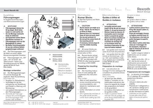
Short instructions<br />
<strong>Runner</strong> <strong>Blocks</strong><br />
for Ball Rail Systems and Roller<br />
Rail Systems<br />
c CAUTION!<br />
• <strong>Runner</strong> blocks can weigh up to<br />
90 kg / 200 lbs. Do not drop (1)<br />
or throw (2) them!<br />
• Remove burrs (3) if necessary!<br />
• Keep all tools and parts clean!<br />
Dry any w<strong>et</strong> surfaces! (4)<br />
• Do not pull the runner block off<br />
the mounting aid (5)!<br />
• If necessary, remove plugs (6)<br />
from the middle mounting<br />
holes!<br />
f All runner blocks are<br />
standard-protected with a<br />
preservative oil film.<br />
f <strong>Runner</strong> blocks whose<br />
part numbers end with “-20”<br />
or “-22” are lubricated with<br />
KP2K-20 roller bearing grease<br />
according to DIN 51825.<br />
Preparing the mounting<br />
procedure<br />
f The mounting instruc-<br />
tions (7) and catalogs (8)<br />
supplement this instruction<br />
leafl<strong>et</strong>.<br />
They contain<br />
– data on load capacities,<br />
– screw-mounting and pinning<br />
recommendations, and<br />
d<strong>et</strong>ails for maintenance and<br />
lubrication<br />
– further information on runner<br />
blocks.<br />
• Oil or grease the end face of<br />
the guide rail (9) and the<br />
runner block sealing lips (10).<br />
R320103184 (2007-10)<br />
Printed in Germany - p 2007/10/100/S<br />
Brève instructions pour<br />
<strong>Guides</strong> <strong>à</strong> <strong>billes</strong> <strong>et</strong><br />
<strong>Guides</strong> <strong>à</strong> rouleaux<br />
c ATTENTION !<br />
• Les guides peuvent peser<br />
jus qu’<strong>à</strong> 90 kg. Ne pas les laisser<br />
tomber (1), ne pas les lancer (2)!<br />
• Eliminer toutes les bavures (3)<br />
éventuelles avant le montage<br />
• Vérifier la propr<strong>et</strong>é des guides!<br />
Sécher les surfaces mouillées! (4)<br />
• Ne pas r<strong>et</strong>irer les guides de<br />
l’auxiliaire de montage (5)!<br />
• Le cas échéant r<strong>et</strong>irer les<br />
bouchons d’obturation (6) des<br />
trous de fixation médians!<br />
f Les guides sont munis en<br />
usine d’une huile de protection.<br />
f Les guides dont les réfé-<br />
rences se terminent par «-20»<br />
ou «-22» sont lubrifiés <strong>à</strong> l’aide<br />
d’une graisse pour roulements<br />
<strong>à</strong> <strong>billes</strong> KP2K-20 selon<br />
DIN 51825.<br />
Préparation du montage<br />
f Les instructions de<br />
montage (7) <strong>et</strong> les catalogues (8)<br />
complètent les présentes brèves<br />
instructions.<br />
Vous y trouverez<br />
– ge ainsi que des détails<br />
relatifs <strong>à</strong> l’entr<strong>et</strong>ien <strong>et</strong> <strong>à</strong> la<br />
lubrificades indications relati<br />
ves <strong>à</strong> la capacité de charge<br />
des propositions de fixation<br />
<strong>et</strong> de goupillation<br />
– <strong>et</strong> d’autres informations sur<br />
les guides <strong>à</strong> <strong>billes</strong>.<br />
• Huiler ou graisser l’extrémité<br />
des rails de guidage (9)<br />
<strong>et</strong> les lèvres d’étanchéité sur<br />
le guide (10).<br />
Istruzioni in breve<br />
Pattini<br />
per guide a sfere su rotaia e<br />
per guide a rulli su rotaia<br />
c ATTENZIONE!<br />
• I pattini possono pesare fino a<br />
90 kg. Non lasciarli ca dere (1),<br />
non lanciarli (2)!<br />
• Prima del montaggio rimuovere/togliere<br />
eventuali bave (3)!<br />
• Far attenzione a che tutto sia<br />
pulito! Asciugare le superfici<br />
bagnate! (4)<br />
• Non sfilare il pattino dalla falsa<br />
rotaia per il montaggio (5)!<br />
• Se necessario, rimuovere i<br />
tappi di chiusura (6) dai fori di<br />
fissaggio centrali!<br />
f I pattini vengono trattati in<br />
stabili mento con un conservante<br />
oleoso.<br />
f I pattini con la cifra « -20 » o<br />
« -22 » alla fine del numero di<br />
identificazione sono provvisti di<br />
lubrificazione di base, eseguita con<br />
grasso per cuscin<strong>et</strong>ti volventi<br />
KP2K-20 come da DIN 51825.<br />
Preparazione del montaggio<br />
f Le istruzioni di montaggio<br />
(7) e il catalogo (8) com pl<strong>et</strong>ano<br />
queste brevi istruzioni.<br />
Qui trovate<br />
– indicazioni relative alla sollecitabilit<strong>à</strong>,<br />
– Proposte per il collegamento a<br />
vite, spinatura e d<strong>et</strong>tagli per la<br />
manutenzione e lubrificazione<br />
– ed altre informazioni sui pattini.<br />
• Lubrificare con olio la parte<br />
frontale della rotaia (9) ed i<br />
labbri di tenuta del pattino<br />
(10).
<strong>Bosch</strong> <strong>Rexroth</strong> AG<br />
<strong>Führungswagen</strong> montieren<br />
• Gewinde im zu tragenden<br />
Bauteil (1) herstellen.<br />
• Höhen der Anschlagkanten<br />
h2 , Eckenradien r2 , Auflageund<br />
Anschlagflächen prüfen.<br />
• Montagehilfe ans<strong>et</strong>zen und<br />
<strong>Führungswagen</strong> vorsichtig<br />
aufschieben (2).<br />
• <strong>Führungswagen</strong> ohne<br />
Grundschmierung vor der<br />
Inb<strong>et</strong>riebnahme schmieren.<br />
Siehe auch entsprechende<br />
Montageanleitung.<br />
• Schrauben mit Anziehdrehmoment<br />
MA verschrauben.<br />
c Achtung<br />
Bei <strong>Führungswagen</strong> aus<br />
Aluminium nur Schrauben<br />
der Festigkeitsklasse 8.8<br />
verwenden!<br />
f In den <strong>Führungswagen</strong><br />
können Vorbohrungen (3) für<br />
Stifte vorhanden sein. Diese<br />
sind zum Aufbohren geeign<strong>et</strong>.<br />
Stiftbohrungen erst nach der<br />
Montage fertigstellen.<br />
c Beim Bohr en der Stift-<br />
löcher darauf achten, dass<br />
keine Späne im Führungsbereich<br />
liegen bleiben.<br />
f Die Stiftlängen L10<br />
und<br />
-durchmesser S11 sind Empfehlungen.<br />
Nach der Montage<br />
f Es kann mit Öl oder F<strong>et</strong>t<br />
nachgeschmiert werden.<br />
Verträglichkeit der Schmierstoffe<br />
beachten.<br />
f Bei der Demontage Mon-<br />
tagehilfe verwenden (4).<br />
<strong>Bosch</strong> <strong>Rexroth</strong> Mechatronics GmbH<br />
D-97419 Schweinfurt<br />
Größe<br />
Size<br />
Taille<br />
Grand-<br />
ezza<br />
h 2<br />
h 2<br />
3<br />
r 2<br />
r 2<br />
O 1<br />
ISO 4762<br />
[DIN 912]<br />
O 2<br />
ISO 4762<br />
[DIN 912]<br />
O2 O1 r2 Tel. + 49- 97 21- 9 37- 0<br />
Fax. + 49- 97 21- 9 37- 2 50 (direct)<br />
2<br />
O 4<br />
ISO 4762<br />
[DIN 912]<br />
h 2<br />
O 5<br />
ISO 4762<br />
[DIN 912]<br />
h 2<br />
(mm)<br />
O 4<br />
Intern<strong>et</strong><br />
www.boschrexroth.com/brl<br />
r 2<br />
(mm)<br />
15 M4x12 M4x10 M5x12 M4x12 4 0,6<br />
20 M5x16 M5x12 M6x16 M5x16 5 0,6<br />
25 M6x20 M6x16 M8x20 M6x18 5 0,8<br />
30 M8x25 M8x16 M10x20 M8x20 6 0,8<br />
35 M8x25 M8x20 M10x25 M8x25 6 0,8<br />
45 M10x30 M10x25 M12x30 M10x30 8 0,8<br />
55 M12x40 M12x30 M14x40 M12x35 10 1,0<br />
65 M14x45 M14x35 M16x45 M16x40 14 1,0<br />
O 5<br />
Größe/Size<br />
Taille/Grandezza<br />
S11 (mm)<br />
L10 (mm)<br />
15 4 18<br />
20 5 24<br />
25 6 32<br />
30 8 36<br />
35 8 40<br />
45 10 50<br />
55 12 60<br />
65 14 60<br />
1<br />
4<br />
O 4<br />
MA (Nm)<br />
Festigkeitsklasse<br />
Strength class<br />
Classe de résistance<br />
Classe di resistenza<br />
8.8 10.9 12.9<br />
M4 2,7 3,8 4,6<br />
M5 5,5 8 9,5<br />
M6 9,5 13 16<br />
M8 23 32 39<br />
M10 46 64 77<br />
M12 80 110 135<br />
M14 125 180 215<br />
M16 195 275 330<br />
Mounting the runner blocks<br />
• Tap holes in the guided<br />
component (1).<br />
• Check heights of fitting edges<br />
h2 , corner radii r2 , and supporting<br />
and reference surfaces.<br />
• Apply the mounting aid and<br />
carefully slide on the runner<br />
block (2).<br />
• Before start-up, lubricate any<br />
runner blocks which are not<br />
factory-lubricated. Refer also to<br />
the applicable mounting<br />
instructions.<br />
• Tighten mounting screws to<br />
tightening torque MA .<br />
c Caution<br />
For aluminum runner blocks,<br />
use only screws of strength<br />
class 8.8!<br />
f The runner blocks may<br />
already have pre-drilled holes<br />
(3) for pins. These holes can be<br />
bored open. Do not prepare<br />
the pin holes until installation<br />
has been compl<strong>et</strong>ed.<br />
c When drilling the pin<br />
holes, make sure that no<br />
chips remain on the guide<br />
rails and runner blocks.<br />
f The pin lengths L10<br />
and<br />
diam<strong>et</strong>ers S11 are recommendations.<br />
After mounting procedure<br />
f Apply lubricant (oil or<br />
grease) as required. Check that<br />
the lubricant is compatible with<br />
the runner block material.<br />
f Always use the mounting<br />
aid (4) for removing runner<br />
blocks.<br />
R320103184 (2007-10)<br />
Printed in Germany - p 2007/10/100/S<br />
Montage des guides<br />
• Réaliser un taraudage pour<br />
la fixation du guide sur la pièce<br />
portante (1).<br />
• Contrôler la hauteur des<br />
bords de référence h2 , les<br />
rayons d’angle r2 , les surfaces<br />
d’appui <strong>et</strong> de référence.<br />
• M<strong>et</strong>tre en place l’auxiliaire<br />
de montage <strong>et</strong> introduire les<br />
guides avec précaution (2).<br />
• Lubrifier le guide sans<br />
lubrification avant service avant<br />
la mise en service. Consulter<br />
également les instructions de<br />
montage correspondantes.<br />
• Serrer les vis au couple de<br />
serrage MA .<br />
c Attention N’utiliser que<br />
des vis de la classe de résistance<br />
8.8 pour les guides<br />
en alu minium!<br />
f Des avant trous (3) peu-<br />
vent exister aux positions de<br />
goupillage recommandées.<br />
Ces avant trous peuvent être<br />
percés. Ne réa-liser les trous<br />
pour le goupillage qu’après le<br />
montage.<br />
c S’assurer qu’aucun<br />
copeau ne demeure dans la<br />
zone de roulement après le<br />
perçage.<br />
f Les longueurs L10<br />
<strong>et</strong> diamètres<br />
S11 de goupilles ne sont<br />
que des recommandations.<br />
Après le montage<br />
f La relubrification peut<br />
s’effectuer <strong>à</strong> l’huile ou <strong>à</strong> la<br />
graisse. Vérifier la compatibilité<br />
des lubrifiants.<br />
f Utiliser l’auxiliaire de mon-<br />
tage pour le démontage (4).<br />
Montaggio dei pattini<br />
• Eseguire fori fil<strong>et</strong>tati sull’elemento<br />
(1) da montare sui pattini.<br />
• Controllare l’altezza delle battute<br />
laterali di riferimento h2 , i<br />
raccordi r2 , le superfici portanti<br />
e le battute laterali.<br />
• Avvicinare la falsa rotaia per<br />
il montaggio e calzare con<br />
precauzione il pattino (2).<br />
• Prima della messa in<br />
funzione, lubrificare i pattini<br />
sprovvisti di lubrificazione di<br />
base. Vedi anche le relative<br />
istruzioni per il montaggio.<br />
• Serrare le viti con coppia di<br />
serraggio MA .<br />
c Attenzione<br />
Per pattini in alluminio utilizzare<br />
soltanto viti della classe<br />
di resistenza 8.8!<br />
f Nei pattini possono<br />
esserci fori preliminari (3) per le<br />
spine. Questi sono adatti per<br />
essere successivamente<br />
allargati. Procedere ai fori di<br />
spinatura soltano dopo il<br />
montaggio.<br />
c Quando si eseguono i<br />
fori di spina tura, far attenzione<br />
a che nella zona di guida<br />
non si depongano trucioli.<br />
f Le lunghezze L10<br />
e i diam<strong>et</strong>ri<br />
S11 delle spine sono una<br />
raccomandazione.<br />
Dopo il montaggio<br />
f Per le lubrificazioni<br />
successive si può utilizzare olio<br />
o grasso. Osservare la compatibilit<strong>à</strong><br />
dei lubrificanti.<br />
f Per lo smontaggio utiliz-<br />
zare la falsa rotaia per il montaggio<br />
(4).