Expo-Telektron Safety Systems MiniPurge Z & Y Purge Manual ...
Expo-Telektron Safety Systems MiniPurge Z & Y Purge Manual ...
Expo-Telektron Safety Systems MiniPurge Z & Y Purge Manual ...

Create successful ePaper yourself
Turn your PDF publications into a flip-book with our unique Google optimized e-Paper software.
<strong>Expo</strong>-<strong>Telektron</strong> <strong>Mini<strong>Purge</strong></strong> Handbook ML 307 Issue A<br />
Page 1-1<br />
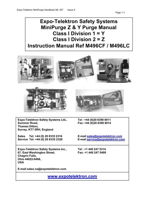
<strong>Expo</strong>-<strong>Telektron</strong> <strong>Safety</strong> <strong>Systems</strong><br />
<strong>Mini<strong>Purge</strong></strong> Z & Y <strong>Purge</strong> <strong>Manual</strong><br />
Class I Division 1 = Y<br />
Class I Division 2 = Z<br />
Instruction <strong>Manual</strong> Ref M496CF / M496LC<br />
<strong>Expo</strong>-<strong>Telektron</strong> <strong>Safety</strong> <strong>Systems</strong> Ltd., Tel : +44 (0)20 8398 8011<br />
Summer Road, Fax: +44 (0)20 8398 8014<br />
Thames Ditton,<br />
Surrey, KT7 0RH, England<br />
Sales Tel: +44 (0) 20 8335 2316 E-mail sales@expotelektron.com<br />
Service Tel: +44 (0) 20 8335 2320 E-mail service@expotelektron.com<br />
<strong>Expo</strong>-<strong>Telektron</strong> <strong>Safety</strong> <strong>Systems</strong> Inc., Tel : +1 440 247 5314<br />
67, East Washington Street, Fax: +1 440 247 5409<br />
Chagrin Falls,<br />
Ohio 44022-0486,<br />
USA<br />
E-mail sales.na@expotelektron.com<br />
www.expotelektron.com
<strong>Expo</strong>-<strong>Telektron</strong> <strong>Mini<strong>Purge</strong></strong> Handbook ML 307 Issue A<br />
TABLE OF CONTENTS<br />
Page 1-2<br />
1 LIST OF FIGURES.........................................................................................................1-4<br />
2 LIST OF TABLES...........................................................................................................2-4<br />
3 ORGANISATION OF THIS MANUAL ............................................................................3-1<br />
4 DESCRIPTION AND PRINCIPLE OF OPERATION .....................................................4-1<br />
4.1 Specification Sheet .....................................................................................................4-2<br />
4.2 Common Elements......................................................................................................4-3<br />
4.3 The Methods of Pressurizing......................................................................................4-4<br />
4.3.1 CF-Continuous Flow ...........................................................................................4-4<br />
4.3.2 LC- Leakage compensation................................................................................4-5<br />
5 TYPE OF OUTPUT ........................................................................................................5-1<br />
5.1 PO- Pneumatic output.................................................................................................5-1<br />
5.2 IS - Intrinsically Safe Output .......................................................................................5-1<br />
5.3 Certification..................................................................................................................5-1<br />
5.4 Equipment components ..............................................................................................5-1<br />
5.4.1 Control Unit (CU)................................................................................................5-2<br />
5.4.2 Relief Valve (RLV)...............................................................................................5-2<br />
5.4.3 Spark Arrestor /Calibrated Outlet Orifice (SAU) .................................................5-2<br />
6 INSTALLATION OF THE SYSTEM ...............................................................................6-1<br />
6.1 Identification of system components...........................................................................6-1<br />
6.2 Location.......................................................................................................................6-1<br />
6.2.1 Internal Gas Release..................................................................................................6-1<br />
6.3 Multiple Enclosures.....................................................................................................6-1<br />
6.4 Control Unit (CU).........................................................................................................6-2<br />
6.5 Relief Valve (RLV) and Spark Arrestor Unit (SAU) ....................................................6-2<br />
6.6 Interconnection............................................................................................................6-2
<strong>Expo</strong>-<strong>Telektron</strong> <strong>Mini<strong>Purge</strong></strong> Handbook ML 307 Issue A<br />
Page 1-3<br />
6.6.1 Connections to protective Gas supply. ...............................................................6-2<br />
6.6.2 <strong>Purge</strong> air from Control Unit to pressurized enclosure........................................6-3<br />
6.6.3 Control Unit to enclosure pressure monitor........................................................6-3<br />
6.6.4 Control unit to flow sensor. .................................................................................6-3<br />
6.6.5 Power supplies and their isolation......................................................................6-3<br />
6.6.6 Adjustments and settings....................................................................................6-4<br />
6.6.7 <strong>Purge</strong> time..........................................................................................................6-4<br />
6.6.8 <strong>Purge</strong> flow rate for Continuous Flow (CF) systems............................................6-5<br />
6.7 Action on loss of pressurization..................................................................................6-5<br />
6.8 Initial Commissioning ..................................................................................................6-6<br />
6.8.1 Check calibration.................................................................................................6-6<br />
6.9 Commissioning............................................................................................................6-7<br />
6.9.1 Continuous Flow (CF) <strong>Systems</strong>..........................................................................6-7<br />
6.9.2 Leakage Compensation systems (LC)................................................................6-8<br />
6.10 Normal operation.......................................................................................................6-10<br />
6.10.1 CF systems........................................................................................................6-10<br />
6.10.2 LC systems........................................................................................................6-10<br />
7 MAINTENANCE OF THE SYSTEM...............................................................................7-1<br />
7.1 Commissioning............................................................................................................7-1<br />
7.2 Routine maintenance..................................................................................................7-1<br />
7.3 Spares list....................................................................................................................7-2<br />
7.3.1 CF spares list......................................................................................................7-2<br />
7.3.2 LC spares list.......................................................................................................7-2<br />
8 FAULT FINDING.............................................................................................................8-1<br />
8.1 General........................................................................................................................8-1<br />
8.1.1 Fault Finding........................................................................................................8-1<br />
8.1.2 Pressure sensor calibration ................................................................................8-4<br />
9 APPROVAL DOCUMENTS....................................................................................... 9-1<br />
9.1 FM Certificate..............................................................................................................9-2<br />
9.2 UL Certificate............................................................................................................ 9-5
<strong>Expo</strong>-<strong>Telektron</strong> <strong>Mini<strong>Purge</strong></strong> Handbook ML 307 Issue A<br />
Page 2-4<br />
10 GLOSSARY ...............................................................................................................10-1<br />
1 List Of Figures<br />
Figure 1 Continuous Flow Circuit Diagram……………………………………..…………4.1.1<br />
Figure 2 Leakage Compensation Circuit Diagram……………………………..………….4.1.2<br />
Figure 3 Relief Valve Type RLV25…………………………………………………...…5.3.25-2<br />
Figure 4 Spark Arrestor Type SAU25............................................................................5.3.3<br />
Figure 5 PE or Minipurge system pressure test point.......................................................6-7<br />
Figure 6 Flow Control valve (FCV) .................................................................................6.9.1<br />
Figure 7 CF Minipurge Indicators………………....……............………………………….6.9.1<br />
Figure 8 Leakage Compensation Valve (LCV)…..…………………........……………….6.9.2<br />
Figure 9 LC Minipurge Status Indicators….……………………….........…………………6.9.2<br />
Figure 10 <strong>Purge</strong> on /off Valve ..........................................................................................6.9.2<br />
2 List Of Tables<br />
Table 1 System Components..............................................................................................6-1<br />
Table 2 <strong>Purge</strong> Flow Rates ..................................................................................................6-5
<strong>Expo</strong>-<strong>Telektron</strong> <strong>Mini<strong>Purge</strong></strong> Handbook ML 307 Issue A<br />
3 Organisation of this manual<br />
Page 3-1<br />
The manual covers the range of systems known as <strong>Mini<strong>Purge</strong></strong> “Z” and “Y” purge from the<br />
<strong>Expo</strong>-<strong>Telektron</strong> range of <strong>Mini<strong>Purge</strong></strong> systems. Section 4 (Description and Principle of<br />
Operation) describes the options available for the different attributes of the system. Each<br />
section of the manual then describes the aspects that are common to all systems and then<br />
deals with specific matters relating to the different options.<br />
If a pressurized enclosure is supplied under the same order as this <strong>Mini<strong>Purge</strong></strong> system,<br />
drawings, specification sheets and certification for these products will be found at the end of<br />
this instruction manual.
<strong>Expo</strong>-<strong>Telektron</strong> <strong>Mini<strong>Purge</strong></strong> Z purge Handbook ML 307 Issue A Page 4-1<br />
4 Description and principle of operation<br />
<strong>Mini<strong>Purge</strong></strong> systems are classified according to the four major attributes as shown in this<br />
example:<br />
• The size or capacity of the system<br />
00 1ZLC/ss/IS/WM (example part number see 4.2)<br />
1 = Sub <strong>Mini<strong>Purge</strong></strong><br />
2 = <strong>Mini<strong>Purge</strong></strong><br />
3 = Super <strong>Mini<strong>Purge</strong></strong><br />
• The certification of the system<br />
00 1ZLC/ss/IS/WM (example part number see page 4-2)<br />
Z = USA / Canada NFPA 496 cULus, E190061. FM, 1X8A4AE<br />
Class I Div 2 Group A, B, C & D<br />
Y = USA / Canada NFPA 496 cULus, E190061. FM, 1X8A4AE<br />
Class I Div 1 Group A, B, C & D<br />
• The method of pressurization<br />
For more detail refer to section 4.3<br />
00 1ZLC/ss/IS/WM (example part number see page 4-2 )<br />
CF = Continuous Flow<br />
LC = Leakage Compensation<br />
• The type of alarm output and indication of the system<br />
00 1ZLC/SS/IS/WM (example part number see page 4-2)<br />
IS = Intrinsically Safe, Exi & EEx i circuit ‘Alarm’ and ‘Pressurized’: used with<br />
others Ex i relay / barrier for alarm interface.<br />
When located in a Division 2, an non-incendive circuit can replace the Ex I circuit or<br />
when the alarm switch is fitted within the pressurized enclosure, 110 / 230V ac mains<br />
supply can be used.<br />
PO = Pneumatic Output<br />
Signal ‘Alarm’: Loss of Pressure = No signal<br />
”Pressurized” = 60 psi / 0.4MPa / 4 bar Signal<br />
C:\Main System Files\Marketing\Memo\ML307 ISSUE A.doc<br />
Page 4-1
<strong>Expo</strong>-<strong>Telektron</strong> <strong>Mini<strong>Purge</strong></strong> Z purge Handbook ML 307 Issue A Page 4-2<br />
4.1 Specification Sheet<br />
C:\Main System Files\Marketing\Memo\ML307 ISSUE A.doc<br />
Page 4-2
<strong>Expo</strong>-<strong>Telektron</strong> <strong>Mini<strong>Purge</strong></strong> Z purge Handbook ML 307 Issue A Page 4-3<br />
4.2 Common Elements<br />
All Mini-Z-<strong>Purge</strong> and Mini-Y-<strong>Purge</strong> pressurization systems provide<br />
A method of pressurizing a Pressurized Enclosure (PE) while at the same time compensating<br />
for any leakage.<br />
A method of purging the enclosure before power is applied to remove any flammable gas that<br />
may have entered the enclosure while it was unpressurized.<br />
Visual indication of Mini-Z-<strong>Purge</strong> system status.<br />
An output to provide remote indication of alarm/pressurization.<br />
C:\Main System Files\Marketing\Memo\ML307 ISSUE A.doc<br />
Page 4-3
<strong>Expo</strong>-<strong>Telektron</strong> <strong>Mini<strong>Purge</strong></strong> Z purge Handbook ML 307 Issue A Page 4-4<br />
4.3 The Methods of Pressurizing<br />
The Methods of pressurizing are as follows:-<br />
4.3.1 CF-Continuous Flow<br />
A continuous flow of protective gas is passed through the pressurized enclosure. Initially this<br />
flow is verified and performs the purging phase of the operation. When the purging phase is<br />
completed – i.e. the purge time has elapsed- the same flow of protective gas maintains the<br />
pressurization of the enclosure. This flow may be required to provide cooling of equipment in<br />
the pressurized enclosure, or to dilute an internal source of hazardous gas release.<br />
LCV<br />
Minimum Pressure /Flow<br />
Sensor<br />
Enclosure Pressure<br />
Test Point (Plugged)<br />
Enclosure Pressure<br />
<strong>Purge</strong> Outlet To Pressurized Enclosure<br />
Figure 1: Continuous Flow Circuit - (Drg ref:-XBR-7TD0-019)<br />
C:\Main System Files\Marketing\Memo\ML307 ISSUE A.doc<br />
Minimum Pressure<br />
& Purging Indicator<br />
Red = Alarm<br />
Green = Pressure/Flow<br />
OK<br />
I.S Switch<br />
(IS Option)<br />
Filter<br />
Alarm/Pressurized Output<br />
Signal @ Supply Pressure<br />
(PO Option)<br />
1 Common<br />
4 Pressurized<br />
2 Alarm<br />
<strong>Purge</strong> Supply<br />
Air or Inert Gas<br />
60-115 PSI<br />
4 – 8 Bar<br />
Page 4-4
<strong>Expo</strong>-<strong>Telektron</strong> <strong>Mini<strong>Purge</strong></strong> Z purge Handbook ML 307 Issue A Page 4-5<br />
4.3.2 LC- Leakage compensation<br />
Initially a high flow of protective gas is passed through the enclosure. This flow is verified<br />
and performs the purging phase of the operation. When the purging phase is completed – i.e.<br />
the purge time has elapsed - the flow of protective gas is provided via a leakage<br />
compensation valve so that it just compensates for any leakage from the pressurized<br />
enclosure in addition to maintaining its pressurization.<br />
LCV<br />
Minimum Pressure<br />
Sensor<br />
Enclosure Pressure<br />
Test Point (Plugged)<br />
<strong>Purge</strong> Flow Sensor<br />
Flow Sensor Connection<br />
Enclosure Pressure<br />
Figure 3: Leakage Compensation circuit (Drg ref:-XBR-7TD0-016)<br />
C:\Main System Files\Marketing\Memo\ML307 ISSUE A.doc<br />
Purging<br />
Indicator<br />
Yellow = <strong>Purge</strong> Flow OK<br />
<strong>Purge</strong> time controlled manually<br />
By the operator<br />
<strong>Purge</strong> Outlet to Pressurized Enclosure<br />
Minimum<br />
Pressure<br />
Indicator<br />
I.S Switch<br />
(I.S Option only)<br />
<strong>Purge</strong> Supply<br />
Air or Inert Gas<br />
60-115 PSI<br />
4 – 8 Bar<br />
Red = Alarm<br />
Green = Pressure OK<br />
Alarm/Pressurized Output<br />
Signal @ Supply Pressure<br />
(PO Option only)<br />
<strong>Purge</strong> Control<br />
Valve<br />
1 Common<br />
4 Pressurized<br />
2 Alarm<br />
Page 4-5
<strong>Expo</strong>-<strong>Telektron</strong> <strong>Mini<strong>Purge</strong></strong> Z purge Handbook ML 307 Issue A Page 5-1<br />
5 Type of Output<br />
The function of the output is alarm/pressurized indication. Alarm output provides a passive<br />
signal to indicate remotely when the enclosure is not pressurized and an active signal when<br />
pressurized.<br />
5.1 PO- Pneumatic output<br />
The pressurized output is a pneumatic signal, which may be used to operate other devices to<br />
provide alarm indication. The lack of any output signal indicates alarm. The positive pressure<br />
signal can be used to indicate the “pressurized” condition of the pressurized enclosure. The<br />
“alarm/pressurized” signal is supplied from the compressed air/inert gas supply at 60 psi / 4<br />
bar / 0.4Mpa. When used with a suitable pressure switch for the area classification, the<br />
switching pressure will be set below the supply pressure.e.g 15 PSI / 1 Bar / 0.1Mpa.<br />
5.2 IS - Intrinsically Safe Output<br />
The alarm output is a volt free contact which form part of an intrinsically safe circuit which<br />
then provides an alarm output in a safe (unclassified) area. The Mini-Y-<strong>Purge</strong> contact must<br />
only be connected to intrinsically safe circuit as the switch contacts are in the hazardous<br />
area.<br />
For Mini-Z-<strong>Purge</strong>, a non indendive circuit can replace the Ex i circuit or when the alarm switch<br />
is fitted within the pressurized enclosure, 110 / 230V ac mains supply can be used when<br />
obtained directly from the main PE supply.<br />
5.3 Certification<br />
<strong>Expo</strong>-<strong>Telektron</strong> Mini-Z-<strong>Purge</strong> and Mini-Y-<strong>Purge</strong> systems are certified to FM and cULus<br />
approved to NFPA 496, North American standard the details of which are included in the<br />
certification section (8-6) of this manual.<br />
5.4 Equipment components<br />
The <strong>Expo</strong>-<strong>Telektron</strong> Mini-Z-<strong>Purge</strong> and Mini-Y-<strong>Purge</strong> system comprises of a number of<br />
component units. The units required depend on the type of system selected. These are<br />
summarized in Table 1 on page 6-1. The general description and function of each is as<br />
follows:<br />
C:\Main System Files\Marketing\Memo\ML307 ISSUE A.doc<br />
Page 5-1
<strong>Expo</strong>-<strong>Telektron</strong> <strong>Mini<strong>Purge</strong></strong> Z purge Handbook ML 307 Issue A Page 5-2<br />
5.4.1 Control Unit (CU)<br />
The control unit is at the heart of the system. It contains a pneumatic logic circuit specially<br />
designed and built to control the functions required for purge and pressurization. For all<br />
systems this includes pressure and purge flow measurement, and local visual indication of<br />
alarm/pressurized and flow sensed. It also provides the output for remote alarm<br />
corresponding to the output type selected.<br />
5.4.2 Relief Valve (RLV)<br />
The Relief Valve unit is fitted to the Pressurized Enclosure to provide a means of limiting the<br />
maximum pressure experienced by the Pressurized Enclosure during operation. The RLV<br />
model number has a suffix giving the diameter of the valve aperture in millimetres e.g. RLV25<br />
(= 25mm/1” bore). It also incorporates a Spark Arrestor to prevent “sparks” being ejected<br />
from the Pressurized Enclosure into the classified / hazardous area. When used with a<br />
5.4.3 Spark Arrestor /Calibrated Outlet Orifice (SAU)<br />
C:\Main System Files\Marketing\Memo\ML307 ISSUE A.doc<br />
“Leakage<br />
Compensation”<br />
system, the RLV<br />
also monitors the<br />
calibrated “purging”<br />
flow rate. The<br />
Relief Valve design<br />
is patented.<br />
Figure 3 Relief<br />
To measure the flow through a pressurized enclosure, the differential pressure across a<br />
Figure 4 Spark arrestor type SAU25<br />
Valve<br />
restriction or orifice is measured. In<br />
Leakage Compensation systems the flow<br />
measurement is incorporated in the Relief<br />
Valve. The continuous flow systems use<br />
the SAU25, which has a range of<br />
interchangeable calibrated orifice plates for<br />
the purge flow measurement. Two SAU25<br />
are supplied with a size 2 CF system.<br />
Page 5-2
<strong>Expo</strong>-<strong>Telektron</strong> <strong>Mini<strong>Purge</strong></strong> Z purge Handbook ML 307 Issue A<br />
6 Installation of the system<br />
6.1 Identification of system components.<br />
There are up to three components for the Mini-Z-<strong>Purge</strong> and Mini-Y-<strong>Purge</strong> system, dependant<br />
upon the system type.<br />
System type Control Unit<br />
(CU)<br />
00 1ZLC/*/*<br />
00 1YLC/*/*<br />
Leakage<br />
Compensation<br />
C:\Main System Files\Marketing\Memo\ML307 ISSUE A.doc<br />
Table 1 System Components<br />
Page 6-1<br />
Relief Valve (RLV) Spark Arrestor<br />
Unit<br />
SAU25<br />
YES YES Integral to RLV<br />
00 1ZCF/*/*<br />
00 1YCF/*/*<br />
Continuous Flow<br />
YES YES YES<br />
* see specification sheet for option codes.<br />
6.2 Location<br />
The Mini-Z-<strong>Purge</strong> and Mini-Y-<strong>Purge</strong> system has been designed to mount directly to the<br />
pressurized enclosure (PE). The system can also be mounted remotely to the PE. See<br />
mounting details.<br />
6.2.1 Internal Gas Release<br />
If the pressurized enclosure contains an internal source of release of flammable gas or vapour,<br />
the procedures for assessment of the release as given in NFPA 496 should be used. <strong>Expo</strong>-<br />
<strong>Telektron</strong> are pleased to provide assistance or consultancy and advice on such matters. The<br />
user must verify that the specification of the <strong>Expo</strong>-<strong>Telektron</strong> system e.g. pressure, continuous<br />
flow (dilution) rate and type of protective gas are correct for the specific application.<br />
6.3 Multiple Enclosures<br />
More than one pressurized enclosure can be protected by a single system. Pressurized<br />
enclosures are connected and purged in "series" e.g. "Daisy Chained", the Relief Valve and,<br />
when using a continuous flow system, the SAU25 should be fitted on the last enclosure. The<br />
<strong>Purge</strong> Inlet should be made into the first enclosure. The bore and length of the pipe or conduit<br />
used to interconnect the enclosures is critical and will determine the maximum pressure<br />
experienced by the first enclosure in the series. Advice on sizing can be obtained from the<br />
<strong>Expo</strong>-<strong>Telektron</strong> sales office. In general terms when using RLV25 or SAU25, the pipe bore size<br />
should not be less than 25mm (1”).<br />
Page 6-1
<strong>Expo</strong>-<strong>Telektron</strong> <strong>Mini<strong>Purge</strong></strong> Z purge Handbook ML 307 Issue A<br />
6.4 Control Unit (CU)<br />
Generally the Control Unit is mounted direct to the pressurized enclosure. Most Control Units<br />
can be remote mounted, and should be installed as close as possible to the pressurized<br />
C:\Main System Files\Marketing\Memo\ML307 ISSUE A.doc<br />
Page 6-2<br />
enclosure. The piped connections to the pressurized enclosure should be made using suitably<br />
rated tube through suitable bulkhead connections. It should be installed so that the system<br />
indicators may be readily observed.<br />
6.5 Relief Valve (RLV) and Spark Arrestor Unit (SAU)<br />
To achieve effective purging the points where air enters and exits the pressurized enclosure<br />
should normally be at opposite ends of the pressurized enclosure. The Relief Valve (RLV) or<br />
Spark Arrestor Unit (SAU) is recommended to be situated on the side at the bottom or on the<br />
bottom of the enclosure, when the control unit is top mounted on the enclosure, thus achieving<br />
top to bottom purging. The Relief Valve may be fitted to a vertical side or to the top of the<br />
enclosure but must not be fitted to the underside of the enclosure, to ensure the correct<br />
orientation. The purge air may be piped within the pressurized enclosure to ensure purging of<br />
potential dead air spots. The proof of this may only be apparent when a purge test is<br />
performed.<br />
6.6 Interconnection<br />
6.6.1 Connections to protective Gas supply.<br />
The system should be connected to a protective gas supply, suitable for purging and<br />
pressurization. Generally instrument quality compressed air is used, though other inert gas<br />
may be used- e.g. Nitrogen. It is important that the air / gas supply is capable of delivering the<br />
quantity required for purging and still maintain sufficient supply pressure. This means ensuring<br />
adequate sized pipe and airline accessories. Over 80% of commissioning problems reported<br />
to <strong>Expo</strong>-<strong>Telektron</strong> are due to inadequate sized piping or air supply. Although Mini-Z-<strong>Purge</strong><br />
and Mini-Y-<strong>Purge</strong> units include a filter, the air / gas supply should be from a clean dry source,<br />
and should have a dedicated local pressure regulator. A stable air supply pressure between 4<br />
bar/ 60 psig / 0.4Mpa and 8 bar/ 115 psig / 0.8Mpa is to be maintained whilst the system is<br />
purging.<br />
Page 6-2
<strong>Expo</strong>-<strong>Telektron</strong> <strong>Mini<strong>Purge</strong></strong> Z purge Handbook ML 307 Issue A<br />
6.6.2 <strong>Purge</strong> air from Control Unit to pressurized enclosure.<br />
When the control unit is directly mounted onto the pressurized enclosure, no connection will<br />
C:\Main System Files\Marketing\Memo\ML307 ISSUE A.doc<br />
Page 6-3<br />
normally be necessary, as the purge air will discharge into the pressurized enclosure directly.<br />
When the control unit is not direct mounted, or where internal air distribution is necessary a<br />
connection should be made from the purge air outlet on the control unit (normally ½” NPT<br />
Female), via pipe pressure rated at least to the supply pressure, to the pressurized enclosure.<br />
This should be kept as short as possible and should be adequately sized to ensure that the full<br />
purge flow can be delivered.<br />
6.6.3 Control Unit to enclosure pressure monitor.<br />
When the control unit is directly mounted onto the pressurized enclosure, no connection will<br />
normally be necessary, as the enclosure pressure monitor point will sense directly inside the<br />
pressurized enclosure. Only if the control unit is not directly mounted or if there are fans, which<br />
may create, localized low-pressure areas within the pressurized enclosure is it necessary to<br />
pipe this connection. The connection is made to the enclosure pressure sensor fitting<br />
(normally 1/8” NPT Female) on the control unit. There is virtually no flow in this circuit so small<br />
bore tube may be used. <strong>Expo</strong>-<strong>Telektron</strong> recommends 6mm (¼”) bore tube. It is important that<br />
all connections are free of leaks.<br />
6.6.4 Control unit to flow sensor.<br />
For Continuous Flow CF systems this function is performed by the enclosure pressure sensor<br />
monitor connection. On Leakage Compensation LC systems this connection is made from the<br />
enclosure flow sensor fitting (normally 1/8” NPT Female) on the control unit, to the fitting<br />
(normally 1/8” NPT Female) on the Relief Valve (RLV). Tube and connections are all internal to<br />
the pressurized enclosure. Again, <strong>Expo</strong>-<strong>Telektron</strong> recommends 6mm (¼”) bore tube.<br />
6.6.5 Power supplies and their isolation<br />
All power entering the pressurized enclosure must be controlled manually by the user.<br />
Reference should be made to NFPA 496 or the relevant local codes.<br />
Page 6-3
<strong>Expo</strong>-<strong>Telektron</strong> <strong>Mini<strong>Purge</strong></strong> Z purge Handbook ML 307 Issue A<br />
6.6.6 Adjustments and settings<br />
The user adjustable settings are as follows:<br />
For continuous flow (CF) systems only – purge flow rate orifice size selection<br />
Leakage Compensation valve / Continuous Flow valve<br />
6.6.7 <strong>Purge</strong> time<br />
If no specific purge test has been performed on the pressurized enclosure, the volume of the<br />
pressurized enclosure must be determined by the manufacturer or user of the pressurized<br />
C:\Main System Files\Marketing\Memo\ML307 ISSUE A.doc<br />
Page 6-4<br />
enclosure, and the necessary purging time calculated based on the purge flow rate specified by<br />
the “standard" or "code” being used. It is the user's responsibility to verify or enter this data on<br />
the pressurized enclosure (label supplied) and/or Mini-Z-<strong>Purge</strong> and Mini-Y-<strong>Purge</strong> system<br />
nameplate. Ask <strong>Expo</strong>-<strong>Telektron</strong> if in doubt.<br />
For North America, NFPA 496 standard permits 4 complete volume changes for enclosures<br />
except when the pressurized enclosure is an electric motor then 10 internal free volume<br />
changes are required.<br />
If the pressurized enclosure external dimensions indicate a total volume of 8 cubic foot, the<br />
following is based on using a 1*LC/ at a purge flow rate of 8 scfm<br />
8 cubic foot enclosure volume x 4 volume changes = 4 minutes purge time<br />
8 cubic foot/minute purge flow rate<br />
If the same pressurized enclosure is a motor, then,<br />
8 cubic foot enclosure volume x 10 volume changes = 10 minutes purge time<br />
Note:<br />
8 cubic foot/minute purge flow rate<br />
1*LC = 8scfm purge flow rate<br />
2*LC = 16scfm purge flow rate<br />
3*LC = 32scfm purge flow rate<br />
Page 6-4
<strong>Expo</strong>-<strong>Telektron</strong> <strong>Mini<strong>Purge</strong></strong> Z purge Handbook ML 307 Issue A<br />
6.6.8 <strong>Purge</strong> flow rate for Continuous Flow (CF) systems.<br />
The purge flow rate is selected by placing the appropriate orifice plate in the SAU (spark<br />
C:\Main System Files\Marketing\Memo\ML307 ISSUE A.doc<br />
Page 6-5<br />
arrestor unit). The purge flow rates given in Table 2 below are based on standard setting of the<br />
flow sensor of 1 in wc, 250Pa, 2.5mbar<br />
Orifice plate<br />
Continuous flow rate with<br />
number 1 in wc, 250 Pa, 2.5 mbarg flow sensor set point<br />
N litre/minute SCFM<br />
1 10 0.4<br />
2 25 0.9<br />
3 40 1.4<br />
4 65 2.3<br />
5 90 3.2<br />
6 135 4.8<br />
7 180 6.4<br />
8 225 8.0<br />
Table 2 <strong>Purge</strong> Flow Rates<br />
Notes: For Leakage Compensation systems the purge flow rate is set by the selection of the<br />
Relief Valve and is not user adjustable.<br />
For size 2 CF systems, a second SAU25 is supplied allowing a continuous flow rate of up to<br />
450 Nl/min, 16 scfm by selecting the number 8 orifice plate for each SAU25. Other flows are<br />
achievable by mixing the orifice plates<br />
i.e. Orifice plates 3 and 8 gives 1.4 + 8 = 9.4 scfm (40 + 225 = 265 Nl/min)<br />
6.7 Action on loss of pressurization<br />
The action on loss of pressurization is ALARM ONLY (AO).<br />
The user must make use of this alarm facility in accordance with the local code of practice for<br />
"action on pressure or flow failure". Reference should be made to NFPA 496 or the relevant<br />
local codes.<br />
Page 6-5
<strong>Expo</strong>-<strong>Telektron</strong> <strong>Mini<strong>Purge</strong></strong> Z purge Handbook ML 307 Issue A<br />
6.8 Initial Commissioning<br />
Check that the system has been installed in accordance with Section 6 of this manual.<br />
Disconnect the protective gas supply pipe from the inlet to the <strong>Mini<strong>Purge</strong></strong> system and blow it<br />
C:\Main System Files\Marketing\Memo\ML307 ISSUE A.doc<br />
Page 6-6<br />
through for at least 10 seconds per 3ft (metre) of length to remove any debris or condensation.<br />
6.8.1 Check calibration<br />
Connect a temporary pressure gauge or water manometer to the pressurized enclosure or<br />
<strong>Mini<strong>Purge</strong></strong> system pressure test point (Remove the red plug on the low pressure sensor and<br />
connect 4mm OD (3/16” OD) nylon tube).<br />
Figure 5. PE or <strong>Mini<strong>Purge</strong></strong> system pressure test point<br />
Page 6-6
<strong>Expo</strong>-<strong>Telektron</strong> <strong>Mini<strong>Purge</strong></strong> Z purge Handbook ML 307 Issue A<br />
6.9 Commissioning.<br />
6.9.1 Continuous Flow (CF) <strong>Systems</strong><br />
Proceed as follows:-<br />
Open the flow control valve (FCV) until the alarm/pressurized indicator just turns from red to<br />
green.<br />
C:\Main System Files\Marketing\Memo\ML307 ISSUE A.doc<br />
Page 6-7<br />
If the flow control valve (FCV) is opened fully and the indicator has still not turned green, check<br />
the air supply pressure at the inlet to the control unit while flow is taking place. It must be<br />
above the minimum 4 bar/ 60 psig/ 0.4Mpa specified.<br />
Figure 6. Flow control valve (FCV)<br />
The manual purge time can commence as soon as the ‘alarm/pressurized’ indicator turns from<br />
red (alarm) to green (pressurized). It is the users responsibility to ensure that the time delay<br />
between the indicator turning green and the manual application of power to the pressurized<br />
enclosure is not less than the minimum time required to purge the pressurized enclosure, (See<br />
Section 6.6.7 <strong>Purge</strong> time).<br />
After the power has been manually applied, the air flow will<br />
continue at the same flow rate to provide pressurization, dilution<br />
or cooling as required.<br />
Figure 7 CF Minipurge Status Indicator<br />
Page 6-7
<strong>Expo</strong>-<strong>Telektron</strong> <strong>Mini<strong>Purge</strong></strong> Z purge Handbook ML 307 Issue A<br />
6.9.2 Leakage Compensation systems (LC)<br />
Proceed as follows: -<br />
Open the Leakage Compensation Valve (LCV) fully.<br />
Figure 8 Leakage Compensation Valve (LCV)<br />
C:\Main System Files\Marketing\Memo\ML307 ISSUE A.doc<br />
Page 6-8<br />
Open the supply valve regulator SLOWLY and allow the pressurized enclosure pressure to rise<br />
until the Relief Valve (RLV) opens. Check that the RLV opens at or below the figure specified<br />
in the documentation (10mbarg / 4”wc). Note tolerance of ± 2 mbarg / 0.8 in wc / 200Pa.<br />
Repeat the test several times.<br />
Open the supply to between 4 barg / 60 psi / 0.4 Mpa. At this time the "alarm/pressurized”<br />
indicator should be green (“pressurized”) then open the purge on / off valve and the purging<br />
flow will start.<br />
Figure 9: LC<br />
Minipurge Status<br />
Indicators<br />
During purge the "purging” indicator should be yellow. If the yellow indicator remains black<br />
the flow through the Relief Valve is below the minimum for which the flow sensor has been<br />
calibrated. Check the air supply pressure at thecon inlet to the Control Unit while purging is<br />
taking place. It must be at or above the minimum specified.<br />
The manual purge time can commence as soon as the "purging" indicator turns yellow. It is<br />
Page 6-8
<strong>Expo</strong>-<strong>Telektron</strong> <strong>Mini<strong>Purge</strong></strong> Z purge Handbook ML 307 Issue A<br />
the users responsibility to ensure that the time delay between the indicator turning yellow and<br />
C:\Main System Files\Marketing\Memo\ML307 ISSUE A.doc<br />
Page 6-9<br />
the manual application of power to the pressurized enclosure is not less than the minimum time<br />
required to purge the pressurized enclosure, (See Section 6.6.7 <strong>Purge</strong> time).<br />
Figure 10: <strong>Purge</strong> On/Off Valve<br />
After the power has been manually applied, the purging on / off valve should be closed and the<br />
air flow into the enclosure will be controlled by the Leakage Compensation Valve (LCV). The<br />
initial setting of fully open will be too high. It should now be adjusted to set the pressurized<br />
enclosure pressure and leakage. There are three possible situations:-<br />
a) Air continues to come out through the RLV Spark Arrestor after the <strong>Purge</strong> on /off Valve<br />
has been closed in considerable quantity. The LCV is much too far open and the air flow is<br />
holding the RLV open continuously.<br />
Close the LCV slowly. The enclosure pressure will start to fall as the flow decreases but<br />
eventually the RLV will close and the enclosure pressure rise again. At this point the Relief<br />
Valve may start to open intermittently as the pressurized enclosure pressure rises to the point<br />
where it exceeds the RLV opening pressure. Proceed now to b) below:-<br />
b) If the Relief Valve is opening intermittently the LCV is slightly too far open. When the<br />
RLV opens the enclosure pressure falls quickly to the point where the RLV re-closes and the<br />
enclosure pressure starts to rise again. This is entirely normal for this type of RLV and shows<br />
that it is working correctly.<br />
Continue then to close the LCV until the cycling stops and the enclosure pressure starts to fall.<br />
Carefully adjust the LCV until the pressurized enclosure pressure is approximately 50% of the<br />
RLV opening pressure and stable. This pressure may be around 5 mbarg / 2 in wc / 500 Pa<br />
and will be the "normal working pressure".<br />
We recommend that the setting of the minimum pressure sensor is checked at this time. Note<br />
the position of the LCV knob. (A pencil mark placed on the knob at "12 O'clock” can be used).<br />
Slowly lower the pressurized enclosure pressure by closing the LCV further, counting the<br />
number of turns from the "normal working pressure" position. Note the pressure at which the<br />
Page 6-9
<strong>Expo</strong>-<strong>Telektron</strong> <strong>Mini<strong>Purge</strong></strong> Z purge Handbook ML 307 Issue A<br />
"alarm/pressurized" indicator turns from green to red and check that it is not lower than the<br />
figure given in the documentation. Return the LCV to its "normal working pressure" position.<br />
c) If, when the <strong>Purge</strong> on /off Valve is closed, the pressurized enclosure pressure falls<br />
below the minimum pressure sensor setting and the LCV is fully open. This is indicative of<br />
excessive leakage from the enclosure. In this case, check the enclosure for leakage, and<br />
C:\Main System Files\Marketing\Memo\ML307 ISSUE A.doc<br />
Page 6-10<br />
reduce or eliminate the leaks. This time, when the <strong>Purge</strong> on /off Valve is closed, the enclosure<br />
should stay pressurized and the Relief Valve action is as in a) or b) above. Proceed as<br />
described above.<br />
6.10 Normal operation<br />
6.10.1 CF systems<br />
Turn the air supply on. <strong>Manual</strong>ly time purge once pressurized indicator has turned green.<br />
<strong>Manual</strong>ly apply power to pressurized enclosure once purge time has elapsed.<br />
6.10.2 LC systems<br />
Turn the air supply on. Open <strong>Purge</strong> on /off Valve. <strong>Manual</strong>ly time purge once purging indicator<br />
has turned yellow. <strong>Manual</strong>ly apply power to pressurized enclosure once purge time has<br />
elapsed. Close <strong>Purge</strong> on /off Valve and ensure the pressurized indicator is still showing green<br />
i.e. “pressurized”.<br />
Tip: soapy water solution can be used to detect leaks. Wide<br />
packing tape can be used to seal around doors to temporarily<br />
reduce the leakage to verify if this is the source. Leaks around<br />
doors due to inadequate strength or inadequate fasteners are<br />
the most common cause of excessive enclosure leakage.<br />
Page 6-10
<strong>Expo</strong>-<strong>Telektron</strong> <strong>Mini<strong>Purge</strong></strong> Z purge Handbook ML 307 Issue A<br />
7 Maintenance of the system<br />
C:\Main System Files\Marketing\Memo\ML307 ISSUE A.doc<br />
Page 7-1<br />
The maintenance recommended for the system consists of the following items, supplemented<br />
by any additional local requirements imposed by the local code of practice.<br />
7.1 Commissioning<br />
The tests to be performed during commissioning are described in Section 2 of this manual.<br />
They include checking the opening pressure of the Relief Valve, the setting of the minimum<br />
pressure sensor, and the "normal working pressure".<br />
7.2 Routine maintenance<br />
<strong>Expo</strong>-<strong>Telektron</strong> recommend that the commissioning tests be repeated at least every twelve<br />
months. In addition the following checks are also recommended at that time: -<br />
Check the condition of any air supply filter element. Clean or replace it as necessary.<br />
Check the RLV and any other spark arrestors. Remove any debris, or replace with a spare.<br />
At least every two years check the following additional items:-<br />
Apparatus is suitable for the hazardous location<br />
There are no unauthorized modifications<br />
The source of air is uncontaminated<br />
The alarms function correctly<br />
Approval labels are legible and undamaged<br />
Adequate spares are carried<br />
Page 7-1
<strong>Expo</strong>-<strong>Telektron</strong> <strong>Mini<strong>Purge</strong></strong> Z purge Handbook ML 307 Issue A<br />
7.3 Spares list<br />
7.3.1 CF spares list<br />
Item Description Part code<br />
1 Pressure/ flow sensor HS1-1XX0-013<br />
7.3.2 LC spares list<br />
Item Description Part code<br />
1 Pressure sensor HS1-1XX0-012<br />
2 Flow sensor HS1-1XX0-014<br />
C:\Main System Files\Marketing\Memo\ML307 ISSUE A.doc<br />
Page 7-2<br />
Page 7-2
<strong>Expo</strong>-<strong>Telektron</strong> <strong>Mini<strong>Purge</strong></strong> Z purge Handbook ML 307 Issue A<br />
8 Fault Finding<br />
8.1 General<br />
If the system does not behave in the manner described in section 6, please call <strong>Expo</strong>-<br />
<strong>Telektron</strong> (24-hour answering) or your supplier for further assistance.<br />
The system has been designed for ease of fault finding. Check components by substitution<br />
C:\Main System Files\Marketing\Memo\ML307 ISSUE A.doc<br />
Page 8-1<br />
only after establishing that such action is necessary. If the system is less than 12 months<br />
old, parts under warranty should be returned to <strong>Expo</strong>-<strong>Telektron</strong> for investigation, with a full<br />
report of the fault and the system serial number.<br />
NOTE: As with any pressurized enclosure, the greatest enemies are water, oil and dirt in<br />
the air supply. A dust and water filter should be fitted. But dirt can enter from other sources<br />
and it is vital therefore that the procedures described in Section 6 is carried out before using<br />
the system for the first time, or following any disconnection of the pipework. Failure to<br />
perform this work may cause damage, which will not be covered under warranty.<br />
8.1.1 Fault Finding<br />
NOTE: Before making the following checks verify that the main air supply pressure is stable<br />
and between 4 and 8 Barg / 60 and115 psi / 0.4 and 0.8 MPa at the Control Unit. Check that<br />
the units are connected correctly in accordance with section 6.<br />
Page 8-1
<strong>Expo</strong>-<strong>Telektron</strong> <strong>Mini<strong>Purge</strong></strong> Z purge Handbook ML 307 Issue A<br />
8.2 Fault Finding (LC)<br />
Alarm (Red) Indicator stays on.<br />
YES<br />
Is the ACTUAL PE<br />
pressure below the setting of the<br />
Minimum Pressure Sensor?<br />
NO<br />
Is the Leakage<br />
Compensation Valve setting<br />
too low?<br />
NO<br />
Leakage Compensation Valve fully<br />
open<br />
NO<br />
Call<br />
<strong>Expo</strong>-<strong>Telektron</strong><br />
C:\Main System Files\Marketing\Memo\ML307 ISSUE A.doc<br />
YES<br />
YES<br />
YES<br />
Check it with a manometer or gauge.<br />
Try increasing the setting of the<br />
Leakage Compensation Valve to raise<br />
the pressure in the PE .<br />
Check PE for leakages. Review door<br />
fasteners and door seal.<br />
Page 8-2<br />
Page 8-2
<strong>Expo</strong>-<strong>Telektron</strong> <strong>Mini<strong>Purge</strong></strong> Z purge Handbook ML 307 Issue A<br />
"Purging" indicator will not turn<br />
amber during purging<br />
Is there insufficient Purging<br />
Flow due to inadequate air<br />
supply pressure?<br />
YES<br />
Is the supply pipe at<br />
least as big as the CU inlet<br />
fitting, i.e. at least 12mm (1/2")<br />
Nominal Bore?<br />
YES<br />
Is there<br />
excessive Pressurized<br />
Enclosure (PE)<br />
Leakage?<br />
NO<br />
Is the PE strong<br />
enough?<br />
YES<br />
Is the tubing<br />
from the RLV Flow Sensing<br />
point to the <strong>Purge</strong> Flow<br />
Switch air tight?<br />
YES<br />
Is the purge flow<br />
sensor not operating<br />
correctly or out of<br />
calibration?<br />
NO<br />
Call<br />
<strong>Expo</strong>-<strong>Telektron</strong><br />
NO<br />
NO<br />
YES<br />
NO<br />
NO<br />
YES<br />
C:\Main System Files\Marketing\Memo\ML307 ISSUE A.doc<br />
Check the air supply pressure at<br />
the inlet to the CU when<br />
purging is taking place<br />
Replace pipework<br />
Any significant leakage must be cured.<br />
Check for leakage down the cables or<br />
conduit.<br />
Ensure leakage does not exceed 60NI/min./<br />
2 scfm<br />
Page 8-3<br />
The standard requires that the PE is tested to 1.5<br />
times the Relief Valve opening pressure e.g. 15mb/6"<br />
wc for many enclosures.<br />
Ensure fitting nuts are tightened and that the tube is<br />
not damaged. Check and repair as necessary.<br />
The basic operation of the purge flow sensor can be checked<br />
by unscrewing the 60mm/2" diameter diaphragm housing and,<br />
by using a finger, block the 12mm /1/2" threaded hole in the<br />
top of the valve module. The valve should operate and the<br />
purging indicator turn yellow. If this is correct the sensor<br />
diaphragm needs recalibrating or replacing.<br />
Page 8-3
<strong>Expo</strong>-<strong>Telektron</strong> <strong>Mini<strong>Purge</strong></strong> Z purge Handbook ML 307 Issue A<br />
Relief Valve opens continuously or<br />
intermittently<br />
Is the PE<br />
pressure too high?<br />
NO<br />
Is there<br />
Debris on the RLV<br />
disk allowing air to<br />
leak from<br />
the valve?<br />
NO<br />
Call<br />
<strong>Expo</strong>-<strong>Telektron</strong><br />
YES<br />
YES<br />
8.2.1 Pressure sensor calibration<br />
C:\Main System Files\Marketing\Memo\ML307 ISSUE A.doc<br />
Page 8-4<br />
If it is decided that the minimum pressure /purge flow sensor needs recalibrating it must be<br />
returned to <strong>Expo</strong> <strong>Telektron</strong> for this service<br />
The Leakage Compensation Valve (LCV) is too far<br />
open. Adjust the LCV as described in Section<br />
6.9.2 above.<br />
Remove the RLV cover and clean the valve disk.<br />
If it is necessary to remove the disk and sping<br />
from the RLV draw a line around it with a pencil to<br />
allow accurate replacement before removal,<br />
otherwise the opening pressure may be affected.<br />
Page 8-4
<strong>Expo</strong>-<strong>Telektron</strong> <strong>Mini<strong>Purge</strong></strong> Z purge Handbook ML 307 Issue A<br />
8.3 Fault Finding (CF)<br />
"Pressurized/Purging"<br />
indicator will not turn green<br />
during start-up<br />
Is there<br />
insufficient Purging Flow<br />
due to indadequate air<br />
supply pressure?<br />
YES<br />
Is the<br />
supply pipe at<br />
least as big as the CU inlet<br />
fitting, i.e. at least 12mm/1/2"<br />
Nominal Bore?<br />
YES<br />
Is<br />
there excessive<br />
Pressurized Enclosure<br />
(PE) leakage?<br />
YES<br />
Is the PE strong<br />
enough?<br />
YES<br />
The<br />
Minimum Pressure<br />
Sensor is not operating<br />
correctly or out of<br />
calibration.<br />
NO<br />
Call<br />
<strong>Expo</strong>-<strong>Telektron</strong><br />
NO<br />
NO<br />
YES<br />
NO<br />
NO<br />
C:\Main System Files\Marketing\Memo\ML307 ISSUE A.doc<br />
Check the air supply pressure<br />
at the inlet to the CUwhen<br />
purging is taking place.<br />
Replace pipework<br />
Any significant leakage must be corrected.<br />
Check for leakage down the cables or conduit.<br />
Ensure leakage does not exceed 60 NI/min<br />
(2 scfm).<br />
The standard requires that the PE is tested to 1.5<br />
times the Relief Valve opening pressure e.g.<br />
15mb/6" wc for many enclosures. Has this been<br />
done?<br />
The basic operation of the Minimum Pressure sensor can be<br />
checked by unscrewing the 60mm/2" diameter diaphragm<br />
housing and, by using a rubber pad, e.g. an eraser, block the<br />
12mm/1/2" threaded hole in the top of the valve module.<br />
The valve should operate and the indicator turn green.<br />
If this is correct the sensor diaphragm needs<br />
recalibrating or replacing.<br />
Page 8-5<br />
Page 8-5
<strong>Expo</strong>-<strong>Telektron</strong> <strong>Mini<strong>Purge</strong></strong> Z purge Handbook ML 307 Issue A<br />
Relief Valve opens<br />
continuously<br />
or intermittently.<br />
Is the<br />
PE pressure<br />
too high?<br />
NO<br />
Is there<br />
Debris on the RLV<br />
disk allowing air<br />
to leak from<br />
the valve?<br />
NO<br />
Call<br />
<strong>Expo</strong>-<strong>Telektron</strong><br />
YES<br />
YES<br />
C:\Main System Files\Marketing\Memo\ML307 ISSUE A.doc<br />
The Flow Control Valve (FCV) is too far open.<br />
Adjust the FCV as described in Section 6.9.1above.<br />
Remove the RLV cover and clean the valve disk. If it is<br />
necessary to remove the disk and spring from the RLV<br />
draw a line around it with a pencil to allow accurate<br />
replacement before removal, otherwise the opening<br />
pressure may be affected.<br />
Page 8-6<br />
Page 8-6
<strong>Expo</strong>-<strong>Telektron</strong> <strong>Mini<strong>Purge</strong></strong> Z purge Handbook ML 307 Issue A<br />
9 Approval Documents<br />
System type Approval authority Certificate number<br />
Z and Y purge FM (USA) 1X8A4AE<br />
UL (USA & Canada) E190061<br />
C:\Main System Files\Marketing\Memo\ML307 ISSUE A.doc<br />
Page 9-1<br />
Page 9-1
<strong>Expo</strong>-<strong>Telektron</strong> <strong>Mini<strong>Purge</strong></strong> Z purge Handbook ML 307 Issue A<br />
9.1 FM Certificate<br />
C:\Main System Files\Marketing\Memo\ML307 ISSUE A.doc<br />
Page 9-2<br />
Page 9-2
<strong>Expo</strong>-<strong>Telektron</strong> <strong>Mini<strong>Purge</strong></strong> Z purge Handbook ML 307 Issue A<br />
C:\Main System Files\Marketing\Memo\ML307 ISSUE A.doc<br />
Page 9-3<br />
Page 9-3
<strong>Expo</strong>-<strong>Telektron</strong> <strong>Mini<strong>Purge</strong></strong> Z purge Handbook ML 307 Issue A<br />
C:\Main System Files\Marketing\Memo\ML307 ISSUE A.doc<br />
Page 9-4<br />
Page 9-4
<strong>Expo</strong>-<strong>Telektron</strong> <strong>Mini<strong>Purge</strong></strong> Z purge Handbook ML 307 Issue A<br />
9.2 UL Certificate<br />
C:\Main System Files\Marketing\Memo\ML307 ISSUE A.doc<br />
Page 9-5<br />
Page 9-5
<strong>Expo</strong>-<strong>Telektron</strong> <strong>Mini<strong>Purge</strong></strong> Z purge Handbook ML 307 Issue A<br />
10 Glossary<br />
Acronym Description<br />
AO Alarm Only<br />
CF Continuous Flow<br />
CU Control Unit<br />
FCV Flow Control Valve<br />
FM Factory Mutual<br />
IS Intrinsically Safe<br />
LC Leakage Compensation<br />
LCV Leakage Compensation Valve<br />
PE Pressurized Enclosure<br />
PO Pneumatic output<br />
RLV Relief Valve<br />
SAU Spark Arrestor Universal<br />
UL Underwriters Laboratories<br />
C:\Main System Files\Marketing\Memo\ML307 ISSUE A.doc<br />
Page 10-1<br />
Page 10-1
<strong>Expo</strong>-<strong>Telektron</strong> <strong>Mini<strong>Purge</strong></strong> Z purge Handbook ML 307 Issue A<br />
C:\Main System Files\Marketing\Memo\ML307 ISSUE A.doc<br />
Page 10-2<br />
Page 10-2
<strong>Expo</strong>-<strong>Telektron</strong> <strong>Mini<strong>Purge</strong></strong> Z purge Handbook ML 307 Issue A<br />
C:\Main System Files\Marketing\Memo\ML307 ISSUE A.doc<br />
Page 10-3<br />
Page 10-3
<strong>Expo</strong>-<strong>Telektron</strong> <strong>Mini<strong>Purge</strong></strong> Z purge Handbook ML 307 Issue A<br />
C:\Main System Files\Marketing\Memo\ML307 ISSUE A.doc<br />
Page 10-4<br />
Page 10-4
<strong>Expo</strong>-<strong>Telektron</strong> <strong>Mini<strong>Purge</strong></strong> Z purge Handbook ML 307 Issue A<br />
C:\Main System Files\Marketing\Memo\ML307 ISSUE A.doc<br />
Page 10-5<br />
Page 10-5
<strong>Expo</strong>-<strong>Telektron</strong> <strong>Mini<strong>Purge</strong></strong> Z purge Handbook ML 307 Issue A<br />
C:\Main System Files\Marketing\Memo\ML307 ISSUE A.doc<br />
Page 10-6<br />
Page 10-6
<strong>Expo</strong>-<strong>Telektron</strong> <strong>Mini<strong>Purge</strong></strong> Z purge Handbook ML 307 Issue A<br />
C:\Main System Files\Marketing\Memo\ML307 ISSUE A.doc<br />
Page 10-7<br />
Page 10-7
<strong>Expo</strong>-<strong>Telektron</strong> <strong>Mini<strong>Purge</strong></strong> Z purge Handbook ML 307 Issue A<br />
C:\Main System Files\Marketing\Memo\ML307 ISSUE A.doc<br />
Page 10-8<br />
Page 10-8