Trade of Electrician Motor Control COURSE NOTES - eCollege
Trade of Electrician Motor Control COURSE NOTES - eCollege
Trade of Electrician Motor Control COURSE NOTES - eCollege

Create successful ePaper yourself
Turn your PDF publications into a flip-book with our unique Google optimized e-Paper software.
FAS Electrical Course Notes – Module 2.4.2<br />
Overload Protection<br />
High temperatures have an adverse effect on insulating materials. It is essential therefore, that<br />
electric motors should be provided with protection against overheating. Excess current taken by<br />
a motor causes overheating. The protective devices most commonly used, detect this excess<br />
current. However excess currents do exist during starting, but as these are not for long periods<br />
<strong>of</strong> time they do not cause overheating. Fuses or MCB’s, cannot be used since the starting<br />
current <strong>of</strong> the motor would cause them to blow / trip. It is therefore desirable for over-current<br />
protective devices to have a built in “time lag” to facilitate such starting currents. The overcurrent<br />
protective device referred to above is called an overload relay. Fuses or MCB’s are<br />
used in conjunction with overload relays to provide protection against short circuits, earth faults<br />
or faults in the main wiring.<br />
Overload Relay<br />
There are two types <strong>of</strong> overload device in use;<br />
The thermal overload relay<br />
The magnetic overload relay<br />
The thermal overload relay is the more popular type and is the only one covered in Phase 2.<br />
Thermal Overload Relay<br />
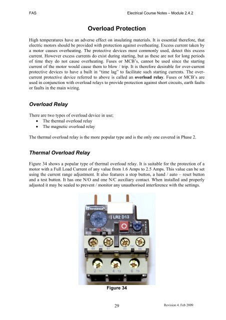
Figure 34 shows a popular type <strong>of</strong> thermal overload relay. It is suitable for the protection <strong>of</strong> a<br />
motor with a Full Load Current <strong>of</strong> any value from 1.6 Amps to 2.5 Amps. This value can be set<br />
using the current range adjustment. It also features a stop button, a hand / auto – reset button<br />
and a test button. It has one N/O and one N/C auxiliary contact. When installed and properly<br />
adjusted it may be sealed to prevent / monitor any unauthorised interference with the settings.<br />
Figure 34<br />
29<br />
Revision 4. Feb 2009