Trade of Electrician Motor Control COURSE NOTES - eCollege
Trade of Electrician Motor Control COURSE NOTES - eCollege
Trade of Electrician Motor Control COURSE NOTES - eCollege

You also want an ePaper? Increase the reach of your titles
YUMPU automatically turns print PDFs into web optimized ePapers that Google loves.
FAS Electrical Course Notes – Module 2.4.2<br />
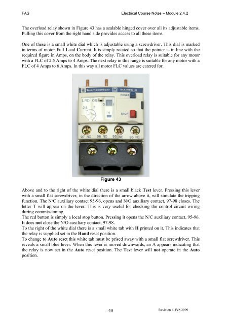
The overload relay shown in Figure 43 has a sealable hinged cover over all its adjustable items.<br />
Pulling this cover from the right hand side provides access to all these items.<br />
One <strong>of</strong> these is a small white dial which is adjustable using a screwdriver. This dial is marked<br />
in terms <strong>of</strong> motor Full Load Current. It is simply rotated so that the pointer is in line with the<br />
required figure in Amps, on the body <strong>of</strong> the relay. This overload relay is suitable for any motor<br />
with a FLC <strong>of</strong> 2.5 Amps to 4 Amps. The next relay in this range is suitable for any motor with a<br />
FLC <strong>of</strong> 4 Amps to 6 Amps. In this way all motor FLC values are catered for.<br />
Figure 43<br />
Above and to the right <strong>of</strong> the white dial there is a small black Test lever. Pressing this lever<br />
with a small flat screwdriver, in the direction <strong>of</strong> the arrow above it, will simulate the tripping<br />
function. The N/C auxiliary contact 95-96, opens and N/O auxiliary contact, 97-98 closes. The<br />
letter T will appear on the lever. This is very useful for checking the control circuit wiring<br />
during commissioning.<br />
The red button is simply a local stop button. Pressing it opens the N/C auxiliary contact, 95-96.<br />
It does not close the N/O auxiliary contact, 97-98.<br />
To the right <strong>of</strong> the white dial there is a small white tab with H printed on it. This indicates that<br />
the relay is supplied set in the Hand reset position.<br />
To change to Auto reset this white tab must be prised away with a small flat screwdriver. This<br />
reveals a small blue lever. When this lever is moved downwards, an A appears indicating that<br />
the relay is now set in the Auto reset position. The Test lever will not operate in the Auto<br />
position.<br />
40<br />
Revision 4. Feb 2009