

Blisk Production of the Future - MTU Aero Engines
Blisk Production of the Future - MTU Aero Engines
Blisk Production of the Future - MTU Aero Engines

Create successful ePaper yourself
Turn your PDF publications into a flip-book with our unique Google optimized e-Paper software.
ISABE-2009-1169<br />
<strong>Blisk</strong> <strong>Production</strong> <strong>of</strong> <strong>the</strong> <strong>Future</strong><br />
Technological and Logistical Aspects <strong>of</strong> <strong>Future</strong>-Oriented Construction and Manufacturing<br />
Processes <strong>of</strong> Integrally Bladed Rotors<br />
Abstract<br />
This paper describes <strong>the</strong> state-<strong>of</strong>-<strong>the</strong>-art in <strong>the</strong><br />
manufacturing technology for integrally bladed<br />
compressor and turbine rotors (blisks) in today’s<br />
engine construction and addresses <strong>the</strong><br />
technological and logistical challenges to be<br />
resolved to ensure flexible and future-oriented<br />
blisk manufacture.<br />
Abbreviations<br />
ECM Electrochemical Machining<br />
PECM Precise Electrochem. Machining<br />
HPC High Performance Cutting<br />
<strong>Blisk</strong> Bladed integrated Disk<br />
IBR Integrated Bladed Rotor<br />
LFW Linear Friction Welding<br />
IHFP Inductive High Frequency Pressure-Welding<br />
LPC Low pressure compressor<br />
AM Adaptive Milling<br />
CMM Coordinate measuring<br />
machine<br />
2. Introduction<br />
Integrally bladed rotors (blisks) are increasingly<br />
being used in modern engine construction.<br />
Meanwhile, advanced compressors for both<br />
commercial and military engines frequently<br />
come as all-blisk designs. Essential benefits<br />
over conventional rotor designs where <strong>the</strong><br />
blades are fitted in slots in <strong>the</strong> disk rim include<br />
weight reductions up to 20 percent and significant<br />
efficiency improvements.<br />
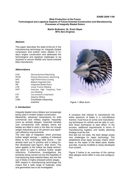
The next step <strong>of</strong> integration which promises<br />
fur<strong>the</strong>r weight savings — welding <strong>of</strong> individual<br />
blisks to form multi-stage blisk drums — has<br />
already been put to practice and is being fur<strong>the</strong>r<br />
developed (see figure1: blisk drum). The<br />
same applies to <strong>the</strong> hollow fan blade technology<br />
which is used to achieve fur<strong>the</strong>r weight<br />
reductions. Fur<strong>the</strong>rmore, investigations are<br />
presently being carried out into <strong>the</strong> feasibility <strong>of</strong><br />
manufacturing dual-material blisks and into <strong>the</strong><br />
use <strong>of</strong> blisks in highly stressed turbine stages.<br />
With respect to manufacturing technology this<br />
means that a wide range <strong>of</strong> materials, sizes<br />
and geometries has to be investigated.<br />
Martin Bußmann, Dr. Erwin Bayer<br />
<strong>MTU</strong> <strong>Aero</strong> <strong>Engines</strong><br />
Figure 1: <strong>Blisk</strong> drum.<br />
A company that intends to manufacture <strong>the</strong><br />
entire spectrum <strong>of</strong> blisks in a cost-effective<br />
manner, must focus on some core manufacturing<br />
techniques for airfoils and be able to combine<br />
<strong>the</strong>se techniques to best effect. In <strong>the</strong><br />
process, additional requirements in terms <strong>of</strong><br />
manufacturing logistics and facility planning<br />
strategy must be met.<br />
And last but not least, <strong>the</strong> blisk design poses<br />
new challenges for repair technology. The<br />
established shop repair process chains which<br />
base on <strong>the</strong> repair <strong>of</strong> <strong>the</strong> detail parts, blades<br />
and disk, must be modified or newly developed<br />
from scratch.<br />
Figure 2 below is an overview <strong>of</strong> <strong>the</strong> various<br />
blisk designs which differ in size and configuration.
1.2 Range<br />
EJ 200<br />
LPC<br />
Ti64<br />
LFW + AM<br />
TP400 Drum<br />
IPC<br />
Ti64<br />
EBW / IFW<br />
HPM<br />
Figure 2: Overview <strong>of</strong> <strong>the</strong> blisk types manufactured by <strong>MTU</strong> <strong>Aero</strong> <strong>Engines</strong>.<br />
3. From <strong>the</strong> strategic approach to <strong>the</strong> present-day<br />
situation at <strong>MTU</strong> <strong>Aero</strong> <strong>Engines</strong><br />
A strategic approach towards market-driven<br />
blisk manufacture was defined by <strong>MTU</strong> <strong>Aero</strong><br />
<strong>Engines</strong> back in 2004.<br />
To be able to manufacture various blisk types<br />
to satisfy <strong>the</strong> demand on <strong>the</strong> commercial and<br />
military markets long-term, several core manufacturing<br />
technologies for <strong>the</strong> production <strong>of</strong> <strong>the</strong><br />
flow duct pr<strong>of</strong>ile must be developed that can be<br />
used in any combination, depending on <strong>the</strong><br />
type <strong>of</strong> blisk involved.<br />
Machining resistance (material)<br />
ECM ECM / / PECM<br />
PECM<br />
HPC<br />
Current current<br />
blisk <strong>Blisk</strong> spectrum<br />
spectrum<br />
HPC<br />
LFW / IHFP<br />
Blade surface area / airfoil length (geometry)<br />
Exc. : Applications <strong>of</strong> airfoiling processes<br />
as referred to two parameters<br />
Figure 3: Core airfoiling processes for blisk<br />
PW6000<br />
HPC<br />
Ti6242<br />
HPM + IFW<br />
EJ 200 Drum<br />
HPC<br />
Ti6242<br />
HPM + IFW<br />
NGPF<br />
HPC<br />
U720;IN718<br />
(PECM)<br />
Focusing on <strong>the</strong>se core technologies makes<br />
sense because <strong>the</strong> production <strong>of</strong> <strong>the</strong> flow duct<br />
accounts for <strong>the</strong> major part <strong>of</strong> <strong>the</strong> manufacturing<br />
costs. In addition, <strong>the</strong> use <strong>of</strong> suitable core<br />
technologies may help reduce raw material<br />
consumption and hence costs.<br />
These core technologies are <strong>the</strong>n supplemented<br />
by hub machining and surface treatment<br />
processes to obtain an optimum process<br />
chain tailored to suit <strong>the</strong> respective type <strong>of</strong><br />
blisk.<br />
If <strong>the</strong>se manufacturing technologies are <strong>the</strong>n<br />
used in conjunction with advanced design and<br />
construction methods a component can be<br />
manufactured that is optimized in terms <strong>of</strong><br />
function, quality and costs.<br />
Based on this approach, a number <strong>of</strong> development<br />
projects were launched which focused<br />
on:<br />
- design to cost<br />
- new or fur<strong>the</strong>r developed joining, milling<br />
and ECM/PECM techniques<br />
- shot peening techniques<br />
- new quality assurance methods<br />
- new repair strategies
The Tool Box Approach in Process Chain Generation<br />
Peripheral Peripheral<br />
processes processes<br />
Niblisk<br />
Tiblisk<br />
Pre-airfoiling processes<br />
Figure 4: Tool box approach<br />
3.1 Design to cost<br />
Airfoiling<br />
Rough-machining Finishing<br />
ECM HPC LFW /<br />
IHFP<br />
ECM /<br />
PECM<br />
HPC<br />
LFW /<br />
IHFP +<br />
AM AM<br />
X X<br />
X<br />
X X<br />
X X<br />
: : : : : :<br />
X<br />
X X<br />
X X<br />
: : : : : :<br />
The primary objective <strong>of</strong> design-to-cost measures<br />
in blisk production is to reduce <strong>the</strong> manufacturing<br />
costs by bringing <strong>the</strong> requirements for<br />
airfoil and annulus surfaces as well as leading<br />
/ trailing edge geometries as closely as possible<br />
in line with <strong>the</strong> fluid mechanical requirements.<br />
In <strong>the</strong> process, <strong>the</strong> friction losses <strong>of</strong><br />
processed surfaces (milled, shot peened,<br />
ground) and/or <strong>the</strong> geometry variations <strong>of</strong> <strong>the</strong><br />
edges must be accounted for in <strong>the</strong> aerodynamic<br />
design as accurately as possible.<br />
TT<br />
Surface- -<br />
treatment<br />
CG<br />
:<br />
X<br />
X<br />
:<br />
Grinding,<br />
etc.<br />
X<br />
:<br />
X<br />
:<br />
Peripheral<br />
processes<br />
-<br />
Post-airfoiling processes / QM<br />
For <strong>the</strong> annulus surfaces, pro<strong>of</strong> could be furnished<br />
that milling marks that extend in <strong>the</strong><br />
direction <strong>of</strong> <strong>the</strong> flow have no adverse effects<br />
whatsoever, as long as <strong>the</strong>ir depth does not<br />
exceed a certain threshold value. This significantly<br />
reduces <strong>the</strong> finish-machining effort.<br />
The results <strong>of</strong> investigations into possible leading<br />
edge geometries on compressor blades<br />
have also revealed technical potential for expanding<br />
<strong>the</strong> acceptance standards.<br />
basic pr<strong>of</strong>ile 1/4 T stub 1/3 T stub 1/8 T concave 1/8 T convex 1/6 T concave<br />
Figure 4: Edge geometries investigated.<br />
∆ω<br />
mittel<br />
∆ω<br />
∆ω<br />
∆ω<br />
0,00%<br />
1/4 1/4 stumpf stub 1/3 1/3 stumpf stub 1/8 1/8 concave konkav 1/8 1/8 convex konvex 1/6 1/6 concave konkav<br />
1-2 Grafiken<br />
3.2 Manufacturing technologies<br />
Edge Kantenform geometries<br />
3.2.1 Joining<br />
Figure 5: Losses ∆ω <strong>of</strong> <strong>the</strong> deviating edge pr<strong>of</strong>iles investigated as compared with a basic pr<strong>of</strong>ile<br />
with constant edge radius.
Linear friction welding (LFW) has proven to be<br />
a suitable method to produce <strong>the</strong> highly<br />
stressed joint between <strong>the</strong> blades and <strong>the</strong> disk<br />
and is now used in production. Fur<strong>the</strong>r development<br />
efforts in this field are mainly targeted<br />
at <strong>the</strong> machine technology to achieve higher<br />
flexibility with respect to <strong>the</strong> various component<br />
geometries to be joined.<br />
Since <strong>the</strong> LFW technique calls for highly engineered<br />
machinery and presupposes certain<br />
geometric conditions regarding <strong>the</strong> components<br />
to be produced, <strong>the</strong> next generation <strong>of</strong><br />
blisk joining techniques is presently being developed:<br />
<strong>the</strong> inductive high-frequency pressure<br />
(IHFP) welding process.<br />
Figure 6: Detail parts and<br />
blisk joined by LFW<br />
Here, <strong>the</strong> energy required to heat <strong>the</strong> materials<br />
to be joined is produced by high-frequency<br />
alternating electromagnetic fields so that <strong>the</strong><br />
complicated machinery needed in <strong>the</strong> LFW<br />
process to produce <strong>the</strong> mechanical vibrations<br />
and high joining forces is no longer required.<br />
Ano<strong>the</strong>r benefit <strong>of</strong> <strong>the</strong> technique is that <strong>the</strong><br />
component proper is subjected to lower<br />
stresses during welding.<br />
1<br />
4<br />
3<br />
2<br />
1= HF generator<br />
2= Welding equipment<br />
3= Hydraulic system<br />
4= CNC control unit<br />
Figures 7 IHFP welding machine<br />
1<br />
Figure 8: section through a IHFP welded joint.<br />
Figure 9: Simulation <strong>of</strong> <strong>the</strong> heating process<br />
during IHFP welding<br />
Presently, <strong>the</strong> technology is being matured for<br />
common joints on titanium materials and crosssections<br />
from <strong>the</strong> fan area to <strong>the</strong> low-pressure<br />
compressor. In <strong>the</strong> process, a capable simulation<br />
<strong>of</strong> coil / alternating field is used which is<br />
particularly suited for <strong>the</strong> component geometry<br />
and significantly reduces parameter testing.<br />
3.2.2 Milling<br />
At <strong>MTU</strong> <strong>Aero</strong> <strong>Engines</strong>, milling is <strong>the</strong> most<br />
commonly used technique to produce blisk<br />
airfoils. In this field, a holistic approach to <strong>the</strong><br />
milling process—machine, setup, milling strategy,<br />
tooling, tool holders, coolant-lubricant,<br />
etc.—helped achieve considerable savings. A<br />
significant contribution came from <strong>the</strong> <strong>MTU</strong>patented<br />
circular stagger milling process.<br />
While with conventional milling <strong>the</strong> angle <strong>of</strong><br />
contact may be up to 180°, this angle is limited<br />
to 30° to 60° with circular milling. This reduces<br />
<strong>the</strong> cutting forces and increases <strong>the</strong> material<br />
removal rate by means larger cutting depths<br />
and higher cutting speeds.
angle <strong>of</strong> contact<br />
angle <strong>of</strong> contact<br />
Figure 10: Angle <strong>of</strong> contact with circular<br />
and conventional milling<br />
Figure 11: Milling on a 5-axis machine<br />
Essential prerequisites for high-performance<br />
machining using <strong>the</strong> circular milling approach<br />
are <strong>the</strong> selection <strong>of</strong> <strong>the</strong> most suitable cutter<br />
material and <strong>the</strong> definition <strong>of</strong> an optimum cutter<br />
geometry. Also, <strong>the</strong> life <strong>of</strong> <strong>the</strong> rough-milling<br />
tools can be more than doubled with an appropriate<br />
edge preparation.<br />
Rounding <strong>of</strong> <strong>the</strong> cutting edge markedly reduces<br />
<strong>the</strong> risk <strong>of</strong> micro-chipping, and <strong>the</strong> cutting<br />
edge normally exhibits a uniform rubbing<br />
wear.<br />
Figure 12: Sharp-edged and rounded edge <strong>of</strong><br />
a rough-milling cutter for blisk machining<br />
These highly dynamic milling processes are<br />
performed using special 5-axis milling machines.<br />
The necessary acceleration can be<br />
achieved by means <strong>of</strong> direct axis drives.<br />
3.2.3 ECM / PECM<br />
So far, <strong>the</strong> advantage <strong>of</strong> electrochemical machining<br />
processes used in <strong>the</strong> production <strong>of</strong><br />
airfoil geometries, i.e. minimum tool wear, has<br />
been <strong>of</strong>fset by <strong>the</strong> drawback <strong>of</strong> inaccurate<br />
contours particularly in <strong>the</strong> edge and radius<br />
areas and a relatively long iteration process.<br />
These disadvantages have now been overcome<br />
by a fur<strong>the</strong>r development <strong>of</strong> <strong>the</strong> process,<br />
<strong>the</strong> so-called precise electrochemical machining<br />
(PECM) technique. A reliable and precise<br />
control <strong>of</strong> this process, which involves very<br />
small gaps between component and vibrating<br />
electrode, has now been made possible by<br />
fur<strong>the</strong>r developments in semiconductor technology<br />
and control systems (precise pulsing<br />
and response times in <strong>the</strong> microsecond range<br />
at high machining currents).<br />
The results <strong>of</strong> trials have shown that, in <strong>the</strong><br />
case <strong>of</strong> materials which are difficult to machine<br />
(nickel-base alloys, nickel PM material), PECM<br />
is distinctly superior to milling in terms <strong>of</strong> machining<br />
speed, tool wear, surface finish, and<br />
process stability <strong>of</strong> <strong>the</strong> geometric features. The<br />
technology has been matured for production<br />
use by <strong>MTU</strong> <strong>Aero</strong> <strong>Engines</strong> and first development<br />
hardware is being machined on prototype<br />
facilities.<br />
Continuous<br />
feed<br />
Part<br />
Part<br />
´Tool<br />
Tool<br />
(-)<br />
(+)<br />
ECM for rough-machining<br />
(electrochemical machining)<br />
• gap > 1 mm<br />
• lower accuracy<br />
• high removal rates<br />
(-)<br />
(+)<br />
Electrolyte<br />
Pulsed<br />
feed<br />
PECM for finishing<br />
(precise electrochemical machining)<br />
•extremely narrow, controlled gap<br />
< 0.1 mm<br />
• pulsed current<br />
• increased accuracy <strong>of</strong> forming<br />
• lower removal rates<br />
Figure 13: ECM / PECM operating principle
ECM premachining<br />
PECM finishing<br />
Figure 14: <strong>Blisk</strong> manufacture by a combination<br />
<strong>of</strong> ECM premachining and PECM finishing –<br />
airfoil geometries and surfaces.<br />
3.2.4 Shot peening<br />
Most <strong>of</strong> <strong>Blisk</strong> blades are subject to controlled<br />
shot peening to increase <strong>the</strong>ir fatigue strength.<br />
Alongside conventional shot peening <strong>MTU</strong><br />
<strong>Aero</strong> <strong>Engines</strong> uses ultra-sound assisted shot<br />
peening which <strong>of</strong>fers <strong>the</strong> advantage <strong>of</strong> minimum<br />
component distortion, since both airfoil<br />
sides are normally compacted simultaneously.<br />
schematic<br />
Figure 15: Test setup for US shot peening<br />
Part<br />
Peening Chamber<br />
Sonotrode<br />
Piezo Shaker<br />
Controller<br />
+ Amplifier<br />
SONATS<br />
Figure 16: Principe <strong>of</strong> US shot peening<br />
Conventional shot peening<br />
Intensity: 0.2 A, coverage: 125 %<br />
US shot peening<br />
Intensity: 0.2 A, coverage 150 %<br />
250µm<br />
Figure 17: Comparison <strong>of</strong> <strong>the</strong> surface texture<br />
achieved by a) conventional and b) US shot<br />
peening<br />
Since US shot peening does not increase <strong>the</strong><br />
roughness <strong>of</strong> <strong>the</strong> airfoil surfaces, in particular<br />
in <strong>the</strong> leading and trailing edge areas, postpeening<br />
finishing processes that had to be<br />
performed after conventional shot peening are<br />
no longer required.
3.2.5 Quality assurance<br />
In this area, optical measuring techniques hold<br />
promise <strong>of</strong> time savings and more reliable<br />
quality statements as compared with conventional<br />
measurements using coordinate measuring<br />
machines (CMM).<br />
In contrast to conventional assembly <strong>of</strong> rotors,<br />
<strong>the</strong> manufacture <strong>of</strong> blisks is subject to particularly<br />
stringent requirements in terms <strong>of</strong> airfoil<br />
location, radius and airfoil pr<strong>of</strong>ile tolerances.<br />
Depending on <strong>the</strong> stability <strong>of</strong> <strong>the</strong> manufacturing<br />
process used, <strong>the</strong>refore, extensive dimensional<br />
inspections must be performed in <strong>the</strong><br />
course <strong>of</strong> in-process and final inspection.<br />
Compared with <strong>the</strong> tactile systems used on<br />
CMMs today’s advanced optical systems <strong>of</strong>fer<br />
great potential <strong>of</strong> reducing <strong>the</strong> inspection effort.<br />
They need far less time to provide complete<br />
models <strong>of</strong> <strong>the</strong> components which can <strong>the</strong>n be<br />
verified by means <strong>of</strong> computation routines, for<br />
example to assess manufacturing deviations in<br />
boundary cases.<br />
In cooperation with <strong>the</strong> measuring system<br />
manufacturers, <strong>MTU</strong> <strong>Aero</strong> <strong>Engines</strong> has succeeded<br />
in improving <strong>the</strong> accuracy <strong>of</strong> <strong>the</strong> systems<br />
also for dimensional inspection <strong>of</strong> leading<br />
and trailing edges, for example.<br />
Figure 18: Dimensional inspection <strong>of</strong> a blisk<br />
Figure 19 : Leading and trailing edges inspected<br />
using optical systems<br />
3.2.6 Repair<br />
Due to <strong>the</strong> integral construction <strong>of</strong> blisks a<br />
variety <strong>of</strong> repair processes needs to be modified<br />
or newly developed. Repairs that go beyond<br />
<strong>the</strong> scope <strong>of</strong> blending, a standard repair<br />
method also for individual blades, involve<br />
processes, such as buildup welding or patching<br />
that call for perfectly matched process<br />
steps, particularly when recoating or subsequent<br />
heat treatments are required.<br />
Repair processes<br />
Figure 20 : Repair categories A, B, C, D<br />
Of <strong>the</strong> repair categories illustrated above, <strong>the</strong><br />
replacement <strong>of</strong> complete airfoils poses <strong>the</strong><br />
most exacting requirements, as this repair<br />
involves <strong>the</strong> use <strong>of</strong> cutting and joining processes<br />
in <strong>the</strong> vicinity <strong>of</strong> critical component<br />
zones. Category A to C repairs are already<br />
used at <strong>MTU</strong> AERO ENGINES, category D is<br />
being developed.<br />
4. <strong>Future</strong> developments<br />
4.1 New designs<br />
The blisk design having become state-<strong>of</strong>-<strong>the</strong>art<br />
in <strong>the</strong> entire compressor area, including <strong>the</strong><br />
high-temperature-resistant high-pressure compressor<br />
stages, <strong>MTU</strong> <strong>Aero</strong> <strong>Engines</strong> is now<br />
working on <strong>the</strong> development <strong>of</strong> fabricated,<br />
high-stressed low-pressure turbine blisks.<br />
Unlike with <strong>the</strong> smaller, integrally cast variants<br />
used, for example, in auxiliary power units<br />
(APUs), <strong>the</strong> special challenge to be overcome<br />
here in manufacturing is <strong>the</strong> material mix <strong>of</strong><br />
forged disks and high-temperature cast blades<br />
and even single-crystal materials.<br />
Figure 21: Design example <strong>of</strong> a fabricated<br />
turbine blisk
4.2 Materials<br />
New engine concepts with enhanced efficiencies<br />
call for <strong>the</strong> use <strong>of</strong> high-strength and hightemperature<br />
alloys. In <strong>the</strong> low-pressure compressor,<br />
<strong>the</strong> simple titanium alloy Ti6V4 is increasingly<br />
being replaced by <strong>the</strong> alloys Ti6242<br />
or Ti6246, and in <strong>the</strong> high-pressure compressor,<br />
<strong>the</strong> modified alloy DA718 with approx. 7 %<br />
more strength is being used instead <strong>of</strong> <strong>the</strong><br />
standard alloy IN718. The last compressor<br />
stages upstream <strong>of</strong> <strong>the</strong> combustion chamber<br />
which are subject to higher <strong>the</strong>rmal stresses<br />
will be made from PM nickel alloys. With <strong>the</strong>se<br />
materials, electrochemical machining processes<br />
are particularly cost-effective.<br />
4.3 Surfaces<br />
To protect blisk blades from erosion by sand<br />
and dust, <strong>MTU</strong> <strong>Aero</strong> <strong>Engines</strong> has developed<br />
new protective coatings which have meanwhile<br />
become <strong>the</strong> standard coatings for airlines operating<br />
in erosive environments. In <strong>the</strong> coating<br />
area, too, poor accessibility <strong>of</strong> <strong>the</strong> blisk calls for<br />
special processes.<br />
Figure 22: <strong>Blisk</strong> airfoils with anti-erosion coating<br />
With aerodynamically optimized compressors,<br />
highest surface finish requirements have to be<br />
satisfied especially in <strong>the</strong> high-pressure compressor<br />
area. To achieve <strong>the</strong> surface finishes<br />
needed blisks with <strong>the</strong>ir special geometrical<br />
constraints have to be processed using o<strong>the</strong>r<br />
and, above all, more cost-effective techniques<br />
than those used on individual blades. In this<br />
field, automated electrochemical process sequences<br />
and o<strong>the</strong>r processes are being tested<br />
at present.<br />
4.4 Quality assurance<br />
<strong>Blisk</strong>s are inspected using <strong>the</strong> standard inspection<br />
methods developed for conventional<br />
disks, such as fluorescent penetrant inspection,<br />
ultrasonic inspection and segregation<br />
etching. For <strong>the</strong> inspection <strong>of</strong> blanks, phased<br />
array technologies are presently being fur<strong>the</strong>r<br />
developed and adapted to suit <strong>the</strong> particular<br />
requirements. Such technologies with <strong>the</strong>ir<br />
high resolution permit production inspection to<br />
be performed quickly and effectively.<br />
4.5 Design<br />
Highly advanced 3D design tools are used in<br />
<strong>the</strong> design <strong>of</strong> <strong>the</strong> blisk blades. Present-day<br />
airfoils are highly twisted, <strong>the</strong> edges frequently<br />
having <strong>the</strong> form <strong>of</strong> an “S”. The blade tips are<br />
hard-faced to protect <strong>the</strong>m against rubbing<br />
wear. These features result in new challenges<br />
for manufacturing technology.<br />
Figure 23 : 3D CAD model <strong>of</strong> a high-pressure<br />
compressor blade<br />
4.6 Industrial production concepts<br />
The manufacturing concept presented here<br />
bases on <strong>the</strong> following prerequisites:<br />
- Tool box concept<br />
The cost-effective and high-quality manufacture<br />
<strong>of</strong> a wide spectrum <strong>of</strong> different blisk types<br />
is possible only by <strong>the</strong> combination <strong>of</strong> various<br />
core manufacturing techniques for airfoiling.<br />
- High investments into <strong>the</strong> special machinery<br />
required are necessary to put <strong>the</strong> tool box concept<br />
in place. Therefore, <strong>the</strong> manufacturing<br />
concept must ensure optimum utilization <strong>of</strong> <strong>the</strong><br />
special machines.<br />
- Owing to <strong>the</strong> integral construction and <strong>the</strong><br />
criticality <strong>of</strong> <strong>the</strong> component and <strong>the</strong> associated<br />
interdependence <strong>of</strong> important quality characteristics<br />
maximum control over an essential<br />
part <strong>of</strong> <strong>the</strong> manufacturing process chain must<br />
be ensured.
- Long response times regarding <strong>the</strong> current<br />
quality situation <strong>of</strong> individual manufacturing<br />
processes must be avoided. A prompt quality<br />
control <strong>of</strong> <strong>the</strong> processes with effective possibilities<br />
to interfere with <strong>the</strong> processes is a must.<br />
Against this background two basic manufacturing<br />
approaches are conceivable:<br />
I) Central concept<br />
Processes that do not form part <strong>of</strong> <strong>the</strong> core<br />
manufacturing techniques are used for <strong>the</strong><br />
entire parts spectrum and are designed to<br />
ensure adequate flexibility <strong>of</strong> machines and<br />
fixtures. Whe<strong>the</strong>r and when a new core manufacturing<br />
technique is included in <strong>the</strong> tool box<br />
depends on <strong>the</strong> parts volume to be processed.<br />
As long as this volume is below a cost-effective<br />
threshold value <strong>the</strong> parts must be processed<br />
using o<strong>the</strong>r methods.<br />
II) Decentral concept<br />
The parts volume for an optimum combination<br />
<strong>of</strong> core manufacturing techniques must be<br />
such that a complete autonomous process<br />
chain is justifiable from <strong>the</strong> economic point <strong>of</strong><br />
view.<br />
pre-stage<br />
parts<br />
Figure 24: Central Concept<br />
p re-stag e<br />
p arts<br />
p re-stag e<br />
p arts<br />
.<br />
.<br />
.<br />
Figure 25: Decentral concept<br />
pre-airfoiling<br />
processes<br />
p re-airfoiling<br />
p ro cesses I<br />
p re-airfoiling<br />
p ro cesses II<br />
.<br />
.<br />
.<br />
rough airfoiling<br />
5. Summary<br />
In advanced engine concepts, blisk construction<br />
makes an important contribution towards<br />
optimizing efficiencies and reducing weight.<br />
Therefore, blisks will find increasing use, also<br />
in <strong>the</strong> turbine area.<br />
To be able to manufacture <strong>the</strong>se critical and<br />
highly stressed engine components in a costeffective<br />
manner, a variety <strong>of</strong> sophisticated<br />
manufacturing and quality techniques is<br />
needed. These have <strong>the</strong>n to be combined into<br />
process chains optimally designed to suit <strong>the</strong><br />
various types <strong>of</strong> blisks to ensure best results in<br />
terms <strong>of</strong> costs and quality.<br />
finish airfoiling<br />
milling PECM<br />
welding<br />
X X<br />
milling X X<br />
ECM X X<br />
airfo ilin g<br />
p ro cess I<br />
airfo ilin g<br />
p ro cess II<br />
.<br />
.<br />
.<br />
post-airfoiling<br />
processes<br />
p o st-airfo ilin g<br />
p ro cesses I<br />
p o st-airfo ilin g<br />
p ro cesses II<br />
.<br />
.<br />
.<br />
quality<br />
inspection<br />
q u ality<br />
in sp ectio n<br />
q u ality<br />
in sp ectio n<br />
.<br />
.<br />
.


![Download PDF [5,37 MB] - MTU Aero Engines](https://img.yumpu.com/21945461/1/190x125/download-pdf-537-mb-mtu-aero-engines.jpg?quality=85)