

THE MTU BRUSH SEAL DESIGN - MTU Aero Engines
THE MTU BRUSH SEAL DESIGN - MTU Aero Engines
THE MTU BRUSH SEAL DESIGN - MTU Aero Engines

Create successful ePaper yourself
Turn your PDF publications into a flip-book with our unique Google optimized e-Paper software.
7+( 078 %586+ 6($/ '(6,*1<br />
Alfons Gail<br />
Stefan Beichl
ÃÃÃÃÃÃÃÃÃÃÃÃ<br />
Alfons Gail<br />
Stefan Beichl<br />
<strong>MTU</strong> <strong>Aero</strong> <strong>Engines</strong>, Munich, Germany<br />
<br />
This report deals with the principles of design and fabrication of the <strong>MTU</strong> Brush Seal which use a unique<br />
manufacturing technique. While other brush seal suppliers around the world use a fabrication process<br />
which entails the 0.07 mm thin wires being secured by a welding process, <strong>MTU</strong> has developed and<br />
patented a method which uses only mechanical joining techniques, such as clamping and swaging. In<br />
doing so, the welding process required to fix the bristles has completely been eliminated.<br />
In the following the advantages inherent in the <strong>MTU</strong> seal design are explained and an insight is given<br />
into the current range of applications. Additionally some results obtained by rig and engine testing are<br />
presented which confirm the functionality, performance and life of <strong>MTU</strong> Brush Seals.<br />
Particular attention is paid to the most significant drawbacks brush seals have to cope with, like blow<br />
down effect, hang-up effect, high operational bristle stiffness, and it is shown that the <strong>MTU</strong> seal design<br />
has either resolved or reduced them to a negligible degree.<br />
The paper concludes that the development undertaken so far with <strong>MTU</strong> Brush Seals paves the way for<br />
making the brush seal a highly competitive element for a variety of future applications.<br />
<br />
1. History<br />
Back in 1983 <strong>MTU</strong> Munich commenced to manufacture brush seals initially applying welding techniques<br />
of the “conventional” seal design. After a series of welding problems became apparent, a new method for<br />
bristle retention was sought in order to delete welding processes.<br />
After numerous attempts, a promising new method to fix the bristles was developed and established.<br />
This method was applied for patent in 1985. The first <strong>MTU</strong> Brush Seals were rig tested in 1986 and<br />
engine testing commenced in 1992. Based on successful engine testing the number of <strong>MTU</strong> Brush Seal<br />
applications in both military and civil engines have increased steadily. Meanwhile <strong>MTU</strong> Brush Seals are<br />
validated at challenging positions where brush seals are successfully applied the first time.<br />
Testing of <strong>MTU</strong> Brush Seals for industrial gas turbine and compressor applications started in 1996. Since<br />
1998 <strong>MTU</strong> Brush Seals are delivered for flight and industrial production engines.<br />
2. The Conventional Brush Seal Design<br />
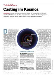
Fig. 1 shows the conventional brush seal design consisting of a backing plate, retaining ring and bristle<br />
pack. The brush seal is formed by squeezing the bristle pack between the backing plate and the<br />
retaining ring followed by circumferential welding to join these three elements to one unit. For more<br />
details see Ref. 1. Basically, the philosophy that is pursued by the conventional seal design is to fix the<br />
bristles at the outer end via the welding seam, whereas the inner end contacts the mating runner.<br />
The following requirements have to be fulfilled:<br />
• Safe retention of every single bristle (bristle diameter usually 0.07 mm (.0028 in))<br />
• No coning of backing plate<br />
• No distortion of side plates<br />
• Constant penetration depth of weld material into the bristle pack
Ã<br />
Ã<br />
ÃÃ<br />
Ã<br />
Ã<br />
Fig.1: Conventional brush seal design (schematic)<br />
ÃÃÃ<br />
1. Basic Design<br />
<br />
The welding process itself is demanding and can<br />
only be used for metallic brush materials.<br />
Obviously it must be re-optimised for each<br />
design change (e.g. change of bristle pack<br />
thickness, bristle diameter, plate thickness,<br />
material).<br />
Furthermore, the bristle material characteristics<br />
may change significantly at the heat affected<br />
zone, causing for example embrittlement and<br />
undercut of bristles respectively. Both effects<br />
jeopardise bristle retention, thus making the seal<br />
susceptible for loss of bristles during operation.<br />
In order to avoid the above mentioned welding problems, the ideal solution was to dispense with the<br />
welding process at all. This approach led to the foundation of the alternative <strong>MTU</strong> Brush Seal design<br />
which is characterised by a completely different manufacturing process.<br />
The idea to eliminate the welding process for fixing the bristles was further developed and means<br />
sought as to mechanically secure the bristles in place. The final solution of this development process is<br />
shown in Fig. 2.<br />
The <strong>MTU</strong> Brush Seal unit is exclusively formed by applying mechanical securing techniques such as<br />
clamping and swaging.<br />
In this way a second important design feature was established, the manufacture of the brush seal unit<br />
from individual and independent elements, namely the core element and the casing, i.e. support plate<br />
and cover plate. This separation allows for a simple adaptation, should the brush seal be applied as a<br />
retrofit solution to an already existing interface. The brush seal side plates can be scaled in dimension to<br />
match with the seal carrier without changing the interior configuration of the seal. This means the<br />
geometry which essentially determines seal function remains unchanged.<br />
2. Manufacturing Process<br />
The manufacturing process is described in detail in Ref. 2. The main process steps are briefly explained<br />
in the following.<br />
2.1. Core Element<br />
The brush seal core element is made from<br />
i) the core wire<br />
ii) the bristle pack<br />
iii) the clamping tube<br />
The first step to produce the core element is to wind the metal thread over the core wire which is situated<br />
twice on a special spindle. These core wires are arranged in parallel and spaced apart from each other.<br />
The winding process produces a densely packed thread pack of approximately oval cross section.
Pack thickness can be varied to produce core elements of 100, 200, 300 or any intermediate number of<br />
bristles per mm. The winding process is followed by the clamping procedure which serves to effectively<br />
fix the bristles around the core wire. Two clamping tubes are pushed over the thread pack at the core<br />
wire positions.<br />
After clamping the thread pack is cut in a section parallel to the spindles, such that two opposite straight<br />
semi-finished brush products of about equal bristle length are produced.<br />
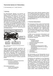
Fig. 3 shows such a longitudinal brush seal strip which is the basic product for the next working steps to<br />
follow.<br />
˚<br />
Fig. 3: Semi-finished Brush Seal strip Fig. 2: Cross section of <strong>MTU</strong> Brush Seal<br />
(light weight version)<br />
This manufacturing technique ensures safe retention of every single bristle. Unlike the conventional seal<br />
design, the bristles are clamped at half the wire length, i.e. both wire ends exit in a free state from the<br />
clamping tube. As the clamping provides a form-fit, loss of bristles other than by rupture when applying<br />
excessive force is excluded.<br />
In this context it is worth-mentioning that the winding process is not confined to special thread materials<br />
but can be applied to every thread or fibre material that is ductile enough not to break when being wound<br />
around the core wire. In this way brush seals consisting of various metal threads as well as ceramic and<br />
plastic fibres have been successfully fabricated.<br />
The process itself is generally independent of the most significant brush seal parameters such as brush<br />
seal size, bristle pack thickness and bristle diameter. Furthermore, reproducibility is excellent.<br />
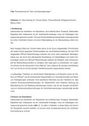
Depending on the desired brush seal size, the longitudinal strip is mechanically formed by rolling to<br />
become a closed ring which completes the core element manufacturing process, Fig. 4.<br />
2.2 Brush Seal Casing<br />
The brush seal casing is formed by two separate parts, the support plate and the cover plate.<br />
These plates are either produced by a deep-drawing process or by turning. The former uses pre-cut<br />
round blanks which are formed to the respective shape via special-to-type die tools. Usually this type of<br />
fabrication of side plates is chosen, if either seal weight plays an important role (for example in aero<br />
engine applications) and/or the quantity of required seals is high to balance additional tooling costs by<br />
reduced production time. A brush seal of this type is shown in fig. 2. Producing the side plates by a<br />
turning process saves the die tooling costs and give flexibility to the design process as the seal outer<br />
dimensions (for example wall thickness) can be adapted to match with the corresponding seal carrier.<br />
<br />
Clamping<br />
Tube<br />
Cover Plate<br />
Bristle Pack<br />
ÃÃ<br />
Swaging Lip<br />
Core Wire<br />
Support Plate
Fig. 4: Photograph of a Brush Seal core element<br />
Any change in seal geometry during the development<br />
process can easily be introduced, hence this<br />
manufacturing process is usually selected for prototype<br />
seals.<br />
An additional field of application for this type of seal is with<br />
non-aero engine applications (e.g. gas and steam turbines,<br />
industrial compressors), where seal weight does not play<br />
an important role. Fig. 5 shows a typical cross section of a<br />
<strong>MTU</strong> Brush Seal having side plates machined on a lathe.<br />
The turning process is currently being optimised and<br />
standardised to reduce costs.<br />
2.3 Completion of Brush Seal Unit<br />
˚ Once the side plates and the core element have been finished, the brush seal unit is formed by putting<br />
the core element inside the support plate and the cover plate. Subsequently these parts are squeezed<br />
together and the swaging lip is rolled inwards to close the seal unit. Thereby the seal housing is<br />
encapsulated which ensures that the core<br />
element is axially and radially clamped<br />
avoiding rotation within the seal housing. In<br />
special cases the support plate and the cover<br />
plate can alternatively be joined by a welding<br />
process. This may be beneficial if due to<br />
space constraints butt-welding of the side<br />
plates is required to further reduce radial seal<br />
height (compare for example fig. 6).<br />
Furthermore a welding joint is often applied to<br />
single prototype seals to keep tooling costs<br />
down. In this way, fabrication is highly flexible<br />
and capable of quickly supporting varying<br />
customer needs.<br />
Once the seal unit is complete, the inner bore<br />
diameter is finally machined. Upon customer<br />
requirement the brush seal can be cut into<br />
segments to enable for example installation<br />
into machines with split housings.<br />
3. Special Design Features<br />
<br />
Swaging Lip<br />
Cover Plate<br />
Bristle Pack<br />
Clamping Tube<br />
Core Wire<br />
Support Plate<br />
Fig. 5: Cross section of <strong>MTU</strong> Brush Seal with<br />
machined side plates<br />
3.1 Shape of Support Plate and Cover Plate<br />
The support plate and the cover plate are both of a cranked shape. In addition to the important functional<br />
aspects which are set out in section 3.6 this allows a reduction of the wall thickness of the support plate<br />
without compromising the structural capability as advantage is taken from the stiffening effect (applies of<br />
course to the light weight version only). The front plate serves to protect the bristle pack against handling<br />
damage and also against high energy swirl during operation. Additionally it helps to reduce the blow<br />
down effect.
3.2 Radial Seal Height<br />
The <strong>MTU</strong> Brush Seal (light weight version) typically measures only about three quarters of the height of a<br />
conventional brush seal. The reduced installation height opens the possibility to fit <strong>MTU</strong> Brush Seals at<br />
positions where conventional brush seals cannot be installed.<br />
3.3 Maximum Pressure Loading<br />
Meanwhile the <strong>MTU</strong> Brush Seal is well proven at differential pressures up to 1200 kPa (175 psid) across<br />
a single element, provided the bristle pack overhang beyond the support plate is moderate. The<br />
capability to cope with such high pressure loads offers the advantage to use a single brush seal element<br />
were formerly multiple brush seal arrangements were required.<br />
Thus the problems known to exist with multiple seal arrangements are avoided and, as a side effect,<br />
weight reduces significantly due to lower number of seals and correspondingly shortened runner length.<br />
3.4 Overall Weight Saving<br />
Typically at aero engine applications, the light weight version (see fig. 2) is selected. When compared<br />
with the conventional seal design, this <strong>MTU</strong> Brush Seal type offers significant weight savings due to:<br />
• thinner side plates,<br />
• reduced radial seal height enabling reduced seal carrier diameter at a given shaft size,<br />
• use of single seal elements instead of double or triple seals, hence, shortened runner lands<br />
Obviously the benefit multiplies with the number of seal positions per engine. This is of special interest<br />
for example at military engine projects where high sealing performance at minimum seal weight is a<br />
requirement.<br />
3.5 Extraction Lip<br />
As detailed in this report, the individual brush seal casing elements allow for simple integration to existing<br />
interfaces or specific customer needs, e.g. to design the seal with an integral extraction lip, as shown in<br />
fig. 6.<br />
This seal is situated such that inspection is possible on modular strip of the engine. The previously used<br />
labyrinth seal, however, required complete module tear down to substitute the seal having significant<br />
cost and time impact to the engine overhaul process. In order to remove this extra work and to expedite<br />
maintenance, the customer expressed the wish to remove and replace the seal in a simple manner with<br />
access only from the rear (right hand side in the figure) and with the main shaft in place.<br />
This requirement was fulfilled by adding an integral extraction lip to the brush seal housing enabling seal<br />
removal by means of a simple puller tool.<br />
˚<br />
Ã<br />
Ã<br />
Fig. 6: <strong>MTU</strong> Brush Seal with integral extraction lip
3.6 Low Hysteresis and Low Stiffness Design<br />
The performance and reliability of highly loaded brush seals is significantly compromised by bristle blow<br />
down, pressure stiffening and hysteresis (hang up) effects. These phenomena inherent in the<br />
conventional brush seal design are well documented in numerous publications, e.g. Ref. 3, 4 and 5.<br />
Blow Down Effect<br />
Blow down is mainly driven by the pressure differential acting across the seal. For a given seal design,<br />
this effect intensifies with increasing ∆p. Typically the blow down effect produces two distinct wear<br />
patterns:<br />
i) chamfering of the upstream bristle rows<br />
ii) uneven circumferential wear mainly in a saw tooth pattern<br />
As a result, the bristle pack suffers from premature wear which extends partially beyond the backing<br />
plate. The blow down effect of the <strong>MTU</strong> Brush Seal<br />
is very low even at high ∆p conditions and, hence,<br />
wear problems are negligible. For the front bristle<br />
rows this may be attributed mainly to the shape<br />
and position of the cover plate which protects the<br />
bristles from swirl and aerodynamic effects. Brush<br />
seal inspections performed on numerous engines<br />
neither showed chamfering nor uneven wear (fig.<br />
7).<br />
Definition of the brush seal inner bore diameter<br />
usually considers some initial rub-in of the seal in<br />
order to compensate for build tolerances, such as<br />
eccentricity, actual size of mating parts, etc. In this<br />
way the brush seal is capable of adapting itself to<br />
the actual build situation. Once this rub-in process<br />
has come to an end, seal wear should basically<br />
Fig. 7: <strong>MTU</strong> Brush Seal after 356 hrs. flight<br />
testing in a military project<br />
Brush Seal Wear Characteristic<br />
0,4<br />
<br />
<br />
0,3<br />
<br />
Ã<br />
<br />
0,2<br />
<br />
<br />
Ã<br />
0,1<br />
<br />
<br />
<br />
Ã<br />
0<br />
<br />
<br />
<br />
-0,1<br />
-0,2<br />
max. tolerance<br />
nominal diameter<br />
min. tolerance<br />
Engine 1<br />
Engine 3<br />
Engine 4<br />
Engine 5<br />
Engine 6<br />
Engine 7<br />
Engine 8<br />
0 100 200 300 400<br />
ÃÃ<br />
Fig. 8: Wear characteristic vs. running time of<br />
<strong>MTU</strong> Brush Seal of a military project<br />
<br />
stop for steady state running. Fig. 8 presents a<br />
typical <strong>MTU</strong> Brush Seal wear characteristic given<br />
as change of the inner bore diameter vs. running<br />
time.<br />
The graph shows an average wear trend that is<br />
based upon mechanical inspection results of eight<br />
engines of a military project after extensive<br />
development and certification testing. The dotted<br />
lines depict the tolerance band for new seals. The<br />
graph clearly indicates that after some running in,<br />
taking up to 50 hrs., the initial wear rate declines<br />
and levels off beyond 250 running hours to give<br />
constant seal performance. Brush seal wear may<br />
then be driven only by extreme flight manoeuvres<br />
involving high g-loads or high gyro loads.
Pressure Stiffening Effect<br />
The pressure stiffening effect occurs when the bristle pack is compressed and pushed against the backing<br />
plate. The increased friction between bristle to bristle and bristles to back plate reduce the seal flexibility<br />
drastically. In the first approximation, this effect grows proportionally with the pressure differential applied<br />
across the seal, i.e. it is particularly pronounced at high pressure loading. During rotor excursions, this<br />
creates high bristle tip forces which in turn leads to wear out of the bristles.. At its worst the frictional heat<br />
generated at the bristle tips may melt the bristle material causing either build-up of deposit on or damage<br />
to the runner.<br />
In order to suppress this effect, brush seal design must aim at generating a pressure-balanced bristle<br />
pack. Ideally, if this was achievable the operational stiffness would be independent of the pressure<br />
loading. In reality, however, as the bristle pack is compressed by the pressure drop and the bristles are<br />
supported by the backing plate, friction and thus seal stiffness inevitably increases. Therefore, the design<br />
objective is to minimise this increase in stiffness. This was accomplished with the <strong>MTU</strong> design and proven<br />
on dedicated static rig tests, i.e at zero speed condition.<br />
Fig. 9 presents a graph of brush seal stiffness versus differential pressures up to 500 kPa (73 psid).<br />
Ref. 3 reports that the stiffness ratio of conventional brush seals increase by more than an order of<br />
magnitude over a pressure range of 550 kPa (80 psid), whereas an advance development of a so called<br />
‘low hysteresis seal 1’, shows a rise in stiffness ratio from 1 at zero load condition to only 4 at 345 kPa (50<br />
psid).<br />
The stiffness ratio is defined as<br />
3<br />
<br />
<br />
Ã<br />
2<br />
<br />
<br />
<br />
1<br />
0<br />
Bristle stiffness at a given<br />
ÃÃÃÃ<br />
ÃÃÃÃÃÃ<br />
Interference 0,7 mm, Rotor Dia 150 mm, 200 Bpmm Pack Thickness<br />
0 1 2 3 4 5 6<br />
ÃÃÃ∆ÃÃ<br />
<br />
<br />
˚ It is evident from the curve in fig. 9, that the pack stiffness of the <strong>MTU</strong> Brush Seal steadily increases with<br />
increasing pressure drop. At a pressure differential of 500 kPa (73 psid) seal stiffness measures approx.<br />
3 times that at a zero load condition, and compares<br />
Fig. 9: <strong>MTU</strong> Brush Seal stiffness ratio vs. pressure differential<br />
<br />
well with the ‘low hysteresis seal 1’ mentioned<br />
above.<br />
When looking at the rise of stiffness ratio it can be<br />
seen that the graph tends to reduce from pressure<br />
differentials of 200 kPa (29 psid) onwards. This<br />
indicates that seal stiffness may increase<br />
moderately only at pressure differentials above 500<br />
kPa (73 psid).<br />
Rig measurements conducted to date have been<br />
under static conditions only (i.e. zero speed), and it<br />
is assumed, that stiffness values may reduce<br />
somewhat under dynamic conditions. To<br />
investigate this behaviour further, dedicated rig<br />
tests are scheduled for later this year.<br />
Hysteresis Effect<br />
The hysteresis effect of a brush seal causes the bristles to get stuck in a displaced position, for example<br />
after a rotor excursion, and do not drop back to the runner surface creating an enlarged gap which results<br />
in higher leakage flow.<br />
The <strong>MTU</strong> Brush Seal hardly shows such hysteresis. This is mainly a result of the pressure-balanced<br />
design along with the position and the width of the contact area where the bristle pack rests against the<br />
support plate.
Fig. 10 depicts a graph taken from rig testing. The intent of the test was to demonstrate seal performance<br />
and life under simulated maximum conditions of a military engine, exposing the seal to radial offsets up to<br />
0.50 mm (.020 in). During the test campaign, when the test rig was operated at 500 °C (930° F), the offset<br />
mechanism unintentionally drifted away from the pre-set value causing radial offsets up to 0.80 mm (.031<br />
in).<br />
With the rig set at about 170 m/s (558 ft/s) rotational speed, inlet air temperatures up to 500°C (930 °F)<br />
and pressure drops up to 600 kPa (87 psid) across the brush seal, the housing was radially displaced<br />
downwards and held eccentric for 30 sec before returning it to a concentric position (illustrated as vertical<br />
arrows on fig. 10).<br />
500<br />
480<br />
460<br />
440<br />
<br />
420<br />
Ã<br />
<br />
<br />
400<br />
<br />
<br />
<br />
<br />
380<br />
<br />
360<br />
340<br />
320<br />
300<br />
100<br />
90<br />
80<br />
70<br />
60<br />
<br />
ÃÈ<br />
50<br />
<br />
<br />
<br />
<br />
<br />
40<br />
30<br />
20<br />
10<br />
0.5mm radial<br />
housing deflection<br />
0<br />
0<br />
310 311 312 313 314 315 316 317 318 319<br />
<br />
N<br />
p upstr.<br />
M_dot red<br />
T up<br />
p downstr.<br />
´<br />
Fig. 10: Test results of <strong>MTU</strong> Brush Seal under radial housing displacement<br />
Ã<br />
1000<br />
900<br />
800<br />
700<br />
600<br />
500<br />
400<br />
300<br />
200<br />
100<br />
5<br />
4,5<br />
4<br />
3,5<br />
<br />
3<br />
<br />
Ã<br />
2,5<br />
<br />
<br />
<br />
<br />
2<br />
During each cycle the rig setting was maintained constant, i.e. changes of the respective curves are due<br />
only to the radial housing movement.<br />
Since the testing was endurance the scan rate was reduced somewhat not to overflow the data storage<br />
capacity. For this reason most of the peaks are cut off (flat, inclined or declined “peak”) and hence do not<br />
represent the true maximum values reached.<br />
In order to get representative results, a total of 300 cycles were performed; all of them giving consistent<br />
seal behaviour.<br />
As can be seen from the traces, the leakage flow increased with the radial displacement of the housing,<br />
because a sickle-shaped gap opens at the lower half of the seal. This leads to a decrease of the<br />
upstream and an increase of the downstream pressure. When looking at the rotational speed it is<br />
apparent that during housing deflection the runner speed reduces. This behaviour can be traced back to<br />
the rig drive motor, being an air turbine. At a given driving pressure turbine revolutions reduced due to<br />
increased friction when the brush seal was pushed down towards the runner.<br />
After returning the housing and thus the brush seal to concentric position, pressures, rotational speed<br />
and seal leakage recover completely to their original value. This shows that the bristles follow the<br />
housing movement without visible hysteresis.<br />
1,5<br />
1<br />
0,5<br />
0<br />
<br />
<br />
<br />
<br />
<br />
<br />
<br />
<br />
Ã<br />
<br />
Ã
4. Range of Application<br />
In principle <strong>MTU</strong> Brush Seals can operate in gas to liquid and gas to gas environments. Currently the<br />
following maximum operating conditions have been tested (per brush seal element):<br />
Absolute Pressure: up to 3500 kPa (500 psi)<br />
Differential Pressure: up to 1200 kPa (175 psid)<br />
Temperature: up to 700 °C (1300 F)<br />
Sliding Velocity: up to 400 m/s (1300 ft/s)<br />
Meanwhile the applicable pressure range is well-proven. With regard to temperature and sliding velocity<br />
engine testing has successfully demonstrated up to 650 °C (1200 F) and 270 m/s (900 ft/s). The<br />
maximum values given above have been demonstrated on rig testing and will be subject to engine<br />
testing in the near future.<br />
The manufacturing process applied by <strong>MTU</strong> enables fabrication of brush seals in a big range of size. At<br />
present <strong>MTU</strong> Brush Seal are produced from 50 mm (2 in) to 650 mm (25in). It is planned, however, to<br />
extend brush seal size to 1 m (39 in) and above to allow installation at the main gas path of large<br />
industrial gas and steam turbines.<br />
5. Experience<br />
The <strong>MTU</strong> Brush Seal design has been substantiated through various test activities, e.g. rig, aero and<br />
industrial turbo engines. The experience gained is briefly summarised in the following sections.<br />
5.1 Rig<br />
<strong>MTU</strong> operates three individual brush seal rigs, viz.:<br />
• The Segment Rig<br />
• The Small Rig (rotor dia 60 mm to 170 mm)<br />
• The Large Rig (rotor dia 170 mm to 350 mm)<br />
Additionally, a separate test rig is currently being designed to investigate multiple seal arrangements.<br />
These rig facilities allow the test specimen to be exposed to the following conditions:<br />
• Upstream pressure up to 3000 kPa (450 psi)<br />
• Downstream pressure up to 1000 kPa (150 psi)<br />
• Temperature up to 600 °C (1100 °F)<br />
• Sliding velocity up to 400 m/s (1300 ft/s)<br />
• Radial housing<br />
deflection up to 0.8 mm (.032 in)<br />
Rig testing commenced in 1986. Since then comprehensive experience has been gathered in the fields<br />
of<br />
• Coating of runner lands<br />
• Single and multiple seal arrangements<br />
• Bristle/fibre materials (metallic and non-metallic)<br />
Numerous test sequences have been conducted to understand and optimise seal performance and life<br />
when subjecting the seal to extreme conditions found within military engines. To date, in excess of 1500<br />
hrs. rig testing has been performed.<br />
5.2 <strong>Aero</strong> <strong>Engines</strong>
Today, <strong>MTU</strong> Brush Seals are validated and cleared for use in two military projects. These two projects<br />
comprise a total of seven seal positions, all being shaft seals, single elements and designed to a seal<br />
pack width of either 100 or 200 Bristle per mm circumferential length. The brush seals are situated at<br />
High and at Low Pressure Turbine areas and serve to control the secondary air system of the engine.<br />
Since 1995 extensive bench and flight testing has been conducted to support engine validation and<br />
certification. Up to now a total of 17,000 bench hours and 3,000 flight hours have been accumulated<br />
within military projects. The highest flight time achieved on a single seal to date is 6oo hrs., and the seal<br />
is still running on. Since this was accomplished on a military engine being subjected to a number of<br />
engine cycles during a typical flight mission, i.e. frequent changes of forward speed, altitude, shaft<br />
speed, g- and gyro loading it multiplies by an order of magnitude when being compared to the flight<br />
profile of civil aero engines.<br />
The success gained on military projects has laid the groundwork to expand the field of application in<br />
order to include civil aero engines.<br />
Today, <strong>MTU</strong> Brush Seals are operated at high duty seal positions such as forward HPT disc as well as<br />
at inner air seal position between adjoining turbine stages. At both positions engine validation tests are<br />
well underway and substantiation is very close to completion. Clearance for production use is expected<br />
imminently.<br />
5.3. Industrial Turbo <strong>Engines</strong><br />
In 1997 <strong>MTU</strong> Brush Seals were first time installed into industrial gas turbines and compressors to<br />
demonstrate their functional benefit over the existing labyrinth seal configurations.<br />
With industrial compressors the leakage flow reduced to one third of the previous labyrinth seal and was<br />
proven to be constant over thousands of hours of operation at service. As a result, <strong>MTU</strong> Brush Seals<br />
were given clearance for series production beginning of the year 2000.<br />
On stationary gas turbines the performance demonstration was similarly successful, but endurance<br />
testing is still ongoing to prove seal life. It is expected, that life substantiation work will be completed by<br />
the end of the year and clearance for series production is planned for the beginning of 2001.<br />
Since November 1998 <strong>MTU</strong> Brush Seals have successfully run in an operational steam turbine.<br />
Additional tests are being performed to investigate brush seal performance in a multiple element<br />
arrangement at the balance piston position.<br />
To date in excess of 120,000 hrs. have been accumulated with industrial turbo engine applications. The<br />
highest time achieved on a seal amounts to approx. 14,000 hrs , and the seal is still running on at a<br />
sealing performance almost unchanged from the beginning.<br />
<br />
The <strong>MTU</strong> Brush Seal design and manufacturing technique has been presented and shown, that it differs<br />
fundamentally from the conventional design. The advantages inherent in the <strong>MTU</strong> design have been<br />
explained and rig and engine test results have been discussed. These confirm that the functional<br />
problems known from conventional brush seals are either resolved or reduced to an acceptable level.<br />
Since the beginning of initial <strong>MTU</strong> Brush Seal development in 1986 significant experience has been<br />
collected mainly with single stage seals. Whilst validation and certification work has generally been<br />
completed, service experience is now being gathered.<br />
Development work is continuing at <strong>MTU</strong> including basic research studies of seal design as well as future<br />
applications, such as multiple seal arrangements and alternative seal materials.<br />
The <strong>MTU</strong> Brush Seal design has reached a high level of maturity which is considered a sound basis for<br />
making the brush seal a highly competitive element for a variety of applications in the years to come.
1. J. Ferguson, ASME Paper No. 88-GT-182, 1988, „Brushes as High Performance Gas Turbine<br />
Seals“<br />
2. European Patent No. 0211275, <strong>MTU</strong> Motoren- und Turbinen-Union GmbH<br />
3. P. Basu, A. Datta, R. Johnson, R. Loewenthal; J. Short AIAA Paper No. 93-1996, 1993, “Hysteresis<br />
and Bristle Stiffening Effects of Conventional Brush Seals”<br />
4. G. Berard, J. Short, AIAA Paper No. 99-2685, 1999, “Influence of Design Features on Brush Seal<br />
Performance”<br />
5. R. Chupp, P. Nelson, AIAA Paper No. 90-2140, 1990, “Evaluation of Brush Seals for Limited-Life<br />
<strong>Engines</strong>”


![Download PDF [5,37 MB] - MTU Aero Engines](https://img.yumpu.com/21945461/1/190x125/download-pdf-537-mb-mtu-aero-engines.jpg?quality=85)