PTO INSTALLATION and OWNER'S MANUAL - Muncie Power ...
PTO INSTALLATION and OWNER'S MANUAL - Muncie Power ...
PTO INSTALLATION and OWNER'S MANUAL - Muncie Power ...

You also want an ePaper? Increase the reach of your titles
YUMPU automatically turns print PDFs into web optimized ePapers that Google loves.
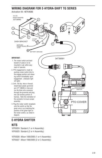
WIRINg dIAgRAM FOR E-HYdRA-SHIFT Tg SERIES<br />
Activation Kit: 48TK4686<br />
12v DC<br />
Switch Assembly<br />
30T39590<br />
2<br />
1<br />
DASH BRACKET<br />
IMPORTANT:<br />
SWITCHED<br />
POWER SOURCE<br />
12VDC<br />
+<br />
1. The rocker switch <strong>and</strong> dash<br />
bracket (if used) is to be<br />
mounted in cab within easy<br />
reach of operator.<br />
2. <strong>PTO</strong> engagement is made by<br />
pushing rocker switch fully to<br />
the engage position <strong>and</strong> releasing<br />
switch immediately upon<br />
engagement. (Indicator light<br />
will light)<br />
3. Drill .750 dia. Hole in firewall,<br />
install black plastic grommet<br />
(p/n 37T 39628) in hole <strong>and</strong><br />
run the three wire connector<br />
through the grommet <strong>and</strong> plug<br />
into cab harness portion of<br />
harness. Note the orientation of<br />
the connector to insure proper<br />
assembly.<br />
4. Plug the rocker switch receptacle<br />
onto the switch so that the<br />
green wire is up (matching the<br />
position of the green light on<br />
the rocker switch.) as noted in<br />
diagram.<br />
E-HYdRA SHIFTER<br />
KITS<br />
16TK5024 St<strong>and</strong>ard (1 or 4 Assembly)<br />
16TK5025 St<strong>and</strong>ard (2 or 4 Assembly)<br />
3<br />
25 AMP<br />
FUSE<br />
16TK5026 Allison 1000/2000 (1 or 4 Assembly)<br />
16TK5027 Allison 1000/2000 (2 or 3 Assembly)<br />
4<br />
RED<br />
BLACK<br />
BATTERY GROUND<br />
GREEN<br />
RED<br />
5<br />
6<br />
3 2 1<br />
34T39591<br />
UP<br />
ENGAGEMENT<br />
SWITCH<br />
<strong>PTO</strong> COVER<br />
2.9