Stress-lite Shot Peening of Compressor Reed Valve Components
Stress-lite Shot Peening of Compressor Reed Valve Components
Stress-lite Shot Peening of Compressor Reed Valve Components

Create successful ePaper yourself
Turn your PDF publications into a flip-book with our unique Google optimized e-Paper software.
USING SHOT<br />
OF PEENING TO<br />
COMPRESSOR<br />
John S. Eckersley<br />
Buzz Ferrelli<br />
Metal Improvement Company<br />
Bloomfield, Connecticut<br />
MULTIPLY THE<br />
COMPONENTS<br />
LIFE<br />
ABSTRACT<br />
Fatigue life increases, by orders <strong>of</strong> magnitude, can be expected<br />
on compressor components treated by <strong>Shot</strong> <strong>Peening</strong> -- a controlled process<br />
that involves the bombardment <strong>of</strong> the metal component by millions<br />
<strong>of</strong> spherical particles <strong>of</strong> steel, glass or ceramic. <strong>Shot</strong> <strong>Peening</strong> is<br />
being applied to crankshafts and con-rods <strong>of</strong> huge reciprocating compressors<br />
and to the small valve reeds, only a few thousands <strong>of</strong> an<br />
inch thick, that are the heart <strong>of</strong> refrigeration and air conditioning<br />
sealed units. In what is perhaps the "ultimate" in design <strong>of</strong> axial<br />
and centrifugal compressors, the modern jet engine, <strong>Shot</strong> <strong>Peening</strong> is<br />
used on all rotating parts, as well as many <strong>of</strong> the stationary ones,<br />
to prevent premature failures from metal fatigue, corrosion and fretting<br />
fatigue, and from stress corrosion cracking.<br />
The paper reviews these and other applications for compressor engineers<br />
so that they will be able to increase the life and/or the<br />
loading on both new and existing designs, without increasing size or<br />
adding weight to critical components. The controlling parameters <strong>of</strong><br />
the <strong>Shot</strong> <strong>Peening</strong> process are also discussed.<br />
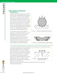
HISTORICAL BACKGROUND<br />
<strong>Shot</strong> <strong>Peening</strong> was first used, in a production application, to extend<br />
the life <strong>of</strong> the valve springs for the Buick and Cadillac engines<br />
<strong>of</strong> the early 1930s (Ref. 1). The process was discovered accidentally<br />
and, although the benefits were soon recognized, it was several years<br />
before a mechanism was proposed and even longer before is was generally<br />
accepted. It was recognized, at the time, that fatigue cracks initiated<br />
under repeated tensile loads. John Almen postulated that shot<br />
peening produced the increases in fatigue life from the introduction,<br />
<strong>of</strong> a high residual compressive stress, which remained just below<br />
the surface <strong>of</strong> the part (Fig. 1, Ref. 2).<br />
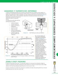
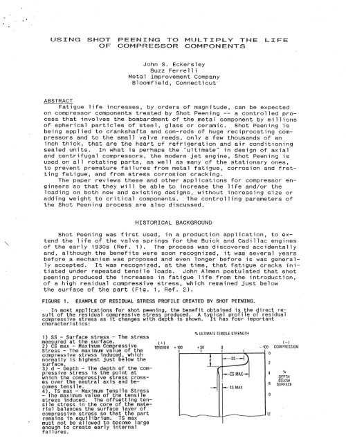
FIGURE 1. EXAMPLE OF RESIDUAL STRESS PROFILE CREATED BY SHOT PEENING.<br />
In most applications for shot peening, the benefit obtained is the direct result<br />
<strong>of</strong> the residual compressive stress produced. A typical pr<strong>of</strong>ile <strong>of</strong> residual<br />
compressive stress as it changes with depth is shown. It has four important<br />
characteristics:<br />
1) SS - Surface stress - The stress<br />
measured at the surface. (+)<br />
2) CS max - Maximum Compressive TENSION +100<br />
<strong>Stress</strong> - The maximum value <strong>of</strong> the t<br />
% ULTIMATE TENSILE STRENGTH<br />
(-)<br />
+50 0 -100 COMPRESSION<br />
I I I I 0<br />
compressive stress induced, which ~----~-,---+------~----i<br />
normally is highest just below the<br />
~ -ss-1),<br />
surface.<br />
.L,<br />
2<br />
3) d - Depth - The depth <strong>of</strong> the compressive<br />
stress is the point at<br />
~S~<br />
4<br />
which the compressive stress crosses<br />
over the neutral axis and be-<br />
6<br />
comes tensile.<br />
...,.- f-- TS MAX<br />
4). TS max - Maximum Tensile <strong>Stress</strong><br />
- The maximum value <strong>of</strong> the tensile<br />
8<br />
stress induced. The <strong>of</strong>fsetting tensile<br />
stress in the core <strong>of</strong> the material<br />
balances the surface layer <strong>of</strong><br />
compressive stress so that the part<br />
12<br />
remains in equilibrium. TS max<br />
must not be allowed to become large<br />
enough to create early internal<br />
fa; lures.<br />
0'0<br />
DEPTH<br />
BELOW<br />
SURFACE
Any applied tensile loads, affirmed Almen, would have to<br />
overcome this residual compression before a crack could start. Furthermore,<br />
Almen claimed that many parts (springs, for instance, from<br />
the coiling operation) had in them, from manufacturing, residual tensile<br />
stresses, that when added upon by the tensile loads, would further<br />
contribute to the part's early failure. <strong>Shot</strong> <strong>Peening</strong>, he said,<br />
reversed the surface residual stress from tension to compression,<br />
accounting for the very great improvements in fatigue life that are<br />
typical <strong>of</strong> the process. The academic community was almost totally<br />
opposed to John Almen's theories since, at the time, the presence <strong>of</strong><br />
residual stresses in metals was not recognized in engineering calculations.<br />
The advent <strong>of</strong> Fracture Mechanics eventually vindicated<br />
Almen's position. Today, we not only recognize residual (or self)<br />
stresses; we are able to measure them with a considerable degree <strong>of</strong><br />
consistency, primarily by x-ray diffraction.<br />
Consideration Of Residual <strong>Stress</strong>es<br />
If the part is dimensionally correct, are residual stresses all<br />
that important, in a fatigue application? A very current case is an<br />
excellent illustration. A group <strong>of</strong> engineers are developing a torsion<br />
bar for a space application (the exact nature is "classified").<br />
They carefully ground the test torsion bars to produce the final pr<strong>of</strong>ile<br />
and a smooth surface. The unpeened torsion bars, at the applied<br />
load level, averaged close to a million cycles to failure and the<br />
stress analyst in the group figured from this information, that shot<br />
peening would about double the life <strong>of</strong> the bars, to two million<br />
cycles: sufficient for the application. To his surprise, the first<br />
(and only) <strong>Shot</strong> Peened torsion bar that they tested ran for 166 million<br />
cycles when the test was discontinued.<br />
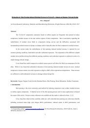
FIGURE 2. RESIDUAL STRESS IN 4340 STEEL (HRC 50) AFTER SURFACE GRINDING.<br />
Graph shows the stress distribution<br />
created by different grinding techniques<br />
- conventional, abusive and<br />
gentle. It is quite evident that<br />
conventional grlnding and abusive<br />
grinding can generate high magnitudes<br />
<strong>of</strong> resiaual tensile stress at<br />
or near the surface <strong>of</strong> the Rarts.<br />
This tensile stress will, <strong>of</strong><br />
course, dramatically affect fatigue<br />
.resistance.<br />
100<br />
80<br />
60<br />
40<br />
~ -20<br />
Vi<br />
en<br />
UJ<br />
a:<br />
a.<br />
1§ -4<br />
o<br />
0<br />
I<br />
/ \<br />
I \<br />
I \<br />
I \<br />
\<br />
:\<br />
\ \<br />
!\ \ \<br />
I "< CONVENTIONAL \. Y ABUSIVE<br />
I<br />
\~<br />
,V<br />
i--.<br />
"
<strong>Shot</strong> Peened, the surface residual stresses were reversed, from close<br />
to the yield strength in tension to close to the yield strength in<br />
compression or a delta, in this case, <strong>of</strong> over 300 KSI. The <strong>Shot</strong> <strong>Peening</strong><br />
actually raised the endurance limit <strong>of</strong> the torsion bars well over<br />
the stress level applied in the testing, contributing to virtually infinite<br />
life. Not all applications <strong>of</strong> <strong>Shot</strong> <strong>Peening</strong> are so dramatic<br />
but this is a good reminder that residual stresses, detrimental or<br />
beneficial, should not be ignored.<br />
Realizing that the Purdue Conference is directed almost exclusively<br />
at engineers involved with small compressors for refrigeration and<br />
air conditioning, we thought it would be useful to review, quite<br />
briefly, some <strong>of</strong> the applications <strong>of</strong> the <strong>Shot</strong> <strong>Peening</strong> process in the<br />
very large or very different compressors that are found in other industries,<br />
since much can be learned from them. Then, we want to be<br />
more specific in discussing the benefits <strong>of</strong> <strong>Shot</strong> <strong>Peening</strong> for valve<br />
reeds and rings since our unique success in this area has propelled<br />
Metal Improvement Company to become one <strong>of</strong> the leading manufactures<br />
<strong>of</strong> these very critical components.<br />
SHOT PEENING FOR INDUSTRIAL AND AIRCRAFT COMPRESSORS<br />
Reciprocating <strong>Compressor</strong>s<br />
1.Crankshafts are most commonly peened in the fillets <strong>of</strong> the<br />
pins and mains to produce increases in fatigue strength <strong>of</strong> up to 30%.<br />
Crankshafts have also been peened in the oil holes and keyways (Fig.<br />
3, Ref. 4).<br />
FIGURE 3. INCREASE IN FATIGUE STRENGTH OF SHOT PEENED CRANKSHAFTS.<br />
The most highly stressed area <strong>of</strong> a crankshaft is the crank pin bearing fillet.<br />
The high stress point is the bottom side <strong>of</strong> the fillet when the pin is in the top<br />
dead center position during the firing cycle. It is common for cracks to initiate<br />
in this pin fillet and propagate through the web <strong>of</strong> the crankshaft to the adjacent<br />
main bearing fillet, causing fatigue failure. All sizes <strong>of</strong> crankshafts respond<br />
well to shot peening, from small high speed shafts with journai bearing diameters<br />
<strong>of</strong> 1" to large slow speed shaft~ having journal bearing diameters <strong>of</strong> 6" and more.<br />
Experlence has shown the process to be effective on forged steel, cast steel, nodu-<br />
1ar iron, and austempered ducti 1e iron. LUBRICATING HOLE<br />
~ /<br />
,Y/<br />
--.v<br />
",I<br />
~I<br />
t;i1u<br />
;tIS<br />
~Ib<br />
~17, WEB<br />
I<br />
2.Connecting Rods are usually peened prior to machining, to prevent<br />
fatigue failures in the I-beam section but some large ones are<br />
also peened in the oil holes and in the fillets by the bolts. Fr~tting<br />
fatigue is prevented by peening the serrations between the rod<br />
and the cap, the bearing surfaces, and the bolt holes.<br />
3. Connecting Rod Bolts are shot peened for axial fatigue in<br />
the shank to head fillet and for fretting fatigue in the shank itself.<br />
Sometimes, the thread roots are peened, which can impart to a<br />
cut thread almost the same fatigue strength as a rolled thread.<br />
4. Tie-Rod Bolts are used in very large compressors to hold the<br />
assembly together or are used just around the cylinder heads. These<br />
bolts are peened for the same reasons as the connecting rod bolts described<br />
above.<br />
5. Tail Rod Cylinders are peened at the intersections <strong>of</strong> crossbores<br />
to prevent crack initiation.<br />
6. Hyper Cups are used to hold the seal around the push rods <strong>of</strong><br />
very high pressure (approaching 50,000 PSI) compressors. The <strong>Shot</strong><br />
<strong>Peening</strong> retards failures from bending and fretting fatigue.<br />
7. Ring and Strip <strong>Valve</strong>s are edge finished and peened for very
Centrifugal <strong>Compressor</strong>s<br />
Impellers have been <strong>Shot</strong> Peened that range in size from less than<br />
2 inches in diameter for a space application to 48 inches for process<br />
air. Turbochargers fall under this classification and many are shot<br />
peened against blade failure. One unique application involved thermal<br />
cracking at some locating serrations on the back face <strong>of</strong> aluminum<br />
impellers for locomotive diesel turbochargers. Of concern was the<br />
heat that might relieve the compressive stresses form <strong>Shot</strong> <strong>Peening</strong>.<br />
However, peening solved the problem, using glass beads to avoid ferrous<br />
contamination <strong>of</strong> the aluminum.<br />
Most <strong>of</strong> the smaller turbines employed in aircraft, sometimes for<br />
propulsion, but most <strong>of</strong>ten as auxiliary power units, air starters,<br />
etc., use <strong>Shot</strong> Peened impellers, as do the engines for the Cruise Missile.<br />
Significant weight reductions are possible by including the<br />
benefits <strong>of</strong> <strong>Shot</strong> <strong>Peening</strong> in the design calculations. Materials for<br />
impellers, incidentally, may be sand cast iron or aluminum, welded<br />
steel, forged aluminum or titanium; even investment cast superalloys:<br />
all respond well to <strong>Shot</strong> <strong>Peening</strong>.<br />
Axial <strong>Compressor</strong>s<br />
Many are used in stationary applications (a good one is for making<br />
snow on the ski slopes), but most axial compressors are used in<br />
combination with a gas turbine to form a jet engine and provide propulsion<br />
for planes, boats and trains, and some experimental trucks.<br />
Because <strong>of</strong> the extreme centrifugal, axial and vibrational forces acting<br />
on the rotating components, all shafts, disks and blades are typically<br />
<strong>Shot</strong> Peened against bending and fretting fatigue. In fact,<br />
there are very few components <strong>of</strong> a high performance jet engine that<br />
are not peened, both during original manufacture and again at periodic<br />
overhaul intervals, and include less obvious components such as<br />
gears and fuel lines.<br />
Diaphragm <strong>Compressor</strong>s<br />
Diaphragm compressors are quite uncommon and are used in applications<br />
where absolutely no contamination (from lubricating oils, for<br />
instance) <strong>of</strong> the compressed gas is permitted. The critical component<br />
is a large (up to 30 inches diameter by 0.030 inch thick) stainless<br />
steel diaphragm that is clamped around the edges in the compressor<br />
head. Because the diaphragm moves up and down under hydraulic pressure,<br />
cracks initiate just inside <strong>of</strong> the bolt hole ring. Typically,<br />
a chemical company, compressj~g Freon, used to replace these diaphragms<br />
every 16 hours <strong>of</strong> service. <strong>Peening</strong> the diaphragm with glass<br />
beads (on stainless steel) extended the service life to 6 months.<br />
The difficulty here is to peen the large but very thin diaphragm and<br />
still maintain flatness: exactly the same problem that is encountered<br />
in peening the small valve reeds with which you are all familiar.<br />
COMPRESSOR VALVE COMPONENTS<br />
To Quote D. N. Lal, Research Engineer at the Carrier Corporation:<br />
"The valve, suction or discharge, is one <strong>of</strong> the most critical<br />
components <strong>of</strong> a compressor. A flapper valve is required to have high<br />
flexibility to allow unrestricted fluid passage through the ports-for<br />
achieving high efficiency and capacity <strong>of</strong> the compressor, but at the<br />
same time it is also expected to have enough stiffness to return back<br />
in time to seal the ports completely. The motion subjects the valve<br />
to severe cyclic stresses and strains. To make the situation worse,<br />
most <strong>of</strong> the valves have irregular geometry as unavoidable design re-<br />
Quirements. This increases the possibility <strong>of</strong> localized stress concentration<br />
and premature failure by fatigue" (Ref. 5). Few would<br />
dispute Lal's statement but it leaves the designer <strong>of</strong> a compressor<br />
with having to make a serious compromise between the efficiency <strong>of</strong><br />
the compressor and the life <strong>of</strong> the valve. The more the flapper reed<br />
flexes, the more passage <strong>of</strong> fluid it will permit but the shorter will<br />
be the number <strong>of</strong> flexures the flapper will sustain before breaking.<br />
It is incumbent on the designer to seek a reed that will allow the<br />
maximum passage <strong>of</strong> fluid without breakage during the expected life <strong>of</strong><br />
the compressor at, let's not forget, a cost that is within budget.
" .<br />
The geometry <strong>of</strong> the reed is usually the first consideration and<br />
one over which the manufacturer <strong>of</strong> the reed has little control. Actually,<br />
the designers are much better served if they include the manufacturer<br />
at an early stage <strong>of</strong> the design. A manufacturer <strong>of</strong> reeds<br />
should not just be able to stamp out metal shapes: he must thoroughly<br />
understand all the factors that influence the life expectancy <strong>of</strong> a<br />
valve. For instance, the diameter <strong>of</strong> a mounting hole or the width <strong>of</strong><br />
a slot, within obvious limits, may have little influence on the efficiency<br />
<strong>of</strong> a reed but they can create difficulties for the reed maker<br />
that will impact both on the life and the cost <strong>of</strong> a reed. The reed<br />
maker must have a complete knowledge <strong>of</strong> materials; stresses (applied<br />
and residual; beneficial and detrimental); how life is affected by<br />
edge geometry, surface conditions, heat and corrosion; and the influence<br />
<strong>of</strong> bending, torsion and impact loads. Because his speciality is<br />
valves (and not compressors) the reed manufacturer can be <strong>of</strong> great<br />
value to the designer.<br />
The ideal valve reed would open fully and close totally in zero<br />
time: and last forever. We certainly are not there yet but an evolving<br />
technology, based on a more complete understanding <strong>of</strong> the many<br />
phenomena involved, is taking the best reed makers ever closer. We<br />
know that there are at least five areas that must be given attention:<br />
1. Choice <strong>of</strong> material, 2. stamped edges, 3. Removal <strong>of</strong> defects<br />
and detrimental stresses, 4. Edge rounding, 5. Depth and magnitude <strong>of</strong><br />
beneficial stress. We will address each <strong>of</strong> these items individually<br />
but it must be remembered that all are very much interrelated. For<br />
instance, maximizing #5, in theory would allow the use <strong>of</strong> thinner<br />
steel (#1) so that the reed would flex more and faster but maintaining<br />
flatness could then become a difficulty that would compromise the<br />
reed's ability to close totally. Overcoming this difficulty is the<br />
province <strong>of</strong> a good reed maker and much has been done in this area.<br />
Pursuing all <strong>of</strong> the above items to the maximum <strong>of</strong> current technology<br />
will produce a reed closest to the ideal. The extent <strong>of</strong> this pursuit<br />
is governed by the cost considerations <strong>of</strong> the application and the<br />
degree <strong>of</strong> efficiency that the designer wishes to obtain for the compressor.<br />
Designers need to be aware <strong>of</strong> the options available to them.<br />
Choice <strong>of</strong> Material<br />
There is much information published by the suppliers <strong>of</strong> valve<br />
steels and it is not our province to review it in detail. High carbon<br />
strip is the choice for thin reeds and is supplied and stamped in<br />
the pre-hardened condition .. Nickel-alloyed steel is usually used for<br />
thicker valves and hardened after stamping. Stainless is preferred<br />
for applications where corrosion can be a problem (Fig. 4, Ref. 6),<br />
such as in the presence <strong>of</strong> air, water or steam, dilute organic acids<br />
and sulphurous fumes. A corrosive environment will always lower fatigue<br />
properties, even in stainless steels, but the effect can be<br />
largely over come by the introduction <strong>of</strong> high residual compressive<br />
stresses.<br />
FIGURE 4. STRESS CORROSION CRACKING.<br />
Effect <strong>of</strong> shot peening with 40-80 m glass shot on the times to failure to<br />
type 304 and 347 stainless steels in a boiling 42% magnesium chloride solution~<br />
280r-----------------------------------------~<br />
ca. 240<br />
:E<br />
.n-<br />
Ul<br />
LrJ<br />
0:: 200<br />
~(/')<br />
0<br />
LrJ<br />
.J 160<br />
a.<br />
a.<br />
~<br />
120<br />
I<br />
10 100<br />
TIME TO FAILURE. HOURS<br />
0347<br />
® 304<br />
---<br />
not shot peened<br />
700
Stamped Edges<br />
A fatigue failure will always nucleate at the point <strong>of</strong> greatest<br />
stress concentration: sometimes at an inclusion in the steel, but in<br />
the case <strong>of</strong> valve reeds, almost always at a surface defect created by<br />
the stamping operation (Ref. 7). All subsequent operations, i.e.,<br />
edge rounding, removal <strong>of</strong> defects and introduction <strong>of</strong> beneficial<br />
stresses, are all performed primarily to remove or <strong>of</strong>fset these surface<br />
defects from stamping. The technology <strong>of</strong> producing good reeds<br />
is totally tied to the technique <strong>of</strong> producing stamped edges that are<br />
as free from defects as possible. The importance <strong>of</strong> this will become<br />
more apparent as we look at the subsequent operations.<br />
Removal <strong>of</strong> Defects and Detrimental <strong>Stress</strong>es<br />
There are a variety <strong>of</strong> processes available to the reed maker to,<br />
essentially, wear away the stamped edges and smooth out the stress<br />
concentrating defects. All are very time-consuming (and cost raising)<br />
and have limitations, especially from reed geometry. For instance,<br />
rough edges <strong>of</strong> narrow slots and small holes are very difficult<br />
to smooth out without loosing dimensions on the more exposed edges.<br />
Starting with stamped edges that are essentially free <strong>of</strong> defects is<br />
paramount here. Also, the stamping operation introduces residual<br />
tensile stresses at the edges <strong>of</strong> the reed. A good edge finishing<br />
process, such as STRESS-LITE, (Fig. 5, Ref. 8) will reverse these<br />
detrimental residual tensile stresses into beneficial compressive<br />
stresses but, again, starting with a near perfect stamping makes the<br />
stress reversal process not only more effective but, in some cases,<br />
even possible.<br />
FIGURE 5. LCF OF SUCTION VALVE, IN THREE CONDITIONS.<br />
The bar chart shows the,performance <strong>of</strong> a particular valve for which filed failure<br />
data have been statistlcally related to a low cycle/high stress condition<br />
ther~by p~rmitting ~ccelerated life testing. This suction valve is used in an air<br />
condltlonlng hermetlc compressor.<br />
AS STAMPED<br />
STRESS-LITE<br />
STRESS-LITE &<br />
SHOTPEEN<br />
I I<br />
I I<br />
I I<br />
I I<br />
CYCLES 0 45M 60M 192M<br />
Edge Rounding<br />
Bending and torsional stresses are concentrated not only by notches<br />
(surface defects) but also at sharp outside corners. Therefore,<br />
even if we had a theoretically perfect stamped edge, it would still<br />
be necessary to use processes that will round the edges and distribute<br />
the applied stresses over a greater area. Here, again, the quality<br />
<strong>of</strong> the stamped edge is key: to the degree that the as-stamped<br />
edge is smooth, less edge-rounding is necessary. Too much edge finishing<br />
can produce a taper in the thickness <strong>of</strong> the reed on the sealing<br />
surface so that the reed will not close <strong>of</strong>f the port. This may<br />
be difficult or even impossible to prevent if large defects from<br />
stamping must be removed in narrow slots to avoid fatigue.<br />
Depth and Magnitude <strong>of</strong> Compressive <strong>Stress</strong>es<br />
Compressive stresses can be introduced by the correct edgefinishing<br />
process. They will be very shallow and <strong>of</strong> relatively low<br />
magnitude but, in many cases, are sufficient for the application,<br />
particularly if the stamped edges are near-perfect.<br />
<strong>Shot</strong> peening will, as we have seen in the earlier sections <strong>of</strong><br />
this paper, introduce much deeper residual compressive stresses and
<strong>of</strong> a magnitude approaching the yield strength <strong>of</strong> the steel. It does<br />
so by" indenting the surface so that the compressive stress is created<br />
in the subsurface layer that can be thought <strong>of</strong> as trying to push the<br />
indentation back out again. The magnitude <strong>of</strong> this compressive<br />
stress, then becomes a function <strong>of</strong> the yield strength <strong>of</strong> the material,<br />
as long as the surface is totally indented. As far as fatigue is<br />
concerned, the higher the magnitude <strong>of</strong> residual compression, the higher<br />
the fatigue strength and the longer the life <strong>of</strong> the reed. However,<br />
surface defects or discontinues always have a debiting effect on<br />
fatigue life, particularly if any are deeper than the layer <strong>of</strong> residual<br />
compressive stress (Fig. 6).<br />
FIGURE 6. STRESS-LITEAND SHOT PEENING.<br />
STRESS-LITE is a proprietaryprocess developedto control edge radius, improve<br />
surface finish and to induce a high magnitude<strong>of</strong> residual compressivestress for increased<br />
fatigue life. The illustrationis <strong>of</strong> a 2-cycle outboard engine reed<br />
blanked out <strong>of</strong> stainless steel, which has a drawing requirementfor a minimum <strong>of</strong><br />
110 000 psi at the tips and 80,000 psi compressionon the balance <strong>of</strong> the reed.<br />
STR~SS-LITE is used to process the entire reed to yield residual stresses as high<br />
as 97,000 to 99,000 psi. Addition <strong>of</strong> <strong>Shot</strong> <strong>Peening</strong> to the tips increasesthe surface<br />
residual compressivestress to as much as 132,000 psi.<br />
STRESS-LITE<br />
+ SHOT PEEN, --}<br />
110,000 psi min.<br />
o o o o o<br />
STRESS-LITE<br />
(-- only<br />
80,060 psi min.<br />
On a relatively thick part, say a quarter inch (6mm) or more, it<br />
is quite easy to peen to a depth <strong>of</strong> 0.010 inch (0.25mm) to get below<br />
surface discontinues. <strong>Peening</strong> very thin valve reeds is an entirely<br />
different proposition and there are two interconnected concerns: distortion<br />
and internal stresses. Metal Improvement Company actually<br />
uses a controlled distortion (Peen Forming) to produce the aerodynamic<br />
curvatures on aircraft wing skins that can be as much as an inch<br />
(25mm) thick and 110 feet (34 meters) long (Ref. 9). Effectively<br />
<strong>Shot</strong> <strong>Peening</strong> reeds that may be only 0.06 inch (0.4mm) thick while<br />
holding acceptable flatness tolerances, requires unusual techniques.<br />
Beyond the distortion, though, consideration must also be given to internal<br />
tensile stresses. Putting the surface into compression always<br />
produces a corresponding tensile stress in the core <strong>of</strong> the metal. If<br />
the depth <strong>of</strong> compression is too deep relative to the thickness, the<br />
core tensile stresses can become high enough to cause subsurface fatigue<br />
failures and shorten valve life (also see Fig. 1). Critical<br />
control <strong>of</strong> the depth <strong>of</strong> compression can be exercised by intelligent<br />
use <strong>of</strong> the Almen Intensity System (Ref. 10). Peenscan R , a fluorescent<br />
tracer, is used to determine when 100% coverage has been reached<br />
(Ref. 11). These and other tools and techniques are applied today to<br />
gain great improvements and repeatability in the fatigue life <strong>of</strong><br />
modern valve reeds.<br />
CONCLUSION<br />
Controlled <strong>Shot</strong> <strong>Peening</strong> is used very effectively in the manufacture<br />
<strong>of</strong> many components <strong>of</strong> both large and small compressors. Very<br />
significant increases in life <strong>of</strong> valve reeds and rings can be<br />
achieved with <strong>Shot</strong> <strong>Peening</strong> but it must be used in combination with<br />
advanced techniques for stamping and edge finishing, as well as<br />
correct choice <strong>of</strong> material.
References<br />
1. "Impact", Fall 1989, Metal Improvement Company, Bloomfield, Connecticut.<br />
2. Fuchs, H. 0., "<strong>Shot</strong> <strong>Peening</strong> <strong>Stress</strong> Pr<strong>of</strong>iles", Metal Improvement<br />
Company, Bloomfield, CT.<br />
3. Koster, W. P., et. al., "Surface Integrity <strong>of</strong> Machined Structural<br />
<strong>Components</strong>", Technical Report AFML-TR-70-11, March 1970.<br />
4. Sandberg, E., Det Norske Veritas, Letter to Metal Improvement Company,<br />
September 1, 1983.<br />
5. Lal, D. N., "The Use <strong>of</strong> Finite Element Method for <strong>Stress</strong> Analysis<br />
<strong>of</strong> <strong>Compressor</strong> <strong>Valve</strong>s", Proceedings <strong>of</strong> the 1978 Purdue <strong>Compressor</strong> Technology<br />
Conference, Purdue University, West Lafayette, Indiana.<br />
6. Heckert, R., Mogul, J., "The App lication <strong>of</strong> Controlled <strong>Shot</strong> <strong>Peening</strong><br />
for the Prevention <strong>of</strong> <strong>Stress</strong> Corrosion Cracking", Metal Improvement<br />
Company.<br />
7. Dusil, R., "On Blanking, Tumbling and <strong>Shot</strong>-<strong>Peening</strong> <strong>of</strong> <strong>Compressor</strong><br />
<strong>Valve</strong>s", Proceedings <strong>of</strong> the 1978 Purdue <strong>Compressor</strong> Technology Conference,<br />
Purdue University, West Lafayette, Indiana.<br />
8. Carlyle <strong>Compressor</strong> Company, Syracuse, New York.<br />
9. "<strong>Shot</strong> <strong>Peening</strong> Applications", Pg. 45, Metal Improvement Company,<br />
Bloomfield, CT.<br />
10. "<strong>Shot</strong> <strong>Peening</strong> Applications", Pg. 61, Metal Improvement Company,<br />
Bloomfield, CT.<br />
11. "<strong>Shot</strong> Peen ing App 1 icat ions", Pg. 64, Meta 1 Improvement Company,<br />
Bloomfield, CT.<br />
Metal Improvement Company<br />
<strong>Valve</strong> Division<br />
98 Filley Street<br />
Bloomfield, CT 06002 USA<br />
Te 1. (203) 243-2220<br />
FAX. (203) 242-7292