9620 Global OBD II Scan Tool - Actron
9620 Global OBD II Scan Tool - Actron
9620 Global OBD II Scan Tool - Actron

You also want an ePaper? Increase the reach of your titles
YUMPU automatically turns print PDFs into web optimized ePapers that Google loves.
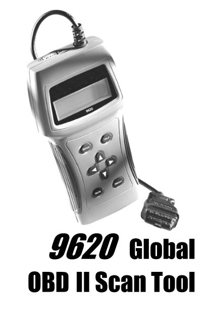
<strong>9620</strong> <strong>Global</strong><br />
<strong>OBD</strong> <strong>II</strong> <strong>Scan</strong> <strong>Tool</strong>
Table of Contents<br />
Vehicle Service Information ......3<br />
Safety Precautions .....................4<br />
Section 1: Vehicle Computer<br />
Systems ------------- 5<br />
1.1 Introduction .....................................5<br />
1.1.1 What The Computer Controls .5<br />
1.1.2 What Has Not Changed ..........5<br />
1.1.3 Computer Control System ......5<br />
1.2 Data Link Connector and Location . 6<br />
1.3 <strong>OBD</strong> <strong>II</strong> <strong>Scan</strong> <strong>Tool</strong> Hookup ................6<br />
1.3.1 Keyboard .................................7<br />
1.3.2 Display .....................................7<br />
1.3.3 Lists, Menus, and Questions ...7<br />
1.4 <strong>Tool</strong> Setup .......................................8<br />
1.4.1 Changing Measurement Units 8<br />
1.4.2 Changing Display Contrast .....8<br />
1.4.3 Displaying <strong>Tool</strong> Information ....9<br />
1.4.4 Program Mode .........................9<br />
1.5 Personal Computer (PC) and<br />
Printer Interface ..............................9<br />
1.6 Replacing the Battery .....................9<br />
1.7 AC Adapter ......................................9<br />
Section 2: Diagnosing with<br />
the <strong>Scan</strong> <strong>Tool</strong> ---- 10<br />
2.1 Preliminary Checks ..................... 10<br />
2.2 Connecting the <strong>Scan</strong> <strong>Tool</strong> ............ 10<br />
2.3 <strong>OBD</strong> <strong>II</strong> Functions List ..................... 11<br />
2.3.1 I/M Readiness ........................ 11<br />
2.3.2 Read Codes .......................... 12<br />
2.3.3 Pending Codes ..................... 12<br />
2.3.4 Erase Codes ......................... 13<br />
2.3.5 View Data .............................. 13<br />
2.3.6 View Freeze Data ................. 15<br />
2.3.7 O2 Monitor Test ..................... 15<br />
2.3.8Diagnostic Monitor Tests ...... 16<br />
2.3.9 On-Board Systems ............... 17<br />
2.3.10 Record Data .......................... 17<br />
2.3.11 Vehicle Info ........................... 18<br />
2.3.12 Modules Present ................... 19<br />
2.3.13 Review Data .......................... 19<br />
2.3.14 Print Data .............................. 20<br />
Section 3: Diagnostic Trouble<br />
Codes (DTC) ---- 22<br />
3.1 DTC Format .................................. 22<br />
3.2 Code Lookup ................................ 23<br />
3.3 Diagnostic Trouble Code Ranges 24<br />
Section 4: Help and Troubleshooting<br />
Tips ---- 25<br />
4.1 How to Use Help ........................... 25<br />
4.2 <strong>Scan</strong> <strong>Tool</strong> Problems ..................... 25<br />
4.2.1 <strong>Scan</strong> <strong>Tool</strong> does not power up:25<br />
4.2.2 <strong>Scan</strong> <strong>Tool</strong> does not “Link”<br />
with vehicle:........................... 25<br />
4.2.3 One or more modules drops<br />
the communication link: ...... 26<br />
4.2.4 Keyboard does not function<br />
properly: ................................ 26<br />
4.3 <strong>Tool</strong> Self-Tests .............................. 26<br />
4.3.1 Display Test ........................... 26<br />
4.3.2 Keyboard Test ....................... 26<br />
4.3.3 Memory Test .......................... 27<br />
4.3.4 Printer Test ............................ 27<br />
4.4 Technical Support ........................ 27<br />
Appendix A: <strong>Global</strong> <strong>OBD</strong> <strong>II</strong> PID<br />
List & Definitions 28<br />
Appendix B: -------- Glossary &<br />
Definitions -------- 31<br />
All information, illustrations and specifications contained in this manual are based on the<br />
latest information available from industry sources at the time of publication. No warranty<br />
(expressed or implied) can be made for its accuracy or completeness, nor is any<br />
responsibility assumed by SPX or anyone connected with it for loss or damages<br />
suffered through reliance on any information contained in this manual or misuse of<br />
accompanying product. SPX reserves the right to make changes at any time to this<br />
manual or accompanying product without obligation to notify any person or organization<br />
of such changes.<br />
2 <strong>9620</strong> Professional <strong>OBD</strong> <strong>II</strong> <strong>Scan</strong> <strong>Tool</strong>
Vehicle Service Information<br />
The following is a list of publishers who have manuals containing electronic engine<br />
control diagnostic information. Some manuals may be available at auto part stores<br />
or local public libraries. For others, write for availability and pricing, specifying the<br />
make, model and year of vehicle.<br />
Service Manuals:<br />
Chilton Book Company<br />
Chilton Way<br />
Radnor, PA 19089<br />
Haynes Publications<br />
861 Lawrence Drive<br />
Newbury Park, CA 91320<br />
Cordura Publications<br />
Mitchell Manuals, Inc.<br />
Post Office Box 26260<br />
San Diego, CA 92126<br />
Motor’s Auto Repair Manual<br />
Hearst Company<br />
250 W 55th Street<br />
New York, NY 10019<br />
Suitable manuals have titles, such as:<br />
• “Electronic Engine Controls”<br />
• “Fuel Injection and Feedback Carburetors”<br />
• “Fuel Injection and Electronic Engine Controls”<br />
• “Emissions Control Manual”<br />
. . . or similar titles<br />
Manufacturer Service Manuals:<br />
General Motors:<br />
Buick, Cadillac, Chevrolet, GEO,<br />
GMC, Oldsmobile, & Pontiac<br />
Helm Incorporated<br />
Post Office Box 07130<br />
Detroit, MI 48207<br />
Saturn<br />
Adistra Corporation<br />
c/o Saturn Publications<br />
101 Union St.<br />
Post Office Box 1000<br />
Plymouth, MI 48170<br />
Ford Motor Company:<br />
Ford, Lincoln, & Mercury<br />
Ford Publication Department<br />
Helm Incorporated<br />
Post Office Box 07150<br />
Detroit, MI 48207<br />
Chrysler Corporation:<br />
Chrysler, Plymouth, & Dodge<br />
Chrysler Motors Service Training<br />
26001 Lawrence Avenue<br />
Center Line, MI 48015<br />
<strong>9620</strong> Professional <strong>OBD</strong> <strong>II</strong> <strong>Scan</strong> <strong>Tool</strong> 3
Safety Precautions<br />
General Safety Guidelines to Follow When Working on Vehicles<br />
To prevent accidents that could result in serious injury and/or damage<br />
to vehicle or test equipment, carefully follow these safety rules and<br />
test procedures at all times when working on vehicles:<br />
• Always wear approved eye protection.<br />
• Always operate the vehicle in a well-ventilated area. Do not inhale exhaust<br />
gases — they are very poisonous!<br />
• Always keep yourself, tools and test equipment away from all moving or hot<br />
engine parts.<br />
• Always make sure the vehicle is in Park (Automatic transmission) or neutral<br />
(manual transmission) and that the parking brake is firmly set. Block the<br />
drive wheels.<br />
• Never lay tools on vehicle battery. You may short the terminals together<br />
causing harm to yourself, the tools or the battery.<br />
• Never use scan tool if its internal circuitry has been exposed to any liquids.<br />
• Never smoke or have open flames near vehicle. Vapors from gasoline and/or<br />
charging battery are highly flammable and explosive.<br />
• Never leave vehicle unattended while running tests.<br />
• Always keep a fire extinguisher suitable for gasoline/electrical/chemical fires<br />
handy.<br />
• Always use extreme caution when working around the ignition coil, distributor<br />
cap, ignition wires, and spark plugs. These components contain high voltage<br />
when the engine is running.<br />
• When performing a road test, never operate the scan tool alone while driving<br />
the vehicle. Always have one person drive the vehicle while an assistant<br />
operates the tester.<br />
• Always turn ignition key OFF when connecting or disconnecting electrical<br />
components, unless otherwise instructed.<br />
• Always follow vehicle manufacturer’s warnings, cautions and service<br />
procedures.<br />
WARNING!:<br />
Some vehicles are equipped with safety air bags. You must follow<br />
vehicle service manual cautions when working around the air bag<br />
components or wiring. If the cautions are not followed, the air bag may<br />
open up unexpectedly, resulting in personal injury. Note that the air<br />
bag can still open up several minutes after the ignition key is off (or<br />
even if the vehicle battery is disconnected) because of a special<br />
energy reserve module.<br />
4 <strong>9620</strong> Professional <strong>OBD</strong> <strong>II</strong> <strong>Scan</strong> <strong>Tool</strong>
Section 1: Vehicle Computer Systems<br />
1.1 Introduction<br />
This section describes the engine computer control system, types of sensors and how<br />
the computer controls engine fuel delivery, idle speed and timing. Additional information<br />
may be found in the technical support books at your local library or auto parts store. The<br />
more known about the computer system, the easier the problem can be diagnosed.<br />
Computer controls were originally installed on vehicles to meet federal government<br />
regulations for lower emission levels and improved fuel economy. This began in the early<br />
1980’s when basic mechanical systems were no longer able to accurately control key<br />
engine parameters. A computer could be programmed to control the engine under various<br />
operating conditions, making the engine more reliable. While these early systems were<br />
very limited in scope of their diagnostics, providing only 10-14 trouble codes, they did help<br />
guide the vehicle repair process.<br />
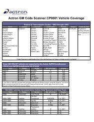
In 1994, manufacturers began equipping vehicles with a new class of computer technology<br />
which puts more processing power under dash than ever before. It is called On-Board<br />
Diagnostics version <strong>II</strong>, or <strong>OBD</strong> <strong>II</strong>. It is required on all vehicles sold in the US beginning<br />
January 1, 1996 (though most domestic manufacturers introduced it earlier than required),<br />
and offers increased system monitoring and diagnostic information. This new system stores<br />
a library of more than 650 general trouble codes and another approximately 400<br />
manufacturer-specific codes, all of which can be accessed with the scan tool. These codes<br />
cover Body Systems (B-Codes), Chassis Systems (C-Codes), Communications Codes<br />
(U-Codes), and Powertrain Systems (P-Codes). Now, basic terms are standardized and<br />
all generic codes will share a common format and terminology that manufacturers and the<br />
Society of Automotive Engineers (SAE) designed.<br />
The <strong>OBD</strong> <strong>II</strong> Professional <strong>Scan</strong> <strong>Tool</strong> performs <strong>OBD</strong> <strong>II</strong> functions on ALL makes of <strong>OBD</strong> <strong>II</strong><br />
compliant vehicles from 1996 and up.<br />
1.1.1 What The Computer Controls<br />
The main control areas of the vehicle computer are fuel delivery, idle speed, spark advance,<br />
and emissions controls. Some on-board computers may also control the transmission,<br />
brakes, and suspension systems as well.<br />
1.1.2 What Has Not Changed<br />
A computer-controlled engine is very similar to the older, non-computerized engine. It is still<br />
an internal combustion engine with pistons, spark plugs, valves, and camshaft(s). The ignition,<br />
charging, starting, and exhaust systems are very similar as well. Test and repair of these<br />
systems are the same as before. The technical manuals for these components provide<br />
instruction on how to perform the tests. Additionally, compression gauges, vacuum pumps,<br />
engine analyzers, and timing lights will continue to be used.<br />
1.1.3 Computer Control System<br />
The vehicle on-board computer, or Powertrain Control Module (PCM), is the “heart” of the<br />
system. It is sealed in a metal box and connected to the rest of the engine by a wiring<br />
harness. The PCM is commonly located in the passenger compartment, behind the<br />
dashboard (kick panel position), although some manufacturers locate the PCM in the<br />
engine compartment. The PCM is programmed by the factory. The program is a complex<br />
list of lookup tables and instructions telling the computer how to control the engine based<br />
on various driving conditions. It does this using sensors to monitor what is happening and<br />
then provide feedback through a network of switches and actuators throughout the vehicle.<br />
<strong>9620</strong> Professional <strong>OBD</strong> <strong>II</strong> <strong>Scan</strong> <strong>Tool</strong> 5
1.2 Data Link Connector and Location<br />
The scan tool communicates with the vehicle PCM via a<br />
data link connector (DLC) – also referred to as a J1962<br />
connector. The term J1962 is taken from physical and<br />
electrical specification number assigned by SAE (Society of<br />
Automotive Engineers). A standardized DLC means all compliant<br />
vehicles will use the same DLC with the generic link information available on the same<br />
pins regardless of vehicle make or model. In addition to the connector definitions, is a<br />
guideline on where the connector is to be located in the vehicle. This guideline states<br />
that the DLC should be located under the dashboard on the driver side of the vehicle.<br />
However, not all <strong>OBD</strong> <strong>II</strong> DLCs are located under the dash on the driver side. If required,<br />
refer to vehicle service documentation for the DLC location.<br />
DLC Location<br />
1.3 <strong>OBD</strong> <strong>II</strong> <strong>Scan</strong> <strong>Tool</strong> Hookup<br />
The <strong>OBD</strong> <strong>II</strong> cable attached to the scan tool fits the <strong>OBD</strong> <strong>II</strong> DLC. Because the <strong>OBD</strong> <strong>II</strong> J1962<br />
connector contains dedicated pins for power and ground, only a single cable connection is<br />
required for both scan tool power and PCM communication.<br />
Connect the scan tool to the DLC. This connection will provide power for the scan tool.<br />
The DLC maintains power even when the ignition is turned off. Therefore, connection to<br />
the battery is not required.<br />
When the scan tool powers up, a series of screens are displayed. The screens start with<br />
a “Welcome” screen and end with a “Key Button Help” screen.<br />
Welcome To<br />
The <strong>Global</strong> <strong>OBD</strong><strong>II</strong><br />
SCANTOOL<br />
Press HELP For Key |<br />
Button Information<br />
Press ENTER To Cont<br />
The screens between the “Welcome” screen and the “Key Button Help” screen are for<br />
tool self-tests and software ID. Refer to this software ID when contacting the <strong>Actron</strong><br />
technical support line with a problem. To review the key button definitions, push the<br />
(HELP) key; otherwise, press ENTER to continue.<br />
The scan tool requires a minimum of 8 volts to power up. If a problem occurs with powerup,<br />
review Section 4: Help and Troubleshooting Tips.<br />
6 <strong>9620</strong> Professional <strong>OBD</strong> <strong>II</strong> <strong>Scan</strong> <strong>Tool</strong>
1.3.1 Keyboard<br />
The scan tool software was designed for ease of use in navigating through operational<br />
menus. Simply follow instructions that match keyboard symbols.<br />
Keyboard Functions<br />
The scan tool uses 8 keys to navigate through the software-user interface:<br />
• ENTER – Used to select or answer a software request.<br />
• HELP – Used to request help when the (|) symbol is displayed in the lower right<br />
hand corner of the display.<br />
• BACK – Used to move one screen back in scan tool flow.<br />
• ARROWS<br />
– UP/DOWN – Used to move the solid cursor (`) in the direction of the arrow or<br />
scroll the data list in the direction you want to move the list.<br />
– LEFT/RIGHT – Used to select and deselect items in custom lists. This key is<br />
also used to answer questions by selecting yes or no.<br />
• ON/OFF – Used to turn scan tool ON and OFF when not powered by vehicle.<br />
Momentarily press and release button when turning ON to allow boot process.<br />
1.3.2 Display<br />
The scan tool has a 4 line x 20 character backlit<br />
Liquid Crystal Display (LCD) for easy viewing. The<br />
backlighting is disabled when the scan tool is<br />
powered by its internal batteries. This gives the<br />
user a large viewing area to display most Help<br />
and Instructional messages. It puts more<br />
<strong>OBD</strong><strong>II</strong> Function List |<br />
3)Erase Codes ]<br />
4)View Data [<br />
`5)View Freeze Data<br />
information on the display instead of having to refer to printed materials. Again the display will<br />
support a number of helpful characters that will prompt the user through test routines. These<br />
characters are shown below:<br />
| Question Mark in lower right corner means there is help available for this screen or<br />
current selectable item.<br />
` Pointer (cursor) is used to indicate current selectable choice.<br />
[ Down Arrow indicates there is additional information on the next screen.<br />
] Up Arrow indicates there is additional information on previous screen.<br />
« Diamond to the left of item indicates it is selected.<br />
The screen at the right shows how some of these symbols will look on your display.<br />
1.3.3 Lists, Menus, and Questions<br />
The scan tool is designed to be as intuitive as possible. Its functions and controls are easy to<br />
understand and use. All menu and screen lists operate the same way. Use the UP/DOWN<br />
arrow keys to move the cursor to a selection. The ENTER key selects that function or item. The<br />
screen examples below show a few selections available on the <strong>OBD</strong><strong>II</strong> Function List.<br />
For example: to read vehicles DTCs, move cursor to Read Codes and press ENTER.<br />
To make a different choice, use the DOWN arrow key to move the cursor down to View Data<br />
and press ENTER. This will select the View Data function.<br />
Sometimes, a list will be longer than three or four items, and will not fit on a single screen. In<br />
this case, the DOWN arrow symbol ([) is visible in the last column of the display, indicating<br />
that there are more choices on the next screen, as shown below on the left. Use the DOWN<br />
arrow key to move the cursor down the list.<br />
<strong>9620</strong> Professional <strong>OBD</strong> <strong>II</strong> <strong>Scan</strong> <strong>Tool</strong> 7
At the bottom of the list, there is now only an UP arrow symbol (]) visible in the last<br />
column indicating the last function in the list has been reached. To return to previous<br />
screens, press the UP arrow key. The UP/DOWN arrow keys work the same way when<br />
scrolling through text such as the Help screen.<br />
The <strong>Scan</strong> <strong>Tool</strong> may ask a question which requires a response from user. These will<br />
always be YES or NO questions, and are answered with cursor and Arrow keys.<br />
<strong>OBD</strong><strong>II</strong> Function List |<br />
`1) I/M Readiness<br />
2)Read Codes [<br />
3)Pending Codes<br />
In these screens, brackets will automatically appear next to default response. To<br />
accept default choice, simply press ENTER. Use LEFT/RIGHT arrow key to move brackets<br />
to other response and press ENTER.<br />
1.4 <strong>Tool</strong> Setup<br />
Only functions of the Main Menu that pertain to getting started with scan tool are discussed<br />
in the following paragraphs. For all other menu selections available, refer to Section 4:<br />
Help and Troubleshooting Tips.<br />
<strong>Tool</strong> Setup is used to change the scan tool default<br />
unit settings. To change the scan tool settings,<br />
select <strong>Tool</strong> Setup from the MAIN MENU and<br />
press the ENTER key.<br />
NOTE: Settings chosen will remain until 9 volt battery is dead.<br />
1.4.1 Changing Measurement Units<br />
After selecting <strong>Tool</strong> Setup option, tool setup menu appears. To choose English or Metric<br />
measurement units, use UP/DOWN arrows to make selection and press ENTER. The<br />
display will look like the following screen:<br />
Setup <strong>Tool</strong> For<br />
`1) English/Metric<br />
2)Display Contrast [<br />
3)<strong>Tool</strong> Information<br />
<strong>OBD</strong><strong>II</strong> Function List |<br />
4)View Data ]<br />
5)View Freeze Data [<br />
`6)Record Data<br />
View Instructions<br />
For Creating Custom<br />
Data List?<br />
Yes <br />
1.4.2 Changing Display Contrast<br />
From the <strong>Tool</strong> Setup menu, select Display Contrast and press ENTER. Use the UP/<br />
DOWN arrow keys as indicated on the screen:<br />
Setup <strong>Tool</strong> For<br />
1) English/Metric<br />
`2)Display Contrast<br />
3)<strong>Tool</strong> Information<br />
MeasurementUnits<br />
`English(Default)<br />
Metric<br />
]Increase Contrast<br />
[Decrease Contrast<br />
Press ENTER To Save<br />
8 <strong>9620</strong> Professional <strong>OBD</strong> <strong>II</strong> <strong>Scan</strong> <strong>Tool</strong>
1.4.3 Displaying <strong>Tool</strong> Information<br />
From <strong>Tool</strong> Setup menu, select <strong>Tool</strong> Information and press ENTER. Use UP/DOWN<br />
arrow keys to view information. Record information in case the need to contact customer<br />
service arises.<br />
Setup <strong>Tool</strong> For<br />
1) English/Metric<br />
2)Display Contrast<br />
`3)<strong>Tool</strong> Information<br />
1.4.4 Program Mode<br />
Used to update scan tool’s software. Instructions will be provided with updates.<br />
1.5 Personal Computer (PC) and Printer Interface<br />
<strong>Scan</strong> tool is equipped with a standard 9 pin serial interface. Use connection to attach<br />
tool to a PC or compatible printer.<br />
• Personal Computer –<br />
Use serial adapter to connect to a PC when updating to current available software.<br />
Software updates may be purchased from <strong>Actron</strong> by calling the toll free number<br />
provided.<br />
Refer to Section 2.4.13 Print Data for default serial port settings and to make<br />
changes to settings.<br />
• Printer Connection –<br />
Connect a compatible printer cable to the scan tool and Printer using specifications<br />
below:<br />
- If the printer connector is a 25 pin connector or if the gender is not compatible, an<br />
adapter will be required.<br />
- Adapters are available at most local PC stores or electronics outlets.<br />
- A NULL modem adapter is required to be connected in series with scan tool and<br />
printer cable.<br />
1.6 Replacing the Battery<br />
To replace the 9V battery, do the following:<br />
• Remove screw from back of scan tool case.<br />
• Slide battery cover back to disengage hooks.<br />
• Replace 9V battery and place in compartment.<br />
• Slide battery cover up, making sure hooks engage scan tool case.<br />
• Install screw.<br />
1.7 AC Adapter<br />
The AC power adapter powers the tool when you review codes and print off-vehicle and when<br />
you update the software vial a personal computer. The <strong>Scan</strong> tool is equipped to accept any<br />
110 Vac–12 Vdc AC adapter with the following specifications.<br />
• 300 mA minimum unregulated wall power adapter.<br />
• Dimensions - 5.5 mm Outside Diameter, 2.5 mm Inside Diameter.<br />
NEG<br />
<strong>Tool</strong> Information:<br />
`Serial No: 1360447]<br />
SW ID: 86E3H[<br />
HW Ver: 1<br />
POS<br />
<strong>9620</strong> Professional <strong>OBD</strong> <strong>II</strong> <strong>Scan</strong> <strong>Tool</strong> 9
Section 2: Diagnosing with the <strong>Scan</strong> <strong>Tool</strong><br />
2.1 Preliminary Checks<br />
Before using scan tool, perform a complete visual inspection. Many driveability problems<br />
are found by visual inspection, saving time. Check the following items before proceeding<br />
with scan tool testing:<br />
1. Has vehicle been serviced recently? Sometimes<br />
things get connected in the wrong place, or not at all.<br />
2. Don’t take shortcuts. Inspect hoses and wiring which<br />
may be difficult to see because of location beneath air<br />
cleaner housings, alternators and similar<br />
components.<br />
3. Inspect air cleaner and ductwork for defects.<br />
4. Check sensors and actuators for damage.<br />
5. Inspect all vacuum hoses for:<br />
• Correct routing. Refer to vehicle service manual, or<br />
Vehicle Emission Control Information (VECI) decal<br />
located in engine compartment.<br />
P<br />
• Pinches and kinks.<br />
A.<br />
• Splits, cuts or breaks.<br />
6. Inspect wiring for:<br />
M<br />
• Contact with sharp edges (this happens frequently).<br />
• Contact with hot surfaces, such as exhaust manifolds.<br />
• Pinched, burned or chafed insulation.<br />
• Proper routing and connections.<br />
7. Check electrical connectors for:<br />
• Corrosion on pins.<br />
• Bent or damaged pins.<br />
• Contacts not properly seated in housing.<br />
• Bad wire crimps to terminals.<br />
Connector problems are common in engine control<br />
system. Inspect for corrosion, bent, pushed out, or over<br />
expanded pins.<br />
Note: Some connectors use special grease on contacts to prevent corrosion. Do not wipe<br />
off! Obtain grease, from vehicle dealer. It is a special type for this purpose.<br />
2.2 Connecting the <strong>Scan</strong> <strong>Tool</strong><br />
Remove protective cap from data link connector,<br />
if present. Connect scan tool and follow scan<br />
tool prompts. Use scan tool 9V battery to do selftests,<br />
review codes, code lookup or print data<br />
when connection to vehicle is not required.<br />
When scan tool powers up, a series of screens<br />
are displayed. The screen starts with “Welcome”<br />
and ends with a “Key Button Help”.<br />
10 <strong>9620</strong> Professional <strong>OBD</strong> <strong>II</strong> <strong>Scan</strong> <strong>Tool</strong><br />
Diagnostic<br />
Connector<br />
T ER<br />
EGR<br />
VAC<br />
REG<br />
EGR<br />
VAC<br />
REG<br />
FUEL<br />
PRESS<br />
REG<br />
HVAC<br />
CRUISE<br />
BRAKE BOOSTER<br />
TO TRANS<br />
MODE<br />
FRONT<br />
OF CAR<br />
9RAC2LAB
After pressing ENTER from HELP Screen, the<br />
Main Menu displays. Select Vehicle Diagnosis<br />
and press ENTER.<br />
The scan tool asks to erase data from previous<br />
test. Use LEFT/RIGHT arrow keys to select a<br />
response and press ENTER.<br />
A message displays Turn Key Off For 10<br />
Seconds, Then Turn Key On and Then Press<br />
ENTER.<br />
2.3 <strong>OBD</strong> <strong>II</strong> Functions List<br />
Use UP/DOWN arrow keys to move cursor(`). Once selection is made, press ENTER.<br />
Press and release BACK key to return to <strong>OBD</strong> <strong>II</strong> Function List. Pressing BACK key from<br />
the <strong>OBD</strong> <strong>II</strong> Function List returns scan tool to Main<br />
Menu. The first time scan tool communicates with<br />
vehicle, the communication type is automatically<br />
detected, and is used until scan tool is turned<br />
OFF or another vehicle is diagnosed.<br />
Not every vehicle will have every function<br />
listed. If function or part of a function selected is not supported by a vehicle, a<br />
message screen informing of this will be shown.<br />
NOTE: If an Operating Error message is displayed, make sure the <strong>OBD</strong> <strong>II</strong> J1962 cable is<br />
securely attached, and ignition key is ON. Cycle ignition key to OFF for 10 seconds,<br />
then ON. This may be required to reset the PCM. If required, select “Yes” to test again.<br />
If problem still exists, refer to Section 4: Help and Troubleshooting Tips.<br />
2.3.1 I/M Readiness<br />
Purpose of the I/M Readiness test is to display current information on emissions-related<br />
systems. These systems are required by <strong>OBD</strong> <strong>II</strong> regulation to be monitored for emissions<br />
testing. <strong>OBD</strong> <strong>II</strong> I/M Readiness Monitors are strategies designed to test operations of<br />
emission related systems or components. The computer module uses these monitors<br />
to check for correct operations of system and components as well as out of range values.<br />
The computer module may perform a special test on a system or component to complete<br />
the monitor. It may be required to operate vehicle under certain conditions in order to<br />
perform an accurate test. If computer module loses power, or codes are erased, monitors<br />
may be cleared. The scan tool displays the state of vehicle <strong>OBD</strong> <strong>II</strong> Monitors.<br />
To enter I/M Readiness viewing mode, select I/M Readiness from <strong>OBD</strong> <strong>II</strong> Function List<br />
and press ENTER.<br />
A list of On-Board system readiness tests and<br />
their status will be displayed. Use vehicle service<br />
manuals for more information on emissionrelated<br />
monitors and their status.<br />
Below are examples of completed versus not<br />
completed I/M Readiness screens:<br />
MAIN MENU |<br />
`1) Vehicle Diagnosis<br />
2)<strong>Tool</strong> Setup [<br />
3)<strong>Tool</strong> Self Test<br />
Erase Data From<br />
Previous Vehicle<br />
Test?<br />
YES <br />
Turn Key Off<br />
For 10 Seconds<br />
Then Turn Key On<br />
Then Press ENTER<br />
<strong>OBD</strong><strong>II</strong> Function List |<br />
`1) I/M Readiness<br />
2)Read Codes [<br />
3)Pending Codes<br />
<strong>OBD</strong><strong>II</strong> Function List |<br />
`1) I/M Readiness<br />
2)Read Codes [<br />
3)Pending Codes<br />
Use the UP/DOWN arrow keys to view monitor list. The monitor list consists of the <strong>OBD</strong><br />
<strong>II</strong> monitor name followed by monitor state. A monitor that is not supported by test vehicle<br />
<strong>9620</strong> Professional <strong>OBD</strong> <strong>II</strong> <strong>Scan</strong> <strong>Tool</strong> 11
will be followed by “n/a.” A monitor that has been completed is followed by “ok.” If not<br />
On-Board Readiness<br />
Tests Are Complete.<br />
Use [ To View Test<br />
completed, “inc” will be displayed. Use the UP/<br />
DOWN arrow keys to scroll through the list.<br />
NOTE: In addition to displaying the state of the<br />
monitor since the last time DTC’s were<br />
cleared, some vehicles will display the<br />
state of the monitors for this drive cycle.<br />
Use the LEFT/RIGHT arrows to switch<br />
between these screens<br />
Press the ENTER key to return to the <strong>OBD</strong> <strong>II</strong><br />
Function List.<br />
2.3.2 Read Codes<br />
The Read Codes function retrieves Diagnostic Trouble Codes (DTCs) from vehicle’s<br />
computer modules. This function can be performed with the key on and the engine off or<br />
the key on and engine running.<br />
These codes cause the computer to illuminate<br />
the Malfunction Indicator Lamp (MIL) when an<br />
emission-related or driveability fault occurs. The<br />
MIL is also known as the “service engine soon”<br />
or “check engine” lamp.<br />
Select Read Codes and press ENTER. The scan tool retrieves the DTCs stored in the<br />
vehicle’s computer module(s).<br />
System Pass:<br />
No DTCs Found.<br />
Press BACK For<br />
<strong>OBD</strong><strong>II</strong> Function List<br />
The scan tool displays the DTCs or a message<br />
stating SYSTEM PASS: NO CODES FOUND.<br />
Press the DOWN arrow key to view the DTCs or<br />
press the BACK key to return to the <strong>OBD</strong><strong>II</strong><br />
Function List.<br />
NotAll Supported<br />
On-Board Readiness<br />
Tests Are Complete.<br />
Use [ To View Test<br />
SINCE DTCS CLEARED<br />
Misfire Monitor ok |<br />
Fuel System Mon inc<br />
Catalyst Mon n/a<br />
This Driving Cycle<br />
Misfire Monitor n/a<br />
Fuel System Mon ok[<br />
Catalyst Mon inc<br />
<strong>OBD</strong><strong>II</strong> Function List |<br />
1) I/M Readiness<br />
`2)Read Codes [<br />
3)Pending Codes<br />
DTCs Found: 2<br />
Use [ To View DTCs<br />
Write Down Codes<br />
For Reference.<br />
Code P0443<br />
EVAP Emission<br />
Control System [<br />
Purge Valve C Fault<br />
Write down the DTCs for reference, then press BACK to return to the <strong>OBD</strong><strong>II</strong> Function List.<br />
2.3.3 Pending Codes<br />
Pending Codes are also referred as “continuous monitor” and “maturing codes”. An<br />
intermittent fault causes computer to store a code in memory. If fault does not occur<br />
again within 40 warm-up cycles, the code clears<br />
from memory. If the fault occurs a specific number <strong>OBD</strong><strong>II</strong> Function List |<br />
of times, the code matures into a DTC. This 1) I/M Readiness<br />
function can be performed with the key on and 2)Read Codes [<br />
engine running or not.<br />
`3)Pending Codes<br />
12 <strong>9620</strong> Professional <strong>OBD</strong> <strong>II</strong> <strong>Scan</strong> <strong>Tool</strong>
Select Pending Codes and press ENTER key.<br />
The scan tool displays codes or a message stating SYSTEM PASS NO FAULT<br />
DETECTED. Press DOWN arrow key to view DTCs or press BACK key to return to <strong>OBD</strong><strong>II</strong><br />
Function List.<br />
System Pass:<br />
No Faults Detected.<br />
Press BACK Key For<br />
Function List<br />
The codes display in same format as Read<br />
Codes. The DTC number and computer module<br />
that stored it display on first line. Use UP/Down<br />
arrow keys to view codes.<br />
Press BACK to return to <strong>OBD</strong><strong>II</strong> Function List.<br />
2.3.4 Erase Codes<br />
The Erase Codes function deletes DTCs from vehicle’s computer memory. Perform this<br />
function only after systems have been checked completely and DTCs have been<br />
documented. This function should be performed with the key on and the engine off.<br />
After servicing vehicle, delete stored DTCs and verify no codes have been reset. If DTCs<br />
return, the problem has not been corrected or other faults are present.<br />
In addition to clearing DTCs, the Erase Codes function may also erase Freeze Frame,<br />
O2 Sensor Data, System Monitors, and On-Board Monitor test results.<br />
Select Erase Codes and press the ENTER key. A message appears asking if you are<br />
sure. Press LEFT ARROW to move brackets to desired response and press ENTER.<br />
Selecting NO displays a COMMAND CANCELLED message prompting to press ENTER<br />
to return back to <strong>OBD</strong><strong>II</strong> Function List. Selecting YES displays a screen prompting to turn<br />
ignition key to on and engine off and press ENTER key.<br />
<strong>OBD</strong><strong>II</strong> Function List |<br />
`4)Erase Codes ]<br />
5)View Data [<br />
6)View Freeze Data<br />
The scan tool sends erase command. Press<br />
ENTER to continue and return to <strong>OBD</strong><strong>II</strong> Function<br />
List.<br />
2.3.5 View Data<br />
Codes Found: 2<br />
Use [ To View Codes<br />
Write Down Codes<br />
For Reference..<br />
P0389 Mod$1E 1 of 2<br />
CrankshaftPosition<br />
Sensor B [<br />
CKT Intermittent<br />
Erase Diagnostic<br />
Results and Codes?<br />
Are You Sure?<br />
YES <br />
Command Sent<br />
Press ENTER To Cont.<br />
The View Data function allows viewing of vehicle’s Parameter Identification data (PID) in<br />
real time. As the computer monitors the vehicle, the information is simultaneously<br />
transmitted to scan tool. Apart from Read Codes, View Data is most useful diagnostic<br />
function for isolating cause of a vehicle<br />
operation problem. Viewing data is also used<br />
for observing sensor data and status of<br />
switches, solenoids, and relays.<br />
Select View Data from <strong>OBD</strong><strong>II</strong> Function List and<br />
press ENTER. The scan tool displays a menu<br />
with display options.<br />
Use the UP/DOWN arrow keys to select an option and press ENTER.<br />
<strong>OBD</strong><strong>II</strong> Function List |<br />
4)Erase Codes ]<br />
`5)View Data [<br />
6)View Freeze Data<br />
<strong>9620</strong> Professional <strong>OBD</strong> <strong>II</strong> <strong>Scan</strong> <strong>Tool</strong> 13
— Entire Data List<br />
Select Entire Data List to display all PIDs supported by vehicle under test.<br />
— Custom Data List<br />
To display only certain PIDs, select Custom Data<br />
List. The ability to display certain PIDs helps in<br />
diagnosing a specific driveability symptom or<br />
system.<br />
If choosing to view a Custom Data List, the scan<br />
tool asks if help is needed to view the<br />
instructions. Select desired response and press<br />
ENTER.<br />
• Use UP/DOWN arrow keys to move<br />
cursor up and down through list.<br />
• Use RIGHT arrow key to select or deselect<br />
PIDs. Selected PIDs are marked with «<br />
symbol.<br />
• Use LEFT arrow key to deselect all<br />
marked PIDs.<br />
View Instructions<br />
For Creating Custom<br />
Data List?<br />
YES <br />
SelectCustom List<br />
«ABSLT TPS(%) ]<br />
`«CALC LOAD(%) [<br />
COOLANT( o F)<br />
• Use the ENTER key to link to the vehicle and retrieve the marked PIDs.<br />
When finished selecting PIDs, press ENTER key to begin viewing them.<br />
NOTE: Refer to Appendix A for a complete list of PIDs.<br />
— View Data Setup<br />
View Data Setup allows display of PIDs on one,<br />
two, three or four lines. Selecting fewer lines of<br />
data provides faster update speeds. The scan<br />
tool default is four-line display.<br />
SelectDisplay Line<br />
2 Lines ]<br />
3 Lines<br />
`4 Lines(Default)<br />
When scan tool links to vehicle, PIDs will display. Navigate through PID list with following<br />
keys:<br />
• Press UP/DOWN arrow keys to scroll Up/<br />
Down line-by-line through list.<br />
• Press LEFT/RIGHT arrow keys to Page<br />
Up/Page Down.<br />
• Press BACK key to return to Select Data<br />
To View menu.<br />
SelectData To View<br />
Entire Data List<br />
`Custom Data List<br />
View Data Setup<br />
ABSLT TPS(%) 0.0<br />
CALC LOAD(%) 5.3<br />
ENGINE(RPM)($10) 180[<br />
ENGINE(RPM)($1A) 865<br />
The same parameter may appear twice if vehicle is equipped with more than one computer<br />
module — Powertrain Control Module (PCM), Transmission Control Module (TCM), etc. The<br />
scan tool identifies them by identification names (ID) assigned by manufacturer (i.e. $10,<br />
$1A, etc). The computer module ID blinks in parentheses. If one or more modules stops<br />
responding, the scan tool displays a message that the module is not responding and asks to<br />
continue without it. If NO is selected, scan tool attempts to reestablish communication with<br />
that module.<br />
14 <strong>9620</strong> Professional <strong>OBD</strong> <strong>II</strong> <strong>Scan</strong> <strong>Tool</strong>
2.3.6 View Freeze Data<br />
When an emission-related fault occurs, certain vehicle conditions are recorded by the<br />
on-board computer. This information is referred to as a Freeze Frame data. The information<br />
is a “snapshot” of operating conditions at time of a fault. This data can be overwritten by<br />
faults with a higher priority.<br />
NOTE: If codes were erased, then freeze frame data may not be stored in vehicle memory.<br />
Select View Freeze Data from the <strong>OBD</strong><strong>II</strong> Function<br />
List and press ENTER.<br />
The scan tool links to the vehicle and displays<br />
Freeze Frame data. Use UP/DOWN arrow keys<br />
to scroll through data.<br />
NOTE: If more than one computer module responds<br />
with freeze frame data, then the frame<br />
number and module display on the first line.<br />
Press the LEFT/Right key to change modules.<br />
When done, press BACK key to return to <strong>OBD</strong><strong>II</strong> Function List.<br />
2.3.7 O2 Monitor Test<br />
<strong>OBD</strong><strong>II</strong> Function List |<br />
4)Erase Codes ]<br />
5)View Data [<br />
` 6)View Freeze Data<br />
FREEZE FRAME DATA<br />
TROUB CODE P0443<br />
CALC LOAD(%) 85.6[<br />
ENGINE(RPM)($10) 1120<br />
FRAME 1 Mod $1A<br />
TROUB CODE P0443<br />
CALC LOAD(%) 85.6[<br />
ENGINE(RPM)($10) 1120<br />
NOTE: The O2 Monitor Test is NOT AN ON-DEMAND TEST. O2 sensors are NOT tested<br />
when selected via the menu. The O2 sensors are tested when engine operating<br />
conditions are within specified limits.<br />
NOTE: If vehicle communicates using a Controller Area Network (CAN), O2 Monitor Tests<br />
are NOT supported by vehicle. A message is displayed. See Diagnostic Monitor<br />
Test to see O2 Monitor Data.<br />
<strong>OBD</strong> <strong>II</strong> regulations require that applicable vehicles monitor and test the oxygen (O2)<br />
sensors to determine problems related to fuel and emissions. The O2 Monitor Test<br />
allows retrieval of completed O2 sensors monitor test results.<br />
O2 sensors are located before (upstream) and after (downstream) catalyst(s). The<br />
sensors are named (xy) for their position relative to both cylinder banks and catalysts.<br />
• The O2 sensor for cylinder bank 1 has the prefix 1y while the O2 sensor for<br />
cylinder bank 2 has the prefix 2y.<br />
• The O2 sensor upstream of the catalyst (closest to the engine) has the suffix x1<br />
while the O2 sensor downstream of the catalyst has suffix x2. If vehicle contains<br />
more catalysts, the O2 sensor downstream of the second catalyst has the suffix<br />
x3 and the O2 sensor downstream of the next catalyst has the suffix x4.<br />
• For example, O2S 21 is the upstream O2 sensor for cylinder bank 2.<br />
<strong>9620</strong> Professional <strong>OBD</strong> <strong>II</strong> <strong>Scan</strong> <strong>Tool</strong> 15
The following O2 sensor tests are available:<br />
• Rich to Lean sensor threshold voltage<br />
• Lean to Rich sensor threshold voltage<br />
• Low sensor voltage for switch time<br />
• High sensor voltage for switch time<br />
• Rich to Lean sensor switch time<br />
• Lean to Rich sensor switch time<br />
• Minimum sensor voltage test cycle<br />
• Maximum sensor voltage test cycle<br />
• Time between sensor transitions<br />
Select O2 Monitor Test from <strong>OBD</strong><strong>II</strong> Function List and press ENTER.<br />
<strong>OBD</strong><strong>II</strong> Function List |<br />
`7)O2 Monitor Test ]<br />
8)Non-Contin Test [<br />
9)On-Board Systems<br />
Select desired test from menu and press ENTER. Grouping O2 sensor tests together<br />
makes data easier to compare.<br />
The O2 sensors located upstream (before catalyst)<br />
may perform differently than the ones<br />
located downstream (after the catalyst).<br />
Oxygen sensor tests not supported by the vehicle display three dashes as the value.<br />
Press the BACK key to return to the O2 Sensor Tests menu or press ENTER to return to<br />
the <strong>OBD</strong><strong>II</strong> Function List.<br />
2.3.8 Diagnostic Monitor Tests<br />
The Diagnostic Monitor Test function is different for Non-CAN and CAN vehicles.<br />
Non-CAN vehicles Diagnostic Monitor Tests receives test results for emission-related<br />
powertrain components and systems not continuously monitored.<br />
CAN vehicles Diagnostic Monitor Tests receives test results for emission-related<br />
powertrain components and systems that are or are not continuously monitored.<br />
The Diagnostic Monitor Test function is useful after servicing or after erasing the vehicle’s<br />
memory. Test results do not necessarily indicate a faulty component or system.<br />
Vehicle manufacturer is responsible for assigning test and component IDs<br />
Select Diagnostic Monitor Test from the <strong>OBD</strong><strong>II</strong><br />
Function List and press ENTER. A list of tests<br />
applicable to the vehicle are displayed. Select a<br />
test and press ENTER.<br />
Non-ContTests Avail<br />
`$0 1<br />
$03 [<br />
$05<br />
O2 Sensor Tests<br />
`1) RICH-LN Thresh<br />
2)LN-RICH Thresh [<br />
3)Lo V For Switch<br />
Low Volts for Switch<br />
O2S 1-1(V) 1.15<br />
O2S 1-2(V) ---[<br />
O2S 2-1(V) 1.28<br />
<strong>OBD</strong><strong>II</strong> Function List |<br />
7)O2 Monitor Test ]<br />
`8)Diag Mon Test[<br />
9)On-Board Systems<br />
Diag Mon Data Avail<br />
` O2 Sensor B1S1<br />
Catalyst B1 [<br />
EVAP (0.090)<br />
NON-CAN VEHICLE CAN VEHICLE<br />
16 <strong>9620</strong> Professional <strong>OBD</strong> <strong>II</strong> <strong>Scan</strong> <strong>Tool</strong>
Applicable tests are displayed . Select a test and press ENTER.<br />
Requested test results are displayed on <strong>Scan</strong> <strong>Tool</strong><br />
Diag Mon Data Avail<br />
$01<br />
$05 [<br />
$10 ~<br />
On Non-CAN vehicles <strong>Scan</strong> <strong>Tool</strong> displays:<br />
On the 1st line is where the test data (test ID) came from.<br />
On the 2nd line is the test heading.<br />
On the 3rd and 4th line is the test measurement (MEAS), specification value (SPEC) and<br />
status (STS). Measurements and Specification values are hexadecimal numbers (i.e.,<br />
$1A, $FE, $11.)<br />
On CAN vehicles <strong>Scan</strong> <strong>Tool</strong> displays:<br />
On the 1st line is where the monitor test data came from. ($00) represents the<br />
source module id from where the data originated.<br />
On the 2nd line is the test performed. The test performed can be $## if test is not<br />
defined. Refer to vehicle service manual for details.<br />
On the 3rd line are the measured value and units in (Volts, Amps, Seconds, etc.) and<br />
status of monitor test data.<br />
On the 4th line, the minimum and maximum limits are shown for the monitor test data.<br />
If additional tests are present, use the up and down arrow to view test results.<br />
Refer to appropriate vehicle service manual for test IDs and definitions.<br />
Press BACK key to return to the Diag Mon Test menu or press ENTER key to return<br />
to <strong>OBD</strong><strong>II</strong> Function List.<br />
2.3.9 On-Board Systems<br />
This test allows scan tool to control operation of vehicle components, tests or systems.<br />
Some manufacturers do not allow tools to control vehicle systems. A vehicle not supporting<br />
an on-board system is identified by a message displayed when selected.<br />
NOTE: Refer to vehicle service manual for on-board systems instructions.<br />
Select On-Board Systems from <strong>OBD</strong><strong>II</strong> Function<br />
List and press ENTER. A list of on-board systems<br />
and components available for testing display on<br />
screen.<br />
Select a test and press ENTER to activate test.<br />
The manufacturer is responsible for determining criteria to automatically stop test. Refer<br />
to appropriate vehicle service manual.<br />
2.3.10 Record Data<br />
Record Data function records PIDs while vehicle is parked or being driven. This function<br />
is mainly used for diagnosing intermittent driveability problems that cannot be isolated<br />
by any other method. The scan tool can maintain only one recording at a time. Be sure to<br />
thoroughly review old recording before erasing.<br />
Select Record Data from <strong>OBD</strong><strong>II</strong> Function List<br />
and press ENTER. Follow all instructions on<br />
display.<br />
Diag Mon Data Avail<br />
O2 Sensor B1S1<br />
Catalyst B1 [<br />
EVAP (0.090) ~<br />
NON-CAN VEHICLES CAN VEHICLES<br />
<strong>OBD</strong><strong>II</strong> Function List |<br />
7)O2 Monitor Test ]<br />
8)Non-Contin Test [<br />
`9)On-Board Systems<br />
<strong>OBD</strong><strong>II</strong> Function List |<br />
`10)Record Data ]<br />
11) Vehicle Info [<br />
12)Modules Present<br />
<strong>9620</strong> Professional <strong>OBD</strong> <strong>II</strong> <strong>Scan</strong> <strong>Tool</strong> 17
If a recording currently exists in memory, a<br />
message prompting to erase data is displayed.<br />
Note: Make sure to review old recorded data<br />
before erasing<br />
<strong>Scan</strong> tool retrieves a list of supported PIDs. After list is generated, scan tool prompts to<br />
select type of data to view. Refer to View Data described earlier in this section to setup<br />
Entire or Custom Data Lists.<br />
On next screen, select a method to trigger a<br />
recording. Manual Trigger allows technician to<br />
use ENTER key. Trigger On Codes automatically<br />
triggers when a DTC is indicated by vehicle.<br />
Once trigger method is selected, scan tool will begin recording data when trigger event<br />
occurs — either a DTC occurs or ENTER key is pressed. The time is recorded and data<br />
from the last five frames is saved. Data will continue to be saved until either the record<br />
memory is full or the technician presses ENTER.<br />
Press ENTER and the scan tool establishes a communication link with the vehicle.<br />
If Manual Trigger is selected, scan tool initializes by recording first five frames. When<br />
done, press ENTER. If Trigger On Codes was selected, then scan tool triggers when a<br />
DTC is stored in vehicle. Press BACK key twice to return to <strong>OBD</strong><strong>II</strong> Function List.<br />
WARNING!<br />
TWO PEOPLE SHOULD BE IN VEHICLE WHEN DRIVING ON ROAD,<br />
ONE TO DRIVE AND THE OTHER TO ATTEND TO THE EQUIPMENT.<br />
<strong>Scan</strong> tool recording times vary. A recording consists of 5 frames of data prior to trigger<br />
and several frames after trigger. Amount of PIDs recorded determine number of frames.<br />
After a recording, scan tool displays a prompt to<br />
playback recording. Answer YES to display<br />
recorded data or NO to return to <strong>OBD</strong><strong>II</strong> Function<br />
Playback Data?<br />
List.<br />
2.3.11 Vehicle Info<br />
No<br />
Vehicle Info function enables scan tool to request vehicle’s VIN number and calibration<br />
ID(s) which uniquely identifies software version in vehicle control module(s).<br />
This function applies to Model Year 2000 and later <strong>OBD</strong> <strong>II</strong> compliant vehicles. The scan<br />
tool cannot verify if data returned is correct for scanned vehicle. This information is<br />
provided by vehicle manufacturer. The Vehicle Info test must be completed with the key in<br />
the ON position and the Engine OFF.<br />
Calibration Verification Numbers (CVNs) are calculated values required by <strong>OBD</strong> <strong>II</strong><br />
regulations with the vehicle engine off. CVNs are reported to determine if emissionrelated<br />
calibrations have been altered. Multiple CVNs may be reported for a control<br />
module. The calculation may take several minutes first time the CVNs are requested.<br />
Select Vehicle Info from <strong>OBD</strong> <strong>II</strong> Function List and<br />
press ENTER.<br />
If the message INVALID displays on screen, then<br />
data returned is incorrect, or not formatted in<br />
accordance with <strong>OBD</strong> <strong>II</strong> specification.<br />
CannotRecord. Old<br />
Recording Filled Up<br />
Memory. Erase Old?<br />
NO<br />
Pick Trigger Method<br />
`1) Manual Trigger<br />
2)Trigger On Codes<br />
<strong>OBD</strong><strong>II</strong> Function List |<br />
10)Record Data ]<br />
`11)Vehicle Info [<br />
12)Modules Present<br />
18 <strong>9620</strong> Professional <strong>OBD</strong> <strong>II</strong> <strong>Scan</strong> <strong>Tool</strong>
<strong>Scan</strong> tool displays VIN, Calibration ID, and CVNs<br />
if supported by vehicle. In example screens, MOD<br />
$10 returned data. Use UP/DOWN arrow keys to<br />
scroll . CVNs are shown as a hexadecimal<br />
number.<br />
Press BACK or ENTER to return to <strong>OBD</strong><strong>II</strong> Function List.<br />
2.3.12 Modules Present<br />
<strong>OBD</strong> <strong>II</strong> information may be provided by a single<br />
module or many separate modules. The scan<br />
tool identifies module IDs and communication<br />
type for <strong>OBD</strong> <strong>II</strong> modules in vehicle.<br />
Select Modules Present from <strong>OBD</strong><strong>II</strong> Function<br />
List and press ENTER.<br />
When selecting this function, scan tool checks for an established communication link. If<br />
No Link Established<br />
Controller List<br />
NotAvailable<br />
no link is made, a message displays stating so. If link was successful, module(s) and<br />
communication type(s) display on screen.<br />
2.3.13 Review Data<br />
Review Data function allows review of information stored in scan tool’s memory. The<br />
scan tool does not require power from vehicle to perform this function. Internal battery<br />
power can be used.<br />
<strong>OBD</strong><strong>II</strong> Function List |<br />
`13)Review Data ]<br />
14)PrintData<br />
15)Code Lookup<br />
<strong>OBD</strong><strong>II</strong> Function List |<br />
10)Record Data ]<br />
11) Vehicle Info [<br />
`12)Modules Present<br />
Review Data<br />
5)O2 Monitor ]<br />
6)Non-Continuous [<br />
`7)Playback<br />
Select Review Data from <strong>OBD</strong><strong>II</strong> Function List and press ENTER. Only one function,<br />
Playback, needs detailed instructions.<br />
— Playback<br />
Playback function is used to play back a recording. This function is very similar to View<br />
Data. The only difference is View Data is real time viewing of PIDs, while Playback is a<br />
viewing of previously recorded PIDs.<br />
To play back recorded PIDs, select Playback and press ENTER key.<br />
No Recording Is<br />
Present. Please<br />
Make Recording<br />
First.<br />
VIN # 1 MOD $10<br />
1F1FS11P0S2100001<br />
ID Protocols<br />
$10 ISO*<br />
$18 ISO* [<br />
$1A ISO*<br />
MIL STATUS ON<br />
CALC LOAD(%) 5.3<br />
ENGINE(RPM)($10) 180[<br />
FRAME: 1 TM: 4.4<br />
<strong>9620</strong> Professional <strong>OBD</strong> <strong>II</strong> <strong>Scan</strong> <strong>Tool</strong> 19<br />
[
The scan tool informs if a recording does not exist. Otherwise, scan tool plays back<br />
Entire Data List or Custom Data List, depending on how data was recorded.<br />
The screen is composed of three lines of data and one line for the frame number and<br />
timestamp (in seconds). Negative frames and timestamps indicate data recorded before<br />
the trigger event. Positive frames and timestamps indicate data recorded after the trigger<br />
event.<br />
• Use UP/DOWN arrow keys to scroll through the recorded PID data of each frame.<br />
The end of the list is reached when only the (up) icon is visible.<br />
• Use the LEFT/RIGHT arrow keys to scroll back and forth through the frames. The<br />
LEFT key advances to the next frame, “wrapping around” to earliest frame when<br />
the final frame is reached. The RIGHT arrow key goes back to the previous frame,<br />
again “wrapping around” to the final frame.<br />
Different vehicles communicate at different speeds and support a different number of<br />
PIDs. Therefore, the maximum number of frames that can be recorded will vary.<br />
Some vehicles wait a long period of time to store a trouble code after the driveability<br />
problem occurs. If you selected “Trigger On Codes” when you made your recording, you<br />
might not see any drastic change in data parameters before and after the trigger point. In<br />
cases like this, the user can manually trigger the recording when the symptom is observed.<br />
When done, press BACK to return to Review Data or to the <strong>OBD</strong><strong>II</strong> Function List.<br />
2.3.14 Print Data<br />
This function allows you to print the diagnostic information stored in the scan tool. The<br />
scan tool’s internal battery power can be used to print data.<br />
<strong>OBD</strong><strong>II</strong> Function List |<br />
13)Review Data ]<br />
`14)PrintData<br />
15)Code Lookup<br />
Select Print Data and press the ENTER key. The scan tool informs you of the printer<br />
settings (Custom or Default), then asks if you wish to change them. If settings are not<br />
changed, then skip the next section and continue with on the next page.<br />
Changing the Printer Settings<br />
NOTE: The default values are designated on the display with the word (Default) next to<br />
the option. Refer to the printer manual for the settings.<br />
After selecting YES and pressing ENTER, the<br />
first item to change is the Baud Rate. Use the<br />
UP/DOWN arrow keys to select an option and<br />
press the ENTER key.<br />
Press ENTER when the Select Data Bits screen<br />
displays. There is nothing to select.<br />
In the Select Stop Bits screen, select 1 BIT or<br />
2 BITS and press ENTER.<br />
<strong>Tool</strong> SetTo Default |<br />
Printer Settings.<br />
Change Settings?<br />
YES <br />
SelectBaud Rate<br />
`9600(Default)<br />
1200 [<br />
2400<br />
SelectData Bits<br />
`8 (Default)<br />
SelectStop Bits<br />
1 Bit(Default)<br />
`2 Bits<br />
20 <strong>9620</strong> Professional <strong>OBD</strong> <strong>II</strong> <strong>Scan</strong> <strong>Tool</strong>
Next, select the parity and press ENTER.<br />
Finally, select the printer speed, FAST or SLOW,<br />
and press ENTER.<br />
Now that the printer settings are changed, it is<br />
time to verify the settings. Press the ENTER key<br />
to print the ASC<strong>II</strong> character set.<br />
Follow the instructions displayed on the screens.<br />
If the printout is OK, press ENTER. Refer to the<br />
settings in the printer manual if the printout is<br />
not OK.<br />
Printing Data (except Playback)<br />
Next, select the data to be printed and press<br />
ENTER. The scan tool displays the menu of<br />
those functions that store data and can be<br />
printed.<br />
Make sure the printer is turned on, on-line and<br />
connected.<br />
When the selected data does not exist in the scan tool’s memory, a message informs<br />
you to run the function. If the selected data is stored in the scan tool, the data automatically<br />
transmits to the printer.<br />
Press ENTER to return to the Select Print Data screen. Either select another item to print<br />
or press BACK to return to the <strong>OBD</strong><strong>II</strong> Function List.<br />
Printing Playback Data<br />
When printing playback data, the Start Frame and<br />
End Frame need to be defined.<br />
After selecting Playback and pressing ENTER,<br />
the Start Frame screen shows the earliest possible<br />
frame. Use the ([) or (]) to change the frame<br />
number and then press ENTER.<br />
SelectParity<br />
`None (Default)<br />
Odd<br />
Even<br />
Printer<br />
`Fast(Default)<br />
Slow<br />
The ASC<strong>II</strong> Character<br />
SetWill Be Printed<br />
Once<br />
Press ENTER To Cont.<br />
Make Sure Printer<br />
Is Turned On, Online<br />
& Connected To <strong>Tool</strong>.<br />
Press ENTER To Cont.<br />
Is Printout OK?<br />
NO<br />
SelectPrintData<br />
1)I/M Readiness<br />
`2)DTC (Codes) [<br />
3)Pending Codes<br />
SelectPrintData<br />
5)O2 Monitor ]<br />
6)Non-Continuous [<br />
`7)Playback<br />
Next, the End Frame screen displays the latest possible frame. Use the Scroll Wheel to<br />
change the frame number and then press ENTER.<br />
The scan tool starts transmitting to the printer, frame-by-frame. After all the frames have<br />
been sent, press ENTER to return to the Select Print Data screen. Press the BACK key to<br />
return to the <strong>OBD</strong><strong>II</strong> Function List.<br />
<strong>9620</strong> Professional <strong>OBD</strong> <strong>II</strong> <strong>Scan</strong> <strong>Tool</strong> 21
Section 3: Diagnostic Trouble Codes (DTC)<br />
3.1 DTC Format<br />
Diagnostic Trouble Codes (DTCs) consist of a five-digit alphanumeric code. The DTC<br />
format and types are shown below. When the on-board computer recognizes and identifies<br />
a problem, a DTC for that fault is stored in memory. These codes are intended to help you<br />
determine the root cause of a problem.<br />
Bx - Body<br />
Cx - Chassis<br />
Px - Powertrain<br />
Ux - Network Comm.<br />
x = 0, 1, 2 or 3<br />
Example:<br />
P0101 - Mass or Volume Air Flow<br />
Circuit Range/Performance Problem<br />
Powertrain Codes<br />
P0xxx - Generic (SAE)<br />
P1xxx - Manufacturer Specific<br />
P2xxx - Generic (SAE)<br />
P30xx-P33xx - Manufacturer Specific<br />
P34xx-P39xx - Generic (SAE)<br />
Chassis Codes<br />
C0xxx - Generic (SAE)<br />
C1xxx - Manufacturer Specific<br />
C2xxx - Manufacturer Specific<br />
C3xxx - Generic (SAE)<br />
P 0 1 0 1<br />
Vehicle Specific System<br />
Specific Fault Designation<br />
Body Codes<br />
B0xxx - Generic (SAE)<br />
B1xxx - Manufacturer Specific<br />
B2xxx - Manufacturer Specific<br />
B3xxx - Generic (SAE)<br />
Network Communication Codes<br />
U0xxx - Generic (SAE)<br />
U1xxx - Manufacturer Specific<br />
U2xxx - Manufacturer Specific<br />
U3xxx - Generic (SAE)<br />
J2012 and ISO 15031-6 are standards for all DTCs, established by SAE, International<br />
Organization for Standardization (ISO) and other governing bodies. Codes and definitions<br />
assigned by this specification are known as Generic <strong>OBD</strong> <strong>II</strong> codes. <strong>OBD</strong> <strong>II</strong> requires<br />
compliance with standards, and has made it standard for all cars, light trucks, APVs,<br />
MPVs, and SUVs sold in U.S. Codes not reserved by SAE are reserved for manufacturer<br />
and referred to as Manufacturer Specific.<br />
Periodically, new DTCs are defined and approved by SAE, ISO and other governing<br />
bodies. The scan tool software will be periodically updated to reflect these changes. For<br />
more information regarding DTC updates, please call our Technical Support line at<br />
1-800-228-7667 (8:00 – 6:00 EST Monday – Friday).<br />
22 <strong>9620</strong> Professional <strong>OBD</strong> <strong>II</strong> <strong>Scan</strong> <strong>Tool</strong>
3.2 Code Lookup<br />
Code Lookup is used to look up definitions of Diagnostic Trouble Codes (DTCs) stored<br />
in the scan tool. The scan tool does not require power from the vehicle to perform this<br />
function. Internal battery power can be used.<br />
To look up DTC definitions, select Code Lookup<br />
from the <strong>OBD</strong><strong>II</strong> Function List and press ENTER.<br />
<strong>OBD</strong><strong>II</strong> Function List |<br />
13)Review Data ]<br />
14)PrintData<br />
`15)Code Lookup<br />
NOTE: When entering codes, only one character can be changed at a time.<br />
To enter a code:<br />
• Use the LEFT/RIGHT arrow keys to move<br />
the ^ symbol under the character that<br />
needs to be changed. The cursor moves<br />
to the right and wraps around to the<br />
beginning when the end is reached.<br />
• Use the UP/DOWN arrow keys to change<br />
the selected character.<br />
• Press the ENTER key to display the<br />
definition.<br />
After entering the code and pressing ENTER,<br />
the code and definition display.<br />
If the DTC is manufacturer specific or does not<br />
exist for the vehicle, some information can be<br />
determined based on the range of the DTC (see<br />
page 24)<br />
Enter Code: P0100 |<br />
Use Arrow Key ^<br />
To Change Or Press<br />
ENTER To Accept<br />
Enter Code: P0A08 |<br />
Use Arrow Key ^<br />
To Change Or Press<br />
ENTER To Accept<br />
P0A08<br />
DC/DC Converter ]<br />
Status Circuit [<br />
P1100<br />
Manufacture Contrl ]<br />
[<br />
Fuel Air Metering<br />
In the definition screen, pressing the ([) or (]) arrow key increments/decrements the<br />
code and its definition. Undefined codes are skipped.<br />
Press the BACK key to return to the Enter Code screen. Press the BACK key again to<br />
return to the <strong>OBD</strong><strong>II</strong> Function List.<br />
NOTE: Refer to an appropriate vehicle service manual for manufacturer specific codes.<br />
<strong>9620</strong> Professional <strong>OBD</strong> <strong>II</strong> <strong>Scan</strong> <strong>Tool</strong> 23
3.3 Diagnostic Trouble Code Ranges<br />
Within each general category, the Diagnostic Trouble Codes are assigned to specific<br />
ranges that cover certain vehicle systems. When displaying manufacturer-specific (or<br />
non-global), the assigned Diagnostic Trouble Codes displays the definition.<br />
Lower Upper Assigned DTC System<br />
P0000 P00FF Fuel and air metering and auxiliary emission controls<br />
P0100 P02FF Fuel and air metering<br />
P0300 P03FF Ignition system or misfire<br />
P0400 P04FF Auxiliary emission controls<br />
P0500 P05FF Vehicle speed, idle control, and auxiliary inputs<br />
P0600 P06FF Computer and auxiliary outputs<br />
P0700 P09FF Transmission<br />
P0A00 P0AFF Hybrid Propulsion<br />
P1000 P10FF Manufacturer controlled fuel, air metering and auxiliary emission<br />
controls<br />
P1100 P12FF Manufacturer controlled fuel and air metering<br />
P1300 P13FF Manufacturer controlled ignition system or misfire<br />
P1400 P14FF Manufacturer controlled auxiliary emission controls<br />
P1500 P15FF Manufacturer controlled vehicle speed, idle control, and auxiliary<br />
inputs<br />
P1600 P16FF Manufacturer controlled computer and auxiliary outputs<br />
P1700 P19FF Manufacturer controlled transmission<br />
P2000 P22FF Fuel and air metering and auxiliary emission controls<br />
P2300 P23FF Ignition system or misfire<br />
P2400 P24FF Auxiliary Emissions Controls<br />
P2500 P25FF Auxiliary Inputs<br />
P2600 P26FF Computer and Auxiliary Outputs<br />
P2700 P27FF Transmission<br />
P2900 P32FF Fuel and air metering and auxiliary emission controls<br />
P3300 P33FF Ignition system or misfire<br />
P3400 P34FF Cylinder deactivation<br />
U0000 U00FF Network electrical<br />
U0100 U02FF Network communication<br />
U0300 U03FF Network software<br />
U0400 U04FF Network data<br />
24 <strong>9620</strong> Professional <strong>OBD</strong> <strong>II</strong> <strong>Scan</strong> <strong>Tool</strong>
Section 4: Help and Troubleshooting Tips<br />
4.1 How to Use Help<br />
The tester contains Help for specific screens,<br />
functions, and error messages. Help is available<br />
when Help symbol (|) appears in upper righthand<br />
corner of display.<br />
To enter Help, press HELP key. Help screens<br />
are in CAPITAL LETTERS to remind viewing Help screens, not screens associated with<br />
a function. If Help message is longer than one screen, then use UP and DOWN arrow<br />
keys to page through message. The symbols ([ and ]) indicate the direction available.<br />
SCANTOOL CAN NOT<br />
COMMUNICATE WITH<br />
VEHICLE. CHECK THE [<br />
FOLLOWING:<br />
To exit Help and return to the screen you where Help was entered, press the BACK key.<br />
4.2 <strong>Scan</strong> <strong>Tool</strong> Problems<br />
Operating Error. |<br />
Check Connections!<br />
Try Again?<br />
No<br />
1.IGNITION KEY ON?<br />
2.HOOKUP TO VEHICLE ]<br />
TEST CONNECTOR OK? [<br />
3.EMISSIONS LABEL<br />
If scan tool fails to power up, link to vehicle, pass <strong>Tool</strong> Self-Tests, or function properly,<br />
then try following Troubleshooting Tips. If these tips fail to resolve problem, contact<br />
<strong>Actron</strong> Technical Support at 1-800-228-7667 (8:00 - 6:00 EST Monday - Friday). Be<br />
prepared to provide scan tool’s Software ID.<br />
4.2.1 <strong>Scan</strong> <strong>Tool</strong> does not power up:<br />
• Check <strong>OBD</strong> <strong>II</strong> connector for power and ground. If no power, check fuse if applicable.<br />
• Verify vehicle’s battery is at least 8 volts.<br />
• Unplug and plug back in the Data Link Connector (DLC) to verify connector is<br />
properly seated to vehicle connector.<br />
• If scan tool is being powered from an AC/DC 110V to 12V adapter, make sure AC<br />
outlet has power.<br />
4.2.2 <strong>Scan</strong> <strong>Tool</strong> does not “Link” with vehicle:<br />
• Make sure cable is correctly connected to DLC. Unplug the DLC adapter from<br />
vehicle and plug back to verify connection.<br />
• Verify ignition key is ON — not in ACCESSORIES position.<br />
• Cycle ignition key OFF for 10 seconds, then ON to reset PCM.<br />
• Inspect DLC adapter and computer module connectors for cracked, bent,<br />
corroded or recessed pins, and for any substance that could prevent a good<br />
electrical connection.<br />
• In vehicle, verify continuity exists between DLC and computer module. In extreme<br />
cases, broken wire(s) may exist.<br />
• Check vehicle computer module for a blown fuse. Refer to vehicle service manual<br />
for fuse location.<br />
• Make sure computer module is grounded to vehicle. If the computer module is<br />
grounded to vehicle, then thoroughly clean connection and apply a conductive<br />
grease to mating surfaces.<br />
• The vehicle computer module may be defective. Refer to applicable vehicle<br />
service manual for test procedures and diagnostic flowcharts.<br />
<strong>9620</strong> Professional <strong>OBD</strong> <strong>II</strong> <strong>Scan</strong> <strong>Tool</strong> 25
4.2.3 One or more modules drops the communication link:<br />
When the <strong>OBD</strong> <strong>II</strong> System Tester initially links to<br />
the vehicle, it builds a list of all <strong>OBD</strong> <strong>II</strong> compliant<br />
computer modules. If in the course of scanning<br />
the vehicle, a module drops the link, a message<br />
will display.<br />
Answering YES will continue operation without the lost module. Answering NO will try to<br />
restore the communication links to get all modules back to an active status.<br />
4.2.4 Keyboard does not function properly:<br />
• Perform Keyboard Test by entering Self-Test and select Keyboard Test function.<br />
• If the keyboard test shows nothing and you still experience the problem, then<br />
contact <strong>Actron</strong> Technical Support.<br />
4.3 <strong>Tool</strong> Self-Tests<br />
<strong>Tool</strong> Self-Tests are used to test the operation of MAIN MENU |<br />
the display, keyboard, internal memory, and 1) Vehicle Diagnosis<br />
printer connection (if applicable).<br />
2)<strong>Tool</strong> Setup [<br />
The <strong>Tool</strong> Self-Test menu is accessed from the<br />
MAIN MENU. Use the UP/DOWN arrow keys to<br />
select the test and then press the ENTER key.<br />
`3)<strong>Tool</strong> Self Test<br />
4.3.1 Display Test<br />
Select Display Test and press the ENTER key. Press ENTER to begin test.<br />
<strong>Tool</strong> Self-Test|<br />
`1) Display Test<br />
2) Keyboard Test[<br />
3) Memory Test<br />
Display Test will fill every pixel of display. Look for<br />
pixels that are not black. Press BACK key to exit<br />
to <strong>Tool</strong> Self-Test menu. Press BACK key again to<br />
display the MAIN MENU.<br />
4.3.2 Keyboard Test<br />
<strong>Tool</strong> Self-Test|<br />
1) Display Test<br />
`2) Keyboard Test[<br />
3) Memory Test<br />
ENTER To Test. Look<br />
For Missing Spots<br />
In Display. Press<br />
BACK When Done<br />
@@@@@@@@@@@@@@@@@@@@<br />
@@@@@@@@@@@@@@@@@@@@<br />
@@@@@@@@@@@@@@@@@@@@<br />
@@@@@@@@@@@@@@@@@@@@<br />
Keyboard Test checks operation of keys. Select Keyboard Test from Self-Test menu and<br />
press ENTER key. Test screen with instructions is displayed:<br />
Each time a key is pressed , key’s name should<br />
appear on display. For example, if UP arrow is<br />
pressed, screen will display “Key: UP ARROW.” If<br />
name is not displayed, key is not working.<br />
Module ($41) Has |<br />
Stopped Responding.<br />
Continue Without It?<br />
(YES) NO<br />
Push Button To Test<br />
Key And Display Name<br />
Key:<br />
BAC When Done<br />
Push Button To Test<br />
Key And Display Name<br />
Key: UP ARROW<br />
BAC When Done<br />
NOTE: When BACK key is pressed, <strong>OBD</strong> <strong>II</strong> System Tester returns to Self-Test Menu, If<br />
not then BACK key is not working.<br />
26 <strong>9620</strong> Professional <strong>OBD</strong> <strong>II</strong> <strong>Scan</strong> <strong>Tool</strong>
4.3.3 Memory Test<br />
Perform the Memory Test if the scan tool has<br />
trouble displaying code definitions or performing<br />
functions that use internal memory. Select<br />
Memory Test from the <strong>Tool</strong> Self-Test menu and<br />
press the ENTER key.<br />
The test begins immediately and displays a<br />
message “Memory Test” followed by periods as<br />
internal memory is tested.<br />
When done, a message displays indicating<br />
whether the test passed or failed. Press ENTER<br />
to return to the <strong>Tool</strong> Self-Test menu.<br />
Memory TestPassed!<br />
Press ENTER To Cont<br />
4.3.4 Printer Test<br />
If you cannot print from the scan tool, select<br />
Printer Test and press the ENTER key. Refer to<br />
section “Changing the Printer Settings“ on<br />
page 20.<br />
4.4 Technical Support<br />
<strong>Tool</strong> Self-Test|<br />
1) Display Test<br />
2) Keyboard Test[<br />
`3) Memory Test<br />
Memory Test . . . . .<br />
. . . . . . .<br />
Memory TestFailed<br />
SW ID = F1E8<br />
Press ENTER To Cont<br />
<strong>Tool</strong> Self-Test|<br />
2) Keyboard Test]<br />
3) Memory Test<br />
` 4) Printer Test<br />
1-800-228-7667 (8:00 - 6:00 EST Monday - Friday). Be prepared to provide the scan<br />
tool’s Software ID.<br />
<strong>9620</strong> Professional <strong>OBD</strong> <strong>II</strong> <strong>Scan</strong> <strong>Tool</strong> 27
Appendix A: <strong>Global</strong> <strong>OBD</strong> <strong>II</strong> PID List &<br />
Definitions<br />
All parameter identification data (PID) listed was verified on actual vehicles to guarantee<br />
accuracy. Definitions used to describe all PIDs were obtained from reliable sources and<br />
are accurate at time of printing. It is possible that some newer vehicles may contain different<br />
data different from that listed. In these cases, refer to an applicable vehicle service manual.<br />
Data Parameter List Format<br />
The PID list is organized in alphabetical order — the same way the scan tool does. For each<br />
PID, the type of reading are provided. Remember to always refer to a vehicle service manual<br />
for detailed diagnostic procedures for troubleshooting incorrect PID readings.<br />
Types of Data Parameters<br />
INPUT: These data parameters are obtained from sensor outputs. Sensor outputs<br />
are inputs to vehicle’s computer module(s). For example, if an Oxygen Sensor<br />
was generating a 400mV signal, then the scan tool displays O2S (v) 0.40.<br />
OUTPUT: These data parameters are outputs or commands that come directly from<br />
computer module(s). For example; the ignition spark advance is controlled<br />
by PCM, on most vehicles, monitoring this PID shows spark output from<br />
PCM. The scan tool would display IGN ADV(°) 10.<br />
CALCULATED: These data parameters are calculated after analyzing various inputs to the<br />
vehicle’s computer module(s). For example, the engine load. The PCM<br />
calculates this from sensor inputs and displays it in a percentage.<br />
PCM VALUE: Is information that is stored in the computer module(s) memory and determined<br />
to be useful to service technician. An example of this is TROUBLE<br />
CODE value, the DTC that caused a freeze frame capture.<br />
NOTE: Several different causes can have the same parameter indication. For information on<br />
diagnostics consult vehicle service manuals.<br />
DATA PARAMETER LIST<br />
ABS FRP (0 - 655350kPA) or (0 - 95050.5PSI)<br />
Absolute Fuel Rail Pressure is the fuel pressure at the engine when reading in reference<br />
to atmospheric pressure.<br />
ABS LOAD (0 - 100%)<br />
Absolute Load Value is the normal value of air mass per intake stroke displayed as a<br />
percent.<br />
ABSLT TPS (0 - 100%)<br />
Absolute Throttle Position represents normal distance throttle is opened.<br />
ACC POS D,E or F (0 - 100%)<br />
Accelerator Pedal Position represents normal distance gas pedal is pressed.<br />
BARO PRESS (0 - 255kPA) or (0 - 36.9PSI)<br />
Barometric Pressure is normally received from a dedicated barometer, manifold absolute<br />
pressure sensor and other inputs during certain modes of driving.<br />
NOTE: The Baro Press may not be the same as some weather services Barometric<br />
Pressure due to being read at sea level.<br />
CALC LOAD (0 - 100%)<br />
Calculated LOAD Value indicates load on engine.<br />
CAT TEMPxy (-40°C - 6513.5°C) or (-40 - 9999.9F)<br />
Catalyst Temperature Bank shall display catalyst substrate temperature for bank catalyst,<br />
if used by control module strategy for on board diagnostics monitoring, bank,<br />
sensor catalyst or temperature sensor.<br />
28 <strong>9620</strong> Professional <strong>OBD</strong> <strong>II</strong> <strong>Scan</strong> <strong>Tool</strong>
CLR DST (0km-65,535km) or (0- 40,722miles)<br />
Distance Since Cleared Diagnostic Codes is distance since diagnostic trouble codes<br />
were erased.<br />
CLR TIM (0 - 65535 min or 1092.25 hours)<br />
Time Since Cleared Diagnostic Code is time since diagnostic trouble codes were erased.<br />
CMD EQ RATxy (0 - 1.99)<br />
Commanded Equivalence Ratio is the ratio of the air/fuel mixture.<br />
NOTE: The CMD EQ RAT will read 1.0 while in a closed loop of fuel<br />
COOLANT (-40 - 215°C)or(°F)<br />
Engine Coolant Temperature displays engine coolant temperature from engine coolant<br />
temperature or cylinder head temperature sensor.<br />
NOTE: The coolant on many diesels may use Engine Oil Temperature instead.<br />
EGR CMD (0 - 100%)<br />
Commanded Exhaust Gas Recirculation is the percentage of exhaust gas being recirculated.<br />
EGR ERR (-100 - 99.22%)<br />
Exhaust Gas Recirculation Error will show the error from changing from one condition to<br />
another.<br />
ENG RUN (0 - 65,535sec.)<br />
Time since Engine Start is the time the engine is running.<br />
NOTE: ENG RUN stops when engine stalls or engine is turned off for any reason.<br />
ENGINE (0 - 16383.75 RPM)<br />
Engine Revolutions Per Minute (RPM) is the speed engine is running.<br />
EQ RATxy<br />
O2 Sensor Equivalence Ratio for Bank x Sensor y.<br />
EVAP REQ (0-100%)<br />
Commanded Evaporative Purge is the position evaporative purge control valve is open<br />
in percentage.<br />
EVAP VP (-8192PA - 8191PA) OR (-32.8878 - 32.8838 H2O)<br />
Evaporative Emissions System Vapor Pressure is pressure in the fuel tank<br />
FUEL LVL (0 - 100%)<br />
Fuel Level Input is the percentage of fuel with 0% equaling tank is full and 100% when tank<br />
is empty.<br />
FUEL PRES (0 - 765kPa) or (0 - 110psi)<br />
Fuel Rail Pressure is the fuel pressure at the engine in respect to atmospheric pressure.<br />
FUEL SYS (OPEN or CLSD)<br />
Fuel System Status show loop status of fuel system banks.<br />
OPEN: Computer module is operating in Open Loop control strategy. The vehicle has<br />
not yet satisfied conditions for the computer module to go to closed loop.<br />
CLSD: Computer module currently functioning in Closed loop control strategy, using<br />
O2 sensor(s) as feedback for fuel control.<br />
OPEN1: Open Loop control strategy is being used by the PCM due to driving conditions<br />
– power enrichment and deceleration enrichment.<br />
OPEN2: Computer module is operating in Open Loop control strategy due to detected<br />
system fault. Certain actuator or sensor faults are usually the cause.<br />
CLSD1: Closed Loop control is current storage being used by PCM, but a fault with at<br />
least one O2 sensor has been detected. The control system may be using<br />
single O2 for fuel control calculations.<br />
<strong>9620</strong> Professional <strong>OBD</strong> <strong>II</strong> <strong>Scan</strong> <strong>Tool</strong> 29
IAT TEMP (-40 - 215°C) or (-40 - 419°F)<br />
Intake Air Temperature is a measure of intake air temperature to determine correct air/<br />
fuel ratios and spark timing operations.<br />
IGN ADV (-64 - 63.5°)<br />
Ignition Timing Advance for cylinder is a signal of how much spark advance to add to<br />
base engine timing (expressed in crankshaft degrees).<br />
LT FL FTRM (-100 - 99.22%)<br />
Long Term Fuel Trim Bank is the fuel mixture adjustment in a range with midpoint being 0.<br />
NOTE: Positive reading indicates module commanded a long-term rich mixture correction<br />
in response to a lean operating condition. A negative reading indicates module has<br />
commanded a long-term lean mixture in response to a rich operating condition.<br />
MAF (0 - 655.35 g/s) or (0 - 86.5lb/min)<br />
Mass Air Flow is the air flow rate the sensor sends to the computer module indicating<br />
mass of air entering engine.<br />
MAP (0 - 255kPa) or (Hg)<br />
Intake Manifold Absolute Pressure displays manifold pressure.<br />
MIL DIST (0 - 65535km) or (0 - 40,722miles)<br />
Distance Traveled while Malfunction Indicator Lamp is Active is a counter that displays<br />
distance traveled since “Check Engine or Service Engine Soon” light came on.<br />
MIL STAT (ON or OFF)<br />
Monitor Status Data Trouble Code state that module is commanding the Malfunction Indicator<br />
Lamp (MIL) to be ON if problem exists.<br />
MIL TIME (0 - 65535min) or (0 - 1092.25Hrs)<br />
The distance traveled since the MIL (Check Engine or Service Engine Soon light) came on.<br />
O2Sxy (0 - 1.275V)<br />
Oxygen Sensor Output Voltage is the voltage generated from the oxygen sensor to<br />
increase and decrease the amount of exhaust gas.<br />
O2Sxy (-128 - 127.996mA)<br />
Oxygen Sensor Output Current is used for linear or wide ratio oxygen sensors to increase<br />
and decrease the amount of exhaust gas<br />
<strong>OBD</strong>2 STAT (CA, <strong>OBD</strong>I, US, NONE, EU and/or JA)<br />
On Board Diagnostic shows what vehicle was made for.<br />
Data Parameters:<br />
CA - Indicates test vehicle meets California on board diagnostic ARB requirements<br />
<strong>OBD</strong> I - Indicates test vehicle does not meet <strong>OBD</strong><strong>II</strong> requirements.<br />
US - Indicates test vehicle meets Federal EPA requirements.<br />
NONE - Indicates test vehicle is not on board diagnostic compliant.<br />
EU - Indicates test vehicle meets European on board diagnostic requirement.<br />
JA - Indicates test vehicle meets Japanese on board diagnostic requirement. Outside Air<br />
Temperature gives temperature outside.<br />
NOTE: The Data Parameters can be used with each other for example CA/US<br />
OUTSID AIR (-40 - 215°C) or (-40 - 419°F)<br />
Outside Air Temperature gives temperature outside.<br />
PTO STATUS (OFF or ON)<br />
Power Take Off Status allows module to keep track of Power at Take-Off.<br />
REL FRP (0 - 5177.27kPa) or (750.9PSI)<br />
Relative Fuel Rail Pressure (Vacuum) is the fuel rail pressure at engine.<br />
30 <strong>9620</strong> Professional <strong>OBD</strong> <strong>II</strong> <strong>Scan</strong> <strong>Tool</strong>
REL TPS (0 - 100%)<br />
Relative Throttle Position is relative throttle position at normal position.<br />
SECOND AIR (AIR_STAT: UPS, DNS or OFF)<br />
Commanded Secondary Air Status is on newer vehicles and actuators to control pollution<br />
control.<br />
UPS - UP STREAM module is demanding that secondary air be added at exhaust<br />
manifolds<br />
DNS - DOWN STREAM module is demanding secondary air be added at catalytic<br />
converter<br />
OFF - Module is demanding no secondary air to be added.<br />
ST FTRMxy (-100 - 99.22%)<br />
Short-term Fuel Trim Bank calculated value represents the short-term relation of fuel<br />
metering on a fuel-injected engine.<br />
NOTE: Short-term Fuel Trim calculated value that has a positive percentage is a rich fuel<br />
trim and if a negative percentage is present the fuel trim is lean.<br />
ST FLTRMx (-100 - 99.2%)<br />
Short-term Fuel Trim value represents the short-term relation of fuel metering on a fuelinjected<br />
engine.<br />
NOTE: Short-term Fuel Trim value with a positive percentage is a rich fuel trim and if a negative<br />
percentage is present the fuel trim is lean.<br />
THR POS (0 - 100%)<br />
Absolute Throttle Position is the position the throttle is located. The more the throttle is<br />
closed the less percent shown.<br />
THROT CMD (0 - 100%)<br />
Commanded Throttle Actuator Control is the position of the throttle. If throttle is closed the<br />
percent will be 0 and if wide open 100%.<br />
TRIPS SNC CLR (0 - 255)<br />
Number of warm-ups since diagnostic trouble codes cleared. Warm-up is when temperature<br />
of coolant rises to at least 22°C (40°F) from engine starting and reaching a minimum temperature<br />
of 70°C (160°F). If a diesel engine the engine minimum temperature is 60°C (140°F.)<br />
NOTE: If there is more than 255 that the engine warms up the TRIPS SNC CLR will remain<br />
at 255.<br />
TROUB CODE (00 00 - FF FF)<br />
Trouble Code Parameter will give the diagnostic trouble code that caused a freeze<br />
frame capture. This information is helpful in diagnosing the cause of a driveability. If no<br />
freeze frame data has been captured this PID will be zero.<br />
VEH SPEED (0 - 255K/h) or (0 - 158mph)<br />
Vehicle Speed shows the speed the vehicle is going.<br />
VPWR (0 - 65.535V)<br />
Control Module Voltage is the power input to the control module.<br />
NOTE: 42-volt vehicles may utilize multiple voltages for different systems on the vehicle.<br />
VPWR may be significantly different than battery voltage.<br />
<strong>9620</strong> Professional <strong>OBD</strong> <strong>II</strong> <strong>Scan</strong> <strong>Tool</strong> 31
Appendix B:Glossary & Definitions<br />
A/C:<br />
Air Conditioning.<br />
A/F:<br />
Air/Fuel ratio. The proportion of air and fuel delivered to the cylinder for combustion. For<br />
example, an A/F ratio of 14:1 denotes 14 times as much air as fuel in the mixture. A<br />
typical ideal A/F ratio is 14.7:1.<br />
AC Clutch Relay:<br />
The PCM uses this relay to energize the A/C clutch, turning the A/C system on or off.<br />
AC Pressure Sensor:<br />
Measures air conditioning refrigerant pressure and sends a voltage signal to the<br />
PCM.<br />
AC Pressure Switch:<br />
A mechanical switch connected to the A/C refrigerant line. The switch is activated<br />
(sending a signal to the PCM) when the A/C refrigerant pressure becomes too low.<br />
Actuator:<br />
Actuators such as relays, solenoids, and motors allow the PCM to control the operation<br />
of vehicle systems.<br />
Air Injection Reaction (AIR) System:<br />
An emission control system operated by the PCM. During cold starts, an air pump<br />
injects outside air into the exhaust manifold to help burn hot exhaust gases. This<br />
reduces pollution and speeds warm-up of oxygen sensors and catalytic converters.<br />
After the engine is warm, the air will either be “dumped” back to the atmosphere (or into<br />
the air cleaner assembly) or sent to the catalytic converter.<br />
Bank 1:<br />
The standard way of referring to the bank of cylinders containing cylinder #1. In-line<br />
engines have only one bank of cylinders. Most commonly used to identify the location of<br />
oxygen sensors. See O2S, Sensor 1, Sensor 2.<br />
Bank 2:<br />
The standard way of referring to the bank of cylinders opposite cylinder #1. Found on V-<br />
6, V-8, V-10, etc. and horizontally opposed engines. Most commonly used to identify the<br />
location of oxygen sensors. See O2S, Sensor 1,Sensor 2.<br />
BARO:<br />
Barometric Pressure Sensor. See MAP Sensor.<br />
Boost Control Solenoid:<br />
A solenoid that is energized by the PCM, in order to control supercharger boost pressure.<br />
Brake Switch Signal:<br />
An input signal to the PCM indicating that the brake pedal is being pressed. This signal<br />
is typically used to disengage Cruise Control systems and Torque Converter Clutch<br />
(TCC) solenoids. See also TCC.<br />
CAM:<br />
Camshaft Position Sensor. Sends a frequency signal to the PCM in order to synchronize<br />
fuel injector and spark plug firing.<br />
CARB:<br />
California Air Resources Board. Governing body for emissions control in California.<br />
Ckt:<br />
Circuit<br />
32 <strong>9620</strong> Professional <strong>OBD</strong> <strong>II</strong> <strong>Scan</strong> <strong>Tool</strong>
CKP REF:<br />
Crankshaft Position Reference.<br />
Closed Loop (CL):<br />
A feedback system that uses the O2 Sensor(s) to monitor the results of combustion.<br />
Based on the signal(s) from the O2 sensor(s), the PCM modifies the air/fuel mixture to<br />
maintain optimum performance with lowest emissions. In closed loop mode, the PCM<br />
can “fine tune” control of a system to achieve an exact result.<br />
CO:<br />
Carbon Monoxide<br />
Continuous Memory Codes:<br />
See Pending Codes.<br />
CPS:<br />
Crankshaft Position Sensor. Sends a frequency signal to the PCM. It is used to reference<br />
fuel injector operation and synchronize spark plug firing on distributorless ignition<br />
systems (DIS).<br />
CTS:<br />
Coolant Temperature Sensor. A resistance sensor that sends a voltage signal to the<br />
PCM indicating the temperature of the coolant. This signal tells the PCM whether the<br />
engine is “cold” or “warm”.<br />
Data Link Connector (DLC):<br />
Connector providing access and/or control of the vehicle information, operating<br />
conditions, and diagnostic information. Vehicles with <strong>OBD</strong> <strong>II</strong> use a 16-pin connector<br />
located in the passenger compartment.<br />
Data Stream:<br />
The actual data communications sent from the vehicle’s PCM to the data connector.<br />
DEPS:<br />
Digital Engine Position Sensor.<br />
Detonation:<br />
See Knock.<br />
DTC:<br />
Diagnostic Trouble Code. An alphanumeric identifier for a fault condition identified by<br />
the On Board Diagnostic System.<br />
DI/DIS:<br />
Direct Ignition/Distributorless Ignition System. A system that produces the ignition spark<br />
without the use of a distributor.<br />
Duty Cycle:<br />
A term applied to signals that switch between “on” and “off”. Duty cycle is the percentage of<br />
time the signal is “on”. For example, if the signal is “on” only one fourth of the time, then the<br />
duty cycle is 25%. The PCM uses duty cycle type signals to maintain precise control of an<br />
actuator.<br />
ECT:<br />
Engine Coolant Temperature sensor. See CTS.<br />
EFI:<br />
Electronic Fuel Injection. Any system where a computer controls fuel delivery to the engine<br />
by using fuel injectors.<br />
EGR:<br />
Exhaust Gas Recirculation. The PCM uses the EGR system to recirculate exhaust gases<br />
back into the intake manifold to reduce emissions. EGR Recirculation is used only during<br />
warm engine cruise conditions. EGR flow at other times can cause stalling or no starts.<br />
<strong>9620</strong> Professional <strong>OBD</strong> <strong>II</strong> <strong>Scan</strong> <strong>Tool</strong> 33
EPA:<br />
Environmental Protection Agency.<br />
ESC:<br />
Electronic Spark Control. An ignition system function that warns the PCM when “knock”<br />
is detected. The PCM will then retard spark timing to eliminate the knocking condition.<br />
EST:<br />
Electronic Spark Timing. An ignition system that allows the PCM to control spark advance<br />
timing. The PCM determines optimum spark timing from sensor information — engine speed,<br />
throttle position, coolant temperature, engine load, vehicle speed, Park/Neutral switch<br />
position, and knock sensor condition.<br />
EVAP:<br />
Evaporative Emissions System.<br />
Freeze Frame:<br />
A block of memory containing the vehicle operating conditions for a specific time.<br />
Ground (GND):<br />
An electrical conductor used as a common return for an electric circuit(s) and with a relative<br />
zero potential (voltage).<br />
Hall Effect Sensor:<br />
Any of a type of sensor utilizing a permanent magnet and a transistorized Hall Effect switch.<br />
Hall Effect type sensors may be used to measure speed and position of the crankshaft or<br />
camshaft — for spark timing and fuel injector control.<br />
HO2S:<br />
Heated Oxygen Sensor. See O2S.<br />
IAC:<br />
Idle Air Control. A device mounted on the throttle body which adjusts the amount of air<br />
bypassing a closed throttle so that the PCM can control idle speed.<br />
ICM:<br />
Ignition Control Module.<br />
I/M:<br />
Inspection and Maintenance. An emission control program.<br />
ISC:<br />
Idle Speed Control. A small electric motor mounted on the throttle body and controlled by<br />
the PCM. The PCM can control idle speed by commanding the ISC to adjust its position.<br />
ISO:<br />
International Organization of Standardization.<br />
Knock:<br />
Uncontrolled ignition of the air/fuel mixture in the cylinder. Also referred to as detonation or<br />
ping. Knock indicates extreme cylinder pressures or “hotspots” which are causing the air/<br />
fuel mixture to detonate prematurely.<br />
Knock Sensor (KS):<br />
Used to detect engine detonation or “knock.” The sensor contains a piezoelectric element<br />
and is threaded into the engine block. Special construction makes the element sensitive<br />
only to engine vibrations associated with detonation.<br />
KOEO:<br />
Key On — Engine Off.<br />
KOER:<br />
Key On — Engine Running.<br />
LCD:<br />
Liquid Crystal Display.<br />
34 <strong>9620</strong> Professional <strong>OBD</strong> <strong>II</strong> <strong>Scan</strong> <strong>Tool</strong>
LT:<br />
Long Term fuel trim.<br />
M/T:<br />
Manual transmission or manual transaxle.<br />
MAF:<br />
Mass Air Flow Sensor. Measures the amount and density of air entering the engine and<br />
sends a frequency or voltage signal to the PCM. The PCM uses this signal in its fuel delivery<br />
calculations.<br />
MAP:<br />
Manifold Absolute Pressure Sensor. Measures intake manifold vacuum or pressure and<br />
sends a frequency or voltage signal (depending on sensor type) to the PCM. This gives the<br />
PCM information on engine load for control of fuel delivery, spark advance, and EGR flow.<br />
MAT:<br />
Manifold Air Temperature sensor. A resistance sensor in the intake manifold that sends a<br />
voltage signal to the PCM indicating the temperature of the incoming air. The PCM uses this<br />
signal for fuel delivery calculations.<br />
MIL:<br />
Malfunction Indicator Lamp. The MIL is most commonly known as the “Check Engine” or<br />
“Service Engine Soon” light. A required on-board indicator to alert the driver of an emissionrelated<br />
malfunction.<br />
Monitor:<br />
A test performed by the on-board computer to verify proper operation of emission related<br />
systems or components.<br />
MPFI or MFI:<br />
Multi-Port Fuel Injection. MPFI is a fuel injection system using one (or more) injector(s) for<br />
each cylinder. The injectors are mounted in the intake manifold, and fired in groups rather<br />
than individually.<br />
NOx:<br />
Oxides of Nitrogen. A pollutant. The EGR system injects exhaust gases into the intake<br />
manifold to reduce these gases at the tailpipe.<br />
O2S:<br />
Oxygen Sensor. Generates a voltage of 0.6 to 1.1 volts when the exhaust gas is rich (low<br />
oxygen content). The voltage changes to 0.4 volts or less when the exhaust gas is lean<br />
(high oxygen content). This sensor only operates after it reaches a temperature of<br />
approximately 349°C (660°F). O2 sensors are usually found both upstream and downstream<br />
of the catalytic converter. The PCM uses these sensors to fine tune the air-fuel ratio and to<br />
monitor the efficiency of the catalytic converter. See Bank 1, Bank 2, Sensor 1, Sensor 2.<br />
ODM:<br />
Output Device Monitor.<br />
<strong>OBD</strong> <strong>II</strong>:<br />
On-Board Diagnostics, Second Generation. <strong>OBD</strong> <strong>II</strong> is a U.S. Government-mandated standard<br />
requiring all cars and light trucks to have a common data connector, location,<br />
communication protocol, DTCs and code definitions.<br />
Sensor:<br />
Any device that reports information to the PCM. The job of the sensor is to convert a parameter<br />
such as engine temperature into an electrical signal that the PCM can understand.<br />
Sensor 1:<br />
A standard term used to identify the location of oxygen sensors. Sensor 1 is located upstream<br />
of the catalytic converter. See O2S, Bank 1, Bank 2.<br />
Sensor 2:<br />
A standard term used to identify the location of oxygen sensors. Sensor 2 is located<br />
downstream of the catalytic converter. See O2S, Bank 1, Bank 2.<br />
<strong>9620</strong> Professional <strong>OBD</strong> <strong>II</strong> <strong>Scan</strong> <strong>Tool</strong> 35
Solenoid:<br />
A device consisting of an electrical coil which when energized, produces a magnetic field in<br />
a plunger, which is pulled to a central position. A solenoid may be used as an actuator in a<br />
valve or switch.<br />
SFI or SEFI:<br />
Sequential Fuel Injection or Sequential Electronic Fuel Injection. A fuel injection system<br />
that uses one or more injectors for each cylinder. The injectors are mounted in the<br />
intake manifold and are fired individually.<br />
ST:<br />
Short Term fuel trim.<br />
TBI:<br />
Throttle Body Injection. A fuel injection system having one or more injectors mounted in a<br />
centrally located throttle body, as opposed to positioning the injectors close to an intake<br />
valve port. TBI is also called Central Fuel Injection (CFI) in some vehicles.<br />
TDC:<br />
Top Dead Center. When a piston is at its uppermost position in the cylinder.<br />
Throttle Body:<br />
A device which performs the same function as a carburetor in a fuel injection system. On a<br />
throttle body injection (TBI) system, the throttle body is both the air door and the location of<br />
the fuel injectors. On port fuel injection systems (PFI, MPFI, SFI, etc.), the throttle body is<br />
simply an air door. Fuel is not added until the injectors at each intake port are activated. In<br />
each case, the throttle body is attached to the accelerator pedal.<br />
TPS:<br />
Throttle Position Sensor. Potentiometer-type sensor connected to the throttle shaft. Its voltage<br />
signal output increases as the throttle is opened. The PCM uses this signal to control many<br />
systems such as idle speed, spark advance, fuel delivery, etc.<br />
TTS:<br />
Transmission Temperature Sensor. A resistance sensor mounted in the transmission<br />
housing in contact with the transmission fluid. It sends a voltage signal to the PCM indicating<br />
the temperature of the transmission.<br />
VECI:<br />
Vehicle Emission Control Information. A decal located in the engine compartment containing<br />
information about the emission control systems found on the vehicle. The VECI is the<br />
authoritative source for determining whether a vehicle is <strong>OBD</strong> <strong>II</strong>-compliant.<br />
VIN:<br />
Vehicle Identification Number. This is the factory-assigned vehicle serial number. This<br />
number is stamped on a number of locations throughout the vehicle, but the most prominent<br />
location is on top of the dashboard on the driver’s side, visible from outside the car. The VIN<br />
includes information about the car, including where it was built, body and engine codes,<br />
options, and a sequential build number.<br />
VSS:<br />
Vehicle Speed Sensor. Sends a frequency signal to the PCM. The frequency increases as<br />
the vehicle moves faster to give the PCM vehicle speed information used to determine shift<br />
points, engine load, and cruise control functions.<br />
WOT:<br />
Wide-Open Throttle. The vehicle operating condition brought about when the throttle is<br />
completely (or nearly) open. The PCM will typically deliver extra fuel to the engine and deenergize<br />
the A/C compressor at this time for acceleration purposes. The PCM uses a<br />
switch or the Throttle Position Sensor to identify the WOT condition.<br />
©2004 SPX <strong>Actron</strong>.<br />
Printed in USA<br />
0002-003-2361<br />
SPX ACTRON<br />
15825 Industrial Parkway<br />
Cleveland, Ohio 44135-9946<br />
USA<br />
Internet and e-mail - http://www.actron.com