24″ ELECTRIC DRYER - Whirlpool
24″ ELECTRIC DRYER - Whirlpool
24″ ELECTRIC DRYER - Whirlpool

You also want an ePaper? Increase the reach of your titles
YUMPU automatically turns print PDFs into web optimized ePapers that Google loves.
CONSUMER SERVICES TECHNICAL<br />
EDUCATION GROUP PRESENTS L-76<br />
<strong>24″</strong> <strong>ELECTRIC</strong><br />
<strong>DRYER</strong><br />
Model LEW0050PQ<br />
JOB AID<br />
Part No. 8178475
FORWARD<br />
This <strong>Whirlpool</strong> Job Aid “<strong>24″</strong> Electric Dryer” (Part No. 8178475), provides the technician with<br />
information on the installation, operation, and service of the <strong>24″</strong> Electric Dryer. It is to be used as<br />
a training Job Aid and Service Manual. For specific information on the model being serviced, refer<br />
to the “Use and Care Guide,” or “Tech Sheet” provided with the dryer.<br />
The Wiring Diagram used in this Job Aid is typical and should be used for training purposes only.<br />
Always use the Wiring Diagram supplied with the product when servicing the unit.<br />
GOALS AND OBJECTIVES<br />
The goal of this Job Aid is to provide detailed information that will enable the service technician to<br />
properly diagnose malfunctions and repair the <strong>24″</strong> Electric Dryer.<br />
The objectives of this Job Aid are to:<br />
• Understand and follow proper safety precautions.<br />
• Successfully troubleshoot and diagnose malfunctions.<br />
• Successfully perform necessary repairs.<br />
• Successfully return the dryer to its proper operational status.<br />
WHIRLPOOL CORPORATION assumes no responsibility for any repairs made<br />
on our products by anyone other than Authorized Service Technicians.<br />
Copyright © 2004, <strong>Whirlpool</strong> Corporation, Benton Harbor, MI 49022<br />
- ii -
TABLE OF CONTENTS<br />
- iii -<br />
Page<br />
GENERAL............................................................................................................................... 1-1<br />
Safety First......................................................................................................................... 1-1<br />
Model & Serial Number Label Location ............................................................................. 1-2<br />
<strong>Whirlpool</strong> Dryer Warranty .................................................................................................. 1-3<br />
INSTALLATION INFORMATION ........................................................................................... 2-1<br />
Installation Instructions ...................................................................................................... 2-1<br />
PRODUCT OPERATION ........................................................................................................ 3-1<br />
Theory Of Operation .......................................................................................................... 3-1<br />
Dryer Use........................................................................................................................... 3-3<br />
COMPONENT ACCESS ......................................................................................................... 4-1<br />
Component Locations ........................................................................................................ 4-1<br />
Removing The Control Switches & Indicator Light ............................................................ 4-2<br />
Removing The Door Switch ............................................................................................... 4-4<br />
Removing The Safety Thermostats & The Dual Heating Elements ................................... 4-5<br />
Removing The Belt And The Drum .................................................................................... 4-6<br />
Removing The Operating & Safety Thermostats ............................................................... 4-8<br />
Removing The Front Slide Blocks & Rear Seal ................................................................. 4-9<br />
Removing The Main And Fan Motors & Capacitors ........................................................ 4-10<br />
COMPONENT TESTING ........................................................................................................ 5-1<br />
Pushbutton Switches ......................................................................................................... 5-1<br />
Door Switch ....................................................................................................................... 5-2<br />
Dual Heating Elements ...................................................................................................... 5-2<br />
Thermostats ....................................................................................................................... 5-3<br />
Main & Fan Motor Capacitors ............................................................................................ 5-3<br />
Main Motor ......................................................................................................................... 5-4<br />
Fan Motor .......................................................................................................................... 5-4<br />
WIRING DIAGRAM................................................................................................................. 6-1
— NOTES —<br />
- iv -
GENERAL<br />
SAFETY FIRST<br />
Your safety and the safety of others is very important.<br />
We have provided many important safety messages in this Job Aid and on the appliance. Always<br />
read and obey all safety messages.<br />
This is the safety alert symbol.<br />
This symbol alerts you to hazards that can kill or hurt you and others.<br />
All safety messages will follow the safety alert symbol and either the word<br />
“DANGER” or “WARNING.” These words mean:<br />
DANGER<br />
WARNING<br />
You can be killed or seriously injured if you don’t<br />
immediately follow instructions.<br />
You can be killed or seriously injured if you don’t<br />
follow instructions.<br />
All safety messages will tell you what the potential hazard is, tell you how to reduce the chance<br />
of injury, and tell you what can happen if the instructions are not followed.<br />
1-1
MODEL & SERIAL NUMBER LABEL LOCATION<br />
The Model/Serial Number label location is shown below.<br />
1-2<br />
Model & Serial Number<br />
Label Location
WHIRLPOOL <strong>DRYER</strong> WARRANTY<br />
ONE-YEAR FULL WARRANTY<br />
For one year from the date of purchase, when this dryer is operated and maintained according to instructions<br />
attached to or furnished with the product, <strong>Whirlpool</strong> Corporation will pay for FSP ® replacement parts and repair<br />
labor costs to correct defects in materials or workmanship. Service must be provided by a <strong>Whirlpool</strong> designated<br />
service company.<br />
<strong>Whirlpool</strong> Corporation will not pay for:<br />
1. Service calls to correct the installation of your dryer, including venting. Heavy 4″ (10.2 cm) metal exhaust<br />
vent must be used. Refer to the venting section of this manual and your Installation Instructions.<br />
2. Service calls to instruct you how to use your dryer, to replace house fuses or correct house wiring or reset<br />
circuit breakers, or to replace owner accessible light bulbs.<br />
3. Repairs when your dryer is used in other than normal, single-family household use.<br />
4. Damage resulting from accident, alteration, misuse, abuse, fire, floods, acts of God, improper installation<br />
(including, but not limited to, venting with plastic or flexible foil), installation not in accordance with local electrical<br />
and plumbing codes, or use of products not approved by <strong>Whirlpool</strong> Corporation.<br />
5. Replacement parts or repair labor costs for units operated outside the United States.<br />
6. Pickup and delivery. This product is designed to be repaired in the home.<br />
7. Repairs to parts or systems resulting from unauthorized modifications made to the appliance.<br />
WHIRLPOOL CORPORATION SHALL NOT BE LIABLE FOR<br />
INCIDENTAL OR CONSEQUENTIAL DAMAGES.<br />
Some states do not allow the exclusion or limitation of incidental or consequential damages, so this exclusion or<br />
limitation may not apply to you. This warranty gives you specific legal rights and you may also have other rights<br />
which vary from state to state.<br />
Outside the 50 United States, this warranty does not apply. Contact your authorized <strong>Whirlpool</strong> dealer to<br />
determine if another warranty applies.<br />
If you need service, first see “Troubleshooting” in the “Use and Care Guide.” Additional help can be found by<br />
checking “Assistance or Service,” or by calling our Customer Interaction Center at 1-800-253-1301, from anywhere<br />
in the U.S.A., or write: <strong>Whirlpool</strong> Corporation, Customer Interaction Center, 553 Benson Road, Benton<br />
Harbor, Ml 49022-2692.<br />
1-3
— NOTES —<br />
1-4
TOOLS AND PARTS<br />
INSTALLATION INFORMATION<br />
INSTALLATION INSTRUCTIONS<br />
Tools Needed<br />
Gather the required tools and parts before<br />
starting installation. Read and follow the safety<br />
instructions provided with any tools listed here.<br />
Flat-blade screwdriver<br />
Level<br />
Adjustable wrench<br />
T20 Torx Screwdriver<br />
Wire stripper (direct wire<br />
installations)<br />
Wood block<br />
Caulking gun and<br />
compound (for installing<br />
new exhaust vent)<br />
Tin snips (new vent<br />
installations)<br />
Vent clamps<br />
Parts Supplied<br />
Remove parts package from the dryer drum.<br />
Check that all parts listed are included.<br />
Coupling<br />
Parts Needed<br />
Check local codes, existing electrical supply<br />
and venting, and see “Venting Requirements”<br />
and “Electrical Requirements” before purchasing<br />
parts.<br />
2-1<br />
LOCATION REQUIREMENTS<br />
WARNING<br />
Explosion Hazard<br />
Keep flammable materials and vapors,<br />
such as gasoline, away from dryer.<br />
Place dryer at least 18 inches (46 cm)<br />
above the floor for a garage installation.<br />
Failure to do so can result in death, explosion,<br />
or fire.<br />
You Will Need<br />
• A location that allows for proper exhaust<br />
installation (see “Venting Requirements”).<br />
• A separate 30 amp circuit.<br />
• A grounded electrical outlet located within 2<br />
ft (61 cm) of either side of the dryer (see<br />
“Electrical Requirements”).<br />
• A sturdy floor to support the dryer weight<br />
(dryer and load) of 115 lbs (52 kg). The<br />
combined weight of a companion appliance<br />
should also be considered.<br />
• A level floor with a maximum slope of 1″<br />
(2.5 cm) under entire dryer.<br />
Do not operate your dryer at temperatures<br />
below 45°F (7°C). At lower temperatures, the<br />
dryer might not shut off at the end of an automatic<br />
cycle. Drying times can be extended.<br />
The dryer must not be installed or stored in an<br />
area where it will be exposed to water and/or<br />
weather.<br />
Check code requirements. Some codes limit,<br />
or do not permit, installation of the dryer in<br />
garages, closets, mobile homes, or sleeping<br />
quarters. Contact your local building inspector.
Installation Clearances<br />
The location must be large enough to allow the<br />
dryer door to open fully.<br />
Dryer Dimensions<br />
39"<br />
(99.1cm)<br />
23-3/8"<br />
(59.37cm)<br />
23-1/4"<br />
(60.3cm)<br />
33-1/4"<br />
(84.45 cm)<br />
Most installations require a minimum 5-1/2″<br />
(14.0 cm) clearance behind the dryer for the<br />
exhaust vent with elbows (see “Venting Requirements”).<br />
Minimum Installation Spacing For<br />
Recessed Area And Closet Installation<br />
The following dimensions shown are for the<br />
minimum spacing allowed when the unit is to<br />
be operated with, or without, the Stack Stand<br />
Kit. To purchase a Stack Stand Kit, see “Assistance<br />
or Service” in the “Use And Care Guide.”<br />
• Additional spacing should be considered for<br />
ease of installation and servicing.<br />
• Additional clearances might be required for<br />
wall, door, and floor moldings.<br />
• Additional spacing of 1″ (2.5 cm) on all sides<br />
of the dryer is recommended to reduce noise<br />
transfer.<br />
• For closet installation with a door, minimum<br />
ventilation openings in the top and bottom of<br />
the door are required. Louvered doors with<br />
equivalent ventilation openings are acceptable.<br />
• Companion appliance spacing should also<br />
be considered.<br />
2-2<br />
Recessed Or Closet Installation—Dryer Only<br />
14"<br />
(35.6cm)<br />
3"<br />
(7.6cm)<br />
18"(45.7 cm)<br />
0"<br />
(0cm)<br />
A B<br />
A. Side view - closet or confined area<br />
B. Recessed area<br />
0"<br />
(0cm)<br />
Recessed Or Closet Installation—Stacked<br />
12"<br />
(30.5 cm)<br />
0" (0 cm)<br />
<strong>DRYER</strong><br />
0" (0 cm)<br />
WASHER<br />
1" (2.5 cm)<br />
3" (7.6 cm)<br />
48 in. 2<br />
(310 cm 2 )<br />
24 in. 2<br />
(155 cm 2 )<br />
A B C<br />
A. Recessed area<br />
B. Side view - closet or confined area<br />
C. Closet door with vents<br />
3"<br />
(7.6 cm)<br />
3"<br />
(7.6 cm)<br />
Mobile Home—Additional Location<br />
Requirements<br />
This dryer is suitable for mobile home installations.<br />
The installation must conform to the<br />
Manufactured Home Construction and Safety<br />
Standard, Title 24 CFR, Part 3280 (formerly<br />
the Federal Standard for Mobile Home Construction<br />
and Safety, Title 245, HUD Part 280).<br />
Mobile Home Installations Require<br />
• Metal exhaust system hardware which is<br />
available for purchase from your dealer.<br />
• Special provisions must be made in mobile<br />
homes to introduce outside air into the dryer.<br />
The opening (such as a nearby window)<br />
should be at least twice as large as the dryer<br />
exhaust opening.
<strong>ELECTRIC</strong>AL REQUIREMENTS Electrical Connection<br />
It is your responsibility<br />
To properly install your dryer, you must determine<br />
the type of electrical connection you will<br />
• To contact a qualified electrical installer. be using and follow the instructions provided<br />
• To be sure that the electrical connection is for it here.<br />
adequate and in conformance with the Na- • This dryer is manufactured ready to install<br />
tional Electrical Code, ANSI/NFPA 70-latest with a 3-wire electrical supply connection.<br />
edition and all local codes and ordinances. The green cabinet-grounding conductor is<br />
The National Electric Code requires a 4-wire permanently connected to the neutral con-<br />
supply connection for homes built after 1996, ductor (white wire) within the dryer. If the<br />
dryer circuits involved in remodeling after dryer is installed with a 4-wire electrical<br />
1996, and all mobile home installations. supply connection, the green cabinet-ground-<br />
A copy of the above code standards can be ing conductor must be removed from the<br />
obtained from: National Fire Protection As- external ground conductor screw (green<br />
sociation, One Batterymarch Park, Quincy, screw), and secured under the neutral termi-<br />
MA 02269.<br />
nal (center or white wire) of the terminal<br />
block. When the green cabinet-grounding<br />
• To supply the required 3 or 4 wire, single<br />
conductor is secured under the neutral ter-<br />
phase, 120/240-volt, 60-Hz., AC-only elecminal<br />
(center or white wire) of the terminal<br />
trical supply (or 3 or 4 wire, 120/208-volt<br />
block, the dryer cabinet is isolated from the<br />
electrical supply, if specified on the serial/<br />
neutral conductor.<br />
rating plate) on a separate 30-amp circuit,<br />
fused on both sides of the line. A time-delay • Use a 4-wire conductor cord when the dryer<br />
fuse or circuit breaker is recommended. is installed in a mobile home or an area<br />
Connect to an individual branch circuit. Do where local codes do not permit grounding<br />
not have a fuse in the neutral or grounding through the neutral.<br />
circuit.<br />
• Do not use an extension cord.<br />
• If codes permit and a separate ground wire<br />
is used, it is recommended that a qualified<br />
electrician determine that the ground path is<br />
adequate.<br />
2-3
If using a power supply cord:<br />
Use a UL listed power supply cord kit marked<br />
for use with clothes dryers. The kit should<br />
contain:<br />
• A UL listed 30 amp power supply cord, rated<br />
120/240-volt minimum. The cord should be<br />
type SRD or SRDT and be at least 4 ft<br />
(1.22m) long. The wires that connect to the<br />
dryer must end in ring terminals or spade<br />
terminals with upturned ends.<br />
• A UL listed strain relief.<br />
If your outlet looks like this:<br />
4-Wire Receptacle (14-30R)<br />
Then choose a 4-wire power supply cord with<br />
ring or spade terminals and UL listed strain<br />
relief. The 4-wire power supply cord, at least 4 ft<br />
(1.22 m) long, must have 4, 10-gauge copper<br />
wires and match a 4-wire receptacle of NEMA<br />
Type 14-30R. The ground wire (ground conductor)<br />
may be either green or bare. The neutral<br />
conductor must be identified by a white<br />
cover.<br />
If your outlet looks like this:<br />
3-Wire Receptacle (10-30R)<br />
Then choose a 3-wire power supply cord with<br />
ring or spade terminals and UL listed strain<br />
relief. The 3-wire power supply cord, at least 4 ft<br />
(1.22 m) long, must have 3, 10-gauge copper<br />
wires and match a 3-wire receptacle of NEMA<br />
Type 10-30R.<br />
2-4<br />
If connecting by direct wire:<br />
Power supply cable must match power supply<br />
(4-wire or 3-wire) and be:<br />
• Flexible armored cable or nonmetallic<br />
sheathed copper cable (with ground wire),<br />
protected with flexible metallic conduit. All<br />
current-carrying wires must be insulated.<br />
• 10-gauge solid copper wire (do not use aluminum).<br />
• At least 5 ft (1.52 m) long.<br />
GROUNDING INSTRUCTIONS<br />
• For a grounded, cord-connected dryer:<br />
This dryer must be grounded. In the event<br />
of malfunction or breakdown, grounding<br />
will reduce the risk of electric shock by<br />
providing a path of least resistance for<br />
electric current. This dryer uses a cord<br />
having an equipment-grounding conductor<br />
and a grounding plug. The plug must be<br />
plugged into an appropriate outlet that is<br />
properly installed and grounded in accordance<br />
with all local codes and ordinances.<br />
• For a permanently connected dryer:<br />
This dryer must be connected to a<br />
grounded metal, permanent wiring system,<br />
or an equipment-grounding conductor<br />
must be run with the circuit conductors<br />
and connected to the equipment-grounding<br />
terminal or lead on the dryer.<br />
WARNING: Improper connection of the<br />
equipment-grounding conductor can result<br />
in a risk of electric shock. Check with a<br />
qualified electrician or service representative,<br />
or personnel if you are in doubt as to<br />
whether the dryer is properly grounded.<br />
Do not modify the plug on the power supply<br />
cord: if it will not fit the outlet, have a<br />
proper outlet installed by a qualified electrician.
<strong>ELECTRIC</strong>AL CONNECTION<br />
Power Supply Cord<br />
WARNING WARNING<br />
Fire Hazard<br />
Use a new UL listed 30 amp power<br />
supply cord.<br />
Use a UL listed strain relief.<br />
Disconnect power before making<br />
electrical connections.<br />
Connect neutral wire (white or center<br />
wire) to center terminal (silver).<br />
Ground wire (green or bare wire) must<br />
be connected to green ground<br />
connector.<br />
Connect remaining 2 supply wires to<br />
remaining 2 terminals (gold).<br />
Securely tighten all electrical<br />
connections.<br />
Failure to do so can result in death, fire,<br />
or electrical shock.<br />
1. Disconnect power.<br />
2. Remove the terminal block cover.<br />
B<br />
A<br />
C<br />
A. Terminal block cover<br />
B. Strain relief<br />
C. Center, terminal block screw<br />
D. External ground conductor screw<br />
D<br />
2-5<br />
Direct Wire<br />
Fire Hazard<br />
Use 10 gauge solid copper wire.<br />
Use a UL listed strain relief.<br />
Disconnect power before making<br />
electrical connections.<br />
Connect neutral wire (white or center<br />
wire) to center terminal (silver).<br />
Ground wire (green or bare wire) must<br />
be connected to green ground<br />
connector.<br />
Connect remaining 2 supply wires to<br />
remaining 2 terminals (gold).<br />
Securely tighten all electrical<br />
connections.<br />
Failure to do so can result in death, fire,<br />
or electrical shock.<br />
3. Unscrew the strain relief from the terminal<br />
block cover.<br />
4. Unscrew the strain relief nut from the<br />
strain relief.<br />
5. Put the power supply cord through the<br />
strain relief nut, then the strain relief.<br />
C<br />
B<br />
A<br />
A. Power cord<br />
B. Strain relief nut<br />
C. UL listed Strain relief
6. Replace strain relief (with power cord inserted)<br />
back into the terminal block cover.<br />
Do not tighten strain relief nut.<br />
A<br />
B<br />
C<br />
D<br />
A. Terminal block cover<br />
B. Strain relief<br />
C. Strain relief nut<br />
D. Power cord<br />
7. Now complete installation following instructions<br />
for your type of electrical connection:<br />
4-wire (recommended)<br />
3-wire (if 4-wire is not available)<br />
Electrical Connection Options<br />
If your home has:<br />
4-wire receptacle<br />
(NEMA type 14-30R)<br />
5"<br />
(12.7 cm)<br />
And you will be<br />
connecting to:<br />
A UL listed,<br />
120/240 volt<br />
minimum, 30<br />
amp, dryer<br />
power supply<br />
cord<br />
4-wire direct A fused<br />
disconnect or<br />
circuit breaker<br />
3-wire receptacle<br />
(NEMA type 10-30R)<br />
box<br />
A UL listed,<br />
120/240 volt<br />
minimum, 30<br />
amp, dryer<br />
power supply<br />
cord<br />
3-wire direct A fused<br />
disconnect or<br />
circuit breaker<br />
box<br />
Go to section:<br />
4-wire connection:<br />
Power supply cord<br />
4-wire connection:<br />
Direct Wire<br />
3-wire connection:<br />
Power supply cord<br />
3-wire connection:<br />
Direct Wire<br />
2-6<br />
4-Wire Connection: Power Supply Cord<br />
A<br />
B<br />
C D E F<br />
A. 4-wire receptacle (NEMA type 14-30R)<br />
B. 4-prong plug<br />
C. Ground prong<br />
D. Neutral prong<br />
E. Spade terminals with upturned ends<br />
F. Ring terminals<br />
1. Locate the neutral grounding wire (green<br />
with yellow stripes) inside the dryer cabinet,<br />
behind the external ground conductor<br />
screw. Remove this wire.<br />
A<br />
A. Remove neutral grounding wire<br />
(green with yellow stripes)<br />
2. Connect ground wire (green or bare) of<br />
power supply cord to external ground conductor<br />
screw. Tighten screw.<br />
3. Connect neutral wire (white or center wire)<br />
of power supply cord under center screw<br />
of the terminal block.<br />
B<br />
A<br />
A. Neutral wire (white or center wire)<br />
B. Center terminal block screw<br />
C. External ground conductor screw<br />
D. Ground wire (green or bare) of power supply cord<br />
4. Connect the other wires to outer terminal<br />
block screws. Tighten screws.<br />
5. Replace the terminal block cover on the<br />
back of the dryer.<br />
6. Tighten strain relief nut.<br />
C<br />
D
4-Wire Connection: Direct Wire<br />
Direct wire cable must have 5 ft (1.52 m) of<br />
extra length so dryer can be moved if needed.<br />
Strip 5″ (12.7 cm) of outer covering from end of<br />
cable, leaving bare ground wire at 5″ (12.7 cm).<br />
Cut 1-1/2″ (3.8 cm) from three remaining wires.<br />
Strip insulation back 1″ (2.5 cm). Shape ends<br />
of wires into a hook shape.<br />
When connecting to the terminal block, place<br />
the hooked end of the wire under the screw of<br />
the terminal block (hook facing right), squeeze<br />
hooked end together and tighten screw.<br />
1. Locate the neutral grounding wire (green<br />
with yellow stripes) inside the dryer cabinet,<br />
behind the external ground conductor<br />
screw. Remove this wire.<br />
A<br />
1"<br />
A. Remove neutral grounding wire<br />
(green with yellow stripes)<br />
2-7<br />
2. Loosen or remove center terminal block<br />
screw.<br />
3. Connect ground wire (green or bare) of<br />
power supply cord to external ground conductor<br />
screw. (If power supply cord has<br />
ring terminals, the ground conductor screw<br />
will need to be removed to make the<br />
connection). Tighten screw.<br />
4. Place the hooked end of the neutral wire<br />
(white or center wire) of power supply<br />
cable under the center screw of terminal<br />
block (hook facing right). Squeeze hooked<br />
end together. Tighten screw.<br />
B<br />
A<br />
A. Neutral wire (white or center wire)<br />
B. Center terminal block screw<br />
C. External ground conductor screw<br />
D. Green or bare wire of power supply cable<br />
5. Place the hooked ends of the other power<br />
supply cable wires under the outer terminal<br />
block screws (hooks facing right).<br />
Squeeze hooked ends together. Tighten<br />
screws.<br />
6. Replace the terminal block cover on the<br />
back of the dryer.<br />
7. Tighten strain relief nut.<br />
C<br />
D
3-Wire Connection: Power Supply Cord<br />
Use where local codes permit connecting<br />
cabinet-ground conductor to neutral wire.<br />
A<br />
A. 3-wire receptacle (NEMA type 10-30R)<br />
B. 3-wire plug<br />
C. Neutral prong<br />
D. Spade terminals with up turned ends<br />
E. Neutral (white or center wire)<br />
F. Ring terminals<br />
1. Loosen or remove center terminal block<br />
screw.<br />
2. Connect neutral wire (white or center wire)<br />
of power supply cord under center screw<br />
of the terminal block. Tighten screw.<br />
B<br />
A<br />
B D<br />
C E F<br />
A. Neutral wire (white or center wire)<br />
B. Center terminal block screw<br />
C. External ground conductor screw<br />
3. Connect the other wires to outer terminal<br />
block screws. Tighten screws.<br />
4. Replace the terminal block cover on the<br />
back of the dryer.<br />
5. Tighten strain relief nut.<br />
C<br />
2-8<br />
3-Wire Connection: Direct Wire<br />
Use where local codes permit connecting<br />
cabinet-ground conductor to neutral wire.<br />
Direct wire cable must have 5 ft (1.52 m) of<br />
extra length so dryer can be moved if needed.<br />
Strip 3-1/2″ (8.9 cm) of outer covering from end<br />
of cable. Strip insulation back 1″ (2.5 cm). If<br />
using 3-wire cable with ground wire, cut bare<br />
wire even with outer covering. Shape ends of<br />
wires into a hook shape.<br />
When connecting to the terminal block, place<br />
the hooked end of the wire under the screw of<br />
the terminal block (hook facing right), squeeze<br />
hooked end together and tighten screw.<br />
1. Loosen or remove center terminal block<br />
screw.<br />
2. Place the hooked end of the neutral wire<br />
(white or center wire) of power supply<br />
cable under the center screw of terminal<br />
block (hook facing right). Squeeze hooked<br />
end together. Tighten screw.<br />
B<br />
A<br />
A. Neutral wire (white or center wire)<br />
B. Center terminal block screw<br />
C. External ground conductor screw<br />
1<br />
C
3. Place the hooked ends of the other power<br />
supply cable wires under the outer terminal<br />
block screws (hooks facing right).<br />
Squeeze hooked ends together. Tighten<br />
screws.<br />
2-9<br />
4. Replace the terminal block cover on the<br />
back of the dryer.<br />
5. Tighten strain relief nut.
VENTING REQUIREMENTS<br />
WARNING<br />
Fire Hazard<br />
Use a heavy metal vent.<br />
Do not use a plastic vent.<br />
Do not use a metal foil vent.<br />
Failure to follow these instructions can<br />
result in death or fire.<br />
WARNING: To reduce the risk of fire, this dryer<br />
MUST BE EXHAUSTED OUTDOORS.<br />
4″ (10.2 cm) heavy metal exhaust vent and<br />
clamps must be used. DURASAFE vent products<br />
are recommended.<br />
DURASAFE vent products can be purchased<br />
from your dealer, or by calling <strong>Whirlpool</strong> Parts<br />
and Accessories.<br />
• The dryer exhaust must not be connected<br />
into any gas vent, chimney, wall, ceiling, or a<br />
concealed space of a building.<br />
• Do not use an exhaust hood with a magnetic<br />
latch.<br />
• Do not install flexible metal vent in enclosed<br />
walls, ceilings or floors.<br />
• Use clamps to seal all joints. Exhaust vent<br />
must not be connected or secured with screws<br />
or other fastening devices which extend into<br />
the interior of the duct. Do not use duct tape.<br />
2-10<br />
IMPORTANT: Observe all governing codes<br />
and ordinances.<br />
Improper venting can cause moisture<br />
and lint to collect indoors, which may<br />
result in:<br />
• Moisture damage to woodwork,<br />
furniture, paint, wallpaper, carpets, etc.<br />
• Housecleaning problems and health<br />
problems.<br />
Use a heavy metal vent. Do not use plastic or<br />
metal foil vent.<br />
Rigid metal vent is recommended to prevent<br />
crushing and kinking.<br />
Flexible metal vent must be fully extended and<br />
supported when the dryer is in its final position.<br />
Remove excess flexible metal vent to avoid<br />
sagging and kinking that may result in reduced<br />
airflow.<br />
An exhaust hood should cap the vent to prevent<br />
rodents and insects from entering the<br />
home.<br />
Exhaust hood must be at least 12″ (30.5 cm)<br />
from the ground or any object that may be in the<br />
path of the exhaust (such as flowers, rocks or<br />
bushes, etc.).<br />
If using an existing vent system, clean lint from<br />
the entire length of the system and make sure<br />
exhaust hood is not plugged with lint. Replace<br />
any plastic or metal foil vent with rigid metal or<br />
flexible metal vent.
PLAN VENT SYSTEM<br />
Typical Exhaust Installations<br />
Typical installations vent the dryer from the<br />
rear of the dryer.<br />
A<br />
B<br />
A. Exhaust hood<br />
B. Flexible metal vent or rigid metal vent<br />
C. Elbow<br />
Alternate Installation For<br />
Close Clearances<br />
Venting systems come in many varieties. Select<br />
the type best for your installation. A closeclearance<br />
installation is shown below. Refer to<br />
the manufacturer’s instructions provided with<br />
the vent system.<br />
Over-The-Top Installation Kit Part Number<br />
4396028 for close clearance alternate installation<br />
is available for purchase. For ordering<br />
information see “Assistance or Service” in the<br />
“Use And Care Guide.”<br />
C<br />
Over-The-Top installation<br />
(also available with one offset elbow)<br />
2-11<br />
Special Provisions For Mobile<br />
Home Installations<br />
The exhaust vent must be securely fastened to<br />
a noncombustible portion of the mobile home<br />
structure and must not terminate beneath the<br />
mobile home. Terminate the exhaust vent outside.<br />
Determine Vent Length<br />
1. Select the route that will provide the<br />
straightest and most direct path outdoors.<br />
Plan the installation to use the fewest<br />
number of elbows and turns. When using<br />
elbows or making turns, allow as much<br />
room as possible. Bend vent gradually to<br />
avoid kinking. Avoid 90° turns when possible.<br />
better good
2. Determine vent length. The maximum<br />
length of the exhaust system depends<br />
upon:<br />
• The type of vent (rigid metal or flexible<br />
metal).<br />
• The number of elbows used.<br />
• Type of hood.<br />
Recommended hood styles are shown<br />
here.<br />
A<br />
4"<br />
(10.2 cm)<br />
4"<br />
(10.2 cm)<br />
A. Louvered style<br />
B. Box hood style<br />
The angled hood style (shown following)<br />
is acceptable.<br />
4"<br />
(10.2 cm)<br />
See the exhaust vent length chart that<br />
matches your hood type for the maximum<br />
vent lengths you can use.<br />
Exhaust systems longer than specified<br />
will:<br />
• Shorten the life of the dryer.<br />
• Reduce performance, resulting in<br />
longer drying times and increased energy<br />
usage.<br />
3. Determine the number of elbows you will<br />
need.<br />
IMPORTANT: Do not use vent runs longer<br />
than specified in the Vent Length Chart.<br />
In the column listing the type of metal vent you<br />
are using (rigid metal or flexible metal), find the<br />
maximum length of metal vent on the same line<br />
as the number of elbows.<br />
B<br />
2-1/2"<br />
(6.4 cm)<br />
2-12<br />
Vent Length Chart<br />
Number of 90°<br />
turns or elbows<br />
0<br />
1<br />
2<br />
Type of vent Box or louvered<br />
hoods<br />
Rigid metal<br />
Flexible metal<br />
Rigid metal<br />
Flexible metal<br />
Rigid metal<br />
Flexible metal<br />
90 ft (27.4 m)<br />
64 ft (19.5 m)<br />
80 ft (24.4 m)<br />
58 ft (17.7 m)<br />
70 ft (21.3 m)<br />
50 ft (15.2 m)<br />
Angled hoods<br />
80 ft (24.4 m)<br />
58 ft (17.7 m)<br />
70 ft (21.3 m)<br />
52 ft (15.8 m)<br />
60 ft (18.3 m)<br />
42 ft (12.8 m)<br />
INSTALL VENT SYSTEM<br />
1. Install exhaust hood. Use caulking compound<br />
to seal exterior wall opening around<br />
exhaust hood.<br />
2. Connect vent to exhaust hood. Vent must<br />
fit inside exhaust hood. Secure vent to<br />
exhaust hood with 4″ (10.2 cm) clamp.<br />
3. Run vent to dryer location. Use the<br />
straightest path possible (see “Determine<br />
Vent Length”). Avoid 90° turns. Use clamps<br />
to seal all joints. Do not use duct tape,<br />
screws or other fastening devices that<br />
extend into the interior of the vent to secure<br />
vent.<br />
LEVEL <strong>DRYER</strong><br />
Check the levelness of the dryer. Check levelness<br />
first side to side, then front to back.<br />
If the dryer is not level, prop up the dryer using<br />
a wood block. Use a wrench to adjust the legs<br />
up or down, and check the level again.<br />
NOTE: It might be necessary to level the dryer<br />
again after it has been moved into its final<br />
position.
CONNECT VENT<br />
1. Using the coupling supplied with the dryer,<br />
connect the exhaust vent to the coupling<br />
and secure with a 4″ (10.2 cm) vent clamp.<br />
See Illustration below.<br />
If connecting to existing vent, make sure<br />
the vent is clean.<br />
2. Turn the coupling (together with the exhaust<br />
vent) counterclockwise in the air<br />
discharge outlet on the back of the dryer.<br />
The dryer exhaust vent must fit over the<br />
coupling and inside the exhaust hood.<br />
A B C<br />
D E<br />
A. Coupling<br />
B. Vent clamp<br />
C. Vent coupler<br />
D. Vent clamp<br />
E. Rigid or flexible metal vent<br />
3. Make sure the exhaust vent is secured to<br />
exhaust hood with a 4″ (10.2 cm) vent<br />
clamp.<br />
4. Move dryer into final position. Do not crush<br />
or kink vent. Make sure dryer is level.<br />
COMPLETE THE INSTALLATION<br />
1. Check to be sure all parts are now installed.<br />
If there is an extra part, go back<br />
through the steps to see which step was<br />
skipped.<br />
2. Check to be sure you have all of your tools.<br />
3. Dispose of/recycle all packaging materials.<br />
2-13<br />
4. Check the dryer’s final location. Be sure<br />
the vent is not crushed or kinked.<br />
5. Check to be sure the dryer is level. See<br />
“Level Dryer.”<br />
6. Plug into a grounded outlet. Turn power<br />
on.<br />
7. Remove the clear protective film on the<br />
front edge and any tape remaining on the<br />
dryer.<br />
8. Read “Dryer Use.”<br />
9. Wipe the dryer drum interior thoroughly<br />
with a damp cloth to remove any dust.<br />
10. Set the dryer on a full heat cycle (not an air<br />
cycle) for 20 minutes and start the dryer.<br />
If the dryer will not start, check the<br />
following:<br />
• Controls are set in a running or “On”<br />
position.<br />
• Start button has been pushed firmly.<br />
• Dryer is plugged into a grounded outlet.<br />
• Electrical supply is connected.<br />
• House fuse is intact and tight, or circuit<br />
breaker has not tripped.<br />
• Dryer door is closed.<br />
11. When the dryer has been running for 5<br />
minutes, open the dryer door and feel for<br />
heat.<br />
If you do not feel heat, turn the dryer off<br />
and check the following:<br />
• There may be 2 fuses or circuit breakers<br />
for the dryer. Check to make sure<br />
both fuses are intact and tight, or that<br />
both circuit breakers have not tripped.<br />
NOTE: You may notice a burning odor when<br />
the dryer is first heated. This odor is common<br />
when the heating element is first used. The<br />
odor will go away.
— NOTES —<br />
2-14
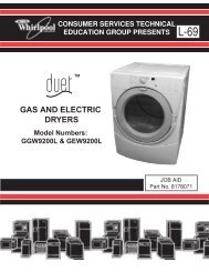
HEATER OPERATION<br />
This dryer uses a dual element heater. Depending<br />
on the selected temperature, either<br />
one or both of the elements will be in the circuit<br />
during the drying mode.<br />
In the Normal temperature setting, both elements<br />
are in the circuit. One element (R1) is<br />
controlled by the operating thermostat. As the<br />
thermostat cycles, the second element (R2)<br />
remains in the circuit, and maintains a consistent<br />
operating temperature.<br />
Manual Reset Thermostat<br />
Self-Resetting Thermostat<br />
PRODUCT OPERATION<br />
THEORY OF OPERATION<br />
Dual Heating Elements<br />
3-1<br />
In the Low temperature setting, a switch opens<br />
the circuit to R2, and it is removed, and drying<br />
takes place with the R1 element only.<br />
SAFETY THERMOSTATS<br />
A pair of safety thermostats is located on the<br />
dual element housing. One is a manual reset<br />
thermostat, (302°F (150°C)), and the other is a<br />
self-resetting thermostat (194°F (90°C)).
AIRFLOW<br />
Primary air is introduced into the dryer through<br />
the slots in the air intake cover.<br />
INTAKE AIR<br />
HEATED AIR<br />
Some air is used to cool the fan and main<br />
motors. The fan motor pulls air from the drum,<br />
and creates a low pressure area. This pulls air<br />
across the heating elements, through the scroll<br />
in the rear panel, and into the drum to dry the<br />
clothes.<br />
INTAKE AIR<br />
EXHAUST AIR<br />
HEATED AIR<br />
INTAKE AIR<br />
3-2<br />
DRUM MOTION<br />
The main drive motor is reversible. It starts in<br />
one direction, stops, then reverses direction. It<br />
continues this throughout the drying cycle.<br />
MOISTURE SENSOR<br />
A moisture sensor circuit is created through the<br />
drum baffles and the brushes on the outside of<br />
the drum. As wet clothes pass between the<br />
drum baffle and the stainless steel drum, the<br />
moisture creates a circuit that is read by the<br />
electronic control. The drum baffle contact is<br />
separated from the drum by an insulator, located<br />
under the contact strip.<br />
Insulator<br />
Drum Baffle Contact<br />
Moisture Sensor Brushes
STARTING THE <strong>DRYER</strong><br />
WARNING<br />
Explosion Hazard<br />
Keep flammable materials and vapors,<br />
such as gasoline, away from dryer.<br />
Do not dry anything that has ever had<br />
anything flammable on it (even after<br />
washing).<br />
Failure to follow these instructions can<br />
result in death, explosion, or fire.<br />
Before using your dryer, wipe the dryer drum<br />
with a damp cloth to remove dust from storing<br />
and shipping.<br />
IMPORTANT: Do not use fabric softener sheets<br />
in this dryer.<br />
1. Clean the lint screen before or after each<br />
cycle.<br />
2. Load clothes loosely into the dryer and<br />
close the door. Do not pack the dryer. Allow<br />
space for clothes to tumble freely.<br />
3. Press the POWER button to turn the dryer<br />
on. The indicator light will glow to indicate<br />
that the power is on.<br />
<strong>DRYER</strong> USE<br />
3-3<br />
4. Press the TEMPERATURE button to select<br />
the recommended temperature setting for<br />
the type of load being dried.<br />
5. Turn the cycle knob to the recommended<br />
setting for the type of load being dried.<br />
6. After a short beep sounds, press the START<br />
button.<br />
STOPPING & RESTARTING<br />
To stop your dryer at any time, turn the cycle<br />
knob to the STOP position, or open the door.<br />
To restart the dryer:<br />
1. Close the door.<br />
2. Select a new cycle and temperature (if<br />
desired).<br />
3. After the beep sounds, press the START<br />
button.<br />
CHANGING CYCLES<br />
AND TEMPERATURES<br />
To change the cycle or temperature after<br />
pressing Start:<br />
1. Open the dryer door.<br />
2. Press the TEMPERATURE button to<br />
change the temperature (if desired).<br />
3. Turn the cycle knob to the new desired<br />
position.<br />
4. After the beep sounds, press the START<br />
button.
LOADING<br />
Load clothes loosely into the dryer. Do not pack<br />
the dryer. Allow space for clothes to tumble<br />
freely. The following chart shows the maximum<br />
load you can place in your compact dryer.<br />
Expect longer drying times.<br />
Loading Suggestions<br />
(Maximum Size Loads)<br />
Heavy Work Clothes Towels<br />
3 jeans 8 bath towels<br />
2 work pants 8 hand towels<br />
3 work shirts 10 washcloths<br />
Permanent Press Mixed Load<br />
1 double sheet 1 sheet (double or twin)<br />
1 dress 4 pillowcases<br />
1 blouse 2 shirts<br />
2 slacks 2 blouses<br />
3 shirts 6 T-shirts<br />
6 handkerchiefs 6 shorts<br />
6 handkerchiefs<br />
Knits Delicates<br />
1 pair pants 1 camisole<br />
2 blouses 4 slips<br />
4 shirts 6 undergarments<br />
4 tops<br />
2 dresses<br />
1 set of sleepwear<br />
DRYING, CYCLE, AND<br />
TEMPERATURE TIPS<br />
Select the correct cycle and temperature for<br />
your load.<br />
The dryer tumbles the load without heat during<br />
the last few minutes of all cycles to make the<br />
load easier to handle and to reduce wrinkling.<br />
After the cool-down cycle ends, the light flashes<br />
and an end-of-cycle signal sounds to indicate<br />
the cycle is complete.<br />
Drying Tips<br />
• Follow care label directions when they are<br />
available.<br />
• Remove the load from the dryer as soon as<br />
tumbling stops to reduce wrinkling. This is<br />
especially important for permanent press,<br />
knits, and synthetic fabrics.<br />
3-4<br />
• Avoid drying heavy work clothes with lighter<br />
fabrics. This could cause overdrying of lighter<br />
fabrics, leading to increased shrinkage or<br />
wrinkling.<br />
Cycle And TemperatureTips<br />
• Dry most loads using an automatic cycle.<br />
• Line dry bonded or laminated fabrics.<br />
NOTE: If you have questions about drying temperatures<br />
for various loads, refer to the care<br />
label directions.<br />
CYCLES<br />
Automatic Cycles<br />
Automatic cycles may be used for most loads.<br />
Automatic cycles give the best drying results in<br />
the shortest time. Drying time varies according<br />
to the type of fabric, size of the load, and<br />
dryness setting.<br />
Dryness is determined by thermostats that<br />
react to the amount of moisture in the air<br />
exhausted from the dryer. Moist air indicates<br />
that clothes are still damp. Dry air indicates that<br />
moisture has been removed.<br />
After drying a load, check the dryness.<br />
• If the load is drier than you like, select a<br />
setting closer to Less Dry the next time you<br />
dry a similar load.<br />
• If a load is not as dry as you like, complete<br />
drying using a Timed cycle. Select a setting<br />
closer to More Dry the next time you dry a<br />
similar load.
See following table for recommended cycles<br />
and temperature settings.<br />
Fabric Type Cycle Temp Setting<br />
REGULAR<br />
Heavy cottons and denims More Dry Normal<br />
Cottons and linens Normal Normal<br />
SYNTHETICS<br />
White and colorfast<br />
permanent press<br />
Normal Low<br />
White and colorfast items<br />
that require ironing<br />
Less Dry Low<br />
Polyester/acrylic blends,<br />
rayon, acetate<br />
Damp Dry Low<br />
Washable silk and nylon Damp Dry Low<br />
Timed Dry<br />
Use this cycle to get up to 60 minutes of heated<br />
drying time or to complete drying if items are<br />
still damp after the automatic cycle. Timed Dry<br />
is also useful for:<br />
• Heavyweight items and work clothes that<br />
require a long drying time.<br />
• Lightweight items, such as lingerie, blouses<br />
and knits that require a short drying time.<br />
See following table for recommended cycles<br />
and temperature settings.<br />
Fabric Type Time (minutes) Temp Setting<br />
Heavy cottons and denims 60 Normal<br />
Cottons and linens 4 0 Normal<br />
White and colorfast<br />
permanent press<br />
4 0 Low<br />
White and colorfast items<br />
that require ironing<br />
4 0 Low<br />
Polyester/acrylic blends,<br />
rayon, acetate<br />
4 0 Low<br />
Washable silk and nylon 4 0 Low<br />
3-5<br />
End of Cycle Signal<br />
The dryer sounds a signal to let you know when<br />
the cycle is finished. The signal is not adjustable<br />
and cannot be turned off. The signal is<br />
helpful when you are drying permanent press,<br />
synthetics, and other items that should be<br />
taken out as soon as the dryer stops.<br />
Anti-Wrinkle<br />
Anti-Wrinkle helps prevent wrinkles that form<br />
when clothes are not removed promptly at the<br />
end of a cycle. Anti-Wrinkle tumbles the load<br />
every minute until the cycle knob is set to the<br />
Stop position or the dryer door is opened.<br />
During Anti-Wrinkle, the End of Cycle Signal<br />
will sound until the cycle knob is set to the Stop<br />
position or the dryer door is opened.<br />
TEMPERATURE CONTROL<br />
The Temperature Control button lets you select<br />
between a normal and low drying temperature.<br />
NOTE: Always refer to the care label on the<br />
garment to determine if it can be tumble dried.<br />
Normal<br />
The Normal temperature setting is for sturdy<br />
fabrics, such as cotton, linen and denim. If this<br />
button is not pressed in, the temperature setting<br />
is Normal.<br />
Low<br />
The Low setting is for synthetics, such as<br />
cotton/polyester blend, rayon, acetate, washable<br />
silk or nylon. If this button is pressed in, the<br />
temperature setting is Low.
— NOTES —<br />
3-6
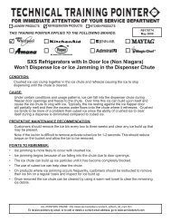
This section instructs you on how to service each component inside the <strong>Whirlpool</strong> <strong>24″</strong> Electric<br />
Dryer. The components and their locations are shown below.<br />
Dryer Selector Switch<br />
Door Switch<br />
Indicator Light<br />
Operating<br />
Thermostat<br />
Safety<br />
Thermostat<br />
Fan Motor<br />
& Capacitor<br />
Drum<br />
COMPONENT ACCESS<br />
COMPONENT LOCATIONS<br />
Viewed From Rear Of Dryer With Drum Removed<br />
4-1<br />
(3) Pushbutton Switches<br />
Main Motor<br />
& Capacitor<br />
Dual Heating Elements<br />
& Safety Thermostats
REMOVING THE CONTROL SWITCHES & INDICATOR LIGHT<br />
WARNING<br />
Electrical Shock Hazard<br />
Disconnect power before servicing.<br />
Replace all parts and panels before<br />
operating.<br />
Failure to do so can result in death or<br />
electrical shock.<br />
1. Unplug dryer or disconnect power.<br />
2. Pull the dryer away from the wall so you<br />
can access the rear of the unit.<br />
3. Remove the two screws from the back of<br />
the top cover.<br />
4. Lift the rear of the top cover, unhook it from<br />
the front, and remove the cover.<br />
Lift Rear Of<br />
Top Cover<br />
Top Cover Screws<br />
Unhook Top Cover<br />
From Front<br />
4-2<br />
Pushbutton<br />
Switches<br />
Dryer Selector<br />
Switch<br />
Indicator Light<br />
5. To remove a pushbutton switch:<br />
a) Using a small-bladed screwdriver,<br />
press the two locking tabs on the sides<br />
of the pushbutton switch toward the<br />
switch body, and pull the switch out of<br />
the mounting location on the control<br />
panel.<br />
Tab<br />
Tab<br />
b) Disconnect the wires from the<br />
pushbutton switch terminals. NOTE:<br />
The wiring for the three pushbutton<br />
switches is shown on the next page.<br />
2 Brown Wires<br />
Power Switch<br />
2 Blue Wires
BK BK<br />
BR<br />
OR GY<br />
BR<br />
BU BU<br />
START<br />
TEMPERATURE<br />
POWER<br />
Pushbutton Switch Wiring<br />
6. To remove the dryer selector switch:<br />
a) Pull the knob off the selector switch<br />
shaft.<br />
b) Remove the two screws from the<br />
switch.<br />
Switch Screws<br />
c) Disconnect the wire connectors from<br />
the dryer selector switch terminals.<br />
NOTE: The 6- and 10-pin connectors<br />
have a locking tab. Raise the tab to<br />
release these connectors.<br />
WH - M2<br />
BK - M1<br />
GY - R2<br />
RD - R1<br />
GY - B<br />
BU - NT<br />
2GY - LT<br />
BR - LT<br />
Dryer Selector Switch<br />
6-PIN<br />
TABS<br />
10-PIN<br />
4-3<br />
7. To remove the indicator light:<br />
a) Remove the dryer selector switch (see<br />
step 6).<br />
b) Push out on the locking sections of the<br />
indicator light holder, and pull the indicator<br />
light out of the holder.<br />
Light Holder<br />
Out<br />
Out<br />
Indicator Light<br />
c) Raise the locking tab and disconnect<br />
the 6-pin connector with the two red<br />
wires from the dryer selector switch.<br />
Dryer Selector Switch<br />
Indicator Light<br />
Assembly<br />
Indicator Light Connector<br />
6-PIN
Electrical Shock Hazard<br />
Disconnect power before servicing.<br />
Replace all parts and panels before<br />
operating.<br />
Failure to do so can result in death or<br />
electrical shock.<br />
REMOVING THE DOOR SWITCH<br />
WARNING<br />
1. Unplug dryer or disconnect power.<br />
2. Remove the top cover from the dryer (see<br />
page 4-2).<br />
3. Open the dryer door and remove the two<br />
door switch screws.<br />
Door Switch Screws<br />
4-4<br />
4. Disconnect the wire connectors from the<br />
door switch terminals and pull the switch<br />
off the mounting plate.<br />
Door Switch<br />
Connectors<br />
Mounting Plate<br />
Door Switch
REMOVING THE SAFETY THERMOSTATS &<br />
THE DUAL HEATING ELEMENTS<br />
WARNING<br />
Electrical Shock Hazard<br />
Disconnect power before servicing.<br />
Replace all parts and panels before<br />
operating.<br />
Failure to do so can result in death or<br />
electrical shock.<br />
1. Unplug dryer or disconnect power.<br />
2. Pull the dryer away from the wall so that<br />
you can access the rear of the unit.<br />
3. Remove the four outer screws from the<br />
heater and thermostat access panel and<br />
remove the panel. NOTE: Do not remove<br />
the two heater screws on the access panel.<br />
They secure the heating elements and<br />
thermostats to the panel.<br />
Air Intake<br />
Cover Screw<br />
Outer Screws<br />
(1 of 4)<br />
Heater & Thermostat<br />
Access Panel<br />
Heater Screws<br />
4-5<br />
4. To remove the safety thermostats:<br />
a) Remove the two screws from the thermostat<br />
bracket and remove the bracket.<br />
b) Remove the wire connectors from the<br />
thermostat you are servicing.<br />
Manual Reset Thermostat<br />
302°F (150°C)<br />
Bracket Screws<br />
5. To remove the dual heating elements:<br />
a) Remove the two thermostats from the<br />
heater bracket (see step 4).<br />
b) Remove the screw from the air intake<br />
cover and remove the cover (see the<br />
left photo).<br />
c) Disconnect the heater & thermostat<br />
connector from the main harness, located<br />
behind the vent cover opening.<br />
d) Remove the two screws from the heater<br />
bracket on the access panel (see the<br />
left photo) and remove the bracket<br />
from the panel.<br />
Heater & Thermostat<br />
Connector<br />
Dual Heating Elements<br />
Safety Thermostat<br />
194°F (90°C)
REMOVING THE BELT AND THE DRUM<br />
WARNING<br />
Electrical Shock Hazard<br />
Disconnect power before servicing.<br />
Replace all parts and panels before<br />
operating.<br />
Failure to do so can result in death or<br />
electrical shock.<br />
1. Unplug dryer or disconnect power.<br />
2. Pull the dryer away from the wall so that<br />
you can access the rear of the unit.<br />
3. Remove the top cover from the dryer (see<br />
page 4-2).<br />
4. Remove the four screws from the crossbraces<br />
on top of the dryer and remove the<br />
braces.<br />
Crossbraces<br />
(4 Screws)<br />
5. Disconnect the blue and brown wires from<br />
the AC Line terminal block, then remove<br />
the hex nut from the green ground wires,<br />
and remove the main harness ground wire<br />
from the rear panel (see the top right<br />
photo).<br />
4-6<br />
Ground Wires<br />
Air Intake<br />
Cover Screw<br />
Brown<br />
Blue<br />
AC Line Terminal Block<br />
6. Remove the four outer screws from the<br />
heater and thermostat access panel, and<br />
remove the panel assembly from the dryer.<br />
Do not remove the two heater (inside)<br />
screws.<br />
7. Remove the air intake cover screw and<br />
remove the cover.<br />
Heater & Thermostat<br />
Access Panel<br />
(4 Screws)<br />
8. Disconnect the heater & thermostat connector<br />
from the wire harness.<br />
Heater & Thermostat<br />
Connector
9. Lay the dryer on its front on a padded<br />
surface to protect the finish.<br />
10. Remove the four screws from the support<br />
flange and remove it and the drum shaft<br />
supports. NOTE: Be careful not to get any<br />
grease on your clothing.<br />
REASSEMBLY NOTE: Be sure to position the<br />
pins on the drum shaft supports facing down<br />
toward the rear panel.<br />
Pin<br />
11. Remove the eight T-20 Torx screws from<br />
the rear panel and remove the panel from<br />
the dryer.<br />
8 Rear Panel Screws<br />
Support Flange<br />
Drum Shaft Supports<br />
(Pins Facing Down)<br />
Rear Panel<br />
REASSEMBLY NOTE: When reassembling<br />
the drum and belt, attach the support flange to<br />
the rear panel, and then slide the rear panel<br />
into position, and install the screws.<br />
4-7<br />
12. To remove the belt from the drum:<br />
a) Pull the belt off the motor pulley.<br />
b) Pull the belt off the drum and remove it.<br />
Belt & Pulley<br />
13. To remove the drum:<br />
a) Remove the belt from the drum (see<br />
step 12).<br />
b) Lift the drum straight up and out of the<br />
dryer cabinet.
REMOVING THE OPERATING & SAFETY THERMOSTATS<br />
WARNING<br />
Electrical Shock Hazard<br />
Disconnect power before servicing.<br />
Replace all parts and panels before<br />
operating.<br />
Failure to do so can result in death or<br />
electrical shock.<br />
1. Unplug dryer or disconnect power.<br />
2. Pull the dryer away from the wall so that<br />
you can access the rear of the unit.<br />
3. Remove the drum and belt from the dryer<br />
(see pages 4-6 and 4-7 for the procedure).<br />
Safety Thermostat<br />
203°F (95°C)<br />
Operating Thermostat<br />
122°F (50°C)<br />
4-8<br />
4. Remove the wire connectors from the<br />
thermostat you are servicing.<br />
5. Remove the two T-20 Torx screws from<br />
the thermostat and remove it from the<br />
dryer. NOTE: The operating thermostat is<br />
identified by a green dot on the body. The<br />
safety thermostat has a white dot on its<br />
body.<br />
Safety Thermostat<br />
Operating Thermostat
REMOVING THE FRONT SLIDE BLOCKS & REAR SEAL<br />
WARNING<br />
Electrical Shock Hazard<br />
Disconnect power before servicing.<br />
Replace all parts and panels before<br />
operating.<br />
Failure to do so can result in death or<br />
electrical shock.<br />
1. Unplug dryer or disconnect power.<br />
2. Pull the dryer away from the wall so that<br />
you can access the rear of the unit.<br />
3. Remove the drum and belt from the dryer<br />
(see pages 4-6 and 4-7 for the procedure).<br />
Front Slide Blocks<br />
4-9<br />
4. To remove the two front slide blocks, lift<br />
the front locking tab on each of the blocks,<br />
and pull them out of the housing.<br />
Pull Out<br />
Slide Block<br />
5. To remove the rear seal:<br />
a) Loosen the spring clamp band screw<br />
and remove the band from the drum<br />
seal.<br />
b) Pull the rear seal off the rear panel<br />
flange.<br />
Spring Clamp<br />
Band Screw<br />
Rear Drum Seal<br />
Rear Panel<br />
Lift Locking<br />
Tab
Electrical Shock Hazard<br />
Disconnect power before servicing.<br />
Replace all parts and panels before<br />
operating.<br />
Failure to do so can result in death or<br />
electrical shock.<br />
REMOVING THE MAIN AND FAN<br />
MOTORS & CAPACITORS<br />
WARNING<br />
1. Unplug dryer or disconnect power.<br />
2. Pull the dryer away from the wall so that<br />
you can access the rear of the unit.<br />
3. Remove the drum and belt from the dryer<br />
(see pages 4-6 and 4-7 for the procedure).<br />
Fan Motor<br />
& Capacitor<br />
Main Motor<br />
& Capacitor<br />
4-10<br />
4. To remove either of the motor capacitors:<br />
a) Loosen the 1/2″ hex-nut and star<br />
washer on the capacitor mounting stud<br />
and remove the capacitor from the<br />
motor.<br />
b) Pull the round terminal cover off the<br />
motor capacitor.<br />
c) Disconnect the brown and blue wires<br />
(main motor), or the red and blue wires<br />
(fan motor), from the motor capacitor<br />
terminals.<br />
Hex-Nut &<br />
Star Washer<br />
Main Motor<br />
Capacitor<br />
Brown Wire<br />
Blue Wire<br />
Terminal<br />
Cover
5. To remove the main motor:<br />
a) Remove the motor capacitor from the<br />
motor (see step 4).<br />
b) Remove the terminal cover from the<br />
capacitor wires.<br />
c) Disconnect the green ground wire from<br />
the motor ground terminal.<br />
d) Disconnect the motor connector from<br />
the main harness.<br />
Terminal Cover<br />
Ground Wire<br />
Motor Connector<br />
e) While holding the motor in place, remove<br />
the four 20 mm hex-head motor<br />
mounting screws from the bottom of<br />
the cabinet, and remove the motor.<br />
Motor Screws<br />
4-11<br />
6. To remove the fan motor:<br />
a) Disconnect the two green ground wires<br />
from the motor ground terminal.<br />
b) Disconnect the motor connector from<br />
the main harness.<br />
Motor Connector<br />
Ground Wires<br />
c) Remove the four 20 mm hex-head<br />
motor mounting screws from the bottom<br />
of the cabinet.<br />
Motor Screws<br />
Continued on the next page.
d) Remove the fan motor assembly from<br />
the bottom of the dryer.<br />
Fan Motor Assembly<br />
e) Remove the rubber coupler from the<br />
fan housing flange. NOTE: If the coupler<br />
is on the vent flange instead of the<br />
fan housing, leave it there.<br />
f) Unsnap the front half of the fan housing<br />
from the rear half and remove it.<br />
NOTE: There may be screws holding<br />
the fan housing halves together. If so,<br />
remove them before separating the<br />
halves.<br />
Rubber Coupler<br />
Front Half Of Housing<br />
4-12<br />
g) While you hold the opposite end of the<br />
fan motor shaft with a pair of pliers,<br />
remove the 1/2″ locknut from the fan<br />
end of the shaft, and remove the fan.<br />
Fan Locknut<br />
h) Remove the three screws from the fan<br />
housing and remove the housing from<br />
the fan motor.<br />
Fan Housing<br />
Screw (1 or 3)<br />
i) Remove the motor capacitor from the<br />
motor (see step 4 on page 4-10 for the<br />
procedure).<br />
Motor Capacitor
Before testing any of the components, perform<br />
the following checks:<br />
• Control failure can be the result of corrosion<br />
on connectors. Therefore, disconnecting and<br />
reconnecting wires will be necessary throughout<br />
test procedures.<br />
• All tests/checks should be made with a VOM<br />
or DVM having a sensitivity of 20,000 ohmsper-volt<br />
DC, or greater.<br />
COMPONENT TESTING<br />
5-1<br />
• Check all connections before replacing components,<br />
looking for broken or loose wires,<br />
failed terminals, or wires not pressed into<br />
connectors far enough.<br />
• Resistance checks must be made with power<br />
cord unplugged from outlet, and with wiring<br />
harness or connectors disconnected.<br />
• Unless stated otherwise, make all resistance<br />
checks by disconnecting the component<br />
connector at the electronic control.<br />
WARNING<br />
Electrical Shock Hazard<br />
Disconnect power before servicing.<br />
Replace all parts and panels before operating.<br />
Failure to do so can result in death or electrical shock.<br />
PUSHBUTTON SWITCHES<br />
1<br />
3<br />
Unused<br />
Plunger<br />
Refer to page 4-2 for the procedure for servicing<br />
the pushbutton switches.<br />
1. Unplug dryer or disconnect power.<br />
2<br />
4<br />
6<br />
2. Disconnect the wires from the terminals of<br />
the pushbutton switch you are testing.<br />
3. Set the ohmmeter to the R x 1 scale.<br />
4. Depending on the pushbutton switch terminal<br />
configuration, touch the ohmmeter<br />
test leads to the following switch terminals.<br />
The meter should indicate either an<br />
open (infinite), or a closed (0 Ω) circuit.<br />
Terminals 1 - 3<br />
Terminals 2 - 4<br />
Terminals 4 - 6<br />
5. Press the plunger, and the switch should<br />
change states (from open to closed, or<br />
closed to open).
DOOR SWITCH DUAL HEATING ELEMENTS<br />
Refer to page 4-4 for the procedure for servicing<br />
the door switch.<br />
1. Unplug dryer or disconnect power.<br />
2. Disconnect the wires from the door switch<br />
terminals.<br />
3. Set the ohmmeter to the R x 1 scale.<br />
4. Touch the ohmmeter test leads to the door<br />
switch terminals. The meter should indicate<br />
an open (infinite) circuit.<br />
5. Press the actuator button, and the switch<br />
should indicate a closed (0 Ω) circuit.<br />
WARNING<br />
Electrical Shock Hazard<br />
Disconnect power before servicing.<br />
Replace all parts and panels before operating.<br />
Failure to do so can result in death or electrical shock.<br />
5-2<br />
Refer to page 4-5 for the procedure for servicing<br />
the dual heating elements.<br />
1. Unplug dryer or disconnect power.<br />
2. Disconnect the heater and thermostat<br />
connector from the wiring harness.<br />
3. Set the ohmmeter to the R X 1 scale.<br />
4. Touch the ohmmeter test leads to the<br />
connector pins with the white and red<br />
wires. The meter should indicate between<br />
68 and 82 Ω<br />
5. Touch the ohmmeter test leads to the<br />
connector pins with the white and black<br />
wires. The meter should indicate between<br />
24 and 35 Ω
THERMOSTATS<br />
Refer to pages 4-5 and 4-8 for the procedures<br />
for servicing the thermostats.<br />
1. Unplug dryer or disconnect power.<br />
2. Disconnect the wire connectors from the<br />
thermostat you are testing.<br />
3. Set the ohmmeter to the R X 1 scale.<br />
4. Touch the ohmmeter test leads to the<br />
thermostat terminals. The meter should<br />
indicate a closed (0 Ω) circuit.<br />
WARNING<br />
Electrical Shock Hazard<br />
Disconnect power before servicing.<br />
Replace all parts and panels before operating.<br />
Failure to do so can result in death or electrical shock.<br />
5-3<br />
MAIN & FAN MOTOR<br />
CAPACITORS<br />
Refer to page 4-10 for the procedure for servicing<br />
the motor capacitors.<br />
1. Unplug dryer or disconnect power.<br />
2. Disconnect the wire connectors from the<br />
motor capacitor terminals.<br />
3. Set the ohmmeter to the R X 10K scale.<br />
4. Touch the ohmmeter test leads to the<br />
motor capacitor terminals. The meter<br />
should indicate several ohms, and then<br />
gradually return towards infinity.
MAIN MOTOR<br />
Refer to page 4-10 for the procedure for servicing<br />
the main motor.<br />
1. Unplug dryer or disconnect power.<br />
2. Disconnect the main motor connector from<br />
the wiring harness connector.<br />
3. Set the ohmmeter to the R x 1 scale.<br />
4. Touch the ohmmeter test leads to the<br />
motor connector pins with the following<br />
wire colors:<br />
a) White and brown wires. The meter<br />
should indicate between 28 and 40 Ω.<br />
b) White and blue wires. The meter should<br />
indicate between 25 and 40 Ω.<br />
c) Blue and brown wires. The meter<br />
should indicate between 58 and 70 Ω.<br />
WARNING<br />
Electrical Shock Hazard<br />
Disconnect power before servicing.<br />
Replace all parts and panels before operating.<br />
Failure to do so can result in death or electrical shock.<br />
5-4<br />
FAN MOTOR<br />
Refer to page 4-10 for the procedure for servicing<br />
the fan motor.<br />
1. Unplug dryer or disconnect power.<br />
2. Disconnect the wire harness connector<br />
from the fan motor terminals.<br />
3. Set the ohmmeter to the R x 1 scale.<br />
4. Touch the ohmmeter test leads to the<br />
motor connector pins with the following<br />
wire colors:<br />
a) Violet and blue wires. The meter should<br />
indicate between 26 and 38 Ω.<br />
b) Violet and red wires. The meter should<br />
indicate between 26 and 38 Ω.<br />
c) Blue and red wires. The meter should<br />
indicate between 58 and 72 Ω.
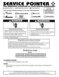
BU 5<br />
Power<br />
BR<br />
2<br />
6<br />
3<br />
BR<br />
OR RD<br />
Temperature<br />
Operating Thermostat<br />
122°F/50°C<br />
RD<br />
RM3 RM2<br />
RM1<br />
RM6/RF6<br />
Dual Heating<br />
Elements<br />
Safety Thermostat<br />
194°F/90°C<br />
OR<br />
SD2 SD1<br />
Manual Reset Thermostat<br />
302°F/150°C<br />
Main<br />
Motor<br />
RM5/RF5<br />
GY<br />
M2<br />
WIRING DIAGRAM<br />
M3<br />
MM<br />
BR<br />
GY<br />
M1<br />
GY<br />
GY<br />
FM<br />
FM2<br />
MP2 MP1<br />
Door Switch<br />
FM1<br />
Fan<br />
Motor<br />
Safety<br />
Thermostat<br />
203°F/95°C<br />
GY<br />
6-1<br />
WH<br />
M2<br />
BK<br />
M1<br />
GY<br />
R2<br />
RD<br />
R1<br />
GY<br />
B<br />
BU<br />
NT<br />
GY<br />
BR<br />
LT<br />
LT<br />
CONTROL<br />
10<br />
9<br />
8<br />
7<br />
6<br />
5<br />
4<br />
3<br />
2<br />
1<br />
RD<br />
RD<br />
BK<br />
BK<br />
RSC<br />
BK<br />
Moisture<br />
Sensor<br />
Brushes<br />
START/STOP<br />
INDICATOR LIGHT<br />
START<br />
AV2 AV3<br />
RD<br />
RSF
— NOTES —<br />
6-2
PRODUCT SPECIFICATIONS<br />
AND<br />
WARRANTY INFORMATION SOURCES<br />
IN THE UNITED STATES:<br />
FOR PRODUCT SPECIFICATIONS AND WARRANTY INFORMATION CALL:<br />
FOR TECHNICAL ASSISTANCE WHILE AT THE CUSTOMER’S HOME CALL:<br />
THE TECHNICAL ASSISTANCE LINE: 1-800-253-2870<br />
HAVE YOUR STORE NUMBER READY TO IDENTIFY YOU AS AN<br />
AUTHORIZED SERVICER<br />
FOR LITERATURE ORDERS:<br />
PHONE: 1-800-851-4605<br />
FOR TECHNICAL INFORMATION AND SERVICE POINTERS:<br />
IN CANADA:<br />
FOR WHIRLPOOL PRODUCTS: 1-800-253-1301<br />
FOR KITCHENAID PRODUCTS: 1-800-422-1230<br />
FOR ROPER PRODUCTS: 1-800-447-6737<br />
www.servicematters.com<br />
FOR PRODUCT SPECIFICATIONS AND WARRANTY INFORMATION CALL:<br />
1-800-461-5681<br />
FOR TECHNICAL ASSISTANCE WHILE AT THE CUSTOMER’S HOME CALL:<br />
THE TECHNICAL ASSISTANCE LINE: 1-800-488-4791<br />
HAVE YOUR STORE NUMBER READY TO IDENTIFY YOU AS AN<br />
AUTHORIZED SERVICER
CORPORATION