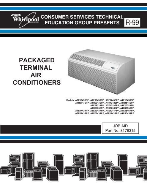
packaged terminal air conditioners - This is a secure site - Whirlpool
packaged terminal air conditioners - This is a secure site - Whirlpool
packaged terminal air conditioners - This is a secure site - Whirlpool

Create successful ePaper yourself
Turn your PDF publications into a flip-book with our unique Google optimized e-Paper software.
PACKAGED<br />
TERMINAL<br />
AIR<br />
CONDITIONERS<br />
CONSUMER SERVICES TECHNICAL<br />
EDUCATION GROUP PRESENTS R-99<br />
Models: ATE0743SPP, ATE0943SPP, ATE1243SPP, ATE1545SPP,<br />
ATR0743SPP, ATR0943SPP, ATR1243SPP, ATR1545SPP<br />
ATE0953SPP, ATE1253SPP, ATE1555SPP,<br />
ATR0953SPP, ATR1253SPP, ATR1555SPP,<br />
ATE0743RPP, ATE0943RPP, ATE1243RPP, ATE1545RPP,<br />
ATR0743RPP, ATR0943RPP, ATR1243RPP, ATR1545RPP<br />
JOB AID<br />
Part No. 8178315
FORWARD<br />
<strong>Th<strong>is</strong></strong> <strong>Whirlpool</strong> Job Aid, “Packaged Terminal Air Conditioners” (Part No. 8178315), provides the<br />
technician with information on the installation, operation, and service of the Packaged Terminal Air<br />
Conditioners . It <strong>is</strong> to be used as a training Job Aid and Service Manual. For specific information<br />
on the model being serviced, refer to the “Use and Care Guide,” or “Tech Sheet” provided with the<br />
<strong>air</strong> conditioner.<br />
The Wiring Diagrams and Strip Circuits used in th<strong>is</strong> Job Aid are typical and should be used for<br />
training purposes only. Always use the Wiring Diagram supplied with the product when servicing<br />
the unit.<br />
GOALS AND OBJECTIVES<br />
The goal of th<strong>is</strong> Job Aid <strong>is</strong> to provide detailed information that will enable the service technician to<br />
properly diagnose malfunctions and rep<strong>air</strong> the Packaged Terminal Air Conditioners.<br />
The objectives of th<strong>is</strong> Job Aid are to:<br />
• Understand and follow proper safety precautions.<br />
• Successfully troubleshoot and diagnose malfunctions.<br />
• Successfully perform necessary rep<strong>air</strong>s.<br />
• Successfully return the <strong>air</strong> conditioner to its proper operational status.<br />
WHIRLPOOL CORPORATION assumes no responsibility for any rep<strong>air</strong>s made<br />
on our products by anyone other than Authorized Service Technicians.<br />
Copyright © 2004, <strong>Whirlpool</strong> Corporation, Benton Harbor, MI 49022<br />
- ii -
TABLE OF CONTENTS<br />
- iii -<br />
Page<br />
GENERAL............................................................................................................................... 1-1<br />
<strong>Whirlpool</strong> Model & Serial Number Designations ................................................................ 1-1<br />
Model & Serial Number Label & Wiring Diagram Locations .............................................. 1-2<br />
Specifications..................................................................................................................... 1-3<br />
<strong>Whirlpool</strong> Packaged Terminal Air Conditioner (PTAC) And<br />
Packaged Terminal Heat Pump (PTHP) Warranty ......................................................... 1-4<br />
INSTALLATION INFORMATION ........................................................................................... 2-1<br />
Electrical Requirements ..................................................................................................... 2-1<br />
Drain Kit Installation ........................................................................................................... 2-2<br />
Chass<strong>is</strong> Installation ............................................................................................................ 2-5<br />
Remote Wall Thermostat Installation ................................................................................. 2-9<br />
PRODUCT OPERATION ........................................................................................................ 3-1<br />
Theory Of Operation .......................................................................................................... 3-1<br />
Refrigeration Operation .................................................................................................. 3-1<br />
Heat Pump Operation .................................................................................................... 3-3<br />
Reversing Valve Operation ............................................................................................ 3-4<br />
Remote Thermostat Operation....................................................................................... 3-5<br />
Heat Pump Function ...................................................................................................... 3-7<br />
Operating The Controls ..................................................................................................... 3-8<br />
COMPONENT ACCESS ......................................................................................................... 4-1<br />
Component Locations ........................................................................................................ 4-1<br />
Removing The Indoor Thermostat, Mode (System) Switch, And Heat Anticipator ............ 4-2<br />
Removing The Power Supply Cord ................................................................................... 4-4<br />
Removing The Defrost Thermostat.................................................................................... 4-5<br />
Removing The Hot Start Relay And Hot Start Sensor ....................................................... 4-6<br />
Removing The Capacitor & Fan Cycle Switch ................................................................... 4-7<br />
Removing The Remote Control Unit Fan Switch ............................................................... 4-8<br />
Removing The Heater & Limit Switch ................................................................................ 4-9<br />
Removing The Fan Motor ................................................................................................ 4-10<br />
Removing The Condensate Valve Bellows...................................................................... 4-13<br />
Removing The Overload Protector And The Compressor ............................................... 4-14<br />
Removing The Evaporator ............................................................................................... 4-16<br />
Removing The Condenser ............................................................................................... 4-18<br />
Removing The Solenoid Coil & Reversing Valve............................................................. 4-20
COMPONENT TESTING ........................................................................................................ 5-1<br />
Indoor Thermostat ............................................................................................................. 5-1<br />
Mode (System) Switch ....................................................................................................... 5-2<br />
Heat Anticipator ................................................................................................................. 5-2<br />
Defrost Thermostat (Emergency Heat Switch) .................................................................. 5-3<br />
Hot Start Relay .................................................................................................................. 5-4<br />
Hot Start Sensor ................................................................................................................ 5-4<br />
Capacitor ........................................................................................................................... 5-5<br />
Fan Cycle Switch & Remote Control Unit Fan Switch ....................................................... 5-5<br />
Heater & Limit Switch ........................................................................................................ 5-6<br />
Fan Motor ......................................................................................................................... 5-6<br />
Overload Protector............................................................................................................. 5-7<br />
Compressor ....................................................................................................................... 5-7<br />
Solenoid Coil...................................................................................................................... 5-8<br />
DIAGNOSIS & TROUBLESHOOTING ................................................................................... 6-1<br />
Diagnosing The Sealed System ........................................................................................ 6-1<br />
Troubleshooting Charts ..................................................................................................... 6-7<br />
WIRING DIAGRAMS & STRIP CIRCUITS ............................................................................. 7-1<br />
Wiring Diagrams ................................................................................................................ 7-5<br />
Strip Circuits .................................................................................................................... 7-10<br />
TECH TIPS ............................................................................................................................. 8-1<br />
Routine Maintenance ......................................................................................................... 8-1<br />
Accessories ....................................................................................................................... 8-2<br />
Optional Desk Control Unit ................................................................................................ 8-4<br />
General Troubleshooting ................................................................................................... 8-5<br />
- iv -
WHIRLPOOL MODEL & SERIAL NUMBER DESIGNATIONS<br />
MODEL NUMBER<br />
SERIAL NUMBER<br />
GENERAL<br />
MODEL NUMBER<br />
PRODUCT GROUP<br />
A = AIR CONDITIONER<br />
A T R 12 4 3 S P P 0<br />
PRODUCT IDENTIFICATION<br />
T = PTAC, WHIRLPOOL<br />
MODEL TYPE<br />
R = HEAT PUMP W/AUXILIARY HEAT<br />
E = COOLING W/ELECTRIC HEAT<br />
NOMINAL COOLING CAPACITY<br />
07 = 7,000 BTU/HR<br />
09 = 9,000 BTU/HR<br />
12 = 12,000 BTU/HR<br />
15 = 15,000 BTU/HR<br />
ELECTRICAL CODE<br />
4 = 208V-230V, 1 PHASE, 60 HZ<br />
5 = 265V, 1 PHASE, 60 HZ<br />
HEATER<br />
2 = 2.5 KW<br />
3 = 3.4 KW<br />
5 = 5.0 KW<br />
FEATURE CODE OPTIONS<br />
S = STANDARD ELECTROMECHANICAL<br />
R = REMOTE WALL-MOUNTED THERMOSTAT<br />
C = SEACOAST PROTECTION / STD. CONTROLS<br />
B = REMOTE THERMOSTAT / SEACOAST PROTECTION<br />
MANUFACTURING LOCATION<br />
P = PURCHASED PRODUCT<br />
YEAR OF INTRODUCTION<br />
M = 2003, P = 2004, R = 2005, S = 2006, T = 2007<br />
ENGINEERING CHANGE<br />
0, 1, 2, ETC.<br />
SERIAL NUMBER<br />
MANUFACTURING RESPONSIBILITY<br />
QR = FRIEDRICH MANUFACTURING CO.<br />
YEAR OF PRODUCTION<br />
P = 2003, R = 2004<br />
WEEK OF PRODUCTION<br />
5TH WEEK<br />
PRODUCT SEQUENCE NUMBER<br />
QR P 05 21234<br />
1-1
MODEL & SERIAL NUMBER LABEL &<br />
WIRING DIAGRAM LOCATIONS<br />
The Model/Serial Number label and Wiring Diagram locations are shown below.<br />
Wiring Diagram Location<br />
(Front Cover Removed)<br />
1-2<br />
Model & Serial<br />
Number Location
<strong>Whirlpool</strong> Model<br />
Control<br />
Type<br />
Cooling BTU<br />
230/208v<br />
SPECIFICATIONS<br />
ATE-SERIES PTAC W/ELECTRIC HEAT — COOLING PERFORMANCE<br />
Heating<br />
BTU<br />
Electric<br />
Volts Heater<br />
KW<br />
1-3<br />
Amps- NEMA Plug Dehum-<br />
EER CFM COP<br />
Breaker Plug Type* Pts/Hr<br />
ATE0743SPP Standard 7500/7000 11600 230 3.4 12.2 20 6-20 20 Amp 2.1 250 NA<br />
ATE0943SPP Standard 9200/9000 11600 230 3.4 11.3 20 6-20 20 Amp 2.7 300 NA<br />
ATE1243SPP Standard 12000/12000 11600 230 3.4 10.7 20 6-20 20 Amp 3.8 325 NA<br />
ATE1545SPP Standard 15000-15000 17000 230 5.0 9.5 30 6-30 30 Amp 5.5 350 NA<br />
ATE0953SPP Standard 9200/9000 11600 265 3.4 11.3 20 6-20 20 Amp 2.7 300 NA<br />
ATE1253SPP Standard 12000/12000 11600 265 3.4 10.7 20 6-20 20 Amp 3.8 325 NA<br />
ATE1555SPP Remote 15000/15000 17000 265 5.0 9.5 30 6-20 30 Amp 3.5 350 NA<br />
ATE0743RPP Remote 7500/75000 11600 230 3.4 12.2 20 6-20 20 Amp 2.1 250 NA<br />
ATE0943RPP Remote 9200/9000 11600 230 3.4 11.3 20 6-20 20 Amp 2.7 300 NA<br />
ATE1243RPP Remote 12000/12000 11600 230 3.4 10.7 20 6-20 20 Amp 3.8 325 NA<br />
ATE1545RPP Remote 15000-15000 17000 230 5.0 9.5 30 6-30 30 Amp 5.5 350 NA<br />
ATR-SERIES PTHP W/HEATING — COOLING PERFORMANCE<br />
<strong>Whirlpool</strong> Model<br />
Control<br />
Type<br />
Cooling BTU<br />
230/208v<br />
Heating<br />
BTU<br />
Electric<br />
Volts Heater<br />
KW<br />
Amps- NEMA Plug Dehum-<br />
EER CFM COP<br />
Breaker Plug Type* Pts/Hr<br />
ATR0743SPP Standard 7200/7000 11600 230 3.4 12.1 20 6-20 20 Amp 2.1 250 3.3<br />
ATR0943SPP Standard 9100/9000 11600 230 3.4 10.5 20 6-20 20 Amp 2.1 250 3.3<br />
ATR1243SPP Standard 12000/12000 11600 230 3.4 10.5 20 6-20 20 Amp 2.1 250 3.3<br />
ATR1545SPP Standard 15000/14700 17000 230 5.0 9.3 30 6-30 30 Amp 5.5 350 2.8<br />
ATR0953SPP Standard 9100/9000 11600 265 3.4 11.3 20 6-20 20 Amp 3.8 325 3.1<br />
ATR1253SPP Standard 12000/12000 11600 265 3.4 10.5 20 6-20 20 Amp 3.8 325 3.1<br />
ATR1555SPP Standard 15000/14700 17000 265 5.0 9.3 30 6-30 30 Amp 5.5 350 2.8<br />
ATR0743RPP Remote 7200/7200 11600 230 3.4 12.1 20 6-20 20 Amp 2.1 250 3.3<br />
ATR0943RPP Remote 9100/9000 11600 230 3.4 11.3 20 6-20 20 Amp 2.1 250 3.3<br />
ATR1243RPP Remote 12000/12000 11600 230 3.4 10.5 20 6-20 20 Amp 3.8 325 3.1<br />
ATR1545RPP Remote 15000/14700 17000 230 5.0 9.3 30 6-30 30 Amp 5.5 350 2.8<br />
* 15 Amps available on special order models<br />
CFM = Cubic Feet per Minute<br />
COP = Coefficient Of Performance (applies to PTHP only)
WHIRLPOOL PACKAGED TERMINAL<br />
AIR CONDITIONER (PTAC) AND PACKAGED<br />
TERMINAL HEAT PUMP (PTHP) WARRANTY<br />
LENGTH OF WARRANTY:<br />
ONE YEAR FULL WARRANTY<br />
FIVE YEAR FULL WARRANTY<br />
SECOND THROUGH FIFTH YEAR<br />
LIMITED WARRANTY<br />
WHIRLPOOL WILL NOT PAY FOR:<br />
WHIRLPOOL WILL PAY FOR:<br />
For one year from the date of installation, if th<strong>is</strong> PTAC/PTHP fails<br />
when operated and maintained according to instructions attached<br />
to or furn<strong>is</strong>hed with the product, <strong>Whirlpool</strong> Corporation will pay for<br />
replacement parts and rep<strong>air</strong> labor to correct defects in materials<br />
or workmanship. Service must be provided by a <strong>Whirlpool</strong> designated<br />
service company.<br />
For five years from the date of purchase, if th<strong>is</strong> PTAC/PTHP fails<br />
when operated and maintained according to instructions attached<br />
to or furn<strong>is</strong>hed with the product, <strong>Whirlpool</strong> Corporation will pay for<br />
replacement parts and rep<strong>air</strong> labor to correct defects in materials<br />
or workmanship in the sealed refrigeration system, including the<br />
compressor, evaporator, condenser, reversing valve and connecting<br />
tubing. Service must be provided by a <strong>Whirlpool</strong> designated<br />
service company.<br />
For the second through fifth year from the date of purchase, if th<strong>is</strong><br />
PTAC/PTHP fails when operated and maintained according to instructions<br />
attached to or furn<strong>is</strong>hed with the product, <strong>Whirlpool</strong> Corporation<br />
will pay for replacement parts to correct defects in materials<br />
or workmanship in the electrical or <strong>air</strong> flow systems including<br />
the fan motor, capacitor, fan, blower wheel, switches, thermostat,<br />
relays, frost controls, heat control, heater, heater protectors, compressor<br />
overload, solenoids, auxiliary controls, and transformer.<br />
<strong>Th<strong>is</strong></strong> <strong>is</strong> a limited parts-only warranty and does not include labor or<br />
transportation to and from the service shop. Service must be provided<br />
by a <strong>Whirlpool</strong> designated service company.<br />
1. Service calls to correct the installation of the PTAC/PTHP, instruct you how to use the PTAC/PTHP, to replace<br />
fuses, correct wiring, reset circuit breakers, or to clean or replace owner accessible <strong>air</strong> filters.<br />
2. Damage resulting from accident, alteration, m<strong>is</strong>use, abuse, fire, floods, acts of God, improper installation not<br />
in accordance with local electrical and plumbing codes, or use of products not approved by <strong>Whirlpool</strong><br />
Corporation, or <strong>Whirlpool</strong> Canada, Inc.<br />
3. Replacement parts or rep<strong>air</strong> labor costs for units operated outside the United States or Canada.<br />
4. Pickup and delivery, or any transportation and reinstallation charges that may be required.<br />
5. The removal and reinstallation of the PTAC/PTHP.<br />
6. Rep<strong>air</strong>s to parts or systems resulting from unauthorized modifications made to the PTAC/PTHP.<br />
WHIRLPOOL CORPORATION AND WHIRLPOOL CANADA, INC. SHALL NOT BE LIABLE FOR INCIDENTAL<br />
OR CONSEQUENTIAL DAMAGES.<br />
Some states and provinces do not allow the exclusion or limitation of incidental or consequential damages, so th<strong>is</strong><br />
exclusion or limitation may not apply to you. <strong>Th<strong>is</strong></strong> warranty gives you specific legal rights and you may also have other<br />
rights which vary from state to state or province to province.<br />
Outside the United States and Canada, a different warranty may apply. For details, please contact your<br />
<strong>Whirlpool</strong> authorized dealer.<br />
If you need service, first see "Troubleshooting" section of the Installation/Operation Manual. After checking<br />
“Troubleshooting,” additional help can be found by checking the “Ass<strong>is</strong>tance or Service” section, or by calling the<br />
<strong>Whirlpool</strong> Corporation Customer Interaction Center at 1-800-253-1301 (toll-free), from anywhere in the United<br />
States. In Canada, please call 1-800-807-6777.<br />
1-4
INSTALLATION INFORMATION<br />
Electrical Shock Hazard<br />
Plug into a grounded 3 prong outlet.<br />
Do not remove ground prong.<br />
Do not use an adapter.<br />
Do not use an extension cord.<br />
Failure to follow these instructions can<br />
result in death, fire, or electrical shock.<br />
IMPORTANT: Connect PTAC/PTHP to a<br />
single-outlet circuit only.<br />
230/208 VOLT PTAC/PTHP<br />
All 230/208 volt PTAC/PTHPs are equipped<br />
with power cords.<br />
230/208 volt 250 volt Receptacles and<br />
PTAC/PTHP Overcurrent Protection<br />
AMPS 15 20 30<br />
RECEPTACLE<br />
NEMA Type 6-15R 6-20R 6-30R<br />
The field-supplied outlet must match plug on<br />
service cord and be within reach of service<br />
cord.<br />
ELECTRICAL REQUIREMENTS<br />
2-1<br />
Electrical Shock Hazard<br />
Electrically ground PTAC/PTHP.<br />
Connect ground wire to green pigtail lead.<br />
Use copper wire for supply connection.<br />
Correct wire gauge <strong>is</strong> shown in the chart<br />
below.<br />
Failure to follow these instructions can<br />
result in death or electrical shock.<br />
Rating Plate Ampacity AWG<br />
Less than 15 14<br />
16 - 20 12<br />
21 - 30 10<br />
265 VOLT PTAC/PTHP<br />
All 265 volt PTAC/PTHPs are equipped with<br />
pigtail leads for field wiring.<br />
IMPORTANT:<br />
• Use copper conductors only.<br />
• Wire sizes are per NEC.<br />
• Use on individual branch circuit only.<br />
• Use overcurrent protection indicated on<br />
PTAC/PTHP’s rating plate.<br />
• PTAC/PTHP must be grounded to branch<br />
circuit.<br />
• Check local codes.
LOCATION REQUIREMENTS<br />
• Unpack and d<strong>is</strong>pose of packaging materials.<br />
• The drain kit accessory contains 10 complete<br />
drain kits.<br />
• Locate the drain kit in the primary area for<br />
best drainage. Maintain at least 1/2″ (1.27<br />
cm) d<strong>is</strong>tance from the embossed area. If the<br />
primary area cannot be used, locate the<br />
drain kit in the secondary area and cut away<br />
the foam insulation to allow access to the<br />
drain. Do not locate the drain kit within 3″ (7.6<br />
cm) of the indoor side of the sleeve.<br />
1<br />
2<br />
3<br />
1. Secondary area<br />
2. Primary area - no foam insulation<br />
3. If the drain must be located in the secondary area,<br />
the foam insulation must be cut away and removed<br />
to allow access to the drain.<br />
4. Embossed area<br />
DRAIN KIT INSTALLATION<br />
4<br />
3"<br />
(7.6 cm)<br />
2-2<br />
NOTES:<br />
Determine whether the drain will be located<br />
on the exterior of the wall, internally in the wall<br />
cavity or internally in the room.<br />
Internal Drain<br />
• Drain kit located inside the room will allow<br />
condensate to drain to a field drain located<br />
inside the room.<br />
• Drain kit located inside the wall cavity will<br />
allow condensate to drain to a field drain<br />
located inside the wall cavity.<br />
External Drain<br />
• Drain kit located outside will allow condensate<br />
to drain to a field drain located outside<br />
or to drain away from the wall sleeve.<br />
• When using an external drain system, select<br />
the drain hole on the back of the wall sleeve<br />
which best meets your drainage situation.<br />
• The cover plate and external drain tube<br />
assembly may be placed on either side of the<br />
wall sleeve.
INTERNAL DRAIN INSTALLATION<br />
(Located Inside The Wall Cavity Or<br />
In The Interior Of The Room)<br />
NOTE: If installing an internal drain, install drain<br />
kit on the wall sleeve before the wall sleeve <strong>is</strong><br />
installed.<br />
1. Using the mounting plate from the drain kit<br />
as a template, mark and drill two 3/16″<br />
mounting holes and a 1/2″ drain hole at the<br />
location chosen above.<br />
2. Remove the backing from the gasket and<br />
mount it on the flat side of the mounting<br />
plate. Insert the drain tube through the<br />
hole in the gasket and mounting plate so<br />
the tube flange will be against the wall<br />
sleeve.<br />
1<br />
2<br />
3<br />
4<br />
5<br />
6<br />
1. Screw<br />
2. Wall sleeve<br />
3. Gasket<br />
4. Mounting plate<br />
5. Nut<br />
6. Drain tube<br />
7. Optional 4 in. (10.2 cm)<br />
straight drain tube<br />
2-3<br />
3. Position the assembly beneath the drilled<br />
holes and <strong>secure</strong> it with #10 - 24 x 1/2″<br />
machine screws and locknuts (provided).<br />
Seal the tops of the screws with silicone<br />
sealant.<br />
4. Connect the drain tube to the drain system<br />
in the building.<br />
IMPORTANT: Follow all local building<br />
codes when making th<strong>is</strong> connection.<br />
5. Attach the 2 cover plates and gaskets over<br />
the drain holes at the rear of the wall<br />
sleeve with #10 sheet metal screws (provided).<br />
NOTE: Check that the 4 overflow slots at<br />
the rear of the wall sleeve are not blocked.<br />
1<br />
2<br />
1. Drain holes<br />
2. Overflow slots<br />
3. Gasket<br />
4. Cover plate<br />
5. #10 sheet metal screws<br />
1<br />
3<br />
4<br />
5
EXTERNAL DRAIN INSTALLATION<br />
(Located On The Exterior<br />
Of The Wall)<br />
1. Peel the backing tape from the gaskets<br />
and mount them on the curved side of one<br />
cover plate and one mounting plate.<br />
2. Place the drain tube through the gasket<br />
and the mounting plate with the flange<br />
toward the wall sleeve.<br />
3. Using 2 - #10 x 1/2″ sheet metal screws<br />
(provided), attach the drain tube assembly<br />
to one of the 2 drain holes at the rear of the<br />
wall sleeve.<br />
Position the large flange at the bottom of<br />
the sleeve facing toward the sleeve, and<br />
partially tighten the screws. Rotate the<br />
drain tube to a horizontal position to allow<br />
for the wall sleeve to be installed into the<br />
wall. Once the wall sleeve <strong>is</strong> installed,<br />
position the drain tube to the desired angle.<br />
Before tightening the screws, check to be<br />
sure the tube’s position will allow the wall<br />
sleeve to fit through the wall. Tighten screws.<br />
2-4<br />
1<br />
2<br />
3<br />
4<br />
1. Drain holes<br />
2. Overflow slots<br />
3. Foam gasket<br />
4. Mounting plate<br />
5. #10 x 1/2 in. sheet metal screws<br />
6. 1/2 in. O.D. tube<br />
7. Optional 4 in. (10.2 cm) straight drain tube<br />
8. Cover plate (no center hole)<br />
4. Using 2 - #10 x 1/2″ sheet metal screws<br />
(provided), attach the cover plate to the<br />
remaining drain hole. Check that the large<br />
flange on the plate <strong>is</strong> positioned at the<br />
bottom of the sleeve.<br />
NOTE: Check that the 4 overflow slots at<br />
the rear of the wall<br />
5. D<strong>is</strong>card any unused kit parts.<br />
1<br />
3<br />
8<br />
7<br />
6<br />
5
Excessive Weight Hazard<br />
Use two or more people to move and<br />
install PTAC/PTHP.<br />
Failure to do so can result in back or other<br />
injury.<br />
NOTES:<br />
• Check to be sure wall sleeve, wall sleeve<br />
extension (if used), wall sleeve adapter (if<br />
used), rear grille, and drain kit are properly<br />
installed before chass<strong>is</strong> installation.<br />
• Locate PTAC/PTHP near the location it will<br />
be installed.<br />
IMPORTANT: Copper refrigerant tubes are not<br />
handles. Product damage will occur if tubes<br />
are used to lift or move the chass<strong>is</strong>.<br />
CHASSIS INSTALLATION<br />
2-5<br />
1. Remove banding and carton.<br />
2. Remove the 2 chass<strong>is</strong> shipping brackets<br />
from the ends of the shipping pallet.<br />
1<br />
2<br />
3<br />
1. Compressor<br />
2. Chass<strong>is</strong> shipping bracket<br />
3. Shipping pallet<br />
3. Remove the front cover, which <strong>is</strong> contained<br />
in a protective plastic bag, from<br />
chass<strong>is</strong>.<br />
4. D<strong>is</strong>pose of all shipping and packaging material.
INSTALL THE CHASSIS<br />
Electrical Shock Hazard<br />
D<strong>is</strong>connect power before servicing.<br />
Replace all parts and panels before<br />
operating.<br />
Failure to do so can result in death or<br />
electrical shock.<br />
1. D<strong>is</strong>connect power.<br />
2. Center the chass<strong>is</strong> in the installed sleeve<br />
and carefully push the chass<strong>is</strong> until the<br />
chass<strong>is</strong> flange and gasket contact the<br />
sleeve flange.<br />
1. Wall sleeve<br />
2. Chass<strong>is</strong> flange and gasket<br />
1<br />
2<br />
2-6<br />
3. Locate the 4 - #10 x 1″ chass<strong>is</strong> mounting<br />
screws (provided). Tighten the screws into<br />
the wall sleeve screw clips.<br />
1<br />
1. Chass<strong>is</strong> mounting screw<br />
2. Screw clips<br />
3. Chass<strong>is</strong> flange<br />
4. Install the front cover by placing the top of<br />
the front cover onto the metal flange at the<br />
top of the chass<strong>is</strong>. Rotate the front cover<br />
into place. Insert the thumbscrews (provided)<br />
into the slots located at the bottom<br />
back corners of the front cover. Tighten to<br />
<strong>secure</strong> the cover.<br />
NOTE: If the unit has been placed in such<br />
a way that there <strong>is</strong> no room to insert the<br />
thumbscrews from the bottom, a side<br />
mounting kit may be used.<br />
MAKE ELECTRICAL CONNECTIONS<br />
IMPORTANT: The installation of field wiring<br />
must conform to the requirements of the National<br />
Electrical Code, ANSI/NFPA NO. 70 (latest<br />
edition) in the United States, and any state<br />
laws and local ordinances (including plumbing<br />
or wastewater codes). In Canada, field wiring<br />
must conform to the Canadian electrical code<br />
PART I, CSA STANDARD C22.1-1993 or current<br />
edition. Local authorities having jur<strong>is</strong>diction<br />
should be consulted before installation <strong>is</strong><br />
made. Such applicable regulations or requirements<br />
take precedence over the general instructions<br />
in th<strong>is</strong> Job Aid.<br />
2<br />
3
Cord Connected Models<br />
Electrical Shock Hazard<br />
Plug into a grounded 3 prong outlet.<br />
Do not remove ground prong.<br />
Do not use an adapter.<br />
Do not use an extension cord.<br />
Failure to follow these instructions can<br />
result in death, fire, or electrical shock.<br />
1. Plug into a grounded 3 prong outlet.<br />
2. Reconnect power.<br />
Direct Wired Models<br />
Electrical Shock Hazard<br />
D<strong>is</strong>connect power before servicing.<br />
Replace all parts and panels before<br />
operating.<br />
Failure to do so can result in death or<br />
electrical shock.<br />
Field wiring connections for direct-wired models<br />
can be done in one of 2 ways:<br />
• Using field-supplied conduit and wires.<br />
• Using the Conduit with Junction Box Kit<br />
accessory.<br />
2-7<br />
FIELD WIRING CONNECTIONS<br />
1. D<strong>is</strong>connect power.<br />
2. Remove the PTAC/PTHP front cover using<br />
the thumbscrews.<br />
3. Route the incoming power supply through<br />
suitable conduit to the PTAC/PTHP control<br />
box.<br />
4. Remove the 4 screws holding the control<br />
box.<br />
1<br />
2<br />
1. Remove these screws.<br />
2. Do not remove these screws.<br />
3. Bushing<br />
5. Pivot the control box down, pull the chass<strong>is</strong><br />
pigtail wires into the control box, and<br />
remove the bushing from the hole. The<br />
field-supplied wires will be routed through<br />
th<strong>is</strong> hole.<br />
1. Bushing<br />
2. Control box<br />
1<br />
2<br />
3<br />
1<br />
2
6. Install field-supplied conduit into the same<br />
hole as the original bushing for the chass<strong>is</strong><br />
pigtail wires on the control box.<br />
1. Field-supplied conduit<br />
2. Control box<br />
1<br />
2<br />
2-8<br />
7. Connect the chass<strong>is</strong> pigtail wires to the<br />
incoming power supply wires using the UL<br />
l<strong>is</strong>ted wire nuts (provided). Connect the<br />
black wire to the incoming L1 (black) wire.<br />
Connect the white wire to the incoming<br />
neutral (white) wire. Connect the green<br />
wire to the incoming ground (green or<br />
bare) wire.<br />
1. Black wire<br />
2. Incoming L1 wire (black wire)<br />
3. Green wire<br />
1 2 3 4 56<br />
4. Ground wire (green or bare wire)<br />
5. White wire<br />
6. Neutral wire (white wire)<br />
8. Reattach the PTAC/PTHP control panel<br />
using the 4 screws removed earlier.<br />
9. Reattach the PTAC/PTHP front cover using<br />
the thumbscrews removed earlier.<br />
10. Reconnect power.
REMOTE WALL THERMOSTAT INSTALLATION<br />
INSTALLATION REQUIREMENTS<br />
• Unpack and d<strong>is</strong>pose of packaging materials.<br />
• <strong>Th<strong>is</strong></strong> thermostat <strong>is</strong> a wall mounted, low-voltage<br />
thermostat that maintains room temperature<br />
by controlling the operation of the<br />
PTAC/PTHP. Batteries are not required—<br />
temperature and mode settings are preserved<br />
with the power off.<br />
• <strong>Th<strong>is</strong></strong> <strong>is</strong> not a 2-stage heat pump thermostat<br />
with emergency heat selection. The PTAC/<br />
PTHP turns on the electric heat automatically<br />
based on the outdoor coil temperature,<br />
which <strong>is</strong> influenced by the outdoor temperature<br />
and humidity conditions.<br />
• Chass<strong>is</strong> must be installed before installing<br />
remote thermostat.<br />
IMPORTANT: Improper wiring or installation<br />
may cause the thermostat not to function. Wiring<br />
must conform to local and national electrical<br />
codes.<br />
Wall Thermostat Terminal Designation<br />
Terminal Letter Operation Contact Made<br />
Y Cooling During call for<br />
cooling.<br />
W Heating During call for heating.<br />
G Fan Continuous if the<br />
slider <strong>is</strong> in the “Fan”<br />
position; otherw<strong>is</strong>e,<br />
on call for cooling or<br />
heating.<br />
C (common) Common<br />
Terminal<br />
Constant<br />
R 24 V to the Constant (directly<br />
thermostat from the transformer)<br />
B (Heat Pump Reversing Made continuously<br />
units Only) Valve when the mode<br />
switch <strong>is</strong> in heating.<br />
2-9<br />
LOCATION REQUIREMENTS<br />
For best performance, thermostat should be<br />
mounted:<br />
• Approximately 5 ft (152.4 cm) from floor.<br />
• Close to or in the room with the PTAC/PTHP,<br />
preferably on an inside partitioning wall.<br />
• On a section of wall without pipes or duct<br />
work.<br />
For best performance, do not mount thermostat:<br />
• Close to a window, on an outside wall, or<br />
next to a door leading to the outside.<br />
• Exposed to direct light and heat from a lamp,<br />
the sun, a fireplace, or other heat source.<br />
<strong>Th<strong>is</strong></strong> may cause a false reading.<br />
• Close to or in direct <strong>air</strong>flow from the PTAC/<br />
PTHP.<br />
• In areas with poor <strong>air</strong> circulation (behind a<br />
door or in an alcove).<br />
INSTALL THE REMOTE WALL<br />
THERMOSTAT<br />
Replacing Ex<strong>is</strong>ting Thermostat<br />
1. D<strong>is</strong>connect power to avoid product damage<br />
during removal of ex<strong>is</strong>ting thermostat.<br />
2. D<strong>is</strong>connect wires from ex<strong>is</strong>ting thermostat,<br />
one at a time. Do not allow wires to fall<br />
back into the wall.<br />
3. As each wire <strong>is</strong> d<strong>is</strong>connected, record wire<br />
color and <strong>terminal</strong> marking.<br />
4. Remove ex<strong>is</strong>ting thermostat from wall.<br />
5. See “Installing The New Thermostat.”<br />
IMPORTANT: Mercury <strong>is</strong> a hazardous waste<br />
and must be d<strong>is</strong>posed of properly. Contact the<br />
Thermostat Recycling Corporation at<br />
www.nema.org/trc for further information, or<br />
contact your local waste management authorities.
Installing The New Thermostat<br />
1. D<strong>is</strong>connect power to avoid product damage<br />
during installation of new thermostat.<br />
2. Remove the PTAC/PTHP front cover.<br />
3. Locate the <strong>terminal</strong> strip on the front of the<br />
control box.<br />
CWY RG B<br />
Remote Remote Control Control Unit Unit<br />
4. Connect the field supplied 5 or 6 conductor,<br />
NEC Class 2, 24 volt thermostat wire<br />
to the <strong>terminal</strong>s in accordance with the<br />
wiring diagram.<br />
1. Typical PTAC/PTHP unit<br />
2. Used for PTHP only<br />
3. Wall thermostat<br />
ON<br />
OFF<br />
1<br />
2<br />
3<br />
2-10<br />
5. Route the 24 volt thermostat wire alongside<br />
the conduit or service cord to the<br />
location chosen for the thermostat.<br />
6. Separate the front housing and back plate<br />
of the thermostat.<br />
1. Back plate<br />
2. Front housing<br />
7. Route thermostat wires through hole in<br />
back plate. Level back plate against wall<br />
(for aesthetic value only—thermostat need<br />
not be leveled for proper operation) and<br />
mark wall through any 2 of the 6 available<br />
mounting holes.<br />
8. Drill two 3/18″ mounting holes in wall where<br />
marked.<br />
Optional Mounting Method: Mounting holes<br />
on thermostat are designed to fit on a<br />
horizontally-mounted junction box.<br />
1.587<br />
2.625<br />
3.275<br />
2.375<br />
1<br />
2
9. Secure back plate to wall with 2 anchors<br />
and screws (provided) making sure all<br />
wires extend through hole in back plate.<br />
10. Connect wires to proper <strong>terminal</strong>s of the<br />
thermostat connector block.<br />
1. Typical PTAC/PTHP unit<br />
2. Used for PTHP only<br />
3. Wall thermostat<br />
11. Push any excess wire back into wall. Excess<br />
wire inside the thermostat housing<br />
can interfere with proper <strong>air</strong>flow across<br />
the temperature sensor. Seal hole in wall<br />
to prevent <strong>air</strong> leaks. Air leaks can affect<br />
operation.<br />
12. Install thermostat housing on back plate.<br />
13. Reattach the PTAC/PTHP front cover.<br />
1<br />
2<br />
3<br />
2-11<br />
14. Reconnect power.<br />
NOTE: On power up, the LCD readout will d<strong>is</strong>play<br />
“oP” momentarily, and then the room temperature.<br />
1<br />
2<br />
3<br />
4<br />
5<br />
6<br />
0.8"<br />
(20.3 mm)<br />
4.55"<br />
(115.6 mm)<br />
1. Heat d<strong>is</strong>play<br />
2. Cool d<strong>is</strong>play<br />
3. Fan d<strong>is</strong>play<br />
4. Set d<strong>is</strong>play<br />
5. Mode button<br />
6. Fan button<br />
WHIRLPOOL DIGITAL<br />
THERMOSTAT OPERATION<br />
Error Messages<br />
3.30"<br />
(83.8 mm)<br />
E4 Internal memory failure.<br />
Replace thermostat.<br />
- - (two dashes) Cannot read room temperature.<br />
Replace<br />
thermostat.<br />
Random Restart Feature<br />
After a power outage, the <strong>Whirlpool</strong> digital thermostat<br />
will wait between 3 and 5 minutes before<br />
allowing the unit to restart. <strong>Th<strong>is</strong></strong> <strong>is</strong> to keep<br />
multiple units from restarting at the same time<br />
when power <strong>is</strong> restored, thus preventing a circuit<br />
overload.
— NOTES —<br />
2-12
The refrigeration system uses the following<br />
four basic principles in its operation:<br />
1. Heat always flows from a warmer body to<br />
a cooler body.<br />
2. Heat must be added to or removed from a<br />
substance before a change in state can<br />
occur.<br />
3. Flow <strong>is</strong> always from a higher pressure<br />
area to a lower pressure area.<br />
4. The temperature at which a liquid or gas<br />
changes state <strong>is</strong> dependent upon the pressure.<br />
The refrigeration cycle begins at the compressor.<br />
Starting the compressor creates a low<br />
pressure in the suction line which draws refrigerant<br />
gas (vapor) into the compressor. The<br />
compressor then “compresses” th<strong>is</strong> refrigerant,<br />
ra<strong>is</strong>ing its pressure, and its temperature.<br />
PRODUCT OPERATION<br />
THEORY OF OPERATION<br />
Refrigeration Operation<br />
Suction Line<br />
3-1<br />
The refrigerant leaves the compressor through<br />
the d<strong>is</strong>charge line as a hot, high pressure gas.<br />
The refrigerant enters the condenser coil where<br />
it gives up some of its heat. The condenser fan<br />
moves <strong>air</strong> across the finned surface of the<br />
condenser coil, and facilitates the transfer of<br />
heat from the refrigerant to the relatively cooler<br />
outdoor <strong>air</strong>.<br />
When a sufficient quantity of heat has been<br />
removed from the refrigerant gas, the refrigerant<br />
will “condense” (change to a liquid). Once<br />
the refrigerant has been condensed to a liquid,<br />
it <strong>is</strong> further cooled by the <strong>air</strong> flowing across the<br />
condenser coil.<br />
The Packaged Terminal Air Conditioner (PTAC)<br />
design determines at exactly what point (in the<br />
condenser) the change of state (gas to liquid)<br />
takes place. In all cases, however, the refrigerant<br />
must be totally evaporated (changed to a<br />
gas) before leaving the evaporator coil.<br />
D<strong>is</strong>charge Line<br />
Evaporator Coil Condenser Coil<br />
Compressor<br />
Capillary Tube<br />
(Metering)<br />
Refrigerant<br />
Strainer Filter/Drier<br />
Liquid Line
The refrigerant leaves the condenser coil as a<br />
warm high pressure liquid. It then passes<br />
through the filter/drier (if so equipped). It <strong>is</strong> the<br />
function of the filter/drier to trap any mo<strong>is</strong>ture,<br />
contaminants, and large particulate matter<br />
present in the sealed system.<br />
The liquid refrigerant next enters a metering<br />
device called a “capillary tube” whose purpose<br />
<strong>is</strong> to “meter” (control or measure) the quantity<br />
of refrigerant entering the evaporator coil.<br />
In the capillary tube, th<strong>is</strong> <strong>is</strong> accompl<strong>is</strong>hed<br />
through its size and length, and the pressure<br />
difference present across the device.<br />
Since the evaporator coil <strong>is</strong> under a lower<br />
pressure than the liquid line, (due to the suction<br />
created by the compressor), the liquid refrigerant<br />
leaves the capillary tube, and enters the<br />
evaporator coil.<br />
As the liquid enters the evaporator coil, the<br />
larger area and lower pressure allows the<br />
refrigerant to expand, and lower its temperature.<br />
<strong>Th<strong>is</strong></strong> expansion <strong>is</strong> often referred to as<br />
“boiling.”<br />
Suction Line<br />
3-2<br />
Since the blower <strong>is</strong> moving indoor <strong>air</strong> across<br />
the finned surface of the evaporator coil, the<br />
expanding refrigerant absorbs some of the<br />
heat. <strong>Th<strong>is</strong></strong> results in a lowering of the indoor <strong>air</strong><br />
temperature, hence the “cooling” effect.<br />
The expansion and absorption of heat causes<br />
the liquid refrigerant to evaporate, and change<br />
back to a gas. Once the refrigerant has been<br />
evaporated, it <strong>is</strong> further heated by the <strong>air</strong> that<br />
continues to flow across the evaporator coil.<br />
The particular system design determines at<br />
exactly what point the change of state, from a<br />
liquid to a gas, takes place in the evaporator. In<br />
all cases, however, the refrigerant must be<br />
totally evaporated (changed to a gas) before<br />
leaving the evaporator coil.<br />
The low pressure (suction) created by the<br />
compressor causes the refrigerant to leave the<br />
evaporator through the suction line as a cool,<br />
low pressure vapor. The refrigerant then returns<br />
to the compressor, where the cycle <strong>is</strong><br />
repeated.<br />
D<strong>is</strong>charge Line<br />
Evaporator Coil Condenser Coil<br />
Compressor<br />
Capillary Tube<br />
(Metering)<br />
Refrigerant<br />
Strainer Filter/Drier<br />
Liquid Line
COOLING<br />
All <strong>air</strong> <strong>conditioners</strong> are basically heat pumps.<br />
They move, or “pump,” heat from inside a room<br />
to the outdoors. A heat pump <strong>air</strong> conditioner<br />
adds a component called a “reversing valve.” It<br />
HEATING<br />
INSIDE COIL<br />
REVERSING<br />
VALVE<br />
DISCHARGE<br />
LINE<br />
When the reversing valve <strong>is</strong> energized, the<br />
normal direction of refrigerant flow <strong>is</strong> diverted<br />
at the valve. The outdoor coil now becomes the<br />
low-pressure side of the system, and the inside<br />
INSIDE COIL<br />
Heat Pump Operation<br />
REVERSING<br />
VALVE<br />
DISCHARGE<br />
LINE<br />
COMPRESSOR<br />
COMPRESSOR<br />
3-3<br />
allows heat to be transferred from the outdoors<br />
into the room. When the reversing valve <strong>is</strong> not<br />
energized, the system operates in the cooling<br />
mode.<br />
ACCUMULATOR<br />
ACCUMULATOR<br />
SUCTION LINE<br />
SUCTION LINE<br />
OUTSIDE COIL<br />
coil becomes the high-pressure side. The flow<br />
of all refrigerant past the reversing valve<br />
changes direction, and now brings heat into the<br />
room from the outdoors.<br />
OUTSIDE COIL
PILOT VALVE SOLENOID<br />
DE-ENERGIZED (COOLING)<br />
The operation of the reversing valve <strong>is</strong> governed<br />
by the pilot solenoid coil. There are two<br />
small lines going to the pilot valve, and two<br />
lines going from the pilot valve to the main<br />
valve body. With the solenoid de-energized,<br />
the direction of flow <strong>is</strong> as shown, and the valve<br />
<strong>is</strong> in the cooling mode.<br />
PILOT VALVE SOLENOID<br />
ENERGIZED (HEATING)<br />
When the solenoid <strong>is</strong> energized, refrigerant<br />
flow from the suction and d<strong>is</strong>charge lines <strong>is</strong><br />
redirected (reversed) through the pilot valve to<br />
oppo<strong>site</strong> ends of the main valve body. <strong>Th<strong>is</strong></strong><br />
reverse in flow (pressure) causes the main<br />
slide in the valve body to shift to the oppo<strong>site</strong><br />
end, and reverses the flow of the entire system.<br />
<strong>Th<strong>is</strong></strong> reversed direction of refrigerant flow <strong>is</strong><br />
maintained as long as the pilot solenoid <strong>is</strong><br />
energized.<br />
Reversing Valve Operation<br />
TO EVAPORATOR<br />
TO EVAPORATOR<br />
3-4<br />
PILOT VALVE<br />
(SOLENOID DE-ENERGIZED)<br />
PILOT VALVE<br />
(SOLENOID ENERGIZED)<br />
DISCHARGE LINE<br />
DISCHARGE LINE<br />
SUCTION LINE<br />
TO CONDENSER<br />
SUCTION LINE<br />
TO CONDENSER
ROOM THERMOSTATS<br />
Room thermostats are controlled by the use of<br />
a remote thermostat that will cycle the <strong>air</strong><br />
conditioner to maintain the desired room temperature.<br />
The fan speed switch controls the high and low<br />
fan speed operation. The switch <strong>is</strong> located on<br />
the control panel, and <strong>is</strong> independent of the<br />
thermostat.<br />
Room thermostats range from the simple bimetallic<br />
type, to the more complex electronic<br />
setback type. No matter how simple or complex,<br />
they are simply a switch (or series of<br />
switches) designed to turn equipment on or off<br />
under the desired conditions.<br />
An improperly operating, or poorly located room<br />
thermostat, can be the source of perceived<br />
equipment problems. A careful check of the<br />
thermostat and wiring must be made then to<br />
insure that it <strong>is</strong> not the source of problems.<br />
THERMOSTAT LOCATION<br />
Thermostats should not be mounted where<br />
they may be affected by drafts, d<strong>is</strong>charge <strong>air</strong><br />
from reg<strong>is</strong>ters, (hot or cold), or heat radiated<br />
from the sun or appliances.<br />
The thermostat should be located about 5′<br />
above the floor, in an area of average temperature,<br />
with good <strong>air</strong> circulation. Close proximity<br />
to the return <strong>air</strong> grille <strong>is</strong> the best choice.<br />
Mercury bulb type thermostats must be level to<br />
control temperature accurately to the desired<br />
set-point.<br />
Remote Thermostat Operation<br />
3-5<br />
HEAT ANTICIPATORS<br />
Heat anticipators are small res<strong>is</strong>tance heaters<br />
that are built into most electromechanical thermostats<br />
(wired in series with the control “W”<br />
circuit). Their purpose <strong>is</strong> to prevent wide swings<br />
in room temperature during system operation<br />
in the “heating” mode. Since anticipators are<br />
wired in series, the “W” section of the circuit will<br />
open if one burns out, preventing the “heat”<br />
operation.<br />
The heat anticipator provides a small amount<br />
of heat to the thermostat causing it to turn off<br />
the heat source just prior to reaching the setpoint<br />
of the thermostat. <strong>Th<strong>is</strong></strong> prevents exceeding<br />
the set point.<br />
To accompl<strong>is</strong>h th<strong>is</strong>, the heat output from the<br />
anticipator must be the same regardless of the<br />
current flowing through it. Consequently, some<br />
thermostats have an adjustment to compensate<br />
for varying current draw in the thermostat<br />
circuits.<br />
Electronic thermostats do not use a res<strong>is</strong>tance-type<br />
anticipator. These thermostats use<br />
a microprocessor that determines a cycle rate<br />
based on a program loaded into it at the factory.
CALCULATING THE<br />
APPROXIMATE CFM<br />
The approximate CFM actually being delivered<br />
can be calculated by using the following formula:<br />
Kilowatts x 3413<br />
Temperature R<strong>is</strong>e x 1.08<br />
Do not use the kilowatt rating of the heater, as<br />
th<strong>is</strong> will result in an incorrect <strong>air</strong>flow calculation.<br />
Kilowatts can be calculated by multiplying the<br />
measured voltage to the unit, times the measured<br />
current draw of all the heaters that are in<br />
operation to obtain the wattage (watts). Kilowatts<br />
are then obtained by dividing the watts by<br />
1000.<br />
3-6<br />
EXAMPLE: The measured voltage to the unit <strong>is</strong><br />
230 volts. The measured current draw of the<br />
heaters <strong>is</strong> 11.0 amps.<br />
230 x 11.0 = 2530<br />
2530 ÷ 1000 = 2.53 Kilowatts<br />
2.53 x 3413 = 8635<br />
Supply Air 95°F<br />
Return Air 75°F<br />
Temperature R<strong>is</strong>e 20°F<br />
20 X 1.08 = 21.6<br />
8635 = 400 CFM<br />
21.6<br />
= CFM
THE HOT START SENSOR<br />
Under cold room conditions, (50°F, or below),<br />
the Hot Start Sensor turns on the heater strips<br />
with a call for heat to d<strong>is</strong>tribute warm <strong>air</strong> at the<br />
beginning of the “Heat” cycle. Once the return<br />
<strong>air</strong> has warmed sufficiently, (above 65°F), the<br />
heat pump mode will begin.<br />
THE HEAT PUMP<br />
The heat pump uses backup electric res<strong>is</strong>tance<br />
heating coils. At extremely low outdoor<br />
ambient temperatures, the heat pump <strong>is</strong> automatically<br />
d<strong>is</strong>abled, and the unit operates solely<br />
on electric res<strong>is</strong>tance heat.<br />
The heating control (defrost thermostat) <strong>is</strong> located<br />
behind the decorative front cover, and <strong>is</strong><br />
found on the right side panel of the chass<strong>is</strong>. Its<br />
function <strong>is</strong> to allow the temperature range in<br />
which the heat pump operates to be manually<br />
adjusted.<br />
The heating control switches the unit’s heat<br />
operation between the heat pump, and electric<br />
res<strong>is</strong>tance heat, based on the outdoor ambient<br />
temperature. These change-over temperatures<br />
are based on the settings of the control. The<br />
factory set-point <strong>is</strong> at the one o’clock position.<br />
If you w<strong>is</strong>h to change the factory set-point,<br />
insert a flat-bladed screwdriver into the slot and<br />
turn counterclockw<strong>is</strong>e to increase the changeover<br />
set-point, or clockw<strong>is</strong>e to decrease it.<br />
NOTE: Use the factory set-point for optimum<br />
performance.<br />
Heat Pump Function<br />
3-7<br />
Emergency Heat Operation Only: In the event<br />
of a compressor malfunction in the “heat pump”<br />
mode, turn the adjustment screw to the extreme<br />
counterclockw<strong>is</strong>e “emergency heat” position.<br />
The heater will then cycle using electric<br />
res<strong>is</strong>tance heat only. Note that in the emergency<br />
heat position, the compressor <strong>is</strong> locked<br />
out, d<strong>is</strong>abling both the heat pump, and the<br />
cooling operations. IMPORTANT: Do not forget<br />
to return the control to its original position<br />
after rep<strong>air</strong>s have been made. Otherw<strong>is</strong>e, the<br />
compressor will remain locked out, and will not<br />
turn on during the “cooling” mode.<br />
Adjustment<br />
Screw
TEMPERATURE CONTROL<br />
The temperature control <strong>is</strong> a full range thermostat<br />
that maintains room temperature at the<br />
desired setting for both heating and cooling.<br />
Turn the knob counterclockw<strong>is</strong>e for a warmer<br />
temperature, and clockw<strong>is</strong>e for a cooler temperature.<br />
NOTE: Always rotate the temperature control<br />
in small increments in the warmer or cooler<br />
direction. Moving the control more than 1/4″ at<br />
a time may overcompensate, and result in an<br />
extreme hot or cold condition.<br />
MODE (SYSTEM) SWITCH<br />
Low and High Cool<br />
<strong>Th<strong>is</strong></strong> setting operates the unit in the “cooling”<br />
mode. Cooling will not begin if the room temperature<br />
<strong>is</strong> below 60°F (15.5°C).<br />
Low and High Heat<br />
<strong>Th<strong>is</strong></strong> setting operates the unit in the “heating”<br />
mode.<br />
Fan Only<br />
<strong>Th<strong>is</strong></strong> setting operates the fan continuously at<br />
high fan speed to circulate <strong>air</strong> within the room.<br />
No heating or cooling functions are active in<br />
th<strong>is</strong> mode.<br />
OPERATING THE CONTROLS<br />
3-8<br />
TEMPERATURE LIMITING<br />
THERMOSTAT<br />
The temperature limiting thermostat allows the<br />
temperature range of the thermostat to be<br />
varied.<br />
To adjust the temperature range:<br />
1. Turn the thermostat (temperature) control<br />
to the center position.<br />
2. Pull the two control knobs off the control<br />
shafts and remove them.<br />
3. Remove the four screws from the control<br />
panel and rotate the panel up.<br />
4. Note the location of the two temperature<br />
limiting screws and remove the screws<br />
from their present location. NOTE: The<br />
screws are factory installed for a temperature<br />
range of between 60 and 90°F (15.5<br />
to 32.2°C).<br />
5. To adjust the temperature range, reinstall<br />
the two screws at the desired hole locations.<br />
NOTE: Each hole represents an<br />
approximate change of 4°. To set a maximum<br />
temperature range of approximately<br />
64 to 86°F (17.7 to 30.0°C), install the two<br />
screws at the hole locations shown in the<br />
round illustration below.<br />
6. Lower the control panel and install the two<br />
screws, then reinstall the two control knobs.
FAN CYCLE SWITCH<br />
The fan cycle switch <strong>is</strong> located behind the<br />
decorative front cover and below the control<br />
box. The switch <strong>is</strong> designed to operate the fan<br />
either continuously, or intermittently with the<br />
compressor or heating elements. When the<br />
switch <strong>is</strong> in the CONTINUOUS position, the fan<br />
will run continuously when the unit <strong>is</strong> turned on.<br />
With the switch in the CYCLE position, the fan<br />
will run only when the compressor or heating<br />
elements cycle on.<br />
CONTINUOUS CYCLE<br />
FRESH AIR VENT CONTROL<br />
The fresh <strong>air</strong> vent control lever <strong>is</strong> located behind<br />
the front cover on the left side of the unit.<br />
The unit <strong>is</strong> shipped in the Closed position with<br />
a locking screw to prevent it from being moved.<br />
Remove the screw to operate the control. When<br />
the lever <strong>is</strong> back, the vent <strong>is</strong> open, and the<br />
outside <strong>air</strong> <strong>is</strong> mixed with indoor <strong>air</strong>. When the<br />
lever <strong>is</strong> forward, the vent <strong>is</strong> closed, and no<br />
outside <strong>air</strong> <strong>is</strong> admitted into the room. Only room<br />
<strong>air</strong> <strong>is</strong> recycled through the unit.<br />
Vent Closed<br />
Lever Forward<br />
Vent Open<br />
3-9<br />
REMOTE THERMOSTAT<br />
Remote thermostat units are controlled with a<br />
remote thermostat that <strong>is</strong> usually mounted on<br />
a wall. The thermostat will cycle the unit to<br />
maintain the desired room temperature (see<br />
page 3-5).<br />
The fan speed switch controls the high and low<br />
fan speed operation. The switch <strong>is</strong> located on<br />
the control panel, and <strong>is</strong> independent of the<br />
thermostat.<br />
Lever Back
— NOTES —<br />
3-10
<strong>Th<strong>is</strong></strong> section instructs you on how to service each component inside the Packaged Terminal Air<br />
Conditioner. The components and their locations are shown below.<br />
Heater & Limit Switch<br />
COMPONENT ACCESS<br />
COMPONENT LOCATIONS<br />
Fan Motor<br />
Evaporator<br />
Hot Start Relay<br />
Capacitor<br />
Hot Start Sensor<br />
Fan Cycle Switch<br />
Not Shown: Condensate Valve Bellows<br />
Condenser<br />
Sensing Bulb &<br />
Heat Anticipator<br />
Control Chass<strong>is</strong> Components<br />
4-1<br />
Reversing Valve & Solenoid Coil<br />
(Heat Pump Models Only)<br />
Compressor &<br />
Overload Protector<br />
Defrost<br />
Thermostat<br />
Indoor<br />
Thermostat<br />
Mode<br />
(System)<br />
Switch<br />
Remote Control Unit<br />
Fan Switch
REMOVING THE INDOOR THERMOSTAT,<br />
MODE (SYSTEM) SWITCH, AND HEAT ANTICIPATOR<br />
Electrical Shock Hazard<br />
D<strong>is</strong>connect power before servicing.<br />
Replace all parts and panels before<br />
operating.<br />
Failure to do so can result in death or<br />
electrical shock.<br />
1. Unplug <strong>air</strong> conditioner or d<strong>is</strong>connect power.<br />
2. Remove the front cover from the unit (see<br />
page 2-11 for the procedure).<br />
3. Remove the four hex-head screws from<br />
the control panel and lift the panel off the<br />
unit.<br />
Screw Control Panel Screw<br />
Screw Screw<br />
Refer to the photos at the top of the right<br />
column.<br />
4. Pull the control knobs off the control shafts.<br />
5. If you are replacing the indoor thermostat,<br />
remove the two hex-head mounting<br />
screws, as shown in the round inset.<br />
4-2<br />
6. Remove the four hex-head screws from<br />
the control chass<strong>is</strong>.<br />
Indoor Thermostat<br />
Screws<br />
Control Chass<strong>is</strong><br />
4 Control Chass<strong>is</strong> Screws<br />
7. Rotate the top of the chass<strong>is</strong> down so that<br />
you can access the components.<br />
Locking<br />
Tab<br />
Indoor<br />
Thermostat<br />
Control<br />
Chass<strong>is</strong><br />
Mode<br />
Switch
8. To remove the mode switch:<br />
a) Ra<strong>is</strong>e the locking tab with a screwdriver<br />
blade, rotate the switch body to the<br />
right approximately 1/4-turn, and remove<br />
it from the chass<strong>is</strong> (see the round<br />
inset photo in step 7).<br />
b) D<strong>is</strong>connect the wires from the switch<br />
<strong>terminal</strong>s. NOTE: D<strong>is</strong>connect the wires<br />
one at a time from the old switch, and<br />
install each of them to the identical<br />
<strong>terminal</strong>s on the new one. <strong>Th<strong>is</strong></strong> will help<br />
prevent m<strong>is</strong>wiring. The switch wiring <strong>is</strong><br />
shown below, and <strong>is</strong> also shown on the<br />
Wiring Diagram supplied with the unit.<br />
OR<br />
(Heat Ant)<br />
Ribbed<br />
(Power Cd)<br />
BK (Fan Cycle Sw)<br />
BK (Thermostat)<br />
RD (Rev. Valve)<br />
RD (Hot Start Sensor)<br />
BR RD Smooth BK RD<br />
(Jumper) (Cap) (Power) (Fan Mtr) (Fan Mtr)<br />
L1 H L<br />
6<br />
COM<br />
5<br />
7<br />
4<br />
L2<br />
BU (Temp Ctrl)<br />
2<br />
8<br />
Locking Tab<br />
9<br />
3<br />
1<br />
WH (Hot Start Relay)<br />
BU<br />
(Hot Start Relay)<br />
(Fan Cycle Sw)<br />
BU<br />
YL (Fan Cycle Sw)<br />
BU<br />
(Thermostat)<br />
RD<br />
(Thermostat)<br />
9. To remove the indoor thermostat:<br />
a) D<strong>is</strong>connect the wires from the indoor<br />
thermostat <strong>terminal</strong>s. NOTE: The wiring<br />
for the thermostat <strong>is</strong> shown to the<br />
right, and also on the Wiring Diagram<br />
supplied with the unit.<br />
b) Pull the sensing bulb & heat anticipator<br />
assembly off the front of the evaporator<br />
(see the photos to the right).<br />
c) Pull the sensing tube out of the holder<br />
and through the grommet in the control<br />
chass<strong>is</strong>, and remove the indoor thermostat.<br />
4-3<br />
10. To remove the heat anticipator:<br />
a) D<strong>is</strong>connect the orange wires from the<br />
indoor thermostat and mode switch <strong>terminal</strong>s.<br />
b) Push the strain relief out of the control<br />
chass<strong>is</strong> hole and remove it from the two<br />
orange wires.<br />
c) Pull the sensing bulb & heat anticipator<br />
assembly off the front of the evaporator.<br />
d) Pull the sensing tube out of the holder<br />
and remove the heat anticipator.<br />
Sensing Bulb<br />
Sensing Bulb & Heat<br />
Anticipator Holder<br />
BU (Mode Sw-Pin 3) BK (Mode Sw-Pin 2)<br />
L3 C2<br />
H1<br />
OR (Heat Anticipator)<br />
Heat Anticipator<br />
Grommet<br />
BK (Rev. Valve)<br />
RD (Mode Sw-Pin 1)<br />
Strain Relief
REMOVING THE POWER SUPPLY CORD<br />
Electrical Shock Hazard<br />
D<strong>is</strong>connect power before servicing.<br />
Replace all parts and panels before<br />
operating.<br />
Failure to do so can result in death or<br />
electrical shock.<br />
1. Unplug <strong>air</strong> conditioner or d<strong>is</strong>connect power.<br />
2. Remove the front cover from the unit (see<br />
page 2-11 for the procedure).<br />
3. Lower the control chass<strong>is</strong> to access the<br />
components (see page 4-2 for the procedure).<br />
4. D<strong>is</strong>connect the ribbed power supply cord<br />
lead from mode switch <strong>terminal</strong> L2, and<br />
the smooth lead from <strong>terminal</strong> L1 of the<br />
mode switch.<br />
5. Remove the machine screw from one end<br />
of the green ground wire at the control<br />
chass<strong>is</strong>, and the screw at the other end of<br />
the green wire at the chass<strong>is</strong> location near<br />
the capacitor.<br />
6. Push the power cord strain relief out of the<br />
control chass<strong>is</strong> mounting hole, and remove<br />
the power supply cord.<br />
4-4<br />
Power Cord<br />
Leads (L1 & L2)<br />
Ground<br />
Screw<br />
Strain Relief<br />
Ground Screw<br />
Electrical Shock Hazard<br />
Connect green ground wire to ground<br />
screws.<br />
Failure to do so can result in death or<br />
electrical shock.<br />
NOTE: Be sure to reinstall the power supply<br />
cord leads to the mode switch <strong>terminal</strong>s L1<br />
(smooth) and L2 (ribbed), and the ends of the<br />
green ground wire to the chass<strong>is</strong> locations with<br />
their machine screws. Also, be sure to reinstall<br />
the strain relief on the power supply cord.
REMOVING THE DEFROST THERMOSTAT<br />
Electrical Shock Hazard<br />
D<strong>is</strong>connect power before servicing.<br />
Replace all parts and panels before<br />
operating.<br />
Failure to do so can result in death or<br />
electrical shock.<br />
1. Unplug <strong>air</strong> conditioner or d<strong>is</strong>connect power.<br />
2. Remove the front cover from the unit (see<br />
page 2-11 for the procedure).<br />
3. Lower the control chass<strong>is</strong> to access the<br />
components (see page 4-2 for the procedure).<br />
Red Wire<br />
Black Wire<br />
2 Brown Wires<br />
4-5<br />
4. D<strong>is</strong>connect the wires from the defrost thermostat<br />
<strong>terminal</strong>s.<br />
5. Remove the two hex-head screws from<br />
the defrost thermostat.<br />
6. Remove the outdoor grille from the rear of<br />
the unit.<br />
7. Pull the sensing tube out of the condenser<br />
and push the tube into the front of the unit<br />
as far as possible.<br />
Sensing Tube<br />
Rear Of Unit<br />
8. Pull the sensing tube inside and remove<br />
the defrost thermostat.<br />
Defrost<br />
Thermostat<br />
Screws<br />
Defrost Sensing Tube<br />
Defrost Thermostat
REMOVING THE HOT START RELAY<br />
AND HOT START SENSOR<br />
Electrical Shock Hazard<br />
D<strong>is</strong>connect power before servicing.<br />
Replace all parts and panels before<br />
operating.<br />
Failure to do so can result in death or<br />
electrical shock.<br />
1. Unplug <strong>air</strong> conditioner or d<strong>is</strong>connect power.<br />
2. Remove the front cover from the unit (see<br />
page 2-11 for the procedure).<br />
3. Lower the control chass<strong>is</strong> to access the<br />
components (see page 4-2 for the procedure).<br />
Hot Start Sensor<br />
Hot Start Relay<br />
4-6<br />
4. To remove the hot start relay:<br />
a) D<strong>is</strong>connect the wires from the relay<br />
<strong>terminal</strong>s.<br />
b) Remove the two hex-head screws from<br />
the relay and remove it.<br />
BR-Defrost<br />
Thermostat<br />
BU<br />
BK<br />
WH<br />
RD<br />
BR-Hot<br />
Start<br />
Sensor<br />
5. To remove the hot start sensor:<br />
a) D<strong>is</strong>connect the wires from the sensor<br />
<strong>terminal</strong>s.<br />
2 RD<br />
BR<br />
b) Remove the two hex-head screws from<br />
the sensor and remove it.<br />
Screw<br />
Screw<br />
Hot Start Sensor
REMOVING THE CAPACITOR & FAN CYCLE SWITCH<br />
Electrical Shock Hazard<br />
D<strong>is</strong>connect power before servicing.<br />
Replace all parts and panels before<br />
operating.<br />
Failure to do so can result in death or<br />
electrical shock.<br />
1. Unplug <strong>air</strong> conditioner or d<strong>is</strong>connect power.<br />
2. Remove the front cover from the unit (see<br />
page 2-11 for the procedure).<br />
3. Lower the control chass<strong>is</strong> to access the<br />
components (see page 4-2 for the procedure).<br />
Capacitor<br />
Fan Cycle Switch<br />
4. To remove the capacitor:<br />
a) D<strong>is</strong>connect the wires from the <strong>terminal</strong>s<br />
(see the illustrration at the top of<br />
the right column).<br />
b) Loosen the two hex-head screws from<br />
the capacitor clamp and remove the<br />
capacitor from the clamp.<br />
4-7<br />
BU<br />
(White Ring)<br />
Clamp<br />
Screw<br />
5. To remove the fan cycle switch:<br />
a) D<strong>is</strong>connect the wires from the switch<br />
<strong>terminal</strong>s.<br />
b) Press in on the locking arms and push<br />
the switch out of the control chass<strong>is</strong><br />
cutout.<br />
REASSEMBLY NOTE: Make sure that you<br />
position the fan cycle switch with the pin 1<br />
<strong>terminal</strong> to the left as shown before you reinstall<br />
it in the chass<strong>is</strong> cutout.<br />
Pin 1<br />
BU<br />
Locking Arms<br />
YL<br />
BR<br />
(Green Ring)<br />
2 RD & YL<br />
(Black Ring)<br />
VT & BK<br />
Clamp<br />
Screw
REMOVING THE REMOTE CONTROL UNIT FAN SWITCH<br />
Electrical Shock Hazard<br />
D<strong>is</strong>connect power before servicing.<br />
Replace all parts and panels before<br />
operating.<br />
Failure to do so can result in death or<br />
electrical shock.<br />
1. Unplug <strong>air</strong> conditioner or d<strong>is</strong>connect power.<br />
2. Remove the front cover from the unit (see<br />
page 2-11 for the procedure).<br />
3. Remove the four hex-head screws from<br />
the remote control panel.<br />
Remote<br />
Screw Control Panel Screw<br />
Screw Screw<br />
4-8<br />
4. Lift the remote control panel off the unit,<br />
and turn it over.<br />
5. D<strong>is</strong>connect the wires from the fan switch<br />
<strong>terminal</strong>s.<br />
6. Press in on the locking arms and push the<br />
switch out of the control panel cutout.<br />
Pin 1<br />
BK<br />
BU<br />
RD<br />
REASSEMBLY NOTE: Make sure that you<br />
position the fan switch with the pin 1 <strong>terminal</strong><br />
positioned as shown before you reinstall it in<br />
the control panel cutout.
REMOVING THE HEATER & LIMIT SWITCH<br />
Electrical Shock Hazard<br />
D<strong>is</strong>connect power before servicing.<br />
Replace all parts and panels before<br />
operating.<br />
Failure to do so can result in death or<br />
electrical shock.<br />
1. Unplug <strong>air</strong> conditioner or d<strong>is</strong>connect power.<br />
2. Remove the front cover from the unit (see<br />
page 2-11 for the procedure).<br />
3. Remove the three hex-head screws from<br />
the screen and remove the screen.<br />
3 Screws<br />
Screen<br />
4. Remove the two hex-head screws from<br />
the <strong>air</strong> deflector and remove the deflector.<br />
Screw Screw<br />
Air Deflector<br />
4-9<br />
5. Remove the four hex-head screws from<br />
the deck, then lift the left end of the deck,<br />
pull the right end tabs out of their slots, and<br />
remove the deck.<br />
4 Screws<br />
Deck<br />
6. Lift the heater out of the unit and d<strong>is</strong>connect<br />
the two wires from the <strong>terminal</strong>s.<br />
7. To remove the limit switch from the heater,<br />
remove the three screws.<br />
Heater<br />
Heater<br />
Screw<br />
Limit Switch<br />
Screw<br />
Screw<br />
Wires
Electrical Shock Hazard<br />
D<strong>is</strong>connect power before servicing.<br />
Replace all parts and panels before<br />
operating.<br />
Failure to do so can result in death or<br />
electrical shock.<br />
1. Unplug <strong>air</strong> conditioner or d<strong>is</strong>connect power.<br />
2. Remove the unit from the wall sleeve (see<br />
pages 2-10 and 2-11 for the procedure).<br />
3. Remove the heater and limit switch from<br />
the unit (see page 4-9 for the procedure).<br />
4. Lower the control chass<strong>is</strong> so you can<br />
access the fan motor wires (perform steps<br />
3, 6, and 7 on page 4-2).<br />
5. D<strong>is</strong>connect the black and red fan motor<br />
wires from mode switch <strong>terminal</strong>s H and L.<br />
REMOVING THE FAN MOTOR<br />
Mode<br />
Switch<br />
4-10<br />
6. D<strong>is</strong>connect the brown and yellow fan motor<br />
wires from the capacitor <strong>terminal</strong>s.<br />
L1 H L<br />
6<br />
COM<br />
5<br />
7<br />
4<br />
L2<br />
BK<br />
(Fan Mtr)<br />
2<br />
8<br />
RD<br />
(Fan Mtr)<br />
9<br />
3<br />
1<br />
BR Fan Mtr<br />
(Green Ring)<br />
YL Fan Mtr<br />
(Black Ring)<br />
7. Pull the ends of the four fan motor wires<br />
through the chass<strong>is</strong> hole and remove them<br />
from the plastic wire clamp.<br />
Wire Clamp<br />
Chass<strong>is</strong> Hole
8. Using a 5/32″ allen wrench, loosen the<br />
collar and clamp screws on the condenser<br />
and evaporator fans.<br />
Collar Screw<br />
Evaporator<br />
Fan<br />
Clamp Screw<br />
Condenser<br />
Fan<br />
9. Remove the four hex-head screws from<br />
the bottom of the fan motor brackets (2 on<br />
each bracket).<br />
Fan Motor Bracket Screw (1 of 4)<br />
4-11<br />
10. Remove the two hex-head screws from<br />
each of the condenser fan shroud mounting<br />
brackets and remove the brackets.<br />
11. Remove the remaining three hex-head<br />
screws from the condenser shroud (1 bottom<br />
and 2 side screws).<br />
Condenser<br />
Fan Shroud<br />
Brackets &<br />
Screws (2 each)<br />
12. From the rear of the unit, pull the defrost<br />
sensing tube out of the condenser and<br />
from behind the bracket, and move it out of<br />
the way.<br />
13. Remove the two hex-head condenser<br />
mounting screws from the chass<strong>is</strong> pan.<br />
Bracket<br />
Side Screw (1 of 2)<br />
Sensor Tube<br />
Condenser<br />
Bottom Screw<br />
Screw Screw<br />
Continued on the next page.
14. Grasp the bottom of the condenser under<br />
the two end brackets, and carefully lift the<br />
assembly until the bottom of each bracket<br />
<strong>is</strong> positioned over the top edge of the<br />
chass<strong>is</strong> pan. Carefully pull the condenser<br />
back just far enough to clear the fan motor<br />
assembly when it <strong>is</strong> removed.<br />
Position Condenser Brackets<br />
Over Top Edge Of Chass<strong>is</strong> Pan<br />
15. Pull the evaporator fan off the front shaft of<br />
the fan motor.<br />
NOTE: When you perform the following step,<br />
be careful not to damage the thin metal vanes<br />
of the condenser.<br />
16. Lift the fan motor assembly and condenser<br />
fan shroud, and pull the front motor shaft<br />
out of the opening in the frame, then<br />
remove the assembly from the unit.<br />
17. Pull the condenser fan shroud and condenser<br />
fan off the motor.<br />
4-12<br />
18. Remove the three 3/8″ hex-head screws<br />
from the fan motor bracket and remove the<br />
motor from the bracket.<br />
Fan Motor<br />
Screw (1 or 3)<br />
Bracket<br />
REASSEMBLY NOTES:<br />
• When reinstalling the condenser fan, position<br />
the front edge of the blade so it <strong>is</strong> even<br />
with the front edge of the shroud.<br />
Keep Blade Edge Even<br />
With Edge Of Shroud<br />
• When reinstalling the evaporator fan, make<br />
sure that the front edge of the collar <strong>is</strong> even<br />
with the front end of the motor shaft.<br />
Keep Even
REMOVING THE CONDENSATE VALVE BELLOWS<br />
Electrical Shock Hazard<br />
D<strong>is</strong>connect power before servicing.<br />
Replace all parts and panels before<br />
operating.<br />
Failure to do so can result in death or<br />
electrical shock.<br />
1. Unplug <strong>air</strong> conditioner or d<strong>is</strong>connect power.<br />
2. Remove the unit from the wall sleeve (see<br />
pages 2-10 and 2-11 for the procedure).<br />
3. Remove the two hex-head screws from<br />
each of the condenser fan shroud mounting<br />
brackets and remove the brackets.<br />
4. Remove the remaining three hex-head<br />
screws from the condenser shroud (1 bottom<br />
and 2 side screws).<br />
Condenser<br />
Fan Shroud<br />
Shroud Brackets &<br />
Screws (2 each)<br />
Side Screw (1 of 2)<br />
Bottom Screw<br />
4-13<br />
5. Tilt the top of the condenser fan shroud<br />
forward and pull the left end away from the<br />
condenser just far enough to access the<br />
condensate valve bellows.<br />
Left Side View<br />
Condenser Fan Shroud<br />
Remove Nut Loosen Nut<br />
Condensate Valve Bellows<br />
(Front View)<br />
6. Remove the left 5/16″ nylon mounting nut<br />
on the condensate valve bellows, and<br />
loosen the right nut approximately half<br />
way on the chass<strong>is</strong> pan stud.
REMOVING THE OVERLOAD PROTECTOR<br />
AND THE COMPRESSOR<br />
Electrical Shock Hazard<br />
D<strong>is</strong>connect power before servicing.<br />
Replace all parts and panels before<br />
operating.<br />
Failure to do so can result in death or<br />
electrical shock.<br />
1. Unplug <strong>air</strong> conditioner or d<strong>is</strong>connect power.<br />
2. Remove the unit from the wall sleeve (see<br />
pages 2-10 and 2-11 for the procedure).<br />
3. To remove the overload protector:<br />
a) Remove the hex cap nut and the nylon<br />
flat washer from the <strong>terminal</strong> cover and<br />
remove the cover.<br />
Hex Cap Nut<br />
& Nylon Flat<br />
Washer<br />
Terminal<br />
Cover<br />
4-14<br />
b) D<strong>is</strong>connect the black wire from the compressor<br />
<strong>terminal</strong>, and the black wire<br />
from the overload protector <strong>terminal</strong>.<br />
Compressor<br />
Terminals<br />
Black<br />
Wires<br />
Overload<br />
Protector<br />
REASSEMBLY NOTE: When you reinstall the<br />
<strong>terminal</strong> cover on the compressor, make sure<br />
that the overload protector <strong>is</strong> centered in the<br />
gasket hole, and does not sit on any portion of<br />
the gasket.<br />
4. To remove the compressor:<br />
a) Remove the overload protector (see<br />
step 3).<br />
b) D<strong>is</strong>connect the blue wire from the S (V)<br />
<strong>terminal</strong> and the red wire from the R (U)<br />
<strong>terminal</strong> of the compressor.<br />
c) Remove the gasket.<br />
Red<br />
Wire<br />
Blue<br />
Wire<br />
Gasket
d) Braze on an access valve and d<strong>is</strong>charge<br />
the sealed system refrigerant<br />
into an approved recovery system.<br />
e) D<strong>is</strong>connect the high side line from the<br />
compressor, and the suction line from<br />
the accumulator.<br />
High Side Line<br />
To Compressor<br />
Suction Line<br />
To Accumulator<br />
f) Remove the three 1/2″ hex bolts from<br />
the compressor’s rubber shock mounts.<br />
1/2″ Hex Bolt<br />
4-15<br />
g) Lift the compressor from the unit and<br />
remove the three rubber shock mounts.<br />
Rubber Shock<br />
Mount (1 of 3)
Electrical Shock Hazard<br />
D<strong>is</strong>connect power before servicing.<br />
Replace all parts and panels before<br />
operating.<br />
Failure to do so can result in death or<br />
electrical shock.<br />
REMOVING THE EVAPORATOR<br />
1. Unplug <strong>air</strong> conditioner or d<strong>is</strong>connect power.<br />
2. Remove the unit from the wall sleeve (see<br />
pages 2-10 and 2-11 for the procedure).<br />
3. Braze on an access valve and d<strong>is</strong>charge<br />
the sealed system refrigerant into an approved<br />
recovery system.<br />
4. Remove the screen, <strong>air</strong> deflector, and<br />
deck from the front of the unit (see steps 3,<br />
4, and 5 on page 4-9).<br />
Deck<br />
Air Deflector<br />
Screen<br />
Evaporator<br />
Mounting Plate<br />
4-16<br />
5. Remove the four hex-head screws from<br />
the control chass<strong>is</strong>, and rotate the chass<strong>is</strong><br />
down.<br />
4 Control Chass<strong>is</strong> Screws<br />
6. Remove the two hex-head screws from<br />
the evaporator mounting plate, located on<br />
the right side of the chass<strong>is</strong>.<br />
Screws
7. Pull the indoor thermostat sensing bulb<br />
and heat anticipator off the evaporator<br />
and position it out of the way.<br />
Sensing Bulb & Heat<br />
Anticipator Holder<br />
8. Remove the six front evaporator mounting<br />
screws (two from the chass<strong>is</strong> flange, two<br />
from the mounting plate, and two from the<br />
chass<strong>is</strong> pan). Remove the mounting plate<br />
from the unit.<br />
Chass<strong>is</strong> Flange Screws<br />
Chass<strong>is</strong> Pan Screws<br />
Mounting Plate Screws<br />
4-17<br />
9. Lift the evaporator just enough to position<br />
it away from the styrofoam holder, and<br />
install heat insulation below it.<br />
10. Unbraze the tubing joints at the top and<br />
bottom of the evaporator.<br />
Unbraze Tubing Joints<br />
Unbraze Tubing Joint<br />
11. After the evaporator cools, remove it from<br />
the unit.
Electrical Shock Hazard<br />
D<strong>is</strong>connect power before servicing.<br />
Replace all parts and panels before<br />
operating.<br />
Failure to do so can result in death or<br />
electrical shock.<br />
1. Unplug <strong>air</strong> conditioner or d<strong>is</strong>connect power.<br />
2. Remove the unit from the wall sleeve (see<br />
pages 2-10 and 2-11 for the procedure).<br />
3. Braze on an access valve and d<strong>is</strong>charge<br />
the sealed system refrigerant into an approved<br />
recovery system.<br />
4. Remove the two hex-head screws from<br />
each of the condenser fan shroud mounting<br />
brackets and remove the brackets<br />
(see the photo at the top of the right<br />
column).<br />
5. Remove the remaining three hex-head<br />
screws from the condenser shroud (1 bottom<br />
and 2 side screws).<br />
6. Tilt the top of the condenser fan shroud<br />
forward and pull it away from the condenser<br />
just far enough to protect it from<br />
the brazing heat.<br />
REMOVING THE CONDENSER<br />
4-18<br />
Condenser<br />
Fan Shroud<br />
Shroud Brackets &<br />
Screws (2 each)<br />
Side Screw (1 of 2)<br />
Bottom Screw<br />
7. Pull the defrost thermostat sensing bulb<br />
from the condenser and move it out of the<br />
way.<br />
8. Remove the two condenser hex-head<br />
screws from the chass<strong>is</strong> pan.<br />
Sensing Bulb<br />
Condenser<br />
Chass<strong>is</strong> Pan Screws
9. Grasp the bottom of the condenser under<br />
the two end brackets, and carefully lift the<br />
assembly until the bottom of each bracket<br />
<strong>is</strong> positioned over the top edge of the<br />
chass<strong>is</strong> pan. Carefully pull the condenser<br />
back just far enough to clear the fan motor<br />
assembly when it <strong>is</strong> removed.<br />
10. Unbraze the three tubing joints (two at the<br />
top and one at the bottom) and remove<br />
them from the condenser.<br />
11. Remove the condenser from the unit.<br />
4-19<br />
Unbraze Tubing Joints<br />
Unbraze<br />
Tubing Joint<br />
Position Condenser Brackets<br />
Over Top Edge Of Chass<strong>is</strong> Pan
REMOVING THE SOLENOID COIL & REVERSING VALVE<br />
Electrical Shock Hazard<br />
D<strong>is</strong>connect power before servicing.<br />
Replace all parts and panels before<br />
operating.<br />
Failure to do so can result in death or<br />
electrical shock.<br />
1. Unplug <strong>air</strong> conditioner or d<strong>is</strong>connect power.<br />
2. Remove the unit from the wall sleeve (see<br />
pages 2-10 and 2-11 for the procedure).<br />
3. Braze on an access valve and d<strong>is</strong>charge<br />
the sealed system refrigerant into an approved<br />
recovery system.<br />
Reversing Valve & Solenoid Coil<br />
4. To remove the solenoid coil (see the<br />
photo at the top of the right column):<br />
a) D<strong>is</strong>connect the two wire connectors<br />
from the coil <strong>terminal</strong>s.<br />
b) Remove the hex-head screw.<br />
c) Slide the coil off the valve.<br />
4-20<br />
Coil Wires<br />
Solenoid Coil<br />
Screw<br />
5. To remove the reversing valve and solenoid:<br />
a) Remove the solenoid coil (see step 4).<br />
b) Unbraze the four tubing joints from the<br />
reversing valve.<br />
c) Apply thermal heat trap material around<br />
the new solenoid and valve to protect<br />
them.<br />
4 Tubing Joints<br />
Solenoid<br />
Reversing Valve
Before testing any of the components, perform<br />
the following checks:<br />
• Control failure can be the result of corrosion<br />
on connectors. Therefore, d<strong>is</strong>connecting and<br />
reconnecting wires will be necessary throughout<br />
test procedures.<br />
• All tests/checks should be made with a VOM<br />
or DVM having a sensitivity of 20,000 ohmsper-volt<br />
DC, or greater.<br />
Electrical Shock Hazard<br />
D<strong>is</strong>connect power before servicing.<br />
Replace all parts and panels before<br />
operating.<br />
Failure to do so can result in death or<br />
electrical shock.<br />
INDOOR THERMOSTAT<br />
COMPONENT TESTING<br />
1<br />
3<br />
2<br />
5-1<br />
• Check all connections before replacing components,<br />
looking for broken or loose wires,<br />
failed <strong>terminal</strong>s, or wires not pressed into<br />
connectors far enough.<br />
• Res<strong>is</strong>tance checks must be made with power<br />
cord unplugged from outlet, and with wiring<br />
harness or connectors d<strong>is</strong>connected.<br />
Refer to page 4-2 for the procedure for servicing<br />
the indoor thermostat.<br />
NOTE: The temperature should be above 60°F<br />
(15.5°C) to determine the following readings.<br />
1. Unplug <strong>air</strong> conditioner or d<strong>is</strong>connect power.<br />
2. D<strong>is</strong>connect the wires from the thermostat<br />
<strong>terminal</strong>s.<br />
3. Set the ohmmeter to the R x 1 scale.<br />
4. Clip the black (–) ohmmeter test lead to<br />
<strong>terminal</strong> 2 (common) and leave it there.<br />
5. Rotate the temperature control fully counterclockw<strong>is</strong>e<br />
(Warmer).<br />
6. Touch the positive (+) ohmmeter test lead<br />
to <strong>terminal</strong> 1. The meter should indicate a<br />
closed (0 Ω) circuit.<br />
7. Touch the positive (+) ohmmeter test lead<br />
to <strong>terminal</strong> 3 (L3). The meter should indicate<br />
an open (infinite) circuit.<br />
8. Rotate the temperature control fully clockw<strong>is</strong>e<br />
(Cooler).<br />
9. Touch the positive (+) ohmmeter test lead<br />
to <strong>terminal</strong> 1. The meter should indicate an<br />
open (infinite) circuit.<br />
10. Touch the positive (+) ohmmeter test lead<br />
to <strong>terminal</strong> 3 (L3). The meter should indicate<br />
a closed (0 Ω) circuit.
Electrical Shock Hazard<br />
D<strong>is</strong>connect power before servicing.<br />
Replace all parts and panels before operating.<br />
Failure to do so can result in death or electrical shock.<br />
MODE (SYSTEM) SWITCH HEAT ANTICIPATOR<br />
Refer to page 4-2 for the procedure for servicing<br />
the mode (system) switch.<br />
1. Unplug <strong>air</strong> conditioner or d<strong>is</strong>connect power.<br />
2. D<strong>is</strong>connect the wires from the mode switch<br />
<strong>terminal</strong>s.<br />
3. Set the ohmmeter to the R x 1 scale.<br />
4. To check the switch contact operation,<br />
touch the ohmmeter test leads to the switch<br />
<strong>terminal</strong>s shown in the following charts:<br />
SWITCH CONTINUITY<br />
SWITCH POSITION CONTACTS MADE<br />
OFF NONE<br />
LOW COOL<br />
HIGH COOL<br />
L1 - 2<br />
5 - 3<br />
4 - 6<br />
L - 9<br />
COM - L2<br />
L1 - 2<br />
5 - 3<br />
4 - 6<br />
H - 9<br />
COM - L2<br />
SWITCH CONTINUITY<br />
SWITCH POSITION CONTACTS MADE<br />
OFF NONE<br />
8 - H<br />
FAN ONLY<br />
COM - L2<br />
L1 - 8<br />
HIGH HEAT<br />
LOW HEAT<br />
5-2<br />
Refer to page 4-2 for the procedure for servicing<br />
the heat anticipator.<br />
1. Unplug <strong>air</strong> conditioner or d<strong>is</strong>connect power.<br />
2. D<strong>is</strong>connect the heat anticipator wires from<br />
the mode switch <strong>terminal</strong>s.<br />
3. Set the ohmmeter to the R x 10K scale.<br />
4. Touch the ohmmeter test leads to the<br />
ends of the orange heat anticipator wires.<br />
The meter should indicate approximately<br />
56 K Ω .<br />
L1 - 2<br />
5 - 1<br />
7 - 6<br />
H - 9<br />
COM - L2<br />
L1 - 2<br />
5 - 1<br />
7 - 6<br />
L - 9<br />
COM - L2
Electrical Shock Hazard<br />
D<strong>is</strong>connect power before servicing.<br />
Replace all parts and panels before operating.<br />
Failure to do so can result in death or electrical shock.<br />
DEFROST THERMOSTAT<br />
(EMERGENCY HEAT SWITCH)<br />
Refer to page 4-5 for the procedure for servicing<br />
the defrost thermostat.<br />
NOTE: Continuity will be read between <strong>terminal</strong>s<br />
2 and 3, providing the temperature of the<br />
capillary tube <strong>is</strong> above 25°F (–4°C). If the<br />
temperature at the capillary tube <strong>is</strong> above 52°F<br />
(11°C), it may be necessary to place the end of<br />
the capillary tube in ice water to determine if the<br />
control <strong>is</strong> sensing temperature changes.<br />
5-3<br />
1. Unplug <strong>air</strong> conditioner or d<strong>is</strong>connect power.<br />
2. D<strong>is</strong>connect the wires from the thermostat<br />
<strong>terminal</strong>s.<br />
3. Turn the screwdriver control to the fully<br />
counterclockw<strong>is</strong>e (emergency heat) position.<br />
4. Set the ohmmeter to the R x 1 scale.<br />
5. Clip the black (–) ohmmeter test lead to<br />
<strong>terminal</strong> 2 (C2) and leave it there.<br />
6. Touch the positive (+) ohmmeter test lead<br />
to <strong>terminal</strong> 1 (H1). The meter should indicate<br />
a closed (0 Ω) circuit.<br />
7. Touch the positive (+) ohmmeter test lead<br />
to <strong>terminal</strong> 3 (L3). The meter should indicate<br />
an open (infinite) circuit.<br />
8. Rotate the screwdriver control clockw<strong>is</strong>e.<br />
When the control reaches its setpoint, the<br />
meter should indicate a closed (0 Ω) circuit.
Electrical Shock Hazard<br />
D<strong>is</strong>connect power before servicing.<br />
Replace all parts and panels before operating.<br />
Failure to do so can result in death or electrical shock.<br />
HOT START RELAY HOT START SENSOR<br />
3<br />
COIL<br />
1 4<br />
Refer to page 4-6 for the procedure for servicing<br />
the hot start relay.<br />
1. Unplug <strong>air</strong> conditioner or d<strong>is</strong>connect power.<br />
2. D<strong>is</strong>connect the wires from the relay <strong>terminal</strong>s.<br />
3. Set the ohmmeter to the R x 1 scale.<br />
4. Touch the ohmmeter test leads to the<br />
following relay <strong>terminal</strong>s:<br />
1 to 3 = open (infinite) circuit<br />
4 to 5 = closed (0 Ω) circuit<br />
5. Set the ohmmeter to the R x 100 scale.<br />
6. Touch the ohmmeter test leads to the coil<br />
(unmarked) <strong>terminal</strong>s. The meter should<br />
indicate between 1480 and 1520 Ω.<br />
5<br />
5-4<br />
Closed Below 50°F<br />
Open above 65°F<br />
Refer to page 4-6 for the procedure for servicing<br />
the hot start sensor.<br />
1. Unplug <strong>air</strong> conditioner or d<strong>is</strong>connect power.<br />
2. D<strong>is</strong>connect the wires from the sensor <strong>terminal</strong>s.<br />
3. Set the ohmmeter to the R x 1 scale.<br />
4. Touch the ohmmeter test leads to the<br />
sensor <strong>terminal</strong>s. The meter should indicate<br />
an open (infinite) circuit at room temperatures<br />
above 65°F.
CAPACITOR<br />
Electrical Shock Hazard<br />
D<strong>is</strong>connect power before servicing.<br />
Replace all parts and panels before operating.<br />
Failure to do so can result in death or electrical shock.<br />
Refer to page 4-7 for the procedure for servicing<br />
the capacitor.<br />
1. Unplug <strong>air</strong> conditioner or d<strong>is</strong>connect power.<br />
2. D<strong>is</strong>connect the wires from the capacitor<br />
<strong>terminal</strong>s.<br />
3. Set the ohmmeter to the R x 1K scale.<br />
4. Touch one of the ohmmeter test leads to<br />
the common (C) <strong>terminal</strong> and the other<br />
test lead to the FAN and HERM <strong>terminal</strong>s.<br />
5. The meter should indicate several ohms<br />
and gradually return to infinity at both the<br />
FAN & HERM <strong>terminal</strong>s.<br />
5-5<br />
FAN CYCLE SWITCH & REMOTE<br />
CONTROL UNIT FAN SWITCH<br />
Refer to page 4-7 for the procedure for servicing<br />
the fan cycle switch, and page 4-8 for the<br />
remote control unit fan switch.<br />
1. Unplug <strong>air</strong> conditioner or d<strong>is</strong>connect power.<br />
2. D<strong>is</strong>connect the wires from the switch <strong>terminal</strong>s.<br />
3. Set the ohmmeter to the R x 1 scale.<br />
4. Clip one of the ohmmeter test leads to the<br />
center (common) <strong>terminal</strong> and leave it<br />
there.<br />
5. Touch the ohmmeter test leads to pins 1<br />
and 3. Depending on the position of the<br />
rocker pushbutton, the meter should indicate<br />
an open (infinite) circuit at one pin,<br />
and a closed (0 Ω) circuit at the other pin.<br />
6. Press the rocker pushbutton to the other<br />
switch position, and repeat step 5. The<br />
meter readings should be reversed.
Electrical Shock Hazard<br />
D<strong>is</strong>connect power before servicing.<br />
Replace all parts and panels before operating.<br />
Failure to do so can result in death or electrical shock.<br />
HEATER & LIMIT SWITCH (N.C.)<br />
Limit Switch<br />
Heater<br />
Refer to page 4-9 for the procedure for servicing<br />
the heater and limit switch.<br />
1. Unplug <strong>air</strong> conditioner or d<strong>is</strong>connect power.<br />
2. D<strong>is</strong>connect the heater wire from the hot<br />
start sensor <strong>terminal</strong>.<br />
3. Set the ohmmeter to the R x 1 scale.<br />
4. To test the heater, touch the ohmmeter<br />
test leads to the heater wire connectors.<br />
The meter should indicate between 11<br />
and 17 Ω.<br />
5. To test the limit switch, touch the ohmmeter<br />
test leads to the <strong>terminal</strong>s. The<br />
meter should indicate a closed circuit at<br />
room temperature.<br />
5-6<br />
FAN MOTOR<br />
Refer to page 4-10 for the procedure for servicing<br />
the fan motor.<br />
1. Unplug <strong>air</strong> conditioner or d<strong>is</strong>connect power.<br />
2. Set the ohmmeter to the R x 1 scale.<br />
3. Touch the ohmmeter test leads to the<br />
following motor wire connectors. D<strong>is</strong>connect<br />
one of the wires before you make the<br />
measurement:<br />
Black to red = 100 to 110 Ω<br />
Yellow to brown = 180 to 200 Ω
Electrical Shock Hazard<br />
D<strong>is</strong>connect power before servicing.<br />
Replace all parts and panels before operating.<br />
Failure to do so can result in death or electrical shock.<br />
OVERLOAD PROTECTOR<br />
Refer to page 4-14 for the procedure for servicing<br />
the overload protector.<br />
1. Unplug <strong>air</strong> conditioner or d<strong>is</strong>connect power.<br />
2. D<strong>is</strong>connect the overload protector wires.<br />
3. Set the ohmmeter to the R x 1 scale.<br />
4. Touch the ohmmeter test leads to the<br />
overload protector <strong>terminal</strong> and connector.<br />
5. The meter should indicate continuity (0 Ω).<br />
5-7<br />
COMPRESSOR<br />
Compressor<br />
Terminals<br />
Blue<br />
R<br />
(U)<br />
C<br />
(W)<br />
Black<br />
S<br />
(V)<br />
Red<br />
Refer to page 4-14 for the procedure for servicing<br />
the compressor.<br />
1. Unplug <strong>air</strong> conditioner or d<strong>is</strong>connect power.<br />
2. D<strong>is</strong>connect the three wires from the compressor<br />
<strong>terminal</strong>s.<br />
3. Set the ohmmeter to the R x 1 scale.<br />
4. Clip an ohmmeter test lead to the overload<br />
protector <strong>terminal</strong> C (W).<br />
5. Touch the free test lead to the following<br />
compressor <strong>terminal</strong>s. The meter should<br />
indicate as shown:<br />
Terminal R (U) = 0.5 Ω<br />
Terminal S (V) = 3.16 Ω<br />
Terminal S (V) to R (U) = 3.65 Ω
SOLENOID COIL<br />
Electrical Shock Hazard<br />
D<strong>is</strong>connect power before servicing.<br />
Replace all parts and panels before operating.<br />
Failure to do so can result in death or electrical shock.<br />
Refer to page 4-20 for the procedure for servicing<br />
the solenoid coil.<br />
5-8<br />
1. Unplug <strong>air</strong> conditioner or d<strong>is</strong>connect power.<br />
2. D<strong>is</strong>connect one of the wires from the solenoid<br />
coil <strong>terminal</strong>s.<br />
3. Set the ohmmeter to the R x 100 scale.<br />
4. Touch the ohmmeter test leads to the<br />
solenoid coil <strong>terminal</strong>s. The meter should<br />
indicate between 1480 and 1520 Ω.
DIAGNOSIS & TROUBLESHOOTING<br />
REFRIGERANT CHARGING<br />
DIAGNOSING THE SEALED SYSTEM<br />
The proper refrigerant charge <strong>is</strong> essential to<br />
proper sealed system operation. Operating the<br />
unit with an improper refrigerant charge will<br />
result in reduced performance and efficiency.<br />
The use of proper charging methods during<br />
servicing will insure that the unit <strong>is</strong> functioning<br />
as designed, and that its compressor will not be<br />
damaged.<br />
Too much (overcharged) or too little (undercharged)<br />
refrigerant in the system can be the<br />
source of compressor failure if uncorrected for<br />
any period of time.<br />
An overcharged system will sometimes return<br />
liquid refrigerant back to the suction side of the<br />
compressor, and eventually cause a mechanical<br />
failure within the compressor. <strong>Th<strong>is</strong></strong> mechanical<br />
failure can manifest itself as valve<br />
failure, bearing failure, or some other mechanical<br />
failure. The specific type of failure will be<br />
influenced by the amount of liquid being returned<br />
to the suction line, and the length of time<br />
that it continues.<br />
An undercharged system will cause the temperature<br />
of the suction gas to increase to the<br />
point where it does not provide sufficient cooling<br />
for the compressor motor. When th<strong>is</strong> occurs,<br />
the motor winding temperature will increase,<br />
causing the motor to overheat, and<br />
open the compressor’s overload protector. Continued<br />
overheating of the motor windings and<br />
cycling of the overload, will eventually lead to<br />
compressor motor, or overload failure.<br />
6-1<br />
METHOD OF CHARGING<br />
The preferred and most accurate method for<br />
charging the PTAC system <strong>is</strong> called the<br />
“Weighed in Charge Method,” and <strong>is</strong> applicable<br />
to all units. <strong>Th<strong>is</strong></strong> method should always<br />
be used whenever a charge <strong>is</strong> removed from a<br />
unit for a leak rep<strong>air</strong>, compressor replacement,<br />
or when there <strong>is</strong> no refrigerant charge left in the<br />
unit.<br />
To use th<strong>is</strong> method, perform the following<br />
steps:<br />
1. Install a piercing valve to remove refrigerant<br />
from the sealed system. NOTE: The<br />
piercing valve must be removed from the<br />
system before recharging.<br />
2. Recover the refrigerant in accordance with<br />
EPA regulations.<br />
3. Install a process tube to the sealed system.<br />
4. Make the necessary rep<strong>air</strong>s to the system.<br />
5. Evacuate the system to 300 microns or<br />
less.<br />
6. Weigh in the refrigerant with the proper<br />
quantity of R-22 refrigerant.<br />
7. Start the unit, and verify its performance.<br />
8. Crimp the process tube closed, and solder<br />
the end shut.
AN UNDERCHARGED SYSTEM<br />
An undercharged system will result in poor<br />
performance (low pressures) in both the heating<br />
and cooling cycle.<br />
Whenever you service a unit with an undercharge<br />
of refrigerant, you can usually suspect<br />
a leak. The leak must be rep<strong>air</strong>ed before charging<br />
the unit.<br />
To check for an undercharged system, turn the<br />
unit on, and allow the compressor to run long<br />
enough (15 to 20 minutes) to establ<strong>is</strong>h working<br />
pressures in the system.<br />
Undercharged System<br />
6-2<br />
During the cooling cycle, l<strong>is</strong>ten carefully at the<br />
exit of the capillary tube into the evaporator. An<br />
undercharged system will cause an intermittent<br />
“h<strong>is</strong>sing” and “gurgling” sound. Intermittent<br />
frosting and thawing of the evaporator <strong>is</strong><br />
another indication of a low charge. However,<br />
frosting and thawing can also be caused by<br />
insufficient <strong>air</strong> over the evaporator.<br />
Check for an undercharged system at the<br />
compressor. If the compressor seems quieter<br />
than normal, it <strong>is</strong> an indication of a low refrigerant<br />
charge. A check of the amperage drawn by<br />
the compressor motor should show a lower<br />
reading (check the unit’s specifications).<br />
After the unit has run 10 to 15 minutes, check<br />
the gauge pressures.<br />
Gauges connected to an undercharged system<br />
will have low head pressures, and substantially<br />
low suction pressures.
AN OVERCHARGED SYSTEM<br />
To help confirm an overcharged system, remove<br />
some of the charge. If conditions improve,<br />
the system <strong>is</strong> most likely overcharged. If<br />
conditions do not improve, non-condensables<br />
(<strong>air</strong>) are indicated.<br />
Whenever an overcharged system <strong>is</strong> indicated,<br />
always make sure that there are no <strong>air</strong>flow<br />
problems. Improper <strong>air</strong>flow over the evaporator<br />
coil may indicate some of the same symptoms<br />
as with an overcharged system.<br />
Overcharged System<br />
6-3<br />
An overcharge can cause the compressor to<br />
fail, since liquid refrigerant <strong>is</strong> entering the suction<br />
line.<br />
The charge for any system <strong>is</strong> critical. When the<br />
compressor <strong>is</strong> no<strong>is</strong>y, and you are sure that<br />
there <strong>is</strong> sufficient <strong>air</strong>flow over the evaporator<br />
coils, suspect an overcharge. Icing of the evaporator<br />
will not be encountered, because the<br />
refrigerant will boil later, if at all. Gauges connected<br />
to the system will usually have a higher<br />
head pressure (depending upon amount of<br />
overcharge). Suction pressure should be slightly<br />
higher.
A RESTRICTED SYSTEM<br />
The following procedures are the more common<br />
problems and solutions to the problems of<br />
a restricted sealed system. There are two<br />
types of refrigerant restrictions:<br />
• Partial restrictions<br />
• Complete restrictions<br />
With a partial restriction, some of the refrigerant<br />
will circulate through the system.<br />
With a complete restriction there <strong>is</strong> no circulation<br />
of refrigerant in the system.<br />
Restricted refrigerant systems will d<strong>is</strong>play the<br />
same symptoms as a “low-charge condition.”<br />
When the unit <strong>is</strong> turned off, the gauges may<br />
equalize very slowly.<br />
Partially Restricted System<br />
6-4<br />
When gauges are connected to a completely<br />
restricted system, the gauges will run in a deep<br />
vacuum. When the unit <strong>is</strong> turned off, the gauges<br />
will not equalize at all.<br />
A quick check for either condition begins at the<br />
evaporator. With a partial restriction, there may<br />
be a “gurgling” sound at the capillary tube<br />
entrance to the evaporator. The evaporator in<br />
a partial restriction could be partially frosted, or<br />
have an ice ball close to the entrance of the<br />
capillary tube. Frost may continue on the suction<br />
line back to the compressor.<br />
Often a partial restriction of any type can be<br />
found by feeling for a temperature difference<br />
from one side of the restriction to the other.
With a complete restriction, there will be no<br />
sound at the capillary tube entrance. An amperage<br />
check of the compressor with a partial<br />
restriction may show normal current when compared<br />
to the unit specification. The current<br />
drawn may be considerably less than normal,<br />
since the compressor <strong>is</strong> running in a deep<br />
vacuum (no load). Much of the area of the<br />
condenser will be relatively cool, since most, or<br />
all of the liquid refrigerant will be stored there.<br />
Completely Restricted System<br />
6-5<br />
CAPILLARY TUBE RESTRICTIONS<br />
All <strong>Whirlpool</strong> PTAC units are equipped with<br />
capillary tubes. When checking for a restricted<br />
capillary tube, use the following procedure.<br />
1. Connect pressure gauges to the unit.<br />
2. Start the unit in the “cooling” mode. If the<br />
pressures are normal after a few minutes of<br />
operation, the check valve and cooling capillary<br />
are not restricted.<br />
3. Switch the unit to the “heating” mode, and<br />
observe the gauge readings after a few<br />
minutes of running time. If the system pressure<br />
<strong>is</strong> lower than normal, the heating capillary<br />
<strong>is</strong> restricted.<br />
4. If the operating pressures are lower than<br />
normal in both the heating and cooling<br />
modes, the cooling capillary <strong>is</strong> restricted.
THE REVERSING VALVE<br />
The reversing valve controls the direction of<br />
refrigerant flow to the indoor and outdoor coils.<br />
The valve cons<strong>is</strong>ts of a pressure-operated<br />
main valve, and a pilot valve that <strong>is</strong> actuated by<br />
a solenoid plunger. The solenoid <strong>is</strong> energized<br />
during the “heating” cycle only. The reversing<br />
valve used in the PTAC system <strong>is</strong> a 2-position,<br />
4-way valve.<br />
The single tube on one side of the main valve<br />
body <strong>is</strong> the high-pressure inlet to the valve from<br />
the compressor. The center tube on the oppo<strong>site</strong><br />
side <strong>is</strong> connected to the low pressure<br />
(suction) side of the system. The other two<br />
tubes are connected to the evaporator and<br />
condenser.<br />
Left Tube To Evaporator Line<br />
Center Tube<br />
Low Pressure<br />
Suction Line<br />
High Pressure Inlet Line<br />
Reversing Valve<br />
Right Tube<br />
To Condenser<br />
Solenoid Coil<br />
6-6<br />
Small capillary tubes connect each end of the<br />
main valve cylinder to the “A” and “B” ports of<br />
the pilot valve. A third capillary <strong>is</strong> a common<br />
return line from these ports to the suction tube<br />
on the main valve body. Four-way reversing<br />
valves also have a capillary tube from the<br />
compressor d<strong>is</strong>charge tube to the pilot valve.<br />
The p<strong>is</strong>ton assembly in the main valve can only<br />
be shifted by the pressure differential between<br />
the high and low sides of the system. The pilot<br />
section of the valve opens and closes ports for<br />
the small capillary tubes to the main valve, to<br />
cause it to shift.<br />
NOTE: The sealed system operating pressures<br />
must be near normal before the valve<br />
can shift.
TROUBLESHOOTING CHARTS<br />
Refrigerant System—Cooling<br />
Low Suction Pressure High Suction Pressure Low Head Pressure High Head Pressure<br />
Low Load Conditions High Load Conditions Low Load Conditions High Load Conditions<br />
Low Airflow Across<br />
Evaporator<br />
Refrigerant System<br />
Restriction<br />
Undercharged System<br />
High Airflow Across<br />
Evaporator<br />
Reversing Valve<br />
Not Fully Seated<br />
Overcharged System<br />
Refrigerant System—Heating<br />
6-7<br />
Refrigerant System<br />
Restriction<br />
Reversing Valve<br />
Not Fully Seated<br />
Undercharged System<br />
Mo<strong>is</strong>ture In System Defective Compressor Defective Compressor<br />
Low Airflow Across<br />
Condenser<br />
Overcharged System<br />
Non-Condensables<br />
(Air) In System<br />
Low Suction Pressure High Suction Pressure Low Head Pressure High Head Pressure<br />
Low Airflow Across<br />
Condenser<br />
Refrigerant System<br />
Restriction<br />
Undercharged System<br />
Outdoor Ambient<br />
Temperature Too High<br />
Reversing Valve<br />
Not Fully Seated<br />
Refrigerant System<br />
Restriction<br />
Reversing Valve<br />
Not Fully Seated<br />
Outdoor Ambient<br />
Temperature Too High<br />
For Operation In Heating<br />
Overcharged System Undercharged System Overcharged System<br />
Mo<strong>is</strong>ture In System Defective Compressor Defective Compressor<br />
Low Airflow Across<br />
Evaporator<br />
Non-Condensables<br />
(Air) In System
Electrical Troubleshooting—Heat Pump<br />
Is Line Voltage Present<br />
At Solenoid Valve?<br />
YES<br />
Is Solenoid Coil Good?<br />
YES<br />
Reversing Valve Stuck<br />
Replace Reversing Valve<br />
NO<br />
NO<br />
System Cools When<br />
Heating Is Desired<br />
6-8<br />
Is Selector Switch<br />
Set For Heat?<br />
Replace Solenoid Coil
WIRING DIAGRAMS & STRIP CIRCUITS<br />
Due to the large number of models for the<br />
Packaged Terminal Air Conditioners, the Wiring<br />
Diagrams and Strip Circuits will be broken<br />
down as follows:<br />
• The charts on th<strong>is</strong> page show the model<br />
numbers, the associated wiring diagram<br />
numbers, and the pages on which the<br />
diagrams are located (parentheses).<br />
Model #<br />
Wiring Diagram #<br />
And (Page #)<br />
ATE0743BPP 5 (7-7)<br />
ATE0743CPP 1 (7-5)<br />
ATE0743RPP 5 (7-7)<br />
ATE0743SPP 1 (7-5)<br />
ATE0753BPP 7 (7-8)<br />
ATE0753CPP 3 (7-6)<br />
ATE0753RPP 7 (7-8)<br />
ATE0753SPP 3 (7-6)<br />
ATE0943BPP 5 (7-7)<br />
ATE0943CPP 1 (7-5)<br />
ATE0943RPP 5 (7-7)<br />
ATE0943SPP 1 (7-5)<br />
ATE0953BPP 7 (7-8)<br />
ATE0953CPP 3 (7-6)<br />
ATE0953RPP 7 (7-8)<br />
ATE0953SPP 3 (7-6)<br />
ATE1243BPP 5 (7-7)<br />
ATE1243CPP 1 (7-5)<br />
ATE1243RPP 5 (7-7)<br />
ATE1243SPP 1 (7-5)<br />
ATE1253BPP 7 (7-8)<br />
ATE1253CPP 3 (7-6)<br />
ATE1253RPP 7 (7-8)<br />
ATE1253SPP 3 (7-6)<br />
ATE1545BPP 5 (7-7)<br />
ATE1545CPP 1 (7-5)<br />
ATE1545RPP 5 (7-7)<br />
ATE1545SPP 1 (7-5)<br />
ATE1555BPP 7 (7-8)<br />
ATE1555CPP 3 (7-6)<br />
ATE1555RPP 7 (7-8)<br />
ATE1555SPP 3 (7-6)<br />
Wiring Diagram Charts<br />
7-1<br />
• Page 7-2 shows the strip circuit chart for<br />
“standard control” models. Page 7-4 shows<br />
the strip circuit chart for “remote thermostat”<br />
models.<br />
• Each strip circuit has a reference number<br />
that <strong>is</strong> l<strong>is</strong>ted in the charts. The “condition”<br />
for each strip circuit <strong>is</strong> shown at the top of<br />
each column, along with the page number<br />
(parentheses) for the strip circuit.<br />
Model #<br />
Wiring Diagram #<br />
And (Page #)<br />
ATR0743BPP 6 (7-8)<br />
ATR0743CPP 2 (7-6)<br />
ATR0743RPP 6 (7-8)<br />
ATR0743SPP 2 (7-6)<br />
ATR0753BPP 8 (7-9)<br />
ATR0753CPP 4 (7-7)<br />
ATR0753RPP 8 (7-9)<br />
ATR0753SPP 4 (7-7)<br />
ATR0943BPP 6 (7-8)<br />
ATR0943CPP 2 (7-6)<br />
ATR0943RPP 6 (7-8)<br />
ATR0943SPP 2 (7-6)<br />
ATR0953BPP 8 (7-9)<br />
ATR0953CPP 4 (7-7)<br />
ATR0953RPP 8 (7-9)<br />
ATR0953SPP 4 (7-7)<br />
ATR1243BPP 6 (7-8)<br />
ATR1243CPP 2 (7-6)<br />
ATR1243RPP 6 (7-8)<br />
ATR1243SPP 2 (7-6)<br />
ATR1253BPP 8 (7-9)<br />
ATR1253CPP 4 (7-7)<br />
ATR1253RPP 8 (7-9)<br />
ATR1253SPP 4 (7-7)<br />
ATR1545BPP 6 (7-8)<br />
ATR1545CPP 2 (7-6)<br />
ATR1545RPP 6 (7-8)<br />
ATR1545SPP 2 (7-6)<br />
ATR1555BPP 8 (7-9)<br />
ATR1555CPP 4 (7-7)<br />
ATR1555RPP 8 (7-9)<br />
ATR1555SPP 4 (7-7)
Model #<br />
Strip Circuit Chart For Standard Control Models<br />
Compressor<br />
Cooling<br />
Compressor<br />
Heating<br />
7-2<br />
Electric Heat Reversing Valve<br />
ATE0743CPP #6 - Pg. 7-11 NA #10 - Pg. 7-13 NA<br />
ATE0743SPP #6 - Pg. 7-11 NA #10 - Pg. 7-13 NA<br />
ATE0753CPP #6 - Pg. 7-11 NA #10 - Pg. 7-13 NA<br />
ATE0753SPP #6 - Pg. 7-11 NA #10 - Pg. 7-13 NA<br />
ATE0943CPP #6 - Pg. 7-11 NA #10 - Pg. 7-13 NA<br />
ATE0943SPP #6 - Pg. 7-11 NA #10 - Pg. 7-13 NA<br />
ATE0953CPP #6 - Pg. 7-11 NA #10 - Pg. 7-13 NA<br />
ATE0953SPP #6 - Pg. 7-11 NA #10 - Pg. 7-13 NA<br />
ATE1243CPP #6 - Pg. 7-11 NA #10 - Pg. 7-13 NA<br />
ATE1243SPP #6 - Pg. 7-11 NA #10 - Pg. 7-13 NA<br />
ATE1253CPP #6 - Pg. 7-11 NA #10 - Pg. 7-13 NA<br />
ATE1253SPP #6 - Pg. 7-11 NA #10 - Pg. 7-13 NA<br />
ATE1545CPP #6 - Pg. 7-11 NA #10 - Pg. 7-13 NA<br />
ATE1545SPP #6 - Pg. 7-11 NA #10 - Pg. 7-13 NA<br />
ATE1555CPP #6 - Pg. 7-11 NA #10 - Pg. 7-13 NA<br />
ATE1555CPP #6 - Pg. 7-11 NA #10 - Pg. 7-13 NA<br />
ATR0743CPP #6 - Pg. 7-11 #7 - Pg. 7-12 #8 or #9 - Pg. 7-12 #7, #8, or #9 - Pg. 7-12<br />
ATR0743SPP #6 - Pg. 7-11 #7 - Pg. 7-12 #8 or #9 - Pg. 7-12 #7, #8, or #9 - Pg. 7-12<br />
ATR0753CPP #6 - Pg. 7-11 #7 - Pg. 7-12 #8 or #9 - Pg. 7-12 #7, #8, or #9 - Pg. 7-12<br />
ATR0753SPP #6 - Pg. 7-11 #7 - Pg. 7-12 #8 or #9 - Pg. 7-12 #7, #8, or #9 - Pg. 7-12<br />
ATR0943CPP #6 - Pg. 7-11 #7 - Pg. 7-12 #8 or #9 - Pg. 7-12 #7, #8, or #9 - Pg. 7-12<br />
ATR0943SPP #6 - Pg. 7-11 #7 - Pg. 7-12 #8 or #9 - Pg. 7-12 #7, #8, or #9 - Pg. 7-12<br />
ATR0953CPP #6 - Pg. 7-11 #7 - Pg. 7-12 #8 or #9 - Pg. 7-12 #7, #8, or #9 - Pg. 7-12<br />
ATR0953SPP #6 - Pg. 7-11 #7 - Pg. 7-12 #8 or #9 - Pg. 7-12 #7, #8, or #9 - Pg. 7-12<br />
ATR1243CPP #6 - Pg. 7-11 #7 - Pg. 7-12 #8 or #9 - Pg. 7-12 #7, #8, or #9 - Pg. 7-12<br />
ATR1243SPP #6 - Pg. 7-11 #7 - Pg. 7-12 #8 or #9 - Pg. 7-12 #7, #8, or #9 - Pg. 7-12<br />
ATR1253CPP #6 - Pg. 7-11 #7 - Pg. 7-12 #8 or #9 - Pg. 7-12 #7, #8, or #9 - Pg. 7-12<br />
ATR1253SPP #6 - Pg. 7-11 #7 - Pg. 7-12 #8 or #9 - Pg. 7-12 #7, #8, or #9 - Pg. 7-12<br />
ATR1545CPP #6 - Pg. 7-11 #7 - Pg. 7-12 #8 or #9 - Pg. 7-12 #7, #8, or #9 - Pg. 7-12<br />
ATR1545SPP #6 - Pg. 7-11 #7 - Pg. 7-12 #8 or #9 - Pg. 7-12 #7, #8, or #9 - Pg. 7-12<br />
ATR1555CPP #6 - Pg. 7-11 #7 - Pg. 7-12 #8 or #9 - Pg. 7-12 #7, #8, or #9 - Pg. 7-12<br />
ATR1555SPP #6 - Pg. 7-11 #7 - Pg. 7-12 #8 or #9 - Pg. 7-12 #7, #8, or #9 - Pg. 7-12
Model #Fan Only<br />
Cool/Heat-<br />
Continuous<br />
Run Fan<br />
7-3<br />
Cool-<br />
Cycling<br />
Fan<br />
Heat-Cycling<br />
Fan<br />
ATE0743CPP #1 - Pg. 7-10 #2 - Pg. 7-10 #3 - Pg. 7-10 #4 - Pg. 7-11<br />
ATE0743SPP #1 - Pg. 7-10 #2 - Pg. 7-10 #3 - Pg. 7-10 #4 - Pg. 7-11<br />
ATE0753CPP #1 - Pg. 7-10 #2 - Pg. 7-10 #3 - Pg. 7-10 #4 - Pg. 7-11<br />
ATE0753SPP #1 - Pg. 7-10 #2 - Pg. 7-10 #3 - Pg. 7-10 #4 - Pg. 7-11<br />
ATE0943CPP #1 - Pg. 7-10 #2 - Pg. 7-10 #3 - Pg. 7-10 #4 - Pg. 7-11<br />
ATE0943SPP #1 - Pg. 7-10 #2 - Pg. 7-10 #3 - Pg. 7-10 #4 - Pg. 7-11<br />
ATE0953CPP #1 - Pg. 7-10 #2 - Pg. 7-10 #3 - Pg. 7-10 #4 - Pg. 7-11<br />
ATE0953SPP #1 - Pg. 7-10 #2 - Pg. 7-10 #3 - Pg. 7-10 #4 - Pg. 7-11<br />
ATE1243CPP #1 - Pg. 7-10 #2 - Pg. 7-10 #3 - Pg. 7-10 #4 - Pg. 7-11<br />
ATE1243SPP #1 - Pg. 7-10 #2 - Pg. 7-10 #3 - Pg. 7-10 #4 - Pg. 7-11<br />
ATE1253CPP #1 - Pg. 7-10 #2 - Pg. 7-10 #3 - Pg. 7-10 #4 - Pg. 7-11<br />
ATE1253SPP #1 - Pg. 7-10 #2 - Pg. 7-10 #3 - Pg. 7-10 #4 - Pg. 7-11<br />
ATE1545CPP #1 - Pg. 7-10 #2 - Pg. 7-10 #3 - Pg. 7-10 #4 - Pg. 7-11<br />
ATE1545SPP #1 - Pg. 7-10 #2 - Pg. 7-10 #3 - Pg. 7-10 #4 - Pg. 7-11<br />
ATE1555CPP #1 - Pg. 7-10 #2 - Pg. 7-10 #3 - Pg. 7-10 #4 - Pg. 7-11<br />
ATE1555CPP #1 - Pg. 7-10 #2 - Pg. 7-10 #3 - Pg. 7-10 #4 - Pg. 7-11<br />
ATR0743CPP #1 - Pg. 7-10 #2 - Pg. 7-10 #3 - Pg. 7-10 #4 - Pg. 7-11<br />
ATR0743SPP #1 - Pg. 7-10 #2 - Pg. 7-10 #3 - Pg. 7-10 #4 - Pg. 7-11<br />
ATR0753CPP #1 - Pg. 7-10 #2 - Pg. 7-10 #3 - Pg. 7-10 #4 - Pg. 7-11<br />
ATR0753SPP #1 - Pg. 7-10 #2 - Pg. 7-10 #3 - Pg. 7-10 #4 - Pg. 7-11<br />
ATR0943CPP #1 - Pg. 7-10 #2 - Pg. 7-10 #3 - Pg. 7-10 #4 - Pg. 7-11<br />
ATR0943SPP #1 - Pg. 7-10 #2 - Pg. 7-10 #3 - Pg. 7-10 #4 - Pg. 7-11<br />
ATR0953CPP #1 - Pg. 7-10 #2 - Pg. 7-10 #3 - Pg. 7-10 #4 - Pg. 7-11<br />
ATR0953SPP #1 - Pg. 7-10 #2 - Pg. 7-10 #3 - Pg. 7-10 #4 - Pg. 7-11<br />
ATR1243CPP #1 - Pg. 7-10 #2 - Pg. 7-10 #3 - Pg. 7-10 #4 - Pg. 7-11<br />
ATR1243SPP #1 - Pg. 7-10 #2 - Pg. 7-10 #3 - Pg. 7-10 #4 - Pg. 7-11<br />
ATR1253CPP #1 - Pg. 7-10 #2 - Pg. 7-10 #3 - Pg. 7-10 #4 - Pg. 7-11<br />
ATR1253SPP #1 - Pg. 7-10 #2 - Pg. 7-10 #3 - Pg. 7-10 #4 - Pg. 7-11<br />
ATR1545CPP #1 - Pg. 7-10 #2 - Pg. 7-10 #3 - Pg. 7-10 #4 - Pg. 7-11<br />
ATR1545SPP #1 - Pg. 7-10 #2 - Pg. 7-10 #3 - Pg. 7-10 #4 - Pg. 7-11<br />
ATR1555CPP #1 - Pg. 7-10 #2 - Pg. 7-10 #3 - Pg. 7-10 #4 - Pg. 7-11<br />
ATR1555SPP #1 - Pg. 7-10 #2 - Pg. 7-10 #3 - Pg. 7-10 #4 - Pg. 7-11
Model #<br />
Strip Circuit Chart For Remote Thermostat Models<br />
Compressor<br />
Cooling<br />
Compressor<br />
Heating<br />
7-4<br />
Electric Heat<br />
Reversing<br />
Valve<br />
Fan Motor<br />
ATE0743BPP #12 - Pg. 7-14 NA #17 - Pg. 7-17 NA #11 - Pg. 7-14<br />
ATE0743RPP #12 - Pg. 7-14 NA #17 - Pg. 7-17 NA #11 - Pg. 7-14<br />
ATE0753BPP #12 - Pg. 7-14 NA #17 - Pg. 7-17 NA #11 - Pg. 7-14<br />
ATE0753RPP #12 - Pg. 7-14 NA #17 - Pg. 7-17 NA #11 - Pg. 7-14<br />
ATE0943BPP #12 - Pg. 7-14 NA #17 - Pg. 7-17 NA #11 - Pg. 7-14<br />
ATE0943RPP #12 - Pg. 7-14 NA #17 - Pg. 7-17 NA #11 - Pg. 7-14<br />
ATE0953BPP #12 - Pg. 7-14 NA #17 - Pg. 7-17 NA #11 - Pg. 7-14<br />
ATE0953RPP #12 - Pg. 7-14 NA #17 - Pg. 7-17 NA #11 - Pg. 7-14<br />
ATE1243BPP #12 - Pg. 7-14 NA #17 - Pg. 7-17 NA #11 - Pg. 7-14<br />
ATE1243RPP #12 - Pg. 7-14 NA #17 - Pg. 7-17 NA #11 - Pg. 7-14<br />
ATE1253BPP #12 - Pg. 7-14 NA #17 - Pg. 7-17 NA #11 - Pg. 7-14<br />
ATE1253RPP #12 - Pg. 7-14 NA #17 - Pg. 7-17 NA #11 - Pg. 7-14<br />
ATE1545BPP #12 - Pg. 7-14 NA #17 - Pg. 7-17 NA #11 - Pg. 7-14<br />
ATE1545RPP #12 - Pg. 7-14 NA #17 - Pg. 7-17 NA #11 - Pg. 7-14<br />
ATE1555BPP #12 - Pg. 7-14 NA #17 - Pg. 7-17 NA #11 - Pg. 7-14<br />
ATE1555RPP #12 - Pg. 7-14 NA #17 - Pg. 7-17 NA #11 - Pg. 7-14<br />
ATR0743BPP #12 - Pg. 7-14 #13 - Pg. 7-15 #15 or #16 - Pg. 7-16 #14 - Pg. 7-15 #11 - Pg. 7-14<br />
ATR0743RPP #12 - Pg. 7-14 #13 - Pg. 7-15 #15 or #16 - Pg. 7-16 #14 - Pg. 7-15 #11 - Pg. 7-14<br />
ATR0753BPP #12 - Pg. 7-14 #13 - Pg. 7-15 #15 or #16 - Pg. 7-16 #14 - Pg. 7-15 #11 - Pg. 7-14<br />
ATR0753RPP #12 - Pg. 7-14 #13 - Pg. 7-15 #15 or #16 - Pg. 7-16 #14 - Pg. 7-15 #11 - Pg. 7-14<br />
ATR0943BPP #12 - Pg. 7-14 #13 - Pg. 7-15 #15 or #16 - Pg. 7-16 #14 - Pg. 7-15 #11 - Pg. 7-14<br />
ATR0943RPP #12 - Pg. 7-14 #13 - Pg. 7-15 #15 or #16 - Pg. 7-16 #14 - Pg. 7-15 #11 - Pg. 7-14<br />
ATR0953BPP #12 - Pg. 7-14 #13 - Pg. 7-15 #15 or #16 - Pg. 7-16 #14 - Pg. 7-15 #11 - Pg. 7-14<br />
ATR0953RPP #12 - Pg. 7-14 #13 - Pg. 7-15 #15 or #16 - Pg. 7-16 #14 - Pg. 7-15 #11 - Pg. 7-14<br />
ATR1243BPP #12 - Pg. 7-14 #13 - Pg. 7-15 #15 or #16 - Pg. 7-16 #14 - Pg. 7-15 #11 - Pg. 7-14<br />
ATR1243RPP #12 - Pg. 7-14 #13 - Pg. 7-15 #15 or #16 - Pg. 7-16 #14 - Pg. 7-15 #11 - Pg. 7-14<br />
ATR1253BPP #12 - Pg. 7-14 #13 - Pg. 7-15 #15 or #16 - Pg. 7-16 #14 - Pg. 7-15 #11 - Pg. 7-14<br />
ATR1253RPP #12 - Pg. 7-14 #13 - Pg. 7-15 #15 or #16 - Pg. 7-16 #14 - Pg. 7-15 #11 - Pg. 7-14<br />
ATR1545BPP #12 - Pg. 7-14 #13 - Pg. 7-15 #15 or #16 - Pg. 7-16 #14 - Pg. 7-15 #11 - Pg. 7-14<br />
ATR1545RPP #12 - Pg. 7-14 #13 - Pg. 7-15 #15 or #16 - Pg. 7-16 #14 - Pg. 7-15 #11 - Pg. 7-14<br />
ATR1555BPP #12 - Pg. 7-14 #13 - Pg. 7-15 #15 or #16 - Pg. 7-16 #14 - Pg. 7-15 #11 - Pg. 7-14<br />
ATR1555RPP #12 - Pg. 7-14 #13 - Pg. 7-15 #15 or #16 - Pg. 7-16 #14 - Pg. 7-15 #11 - Pg. 7-14
DIAGRAM #1<br />
WIRING DIAGRAMS<br />
7-5
DIAGRAM #2<br />
DIAGRAM #3<br />
7-6
DIAGRAM #4<br />
DIAGRAM #5<br />
7-7
DIAGRAM #6<br />
DIAGRAM #7<br />
7-8
DIAGRAM #8<br />
7-9
(#1) FAN ONLY<br />
L1<br />
L1 8 H<br />
STRIP CIRCUITS<br />
Standard Control Models<br />
(#2) COOL OR HEAT—FAN MOTOR CONTINUOUS RUN<br />
(#3) COOL—FAN MOTOR CYCLING<br />
L1<br />
L1<br />
FUSE<br />
(265V<br />
MODELS<br />
ONLY)<br />
FUSE<br />
(265V<br />
MODELS<br />
ONLY)<br />
FUSE<br />
(265V<br />
MODELS<br />
ONLY)<br />
SYSTEM<br />
SWITCH<br />
SYSTEM<br />
SWITCH<br />
SYSTEM SWITCH<br />
FAN CYCLE<br />
SWITCH<br />
L1 2 3 2<br />
BK<br />
FAN MOTOR<br />
SYSTEM<br />
SWITCH<br />
9<br />
H<br />
L<br />
(9 - H = HIGH)<br />
(9 - L = LOW)<br />
(HIGH)<br />
BK<br />
(LOW)<br />
R<br />
SYSTEM<br />
MAIN<br />
SWITCH FAN CYCLE<br />
THERMOSTAT<br />
SWITCH<br />
BK BU BU<br />
L1 2 2 3<br />
3 5<br />
1 2<br />
7-10<br />
Y R<br />
BR<br />
C<br />
F<br />
FAN MOTOR<br />
SYSTEM<br />
SWITCH<br />
9<br />
H<br />
(9 - H = HIGH)<br />
(9 - L = LOW)<br />
L<br />
(HIGH)<br />
BK<br />
(LOW)<br />
R<br />
BR<br />
SYSTEM SWITCH<br />
COM L2<br />
Y R<br />
C<br />
F<br />
FAN MOTOR<br />
SYSTEM SWITCH<br />
BR<br />
COM L2<br />
Y R<br />
C<br />
F<br />
L2<br />
COM L2<br />
L2<br />
SYSTEM SWITCH<br />
L2
(#4) HEAT—FAN MOTOR CYCLING<br />
L1<br />
(#5) COMPRESSOR COOLING (HEAT PUMP MODELS)<br />
L1<br />
(#6) COMPRESSOR COOLING (NON-HEAT PUMP MODELS)<br />
L1<br />
FUSE<br />
(265V<br />
MODELS<br />
ONLY)<br />
FUSE<br />
(265V<br />
MODELS<br />
ONLY)<br />
L1 2 2 3<br />
FUSE<br />
(265V<br />
MODELS<br />
ONLY)<br />
SYSTEM<br />
SWITCH<br />
SYSTEM<br />
SWITCH<br />
SYSTEM<br />
SWITCH<br />
MAIN<br />
THERMOSTAT<br />
L1 2 3<br />
2<br />
MAIN<br />
THERMOSTAT<br />
SYSTEM<br />
SWITCH<br />
FAN CYCLE<br />
SWITCH<br />
BK R BU Y<br />
L1 2 2 1<br />
1 5<br />
SYSTEM<br />
SWITCH<br />
BK BU BK<br />
BK<br />
3 5<br />
1 2<br />
COMPRESSOR<br />
MAIN<br />
THERMOSTAT<br />
BK BU<br />
SYSTEM<br />
SWITCH<br />
HOT START<br />
RELAY<br />
BU R<br />
DEFROST<br />
THERM.<br />
OVERLOAD<br />
BK<br />
S<br />
3 5 4 5 2 3<br />
C<br />
R<br />
SYSTEM<br />
SWITCH<br />
6 4<br />
SYSTEM<br />
SWITCH<br />
9<br />
7-11<br />
(9 - H = HIGH)<br />
(9 - L = LOW)<br />
H<br />
L<br />
(HIGH)<br />
BK<br />
(LOW)<br />
R<br />
OVERLOAD<br />
COMPRESSOR<br />
C<br />
FAN MOTOR<br />
S<br />
R<br />
Y R<br />
BU<br />
BR<br />
BU<br />
R<br />
R<br />
C<br />
F<br />
H<br />
C<br />
H<br />
C<br />
R<br />
SYSTEM SWITCH<br />
R<br />
COM L2<br />
SYSTEM SWITCH<br />
COM L2<br />
SYSTEM SWITCH<br />
COM L2<br />
L2<br />
L2<br />
L2
(#7) COMPRESSOR HEATING—HOT START SENSOR OPEN—<br />
ROOM ABOVE 65°F (HEAT PUMP MODELS)<br />
L1<br />
FUSE<br />
(265V<br />
MODELS<br />
ONLY)<br />
SYSTEM<br />
SWITCH<br />
MAIN<br />
THERMOSTAT<br />
BK<br />
R<br />
SYSTEM<br />
SWITCH<br />
HOT START<br />
RELAY<br />
BU R<br />
DEFROST<br />
THERM.<br />
OVERLOAD<br />
BK<br />
1 5 4 5 2 3<br />
L1 2 2 1<br />
BK<br />
OR<br />
REV. VALVE SOLENOID<br />
ANTICIPATOR<br />
7-12<br />
OR<br />
7 6<br />
COMPRESSOR<br />
C<br />
S<br />
R<br />
BU<br />
R<br />
H<br />
C<br />
R<br />
SYSTEM SWITCH<br />
COM L2<br />
(#8) ELECTRIC HEAT—HOT START SENSOR OPEN—ROOM ABOVE 65°F<br />
AND OUTDOOR AMBIENT BELOW 47°F (HEAT PUMP MODELS)<br />
L1<br />
FUSE<br />
(265V<br />
MODELS<br />
ONLY)<br />
SYSTEM<br />
SWITCH<br />
(#9) ELECTRIC HEAT—HOT START SENSOR CLOSED—ROOM BELOW 50°F<br />
(HEAT PUMP MODELS)<br />
L1<br />
FUSE<br />
(265V<br />
MODELS<br />
ONLY)<br />
MAIN<br />
THERMOSTAT<br />
BK<br />
R<br />
SYSTEM<br />
SWITCH<br />
HOT START<br />
RELAY<br />
BU R<br />
DEFROST<br />
THERM.<br />
BR<br />
1 5 4 5 2 1<br />
L1 2 2 1<br />
L1 2 1<br />
2<br />
BK<br />
BK<br />
BK<br />
OR OR<br />
SYSTEM<br />
SYSTEM HOT START<br />
MAIN<br />
SWITCH SWITCH<br />
RELAY<br />
HEAT<br />
THERMOSTAT<br />
LIMIT SW<br />
BK<br />
R<br />
BU<br />
BR<br />
1 5<br />
SYSTEM SWITCH<br />
HOT START<br />
RELAY COIL HOT START<br />
BU WH BR<br />
SENSOR<br />
R<br />
3<br />
OR<br />
8<br />
ANTICIPATOR<br />
1 3<br />
OR<br />
REV. VALVE SOLENOID<br />
REV. VALVE SOLENOID<br />
ANTICIPATOR<br />
BK<br />
HEAT<br />
LIMIT SW<br />
HEATING<br />
ELEMENT<br />
HEATING<br />
ELEMENT<br />
SYSTEM<br />
SWITCH<br />
R TN<br />
7 6<br />
SYSTEM<br />
SWITCH<br />
R TN<br />
7 6<br />
SYSTEM SWITCH<br />
COM L2<br />
SYSTEM SWITCH<br />
COM L2<br />
L2<br />
L2<br />
L2
(#10) ELECTRIC HEAT<br />
(NON-HEAT PUMP MODELS)<br />
L1<br />
FUSE<br />
(265V<br />
MODELS<br />
ONLY)<br />
SYSTEM<br />
SWITCH<br />
MAIN<br />
THERMOSTAT<br />
BK R<br />
L1 2 2 1<br />
SYSTEM<br />
SWITCH<br />
1 5<br />
BU<br />
ANTICIPATOR<br />
OR OR<br />
SYSTEM<br />
SWITCH<br />
6 7<br />
R<br />
7-13<br />
HEATING<br />
ELEMENT<br />
HEAT<br />
LIMIT SW<br />
SYSTEM SWITCH<br />
COM L2<br />
L2
(#11) FAN MOTOR OPERATION<br />
L1<br />
(#12) COMPRESSOR COOLING<br />
L1<br />
H<br />
C<br />
C<br />
F<br />
BR<br />
BU<br />
R<br />
Y<br />
FAN MOTOR<br />
COMPRESSOR<br />
S<br />
C<br />
Remote Thermostat Models<br />
R<br />
R<br />
BK<br />
1<br />
3<br />
OVERLOAD<br />
FAN SPEED<br />
SWITCH<br />
2<br />
BU<br />
BK<br />
SUCTION LINE<br />
THERMO<br />
BK<br />
7-14<br />
FAN RELAY<br />
2 4<br />
COM 24V<br />
TRANSFORMER<br />
COOLING RELAY<br />
2 4<br />
3 1<br />
WALL THERMO.<br />
COM 24V Y R Y<br />
TRANSFORMER<br />
R<br />
PU<br />
G<br />
WALL THERMO.<br />
FUSE (265V<br />
MODELS ONLY)<br />
L2<br />
FUSE (265V<br />
MODELS ONLY)<br />
L2
(#13) COMPRESSOR HEATING—HOT START SENSOR OPEN—<br />
ROOM ABOVE 65°F, REVERSING VALVE ENERGIZED (SEE #14)<br />
(HEAT PUMP MODELS)<br />
L1<br />
H<br />
C<br />
BU<br />
R<br />
S<br />
C<br />
R<br />
HOT START<br />
DEFROST<br />
RELAY<br />
OVERLOAD THERM.<br />
R<br />
BK RD BU<br />
3 2 5 4 1<br />
1 3<br />
(#14) REVERSING VALVE (HEAT PUMP MODELS)<br />
L1<br />
COMPRESSOR<br />
REV. VALVE REV. VALVE<br />
HEATING SOLENOID COIL RELAY<br />
BK RELAY BK BK<br />
7-15<br />
RD<br />
4 4 2<br />
RD<br />
HEATING<br />
RELAY<br />
BU<br />
COM 24V R W<br />
TRANSFORMER<br />
WH<br />
COM 24V R B<br />
TRANSFORMER<br />
FUSE (265V<br />
MODELS ONLY)<br />
WALL THERMO.<br />
FUSE (265V<br />
MODELS ONLY)<br />
WALL THERMO.<br />
L2<br />
L2
(#15) ELECTRIC HEAT—HOT START SENSOR CLOSED—<br />
ROOM BELOW 50°F, REVERSING VALVE ENERGIZED (SEE #14)<br />
(HEAT PUMP MODELS)<br />
L1<br />
L1<br />
HOT START<br />
HEATING<br />
ELECTRIC HEATER<br />
RELAY<br />
RELAY<br />
BK TN HEATER LIMIT SW<br />
BR<br />
BU<br />
BK<br />
4 6<br />
BK<br />
HEATING<br />
RELAY TN<br />
4 6<br />
ELECTRIC<br />
HEATER<br />
HEATER<br />
LIMIT SW<br />
3 1<br />
7-16<br />
HOT START<br />
SENSOR<br />
RD<br />
DEFROST<br />
HOT START<br />
RELAY<br />
BR<br />
THERM.<br />
RD<br />
BU<br />
1 2<br />
RD<br />
1<br />
3<br />
COM 24V<br />
TRANSFORMER<br />
HEATING<br />
RELAY<br />
5 4 1 1 3<br />
BU<br />
FUSE (265V<br />
MODELS ONLY)<br />
WALL THERMO.<br />
R W<br />
(#16) ELECTRIC HEAT—HOT START SENSOR OPEN—ROOM ABOVE 65°F,<br />
AND OUTDOOR AMBIENT BELOW 47°F, REVERSING VALVE ENERGIZED<br />
(SEE #14) (HEAT PUMP MODELS)<br />
BU<br />
COM 24V R W<br />
TRANSFORMER<br />
WALL THERMO.<br />
L2<br />
FUSE (265V<br />
MODELS ONLY)<br />
L2
(#17) ELECTRIC HEAT (NON-HEAT PUMP MODELS)<br />
L1<br />
HEATER<br />
HEATING<br />
RELAY<br />
BK<br />
LIMIT SWITCH HEATING ELEMENT<br />
Y<br />
BK<br />
RD<br />
7-17<br />
2 4<br />
BU<br />
COM 24V R W<br />
TRANSFORMER<br />
FUSE (265V<br />
MODELS ONLY)<br />
WALL THERMO.<br />
L2
— NOTES —<br />
7-18
WARNING<br />
Electrical Shock Hazard<br />
D<strong>is</strong>connect power before servicing.<br />
Replace all parts and panels before<br />
operating.<br />
Failure to do so can result in death or<br />
electrical shock.<br />
NOTE: Units are to be inspected and serviced<br />
by qualified <strong>Whirlpool</strong> service personnel only.<br />
1. Clean the unit <strong>air</strong> intake filter after 300 to<br />
350 hours of operation with a mild detergent<br />
in warm water. Allow the filter to dry<br />
thoroughly before reinstalling it.<br />
2. The indoor (evaporator) coil, the outdoor<br />
(condenser) coil, and base pan should be<br />
inspected periodically (every 6 to 12<br />
months), and cleaned of all debr<strong>is</strong> (lint,<br />
dirt, leaves, paper, etc.). Clean the coils<br />
and base pan with a soft brush and compressed<br />
<strong>air</strong>, or vacuum.<br />
If you use a pressure washer, be careful<br />
not to bend the aluminum fin pack. Use an<br />
up and down sweeping motion in the direction<br />
of the vertical aluminum fin pack.<br />
Cover all electrical components to protect<br />
them from water. Allow the unit to dry<br />
thoroughly,<br />
3. Inspect all gasket material for deterioration.<br />
IMPORTANT: Do not use a caustic coil cleaning<br />
agent on the coils or base pan. Use only<br />
a biodegradable cleaning agent.<br />
TECH TIPS<br />
ROUTINE MAINTENANCE<br />
8-1<br />
4. Before reinstalling the chass<strong>is</strong> in the sleeve,<br />
inspect the indoor blower housing, the<br />
blower wheel, condenser fan blade, and<br />
condenser shroud periodically (every 6 to<br />
12 months). Remove all debr<strong>is</strong> (lint, dirt,<br />
mold, fungus, etc.)<br />
5. Clean the blower housing area and blower<br />
wheel with an antibacterial / antifungal<br />
cleaner.<br />
6. Use a biodegradable cleaning agent and<br />
degreaser on the condenser fan and condenser<br />
shroud. Use warm or cold water<br />
when rinsing these items, and allow them<br />
to dry thoroughly before reinstalling them.<br />
7. Periodically (every 6 to 12 months) inspect<br />
all control components, both electrical<br />
and mechanical, as well as the power<br />
supply. Use the proper testing instruments<br />
(voltmeter, ohmmeter, ammeter, wattmeter,<br />
etc.) to perform any electrical tests.<br />
8. Use an <strong>air</strong> conditioning or refrigeration<br />
thermometer to check room, outdoor, and<br />
coil operating temperatures. Use a sling<br />
psychrometer to measure wet bulb temperatures<br />
indoors and outdoors.<br />
9. Inspect the inside and outside surrounding<br />
areas to ensure that the unit clearances<br />
have not been comprom<strong>is</strong>ed or<br />
altered.<br />
10. Inspect the wall sleeve and drain system<br />
periodically (every 6 to 12 months) and<br />
clean them of all obstructions and debr<strong>is</strong>.<br />
Clean both areas with an antibacterial and<br />
antifungal cleaner, and rinse both items<br />
thoroughly with water. Make sure that the<br />
drain outlets are operating correctly. Check<br />
the sealant around the sleeve and reseal<br />
any areas, as needed.<br />
11. Clean the front cover with a mild detergent<br />
and warm water, and allow it to dry thoroughly<br />
before installing it in the chass<strong>is</strong>.
ACCESSORIES<br />
PART NUMBER DESCRIPTION PHOTO<br />
4396585<br />
4396586<br />
4396591<br />
4396595<br />
4396587<br />
4396594<br />
4396592<br />
4396590<br />
WALL SLEEVE:<br />
• G-90 zinc coated steel <strong>is</strong> prepared in an<br />
eleven-step process, then electrostatically<br />
coated with a polyester fin<strong>is</strong>h, and cured<br />
in an oven for exceptional durability.<br />
• The wall sleeve <strong>is</strong> insulated for thermal<br />
efficiency. 16″ H x 42″ W x 13-3/4″ D.<br />
STANDARD GRILLE:<br />
• Stamped aluminum.<br />
• Anodized to res<strong>is</strong>t chalking and oxidation.<br />
ARCHITECTURAL LOUVERS:<br />
• Heavy-gauge 6063-T5 aluminum alloy.<br />
• Clear, extruded aluminum.<br />
• Dark bronze acrylic enamel.<br />
• Also available in custom colors.<br />
CONDENSATE DRAIN KIT:<br />
• Attaches to the bottom of the wall sleeve<br />
for internal draining of condensate or to<br />
the rear wall sleeve flange for external<br />
draining.<br />
• Recommended on all units to remove<br />
excess condensate.<br />
• Packaged in quantities of ten.<br />
DEEP WALL SLEEVE EXTENSION:<br />
• 4″ deep anodized aluminum extension<br />
that attaches to the outside of the wall<br />
sleeve when the wall <strong>is</strong> thicker than 13″<br />
thick (11-3/4″ when a subbase <strong>is</strong> used,<br />
12-3/4″ when a lateral duct <strong>is</strong> used).<br />
DECORATIVE SUBBASE:<br />
• Provides unit support for walls less than<br />
6″ thick.<br />
• Includes leveling legs, side filler panels<br />
and mounting brackets for electrical<br />
accessories.<br />
• Accepts a circuit breaker, power d<strong>is</strong>connect<br />
switch, or conduit kit.<br />
DESK CONTROL KIT:<br />
• A field installed kit which allows the unit to<br />
be turned On or Off from a remote location.<br />
8-2
PART NUMBER DESCRIPTION PHOTO<br />
4396597<br />
4396593<br />
4396583<br />
4396600<br />
4396601<br />
ATXFT0<br />
CONDUIT KIT WITH JUNCTION BOX:<br />
• Makes field wiring connections for direct<br />
wired 265V PTAC/PTHPs.<br />
• Kit includes a means of quick-d<strong>is</strong>connect<br />
for easy removal of the chass<strong>is</strong>.<br />
• It can be used with or without a subbase.<br />
DIGITAL REMOTE THERMOSTAT:<br />
• A Honeywell wall-mounted remote thermostat.<br />
Requires a single stage cooling<br />
and heating thermostat.<br />
SLEEVE EXTENSION RETROFIT KIT:<br />
• G-90 zinc coated steel, 2.4″ sleeve<br />
extension attached to the room-side of the<br />
sleeve to allow for the installation of a<br />
P-Series unit.<br />
LATERAL DUCT ADAPTER:<br />
• Attaches to the PTAC/PTHP unit and<br />
provides a transition to direct up to 35% of<br />
the total CFM to a secondary room, either<br />
left or right of the unit.<br />
• Kit includes duct plenum with a d<strong>is</strong>charge<br />
grille.<br />
LATERAL DUCT EXTENSION:<br />
• A three foot insulated plenum that attaches<br />
to the left or right side of the duct<br />
adapter.<br />
• The extension can be cut to length by the<br />
installer.<br />
REPLACEMENT FILTER PACK:<br />
• Original equipment return <strong>air</strong> filters.<br />
• Reusable and can be cleaned by vacuuming<br />
or washing.<br />
Additional Components:<br />
4396598 D<strong>is</strong>connect Switch: Installed in the subbase and provides a means for d<strong>is</strong>connecting<br />
power to the PTAC/PTHP.<br />
4396602 Front Cover Side Modifies the method of attaching the front cover when the<br />
Mount Kit: PTAC/PTHP <strong>is</strong> mounted close to or against the floor.<br />
8-3
OPTIONAL DESK CONTROL UNIT<br />
The desk control unit allows the <strong>air</strong> conditioner<br />
to be turned off and on from a remote location.<br />
The unit cons<strong>is</strong>ts of a p<strong>air</strong> of switches that are<br />
controlled by a 24-volt relay.<br />
TO PTAC<br />
SELECTOR<br />
SWITCH<br />
DESK CONTROL RELAY (N.C.)<br />
When the desk control switch <strong>is</strong> closed, the 24volt<br />
supply <strong>is</strong> applied to the relay coil,the contacts<br />
open, and the <strong>air</strong> conditioner will not<br />
TO PTAC<br />
SELECTOR<br />
SWITCH<br />
DESK CONTROL RELAY (N.C.)<br />
8-4<br />
The main power supply <strong>is</strong> wired in series through<br />
the relay contacts. When the desk control<br />
switch <strong>is</strong> open, the 24-volt supply <strong>is</strong> removed<br />
from the relay coil, the contacts are closed, and<br />
the <strong>air</strong> conditioner will operate.<br />
L1 POWER SUPPLY<br />
L2 POWER SUPPLY<br />
24 VOLTS<br />
FROM DESK<br />
operate.The <strong>air</strong> conditioner will not run as long<br />
as the 24 volts <strong>is</strong> present at the desk control<br />
unit.<br />
L1 POWER SUPPLY<br />
L2 POWER SUPPLY<br />
24 VOLTS<br />
FROM DESK
GENERAL TROUBLESHOOTING<br />
If the PTAC/PTHP <strong>is</strong> not working sat<strong>is</strong>factorily,<br />
follow these basic troubleshooting suggestions.<br />
Being familiar with the sequence of operation<br />
on Standard Controlled Operating Units or the<br />
operation of the Remote Thermostat Controlled<br />
Units <strong>is</strong> important. The following questions and<br />
answers may help to identify performance problems.<br />
ENVIRONMENTAL EFFECTS—<br />
COOLING MODE<br />
• Is the PTAC/PTHP sized to the room size<br />
area and the cooling load demand? Room<br />
width x length x 3.5 equals an approximation<br />
of the number of BTU’s required for the area.<br />
Other factors can affect the number of BTU’s<br />
required for an area, such as, the number of<br />
electrical devices, solar gains, etc. Consider<br />
these factors when sizing the PTAC/PTHP<br />
for your application.<br />
• Is the outdoor temperature 60°F (15.6°C)<br />
or below? The PTAC/PTHP <strong>is</strong> designed for<br />
proper cooling operation at outdoor temperatures<br />
above 60°F (15.6°C).<br />
• Is the indoor temperature 80°F (26.7°C) or<br />
above? Ambient indoor temperatures of 80°F<br />
(26.7°C) or above will take a longer period of<br />
run time to cool down the area. Long run<br />
times may indicate that the PTAC/PTHP <strong>is</strong><br />
undersized.<br />
• Is indoor humidity high? <strong>Th<strong>is</strong></strong> condition will<br />
cause the PTAC/PTHP to operate longer to<br />
remove humidity before noticing any cooling<br />
effect.<br />
• Has the cooling load been increased by<br />
additional devices such as computer<br />
equipment or has the room area been<br />
increased where the PTAC/PTHP <strong>is</strong> located?<br />
If conditions have changed, the<br />
PTAC/PTHP may not be able to cool and<br />
condition as effectively as previously planned.<br />
8-5<br />
ENVIRONMENTAL EFFECTS—<br />
HEATING MODE<br />
• Is the PTAC/PTHP properly sized to the<br />
room area and heat load demand? Multiplying<br />
the width x length x 3.5 provides an<br />
approximation of the number of BTU’s required<br />
for the area. Other factors can affect<br />
the number of BTU’s required for an area,<br />
such as, the number of electrical devices,<br />
solar gains, etc. Consider these factors when<br />
sizing the PTAC/PTHP for your application.<br />
• Is the outdoor temperature 70°F (21.1°C)<br />
or above? The PTAC/PTHP <strong>is</strong> designed for<br />
proper heating operation at outdoor temperatures<br />
below 70°F (21.1°C).<br />
• Is the indoor temperature 60°F (15.6°C) or<br />
below? Ambient indoor temperatures of 60°F<br />
(15.6°C) or below will take a longer period of<br />
run time to heat the area. Long run times may<br />
indicate that the PTAC/PTHP <strong>is</strong> undersized.<br />
• Has the room area been increased where<br />
the PTAC/PTHP <strong>is</strong> located? If the area<br />
where the PTAC/PTHP <strong>is</strong> located has been<br />
increased, the PTAC/PTHP may not provide<br />
adequate heat.<br />
INSUFFICIENT MAINTENANCE<br />
AND INSPECTION<br />
Installation errors are the most common cause<br />
of poor performance. Please follow the installation<br />
instructions carefully.
— NOTES —<br />
8-6
PRODUCT SPECIFICATIONS<br />
AND<br />
WARRANTY INFORMATION SOURCES<br />
IN THE UNITED STATES:<br />
FOR PRODUCT SPECIFICATIONS AND WARRANTY INFORMATION CALL:<br />
FOR TECHNICAL ASSISTANCE WHILE AT THE CUSTOMER’S HOME CALL:<br />
THE TECHNICAL ASSISTANCE LINE: 1-800-253-2870<br />
HAVE YOUR STORE NUMBER READY TO IDENTIFY YOU AS AN<br />
AUTHORIZED SERVICER<br />
FOR LITERATURE ORDERS:<br />
PHONE: 1-800-851-4605<br />
FOR TECHNICAL INFORMATION AND SERVICE POINTERS:<br />
IN CANADA:<br />
FOR WHIRLPOOL PRODUCTS: 1-800-253-1301<br />
FOR KITCHENAID PRODUCTS: 1-800-422-1230<br />
FOR ROPER PRODUCTS: 1-800-447-6737<br />
www.servicematters.com<br />
FOR PRODUCT SPECIFICATIONS AND WARRANTY INFORMATION CALL:<br />
1-800-461-5681<br />
FOR TECHNICAL ASSISTANCE WHILE AT THE CUSTOMER’S HOME CALL:<br />
THE TECHNICAL ASSISTANCE LINE: 1-800-488-4791<br />
HAVE YOUR STORE NUMBER READY TO IDENTIFY YOU AS AN<br />
AUTHORIZED SERVICER
CORPORATION