Repair Manual for Wheel Loader WL 30 - Wacker Neuson
Repair Manual for Wheel Loader WL 30 - Wacker Neuson
Repair Manual for Wheel Loader WL 30 - Wacker Neuson

You also want an ePaper? Increase the reach of your titles
YUMPU automatically turns print PDFs into web optimized ePapers that Google loves.
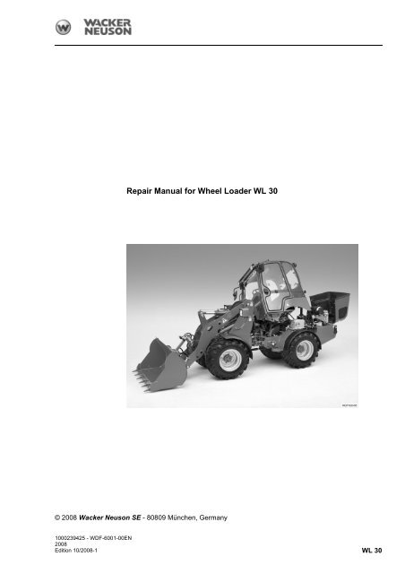
© 2008 <strong>Wacker</strong> <strong>Neuson</strong> SE - 80809 München, Germany<br />
1000239425 - WDF-6001-00EN<br />
2008<br />
Edition 10/2008-1<br />
<strong>Repair</strong> <strong>Manual</strong> <strong>for</strong> <strong>Wheel</strong> <strong>Loader</strong> <strong>WL</strong> <strong>30</strong><br />
<strong>WL</strong> <strong>30</strong>
1000239425 - WDF-6001-00EN<br />
<strong>WL</strong> <strong>30</strong> - 10/2008-1 (WDF-7018-00EN)
Service address and<br />
spare parts<br />
<strong>WL</strong> <strong>30</strong> - 10/2008-1 (WDF-7018-00EN) 1000239425 - WDF-6001-00EN<br />
<strong>Repair</strong> <strong>Manual</strong><br />
<strong>Repair</strong> <strong>Manual</strong><br />
If you have any queries, contact your nearest <strong>Wacker</strong> <strong>Neuson</strong> SE dealership.<br />
You can find the address at www.wackerneuson.com.<br />
You can also order spare parts from there.<br />
The operator's manual <strong>for</strong> the loader is also available from here.<br />
Be<strong>for</strong>e you continue reading ...<br />
Operator's manual In addition to this repair manual, the operator's manual <strong>for</strong> the loader is also<br />
required <strong>for</strong> doing all work in full.<br />
The repair manual is comprised of six parts:<br />
1. Safety<br />
2. Technical data, testing equipment and special tools<br />
3. Inspections, maintenance work and troubleshooting<br />
4. Replacement and repair procedures<br />
5. Circuit diagrams and technical descriptions<br />
6. Supplier service manuals (must be added to locally)<br />
Structure Each part is subdivided into the following, based on the loader's structure:<br />
1. Complete vehicle<br />
2. Engine<br />
3. Hydraulic system<br />
4. Drive and axles<br />
5. Brake system (mechanical section)<br />
6. Vehicle frame and load arm<br />
7. Operator's plat<strong>for</strong>m/cab<br />
8. Electrical system<br />
9. Attachments<br />
Navigation In each part of the manual, there is a table of contents to assist you in<br />
searching <strong>for</strong> individual sections.<br />
The overall table of contents follows on the next pages, after the list of abbreviations<br />
and units.<br />
The overall list of key words can be found immediately be<strong>for</strong>e the "Safety" part.<br />
The list of key words <strong>for</strong> the respective part of the manual can be found at the<br />
end of that part.<br />
Applicability The repair manual applies to loaders of the type <strong>WL</strong> <strong>30</strong>, with the following<br />
article numbers:<br />
0610135<br />
0610164<br />
0610174<br />
0610228<br />
Special features The repair manual also describes work on special features that are not present<br />
on every loader.<br />
0-3
<strong>Repair</strong> <strong>Manual</strong><br />
Abbreviations and units<br />
% Percent<br />
A High-pressure connection on the variable displacement<br />
pump<br />
as req. As required<br />
B High-pressure connection on the variable displacement<br />
pump<br />
bar Unit of pressure<br />
BK Black<br />
BL Blue<br />
BN Brown<br />
cm Centimeter<br />
cm 3 Cubic centimeter<br />
F3 Fuse No. 3<br />
G Supply pressure at the variable displacement pump<br />
or<br />
Test pressure at the variable displacement motor<br />
GN Green<br />
GR Gray<br />
h Hour<br />
KL<strong>30</strong> Terminal designation<br />
l Liter<br />
LB Light blue<br />
M 1<br />
M A<br />
max. Maximum, highest<br />
M B<br />
min Minute<br />
min. Minimum, at least<br />
Nm Newton meter<br />
Ø [mm 2 ]<br />
OR Orange<br />
P Pin, pin contact<br />
PK Pink<br />
RD Red<br />
Test pressure at the variable displacement motor<br />
Test pressure at the variable displacement pump<br />
Test pressure at the variable displacement pump<br />
Wire cross section [in square millimeters]<br />
rpm Unit of speed (revolutions per minute)<br />
s Second<br />
S Socket, socket contact<br />
SKA Standard configuration, SKA machines<br />
SP1 Welding point No. 1 in the machine's wiring harness<br />
SP1M Welding point No. 1 in the motor wiring harness<br />
SV Solenoid valve<br />
TR Transparent<br />
0-4 1000239425 - WDF-6001-00EN<br />
<strong>WL</strong> <strong>30</strong> - 10/2008-1 (WDF-7018-00EN)
VI Violet<br />
WH White<br />
X Plug connector<br />
X 1<br />
X 2<br />
YE Yellow<br />
<strong>WL</strong> <strong>30</strong> - 10/2008-1 (WDF-7018-00EN) 1000239425 - WDF-6001-00EN<br />
<strong>Repair</strong> <strong>Manual</strong><br />
Control pressure at the variable displacement pump<br />
Control pressure at the variable displacement pump<br />
0-5
<strong>Repair</strong> <strong>Manual</strong><br />
0-6 1000239425 - WDF-6001-00EN<br />
<strong>WL</strong> <strong>30</strong> - 10/2008-1 (WDF-7018-00EN)
Part 1 Safety<br />
1 <strong>Repair</strong> work<br />
(complete vehicle) . . . . . . . . . . . 1-7<br />
2 Engine . . . . . . . . . . . . . . . . . . . . . . . 1-9<br />
3 Hydraulic system . . . . . . . . . . . 1-11<br />
4 Drive and axles . . . . . . . . . . . . . 1-13<br />
5 Brake system . . . . . . . . . . . . . . . 1-15<br />
6 Vehicle frame and<br />
load arm . . . . . . . . . . . . . . . . . . . . 1-17<br />
7 Electrical system. . . . . . . . . . . . 1-19<br />
Part 2 Technical data, testing<br />
equipment and special tools<br />
1 Technical data . . . . . . . . . . . . . . . 2-7<br />
2 Filling quantities . . . . . . . . . . . . . 2-9<br />
3 Tightening torques . . . . . . . . . . 2-11<br />
4 Pressure values . . . . . . . . . . . . . 2-13<br />
5 Flow rates. . . . . . . . . . . . . . . . . . . 2-15<br />
6 Safety stickers . . . . . . . . . . . . . . 2-17<br />
7 Testing equipment . . . . . . . . . . 2-23<br />
7.1 Test pressure gauge . . . . . . . . . . . . . 2-23<br />
7.2 Flow meter . . . . . . . . . . . . . . . . . . . . 2-23<br />
7.3 Test pump . . . . . . . . . . . . . . . . . . . . . 2-24<br />
8 Special tools . . . . . . . . . . . . . . . . 2-25<br />
8.1 Insertion tool . . . . . . . . . . . . . . . . . . . 2-25<br />
8.2 Sealing plate (2 x) . . . . . . . . . . . . . . . 2-25<br />
8.3 Expulsion and driving sleeves. . . . . . 2-25<br />
8.4 Driving bolts . . . . . . . . . . . . . . . . . . . 2-26<br />
8.5 Electrical contact key . . . . . . . . . . . . 2-27<br />
8.6 Generator tester . . . . . . . . . . . . . . . . 2-27<br />
8.7 Half-shells and pull-off fixture . . . . . . 2-28<br />
9 Hose book . . . . . . . . . . . . . . . . . . 2-29<br />
<strong>WL</strong> <strong>30</strong> - 10/2008-1 (WDF-7018-00DE) 1000239425 - WDF-6001-00EN<br />
Contents<br />
Part 3 Inspections, maintenance work<br />
and troubleshooting<br />
1 Complete vehicle . . . . . . . . . . . . 3-7<br />
1.1 Inspection log. . . . . . . . . . . . . . . . . . . 3-7<br />
2 Engine . . . . . . . . . . . . . . . . . . . . . . 3-9<br />
2.1 Checking and adjusting the<br />
valve play. . . . . . . . . . . . . . . . . . . . . . 3-9<br />
2.2 Inspecting the exhaust system<br />
<strong>for</strong> leaks . . . . . . . . . . . . . . . . . . . . . . 3-11<br />
2.3 Checking the radiator<br />
installation . . . . . . . . . . . . . . . . . . . . 3-12<br />
2.4 Inspect the radiator <strong>for</strong> leaks . . . . . . 3-13<br />
2.5 Troubleshooting on the engine . . . . 3-14<br />
3 Hydraulic system . . . . . . . . . . . 3-17<br />
3.1 Checking and adjusting the<br />
starting speed . . . . . . . . . . . . . . . . . 3-17<br />
3.2 Checking and adjusting the<br />
inching pedal . . . . . . . . . . . . . . . . . . 3-17<br />
3.3 Checking and adjusting the<br />
pressure cut-off . . . . . . . . . . . . . . . . 3-18<br />
3.4 Adjusting the driving speed . . . . . . . 3-19<br />
3.5 Checking the variable displacement<br />
pump supply pressure . . . . . . . . . . . 3-20<br />
3.6 Checking the variable displacement<br />
pump high pressure . . . . . . . . . . . . . 3-21<br />
3.7 Checking the variable displacement<br />
pump positioning pressure. . . . . . . . 3-23<br />
3.8 Checking and adjusting the control<br />
commencement of the variable<br />
displacement motor . . . . . . . . . . . . . 3-24<br />
3.9 Testing the steering hydraulics . . . . 3-25<br />
3.10 Checking the gear pump . . . . . . . . . 3-27<br />
3.11 Checking the control valve<br />
function . . . . . . . . . . . . . . . . . . . . . . 3-29<br />
3.12 Troubleshooting on the hydraulic<br />
system . . . . . . . . . . . . . . . . . . . . . . . 3-<strong>30</strong><br />
4 Drive and axles . . . . . . . . . . . . . 3-33<br />
4.1 Inspecting the differential lock . . . . . 3-33<br />
4.2 Checking the water filling of the<br />
wheels . . . . . . . . . . . . . . . . . . . . . . . 3-34<br />
4.3 Troubleshooting on the drive . . . . . . 3-35<br />
5 Vehicle frame and<br />
load arm. . . . . . . . . . . . . . . . . . . . 3-37<br />
5.1 Checking and adjusting the<br />
curling to load and dumping<br />
stops . . . . . . . . . . . . . . . . . . . . . . . . 3-37<br />
6 Cab. . . . . . . . . . . . . . . . . . . . . . . . . 3-39<br />
6.1 Checking the heater. . . . . . . . . . . . . 3-39<br />
6.2 Troubleshooting in the cab . . . . . . . 3-40<br />
0-7
Contents<br />
7 Electrical system . . . . . . . . . . . 3-41<br />
7.1 Checking the generator . . . . . . . . . . 3-41<br />
7.2 Checking the temperature<br />
sensors . . . . . . . . . . . . . . . . . . . . . . 3-41<br />
7.3 Testing the belt buckle circuit. . . . . . 3-42<br />
7.4 Testing the fuel level sensor . . . . . . 3-43<br />
7.5 Troubleshooting on the electrical<br />
system . . . . . . . . . . . . . . . . . . . . . . . 3-44<br />
Part 4 Replacement and repair<br />
procedures<br />
1 Complete vehicle . . . . . . . . . . . . 4-9<br />
1.1 Helpful tips . . . . . . . . . . . . . . . . . . . . . 4-9<br />
1.2 Replacing protective stickers . . . . . . . 4-9<br />
2 Engine. . . . . . . . . . . . . . . . . . . . . . 4-11<br />
2.1 Engine (as supplied) . . . . . . . . . . . . 4-11<br />
2.1.1 Engine removal . . . . . . . . . . . . . . . . 4-11<br />
2.1.2 Engine installation . . . . . . . . . . . . . . 4-13<br />
2.1.3 Replacing the front rubber<br />
buffers . . . . . . . . . . . . . . . . . . . . . . . 4-16<br />
2.1.4 Replacing the rear rubber buffer . . . 4-17<br />
2.1.5 Replacing the clutch PA flange . . . . 4-18<br />
2.1.6 Cleaning the engine (after toppling<br />
the loader) . . . . . . . . . . . . . . . . . . . . 4-19<br />
2.2 Radiator . . . . . . . . . . . . . . . . . . . . . . 4-21<br />
2.2.1 Removing the radiator . . . . . . . . . . . 4-21<br />
2.2.2 Installing the radiator . . . . . . . . . . . . 4-22<br />
2.3 Air filter system . . . . . . . . . . . . . . . . 4-25<br />
2.3.1 Replacing the complete air filter. . . . 4-25<br />
2.3.2 Replacing the air filter housing. . . . . 4-26<br />
2.4 Fuel system . . . . . . . . . . . . . . . . . . . 4-27<br />
2.4.1 Replacing the complete fuel<br />
filter . . . . . . . . . . . . . . . . . . . . . . . . . 4-27<br />
2.4.2 Replacing the complete main<br />
fuel filter . . . . . . . . . . . . . . . . . . . . . . 4-28<br />
2.4.3 Replacing the water separator . . . . . 4-29<br />
2.4.4 Replacing the fuel feed pump . . . . . 4-<strong>30</strong><br />
2.4.5 Replacing the fuel line . . . . . . . . . . . 4-31<br />
2.4.6 Tank lock emergency opening . . . . . 4-32<br />
2.5 Exhaust system . . . . . . . . . . . . . . . . 4-33<br />
2.5.1 Replacing the flue . . . . . . . . . . . . . . 4-33<br />
2.5.2 Replacing the muffler and<br />
flexi-pipe. . . . . . . . . . . . . . . . . . . . . . 4-33<br />
3 Hydraulic system . . . . . . . . . . . 4-37<br />
3.1 Complete vehicle . . . . . . . . . . . . . . . 4-37<br />
3.1.1 Depressurizing the hydraulic<br />
system . . . . . . . . . . . . . . . . . . . . . . . 4-37<br />
3.1.2 Replacing the pivot bearing on the<br />
hydraulic cylinder . . . . . . . . . . . . . . . 4-37<br />
3.1.3 Sealing the hydraulic cylinder . . . . . 4-38<br />
3.2 Driving hydraulics. . . . . . . . . . . . . . . 4-42<br />
3.2.1 Replacing the variable<br />
displacement pump . . . . . . . . . . . . . 4-42<br />
3.2.2 Replacing the clutch hub . . . . . . . . . 4-44<br />
3.2.3 Replacing the annular shaft seal<br />
of the variable displacement<br />
pump. . . . . . . . . . . . . . . . . . . . . . . . . 4-45<br />
3.2.4 Replacing the variable displacement<br />
motor . . . . . . . . . . . . . . . . . . . . . . . . 4-45<br />
3.3 Steering hydraulics . . . . . . . . . . . . . . 4-48<br />
3.3.1 Cleaning the priority valve . . . . . . . . 4-48<br />
3.3.2 Replacing the priority valve . . . . . . . 4-50<br />
3.3.3 Replacing the orbital steering<br />
valve . . . . . . . . . . . . . . . . . . . . . . . . . 4-51<br />
3.3.4 Removing the steering cylinder . . . . 4-52<br />
3.3.5 Installing the steering cylinder . . . . . 4-54<br />
3.4 Brake hydraulics . . . . . . . . . . . . . . . . 4-55<br />
3.4.1 Replacing the main brake<br />
cylinder . . . . . . . . . . . . . . . . . . . . . . . 4-55<br />
3.4.2 Replacing the brake hydraulics<br />
tank. . . . . . . . . . . . . . . . . . . . . . . . . . 4-56<br />
3.4.3 Replacing the brake fluid . . . . . . . . . 4-57<br />
3.4.4 Venting the brake hydraulics . . . . . . 4-58<br />
3.5 Working hydraulics . . . . . . . . . . . . . . 4-59<br />
3.5.1 Replacing the gear pump . . . . . . . . . 4-59<br />
3.5.2 Sealing the gear pump . . . . . . . . . . . 4-61<br />
3.5.3 Removing the control valve . . . . . . . 4-63<br />
3.5.4 Installing the control valve . . . . . . . . 4-64<br />
3.5.5 Sealing the control valve . . . . . . . . . 4-66<br />
3.5.6 Installing the catch on the control<br />
valve . . . . . . . . . . . . . . . . . . . . . . . . . 4-70<br />
3.5.7 Replacing the cross controller . . . . . 4-70<br />
3.5.8 Replacing the lifting cylinder. . . . . . . 4-71<br />
3.5.9 Removing the tipping cylinder . . . . . 4-73<br />
3.5.10 Installing the tipping cylinder . . . . . . 4-75<br />
3.5.11 Replacing the rod-end bearing<br />
of the tipping cylinder . . . . . . . . . . . . 4-76<br />
3.6 Auxiliary hydraulics and hydraulic<br />
lock . . . . . . . . . . . . . . . . . . . . . . . . . . 4-77<br />
3.6.1 Replacing the cover of the auxiliary<br />
hydraulics . . . . . . . . . . . . . . . . . . . . . 4-77<br />
3.6.2 Replacing the control lever and<br />
cover of the auxiliary hydraulics . . . . 4-78<br />
3.6.3 Replacing the locking cylinder . . . . . 4-79<br />
3.7 Tank, filter and hydraulic lines . . . . . 4-80<br />
3.7.1 Replacing the hydraulic fluid tank. . . 4-80<br />
3.7.2 Replacing the complete return<br />
filter. . . . . . . . . . . . . . . . . . . . . . . . . . 4-82<br />
3.7.3 Replacing the pressure filter. . . . . . . 4-83<br />
3.7.4 Replacing the hydraulic line . . . . . . . 4-84<br />
4 Drive and axles . . . . . . . . . . . . . 4-85<br />
4.1 Replacing the drive shaft . . . . . . . . . 4-85<br />
4.2 Front axle . . . . . . . . . . . . . . . . . . . . . 4-86<br />
4.2.1 Removing the front axle . . . . . . . . . . 4-86<br />
4.2.2 Installing the front axle . . . . . . . . . . . 4-88<br />
0-8 1000239425 - WDF-6001-00EN<br />
<strong>WL</strong> <strong>30</strong> - 10/2008-1 (WDF-7018-00DE)
4.3 Rear axle. . . . . . . . . . . . . . . . . . . . . . 4-91<br />
4.3.1 Removing the rear axle. . . . . . . . . . . 4-91<br />
4.3.2 Installing the rear axle. . . . . . . . . . . . 4-93<br />
4.4 Changing the wheel of the twin<br />
tires . . . . . . . . . . . . . . . . . . . . . . . . . . 4-95<br />
5 Brake system<br />
(mechanical section) . . . . . . . . 4-97<br />
5.1 Service brake . . . . . . . . . . . . . . . . . . 4-97<br />
5.1.1 Replacing the brake shoes . . . . . . . . 4-97<br />
5.1.2 Replacing the brake drum. . . . . . . . . 4-98<br />
5.2 Parking brake . . . . . . . . . . . . . . . . . . 4-99<br />
5.2.1 Replacing the Bowden cable<br />
of the parking brake . . . . . . . . . . . . . 4-99<br />
6 Vehicle frame and<br />
load arm . . . . . . . . . . . . . . . . . . . 4-103<br />
6.1 Front carriage . . . . . . . . . . . . . . . . . 4-103<br />
6.1.1 Replacing the front fender. . . . . . . . 4-103<br />
6.2 Rear carriage and engine hood. . . . 4-103<br />
6.2.1 Replacing the rear fender . . . . . . . . 4-103<br />
6.2.2 Replacing the additional<br />
weight/base plate . . . . . . . . . . . . . . 4-104<br />
6.2.3 Replacing the rear weight . . . . . . . . 4-105<br />
6.2.4 Replacing the engine hood . . . . . . . 4-107<br />
6.2.5 Replacing the lock of the engine<br />
hood . . . . . . . . . . . . . . . . . . . . . . . . 4-108<br />
6.2.6 Emergency release of the engine<br />
hood . . . . . . . . . . . . . . . . . . . . . . . . 4-109<br />
6.3 Center joint . . . . . . . . . . . . . . . . . . . 4-109<br />
6.3.1 Detaching the center joint . . . . . . . . 4-109<br />
6.3.2 Connecting the center joint . . . . . . . 4-111<br />
6.3.3 Replacing the bearing in the<br />
self-aligning bearing . . . . . . . . . . . . 4-115<br />
6.3.4 Replacing the lower bearing . . . . . . 4-116<br />
6.4 Step plate and insulation mats . . . . 4-117<br />
6.4.1 Removing the operator's<br />
plat<strong>for</strong>m . . . . . . . . . . . . . . . . . . . . . . 4-117<br />
6.4.2 Installing the operator's<br />
plat<strong>for</strong>m . . . . . . . . . . . . . . . . . . . . . . 4-120<br />
6.4.3 Replacing the rubber buffer<br />
of the step plate. . . . . . . . . . . . . . . . 4-123<br />
6.4.4 Replacing the insulation mat . . . . . . 4-124<br />
6.5 Load arm. . . . . . . . . . . . . . . . . . . . . 4-125<br />
6.5.1 Replacing the complete<br />
load arm . . . . . . . . . . . . . . . . . . . . . 4-125<br />
6.5.2 Replacing the bearings of the<br />
short drawbar . . . . . . . . . . . . . . . . . 4-127<br />
6.5.3 Replacing the bearings of the<br />
short reversing lever . . . . . . . . . . . . 4-128<br />
6.5.4 Replacing the bearings of the<br />
long reversing lever. . . . . . . . . . . . . 4-129<br />
6.5.5 Replacing the upper bearing<br />
of the long drawbar . . . . . . . . . . . . . 4-131<br />
6.5.6 Replacing the lower bearing<br />
of the long drawbar . . . . . . . . . . . . . 4-132<br />
6.6 Tool attachment . . . . . . . . . . . . . . . 4-133<br />
<strong>WL</strong> <strong>30</strong> - 10/2008-1 (WDF-7018-00DE) 1000239425 - WDF-6001-00EN<br />
Contents<br />
6.6.1 Replacing the tool attachment . . . . 4-133<br />
6.6.2 Replacing the locking pin. . . . . . . . 4-134<br />
6.6.3 Replacing the lock of the tool<br />
attachment (US). . . . . . . . . . . . . . . 4-135<br />
7 Operator's plat<strong>for</strong>m<br />
and cab . . . . . . . . . . . . . . . . . . . 4-137<br />
7.1 Seat . . . . . . . . . . . . . . . . . . . . . . . . 4-137<br />
7.1.1 Replacing the driver's seat. . . . . . . 4-137<br />
7.1.2 Replacing the complete seat<br />
belt . . . . . . . . . . . . . . . . . . . . . . . . . 4-138<br />
7.1.3 Replacing the belt buckle. . . . . . . . 4-138<br />
7.2 ROPS bar and driver's canopy . . . 4-139<br />
7.2.1 Replacing the ROPS bar . . . . . . . . 4-139<br />
7.2.2 Replacing the driver's canopy . . . . 4-139<br />
7.2.3 Replacing the lower section of<br />
the ROPS bar/driver's canopy . . . . 4-141<br />
7.2.4 Replacing the document<br />
compartment . . . . . . . . . . . . . . . . . 4-142<br />
7.2.5 Replacing the storage<br />
compartment . . . . . . . . . . . . . . . . . 4-143<br />
7.3 Cab . . . . . . . . . . . . . . . . . . . . . . . . 4-144<br />
7.3.1 Removing the complete cab . . . . . 4-144<br />
7.3.2 Installing the complete cab . . . . . . 4-146<br />
7.3.3 Replacing the windshield wiper<br />
arms. . . . . . . . . . . . . . . . . . . . . . . . 4-149<br />
7.3.4 Replacing the windshield washer<br />
container . . . . . . . . . . . . . . . . . . . . 4-150<br />
7.3.5 Replacing the door lock . . . . . . . . . 4-151<br />
7.3.6 Replacing the door stay . . . . . . . . . 4-152<br />
7.3.7 Replacing the complete door . . . . . 4-153<br />
7.3.8 Replacing the roof grille<br />
of the cab . . . . . . . . . . . . . . . . . . . . 4-154<br />
7.3.9 Replacing the window and the<br />
rubber clamping profile . . . . . . . . . 4-154<br />
7.3.10 Replacing a bonded-in window . . . 4-156<br />
7.3.11 Replacing the complete heater . . . 4-158<br />
7.4 Steering column. . . . . . . . . . . . . . . 4-159<br />
7.4.1 Replacing the instrument<br />
steering column . . . . . . . . . . . . . . . 4-159<br />
7.4.2 Replacing the steering wheel. . . . . 4-161<br />
8 Electrical system . . . . . . . . . . 4-163<br />
8.1 Generator, battery and motors. . . . 4-163<br />
8.1.1 Replacing the generator . . . . . . . . 4-163<br />
8.1.2 Replacing the starter . . . . . . . . . . . 4-164<br />
8.1.3 Replacing the rear windshield<br />
wiper motor . . . . . . . . . . . . . . . . . . 4-165<br />
8.1.4 Replacing the front windshield<br />
wiper motor . . . . . . . . . . . . . . . . . . 4-166<br />
8.2 Switches and sensors . . . . . . . . . . 4-167<br />
8.2.1 Replacing the switches in the<br />
instrument panel . . . . . . . . . . . . . . 4-167<br />
8.2.2 Replacing the combination<br />
switch. . . . . . . . . . . . . . . . . . . . . . . 4-168<br />
8.2.3 Replacing the glow-plug<br />
indicator . . . . . . . . . . . . . . . . . . . . . 4-168<br />
0-9
Contents<br />
8.2.4 Replacing the switches in the<br />
cab . . . . . . . . . . . . . . . . . . . . . . . . . 4-169<br />
8.2.5 Replacing the ignition lock . . . . . . . 4-170<br />
8.2.6 Replacing the battery disconnect<br />
switch . . . . . . . . . . . . . . . . . . . . . . . 4-171<br />
8.2.7 Replacing the parking brake<br />
switch . . . . . . . . . . . . . . . . . . . . . . . 4-172<br />
8.2.8 Replacing the return filter<br />
overpressure switch . . . . . . . . . . . . 4-173<br />
8.2.9 Replacing the engine temperature<br />
sensor . . . . . . . . . . . . . . . . . . . . . . 4-174<br />
8.2.10 Replacing the temperature sensor<br />
of the hydraulic fluid tank . . . . . . . . 4-175<br />
8.2.11 Replacing the fuel level sensor . . . 4-176<br />
8.3 Relays, coils and fuses . . . . . . . . . 4-177<br />
8.3.1 Replacing the relays . . . . . . . . . . . 4-177<br />
8.3.2 Replacing the solenoid valve<br />
drives on the variable<br />
displacement motor . . . . . . . . . . . . 4-177<br />
8.3.3 Replacing the solenoid valve<br />
of the variable displacement<br />
pump . . . . . . . . . . . . . . . . . . . . . . . 4-178<br />
8.3.4 Replacing the coil on the variable<br />
displacement pump . . . . . . . . . . . . 4-179<br />
8.4 Indicator lamps, audible warning<br />
generators and instruments . . . . . . 4-180<br />
8.4.1 Replacing the indicator lamp<br />
in the instrument panel. . . . . . . . . . 4-180<br />
8.4.2 Replacing the instrument lights . . . 4-181<br />
8.4.3 Replacing the horn. . . . . . . . . . . . . 4-182<br />
8.4.4 Replacing the audible warning<br />
generator . . . . . . . . . . . . . . . . . . . . 4-183<br />
8.4.5 Replacing the engine-hour<br />
indicator . . . . . . . . . . . . . . . . . . . . . 4-183<br />
8.5 Lighting system . . . . . . . . . . . . . . . 4-185<br />
8.5.1 Replacing a complete headlamp<br />
with indicator . . . . . . . . . . . . . . . . . 4-185<br />
8.5.2 Replacing a complete tail lamp . . . 4-185<br />
8.5.3 Replacing the headlight . . . . . . . . . 4-186<br />
9 Attachments. . . . . . . . . . . . . . . 4-189<br />
9.1 Replacing the earth bucket<br />
digging tooth . . . . . . . . . . . . . . . . . 4-189<br />
Part 5 Circuit diagrams and technical<br />
descriptions<br />
1 Hydraulic circuit diagram . . . . 5-7<br />
2 Electrical circuit diagram . . . . 5-9<br />
3 Plug assignments /<br />
contact assignments. . . . . . . . 5-19<br />
4 Technical description . . . . . . . 5-21<br />
Part 6 Supplier service manuals<br />
1 Engine workshop manual<br />
(example) . . . . . . . . . . . . . . . . . . . . 6-7<br />
2 Variable displ. pump repair<br />
instructions (example) . . . . . . . 6-9<br />
3 Variable displ. motor repair<br />
instructions (example) . . . . . . 6-11<br />
4 Planetary axle workshop<br />
manual (example) . . . . . . . . . . . 6-13<br />
0-10 1000239425 - WDF-6001-00EN<br />
<strong>WL</strong> <strong>30</strong> - 10/2008-1 (WDF-7018-00DE)
A<br />
Additional weight<br />
Replacement . . . . . . . . . . . . . . . . . . . . . . 4-104<br />
Air filter<br />
Replacing complete . . . . . . . . . . . . . . . . . . 4-25<br />
Replacing the housing . . . . . . . . . . . . . . . . 4-26<br />
Alternator<br />
See generator . . . . . . . . . . . . . . . . . . . . . 4-163<br />
Annular shaft seal, replacement<br />
Variable displacement pump . . . . . . . . . . . 4-45<br />
Assignment<br />
Combination switch . . . . . . . . . . . . . . . . . . 5-19<br />
Ignition lock . . . . . . . . . . . . . . . . . . . . . . . . 5-19<br />
Multi-function lever . . . . . . . . . . . . . . . . . . 5-19<br />
Windshield wiper switch . . . . . . . . . . . . . . 5-19<br />
Audible warning generator<br />
Replacing . . . . . . . . . . . . . . . . . . . . . . . . 4-183<br />
Auxiliary hydraulics<br />
Replacing the cover . . . . . . . . . . . . . . . . . 4-77<br />
Axles<br />
Safety instructions . . . . . . . . . . . . . . . . . . . 1-13<br />
B<br />
Base plate<br />
Replacement . . . . . . . . . . . . . . . . . . . . . . 4-104<br />
Battery disconnect switch<br />
Replacing . . . . . . . . . . . . . . . . . . . . . . . . 4-171<br />
Bearings, replacing<br />
Drawbar, long . . . . . . . . . . . . . . . 4-131, 4-132<br />
Drawbar, short . . . . . . . . . . . . . . . . . . . . . 4-127<br />
Lower bearing . . . . . . . . . . . . . . . . . . . . . 4-116<br />
Reversing lever, long . . . . . . . . . . . . . . . 4-129<br />
Reversing lever, short . . . . . . . . . . . . . . . 4-128<br />
Self-aligning bearing . . . . . . . . . . . . . . . . 4-115<br />
Belt buckle<br />
Replacing . . . . . . . . . . . . . . . . . . . . . . . . 4-138<br />
Belt buckle circuit<br />
Testing . . . . . . . . . . . . . . . . . . . . . . . . . . . 3-42<br />
Brake cylinder<br />
see Main brake cylinder . . . . . . . . . . . . . . 4-55<br />
Brake drum<br />
Replacing . . . . . . . . . . . . . . . . . . . . . . . . . 4-98<br />
Brake fluid<br />
Changing . . . . . . . . . . . . . . . . . . . . . . . . . . 4-57<br />
Brake hydraulics<br />
Replacing the tank . . . . . . . . . . . . . . . . . . 4-56<br />
Venting . . . . . . . . . . . . . . . . . . . . . . . . . . . 4-58<br />
Brake shoes<br />
Replacing . . . . . . . . . . . . . . . . . . . . . . . . . 4-97<br />
Brake system<br />
Safety instructions . . . . . . . . . . . . . . . . . . . 1-15<br />
<strong>WL</strong> <strong>30</strong> - 10/2008-1 (WDF-7018-00DE) 1000239425 - WDF-6001-00EN<br />
C<br />
Index<br />
Cab<br />
Removing complete . . . . . . . . . . . 4-144, 4-146<br />
Switches, replacing . . . . . . . . . . . . . . . . 4-169<br />
Cardan shaft<br />
see Drive shaft . . . . . . . . . . . . . . . . . . . . . 4-85<br />
Center joint<br />
Connecting . . . . . . . . . . . . . . . . . . . . . . . 4-111<br />
Detaching . . . . . . . . . . . . . . . . . . . . . . . . 4-109<br />
Circuit diagram<br />
Electrical circuit diagram . . . . . . . . . . . . . . 5-9<br />
Hydraulic circuit diagram . . . . . . . . . . . . . . 5-7<br />
Cleanliness . . . . . . . . . . . . . . . . . . . . . . . . . . . 4-9<br />
Clutch hub<br />
Replacing . . . . . . . . . . . . . . . . . . . . . . . . . 4-44<br />
Clutch PA flange<br />
Replacing . . . . . . . . . . . . . . . . . . . . . . . . . 4-18<br />
Combination switch<br />
Replacing . . . . . . . . . . . . . . . . . . . . . . . . 4-168<br />
Contact assignment . . . . . . . . . . . . . . . . . . . . 5-19<br />
Control valve<br />
Checking the function . . . . . . . . . . . . . . . 3-29<br />
Installing . . . . . . . . . . . . . . . . . . . . . . . . . . 4-64<br />
Installing the catch . . . . . . . . . . . . . . . . . . 4-70<br />
Removing . . . . . . . . . . . . . . . . . . . . . . . . . 4-63<br />
Sealing . . . . . . . . . . . . . . . . . . . . . . . . . . . 4-66<br />
Cover, replacing<br />
Auxiliary hydraulics control lever . . . . . . . 4-78<br />
Cross controller<br />
Replacing . . . . . . . . . . . . . . . . . . . . . . . . . 4-70<br />
Curling to load stop<br />
Checking and adjusting . . . . . . . . . . . . . . 3-37<br />
D<br />
Depressurize the hydraulic system . . . . . . . . 4-37<br />
Description<br />
see Technical description . . . . . . . . . . . . 5-21<br />
Differential lock<br />
Inspecting . . . . . . . . . . . . . . . . . . . . . . . . . 3-33<br />
Digging tooth, replacing<br />
Earth bucket . . . . . . . . . . . . . . . . . . . . . . 4-189<br />
Document compartment<br />
Replacing . . . . . . . . . . . . . . . . . . . . . . . . 4-142<br />
Door<br />
Replacing complete . . . . . . . . . . . . . . . . 4-153<br />
Door lock<br />
Replacing . . . . . . . . . . . . . . . . . . . . . . . . 4-151<br />
Door stay<br />
Replacing . . . . . . . . . . . . . . . . . . . . . . . . 4-152<br />
0-11
Index<br />
Drawbar, long<br />
Lower bearing, replacing . . . . . . . . . . . . 4-132<br />
Upper bearing, replacing . . . . . . . . . . . . 4-131<br />
Drawbar, short<br />
Replacing the bearings . . . . . . . . . . . . . 4-127<br />
Drive<br />
Safety instructions . . . . . . . . . . . . . . . . . . 1-13<br />
Drive shaft<br />
Disassembling . . . . . . . . . . . . . . . . . . . . . 4-85<br />
Replacing . . . . . . . . . . . . . . . . . . . . . . . . . 4-85<br />
Temporary securing . . . . . . . . . . . . . . . . . 4-86<br />
Driver's canopy<br />
Lower section, replacing . . . . . . . . . . . . 4-141<br />
Replacing . . . . . . . . . . . . . . . . . . . . . . . . 4-139<br />
Driver's seat<br />
Replacing . . . . . . . . . . . . . . . . . . . . . . . . 4-137<br />
Driving bolts . . . . . . . . . . . . . . . . . . . . . . . . . . 2-26<br />
Driving motor<br />
see Variable displacement motor . . . . . . . 4-45<br />
Driving sleeve . . . . . . . . . . . . . . . . . . . . . . . . . 2-25<br />
Driving speed<br />
Adjusting . . . . . . . . . . . . . . . . . . . . . . . . . 3-19<br />
Dumping stop<br />
Checking and adjusting . . . . . . . . . . . . . . 3-37<br />
E<br />
Electrical circuit diagram . . . . . . . . . . . . . . . . . 5-9<br />
Electrical contact key . . . . . . . . . . . . . . . . . . . 2-27<br />
Electrical system<br />
Safety instructions . . . . . . . . . . . . . . . . . . 1-19<br />
Engine<br />
Cleaning after toppling . . . . . . . . . . . . . . . 4-19<br />
Installation . . . . . . . . . . . . . . . . . . . . . . . . 4-13<br />
Removal . . . . . . . . . . . . . . . . . . . . . . . . . . 4-11<br />
Safety instructions . . . . . . . . . . . . . . . . . . . 1-9<br />
Temperature sensor, replacement . . . . . 4-174<br />
Troubleshooting . . . . . . . . . . . . . . . . . . . . 3-14<br />
Workshop manual (example) . . . . . . . . . . . 6-7<br />
Engine hood<br />
Emergency release . . . . . . . . . . . . . . . . 4-109<br />
Replacing . . . . . . . . . . . . . . . . . . . . . . . . 4-107<br />
Replacing the lock . . . . . . . . . . . . . . . . . 4-108<br />
Engine temperature gauge, replacing<br />
see Engine-hour indicator, replacing . . . 4-183<br />
Engine-hour indicator<br />
Replacing . . . . . . . . . . . . . . . . . . . . . . . . 4-183<br />
Exhaust system<br />
Inspecting <strong>for</strong> leaks . . . . . . . . . . . . . . . . . 3-11<br />
Expulsion sleeve . . . . . . . . . . . . . . . . . . . . . . 2-25<br />
F<br />
Fender<br />
Replacing front . . . . . . . . . . . . . . . . . . . . 4-103<br />
Replacing rear . . . . . . . . . . . . . . . . . . . . 4-103<br />
Flow meter . . . . . . . . . . . . . . . . . . . . . . . . . . . 2-23<br />
Flow rates . . . . . . . . . . . . . . . . . . . . . . . . . . . . 2-15<br />
Flue<br />
Replacing . . . . . . . . . . . . . . . . . . . . . . . . . 4-33<br />
Front axle<br />
Installing . . . . . . . . . . . . . . . . . . . . . . . . . . 4-88<br />
Relieving the load . . . . . . . . . . . . . . . . . . . 4-87<br />
Removing . . . . . . . . . . . . . . . . . . . . . . . . . 4-86<br />
Fuel feed pump<br />
Replacing . . . . . . . . . . . . . . . . . . . . . . . . . 4-<strong>30</strong><br />
Fuel filter<br />
Replacing complete . . . . . . . . . . . . . . . . . 4-27<br />
Fuel level sensor<br />
Replacing . . . . . . . . . . . . . . . . . . . . . . . . 4-176<br />
Testing . . . . . . . . . . . . . . . . . . . . . . . . . . . 3-43<br />
Fuel tank gauge, replacing<br />
see Engine-hour indicator, replacing . . . 4-183<br />
G<br />
Gear pump<br />
Checking . . . . . . . . . . . . . . . . . . . . . . . . . . 3-27<br />
Replacing . . . . . . . . . . . . . . . . . . . . . . . . . 4-59<br />
Sealing . . . . . . . . . . . . . . . . . . . . . . . . . . . 4-61<br />
Generator<br />
Checking . . . . . . . . . . . . . . . . . . . . . . . . . . 3-41<br />
Replacing . . . . . . . . . . . . . . . . . . . . . . . . 4-163<br />
Generator tester . . . . . . . . . . . . . . . . . . . . . . . 2-27<br />
Glow-plug indicator<br />
Replacing . . . . . . . . . . . . . . . . . . . . . . . . 4-168<br />
0-12 1000239425 - WDF-6001-00EN<br />
<strong>WL</strong> <strong>30</strong> - 10/2008-1 (WDF-7018-00DE)<br />
H<br />
Half-shells and pull-off fixture . . . . . . . . . . . . . 2-28<br />
Handbrake<br />
see Parking brake . . . . . . . . . . . . . . . . . . . 4-99<br />
Headlamp<br />
Replacing complete . . . . . . . . . . . . . . . . 4-185<br />
Headlight<br />
Replacing . . . . . . . . . . . . . . . . . . . . . . . . 4-186<br />
Heater<br />
Checking . . . . . . . . . . . . . . . . . . . . . . . . . . 3-39<br />
Replacing complete . . . . . . . . . . . . . . . . 4-158<br />
High pressure, checking<br />
Variable displacement pump . . . . . . . . . . 3-21<br />
Horn<br />
Replacing . . . . . . . . . . . . . . . . . . . . . . . . 4-182<br />
see Audible warning generator . . . . . . . . 4-183
Hose book . . . . . . . . . . . . . . . . . . . . . . . . . . . . 2-29<br />
Hydraulic circuit diagram . . . . . . . . . . . . . . . . . . 5-7<br />
Hydraulic cylinder<br />
Sealing . . . . . . . . . . . . . . . . . . . . . . . . . . . 4-38<br />
Hydraulic fluid tank<br />
Replacing . . . . . . . . . . . . . . . . . . . . . . . . . 4-80<br />
Temperature sensor, replacement . . . . . 4-175<br />
Hydraulic line<br />
Replacing . . . . . . . . . . . . . . . . . . . . . . . . . 4-84<br />
Hydraulic motor<br />
see Variable displacement motor . . . . . . . 4-45<br />
Hydraulic pump<br />
see Gear pump . . . . . . . . . . . . . . . . . . . . . 4-59<br />
see Variable displacement pump . . . . . . . 4-42<br />
Hydraulic system<br />
Safety instructions . . . . . . . . . . . . . . . . . . . 1-11<br />
I<br />
Ignition lock<br />
Replacing . . . . . . . . . . . . . . . . . . . . . . . . 4-170<br />
Inching pedal<br />
Checking and adjusting . . . . . . . . . . . . . . . 3-17<br />
Indicator lamp<br />
Replacing . . . . . . . . . . . . . . . . . . . . . . . . 4-180<br />
Insertion tool . . . . . . . . . . . . . . . . . . . . . . . . . . 2-25<br />
Instrument lights<br />
Replacing . . . . . . . . . . . . . . . . . . . . . . . . 4-181<br />
Instrument panel<br />
Switches, replacing . . . . . . . . . . . . . . . . . 4-167<br />
Instrument steering column<br />
Replacing . . . . . . . . . . . . . . . . . . . . . . . . 4-159<br />
Insulation mat<br />
Replacing . . . . . . . . . . . . . . . . . . . . . . . . 4-124<br />
L<br />
Lifting cylinder<br />
Installing . . . . . . . . . . . . . . . . . . . . . . . . . . 4-72<br />
Removing . . . . . . . . . . . . . . . . . . . . . . . . . 4-72<br />
Replacing . . . . . . . . . . . . . . . . . . . . . . . . . 4-71<br />
Load arm<br />
Replacing complete . . . . . . . . . . . . . . . . . 4-125<br />
Safety instructions . . . . . . . . . . . . . . . . . . . 1-17<br />
Locking agent . . . . . . . . . . . . . . . . . . . . . . . . . . 4-9<br />
Locking cylinder<br />
Replacement . . . . . . . . . . . . . . . . . . . . . . . 4-79<br />
Locking pin<br />
Replacing . . . . . . . . . . . . . . . . . . . . . . . . 4-134<br />
Lower bearing<br />
Replacing . . . . . . . . . . . . . . . . . . . . . . . . 4-116<br />
<strong>WL</strong> <strong>30</strong> - 10/2008-1 (WDF-7018-00DE) 1000239425 - WDF-6001-00EN<br />
Index<br />
M<br />
Main brake cylinder<br />
Replacing . . . . . . . . . . . . . . . . . . . . . . . . . 4-55<br />
Main fuel filter<br />
Replacing complete . . . . . . . . . . . . . . . . . 4-28<br />
Muffler<br />
Replacing . . . . . . . . . . . . . . . . . . . . . . . . . 4-33<br />
O<br />
Operator's plat<strong>for</strong>m<br />
Installing . . . . . . . . . . . . . . . . . . . . . . . . . 4-120<br />
Removing . . . . . . . . . . . . . . . . . . . . . . . . 4-117<br />
Orbital steering valve<br />
Replacing . . . . . . . . . . . . . . . . . . . . . . . . . 4-51<br />
Overpressure switch, replacing<br />
Return filter . . . . . . . . . . . . . . . . . . . . . . 4-173<br />
P<br />
Parking brake<br />
Fitting the Bowden cable . . . . . . . . 4-89, 4-100<br />
Removing the Bowden cable . . . . .4-87, 4-100<br />
Replacing the Bowden cable . . . . . . . . . . 4-99<br />
Switch, replacing . . . . . . . . . . . . . . . . . . 4-172<br />
Pivot bearing<br />
Replacing . . . . . . . . . . . . . . . . . . . . . . . . . 4-37<br />
Planetary axle<br />
Workshop manual (example) . . . . . . . . . . 6-13<br />
Plug assignment . . . . . . . . . . . . . . . . . . . . . . 5-19<br />
Positioning pressure, checking<br />
Variable displacement pump . . . . . . . . . . 3-23<br />
Pressure cut-off<br />
Checking and adjusting . . . . . . . . . . . . . . 3-18<br />
Pressure filter<br />
Replacing . . . . . . . . . . . . . . . . . . . . . . . . . 4-83<br />
Pressure value<br />
Variable displacement pump and<br />
variable displacement motor . . . . . . . . . . 2-13<br />
Priority valve<br />
Cleaning . . . . . . . . . . . . . . . . . . . . . . . . . . 4-48<br />
Replacing . . . . . . . . . . . . . . . . . . . . . . . . . 4-50<br />
Protective stickers<br />
Replacement . . . . . . . . . . . . . . . . . . . . . . . 4-9<br />
R<br />
Radiator<br />
Checking installation . . . . . . . . . . . . . . . . 3-12<br />
Inspecting <strong>for</strong> leaks . . . . . . . . . . . . . . . . . 3-13<br />
Installation . . . . . . . . . . . . . . . . . . . . . . . . 4-22<br />
Removing . . . . . . . . . . . . . . . . . . . . . . . . . 4-21<br />
0-13
Index<br />
Rear axle<br />
Installing . . . . . . . . . . . . . . . . . . . . . . . . . . 4-93<br />
Removing . . . . . . . . . . . . . . . . . . . . . . . . . 4-91<br />
Rear muffler<br />
see Muffler . . . . . . . . . . . . . . . . . . . . . . . . 4-33<br />
Rear weight<br />
Replacing . . . . . . . . . . . . . . . . . . . . . . . . 4-105<br />
Relay<br />
Replacing . . . . . . . . . . . . . . . . . . . . . . . . 4-177<br />
<strong>Repair</strong> work<br />
Safety instructions . . . . . . . . . . . . . . . . . . . 1-7<br />
Replacing . . . . . . . . . . . . . . . . . . . . . . . . . . . . 4-31<br />
Replacing the rubber buffers<br />
Engine, front . . . . . . . . . . . . . . . . . . . . . . . 4-16<br />
Engine, rear . . . . . . . . . . . . . . . . . . . . . . . 4-17<br />
Return filter<br />
Overpressure switch, replacing . . . . . . . 4-173<br />
Replacing the complete . . . . . . . . . . . . . . 4-82<br />
Reversing lever, long<br />
Replacing the bearings . . . . . . . . . . . . . 4-129<br />
Reversing lever, short<br />
Replacing the bearings . . . . . . . . . . . . . 4-128<br />
Roof grille<br />
Replacing . . . . . . . . . . . . . . . . . . . . . . . . 4-154<br />
ROPS bar<br />
Lower section, replacing . . . . . . . . . . . . 4-141<br />
Replacing . . . . . . . . . . . . . . . . . . . . . . . . 4-139<br />
Rubber buffer, replacing<br />
Step plate . . . . . . . . . . . . . . . . . . . . . . . . 4-123<br />
S<br />
Safety stickers<br />
Meaning and position . . . . . . . . . . . . . . . . 2-17<br />
Sealing plate . . . . . . . . . . . . . . . . . . . . . . . . . 2-25<br />
Seat belt<br />
Replacing . . . . . . . . . . . . . . . . . . . . . . . . 4-138<br />
Self-aligning bearing<br />
Replacing bearings . . . . . . . . . . . . . . . . 4-115<br />
Small parts . . . . . . . . . . . . . . . . . . . . . . . . . . . . 4-9<br />
Solenoid valve, replacing . . . . . . . . . . . . . . . 4-177<br />
Variable displacement pump . . . . . . . . . 4-178<br />
Solenoid valve, replacing the coil . . . . . . . . . 4-179<br />
Solenoid valve, replacing the drive<br />
Variable displacement motor . . . . . . . . . 4-177<br />
Starter<br />
Replacing . . . . . . . . . . . . . . . . . . . . . . . . 4-164<br />
Starting speed<br />
Checking and adjusting . . . . . . . . . . . . . . 3-17<br />
Steering cylinder<br />
Installing . . . . . . . . . . . . . . . . . . . . . . . . . . 4-54<br />
Removing . . . . . . . . . . . . . . . . . . . . . . . . . 4-52<br />
Steering hydraulics<br />
Testing . . . . . . . . . . . . . . . . . . . . . . . . . . . 3-25<br />
Steering wheel<br />
Replacing . . . . . . . . . . . . . . . . . . . . . . . . 4-161<br />
Step plate<br />
Rubber buffer, replacing . . . . . . . . . . . . . 4-123<br />
Stickers<br />
see Protective stickers . . . . . . . . . . . . . . . . 4-9<br />
Storage compartment<br />
Replacing . . . . . . . . . . . . . . . . . . . . . . . . 4-143<br />
Supply pressure, checking<br />
Variable displacement pump . . . . . . . . . . 3-20<br />
Switch, replacing<br />
Parking brake . . . . . . . . . . . . . . . . . . . . . 4-172<br />
Switches, replacing<br />
Cab . . . . . . . . . . . . . . . . . . . . . . . . . . . . . 4-169<br />
Instrument panel . . . . . . . . . . . . . . . . . . . 4-167<br />
T<br />
Tail lamp<br />
Replacing the complete . . . . . . . . . . . . . 4-185<br />
Tank lock<br />
Drilling open . . . . . . . . . . . . . . . . . . . . . . . 4-32<br />
Emergency opening . . . . . . . . . . . . . . . . . 4-32<br />
Technical data . . . . . . . . . . . . . . . . . . . . . . . . . 2-7<br />
Technical description . . . . . . . . . . . . . . . . . . . 5-21<br />
Temperature sensor, replacement<br />
Engine . . . . . . . . . . . . . . . . . . . . . . . . . . . 4-174<br />
Hydraulic fluid tank . . . . . . . . . . . . . . . . . 4-175<br />
Temperature sensors<br />
Checking . . . . . . . . . . . . . . . . . . . . . . . . . . 3-41<br />
Test pressure gauge . . . . . . . . . . . . . . . . . . . . 2-23<br />
Test pump . . . . . . . . . . . . . . . . . . . . . . . . . . . . 2-24<br />
Tightening torques<br />
General . . . . . . . . . . . . . . . . . . . . . . . . . . . 2-11<br />
Special . . . . . . . . . . . . . . . . . . . . . . . . . . . 2-11<br />
Tipping cylinder<br />
Installing . . . . . . . . . . . . . . . . . . . . . . . . . . 4-75<br />
Removing . . . . . . . . . . . . . . . . . . . . . . . . . 4-73<br />
Replacing the rod-end bearing . . . . . . . . . 4-76<br />
Tool attachment<br />
Replacing . . . . . . . . . . . . . . . . . . . . . . . . 4-133<br />
Tool attachment (US)<br />
Lock, replacing . . . . . . . . . . . . . . . . . . . . 4-135<br />
Transmission pump<br />
see Variable displacement pump . . . . . . . 4-42<br />
Troubleshooting<br />
Cab . . . . . . . . . . . . . . . . . . . . . . . . . . . . . . 3-40<br />
Drive . . . . . . . . . . . . . . . . . . . . . . . . . . . . . 3-35<br />
Electrical system . . . . . . . . . . . . . . . . . . . . 3-44<br />
Hydraulic system . . . . . . . . . . . . . . . . . . . 3-<strong>30</strong><br />
0-14 1000239425 - WDF-6001-00EN<br />
<strong>WL</strong> <strong>30</strong> - 10/2008-1 (WDF-7018-00DE)
Turning the bearing<br />
see Engine, cleaning after toppling . . . . . . 4-19<br />
Twin tires<br />
Changing the wheel . . . . . . . . . . . . . . . . . 4-95<br />
V<br />
Valve play<br />
Checking and adjusting . . . . . . . . . . . . . . . . 3-9<br />
Variable displacement motor<br />
<strong>Repair</strong> instructions (example) . . . . . . . . . . 6-11<br />
Replacing . . . . . . . . . . . . . . . . . . . . . . . . . 4-45<br />
Solenoid valve, replacement . . . . . . . . . . 4-177<br />
Variable displacement motor control<br />
commencement<br />
Checking and adjusting . . . . . . . . . . . . . . . 3-24<br />
Variable displacement pump<br />
Annular shaft seal, replacement . . . . . . . . 4-45<br />
Coil, replacement . . . . . . . . . . . . . . . . . . 4-179<br />
High pressure, checking . . . . . . . . . . . . . . 3-21<br />
<strong>Repair</strong> instructions (example) . . . . . . . . . . . 6-9<br />
Replacing . . . . . . . . . . . . . . . . . . . . . . . . . 4-42<br />
Solenoid valve, replacing . . . . . . . . . . . . 4-178<br />
Supply pressure, checking . . . . . . . . . . . . 3-20<br />
Vehicle frame<br />
Safety instructions . . . . . . . . . . . . . . . . . . . 1-17<br />
W<br />
Water separator<br />
Replacing . . . . . . . . . . . . . . . . . . . . . . . . . 4-29<br />
<strong>Wheel</strong>s<br />
Checking the water filling . . . . . . . . . . . . . 3-34<br />
Window, replacing<br />
Bonded-in window . . . . . . . . . . . . . . . . . . 4-156<br />
Window with rubber clamping profile . . . 4-154<br />
Windshield washer container<br />
Replacing . . . . . . . . . . . . . . . . . . . . . . . . 4-150<br />
Windshield wiper arms<br />
Replacing . . . . . . . . . . . . . . . . . . . . . . . . 4-149<br />
Windshield wiper motor, front<br />
Replacing . . . . . . . . . . . . . . . . . . . . . . . . 4-166<br />
Windshield wiper motor, rear<br />
Replacing . . . . . . . . . . . . . . . . . . . . . . . . 4-165<br />
<strong>WL</strong> <strong>30</strong> - 10/2008-1 (WDF-7018-00DE) 1000239425 - WDF-6001-00EN<br />
Index<br />
0-15
Index<br />
0-16 1000239425 - WDF-6001-00EN<br />
<strong>WL</strong> <strong>30</strong> - 10/2008-1 (WDF-7018-00DE)
© 2008 <strong>Wacker</strong> <strong>Neuson</strong> SE - 80809 München, Germany<br />
1000239425 - WDF-6001-00EN<br />
2008<br />
Edition 10/2008-1<br />
<strong>Repair</strong> <strong>Manual</strong> <strong>for</strong> <strong>Wheel</strong> <strong>Loader</strong> <strong>WL</strong> <strong>30</strong><br />
Part 1<br />
Safety<br />
<strong>WL</strong> <strong>30</strong>
1000239425 - WDF-6001-00EN<br />
<strong>WL</strong> <strong>30</strong> - 10/2008-1 (WDF-7019-00EN)
<strong>WL</strong> <strong>30</strong> - 10/2008-1 (WDF-7019-00EN) 1000239425 - WDF-6001-00EN<br />
Safety<br />
Safety<br />
This part of the repair manual contains special safety instructions relating to<br />
the loader's individual assemblies.<br />
Warning notices Warning notices are identified by a symbol, and differ in terms of the type and<br />
severity of the hazard described. The various types are shown below.<br />
DANGER<br />
Identifies a hazard that will result in death or serious, irreversible<br />
injury if it is not prevented.<br />
Follow the instructions in order to prevent the hazard.<br />
WARNING<br />
Identifies a hazard that can result in death or serious, irreversible<br />
injury if it is not prevented.<br />
Follow the instructions in order to prevent the hazard.<br />
CAUTION<br />
Identifies a hazard that can result in minor reversible injury.<br />
Follow the instructions in order to prevent the hazard.<br />
Identifies possible damage to the loader or to other property.<br />
Notices The following notices point out important items of in<strong>for</strong>mation:<br />
Identifies a special item of in<strong>for</strong>mation that is required <strong>for</strong> effective and efficient<br />
working.<br />
Identifies an environmental notice.<br />
Do not start working until you have read and understood all safety instructions.<br />
Sequence The sequence of the described work is binding. Keep to the defined sequence<br />
in order to avoid hazards.<br />
1-3
Safety<br />
1-4 1000239425 - WDF-6001-00EN<br />
<strong>WL</strong> <strong>30</strong> - 10/2008-1 (WDF-7019-00EN)
1 <strong>Repair</strong> work<br />
(complete vehicle) . . . . . . . . . . . 1-7<br />
2 Engine . . . . . . . . . . . . . . . . . . . . . . . 1-9<br />
3 Hydraulic system . . . . . . . . . . . 1-11<br />
4 Drive and axles . . . . . . . . . . . . . 1-13<br />
5 Brake system . . . . . . . . . . . . . . . 1-15<br />
6 Vehicle frame and<br />
load arm . . . . . . . . . . . . . . . . . . . . 1-17<br />
7 Electrical system. . . . . . . . . . . . 1-19<br />
<strong>WL</strong> <strong>30</strong> - 10/2008-1 (WDF-7019-00EN) 1000239425 - WDF-6001-00EN<br />
Contents<br />
1-5
Contents<br />
1-6 1000239425 - WDF-6001-00EN<br />
<strong>WL</strong> <strong>30</strong> - 10/2008-1 (WDF-7019-00EN)
<strong>WL</strong> <strong>30</strong> - 10/2008-1 (WDF-7019-00EN) 1000239425 - WDF-6001-00EN<br />
<strong>Repair</strong> work (complete vehicle) 1<br />
1<strong>Repair</strong> work (complete vehicle)<br />
Safety instructions <strong>for</strong> repair work (complete vehicle)<br />
<strong>Repair</strong> personnel The repair personnel must have specialized knowledge of and experience<br />
in repairing this or comparable loaders.<br />
Should such knowledge be lacking, thorough training must be provided by<br />
experienced repair personnel from e.g. the manufacturer's in-house Service<br />
Department.<br />
Personnel requiring training, familiarization or instruction, or personnel who<br />
are currently undergoing general training, may work on or with the machine<br />
only under the constant supervision of an experienced, authorized supervisor.<br />
Equipment and work<br />
safety<br />
Besides the safety regulations outlined here, also pay attention to all safety<br />
instructions in the operator's manual.<br />
Workshop equipment appropriate <strong>for</strong> the work being done is absolutely<br />
essential <strong>for</strong> carrying out maintenance and repair measures.<br />
When working above head height, use suitable, safe climbing aids and<br />
work plat<strong>for</strong>ms. Never use parts of the machine as climbing aids. Keep all<br />
handles, steps, railings, pedestals, plat<strong>for</strong>ms and ladders free of dirt, snow<br />
and ice.<br />
If there are particular hazards involved, e.g. toxic gases, corrosive vapors,<br />
a toxic machine environment etc., wear personal safety equipment (filter <strong>for</strong><br />
the inhaled air, protective overalls).<br />
Environmental protection Ensure that fuels, consumables and replacement parts are disposed of<br />
safely and in an environmentally responsible way.<br />
General safety No modifications, attachments or conversions that could impair safety may<br />
be applied to the loader unless expressly authorized by the manufacturer.<br />
The same also applies to the installation and settings of safety devices and<br />
safety valves, and also to welding on supporting parts.<br />
Replace the ROPS or FOPS protective structures if they are de<strong>for</strong>med or<br />
corroded (even only partially), or if they have been modified.<br />
Consult the manufacturer if the attachment points, the frame or the fasteners<br />
are damaged. Do not attempt to repair, align or reuse damaged<br />
ROPS or FOPS protective structures.<br />
Spare parts, fuels and consumables must con<strong>for</strong>m to the technical requirements<br />
specified by the manufacturer. This is always the case with original<br />
spare parts.<br />
Be<strong>for</strong>e dispatch, empty components completely in order to prevent<br />
damage, e.g. from frost.<br />
It is prohibited to change rated pressures of pressure control valves without<br />
the manufacturer's express approval.<br />
Be<strong>for</strong>e repairs The entire loader, particularly the connections and screw attachments,<br />
must be cleaned with care agents at the start of the maintenance and repair<br />
work. Use fiber-free cleaning cloths and do not use any aggressive<br />
cleaning agents.<br />
Be<strong>for</strong>e cleaning the loader with water, a steam jet (high-pressure cleaner)<br />
or other cleaning agents, cover or seal all openings into which no water,<br />
steam or cleaning agents must not enter <strong>for</strong> safety or function-related reasons.<br />
The electrical components, the inlet and outlet openings <strong>for</strong> the engine's<br />
combustion air and refueling openings are at particular risk.<br />
Remove the covers and seals completely after cleaning.<br />
1-7
1 <strong>Repair</strong> work (complete vehicle)<br />
Removing components Burn hazard from hot parts or liquids! Do not remove components when the<br />
loader is still at operating temperature!<br />
Clean components carefully be<strong>for</strong>e disassembly.<br />
So that no dirt can enter, carefully close off connections and any open<br />
holes uncovered when the component was removed.<br />
Lifting loads When carrying out repairs on and replacing heavy individual parts and<br />
assemblies, use lifting gear to lift and secure them. Use only suitable lifting<br />
gear and load support equipment that is in perfect condition and that has a<br />
sufficient load-carrying capacity. Never stand or work under suspended<br />
loads!<br />
Only experienced personnel may be tasked with securing loads and<br />
instructing crane drivers. The instructor must be within sight of the operator,<br />
or must be in voice contact with him.<br />
Installing components When it is necessary to dismantle safety devices <strong>for</strong> mounting, maintenance<br />
or repair work: Immediately after completing the work, refit all safety<br />
devices and check that they function correctly.<br />
Secure Bowden cables and safety cables at the ends so that the eyes<br />
remain rotatable in order to prevent the cables from bending and then<br />
breaking.<br />
Screw connections that have been undone during maintenance and repair<br />
work, particularly on lines carrying oil or fuel, must be tightened again prior<br />
to restarting. When carrying out maintenance and repair work, check all<br />
lines and screw connections <strong>for</strong> leaks and to make sure that they are<br />
secure.<br />
After repairs If an area has been repainted and a safety sticker has been damaged or<br />
rendered illegible: Replace the safety sticker be<strong>for</strong>e restarting the machine.<br />
If there was a safety sticker on a replaced component or assembly: Also<br />
apply a safety sticker to the replacement part. Replacement stickers are<br />
available from the manufacturer.<br />
Apply protective varnish to all bare metal parts in order to prevent corrosion<br />
damage.<br />
Reattach the cable fastening screws after completing the repair work.<br />
After completing repair work, reinstall all safety fixtures, covers and insulation<br />
to protect against noise and vibrations.<br />
Check the function of the loader, particularly the function of the repaired<br />
components, in a test operation. When doing this, ensure that nobody is<br />
within the loader's danger area.<br />
Do not approve the loader <strong>for</strong> use again until it functions correctly in all<br />
areas.<br />
1-8 1000239425 - WDF-6001-00EN<br />
<strong>WL</strong> <strong>30</strong> - 10/2008-1 (WDF-7019-00EN)
Safety instructions <strong>for</strong> working on the engine<br />
<strong>WL</strong> <strong>30</strong> - 10/2008-1 (WDF-7019-00EN) 1000239425 - WDF-6001-00EN<br />
Engine 2<br />
Only per<strong>for</strong>m repair work when the loader is secured (see operator's<br />
manual "Securing the loader").<br />
Caution: Risk of poisoning! Engine exhausts are toxic! Do not inhale any<br />
engine exhaust fumes!<br />
Per<strong>for</strong>m the following measures <strong>for</strong> all work involving running the engine in<br />
an enclosed room: Ventilate the room well and extract the exhaust fumes<br />
with an extractor system.<br />
Risk of injury from rotating and hot parts! Allow the engine to cool down<br />
after switching it off.<br />
Inspect the V-belt only when the engine is stationary.<br />
Do not smoke when handling flammable liquids, and avoid naked flame or<br />
fire.<br />
Do not use water to extinguish fires on the loader and burning liquids. Use<br />
suitable extinguishing agents such as powder, carbon dioxide or foam.<br />
Always call the Fire Department in the event of a fire!<br />
Fix oil and fuel leaks immediately.<br />
Avoid damaging the environment. Do not allow oil and waste containing oil<br />
to enter the soil or bodies of water.<br />
Absorb escaped oil or fuel immediately using a binding agent. Dispose of<br />
the binding agent and the absorbed liquid separately from other waste and<br />
in an environmentally responsible manner.<br />
Biodegradable "environmentally friendly" oil must also be disposed of separately,<br />
just like any other oil.<br />
2Engine<br />
1-9
2 Engine<br />
1-10 1000239425 - WDF-6001-00EN<br />
<strong>WL</strong> <strong>30</strong> - 10/2008-1 (WDF-7019-00EN)
<strong>WL</strong> <strong>30</strong> - 10/2008-1 (WDF-7019-00EN) 1000239425 - WDF-6001-00EN<br />
Hydraulic system 3<br />
Safety instructions <strong>for</strong> working on the hydraulic<br />
system<br />
3Hydraulic system<br />
Only trained experts with special knowledge and experience may work on<br />
hydraulic equipment.<br />
Residual pressure decreases only gradually! Even when the loader is<br />
parked on a horizontal surface with its lift frame lowered and its engine<br />
switched off, there can still be significant residual pressure in parts of the<br />
hydraulic system.<br />
Depressurize the system be<strong>for</strong>e carrying out repair work on the hydraulic<br />
system (see the section "Depressurizing the hydraulic system" in Part 4).<br />
Leaks from which oil escapes must be repaired in order to prevent the following<br />
hazards:<br />
Environmental hazard<br />
Fire hazard<br />
Slip hazard<br />
Explosion hazard<br />
Injury hazard<br />
Caution: Injury hazard! A fine, pressurized jet of hydraulic fluid can penetrate<br />
the skin! Seek immediate medical attention if oil gets in your eyes or<br />
penetrates your skin.<br />
Do not search <strong>for</strong> leaks using your hands! To trace a leak, use a piece of<br />
card or paper that shows up sprayed-out oil.<br />
Do not repair damaged pipelines and hydraulic hoses. Instead, replace<br />
them immediately with new ones even if only the penetration of dampness<br />
is visible.<br />
Hydraulic hoses must be replaced after a service life of six years.<br />
Open hydraulic connections with care, so that you can react if large quantities<br />
of oil escape.<br />
Do not open damaged pre-tensioned units (e.g. hydraulic accumulators)!<br />
Always replace them completely instead.<br />
Use only suitable vessels to collect hydraulic oil.<br />
Dispose of escaped oil and waste containing oil in an environmentally<br />
responsible manner.<br />
Handle O-rings, Q-rings and gaskets with particular care.<br />
Replace damaged or lost O-rings, Q-rings and gaskets immediately.<br />
Hydraulic lines must be laid and installed correctly! This work may only be<br />
done by authorized experts. Ensure that no connections are mixed up. The<br />
fittings, length and quality - particularly the pressure and temperature resistance<br />
of hydraulic lines - must meet requirements.<br />
1-11
3 Hydraulic system<br />
1-12 1000239425 - WDF-6001-00EN<br />
<strong>WL</strong> <strong>30</strong> - 10/2008-1 (WDF-7019-00EN)
<strong>WL</strong> <strong>30</strong> - 10/2008-1 (WDF-7019-00EN) 1000239425 - WDF-6001-00EN<br />
Drive and axles 4<br />
4Drive and axles<br />
Safety instructions <strong>for</strong> working on the drive and axles<br />
When jacking up the loader, keep the load arm as low as possible in order<br />
to keep the center of gravity as close to the ground as possible.<br />
Use only suitable equipment, e.g. a garage jack, to jack up and support the<br />
loader.<br />
1-13
4 Drive and axles<br />
1-14 1000239425 - WDF-6001-00EN<br />
<strong>WL</strong> <strong>30</strong> - 10/2008-1 (WDF-7019-00EN)
<strong>WL</strong> <strong>30</strong> - 10/2008-1 (WDF-7019-00EN) 1000239425 - WDF-6001-00EN<br />
Brake system 5<br />
Safety instructions <strong>for</strong> working on the brake system<br />
<strong>Repair</strong> work on brakes may only be carried out if the personnel is trained<br />
<strong>for</strong> working on brake systems. If in doubt, the manufacturer's Service<br />
Department must do the work.<br />
It is <strong>for</strong>bidden to use any brake fluid not approved by the manufacturer.<br />
When working with brake fluid, pay attention to the health hazard in<strong>for</strong>mation<br />
and environmental protection.<br />
Only per<strong>for</strong>m repair work on brakes when the loader is secured (see operator's<br />
manual "Securing the loader").<br />
5Brake system<br />
1-15
5 Brake system<br />
1-16 1000239425 - WDF-6001-00EN<br />
<strong>WL</strong> <strong>30</strong> - 10/2008-1 (WDF-7019-00EN)
<strong>WL</strong> <strong>30</strong> - 10/2008-1 (WDF-7019-00EN) 1000239425 - WDF-6001-00EN<br />
Vehicle frame and load arm 6<br />
6Vehicle frame and load arm<br />
Safety instructions <strong>for</strong> working on the vehicle frame<br />
and load arm<br />
Fit the support provided <strong>for</strong> the lift frame be<strong>for</strong>e commencing work on the<br />
raised lift frame, so that the lift frame does not descend suddenly and unintentionally.<br />
This fixture must con<strong>for</strong>m to ISO 10533.<br />
When carrying out repair work in the articulation crush zone, always block<br />
the articulated link with the articulation frame lock.<br />
Remove the block after completing the repair work.<br />
Welding work Welding work may only be done by persons with the necessary training.<br />
Containers that contain or have contained materials that are combustible,<br />
promote combustion, are explosive or can produce harmful vapor, gas,<br />
mist or dust during welding work: Only authorized persons under the supervision<br />
of a competent expert may carry out welding work on these containers.<br />
Always consult the manufacturer's Service Department if you have<br />
any problems or queries.<br />
Disconnect the battery be<strong>for</strong>e commencing welding work (see "Disconnecting<br />
and connecting the battery/changing the battery" in the operator's<br />
manual).<br />
Protect bare terminals and connections against short circuits!<br />
Attach the welding grounding terminal in the immediate vicinity of the<br />
welding location. The welding current must not pass through gears, bolts,<br />
articulated joints or hydraulic cylinders.<br />
Connect the battery after welding (see "Disconnecting and connecting the<br />
battery/changing the battery" in the operator's manual).<br />
1-17
6 Vehicle frame and load arm<br />
1-18 1000239425 - WDF-6001-00EN<br />
<strong>WL</strong> <strong>30</strong> - 10/2008-1 (WDF-7019-00EN)
<strong>WL</strong> <strong>30</strong> - 10/2008-1 (WDF-7019-00EN) 1000239425 - WDF-6001-00EN<br />
Electrical system 7<br />
7Electrical system<br />
Safety instructions <strong>for</strong> working on the electrical system<br />
Work on the machine's electrical equipment may only be carried out by a<br />
qualified electrician or by trained persons working under the supervision of<br />
a qualified electrician.<br />
Caution: Explosion hazard! Batteries give off explosive gases! No not<br />
smoke or bring naked flames near to a battery.<br />
Do not place any objects on the battery. If a metal object touches both the<br />
positive pole and the negative pole of a battery, a short occurs - and possibly<br />
an explosion. This can result in serious burns.<br />
Caution: Injury hazard! Battery acid is corrosive. Make sure that battery<br />
acid does not come into contact with your skin, eyes, mouth and clothes.<br />
Wear protective gloves and safety goggles. If you come into direct contact<br />
with battery acid, rinse off the contaminated part of your body immediately<br />
with a lot of clean water. Seek immediate medical attention.<br />
Always remove metal jewelry and watches be<strong>for</strong>e working on the battery or<br />
the electrical system.<br />
Dispose of old batteries in an environmentally responsible manner and<br />
separate from other waste.<br />
Replacement fuses must be of the same type and current rating as specified<br />
by the manufacturer.<br />
1-19
7 Electrical system<br />
1-20 1000239425 - WDF-6001-00EN<br />
<strong>WL</strong> <strong>30</strong> - 10/2008-1 (WDF-7019-00EN)
A<br />
Axles<br />
Safety instructions . . . . . . . . . . . . . . . . . . . 1-13<br />
B<br />
Brake system<br />
Safety instructions . . . . . . . . . . . . . . . . . . . 1-15<br />
D<br />
Drive<br />
Safety instructions . . . . . . . . . . . . . . . . . . . 1-13<br />
E<br />
Electrical system<br />
Safety instructions . . . . . . . . . . . . . . . . . . . 1-19<br />
Engine<br />
Safety instructions . . . . . . . . . . . . . . . . . . . . 1-9<br />
H<br />
Hydraulic system<br />
Safety instructions . . . . . . . . . . . . . . . . . . . 1-11<br />
L<br />
Load arm<br />
Safety instructions . . . . . . . . . . . . . . . . . . . 1-17<br />
R<br />
<strong>Repair</strong> work<br />
Safety instructions . . . . . . . . . . . . . . . . . . . . 1-7<br />
V<br />
Vehicle frame<br />
Safety instructions . . . . . . . . . . . . . . . . . . . 1-17<br />
<strong>WL</strong> <strong>30</strong> - 10/2008-1 (WDF-7019-00EN) 1000239425 - WDF-6001-00EN<br />
Index<br />
1-21
Index<br />
1-22 1000239425 - WDF-6001-00EN<br />
<strong>WL</strong> <strong>30</strong> - 10/2008-1 (WDF-7019-00EN)
© 2008 <strong>Wacker</strong> <strong>Neuson</strong> SE - 80809 München, Germany<br />
1000239425 - WDF-6001-00EN<br />
2008<br />
Edition 10/2008-1<br />
<strong>Repair</strong> <strong>Manual</strong> <strong>for</strong> <strong>Wheel</strong> <strong>Loader</strong> <strong>WL</strong> <strong>30</strong><br />
Part 2<br />
Technical data, testing equipment and special tools<br />
<strong>WL</strong> <strong>30</strong>
1000239425 - WDF-6001-00EN<br />
<strong>WL</strong> <strong>30</strong> - 10/2008-1 (WDF-7020-00EN)
<strong>WL</strong> <strong>30</strong> - 10/2008-1 (WDF-7020-00EN) 1000239425 - WDF-6001-00EN<br />
Technical data<br />
Technical data<br />
This part of the repair manual contains general technical data that gives an<br />
overview of the loader's properties.<br />
Filling quantities The list of filling quantities contains the fuels and consumables that are<br />
required <strong>for</strong> smooth operation of the loader.<br />
Tightening torques The list of tightening torques contains the values that must be maintained in<br />
order to reliably secure components and at the same time prevent damage to<br />
the connecting elements.<br />
Pressure values The list of pressure values refers to the variable displacement pump and variable<br />
displacement motor. The list simplifies troubleshooting on the hydraulic<br />
system.<br />
Meaning and position of<br />
the safety stickers<br />
On the loader there are safety stickers that warn about hazards or give instructions.<br />
The meanings and location points <strong>for</strong> the safety stickers are summarized in a<br />
list.<br />
Testing equipment Special testing equipment is required <strong>for</strong> troubleshooting and adjustment<br />
work.<br />
The standard tools <strong>for</strong> the work described are required in addition to the testing<br />
equipment summarized in this list.<br />
Special tools The described special tools are absolutely essential <strong>for</strong> the work described.<br />
However, the special tools make work easier and in most cases you can make<br />
them yourself with little ef<strong>for</strong>t.<br />
2-3
Technical data<br />
2-4 1000239425 - WDF-6001-00EN<br />
<strong>WL</strong> <strong>30</strong> - 10/2008-1 (WDF-7020-00EN)
1 Technical data . . . . . . . . . . . . . . . 2-7<br />
2 Filling quantities . . . . . . . . . . . . . 2-9<br />
3 Tightening torques . . . . . . . . . . 2-11<br />
4 Pressure values . . . . . . . . . . . . . 2-13<br />
5 Flow rates. . . . . . . . . . . . . . . . . . . 2-15<br />
6 Safety stickers . . . . . . . . . . . . . . 2-17<br />
7 Testing equipment . . . . . . . . . . 2-23<br />
7.1 Test pressure gauge . . . . . . . . . . . . . 2-23<br />
7.2 Flow meter . . . . . . . . . . . . . . . . . . . . 2-23<br />
7.3 Test pump . . . . . . . . . . . . . . . . . . . . . 2-24<br />
8 Special tools . . . . . . . . . . . . . . . . 2-25<br />
8.1 Insertion tool . . . . . . . . . . . . . . . . . . . 2-25<br />
8.2 Sealing plate (2 x) . . . . . . . . . . . . . . . 2-25<br />
8.3 Expulsion and driving sleeves. . . . . . 2-25<br />
8.4 Driving bolts . . . . . . . . . . . . . . . . . . . 2-26<br />
8.5 Electrical contact key . . . . . . . . . . . . 2-27<br />
8.6 Generator tester . . . . . . . . . . . . . . . . 2-27<br />
8.7 Half-shells and pull-off fixture . . . . . . 2-28<br />
9 Hose book . . . . . . . . . . . . . . . . . . 2-29<br />
<strong>WL</strong> <strong>30</strong> - 10/2008-1 (WDF-7020-00EN) 1000239425 - WDF-6001-00EN<br />
Contents<br />
2-5
Contents<br />
2-6 1000239425 - WDF-6001-00EN<br />
<strong>WL</strong> <strong>30</strong> - 10/2008-1 (WDF-7020-00EN)
Engine Perkins 4-cylinder Diesel engine<br />
Output 35.7 kW / 49 HP at 2600 rpm<br />
Type 404 D – 22 water-cooled<br />
Capacity 2216 cm 3<br />
Hydraulic system Driving hydraulics<br />
Flow rate 72.8 l/min<br />
Working pressure 450 bar<br />
Working hydraulics<br />
Flow rate 49 l/min<br />
Primary pressure, working pressure 210 bar<br />
Secondary pressure, curling to load 250 bar<br />
Secondary pressure, dumping 140 bar<br />
Steering hydraulics<br />
Flow rate 49 l/min<br />
Working pressure 210 bar<br />
Drive (driving speed) 1. gear 0 - 7 km/h<br />
2. gear 0 - 20 km/h<br />
Electrical system Operating voltage 12 V<br />
Battery 77 Ah<br />
Generator<br />
Charging voltage 14 V (at 2000 rpm)<br />
Maximum capacity 65 A<br />
<strong>WL</strong> <strong>30</strong> - 10/2008-1 (WDF-7020-00EN) 1000239425 - WDF-6001-00EN<br />
Technical data 1<br />
1Technical data<br />
2-7
1 Technical data<br />
2-8 1000239425 - WDF-6001-00EN<br />
<strong>WL</strong> <strong>30</strong> - 10/2008-1 (WDF-7020-00EN)
<strong>WL</strong> <strong>30</strong> - 10/2008-1 (WDF-7020-00EN) 1000239425 - WDF-6001-00EN<br />
Filling quantities 2<br />
All values are approximate values.<br />
The inspection holes, inspection glasses or dipsticks must be used to<br />
obtain a correct filling.<br />
Location Quantity in<br />
liters<br />
Liquid Specification<br />
Engine Fuel tank 53 Diesel fuel DIN 51601 (see engine<br />
manual)<br />
Engine oil with filter<br />
Cooling system<br />
contents<br />
with heater<br />
Hydraulic system Complete hydraulic<br />
system<br />
Hydraulic fluid<br />
tank<br />
Drive and axles Front axle APR<br />
715-PA940<br />
8.3 Engine oil SAE<br />
10 W 40<br />
Ambient temperature<br />
-20 °C to<br />
+40 °C<br />
11.5 Water with<br />
standard HP<br />
12 coolant / antifreeze<br />
40 Hydraulic fluid<br />
HLP<br />
<strong>30</strong> Hydraulic fluid<br />
HLP<br />
API CG-4 / API CH-4<br />
(see engine manual)<br />
HP coolant / antifreeze:<br />
ASTM D3<strong>30</strong>6<br />
ISO VG 46<br />
ISO VG 46<br />
Brake hydraulics 1 Hydraulic oil ATF oil<br />
Rear axle APR<br />
715-PA940<br />
3.2 Transmission oil<br />
SAE 90 GL 5<br />
3.9 Transmission oil<br />
SAE 90 GL 5<br />
Hypoid<br />
Hypoid<br />
2Filling quantities<br />
2-9
2 Filling quantities<br />
2-10 1000239425 - WDF-6001-00EN<br />
<strong>WL</strong> <strong>30</strong> - 10/2008-1 (WDF-7020-00EN)
Special tightening<br />
torques<br />
General tightening<br />
torques<br />
Screws with coarse-pitch<br />
thread<br />
<strong>WL</strong> <strong>30</strong> - 10/2008-1 (WDF-7020-00EN) 1000239425 - WDF-6001-00EN<br />
Tightening torques 3<br />
This section summarizes the tightening torques in two groups:<br />
Special tightening torques<br />
General tightening torques<br />
If no special tightening torque is stipulated, the general tightening torques<br />
apply (see "General tightening torques").<br />
Assembly Connection Tightening torque (Nm)<br />
Engine Cylinder head cover:<br />
Bolt<br />
Nut<br />
Drive and axles Front axle securing 360<br />
Tightening torques <strong>for</strong> screws with coarse-pitch thread as a function of the<br />
quality<br />
14<br />
14<br />
Rear axle securing 360<br />
<strong>Wheel</strong> <strong>Wheel</strong> nut 285<br />
<strong>Wheel</strong> (twin tires) Hooked bolt nut 285<br />
Thread size in mm Tightening torque 1) in Nm<br />
Quality 8.8 Quality 10.9 Quality 12.9<br />
M4 3 4 5<br />
M5 5.5 8 10<br />
M6 10 14 16<br />
M8 23 34 40<br />
M10 46 67 79<br />
M12 79 115 135<br />
M14 125 185 220<br />
M16 195 290 340<br />
M18 280 400 470<br />
M20 395 560 660<br />
M22 540 760 890<br />
M24 680 970 1150<br />
M27 1000 1450 1700<br />
M<strong>30</strong> 1350 1950 2<strong>30</strong>0<br />
1) These values apply to screws with an untreated, unlubricated surface.<br />
3Tightening torques<br />
2-11
3 Tightening torques<br />
Screws with fine-pitch<br />
thread<br />
Tightening torques <strong>for</strong> screws with fine-pitch thread as a function of the quality<br />
Thread size in mm Tightening torque 1) in Nm<br />
Quality 8.8 Quality 10.9 Quality 12.9<br />
M8x1 28 39 46<br />
M10x1.25 53 74 89<br />
M12x1.5 91 126 151<br />
M14x1.5 150 210 250<br />
M16x1.5 225 315 380<br />
M18x1.5 325 460 550<br />
M20x1.5 460 640 770<br />
M22x1.5 610 860 1050<br />
M24x2 780 1100 1<strong>30</strong>0<br />
M27x2 1160 1640 1970<br />
M<strong>30</strong>x2 1600 23<strong>30</strong> 27<strong>30</strong><br />
1) These values apply to screws with an untreated, unlubricated surface.<br />
Hydraulic lines Tightening torques <strong>for</strong> conical sealing screw connections<br />
Pipe outside diameter Tightening torque 1) in Nm ± 5 %<br />
L 6 20<br />
L 8 <strong>30</strong><br />
L 10 40<br />
L 12 50<br />
L 15 70<br />
L 18 90<br />
L 22 120<br />
L 28 160<br />
L 35 250<br />
L 42 380<br />
S 6 25<br />
S 8 40<br />
S 10 50<br />
S 12 60<br />
S 14 75<br />
S 16 85<br />
S 20 140<br />
S 25 190<br />
S <strong>30</strong> 270<br />
S 38 400<br />
1) Union nut waxed, thread oiled (source: www.voss.de, 07.09.08)<br />
2-12 1000239425 - WDF-6001-00EN<br />
<strong>WL</strong> <strong>30</strong> - 10/2008-1 (WDF-7020-00EN)
Variable displacement<br />
pump, driving <strong>for</strong>ward<br />
Variable displacement<br />
pump, reversing<br />
Variable displacement<br />
motor<br />
<strong>WL</strong> <strong>30</strong> - 10/2008-1 (WDF-7020-00EN) 1000239425 - WDF-6001-00EN<br />
Pressure values 4<br />
The stated values are guideline values and can vary between loaders.<br />
The values are intended as orientation aids <strong>for</strong> troubleshooting.<br />
The following table contains the pressure values (in bar) at the variable displacement<br />
pump <strong>for</strong> driving <strong>for</strong>ward and with the drive blocked.<br />
Speed [rpm] Pressure (in bar) at measuring point<br />
G X2MA X1 MB 980 25 6 35 < 2 25<br />
1050 25 7 110 < 2 25<br />
1370 27 9 220 < 2 25<br />
1600 25 11 <strong>30</strong>0 < 2 25<br />
2350 27 16 450 < 2 25<br />
2800 27 18 450 < 2 25<br />
The following table contains the pressure values (in bar) at the variable displacement<br />
pump <strong>for</strong> reversing and with the drive blocked.<br />
Speed [rpm] Pressure (in bar) at measuring point<br />
G X2MA X1 MB 980 25 < 2 25 6 35<br />
1050 25 < 2 25 7 110<br />
1370 27 < 2 25 9 220<br />
1600 25 < 2 25 11 <strong>30</strong>0<br />
2350 27 < 2 25 16 450<br />
2800 27 < 2 25 18 450<br />
The following table contains the pressure values (in bar) at the variable displacement<br />
motor with the drive blocked.<br />
Speed [rpm] Pressure (in bar) at measuring point<br />
G M1 980 25 0<br />
1050 110 0<br />
1370 220 110<br />
1600 <strong>30</strong>0 <strong>30</strong>0<br />
2350 450 450<br />
2800 450 450<br />
4Pressure values<br />
2-13
4 Pressure values<br />
2-14 1000239425 - WDF-6001-00EN<br />
<strong>WL</strong> <strong>30</strong> - 10/2008-1 (WDF-7020-00EN)
The gear pump delivers 19 cm3 per revolution.<br />
This provides the following flow rates in liters per minute:<br />
<strong>WL</strong> <strong>30</strong> - 10/2008-1 (WDF-7020-00EN) 1000239425 - WDF-6001-00EN<br />
Flow rates 5<br />
The stated values are guideline values and can vary between loaders.<br />
The values are intended as orientation aids <strong>for</strong> troubleshooting.<br />
Speed [rpm] Flow rate [l/min]<br />
Gear pump 980 19<br />
1050 20<br />
1370 26<br />
1600 <strong>30</strong><br />
2350 45<br />
2600 49<br />
2800 53<br />
5Flow rates<br />
2-15
5 Flow rates<br />
2-16 1000239425 - WDF-6001-00EN<br />
<strong>WL</strong> <strong>30</strong> - 10/2008-1 (WDF-7020-00EN)
Meaning and position of the safety stickers<br />
Meaning The stickers have the following meanings:<br />
Sticker Meaning<br />
<strong>WL</strong> <strong>30</strong> - 10/2008-1 (WDF-7020-00EN) 1000239425 - WDF-6001-00EN<br />
Safety stickers 6<br />
Hazard<br />
Stay out of the loader's danger area during operation.<br />
Do not walk under the raised lift frame.<br />
Hazard<br />
Risk of injury by moving parts.<br />
Never open the safety devices while the engine is running.<br />
Hazard<br />
Always stay outside the unsecured danger area.<br />
Use the safety supports.<br />
Hazard<br />
Always lock the roll bar in the protection position as<br />
soon as working conditions allow.<br />
Hazard<br />
Remove the ignition key be<strong>for</strong>e starting maintenance<br />
and repair work.<br />
Always follow the operator's manual when carrying out<br />
maintenance and repair work.<br />
6Safety stickers<br />
2-17
6 Safety stickers<br />
Sticker Meaning<br />
Risk of equipment damage<br />
Lubricate the center joint daily be<strong>for</strong>e start-up.<br />
Refer to the lubrication plan in the operator's manual.<br />
Hazard<br />
Hot surfaces can cause burns.<br />
Never touch hot surfaces.<br />
Allow the surface to cool down and wear protective<br />
gloves.<br />
Hazard<br />
Risk of injury from falling.<br />
Do not climb into the raised earth bucket.<br />
Never lift persons with the earth bucket.<br />
Hazard<br />
Hot coolant can cause scalding injuries!<br />
Never open the cooling system when it is under pressure<br />
or when the engine is hot.<br />
Allow the engine to cool down and wear protective<br />
gloves.<br />
Hazard<br />
Falling out of the loader can cause injury.<br />
Always wear a seat belt when working.<br />
2-18 1000239425 - WDF-6001-00EN<br />
<strong>WL</strong> <strong>30</strong> - 10/2008-1 (WDF-7020-00EN)
Sticker Meaning<br />
<strong>WL</strong> <strong>30</strong> - 10/2008-1 (WDF-7020-00EN) 1000239425 - WDF-6001-00EN<br />
Hazard<br />
Risk of injury from being run over.<br />
Never carry passengers in the loader.<br />
Never sit on the fenders.<br />
Safety stickers 6<br />
Risk of equipment damage<br />
The ROPS bar and the driver's canopy are safety components<br />
that must never be modified.<br />
Do not drill holes in the material.<br />
Do not weld the material.<br />
Only do work that is described in this documentation.<br />
Hazard<br />
Risk of crush injury.<br />
All persons must remain outside the working loader's<br />
danger area.<br />
Always maintain a safety clearance from the working<br />
loader.<br />
Always use the climbing aids to climb in and out of the<br />
loader.<br />
Hazard<br />
Risk of crush injury.<br />
Always lock the center joint when carrying out maintenance<br />
work.<br />
Hazard<br />
When hydraulically operated attachments are used, the<br />
lever must always be set to "Hydraulic connection".<br />
Risk of equipment damage<br />
Close both doors be<strong>for</strong>e tilting the cab.<br />
Identifies an attachment point<br />
2-19
6 Safety stickers<br />
Sticker Meaning<br />
Identifies a tie-down point<br />
Identifies the maximum acoustic power level<br />
Indicates the use of hydraulic oil<br />
Indicates the use of oil in the brake system<br />
Indicates that hardening time of the varnish<br />
Location The locations of the safety stickers are shown in the following drawings:<br />
Fig. 1 Stickers located on the left in the driving direction<br />
2-20 1000239425 - WDF-6001-00EN<br />
<strong>WL</strong> <strong>30</strong> - 10/2008-1 (WDF-7020-00EN)
Fig. 2 Stickers located on the right in the driving direction<br />
Fig. 3 Stickers located in the engine<br />
compartment (left)<br />
<strong>WL</strong> <strong>30</strong> - 10/2008-1 (WDF-7020-00EN) 1000239425 - WDF-6001-00EN<br />
Safety stickers 6<br />
Fig. 4 Stickers located in the engine<br />
compartment (right)<br />
2-21
6 Safety stickers<br />
2-22 1000239425 - WDF-6001-00EN<br />
<strong>WL</strong> <strong>30</strong> - 10/2008-1 (WDF-7020-00EN)
7.1 Test pressure gauge<br />
<strong>WL</strong> <strong>30</strong> - 10/2008-1 (WDF-7020-00EN) 1000239425 - WDF-6001-00EN<br />
Testing equipment 7<br />
Purpose The test pressure gauge shows the pressure of the hydraulic circuit, the test<br />
connection of which it is connected to.<br />
Configuration For the pressure ranges, see the table "Pressure range and number"<br />
Measuring line (Fig. 5,2)<br />
Adapter (Fig. 5,1)<br />
Pressure range and<br />
number<br />
Fig. 5 Test pressure gauge (up to<br />
400 bar)<br />
Pressure range Number required<br />
0 ... 60 bar 3<br />
0 ... 250 bar 1<br />
0 ... 600 bar 2<br />
7.2 Flow meter<br />
Purpose The flow meter shows the flow and the pressure of the hydraulic circuit in<br />
which the flow meter is installed.<br />
Configuration Pressure range up to 400 bar<br />
Flow up to 200 l/min<br />
Oil temperature up to 114 °C<br />
Fig. 6 Flow meter<br />
7Testing equipment<br />
2-23
7 Testing equipment<br />
7.3 Test pump<br />
Purpose The test pump checks the pressure resistance of the cooling system and that<br />
it is free of leaks.<br />
Configuration Pressure range up to 1.6 bar<br />
Hand pump<br />
Connection <strong>for</strong> cooler opening<br />
Fig. 7 Test pump<br />
2-24 1000239425 - WDF-6001-00EN<br />
<strong>WL</strong> <strong>30</strong> - 10/2008-1 (WDF-7020-00EN)
8.1 Insertion tool<br />
<strong>WL</strong> <strong>30</strong> - 10/2008-1 (WDF-7020-00EN) 1000239425 - WDF-6001-00EN<br />
Special tools 8<br />
Purpose The insertion tool is used to insert the annular seals into the guide bushes of<br />
the hydraulic cylinders, without bending or otherwise damaging the annular<br />
seals.<br />
Configuration Metal<br />
2 hand levers<br />
Fig. 8 Insertion tool<br />
8.2 Sealing plate (2 x)<br />
Purpose The sealing plates seal the hydraulic lines to the gear pump <strong>for</strong> as long as the<br />
gear pump is removed.<br />
Configuration Metal plate<br />
Square<br />
4 holes<br />
Fig. 9 Sealing plate<br />
8.3 Expulsion and driving sleeves<br />
Purpose The expulsion and driving sleeves are used to expel and drive in pivot bearings<br />
(e.g. of the steering cylinder) straight and without damaging the pivot<br />
bearing.<br />
For expulsion, the expulsion and driving sleeves of the next largest pivot<br />
bearing can be placed as a support under the component from which the pivot<br />
bearing is being expelled.<br />
Configuration Metal, solid material<br />
For details, see the table "Dimensions and bearing types"<br />
8Special tools<br />
2-25
8 Special tools<br />
Dimensions and<br />
bearing types<br />
Fig. 10 Expulsion and driving sleeves<br />
(section)<br />
Bearing type Dimensions in mm<br />
D d H h<br />
GE25 37 31 <strong>30</strong> 20<br />
GE<strong>30</strong> 42 37 <strong>30</strong> 20<br />
GE40 60 50 50 25<br />
GE45 70 60 50 25<br />
GE50 (removal) 66 60 50 25<br />
GE50 (installation) 75 51 50 25<br />
GE50FO 81 72 50 25<br />
GE63 (removal) 82 75 50 25<br />
GE63 (installation) 94 64 50 25<br />
GE70 110 100 50 25<br />
8.4 Driving bolts<br />
Purpose The driving bolts are used to drive in bearing bushes (e.g. sliding bearings on<br />
the short drawbar) straight and without damaging the bearing.<br />
Configuration Metal, solid material<br />
Cylindrical<br />
Handle (Fig. 11,1)<br />
d < inside diameter of the bearing bush<br />
D > outside diameter of the bearing bush<br />
Fig. 11 Driving bolt<br />
2-26 1000239425 - WDF-6001-00EN<br />
<strong>WL</strong> <strong>30</strong> - 10/2008-1 (WDF-7020-00EN)
8.5 Electrical contact key<br />
<strong>WL</strong> <strong>30</strong> - 10/2008-1 (WDF-7020-00EN) 1000239425 - WDF-6001-00EN<br />
Special tools 8<br />
Purpose The electrical contact key is used to remove and install the contacts on the tab<br />
connectors of the cables leading to the control unit.<br />
Configuration Metal/plastic<br />
Fig. 12 Electrical contact key<br />
Availability The electrical contact key, Article No. 124423, is available via:<br />
Berner GmbH<br />
Befestigungs- und Verbindungstechnik<br />
Bernerstr. 4<br />
74653 Künzelsau, Germany<br />
8.6 Generator tester<br />
Purpose The generator tester allows the charging voltage and current intensity to be<br />
measured as a function of the engine speed.<br />
At an engine speed of 2000 rpm, the charging voltage must be 14 V and the<br />
current intensity must be 65 A.<br />
Configuration 1 current indicator<br />
1 voltage indicator<br />
3 adjustable voltage ranges<br />
3 adjustable current ranges<br />
1 zero position<br />
1 variable load<br />
2 heavy current cable<br />
1 clip-on ammeter<br />
Fig. 13 Generator tester<br />
1 Heavy current cable<br />
2 Variable load<br />
3 Generator tester<br />
4 Clip-on ammeter<br />
2-27
8 Special tools<br />
Fig. 14 Measurement set-up<br />
1 Generator tester<br />
2 Clip-on ammeter<br />
3 Generator<br />
4 Battery<br />
Fig. 14 shows a possible measuring set-up with a generator tester (Fig. 14,1).<br />
The two heavy current cables connect the battery (Fig. 14,4) to the generator<br />
tester (Fig. 14,1). The clip-on ammeter (Fig. 14,2) covers the cable between<br />
the generator (Fig. 14,3) and the battery (Fig. 14,4).<br />
8.7 Half-shells and pull-off fixture<br />
Purpose The two half-shells and a three-arm pull-off fixture are used to pull the steering<br />
wheel off the steering column without damaging the steering wheel.<br />
Configuration Metal, solid material<br />
For details, see the table "Dimensions"<br />
Fig. 15 Half-shells (section view) Fig. 16 Half-shells (top view)<br />
Dimensions in mm<br />
D d H<br />
Dimensions 52 46 7<br />
2-28 1000239425 - WDF-6001-00EN<br />
<strong>WL</strong> <strong>30</strong> - 10/2008-1 (WDF-7020-00EN)
Enter every replaced hydraulic line in the hose book.<br />
<strong>WL</strong> <strong>30</strong> - 10/2008-1 (WDF-7020-00EN) 1000239425 - WDF-6001-00EN<br />
Hose book 9<br />
9Hose book<br />
2-29
9 Hose book<br />
Model: <strong>WL</strong> <strong>30</strong> Publisher: <strong>Wacker</strong> <strong>Neuson</strong> SE Date/Edition: Inspections:<br />
Chassis number: Place: D-80809 München<br />
1 2 3 4 5 6 7 8 9 10 11 12 13 14<br />
Hose line Next hose Date of hose Hose line Next hose Date of hose Hose line Next hose<br />
installation / replacement line installation / replacement line installation / replacement<br />
company date manufacture company date manufacture company date<br />
[Quarters] [Month / year] [Date] [Quarter / year] [Month / year] [Date] [Quarter / year] [Month / year] [Date] [Quarter / year]<br />
Date of hose<br />
line<br />
manufacture<br />
Max.<br />
period of use<br />
In acc. with<br />
DIN / EN / ISO<br />
Ser.<br />
No. Article number Installation location<br />
1<br />
2<br />
3<br />
4<br />
5<br />
6<br />
7<br />
8<br />
9<br />
10<br />
11<br />
12<br />
13<br />
14<br />
15<br />
16<br />
17<br />
18<br />
19<br />
20<br />
21<br />
22<br />
23<br />
24<br />
25<br />
26<br />
27<br />
28<br />
29<br />
<strong>30</strong><br />
2-<strong>30</strong> 1000239425 - WDF-6001-00EN<br />
<strong>WL</strong> <strong>30</strong> - 10/2008-1 (WDF-7020-00EN)
D<br />
Driving bolts . . . . . . . . . . . . . . . . . . . . . . . . . . . 2-26<br />
Driving sleeve . . . . . . . . . . . . . . . . . . . . . . . . . 2-25<br />
E<br />
Electrical contact key . . . . . . . . . . . . . . . . . . . . 2-27<br />
Expulsion sleeve . . . . . . . . . . . . . . . . . . . . . . . 2-25<br />
F<br />
Flow meter . . . . . . . . . . . . . . . . . . . . . . . . . . . . 2-23<br />
Flow rates . . . . . . . . . . . . . . . . . . . . . . . . . . . . 2-15<br />
G<br />
Generator tester . . . . . . . . . . . . . . . . . . . . . . . 2-27<br />
H<br />
Half-shells and pull-off fixture . . . . . . . . . . . . . 2-28<br />
Hose book . . . . . . . . . . . . . . . . . . . . . . . . . . . . 2-29<br />
I<br />
Insertion tool . . . . . . . . . . . . . . . . . . . . . . . . . . 2-25<br />
P<br />
Pressure value<br />
Variable displacement pump and<br />
variable displacement motor . . . . . . . . . . . 2-13<br />
S<br />
Safety stickers<br />
Meaning and position . . . . . . . . . . . . . . . . 2-17<br />
Sealing plate . . . . . . . . . . . . . . . . . . . . . . . . . . 2-25<br />
T<br />
Technical data . . . . . . . . . . . . . . . . . . . . . . . . . . 2-7<br />
Test pressure gauge . . . . . . . . . . . . . . . . . . . . 2-23<br />
Test pump . . . . . . . . . . . . . . . . . . . . . . . . . . . . 2-24<br />
Tightening torques<br />
General . . . . . . . . . . . . . . . . . . . . . . . . . . . 2-11<br />
Special . . . . . . . . . . . . . . . . . . . . . . . . . . . 2-11<br />
<strong>WL</strong> <strong>30</strong> - 10/2008-1 (WDF-7020-00EN) 1000239425 - WDF-6001-00EN<br />
Index<br />
2-31
Index<br />
2-32 1000239425 - WDF-6001-00EN<br />
<strong>WL</strong> <strong>30</strong> - 10/2008-1 (WDF-7020-00EN)
© 2008 <strong>Wacker</strong> <strong>Neuson</strong> SE - 80809 München, Germany<br />
1000239425 - WDF-6001-00EN<br />
2008<br />
Edition 10/2008-1<br />
<strong>Repair</strong> <strong>Manual</strong> <strong>for</strong> <strong>Wheel</strong> <strong>Loader</strong> <strong>WL</strong> <strong>30</strong><br />
Part 3<br />
Inspections, maintenance work and troubleshooting<br />
<strong>WL</strong> <strong>30</strong>
1000239425 - WDF-6001-00EN<br />
<strong>WL</strong> <strong>30</strong> - 10/2008-1 (WDF-7021-00EN)
Hydraulic system<br />
<strong>WL</strong> <strong>30</strong> - 10/2008-1 (WDF-7021-00EN) 1000239425 - WDF-6001-00EN<br />
Inspections<br />
Inspections<br />
This part of the repair manual contains inspection and adjustment procedures,<br />
details of special maintenance work (if applicable) and individual troubleshooting<br />
lists, subdivided on the basis of the loader's assemblies.<br />
Only <strong>Wacker</strong> <strong>Neuson</strong> Customer Service may remove the lead seals. Unauthorized<br />
removal of the lead seals renders the warranty void. If in doubt,<br />
consult <strong>Wacker</strong> <strong>Neuson</strong> Customer Service.<br />
Some adjustment screws on the variable displacement pump and variable<br />
displacement motor have been lead-sealed by the manufacturer.<br />
For all inspections on the variable displacement motor, it must be operated<br />
across its entire control range, i.e. the variable displacement motor must be<br />
switched to "overdrive" (if present).<br />
Maintenance The operator's manual contains a complete overview of the maintenance work<br />
and intervals.<br />
3-3
Inspections<br />
3-4 1000239425 - WDF-6001-00EN<br />
<strong>WL</strong> <strong>30</strong> - 10/2008-1 (WDF-7021-00EN)
1 Complete vehicle. . . . . . . . . . . . . 3-7<br />
1.1 Inspection log . . . . . . . . . . . . . . . . . . . 3-7<br />
2 Engine . . . . . . . . . . . . . . . . . . . . . . . 3-9<br />
2.1 Checking and adjusting the valve<br />
play . . . . . . . . . . . . . . . . . . . . . . . . . . . 3-9<br />
2.2 Inspecting the exhaust system <strong>for</strong><br />
leaks . . . . . . . . . . . . . . . . . . . . . . . . . 3-11<br />
2.3 Checking the radiator installation . . . 3-12<br />
2.4 Inspect the radiator <strong>for</strong> leaks. . . . . . . 3-13<br />
2.5 Troubleshooting on the engine . . . . . 3-14<br />
3 Hydraulic system . . . . . . . . . . . 3-17<br />
3.1 Checking and adjusting the<br />
starting speed . . . . . . . . . . . . . . . . . . 3-17<br />
3.2 Checking and adjusting the<br />
inching pedal. . . . . . . . . . . . . . . . . . . 3-17<br />
3.3 Checking and adjusting the<br />
pressure cut-off . . . . . . . . . . . . . . . . . 3-18<br />
3.4 Adjusting the driving speed. . . . . . . . 3-19<br />
3.5 Checking the variable<br />
displacement pump supply<br />
pressure . . . . . . . . . . . . . . . . . . . . . . 3-20<br />
3.6 Checking the variable<br />
displacement pump high<br />
pressure . . . . . . . . . . . . . . . . . . . . . . 3-21<br />
3.7 Checking the variable<br />
displacement pump positioning<br />
pressure . . . . . . . . . . . . . . . . . . . . . . 3-23<br />
3.8 Checking and adjusting the<br />
control commencement of the<br />
variable displacement motor . . . . . . . 3-24<br />
3.9 Testing the steering hydraulics . . . . . 3-25<br />
3.10 Checking the gear pump . . . . . . . . . . 3-27<br />
3.11 Checking the control valve<br />
function . . . . . . . . . . . . . . . . . . . . . . . 3-29<br />
3.12 Troubleshooting on the hydraulic<br />
system. . . . . . . . . . . . . . . . . . . . . . . . 3-<strong>30</strong><br />
4 Drive and axles . . . . . . . . . . . . . 3-33<br />
4.1 Inspecting the differential lock. . . . . . 3-33<br />
4.2 Checking the water filling of the<br />
wheels. . . . . . . . . . . . . . . . . . . . . . . . 3-34<br />
4.3 Troubleshooting on the drive. . . . . . . 3-35<br />
5 Vehicle frame and<br />
load arm . . . . . . . . . . . . . . . . . . . . 3-37<br />
5.1 Checking and adjusting the<br />
curling to load and dumping<br />
stops . . . . . . . . . . . . . . . . . . . . . . . . . 3-37<br />
6 Cab . . . . . . . . . . . . . . . . . . . . . . . . . 3-39<br />
6.1 Checking the heater . . . . . . . . . . . . . 3-39<br />
6.2 Troubleshooting in the cab . . . . . . . . 3-40<br />
<strong>WL</strong> <strong>30</strong> - 10/2008-1 (WDF-7021-00EN) 1000239425 - WDF-6001-00EN<br />
Contents<br />
7 Electrical system . . . . . . . . . . . 3-41<br />
7.1 Checking the generator . . . . . . . . . . 3-41<br />
7.2 Checking the temperature<br />
sensors . . . . . . . . . . . . . . . . . . . . . . 3-41<br />
7.3 Testing the belt buckle circuit . . . . . 3-42<br />
7.4 Testing the fuel level sensor . . . . . . 3-43<br />
7.5 Troubleshooting on the electrical<br />
system . . . . . . . . . . . . . . . . . . . . . . . 3-44<br />
3-5
Contents<br />
3-6 1000239425 - WDF-6001-00EN<br />
<strong>WL</strong> <strong>30</strong> - 10/2008-1 (WDF-7021-00EN)
1.1 Inspection log<br />
Vehicle data Vehicle type<br />
<strong>WL</strong> <strong>30</strong> - 10/2008-1 (WDF-7021-00EN) 1000239425 - WDF-6001-00EN<br />
Complete vehicle 1<br />
1Complete vehicle<br />
Be<strong>for</strong>e the measurements, the vehicle must be brought to an operating<br />
temperature of between 50 and 60 °C (oil temperature).<br />
If you wish to use the inspection log more than once, copy it be<strong>for</strong>e entering<br />
the inspection results.<br />
Chassis number<br />
Factory number of the variable displacement<br />
pump<br />
Factory number of the variable displacement<br />
motor<br />
Inspection characteristic<br />
Note Setpoint Actual<br />
Engine Idling speed 980 rpm<br />
Maximum speed No load 2800 rpm<br />
Valve play 0.2 mm<br />
Inspection characteristic<br />
Hydraulic system Starting speed On a level surface<br />
Driving speed, max. Downhill and<br />
loaded<br />
Pressure cut-off At maximum<br />
speed<br />
Variable displacement<br />
pump supply<br />
pressure<br />
High pressure M A<br />
High pressure M B<br />
Positioning pressure<br />
X 2<br />
Positioning pressure<br />
X 1<br />
Note Setpoint Actual<br />
At maximum<br />
speed<br />
At maximum<br />
speed, <strong>for</strong>wards<br />
At maximum<br />
speed, reverse<br />
At maximum<br />
speed, <strong>for</strong>wards<br />
At maximum<br />
speed, reverse<br />
Steering pressure Steering wheel<br />
fully turned<br />
Primary pressure,<br />
gear pump<br />
At maximum<br />
speed<br />
Flow rate, gear pump At maximum<br />
speed, no load<br />
"Dumping" secondary<br />
pressure<br />
"Curling to load" secondary<br />
pressure<br />
1080 rpm<br />
27 km/h<br />
450 bar<br />
27 bar<br />
450 bar<br />
450 bar<br />
18 bar<br />
18 bar<br />
190 bar<br />
210 bar<br />
53 l/min<br />
140 bar<br />
250 bar<br />
3-7
1 Complete vehicle<br />
Inspection characteristic<br />
Electrical system Battery voltage Engine switched<br />
off<br />
Charging voltage At 2000 rpm,<br />
loaded<br />
Charging current At 2000 rpm,<br />
loaded<br />
Note Setpoint Actual<br />
3-8 1000239425 - WDF-6001-00EN<br />
<strong>WL</strong> <strong>30</strong> - 10/2008-1 (WDF-7021-00EN)<br />
12 V<br />
14 V<br />
65 A
2.1 Checking and adjusting the valve play<br />
<strong>WL</strong> <strong>30</strong> - 10/2008-1 (WDF-7021-00EN) 1000239425 - WDF-6001-00EN<br />
Engine 2<br />
WARNING<br />
Risk of injury by moving parts.<br />
Do not open the engine hood when the engine is running, unless this<br />
manual expressly instructs you to do so.<br />
The valve play may only be adjusted when the engine is cold.<br />
The adjustment sequence refers to the view of the engine from the fan side<br />
(see Fig. 4).<br />
Rotate the crankshaft clockwise.<br />
Valve play (inlet and outlet): 0.2 mm, cold<br />
Fig. 1 Cylinder arrangement<br />
1<br />
2<br />
V1<br />
V2<br />
V3<br />
V4<br />
V5<br />
V6<br />
V7<br />
V8<br />
Z1<br />
Z2<br />
Z3<br />
Z4<br />
Fan wheel<br />
Flywheel, ring gear<br />
Inlet valve 1<br />
Outlet valve 2<br />
Inlet valve 3<br />
Outlet valve 4<br />
Inlet valve 5<br />
Outlet valve 6<br />
Inlet valve 7<br />
Outlet valve 8<br />
Cylinder 1<br />
Cylinder 2<br />
Cylinder 3<br />
Cylinder 4<br />
2Engine<br />
3-9
2 Engine<br />
Requirements Ensure the following:<br />
Removing the cylinder head<br />
cover<br />
Checking and adjusting the<br />
valve play<br />
Overlap Adjust valve play<br />
Cylinder 4 1 and 2<br />
Cylinder 2 5 and 6<br />
Cylinder 1 7 and 8<br />
Cylinder 3 3 and 4<br />
The operator's plat<strong>for</strong>m is tilted (see operator's manual "Tilting the operator's<br />
plat<strong>for</strong>m").<br />
Fig. 2 Connection to the air filter Fig. 3 Cylinder head cover attachment<br />
Release the 2 clamps (Fig. 2,1).<br />
Remove the hose (Fig. 2,2).<br />
Unscrew the 4 nuts (Fig. 3,1).<br />
Unscrew the 5 screws (Fig. 3,2).<br />
Remove the cylinder head cover (Fig. 3,3).<br />
Fig. 4 Valve 7<br />
Push the feeler gauge (Fig. 4,1) under the tipping lever (Fig. 4,2).<br />
If necessary, hold the nut with a suitable wring wrench and adjust the valve<br />
play with a screwdriver.<br />
3-10 1000239425 - WDF-6001-00EN<br />
<strong>WL</strong> <strong>30</strong> - 10/2008-1 (WDF-7021-00EN)
Installing the cylinder head<br />
cover<br />
Inspecting the engine<br />
compartment interior<br />
Fig. 5 Cylinder head cover seal<br />
<strong>WL</strong> <strong>30</strong> - 10/2008-1 (WDF-7021-00EN) 1000239425 - WDF-6001-00EN<br />
Engine 2<br />
Inspect the cylinder head cover seal (Fig. 5) and replace it if necessary.<br />
Put the cylinder head cover (Fig. 3,3) into position.<br />
Screw in the 5 screws (Fig. 3,2).<br />
Screw the 4 nuts (Fig. 3,1) onto the threaded bolts.<br />
Tighten the screws and nuts with a tightening torque of 14 Nm.<br />
Attach the hose (Fig. 2,2) with clamps (Fig. 2,1) to the air filter and suction<br />
pipe.<br />
Tighten the 2 clamps (Fig. 2,1).<br />
Final work Tilt the operator's plat<strong>for</strong>m back (see operator's manual "Tilting the operator's<br />
plat<strong>for</strong>m").<br />
2.2 Inspecting the exhaust system <strong>for</strong> leaks<br />
WARNING<br />
Hot parts can cause burns.<br />
Never work on the engine when it is at operating temperature.<br />
Allow the engine to cool down or wear protective gloves.<br />
WARNING<br />
Hot parts can cause burns.<br />
Never work on the exhaust when it is at operating temperature.<br />
Allow the exhaust to cool down or wear protective gloves.<br />
Open the engine hood (see operator's manual "Opening the engine hood").<br />
Inspect the engine compartment interior <strong>for</strong> soot deposits.<br />
If there are no soot deposits, the exhaust system is free of leaks and this<br />
concludes the inspection.<br />
Localizing the leak If there are soot deposits, inspect the exhaust system <strong>for</strong> visible damage.<br />
3-11
2 Engine<br />
DANGER<br />
Exhaust fumes are toxic and potentially lethal!<br />
Do not inhale exhaust fumes.<br />
Ensure that the area where you are carrying out the inspection is sufficiently<br />
well ventilated.<br />
WARNING<br />
Risk of injury by moving parts.<br />
Never reach into the engine compartment while the engine is running.<br />
If there is no visible damage, start the engine, close the exhaust and check<br />
the exhaust system <strong>for</strong> escaping smoke.<br />
Switch off the engine.<br />
If damage is found:<br />
Remedying the problem Replace the damaged component.<br />
Repeat the inspection.<br />
Final work Close the engine hood.<br />
2.3 Checking the radiator installation<br />
WARNING<br />
Hot coolant can cause scalding injuries!<br />
Never open the cooling system when the engine is hot or the cooling<br />
system is pressurized.<br />
Allow the engine to cool down or wear protective gloves.<br />
Requirements Ensure the following:<br />
The loader is secured (see operator's manual "Securing the loader").<br />
The engine hood is open (see operator's manual "Opening the engine<br />
hood").<br />
Fig. 6 Radiator<br />
Check that the fan wheel has sufficient clearance from other parts.<br />
<strong>Manual</strong>ly check that the fan wheel (Fig. 6,2) turns smoothly.<br />
Check whether the fan wheel projects approx. 1/3 into the opening of the<br />
air deflector (Fig. 6,1).<br />
Inspect the foam insulation (Fig. 6,3) fan <strong>for</strong> damage. Short circuit risk!<br />
3-12 1000239425 - WDF-6001-00EN<br />
<strong>WL</strong> <strong>30</strong> - 10/2008-1 (WDF-7021-00EN)
If a fault is found:<br />
<strong>WL</strong> <strong>30</strong> - 10/2008-1 (WDF-7021-00EN) 1000239425 - WDF-6001-00EN<br />
Engine 2<br />
Remedying the problem Correct the position of the radiator (see Part 4, "Installing the radiator" section).<br />
Add to the foam insulation if necessary.<br />
Final work Close the engine hood.<br />
2.4 Inspect the radiator <strong>for</strong> leaks<br />
Requirements Ensure the following:<br />
Spare parts and<br />
auxiliary equipment<br />
WARNING<br />
Hot coolant can cause scalding injuries!<br />
Never open the cooling system when the engine is hot or the cooling<br />
system is pressurized.<br />
Allow the engine to cool down or wear protective gloves.<br />
The loader is secured (see operator's manual "Securing the loader").<br />
The engine hood is open (see operator's manual "Opening the engine<br />
hood").<br />
Designation Quantity<br />
Test pump 1<br />
Fig. 7 Leakage inspection<br />
Remove the cover (Fig. 7,3) from the radiator (Fig. 7,2).<br />
Place the test pump (Fig. 7,1) onto the radiator and lock it.<br />
Generate a pressure of approx. 1 bar in the radiator with the hand pump.<br />
Wait overnight.<br />
Read off the pressure on the pressure gauge.<br />
When the pressure has dropped, check the radiator and the engine <strong>for</strong><br />
leaks.<br />
Remedy any leaks and repeat the inspection.<br />
Final work Remove the inspection tools.<br />
Close the engine hood.<br />
3-13
2 Engine<br />
2.5 Troubleshooting on the engine<br />
Symptom Possible cause Remedy<br />
Engine will not start Parking brake not applied Apply parking brake<br />
Driving direction switch<br />
switched<br />
Bring the driving direction<br />
switch into the Neutral<br />
position<br />
Fuel tank empty Fill the fuel tank and, if<br />
necessary, vent the fuel<br />
system (see operator's<br />
manual "Venting the fuel<br />
system")<br />
Fuel filters dirty (paraffin<br />
precipitation in winter)<br />
Enabling solenoid on the<br />
engine does not pick up<br />
Change all fuel filters<br />
(see operator's manual<br />
"Servicing the fuel system"),<br />
refill with winter<br />
fuel<br />
Check fuse element <strong>for</strong><br />
continuity and replace if<br />
necessary<br />
Fuel line leaking Check the condition of<br />
the fuel lines and replace<br />
if necessary<br />
Starter speed too low Check the battery and<br />
charge if necessary,<br />
clean the battery pole terminals<br />
and check that all<br />
is secure<br />
Starter defective Replace the starter<br />
Engine speed too low Insufficient fuel supply Inspect the fuel filter and<br />
fuel pump and replace if<br />
necessary<br />
Accelerator actuator dirty Clean the accelerator actuator<br />
Bowden cable of the accelerator<br />
actuator stiff<br />
Inspect the accelerator<br />
actuator and replace the<br />
Bowden cable if necessary<br />
Air filter system dirty Check the air filter system<br />
<strong>for</strong> cleanliness<br />
Engine faulty Replace the engine or repair<br />
it as described in the<br />
engine manufacturer's<br />
workshop manual<br />
3-14 1000239425 - WDF-6001-00EN<br />
<strong>WL</strong> <strong>30</strong> - 10/2008-1 (WDF-7021-00EN)
Symptom Possible cause Remedy<br />
Engine pressed hard High-pressure valves of<br />
the variable displacement<br />
pump incorrectly set<br />
Variable displacement<br />
pump defective (wear)<br />
Transposition of the variable<br />
displacement pump<br />
incorrectly set<br />
Control commencement<br />
of the variable displacement<br />
motor incorrectly<br />
set<br />
Variable displacement<br />
motor defective (wear)<br />
<strong>WL</strong> <strong>30</strong> - 10/2008-1 (WDF-7021-00EN) 1000239425 - WDF-6001-00EN<br />
Engine 2<br />
Adjust high-pressure<br />
valves or replace variable<br />
displacement pump<br />
Replace variable displacement<br />
pump<br />
Have transposition set,<br />
check diameter of the diaphragm<br />
in the control<br />
cartridge or replace the<br />
variable displacement<br />
pump<br />
Check and adjust the<br />
control commencement<br />
of the variable displacement<br />
motor<br />
Replace variable displacement<br />
motor<br />
Insufficient fuel supply Inspect the fuel filter and<br />
fuel pump and replace if<br />
necessary<br />
Injection pump defective Replace engine and have<br />
injection pump inspected<br />
Engine overheats Radiator dirty Clean the radiator<br />
Liquid level too low Top up liquid level (see<br />
operator's manual<br />
"Checking the coolant<br />
level/refilling the coolant")<br />
Radiator incorrectly installed<br />
Check the radiator installation<br />
Radiator defective Inspect radiator and replace<br />
it if necessary<br />
Thermostat sticks Replace thermostat (see<br />
the engine manufacturer's<br />
repair manual)<br />
V-belt on fan blade loose Check and adjust V-belt<br />
tension (see the engine<br />
manufacturer's repair<br />
manual)<br />
Oil level too low or too<br />
high<br />
Check oil level (see operator's<br />
manual "Checking<br />
the engine oil level")<br />
Engine power too low Air filter system dirty Check the air filter system<br />
<strong>for</strong> cleanliness<br />
Wrong fuel type Change fuel<br />
Engine speed too low See above<br />
3-15
2 Engine<br />
3-16 1000239425 - WDF-6001-00EN<br />
<strong>WL</strong> <strong>30</strong> - 10/2008-1 (WDF-7021-00EN)
3.1 Checking and adjusting the starting speed<br />
Checking the starting speed Park the loader on level ground.<br />
Start the engine.<br />
Adjusting the starting speed Undo the nut (Fig. 8,1).<br />
<strong>WL</strong> <strong>30</strong> - 10/2008-1 (WDF-7021-00EN) 1000239425 - WDF-6001-00EN<br />
Hydraulic system 3<br />
Carry out all checks, inspections and adjustment work on the hydraulic<br />
system when it is at operating temperature.<br />
In all cases, also refer to the variable displacement pump manufacturer's<br />
workshop manual.<br />
Increase speed until the loader starts to move (setpoint value: idling<br />
speed + 100 rpm).<br />
Adjust the starting speed if it is too low or too high.<br />
Fig. 8 Adjustment screw<br />
Turn the screw (Fig. 8,2) 1/8 of a turn clockwise.<br />
Tighten the nut (Fig. 8,1).<br />
Recheck the starting speed.<br />
3.2 Checking and adjusting the inching pedal<br />
In all cases, also refer to the variable displacement pump manufacturer's<br />
workshop manual.<br />
There should be a pedal travel "X" at which the loader rolls, but it should be<br />
the minimum.<br />
Checking the inching pedal Stop the loader on an ascent with the service brake.<br />
Maintain the driving direction and apply full throttle.<br />
Release the service brake slowly until the loader starts to roll backwards.<br />
Release the service brake further until the loader starts to move <strong>for</strong>wards.<br />
Adjust the inching pedal as necessary.<br />
3Hydraulic system<br />
3-17
3 Hydraulic system<br />
Adjusting the inching pedal Remove the cap (Fig. 9,1).<br />
Undo the nut (Fig. 10,1).<br />
Adjust the inching pedal at the screw (Fig. 10,2):<br />
Rotate the screw clockwise: The pedal travel "X" is reduced.<br />
Turn the screw counterclockwise: The pedal travel "X" is increased.<br />
Tighten the nut (Fig. 10,1).<br />
Check the inching pedal again.<br />
3.3 Checking and adjusting the pressure cut-off<br />
Requirements Ensure the following:<br />
Spare parts and<br />
auxiliary equipment<br />
Checking the pressure<br />
cut-off<br />
Fig. 9 Cover Fig. 10 Adjustment screw<br />
Pay attention to the "Safety instructions <strong>for</strong> working on the hydraulic<br />
system" (see Part 1 "Safety").<br />
The operator's plat<strong>for</strong>m is tilted (see operator's manual "Tilting the operator's<br />
plat<strong>for</strong>m").<br />
Designation Quantity<br />
Test pressure gauge 0 ... 600 bar 1<br />
Fig. 11 Test connections Fig. 12 Obstacle<br />
Connect the test pressure gauge, 0 ... 600 bar to the test connection M A<br />
(Fig. 11,1) of the variable displacement pump.<br />
Tilt the operator's plat<strong>for</strong>m back (see operator's manual "Tilting the operator's<br />
plat<strong>for</strong>m").<br />
3-18 1000239425 - WDF-6001-00EN<br />
<strong>WL</strong> <strong>30</strong> - 10/2008-1 (WDF-7021-00EN)
Adjusting the pressure<br />
cut-off<br />
<strong>WL</strong> <strong>30</strong> - 10/2008-1 (WDF-7021-00EN) 1000239425 - WDF-6001-00EN<br />
Hydraulic system 3<br />
Carefully drive the loader with the tool attachment in front of an obstacle<br />
(Fig. 12).<br />
Driving <strong>for</strong>wards, press the loader against the obstacle and slowly increase<br />
the speed to the maximum.<br />
Read off the pressure on the test pressure gauge (setpoint value: 450 bar).<br />
Adjust the pressure cut-off if necessary.<br />
Fig. 13 Cover Fig. 14 Adjustment screw<br />
Remove the cap (Fig. 13,1).<br />
Undo the nut (Fig. 14,2).<br />
Adjust the pressure cut-off at the screw (Fig. 14,1):<br />
Rotate the screw clockwise: The pressure increases.<br />
Turn the screw counterclockwise: The pressure decreases.<br />
Tighten the nut (Fig. 14,2).<br />
Check the pressure cut-off pedal again.<br />
Final work Remove the inspection tools.<br />
Tilt the operator's plat<strong>for</strong>m back (see operator's manual "Tilting the operator's<br />
plat<strong>for</strong>m").<br />
3.4 Adjusting the driving speed<br />
DANGER<br />
Excessive speed can be fatal!<br />
The set driving speed must not be significantly exceeded even if the<br />
operating temperature has been reached and the loader is driving downhill<br />
fully loaded.<br />
Do not set the driving speed higher than the permissible maximum<br />
speed of 27 km/h.<br />
The cap (Fig. 15,1) serves as a lead seal.<br />
Only <strong>Wacker</strong> <strong>Neuson</strong> Customer Service may remove the lead seals. Unauthorized<br />
removal of the lead seals renders the warranty void. If in doubt,<br />
consult <strong>Wacker</strong> <strong>Neuson</strong> Customer Service.<br />
Use suitable, calibrated measuring devices to determine the driving speed.<br />
3-19
3 Hydraulic system<br />
Remove the cap (Fig. 15,1).<br />
Undo the nut (Fig. 16,2).<br />
Adjust the driving speed at the screw (Fig. 16,1):<br />
Rotate the screw clockwise: The driving speed decreases.<br />
Turn the screw counterclockwise: The driving speed increases.<br />
Tighten the nut (Fig. 16,2).<br />
Put a new cap (Fig. 15,1) on the screw (Fig. 16,1).<br />
Check the driving speed again.<br />
3.5 Checking the variable displacement pump supply<br />
pressure<br />
Requirements Ensure the following:<br />
Spare parts and<br />
auxiliary equipment<br />
Fig. 15 Cover Fig. 16 Adjustment screw<br />
Pay attention to the "Safety instructions <strong>for</strong> working on the hydraulic<br />
system" (see Part 1 "Safety").<br />
The hydraulic system is depressurized (see Part 4, "Depressurizing the<br />
hydraulic system").<br />
The operator's plat<strong>for</strong>m is tilted (see operator's manual "Tilting the operator's<br />
plat<strong>for</strong>m").<br />
Designation Quantity<br />
Test pressure gauge 0 ... 60 bar 1<br />
3-20 1000239425 - WDF-6001-00EN<br />
<strong>WL</strong> <strong>30</strong> - 10/2008-1 (WDF-7021-00EN)
<strong>WL</strong> <strong>30</strong> - 10/2008-1 (WDF-7021-00EN) 1000239425 - WDF-6001-00EN<br />
Hydraulic system 3<br />
Connect the test pressure gauge to the test connection (Fig. 17,1) of the<br />
solenoid valve.<br />
Tilt the operator's plat<strong>for</strong>m back (see operator's manual "Tilting the operator's<br />
plat<strong>for</strong>m").<br />
Start the engine.<br />
Read off the supply pressure "G" on the test pressure gauge (setpoint<br />
value: 25 bar).<br />
Switch off the engine.<br />
If the supply pressure does not reach the setpoint value, the supply pump<br />
is probably faulty.<br />
If a fault is found:<br />
Remedying the problem Inspect the supply pressure valve.<br />
Inspect the supply pump and replace it if necessary (see the variable displacement<br />
pump manufacturer's repair instructions).<br />
Final work Remove the inspection tools.<br />
Tilt the operator's plat<strong>for</strong>m back (see operator's manual "Tilting the operator's<br />
plat<strong>for</strong>m").<br />
3.6 Checking the variable displacement pump high<br />
pressure<br />
Requirements Ensure the following:<br />
Spare parts and<br />
auxiliary equipment<br />
Fig. 17 Test connection<br />
If the supply pump shows no visible signs of wear, the variable displacement<br />
pump may be seriously damaged.<br />
Replace the variable displacement pump or have it repaired.<br />
Pay attention to the "Safety instructions <strong>for</strong> working on the hydraulic<br />
system" (see Part 1 "Safety").<br />
The operator's plat<strong>for</strong>m is tilted (see operator's manual "Tilting the operator's<br />
plat<strong>for</strong>m").<br />
Designation Quantity<br />
Test pressure gauge 0 ... 600 bar 2<br />
3-21
3 Hydraulic system<br />
Checking the high pressure<br />
- driving <strong>for</strong>ward<br />
Checking the high pressure<br />
- reversing<br />
Fig. 18 Test connections<br />
Connect a test pressure gauge to each of the two test connections<br />
(Fig. 18,1 and 2).<br />
Tilt the operator's plat<strong>for</strong>m back (see operator's manual "Tilting the operator's<br />
plat<strong>for</strong>m").<br />
Carefully drive the loader with the tool attachment in front of an obstacle<br />
(Fig. 12).<br />
Select the fast <strong>for</strong>ward driving stage.<br />
Press the loader against the obstacle and slowly increase the speed to the<br />
maximum.<br />
Read off the high pressure "M A " at the test pressure gauge (<strong>for</strong> the setpoint<br />
values, see Part 2, "Pressure values" section).<br />
If the high pressure "M A" does not reach the setpoint values, the variable<br />
displacement pump is defective.<br />
Secure the tool attachment very securely at a suitable point (e.g. tractor) in<br />
order to block the drive.<br />
Release the parking brake.<br />
Select the fast reversing stage.<br />
Slowly increase the speed to the maximum.<br />
Read off the high pressure "MB " on the test pressure gauge (setpoint<br />
values: see Part 2, "Pressure values" section).<br />
Switch off the engine.<br />
If the high pressure "MB " does not reach the setpoint values, the variable<br />
displacement pump is defective.<br />
If a fault is found:<br />
Remedying the problem Replace the variable displacement pump or have it repaired.<br />
Final work Remove the inspection tools.<br />
Tilt the operator's plat<strong>for</strong>m back (see operator's manual "Tilting the operator's<br />
plat<strong>for</strong>m").<br />
3-22 1000239425 - WDF-6001-00EN<br />
<strong>WL</strong> <strong>30</strong> - 10/2008-1 (WDF-7021-00EN)
<strong>WL</strong> <strong>30</strong> - 10/2008-1 (WDF-7021-00EN) 1000239425 - WDF-6001-00EN<br />
Hydraulic system 3<br />
3.7 Checking the variable displacement pump positioning<br />
pressure<br />
Requirements Ensure the following:<br />
Spare parts and<br />
auxiliary equipment<br />
Pay attention to the "Safety instructions <strong>for</strong> working on the hydraulic<br />
system" (see Part 1 "Safety").<br />
The operator's plat<strong>for</strong>m is tilted (see operator's manual "Tilting the operator's<br />
plat<strong>for</strong>m").<br />
Designation Quantity<br />
Test pressure gauge 0 ... 60 bar 2<br />
Test adapter 2<br />
Fig. 19 Screw attachments Fig. 20 Test adapter<br />
Unscrew 2 screw attachments (Fig. 19,1 and 2).<br />
Screw in and tighten 2 test adapters (Fig. 20,1).<br />
Connect 1 test pressure gauge, 0 ... 60 bar to each test adapter.<br />
Tilt the operator's plat<strong>for</strong>m back (see operator's manual "Tilting the operator's<br />
plat<strong>for</strong>m").<br />
Carefully drive the loader with the tool attachment in front of an obstacle.<br />
Driving <strong>for</strong>wards, press the loader against the obstacle and slowly increase<br />
the speed to the maximum.<br />
Read off the positioning pressure "X 2 " on the test pressure gauge (setpoint<br />
values: see Part 2, "Pressure values" section).<br />
If a fault is found:<br />
Remedying the problem Initiate a fault search (see the section 3.12 "Troubleshooting on the<br />
hydraulic system").<br />
Final work Remove all test adapters.<br />
Tilt the operator's plat<strong>for</strong>m back (see operator's manual "Tilting the operator's<br />
plat<strong>for</strong>m").<br />
Per<strong>for</strong>m a function test.<br />
3-23
3 Hydraulic system<br />
3.8 Checking and adjusting the control commencement of<br />
the variable displacement motor<br />
Requirements Ensure the following:<br />
Checking the control<br />
commencement<br />
Pay attention to the "Safety instructions <strong>for</strong> working on the hydraulic<br />
system" (see Part 1 "Safety").<br />
Pressure (in bar) at measuring point<br />
G M1 Setpoint values < 220 bar 0 bar<br />
= 220 bar 110 bar<br />
Spare parts and<br />
auxiliary equipment<br />
> 220 bar same as G<br />
Set the control commencement so that the variable displacement motor<br />
switches to the high displacement volume as from 220 bar high pressure.<br />
The control process begins when half the high pressure of Connection G is<br />
reached at M 1.<br />
The operator's plat<strong>for</strong>m is tilted (see operator's manual "Tilting the operator's<br />
plat<strong>for</strong>m").<br />
Designation Quantity<br />
Test pressure gauge 0 ... 600 bar 2<br />
Test adapter 2<br />
Fig. 21 Screw attachments Fig. 22 Test adapter<br />
Unscrew 2 screw attachments (Fig. 21,1 and 2).<br />
Screw in and tighten 2 test adapters (Fig. 22,1).<br />
Connect 1 test pressure gauge, 0 ... 600 bar to each test adapter.<br />
Tilt the operator's plat<strong>for</strong>m back (see operator's manual "Tilting the operator's<br />
plat<strong>for</strong>m").<br />
Carefully drive the loader with the tool attachment in front of an obstacle.<br />
Driving <strong>for</strong>wards, press the loader against the obstacle and slowly increase<br />
the speed to the maximum.<br />
Read off the pressure "G" and pressure "M1" of the variable displacement<br />
motor on the test pressure gauges (setpoint values: see Setpoint Values<br />
table).<br />
3-24 1000239425 - WDF-6001-00EN<br />
<strong>WL</strong> <strong>30</strong> - 10/2008-1 (WDF-7021-00EN)
Adjusting the control<br />
commencement<br />
Remove the cap (Fig. 23,1).<br />
Undo the nut (Fig. 24,1).<br />
Adjust the control commencement at the screw (Fig. 24,2):<br />
<strong>WL</strong> <strong>30</strong> - 10/2008-1 (WDF-7021-00EN) 1000239425 - WDF-6001-00EN<br />
Hydraulic system 3<br />
Rotate the screw clockwise: Earlier control commencement (at lower<br />
pressure "G").<br />
Turn the screw counterclockwise: Later control commencement (at<br />
higher pressure "G").<br />
Tighten the nut (Fig. 24,1).<br />
Put a new cap (Fig. 23,1) on the screw (Fig. 24,2).<br />
Check the control commencement.<br />
Final work Remove all test adapters.<br />
Tilt the operator's plat<strong>for</strong>m back (see operator's manual "Tilting the operator's<br />
plat<strong>for</strong>m").<br />
Per<strong>for</strong>m a function test.<br />
3.9 Testing the steering hydraulics<br />
Requirements Ensure the following:<br />
Spare parts and<br />
auxiliary equipment<br />
Fig. 23 Protective cap Fig. 24 Adjustment screw<br />
Pay attention to the "Safety instructions <strong>for</strong> working on the hydraulic<br />
system" (see Part 1 "Safety").<br />
The hydraulic system is depressurized (see Part 4, "Depressurizing the<br />
hydraulic system").<br />
The operator's plat<strong>for</strong>m is tilted (see operator's manual "Tilting the operator's<br />
plat<strong>for</strong>m").<br />
Designation Quantity<br />
Test pressure gauge 0 ... 600 bar 1<br />
T-screw connection 1<br />
3-25
3 Hydraulic system<br />
Testing the steering<br />
pressure<br />
Adjusting the steering<br />
pressure<br />
Checking the steering<br />
cylinder <strong>for</strong> internal leaks<br />
Fig. 25 Test connection<br />
Install the T-screw connection with the test adapter (Fig. 25,1) in the base<br />
hydraulic line of the steering cylinder.<br />
Connect a test pressure gauge, 0 ... 600 bar.<br />
Turn the steering wheel clockwise with the engine running until the articulated<br />
link is at the limit position.<br />
Read off the steering pressure on the test pressure gauge (setpoint value:<br />
190 bar).<br />
Adjust the steering pressure if it deviates from the setpoint value.<br />
Fig. 26 Orbital steering valve<br />
Undo the screw connection (Fig. 26,1).<br />
Set the steering pressure at the screw underneath:<br />
Rotate the screw clockwise: Pressure increases.<br />
Turn the screw counter-clockwise: Pressure drops.<br />
Screw in and tighten the screw connection (Fig. 26,1).<br />
Fig. 27 Hydraulic connection, rod end<br />
Extend the steering cylinder fully.<br />
Unscrew and close off the hydraulic line (Fig. 27,1).<br />
3-26 1000239425 - WDF-6001-00EN<br />
<strong>WL</strong> <strong>30</strong> - 10/2008-1 (WDF-7021-00EN)
Checking the emergency<br />
steering capability<br />
<strong>WL</strong> <strong>30</strong> - 10/2008-1 (WDF-7021-00EN) 1000239425 - WDF-6001-00EN<br />
Hydraulic system 3<br />
Leave the hydraulic connection on the steering cylinder open.<br />
Turn the steering wheel further clockwise with the engine running.<br />
When oil escapes at the hydraulic connection, the steering cylinder must<br />
be sealed on the inside (see Part 4, "Sealing the hydraulic cylinder" section).<br />
Turn the steering wheel counter-clockwise with the engine not running until<br />
the articulated link is at the limit position.<br />
If the steering wheel can still be turned despite reaching the limit position,<br />
replace the orbital steering valve (see Part 4, "Replacing the orbital<br />
steering valve" section).<br />
Final work Remove all test adapters.<br />
Tilt the operator's plat<strong>for</strong>m back (see operator's manual "Tilting the operator's<br />
plat<strong>for</strong>m").<br />
Per<strong>for</strong>m a function test.<br />
3.10 Checking the gear pump<br />
Requirements Ensure the following:<br />
Spare parts and<br />
auxiliary equipment<br />
Checking the primary<br />
pressure<br />
Pay attention to the "Safety instructions <strong>for</strong> working on the hydraulic<br />
system" (see Part 1 "Safety").<br />
The hydraulic system is depressurized (see Part 4, "Depressurizing the<br />
hydraulic system").<br />
The operator's plat<strong>for</strong>m is tilted (see operator's manual "Tilting the operator's<br />
plat<strong>for</strong>m").<br />
Designation Quantity<br />
Test pressure gauge 0 ... 600 bar 1<br />
T-screw connection 1<br />
Flow meter 1<br />
Fig. 28 Test connection P H<br />
Install the T-screw connection with the test adapter (Fig. 28,1) in the<br />
hydraulic line between the gear pump and the pressure filter.<br />
Connect a test pressure gauge, 0 ... 600 bar at the test adapter.<br />
Move the lift frame to its stop with the "Lift" function.<br />
3-27
3 Hydraulic system<br />
Setting the primary<br />
pressure<br />
Checking the secondary<br />
pressures<br />
Read off the supply pressure "P H " on the test pressure gauge (setpoint<br />
value: 210 bar).<br />
Check the secondary pressures when the setpoint value is reached. Otherwise,<br />
set the primary pressure and repeat the test.<br />
Fig. 29 Cover Fig. <strong>30</strong> Pressure control valve<br />
Unscrew the cap (Fig. 29,1) from the primary pressure control valve on the<br />
control valve.<br />
Turn the primary pressure control valve (Fig. <strong>30</strong>,1) clockwise with a<br />
hexagon socket wrench: Pressure increases.<br />
Check the primary pressure.<br />
If the primary pressure has changed, adjust the primary pressure control<br />
valve until the setpoint value is reached.<br />
If the primary pressure has not changed, turn the primary pressure control<br />
valve another turn clockwise.<br />
Check the primary pressure.<br />
If the primary pressure has changed, adjust the primary pressure control<br />
valve until the setpoint value is reached. Then check the secondary pressures.<br />
If the primary pressure has not changed, turn the primary pressure control<br />
valve another 2 turns counter-clockwise. Then check the gear pump flow.<br />
Screw the cap (Fig. 29,1) onto the primary pressure control valve and<br />
tighten it.<br />
Fig. 31 Test connection<br />
Install the T-screw connection with the test adapter (Fig. 31,1) in the rodend<br />
hydraulic line of the tipping cylinder.<br />
Connect a test pressure gauge, 0 ... 600 bar at the test adapter.<br />
Raise the lift frame until it is approximately horizontal.<br />
Tip out the tool attachment completely.<br />
3-28 1000239425 - WDF-6001-00EN<br />
<strong>WL</strong> <strong>30</strong> - 10/2008-1 (WDF-7021-00EN)
<strong>WL</strong> <strong>30</strong> - 10/2008-1 (WDF-7021-00EN) 1000239425 - WDF-6001-00EN<br />
Hydraulic system 3<br />
Raise the lift frame and read off the "Dumping" secondary pressure on the<br />
test pressure gauge (setpoint value: 140 bar).<br />
To check the "Curling to load" secondary pressure, swap round the<br />
hydraulic lines on the tipping cylinder and repeat the test (setpoint value:<br />
250 bar).<br />
If the secondary pressures do not correspond to the setpoint values,<br />
replace the secondary pressure control valves on the control valve.<br />
Fig. 32 Flow meter<br />
Checking the flow rate Install a flow meter in the hydraulic line between the gear pump and the<br />
pressure filter (Fig. 32).<br />
Read off the gear pump's flow rate on the flow meter (setpoint value:<br />
49 l/min at 2600 rpm).<br />
If the flow rate is too low, seal or replace the gear pump.<br />
Final work Remove all test adapters.<br />
Tilt the operator's plat<strong>for</strong>m back (see operator's manual "Tilting the operator's<br />
plat<strong>for</strong>m").<br />
Per<strong>for</strong>m a function test.<br />
3.11 Checking the control valve function<br />
Check all functions of the working hydraulics (see operator's manual "Control<br />
lever <strong>for</strong> lift frame").<br />
Lifting<br />
Lowering<br />
Curling to load<br />
Dumping<br />
Float control<br />
Check whether the multi-function lever springs into the zero position when<br />
it is released.<br />
Check all functions of the auxiliary hydraulics (see operator's manual "Auxiliary<br />
hydraulics control lever").<br />
Unlock<br />
Lock<br />
Check whether the control lever of the auxiliary hydraulics springs into the<br />
zero position when it is released.<br />
Check the function of the lift frame locking system (see operator's manual<br />
"Lift frame locking system").<br />
3-29
3 Hydraulic system<br />
If a fault is found:<br />
Remedying the problem Inspect the gear pump (see the section 3.10 "Checking the gear pump").<br />
Seal the control valve (see Part 4, "Sealing the control valve" section) or<br />
replace it (see Part 4, "Removing the control valve" section and "Installing<br />
the control valve" section).<br />
Inspect the hydraulic cylinder if necessary.<br />
3.12 Troubleshooting on the hydraulic system<br />
Symptom Possible cause Remedy<br />
No hydraulic function<br />
while the engine is running<br />
High pressure of the driving<br />
hydraulics insufficient<br />
Hydraulic component of<br />
the driving direction recognition<br />
defective<br />
Driving speed<br />
changeover does not<br />
work<br />
Insufficient thrust or driving<br />
speed<br />
Clutch hub of the variable<br />
displacement pump defective<br />
Clutch PA flange of the<br />
engine defective<br />
Pressure cut-off maladjusted<br />
Incorrect starting speed<br />
set<br />
Pressure "G" at the variable<br />
displacement motor<br />
too low<br />
Driving direction recognition<br />
defective<br />
Driving direction recognition<br />
defective<br />
Replacing the clutch hub<br />
Replace the clutch PA<br />
flange<br />
Check that the pressure<br />
cut-off is at the correct<br />
value<br />
Check and adjust the<br />
starting speed<br />
Check pressure "G" of<br />
the variable displacement<br />
motor, replace the coil<br />
and drive of the solenoid<br />
valve if necessary<br />
Inspect the electrical controller<br />
Inspect the electrical controller<br />
3-<strong>30</strong> 1000239425 - WDF-6001-00EN<br />
<strong>WL</strong> <strong>30</strong> - 10/2008-1 (WDF-7021-00EN)
Symptom Possible cause Remedy<br />
Supply pressure "G" of<br />
the variable displacement<br />
pump too low 1)<br />
Hydraulic fluid level too<br />
low<br />
<strong>WL</strong> <strong>30</strong> - 10/2008-1 (WDF-7021-00EN) 1000239425 - WDF-6001-00EN<br />
Hydraulic system 3<br />
Check the hydraulic fluid<br />
level (see operator's<br />
manual "Checking the<br />
hydraulic fluid level")<br />
Wrong oil used Change the hydraulic fluid<br />
(see operator's manual<br />
"Changing the hydraulic<br />
fluid")<br />
Hydraulic fluid filter dirty<br />
(warning lamp lights up)<br />
Hydraulic fluid filter dirty<br />
(warning lamp lights up)<br />
Suction hose between<br />
hydraulic fluid filter and<br />
variable displacement<br />
pump bent or defective<br />
Supply pressure valve<br />
sticks open<br />
Supply pump of the variable<br />
displacement pump<br />
defective<br />
Variable displacement<br />
motor defective<br />
Check the hydraulic fluid<br />
filter <strong>for</strong> cleanliness and<br />
replace it if necessary<br />
(see operator's manual<br />
"Changing the return filter<br />
element"). If the hydraulic<br />
fluid is dirty, also change<br />
the hydraulic fluid (see<br />
operator's manual<br />
"Changing the hydraulic<br />
fluid")<br />
Check the overpressure<br />
switch of the return filter<br />
<strong>for</strong> cleanliness and replace<br />
it if necessary (see<br />
operator's manual<br />
"Changing the return filter<br />
element"). If the hydraulic<br />
fluid is dirty, also change<br />
the hydraulic fluid (see<br />
operator's manual<br />
"Changing the hydraulic<br />
fluid")<br />
Check that the hose has<br />
been laid correctly and is<br />
in good condition, and if<br />
necessary relay or replace<br />
the hose<br />
Inspect the supply pressure<br />
valve and clean or<br />
replace it if necessary<br />
(see the variable displacement<br />
pump manufacturer's<br />
repair<br />
instructions).<br />
Check the supply pressure<br />
of the variable displacement<br />
pump, replace<br />
supply pump<br />
Replace the variable displacement<br />
motor and<br />
have it repaired if necessary.<br />
Engine speed too low See the section 2.5<br />
"Troubleshooting on the<br />
engine"<br />
3-31
3 Hydraulic system<br />
Symptom Possible cause Remedy<br />
Positioning pressure<br />
("X 1" or "X 2") of the variable<br />
displacement pump<br />
too low<br />
High pressure "M A " or<br />
"M B " insufficient<br />
Oil temperature too high<br />
(warning lamp lights up)<br />
Incorrect starting speed<br />
set<br />
Inching pedal incorrectly<br />
set<br />
Brake linkage incorrectly<br />
set<br />
Main brake cylinder defective<br />
(pressure on the<br />
brake line without pedal<br />
actuation)<br />
Clean the cooling system<br />
and check <strong>for</strong> leaks,<br />
replace parts if necessary<br />
Check and adjust the<br />
starting speed<br />
Check and adjust the<br />
inching pedal<br />
Check the brake linkage<br />
and pedal play, adjust<br />
the pedal play if necessary<br />
(setpoint value:<br />
2mm)<br />
Replace the main brake<br />
cylinder<br />
Inching actuator sticks Inspect inching actuator<br />
and replace it if necessary<br />
Inching valve defective Replace the solenoid<br />
valve<br />
Pressure cut-off incorrectly<br />
set<br />
Positioning cylinder in the<br />
variable displacement<br />
pump leaks<br />
High pressure valve is<br />
still in the towing position<br />
Check and adjust the<br />
pressure cut-off<br />
Replace variable displacement<br />
pump or have<br />
it repaired<br />
Check the high pressure<br />
valve and set to Driving<br />
operation if necessary<br />
(see operator's manual<br />
"Disconnecting the<br />
drive")<br />
High pressure valve dirty Remove the high pressure<br />
valve, per<strong>for</strong>m a visual<br />
inspection and clean<br />
if necessary (see the<br />
variable displacement<br />
pump manufacturer's repair<br />
instructions)<br />
Variable displacement<br />
pump defective<br />
Variable displacement<br />
motor defective<br />
Replace variable displacement<br />
pump or have<br />
it repaired<br />
Replace variable displacement<br />
motor or have<br />
it repaired<br />
1) When measuring the supply pressure "G", it is necessary to eliminate the possibility<br />
of leaks at the connected secondary loads.<br />
3-32 1000239425 - WDF-6001-00EN<br />
<strong>WL</strong> <strong>30</strong> - 10/2008-1 (WDF-7021-00EN)
4.1 Inspecting the differential lock<br />
Requirements Ensure the following:<br />
<strong>WL</strong> <strong>30</strong> - 10/2008-1 (WDF-7021-00EN) 1000239425 - WDF-6001-00EN<br />
Drive and axles 4<br />
2 persons are required to carry out this work.<br />
When the differential lock is engaged and is active, the wheels cannot be<br />
rotated against the resistance of the transmission pump.<br />
The loader is secured against rolling away at the axle that is not being<br />
raised (e.g. with chocks).<br />
The articulated link is blocked (see operator's manual "Blocking the articulated<br />
link").<br />
The parking brake is released.<br />
Fig. 33 Rotation of the wheels<br />
Per<strong>for</strong>ming the inspection Lift the loader on the axle to be inspected (e.g. with a jack) until the wheels<br />
can rotate freely.<br />
If the differential lock is not engaged, the wheels rotate in opposite directions.<br />
At the same time, rotate one wheel and observe the other wheel.<br />
Start the engine.<br />
Switch on the differential lock (see operator's manual "Differential lock").<br />
If the differential lock is engaged, the wheel can no longer be rotated.<br />
Rotate the wheel until the differential lock tangibly engages.<br />
Switch off the differential lock (see operator's manual "Differential lock").<br />
If the differential lock is not engaged, the wheels rotate in opposite directions.<br />
At the same time, rotate one wheel and observe the other wheel.<br />
If a fault is found:<br />
Remedying the problem Check electrical actuation of the differential lock.<br />
Check the differential lock in the axle (see the axle manufacturer's workshop<br />
manual).<br />
4Drive and axles<br />
3-33
4 Drive and axles<br />
4.2 Checking the water filling of the wheels<br />
WARNING<br />
Risk of injury from aggressive tire-filler fluid.<br />
Avoid contact with the hands.<br />
Wear protective gloves.<br />
Rinse any fluid splashes off the skin immediately using plenty of clean<br />
water and seek medical advice as a precaution.<br />
Fig. 34 Position of the wheel Fig. 35 Water filling valve<br />
The valve on tires with a water filling (Fig. 35) differs in terms of the air<br />
valve design.<br />
Park the loader so that the tire valve is at the top (Fig. 34).<br />
Release some air in order to eliminate the residual water from the valve.<br />
Check the air pressure (see operator's manual "Pumping up the tires").<br />
Check the wheel <strong>for</strong> leaks, i.e. escaping water or air.<br />
If the wheel is leaking, have it emptied and repaired or replaced by experts.<br />
Observe the specified composition of the tire-filler fluid.<br />
3-34 1000239425 - WDF-6001-00EN<br />
<strong>WL</strong> <strong>30</strong> - 10/2008-1 (WDF-7021-00EN)
4.3 Troubleshooting on the drive<br />
Symptom Possible cause Remedy<br />
<strong>Loader</strong> does not move<br />
when the engine is running<br />
<strong>Loader</strong> does not stop<br />
when the engine is running<br />
<strong>Loader</strong> starts moving too<br />
late<br />
<strong>WL</strong> <strong>30</strong> - 10/2008-1 (WDF-7021-00EN) 1000239425 - WDF-6001-00EN<br />
Drive and axles 4<br />
Parking brake applied Release the parking<br />
brake<br />
Parking brake switch defective<br />
Control commencement<br />
of the variable displacement<br />
pump incorrectly<br />
set<br />
Mechanical zero position<br />
of the variable displacement<br />
pump incorrectly<br />
set<br />
Incorrect starting speed<br />
set<br />
Inching pedal incorrectly<br />
set<br />
Control commencement<br />
of the variable displacement<br />
pump incorrectly<br />
set<br />
Supply pressure "G" of<br />
the variable displacement<br />
pump too low<br />
Positioning pressure<br />
("X 1 " or "X 2 ") of the variable<br />
displacement pump<br />
too low<br />
Check the switching behavior<br />
of the parking<br />
brake switch (see circuit<br />
diagram) and replace if<br />
necessary<br />
Check and adjust the<br />
control commencement<br />
of the variable displacement<br />
pump (see the variable<br />
displacement pump<br />
manufacturer's repair instructions)<br />
Check the Mechanical<br />
zero position of the variable<br />
displacement pump<br />
(see the variable displacement<br />
pump manufacturer's<br />
repair<br />
instructions)<br />
Check and adjust the<br />
starting speed<br />
Check and adjust the<br />
inching pedal<br />
Check and adjust the<br />
control commencement<br />
of the variable displacement<br />
pump<br />
See the section 3.12<br />
"Troubleshooting on the<br />
hydraulic system"<br />
See the section 3.12<br />
"Troubleshooting on the<br />
hydraulic system"<br />
3-35
4 Drive and axles<br />
Symptom Possible cause Remedy<br />
Insufficient thrust Incorrect tire size Check that tires are the<br />
correct size<br />
Driving speed not<br />
reached<br />
Parking brake applied Release the parking<br />
brake.<br />
Bowden cable of the<br />
parking brake stiff<br />
Inspect the parking brake<br />
and replace the Bowden<br />
cable if necessary<br />
Engine speed too low See the section 2.5<br />
"Troubleshooting on the<br />
engine"<br />
High pressure of the driving<br />
hydraulics insufficient<br />
Electrical component of<br />
the driving direction recognition<br />
defective<br />
Hydraulic component of<br />
the driving direction recognition<br />
defective<br />
Control commencement<br />
of the variable displacement<br />
pump incorrectly<br />
set<br />
See the section 3.12<br />
"Troubleshooting on the<br />
hydraulic system"<br />
See the section 7.5<br />
"Troubleshooting on the<br />
electrical system"<br />
See the section 3.12<br />
"Troubleshooting on the<br />
hydraulic system"<br />
Check and adjust the<br />
control commencement<br />
of the variable displacement<br />
pump<br />
Engine speed too low Check and adjust the engine<br />
speed (see the repair<br />
manual of the engine<br />
manufacturer)<br />
Inching pedal incorrectly<br />
set<br />
Positioning pressure<br />
("X 1" or "X 2") of the variable<br />
displacement pump<br />
too low<br />
Check and adjust the<br />
inching pedal<br />
See the section 3.12<br />
"Troubleshooting on the<br />
hydraulic system"<br />
Incorrect tire size Check that tires are the<br />
correct size<br />
Control commencement<br />
of the variable displacement<br />
motor incorrectly<br />
set<br />
Check and adjust the<br />
control commencement<br />
of the variable displacement<br />
motor<br />
Overdrive deactivated Activate overdrive (see<br />
operator's manual<br />
"Changing speeds").<br />
Electrical component of<br />
the overdrive circuit defective<br />
See the section 7.5<br />
"Troubleshooting on the<br />
electrical system"<br />
3-36 1000239425 - WDF-6001-00EN<br />
<strong>WL</strong> <strong>30</strong> - 10/2008-1 (WDF-7021-00EN)
Checking and adjusting the<br />
curling to load stop<br />
Checking and adjusting the<br />
dumping stop<br />
<strong>WL</strong> <strong>30</strong> - 10/2008-1 (WDF-7021-00EN) 1000239425 - WDF-6001-00EN<br />
Vehicle frame and load arm 5<br />
5.1 Checking and adjusting the curling to load and<br />
dumping stops<br />
The stops protect the kinematics and the hydraulic cylinder.<br />
Correctly set stops help to prevent damage.<br />
Fig. 36 Curling to load stop<br />
5Vehicle frame and load arm<br />
Raise the load arm approximately 1 m.<br />
Curl the tool attachment until the tipping cylinder is at the stop on the rod<br />
end.<br />
Lower the load arm as far as possible.<br />
Undo the nut (Fig. 36,2).<br />
Unscrew the stop screw (Fig. 36,1) until the screw head just touches the<br />
attachment.<br />
Tighten the nut.<br />
Fig. 37 Front stop Fig. 38 Dumping stop<br />
Tilt out the tool attachment until the tipping cylinder is at the bottom-end<br />
stop.<br />
Raise the load arm until the front stops (Fig. 37) just touch the tool attachment.<br />
Unscrew the 2 screws (Fig. 38,1) on the dumping stop.<br />
Place a sufficient number of stop irons (Fig. 38,2) underneath so that the<br />
reversing lever is supported without play.<br />
Tighten the 2 screws.<br />
3-37
5 Vehicle frame and load arm<br />
3-38 1000239425 - WDF-6001-00EN<br />
<strong>WL</strong> <strong>30</strong> - 10/2008-1 (WDF-7021-00EN)
6.1 Checking the heater<br />
Start the engine.<br />
Set the temperature regulator (Fig. 39,1) to the lowest temperature.<br />
Set the fan switch (Fig. 39,2) to "I": The fan blows air into the cab.<br />
<strong>WL</strong> <strong>30</strong> - 10/2008-1 (WDF-7021-00EN) 1000239425 - WDF-6001-00EN<br />
Cab 6<br />
DANGER<br />
Exhaust fumes are toxic and potentially lethal!<br />
Do not inhale exhaust fumes.<br />
Ensure that the area where you are carrying out the inspection is sufficiently<br />
well ventilated.<br />
Carry out this test only when at operating temperature.<br />
Fig. 39 Heater<br />
Set the air regulators in turn to "II" and "III": The fan blows more air into the<br />
cab.<br />
Set the temperature regulator to the highest temperature: The air blown<br />
into the cab becomes warmer.<br />
Switch off the engine.<br />
If damage is found:<br />
Remedying the problem Check the coolant (see operator's manual "Checking the coolant level/<br />
refilling the coolant")<br />
If necessary, check the electrical connections (see the section 7.5 "Troubleshooting<br />
on the electrical system").<br />
Replace the heater if necessary (see Part 4, "Replacing the complete<br />
heater" section).<br />
6Cab<br />
3-39
6 Cab<br />
6.2 Troubleshooting in the cab<br />
Symptom Possible cause Remedy<br />
Ventilation system not<br />
working<br />
Fuse element faulty Check fuse element <strong>for</strong><br />
continuity and replace if<br />
necessary<br />
Fan switch defective Check the switch and replace<br />
it if necessary<br />
Fan motor defective Replace the fan motor<br />
Heater not working Coolant cold Keep the engine running<br />
until the coolant is warm<br />
Heater regulator faulty Replace the heater regulator<br />
3-40 1000239425 - WDF-6001-00EN<br />
<strong>WL</strong> <strong>30</strong> - 10/2008-1 (WDF-7021-00EN)
7.1 Checking the generator<br />
Requirements Ensure the following:<br />
Measuring the battery<br />
voltage<br />
<strong>WL</strong> <strong>30</strong> - 10/2008-1 (WDF-7021-00EN) 1000239425 - WDF-6001-00EN<br />
Electrical system 7<br />
DANGER<br />
Exhaust fumes are toxic and potentially lethal!<br />
Do not inhale exhaust fumes.<br />
Ensure that the area where you are carrying out the inspection is sufficiently<br />
well ventilated.<br />
If possible, test the generator with a generator tester (see Part 2, "Generator<br />
tester" section) (setpoint values: see "Technical data").<br />
If no generator tester is available, the a basic test of the generator can be<br />
per<strong>for</strong>med using the method described here.<br />
The operator's plat<strong>for</strong>m is tilted (see operator's manual "Tilting the operator's<br />
plat<strong>for</strong>m").<br />
The engine hood is folded over the engine.<br />
Start the engine.<br />
Measure the battery voltage at idling speed (setpoint value: 14 V).<br />
Switch on all headlamps.<br />
Measure the battery voltage at idling speed (setpoint value: 13.8 V).<br />
Measure the battery voltage at maximum speed (setpoint value: 14 V).<br />
Switch off the engine.<br />
If damage is found:<br />
Remedying the problem Replace the generator (see Part 4, "Replacing the generator" section).<br />
Final work Close the engine hood.<br />
7.2 Checking the temperature sensors<br />
WARNING<br />
Hot parts can cause burns.<br />
Never work on the engine when it is at operating temperature.<br />
Allow the engine to cool down or wear protective gloves.<br />
Per<strong>for</strong>m the test if the engine temperature/hydraulic fluid temperature<br />
warning lamp also lights up in the cooled-down state.<br />
The temperature sensors in the hydraulic fluid tank (Fig. 40) and in the<br />
engine (Fig. 41) switch on the indicator lamp at 110 °C.<br />
Requirements Ensure the following:<br />
The loader is secured (see operator's manual "Securing the loader").<br />
The engine hood is open (see operator's manual "Opening the engine<br />
hood").<br />
7Electrical system<br />
3-41
7 Electrical system<br />
Fig. 40 Temperature sensor on the<br />
hydraulic fluid tank<br />
Switch on the ignition.<br />
Remove the plug (Fig. 40,2).<br />
When the warning lamp goes out, replace the temperature sensor<br />
(Fig. 40,1) (see Part 4, "Replacing the temperature sensor of the hydraulic<br />
fluid tank" section).<br />
Plug the plug onto the temperature sensor.<br />
Remove the plug (Fig. 41,2).<br />
When the warning lamp goes out, replace the temperature sensor<br />
(Fig. 41,1) (see Part 4, "Replacing the engine temperature sensor" section).<br />
If the warning lamp does not go out, check the cable <strong>for</strong> shearing and short<br />
circuit, and replace it if necessary.<br />
Plug the plug onto the temperature sensor.<br />
Switch off the ignition.<br />
Final work Close the engine hood.<br />
7.3 Testing the belt buckle circuit<br />
Fasten the seat belt.<br />
Switch on the ignition. Both indicator lamps <strong>for</strong> the driving directions light<br />
up.<br />
Select the driving direction at the multi-function lever: The indicator lamp of<br />
the unselected driving direction goes out.<br />
Unfasten the belt buckle: Both indicator lamps <strong>for</strong> the driving directions light<br />
up.<br />
Fasten the seat belt: Both indicator lamps <strong>for</strong> the driving directions remain<br />
on.<br />
Set the driving direction switch to any desired driving direction via the Neutral<br />
position: The indicator lamp of the unselected driving direction goes<br />
out.<br />
Switch off the ignition.<br />
If a fault is found:<br />
Fig. 41 Temperature sensor on the<br />
engine<br />
Remedying the problem Replace the belt buckle (see Part 4, "Replacing the complete seat belt"<br />
section).<br />
3-42 1000239425 - WDF-6001-00EN<br />
<strong>WL</strong> <strong>30</strong> - 10/2008-1 (WDF-7021-00EN)
7.4 Testing the fuel level sensor<br />
Requirements Ensure the following:<br />
<strong>WL</strong> <strong>30</strong> - 10/2008-1 (WDF-7021-00EN) 1000239425 - WDF-6001-00EN<br />
Electrical system 7<br />
WARNING<br />
Explosion and fire hazard!<br />
Do not smoke when handling fuel, and avoid naked flame or fire.<br />
Do not mix gasoline with the Diesel fuel.<br />
Avoid damaging the environment. Collect any escaping fuel and dispose of<br />
it in an environmentally responsible way.<br />
If the fuel tank is too full, fuel can escape from the fuel level sensor opening.<br />
Empty the fuel tank until the fuel level is below the tank sensor opening.<br />
The stated resistance values are guideline values and can vary between<br />
loaders.<br />
The fuel level sensor has been removed (see Part 4, "Replacing the fuel<br />
level sensor" section).<br />
Fig. 42 Electrical cable<br />
Testing the fuel level sensor Connect the ohmmeter to the black and orange wires.<br />
Hold the fuel level sensor so that the tubes point upwards.<br />
Read off the resistance on the ohmmeter.<br />
The displayed measured value must be approx. 5 Ω (tolerance ± 5 Ω).<br />
Hold the fuel level sensor in the normal position.<br />
Read off the resistance on the ohmmeter.<br />
The displayed measured value must be approx. 320 Ω (tolerance ± 20 Ω).<br />
If a fault is found:<br />
Remedying the problem Replace the fuel level sensor (see Part 4, "Replacing the fuel level sensor"<br />
section).<br />
3-43
7 Electrical system<br />
7.5 Troubleshooting on the electrical system<br />
Symptom Possible cause Remedy<br />
Electrical part of the gear<br />
changer is not working<br />
Low gear selection cannot<br />
be engaged<br />
Fuse element faulty Check fuse element <strong>for</strong><br />
continuity and replace if<br />
necessary<br />
Multi-function lever defective<br />
Driving direction recognition<br />
solenoid valve defective<br />
Check the switching behavior<br />
of the multi-function<br />
lever (see circuit<br />
diagram) and replace if<br />
necessary<br />
Check the function of the<br />
solenoid valve, replace<br />
the coil and drive if necessary<br />
Cable defective Check cable <strong>for</strong> continuity<br />
and replace if necessary<br />
Fuse element faulty Check fuse element <strong>for</strong><br />
continuity and replace if<br />
necessary<br />
Button <strong>for</strong> overdrive circuit<br />
defective<br />
Solenoid valve of the<br />
overdrive circuit defective<br />
Check the switching behavior<br />
of the button (see<br />
circuit diagram) and replace<br />
if necessary<br />
Check the function of the<br />
solenoid valve, replace<br />
the coil and drive if necessary<br />
Cable defective Check cable <strong>for</strong> continuity<br />
and replace if necessary<br />
3-44 1000239425 - WDF-6001-00EN<br />
<strong>WL</strong> <strong>30</strong> - 10/2008-1 (WDF-7021-00EN)
B<br />
Belt buckle circuit<br />
Testing . . . . . . . . . . . . . . . . . . . . . . . . . . . 3-42<br />
C<br />
Control valve<br />
Checking the function . . . . . . . . . . . . . . . . 3-29<br />
Curling to load stop<br />
Checking and adjusting . . . . . . . . . . . . . . . 3-37<br />
D<br />
Differential lock<br />
Inspecting . . . . . . . . . . . . . . . . . . . . . . . . . 3-33<br />
Driving speed<br />
Adjusting . . . . . . . . . . . . . . . . . . . . . . . . . . 3-19<br />
Dumping stop<br />
Checking and adjusting . . . . . . . . . . . . . . . 3-37<br />
E<br />
Engine<br />
Troubleshooting . . . . . . . . . . . . . . . . . . . . 3-14<br />
Exhaust system<br />
Inspecting <strong>for</strong> leaks . . . . . . . . . . . . . . . . . . 3-11<br />
F<br />
Fuel level sensor<br />
Testing . . . . . . . . . . . . . . . . . . . . . . . . . . . 3-43<br />
G<br />
Gear pump<br />
Checking . . . . . . . . . . . . . . . . . . . . . . . . . . 3-27<br />
Generator<br />
Checking . . . . . . . . . . . . . . . . . . . . . . . . . . 3-41<br />
H<br />
Heater<br />
Checking . . . . . . . . . . . . . . . . . . . . . . . . . . 3-39<br />
High pressure, checking<br />
Variable displacement pump . . . . . . . . . . . 3-21<br />
I<br />
Inching pedal<br />
Checking and adjusting . . . . . . . . . . . . . . . 3-17<br />
P<br />
Positioning pressure, checking<br />
Variable displacement pump . . . . . . . . . . . 3-23<br />
Pressure cut-off<br />
Checking and adjusting . . . . . . . . . . . . . . . 3-18<br />
<strong>WL</strong> <strong>30</strong> - 10/2008-1 (WDF-7021-00EN) 1000239425 - WDF-6001-00EN<br />
Index<br />
R<br />
Radiator<br />
Checking installation . . . . . . . . . . . . . . . . 3-12<br />
Inspecting <strong>for</strong> leaks . . . . . . . . . . . . . . . . . 3-13<br />
S<br />
Starting speed<br />
Checking and adjusting . . . . . . . . . . . . . . 3-17<br />
Steering hydraulics<br />
Testing . . . . . . . . . . . . . . . . . . . . . . . . . . . 3-25<br />
Supply pressure, checking<br />
Variable displacement pump . . . . . . . . . . 3-20<br />
T<br />
Temperature sensors<br />
Checking . . . . . . . . . . . . . . . . . . . . . . . . . 3-41<br />
Troubleshooting<br />
Cab . . . . . . . . . . . . . . . . . . . . . . . . . . . . . 3-40<br />
Drive . . . . . . . . . . . . . . . . . . . . . . . . . . . . . 3-35<br />
Electrical system . . . . . . . . . . . . . . . . . . . 3-44<br />
Hydraulic system . . . . . . . . . . . . . . . . . . . 3-<strong>30</strong><br />
V<br />
Valve play<br />
Checking and adjusting . . . . . . . . . . . . . . . 3-9<br />
Variable displacement motor control<br />
commencement<br />
Checking and adjusting . . . . . . . . . . . . . . 3-24<br />
Variable displacement pump<br />
High pressure, checking . . . . . . . . . . . . . 3-21<br />
Supply pressure, checking . . . . . . . . . . . . 3-20<br />
W<br />
<strong>Wheel</strong>s<br />
Checking the water filling . . . . . . . . . . . . . 3-34<br />
3-45
Index<br />
3-46 1000239425 - WDF-6001-00EN<br />
<strong>WL</strong> <strong>30</strong> - 10/2008-1 (WDF-7021-00EN)
© 2008 <strong>Wacker</strong> <strong>Neuson</strong> SE - 80809 München, Germany<br />
1000239425 - WDF-6001-00EN<br />
2008<br />
Edition 10/2008-1<br />
<strong>Repair</strong> <strong>Manual</strong> <strong>for</strong> <strong>Wheel</strong> <strong>Loader</strong> <strong>WL</strong> <strong>30</strong><br />
Part 4<br />
Replacement and repair procedures<br />
<strong>WL</strong> <strong>30</strong>
1000239425 - WDF-6001-00EN<br />
<strong>WL</strong> <strong>30</strong> - 10/2008-1 (WDF-7022-00EN)
<strong>WL</strong> <strong>30</strong> - 10/2008-1 (WDF-7022-00EN) 1000239425 - WDF-6001-00EN<br />
Replacement<br />
Replacement<br />
This part of the repair manual contains the necessary replacement and repair<br />
procedures.<br />
Sequence The sequence of the described work is binding. Keep to the defined sequence<br />
in order to avoid hazards.<br />
Safety Pay attention to ensuring your own safety and that of others. Obey the safety<br />
and warning notices in order to avoid the risk of injury and property damage.<br />
Connection Work not described in this repair manual may not be carried out.<br />
Spare parts Use only original spare parts or spare parts that the manufacturer has<br />
expressly approved.<br />
4-3
Replacement<br />
4-4 1000239425 - WDF-6001-00EN<br />
<strong>WL</strong> <strong>30</strong> - 10/2008-1 (WDF-7022-00EN)
1 Complete vehicle. . . . . . . . . . . . . 4-9<br />
1.1 Helpful tips . . . . . . . . . . . . . . . . . . . . . 4-9<br />
1.2 Replacing protective stickers . . . . . . . 4-9<br />
2 Engine . . . . . . . . . . . . . . . . . . . . . . 4-11<br />
2.1 Engine (as supplied) . . . . . . . . . . . . . 4-11<br />
2.1.1 Engine removal . . . . . . . . . . . . . . . . . 4-11<br />
2.1.2 Engine installation. . . . . . . . . . . . . . . 4-13<br />
2.1.3 Replacing the front rubber buffers. . . 4-16<br />
2.1.4 Replacing the rear rubber buffer . . . . 4-17<br />
2.1.5 Replacing the clutch PA flange . . . . . 4-18<br />
2.1.6 Cleaning the engine (after toppling<br />
the loader). . . . . . . . . . . . . . . . . . . . . 4-19<br />
2.2 Radiator. . . . . . . . . . . . . . . . . . . . . . . 4-21<br />
2.2.1 Removing the radiator. . . . . . . . . . . . 4-21<br />
2.2.2 Installing the radiator. . . . . . . . . . . . . 4-22<br />
2.3 Air filter system . . . . . . . . . . . . . . . . . 4-25<br />
2.3.1 Replacing the complete air filter . . . . 4-25<br />
2.3.2 Replacing the air filter housing . . . . . 4-26<br />
2.4 Fuel system. . . . . . . . . . . . . . . . . . . . 4-27<br />
2.4.1 Replacing the complete fuel filter . . . 4-27<br />
2.4.2 Replacing the complete main<br />
fuel filter. . . . . . . . . . . . . . . . . . . . . . . 4-28<br />
2.4.3 Replacing the water separator . . . . . 4-29<br />
2.4.4 Replacing the fuel feed pump . . . . . . 4-<strong>30</strong><br />
2.4.5 Replacing the fuel line. . . . . . . . . . . . 4-31<br />
2.4.6 Tank lock emergency opening . . . . . 4-32<br />
2.5 Exhaust system. . . . . . . . . . . . . . . . . 4-33<br />
2.5.1 Replacing the flue . . . . . . . . . . . . . . . 4-33<br />
2.5.2 Replacing the muffler and<br />
flexi-pipe . . . . . . . . . . . . . . . . . . . . . . 4-33<br />
3 Hydraulic system . . . . . . . . . . . 4-37<br />
3.1 Complete vehicle. . . . . . . . . . . . . . . . 4-37<br />
3.1.1 Depressurizing the hydraulic<br />
system. . . . . . . . . . . . . . . . . . . . . . . . 4-37<br />
3.1.2 Replacing the pivot bearing on the<br />
hydraulic cylinder . . . . . . . . . . . . . . . 4-37<br />
3.1.3 Sealing the hydraulic cylinder . . . . . . 4-38<br />
3.2 Driving hydraulics . . . . . . . . . . . . . . . 4-42<br />
3.2.1 Replacing the variable displacement<br />
pump . . . . . . . . . . . . . . . . . . . . . . . . . 4-42<br />
3.2.2 Replacing the clutch hub. . . . . . . . . . 4-44<br />
3.2.3 Replacing the annular shaft seal<br />
of the variable displacement<br />
pump . . . . . . . . . . . . . . . . . . . . . . . . . 4-45<br />
3.2.4 Replacing the variable displacement<br />
motor. . . . . . . . . . . . . . . . . . . . . . . . . 4-45<br />
3.3 Steering hydraulics . . . . . . . . . . . . . . 4-48<br />
3.3.1 Cleaning the priority valve. . . . . . . . . 4-48<br />
3.3.2 Replacing the priority valve. . . . . . . . 4-50<br />
3.3.3 Replacing the orbital steering<br />
valve . . . . . . . . . . . . . . . . . . . . . . . . . 4-51<br />
3.3.4 Removing the steering cylinder. . . . . 4-52<br />
3.3.5 Installing the steering cylinder. . . . . . 4-54<br />
<strong>WL</strong> <strong>30</strong> - 10/2008-1 (WDF-7022-00EN) 1000239425 - WDF-6001-00EN<br />
Contents<br />
3.4 Brake hydraulics . . . . . . . . . . . . . . . 4-55<br />
3.4.1 Replacing the main brake<br />
cylinder . . . . . . . . . . . . . . . . . . . . . . 4-55<br />
3.4.2 Replacing the brake hydraulics<br />
tank . . . . . . . . . . . . . . . . . . . . . . . . . 4-56<br />
3.4.3 Replacing the brake fluid . . . . . . . . . 4-57<br />
3.4.4 Venting the brake hydraulics . . . . . . 4-58<br />
3.5 Working hydraulics . . . . . . . . . . . . . 4-59<br />
3.5.1 Replacing the gear pump. . . . . . . . . 4-59<br />
3.5.2 Sealing the gear pump. . . . . . . . . . . 4-61<br />
3.5.3 Removing the control valve . . . . . . . 4-63<br />
3.5.4 Installing the control valve . . . . . . . . 4-64<br />
3.5.5 Sealing the control valve . . . . . . . . . 4-66<br />
3.5.6 Installing the catch on the control<br />
valve . . . . . . . . . . . . . . . . . . . . . . . . 4-70<br />
3.5.7 Replacing the cross controller . . . . . 4-70<br />
3.5.8 Replacing the lifting cylinder . . . . . . 4-71<br />
3.5.9 Removing the tipping cylinder . . . . . 4-73<br />
3.5.10 Installing the tipping cylinder . . . . . . 4-75<br />
3.5.11 Replacing the rod-end bearing<br />
of the tipping cylinder. . . . . . . . . . . . 4-76<br />
3.6 Auxiliary hydraulics and hydraulic<br />
lock . . . . . . . . . . . . . . . . . . . . . . . . . 4-77<br />
3.6.1 Replacing the cover of the auxiliary<br />
hydraulics. . . . . . . . . . . . . . . . . . . . . 4-77<br />
3.6.2 Replacing the control lever and<br />
cover of the auxiliary hydraulics. . . . 4-78<br />
3.6.3 Replacing the locking cylinder . . . . . 4-79<br />
3.7 Tank, filter and hydraulic lines . . . . . 4-80<br />
3.7.1 Replacing the hydraulic fluid<br />
tank . . . . . . . . . . . . . . . . . . . . . . . . . 4-80<br />
3.7.2 Replacing the complete return<br />
filter . . . . . . . . . . . . . . . . . . . . . . . . . 4-82<br />
3.7.3 Replacing the pressure filter . . . . . . 4-83<br />
3.7.4 Replacing the hydraulic line. . . . . . . 4-84<br />
4 Drive and axles . . . . . . . . . . . . . 4-85<br />
4.1 Replacing the drive shaft . . . . . . . . . 4-85<br />
4.2 Front axle. . . . . . . . . . . . . . . . . . . . . 4-86<br />
4.2.1 Removing the front axle. . . . . . . . . . 4-86<br />
4.2.2 Installing the front axle. . . . . . . . . . . 4-88<br />
4.3 Rear axle . . . . . . . . . . . . . . . . . . . . . 4-91<br />
4.3.1 Removing the rear axle . . . . . . . . . . 4-91<br />
4.3.2 Installing the rear axle . . . . . . . . . . . 4-93<br />
4.4 Changing the wheel of the twin<br />
tires . . . . . . . . . . . . . . . . . . . . . . . . . 4-95<br />
5 Brake system<br />
(mechanical section) . . . . . . . 4-97<br />
5.1 Service brake. . . . . . . . . . . . . . . . . . 4-97<br />
5.1.1 Replacing the brake shoes . . . . . . . 4-97<br />
5.1.2 Replacing the brake drum . . . . . . . . 4-98<br />
5.2 Parking brake. . . . . . . . . . . . . . . . . . 4-99<br />
5.2.1 Replacing the Bowden cable of the<br />
parking brake . . . . . . . . . . . . . . . . . . 4-99<br />
4-5
Contents<br />
6 Vehicle frame and<br />
load arm . . . . . . . . . . . . . . . . . . . 4-103<br />
6.1 Front carriage. . . . . . . . . . . . . . . . . 4-103<br />
6.1.1 Replacing the front fender . . . . . . . 4-103<br />
6.2 Rear carriage and engine hood . . . 4-103<br />
6.2.1 Replacing the rear fender . . . . . . . 4-103<br />
6.2.2 Replacing the additional<br />
weight/base plate . . . . . . . . . . . . . . 4-104<br />
6.2.3 Replacing the rear weight . . . . . . . 4-105<br />
6.2.4 Replacing the engine hood . . . . . . 4-107<br />
6.2.5 Replacing the lock of the engine<br />
hood . . . . . . . . . . . . . . . . . . . . . . . . 4-108<br />
6.2.6 Emergency release of the engine<br />
hood . . . . . . . . . . . . . . . . . . . . . . . . 4-109<br />
6.3 Center joint. . . . . . . . . . . . . . . . . . . 4-109<br />
6.3.1 Detaching the center joint . . . . . . . 4-109<br />
6.3.2 Connecting the center joint . . . . . . 4-111<br />
6.3.3 Replacing the bearing in the<br />
self-aligning bearing. . . . . . . . . . . . 4-115<br />
6.3.4 Replacing the lower bearing . . . . . 4-116<br />
6.4 Step plate and insulation mats. . . . 4-117<br />
6.4.1 Removing the operator's<br />
plat<strong>for</strong>m . . . . . . . . . . . . . . . . . . . . . 4-117<br />
6.4.2 Installing the operator's<br />
plat<strong>for</strong>m . . . . . . . . . . . . . . . . . . . . . 4-120<br />
6.4.3 Replacing the rubber buffer<br />
of the step plate . . . . . . . . . . . . . . . 4-123<br />
6.4.4 Replacing the insulation mat . . . . . 4-124<br />
6.5 Load arm . . . . . . . . . . . . . . . . . . . . 4-125<br />
6.5.1 Replacing the complete<br />
load arm . . . . . . . . . . . . . . . . . . . . . 4-125<br />
6.5.2 Replacing the bearings of the<br />
short drawbar . . . . . . . . . . . . . . . . . 4-127<br />
6.5.3 Replacing the bearings of the<br />
short reversing lever . . . . . . . . . . . 4-128<br />
6.5.4 Replacing the bearings of the<br />
long reversing lever . . . . . . . . . . . . 4-129<br />
6.5.5 Replacing the upper bearing<br />
of the long drawbar . . . . . . . . . . . . 4-131<br />
6.5.6 Replacing the lower bearing<br />
of the long drawbar . . . . . . . . . . . . 4-132<br />
6.6 Tool attachment . . . . . . . . . . . . . . . 4-133<br />
6.6.1 Replacing the tool attachment . . . . 4-133<br />
6.6.2 Replacing the locking pin . . . . . . . . 4-134<br />
6.6.3 Replacing the lock of the tool<br />
attachment (US). . . . . . . . . . . . . . . 4-135<br />
7 Operator's plat<strong>for</strong>m<br />
and cab. . . . . . . . . . . . . . . . . . . . 4-137<br />
7.1 Seat . . . . . . . . . . . . . . . . . . . . . . . . 4-137<br />
7.1.1 Replacing the driver's seat. . . . . . . 4-137<br />
7.1.2 Replacing the complete seat<br />
belt . . . . . . . . . . . . . . . . . . . . . . . . . 4-138<br />
7.1.3 Replacing the belt buckle. . . . . . . . 4-138<br />
7.2 ROPS bar and driver's canopy . . . 4-139<br />
7.2.1 Replacing the ROPS bar . . . . . . . . 4-139<br />
7.2.2 Replacing the driver's canopy. . . . . 4-139<br />
7.2.3 Replacing the lower section<br />
of the ROPS bar/driver's<br />
canopy . . . . . . . . . . . . . . . . . . . . . . 4-141<br />
7.2.4 Replacing the document<br />
compartment. . . . . . . . . . . . . . . . . . 4-142<br />
7.2.5 Replacing the storage<br />
compartment. . . . . . . . . . . . . . . . . . 4-143<br />
7.3 Cab . . . . . . . . . . . . . . . . . . . . . . . . . 4-144<br />
7.3.1 Removing the complete cab . . . . . . 4-144<br />
7.3.2 Installing the complete cab . . . . . . . 4-146<br />
7.3.3 Replacing the windshield<br />
wiper arms . . . . . . . . . . . . . . . . . . . 4-149<br />
7.3.4 Replacing the windshield<br />
washer container . . . . . . . . . . . . . . 4-150<br />
7.3.5 Replacing the door lock . . . . . . . . . 4-151<br />
7.3.6 Replacing the door stay . . . . . . . . . 4-152<br />
7.3.7 Replacing the complete door . . . . . 4-153<br />
7.3.8 Replacing the roof grille<br />
of the cab . . . . . . . . . . . . . . . . . . . . 4-154<br />
7.3.9 Replacing the window and the<br />
rubber clamping profile . . . . . . . . . . 4-154<br />
7.3.10 Replacing a bonded-in window. . . . 4-156<br />
7.3.11 Replacing the complete heater. . . . 4-158<br />
7.4 Steering column . . . . . . . . . . . . . . . 4-159<br />
7.4.1 Replacing the instrument<br />
steering column . . . . . . . . . . . . . . . 4-159<br />
7.4.2 Replacing the steering wheel . . . . . 4-161<br />
8 Electrical system . . . . . . . . . . 4-163<br />
8.1 Generator, battery and motors . . . . 4-163<br />
8.1.1 Replacing the generator . . . . . . . . . 4-163<br />
8.1.2 Replacing the starter . . . . . . . . . . . 4-164<br />
8.1.3 Replacing the rear windshield<br />
wiper motor. . . . . . . . . . . . . . . . . . . 4-165<br />
8.1.4 Replacing the front windshield<br />
wiper motor. . . . . . . . . . . . . . . . . . . 4-166<br />
8.2 Switches and sensors. . . . . . . . . . . 4-167<br />
8.2.1 Replacing the switches in the<br />
instrument panel . . . . . . . . . . . . . . . 4-167<br />
8.2.2 Replacing the combination<br />
switch . . . . . . . . . . . . . . . . . . . . . . . 4-168<br />
8.2.3 Replacing the glow-plug<br />
indicator . . . . . . . . . . . . . . . . . . . . . 4-168<br />
8.2.4 Replacing the switches<br />
in the cab . . . . . . . . . . . . . . . . . . . . 4-169<br />
8.2.5 Replacing the ignition lock . . . . . . . 4-170<br />
8.2.6 Replacing the battery disconnect<br />
switch . . . . . . . . . . . . . . . . . . . . . . . 4-171<br />
8.2.7 Replacing the parking brake<br />
switch . . . . . . . . . . . . . . . . . . . . . . . 4-172<br />
8.2.8 Replacing the return filter<br />
overpressure switch . . . . . . . . . . . . 4-173<br />
8.2.9 Replacing the engine temperature<br />
sensor. . . . . . . . . . . . . . . . . . . . . . . 4-174<br />
8.2.10 Replacing the temperature sensor<br />
of the hydraulic fluid tank . . . . . . . . 4-175<br />
4-6 1000239425 - WDF-6001-00EN<br />
<strong>WL</strong> <strong>30</strong> - 10/2008-1 (WDF-7022-00EN)
8.2.11 Replacing the fuel level sensor . . . . 4-176<br />
8.3 Relays, coils and fuses . . . . . . . . . . 4-177<br />
8.3.1 Replacing the relays . . . . . . . . . . . . 4-177<br />
8.3.2 Replacing the solenoid valve<br />
drives on the variable<br />
displacement motor. . . . . . . . . . . . . 4-177<br />
8.3.3 Replacing the solenoid valve<br />
of the variable displacement<br />
pump . . . . . . . . . . . . . . . . . . . . . . . . 4-178<br />
8.3.4 Replacing the coil on the variable<br />
displacement pump. . . . . . . . . . . . . 4-179<br />
8.4 Indicator lamps, audible warning<br />
generators and instruments . . . . . . 4-180<br />
8.4.1 Replacing the indicator lamp<br />
in the instrument panel . . . . . . . . . . 4-180<br />
8.4.2 Replacing the instrument<br />
lights . . . . . . . . . . . . . . . . . . . . . . . . 4-181<br />
8.4.3 Replacing the horn . . . . . . . . . . . . . 4-182<br />
8.4.4 Replacing the audible warning<br />
generator. . . . . . . . . . . . . . . . . . . . . 4-183<br />
8.4.5 Replacing the engine-hour<br />
indicator. . . . . . . . . . . . . . . . . . . . . . 4-183<br />
8.5 Lighting system . . . . . . . . . . . . . . . . 4-185<br />
8.5.1 Replacing a complete headlamp<br />
with indicator . . . . . . . . . . . . . . . . . . 4-185<br />
8.5.2 Replacing a complete tail<br />
lamp . . . . . . . . . . . . . . . . . . . . . . . . 4-185<br />
8.5.3 Replacing the headlight. . . . . . . . . . 4-186<br />
9 Attachments . . . . . . . . . . . . . . . 4-189<br />
9.1 Replacing the earth bucket<br />
digging tooth . . . . . . . . . . . . . . . . . . 4-189<br />
<strong>WL</strong> <strong>30</strong> - 10/2008-1 (WDF-7022-00EN) 1000239425 - WDF-6001-00EN<br />
Contents<br />
4-7
Contents<br />
4-8 1000239425 - WDF-6001-00EN<br />
<strong>WL</strong> <strong>30</strong> - 10/2008-1 (WDF-7022-00EN)
1.1 Helpful tips<br />
<strong>WL</strong> <strong>30</strong> - 10/2008-1 (WDF-7022-00EN) 1000239425 - WDF-6001-00EN<br />
Complete vehicle 1<br />
Locking agent Locking agent hardens quickly.<br />
Work quickly when using locking agent, so as to prevent it from hardening<br />
during assembly.<br />
Small parts Small parts are especially sensitive to dirt.<br />
Use suitable vessels (e.g. plastic bowls) <strong>for</strong> the temporary storage of small<br />
parts while working.<br />
Cleanliness Foreign bodies can damage the loader's systems (e.g. the hydraulic system).<br />
Clean the loader be<strong>for</strong>e starting repair work.<br />
Close off the openings and connections in order to prevent the ingress of <strong>for</strong>eign<br />
bodies.<br />
Drive shaft Parts of the drive shaft are not easy to access.<br />
The drive shaft can be rotated into a better position <strong>for</strong> working.<br />
Secure the loader to prevent it from rolling away (e.g. with chocks).<br />
Release the parking brake.<br />
Rotate the drive shaft into the desired position.<br />
Apply the parking brake<br />
Changing a wheel <strong>Wheel</strong>s can be very heavy and unwieldy.<br />
If necessary, lift a wheel with a wheel spider on the hub.<br />
Hydraulic connections Some hydraulic lines are secured very tightly to the connections.<br />
When loosening the hydraulic connection, hold the screw attachment securely<br />
in place in order to prevent damage to the screw attachment or the hydraulic<br />
cylinder.<br />
Coolant Coolant is expensive.<br />
Collect the coolant during disassembly, filter it and reuse during <strong>for</strong> reassembly.<br />
1.2 Replacing protective stickers<br />
Stickers Stickers are applied to the loader in order to warn the operator about hazards<br />
or to give him operating instructions.<br />
The stickers used and their locations are shown in a drawing (see Part 2,<br />
"Safety stickers" section).<br />
Requirements Ensure the following:<br />
The remainder of the damaged or missing sticker has been completely<br />
removed.<br />
The surface is completely clean and free of grease.<br />
1Complete vehicle<br />
4-9
1 Complete vehicle<br />
Fig. 1 Example<br />
Replacement Peel off approximately 1/3 of the protective film on the back of the sticker.<br />
Apply the sticker in the desired location.<br />
At the same time, remove the remainder of the protective film and smooth<br />
out the sticker with your hand.<br />
4-10 1000239425 - WDF-6001-00EN<br />
<strong>WL</strong> <strong>30</strong> - 10/2008-1 (WDF-7022-00EN)
2.1 Engine (as supplied)<br />
2.1.1 Engine removal<br />
Requirements Ensure the following:<br />
<strong>WL</strong> <strong>30</strong> - 10/2008-1 (WDF-7022-00EN) 1000239425 - WDF-6001-00EN<br />
Engine 2<br />
WARNING<br />
Risk of injury by moving parts.<br />
Do not open the engine hood when the engine is running, unless this<br />
manual expressly instructs you to do so.<br />
WARNING<br />
Explosion and fire hazard!<br />
Do not smoke when handling fuel, and avoid naked flame or fire.<br />
Do not mix gasoline with the Diesel fuel.<br />
Avoid damaging the environment. Collect any escaping fuel and dispose of<br />
it in an environmentally responsible way.<br />
Use suitable lifting gear to lift the engine (e.g. workshop crane).<br />
The engine must be replaced by two persons.<br />
Mark the electric cables in order to avoid mix-ups.<br />
The radiator has been removed (see the section 2.2.1 "Removing the radiator").<br />
The starter has been removed (see the section 8.1.2 "Replacing the<br />
starter").<br />
The complete air filter has been removed (see the section 2.3.1 "Replacing<br />
the complete air filter").<br />
The brake hydraulics tank has been removed (see the section 3.4.2<br />
"Replacing the brake hydraulics tank").<br />
Fig. 2 Electrical connections (right) Fig. 3 Securing the grounding strip<br />
(right)<br />
Removing the cables (right) Unplug the plugs from the temperature sensors (Fig. 2,1 and Fig. 2,2).<br />
Remove the 3 cables from the generator (Fig. 2,3).<br />
Unscrew the screw (Fig. 3,1) on the grounding strip.<br />
2Engine<br />
4-11
2 Engine<br />
Removing the holder and<br />
plug<br />
Fig. 4 Holder attachment Fig. 5 Temperature sensor plug<br />
Mark the position of the holder on the rear carriage.<br />
Undo 2 nuts (Fig. 4) and remove the holder.<br />
Remove the plug from the temperature sensor (Fig. 5,1).<br />
Fig. 6 Connections (left)<br />
Removing the cables (left) Unplug the plug from the oil pressure switch (Fig. 6,2), from the hydraulic<br />
fluid switch (Fig. 6,5) and from the cutoff solenoid (Fig. 6,8).<br />
Detach the connection (Fig. 6,1) <strong>for</strong> the glow plugs.<br />
Fix the grounding strip (Fig. 6,10) on the engine.<br />
Loosen the hydraulic line (Fig. 6,7), rotate it outwards and tighten it.<br />
Unhook the accelerator cable (Fig. 6,4).<br />
Close off and separate the fuel line (Fig. 6,6) and fuel return line (Fig. 6,9)<br />
(e.g. with a hose clamp).<br />
Remove the 2 heater cables (Fig. 6,3) (if present).<br />
4-12 1000239425 - WDF-6001-00EN<br />
<strong>WL</strong> <strong>30</strong> - 10/2008-1 (WDF-7022-00EN)
Releasing the engine<br />
mounts<br />
Fig. 7 Engine attachment Fig. 8 Engine mount<br />
<strong>WL</strong> <strong>30</strong> - 10/2008-1 (WDF-7022-00EN) 1000239425 - WDF-6001-00EN<br />
Engine 2<br />
Attach suitable lifting gear to the engine (e.g. workshop crane) (Fig. 7).<br />
Undo 1 screw (Fig. 8,1) on each engine mount (Fig. 8,2).<br />
Fig. 9 Clutch bell attachment<br />
Lifting out the engine Undo 8 nuts (Fig. 9) <strong>for</strong> securing the clutch bell.<br />
Carefully lift out the engine upwards and towards the rear.<br />
If necessary, remove the clutch PA flange (see the section 2.1.5 "Replacing<br />
the clutch PA flange").<br />
2.1.2 Engine installation<br />
WARNING<br />
Explosion and fire hazard!<br />
Do not smoke when handling fuel, and avoid naked flame or fire.<br />
Do not mix gasoline with the Diesel fuel.<br />
Avoid damaging the environment. Collect any escaping fuel and dispose of<br />
it in an environmentally responsible way.<br />
Use suitable lifting gear to lift the engine (e.g. workshop crane).<br />
The engine must be replaced by two persons.<br />
4-13
2 Engine<br />
Fig. 10 Engine attachment Fig. 11 Clutch bell support<br />
Installing the engine Using suitable lifting gear, carefully install the engine from above and the<br />
rear (Fig. 10).<br />
Raise the clutch bell slightly (e.g. with a jack) (Fig. 11).<br />
Fig. 12 Connecting elements Fig. 13 Clutch bell attachment<br />
Connecting the engine Swivel the engine into the clutch bell so that the bolts (Fig. 12,2) engage in<br />
the corresponding holes on the engine.<br />
Screw some of the 8 nuts (Fig. 13) loosely onto the bolts in order to fix the<br />
position of the clutch bell and the engine.<br />
Rotate the engine on the fan wheel until the clutch hub (Fig. 12,1) engages<br />
in the clutch PA flange.<br />
Push the engine <strong>for</strong>wards until the clutch bell abuts.<br />
Tighten 8 nuts (Fig. 13) <strong>for</strong> securing the clutch bell.<br />
Remove the clutch bell support<br />
Fig. 14 Engine mount<br />
Securing the engine Undo 2 screws (Fig. 14,4) on each of the rubber buffers, but do not<br />
unscrew them completely.<br />
Screw in 1 screw (Fig. 14,1) on each of the engine mounts but do not<br />
tighten.<br />
4-14 1000239425 - WDF-6001-00EN<br />
<strong>WL</strong> <strong>30</strong> - 10/2008-1 (WDF-7022-00EN)
Fig. 15 Connections (left)<br />
<strong>WL</strong> <strong>30</strong> - 10/2008-1 (WDF-7022-00EN) 1000239425 - WDF-6001-00EN<br />
Engine 2<br />
Installing the lines (left) Connect the fuel line (Fig. 15,6) and fuel return line (Fig. 15,9) with a clamp<br />
and open them (e.g. remove hose clamp).<br />
Hook in the accelerator cable (Fig. 15,4), pull it taut and secure it with the<br />
screw.<br />
Loosen the hydraulic line (Fig. 15,7), rotate it inwards and tighten it.<br />
Lay the grounding strip (Fig. 15,10) in the direction of the battery.<br />
Fit the connection (Fig. 15,1) <strong>for</strong> the glow plugs.<br />
Plug in the plug on the oil pressure switch (Fig. 15,2), on the hydraulic fluid<br />
pressure switch (Fig. 15,5) and on the cutoff solenoid (Fig. 15,8).<br />
Install the 2 heater cables (Fig. 15,3) (if present).<br />
Fig. 16 Temperature sensor plug Fig. 17 Holder attachment<br />
Fitting the holder and plug Plug the plug onto the temperature sensor (Fig. 16,1).<br />
Place the holder into position, align it and tighten the 2 nuts (Fig. 17).<br />
4-15
2 Engine<br />
Fig. 18 Securing the grounding strip<br />
(right)<br />
Installing the cables (right) Secure the grounding strip with the screw (Fig. 18,1), spring lock washer<br />
and disk.<br />
Connect the 3 cables to the generator (Fig. 19,3).<br />
Plug in the plug on the temperature sensors (Fig. 19,1 and Fig. 19,2).<br />
Final work Install the brake hydraulics tank (see the section 3.4.2 "Replacing the brake<br />
hydraulics tank").<br />
Install the complete air filter (see the section 2.3.1 "Replacing the complete<br />
air filter").<br />
Install the starter (see the section 8.1.2 "Replacing the starter").<br />
Install the radiator (see Part 3, "Installing the radiator" section).<br />
Make sure that the engine is in the correct position with respect to the radiator<br />
and lower it (see Part 3, "Checking the radiator installation" section).<br />
Tighten 2 screws in each case (Fig. 14,4).<br />
Tighten 1 screw in each case (Fig. 14,1).<br />
Vent the fuel lines (see operator's manual "Venting the fuel system").<br />
2.1.3 Replacing the front rubber buffers<br />
Requirements Ensure the following:<br />
Fig. 19 Electrical connections (right)<br />
WARNING<br />
Risk of injury by moving parts.<br />
Do not open the engine hood when the engine is running, unless this<br />
manual expressly instructs you to do so.<br />
Between the engine mount and the rubber buffer, there can be shim<br />
washers in order to reduce the play and prevent damage.<br />
The loader is secured (see operator's manual "Securing the loader").<br />
The operator's plat<strong>for</strong>m is tilted (see operator's manual "Tilting the operator's<br />
plat<strong>for</strong>m").<br />
The battery has been removed (see operator's manual "Disconnecting and<br />
connecting the battery/changing the battery").<br />
4-16 1000239425 - WDF-6001-00EN<br />
<strong>WL</strong> <strong>30</strong> - 10/2008-1 (WDF-7022-00EN)
Spare parts and<br />
auxiliary equipment<br />
Removing the rubber<br />
buffers<br />
<strong>WL</strong> <strong>30</strong> - 10/2008-1 (WDF-7022-00EN) 1000239425 - WDF-6001-00EN<br />
Engine 2<br />
Unscrew the screw (Fig. 20,1) on the bearing to be replaced.<br />
Unscrew 1 screw (Fig. 20,1) on each of the other bearings.<br />
Attach the engine on one side (Fig. 21) using suitable lifting gear (e.g.<br />
workshop crane).<br />
Unscrew the 2 screws (Fig. 20,4).<br />
Remove the rubber buffers (Fig. 20,3).<br />
Installing the rubber buffers Insert the rubber buffer (Fig. 20,3).<br />
Insert the 2 screws (Fig. 20,4) but do not tighten them yet.<br />
Screw in the screw (Fig. 20,1) but do not tighten it yet.<br />
Make sure that the engine is in the correct position with respect to the radiator<br />
and lower it (see Part 3, "Checking the radiator installation" section).<br />
Tighten the 2 screws (Fig. 20,4).<br />
Tighten 1 screw (Fig. 20,1) on each engine mount.<br />
Final work Install the battery (see operator's manual "Disconnecting and connecting<br />
the battery/changing the battery").<br />
2.1.4 Replacing the rear rubber buffer<br />
Requirements Ensure the following:<br />
Designation Quantity<br />
Rubber buffer 2<br />
Fig. 20 Engine mount Fig. 21 Engine attachment<br />
WARNING<br />
Risk of injury by moving parts.<br />
Do not open the engine hood when the engine is running, unless this<br />
manual expressly instructs you to do so.<br />
The loader is secured (see operator's manual "Securing the loader").<br />
The operator's plat<strong>for</strong>m is tilted (see operator's manual "Tilting the operator's<br />
plat<strong>for</strong>m").<br />
The flue has been removed (see the section 2.5.1 "Replacing the flue").<br />
The complete air filter has been removed (see the section 2.3.1 "Replacing<br />
the complete air filter").<br />
4-17
2 Engine<br />
Spare parts and<br />
auxiliary equipment<br />
Removing the rubber<br />
buffers<br />
Unscrew the screw (Fig. 22,1) on the bearing to be replaced.<br />
Unscrew 1 screw (Fig. 22,1) on each of the other bearings.<br />
Attach the engine on one side (Fig. 23) using suitable lifting gear (e.g.<br />
workshop crane).<br />
Unscrew the 2 screws (Fig. 22,4).<br />
Remove the rubber buffers (Fig. 22,3).<br />
Installing the rubber buffers Insert the rubber buffer (Fig. 22,3).<br />
Insert the 2 screws (Fig. 22,4) but do not tighten them yet.<br />
Screw in the screw (Fig. 22,1) but do not tighten it yet.<br />
Make sure that the engine is in the correct position with respect to the radiator<br />
(see Part 3, "Checking the radiator installation" section) and lower it.<br />
Tighten the 2 screws (Fig. 22,4).<br />
Tighten 1 screw (Fig. 22,1) on each engine mount.<br />
Final work Install the complete air filter (see the section 2.3.1 "Replacing the complete<br />
air filter").<br />
Install the flue (see the section 2.5.1 "Replacing the flue").<br />
2.1.5 Replacing the clutch PA flange<br />
Requirements Ensure the following:<br />
Spare parts and<br />
auxiliary equipment<br />
Designation Quantity<br />
Rubber buffer 2<br />
Fig. 22 Engine mount Fig. 23 Engine attachment<br />
The engine has been removed (see the section 2.1.1 "Engine removal").<br />
Designation Quantity<br />
Clutch PA flange 1<br />
4-18 1000239425 - WDF-6001-00EN<br />
<strong>WL</strong> <strong>30</strong> - 10/2008-1 (WDF-7022-00EN)
Fig. 24 Clutch PA flange attachment Fig. 25 Installation direction<br />
Removing the flange Unscrew the 8 screws (Fig. 24,1).<br />
Remove the clutch PA flange.<br />
Place the clutch PA flange into position.<br />
Tighten the 8 screws.<br />
Install the engine (see the section 2.1.2 "Engine installation").<br />
2.1.6 Cleaning the engine (after toppling the loader)<br />
Requirements Ensure the following:<br />
<strong>WL</strong> <strong>30</strong> - 10/2008-1 (WDF-7022-00EN) 1000239425 - WDF-6001-00EN<br />
Engine 2<br />
Pay attention to the installation direction (Fig. 25) of the clutch PA flange.<br />
WARNING<br />
Risk of injury by moving parts.<br />
Do not open the engine hood when the engine is running, unless this<br />
manual expressly instructs you to do so.<br />
WARNING<br />
Hot parts can cause burns.<br />
Never work on the engine when it is at operating temperature.<br />
Allow the engine to cool down or wear protective gloves.<br />
The loader is secured (see operator's manual "Securing the loader").<br />
The engine hood is open (see operator's manual "Opening the engine<br />
hood").<br />
4-19
2 Engine<br />
Turning the engine<br />
manually<br />
Turning the engine with the<br />
starter (3 seconds)<br />
Turning the engine with the<br />
starter (5 seconds)<br />
Fig. 26 Engine (left side)<br />
Detach and insulate the connection (Fig. 26,1) <strong>for</strong> the glow plugs.<br />
Remove the distributor busbar and glow plugs (see the engine manufacturer's<br />
workshop manual).<br />
Cover the glow plug holes with an absorptive cloth.<br />
Slowly turn the engine manually (e.g. at the fan wheel) through 5 full revolutions.<br />
Remove any escaped oil.<br />
Cover the glow plug holes with absorptive cloths so that the cloths cannot<br />
be pulled in by moving parts.<br />
Close the engine hood.<br />
Actuate the starter <strong>for</strong> 3 seconds.<br />
Open the engine hood.<br />
Remove any escaped oil.<br />
Cover the glow plug holes with absorptive cloths so that the cloths cannot<br />
be pulled in by moving parts.<br />
Close the engine hood.<br />
Actuate the starter <strong>for</strong> 5 seconds.<br />
Open the engine hood.<br />
Remove any escaped oil.<br />
A slight deviation from the compression setpoint value occurs due to<br />
residual oil in the cylinders.<br />
If the deviation is greater than 3 bar, repair the engine in accordance with<br />
the manufacturer's workshop manual.<br />
Per<strong>for</strong>m a compression measurement (see the engine manufacturer's<br />
workshop manual)<br />
Remove the glow plugs and distributor busbar (see the engine manufacturer's<br />
workshop manual).<br />
Fit the connection (Fig. 26,1) <strong>for</strong> the glow plugs.<br />
4-20 1000239425 - WDF-6001-00EN<br />
<strong>WL</strong> <strong>30</strong> - 10/2008-1 (WDF-7022-00EN)
Checking the air supply and<br />
oil level<br />
Starting the engine Start the engine.<br />
<strong>WL</strong> <strong>30</strong> - 10/2008-1 (WDF-7022-00EN) 1000239425 - WDF-6001-00EN<br />
Engine 2<br />
Check the air filter system <strong>for</strong> cleanliness.<br />
Remove the cylinder head cover (see Part 3, "Checking and adjusting the<br />
valve play" section).<br />
Check the intake manifold <strong>for</strong> cleanliness.<br />
Check the valve drive <strong>for</strong> completeness and that the parts are in the correct<br />
position (see the engine manufacturer's workshop manual).<br />
Install the cylinder head cover (see Part 3, "Checking and adjusting the<br />
valve play" section).<br />
Check the engine oil level (see operator's manual "Checking the engine oil<br />
level")<br />
Give the engine a cursory external clean.<br />
Close the engine hood.<br />
Heavy smoke when the engine is started is caused by residual oil in the cylinders.<br />
If the exhaust does not become noticeably clearer after a maximum of<br />
<strong>30</strong> minutes, repair the engine in accordance with the manufacturer's workshop<br />
manual.<br />
If unusual noises occur <strong>for</strong> any length of time, repair the engine as<br />
described in the manufacturer's workshop manual.<br />
2.2 Radiator<br />
2.2.1 Removing the radiator<br />
WARNING<br />
Risk of injury by moving parts.<br />
Do not open the engine hood when the engine is running, unless this<br />
manual expressly instructs you to do so.<br />
WARNING<br />
Hot coolant can cause scalding injuries!<br />
Never open the cooling system when the engine is hot or the cooling<br />
system is pressurized.<br />
Allow the engine to cool down or wear protective gloves.<br />
Pay attention to the "Safety instructions <strong>for</strong> working on the hydraulic<br />
system" (see Part 1 "Safety").<br />
Requirements Ensure the following:<br />
The hydraulic system is depressurized (see the section 3.1.1 "Depressurizing<br />
the hydraulic system").<br />
The engine hood has been removed (see the section 6.2.4 "Replacing the<br />
engine hood").<br />
The additional weight/base plate has been removed (see the section 6.2.2<br />
"Replacing the additional weight/base plate").<br />
4-21
2 Engine<br />
Detaching the lines on the<br />
underside<br />
Fig. 27 Underside of the radiator Fig. 28 Cooling hose<br />
Unscrew and close off the hydraulic line (Fig. 27,2).<br />
Unscrew the 2 nuts (Fig. 27,1).<br />
Place a collecting vessel under the radiator.<br />
Open the radiator cap.<br />
Detach the hose clamp on the cooling hose (Fig. 28).<br />
Pull off the cooling hose slowly to allow coolant to run off in a controlled<br />
manner.<br />
Fig. 29 Topside of the radiator Fig. <strong>30</strong> Side radiator attachment<br />
Removing the radiator Detach the hose clamp on the cooling hose (Fig. 29,1).<br />
Pull off the cooling hose.<br />
Unscrew and close off the hydraulic line (Fig. 29,2).<br />
Undo 1 screw (Fig. <strong>30</strong>,1) on both sides of the radiator, but do not unscrew<br />
them completely.<br />
Carefully tilt the radiator back and lift it out.<br />
2.2.2 Installing the radiator<br />
The coolant must consist of equal amounts of water and antifreeze. This<br />
mixture guarantees an optimum ratio between cooling per<strong>for</strong>mance and<br />
corrosion protection.<br />
Do not fill with coolant too quickly. Fill at a maximum of 5 l/min. If the<br />
cooling system is filled too quickly, air can be trapped in the cooling system<br />
and cause the engine to overheat.<br />
Pay attention to the "Safety instructions <strong>for</strong> working on the hydraulic<br />
system" (see Part 1 "Safety").<br />
4-22 1000239425 - WDF-6001-00EN<br />
<strong>WL</strong> <strong>30</strong> - 10/2008-1 (WDF-7022-00EN)
Spare parts and<br />
auxiliary equipment<br />
Designation Quantity<br />
Water/oil cooler 1<br />
Coolant approx. 11.5 l<br />
Fig. 31 Attachment points<br />
<strong>WL</strong> <strong>30</strong> - 10/2008-1 (WDF-7022-00EN) 1000239425 - WDF-6001-00EN<br />
Engine 2<br />
Putting in the radiator Put in the radiator carefully so that the screws on the underside of the radiator<br />
engage in the attachment point slots (Fig. 31).<br />
Fig. 32 Side radiator attachment Fig. 33 Topside of the radiator<br />
Attaching the radiator Carefully tilt the radiator <strong>for</strong>wards until the screws (Fig. 32,1) slide into the<br />
guides on both sides of the radiator with 1 washer each.<br />
Tighten 1 screw on both sides.<br />
Push the cooling hose (Fig. 33,1) onto the connection on the radiator and<br />
tighten the hose clamp.<br />
Screw the hydraulic line (Fig. 332) onto the connection on the radiator and<br />
tighten it.<br />
4-23
2 Engine<br />
Connecting the lines on the<br />
underside<br />
Fig. 34 Cooling hose Fig. 35 Underside of the radiator<br />
Push the cooling hose (Fig. 34) onto the connection on the radiator and<br />
tighten the hose clamp.<br />
Align the radiator so that the fan wheel of the engine projects approx. 2/3<br />
of the way into the air deflector (see Part 3, "Checking the radiator installation").<br />
Tighten the 2 nuts (Fig. 35,1) with disks and spring lock washers.<br />
Screw the hydraulic line (Fig. 35,2) onto the connection on the radiator and<br />
tighten it.<br />
Slowly fill with coolant until the radiator slats are covered with coolant.<br />
Close the radiator cap.<br />
Fill with coolant.<br />
WARNING<br />
Risk of injury by moving parts.<br />
Never reach into the engine compartment while the engine is running.<br />
Start the engine.<br />
Set the heater temperature regulator (if present) to the maximum setting.<br />
Slowly increase the speed and maintain it <strong>for</strong> 2 minutes.<br />
Switch off the engine.<br />
Check the coolant level (see operator's manual "Checking the coolant<br />
level/refilling the coolant").<br />
Final work Install the additional weight/base plate (see the section 6.2.2 "Replacing<br />
the additional weight/base plate").<br />
Install the engine hood (see the section 6.2.4 "Replacing the engine<br />
hood").<br />
Check the coolant level after half an hour's operation (see operator's<br />
manual "Checking the coolant level/refilling the coolant")<br />
4-24 1000239425 - WDF-6001-00EN<br />
<strong>WL</strong> <strong>30</strong> - 10/2008-1 (WDF-7022-00EN)
2.3 Air filter system<br />
2.3.1 Replacing the complete air filter<br />
Requirements Ensure the following:<br />
Spare parts and<br />
auxiliary equipment<br />
Removing the complete<br />
air filter<br />
Installing the complete<br />
air filter<br />
<strong>WL</strong> <strong>30</strong> - 10/2008-1 (WDF-7022-00EN) 1000239425 - WDF-6001-00EN<br />
Engine 2<br />
WARNING<br />
Risk of injury by moving parts.<br />
Do not open the engine hood when the engine is running, unless this<br />
manual expressly instructs you to do so.<br />
WARNING<br />
Hot parts can cause burns.<br />
Never work on the engine when it is at operating temperature.<br />
Allow the engine to cool down or wear protective gloves.<br />
The loader is secured (see operator's manual "Securing the loader").<br />
The engine hood is open (see operator's manual "Opening the engine<br />
hood").<br />
Designation Quantity<br />
Bellows 1<br />
Air filter 1<br />
Retaining clamp 1<br />
Vacuum indicator 1<br />
Rubber dust valve 1<br />
Fig. 36 Air filter<br />
Mark the position of the air filter (Fig. 36,3) on the mount (Fig. 36,4).<br />
Undo the hose clamp (Fig. 36,2) and pull off the hose.<br />
Unscrew the 2 screws (Fig. 36,1).<br />
Remove the complete air filter.<br />
Close off the air inlet on the engine (e.g. with a cloth).<br />
If necessary, uncover the air inlet on the engine (e.g. remove cloth).<br />
Put in the complete air filter and align it on the marking on the mount<br />
(Fig. 36,4).<br />
Tighten the 2 screws (Fig. 36,1) with washers.<br />
4-25
2 Engine<br />
Push the hose onto the engine's air inlet and tighten the hose clamp<br />
(Fig. 36,2).<br />
Check the position of the air filter if necessary (see the section 2.3.2<br />
"Replacing the air filter housing").<br />
Final work Close the engine hood.<br />
2.3.2 Replacing the air filter housing<br />
Requirements Ensure the following:<br />
Spare parts and<br />
auxiliary equipment<br />
Removing the air filter<br />
housing<br />
Installing the air filter<br />
housing<br />
WARNING<br />
Risk of injury by moving parts.<br />
Do not open the engine hood when the engine is running, unless this<br />
manual expressly instructs you to do so.<br />
The loader is secured (see operator's manual "Securing the loader").<br />
The engine hood is open (see operator's manual "Opening the engine<br />
hood").<br />
Designation Quantity<br />
Air filter 1<br />
Fig. 37 Air filter Fig. 38 Air filter holder<br />
Mark the position of the air filter housing on the retaining clamp (Fig. 37,3).<br />
Remove the cover and the filter insert (see operator's manual "Servicing<br />
the air filter system").<br />
Undo the hose clamp (Fig. 37,4) and pull off the hose.<br />
Unscrew the 2 screws (Fig. 37,2).<br />
Carefully bend open the retaining clamp (Fig. 38) and remove the air filter<br />
housing.<br />
If necessary, apply the marking to the air filter housing.<br />
Carefully bend open the retaining clamp and insert the air filter housing so<br />
that the markings correspond.<br />
Tighten the 2 screws (Fig. 37,2).<br />
Push the hose onto the connection on the air filter housing and tighten hose<br />
clamp (Fig. 37,4).<br />
Install the filter inserts and cover (see operator's manual "Servicing the air<br />
filter system").<br />
4-26 1000239425 - WDF-6001-00EN<br />
<strong>WL</strong> <strong>30</strong> - 10/2008-1 (WDF-7022-00EN)
Checking the position of the<br />
air filter<br />
Fig. 39 Position of the air filter<br />
<strong>WL</strong> <strong>30</strong> - 10/2008-1 (WDF-7022-00EN) 1000239425 - WDF-6001-00EN<br />
Engine 2<br />
Tilt the operator's plat<strong>for</strong>m (see operator's manual "Tilting the operator's<br />
plat<strong>for</strong>m").<br />
Carefully close the engine hood and check the position of the air filter<br />
(Fig. 39).<br />
The intake opening of the air filter must cover the intake opening of the<br />
engine hood.<br />
If the intake opening of the air filter does not cover the intake opening of the<br />
engine hood, rotate the air filter housing in the air filter holder.<br />
Lower the operator's plat<strong>for</strong>m (see operator's manual "Tilting the operator's<br />
plat<strong>for</strong>m").<br />
Final work Close the engine hood.<br />
2.4 Fuel system<br />
2.4.1 Replacing the complete fuel filter<br />
WARNING<br />
Explosion and fire hazard!<br />
Do not smoke when handling fuel, and avoid naked flame or fire.<br />
Do not mix gasoline with the Diesel fuel.<br />
Requirements Ensure the following:<br />
Spare parts and<br />
auxiliary equipment<br />
The operator's plat<strong>for</strong>m is tilted (see operator's manual "Tilting the operator's<br />
plat<strong>for</strong>m").<br />
Designation Quantity<br />
Filter 1<br />
Clamp 2<br />
4-27
2 Engine<br />
Fig. 40 Fuel filter attachment Fig. 41 Fuel filter connections<br />
Removing the fuel filter Undo the screw (Fig. 40,1).<br />
Swivel the fuel filter (Fig. 40,2) to the side.<br />
Mark the fuel lines (input and output side) in order to prevent mix-ups.<br />
Close off the fuel lines (Fig. 41,2).<br />
Remove the 2 clamps (Fig. 41,1).<br />
Pull off the fuel lines and remove the fuel filter (Fig. 41,3).<br />
Installing the fuel filter Attach the fuel lines (Fig. 41,2) with clamps (Fig. 41,1) to the fuel filter<br />
(Fig. 41,3).<br />
Secure the 2 clamps (Fig. 41,1).<br />
Open the fuel lines.<br />
Position the fuel filter (Fig. 40,2), screw in the screw (Fig. 40,1) with the<br />
washer and tighten it.<br />
Final work Vent the fuel system (see operator's manual "Venting the fuel system").<br />
2.4.2 Replacing the complete main fuel filter<br />
WARNING<br />
Explosion and fire hazard!<br />
Do not smoke when handling fuel, and avoid naked flame or fire.<br />
Do not mix gasoline with the Diesel fuel.<br />
Requirements Ensure the following:<br />
Spare parts and<br />
auxiliary equipment<br />
This section describes the replacement of the complete filter (including the<br />
housing).<br />
Replacement of the filter insert is described in the operator's manual.<br />
The operator's plat<strong>for</strong>m is tilted (see operator's manual "Tilting the operator's<br />
plat<strong>for</strong>m").<br />
Designation Quantity<br />
Filter 1<br />
Clamp 2<br />
4-28 1000239425 - WDF-6001-00EN<br />
<strong>WL</strong> <strong>30</strong> - 10/2008-1 (WDF-7022-00EN)
Removing the main<br />
fuel filter<br />
Fig. 42 Main fuel filter<br />
<strong>WL</strong> <strong>30</strong> - 10/2008-1 (WDF-7022-00EN) 1000239425 - WDF-6001-00EN<br />
Engine 2<br />
Mark the fuel lines (input and output side) in order to prevent mix-ups.<br />
Close off the fuel lines (Fig. 42,3).<br />
Remove the 2 clamps (Fig. 42,2).<br />
Pull off the fuel lines.<br />
Unscrew the 2 screws (Fig. 42,4) and remove the main fuel filter<br />
(Fig. 42,1).<br />
Installing the main fuel filter Position the main fuel filter (Fig. 42,1).<br />
Screw in and tighten the 2 screws (Fig. 42,4) with 1 washer <strong>for</strong> each.<br />
Plug the fuel lines (Fig. 42,3) with clamps (Fig. 42,2) onto the main fuel<br />
filter.<br />
Secure the 2 clamps (Fig. 42,2).<br />
Open the fuel lines.<br />
Final work Vent the fuel system (see operator's manual "Venting the fuel system").<br />
2.4.3 Replacing the water separator<br />
WARNING<br />
Explosion and fire hazard!<br />
Do not smoke when handling fuel, and avoid naked flame or fire.<br />
Do not mix gasoline with the Diesel fuel.<br />
Requirements Ensure the following:<br />
Spare parts and<br />
auxiliary equipment<br />
This section describes replacement of the water separator.<br />
Servicing the water separator is described in the operator's manual.<br />
The operator's plat<strong>for</strong>m is tilted (see operator's manual "Tilting the operator's<br />
plat<strong>for</strong>m").<br />
Designation Quantity<br />
Water separator 1<br />
Clamp 2<br />
4-29
2 Engine<br />
Removing the water<br />
separator<br />
Installing the water<br />
separator<br />
Fig. 43 Water separator<br />
Undo the screw (Fig. 43,3).<br />
Mark the fuel lines (input and output side) in order to prevent mix-ups.<br />
Close off the fuel lines (Fig. 43,1).<br />
Remove the 2 clamps (Fig. 43,2).<br />
Pull off the fuel lines and remove the water separator (Fig. 43,4).<br />
Plug the fuel lines (Fig. 43,1) with clamps (Fig. 43,2) onto the water separator<br />
(Fig. 43,4).<br />
Secure the 2 clamps (Fig. 43,2).<br />
Open the fuel lines.<br />
Position the water separator, screw in the screw (Fig. 43,3) with the spring<br />
lock washer and disk, and tighten it.<br />
Final work Vent the fuel system (see operator's manual "Venting the fuel system").<br />
2.4.4 Replacing the fuel feed pump<br />
WARNING<br />
Explosion and fire hazard!<br />
Do not smoke when handling fuel, and avoid naked flame or fire.<br />
Do not mix gasoline with the Diesel fuel.<br />
Requirements Ensure the following:<br />
Spare parts and<br />
auxiliary equipment<br />
The operator's plat<strong>for</strong>m is tilted (see operator's manual "Tilting the operator's<br />
plat<strong>for</strong>m").<br />
Designation Quantity<br />
Pump 1<br />
Clamp 2<br />
4-<strong>30</strong> 1000239425 - WDF-6001-00EN<br />
<strong>WL</strong> <strong>30</strong> - 10/2008-1 (WDF-7022-00EN)
Removing the fuel feed<br />
pump<br />
Fig. 44 Fuel feed pump<br />
<strong>WL</strong> <strong>30</strong> - 10/2008-1 (WDF-7022-00EN) 1000239425 - WDF-6001-00EN<br />
Engine 2<br />
Unscrew the 2 screws (Fig. 44,1).<br />
Disconnect the electrical plug (Fig. 44,3).<br />
Mark the fuel lines (input and output side) in order to prevent mix-ups.<br />
Close off the fuel lines (Fig. 44,2).<br />
Remove the 2 clamps (Fig. 44,4).<br />
Pull off the fuel lines and remove the fuel feed pump (Fig. 44,5).<br />
Installing the fuel feed pump Plug the fuel lines (Fig. 44,2) with clamps (Fig. 44,4) onto the fuel feed<br />
pump.<br />
Secure the 2 clamps (Fig. 44,4).<br />
Open the fuel lines.<br />
Connect the plug (Fig. 44,3).<br />
Position the fuel feed pump, screw in the 2 screws (Fig. 44,1) with 1 spring<br />
lock washer and 1 disk <strong>for</strong> each, and tighten.<br />
Final work Vent the fuel system (see operator's manual "Venting the fuel system").<br />
2.4.5 Replacing the fuel line<br />
WARNING<br />
Explosion and fire hazard!<br />
Do not smoke when handling fuel, and avoid naked flame or fire.<br />
Do not mix gasoline with the Diesel fuel.<br />
Requirements Ensure the following:<br />
Spare parts and<br />
auxiliary equipment<br />
The operator's plat<strong>for</strong>m is tilted (see operator's manual "Tilting the operator's<br />
plat<strong>for</strong>m").<br />
This section describes the replacement of a fuel line.<br />
The other fuel lines are replaced in the same way.<br />
Reuse fuel in the fuel line or dispose of it in an environmentally responsible<br />
manner.<br />
Designation Quantity<br />
Hose (meter goods) as req.<br />
Clamp 2<br />
4-31
2 Engine<br />
Removing the fuel line Close off the fuel line (Fig. 45,1) at both ends.<br />
Remove the clamp (Fig. 45,2) and clamp (Fig. 46,4).<br />
Pull off the fuel line.<br />
Remove the fuel line.<br />
Installing the fuel line Cut the new fuel line to the required length.<br />
Attach the fuel line to the water separator (Fig. 45,4) and fuel feed pump<br />
(Fig. 46,5) using 1 clamp (Fig. 45,2) in each case.<br />
Secure the clamp (Fig. 45,2) and clamp (Fig. 46,4).<br />
Spare parts and<br />
auxiliary equipment<br />
Fig. 45 Water separator Fig. 46 Fuel feed pump<br />
Final work Vent the fuel system (see operator's manual "Venting the fuel system").<br />
2.4.6 Tank lock emergency opening<br />
Do not allow any <strong>for</strong>eign bodies to enter the fuel tank.<br />
Designation Quantity<br />
Tank cap 1<br />
Fig. 47 Tank cap<br />
Drill a hole (Fig. 47) on the edge of the tank cap.<br />
Screw a sheet metal screw into the hole.<br />
Open and remove the tank cap.<br />
Close off the tank nozzle with a new tank cap.<br />
4-32 1000239425 - WDF-6001-00EN<br />
<strong>WL</strong> <strong>30</strong> - 10/2008-1 (WDF-7022-00EN)
2.5 Exhaust system<br />
2.5.1 Replacing the flue<br />
Requirements Ensure the following:<br />
Spare parts and<br />
auxiliary equipment<br />
<strong>WL</strong> <strong>30</strong> - 10/2008-1 (WDF-7022-00EN) 1000239425 - WDF-6001-00EN<br />
Engine 2<br />
WARNING<br />
Risk of injury by moving parts.<br />
Do not open the engine hood when the engine is running, unless this<br />
manual expressly instructs you to do so.<br />
The loader is secured (see operator's manual "Securing the loader").<br />
The engine hood is open (see operator's manual "Opening the engine<br />
hood").<br />
Designation Quantity<br />
Flue 1<br />
Fig. 48 Flue<br />
Removing the flue Undo the bolt clamp (Fig. 48,1).<br />
Unscrew the 4 screws (Fig. 48,3).<br />
Remove the flue and seal (Fig. 48,2).<br />
If necessary, secure the seal loosely to the engine with 4 screws in order<br />
to prevent loss of the seal.<br />
Close off the uncovered openings (e.g. with cloths).<br />
Installing the flue Uncover the openings if necessary (e.g. remove the cloths).<br />
Place the flue with the seal (Fig. 48,2) onto the engine.<br />
Tighten the 4 screws (Fig. 48,3) with spring lock washers and disks.<br />
Tighten the bolt clamp (Fig. 48,1).<br />
Final work Close the engine hood.<br />
2.5.2 Replacing the muffler and flexi-pipe<br />
WARNING<br />
Hot parts can cause burns.<br />
Never work on the exhaust when it is at operating temperature.<br />
Allow the exhaust to cool down or wear protective gloves.<br />
4-33
2 Engine<br />
Requirements Ensure the following:<br />
Spare parts and<br />
auxiliary equipment<br />
The rear weight has been removed (see the section 6.2.3 "Replacing the<br />
rear weight").<br />
Designation Quantity<br />
Muffler 1<br />
Flexi-pipe 1<br />
Fig. 49 Rear attachment Fig. 50 Side attachment<br />
Removing the cover Mark the position of the cover (Fig. 49,4) on the rear carriage.<br />
Undo the 2 screws (Fig. 49,3).<br />
Undo the screw (Fig. 50,1).<br />
Remove the cover to the side.<br />
Fig. 51 Muffler attachment<br />
Replacing the muffler Mark the position of the muffler (Fig. 51,3) on the rear carriage.<br />
Undo the clamp (Fig. 51,1).<br />
Unscrew the 2 screws (Fig. 51,2).<br />
Remove the muffler.<br />
Position the new muffler and screw in the 2 screws.<br />
Tighten the clamp (Fig. 51,1).<br />
Align the muffler and tighten the 2 screws (Fig. 51,2).<br />
Replacing the flexi-pipe Release the 2 clamps (Fig. 51,1) on the flexi-pipe.<br />
Remove the flexi-pipe.<br />
Insert a new flexi-pipe.<br />
Tighten the 2 clamps (Fig. 51,1) on the flexi-pipe.<br />
4-34 1000239425 - WDF-6001-00EN<br />
<strong>WL</strong> <strong>30</strong> - 10/2008-1 (WDF-7022-00EN)
<strong>WL</strong> <strong>30</strong> - 10/2008-1 (WDF-7022-00EN) 1000239425 - WDF-6001-00EN<br />
Engine 2<br />
Fitting the cover Put the cover (Fig. 49,4) into position at the side and push under the screws<br />
(Fig. 49,3) with washers.<br />
Screw in the screw (Fig. 50,1) with the washer.<br />
Align the cover and tighten the screws.<br />
Final work Check the exhaust <strong>for</strong> leaks (see Part 3, "Inspecting the exhaust system <strong>for</strong><br />
leaks" section).<br />
Install the rear weight (see the section 6.2.3 "Replacing the rear weight").<br />
4-35
2 Engine<br />
4-36 1000239425 - WDF-6001-00EN<br />
<strong>WL</strong> <strong>30</strong> - 10/2008-1 (WDF-7022-00EN)
Depressurizing the<br />
hydraulic system<br />
3.1 Complete vehicle<br />
3.1.1 Depressurizing the hydraulic system<br />
<strong>WL</strong> <strong>30</strong> - 10/2008-1 (WDF-7022-00EN) 1000239425 - WDF-6001-00EN<br />
Hydraulic system 3<br />
Pay attention to the "Safety instructions <strong>for</strong> working on the hydraulic<br />
system" (see Part 1 "Safety").<br />
Fig. 52 Depressurizing the hydraulic<br />
system<br />
3Hydraulic system<br />
Fully lower the lift frame.<br />
Switch off the engine.<br />
Immediately after switching off the engine, move all control levers and<br />
pedals of the hydraulic system several times in all directions.<br />
Open the cap (Fig. 52,2) in order to depressurize the hydraulic fluid tank.<br />
Briefly open the cap (Fig. 52,1) so that the hydraulic fluid can flow out of the<br />
return filter and into the hydraulic fluid tank.<br />
Close the 2 caps (Fig. 52,1 and 2).<br />
3.1.2 Replacing the pivot bearing on the hydraulic cylinder<br />
WARNING<br />
Risk of injury from flying metal chips!<br />
Wear safety goggles and protective gloves.<br />
Requirements Ensure the following:<br />
Spare parts and<br />
auxiliary equipment<br />
Use home-made sleeves to expel and drive in the bearings (see Part 2,<br />
"Expulsion and driving sleeves" section).<br />
The hydraulic cylinder has been removed (see the section 3.3.4 "Removing<br />
the steering cylinder", 3.5.8 "Replacing the lifting cylinder" or 3.5.9<br />
"Removing the tipping cylinder").<br />
The hydraulic cylinder is lying horizontally on a workbench and is secured<br />
against accidental movement.<br />
Designation Quantity<br />
Pivot bearing as req.<br />
Locking ring 1 per bearing<br />
Lubricating grease as req.<br />
4-37
3 Hydraulic system<br />
Fig. 53 Securing the bearing Fig. 54 Expulsion tool<br />
Removing the pivot bearing Remove the locking ring (Fig. 53).<br />
Rotate the hydraulic cylinder.<br />
Drive out the pivot bearing downwards using a suitable expulsion tool<br />
(Fig. 54).<br />
Fig. 55 Driving tool Fig. 56 Securing the bearing<br />
Installing the pivot bearing Rotate the hydraulic cylinder if necessary.<br />
Position the pivot bearing from above and use a suitable driving tool to<br />
drive it in (Fig. 55).<br />
Insert the locking ring (Fig. 56).<br />
Check that all locking rings are fitted correctly.<br />
Final work Install the hydraulic cylinder (see the section 3.3.5 "Installing the steering<br />
cylinder", 3.5.8 "Replacing the lifting cylinder" or 3.5.10 "Installing the tipping<br />
cylinder").<br />
Lubricate the new bearing.<br />
3.1.3 Sealing the hydraulic cylinder<br />
Pay attention to the "Safety instructions <strong>for</strong> working on the hydraulic<br />
system" (see Part 1 "Safety").<br />
4-38 1000239425 - WDF-6001-00EN<br />
<strong>WL</strong> <strong>30</strong> - 10/2008-1 (WDF-7022-00EN)
Requirements Ensure the following:<br />
Spare parts and<br />
auxiliary equipment<br />
<strong>WL</strong> <strong>30</strong> - 10/2008-1 (WDF-7022-00EN) 1000239425 - WDF-6001-00EN<br />
Hydraulic system 3<br />
The hydraulic cylinder has been removed (see the section 3.3.4 "Removing<br />
the steering cylinder", 3.5.8 "Replacing the lifting cylinder" or 3.5.9<br />
"Removing the tipping cylinder").<br />
The hydraulic cylinder is lying horizontally on a workbench and is secured<br />
against accidental movement.<br />
Designation Quantity<br />
Set of seals 1<br />
Lubricating grease as req.<br />
Crepe tape as req.<br />
Locking agent (e.g. Loctite ® )<br />
Removing the piston Undo the screw (Fig. 57,1).<br />
Unscrew the guide bush (Fig. 57,2) with a sickle spanner (Fig. 58).<br />
Remove the plug in the base of necessary.<br />
Carefully pull the piston out of the cylinder.<br />
Inspect the inside of the cylinder <strong>for</strong> damage.<br />
as req.<br />
Fig. 57 Securing the guide bush Fig. 58 Sickle spanner<br />
Collect any escaping hydraulic fluid.<br />
If there are any scratches, furrows or similar on the inside of the cylinder,<br />
the complete hydraulic cylinder must be replaced.<br />
4-39
3 Hydraulic system<br />
Fig. 59 Guide rings Fig. 60 Securing the piston<br />
Removing the piston Remove the 2 guide rings (Fig. 59,1).<br />
Remove the annular seal (Fig. 60,3) and the O-ring underneath.<br />
Unscrew the stud screw (Fig. 60,2).<br />
Unscrew the piston (Fig. 60,4) with a face spanner.<br />
Remove the spacer (Fig. 60,1) with the O-ring.<br />
Carefully pull the guide bush off the piston rod.<br />
If there are any scratches, furrows or similar on the piston rod or piston, the<br />
complete hydraulic cylinder must be replaced.<br />
Inspect the piston rod and the piston <strong>for</strong> damage.<br />
Fig. 61 Compression of the annular<br />
seal<br />
Sealing the piston Clean the piston thoroughly.<br />
Place the O-ring in the middle groove.<br />
The annular seal is always widened slightly when it is removed.<br />
Place the annular seal (Fig. 60,3) over the O-ring.<br />
Wrap the annular seal securely in several layers of crepe tape (Fig. 61).<br />
Press the annular seal into its original shape with a clip.<br />
4-40 1000239425 - WDF-6001-00EN<br />
<strong>WL</strong> <strong>30</strong> - 10/2008-1 (WDF-7022-00EN)
Cleaning the guide bush Remove the O-ring (Fig. 62,1).<br />
Remove the support ring (Fig. 62,2).<br />
Remove the annular seal (Fig. 63,2).<br />
Remove the dust arrester (Fig. 63,1).<br />
<strong>WL</strong> <strong>30</strong> - 10/2008-1 (WDF-7022-00EN) 1000239425 - WDF-6001-00EN<br />
Hydraulic system 3<br />
Fig. 62 Inside of the guide bush Fig. 63 Outside of the guide bush<br />
Clean the guide bush thoroughly.<br />
If there are any scratches, furrows or similar on the guide bush, the complete<br />
hydraulic cylinder must be replaced.<br />
Inspect the guide bush <strong>for</strong> damage.<br />
Fig. 64 Annular seal with insertion tool<br />
Sealing the guide bush Insert the dust arrester (Fig. 63,1) into the guide bush so that the seal lip<br />
faces outwards.<br />
Slightly grease the annular seal (Fig. 63,2) and, with the insertion tool<br />
(Fig. 64), insert it into the guide bush so that the groove faces inwards.<br />
Insert the support ring (Fig. 62,2).<br />
Insert the O-ring (Fig. 62,1).<br />
Installing the piston Clean the piston rod thoroughly.<br />
Carefully push the guide bush onto the piston rod.<br />
Carefully push the spacer (Fig. 60,1) with the O-ring onto the piston rod.<br />
Screw and tighten the piston (Fig. 60,4) onto the piston rod.<br />
Coat the stud screw (Fig. 60,2) with locking agent and screw it in.<br />
Insert the 2 guide rings (Fig. 59,1).<br />
Installing the piston Remove the clamp and the crepe tape (Fig. 61).<br />
Slightly grease the cylinder on the thread and the piston.<br />
4-41
3 Hydraulic system<br />
Carefully push the piston into the cylinder.<br />
Screw in the guide bush until the recesses <strong>for</strong> the screw (Fig. 57,1) correspond.<br />
Screw in and tighten the screw (Fig. 57,1).<br />
Final work Install the hydraulic cylinder (see the section 3.3.5 "Installing the steering<br />
cylinder", 3.5.8 "Replacing the lifting cylinder" or 3.5.10 "Installing the tipping<br />
cylinder").<br />
Lubricate the new bearing.<br />
3.2 Driving hydraulics<br />
3.2.1 Replacing the variable displacement pump<br />
CAUTION<br />
Risk of injury by a heavy component.<br />
The variable displacement pump weighs approx. <strong>30</strong> kg.<br />
When removing and installing the variable displacement pump, use suitable<br />
lifting gear or work with another person.<br />
Requirements Ensure the following:<br />
Spare parts and<br />
auxiliary equipment<br />
Pay attention to the "Safety instructions <strong>for</strong> working on the hydraulic<br />
system" (see Part 1 "Safety").<br />
The hydraulic system is depressurized (see the section 3.1.1 "Depressurizing<br />
the hydraulic system").<br />
The operator's plat<strong>for</strong>m is tilted (see operator's manual "Tilting the operator's<br />
plat<strong>for</strong>m").<br />
The battery has been removed (see "Disconnecting and connecting the<br />
battery/changing the battery" in the operator's manual).<br />
The gear pump has been removed (see the section 3.5.1 "Replacing the<br />
gear pump").<br />
Designation Quantity<br />
Variable displacement pump 1<br />
4-42 1000239425 - WDF-6001-00EN<br />
<strong>WL</strong> <strong>30</strong> - 10/2008-1 (WDF-7022-00EN)
<strong>WL</strong> <strong>30</strong> - 10/2008-1 (WDF-7022-00EN) 1000239425 - WDF-6001-00EN<br />
Hydraulic system 3<br />
Detaching the lines Unscrew and close off the hydraulic line from the inching pedal (Fig. 65,2).<br />
Removing the variable<br />
displacement pump<br />
Installing the variable<br />
displacement pump<br />
Fig. 65 Topside of the variable displacement<br />
pump<br />
Fig. 66 Output end of the variable displacement<br />
pump<br />
Mark the connectors of the solenoid valves in order to avoid mix-ups.<br />
Undo 1 screw on each of the connectors (Fig. 65,1), pull the connectors off<br />
the solenoid valves and protect the contacts (e.g. with a protective cap).<br />
Unscrew and close off the hydraulic line to the cross flushing connection<br />
(Fig. 65,4).<br />
Unscrew and close off the hydraulic line to the differential lock (Fig. 66,2).<br />
Unscrew and close off the hydraulic line from the combination filter<br />
(Fig. 66,3).<br />
Undo 4 screws on each of the flange halves of the two high pressure lines<br />
(Fig. 66,1) and remove the flange halves.<br />
Remove and close off the high pressure lines.<br />
Unscrew the 2 screws (Fig. 65,3).<br />
Two persons must then carefully lift out the variable displacement pump.<br />
If the clutch hub is to be reused, remove it (see the section 3.2.2 "Replacing<br />
the clutch hub").<br />
If necessary, fit the clutch hub (see the section 3.2.2 "Replacing the clutch<br />
hub").<br />
Two persons must then carefully insert the variable displacement pump.<br />
Tighten the 2 screws (Fig. 65,3) with spring lock washers and disks.<br />
Connecting the lines Put each flange half <strong>for</strong> securing the high pressure lines (Fig. 66,1) into<br />
position and loosely screw in 2 screws with spring lock washers.<br />
Press 1 high pressure line under each flange half and align so that the<br />
second flange half can be put into position.<br />
Put each second flange half into position and loosely screw in 2 screws with<br />
spring lock washers.<br />
Tighten the 4 screws on each of the high pressure lines.<br />
Screw the hydraulic line from the combination filter (Fig. 66,3) onto the connection<br />
on the variable displacement pump and tighten.<br />
Screw the hydraulic line to the differential lock (Fig. 66,2) onto the connection<br />
on the variable displacement pump and tighten.<br />
Screw the hydraulic line to the cross flushing connection (Fig. 65,4) onto<br />
the connection on the variable displacement pump and tighten.<br />
4-43
3 Hydraulic system<br />
Plug the connectors (Fig. 65,1) onto the solenoid valves and secure with<br />
1 screw <strong>for</strong> each.<br />
Screw the hydraulic line of the inching pedal (Fig. 65,2) onto the connection<br />
on the variable displacement pump and tighten.<br />
Final work Install the gear pump (see the section 3.5.1 "Replacing the gear pump").<br />
Install the battery (see operator’s manual "Disconnecting and connecting<br />
the battery/changing the battery").<br />
Vent the service brake (see the section 3.4.3 "Replacing the brake fluid").<br />
3.2.2 Replacing the clutch hub<br />
Requirements Ensure the following:<br />
Spare parts and<br />
auxiliary equipment<br />
The variable displacement pump has been removed (see the section 3.2.1<br />
"Replacing the variable displacement pump").<br />
Removing the clutch hub Undo the screw (Fig. 67,2).<br />
Designation Quantity<br />
Clutch hub 1<br />
Locking agent (e.g. Loctite ® )<br />
as req.<br />
Fig. 67 Clutch hub attachment Fig. 68 Variable displacement pump<br />
drive<br />
Widen the gap in the clutch hub (Fig. 67,1) slightly using a suitable tool<br />
(e.g. wedge).<br />
Pull off the clutch hub.<br />
Clean the internal teeth of the clutch hub and variable displacement pump<br />
drive (Fig. 68) to remove locking agent residues.<br />
Fitting the clutch hub Coat the internal teeth of the clutch hub with locking agent.<br />
Place the clutch hub onto the variable displacement pump drive.<br />
Coat the screw thread with locking agent.<br />
Tighten the screw.<br />
Final work Install the variable displacement pump (see the section 3.2.1 "Replacing<br />
the variable displacement pump").<br />
4-44 1000239425 - WDF-6001-00EN<br />
<strong>WL</strong> <strong>30</strong> - 10/2008-1 (WDF-7022-00EN)
3.2.3 Replacing the annular shaft seal of the variable<br />
displacement pump<br />
Requirements Ensure the following:<br />
Spare parts and<br />
auxiliary equipment<br />
Removing the annular shaft<br />
seal<br />
<strong>WL</strong> <strong>30</strong> - 10/2008-1 (WDF-7022-00EN) 1000239425 - WDF-6001-00EN<br />
Hydraulic system 3<br />
Pay attention to the "Safety instructions <strong>for</strong> working on the hydraulic<br />
system" (see Part 1 "Safety").<br />
The clutch hub has been removed (see the section 3.2.2 "Replacing the<br />
clutch hub").<br />
Designation Quantity<br />
Annular shaft seal 1<br />
Locking ring 1<br />
Fig. 69 Securing the annular shaft seal Fig. 70 Annular shaft seal<br />
Remove the locking ring (Fig. 69,1).<br />
Screw 2 sheet metal screws into the holes (Fig. 70,1).<br />
Pull out the annular shaft seal (Fig. 70,2) on the sheet metal screws.<br />
Fitting the annular shaft seal Slightly oil the new annular shaft seal (Fig. 70,2).<br />
Place the annular shaft seal into position so that the metal ring faces away<br />
from the variable displacement pump (Fig. 70,3).<br />
Using a suitable driving tool, carefully drive in the annular shaft seal sufficiently<br />
far <strong>for</strong> the locking ring (Fig. 69,1) to be inserted.<br />
Insert the locking ring (Fig. 69,1).<br />
Final work Install the clutch hub (see the section 3.2.2 "Replacing the clutch hub").<br />
3.2.4 Replacing the variable displacement motor<br />
WARNING<br />
Risk of injury by a heavy component.<br />
The variable displacement motor weighs approx. 26 kg.<br />
When removing and installing the variable displacement motor, use suitable<br />
lifting gear or work with another person.<br />
4-45
3 Hydraulic system<br />
Requirements Ensure the following:<br />
Spare parts and<br />
auxiliary equipment<br />
Detaching the lines on the<br />
topside<br />
Pay attention to the "Safety instructions <strong>for</strong> working on the hydraulic<br />
system" (see Part 1 "Safety").<br />
The parking brake has been applied and the loader secured against rolling<br />
away (e.g. with chocks).<br />
The drive shaft has been removed on the rear axle (see the section 4.1<br />
"Replacing the drive shaft").<br />
The hydraulic system is depressurized (see the section 3.1.1 "Depressurizing<br />
the hydraulic system").<br />
Designation Quantity<br />
Variable displacement motor 1<br />
Sealant as req.<br />
Locking agent (e.g. Loctite ® )<br />
Fig. 71 Topside of the variable displacement<br />
motor<br />
as req.<br />
Tilt the operator's plat<strong>for</strong>m (see operator's manual "Tilting the operator's<br />
plat<strong>for</strong>m").<br />
Mark the connectors of the solenoid valves in order to avoid mix-ups.<br />
Undo 1 screw on each of the connectors (Fig. 71,2), pull the connectors off<br />
the solenoid valves and protect the contacts (e.g. with a protective cap).<br />
Unscrew and close off the hydraulic line of the cross flushing connection<br />
(Fig. 71,3).<br />
Undo 4 screws on each of the flange halves of the two high pressure lines<br />
(Fig. 71,1) and remove the flange halves.<br />
Remove and close off the high pressure lines.<br />
Tilt the operator's plat<strong>for</strong>m back (see operator's manual "Tilting the operator's<br />
plat<strong>for</strong>m").<br />
4-46 1000239425 - WDF-6001-00EN<br />
<strong>WL</strong> <strong>30</strong> - 10/2008-1 (WDF-7022-00EN)
Removing the variable<br />
displacement motor<br />
<strong>WL</strong> <strong>30</strong> - 10/2008-1 (WDF-7022-00EN) 1000239425 - WDF-6001-00EN<br />
Hydraulic system 3<br />
Unscrew and close off the hydraulic line of the cross flushing connection<br />
(Fig. 72,2).<br />
Loosen the 4 screws (Fig. 72,1) but do not unscrew them.<br />
Get a second person to help you hold the variable displacement motor<br />
securely in place.<br />
Unscrew the 4 screws and carefully lift off the variable displacement motor<br />
(two persons).<br />
Close off the opening in the rear axle (e.g. with a cloth).<br />
Gear wheel replacement Unscrew the screw (Fig. 73,1) and remove the washer (Fig. 73,2).<br />
Installing the variable<br />
displacement motor<br />
Fig. 72 Underside of the variable displacement<br />
motor<br />
Fig. 73 Variable displacement motor<br />
output<br />
Pull off the gear wheel (Fig. 73,3).<br />
Fig. 74 Sealing the variable displacement<br />
motor<br />
Place the gear wheel in the correct position on the new variable displacement<br />
motor (Fig. 74).<br />
Coat the thread of the screw with the washer with locking agent.<br />
Screw in and tighten the screw with the washer.<br />
Clean the contact surfaces on the variable displacement motor and the rear<br />
axle.<br />
Uncover the opening on the rear axle if necessary (e.g. remove the cloths).<br />
Apply sealant along the O-ring (Fig. 74,1).<br />
Coat the thread of the 4 screws (Fig. 72,1) with locking agent.<br />
Carefully (two people!) insert the variable displacement motor into the rear<br />
axle and screw in the 4 screws.<br />
Tighten the 4 screws. Sealant escapes at the side.<br />
Screw the hydraulic line of the cross flushing connection (Fig. 72,2) onto<br />
the connection on the variable displacement motor and tighten.<br />
4-47
3 Hydraulic system<br />
Connecting the lines on the<br />
topside<br />
Fig. 75 Topside of the variable displacement<br />
motor<br />
Tilt the operator's plat<strong>for</strong>m (see operator's manual "Tilting the operator's<br />
plat<strong>for</strong>m").<br />
Put each flange half <strong>for</strong> securing the high pressure lines into position<br />
(Fig. 75,1) and loosely screw in 2 screws with spring lock washers.<br />
Press 1 high pressure line under each flange half and align so that the<br />
second flange half can be put into position.<br />
Put each second flange half into position and loosely screw in 2 screws with<br />
spring lock washers.<br />
Tighten the 4 screws on each of the high pressure lines.<br />
Screw the hydraulic line of the cross flushing connection (Fig. 75,3) onto<br />
the connection on the variable displacement motor and tighten.<br />
Plug the connectors (Fig. 75,2) onto the solenoid valves and secure with<br />
1 screw <strong>for</strong> each.<br />
Tilt the operator's plat<strong>for</strong>m back (see operator's manual "Tilting the operator's<br />
plat<strong>for</strong>m").<br />
Final work Install the drive shaft on the rear axle (see the section 4.1 "Replacing the<br />
drive shaft").<br />
3.3 Steering hydraulics<br />
3.3.1 Cleaning the priority valve<br />
Pay attention to the "Safety instructions <strong>for</strong> working on the hydraulic<br />
system" (see Part 1 "Safety").<br />
Under the screw attachment there is a spring that is under slight pressure.<br />
Requirements Ensure the following:<br />
The hydraulic system is depressurized (see the section 3.1.1 "Depressurizing<br />
the hydraulic system").<br />
4-48 1000239425 - WDF-6001-00EN<br />
<strong>WL</strong> <strong>30</strong> - 10/2008-1 (WDF-7022-00EN)
Fig. 76 Steering cover Fig. 77 Priority valve<br />
Opening the priority valve Unscrew the 4 screws (Fig. 76,1).<br />
Remove the cover (Fig. 76,2).<br />
Undo the screw attachment (Fig. 77,1).<br />
<strong>WL</strong> <strong>30</strong> - 10/2008-1 (WDF-7022-00EN) 1000239425 - WDF-6001-00EN<br />
Hydraulic system 3<br />
Fig. 78 Control piston Fig. 79 Individual parts<br />
Cleaning the control piston Carefully screw the M6 screw into the control piston from above.<br />
Carefully pull out the control piston and unscrew the M6 screw.<br />
Do not damage the outer surfaces of the control piston (Fig. 78,1).<br />
If necessary, hold the control piston firmly in the recesses (Fig. 78).<br />
Unscrew the nozzle (Fig. 78,2).<br />
Clean the control piston and nozzle thoroughly and blow them off with compressed<br />
air.<br />
Screw the nozzle into the control piston and tighten hand-tight.<br />
Carefully place the control piston into the priority valve.<br />
Closing off the priority valve Screw the screw attachment (Fig. 77,1) into the priority valve and tighten<br />
hand-tight.<br />
Place on the cover (Fig. 76,2).<br />
Screw in the 4 screws (Fig. 76,1) with washers and tighten.<br />
4-49
3 Hydraulic system<br />
3.3.2 Replacing the priority valve<br />
Requirements Ensure the following:<br />
Spare parts and<br />
auxiliary equipment<br />
Pay attention to the "Safety instructions <strong>for</strong> working on the hydraulic<br />
system" (see Part 1 "Safety").<br />
The hydraulic system is depressurized (see the section 3.1.1 "Depressurizing<br />
the hydraulic system").<br />
Designation Quantity<br />
Priority valve 1<br />
Fig. 80 Steering cover Fig. 81 Priority valve<br />
Removing the priority valve Unscrew the 4 screws (Fig. 80,1).<br />
Remove the cover (Fig. 80,2).<br />
Mark the hydraulic lines in order to prevent mix-ups.<br />
Unscrew and close off the hydraulic lines (Fig. 81,3).<br />
Unscrew the 2 screws (Fig. 81,2).<br />
Remove the priority valve (Fig. 81,1).<br />
Installing the priority valve Place the priority valve (Fig. 81,1) into position.<br />
Screw in and tighten the 2 screws (Fig. 81,2).<br />
Screw the hydraulic lines (Fig. 81,3) onto the connection on the priority<br />
valve and tighten.<br />
Place on the cover (Fig. 80,2).<br />
Screw in the 4 screws (Fig. 80,1) with washers and tighten.<br />
4-50 1000239425 - WDF-6001-00EN<br />
<strong>WL</strong> <strong>30</strong> - 10/2008-1 (WDF-7022-00EN)
Spare parts and<br />
auxiliary equipment<br />
Removing the steering<br />
column cladding<br />
3.3.3 Replacing the orbital steering valve<br />
<strong>WL</strong> <strong>30</strong> - 10/2008-1 (WDF-7022-00EN) 1000239425 - WDF-6001-00EN<br />
Hydraulic system 3<br />
Pay attention to the "Safety instructions <strong>for</strong> working on the hydraulic<br />
system" (see Part 1 "Safety").<br />
Designation Quantity<br />
Steering 1<br />
Valve as req.<br />
Fig. 82 Upper cladding Fig. 83 Lower cladding<br />
Unscrew the 4 screws (Fig. 82,2).<br />
Unscrew the 4 screws (Fig. 82,3).<br />
Carefully pull the upper steering column cladding (Fig. 82,4) apart so that<br />
the screws (Fig. 83,1) are freed.<br />
Unscrew the 4 screws (Fig. 83,1).<br />
Unscrew the 2 screws (Fig. 83,3).<br />
Remove the lower steering column cladding (Fig. 83,2).<br />
Carefully connect the upper steering column cladding and screw in 1 screw<br />
(Fig. 82,3) loosely.<br />
Fig. 84 Steering cover Fig. 85 Hydraulic lines<br />
Detaching the lines Unscrew the 4 screws (Fig. 84,1).<br />
Remove the cover (Fig. 84,2).<br />
Mark the hydraulic lines in order to avoid mix-ups.<br />
Unscrew and close off the hydraulic lines (Fig. 85,2).<br />
4-51
3 Hydraulic system<br />
Replacing the orbital<br />
steering valve<br />
Unscrew the 4 screws (Fig. 86,1).<br />
Remove the orbital steering valve (Fig. 86,3) to the rear and lift it out<br />
upwards and to the rear.<br />
If necessary, remove the priority valve (Fig. 87,2) and reuse it.<br />
Insert the new orbital steering valve from the top and rear, and attach it onto<br />
the steering column from below.<br />
Screw in the 4 screws (Fig. 86,1) with spring lock washers and tighten.<br />
Connecting the lines Screw the hydraulic lines (Fig. 85,2) onto the connections on the priority<br />
valve (Fig. 85,1) and tighten.<br />
Place on the cover (Fig. 84,2).<br />
Screw in the 4 screws (Fig. 84,1) with washers and tighten.<br />
Installing the steering<br />
column cladding<br />
Fig. 86 Steering attachment Fig. 87 Steering<br />
Unscrew 1 screw (Fig. 82,3).<br />
Carefully pull the steering column cladding (Fig. 82,4) apart slightly.<br />
Place the lower steering column cladding (Fig. 83,2) into position.<br />
Screw in and tighten the 2 screws (Fig. 83,3).<br />
Screw in and tighten the 4 screws (Fig. 83,1).<br />
Carefully connect the upper steering column cladding, screw in the<br />
4 screws (Fig. 82,3) and tighten.<br />
Align the instrument panel (Fig. 82,1), screw in the 4 screws (Fig. 82,2) and<br />
tighten.<br />
3.3.4 Removing the steering cylinder<br />
Pay attention to the "Safety instructions <strong>for</strong> working on the hydraulic<br />
system" (see Part 1 "Safety").<br />
On both sides of the bearing, there can be shim washers in order to reduce<br />
the play and prevent damage.<br />
Take out the shim washers during the removal procedure and reuse them<br />
during installation if necessary.<br />
Avoid damaging the piston rod.<br />
4-52 1000239425 - WDF-6001-00EN<br />
<strong>WL</strong> <strong>30</strong> - 10/2008-1 (WDF-7022-00EN)
Requirements Ensure the following:<br />
Removing the steering<br />
cylinder at the rod end<br />
Removing the steering<br />
cylinder at the bottom end<br />
Removing the steering<br />
cylinder<br />
<strong>WL</strong> <strong>30</strong> - 10/2008-1 (WDF-7022-00EN) 1000239425 - WDF-6001-00EN<br />
Hydraulic system 3<br />
The parking brake has been applied and the loader secured against rolling<br />
away (e.g. with chocks).<br />
The articulated link is blocked (see operator's manual "Blocking the articulated<br />
link").<br />
Fig. 88 Steering cylinder, rod end Fig. 89 Steering cylinder support surface<br />
Remove the locking ring (Fig. 88,2) and take off the washer.<br />
Drive out the pin (Fig. 88,1) downwards.<br />
Hold and guide the piston rod (Fig. 88,3) in the painted area.<br />
Slowly rotate the steering wheel counter-clockwise until the steering cylinder<br />
is fully in.<br />
Place the steering cylinder on the rear carriage (Fig. 89).<br />
Fig. 90 Hydraulic line, rod end Fig. 91 Steering cylinder, bottom end<br />
Depressurize the hydraulic system (see the section 3.1.1 "Depressurizing<br />
the hydraulic system").<br />
Tilt the operator's plat<strong>for</strong>m (see operator's manual "Tilting the operator's<br />
plat<strong>for</strong>m").<br />
Unscrew and close off the hydraulic line (Fig. 90,1).<br />
Unscrew and close off the hydraulic line (Fig. 91,1).<br />
Unscrew the remote lubrication line (Fig. 91,2).<br />
Remove the locking ring (Fig. 91,3) and take off the washer.<br />
Drive out the pin (Fig. 91,4) downwards.<br />
Pull the steering cylinder <strong>for</strong>wards out of the pin holder.<br />
Lift out the steering cylinder up and to the rear.<br />
If necessary, unscrew the bottom-end screw attachments.<br />
4-53
3 Hydraulic system<br />
Spare parts and<br />
auxiliary equipment<br />
Inserting the steering<br />
cylinder<br />
Installing the steering<br />
cylinder at the bottom end<br />
3.3.5 Installing the steering cylinder<br />
Pay attention to the "Safety instructions <strong>for</strong> working on the hydraulic<br />
system" (see Part 1 "Safety").<br />
On both side of the bearing, there can be shim washers in order to reduce<br />
the play and prevent damage.<br />
If the pin holder on the front carriage is worn out, replace it with a new one.<br />
If the pin holder on the rear carriage is worn out, use an expander pin in the<br />
installation procedure (see "Expander pin documentation").<br />
Avoid damaging the piston rod.<br />
Designation Quantity<br />
Expander pin 1<br />
Lubricating grease as req.<br />
Fig. 92 Hydraulic line, rod end Fig. 93 Steering cylinder, bottom end<br />
If necessary, screw in the bottom-end screw attachments.<br />
Guide the steering cylinder from the rear and above through the opening<br />
next to the center joint.<br />
Push the bottom end of the steering cylinder into the pin holder from the<br />
front, if necessary with shim washers.<br />
Grease the pin and bearing slightly.<br />
Carefully align the pin holder, bearing and shim washers over each other<br />
so that there are no noticeable steps on the inside between the components.<br />
Drive in the pin (Fig. 93,4) with the washer from above.<br />
Place the washer into position at the bottom and secure it with the locking<br />
ring (Fig. 93,3).<br />
Screw the remote lubrication line (Fig. 93,2) onto the connection on the<br />
steering cylinder and tighten.<br />
Screw the hydraulic line (Fig. 93,1) onto the connection on the steering cylinder<br />
and tighten.<br />
Screw the hydraulic line (Fig. 92,1) onto the connection on the steering cylinder<br />
and tighten.<br />
Tilt the operator's plat<strong>for</strong>m back (see operator's manual "Tilting the operator's<br />
plat<strong>for</strong>m").<br />
4-54 1000239425 - WDF-6001-00EN<br />
<strong>WL</strong> <strong>30</strong> - 10/2008-1 (WDF-7022-00EN)
Installing the steering<br />
cylinder at the rod end<br />
<strong>WL</strong> <strong>30</strong> - 10/2008-1 (WDF-7022-00EN) 1000239425 - WDF-6001-00EN<br />
Hydraulic system 3<br />
Lift and guide the piston rod in the painted area (Fig. 95).<br />
Rotate the steering wheel clockwise slowly until the bearing of the steering<br />
cylinder projects into the pin holder of the front carriage.<br />
Grease the pin and bearing slightly.<br />
Insert shim washers if necessary.<br />
Carefully align the pin holder, bearing and shim washers over each other<br />
so that there are no noticeable steps on the inside between the components.<br />
Drive in the pin (Fig. 94,1) with the washer from above.<br />
Place the washer into position at the bottom and secure it with the locking<br />
ring (Fig. 94,2).<br />
3.4 Brake hydraulics<br />
3.4.1 Replacing the main brake cylinder<br />
Requirements Ensure the following:<br />
Spare parts and<br />
auxiliary equipment<br />
Fig. 94 Steering cylinder, rod end Fig. 95 Steering cylinder support surface<br />
Check that all locking rings are fitted correctly.<br />
Pay attention to the "Safety instructions <strong>for</strong> working on the hydraulic<br />
system" (see Part 1 "Safety").<br />
For the brake hydraulics, use only mineral oil of the specified quality (see<br />
Part 2 "Filling quantities").<br />
The hydraulic system is depressurized (see the section 3.1.1 "Depressurizing<br />
the hydraulic system").<br />
The operator's plat<strong>for</strong>m is tilted (see operator's manual "Tilting the operator's<br />
plat<strong>for</strong>m").<br />
Designation Quantity<br />
Main brake cylinder 1<br />
4-55
3 Hydraulic system<br />
Removing the main brake<br />
cylinder<br />
Installing the main brake<br />
cylinder<br />
Fig. 96 Connection to the brake<br />
linkage<br />
Unlock the pin (Fig. 96,1) and pull it out of the <strong>for</strong>k end.<br />
Unscrew and close off the 2 hydraulic lines (Fig. 97,4).<br />
Close off the hydraulic line (Fig. 97,3) with a clip, open the clamp and pull<br />
off the hydraulic line.<br />
Unscrew the 2 screws (Fig. 97,1).<br />
Remove the main brake cylinder (Fig. 97,2).<br />
Insert the main brake cylinder (Fig. 97,2).<br />
Screw in the 2 screws (Fig. 97,1) with washers and tighten.<br />
Attach the hydraulic line (Fig. 97,3) to the connection on the main brake<br />
cylinder, secure it with a clamp and open the clip.<br />
Screw the 2 hydraulic lines (Fig. 97,4) onto the connections on the main<br />
brake cylinder and tighten.<br />
Push the pin (Fig. 96,1) through the <strong>for</strong>k end and brake linkage and secure.<br />
Final work Vent the brake hydraulics (see the section 3.4.4 "Venting the brake hydraulics").<br />
Tilt the operator's plat<strong>for</strong>m back (see operator's manual "Tilting the operator's<br />
plat<strong>for</strong>m").<br />
3.4.2 Replacing the brake hydraulics tank<br />
Requirements Ensure the following:<br />
Fig. 97 Hydraulic connections<br />
WARNING<br />
Risk of injury by moving parts.<br />
Do not open the engine hood when the engine is running, unless this<br />
manual expressly instructs you to do so.<br />
Pay attention to the "Safety instructions <strong>for</strong> working on the hydraulic<br />
system" (see Part 1 "Safety").<br />
For the brake hydraulics, use only mineral oil of the specified quality (see<br />
Part 2 "Filling quantities").<br />
The loader is secured (see operator's manual "Securing the loader").<br />
The engine hood is open (see operator's manual "Opening the engine<br />
hood").<br />
4-56 1000239425 - WDF-6001-00EN<br />
<strong>WL</strong> <strong>30</strong> - 10/2008-1 (WDF-7022-00EN)
Spare parts and<br />
auxiliary equipment<br />
Removing the tank Unscrew the 2 screws (Fig. 98,1).<br />
Remove the tank.<br />
Replacing the tank Unscrew the cap (Fig. 98,2).<br />
Pour the mineral oil into a suitable vessel.<br />
Remove the tab clamp (Fig. 98,4).<br />
Pull the tank off the hose.<br />
Push a new tab clamp over the hose.<br />
Insert the new tank into the hose.<br />
Secure the tab clamp.<br />
Installing the tank Place the tank into position on the holder (Fig. 98,3).<br />
Tighten the 2 screws (Fig. 98,1) with washers.<br />
<strong>WL</strong> <strong>30</strong> - 10/2008-1 (WDF-7022-00EN) 1000239425 - WDF-6001-00EN<br />
Hydraulic system 3<br />
Final work Top up the mineral oil (see operator's manual "Checking the brake fluid<br />
level/refilling the brake fluid")<br />
Vent the brake hydraulics (see the section 3.4.4 "Venting the brake hydraulics").<br />
Close the engine hood.<br />
3.4.3 Replacing the brake fluid<br />
Requirements Ensure the following:<br />
Designation Quantity<br />
Brake fluid container 1<br />
Tab clamp 1<br />
Mineral oil Transfluid JD as req.<br />
Fig. 98 Brake hydraulics tank<br />
Pay attention to the "Safety instructions <strong>for</strong> working on the hydraulic<br />
system" (see Part 1 "Safety").<br />
For the brake hydraulics, use only mineral oil of the specified quality (see<br />
Part 2 "Filling quantities").<br />
The operator's plat<strong>for</strong>m is tilted (see operator's manual "Tilting the operator's<br />
plat<strong>for</strong>m").<br />
4-57
3 Hydraulic system<br />
Spare parts and<br />
auxiliary equipment<br />
Designation Quantity<br />
Hose, transparent as req.<br />
Fig. 99 Front axle venting nipple Fig. 100 Variable displacement pump<br />
venting nipple<br />
Draining off the brake fluid Pull off the protective cap (Fig. 99,1).<br />
Attach the transparent hose to the venting nipple (Fig. 99,2).<br />
Pull off the protective cap (Fig. 100,1).<br />
Attach the transparent hose to the venting nipple (Fig. 100,2).<br />
Collect the brake fluid in suitable vessels.<br />
Unscrew both venting nipples by 1/2 a turn.<br />
Open the lid of the brake hydraulics tank.<br />
Press down the brake pedal as many times as necessary until no more oil<br />
comes out of either of the two venting nipples.<br />
Filling the brake fluid Tighten both venting nipples.<br />
Fill the brake hydraulics tank<br />
Final work Vent the brake hydraulics (see the section 3.4.4 "Venting the brake hydraulics").<br />
Tilt the operator's plat<strong>for</strong>m back (see operator's manual "Tilting the operator's<br />
plat<strong>for</strong>m").<br />
3.4.4 Venting the brake hydraulics<br />
Pay attention to the "Safety instructions <strong>for</strong> working on the hydraulic<br />
system" (see Part 1 "Safety").<br />
For the brake hydraulics, use only mineral oil of the specified quality (see<br />
Part 2 "Filling quantities").<br />
Never mix mineral oil and ordinary brake fluid.<br />
If possible, vent the brake hydraulics with a brake venting unit <strong>for</strong> mineral<br />
oil.<br />
If no brake venting unit is available, the brake hydraulics can be vented<br />
using the method described here.<br />
4-58 1000239425 - WDF-6001-00EN<br />
<strong>WL</strong> <strong>30</strong> - 10/2008-1 (WDF-7022-00EN)
Requirements Ensure the following:<br />
Spare parts and<br />
auxiliary equipment<br />
Venting the brake line to the<br />
front axle<br />
Venting the brake line to the<br />
variable displacement pump<br />
<strong>WL</strong> <strong>30</strong> - 10/2008-1 (WDF-7022-00EN) 1000239425 - WDF-6001-00EN<br />
Hydraulic system 3<br />
The operator's plat<strong>for</strong>m is tilted (see operator's manual "Tilting the operator's<br />
plat<strong>for</strong>m").<br />
Designation Quantity<br />
Hose, transparent as req.<br />
Fig. 101 Front axle venting nipple Fig. 102 Variable displacement pump<br />
venting nipple<br />
Press down the brake pedal as many times as necessary until a tangible<br />
pressure has built up.<br />
Hold down the brake pedal in the uppermost position against the pressure.<br />
Unscrew the venting nipple (Fig. 101,2) by 1/2 a turn. Air and brake fluid<br />
escape.<br />
Tighten the venting nipple when the brake pedal is in the lowest position.<br />
Build up the pressure and release it via the front axle venting nipple as<br />
often as necessary until the brake fluid emerges without any bubbles at the<br />
venting nipple.<br />
Pull the transparent hose off the venting nipple.<br />
Place the protective cap (Fig. 101,1) onto the venting nipple.<br />
Build up the pressure and release it via the variable displacement pump<br />
venting nipple (Fig. 102,2) as often as necessary until the brake fluid<br />
emerges without any bubbles at the venting nipple.<br />
Pull the transparent hose off the venting nipple.<br />
Place the protective cap (Fig. 102,1) onto the venting nipple.<br />
Fill up the brake hydraulics tank.<br />
Final work Tilt the operator's plat<strong>for</strong>m back (see operator's manual "Tilting the operator's<br />
plat<strong>for</strong>m").<br />
3.5 Working hydraulics<br />
3.5.1 Replacing the gear pump<br />
Pay attention to the "Safety instructions <strong>for</strong> working on the hydraulic<br />
system" (see Part 1 "Safety").<br />
4-59
3 Hydraulic system<br />
Requirements Ensure the following:<br />
Spare parts and<br />
auxiliary equipment<br />
Use home-made sealing plates to temporarily seal the hydraulic lines at the<br />
screw connections (see Part 2, "Sealing plate" section).<br />
The hydraulic system is depressurized (see the section 3.1.1 "Depressurizing<br />
the hydraulic system").<br />
The operator's plat<strong>for</strong>m is tilted (see operator's manual "Tilting the operator's<br />
plat<strong>for</strong>m").<br />
Designation Quantity<br />
Gear pump 1<br />
Seal 1<br />
O-ring 1<br />
O-ring 2<br />
Fig. 103 Gear pump Fig. 104 Gear pump seals<br />
Removing the gear pump Unscrew 4 screws on each of the screw connections of the hydraulic lines<br />
(Fig. 103,1).<br />
Remove and close off the hydraulic lines.<br />
Unscrew the 2 screws (Fig. 103,2).<br />
Carefully remove the gear pump.<br />
Be<strong>for</strong>e installing the gear pump, replace the used seals with new ones.<br />
Installing the gear pump Place a seal (Fig. 104,3) onto the flange (Fig. 104,1) of the gear pump.<br />
Place an O-ring (Fig. 104,2) onto the seal.<br />
Carefully position gear pump on the variable displacement pump.<br />
Tighten the 2 screws (Fig. 103,2) with spring lock washers.<br />
Put on the hydraulic lines (Fig. 103,1) with new O-rings.<br />
Tighten 4 screws with spring lock washers on each of the screw connections<br />
of the hydraulic lines.<br />
Final work Tilt the operator's plat<strong>for</strong>m back (see operator's manual "Tilting the operator's<br />
plat<strong>for</strong>m").<br />
4-60 1000239425 - WDF-6001-00EN<br />
<strong>WL</strong> <strong>30</strong> - 10/2008-1 (WDF-7022-00EN)
3.5.2 Sealing the gear pump<br />
Requirements Ensure the following:<br />
Spare parts and<br />
auxiliary equipment<br />
Disassembling the gear<br />
pump<br />
<strong>WL</strong> <strong>30</strong> - 10/2008-1 (WDF-7022-00EN) 1000239425 - WDF-6001-00EN<br />
Hydraulic system 3<br />
Pay attention to the "Safety instructions <strong>for</strong> working on the hydraulic<br />
system" (see Part 1 "Safety").<br />
The gear pump has been removed (see the section 3.5.1 "Replacing the<br />
gear pump").<br />
Designation Quantity<br />
Set of seals 1<br />
Fig. 105 Gear pump housing Fig. 106 Internal configuration<br />
Mark the pump housing and cover.<br />
Unscrew the 4 screws (Fig. 105,1).<br />
Remove the cover (Fig. 105,2) and place it aside.<br />
The position and sequence of the internal components is important.<br />
Do not mix up any components and do not alter the installation position.<br />
Carefully remove the housing (Fig. 105,3) and place it aside.<br />
Remove the outer bearing (Fig. 106,2) and place it aside.<br />
Remove the gears (Fig. 106,1 and 3) and place them aside.<br />
Remove the inner bearing (Fig. 106,4) and place it aside.<br />
4-61
3 Hydraulic system<br />
Replacing the seals Remove 1 support ring (Fig. 107,2) on each of the two bearings.<br />
Replacing the annular shaft<br />
seal<br />
Fig. 107 Bearing seal Fig. 108 Housing seal<br />
Remove 1 spectacle seal (Fig. 107,1) on each of the two bearings.<br />
Clean the bearing.<br />
Insert 1 new support ring into each of the two bearings.<br />
Insert 1 new spectacle seal into each of the two bearings.<br />
Remove 1 seal (Fig. 108,1) on each side of the housing.<br />
Clean the housing.<br />
Insert 1 new seal on each side of the housing.<br />
Fig. 109 Annular shaft seal<br />
Remove the locking ring (Fig. 109,1).<br />
Drive out the shaft seal (Fig. 109,2) outwards.<br />
Clean the flange (Fig. 109,3) thoroughly.<br />
Drive in the new annular shaft seal from the outside sufficiently far so that<br />
the locking ring can engage.<br />
Insert the locking ring.<br />
Assembling the gear pump Place the inner bearing (Fig. 106,4) onto the flange.<br />
Insert the gear wheel (Fig. 106,1) through the bearing and the flange.<br />
Insert the gear wheel (Fig. 106,3) into the inner bearing.<br />
Connect the outer bearing (Fig. 106,2) onto the gear wheels.<br />
Pull the housing (Fig. 105,3) over the internal components.<br />
Place the cover (Fig. 105,2) onto the housing.<br />
Screw in the 4 screws (Fig. 105,1) with washers and tighten.<br />
Final work Install the gear pump (see the section 3.5.1 "Replacing the gear pump").<br />
4-62 1000239425 - WDF-6001-00EN<br />
<strong>WL</strong> <strong>30</strong> - 10/2008-1 (WDF-7022-00EN)
3.5.3 Removing the control valve<br />
Requirements Ensure the following:<br />
Removing the control valve<br />
console<br />
Removing the multi-function<br />
lever<br />
<strong>WL</strong> <strong>30</strong> - 10/2008-1 (WDF-7022-00EN) 1000239425 - WDF-6001-00EN<br />
Hydraulic system 3<br />
Pay attention to the "Safety instructions <strong>for</strong> working on the hydraulic<br />
system" (see Part 1 "Safety").<br />
The hydraulic system is depressurized (see the section 3.1.1 "Depressurizing<br />
the hydraulic system").<br />
The operator's plat<strong>for</strong>m is tilted (see operator's manual "Tilting the operator's<br />
plat<strong>for</strong>m").<br />
Fig. 110 Control valve console<br />
Release the 2 clamps (Fig. 110,4).<br />
Pull the bellows (Fig. 110,3 and 5) upwards over the handles.<br />
Unscrew the ball (Fig. 110,6) off the lever of the lift frame lock.<br />
Unscrew the 4 bolts (Fig. 110,1).<br />
Remove the control valve console (Fig. 110,2) carefully upwards.<br />
Fig. 111 Control unit Fig. 112 Multi-function lever attachment<br />
Unplug the plug (Fig. 111) on the control unit.<br />
Carefully guide the cable of the multi-function lever outwards through the<br />
opening under the control valve console.<br />
Loosen the stud screw (Fig. 112,2) but do not unscrew it.<br />
Undo the nut (Fig. 112,3).<br />
Unscrew the multi-function lever (Fig. 112,1).<br />
4-63
3 Hydraulic system<br />
Detaching the lines Undo 1 screw on each of the connectors (Fig. 113,1).<br />
Pull off 1 connector on both the topside and underside of the solenoid valve<br />
and protect the contacts.<br />
Mark the hydraulic lines in order to prevent mix-ups.<br />
Unscrew and close off the hydraulic lines (Fig. 113,2).<br />
Removing the control valve Remove 3 caps (Fig. 114,1).<br />
Spare parts and<br />
auxiliary equipment<br />
Fig. 113 Underside of the control valve<br />
Fig. 114 Covers Fig. 115 Control valve attachment<br />
Unscrew the 3 screws (Fig. 115,1).<br />
Lift out the control valve upwards.<br />
Remove the cross controller if necessary.<br />
3.5.4 Installing the control valve<br />
Pay attention to the "Safety instructions <strong>for</strong> working on the hydraulic<br />
system" (see Part 1 "Safety").<br />
Designation Quantity<br />
Control valve 1<br />
Securing material (e.g. cable ties) as req.<br />
4-64 1000239425 - WDF-6001-00EN<br />
<strong>WL</strong> <strong>30</strong> - 10/2008-1 (WDF-7022-00EN)
Inserting the control valve Install the cross controller if necessary.<br />
Insert the control valve from above.<br />
Screw in and tighten the 3 screws (Fig. 116,1).<br />
<strong>WL</strong> <strong>30</strong> - 10/2008-1 (WDF-7022-00EN) 1000239425 - WDF-6001-00EN<br />
Hydraulic system 3<br />
Connecting the lines Screw the hydraulic lines (Fig. 117,2) onto the connection on the control<br />
valve and tighten.<br />
Plug in 1 plug (Fig. 117,1) on both the topside and underside of the solenoid<br />
valve, and secure with 1 screw in each case.<br />
Installing the multi-function<br />
lever<br />
Fig. 116 Control valve attachment<br />
Fig. 117 Underside of the control valve<br />
Fig. 118 Securing the multi-function<br />
lever<br />
Fig. 119 Control unit<br />
Screw the multi-function lever (Fig. 118,1) onto the piston rod and align it.<br />
Secure the multi-function lever with the nut (Fig. 118,3).<br />
Tighten the stud screw (Fig. 118,2) hand-tight.<br />
Carefully guide the cable of the multi-function lever inwards through the<br />
opening under the control valve console and secure it.<br />
Plug in the plug (Fig. 119) on the control unit.<br />
Per<strong>for</strong>m a control valve function test. If the function test is successful, continue<br />
with installation.<br />
4-65
3 Hydraulic system<br />
Installing the control valve<br />
console<br />
Press 3 caps (Fig. 120,1) into the holes.<br />
Carefully place the valve control console (Fig. 121,2) on from above so that<br />
the lever of the lift frame lock moves easily.<br />
Screw in the 4 screws (Fig. 121,1) with washers and tighten.<br />
Screw the ball (Fig. 121,6) onto the lift frame lock.<br />
Pull down the bellows (Fig. 121,3 and 5).<br />
Tighten the 2 clamps (Fig. 121,4).<br />
Final work Tilt the operator's plat<strong>for</strong>m back (see operator's manual "Tilting the operator's<br />
plat<strong>for</strong>m").<br />
3.5.5 Sealing the control valve<br />
Requirements Ensure the following:<br />
Spare parts and<br />
auxiliary equipment<br />
Fig. 120 Covers Fig. 121 Control valve console<br />
Pay attention to the "Safety instructions <strong>for</strong> working on the hydraulic<br />
system" (see Part 1 "Safety").<br />
The control valve has been removed (see the section 3.5.3 "Removing the<br />
control valve").<br />
The cross controller has been removed (see the section 3.5.7 "Replacing<br />
the cross controller").<br />
The auxiliary hydraulics cover has been removed (see the section 3.6.1<br />
"Replacing the cover of the auxiliary hydraulics").<br />
Designation Quantity<br />
Set of seals 1<br />
Locking agent (e.g. Loctite ® )<br />
as req.<br />
Lubricating grease as req.<br />
4-66 1000239425 - WDF-6001-00EN<br />
<strong>WL</strong> <strong>30</strong> - 10/2008-1 (WDF-7022-00EN)
Removing the coils Unscrew 1 nut (Fig. 122,2) on both sides.<br />
Pull off the 2 coils (Fig. 122,1).<br />
Removing the valve body Unscrew the 2 drives (Fig. 123,1).<br />
Disassembling the control<br />
valve<br />
Fig. 122 Control valve<br />
Carefully pull out the control piston (Fig. 124,3).<br />
<strong>WL</strong> <strong>30</strong> - 10/2008-1 (WDF-7022-00EN) 1000239425 - WDF-6001-00EN<br />
Hydraulic system 3<br />
Fig. 123 Drives and valves Fig. 124 Valve control piston<br />
Unscrew the secondary pressure control valve (Fig. 123,3).<br />
Unscrew the dummy plug (Fig. 123,2).<br />
Unscrew the non-return valve (Fig. 123,4) on the rear side.<br />
Unscrew the 3 nuts (Fig. 124,1).<br />
Remove the cover (Fig. 124,2).<br />
Remove the valve body (Fig. 124,4).<br />
Fig. 125 Valves of the control valve Fig. 126 Seals of the slide valve<br />
Mark the valves (Fig. 125,2) and slide valves (Fig. 125,1) in order to prevent<br />
mix-ups.<br />
Unscrew the 3 valves (Fig. 125,2).<br />
Unscrew the 3 non-return valves (Fig. 125,3).<br />
4-67
3 Hydraulic system<br />
Unscrew the 4 screws (Fig. 125,5).<br />
Remove the 3 caps (Fig. 125,6).<br />
Removing the slide valve Unscrew 1 screw (Fig. 127,3) <strong>for</strong> each.<br />
Removing the pressure<br />
control valve<br />
Cleaning and sealing the<br />
control valve<br />
Installing the pressure<br />
control valve<br />
Fig. 127 Spring assembly attachment<br />
Remove 1 spring assembly (Fig. 127,2) in each case.<br />
Remove 1 sleeve (Fig. 127,1) in each case.<br />
Pull out the 3 slide valves (Fig. 125,1).<br />
Remove the 3 washers (Fig. 126,2) with O-rings (Fig. 126,1).<br />
Unscrew the 3 dummy plugs (Fig. 126,3).<br />
Fig. 128 Pressure control valve<br />
Unscrew the cap (Fig. 128,1).<br />
Unscrew the pressure control valve (Fig. 128,2).<br />
Clean all components thoroughly.<br />
Inspect the contact, sealing and sliding surfaces <strong>for</strong> damage.<br />
Replace all seals in the set of seals.<br />
When assembling, make sure that the parts move easily.<br />
Replace damaged or stiff parts.<br />
Slightly grease all parts apart from the slide valves.<br />
Screw in and tighten the pressure control valve (Fig. 128,2) with the O-ring.<br />
Screw the cap (Fig. 128,1) with the copper seal onto the pressure control<br />
valve and tighten it.<br />
4-68 1000239425 - WDF-6001-00EN<br />
<strong>WL</strong> <strong>30</strong> - 10/2008-1 (WDF-7022-00EN)
<strong>WL</strong> <strong>30</strong> - 10/2008-1 (WDF-7022-00EN) 1000239425 - WDF-6001-00EN<br />
Hydraulic system 3<br />
Installing the slide valve Push 1 sleeve (Fig. 129,2) onto each slide valve (Fig. 129,3) as far as necessary<br />
so that both abut evenly.<br />
Coat the thread of the screws (Fig. 129,1) with locking agent.<br />
Screw 1 screw (Fig. 129,1) with a spring assembly into each slide valve<br />
and tighten.<br />
Slightly oil the slide valves.<br />
Insert 3 slide valves (Fig. 125,1) into the control valve.<br />
Press 3 caps (Fig. 125,6) onto the spring assemblies.<br />
Screw in and tighten 4 screws (Fig. 125,5) in each case.<br />
Fit 3 washers (Fig. 126,2) with O-rings (Fig. 126,1) onto the slide valves.<br />
Screw in the 3 dummy plugs (Fig. 126,3) with copper seals and tighten.<br />
Assembling the control<br />
valve<br />
Fig. 129 Securing the spring assembly<br />
Screw in and tighten the 3 non-return valves (Fig. 125,3) with O-rings.<br />
Screw in and tighten the 3 valves (Fig. 125,2) with O-rings.<br />
Installing the valve bodies Fit the valve bodies (Fig. 124,4) with O-rings to the threaded rods.<br />
Fit the covers (Fig. 124,2) with O-rings to the valve bodies.<br />
Screw the 3 nuts (Fig. 124,1) with spring lock washers onto the threaded<br />
rods and tighten.<br />
Screw in and tighten the non-return valve (Fig. 123,4) with an O-ring on the<br />
rear side.<br />
Screw in and tighten the dummy plugs (Fig. 123,2) with the copper seal.<br />
Screw in and tighten the secondary pressure control valve (Fig. 123,3) with<br />
the copper seal.<br />
Carefully insert the control piston (Fig. 124,3) into the valve body.<br />
Screw in and tighten the 2 drives (Fig. 123,1) with O-rings.<br />
Installing the coils Fit the 2 coils (Fig. 122,1) with O-rings onto the drives.<br />
Screw and tighten 1 nut (Fig. 122,2) with an O-ring onto the drives on each<br />
side.<br />
Final work Install the auxiliary hydraulics cover (see the section 3.6.1 "Replacing the<br />
cover of the auxiliary hydraulics").<br />
Install the cross controller (see the section 3.5.7 "Replacing the cross controller").<br />
Install the control valve (see the section 3.5.4 "Replacing the control<br />
valve").<br />
4-69
3 Hydraulic system<br />
3.5.6 Installing the catch on the control valve<br />
Requirements Ensure the following:<br />
Spare parts and<br />
auxiliary equipment<br />
The operator's plat<strong>for</strong>m is tilted (see operator's manual "Tilting the operator's<br />
plat<strong>for</strong>m").<br />
Replacing the cover Unscrew the 4 screws (Fig. 1<strong>30</strong>,1).<br />
Remove the cover (Fig. 1<strong>30</strong>,2).<br />
Unscrew the screw (Fig. 131,1).<br />
Remove the spring assembly (Fig. 131,2).<br />
Put a new spring assembly (Fig. 131,2) on the slide valve (Fig. 131,3).<br />
Coat the thread of the screw (Fig. 131,1) with locking agent.<br />
Screw in and tighten the screw (Fig. 131,1).<br />
Place the cover with the catch onto the control valve.<br />
Screw in and tighten the 4 screws.<br />
Final work Tilt the operator's plat<strong>for</strong>m back (see operator's manual "Tilting the operator's<br />
plat<strong>for</strong>m").<br />
3.5.7 Replacing the cross controller<br />
Requirements Ensure the following:<br />
Spare parts and<br />
auxiliary equipment<br />
Pay attention to the "Safety instructions <strong>for</strong> working on the hydraulic<br />
system" (see Part 1 "Safety").<br />
Designation Quantity<br />
Cover with catch 1<br />
Locking agent (e.g. Loctite ® )<br />
as req.<br />
Fig. 1<strong>30</strong> Underside of the control valve Fig. 131 Securing the spring assembly<br />
The multi-function lever been removed (see the section 3.5.3 "Removing<br />
the control valve").<br />
Designation Quantity<br />
Cross controller 1<br />
Stop nut 3<br />
4-70 1000239425 - WDF-6001-00EN<br />
<strong>WL</strong> <strong>30</strong> - 10/2008-1 (WDF-7022-00EN)
Removing the cross<br />
controller<br />
Installing the cross<br />
controller<br />
Fig. 132 Securing the cross controller<br />
<strong>WL</strong> <strong>30</strong> - 10/2008-1 (WDF-7022-00EN) 1000239425 - WDF-6001-00EN<br />
Hydraulic system 3<br />
Unscrew the nut (Fig. 132,4).<br />
Remove the lifting unit lock (Fig. 132,5).<br />
Unscrew the nut (Fig. 132,2) and pull out the stay pin.<br />
Unscrew the nut (Fig. 132,3) and pull out the stay pin.<br />
Pull out the third stay pin and remove the cross controller (Fig. 132,1).<br />
Place the cross controller into position, insert the stay pin through the<br />
attachment and screw the nut (Fig. 132,4) loosely onto the thread.<br />
Insert the stay pin through the hole and screw the nut (Fig. 132,3) onto the<br />
thread.<br />
Insert the stay pin through the hole and screw the nut (Fig. 132,2) onto the<br />
thread.<br />
Unscrew the nut (Fig. 132,4).<br />
Position the lifting unit lock (Fig. 132,5) so that the pin engages in the<br />
holder of the cross controller.<br />
Screw the nut (Fig. 132,4) onto the stay pin and tighten it.<br />
Tighten the 2 nuts (Fig. 132,3 and 2).<br />
Final work Fit the multi-function lever (see the section 3.5.4 "Installing the control<br />
valve").<br />
3.5.8 Replacing the lifting cylinder<br />
CAUTION<br />
Risk of injury by a heavy component.<br />
The lifting cylinder weighs approx. 22 kg.<br />
When removing and installing the lifting cylinder, use suitable lifting gear<br />
or work with another person.<br />
Pay attention to the "Safety instructions <strong>for</strong> working on the hydraulic<br />
system" (see Part 1 "Safety").<br />
On both side of the bearing, there can be shim washers in order to reduce<br />
the play and prevent damage.<br />
This section describes replacement of a lifting cylinder.<br />
The second lifting cylinder is replaced in the same way.<br />
4-71
3 Hydraulic system<br />
Spare parts and<br />
auxiliary equipment<br />
Removing the lifting<br />
cylinder, rod end<br />
Removing the lifting<br />
cylinder, bottom end<br />
Installing the lifting cylinder,<br />
bottom end<br />
Designation Quantity<br />
Hydraulic cylinder 1<br />
Lubricating grease as req.<br />
Fig. 133 Lift frame safety lock Fig. 134 Hydraulic lines<br />
Raise the lifting cylinder, and to prevent accidental lowering (Fig. 133,2),<br />
secure it at the side on which the lifting cylinder is not being replaced.<br />
Depressurize the hydraulic system (see the section 3.1.1 "Depressurizing<br />
the hydraulic system").<br />
Unscrew the screw (Fig. 133,3).<br />
Drive out the pin (Fig. 133,1).<br />
Carefully place the lifting cylinder on the front carriage.<br />
Insert the lifting cylinder fully.<br />
Detach and close off the hydraulic lines (Fig. 134,1).<br />
Fig. 135 Locking the pin<br />
Unscrew the 2 screws (Fig. 135,3) and remove the locking plate<br />
(Fig. 135,2).<br />
At the same time, hold the lifting cylinder in place and drive out the pin<br />
(Fig. 135,1), removing the shim washers if necessary.<br />
Remove the lifting cylinder (two persons).<br />
Unscrew the screw attachments if necessary.<br />
Screw in and tighten the screw attachments if necessary.<br />
Insert the lifting cylinder so that the pin holders at the bottom end line up<br />
exactly.<br />
Insert shim washers if necessary.<br />
Grease the pin slightly.<br />
4-72 1000239425 - WDF-6001-00EN<br />
<strong>WL</strong> <strong>30</strong> - 10/2008-1 (WDF-7022-00EN)
Installing the lifting cylinder,<br />
rod end<br />
Unlocking the pin, bottom<br />
end<br />
<strong>WL</strong> <strong>30</strong> - 10/2008-1 (WDF-7022-00EN) 1000239425 - WDF-6001-00EN<br />
Hydraulic system 3<br />
Drive in the pin (Fig. 135,1) so that the groove <strong>for</strong> the locking plate points<br />
towards the screws (Fig. 135,3).<br />
Insert the locking plate (Fig. 135,2).<br />
Screw in the 2 screws (Fig. 135,3) with spring lock washers and tighten.<br />
Screw the hydraulic lines (Fig. 134,1) onto the connection on the bottom<br />
end and the rod end and tighten.<br />
At the same time, raise the lifting cylinder and extend it sufficiently far that<br />
the pin holders at the rod end line up exactly.<br />
Grease pin and bearing slightly.<br />
Drive in the pin (Fig. 133,1).<br />
Screw in and tighten the screw (Fig. 133,2) with the washer.<br />
Final work Lubricate the lifting cylinder bearings.<br />
3.5.9 Removing the tipping cylinder<br />
CAUTION<br />
Risk of injury by a heavy component.<br />
The tipping cylinder weighs approx. 27 kg.<br />
When removing and installing the tipping cylinder, use suitable lifting<br />
gear or work with another person.<br />
Pay attention to the "Safety instructions <strong>for</strong> working on the hydraulic<br />
system" (see Part 1 "Safety").<br />
On both side of the bearing, there can be shim washers in order to reduce<br />
the play and prevent damage.<br />
Fig. 136 Securing the lift frame Fig. 137 Locking the pin<br />
Raise the lift frame and secure it to prevent accidental lowering (Fig. 136).<br />
The pin at the bottom end is secured with a hollow dowel pin.<br />
Be<strong>for</strong>e removing, mark the position of the pin on the front carriage so that<br />
the holes <strong>for</strong> the hollow dowel pin line up again precisely during installation.<br />
4-73
3 Hydraulic system<br />
Removing the tipping<br />
cylinder, rod end<br />
Removing the tipping<br />
cylinder, bottom end<br />
Drive out the hollow dowel pin (Fig. 137,1).<br />
Remove the lift frame safety lock<br />
Fig. 138 Resting the tool attachment Fig. 139 Rod end attachment<br />
Set down the tool attachment slightly raised on a suitable aid (e.g. block of<br />
wood) (Fig. 138).<br />
Depressurize the hydraulic system (see the section 3.1.1 "Depressurizing<br />
the hydraulic system").<br />
Detach and close off the hydraulic lines at the rod end and bottom end.<br />
Unscrew the screw (Fig. 139,2).<br />
Drive out the pin (Fig. 139,1).<br />
Fig. 140 Raising the tipping cylinder Fig. 141 Bottom end attachment<br />
Do not bend or damage the tilting indicator (Fig. 140,1).<br />
Raise the tipping cylinder at the rod end as far as possible using suitable<br />
lifting gear (e.g. a crane).<br />
Drive out the pin (Fig. 141,1) and remove the shim washers (Fig. 141,3) if<br />
necessary.<br />
Remove the tipping cylinder.<br />
Unscrew the screw attachments if necessary.<br />
4-74 1000239425 - WDF-6001-00EN<br />
<strong>WL</strong> <strong>30</strong> - 10/2008-1 (WDF-7022-00EN)
Spare parts and<br />
auxiliary equipment<br />
Installing the tipping<br />
cylinder, bottom end<br />
3.5.10 Installing the tipping cylinder<br />
<strong>WL</strong> <strong>30</strong> - 10/2008-1 (WDF-7022-00EN) 1000239425 - WDF-6001-00EN<br />
Hydraulic system 3<br />
CAUTION<br />
Risk of injury by a heavy component.<br />
The tipping cylinder weighs approx. 27 kg.<br />
When removing and installing the tipping cylinder, use suitable lifting<br />
gear or work with another person.<br />
Pay attention to the "Safety instructions <strong>for</strong> working on the hydraulic<br />
system" (see Part 1 "Safety").<br />
Do not bend or damage the tilting indicator (Fig. 142,1).<br />
On both side of the bearing, there can be shim washers in order to reduce<br />
the play and prevent damage.<br />
Designation Quantity<br />
Hydraulic cylinder 1<br />
Lubricating grease as req.<br />
Fig. 142 Raising the tipping cylinder Fig. 143 Bottom end attachment<br />
Screw in and tighten the screw attachments if necessary.<br />
Using suitable lifting gear (e.g. a crane), guide the tipping cylinder into the<br />
front carriage from above so that the pin holders line up precisely.<br />
Insert shim washers (Fig. 143,3) if necessary.<br />
Grease pin and bearing slightly.<br />
Drive in the pin (Fig. 143,1) so that the holes <strong>for</strong> the hollow dowel pin line<br />
up precisely.<br />
Drive the hollow dowel pin into the hole (Fig. 143,2).<br />
4-75
3 Hydraulic system<br />
Installing the tipping<br />
cylinder, rod end<br />
Spare parts and<br />
auxiliary equipment<br />
Removing the tipping<br />
cylinder, rod end<br />
Fig. 144 Rod end attachment<br />
Lower the tipping cylinder until the rod-end pin holders line up precisely.<br />
Grease pin and bearing slightly.<br />
Drive in the pin (Fig. 144,1).<br />
Screw in and tighten the screw (Fig. 144,2) with the washer.<br />
Screw the hydraulic lines onto the rod-end and bottom-end connections<br />
and tighten.<br />
Final work Lubricate the tipping cylinder bearings.<br />
3.5.11 Replacing the rod-end bearing of the tipping cylinder<br />
On both side of the bearing, there can be shim washers in order to reduce<br />
the play and prevent damage.<br />
Designation Quantity<br />
Bearing 1<br />
Lubricating grease as req.<br />
Fig. 145 Rod end attachment Fig. 146 Piston rod support<br />
Unscrew the screw (Fig. 145,2).<br />
Drive out the pin (Fig. 145,1).<br />
Raise the tipping cylinder and carefully extend it until the painted part of the<br />
piston rod is lying on the pin holder of the reversing lever (Fig. 146).<br />
Unscrew the grease nipple (Fig. 146,2).<br />
Replacing the bearing Drive out the bearing (Fig. 146,1).<br />
Drive in the new bearing.<br />
4-76 1000239425 - WDF-6001-00EN<br />
<strong>WL</strong> <strong>30</strong> - 10/2008-1 (WDF-7022-00EN)
Installing the tipping<br />
cylinder, rod end<br />
Drill a hole through the bearing (Fig. 146,1).<br />
Screw in the grease nipple (Fig. 146,2).<br />
<strong>WL</strong> <strong>30</strong> - 10/2008-1 (WDF-7022-00EN) 1000239425 - WDF-6001-00EN<br />
Hydraulic system 3<br />
Raise the tipping cylinder and carefully retract it until the pin holders line up<br />
precisely.<br />
Grease pin and bearing slightly.<br />
Drive in the pin (Fig. 145,1).<br />
Screw in and tighten the screw (Fig. 145,2) with the washer.<br />
Final work Lubricate the tipping cylinder bearings.<br />
3.6 Auxiliary hydraulics and hydraulic lock<br />
3.6.1 Replacing the cover of the auxiliary hydraulics<br />
Requirements Ensure the following:<br />
Spare parts and<br />
auxiliary equipment<br />
Drill the next hole as large as possible without damaging the thread.<br />
Centering pieces are pushed onto the retaining screws between the cover<br />
and valve body.<br />
Do not damage or lose the centering pieces.<br />
The control valve console been removed (see the section 3.5.3 "Removing<br />
the control valve").<br />
Designation Quantity<br />
Cover 1<br />
Fig. 147 Auxiliary hydraulics valve<br />
Removing the cover Unscrew the 2 screws (Fig. 147,1).<br />
Remove the cover (Fig. 147,2) with centering pieces.<br />
Installing the cover Carefully put the cover with the centering pieces into position.<br />
Hold the cover in place and check that the valve actuates smoothly.<br />
Screw in and tighten the 2 screws.<br />
Final work Install the control valve console (see the section 3.5.4 "Installing the control<br />
valve").<br />
4-77
3 Hydraulic system<br />
3.6.2 Replacing the control lever and cover of the auxiliary<br />
hydraulics<br />
Requirements Ensure the following:<br />
Spare parts and<br />
auxiliary equipment<br />
Removing the control lever<br />
and cover<br />
Installing the cover and<br />
control lever<br />
Centering pieces are pushed onto the retaining screws between the cover<br />
and valve body.<br />
Do not damage or lose the centering pieces.<br />
The control valve console been removed (see the section 3.5.3 "Removing<br />
the control valve").<br />
Designation Quantity<br />
Lever 1<br />
Nut 1<br />
Cover 1<br />
Fig. 148 Securing the control lever Fig. 149 Valve drive<br />
Undo the nut (Fig. 148,4).<br />
Unscrew the control lever (Fig. 148,3).<br />
Unscrew the 2 screws (Fig. 148,1).<br />
Remove the cover (Fig. 148,2) with centering pieces.<br />
If necessary, pull the bellows off the control lever and fit them to the new<br />
control lever.<br />
Place the cover (Fig. 148,2) with centering pieces onto the control valve so<br />
that the lever engages inside the valve's drive (Fig. 149).<br />
Screw in and tighten the 2 screws (Fig. 148,1).<br />
Screw the control lever (Fig. 148,3) into the lever.<br />
Tighten the nut (Fig. 148,4).<br />
Final work Install the control valve console (see the section 3.5.4 "Installing the control<br />
valve").<br />
4-78 1000239425 - WDF-6001-00EN<br />
<strong>WL</strong> <strong>30</strong> - 10/2008-1 (WDF-7022-00EN)
Spare parts and<br />
auxiliary equipment<br />
3.6.3 Replacing the locking cylinder<br />
Removing the pins Unscrew 1 screw (Fig. 150,1) <strong>for</strong> each.<br />
Removing the locking<br />
cylinder<br />
Installing the locking<br />
cylinder<br />
Remove the covers (Fig. 150,2).<br />
Unscrew 1 screw (Fig. 151,1) <strong>for</strong> each.<br />
Remove 1 sleeve (Fig. 151,2) in each case.<br />
Push the pin fully out.<br />
<strong>WL</strong> <strong>30</strong> - 10/2008-1 (WDF-7022-00EN) 1000239425 - WDF-6001-00EN<br />
Hydraulic system 3<br />
Pay attention to the "Safety instructions <strong>for</strong> working on the hydraulic<br />
system" (see Part 1 "Safety").<br />
Designation Quantity<br />
Locking cylinder 1<br />
Stop nut 2<br />
Fig. 150 Covers Fig. 151 Pin attachment<br />
Fig. 152 Locking cylinder<br />
Retract the locking cylinder fully.<br />
Lift the locking cylinder upwards and to the rear out of the tool attachment.<br />
Extend the locking cylinder fully.<br />
With the engine switched off, move the auxiliary hydraulics lever back and<br />
<strong>for</strong>th several times in order to depressurize the auxiliary hydraulics.<br />
Unscrew and close off the hydraulic lines (Fig. 152,1).<br />
Screw the hydraulic lines (Fig. 152,1) onto the connections on the locking<br />
cylinder and tighten.<br />
Retract the locking cylinder fully.<br />
Insert the locking cylinder into the tool attachment from the rear and above.<br />
4-79
3 Hydraulic system<br />
Fitting the pins Attach the rod-end pin onto the locking cylinder.<br />
Screw in and tighten the screw (Fig. 151,1) with a sleeve (Fig. 151,2).<br />
Attach the rod-end pin onto the locking cylinder.<br />
Screw in and tighten the screw with the washer.<br />
Place on the covers (Fig. 150,2).<br />
Screw in and tighten 1 screw (Fig. 150,1) in each case.<br />
3.7 Tank, filter and hydraulic lines<br />
3.7.1 Replacing the hydraulic fluid tank<br />
Requirements Ensure the following:<br />
Spare parts and<br />
auxiliary equipment<br />
Fig. 153 Euro holder<br />
In the case of the Euro holder, the retaining screws (Fig. 153,1) of the<br />
locking pins are not behind a cover.<br />
Pay attention to the "Safety instructions <strong>for</strong> working on the hydraulic<br />
system" (see Part 1 "Safety").<br />
The hydraulic fluid tank is empty (see operator's manual "Replacing the<br />
hydraulic fluid").<br />
The rear weight has been removed (see the section 6.2.3 "Replacing the<br />
rear weight").<br />
Designation Quantity<br />
Hydraulic fluid tank 1<br />
4-80 1000239425 - WDF-6001-00EN<br />
<strong>WL</strong> <strong>30</strong> - 10/2008-1 (WDF-7022-00EN)
Detaching the lines Remove the plug (Fig. 154,1) from the temperature sensor.<br />
Replacing the hydraulic fluid<br />
tank<br />
Unscrew and close off the hydraulic lines (Fig. 154,2).<br />
<strong>WL</strong> <strong>30</strong> - 10/2008-1 (WDF-7022-00EN) 1000239425 - WDF-6001-00EN<br />
Hydraulic system 3<br />
Fig. 154 Connections on the underside Fig. 155 Connections on the topside<br />
Pull off the connector (Fig. 155,3) from the pressure switch.<br />
Unscrew and close off the hydraulic lines (Fig. 155,2).<br />
Fig. 156 Rear attachment<br />
Mark the position of the hydraulic fluid tank (Fig. 156,1) on the rear carriage.<br />
Undo the 2 screws (Fig. 156,2).<br />
Unscrew the screw (Fig. 155,1).<br />
Remove the hydraulic fluid tank to the side.<br />
Replace the return filter if necessary.<br />
Put the new hydraulic fluid tank into position at the side and push under the<br />
screws (Fig. 156,2) with washers.<br />
Screw in the screw (Fig. 155,1) with the washer.<br />
Align the hydraulic fluid tank and tighten the screws.<br />
Connecting the lines Screw the hydraulic lines (Fig. 155,2) onto the return filter and tighten.<br />
Attach the connector (Fig. 155,3) onto the pressure switch.<br />
Screw the hydraulic lines (Fig. 154,2) onto the connections on the hydraulic<br />
fluid tank and tighten.<br />
Attach the connector (Fig. 154,1) onto the pressure switch.<br />
Final work Install the rear weight (see the section 6.2.3 "Replacing the rear weight").<br />
Fill the hydraulic fluid tank (see operator's manual "Replacing the hydraulic<br />
fluid")<br />
4-81
3 Hydraulic system<br />
3.7.2 Replacing the complete return filter<br />
Requirements Ensure the following:<br />
Spare parts and<br />
auxiliary equipment<br />
Pay attention to the "Safety instructions <strong>for</strong> working on the hydraulic<br />
system" (see Part 1 "Safety").<br />
Foreign bodies and sealant can damage the hydraulic system.<br />
Do not allow any <strong>for</strong>eign bodies to enter the hydraulic fluid tank.<br />
Do not allow any sealant to enter the hydraulic fluid tank.<br />
The loader is secured (see operator's manual "Securing the loader").<br />
The engine hood is open (see operator's manual "Opening the engine<br />
hood").<br />
Removing the return filter Open the cap (Fig. 157,4).<br />
Designation Quantity<br />
Return filter 1<br />
Sealant as req.<br />
Fig. 157 Return filter<br />
Briefly open the cap (Fig. 157,3) so that the fluid can flow out of the return<br />
filter and into the hydraulic fluid tank.<br />
Close the 2 caps (Fig. 157,3 and 4).<br />
Pull off the connector (Fig. 157,2) from the pressure switch.<br />
Unscrew and close off the hydraulic lines (Fig. 157,1).<br />
Unscrew the 2 screws (Fig. 157,6).<br />
Pull the return filter (Fig. 157,5) upwards and to the rear out of the hydraulic<br />
fluid tank.<br />
Cover the openings immediately (e.g. with cloths).<br />
4-82 1000239425 - WDF-6001-00EN<br />
<strong>WL</strong> <strong>30</strong> - 10/2008-1 (WDF-7022-00EN)
<strong>WL</strong> <strong>30</strong> - 10/2008-1 (WDF-7022-00EN) 1000239425 - WDF-6001-00EN<br />
Hydraulic system 3<br />
Installing the return filter Clean the contact surfaces on the return filter and the hydraulic fluid tank.<br />
Apply sealant along both O-rings (Fig. 158).<br />
Carefully place the return filter into the hydraulic fluid tank from above.<br />
Screw in the 2 screws (Fig. 157,6) with spring lock washers and tighten.<br />
Screw the hydraulic lines (Fig. 157,1) onto the return filter and tighten.<br />
Attach the connector (Fig. 157,2) onto the pressure switch.<br />
Final work Close the engine hood.<br />
3.7.3 Replacing the pressure filter<br />
Requirements Ensure the following:<br />
Spare parts and<br />
auxiliary equipment<br />
Fig. 158 Sealing<br />
Pay attention to the "Safety instructions <strong>for</strong> working on the hydraulic<br />
system" (see Part 1 "Safety").<br />
The hydraulic system is depressurized (see the section 3.1.1 "Depressurizing<br />
the hydraulic system").<br />
The operator's plat<strong>for</strong>m is tilted (see operator's manual "Tilting the operator's<br />
plat<strong>for</strong>m").<br />
Designation Quantity<br />
Pressure filter 1<br />
Fig. 159 Connections Fig. 160 Securing the pressure filter<br />
Unscrew and close off the 2 hydraulic lines (Fig. 159,1).<br />
Unscrew the 4 screws (Fig. 160,1).<br />
Remove the pressure filter (Fig. 159,2).<br />
4-83
3 Hydraulic system<br />
Put a new pressure filter in place.<br />
Screw in and tighten the 4 screws (Fig. 160,1).<br />
Screw the 2 hydraulic lines (Fig. 159,1) onto the connections on the pressure<br />
filter and tighten.<br />
Final work Tilt the operator's plat<strong>for</strong>m back (see operator's manual "Tilting the operator's<br />
plat<strong>for</strong>m").<br />
3.7.4 Replacing the hydraulic line<br />
Requirements Ensure the following:<br />
Spare parts and<br />
auxiliary equipment<br />
Pay attention to the "Safety instructions <strong>for</strong> working on the hydraulic<br />
system" (see Part 1 "Safety").<br />
This section describes replacement of a hydraulic line.<br />
The other hydraulic lines are replaced in the same way.<br />
Reuse hydraulic fluid in the hydraulic line or dispose of it in an environmentally<br />
responsible manner.<br />
The hydraulic system is depressurized (see the section 3.1.1 "Depressurizing<br />
the hydraulic system").<br />
Designation Quantity<br />
Hydraulic hose (prefabricated) as req.<br />
Fig. 161 Hydraulic connections Fig. 162 Hydraulic connection<br />
Removing the hydraulic line Unscrew and close off the hydraulic line (Fig. 161,3).<br />
Unscrew and close off the hydraulic line (Fig. 162,1).<br />
Remove the hydraulic line.<br />
Installing the hydraulic line Select the required hydraulic line.<br />
Screw the hydraulic line (Fig. 162,1) onto the coupling and tighten.<br />
Screw the hydraulic line (Fig. 161,3) onto the screw connection and<br />
tighten.<br />
4-84 1000239425 - WDF-6001-00EN<br />
<strong>WL</strong> <strong>30</strong> - 10/2008-1 (WDF-7022-00EN)
4.1 Replacing the drive shaft<br />
Requirements Ensure the following:<br />
Spare parts and<br />
auxiliary equipment<br />
<strong>WL</strong> <strong>30</strong> - 10/2008-1 (WDF-7022-00EN) 1000239425 - WDF-6001-00EN<br />
Drive and axles 4<br />
Do not disassemble the drive shaft <strong>for</strong> removal or installation.<br />
If the drive shaft has been disassembled, pay attention to the markings<br />
during assembly (Fig. 163). If necessary, apply markings yourself.<br />
Do not damage the grease nipple on the drive shaft.<br />
Fig. 163 Markings on the drive shaft<br />
The parking brake has been applied and the loader secured against rolling<br />
away (e.g. with chocks).<br />
The articulated link is blocked (see operator's manual "Blocking the articulated<br />
link").<br />
Designation Quantity<br />
Drive shaft 1<br />
Stop nut - hexagon M10 8<br />
Stop nut - hexagon M8x1 6<br />
Locking agent (e.g. Loctite ® )<br />
Removing the drive shaft Unscrew the 8 nuts (Fig. 164,1).<br />
Unscrew the 6 nuts (Fig. 165,1).<br />
Detach the drive shaft from the front axle.<br />
Detach the drive shaft from the rear axle.<br />
as req.<br />
Fig. 164 Connection to the front axle Fig. 165 Connection to the rear axle<br />
Clean both contact surfaces if the same drive shaft is to be re-installed.<br />
4Drive and axles<br />
4-85
4 Drive and axles<br />
Installing the drive shaft Clean the contact surface and the threaded bolts on the front axle.<br />
Coat the 8 threaded bolts with locking agent.<br />
Place the drive shaft onto the threaded bolts on the front axle.<br />
Screw the 8 nuts (Fig. 164,1) onto the threaded bolts and tighten.<br />
Clean the contact surface and the threaded bolts on the rear axle.<br />
Coat the 6 threaded bolts and the contact surface with locking agent.<br />
Place the drive shaft onto the threaded bolts on the rear axle.<br />
Screw the 6 nuts (Fig. 165,1) onto the threaded bolts and tighten.<br />
If you must only remove the drive shaft on one side, you can swing the drive<br />
shaft to the side and secure it temporarily to allow you to work more easily<br />
(Fig. 166).<br />
Fig. 166 Temporary securing<br />
4.2 Front axle<br />
4.2.1 Removing the front axle<br />
Pay attention to the "Safety instructions <strong>for</strong> working on the hydraulic<br />
system" (see Part 1 "Safety").<br />
Rest the axle on a suitable support (e. g. a jack) to prevent it from tipping<br />
over and to prevent damage.<br />
Requirements Ensure the following:<br />
The rear axle of the loader is secured to prevent it from rolling away (e.g.<br />
with chocks).<br />
The articulated link is blocked (see operator's manual "Blocking the articulated<br />
link").<br />
The hydraulic system is depressurized (see the section 3.1.1 "Depressurizing<br />
the hydraulic system").<br />
The drive shaft has been removed on the front axle (see the section 4.1<br />
"Replacing the drive shaft").<br />
The parking brake is released.<br />
4-86 1000239425 - WDF-6001-00EN<br />
<strong>WL</strong> <strong>30</strong> - 10/2008-1 (WDF-7022-00EN)
Removing the hydraulic<br />
lines<br />
Relieving the load on the<br />
front axle<br />
Removing the Bowden<br />
cable<br />
Fig. 167 Hydraulic line of the differential<br />
lock<br />
<strong>WL</strong> <strong>30</strong> - 10/2008-1 (WDF-7022-00EN) 1000239425 - WDF-6001-00EN<br />
Drive and axles 4<br />
Fig. 168 Hydraulic line of the service<br />
brake<br />
Unscrew and close off the hydraulic line of the differential lock (Fig. 167).<br />
Unscrew and close off the hydraulic line of the service brake (Fig. 168).<br />
Fig. 169 Front carriage support Fig. 170 Lift frame safety lock<br />
Raise the front carriage (e.g. with a jack).<br />
Support the front carriage with suitable blocks to prevent it from tipping<br />
over (Fig. 169), and so that the wheels can be turned freely.<br />
Remove the wheels (see operator's manual "Changing wheels").<br />
Raise the lift frame and secure it to prevent accidental lowering (Fig. 170).<br />
Fig. 171 Bowden cable on the handbrake<br />
lever<br />
Fig. 172 Bowden cable on the front axle<br />
Tilt the operator's plat<strong>for</strong>m (see operator's manual "Tilting the operator's<br />
plat<strong>for</strong>m").<br />
Unscrew the nut (Fig. 171,1) on the handbrake lever<br />
Unhook the Bowden cable holder with the spacer ring.<br />
Tilt the operator's plat<strong>for</strong>m back.<br />
Push back the sleeve (Fig. 172,3).<br />
4-87
4 Drive and axles<br />
Carefully bend the hook of the fastener (Fig. 172,2) out to the side.<br />
Pull out the Bowden cable (Fig. 172,1) to the side.<br />
Removing the front axle Support the front axle with the jack (Fig. 173).<br />
Spare parts and<br />
auxiliary equipment<br />
Fig. 173 Front axle support<br />
Unscrew the 4 bolts (Fig. 173,1).<br />
Carefully lower and extend the front axle.<br />
Place the spacer plates (Fig. 173,2) to the side.<br />
4.2.2 Installing the front axle<br />
Pay attention to the "Safety instructions <strong>for</strong> working on the hydraulic<br />
system" (see Part 1 "Safety").<br />
Rest the axle on a suitable support (e. g. a jack) to prevent it from tipping<br />
over and to prevent damage.<br />
Designation Quantity<br />
Stop nut - hexagon M20 4<br />
4-88 1000239425 - WDF-6001-00EN<br />
<strong>WL</strong> <strong>30</strong> - 10/2008-1 (WDF-7022-00EN)
Fig. 174 Front axle support<br />
<strong>WL</strong> <strong>30</strong> - 10/2008-1 (WDF-7022-00EN) 1000239425 - WDF-6001-00EN<br />
Drive and axles 4<br />
Securing the front axle Clean the contact surfaces on the front axle and front carriage.<br />
Carefully press the front axle with the spacer plates (Fig. 174,2) against the<br />
front carriage from below.<br />
Insert the 4 bolts (Fig. 174,1) with washers through the holes from above.<br />
Screw the 4 nuts with washers onto the bolts (Fig. 174,1).<br />
Tighten the 4 bolts (Fig. 174,1) with a tightening torque of 360 Nm.<br />
Fig. 175 Bowden cable on the front axle Fig. 176 Bowden cable on the handbrake<br />
lever<br />
Fitting the Bowden cable Push in the Bowden cable (Fig. 175,1) at the side.<br />
Push the fastener (Fig. 175,2) towards the brake drum and secure it with<br />
the hook.<br />
Push the sleeve (Fig. 175,3) over the fastener.<br />
Tilt the operator's plat<strong>for</strong>m (see operator's manual "Tilting the operator's<br />
plat<strong>for</strong>m").<br />
Hook in the Bowden cable with the spacer ring on the handbrake lever.<br />
Tighten the nut (Fig. 176,1) so that the Bowden cable holder remains rotatable<br />
in the handbrake lever.<br />
Lower the operator's plat<strong>for</strong>m.<br />
Slowly apply the parking brake 6 x in order to adjust the automatic brake<br />
setting.<br />
4-89
4 Drive and axles<br />
Loading the front axle Remove the fastener (Fig. 177) and lower the lift frame.<br />
Connecting the hydraulic<br />
lines<br />
Fig. 177 Lift frame safety lock Fig. 178 Front axle support<br />
Fit the wheels (see operator's manual "Changing wheels").<br />
Raise the front carriage and remove the chocks (Fig. 178).<br />
Lower the front carriage.<br />
Fig. 179 Hydraulic line of the differential<br />
lock<br />
Depressurize the hydraulic system (see the section 3.1.1 "Depressurizing<br />
the hydraulic system").<br />
Screw the hydraulic line of the differential lock (Fig. 179) onto the connection<br />
on the axle bracket and tighten.<br />
Do not allow any oil to enter the brake drum.<br />
Clean the brake drum if oil enters it.<br />
Fig. 180 Hydraulic line of the service<br />
brake<br />
Screw the hydraulic line of the service brake (Fig. 180) onto the connection<br />
on the brake drum and tighten.<br />
Final work Install the drive shaft (see the section 4.1 "Replacing the drive shaft").<br />
Adjust the parking brake (see the section 5.2.1 "Replacing the Bowden<br />
cable of the parking brake").<br />
Vent the service brake (see the section 3.4.4 "Venting the brake hydraulics").<br />
4-90 1000239425 - WDF-6001-00EN<br />
<strong>WL</strong> <strong>30</strong> - 10/2008-1 (WDF-7022-00EN)
4.3 Rear axle<br />
4.3.1 Removing the rear axle<br />
Requirements Ensure the following:<br />
Relieving the load on the<br />
rear axle<br />
<strong>WL</strong> <strong>30</strong> - 10/2008-1 (WDF-7022-00EN) 1000239425 - WDF-6001-00EN<br />
Drive and axles 4<br />
Pay attention to the "Safety instructions <strong>for</strong> working on the hydraulic<br />
system" (see Part 1 "Safety").<br />
Rest the axle on a suitable support (e. g. a jack with a pallet) to prevent it<br />
from tipping over and to prevent damage.<br />
The parking brake has been applied and the loader secured against rolling<br />
away (e.g. with chocks).<br />
The articulated link is blocked (see operator's manual "Blocking the articulated<br />
link").<br />
The hydraulic system is depressurized (see the section 3.1.1 "Depressurizing<br />
the hydraulic system").<br />
The drive shaft has been removed on the rear axle (see the section 4.1<br />
"Replacing the drive shaft").<br />
The lift frame has not been fully lowered.<br />
Fig. 181 Rear axle with support Fig. 182 Rear carriage support<br />
Raise the rear carriage to the height of the rear axle with the support<br />
(Fig. 181, H).<br />
Support the rear carriage with suitable chocks to prevent it from tipping<br />
over.<br />
If necessary, secure the loader with suitable lifting gear.<br />
Remove the wheels (see operator's manual "Changing wheels").<br />
4-91
4 Drive and axles<br />
Detaching the hydraulic<br />
lines on the underside<br />
Detaching the lines on the<br />
topside<br />
Fig. 183 Hydraulic line of the differential<br />
lock<br />
Unscrew and close off the hydraulic line of the differential lock (Fig. 183,1).<br />
Unscrew and close off the hydraulic line of the cross flushing connection<br />
(Fig. 184,1).<br />
Fig. 185 Topside of the variable displacement<br />
motor<br />
Fig. 184 Hydraulic line of the cross<br />
flushing connection<br />
Tilt the operator's plat<strong>for</strong>m (see operator's manual "Tilting the operator's<br />
plat<strong>for</strong>m").<br />
Mark the connectors of the solenoid valves in order to avoid mix-ups.<br />
Undo 1 screw on each of the connectors (Fig. 185,2), pull the connectors<br />
off the solenoid valves and protect the contacts (e.g. with a protective cap).<br />
Unscrew and close off the hydraulic line of the cross flushing connection<br />
(Fig. 185,3).<br />
Undo 4 screws on each of the flange halves of the two high pressure lines<br />
(Fig. 185,1) and remove the flange halves.<br />
Remove and close off the high pressure lines.<br />
Tilt the operator's plat<strong>for</strong>m back (see operator's manual "Tilting the operator's<br />
plat<strong>for</strong>m").<br />
4-92 1000239425 - WDF-6001-00EN<br />
<strong>WL</strong> <strong>30</strong> - 10/2008-1 (WDF-7022-00EN)
<strong>WL</strong> <strong>30</strong> - 10/2008-1 (WDF-7022-00EN) 1000239425 - WDF-6001-00EN<br />
Drive and axles 4<br />
Removing the rear axle Provide a suitable support <strong>for</strong> the rear axle (e.g. pallet and lifting carriage)<br />
(Fig. 186).<br />
Unscrew 2 bolts (Fig. 187,1) on each side of the rear axle.<br />
Carefully lower the rear axle.<br />
Spare parts and<br />
auxiliary equipment<br />
Fig. 186 Rear axle support Fig. 187 Securing the rear axle<br />
Make sure that the solenoid valves are not damaged.<br />
Carefully pull out the rear axle to the side.<br />
Place the spacer plates (Fig. 187,2) to the side.<br />
4.3.2 Installing the rear axle<br />
Pay attention to the "Safety instructions <strong>for</strong> working on the hydraulic<br />
system" (see Part 1 "Safety").<br />
Rest the axle on a suitable support (e. g. a jack with a pallet) to prevent it<br />
from tipping over and to prevent damage.<br />
Make sure that the solenoid valves are not damaged.<br />
Designation Quantity<br />
Stop nut - hexagon M20 4<br />
Fig. 188 Securing the rear axle<br />
Securing the rear axle Clean the contact surfaces on the rear axle and rear carriage.<br />
Carefully push the rear axle under the rear carriage from the side.<br />
4-93
4 Drive and axles<br />
Connecting the lines on the<br />
topside<br />
Carefully press the rear axle with the spacer plates (Fig. 188,2) against the<br />
rear carriage from below.<br />
Insert 2 bolts (Fig. 188,1) with washers on both sides of the rear axle<br />
through the holes from above.<br />
Screw the 2 nuts with washers onto the bolts (Fig. 188,1).<br />
In each case, tighten the 2 bolts (Fig. 188,1) with a tightening torque of<br />
360 Nm.<br />
Fig. 189 Topside of the variable displacement<br />
motor<br />
Tilt the operator's plat<strong>for</strong>m (see operator's manual "Tilting the operator's<br />
plat<strong>for</strong>m").<br />
Depressurize the hydraulic system (see the section 3.1.1 "Depressurizing<br />
the hydraulic system").<br />
Put each flange half <strong>for</strong> securing the high pressure lines (Fig. 189,1) into<br />
position and loosely screw in 2 screws with spring lock washers.<br />
Press 1 high pressure line under each flange half and align so that the<br />
second flange half can be put into position.<br />
Put each second flange half into position and loosely screw in 2 screws with<br />
spring lock washers.<br />
Tighten the 4 screws on each of the high pressure lines.<br />
Screw the hydraulic line of the cross flushing connection (Fig. 189,3) onto<br />
the connection on the variable displacement motor and tighten.<br />
Plug the connectors (Fig. 189,2) onto the solenoid valves and secure with<br />
1 screw <strong>for</strong> each.<br />
Tilt the operator's plat<strong>for</strong>m back (see operator's manual "Tilting the operator's<br />
plat<strong>for</strong>m").<br />
4-94 1000239425 - WDF-6001-00EN<br />
<strong>WL</strong> <strong>30</strong> - 10/2008-1 (WDF-7022-00EN)
Connecting the hydraulic<br />
lines on the underside<br />
Fig. 190 Hydraulic line of the differential<br />
lock<br />
<strong>WL</strong> <strong>30</strong> - 10/2008-1 (WDF-7022-00EN) 1000239425 - WDF-6001-00EN<br />
Drive and axles 4<br />
Screw the hydraulic line of the differential lock (Fig. 190,1) onto the connection<br />
on the axle bracket and tighten.<br />
Screw the hydraulic line of the cross flushing connection (Fig. 191,1) onto<br />
the connection on the variable displacement motor and tighten.<br />
Fig. 192 Rear carriage support<br />
Loading the rear axle Fit the wheels (see operator's manual "Changing wheels").<br />
Raise the rear carriage and remove the chocks (Fig. 192).<br />
Lower the rear carriage.<br />
Final work Install the drive shaft (see the section 4.1 "Replacing the drive shaft").<br />
4.4 Changing the wheel of the twin tires<br />
Fig. 191 Hydraulic line of the cross<br />
flushing connection<br />
DANGER<br />
Risk of death/risk of injury!<br />
To change the wheel, park the loader on a flat, solid surface.<br />
Use only a safe, suitable jack with sufficient lifting strength. Pay attention<br />
to the loader's operational weight.<br />
Always tighten the wheel bolts with a torque wrench and the specified tightening<br />
torque.<br />
Always tighten the wheel bolts opposite each other alternately.<br />
After changing the wheel, check the tightening torque of the wheel bolts<br />
every two hours until it remains constant.<br />
Pay attention to the tire profile so that the greatest power of the loader is<br />
attained when driving <strong>for</strong>wards.<br />
4-95
4 Drive and axles<br />
Requirements Ensure the following:<br />
The loader is secured against rolling away at the axle that is not being<br />
raised (e.g. with chocks).<br />
The articulated link is blocked (see operator's manual "Blocking the articulated<br />
link").<br />
The parking brake is released.<br />
Fig. 193 Securing the wheels Fig. 194 Twin tires<br />
Removing the wheel Use suitable lifting gear (e.g. a garage jack) to raise the axle on the side on<br />
which the wheel is to be changed.<br />
Unscrew the 2 nuts (Fig. 193,1).<br />
Release the 2 hooks (Fig. 193,3).<br />
Remove the wheel (Fig. 194,1).<br />
If no new wheel is fitted, unscrew 2 eye nuts (Fig. 193,4) and replace them<br />
with suitable wheel nuts.<br />
Fitting the wheel Put the wheel (Fig. 194,1) in place.<br />
Hook the 2 hooks (Fig. 193,3) into the eye nut and insert them through the<br />
holders (Fig. 193,2).<br />
Screw the 2 nuts (Fig. 193,1) onto the hooks and tighten.<br />
4-96 1000239425 - WDF-6001-00EN<br />
<strong>WL</strong> <strong>30</strong> - 10/2008-1 (WDF-7022-00EN)
5.1 Service brake<br />
5.1.1 Replacing the brake shoes<br />
Requirements Ensure the following:<br />
Spare parts and<br />
auxiliary equipment<br />
<strong>WL</strong> <strong>30</strong> - 10/2008-1 (WDF-7022-00EN) 1000239425 - WDF-6001-00EN<br />
Brake system (mechanical section) 5<br />
5Brake system (mechanical section)<br />
Keep the contact surface of the brake drum and the brake shoes free of<br />
grease and oil.<br />
The brake drum has been removed (see the section 5.1.2 "Replacing the<br />
brake drum").<br />
Designation Quantity<br />
Brake shoe 1<br />
Brake shoe with brake lever 1<br />
Lubricating grease as req.<br />
Fig. 195 Brake shoe attachment Fig. 196 Upper bearing<br />
Releasing the brake shoes Undo the 2 screws (Fig. 195,1 and 4).<br />
Apply a suitable lever between the metal plate (Fig. 195,2) and the brake<br />
cylinder (Fig. 195,6).<br />
With the lever, move the metal plate (Fig. 195,2) slightly upwards and<br />
unscrew the screw (Fig. 195,1).<br />
Unhook and remove the 2 springs (Fig. 195,3) on the metal plate<br />
(Fig. 195,2).<br />
Press the 2 springs (Fig. 195,7) through the brake shoes (Fig. 195,5),<br />
rotate them clockwise through 90° and pull them out.<br />
Temporarily secure the metal plate (Fig. 196,2) with the screw (Fig. 196,1).<br />
Do not lose the washer (Fig. 196,4).<br />
Press the brake shoes together on the upper bearing against the spring<br />
(Fig. 196,3) and remove.<br />
4-97
5 Brake system (mechanical section)<br />
Removing the brake shoes Unhook the spring (Fig. 197,1) on both sides.<br />
Checking and setting the<br />
adjustment device<br />
Fig. 197 Lower bearing Fig. 198 Bowden cable attachment<br />
Unhook the hook (Fig. 198,1) from the Bowden cable (Fig. 198,2).<br />
Remove the brake shoes.<br />
Check that adjustment device is in perfect condition.<br />
If the adjustment device has visible damage, contact the manufacturer.<br />
Slightly grease the thread (Fig. 198,5).<br />
Raise the lock (Fig. 198,4) and rotate the adjustment wheel (Fig. 198,3) as<br />
far as possible clockwise.<br />
Installing the brake shoes Place the brake shoes into position.<br />
Hook the hook (Fig. 198,1) into the Bowden cable (Fig. 198,2).<br />
Hook the spring (Fig. 197,1) into the brake shoes on both sides.<br />
Plug the brake shoes onto pin (Fig. 197,2).<br />
Securing the brake shoes Push the brake shoes (Fig. 195,5) together on the upper bearing against<br />
the spring (Fig. 196,3) with the washer (Fig. 196,4) and insert.<br />
Press the 2 springs (Fig. 195,7) through the brake shoes, rotate them<br />
counter-clockwise through 90° and hook them in on the rear side of the<br />
brake housing.<br />
Hook the 2 springs (Fig. 195,3) into the brake shoes.<br />
Undo the screw (Fig. 195,1).<br />
Hook in the 2 springs (Fig. 195,3) in the center of the metal plate<br />
(Fig. 195,2).<br />
Apply a suitable lever between the metal plate (Fig. 195,2) and the brake<br />
cylinder (Fig. 195,6).<br />
Move the metal plate (Fig. 195,2) sufficiently far up and tension the springs<br />
(Fig. 195,3) sufficiently so that the screw (Fig. 195,1) can be screwed in.<br />
Screw in the screw (Fig. 195,1).<br />
Screw in and tighten the 2 screws (Fig. 195,1 and 4).<br />
Final work Install the brake drum (see the section 5.1.2 "Replacing the brake drum"),<br />
including the final work.<br />
5.1.2 Replacing the brake drum<br />
Keep the contact surface of the brake drum and the brake shoes free of<br />
grease and oil.<br />
Clean the contact surfaces thoroughly if they are contaminated with oil or<br />
grease.<br />
4-98 1000239425 - WDF-6001-00EN<br />
<strong>WL</strong> <strong>30</strong> - 10/2008-1 (WDF-7022-00EN)
Requirements Ensure the following:<br />
Spare parts and<br />
auxiliary equipment<br />
<strong>WL</strong> <strong>30</strong> - 10/2008-1 (WDF-7022-00EN) 1000239425 - WDF-6001-00EN<br />
Brake system (mechanical section) 5<br />
The rear axle of the loader is secured to prevent it from rolling away (e.g.<br />
with chocks).<br />
The articulated link is blocked (see operator's manual "Blocking the articulated<br />
link").<br />
The hydraulic system is depressurized (see the section 3.1.1 "Depressurizing<br />
the hydraulic system").<br />
The drive shaft has been removed on the front axle (see the section 4.1<br />
"Replacing the drive shaft").<br />
The parking brake is released.<br />
Removing the brake drum Unscrew the 2 screws (Fig. 199,2).<br />
Remove the brake drum (Fig. 199,1).<br />
Fitting the brake drum Put the brake drum into position.<br />
Screw in and tighten the 2 screws hand-tight.<br />
Final work Install the drive shaft (see the section 4.1 "Replacing the drive shaft").<br />
Adjust the parking brake (see the section 5.2.1 "Replacing the Bowden<br />
cable of the parking brake").<br />
Vent the service brake (see the section 3.4.4 "Venting the brake hydraulics").<br />
5.2 Parking brake<br />
5.2.1 Replacing the Bowden cable of the parking brake<br />
Requirements Ensure the following:<br />
Spare parts and<br />
auxiliary equipment<br />
Designation Quantity<br />
Brake drum 1<br />
Fig. 199 Brake drum<br />
The rear axle of the loader is secured to prevent it from rolling away (e.g.<br />
with chocks).<br />
The parking brake is released.<br />
The operator's plat<strong>for</strong>m is tilted (see operator's manual "Tilting the operator's<br />
plat<strong>for</strong>m").<br />
Designation Quantity<br />
Bowden cable 1<br />
4-99
5 Brake system (mechanical section)<br />
Removing the Bowden<br />
cable<br />
Fig. 200 Bowden cable on the handbrake<br />
lever<br />
Unscrew the nut (Fig. 200,1) on the handbrake lever<br />
Unhook the Bowden cable holder with the spacer ring.<br />
Tilt the operator's plat<strong>for</strong>m back.<br />
Push back the sleeve (Fig. 201,3).<br />
Carefully bend the hook of the fastener (Fig. 201,2) out to the side.<br />
Pull out the Bowden cable (Fig. 201,1) to the side.<br />
Fig. 202 Bowden cable attachment<br />
Pulling in the Bowden cable Unscrew the nut (Fig. 202,1) from the Bowden cable.<br />
Remove the holder (Fig. 202,2) with the spacer ring and nut.<br />
Pull off the rubber bushing (Fig. 202,3).<br />
Fig. 201 Bowden cable on the front axle<br />
Unscrew the nut (Fig. 202,4) and remove it from the Bowden cable with<br />
2 washers.<br />
Undo or remove all fastenings (e.g. cable ties) along the Bowden cable.<br />
At the same time, pull out the Bowden cable towards the front axle and at<br />
the same time pull in the new Bowden cable.<br />
Secure the Bowden cable with 2 washers and nuts (Fig. 202,4).<br />
Attach the rubber bushing (Fig. 202,3) onto the Bowden cable.<br />
Attach the holder (Fig. 202,2) with the spacer ring and nut onto the Bowden<br />
cable and secure with the nut (Fig. 202,1).<br />
Fitting the Bowden cable Push in the Bowden cable (Fig. 201,1) at the side.<br />
Push the fastener (Fig. 201,2) towards the brake drum and secure it with<br />
the hook.<br />
Push the sleeve (Fig. 201,3) over the fastener.<br />
Tilt the operator's plat<strong>for</strong>m (see operator's manual "Tilting the operator's<br />
plat<strong>for</strong>m").<br />
4-100 1000239425 - WDF-6001-00EN<br />
<strong>WL</strong> <strong>30</strong> - 10/2008-1 (WDF-7022-00EN)
<strong>WL</strong> <strong>30</strong> - 10/2008-1 (WDF-7022-00EN) 1000239425 - WDF-6001-00EN<br />
Brake system (mechanical section) 5<br />
Hook in the Bowden cable with the spacer ring on the handbrake lever.<br />
Tighten the nut (Fig. 200,1) so that the Bowden cable holder remains rotatable<br />
in the handbrake lever.<br />
Tilt the operator's plat<strong>for</strong>m back.<br />
Adjusting the parking brake Screw the nut (Fig. 202,1) onto the Bowden cable sufficiently far so that the<br />
parking brake can be pulled in up to the fifth or sixth catch.<br />
Final work Tighten or replace undone or removed fastenings (e.g. cable ties) along the<br />
Bowden cable.<br />
Tilt the operator's plat<strong>for</strong>m back (see operator's manual "Tilting the operator's<br />
plat<strong>for</strong>m").<br />
4-101
5 Brake system (mechanical section)<br />
4-102 1000239425 - WDF-6001-00EN<br />
<strong>WL</strong> <strong>30</strong> - 10/2008-1 (WDF-7022-00EN)
Spare parts and<br />
auxiliary equipment<br />
6.1 Front carriage<br />
6.1.1 Replacing the front fender<br />
<strong>WL</strong> <strong>30</strong> - 10/2008-1 (WDF-7022-00EN) 1000239425 - WDF-6001-00EN<br />
Vehicle frame and load arm 6<br />
Replacing the fender Unscrew the 3 screws (Fig. 203,2) and remove the fender.<br />
Position a new fender in place so that the recess (Fig. 203,1) is exactly<br />
above the holder.<br />
Mark the position of the holes from below and drill them.<br />
Tighten the 3 screws (Fig. 203,2).<br />
6Vehicle frame and load arm<br />
Final work If necessary, undo the screw (Fig. 204,1) and move the fender to the side<br />
so that it is exactly in the center above the wheel.<br />
Tighten the screw (Fig. 204,1).<br />
6.2 Rear carriage and engine hood<br />
6.2.1 Replacing the rear fender<br />
Requirements Ensure the following:<br />
Spare parts and<br />
auxiliary equipment<br />
Designation Quantity<br />
Fender 270 mm 1<br />
Fig. 203 Fender Fig. 204 Attachment<br />
The holes must be 0.5 mm smaller than the outside diameter of the<br />
threaded sleeves.<br />
This section describes replacement of a fender.<br />
The second fender is replaced in the same way.<br />
The operator's plat<strong>for</strong>m is tilted (see operator's manual "Tilting the operator's<br />
plat<strong>for</strong>m").<br />
Designation Quantity<br />
Fender 1<br />
Threaded sleeve 11<br />
4-103
6 Vehicle frame and load arm<br />
Fig. 205 Fender attachment<br />
Removing the fender Unscrew the 11 screws (Fig. 205,1).<br />
Remove the fender (Fig. 205,2).<br />
Fig. 206 Fender attachment<br />
Attaching the fender Place the fender into position so that the bead (Fig. 206,2) is exactly below<br />
the rear carriage and the wheel projects approximately 10 mm over the<br />
fender (Fig. 206,3).<br />
Mark the position of the first hole (Fig. 206,1) and drill it.<br />
Press the threaded sleeve into the hole from the inside.<br />
Screw in the 1 screw (Fig. 206,1).<br />
Align the fender parallel to the wheel.<br />
Mark the position of the other holes and drill them.<br />
Press the threaded sleeves into the hole from the inside.<br />
Screw in the 10 screws (Fig. 205,1) and tighten all screws.<br />
Final work Tilt the operator's plat<strong>for</strong>m back (see operator's manual "Tilting the operator's<br />
plat<strong>for</strong>m").<br />
6.2.2 Replacing the additional weight/base plate<br />
DANGER<br />
Risk of injury by a heavy component.<br />
The additional weight weighs approx. 97 kg.<br />
Use suitable lifting gear to remove and install the additional weight.<br />
The base plate is much lighter than the additional weight and can be<br />
removed in the same way without aids.<br />
4-104 1000239425 - WDF-6001-00EN<br />
<strong>WL</strong> <strong>30</strong> - 10/2008-1 (WDF-7022-00EN)
Spare parts and<br />
auxiliary equipment<br />
Removing the additional<br />
weight<br />
Installing the additional<br />
weight<br />
<strong>WL</strong> <strong>30</strong> - 10/2008-1 (WDF-7022-00EN) 1000239425 - WDF-6001-00EN<br />
Vehicle frame and load arm 6<br />
Provide a suitable support <strong>for</strong> the additional weight (e.g. pallet and lifting<br />
carriage) so that it is secure against slipping or tipping over.<br />
Unscrew the 4 screws (Fig. 207,1).<br />
Lower the additional weight.<br />
Carefully press the additional weight against the rear carriage from above.<br />
Tighten the 4 screws (Fig. 207,1) with spring lock washers and disks.<br />
6.2.3 Replacing the rear weight<br />
Requirements Ensure the following:<br />
Spare parts and<br />
auxiliary equipment<br />
Designation Quantity<br />
Additional weight 1<br />
Base plate 1<br />
Fig. 207 Support <strong>for</strong> the additional<br />
weight<br />
DANGER<br />
Risk of injury by a heavy component.<br />
The rear weight weighs approx. 140 kg.<br />
Use suitable lifting gear to remove and install the rear weight.<br />
Attach the rear weight to the side crane eyes.<br />
Do not damage the exhaust when removing and installing the rear weight.<br />
Do not damage the electrical cables when removing and installing the rear<br />
weight.<br />
The additional weight/base plate has been removed (see the section 6.2.2<br />
"Replacing the additional weight/base plate").<br />
The engine hood has been removed (see the section 6.2.4 "Replacing the<br />
engine hood").<br />
Designation Quantity<br />
Rear weight 1<br />
4-105
6 Vehicle frame and load arm<br />
Fig. 208 Cable <strong>for</strong> the rear lighting<br />
Disconnecting the cable Disconnect the electrical plug (Fig. 208,1).<br />
Fig. 209 Securing the rear weight Fig. 210 Rear weight attachment<br />
Removing the rear weight Unscrew 1 screw (Fig. 209,2) in each case.<br />
Rotate the crane eyes (Fig. 209,1) upwards on both sides and tighten<br />
1 screw in each case.<br />
Secure the rear weight with suitable lifting gear (e.g. a crane).<br />
Unscrew the 4 nuts (Fig. 210).<br />
Carefully separate the rear weight from the rear carriage.<br />
Installing the rear weight Carefully swivel the rear weight against the rear carriage using suitable<br />
lifting gear (e.g. a crane).<br />
Screw the 4 nuts (Fig. 210) onto the bolts.<br />
Align the rear weight so that it abuts flush at the top and sides.<br />
Tighten the 4 nuts.<br />
Unscrew 1 screw (Fig. 209,2) in each case.<br />
Rotate the crane eyes (Fig. 209,1) downwards on both sides and tighten<br />
1 screw in each case.<br />
Final work Connect and secure the electrical plug (Fig. 208,1).<br />
Install the engine hood (see the section 6.2.4 "Replacing the engine<br />
hood").<br />
Install the additional weight/base plate (see the section 6.2.2 "Replacing<br />
the additional weight/base plate").<br />
4-106 1000239425 - WDF-6001-00EN<br />
<strong>WL</strong> <strong>30</strong> - 10/2008-1 (WDF-7022-00EN)
6.2.4 Replacing the engine hood<br />
Requirements Ensure the following:<br />
Spare parts and<br />
auxiliary equipment<br />
<strong>WL</strong> <strong>30</strong> - 10/2008-1 (WDF-7022-00EN) 1000239425 - WDF-6001-00EN<br />
Vehicle frame and load arm 6<br />
WARNING<br />
Risk of injury by moving parts.<br />
Do not open the engine hood when the engine is running, unless this<br />
manual expressly instructs you to do so.<br />
Replace the engine hood with another person.<br />
If you are working alone, use a bench that is as high as the upper edge of<br />
the rear weight.<br />
The loader is secured (see operator's manual "Securing the loader").<br />
The engine hood is open (see operator's manual "Opening the engine<br />
hood").<br />
Designation Quantity<br />
Engine hood 1<br />
Fig. 211 Cable Fig. 212 Engine hood attachment<br />
Removing the engine hood Loosen the nut (Fig. 211,1) but do not unscrew it.<br />
Mark the position of the fastenings.<br />
Loosen 1 nut (Fig. 212,2) in each case, but do not unscrew it.<br />
Get a second person to help you firmly hold the engine hood.<br />
Unscrew 1 nut (Fig. 212,2) in each case and remove the bolt (Fig. 212,1).<br />
Unscrew the nut (Fig. 211,1) and pull out the eye (Fig. 211,2).<br />
Remove the engine hood.<br />
Installing the engine hood Get a second person to help you position the engine hood.<br />
Push the eye (Fig. 211,2) onto the thread with washers.<br />
Push the nut (Fig. 211,1) loosely onto the thread with a washer.<br />
In each case, insert 1 bolt (Fig. 212,1) through the fastening from below<br />
and secure it.<br />
In each case, screw 1 nut (Fig. 212,2) loosely onto the bolt with a washer.<br />
Align the engine hood and tighten 1 bolt (Fig. 212,2) in each case.<br />
Tighten the nut (Fig. 211,1) so that the eye remains rotatable.<br />
Final work Close the engine hood.<br />
4-107
6 Vehicle frame and load arm<br />
6.2.5 Replacing the lock of the engine hood<br />
Requirements Ensure the following:<br />
Spare parts and<br />
auxiliary equipment<br />
The loader is secured (see operator's manual "Securing the loader").<br />
The engine hood is open (see operator's manual "Opening the engine<br />
hood").<br />
Designation Quantity<br />
Lock 1<br />
Handle 1<br />
Metal plate 1<br />
Fig. 213 Securing the lock<br />
Removing the lock Mark the position of the lock (Fig. 213,2) on the holder (Fig. 213,3).<br />
Unscrew the 2 bolts (Fig. 213,1) and remove the fender.<br />
Fig. 214 Securing the handle Fig. 215 Holes in the engine hood<br />
Replacing the handle Unscrew the 2 screws (Fig. 214,2).<br />
Thread the handle with the metal plate (Fig. 214,1) through the hole<br />
(Fig. 215) and remove.<br />
Insert the new handle with the metal plate (Fig. 214,1) through the hole<br />
(Fig. 215).<br />
Screw in the 2 screws (Fig. 214,2) with washers and tighten.<br />
Installing the lock Place the lock (Fig. 213,2) on the holder and align it.<br />
Tighten the 2 screws (Fig. 213,1).<br />
Final work If necessary, align the lock until the engine hood closes reliably.<br />
Close the engine hood.<br />
4-108 1000239425 - WDF-6001-00EN<br />
<strong>WL</strong> <strong>30</strong> - 10/2008-1 (WDF-7022-00EN)
6.2.6 Emergency release of the engine hood<br />
Requirements Ensure the following:<br />
Emergency release of the<br />
engine hood<br />
<strong>WL</strong> <strong>30</strong> - 10/2008-1 (WDF-7022-00EN) 1000239425 - WDF-6001-00EN<br />
Vehicle frame and load arm 6<br />
Two persons are required <strong>for</strong> the emergency release.<br />
Release the engine hood with a home-made hook at least 1 m long.<br />
The additional weight/base plate has been removed (see the section 6.2.2<br />
"Replacing the additional weight/base plate").<br />
Fig. 216 Underside of the rear carriage Fig. 217 Engine hood lock<br />
Push the hook between the engine and rear carriage (Fig. 216) from below<br />
so that the lever (Fig. 217) on the engine hood lock can be pulled down.<br />
At the same time, pull down the lever (Fig. 217) and open the engine hood.<br />
Final work Install the additional weight/base plate (see the section 6.2.2 "Replacing<br />
the additional weight/base plate").<br />
6.3 Center joint<br />
6.3.1 Detaching the center joint<br />
For the front and rear carriages, the center of gravity is behind the<br />
axle in each case.<br />
Support the front carriage between the axle and the center joint.<br />
Support the rear carriage at the rear weight.<br />
On both side of the bearing, there can be shim washers in order to reduce<br />
the play and prevent damage.<br />
Mark the line assemblies in order to avoid mix-ups during installation.<br />
Requirements Ensure the following:<br />
Both axles of the loader are secured to prevent it from rolling away (e.g.<br />
with chocks).<br />
The front and rear carriages are supported (e.g. with jacks).<br />
The drive shaft has been removed (see the section 4.1 "Replacing the drive<br />
shaft").<br />
The steering cylinder has been removed at the rod end (see the section<br />
3.3.4 "Removing the steering cylinder").<br />
The operator's plat<strong>for</strong>m is tilted (see operator's manual "Tilting the operator's<br />
plat<strong>for</strong>m").<br />
The articulated link is not blocked.<br />
4-109
6 Vehicle frame and load arm<br />
Fig. 218 Securing the solenoid valve Fig. 219 Securing the lines<br />
Exposing the center joint Undo 2 screws (Fig. 218,1) on each solenoid valve.<br />
Temporarily secure the solenoid valves on the front carriage at the side<br />
(e.g. with belts).<br />
Unscrew the 2 screws (Fig. 219,2) and remove the holder (Fig. 219,1).<br />
Unscrew the 2 screws (Fig. 219,4) and remove the holder (Fig. 219,3).<br />
Unscrew the 2 screws (Fig. 219,5) and remove the holder (Fig. 219,6).<br />
Unscrew the 2 screws (Fig. 219,10) and remove the holder (Fig. 219,9).<br />
Lift up all the lines and temporarily secure them on the operator's plat<strong>for</strong>m<br />
(e. g. with belts).<br />
Unscrew the 2 screws (Fig. 219,8) and remove the holder (Fig. 219,7).<br />
Fig. 220 Hydraulic line of the front differential<br />
lock<br />
Preparing the lower bearing Unscrew and close off the hydraulic line (Fig. 220,1).<br />
Unscrew the grease nipple (Fig. 221,1).<br />
Fig. 221 Securing the lower bearing<br />
Unscrew the 6 screws (Fig. 221,2) and remove the per<strong>for</strong>ated disk<br />
(Fig. 221,3).<br />
Unscrew the bolt (Fig. 221,5) and remove the liner (Fig. 221,4) with the<br />
disk.<br />
Screw the screw (Fig. 221,5) loosely into the thread.<br />
4-110 1000239425 - WDF-6001-00EN<br />
<strong>WL</strong> <strong>30</strong> - 10/2008-1 (WDF-7022-00EN)
Preparing the self-aligning<br />
bearing<br />
Removing the self-aligning<br />
bearing<br />
Separating the front and<br />
rear carriage<br />
Remove the protective caps (Fig. 222,1).<br />
Remove the 2 locking rings (Fig. 223,1).<br />
Unscrew the 2 grease nipples (Fig. 223,2).<br />
<strong>WL</strong> <strong>30</strong> - 10/2008-1 (WDF-7022-00EN) 1000239425 - WDF-6001-00EN<br />
Vehicle frame and load arm 6<br />
Fig. 222 Protective caps Fig. 223 Retaining mounts of the selfaligning<br />
bearing<br />
Fig. 224 Removing the self-aligning<br />
bearing<br />
Pull up the self-aligning bearing using a suitable tool (Fig. 224).<br />
Using a suitable removal tool, press the shaft of the front carriage up and<br />
out of the lower bearing (Fig. 225).<br />
Swivel the front carriage to the side.<br />
6.3.2 Connecting the center joint<br />
Fig. 225 Removing the shaft<br />
The pivot bearings can sit very securely on the shaft or the bolt.<br />
If necessary, use a hydraulic tool (Fig. 225) to pull off, drive out or drive in<br />
the pivot bearings (e.g. hydraulic hand pump).<br />
Use home-made sleeves to expel and drive in the bearings (see Part 2,<br />
"Expulsion and driving sleeves" section).<br />
On both side of the bearing, there can be shim washers in order to reduce<br />
the play and prevent damage.<br />
The pivot bearings can sit very securely on the shaft or the bolt.<br />
If necessary, use a hydraulic tool to pull off, drive out or drive in the pivot<br />
bearings (e.g. hydraulic hand pump).<br />
4-111
6 Vehicle frame and load arm<br />
Spare parts and<br />
auxiliary equipment<br />
Securing the lower bearing Coat the thread of the bolts (Fig. 226,2) with locking agent.<br />
Connecting the front and<br />
rear carriages<br />
Designation Quantity<br />
Locking ring 2<br />
Rubber washer 1<br />
Locking agent (e.g. Loctite ® )<br />
Put the per<strong>for</strong>ated disk in position (Fig. 226,1).<br />
Screw in and tighten the 6 screws (Fig. 226,2).<br />
as req.<br />
Lubricating grease as req.<br />
Fig. 226 Securing the lower bearing<br />
Fig. 227 Shaft and bearing Fig. 228 Pressing tool<br />
Position the shaft of the front carriage exactly over the lower bearing<br />
(Fig. 227).<br />
Grease the pin and the bearing slightly.<br />
If the rubber washer (Fig. 227,1) is faulty, replace it with a new one.<br />
If necessary, fit shim washers (Fig. 227,2) onto the shaft.<br />
Press the shaft into the bearing from above using a suitable pressing tool<br />
(Fig. 228).<br />
4-112 1000239425 - WDF-6001-00EN<br />
<strong>WL</strong> <strong>30</strong> - 10/2008-1 (WDF-7022-00EN)
Installing the self-aligning<br />
bearing<br />
Securing the self-aligning<br />
bearing<br />
Fig. 229 Self-aligning bearing<br />
<strong>WL</strong> <strong>30</strong> - 10/2008-1 (WDF-7022-00EN) 1000239425 - WDF-6001-00EN<br />
Vehicle frame and load arm 6<br />
Grease the pin and bearing slightly.<br />
If necessary, fit shim washers onto the pins.<br />
Place the self-aligning bearing onto the pins from above (Fig. 229).<br />
If necessary, readjust the front and rear carriages.<br />
Using a suitable tool, press the self-aligning bearing from above onto the<br />
pins.<br />
Fig. 2<strong>30</strong> Protective caps Fig. 231 Retaining mounts of the selfaligning<br />
bearing<br />
If necessary, fit shim washers (Fig. 231,3) onto the pins.<br />
Insert 1 locking ring (Fig. 231,1) <strong>for</strong> each.<br />
Screw 2 grease nipples (Fig. 231,2) into the self-aligning bearing.<br />
Press 1 protective cap (Fig. 2<strong>30</strong>,1) into each hole.<br />
Check that all locking rings are fitted correctly.<br />
4-113
6 Vehicle frame and load arm<br />
Securing the front carriage<br />
at the bottom<br />
Fig. 232 Lower bearing attachment Fig. 233 Hydraulic line of the front differential<br />
lock<br />
Coat the thread of the bolt (Fig. 232,5) with locking agent.<br />
Screw in the liner (Fig. 232,4) with the disk.<br />
Screw in and tighten the screw (Fig. 232,5).<br />
Screw in the grease nipple (Fig. 232,1).<br />
Screw the hydraulic line (Fig. 233,1) onto the connection on the valve and<br />
tighten.<br />
Fig. 234 Line attachment Fig. 235 Solenoid valve attachment<br />
Attaching the lines Put the holder (Fig. 234,7) into position and tighten the 2 screws<br />
(Fig. 234,8).<br />
Place the lower line assembly into the holder.<br />
Put the holder (Fig. 234,9) into position and tighten the 2 screws<br />
(Fig. 234,10).<br />
Put the holder (Fig. 234,6) into position and tighten the 2 screws<br />
(Fig. 234,5).<br />
Place the upper line assembly onto the holders.<br />
Put the holder (Fig. 234,3) into position and tighten the 2 screws<br />
(Fig. 234,4).<br />
Put the holder (Fig. 234,1) into position and tighten the 2 screws<br />
(Fig. 234,2).<br />
Place the solenoid valves onto the front carriage and tighten 2 screws<br />
(Fig. 235,1) <strong>for</strong> each.<br />
Final work Tilt the operator's plat<strong>for</strong>m back (see operator's manual "Tilting the operator's<br />
plat<strong>for</strong>m").<br />
Install the steering cylinder at the rod end (see the section 3.3.5 "Installing<br />
the steering cylinder").<br />
4-114 1000239425 - WDF-6001-00EN<br />
<strong>WL</strong> <strong>30</strong> - 10/2008-1 (WDF-7022-00EN)
<strong>WL</strong> <strong>30</strong> - 10/2008-1 (WDF-7022-00EN) 1000239425 - WDF-6001-00EN<br />
Vehicle frame and load arm 6<br />
Install the drive shaft (see the section 4.1 "Replacing the drive shaft").<br />
Lubricate all bearings of the center joint.<br />
6.3.3 Replacing the bearing in the self-aligning bearing<br />
Requirements Ensure the following:<br />
Spare parts and<br />
auxiliary equipment<br />
WARNING<br />
Risk of injury from flying metal chips!<br />
Wear safety goggles and protective gloves.<br />
Use home-made sleeves to expel and drive in the bearings (see Part 2,<br />
"Expulsion and driving sleeves" section).<br />
The self-aligning bearing has been removed (see the section 6.3.1<br />
"Detaching the center joint").<br />
Designation Quantity<br />
Pivot bearing as req.<br />
Locking ring 1 per bearing<br />
Lubricating grease as req.<br />
Fig. 236 Securing the bearing Fig. 237 Expulsion tool<br />
Driving out the pivot bearing Remove the locking ring (Fig. 236,2) and washer (Fig. 236,1) on the underside<br />
of the self-aligning bearing.<br />
Turn the self-aligning bearing over.<br />
Drive out the pivot bearing downwards using a suitable expulsion tool<br />
(Fig. 237).<br />
4-115
6 Vehicle frame and load arm<br />
Fig. 238 Underside of the self-aligning<br />
bearing<br />
Driving in the pivot bearing Slightly grease the pivot bearing and the bearing eye.<br />
Put the pivot bearing into position on the underside (Fig. 238) of the selfaligning<br />
bearing and drive it in using a suitable driving tool.<br />
Insert the washer (Fig. 239,1) and locking ring (Fig. 239,2).<br />
Final work Install the self-aligning bearing (see the section 6.3.2 "Connecting the<br />
center joint").<br />
6.3.4 Replacing the lower bearing<br />
Requirements Ensure the following:<br />
Spare parts and<br />
auxiliary equipment<br />
Check that all locking rings are fitted correctly.<br />
WARNING<br />
Risk of injury from flying metal chips!<br />
Wear safety goggles and protective gloves.<br />
Fig. 239 Securing the bearing<br />
Use home-made sleeves to expel and drive in the bearings (see Part 2,<br />
"Expulsion and driving sleeves" section).<br />
The front and rear carriages are separated (see the section 6.3.1<br />
"Detaching the center joint").<br />
Designation Quantity<br />
Pivot bearing as req.<br />
Locking ring 1 per bearing<br />
Lubricating grease as req.<br />
4-116 1000239425 - WDF-6001-00EN<br />
<strong>WL</strong> <strong>30</strong> - 10/2008-1 (WDF-7022-00EN)
<strong>WL</strong> <strong>30</strong> - 10/2008-1 (WDF-7022-00EN) 1000239425 - WDF-6001-00EN<br />
Vehicle frame and load arm 6<br />
Fig. 240 Rear carriage support Fig. 241 Expulsion tool<br />
Driving out the pivot bearing Support the rear carriage with a suitable support (Fig. 240).<br />
Drive out the pivot bearing downwards using a suitable expulsion tool<br />
(Fig. 241).<br />
Fig. 242 Driving tool<br />
Driving in the pivot bearing Slightly grease the bearing and the bearing eye.<br />
Put the bearing into position and press it in using a suitable pressing tool<br />
(Fig. 242).<br />
Final work Connect the front and rear carriages (see the section 6.3.2 "Connecting the<br />
center joint").<br />
6.4 Step plate and insulation mats<br />
6.4.1 Removing the operator's plat<strong>for</strong>m<br />
Pay attention to the "Safety instructions <strong>for</strong> working on the hydraulic<br />
system" (see Part 1 "Safety").<br />
Requirements Ensure the following:<br />
The hydraulic system is depressurized (see the section 3.1.1 "Depressurizing<br />
the hydraulic system").<br />
The operator's plat<strong>for</strong>m is tilted (see operator's manual "Tilting the operator's<br />
plat<strong>for</strong>m").<br />
The battery disconnect switch has been removed (see the section 8.2.6<br />
"Replacing the battery disconnect switch").<br />
4-117
6 Vehicle frame and load arm<br />
Detaching the lines Mark the hydraulic lines in order to avoid mix-ups.<br />
Removing the main brake<br />
cylinder<br />
Removing the Bowden<br />
cables<br />
Fig. 243 Underside of the control valve Fig. 244 Control unit<br />
Undo 1 screw on each of the connectors (Fig. 243,1).<br />
Pull off 1 connector on both the topside and underside of the solenoid valve<br />
and protect the contacts.<br />
Unscrew and close off the hydraulic lines (Fig. 243,2).<br />
Unplug the plug (Fig. 244,3) on the control unit (Fig. 244,1).<br />
Unscrew the nut (Fig. 244,2) and remove the relay and grounding cable.<br />
Fig. 245 Main brake cylinder<br />
Unlock the pin (Fig. 245,1) and pull it out of the <strong>for</strong>k end.<br />
Unscrew and close off the hydraulic line (Fig. 245,4).<br />
Unscrew the 2 bolts (Fig. 245,2).<br />
Pull out the main brake cylinder (Fig. 245,3) to the rear and set it down.<br />
Fig. 246 Bowden cable of the parking<br />
brake<br />
Fig. 247 Bowden cable of the accelerator<br />
Unscrew the nut (Fig. 246,1) and remove the spacer (Fig. 246,2).<br />
Undo the nut (Fig. 246,4).<br />
Remove the Bowden cable (Fig. 246,3) from the holder (Fig. 246,5).<br />
4-118 1000239425 - WDF-6001-00EN<br />
<strong>WL</strong> <strong>30</strong> - 10/2008-1 (WDF-7022-00EN)
Disconnecting electrical<br />
cables<br />
Unscrew the screw (Fig. 247,1).<br />
Undo the nut (Fig. 247,2).<br />
<strong>WL</strong> <strong>30</strong> - 10/2008-1 (WDF-7022-00EN) 1000239425 - WDF-6001-00EN<br />
Vehicle frame and load arm 6<br />
Remove the Bowden cable (Fig. 247,4) from the holder (Fig. 247,3).<br />
Disconnect the plug (Fig. 248,1) of the belt switch.<br />
Pull the plug (Fig. 248,2) off the parking brake switch.<br />
Mark and disconnect all plugs (Fig. 249).<br />
Disconnecting connections Disconnect the Bowden cables, electrical and hydraulic lines from the step<br />
plate and place them on the rear carriage (Fig. 250).<br />
Unscrew the nut (Fig. 251,2).<br />
Remove the eye bolt (Fig. 251,1) and place the cable on the rear carriage.<br />
Tilt the operator's plat<strong>for</strong>m back (see operator's manual "Tilting the operator's<br />
plat<strong>for</strong>m").<br />
Removing the operator's<br />
plat<strong>for</strong>m<br />
Fig. 248 Electrical plug Fig. 249 Electrical cables<br />
Fig. 250 Lines Fig. 251 Securing the cable<br />
Fig. 252 Front attachment (right) Fig. 253 Rear attachment (left)<br />
Unscrew the bolt (Fig. 252,2) and remove the grounding strip.<br />
Secure the operator's plat<strong>for</strong>m with suitable lifting gear (e.g. a crane).<br />
Unscrew 1 nut (Fig. 252,1) on both front attachments.<br />
4-119
6 Vehicle frame and load arm<br />
Spare parts and<br />
auxiliary equipment<br />
Placing the operator's<br />
plat<strong>for</strong>m into position<br />
Unscrew 1 nut (Fig. 253,1) on both rear attachments.<br />
Carefully lift off the operator's plat<strong>for</strong>m upwards with lifting gear.<br />
6.4.2 Installing the operator's plat<strong>for</strong>m<br />
Pay attention to the "Safety instructions <strong>for</strong> working on the hydraulic<br />
system" (see Part 1 "Safety").<br />
Designation Quantity<br />
Step plate 1<br />
Driver's canopy 1<br />
or ROPS bar 1<br />
Fig. 254 Rear attachment (left) Fig. 255 Front attachment (right)<br />
Secure the operator's plat<strong>for</strong>m with suitable lifting gear (e.g. a crane).<br />
Carefully place the operator's plat<strong>for</strong>m onto the rear carriage from above<br />
so that the attachments are lined up.<br />
On each of the two rear attachments, screw 1 nut (Fig. 254,1) onto the bolt<br />
with a spring lock washer and disk.<br />
On each of the two front attachments, screw 1 nut (Fig. 255,1) onto the bolt<br />
with a spring lock washer and disk.<br />
Tighten the 4 nuts.<br />
Screw in and tighten the screw (Fig. 255,2) on the grounding strip with a<br />
spring lock washer and disk.<br />
4-120 1000239425 - WDF-6001-00EN<br />
<strong>WL</strong> <strong>30</strong> - 10/2008-1 (WDF-7022-00EN)
Securing the operator's<br />
plat<strong>for</strong>m<br />
Connecting the electrical<br />
cables<br />
Fig. 256 Cable attachment<br />
<strong>WL</strong> <strong>30</strong> - 10/2008-1 (WDF-7022-00EN) 1000239425 - WDF-6001-00EN<br />
Vehicle frame and load arm 6<br />
Tilt the operator's plat<strong>for</strong>m (see operator's manual "Tilting the operator's<br />
plat<strong>for</strong>m").<br />
Place the eye bolt (Fig. 256,1) into position and secure it with the bolt, disk,<br />
spring lock washer and nut (Fig. 256,2).<br />
Fig. 257 Electrical cables Fig. 258 Electrical plug<br />
Connect and secure all plugs (Fig. 257).<br />
Plug the plug (Fig. 258,2) onto the parking brake switch.<br />
Connect and secure the plug (Fig. 258,1) of the belt switch.<br />
Fig. 259 Bowden cable of the accelerator<br />
Fitting the Bowden cables Push the Bowden cable (Fig. 259,4) into the holder (Fig. 259,3) at the side.<br />
Tighten the nut (Fig. 259,2).<br />
Secure the Bowden cable with the screw (Fig. 259,1).<br />
Fig. 260 Bowden cable of the parking<br />
brake<br />
Insert the Bowden cable (Fig. 260,3) into the holder (Fig. 260,5) from<br />
above.<br />
Tighten the nut (Fig. 260,4).<br />
Secure the Bowden cable with a spacer (Fig. 260,2) and nut (Fig. 260,1).<br />
4-121
6 Vehicle frame and load arm<br />
Fitting the main brake<br />
cylinder<br />
Fig. 261 Main brake cylinder<br />
Insert the main brake cylinder (Fig. 261,3) through the metal plate from the<br />
rear.<br />
Tighten the 2 bolts (Fig. 261,2).<br />
Screw the hydraulic line (Fig. 261,4) onto the connection on the main brake<br />
cylinder and tighten.<br />
Push the pin (Fig. 261,1) through the <strong>for</strong>k end and secure.<br />
Fig. 262 Control unit Fig. 263 Underside of the control valve<br />
Connecting lines Insert the screw (Fig. 262,2) with the spring lock washer and disk through<br />
the relay and grounding cable, screw it in and tighten it.<br />
Plug in the plug (Fig. 262,3) on the control unit (Fig. 262,1).<br />
Screw the hydraulic lines (Fig. 263,2) onto the connection on the control<br />
valve and tighten.<br />
Plug in 1 plug (Fig. 263,1) on both the topside and underside of the solenoid<br />
valve, and secure with 1 screw in each case.<br />
Final work Adjust the parking brake (see the section 5.2.1 "Replacing the Bowden<br />
cable of the parking brake").<br />
Vent the service brake (see the section 3.4.4 "Venting the brake hydraulics").<br />
Tilt the operator's plat<strong>for</strong>m back (see operator's manual "Tilting the operator's<br />
plat<strong>for</strong>m").<br />
4-122 1000239425 - WDF-6001-00EN<br />
<strong>WL</strong> <strong>30</strong> - 10/2008-1 (WDF-7022-00EN)
<strong>WL</strong> <strong>30</strong> - 10/2008-1 (WDF-7022-00EN) 1000239425 - WDF-6001-00EN<br />
Vehicle frame and load arm 6<br />
6.4.3 Replacing the rubber buffer of the step plate<br />
Requirements Ensure the following:<br />
Spare parts and<br />
auxiliary equipment<br />
Removing the rubber<br />
buffers<br />
Do not damage electrical or hydraulic lines when lifting the step plate.<br />
Work very carefully.<br />
This section describes how to replace the front rubber buffer.<br />
The rear rubber buffers are replaced in the same way.<br />
The loader is secured (see operator's manual "Securing the loader").<br />
The engine hood is open (see operator's manual "Opening the engine<br />
hood").<br />
Designation Quantity<br />
Rubber buffer 2<br />
Fig. 264 Front grounding strip Fig. 265 Securing the step plate<br />
Undo the screw (Fig. 264,1).<br />
Unscrew 1 nut (Fig. 265,1) on both sides.<br />
Unscrew the 4 bolts (Fig. 265,3).<br />
Carefully raise the operator's plat<strong>for</strong>m at the font using suitable lifting gear<br />
(e.g. a crane) so that the rubber buffers (Fig. 265,4) can be removed.<br />
Remove 1 spacer plate in each case (Fig. 265,2) and place it aside.<br />
Lift out 1 rubber buffer (Fig. 265,4) upwards in each case.<br />
Installing the rubber buffers Insert 1 rubber buffer (Fig. 265,4) from above in each case.<br />
In each case place 1 spacer plate (Fig. 265,2) centrally onto the rubber<br />
buffer.<br />
Carefully lower the operator's plat<strong>for</strong>m so that the attachments line up<br />
exactly.<br />
In each case, insert 1 bolt (Fig. 265,5) with a washer from below through<br />
the rubber buffer and hold it securely in place.<br />
In each case, screw 1 nut (Fig. 265,1) with a spring lock washer and disk<br />
onto the bolt and tighten.<br />
Screw in and tighten the screw (Fig. 264,1) on the grounding strip with a<br />
spring lock washer and disk.<br />
Final work Close the engine hood.<br />
4-123
6 Vehicle frame and load arm<br />
Spare parts and<br />
auxiliary equipment<br />
Removing the insulation<br />
mat<br />
6.4.4 Replacing the insulation mat<br />
CAUTION<br />
Risk of injury by pointed objects.<br />
The attachment pins can be sharp.<br />
Do not knock or press onto the attachment pins with your bare hand.<br />
Wear protective gloves.<br />
This section describes an example replacement of an insulation mat.<br />
The replacement procedure <strong>for</strong> the other insulation mats may differ slightly.<br />
Designation Quantity<br />
Set of insulation mats 1<br />
Fig. 266 Insulation mat Fig. 267 Attachment pins<br />
Remove the attachment clips (Fig. 266,1).<br />
Remove the entire insulation mat (Fig. 266,2).<br />
Installing the insulation mat Clean the bonding surface and attachment pins (Fig. 267).<br />
Place the insulation mat into position and press it carefully onto the attachment<br />
pins.<br />
Remove the insulation mat and cut the protective film on the rear with a<br />
knife.<br />
Carefully press the insulation mat onto the attachment pins.<br />
Slightly raise the insulation mat on the upper edge, pull off the protective<br />
film and press on the insulation mat.<br />
Raise the lower edge of the insulation mat slightly, pull off the second half<br />
of the protective film and press on the insulation mat.<br />
Connect the attachment clips (Fig. 266,1) to the attachment pins and knock<br />
them carefully into place with the hammer.<br />
Final work Tilt the operator's plat<strong>for</strong>m back (see operator's manual "Tilting the operator's<br />
plat<strong>for</strong>m").<br />
4-124 1000239425 - WDF-6001-00EN<br />
<strong>WL</strong> <strong>30</strong> - 10/2008-1 (WDF-7022-00EN)
6.5 Load arm<br />
6.5.1 Replacing the complete load arm<br />
Requirements Ensure the following:<br />
Spare parts and<br />
auxiliary equipment<br />
Removing the hydraulic<br />
lines<br />
<strong>WL</strong> <strong>30</strong> - 10/2008-1 (WDF-7022-00EN) 1000239425 - WDF-6001-00EN<br />
Vehicle frame and load arm 6<br />
DANGER<br />
Risk of injury by a heavy component.<br />
The complete load arm weighs approx. 170 kg.<br />
Use suitable lifting gear (e.g. a crane) to remove and install the load arm.<br />
Pay attention to the "Safety instructions <strong>for</strong> working on the hydraulic<br />
system" (see Part 1 "Safety").<br />
On both side of the bearing, there can be shim washers in order to reduce<br />
the play and prevent damage.<br />
The hydraulic lock (if present) is completely extended.<br />
The hydraulic system is depressurized (see the section 3.1.1 "Depressurizing<br />
the hydraulic system").<br />
Designation Quantity<br />
Load arm, complete 1<br />
Lubricating grease as req.<br />
Fig. 268 Hydraulic lines<br />
Unscrew and close off the hydraulic lines of the auxiliary hydraulics<br />
(Fig. 268,1, 2 and 3).<br />
4-125
6 Vehicle frame and load arm<br />
Removing the hydraulic<br />
cylinder at the rod end<br />
Fully lower the lift frame.<br />
Remove the tipping cylinder at the rod end (see the section 3.5.11<br />
"Replacing the rod-end bearing of the tipping cylinder").<br />
Raise the tipping cylinder and use suitable means (e.g. a fabric belt) to prevent<br />
it from descending accidentally (Fig. 269).<br />
Unscrew the screw (Fig. 270,1).<br />
Drive out the pin (Fig. 270,2).<br />
Place both lifting cylinders on the front carriage.<br />
Removing the load arm Secure the load arm with suitable lifting gear (Fig. 271).<br />
Unscrew the 2 screws (Fig. 272,3) and remove the locking plate<br />
(Fig. 272,2).<br />
Drive out the pin (Fig. 272,1) (e.g. with a slide hammer puller).<br />
Raise the load arm with suitable lifting gear.<br />
Reverse the loader away carefully.<br />
Installing the load arm Carefully drive the loader under the load arm.<br />
Carefully lower the load arm so that the pin holders line up exactly.<br />
Drive in the pin (Fig. 272,1) from the outside so that the groove <strong>for</strong> the<br />
locking plate points towards the screws (Fig. 272,3).<br />
Insert 1 locking plate (Fig. 272,2).<br />
Screw in the 2 screws (Fig. 272,3) with spring lock washers and tighten.<br />
Fitting the hydraulic cylinder<br />
at the rod end<br />
Fig. 269 Securing the tipping cylinder Fig. 270 Attachment of the lifting cylinder<br />
at the rod end<br />
Fig. 271 Securing the load arm Fig. 272 Securing the pin<br />
Raise the lifting cylinder until the rod-end pin holders line up precisely.<br />
Drive in the pin (Fig. 270,2).<br />
4-126 1000239425 - WDF-6001-00EN<br />
<strong>WL</strong> <strong>30</strong> - 10/2008-1 (WDF-7022-00EN)
Connecting the hydraulic<br />
lines<br />
Spare parts and<br />
auxiliary equipment<br />
<strong>WL</strong> <strong>30</strong> - 10/2008-1 (WDF-7022-00EN) 1000239425 - WDF-6001-00EN<br />
Vehicle frame and load arm 6<br />
Screw in and tighten the screw (Fig. 270,1) with the washer.<br />
Install the tipping cylinder at the rod end (see the section 3.5.11 "Replacing<br />
the rod-end bearing of the tipping cylinder").<br />
Depressurize the hydraulic system (see the section 3.1.1 "Depressurizing<br />
the hydraulic system").<br />
Screw the hydraulic lines of the auxiliary hydraulics (Fig. 268,1, 2 and 3)<br />
onto the screw attachments near the center joint and tighten them.<br />
Final work Lubricate the tipping cylinder bearings.<br />
Lubricate the lifting cylinder bearings.<br />
Lubricate the load arm bearings.<br />
6.5.2 Replacing the bearings of the short drawbar<br />
This section describes replacement of one bearing.<br />
The second bearing is replaced in the same way.<br />
Designation Quantity<br />
Bearing 2<br />
Lubricating grease as req.<br />
Fig. 273 Securing the drawbar Fig. 274 Bearings<br />
Removing the bearings Set down the tool attachment so that it cannot tip over (e.g. on the work<br />
bench).<br />
Unscrew the 2 nuts (Fig. 273,1) and remove the three hydraulic lines<br />
(Fig. 273,2) of the auxiliary hydraulics.<br />
Unscrew the screw (Fig. 273,4).<br />
Drive out the pin (Fig. 273,3).<br />
Fold the drawbar <strong>for</strong>wards and tilt in the lift frame at the same time.<br />
Drive out the bearing (Fig. 274) outwards.<br />
Use a suitable tool to drive in the bearing without tilting it (see Part 2,<br />
"Driving bolts").<br />
Installing the bearing Drive in the bearing (Fig. 274) from the outside.<br />
At the same time, fold the drawbar towards the loader and tilt out the lift<br />
frame sufficiently far that the pin holders line up precisely.<br />
Grease the pin slightly.<br />
4-127
6 Vehicle frame and load arm<br />
Spare parts and<br />
auxiliary equipment<br />
Removing the reversing<br />
lever<br />
Drive in the pin (Fig. 273,3).<br />
Screw in and tighten the screw (Fig. 273,4) with the washer.<br />
Place 3 hydraulic lines (Fig. 273,2) of the auxiliary hydraulics into position<br />
and in each case screw 2 nuts (Fig. 273,1) onto the thread and tighten.<br />
Final work Lubricate the drawbar bearing.<br />
6.5.3 Replacing the bearings of the short reversing lever<br />
This section describes replacement of one bearing.<br />
The second bearing is replaced in the same way.<br />
Designation Quantity<br />
Bearing 2<br />
Lubricating grease as req.<br />
Fig. 275 Securing the reversing lever Fig. 276 Securing the pin<br />
Set down the tool attachment so that it cannot tip over (e.g. on the work<br />
bench).<br />
Secure the reversing lever with suitable lifting gear (e.g. a crane)<br />
(Fig. 275).<br />
Unscrew the 2 screws (Fig. 276,3) and remove the locking plate<br />
(Fig. 276,2).<br />
Drive out the pin (Fig. 276,1).<br />
Fig. 277 Bearing in the short reversing<br />
lever<br />
Replacing the bearing Lower the reversing lever sufficiently far that the bearing (Fig. 277,1) is<br />
free.<br />
Drive out the bearing outwards.<br />
4-128 1000239425 - WDF-6001-00EN<br />
<strong>WL</strong> <strong>30</strong> - 10/2008-1 (WDF-7022-00EN)
Drive in a new bearing from the outside.<br />
<strong>WL</strong> <strong>30</strong> - 10/2008-1 (WDF-7022-00EN) 1000239425 - WDF-6001-00EN<br />
Vehicle frame and load arm 6<br />
Installing the reversing lever Using a suitable tool, raise the reversing lever sufficiently far that the pin<br />
holders line up precisely.<br />
Grease pin and bearing slightly.<br />
Drive in the pin so that the groove <strong>for</strong> the locking plate points towards the<br />
screws (Fig. 276,3).<br />
Insert the locking plate (Fig. 276,2).<br />
Screw in the 2 bolts (Fig. 276,3) with spring lock washers and tighten.<br />
Spare parts and<br />
auxiliary equipment<br />
Removing the tipping<br />
cylinder, rod end<br />
Use a suitable tool to drive in the bearing without tilting it (see Part 2,<br />
"Driving bolts").<br />
Final work Lubricate the reversing lever bearing.<br />
6.5.4 Replacing the bearings of the long reversing lever<br />
This section describes replacement of one bearing.<br />
The second bearing is replaced in the same way.<br />
Designation Quantity<br />
Bearing 2<br />
Lubricating grease as req.<br />
Fig. 278 Resting the tool attachment Fig. 279 Securing the tipping cylinder<br />
Set down the tool attachment slightly raised on a suitable aid (e.g. block of<br />
wood) (Fig. 278).<br />
Remove the tipping cylinder at the rod end (see the section 3.5.11<br />
"Replacing the rod-end bearing of the tipping cylinder").<br />
Raise the tipping cylinder and use suitable means (e.g. a fabric belt) to prevent<br />
it from descending accidentally.<br />
4-129
6 Vehicle frame and load arm<br />
Removing the reversing<br />
lever<br />
Fig. 280 Securing the reversing lever Fig. 281 Reversing lever attachment<br />
Secure the reversing lever with suitable lifting gear (e.g. a crane)<br />
(Fig. 280).<br />
Unscrew the screw (Fig. 281,2).<br />
Drive out the pin (Fig. 281,1).<br />
Fig. 282 Center bearing<br />
Replacing the bearing Set down the reversing lever <strong>for</strong>wards.<br />
Drive out the bearing (Fig. 282,1) outwards.<br />
Use a suitable tool to drive in the bearing without tilting it (see Part 2,<br />
"Driving bolts").<br />
Drive in a new bearing from the outside.<br />
Installing the reversing lever Using suitable lifting gear (e.g. a crane), raise the reversing lever sufficiently<br />
far that the pin holders line up precisely.<br />
Drive in the pin (Fig. 281,1) from the left.<br />
Screw in and tighten the screw (Fig. 281,2) with the washer.<br />
Install the tipping cylinder at the rod end (see the section 3.5.11 "Replacing<br />
the rod-end bearing of the tipping cylinder").<br />
Final work Lubricate the reversing lever bearing.<br />
4-1<strong>30</strong> 1000239425 - WDF-6001-00EN<br />
<strong>WL</strong> <strong>30</strong> - 10/2008-1 (WDF-7022-00EN)
Spare parts and<br />
auxiliary equipment<br />
<strong>WL</strong> <strong>30</strong> - 10/2008-1 (WDF-7022-00EN) 1000239425 - WDF-6001-00EN<br />
Vehicle frame and load arm 6<br />
6.5.5 Replacing the upper bearing of the long drawbar<br />
This section describes replacement of one bearing.<br />
The second bearing is replaced in the same way.<br />
Designation Quantity<br />
Bearing 2<br />
Lubricating grease as req.<br />
Fig. 283 Securing the drawbar Fig. 284 Drawbar support<br />
Removing the bearing Set down the tool attachment so that it cannot tip over (e.g. on the work<br />
bench).<br />
Unscrew the screw (Fig. 283,2).<br />
Drive out the pin (Fig. 283,1).<br />
Raise the drawbar and support it by suitable means (e.g. wooden block).<br />
Drive out the bearing (Fig. 284,1) outwards.<br />
Use a suitable tool to drive in the bearing without tilting it (see Part 2,<br />
"Driving bolts").<br />
Installing the bearing Drive in a new bearing (Fig. 284,1) from the outside.<br />
Remove the aid and guide the drawbar down sufficiently far that the pin<br />
holders line up precisely.<br />
Grease the pin slightly.<br />
Drive in the pin (Fig. 283,1).<br />
Screw in and tighten the screw (Fig. 283,2) with the washer.<br />
Final work Lubricate the drawbar bearing.<br />
4-131
6 Vehicle frame and load arm<br />
Spare parts and<br />
auxiliary equipment<br />
6.5.6 Replacing the lower bearing of the long drawbar<br />
This section describes replacement of one bearing.<br />
The second bearing is replaced in the same way.<br />
Designation Quantity<br />
Bearing 2<br />
Lubricating grease as req.<br />
Fig. 285 Securing the tool attachment Fig. 286 Securing the pin<br />
Removing the drawbar Set down the tool attachment approximately vertically (e.g. on the work<br />
bench) and secure it with suitable lifting gear (Fig. 285).<br />
Unscrew the screw (Fig. 286,2).<br />
Remove the disk with the spacer (Fig. 286,1).<br />
Drive out the pin (Fig. 286,3).<br />
Fig. 287 Lower bearing<br />
Replacing the bearing Allow the drawbar to hang down.<br />
Drive out the bearing (Fig. 287,1) outwards.<br />
Use a suitable tool to drive in the bearing without tilting it (see Part 2,<br />
"Driving bolts").<br />
Drive in a new bearing from the outside.<br />
4-132 1000239425 - WDF-6001-00EN<br />
<strong>WL</strong> <strong>30</strong> - 10/2008-1 (WDF-7022-00EN)
<strong>WL</strong> <strong>30</strong> - 10/2008-1 (WDF-7022-00EN) 1000239425 - WDF-6001-00EN<br />
Vehicle frame and load arm 6<br />
Installing the drawbar Raise the drawbar until the pin holders line up precisely.<br />
Spare parts and<br />
auxiliary equipment<br />
Grease the pin slightly.<br />
Drive in the pin (Fig. 286,3).<br />
Insert the disk with the spacer (Fig. 286,1).<br />
Screw in and tighten the screw (Fig. 286,2).<br />
Final work Lubricate the drawbar bearing.<br />
Removing the tool<br />
attachment<br />
Installing the tool<br />
attachment<br />
6.6 Tool attachment<br />
6.6.1 Replacing the tool attachment<br />
If the tool attachment has a hydraulic lock, the locking cylinder must first be<br />
removed (see the section 3.6.3 "Replacing the locking cylinder").<br />
Designation Quantity<br />
Tool attachment 1<br />
Lubricating grease as req.<br />
Fig. 288 Securing the tool attachment<br />
Set down the tool attachment so that it cannot tip over (e.g. on the work<br />
bench).<br />
Unscrew the 3 screws (Fig. 288,2).<br />
Drive out the pin (Fig. 288,4) on the drawbar.<br />
Tilt in the drawbar.<br />
Drive out the 2 pins (Fig. 288,1).<br />
Carefully raise the load arm until the tool attachment (Fig. 288,3) is free.<br />
Lower the load arm into the tool attachment (Fig. 288,3) so that the holes<br />
of the pin holders line up precisely.<br />
Grease the pin slightly.<br />
Drive in the 2 pins (Fig. 288,1).<br />
Tilt out the drawbar until the pin holders line up precisely.<br />
Drive in the pin (Fig. 288,4).<br />
Tighten the 3 screws (Fig. 288,2).<br />
4-133
6 Vehicle frame and load arm<br />
Final work Check and, if necessary, adjust the curling to load and dumping stops (see<br />
Part 3, section "Checking and adjusting the curling to load and dumping<br />
stops").<br />
Lubricate the tool attachment bearings.<br />
If necessary, install the locking cylinder (see the section 3.6.3 "Replacing<br />
the locking cylinder").<br />
6.6.2 Replacing the locking pin<br />
Requirements Ensure the following:<br />
Spare parts and<br />
auxiliary equipment<br />
If the locking pin is rusty, check that guide is clean and grind it out if necessary.<br />
The locking cylinder has been removed (see the section 3.6.3 "Replacing<br />
the locking cylinder").<br />
Designation Quantity<br />
Pin 2<br />
Lubricating grease as req.<br />
Fig. 289 Locking pin<br />
Replacing the locking pin Remove the locking pin (Fig. 289,2) inwards out of the guide (Fig. 289,1).<br />
Grease the guide and pin slightly.<br />
Insert a new pin into the guide from the inside.<br />
Final work Install the locking cylinder (see the section 3.6.3 "Replacing the locking cylinder").<br />
Lubricate the locking pin.<br />
4-134 1000239425 - WDF-6001-00EN<br />
<strong>WL</strong> <strong>30</strong> - 10/2008-1 (WDF-7022-00EN)
Spare parts and<br />
auxiliary equipment<br />
<strong>WL</strong> <strong>30</strong> - 10/2008-1 (WDF-7022-00EN) 1000239425 - WDF-6001-00EN<br />
Vehicle frame and load arm 6<br />
6.6.3 Replacing the lock of the tool attachment (US)<br />
Designation Quantity<br />
Lock 1<br />
Stop nut 1<br />
Fig. 290 Securing the lock Fig. 291 Inserting the lock<br />
Removing the lock Bring the tool attachment into an approximately vertical position.<br />
Drive in the hollow dowel pin (Fig. 290,3) from the front sufficiently far so<br />
that it no longer projects into the slot (Fig. 291,1).<br />
Unscrew the nut (Fig. 290,2).<br />
Remove the disk and spring.<br />
Turn the lock (Fig. 290,1) clockwise and lift it out.<br />
Installing the lock Insert the lock (Fig. 290,1) into the guide (Fig. 291,2) from above.<br />
Rotate the lock counter-clockwise until the hole and thread line up precisely.<br />
Put the spring and disk onto the bolt.<br />
Screw the nut (Fig. 290,2) onto the bolt and tighten it hand-tight.<br />
Drive in the hollow dowel pin (Fig. 290,3) <strong>for</strong>wards sufficiently far so that it<br />
projects into the slot (Fig. 291,1).<br />
Final work Lubricate the lock via the grease nipple on the guide (Fig. 291,2).<br />
4-135
6 Vehicle frame and load arm<br />
4-136 1000239425 - WDF-6001-00EN<br />
<strong>WL</strong> <strong>30</strong> - 10/2008-1 (WDF-7022-00EN)
7.1 Seat<br />
7.1.1 Replacing the driver's seat<br />
Requirements Ensure the following:<br />
Spare parts and<br />
auxiliary equipment<br />
<strong>WL</strong> <strong>30</strong> - 10/2008-1 (WDF-7022-00EN) 1000239425 - WDF-6001-00EN<br />
Operator's plat<strong>for</strong>m and cab 7<br />
7Operator's plat<strong>for</strong>m and cab<br />
The operator's plat<strong>for</strong>m is tilted (see operator's manual "Tilting the operator's<br />
plat<strong>for</strong>m").<br />
Designation Quantity<br />
Seat 1<br />
Stop nut, hexagon 4<br />
Fig. 292 Belt switch plug Fig. 293 Securing the driver's seat<br />
Removing the seat Disconnect the plug (Fig. 292,1) of the belt switch.<br />
Unscrew the 4 nuts (Fig. 293,1).<br />
Tilt the operator's plat<strong>for</strong>m back (see operator's manual "Tilting the operator's<br />
plat<strong>for</strong>m").<br />
Remove the driver's seat upwards.<br />
Fig. 294 Spacer<br />
Installing the seat Place the square tubes (Fig. 294,1) onto the step plate so that the holes<br />
line up with the slots (Fig. 294,2).<br />
Place the driver's seat with the bolts onto the square tubes from above.<br />
Tilt the operator's plat<strong>for</strong>m (see operator's manual "Tilting the operator's<br />
plat<strong>for</strong>m").<br />
Screw the 4 nuts (Fig. 293,1) with washers onto the bolts.<br />
Align the driver's seat and tighten the nuts.<br />
Connect and secure the plug (Fig. 292,1) of the belt switch.<br />
Final work Tilt the operator's plat<strong>for</strong>m back (see operator's manual "Tilting the operator's<br />
plat<strong>for</strong>m").<br />
4-137
7 Operator's plat<strong>for</strong>m and cab<br />
Spare parts and<br />
auxiliary equipment<br />
7.1.2 Replacing the complete seat belt<br />
Removing the seat belt Unplug the plug (Fig. 295,1).<br />
Unscrew 1 cap (Fig. 295,2) on both sides.<br />
Unscrew 1 screw (Fig. 296,2) on both sides.<br />
Remove the seat belt, including the belt buckle (Fig. 296,1).<br />
Fitting the seat belt Position the new seat belt so that the belt buckle (Fig. 296,1) is on the left<br />
side.<br />
Screw in 1 screw (Fig. 296,2) on both sides and tighten.<br />
Fit a cap (Fig. 295,2) to each screw on both sides.<br />
Connect and secure the plug (Fig. 295,1).<br />
Spare parts and<br />
auxiliary equipment<br />
Designation Quantity<br />
Seat belt 1<br />
Fig. 295 Belt switch plug Fig. 296 Securing the seat belt<br />
7.1.3 Replacing the belt buckle<br />
Designation Quantity<br />
Belt buckle 1<br />
Fig. 297 Belt switch plug Fig. 298 Securing the seat belt<br />
Removing the belt buckle Unplug the plug (Fig. 297,1).<br />
Remove the cap (Fig. 297,2).<br />
Unscrew the screw (Fig. 298,2).<br />
Remove the belt buckle (Fig. 298,1).<br />
4-138 1000239425 - WDF-6001-00EN<br />
<strong>WL</strong> <strong>30</strong> - 10/2008-1 (WDF-7022-00EN)
<strong>WL</strong> <strong>30</strong> - 10/2008-1 (WDF-7022-00EN) 1000239425 - WDF-6001-00EN<br />
Operator's plat<strong>for</strong>m and cab 7<br />
Fitting the belt buckle Position the new belt buckle (Fig. 298,1) on the left side.<br />
Spare parts and<br />
auxiliary equipment<br />
Screw in and tighten the screw (Fig. 298,2).<br />
Put a cap (Fig. 297,2) onto the screw.<br />
Connect and secure the plug (Fig. 297,1).<br />
7.2 ROPS bar and driver's canopy<br />
7.2.1 Replacing the ROPS bar<br />
CAUTION<br />
Risk of injury by a heavy component.<br />
The ROPS bar weighs approx. 22 kg.<br />
When removing and installing the ROPS bar, use suitable lifting gear or<br />
work with another person.<br />
Removing the ROPS bar Hook up the ROPS bar with suitable lifting gear (Fig. 299).<br />
Unscrew 2 screws (Fig. <strong>30</strong>0,1) on both sides.<br />
Carefully remove the ROPS bar upwards.<br />
Installing the ROPS bar Carefully place the ROPS bar into position from above.<br />
Screw in 2 screws (Fig. <strong>30</strong>0,1) with washers on both sides and tighten.<br />
Remove the lifting gear.<br />
7.2.2 Replacing the driver's canopy<br />
Requirements Ensure the following:<br />
Designation Quantity<br />
ROPS bar 1<br />
Fig. 299 Hooking up Fig. <strong>30</strong>0 Securing the ROPS bar<br />
WARNING<br />
Risk of injury by a heavy component.<br />
The driver's canopy weighs approx. 68 kg.<br />
Use suitable lifting gear (e.g. a crane) to remove and install the driver's<br />
canopy.<br />
The operator's plat<strong>for</strong>m is tilted (see operator's manual "Tilting the operator's<br />
plat<strong>for</strong>m").<br />
4-139
7 Operator's plat<strong>for</strong>m and cab<br />
Spare parts and<br />
auxiliary equipment<br />
Disconnecting the cables Disconnect 1 plug (Fig. <strong>30</strong>1) <strong>for</strong> the headlights.<br />
Hooking up the driver's<br />
canopy<br />
Removing the driver's<br />
canopy<br />
Designation Quantity<br />
Driver's canopy 1<br />
Fig. <strong>30</strong>1 Electrical cables Fig. <strong>30</strong>2 Rear headlight<br />
Tilt the operator's plat<strong>for</strong>m back (see operator's manual "Tilting the operator's<br />
plat<strong>for</strong>m").<br />
Unplug 1 plug (Fig. <strong>30</strong>2,1) from each of the two rear headlights.<br />
Fig. <strong>30</strong>3 Hooking up<br />
Hook up the driver's canopy with suitable lifting gear (Fig. <strong>30</strong>3).<br />
Fig. <strong>30</strong>4 Front attachment Fig. <strong>30</strong>5 Rear attachment<br />
Unscrew 2 screws (Fig. <strong>30</strong>4,1) at the front on both sides.<br />
Unscrew 2 screws (Fig. <strong>30</strong>5,1) at the rear on both sides.<br />
Carefully lift off the driver's canopy upwards.<br />
4-140 1000239425 - WDF-6001-00EN<br />
<strong>WL</strong> <strong>30</strong> - 10/2008-1 (WDF-7022-00EN)
Installing the driver's<br />
canopy<br />
<strong>WL</strong> <strong>30</strong> - 10/2008-1 (WDF-7022-00EN) 1000239425 - WDF-6001-00EN<br />
Operator's plat<strong>for</strong>m and cab 7<br />
Carefully place the new driver's canopy onto the step plate from above.<br />
Screw and tighten in 2 screws (Fig. <strong>30</strong>5,1) with washers at the rear on both<br />
sides.<br />
Screw and tighten in 2 screws (Fig. <strong>30</strong>4,1) with washers at the front on both<br />
sides.<br />
Remove the lifting gear.<br />
Connecting lines Plug in 1 plug (Fig. <strong>30</strong>2,1) on each of the rear headlights.<br />
Tilt the operator's plat<strong>for</strong>m (see operator's manual "Tilting the operator's<br />
plat<strong>for</strong>m").<br />
Connect and secure 1 plug (Fig. <strong>30</strong>1) <strong>for</strong> the headlights.<br />
Final work Tilt the operator's plat<strong>for</strong>m back (see operator's manual "Tilting the operator's<br />
plat<strong>for</strong>m").<br />
7.2.3 Replacing the lower section of the ROPS bar/driver's canopy<br />
WARNING<br />
Risk of injury by a heavy component.<br />
The lower section weighs approx. 32 kg.<br />
When removing and installing the lower section, use suitable lifting gear<br />
(e.g. a crane) or work with another person.<br />
Requirements Ensure the following:<br />
Spare parts and<br />
auxiliary equipment<br />
The ROPS bar has been removed (see the section 7.2.1 "Replacing the<br />
ROPS bar").<br />
The headlight has been removed (see the section 8.5.3 "Replacing the<br />
headlight").<br />
or<br />
The driver's canopy has been removed (see the section 7.2.2 "Replacing<br />
the driver's canopy").<br />
The document compartment has been removed (see the section 7.2.4<br />
"Replacing the document compartment").<br />
The storage compartment has been removed (see the section 7.2.5<br />
"Replacing the storage compartment" - model-specific).<br />
The operator's plat<strong>for</strong>m is tilted (see operator's manual "Tilting the operator's<br />
plat<strong>for</strong>m").<br />
Designation Quantity<br />
Lower section 1<br />
Stop nut 8<br />
4-141
7 Operator's plat<strong>for</strong>m and cab<br />
Removing the lower section Unscrew 1 bolt (Fig. <strong>30</strong>6,1) on both sides.<br />
Tilt the operator's plat<strong>for</strong>m back (see operator's manual "Tilting the operator's<br />
plat<strong>for</strong>m").<br />
If necessary, disconnect the cable of the headlight.<br />
Unscrew the 4 nuts (Fig. <strong>30</strong>7,1).<br />
Raise the lower section with suitable lifting gear.<br />
Installing the lower section Carefully the position the lower section with suitable lifting gear.<br />
Tighten the 4 nuts (Fig. <strong>30</strong>7,1).<br />
If necessary, connect the cable of the headlight.<br />
Tilt the operator's plat<strong>for</strong>m (see operator's manual "Tilting the operator's<br />
plat<strong>for</strong>m").<br />
Screw in 1 bolt (Fig. <strong>30</strong>6,1) on both sides and tighten.<br />
Final work Tilt the operator's plat<strong>for</strong>m back (see operator's manual "Tilting the operator's<br />
plat<strong>for</strong>m").<br />
Install the storage compartment (see the section 7.2.5 "Replacing the<br />
storage compartment" - model-specific).<br />
Install the document compartment (see the section 7.2.4 "Replacing the<br />
document compartment").<br />
Install the driver's canopy (see the section 7.2.2 "Replacing the driver's<br />
canopy").<br />
or<br />
Install the headlight (see the section 8.5.3 "Replacing the headlight").<br />
Install the ROPS bar (see the section 7.2.1 "Replacing the ROPS bar").<br />
7.2.4 Replacing the document compartment<br />
Requirements Ensure the following:<br />
Spare parts and<br />
auxiliary equipment<br />
Fig. <strong>30</strong>6 Upper attachment Fig. <strong>30</strong>7 Lower attachment<br />
The loader is secured (see operator's manual "Securing the loader").<br />
The engine hood is open (see operator's manual "Opening the engine<br />
hood").<br />
Designation Quantity<br />
Document compartment 1<br />
4-142 1000239425 - WDF-6001-00EN<br />
<strong>WL</strong> <strong>30</strong> - 10/2008-1 (WDF-7022-00EN)
Removing the document<br />
compartment<br />
Installing the document<br />
compartment<br />
Open the document compartment.<br />
Unscrew the 3 screws (Fig. <strong>30</strong>8,1).<br />
Remove the document compartment (Fig. <strong>30</strong>8,2).<br />
Place the document compartment into position.<br />
Screw in the 3 screws with washers and tighten.<br />
Close the document compartment.<br />
Final work Close the engine hood.<br />
7.2.5 Replacing the storage compartment<br />
Requirements Ensure the following:<br />
Spare parts and<br />
auxiliary equipment<br />
Removing the storage<br />
compartment<br />
Fig. <strong>30</strong>8 Document compartment<br />
<strong>WL</strong> <strong>30</strong> - 10/2008-1 (WDF-7022-00EN) 1000239425 - WDF-6001-00EN<br />
Operator's plat<strong>for</strong>m and cab 7<br />
The loader is secured (see operator's manual "Securing the loader").<br />
The engine hood is open (see operator's manual "Opening the engine<br />
hood").<br />
Designation Quantity<br />
Storage compartment 1<br />
Fig. <strong>30</strong>9 Securing the storage compartment<br />
Open the lid of the storage compartment (Fig. <strong>30</strong>9,1).<br />
Unscrew the 2 screws (Fig. <strong>30</strong>9,2).<br />
Remove the storage compartment.<br />
4-143
7 Operator's plat<strong>for</strong>m and cab<br />
Installing the storage<br />
compartment<br />
Place the storage compartment into position.<br />
Screw in the 2 screws with washers and tighten.<br />
Close the lid of the storage compartment.<br />
Final work Close the engine hood.<br />
7.3 Cab<br />
7.3.1 Removing the complete cab<br />
Requirements Ensure the following:<br />
The hydraulic system is depressurized (see the section 3.1.1 "Depressurizing<br />
the hydraulic system").<br />
The operator's plat<strong>for</strong>m is tilted (see operator's manual "Tilting the operator's<br />
plat<strong>for</strong>m").<br />
The battery disconnect switch has been removed (see the section 8.2.6<br />
"Replacing the battery disconnect switch").<br />
Detaching the lines Mark the hydraulic lines in order to prevent mix-ups.<br />
Removing the main brake<br />
cylinder<br />
Pay attention to the "Safety instructions <strong>for</strong> working on the hydraulic<br />
system" (see Part 1 "Safety").<br />
Fig. 310 Underside of the control valve Fig. 311 Control unit<br />
Unscrew and close off the hydraulic lines (Fig. 310,2).<br />
Unplug the plug (Fig. 311,3) on the control unit (Fig. 311,1).<br />
Unscrew the nut (Fig. 311,2) and remove the relay and grounding cable.<br />
Fig. 312 Main brake cylinder<br />
Unlock the pin (Fig. 312,1) and pull it out of the <strong>for</strong>k end.<br />
Unscrew and close off the hydraulic line (Fig. 312,4).<br />
4-144 1000239425 - WDF-6001-00EN<br />
<strong>WL</strong> <strong>30</strong> - 10/2008-1 (WDF-7022-00EN)
Removing the Bowden<br />
cables<br />
Unscrew the 2 bolts (Fig. 312,2).<br />
<strong>WL</strong> <strong>30</strong> - 10/2008-1 (WDF-7022-00EN) 1000239425 - WDF-6001-00EN<br />
Operator's plat<strong>for</strong>m and cab 7<br />
Pull out the main brake cylinder (Fig. 312,3) to the rear and set it down.<br />
Fig. 313 Bowden cable of the parking<br />
brake<br />
Unscrew the nut (Fig. 313,1) and remove the spacer (Fig. 313,2).<br />
Undo the nut (Fig. 313,4).<br />
Remove the Bowden cable (Fig. 313,3) from the holder (Fig. 313,5).<br />
Undo the screw (Fig. 314,1).<br />
Undo the nut (Fig. 314,2).<br />
Remove the Bowden cable (Fig. 314,4) from the holder (Fig. 314,3).<br />
Fig. 315 Electrical plugs Fig. 316 Lines<br />
Disconnecting the lines Disconnect the plug (Fig. 315,1) of the belt switch.<br />
Pull the plug (Fig. 315,2) off the parking brake switch.<br />
Mark and disconnect all plugs (Fig. 316,1).<br />
Fig. 314 Bowden cable of the accelerator<br />
Mark, disconnect and close off the lines (Fig. 316,2) of the heater.<br />
4-145
7 Operator's plat<strong>for</strong>m and cab<br />
Disconnecting connections Disconnect the Bowden cables, electrical and hydraulic lines from the step<br />
plate and place them on the rear carriage (Fig. 317).<br />
Unscrew the nut (Fig. 318,2).<br />
Remove the eye bolt (Fig. 318,1) and place the cable on the rear carriage.<br />
Tilt the operator's plat<strong>for</strong>m back (see operator's manual "Tilting the operator's<br />
plat<strong>for</strong>m").<br />
Removing the cab Unscrew the screw (Fig. 319,2) and remove the grounding strip.<br />
Spare parts and<br />
auxiliary equipment<br />
Fig. 317 Lines Fig. 318 Cable attachment<br />
Fig. 319 Front attachment (right) Fig. 320 Rear attachment (left)<br />
Hook up the cab with suitable lifting gear (e.g. a crane).<br />
Unscrew 1 nut (Fig. 319,1) on both front attachments.<br />
Unscrew 1 nut (Fig. 320,1) on both rear attachments.<br />
Carefully lift off the cab upwards with lifting gear.<br />
7.3.2 Installing the complete cab<br />
Pay attention to the "Safety instructions <strong>for</strong> working on the hydraulic<br />
system" (see Part 1 "Safety").<br />
Designation Quantity<br />
Step plate 1<br />
Cab 1<br />
4-146 1000239425 - WDF-6001-00EN<br />
<strong>WL</strong> <strong>30</strong> - 10/2008-1 (WDF-7022-00EN)
<strong>WL</strong> <strong>30</strong> - 10/2008-1 (WDF-7022-00EN) 1000239425 - WDF-6001-00EN<br />
Operator's plat<strong>for</strong>m and cab 7<br />
Placing the cab into position Hook up the cab with suitable lifting gear (e.g. a crane).<br />
Securing the operator's<br />
plat<strong>for</strong>m<br />
Fig. 321 Rear attachment (left) Fig. 322 Front attachment (right)<br />
Carefully place the cab onto the rear carriage from above so that the<br />
attachments are lined up.<br />
On each of the two rear attachments, screw 1 nut (Fig. 321,1) onto the bolt<br />
with a spring lock washer and disk.<br />
On each of the two front attachments, screw 1 nut (Fig. 322,1) onto the bolt<br />
with a spring lock washer and disk.<br />
Tighten the 4 nuts.<br />
Screw in and tighten the screw (Fig. 322,2) on the grounding strip with a<br />
spring lock washer and disk.<br />
Fig. 323 Cable attachment<br />
Tilt the operator's plat<strong>for</strong>m (see operator's manual "Tilting the operator's<br />
plat<strong>for</strong>m").<br />
Place the eye bolt (Fig. 323,1) into position and secure it with the bolt, disk,<br />
spring lock washer and nut (Fig. 323,2).<br />
Fig. 324 Lines Fig. 325 Electrical plugs<br />
Connecting lines Connect the lines (Fig. 324,2) of the heater.<br />
Connect and secure the plug (Fig. 324,1).<br />
4-147
7 Operator's plat<strong>for</strong>m and cab<br />
Plug the plug (Fig. 325,2) onto the parking brake switch.<br />
Connect and secure the plug (Fig. 325,1) of the belt switch.<br />
Fitting the Bowden cables Push the Bowden cable (Fig. 326,4) into the holder (Fig. 326,3) at the side.<br />
Fitting the main brake<br />
cylinder<br />
Fig. 326 Bowden cable of the accelerator<br />
Tighten the nut (Fig. 326,2).<br />
Secure the Bowden cable with the screw (Fig. 326,1).<br />
Insert the Bowden cable (Fig. 327,3) into the holder (Fig. 327,5) from<br />
above.<br />
Tighten the nut (Fig. 327,4).<br />
Secure the Bowden cable with a spacer (Fig. 327,2) and nut (Fig. 327,1).<br />
Fig. 328 Main brake cylinder<br />
Fig. 327 Bowden cable of the parking<br />
brake<br />
Insert the main brake cylinder (Fig. 328,3) through the metal plate from the<br />
rear.<br />
Tighten the 2 screws (Fig. 328,2).<br />
Screw the hydraulic line (Fig. 328,4) onto the connection on the main brake<br />
cylinder and tighten.<br />
Push the pin (Fig. 328,1) through the <strong>for</strong>k end and secure.<br />
4-148 1000239425 - WDF-6001-00EN<br />
<strong>WL</strong> <strong>30</strong> - 10/2008-1 (WDF-7022-00EN)
<strong>WL</strong> <strong>30</strong> - 10/2008-1 (WDF-7022-00EN) 1000239425 - WDF-6001-00EN<br />
Operator's plat<strong>for</strong>m and cab 7<br />
Connecting lines Insert the bolt (Fig. 329,2) with the spring lock washer and disk through the<br />
relay and grounding cable, screw it in and tighten it.<br />
Plug in the plug (Fig. 329,3) on the control unit (Fig. 329,1).<br />
Screw the hydraulic lines (Fig. 3<strong>30</strong>,2) onto the connection on the control<br />
valve and tighten.<br />
Spare parts and<br />
auxiliary equipment<br />
Final work Adjust the parking brake (see the section 5.2.1 "Replacing the Bowden<br />
cable of the parking brake").<br />
Vent the service brake (see the section 3.4.4 "Replacing the brake fluid").<br />
Vent the heater system (see operator's manual "Checking the coolant<br />
level/refilling the coolant")<br />
Tilt the operator's plat<strong>for</strong>m back (see operator's manual "Tilting the operator's<br />
plat<strong>for</strong>m").<br />
Removing the rear<br />
windshield wiper arm<br />
Fitting the rear windshield<br />
wiper arm<br />
Fig. 329 Control unit Fig. 3<strong>30</strong> Underside of the control valve<br />
7.3.3 Replacing the windshield wiper arms<br />
Designation Quantity<br />
Windshield wiper arm 1<br />
or windshield wiper arm, parallel 1<br />
Fig. 331 Rear windshield wiper arm<br />
Mark the position of the windshield wiper arm.<br />
Fold the cap (Fig. 331,1) away from the fastening.<br />
Undo the nut (Fig. 331,2).<br />
Press the windshield wiper arm (Fig. 331,3) against the nut with a lever.<br />
Remove the nut and windshield wiper arm.<br />
Fit a new windshield wiper arm onto the bolt.<br />
Screw the nut (Fig. 331,2) onto the bolt and tighten it.<br />
4-149
7 Operator's plat<strong>for</strong>m and cab<br />
Removing the front<br />
windshield wiper arms<br />
Fitting the front windshield<br />
wiper arms<br />
Check the function.<br />
Readjust the windshield wiper arm if the desired wiping area is not covered.<br />
Fold the cap (Fig. 331,1) over the nut.<br />
Fig. 332 Front windshield wiper arm<br />
Mark the position of the windshield wiper arms.<br />
Pull off the hose (Fig. 332,3) of the windshield washer system.<br />
Fold the 2 caps (Fig. 332,4) away from the fastening.<br />
Undo the 2 nuts (Fig. 332,2).<br />
Press both windshield wiper arms (Fig. 332,1) against the nuts with a lever.<br />
Remove the nuts and windshield wiper arms.<br />
Fit new windshield wiper arms onto the bolts.<br />
Screw the 2 nuts (Fig. 332,2) onto the bolts and tighten.<br />
Check the function.<br />
Readjust the windshield wiper arms if the desired wiping area (the center<br />
of the front windshield) is not covered.<br />
Fold the 2 caps (Fig. 332,4) over the nuts.<br />
Insert the hose (Fig. 332,3) onto the connection below the windshield.<br />
7.3.4 Replacing the windshield washer container<br />
WARNING<br />
Risk of injury by moving parts.<br />
Do not open the engine hood when the engine is running, unless this<br />
manual expressly instructs you to do so.<br />
Requirements Ensure the following:<br />
Spare parts and<br />
auxiliary equipment<br />
The engine hood is open (see operator's manual "Opening the engine<br />
hood").<br />
Designation Quantity<br />
Windshield washer container 1<br />
4-150 1000239425 - WDF-6001-00EN<br />
<strong>WL</strong> <strong>30</strong> - 10/2008-1 (WDF-7022-00EN)
Removing the windshield<br />
washer container<br />
Installing the windshield<br />
washer container<br />
Spare parts and<br />
auxiliary equipment<br />
<strong>WL</strong> <strong>30</strong> - 10/2008-1 (WDF-7022-00EN) 1000239425 - WDF-6001-00EN<br />
Operator's plat<strong>for</strong>m and cab 7<br />
Fig. 333 Windshield washer container Fig. 334 Holder<br />
Unplug the cable (Fig. 333,3) from the cable eye.<br />
Unplug the plug (Fig. 333,1) from washer water pump.<br />
Unplug the transparent hose (Fig. 333,4) from the washer water pump and<br />
close it off.<br />
Pull up the windshield washer container (Fig. 333,2) and remove it from the<br />
holder (Fig. 334,1).<br />
Push the windshield washer container (Fig. 333,2) onto the holder<br />
(Fig. 334,1) from above<br />
Connect the transparent hose (Fig. 333,4) to the washer water pump.<br />
Plug the connector (Fig. 333,1) onto the washer water pump.<br />
Press the cable (Fig. 333,3) into the cable eye.<br />
Final work Top up the washing water (see operator's manual "Filling the container <strong>for</strong><br />
the windshield washer system").<br />
Check that the washer water pump is working.<br />
7.3.5 Replacing the door lock<br />
Designation Quantity<br />
Lock 1<br />
Handle 1<br />
Fig. 335 Door lock<br />
Removing the door lock Carefully remove the plastic rivet (Fig. 335,4).<br />
The cover is partially under the clamping profile.<br />
4-151
7 Operator's plat<strong>for</strong>m and cab<br />
Carefully remove the cover (Fig. 335,3).<br />
Unscrew the 2 screws (Fig. 335,1).<br />
Remove the lock (Fig. 335,2).<br />
Removing the door handle Undo the screw (Fig. 336,2).<br />
Rotate the button (Fig. 336,1) upwards so that it fits through the opening in<br />
the door plate.<br />
Unscrew the 4 screws (Fig. 336,3).<br />
Remove the door handle outwards.<br />
Installing the door handle Insert the door handle from the outside.<br />
Screw in and tighten the 4 screws (Fig. 336,3).<br />
Rotate the button (Fig. 336,1) horizontally.<br />
Tighten the screw (Fig. 336,2).<br />
Fitting the door lock Place on the lock (Fig. 335,2) into position.<br />
Screw in and tighten the 2 screws (Fig. 335,1).<br />
Place the cover (Fig. 335,3) into position and carefully insert it under the<br />
clamping profile.<br />
Insert the plastic rivet (Fig. 335,4) into the hole.<br />
Spare parts and<br />
auxiliary equipment<br />
Fig. 336 Door handle attachment<br />
7.3.6 Replacing the door stay<br />
Designation Quantity<br />
Holder 1<br />
Stop nut, hexagon M5 3<br />
4-152 1000239425 - WDF-6001-00EN<br />
<strong>WL</strong> <strong>30</strong> - 10/2008-1 (WDF-7022-00EN)
Spare parts and<br />
auxiliary equipment<br />
Fig. 337 Securing the door stay<br />
Unscrew the 3 nuts (Fig. 337,1).<br />
Remove the door stay (Fig. 337,2) outwards.<br />
<strong>WL</strong> <strong>30</strong> - 10/2008-1 (WDF-7022-00EN) 1000239425 - WDF-6001-00EN<br />
Operator's plat<strong>for</strong>m and cab 7<br />
Insert the new door stay from the outside so that the handle points down.<br />
Screw the 3 nuts onto the bolts and tighten them.<br />
7.3.7 Replacing the complete door<br />
The hinges are lined with plastic washers.<br />
Take off the plastic washers after removal and put them back during installation.<br />
Designation Quantity<br />
Door 1<br />
Stop nut, hexagon 1<br />
Fig. 338 Securing the door<br />
Removing the door Unscrew the nut (Fig. 338,1).<br />
Open the door.<br />
Carefully lift the door up and remove it.<br />
Installing the door Carefully insert the door from above first into the upper and then into the<br />
lower hinge.<br />
Close the door.<br />
Screw the nut (Fig. 338,1) onto the bolt and tighten it.<br />
Final work Lubricate both hinges.<br />
4-153
7 Operator's plat<strong>for</strong>m and cab<br />
Spare parts and<br />
auxiliary equipment<br />
7.3.8 Replacing the roof grille of the cab<br />
Designation Quantity<br />
Roof grille 1<br />
Stop nut, M10 4<br />
Fig. 339 Roof grille attachment<br />
Removing the roof grille Unplug 1 plug (Fig. 339,1) from the headlight on each side.<br />
Remove 4 caps (Fig. 339,3).<br />
Unscrew the 4 nuts (Fig. 339,4).<br />
Remove the roof grille (Fig. 339,2).<br />
Installing the roof grille Place the roof grille carefully into position.<br />
Screw the 4 nuts (Fig. 339,4), with washers, onto the bolts and tighten.<br />
Fit the 4 caps (Fig. 339,3) onto the nuts.<br />
Plug 1 plug (Fig. 339,1) onto the headlight on each side.<br />
Spare parts and<br />
auxiliary equipment<br />
7.3.9 Replacing the window and the rubber clamping profile<br />
WARNING<br />
Risk of injury by falling window.<br />
Windows can be very heavy and unwieldy.<br />
Use suitable lifting gear, or get a second person to assist you.<br />
Always follow the glass manufacturer's fitting instructions.<br />
Always follow the adhesive manufacturer's fitting instructions.<br />
Windows can break when under stress.<br />
Avoid pending or twisting (torsion) the window.<br />
This section describes how to replace a window with a rubber clamping<br />
profile.<br />
All other windows with a rubber clamping profile are replaced in the<br />
same way.<br />
Designation Quantity<br />
Window 1<br />
Rubber clamping profile (meter goods) as req.<br />
Rubber clamping profile filler (meter goods) as req.<br />
4-154 1000239425 - WDF-6001-00EN<br />
<strong>WL</strong> <strong>30</strong> - 10/2008-1 (WDF-7022-00EN)
<strong>WL</strong> <strong>30</strong> - 10/2008-1 (WDF-7022-00EN) 1000239425 - WDF-6001-00EN<br />
Operator's plat<strong>for</strong>m and cab 7<br />
Fig. 340 Rubber clamping profile Fig. 341 Starting point<br />
Removing the window Use a disassembly tool (Fig. 340,2) to lift the rubber clamping profile filler<br />
(Fig. 340,1) at the joint.<br />
Slowly remove the rubber clamping profile filler all round.<br />
At one corner (Fig. 341), insert the disassembly tool between the window<br />
and the rubber clamping profile.<br />
Carefully lever the window out of the rubber clamping profile all the way<br />
round.<br />
Remove the rubber clamping profile if necessary.<br />
Fig. 342 Inserting the window Fig. 343 Rubber clamping profile filler<br />
Installing the window If necessary, cut a new rubber clamping profile to the correct length and<br />
attach it to the metal so that the groove <strong>for</strong> the rubber clamping profile filler<br />
faces outwards.<br />
Coat the rubber clamping profile (Fig. 342,1) and the edge of the window<br />
(Fig. 342,2) with a suitable lubricant (e.g. silicone spray).<br />
Fix the window to one side of the rubber clamping profile.<br />
Using the disassembly tool (Fig. 342,3), carefully pull the rubber clamping<br />
profile over the edge of the window all the way round.<br />
Align the window with the metal in the rubber clamping profile.<br />
Thread the rubber clamping profile filler (Fig. 343,2) through the assembly<br />
tool (Fig. 343,1) and use this to press the rubber clamping profile filler into<br />
the groove of the rubber clamping profile (Fig. 343,3).<br />
Cut the rubber clamping profile filler to the correct length at the abutment.<br />
4-155
7 Operator's plat<strong>for</strong>m and cab<br />
Spare parts and<br />
auxiliary equipment<br />
7.3.10 Replacing a bonded-in window<br />
WARNING<br />
Risk of injury from glass splinters.<br />
Wear protective gloves and safety goggles.<br />
WARNING<br />
Risk of injury by falling window.<br />
Windows can be very heavy and unwieldy.<br />
Use suitable lifting gear, or get a second person to assist you.<br />
Always follow the glass manufacturer's fitting instructions.<br />
Always follow the adhesive manufacturer's fitting instructions.<br />
This section describes replacement of a bonded-in window.<br />
All other bonded-in windows are replaced in the same way.<br />
Designation Quantity<br />
Window 1<br />
Adhesive set 1<br />
Fig. 344 Remains of the window Fig. 345 Glass and residual beading<br />
Removing glass remains Remove and set aside fittings under which there are splinters, e.g. door<br />
handle (Fig. 344,1).<br />
Remove and clean the seals (Fig. 344,3) and place them aside.<br />
Remove loose glass splinters.<br />
DANGER<br />
Risk of injury from slipping with the cutting tool.<br />
Work very carefully and wear cut-resistant work clothing.<br />
Cut open the adhesive between the glass remains (Fig. 345,1) and the<br />
door.<br />
Remove the glass remains.<br />
Scrape off the residual beading (Fig. 345,2) so that it is smooth, leaving<br />
approx. 1 mm.<br />
If necessary, touch up minor paint damage on the frame.<br />
Clean the bonding surfaces on the door thoroughly.<br />
4-156 1000239425 - WDF-6001-00EN<br />
<strong>WL</strong> <strong>30</strong> - 10/2008-1 (WDF-7022-00EN)
Preparation <strong>for</strong> bonding Place the window into the door to check the fit.<br />
<strong>WL</strong> <strong>30</strong> - 10/2008-1 (WDF-7022-00EN) 1000239425 - WDF-6001-00EN<br />
Operator's plat<strong>for</strong>m and cab 7<br />
Fig. 346 Adhesive dispenser Fig. 347 Primer and activator<br />
Clean the bonding surfaces of the window thoroughly.<br />
Cut off the end of the adhesive dispenser (Fig. 346) and make a notch (see<br />
the adhesive manufacturer's instructions).<br />
Touch up minor damage on the door's black UV protective coating with the<br />
primer (Fig. 347,1) and allow it to dry thoroughly.<br />
Break the small glass tube inside the activator (Fig. 347,2) to activate the<br />
activator.<br />
Using the yellow fleece, apply the activator to the bonding surfaces of the<br />
door and window, and allow it to dry.<br />
Fig. 348 Adhesive bead<br />
Bonding in the window Apply the adhesive in a bead (Fig. 348) along the bonding surface of the<br />
door.<br />
Do not touch the bonding surfaces of the window.<br />
When per<strong>for</strong>ming vertical installation, use spacers to the edge until the<br />
adhesive has hardened.<br />
When per<strong>for</strong>ming vertical installation, secure the window in place until the<br />
adhesive has hardened.<br />
Place the window onto the adhesive bead, align it and press it on until the<br />
window is flush against the door.<br />
Allow the adhesive to harden (see the adhesive manufacturer's instructions).<br />
Fit the seals and attachments, e.g. door handle.<br />
If necessary, seal individual points with sealant (e.g. silicone).<br />
4-157
7 Operator's plat<strong>for</strong>m and cab<br />
7.3.11 Replacing the complete heater<br />
Requirements Ensure the following:<br />
Spare parts and<br />
auxiliary equipment<br />
WARNING<br />
Hot coolant can cause scalding injuries!<br />
Never open the cooling system when the engine is hot or the cooling<br />
system is pressurized.<br />
Allow the engine to cool down or wear protective gloves.<br />
The operator's plat<strong>for</strong>m is tilted (see operator's manual "Tilting the operator's<br />
plat<strong>for</strong>m").<br />
Designation Quantity<br />
Heater 1<br />
Fig. 349 Lines Fig. 350 Grille attachment<br />
Dismantling the water lines Open the radiator cap briefly in order to depressurize the cooling system.<br />
Mark, disconnect and close off the lines (Fig. 349,2) of the heater.<br />
Tilt the operator's plat<strong>for</strong>m back (see operator's manual "Tilting the operator's<br />
plat<strong>for</strong>m").<br />
Unscrew the 2 screws (Fig. 350,2).<br />
Remove the grille (Fig. 350,1) with the filter mat.<br />
Fig. 351 Heater attachment Fig. 352 Plug<br />
Removing the heater Unscrew the 4 screws (Fig. 351,1).<br />
Unscrew 1 screw (Fig. 351,2).<br />
Place the heater (Fig. 352,1) onto the floor of the cab.<br />
Unplug the plug (Fig. 352,2).<br />
4-158 1000239425 - WDF-6001-00EN<br />
<strong>WL</strong> <strong>30</strong> - 10/2008-1 (WDF-7022-00EN)
<strong>WL</strong> <strong>30</strong> - 10/2008-1 (WDF-7022-00EN) 1000239425 - WDF-6001-00EN<br />
Operator's plat<strong>for</strong>m and cab 7<br />
Carefully pull the heater's lines inwards through the opening (Fig. 352,3).<br />
Remove the heater.<br />
Installing the heater Place the heater (Fig. 352,1) onto the floor of the cab.<br />
Carefully route the heater's lines outwards through the opening<br />
(Fig. 352,3).<br />
Connect and secure the plug (Fig. 352,2).<br />
Place the heater into position, screw in and tighten 1 screw (Fig. 351,2).<br />
Screw in and tighten the 4 screws (Fig. 351,1).<br />
Connecting the water lines Place the grille (Fig. 350,1) into position with the filter mat.<br />
Screw in and tighten the 2 screws (Fig. 350,2).<br />
Tilt the operator's plat<strong>for</strong>m (see operator's manual "Tilting the operator's<br />
plat<strong>for</strong>m").<br />
Connect the lines (Fig. 349,2) of the heater.<br />
Spare parts and<br />
auxiliary equipment<br />
Removing the cables at the<br />
front<br />
Final work Vent the heater (see operator's manual "Checking the coolant level/refilling<br />
the coolant")<br />
Tilt the operator's plat<strong>for</strong>m back (see operator's manual "Tilting the operator's<br />
plat<strong>for</strong>m").<br />
7.4 Steering column<br />
7.4.1 Replacing the instrument steering column<br />
Designation Quantity<br />
Instrument steering column 1<br />
Fig. 353 Electrical cables Fig. 354 Horn<br />
Mark and disconnect all plugs (Fig. 353).<br />
Unscrew the screw (Fig. 354,1).<br />
Pull the 2 connectors (Fig. 354,3) off the horn and set the horn (Fig. 354,2)<br />
aside.<br />
4-159
7 Operator's plat<strong>for</strong>m and cab<br />
Removing the grounding<br />
strip<br />
Removing the steering<br />
column cladding<br />
Removing the instrument<br />
steering column<br />
Fig. 355 Steering cover Fig. 356 Grounding point<br />
Unscrew the 4 screws (Fig. 355,1).<br />
Remove the cover (Fig. 355,2).<br />
Unscrew the screw (Fig. 356,1) and remove the grounding cable.<br />
Fig. 357 Upper cladding Fig. 358 Lower cladding<br />
Unscrew the 4 screws (Fig. 357,2).<br />
Unscrew the 4 screws (Fig. 357,3).<br />
Carefully pull the upper steering column cladding (Fig. 357,4) apart so that<br />
the screws (Fig. 358,1) are freed.<br />
Unscrew the 4 screws (Fig. 358,1).<br />
Unscrew the 2 screws (Fig. 358,3).<br />
Remove the lower steering column cladding (Fig. 358,2).<br />
Carefully connect the upper steering column cladding and screw in 1 screw<br />
(Fig. 357,3) loosely.<br />
Fig. 359 Steering attachment<br />
Unscrew the 4 screws (Fig. 359,1).<br />
Carefully set down the orbital steering valve (Fig. 359,3) to the rear.<br />
4-160 1000239425 - WDF-6001-00EN<br />
<strong>WL</strong> <strong>30</strong> - 10/2008-1 (WDF-7022-00EN)
Installing the instrument<br />
steering column<br />
Installing the steering<br />
column cladding<br />
Installing the grounding<br />
cable<br />
Connecting the lines at the<br />
front<br />
Spare parts and<br />
auxiliary equipment<br />
<strong>WL</strong> <strong>30</strong> - 10/2008-1 (WDF-7022-00EN) 1000239425 - WDF-6001-00EN<br />
Operator's plat<strong>for</strong>m and cab 7<br />
At the same time, hold the instrument steering column firmly in place and<br />
unscrew the 4 screws (Fig. 359,2).<br />
Remove the instrument steering column, including the cable harness.<br />
Carefully put the instrument steering column into position and hold it in<br />
place.<br />
Screw in the 4 screws (Fig. 359,2) with washers and tighten.<br />
Carefully set down the orbital steering valve (Fig. 359,3) from the rear.<br />
Screw in the 4 screws (Fig. 359,1) with spring lock washers and tighten.<br />
Unscrew 1 screw (Fig. 357,3).<br />
Carefully pull the steering column cladding (Fig. 357,4) apart slightly.<br />
Place the lower steering column cladding (Fig. 358,2) into position.<br />
Screw in and tighten the 2 screws (Fig. 358,3).<br />
Screw in and tighten the 4 screws (Fig. 358,1).<br />
Carefully connect the upper steering column cladding, screw in the<br />
4 screws (Fig. 357,3) and tighten.<br />
Align the instrument panel (Fig. 357,1), screw in the 4 screws (Fig. 357,2)<br />
and tighten.<br />
Place the grounding cable into position, screw in the screw (Fig. 356,1)<br />
with the spring lock washer and disk, and tighten it.<br />
Place on the cover (Fig. 355,2).<br />
Screw in the 4 screws (Fig. 355,1) with washers and tighten.<br />
Connect the 2 plugs (Fig. 354,3) to the contact tabs of the horn.<br />
Place the horn (Fig. 354,2) into position, screw in the screw (Fig. 354,1)<br />
with the spring lock washer and disk, and tighten it.<br />
Connect and secure all plugs (Fig. 353).<br />
Final work Check the function of the instrument steering column.<br />
7.4.2 Replacing the steering wheel<br />
So as not to damage the underside of the steering wheel, to pull it off use<br />
two suitable half-shells (see Part 2, "Half-shells and pull-off fixture" section)<br />
and and a three-armed puller (see Fig. 362).<br />
Designation Quantity<br />
Steering wheel 1<br />
4-161
7 Operator's plat<strong>for</strong>m and cab<br />
Removing the steering<br />
wheel<br />
Fig. 360 Cover Fig. 361 Steering wheel attachment<br />
Remove the cap (Fig. 360,1).<br />
Unscrew the nut (Fig. 361,2).<br />
Remove the washer (Fig. 361,3).<br />
Carefully pull off the steering wheel (Fig. 361,1) with a suitable tool.<br />
Fig. 362 Pulling off the steering wheel Fig. 363 Position of the half-shells<br />
Insert the 2 half-shells (Fig. 363,4) from below and hold them in place.<br />
Position a three-armed puling device (Fig. 363,1) on the steering wheel.<br />
Carefully pull the steering wheel (Fig. 363,2) off the steering column<br />
(Fig. 363,3).<br />
Installing the steering wheel Fit the steering wheel (Fig. 361,1) to the steering column.<br />
Screw the nut (Fig. 361,2) with the washer (Fig. 361,3) onto the steering<br />
column and tighten it with a tightening torque of 15 Nm.<br />
Put the cap (Fig. 360,1) onto the steering wheel.<br />
4-162 1000239425 - WDF-6001-00EN<br />
<strong>WL</strong> <strong>30</strong> - 10/2008-1 (WDF-7022-00EN)
8.1 Generator, battery and motors<br />
8.1.1 Replacing the generator<br />
Requirements Ensure the following:<br />
Spare parts and<br />
auxiliary equipment<br />
<strong>WL</strong> <strong>30</strong> - 10/2008-1 (WDF-7022-00EN) 1000239425 - WDF-6001-00EN<br />
Electrical system 8<br />
WARNING<br />
Risk of injury by moving parts.<br />
Do not open the engine hood when the engine is running, unless this<br />
manual expressly instructs you to do so.<br />
WARNING<br />
Hot parts can cause burns.<br />
Never work on the engine when it is at operating temperature.<br />
Allow the engine to cool down or wear protective gloves.<br />
The loader is secured (see operator's manual "Securing the loader").<br />
The engine hood is open (see operator's manual "Opening the engine<br />
hood").<br />
The battery has been disconnected (see "Disconnecting and connecting<br />
the battery/changing the battery" in the operator's manual).<br />
Designation Quantity<br />
Generator 1<br />
Fig. 364 Generator<br />
Removing the generator Unscrew the 3 nuts (Fig. 364,4) and remove the 3 cables.<br />
Undo the screw (Fig. 364,2).<br />
Undo the nut (Fig. 364,5).<br />
8Electrical system<br />
Screw the generator (Fig. 364,3) sufficiently far towards the engine that the<br />
V-belt (Fig. 364,1) is free.<br />
Unscrew the screw (Fig. 364,2).<br />
Unscrew the nut (Fig. 364,5).<br />
Lift out the generator.<br />
Installing the generator Insert the generator (Fig. 364,3).<br />
Screw the nut (Fig. 364,5) with the washer onto the bolt.<br />
Screw in the screw (Fig. 364,2) with the washer.<br />
Place the V-belt (Fig. 364,1) over the drive pulley.<br />
Pull the generator sufficiently far out so that the V-belt is taut and tighten<br />
the screw (Fig. 364,2).<br />
4-163
8 Electrical system<br />
Tighten the nut (Fig. 364,5).<br />
Connect the 3 cables, screw the 3 nuts (Fig. 364,4) with the washers onto<br />
the connections and tighten them.<br />
Final work Check the V-belt tension (see the engine manufacturer's workshop manual<br />
"Checking and adjusting the V-belt").<br />
Close the engine hood.<br />
8.1.2 Replacing the starter<br />
Requirements Ensure the following:<br />
Spare parts and<br />
auxiliary equipment<br />
WARNING<br />
Risk of injury by moving parts.<br />
Do not open the engine hood when the engine is running, unless this<br />
manual expressly instructs you to do so.<br />
The battery has been disconnected (see "Disconnecting and connecting<br />
the battery/changing the battery" in the operator's manual).<br />
The flue has been removed (see the section 2.5.1 "Replacing the flue").<br />
The flexi-pipe has been removed (see the section 2.5.2 "Replacing the<br />
muffler and flexi-pipe").<br />
Designation Quantity<br />
Starter 1<br />
Fig. 365 Starter Fig. 366 Installation opening<br />
Removing the starter Disconnect the electrical cables from the starter (Fig. 365,1).<br />
Unscrew the 2 nuts (Fig. 365,2).<br />
Remove the starter.<br />
Installing the starter Insert the starter into the installation opening (Fig. 366).<br />
Screw and tighten the 2 nuts (Fig. 365,2) with spring lock washers onto the<br />
thread.<br />
Connect the electrical cables to the starter.<br />
Final work Install the flexi-pipe (see the section 2.5.2 "Replacing the muffler and flexipipe").<br />
Install the flue (see the section 2.5.1 "Replacing the flue").<br />
Connect the battery (see "Disconnecting and connecting the battery/<br />
changing the battery" in the operator's manual).<br />
4-164 1000239425 - WDF-6001-00EN<br />
<strong>WL</strong> <strong>30</strong> - 10/2008-1 (WDF-7022-00EN)
8.1.3 Replacing the rear windshield wiper motor<br />
Requirements Ensure the following:<br />
Spare parts and<br />
auxiliary equipment<br />
Disconnecting the electrical<br />
cable<br />
Removing the windshield<br />
wiper motor<br />
Installing the windshield<br />
wiper motor<br />
Connecting the electrical<br />
cable<br />
<strong>WL</strong> <strong>30</strong> - 10/2008-1 (WDF-7022-00EN) 1000239425 - WDF-6001-00EN<br />
Electrical system 8<br />
The surround has been removed (see the section 8.2.4 "Replacing the<br />
switches in the cab").<br />
The rear windshield wiper arm has been removed (see the section 7.3.3<br />
"Replacing the windshield wiper arms").<br />
Designation Quantity<br />
Windshield wiper motor 1<br />
Fig. 367 Installation console attachment Fig. 368 Electrical cable of the windshield<br />
wiper motor<br />
Unscrew the 2 screws (Fig. 367,1).<br />
Remove the installation console (Fig. 367,2).<br />
Unplug the plug (Fig. 368,1).<br />
Fig. 369 Windshield wiper motor attachment<br />
Undo the nut (Fig. 369,3).<br />
Undo the nut (Fig. 369,2).<br />
Open the rear window if necessary.<br />
Unscrew both nuts and remove the windshield wiper motor (Fig. 369,1).<br />
Insert the windshield wiper motor (Fig. 369,1).<br />
Screw the nut (Fig. 369,2) with the rubber washer onto the thread and<br />
tighten.<br />
Screw the nut (Fig. 369,3) onto the rigid part of the drive shaft and tighten it.<br />
Connect the plug (Fig. 368,1).<br />
4-165
8 Electrical system<br />
Spare parts and<br />
auxiliary equipment<br />
Place the installation console (Fig. 367,2) into position.<br />
Screw in the 2 screws (Fig. 367,1) with washers and tighten.<br />
Switch the rear windshield wiper on and off in order to bring the windshield<br />
wiper motor into its end position.<br />
Final work Install the rear windshield wiper arm (see the section 7.3.3 "Replacing the<br />
windshield wiper arms").<br />
Install the surround (see the section 8.2.4 "Replacing the switches in the<br />
cab").<br />
8.1.4 Replacing the front windshield wiper motor<br />
Removing the cover Unscrew the 3 screws (Fig. 370,1).<br />
Remove the cover (Fig. 370,2).<br />
Removing the windshield<br />
wiper motor<br />
Do not damage any wires or cables when fitting the installation console.<br />
Designation Quantity<br />
Windshield wiper motor 1<br />
Fig. 370 Cover<br />
Fig. 371 Electrical wire and holder Fig. 372 Windshield wiper motor attachment<br />
Unplug the plug (Fig. 371,3).<br />
Unscrew the 2 screws (Fig. 371,1).<br />
Undo the screw (Fig. 372,5).<br />
Pull the rod (Fig. 372,6) off the shaft (Fig. 372,4).<br />
4-166 1000239425 - WDF-6001-00EN<br />
<strong>WL</strong> <strong>30</strong> - 10/2008-1 (WDF-7022-00EN)
Installing the windshield<br />
wiper motor<br />
Unscrew the 3 screws (Fig. 372,1).<br />
Remove the windshield wiper motor (Fig. 372,2).<br />
<strong>WL</strong> <strong>30</strong> - 10/2008-1 (WDF-7022-00EN) 1000239425 - WDF-6001-00EN<br />
Electrical system 8<br />
Insert the windshield wiper motor (Fig. 372,2) into the holder (Fig. 372,3).<br />
Screw in and tighten the 3 screws (Fig. 372,1).<br />
Connect the plug (Fig. 371,3).<br />
Switch the front windshield wiper on and off in order to bring the windshield<br />
wiper motor into its end position.<br />
Attach the rod (Fig. 372,6) horizontally onto the shaft (Fig. 372,4).<br />
Tighten the screw (Fig. 372,5).<br />
Place the holder (Fig. 371,2) into position.<br />
Screw in and tighten the 2 screws (Fig. 371,1).<br />
Check the function of the windshield wiper motor.<br />
Fitting the cover Place on the cover (Fig. 370,2).<br />
Screw in and tighten the 3 screws (Fig. 370,1).<br />
Spare parts and<br />
auxiliary equipment<br />
8.2 Switches and sensors<br />
8.2.1 Replacing the switches in the instrument panel<br />
Designation Quantity<br />
Switch as req.<br />
Fig. 373 Rubber guard Fig. 374 Switches<br />
Carefully pull off the rubber guard (Fig. 373,1).<br />
Carefully pull the switches (Fig. 374,1) out of the installation frame<br />
(Fig. 374,2).<br />
Pull the connector off the switch.<br />
Attach the connector onto the new switch.<br />
Carefully insert the switch into the installation frame.<br />
Place the rubber guard over the switch and carefully insert it under the<br />
edge of the installation frame.<br />
4-167
8 Electrical system<br />
Spare parts and<br />
auxiliary equipment<br />
Removing the combination<br />
switch<br />
Installing the combination<br />
switch<br />
8.2.2 Replacing the combination switch<br />
Carefully pull off the bellows (Fig. 375,1).<br />
Unscrew the 4 screws (Fig. 376,2).<br />
Pull out the mounting plate (Fig. 376,1).<br />
Unplug the plug (Fig. 377,1).<br />
Connect the plug (Fig. 377,1).<br />
Carefully insert the mounting plate (Fig. 376,1) into the instrument panel.<br />
Screw in and tighten the 4 screws (Fig. 376,2).<br />
Carefully insert the bellows (Fig. 375,1) under the edge of the mounting<br />
plate.<br />
8.2.3 Replacing the glow-plug indicator<br />
Requirements Ensure the following:<br />
Spare parts and<br />
auxiliary equipment<br />
Designation Quantity<br />
Combination switch 1<br />
Fig. 375 Bellows Fig. 376 Combination switch attachment<br />
Fig. 377 Electrical connection<br />
The instrument panel has been removed (see the section 8.4.5 "Replacing<br />
the engine-hour indicator").<br />
Designation Quantity<br />
Glow-plug indicator 1<br />
4-168 1000239425 - WDF-6001-00EN<br />
<strong>WL</strong> <strong>30</strong> - 10/2008-1 (WDF-7022-00EN)
Spare parts and<br />
auxiliary equipment<br />
Unscrew the 2 nuts (Fig. 378,1).<br />
Unscrew the nut (Fig. 379,1).<br />
Pull out the glow-plug indicator towards the inside.<br />
<strong>WL</strong> <strong>30</strong> - 10/2008-1 (WDF-7022-00EN) 1000239425 - WDF-6001-00EN<br />
Electrical system 8<br />
Fig. 378 Electrical connection Fig. 379 Glow-plug indicator attachment<br />
Insert the new glow-plug indicator through the instrument panel from the<br />
inside.<br />
Screw the nut (Fig. 379,1) onto the glow-plug indicator and tighten it.<br />
Tighten the 2 wires with 2 nuts (Fig. 378,1).<br />
Final work Install the instrument panel (see the section 8.4.5 "Replacing the enginehour<br />
indicator").<br />
8.2.4 Replacing the switches in the cab<br />
Designation Quantity<br />
Switch as req.<br />
Fig. 380 Surround attachment<br />
Removing the surround Unscrew the 2 screws (Fig. 380,1).<br />
Remove the surround (Fig. 380,2).<br />
4-169
8 Electrical system<br />
Replacing a switch Disconnect the plug (Fig. 381,1) from the switch.<br />
Press the switch (Fig. 381,2) out of the installation frame (Fig. 381,3)<br />
towards the front.<br />
Press the new switch into the installation frame from the front.<br />
Attach the plug (Fig. 381,1) onto the switch.<br />
Installing the surround Place the surround (Fig. 380,2) into position.<br />
Screw in and tighten the 2 screws (Fig. 380,1).<br />
8.2.5 Replacing the ignition lock<br />
Requirements Ensure the following:<br />
Spare parts and<br />
auxiliary equipment<br />
Disconnecting the electrical<br />
connections<br />
Fig. 381 Switch connection<br />
The battery has been disconnected (see "Disconnecting and connecting<br />
the battery/changing the battery" in the operator's manual).<br />
Designation Quantity<br />
Ignition lock 1<br />
Fig. 382 Upper cladding Fig. 383 Electrical connections<br />
Unscrew the 4 screws (Fig. 382,2).<br />
Unscrew the 4 screws (Fig. 382,3).<br />
Raise the instrument panel (Fig. 382,1) sufficiently far so that the upper<br />
cladding (Fig. 382,4) can be folded upwards.<br />
Fold the upper right cladding to the side sufficiently far so that the rear of<br />
the ignition lock (Fig. 383,1) is accessible.<br />
Mark the wires in order to avoid mix-ups.<br />
Unscrew 1 screw (Fig. 383,3) in each case and remove the respective wire<br />
(Fig. 383,3).<br />
4-170 1000239425 - WDF-6001-00EN<br />
<strong>WL</strong> <strong>30</strong> - 10/2008-1 (WDF-7022-00EN)
Replacing the ignition lock Unscrew the nut (Fig. 384,1).<br />
Connecting the electrical<br />
connections<br />
Remove the metal plate (Fig. 384,2).<br />
Remove the ignition lock inwards.<br />
<strong>WL</strong> <strong>30</strong> - 10/2008-1 (WDF-7022-00EN) 1000239425 - WDF-6001-00EN<br />
Electrical system 8<br />
Insert the new ignition lock through the upper cladding from the inside.<br />
Put the metal plate (Fig. 384,2) onto the ignition lock.<br />
Screw the nut (Fig. 384,1) onto the ignition lock and tighten it.<br />
Secure each wire (Fig. 383,3) with 1 screw (Fig. 383,2).<br />
Push together the upper cladding (Fig. 382,4).<br />
Screw in and tighten the 4 screws (Fig. 382,3).<br />
Place the instrument panel (Fig. 382,1) onto the upper cladding.<br />
Screw in and tighten the 4 screws (Fig. 382,2).<br />
8.2.6 Replacing the battery disconnect switch<br />
Requirements Ensure the following:<br />
Spare parts and<br />
auxiliary equipment<br />
Fig. 384 Ignition lock attachment<br />
During removal and installation, pay attention to the spacer sleeves located<br />
between the step plate and the battery disconnect switch.<br />
The operator's plat<strong>for</strong>m is tilted (see operator's manual "Tilting the operator's<br />
plat<strong>for</strong>m").<br />
The battery has been disconnected (see "Disconnecting and connecting<br />
the battery/changing the battery" in the operator's manual).<br />
The control valve console been removed (see the section 3.5.3 "Removing<br />
the control valve").<br />
Designation Quantity<br />
Switch 1<br />
4-171
8 Electrical system<br />
Removing the battery<br />
disconnect switch<br />
Installing the battery<br />
disconnect switch<br />
Undo the 2 bolts (Fig. 385,1) and unscrew the 2 nuts on the rear side.<br />
Remove the battery disconnect switch (Fig. 386,1) out of the step plate<br />
from below.<br />
Remove the 2 caps (Fig. 386,4).<br />
Unscrew the 2 nuts (Fig. 386,3).<br />
Disconnect the cable (Fig. 386,2) from the battery disconnect switch.<br />
Connect the cable (Fig. 386,2) to the battery disconnect switch.<br />
Tighten the 2 nuts (Fig. 386,3).<br />
Fit the 2 caps (Fig. 386,4) onto the nuts.<br />
Insert the battery disconnect switch (Fig. 386,1) through the step plate from<br />
below.<br />
Fit 2 bolts (Fig. 385,1), each with 1 washer and 1 spacer sleeve, through<br />
the battery disconnect switch.<br />
Screw 1 nut and disk with a spring lock washer onto the 2 bolts (Fig. 385,1)<br />
from the rear and tighten.<br />
Final work Install the control valve console (see the section 3.5.4 "Installing the control<br />
valve").<br />
Connect the battery (see "Disconnecting and connecting the battery/<br />
changing the battery" in the operator's manual).<br />
Tilt the operator's plat<strong>for</strong>m back (see operator's manual "Tilting the operator's<br />
plat<strong>for</strong>m").<br />
8.2.7 Replacing the parking brake switch<br />
Requirements Ensure the following:<br />
Spare parts and<br />
auxiliary equipment<br />
Fig. 385 Battery disconnect switch<br />
attachment<br />
Fig. 386 Electrical connections<br />
Install the switch so that the parking brake indicator lamp lights up no later<br />
than after the third catch.<br />
The operator's plat<strong>for</strong>m is tilted (see operator's manual "Tilting the operator's<br />
plat<strong>for</strong>m").<br />
Designation Quantity<br />
Parking brake switch 1<br />
4-172 1000239425 - WDF-6001-00EN<br />
<strong>WL</strong> <strong>30</strong> - 10/2008-1 (WDF-7022-00EN)
Remove the plug (Fig. 387,3).<br />
Unscrew the 2 screws (Fig. 387,1).<br />
Remove the switch (Fig. 387,2).<br />
Put a new switch in place.<br />
Screw in the 2 screws with washers and tighten.<br />
Plug the plug onto the switch.<br />
<strong>WL</strong> <strong>30</strong> - 10/2008-1 (WDF-7022-00EN) 1000239425 - WDF-6001-00EN<br />
Electrical system 8<br />
Final work Tilt the operator's plat<strong>for</strong>m back (see operator's manual "Tilting the operator's<br />
plat<strong>for</strong>m").<br />
8.2.8 Replacing the return filter overpressure switch<br />
Requirements Ensure the following:<br />
Spare parts and<br />
auxiliary equipment<br />
Replacing the overpressure<br />
switch<br />
Fig. 387 Switch attachment<br />
Pay attention to the "Safety instructions <strong>for</strong> working on the hydraulic<br />
system" (see Part 1 "Safety").<br />
The hydraulic system is depressurized (see the section 3.1.1 "Depressurizing<br />
the hydraulic system").<br />
Designation Quantity<br />
Switch 1<br />
Fig. 388 Return filter<br />
Open the cap (Fig. 388,4).<br />
Briefly open the cap (Fig. 388,3) so that the fluid can flow out of the return<br />
filter and into the hydraulic fluid tank.<br />
Close the 2 caps (Fig. 388,3 and 4).<br />
4-173
8 Electrical system<br />
Remove the 2 plugs (Fig. 388,2).<br />
Unscrew the overpressure switch (Fig. 388,1).<br />
Screw a new overpressure switch into the return filter (Fig. 388,5) and<br />
tighten it.<br />
Connect the 2 plugs (Fig. 388,2) onto the overpressure switch.<br />
8.2.9 Replacing the engine temperature sensor<br />
Requirements Ensure the following:<br />
Spare parts and<br />
auxiliary equipment<br />
Replacing the engine<br />
temperature sensor<br />
WARNING<br />
Hot parts can cause burns.<br />
Never work on the engine when it is at operating temperature.<br />
Allow the engine to cool down or wear protective gloves.<br />
WARNING<br />
Risk of injury by moving parts.<br />
Do not open the engine hood when the engine is running, unless this<br />
manual expressly instructs you to do so.<br />
The loader is secured (see operator's manual "Securing the loader").<br />
The engine hood is open (see operator's manual "Opening the engine<br />
hood").<br />
Designation Quantity<br />
Temperature sensor 1<br />
Sealant as req.<br />
Fig. 389 Temperature sensor<br />
Open the radiator cap briefly in order to depressurize the cooling system.<br />
Remove the plug (Fig. 389,2).<br />
Unscrew the temperature sensor (Fig. 389,1) and close off the opening in<br />
the engine.<br />
Screw the new temperature sensor into the engine and tighten it.<br />
Plug the plug onto the temperature sensor.<br />
Final work Close the engine hood.<br />
4-174 1000239425 - WDF-6001-00EN<br />
<strong>WL</strong> <strong>30</strong> - 10/2008-1 (WDF-7022-00EN)
<strong>WL</strong> <strong>30</strong> - 10/2008-1 (WDF-7022-00EN) 1000239425 - WDF-6001-00EN<br />
Electrical system 8<br />
8.2.10 Replacing the temperature sensor of the hydraulic fluid tank<br />
Requirements Ensure the following:<br />
Spare parts and<br />
auxiliary equipment<br />
Replacing the temperature<br />
sensor<br />
Pay attention to the "Safety instructions <strong>for</strong> working on the hydraulic<br />
system" (see Part 1 "Safety").<br />
The additional weight/base plate has been removed (see the section 6.2.2<br />
"Replacing the additional weight/base plate").<br />
The hydraulic system is depressurized (see the section 3.1.1 "Depressurizing<br />
the hydraulic system").<br />
Designation Quantity<br />
Temperature sensor 1<br />
Sealant as req.<br />
Fig. 390 Connections on the hydraulic<br />
fluid tank<br />
CAUTION<br />
Hazard from escaping hydraulic fluid.<br />
Wear suitable protective clothing (e.g. gloves, protective goggles etc.) to<br />
protect yourself against the hydraulic fluid.<br />
Be<strong>for</strong>e starting work, wrap the thread of the new temperature sensor in<br />
sealant so that you can install it quickly.<br />
Remove the plug (Fig. 390,2).<br />
Unscrew the temperature sensor (Fig. 390,1) and close off the opening in<br />
the hydraulic fluid tank.<br />
Screw the new temperature sensor into the hydraulic fluid tank and tighten<br />
it.<br />
Plug the plug onto the temperature sensor.<br />
Final work Install the additional weight/base plate (see the section 6.2.2 "Replacing<br />
the additional weight/base plate").<br />
Check the hydraulic fluid level (see operator's manual "Checking the<br />
hydraulic fluid level").<br />
4-175
8 Electrical system<br />
Spare parts and<br />
auxiliary equipment<br />
Removing the fuel level<br />
sensor<br />
Installing the fuel level<br />
sensor<br />
8.2.11 Replacing the fuel level sensor<br />
WARNING<br />
Explosion and fire hazard!<br />
Do not smoke when handling fuel, and avoid naked flame or fire.<br />
Do not mix gasoline with the Diesel fuel.<br />
Avoid damaging the environment. Collect any escaping fuel and dispose of<br />
it in an environmentally responsible way.<br />
If the fuel tank is too full, fuel can escape from the fuel level sensor opening.<br />
Empty the fuel tank until the fuel level is below the tank sensor opening.<br />
Designation Quantity<br />
Fuel level sensor 1<br />
Fig. 391 Electrical cable Fig. 392 Fuel level sensor attachment<br />
Unplug the plug (Fig. 391,1).<br />
Mark the fuel lines (input and output side) in order to prevent mix-ups.<br />
Close off the fuel lines (Fig. 392,1).<br />
Remove the 2 clamps (Fig. 392,2).<br />
Pull off the fuel lines.<br />
Unscrew the 6 screws (Fig. 392,3).<br />
Pull out the fuel level sensor (Fig. 392,4).<br />
Insert the fuel level sensor (Fig. 392,4) into the fuel tank.<br />
Screw in and tighten the 6 screws (Fig. 392,3).<br />
Plug the fuel lines (Fig. 392,1) with clamps (Fig. 392,2) onto the fuel level<br />
sensor.<br />
Secure the 2 clamps (Fig. 392,2).<br />
Open the fuel lines.<br />
Connect and secure the plug (Fig. 391,1).<br />
Final work Vent the fuel system (see operator's manual "Venting the fuel system").<br />
4-176 1000239425 - WDF-6001-00EN<br />
<strong>WL</strong> <strong>30</strong> - 10/2008-1 (WDF-7022-00EN)
8.3 Relays, coils and fuses<br />
8.3.1 Replacing the relays<br />
Requirements Ensure the following:<br />
Spare parts and<br />
auxiliary equipment<br />
This section describes replacement of a relay.<br />
The other relays are replaced in the same way.<br />
<strong>WL</strong> <strong>30</strong> - 10/2008-1 (WDF-7022-00EN) 1000239425 - WDF-6001-00EN<br />
Electrical system 8<br />
The operator's plat<strong>for</strong>m is tilted (see operator's manual "Tilting the operator's<br />
plat<strong>for</strong>m").<br />
Unscrew the screw (Fig. 393,1).<br />
Remove the relay (Fig. 393,2).<br />
Remove the plug (Fig. 3933).<br />
Connect the plug to the new relay.<br />
Place the relay in position.<br />
Screw in and tighten the screw with spring lock washer and disk.<br />
Final work Tilt the operator's plat<strong>for</strong>m back (see operator's manual "Tilting the operator's<br />
plat<strong>for</strong>m").<br />
8.3.2 Replacing the solenoid valve drives on the variable<br />
displacement motor<br />
Requirements Ensure the following:<br />
Spare parts and<br />
auxiliary equipment<br />
Designation Quantity<br />
Relay 1<br />
Fig. 393 Relay attachment<br />
Pay attention to the "Safety instructions <strong>for</strong> working on the hydraulic<br />
system" (see Part 1 "Safety").<br />
The variable displacement motor has been removed (see the section 3.2.4<br />
"Replacing the variable displacement motor").<br />
Designation Quantity<br />
Coil 2<br />
Drive 2<br />
4-177
8 Electrical system<br />
Removing the drives Unscrew the 2 nuts (Fig. 394,1).<br />
Pull off the 2 coils (Fig. 394,2).<br />
Unscrew the 2 drives (Fig. 395,1).<br />
Installing the drives Screw in and tighten the 2 drives (Fig. 395,1).<br />
Connect the 2 coils (Fig. 394,2) onto the drives.<br />
Screw the 2 nuts (Fig. 394,1), each with an O-ring, onto the drives and<br />
tighten hand-tight.<br />
Final work Install the variable displacement motor (see the section 3.2.4 "Replacing<br />
the variable displacement motor").<br />
8.3.3 Replacing the solenoid valve of the variable displacement<br />
pump<br />
Requirements Ensure the following:<br />
Spare parts and<br />
auxiliary equipment<br />
Fig. 394 Coil attachment Fig. 395 Drives<br />
Pay attention to the "Safety instructions <strong>for</strong> working on the hydraulic<br />
system" (see Part 1 "Safety").<br />
The hydraulic system is depressurized (see the section 3.1.1 "Depressurizing<br />
the hydraulic system").<br />
The operator's plat<strong>for</strong>m is tilted (see operator's manual "Tilting the operator's<br />
plat<strong>for</strong>m").<br />
Designation Quantity<br />
Solenoid valve 1<br />
4-178 1000239425 - WDF-6001-00EN<br />
<strong>WL</strong> <strong>30</strong> - 10/2008-1 (WDF-7022-00EN)
Removing the solenoid<br />
valve<br />
Mark the connectors in order to prevent mix-ups.<br />
Unscrew 1 screw on each of the connectors (Fig. 396,1).<br />
Remove the 2 connectors.<br />
Unscrew the 4 screws (Fig. 396,4).<br />
Unscrew the screw (Fig. 396,2).<br />
Remove the solenoid valve (Fig. 396,3).<br />
<strong>WL</strong> <strong>30</strong> - 10/2008-1 (WDF-7022-00EN) 1000239425 - WDF-6001-00EN<br />
Electrical system 8<br />
Installing the solenoid valve Clean the contact surfaces of the variable displacement pump.<br />
Place the solenoid valve (Fig. 396,3) with new O-rings onto the variable<br />
displacement pump and press it into place.<br />
Screw in the screw (Fig. 396,2).<br />
Screw in the 4 screws (Fig. 396,4).<br />
Tighten the screws evenly.<br />
Plug the 2 connectors (Fig. 396,1) onto the connections on the solenoid<br />
valve and secure with 1 screw <strong>for</strong> each.<br />
Final work Tilt the operator's plat<strong>for</strong>m back (see operator's manual "Tilting the operator's<br />
plat<strong>for</strong>m").<br />
8.3.4 Replacing the coil on the variable displacement pump<br />
Requirements Ensure the following:<br />
Spare parts and<br />
auxiliary equipment<br />
Fig. 396 Securing the solenoid valve<br />
Tighten the retaining screws alternately so that both contact surfaces are<br />
sealed.<br />
The operator's plat<strong>for</strong>m is tilted (see operator's manual "Tilting the operator's<br />
plat<strong>for</strong>m").<br />
Designation Quantity<br />
Coil 1<br />
4-179
8 Electrical system<br />
Removing the coil Unscrew the screw (Fig. 397,2) on the connector.<br />
Disconnect the plug.<br />
Unscrew the nut (Fig. 397,1).<br />
Pull off the coil (Fig. 397,3).<br />
Installing the coil Attach the new coil (Fig. 397,3) onto the solenoid valve drive.<br />
Screw the nut (Fig. 397,1) with the O-ring onto the solenoid valve drive and<br />
tighten it hand-tight.<br />
Pull the plug (Fig. 397,2) into the connections on the coil.<br />
Tighten the screw on the plug.<br />
Final work Tilt the operator's plat<strong>for</strong>m back (see operator's manual "Tilting the operator's<br />
plat<strong>for</strong>m").<br />
8.4 Indicator lamps, audible warning generators and<br />
instruments<br />
8.4.1 Replacing the indicator lamp in the instrument panel<br />
Requirements Ensure the following:<br />
Spare parts and<br />
auxiliary equipment<br />
Fig. 397 Variable displacement pump<br />
solenoid valve<br />
The instrument panel has been removed (see the section 8.4.5 "Replacing<br />
the engine-hour indicator").<br />
Designation Quantity<br />
Indicator lamp as req.<br />
4-180 1000239425 - WDF-6001-00EN<br />
<strong>WL</strong> <strong>30</strong> - 10/2008-1 (WDF-7022-00EN)
Replacing the indicator<br />
lamp<br />
<strong>WL</strong> <strong>30</strong> - 10/2008-1 (WDF-7022-00EN) 1000239425 - WDF-6001-00EN<br />
Electrical system 8<br />
Remove the plug (Fig. 398,2).<br />
Pull the bulb out of the indicator lamp.<br />
Unscrew the nut (Fig. 398,1).<br />
Pull the indicator lamp <strong>for</strong>wards out of the instrument panel.<br />
Installing the indicator lamp Insert the indicator lamp into the instrument panel from the front.<br />
Screw the nut (Fig. 398,1) with the ring onto the indicator lamp and tighten.<br />
Insert the bulb into the indicator lamp.<br />
Plug the connector (Fig. 398,2) onto the bulb.<br />
Final work Install the instrument panel (see the section 8.4.5 "Replacing the enginehour<br />
indicator").<br />
8.4.2 Replacing the instrument lights<br />
Requirements Ensure the following:<br />
Spare parts and<br />
auxiliary equipment<br />
Fig. 398 Indicator lamps<br />
The instrument panel has been removed (see the section 8.4.5 "Replacing<br />
the engine-hour indicator").<br />
This section describes replacing the instrument lights of an analog device.<br />
The other instrument lights are replaced in the same way.<br />
Designation Quantity<br />
Bulb as req.<br />
4-181
8 Electrical system<br />
Spare parts and<br />
auxiliary equipment<br />
Fig. 399 Rear side of the engine-hour<br />
indicator<br />
Rotate the locking mechanism (Fig. 399,1) counter-clockwise and remove<br />
it.<br />
Pull out the bulb.<br />
Insert a new bulb.<br />
Carefully insert the locking mechanism (Fig. 399,1) into the engine-hour<br />
indicator and rotate it clockwise until it is locked.<br />
Final work Install the instrument panel (see the section 8.4.5 "Replacing the enginehour<br />
indicator").<br />
8.4.3 Replacing the horn<br />
Designation Quantity<br />
Horn 1<br />
Fig. 400 Horn<br />
Unscrew the screw (Fig. 400,1).<br />
Remove the 2 plugs (Fig. 400,2).<br />
Connect the 2 plugs (Fig. 400,2) to the new horn.<br />
Screw in and tighten the screw (Fig. 400,1) with the spring lock washer and<br />
disk.<br />
4-182 1000239425 - WDF-6001-00EN<br />
<strong>WL</strong> <strong>30</strong> - 10/2008-1 (WDF-7022-00EN)
8.4.4 Replacing the audible warning generator<br />
Requirements Ensure the following:<br />
Spare parts and<br />
auxiliary equipment<br />
<strong>WL</strong> <strong>30</strong> - 10/2008-1 (WDF-7022-00EN) 1000239425 - WDF-6001-00EN<br />
Electrical system 8<br />
The operator's plat<strong>for</strong>m is tilted (see operator's manual "Tilting the operator's<br />
plat<strong>for</strong>m").<br />
Unplug the plug (Fig. 401,3).<br />
Unscrew the screw (Fig. 401,2).<br />
Remove the audible warning generator (Fig. 401,1).<br />
Put a new audible warning generator into place.<br />
Screw in and tighten the screw (Fig. 401,2) with the washer.<br />
Connect and secure the plug (Fig. 401,3).<br />
8.4.5 Replacing the engine-hour indicator<br />
Requirements Ensure the following:<br />
Spare parts and<br />
auxiliary equipment<br />
Designation Quantity<br />
Audible warning generator 1<br />
Fig. 401 Audible warning generator<br />
Always follow the manufacturer's installation instructions.<br />
This section describes the replacement of an analog device.<br />
The other analog devices are replaced in the same way.<br />
The steering wheel has been removed (see the section 7.4.2 "Replacing<br />
the steering wheel").<br />
The battery disconnect switch is switched off (see the operator's manual<br />
"Battery disconnect switch").<br />
Designation Quantity<br />
Engine-hour indicator 1<br />
4-183
8 Electrical system<br />
Removing the instrument<br />
panel<br />
Removing the engine-hour<br />
indicator<br />
Installing the engine-hour<br />
indicator<br />
Fig. 402 Instrument panel attachment<br />
Unscrew the 4 screws (Fig. 402,2).<br />
Carefully lift the instrument panel (Fig. 402,1) and tilt it towards the driver's<br />
seat.<br />
Fig. 403 Engine-hour indicator attachment<br />
Fig. 404 DIP switch<br />
Remove the plug (Fig. 403,5).<br />
Unscrew the 2 nuts (Fig. 403,2).<br />
Remove the bar (Fig. 403,4).<br />
Carefully push the engine-hour indicator (Fig. 403,3) to the front side and<br />
out of the instrument panel (Fig. 403,1).<br />
Carefully insert the new engine-hour indicator (Fig. 403,3) into the instrument<br />
panel (Fig. 403,1) from the front side.<br />
Place the bar (Fig. 403,4) into position.<br />
Screw the 2 nuts (Fig. 403,2) with spring lock washers onto the thread.<br />
Align the engine-hour indicator in the instrument panel so that it can be<br />
read easily.<br />
Tighten the 2 nuts (Fig. 403,2).<br />
Transfer the coding of the DIP switch from the old engine-hour indicator<br />
(Fig. 404).<br />
Attach the connector (Fig. 403,5) onto the engine-hour indicator.<br />
Do not damage any wires or cables when fitting the instrument panel.<br />
Carefully pull the instrument panel (Fig. 402,1) over the steering column.<br />
Screw in and tighten the 4 screws (Fig. 402,2) hand-tight.<br />
4-184 1000239425 - WDF-6001-00EN<br />
<strong>WL</strong> <strong>30</strong> - 10/2008-1 (WDF-7022-00EN)
Spare parts and<br />
auxiliary equipment<br />
<strong>WL</strong> <strong>30</strong> - 10/2008-1 (WDF-7022-00EN) 1000239425 - WDF-6001-00EN<br />
Electrical system 8<br />
Final work Install the steering wheel (see the section 7.4.2 "Replacing the steering<br />
wheel").<br />
8.5 Lighting system<br />
8.5.1 Replacing a complete headlamp with indicator<br />
Replacing a headlamp Remove the plug (Fig. 405,3).<br />
Unscrew the nut (Fig. 405,1).<br />
Remove the headlamp (Fig. 405,2).<br />
Place a new headlamp into position.<br />
Screw the nut (Fig. 405,1), with the washer, onto the thread and tighten.<br />
Connect the plug (Fig. 405,3) to the connection on the headlamp.<br />
Adjusting the headlamp Drive the loader (parallel) to 10 m in front of a flat wall (Fig. 406).<br />
Switch on the dipped beam.<br />
Undo the nut (Fig. 405,1).<br />
Align the headlamp so that the light/dark border of the dipped beam is 1 m<br />
above the ground (Fig. 406).<br />
Tighten the nut (Fig. 405,1).<br />
Spare parts and<br />
auxiliary equipment<br />
Designation Quantity<br />
Headlamp 1<br />
Fig. 405 Headlamp attachment Fig. 406 Alignment dimensions<br />
8.5.2 Replacing a complete tail lamp<br />
Designation Quantity<br />
Lamp 1<br />
Locking agent (e.g. Loctite ® )<br />
as req.<br />
4-185
8 Electrical system<br />
Removing the tail lamp Carefully push the 2 tabs (Fig. 407,2) outwards and remove the lamp glass<br />
(Fig. 407,1).<br />
Remove the bulbs.<br />
Remove the 3 plugs (Fig. 408,1).<br />
Unscrew the 2 screws (Fig. 408,2).<br />
Remove the tail lamp.<br />
If necessary, replace the electric cable.<br />
Installing the tail lamp Thread the electric cable through the hole in the tail lamp.<br />
Coat the thread of the 2 screws (Fig. 408,2) with locking agent.<br />
Screw in and tighten the 2 screws.<br />
Connect the 3 plugs (Fig. 408,1) onto the contact tabs.<br />
Install the bulbs.<br />
Carefully push on the lamp glass (Fig. 407,1) until the 2 tabs (Fig. 407,2)<br />
engage.<br />
Spare parts and<br />
auxiliary equipment<br />
Fig. 407 Tail lamp Fig. 408 Connections<br />
Final work Check that the lighting system is working.<br />
8.5.3 Replacing the headlight<br />
This section describes replacement of a suspended headlight.<br />
The vertically mounted headlight is replaced in the same way.<br />
Designation Quantity<br />
Headlight 1<br />
4-186 1000239425 - WDF-6001-00EN<br />
<strong>WL</strong> <strong>30</strong> - 10/2008-1 (WDF-7022-00EN)
Fig. 409 Rear headlight<br />
Removing the headlight Remove the plug (Fig. 409,5).<br />
Unscrew the nut (Fig. 409,4).<br />
Remove the headlight.<br />
Fitting the headlight Place the new headlight into position.<br />
Screw the nut (Fig. 409,4) onto the thread and tighten it.<br />
Attach the connector (Fig. 409,5) onto the headlight.<br />
Aligning the lamp glass Unscrew the 4 screws (Fig. 409,1).<br />
Remove the frame (Fig. 409,2).<br />
Rotate the lamp glass (Fig. 409,3) into the desired position.<br />
Place the frame into position.<br />
Tighten the 4 screws.<br />
Final work Check that the lighting system is working.<br />
<strong>WL</strong> <strong>30</strong> - 10/2008-1 (WDF-7022-00EN) 1000239425 - WDF-6001-00EN<br />
Electrical system 8<br />
The lamp glass (Fig. 409,3) must be aligned so that the lettering is not<br />
upside down. Align the lamp glass as necessary.<br />
4-187
8 Electrical system<br />
4-188 1000239425 - WDF-6001-00EN<br />
<strong>WL</strong> <strong>30</strong> - 10/2008-1 (WDF-7022-00EN)
Spare parts and<br />
auxiliary equipment<br />
9.1 Replacing the earth bucket digging tooth<br />
Designation Quantity<br />
Digging tooth 1<br />
Fig. 410 Digging tooth attachment<br />
Unscrew the 2 nuts (Fig. 410,2).<br />
Remove the digging tooth (Fig. 410,1).<br />
Put a new digging tooth into place.<br />
<strong>WL</strong> <strong>30</strong> - 10/2008-1 (WDF-7022-00EN) 1000239425 - WDF-6001-00EN<br />
Attachments 9<br />
Screw the 2 nuts (Fig. 410,2) with spring lock washers onto the bolts and<br />
tighten.<br />
9Attachments<br />
4-189
9 Attachments<br />
4-190 1000239425 - WDF-6001-00EN<br />
<strong>WL</strong> <strong>30</strong> - 10/2008-1 (WDF-7022-00EN)
A<br />
Additional weight<br />
Replacement . . . . . . . . . . . . . . . . . . . . . . 4-104<br />
Air filter<br />
Replacing complete . . . . . . . . . . . . . . . . . . 4-25<br />
Replacing the housing . . . . . . . . . . . . . . . . 4-26<br />
Alternator<br />
See generator . . . . . . . . . . . . . . . . . . . . . 4-163<br />
Annular shaft seal, replacement<br />
Variable displacement pump . . . . . . . . . . . 4-45<br />
Audible warning generator<br />
Replacing . . . . . . . . . . . . . . . . . . . . . . . . 4-183<br />
Auxiliary hydraulics<br />
Replacing the cover . . . . . . . . . . . . . . . . . 4-77<br />
B<br />
Base plate<br />
Replacement . . . . . . . . . . . . . . . . . . . . . . 4-104<br />
Battery disconnect switch<br />
Replacing . . . . . . . . . . . . . . . . . . . . . . . . 4-171<br />
Bearings, replacing<br />
Drawbar, long . . . . . . . . . . . . . . . 4-131, 4-132<br />
Drawbar, short . . . . . . . . . . . . . . . . . . . . . 4-127<br />
Lower bearing . . . . . . . . . . . . . . . . . . . . . 4-116<br />
Reversing lever, long . . . . . . . . . . . . . . . 4-129<br />
Reversing lever, short . . . . . . . . . . . . . . . 4-128<br />
Self-aligning bearing . . . . . . . . . . . . . . . . 4-115<br />
Belt buckle<br />
Replacing . . . . . . . . . . . . . . . . . . . . . . . . 4-138<br />
Brake cylinder<br />
see Main brake cylinder . . . . . . . . . . . . . . 4-55<br />
Brake drum<br />
Replacing . . . . . . . . . . . . . . . . . . . . . . . . . 4-98<br />
Brake fluid<br />
Changing . . . . . . . . . . . . . . . . . . . . . . . . . . 4-57<br />
Brake hydraulics<br />
Replacing the tank . . . . . . . . . . . . . . . . . . 4-56<br />
Venting . . . . . . . . . . . . . . . . . . . . . . . . . . . 4-58<br />
Brake shoes<br />
Replacing . . . . . . . . . . . . . . . . . . . . . . . . . 4-97<br />
C<br />
Cab<br />
Removing complete . . . . . . . . . . 4-144, 4-146<br />
Switches, replacing . . . . . . . . . . . . . . . . . 4-169<br />
Cardan shaft<br />
see Drive shaft . . . . . . . . . . . . . . . . . . . . . 4-85<br />
Center joint<br />
Connecting . . . . . . . . . . . . . . . . . . . . . . . 4-111<br />
Detaching . . . . . . . . . . . . . . . . . . . . . . . . 4-109<br />
Cleanliness . . . . . . . . . . . . . . . . . . . . . . . . . . . . 4-9<br />
<strong>WL</strong> <strong>30</strong> - - (WDF-7022-00) 1000239425 - WDF-6001-00EN<br />
Index<br />
Clutch hub<br />
Replacing . . . . . . . . . . . . . . . . . . . . . . . . . 4-44<br />
Clutch PA flange<br />
Replacing . . . . . . . . . . . . . . . . . . . . . . . . . 4-18<br />
Combination switch<br />
Replacing . . . . . . . . . . . . . . . . . . . . . . . . 4-168<br />
Control valve<br />
Installing . . . . . . . . . . . . . . . . . . . . . . . . . . 4-64<br />
Installing the catch . . . . . . . . . . . . . . . . . . 4-70<br />
Removing . . . . . . . . . . . . . . . . . . . . . . . . . 4-63<br />
Sealing . . . . . . . . . . . . . . . . . . . . . . . . . . . 4-66<br />
Cover, replacing<br />
Auxiliary hydraulics control lever . . . . . . . 4-78<br />
Cross controller<br />
Replacing . . . . . . . . . . . . . . . . . . . . . . . . . 4-70<br />
D<br />
Depressurize the hydraulic system . . . . . . . . 4-37<br />
Digging tooth, replacing<br />
Earth bucket . . . . . . . . . . . . . . . . . . . . . . 4-189<br />
Document compartment<br />
Replacing . . . . . . . . . . . . . . . . . . . . . . . . 4-142<br />
Door<br />
Replacing complete . . . . . . . . . . . . . . . . 4-153<br />
Door lock<br />
Replacing . . . . . . . . . . . . . . . . . . . . . . . . 4-151<br />
Door stay<br />
Replacing . . . . . . . . . . . . . . . . . . . . . . . . 4-152<br />
Drawbar, long<br />
Lower bearing, replacing . . . . . . . . . . . . 4-132<br />
Upper bearing, replacing . . . . . . . . . . . . 4-131<br />
Drawbar, short<br />
Replacing the bearings . . . . . . . . . . . . . 4-127<br />
Drive shaft<br />
Disassembling . . . . . . . . . . . . . . . . . . . . . 4-85<br />
Replacing . . . . . . . . . . . . . . . . . . . . . . . . . 4-85<br />
Temporary securing . . . . . . . . . . . . . . . . . 4-86<br />
Driver's canopy<br />
Lower section, replacing . . . . . . . . . . . . 4-141<br />
Replacing . . . . . . . . . . . . . . . . . . . . . . . . 4-139<br />
Driver's seat<br />
Replacing . . . . . . . . . . . . . . . . . . . . . . . . 4-137<br />
Driving motor<br />
see Variable displacement motor . . . . . . . 4-45<br />
E<br />
Engine<br />
Cleaning after toppling . . . . . . . . . . . . . . . 4-19<br />
Installation . . . . . . . . . . . . . . . . . . . . . . . . 4-13<br />
Removal . . . . . . . . . . . . . . . . . . . . . . . . . . 4-11<br />
Temperature sensor, replacement . . . . . 4-174<br />
4-191
Index<br />
Engine hood<br />
Emergency release . . . . . . . . . . . . . . . . 4-109<br />
Replacing . . . . . . . . . . . . . . . . . . . . . . . . 4-107<br />
Replacing the lock . . . . . . . . . . . . . . . . . 4-108<br />
Engine temperature gauge, replacing<br />
see Engine-hour indicator, replacing . . . 4-183<br />
Engine-hour indicator<br />
Replacing . . . . . . . . . . . . . . . . . . . . . . . . 4-183<br />
F<br />
Fender<br />
Replacing front . . . . . . . . . . . . . . . . . . . . 4-103<br />
Replacing rear . . . . . . . . . . . . . . . . . . . . 4-103<br />
Flue<br />
Replacing . . . . . . . . . . . . . . . . . . . . . . . . . 4-33<br />
Front axle<br />
Installing . . . . . . . . . . . . . . . . . . . . . . . . . . 4-88<br />
Relieving the load . . . . . . . . . . . . . . . . . . 4-87<br />
Removing . . . . . . . . . . . . . . . . . . . . . . . . . 4-86<br />
Fuel feed pump<br />
Replacing . . . . . . . . . . . . . . . . . . . . . . . . . 4-<strong>30</strong><br />
Fuel filter<br />
Replacing complete . . . . . . . . . . . . . . . . . 4-27<br />
Fuel level sensor<br />
Replacing . . . . . . . . . . . . . . . . . . . . . . . . 4-176<br />
Fuel tank gauge, replacing<br />
see Engine-hour indicator, replacing . . . 4-183<br />
G<br />
Gear pump<br />
Replacing . . . . . . . . . . . . . . . . . . . . . . . . . 4-59<br />
Sealing . . . . . . . . . . . . . . . . . . . . . . . . . . . 4-61<br />
Generator<br />
Replacing . . . . . . . . . . . . . . . . . . . . . . . . 4-163<br />
Glow-plug indicator<br />
Replacing . . . . . . . . . . . . . . . . . . . . . . . . 4-168<br />
H<br />
Handbrake<br />
see Parking brake . . . . . . . . . . . . . . . . . . 4-99<br />
Headlamp<br />
Replacing complete . . . . . . . . . . . . . . . . 4-185<br />
Headlight<br />
Replacing . . . . . . . . . . . . . . . . . . . . . . . . 4-186<br />
Heater<br />
Replacing complete . . . . . . . . . . . . . . . . 4-158<br />
Horn<br />
Replacing . . . . . . . . . . . . . . . . . . . . . . . . 4-182<br />
see Audible warning generator . . . . . . . 4-183<br />
Hydraulic cylinder<br />
Sealing . . . . . . . . . . . . . . . . . . . . . . . . . . . 4-38<br />
Hydraulic fluid tank<br />
Replacing . . . . . . . . . . . . . . . . . . . . . . . . . 4-80<br />
Temperature sensor, replacement . . . . . 4-175<br />
Hydraulic line<br />
Replacing . . . . . . . . . . . . . . . . . . . . . . . . . 4-84<br />
Hydraulic motor<br />
see Variable displacement motor . . . . . . . 4-45<br />
Hydraulic pump<br />
see Gear pump . . . . . . . . . . . . . . . . . . . . . 4-59<br />
see Variable displacement pump . . . . . . . 4-42<br />
I<br />
Ignition lock<br />
Replacing . . . . . . . . . . . . . . . . . . . . . . . . 4-170<br />
Indicator lamp<br />
Replacing . . . . . . . . . . . . . . . . . . . . . . . . 4-180<br />
Instrument lights<br />
Replacing . . . . . . . . . . . . . . . . . . . . . . . . 4-181<br />
Instrument panel<br />
Switches, replacing . . . . . . . . . . . . . . . . . 4-167<br />
Instrument steering column<br />
Replacing . . . . . . . . . . . . . . . . . . . . . . . . 4-159<br />
Insulation mat<br />
Replacing . . . . . . . . . . . . . . . . . . . . . . . . 4-124<br />
L<br />
Lifting cylinder<br />
Installing . . . . . . . . . . . . . . . . . . . . . . . . . . 4-72<br />
Removing . . . . . . . . . . . . . . . . . . . . . . . . . 4-72<br />
Replacing . . . . . . . . . . . . . . . . . . . . . . . . . 4-71<br />
Load arm<br />
Replacing complete . . . . . . . . . . . . . . . . 4-125<br />
Locking agent . . . . . . . . . . . . . . . . . . . . . . . . . . 4-9<br />
Locking cylinder<br />
Replacement . . . . . . . . . . . . . . . . . . . . . . . 4-79<br />
Locking pin<br />
Replacing . . . . . . . . . . . . . . . . . . . . . . . . 4-134<br />
Lower bearing<br />
Replacing . . . . . . . . . . . . . . . . . . . . . . . . 4-116<br />
M<br />
Main brake cylinder<br />
Replacing . . . . . . . . . . . . . . . . . . . . . . . . . 4-55<br />
Main fuel filter<br />
Replacing complete . . . . . . . . . . . . . . . . . 4-28<br />
Muffler<br />
Replacing . . . . . . . . . . . . . . . . . . . . . . . . . 4-33<br />
4-192 1000239425 - WDF-6001-00EN<br />
<strong>WL</strong> <strong>30</strong> - - (WDF-7022-00)
O<br />
Operator's plat<strong>for</strong>m<br />
Installing . . . . . . . . . . . . . . . . . . . . . . . . . 4-120<br />
Removing . . . . . . . . . . . . . . . . . . . . . . . . 4-117<br />
Orbital steering valve<br />
Replacing . . . . . . . . . . . . . . . . . . . . . . . . . 4-51<br />
Overpressure switch, replacing<br />
Return filter . . . . . . . . . . . . . . . . . . . . . . . 4-173<br />
P<br />
Parking brake<br />
Fitting the Bowden cable . . . . . . . . 4-89, 4-100<br />
Removing the Bowden cable . . . . 4-87, 4-100<br />
Replacing the Bowden cable . . . . . . . . . . . 4-99<br />
Switch, replacing . . . . . . . . . . . . . . . . . . . 4-172<br />
Pivot bearing<br />
Replacing . . . . . . . . . . . . . . . . . . . . . . . . . 4-37<br />
Pressure filter<br />
Replacing . . . . . . . . . . . . . . . . . . . . . . . . . 4-83<br />
Priority valve<br />
Cleaning . . . . . . . . . . . . . . . . . . . . . . . . . . 4-48<br />
Replacing . . . . . . . . . . . . . . . . . . . . . . . . . 4-50<br />
Protective stickers<br />
Replacement . . . . . . . . . . . . . . . . . . . . . . . . 4-9<br />
R<br />
Radiator<br />
Installation . . . . . . . . . . . . . . . . . . . . . . . . . 4-22<br />
Removing . . . . . . . . . . . . . . . . . . . . . . . . . 4-21<br />
Rear axle<br />
Installing . . . . . . . . . . . . . . . . . . . . . . . . . . 4-93<br />
Removing . . . . . . . . . . . . . . . . . . . . . . . . . 4-91<br />
Rear muffler<br />
see Muffler . . . . . . . . . . . . . . . . . . . . . . . . 4-33<br />
Rear weight<br />
Replacing . . . . . . . . . . . . . . . . . . . . . . . . 4-105<br />
Relay<br />
Replacing . . . . . . . . . . . . . . . . . . . . . . . . 4-177<br />
Replacing . . . . . . . . . . . . . . . . . . . . . . . . . . . . 4-31<br />
Replacing the rubber buffers<br />
Engine, front . . . . . . . . . . . . . . . . . . . . . . . 4-16<br />
Engine, rear . . . . . . . . . . . . . . . . . . . . . . . . 4-17<br />
Return filter<br />
Overpressure switch, replacing . . . . . . . . 4-173<br />
Replacing the complete . . . . . . . . . . . . . . . 4-82<br />
Reversing lever, long<br />
Replacing the bearings . . . . . . . . . . . . . . 4-129<br />
Reversing lever, short<br />
Replacing the bearings . . . . . . . . . . . . . . 4-128<br />
Roof grille<br />
Replacing . . . . . . . . . . . . . . . . . . . . . . . . 4-154<br />
<strong>WL</strong> <strong>30</strong> - - (WDF-7022-00) 1000239425 - WDF-6001-00EN<br />
Index<br />
ROPS bar<br />
Lower section, replacing . . . . . . . . . . . . 4-141<br />
Replacing . . . . . . . . . . . . . . . . . . . . . . . . 4-139<br />
Rubber buffer, replacing<br />
Step plate . . . . . . . . . . . . . . . . . . . . . . . . 4-123<br />
S<br />
Seat belt<br />
Replacing . . . . . . . . . . . . . . . . . . . . . . . . 4-138<br />
Self-aligning bearing<br />
Replacing bearings . . . . . . . . . . . . . . . . 4-115<br />
Small parts . . . . . . . . . . . . . . . . . . . . . . . . . . . . 4-9<br />
Solenoid valve, replacing . . . . . . . . . . . . . . . 4-177<br />
Variable displacement pump . . . . . . . . . 4-178<br />
Solenoid valve, replacing the coil . . . . . . . . . 4-179<br />
Solenoid valve, replacing the drive<br />
Variable displacement motor . . . . . . . . . 4-177<br />
Starter<br />
Replacing . . . . . . . . . . . . . . . . . . . . . . . . 4-164<br />
Steering cylinder<br />
Installing . . . . . . . . . . . . . . . . . . . . . . . . . . 4-54<br />
Removing . . . . . . . . . . . . . . . . . . . . . . . . . 4-52<br />
Steering wheel<br />
Replacing . . . . . . . . . . . . . . . . . . . . . . . . 4-161<br />
Step plate<br />
Rubber buffer, replacing . . . . . . . . . . . . 4-123<br />
Stickers<br />
see Protective stickers . . . . . . . . . . . . . . . . 4-9<br />
Storage compartment<br />
Replacing . . . . . . . . . . . . . . . . . . . . . . . . 4-143<br />
Switch, replacing<br />
Parking brake . . . . . . . . . . . . . . . . . . . . . 4-172<br />
Switches, replacing<br />
Cab . . . . . . . . . . . . . . . . . . . . . . . . . . . . 4-169<br />
Instrument panel . . . . . . . . . . . . . . . . . . 4-167<br />
T<br />
Tail lamp<br />
Replacing the complete . . . . . . . . . . . . . 4-185<br />
Tank lock<br />
Drilling open . . . . . . . . . . . . . . . . . . . . . . . 4-32<br />
Emergency opening . . . . . . . . . . . . . . . . . 4-32<br />
Temperature sensor, replacement<br />
Engine . . . . . . . . . . . . . . . . . . . . . . . . . . 4-174<br />
Hydraulic fluid tank . . . . . . . . . . . . . . . . . 4-175<br />
Tipping cylinder<br />
Installing . . . . . . . . . . . . . . . . . . . . . . . . . . 4-75<br />
Removing . . . . . . . . . . . . . . . . . . . . . . . . . 4-73<br />
Replacing the rod-end bearing . . . . . . . . . 4-76<br />
Tool attachment<br />
Replacing . . . . . . . . . . . . . . . . . . . . . . . . 4-133<br />
4-193
Index<br />
Tool attachment (US)<br />
Lock, replacing . . . . . . . . . . . . . . . . . . . . 4-135<br />
Transmission pump<br />
see Variable displacement pump . . . . . . . 4-42<br />
Turning the bearing<br />
see Engine, cleaning after toppling . . . . . 4-19<br />
Twin tires<br />
Changing the wheel . . . . . . . . . . . . . . . . . 4-95<br />
V<br />
Variable displacement motor<br />
Replacing . . . . . . . . . . . . . . . . . . . . . . . . . 4-45<br />
Solenoid valve, replacement . . . . . . . . . 4-177<br />
Variable displacement pump<br />
Annular shaft seal, replacement . . . . . . . 4-45<br />
Coil, replacement . . . . . . . . . . . . . . . . . . 4-179<br />
Replacing . . . . . . . . . . . . . . . . . . . . . . . . . 4-42<br />
Solenoid valve, replacing . . . . . . . . . . . . 4-178<br />
W<br />
Water separator<br />
Replacing . . . . . . . . . . . . . . . . . . . . . . . . . 4-29<br />
Window, replacing<br />
Bonded-in window . . . . . . . . . . . . . . . . . 4-156<br />
Window with rubber clamping profile . . . 4-154<br />
Windshield washer container<br />
Replacing . . . . . . . . . . . . . . . . . . . . . . . . 4-150<br />
Windshield wiper arms<br />
Replacing . . . . . . . . . . . . . . . . . . . . . . . . 4-149<br />
Windshield wiper motor, front<br />
Replacing . . . . . . . . . . . . . . . . . . . . . . . . 4-166<br />
Windshield wiper motor, rear<br />
Replacing . . . . . . . . . . . . . . . . . . . . . . . . 4-165<br />
4-194 1000239425 - WDF-6001-00EN<br />
<strong>WL</strong> <strong>30</strong> - - (WDF-7022-00)
© 2008 <strong>Wacker</strong> <strong>Neuson</strong> SE - 80809 München, Germany<br />
1000239425 - WDF-6001-00EN<br />
2008<br />
Edition 10/2008-1<br />
<strong>Repair</strong> <strong>Manual</strong> <strong>for</strong> <strong>Wheel</strong> <strong>Loader</strong> <strong>WL</strong> <strong>30</strong><br />
Part 5<br />
Circuit diagrams and technical descriptions<br />
<strong>WL</strong> <strong>30</strong>
1000239425 - WDF-6001-00EN<br />
<strong>WL</strong> <strong>30</strong> - 10/2008-1 (WDF-7023-00EN)
<strong>WL</strong> <strong>30</strong> - 10/2008-1 (WDF-7023-00EN) 1000239425 - WDF-6001-00EN<br />
Circuit diagrams and descriptions<br />
Circuit diagrams and descriptions<br />
This part of the repair manual contains circuit diagrams and drawings that are<br />
required <strong>for</strong> fault searches and troubleshooting.<br />
Additional features Some of the circuit diagrams contain additional functions that are not installed<br />
in all loaders.<br />
5-3
Circuit diagrams and descriptions<br />
5-4 1000239425 - WDF-6001-00EN<br />
<strong>WL</strong> <strong>30</strong> - 10/2008-1 (WDF-7023-00EN)
1 Hydraulic circuit diagram . . . . 5-7<br />
2 Electrical circuit diagram. . . . . 5-9<br />
3 Plug assignments /<br />
contact assignments . . . . . . . . 5-19<br />
4 Technical description . . . . . . . 5-21<br />
<strong>WL</strong> <strong>30</strong> - 10/2008-1 (WDF-7023-00EN) 1000239425 - WDF-6001-00EN<br />
Contents<br />
5-5
Contents<br />
5-6 1000239425 - WDF-6001-00EN<br />
<strong>WL</strong> <strong>30</strong> - 10/2008-1 (WDF-7023-00EN)
<strong>WL</strong> <strong>30</strong> - 10/2008-1 (WDF-7023-00EN) 1000239425 - WDF-6001-00EN<br />
Hydraulic circuit diagram 1<br />
1Hydraulic circuit diagram<br />
5-7
1 Hydraulic circuit diagram<br />
5-8 1000239425 - WDF-6001-00EN<br />
<strong>WL</strong> <strong>30</strong> - 10/2008-1 (WDF-7023-00EN)
<strong>WL</strong> <strong>30</strong> - 10/2008-1 (WDF-7023-00EN) 1000239425 - WDF-6001-00EN<br />
Electrical circuit diagram 2<br />
2Electrical circuit diagram<br />
5-9
2 Electrical circuit diagram<br />
Component list <strong>WL</strong> <strong>30</strong> Date: 06.08.08 P1<br />
ID Component Path ID Component Path ID Component Path<br />
K16 Release relay 2, Kl. 15 138-139<br />
Controll unit, radio F2-1 Fuse, Blinker Kl. 15 72<br />
A1 Control unit, travelling drive, hydraulics 86-88 F2-2 Fuse, Right side lamp 58<br />
A3 Control lever 83-84 F2-3 Fuse, Left side lamp 57 Engine<br />
A4 Radio 127 F2-4 Fuse, Dipped beam left & right 63 M1 Starter 11<br />
F2-5 Fuse, Main beam left & right 66 M2 Front windscreen wiper 114<br />
F2-6 Fuse, Free 22 M3 Rear windscreen wiper 118<br />
Converters M4 Front windscreen washer pump 116<br />
B1 Fuel gauge sensor 40 F3-1 Fuse, Front work light 123 M6Heater fan, max. 18A 133-134<br />
B2 Cooling water / engine oil temperatur emitter 42 F3-2 Fuse, Front windscreen wiper 115<br />
B3 Horn 86 F3-3 Fuse, Rear windscreen wiper 119<br />
F3-4 Fuse, Rear work light 121 Instrument<br />
F3-5 Fuse, Rotating beacon, radio 125 P1 Fuel gauge 40<br />
Lights - headlights F3-6 Fuse, Cab inside light, radio 129 P2Time meter, tachometer 32-33<br />
E1 Front left headlight 112, 168 P3 Engine temperature display 42<br />
E2 Front right headlight 123, 168 F<strong>30</strong>c Main fuse cab 7<br />
E3 Left rear work light 120, 170<br />
E4 Right rear work light 121, 170 Resistance<br />
Power supply R1 Heater plug indicator, 12V 28A (Perkins) 19<br />
E5 Left front headlight acc. to the Road Traffic Licensing Regulations 56,63,70 G1 Generator, 12V 65A 2 R2 Heater plugs (Perkins); heater coil 1 (Deutz) 20<br />
E6 Right front headlight acc. to the Road Traffic Licensing Regulations 59,66,73 G2 Starter battery, 12V 74Ah 4 R3 Resistance, exciter circuit <strong>30</strong><br />
E7 Left rear light acc. to the road Traffic Licensing Regulations 57,71<br />
E8 Right rear light acc. to the Road Traffic Licensing Regulations 58,72<br />
Indicator light Switch<br />
E9 Cab inside light 129 H1 Preheat 29 S1 Battery cut-off switch 7<br />
E10 Rotating beacon 124-126, 172 H3 Hydraulic oil contamination 44 S2 Heater start switch 15-19<br />
H5 Fuel reserve 39 S3 Fittings, warning blinker 73-75<br />
H6 Cooling water / Hydraulic oil temperatur 37 S7 Fittings, light, windscreen wiper, horn, blinker 57-70<br />
H7 Battery, generator 31 S15 Cab roof, front headlights 123<br />
H8 Blinker 79 S16 Cab roof, rear work lights 121<br />
Fuses H9 Main Beam 67 S17 Cab roof, rear windscreen wiper/washer 117-119<br />
F1-1 Fuse, Control unit 90 H10 Engine oil pressure 34 S19 Cab roof, rotating beacon 125<br />
F1-2 Fuse, indicator, instrument lights 39 H11 Parking brake 46 S21 Parking brake, handbrake 46<br />
F1-3 Fuse, heater, Release relay 134, 170 H13 Overdrive 93 S23 Cooling water/engine oil temperature 36<br />
H14 Crawler gear 95 S24 Engine oil pressure 34<br />
F1-4 Fuse, Horn 68 H15 Forward gear 99 S25 Fuel reserve 39<br />
F1-5 Fuse, Shut-off valve, fuel pump 14 H16 Reverse gear 97S27 Hydraulic oil filter, positve pressure 44<br />
F1-6 Fuse, Socket, warning blinker 25 H18 Dipped beam 58 S29 Hydraulic oil temperature 37<br />
F1-3 Fuse, Work light, Rotating beacon 170 S34 Belt lock switch 153<br />
S36 Fittings, rotating beacon 172<br />
F1-4 Fuse, Horn 68 Relay S39 Cab roof, front windscreen wiper/washer 113-116<br />
F1-5 Fuse, Shut-off valve, fuel pump 14 K1 Relief relay, lighting, 20A 56-57 S40 Fittings, rear work lights 168<br />
F1-6 Fuse, Socket, warning blinker 25 K3 Blinker interval relay 77 S41 Fittings, front headlights 170<br />
K13 Safety switching 152-153<br />
K14 Com<strong>for</strong>t hydro connection 109-110<br />
K15 Release relay 1 KL 15 111-113<br />
5-10 1000239425 - WDF-6001-00EN<br />
<strong>WL</strong> <strong>30</strong> - 10/2008-1 (WDF-7023-00EN)
Component list <strong>WL</strong> <strong>30</strong> Date: 06.08.08 P2<br />
ID Component Path ID Component Path ID Component Path<br />
Diode<br />
V1 Free-wheeling diode, heater fan12V 31<br />
V2 Diode 12V 134<br />
V3 Diode 12V 149<br />
Socket<br />
X1 Socket, cigarette lighter, 12V 5A 25<br />
X2 3 pole plug, 12V, max. 5 amps 104<br />
Solenoid valve/pump<br />
Y1 Shut-off valve, injection pump 13<br />
Y2 Fuel pump 14<br />
Y3 Forward gear 99<br />
Y4 Reverse gear 97<br />
Y5 Overdrive 93<br />
Y6 Drive direction detector 95<br />
Y7 Locking differential 102<br />
Y13 By-pass, lowering brake valves, lifting cylinder left 165<br />
Y14 By-pass, lowering brake valves, right lifting cylinder 167<br />
Y23 Lifting cylinder block 151<br />
Y24 Tipping cylinder block 152<br />
Y25 Com<strong>for</strong>t hydro connection 122<br />
Y26 <strong>Wacker</strong> hydro connection 106<br />
Y27 <strong>Wacker</strong> hydro connection 108<br />
<strong>WL</strong> <strong>30</strong> - 10/2008-1 (WDF-7023-00EN) 1000239425 - WDF-6001-00EN<br />
Electrical circuit diagram 2<br />
5-11
2 Electrical circuit diagram<br />
5-12 1000239425 - WDF-6001-00EN<br />
<strong>WL</strong> <strong>30</strong> - 10/2008-1 (WDF-7023-00EN)
<strong>WL</strong> <strong>30</strong> - 10/2008-1 (WDF-7023-00EN) 1000239425 - WDF-6001-00EN<br />
Electrical circuit diagram 2<br />
5-13
2 Electrical circuit diagram<br />
5-14 1000239425 - WDF-6001-00EN<br />
<strong>WL</strong> <strong>30</strong> - 10/2008-1 (WDF-7023-00EN)
<strong>WL</strong> <strong>30</strong> - 10/2008-1 (WDF-7023-00EN) 1000239425 - WDF-6001-00EN<br />
Electrical circuit diagram 2<br />
5-15
2 Electrical circuit diagram<br />
5-16 1000239425 - WDF-6001-00EN<br />
<strong>WL</strong> <strong>30</strong> - 10/2008-1 (WDF-7023-00EN)
<strong>WL</strong> <strong>30</strong> - 10/2008-1 (WDF-7023-00EN) 1000239425 - WDF-6001-00EN<br />
Electrical circuit diagram 2<br />
5-17
2 Electrical circuit diagram<br />
5-18 1000239425 - WDF-6001-00EN<br />
<strong>WL</strong> <strong>30</strong> - 10/2008-1 (WDF-7023-00EN)
Plug assignment,<br />
multi-function lever<br />
Ignition lock contact<br />
assignment<br />
Combination switch<br />
contact assignment<br />
Windshield wiper<br />
switch contact<br />
assignment<br />
<strong>WL</strong> <strong>30</strong> - 10/2008-1 (WDF-7023-00EN) 1000239425 - WDF-6001-00EN<br />
Plug assignments / contact assignments 3<br />
No. Assignment<br />
1 Common foot contact <strong>for</strong> the switches and buttons<br />
2 Driving direction switch "Reverse"<br />
3 Driving direction switch "Forwards"<br />
4 "Overdrive" button<br />
5 "E-connection" button<br />
6 "Differential lock" button<br />
7 Not assigned<br />
8 Not assigned<br />
9 Not assigned<br />
10 Not assigned<br />
11 Not assigned<br />
12 Not assigned<br />
13 Not assigned<br />
14 Not assigned<br />
15 Not assigned<br />
16 Not assigned<br />
15 Switched output<br />
17 Glow plugs / glow check (starting)<br />
19 Glow plugs / glow check (pre-heating)<br />
<strong>30</strong>a Positive pole (via battery disconnect switch)<br />
50 Starter<br />
(GR) Positive pole (via battery disconnect switch - <strong>30</strong>b)<br />
56a Main beam, main headlights<br />
56b Dipped beam, main headlights<br />
58 Sidelight<br />
L Indicator, left<br />
R Indicator, right<br />
(VI/BK) Horn<br />
(WH/BK) Indicator relay<br />
1 Intermittent operation<br />
2 Continuous operation<br />
3 Positive pole (via relay K3)<br />
4 Washer pump<br />
3Plug assignments / contact assignments<br />
5-19
3 Plug assignments / contact assignments<br />
5-20 1000239425 - WDF-6001-00EN<br />
<strong>WL</strong> <strong>30</strong> - 10/2008-1 (WDF-7023-00EN)
<strong>WL</strong> <strong>30</strong> - 10/2008-1 (WDF-7023-00EN) 1000239425 - WDF-6001-00EN<br />
Technical description 4<br />
4Technical description<br />
The loader consists of the vehicle frame, the drive and the axles. The vehicle<br />
frame houses all drive and control units in the loader's standard configuration.<br />
The vehicle frame consists of the front carriage with the lift frame and the rear<br />
carriage, which houses the drive unit. The front and rear carriages are connected<br />
by an articulated pendulum link.<br />
Engine A Diesel engine provides the necessary power. The Diesel engine drives both<br />
the variable displacement pump <strong>for</strong> the driving hydraulics, as well as the gear<br />
pump <strong>for</strong> the working and steering hydraulics.<br />
The figure below shows the engine's control and output end (example).<br />
Fig. 1 Control and output end of the engine<br />
1 Elastic clutch<br />
2 Flywheel with starter ring gear<br />
3 Injection line<br />
4 Oil filler neck<br />
5 Oil dipstick<br />
6 Cutoff solenoid<br />
7 Injection pump<br />
8 Attachment flange<br />
9 Heater connection<br />
10 Oil filter<br />
11 Oil drainage screw<br />
5-21
4 Technical description<br />
The figure below shows the engine's exhaust and fan side (example).<br />
Fig. 2 Exhaust and fan side of the engine<br />
1 Fan wheel<br />
2 Oil pressure switch<br />
3 Thermostat housing<br />
4 Temperature sensor<br />
5 Exhaust manifold<br />
6 Generator<br />
7 Installation opening <strong>for</strong> starter<br />
8 Oil sump<br />
9 Attachment flange<br />
10 V-belt<br />
Hydraulic systems The loader has two hydraulic systems that are supplied from a hydraulic fluid<br />
tank:<br />
Hydrostatic drive<br />
Steering and working hydraulics<br />
The hydrostatic drive consists of an axial piston variable displacement pump<br />
that drives an axial piston variable displacement motor. The axial piston variable<br />
displacement pump is mounted on the Diesel engine, and the axial piston<br />
variable displacement motor is mounted on the pto gear.<br />
5-22 1000239425 - WDF-6001-00EN<br />
<strong>WL</strong> <strong>30</strong> - 10/2008-1 (WDF-7023-00EN)
<strong>WL</strong> <strong>30</strong> - 10/2008-1 (WDF-7023-00EN) 1000239425 - WDF-6001-00EN<br />
Technical description 4<br />
The figures below show the connections and adjustment devices of the variable<br />
displacement pump.<br />
Fig. 3 Drive end of the variable displacement<br />
pump<br />
1 Control valve<br />
2 Measuring point, high pressure MB 3 Solenoid valve connector<br />
4 Measuring point, positioning pressure<br />
X1 5 Measuring point, positioning pressure<br />
X2 6 Attachment flange<br />
7 Drive<br />
8 Transposition<br />
9 Measuring point, high pressure MA 10 Supply pressure valve<br />
Fig. 4 Output end of the variable displacement<br />
pump<br />
1 High-pressure connection B<br />
2 Solenoid valve connector<br />
3 Pressure cut-off<br />
4 High-pressure valve (B)<br />
5 High-pressure valve (A)<br />
6 High pressure connection A<br />
5-23
4 Technical description<br />
The figure below shows the configuration of the pressure cut-off.<br />
Fig. 5 Pressure cut-off configuration<br />
5-24 1000239425 - WDF-6001-00EN<br />
<strong>WL</strong> <strong>30</strong> - 10/2008-1 (WDF-7023-00EN)
<strong>WL</strong> <strong>30</strong> - 10/2008-1 (WDF-7023-00EN) 1000239425 - WDF-6001-00EN<br />
Technical description 4<br />
The adjustment is per<strong>for</strong>med automatically and steplessly, but is dependent<br />
on the speed and load. The driving speed depends on the engine speed and<br />
the unit's load. Driving begins with the setpoint speed and ends with the max.<br />
engine speed by pressing the accelerator pedal. Depending on the loader's<br />
load, the variable displacement pump is automatically reduced, so that the<br />
most favorable speed is maintained. The greater the load on the loader (during<br />
loading work or driving uphill), the more the driving speed is reduced. This regulation<br />
makes optimum use of the entire power range. Pressing the inching<br />
pedal (inching delay, pedal in the left driving direction) enables the regulation<br />
to be additionally influenced, with the result that at any engine speed, the<br />
loader can be gradually slowed down until it comes to a standstill.<br />
The figures below show the connections and adjustment devices of the variable<br />
displacement motor.<br />
The steering and working cylinders are supplied with fluid by a hydraulic gear<br />
pump. The gear pump is mounted on the variable displacement pump of the<br />
drive.<br />
The hydraulic system is equipped with pressure control valves, filters and an<br />
oil cooler.<br />
The steering is designed as fully-hydraulic articulated pendulum steering via a<br />
dual-action cylinder.<br />
Drive and axles The pto gear, which transfers the power to the rear axle and (via a drive shaft)<br />
to the front axle, is driven via the driving hydraulics.<br />
The axles are configured as rigid axles.<br />
Vehicle frame and load<br />
arm<br />
Fig. 6 Underside of the variable displacement<br />
motor<br />
1 High pressure connection A<br />
2 Measuring point, driving pressure G<br />
3 Output<br />
4 Cross flushing connection<br />
5 Volume adjustment in overdrive<br />
6 Measuring point, reversing pressure<br />
M1 Fig. 7 Topside of the variable displacement<br />
motor<br />
1 Cross flushing connection<br />
2 Volume adjustment in working gear<br />
3 High pressure connection A<br />
4 High-pressure connection B<br />
5 Gear selection solenoid valve<br />
6 Driving direction recognition<br />
Brakes The drive also functions as the service brake. The service brake acts on the<br />
front and rear axle, and is actuated via the braking inching pedal. The drum<br />
brake on the differential is also actuated via the braking inching pedal. The<br />
parking brake acts mechanically on the drum brake via a Bowden cable.<br />
The loading equipment consists of the lift frame with an integrated mechanical<br />
or hydraulic quick-change attachment, lifting and tipping cylinders and the corresponding<br />
attachments.<br />
The loader has a rollover protective structure (ROPS structure).<br />
5-25
4 Technical description<br />
Electrical system The electrical system has an operating voltage of 12 Volts. The loads and their<br />
supply cables are protected by fuse elements.<br />
5-26 1000239425 - WDF-6001-00EN<br />
<strong>WL</strong> <strong>30</strong> - 10/2008-1 (WDF-7023-00EN)
A<br />
Assignment<br />
Combination switch . . . . . . . . . . . . . . . . . . 5-19<br />
Ignition lock . . . . . . . . . . . . . . . . . . . . . . . . 5-19<br />
Multi-function lever . . . . . . . . . . . . . . . . . . 5-19<br />
Windshield wiper switch . . . . . . . . . . . . . . 5-19<br />
C<br />
Circuit diagram<br />
Electrical circuit diagram . . . . . . . . . . . . . . . 5-9<br />
Hydraulic circuit diagram . . . . . . . . . . . . . . . 5-7<br />
Contact assignment . . . . . . . . . . . . . . . . . . . . . 5-19<br />
D<br />
Description<br />
see Technical description . . . . . . . . . . . . . 5-21<br />
E<br />
Electrical circuit diagram . . . . . . . . . . . . . . . . . . 5-9<br />
H<br />
Hydraulic circuit diagram . . . . . . . . . . . . . . . . . . 5-7<br />
P<br />
Plug assignment . . . . . . . . . . . . . . . . . . . . . . . 5-19<br />
T<br />
Technical description . . . . . . . . . . . . . . . . . . . . 5-21<br />
<strong>WL</strong> <strong>30</strong> - 10/2008-1 (WDF-7023-00EN) 1000239425 - WDF-6001-00EN<br />
Index<br />
5-27
Index<br />
5-28 1000239425 - WDF-6001-00EN<br />
<strong>WL</strong> <strong>30</strong> - 10/2008-1 (WDF-7023-00EN)
© 2008 <strong>Wacker</strong> <strong>Neuson</strong> SE - 80809 München, Germany<br />
1000239425 - WDF-6001-00EN<br />
2008<br />
Edition 10/2008-1<br />
<strong>Repair</strong> <strong>Manual</strong> <strong>for</strong> <strong>Wheel</strong> <strong>Loader</strong> <strong>WL</strong> <strong>30</strong><br />
Part 6<br />
Supplier service manuals<br />
<strong>WL</strong> <strong>30</strong>
1000239425 - WDF-6001-00EN<br />
<strong>WL</strong> <strong>30</strong> - 10/2008-1 (WDF-7024-00EN)
<strong>WL</strong> <strong>30</strong> - 10/2008-1 (WDF-7024-00EN) 1000239425 - WDF-6001-00EN<br />
Supplier documentation<br />
Supplier documentation<br />
This part of the repair manual lists the documents of the assembly or component<br />
suppliers.<br />
Add to the list of documents as necessary, and keep the list up to date.<br />
If you require additional documents, consult the loader manufacturer's or the<br />
supplier's Customer Service department (see "Service Address").<br />
Recommended documents are:<br />
The engine manufacturer's workshop manual<br />
The variable displacement pump manufacturer's repair instructions<br />
The variable displacement motor manufacturer's repair instructions<br />
The axle manufacturer's workshop manual<br />
Installation instructions <strong>for</strong> the electrical components<br />
6-3
Supplier documentation<br />
6-4 1000239425 - WDF-6001-00EN<br />
<strong>WL</strong> <strong>30</strong> - 10/2008-1 (WDF-7024-00EN)
1 Engine workshop manual<br />
(example) . . . . . . . . . . . . . . . . . . . . 6-7<br />
2 Variable displ. pump repair<br />
instructions (example) . . . . . . . 6-9<br />
3 Variable displ. motor repair<br />
instructions (example) . . . . . . 6-11<br />
4 Planetary axle workshop<br />
manual (example) . . . . . . . . . . . 6-13<br />
<strong>WL</strong> <strong>30</strong> - 10/2008-1 (WDF-7024-00EN) 1000239425 - WDF-6001-00EN<br />
Contents<br />
6-5
Contents<br />
6-6 1000239425 - WDF-6001-00EN<br />
<strong>WL</strong> <strong>30</strong> - 10/2008-1 (WDF-7024-00EN)
<strong>WL</strong> <strong>30</strong> - 10/2008-1 (WDF-7024-00EN) 1000239425 - WDF-6001-00EN<br />
Engine workshop manual (example) 1<br />
1Engine workshop manual (example)<br />
6-7
1 Engine workshop manual (example)<br />
6-8 1000239425 - WDF-6001-00EN<br />
<strong>WL</strong> <strong>30</strong> - 10/2008-1 (WDF-7024-00EN)
Electric Drives<br />
and Controls<br />
Hydraulics<br />
Verstellpumpe A4VG 28<br />
Variable Pump A4VG 28<br />
Baureihe/Series 32<br />
Reparaturanleitung / <strong>Repair</strong> <strong>Manual</strong><br />
Baugruppen / Assembly Groups<br />
Variable displ. pump repair instructions (example) 2<br />
Linear Motion and<br />
Assembly Technologies Pneumatics<br />
Service<br />
<strong>WL</strong> <strong>30</strong> - 10/2008-1 (WDF-7024-00EN) 1000239425 - WDF-6001-00EN<br />
RDE 92003-41-R/02.08<br />
ersetzt/replaces 03.06<br />
R1<br />
2Variable displ. pump repair instructions (example)<br />
6-9
2 Variable displ. pump repair instructions (example)<br />
6-10 1000239425 - WDF-6001-00EN<br />
<strong>WL</strong> <strong>30</strong> - 10/2008-1 (WDF-7024-00EN)
Electric Drives<br />
and Controls<br />
Hydraulics<br />
Variable displ. motor repair instructions (example) 3<br />
Linear Motion and<br />
Assembly Technologies Pneumatics<br />
Service<br />
Verstellmotor A6VM NG 28–200<br />
Variable Displ. Motor A6VM NG 28–200<br />
Baureihe/Series 63<br />
Reparaturanleitung / <strong>Repair</strong> <strong>Manual</strong><br />
Baugruppen / Assembly Groups<br />
<strong>WL</strong> <strong>30</strong> - 10/2008-1 (WDF-7024-00EN) 1000239425 - WDF-6001-00EN<br />
RDE 91 604-11-R/03.06<br />
R1<br />
3Variable displ. motor repair instructions (example)<br />
6-11
3 Variable displ. motor repair instructions (example)<br />
6-12 1000239425 - WDF-6001-00EN<br />
<strong>WL</strong> <strong>30</strong> - 10/2008-1 (WDF-7024-00EN)
<strong>WL</strong> <strong>30</strong> - 10/2008-1 (WDF-7024-00EN) 1000239425 - WDF-6001-00EN<br />
Planetary axle workshop manual (example) 4<br />
Bestell-Nr.: 5871 419 001<br />
ZF-PLANETENACHSE<br />
ZF Passau GmbH<br />
Donaustr. 25 - 71<br />
D- 94 034 Passau<br />
AP-R 715<br />
Ausgabe: 2001/07<br />
4Planetary axle workshop manual (example)<br />
6-13
4 Planetary axle workshop manual (example)<br />
Bestell-Nr.: 5871 419 901<br />
Schmier- und Wartungsvorschrift<br />
ZF - PLANETENACHSE<br />
ZF Passau GmbH<br />
Donaustr. 25 - 71<br />
D- 94034 Passau<br />
AP-R 715<br />
6-14 1000239425 - WDF-6001-00EN<br />
<strong>WL</strong> <strong>30</strong> - 10/2008-1 (WDF-7024-00EN)
<strong>WL</strong> <strong>30</strong> - 10/2008-1 (WDF-7024-00EN) 1000239425 - WDF-6001-00EN<br />
Planetary axle workshop manual (example) 4<br />
<br />
<br />
<br />
<br />
<br />
<br />
<br />
<br />
<br />
<br />
<br />
<br />
<br />
<br />
<br />
<br />
<br />
<br />
<br />
<br />
<br />
<br />
<br />
<br />
<br />
<br />
<br />
<br />
<br />
<br />
<br />
<br />
<br />
<br />
<br />
<br />
<br />
<br />
<br />
<br />
<br />
<br />
<br />
<br />
<br />
<br />
<br />
<br />
<br />
<br />
<br />
<br />
x<br />
<br />
<br />
<br />
<br />
<br />
6-15
4 Planetary axle workshop manual (example)<br />
6-16 1000239425 - WDF-6001-00EN<br />
<strong>WL</strong> <strong>30</strong> - 10/2008-1 (WDF-7024-00EN)
E<br />
Engine<br />
Workshop manual (example) . . . . . . . . . . . 6-7<br />
P<br />
Planetary axle<br />
Workshop manual (example) . . . . . . . . . . 6-13<br />
V<br />
Variable displacement motor<br />
<strong>Repair</strong> instructions (example) . . . . . . . . . . 6-11<br />
Variable displacement pump<br />
<strong>Repair</strong> instructions (example) . . . . . . . . . . . 6-9<br />
<strong>WL</strong> <strong>30</strong> - 10/2008-1 (WDF-7024-00EN) 1000239425 - WDF-6001-00EN<br />
Index<br />
6-17
Index<br />
6-18 1000239425 - WDF-6001-00EN<br />
<strong>WL</strong> <strong>30</strong> - 10/2008-1 (WDF-7024-00EN)