The Frankfurt Zeil Grid Shell - RiuNet
The Frankfurt Zeil Grid Shell - RiuNet
The Frankfurt Zeil Grid Shell - RiuNet

Create successful ePaper yourself
Turn your PDF publications into a flip-book with our unique Google optimized e-Paper software.
Proceedings of the International Association for <strong>Shell</strong> and Spatial Structures (IASS) Symposium 2009, Valencia<br />
Evolution and Trends in Design, Analysis and Construction of <strong>Shell</strong> and Spatial Structures<br />
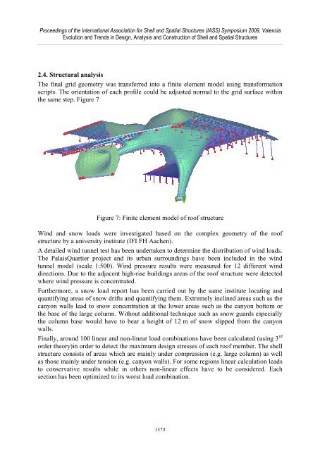
2.4. Structural analysis<br />
<strong>The</strong> final grid geometry was transferred into a finite element model using transformation<br />
scripts. <strong>The</strong> orientation of each profile could be adjusted normal to the grid surface within<br />
the same step. Figure 7<br />
Figure 7: Finite element model of roof structure<br />
Wind and snow loads were investigated based on the complex geometry of the roof<br />
structure by a university institute (IFI FH Aachen).<br />
A detailed wind tunnel test has been undertaken to determine the distribution of wind loads.<br />
<strong>The</strong> PalaisQuartier project and its urban surroundings have been included in the wind<br />
tunnel model (scale 1:500). Wind pressure results were measured for 12 different wind<br />
directions. Due to the adjacent high-rise buildings areas of the roof structure were detected<br />
where wind pressure is concentrated.<br />
Furthermore, a snow load report has been carried out by the same institute locating and<br />
quantifying areas of snow drifts and quantifying them. Extremely inclined areas such as the<br />
canyon walls lead to snow concentration at the lower areas such as the canyon bottom or<br />
the base of the large column. Without additional technique such as snow guards especially<br />
the column base would have to bear a height of 12 m of snow slipped from the canyon<br />
walls.<br />
Finally, around 100 linear and non-linear load combinations have been calculated (using 3 rd<br />
order theory)in order to detect the maximum design stresses of each roof member. <strong>The</strong> shell<br />
structure consists of areas which are mainly under compression (e.g. large column) as well<br />
as those mainly under tension (e.g. canyon walls). For some regions linear calculation leads<br />
to conservative results while in others non-linear effects have to be considered. Each<br />
section has been optimized to its worst load combination.<br />
1373