SIREN MODEL GS-150 - Galls
SIREN MODEL GS-150 - Galls
SIREN MODEL GS-150 - Galls

You also want an ePaper? Increase the reach of your titles
YUMPU automatically turns print PDFs into web optimized ePapers that Google loves.
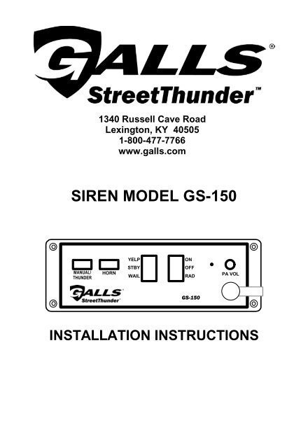
1340 Russell Cave Road<br />
Lexington, KY 40505<br />
1-800-477-7766<br />
www.galls.com<br />
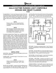
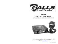
<strong>SIREN</strong> <strong>MODEL</strong> <strong>GS</strong>-<strong>150</strong><br />
MANUAL/<br />
THUNDER<br />
HORN<br />
YELP<br />
STBY<br />
WAIL<br />
INSTALLATION INSTRUCTIONS<br />
ON<br />
OFF<br />
RAD<br />
<strong>GS</strong> - <strong>150</strong><br />
PA VOL
Page 2 <strong>GS</strong>-<strong>150</strong> Installation Instructions<br />
LIMITED WARRANTY<br />
<strong>Galls</strong> Inc. warrants this new product to be free from defects in material and workmanship,<br />
under normal use and service, for a period of seven years from the date of purchase to the<br />
first user-purchaser.<br />
This warranty does not extend to any unit that has been subjected to abuse, misuse, improper<br />
installation or which has not been adequately maintained, nor to units which have<br />
problems related to service or modification at any facility other than the manufacturer.<br />
This warranty does not cover labor charges for removal or re-installation of the product.<br />
THERE ARE NO OTHER WARRANTIES, EXPRESSED OR IMPLIED, INCLUDING BUT<br />
NOT LIMITED TO, ANY IMPLIED WARRANTIES OF MERCHANTABILITY OR FITNESS<br />
FOR A PARTICULAR PURPOSE. IN NO EVENT SHALL GALLS INC. BE LIABLE FOR ANY<br />
INDIRECT OR CONSEQUENTIAL DAMAGES ARISING OUT OF ANY SUCH DEFECT IN<br />
MATERIALS OR WORKMANSHIP.<br />
TABLE OF CONTENTS<br />
GENERAL DESCRIPTION .......................................................................................3<br />
SPECIFICATIONS ....................................................................................................3<br />
INSTALLATION ........................................................................................................3<br />
SAFETY PRECAUTIONS ....................................................................................3<br />
UNPACKING ........................................................................................................4<br />
MOUNTING ..........................................................................................................4<br />
INSTALLER-SELECTABLE OPTIONS ...............................................................4<br />
ELECTRICAL CONNECTIONS ...........................................................................5<br />
OPERATION .............................................................................................................6<br />
GENERAL ............................................................................................................6<br />
SELECTOR SWITCHES .....................................................................................6<br />
MANUAL/THUNDER ...........................................................................................6<br />
HORN ...................................................................................................................6<br />
MICROPHONE ....................................................................................................6<br />
PUBLIC ADDRESS VOLUME .............................................................................6<br />
RADIO VOLUME .................................................................................................6<br />
AUXILIARY INPUT ..............................................................................................6<br />
CUTOUT ..............................................................................................................6<br />
SERVICE ..................................................................................................................7<br />
PROBLEMS .........................................................................................................7<br />
PARTS ..................................................................................................................7<br />
RETURNS .................................................................................................................8<br />
NOTICE<br />
Due to continuous product improvements, we must reserve the right to change any specifications and information,<br />
contained in this manual at any time without notice.<br />
Carson Manufacturing Co., Inc. or Gall’s Inc. makes no warranty of any kind with regard to this manual, including,<br />
but not limited to, the implied warranties of merchantability and fitness for a particular purpose.<br />
Carson Manufacturing Co., Inc. or Gall’s Inc. shall not be liable for errors contained herein or for incidental or<br />
consequential damages in connection with the furnishing, performance, or use of this manual.<br />
7/12/02 CP4768C
<strong>GS</strong>-<strong>150</strong> Installation Instructions Page 3<br />
GENERAL DESCRIPTION<br />
Gall’s <strong>GS</strong>-<strong>150</strong> Streetthunder Siren is designed for single 100W speaker use. The primary operating<br />
modes are Yelp, Wail, Standby and Radio. A Noise Canceling PA Override and push-button<br />
Horn Override are available in all modes except Radio. A push-button is provided for push-on/<br />
push-off Thunder operation in the Yelp and Wail modes, and Manual siren control in the Standby<br />
mode. The Thunder function can be optionally replaced by Two-Tone or disabled entirely with<br />
program jumpers. A latching siren cutout input is provided for connection to a door switch, etc. to<br />
disable the siren when exiting the vehicle. Radio and PA volume controls are provided on the<br />
front panel. The front panel is backlighted for night visibility. This unit utilizes short circuit, high<br />
voltage, and reverse polarity protection systems for maximum service life.<br />
SPECIFICATIONS<br />
Input Voltage 9 - 16 VDC (negative ground)<br />
Input Current 8.0 AMPS (@14.0 VDC - single 100W speaker)<br />
Standby Current Less than 250 ma<br />
Audio Frequency 200Hz - 10 kHz + 3db<br />
Audio Distortion Less than 3% (@1 kHz - single 100W speaker)<br />
Audio Output 40 watts (@14.0 VDC - single 100W speaker)<br />
Audio Input 400 ohms + 10%<br />
Output Power 105 WATTS RMS MAX. (15.0 VDC - single 100W speaker)<br />
Siren Frequency 700Hz - 1450Hz (Two-Tone and Horn = 435 & 585Hz)<br />
Tones / Cycle Rates Horn Wail Yelp Thunder Two-Tone<br />
Cycle Rates 109 CPS 15 CPM 205 CPM 100 CPM 60 CPM<br />
High Voltage<br />
16 - 18 VDC will cause siren output to cease, resume at normal voltage<br />
Protection<br />
Short Circuit Current 50 AMPS (supply circuit must be capable of supplying this)<br />
Operating<br />
-15° F to +140°F<br />
Temperature<br />
Controls 2 rocker selector switches (Yelp, Wail, Standby, On, Off and Radio).<br />
Momentary push-button Horn switch.<br />
Momentary push-button Manual/Thunder toggle switch.<br />
Auxiliary input connection jumper-programmable for positive or negative Horn or<br />
Manual/Thunder operation.<br />
Cutout input connection jumper-programmable for positive or negative latching<br />
cutout operation.<br />
Connections<br />
(2) Positive, (2) Negative, (2) Speaker, (2) Radio, Cutout, Auxiliary<br />
(Removable 10-Term<br />
Block)<br />
Size 6" Wide, 6" Deep, 2" High<br />
Weight 4 LBS.<br />
INSTALLATION<br />
Proper installation of the unit is essential for years of safe, reliable operation. Please read all<br />
instruction before installing the unit. Failure to follow these instructions can cause serious damage<br />
to the unit or vehicle and may void warranties.<br />
SAFETY PRECAUTIONS<br />
For the safety of the installer, vehicle operator, passengers and the community please observe<br />
the following safety precautions. Failure to follow all safety precautions and instructions may<br />
result in property damage, injury or death.<br />
Qualifications - The installer must have a firm knowledge of basic electricity, vehicle electrical<br />
systems and emergency equipment.<br />
Sound Hazards - Sound levels produced by attached speakers can cause permanent hearing<br />
loss. Never operate this unit without adequate hearing protection for you and others in the area.<br />
(OSHA 1910.95)<br />
Mounting - Mount the unit for easy access by the vehicle operator. DO NOT mount in air bag<br />
deployment area. Assure clearances before drilling in vehicle.<br />
CP4768C 7/12/02
Page 4 <strong>GS</strong>-<strong>150</strong> Installation Instructions<br />
Wiring - Use wiring capable of handling the current required. Make sure all connections are tight.<br />
Route wiring to prevent wear, overheating and interference with air bag deployment. Install and<br />
check all wiring before connection to vehicle battery.<br />
Testing - Test all siren functions after installation to assure proper operation. Test vehicle operation<br />
to assure no damage to vehicle.<br />
Keep These Instructions - Keep these instructions in the vehicle or other safe place for future<br />
reference. Advise the vehicle operator of the location.<br />
UNPACKING<br />
Inspect contents for shipping damage. If found alert carrier immediately. Contents should include<br />
unit with attached microphone, mounting bracket, microphone bracket with screws, mounting<br />
hardware, connector and these instructions. Contact supplier immediately if any components<br />
are missing.<br />
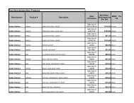
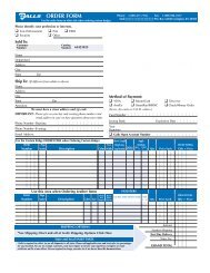
MOUNTING<br />
The mounting bracket supplied can be installed above<br />
or below the unit. Mounting bolts slide into channels<br />
on each side of the case. Lockwashers should be<br />
used between the case and bracket as well as between<br />
the bracket and nut. Choose a mounting location convenient<br />
to the operator and away from any air bag<br />
deployment areas. Inspect behind mounting area for<br />
clearance. Assure adequate ventilation to prevent<br />
overheating. Consider wire routing and access to<br />
connections, as well as microphone bracket placement.<br />
Install mounting bracket to vehicle using 1/4" hardware<br />
(not supplied).<br />
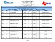
INSTALLER-SELECTABLE OPTIONS<br />
Carefully cutting programming resistor jumpers on the<br />
printed circuit board inside the case can select various options.<br />
Accessing Programming Options - Remove the front<br />
panel to gain access to the programming resistor jumpers by<br />
removing the 4 corner screws. Observe polarity of the microphone<br />
connector. When replacing the front panel re-install<br />
the microphone connector, observing polarity and clearance<br />
for lighting.<br />
Auxiliary Input Function - The auxiliary input normally activates<br />
the Horn function. To activate the Manual/Thunder<br />
function with the auxiliary input cut the resistor jumper labeled<br />
"AUXI".<br />
Auxiliary Input Polarity - The auxiliary input is normally<br />
activated by connecting to positive. To activate by connecting<br />
to ground cut the two resistor jumpers labeled "AUXP".<br />
Cutout Input Polarity - The cutout input is normally activated<br />
by connecting to positive. To activate by connecting to<br />
ground cut the two resistor jumpers labeled "CUTP".<br />
Lockwashers<br />
HORN SWITCH<br />
YELP/STBY/WAIL<br />
SWITCH<br />
TH/H<br />
T-T<br />
AUXI<br />
AUXP<br />
CUTP<br />
OPTION JUMPERS<br />
Two-Tone - Two-Tone can replace Thunder by cutting the resistor jumper labeled "T-T".<br />
Thunder/Horn Disable - Some jurisdictions do not allow special tones in the siren. The Thunder<br />
and Horn functions can be completely disabled by cutting the resistor jumper labeled "TH/H".<br />
7/12/02 CP4768C<br />
Nut<br />
Bolt<br />
Bracket<br />
Channel<br />
(from rear)
<strong>GS</strong>-<strong>150</strong> Installation Instructions Page 5<br />
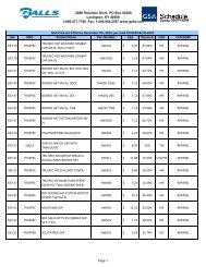
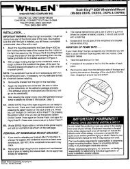
ELECTRICAL CONNECTIONS<br />
Electrical connections to the unit are made<br />
using a removable terminal block located<br />
on the back. A label on the unit identifies<br />
the terminal function. You should install<br />
the terminal block on the unit before wiring.<br />
If the unit needs service the block can<br />
be easily removed without unwiring the<br />
block.<br />
The power supply of the unit must be capable<br />
of delivering peak currents up to 50<br />
amps for adequate short circuit protection<br />
and reliable operation. The preferred<br />
source is directly at the vehicle battery.<br />
The unit is internally fused.<br />
Attach leads by stripping 3/8", inserting<br />
into connector and clamp by tightening<br />
screw. Make sure the screw is tight and<br />
the wire can't be pulled out. Failure to<br />
adequately tighten the screw can result<br />
in improper operation or burning the<br />
connector and wire.<br />
Wire Size and Termination - The diagram shows the minimum wire size used for each connection,<br />
along with recommended lead color. If the wire is longer than 10 ft. use the next larger wire<br />
size. Use only high quality crimp connectors for installation on the vehicle.<br />
Auxiliary Input Connection -<br />
The Auxiliary Input allows activation<br />
by an external source of<br />
either the Horn or Manual/<br />
Thunder function. The adjacent<br />
diagram shows three connection<br />
examples. See the IN-<br />
STALLER-SELECTABLE OP-<br />
TIONS section for programming<br />
details.<br />
NOTE: Permanent disconnection<br />
of the vehicle horn is NOT<br />
recommended.<br />
HORN<br />
RING<br />
SWITCH<br />
(2) #18 AWG BRN<br />
Cutout Input Connection - The Cutout Input turns<br />
off any siren tone output when activated, and remains<br />
off until a control is activated or changed. The adjacent<br />
diagram shows two connection examples. See<br />
the INSTALLER-SELECTABLE OPTIONS section for<br />
programming details.<br />
+12<br />
SPLICE<br />
AUX<br />
(2) #22 AWG BLU<br />
Connect to output<br />
jack, terminals or<br />
speaker of radio<br />
RADIO<br />
••••••••••<br />
SPKR →<br />
SPKR →<br />
POS →<br />
POS →<br />
RAD →→<br />
RAD →<br />
AUX →→<br />
CUT →→<br />
NEG →→<br />
NEG →<br />
#22 AWG GRN (See below)<br />
#22 AWG WHT (See below)<br />
#14 AWG RED<br />
Use either terminal<br />
#14 AWG BLK<br />
Use either terminal<br />
CONNECTIONS AT REAR OF UNIT<br />
HORN<br />
RING<br />
SWITCH<br />
+12 Switching examples<br />
+<br />
BAT<br />
-<br />
CP4768C 7/12/02<br />
HORN<br />
DOOR<br />
SWITCH<br />
+12<br />
+12<br />
Added<br />
SPDT<br />
Switch<br />
SPLICE<br />
CUT<br />
AUX<br />
+12 Switching<br />
example<br />
HORN<br />
DOME<br />
LIGHT<br />
MOMENTARY<br />
FOOT<br />
SWITCH<br />
AUX<br />
Ground<br />
switching<br />
example<br />
Must cut AUXP<br />
option resistors<br />
ADDED<br />
DOOR<br />
SWITCH<br />
CUT<br />
Ground<br />
switching<br />
example<br />
Must cut CUTP<br />
option resistors
Page 6 <strong>GS</strong>-<strong>150</strong> Installation Instructions<br />
OPERATION<br />
GENERAL<br />
This unit is designed for easy operation under the stress associated with high-speed pursuit.<br />
Most siren functions are accessible with one simple motion without repetitive activation of<br />
switches or automatic timed switching that can interfere with desired operation.<br />
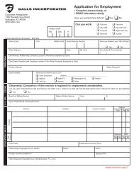
SELECTOR SWITCHES<br />
Two rocker switches control the primary operating<br />
function of the siren.<br />
Yelp - A rapidly changing tone used in congested YELP<br />
ON<br />
areas.<br />
Wail - A slower changing tone used on highways. STBY<br />
OFF<br />
Stby - A silent mode that allows Manual, Horn and<br />
Public Address operation.<br />
On & Off - Controls siren power.<br />
Radio - Also known as Radio Repeat, this function<br />
WAIL<br />
RAD<br />
amplifies a radio speaker input for re-broadcast outside the vehicle. No siren tones or PA operation<br />
are available in this position.<br />
MANUAL/THUNDER<br />
This momentary push-button switch provides a very rapid<br />
changing tone (Thunder) when the selector switches are in the<br />
Yelp or Wail positions. This tone is used at intersections and<br />
very highly congested areas. Pressing the button once changes<br />
to the Thunder tone and pressing again changes the tone back<br />
to Yelp or Wail.<br />
With the selector switches in the Stby position this switch pro-<br />
MANUAL/<br />
THUNDER<br />
vides Manual siren tone control, rising when pressed and falling when released. This is used to<br />
momentarily alert motorists or in low noise areas.<br />
Optional operation includes replacement of the Thunder tone with Two-Tone or disabling the<br />
Thunder tone entirely. These options are selected during installation and may be governed by<br />
State or Local laws. (TH/H option.)<br />
HORN<br />
This momentary push-button switch provides a simulated air-horn tone while pressed. This can<br />
be used to supplement the normal vehicle horn and is useful at intersections or in low noise areas.<br />
This tone will override all other siren tones. This function may be disabled during installation and<br />
may be governed by State or Local laws. (TH/H option.)<br />
MICROPHONE<br />
The attached noise-canceling microphone is used for public address operation and overrides any<br />
siren tone when the button on the side is pressed.<br />
PUBLIC ADDRESS VOLUME<br />
A volume control is provided for public address volume. This should be set<br />
when the vehicle is parked. Set the PA volume to the maximum level with<br />
no feedback (squeal).<br />
radio adjust<br />
HORN<br />
PA VOL<br />
RADIO VOLUME<br />
Set the radio volume with the Radio switch on and the radio volume set to<br />
the desired level. Use a small screwdriver inserted into the radio adjust hole shown to adjust the<br />
volume to the desired level.<br />
AUXILIARY INPUT<br />
During installation an auxiliary input may be connected to the horn ring or other switching device.<br />
It provides the same operation as pressing the Horn button or optionally the Manual/Thunder<br />
button.<br />
CUTOUT<br />
During installation, a cutout input may be connected to a door switch. It turns off any siren tone<br />
when the door is opened. The siren tone will continue to be cut off even when the door is closed.<br />
Operating any switch or input will restore normal function.<br />
7/12/02 CP4768C
<strong>GS</strong>-<strong>150</strong> Installation Instructions Page 7<br />
SERVICE<br />
This unit is designed to provide years of reliable service under even the worst conditions. Many<br />
times there may appear to be a problem with the unit when the true problem is in the speaker or<br />
improper installation. The following chart shows typical symptoms and possible causes.<br />
A blown internal fuse doesn't necessarily mean that the unit is bad. If a speaker or speaker lead<br />
is shorted the internal fuse will blow before the unit is damaged. Disconnect the SPKR leads and<br />
replace the fuse. If the siren emits a sound when in the Yelp position it is OK. Check the speaker<br />
or leads for possible shorting.<br />
PROBLEMS<br />
Symptom Possible Cause Check<br />
No power or siren<br />
output<br />
Power switch not turned on<br />
Bad speaker<br />
Connector loose<br />
Rear panel fuse blown<br />
PARTS<br />
The following parts are available from Gall’s:<br />
Does backlighting come on?<br />
Do you hear a "pop" when turned on?<br />
With siren on and Yelp selected, listen for tone in amplifier.<br />
Is an external fuse or circuit breaker used?<br />
Are the negative leads connected to a good ground?<br />
The input voltage must be less than 16 volts.<br />
Does microphone button release properly?<br />
Does the siren work when Cutout input is disconnected?<br />
Is the CUTP option properly configured?<br />
Have you tried turning the PA volume control?<br />
PA is not available when Radio is on<br />
Is the speaker bell or tip loose?<br />
Is the Aux Input used and wired properly?<br />
The input voltage must be greater than 9 volts.<br />
No siren tone -<br />
Loose connection at power source<br />
High Voltage Protection<br />
PA works Microphone button stuck<br />
Cutout activated<br />
Cutout Polarity Option set wrong<br />
No PA PA volume not set properly<br />
Radio switch on<br />
Distorted siren Speaker assembly loose<br />
sound<br />
Intermittent Aux Input connection<br />
Low vehicle voltage<br />
Intermittent siren High Voltage Protection<br />
Is the vehicle voltage regulator working properly?<br />
tone<br />
Connector loose<br />
Is the connector tight on the back of the unit?<br />
Bad power connection<br />
Is there a loose connection on a power lead?<br />
Microphone button activation Is something lying on the microphone?<br />
Circuit breaker in supply connection Is a circuit breaker used with at least a 50A rating?<br />
Horn function<br />
stuck on or<br />
Manual/Thunder<br />
stuck on<br />
Horn switch stuck<br />
Manual/Thunder switch stuck<br />
Aux Input improperly connected<br />
Aux Input Polarity Option set wrong<br />
No Radio Unit not connected to radio<br />
Radio volume too low<br />
Does the horn switch return fully when released?<br />
Does Manual/Thunder switch return fully when released?<br />
Is the Aux Input used and wired properly?<br />
Is the AUXP option properly configured?<br />
Is the radio connected properly to the unit?<br />
Can you here the radio in the vehicle?<br />
Have you tried adjusting the radio adjust control?<br />
Is the T-T option jumper cut?<br />
Is the AUXI jumper configured properly?<br />
Wrong siren tone Two-Tone option installed<br />
Aux Input set to wrong function<br />
Thunder & Horn<br />
not working<br />
Thunder/Horn disabled Is the TH/H option jumper cut?<br />
Part Description<br />
ED1602 Hardware Kit (Terminal block, bolts, nuts, lockwashers, microphone bracket with screws)<br />
CP4688-10 Removable Terminal Block<br />
CP3633 Microphone Bracket with Screws<br />
ATO/ATC 15A 15 Amp Automotive Fuse<br />
CP4750 Noise Canceling Microphone<br />
SR-15-1 Microphone Strain Relief<br />
CP4119 TIP36C Power Transistor<br />
CP3571 Mounting Bracket<br />
CP4768 <strong>GS</strong>-<strong>150</strong> Installation Instructions<br />
CP4768C 7/12/02
Page 8 <strong>GS</strong>-<strong>150</strong> Installation Instructions<br />
RETURNS<br />
Defective units should be returned for service to:<br />
Gall’s Inc.<br />
1340 Russell Cave Road<br />
Lexington, KY 40505<br />
1-800-477-7766<br />
www.galls.com<br />
Please include name, return address and a description of the defect.<br />
No Hassle Guarantee<br />
It takes gall to guarantee every purchase you make.<br />
That’s why we offer only quality products.<br />
If you aren’t satisfied with an item, return it to us and<br />
we’ll either repair or replace it, or refund your money.<br />
7/12/02 CP4768C