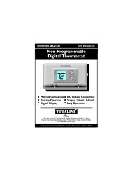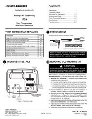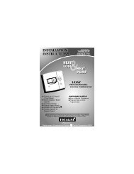
69-1849 - PRO 4110D Programmable Thermostat - Honeywell
69-1849 - PRO 4110D Programmable Thermostat - Honeywell
69-1849 - PRO 4110D Programmable Thermostat - Honeywell

You also want an ePaper? Increase the reach of your titles
YUMPU automatically turns print PDFs into web optimized ePapers that Google loves.
Installation<br />
Guide<br />
TH<strong>4110D</strong><br />
<strong>Programmable</strong> <strong>Thermostat</strong>
Product Application<br />
This thermostat provides electronic control of 24 VAC single-stage heating and cooling<br />
systems, or 750 mV heating systems.<br />
System Types<br />
• Gas, oil, or electric heat with air<br />
conditioning<br />
• Warm air, hot water, high-efficiency<br />
furnaces, heat pumps, steam, gravity<br />
• Heat only<br />
• Heat only with fan<br />
• Cool only<br />
• 750 mV heating systems<br />
Power Type<br />
• Battery power<br />
• Common wire<br />
• Common wire with battery backup<br />
System Settings<br />
• Heat, Off, Cool<br />
Fan Settings<br />
• Auto, On<br />
Must be installed by a trained, experienced technician<br />
• Read these instructions carefully. Failure to follow these instructions can damage<br />
the product or cause a hazardous condition.<br />
• Check the ratings in this booklet to verify that this product is suitable for your<br />
application (see page 13).<br />
• Always test for proper operation after installation (see pages 8-9).<br />
CAUTION: ELECTRICAL HAZARD<br />
Can cause electrical shock or equipment damage. Disconnect power before<br />
beginning installation.<br />
MERCURY NOTICE<br />
If this product is replacing a control that contains mercury in a sealed tube, do not<br />
place the old control in the trash. Contact your local waste management authority for<br />
instructions regarding recycling and proper disposal.<br />
® U.S. Registered Trademark. Patents pending.<br />
Copyright © 2005 <strong>Honeywell</strong> International Inc. All rights reserved.
<strong>PRO</strong> TH<strong>4110D</strong> <strong>Programmable</strong> <strong>Thermostat</strong><br />
Table of contents<br />
Installation<br />
Pre-installation checklist ................2<br />
Wallplate installation ......................3<br />
Wiring..............................................4<br />
Wiring diagrams ..............................5<br />
Installer Setup<br />
Fan operation settings ....................6<br />
Battery installation ..........................7<br />
<strong>Thermostat</strong> mounting ....................7<br />
Installer setup..................................8<br />
Installer system test ........................8<br />
Appendices<br />
Adaptive Intelligent Recovery ......10<br />
Compressor protection ................10<br />
Quick reference to controls..........11<br />
Quick reference to display............11<br />
In case of difficulty ......................12<br />
Accessories....................................13<br />
Specifications ................................13<br />
Installation tips<br />
Install the thermostat about 5 feet (1.5m) above the floor in an area<br />
with good air circulation at average temperature.<br />
NO<br />
NO<br />
NO<br />
Do not install in locations where the thermostat can be affected by:<br />
• Drafts or dead spots behind doors and in corners<br />
• Hot or cold air from ducts<br />
• Sunlight or radiant heat from appliances<br />
• Concealed pipes or chimneys<br />
• Unheated/uncooled areas such as an outside wall behind the thermostat<br />
1
Installation Guide<br />
Pre-installation checklist<br />
Package contents<br />
Check to make sure your package includes the following items:<br />
• <strong>PRO</strong> TH<strong>4110D</strong> digital thermostat (wallplate attached to back)<br />
• Operating manual<br />
• Wall anchors and mounting screws (2 each)<br />
• AA alkaline batteries (2)<br />
• Quick reference card<br />
Required tools & supplies<br />
• No. 2 Phillips screwdriver<br />
• Small pocket screwdriver<br />
• Drill<br />
• Drill bit (3/16” for drywall, 7/32” for plaster)<br />
• Hammer<br />
• Pencil<br />
• Electrical tape<br />
• Level (optional)<br />
2
<strong>PRO</strong> TH<strong>4110D</strong> <strong>Programmable</strong> <strong>Thermostat</strong><br />
Wallplate installation<br />
Grasp top and bottom of wallplate<br />
and pull to remove from thermostat.<br />
Remove the wallplate from the thermostat<br />
as shown at left, then follow<br />
directions below for mounting.<br />
1 Pull wires through wire hole.<br />
2 Position wallplate on wall, level and<br />
mark hole positions with pencil.<br />
3 Drill holes at marked positions as<br />
shown below, then tap in supplied<br />
wall anchors.<br />
4 Place wallplate over anchors, insert<br />
and tighten mounting screws.<br />
5 Insert quick reference card in slot<br />
in front of wall plate.<br />
Insert quick reference card after<br />
wallplate is mounted (see mounting<br />
instructions, below)<br />
Drill 3/16” holes for drywall.<br />
Drill 7/32” holes for plaster.<br />
Wire hole<br />
Mounting screws<br />
Wall anchors<br />
3
Installation Guide<br />
Wiring<br />
CAUTION: ELECTRICAL HAZARD. Can cause electrical shock or equipment damage.<br />
Disconnect power before wiring.<br />
Keep wires in this<br />
shaded area<br />
Jumper<br />
Wiring<br />
1 Loosen screw terminals, insert<br />
wires into terminal block, then retighten<br />
screws.<br />
2 Push excess wire back into the<br />
wall opening. Keep wires in shaded<br />
area as shown at left.<br />
3 Plug the wall opening with nonflammable<br />
insulation to prevent<br />
drafts from affecting thermostat<br />
operation.<br />
Terminal<br />
block<br />
NOTES<br />
R & Rc terminals<br />
In single-transformer system, leave metal<br />
jumper in place between R & Rc. Remove<br />
metal jumper if two-transformer system.<br />
Heat pump systems<br />
If wiring to a heat pump, use a small piece of<br />
wire (not supplied) to connect terminals W<br />
and Y.<br />
C terminal<br />
The C (common wire) terminal is optional<br />
when thermostat is powered by batteries.<br />
Wire specifications<br />
Use 18- to 22-gauge thermostat wire.<br />
Shielded cable is not required.<br />
Terminal Designations<br />
W Heat relay.<br />
Y<br />
G<br />
Compressor contactor.<br />
Fan relay.<br />
O Heat pump changeover valve energized<br />
in cooling.<br />
Rc Cooling power. Connect to<br />
secondary side of cooling<br />
system transformer.<br />
R<br />
B<br />
C<br />
Heating power. Connect to<br />
secondary side of heating<br />
system transformer.<br />
Heat pump changeover valve energized<br />
in heating.<br />
Common wire from secondary side<br />
of cooling system transformer.<br />
4
<strong>PRO</strong> TH<strong>4110D</strong> <strong>Programmable</strong> <strong>Thermostat</strong><br />
Wiring diagrams<br />
1 Power supply. Provide disconnect means and overload protection as required.<br />
2 Factory-installed jumper. Remove for 2-transformer systems only.<br />
3 Use either O or B terminals for changeover valve.<br />
4 Use a small piece of wire (not supplied) to connect W and Y terminals.<br />
5 Set fan operation switch to Heat Pump (see page 6) and configure for heat pump (see pg. 8).<br />
6 Optional 24 VAC common connection.<br />
Typical 1H/1C system: 1 transformer<br />
Typical 1H/1C system: 2 transformers<br />
Remove jumper<br />
Typical 1H/1C heat pump system<br />
Typical heat-only system<br />
Typical heat-only system with fan<br />
Typical cool-only system<br />
5
Installation Guide<br />
Fan operation settings<br />
• Gas or Oil: For gas or oil heating<br />
systems, leave the fan operation<br />
switch in this factory-set position<br />
(This setting is for systems that<br />
control the fan in a call for heat.)<br />
• Electric or Heat Pump: Change the<br />
switch to this setting for heat<br />
pump or electric heat systems.<br />
(This setting is for systems that<br />
allow the thermostat to control the<br />
fan in a call for heat, if a fan wire is<br />
connected to the G<br />
terminal.)<br />
Set fan operation switch<br />
6
<strong>PRO</strong> TH<strong>4110D</strong> <strong>Programmable</strong> <strong>Thermostat</strong><br />
Power options & mounting<br />
Connect common<br />
side of transformer<br />
to “C” terminal<br />
AC Power<br />
The thermostat can be powered by 24<br />
VAC power, or by batteries.<br />
To wire the thermostat for AC power,<br />
connect the common side of the<br />
cooling transformer to the “C” terminal<br />
as shown at left.<br />
Important: Remove R/Rc jumper for<br />
2-transformer systems only. (See wiring<br />
diagram on page 5.)<br />
Battery Power<br />
The thermostat can be powered by<br />
batteries alone or, if used with AC<br />
power, can provide backup power.<br />
During power interruptions the<br />
batteries will save time/day settings<br />
and power the display.<br />
Install batteries in back of thermostat<br />
(optional if AC powered).<br />
To Mount <strong>Thermostat</strong><br />
Align the 4 tabs on the wallplate with<br />
corresponding slots on the back of the<br />
thermostat, then push gently until the<br />
thermostat snaps in place.<br />
7
Installation Guide<br />
Installer setup<br />
Follow the procedure below to configure the thermostat to match the installed<br />
heating/cooling system, and customize feature operation as desired.<br />
Press and hold both buttons<br />
Function<br />
number<br />
Setting<br />
Setup<br />
1 0<br />
To begin, press and hold the and<br />
buttons until the display changes<br />
Press to change settings<br />
Press to advance to next function<br />
Press and hold to exit and save settings<br />
Setup Function<br />
1<br />
5<br />
9<br />
System type<br />
Heating cycle rate<br />
(CPH: cycles/hour)<br />
Compressor<br />
cycle rate (CPH)<br />
Settings & Options<br />
0 Gas, oil or electric heat with air conditioning<br />
1 Heat pump (5 minute compressor off time in heating and cooling)<br />
5 For gas or oil furnaces of less than 90% efficiency<br />
1 For steam or gravity systems<br />
3 For hot water systems & furnaces of over 90% efficiency<br />
9 For electric furnaces<br />
[Other cycle rate options: 2, 4, 6, 7, 8, 10, 11 or 12 CPH]<br />
3 Recommended for most compressors<br />
[Other cycle rate options: 1, 2, 4, 5 or 6 CPH]<br />
13<br />
14<br />
15<br />
Adaptive Intelligent<br />
Recovery<br />
Temperature<br />
display<br />
Compressor<br />
protection<br />
1 On **See page 10<br />
0 Off<br />
0 Fahrenheit<br />
1 Celsius<br />
5 Five-minute compressor off time **See page 10<br />
[Other options: 0, 1, 2, 3 or 4-minute off time]<br />
Installer system test<br />
After completing the installer setup above, press the<br />
system test (see next page).<br />
button again to begin a<br />
8
<strong>PRO</strong> TH<strong>4110D</strong> <strong>Programmable</strong> <strong>Thermostat</strong><br />
Installer system test<br />
Follow the procedure below to test the heating and cooling system.<br />
System test<br />
number<br />
System status<br />
10 0Test<br />
System switch<br />
1 Set SYSTEM switch to Cool.<br />
2 Press to turn on cooling system, then check system status (see table, below).<br />
3 Press to turn off cooling system.<br />
4 Set SYSTEM switch to Heat.<br />
5 Press to turn on heating system, then check system status (see table, below).<br />
6 Press to turn off heating system.<br />
7 [Optional] Set SYSTEM switch to Off to display thermostat information (see table, below).<br />
Press to display 71-76.<br />
8 Press and hold to terminate system test at any time.<br />
System Test<br />
System Status<br />
10<br />
30<br />
Heating system<br />
Cooling system<br />
0 Heat and fan turn off.<br />
1 Heat turns on. Fan also turns on immediately if Fan Operation<br />
Switch is set to Electric Heat/Heat Pump (see page 6).<br />
0 Compressor and fan turn off.<br />
1 Compressor and fan turn on.<br />
70<br />
<strong>Thermostat</strong><br />
information<br />
(for reference only)<br />
71 Software revision number (major revisions)<br />
72 Software revision number (minor revisions)<br />
73 Configuration identification code (major)<br />
74 Configuration identification code (minor)<br />
75 Production configuration date code (week)<br />
76 Production configuration date code (year)<br />
CAUTION: EQUIPMENT DAMAGE HAZARD<br />
Compressor protection (minimum off time) is bypassed during testing. To prevent<br />
equipment damage, avoid cycling the compressor quickly.<br />
9
Installation Guide<br />
Adaptive Intelligent Recovery (Setup Function 13)<br />
Adaptive Intelligent Recovery eliminates guesswork when setting your schedule. It<br />
allows the thermostat to “learn” how long your furnace and air conditioner take to<br />
reach the temperature you want.<br />
Just set your program schedule to the time you want the house to reach your<br />
desired temperature.The thermostat then turns on the heating or cooling at just the<br />
right time to reach your scheduled temperature at your scheduled time.<br />
For example: Set the Wake time to 6 am, and the temperature to 70°.The heat will<br />
come on before 6 am, so the temperature is 70° by the time you wake at 6.<br />
Built-in compressor protection (Setup Function 15)<br />
Inside<br />
Set To<br />
75<br />
° °<br />
75<br />
6:30 AM<br />
Wake<br />
Cool<br />
Wed<br />
On<br />
Message flashes until safe<br />
restart time has elapsed<br />
This feature helps prevent damage to the<br />
compressor in the air conditioning or heat<br />
pump system.<br />
Damage can occur if the compressor is restarted<br />
too soon after shutdown.This feature<br />
forces the compressor to wait for a few<br />
minutes before restarting.<br />
During the wait time, the message Cool On<br />
(or Heat On if you have a heat pump) will<br />
flash on the display.When the safe wait time<br />
has elapsed, the message stops flashing and<br />
the compressor turns on.<br />
10
<strong>PRO</strong> TH<strong>4110D</strong> <strong>Programmable</strong> <strong>Thermostat</strong><br />
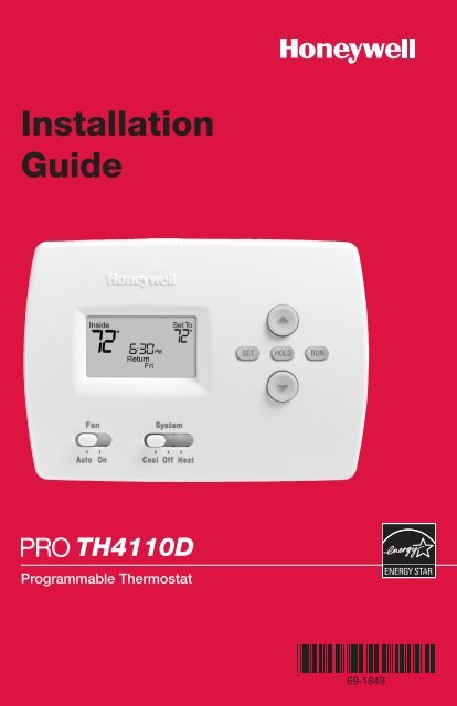
Quick reference to controls<br />
Temperature adjustment<br />
• Set: Press to set time/day/<br />
schedule<br />
• Hold: Press to override<br />
programmed temperature control.<br />
• Run: Press to resume program<br />
schedule<br />
Fan switch<br />
On: Fan runs continuously.<br />
Auto: Fan runs only when heating<br />
or cooling system is on.<br />
System switch<br />
• Cool: <strong>Thermostat</strong> controls only<br />
the cooling system.<br />
• Heat: <strong>Thermostat</strong> controls only<br />
the heating system.<br />
• Off: Heating and cooling<br />
systems are off.<br />
Quick reference to display screen<br />
Low battery warning<br />
Adaptive Intelligent Recovery<br />
Current inside<br />
temperature<br />
Current program period<br />
Wake/Leave/Return/Sleep<br />
Replace Batt<br />
Inside<br />
Set To<br />
75<br />
°<br />
Recovery<br />
°<br />
75<br />
6:30 AM<br />
Wake<br />
Cool<br />
Wed<br />
On<br />
Temperature setting<br />
System status<br />
(Heat On, Cool On)<br />
Current day/time<br />
11
Installation Guide<br />
In case of difficulty<br />
If you have difficulty with your thermostat, please try the suggestions below. Most<br />
problems can be corrected quickly and easily.<br />
Display is blank • Check circuit breaker and reset if necessary.<br />
• Make sure heating & cooling power switches are on.<br />
• Make sure equipment door is securely closed.<br />
• If battery powered, make sure fresh AA alkaline batteries are installed.<br />
Temperature<br />
settings do not<br />
change<br />
Heating system<br />
does not respond<br />
(“Heat On”<br />
appears on<br />
screen)<br />
Cooling system<br />
does not respond<br />
(“Cool On”<br />
appears on<br />
screen)<br />
Fan does not<br />
turn on in a<br />
call for heat<br />
“Cool On” or<br />
“Heat On”<br />
is flashing<br />
“Heat On” is<br />
not displayed<br />
Make sure heating and cooling temperatures are set to acceptable ranges:<br />
• Heat: 40° to 90°F (4.5° to 32°C).<br />
• Cool: 50° to 99°F (10° to 37°C).<br />
• Check for 24 Vac at the equipment on the secondary side of the transformer<br />
between power and common. If voltage is not present, check the<br />
heating equipment to find the cause of the problem.<br />
• Check for 24 Vac between the heat terminal (W) and the transformer<br />
common. If 24 Vac is present, the thermostat is functional. Check the<br />
heating equipment to find the cause of the problem.<br />
• Check for loose or broken wires between the thermostat and the heating<br />
equipment.<br />
• Check for 24 Vac at the equipment on the secondary side of the transformer<br />
between power and common. If voltage is not present, check the<br />
cooling equipment to find the cause of the problem<br />
• Check for 24 Vac between the cooling terminal (Y) and the transformer<br />
common. If 24 Vac is present, the thermostat is functional. Check the<br />
cooling system to find the cause of the problem.<br />
• Check for loose or broken wires between the thermostat and the cooling<br />
equipment.<br />
• Make sure the Fan Operation switch is set to the proper system.<br />
• Compressor protection timeout is engaged. Wait 5 minutes for the<br />
system to restart safely, without damage to the compressor.<br />
• Set the System switch to Heat, and set the temperature level above the<br />
current room temperature.<br />
“Cool On” is<br />
not displayed<br />
• Set the System switch to Cool, and set the temperature level below the<br />
current room temperature.<br />
12
<strong>PRO</strong> TH<strong>4110D</strong> <strong>Programmable</strong> <strong>Thermostat</strong><br />
Accessories<br />
Please contact your distributor to order accessories.<br />
Cover plate assembly ............................................Part Number 50002883-001<br />
(Used to cover marks left by old thermostats.)<br />
Specifications<br />
Temperature Ranges<br />
• Heat: 40° to 90°F (4.5° to 32°C)<br />
• Cool: 50° to 99°F (10° to 37°C)<br />
Operating Ambient Temperature<br />
• 32° to 120°F (0° to 48.9°C)<br />
Shipping Temperature<br />
• -20° to 120°F (-28.9° to 48.9°C)<br />
Electrical Ratings<br />
System Voltage (50/60Hz) Running Current<br />
Heating 20-30 Vac 0.02-1.0 A<br />
(Powerpile) 750 mV DC 100 mA DC<br />
Cooling 20-30 Vac 0.02-1.0 A<br />
Operating Relative Humidity<br />
• 5% to 90% (non-condensing)<br />
Physical Dimensions<br />
• 3-13/16” H x 5-3/8” W x 1-1/4” D<br />
• 97 mm H x 137 mm W x 32 mm D<br />
13
Automation and Control Solutions<br />
<strong>Honeywell</strong> International Inc. <strong>Honeywell</strong> Limited-<strong>Honeywell</strong> Limitée<br />
1985 Douglas Drive North 35 Dynamic Drive<br />
Golden Valley, MN 55422 Scarborough, Ontario M1V 4Z9<br />
http://yourhome.honeywell.com<br />
Printed in U.S.A. on recycled<br />
paper containing at least 10%<br />
post-consumer paper fibers.<br />
® U.S. Registered Trademark.<br />
© 2005 <strong>Honeywell</strong> International Inc.<br />
Patents pending. All rights reserved.<br />
<strong>69</strong>-<strong>1849</strong> • 06-2005