Application Note Softune Workbench Getting started - Slot Tech Forum
Application Note Softune Workbench Getting started - Slot Tech Forum
Application Note Softune Workbench Getting started - Slot Tech Forum

Create successful ePaper yourself
Turn your PDF publications into a flip-book with our unique Google optimized e-Paper software.
<strong>Application</strong> <strong>Note</strong><br />
<strong>Softune</strong> <strong>Workbench</strong><br />
<strong>Getting</strong> <strong>started</strong><br />
© Fujitsu Microelectronics Europe GmbH, Microcontroller <strong>Application</strong> Group<br />
History<br />
09 th Mai 99 TKa V1.0 <strong>started</strong><br />
28 th June 00 TKa V1.1 New format, some minor changes<br />
1
Warranty and Disclaimer<br />
To the maximum extent permitted by applicable law, Fujitsu Mikroelektronik GmbH restricts its warranties<br />
and its liability for all products delivered free of charge (eg. software include or header files, application<br />
examples, application <strong>Note</strong>s, target boards, evaluation boards, engineering samples of IC’s etc.), its<br />
performance and any consequential damages, on the use of the Product in accordance with (i) the terms of<br />
the License Agreement and the Sale and Purchase Agreement under which agreements the Product has<br />
been delivered, (ii) the technical descriptions and (iii) all accompanying written materials. In addition, to<br />
the maximum extent permitted by applicable law, Fujitsu Mikroelektronik GmbH disclaims all warranties<br />
and liabilities for the performance of the Product and any consequential damages in cases of unauthorised<br />
decompiling and/or reverse engineering and/or disassembling. <strong>Note</strong>, all these products are intended and<br />
must only be used in an evaluation laboratory environment.<br />
1. Fujitsu Mikroelektronik GmbH warrants that the Product will perform substantially in accordance<br />
with the accompanying written materials for a period of 90 days form the date of receipt by the<br />
customer. Concerning the hardware components of the Product, Fujitsu Mikroelektronik GmbH<br />
warrants that the Product will be free from defects in material and workmanship under use and<br />
service as specified in the accompanying written materials for a duration of 1 year from the date of<br />
receipt by the customer.<br />
2. Should a Product turn out to be defect, Fujitsu Mikroelektronik GmbH´s entire liability and the<br />
customer´s exclusive remedy shall be, at Fujitsu Mikroelektronik GmbH´s sole discretion, either<br />
return of the purchase price and the license fee, or replacement of the Product or parts thereof, if<br />
the Product is returned to Fujitsu Mikroelektronik GmbH in original packing and without further<br />
defects resulting from the customer´s use or the transport. However, this warranty is excluded if<br />
the defect has resulted from an accident not attributable to Fujitsu Mikroelektronik GmbH, or<br />
abuse or misapplication attributable to the customer or any other third party not relating to Fujitsu<br />
Mikroelektronik GmbH.<br />
3. To the maximum extent permitted by applicable law Fujitsu Mikroelektronik GmbH disclaims all<br />
other warranties, whether expressed or implied, in particular, but not limited to, warranties of<br />
merchantability and fitness for a particular purpose for which the Product is not designated.<br />
4. To the maximum extent permitted by applicable law, Fujitsu Mikroelektronik GmbH´s and its<br />
suppliers´ liability is restricted to intention and gross negligence.<br />
NO LIABILITY FOR CONSEQUENTIAL DAMAGES<br />
To the maximum extent permitted by applicable law, in no event shall Fujitsu<br />
Mikroelektronik GmbH and its suppliers be liable for any damages whatsoever (including<br />
but without limitation, consequential and/or indirect damages for personal injury, assets of<br />
substantial value, loss of profits, interruption of business operation, loss of information, or<br />
any other monetary or pecuniary loss) arising from the use of the Product.<br />
Should one of the above stipulations be or become invalid and/or unenforceable, the remaining stipulations<br />
shall stay in full effect.<br />
.<br />
2
<strong>Softune</strong> <strong>Workbench</strong> getting <strong>started</strong><br />
The <strong>Softune</strong> <strong>Workbench</strong> is a software development environment to develop programs for the Fujitsu<br />
F2MC-8L, F2MC-16L/LX and FR families of microcontrollers. It is a combination of a development<br />
manager, emulator debugger, simulator and an integrated development environment for efficient<br />
development.<br />
This is a short documentation to give an introduction how to start a project with the <strong>Softune</strong> <strong>Workbench</strong>. In<br />
the main it is referred to the F2MC-16L/LX Family but the settings for the F2MC-8L family are quite<br />
similar.<br />
1. <strong>Getting</strong> <strong>started</strong><br />
1.1 Creating a new Project<br />
To start a new project with the <strong>Softune</strong> <strong>Workbench</strong> just use the , , menu. After<br />
that the following dialog box appears:<br />
Here the project name must be entered first. This will create a new directory for this project. The location<br />
of this directory can be selected by the project directory browse button. The default target file name is<br />
myproject.abs, which is the loadmodule for the simulator or emulator. The default directory for this file is<br />
myproject\ABS.<br />
In the next step the chip Family must be defined: 16LX, 16L (8L for the 8-Bit environment). In the last step<br />
the used target µC must be specified.<br />
NOTE: Special template projects exists for each microcontroller series. These template projects<br />
include some basic settings for the MCU itself (which is done in a start.asm file), corresponding<br />
headerfiles and some basic project settings for the C-Compiler/Assembler/Linker and debugger. The<br />
easiest method to start a new project is to start with such a template project.<br />
Of course the user has always to check the tool settings and settings in the start.asm file, which must<br />
be modified to the needs of the user application!<br />
3
1.2 Edit the members List of the Project<br />
When the setup of the new project is defined you will find all used modules of the project within the project<br />
window. Here the source files, include files and objects can be seen which are part of the current project.<br />
To add a new member to the project just click with the right mouse button on the target file name of the<br />
project (myproject.abs). A drop down menu appears to add the new member. Just browse to the<br />
corresponding location and add the module to the project.<br />
Use the property tab to check the location of the .abs file and the location of the modules which are used in<br />
the project. With the “set linkage order” tab it is possible to set the order of the modules for the linker. It is<br />
recommended to have the start.asm file first in the linkage order. A standard start.asm file is offered by<br />
Fujitsu to do the basic initialisations and to define the segments which are used by the compiler. This<br />
start.asm file must be checked and modified corresponding to the needs of the application. This start.asm is<br />
just an example to simplify the first steps.<br />
<strong>Note</strong>: The displayed order of the modules does not correspond to the linkage order. Therefore use always<br />
the linkage order tab to check the right order.<br />
The project tab can also be used to have a look at the generated List Files (generated by the Assembler, C-<br />
Compiler, Linker) and the Hex output Files generated by the converter. After a Build of a project a look at<br />
the mapping file is highly recommended to check the segment locations, Stack, Vector table and so on.<br />
The source files can be opened with the editor be a double click on the source name. To create a new<br />
source file use the , , menu. The editor supports syntax highlighting, line<br />
numbers, different font selection and some more features which can be configured by the user. To<br />
customize the editor view just open the source file and use the right mouse button to drop down the context<br />
menu.<br />
4
1.3 Check Project Setup<br />
To check and modify the project setups use the , menu. Here the microcontroller Family,<br />
the target CPU and the detailed CPU Information can be configured. Especially the ,<br />
tab should be checked. Here the internal ROM area is defined and the ROM mirror<br />
function is enabled to use the ROM mirror feature (mirrors address area 0xFF4000-0xFFFFFF to the area<br />
0x004000 – 0x00FFFF). The mirror function is recommended for single chip mode with small or compact<br />
memory model (Defined in the C-Compiler Options).<br />
1.4 Tool Option Setup<br />
Before a “Build” some basic settings should be done at least for the Linker. Use the , menu to enter the options for the C-Compiler, Assembler Linker and the other development tools.<br />
- C Compiler:<br />
- Category: Set Include path:<br />
- e.g. c:\<strong>Softune</strong>\lib\907\include\sample sets the default include path<br />
- Enable the “Output Debug Information” to be able to use the emulator debugger or simulator<br />
- Enable the “ Create assembly list file” in order to check the generated assembly code. If<br />
Compiler setting "Assembly List" file is on, also setting: - INF srcin is recommended. This<br />
adds C-source lines to the assembly list. The list files can be opened by selecting *.lst from<br />
List-files entry of the context menu in the member list.<br />
- Category: Target dependent<br />
Select the memory model which should be used (Small, Medium, Compact or Large Model).<br />
Corresponding to this setting 16Bit or 24Bit addresses will be generated for code and data adresses.<br />
Please look at the C-Compiler Manual for more detailed information on that topic. Small memory<br />
model should be idle for first getting <strong>started</strong>. Medium model should be used for bigger projects (code<br />
size > 64Kbyte).<br />
Now define whether Constants should be used in RAM or not. If Constant in RAM is selected all<br />
“variables” which are declared by const in the C-source file, will be accessed in RAM. For that<br />
purpose a segment CINIT is generated which is located by default in the RAM area. To have the<br />
correct values available in the CINIT segment, it is necessary to copy the initial values from ROM to<br />
the CINIT segment which is done in the start.asm file. To use the copy routines it is also necessary to<br />
set RAMCONST in the start.asm file! Otherwise no copy of the initial values to the RAM area will be<br />
done!<br />
5
If ROMCONST is selected in the start.asm file, do not enable the compiler option Const in RAM!<br />
Otherwise the constants are located into the CINIT segment. But this CINIT is not initialized because<br />
the copy routines are not executed if ROMCONST is selected. If compiler is set to ROMCONST and<br />
the startup file (start.asm) is set to RAMCONST, the startup file will only generate an empty section.<br />
The code, which copies from CONST to CINIT will not have any effect then. It is highly<br />
recommended to set the compiler to ROMCONST for single-chip mode or internal ROM+ext bus.<br />
- Assembler:<br />
- Set Include path: e.g. c:\<strong>Softune</strong>\lib\907\include\sample<br />
- Enable the “Output Debug Information”<br />
<strong>Note</strong>: With the above mentioned include path, it is referred to the default header files supplied by<br />
Fujitsu Limited. Fujitsu Electronic Devices Europe (Germany) also offers some headerfiles which are<br />
compatible to the previous <strong>Softune</strong> Version V01. Therefore have a look onto the latest CD-ROM or<br />
contact Fujitsu for any updates.<br />
- Converter<br />
This tool generates a file with binary object code only. This is used for programming Flash or datafor<br />
mask ROM release. The emulator debugger does not use this file and reads the binary object from the<br />
.abs file.<br />
- The Converter itself must be enabled in the , , menu. Enable<br />
“Absolute Module Converter is <strong>started</strong>”. Which converter should be used is defined in the<br />
, menu.<br />
- Set “Output Data Format” to “Intel” or “Motorola”. For the 16-Bit µC “Motorola” format is<br />
recommended to be able to use the serial Flash Programming utility. Otherwise program download<br />
will not work. Default setting is Motorola S-Record. For the 8-Bit µC “Intel” format is<br />
recommended if the 8-Bit starterkit is used to download and test the software.<br />
- Enable the “Output Debug Information”<br />
- Linker Settings<br />
One of the basic settings are the linker settings to define the RAM and ROM areas with the adequate<br />
location settings for the used segments. First use the Category “Disposition Connection” and select Auto<br />
Disposition “Mode 2”. In this mode the linker will place the segments corresponding to the attribute type<br />
into the RAM or ROM area automatically. Now the RAM and ROM areas must be defined.<br />
For example:<br />
- Linker Settings<br />
- Category: Disposition/Connection<br />
- Auto Disposition: Mode2<br />
6
- ROM/RAM Area Name:<br />
- RAM1<br />
- Area Attribute: RAM<br />
- Start Address: 0x100<br />
- End Address: 0x900<br />
- ROM1<br />
- Area Atrribute: ROM<br />
- Start Address: H’FF0000<br />
- End Address: H’FFFFFF<br />
- Set Section<br />
- RAM/ROM Area Name: ROM1<br />
- Section Name: START_CODE<br />
- Contents type: CODE<br />
- Alignment: Byte<br />
- RAM/ROM Area Name: Specify in Address<br />
- Section Name: CONST<br />
- Adress: FF4000<br />
- Contents type: CONST<br />
- Alignment: Byte<br />
This linker settings are used to locate the START_CODE segment – which is defined in the start.asm file –<br />
to the address 0xFF0000. The other code is linked automatically beyond this location into the ROM area.<br />
Of course it is possible to define several sections independantly.<br />
The special Linker address setting for the CONST segment is necessary to support the ROM mirror<br />
function. This ROM mirror function – if enabled in the start.asm file – mirrors the address area 0xFF4000 –<br />
0xFFFFFF to the area 0x004000 – 0x00FFFF. This allows to access the upper ROM area, even if the small<br />
memory model is used. Therefore set CONST to any address above 0xFF4000.<br />
- Category Register Banks<br />
- At least register bank 0 has to be selected in this setting if the C-Compiler is used. This<br />
reserves the memory area for register bank0 which is used by default from the C-<br />
Compiler.<br />
7
Special Linker Feature<br />
The <strong>Softune</strong> <strong>Workbench</strong> offers a special Linker feature which can be used for versatile applications. This<br />
feature is here explained to be used for the INIT and DIRINIT segments as an example.<br />
<strong>Note</strong>: It should be mentioned that the default start.asm does not use this special feature for the above<br />
mentioned segments, because the far addressed data need to be collected for all modules in a special section<br />
(DTRANS, DCLEAR). This feature can be very helpful for other applications, e.g. to store the compiled<br />
code in ROM which is executed in RAM later on.<br />
Special Linker setting:<br />
- RAM/ROM Area Name: ROM1<br />
- Section Name: @INIT<br />
- Section Name: @DIRINIT<br />
If in the program a variable is used with an initial value, it is often necessary to<br />
rewrite the variable during code execution. Therefore the variable must be located in<br />
the RAM area. The initial value of course has to be located in the ROM area. These<br />
initial values are linked to the INIT and DIRINT segments.<br />
So after startup the initial values has to be transferred from ROM to RAM. This can<br />
be done by the @INIT and @DIRINIT definition. The INIT and the DIRINIT<br />
segment are located in RAM, while the @INIT and @DIRINIT are located in the<br />
ROM area. With this definitions the symbols _RAM_INIT (transfer destination<br />
address) and _ROM_INIT (transfer source address) are generated by the linker. So<br />
these symbols can be used for a macro to copy the segment areas from ROM to<br />
RAM.<br />
Save Settings<br />
NOTE: All software settings are saved automatically when the <strong>Softune</strong> <strong>Workbench</strong> is closed or by the<br />
, , .<br />
<strong>Note</strong>: The settings are not saved by the , command.<br />
1.5 Build a Project<br />
After this basic settings a Compile, Make or Build command can be executed. Therefore the special buttons<br />
can be used:<br />
Make<br />
Abort<br />
Compile Build<br />
If there are error you will get warning or error messages in the output window corresponding to the selected<br />
warning level (Tool option settings).<br />
To jump to the source code line which invoked this error message just double click the error/warning<br />
message or use F1 to get the adequate help information for this message.<br />
8
1.6 Headerfiles<br />
Fujitsu provides for each microcontroller series an example for a corresponding headerfile. After the<br />
default installation you will find Headerfiles in c:\<strong>Softune</strong>\lib\907\include\sample. These headerfiles have a<br />
complete different structure and I/O Register declaration as the former headerfiles supplied for <strong>Softune</strong><br />
version 01.<br />
To make the Software transfer from Version 01 to Version 03 as smooth as possible Fujitsu Electronic<br />
Devices Europe supplies new headerfiles which are compatible to the previous version. You will find these<br />
headerfiles on the CD-ROM. For any updates please contact Fujitsu or your local Distribution partner.<br />
These headerfiles consist of two files, a .asm file and a .h file, e.g. mb90595.asm, mb90595.h. In the .asm<br />
file the I/O register definitions are done, in the .h file the declarations are done. To use these headerfiles<br />
just include the .h file by e.g. #include “mb90595.h” and add the .asm file to your project.<br />
1.7 Fine Tuning and Error Checking<br />
After Linking it is always worthwhile to have a look at the linkage map and the output listfiles which were<br />
generated. In the Linker Mapping file (.mp1) can be checked whether any segment are overlapping. The<br />
location of the segments itself can be checked (e.g. Stack area) and the I/O register addresses can be<br />
checked. Right at the beginning also the linkage order can be seen. The other generated list files (if enabled<br />
in the Tool options) contains further detailed information which are very useful in case of debugging and<br />
error search.<br />
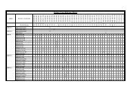
The following Table shows the segment listing, which is an extract from the Linker mapping file.<br />
FFMC-16 Family <strong>Softune</strong> Linker Mapping List<br />
S_Addr. -E_Addr. Size Section Type Al Sec.<br />
00000000-000000BF 000000C0 IO N RW-- 00 ABS IOBASE<br />
00000100-00000103 00000004 DATA P RW-- 02 REL DATA<br />
00000100-........ 00000000 DIR P RW-- 02 REL DIRDATA<br />
00000100-........ 00000000 DIR P RW-- 02 REL DIRINIT<br />
00000104-0000010B 00000008 DATA P RW-- 02 REL INIT<br />
0000010C-........ 00000000 DATA P RW-- 02 REL CINIT<br />
0000010C-........ 00000000 DATA P RW-- 02 REL LIBDATA<br />
0000010C-........ 00000000 DATA P RW-- 02 REL LIBINIT<br />
0000010C-0000040B 00000300 STACK P RW-- 02 REL SSTACK<br />
0000040C-0000040D 00000002 STACK P RW-- 02 REL USTACK<br />
00001900-00001FFF 00000700 DATA N RW-- 00 ABS IOXTND<br />
00FFA000-00FFA103 00000104 CODE P R-XI 01 REL CODE_START<br />
00FFA104-00FFA104 00000001 CONST P R--I 02 REL CONST<br />
00FFA105-00FFA185 00000081 CODE P R-XI 01 REL CODE<br />
00FFA186-00FFA18D 00000008 CONST P R--I 02 REL DCONST<br />
00FFA18E-........ 00000000 DIRC P R--I 02 REL DIRCONST<br />
00FFA18E-........ 00000000 CONST P R--I 02 REL LIBDCONST<br />
00FFA18E-........ 00000000 CONST P R--I 02 REL DCLEAR<br />
00FFA18E-........ 00000000 CONST P R--I 02 REL DTRANS<br />
00FFFF6C-00FFFFC3 00000058 DATA N RW-- 00 ABS INTVECT<br />
00FFFFDC-00FFFFDF 00000004 CONST N R--I 00 ABS RESVECT<br />
1.8 Download Program to old Starterkit 16<br />
To download the program to the old Starterkit 16, the SKWizard or the HexloadW utility can be used.<br />
Therefore the SKWizard can be added to the , menu. First the , <br />
menu must be <strong>started</strong> to add the SKWizard to the Utility list. Use the following options for the SKWizard:<br />
1 –sk16 –C %D%X.mhx.<br />
Alternately the HexloadW can be used with the option: 1 –sk16 -c %D%X.mhx<br />
NOTE:<br />
With the new <strong>Softune</strong> <strong>Workbench</strong> Symbolic debugging is not supported anymore. Furthermore the QSD<br />
source level debugger does not work if the code was created with the <strong>Softune</strong> <strong>Workbench</strong>. This is because<br />
HexloadW and the QSD debugger cannot use the new output file format of the <strong>Softune</strong> <strong>Workbench</strong>.<br />
9
1.9 Converting a Project from <strong>Softune</strong> Version 01<br />
To convert a project from <strong>Softune</strong> version 01 to version 03 a special converter is offered. This conversion is<br />
necessary because some macro assembler instructions has been changed (e.g. definition of sections,<br />
reserving Bytes). Unfortunately this converter has some restrictions so that some modifications has to be<br />
done manually. For a detailed description of this converter please have a look at the manual. Also some<br />
documents are delivered describing the differences between the old and the new versions of C-Compiler,<br />
Assembler, Linker and so on.<br />
1.10 Debugging<br />
To debug the generated source code the simulator or emulator debugger can be used. Therefore the<br />
simulator and the emulator setup must be done first. Within the <strong>Softune</strong> <strong>Workbench</strong> it is possible to save<br />
different setups. The important news is that the debugger is now fully integrated into the <strong>Workbench</strong><br />
environment.<br />
1.10.1 Setup the Simulator/Emulator Debugger<br />
Use the , , tab to enter the setup configuration. After that Setup Dialog box is<br />
opened to enter the settings. Select “Not Start Debugger” or “Start Debugger” to start the debugger via the<br />
, or automatically after the project was built without any errors. The “Auto<br />
Load” option should be selected to ensure that the latest file is always loaded when the debugger is <strong>started</strong>.<br />
In the next step enter the setup name, e.g. simulator. After that push the Add button. After that the setup<br />
Wizard is called to do the settings. Select for the debug type “Simulator Debugger” for a simulator setup<br />
and “Emulator debugger” for an emulator setting.<br />
10
The Next button will lead to the next dialog box. Now select Auto load when starting debug if the debug<br />
file should be loaded automatically whenever the debugger is <strong>started</strong>. Furthermore a batch file can be<br />
entered which should be executed before or after the download. Such a batchfile could be e.g. a procedure<br />
file for the debugger.<br />
After pushing the Next button it is possible to select the items which should be restored after the debugger<br />
is <strong>started</strong>. By default all items are selected. Just use the Finish button to close the setup.<br />
1.10.2 Start Emulator /Simulator Debugger<br />
When the debugger is <strong>started</strong> first the debug area must be defined. There exits two 512Kbyte debug areas<br />
which can be defined by the user. Attributes like read, write, read/write and code can be defined for these<br />
areas.<br />
As a standard startup, for the debug area 1 the address area 0x000000 – 0x07FFFF (page 0) is used for data<br />
read/write access. For debug area 2 the address area 0xF80000 – 0xFFFFFF (page FF) is defined for code<br />
access.<br />
After Starting the debugger the source window can be opened. Use the right mouse button (open context<br />
menu) to set Breakpoints, Watch Windows and so on. A special feature offers the memory window. First of<br />
all two different memory areas can be displayed in this window and each of these parts can be configured<br />
for different display modes (Binary, Byte, Word, LWord). The following screenshot gives a small<br />
impression of the look and feel.<br />
11
1.10.3 Special Simulator Settings<br />
Because the simulator is a core simulator only, it is not possible to simulate the resources as e.g. the UART.<br />
But it is possible to simulate interrupts and IO ports. I/O ports can be simulated using a file to input or<br />
output data whenever an access is made to a special I/O address. To simulate Interrupts or I/O port<br />
functionality use the , menu, after the debugger is <strong>started</strong>.<br />
After starting the debugger it is very important to setup the memory map for the debugger. Here the address<br />
areas must be defined which are accesses by the code. This means the I/O area, RAM and ROM area must<br />
be defined. The following screenshot gives an example setup configuration for the simulator.<br />
Use the , menu to configure the address map. Different attributes Read, Write,<br />
Code can be defined for the areas.<br />
12
<strong>Note</strong>:<br />
If the ROM Mirror Function is used with the simulator, it is necessary to copy manually the address area<br />
0xFF4000 – 0xFFFFFF to 0x004000 – 0x00FFFF. Therefore open the memory window and use the right<br />
mouse button to select the copy command.<br />
1.10.4 Special Emulator Settings<br />
Monitor download<br />
For the Hardware installation of the Emulator Debugger please look at the short description for the<br />
Emulator Hardware setup or read the manuals for the MB2141A main Unit and MB2145-507 emulation<br />
pod.<br />
If the emulator is <strong>started</strong> for the first time or if the microcontroller Family (16L 16LX) for the project<br />
has been changed it is necessary to download a monitor program first. For that reason start the Monitor<br />
Loader from the windows desktop (, , ,<br />
).<br />
Select the corresponding monitor program (eml905n.hex for 16LX family and MB2145-507 emulation pod,<br />
eml905.hex for 16LX family and MB2145-506 emulation pod, eml906n.hex for 16L family and MB2145-<br />
507 emulation pod, eml906.hex for 16L family and MB2145-506 emulation pod). The monitor files itself<br />
are located in the c:\<strong>Softune</strong>\lib\907\ directory. Also the communication interface (RS232 or LAN), the<br />
Baud-rate and the communication port must be selected. After this push the Start button to start the<br />
download.<br />
Memory map setting<br />
The address map for the emulator system is configured in the , menu.<br />
13
Use the Setup button to enter the memory areas. For each areas different attributes like read, write, code,<br />
user memory, emulation memory can be specified. User memory is memory which is located in hardware<br />
on the target system. Emulation memory is memory which is located in the emulator system<br />
A special feature is the memory mirror. A mirror area is always necessary for user memory to allow a<br />
memory read on the fly, which means to display the memory area while the program is running.<br />
To add a mirror area just highlight the corresponding address area within the dialog box and click on the<br />
Add Mirror button. Therefore a mirror is necessary because otherwise the emulator has to perform<br />
additional read cycles to this memory area during the normal program execution. This would disturb the<br />
normal program run sequence and execution time. Therefore a mirror within the emulation memory is used,<br />
so on every CPU access to the memory this data is updated in the memory mirror.<br />
1.11 Windows setup for Floating Point operations<br />
If floating point operations are used in the application, the Windows setup “Regional Settings” must be<br />
checked! In the “Regional Setting” for Windows (which can be found in the “control panel”), the number<br />
definition for “Decimal Symbol” must be set to “.”. If “,” is used, float operations will not be performed<br />
correctly! This problem is solved with the <strong>Softune</strong> <strong>Workbench</strong> Package V30L24.<br />
14
2.0 Special <strong>Note</strong>s for the F2MC-8L environment<br />
After Installation of the <strong>Workbench</strong> a demo program (Led8lirq.prj) can be found for the Starterkit 8. This<br />
demo program is an example which explains how to implement interrupts and how to include the standard<br />
header files for the corresponding microcontroller.<br />
<strong>Note</strong>:<br />
If a <strong>Softune</strong> V01 project is opened with the <strong>Softune</strong> <strong>Workbench</strong> an automatic converter can be <strong>started</strong>.<br />
Unfortunately this converter does not convert the assembler- and header files. So the conversion of the<br />
<strong>Softune</strong> V01 assembler- and header files must be done manually. This is necessary because the syntax of<br />
the assembler pseudo instruction has slightly been changed, e.g. definition of segments and label<br />
instructions.<br />
Creating a new Project<br />
The following steps describe how to create a new project.<br />
- File<br />
- New<br />
- Project File<br />
- Select Project Type: e.g. Loadmodul (ABS)<br />
- Enter Project Name: e.g name1<br />
- Select target MCU: e.g. 89T637A<br />
<strong>Note</strong>: This setting has an influence to the emulator/simulator settings. Address settings for<br />
the Linker must be done separately.<br />
- To create a new source file use , , Text file<br />
- In the example projects some init.asm files can be found. Within these init files some segment<br />
definitions and basic initializations are done. Corresponding to the application some changes has to be<br />
done, e.g. Stack size definition.<br />
- In the example projects a file mode_ext.asm or mode_sng.asm can be found. This files give an<br />
example how to specify the Reset vector and the Mode Byte to use an external bus interface or to use<br />
the single chip operating mode.<br />
- Additionally some settings has to be done, which are described in the next section.<br />
<strong>Note</strong>: Special template projects exists for each microcontroller series. These template projects<br />
include some basic settings for the MCU itself (which is done in a start.asm file), corresponding<br />
headerfiles and some basic project settings for the C-Compiler/Assembler/Linker and debugger. The<br />
easiest method to start a new project is to start with such a template project.<br />
Of course the user has always to check the tool settings and settings in the start.asm file, which must<br />
be modified to the needs of the user application!<br />
15
Setups<br />
If a new project has been created, check the following setups in the , <br />
menu. The following example shows some settings.<br />
- C Compiler:<br />
- Set Include path: e.g. c:\<strong>Softune</strong>\lib\896\include\sample<br />
- Enable the “Output Debug Information”<br />
- Enable the “ Create assembly list file”<br />
- Assembler:<br />
- Set Include path: e.g. c:\<strong>Softune</strong>\lib\896\include\sample<br />
- Enable the “Output Debug Information”<br />
- Converter<br />
- Enable the “Output Debug Information”<br />
- Set “Output Data Format” for 8Bit Starterkit applications to “Intel”. Otherwise program download<br />
will not work. Default setting is Motorola S-Record<br />
- In the , , menu select: absolute module converter is <strong>started</strong><br />
- Linker<br />
- Category: Disposition/Connection<br />
- Auto Disposition: Mode2<br />
- ROM/RAM Area Name:<br />
- RAM1<br />
- Area Attribute: RAM<br />
- Start Address: 0x80<br />
- End Address: 0x480<br />
- ROM1<br />
- Area Atrribute: ROM<br />
- Start Address: H’2000<br />
- End Address: H’FFFF<br />
- Set Section<br />
- RAM/ROM Area Name: Specify in Address<br />
- Section Name: CODE<br />
- Start Address: H’2000<br />
- Contents type: Code<br />
- Section Name: CONST<br />
- Contents Type: Const<br />
- RAM/ROM Area Name: ROM1<br />
- Section Name: @INIT<br />
- Section Name: @DIRINIT<br />
If in the program a variable is used with an initial value, it is often necessary to<br />
rewrite the variable. Therefore the variable must be located in the RAM area. The<br />
initial value of course has to be located in the ROM area. These initial values are<br />
linked to the INIT and DIRINT segments.<br />
So after startup the initial values has to be transferred from ROM to RAM. This can<br />
be done by the @INIT and @DIRINIT definition. The INIT and the DIRINIT<br />
segment are located in RAM, while the @INIT and @DIRINIT are located in the<br />
ROM area. With this definitions the symbols _RAM_INIT (transfer destination<br />
address) and _ROM_INIT (transfer source address) are generated by the linker. So<br />
these symbols can be used for a macro to copy the segment areas from ROM to<br />
RAM which is done in the init.asm.<br />
16
Download Program to Starterkit 8<br />
To download the program to the Starterkit 8 the SKWizard can be used. Therefore the SKWizard can be<br />
added to the , menu. First the , menu must be <strong>started</strong> to add the<br />
SKWizard to the Utility list. Use the following options for the SKWizard: 1 –sk8 –R –C %D%X.ihx.<br />
Alternately the HexloadW can be used with the option: 1 -i9600 -w -c %D%X.ihx<br />
<strong>Note</strong>: Symbolic debugging is not supported at the moment. This is because Hexloadw3a cannot generate<br />
the symbol list from the <strong>Softune</strong> <strong>Workbench</strong> input file.<br />
17