

Optima ES-SM Flushometers - Sloan Valve Company
Optima ES-SM Flushometers - Sloan Valve Company
Optima ES-SM Flushometers - Sloan Valve Company

You also want an ePaper? Increase the reach of your titles
YUMPU automatically turns print PDFs into web optimized ePapers that Google loves.
Code No. 0816835<br />
Rev. 1 (05/10)<br />
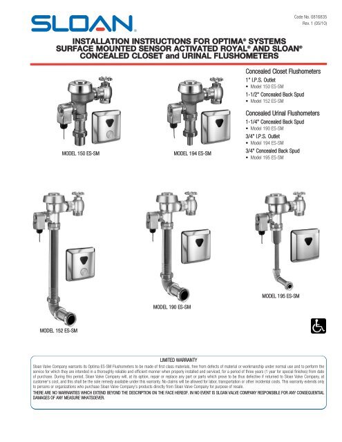
INSTALLATION INSTRUCTIONS FOR OPTIMA ® SYSTEMS<br />
SURFACE MOUNTED SENSOR ACTIVATED ROYAL ® AND SLOAN ®<br />
CONCEALED CLOSET and URINAL FLUSHOMETERS<br />
Concealed Closet <strong>Flushometers</strong><br />
1” I.P.S. Outlet<br />
• Model 150 <strong>ES</strong>-<strong>SM</strong><br />
1-1/2" Concealed Back Spud<br />
• Model 152 <strong>ES</strong>-<strong>SM</strong><br />
MODEL 150 <strong>ES</strong>-<strong>SM</strong><br />
MODEL 194 <strong>ES</strong>-<strong>SM</strong><br />
Concealed Urinal <strong>Flushometers</strong><br />
1-1/4" Concealed Back Spud<br />
• Model 190 <strong>ES</strong>-<strong>SM</strong><br />
3/4” I.P.S. Outlet<br />
• Model 194 <strong>ES</strong>-<strong>SM</strong><br />
3/4" Concealed Back Spud<br />
• Model 195 <strong>ES</strong>-<strong>SM</strong><br />
MODEL 190 <strong>ES</strong>-<strong>SM</strong><br />
MODEL 195 <strong>ES</strong>-<strong>SM</strong><br />
MODEL 152 <strong>ES</strong>-<strong>SM</strong><br />
LIMITED WARRANTY<br />
<strong>Sloan</strong> <strong>Valve</strong> <strong>Company</strong> warrants its <strong>Optima</strong> <strong>ES</strong>-<strong>SM</strong> <strong>Flushometers</strong> to be made of first class materials, free from defects of material or workmanship under normal use and to perform the<br />
service for which they are intended in a thoroughly reliable and efficient manner when properly installed and serviced, for a period of three years (1 year for special finishes) from date<br />
of purchase. During this period, <strong>Sloan</strong> <strong>Valve</strong> <strong>Company</strong> will, at its option, repair or replace any part or parts which prove to be thus defective if returned to <strong>Sloan</strong> <strong>Valve</strong> <strong>Company</strong>, at<br />
customer's cost, and this shall be the sole remedy available under this warranty. No claims will be allowed for labor, transportation or other incidental costs. This warranty extends only<br />
to persons or organizations who purchase <strong>Sloan</strong> <strong>Valve</strong> <strong>Company</strong>'s products directly from <strong>Sloan</strong> <strong>Valve</strong> <strong>Company</strong> for purpose of resale.<br />
THERE ARE NO WARRANTI<strong>ES</strong> WHICH EXTEND BEYOND THE D<strong>ES</strong>CRIPTION ON THE FACE HEREOF. IN NO EVENT IS SLOAN VALVE COMPANY R<strong>ES</strong>PONSIBLE FOR ANY CONSEQUENTIAL<br />
DAMAG<strong>ES</strong> OF ANY MEASURE WHATSOEVER.
M<br />
M<br />
VALVE ROUGH-IN<br />
150 <strong>ES</strong>-<strong>SM</strong> MODEL 150 <strong>ES</strong>-<strong>SM</strong><br />
152 MODEL <strong>ES</strong>-<strong>SM</strong>152 <strong>ES</strong>-<strong>SM</strong> 152 <strong>ES</strong>-<strong>SM</strong><br />
150 150 <strong>ES</strong>-<strong>SM</strong> <strong>ES</strong>-<strong>SM</strong> 152 <strong>ES</strong>-<strong>SM</strong> 152 152 <strong>ES</strong>-<strong>SM</strong> <strong>ES</strong>-<strong>SM</strong><br />
M<br />
M<br />
190 <strong>ES</strong>-<strong>SM</strong><br />
194 <strong>ES</strong>-<strong>SM</strong> 194 <strong>ES</strong>-<strong>SM</strong><br />
190 190 <strong>ES</strong>-<strong>SM</strong> <strong>ES</strong>-<strong>SM</strong> 194 <strong>ES</strong>-<strong>SM</strong> 194 194 <strong>ES</strong>-<strong>SM</strong> <strong>ES</strong>-<strong>SM</strong><br />
NOTE: Flush Connection shown with dotted lines is not included.<br />
MODEL 190 <strong>ES</strong>-<strong>SM</strong><br />
MODEL 194 <strong>ES</strong>-<strong>SM</strong><br />
M<br />
M<br />
195 <strong>ES</strong>-<strong>SM</strong><br />
195 195 <strong>ES</strong>-<strong>SM</strong> <strong>ES</strong>-<strong>SM</strong><br />
MODEL 195 <strong>ES</strong>-<strong>SM</strong><br />
NOTE: Flush Connection shown with dotted lines is not included.<br />
‡ POSITION OF SENSOR BOX CAN BE RAISED OR LOWERED 1” (25 mm)<br />
IF IN CONFLICT WITH HANDICAP GRAB BARS.<br />
SENSOR LOCATION & POSITIONING IS CRITICAL!<br />
Failure to properly position the electrical boxes to the plumbing rough-in<br />
will result in improper installation and impair product performance.<br />
All tradesmen (plumbers, electricians, tile setters, etc.) involved with<br />
the installation of this product must coordinate their work to assure<br />
proper product installation.<br />
2
PRIOR TO FLUSHOMETER INSTALLATION<br />
Prior to installing the <strong>Sloan</strong> OPTIMA equipped Flushometer, install the items<br />
listed below. Refer to Rough-ins on Page 2 and illustration on this page.<br />
• 2-gang electrical box — 4" x 4" x 2-1/2" (102 mm x 102 mm x 64<br />
mm) for transformer; see paragraph entitled “Transformer Installation”<br />
(mount in a convenient location)<br />
• Electrical wiring to the transformer box (120 VAC, 2 amp service<br />
required for each EL-154, 24 VAC, 50 VA transformer used)<br />
• Closet/urinal fixture<br />
• Drain line<br />
• Water supply line<br />
Important:<br />
• INSTALL ALL ELECTRICAL WIRING IN ACCORDANCE WITH<br />
NATIONAL/LOCAL COD<strong>ES</strong> AND REGULATIONS.<br />
• INSTALL ALL PLUMBING IN ACCORDANCE WITH APPLICABLE COD<strong>ES</strong><br />
AND REGULATIONS.<br />
• WATER SUPPLY LIN<strong>ES</strong> MUST BE SIZED TO PROVIDE AN ADEQUATE<br />
VOLUME OF WATER FOR EACH FIXTURE.<br />
• A 24 VAC STEP-DOWN TRANSFORMER MUST BE USED.<br />
• USE APPROPRIATE PRECAUTIONS WHILE CONNECTING TRANSFORMER<br />
TO 120 VAC POWER SOURCE.<br />
• FLUSH ALL WATER LIN<strong>ES</strong> PRIOR TO MAKING CONNECTIONS.<br />
Royal ® and <strong>Sloan</strong> ® <strong>Flushometers</strong> are designed to operate with 15 to 100<br />
psi (104 to 689 kPa) of water pressure. THE MINIMUM PR<strong>ES</strong>SURE<br />
REQUIRED TO THE VALVE IS DETERMINED BY THE TYPE OF FIXTURE<br />
SELECTED. Consult fixture manufacturer for minimum pressure<br />
requirements.<br />
Most Low Consumption water closets (1.6 gallon/6.0 liter) require a<br />
minimum flowing pressure of 25 psi (172 kPa).<br />
Protect the Chrome or Special finish of this Flushometer — DO NOT USE<br />
TOOTHED TOOLS TO INSTALL OR SERVICE THE VALVE. Also, see "Care<br />
and Cleaning" section of this manual.<br />
IMPORTANT: EXCEPT FOR CONTROL STOP INLET, DO NOT USE PIPE<br />
SEALANT OR PLUMBING GREASE ON ANY VALVE COMPONENT OR<br />
COUPLING!<br />
TRANSFORMER INSTALLATION AND SENSOR BOX LOCATION<br />
Transformer Installation<br />
Install Transformer (EL-154) on a 2-Gang Electrical Box, 4" x 4" x 2-1/2"<br />
(102 mm x 102 mm x 64 mm) in a convenient location; refer to the<br />
illustration at upper right side of this page.<br />
Note: One <strong>Sloan</strong> EL-154 transformer can operate up to ten OPTIMA<br />
equipped <strong>Flushometers</strong>. Run 18-gauge wire from transformer to<br />
Flushometer(s). Wire supplied by others. DO NOT supply power to<br />
transformer until installation of Flushometer is complete.<br />
Note: A maximum of ten (10) Flushometer units can operate from one (1)<br />
<strong>Sloan</strong> EL-154 Transformer, Class 2, UL Listed, 50 VA (min.) at 24 VAC,<br />
plate mounted.<br />
Sensor Box Location<br />
Failure to properly position the sensor to the plumbing rough-in will result<br />
in improper installation and impair product performance. All tradesmen<br />
(plumbers, electricians, tile setters, etc.) involved with the installation of this<br />
product must coordinate their work to assure proper product installation.<br />
TOOLS REQUIRED FOR INSTALLATION<br />
• Phillips screwdriver<br />
• Drill – 1/16” and 1” drill bit<br />
• Wire stripper<br />
• <strong>Sloan</strong> A-50 Super-Wrench, <strong>Sloan</strong> A-109 Plier Wrench or smooth jawed spud wrench<br />
† MOUNT TRANSFORMER<br />
WITHIN 50 FEET (15 m) OF<br />
FLUSHOMETER<br />
2-GANG ELECTRICAL BOX -<br />
4" x 4" x 2½" (102 mm x 102 mm x 64 mm)<br />
EL-154 TRANSFORMER †<br />
!!! IMPORTANT !!!<br />
With the exception of Control Stop Inlet, DO NOT use pipe sealant or<br />
plumbing grease on any valve component or coupling!<br />
!!! IMPORTANT !!!<br />
Never open Control Stop to where the flow from the valve<br />
exceeds the flow capability of the fixture. In the event of<br />
a valve failure, the fixture must be able to accommodate a<br />
continuous flow from the valve.<br />
!!! IMPORTANT !!!<br />
This product contains mechanical and/or electrical components<br />
that are subject to normal wear. These components should be<br />
checked on a regular basis and replaced as needed to maintain<br />
the valve’s performance.<br />
!!! IMPORTANT !!!<br />
Protect the chrome or special finish of <strong>Sloan</strong> <strong>Flushometers</strong> —<br />
DO NOT USE toothed tools to install or service these valves. Use<br />
a <strong>Sloan</strong> A-50 Super-Wrench, <strong>Sloan</strong> A-109 Plier Wrench or<br />
smooth jawed spud wrench to secure all couplings. Also see<br />
“Care and Cleaning” section of this manual.<br />
If you have questions about how to install your <strong>Sloan</strong> Flushometer, consult your local<br />
<strong>Sloan</strong> Representative or call <strong>Sloan</strong> Installation Engineering Department at:<br />
1-888-SLOAN-14 (1-888-756-2614) OR 1-847-233-2016<br />
3
1 - INSTALL OPTIONAL SWEAT SOLDER ADAPTER (ONLY IF YOUR SUPPLY PIPE DO<strong>ES</strong> NOT<br />
HAVE A MALE THREAD)<br />
A<br />
B<br />
Slide Threaded Adapter fully onto pipe.<br />
Sweat solder the Adapter to pipe.<br />
THREADED ADAPTER<br />
2 - INSTALL CONTROL STOP ONTO SUPPLY PIPE<br />
A<br />
Install the <strong>Sloan</strong> Bak-Chek ® Control Stop onto the water supply line<br />
with the outlet positioned as required.<br />
!!! IMPORTANT !!!<br />
With the exception of Control Stop Inlet, DO NOT use pipe sealant or<br />
plumbing grease on any valve component or coupling!<br />
WATER SUPPLY PIPE<br />
BAK-CHEK ®<br />
CONTROL STOP<br />
IRON PIPE NIPPLE OR<br />
COPPER PIPE WITH<br />
SWEAT SOLDER ADAPTER<br />
3 - INSTALL VACUUM BREAKER FLUSH CONNECTION<br />
A<br />
Assemble Pipe, Elbows, Couplings, Nylon Slip Gasket, Rubber<br />
Gaskets and Flanges as illustrated on parts page.<br />
DO NOT USE PIPE SEALANT ON<br />
SCORED SLIP CONNECTION<br />
B<br />
C<br />
Insert Tube into Fixture Spud.<br />
Hand tighten all Couplings.<br />
IMPORTANT: WHEN CUTTING<br />
SCORED PIPE TO LENGTH<br />
LEAVE A MINIMUM OF 1-1/4”<br />
(32 mm) OF SCORING TO<br />
ENSURE PROPER<br />
ENGAGEMENT<br />
1-1/4" (32 mm) MIN.<br />
4 - INSTALL FLUSHOMETER<br />
A<br />
B<br />
C<br />
Lubricate tailpiece O-ring with water. Insert Adjustable Tailpiece into<br />
Control Stop. Tighten Tailpiece Coupling by hand.<br />
Align Flushometer directly above the Vacuum Breaker Flush<br />
Connection by sliding the Flushometer Body IN or OUT as needed.<br />
Tighten Vacuum Breaker Coupling by hand.<br />
Align Flushometer Body and securely tighten first the Tailpiece<br />
Coupling (1), then the Vacuum Breaker and Pipe Couplings (2), and<br />
finally the Spud Coupling (3). Use a wrench to tighten these<br />
couplings in the order shown.<br />
NOTE<br />
Max. adjustment of <strong>Sloan</strong> Adjustable Tailpiece is ½" (13 mm) IN or OUT<br />
from the standard 4¾" (121 mm) (c/l of <strong>Valve</strong> to c/l of Control Stop).<br />
FLUSHOMETER<br />
BODY<br />
G-44 FRICTION RING<br />
VACUUM BREAKER<br />
COUPLING<br />
2<br />
VACUUM BREAKER<br />
FLUSH CONNECTION<br />
VACUUM<br />
BREAKER<br />
REPAIR KIT<br />
TAILPIECE COUPLING<br />
1<br />
O-RING<br />
ADJUSTABLE TAILPIECE<br />
CONTROL STOP<br />
If roughing-in measurement exceeds 5¼” (133 mm), consult factory<br />
for longer tailpiece.<br />
C/L FIXTURE<br />
C/L SUPPLY<br />
4
5 - INSTALL SENSOR BOX<br />
A<br />
Refer to Page 2 Rough-in<br />
drawings for the proper<br />
location of the Sensor Box.<br />
Position Gasket (EL-456) onto<br />
Finished Wall in the Sensor Box<br />
location just determined. Using<br />
the Gasket as a template, mark<br />
Mounting Holes and Sensor<br />
Box Cable location.<br />
D<br />
E<br />
F<br />
Install Gasket (EL-456) and Wall Bracket (EL-460) onto Finished<br />
Wall using two (2) #6 Phillips screws. Ensure that Sensor Lens<br />
faces outward and horizontally from finished wall.<br />
Feed the 15-Foot Cord With RJ-11 Plug through the Wall Bracket,<br />
Gasket and 1” (25 mm) diameter hole.<br />
Install Sensor Cover Plate and secure with Screw.<br />
B<br />
Drill a 1/16” (1.6 mm) hole at the two Mounting Hole locations.<br />
Drill a 1” (25 mm) hole at the Sensor Box Cable location.<br />
ETF-212<br />
(#6 PHILLIPS)<br />
SCREWS<br />
1” (25 mm) DIAMETER HOLE FINISHED<br />
WALL<br />
MOUNTING HOL<strong>ES</strong><br />
SENSOR<br />
ETF-211 WALL<br />
ANCHORS<br />
(INSTALLED)<br />
SENSOR BOX<br />
CABLE HOLE<br />
EL-456 GASKET<br />
(FLAT SIDE TOWARD WALL)<br />
C<br />
Install an ETF-211 Wall Anchor in each Mounting Hole.<br />
OVERRIDE BUTTON<br />
(MODELS 150 & 152)<br />
SCREW<br />
EL-460 WALL<br />
BRACKET<br />
6 - ELECTRICAL HOOK-UP<br />
A<br />
Be certain power is OFF to prevent damage to electrical<br />
components. Connect all cables EXACTLY as shown.<br />
WATER CLOSET<br />
URINAL<br />
EL-461<br />
WATER CLOSET<br />
SENSOR<br />
MODEL 150 <strong>ES</strong>-<strong>SM</strong><br />
SHOWN<br />
MODULAR<br />
RECEPTACL<strong>ES</strong> ARE<br />
INTERCHANGEABLE<br />
(CONNECTORS CAN<br />
BE INSERTED INTO<br />
ANY RECEPTACLE)<br />
EL-497<br />
URINAL<br />
SENSOR<br />
MODEL 194 <strong>ES</strong>-<strong>SM</strong><br />
SHOWN<br />
MODULAR<br />
RECEPTACL<strong>ES</strong> ARE<br />
INTERCHANGEABLE<br />
(CONNECTORS CAN<br />
BE INSERTED INTO<br />
ANY RECEPTACLE)<br />
24 VAC<br />
TERMINAL<br />
BLOCK<br />
ETF-492-A<br />
CONTROL MODULE<br />
24 VAC<br />
TERMINAL<br />
BLOCK<br />
ETF-492-A<br />
CONTROL MODULE<br />
36-INCH CORD<br />
WITH RJ-11 PLUG<br />
TO TERMINAL BLOCK<br />
15-FOOT CORD WITH<br />
RJ-11 PLUG<br />
36-INCH CORD<br />
WITH RJ-11 PLUG<br />
TO TERMINAL BLOCK<br />
15-FOOT CORD WITH<br />
RJ-11 PLUG<br />
24 VAC POWER CORD<br />
TO 24 VAC<br />
TRANSFORMER<br />
24 VAC POWER CORD<br />
TO 24 VAC<br />
TRANSFORMER<br />
One 50 VA Transformer serves up to ten (10) OPTIMA Closet/Urinal <strong>Flushometers</strong>. Specify number of transformers required accordingly.<br />
5
7 - FLUSH OUT SUPPLY LINE<br />
A<br />
B<br />
C<br />
D<br />
Make sure Control Stop is CLOSED.<br />
Remove Flushometer Cover and lift out Inside Parts Assembly. Install<br />
Flushometer Cover wrench tight.<br />
Open Control Stop. Turn on water supply to flush line of any debris or<br />
sediment.<br />
Shut off Control Stop, remove Cover and reinstall Inside Parts<br />
Assembly. Install Flushometer Cover wrench tight. Do Not open Control<br />
Stop until Step 10.<br />
8 - POWER, START-UP MODE, AND ACTIVATION/DETECTION<br />
Note: It is recommended that all electronic connections be tested with the water<br />
supply OFF.<br />
A<br />
B<br />
Turn Power ON. The self adaptive sensor automatically adapts to the<br />
surrounding environment when 24 volt supply is activated. No manual<br />
adjustments are required.<br />
Start-up mode will take approximately five (5) minutes to complete its<br />
cycle and is important that no non-permanent target is present at this<br />
time. A continuous red light visible in sensor window indicates sensor is<br />
in the start-up mode. If the red light is flashing, this indicates that the<br />
sensor is picking up a target. Unless this target is a permanent fixture<br />
in the sensor’s environment (i.e., a wall or stall door), it must be<br />
removed from the view of the sensor. If this target is permanent, the<br />
sensor will adapt itself around this target. In this case, the start-up<br />
mode may take up to ten (10) minutes. When the start-up cycle is<br />
completed, no light is visible in sensor window.<br />
Note: If 24 volt power supply is interrupted at any time for more than fifteen (15)<br />
seconds, the start-up mode automatically repeats itself when power is restored.<br />
C<br />
D<br />
The self-adaptive sensor is equipped with the sentinel flush<br />
feature (automatically flushes every twenty-four (24) hours<br />
after last use).<br />
When an object is detected, a steady flashing red light will<br />
appear in the sensor window. After approximately eight (8) to<br />
ten (10) seconds, the light will turn off indicating sensor is<br />
armed and ready to activate solenoid when the object leaves<br />
the detection area. The solenoid will be activated within two (2)<br />
to four (4) seconds after non-detection.<br />
9 - TURN WATER ON AND ADJUST CONTROL STOP<br />
A<br />
B<br />
Adjust Control Stop to meet the flow rate required for proper cleansing<br />
of the fixture. Open Control Stop COUNTERCLOCKWISE 1/2 turn from<br />
the closed position.<br />
Activate Flushometer by placing hand in front of OPTIMA Sensor Lens<br />
for ten (10) seconds and then moving it away.<br />
C<br />
Adjust Control Stop after each flush until the rate of flow<br />
delivered properly cleanses the fixture.<br />
!!! IMPORTANT !!!<br />
The Royal ® and <strong>Sloan</strong> ® Flushometer is engineered for<br />
quiet operation. Excessive water flow creates noise,<br />
while too little water flow may not satisfy the needs of the<br />
fixture. Proper adjustment is made when plumbing fixture<br />
is cleansed after each flush without splashing water out<br />
from the lip AND a quiet flushing cycle is achieved.<br />
Never open Control Stop to where the flow from the<br />
valve exceeds the flow capability of the fixture. In the<br />
event of a valve failure, the fixture must be able to<br />
accommodate a continuous flow from the valve.<br />
6
OPERATION<br />
1. A continuous, invisible light<br />
beam is emitted from the<br />
OPTIMA Sensor.<br />
2. When a user enters the<br />
beam’s effective range, the<br />
beam is reflected into the<br />
OPTIMA’s scanning window<br />
and transformed into a low<br />
voltage electrical signal that<br />
activates a ten-second time<br />
delay circuit. The time delay<br />
circuit eliminates false<br />
operation from passers-by in<br />
the rest room. Once the time<br />
delay is completed, the<br />
output circuit is alerted and<br />
continues in a “hold” mode<br />
for as long as the user<br />
remains within the effective<br />
range of the sensor.<br />
3. When the user steps away<br />
from the OPTIMA Sensor,<br />
the loss of reflected light<br />
initiates an electrical “onetime”<br />
signal that energizes<br />
the Solenoid Operator, and<br />
activates the Flushometer to<br />
flush the fixture. This occurs<br />
approximately three (3)<br />
seconds after indication.<br />
This delay is built into the<br />
Sensor to help prevent false<br />
flushing due to movement<br />
by the user. The circuit then<br />
automatically resets and is<br />
ready for the next user.<br />
CARE AND CLEANING<br />
DO NOT use abrasive or chemical cleaners (including chlorine bleach) to<br />
clean <strong>Flushometers</strong> as they may dull the luster and attack the chrome or<br />
special decorative finishes. Use ONLY soap and water, then wipe dry with<br />
clean cloth or towel.<br />
While cleaning the bathroom tile, the Flushometer should be protected from<br />
any splattering of cleaner. Acids and cleaning fluids can discolor or remove<br />
chrome plating.<br />
TROUBL<strong>ES</strong>HOOTING GUIDE<br />
NOTE: Upon detection of the user, the red indicator light is steadily on for a<br />
period of eight seconds. When the user leaves the detection range, the<br />
indicator light will turn off and the Sensor initiates the flush sequence. Then<br />
the indicator light stops flashing and the valve flushes. The valve will flush<br />
after a three-second delay.<br />
1. PROBLEM: <strong>Valve</strong> does not function (red light does not turn on when user<br />
steps in front of sensor).<br />
CAUSE: No power is being supplied to sensor.<br />
SOLUTION: Ensure that the main power is turned “ON.” Check<br />
transformer, leads and connections. Repair or replace as<br />
necessary.<br />
CAUSE: Sensor is not operating.<br />
SOLUTION: Replace Sensor.<br />
2. PROBLEM: <strong>Valve</strong> does not function (red light flashes when user steps in<br />
front of Sensor).<br />
INDICATOR:<br />
CAUSE:<br />
SOLUTION:<br />
CAUSE:<br />
SOLUTION:<br />
INDICATOR:<br />
CAUSE:<br />
SOLUTION:<br />
Red light stops flashing when user steps away and valve<br />
makes a “clicking” sound but does not flush.<br />
No water is being supplied to the valve.<br />
Make certain that water supply is turned “ON” and the Control<br />
Stop is open.<br />
EL-128-A cartridge is fouled or jammed.<br />
Turn electronic power to valve “OFF” (failure to do so could<br />
result in damage to the solenoid coil). Remove the solenoid<br />
operator from the valve and remove the<br />
EL-128-A cartridge. Clean and/or repair as necessary.<br />
The red light does not turn off when user steps away and the<br />
valve does NOT make a “clicking” sound and does NOT flush.<br />
EL-163-A solenoid shaft assembly is fouled or jammed.<br />
Turn electronic power to valve “OFF” (failure to do so could<br />
result in damage to the solenoid coil). Remove<br />
EL-101 or EL-166 nut from the solenoid operator. Remove the<br />
coil from the solenoid operator. Use a spanner wrench or pliers<br />
to remove the EL-163-A solenoid shaft assembly from valve.<br />
Clean and/or replace as necessary. Be sure to replace plunger<br />
spring when reassembling Solenoid Shaft Assembly.<br />
7<br />
3. PROBLEM: Volume of water is insufficient to adequately siphon fixture.<br />
CAUSE: Control Stop is not open wide enough.<br />
SOLUTION: Adjust control stop for desired water delivery.<br />
CAUSE: Low Consumption unit is installed on Water Saver or<br />
Conventional fixture.<br />
SOLUTION: Replace Diaphragm component parts of valve with kit that<br />
corresponds to appropriate flush volume of fixture.<br />
CAUSE: Inadequate water volume or pressure available from supply.<br />
SOLUTION: Increase pressure or supply (flow rate) to the valve. Consult<br />
factory for assistance.<br />
4. PROBLEM: Length of flush is too long (long flushing) or valve fails to shut<br />
off.<br />
CAUSE: Water Saver valve is installed on Low Consumption fixture.<br />
SOLUTION: Replace Diaphragm component parts of valve with kit that<br />
corresponds to appropriate flush volume of fixture.<br />
CAUSE: Relief valve in diaphragm is not seated properly or bypass hole<br />
in diaphragm is clogged.<br />
SOLUTION: Disassemble inside Diaphragm component parts and wash<br />
parts thoroughly. Replace worn parts if necessary.<br />
5. PROBLEM: Water splashes from fixture.<br />
CAUSE:<br />
SOLUTION:<br />
Supply flow rate is more than necessary.<br />
Adjust Control Stop to meet flow rate required for proper<br />
cleansing of the fixture.<br />
If further assistance is required, please contact <strong>Sloan</strong> <strong>Valve</strong> <strong>Company</strong><br />
Installation Engineering Department at:<br />
1-888-SLOAN-14 (1-888-756-2614).<br />
!!! IMPORTANT — Control Stop Setting !!!<br />
Never open Control Stop to where the flow from the valve exceeds the flow<br />
capability of the fixture. In the event of a valve failure, the fixture must be<br />
able to accommodate a continuous flow from the valve.
ROYAL PARTS LIST<br />
3A<br />
3B 2<br />
1<br />
4<br />
150 <strong>ES</strong>-<strong>SM</strong> 194 <strong>ES</strong>-<strong>SM</strong><br />
152 <strong>ES</strong>-<strong>SM</strong><br />
190 <strong>ES</strong>-<strong>SM</strong> 195 <strong>ES</strong>-<strong>SM</strong><br />
5A<br />
5B<br />
5C<br />
INSTALL WITH<br />
FLANGE<br />
AGAINST SPUD<br />
5D<br />
5E<br />
7<br />
11<br />
12<br />
8 13<br />
9<br />
9<br />
6<br />
7<br />
10<br />
6<br />
10<br />
Item Part Description<br />
No. No.<br />
1 ‡ Solenoid Activated <strong>Valve</strong> Assembly<br />
2 H-730-A 1" (25 mm) Concealed WH Bak-Chek ® Angle Stop RB<br />
H-730-A ¾" (19 mm) Concealed WH Bak-Chek ® Angle Stop RB<br />
3A EL-461 Surface Mounted Sensor and Override Button Assembly<br />
(closet only)<br />
3B EL-497 Surface Mounted Sensor Assembly (urinal only)<br />
4 ETF-492-A Control Module<br />
5A V-500-A 1½" (38 mm) Vacuum Breaker Assembly RB<br />
(Model 150 <strong>ES</strong>-<strong>SM</strong>)<br />
5B V-500-A ¾" (19 mm) Vacuum Breaker Assembly RB (Model 194 <strong>ES</strong>-<strong>SM</strong>)<br />
5C V-500-A 1½" (38 mm) x 11½" (292 mm) Vacuum Breaker Assembly RB<br />
(Model 152 <strong>ES</strong>-<strong>SM</strong>)<br />
5D V-500-AA 1½" (38 mm) x 11½" (292 mm) Vacuum Breaker Assembly RB<br />
(Model 190 <strong>ES</strong>-<strong>SM</strong>)<br />
5E V-500-AA ¾" (19 mm) x 10½" (267 mm) Vacuum Breaker Assembly RB<br />
(Model 195 <strong>ES</strong>-<strong>SM</strong>)<br />
Item Part Description<br />
No. No.<br />
6 F-21 1½" (38 mm) Double Slip Elbow RB<br />
(Models 152 <strong>ES</strong>-<strong>SM</strong> and 190 <strong>ES</strong>-<strong>SM</strong>)<br />
7 F-2-AA 1½" (38 mm) Slip Joint Coupling RB (Set of Two)<br />
(Model 152 <strong>ES</strong>-<strong>SM</strong>)<br />
8 F-2A 1½" (38 mm) Slip Joint Coupling RB (Model 190 <strong>ES</strong>-<strong>SM</strong>)<br />
9 F-2-AW ¾" (19 mm) Slip Joint Coupling RB (Model 195 <strong>ES</strong>-<strong>SM</strong>)<br />
10 F-2-A 1½" (38 mm) Coupling with S-21 Gasket<br />
11 F-102 1½" (38 mm) Outlet Tube RB<br />
12 F-110 1¼" (32 mm) O.D. Outlet Tube RB<br />
13 F-2-AU 1¼" (32 mm) Slip Joint Coupling RB<br />
‡ Part number varies with valve model variation; consult factory.<br />
NOTE: The information contained in this document is subject to change without<br />
notice.<br />
Royal and <strong>Sloan</strong><br />
Detailed Parts Breakdown<br />
For a detailed parts breakdown of Royal and <strong>Sloan</strong> <strong>Optima</strong> <strong>ES</strong>-<strong>SM</strong><br />
<strong>Flushometers</strong>, see Repair Parts and Maintenance Guide.<br />
Copyright © 2010 SLOAN VALVE COMPANY<br />
SLOAN VALVE COMPANY • 10500 Seymour Avenue • Franklin Park, IL 60131<br />
Phone: 1-800-982-5839 or 1-847-671-4300 • Fax: 1-800-447-8329 or 1-847-671-4380<br />
www.sloanvalve.com<br />
Code No. 0816835 – Rev. 1 (05/10)


