Motor Controls & Contactors - Geeco
Motor Controls & Contactors - Geeco
Motor Controls & Contactors - Geeco

You also want an ePaper? Increase the reach of your titles
YUMPU automatically turns print PDFs into web optimized ePapers that Google loves.
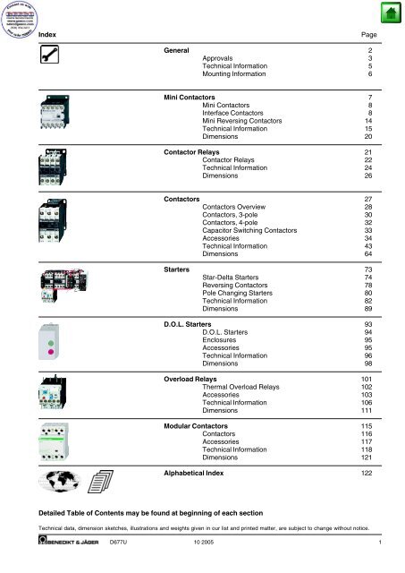
Index<br />
Page<br />
General 2<br />
Approvals 3<br />
Technical Information 5<br />
Mounting Information 6<br />
Mini <strong>Contactors</strong> 7<br />
Mini <strong>Contactors</strong> 8<br />
Interface <strong>Contactors</strong> 8<br />
Mini Reversing <strong>Contactors</strong> 14<br />
Technical Information 15<br />
Dimensions 20<br />
Contactor Relays 21<br />
Contactor Relays 22<br />
Technical Information 24<br />
Dimensions 26<br />
<strong>Contactors</strong> 27<br />
<strong>Contactors</strong> Overview 28<br />
<strong>Contactors</strong>, 3-pole 30<br />
<strong>Contactors</strong>, 4-pole 32<br />
Capacitor Switching <strong>Contactors</strong> 33<br />
Accessories 34<br />
Technical Information 43<br />
Dimensions 64<br />
Starters 73<br />
Star-Delta Starters 74<br />
Reversing <strong>Contactors</strong> 78<br />
Pole Changing Starters 80<br />
Technical Information 82<br />
Dimensions 89<br />
D.O.L. Starters 93<br />
D.O.L. Starters 94<br />
Enclosures 95<br />
Accessories 95<br />
Technical Information 96<br />
Dimensions 98<br />
Overload Relays 101<br />
Thermal Overload Relays 102<br />
Accessories 103<br />
Technical Information 106<br />
Dimensions 111<br />
Modular <strong>Contactors</strong> 115<br />
<strong>Contactors</strong> 116<br />
Accessories 117<br />
Technical Information 118<br />
Dimensions 121<br />
Alphabetical Index 122<br />
Detailed Table of Contents may be found at beginning of each section<br />
Technical data, dimension sketches, illustrations and weights given in our list and printed matter, are subject to change without notice.<br />
D677U 10 2005<br />
1
General<br />
Quality Control System<br />
Since November 1991 Benedikt & Jäger has been certified according<br />
to the quality control system ÖNORM EN ISO 29001. The target of the<br />
ISO-certification is, to grant the customer the quality of the performance<br />
of his supplier, who is audited in accordance with this standard.<br />
CE-Marking<br />
The manufacturer has to sign his products with the CE-Marking. With<br />
the CE-Marking the manufacturer confirms the accordance with the<br />
different EEC Directives. The CE-Marking is absolutely necessary to<br />
sell the products in the EEC.<br />
Attached you find the EEC Directives concerning our products.<br />
Low Voltage Directive (73/23/EEC)<br />
EMC Directive ( 89/336/EEC)<br />
Declarations of Conformity art. no. D586.. on request.<br />
Test Authorities, Registration Mark, Approvals<br />
Benedikt & Jäger Low voltage switchgear is built and tested<br />
to national and international specifications. All devices suit all<br />
important specifications without any test obligation, like VDE,<br />
BS and also relative to IEC Recommendations and to European<br />
Standards like IEC 947 and EN 60947.<br />
It is for this reason Benedikt & Jäger Low voltage switchgear is used<br />
all over the world. In order to provide special versions, limitations to<br />
the max. voltages, currents and power ratings or special markings are<br />
sometimes necessary.<br />
Benedikt & Jäger Low voltage switchgear is also suitable for applications<br />
in marine environments.<br />
They are classified in "Lloyd`s Register of Shipping" and in the "Maritime<br />
Register of Shipping" (GUS). The "American Bureau of Shipping" does<br />
not claim a general approval for single components, the complete<br />
electrical equipment on board has to be approved. The devices should<br />
have UL- and CSA-approvals. Further information for Guide-No. and<br />
File-No. (CSA, UL) you will find on page 4.<br />
For approved values see technical data of the devices.<br />
Country Canada USA Switzer- Den- Norway Sweden Finland Poland Slowa- Czech Hunland<br />
mark kia garia<br />
State deputy CSA UL UL SEV DEMKO NEMKO SEMKO SETI SEP SKTC EZU MEEI<br />
or private examination<br />
(state admitted)<br />
Label marking 1)<br />
of examination boards<br />
Duty of approvals All switchgear or No approval since 1. 1. 1994<br />
Approval Our devices are according to the harmonised<br />
of switchgear European Standards e.g. EN 60947<br />
commendable (IEC 947, VDE 0660) and can be used generally<br />
Specification UL is authorised for approvals Marking with approbation label is no longer<br />
acc. to Canadian Standards<br />
necessary<br />
1) CSA-approvals are replaced by UL-approvals valid for USA and Canada. From 1. 1. 2000 switchgear will be marked with the combined approval.<br />
UL-mark or only.<br />
Explanations for choice and supply of low voltage switchgears in Canada and USA<br />
Marking of auxiliary contacts<br />
At several devices in UL-data are two voltages for auxiliary contacts<br />
mentioned (e. g.: 600 volts at same potential, 150 volts at different<br />
potentials). That means, if the voltage is higher than 150 volts, the<br />
control voltage applied to input terminals must be at the same potential.<br />
Low voltage switchgear for auxiliary circuits (e. g. contactor relays,<br />
control units, auxiliary contacts in general) usually approved for "Heavy<br />
Duty" or "Standard Duty" UL and besides these marked with the<br />
admissible max. voltage or with short codes (see table).<br />
Marking of Max. rated values per pole Contact<br />
auxiliary contacts Voltage Current Cont. Rating<br />
according to Make Break Current Code<br />
CSA and UL V A A A Designation<br />
Heavy Duty AC 120 60 6 10 A150<br />
(HD or HVY DTY) AC 240 30 3 10 A300<br />
AC 480 15 1,5 10 A600<br />
AC 600 12 1,2 10 A600<br />
DC 125 2,2 2,2 10 N150<br />
DC 250 1,1 1,1 10 N300<br />
DC 600 0,4 0,4 10 N600<br />
Standard Duty AC 120 30 3 5 B150<br />
(SD or STD DTY) AC 240 15 1,5 5 B300<br />
AC 480 7,5 0,75 5 B600<br />
AC 600 6 0,6 5 B600<br />
DC 125 1,1 1,1 5 P150<br />
DC 250 0,55 0,55 5 P300<br />
DC 600 0,2 0,2 5 P600<br />
- AC 120 15 1,5 2,5 C150<br />
AC 240 7,5 0,75 2,5 C300<br />
AC 480 3,75 0,375 2,5 C600<br />
AC 600 3 0,3 2,5 C600<br />
DC 125 0,55 0,55 2,5 Q150<br />
DC 250 0,27 0,27 2,5 Q300<br />
DC 600 0,1 0,1 2,5 Q600<br />
- AC 120 3,6 0,6 1 D150<br />
AC 240 1,8 0,3 1 D300<br />
DC 125 0,22 0,22 1 R150<br />
DC 250 0,11 0,11 1 R300<br />
- AC 120 1,8 0,3 0,5 E150<br />
Discernment at UL-Standards<br />
Recognized Component<br />
Industrial Control Equipment<br />
UL issues yellow "Guide cards"<br />
with Guide- and File-No.<br />
Devices have permission to be<br />
marked with<br />
on the label<br />
Devices as components approved for<br />
"factory wiring":<br />
devices for employment in control<br />
panels, when they are selected,<br />
mounted and wired according to<br />
the charging conditions by skilled<br />
worker.<br />
Listed<br />
Industrial Control Equipment<br />
UL issues white "Guide cards"<br />
with Guide- and File-No.<br />
Devices have to be marked<br />
with the<br />
"UL-Listing Mark"<br />
Devices approved for "field wiring",<br />
a) devices for employment<br />
in control panels, when<br />
they are mounted and<br />
wired by skilled worker.<br />
b) devices for retail in USA<br />
Valid UL-Standards:<br />
Valid UL-Standards:<br />
UL 508 "Standard for Industrial UL 508 "Standard for Industrial Control<br />
Control Equipment"<br />
Equipment" (unlimited)<br />
(partly limited) UL 486 "Standard for Wire Connectors<br />
and Soldering Lugs"<br />
Are devices approved as "Listed Equipment"<br />
using as "Recognized Component" .<br />
the approval is also valid for<br />
2 D677U
Approvals<br />
Country USA, Canada Switzerland Europe Russia Register of Shipping CENELEC<br />
GOST<br />
CB-Certificates<br />
UL<br />
SEV<br />
Great Britain GUS Italy<br />
Type LRS MRS RINA<br />
Mini <strong>Contactors</strong>, Reversing <strong>Contactors</strong> K1 and Accessories<br />
K1-07D..(=) o - o o o - - - o<br />
K1-07L..(=) - o o o o - - - o<br />
K1-07F..(=) - o - o - - - - -<br />
K1-09D..(=) o - o o o - - - o<br />
K1-09L..(=) - o o o o - - - o<br />
K1-09F..(=) - o - o - - - - -<br />
K1-12D..(=) o - - o - - - - -<br />
K1W09D01(=) o - - o - - - - -<br />
K1W12D01(=) o - - o - - - -<br />
K1W09L01(=) - o - o - - - - -<br />
HK.., HKM.. o - o o - - - - o<br />
RC-K1 o - - o - - - - -<br />
Contactor Relays Series K3 and KG2<br />
K3-07A..(=) o - o o - - - - -<br />
K3-07D..(=) o - o o - - - - -<br />
KG3-07.. o - - o - - - - o<br />
KG2-07A.. o - o o o o - - o<br />
KG2-07D.. - - o o o - - - o<br />
<strong>Contactors</strong> Series K3 and K<br />
K3-10A..(=) o - o o o - - - o<br />
K3-14A..(=) o - o o o - - - o<br />
K3-18A..(=) o - o o o - - - o<br />
K3-22A..(=) o - o o o - - - o<br />
K3-24A..(=) o - o o o - - - o<br />
K3-32A..(=) o - o o o - - - o<br />
K3-40A..(=) o - o o o - - - o<br />
K3-50A..(=) o - o o o - - - o<br />
K3-62A..(=) o - o o o - - - o<br />
K3-74A..(=) o - o o o - - - o<br />
K85A..(=) o - o o o o o - o<br />
K110A..(=) o - o o o o o - o<br />
K3-151A..(=) o - - o - - - - -<br />
K3-176A..(=) o - - o - - - - -<br />
K3-200A..(=) - - - o - - - o -<br />
K3-315A..(=) - - - o - - - o -<br />
K3-450A..(=) o - - o - - - o -<br />
K3-550A..(=) o - - o - - - o -<br />
K3-700A..(=) o - - o - - - o -<br />
K3-860A..(=) o - - o - - - o -<br />
K3-1000A..(=) - - - o - - - o -<br />
K3-1200A..(=) o - - o - - - o -<br />
AC Operated <strong>Contactors</strong>, Series KG3<br />
KG3-10.. o - - o - - - - o<br />
KG3-14.. o - - o - - - - o<br />
KG3-18.. o - - o - - - - o<br />
KG3-22.. o - - o - - - - o<br />
Capacitor <strong>Contactors</strong> Series K3<br />
K3-18K.. o - - o o - - - o<br />
K3-24K.. o - - o o - - - o<br />
K3-32K.. o - - o o - - - o<br />
K3-50K.. o - - o o - - - o<br />
K3-62K.. o - - o o - - - o<br />
K3-74K.. o - - o o - - - o<br />
Aux. contacts<br />
HN.., HTN.. o - o o o o - - o<br />
HA.. o - o o o o o - o<br />
HB11 o - o o o - - - o<br />
K2-DK, K2-SK o - - o - - - - -<br />
HKA.., HKT.. - - - o - - - - -<br />
HKF22 - - - o - - - - -<br />
o In standard version approved x In test - Not provided for test till now<br />
D677U 3
Approvals<br />
Country USA, Canada Switzerland Europe Russia Register of Shipping CENELEC<br />
GOST<br />
CB-Certificates<br />
UL<br />
SEV<br />
Great Britain GUS Italy<br />
Type LRS MRS RINA<br />
Accessories<br />
K2-T..E, -A - - - o - - - - -<br />
K2-TP o - - o - - - - -<br />
K2-L o - - o - - - - -<br />
K2-IN. o - - o - - - - -<br />
K2-UN. o - - o - - - - -<br />
K2-IM - - - o - - - - -<br />
K2-E o - - o - - - - -<br />
VG-K2 - - - o - - - - -<br />
RC-K3 o - - o - - - - -<br />
Reversing <strong>Contactors</strong> , Serie KW3<br />
KW3-10 o - - o - - - - -<br />
KW3-14 o - - o - - - - -<br />
KW3-18 o - - o - - - - -<br />
KW3-22 o - - o - - - - -<br />
KW3-24 o - - o - - - - -<br />
KW3-32 o - - o - - - - -<br />
KW3-40 o - - o - - - - -<br />
KW3-50 - - - o - - - - -<br />
KW3-62 - - - o - - - - -<br />
KW3-74 - - - o - - - - -<br />
KW85 o - - o - - - - -<br />
KW110 o - - o - - - - -<br />
D.O.L. Starters<br />
P1.. o - - o - - - - -<br />
Thermal Overload Relays<br />
U3/32 x - o o o - - - o<br />
U3/42 o - o o o - - - o<br />
U3/74 o - o o o - - - o<br />
U12/16E o - o o o o o - o<br />
U12/16A - - o o o o o - o<br />
U12/16EM - - o o o - - - o<br />
U12/16EQ - - o o o - - - o<br />
U32 o - - o o o o - o<br />
U60 o - - o o o o - o<br />
U85 o - o o o o o - o<br />
U205 - - - o - - - - -<br />
U310 - - - o - - - - -<br />
U840 - - - o - - - - -<br />
U1250 - - - o - - - - -<br />
Modular <strong>Contactors</strong><br />
R20 o - o o o - - - o<br />
R25 o - o o o - - - o<br />
R40 o - o o o - - - o<br />
R63 o - o o o - - - o<br />
K1R - - o o o - - - o<br />
RH11 o - - o o - - - o<br />
o In standard version approved x In test - Not provided for test till now<br />
- and - Guide- and File-No.<br />
These data are important for UL-inspecting engineers.<br />
Devices Guide-No. File-No.<br />
Kanada USA Kanada USA<br />
<strong>Contactors</strong> NLDX7 NLDX NLDX8 NLDX2 E41502<br />
Reversing <strong>Contactors</strong> NLDX7 NLDX - - E41502<br />
Control Relays, Accessories NKCR7 NKCR NKCR8 NKCR2 E66273<br />
Thermal Overload Relays NKCR7 NKCR - - E66273<br />
Cam Switches NLRV7 NLRV - -<br />
Circuit Breakers M3.. as Manual <strong>Motor</strong> Controller NLRV7 NLRV - - E129916<br />
Circuit Breakers M3.. as Combination <strong>Motor</strong> Controller NKJH7 NKJH - - E197641<br />
M3 Bus Bar Assemblies NLRV7 NLRV - - E129916<br />
M3 Accessories NKCR7 NKCR - - E66273<br />
4 D677U
Technical Information<br />
Degree of protection acc. to EN/IEC 60947-1<br />
Protection ratings are prefixed by the internationally agreed letters IP<br />
followed by two digits.<br />
1 st digit: Pertains to solid objects<br />
2 nd digit: Pertains to water.<br />
1 st Short description Definition<br />
digit<br />
1 Protected against Excludes solid objects exceeding 50 mm<br />
solid objects in diameter and protects against contact<br />
greater than 50 mm with live and moving parts by a large<br />
body<br />
surface such as a hand (but not against<br />
deliberate access).<br />
2L Protected against Excludes solid objects exceeding<br />
solid objects 12,5 mm in diameter and protects against<br />
greater than contact with live and moving parts by a<br />
12,5 mm and standard test finger or similar objects<br />
against contact by not exceeding 80 mm in length.<br />
standard test finger<br />
3 Protected against Excludes solid objects exceeding 2,5 mm<br />
solid objects in diameter or thickness.<br />
greater than 2,5mm<br />
4 Protected against Excludes solid objects exceeding 1 mm<br />
solid objects in diameter or thickness.<br />
greater than 1 mm<br />
5 Dust protected Prevents ingress of dust in quantities<br />
and locations that would interfere with<br />
the intended operation of the equipment.<br />
6 Dust tight Prevents ingress of dust.<br />
2 nd Short description Definition<br />
digit<br />
1 Protected against Dripping water (vertically falling drops)<br />
dripping water shall have no harmful effect.<br />
2 Protected against Vertically dripping water shall have no<br />
dripping water harmful effect when the enclosure is tilted<br />
when tilted at any angle up to 15° from its normal<br />
up to 15°<br />
position.<br />
3 Protected against Water falling as a spray at an angle up<br />
spraying water to 60° from the vertical shall have no<br />
harmful effect.<br />
4 Protected against Water splashed against the enclosure<br />
splashing water from any direction shall have no harmful<br />
effect.<br />
5 Protected against Water protected by a nozzle against the<br />
water jets<br />
enclosure from any direction shall have<br />
no harmful effect.<br />
6 Protected against Water from heavy seas or water<br />
heavy seas projected in powerful jets shall not<br />
enter the enclosure in harmful<br />
quanties.<br />
7 Protected against Ingress of water in a harmful quantity<br />
the effects of shall not be possible when the<br />
immersion enclosure is immersed in water under<br />
standard conditions of pressure and<br />
time.<br />
8 Protected against No ingress of water.<br />
submersion<br />
Terminal markings acc. to EN50011<br />
Auxiliary contacts of AC contactors and contacts of contactor relays and<br />
thermal overload relays are particularly marked. The terminal markings<br />
of normally-open contacts are printed as positive figures, they of<br />
normally-closed contacts as negative figures.<br />
This gives a clear indication of the function of the contacts.<br />
The figure below illustrates the determination of terminal markings for<br />
contactors with auxiliary contact blocks.<br />
Sequence number<br />
Function number<br />
The complete terminal marking according to EN<br />
50011 and EN 50012 results from the sequence<br />
numbers on the contactor relay or ac contactor<br />
(2., 3.) and the function numbers on the auxiliary<br />
contact blocks (e. g. .1, .2, or .3, .4).<br />
Resistance to climatic conditionsm acc. to IEC 68<br />
Open-type devices are climate-resistant in the constant climate according<br />
to IEC 68-2-3 (this is a climate with an ambient temperature of 40°C<br />
and an atmospheric humidity of 90 to 95%).<br />
Enclosed devices are climate-resistant in an alternating climate according<br />
to IEC 68-2-30 (this is a moist alternating climate with a 24-hour<br />
cycle between climates with an ambient temperature of 25°C, and an<br />
atmospheric humidity of 95 to 100% and an ambient temperature of<br />
40°C, and an atmospheric humidity of 90 to 96% in the presence of<br />
condensation during rises in temperature).<br />
Data are valid up to an altitude of 2000m above sea level.<br />
Short circuit protection<br />
Back up fuses should be used to protect contactors and starters against<br />
short circuits. For starters the device with the smaller admissible fuse at<br />
the main and at the control circuit (contactor or thermal overload)<br />
determines the fuse size.<br />
After a short circuit devices have to be checked for correct operation.<br />
Disconnect power before proceeding with any work on the equipment!<br />
D677U 5
Technical Information<br />
Mounting positions of contactors<br />
K1-07 to K1-12 K3-07 to K3-74, K85 to K110 K3-150.. to K3-1200..<br />
Terminal screws<br />
Devices<br />
Kind of connection<br />
Screw with Screw with<br />
Type washer clamp box<br />
Mini <strong>Contactors</strong><br />
All conductors<br />
K1-.. M3,5 -<br />
Contactor Relays<br />
All conductors<br />
K3-07 M3,5 -<br />
<strong>Contactors</strong><br />
Main conductor<br />
KG2-.. M3,5 -<br />
K3-10.. to K3-22.. M3,5 -<br />
K3-24.. to K3-40.. - M5<br />
K3-50.. to K3-74.. - M6<br />
K85, 110, - M8<br />
Auxiliary conductor<br />
K3-10 to K3-22 M3,5 -<br />
K85, K110, KG2-.. M3,5 -<br />
Coil conductor<br />
K3-10 to K110, KG2-. M3,5 -<br />
Devices<br />
Kind of connection<br />
Screw with Screw with<br />
Type washer clamp box<br />
Thermal Overload Relays<br />
Main conductor<br />
U12/16 M4 -<br />
U3/32 M3,5 -<br />
U3/42 M5 -<br />
U3/74 - M6<br />
UAT21 - M4<br />
UAT22 - M4<br />
UAT23 - M5<br />
Auxiliary conductor<br />
All devices M3,5 -<br />
<strong>Contactors</strong> for Distribution Boards<br />
Conductors<br />
R20, R25 - M3,5<br />
R40, R63 - M5<br />
K1R M3,5 -<br />
Coil conductor<br />
R20 to R63 - M3<br />
K1R M3,5 -<br />
Accessories<br />
HK, HKM M3,5 -<br />
HA, HN, K2-.. M3,5 -<br />
Terminal screws in relation to screwdriver sizes and tightening torques<br />
Terminal screws Pozidriv Screw driver Tightening torque<br />
Version Size Nm lb. inch<br />
Screw with M3 Pz 1 Size 1 0,6 - 1,2 5 - 11<br />
Pozidriv and slot M3,5 1) Pz 1 Size 1 0,8 - 1,4 7 - 12<br />
M3,5 Pz 2 Size 2, 3 0,8 - 1,4 7 - 12<br />
M4 Pz 2 Size 3, 4 1,2 - 1,8 11 - 16<br />
M5 Pz 2 Size 3, 4, 5 2,5 - 3 22 - 26<br />
M6 Pz 3 Size 4, 5 3,5 - 4,5 31 - 40<br />
Screw or M8 - - 6 - 10 53 - 88<br />
nut with hexagonal-head<br />
1) Modular contactors R20, R25<br />
6 D677U
Mini <strong>Contactors</strong><br />
Mini Contactor Relays 4-pole 8<br />
Auxiliary Contact Blocks<br />
Interface Contactor Relays<br />
Mini <strong>Contactors</strong> 10<br />
Auxiliary Contact Blocks<br />
Interface <strong>Contactors</strong><br />
Mini <strong>Contactors</strong> With Fast On Tab Connectors 12<br />
Mini <strong>Contactors</strong> With Solder Pins 12<br />
Coils 13<br />
Mini Reversing <strong>Contactors</strong> 14<br />
Auxiliary Contact Blocks<br />
Technical Data 16<br />
Dimensions 20<br />
D677U 7
Mini Contactor Relays 4-pole<br />
AC Operated<br />
Contacts Distinc. Ratings General Type Coil voltage 1)<br />
Number Heavy Pilot Use 24 24V 50/60Hz<br />
acc. to Duty 600V 100 110-115V 60Hz<br />
DIN EN ⏐ Pack Weight<br />
NO NC 50011 A pcs. kg/pc.<br />
4-pole, With Screw Terminals<br />
4 - 40E A600 Q600 10 K1-07D40 24<br />
10 0,16<br />
K1-07D40 230<br />
3 1 31E A600 Q600 10 K1-07D31 24<br />
10 0,16<br />
K1-07D31 230<br />
2 2 22E A600 Q600 10 K1-07D22 24<br />
10 0,16<br />
K1-07D22 230<br />
1) Other coil voltages see page 13<br />
DC Solenoid Operated<br />
Contacts Distinc. Ratings General Type Pack Weight<br />
Number Heavy Pilot Use Coil 24V DC<br />
acc. to Duty 600V 2,5W<br />
DIN EN<br />
NO NC 50011 A pcs. kg/pc.<br />
4-pole, With Screw Terminals<br />
4 - 40E A600 Q600 10 K1-07D40= 24<br />
10 0,19<br />
3 1 31E A600 Q600 10 K1-07D31= 24<br />
10 0,19<br />
2 2 22E A600 Q600 10 K1-07D22= 24<br />
10 0,19<br />
Interface Contactor Relay w. coil suppressor<br />
Coil 19 to 30V DC<br />
1,5W<br />
4 - 40E A600 Q600 10 K1-07D40= 24VR<br />
10 0,20<br />
3 1 31E A600 Q600 10 K1-07D31= 24VR<br />
10 0,20<br />
2 2 22E A600 Q600 10 K1-07D22= 24VR<br />
10 0,20<br />
Auxiliary Contact Blocks For Contactor Relays K1-07<br />
Contacts Ratings General Type Pack Weight<br />
Heavy Pilot Use<br />
Duty<br />
600V<br />
NO NC A pcs. kg/pc.<br />
1 1 A600 Q600 10 HK11<br />
10 0,04<br />
- 2 A600 Q600 10 HK02<br />
10 0,04<br />
4 - A600 Q600 10 HK40<br />
10 0,04<br />
2 2 A600 Q600 10 HK22<br />
10 0,04<br />
8 D677U
Wiring Diagrams Distinc. Auxiliary Contactor Relay with Contacts suitable for Electronic<br />
Number Contact Blocks Auxiliary Contact Block Circuits according to DIN 19240<br />
acc. to Distinc. Number for rated voltage 24V DC<br />
DIN EN according to (test ratings 17V DC, 5mA)<br />
50011 Type NO NC DIN EN 50011 NO NC Positively guided contacts<br />
40E HK11 1 1 51E 5 1 Preferable combinations with<br />
HK02 0 2 42E 4 2 distinctive letter "E"<br />
HK40 4 0 80E 8 0 according to DIN EN 50011<br />
HK22 2 2 62E 6 2<br />
31E HK11 1 1 42Y 4 2<br />
HK02 0 2 33Y 3 3<br />
HK40 4 0 71Y 7 1<br />
HK22 2 2 53Y 5 3<br />
22E HK11 1 1 33Y 3 3<br />
HK02 0 2 24Y 2 4<br />
HK40 4 0 62Y 6 2<br />
HK22 2 2 44Y 4 4<br />
Wiring Diagrams Distinc. Auxiliary Contactor Relay with<br />
Number Contact Blocks Auxiliary Contact Block<br />
acc. to<br />
Distinc. Number<br />
DIN EN<br />
according to<br />
50011 Type NO NC DIN EN 50011 NO NC<br />
40E HK11 1 1 51E 5 1 Preferable combinations with<br />
HK02 0 2 42E 4 2 distinctive letter "E"<br />
HK40 4 0 80E 8 0 according to DIN EN 50011<br />
HK22 2 2 62E 6 2<br />
31E HK11 1 1 42Y 4 2<br />
HK02 0 2 33Y 3 3<br />
HK40 4 0 71Y 7 1<br />
HK22 2 2 53Y 5 3<br />
22E HK11 1 1 33Y 3 3<br />
HK02 0 2 24Y 2 4<br />
HK40 4 0 62Y 6 2<br />
40E<br />
Cannot be used with<br />
auxiliary contact blocks<br />
31E<br />
Cannot be used with<br />
auxiliary contact blocks<br />
22E<br />
Cannot be used with<br />
auxiliary contact blocks<br />
Wiring Diagrams<br />
Contacts suitable for Electronic<br />
Circuits according to DIN 19240<br />
for rated voltage 24V DC<br />
HK11 HK02 HK40 HK22 (test ratings 17V DC, 5mA)<br />
Positively guided contacts<br />
D677U 9
Mini <strong>Contactors</strong><br />
AC Operated<br />
Max. 3 phase General Aux. Accept Type Coil voltage 1)<br />
motor rating 50/60Hz Use ContactsOverload 24 24V 50/60Hz<br />
UL, cUL Relay 100 110-115V 60Hz<br />
see 24VS 24V 50/60Hz w. protection 2)<br />
200V Page 104 100VS 110-115V 60Hz w. protect. 2)<br />
115V 230V 460V 575V 600V ⏐ Pack Weight<br />
hp hp hp hp A NO NC Type pcs. kg/pc.<br />
3-pole, With Screw Terminals<br />
1½ 3 5 7½ 15 1 - U12/16..K1 K1-09D10 . . .<br />
10 0,16<br />
2 3 7½ 10 20 1 - U12/16..K1 K1-12D10 . . .<br />
10 0,16<br />
1½<br />
2<br />
3<br />
3<br />
5<br />
7½<br />
7½<br />
10<br />
15<br />
20<br />
-<br />
-<br />
1<br />
1<br />
U12/16..K1<br />
U12/16..K1<br />
K1-09D01 . . .<br />
K1-12D01 . . .<br />
10<br />
10<br />
0,16<br />
0,16<br />
4-pole, With Screw Terminals<br />
1½<br />
2<br />
3<br />
3<br />
5<br />
7½<br />
7½<br />
10<br />
15<br />
20<br />
-<br />
-<br />
-<br />
-<br />
U12/16..K1<br />
U12/16..K1<br />
K1-09D00-40 . . .<br />
K1-12D00-40 . . .<br />
10<br />
10<br />
0,16<br />
0,16<br />
1) Other coil voltages see page 13 2) with built-in coil suppressor (varistor)<br />
DC Solenoid Operated<br />
Max. 3 phase General Aux. Accept Type Coil voltage<br />
motor rating 50/60Hz Use ContactsOverload 24 24V DC 2,5W<br />
200V UL, CUL Relay 24VS 24V DC w. protection 3)<br />
115V 230V 460V 575V 600V Page 104 ⏐ Pack Weight<br />
hp hp hp hp A NO NC Type pcs. kg/pc.<br />
3-pole, With Screw Terminals<br />
1½ 3 5 7½ 15 1 - U12/16..K1 K1-09D10= . . .<br />
10 0,19<br />
2 3 7½ 10 20 1 - U12/16..K1 K1-12D10= . . .<br />
10 0,19<br />
1½ 3 5 7½ 15 - 1 U12/16..K1 K1-09D01= . . .<br />
10 0,19<br />
2 3 7½ 10 20 - 1 U12/16..K1 K1-12D01= . . .<br />
10 0,19<br />
Interface Contactor, 3-pole w. coil suppressor 3)<br />
Coil 19 to 30V DC<br />
1,5W<br />
1½ 3 5 7½ 15 1 - U12/16..K1 K1-09D10= 24VR<br />
10 0,20<br />
1½ 3 5 7½ 15 - 1 U12/16..K1 K1-09D01= 24VR<br />
10 0,20<br />
3) with built-in coil suppressor (diode with zener diode)<br />
Auxiliary Contact Blocks for <strong>Contactors</strong> K1-09D10 and K1-12D10<br />
Contacts Ratings General Type Price Pack Weight<br />
Heavy Pilot Use<br />
Duty<br />
600V<br />
NO NC A pcs. kg/pc.<br />
1 1 A600 Q600 10 HKM11<br />
10 0,04<br />
- 2 A600 Q600 10 HKM02<br />
10 0,04<br />
2 2 A600 Q600 10 HKM22<br />
10 0,04<br />
Suppressor Units for <strong>Contactors</strong> K1-..D..<br />
Voltage Range Mounting Type Pack Weight<br />
V pcs. kg/pc.<br />
12 - 48V AC/DC to snap on the contactor RC-K1 24<br />
10 0,01<br />
48 - 127V AC/DC to snap on the contactor RC-K1 110<br />
10 0,01<br />
110 - 230V AC/DC to snap on the contactor RC-K1 230<br />
10 0,01<br />
10 D677U
Wiring Diagrams Distinc. Auxiliary Contact Blocks Contactor with Contacts suitable for Electronic<br />
Number Auxiliary Contact Block Circuits according to DIN 19240<br />
acc. to Distinc. Number for rated voltage 24V DC<br />
DIN EN according to (test ratings 17V DC, 5mA)<br />
50012 Type NO NC DIN EN 50012 NO NC Positively guided contacts<br />
10 HKM11 1 1 21 2 1 Prefer combinations<br />
HKM02 0 2 12 1 2 according to DIN EN 50012<br />
HKM22 2 2 32 3 2<br />
01 HK11 1 1 - 1 2 Contacts according to DIN EN 50005<br />
HK02 0 2 - 0 3<br />
HK40 4 0 - 4 1<br />
HK22 2 2 - 2 3<br />
00 HK11 1 1 - 1 1 Contacts according to DIN EN 50005<br />
HK02 0 2 - 0 2<br />
HK40 4 0 - 4 0<br />
HK22 2 2 - 2 2<br />
Wiring Diagrams Distinc. Auxiliary Contact Blocks Contactor with<br />
Number<br />
Auxiliary Contact Block<br />
acc. to<br />
Distinc. Number<br />
DIN EN<br />
according to<br />
50012 Type NO NC DIN EN 50012 NO NC<br />
10 HKM11 1 1 21 2 1 Prefer combinations<br />
HKM02 0 2 12 1 2 according to DIN EN 50012<br />
HKM22 2 2 32 3 2<br />
01 HK11 1 1 - 1 2 Contacts according to DIN EN 50005<br />
HK02 0 2 - 0 3<br />
HK40 4 0 - 4 1<br />
HK22 2 2 - 2 3<br />
10 Cannot be used with<br />
auxiliary contact blocks<br />
01 Cannot be used with<br />
auxiliary contact blocks<br />
Wiring Diagrams<br />
Contacts suitable for Electronic<br />
Circuits according to DIN 19240<br />
for rated voltage 24V DC<br />
HKM11 HKM02 HKM22 HK11 HK02 HK40 HK22 (test ratings 17V DC, 5mA)<br />
Positively guided contacts<br />
D677U 11
Mini <strong>Contactors</strong><br />
AC Operated<br />
Max. 3 phase General Aux. Accept Type Coil voltage 1)<br />
motor rating 50/60Hz Use ContactsOverload 24 24V 50/60Hz<br />
UL, cUL Relay 100 110-115V 60Hz<br />
see 24VS 24V 50/60Hz w. protection 2)<br />
200V Page 104 100VS 110-115V 60Hz w. protect. 2)<br />
115V 230V 460V 575V 600V ⏐ Pack Weight<br />
hp hp hp hp A NO NC Type pcs. kg/pc.<br />
3-pole, With Fast On Tab Connectors 1 x 6,3mm or 2 x 2,8mm<br />
1½ 3 5 7½ 15 1 - K1-09F10 . . .<br />
10 0,16<br />
1½ 3 5 7½ 15 - 1 K1-09F01 . . .<br />
10 0,16<br />
3-pole, With Solder Pins Ø1,15 For Printed Circuits Applications<br />
1½ 3 5 7½ 20 1 - K1-09L10 . . .<br />
10 0,16<br />
1½ 3 5 7½ 20 - 1 K1-09L01 . . .<br />
10 0,16<br />
1) Other coil voltages see page 13<br />
2) with built-in coil suppressor (varistor)<br />
DC Solenoid Operated<br />
Max. 3 phase General Aux. Type Coil voltage<br />
motor rating 50/60Hz Use Contacts 24 24V DC 2,5W<br />
UL, CUL 24VS 24V DC w. protection 3)<br />
200V<br />
⏐<br />
115V 230V 460V 575V 600V ⏐ Pack Weight<br />
hp hp hp hp A NO NC pcs. kg/pc.<br />
3-pole, With Solder Pins Ø1,15 For Printed Circuits Applications<br />
1½ 3 5 7½ 20 1 - K1-09L10= ...<br />
10 0,19<br />
1½ 3 5 7½ 20 - 1 K1-09L01= ...<br />
10 0,19<br />
3) with built-in coil suppressor (diode with zener diode)<br />
12 D677U
Wiring Diagrams Distinc. Auxiliary Contactor with Contacts suitable for Electronic<br />
Number Contact Blocks Auxiliary Contact Block Circuits according to DIN 19240<br />
acc. to Distinc. Number for rated voltage 24V DC<br />
DIN EN according to (test ratings 17V DC, 5mA)<br />
50012 Type NO NC DIN EN 50012 NO NC Positively guided contacts<br />
10 HKM11 1 1 21 2 1 Prefer combinations<br />
HKM02 0 2 12 1 2 according to DIN EN 50012<br />
HKM22 2 2 32 3 2<br />
01 HK11 1 1 - 1 2 Contacts according to DIN EN 50005<br />
HK02 0 2 - 0 3<br />
HK40 4 0 - 4 1<br />
HK22 2 2 - 2 3<br />
10 Cannot be used with<br />
auxiliary contact blocks<br />
01 Cannot be used with<br />
auxiliary contact blocks<br />
Wiring Diagrams<br />
Distinc.<br />
Number<br />
acc. to<br />
DIN EN<br />
50012<br />
10 Cannot be used with<br />
auxiliary contact blocks<br />
01 Cannot be used with<br />
auxiliary contact blocks<br />
Coils For AC Operated <strong>Contactors</strong> K1..<br />
Suffix Voltage Marking Rated Control Voltage U s<br />
to<br />
contactor at the coil range<br />
type for for for 50Hz for 60Hz<br />
e.g. 50Hz 60Hz min. max. min. max.<br />
K1-09D10 24 V V V V V V<br />
12 12 12 11 12 12 12<br />
24 24 24 22 24 24 24<br />
42 42 42 38,5 42 42 42<br />
48 48 48 48 50 48 52<br />
90 100 100 90 100 100 105<br />
95 95-100 105-110 95 100 105 110<br />
100 100 110-115 100 105 110 115<br />
105 105-110 115-120 105 110 115 120<br />
110 110-115 120-125 110 115 120 125<br />
180 200 200 185 200 200 210<br />
Suffix Voltage Marking Rated Control Voltage U s<br />
to<br />
contactor at the coil range<br />
type for for for 50Hz for 60Hz<br />
e.g. 50Hz 60Hz min. max. min. max.<br />
K1-09D10 230 V V V V V V<br />
200 200 210-220 195 205 210 220<br />
210 205-215 220-230 205 215 220 230<br />
220 210-220 230-240 210 220 230 240<br />
230 220-230 240 220 230 240 250<br />
240 230-240 230 240 250 260<br />
400 380-400 440 380 400 415 440<br />
500 475-500 520-545 475 500 520 545<br />
550 525-550 600 525 550 570 600<br />
Standard voltages in bold type letters<br />
Coil not exchangeable<br />
D677U 13
Mini Reversing <strong>Contactors</strong>, Mechanical Interlocked<br />
AC Operated<br />
Max. 3 phase General Aux. Accept Type Coil voltage 1)<br />
motor rating 50/60Hz Use ContactsOverload 24 24V 50/60Hz<br />
UL, cUL Relay 230 220-230V 50Hz<br />
see 24VS 24V 50/60Hz w. protection 2)<br />
200V Page 104 230VS 220-230V 50Hz w. protect. 2)<br />
115V 230V 460V 575V 600V ⏐ Pack Weight<br />
hp hp hp hp A NO NC Type pcs. kg/pc.<br />
Screw Terminals<br />
1½ 3 5 7½ 15 - 1 U12/16E K1W09D01M . . .<br />
1 0,32<br />
2 3 7½ 10 20 - 1 U12/16E K1W12D01M . . .<br />
1 0,32<br />
1½ 3 5 7½ 15 1 - U12/16E K1W09D10M . . .<br />
1 0,32<br />
2 3 7½ 10 20 1 - U12/16E K1W12D10M . . .<br />
1 0,32<br />
1½ 3 5 7½ 15 - - U12/16E K1W09D00-40M . .<br />
1 0,32<br />
2 3 7½ 10 20 - - U12/16E K1W12D00-40M . .<br />
1 0,32<br />
Solder Pins Ø1,15 For Printed Circuits Applications<br />
1½ 3 5 7½ 20 - 1 - K1W09L01M . . .<br />
1 0,32<br />
1½ 3 5 7½ 20 1 - - K1W09L10M . . .<br />
1 0,32<br />
1)Non-standard coil voltages see page 13<br />
2) with built-in coil suppressor (varistor)<br />
DC Solenoid Operated<br />
Max. 3 phase General Aux. Accept Type Coil voltage<br />
motor rating 50/60Hz Use ContactsOverload 24 24V DC 2,5W<br />
UL, CUL Relay 24VS 24V DC w. protection 3)<br />
200V see ⏐<br />
115V 230V 460V 575V 600V Page 104 ⏐ Pack Weight<br />
hp hp hp hp A NO NC Type pcs. kg/pc.<br />
3-pole, With Screw Terminals<br />
1½ 3 5 7½ 15 - 1 U12/16E K1W09D01M= . . .<br />
1 0,38<br />
2 3 7½ 10 20 - 1 U12/16E K1W12D01M= . . .<br />
1 0,38<br />
1½ 3 5 7½ 15 1 - U12/16E K1W09D10M= . . .<br />
1 0,38<br />
2 3 7½ 10 20 1 - U12/16E K1W12D10M= . . .<br />
1 0,38<br />
3-pole, With Solder Pins Ø1,15 For Printed Circuits Applications<br />
1½ 3 5 7½ 20 - 1 _ K1W09L01M= . . .<br />
1 0,38<br />
1½ 3 5 7½ 20 1 - _ K1W09L10M= . . .<br />
1 0,38<br />
3) with built-in coil suppressor (diode with zener diode)<br />
Auxiliary Contact Blocks For Reversing <strong>Contactors</strong> K1W09D, K1W12D<br />
Contacts Ratings General Type Price Pack Weight<br />
Heavy Pilot Use<br />
Duty<br />
600V<br />
NO NC A pcs. kg/pc.<br />
1<br />
1<br />
1<br />
1<br />
A600<br />
A600<br />
Q600<br />
Q600<br />
10<br />
10<br />
HKM11V<br />
HKM11X<br />
10<br />
10<br />
0,04<br />
0,04<br />
14 D677U
Wiring Diagrams Distinc. Number Auxiliary Contact Blocks suitable for Contacts suitable for Electronic<br />
of the contactors left hand side right hand side Circuits according to DIN 19240<br />
according to Contactor K1 Contactor K2 for rated voltage 24V DC<br />
DIN EN<br />
(test ratings 17V DC, 5mA)<br />
50012 Type NO NC Type NO NC Positively guided contacts<br />
01 HKM11V 1 1 HKM11X 1 1<br />
10 no HKM11 1 1<br />
no HKM02 0 2<br />
no HKM22 2 2<br />
00 no HKM11 1 1<br />
no HKM02 0 2<br />
no HKM22 2 2<br />
01 - -<br />
10 - -<br />
Wiring Diagrams Distinc. Number Auxiliary Contact Blocks suitable for<br />
of the contactors left hand side right hand side<br />
according to Contactor K1 Contactor K2<br />
DIN EN<br />
50012 Type NO NC Type NO NC<br />
01 HKM11V 1 1 HKM11X 1 1<br />
10 no HKM11 1 1<br />
no HKM02 0 2<br />
no HKM22 2 2<br />
01 - -<br />
10 - -<br />
Wiring Diagrams<br />
Contacts suitable for Electronic<br />
Circuits according to DIN 19240<br />
for rated voltage 24V DC<br />
HKM11V HKM11X HKM11 HKM02 HKM22 (test ratings 17V DC, 5mA)<br />
Positively guided contacts<br />
D677U 15
Mini <strong>Contactors</strong><br />
Data according to IEC 947-4-1, VDE 0660, EN 60947-4-1<br />
Main Contacts Type K1-09D.. K1-09F.. K1-09L.. K1-12D..<br />
Rated insulation voltage U i<br />
V AC 690 1) 690 1) 690 2) 690 1)<br />
Making capacity I eff<br />
at U e<br />
= 690V AC A 165 165 165 165<br />
Breaking capacity I eff<br />
400V AC A 100 100 100 100<br />
cosϕ = 0,65 500V AC A 90 90 90 90<br />
690V AC A 80 80 80 80<br />
Utilization category AC1<br />
Switching of resistive load<br />
Rated operational current I e<br />
(=I th<br />
) at 40°C, open A 20 16 16 20<br />
Rated operational power of three-phase resistive loads 230V kW 7,9 6 6 7,9<br />
50-60Hz, cosϕ = 1 240V kW 8,3 6,5 6,5 8,3<br />
400V kW 13,8 11 11 13,8<br />
415V kW 14,3 11,5 11,5 14,3<br />
Rated operational current I e<br />
(=I the<br />
) at 60°C, enclosed A 16 12 12 16<br />
Rated operational power of three-phase resistive loads 230V kW 6,3 4,5 4,5 6,3<br />
50-60Hz, cosϕ = 1 240V kW 6,7 5 5 6,7<br />
400V kW 11 8 8 11<br />
415V kW 11,5 8,5 8,5 11,5<br />
Minimum cross-section of conductor at load with I e<br />
(=I th<br />
) mm² 2,5 2,5 - 2,5<br />
Utilization category AC2 and AC3<br />
Switching of three-phase motors<br />
Rated operational current I e<br />
220V A 12 12 12 15<br />
open and enclosed 230V A 11,5 11,5 11,5 14,5<br />
240V A 11 11 11 14<br />
380-400V A 9 9 9 12<br />
415-440V A 8 8 8 11<br />
500V A 7 7 7 9<br />
660-690V A 5 5 5 6,5<br />
Rated operational power of three-phase motors 220-240V kW 3 3 3 4<br />
50-60Hz 380-440V kW 4 4 4 5,5<br />
500-690V kW 4 4 4 5,5<br />
Utilization category AC4<br />
Switching of squirrel cage motors, inching<br />
Rated operational current I e<br />
220V A 12 12 12 15<br />
open and enclosed 230V A 11,5 11,5 11,5 14,5<br />
240V A 11 11 11 14<br />
380-400V A 9 9 9 12<br />
415-440V A 8 8 8 11<br />
500V A 7 7 7 9<br />
660-690V A 5 5 5 6,5<br />
Rated operational power of three-phase motors 220-240V kW 3 3 3 4<br />
50-60Hz 380-440V kW 4 4 4 5,5<br />
500-690V kW 4 4 4 5,5<br />
1) Suitable at 690V for: earthed-neutral systems, overvoltage category I to IV, pollution degree 3 (standard-industry): Uimp = 8kV.<br />
Data for other conditions on request.<br />
2) Suitable at 690V for pollution degree 2, Uimp = 6kV.<br />
Pollution degree 3 U i<br />
= 690V non-tracking of the printed circuit CTI ≥600<br />
Pollution degree 3 U i<br />
= 500V non-tracking of the printed circuit CTI ≥400<br />
Pollution degree 3 U i<br />
= 400V non-tracking of the printed circuit CTI ≥100<br />
16 D677U
Mini <strong>Contactors</strong><br />
Data according to IEC 947-4-1, VDE 0660, EN 60947-4-1<br />
Main Contacts Type K1-09D.. K1-09F.. K1-09L.. K1-12D..<br />
Utilization category DC1<br />
Switching of resistive load 1 pole 24V A 20 16 16 20<br />
Time constant L/R ≤1ms 60V A 20 16 16 20<br />
Rated operational current I e<br />
110V A 5 5 5 5<br />
220V A 0,6 0,6 0,6 0,6<br />
3 poles in series 24V A 20 20 20 20<br />
60V A 20 20 20 20<br />
110V A 20 20 20 20<br />
220V A 16 16 16 16<br />
Utilization category DC3 and DC5<br />
Switching of shunt motors 1 pole 24V A 20 16 16 20<br />
and series motors 60V A 5 5 5 5<br />
Time constant L/R ≤15ms 110V A 1 1 1 1<br />
Rated operational current I e<br />
220V A 0,15 0,15 0,15 0,15<br />
3 poles in series 24V A 20 16 16 20<br />
60V A 20 16 16 20<br />
110V A 20 16 16 20<br />
220V A 2 2 2 2<br />
Maximum ambient temperature<br />
Operation open °C -40 to +60 (+90) 1)<br />
enclosed °C -40 to +40<br />
with thermal overload relay open °C -25 to +60<br />
enclosed °C -25 to +40<br />
Storage °C -50 to +90<br />
Short circuit protection<br />
for contactors without thermal overload relay<br />
Coordination-type "1" according to IEC 947-4-1<br />
Contact welding without hazard of persons<br />
max. fuse size gL (gG) A 40 40 40 40<br />
Coordination-type “2” according to IEC 947-4-1<br />
Light contact welding accepted<br />
max. fuse size gL (gG) A 25 25 25 25<br />
Contact welding not accepted<br />
max. fuse size gL (gG) A 10 10 10 10<br />
For contactors with thermal overload relay the<br />
device with the smaller admissible backup fuse<br />
(contactor or thermal overload relay) determines the fuse size.<br />
Cable cross-sections<br />
for contactors without thermal overload relay<br />
main connector solid or stranded mm² 0,5 - 2,5 Fast on Solder connector 0,5 - 2,5<br />
flexible mm² 0,5 - 2,5 1x 6,3 x 0,8 Ø 1,15 0,5 - 2,5<br />
flexible with multicore cable end mm² 0,5 - 1,5 or 0,5 - 1,5<br />
Cables per clamp 2 2x 2,8 x 0,8 - 2<br />
solid or stranded AWG 18 - 14 18 - 14<br />
Frequency of operations z without load 1/h 10000 10000 10000 10000<br />
<strong>Contactors</strong> without thermal overload relay AC3, I e<br />
1/h 600 600 600 700<br />
AC4, I e<br />
1/h 120 120 120 150<br />
DC3, I e<br />
1/h 600 600 600 700<br />
Mechanical life AC operated S x 10 6 5 5 5 5<br />
DC operated S x 10 6 15 15 15 15<br />
Short time current 10s-current A 96 96 96 120<br />
Power loss per pole at I e<br />
/AC3 400V W 0,15 0,15 0,15 0,25<br />
Resistance to shock according to IEC 68-2-27<br />
Shock time 20ms sine-wave<br />
AC operated NO g 5 5 5 5<br />
NC g 5 5 5 5<br />
DC operated NO g 8 8 8 8<br />
NC g 6 6 6 6<br />
1) With reduced control voltage range 0,9 up to 1,0 x U s<br />
and with reduced rated current I e<br />
/AC1according to I e<br />
/AC3<br />
D677U 17
Mini <strong>Contactors</strong><br />
Data according to IEC 947-5-1, VDE 0660, EN 60947-5-1<br />
Auxiliary Contacts Type K1-07D.. K1-07D..=<br />
K1-09D.. K1-09D..= K1-07D..= 24VR K1-07L..<br />
K1-12D.. K1-12D..= K1-09D..= 24VR K1-09F.. K1-09L.. HK..<br />
Rated insulation voltage U i<br />
V AC 690 1) 690 1) 690 1) 690 1) 690 2) 690 1)<br />
Thermal rated current I th<br />
to 690V<br />
Ambient temperature 40°C A 10 10 10 10 10 10<br />
60°C A 6 6 6 6 6 6<br />
Power loss per pole at I th<br />
W 0,5 0,5 0,5 0,5 0,5 0,5<br />
Utilization category AC15<br />
Rated operational current I e<br />
220-240V A 3 3 3 3 3 3<br />
380-415V A 2 2 2 2 2 2<br />
440V A 1,6 1,6 1,6 1,6 1,6 1,6<br />
500V A 1,2 1,2 1,2 1,2 1,2 1,2<br />
660-690V A 0,6 0,6 0,6 0,6 0,6 0,6<br />
Utilization category DC13<br />
Rated operational current I e<br />
60V A 2 2 2 2 2 2<br />
110V A 0,4 0,4 0,4 0,4 0,4 0,4<br />
220V A 0,1 0,1 0,1 0,1 0,1 0,1<br />
Maximum ambient temperature<br />
Operation open °C -40 to +60 (+90) 3)<br />
enclosed °C -40 to +40<br />
Storage °C -40 to +90<br />
Short circuit protection<br />
short-circuit current 1kA,<br />
contact welding not accepted<br />
max. fuse size gL (gG) A 20 20 20 20 20 20<br />
For contactors with thermal overload relay the<br />
device with the smaller admissible control fuse<br />
(contactor or thermal overload relay)<br />
determines the fuse size.<br />
Power consumption of coils<br />
AC operated inrush VA 25 - - 25 25 -<br />
sealed VA 4 - 5 - - 4 - 5 4 - 5 -<br />
W 1,2 - - 1,2 1,2 -<br />
DC operated inrush W - 2,5 1,5 - - -<br />
sealed W - 2,5 1,5 - - -<br />
Operation range of coils<br />
19 - 30V DC<br />
in multiples of control voltage U s<br />
0,85 - 1,1 0,8 - 1,1 0,85 - 1,1 0,85 - 1,1 -<br />
4) 5)<br />
Switching time at control voltage U s<br />
±10%<br />
AC operated make time ms 15 - 25 - - 15 - 25 15 - 25 -<br />
release time ms 8 - 25 - - 8 - 25 8 - 25 -<br />
arc duration ms 10 -15 - - 10 -15 10 -15 -<br />
DC operated make time ms - 15 - 19 15 - 19 - - -<br />
release time ms - 8 - 25 8 - 25 - - -<br />
arc duration ms - 10 -15 10 -15 - - -<br />
Cable cross-section<br />
all connectors solid mm 2 0,75 - 2,5 0,75 - 2,5 0,75 - 2,5 Fast on Solder connector 0,75 - 2,5<br />
flexible mm 2 0,75 - 2,5 0,75 - 2,5 0,75 - 2,5 1x 6,3 x 0,8 Ø 1,15 0,75 - 2,5<br />
flexible with multicore cable end mm 2 0,5 - 1,5 0,5 - 1,5 0,5 - 1,5 or 0,5 - 2,5<br />
2x 2,8 x 0,8<br />
Clamps per pole 2 2 2 - - 2<br />
solid or stranded AWG 18 - 14 18 - 14 18 - 14 18 - 14<br />
1) Suitable at 690V for: earthed-neutral systems, overvoltage category I to IV, pollution degree 3 (standard-industry): Uimp = 8kV.<br />
Data for other conditions on request.<br />
2) Suitable at 690V for pollution degree 2, Uimp = 6kV.<br />
Pollution degree 3 U i<br />
= 690V non-tracking of the printed circuit CTI ≥600<br />
Pollution degree 3 U i<br />
= 500V non-tracking of the printed circuit CTI ≥400<br />
Pollution degree 3 U i<br />
= 400V non-tracking of the printed circuit CTI ≥100<br />
3) With reduced control voltage range 0,9 up to 1,0 x U s<br />
and with reduced thermal rated current I th<br />
to I e<br />
/AC15<br />
4) Summary switching time = release time + arc duration<br />
5) Release time of NC make time of NO increase when suppressor units for voltage peak protection are used (Varistor, RC-units, Diode units).<br />
18 D677U
Mini <strong>Contactors</strong> for North America<br />
Data according to UL508<br />
Main Contacts (cULus) Type K1-09D.. K1-09F.. K1-09L.. K1-07D.. K1-12D.. HK..<br />
K1W09D01<br />
K1W12D01<br />
Rated operational current "General Use" A 15 15 20 10 20 10<br />
Rated operational power of three-phase motors 110-120V hp 1½ 1½ 1½ - 2 -<br />
at 60Hz (3ph) 200-208V hp 3 3 3 - 3 -<br />
220-240V hp 3 3 3 - 3 -<br />
440-480V hp 5 5 5 - 7½ -<br />
550-600V hp 7½ 7½ 7½ - 10 -<br />
Rated operational power of of AC motors 110-120V hp ½ ½ ½ - ¾ -<br />
at 60Hz (1ph) 200-208V hp 1 1 1 - 1½ -<br />
220-240V hp 1½ 1½ 1½ - 2 -<br />
Fuses A 30 30 30 - 30 -<br />
Suitable for use on a capability of delivering not more than rms A 5000 5000 5000 - 5000 -<br />
V 600 600 600 - 600 -<br />
Rated voltage V AC 600 600 600 1) 600 600 600<br />
Auxiliary Contacts (cULus) heavy pilot duty AC A600 A600 A600 A600 A600 A600<br />
standard pilot duty DC Q600 Q600 Q600 Q600 Q600 Q600<br />
1) Pollution degree CTI - PWB U i<br />
2 ≥ 100 600V<br />
3 ≥ 400 480V<br />
3 100 - 400 240V<br />
D677U 19
Mini <strong>Contactors</strong><br />
Dimensions<br />
AC and DC operated<br />
with screw terminals<br />
K1-07D..<br />
K1-09D..<br />
K1-12D..<br />
with fast on terminals<br />
K1-07F..<br />
K1-09F..<br />
AC and DC operated<br />
with solder connections<br />
K1-07L..<br />
K1-09L..<br />
Auxiliary Contact Blocks<br />
HK..<br />
Reversing <strong>Contactors</strong><br />
K1W09D..<br />
K1W12D..<br />
K1W09L..<br />
K1W09D.. + U12/16E K1<br />
K1W12D.. + U12/16E K1<br />
K1W09D.. + U12/16E<br />
K1W12D.. + U12/16E<br />
20 D677U
Contactor Relays<br />
Contactor Relays 4-pole, AC Operated 22<br />
Auxiliary Contact Blocks 1-pole 22<br />
Contactor Relays 4-pole, DC Operated 23<br />
Contactor Relays 4-pole, DC Solenoid Operated 23<br />
Technical Data 24<br />
Dimensions 26<br />
D677U 21
Contactor Relays<br />
AC Operated<br />
1) Other coil voltages see page 40<br />
2) Test ratings 17V DC, 5mA<br />
Contacts Distinc. Additional Heavy Pilot General Type Coil voltage 1)<br />
Number Auxiliary Duty Use 24 24V 50/60Hz<br />
acc. to Contacts 600V 110 110V 50Hz 110-120V 60Hz<br />
180 180-210V 50Hz 200-240V 60H.<br />
230 220-240V 50Hz 240V 60Hz<br />
DIN EN ⏐ Pack Weight<br />
NO NC 50011 Type A pcs. kg/pc.<br />
4-pole, for high switching capacity<br />
4<br />
3<br />
2<br />
-<br />
-<br />
1<br />
2<br />
4<br />
40E<br />
31E<br />
22E<br />
04E<br />
max. 4<br />
HN..<br />
or<br />
HA..<br />
A600<br />
A600<br />
A600<br />
A600<br />
16<br />
16<br />
16<br />
16<br />
K3-07A40 . . .<br />
K3-07A31 . . .<br />
K3-07A22 . . .<br />
K3-07A04 . . .<br />
1<br />
1<br />
1<br />
1<br />
0,22<br />
0,22<br />
0,22<br />
0,22<br />
4-pole, contacts suitable for electronic circuits according to DIN 19240 2)<br />
4<br />
3<br />
2<br />
-<br />
-<br />
1<br />
2<br />
4<br />
40E<br />
31E<br />
22E<br />
04E<br />
max. 4<br />
HN..<br />
A600<br />
A600<br />
A600<br />
A600<br />
10<br />
10<br />
10<br />
10<br />
K3-07D40 . . .<br />
K3-07D31 . . .<br />
K3-07D22 . . .<br />
K3-07D04 . . .<br />
1<br />
1<br />
1<br />
1<br />
0,22<br />
0,22<br />
0,22<br />
0,22<br />
Auxiliary Contact Blocks<br />
2) Test ratings 17V DC, 5mA<br />
Technical data see page 62<br />
Accessories see page 34 - 38<br />
Contacts Heavy Pilot General Type Pack Weight<br />
Duty<br />
Use<br />
600V<br />
NO NC EM LB A pcs. kg/pc.<br />
1-pole, contacts suitable for electronic circuits according to DIN 19240 2)<br />
1<br />
-<br />
-<br />
-<br />
-<br />
1<br />
-<br />
-<br />
-<br />
-<br />
1<br />
-<br />
-<br />
-<br />
-<br />
1<br />
A600<br />
A600<br />
A600<br />
A600<br />
10<br />
10<br />
10<br />
10<br />
HN10<br />
HN01<br />
HN10U<br />
HN01U<br />
10<br />
10<br />
10<br />
10<br />
0,02<br />
0,02<br />
0,02<br />
0,02<br />
1-pole, for high switching capacity<br />
1 - - - A600 16 HA10<br />
10 0,03<br />
- 1 - - A600 16 HA01<br />
10 0,03<br />
22 D677U
Contactor Relays<br />
DC Operated<br />
1) Other coil voltages see page 40<br />
2) Test ratings 17V DC, 5mA<br />
Accessories see page 34 - 38<br />
Contacts Distinc. Additional Heavy Pilot General Type Coil voltage 1)<br />
Number Auxiliary Duty Use 24 24V DC<br />
acc. to Contacts Current 60 60V DC<br />
110 110V DC<br />
220 220V DC<br />
DIN EN 600V ⏐ Pack Weight<br />
NO NC 50011 Type A pcs. kg/pc.<br />
3W Coil power, for high switching capacity, with coil suppressor<br />
4 - 40E max. 4 A600 16 KG3-07A40 . . .<br />
1 0,53<br />
3 1 31E HN.. A600 16 KG3-07A31 . . .<br />
1 0,53<br />
2 2 22E or A600 16 KG3-07A22 . . .<br />
1 0,53<br />
- 4 04E HA.. A600 16 KG3-07A04 . . .<br />
1 0,53<br />
3W Coil power, for electronic circuits acc. to DIN 19240 2), , with coil suppressor<br />
4 - 40E max. 4 A600 10 KG3-07D40 . . .<br />
1 0,53<br />
3 1 31E HN.. A600 10 KG3-07D31 . . .<br />
1 0,53<br />
2 2 22E A600 10 KG3-07D22 . . .<br />
1 0,53<br />
- 4 04E A600 10 KG3-07D04 . . .<br />
1 0,53<br />
with double winding coil, for high switching capacity<br />
4 - 40E max. 3 A600 16 K3-07A40= . . .<br />
1 0,22<br />
3 1 31E HN.. A600 16 K3-07A31= . . .<br />
1 0,22<br />
2 2 22E or A600 16 K3-07A22= . . .<br />
1 0,22<br />
- 4 04E HA.. A600 16 K3-07A04= . . .<br />
1 0,22<br />
with double winding coil, for electronic circuits acc. to DIN 19240 2)<br />
4 - 40E max. 3 A600 10 K3-07D40= . . .<br />
1 0,22<br />
3 1 31E HN.. A600 10 K3-07D31= . . .<br />
1 0,22<br />
2 2 22E A600 10 K3-07D22= . . .<br />
1 0,22<br />
- 4 04E A600 10 K3-07D04= . . .<br />
1 0,22<br />
6,5W Coil power, for high switching capacity<br />
4 - 40E max. 4 A600 16 KG2-07A40 . . .<br />
1 0,58<br />
3 1 31E HN.. A600 16 KG2-07A31 . . .<br />
1 0,58<br />
2 2 22E or A600 16 KG2-07A22 . . .<br />
1 0,58<br />
- 4 04E HA.. A600 16 KG2-07A04 . . .<br />
1 0,58<br />
6,5W Coil power, for electronic circuits acc. to DIN 19240 2)<br />
4 - 40E max. 4 A600 10 KG2-07D40 . . .<br />
1 0,58<br />
3 1 31E HN.. A600 10 KG2-07D31 . . .<br />
1 0,58<br />
2 2 22E A600 10 KG2-07D22 . . .<br />
1 0,58<br />
- 4 04E A600 10 KG2-07D04 . . .<br />
1 0,58<br />
D677U 23
Contactor Relays<br />
Data according to IEC 947-5-1, VDE 0660, EN 60947-5-1<br />
Type K3-07A K3-07D K3-07A= K3-07D= KG3-07A KG3-07D KG2-07A KG2-07D<br />
Rated insulation voltage U i<br />
1)<br />
V AC 690 690 690 690 690 690 690 690<br />
Thermal rated current I th<br />
to 690V<br />
Ambient temperature 40°C A 20 10 20 10 20 10 20 10<br />
60°C A 16 6 16 6 16 6 16 6<br />
Frequency of operations z 1/h 10000 10000 10000 10000 10000 10000 10000 10000<br />
Mechanical life S x 10 6 10 10 10 10 50 50 50 50<br />
Utilization category AC15<br />
Rated operational 220-240V A 12 4 12 4 12 4 12 4<br />
current I e<br />
380-415V A 4 2 4 2 4 2 4 2<br />
440V A 4 1,6 4 1,6 4 1,6 4 1,6<br />
500V A 3 1,2 3 1,2 3 1,2 3 1,2<br />
660-690V A 1 0,6 1 0,6 1 0,6 1 0,6<br />
Utilization category DC13<br />
Rated operational 24-60V A 8 3,5 8 3,5 8 3,5 8 3,5<br />
current I e<br />
110V A 1 0,5 1 0,5 1 0,5 1 0,5<br />
per pole 220V A 0,1 0,1 0,1 0,1 0,1 0,1 0,1 0,1<br />
Power consumption of coils<br />
AC operated inrush VA 30 - 45 30 - 45 - - - - - -<br />
sealed VA 7 - 10 7 - 10 - - - - - -<br />
W 2,6 - 3 2,6 - 3 - - - - - -<br />
DC operated inrush W - - 75 75 3 3 6,5 6,5<br />
sealed W - - 2 2 3 3 6,5 6,5<br />
Operation range of coils<br />
in multiples of control voltage U s<br />
0,85 - 1,1 0,85 - 1,1 0,8 - 1,1 0,8 - 1,1 0,8 - 1,1 0,8 - 1,1 0,8 - 1,1 0,8 - 1,1<br />
Switching time at control voltage U s<br />
±10%<br />
make time ms 8 - 16 8 - 16 8 - 16 8 - 16 65 - 85 65 - 85 25 - 35 25 - 35<br />
release time ms 5 - 13 5 - 13 5 - 13 5 - 13 20 - 30 3) 20 - 30 3) 8 - 12 8 - 12<br />
Maximum ambient temperature<br />
Operation open °C -40 to +60 (+90) 2)<br />
enclosed °C -40 to +40<br />
Storage °C -40 to +90<br />
Short circuit protection<br />
short-circuit current 1kA,<br />
contact welding not accepted<br />
max. fuse size gL (gG) A 25 20 25 20 25 20 25 20<br />
Cable cross-section<br />
Connector solid mm 2 0,75 - 6 0,75 - 4<br />
flexible mm 2 1 - 4 0,75 - 2,5<br />
flexible with multicore cable end mm 2 0,75 - 4 0,5 - 2,5<br />
Magnet coil solid mm 2 0,75 - 2,5 0,75 - 2,5<br />
flexible mm 2 0,75 - 2,5 0,75 - 2,5<br />
flexible with multicore cable end mm 2 0,5 - 1,5 0,5 - 1,5<br />
Clamps per pole 2 2<br />
Connector solid AWG 18 - 10 14 - 10<br />
flexible AWG 18 - 10 18 - 10<br />
Clamps per pole 2 2<br />
Magnet coil solid AWG 14 - 12 14 - 12<br />
flexible AWG 18 - 12 18 - 12<br />
Clamps per pole 2 2<br />
Data according to UL508<br />
Rated operational current A 20 10 20 10 - - 16 -<br />
"General Use"<br />
Rated operational voltage max. V AC 600 600 600 600 - - 600 -<br />
Auxiliary Contacts A600 hpd A600 hpd A600 hpd A600 hpd - - A600 hpd -<br />
1) Suitable at 690V for: earthed-neutral systems, overvoltage category I to IV, pollution degree 3 (standard-industry): Uimp = 8kV.<br />
Data for other conditions on request.<br />
2) With reduced control voltage range 0,9 up to 1,0 x U s<br />
and with reduced thermal rated current I th<br />
according to I e<br />
/AC15 3) with built-in coil suppressor<br />
24 D677U
Contactor Relays<br />
Wiring Diagrams<br />
Terminal markings according to DIN EN 50011<br />
AC operated, DC solenoid operated with double wound coil<br />
K3-07A22 K3-07A31 K3-07A40 K3-07A04<br />
K3-07D22 K3-07D31 K3-07D40 K3-07D04<br />
KG3-07A22 KG3-07A31 KG3-07A40 KG3-07A04<br />
KG3-07D22 KG3-07D31 KG3-07D40 KG3-07D04<br />
KG2-07A22 KG2-07A31 KG2-07A40 KG2-07A04<br />
KG2-07D22 KG2-07D31 KG2-07D40 KG2-07D04<br />
DC operated with double wound coil<br />
K3-07A22= K3-07A31= K3-07A40= K3-07A04=<br />
K3-07D22= K3-07D31= K3-07D40= K3-07D04=<br />
Position of Terminals<br />
AC operated<br />
DC operated with double wound coil<br />
K3-07A22 K3-07A31 K3-07A40 K3-07A04 K3-07A22= K3-07A31= K3-07A40= K3-07A04=<br />
K3-07D22 K3-07D31 K3-07D40 K3-07D04 K3-07D22= K3-07D31= K3-07D40= K3-07D04=<br />
DC solenoid operated<br />
KG3-07A22 KG3-07A31 KG3-07A40 KG3-07A04 KG2-07A22 KG2-07A31 KG2-07A40 KG2-07A04<br />
KG3-07D22 KG3-07D31 KG3-07D40 KG3-07D04 KG2-07D22 KG2-07D31 KG2-07D40 KG2-07D04<br />
D677U 25
Contactor Relays<br />
Dimensions<br />
AC operated<br />
DC solenoid operated<br />
K3-07 KG3-07<br />
DC operated with double wound coil<br />
K3-07=<br />
DC solenoid operated<br />
KG2-07<br />
Auxiliary contact blocks<br />
HN10, HN01<br />
HA10, HA01<br />
26 D677U
<strong>Contactors</strong><br />
Contactor overview 28<br />
<strong>Contactors</strong> 3-pole, AC Operated 30<br />
<strong>Contactors</strong> 3-pole, DC Operated 31<br />
<strong>Contactors</strong> 4-pole 32<br />
Capacitor Switching <strong>Contactors</strong> 33<br />
Auxiliary Contact Blocks 34<br />
Snap-on Momentary Contacts<br />
Additional Fourth Poles for <strong>Contactors</strong><br />
Pneumatic Timers 35<br />
Electronic Timers On-delay<br />
Electronic Timers Off-delay<br />
Mechanical Interlocks 36<br />
Latch<br />
Additional Terminals, Parallel Connectors<br />
Indicator Units 37<br />
Fuse Holders, Interface<br />
Suppressor Units<br />
Interface 38<br />
Terminal Covers<br />
Mounting Parts, Marking System<br />
Coils AC-operated 39<br />
Feeder Groups<br />
Control Voltages 40<br />
Coils DC-operated 42<br />
Contacts<br />
Technical Data 44<br />
Dimensions 64<br />
D677U 27
<strong>Contactors</strong> 3-pole<br />
Up to 1200A AC3<br />
Up to 1350A AC1<br />
DIN-rail mounting up to AC3 74A<br />
International Approvals<br />
Data according to IEC 947 / EN 60947<br />
Ratings <strong>Motor</strong><br />
1-phase 220-240V hp 1½ 2 3 3 5 5 7½ 10 15 15<br />
3-phase 220-240V hp 3 3 7½ 7½ 10 10 15 20 25 30<br />
440-480V hp 5 7½ 10 15 15 20 25 30 40 50<br />
General Use 600V 25A 25A 30A 30A 50A 65A 80A 110A 120A 130A<br />
Type K3- K3- K3- K3- K3- K3- K3- K3- K3- K3-<br />
10A10 14A10 18A10 22A10 24A00 32A00 40A00 50A00 62A00 74A00<br />
Auxiliary contacts 1NO 1NO 1NO 1NO - - - - - -<br />
Type K3- K3- K3- K3-<br />
10A01 14A01 18A01 22A01<br />
Auxiliary contacts 1NC 1NC 1NC 1NC<br />
Cable cross-section<br />
Solid AWG 18 - 10 16 - 10 12 - 10<br />
Stranded AWG 18 - 10 14 - 4 10 - 0<br />
Cables per clamp 2 1 + 1 1 + 1<br />
Auxiliary contact<br />
I th<br />
40°C A 16 - -<br />
AC15 230V A 12 - -<br />
400V A 4 - -<br />
Power consumption Inrush VA 33 - 45 90 - 115 140 - 165<br />
of coils hold VA 7 - 10 9 - 13 13 - 18<br />
Operation range of coils 0,85 - 1,1 0,85 - 1,1 0,85 - 1,1<br />
Mounting<br />
35mm DIN-rail or base<br />
Additional aux. contact blocks<br />
Front mounting Type HN10 HN01 HA10 HA01 max.<br />
contacts 1NO 1NC 1NO 1NC 4 HN..<br />
f. low level f. low level 25A I th 25A I th<br />
or<br />
switching switching HA..<br />
Additional aux. contact blocks<br />
Side mounting Type - - - - HB11<br />
contacts 1NO+1NC max.<br />
f. low level switching 2 HB11<br />
Overload Relay (thermal)<br />
Single phase protection<br />
Temperature compensation<br />
Trip and alarm contacts<br />
Type U3/32 U12/16 ( ) U3/42 U3/74<br />
Setting Ranges U3/32, U12/16 Setting Ranges Setting Ranges<br />
0,12 - 0,18A 1,8 - 2,7A 10 - 14A 20 - 28A<br />
0,18 - 0,27A 2,7 - 4A 14 - 20A 28 - 42A<br />
0,27 - 0,4A 4 - 6A 20 - 28A 40 - 52A<br />
0,4 - 0,6A 6 - 9A 28 - 42A 52 - 65A<br />
0,6 - 0,9A 8 - 11A 60 - 74A<br />
0,8 - 1,2A 10 - 14A<br />
1,2 - 1,8A 13 - 18A<br />
17 - (23)24A (22)23 - (30)32A<br />
28 D677U
20 20 - - - - - - - - - -<br />
35 40 50 60 75 100 125 150 200 250 300 450<br />
65 75 100 125 150 200 250 350 500 600 600 900<br />
125A 125A 180A 220A 250A 320A 420A 520A 700A 810A - 1215A<br />
K3- K3- K3- K3- K3- K3- K3- K3- K3- K3-<br />
K85A22 K110A22 151A00 176A00 200A21 315A21 450A22 550A22 700A22 860A22 1000A12 1200A12<br />
2NO+2NC 2NO+2NC - - 2NO+1NC 2NO+1NC 2NO+2NC 2NO+2NC 2NO+2NC 2NO+2NC 1NO+2NC 1NO+2NC<br />
10-70 10-70 busbar busbar busbar busbar busbar busbar busbar busbar busbar busbar<br />
16-50 16-50 20x5 20x6 22x4 25x5 30x5 40x6 50x8 50x8 50x10 50x10<br />
1 1 1 1 1 1 2 2 2 2 2 2<br />
16 - 10 10 10<br />
12 - 3 3 3<br />
6 - 2 2 2<br />
350 - 420 350 350 700 700 950 950 1600 1600 2400 2100<br />
23 - 29 18 18 20 20 11 11 25 25 70 60<br />
0,85 - 1,1 0,85 - 1,1 0,85 - 1,1 0,85 - 1,1<br />
base<br />
HKT11<br />
- - 1NO+ 1NC HKF22 max. 1 Stk. HKB11<br />
HKT22 2NO + 2NC max. 1 pc. 1NO + 1NC<br />
2NO + 2NC<br />
max. 1 pc.<br />
max. 2 pcs.<br />
- - HKA11 - - - - - - - -<br />
1NO+ 1NC<br />
max. 2 pcs.<br />
U85 U205 U310 U840 U1250<br />
Setting Ranges Setting Ranges Setting Range Setting Ranges Setting Range<br />
60 - 90A 100 - 150A 220 - 310A 260 - 360A 700 - 1250A<br />
80 - 120A 140 - 220A incl. busbars 340 - 480A<br />
for K3-315<br />
440 - 620A<br />
560 - 800A<br />
Busbar sets<br />
Busbar sets<br />
SU205/176 SU205/176 SU205/200 SU205/315 SU840/550 SU840/550 SU840/860 SU840/860<br />
D677U 29
<strong>Contactors</strong> 3-pole<br />
AC Operated<br />
Max. 3 phase General Aux. Contacts Type Coil voltage 1)<br />
motor rating 50/60Hz Use Built-in Additional 24 24V 50/60Hz<br />
see 110 110-120V 600Hz<br />
220V 440V page 34 230 220-240V 50Hz<br />
200V 240V 480V 6090V 400 380-415V 50H. Pack Weight<br />
hp hp hp A NONC Type pcs. kg/pc.<br />
3 3 5 25 1 - max. 4 K3-10A10 . . .<br />
1 0,23<br />
3 3 5 25 - 1 HN.. K3-10A01 . . .<br />
1 0,23<br />
or<br />
3 3 7,5 25 1 - HA.. K3-14A10 . . .<br />
1 0,23<br />
3 3 7,5 25 - 1 K3-14A01 . . .<br />
1 0,23<br />
5 7,5 10 30 1 - K3-18A10 . . .<br />
1 0,23<br />
5 7,5 10 30 - 1 K3-18A01 . . .<br />
1 0,23<br />
5 7,5 15 30 1 - K3-22A10 . . .<br />
1 0,23<br />
5 7,5 15 30 - 1 K3-22A01 . . .<br />
1 0,23<br />
7,5 10 15 50 - - max. 4 K3-24A00 . . .<br />
1 0,48<br />
HN..<br />
or<br />
10 10 20 65 - - HA.. K3-32A00 . . .<br />
1 0,48<br />
+ 2HB11<br />
10 15 25 80 - - K3-40A00 . . .<br />
1 0,48<br />
15 20 30 110 - - max. 4 K3-50A00 . . .<br />
1 0,85<br />
HN..<br />
or<br />
20 25 40 120 - - HA.. K3-62A00 . . .<br />
1 0,85<br />
+ 2HB11<br />
25 30 50 130 - - K3-74A00 . . .<br />
1 0,85<br />
Aux. Contacts Type Coil voltage 1)<br />
220V 440V Built-in Additional 230 220-230V 50Hz<br />
200V 240V 480V 6090V 400 380-400V 50H. Pack Weight<br />
hp hp hp A NONC Type pcs. kg/pc.<br />
- 35 65 125 2 2 - K85A22 . . .<br />
1 1,8<br />
30 40 75 125 2 2 - K110A22 . . .<br />
1 1,9<br />
40 50 100 230 - - 1x HKT.. K3-151A00 . . .<br />
1 4<br />
+<br />
2x HKA11<br />
50 60 125 250 - - K3-176A00 . . .<br />
1 4<br />
60 75 150 250 2 1 1x HKF22 K3-200A21 . . .<br />
1 7,3<br />
with integrated<br />
coil suppressor<br />
75 100 200 320 2 1 K3-315A21 . . .<br />
1 12,8<br />
125 125 250 420 2 2 1x HKF22 K3-450A22 . . .<br />
1 13<br />
150 150 350 520 2 2 K3-550A22 . . .<br />
1 13,5<br />
200 250 500 700 2 2 K3-700A22 . . .<br />
1 26,5<br />
250 300 600 810 2 2 K3-860A22 . . .<br />
1 27,6<br />
250 300 600 - 1 2 2x HKB11 K3-1000A12 . . .<br />
1 49<br />
450 450 900 1215 1 2 K3-1200A12 . . .<br />
1 53<br />
1) Coil voltage range and other coil voltages see page 40<br />
30 D677U
DC Operated<br />
Type Coil voltage Coil Aux. Contacts Weight Accept Addit. Wiring Diagram<br />
24 24V DC power Built-in Additional Overload Fourth<br />
60 60V DC Relay Pole Coil Circuits<br />
110 110V DC inrush/ see see see see page 41<br />
220 220V DC hold page 34 page 102 page 34<br />
W/W NO NC Type kg/pc. Type Type Terminal Markings<br />
with integrated<br />
coil suppressor<br />
with coil suppressor<br />
KG3-10A10 . . .<br />
KG3-10A01 . . .<br />
KG3-14A10 . . .<br />
KG3-14A01 . . .<br />
KG3-18A10 . . .<br />
KG3-18A01 . . .<br />
KG3-22A10 . . .<br />
KG3-22A01 . . .<br />
KG3-24A00 . . .<br />
KG3-32A00 . . .<br />
KG3-40A00 . . .<br />
K3-50A00= . . .<br />
K3-62A00= . . .<br />
K3-74A00= . . .<br />
3/3 1 - max. 4 0,53 U3/32 - ... A00<br />
3/3 - 1 HN.. 0,53 -<br />
or<br />
3/3 1 - HA.. 0,53 -<br />
3/3 - 1 0,53 -<br />
3/3 1 - 0,53 - ... A01<br />
3/3 - 1 0,53 -<br />
U12/16E<br />
3/3 1 - 0,53 U12/16A -<br />
3/3 - 1 0,53 U12/16EQ -<br />
4/4 - - max. 4 0,57 U3/32 - ... A00<br />
HN.. U3/42<br />
or<br />
4/4 - - HA.. 0,57 -<br />
+<br />
2HB..<br />
UAT21<br />
4/4 - - 0,57 UAT22 -<br />
UAT23<br />
200/6 - - max. 3 0,9 U3/74 -<br />
HN..<br />
or<br />
200/6 - - HA.. 0,9 -<br />
+<br />
2HB..<br />
UAT23<br />
200/6 - - 0,9 U60 -<br />
U85<br />
Type Coil voltage Coil Aux. Contacts Weight Accept Addit. ... A22<br />
110 110V DC power Built-in Additional Overload Fourth<br />
220 220V DC Relay Pole<br />
W/W NO NC Type kg/pc. Type Type<br />
K85A21= . . .<br />
170/2 2 1 - 1,8 U85 - ... A21<br />
K110A21= . . .<br />
340/4 2 1 - 1,9 -<br />
K3-151A00 . . . 1)<br />
K3-176A00 . . . 1)<br />
350/5 - - 1HKT.. 4 U205 - ... A00<br />
+ +SU205/176<br />
2HKA11<br />
350/5 - - 4 -<br />
with integrated<br />
coil suppressor<br />
K3-200A21 . . . 1)<br />
K3-315A21 . . . 1)<br />
K3-450A22 . . . 1)<br />
K3-550A22 . . . 1)<br />
700/20 2 1 1HKF22 7,3 U205 NP175 ... A21<br />
+SU205/200 NP350<br />
700/20 2 1 12,8 U205+SU.. NP325<br />
U310 NP500<br />
800/10 2 2 1HKF22 13 U840 NP325 ... A22<br />
+SU840/550 NP500<br />
NP760<br />
800/10 2 2 13,5<br />
K3-700A22 . . . 1)<br />
K3-860A22 . . . 1)<br />
1500/20 2 2 1HKF22 26,5 U840 NP501<br />
+SU840/860 NP1000<br />
1500/20 2 2 27,6<br />
K3-1000A12= . . .<br />
2100/60 1 2 2HKB11 49 U1250 NP1001 ... A12<br />
K3-1200A12= . . .<br />
2100/60 1 2 53<br />
1) <strong>Contactors</strong> K3-151A00 230 to K3-860A22 230 can be used at 220V DC<br />
D677U 31
<strong>Contactors</strong> 3-pole<br />
DC Operated<br />
Max. 3 phase General Aux. Contacts Type Coil voltage 2)<br />
motor rating 50/60Hz Use Built-in Additional 24 24V DC<br />
see 60 60V DC<br />
page 34 110 110V DC<br />
220V 440V AC1 220 220V DC<br />
200V 240V 480V 600V ⏐ Pack Weight<br />
hp hp hp A NONC Type pcs. kg/pc.<br />
with doouble winding coil 2)<br />
3 3 5 25 1 - max. 3 K3-10A10= . . .<br />
1 0,25<br />
3 3 5 25 - 1 HN.. K3-10A01= . . .<br />
1 0,25<br />
or<br />
3 3 7,5 25 1 - HA.. K3-14A10= . . .<br />
1 0,25<br />
3 3 7,5 25 - 1 K3-14A01= . . .<br />
1 0,25<br />
5 7,5 10 30 1 - K3-18A10= . . .<br />
1 0,25<br />
5 7,5 10 30 - 1 K3-18A01= . . .<br />
1 0,25<br />
5 7,5 15 30 1 - K3-22A10= . . .<br />
1 0,25<br />
5 7,5 15 30 - 1 K3-22A01= . . .<br />
1 0,25<br />
with doouble winding coil 2)<br />
7,5 10 15 50 - - max. 3 K3-24A00= . . .<br />
1 0,55<br />
HN..<br />
or<br />
10 10 20 65 - - HA.. K3-32A00= . . .<br />
1 0,55<br />
10 15 25 80 - - K3-40A00= . . .<br />
1 0,55<br />
1) other coil voltages on request<br />
2) Pay attention to the higher inrush power consumption, see page 52<br />
<strong>Contactors</strong> 4-pole<br />
AC Operated<br />
Ratings Rated Aux. Contacts Type Coil voltage 3)<br />
AC2, Current Built-in Additional 24 24V 50/60Hz<br />
AC3 see 110 110V 50Hz<br />
380V page 34 230 220-240V 50Hz<br />
400V AC1 AC1 400 380-415V 50Hz<br />
415V 400V 690V ⏐ Pack Weight<br />
kW kW A NO NC Type pcs. kg/pc.<br />
4 17,5 25 - - max. 4 K3-10A00-40 . . .<br />
1 0,22<br />
HN..<br />
5,5 17,5 25 - - or K3-14A00-40 . . .<br />
1 0,22<br />
HA..<br />
7,5 22 32 - - K3-18A00-40 . . .<br />
1 0,22<br />
11 22 32 - - K3-22A00-40 . . .<br />
1 0,22<br />
11 31 45 - - max. 4 K2-23A00-40 . . .<br />
1 0,65<br />
HN..<br />
15 34,5 50 - - or K2-30A00-40 . . .<br />
1 0,65<br />
HA..<br />
18,5 34,5 50 - - K2-37A00-40 . . .<br />
1 0,65<br />
22 55 80 - - max. 4 K2-45A00-40 . . .<br />
1 1,1<br />
HN..<br />
30 69 100 - - or K2-60A00-40 . . .<br />
1 1,1<br />
HA..<br />
55 139 200 - - 1HKT.. K3-116A00-40 . . .<br />
1 4,7<br />
+<br />
75 159 230 - - 2xHKA11 K3-151A00-40 . . .<br />
1 4,7<br />
90 173 250 - - K3-176A00-40 . . .<br />
1 4,7<br />
3) Coil voltage range and non-standard coil voltages see page 40<br />
Latch for <strong>Contactors</strong> 4-pole see page 36<br />
32 D677U
Capacitor Switching <strong>Contactors</strong><br />
for use with reactive or non-reactive capacitor banks<br />
Rated Operational Power at 60Hz Aux. Type Pack Weight<br />
Contacts<br />
Built-inAdd. Coil Voltage<br />
110V 220V 440V 550V 220-240V 50Hz<br />
120V 200V 240V 480V 600V<br />
kVAr kVAr kVAr kVAr kVAr NO NC pcs. pcs. kg/pc.<br />
0-3,5 0,5-6 0-7 0-15 0-18 1 - 1 1) K3-18K10 230<br />
1 0,34<br />
0-3,5 0,5-6 0-7 0-15 0-18 - 1 1 1) K3-18K01 230<br />
1 0,34<br />
3-5,5 4,5-10 5,5-11 11,5-25 14,5-30 - - 3 2) K3-24K00 230<br />
1 0,62<br />
3-7 4,5-10,5 5,5-15 11,5-30 14,5-35 - - 3 2) K3-32K00 230<br />
1 0,62<br />
6,5-10 10-16,7 12,5-20 25-40 31-50 - - 3 2) K3-50K00 230<br />
1 1,0<br />
6,5-15 10-25 12,5-30 25-60 31-75 - - 3 2) K3-62K00 230<br />
1 1,0<br />
6,5-18 3) 10-32 3) 12,5-36 3) 25-72 3) 31-90 3) - - 3 2) K3-74K00 230<br />
1 1,0<br />
Technical Data acc. to UL<br />
1) 1 HN.. or HA.. snap-on 2) 2HB.. for side mounting and 1 HN.. or HA.. snap-on<br />
3) Consider the max. thermal current of the contactor K3-74A: I th 130A<br />
Specification: <strong>Contactors</strong> K3-..K are suitable for switching low-inductive and low loss capacitors in capacitor<br />
banks (IEC70 and 831, VDE 0560) without and with reactors.<br />
Capacitor switching contactors are fitted with early make contacts and damping resistors, to reduce the value of<br />
make current
Auxiliary Contact Blocks for contactors K3-07.. to K3-74.., type HN.. for low level switching 1)<br />
Heavy Pilot General Contacts Type Pack Weight<br />
Duty Use<br />
600V<br />
A NO NC EM LB pcs. kg/pc.<br />
A600<br />
A600<br />
10<br />
10<br />
1<br />
-<br />
-<br />
1<br />
-<br />
-<br />
-<br />
-<br />
HN10<br />
HN01<br />
10<br />
10<br />
0,02<br />
0,02<br />
A600<br />
A600<br />
10<br />
10<br />
-<br />
-<br />
-<br />
-<br />
1<br />
-<br />
-<br />
1<br />
HN10U<br />
HN01U<br />
10<br />
10<br />
0,02<br />
0,02<br />
A600 16 1 - - - HA10<br />
10 0,03<br />
A600 16 - 1 - - HA01<br />
10 0,03<br />
1) suitable according to DIN 19240 (test ratings 17V DC, 5mA)Technical data see page 62<br />
Auxiliary Contact Block for contactors K3-07.. to K3-74.., type HN.. for low level switching 1)<br />
Heavy Pilot General Use<br />
Duty 600V 1 HB.. on left side<br />
A and 1 HB.. on right side NO NC pcs. kg/pc.<br />
A600 10 1 1 HB11<br />
10 0,02<br />
A600 10 - 2 HB02<br />
10 0,02<br />
Auxiliary Contact Blocks for contactors K3-150.. to K3-1200<br />
Heavy Pilot<br />
Duty<br />
General Use<br />
600V<br />
A For contactors NO NC pcs. kg/pc.<br />
A600<br />
A600<br />
A600<br />
A600<br />
A600<br />
A600<br />
A600<br />
10<br />
10<br />
10<br />
10<br />
10<br />
10<br />
10<br />
K3-151, K3-176 top<br />
K3-151, K3-176 top<br />
K3-151, K3-176 outside<br />
K3-150, K3-175 inside<br />
K3-150, K3-175 outside<br />
K3-200A22 - K3-860A22 2)<br />
K3-1000, K3-1200 inside<br />
1<br />
2<br />
1<br />
1<br />
1<br />
2 2)<br />
1<br />
1<br />
2<br />
1<br />
1<br />
1<br />
2<br />
1<br />
HKT11<br />
HKT22<br />
HKA11<br />
HKS11<br />
HKS11A<br />
HKF22<br />
HKB11<br />
1<br />
1<br />
1<br />
1<br />
1<br />
1<br />
1<br />
0,04<br />
0,05<br />
0,05<br />
0,08<br />
0,05<br />
0,12<br />
0,17<br />
2) Contact travel of make contacts adjustable, see page 63 Technical data see page 62<br />
Snap-on Momentary Contacts for K3-07.. to K3-74.. and K(G)2-.., for low level switching 1)<br />
Rated Operational Current Contacts Type Pack Weight<br />
AC15 AC15 AC1<br />
230V 400V 690V<br />
A A A Specification NO NC pcs. kg/pc.<br />
3 2 10 manual operated 1 - HTN10<br />
10 0,02<br />
3 2 10 manual operated - 1 HTN01<br />
10 0,02<br />
1) suitable according to DIN 19240 (test ratings 17V DC, 5mA)Technical data see page 62<br />
Additional 4. Poles for contactors K3-150.. to K3-1200<br />
For Ccontactors Thermal Current I th<br />
Type Pack Weight<br />
A pcs. kg/pc.<br />
K3-150, K3-175<br />
K3-150, K3-175<br />
K3-200<br />
K3-200<br />
125<br />
250<br />
175<br />
350<br />
NP120<br />
NP250<br />
NP175<br />
NP350<br />
1<br />
1<br />
1<br />
1<br />
0,2<br />
0,6<br />
0,6<br />
0,7<br />
K3-315, K3-450, K3-550 325 NP325<br />
1 0,7<br />
K3-315, K3-450, K3-550 500 NP500<br />
1 1,3<br />
K3-450, K3-550 760 NP760<br />
1 1,4<br />
K3-700, K3-860 500 NP501<br />
1 1,3<br />
K3-700, K3-860 1000 NP1000<br />
1 1,6<br />
K3-1000, K3-1200 1000 NP1001<br />
1 1,6<br />
34 D677U
Pneumatic Timer for contactors K(G)3-07.. to K(G)3-40.. and K(G)2-07 to KG()2-16<br />
Timer must be snapped onto the contactor, mechanically operated by the contactor and occupies 4 add-on spaces. The contacts of the timer<br />
switch delayed tothe contacts of the contactor.<br />
Contacts Type Pack Weight<br />
Function<br />
Time Range<br />
s NO NC NO NC pcs. kg/pc.<br />
On-delay<br />
On-delay<br />
Off-delay<br />
Off-delay<br />
0,1 - 40<br />
10 - 180<br />
0,1 - 40<br />
10 - 180<br />
1<br />
1<br />
-<br />
-<br />
1<br />
1<br />
-<br />
-<br />
-<br />
-<br />
1<br />
1<br />
-<br />
-<br />
1<br />
1<br />
K2-TP40DE<br />
K2-TP180DE<br />
K2-TP40IA<br />
K2-TP180IA<br />
1<br />
1<br />
1<br />
1<br />
0,09<br />
0,09<br />
0,09<br />
0,09<br />
Electronic Timer On-delay for contactors K(G)3-07.. to K3-74.. and K(G)2-..<br />
Timer will be connected with the contactor coil, can be snapped onto the contactor and occupies 2 add-on spaces. Contactor switches On-delay.<br />
Operational Time Range Rated Current Type Pack Weight<br />
Voltage<br />
AC15<br />
V s A pcs. kg/pc.<br />
24 - 60V AC/DC<br />
100 - 250V AC/DC<br />
24 - 60V AC/DC<br />
100 - 250V AC/DC<br />
24 - 60V AC/DC<br />
100 - 250V AC/DC<br />
1 - 30<br />
1 - 30<br />
10 - 180<br />
10 - 180<br />
30 - 600<br />
30 - 600<br />
0,75<br />
0,75<br />
0,75<br />
0,75<br />
0,75<br />
0,75<br />
K2-TE30 60<br />
K2-TE30 250<br />
K2-TE180 60<br />
K2-TE180 250<br />
K2-TE600 60<br />
K2-TE600 250<br />
1<br />
1<br />
1<br />
1<br />
1<br />
1<br />
0,08<br />
0,08<br />
0,08<br />
0,08<br />
0,08<br />
0,08<br />
Wiring Diagram<br />
brown<br />
Timing Chart<br />
Control voltage<br />
LED<br />
Contactor<br />
Operation Range<br />
0,8 - 1,1 x U s<br />
Time repeat accuracy ≤1%<br />
Recovery time (typical)<br />
50ms<br />
Voltage Drop after the time delay t e<br />
Mechanical Interlocks<br />
Interlocks contactor with contactor Mounting Type Pack Weight<br />
Type Type pcs. kg/pc.<br />
K3-07 to K3-40 K3-07 to K3-40 horizontal LG10889<br />
1 0,006<br />
KG3-07 to KG3-22 KG3-07 to KG3-22<br />
KG3-24 to KG3-40 KG3-24 to KG3-40<br />
K2-07 to K2-37 K2-07 to K2-37<br />
K3-24 to K3-74 K3-50 to K3-74 horizontal LG10890<br />
1 0,010<br />
K2-23 to K2-60 K2-45 to K2-60<br />
K65 to K110 K65 to K110 horizontal LG8511<br />
1 0,076<br />
K3-151, K3-176 K3-151, K3-176 horizontal LG11223H<br />
1 0,06<br />
K3-150 and K3-175 K3-150 and K3-175 horizontal LG10397H<br />
1 0,08<br />
K3-200 K3-200 horizontal LG10398H<br />
1 0,55<br />
K3-200 K3-200 vertical LG10398V<br />
1 0,65<br />
K3-315 to K3-550 K3-315 to K3-550 horizontal LG10400H<br />
1 0,8<br />
K3-315 to K3-550 K3-315 to K3-550 vertical LG10400V<br />
1 0,8<br />
K3-450, K3-550 K3-700, K3-860 horizontal LG10399H<br />
1 1,6<br />
K3-450, K3-550 K3-700, K3-860 vertical LG10399V<br />
1 0,9<br />
K3-700, K3-860 K3-700, K3-860 horizontal LG10402H<br />
1 1,5<br />
K3-700, K3-860 K3-700, K3-860 vertical LG10402V<br />
1 0,9<br />
K3-700, K3-860 K3-1000, K3-1200 horizontal LG10401H<br />
1 1,9<br />
K3-700, K3-860 K3-1000, K3-1200 vertical LG10401V<br />
1 1,6<br />
K3-1000 to K3-1200 K3-1000 to K3-1200 horizontal LG10403H<br />
1 1,8<br />
K3-1000 to K3-1200 K3-1000 to K3-1200 vertical LG10403V<br />
1 1,5<br />
Latch for contactors K(G)3-07.. to K3-74..<br />
with NC aux. contact Type Coil voltage<br />
24 22-26V 50/60Hz<br />
power consumption max. 30VA 110 100-120V 50/60Hz<br />
230 210 -250V 50/60Hz<br />
400 360-440V 50/60Hz<br />
⏐ Pack Weight<br />
For <strong>Contactors</strong> pcs. kg/pc.<br />
K3-07 to K3-22, K2-07 to K2-16 K2-L22 . . .<br />
1 0,08<br />
K3-24 to K3-40, K2-23 to K2-37, KG3-10 to KG3-40 K2-L40 . . .<br />
1 0,08<br />
K3-50 to K3-74, K2-45 to K2-60 K2-L74 . . .<br />
1 0,08<br />
Technical data see page 62<br />
Latch for <strong>Contactors</strong> K3-200 to K3-860 on request<br />
Additional Terminals, Parallel Connectors<br />
For <strong>Contactors</strong> Cable Cross-sections to clamp mm² Type Pack Weight<br />
solid or<br />
flex. with multistranded<br />
flexible core cable end pcs. kg/pc.<br />
Additional Terminal Single Pole, with fingertouch protection<br />
K3-10 to K3-22 0,75 - 10 0,75 - 6 0,75 - 6 LG9339<br />
6 0,009<br />
K(G)2-09 to K(G)2-16<br />
K3-151 bis K3-176 16 - 120 + 16 - 95 LG11224<br />
1 0,10<br />
Additional Terminal Single Pole, set with 3 pieces<br />
K3-50 to K3-74, 4 - 35 6 - 25 4 - 25 LG9030<br />
1 0,052<br />
K2-45, K2-60<br />
K3-50 to K3-74 10 - 70 16 - 50 10 - 35 LG9357<br />
1 0,170<br />
K2-45, K2-60<br />
K85, K110 10 - 70 16 - 50 10 - 35 LG9031<br />
1 0,170<br />
K85, K110 busbar 20x4 with screw M8 LG9032<br />
1 0,170<br />
Parallel Connectors, 3 Poles Parallel<br />
Current-carrying capacity: 2,5 x AC1-value of the contactor<br />
K3-10 to K3-22 terminal hole for screw M5 LG9241<br />
50 0,004<br />
K(G)2-09 to K(G)2-16<br />
K2-23 to K2-37 4 - 35 6 - 25 4 - 25 LG5587<br />
10 0,022<br />
Parallel Connectors, 4 Poles Parallel<br />
Current-carrying capacity: 3,2 x AC1-value of the contactor<br />
K3-10 to K3-22 terminal hole for screw M5 LG7360<br />
10 0,006<br />
K(G)2-09 to K(G)2-16<br />
36 D677U
Terminal Blocks for contactors K(G)3-07.. to K3-74.. and K(G)2-..<br />
Specification Thermal Current I th<br />
Type Pack Weight<br />
A pcs. kg/pc.<br />
2 terminals interconnected 26 K2-DK<br />
10 0,02<br />
2 terminals insulated 26 K2-SK<br />
10 0,02<br />
Indicator Units for contactors K(G)3-07.. to K3-74.. and K(G)2-..<br />
Specifications Voltage Type Pack Weight<br />
Range pcs. kg/pc.<br />
Coil Current Indicator, green (LED)<br />
Coil Current Indicator, red (LED)<br />
24 - 660V AC/DC<br />
24 - 660V AC/DC<br />
K2-ING<br />
K2-INR<br />
10<br />
10<br />
0,02<br />
0,02<br />
To connect in series with the contactor coil. In case of coil<br />
interruption the indication goes out. Voltage drop appr. 2 volts<br />
Voltage Indicator, clear (glow-disc. l.)<br />
Voltage Indicator, red (LED)<br />
220 - 415V AC/DC<br />
24 - 120V AC/DC<br />
K2-UN<br />
K2-UNR<br />
10<br />
10<br />
0,02<br />
0,02<br />
To connect parallel to the contactor coil. In case of applied<br />
voltage the indication also lights at coil interruption.<br />
Fuse Holders for contactors K(G)3-07.. to K3-74.. and K(G)2-..<br />
Specifications Rated Voltage Type Pack Weight<br />
pcs. kg/pc.<br />
Fuse holder for fuse 5x20mm (max. 6,3A) 250V AC K2-F<br />
1 0,02<br />
with built-in rectifier 1A<br />
with built-in rectifier 3A<br />
250V AC<br />
250V AC<br />
K2-RF1<br />
K2-RF3<br />
1<br />
1<br />
0,03<br />
0,03<br />
Fuses are not included.<br />
Suppressor Units<br />
Voltage Range Mounting Type Pack Weight<br />
V pcs. kg/pc.<br />
Varistor for contactors K3-07 to K2-22, K2-07 to K2-16<br />
12 - 24V AC/DC<br />
24 - 48V AC/DC<br />
110 - 230V AC/DC<br />
250 - 415V AC/DC<br />
to snap on to coil terminals<br />
to snap on to coil terminals<br />
to snap on to coil terminals<br />
to snap on to coil terminals<br />
K2-E24<br />
K2-E48<br />
K2-E230<br />
K2-E400<br />
10<br />
10<br />
10<br />
10<br />
0,01<br />
0,01<br />
0,01<br />
0,01<br />
Varistor for contactors K3-07 to K3-74, K(G)2-07 to K2-60<br />
12 - 24V AC/DC<br />
24 - 48V AC/DC<br />
110 - 230V AC/DC<br />
250 - 415V AC/DC<br />
to snap on the contactor<br />
to snap on the contactor<br />
to snap on the contactor<br />
to snap on the contactor<br />
VG-K2/24<br />
VG-K2/48<br />
VG-K2/230<br />
VG-K2/400<br />
10<br />
10<br />
10<br />
10<br />
0,02<br />
0,02<br />
0,02<br />
0,02<br />
RC-units for contactors K3-07 - K3-74, K(G)2-09 - K2-60<br />
12 - 48V AC/DC<br />
48 - 127V AC/DC<br />
110 - 230V AC/DC<br />
to snap on the contactor<br />
to snap on the contactor<br />
to snap on the contactor<br />
RC-K3 24<br />
RC-K3 110<br />
RC-K3 230<br />
10<br />
10<br />
10<br />
0,01<br />
0,01<br />
0,01<br />
RC-unit for contactors K1-07 to K3-40<br />
110 - 230V AC/DC between DIN-rail and contactor RCS-022/230<br />
1 0,036<br />
RC-units for contactors K1-07 to K110<br />
24 - 48V AC/DC<br />
110 - 250V AC/DC<br />
250 - 415V AC<br />
universal (fixing band, adhesive strip)<br />
universal (fixing band, adhesive strip)<br />
universal (fixing band, adhesive strip)<br />
RC-AD22/48<br />
RC-AD047/230<br />
RC-AD047/400<br />
5<br />
5<br />
5<br />
0,02<br />
0,02<br />
0,02<br />
Zener Diode Unit for contactors K65, K85 and K110<br />
24 - 48V DC universal (fixing band, adhesive strip) LG-ADZ/24<br />
10 0,02<br />
Diode Unit for contactors K65, K85 and K110<br />
24 - 230V DC universal (fixing band, adhesive strip) LG-A03<br />
10 0,02<br />
D677U 37
Interface for contactors K3-07.. to K3-74.. and K2-07.. to K2-60..<br />
Input Power Rated Current I e<br />
AC15 Type Pack Weight<br />
Voltage U e<br />
Consumption 250V AC 400V AC pcs. kg/pc.<br />
24V DC 0,35W 0,75A 0,5A K2-IM<br />
1 0,03<br />
Amplifier element for contactor control<br />
by programmable controller<br />
Terminal Covers for terminal protection according to DIN 57106, VBG 4<br />
For <strong>Contactors</strong> Specification Type Pack Weight<br />
pcs. kg/pc.<br />
K65 to K110 (spare part) for 6 terminals LG9333<br />
1 0,045<br />
K3-150 bis K3-176 for 3 terminals LG10404<br />
1 0,12<br />
K3-200 for 3 terminals LG10405<br />
1 0,18<br />
K3-315, K3-450 for 3 terminals LG10406<br />
1 0,28<br />
K3-550 for 3 terminals LG10407<br />
1 0,34<br />
K3-700 for 3 terminals LG10408<br />
1 0,39<br />
K3-860 for 3 terminals LG10409<br />
1 0,49<br />
Mounting Parts<br />
Description For Type Specification Type Pack Weight<br />
pcs. kg/pc.<br />
Clamp, K3-07 to K3-74 To join contactors P426-1<br />
50 0,001<br />
no distance K2-07 to K2-37 without distance,<br />
2 pieces required<br />
Clamp, K3-07 to K3-74 To join contactors P418-1<br />
10 0,002<br />
7mm distance K2-07 to K2-37 with 7mm distance,<br />
2 pieces required<br />
Clamp, K3-07 to K3-74 To join contactors P807-1<br />
10 0,002<br />
12mm distance K2-07 to K2-37 with 12mm distance,<br />
2 pieces required<br />
Clamp K3-07 to K3-40 To join contactors P785-1<br />
10 0,002<br />
asymmetric with K3-50 - K3-74 with 12mm distance,<br />
2 pieces required<br />
Snap-On K2-DK, K2-.N for snap-on mounting of K2-SM<br />
10 0,009<br />
Adapter K2-TE, K2-TA accessories on 35mm<br />
K2-F, K2-RF DIN-rail acc. DIN EN 50022<br />
Marking Systems for contactors K3-07.. to K3-74.., K(G)2-.. and aux. contact blocks HN and HA<br />
Description Specification Type Pack Weight<br />
pcs. kg/100pc<br />
Marking Plate 2-section without marking, divisible P487-1<br />
100 0,025<br />
Marking Plate 4-section without marking, divisible P245-1<br />
100 0,050<br />
Marking Plate marked, choice of K1...K32 P245-K..<br />
100 0,013<br />
Label Holder for max. 3 snap-on labels LG9337-.. P527-1<br />
1 0,012<br />
Snap-on Labels for use with label holder type P527-1 LG9337<br />
10(x10) 0,080<br />
without marking, 1 strip (10 pcs.)<br />
Snap-on Labels for use with label holder type P527-1 LG9337-.<br />
10(x10) 0,080<br />
marked, choice of K, 0 to 9, 1 strip (10 pcs.)<br />
38 D677U
Standard Coils for AC operated contactors<br />
Type Coil voltage 1)<br />
4.24 24V 50Hz<br />
4.42 42V 50Hz<br />
4.110 110V 50Hz<br />
41.180 180V 50Hz, 220V 60Hz<br />
4.230 220-240V 50Hz<br />
4.400 380-415V 50Hz<br />
⏐ Pack Weight<br />
For <strong>Contactors</strong> pcs. kg/pc.<br />
K3-07.. up to K3-22.. K3-6/ . . .<br />
10 0,040<br />
K2-07.. up to K2-16.. K6/ . . .<br />
10 0,040<br />
K3-24.. up to K3-40.. K24/ . . .<br />
1 0,085<br />
K2-23.. up to K2-37.. K23/ . . .<br />
1 0,085<br />
K3-50.. up to K3-74.., K2-45.., K2-60.. K45/ . . .<br />
1 0,110<br />
K65.., K85.. K85/ . . .<br />
1 0,215<br />
K110.. K110/ . . .<br />
1 0,220<br />
Type 4.110 110V 50Hz, 110-115V 60Hz<br />
4.230 220-230V 50Hz<br />
4.400 380-400V 50Hz<br />
For <strong>Contactors</strong> pcs. kg/pc.<br />
K3-150.., K3-175.. K3-175/ . . .<br />
1 0,38<br />
K3-1000.., K3-1200.. without feeder group 2) K3-1200/ . . .<br />
1 3,12<br />
Coil voltage range and non-standard coil voltages see page 40<br />
Standard Coils for AC and DC operated contactors<br />
Type Coil voltage 1)<br />
4.24 24V 50/60Hz / 24V DC<br />
4.110 110-120V 50/60Hz / 110V DC<br />
4.230 220-240V 50/60Hz / 220V DC<br />
4.400 380-415V 50/60Hz<br />
For <strong>Contactors</strong> pcs. kg/pc.<br />
K3-151.., K3-176.. K3-176/ . . .<br />
1 0,68<br />
K3-450.., K3-550.. without feeder group 2) K3-550/ . . .<br />
1 1,63<br />
K3-700.., K3-860.. without feeder group 2) K3-860/ . . .<br />
1 2,44<br />
Type 47.24 24V 50/60Hz / 24V DC<br />
47.110 110-120V 50/60Hz / 110V DC<br />
47.230 220-240V 50/60Hz / 220V DC<br />
47.400 380-415V 50/60Hz<br />
For <strong>Contactors</strong> pcs. kg/pc.<br />
K3-200A21 without feeder group 2) K3-200/ . . .<br />
1 0,56<br />
K3-315A21 without feeder group 2) K3-315/ . . .<br />
1 1,45<br />
1) Other coil voltages on request<br />
2) In case of changing control voltage, change coil and feeder group too<br />
Feeder Groups for contactors K3-450.. to K3-860..<br />
1) Other coil voltages on request<br />
In case of changing control voltage, Type Coil voltage 1)<br />
change coil and feeder group too 110 110-120V 50/60Hz / 110V DC<br />
230 220-240V 50/60Hz / 220V DC<br />
400 380-415V 50/60Hz<br />
⏐ Pack Weight<br />
For <strong>Contactors</strong> for coils pcs. kg/pc.<br />
K3-450.., K3-550.. K3-550/4... K3-550/FG . . .<br />
1 0,33<br />
K3-700.., K3-860.. K3-860/4.. K3-860/FG . . .<br />
1 0,54<br />
D677U 39
Coils for AC operated contactors<br />
Type-suffix for coil-types K6/.. to K45/...<br />
for contactor-types K3-07.. to K3-74<br />
Type-suffix for coil-types K85/... and K110/...<br />
for contactor-types K65 to K110<br />
Suffix Voltage Marking Rated Control Voltage U s<br />
to to<br />
contactor coil at the coil range<br />
type type for for for 50Hz for 60Hz<br />
e..g. e.g. 50Hz 60Hz min. max. min. max.<br />
K3-10A10 24 K6/4.24 V V V V V V<br />
6 41.6 6 6 6,6 6,6 7,3<br />
6,6 41.6,6 6,6 6,6 7,3 7,3 8<br />
7,3 41.7,3 7,3 7,3 8 8 9<br />
8 41.8 8 8 9 9 10<br />
9 41.9 9 9 10 10 11<br />
10 41.10 10 10 11 11 12<br />
11 41.11 11 12 11 12 12 13,2<br />
12 41.12 12 12 13,2 13,2 14,5<br />
13,2 41.13 13,2 13,2 14,5 14,5 16<br />
14,5 41.14 14,5 14,5 16 16 18<br />
16 41.16 16 16 18 18 20<br />
18 41.18 18 18 20 20 22<br />
20 41.20 20 20 22 22 24<br />
24 4.24 24 24 22 24 24 27<br />
25 41.25 25 24 27 27 30<br />
27 41.27 27 32 27 30 30 33<br />
31 41.32 32 36 30 33 33 36<br />
33 41.33 36 36 33 36 36 39<br />
36 41.36 36 42 36 39 39 42<br />
40 41.40 42 42 39 42 42 47<br />
42 4.42 42 48 42 47 47 52<br />
48 41.48 48 48 44 48 48 52<br />
55 41.55 55 60 52 58 58 65<br />
60 41.60 60 58 65 65 72<br />
65 41.65 65 65 72 72 80<br />
75 41.75 75 72 80 80 90<br />
85 41.85 85 80 90 90 100<br />
90 41.90 100 100 90 100 100 110<br />
110 4.110 110 110-120 100 110 110 122<br />
115 41.115 115 125 110 122 122 135<br />
127 41.127 127 122 135 135 150<br />
140 41.140 140 135 150 150 165<br />
150 41.150 150 150 165 165 180<br />
165 41.165 165 180-208 165 180 180 208<br />
180 41.180 180-210 200-240 180 210 200 240<br />
200 41.200 200-230 1) 220-240 200 230 1) 220 240<br />
230 4.230 220-240 240 220 240 240 264<br />
254 41.254 254 277 240 264 264 290<br />
270 41.270 270 264 290 290 315<br />
300 41.300 300 290 315 315 345<br />
320 41.320 320 315 345 345 380<br />
345 41.345 345-400 1) 380-440 1) 345 400 1) 380 440 1)<br />
400 4.400 380-415 415-440 380 415 415 460<br />
415 41.415 415-440 440-480 400 440 440 480<br />
440 41.440 440-480 480-500 440 480 480 530<br />
480 41.480 480-500 530-580 480 530 530 580<br />
500 41.500 500-550 550-600 500 550 550 600<br />
Suffix Voltage Marking Rated Control Voltage U s<br />
to to<br />
contactor coil at the coil range<br />
type type for for for 50Hz for 60Hz<br />
e.g. e.g.: 50Hz 60Hz min. max. min. max.<br />
K85A22 24 K85/4.24 V V V V V V<br />
6 41.6 6 6 6,6 7,2 7,9<br />
6,6 41.6,6 6,6 6,6 7,3 7,9 8,8<br />
7,3 41.7,3 7,3 7,3 8 8,8 9,6<br />
8 41.8 8 8 9 9,6 10,8<br />
9 41.9 9 9 10 10,8 12<br />
10 41.10 10 10 11 12 13,2<br />
11 41.11 11 11 12 13,2 14,4<br />
12 41.12 12 12 13,2 14,4 15,8<br />
13,2 41.13 13,2 13,2 14,5 15,8 17,4<br />
14,5 41.14 14,5 14,5 16 17,4 19,2<br />
16 41.16 16 16 18 19,2 21,6<br />
18 41.18 18 24 18 20 21,6 24<br />
20 4.20 20 24 20 22 24 26<br />
22 41.22 22 22 24 26 29<br />
24 4.24 24 24 27 29 32<br />
27 41.27 27 32 27 30 32 36<br />
32 41.32 32 36 30 33 36 40<br />
33 41.33 36 42 33 36 40 43<br />
36 41.36 36 36 39 43 47<br />
39 41.39 42 48 39 42 47 50<br />
42 4.42 42 42 47 50 56<br />
48 41.48 48 60 47 52 56 62<br />
55 41.55 55 52 58 62 70<br />
60 41.60 60 58 65 70 78<br />
65 41.65 65 65 72 78 86<br />
75 41.75 75 72 80 86 96<br />
85 41.85 85 80 90 96 108<br />
90 41.90 90 110-120 90 100 108 120<br />
100 41.100 100 125 100 110 120 132<br />
110 4.110 110-120 110 122 132 146<br />
127 41.127 127 122 135 146 162<br />
140 41.140 140 135 150 162 180<br />
150 41.150 150 150 165 180 198<br />
165 41.165 165 200-208 165 180 198 208<br />
180 41.180 180-200 208-240 180 200 208 240<br />
200 41.200 200-230 1) 240-260 200 230 1) 240 264<br />
230 4.230 220-240 277 220 240 264 288<br />
254 41.254 254 240 264 288 317<br />
270 41.270 270 264 290 317 348<br />
300 41.300 300 290 315 348 380<br />
320 41.320 320 380-415 315 345 380 415<br />
345 41.345 345-400 1) 415-440 345 400 1) 415 455<br />
400 4.400 380-415 460-480 380 415 455 498<br />
415 41.415 415-440 480-500 400 440 480 528<br />
440 41.440 440-480 550-575 440 480 528 575<br />
480 41.480 480-500 575-600 480 530 575 630<br />
500 41.500 500-550 600-660 500 550 600 660<br />
550 41.550 550-600 550 600<br />
Standard voltages in bold type letters<br />
24FR 42.24FR 24 24 20 24 24 28<br />
110FR 42.110FR 110 110 92 110 110 132<br />
Operating range of magnet-coils: 0,85 x U s<br />
(min. value of rated control voltage) up to 1,1 x U s<br />
(max. value of rated control voltage)<br />
1) Operating range of magnet-coils: 0,85 x U s<br />
(min. value of rated control voltage) up to 1,05 x U s<br />
(max. value of rated control voltage)<br />
40 D677U
Coils for contactors K3-151.. to K3-1200..<br />
Suffix Voltage Marking Rated Control Voltage U s<br />
to to<br />
contactor coil at the coil range<br />
type type for for for 50Hz for 60Hz<br />
50/60Hz DC min. max. min. max.<br />
V V V V V V<br />
<strong>Contactors</strong> K3-151.. to K3-315.. and Coils K3-176/.. to K3-315/..<br />
24 4.24 24 24 24 24 24 24<br />
48 4.48 48 48 48 48 48 48<br />
110 4.110 110-120 110 110 120 110 120<br />
230 4.230 220-240 220 220 240 220 240<br />
400 4.400 380-415 - 380 415 380 415<br />
<strong>Contactors</strong> K3-1000.. to K3-1200.. and Coils K3-1200/..<br />
110 4.110 110-115 - 110 115 110 115<br />
230 4.230 220-230 - 220 230 220 230<br />
400 4.400 380-400 - 380 400 380 400<br />
Suffix Voltage Marking Rated Control Voltage U s<br />
to to<br />
contactor coil at the coil range<br />
type type for for for 50Hz for 60Hz<br />
50/60Hz DC min. max. min. max.<br />
V V V V V V<br />
<strong>Contactors</strong> K3-450.. to K3-860.. and Coils K3-550/.., K3-860/..<br />
24 4.24 24 24 24 24 24 24<br />
48 4.48 48 48 48 48 48 48<br />
110 4.110 110-120 110 110 120 110 120<br />
230 4.230 220-240 220 220 240 220 240<br />
400 4.400 380-415 - 380 415 380 415<br />
440 4.440 440-480 - 440 480 440 480<br />
Standard voltages in bold type letters<br />
Operating range of magnet-coils: 0,85 x U s<br />
(min. value of rated<br />
control voltage) up to 1,1 x U s<br />
(max. value of rated control<br />
voltage)<br />
440 4.440 440 - 440 440 440 440<br />
Wiring Diagrams Coil Circuit<br />
AC operated, DC operated DC operated<br />
with double winding coil<br />
K3-07.. K3-07..= KG3..<br />
bis K110..<br />
bis K3-22..=<br />
AC and DC operated K3-24..= AC and DC operated<br />
with double winding coil bis with series resistor<br />
K3-151A00 K3-74..= K3-200A21<br />
K3-176A00<br />
K3-315A21<br />
K85..=<br />
K110..=<br />
AC and DC operated DC operated AC operated<br />
with series resistor with DC coil with DC coil<br />
K3-450.. bis K3-860.. K3-1000.., K3-1200.. K3-1000.., K3-1200..<br />
Adjustable dropout operating time for K3-450.. to K3-860..: Contactor K3-1000.., K3-1200..:<br />
150-200ms: Wiring see above (delivery standard) For control voltages up to 125V<br />
500-1000ms: Jumper device "Z" NC contacts 21-22 and 11-12 are connected parallel,<br />
approx. 20ms: Special wiring see package folder<br />
for higher voltages contacts are connected in series (delivery standard).<br />
D677U 41
Standard Coils for DC operated contactors<br />
Aux. Contact Block Type Coil voltage 1)<br />
for double wound coil 47.24 24V DC<br />
47.110 110V DC<br />
47.220 220V DC<br />
⏐ Pack Weight<br />
For <strong>Contactors</strong> pcs. kg/pc.<br />
K3-07..= up to K3-22..= HN01U K3-6/ . . .<br />
1 0,042<br />
K2-07..= up to K2-16..= HN01U K6/ . . .<br />
1 0,042<br />
K3-24..= up to K3-40..= HN01X K24/ . . .<br />
1 0,090<br />
K2-23..= up to K2-37..= HN01X K23/ . . .<br />
1 0,090<br />
K3-50..= up to K3-74..=, K2-45..=, K2-60..= HN01Z K45/ . . .<br />
1 0,115<br />
K65..=, K85..= - K85/ . . .<br />
1 0,220<br />
K110..= - K110/ . . .<br />
1 0,225<br />
Type 43.110 110V DC<br />
43.220 220V DC<br />
For <strong>Contactors</strong> pcs. kg/pc.<br />
K3-1000..=, K3-1200..= without feeder group 2) K3-1200/ . . .<br />
1 3,12<br />
Standard Coils for DC solenoid operated contactors<br />
Type Coil voltage 1)<br />
4.24 24V DC<br />
4.110 110V DC<br />
4.220 220V DC<br />
⏐ Pack Weight<br />
For <strong>Contactors</strong> pcs. kg/pc.<br />
KG2-07.., up to KG2-16.. KG2/ . . .<br />
1 0,185<br />
1) Other coil voltages on request<br />
2) In case of changing control voltage, change coil and feeder group too<br />
Spare Contacts<br />
Main Contacts Type Pack Weight<br />
for <strong>Contactors</strong> pcs. kg/pc.<br />
K65.. EK65/1<br />
3 0,230<br />
K85.. EK85/1<br />
3 0,235<br />
K110.. EK110/1<br />
3 0,275<br />
K3-151.. EK3-151/10<br />
1 ?<br />
K3-176.. EK3-176/10<br />
1 ?<br />
K3-150.. EK3-150/10<br />
1 0,32<br />
K3-175.. EK3-175/10<br />
1 0,32<br />
K3-200.. EK3-200/10<br />
1 0,18<br />
K3-315.. EK3-315/10<br />
1 0,34<br />
K3-450.. EK3-450/10<br />
1 0,35<br />
K3-550.. EK3-550/10<br />
1 0,35<br />
K3-700.. EK3-700/10<br />
1 0,85<br />
K3-860.. EK3-860/10<br />
1 1,0<br />
K3-1000.. EK3-1000/10<br />
1 1,4<br />
K3-1200.. EK3-1200/10<br />
1 1,4<br />
42 D677U
Approximate Values for three-phase <strong>Motor</strong>s<br />
<strong>Motor</strong> Full Load Currents<br />
Approximate values of motor F.L.C. and minimum "slow blow" respectively "gL" short-circuit fuse<br />
<strong>Motor</strong> Range 220-230V Value 240V Value 380-400V Value 415V Value<br />
rating according to <strong>Motor</strong> of fusing at <strong>Motor</strong> of fusing at <strong>Motor</strong> of fusing at <strong>Motor</strong> of fusing at<br />
BS for motor start motor start motor start motor start<br />
415V F.L.C. D.O.L. YD F.L.C. D.O.L. YD F.L.C. D.O.L. YD F.L.C. D.O.L. YD<br />
kW PS~hp hp cosϕ % A A A A A A A A A A A A<br />
0,06 0,08 - 0,7 59 0,38 1 1 0,35 1 1 0,22 1 1 - - -<br />
0,09 0,12 - 0,7 60 0,55 2 2 0,5 2 2 0,33 1 1 - - -<br />
0,12 0,16 - 0,7 61 0,76 2 2 0,68 2 2 0,42 2 2 - - -<br />
0,18 0,24 - 0,7 61 1,1 2 2 1 2 2 0,64 2 2 - - -<br />
0,25 0,34 - 0,7 62 1,4 4 2 1,38 4 2 0,88 2 2 - - -<br />
0,37 0,5 - 0,72 64 2,1 4 4 1,93 4 4 1,22 4 2 - - -<br />
0,55 0,75 - 0,75 69 2,7 4 4 2,3 4 4 1,5 4 2 - - -<br />
0,75 1 1 0,8 74 3,3 6 4 3,1 6 4 2 4 4 2 4 4<br />
1,1 1,5 1,5 0,83 77 4,9 10 6 4,1 6 6 2,6 4 4 2,5 4 4<br />
1,5 2 2 0,83 78 6,2 10 10 5,6 10 10 3,5 6 4 3,5 6 4<br />
2,2 3 3 0,83 81 8,7 16 10 7,9 16 10 5 10 6 5 10 6<br />
2,5 3,4 - 0,83 81 9,8 16 16 8,9 16 10 5,7 10 10 - - -<br />
3 4 4 0,84 81 11,6 20 16 10,6 20 16 6,6 16 10 6,5 16 10<br />
3,7 5 5 0,84 82 14,2 25 20 13 25 16 8,2 16 10 7,5 16 10<br />
4 5,5 - 0,84 82 15,3 25 20 14 25 20 8,5 16 10 - - -<br />
5,5 7,5 7,5 0,85 83 20,6 35 25 18,9 35 25 11,5 20 16 11 20 16<br />
7,5 10 10 0,86 85 27,4 35 35 24,8 35 35 15,5 25 20 14 25 16<br />
8 11 - 0,86 85 28,8 50 35 26,4 35 35 16,7 25 20 - - -<br />
11 15 15 0,86 87 39,2 63 50 35,3 50 50 22 35 25 21 35 25<br />
12,5 17 - 0,86 87 43,8 63 50 40,2 63 50 25 35 35 - - -<br />
15 20 20 0,86 87 52,6 80 63 48,2 80 63 30 50 35 28 35 35<br />
18,5 25 25 0,86 88 64,9 100 80 58,7 80 63 37 63 50 35 50 50<br />
20 27 - 0,86 88 69,3 100 80 63,4 80 80 40 63 50 - - -<br />
22 30 30 0,87 89 75,2 100 80 68 100 80 44 63 50 40 63 50<br />
25 34 - 0,87 89 84,4 125 100 77,2 100 100 50 80 63 - - -<br />
30 40 40 0,87 90 101 125 125 92,7 125 100 60 80 63 55 80 63<br />
37 50 50 0,87 90 124 160 160 114 160 125 72 100 80 66 100 80<br />
40 54 - 0,87 90 134 160 160 123 160 160 79 100 100 - - -<br />
45 60 60 0,88 91 150 200 160 136 200 160 85 125 100 80 100 100<br />
51 70 - 0,88 91 168 200 200 154 200 200 97 125 100 - - -<br />
55 75 - 0,88 91 181 250 200 166 200 200 105 160 125 - - -<br />
59 80 80 0,88 91 194 250 250 178 250 200 112 160 125 105 160 125<br />
75 100 100 0,88 91 245 315 250 226 315 250 140 200 160 135 200 160<br />
90 125 125 0,88 92 292 400 315 268 315 315 170 250 200 165 200 200<br />
110 150 150 0,88 92 358 500 400 327 400 400 205 250 250 200 250 250<br />
129 175 175 0,88 92 420 500 500 384 500 400 242 315 250 230 315 250<br />
132 180 - 0,88 92 425 500 500 393 500 500 245 315 250 - - -<br />
147 200 200 0,88 93 472 630 630 432 630 500 273 315 315 260 315 315<br />
160 220 - 0,88 93 502 630 630 471 630 630 295 400 315 - - -<br />
184 250 250 0,88 93 590 800 630 541 630 630 340 400 400 325 400 400<br />
200 270 - 0,88 93 626 800 800 589 800 630 370 500 400 - - -<br />
220 300 300 0,88 93 700 1000 800 647 800 800 408 500 500 385 500 400<br />
250 340 - 0,88 93 803 1000 1000 736 1000 800 460 630 500 - - -<br />
257 350 350 0,88 93 826 1000 1000 756 1000 800 475 630 630 450 630 500<br />
295 400 400 0,88 93 948 1250 1000 868 1000 1000 546 800 630 500 630 630<br />
315 430 - 0,88 93 990 1250 1250 927 1250 1000 580 800 630 - - -<br />
355 483 - 0,89 95 - - - - - - 636 800 800 - - -<br />
400 545 - 0,89 96 - - - - - - 710 1000 800 - - -<br />
The motor F.L.C. be valid for standard internal and surface cooled three-pole<br />
motors with 1500 min -1 . The fuses values be valid for the motor F.L.C. shown in<br />
the table and D.O.L.-start: starting current max. 6x motor F.L.C., starting time<br />
max. 5s; star-delta-start: starting current max. 2x motor F.L.C., starting time max.<br />
Approximate values of motor F.L.C. according to CSA and UL<br />
15s. For motors with higher F.L.C., higher starting current and / or longer starting<br />
time, larger short-circuit fuses are required.<br />
The maximum admissible value is dependent on the switchgear respectively<br />
thermal overload relay.<br />
<strong>Motor</strong> <strong>Motor</strong> F.L.C. at 110-120V <strong>Motor</strong> F.L.C. at 220-240V 1) <strong>Motor</strong> F.L.C. at 440-480V <strong>Motor</strong> F.L.C. at 550-600V<br />
rating 1-phase 2-phase 3-phase 1-phase 2-phase 3-phase 1-phase 2-phase 3-phase 1-phase 2-phase 3-phase<br />
hp A A A A A A A A A A A A<br />
1/2 9.8 4.0 4.4 4.9 2.0 2.2 2.5 1.0 1.1 2.0 0.8 0.9<br />
3/4 13.8 4.8 6.4 6.9 2.4 3.2 3.5 1.2 1.6 2.8 1.0 1.3<br />
1 16.0 6.4 8.4 8.0 3.2 4.2 4.0 1.6 2.1 3.2 1.3 1.7<br />
1-1/2 20.0 9.0 12.0 10.0 4.5 6.0 5.0 2.3 3.0 4.0 1.8 2.4<br />
2 24.0 11.8 13.6 12.0 5.9 6.8 6.0 3.0 3.4 4.8 2.4 2.7<br />
3 34.0 16.6 19.2 17.0 8.3 9.6 8.5 4.2 4.8 6.8 3.3 3.9<br />
5 56.0 26.4 30.4 28.0 13.2 15.2 14.0 6.6 7.6 11.2 5.3 6.1<br />
7-1/2 80.0 38.0 44.0 40.0 19.0 22.0 21.0 9.0 11.0 16.0 8.0 9.0<br />
10 100.0 48.0 56.0 50.0 24.0 28.0 26.0 12.0 14.0 20.0 10.0 11.0<br />
15 135.0 72.0 84.0 68.0 36.0 42.0 34.0 18.0 21.0 27.0 14.0 17.0<br />
20 - 94.0 108.0 88.0 47.0 54.0 44.0 23.0 27.0 35.0 19.0 22.0<br />
25 - 118.0 136.0 110.0 59.0 68.0 55.0 29.0 34.0 44.0 24.0 27.0<br />
30 - 138.0 160.0 136.0 69.0 80.0 68.0 35.0 40.0 54.0 28.0 32.0<br />
40 - 180.0 208.0 176.0 90.0 104.0 88.0 45.0 52.0 70.0 36.0 41.0<br />
50 - 226.0 260.0 216.0 113.0 130.0 108.0 56.0 65.0 86.0 45.0 52.0<br />
60 - - - - 133.0 145.0 - 67.0 77.0 - 53.0 62.0<br />
75 - - - - 166.0 192.0 - 83.0 96.0 - 66.0 77.0<br />
100 - - - - 218.0 248.0 - 109.0 124.0 - 87.0 99.0<br />
125 - - - - - 312.0 - 135.0 156.0 - 108.0 125.0<br />
150 - - - - - 360.0 - 156.0 180.0 - 125.0 144.0<br />
200 - - - - - 480.0 - 208.0 240.0 - 167.0 192.0<br />
250 - - - - - 602.0 - - 302.0 - - 242.0<br />
300 - - - - - - - - 361.0 - - 289.0<br />
350 - - - - - - - - 414.0 - - 336.0<br />
400 - - - - - - - - 477.0 - - 382.0<br />
500 - - - - - - - - 590.0 - - 472.0<br />
1) Determine the motor current for 200V and 208V by increasing the values for 220-240V at 200V about 15% and for 208V about 10%.<br />
500V Value 660-690V Value<br />
<strong>Motor</strong> of fusing at <strong>Motor</strong> of fusing at<br />
motor start motor start<br />
F.L.C. D.O.L. YD F.L.C. D.O.L. YD<br />
A A A A A A<br />
0,16 1 1 - - -<br />
0,24 1 1 - - -<br />
0,33 1 1 - - -<br />
0,46 1 1 - - -<br />
0,59 2 2 - - -<br />
0,85 2 2 0,7 2 2<br />
1,2 4 2 0,9 2 2<br />
1,48 4 2 1,1 2 2<br />
2,1 4 4 1,5 4 2<br />
2,6 4 4 2 4 4<br />
3,8 6 6 2,9 6 4<br />
4,3 6 6 - - -<br />
5,1 10 10 3,5 6 4<br />
6,2 16 10 - - -<br />
6,5 16 10 4,9 10 6<br />
8,9 16 10 6,7 16 10<br />
11,9 20 16 9 16 10<br />
12,7 20 16 - - -<br />
16,7 25 20 13 25 16<br />
19 35 25 - - -<br />
22,5 35 25 17,5 25 20<br />
28,5 50 35 21 35 25<br />
30,6 50 35 - - -<br />
33 50 50 25 35 35<br />
38 63 50 - - -<br />
44 63 50 33 50 35<br />
54 80 63 42 63 50<br />
60 80 63 - - -<br />
64,5 100 80 49 63 63<br />
73,7 100 80 - - -<br />
79 125 100 60 80 63<br />
85,3 125 100 - - -<br />
106 160 125 82 125 100<br />
128 160 160 98 125 125<br />
156 200 200 118 160 125<br />
184 250 200 - - -<br />
186 250 200 140 200 160<br />
207 250 250 - - -<br />
220 315 250 170 200 200<br />
259 315 315 - - -<br />
278 315 315 215 250 250<br />
310 400 400 - - -<br />
353 500 400 268 315 315<br />
363 500 400 - - -<br />
416 500 500 - - -<br />
445 630 500 337 400 400<br />
483 630 630 366 500 400<br />
538 630 630 410 500 500<br />
D677U 43
<strong>Contactors</strong><br />
Data according to IEC 947-4-1, EN 60947-4-1, VDE 0660<br />
Main Contacts Type K(G)3-10 K(G)3-14 K(G)3-18 K(G)3-22 K(G)3-24 K(G)3-32 K(G)3-40 K3-50 K3-62 K3-74<br />
Rated insulation voltage U i 1) V AC 690 690 690 690 690 690 690 690 690 690<br />
Making capacity I eff<br />
at U e<br />
= 690V AC A 200 200 200 200 400 500 500 700 900 900<br />
Breaking capacity I eff<br />
400V AC A 180 180 200 200 380 400 400 600 800 800<br />
K1-09 to K3-22 cosϕ = 0,65 500V AC A 150 150 180 180 300 370 370 500 700 700<br />
K3-24 to K3-1200 cosϕ = 0,35690V AC A 100 100 150 150 260 340 340 400 500 500<br />
1000V AC A - - - - - - - - -<br />
Utilization category AC1<br />
Switching of resistive load<br />
Rated operational current I e<br />
(=I th<br />
) A 25 25 32 32 50 65 80 110 120 130<br />
at 40°C, open<br />
Rated operational power 220V kW 9,5 9,5 12,2 12,2 19,0 24,7 30,4 41,9 45,7 49,5<br />
of three-phase resistive loads 230V kW 9,9 9,9 12,7 12,7 19,9 25,9 31,8 43,8 47,7 51,7<br />
50-60Hz, cosϕ = 1 240V kW 10,4 10,4 13,3 13,3 20,8 27,0 33,2 45,7 49,8 54,0<br />
380V kW 16,4 16,4 21,0 21,0 32,9 42,7 52,6 72,3 78,9 85,5<br />
400V kW 17,3 17,3 22,1 22,1 34,6 45,0 55,4 76,1 83,0 90,0<br />
415V kW 17,9 17,9 23,0 23,0 35,9 46,7 57,4 79,0 86,2 93,3<br />
440V kW 19,0 19,0 24,4 24,4 38,1 49,5 60,9 83,7 91,3 99,0<br />
500V kW 21,6 21,6 27,7 27,7 43,3 56,2 69,2 95,2 103,8 112,5<br />
660V kW 28,5 28,5 36,5 36,5 57,1 74,2 91,3 125,6 137,0 148,4<br />
690V kW 29,8 29,8 38,2 38,2 59,7 77,6 95,5 131,3 143,2 155,2<br />
1000V kW - - - - - - - - -<br />
Rated operational current I e<br />
(=I the<br />
) A 25 25 32 32 40 55 65 90 100 110<br />
at 60°C, enclosed<br />
Rated operational power 220V kW 9,5 9,5 12,2 12,2 15,2 20,9 24,7 34,3 38,1 41,9<br />
of three-phase resistive loads 230V kW 9,9 9,9 12,7 12,7 15,9 21,9 25,9 35,8 39,8 43,8<br />
50-60Hz, cosϕ = 1 240V kW 10,4 10,4 13,3 13,3 16,6 22,8 27,0 37,4 41,5 45,7<br />
380V kW 16,4 16,4 21,0 21,0 26,3 36,2 42,7 59,2 65,7 72,3<br />
400V kW 17,3 17,3 22,1 22,1 27,7 38,1 45,0 62,3 69,2 76,1<br />
415V kW 17,9 17,9 23,0 23,0 28,7 39,5 46,7 64,6 71,8 79,0<br />
440V kW 19,0 19,0 24,4 24,4 30,4 41,9 49,5 68,5 76,1 83,7<br />
500V kW 21,6 21,6 27,7 27,7 34,6 47,6 56,2 77,9 86,5 95,2<br />
660V kW 28,5 28,5 36,5 36,5 45,7 62,8 74,2 102,8 114,2 125,6<br />
690V kW 29,8 29,8 38,2 38,2 47,7 65,7 77,6 107,4 119,4 131,3<br />
1000V kW - - - - - - - - -<br />
Minimum cross-section of conductor<br />
at load with I e<br />
(=I th<br />
) mm² 4 4 6 6 10 16 25 35 50 50<br />
Utilization category AC2 and AC3<br />
Switching of three-phase motors<br />
Rated operational current I e<br />
220V A 12 15 18 22 24 30 40 50 63 74<br />
open and enclosed 230V A 11,5 14,5 18 22 24 30 40 50 62 74<br />
240V A 11 14 18 22 24 32 40 50 62 74<br />
380-400V A 10 14 18 22 24 32 40 50 62 74<br />
415V A 9 14 18 22 23 30 40 50 62 74<br />
440V A 9 14 18 22 23 30 40 50 62 74<br />
500V A 7 9 9 9 17,5 21 21 33 42 42<br />
660-690V A 6,5 8,5 8,5 8,5 17 20 20 31 40 40<br />
1000V A - - - - - - - - -<br />
Rated operational power 220-230V kW 3 4 5 6 6 8,5 11 12,5 18,5 22<br />
of three-phase motors 240V kW 3 4 5 7 7 9 11,5 13,5 19 23<br />
50-60Hz 380-400V kW 4 5,5 7,5 11 11 15 18,5 22 30 37<br />
415V kW 4,5 6 8,5 12 12 16 20 24 33 40<br />
440V kW 4,5 6 8,5 12 12 16 20 24 33 40<br />
500V kW 5,5 7,5 10 10 15 18,5 18,5 30 37 45<br />
660-690V kW 5,5 7,5 10 10 15 18,5 18,5 30 37 45<br />
1000V kW - - - - - - - - -<br />
1) Suitable at 690V for: earthed-neutral systems, overvoltage category I to IV, pollution degree 3 (standard-industry): Uimp = 8kV.<br />
Data for other conditions on request.<br />
44 D677U
<strong>Contactors</strong><br />
Data according to IEC 947-4-1, EN 60947-4-1, VDE 0660<br />
Type K85 K110 K3-151 K3-176 K3-200 K3-315 K3-450 K3-550 K3-700 K3-860 K3-1000 K3-1200<br />
V AC 750 750 690 690 690 690 1000 1000 1000 1000 690 690<br />
A 1100 1200 1500 1800 1700 3200 4500 5500 7000 8600 10000 12000<br />
A 950 1100 1200 1400 1600 2600 4500 5500 7000 8000 8000 10000<br />
A 850 1000 1200 1400 1600 2600 4500 5500 7000 8000 8000 10000<br />
A 600 600 700 800 1200 2300 3200 4400 5600 6900 7000 8000<br />
A - - - - - - - - - - - -<br />
A 150 170 230 250 350 450 700 760 1000 1100 1200 1350<br />
kW 57 64 87 95 133 171 266 289 381 419 457 514<br />
kW 59 67 91 99 139 179 279 302 398 438 478 537<br />
kW 62 70 95 103 145 187 291 315 415 457 498 561<br />
kW 98 111 151 164 230 296 460 500 658 724 789 888<br />
kW 103 117 159 173 242 311 485 526 692 762 831 935<br />
kW 107 122 165 179 251 323 503 546 718 790 862 970<br />
kW 114 129 175 190 266 342 533 579 762 838 914 1028<br />
kW 130 147 199 216 303 389 606 658 866 952 1039 1169<br />
kW 171 194 262 285 400 514 800 868 1143 1257 1371 1543<br />
kW 179 203 274 298 418 537 836 908 1195 1314 1434 1613<br />
kW - - 398 433 - - 1212 1316 - - - -<br />
A 100 125 180 200 280 400 550 600 800 875 960 1080<br />
kW 38 47 68 76 106 152 209 228 304 333 365 411<br />
kW 40 49 71 79 111 159 219 239 318 348 382 430<br />
kW 41 52 74 83 116 166 228 249 332 363 399 448<br />
kW 65 82 118 131 184 263 362 395 526 575 631 710<br />
kW 69 86 124 138 193 277 381 415 554 606 665 748<br />
kW 71 89 129 143 201 287 395 431 575 628 690 776<br />
kW 71 95 137 152 213 304 419 457 609 666 731 823<br />
kW 86 108 155 173 242 346 476 519 692 757 831 935<br />
kW 114 142 205 228 320 457 628 685 914 1000 1097 1234<br />
kW 119 149 215 239 334 478 657 717 956 1045 1147 1290<br />
kW - - - - - - - - - - - -<br />
mm² 50 70 95 120 185 2x(30x5) 2x(40x5) 2x(50x5) 2x(60x5) 2x(60x6) 2x(60x6) 2x(60x8)<br />
A 85 110 150 175 210 315 450 550 700 860 1000 1200<br />
A 85 110 150 175 210 315 450 550 700 860 1000 1200<br />
A 85 110 150 175 210 315 450 550 700 860 1000 1200<br />
A 85 110 150 175 210 315 450 550 700 860 1000 1200<br />
A 85 110 150 175 210 315 450 550 700 860 1000 1200<br />
A 85 110 150 175 210 315 450 550 700 860 1000 1200<br />
A 60 60 150 175 210 315 450 550 700 860 1000 1200<br />
A 57,5 57,5 120 140 150 240 400 500 630 700 860 1000<br />
A - - 60 70 - - 200 250 - - - -<br />
kW 25 33 40 50 60 90 132 175 225 280 325 390<br />
kW 27 35 45 55 65 100 140 185 235 290 335 400<br />
kW 45 55 75 90 110 160 250 300 400 500 580 680<br />
kW 49 63 80 95 115 180 257 315 415 515 600 710<br />
kW 49 63 85 100 125 190 270 335 450 530 630 750<br />
kW 55 75 90 100 132 210 300 375 500 600 720 850<br />
kW 55 55 110 132 132 210 375 500 630 700 850 1000<br />
kW - - 75 90 - - 280 355 - - - -<br />
D677U 45
<strong>Contactors</strong><br />
Data according to IEC 947-4-1, EN 60947-4-1, VDE 0660<br />
Main Contacts Type K(G)3-10 K(G)3-14 K(G)3-18 K(G)3-22 K(G)3-24 K(G)3-32 K(G)3-40 K3-50 K3-62 K3-74<br />
Utilization category AC4<br />
Switching of squirrel cage motors, inching<br />
Rated operational current I e<br />
220V A 12 15 18 18 24 30 40 50 63 63<br />
open and enclosed 230V A 11,5 14,5 18 18 24 30 40 50 62 62<br />
240V A 11 14 18 18 24 32 40 50 62 62<br />
380-400V A 10 14 18 18 24 32 40 50 62 62<br />
415V A 9 14 18 18 23 30 37 45 60 60<br />
440V A 9 14 18 18 23 30 37 45 55 55<br />
500V A 9 12 16 16 17,5 21 21 33 42 42<br />
660V A 7 9 9 9 17 20 20 31 40 40<br />
690V A 6,5 8,5 8,5 8,5 17 20 20 31 40 40<br />
1000V A - - - - - - - - -<br />
Rated operational power 220-230V kW 3 4 5 5 6 8,5 11 12,5 18,5 18,5<br />
of three-phase motors 240V kW 3 4 5 5 7 9 11,5 13,5 19 19<br />
50-60Hz 380-400V kW 4 5,5 7,5 7,5 11 15 18,5 22 30 30<br />
Utilization category AC5a<br />
Switching of gas discharge lamps<br />
Rated operational current I e<br />
per pole at 220/230V<br />
415V kW 4,5 6 8,5 8,5 12 16 20 24 33 33<br />
440V kW 4,5 6 8,5 8,5 12 16 20 24 33 33<br />
500V kW 5,5 7,5 10 10 15 18,5 18,5 30 37 37<br />
660-690V kW 5,5 7,5 10 10 15 18,5 18,5 30 37 37<br />
1000V kW - - - - - - - - -<br />
Fluorescent lamps,<br />
uncompensated and serial compensated A 20 20 25 25 40 52 64 88 96 104<br />
parallel compensated A 7 9 9 9 18 22 22 30 40 45<br />
dual-connection A 22,5 22,5 28 28 45 58 72 98 108 117<br />
Metal halide lamps 1) ,<br />
uncompensated A 12 15 19 19 30 39 48 66 72 78<br />
parallel compensated A 7 9 9 9 18 22 22 30 40 45<br />
Mercury-vapour lamps 2) ,<br />
uncompensated A 22,5 25 28 28 45 58 72 99 108 117<br />
parallel compensated A 7 9 9 9 18 22 22 30 40 45<br />
Mixed light lamps 3) A 20 20 25 25 40 52 64 88 96 104<br />
Utilization category AC5b<br />
Switching of incandescent lamps 4)<br />
Rated operational current I e<br />
per pole at 220/230V A 12,5 12,5 12,5 12,5 25 31 31 43 56 56<br />
1) Metal halide lamps and sodium-vapour lamps (high- and low-pressure lamps)<br />
2) High-pressure lamps<br />
3) Blended lamps, containing a mercury high-pressure unit and a tungsten helix in a flourescent glass bulb (daylight lamps)<br />
4) Current inrush approx. 16 x Ie<br />
46 D677U
<strong>Contactors</strong><br />
Data according to IEC 947-4-1, EN 60947-4-1, VDE 0660<br />
Type K85 K110 K3-151 K3-176 K3-200 K3-315 K3-450 K3-550 K3-700 K3-860 K3-1000 K3-1200<br />
A 85 98 55 63 85 120 150 180 230 280 340 400<br />
A 85 98 55 63 85 120 150 180 230 280 340 400<br />
A 85 98 55 63 85 120 150 180 230 280 340 400<br />
A 85 85 55 63 85 120 150 180 230 280 340 400<br />
A 85 85 55 63 85 120 150 180 230 280 340 400<br />
A 85 85 55 63 85 120 150 180 230 280 340 400<br />
A 85 85 - - - - - - - - - -<br />
A 60 60 - - - - - - - - - -<br />
A 57,5 57,5 - - - - - - - - - -<br />
A - - - - - - - - - - - -<br />
kW 25 30 15 18,5 25 37 45 51 68 80 110 132<br />
kW 27 32 15,5 19 26 38 47 53 71 83 115 137<br />
kW 45 45 25 30 45 63 75 90 120 150 185 220<br />
kW 49 49 25 33 45 65 80 100 132 160 200 230<br />
kW 49 49 30 34 48 67 85 100 132 160 200 230<br />
kW 55 55 25 30 55 75 100 110 150 185 220 257<br />
kW 55 55 25 30 55 75 100 110 150 185 220 257<br />
kW - - - - - - - - - - - -<br />
A 100 120 120 140 180 280 360 450 570 700 850 1000<br />
A 55 70 85 100 120 200 300 360 460 550 660 800<br />
A 112 144 120 140 180 280 360 450 570 700 850 1000<br />
A 85 90 95 110 140 230 300 380 490 610 750 890<br />
A 55 70 75 85 110 170 260 300 400 480 580 700<br />
A 112 144 120 140 180 280 360 450 570 700 850 1000<br />
A 55 70 75 85 110 170 260 300 400 480 580 700<br />
A 100 120 100 120 160 250 320 400 500 600 700 800<br />
A 69 75 100 120 160 220 260 315 440 500 560 630<br />
D677U 47
<strong>Contactors</strong><br />
Data according to IEC 947-4-1, EN 60947-4-1, VDE 0660<br />
Main Contacts Type K3-10 K3-14 K3-18 K3-22 K3-24 K3-32 K3-40 K3-50 K3-62 K3-74<br />
Utilization category AC6a<br />
Transformer primary switching<br />
at inrush n 30 30 30 30 30 30 30 30 30 30<br />
Rated operational current I e<br />
400V A 4,5 5,5 7,5 7,5 10,5 13,5 13,5 20 27 33<br />
Rated operational power 220-230V kVA 1,8 2,2 3 3 4,2 5,4 5,4 8 10,7 13<br />
dependent on inrush n 240V kVA 1,9 2,3 3,1 3,1 4,3 5,6 5,6 8,3 11,2 13,5<br />
380-400V kVA 3,1 3,8 5,2 5,2 7,3 9,3 9,3 13,5 18,5 22,5<br />
For different inrush-factors x 415-440V kVA 3,4 4,2 5,7 5,7 8 10,2 10,2 15 20,5 25<br />
use the following formula: 500V kVA 3,9 4,8 6,5 6,5 9 11,5 11,5 17 23 28<br />
Px=Pn*(n/x) 660-690V kVA 5,4 6,5 9 9 12,5 16 16 24 32 39<br />
Utilization category AC6b<br />
Switching of three-phase capacitors<br />
Maximum inrush current (peak value)<br />
as multiple k of the<br />
capacitor rated current k 35 25 20 20 25 25 25 25 25 20<br />
Rated operational current I e<br />
500V A 8 12 15,5 15,5 23 32 32 45 60 70<br />
Rated operational power 220-230V kVAr 3 4,5 6 6 8,5 12 12 17 24 28<br />
(sinϕ→1) 240V kVAr 3,5 5 6,5 6,5 9,5 13 13 18,5 25 29<br />
380-400V kVAr 5 7,5 10 10 15 20 20 29 39 46<br />
For different multiples x 415-440V kVAr 5,5 8 11 11 16 22 22 32 43 50<br />
use the following formula: 500V kVAr 7 10 13 13 20 26 26 39 50 58<br />
Px=Pk*(k/x) 660-690V kVAr 7 10 13 13 20 26 26 40 50 58<br />
Switching of<br />
reactive capacitor banks<br />
Rated operational current I e<br />
690V A 8 13 18 20 28 36 42 48 72 108 1)<br />
Rated operational power 220-230V kVAr 2,9 5 7 7,5 11 14 16 20 28 33<br />
240V kVAr 3,1 5,4 7 8 11 14 17 20 28 36<br />
380-400V kVAr 5 9 12,5 13 20 25 27,5 33,3 50 75 1)<br />
415-440V kVAr 5,5 9,5 13 14 22 27 30 36 53 75 1)<br />
500V kVAr 6 11 15 17 25 30 36 40 60 75<br />
660-690V kVAr 8 15 20 22 33 41 48 55 82 100<br />
Utilization category DC1<br />
Switching of resistive load<br />
Time constant L/R ≤1ms<br />
Rated operational current I e<br />
1 pole 24V A 20 25 32 32 50 65 80 110 120 130<br />
60V A 20 25 32 32 50 65 80 110 120 130<br />
110V A 6 6 6 6 10 10 10 12 12 12<br />
220V A 0,8 0,8 0,8 0,8 1,4 1,4 1,4 1,4 1,4 1,4<br />
3 poles in series 24V A 20 25 32 32 50 65 80 110 120 130<br />
60V A 20 25 32 32 50 65 80 110 120 130<br />
110V A 20 25 32 32 50 65 80 110 120 130<br />
220V A 16 20 20 20 30 35 35 63 80 80<br />
Utilization category DC3 and DC5<br />
Switching of shunt motors<br />
and series motors<br />
Time constant L/R ≤15ms<br />
Rated operational current I e<br />
1 pole 24V A 20 25 32 32 50 65 80 110 120 130<br />
60V A 6 6 6 6 30 30 30 60 60 60<br />
110V A 1,2 1,2 1,2 1,2 1,8 1,8 1,8 1,8 1,8 1,8<br />
220V A 0,2 0,2 0,2 0,2 0,2 0,2 0,2 0,25 0,25 0,25<br />
3 poles in series 24V A 20 25 32 32 50 65 80 110 120 130<br />
60V A 20 25 32 32 40 40 40 80 80 80<br />
110V A 20 20 20 20 40 40 40 80 80 80<br />
220V A 2,5 2,5 2,5 2,5 4 4 4 5 5 5<br />
1) Consider resistive load (I th ). see page 44<br />
48 D677U
<strong>Contactors</strong><br />
Data according to IEC 947-4-1, EN 60947-4-1, VDE 0660<br />
Type K85 K110 K3-151 K3-176 K3-200 K3-315 K3-450 K3-550 K3-700 K3-860 K3-1000 K3-1200<br />
n 30 30 30 30 30 30 30 30 30 30 30 30<br />
A 38 50 65 80 90 142 203 248 315 390 450 540<br />
kVA 15 20 25 30 34 54 77 95 120 148 170 200<br />
kVA 15,5 20,5 27 33 37 59 80 100 130 160 185 220<br />
kVA 26 34 45 55 60 95 140 170 210 270 310 370<br />
kVA 29 38 46 57 63 100 145 175 220 280 320 380<br />
kVA 33 43 55 69 75 120 170 210 270 330 380 460<br />
kVA 45 60 56 69 100 160 200 250 320 350 500 600<br />
k 20 20 20 20 15 20 20 20 20 20 20 20<br />
A 87 100 120 155 195 255 300 370 440 520 680 760<br />
kVAr 33 38 45 60 75 100 115 145 170 200 260 290<br />
kVAr 36 42 52 62 78 104 120 150 175 205 270 300<br />
kVAr 57 65 80 100 130 170 200 250 300 350 450 500<br />
kVAr 60 70 95 110 135 175 210 260 310 360 465 520<br />
kVAr 70 80 100 130 170 220 260 320 380 450 590 660<br />
kVAr 70 80 100 130 170 220 260 320 380 450 590 660<br />
A 98 105 115 140 200 250 330 420 550 600 680 760<br />
kVAr 35 40 43 53 76 95 125 160 209 228 260 290<br />
kVAr 39 43 45 55 80 100 130 170 220 240 280 310<br />
kVAr 68 75 75 90 130 160 210 270 350 390 440 480<br />
kVAr 71 77 80 100 140 170 230 290 380 420 470 530<br />
kVAr 85 90 95 120 170 210 280 350 450 500 570 640<br />
kVAr 110 120 125 150 200 260 350 450 600 650 700 800<br />
A 150 170 - - - - - - - - - -<br />
A 150 170 - - - - - - - - - -<br />
A 20 25 - - - - - - - - - -<br />
A 2 2,5 - - - - - - - - - -<br />
A 150 170 200 250 350 450 600 760 1000 1100 1200 1350<br />
A 150 170 200 250 350 450 600 760 1000 1100 1200 1350<br />
A 150 170 150 170 250 315 400 480 560 630 800 900<br />
A 100 160 80 100 150 200 250 315 400 450 500 600<br />
A 150 170 - - - - - - - - - -<br />
A 85 110 - - - - - - - - - -<br />
A 2 2,5 - - - - - - - - - -<br />
A 0,5 0,5 - - - - - - - - - -<br />
A 150 170 - - - - - - - - - -<br />
A 100 110 - - - - - - - - - -<br />
A 100 110 - - - - - - - - - -<br />
A 7 8 - - - - - - - - - -<br />
D677U 49
<strong>Contactors</strong><br />
Data according to IEC 947-4-1, EN 60947-4-1, VDE 0660<br />
Main Contacts Type K(G)3-10 K(G)3-14 K(G)3-18 K(G)3-22 K(G)3-24 K(G)3-32 K(G)3-40 K3-50 K3-62 K3-74<br />
Maximum ambient temperature<br />
Operation open °C -40 to +60 (+90) 1)<br />
enclosed °C -40 to +40<br />
with thermal overload relay open °C -25 to +60<br />
enclosed °C -25 to +40<br />
Storage °C -50 to +90<br />
Short circuit protection<br />
for contactors without thermal overload relay<br />
Coordination-type "1" according to IEC 947-4-1<br />
Contact welding without<br />
hazard of persons<br />
max. fuse size gL (gG) A 63 63 63 63 80 80 80 160 160 160<br />
Coordination-type “2” according to IEC 947-4-1<br />
Light contact welding accepted<br />
max. fuse size gL (gG) A 25 35 35 35 50 50 50 100 125 125<br />
Contact welding not accepted<br />
max. fuse size gL (gG) A 16 16 16 16 25 35 35 50 63 63<br />
For contactors with thermal overload relay the<br />
device with the smaller admissible backup fuse<br />
(contactor or thermal overload relay)<br />
determines the fuse size.<br />
Cable cross-sections<br />
for contactors without thermal overload relay<br />
1 cable per clamp<br />
main connector solid or stranded mm² 0,75 - 6 1,5 - 25 4 - 50<br />
flexible mm² 1 - 4 2,5 - 16 10 - 35<br />
flexible with multicore cable end mm² 0,75 - 4 1,5 - 16 6 - 35<br />
2 cables per clamp<br />
solid or stranded mm² 6+(1-6) / 4+(0,75-4) 16+(2,5-16) / 10+(4-16) 50+4 / 35+6 / 25+(6-16)<br />
2,5+(0,75-2,5) / 1,5+(0,75-1,5) 6+(4-16) / 4+(2,5-16) 16+(6-16) / 10+(6-16)<br />
flexible mm² 6+(1,5-4) / 4+(1-4) 16+(2,5-6) / 10+(4-10) 50+(4-10) / 35+(4-16)<br />
2,5+(0,75-2,5) / 1,5+(0,75-1,5) 6+(4-16) / 4+(2,5-16) 25+(4-25) / 16+(4-16)<br />
1 cable per clamp<br />
main connector solid AWG 18 - 10 16 - 10 12 - 10<br />
flexible AWG 18 - 10 14 - 4 10 - 0<br />
2 cables per clamp<br />
solid AWG 10+(16-10) / 12+(18-12) 10+(16-10) / 12+(18-12) 10+(12-10) / 12+12<br />
14+(18-14) / 16+(18-16) 14+(18-14) / 16+(18-16)<br />
flexible AWG 10+(14-10) / 12+(18-12) 4+(18-12) / 6+(18-8) 1+(12-10) / 2+(8-12)<br />
14+(18-14) / 16+(18-16) 8+(18-8) / 10+(18-12) 3+(12-8) / 4+(10-6)<br />
Frequency of operations z<br />
<strong>Contactors</strong> without thermal overload relay<br />
without load 1/h 10000 10000 10000 10000 7000 7000 7000 7000 7000 7000<br />
AC3, I e<br />
1/h 600 600 600 600 600 600 600 400 400 400<br />
AC4, I e<br />
1/h 120 120 120 120 120 120 120 120 120 120<br />
DC3, I e<br />
1/h 600 600 600 600 600 600 600 400 400 400<br />
Mechanical life<br />
AC operated S x 10 6 10 10 10 10 10 10 10 10 10 10<br />
DC operated S x 10 6 10 10 10 10 10 10 10 10 10 10<br />
DC-solenoid operated (KG3) S x 10 6 50 50 50 50 50 50 50 - - -<br />
Short time current 10s-current A 96 120 144 176 184 240 296 360 504 592<br />
Power loss per pole at I e<br />
/AC3 400V W 0,21 0,35 0,5 0,75 0,7 1,3 2 2,2 3,9 5,5<br />
Resistance to shock acc. to IEC 68-2-27<br />
Shock time 20ms sine-wave NO g 10 10 10 10 8 8 8 8 8 8<br />
NC g 6 6 6 6 - - - - - -<br />
1) With reduced control voltage range 0,9 up to 1,0 x U s<br />
and with reduced rated current I e<br />
/AC1according to I e<br />
/AC3<br />
2) Maximum cable cross-section with prepared conductor<br />
50 D677U
<strong>Contactors</strong><br />
Data according to IEC 947-4-1, EN 60947-4-1, VDE 0660<br />
Type K85 K110 K3-151 K3-176 K3-200 K3-315 K3-450 K3-550 K3-700 K3-860 K3-1000 K3-1200<br />
°C -40 to +60 (+90) 1) -25 to +55 (+70) 3)<br />
°C -40 to +40 -25 to +40<br />
°C -25 to +60 -25 to +55<br />
°C -25 to +40 -25 to +40<br />
°C -50 to +90 -55 to +80<br />
A 250 250 250 315 400 500 630 630 800 1000 1000 1250<br />
A 160 200 200 250 315 400 500 560 - - - -<br />
A 100 125 160 200 250 315 - - - - - -<br />
busbar busbar busbar busbar busbar busbar busbar busbar busbar busbar<br />
mm² 10 - 70 2) 10 - 70 2) 18 x 4 18 x 4 22 x 4 25 x 5 30 x 5 40 x 6 50 x 8 50 x 8 50 x 10 50 x 10<br />
mm² 16 - 50 2) 16 - 50 2) screw screw screw screw screw screw screw screw screws screws<br />
mm² 10 - 35 10 - 35 M8 M8 M8 M10 M10 M12 M12 M14 2 x M12 2 x M12<br />
1 1 - - - - - - - - - -<br />
mm²<br />
mm²<br />
AWG 10 10<br />
AWG 6 - 0 6 - 0<br />
1 1<br />
AWG<br />
AWG<br />
1/h 3000 3000 1200 1200 1200 1200 1200 1200 1200 1200 300 300<br />
1/h 300 300 - - - - - - - - - -<br />
1/h 120 120 - - - - - - - - - -<br />
1/h 300 300 - - - - - - - - -<br />
S x 10 6 5 5 10 10 8 5 5 5 5 5 5 4) 5 4)<br />
S x 10 6 5 5 10 10 8 5 5 5 5 5 5 4) 5 4)<br />
S x 10 6 - - - - - - - - - - - -<br />
A 680 880 1200 1400 1800 2600 3600 4400 5600 6900 8000 9600<br />
W 4,3 6,0 8 11 8 15,9 26,3 33,3 49 59,2 60 72<br />
g 7 7 - - - - - - - - - -<br />
g 5 5 - - - - - - - - - -<br />
1) With reduced control voltage range 0,9 up to 1,0 x U s<br />
and with reduced rated current I e<br />
/AC1according to I e<br />
/AC3<br />
2) Maximum cable cross-section with prepared conductor<br />
3) With reduced control voltage range 1,0 x U s<br />
and with reduced rated current I e<br />
/AC1according to I e<br />
/AC3<br />
4) After each 1x10 6 operations magnetic core and built-in auxiliary contact block must be changed<br />
D677U 51
<strong>Contactors</strong><br />
Data according to IEC 947-4-1, EN 60947-4-1, VDE 0660<br />
Auxiliary Contacts Type K(G)3-10 K(G)3-14 K(G)3-18 K(G)3-22 K(G)3-24 K(G)3-32 K(G)3-40 K3-50 K3-62 K3-74<br />
Rated insulation voltage U i 1) V~ 690 690 690 690 - - - - - -<br />
Thermal rated current I th<br />
to 690V<br />
Ambient temperature 40°C A 16 16 16 16 - - - - - -<br />
60°C A 12 12 12 12 - - - - - -<br />
Utilization category AC15<br />
Rated operational current I e<br />
220-240V A 12 12 12 12 - - - - - -<br />
380-415V A 4 4 4 4 - - - - - -<br />
440V A 4 4 4 4 - - - - - -<br />
500V A 3 3 3 3 - - - - - -<br />
660-690V A 1 1 1 1 - - - - - -<br />
Utilization category DC13<br />
Rated operational current I e<br />
60V A 8 8 8 8 - - - - - -<br />
110V A 1 1 1 1 - - - - - -<br />
220V A 0,1 0,1 0,1 0,1 - - - - - -<br />
Short circuit protection<br />
short-circuit current 1kA,<br />
For contactors with thermal overload relay the device with the smaller admissible control<br />
fuse (contactor or thermal overload relay) determines the fuse.<br />
contact welding not accepted<br />
max. fuse size gL (gG) A 25 25 25 25 - - - - - -<br />
Control Circuit<br />
Power consumption of coils<br />
AC operated inrush VA 33-45 90-115 140-165<br />
sealed VA 7-10 9-13 13-18<br />
W 2,6-3 2,7-4 5,4-7<br />
DC operated inrush W 75 140 200<br />
sealed W 2 2 6<br />
DC solenoid operated inrush W 3 4 -<br />
(KG3) sealed W 3 4 -<br />
Operation range of coils<br />
in multiples of control voltage U s<br />
AC operated 0,85-1,1 0,85-1,1 0,85-1,1<br />
DC operated 0,8-1,1 0,8-1,1 0,8-1,1<br />
2) 3)<br />
Switching time at control voltage U s<br />
±10%<br />
AC operated make time ms 8-16 10-25 12-28<br />
release time ms 5-13 8-15 8-15<br />
arc duration ms 10-15 10-15 10-15<br />
DC operated make time ms 8-12 10-20 12-23<br />
release time ms 8-13 10-15 10-18<br />
arc duration ms 10-15 10-15 10-15<br />
DC solenoid operated make time ms 65 - 85 - -<br />
(KG3) release time ms 20 - 30 4) - -<br />
arc duration ms 10-15 - -<br />
Cable cross-section<br />
Auxiliary connector solid mm² 0,75-6 - -<br />
flexible mm² 1-4 - -<br />
flexible with multicore cable end mm² 0,75-4 - -<br />
Magnet coil solid mm² 0,75-2,5 0,75-2,5 0,75-2,5<br />
flexible mm² 0,5-2,5 0,5-2,5 0,5-2,5<br />
flexible with multicore cable end mm² 0,5-1,5 0,5-1,5 0,5-1,5<br />
Clamps per pole 2 2 2<br />
Auxiliary connector solid AWG 18 - 10- - -<br />
flexible AWG 18 - 10 - -<br />
Magnet coil solid AWG 14 - 12 14 - 12 14 - 12<br />
flexible AWG 18 - 12 18 - 12 18 - 12<br />
Clamps per pole 2 2 2<br />
1) Suitable for: earthed-neutral systems, overvoltage category I to IV, pollution degree 3 (standard-industry): Uimp = 8kV. Data for other conditions on request<br />
2) Total breaking time = release time + arc duration<br />
3) Values for delay of the release time of the make contact and the make time of the break contact will be increased, if magnet coils are protected against voltage<br />
peaks (varistor, RC-unit, diode-unit)<br />
4) with built-in coil suppressor<br />
52 D677U
<strong>Contactors</strong><br />
Data according to IEC 947-4-1, EN 60947-4-1, VDE 0660<br />
Type K85 K110 K3-151 K3-176 K3-200 K3-315 K3-450 K3-550 K3-700 K3-860 K3-1000 K3-1200<br />
V~ 690 690 690 690 690 690 690 690 690 690 690 690<br />
A 16 16 10 10 10 10 10 10 10 10 10 10<br />
A 12 12 - - - - - - - - - -<br />
A 12 12 3 3 3 3 3 3 3 3 3 3<br />
A 6 6 2 2 2 2 2 2 2 2 2 2<br />
A 6 6 1,5 1,5 1,5 1,5 1,5 1,5 1,5 1,5 1,5 1,5<br />
A 4 4 1,5 1,5 1,5 1,5 1,5 1,5 1,5 1,5 1,5 1,5<br />
A 2 2 1 1 1 1 1 1 1 1 1 1<br />
A 8 8 - - - - - - - - - -<br />
A 1 1 0,5 0,5 1 1 1 1 1 1 1 1<br />
A 0,1 0,1 0,2 0,2 0,5 0,5 0,5 0,5 0,5 0,5 0,5 0,5<br />
A 25 25 10 10 10 10 10 10 10 10 10 10<br />
VA 280-350 350-420 350 350 700 700 800-950 800-950 1350-1600 1350-1600 2400 2400<br />
VA 16 -23 23 -29 5 5 20 20 9-11 9-11 21-25 21-25 70 70<br />
W 4-6 6-7,3 - - - - - - - - - -<br />
W 170 320 350 350 700 700 700-850 700-850 1300-1550 1300-1550 2100 2100<br />
W 2 4 5 5 20 20 8-10 8-10 18-22 18-22 60 60<br />
W - - - - - - - - - - - -<br />
W - - - - - - - - - - - -<br />
0,85-1,1 0,85-1,1 0,85-1,1 0,85-1,1 0,85-1,1 0,85-1,1 0,85-1,1<br />
0,8-1,1 0,85-1,1 0,85-1,1 0,85-1,1 0,85-1,1 0,85-1,1 0,85-1,1<br />
ms 13-30 30-60 30-60 40-60 40-60 50-100 50-100<br />
ms 8-15 30-80 30-80 15-45 15-30 150-200 / 500-1000 1) 25-50<br />
ms 10-15 - - - - -<br />
ms 20-30 30-60 30-60 40-60 40-60 - -<br />
ms 10-18 30-80 30-80 15-45 15-30 - -<br />
ms 10-15 - - - - - -<br />
ms - - - - - - - - - - - -<br />
ms - - - - - - - - - - - -<br />
ms - - - - - - - - - - - -<br />
mm² 0,75-2,5 - 0,75-2,5 0,75-2,5 0,75-2,5<br />
mm² 0,75-2,5 - 0,75-2,5 0,75-2,5 0,75-2,5<br />
mm² 0,5-1,5 - - - -<br />
mm² 0,75-2,5 1-2,5 1-2,5 1-2,5<br />
mm² 0,5-2,5 1-2,5 1-2,5 1-2,5<br />
mm² 0,5-1,5 - - -<br />
2 2 2 2<br />
AWG 14 - 12 - 16 - 12 16 - 12 16 - 12<br />
AWG 18 - 12 - 16 - 12 16 - 12 16 - 12<br />
AWG 14 - 12 16 - 12 16 - 12 16 - 12<br />
AWG 18 - 12 16 - 12 16 - 12 16 - 12<br />
2 2 2 2<br />
D677U 53
<strong>Contactors</strong><br />
Data according to IEC 947-4-1, EN 60947-4-1, VDE 0660<br />
Main Contacts Type K(G)2-09 K(G)2-12 K(G)2-16 K2-23 K2-30 K2-37 K2-45 K2-60<br />
Rated insulation voltage U i 1) V AC 690 690 690 690 690 690 690 690<br />
Making capacity I eff<br />
at U e<br />
= 690V AC A 200 200 200 400 500 500 700 900<br />
Breaking capacity I eff<br />
400V AC A 180 180 200 380 400 400 600 800<br />
K1-09 to K2-16 cosϕ = 0,65 500V AC A 150 150 180 300 370 370 500 700<br />
K2-23 to K3-1200 cosϕ = 0,35 690V AC A 100 100 150 260 340 340 400 500<br />
1000V AC A - - - - - - - -<br />
Utilization category AC1<br />
Switching of resistive load<br />
Rated operational current I e<br />
(=I th<br />
) A 25 25 25 45 50 50 80 100<br />
at 40°C, open<br />
Rated operational power 220V kW 9,5 9,5 9,5 17 19 19 30 38<br />
of three-phase resistive loads 230V kW 10 10 10 18 20 20 31,5 40<br />
50-60Hz, cosϕ = 1 240V kW 10,5 10,5 10,5 18,5 20,5 20,5 33 41<br />
380V kW 16,5 16,5 16,5 29,5 33 33 52 65<br />
400V kW 17,5 17,5 17,5 31 34,5 34,5 55 69<br />
415V kW 18 18 18 32 36 36 57 71<br />
440V kW 19 19 19 34 38 38 61 76<br />
500V kW 21,5 21,5 21,5 39 43 43 69 86<br />
660V kW 28,5 28,5 28,5 51 57 57 91 114<br />
690V kW 29,5 29,5 29,5 53,5 60 60 95 119<br />
Rated operational current I e<br />
(=I the<br />
) A 20 25 25 35 40 40 63 80<br />
at 60°C, enclosed<br />
Rated operational power 220V kW 7,5 9,5 9,5 13 15 15 24 30<br />
of three-phase resistive loads 230V kW 8 10 10 13,5 16 16 25 31,5<br />
50-60Hz, cosϕ = 1 240V kW 8 10,5 10,5 14,5 16,5 16,5 26 33<br />
380V kW 13 16,5 16,5 23 26 26 41 52<br />
400V kW 13,5 17,5 17,5 24 27,5 27,5 43 55<br />
415V kW 14 18 18 25 28,5 28,5 45 57<br />
440V kW 15 19 19 26,5 30 30 48 61<br />
500V kW 17 21,5 21,5 30 34 34 54 69<br />
660V kW 22,5 28,5 28,5 40 45 45 72 91<br />
690V kW 23,5 29,5 29,5 42 48 48 75 95<br />
Minimum cross-section of conductor<br />
at load with I e<br />
(=I th<br />
) mm² 4 4 4 10 10 10 25 35<br />
Utilization category AC2 and AC3<br />
Switching of three-phase motors<br />
Rated operational current I e<br />
220V A 12 15 18 23 30 37 45 63<br />
open and enclosed 230V A 11,5 14,5 17,5 23 30 37 45 61<br />
240V A 11 14 17 23 30 37 45 60<br />
380-400V A 10 12 16 23 30 37 45 60<br />
415-440V A 9 12 16 23 30 37 45 60<br />
500V A 9 12 16 23 30 30 45 55<br />
660V A 7 9 9 17,5 21 21 33 42<br />
690V A 6,5 8,5 8,5 17 20 20 31 40<br />
Rated operational power 220-230V kW 3 4 5 6 8,5 11 12,5 18,5<br />
of three-phase motors 240V kW 3 4 5 7 9 11,5 13,5 19<br />
50-60Hz 380-400V kW 4 5,5 7,5 11 15 18,5 22 30<br />
415V kW 4,5 6 8,5 12 16 20 24 33<br />
440V kW 4,5 6 8,5 12 16 20 24 33<br />
500V kW 5,5 7,5 10 15 18,5 18,5 30 37<br />
660-690V kW 5,5 7,5 7,5 15 18,5 18,5 30 37<br />
1) Suitable at 690V for: earthed-neutral systems, overvoltage category I to IV, pollution degree 3 (standard-industry): Uimp = 8kV.<br />
Data for other conditions on request.<br />
54 D677U
<strong>Contactors</strong><br />
Data according to IEC 947-4-1, EN 60947-4-1, VDE 0660<br />
Main Contacts Type K(G)2-09 K(G)2-12 K(G)2-16 K2-23 K2-30 K2-37 K2-45 K2-60<br />
Utilization category AC4<br />
Switching of squirrel cage motors, inching<br />
Rated operational current I e<br />
220V A 12 15 16 23 30 37 45 63<br />
open and enclosed 230V A 11,5 14,5 16 23 30 37 45 61<br />
240V A 11 14 16 23 30 37 45 60<br />
380-400V A 10 12 16 23 30 37 45 60<br />
415V A 9 12 16 21 28 37 45 60<br />
440V A 9 12 16 21 28 37 45 60<br />
500V A 9 12 16 17 23 23 45 55<br />
660V A 7 9 9 13 17 17 33 42<br />
690V A 6,5 8,5 8,5 12,5 16,5 16,5 31 40<br />
Rated operational power 220-230V kW 3 4 5 6 8,5 11 12,5 18,5<br />
of three-phase motors 240V kW 3 4 5 7 9 11,5 13,5 19<br />
50-60Hz 380-400V kW 4 5,5 7,5 11 15 18,5 22 30<br />
Utilization category AC5a<br />
Switching of gas discharge lamps<br />
Rated operational current I e<br />
per pole at 220/230V<br />
415-440V kW 4,5 6 8,5 11 15 20 24 33<br />
500V kW 5,5 7,5 10 11 15 15 30 37<br />
660-690V kW 5,5 7,5 7,5 11 15 15 30 37<br />
Fluorescent lamps, uncompensated A 20 20 20 35 40 40 65 85<br />
Fluorescent lamps, compensated A 7 9 9 18 22 22 30 40<br />
Fluorescent lamps, dual-connection A 22,5 22,5 22,5 41 45 45 72 90<br />
Metal-vapour lamps 1) , uncompensated A 12 15 15 28 30 30 50 62<br />
Metal-vapour lamps 1) , compensated A 7 9 9 18 22 22 30 40<br />
Mercury-vapour lamps 2) , uncompensated A 22,5 25 25 41 45 45 72 90<br />
Mercury-vapour lamps 2) , compensated A 7 9 9 18 22 22 30 40<br />
Mixed light lamps 3) A 20 20 20 35 40 40 65 85<br />
Utilization category AC5b<br />
Switching of incandescent lamps 4)<br />
Rated operational current I e<br />
per pole at 220/230V A 12,5 12,5 12,5 25 31 31 43 56<br />
Utilization category AC6a<br />
Transformer primary switching<br />
at inrush n 30 30 30 30 30 30 30 30<br />
Rated operational current I e<br />
400V A 4,5 5,5 7,5 10,5 13,5 13,5 20 27<br />
Rated operational power 220-230V kVA 1,8 2,2 3 4,2 5,4 5,4 8 10,7<br />
dependent on inrush n 240V kVA 1,9 2,3 3,1 4,3 5,6 5,6 8,3 11,2<br />
380-400V kVA 3,1 3,8 5,2 7,3 9,3 9,3 13,5 18,5<br />
For different inrush-factors x 415-440V kVA 3,4 4,2 5,7 8 10,2 10,2 15 20,5<br />
use the following formula: 500V kVA 3,9 4,8 6,5 9 11,5 11,5 17 23<br />
Px=Pn*(n/x) 660-690V kVA 5,4 6,5 9 12,5 16 16 24 32<br />
Utilization category DC1<br />
Switching of resistive load<br />
Time constant L/R ≤1ms<br />
Rated operational current I e<br />
1 pole 24V A 20 25 25 45 50 50 80 100<br />
60V A 20 25 25 45 50 50 80 100<br />
110V A 6 6 6 10 10 10 12 12<br />
220V A 0,8 0,8 0,8 1,4 1,4 1,4 1,4 1,4<br />
3 poles in series 24V A 20 25 25 45 50 50 80 100<br />
60V A 20 25 25 45 50 50 80 100<br />
110V A 20 25 25 45 50 50 80 100<br />
220V A 16 20 20 30 35 35 63 80<br />
1) Metal halide lamps and sodium-vapour lamps (high- and low-pressure lamps)<br />
2) High-pressure lamps<br />
3) Blended lamps, containing a mercury high-pressure unit and a tungsten helix in a flourescent glass bulb (daylight lamps)<br />
4) Current inrush approx. 16 x Ie<br />
5) With central compensation pay attention to the current inrush (capacitor switching contactors)<br />
D677U 55
<strong>Contactors</strong><br />
Data according to IEC 947-4-1, EN 60947-4-1, VDE 0660<br />
Main Contacts Type K(G)2-09 K(G)2-12 K(G)2-16 K2-23 K2-30 K2-37 K2-45 K2-60<br />
Utilization category DC3 and DC5<br />
Switching of shunt motors<br />
and series motors<br />
Time constant L/R ≤15ms<br />
Rated operational current I e<br />
1 pole 24V A 20 25 25 45 50 50 80 100<br />
60V A 6 6 6 30 30 30 60 60<br />
110V A 1,2 1,2 1,2 1,8 1,8 1,8 1,8 1,8<br />
220V A 0,2 0,2 0,2 0,2 0,2 0,2 0,25 0,25<br />
3 poles in series 24V A 20 25 25 45 50 50 80 100<br />
60V A 20 25 25 40 40 40 80 80<br />
110V A 20 20 20 40 40 40 80 80<br />
220V A 2,5 2,5 2,5 4 4 4 5 5<br />
Maximum ambient temperature<br />
Operation open °C -40 to +60 (+90) 1)<br />
enclosed °C -40 to +40<br />
with thermal overload relay open °C -25 to +60<br />
enclosed °C -25 to +40<br />
Storage °C -50 to +90<br />
Short circuit protection<br />
for contactors without thermal overload relay<br />
Coordination-type "1" according to IEC 947-4-1<br />
Contact welding without<br />
hazard of persons<br />
max. fuse size gL (gG) A 63 63 63 80 80 80 160 160<br />
Coordination-type “2” according to IEC 947-4-1<br />
Light contact welding accepted<br />
max. fuse size gL (gG) A 25 35 35 50 50 50 100 125<br />
Contact welding not accepted<br />
max. fuse size gL (gG) A 16 16 16 25 35 35 50 63<br />
For contactors with thermal overload relay the<br />
device with the smaller admissible backup fuse<br />
(contactor or thermal overload relay)<br />
determines the fuse size.<br />
Cable cross-sections<br />
for contactors without thermal overload relay<br />
main connector solid or stranded mm² 0,75 - 4 1,5-10 + 1,5-6 4 - 35 2)<br />
flexible mm² 0,75 - 2,5 1,5-6 + 1,5-4 6 - 25 2)<br />
flexible with multicore cable end mm² 0,5 - 2,5 1,5-6 + 1,5-4 4 - 25<br />
Cables per clamp 2 1+1 1<br />
main connector solid AWG 14 - 10 14 - 10 + 14 - 10 10<br />
flexible AWG 18 - 10 14 - 8 + 14 - 10 10 - 2<br />
Cables per clamp 2 1+1 1<br />
Frequency of operations z<br />
<strong>Contactors</strong> without thermal overload relay<br />
without load 1/h 10000 10000 10000 7000 7000 7000 7000 7000<br />
AC3, I e<br />
1/h 600 600 600 600 600 600 400 400<br />
AC4, I e<br />
1/h 120 120 120 120 120 120 120 120<br />
DC3, I e<br />
1/h 600 600 600 600 600 600 400 400<br />
Mechanical life<br />
AC operated S x 10 6 10 10 10 10 10 10 10 10<br />
DC operated with economy resistor S x 10 6 10 10 10 10 10 10 10 10<br />
DC solenoid operated (KG2-..) S x 10 6 50 50 50 - - - - -<br />
Short time current 10s-current A 96 120 144 184 240 296 360 504<br />
Power loss per pole at I e<br />
/AC3 400V W 0,21 0,26 0,4 0,63 1,1 1,7 1,8 3,6<br />
Resistance to shock acc. to IEC 68-2-27<br />
Shock time 20ms sine-wave NO g 10 10 10 8 8 8 8 8<br />
NC g 6 6 6 5 5 5 - -<br />
1) With reduced control voltage range 0,9 up to 1,0 x U s<br />
and with reduced rated current I e<br />
/AC1according to I e<br />
/AC3<br />
2) Maximum cable cross-section with prepared conductor<br />
56 D677U
<strong>Contactors</strong><br />
Data according to IEC 947-4-1, EN 60947-4-1, VDE 0660<br />
Auxiliary Contacts Type K(G)2-09 K(G)2-12 K(G)2-16 K2-23 K2-30 K2-37 K2-45 K2-60<br />
Rated insulation voltage U i 1) V AC 690 690 690 - - - - -<br />
Thermal rated current I th<br />
to 690V<br />
Ambient temperature 40°C A 16 16 16 - - - - -<br />
60°C A 12 12 12 - - - - -<br />
Utilization category AC15<br />
Rated operational current I e<br />
220-240V A 12 12 12 - - - - -<br />
380-415V A 4 4 4 - - - - -<br />
440V A 4 4 4 - - - - -<br />
500V A 3 3 3 - - - - -<br />
660-690V A 1 1 1 - - - - -<br />
Utilization category DC13<br />
Rated operational current I e<br />
60V A 8 8 8 - - - - -<br />
110V A 1 1 1 - - - - -<br />
220V A 0,1 0,1 0,1 - - - - -<br />
Short circuit protection<br />
short-circuit current 1kA,<br />
contact welding not accepted<br />
max. fuse size gL (gG) A 25 25 25 - - - - -<br />
For contactors with thermal overload relay the<br />
device with the smaller admissible control fuse<br />
(contactor or thermal overload relay)<br />
determines the fuse.<br />
Control Circuit<br />
Power consumption of coils<br />
AC operated inrush VA 33-45 33-45 33-45 90-115 90-115 90-115 140-165 140-165<br />
sealed VA 7-10 7-10 7-10 9-13 9-13 9-13 13-18 13-18<br />
W 2,6-3 2,6-3 2,6-3 2,7-4 2,7-4 2,7-4 5,4-7 5,4-7<br />
DC operated inrush W 75 75 75 140 140 140 200 200<br />
w. econ. circuit up to 24/above 24Vsealed W 2 / 7 2 / 7 2 / 7 2 2 2 6 6<br />
DC solenoid operated (KG2-..) inrush W 6,5 6,5 6,5 - - - - -<br />
sealed W 6,5 6,5 6,5 - - - - -<br />
Operation range of coils<br />
in multiples of control voltage U s<br />
AC operated 0,85-1,1 0,85-1,1 0,85-1,1 0,85-1,1 0,85-1,1 0,85-1,1 0,85-1,1 0,85-1,1<br />
DC operated 0,8-1,1 0,8-1,1 0,8-1,1 0,8-1,1 0,8-1,1 0,8-1,1 0,8-1,1 0,8-1,1<br />
2) 3)<br />
Switching time at control voltage U s<br />
±10%<br />
AC operated make time ms 8-16 8-16 8-16 10-25 10-25 10-25 12-28 12-28<br />
release time ms 5-13 5-13 5-13 8-15 8-15 8-15 8-15 8-15<br />
arc duration ms 10-15 10-15 10-15 10-15 10-15 10-15 10-15 10-15<br />
DC operated make time ms 8-12 8-12 8-12 10-20 10-20 10-20 12-23 12-23<br />
with AC magnet system release time ms 8-13 8-13 8-13 10-15 10-15 10-15 10-18 10-18<br />
arc duration ms 10-15 10-15 10-15 10-15 10-15 10-15 10-15 10-15<br />
Cable cross-section<br />
Auxiliary connector solid mm² 0,75-4 0,75-4 0,75-4 - - - - -<br />
flexible mm² 0,75-2,5 0,75-2,5 0,75-2,5 - - - - -<br />
flexible with multicore cable end mm² 0,5-2,5 0,5-2,5 0,5-2,5 - - - - -<br />
Magnet coil solid mm² 0,75-2,5 0,75-2,5 0,75-2,5 0,75-2,5 0,75-2,5 0,75-2,5 0,75-2,5 0,75-2,5<br />
flexible mm² 0,5-2,5 0,5-2,5 0,5-2,5 0,5-2,5 0,5-2,5 0,5-2,5 0,5-2,5 0,5-2,5<br />
flexible with multicore cable end mm² 0,5-1,5 0,5-1,5 0,5-1,5 0,5-1,5 0,5-1,5 0,5-1,5 0,5-1,5 0,5-1,5<br />
Clamps per pole 2 2 2 2 2 2 2 2<br />
1) Suitable for: earthed-neutral systems, overvoltage category I to IV, pollution degree 3 (standard-industry): Uimp = 8kV. Data for other conditions on request<br />
2) Total breaking time = release time + arc duration<br />
3) Values for delay of the release time of the make contact and the make time of the break contact will be increased, if magnet coils are protected against voltage<br />
peaks (varistor, RC-unit, diode-unit)<br />
D677U 57
<strong>Contactors</strong> for North America<br />
Data according to UL508<br />
Main Contacts (cULus) Type K(G)3-10 K(G)3-14 K(G)3-18 K(G)3-22 K3-24 K3-32 K3-40 K3-50 K3-62 K3-74<br />
Rated operational current A 25 25 30 30 50 65 80 110 120 130<br />
"General Use"<br />
Rated operational power 110-120V hp 1½ 2 2 3 5 5 7½ 10 10 10<br />
of three-phase motors 200V hp 3 3 5 5 7½ 10 10 15 20 25<br />
at 60Hz (3ph) 220-240V hp 3 3 7½ 7½ 10 10 15 20 25 30<br />
277V hp 3 5 7½ 7½ 7½ 10 15 20 25 30<br />
380-415V hp 5 5 10 10 10 15 20 25 30 40<br />
440-480V hp 5 7½ 10 15 15 20 25 30 40 50<br />
550-600V hp 7½ 10 15 20 20 25 30 40 50 50<br />
Rated operational power 110-120V hp ½ ¾ 1 1½ 1½ 2 3 3 5 7½<br />
of AC motors 200V hp 1 1,5 2 3 3 5 7½ 7½ 10 15<br />
at 60Hz (1ph) 220-240V hp 1½ 2 3 3 5 5 7½ 10 15 15<br />
277V hp 2 3 3 5 5 7½ 10 10 15 15<br />
380-415V hp 3 3 5 5 5 7½ 10 15 20 20<br />
440-480V hp 3 5 5 7½ 7½ 10 15 20 25 25<br />
550-600V hp 3 5 7½ 10 10 15 20 25 30 30<br />
Rated operational power of 110-120V hp - - - - 2 3 - 3 5 -<br />
three-phase motors at 60Hz (3ph) 200V hp - - - - 3 5 - 7½ 10 -<br />
for elevators 220-240V hp - - - - 5 7½ - 7½ 10 -<br />
Demands according to ANSI A17.5<br />
(500.000 operations) 440-480V hp - - - - 10 15 - 20 25 -<br />
550-600V hp - - - - 10 20 - 25 30 -<br />
Rated operational current 600V A - - - - 15 22 - 27 37 -<br />
Fuses A 30 40 50 50 90 125 175 175 225 250<br />
Suitable for use on a capability<br />
of delivering not more than (SCCR) rms A 5000 5000 5000 5000 5000 5000 5000 5000 5000 5000<br />
V 600 600 600 600 600 600 600 600 600 600<br />
Auxiliary Contacts (cULus) A600 A600 A600 A600 - - - - - -<br />
Main Contacts (cULus) Type KG2-09 KG2-12 KG2-16 K2-23 K2-30 K2-45 K2-60<br />
Rated operational current A 25 25 25 40 40 72 90<br />
"General Use"<br />
Rated operational power 110-120V hp 1½ 2 2 3 5 - -<br />
of three-phase motors 200V hp 2 3 3 5 7½ 10 15<br />
at 60Hz (3ph) 220-240V hp 3 3 5 7½ 10 15 20<br />
440480V hp 5 7½ 10 15 20 30 40<br />
550-600V hp 7½ 10 15 20 25 40 50<br />
Rated operational power 110-120V hp ½ ¾ 1 1½ 2 3 5<br />
of AC motors 200V hp 1 2 2 3 3 5 7½<br />
at 60Hz (1ph) 220-240V hp 1½ 2 3 3 5 7½ 10<br />
Fuses A 30 40 50 60 110 175 175<br />
Suitable for use on a capability<br />
of delivering not more than (SCCR) rms A 5000 5000 5000 5000 5000 5000 5000<br />
V 600 600 600 600 600 600 600<br />
Auxiliary Contacts (cULus) A600 A600 A600 A600 A600 - -<br />
58 D677U
<strong>Contactors</strong> for North America<br />
Data according to UL508<br />
Type K85 K110 K3-151 K3-176 K3-200 K3-315 K3-450 K3-550 K3-700 K3-860 K3-1000 K3-1200<br />
A 125 125 180 220 - - 420 520 700 810 - 1215<br />
hp 15 - - - - - - - - - - -<br />
hp - 30 40 50 - - 125 150 200 250 - 450<br />
hp 35 40 50 60 - - 125 150 250 300 - 450<br />
hp - - - - - - - - - - - -<br />
hp - - - - - - - - - - - -<br />
hp 65 75 100 125 - - 250 350 500 600 - 900<br />
hp 85 100 125 150 - - 250 350 500 600 - 900<br />
hp 8 10 15 25 - - - - - - - -<br />
hp - 20 - - - - - - - - - -<br />
hp 20 20 25 30 - - - - - - - -<br />
hp - - - - - - - - - - - -<br />
hp - - - - - - - - - - - -<br />
hp - 50 - - - - - - - - - -<br />
hp - 60 - - - - - - - - - -<br />
hp - - - - - - - - - - - -<br />
hp - - - - - - - - - - - -<br />
hp - - - - - - - - - - - -<br />
hp - - - - - - - - - - - -<br />
hp - - - - - - - - - - - -<br />
A - 62 - - - - - - - - - -<br />
A - 300 300 350 - - 1200 1200 2000 2000 - 2000<br />
A 10000 10000 10000 10000 - - 18000 18000 30000 30000 - 42000<br />
V 600 600 600 600 - - 600 600 600 600 - 600<br />
A600 A600 - - - - A600 A600 A600 A600 - A600<br />
Main Contacts (cULus) Type K3-18K K3-24K K3-32K K3-40K K3-50K K3-62K K3-74K<br />
Rated operational power<br />
of 3-phase capacitor banks 110-120V kVAr 0-3,5 3-5,5 3-7 3-8 6,5-10 6,5-15 6,5-18 1)<br />
at 60Hz (3ph) 200V kVAr 0,5-6 4,5-10 4,5-12,5 4,5-13,5 10-16,7 10-25 10-32 1)<br />
220-240V kVAr 0-7 5,5-11 5,5-15 5,5-16,5 12,5-20 12,5-30 12,5-36 1)<br />
440-480V kVAr 0-15 11,5-25 11,5-30 11,5-33 25-40 25-60 25-72 1)<br />
550-600V kVAr 0-18 14,5-30 14,5-35 14,5-41 31-50 31-75 31-90 1)<br />
Fuses A 50 90 125 175 175 225 250<br />
Suitable for use on a capability<br />
of delivering not more than (SCCR) rms A 5000 5000 5000 5000 5000 5000 5000<br />
V 600 600 600 600 600 600 600<br />
Auxiliary Contacts (cULus) A600 - - - - - -<br />
1) Consider the max. thermal current of the contactor K3-74A: I th 130A<br />
D677U 59
<strong>Contactors</strong><br />
Data according to IEC 947-4-1, EN 60947-4-1, VDE 0660<br />
Contact Life<br />
For selection of the suitable contactor-type according to supply voltage,<br />
power rating and application (utilization category AC1, AC3 or AC4) use<br />
contact life characteristic diagram.<br />
For the most common supply voltages four scales of power ratings P n<br />
M =<br />
are provided for each utilization category.<br />
Select contactor-type according to utilization category AC3 (breaking<br />
current I a<br />
= I e<br />
) using the motor rating scales to the right, according to<br />
utilization category AC4 (breaking current I a<br />
= 6 x I e<br />
) using the motor<br />
rating scales to the left. 1)<br />
Select contactor-type according to utilization category AC1 (breaking<br />
current I a<br />
= I e<br />
/AC1) using the breaking current scale. 1)<br />
For contactors frequently used under AC3/AC4-mixed service conditions<br />
calculate contact life with the formula:<br />
AC3<br />
%AC4 AC3<br />
1+ x( -1)<br />
100 AC4<br />
M = Contact life (switching cycles) for AC3/AC4-mixed operations<br />
AC3 = Contact life (switching cycles) for AC3 operations (normal switching<br />
conditions). Breaking current I a<br />
= rated motor current I n<br />
.<br />
AC4 = Contact life (switching cycles) for AC4 operations (inching).<br />
Breaking current I a<br />
= multiples of rated motor current I n<br />
.<br />
%AC4 = Percents of AC4-operations related to the total cycles.<br />
<strong>Motor</strong> Rating <strong>Motor</strong> Rating Breaking Current<br />
P n<br />
/AC4 P n<br />
/AC3 I a<br />
( = I e<br />
/AC1)<br />
A<br />
Millions of Operations<br />
<strong>Motor</strong> Rating <strong>Motor</strong> Rating Breaking Current<br />
P n<br />
/AC4 P n<br />
/AC3 I a<br />
( = I e<br />
/AC1)<br />
A<br />
Millions of Operations<br />
1) Pay attention to the approved rated values of the selected contactor according to the national approvals<br />
60 D677U
<strong>Contactors</strong><br />
Utilization Categories<br />
For easier choice of devices and in order to make the comparison<br />
of different products simplier are utilization categories for contactors<br />
and motor-starters according to IEC 947-4-1 and VDE 0660 Part 102,<br />
for control circuit devices and switching elements according to<br />
IEC 947-5-1 and VDE 0660 Part 200 determind. The table offers different<br />
utilization categories, typical applications and assorted test conditions.<br />
Type of Cate- Typical applications Rated Test conditions for the number of Test conditions for<br />
current gory operational on-load operating cycles making and breaking capacities<br />
current Make Break Make Break<br />
I/I e<br />
U/U e<br />
cosϕ I c<br />
/I e<br />
U r<br />
/U e<br />
cosϕ I/I e<br />
U/U e<br />
cosϕ I c<br />
/I e<br />
U r<br />
/U e<br />
cosϕ<br />
Alter-<br />
Non-inductive or<br />
nating AC1 slightly inductive loads all values 1 1 0,95 1 1 0,95 1,5 1,05 0,8 1,5 1,05 0,8<br />
Current<br />
resistance furnaces<br />
Slip-ring motors:<br />
AC2 starting, switching off all values 2,5 1 0,65 2,5 1 0,65 4 1,05 0,65 4 1,05 0,65<br />
AC3<br />
Squirrel-cage motors: I e<br />
≤ 17A 6 1 0,65 1 0,17 0,65 10 1,05 0,45 8 1,05 0,45<br />
starting, switching off 17A< I e<br />
≤ 100A 6 1 0,35 1 0,17 0,35 10 1,05 0,45 8 1,05 0,45<br />
motors during running I e<br />
> 100A 6 1 0,35 1 0,17 0,35 10 1,05 0,35 8 1,05 0,35<br />
AC4<br />
Squirrel-cage motors: I e<br />
≤ 17A 6 1 0,65 6 1 0,65 12 1,05 0,45 10 1,05 0,45<br />
starting, plugging, 17A< I e<br />
≤ 100A 6 1 0,35 6 1 0,35 12 1,05 0,45 10 1,05 0,45<br />
inching I e<br />
> 100A 6 1 0,35 6 1 0,35 12 1,05 0,35 10 1,05 0,35<br />
Switching of electric<br />
AC5a discharge lamp controls all values - - - - - - 3 1,05 0,45 3 1,05 0,45<br />
Switching of<br />
AC5b incandescent lamps all values - - - - - - 1,5 1,05 1) 4 1,05 1)<br />
Switching of<br />
AC6a transformers I e<br />
≤ 100A - - - - - - 4,5 1,05 0,45 3,6 1,05 0,45<br />
I e<br />
> 100A - - - - - - 4,5 1,05 0,35 3,6 1,05 0,35<br />
Switching of<br />
2) 2)<br />
AC6b capacitors - - - - - - -<br />
Slightly inductive loads<br />
AC7a in household appliances all values - - - - - - 1,5 1,05 0,8 1,5 1,05 0,8<br />
and similar applications<br />
<strong>Motor</strong> loads<br />
AC7b for household applications I e<br />
≤ 100A - - - - - - 8 1,05 0,45 6 1,05 0,45<br />
I e<br />
> 100A - - - - - - 8 1,05 0,35 6 1,05 0,35<br />
Hermetic refrigerant compressor<br />
AC8a motor control with manual I e<br />
≤ 100A - - - - - - 6 1,05 0,45 6 1,05 0,45<br />
resetting of overload releases I e<br />
> 100A - - - - - - 6 1,05 0,35 6 1,05 0,35<br />
Hermetic refrigerant compressor<br />
AC8b motor control with automatic I e<br />
≤ 100A - - - - - - 6 1,05 0,45 6 1,05 0,45<br />
resetting of overload releases I e<br />
> 100A - - - - - - 6 1,05 0,35 6 1,05 0,35<br />
Control of resistive loads and<br />
AC12 solid state loads with all values - - - - - - 1 1 0,9 1 1 0.9<br />
isolation by opto couplers<br />
Control of<br />
AC13 solid state loads with all values - - - - - - 10 1,1 0,65 1,1 1,1 0,65<br />
transformer isolation<br />
Control of<br />
AC14 small electromagnetic loads - - - - - - - 6 1,1 0,7 6 1,1 0,7<br />
(≤72VA)<br />
Control of<br />
AC15 electromagnetic load - 10 1 0,7 1 1 0,4 10 1,1 0,3 10 1,1 0,3<br />
(>72VA)<br />
Make L/R Break L/R Make L/R Break L/R<br />
I/I e<br />
U/U e<br />
[ms] I c<br />
/I e<br />
U r<br />
/U e<br />
[ms] I/I e<br />
U/U e<br />
[ms] I c<br />
/I e<br />
U r<br />
/U e<br />
[ms]<br />
Direct<br />
Non-inductive or<br />
Current DC1 slightly inductive loads all values 1 1 1 1 1 1 1,5 1,05 1 1,5 1,05 1<br />
resistance furnaces<br />
Shunt-motors:<br />
DC3 starting, plugging, inching all values 2,5 1 2 2,5 1 2 4 1,05 2,5 4 1,05 2,5<br />
dynamic braking of d.c. motors<br />
Series-motors:<br />
DC5 starting, plugging, inching all values 2,5 1 7,5 2,5 1 7,5 4 1,05 15 4 1,05 15<br />
dynamic braking of d.c. motors<br />
Switching of<br />
DC6 incandescent lamps all values - - - - - - 1,5 1,05 1) 4 1,05 1)<br />
Control of resistive loads and<br />
DC12 solid state loads with all values - - - - - - 1 1 1 1 1 1<br />
isolation by opto couplers<br />
Control of<br />
DC13 electromagnets all values 1 1 ≤300 1 1 ≤300 1,1 1,1 ≤300 1,1 1,1 ≤300<br />
Control of<br />
DC14 electromagnetic loads having all values - - - - - - 10 1,1 15 10 1,1 15<br />
economy resistors in circuit<br />
U e<br />
Rated operational voltage, U Voltage before make, U r<br />
Recovery voltage, I e<br />
Rated operational current, I Current make, I c<br />
Current broken<br />
1) Test with incandescent lamps<br />
2) Test conditions according to standard<br />
D677U 61
Accessories<br />
Data according to IEC 947-4-1, EN 60947-4-1, VDE 0660<br />
Type HN HTN HA HB HKT HKF K2-DK K2-TP K2-L 2)<br />
HKA HKB K2-SK<br />
Rated insulation voltage U i 1) V AC 690 690 690 690 690 690 690 690 690<br />
Thermal rated current I th<br />
to 690V<br />
Ambient temperature max. 40°C A 10 10 25 10 10 16 26 10 -<br />
max. 60°C A 6 6 20 6 - - - - -<br />
Frequency of operations z 1/h 3000 - 3000 3000 - - - 1200 3000<br />
Mechanical life S x 10 6 10 10 10 10 - - - 1 10<br />
Power loss per pole at I e<br />
/AC1 W 0,5 0,5 1,5 0,5 - - -<br />
Utilization category AC15<br />
Rated operational 220-240V A 3 3 6 3 3 3 - 4 -<br />
current I e<br />
380-400V A 2 2 3 2 2 2 - 3 -<br />
440V A 1,6 1,6 2 1,6 1,5 1,5 - 2<br />
500V A 1,2 1,2 2 1,2 1,5 1,5 - 2 -<br />
660-690V A 0,6 0,6 1 0,6 1 1 - 2 -<br />
Utilization category DC13<br />
Rated operational 60V A 2 2 8 2 - - - 2,5 -<br />
current I e<br />
110V A 0,4 0,4 1 0,4 0,5 0,5 - 1,5 -<br />
220V A 0,1 0,1 0,1 0,1 0,2 0,2 - 0,2 -<br />
Short circuit protection<br />
short-circuit current 1kA,<br />
contact welding not accepted<br />
max. fuse size gL (gG) A 20 20 25 20 10 10 - 10 -<br />
For contactors with thermal overload relay or<br />
auxiliary contacts the device with the smaller<br />
admissible control fuse (contactor or thermal<br />
overload relay) determines the fuse size.<br />
Cable cross-sections<br />
solid or stranded mm² 0,75-2,5 0,75-2,5 0,75-2,5 0,75-2,5 0,75-2,5 0,75-2,5 1-2,5 0,75-2,5<br />
flexible mm² 0,75-2,5 0,75-2,5 0,75-2,5 0,75-2,5 0,75-2,5 0,75-2,5 0,75-2,5 0,75-2,5<br />
flexible with multicore cable end mm² 0,5-1,5 0,5-1,5 0,5-1,5 0,5-1,5 0,5-1,5 0,5-1,5 0,75-2,5 0,5-1,5<br />
Cables per clamp 2 2 2 2 2 2 2 2<br />
Data according to CSA, UL and CUL<br />
Type HN HTN HA HB.. HKT, HKA K2-DK K2-TP K2-L 2)<br />
HKF K2-SK<br />
Rated operational current A 10 10 16 10 10 - 10 -<br />
"General Use"<br />
Rated operational voltage max. V AC 600 600 600 600 600 - 600 600<br />
Auxiliary Contacts A600 A600 A600 A600 A600 - A600 Intermittent<br />
duty<br />
1) Suitable for: earthed-neutral systems, overvoltage category I to IV, pollution degree 3 (standard-industry): Uimp = 8kV. Data for other conditions on request.<br />
2) Command duration min. 30ms, 10% duty cycle, max. 30 eec.<br />
62 D677U
<strong>Contactors</strong> and Accessories<br />
Wiring diagrams<br />
Auxiliary contact blocks<br />
Snap-on momentary contact blocks<br />
HN10 HN01 HN10U HN01U HTN10 HTN01<br />
HA10<br />
HA01<br />
HKS11 HB11 HB02 HKT11 HB11, HKS11A, HB02:<br />
HKA11 HKS11A Correct terminal marking<br />
is given by mounting.<br />
HKF22 HKF22: NO contacts position related to the main poles HKT22<br />
can be regulated by user screwing<br />
or unscrewing the adjustable screw.<br />
state of delivery NO/NC overlapped NO delayed<br />
HKF22 NC NC NC<br />
HKF22 NO NO NO<br />
Contactor<br />
position:<br />
open<br />
18 16 14 12 10 8 6 4 2 0 18 16 14 12 10 8 6 4 2 0 18 16 14 12 10 8 6 4 2 0<br />
Standard position of regulation screw Regulation screw position (unscrew by 4 turns) Regulation screw position (screw by 4 turns)<br />
Pneumatic timer<br />
Indicator units<br />
on-delayed off-delayed Coil current indicator Voltage indicator<br />
K2-TP..E K2-TP..A K2-ING K2-UN<br />
K2-INR<br />
K2-UNR<br />
red<br />
red<br />
Latch Fuse holder Interface<br />
with rectifier<br />
K2-L.. K2-F K2-RF1 K2-IM<br />
K2-RF3<br />
red black Colours mentioned in<br />
wiring diagram refer<br />
to the outgoing<br />
connection wires<br />
of the device.<br />
D677U 63
<strong>Contactors</strong><br />
Dimensions<br />
AC operated<br />
K3-10..<br />
K3-14..<br />
K3-18..<br />
K3-22..<br />
DC operated<br />
KG3-10..<br />
KG3-14..<br />
KG3-18..<br />
KG3-22..<br />
K3-24..<br />
K3-32..<br />
K3-40..<br />
KG3-24..<br />
KG3-32..<br />
KG3-40..<br />
K3-50..<br />
K3-62..<br />
K3-74..<br />
K3-50..=<br />
K3-62..=<br />
K3-74..=<br />
AC and DC operated<br />
K85..<br />
K110..<br />
64 D677U
<strong>Contactors</strong><br />
Dimensions<br />
AC operated, DC operated<br />
K3-151..<br />
K3-176..<br />
HKA11<br />
HKT..<br />
K3-200..<br />
K3-315..<br />
D677U 65
<strong>Contactors</strong><br />
Dimensions<br />
AC and DC operated<br />
K3-450..<br />
K3-550..<br />
Type A B C H N<br />
K3-450 30 10,5 5 233 206<br />
K3-550 40 12,5 6 258 228<br />
K3-700..<br />
K3-860..<br />
Type B H N<br />
K3-700 13 310 277<br />
K3-860 15 361 325<br />
K3-1000..<br />
K3-1200..<br />
1) for K3-1200 in UL conformity application only<br />
<strong>Contactors</strong> DC operated<br />
K3-10..=<br />
K3-14..=<br />
K3-18..=<br />
K3-22..=<br />
K3-24..=<br />
K3-32..=<br />
K3-40..=<br />
66 D677U
<strong>Contactors</strong><br />
Dimensions<br />
<strong>Contactors</strong> 4-pole, AC operated<br />
K3-10A00-40<br />
K3-14A00-40<br />
K3-18A00-40<br />
K3-22A00-40<br />
K2-23A00-40<br />
K2-30A00-40<br />
K2-37A00-40<br />
<strong>Contactors</strong> 4-pole, AC operated<br />
K3-116A00-40<br />
K3-151A00-40<br />
K3-176A00-40<br />
<strong>Contactors</strong> 4-pole, AC operated<br />
K2-45A00-40<br />
K2-60A00-40<br />
Capacitor switching contactors, AC operated<br />
K3-18K..<br />
Capacitor switching contactors, AC operated<br />
K3-24K..<br />
K3-32K..<br />
K3-50K..<br />
K3-62K..<br />
K3-74K..<br />
D677U 67
<strong>Contactors</strong><br />
Dimensions Accessories<br />
Aux. cont. blocks, terminal blocks Snap-on momentary cont. blocks Auxiliary contact blocks<br />
HN10, HN01 K2-SK, K2-DK HTN10, HTN01 HA10, HA01 HB11<br />
4. pole for contactors K3..<br />
Type A B C D E F G H<br />
NP120 168 102 21 46 48 3 76 M8<br />
NP250 185 148 26 60 89 5 122 M8<br />
NP175 223 148 26 52 98 5 122 M8<br />
NP350 223 148 26 52 98 5 122 M8<br />
NP325 262 148 26 55 116 5 122 M10<br />
NP500 294 220 53 72 138 5 152 M12<br />
NP760 294 220 53 72 138 5 152 M12<br />
NP501 348 220 53 73 145 5 152 M12<br />
NP1000 348 220 53 73 145 8 152 M12<br />
NP1001 410 220 53 110 157 8 152 M12<br />
Electronic timer on-delay Electronic timer off-delay Pneumatic timer<br />
K2-TE.. K2-TA.. K2-TP<br />
68 D677U
<strong>Contactors</strong><br />
Dimensions Accessories<br />
Mechanical interlocks<br />
LG10397H<br />
Type Contactor 1 Contactor 2 A1 A2 A3 B1 B2 C1 C2 C3 D1 D2<br />
LG10889 K3-07 to K3-40 K3-07 to K3-40 45 7 45 50 50 35 17 35 4,5 4,5<br />
LG10889 KG3-07 to KG3-22 KG3-07 to KG3-22 45 7 45 80 50 35 17 35 4,5 4,5<br />
LG10889 KG3-24 to KG3-40 KG3-22 to KG3-40 45 7 45 80 50 35 17 35 4,5 4,5<br />
LG10889 K2-09, -12, -16 K2-09, -12, -16 45 7 45 50 50 35 17 35 4,5 4,5<br />
LG10890 K3-50 bis K3-74 K3-24 bis K3-40 60 12 55 100 65 50 22 45 5,5 4,5<br />
LG10890 K3-50 bis K3-74 K3-50 bis K3-74 60 12 60 100 100 50 22 50 5,5 5,5<br />
LG8511 K65 - K110 K65 - K110 90 12 90 100 100 75 27 75 6 6<br />
LG10398H to LG10403H<br />
Type Contactor 1 Contactor 2 A B1 B2 C1 C2 C3 D1 D2<br />
LG11223H K3-151, -176 K3-151, -176 250 130 130 100 40 100 6 6 3-pole contactor<br />
LG11223H K3-116,-151, -176 K3-116,-151, -176 324 130 130 135 42 135 6 6 4-pole contactor<br />
LG10398H K3-200 K3-200 400 185 185 100 124,5 100 7 7<br />
LG10400H K3-315 - K3-550 K3-315 - K3-550 482 220 220 110 152 110 9 9<br />
LG10402H K3-700, -860 K3-700, -860 592 280 280 175 137 175 11 11<br />
LG10403H K3-1000, -1200 K3-1000, -1200 714 380 380 120 260 120 13,5 13,5<br />
LG10399H K3-450, -550 K3-700, -860 537 220 280 110 144,5 175 9 11<br />
LG10401H K3-700, -860 K3-1000, -1200 687 280 380 175 232,5 120 11 13,5<br />
LG10398V, LG10400V, LG10402V LG10399V LG10403V, LG10401V<br />
Type Contactor 1 Contactor 2 A A1 B1 B2 B3 C1 C2 C3 C4 D1 D2<br />
LG10398V K3-200 K3-200 217 118 185 85 185 100 100 - - 7 7<br />
LG10400V K3-315 - K3-550 K3-315 - K3-550 250 134 220 94 220 110 110 - - 9 9<br />
LG10402V K3-700, -860 K3-700, -860 302 162 280 200 280 175 175 - - 11 11<br />
LG10403V K3-1000, -1200 K3-1000, -1200 - - 380 280 380 120 120 - - 13,5 13,5<br />
LG10399V K3-450, -550 K3-700, -860 302 - 220 150 280 110 175 51 74,5 9 11<br />
LG10401V K3-700, -860 K3-1000, -1200 - - 280 240 380 175 120 - - 11 13,5<br />
D677U 69
<strong>Contactors</strong><br />
Dimensions Accessories<br />
Latch<br />
K2-L..<br />
<strong>Contactors</strong> with additional terminals<br />
LG9339 (2 x 3 pieces)<br />
K2-DK, K2-SK<br />
Contactor<br />
A<br />
K3-10A to K3-22A 40<br />
KG2-09A to KG2-16A 86<br />
Indicator units Fuse holder Fuse holder with rectifier<br />
K2-ING, K2-INR K2-RF K2-RF1<br />
K2-UN, K2-UNR<br />
K2-RF3<br />
70 D677U
<strong>Contactors</strong><br />
Dimensions Accessories<br />
Interface<br />
K2-IM<br />
Snap-on adapter<br />
K2-SM<br />
Suppressor units<br />
K2-E.. VG-K2/.. RC-K3 ..<br />
RC-AD.., LG-ADZ.., LG-A03 RCS.. Marking systems<br />
marking label<br />
P487-1 or P245-.<br />
label holder P527-1 with<br />
snap-on labels LG9337<br />
D677U 71
<strong>Contactors</strong><br />
Position of terminals<br />
AC operated<br />
K3-10A10 bis K3-10A01 bis K3-24A00, K3-24K00 K3-50A00, K3-50K00 K3-10A00-40 to K85A22<br />
K3-22A10 K3-22A10 K3-32A00, K3-32K00 K3-62A00, K3-62K00 K3-22A00-40 K110A22<br />
K3-18K10 K3-18K01 K3-40A00 K3-74A00, K3-74K00 K2-23A00-40 to<br />
K2-60A00-40<br />
AC and DC operated<br />
AC operated<br />
K3-151A00 K3-151A00-40 K3-200A21 K3-450A22 to K3-1000A12<br />
K3-176A00 K3-176A00-40 K3-315A21 K3-860A22 K3-1200A12<br />
DC solenoid operated<br />
KG3-10A10 KG3-10A01 KG3-10A00-40 KG3-24A00<br />
KG3-14A10 KG3-14A01 KG3-14A00-40 KG3-32A00<br />
KG3-18A10 KG3-18A01 KG3-18A00-40 KG3-40A00<br />
KG3-22A10 KG3-22A01 KG3-22A00-40<br />
DC operated<br />
K3-10A10= K3-10A01= K3-24A00= K3-50A00= K85A21= K3-1000A12=<br />
K3-14A10= K3-14A01= K3-32A00= K3-62A00= K110A21= K3-1200A12=<br />
K3-18A10= K3-18A01= K3-40A00= K3-74A00=<br />
K3-22A10= K3-22A01=<br />
72 D677U
<strong>Motor</strong> Starters<br />
Star-Delta Starters Open Type 74<br />
Star-Delta Starters Enclosed 76<br />
Enclosure for Star-Delta Starters 76<br />
Accessories 77<br />
Reversing <strong>Contactors</strong> 78<br />
Pole Changing Starters 80<br />
Technical Data 82<br />
Wiring Diagrams 85<br />
Dimensions 89<br />
D677U 73
Star-Delta Starters Open Type<br />
AC Operated<br />
Max. 3 phase Wired to accept Type Coil voltage 1)<br />
motor rating 50/60Hz Overload Relay 230 220-240V 50Hz<br />
400 380-415V 50Hz<br />
200V 440V 550V ⏐<br />
200V 240V 460V 600V ⏐ Pack Weight<br />
hp hp hp hp Type pcs. kg/pc.<br />
3 5 10 15 U3/32 K3Y15 . . .<br />
1 0,9<br />
U12/16<br />
7 ½ 10 20 25 U3/32 K3Y26 . . .<br />
1 0,9<br />
U12/16<br />
10 15 30 40 U3/42 K3Y40 . . .<br />
1 1,4<br />
15 20 40 50 U3/42 K3Y52 . . .<br />
1 1,8<br />
20 30 60 75 U3/74 K3Y80 . . .<br />
1 3,5<br />
30 40 75 100 U3/74 K3Y100 . . .<br />
1 3,7<br />
Wired to accept Type Coil voltage 1)<br />
200V 440V 550V Overload Relay 230 220-230V 50Hz<br />
200V 240V 460V 600V ⏐ Pack Weight<br />
hp hp hp hp Type pcs. kg/pc.<br />
40 50 100 125 U85 K2Y140 230<br />
1 5,5<br />
60 75 125 150 U85 K2Y200 230<br />
1 5,7<br />
60 75 150 200 U205 K3Y250 . . .<br />
1 15<br />
75 100 200 200 U205 K3Y315 . . .<br />
1 19<br />
1) Coil voltage range and other coil voltages see page 82<br />
Thermal Overload Relays<br />
Star-delta starters are wired to accept thermal overload relay. The thermal overload relay has to be ordered<br />
separately. For full load current setting use the YD-dial of thermal overload relay.<br />
Ordering Example: Star-Delta Starter, open type, rated AC3 at 400V 205A<br />
rated control voltage 230V 50Hz - Order Type: K2Y200 230 + U85 120<br />
Rated <strong>Motor</strong> Current Type Price Pack Weight<br />
A pcs. kg/pc.<br />
For Star-Delta Starters K3Y15.. to K3Y52..<br />
7 - 10,5 U3/32 6<br />
1 0,10<br />
10,5 - 15,5 U3/32 9<br />
1 0,10<br />
14 - 19 U3/32 11<br />
1 0,10<br />
18<br />
23<br />
30<br />
40<br />
- 24<br />
- 31<br />
- 41<br />
- 55<br />
hand- and auto reset<br />
U3/32 14<br />
U3/32 18<br />
U3/32 24<br />
U3/32 32<br />
1<br />
1<br />
1<br />
1<br />
0,10<br />
0,10<br />
0,10<br />
0,13<br />
For Star-Delta Starters K3Y40.., K3Y52..<br />
18 - 24 U3/42 14<br />
1 0,30<br />
24 - 35 U3/42 20<br />
1 0,30<br />
35 - 48 U3/42 28<br />
1 0,30<br />
48 - 73 U3/42 42<br />
1 0,30<br />
hand- and auto reset<br />
74 D677U
Components for Combinations Auxiliary Contacts Free Space for<br />
Line Delta Star Electronic Mechanical Built-in for use Aux. Contact Blocks<br />
Contactor Contactor Contactor Timer Interlock on Contactor on Contactor<br />
between Line Delta Star Line Delta Star<br />
K1 K2 K3 K4 K2 and K3 K1 K2 K3 K1 K2 K3<br />
Type Type Type Type Type NO/NC NO/NC NO/NC HN.. or HA..<br />
K3-10A01 K3-10A01 K3-10A10 Y9A LG10889 - - - 3 4 2<br />
+ HN10 + HN10 + HN01<br />
K3-18A01 K3-18A01 K3-14A10 Y9A LG10889 - - - 3 4 2<br />
+ HN10 + HN10 + HN01<br />
K3-24A00 K3-24A00 K3-18A10 Y9A LG10889 - - - 2 3 2<br />
+ HN10 + HN01 + HN01 + HN10 + HN01<br />
K3-32A00 K3-32A00 K3-24A00 Y9A LG10889 - - - 2 3 1<br />
+ HN10 + HN01 + HN01 + 2HN10 + HN01<br />
K3-50A00 K3-50A00 K3-32A00 Y9A LG10890 - - - 2 3 1<br />
+ HN01 + HN10 + HN01 + 2HN10 + HN01<br />
K3-62A00 K3-62A00 K3-50A00 Y9A LG10890 - - - 2 3 1<br />
+ HN01 + HN10 + HN01 + 2HN10 + HN01<br />
K85A22 K85A22 K85A22 Y9A LG8511 1/1 2/1 -/1 - - -<br />
K110A22 K110A22 K85A22 Y9A LG8511 1/1 2/1 -/1 - - -<br />
K3-176A00 K3-176A00 K85A22 Y9A - - 1/- -/1 1 1 -<br />
+ HKA11 + HKA11<br />
K3-200A21 K3-200A21 K110A22 Y9A - 1/- 2/- -/1 1 1 -<br />
Applications<br />
The star-delta starting method is only practicable in such cases where<br />
the motor windings are connected in delta configuration for normal<br />
operation and the torque which is needed during the starting period is<br />
not higher than approx. 30% of the rated torque. The starting current<br />
drawn from the line will be approx. 2 to 2,7 times the rated motor current.<br />
Thermal Overload Relays<br />
Time setting<br />
The transition from start (star configuration) to normal operation (delta<br />
configuration) should be after the motor achieves practically full rotational<br />
speed. The use of star-delta timer Y9A with a dwell period of approx.<br />
25ms provides a careful operation of motor and drive equipment.<br />
Rated <strong>Motor</strong> Current Type Pack Weight<br />
A pcs. kg/pc.<br />
For Star-Delta Starters K3Y80.., K3Y100..<br />
U3/74 28<br />
U3/74 42<br />
35 - 48 1 0,40<br />
48 - 73 U3/74 52<br />
U3/74 65<br />
1 0,40<br />
70 - 90 1 0,40<br />
90 -112 1 0,40<br />
hand- and auto reset<br />
For Star-Delta Starters K2Y140.., K2Y200..<br />
U85 90<br />
hand<br />
104 -156 U85 120<br />
1 0,90<br />
reset<br />
140 -207 1 0,90<br />
For Star-Delta Starters K3Y250.., K3Y315..<br />
175 - 260 U205 150<br />
1 1,5<br />
240 - 380 U205 210<br />
1 1,5<br />
Busbar sets<br />
for U205 with K3Y250 SU205/175<br />
1 0,6<br />
hand reset<br />
for U205 with K3Y315 SU205/200<br />
1 0,7<br />
D677U 75
Star-Delta Starters Enclosed Type<br />
AC Operated<br />
Max. 3 phase Optional Wired Type Coil voltage 1)<br />
motor rating 50/60Hz Extras to accept 230 220-240V 50Hz<br />
Overload 400 380-415V 50Hz<br />
200V 440V 550V Relay ⏐<br />
200V 240V 460V 600V ⏐ Pack Weight<br />
hp hp hp hp Type pcs. kg/pc.<br />
Plastic Enclosed, protected to IP65<br />
7 ½ 10 20 25 ST U3/32 K3Y26P . . .<br />
1 1,8<br />
U12/16<br />
10 15 30 40 ST, H U3/42 K3Y40P . . .<br />
1 3,8<br />
15 20 40 50 ST, H U3/42 K3Y52P . . .<br />
1 4,2<br />
20 30 60 75 ST, H U3/74 K3Y80P . . .<br />
1 5,9<br />
30 40 75 100 ST, H U3/74 K3Y100P . . .<br />
1 8,7<br />
40 50 100 125 ST, H U85 K2Y140P . . .<br />
1 8,9<br />
Sheet Steel Enclosed, protected to IP54<br />
7 ½ 10 20 25 ST, H U3/32<br />
U12/16<br />
K3Y26B . . .<br />
1 4,8<br />
10 15 30 40 ST, H U3/42 K3Y40B . . .<br />
1 4,8<br />
15 20 40 50 ST, H U3/42 K3Y52B . . .<br />
1 5,2<br />
20 30 60 75 ST, H U3/74 K3Y80B . . .<br />
1 15<br />
30 40 75 100 ST, H U3/74 K3Y100B . . .<br />
1 15<br />
40 50 100 125 ST, H U85 K2Y140B . . .<br />
1 22<br />
60 75 125 150 ST, H U85 K2Y200B . . .<br />
1 22<br />
1) Coil voltage range and other coil voltages see page 80<br />
Type-suffix for optional extras<br />
Start-Stop Push Buttons<br />
Selector Switch<br />
Typical wiring diagrams see page 86<br />
. . . . . . .T . . .<br />
. . . . . . .W . . .<br />
Control Circuit Fuse<br />
Run Hour Meter<br />
250V (2 pieces)<br />
. . . . . . .ST . . .<br />
. . . . . . .ST . . .<br />
. . . . . . .H . . .<br />
Enclosures for Star Delta Starter<br />
Ordering Example: Star-Delta Starter, steel sheet enclosed, with selector switch and run hour meter<br />
rated AC3 at 400V 82A, rated control voltage 230V 50Hz - Order Type: K3Y80BWH 230 + U3/74 52<br />
accept Type Pack Weight<br />
for Starter Overload Relay pcs. kg/pc.<br />
Plastic IP65<br />
K3Y15, K3Y26 U3/32, U12/16 K3Y26P-G3<br />
1 1,0<br />
K3Y40, K3Y52 U3/42, U3/32 K3Y40/52P-G3<br />
1 2,4<br />
Sheet Steel IP54<br />
K3Y15, K3Y26 U3/32, U12/16 K3Y26B-G3<br />
1 3,4<br />
K3Y40, K3Y52 U3/42, U3/32 K3Y40/52B-G3<br />
1 3,4<br />
76 D677U
Additional Terminals<br />
For Star-Delta Starter Types Cable Type Pack Weight<br />
Line Conn. <strong>Motor</strong> Conn. cross-section<br />
Line Contactor Overload Relay mm² Order No. pcs. kg/pc.<br />
Single pole with Fingertouch Protection<br />
K3Y15, K3Y26 U12/16 0,75 - 10 solid LG9339<br />
6 0,009<br />
0,75 - 6 flex.<br />
Three-pole with Fingertouch Protection<br />
U3/42 4 - 35 strand. LG7559<br />
1 0,052<br />
4 - 25 flex.<br />
Electronic Timers for Star-Delta Starters<br />
Rated Control Time Range Delay Time Rated Current AC15 Type Pack Weight<br />
Voltage 230V 400V<br />
V s ms A A pcs. kg/pc.<br />
24 - 60V AC 1 - 20 20 - 25 6 4 Y9A 60<br />
1 0,075<br />
110 - 415V AC 1 - 20 20 - 25 6 4 Y9A 415<br />
1 0,075<br />
24 - 60V AC 10 - 60 40 - 60 6 4 Y91A 60<br />
1 0,075<br />
110 - 415V AC 10 - 60 40 - 60 6 4 Y91A 415<br />
1 0,075<br />
Time repeat accuracy ± 1% Power consumption at 24V 0,2VA<br />
60V 5VA<br />
Minimum interval between operations 2s<br />
220-240V 2VA<br />
Short circuit protection 4A gl (gG) 380-415V 7VA<br />
Mounting Bar<br />
Specification Type Pack Weight<br />
pcs. kg/pc.<br />
For screw mounting of electronic timer Y9.. LG7735<br />
10 0,09<br />
Star-Delta Starters in Special Versions<br />
Starters for Longer Starting Time<br />
For longer starting times the thermal overload relay is mounted on delta-contactor. The motor is not protected in<br />
Y-connection. The timer used for this starter-type is the type Y91A, time range is 10 to 60s.<br />
Principal wiring diagram see page 86.<br />
Ordering Example: K3YL52S 230<br />
Starters with two Thermal Overload Relays on request<br />
Principal wiring diagram see page 86<br />
D677U 77
Reversing <strong>Contactors</strong> with Mechanical Interlock<br />
AC Operated<br />
Ratings Rated Wired Type Coil voltage 1)<br />
AC3 Current to accept 110 110V 50Hz<br />
380V Overload 230 220-240V 50Hz<br />
400V 660V AC3 Relay 400 380-415 50Hz<br />
415V 500V 690V 400V page 102 ⏐ Pack Weight><br />
kW kW kW A Type pcs. kg/pc.<br />
Open Type<br />
4 5,5 5,5 10 U3/32 K3WU10 . . .<br />
1 0,6<br />
U12/16<br />
7,5 10 10 18 U3/32 K3WU18 . . .<br />
1 0,6<br />
U12/16<br />
11 15 15 24 U3/42 K3WU24 . . .<br />
1 1,2<br />
15 18,5 18,5 32 U3/42 K3WU32 . . .<br />
1 1,4<br />
22 30 30 50 U3/74 K3WU50 . . .<br />
1 2,5<br />
30 37 37 62 U3/74 K3WU62 . . .<br />
1 2,5<br />
37 45 45 74 U3/74 K3WU74 . . .<br />
1 2,5<br />
45 55 55 85 U85 KWU85 . . .<br />
1 5,3<br />
55 75 55 110 U85 KWU110 . . .<br />
1 5,6<br />
Sheet Steel Enclosed, protected to IP54<br />
4 5,5 5,5 10 U3/32<br />
U12/16<br />
K3WU10B . . .<br />
1 3,9<br />
7,5 10 10 18 U3/32<br />
U12/16<br />
K3WU18B . . .<br />
1 4,1<br />
11 15 15 24 U3/42 K3WU24B . . .<br />
1 4,5<br />
15 18,5 18,5 32 U3/42 K3WU32B . . .<br />
1 4,7<br />
22 30 30 50 U3/74 K3WU50B . . .<br />
1 7,1<br />
30 37 37 62 U3/74 K3WU62B . . .<br />
1 7,1<br />
1) Other coil voltages see page 40<br />
78 D677U
Components for Combinations Auxiliary Contacts Free Space for<br />
Left Hand Side Right Hand Side Mechanical Built-in for use Aux. Contact Blocks<br />
Contactor Contactor Interlock on Contactor on Contactor<br />
K1 K2 K1 K2 K1 K2<br />
Type Type Type NO/NC NO/NC HN.. or HA..<br />
K3-10A10 K3-10A10 LG10889 - - 3 3<br />
+ HN01 + HN01<br />
K3-18A10 K3-18A10 LG10889 - - 3 3<br />
+ HN01 + HN01<br />
K3-24A00 K3-24A00 LG10889 - - 2 2<br />
+ HN10 + HN01 + HN10 + HN01<br />
K3-32A00 K3-32A00 LG10889 - - 2 2<br />
+ HN10 + HN01 + HN10 + HN01<br />
K3-50A00 K3-50A00 LG10890 - - 2 2<br />
+ HN10 + HN01 + HN10 + HN01<br />
K3-62A00 K3-62A00 LG10890 - - 2 2<br />
+ HN10 + HN01 + HN10 + HN01<br />
K3-74A00 K3-74A00 LG10890 - - 2 2<br />
+ HN10 + HN01 + HN10 + HN01<br />
K85A22 K85A22 LG8511 1/1 1/1 - -<br />
K110A22 K110A22 LG8511 1/1 1/1 - -<br />
K3-10A10 K3-10A10 LG10889 - - 3 3<br />
+ HN01 + HN01<br />
K3-18A10 K3-18A10 LG10889 - - 3 3<br />
+ HN01 + HN01<br />
K3-24A00 K3-24A00 LG10889 - - 2 2<br />
+ HN10 + HN01 + HN10 + HN01<br />
K3-32A00 K3-32A00 LG10889 - - 2 2<br />
+ HN10 + HN01 + HN10 + HN01<br />
K3-50A00 K3-50A00 LG10890 - - 2 2<br />
+ HN10 + HN01 + HN10 + HN01<br />
K3-62A00 K3-62A00 LG10890 - - 2 2<br />
+ HN10 + HN01 + HN10 + HN01<br />
D677U 79
Reversing <strong>Contactors</strong> for North America<br />
AC Operated<br />
Max. 3 phase Wired Type Coil voltage 1)<br />
motor rating 50/60Hz to accept 180 208-240V 60H.<br />
Overload<br />
⏐<br />
200V 440V 550V Relay ⏐<br />
200V 240V 460V 600V page 102 ⏐ Pack Weight<br />
hp hp hp hp Type pcs. kg/pc.<br />
Open Type<br />
3 3 5 7,5 U3/32 KW3-10 . . .<br />
1 0,6<br />
U12/16<br />
5 7,5 10 15 U3/32 KW3-18 . . .<br />
1 0,6<br />
U12/16<br />
7,5 10 15 20 U3/42 KW3-24 . . .<br />
1 1,2<br />
10 10 20 25 U3/42 KW3-32 . . .<br />
1 1,4<br />
15 20 30 40 U3/74 KW3-50 . . .<br />
1 2,5<br />
20 25 40 50 U3/74 KW3-62 . . .<br />
1 2,5<br />
25 30 50 50 U3/74 KW3-74 . . .<br />
1 2,5<br />
30 40 75 100 U85 KW110 . . .<br />
1 5,6<br />
Pole Changing Starters<br />
AC Operated<br />
Max. 3 phase Wired Type Coil voltage 1)<br />
motor rating 50/60Hz to accept 110 110V 50Hz 110-120V 60Hz<br />
Overload 180 180-210V 50Hz 200-240V 60H.<br />
200V 440V 550V Relay 230 220-240V 50Hz 240V60Hz<br />
200V 240V 460V 600V page 102 ⏐ Pack Weight<br />
hp hp hp hp Type pcs. kg/pc.<br />
Open Type<br />
3 5 10 15 2 x U3/32 K3PU18 . . .<br />
1 1,0<br />
2 x U12/16<br />
5 7 ½ 15 20 2 x U3/32 K3PU24 . . .<br />
1 1,5<br />
2 x U12/16<br />
7 ½ 10 20 25 2 x U3/32 K3PU32 . . .<br />
1 1,9<br />
10 15 30 40 2 x U3/74 K3PU50 . . .<br />
1 3,9<br />
15 20 40 50 2 x U3/74 K3PU62 . . .<br />
1 3,9<br />
Sheet Steel Enclosed, protected to IP54<br />
3 5 10 15 2 x U3/32<br />
2 x U12/16<br />
K3PU18B . . .<br />
1 1,0<br />
5 7 ½ 15 20 2 x U3/32 K3PU24B . . .<br />
1 1,5<br />
7 ½ 10 20 25 2 x U3/32 K3PU32B . . .<br />
1 1,9<br />
1) Other coil voltages see page 40<br />
Ordering Example: Pole Changing Starter, open version, rated AC3 at 400V 28A and 15A, control voltage 230V 50Hz<br />
Order Type: K3PU32 230 + U32 28 + U12/16E 18<br />
Pole Changing Starters for Star-Delta Operation on request<br />
80 D677U
Components for Combinations Auxiliary Contacts Free Space for<br />
Left Hand Side Right Hand Side Mechanical Built-in for use Aux. Contact Blocks<br />
Contactor Contactor Interlock on Contactor on Contactor<br />
K1 K2 K1 K2 K1 K2<br />
Type Type Type NO/NC NO/NC HN.. or HA..<br />
K3-10A01 K3-10A01 LG10889 - - 4 4<br />
K3-18A01 K3-18A01 LG10889 - - 4 4<br />
K3-24A00 K3-24A00 LG10889 - - 3 3<br />
+ HN01 + HN01<br />
K3-32A00 K3-32A00 LG10889 - - 3 3<br />
+ HN01 + HN01<br />
K3-50A00 K3-50A00 LG10890 - - 3 3<br />
+ HN01 + HN01<br />
K3-62A00 K3-62A00 LG10890 - - 3 3<br />
+ HN01 + HN01<br />
K3-74A00 K3-74A00 LG10890 - - 3 3<br />
+ HN01 + HN01<br />
K110A22 K110A22 LG8511 2/1 2/1 - -<br />
Components for Combinations<br />
Free Space for<br />
High Low Star Aux. Contact Blocks on Contactor<br />
Speed Speed Contactor High Low Star<br />
Speed Speed<br />
K1 K2 K3 K1 K2 K3<br />
Type Type Type HN.. or HA..<br />
K3-18A01 K3-18A01 K3-14A10 2 3 4<br />
+ 2 x HN10 + HN10<br />
K3-24A00 K3-24A00 K3-18A10 1 2 4<br />
+ HN01 + 2 x HN10 + HN01 + HN10<br />
K3-32A00 K3-32A00 K3-24A00 1 2 3<br />
+ HN01 + 2 x HN10 + HN01 + HN10 + HN10<br />
K3-50A00 K3-50A00 K3-32A00 1 2 3<br />
+ HN01 + 2 x HN10 + HN01 + HN10 + HN10<br />
K3-62A00 K3-62A00 K3-50A00 1 2 3<br />
+ HN01 + 2 x HN10 + HN01 + HN10 + HN10<br />
K3-18A01 K3-18A01 K3-14A10 2 3 4<br />
+ 2 x HN10 + HN10<br />
K3-24A00 K3-24A00 K3-18A10 1 2 4<br />
+ HN01 + 2 x HN10 + HN01 + HN10<br />
K3-32A00 K3-32A00 K3-24A00 1 2 3<br />
+ HN01 + 2 x HN10 + HN01 + HN10 + HN10<br />
D677U 81
Star-Delta Starters<br />
Data according to IEC 947-4-1, VDE 0660, EN 60947-4-1<br />
Type K3Y15 K3Y26 K3Y40 K3Y52 K3Y80 K3Y100 K2Y140 K2Y200 K3Y250 K3Y315<br />
Main Contacts<br />
1)<br />
Rated insulation voltage U i<br />
V AC 690 690 690 690 690 690 690 690 690 690<br />
Frequency of operations z AC3, I e<br />
1/h 15<br />
Change-over time max. (Y-step) s 20 (Type K3YL ... 60)<br />
Utilization category AC3<br />
Switching of three-phase motors<br />
Rated operational 220-230V A 16 30 45 60 85 109 150 205 285 363<br />
current I e<br />
240V A 16 30 45 60 85 109 150 205 285 363<br />
380-400V A 16 30 45 60 85 109 150 205 285 363<br />
415-440V A 15 30 45 60 85 109 150 205 285 363<br />
500V A 15 30 45 60 85 95 150 205 240 330<br />
660-690V A 13 17 30 36 57 72 103 118 180 255<br />
Rated operational power 220-230V kW 4 7,5 11 15 22 30 45 55 90 110<br />
of three-phase motors 240V kW 5,5 11 15 18,5 22 30 45 55 90 110<br />
50-60Hz 380-400V kW 7,5 15 22 30 45 55 75 110 150 200<br />
415-440V kW 7,5 15 22 30 45 55 75 110 160 200<br />
500V kW 7,5 18,5 30 37 55 75 90 132 160 220<br />
660-690V kW 11 15 22 30 45 55 90 110 170 250<br />
Cable cross-sections<br />
Line solid or stranded mm² 1,5 - 6 2) 1,5 - 16 10 - 70 3) busbar busbar busbar<br />
flexible mm² 1,5 - 4 2) 1,5 - 16 16 - 50 3) 20x4 18x5 22x5<br />
flexible with multicore cable end mm² 1,5 - 4 2) 1,5 - 16 10 - 35 M8 M8 M10<br />
<strong>Motor</strong><br />
solid or stranded mm² 1,5 - 6 1,5 - 16 4 - 35 3) 10 - 70 3) busbar busbar<br />
flexible mm² 1,5 - 4 1,5 - 16 6 - 25 3) 16 - 50 3) 18x5 22x5<br />
flexible with multicore cable end mm² 1,5 - 4 1,5 - 16 4 - 25 10 - 35 M8 M10<br />
Power consumption of the combination<br />
inrush and change-over VA 55 55 130 130 183 183 375 450 670 1170<br />
sealed VA 20 20 26 26 36 36 46 58 240 132<br />
W 6 6 8 8 14 14 12 15 - -<br />
Coil Voltage Ranges and Non Standard Voltages for Star-Delta Starters<br />
K3Y15.. to K3Y100..<br />
Suffix to<br />
Rated Control Voltage U s<br />
Star-Delta Starter range for 50Hz range for 60Hz<br />
type min. max. min. max.<br />
e.g. K3Y80 400 V V V V<br />
24 24 24 24 27<br />
42 42 47 47 52<br />
110 100 110 110 122<br />
180 180 210 200 240<br />
230 220 240 240 264<br />
400 380 415 415 415<br />
Standard voltages in bold type letters<br />
K2Y140, K2Y200..<br />
Suffix to<br />
Rated Control Voltage U s<br />
Star-Delta Starter range for 50Hz range for 60Hz<br />
type min. max. min. max.<br />
e.g. K2Y200 230 V V V V<br />
24 24 27 29 32<br />
42 42 47 50 56<br />
110 110 122 132 146<br />
180 180 200 208 240<br />
230 220 240 264 288<br />
400 380 415 - -<br />
Standard voltages in bold type letters<br />
K3Y250, K3Y315..<br />
Suffix to<br />
Rated Control Voltage U s<br />
Star-Delta Starter range for 50Hz range for 60Hz<br />
type min. max. min. max.<br />
e.g. K3Y250 230 V V V V<br />
230 220 230 - -<br />
400 380 400 - -<br />
1) Suitable for: earthed-neutral systems, overvoltage category I to IV, pollution<br />
degree 3 (standard-industry): Uimp = 8kV. Data for other conditions on request.<br />
2) Additional terminals see page 77<br />
3) Maximum cable cross-section with prepared conductor<br />
82 D677U
Reversing Starters<br />
Data according to IEC 947-4-1, VDE 0660, EN 60947-4-1<br />
Type K3WU10 K3WU18 K3WU24 K3WU32 K3WU50 K3WU62 KWU85 KWU110<br />
Main Contacts<br />
1)<br />
Rated insulation voltage U i<br />
V AC 690 690 690 690 690 690 690 690<br />
Utilization category AC3<br />
Switching of three-phase motors<br />
Rated operational current I e<br />
220V A 12 18 24 32 50 63 85 110<br />
230V A 11,5 18 24 32 50 62 85 110<br />
240V A 11 18 24 32 50 62 85 110<br />
380-400V A 10 18 24 32 50 62 85 110<br />
415-440V A 9 18 23 30 50 62 85 110<br />
500V A 9 16 23 30 45 55 85 110<br />
660-690V A 7 9 17 21 31 40 57,5 57,5<br />
Rated operational power 220-230V kW 3 5 6 8,5 12,5 18,5 25 33<br />
of three-phase motors 240V kW 3 5 7 9 13,5 19 27 35<br />
50-60Hz 380-400V kW 4 7,5 11 15 22 30 45 55<br />
415-440V kW 4,5 8,5 12 16 24 33 49 63<br />
500V kW 5,5 10 15 18,5 30 37 55 75<br />
660-690V kW 5,5 7,5 15 18,5 30 37 55 55<br />
Cable cross-sections<br />
Line solid or stranded mm² 0,75 - 6 1,5 - 25 4 - 50 10 - 70<br />
flexible mm² 1 - 4 2,5 - 16 6 - 35 16 - 50<br />
flexible with multicore cable end mm² 0,75 - 4 1,5 - 16 6 - 35 10 - 35<br />
Cables per clamp 1 1 1 1<br />
Power consumption of the combination<br />
inrush and change-over VA 33 - 45 90 - 115 140 - 185 350 - 420<br />
sealed VA 7 - 10 9 - 13 13 - 18 23 - 29<br />
W 2,6 - 3 2,7 - 4 5,4 - 7 6 - 7,3<br />
Technical Data according to UL508<br />
Main Contacts (cULus) Type KW3-10 KW3-18 KW3-24 KW3-32 KW3-50 KW3-62 KW3-74 KW110<br />
Rated operational power 110-120V hp 1½ 2 5 5 10 10 10 -<br />
of three-phase motors 200V hp 3 5 7½ 10 15 20 25 30<br />
at 60Hz (3ph) 220-240V hp 3 7½ 10 10 20 25 30 40<br />
277V hp 3 7½ 7½ 10 20 25 30 -<br />
380-415V hp 5 10 10 15 25 30 40 -<br />
440-480V hp 5 10 15 20 30 40 50 75<br />
550-600V hp 7½ 15 20 25 40 50 50 100<br />
Fuses A 30 50 90 125 175 225 250 300<br />
Suitable for use on a capability<br />
of delivering not more than rms A 5000 5000 5000 5000 5000 5000 5000 10000<br />
V 600 600 600 600 600 600 600 600<br />
Auxiliary Contacts (cULus) A600 A600 A600 A600 A600 A600 A600 A600<br />
Cable cross-sections<br />
for main connectors solid AWG 18 - 10 16 - 10 12 - 10 10<br />
flexible AWG 18 - 10 14 - 4 10 - 6 6 - 0<br />
Cables per clamp 1 1 1 1<br />
1) Suitable for: earthed-neutral systems, overvoltage category I to IV, pollution degree 3 (standard-industry): Uimp = 8kV. Data for other conditions on request.<br />
D677U 83
Pole Changing Starters<br />
Data according to IEC 947-4-1, VDE 0660, EN 60947-4-1<br />
Type K3PU18 K3PU24 K3PU32 K3PU50 K3PU62<br />
Main Contacts<br />
1)<br />
Rated insulation voltage U i<br />
V AC 690 690 690 690 690<br />
Utilization category AC3<br />
Switching of three-phase motors<br />
Rated operational current I e<br />
220V A 18 24 32 50 63<br />
230V A 18 24 32 50 60<br />
240V A 18 24 32 50 60<br />
380-400V A 18 24 32 50 60<br />
415V A 18 23 30 50 60<br />
440V A 18 23 30 50 60<br />
500V A 16 23 30 45 55<br />
660V A 8,5 17 20 31 42<br />
690V A 8,5 17 20 31 40<br />
Rated operational power 220-230V kW 5 6 8,5 12,5 18,5<br />
of three-phase motors 240V kW 5 7 9 13,5 19<br />
50-60Hz 380-400V kW 7,5 11 15 22 30<br />
415-440V kW 8,5 12 16 24 33<br />
500V kW 10 15 18,5 30 37<br />
660-690V kW 7,5 15 18,5 30 37<br />
Cable cross-sections<br />
Line solid or stranded mm² 0,75 - 4 2) 1,5 - 10 2) 1,5 - 10 2) 4 - 35 2) 4 - 35 2)<br />
flexible mm² 0,75 - 2,5 1,5 - 6 1,5 - 6 6 - 25 2) 6 - 25 2)<br />
flexible with multicore cable end mm² 0,5 - 2,5 1,5 - 6 1,5 - 6 4 - 25 4 - 25<br />
<strong>Motor</strong> solid or stranded mm² 0,75 - 6 2) 0,75 - 6 2) 0,75 - 10 2) 4 - 35 2) 4 - 35 2)<br />
(high speed) flexible mm² 0,75 - 4 2) 0,75 - 4 2) 0,75 - 6 6 - 25 2) 6 - 25 2)<br />
flexible with multicore cable end mm² 0,5 - 2,5 0,5 - 2,5 0,75 - 6 4 - 25 4 - 25<br />
<strong>Motor</strong> solid or stranded mm² 0,75 - 6 2) 0,75 - 6 2) 0,75 - 6 2) 4 - 35 2) 4 - 35 2)<br />
(low speed) flexible mm² 0,75 - 4 2) 0,75 - 4 2) 0,75 - 4 2) 6 - 25 2) 6 - 25 2)<br />
flexible with multicore cable end mm² 0,5 - 2,5 0,5 - 2,5 0,5 - 2,5 4 - 25 4 - 25<br />
Power consumption of the combination<br />
inrush and change-over VA 55 125 128 178 178<br />
sealed VA 20 23 26 31 31<br />
W 6 7 8 11 11<br />
1) Suitable for: earthed-neutral systems, overvoltage category I to IV, pollution degree 3 (standard-industry): Uimp = 8kV. Data for other conditions on request.<br />
84 D677U
Star-Delta Starters<br />
Wiring Diagrams Main Circuit<br />
Terminal markings of contactors and relays according to DIN EN 50012<br />
Connections shown in main and circuits as broken lines are not included.<br />
K3Y15 to K3Y100<br />
with thermal overload relay U3/.. or U12/16<br />
K2Y140 to K3Y315<br />
with thermal overload relay U85 or U205<br />
Wiring Diagrams Control Circuit<br />
K3Y15 to K3Y52 K3Y15 to K3Y52 K3Y80, K3Y100<br />
operating with control switch operating with push buttons operating with control switch<br />
K3Y80, K3Y100 K2Y140 to K3Y315 K2Y140 to K3Y315<br />
operating with push buttons operating with control switch operating with push buttons<br />
D677U 85
Star-Delta Starters<br />
Wiring Diagrams Main Circuit<br />
Terminal markings of contactors and relays according to DIN EN 50012<br />
Connections shown in main and control circuits as broken lines are not included.<br />
K3YL..<br />
Typical circuit diagram<br />
K3Y.. with 2 Thermal Overload Relays<br />
Typical circuit diagram<br />
Wiring Diagrams Control Circuit<br />
with selector switch<br />
with push buttons<br />
K3Y..W<br />
K3Y..T<br />
Typical circuit diagram Typical circuit diagram Typical circuit diagram<br />
operating with control switch<br />
operating with push buttons<br />
86 D677U
Reversing <strong>Contactors</strong><br />
Wiring Diagrams Main Circuit<br />
Terminal markings of contactors and relays according to DIN EN 50012<br />
Connections shown in main and control circuits as broken lines are not included.<br />
K3WU10 to K3WU74<br />
with thermal overload relay U3/32, U3/42 or U3/74<br />
KWU85, KWU110<br />
with thermal overload relay U85<br />
Wiring Diagrams Control Circuit<br />
K3WU10 to K3WU32<br />
operating with control switch<br />
operating with push buttons<br />
Reversing over off-position<br />
Reversing direct<br />
K3WU50, K3WU62, K3WU74<br />
KWU85, KWU110<br />
operating with control switch operating with push buttons operating with control switch operating with push buttons<br />
D677U 87
Pole Changing Starters<br />
Wiring Diagrams<br />
Terminal markings of contactors and relays according to DIN EN 50012<br />
Connections shown in main and control circuits as broken lines are not included.<br />
Main Circuit<br />
Principal Control Circuit Wiring Diagram<br />
operating with control switch<br />
operating with push buttons<br />
Low High Low High<br />
speed speed speed speed<br />
Operation Delta Double-Star Star Double-Star<br />
Speed relation 1 2 1 2<br />
Power relation 1 1,5 - 1,8 0,3 1<br />
88 D677U
Star-Delta Starters<br />
Dimensions (mm)<br />
Star-Delta Starters, AC operated, open type<br />
K3Y15 + U3/32 K3Y15 + U12/16<br />
K3Y26<br />
K3Y26<br />
K3Y40 + U3/32 K3Y52 + U3/42<br />
K3Y80 + U3/74 K3Y100 + U3/74<br />
K2Y140 + U85<br />
K2Y200<br />
K3Y250 + U205<br />
K3Y315<br />
D677U 89
Star-Delta Starters<br />
Dimensions<br />
Star-Delta Starters, plastic enclosed, protected to IP65<br />
K3Y26P<br />
K3Y40P to K2Y140P<br />
2 x Ø50,5/25,5 + Ø20,5<br />
Type A B C D E Ø F Ø G H J<br />
K3Y40P 300 346 180 272 320 6,5 32,5 32,5 60 60<br />
K3Y52P 300 346 180 272 320 6,5 32,5 32,5 60 60<br />
K3Y80P 300 446 180 272 420 6,5 40,5 40,5 70 70<br />
K3Y100P 300 446 180 272 420 6,5 50,5 40,5 70 70<br />
K2Y140P 300 446 180 272 420 6,5 63,5 50,5 80 80<br />
Star-Delta Starters, sheet steel enclosed, protected to IP54<br />
K3Y26B to K3Y52B<br />
Type Ø F Ø G<br />
K3Y26B 25,5 25,5<br />
K3Y40B 32,5 32,5<br />
K3Y52B 32,5 32,5<br />
Mounting by included fixing link<br />
K3Y80B to K2Y200B<br />
Type A B C D E L M<br />
K3Y80B 380 380 210 340 340 8,7 65<br />
K3Y100B 380 380 210 340 340 8,7 65<br />
K2Y140B 380 600 210 560 340 8,7 65<br />
K2Y200B 380 600 210 560 340 8,7 65<br />
Type Ø F Ø G H J K<br />
K3Y80B 40,5 40,5 70 70 60<br />
K3Y100B 50,5 40,5 80 70 60<br />
K2Y140B 50,5 50,5 80 80 70<br />
K2Y200B 50,5 50,5 80 80 70<br />
90 D677U
Reversing <strong>Contactors</strong><br />
Dimensions<br />
Reversing Starters, AC operated, open type<br />
K3WU10 + U3/32 K3WU10 + U12/16<br />
K3WU18<br />
K3WU18<br />
K3WU24 + U3/32 K3WU24 + U3/42<br />
K3WU32<br />
K3WU32<br />
K3WU40<br />
K3WU40<br />
K3WU50 + U3/74<br />
K3WU62<br />
K3WU74<br />
KWU85 + U85<br />
KWU110<br />
Reversing <strong>Contactors</strong>, sheet steel enclosed, protected to IP54<br />
Type A B C D E F G H K<br />
K3WU18B 300 300 150 250 250 30 30 Ø25,5 41<br />
K3WU24B 300 300 150 250 250 30 30 Ø32,5 41<br />
K3WU32B 300 300 150 250 250 30 30 Ø32,5 41<br />
K3WU50B 300 300 150 250 250 40 40 Ø32,5 59<br />
K3WU62B 300 300 150 250 250 40 40 Ø32,5 59<br />
Mounting by included fixing link<br />
D677U 91
Pole Changing Starters<br />
Dimensions<br />
Pole Changing Starters, AC operated, open type<br />
K3PU18 + 2x U3/32 K3PU18 + 2x U12/16<br />
K3PU24 + U3/32 K3PU50 + 2x U3/74<br />
K3PU32<br />
K3PU62<br />
Pole Changing Starters, sheet steel enclosed, protected to IP54<br />
K3PU18B to K3PU32B<br />
Type Ø F Ø G<br />
K3PU18B 25,5 25,5<br />
K3PU24B 32,3 32,5<br />
K3PU32B 32,3 32,5<br />
Mounting by included fixing link<br />
92 D677U
D.O.L. Starters<br />
D.O.L. Starters With Start-Stop Buttons 94<br />
D.O.L. Starters With Selector Switch 94<br />
D.O.L. Starters With Selector Switch And 94<br />
Pneumatic Switch For Use In Moist Rooms<br />
Enclosures 95<br />
Accessories 95<br />
Wiring Diagrams 96<br />
Dimensions 98<br />
D677U 93
D.O.L. Starters In Plastic Enclosure<br />
Max. Included Free Wired Protec- Conduit Type Coil voltage 1)<br />
3-phase Contactor Space to tion Entries 110 110V 50Hz 110-120V 60Hz<br />
motor f. Aux. accept Degree 180 180-210V 50Hz 200-240V 60H.<br />
rating Cont. Overload ⏐<br />
230V HN.. Relay ⏐ Pack Weight<br />
hp Type pcs. Type pcs. kg/pc.<br />
D.O.L. Starters With Start-Stop/Reset Push Buttons<br />
3 K2-09A10 2 U12/16 IP65 Ø 20,5mm P1T09 . . .<br />
1 0,6<br />
5 K2-16A10 2 U12/16 IP65 Ø 20,5mm P1T16 . . .<br />
1 0,6<br />
D.O.L. Starters With Selector Switch<br />
7,5 K2-23A10 3 U12/16 IP55 M32 + M25 K2U23PT . . .<br />
1 1,3<br />
10 K2-30A10 3 U12/16 IP55 M32 + M25 K2U30PT . . .<br />
1 1,3<br />
3 K2-09A10 2 U12/16 IP65 Ø 20,5mm P1W09 . . .<br />
1 0,6<br />
5 K2-16A10 2 U12/16 IP65 Ø 20,5mm P1W16 . . .<br />
1 0,6<br />
7,5 K2-23A10 2 U12/16 IP54 M32 + M25 K2U23PW . . .<br />
1 1,3<br />
10 K2-30A10 2 U12/16 IP54 M32 + M25 K2U30PW . . .<br />
1 1,3<br />
D.O.L. Starters With Selector Switch And Pneumatic Switch for moist rooms<br />
5 K2-16A10 2 U12/16 IP65 Ø 20,5mm P1W16P . . .<br />
1 0,6<br />
Push button and tube on request<br />
1) Non-standard coil voltages see page 40<br />
Ordering Example: D.O.L. Starter with selector switch, plastic enclosed, rated AC3 at 400V 15,5A,<br />
rated control voltage 230V 50Hz - Order Type: P1W16 230 + U12/16E 18<br />
Thermal Overload Relays<br />
Setting Range Type Pack Weight<br />
D.O.L. A pcs. kg/pc.<br />
0,12 - 0,18 U12/16E 0,18<br />
1 0,10<br />
0,18 - 0,27 U12/16E 0,27<br />
1 0,10<br />
0,27 - 0,4 U12/16E 0,4<br />
1 0,10<br />
0,4 - 0,6 U12/16E 0,6<br />
1 0,10<br />
0,6 - 0,9 U12/16E 0,9<br />
1 0,10<br />
0,8 - 1,2 U12/16E 1,2<br />
1 0,10<br />
1,2 - 1,8 U12/16E 1,8<br />
1 0,10<br />
1,8 - 2,7 U12/16E 2,7<br />
1 0,10<br />
2,7 - 4 U12/16E 4<br />
1 0,10<br />
4 - 6<br />
hand reset<br />
U12/16E 6<br />
1 0,10<br />
6 - 9 U12/16E 9<br />
1 0,10<br />
8 - 11 U12/16E 11<br />
1 0,10<br />
10 - 14 U12/16E 14<br />
1 0,10<br />
13 - 18 U12/16E 18<br />
1 0,10<br />
17 - 23 U12/16E 23<br />
1 0,10<br />
22 - 30 U12/16E 30<br />
1 0,13<br />
Overload Relays With Quick Tripping Characteristic for submersible pumps see page 105<br />
Technical data see contactors page 54 and thermal overload relays page 107<br />
94 D677U
Enclosures For <strong>Contactors</strong><br />
Suitable for Protection Conduit Entries Type Pack Weight<br />
contactor Degree Top Bottom pcs. kg/pc.<br />
K2-07.. to K2-16.. IP65 2 x Ø 20,5mm 2 x Ø 20,5mm P1<br />
1 0,35<br />
K3-07.. to K3-22..<br />
K2-23.. 1) to K2-37.. 1)<br />
K3-24.. 1) to K3-40.. 1)<br />
K2-23.. 1) , K2-30.. 1) IP55 M32 + M25 M32 + M25 K30P<br />
1 0,7<br />
K2-45.. 1) , K2-60.. 1) IP55 M32 + M25 M32 + M25 K45/60P<br />
1 0,8<br />
K3-50.. 1) , K3-62.. 1)<br />
1)<br />
without auxiliary contact blocks<br />
Enclosures For D.O.L. Starters with reset button<br />
Suitable for Protection Conduit Entries Type Pack Weight<br />
contactor Degree Top Bottom pcs. kg/pc.<br />
K2-09.. to K2-16.. IP65 2 x Ø 20,5mm 2 x Ø 20,5mm P1R<br />
1 0,35<br />
+U12/16<br />
K2-23.., K2-30.. IP55 M32 + M25 M32 + M25 KU30P<br />
1 0,7<br />
+U12/16 or U32<br />
Indicator Units<br />
Specifications Voltage Range Type Pack Weight<br />
pcs. kg/pc.<br />
Coil Current Indicator, green (LED)<br />
Coil Current Indicator, red (LED)<br />
24 - 660V AC/DC<br />
24 - 660V AC/DC<br />
K2-ING<br />
K2-INR<br />
10<br />
10<br />
0,02<br />
0,02<br />
To be connected in series with the contactor coil. In case of coil<br />
interruption the indicator goes out. Voltage drop approx. 2 volts<br />
Voltage Indicator, clear (glow-disc. l.) 220 - 415V AC/DC K2-UN<br />
10 0,02<br />
Voltage Indicator, red (LED) 24 - 120V AC/DC K2-UNR<br />
10 0,02<br />
To be connected parallel to the contactor coil. In case of<br />
applied voltage the indicator also lights at coil interruption.<br />
Lens Caps For Indicator Units<br />
Lens cap transparent<br />
Lens cap red<br />
Lens cap green<br />
LG9743T<br />
LG9743R<br />
LG9743GR<br />
10<br />
10<br />
10<br />
0,005<br />
0,005<br />
0,005<br />
Mounting instructions see page 100<br />
Heating Element<br />
Specifications Voltage Range Type Pack Weight<br />
Power Consumption pcs. kg/pc.<br />
To avoid condensed water on places 380 - 415V K2-HR<br />
10 0,02<br />
where high humidity is given together 1,5W<br />
with alterations of ambient temperature<br />
Additional Terminals, Start Contact<br />
Specification Cable Cross-sections to clamp mm² Type Pack Weight<br />
solid or<br />
flexib. w. multistranded<br />
flexible core cable end pcs. kg/pc.<br />
Neutral Terminal<br />
Earth Terminal<br />
2 x 0,75-4<br />
2,5-16<br />
2 x 0,75-2,5<br />
1,5-10<br />
2 x 0,5-2,5<br />
1,5-10<br />
LG9744<br />
LG9750<br />
10<br />
10<br />
0,009<br />
0,052<br />
Mounting instructions see page 100<br />
Start Contact for contactor to be snapped on top of LG9319<br />
10 0,03<br />
K2-09 to K2-16 the auxiliary contact<br />
D677U 95
D.O.L. Starters<br />
Wiring Diagrams Main Circuit<br />
All fuses F0 shown in the main circuits are not included.<br />
Terminal markings according to EN 50012<br />
P1.09 to K2U30 Wiring for single phase motors<br />
with overload relay U12/16 or U32<br />
Wiring Diagrams Control Circuit<br />
D.O.L. Starters P1 with standard coil voltages (see page 94) are supplied with connectors between main circuit and control circuit.<br />
Coil connectors<br />
Coils for 380-415V 50Hz and 415-440V 60Hz: The starter is supplied<br />
with control circuit connectors between terminals1 (L1) and 5 (L3).<br />
Coils for 220-240V 50Hz and 240V 60Hz: The starter is supplied with<br />
control circuit connectors between terminals 95 and 5 (L3). Connect<br />
neutral wire to terminal A1.<br />
Coils for other voltages: Without connectors between supply and<br />
control circuit. Connect supply to terminals A1 and 95.<br />
Separate coil supply<br />
Coils for 380-415V 50Hz and 415-440V 60Hz: Remove connectors A1-<br />
1 and 95-5, connect supply to terminals A1 and 95.<br />
Coils for 220-240V 50Hz and 240V 60Hz: Remove connectors 95-5<br />
connect supply to terminals A1 and 95.<br />
Coils for other voltages: Connect supply to terminals A1 and 95.<br />
Coil phase to phase<br />
(380-415V 50Hz)<br />
Coil phase to neutral<br />
(220-240V 50Hz)<br />
Coil phase to phase<br />
Coil phase to neutral<br />
local control<br />
or remote control<br />
local control<br />
or remote control<br />
local control<br />
or remote control<br />
local control<br />
or remote control<br />
D.O.L. Starters K2U23 and K2U30 are supplied without connectors between main circuit and control circuit.<br />
D.O.L. Starters with remote control<br />
P1.09 to K2U30<br />
Remote 2-wire (switch) control Remote 3-wire (push button) control Remote start-stop control<br />
(3 control stations)<br />
96 D677U
D.O.L. Starters<br />
Wiring Diagrams Control Circuits<br />
Typical circuit diagram (for separate coil supply, control circuit connected between L1 and N)<br />
Terminal markings according to EN 50012<br />
D.O.L. Starters with Start-Stop/Reset Push Buttons<br />
P1T09, P1T16 P1T09, P1T16 K2U23PT, K2U30PT K2U23PT, K2U30PT<br />
with overload relay U12/16 with external push buttons with overload relay U12/16 with external push buttons<br />
D.O.L. Starters with Selector Switch<br />
P1W09, P1W16 P1W09, P1W16 K2U23PW, KU30PW K2U23PW, KU30PW<br />
with external control switch with external push buttons with external control switch with external push buttons<br />
D.O.L. Starters with Selector Switch and Pneumatic Switch<br />
for Swimmingpool Control Gear and for use in Moist Rooms<br />
P1W16P<br />
with overload relay U12/16<br />
push button<br />
ON/OFF<br />
D677U 97
D.O.L. Starters<br />
Dimensions (mm)<br />
D.O.L. Starters with Start-Stop/Reset Push Buttons, Plastic Enclosed<br />
P1T.., P1TP..<br />
K2U23PT, K2U30PT<br />
D.O.L. Starters with Selector Switch, Plastic Enclosed<br />
P1W.., P1W16P<br />
K2U23PW, K2U30PW<br />
P1W16P: plug-in for air tube inside diameter 3mm<br />
Rear Conduit Entries<br />
knockouts<br />
knockouts<br />
4 x Ø 23 4 x Ø 23<br />
98 D677U
Enclosures<br />
Dimensions (mm)<br />
Enclosures for <strong>Contactors</strong><br />
P1<br />
K30P<br />
K45/60P<br />
Enclosures for D.O.L. Starters<br />
P1R, P1P<br />
KU30P<br />
Rear Conduit Entries<br />
knockouts<br />
knockouts<br />
4 x Ø 23 4 x Ø 23<br />
D677U 99
D.O.L. Starters<br />
Mounting and Wiring Instructions<br />
Indicators and Lens Caps for D.O.L. Starters P1<br />
K2-UN., K2-IN.<br />
LG9743.<br />
Wiring Examples<br />
Coil Current Indicator Voltage Indicator Heating Element<br />
K2-ING K2-UN K2-HR<br />
K2-INR<br />
K2-UNR<br />
red<br />
red<br />
Colour mentioned in wiring diagrams refer to<br />
the outgoing connection wire of the device.<br />
Earth Terminal LG9750 for K2-23 and K2-30 in Enclosure P1<br />
Neutral Terminal LG9744<br />
for K2-23 and K2-30 remove spacing piece<br />
LG9750<br />
LG9744<br />
100 D677U
Thermal Overload Relays<br />
Thermal Overload Relays For Direct Mounting 102<br />
Thermal Overload Relays For Separate Mounting 103<br />
Accessories 103<br />
Thermal Overload Relays With Special Designs 104, 105<br />
Technical Data 106<br />
Dimensions 111<br />
D677E 101
Thermal Overload Relays for plug-in mounting<br />
Setting Range Type Pack Weight<br />
D.O.L. (A) (A) pcs. kg/pc.<br />
For contactors K3-10A.. to K3-40A..<br />
0,12 -<br />
0,18 -<br />
0,27 -<br />
0,18<br />
0,27<br />
0,4<br />
-<br />
-<br />
-<br />
U3/32 0,18<br />
U3/32 0,27<br />
U3/32 0,4<br />
1<br />
1<br />
1<br />
0,14<br />
0,14<br />
0,14<br />
0,4<br />
0,6<br />
0,8<br />
1,2<br />
1,8<br />
2,7<br />
-<br />
-<br />
-<br />
-<br />
-<br />
-<br />
0,6<br />
0,9<br />
1,2<br />
1,8<br />
2,7<br />
4<br />
-<br />
-<br />
-<br />
-<br />
-<br />
-<br />
U3/32 0,6<br />
U3/32 0,9<br />
U3/32 1,2<br />
U3/32 1,8<br />
U3/32 2,7<br />
U3/32 4<br />
1<br />
1<br />
1<br />
1<br />
1<br />
1<br />
0,14<br />
0,14<br />
0,14<br />
0,14<br />
0,14<br />
0,14<br />
4 - 6 7 - 10,5 manual and auto U3/32 6<br />
1 0,14<br />
6 - 9 10,5 - 15,5 reset<br />
U3/32 9<br />
1 0,14<br />
8<br />
10<br />
13<br />
17<br />
23<br />
- 11<br />
- 14<br />
- 18<br />
- 24<br />
- 32<br />
14<br />
18<br />
23<br />
30<br />
40<br />
- 19<br />
- 24<br />
- 31<br />
- 41<br />
- 55<br />
U3/32 11<br />
U3/32 14<br />
U3/32 18<br />
U3/32 24<br />
U3/32 32<br />
1<br />
1<br />
1<br />
1<br />
1<br />
0,14<br />
0,14<br />
0,14<br />
0,14<br />
0,14<br />
For contactors K3-24A.. to K3-40A ..<br />
10<br />
14<br />
20<br />
28<br />
- 14<br />
- 20<br />
- 28<br />
- 42<br />
18<br />
24<br />
35<br />
48<br />
- 24<br />
- 35<br />
- 48<br />
- 73<br />
U3/42 14<br />
U3/42 20<br />
U3/42 28<br />
U3/42 42<br />
1<br />
1<br />
1<br />
1<br />
0,30<br />
0,30<br />
0,30<br />
0,30<br />
manual and auto reset,<br />
For contactors K3-50A.. to K3-74A..<br />
20<br />
28<br />
40<br />
52<br />
60<br />
- 28<br />
- 42<br />
- 52<br />
- 65<br />
- 74<br />
35<br />
48<br />
70<br />
90<br />
104<br />
- 48<br />
- 73<br />
- 90<br />
- 112<br />
- 128<br />
U3/74 28<br />
U3/74 42<br />
U3/74 52<br />
U3/74 65<br />
U3/74 74<br />
1<br />
1<br />
1<br />
1<br />
1<br />
0,40<br />
0,40<br />
0,40<br />
0,40<br />
0,40<br />
manual and auto reset<br />
Thermal Overload Relays for separate mounting<br />
Setting Range Type Pack Weight<br />
D.O.L. (A) (A) pcs. kg/pc.<br />
For contactors K85.. , K110.. , K3-151..<br />
60<br />
80<br />
- 90<br />
-120<br />
104<br />
140<br />
- 156<br />
- 207<br />
U85 90<br />
U85 120<br />
1<br />
1<br />
0,90<br />
0,90<br />
manual reset<br />
102 D677E
Thermal Overload Relays for separate mounting<br />
Setting Range Type Pack Weight<br />
D.O.L. (A) (A) pcs. kg/pc.<br />
For contactors K3-151.. up to K3-315..<br />
100 - 150 175 - 260 U205 150<br />
1 1,5<br />
140 - 220 240 - 380 U205 210<br />
1 1,5<br />
busbar sets<br />
see accessories<br />
manual reset<br />
For contactors K3-315.., busbars included<br />
220 - 310 380 - 535 U310 310<br />
1 1,8<br />
hand- and auto<br />
reset<br />
For contactors K3-315.. , K3-450.. , K3-550.. , K3-700.. , K3-860..<br />
260 - 360 450 - 620 U840 360<br />
1 4,1<br />
340 - 480 590 - 830 U840 480<br />
1 4,1<br />
440 - 620 760 -1070 U840 620<br />
1 4,1<br />
560 - 800 970 -1385 U840 800<br />
1 4,1<br />
busbar sets manual and auto reset<br />
see accessories<br />
For contactors K3-1000.. , K3-1200..<br />
700 -1000 1200 -1730 U1250 1000<br />
1 7,0<br />
875 -1250 1510 -2160 U1250 1000<br />
1 7,0<br />
busbars must be<br />
installed by user<br />
manual and auto reset<br />
Accessories<br />
Type Pack Weight<br />
for overload relays for contactors set kg/set<br />
Busbar Sets<br />
U205 K3-151.. , K3-176.. SU205/176<br />
1 0,6<br />
U205 K3-150.. , K3-175.. SU205/175<br />
1 0,6<br />
U205 K3-200.. SU205/200<br />
1 0,7<br />
U205 K3-315.. SU205/315<br />
1 0,8<br />
U840 K3-315.. , K3-450.. , K3-550.. SU840/550<br />
1 1,7<br />
U840 K3-700.. , K3-860.. SU840/860<br />
1 2,1<br />
U1250 K3-1000.. , K3-1200.. busbars must be installed by user<br />
Cable Cross-section to clamp (mm 2) Type Pack Weight<br />
solid or<br />
flex. with multifor<br />
overload relay stranded flexible core cable end pcs. kg/pc.<br />
Sets for Single Mounting for DIN-rail mounting<br />
U3/32 0,75 - 6 0,75 - 4 0,5 - 4 U3/32SM<br />
1 0,035<br />
U12/16 0,75 - 6 0,75 - 4 0,5 - 4 U12SM<br />
1 0,035<br />
U3/42, U3/74 - - - U3/42G<br />
1 0,030<br />
Connecting Wire Set for U3/42, U3/74 with Single Mounting<br />
U3/42, U3/74 150mm long 10mm 2 LG5830-4<br />
1 0,060<br />
U3/42, U3/74 250mm long 10mm 2 LG5830-2<br />
1 0,100<br />
Additional Terminals with fingertouch protection<br />
3-pole for U3/42 4 - 35 6 - 25 4 - 25 LG7559<br />
1 0,052<br />
1-pole for U3/32 0,75 - 10 0,75 - 6 0,75 - 6 LG9339<br />
1 0,009<br />
U12/16<br />
Marking System<br />
Snap-on Labels for U12/16 to U205, marked 10 0,008<br />
choice of F, 0 to 9, 1 strip (10 pcs) LG9337-..<br />
D677E 103
Thermal Overload Relays With Special Designs<br />
Setting Range Type Pack Weight<br />
D.O.L. (A) (A) pcs. kg/pc.<br />
With Manual Reset, for contactors K1-..<br />
0,12 - 0,18 - U12/16E 0,18 K1<br />
1 0,10<br />
0,18 - 0,27 - U12/16E 0,27 K1<br />
1 0,10<br />
0,27 - 0,4 - U12/16E 0,4 K1<br />
1 0,10<br />
0,4 - 0,6 - U12/16E 0,6 K1<br />
1 0,10<br />
0,6 - 0,9 - U12/16E 0,9 K1<br />
1 0,10<br />
0,8 - 1,2 - U12/16E 1,2 K1<br />
1 0,10<br />
1,2 - 1,8 - manual reset U12/16E 1,8 K1<br />
1 0,10<br />
1,8 - 2,7 - U12/16E 2,7 K1<br />
1 0,10<br />
2,7 - 4 - U12/16E 4 K1<br />
1 0,10<br />
4 - 6 7 - 10,5 U12/16E 6 K1<br />
1 0,10<br />
6 - 9 10,5 - 15,5 U12/16E 9 K1<br />
1 0,10<br />
8 - 11 14 - 19 U12/16E 11 K1<br />
1 0,10<br />
10 - 14 18 - 24 U12/16E 14 K1<br />
1 0,10<br />
With Auto Reset, for contactors K1-..<br />
0,12 - 0,18 - U12/16A 0,18 K1<br />
1 0,10<br />
0,18 - 0,27 - U12/16A 0,27 K1<br />
1 0,10<br />
0,27 - 0,4 - U12/16A 0,4 K1<br />
1 0,10<br />
0,4 - 0,6 - U12/16A 0,6 K1<br />
1 0,10<br />
0,6 - 0,9 - U12/16A 0,9 K1<br />
1 0,10<br />
0,8 - 1,2 - U12/16A 1,2 K1<br />
1 0,10<br />
1,2 - 1,8 - manual and auto U12/16A 1,8 K1<br />
1 0,10<br />
1,8 - 2,7 - reset<br />
U12/16A 2,7 K1<br />
1 0,10<br />
2,7 - 4 - U12/16A 4 K1<br />
1 0,10<br />
4 - 6 7 - 10,5 U12/16A 6 K1<br />
1 0,10<br />
6 - 9 10,5 - 15,5 U12/16A 9 K1<br />
1 0,10<br />
8 - 11 14 - 19 U12/16A 11 K1<br />
1 0,10<br />
10 - 14 18 - 24 U12/16A 14 K1<br />
1 0,10<br />
With Quick Tripping Characteristic for EEx e motors and submersible pumps, f. contactors K1-..<br />
0,4 - 0,6 - U12/16EQ 0,6 K1<br />
1 0,10<br />
0,6 - 0,9 - U12/16EQ 0,9 K1<br />
1 0,10<br />
0,8 - 1,2 - U12/16EQ 1,2 K1<br />
1 0,10<br />
1,2 - 1,8 - U12/16EQ 1,8 K1<br />
1 0,10<br />
1,8 - 2,7 - U12/16EQ 2,7 K1<br />
1 0,10<br />
2,7 - 4 - U12/16EQ 4 K1<br />
1 0,10<br />
4 - 6 7 - 10,5<br />
manual reset<br />
U12/16EQ 6 K1<br />
1 0,10<br />
6 - 9 10,5 - 15,5 U12/16EQ 9 K1<br />
1 0,10<br />
8 - 11 14 - 19 U12/16EQ 11 K1<br />
1 0,10<br />
10 - 14 18 - 24 U12/16EQ 14 K1<br />
1 0,10<br />
With Slow Tripping Characteristic for heavy duty starting with long run up times<br />
For separate mounting, suitable for all contactors<br />
0,8 - 1,2 1,2 - 2,1 UAT21 1,2<br />
1 1,0<br />
1,2 - 1,8 2,1 - 3,1 UAT21 1,8<br />
1 1,0<br />
1,6 - 2,4 2,8 - 4,2 UAT21 2,4<br />
1 1,0<br />
2,4 - 3,7 4,2 - 6,4 UAT21 3,7<br />
1 1,0<br />
3,7 - 5,7 6,4 - 9,9 UAT21 5,7<br />
1 1,0<br />
5,3 - 8,2 9,2 - 14,2 UAT21 8,2<br />
1 1,0<br />
8 - 12 13,9 - 20,1 UAT21 12<br />
1 1,0<br />
12 - 18 20,1 - 31,2 manual reset UAT21 18<br />
1 1,0<br />
16 - 24 27,7 - 41,6 UAT22 24<br />
1 1,1<br />
24 - 37 41,6 - 64 UAT23 37<br />
1 1,3<br />
32 - 49 55,4 - 85 UAT23 49<br />
1 1,3<br />
48 - 72 83 -125 UAT23 72<br />
1 1,3<br />
104 D677E
Thermal Overload Relays With Special Designs<br />
Setting Range Type Pack Weight<br />
D.O.L. (A) (A) pcs. kg/pc.<br />
With Manual Reset, for contactors K(G)3-10.. to K(G)3-22.. , K2-09.. to K2-37..<br />
0,12 - 0,18 - U12/16E 0,18<br />
1 0,10<br />
0,18 - 0,27 - U12/16E 0,27<br />
1 0,10<br />
0,27 - 0,4 - U12/16E 0,4<br />
1 0,10<br />
0,4 - 0,6 - U12/16E 0,6<br />
1 0,10<br />
0,6 - 0,9 - U12/16E 0,9<br />
1 0,10<br />
0,8 - 1,2 - U12/16E 1,2<br />
1 0,10<br />
1,2 - 1,8 - U12/16E 1,8<br />
1 0,10<br />
1,8 - 2,7 - U12/16E 2,7<br />
1 0,10<br />
2,7 - 4 -<br />
manual reset<br />
U12/16E 4<br />
1 0,10<br />
4 - 6 7 - 10,5 U12/16E 6<br />
1 0,10<br />
6 - 9 10,5 - 15,5 U12/16E 9<br />
1 0,10<br />
8 - 11 14 - 19 U12/16E 11<br />
1 0,10<br />
10 - 14 18 - 24 U12/16E 14<br />
1 0,10<br />
13 - 18 23 - 31 U12/16E 18<br />
1 0,10<br />
17 - 23 30 - 40 U12/16E 23<br />
1 0,10<br />
22 - 30 38 - 52 U12/16E 30<br />
1 0,13<br />
With Auto Reset, for contactors K(G)3-10.. to K(G)3-22.. , K2-09.. to K2-37..<br />
0,12 - 0,18 - U12/16A 0,18<br />
1 0,10<br />
0,18 - 0,27 - U12/16A 0,27<br />
1 0,10<br />
0,27 - 0,4 - U12/16A 0,4<br />
1 0,10<br />
0,4 - 0,6 - U12/16A 0,6<br />
1 0,10<br />
0,6 - 0,9 - U12/16A 0,9<br />
1 0,10<br />
0,8 - 1,2 - U12/16A 1,2<br />
1 0,10<br />
1,2 - 1,8 - U12/16A 1,8<br />
1 0,10<br />
1,8 - 2,7 -<br />
manual and auto<br />
U12/16A 2,7<br />
1 0,10<br />
2,7 - 4 -<br />
reset<br />
U12/16A 4<br />
1 0,10<br />
4 - 6 7 - 10,5 U12/16A 6<br />
1 0,10<br />
6 - 9 10,5 - 15,5 U12/16A 9<br />
1 0,10<br />
8 - 11 14 - 19 U12/16A 11<br />
1 0,10<br />
10 - 14 18 - 24 U12/16A 14<br />
1 0,10<br />
13 - 18 23 - 31 U12/16A 18<br />
1 0,10<br />
17 - 23 30 - 40 U12/16A 23<br />
1 0,10<br />
Mit flinker Auslösecharakteristik, für Schütze K(G)3-10.. bis K(G)3-22.. , K2-09.. bis K2-37..<br />
0,4 - 0,6 - U12/16EQ 0,6<br />
1 0,10<br />
0,6 - 0,9 - U12/16EQ 0,9<br />
1 0,10<br />
0,8 - 1,2 - U12/16EQ 1,2<br />
1 0,10<br />
1,2 - 1,8 - U12/16EQ 1,8<br />
1 0,10<br />
1,8 - 2,7 - U12/16EQ 2,7<br />
1 0,10<br />
2,7 - 4 - U12/16EQ 4<br />
1 0,10<br />
4 - 6 7 - 10,5 U12/16EQ 6<br />
1 0,10<br />
6 - 9 10,5 - 15,5 U12/16EQ 9<br />
1 0,10<br />
8 - 11 14 - 19 manual reset U12/16EQ 11<br />
1 0,10<br />
10 - 14 18 - 24 U12/16EQ 14<br />
1 0,10<br />
With Magnetic Quick Tripping and manual reset<br />
For contactors K(G)3-10.. to K(G)3-22.. , K2-09.. to K2-37..<br />
0,12 - 0,18 - U12/16EM 0,18<br />
1 0,10<br />
0,18 - 0,27 - U12/16EM 0,27<br />
1 0,10<br />
0,27 - 0,4 - U12/16EM 0,4<br />
1 0,10<br />
0,4 - 0,6 - U12/16EM 0,6<br />
1 0,10<br />
0,6 - 0,9 - U12/16EM 0,9<br />
1 0,10<br />
0,8 - 1,2 - U12/16EM 1,2<br />
1 0,10<br />
manual reset<br />
1,2 - 1,8 - magnetic quick U12/16EM 1,8<br />
1 0,10<br />
1,8 - 2,7 - tripping<br />
U12/16EM 2,7<br />
1 0,10<br />
2,7 - 4 - U12/16EM 4<br />
1 0,10<br />
D677E 105
Thermal Overload Relays, tripping times for selection to motors of protection degree EEx e<br />
Relays With Standard Tripping Characteristic<br />
Relays With Quick Tripping Characteristic<br />
preferably for motors with short t E<br />
time<br />
and for submersible pumps<br />
Setting Range<br />
Tripping time depending on the multiple<br />
of the current setting from cold condition<br />
(tolerance ±20% of the tripping time)<br />
Setting Range<br />
Tripping time depending on the multiple<br />
of the current setting from cold condition<br />
(tolerance ±20% of the tripping time)<br />
I A<br />
/I N<br />
I A<br />
/I N<br />
I A<br />
/I N<br />
I A<br />
/I N<br />
I A<br />
/I N<br />
I A<br />
/I N<br />
A A 3 4 5 6 7,2 8<br />
U3/32 .. s s s s s s<br />
0,12 - 0,18 16,1 9,6 6,8 5,3 4,2 3,7<br />
0,18 - 0,27 16,6 9,7 6,7 5,2 4,1 3,6<br />
0,27 - 0,4 19,4 11,4 7,9 6,1 4,7 4,2<br />
0,4 - 0,6 18,7 10,9 7,6 5,9 4,6 4,0<br />
0,6 - 0,9 19,2 11,2 7,7 5,9 4,6 4,1<br />
0,8 - 1,2 20,8 12,3 8,5 6,6 5,2 4,6<br />
1,2 - 1,8 25,5 14,1 9,8 7,6 5,9 5,2<br />
1,8 - 2,7 26,6 15,6 10,9 8,3 6,5 5,7<br />
2,7 - 4 22,7 13,6 9,5 7,4 5,8 5,1<br />
4 - 6 22,2 13,3 9,3 7,1 5,6 4,9<br />
6 - 9 20,4 11,9 8,2 6,1 4,7 4,0<br />
8 - 11 20,9 11,8 7,9 5,7 4,3 3,5<br />
10 - 14 21,3 11,7 7,4 5,1 3,7 3,0<br />
13 - 18 21,2 12,1 8,0 6,2 4,6 4,1<br />
17 - 24 20,4 12,0 8,6 6,3 4,5 3,7<br />
23 - 32 20,2 10,2 6,7 4,7 3,4 2,8<br />
U3/42 s s s s s s<br />
10 - 14 21,8 11,4 7,0 5,0 3,7 2,8<br />
14 - 20 22,4 11,2 6,7 4,5 3,2 2,4<br />
20 - 28 21,8 10,8 6,5 4,5 3,3 2,5<br />
28 - 42 25,2 13,3 8,0 5,5 4,0 3,1<br />
U3/74 s s s s s s<br />
20 - 28 21,8 10,8 6,5 4,5 3,3 2,5<br />
28 - 42 25,2 13,3 8,0 5,5 4,0 3,1<br />
40 - 52 18,3 9,2 5,6 3,9 2,8 2,2<br />
52 - 65 17,8 8,7 5,2 3,4 2,5 1,9<br />
U85 .. s s s s s s<br />
60 - 90 19,5 13,5 11,0 10,0 9,5 8,5<br />
80 - 120 18,0 11,0 10,0 9,0 8,5 8,0<br />
U205 .. s s s s s s<br />
100 - 150 34,0 26,0 24,0 20,5 19,0 18,0<br />
140 - 210 30,0 24,0 21,0 18,5 17,0 16,0<br />
U840 .. s s s s s s<br />
260 - 360 23,3 14,1 10,0 7,6 6,1 5,4<br />
340 - 480 23,0 13,8 9,6 7,6 6,1 5,4<br />
440 - 620 20,5 12,4 9,0 7,0 5,5 5,0<br />
560 - 800 21,0 12,5 9,0 7,0 5,6 5,2<br />
U12/16E(A) .. s s s s s s<br />
0,12 - 0,18 18,5 10,4 7,2 5,5 4,3 3,6<br />
0,18 - 0,27 16,7 9,8 6,5 5,0 4,1 3,5<br />
0,27 - 0,4 19,4 12,1 8,2 5,9 4,9 4,2<br />
0,4 - 0,6 18,7 11,2 8,0 6,0 4,9 4,1<br />
0,6 - 0,9 19,7 11,6 8,1 6,1 4,9 4,2<br />
0,8 - 1,2 22,9 13,6 10,0 7,3 6,0 5,2<br />
1,2 - 1,8 22,2 13,2 9,2 7,6 5,8 5,3<br />
1,8 - 2,7 23,0 13,7 9,3 7,6 5,7 5,1<br />
2,7 - 4 24,0 14,4 9,9 7,8 5,9 5,1<br />
4 - 6 24,7 13,8 9,9 7,3 5,6 4,8<br />
6 - 9 22,0 13,4 8 5,7 4,1 3,5<br />
8 - 11 17,4 9,2 5,9 4,1 2,9 2,3<br />
10 - 14 26,4 12,9 7,6 5,2 3,5 2,8<br />
13 - 18 14,7 7,7 4,8 3,2 2,3 1,7<br />
17 - 23 16,2 8,4 5,0 3,6 2,4 1,8<br />
22 - 30 16,8 8,5 5,0 3,6 2,3 1,9<br />
I A<br />
/I N<br />
I A<br />
/I N<br />
I A<br />
/I N<br />
I A<br />
/I N<br />
I A<br />
/I N<br />
I A<br />
/I N<br />
A A 3 4 5 6 7,2 8<br />
U12/16EQ .. s s s s s s<br />
0,4 - 0,6 13,6 8,4 5,9 4,2 3,3 3,0<br />
0,6 - 0,9 13,8 7,8 5,2 4,1 3,2 2,7<br />
0,8 - 1,2 13,1 7,5 5,2 3,9 3,1 2,7<br />
1,2 - 1,8 14,6 8,7 6,0 4,6 3,6 3,2<br />
1,8 - 2,7 13,5 7,6 5,3 3,9 3,1 2,7<br />
2,7 - 4 11,0 6,0 4,1 2,6 1,7 1,4<br />
4 - 6 9,6 5,3 3,3 2,3 1,6 1,3<br />
6 - 9 10,2 5,4 3,4 2,3 1,6 1,3<br />
8 - 11 12,0 6,2 3,9 2,5 1,8 1,3<br />
10 - 14 12,8 6,6 4,0 2,6 1,8 1,4<br />
All tripping times of overload relays U12/16EQ are shorter than the<br />
minimum values of the t E<br />
time for motors of protection degree EEx e<br />
acc. to EN 50019 and therefore are suitable for all motors of protection<br />
degree EEx e. For these overload relays the selection on basis of<br />
tripping curves is thereby not necessary.<br />
When selecting a standard overload, refer to the tripping curve.<br />
Determine the values of the starting current ratio I A<br />
/I N<br />
and the time t E<br />
which is marked on the label of the motor. The overload must trip<br />
within the t E<br />
time, which means that the tripping curve from cold<br />
condition must be (20% due to tolerance) below the co-ordination<br />
point I A<br />
/I N<br />
and the time t E<br />
.<br />
I A<br />
= Starting current of motor I N<br />
= Rated current of motor<br />
t E<br />
= t E<br />
-time of motor<br />
Time t E<br />
/Tripping time<br />
s<br />
ratio I A<br />
/I N<br />
Labels of tripping curves for each setting range, sized 148x105mm<br />
(self-adhesive) are available on request.<br />
Order No. D588, specify type and setting range.<br />
Example of selection for thermal overload relay:<br />
Technical data of a motor protection EEx e<br />
P N<br />
= 1,5kW I N<br />
= 3,6A I A<br />
/I N<br />
= 5 t E<br />
time = 8s<br />
1) U12/16E 4 (2,7 - 4A)<br />
Tripping time at 5 x I N<br />
= 9,9s<br />
9,9s + 20% tolerance = 11,9s > t E <strong>Motor</strong><br />
= 8s<br />
The device U12/16E 4 is not suitable.<br />
2) U12/16EQ 4 (2,7 - 4A)<br />
Tripping time at 5 x I N<br />
= 4,1s<br />
4,1s + 20% tolerance = 4,9s < t E <strong>Motor</strong><br />
= 8s<br />
The device U12/16EQ 4 is therefore suitable<br />
for motor protection<br />
Typical tripping<br />
curve for overload<br />
relay U12/16E<br />
Minimum values of<br />
t E<br />
time (motor)<br />
acc. to EN50019<br />
Typical tripping<br />
curve for overload<br />
relay U12/16EQ<br />
106 D677E
Thermal Overload Relays<br />
Fuses for U3/32, U3/42, U3/74, U12/16E, U85, U310, U205, U840 and U1250<br />
Max. Fuse Size According to Coordination-type Fuse UL SCCR<br />
Type Setting Range "2" 1) "1" 1)<br />
DOL quick slow, gL(gG) slow, gL(gG) aM<br />
A A A A A A A kA<br />
U3/32 0,12 - 0,18 - 0,5 2) 0,5 2) 25 - 15 5<br />
(U12/16E) 0,18 - 0,27 - 1,0 2) 1,0 2) 25 - 15 5<br />
0,27 - 0,4 - 2 2 25 - 15 5<br />
0,4 - 0,6 - 2 2 25 - 15 5<br />
0,6 - 0,9 - 4 4 25 - 15 5<br />
0,8 - 1,2 - 4 4 25 2 15 5<br />
1,2 - 1,8 - 6 6 25 2 15 5<br />
1,8 - 2,7 - 10 10 25 4 15 5<br />
2,7 - 4 - 16 10 25 4 15 5<br />
4 - 6 7 - 10,5 20 16 25 6 15 5<br />
6 - 9 10,5 - 15,5 35 25 35 10 25 5<br />
8 - 11 14 - 19 35 25 35 16 30 5<br />
10 - 14 18 - 24 50 35 63 16 40 5<br />
13 - 18 23 - 31 50 35 63 20 50 5<br />
17 -(23)24 30 -(40)41 63 50 63 25 60 5<br />
(22)23 -(30)32 (38)40 -(52)55 80 63 80 35 70 5<br />
U3/42 10 - 14 18 - 24 50 35 80 16 40 5<br />
14 - 20 24 - 35 63 50 80 25 60 5<br />
20 - 28 35 - 48 80 63 80 35 80 5<br />
28 - 42 48 - 73 100 80 150 50 110 5<br />
U3/74 20 - 28 35 - 48 100 80 150 35 80 5<br />
28 - 42 48 - 73 125 100 150 50 110 5<br />
40 - 52 70 - 90 160 100 150 63 200 5<br />
52 - 65 90 - 112 160 125 150 80 250 10<br />
60 - 74 104 - 128 160 125 150 80 250 10<br />
U85 60 - 90 104 - 156 300 10<br />
80 -120 140 - 207 - 10<br />
For short circuit protecting overload relays with<br />
U205, U310 all ranges current transformer use fuse according to the - -<br />
U840, U1250 all ranges contactor of the combination. - -<br />
Tripping Characteristics for U3/32, U3/42, U3/74 and U12/16E<br />
Detailed tripping times for each range see table page 106<br />
with three-phase load<br />
Tripping time<br />
min. s<br />
Average value of typical<br />
tolerance curves from<br />
cold condition<br />
with two-pole load<br />
Tripping time<br />
min. s<br />
Typical tolerance curve<br />
from cold condition<br />
Proceeding from service<br />
condition the times<br />
decrease to 20-30% of<br />
the characteristic values<br />
Proceeding from service<br />
condition the times<br />
decrease to 70-80% of<br />
the characteristic values<br />
K =Imax /Ie<br />
F. L. C. multiplication factor<br />
1) Coordination-type according to IEC 947-4-1:<br />
"2": Light contact welding accepted. Thermal overload relay must not be damaged.<br />
"1": Welding of contactor and damage of the thermal overload relay allowed.<br />
2) Miniature fuse 3) Suitable for use on a capability of delivering not more than<br />
D677E 107<br />
K<br />
Imax = max. phase current<br />
Ie = max. scale value
Thermal Overload Relays<br />
Tripping Characteristics for U85, U205, U310, U840 and U1250<br />
Detailed tripping times for each range of U85 and U205 see table page 106<br />
U85 with three-phase load U205 with three-phase load U310, U840 with three-phase load<br />
Tripping time Tripping time Tripping time<br />
min. s min. s min. s<br />
F. L. C. multiplication factor<br />
Average value of typical tolerance curves from cold condition<br />
Proceeding from service condition the times decrease to 20-30% of the characteristic values<br />
U85 with two-pole load U205 with two-pole load U1250 with three-phase load<br />
Tripping time Tripping time Tripping time<br />
min. s min. s min. s<br />
K =Imax /Ie<br />
Imax = maximum<br />
phase current<br />
Ie = maximum<br />
scale value<br />
K<br />
Typical tolerance curve from cold condition<br />
Proceeding from service condition the times decrease to 70-80% of the characteristic values<br />
Position of Terminals<br />
K =Imax /Ie<br />
Imax = maximum<br />
phase current<br />
Ie = maximum<br />
scale value<br />
K<br />
F. L. C. multiplication factor<br />
Proceeding from service condition the<br />
times decrease to 20-30% of the<br />
characteristic values<br />
U3/32 U12/16E, U12/16EM, U12/16EQ U12/16A U3/42, U3/74<br />
108 D677E
Thermal Overload Relays in Special Version<br />
Fuse for U12/16EQ<br />
Setting Range Maximum Fuse Acc. to Coordination-type<br />
"2" 1) "1" 1)<br />
quick slow, gL(gG) slow, gL(gG)<br />
A A A A<br />
0,4 - 0,6 2 2 25<br />
0,6 - 0,9 4 4 25<br />
0,8 - 1,2 4 4 25<br />
1,2 - 1,8 6 6 25<br />
1,8 - 2,7 10 10 25<br />
2,7 - 4 16 10 25<br />
4 - 6 20 16 25<br />
6 - 9 35 25 35<br />
8 - 11 35 25 35<br />
Fuse for U12/16EM<br />
Setting Range Maximum Fuse Acc. to Coordination-type "2" 1)<br />
380-400V 500V 660-690V<br />
slow, gL(gG) slow, gL(gG) slow, gL(gG)<br />
A A A A<br />
0,12 - 0,18 none none on request<br />
0,18 - 0,27 none none on request<br />
0,27 - 0,4 none none on request<br />
0,4 - 0,6 none none on request<br />
0,6 - 0,9 none none on request<br />
0,8 - 1,2 none 10 on request<br />
1,2 - 1,8 none 16 on request<br />
1,8 - 2,7 20 20 on request<br />
2,7 - 4 35 35 on request<br />
10 - 14 50 35 63<br />
Tripping Characteristic for U12/16EQ<br />
Detailed tripping times for each range see table page 106<br />
with three-phase load<br />
Tripping Characteristic for U12/16EM<br />
with three-phase load<br />
Tripping time<br />
min. s<br />
range 0,4-0,6 to 1,8-2,7A<br />
Typical tolerance curve<br />
from cold condition<br />
Proceeding from service<br />
condition the times<br />
decrease to 20-30% of<br />
the characteristic values<br />
Tripping time<br />
min. s<br />
Average value of<br />
typical tolerance<br />
curves from cold<br />
condition<br />
Proceeding from<br />
service condition<br />
the times<br />
decrease to 20-<br />
30% of the<br />
characteristic<br />
values<br />
Lower scale value<br />
Upper scale value<br />
F. L. C. multiplication factor<br />
F. L. C. multiplication factor<br />
Tripping time range 2,7-4 to 10-14A<br />
min. s<br />
Average value of typical<br />
tolerance curves from<br />
cold condition<br />
Fuse for UAT21, UAT22, UAT23<br />
For short circuit protecting thermal overload relays with current<br />
transformer use fuse according to the contactor of the combination.<br />
Proceeding from service<br />
condition the times<br />
decrease to 20-30% of<br />
the characteristic values<br />
Tripping characteristic for UAT21, UAT22, UAT23<br />
with three-phase load<br />
Tripping time in s<br />
Average value of<br />
typical tolerance curves<br />
from cold condition<br />
F. L. C. multiplication factor<br />
F. L. C. multiplication factor<br />
Proceeding from<br />
service condition the<br />
times decrease to<br />
20-30% of the<br />
characteristic values<br />
1) Coordination-type according to IEC 947-4-1:<br />
"2": Light contact welding accepted. Thermal overload relay must not be damaged.<br />
"1": Welding of contactor and damage of the thermal overload relay allowed.<br />
D677E 109
Thermal Overload Relays<br />
Data according to IEC 947-4-1, IEC 947-5-1, VDE 0660, EN 60947-4-1, EN 60947-5-1<br />
Type U3/32 U12/16 6) U3/42 U3/74 U85 U205 U310 U840 U1250 UAT21 UAT22 UAT23<br />
1)<br />
Rated insulation voltage U i<br />
V~ 690 690 690 690 750 690 1000 1000 690 690 690 690<br />
Permissible ambient temperature<br />
operation open °C -25 to +60 -25 to +55 -25 to +60<br />
storage °C -50 to +70 -40 to +70 -50 to +70<br />
Trip class according to IEC 947-4-1 10A 10A 10A 10A 20 20 10 10 10 30 30 30<br />
Cable cross-section<br />
main connector solid or stranded mm² 0,75-6 0,75-6+0,75-2,5 2) 0,75-10 4-35 2) 3) 7) - 7) - 0,5-10 0,5-16 0,5-25<br />
flexible mm² 1-4 0,75-4+0,5-2,5 2 ) 0,75-6 6-25 2) 0,5-6 0,5-10 0,5-16<br />
flexible with multicore cable end mm² 0,75-4 0,5-2,5+0,5-1,5 0,75-6 4-25 0,5-6 0,5-10 0,5-16<br />
Cables per clamp number 2 1+1 2 1 1 1 1<br />
auxiliary connector solid mm² 0,75-2,5 2) 1-2,5 2) 0,75-2,5 2)<br />
flexible mm² 0,5-2,5 2) 1-2,5 2) 0,5-2,5 2)<br />
flexible with multicore cable end mm² 0,5-1,5 1-2,5 2) 0,5-1,5<br />
Cables per clamp number 2 2 2<br />
Type U3/32 U12/16A U12/16E U12/16EQ U3/42 U85 U310 UAT21<br />
U12/16EM U3/74 U205 U840 UAT22<br />
Auxiliary contacts U1250 UAT23<br />
1)<br />
Rated insulation voltage U i<br />
same potential V~ 690 690 690 690 690 690 500 690<br />
different potential V~ 440 - 440 440 250 440 500 440<br />
Utilization category AC15<br />
Rated operational 24V A 3 4 5 5 4 5 4 5) 5<br />
current I e<br />
230V A 2 2,5 3 3 2,5 3 2,5 3<br />
400V A 1 1,5 2 2 1,5 2 1,5 2<br />
690V A 0,5 0,6 0,6 0,6 0,6 0,6 0,6 0,6<br />
Utilization category DC13<br />
Rated operational 24V A 1 1,2 1,2 1,2 1,2 1,2 1,2 1,2<br />
current I e<br />
110V A 0,15 0,15 0,15 0,15 0,15 0,15 0,15 0,15<br />
220V A 0,1 0,1 0,1 0,1 0,1 0,1 0,1 0,1<br />
Short circuit prot. (without welding 1kA)<br />
highest fuse rating gL (gG) A 4 4 6 6 6 6 6 6<br />
Type U3/32 U12/16 U12/16E U3/42 U3/42 U3/74 U3/74 U85<br />
Setting range all to 23A 22 - 30A to 28A 28 - 42A to 52A 52 - 65A all<br />
Power loss per current path (max.)<br />
minimum setting value W 1,1 1,1 1,7 1,3 1,3 2,0 2,9 1,1<br />
maximum setting value W 2,3 2,3 3,7 2,6 3,3 3,7 4,5 2,5<br />
Data according to cULus<br />
Type U3/32 U12/16A U12/16E U12/16EQ U3/42 U3/74 U85<br />
Rated insulation voltage V~ 600 600 600 600 600 600 600<br />
Rated current A 32 23 23 23 42 74 85<br />
Auxiliary contacts<br />
Rated voltage<br />
same potential V AC 600 600 600 600 600 600 600<br />
different potential V~ 150 - 150 150 150 150 150<br />
Switching capacity AC VA 500 500 500 500 600 8) 600 8) 600<br />
of aux. contacts A 2 3 4 4 4 4 4<br />
Temperature Compensation<br />
In case of higher ambient temperature use the following formula:<br />
(Ambient temperature - 20) x 0,125 = correction factor in % of the<br />
full load motor current<br />
Example: Ambient temperature 70°C, full load motor current 7A<br />
(70 - 20) x 0,125 = 6,25%<br />
Setting value: 7A + 6,25% = 7,44A<br />
1) Suitable for: earthed-neutral systems, overvoltage category I to III, pollution degree 3 (standard-industry): Uimp = 4kV (at 440V), 6kV (at 690V).<br />
Data for other conditions on request.<br />
2) Maximum cable cross-section with prepared conductor<br />
3) Without terminals, suitable for bushing one connector 70mm² (stranded) per phase<br />
4) Switching capacity of the start contact: AC15 300VA, max. 1,5A, DC13 (max. 220V) 30W, max. 1,5A<br />
5) Switching capacity of the make contact: AC15 400VA, max. 1,7A, DC13 (max. 220V) 10W, max. 1A<br />
6) U12/16E 30: Cable cross-section for main connector like type U3/42, one connector only<br />
7) Busbar sets see accessories page 103<br />
8) Switching capacity of the start contact: 300VA, max. 2A<br />
110 D677E
Thermal Overload Relays<br />
Dimensions<br />
K3-10 + U3/32 KG3-10 + U3/32<br />
K3-14 KG3-14<br />
K3-18 KG3-18<br />
K3-22 KG3-22<br />
K3-24 + U3/32 KG3-24 + U3/32<br />
K3-32 KG3-32<br />
K3-40 KG3-40<br />
K3-24 + U3/42 KG3-24 + U3/42<br />
K3-32 KG3-32<br />
K3-40 KG3-40<br />
U3/32SM<br />
U3/42G +LG5830-.<br />
Changing of connecting wire with 1,8Nm<br />
D677E 111
Thermal Overload Relays<br />
Dimensions<br />
K1-09 + U12/16.. K1 K1-09 + U12/16E<br />
K1-12 K1-12<br />
K3-10 + U12/16 KG3-10 + U12/16<br />
K3-14 KG3-14<br />
K3-18 KG3-18<br />
K3-22 KG3-22<br />
U12SM<br />
U12/16 + U12SM for snap-on 35mm DIN-rail according to<br />
DIN EN50022 and screw mounting (single mounting)<br />
K3-50 + U3/74 K85 + U85<br />
K3-62 K110<br />
K3-74<br />
112 D677E
Thermal Overload Relays<br />
Dimensions<br />
K3-151A + U205 + SU205/176<br />
K3-176A<br />
K3-200A21 + U205 + SU205/200<br />
K3-315A21 + U310<br />
D677E 113
Thermal Overload Relays<br />
Dimensions<br />
U840<br />
U840 with A B C D E F G H J K<br />
K3-315 210 366 110 220 158 40 179 220 12,5 9<br />
K3-450 220 372 110 220 158 40 185 225 12,5 9<br />
K3-550 220 395 110 220 158 40 196 225 12,5 9<br />
K3-700 280 487 175 280 202 50 257 291 14,5 11<br />
K3-860 280 540 175 280 202 50 280 291 14,5 11<br />
U1250<br />
UAT21<br />
UAT22<br />
UAT23<br />
Type Setting Range A B<br />
UAT23 37 23-37A 105,5 97,5<br />
UAT23 49 32-49A 94 86<br />
UAT23 72 48-72A 94 86<br />
114 D677E
Modular <strong>Contactors</strong><br />
Modular <strong>Contactors</strong> 116<br />
Auxiliary Contact Block 117<br />
Accessories 117<br />
Switching Of Lamps 118<br />
Technical Data 120<br />
Dimensions 121<br />
D677U 115
Modular <strong>Contactors</strong><br />
Rated Heating Power Wiring Diagram Type coil voltage<br />
Current AC1 at 24 24V 50/60Hz<br />
AC1 AC1 3 AC 230 220-240V 50Hz<br />
400V 230V 400V ⏐ Pack Weight<br />
A kW kW pcs. kg/pc.<br />
One-pole 1 module (17,5mm)<br />
20 4,6 - R20-10 24<br />
12 0,13<br />
20 4,6 - R20-10 230<br />
12 0,13<br />
Two-pole 1 module (17,5mm)<br />
20 4,6 - R20-20 24<br />
12 0,13<br />
20 4,6 - R20-20 230<br />
12 0,13<br />
20 4,6 - R20-11 24<br />
12 0,13<br />
20 4,6 - R20-11 230<br />
12 0,13<br />
20 4,6 - R20-02 24<br />
12 0,13<br />
20 4,6 - R20-02 230<br />
12 0,13<br />
Four-pole 2 modules (35mm) 1)<br />
25<br />
25<br />
25<br />
25<br />
25<br />
25<br />
25<br />
25<br />
25<br />
25<br />
5,7<br />
5,7<br />
5,7<br />
5,7<br />
5,7<br />
5,7<br />
5,7<br />
5,7<br />
5,7<br />
5,7<br />
17<br />
17<br />
17<br />
17<br />
17<br />
17<br />
-<br />
-<br />
17<br />
17<br />
R25-40 24<br />
R25-40 230<br />
R25-31 24<br />
R25-31 230<br />
R25-13 24<br />
R25-13 230<br />
R25-22 24<br />
R25-22 230<br />
R25-04 24<br />
R25-04 230<br />
6<br />
6<br />
6<br />
6<br />
6<br />
6<br />
6<br />
6<br />
6<br />
6<br />
0,22<br />
0,22<br />
0,22<br />
0,22<br />
0,22<br />
0,22<br />
0,22<br />
0,22<br />
0,22<br />
0,22<br />
Four-pole 3 modules (52,5mm) 1)<br />
40<br />
40<br />
40<br />
40<br />
40<br />
40<br />
40<br />
40<br />
9<br />
9<br />
9<br />
9<br />
9<br />
9<br />
9<br />
9<br />
27,5<br />
27,5<br />
27,5<br />
27,5<br />
-<br />
-<br />
27,5<br />
27,5<br />
R40-40 24<br />
R40-40 230<br />
R40-31 24<br />
R40-31 230<br />
R40-22 24<br />
R40-22 230<br />
R40-04 24<br />
R40-04 230<br />
4<br />
4<br />
4<br />
4<br />
4<br />
4<br />
4<br />
4<br />
0,36<br />
0,36<br />
0,36<br />
0,36<br />
0,36<br />
0,36<br />
0,36<br />
0,36<br />
63<br />
63<br />
63<br />
63<br />
63<br />
63<br />
63<br />
63<br />
14,3<br />
14,3<br />
14,3<br />
14,3<br />
14,3<br />
14,3<br />
14,3<br />
14,3<br />
43<br />
43<br />
43<br />
43<br />
-<br />
-<br />
43<br />
43<br />
R63-40 24<br />
R63-40 230<br />
R63-31 24<br />
R63-31 230<br />
R63-22 24<br />
R63-22 230<br />
R63-04 24<br />
R63-04 230<br />
4<br />
4<br />
4<br />
4<br />
4<br />
4<br />
4<br />
4<br />
0,36<br />
0,36<br />
0,36<br />
0,36<br />
0,36<br />
0,36<br />
0,36<br />
0,36<br />
Four-pole, solenoid operated, width 45mm, sealable<br />
20 4,6 13,8 K1R40 230<br />
10 0,21<br />
20 4,6 13,8 K1R31 230<br />
10 0,21<br />
1) Sealable with Sealing Cover (see page 117)<br />
116 D677U
Auxiliary Contact Block ½ module (8,8mm) for contactor R25, R40, R63 (max. 1pc.)<br />
Rated Operational Current Wiring Diagram Type Pack Weight<br />
AC15 AC15 AC1<br />
230V 400V 690V<br />
A A A pcs. kg/pc.<br />
3 2 10 RH11<br />
3 0,026<br />
Accessories<br />
Description for contactors Type Pack Weight<br />
pcs. kg/pc.<br />
RC-unit<br />
for 12V to 250V AC<br />
2x R20.. to R63.. RC-R 230<br />
1 0,05<br />
Spacing piece ½ module (8,8mm) R20.. to R63.. P730<br />
10 0,012<br />
for ambient temperature >40°C<br />
≤ 40°C<br />
40 - 60°C<br />
Sealing cover R25.. P721<br />
10 0,002<br />
Sealing cover R40.., R63.. P690<br />
10 0,003<br />
D677U 117
Modular <strong>Contactors</strong><br />
Switching of lamps<br />
Lamp Type Power Current Capacitors Max. lamps per pole at 230V 50Hz and max. 60°C<br />
W A μF R20.. R25.. R40.. R63.. K1R<br />
Incandescent lamps 60 0,27 - 22 28 92 129 28<br />
100 0,45 - 13 17 55 77 17<br />
200 0,91 - 7 8 27 38 8<br />
300 1,36 - 4 5 19 26 5<br />
500 2,27 - 3 3 11 16 3<br />
1000 4,5 - 1 1 6 8 1<br />
Fluorescent lamps 11 0,16 - 60 75 210 310 60<br />
uncompensated or 18 0,37 2,7 25 30 90 140 25<br />
serial compensated 24 0,35 2,5 25 30 90 140 25<br />
36 0,43 3,4 20 25 70 140 20<br />
58 0,67 5,3 14 17 45 70 14<br />
65 0,67 5,3 13 16 40 65 13<br />
85 0,8 - 11 14 35 60 11<br />
Fluorescent lamps 11 0,07 - 2 x 100 2 x 110 2 x 220 2 x 250 2 x 100<br />
dual-connection 18 0,11 - 2 x 50 2 x 55 2 x 130 2 x 200 2 x 50<br />
24 0,14 - 2 x 40 2 x 44 2 x 110 2 x 160 2 x 40<br />
36 0,22 - 2 x 30 2 x 33 2 x 70 2 x 100 2 x 30<br />
58 0,35 - 2 x 20 2 x 22 2 x 45 2 x 70 2 x 20<br />
65 0,35 - 2 x 15 2 x 16 2 x 40 2 x 60 2 x 15<br />
85 0,47 - 2 x 10 2 x 11 2 x 30 2 x 40 2 x 10<br />
Fluorescent lamps 11 0,16 2,0 30 30 67 107 30<br />
parallel compensated 18 0,37 2 20 20 50 80 20<br />
24 0,35 3 15 15 50 80 15<br />
36 0,43 4 10 10 50 80 10<br />
58 0,67 7 6 6 36 46 6<br />
65 0,67 7 5 5 36 46 5<br />
85 0,8 8 4 4 33 44 4<br />
Fluorescent lamps 18 0,09 - 40 40 100 150 40<br />
with serial electronic 36 0,16 - 20 20 50 75 20<br />
58 0,25 - 15 15 30 55 15<br />
2 x 18 0,17 - 2 x 20 2 x 20 2 x 50 2 x 60 2 x 20<br />
2 x 36 0,32 - 2 x 10 2 x 10 2 x 25 2 x 30 2 x 10<br />
2 x 58 0,49 - 2 x 7 2 x 7 2 x 15 2 x 20 2 x 7<br />
Transformers 20 - 40 52 110 174 40<br />
for metal halid 50 - 20 24 50 80 20<br />
low voltage lamps 75 - 13 16 35 54 13<br />
100 - 10 12 27 43 10<br />
150 - 7 9 19 29 7<br />
200 - 5 5 14 23 5<br />
300 - 3 4 9 14 3<br />
Mercury-vapour lamps 50 0,61 - 16 18 38 55 16<br />
(high-pressure lamps), 80 0,8 - 12 14 28 40 12<br />
uncompensated 125 1,15 - 8 9 20 28 8<br />
e. g. HQL, HPL<br />
250 2,15 - 4 5 11 15 4<br />
400 3,25 - 3 4 7 10 3<br />
700 5,4 - 1 2 4 6 1<br />
1000 7,5 - 1 1 3 4 1<br />
Mercury-vapour lamps 50 0,28 7 7 7 36 50 7<br />
(high-pressure lamps), 80 0,41 8 5 5 31 44 5<br />
compensated 125 0,65 10 3 3 25 35 3<br />
e. g. HQL, HPL<br />
250 1,22 18 2 2 14 19 2<br />
400 1,95 25 1 1 10 14 1<br />
700 3,45 45 1 1 6 8 1<br />
1000 4,8 60 - - 4 6 -<br />
118 D677U
Modular <strong>Contactors</strong><br />
Switching of lamps<br />
Lamp Type Power Current Capacitors Max. lamps per pole at 230V 50Hz and max. 60°C<br />
W A mF R20.. R25.. R40.. R63.. K1R<br />
Metal halide lamps 35 0,53 - 22 24 57 65 22<br />
uncompensated 70 1 - 12 14 30 35 12<br />
e. g. HQI, HPI, CDM 150 1,8 - 6 8 17 18 6<br />
250 3 - 4 5 10 12 4<br />
400 3,5 - 3 4 8 10 3<br />
1000 9,5 - 1 1 3 4 1<br />
2000 16,5 - - - 2 2 -<br />
400V per pole 2000 10,5 - - - 2 2 -<br />
3500 18 - - - 1 1 -<br />
Metal halide lamps 35 0,25 6 8 8 42 58 8<br />
compensated 70 0,45 12 4 4 21 29 4<br />
e. g. HQI, HPI, CDM 150 0,75 20 2 2 13 18 2<br />
250 1,5 33 1 1 9 11 1<br />
400 2,1 35 1 1 9 10 1<br />
1000 5,8 95 - - 3 4 -<br />
2000 11,5 148 - - 2 2 -<br />
400V per pole 2000 6,6 58 - - 3 4 -<br />
3500 11,6 100 - - 2 3 -<br />
Metallhalogenlampen 20 0,1 integrated 9 9 18 20 9<br />
mit elektronischem 35 0,2 integrated 6 6 11 13 6<br />
Vorschaltgerät (z. B.: PCI) 70 0,36 integrated 5 5 10 12 5<br />
50-125 x I nLampe für 0,6ms 150 0,7 integrated 4 4 8 10 4<br />
Sodium-vapour lamps 35 1,5 - 7 9 22 30 7<br />
(low pressure lamps), 55 1,5 - 7 9 22 30 7<br />
uncompensated 90 2,4 - 4 6 13 19 4<br />
135 3,5 - 3 4 10 14 3<br />
150 3,3 - 3 4 10 14 3<br />
180 3,3 - 3 4 10 14 3<br />
200 3,3 - 3 4 10 14 3<br />
Sodium-vapour lamps 35 0,31 20 3 3 15 18 3<br />
(low pressure lamps), 55 0,42 20 2 2 15 18 2<br />
compensated 90 0,63 30 1 1 10 12 1<br />
135 0,94 45 1 1 7 8 1<br />
150 1 40 1 1 8 9 1<br />
180 1,16 40 1 1 8 9 1<br />
200 1,32 25 - - 10 12 -<br />
Sodium-vapour lamps 150 1,8 - 5 6 15 22 5<br />
(high pressure lamps), 250 3 - 4 5 10 13 4<br />
uncompensated 330 3,7 - 3 4 8 10 3<br />
400 4,7 - 2 2 6 8 2<br />
1000 10,3 - 1 1 3 4 1<br />
Sodium-vapour lamps 150 0,83 20 2 2 20 25 2<br />
(high pressure lamps), 250 1,5 33 1 1 12 15 1<br />
compensated 330 2 40 1 1 10 13 1<br />
400 2,4 48 1 1 8 12 1<br />
1000 6,3 106 - - 4 6 -<br />
Sodium-vapour lamps 20 0,1 integrated 9 9 18 20 9<br />
(high pressure lamps) 35 0,2 integrated 6 6 11 13 6<br />
with serial electronic 70 0,36 integrated 5 5 10 12 5<br />
(e. g.: PCI) 150 0,7 integrated 4 4 8 10 4<br />
50-125 x I nLampe for 0,6ms<br />
D677U 119
Modular <strong>Contactors</strong><br />
Data according to IEC 947-4-1, IEC 947-5-1, VDE 0660, EN 60947-4-1, EN 60947-5-1<br />
Type R20.. R25.. R40.. R63.. K1R.. RH11<br />
5) 6) 7)<br />
Main Contacts<br />
Rated insulation voltage U i<br />
V AC 440 2) 440 2) 440 2) 440 2) 690 1) 440 2)<br />
Rated operation voltage U e<br />
V AC 440 440 440 440 690 440<br />
Frequency of operations zAC1, AC3 1/h 300 300 600 600 600 600<br />
Mechanical life S x 10 6 1 1 1 1 5 1<br />
Utilization category AC1<br />
Rated operational current I e<br />
(=I th<br />
)<br />
open at 60°C A 20 25 40 63 20 -<br />
Contact life S x 10 6 0,1 0,1 0,1 0,1 0,2 -<br />
Minimum Switch Voltage V/mA 24/100 24/100 24/100 24/100 24/100 17/5<br />
Short time current 10s-current A 72 72 216 240 96 -<br />
Power loss per pole at I e<br />
/AC1 W 2 2 3 7 1 0,5<br />
Utilization category AC3<br />
Switching of three-phase motors<br />
Rated operational current I e<br />
A - 9 27 30 12 -<br />
Rated operational power<br />
of three-phase motors 220V kW - 2,2 7,5 8 3 -<br />
50-60Hz 230-240V kW 1,1 4) 2,5 8 8,5 3 -<br />
380-415V kW - 4 12,5 15 4 -<br />
Contact life S x 10 6 - 0,15 0,15 0,15 0,9 -<br />
Power consumption of coils<br />
AC operated inrush VA 7 - 9 14 - 18 33 - 45 33 - 45 3 - 3,5 -<br />
sealed VA 2,2 - 4,2 4 - 6 7 7 3 - 3,5 -<br />
W 0,8 - 1,6 1,6 - 3,2 2,6 2,6 3 - 3,5 -<br />
Operation range of coils<br />
in multiples of control voltage U s<br />
(-40 to +40°C) 0,85 - 1,1 0,85 - 1,1 0,85 - 1,1 0,85 - 1,1 0,85 - 1,1 -<br />
Short circuit protection<br />
max. fuse Coordination-type "1" gL (gG) A 35 35 63 80 35 -<br />
Rated short circuit current "r" kA 3 3 3 3 1 -<br />
"Iq" kA 3 10 10 10 1 -<br />
Cable cross-sections<br />
Main connector solid or stranded mm² 1,5 - 10 1,5 - 10 2,5 - 25 2,5 - 25 0,5 - 2,5 3) 0,5 - 2,5 3)<br />
flexible mm² 1,5 - 6 1,5 - 6 2,5 - 16 2,5 - 16 0,5 - 2,5 3) 0,5 - 2,5 3)<br />
flexible with multicore cable end mm² 1,5 - 6 1,5 - 6 2,5 - 16 2,5 - 16 0,5 - 1,5 0,5 - 1,5<br />
Clamps per pole 1 1 1 1 2 2<br />
Magnetic coil solid or stranded mm² 0,75 - 2,5 0,75 - 2,5 0,75 - 2,5 0,75 - 2,5 0,5 - 2,5 3) -<br />
flexible mm² 0,5 - 2,5 0,5 - 2,5 0,5 - 2,5 0,5 - 2,5 0,5 - 2,5 3) -<br />
flexible with multicore cable end mm² 0,5 - 1,5 0,5 - 1,5 0,5 - 1,5 0,5 - 1,5 0,5 - 1,5 -<br />
Clamps per pole 1 1 1 1 2 -<br />
5) 6) 7)<br />
Auxiliary Contacts<br />
1)<br />
Rated insulation voltage U i<br />
V AC - - - -<br />
-<br />
440 2)<br />
Thermal rated current I th<br />
40°C A - - - -<br />
-<br />
10<br />
Ambient temperature 60°C A - - - -<br />
-<br />
6<br />
Utilization category AC15<br />
Rated operational 220-240V A - - - -<br />
-<br />
3<br />
current I e<br />
380-415V A - - - -<br />
-<br />
2<br />
440V A - - - -<br />
-<br />
1,6<br />
Utilization category DC13<br />
Rated operational 24-60V A - - - -<br />
-<br />
2<br />
current I e<br />
110V A - - - -<br />
-<br />
0,4<br />
per pole 220V A - - - -<br />
-<br />
0,1<br />
Short circuit protection<br />
short-circuit current 1kA,<br />
contact welding not accepted<br />
max. fuse size gL (gG) A - - - -<br />
-<br />
10<br />
Switching time at control voltage U s<br />
±10%<br />
make time ms 7 - 16 9 - 15 11 - 15 11 - 15 15 - 19<br />
release time ms 6 - 12 4 - 8 6 - 13 6 - 13 8 - 25<br />
arc duration ms 10 - 15 10 - 15 10 - 15 10 - 15 10 - 15<br />
1) Suitable for: earthed-neutral systems, overvoltage category I to IV, pollution degree 3 (standard-industry): Uimp = 8kV.<br />
2) Suitable for: earthed-neutral systems, overvoltage category I to III, pollution degree 3 (standard-industry): Uimp = 4kV.<br />
3) Maximum cable cross-section with prepared conductor 4) AC7b motor 2-pole 230V 1,1kW<br />
5) Rated frequency 50/60Hz 6) Max. occ. switching overvoltage
Modular <strong>Contactors</strong><br />
Dimensions<br />
R20-.. R25-.. Aux. contact block<br />
RC-R 230<br />
RH11<br />
R40-..<br />
R63-..<br />
K1R40<br />
K1R31<br />
<strong>Contactors</strong> for North America<br />
Data according to UL508<br />
Main Contacts (cULus) Type R20 R25 R40 R63 RH11<br />
Rated operational current "General Use" A 20 25 40 63 10<br />
Rated operational power of three-phase motors 110-120V hp - 1 2 3 -<br />
at 60Hz (3ph) 200-208V hp - 2 5 7½ -<br />
220-240V hp - 3 7½ 10 -<br />
265-277V hp - 3 7½ 10 -<br />
Rated operational power of of AC motors 110-120V hp ½ ½ 1 1½ -<br />
at 60Hz (1ph) 200-208V hp 1 1 2 3 -<br />
220-240V hp 1½ 1½ 3 5 -<br />
265-277V hp 1½ 2 3 5 -<br />
Fuses (Sicherungen) A 40 40 80 80 -<br />
Suitable for use on a capability of delivering not more than rms A 5000 5000 5000 5000 -<br />
V 300 300 300 300 300<br />
Rated operation voltage V~ 300 300 300 300 300<br />
Auxiliary Contacts (cULus) heavy pilot duty AC - - - - C300<br />
D677U 121
Alphabetical Index<br />
Description Type Page Description Type Page<br />
Additional Terminals for <strong>Contactors</strong> LG.. 36<br />
for D.O.L. Starters LG.. 97<br />
for Star-Delta Starters LG.. 77<br />
for Thermal Overload Relays LG.. 103<br />
Auxiliary Contact Blocks for <strong>Contactors</strong> K1-07 HK.. 8<br />
for <strong>Contactors</strong> K1-09 HKM.. 10, 14<br />
for <strong>Contactors</strong> K3 HA.. 22, 33, 34<br />
for <strong>Contactors</strong> K3 HB11 33, 34<br />
for <strong>Contactors</strong> K3 HN.. 22, 33, 34<br />
for <strong>Contactors</strong> K3 HK.. 34<br />
Busbar Sets for Thermal Overload Relays SU205/... 99<br />
SU840/... 99<br />
Capacitor Switching <strong>Contactors</strong> K3-18K.. 33<br />
K3-24K.. 33<br />
K3-32K.. 33<br />
K3-50K.. 33<br />
K3-62K.. 33<br />
K3-74K.. 33<br />
Coil Voltage Ranges for <strong>Contactors</strong> K1 13<br />
for <strong>Contactors</strong> K3 40,41<br />
Contactor Relays, AC Operated K3-07.. 20, 21<br />
Contactor Relays, DC Operated KG3-07A.. 21<br />
KG2-07.. 21<br />
<strong>Contactors</strong>, AC and DC Operated K3-10A.. 30, 31<br />
K3-14A.. 30, 31<br />
K3-18A.. 30, 31<br />
K3-22A.. 30, 31<br />
K3-24A.. 30, 31<br />
K3-32A.. 30, 31<br />
K3-40A.. 30, 31<br />
K3-50A.. 30, 31<br />
K3-62A.. 30, 31<br />
K3-74A.. 30, 31<br />
K85A.. 30, 31<br />
K110A.. 30, 31<br />
K3-151A.. 30, 31<br />
K3-176A.. 30, 31<br />
K3-200A.. 30, 31<br />
K3-315A.. 30, 31<br />
K3-450A.. 30, 31<br />
K3-550A.. 30, 31<br />
K3-700A.. 30, 31<br />
K3-860A.. 30, 31<br />
K3-1000A.. 30, 31<br />
K3-1200A.. 30, 31<br />
<strong>Contactors</strong>, DC Solenoid Operated KG3-10A.. 31<br />
KG3-14A.. 31<br />
KG3-18A.. 31<br />
KG3-22A.. 31<br />
KG3-24A00 32<br />
KG3-32A00 32<br />
KG3-40A00 32<br />
<strong>Contactors</strong> 4-pole K3-10A00-40 ... 32<br />
K3-14A00-40 ... 32<br />
K3-18A00-40 ... 32<br />
K3-22A00-40 ... 32<br />
K2-23A00-40 ... 32<br />
K2-30A00-40 ... 32<br />
K2-37A00-40 ... 32<br />
K2-45A00-40 ... 32<br />
K2-60A00-40 ... 32<br />
K3-116A00-40 32<br />
K3-151A00-40 32<br />
K3-176A00-40 32<br />
Contacts for <strong>Contactors</strong> EK../.. 42<br />
D.O.L. Starters with Start-Stop Push Buttons P1T, K2U..PT 96<br />
D.O.L. Starters with Selector Switch P1W, K2U..PW 96<br />
D.O.L. Starters with Selector and Pneumatic Switch P1W16P 96<br />
Electronic Timer Off-delay K2-TA.. 35<br />
Electronic Timer On-delay K2-TE.. 35<br />
Electronic Timer for Star-Delta Starters Y9.. 77<br />
Enclosures for <strong>Contactors</strong> P1, K...P 97<br />
Enclosures for D.O.L. Starters P1R, KU30P 97<br />
Feeder Groups for <strong>Contactors</strong> K3 K3-../FG... 39<br />
Fourth Pole for <strong>Contactors</strong> K3 NP.. 34<br />
Fuse Holders K2-F 37<br />
Fuse Holders with Rectifier K2-RF. 37<br />
Heating Element for D.O.L. Starters K2-HR 97<br />
Indicator Units, Coil Current Indicator K2-IN. 37, 97<br />
Indicator Units, Lens Caps for Indicator Units LG9743.. 97<br />
Indicator Units, Voltage Indicator K2-UN. 37, 97<br />
Interface K2-IM 37<br />
Latch K2-L.. 36<br />
Marking System for Thermal Overload Relays LG.. 103<br />
Marking Systems for <strong>Contactors</strong> LG.., P... 38<br />
Mechanical Interlock LG.. 40<br />
Mini Contactor Relays K1-07D.. 8<br />
Mini <strong>Contactors</strong> K1-09.. 10<br />
Mini Reversing Starters K1W09D.. 12<br />
Modular <strong>Contactors</strong> K1R.. 116<br />
R20.. 116<br />
R25.. 116<br />
R40.. 116<br />
R63.. 116<br />
Momentary Contacts for <strong>Contactors</strong> K2 HTN.. 34<br />
Mounting Bar for Electronic Timer Y9.. LG7735 77<br />
Mounting Parts for <strong>Contactors</strong> K2-..SM, P... 38<br />
Parallel Connectors LG.. 36<br />
Pneumatic Timer K2-TP.. 35<br />
Pole Changing Starters Open Type K3PU.. 80<br />
Pole Changing Starters Steel Sheet Enclosed K3PU..B 80<br />
Reversing Starters Open Type K3WU.. 78<br />
KWU.. 74<br />
Reversing Starters Steel Sheet Enclosed K2WU..B 78<br />
Sets for Single Mounting Thermal Overload Relays U12SM 103<br />
U3/32SM 103<br />
U3/42G<br />
Standard Coils for <strong>Contactors</strong> K../4.. 39, 42<br />
Star-Delta Starters Open Type K3Y.. 74<br />
Star-Delta Starters Plastic Enclosed Type K3Y..P 76<br />
Star-Delta Starters Steel Sheet Enclosed Type K3Y..B 76<br />
Suppressor Units, Diode units LG-A.. 37<br />
RC-units RC-K1 10<br />
RC-units RC.. 37<br />
Varistor K2-E... 37<br />
Varistor VG-K2/.. 37<br />
Varistor VG-K3/.. 37<br />
Terminal Block (2 term. insulated) f. <strong>Contactors</strong> K2 K2-SK 37<br />
Terminal Block (2 term. interconn.) f. <strong>Contactors</strong> K2 K2-DK 37<br />
Terminal Covers for <strong>Contactors</strong> LG.. 38<br />
Terminal Covers for Star-Delta Starters LG.. 73<br />
Thermal Overload Relays U12/16A .. 105<br />
U12/16A .. K1 104<br />
U12/16E .. 96, 104<br />
U12/16E .. K1 104<br />
U3/32 .. 74,102<br />
U3/42 .. 74, 102<br />
U3/74 .. 75, 102<br />
U85 .. 75, 102<br />
U205 .. 75, 103<br />
U310 310 103<br />
U840 .. 103<br />
U1250 .. 102<br />
with Magnetic Quick Tripping U12/16EM .. 105<br />
with Quick Tripping Characteristic U12/16EQ .. 105<br />
U12/16EQ .. K1 104<br />
with Slow Tripping Characteristic UAT.. 105<br />
122 D677U