

Lenovo G470/G475/G570/G575 Hardware Maintenance Manual
Lenovo G470/G475/G570/G575 Hardware Maintenance Manual
Lenovo G470/G475/G570/G575 Hardware Maintenance Manual

Create successful ePaper yourself
Turn your PDF publications into a flip-book with our unique Google optimized e-Paper software.
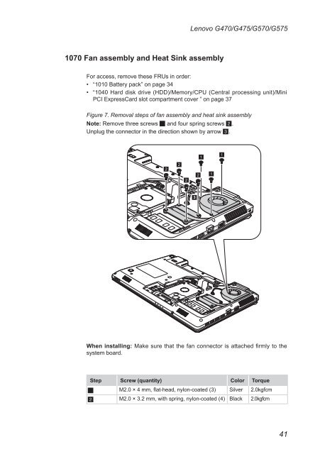
1070 Fan assembly and Heat Sink assembly<br />
<strong>Lenovo</strong> <strong>G470</strong>/<strong>G475</strong>/<strong>G570</strong>/<strong>G575</strong><br />
For access, remove these FRUs in order:<br />
• “1010 Battery pack” on page 34<br />
• “1040 Hard disk drive (HDD)/Memory/CPU (Central processing unit)/Mini<br />
PCI ExpressCard slot compartment cover ” on page 37<br />
Figure 7. Removal steps of fan assembly and heat sink assembly<br />
Note: Remove three screws 1 and four spring screws 2.<br />
Unplug the connector in the direction shown by arrow 3.<br />
2<br />
2<br />
2<br />
When installing: Make sure that the fan connector is attached firmly to the<br />
system board.<br />
Step Screw (quantity) Color Torque<br />
1 M2.0 × 4 mm, flat-head, nylon-coated (3) Silver 2.0kgfcm<br />
2 M2.0 × 3.2 mm, with spring, nylon-coated (4) Black 2.0kgfcm<br />
3<br />
2<br />
1<br />
1<br />
1<br />
41