

Lenovo G470/G475/G570/G575 Hardware Maintenance Manual
Lenovo G470/G475/G570/G575 Hardware Maintenance Manual
Lenovo G470/G475/G570/G575 Hardware Maintenance Manual

You also want an ePaper? Increase the reach of your titles
YUMPU automatically turns print PDFs into web optimized ePapers that Google loves.
1170 LCD panel and hinges<br />
<strong>Lenovo</strong> <strong>G470</strong>/<strong>G475</strong>/<strong>G570</strong>/<strong>G575</strong><br />
For access, remove these FRUs in order:<br />
• “1010 Battery pack” on page 34<br />
• “1020 Dummy card” on page 35<br />
• “1030 Optical drive” on page 36<br />
• “1040 Hard disk drive (HDD)/Memory/CPU (Central processing unit)/Mini<br />
PCI ExpressCard slot compartment cover ” on page 37<br />
• “1050 Hard disk drive ” on page 38<br />
• “1060 DIMM” on page 40<br />
• “1070 Fan assembly and Heat Sink assembly” on page 41<br />
• “1090 PCI Express Mini Card for wireless LAN” on page 45<br />
• “1100 Keyboard” on page 47<br />
• “1110 Keyboard bezel” on page 49<br />
• “1130 System board” on page 53<br />
• “1140 LCD unit” on page 56<br />
• “1160 LCD front bezel” on page 64<br />
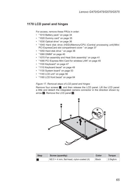
Figure 17. Removal steps of LCD panel and hinges<br />
Remove four screws 1, and then release the LCD panel. Lift the LCD panel<br />
a little and detach the integrated camera connector in the direction shown by<br />
arrow 2. Remove the LCD panel 3.<br />
1<br />
3<br />
Step Screw (quantity) Color Torque<br />
1 M2.5 × 4 mm, flat-head, nylon-coated (4) Black 2.0kgfcm<br />
3<br />
1<br />
1<br />
3<br />
2<br />
1<br />
65