

900 Series Hydraulic Flushometers - Sloan Valve Company
900 Series Hydraulic Flushometers - Sloan Valve Company
900 Series Hydraulic Flushometers - Sloan Valve Company

Create successful ePaper yourself
Turn your PDF publications into a flip-book with our unique Google optimized e-Paper software.
Code No. 0816300<br />
Rev. 4 (05/13)<br />
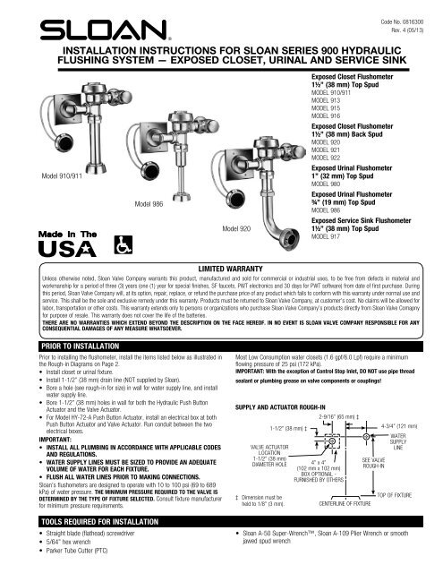
INSTALLATION INSTRUCTIONS FOR SLOAN SERIES <strong>900</strong> HYDRAULIC<br />
FLUSHING SYSTEM — EXPOSED CLOSET, URINAL AND SERVICE SINK<br />
Model 910/911<br />
Model 986<br />
Model 920<br />
Exposed Closet Flushometer<br />
1½” (38 mm) Top Spud<br />
MODEL 910/911<br />
MODEL 913<br />
MODEL 915<br />
MODEL 916<br />
Exposed Closet Flushometer<br />
1½” (38 mm) Back Spud<br />
MODEL 920<br />
MODEL 921<br />
MODEL 922<br />
Exposed Urinal Flushometer<br />
1 ” (32 mm) Top Spud<br />
MODEL 980<br />
Exposed Urinal Flushometer<br />
¾” (19 mm) Top Spud<br />
MODEL 986<br />
Exposed Service Sink Flushometer<br />
1½” (38 mm) Top Spud<br />
MODEL 917<br />
LIMITED WARRANTY<br />
Unless otherwise noted, <strong>Sloan</strong> <strong>Valve</strong> <strong>Company</strong> warrants this product, manufactured and sold for commercial or industrial uses, to be free from defects in material and<br />
workmanship for a period of three (3) years (one (1) year for special finishes, SF faucets, PWT electronics and 30 days for PWT software) from date of first purchase. During<br />
this period, <strong>Sloan</strong> <strong>Valve</strong> <strong>Company</strong> will, at its option, repair, replace, or refund the purchase price of any product which fails to conform with this warranty under normal use and<br />
service. This shall be the sole and exclusive remedy under this warranty. Products must be returned to <strong>Sloan</strong> <strong>Valve</strong> <strong>Company</strong>, at customer’s cost. No claims will be allowed for<br />
labor, transportation or other costs. This warranty extends only to persons or organizations who purchase <strong>Sloan</strong> <strong>Valve</strong> <strong>Company</strong>’s products directly from <strong>Sloan</strong> <strong>Valve</strong> Comapny<br />
for purpose of resale. This warranty does not cover the life of the batteries.<br />
THERE ARE NO WARRANTIES WHICH EXTEND BEYOND THE DESCRIPTION ON THE FACE HEREOF. IN NO EVENT IS SLOAN VALVE COMPANY RESPONSIBLE FOR ANY<br />
CONSEQUENTIAL DAMAGES OF ANY MEASURE WHATSOEVER.<br />
PRIOR TO INSTALLATION<br />
Prior to installing the flushometer, install the items listed below as illustrated in<br />
the Rough-in Diagrams on Page 2.<br />
• Install closet or urinal fixture.<br />
• Install 1-1/2” (38 mm) drain line (NOT supplied by <strong>Sloan</strong>).<br />
• Bore a hole (see rough-in for size) in wall for water supply line, and install<br />
water supply line.<br />
• Bore 1-1/2” (38 mm) holes in wall for both the <strong>Hydraulic</strong> Push Button<br />
Actuator and the <strong>Valve</strong> Actuator.<br />
• For Model HY-72-A Push Button Actuator, install an electrical box at both<br />
Push Button Actuator and <strong>Valve</strong> Actuator. Run conduit between the two<br />
electrical boxes.<br />
IMPORTANT:<br />
• INSTALL ALL PLUMBING IN ACCORDANCE WITH APPLICABLE CODES<br />
AND REGULATIONS.<br />
• WATER SUPPLY LINES MUST BE SIZED TO PROVIDE AN ADEQUATE<br />
VOLUME OF WATER FOR EACH FIXTURE.<br />
• FLUSH ALL WATER LINES PRIOR TO MAKING CONNECTIONS.<br />
<strong>Sloan</strong>’s flushometers are designed to operate with 10 to 100 psi (69 to 689<br />
kPa) of water pressure. THE MINIMUM PRESSURE REQUIRED TO THE VALVE IS<br />
DETERMINED BY THE TYPE OF FIXTURE SELECTED. Consult fixture manufacturer<br />
for minimum pressure requirements.<br />
TOOLS REQUIRED FOR INSTALLATION<br />
• Straight blade (flathead) screwdriver<br />
• 5/64” hex wrench<br />
• Parker Tube Cutter (PTC)<br />
Most Low Consumption water closets (1.6 gpf/6.0 Lpf) require a minimum<br />
flowing pressure of 25 psi (172 kPa).<br />
IMPORTANT: With the exception of Control Stop Inlet, DO NOT use pipe thread<br />
sealant or plumbing grease on valve components or couplings!<br />
SUPPLY AND ACTUATOR ROUGH-IN<br />
2-9/16” (65 mm) ‡<br />
VALVE ACTUATOR<br />
LOCATION<br />
1-1/2” (38 mm)<br />
DIAMETER HOLE<br />
‡ Dimension must be<br />
held to 1/8” (3 mm).<br />
1-1/2” (38 mm) ‡<br />
4” x 4”<br />
(102 mm x 102 mm)<br />
BOX OPTIONAL -<br />
FURNISHED BY OTHERS<br />
CENTERLINE OF FIXTURE<br />
SEE VALVE<br />
ROUGH-IN<br />
4-3/4” (121 mm)<br />
WATER<br />
SUPPLY<br />
LINE<br />
TOP OF FIXTURE<br />
• <strong>Sloan</strong> A-50 Super-Wrench, <strong>Sloan</strong> A-109 Plier Wrench or smooth<br />
jawed spud wrench
VALVE ROUGH-INS (NOTE: SPECIFY ACTUATOR VARIATION NEEDED FOR YOUR APPLICATION)<br />
MODEL 910/911<br />
MODELS 913/915/916<br />
1-1/2” (38 mm)<br />
OPENING<br />
IN WALL<br />
2-1/4” (57 mm)<br />
MIN.<br />
1-1/2” (38 mm)<br />
OPENING<br />
IN WALL<br />
2-1/4” (57 mm)<br />
MIN.<br />
1-1/2”<br />
(38 mm)<br />
11-1/2”<br />
(292 mm)<br />
2-9/16”<br />
(65 mm)<br />
CENTERLINE<br />
OF FIXTURE<br />
4-3/4”<br />
(121 mm)<br />
PUSH BUTTON<br />
(LOCATION<br />
OPTIONAL)<br />
1” I.P.S.<br />
(25 mm DN)<br />
WATER SUPPLY<br />
1-1/2”<br />
(38 mm)<br />
(913): 16” (406 mm)<br />
(915): 24” (610 mm)<br />
(916): 27” (686 mm)<br />
2-9/16”<br />
(65 mm)<br />
CENTERLINE<br />
OF FIXTURE<br />
4-3/4”<br />
(121 mm)<br />
PUSH BUTTON<br />
(LOCATION<br />
OPTIONAL)<br />
1” I.P.S.<br />
(25 mm DN)<br />
WATER SUPPLY<br />
FIN.<br />
FLOOR<br />
FIN.<br />
FLOOR<br />
FIN. WALL<br />
FIN. WALL<br />
MODELS 920/921/922 MODEL 980<br />
1-1/2” (38 mm)<br />
OPENING<br />
IN WALL<br />
1-1/2”<br />
(38 mm)<br />
11-1/2”<br />
(292 mm)<br />
2-1/4” (57 mm)<br />
MIN.<br />
2-9/16”<br />
(65 mm)<br />
CENTERLINE<br />
OF FIXTURE<br />
4-3/4”<br />
(121 mm)<br />
PUSH BUTTON<br />
(LOCATION<br />
OPTIONAL)<br />
1” I.P.S.<br />
(25 mm DN)<br />
WATER SUPPLY<br />
6-1/2” (165 mm)<br />
7-1/2” (191 mm) IF<br />
2” (51 mm) SPUD<br />
FIN.<br />
WALL<br />
FIN.<br />
FLOOR<br />
FIN. WALL<br />
FIN.<br />
FLOOR<br />
MODEL 986<br />
MODEL 917<br />
1-1/2” (38 mm)<br />
OPENING<br />
IN WALL<br />
1-1/2”<br />
(38 mm)<br />
11-1/2”<br />
(292 mm)<br />
2-1/4” (57 mm)<br />
MIN.<br />
2-9/16”<br />
(65 mm)<br />
CENTERLINE<br />
OF FIXTURE<br />
4-3/4”<br />
(121 mm)<br />
PUSH BUTTON<br />
(LOCATION<br />
OPTIONAL)<br />
3/4” I.P.S.<br />
(20 mm DN)<br />
WATER SUPPLY<br />
1-1/2” (38 mm)<br />
OPENING<br />
IN WALL<br />
1-1/2”<br />
(38 mm)<br />
24”<br />
(610 mm)<br />
2-1/4” (57 mm)<br />
MIN.<br />
2-9/16”<br />
(65 mm)<br />
CENTERLINE<br />
OF FIXTURE<br />
4-3/4”<br />
(121 mm)<br />
PUSH BUTTON<br />
(LOCATION<br />
OPTIONAL)<br />
1” I.P.S.<br />
(25 mm DN)<br />
WATER SUPPLY<br />
FIN.<br />
WALL<br />
FIN.<br />
FLOOR<br />
NOTE: Water Closet <strong>Valve</strong>s with<br />
“-2.4” Model Designation deliver 2.4<br />
gpf (9.0 Lpf).<br />
2<br />
FIN.<br />
WALL<br />
FIN.<br />
FLOOR
!!! IMPORTANT !!! !!! IMPORTANT !!!<br />
NEVER OPEN THE CONTROL STOP TO WHERE THE FLOW FROM<br />
THE VALVE EXCEEDS THE FLOW CAPABILITY OF THE FIXTURE. IN<br />
THE EVENT OF A VALVE FAILURE, THE FIXTURE MUST BE ABLE TO<br />
ACCOMMODATE A CONTINUOUS FLOW FROM THE VALVE.<br />
THIS PRODUCT CONTAINS MECHANICAL AND THAT ARE SUBJECT<br />
TO NORMAL WEAR. THESE COMPONENTS SHOULD BE CHECKED ON<br />
A REGULAR BASIS AND REPLACED AS NEEDED TO MAINTAIN THE<br />
VALVE’S PERFORMANCE.<br />
!!! IMPORTANT !!!<br />
PROTECT THE CHROME OR SPECIAL FINISH OF SLOAN’S<br />
FLUSHOMETERS. DO NOT USE TOOTHED TOOLS TO INSTALL OR<br />
SERVICE VALVES. USE A SLOAN A-50 SUPER WRENCH, SLOAN<br />
A-109 PLIER WRENCH OR SMOOTH JAWED SPUD WRENCH TO<br />
SECURE COUPLINGS. SEE “CARE AND CLEANING” SECTION FOR<br />
MORE DETAILS.<br />
!!! IMPORTANT !!!<br />
WITH THE EXCEPTION OF THE CONTROL STOP INLET,<br />
DO NOT USE PIPE THREAD SEALANT OR PLUMBING<br />
GREASE ON VALVE COMPONENTS OR COUPLINGS.<br />
When further assistance is required, please consult your local <strong>Sloan</strong><br />
Representative, or <strong>Sloan</strong> Technical Support at:<br />
1-888-SLOAN-14 (1-888-756-2614)<br />
1 - INSTALL OPTIONAL SWEAT SOLDER ADAPTER (ONLY IF YOUR SUPPLY PIPE DOES NOT HAVE A MALE THREAD)<br />
A Measure from finished wall to C/L of Fixture Spud. Cut pipe 1¼” (32<br />
mm) shorter than this measurement. Chamfer O.D. and I.D. of water<br />
supply pipe.<br />
B<br />
Slide Threaded Adapter fully onto pipe.<br />
WATER SUPPLY PIPE<br />
FINISHED WALL<br />
1-1/4”<br />
(32 mm)<br />
C<br />
Sweat solder the Adapter to pipe.<br />
2 - INSTALL COVER TUBE, WALL FLANGE, AND CONTROL STOP TO SUPPLY PIPE<br />
A<br />
B<br />
C<br />
Measure from finished wall<br />
to first thread of adapter<br />
or threaded supply pipe<br />
(dimension “X”). Cut cover tube<br />
to this length.<br />
Slide cover tube over pipe.<br />
Slide wall flange over cover<br />
tube until against wall.<br />
Install the <strong>Sloan</strong> Bak-Chek ®<br />
control stop to the water supply<br />
line with the outlet positioned<br />
as required.<br />
WATER<br />
SUPPLY PIPE<br />
SET SCREW<br />
SWEAT SOLDER<br />
ADAPTER<br />
COVER TUBE<br />
WALL<br />
FLANGE<br />
SET SCREW<br />
SUPPLY<br />
FLANGE ‡<br />
D<br />
Tighten Set Screw with a 1/16”<br />
hex wrench. DO NOT install vandal<br />
resistant stop cap at this time.<br />
C/L OF<br />
FIXTURE<br />
SPUD<br />
SWEAT<br />
SOLDER<br />
ADAPTER<br />
IRON PIPE NIPPLE OR<br />
COPPER PIPE WITH SWEAT<br />
SOLDER ADAPTER<br />
COVER TUBE ‡<br />
BAK-CHEK ®<br />
CONTROL STOP<br />
‡ Cover Tube<br />
and Supply<br />
Flange with<br />
Set Screw is<br />
supplied with<br />
Royal valves;<br />
available in<br />
“YBYC” Sweat<br />
Kit for Regal<br />
valves.<br />
3 - INSTALL VACUUM BREAKER FLUSH CONNECTION<br />
A<br />
B<br />
Slide the spud coupling, nylon slip gasket, rubber gasket and<br />
spud flange over the vacuum breaker tube.<br />
Insert tube into fixture spud. Hand tighten spud coupling<br />
onto fixture spud.<br />
VACUUM<br />
BREAKER<br />
ELBOW<br />
FLUSH<br />
CONNECTION<br />
3<br />
SPUD<br />
COUPLING<br />
MODELS<br />
920, 921 & 922<br />
NYLON<br />
SLIP<br />
GASKET<br />
SPUD<br />
FLANGE<br />
RUBBER<br />
GASKET<br />
MODELS<br />
910, 913, 915,<br />
916 & 917<br />
VACUUM<br />
BREAKER<br />
TUBE<br />
SPUD<br />
COUPLING<br />
NYLON<br />
SLIP<br />
GASKET<br />
RUBBER<br />
GASKET<br />
SPUD<br />
FLANGE<br />
MODEL<br />
980<br />
VACUUM<br />
BREAKER<br />
TUBE<br />
SPUD<br />
COUPLING<br />
NYLON<br />
SLIP<br />
GASKET<br />
RUBBER<br />
GASKET<br />
SPUD<br />
FLANGE<br />
MODEL<br />
986
4 - INSTALL VALVE ACTUATOR<br />
A<br />
B<br />
C<br />
Insert actuator cartridge into flushometer valve body.<br />
Install valve actuator housing onto flushometer valve body. Tighten<br />
housing nut with a wrench.<br />
Cut off excess tubing with plastic tube cutter (PTC) so that there will<br />
be about 3” to 4” (76 to 102 mm) of slack when connected to valve<br />
actuator. If “L” and “O” marketings on the tubing will be cut off, then<br />
remark tubing appropriately to retain identification.<br />
D Slide plastic tubing into its corresponding valve actuator fitting. Pull<br />
tubing to make sure connection is secure. (Tubing can be removed by<br />
pressing on blue connection button to release.)<br />
5 - INSTALL FLUSHOMETER<br />
A<br />
B<br />
C<br />
D<br />
E<br />
Align flushometer Body on top of vacuum<br />
breaker flush connection. Measure distance<br />
from valve actuator Housing to finished wall. Cut<br />
chrome sleeve adding an additional 1” (25 mm)<br />
to the previously measured distance.<br />
IMPORTANT: DO NOT CUT THREADED END OF<br />
CHROME SLEEVE. ONLY CUT NON-THREADED END.<br />
Remove flushometer body from top of<br />
vacuum breaker flush connection.<br />
Slide chrome sleeve (threaded end first) over<br />
plastic tubing. Thread onto valve actuator until chrome sleeve is tight<br />
against valve actuator housing.<br />
Slide flange and cover plate over plastic tubing and onto chrome<br />
sleeve.<br />
Run plastic tubing through wall hole to push button actuator location.<br />
(If installing HY-72-A push button actuator, run plastic tubing through<br />
electrical box and conduit and out through the electrical box at push<br />
button actuator location.<br />
Maximum adjustment of<br />
the <strong>Sloan</strong> Adjustable<br />
Tailpiece is 1/2” (13 mm)<br />
IN or OUT from the<br />
standard 4-3/4” (121 mm)<br />
(C/L of Flushometer to<br />
C/L of Control Stop). If<br />
rough-in measurement<br />
exceeds 5-1/4” (133 mm),<br />
consult factory for<br />
longer tailpiece.<br />
Mount Wall Flange onto Cover Plate using (2) Flathead Screws,<br />
Lockwashers and Nuts provided. Tighten Fasteners securely.<br />
Insert extension Stem into extension Adapter and thread extension<br />
Adapter onto Push Button Actuator.<br />
Insert threaded end of Push Button Actuator Assembly through Cover<br />
Plate Assembly. Fasten to Plate with Nut. Tighten securely.<br />
Place Brass Insert into black Push Button. Concave side of Brass Insert<br />
must face outward of Push Button.<br />
Insert black Push Button into Button Flange. Place Spring against<br />
Brass Insert of Push Button. Install Push Button Assembly onto Cover<br />
Plate. Secure with Setscrew located on Button Flange.<br />
Attach plastic tubing. See: Steps to attach plastic tubing on next page.<br />
4<br />
COVER PLATE<br />
PLASTIC<br />
TUBES<br />
FLANGE<br />
CHROME<br />
SLEEVE<br />
VACUUM<br />
BREAKER TUBE<br />
WITH REPAIR KIT<br />
QUICK<br />
CONNECT<br />
FITTINGS (2)<br />
HOUSING<br />
NUT<br />
VALVE<br />
ACTUATOR<br />
HOUSING<br />
BAK-CHEK ®<br />
CONTROL STOP<br />
FLUSHOMETER<br />
VALVE BODY<br />
HY-83-A<br />
ACTUATOR<br />
CARTRIDGE<br />
IMPORTANT: USE A SLOAN A-50 SUPER WRENCH, SLOAN A-109<br />
PLIER WRENCH OR SMOOTH JAWED SPUD WRENCH TO SECURE ALL<br />
COUPLINGS. THIS WILL ELIMINATE DAMAGE TO CHROME OR SPECIAL<br />
FINISH THAT NORMALLY OCCURS WHEN SLIP-JOINT PLIERS, PIPE<br />
WRENCHES OR OTHER “TOOTHED” TOOLS ARE USED.<br />
F Insert adjustable tailpiece into control stop.<br />
Lubricate o-ring seal with water. Hand<br />
tighten tailpiece coupling.<br />
G Align flushometer body on top of vacuum<br />
breaker flush connection. Hand tighten<br />
vacuum breaker coupling.<br />
H Align flushometer body. Using a wrench, securely tighten couplings in<br />
order given: (1) tailpiece coupling, (2) vacuum breaker coupling and<br />
(3) spud coupling. Then tighten valve actuator housing nut securely.<br />
I<br />
With flushometer<br />
body aligned on top<br />
of vacuum breaker<br />
flush connection,<br />
assemble cover plate<br />
to plaster ring with<br />
hex head screws.<br />
Slide flange against<br />
cover plate.<br />
6A - INSTALL PUSH BUTTON ACTUATOR (HY-72-A SIDE WALL (SW VARIATION) PUSH BUTTON ACTUATOR)<br />
A<br />
B<br />
C<br />
D<br />
E<br />
F<br />
G<br />
!!! IMPORTANT !!!<br />
observe “L” and “O” markings on tubing.<br />
tubing must be connected to corresponding<br />
“L” and “O” markings on valve actuator.<br />
2-9/16”<br />
(65 mm)<br />
4-1/4”<br />
(108 mm)<br />
MIN.<br />
5-1/4”<br />
(133 mm)<br />
MAX.<br />
MEASURE DISTANCE<br />
AND ADD 1” (25 mm)<br />
1-1/2” (38 mm)<br />
— DIMENSION<br />
MUST BE HELD<br />
TO 1/8” (3 mm)<br />
Mount Cover Plate Assembly onto electrical box cover using the four (4)<br />
Screws provided.<br />
UNIVERSAL<br />
(2) GANG<br />
ELEC. BOX<br />
1-5/8” D x<br />
4-1/2” H x<br />
6-13/16”<br />
W (NOT<br />
SUPPLIED<br />
BY SLOAN)<br />
PLASTIC<br />
TUBING<br />
ACTUATOR<br />
ASSEMBLY<br />
FLUSHOMETER<br />
BODY<br />
VACUUM<br />
BREAKER<br />
COUPLING)<br />
2<br />
VACUUM<br />
BREAKER<br />
FLUSH<br />
CONNECTION<br />
(2) GANG ELEC. BOX DEVICE COVER 3/4” RAISED<br />
x 4-3/4” H x 7-1/16” W (NOT SUPPLIED BY SLOAN)<br />
WALL<br />
C/L<br />
FIXTURE<br />
ADJUSTABLE<br />
TAILPIECE<br />
VACUUM<br />
BREAKER<br />
REPAIR KIT<br />
4-3/4”<br />
(121 mm)<br />
ACTUATOR<br />
EXTENSION STEM<br />
EXTENSION ADAPTER<br />
COVER PLATE SCREWS (4)<br />
NUT<br />
NUTS (2)<br />
LOCKWASHERS (2)<br />
COVER PLATE<br />
WALL FLANGE<br />
FLATHEAD SCREWS (2)<br />
PUSH BUTTON<br />
C/L<br />
SUPPLY<br />
TAILPIECE<br />
COUPLING<br />
1<br />
CONTROL<br />
STOP<br />
O-RING<br />
G-44<br />
FRICTION<br />
RING<br />
SPUD<br />
COUPLING<br />
3<br />
SPRING<br />
BRASS INSERT<br />
BUTTON<br />
FLANGE<br />
SETSCREW
6B - INSTALL PUSH BUTTON ACTUATOR (HY-33-A FIXTURE WALL (FW VARIATION) PUSH BUTTON ACTUATOR<br />
– WALL INSTALLATION)<br />
NOTE: The HY-33-A Fixture Wall may be installed directly onto fixture wall where access behind wall is available. If rear access is not available,<br />
HY-33-A may be installed onto a <strong>Sloan</strong> Easy Access Wall Box Assembly. Parts for both installations are included with the HY-33-A Push Button.<br />
NUT<br />
LOCKWASHER<br />
D Place Brass Insert into black Push Button. Concave side of Brass Insert<br />
THREADED<br />
must face outward of Push Button.<br />
ROD<br />
RETAINING<br />
BAR<br />
SPACER SLEEVE — USE ONLY IF<br />
WALL THICKNESS IS LESS THAN<br />
2” (51 mm)<br />
QUICK<br />
CONNECT<br />
FITTINGS (2)<br />
A<br />
B<br />
C<br />
PUSH BUTTON<br />
ACTUATOR<br />
WALL<br />
WALL<br />
FLANGE<br />
PLASTIC TUBING<br />
NUT<br />
PUSH BUTTON<br />
SPRING<br />
BRASS<br />
INSERT<br />
If not already completed, bore a 1½” (38 mm) diameter hole in wall<br />
for the push button sctuator. Refer to the rough-in drawings on pages<br />
1 and 2.<br />
Screw Threaded Rod into back of Push Button Actuator.<br />
Insert threaded end of Push Button Actuator into Wall Flange and<br />
install Nut. Tighten Nut securely.<br />
LOCKWASHERS (2)<br />
NUTS (2)<br />
QUICK<br />
CONNECT<br />
FITTINGS (2)<br />
CLIP<br />
NUTS (2)<br />
A<br />
METAL<br />
PARTITION<br />
PLASTIC<br />
TUBING<br />
QUICK<br />
CONNECT<br />
FITTINGS (2)<br />
WALL<br />
FLANGE<br />
PUSH<br />
BUTTON<br />
ACTUATOR<br />
WALL<br />
FLANGE<br />
WALL BOX COVER PLATE<br />
PLASTIC TUBING<br />
NUT<br />
PUSH<br />
BUTTON<br />
SPRING<br />
BUTTON<br />
FLANGE<br />
SETSCREW<br />
FLATHEAD SCREWS (2)<br />
BRASS<br />
INSERT<br />
COVER PLATE MOUNTING HOLE<br />
PUSH BUTTON ACTUATOR<br />
NUT<br />
COVER PLATE<br />
PUSH BUTTON<br />
BUTTON<br />
FLANGE<br />
SETSCREW<br />
FLATHEAD SCREWS (2)<br />
SPRING<br />
BRASS INSERT<br />
BUTTON<br />
FLANGE<br />
SETSCREW<br />
Using cover plate as a template, drill two 3/16” (5 mm) cover plate<br />
mounting holes and cut opening for push button actuator into the metal<br />
partition. Install clip nuts with threaded side toward back.<br />
E<br />
F<br />
G<br />
H<br />
I<br />
A<br />
B<br />
C<br />
D<br />
E<br />
B<br />
C<br />
D<br />
E<br />
F<br />
Insert black Push Button into Button Flange. Place Spring against<br />
Brass Insert of Push Button. Install Push Button Assembly onto Wall<br />
Flange. Secure with Setscrew located on Button Flange.<br />
If spacer sleeve is required, from behind wall, run plastic tubing through<br />
sleeve (notched end of sleeve toward rear) and through wall. Spacer<br />
sleeve is only required if wall thickness is less than 2” (51 mm).<br />
Attach Plastic Tubing. See: Steps to Attach Plastic Tubing below.<br />
Insert Push Button Assembly into the 1-1/2” (38 mm) wall hole.<br />
From behind wall, slide spacer sleeve (if required) over threaded<br />
rod and rest it against rear of wall. Slide retaining bar onto threaded<br />
rod and into slots of sleeve (if required), or against wall if Sleeve is<br />
not required. Install lockwasher and nut onto threaded rod. Tighten<br />
securely. Carefully cut excess threaded rod, making certain to not<br />
damage plastic tubing.<br />
6C - INSTALL PUSH BUTTON ACTUATOR (HY-33-A FIXTURE WALL (FW VARIATION) PUSH BUTTON ACTUATOR – WALL<br />
BOX INSTALLATION)<br />
NOTE: <strong>Sloan</strong> WB-1-A easy access wall box is designed for use with HY-33-A and HY-108-A Actuators.<br />
Insert threaded end of push button actuator through wall flange and<br />
install nut. Tighten nut securely.<br />
Mount wall flange and push button actuator to wall box cover plate<br />
using flathead screws, lockwashers and nuts provided. Tighten<br />
fasteners securely.<br />
Place Brass Insert into black push button. Concave side of Brass Insert<br />
must face outward of Push Button.<br />
Insert black push button into button flange. Place spring against brass<br />
Insert of push button. Install push button assembly onto wall flange.<br />
secure with setscrew located on Button flange.<br />
Attach plastic tubing. See: Steps to Attach Plastic Tubing (lower left<br />
side of this page).<br />
6D - INSTALL PUSH BUTTON ACTUATOR (HY-49-A METAL PARTITION (MP VARIATION) PUSH BUTTON ACTUATOR)<br />
Insert threaded end of push button actuator through cover plate and<br />
wall flange and install nut. Tighten nut securely.<br />
Attach plastic tubing. See: Steps to attach plastic tubing (lower right<br />
side of page).<br />
Insert flathead Screws through wall flange and cover plate mounting<br />
holes. Mount wall flange and cover plate to metal partition using<br />
flathead screws provided. Tighten fasteners securely.<br />
Place brass Insert into black push button. Concave side of brass insert<br />
must face outward of push button.<br />
Insert black push button into button flange. Place spring against brass<br />
Insert of push button. Install Push Button assembly onto wall flange.<br />
Secure with Setscrew located on Button flange.<br />
STEPS TO ATTACH PLASTIC TUBING<br />
1. The push button actuator is connected to the flushometer body by two plastic 3. Slide plastic tubing into its corresponding valve actuator fitting. Pull tubing to<br />
tubes, marked “L” and “O”. Match markings on the tubes to markings on the make sure connection is secure. (Tubing can be removed by pressing on blue<br />
actuator.<br />
connection button to release.)<br />
2. Cut off excess plastic tubing with plastic tube cutter (PTC) leaving 3” to 4”<br />
(76 to 102 mm) of slack when push button actuator is installed. If the “L” and<br />
“O” markings will be cut off, remark the tubing to not lose identification.<br />
5
6E - INSTALL PUSH BUTTON ACTUATOR (HY-100-A METAL BUTTON (MBFW VARIATION) ACTUATOR – FIXTURE WALL)<br />
NUT<br />
A<br />
B<br />
Note: Behind wall access required to install HY-100-A (MBFW)<br />
LOCKWASHER<br />
RETAINING<br />
BAR<br />
SPACER SLEEVE —<br />
USE ONLY IF WALL<br />
THICKNESS IS LESS<br />
THAN 2” (51 mm)<br />
THREADED ROD<br />
PLASTIC<br />
TUBING<br />
PUSH<br />
BUTTON<br />
ACTUATOR<br />
QUICK<br />
CONNECT<br />
FITTINGS (2)<br />
WALL<br />
ACTUATOR<br />
ASSEMBLY SPRING<br />
NUT BUTTON FLANGE<br />
If not already completed, bore a 1-1/2” (38 mm) diameter hole in<br />
wall for the Push Button Actuator. Refer to the Rough-in drawings on<br />
Pages 1 and 2.<br />
Screw Threaded Rod into back of Push Button Actuator.<br />
SPACER<br />
RING<br />
METAL<br />
BUTTON<br />
C<br />
D<br />
Thread Actuator Assembly Nut onto end of Push Button Actuator.<br />
Slide Spring over Metal Push Button until it snaps into place.<br />
Insert Metal Push Button into Button Flange.<br />
E Place Spacer Ring over threads of Button Flange and thread<br />
Button Flange Assembly into Actuator Assembly Nut.<br />
F From behind wall, run Plastic Tubing through optional Spacer Sleeve<br />
(notched end of sleeve toward rear) and wall. Spacer Sleeve only<br />
required if wall thickness is less than 2” (51 mm).<br />
G Attach Plastic Tubing. See: Steps to Attach Plastic Tubing (Page 5).<br />
H<br />
I<br />
Insert Push Button Assembly into the 1-1/2” (38 mm) wall hole.<br />
From behind wall, slide Spacer Sleeve (if required) over Threaded Rod<br />
and rest it against rear of wall. Slide Retaining Bar onto Threaded<br />
Rod and into slots of Sleeve (if required), or against wall if Sleeve is<br />
not required. Install Lockwasher and Nut onto Threaded Rod. Tighten<br />
securely. Carefully cut excess Threaded Rod, making certain to not<br />
damage Plastic Tubing.<br />
6F - INSTALL PUSH BUTTON ACTUATOR (HY-108-A METAL BUTTON (MBPM VARIATION) ACTUATOR – PANEL MOUNT)<br />
PLASTIC<br />
TUBING<br />
Note: Use HY-108-A (MBPM) on punched stainless steel plates and<br />
security fixtures with front access.<br />
QUICK CONNECT<br />
FITTINGS (2)<br />
PUSH BUTTON<br />
ACTUATOR<br />
ACTUATOR<br />
ASSEMBLY NUT<br />
WASHER<br />
PANEL<br />
SPRING<br />
METAL BUTTON<br />
BUTTON FLANGE<br />
A<br />
B<br />
C<br />
D<br />
Attach plastic tubing to push button actuator. See: Steps to Attach<br />
plastic tubing (Page 5).<br />
Thread actuator assembly nut onto threaded end of push button<br />
actuator.<br />
Slide Spring over Metal Push Button until it snaps into place.<br />
Insert Metal Push Button into Button Flange.<br />
From front of panel, insert Button Flange Assembly into hole of panel.<br />
Behind panel, place Washer over threads of Button Flange. Thread<br />
Button Flange onto Actuator. Tighten Flange securely.<br />
7 - FLUSH OUT SUPPLY LINE AND ADJUST CONTROL STOP<br />
A<br />
B<br />
C<br />
Shut off control stop by turning handle<br />
CLOCKWISE. Then remove flushometer<br />
cover.<br />
Lift out the inside parts assembly as a<br />
complete unit. Reinstall flushometer cover<br />
and tighten with wrench. Open control<br />
stop. Turn on water supply to flush line of<br />
any debris or sediment.<br />
Shut off control stop and remove flushometer<br />
cover. Reinstall Inside Parts assembly and<br />
flushometer cover. Tighten cover with<br />
wrench. Open control stop and activate<br />
flushometer.<br />
D<br />
Adjust control stop to meet flow rate required<br />
for proper cleansing of fixture. Open control<br />
stop COUNTERCLOCKWISE ONE FULL turn<br />
from closed position. Activate flushometer.<br />
Adjust control stop after each flush until the<br />
rate of flow delivered properly cleanses the<br />
fixture.<br />
!!! IMPORTANT !!!<br />
SLOAN FLUSHOMETERS ARE ENGINEERED FOR QUIET OPERATION.<br />
EXCESSIVE WATER FLOW CREATES NOISE, WHILE TOO LITTLE WATER<br />
FLOW MAY NOT SATISFY THE NEEDS OF THE FIXTURE. PROPER<br />
ADJUSTMENT IS MADE WHEN TEH PLUMBING FIXTURE IS CLEANSED<br />
AFTER EACH FLUSH WITHOUT SPLASHING WATER OUT FROM THE LIP<br />
AND A QUIET FLUSHING CYCLE IS ACHIEVED.<br />
NEVER OPEN CONTROL STOP TO WHERE THE FLOW FROM THE VALVE<br />
EXCEEDS THE FLOW FROM THE VALVE EXCEEDS THE FLOW CAPABILITY OF<br />
THE FIXTURE. IN THE EVENT OF A VALVE FAILURE, THE FIXTURE MUST BE<br />
ABLE TO ACCOMMODATE A CONTINUOUS FLOW FROM THE VALVE.<br />
CARE AND CLEANING OF CHROME AND SPECIAL FINISHES<br />
DO NOT USE abrasive or chemical cleaners (including chlorine bleach) to clean flushometers that may dull the luster and attack the chrome or special decorative<br />
finishes. Use ONLY mild soap and water, then wipe dry with clean cloth or towel.<br />
While cleaning the bathroom tile, protect the Flushometer from any splattering of cleaner. Acids and cleaning fluids will discolor or remove chrome plating.<br />
6
8 - INSTALL VANDAL RESISTANT CONTROL STOP CAP<br />
ROYAL FLUSHOMETERS<br />
IMPORTANT: DO NOT INSTALL CAP ONTO SLEEVE UNLESS THE SLEEVE HAS BEEN<br />
THREADED ONTO THE BONNET. IF THE SLEEVE AND CAP ARE ASSEMBLED OFF<br />
THE CONTROL STOP, THE SLEEVE WILL NOT COME APART FROM THE CAP.<br />
A<br />
B<br />
Thread the plastic sleeve<br />
onto the stop bonnet until it<br />
is snug. Hand tighten only; do<br />
not use pliers or a wrench.<br />
CONTROL STOP<br />
BONNET<br />
BAK-CHEK ®<br />
CONTROL STOP<br />
PLASTIC SLEEVE<br />
CONTROL<br />
STOP CAP<br />
Place the metal control stop cap over the plastic sleeve. Use the palm<br />
of your hand to push or “pop” the cap over the fingers of the Sleeve.<br />
The cap should spin freely on the sleeve.<br />
TROUBLESHOOTING<br />
1. Push Button Leaks.<br />
The actuator cartridge has an accumulation of lime or its seals are damaged or worn.<br />
Replace with a new HY-32-A cartridge.<br />
2. THE FLUSHOMETER DOES NOT FLUSH AND A SMALL AMOUNT OF LEAKEAGE IS<br />
VISIBLE BELOW THE VALVE.<br />
A. Foreign material lodged in the cartridge. Remove the cartridge and inspect for foreign<br />
material. Clean under running water.<br />
B. The actuator cartridge has an accumulation of lime or its seals are damaged or worn.<br />
Replace with a new HY-32-A cartridge.<br />
C. Plastic tubing is installed incorrectly. Install plastic tubing correctly (Steps 4 and 6).<br />
ACTUATOR CARTRIDGE REMOVAL<br />
Plastic Push Button Actuator Removal:<br />
(1) Loosen the setscrew in the button flange and remove the button, flange, and spring from<br />
the actuator body.<br />
(2) Unscrew the cartridge from the actuator body.<br />
NOTE: An automatic check valve in the actuator body allows removal of the<br />
cartridge without turning off the water.<br />
Metal Push Button Actuator Removal:<br />
(1) Remove the button or actuator assembly from the wall or fixture.<br />
(2) Disassemble the flange or button assembly from the actuator body.<br />
(3) Unscrew the cartridge from the actuator body.<br />
NOTE: The metal Push Button is designed to be vandal-proof and must be removed<br />
from the wall or fixture for service.<br />
3. The flushometer does not flush or flushes only once and will not<br />
flush a second time when the button is pushed.<br />
A. The plunger is lodged in the actuator cartridge or the plunger bypass hole is clogged.<br />
Remove actuator housing and cartridge from the flushometer. Clean under running<br />
water. If cartridge parts are worn, deteriorated or limed up and problem persists after<br />
cleaning, replace with a new HY-83-A cartridge.<br />
B. Plastic tubing is installed incorrectly. Install plastic tubing correctly (Steps 4 and 6).<br />
REMOVAL OF THE ACTUATOR FROM THE FLUSHOMETER:<br />
Turn off water at the control stop. Unscrew the actuator housing coupling nut from the<br />
flushometer. Remove the actuator housing from the flushometer. The tubing connections<br />
can be left intact. Carefully remove the actuator cartridge from the flushometer body to<br />
prevent the actuator from abrupt separation due to expansion of an internal spring. If the<br />
actuator cartridge is lodged in the flushometer body cavity, gently grip the exposed portion of<br />
the cartridge with a channel-lock pliers and rotate back and forth to loosen the o-ring seal.<br />
Carefully separate the actuator housing to reveal the spring and plunger.<br />
4. Flushometer does not function (no flush).<br />
A. Control stop or main valve is closed. Open control stop or main valve.<br />
B. Relief valve is worn. Replace performance kit (Royal) or inside parts kit (Regal XL).<br />
5. Volume of water is not sufficient to siphon fixture.<br />
A. Control stop is not open wide enough. Adjust control stop for desired delivery of water<br />
volume.<br />
B. Urinal flushometer parts installed in a closet flushometer. Replace inside urinal<br />
flushometer parts with proper closet flushometer parts.<br />
C. Incorrect dual filtered diaphragm assembly (Royal) or inside parts kit (Regal XL) is<br />
installed in flushometer; for instance, urinal assembly inside a closet flushometer, or low<br />
consumption assembly inside a higher consumption fixture. Determine the flush volume<br />
required by the fixture and replace Royal performance kit or inside parts kit. Use valve<br />
label and markings on fixture for reference.<br />
D. Water supply volume or pressure is inadequate. If no gauges are available to properly<br />
measure supply pressure or volume of water at the flushometer, then remove the relief<br />
valve from the dual filtered fixed bypass diaphragm assembly (Royal) or inside parts kit<br />
(Regal XL), reassemble the flushometer and completely open the control stop. If the<br />
fixture siphons, more water volume is required.<br />
For Royal — Install a higher flushing volume Royal performance kit.<br />
For Regal XL — If a 3.5 gpf inside parts kit is installed in the flushometer, then first<br />
flip the refill head (under the diaphragm) to obtain a 4.5 gpf volume. If this volume is still<br />
inadequate, remove the flow ring from the guide to obtain a 6.5 gpf Kit. If additional flow<br />
is still required, try a low pressure guide kit A-175-A (0301104).<br />
7<br />
Control Stop Cap Removal (Royal)<br />
Use a large flat screwdriver as a lever to remove the<br />
cap from the control stop. Insert the screwdriver blade<br />
between the bottom edge of the cap and the flat<br />
surface of the control stop body as shown. Push the<br />
screwdriver handle straight back toward the wall to<br />
gently lift the cap. If necessary, work the screwdriver<br />
around the diameter of the cap until you can grasp<br />
the cap and lift it completely off the sleeve. The sleeve should<br />
remain attached to the bonnet of the control stop.<br />
REGAL XL FLUSHOMETERS<br />
A<br />
Install control stop plug onto the<br />
control stop. Wrench tighten<br />
control stop plug to eliminate<br />
vandalism.<br />
IMPORTANT — LAWS AND REGULATIONS REQUIRING PROHIBIT THE USE OF<br />
HIGHER FLUSHING VOLUMES THAN LISTED ON FIXTURE OR FLUSHOMETER.<br />
If the fixture does not siphon or if a Low Consumption flush is required, steps must<br />
be taken to increase the water supply pressure and/or volume. Contact the fixture<br />
manufacturer for minimum water supply requirements of the fixture.<br />
6. Flushometer closes off immediately.<br />
A. Ruptured or damaged diaphragm. Replace Royal performance kit (Royal) or inside parts<br />
kit (Regal XL).<br />
B. For Regal XL— An enlarged bypass orifice from corrosion or damage. Replace Inside<br />
parts kit.<br />
7. Length of flush is too short (Short Flush).<br />
A. For Regal XL — The diaphragm Assembly and Guide Assembly are not hand tight.<br />
Screw the two assemblies hand tight.<br />
B. For Regal XL — An enlarged bypass orifice from corrosion or damage. Replace inside<br />
parts kit.<br />
C. Dual filtered fixed bypass diaphragm assembly (Royal) or inside parts kit (Regal XL) is<br />
damaged. Replace Royal performance kit or inside parts kit.<br />
D. Incorrect dual filtered diaphragm assembly (Royal) or inside parts kit (Regal XL) is<br />
installed in flushometer; for instance, urinal assembly inside a closet flushometer, or low<br />
consumption assembly inside a higher consumption fixture. Determine the flush volume<br />
required by the fixture and replace Royal performance kit or inside parts kit. Use valve<br />
label and markings on fixture for reference.<br />
5. Length of flush is too long (Long Flush) or continuous.<br />
A. For Royal — Metering bypass hole in diaphragm is clogged. Remove the dual filtered<br />
diaphragm assembly. Remove the primary and secondary filter rings from the diaphragm<br />
and wash under running water. Replace Royal performance kit if cleaning does not<br />
correct the problem.<br />
B. For Regal XL — Relief <strong>Valve</strong> (A-19-A) is not seating properly or bypass orifice<br />
is clogged. Disassemble the working parts and wash thoroughly. NOTE: SIZE OF<br />
THE ORIFICE IN THE BYPASS IS OF UTMOST IMPORTANCE FOR THE PROPER<br />
METERING OF WATER INTO THE UPPER CHAMBER OF THE FLUSHOMETER.<br />
DO NOT ENLARGE OR DAMAGE THIS ORIFICE. REPLACE INSIDE PARTS KIT IF<br />
CLEANING DOES NOT CORRECT PROBLEM.<br />
C. Supply line water pressure has dropped and is not sufficient to close the valve. Close<br />
control stop until pressure is restored.<br />
D. Dual filtered fixed bypass diaphragm assembly (Royal) or inside parts kit (Regal XL) is<br />
damaged. Replace Royal performance kit or inside parts kit.<br />
E. Incorrect dual filtered fixed bypass diaphragm assembly (Royal) or inside parts kit<br />
(Regal XL) is installed in flushometer; for instance, urinal assembly inside a closet<br />
flushometer, or low consumption assembly inside a higher consumption fixture.<br />
Determine the flush volume required by the fixture and replace Royal performance kit or<br />
inside parts kit. Use valve label and markings on fixture for reference.<br />
F. White closet relief valve has been used in a urinal flushometer. Replace closet relief<br />
valve (A-19-AC) with black urinal relief valve (A-19-AU).<br />
G. Inside cover is cracked or damaged. Replace the inside cover (A-71).<br />
H. Conditions in the piping system may contribute to the noise. A degree of high pressure<br />
in the piping may be relieved by adjustments to control stop. Other noises created by<br />
loose pipes, lack of air chambers, inadequate pipe sizes, etc., are problems that must be<br />
discussed with the building engineer.<br />
6. Chattering noise is heard during flush.<br />
A. Inside cover is damaged. Replace inside cover (A-71).<br />
B. For Regal XL — A-156-A segment diaphragm has been installed upside-down.<br />
Reposition the segment diaphragm properly (see markings on the diaphragm).<br />
When further assistance is required, please contact your<br />
local <strong>Sloan</strong> Representative or <strong>Sloan</strong> Technical Support at:<br />
1-888-SLOAN-14 (1-888-756-2614)<br />
BAK-CHEK ®<br />
CONTROL STOP<br />
CONTROL<br />
STOP PLUG
PARTS LIST<br />
7<br />
3B<br />
3A<br />
11B<br />
10<br />
2C<br />
9<br />
1<br />
11A<br />
8<br />
2A<br />
2B<br />
4D<br />
4A<br />
5<br />
6A<br />
4C<br />
4B<br />
6A<br />
6C<br />
6B<br />
Item Part<br />
No. No.<br />
Description<br />
1 † <strong>Valve</strong> Assembly<br />
2A HY-65 <strong>Valve</strong> Actuator Housing<br />
2B A-6 Housing Nut<br />
2C HY-83 Actuator Cartridge Assembly<br />
3A H-700-A Bak-Chek ® Control Stop (Royal <strong>Valve</strong>s)<br />
3B H-790-A Bak-Chek ® Control Stop (Regal XL <strong>Valve</strong>s)<br />
4A V-600-AA 1-1/2” (38 mm) Vacuum Breaker Assembly<br />
4B V-600-AA 1-1/4” (32 mm) Vacuum Breaker Assembly<br />
4C V-600-AA 3/4” (19 mm) Vacuum Breaker Assembly<br />
4D V-600-A Vacuum Breaker<br />
5 F-109 1-1/2” (38 mm) Elbow Flush Connection<br />
6A F-5-A 1-1/2” (38 mm) Spud Coupling Assembly (Royal <strong>Valve</strong>s)<br />
F-56-A 1-1/2” (38 mm) Spud Coupling Assembly (Regal XL <strong>Valve</strong>s)<br />
Item Part<br />
No. No.<br />
Description<br />
6B F-5-A 1-1/4” (32 mm) Spud Coupling Assembly (Royal <strong>Valve</strong>s)<br />
F-57-A 1-1/4” (32 mm) Spud Coupling Assembly (Regal XL <strong>Valve</strong>s)<br />
6C F-5-A 3/4” (19 mm) Spud Coupling Assembly (Royal <strong>Valve</strong>s)<br />
F-58-A 3/4” (19 mm) Spud Coupling Assembly (Regal XL <strong>Valve</strong>s)<br />
7 H-633-AA 1” (25 mm) Sweat Solder Kit & Cast Wall Flange w/Set Screw<br />
H-636-AA 3/4” (19 mm) Sweat Solder Kit & Cast Wall Flange w/Set Screw<br />
8 HY-64 Chrome Sleeve<br />
9 F-7 Tube Flange<br />
10 HY-112-A Plate with Screws<br />
11A H-1010-A Free Spinning Vandal Resistant Stop Cap (Royal <strong>Valve</strong>s)<br />
11B H-528 Vandal Resistant Hole Plug (Regal <strong>Valve</strong>s)<br />
† Part number varies with valve model variation; consult factory.<br />
NOTE: The information contained in this document is subject to change without notice.<br />
SLOAN HEADQUARTERS • 10500 SEYMOUR AVENUE • FRANKLIN PARK, IL 60131<br />
Phone: 1-800-982-5839 or 1-847-671-4300 • Fax: 1-800-447-8329 or 1-847-671-4380 • www.sloanvalve.com<br />
© 2013 SLOAN VALVE COMPANY Code No: 0816300 – Rev. 4 (05/13)


