

Tube-Based Crossovers article - Tube CAD Journal
Tube-Based Crossovers article - Tube CAD Journal
Tube-Based Crossovers article - Tube CAD Journal

Create successful ePaper yourself
Turn your PDF publications into a flip-book with our unique Google optimized e-Paper software.
<strong>Tube</strong>-<strong>Based</strong> <strong>Crossovers</strong><br />
Just behind tube phono preamps and tube<br />
headphone amplifiers, the largest number of<br />
circuit requests I receive is for tube-based<br />
crossovers. Using tubes rather than ICs in a<br />
crossover requires no justification for those who<br />
already have a tube-based system. But for those<br />
not so lucky, or for those solid-state besotted,<br />
they will be pleased to learn that the tube does<br />
not sacrifice too much measured performance<br />
compared to the IC in this application; however,<br />
they will be saddened by the fourfold increase in<br />
cost. So is a tube crossover worth the cost and<br />
effort? One friend tells me that the single biggest<br />
improvement in his system resulted from<br />
replacing his expensive solid-state active<br />
crossover with a tube-based one.<br />
Fortunately, the vacuum tube is better suited<br />
to the task of actively buffering filter<br />
components than it is to other tasks such as<br />
amplifying the frail phono cartridge’s output or<br />
driving the headphone’s punishingly low<br />
impedance. However, taking advantage of the<br />
vacuum tube’s attributes requires a little extra<br />
thought when designing a tube-based crossover<br />
to maximize the performance and to protect the<br />
tube from possible damage.<br />
Bipolar Power Supplies<br />
The easiest tube topology to implement is<br />
based on cathode followers and bi-polar power<br />
supplies. The cathode followers both isolate the<br />
filter sections and provide the means of<br />
interjecting positive feedback back into the<br />
filter. The positive feedback aspect is seldom<br />
considered, but it is vital to creating an active<br />
filter. You see in the absence of the reactive<br />
pairing of inductor and capacitor, there is only<br />
lost gain and gain is necessary to compensate for<br />
the otherwise sagging output of a purely<br />
capacitive and resistive network. The unity gain<br />
output of a cathode follower bootstraps signal<br />
going into the filter, which allows for the<br />
elimination of the inductor. (And as was covered<br />
in the previous <strong>article</strong>, inductors are a nuisance.)<br />
The bipolar power supply allows us to keep the<br />
heater power supply referenced to ground and it<br />
allows for DC coupling at the input, two real<br />
benefits. Yet many tube aficionados won’t touch<br />
a bipolar power supply. True it is harder to make<br />
a bipolar power supply with tube rectifiers and<br />
off-the-shelf power transformers. But making a<br />
bipolar power supply with solid-state rectifiers<br />
and center-tapped off-the-shelf power<br />
transformers is a breeze.<br />
Still, the advantages that derive from using the<br />
bipolar power supply are worth looking into. For<br />
example, the goal of not using the signal ground<br />
for any purpose other than signal processing is<br />
much more easily done and often power supply<br />
noises can be made to cancel with a bipolar<br />
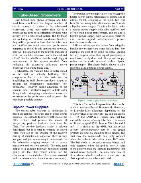
power supply. The circuit below shows a tube<br />
filter that uses a bipolar power supply.<br />
1M<br />
300<br />
10v<br />
6N1P<br />
40k<br />
+3.3v<br />
R1<br />
C1<br />
+200v<br />
-200v<br />
300<br />
6N1P<br />
40k<br />
1µF<br />
Bipolar power supply based crossover<br />
This is a 2nd order lowpass filter that can be<br />
made to realize a Bessel, Butterworth, Gaussian,<br />
or Linkwitz-Riley alignment depending on the<br />
relative values of resistors R1, R2 and capacitors<br />
C1, C2. The 6N1P is a Russian tube that has<br />
earned the respect of many tube fans. It has a mu<br />
of 34 and an rp of 9750 ohms at 200 volts and 5<br />
mA. It is similar to the 6DJ8, but not at all<br />
directly interchangeable with it. This circuit<br />
protects its tubes by including three diodes. The<br />
first two, the zener-diode pair, only conduct<br />
when the cathode falls below about 10.7 volts.<br />
The last diode is normally reverse biased and<br />
only conducts when the grid is over .7 volts<br />
more positive than the cathode (something that<br />
should never happen). The only time any of<br />
these diodes should conduct is when power is<br />
first applied and the tube is still cold.<br />
R2<br />
C2<br />
+6v<br />
1M<br />
< PREVIOUS<br />
Pg. 1<br />
www.tubecad.com Copyright © 2001 GlassWare All Rights Reserved NEXT >
Single Polarity Power Supplies<br />
We still need to use cathode followers to<br />
isolate the filter elements and to provide positive<br />
feedback. We cannot just ground referenced DC<br />
couple the input to the cathode follower, as the<br />
cathode follower’s distortion increases with a<br />
decrease cathode load resistance. This means the<br />
cathode follower must find a DC bias voltage so<br />
that a large valued cathode resistor can be used.<br />
Two approaches present themselves: we can add<br />
a grounded-cathode amplifier to the input and<br />
then DC couple to its output or we can uses a<br />
coupling capacitor and a resistor voltage divider<br />
network to establish the required DC bias<br />
voltage.<br />
<strong>Tube</strong> <strong>CAD</strong><br />
+300v<br />
30k<br />
300<br />
input 300<br />
12AU7<br />
12AU7<br />
+150v<br />
Filter<br />
1M<br />
30k<br />
0v<br />
DC coupled gain producing input stage<br />
The circuit above has the advantage, or<br />
disadvantage, depending on your perspective, of<br />
providing some gain. The advantage of having<br />
gain is that it offers more flexibility. Passive<br />
attenuator boxes can be used with a active filter<br />
that provides gain, as gain overrides the insertion<br />
losses of the filter. And since different amplifiers<br />
differ in gain and since high-frequency drivers<br />
are usually much more efficient than lowfrequency<br />
drivers, the active filter with gain<br />
allows us to use potentiometers to bring each<br />
driver up or down to a baseline.<br />
The disadvantage to gain is that the gain is not<br />
free. We had to pay for it with increased<br />
distortion and noise. Obtaining a cleaner gain<br />
requires more circuitry and a possibly a cleaner<br />
power supply. The simple cathode follower<br />
circuit, on the other hand, is clean and quiet.<br />
<strong>Tube</strong> <strong>CAD</strong> does the hard math for you.<br />
This program covers 13 types of tube<br />
circuits, each one divided into four<br />
variations: 52 circuits in all. <strong>Tube</strong> <strong>CAD</strong><br />
calculates the noteworthy results, such as<br />
gain, phase, output impedance, low<br />
frequency cutoff, PSRR, bias voltage, plate<br />
and load resistor heat dissipations. Which<br />
tube gives the most gain? <strong>Tube</strong> <strong>CAD</strong>'s<br />
scenario comparison feature shows which<br />
tube wins.<br />
Windows 95/98/Me/NT/2000<br />
For more information, please visit our Web site :<br />
www.glass-ware.com<br />
< PREVIOUS<br />
Pg. 2<br />
www.tubecad.com Copyright © 2001 GlassWare All Rights Reserved NEXT >
input<br />
.22µF<br />
1M<br />
300<br />
6N1P<br />
+150v<br />
+300v<br />
Filter<br />
SE Amp <strong>CAD</strong><br />
1M<br />
1M<br />
30k<br />
The circuit above uses the coupling capacitor<br />
and two resistor voltage divider to DC bias<br />
correctly the cathode follower. The gain is close<br />
to unity and output impedance is low enough<br />
not interact too greatly with the filter<br />
components. The diode serves to protect the<br />
6N1P at turn on. The coupling capacitor can<br />
become part of the crossover. For example, biampped<br />
satellite loudspeaker might require a<br />
100 Hz crossover point between it and the<br />
subwoofer. In this case the .22µF capacitor must<br />
be replaced with a 3183pF capacitor. (The two<br />
1M resistors are in parallel, thus the terminating<br />
resistance for this capacitor is 500k.)<br />
A third possibility is to make a hybrid<br />
crossover, tubes on top and FETs on the bottom.<br />
The circuit below uses a DC power supply to<br />
power both the heater string and to load the<br />
cathode followers. The constant current source<br />
can be the two lead FET current sources such as<br />
the 1N5314 or CRO-470. (Many tube fanciers<br />
will tolerate a solid-state device, but only if it<br />
has two leads, strange but true.)<br />
Successful design and analysis of a<br />
single-ended amplifier output stage<br />
requires an accurate model of the<br />
tube's plate curves. SE Amp <strong>CAD</strong> is a<br />
tube audio design program that has a<br />
library of 30 tubes and over 100 output<br />
transformers and SE Amp <strong>CAD</strong> knows<br />
how these tubes really curve in a<br />
singled-ended amplifier.<br />
Windows 95 / 98 / Me /NT / 2000<br />
+200v<br />
300<br />
For more information, please visit:<br />
1M<br />
heater<br />
6N1P<br />
+3.5v<br />
Filter<br />
6N1P<br />
www.glass-ware.com<br />
heater<br />
FETs = 1N5314 or CRO-470<br />
-12.6v<br />
< PREVIOUS<br />
Pg. 3<br />
www.tubecad.com Copyright © 2001 GlassWare All Rights Reserved NEXT >
1st Order Filters<br />
Simplicity itself: a resistor and a capacitor in<br />
between two cathode followers. We can<br />
eliminate some the components in the signal<br />
path but at the cost of eliminating some its<br />
universality. The circuit below makes the point.<br />
B+<br />
2nd Order Filters<br />
The 2nd and higher order filters rely on the<br />
cathode follower to provide positive feedback at<br />
some frequencies to define the desired crossover<br />
shape. In the highpass filter below, resistor R1<br />
provides the positive feedback path back into the<br />
circuit.<br />
300<br />
+200v<br />
6N1P<br />
R1<br />
300<br />
C1<br />
C2<br />
300<br />
C1<br />
6N1P<br />
R1<br />
R2<br />
30k<br />
30k<br />
1M<br />
B+<br />
B-<br />
30k<br />
-200v<br />
300<br />
C2<br />
2nd Order highpass filter<br />
1M<br />
6N1P<br />
30k<br />
B-<br />
1M<br />
The low pass filter is safely tucked inside the<br />
two cathode followers and the highpass filter is<br />
buffered from the output impedance of the signal<br />
source; but its termination is can change with a<br />
different power amplifier. Consequently, a better<br />
choice might be to enclose the high pass filter<br />
within the confines of the two cathode followers.<br />
1M<br />
300<br />
C1<br />
R1<br />
6N1P<br />
30k<br />
300<br />
R1<br />
C1<br />
6N1P<br />
30k<br />
300<br />
B+<br />
B-<br />
6N1P<br />
30k<br />
1M<br />
B+<br />
B-<br />
RL<br />
1M<br />
The deviation between resistors R1 and R2<br />
and the “nominal” resistor values defines the Q<br />
of the filter. The nominal value is the textbook<br />
(R = 1/(2piFC) value. For example, given a<br />
crossover frequency of 1 kHz and a capacitor C1<br />
value of .159µF, the nominal resistor value is<br />
1k. In a Butterworth filter, R1’s value would be<br />
707 ohms; R2, 1414 ohms. The Butterworth<br />
filter uses 1/√2 and √2 to achieve its alignment.<br />
Thus the ratio between R1 and R2 is 2.<br />
The Bessel filter uses a more complicated<br />
ratio: R1 = 3/4xR2. R2 is twice the nominal<br />
value and R1 is 75% of R2’s value. At the core<br />
of these relationships is √3. For example, (√3 /2)<br />
² = 3/4. Fortunately, once one set of resistor and<br />
capacitor values have been determined, setting a<br />
different crossover frequency only requires<br />
scaling either (but not both) the resistor or the<br />
capacitor values up or down.<br />
(Q is the inverse of the damping factor of a<br />
filter. Thus a Q of .5 equals a damping of factor<br />
of 2. Thus the higher the Q, the less damped the<br />
filter is and the more likely it is to ring or peak.<br />
The lower the Q, the more likely the output will<br />
droop at the crossover frequency. Expect to see<br />
both Q and “damping” used in the literature.)<br />
< PREVIOUS<br />
Pg. 4<br />
www.tubecad.com Copyright © 2001 GlassWare All Rights Reserved NEXT >
3rd Order Filters<br />
Two ways of making a 3rd order filter exists.<br />
The first is to have a 2nd order filter cascade<br />
with 1st order filter. The Q of the 2nd order filter<br />
must be made to compensate for the unadjustable<br />
1st order filter. The second approach<br />
is to place all the RC sections in series.<br />
R1 R2 R3<br />
C1 C2 C3<br />
What advantage does one hold over the other?<br />
For the cathode follower based filters, little<br />
advantage exist other than the two section<br />
method having one less active device in the<br />
signal path. But if the buffers were replaced with<br />
amplifiers, then the two section method allows<br />
for all the resistors to equal each other. How is<br />
that an advantage? If all the resistors equal, then<br />
an adjustable crossover point can easily be had<br />
by using a three deck potentiometer to set the<br />
crossover frequency.<br />
Two section 3rd order lowpass filter<br />
B+<br />
R1 R2 R3<br />
R1 R2 R3<br />
C1 C2 C3<br />
Single section 3rd order lowpass filter<br />
C1 C2 C3<br />
R1 R2 R3<br />
B-<br />
4th Order Filters<br />
While 4th order filters can be made from a<br />
single section, it is much easier to cascade two<br />
2nd order filters. Remember the Qs multiply<br />
against each other. Thus two Butterworth 2nd<br />
order filter with a Q of .707 will when cascaded<br />
yield a Q of .5, which is, by the way, the Q of<br />
the Linkwitz-Riley filter. So in order to make a<br />
4th order Butterworth filter, one section’s Q<br />
might be .84 and the second section would have<br />
to be also .84 to have the product equal .707.<br />
R1<br />
R2<br />
R3<br />
R4<br />
Two section 3rd order highpass filter<br />
C1 C2 C3<br />
C4<br />
B+<br />
C1 C2 C3<br />
4th order lowpass filter<br />
R1<br />
R3<br />
C1 C2 C3 C4<br />
R2<br />
R1<br />
R2<br />
R3<br />
R4<br />
Single section 3rd order highpass filter<br />
B-<br />
4th order highpass filter<br />
< PREVIOUS<br />
Pg. 5<br />
www.tubecad.com Copyright © 2001 GlassWare All Rights Reserved NEXT >
The Resistor and Capacitor Values<br />
The table below gives all values for the 1st,<br />
2nd, 3rd with one section, 3rd with two sections,<br />
and 4th order filters. The base frequency is 1000<br />
Hz. To decrease the frequency, scale either the<br />
resistor or the capacitor values down by 1000/F,<br />
where F equals the desired crossover frequency.<br />
To increase the frequency, scale either the<br />
resistor or the capacitor values up by F/1000,<br />
where F equals the desired crossover frequency.<br />
C1<br />
1st Order Highpass & Lowpass<br />
.015915µF<br />
R1<br />
2nd Order Lowpass<br />
10k<br />
Butterworth Bessel L-R<br />
C1 .02251µF .013783µF .015915µF<br />
C2 .01125µF .018194µF .015915µF<br />
R1 10k 10k 10k<br />
R2 10k 10k 10k<br />
NOTE<br />
Do not scale both resistor and capacitor<br />
values at the same time (or the frequency will<br />
not change).<br />
"Hey, these values don't match the ones in<br />
my textbook!" It turns out that there are two<br />
different ways to determine where the crossover<br />
frequency falls; the -3 dB frequency, or the<br />
degree of phase shift frequency. We chose the<br />
former; many books choose the latter. Our<br />
choice makes more sense for loudspeaker<br />
crossovers; their choice, for single filters.<br />
2nd Order Highpass<br />
Butterworth Bessel L-R<br />
C1 .01µF .01µF .01µF<br />
C2 .01µF .01µF .01µF<br />
R1 11,250 13,780 15,915<br />
R2 22,500 13,380 15,915<br />
3rd Order One-Section Lowpass<br />
Butterworth<br />
Bessel<br />
C1 .02215µF .022198µF<br />
C2 .05644µF .031939µF<br />
C3 .003221µF .0056962µF<br />
R1 10k 10k<br />
R2 10k 10k<br />
R3 10k 10k<br />
4th Order Lowpass<br />
Butterworth Bessel L-R<br />
C1 .01723µF .01759µF .02251µF<br />
C2 .0147µF .01614µF .01125µF<br />
C3 .04159µF .02422µF .02251µF<br />
C4 .00609µF .00933µF .01125µF<br />
R1 10k 10k 10k<br />
R2 10k 10k 10k<br />
R3 10k 10k 10k<br />
R4 10k 10k 10k<br />
3rd Order One-Section Highpass<br />
Butterworth<br />
Bessel<br />
C1 .01µF .01µF<br />
C2 .01µF .01µF<br />
C3 .01µF .01µF<br />
R1 11,433 11,430<br />
R2 4,488 7,931<br />
R3 78,628 44,470<br />
4th Order Highpass<br />
Butterworth Bessel L-R<br />
C1 .01µF .01µF .01µF<br />
C2 .01µF .01µF .01µF<br />
C3 .01µF .01µF .01µF<br />
C4 .01µF .01µF .01µF<br />
R1 17,227 14,400 11,250<br />
R2 14,704 15,690 22,500<br />
R3 41,587 10,460 11,250<br />
R4 6,091 27,140 22,500<br />
< PREVIOUS<br />
Pg. 6<br />
www.tubecad.com Copyright © 2001 GlassWare All Rights Reserved NEXT >
The Solution<br />
The challenge facing GlassWare was this:<br />
what to do with the <strong>Tube</strong> <strong>CAD</strong> <strong>Journal</strong>? how to<br />
keep publishing it without charging for it? Some<br />
possibilities were to stop writing the journal, to<br />
charge a subscription fee, or to take on annoying<br />
banner ads. None of those options appealed to<br />
me. But the idea of writing small and<br />
inexpensive companion software, the sale of<br />
which would allow me to continue to publish<br />
this journal for free, seemed like the ideal<br />
solution, as no one is required to buy the<br />
software, but those who do will bask in the<br />
satisfaction of helping keep this free journal<br />
alive.<br />
The downloadable software is incredibly<br />
affordable, $12.95 USD -- the price of a budget<br />
CD. A disk version is available for a few bucks<br />
more. And if you buy either during October<br />
2001, you get an early bird $3 discount: only<br />
$9.95 USD. (For Windows 9x/Me/NT/2000.)<br />
First TCJ Program<br />
This journal's first companion program is<br />
TCJ Filter Designer, which lets you design a<br />
filter or crossover (passive, solid-state or tube)<br />
without having to check out thick textbooks<br />
from the library and without having to breakout<br />
the scientific calculator. This program's goal is<br />
to provide a quick and easy display not only of<br />
the frequency response, but also of the resistor<br />
and capacitor values for a passive and active<br />
filters and crossovers.<br />
While the program’s main concern is active<br />
filters, solid-state and tube, it also does passive<br />
filters. In fact, it can be used to calculate passive<br />
crossovers for use with speakers by entering 8<br />
ohms as the terminating resistance. Covering<br />
tube-based filters would never even be<br />
contemplated at the mainstream EE software<br />
mills, but tube crossovers are a major part of this<br />
program; both buffered and un-buffered tube<br />
based filters along with mono-polar and bipolar<br />
power supply topologies are covered.<br />
< PREVIOUS<br />
Pg. 7<br />
www.tubecad.com Copyright © 2001 GlassWare All Rights Reserved NEXT >
TCJ Filter Design is easy to use, but not<br />
lightweight, holding over 60 filter topologies<br />
and up to four filter alignments: Bessel,<br />
Butterworth, Gaussian, and Linkwitz-Riley.<br />
Passive Filters<br />
1. low-pass 1st-order RC filter<br />
2. low-pass 1st-order LCR filter<br />
3. high-pass 1st-order RC filter<br />
4. high-pass 1st-order LCR filter<br />
5. low-pass 2nd-order RC filter<br />
6. low-pass 2nd-order LCR filter<br />
7. high-pass 2nd-order RC filter<br />
8. high-pass 2nd-order LCR filter<br />
9. low-pass 3rd-order LCR filter<br />
10. high-pass 3rd-order LCR filter<br />
11. low-pass 4th-order LCR filter<br />
12. high-pass 4th-order LCR filter<br />
Solid-State Filters<br />
1. low-pass 1st-order filter<br />
2. low-pass inverting 1st-order filter<br />
3. high-pass 1st-order filter<br />
4. high-pass inverting 1st-order filter<br />
5. low-pass 2nd-order filter<br />
6. low-pass 2nd-order equal value capacitors filter<br />
7. low-pass -inverting 2nd-order MFB filter<br />
8. high-pass 2nd-order filter<br />
9. high-pass 2nd-order equal valued resistors filter<br />
10. high-pass -inverting 2nd-order MFB filter<br />
11. low-pass 3rd-order filter<br />
12. low-pass 3rd-order two-section filter<br />
13. low-pass 3rd-order two-section equal valued<br />
capacitors filter<br />
14. low-pass -inverting 3rd-order MFB filter<br />
15. high-pass 3rd-order filter<br />
16. high-pass 3rd-order two-section filter<br />
17. high-pass 3rd-order two-section equal valued<br />
resistors filter<br />
18. high-pass -inverting 3rd-order MFB filter<br />
19. low-pass 4th-order filter<br />
20. low-pass 4th-order two-section equal valued<br />
capacitors filter<br />
21. high-pass 4th-order filter<br />
22. high-pass 4th-order two-section equal valued<br />
resistors filter<br />
23. low-pass -inverting 4th-order MFB filter<br />
24. high-pass -inverting 4th-order MFB filter<br />
<strong>Tube</strong> <strong>Based</strong> Filters<br />
1. low-pass 1st-order filter<br />
2. low-pass 1st-order self-bias filter<br />
3. low-pass 1st-order self-bias buffered filter<br />
4. high-pass 1st-order self-bias filter<br />
5. high-pass 1st-order self-bias buffered filter<br />
6. low-pass 2nd-order filter<br />
7. low-pass 2nd-order self-bias filter<br />
8. low-pass 2nd-order self-bias buffered filter<br />
9. high-pass 2nd-order filter<br />
10. high-pass 2nd-order self-bias filter<br />
11. low-pass 3rd-order filter<br />
12. low-pass 3rd-order self-bias filter<br />
13. low-pass 3rd-order self-bias buffered filter<br />
14. low-pass 3rd-order two-section filter<br />
15. low-pass 3rd-order two-section filter self-bias<br />
16. low-pass 3rd-order two-section self-bias<br />
buffered filter<br />
17. high-pass 3rd-order<br />
18. high-pass 3rd-order self-bias filter<br />
19. high-pass 3rd-order two-section filter<br />
20. high-pass 3rd-order two-section self-bias filter<br />
21. low-pass 4th-order filter<br />
22. low-pass 4th-order self-bias filter<br />
23. low-pass 4th-order self-bias buffered filter<br />
24. high-pass 4th-order filter<br />
25. high-pass 4th-order self-bias buffered filter<br />
26. Output coupling capacitor 1st-order filter<br />
How to Use the Program<br />
This program takes advantage of point and<br />
click interaction. The Fc frequency is entered in<br />
the drop-down box or the adjoining arrow<br />
buttons are pressed to move the frequency up or<br />
down to the desired value.<br />
Clicking on any<br />
of the 17 filter<br />
choice buttons,<br />
causes the program<br />
to find and display<br />
the appropriate<br />
filter. And the<br />
drop-down box<br />
below the buttons<br />
is used to select the<br />
desired filter<br />
alignment.<br />
Each time a new<br />
filter is chosen, the<br />
user-definable part<br />
list is displayed in<br />
the Circuit Element<br />
choice box of the<br />
program.<br />
< PREVIOUS<br />
Pg. 8<br />
www.tubecad.com Copyright © 2001 GlassWare All Rights Reserved NEXT >
By selecting the<br />
circuit element's<br />
choice eyelet, the<br />
part's value is<br />
displayed in the<br />
drop-down box<br />
below it.<br />
The value then can be changed by direct<br />
entry into the drop-down box or by choosing a<br />
value from its drop-down menu or by using the<br />
up-down buttons to the box's right. Once a<br />
circuit element is selected the schematic display<br />
show a bold face part label.<br />
This window can be moved about at will and<br />
hidden by pressing the Results button once<br />
again.<br />
To graphically see the results only requires<br />
clicking on "Output" on the program's menu, as<br />
this will bring up a graph of either the filter's<br />
frequency response or its phase response,<br />
depending on which selection is made. Clicking<br />
on "Schematic" on the same menu returns the<br />
schematic into view.<br />
The circuit element can also be selected by<br />
clicking on the element's symbol in the<br />
schematic instead. Once the element is selected<br />
and its value changed, the program recalculates<br />
the other element's values and updates the<br />
schematic's display.<br />
The Results and the Output<br />
For most users it is not enough to have the<br />
program calculate the circuit element values,<br />
they need to also know what the resulting Q, Fc<br />
attenuation, bandpass gain, and Fc phase shift.<br />
Pressing the Results<br />
button brings up the<br />
Results window that<br />
displays the important<br />
information.<br />
Click on images to see enlargements<br />
Moving the cursor over either graph will<br />
reveal in the hint-line either the phase and<br />
frequency at that point or the amplitude and<br />
frequency.<br />
How to Buy TCJ Filter Designer<br />
To purchase the program, follow the link to<br />
our new Yahoo store:<br />
http://store.yahoo.com/glass-ware<br />
< PREVIOUS<br />
Pg. 9<br />
www.tubecad.com Copyright © 2001 GlassWare All Rights Reserved NEXT >


