GB - Duplomatic
GB - Duplomatic
GB - Duplomatic

Create successful ePaper yourself
Turn your PDF publications into a flip-book with our unique Google optimized e-Paper software.
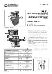
41 610/112 ED<br />
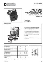
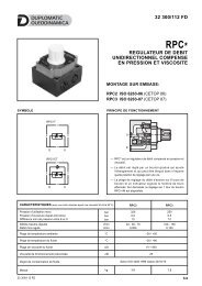
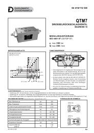
DSR3<br />
ROLLER CAM OPERATED<br />
DIRECTIONAL CONTROL VALVE<br />
SERIES 11<br />
SUBPLATE MOUNTING<br />
ISO 4401-03 (CETOP 03)<br />
p max 350 bar<br />
Q nom 75 l/min<br />
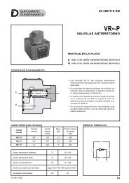
MOUNTING INTERFACE<br />
OPERATING PRINCIPLE<br />
ISO 4401-03-02-0-05<br />
(CETOP 4.2-4-03-350)<br />
40.5<br />
33<br />
DSR3L<br />
30.2<br />
21.5<br />
T<br />
P<br />
T<br />
12.7<br />
31<br />
25.9 15.5 5.1<br />
A<br />
T<br />
P<br />
B<br />
0.75<br />
31.75<br />
A<br />
DSR3H<br />
B<br />
ø 7.5 (max)<br />
ø4<br />
M5<br />
T<br />
P<br />
T<br />
PERFORMANCE RATINGS<br />
(obtained with mineral oil with viscosity of 36 cSt at 50°C)<br />
A<br />
B<br />
Maximum operating pressure:<br />
- P A B ports<br />
- T ports<br />
bar 350<br />
25<br />
Nominal flow rate l/min 75<br />
Pressure drop ∆p-Q see par. 4<br />
Operating limits see par. 5<br />
Ambient temperature range °C -20 / +50<br />
Fluid temperature range °C -20 / +80<br />
Fluid viscosity range cSt 10 ÷ 400<br />
Fluid contamination degree<br />
according to ISO 4406:<br />
1999 class 20/18/15<br />
Recommended viscosity cSt 25<br />
Mass:<br />
DSR3L-TA<br />
DSR3L-R<br />
DSR3H-TA<br />
kg<br />
1,1<br />
1,2<br />
1,2<br />
— The DSR3* are roller cam operated directional control<br />
valves, available with 4 ways, with mounting interface<br />
according to ISO 4401 (CETOP RP121H) standards.<br />
— The valve body is made with high strength iron castings<br />
provided with wide internal passages in order to minimize<br />
the flow pressure drop.<br />
— It is available in LIGHT (short) and HEAVY DUTY (long)<br />
versions, with 2 positions with return spring or with 2<br />
positions with double mechanical command.<br />
— The roller of the valve operating device can be positioned<br />
at 90° with respect to the valve mounting surface, in order<br />
to achieve flexible installation.<br />
— This type of valve can be used as a hydraulic stroke end<br />
for cylinders, speed selectors (not compensated),<br />
hydraulic safety devices, directional control of hydraulic<br />
axes.<br />
41 610/112 ED 1/4
DSR3<br />
SERIES 11<br />
1 - IDENTIFICATION CODE<br />
D S R 3 - / 11<br />
Directional control<br />
valve with spool<br />
Roller cam operated<br />
Seals:<br />
N = NBR seals for mineral oil (standard)<br />
V = FPM seals for special fluids<br />
ISO 4401-03 (CETOP 03) size<br />
Series No. (the overall and mounting dimensions<br />
remain unchanged from 10 to 19)<br />
Version:<br />
L = LIGHT (short)<br />
H = HEAVY DUTY (long)<br />
Spool type (see par. 3)<br />
TA<br />
R (available only for DSR3L version)<br />
2 - HYDRAULIC FLUIDS<br />
Use mineral oil-based hydraulic fluids HL or HM type, according to ISO 6743-4. For these fluids, use NBR seals. For fluids HFDR type<br />
(phosphate esters) use FPM seals (code V). For the use of other kinds of fluid such as HFA, HFB, HFC, please consult our technical<br />
department.<br />
Using fluids at temperatures higher than 80 °C causes a faster degradation of the fluid and of the seals characteristics. The fluid must be<br />
preserved in its physical and chemical characteristics.<br />
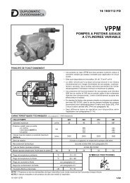
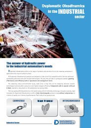
3 - SPOOL TYPE<br />
Type TA:<br />
2 external positions<br />
with return spring<br />
Type R:<br />
2 positions<br />
with double mechanical command<br />
a<br />
a<br />
A<br />
P<br />
B<br />
b<br />
T<br />
a<br />
A<br />
a<br />
P<br />
B<br />
b<br />
T<br />
b<br />
TA<br />
a<br />
R<br />
a<br />
b<br />
41 610/112 ED 2/4
DSR3<br />
SERIES 11<br />
4 - PRESSURE DROPS ∆p-Q (obtained with viscosity 36 cSt at 50 °C)<br />
FLOW DIRECTION<br />
SPOOL TYPE<br />
P→A P→B A→T B→T<br />
CURVES ON GRAPH<br />
DSR3L-TA 1 1 1 1<br />
DSR3L-R 1 1 1 1<br />
DSR3H-TA 1 1 1 1<br />
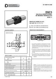
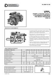
5 - OPERATING LIMITS<br />
The curves define the flow rate operating fields according to the valve pressure of the different versions. The values have been obtained<br />
according to ISO 6403 norm, with mineral oil viscosity 36 cSt at 50 °C and filtration according to ISO 4406:1999 class 18/16/13.<br />
p<br />
[bar]<br />
350<br />
300<br />
2<br />
1<br />
SPOOL TYPE<br />
CURVE<br />
250<br />
200<br />
150<br />
100<br />
50<br />
2<br />
P→A P→B<br />
DSR3L-TA 2 2<br />
DSR3L-R 1 1<br />
DSR3H-TA 1 1<br />
0<br />
25<br />
50<br />
75<br />
Q [l/min]<br />
6 - INSTALLATION<br />
Configurations with centering and return springs can be mounted in any position; type R valves -<br />
without springs - must be mounted with the longitudinal axis horizontal. Valve fixing is by means of<br />
screws or tie rods, with the valve mounted on a lapped surface, with values of planarity and<br />
smoothness that are equal to or better than those indicated in the drawing. If the minimum values of<br />
planarity and/or smoothness are not met, fluid leakage between valve and mounting surface can<br />
easily occur.<br />
Surface finishing<br />
41 610/112 ED 3/4
DSR3<br />
SERIES 11<br />
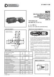
7 - OVERALL AND MOUNTING DIMENSIONS<br />
Max.30°<br />
Camma<br />
DSR3L - TA<br />
DSR3L - R<br />
8.4<br />
115.3<br />
22<br />
41.6<br />
125.8<br />
A B<br />
2<br />
A<br />
P<br />
B<br />
22.5<br />
47<br />
50.5<br />
A<br />
P<br />
B<br />
P T<br />
A B<br />
P T<br />
A B<br />
±0.2<br />
1.3<br />
1.1<br />
±0.2<br />
±0.2<br />
1.3<br />
11<br />
65<br />
1<br />
46<br />
(8.4) 22 65<br />
22 8.4<br />
P T<br />
Max corsa stroke 3.7 3.7<br />
3<br />
11.2<br />
7.5<br />
ø30<br />
A<br />
P<br />
T<br />
B<br />
41.6<br />
dimensions in mm<br />
A B<br />
P T<br />
A B<br />
P T<br />
A B<br />
P T<br />
2<br />
3<br />
26.1<br />
2.7<br />
1<br />
2.3<br />
±0.1<br />
±0.1<br />
±0.1<br />
Max.30°<br />
Camma<br />
14.5<br />
45<br />
Max corsastroke 6 6<br />
11.2<br />
156<br />
A<br />
P<br />
65<br />
7.5<br />
B<br />
DSR3H - TA<br />
1<br />
22.5<br />
46<br />
47 50.5<br />
1 Mounting surface with sealing rings<br />
4 OR type 2037 (9.25x1.78) - 90 Shore<br />
2 Roller for valve operation<br />
(see NOTE)<br />
3 Countersunk hexagonal screw for<br />
roller operation: DSR3L spanner 2<br />
DSR3H spanner 2,5<br />
NOTE: The valve is supplied as standard with the<br />
operating roller oriented in a perpendicular<br />
position with respect to the mounting surface. For<br />
installation needs the roller can be oriented by the<br />
user directly at 90° to the standard position:<br />
- untight the locking nut and the countersunk<br />
hexagonal screw (ref. 3) until the spool and the<br />
relevant roller can be freely oriented.<br />
ø30<br />
74.3<br />
82.3<br />
A<br />
P<br />
T<br />
B<br />
- rotate through 90° the spool with the roller<br />
- tighten the fixing screw (ref. 3) being careful<br />
that it goes inside the spool anti-rotation slot<br />
without preventing the spool movement.<br />
8 - VALVE FASTENING BOLTS<br />
N. 4 fastening bolts SHC ISO 4762 M5x30<br />
Tightening torque 5 Nm (bolts A 8.8)<br />
9 - SUBPLATES (see catalogue 51 000)<br />
Type PMMD-AI3G with rear ports 3/8” BSP<br />
Type PMMD-AL3G with side ports 3/8” BSP<br />
DUPLOMATIC OLEODINAMICA S.p.A.<br />
20015 PARABIAGO (MI) • Via M. Re Depaolini 24<br />
Tel. +39 0331.895.111<br />
Fax +39 0331.895.339<br />
www.duplomatic.com • e-mail: sales.exp@duplomatic.com<br />
41 610/112 ED REPRODUCTION IS FORBIDDEN. THE COMPANY RESERVES THE RIGHT TO APPLY ANY MODIFICATIONS.<br />
4/4