Rexroth Hydraulics Product Catal... - Hasmak.com.tr
Rexroth Hydraulics Product Catal... - Hasmak.com.tr
Rexroth Hydraulics Product Catal... - Hasmak.com.tr

Create successful ePaper yourself
Turn your PDF publications into a flip-book with our unique Google optimized e-Paper software.
<s<strong>tr</strong>ong>Hydraulics</s<strong>tr</strong>ong> <s<strong>tr</strong>ong>Product</s<strong>tr</strong>ong> <s<strong>tr</strong>ong>Catal</s<strong>tr</strong>ong>og<br />
With Preferred & Spotlight Delivery<br />
Programs Section
Authorized<br />
Distibution<br />
Network<br />
The<br />
Drive & Con<strong>tr</strong>ol<br />
Company<br />
Full-line Bosch <s<strong>tr</strong>ong>Rexroth</s<strong>tr</strong>ong> Hydraulic Dis<strong>tr</strong>ibutors<br />
Bosch <s<strong>tr</strong>ong>Rexroth</s<strong>tr</strong>ong> is proud to work with the highest qualifi ed Dis<strong>tr</strong>ibutors in the hydraulics indus<strong>tr</strong>y. These dis<strong>tr</strong>ibutors<br />
add value by extending the level of technical and indus<strong>tr</strong>y expertise available to users of fl uid power across the coun<strong>tr</strong>y.<br />
They work closely with our applications engineering personnel to deliver innovative, effective, and reliable solutions to<br />
your most challenging needs. Following is the list of our authorized full-line Hydraulic Dis<strong>tr</strong>ibutors:<br />
A & L <s<strong>tr</strong>ong>Hydraulics</s<strong>tr</strong>ong>, Inc.<br />
4412 South 87th S<strong>tr</strong>eet<br />
Omaha, NE 68127<br />
(402) 339-3873<br />
Airline <s<strong>tr</strong>ong>Hydraulics</s<strong>tr</strong>ong>, Inc.<br />
Expressway 95 Business C<strong>tr</strong>.<br />
3557 Progress Drive<br />
Bensalem, PA 19020<br />
(215) 638-4700<br />
Catey Con<strong>tr</strong>ols, Inc.<br />
3102 West Broadway<br />
Missoula, MT 59808<br />
(406) 728-7860<br />
Flodyne/Hydradyne, Inc.<br />
1000 Muirfi eld Drive<br />
Hanover Park, IL 60103<br />
(630) 563-3600<br />
FPS Technologies, Inc.<br />
1417 Forestdale Boulevard<br />
Birmingham, AL 35214<br />
(205) 798-9440<br />
Fluid System<br />
Components, Inc.<br />
1700 Suburban Drive<br />
DePere, WI 54115<br />
(920) 337-0234<br />
Gulf Con<strong>tr</strong>ols Company, LLC<br />
5201 Tampa West Boulevard<br />
Tampa, FL 33634<br />
(813) 884-0471<br />
Hydraulic Con<strong>tr</strong>ols, Inc.<br />
4700 San Pablo Avenue<br />
Emeryville, CA 94608<br />
(510) 658-8300<br />
Hydrotech, Inc.<br />
10052 Commerce Park Drive<br />
Cincinnati, OH 45246<br />
(513) 881-7000<br />
Innotek Engineered <s<strong>tr</strong>ong>Product</s<strong>tr</strong>ong>s<br />
9140 Zachary Lane North<br />
Maple Grove, MN 55369<br />
(763) 488-9910<br />
Interstate <s<strong>tr</strong>ong>Hydraulics</s<strong>tr</strong>ong>, Inc.<br />
426 West 9160 South<br />
Sandy, UT 84070<br />
(801) 566-4333<br />
Iowa Fluid Power, Inc.<br />
1610 Blairs Ferry Road NE<br />
Cedar Rapids, IA 52402<br />
(319) 395-7000<br />
John Henry Foster, Co.<br />
4700 Lebourget Drive<br />
St. Louis, MO 63134<br />
(314) 427-0600<br />
Livingston & Haven, Inc.<br />
11616 Wilmar Boulevard<br />
Charlotte, NC 28273<br />
(704) 588-3670<br />
Morrell, Inc.<br />
3333 Bald Mountain Road<br />
Auburn Hills, MI 48326<br />
(248) 373-1600<br />
Pacific Power Tech, LLC<br />
18977 NE Portal Way<br />
Portland, OR 97230<br />
(503) 667-9222<br />
Womack Machine Supply Co.<br />
2010 Shea Road<br />
Dallas, TX 75235<br />
(214) 357-3871<br />
For more information on dis<strong>tr</strong>ibutor coverage in your local area,<br />
go to our Web site www.boschrexroth-us.<s<strong>tr</strong>ong>com</s<strong>tr</strong>ong> and enter Web code US0017.<br />
Elec<strong>tr</strong>ic Drives<br />
and Con<strong>tr</strong>ols<br />
<s<strong>tr</strong>ong>Hydraulics</s<strong>tr</strong>ong><br />
Linear Motion and<br />
Assembly Technologies Pneumatics Service
Elec<strong>tr</strong>ic Drives<br />
and Con<strong>tr</strong>ols<br />
<s<strong>tr</strong>ong>Hydraulics</s<strong>tr</strong>ong><br />
Linear Motion and<br />
Assembly Technologies Pneumatics Service<br />
To our valued Bosch <s<strong>tr</strong>ong>Rexroth</s<strong>tr</strong>ong> Customer;<br />
The Bosch <s<strong>tr</strong>ong>Rexroth</s<strong>tr</strong>ong> Corporation’s Hydraulic Technology Group, is pleased to provide a <s<strong>tr</strong>ong>Hydraulics</s<strong>tr</strong>ong> <s<strong>tr</strong>ong>Product</s<strong>tr</strong>ong> Program <s<strong>tr</strong>ong>Catal</s<strong>tr</strong>ong>og including a<br />
specific listing of Preferred and Spotlight products.<br />
Purpose: This catalog represents an overview of the North American Bosch <s<strong>tr</strong>ong>Rexroth</s<strong>tr</strong>ong> Hydraulic product portfolio, and an identified, focused<br />
range of <s<strong>tr</strong>ong>Rexroth</s<strong>tr</strong>ong> Preferred & Spotlight <s<strong>tr</strong>ong>Product</s<strong>tr</strong>ong>s to guide selections for a wide range of typical applications.<br />
The focus on a range of Preferred & Spotlight products allows us to offer a higher service level including:<br />
• Delivery of Preferred items not to exceed four weeks †<br />
• Delivery of Spotlight items not to exceed two weeks* †<br />
• Simplifi ed pricing<br />
• Enhanced customer service<br />
* See <s<strong>tr</strong>ong>Hydraulics</s<strong>tr</strong>ong> Preferred <s<strong>tr</strong>ong>Product</s<strong>tr</strong>ong>s Component List for specific Preferred and Spotlight product identification, in Section XX.<br />
† Nine (9) pieces per material number, per order, is the maximum quantity permitted. We reserve the right to limit quantities; however,<br />
will acknowledge all orders and the quantity which will be delivered to Preferred and Spotlight lead times. If quantities greater than<br />
(9) pieces per material number are required, please consult us for price and delivery.<br />
Material numbers listed in the Preferred and Spotlight section of this catalog for quantities (9) or less will be considered preferred<br />
product orders, unless specifi ed under another agreement.<br />
Delivery, Preferred products will be delivered in (4) weeks or less, Spotlight products will be delivered in (2) weeks or less.<br />
Dis<strong>tr</strong>ibuted by:<br />
Please visit our website at<br />
www.boschrexroth-us.<s<strong>tr</strong>ong>com</s<strong>tr</strong>ong><br />
and select the Sales Lo ca tor<br />
for the name of your nearest<br />
Bosch <s<strong>tr</strong>ong>Rexroth</s<strong>tr</strong>ong> Dis<strong>tr</strong>ibutor<br />
or call 1-800-REXROTH.<br />
All items subject to prior sale. It is advisable to confi rm critical delivery requirements at time of order.<br />
WARNING!<br />
FAILURE, IMPROPER SELECTION OR IMPROPER USE<br />
OF THE PRODUCTS AND/OR SYSTEMS DESCRIBED HEREIN OR OF RELATED ITEMS<br />
CAN CAUSE DEATH, PERSONAL INJURY AND PROPERTY DAMAGE.<br />
This document and other information from Bosch <s<strong>tr</strong>ong>Rexroth</s<strong>tr</strong>ong> Corporation and its divisions provide products and/or system options for<br />
further investigation by users having technical expertise. It is important that you analyze all aspects of your application and review<br />
the information concerning the products or systems in <s<strong>tr</strong>ong>Rexroth</s<strong>tr</strong>ong>’s Technical Data Sheets & <s<strong>tr</strong>ong>Catal</s<strong>tr</strong>ong>ogs. Due to the variety of operating<br />
conditions and applications for these products or systems, the user, through his own analysis and testing, is solely responsible for<br />
making the fi nal selection of the products and systems and assuring that all performance, safety andwarning requirements are met.<br />
The products described herein, including without limitation, product features, specifi cations, designs, and prices are subject to<br />
change at any time without notice.
Elec<strong>tr</strong>ic Drives<br />
and Con<strong>tr</strong>ols<br />
<s<strong>tr</strong>ong>Hydraulics</s<strong>tr</strong>ong><br />
Linear Motion and<br />
Assembly Technologies Pneumatics Service<br />
Table of Contents<br />
For a <s<strong>tr</strong>ong>com</s<strong>tr</strong>ong>plete copy of the<br />
data sheets in this catalog,<br />
visit our website at:<br />
www.boschrexroth-us.<s<strong>tr</strong>ong>com</s<strong>tr</strong>ong><br />
u <s<strong>tr</strong>ong>Product</s<strong>tr</strong>ong>s and Solutions<br />
u Indus<strong>tr</strong>ial Hy drau lics<br />
u <s<strong>tr</strong>ong>Product</s<strong>tr</strong>ong>s and <s<strong>tr</strong>ong>Catal</s<strong>tr</strong>ong>ogs<br />
u Preferred <s<strong>tr</strong>ong>Product</s<strong>tr</strong>ong><br />
<s<strong>tr</strong>ong>Catal</s<strong>tr</strong>ong>og<br />
The Drive & Con<strong>tr</strong>ol Company<br />
• Section 1. Pumps and Motors ............................... 1<br />
• Section 2. Check Valves .................................... 127<br />
• Section 3. Directional Valves ............................. 147<br />
• Section 4. Mobile Con<strong>tr</strong>ols ................................ 181<br />
• Section 5. Pressure Con<strong>tr</strong>ol Valves ................. 219<br />
• Section 6. Flow Con<strong>tr</strong>ol Valves ......................... 257<br />
• Section 7. Proportional Valves .......................... 275<br />
• Section 8. Proportional Elec<strong>tr</strong>onics ................. 361<br />
• Section 9. Mobile Elec<strong>tr</strong>onics ........................... 411<br />
• Section 10. Accessories .................................... 461<br />
• Section 11. Manifolds ......................................... 481<br />
• Section 12. Tie Rod Cylinders .......................... 489<br />
• Section 13. Power Packs ................................... 497<br />
• Section 14. Gear Drives ..................................... 503<br />
• Section 15. Seal Kits ........................................... 543<br />
• Section 16. Preferred & Spotlight Delivery<br />
Programs Section .................................................. 547<br />
iii<br />
iii
Elec<strong>tr</strong>ic Drives<br />
and Con<strong>tr</strong>ols<br />
<s<strong>tr</strong>ong>Hydraulics</s<strong>tr</strong>ong><br />
Linear Motion and<br />
Assembly Technologies Pneumatics Service<br />
Section 1<br />
Pumps and Motors<br />
For a <s<strong>tr</strong>ong>com</s<strong>tr</strong>ong>plete copy of the<br />
data sheets in this catalog,<br />
visit our website at:<br />
www.boschrexroth-us.<s<strong>tr</strong>ong>com</s<strong>tr</strong>ong><br />
u <s<strong>tr</strong>ong>Product</s<strong>tr</strong>ong>s and Solutions<br />
u Indus<strong>tr</strong>ial Hy drau lics<br />
u <s<strong>tr</strong>ong>Product</s<strong>tr</strong>ong>s and <s<strong>tr</strong>ong>Catal</s<strong>tr</strong>ong>ogs<br />
u Preferred <s<strong>tr</strong>ong>Product</s<strong>tr</strong>ong><br />
<s<strong>tr</strong>ong>Catal</s<strong>tr</strong>ong>og<br />
The Drive & Con<strong>tr</strong>ol Company<br />
– External gear pump – F, N & G ......................................... 2<br />
– External gear motors – F & N ............................................ 8<br />
– Internal gear pump, fi xed displacement<br />
• PGF ....................................................................................11<br />
• PGH ...................................................................................14<br />
– Fixed displacement vane pump – PVV..........................17<br />
– Variable displacement vane pumps – PSV ..................19<br />
– Radial piston pump – R4 .................................................21<br />
– Radial piston pump – R4 mini .........................................23<br />
– Variable vane pumps – VPV ............................................25<br />
– Radial piston motor, low speed, high torque<br />
• MCR 03 ............................................................................28<br />
• MCR 05 ............................................................................33<br />
• MCR 10 ............................................................................37<br />
• MCR 15 ............................................................................41<br />
• MCR 20 ............................................................................44<br />
– Fixed displacement motor, open and closed –<br />
AA2FM (A2FM) ..................................................................47<br />
– Fixed displacement motor, open and closed –<br />
A10FM, standard version; A10FE, plug-in version .....52<br />
– Fixed displacement pump, open –<br />
AA2FO (A2FO) ..................................................................56<br />
– Variable displacement motor, open and closed –<br />
AA6VM (A6VM)..................................................................60<br />
– Dual displacement motor, open and closed –<br />
A10VM; A10VE, plug-in version .....................................64<br />
– Variable displacement pump, closed – AA4VG .........68<br />
– Variable displacement pump, open – A4VSO ............73<br />
– Axial piston variable pump for HFC fl uids<br />
(water-glycol) – AA4VSO ................................................78<br />
– Variable displacement pump, closed – A4VSG .........82<br />
– Axial piston-<s<strong>tr</strong>ong>com</s<strong>tr</strong>ong>pact unit – AA4CSG (A4CSG) .......87<br />
– Variable displacement pump, open – AA11VO ..........91<br />
– Variable displacement pump, open – A10V(S)O .......95<br />
– Variable displacement pump, open – A10VO ............99<br />
– Variable displacement pump, open –<br />
AA10VSO (A10VSO: sizes 10 & 18) ........................103<br />
– Variable displacement pump, open – A10VSO .......107<br />
– Variable displacement pump, open – A10VNO ......111<br />
– Variable displacement pump, closed –<br />
AA10VG ............................................................................114<br />
– Closed loop pressure and fl ow con<strong>tr</strong>ol system –<br />
SYDFE1 ............................................................................118<br />
– Pressure and fl ow closed loop – SYDFEE ...............121<br />
– Pressure-fl ow closed loop con<strong>tr</strong>ol – SYHDFEE ......124<br />
1<br />
1
Elec<strong>tr</strong>ic Drives<br />
and Con<strong>tr</strong>ols<br />
<s<strong>tr</strong>ong>Hydraulics</s<strong>tr</strong>ong><br />
Linear Motion and<br />
Assembly Technologies Pneumatics Service<br />
Ex<strong>tr</strong>acted from RA 10 097/02.06<br />
Page 1 of 6<br />
See Section 16 for applicable<br />
Issue: 06.06<br />
Preferred/Spotlight part numbers<br />
and unit price.<br />
External gear pumps<br />
Series F, N, & G<br />
Fixed displacement pumps<br />
Sizes 4.1...63.0 cm 3 (0.26...3.84 in 3 )<br />
– Displacements of 4cc to 63cc<br />
– Plain bearings for heavy duty applications<br />
– Drive shafts SAE or ISO<br />
– Multiple Pump Assemblies<br />
– Port connections: fl ange or threaded<br />
– Optimized pressure pulsation, which reduces noise levels and<br />
vibration excitation in the system<br />
– Consistent high quality<br />
– Considerably longer life due to reinforced shaft and housing<br />
Series G<br />
Series N<br />
Series F<br />
Pumps and Motors 2 Section 1
Elec<strong>tr</strong>ic Drives<br />
and Con<strong>tr</strong>ols<br />
<s<strong>tr</strong>ong>Hydraulics</s<strong>tr</strong>ong><br />
Linear Motion and<br />
Assembly Technologies Pneumatics Service<br />
Ex<strong>tr</strong>acted from RA 10 097/02.06<br />
Page 2 of 6<br />
See Section 16 for applicable<br />
Issue: 06.06<br />
Preferred/Spotlight part numbers<br />
and unit price.<br />
Ordering code F series pump<br />
* Common S0 Codes: S0022 – Long Keyed Shaft<br />
Contact factory for additional codes.<br />
Pumps and Motors 3 Section 1
Elec<strong>tr</strong>ic Drives<br />
and Con<strong>tr</strong>ols<br />
<s<strong>tr</strong>ong>Hydraulics</s<strong>tr</strong>ong><br />
Linear Motion and<br />
Assembly Technologies Pneumatics Service<br />
Ex<strong>tr</strong>acted from RA 10 097/02.06<br />
Page 3 of 6<br />
See Section 16 for applicable<br />
Issue: 06.06<br />
Preferred/Spotlight part numbers<br />
and unit price.<br />
Ordering code N series pump<br />
* Common S0 Codes: S0075 – Tapered Shaft<br />
Contact factory for additional codes.<br />
Pumps and Motors 4 Section 1
Elec<strong>tr</strong>ic Drives<br />
and Con<strong>tr</strong>ols<br />
<s<strong>tr</strong>ong>Hydraulics</s<strong>tr</strong>ong><br />
Linear Motion and<br />
Assembly Technologies Pneumatics Service<br />
Ex<strong>tr</strong>acted from RA 10 097/02.06<br />
Page 4 of 6<br />
See Section 16 for applicable<br />
Issue: 06.06<br />
Preferred/Spotlight part numbers<br />
and unit price.<br />
Ordering code G series pump<br />
Note: Consult factory for availability<br />
Pumps and Motors 5 Section 1
Elec<strong>tr</strong>ic Drives<br />
and Con<strong>tr</strong>ols<br />
<s<strong>tr</strong>ong>Hydraulics</s<strong>tr</strong>ong><br />
Linear Motion and<br />
Assembly Technologies Pneumatics Service<br />
Ex<strong>tr</strong>acted from RA 10 097/02.06<br />
Page 5 of 6<br />
See Section 16 for applicable<br />
Issue: 06.06<br />
Preferred/Spotlight part numbers<br />
and unit price.<br />
Ordering code for multiple pumps<br />
* Contact factory for availability of units with no ordering number listed.<br />
** Refer to page 18 for SAE O-Ring Boss specifications and dimensions.<br />
Pumps and Motors 6 Section 1
Elec<strong>tr</strong>ic Drives<br />
and Con<strong>tr</strong>ols<br />
<s<strong>tr</strong>ong>Hydraulics</s<strong>tr</strong>ong><br />
Linear Motion and<br />
Assembly Technologies Pneumatics Service<br />
Ex<strong>tr</strong>acted from RA 10 097/02.06<br />
Page 6 of 6<br />
See Section 16 for applicable<br />
Issue: 06.06<br />
Preferred/Spotlight part numbers<br />
and unit price.<br />
Performance ratings<br />
F Series Performance Ratings<br />
Size<br />
004 005 008 011 014 016 019 022 025 028<br />
Displacement<br />
cm3/rev 4.1 5.6 8.2 11.3 14.3 16.5 19.5 22.9 25.4 28.5<br />
Inlet pressure<br />
bar<br />
min. 0.7 max. 3 (absolute)<br />
max. continuous pressure p 1 bar<br />
250<br />
210 180 200 170<br />
psi<br />
3625<br />
3045 2610 2900 2465<br />
max. intermittent pressure p 2 bar<br />
280<br />
230 210 220 190<br />
psi<br />
4060<br />
3335 3045 3190 2755<br />
max. peak pressure p 3 bar<br />
300<br />
250 230 240 210<br />
psi<br />
4350<br />
3625 3335 3528 3045<br />
min. rotational speed (RPM) % 100 RPM 600 500 500 500 500 500 500 500 500 500<br />
max. rotational speed at (RPM) p 1 0 3500 3000 2500 2000 2000 2000 2000 2000<br />
max. Drehzahl bei p 2 0 4000 3500 3500 3500 3000 2750 2500 2500<br />
N Series Performance Ratings<br />
Size<br />
020 022 025 028 032 036<br />
Displacement<br />
cm3/rev 20.4 23.1 25.8 28.4 32.4 36.4<br />
Inlet pressure bar min. 0.7 max. 3 (absolute)<br />
max. continuous pressure p 1 bar 230 230 230 210 180 160<br />
psi 3335 3335 3335 3045 2610 2610<br />
max. intermittent pressure p 2 bar 250 250 250 230 200 180<br />
psi 3625 3625 3625 3335 2900 2610<br />
max. peak pressure p 3 bar 270 270 270 250 220 200<br />
psi 3915 3915 3915 3625 3190 2900<br />
min. rotational speed (RPM) % 100 RPM 500 500 500 500 500 500<br />
max. rotational speed at (RPM) p 1 0 2500 2500 2500 2300 2300 2100<br />
max. Drehzahl bei p 2 0 3000 3000 3000 2800 2800 2600<br />
G Series Performance Ratings<br />
Size<br />
32<br />
36<br />
45<br />
56<br />
63<br />
Displacement:<br />
cm3/rev 32 36 45 56 63<br />
cu in/rev 1.95 2.20 2.75 3.42 3.84<br />
Range Speed: Min RPM 400 400 400 400 400<br />
Max RPM 2800 2800 2600 2300 2300<br />
Pressure - Rated: p 1 (Bar) 250 250 250 195 170<br />
(PSI) 3625 3625 3625 2828 2465<br />
Intermittent: p 2 (Bar) 280 280 280 225 200<br />
(PSI) 4060 4060 4060 3263 2900<br />
Max Peak: p 3 (Bar) 300 300 300 250 230<br />
(PSI) 4350 4350 4350 3625 3335<br />
Inlet Pressure:<br />
Continuous 0.7 - 3.0 bar absolute (9in Hg vacuum to 29 PSIG<br />
Intermittent 0.1 - 10 bar absolute (26in Hg vacuum to 130 PSIG<br />
Pumps and Motors 7 Section 1
Elec<strong>tr</strong>ic Drives<br />
and Con<strong>tr</strong>ols<br />
<s<strong>tr</strong>ong>Hydraulics</s<strong>tr</strong>ong><br />
Linear Motion and<br />
Assembly Technologies Pneumatics Service<br />
Ex<strong>tr</strong>acted from RA 14 025/08.06<br />
Page 1 of 3<br />
See Section 16 for applicable<br />
Issue: 06.06<br />
Preferred/Spotlight part numbers<br />
and unit price.<br />
External gear motors<br />
Series F & N<br />
Fixed displacement motors<br />
Sizes 8.2...36.4 cm 3 (0.51...2.28 in 3 )<br />
– Plain bearings for heavy duty applications<br />
– Drive shafts SAE or ISO<br />
– Port connections: fl ange or threaded<br />
– Consistent high quality<br />
– Considerably longer life due to reinforced shaft and housing<br />
Ratings and specifications<br />
Pumps and Motors 8 Section 1
Elec<strong>tr</strong>ic Drives<br />
and Con<strong>tr</strong>ols<br />
<s<strong>tr</strong>ong>Hydraulics</s<strong>tr</strong>ong><br />
Linear Motion and<br />
Assembly Technologies Pneumatics Service<br />
Ex<strong>tr</strong>acted from RA 14 025/08.06<br />
Page 2 of 3<br />
See Section 16 for applicable<br />
Issue: 06.06<br />
Preferred/Spotlight part numbers<br />
and unit price.<br />
Ordering code F series motor<br />
* Common S0 Codes: S0018 = Cross check valve in rear cover (internal case drain), S0022 = Long keyed shaft,<br />
S0030 = S0018 + S0022, S0028 = Pressure relief valve and anti-cavitation valve.<br />
Pumps and Motors 9 Section 1
Elec<strong>tr</strong>ic Drives<br />
and Con<strong>tr</strong>ols<br />
<s<strong>tr</strong>ong>Hydraulics</s<strong>tr</strong>ong><br />
Linear Motion and<br />
Assembly Technologies Pneumatics Service<br />
Ex<strong>tr</strong>acted from RA 14 025/08.06<br />
Page 3 of 3<br />
See Section 16 for applicable<br />
Issue: 06.06<br />
Preferred/Spotlight part numbers<br />
and unit price.<br />
Ordering code N series motor<br />
* Common S0 Codes: S0018 = Cross check valve in rear cover (internal case drain), S0022 = Long keyed shaft,<br />
S0030 = S0018 + S0022, S0028 = Pressure relief valve and anti-cavitation valve.<br />
Pumps and Motors 10 Section 1
Elec<strong>tr</strong>ic Drives<br />
and Con<strong>tr</strong>ols<br />
<s<strong>tr</strong>ong>Hydraulics</s<strong>tr</strong>ong><br />
Linear Motion and<br />
Assembly Technologies Pneumatics Service<br />
Ex<strong>tr</strong>acted from RE 10213/04.05<br />
Page 1 of 3<br />
See Section 16 for applicable<br />
Issue: 06.06<br />
Preferred/Spotlight part numbers<br />
and unit price.<br />
Internal gear pump, fixed displacement<br />
Model PGF<br />
Frame sizes 1, 2 and 3<br />
Component series: 2X (FS1 and 2)<br />
3X (FS3)<br />
Max. operating pressure up to 250 bar (3626 PSI)<br />
Max. displacement 1.7 to 40 cm 3 (0.10 to 2.44 in 3 )<br />
– Fixed displacement<br />
– Low operating noise<br />
– Low fl ow pulsation<br />
– High effi ciency even at low viscosity due to sealing<br />
gap <s<strong>tr</strong>ong>com</s<strong>tr</strong>ong>pensation<br />
– Long service life due to plain bearings and sealing<br />
gap <s<strong>tr</strong>ong>com</s<strong>tr</strong>ong>pensation<br />
– Suitable for a wide viscosity and speed range<br />
– Excellent suction characteristics<br />
– All frame sizes can be <s<strong>tr</strong>ong>com</s<strong>tr</strong>ong>bined with each other<br />
– Can be <s<strong>tr</strong>ong>com</s<strong>tr</strong>ong>bined with PGH internal gear pumps,<br />
PV7 vane pumps and axial piston pumps<br />
– Valve technology can be integrated in the cover plate on inquiry<br />
Model PGF1... for direct mounting<br />
Model PGF3... for direct mounting<br />
Pumps and Motors 11 Section 1
Elec<strong>tr</strong>ic Drives<br />
and Con<strong>tr</strong>ols<br />
<s<strong>tr</strong>ong>Hydraulics</s<strong>tr</strong>ong><br />
Linear Motion and<br />
Assembly Technologies Pneumatics Service<br />
Ex<strong>tr</strong>acted from RE 10213/04.05<br />
Page 2 of 3<br />
See Section 16 for applicable<br />
Issue: 06.06<br />
Preferred/Spotlight part numbers<br />
and unit price.<br />
Ordering code<br />
PG F – / V *<br />
Series<br />
Medium-pressure pump<br />
= F<br />
Frame size – <s<strong>tr</strong>ong>com</s<strong>tr</strong>ong>ponent series<br />
FS1 – <s<strong>tr</strong>ong>com</s<strong>tr</strong>ong>ponent series 2X = 1–2X<br />
(<s<strong>tr</strong>ong>com</s<strong>tr</strong>ong>ponent series 20 to 29: unchanged<br />
installation and connection dimensions)<br />
FS2 – <s<strong>tr</strong>ong>com</s<strong>tr</strong>ong>ponent series 2X = 2–2X<br />
(<s<strong>tr</strong>ong>com</s<strong>tr</strong>ong>ponent series 20 to 29: unchanged<br />
installation and connection dimensions)<br />
FS3 – <s<strong>tr</strong>ong>com</s<strong>tr</strong>ong>ponent series 3X = 3–3X<br />
(<s<strong>tr</strong>ong>com</s<strong>tr</strong>ong>ponent series 30 to 39: unchanged<br />
installation and connection dimensions)<br />
Size<br />
Size<br />
FS1 1.7<br />
2.2<br />
2.8<br />
3.2<br />
4.1<br />
5.0<br />
FS2 6.3<br />
8.0<br />
11.0<br />
13.0<br />
16.0<br />
19.0<br />
22.0<br />
FS3 20.0<br />
22.0<br />
25.0<br />
32.0<br />
40.0<br />
Displacement/<br />
revolution<br />
1.7 cm 3 (0.10 in 3 )<br />
2.2 cm 3 (0.13 in 3 )<br />
2.8 cm 3 (0.17 in 3 )<br />
3.2 cm 3 (0.20 in 3 )<br />
4.1 cm 3 (0.25 in 3 )<br />
5.0 cm 3 (0.31 in 3 )<br />
6.5 cm 3 (0.40 in 3 )<br />
8.2 cm 3 (0.50 in 3 )<br />
11.0 cm 3 (0.67 in 3 )<br />
13.3 cm 3 (0.81 in 3 )<br />
16.0 cm 3 (0.98 in 3 )<br />
18.9 cm 3 (1.15 in 3 )<br />
22.0 cm 3 (1.34 in 3 )<br />
20.6 cm 3 (1.26 in 3 )<br />
22.2 cm 3 (1.35 in 3 )<br />
25.4 cm 3 (1.55 in 3 )<br />
32.5 cm 3 (1.98 in 3 )<br />
40.5 cm 3 (2.47 in 3 )<br />
= 1.7<br />
= 2.2<br />
= 2.8<br />
= 3.2<br />
= 4.1<br />
= 5.0<br />
= 006<br />
= 008<br />
= 011<br />
= 013<br />
= 016<br />
= 019<br />
= 022<br />
= 020<br />
= 022<br />
= 025<br />
= 032<br />
= 040<br />
R =<br />
L =<br />
A =<br />
E =<br />
T =<br />
J =<br />
N =<br />
L =<br />
S =<br />
O =<br />
V =<br />
01 =<br />
07 1) =<br />
20 =<br />
K4 =<br />
E4 =<br />
U2 =<br />
M =<br />
P =<br />
P1 =<br />
P2 =<br />
N =<br />
D =<br />
K =<br />
1)<br />
Part code 07 is only available on FS3 option<br />
Further details in clear text<br />
Options<br />
Anti-cavitation valve<br />
Pressure relief valve<br />
Cover plate for mounting the<br />
next smaller size<br />
Mounting flange centering<br />
Special flange to ISO 7653-1985 (for<br />
<strong>tr</strong>uck PTO)<br />
4-hole mounting flange to ISO 3019/2<br />
and VDMA 24560 part 1<br />
SAE 2-hole mounting flange<br />
2-hole mounting,<br />
centering Ø32 mm (1.26 in.) – FS1,<br />
centering Ø52 mm (2.05 in.) – FS2 and 3<br />
2 hole mounting,<br />
centering Ø 50 mm (1.97 in.)<br />
2-hole mounting,<br />
centering Ø 45.24 mm (1.78 in.)<br />
2-hole mounting,<br />
centering Ø 63 mm (2.48 in.)<br />
Seal material<br />
FKM seals<br />
Please observe our regulations<br />
to data sheet RE 07075!<br />
Suction and pressure port<br />
BSP to ISO 228/1<br />
SAE flange connection<br />
Square flange connection to DIN 3901<br />
or DIN 3902, me<strong>tr</strong>ic mounting thread<br />
Shaft versions<br />
Cylindrical<br />
Cylindrical with output<br />
Involute splines<br />
Involute splines with output<br />
Two flats for claw coupling<br />
Two flats for claw coupling with output<br />
Conical 1 : 5<br />
Conical with output 1 : 5<br />
Direction of rotation (viewed to shaft end)<br />
Clockwise<br />
Counter-clockwise<br />
Pumps and Motors 12 Section 1
Elec<strong>tr</strong>ic Drives<br />
and Con<strong>tr</strong>ols<br />
<s<strong>tr</strong>ong>Hydraulics</s<strong>tr</strong>ong><br />
Linear Motion and<br />
Assembly Technologies Pneumatics Service<br />
Ex<strong>tr</strong>acted from RE 10213/04.05<br />
Page 3 of 3<br />
See Section 16 for applicable<br />
Issue: 06.06<br />
Preferred/Spotlight part numbers<br />
and unit price.<br />
Technical data<br />
Frame Size 1<br />
Nominal Displacement cc/rev. 1.7 2.2 2.8 3.2 4.1 5.0<br />
Actual Displacement in 3 /rev. 0.10 0.13 0.17 0.20 0.25 0.31<br />
Max. Outlet Pressure psig 2610 3045 2610<br />
Inlet Pressure Range psia 11.8 to 29.0<br />
Viscosity SUS 55 to 1450<br />
Bulk Fluid Temperature °F –4 to +212<br />
Minimum Speed rpm 600<br />
Maximum Speed rpm 4500 3600 4000 3600<br />
Rotation<br />
RH or LH possible (not capable of bi-directional rotation)<br />
Frame Size 2<br />
Nominal Displacement cc/rev. 6.3 8 11 13 16 19 22<br />
Actual Displacement in 3 /rev. 0.40 0.50 0.67 0.81 0.98 1.15 1.34<br />
Max. Outlet Pressure psig 3045 2610<br />
Inlet Pressure Range psia 8.9 to 29.0<br />
Viscosity SUS 55 to 1450<br />
Bulk Fluid Temperature °F –4 to +212<br />
Minimum Speed rpm 600<br />
Maximum Speed rpm 3600 3000<br />
Rotation<br />
RH or LH possible (not capable of bi-directional rotation)<br />
Frame Size 3<br />
Nominal Displacement cc/rev. 20 22 25 32 40<br />
Actual Displacement in 3 /rev. 1.26 1.35 1.55 1.98 2.47<br />
Max. Outlet Pressure psig 3045 2610<br />
Inlet Pressure Range psia 8.9 to 29.0<br />
Viscosity SUS 55 to 1450<br />
Bulk Fluid Temperature °F –4 to +212<br />
Minimum Speed rpm 500<br />
Maximum Speed rpm 3600 3400 3200 3000 2500<br />
Rotation<br />
RH or LH possible (not capable of bi-directional rotation)<br />
Pumps and Motors 13 Section 1
Elec<strong>tr</strong>ic Drives<br />
and Con<strong>tr</strong>ols<br />
<s<strong>tr</strong>ong>Hydraulics</s<strong>tr</strong>ong><br />
Linear Motion and<br />
Assembly Technologies Pneumatics Service<br />
Ex<strong>tr</strong>acted from RE 10223/03.05<br />
Page 1 of 3<br />
See Section 16 for applicable<br />
Issue: 06.06<br />
Preferred/Spotlight part numbers<br />
and unit price.<br />
Internal gear pump, fixed displacement<br />
Model PGH<br />
Frame sizes 2, 3, 4 and 5<br />
Component series: 2X<br />
Max. operating pressure up to 350 bar (5076 PSI)<br />
Max. displacement 250 cm 3 (15.26 in 3 )<br />
– Fixed displacement<br />
– Low operating noise<br />
– Low fl ow pulsation<br />
– High effi ciency even at low speed and viscosity due to sealing<br />
gap <s<strong>tr</strong>ong>com</s<strong>tr</strong>ong>pensation<br />
– Suitable for wide viscosity and speed ranges<br />
– All frame sizes and nominal sizes can freely <s<strong>tr</strong>ong>com</s<strong>tr</strong>ong>bined with<br />
each other<br />
– Can be <s<strong>tr</strong>ong>com</s<strong>tr</strong>ong>bined with PGF internal gear pumps, vane pumps<br />
and axial piston pumps<br />
– Suitable for operation with HFC fl uids<br />
(seal version “W“)<br />
Model PGH... with SAE 2-hole mounting fl ange<br />
Double pump model PGH4 + PGH3<br />
Pumps and Motors 14 Section 1
Elec<strong>tr</strong>ic Drives<br />
and Con<strong>tr</strong>ols<br />
<s<strong>tr</strong>ong>Hydraulics</s<strong>tr</strong>ong><br />
Linear Motion and<br />
Assembly Technologies Pneumatics Service<br />
Ex<strong>tr</strong>acted from RE 10223/03.05<br />
Page 2 of 3<br />
See Section 16 for applicable<br />
Issue: 06.06<br />
Preferred/Spotlight part numbers<br />
and unit price.<br />
Ordering code<br />
PG H – 2X / *<br />
Series<br />
= H<br />
High pressure pump<br />
Frame size<br />
FS2<br />
FS3<br />
FS4<br />
FS5<br />
Component series:<br />
Component series 20 to 29<br />
(20 to 29: unchanged installation and<br />
connection dimensions)<br />
Size<br />
Displacement/<br />
Size<br />
revolution<br />
FS2 5.0<br />
6.3<br />
8.0<br />
FS3 11<br />
13<br />
16<br />
FS4 20<br />
25<br />
32<br />
40<br />
50<br />
63<br />
80<br />
100<br />
FS5 63<br />
80<br />
100<br />
125<br />
160<br />
200<br />
250<br />
5.2 cm 3 (0.32 in 3 )<br />
6.5 cm 3 (0.40 in 3 )<br />
8.2 cm 3 (0.50 in 3 )<br />
11.0 cm 3 (0.67 in 3 )<br />
13.3 cm 3 (0.81 in 3 )<br />
16.0 cm 3 (0.98 in 3 )<br />
20.1 cm 3 (1.23 in 3 )<br />
25.3 cm 3 (1.54 in 3 )<br />
32.7 cm 3 (2.00 in 3 )<br />
40.1 cm 3 (2.45 in 3 )<br />
50.7 cm 3 (3.09 in 3 )<br />
65.5 cm 3 (4.00 in 3 )<br />
80.3 cm 3 (4.90 in 3 )<br />
101.4 cm 3 (6.19 in 3 )<br />
64.7 cm 3 (3.95 in 3 )<br />
81.4 cm 3 (4.97 in 3 )<br />
100.2 cm 3 (6.11 in 3 )<br />
125.3 cm 3 (7.65 in 3 )<br />
162.8 cm 3 (9.93 in 3 )<br />
200.4 cm 3 (12.23 in 3 )<br />
250.5 cm 3 (15.29 in 3 )<br />
= 2<br />
= 3<br />
= 4<br />
= 5<br />
= 2X<br />
= 005<br />
= 006<br />
= 008<br />
= 011<br />
= 013<br />
= 016<br />
= 020<br />
= 025<br />
= 032<br />
= 040<br />
= 050<br />
= 063<br />
= 080<br />
= 100<br />
= 063<br />
= 080<br />
= 100<br />
= 125<br />
= 160<br />
= 200<br />
= 250<br />
R =<br />
L =<br />
E =<br />
R =<br />
07 =<br />
11 =<br />
V =<br />
W = 2)<br />
U2 =<br />
E4 = 1)<br />
Further details in clear text<br />
Mounting flange<br />
SAE 2-hole mounting flange<br />
ISO 4-hole mounting flange to<br />
ISO 3019/2 and<br />
VDMA 24560 part 1<br />
Seal material<br />
FKM seals<br />
Shaft seal ring made of NBR<br />
(other seals made of FKM)<br />
Suction and pressure port to SAE 3)<br />
Pressure port for standard pressure series<br />
Pressure port for high pressure series<br />
Shaft version<br />
Cylindrical<br />
SAE involute splined shaft<br />
Direction of rotation (viewed to shaft end)<br />
Clockwise<br />
Counter-clockwise<br />
1)<br />
Only in conjunction with cylindrical shaft (to VDMA),<br />
frame sizes 4 and 5 only, clockwise rotation only<br />
2)<br />
FS4 and FS5 only for operation with HFC fl uid<br />
3)<br />
A type of connection 07 or 11 is determined for each size:<br />
07: PGH2-2X/005/006/008…<br />
PGH3-2X/011/013/016…<br />
PGH4-2X/063/080/100…<br />
PGH5-2X/160/200/250…<br />
11: PGH4-2X/020/025/032/040/050…<br />
PGH5-2X/063/080/100/125…<br />
The suction ports are standard pressure series ports<br />
(for the dimensions, see page 17).<br />
Pumps and Motors 15 Section 1
Elec<strong>tr</strong>ic Drives<br />
and Con<strong>tr</strong>ols<br />
<s<strong>tr</strong>ong>Hydraulics</s<strong>tr</strong>ong><br />
Linear Motion and<br />
Assembly Technologies Pneumatics Service<br />
Ex<strong>tr</strong>acted from RE 10223/03.05<br />
Page 3 of 3<br />
See Section 16 for applicable<br />
Issue: 06.06<br />
Preferred/Spotlight part numbers<br />
and unit price.<br />
Technical data<br />
Frame Size 2 Frame Size 3<br />
Nominal Displacement cc/rev. 5 6 8 11 13 16<br />
Actual Displacement in 3 /rev. 0.32 0.40 0.50 0.67 0.81 0.98<br />
Max. Outlet Pressure psig 4570<br />
Inlet Pressure Range psia 11.5 to 29.0<br />
Viscosity SUS 55 to 1450<br />
Bulk Fluid Temperature °F 14 to 176<br />
Minimum Speed rpm 600<br />
Maximum Speed rpm 3000<br />
Rotation<br />
RH or LH possible (not capable of bi-directional rotation)<br />
Frame Size 4<br />
Nominal Displacement cc/rev. 20 25 32 40 50 63 80 100<br />
Actual Displacement in 3 /rev. 1.23 1.54 2.00 2.45 3.09 4.00 4.90 6.19<br />
Max. Outlet Pressure psig 3625 3045 2320<br />
Inlet Pressure Range psia 11.5 to 29.0<br />
Viscosity SUS 55 to 1450<br />
Bulk Fluid Temperature °F 14 to 176<br />
Minimum Speed rpm 500 400<br />
Maximum Speed rpm 3000 2600 2200<br />
Rotation<br />
RH or LH possible (not capable of bi-directional rotation)<br />
Frame Size 5<br />
Nominal Displacement cc/rev. 63 80 100 125 160 200 250<br />
Actual Displacement in 3 /rev. 3.95 4.97 6.11 7.65 9.93 12.23 15.29<br />
Max. Outlet Pressure psig 3625 3045 2320 1810<br />
Inlet Pressure Range psia 11.5 to 29.0<br />
Viscosity SUS 55 to 1450<br />
Bulk Fluid Temperature °F 14 to 176<br />
Minimum Speed rpm 400 300<br />
Maximum Speed rpm 2600 2200 1800<br />
Rotation<br />
RH or LH possible (not capable of bi-directional rotation)<br />
Pumps and Motors 16 Section 1
Elec<strong>tr</strong>ic Drives<br />
and Con<strong>tr</strong>ols<br />
<s<strong>tr</strong>ong>Hydraulics</s<strong>tr</strong>ong><br />
Linear Motion and<br />
Assembly Technologies Pneumatics Service<br />
Ex<strong>tr</strong>acted from RE 10335/11.02<br />
Page 1 of 2<br />
See Section 16 for applicable<br />
Issue: 01.01<br />
Preferred/Spotlight part numbers<br />
and unit price.<br />
Fixed displacement vane pump<br />
Model PVV<br />
Series 1X<br />
Max. pressure up to 210 bar (3050 PSI)<br />
Max. displacement 18–193 cm 3 (1.09–11.78 in 3 )<br />
– 4 frame sizes<br />
– single pumps<br />
– double pumps<br />
– Standard, right hand rotation<br />
– SAE dimensions<br />
– Direct replacement capability to other manufacturers’ product<br />
– Fixed displacement<br />
– Long bearing life due to minimal shaft loading<br />
– Low wear due to minimal vane tip loading<br />
– Low operating noise<br />
– Easy to service due to exchangable pump car<strong>tr</strong>idges<br />
– Good effi ciency<br />
– Optional positioning of the pressure connection<br />
– Keyed or splined drive shafts available<br />
Double pump:<br />
– Very <s<strong>tr</strong>ong>com</s<strong>tr</strong>ong>pact design<br />
– The position of the pressure connections is separately se lect able<br />
– Indus<strong>tr</strong>ial version PVV<br />
Single pump model PVV2-1X/...A15D..<br />
Double pump model PVV21-1X/...A15DD..<br />
Technical data<br />
Design<br />
vane pump, fi xed<br />
Type<br />
PVV<br />
Mounting style<br />
fl ange mounting to SAE J744<br />
Pipe connections<br />
SAE fl ange version (UNC mounting bolts)<br />
Direction of rotation<br />
clockwise or counter-clockwise<br />
Direction of fl ow<br />
inlet and outlet are independent of the direction of rotation<br />
Drive<br />
direct, radial and axial forces are not permitted<br />
Frame size (pump car<strong>tr</strong>idge) 1 2 4 5<br />
Nom. displacement ≈ V cm 3 18 27 36 40 46 40 45 55 60 68 69 82 98 113 122 139 154<br />
in 3 1.09 1.64 2.19 2.44 2.80 2.44 2.74 3.35 3.66 4.14 4.21 5.00 5.97 6.89 7.44 8.48 9.39<br />
Max. fl ow (q v )<br />
L/min 26 39 53 59 70 59 66 80 89 100 101 120 141 167 177 203 223<br />
at n = 1500 RPM,<br />
GPM 6.8 10.3 14.0 15.5 18.5 15.5 17.4 21.1 23.5 26.4 26.6 31.7 37.2 44.1 46.7 53.6 58.9<br />
p = 0.7 bar (10.2 PSI) and n = 25 mm 2 /s (119 SUS)<br />
Outlet continuous for PVV p max bar<br />
PSI<br />
210<br />
3000<br />
210<br />
3000<br />
210<br />
3000<br />
160<br />
2400<br />
140<br />
2000<br />
175<br />
2500<br />
peak p max<br />
a max. of 10 % above the max. continuous output pressure; not longer than 0.5 seconds<br />
RPM: n min RPM 600 600 600 600<br />
at 1 bar (14.5 PSI) n max for PVV RPM 2700 2000 1800 1800 1800<br />
175<br />
2500<br />
175<br />
2500<br />
175<br />
2500<br />
175<br />
2500<br />
175<br />
2500<br />
175<br />
2500<br />
175<br />
2500<br />
175<br />
2500<br />
175<br />
2500<br />
175<br />
2500<br />
175<br />
2500<br />
162<br />
9.88<br />
234<br />
61.8<br />
175<br />
2500<br />
183<br />
11.1<br />
267<br />
70.5<br />
175<br />
2500<br />
193<br />
11.7<br />
285<br />
75.2<br />
175<br />
2500<br />
Pumps and Motors 17 Section 1
Elec<strong>tr</strong>ic Drives<br />
and Con<strong>tr</strong>ols<br />
<s<strong>tr</strong>ong>Hydraulics</s<strong>tr</strong>ong><br />
Linear Motion and<br />
Assembly Technologies Pneumatics Service<br />
Ex<strong>tr</strong>acted from RE 10335/11.02<br />
Page 2 of 2<br />
See Section 16 for applicable<br />
Issue: 04.03<br />
Preferred/Spotlight part numbers<br />
and unit price.<br />
Ordering code<br />
PV – 1X / R 15 D M *<br />
Pump type Indus<strong>tr</strong>ial version<br />
Frame size<br />
Single pumps<br />
Double pumps<br />
= V<br />
Series Series 10 to 19<br />
(10 to 19, unchanged installation and<br />
connection dimensions)<br />
1<br />
2<br />
4<br />
5<br />
21<br />
41<br />
42<br />
51<br />
52<br />
54<br />
= 1X<br />
Nominal Displacement(For codes please<br />
see table on next page)<br />
Direction of rotation (viewed on the shaft end)<br />
Clockwise<br />
Shaft end<br />
Drive shaft (keyed)<br />
Splined drive shaft (SAE)<br />
= R<br />
= A<br />
= J<br />
Connections<br />
SAE suction and pressure connections, UNC mounting bolt = 15<br />
Position of the pressure connection (as viewed from rear) (Front<br />
pump or single pump, fl ange end)<br />
Top (0° from the inlet)<br />
= D<br />
D =<br />
D =<br />
M =<br />
B =<br />
C =<br />
Further details to be<br />
written in clear text<br />
Flange version<br />
SAE-B-2 hole fl ange<br />
(Frame sizes 1; 2; 21)<br />
SAE-C-2 hole fl ange<br />
(Frame sizes 4; 5 and<br />
Frame sizes 41 to 54)<br />
Seals<br />
NBR seals<br />
Only for double pump<br />
pressure connection<br />
(as viewed from cover)<br />
Frame sizes 21 to 52<br />
Top (45° to the right of the inlet)<br />
Frame size 54<br />
Top (0° from the inlet)<br />
Ordering example, single pump:<br />
PVV2-1X/055RA15DMB<br />
Ordering example, double pump:<br />
PVV52-1X/154-068RB15DDMC<br />
Technical data (continued from page 1)<br />
Alternative pressure fl uids: Water in oil emulsion Water glycol fl uids<br />
Max. perm. operating pressure bar<br />
(PSI)<br />
70<br />
(1015)<br />
140<br />
(2030)<br />
Only in conjunction with a return fi lter, retention effi ciency b 10 ≥ 100 or higher. The permissible pressure<br />
fl uid temperature range is 15 °C to 50 °C (59 °F to 122 °F). Maximum permissible RPM: 1200.<br />
Please consult us before applying fi xed displacement vane pumps with alternative fl uids!<br />
Weight Frame size 1 2 4 5 21 41 42 51 52 54<br />
kg<br />
(lbs.)<br />
12<br />
(26.45)<br />
14.8<br />
(32.62)<br />
23<br />
(50.69)<br />
34<br />
(74.94)<br />
20<br />
(44.08)<br />
34<br />
(74.94)<br />
34.5<br />
(76.04)<br />
43<br />
(94.77)<br />
46<br />
(101.38)<br />
54<br />
(119.02)<br />
Pumps and Motors 18 Section 1
Elec<strong>tr</strong>ic Drives<br />
and Con<strong>tr</strong>ols<br />
<s<strong>tr</strong>ong>Hydraulics</s<strong>tr</strong>ong><br />
Linear Motion and<br />
Assembly Technologies Pneumatics Service<br />
Ex<strong>tr</strong>acted from 9535233084, 9535233089,<br />
9535233090, &<br />
9535233091<br />
Page 1 of 2<br />
Issue: 06.06<br />
See Section 16 for applicable<br />
Preferred/Spotlight part numbers<br />
and unit price.<br />
Vane pumps<br />
Model PSV<br />
Series 5X and 6X<br />
Max. pressure up to 140 bar (2000 PSI)<br />
Max. displacement 164 cm 3 (10 in 3 )<br />
The PSV product is a variable displacement vane pump from the<br />
Racine Fluid Power legacy. The success of the PSV pump over<br />
the years’ has created a large installed base of satisfied customers.<br />
Bosch <s<strong>tr</strong>ong>Rexroth</s<strong>tr</strong>ong> is pleased to continue the support of this<br />
product in the market for both new and replacement business.<br />
In most cases, current production is backwards <s<strong>tr</strong>ong>com</s<strong>tr</strong>ong>patible with<br />
previous designs and can be upgraded with little or no rework by<br />
the end user. A <s<strong>tr</strong>ong>com</s<strong>tr</strong>ong>plete array of spare parts and kits also remain<br />
available for service requests.<br />
Complete details on the PSV product line can be re<strong>tr</strong>ieved<br />
from the product datasheets online in the Bosch branded product<br />
section.<br />
PSV10/15 Datasheet number 9535233084<br />
PSV20/25 Datasheet number 9535233089<br />
PSV40 Datasheet number 9535233090<br />
PSV80/100 Datasheet number 9535233091<br />
Ordering code<br />
PSV F R –<br />
Model designation<br />
Compensator type<br />
Pressure <s<strong>tr</strong>ong>com</s<strong>tr</strong>ong>p.<br />
with remote capability<br />
Solenoid two pressure<br />
Volume con<strong>tr</strong>ol<br />
Volume con<strong>tr</strong>ol<br />
No volume con<strong>tr</strong>ol<br />
Mounting type<br />
Subplate<br />
Pilot (flange) with threaded ports<br />
Pilot (flange) with flanged ports<br />
Seal type<br />
Viton<br />
Displacement<br />
1.0 cid<br />
1.5 cid<br />
2.0 cid<br />
2.6 cid<br />
4.0 cid<br />
8.0 cid<br />
10.0 cid<br />
= P<br />
= S<br />
= S<br />
= N<br />
= S<br />
= A<br />
= C<br />
= F<br />
= 10<br />
= 15<br />
= 20<br />
= 25<br />
= 40<br />
= 80<br />
= 100<br />
H =<br />
G =<br />
E =<br />
D =<br />
M =<br />
D =<br />
L =<br />
S =<br />
5X =<br />
6X =<br />
Design series<br />
Shaft type<br />
Keyed/<s<strong>tr</strong>ong>com</s<strong>tr</strong>ong>bination<br />
Thru<br />
Long<br />
Short<br />
Rotation<br />
RH only<br />
Pressure rating<br />
2000 PSI<br />
1500 PSI<br />
1000 PSI<br />
750 PSI<br />
Pumps and Motors 19 Section 1
Elec<strong>tr</strong>ic Drives<br />
and Con<strong>tr</strong>ols<br />
<s<strong>tr</strong>ong>Hydraulics</s<strong>tr</strong>ong><br />
Linear Motion and<br />
Assembly Technologies Pneumatics Service<br />
Ex<strong>tr</strong>acted from 9535233084, 9535233089,<br />
9535233090, &<br />
9535233091<br />
Page 2 of 2<br />
Issue: 06.06<br />
See Section 16 for applicable<br />
Preferred/Spotlight part numbers<br />
and unit price.<br />
Technical data<br />
PSV10 PSV15 PSV20 PSV25 PSV40 PSV80 PSV100<br />
Displacement in 3 /rev 1.0 1.5 2.0 2.6 4.0 8.0 10.0<br />
Max. Outlet Pressure PSI 2000 1000 2000 1000 2000 1500 1000<br />
Max. Inlet Vacuum Pressure<br />
6 in. of Hg<br />
Max. Case Pressure PSIG 10<br />
Viscosity SUS 100 - 1000 150 - 1000<br />
Bulk Fluid Temperature °F 130 Max.<br />
Speed Range rpm 750 to 1800<br />
Rotation<br />
RH Only (CW as viewed from shaft end)<br />
Fluid Compatibility<br />
Mineral Oil and Esters OK, Water Glycol Prohibited<br />
Mounting Types<br />
S = Subplate<br />
P = Pilot / Flanged”<br />
S & P S & P S & P S & P P Only P Only P Only<br />
Pumps and Motors 20 Section 1
Elec<strong>tr</strong>ic Drives<br />
and Con<strong>tr</strong>ols<br />
<s<strong>tr</strong>ong>Hydraulics</s<strong>tr</strong>ong><br />
Linear Motion and<br />
Assembly Technologies Pneumatics Service<br />
Ex<strong>tr</strong>acted from RE 11263/03.05<br />
Page 1 of 2<br />
See Section 16 for applicable<br />
Issue: 07.05<br />
Preferred/Spotlight part numbers<br />
and unit price.<br />
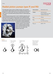
Radial piston pump<br />
Model R4<br />
Sizes 1.6 to 20, Series 3X<br />
Max. pressure up to 700 bar (10,000 PSI)<br />
Max. displacement to 19.43 cm 3 (1.19 in 3 )<br />
– Self-priming, check valve operated<br />
– 14 sizes, with overlapping displacements with varying<br />
pressure capacity<br />
– Hydro-dynamically lubricated bearings for long bearing life<br />
– Cylinder outlets can be connected in various <s<strong>tr</strong>ong>com</s<strong>tr</strong>ong> bi na tions<br />
Ordering code<br />
PR 4 – 3X / R A 12 M / *<br />
Series<br />
Series 30 to 39<br />
(30 to 39: installation and connection<br />
dimensions remain unchanged)<br />
Size<br />
Displacement<br />
1.51 cm 3 (0.092 in 3 )<br />
2.14 cm 3 (0.131 in 3 )<br />
2.59 cm 3 (0.158 in 3 )<br />
3.57 cm 3 (0.218 in 3 )<br />
4.32 cm 3 (0.264 in 3 )<br />
7.14 cm 3 (0.527 in 3 )<br />
8.63 cm 3 (0.207 in 3 )<br />
3.39 cm 3 (0.294 in 3 )<br />
5.83 cm 3 (0.356 in 3 )<br />
8.03 cm 3 (0.490 in 3 )<br />
16.07 cm 3 (0.981 in 3 )<br />
19.43 cm 3 (1.186 in 3 )<br />
(3)<br />
(3)<br />
(3)<br />
(5)<br />
(5)<br />
(10)<br />
(3)<br />
(3)<br />
(3)<br />
(5)<br />
(10)<br />
(10)<br />
= 3X<br />
Size–p max<br />
= 1.60 – 700<br />
= 2.00 – 700<br />
= 2.50 – 700<br />
= 3.15 – 700<br />
= 4.00 – 700<br />
= 8.00 – 700<br />
= 3.15 – 700<br />
= 5.00 – 500<br />
= 6.30 – 500<br />
= 8.00 – 500<br />
= 16.00 – 500<br />
= 20.00 – 500<br />
(3), (5), (10) ≈ Radial piston pump with 3, 5, 10 pistons<br />
A =<br />
Code No. of<br />
output<br />
ports<br />
01 1<br />
Further details to be<br />
written in clear text<br />
M = NBR – seals, suitable for mineral oil<br />
(HLP) pe<strong>tr</strong>oleum oils<br />
12 = SAE threaded outlet port<br />
parallel shaft end<br />
Pumps and Motors 21 Section 1
Elec<strong>tr</strong>ic Drives<br />
and Con<strong>tr</strong>ols<br />
<s<strong>tr</strong>ong>Hydraulics</s<strong>tr</strong>ong><br />
Linear Motion and<br />
Assembly Technologies Pneumatics Service<br />
Ex<strong>tr</strong>acted from RE 11263/03.05<br />
Page 2 of 2<br />
See Section 16 for applicable<br />
Issue: 07.05<br />
Preferred/Spotlight part numbers<br />
and unit price.<br />
Technical data<br />
Speed range rpm 1000 to 2000<br />
Operating pressure – inlet bar (PSIA) 0.8 to 2.5 absolute (12 to 35)<br />
Cylinder I.D. Ø 10 mm (0.394 in) Ø 15 mm (0.591 in)<br />
– outlet bar (PSI) 700 (10,150) 500 (7250)<br />
Max. torque (drive shaft) Nm (lb-ft) 160 (118)<br />
Mounting position<br />
optional<br />
Shaft loading<br />
radial- and axial forces may not be <strong>tr</strong>ansmitted<br />
Mounting<br />
face mounting<br />
Connection ports<br />
threaded ports<br />
Direction of rotation<br />
clockwise<br />
Fluid HLP mineral oils to DIN 51 524 part 2<br />
Also, please observe the fluid specifications in RA 07 075!<br />
Fluid temperature range °C (°F) –10 … +70 (14 … 158)<br />
Viscosity range mm 2 /s (SUS) 10 to 200 (45 … 930)<br />
Maximum permissible degree of contamination of fl uid to NAS 1638 Class 9.<br />
3 pistons 5 pistons 10 pistons<br />
Weight kg (lbs.) 6.8 (15) 8.6 (19) 12.7 (28)<br />
Pumps and Motors 22 Section 1
Elec<strong>tr</strong>ic Drives<br />
and Con<strong>tr</strong>ols<br />
<s<strong>tr</strong>ong>Hydraulics</s<strong>tr</strong>ong><br />
Linear Motion and<br />
Assembly Technologies Pneumatics Service<br />
Ex<strong>tr</strong>acted from RE 11260/08.05<br />
Page 1 of 2<br />
See Section 16 for applicable<br />
Issue: 06.04<br />
Preferred/Spotlight part numbers<br />
and unit price.<br />
Radial piston pump<br />
Model R4 mini<br />
Series 1X<br />
Operating pressure up to 700 bar (10,000 PSI)<br />
Sizes 0.40 to 2.00 mm 3 (0.024 to 0.122 in 3 )<br />
– Self-priming, valve con<strong>tr</strong>olled<br />
– Very low noise<br />
– High bearing life due to hydro-dynamically lubricated<br />
plain bearings<br />
– Very <s<strong>tr</strong>ong>com</s<strong>tr</strong>ong>pact design, therefore installation-friendly dimensions<br />
– Can be <s<strong>tr</strong>ong>com</s<strong>tr</strong>ong>bined with fi xed and variable displacement<br />
vane pumps<br />
– Five nominal sizes<br />
Ordering code<br />
PR4 – 1X / W 01 01 *<br />
Series<br />
Series 10 to 19<br />
(10 to 19: installation and connection<br />
dimensions remain unchanged)<br />
Size<br />
Displacement<br />
0.40 mm 3 (0.024 in 3 )<br />
0.63 mm 3 (0.038 in 3 )<br />
1.00 mm 3 (0.061 in 3 )<br />
1.60 mm 3 (0.098 in 3 )<br />
2.00 mm 3 (0.122 in 3 )<br />
Direction of rotation Counter- and clockwise<br />
Note: All fi ve sizes of pump have 3 pistons<br />
= 1X<br />
Size–pmax<br />
= 0.40 – 700<br />
= 0.63 – 700<br />
= 1.00 – 450<br />
= 1.60 – 250<br />
= 2.00 – 175<br />
= W<br />
G =<br />
A =<br />
01 =<br />
M =<br />
V =<br />
01 =<br />
Further details to be<br />
written in clear text<br />
Number of pressure ports<br />
1 pressure port<br />
NBR seals, suitable for mineral oil<br />
HLP to DIN 51 524, part 2<br />
FKM seals<br />
Suction and pressure ports<br />
Pipe threads to ISO 228/1<br />
Splined shaft end<br />
(for use as <s<strong>tr</strong>ong>com</s<strong>tr</strong>ong>bination pump with vane pumps)<br />
Cylinderical shaft end<br />
Pumps and Motors 23 Section 1
Elec<strong>tr</strong>ic Drives<br />
and Con<strong>tr</strong>ols<br />
<s<strong>tr</strong>ong>Hydraulics</s<strong>tr</strong>ong><br />
Linear Motion and<br />
Assembly Technologies Pneumatics Service<br />
Ex<strong>tr</strong>acted from RE 11260/07.02<br />
Page 2 of 2<br />
See Section 16 for applicable<br />
Issue: 06.04<br />
Preferred/Spotlight part numbers<br />
and unit price.<br />
Technical data<br />
Size mm 3 (in 3 ) 0.40 (0.024) 0.63 (0.038) 1.00 (0.061) 1.60 (0.098) 2.00 (0.122)<br />
Speed range rpm 1000–3400 1000–3000 1000–2000 1000–2000 1000–2000<br />
Operating pressure range<br />
Inlet (absolute)<br />
bar<br />
(PSI)<br />
0.80–1.5<br />
(11.6–21.8)<br />
0.80–1.5<br />
(11.6–21.8)<br />
0.80–1.5<br />
(11.6–21.8)<br />
0.80–1.5<br />
(11.6–21.8)<br />
0.80–1.5<br />
(11.6–21.8)<br />
Outlet (max. permissible)<br />
bar<br />
(PSI)<br />
700<br />
(10,000)<br />
700<br />
(10,000)<br />
450<br />
(6527)<br />
250<br />
(3626)<br />
175<br />
(2538)<br />
Installation<br />
Size: 0.024 in 3 – 10,000 PSI<br />
Horizontal: The suction port should lie vertically above the pressure port.<br />
This improves the bleeding of the pump<br />
Vertical: No limitation<br />
All other sizes have no installation limitations.<br />
Max. permissible torque (drive shaft) Nm (lb-ft) 10 (7.38)<br />
Shaft loading<br />
Radial and axial forces are not permitted.<br />
Mounting style<br />
Face mounting<br />
Pipe connections<br />
Threaded connections<br />
Direction of rotation<br />
Clockwise and counter-clockwise, does not affect the direction of fl ow<br />
Pressure fl uid<br />
HLP mineral oil to DIN 51 524 part 2, other pressure fl uid upon request.<br />
Also, please observe the fluid specifications in RA 07 075!<br />
Pressure fl uid temperature range °C (°F) –10 … +70 (14 … 158)<br />
Viscosity range mm 2 /s (SUS) 10 … 200 (45 … 930)<br />
Required fi l<strong>tr</strong>ation Maximum permissible degree of contamination of fl uid to NAS 1638 Class 9.<br />
Weight kg (lbs.) 2.6 (5.7)<br />
Pumps and Motors 24 Section 1
Elec<strong>tr</strong>ic Drives<br />
and Con<strong>tr</strong>ols<br />
<s<strong>tr</strong>ong>Hydraulics</s<strong>tr</strong>ong><br />
Linear Motion and<br />
Assembly Technologies Pneumatics Service<br />
Ex<strong>tr</strong>acted from 9 535 233 724/10.03<br />
Page 1 of 3<br />
See Section 16 for applicable<br />
Issue: 06.04<br />
Preferred/Spotlight part numbers<br />
and unit price.<br />
Vane pumps<br />
Model VPV<br />
Sizes 16 to 164, Pressure to 210 bar (3050 PSI)<br />
<s<strong>tr</strong>ong>Rexroth</s<strong>tr</strong>ong> is leading the way in advanced variable vane pump technol<br />
o gy.<br />
Market conditions favor hydraulic <s<strong>tr</strong>ong>com</s<strong>tr</strong>ong> po nents that operate at<br />
low noise levels without sacrifi cing effi ciency or durability while<br />
keeping pricing <s<strong>tr</strong>ong>com</s<strong>tr</strong>ong>petitive. VPV pumps feature an out stand ing<br />
response to the needs of the market today and for the future.<br />
– Flows from 30 to 287 L/min (7.6 to 75.8 GPM) in single pumps<br />
– Available in <s<strong>tr</strong>ong>com</s<strong>tr</strong>ong> bi na tion with other VPV pumps and<br />
<s<strong>tr</strong>ong>Rexroth</s<strong>tr</strong>ong> gear pumps<br />
– Through-drive horsepower <strong>tr</strong>ansfer is 100% to the<br />
second pump<br />
– VPV pumps are available with through shaft versions for<br />
quick <s<strong>tr</strong>ong>com</s<strong>tr</strong>ong>binations<br />
– Pressures to 210 bar (3050 PSI)<br />
– Continuous speeds from 1000 to 1800 rpm<br />
– Overall effi ciencies to 89%<br />
– A variety of fl uids can be used: mineral oil, phosphate ester,<br />
and en vi ron men tal ly friendly fl uids<br />
– Con<strong>tr</strong>ols include standard pressure <s<strong>tr</strong>ong>com</s<strong>tr</strong>ong> pen sa tion, remote<br />
pressure <s<strong>tr</strong>ong>com</s<strong>tr</strong>ong> pen sa tion, load sense, solenoid 2-pressure, and<br />
solenoid vented<br />
w SAE<br />
Size – in 3 /rev (cc/rev) 1.0 (16) 1.5 (25) 2.0 (32) 2.75 (45) 3.84 (63) 4.88 (80) 6.0 (100) 7.93 (130) 10.0 (164)<br />
Flow 1)<br />
L/min<br />
GPM<br />
30<br />
(7.6)<br />
43<br />
(11.4)<br />
57<br />
(15.1)<br />
79<br />
(20.8)<br />
110<br />
(29.1)<br />
140<br />
(37.0)<br />
172<br />
(45.4)<br />
227<br />
(60.0)<br />
287<br />
(75.8)<br />
Max. Pressure<br />
bar<br />
(PSI)<br />
210<br />
(3000)<br />
210<br />
(3000)<br />
210<br />
(3000)<br />
210<br />
(3000)<br />
210<br />
(3000)<br />
210<br />
(3000)<br />
210<br />
(3000)<br />
210<br />
(3000)<br />
Speed range<br />
1000 to 1800 rpm<br />
Mounting Flange to ISO 3019/1<br />
Mount Position<br />
Any<br />
Rotation<br />
RH<br />
Sound Pressure Level 2) 67 69 69 68 69 71 74 76 77<br />
1) 1750 rpm in GPM.<br />
2) dB(A) at 3000 PSI, 1750 rpm, full fl ow in a hemi-anechoic chamber with microphone placed 1 meter away at 7 discrete<br />
locations. Sound pressure levels are spacially and time weighted averaged.<br />
210<br />
(3000)<br />
Pumps and Motors 25 Section 1
Elec<strong>tr</strong>ic Drives<br />
and Con<strong>tr</strong>ols<br />
<s<strong>tr</strong>ong>Hydraulics</s<strong>tr</strong>ong><br />
Linear Motion and<br />
Assembly Technologies Pneumatics Service<br />
Ex<strong>tr</strong>acted from 9 535 233 724/10.03<br />
Page 2 of 3<br />
See Section 16 for applicable<br />
Issue: 06.04<br />
Preferred/Spotlight part numbers<br />
and unit price.<br />
VPV “Whisper Pumps” <br />
Size in3/rev<br />
(cc/rev)<br />
Mount<br />
Maximum<br />
Pressure<br />
bar (PSI)<br />
L/min (GPM)<br />
@ 1750<br />
Rotation Description Matl. No.<br />
Weight<br />
kg (lbs)<br />
1.00 (16) SAE A 210 (3050) 30 (7.6) R 0513R18C3VPV16SM21HYB03 0 513 300 212 17.7 (39.0)<br />
1.00 (16) SAE A 210 (3050) 30 (7.6) R 0513R18C3VPV16SM21HYB03P1 0 513 300 246 20.9 (46.0)<br />
1.50 (25) SAE B 210 (3050) 43 (11.4) R 0513R18C3VPV25SM21HYB03 0 513 400 212 30.4 (67.0)<br />
1.50 (25) SAE B 210 (3050) 43 (11.4) R 0513R18C3VPV25SM21HYB03P1 0 513 400 248 33.6 (74.0)<br />
2.00 (32) SAE B 210 (3050) 57 (15.1) R 0513R18C3VPV32SM21HYB03 0 513 500 220 30.4 (67.0)<br />
2.00 (32) SAE B 210 (3050) 57 (15.1) R 0513R18C3VPV32SM21HYB03P1 0 513 500 254 33.7 (74.0)<br />
2.75 (45) SAE C 210 (3050) 79 (20.8) R 0513R18C3VPV45SM21HYB05 0 513 600 214 57.6 (127.0)<br />
2.75 (45) SAE C 210 (3050) 79 (20.8) R 0513R18C3VPV45SM21HYB05P1 0 513 600 234 61.2 (135.0)<br />
3.84 (63) SAE C 210 (3050) 110 (29.1) R 0513R18C3VPV63SM21HYB05 0 513 700 218 57.6 (127.0)<br />
3.84 (63) SAE C 210 (3050) 110 (29.1) R 0513R18C3VPV63SM21HYB05P1 0 513 700 242 61.2 (135.0)<br />
4.88 (80) SAE C 210 (3050) 140 (37.0) R 0513R18C3VPV80SM21HYB05 0 513 800 248 57.6 (127.0)<br />
4.88 (80) SAE C 210 (3050) 140 (37.0) R 0513R18C3VPV80SM21HYB05P1 0 513 800 238 61.2 (135.0)<br />
6.00 (100) SAE D 210 (3050) 172 (45.4) R 0513R18C3VPV100SM21HYB04 0 513 850 216 111.1 (245.0)<br />
6.00 (100) SAE D 210 (3050) 172 (45.4) R 0513R18C3VPV100SM21HYB04P1 0 513 850 214 115.7 (255.0)<br />
7.93 (130) SAE D 210 (3050) 227 (60.0) R 0513R18C3VPV130SM21HYB04 0 513 860 250 111.1 (245.0)<br />
7.93 (130) SAE D 210 (3050) 227 (60.0) R 0513R18C3VPV130SM21HYB04P1 0 513 860 258 115.7 (255.0)<br />
10.0 (164) SAE D 210 (3050) 287 (75.8) R 0513R18C3VPV164SM21HYB04 0 513 870 226 111.1 (245.0)<br />
10.0 (164) SAE D 210 (3050) 287 (75.8) R 0513R18C3VPV164SM21HYB04P1 0 513 870 216 115.7 (255.0)<br />
See catalog #9 535 233 724 for <s<strong>tr</strong>ong>com</s<strong>tr</strong>ong>plete description and performance specifi cations.<br />
Adaptor Kits for Combinations Old Number Matl. No.<br />
VPV 16 to VPV 16 SAE 9 511 230 518 9 511 230 518<br />
VPV 16 to “F” Gear Pump SAE Key 9 511 230 521 R978711779<br />
VPV 25/32 to VPV 25/32 SAE 9 511 230 523 9 511 230 523<br />
VPV 25/32 to VPV 16 SAE 9 511 230 525 9 511 230 525<br />
VPV 45/63/80 to VPV 45/63/80 SAE 9 511 230 528 9 511 230 528<br />
VPV 45/63/80 to VPV 16 SAE 9 511 230 532 9 511 230 532<br />
VPV 45/63/80 to VPV 25/32 9 511 230 530 9 511 230 530<br />
VPV 45/63/80 to “F” Gear Pump SAE Key 9 511 230 533 R978711781<br />
VPV 45/63/80 to “G” Gear Pump SAE Key 9 511 230 534 R978711782<br />
VPV 100/130/164 to VPV 100/130/164 9 511 230 536 9 511 230 536<br />
VPV 100/130/164 to VPV 45/63/80 9 511 230 538 9 511 230 538<br />
VPV 100/130/164 to VPV 25/32 9 511 230 540 9 511 230 540<br />
VPV 100/130/164 to VPV 16 9 511 230 542 9 511 230 542<br />
VPV 100/130/164 to “F” Gear Pump SAE Key 9 511 230 543 R978711783<br />
VPV 100/130/164 to “G” Gear Pump SAE Key 9 511 230 594 R978711808<br />
See catalog #9 535 233 724 for <s<strong>tr</strong>ong>com</s<strong>tr</strong>ong>plete description and performance specifi cations.<br />
Pumps and Motors 26 Section 1
Elec<strong>tr</strong>ic Drives<br />
and Con<strong>tr</strong>ols<br />
<s<strong>tr</strong>ong>Hydraulics</s<strong>tr</strong>ong><br />
Linear Motion and<br />
Assembly Technologies Pneumatics Service<br />
Ex<strong>tr</strong>acted from 9 535 233 724/10.03<br />
Page 3 of 3<br />
See Section 16 for applicable<br />
Issue: 06.04<br />
Preferred/Spotlight part numbers<br />
and unit price.<br />
VPV “Whisper Pumps” TM (continued)<br />
Pump Repair Kits SAE 210 bar (3050 PSI) Old Number Matl. No.<br />
VPV 16 Standard Pump 9 511 230 606 R978711812<br />
VPV 16 “P1” Pump 9 511 230 608 R978711814<br />
VPV 25/32 Standard Pump 9 511 230 598 R978711809<br />
VPV 25/32 “P1” Pump 9 511 230 623 R978711825<br />
VPV 45/63 Standard Pump 9 511 230 639 R978711838<br />
VPV 45/63 “P1” Pump 9 511 230 642 R978711841<br />
VPV 80 Standard Pump 9 511 230 641 R978711840<br />
VPV 80 “P1” Pump 9 511 230 643 R978711842<br />
VPV 100/130 Standard Pump 9 511 230 650 R978711849<br />
VPV 100/130 “P1” Pump 9 511 230 652 R978711851<br />
VPV 164 Standard Pump 9 511 230 651 R978711850<br />
VPV 164 “P1” Pump 9 511 230 653 R978711852<br />
Seal Kits for VPV SAE Old Number Material No.<br />
VPV 16 9 511 230 605 9 511 230 605<br />
VPV 25/32 9 511 230 597 9 511 230 597<br />
VPV 45/63/80 9 511 230 658 9 511 230 658<br />
VPV 100/130/164 9 511 230 659 9 511 230 659<br />
See catalog #9 535 233 724 for <s<strong>tr</strong>ong>com</s<strong>tr</strong>ong>plete description and performance specifi cations.<br />
Pumps and Motors 27 Section 1
Elec<strong>tr</strong>ic Drives<br />
and Con<strong>tr</strong>ols<br />
<s<strong>tr</strong>ong>Hydraulics</s<strong>tr</strong>ong><br />
Linear Motion and<br />
Assembly Technologies Pneumatics Service<br />
Ex<strong>tr</strong>acted from RE 15 205/02.98<br />
Page 1 of 5<br />
See Section 16 for applicable<br />
Issue: 06.06<br />
Preferred/Spotlight part numbers<br />
and unit price.<br />
Hydraulic motor<br />
Radial piston, low speed, high torque<br />
Model MCR 03<br />
Sizes 160 to 400<br />
Series 3X<br />
Maximum operating pressure 6500 psi (450 bar)<br />
Maximum displacement volume 24.4 in 3 (400 cm 3 )<br />
Maximum output torque 1702 lb-ft (2307 Nm)<br />
– Compact, sturdy cons<strong>tr</strong>uction<br />
– Smooth running even at very low speeds<br />
– Low noise<br />
– Reversible<br />
– Sealed taper roller bearings<br />
– High radial forces permitted on the output shaft<br />
– Shaft seal up to 10 bar<br />
– Freewheeling<br />
– Available with optional built-on holding (multi-disc) brake<br />
or dynamic (drum) brake<br />
Function<br />
Closed circuit<br />
Minimum inlet pressure must be adapted to suit operating conditions;<br />
the following must be taken into consideration:<br />
Idling pressure. flow resistances. pump operation.<br />
Minimum flow of the feed pump must be adapted to suit operating<br />
conditions.<br />
Open circuit<br />
Minimum inlet pressure must be adapted to suit operating conditions;<br />
the following must be taken into consideration:<br />
Idling pressure. flow resistances. pump operation.<br />
The outlet pressure must be at least 2 bar greater than the pressure<br />
in the housing.<br />
Note: If the motor circuits are in series please consult the<br />
manufacturer.<br />
Pumps and Motors 28 Section 1
Elec<strong>tr</strong>ic Drives<br />
and Con<strong>tr</strong>ols<br />
<s<strong>tr</strong>ong>Hydraulics</s<strong>tr</strong>ong><br />
Linear Motion and<br />
Assembly Technologies Pneumatics Service<br />
Ex<strong>tr</strong>acted from RE 15 205/02.98<br />
Page 2 of 5<br />
See Section 16 for applicable<br />
Issue: 06.06<br />
Preferred/Spotlight part numbers<br />
and unit price.<br />
Ordering code<br />
MCR 03 Z – 3X / M / *<br />
Frame size<br />
Size 3 = 03<br />
Flange housing<br />
Compact version<br />
= A<br />
Flange motor<br />
= D<br />
Wheel motor<br />
= F<br />
Hydrobase<br />
= H<br />
Nominal size, displacement V<br />
Size 160 = 160 cm 3 = 160<br />
Size 225 = 225 cm 3 = 225<br />
Size 255 = 255 cm 3 = 255<br />
Size 280 = 280 cm 3 = 280<br />
Size 325 = 325 cm 3 = 325<br />
Size 365 = 365 cm 3 = 365<br />
Size 400 = 400 cm 3 = 400<br />
Single shaft end<br />
Splined to DIN 5480 = W40 1<br />
)<br />
Parallel with key Ø 40 mm = L40 2<br />
)<br />
With flange Ø 172 mm = F180 3 )<br />
Without 2nd shaft end<br />
= Z<br />
1<br />
) only with flange housing A maximum torque 1500 Nm<br />
2<br />
) only with flange housing D maximum torque 1500 Nm<br />
3<br />
) only with flange housing F<br />
M =<br />
further information<br />
in clear text<br />
Wheel stud<br />
No code = without wheel stud<br />
/S = with wheel stud<br />
Ports<br />
01 = pipe thread to ISO 228/1<br />
12 = UNF-SAE-thread<br />
No code =<br />
2W =<br />
Two speed operation<br />
not switchable<br />
switchable operation<br />
Seals<br />
NBR seals suitable for mineral oil to<br />
DIN 51 524 (HL,HLP)<br />
(except dynamic brake see p.10)<br />
Brake mounting<br />
A0 = without brake<br />
B2 = hydraulic release holding brake<br />
(spring pressure disc brake)<br />
3<br />
) C2R = dynamic brake (drum brake)<br />
for right hand side of vehicle (see Fig., p.10)<br />
3<br />
) C2L = dynamic brake (drum brake)<br />
for left hand side of vehicle (see Fig., p.10)<br />
Series<br />
3X = Series 32 to 39<br />
(30 to 39: externally interchangeable)<br />
Pumps and Motors 29 Section 1
Elec<strong>tr</strong>ic Drives<br />
and Con<strong>tr</strong>ols<br />
<s<strong>tr</strong>ong>Hydraulics</s<strong>tr</strong>ong><br />
Linear Motion and<br />
Assembly Technologies Pneumatics Service<br />
Ex<strong>tr</strong>acted from RE 15 205/02.98<br />
Page 3 of 5<br />
See Section 16 for applicable<br />
Issue: 06.06<br />
Preferred/Spotlight part numbers<br />
and unit price.<br />
Technical data (For applications outside these parameters please consult us)<br />
Description<br />
Radial piston multi-disc motor with fi xed displacement<br />
Frame size MCR 03...<br />
Type of mounting<br />
Flange mounting; face mounting<br />
Cable connections<br />
Threaded or fl anged<br />
Mounting position<br />
Optional<br />
Shaft load See page 7<br />
Direction of rotation<br />
Right/left – reversible<br />
Frame size 3<br />
Nominal size 160 225 255 280 325 365 400<br />
Displacement volume V cm 3 160 225 255 280 325 365 400<br />
Flow at n =100 rpm/100bar q V L/min 16 22.5 25.5 28 32.5 36.5 40<br />
Output torque 1; 7 )<br />
– specifi c torque (at Δp = 100 bar) T Nm 225 358 405 445 517 580 636<br />
– peak torque T Nm 1022 1386 1570 1760 1875 2105 2307<br />
Output speed 1; 7 )<br />
– min. speed n rpm 5 to 10 when running smooth, dependent on application<br />
– max. continuous speed n rpm 320 320 280 260 240 240 240<br />
– max. peak speed n rpm 400 400 360 330 310 280 260<br />
– freewheeling speed n rpm 900<br />
Output power 1; 7 )<br />
– continuous power P kW 18 18 18 18 22 22 22<br />
– cont. power half displacement P kW 12 12 12 12 14 14 14<br />
Weight see unit dimensions pages 8 to 10<br />
Polar moment of inertia J m kgmm 2 see unit dimensions pages 8 to 10 (rotating mass only)<br />
Hydraulic<br />
Nominal pressure p bar 250<br />
Pressure differential, fi xed 2; 6 )<br />
Δp<br />
– with mineral oil (HL, HLP)<br />
Pressure differential, peak 3; 6 )<br />
Δp<br />
bar 250<br />
– with mineral oil (HL, HLP)<br />
bar 450 400<br />
Inlet pressure 6 ) Port “A” or “B” p bar 450 420 400<br />
Summated pressure 4; 6 ) Port “A” + “B” p bar 450 420 400<br />
Case drain pressure max. p bar 10<br />
Hydraulic fl uid 5 ) Mineral oil (HL, HLP) to DIN 51 524<br />
Hydraulic fl uid temperature range ϑ °C – 20 to +80<br />
Viscosity range ν mm 2 /s 10 to 2000<br />
Fluid cleanliness Max. degree of contamination of the fl uid to NAS 1638 class 9.<br />
We re<s<strong>tr</strong>ong>com</s<strong>tr</strong>ong>mend a fi lter with a min retention rate of ß 10 ≥ 75.<br />
Brake<br />
Holding brake (disc brake)<br />
Holding torque T Nm 2200<br />
Release pressure p bar min. 15; max. 30<br />
volume to operate brake V cm 3 23<br />
1<br />
) The data given apply after 100 hours running-in time<br />
2<br />
) Continuous operation<br />
3<br />
) Peak values may occur for a maximum duration of one second<br />
within an operating minute.<br />
4<br />
) In the return line we re<s<strong>tr</strong>ong>com</s<strong>tr</strong>ong>mend p min = 15 ba 5 ) Environmentally<br />
friendly fl uids HETG. HEPG. HEE to RE 90 221<br />
6<br />
) For connection in series. consult the technical sales department.<br />
7<br />
) Warning! During the running-in time of the motor (min. 20 hours)<br />
motors should not be run unloaded at greater than 50% of<br />
maximum speed.<br />
Pumps and Motors 30 Section 1
Elec<strong>tr</strong>ic Drives<br />
and Con<strong>tr</strong>ols<br />
<s<strong>tr</strong>ong>Hydraulics</s<strong>tr</strong>ong><br />
Linear Motion and<br />
Assembly Technologies Pneumatics Service<br />
Ex<strong>tr</strong>acted from RE 15 205/02.98<br />
Page 4 of 5<br />
See Section 16 for applicable<br />
Issue: 06.06<br />
Preferred/Spotlight part numbers<br />
and unit price.<br />
Technical data (Mean values, measured at ν = 46 mm 2 /s and ϑ = 45 °C)<br />
Pressure<br />
diff.<br />
Δp in bar<br />
Speed n in rpm<br />
Speed n in rpm<br />
0 25 50 100 200 300 320 0 25 50 100 150 200 240<br />
MCR 03 . 160 MCR 03. 325<br />
T Nm 147 214 219 224 222 213 208 284 447 467 452 429 412<br />
100 q L/min 0.3 4.3 8.3 16.3 32.6 48.7 52.0 0.8 8.9 17.1 33.3 49.6 66.0 79.0<br />
q VL L/min 0.15 0.15 0.15 0.15 0.30 0.35 0.40 0.40 0.40 0.40 0.40 0.40 0.50 0.50<br />
T Nm 321 438 453 463 463 672 917 952 952 937<br />
200 q L/min 0.3 4.3 8.3 16.6 32.8 2.0 10.1 18.3 34.5 51.2<br />
q VL L/min 0.15 0.15 0.15 0.30 0.40 1.00 1.00 1.00 1.00 1.20<br />
T Nm 519 659 680 695 1086 1397 1432 1440<br />
300 q L/min 0.4 4.4 8.4 16.8 3.6 11.3 19.5 35.9<br />
q VL L/min 0.20 0.20 0.20 0.40 1.80 1.60 1.60 1.70<br />
T Nm 693 876 908 926 1489 1875<br />
400 q L/min 0.6 4.6 8.8 17.0 4.4 12.1<br />
q VL L/min 0.30 0.30 0.40 0.5 2.20 2.00<br />
T Nm 779 985 1022<br />
450 q L/min 1.0 5.4 9.8<br />
q VL L/min 0.5 0.7 0<br />
Charge pressure p bar 1 2 2 3 6 9 10 1 2 3 4 6 8 10<br />
Pressure<br />
Speed n in rpm<br />
Speed n in rpm<br />
diff.<br />
0 25 50 100 150 220 0 25 50 100 150 200 240<br />
Δp in bar<br />
MCR 03 . 225 MCR 03 . 365<br />
T Nm 215 308 315 322 318 305 320 503 524 507 495 483 462<br />
100 q L/min 0.3 5.9 11.6 22.8 45.6 68.2 0.8 9.9 19.1 37.3 55.6 74.0 88.6<br />
q VL L/min 0.15 0.15 0.15 0.15 0.3 0.35 0.4 0.4 0.4 0.4 0.4 0.5 0.5<br />
T L/min 466 630 651 666 651 755 1030 1069 1068 1053<br />
200 q L/min 0.3 5.9 11.6 23.1 45.8 2.0 11.1 20.3 38.5 57.2<br />
q VL L/min 0.15 0.15 0.15 0.3 0.4 1.0 1.0 1.0 1.0 1.2<br />
T Nm 752 946 978 999 1219 1570 1609 1617<br />
300 q L/min 0.4 6.0 11.7 23.3 3.6 12.3 21.5 39.9<br />
q VL L/min 0.20 0.20 0.20 0.40 1.80 1.60 1.60 1.70<br />
T Nm 1003 1261 1304 1673 2105<br />
400 q L/min 0.6 6.2 12.1 4.4 13.1<br />
q VL L/min 0.3 0.3 0.4 2.2 2.0<br />
T Nm 1128 1386<br />
450 q L/min 1.0 7.0<br />
q VL L/min 0.5 0.7<br />
– All torques given apply to run-in motors (see page 4. footnote 7 of <s<strong>tr</strong>ong>com</s<strong>tr</strong>ong>plete data sheet.)<br />
– For “half displacement” operating mode multiply the torques and Q–values by 0.5.<br />
– For maximum case leakage multiply Q L by 2<br />
T = torque in Nm<br />
Q = input flow in L/min<br />
Q L = mean case leakage in L/min<br />
p = min. charge pressure in pump mode<br />
Pumps and Motors 31 Section 1
Elec<strong>tr</strong>ic Drives<br />
and Con<strong>tr</strong>ols<br />
<s<strong>tr</strong>ong>Hydraulics</s<strong>tr</strong>ong><br />
Linear Motion and<br />
Assembly Technologies Pneumatics Service<br />
Ex<strong>tr</strong>acted from RE 15 205/02.98<br />
Page 5 of 5<br />
See Section 16 for applicable<br />
Issue: 06.06<br />
Preferred/Spotlight part numbers<br />
and unit price.<br />
Technical data (Mean values, measured at ν = 46 mm 2 /s and ϑ = 45 °C)<br />
Charge pressure p bar 1 2 2 3 6 9 1 3 3 5 6 9 11<br />
Pressure<br />
Speed n in rpm<br />
Speed n in rpm<br />
diff.<br />
0 25 50 100 150 220 0 25 50 100 150<br />
Δp in bar<br />
MCR 03 . 255 MCR 03 . 400<br />
T Nm 239 342 350 358 354 338 350 551 575 556 543 529 506<br />
100 q L/min 0.4 6.8 13.2 25.9 51.8 72.4 0.8 10.8 20.8 40.8 60.8 81.0 97.0<br />
q VL L/min 0.2 0.2 0.2 0.2 0.4 0.5 0.4 0.4 0.4 0.4 0.4 0.5 0.5<br />
T Nm 517 700 724 740 724 828 1129 1171 1171 1153<br />
200 q L/min 0.4 6.8 13.2 26.3 52.2 2.0 12.0 22.0 42.0 62.4<br />
q VL L/min 0.2 0.2 0.2 0.4 0.6 1.0 1.0 1.0 1.0 1.20<br />
T Nm 836 1051 1087 1110 1337 1721 1762 1772<br />
300 q L/min 0.6 7.0 13.4 26.7 3.6 13.2 23.2 43.4<br />
q VL L/min 0.3 0.3 0.3 0.6 1.8 1.6 1.6 1.7<br />
T Nm 1114 1401 1449 1834 2307<br />
400 q L/min 0.8 7.2 14.0 4.4 14.0<br />
q VL L/min 0.4 0.4 0.6 2.20 2.00<br />
T Nm 1253 1575<br />
450 q L/min 1.6 8.4<br />
q VL L/min 0.8 1.0<br />
Charge pressure p bar 1 2 2 4 6 9 1 3 3 5 6 9 11<br />
Pressure<br />
Speed n in rpm<br />
diff.<br />
0 25 50 100 200 300<br />
Δp in bar<br />
MCR 03. 280<br />
T Nm 287 383 392 401 397 365<br />
100 q L/min 0.6 7.6 14.6 28.6 56.8 85.0<br />
q VL L/min 0.30 0.30 0.30 0.30 0.40 0.50<br />
T L/min 579 784 811 829 811<br />
200 q L/min 0.6 7.6 14.6 28.8 57.2<br />
q VL L/min 0.30 0.30 0.30 0.40 0.60<br />
T Nm 936 1177 1217 1243<br />
300 q L/min 0.6 7.6 14.6 29.2<br />
q VL L/min 0.30 0.30 0.30 0.60<br />
T Nm 1248 1569 1623<br />
400 q L/min 0.8 7.8 15.2<br />
q VL L/min 0.40 0.40 0.60<br />
T Nm 1404 1764<br />
450 q L/min 1.6 9.0<br />
q VL L/min 0.8 1.0<br />
Charge pressure p bar 1 2 2 4 7 10<br />
– All torques given apply to run-in motors (see page 4. footnote 7 of <s<strong>tr</strong>ong>com</s<strong>tr</strong>ong>plete data sheet.)<br />
– For “half displacement” operating mode multiply the torques and Q–values by 0.5.<br />
– For maximum case leakage multiply Q L by 2<br />
T = torque in Nm<br />
Q = input flow in L/min<br />
Q L = mean case leakage in L/min<br />
p = min. charge pressure in pump mode<br />
Pumps and Motors 32 Section 1
Elec<strong>tr</strong>ic Drives<br />
and Con<strong>tr</strong>ols<br />
<s<strong>tr</strong>ong>Hydraulics</s<strong>tr</strong>ong><br />
Linear Motion and<br />
Assembly Technologies Pneumatics Service<br />
Ex<strong>tr</strong>acted from RE 15 206/02.98<br />
Page 1 of 4<br />
See Section 16 for applicable<br />
Issue: 06.06<br />
Preferred/Spotlight part numbers<br />
and unit price.<br />
Hydraulic motor<br />
Radial piston, low speed, high torque<br />
Model MCR 05<br />
Sizes 380 to 820<br />
Series 3X<br />
Maximum operating pressure 6500 psi (450 bar)<br />
Maximum displacement volume 50 in 3 (820 cm 3 )<br />
Maximum output torque 3573 lb-ft (4844 Nm)<br />
– Compact, sturdy cons<strong>tr</strong>uction<br />
– Smooth running even at very low speeds<br />
– Low noise<br />
– Reversible<br />
– Sealed taper roller bearings<br />
– High radial forces permitted on the output shaft<br />
– Shaft seal up to 10 bar<br />
– Freewheeling<br />
– Available with optional built-on holding (multi-disc) brake<br />
or dynamic (drum) brake<br />
Model MCR 05 C...F180Z-3X/B4M/..<br />
Function<br />
Closed circuit<br />
Minimum inlet pressure must be adapted to suit operating conditions;<br />
the following must be taken into consideration:<br />
Idling pressure. flow resistances. pump operation.<br />
Minimum flow of the feed pump must be adapted to suit operating<br />
conditions.<br />
Open circuit<br />
Minimum inlet pressure must be adapted to suit operating conditions;<br />
the following must be taken into consideration:<br />
Idling pressure. flow resistances. pump operation.<br />
The outlet pressure must be at least 2 bar greater than the pressure<br />
in the housing.<br />
Note: If the motor circuits are in series please consult the<br />
manufacturer.<br />
Pumps and Motors 33 Section 1
Elec<strong>tr</strong>ic Drives<br />
and Con<strong>tr</strong>ols<br />
<s<strong>tr</strong>ong>Hydraulics</s<strong>tr</strong>ong><br />
Linear Motion and<br />
Assembly Technologies Pneumatics Service<br />
Ex<strong>tr</strong>acted from RE 15 206/02.98<br />
Page 2 of 4<br />
See Section 16 for applicable<br />
Issue: 06.06<br />
Preferred/Spotlight part numbers<br />
and unit price.<br />
Ordering code<br />
MCR 05 Z – 3X / M / *<br />
Frame size<br />
Size 05 = 05<br />
Flange housing<br />
Short motor<br />
= A<br />
Compact version<br />
= C<br />
Flange motor<br />
= D<br />
Wheel motor<br />
= F<br />
Hydrobase<br />
= H<br />
Nominal size, displacement V<br />
Size 380 = 380 cm 3 = 380<br />
Size 470 = 470 cm 3 = 470<br />
Size 520 = 520 cm 3 = 520<br />
Size 565 = 565 cm 3 = 565<br />
Size 680 = 680 cm 3 = 680<br />
Size 750 = 750 cm 3 = 750<br />
Size 820 = 820 cm 3 = 820<br />
Single shaft end<br />
Splined to DIN 5480 = W50 1<br />
)<br />
Parallel with key Ø 50 mm = L50 2<br />
)<br />
With flange Ø 180 mm = F180 3 )<br />
Without shaft = Z 5<br />
)<br />
Without 2nd shaft end<br />
= Z<br />
1<br />
) only with flange housing A maximum torque 3000 Nm<br />
2<br />
) only with flange housing D maximum torque 3000 Nm<br />
3<br />
) only with flange housing C or F<br />
4<br />
) only with flange housing F<br />
5<br />
) only with Hydrobase<br />
Further information<br />
in clear text<br />
Wheel stud<br />
No code = without wheel stud<br />
/S = with wheel stud<br />
Ports<br />
01 = Pipe thread to ISO 228/1<br />
12 = UNF-SAE-thread<br />
Two speed operating<br />
No code =<br />
not switchable<br />
2W =<br />
switchable operation<br />
Seals<br />
M = NBR seals suitable for mineral oil to<br />
DIN 51 524 (HL,HLP)<br />
(except drum brake see p.12)<br />
Brake mounting<br />
A0 = without brake<br />
B4 = hydraulic release holding brake<br />
(spring pressure disc brake)<br />
4<br />
) C4R = dynamic brake (drum brake)<br />
for right hand side of vehicle (see Fig., p.12)<br />
4<br />
) C4L = <strong>tr</strong>avel brake (drum brake)<br />
for left hand side of vehicle (see Fig., p.12)<br />
Series<br />
3X = Series 32 to 39<br />
(30 to 39: externally interchangeable)<br />
Pumps and Motors 34 Section 1
Elec<strong>tr</strong>ic Drives<br />
and Con<strong>tr</strong>ols<br />
<s<strong>tr</strong>ong>Hydraulics</s<strong>tr</strong>ong><br />
Linear Motion and<br />
Assembly Technologies Pneumatics Service<br />
Ex<strong>tr</strong>acted from RE 15 206/02.98<br />
Page 3 of 4<br />
See Section 16 for applicable<br />
Issue: 06.06<br />
Preferred/Spotlight part numbers<br />
and unit price.<br />
Technical data (For applications outside these parameters please consult us!)<br />
Radial piston multi-disc motor with fi xed displacement<br />
Frame size MCR 05...<br />
Type of mounting<br />
Flange mounting; face mounting<br />
Pipe connections<br />
Threaded or fl anged<br />
Mounting position<br />
optional<br />
Shaft loading see page 7<br />
Direction of rotation<br />
Right/left - reversible<br />
Frame size 05<br />
Nominal size 380 470 520 565 680 750 820<br />
Displacement V cm 3 380 470 520 565 680 750 820<br />
Flow at n = 100 rpm/100 bar q V L/min 38 47 52 56.5 70 77 84<br />
Output torque 1; 7 )<br />
– specifi c torque (at Δp = 100 bar) T Nm 604 748 827 899 1082 1194 1305<br />
– peak torque T Nm 2528 3127 3459 3759 4017 4430 4844<br />
Output speed 1; 7 )<br />
– min. speed n rpm 5 to 10 when running smoothly, dependent on application<br />
– max. speed n rpm 220 220 220 220 200 170 150<br />
– freewheeling speed n rpm 600<br />
Output power 1; 7 )<br />
– cont. power at full displacenent P kW 29 29 29 29 35 35 35<br />
– cont. power at half displacement P kW 19 19 19 19 23 23 23<br />
Weight m kg see unit dimensions pages 8 to 12<br />
Polar moment of inertia J m kgmm 2 see unit dimensions pages 8 to 12<br />
Hydraulic<br />
Nominal pressure p bar 250<br />
Pressure differential, cont. 2; 3 )<br />
Δp<br />
– with mineral oil (HL, HLP)<br />
Pressure differential, peak 4; 3 )<br />
Δp<br />
bar 250<br />
– with mineral oil (HL, HLP)<br />
bar 450 400<br />
Inlet pressure Port “A” or “B” p bar 470 420<br />
Summated pressure 5; 3 ) ports “A” + “B” p bar 470 420<br />
Case drain pressure,max p bar 10<br />
Hydraulic fl uid 6 ) Mineral oils (HL, HLP) to DIN 51 524<br />
Hydraulic fl uid temperature range ϑ °C – 20 to +80<br />
Viscosity range ν mm 2 /s 10 to 2000<br />
Fluid cleanliness Maximum degree of contamination of the fl uid to NAS 1638<br />
class 9. We therefore re<s<strong>tr</strong>ong>com</s<strong>tr</strong>ong>mend a fi lter with a minimum<br />
retention rate of ß 10 ≥ 75.<br />
Brake<br />
Holding brake (disc brake) B2 B4<br />
Holding torque T Nm 2200 5000<br />
Release pressure, min – max p bar 15 – 30 15 – 30<br />
Volume to operate brake V cm 3 23 46<br />
1<br />
) The data given apply after 100 hours running-in time<br />
2<br />
) Continuous operation<br />
3<br />
) Peak values may occur for a maximum duration of one second<br />
within an operating minute.<br />
4<br />
) In the return line we re<s<strong>tr</strong>ong>com</s<strong>tr</strong>ong>mend p min = 15 bar<br />
5<br />
) Environmentally friendly fl uids HETG. HEPG. HEE to RE 90 221<br />
6<br />
) For connection in series. consult the technical sales department.<br />
7<br />
) Warning! During the running-in time of the motor (min. 20<br />
hours) motors should not be run unloaded at greater than 50% of<br />
maximum speed.<br />
Pumps and Motors 35 Section 1
Elec<strong>tr</strong>ic Drives<br />
and Con<strong>tr</strong>ols<br />
<s<strong>tr</strong>ong>Hydraulics</s<strong>tr</strong>ong><br />
Linear Motion and<br />
Assembly Technologies Pneumatics Service<br />
Technical data (Mean values, measured at ν = 46 mm 2 /s and ϑ = 45 °C)<br />
Pressure<br />
Speed n in rpm<br />
Speed n in rpm<br />
diff.<br />
0 25 50 100 150 220 0 25 50 100 150 220<br />
Δp in bar<br />
MCR 05 . 380 MCR 05. 680<br />
T Nm 393 513 538 544 525 507 5.95 989 995 908 821 698<br />
100 q V L/min 0.3 9.8 19.3 38.6 57.7 84.4 0.88 17.64 34.93 70.01 102.76 139.54<br />
q V L L/min 0.15 0.15 0.15 0.30 0.35 0.40 0.44 0.47 0.50 0.57 0.64 0.64<br />
T Nm 846 1075 1123 1111 1087 1407 1938 2017 1973 1862<br />
200 q V L/min 0.7 10.2 19.7 38.9 58.0 2.4 18.55 36.09 72.17 103.61<br />
q VL L/min 0.35 0.35 0.35 0.45 0.50 1.20 1.22 1.24 1.30 1.41<br />
T Nm 1268 1613 1685 1667 2338 2964 3026 3013<br />
300 q V L/min 0.9 10.4 19.9 39.2 3.7 19.24 36.82 71.98<br />
q VL L/min 0.45 0.45 0.45 0.60 1.85 1.91 1.97 2.14<br />
T Nm 1691 2150 2247 3116 3939 4017<br />
400 q V L/min 1.5 11.0 20.5 4.34 19.91 38.18<br />
q VL L/min 0.75 0.75 0.75 2.17 2.35 2.33<br />
T Nm 1903 2419 2528<br />
450 q V L/min 2.2 11.7 21.2<br />
q VL L/min 1.1 1.1 1.1<br />
Charge pressure p bar 1 4 4 6 9 14 1 2 3 7 12 23<br />
Speed n rpm 0 25 50 100 150 220 0 25 50 100 150<br />
MCR 05 . 470 MCR 05 . 750<br />
T Nm 484 632 662 670 647 625 657 1091 1098 1002 906<br />
100 q V L/min 0.40 12.2 23.9 47.8 71.5 105.0 0.88 19.39 38.43 77.01 113.26<br />
q V L L/min 0.20 0.20 0.20 0.40 0.50 0.80 0.44 0.47 0.50 0.57 0.64<br />
T L/min 1042 1324 1384 1369 1339 1551 2137 2224 2176<br />
200 q V L/min 0.80 12.6 24.3 48.2 71.9 2.40 20.30 39.59 79.17<br />
q V L L/min 0.40 0.40 0.40 0.60 0.70 1.20 1.22 1.24 1.30<br />
T Nm 1562 1986 2076 2053 2578 3270 3338<br />
300 q V L/min 1.2 13.0 24.7 48.6 3.7 20.99 40.32<br />
q V L L/min 0.60 0.60 0.60 0.80 1.85 1.91 1.97<br />
T Nm 2083 2649 2768 3438 4345 4430<br />
400 q V L/min 2.0 13.8 25.5 4.34 21.66 41.73<br />
q V L L/min 1.0 1.0 1.0 2.17 2.35 2.37<br />
T Nm 2344 2980 3114<br />
450 q V L/min 3.0 14.8 26.5<br />
q V L L/min 1.5 1.5 1.5<br />
Charge pressure p bar 1 5 5 7 10 16 1 3 4 9 15<br />
Speed n min -1 0 25 50 100 150 220 0 25 50 100 150<br />
MCR 05 . 520 MCR 05 . 820<br />
T Nm 538 702 737 744 683 620 718 1192 1200 1095 990<br />
100<br />
q V L/min 0.4 13.4 26.4 52.8 79.0 116.0 0.88 21.14 41.93 84.01 123.76<br />
q V L L/min 0.20 0.20 0.20 0.40 0.50 0.80 0.44 0.47 0.50 0.57 0.64<br />
T Nm 1158 1472 1537 1520 1487 1697 2337 2432 2380<br />
200 q V L/min 0.80 13.8 26.8 53.2 79.4 2.40 22.05 43.09 86.17<br />
q V L L/min 0.40 0.40 0.40 0.60 0.70 1.20 1.22 1.24 1.30<br />
T Nm 1735 2207 2305 2281 2819 3573 3649<br />
300 q V L/min 1.2 14.2 27.2 53.6 3.70 22.74 43.82<br />
q V L L/min 0.60 0.60 0.60 0.80 1.85 1.91 1.97<br />
T Nm 2314 2942 3074 3758 4750 4844<br />
400 q V L/min 2.0 15.0 28.0 4.34 23.35 45.18<br />
q VL L/min 1.00 1.00 1.00 2.17 2.35 2.37<br />
T Nm 2604 3310 3459<br />
450 q V L/min 3.0 16.0 29.0<br />
q V L L/min 1.5 1.5 1.5<br />
Charge pressure p bar 1 6 6 7 11 17 1 4 6 11 19<br />
– All torques given apply to run-in motors (see page 4. footnote 7 of <s<strong>tr</strong>ong>com</s<strong>tr</strong>ong>plete data sheet.)<br />
– For “half displacement” operating mode multiply the torques and Q–values by 0.5.<br />
– For maximum case leakage multiply Q L by 2<br />
T = torque in Nm<br />
Q = input flow in L/min<br />
Q L = mean case leakage in L/min<br />
Pumps and Motors 36 Section 1
Elec<strong>tr</strong>ic Drives<br />
and Con<strong>tr</strong>ols<br />
<s<strong>tr</strong>ong>Hydraulics</s<strong>tr</strong>ong><br />
Linear Motion and<br />
Assembly Technologies Pneumatics Service<br />
Ex<strong>tr</strong>acted from RE 15 207/02.98<br />
Page 1 of 4<br />
See Section 16 for applicable<br />
Issue: 06.06<br />
Preferred/Spotlight part numbers<br />
and unit price.<br />
Hydraulic motor<br />
Radial piston, low speed, high torque<br />
Model MCR 10<br />
Sizes 780 to 1340<br />
Series 3X<br />
Maximum operating pressure 6500 psi (450 bar)<br />
Maximum displacement volume 81.8 in 3 (1340 cm 3 )<br />
Maximum output torque 5920 lb-ft (8027 Nm)<br />
– Compact, robust cons<strong>tr</strong>uction<br />
– Smooth running even at very low speeds<br />
– Low noise<br />
– Reversible<br />
– Sealed taper roller bearings<br />
– High radial forces permitted on the output shaft<br />
– Shaft seal up to 10 bar<br />
– Available with optional built-on holding (multi-disc)<br />
brake or dynamic (drum) brake<br />
– switchable<br />
• free-running<br />
• half displacement volume<br />
– for open and closed circuit operation<br />
Model MCR 10 F...F250Z-3X/A0M...<br />
Function<br />
Closed circuit<br />
Minimum inlet pressure must be adapted to suit operating conditions;<br />
the following must be taken into consideration:<br />
Idling pressure. flow resistances. pump operation.<br />
Minimum flow of the feed pump must be adapted to suit operating<br />
conditions.<br />
Open circuit<br />
Minimum inlet pressure must be adapted to suit operating conditions;<br />
the following must be taken into consideration:<br />
Idling pressure. flow resistances. pump operation.<br />
The outlet pressure must be at least 2 bar greater than the pressure<br />
in the housing.<br />
Note: If the motor circuits are in series please consult the<br />
manufacturer.<br />
Model MCR 10 F...F250Z-3X/B7M...<br />
Model MCR 10 F...F250Z-3X/C7.M...<br />
Pumps and Motors 37 Section 1
Elec<strong>tr</strong>ic Drives<br />
and Con<strong>tr</strong>ols<br />
<s<strong>tr</strong>ong>Hydraulics</s<strong>tr</strong>ong><br />
Linear Motion and<br />
Assembly Technologies Pneumatics Service<br />
Ex<strong>tr</strong>acted from RE 15 207/02.98<br />
Page 2 of 4<br />
See Section 16 for applicable<br />
Issue: 06.06<br />
Preferred/Spotlight part numbers<br />
and unit price.<br />
Ordering code<br />
Frame size<br />
Frame size 10 = 10<br />
Flange housing<br />
Short motor<br />
= C<br />
Wheel motor<br />
= F<br />
Flange motor<br />
= D<br />
Size/displacement volume V<br />
Size 780 = 780 cm 3 = 780<br />
Size 940 = 940 cm 3 = 940<br />
Size 1120 = 1120 cm 3 = 1120<br />
Size 1250 = 1250 cm 3 = 1250<br />
Size 1340 = 1340 cm 3 = 1340<br />
Single shaft end<br />
With flange Ø 250 = F250 1 )<br />
Parallel with key Ø 60 = L60 2; 3 )<br />
Without 2nd shaft end<br />
= Z<br />
Series nos.<br />
Series 30 to 39<br />
(30 to 39, externally interchangeable)<br />
1<br />
) Only with flange housing C or F<br />
2<br />
) Only with flange housing D<br />
3<br />
) Max. permitted pressure differential Δp = 250 bar<br />
4<br />
) Only with flange housing F<br />
MCR 10 Z – 3X M * Further details<br />
= 3X<br />
M =<br />
A0 =<br />
B7 =<br />
No code =<br />
2W =<br />
in clear text<br />
Studs<br />
No code = without studs<br />
/S = with studs for<br />
wheel mounting<br />
Connections<br />
/11 = Pipe thread to ISO 228/1<br />
/42 = UNF-SAE-thread<br />
Switchable displacement<br />
not switchable<br />
switchable operation<br />
Seals<br />
NBR seals suitable for<br />
mineral oil to DIN 51 524 (HL, HLP)<br />
Brake mounting<br />
no brake<br />
hydraulically released holding brake<br />
(spring pressure disc brake)<br />
4<br />
) C7R = <strong>tr</strong>avel brake (drum brake)<br />
for right hand side of vehicle, see fig., p. 9<br />
4<br />
) C7L = <strong>tr</strong>avel brake (drum brake)<br />
for left hand side of vehicle, see fig., p. 9<br />
Pumps and Motors 38 Section 1
Elec<strong>tr</strong>ic Drives<br />
and Con<strong>tr</strong>ols<br />
<s<strong>tr</strong>ong>Hydraulics</s<strong>tr</strong>ong><br />
Linear Motion and<br />
Assembly Technologies Pneumatics Service<br />
Ex<strong>tr</strong>acted from RE 15 207/02.98<br />
Page 3 of 4<br />
See Section 16 for applicable<br />
Issue: 06.06<br />
Preferred/Spotlight part numbers<br />
and unit price.<br />
Technical data (For applications outside these parameters please consult us)<br />
Description<br />
Radial piston multi-disc motor, switchable displacement<br />
Model description MCR 10...<br />
Type of mounting<br />
Flange mounting; face mounting<br />
Connections<br />
Threaded or fl anged<br />
Mounting position<br />
Optional<br />
Shaft loading See page 6<br />
Rotation<br />
clockwise/anti-clockwise - reversible<br />
Frame size 10<br />
Size 780 940 1120 1250 1340<br />
Displacement V cm 3 780 940 1120 1250 1340<br />
Flow n = 100 rpm/100 bar q V L/min 79 95 113.5 126.5 136.5<br />
Output torque 1; 7 )<br />
– specifi c torque (at Δp = 100 bar) T Nm 1240 1494 1783 1990 2130<br />
– peak torque T Nm 5134 6187 6659 7432 8027<br />
Output speed 1; 7 )<br />
– min. speed<br />
n rpm 5 to 10 for smooth running, depending on application<br />
– max. speed n rpm 170 150 150 140 120<br />
– freewheeling speed n rpm 400<br />
Output power 1; 7 )<br />
– continuous power P kW 44 44 50 50 50<br />
Weight – motor m kg 69<br />
– motor with holding brake m kg 81<br />
– motor with <strong>tr</strong>avel brake m kg 92<br />
Hydraulic<br />
Nominal pressure p bar 250<br />
Pressure differential, cont. 2; 6; 7; 8 )<br />
Δp<br />
– for mineral oil (HL, HLP)<br />
Pressure differential, peak 3; 6; 7; 8 )<br />
Δp<br />
bar 250<br />
–for mineral oil (HL, HLP)<br />
bar 450 400<br />
Inlet pressure 6 ) Port “A” or “B” p bar 470 420<br />
Summated pressure 4; 6 ) Port “A” + “B” p bar 470 420<br />
Case drain pressure, max. p max bar 10<br />
Switching pressure (displacement switching) bar 10 to 30<br />
Hydraulic fl uid 5 ) Mineral oil (HL, HLP) to DIN 51 524<br />
Hydraulic fl uid temperature range ϑ °C – 20 to +80<br />
Viscosity range ν mm 2 /s 10 to 2000<br />
Fluid cleanliness:<br />
Maximum permissible degree of contamination of fl uid to<br />
NAS 1638 Class 9. We therefore re<s<strong>tr</strong>ong>com</s<strong>tr</strong>ong>mend a fi lter with<br />
a minimum retention rate of ß 10 ≥ 75.<br />
Brake Holding brake (disc brake)<br />
Holding torque T Nm 7000<br />
Release pressure p bar min. 15; max. 30<br />
1<br />
) The data given apply after 100 hours running-in time<br />
2<br />
) Continuous operation<br />
3<br />
) Peak values may occur for a maximum duration of one second<br />
within an operating minute.<br />
4<br />
) In the return line we re<s<strong>tr</strong>ong>com</s<strong>tr</strong>ong>mend p min = 15 bar<br />
5<br />
) Environmentally friendly fl uids HETG. HEPG. HEE to RE 90 221<br />
6<br />
) For connection in series. consult the technical sales department.<br />
7<br />
) Warning! During the running-in time of the motor (min. 20 hours)<br />
motors should not be run unloaded at greater than 50% of<br />
maximum speed.<br />
8<br />
) For single shaft end “L60” max. permissible pressure differential<br />
Δp = 250 bar<br />
Pumps and Motors 39 Section 1
Elec<strong>tr</strong>ic Drives<br />
and Con<strong>tr</strong>ols<br />
<s<strong>tr</strong>ong>Hydraulics</s<strong>tr</strong>ong><br />
Linear Motion and<br />
Assembly Technologies Pneumatics Service<br />
Ex<strong>tr</strong>acted from RE 15 207/02.98<br />
Page 4 of 4<br />
See Section 16 for applicable<br />
Issue: 06.06<br />
Preferred/Spotlight part numbers<br />
and unit price.<br />
Technical data (Mean values, measured at ν = 46 mm 2 /s and ϑ = 45 °C)<br />
Nominal Size 780 1250<br />
Speed n in rev/min 0 25 50 100 150 0 25 50 100 150<br />
T Nm 806 994 1049 1029 911 1094 1818 1726 1517 1309<br />
100 q V L/min 0.3 19.8 39.47 79.00 118.20 1.00 32.09 63.73 126.69 189.30<br />
q VL L/min 0.15 0.15 0.24 0.50 0.60 0.50 0.56 0.63 0.76 0.90<br />
T Nm 1736 2232 2282 2232 2158 2586 3669 3684 3497<br />
200 q V L/min 0.60 20.10 39.80 79.50 118.8 2.86 33.03 64.63 127.82<br />
q VL L/min 0.30 0.30 0.40 0.75 0.9 1.43 1.44 1.45 1.46<br />
T Nm 2604 3348 3422 3348 4178 5550 5574<br />
300 q V L/min 0.80 20.30 40.00 80.00 4.08 34.08 66.16<br />
q VL L/min 0.40 0.40 0.50 1.00 2.04 2.10 2.16<br />
T Nm 3472 4464 4563 5730 7432 7416<br />
400 q V L/min 1.40 20.90 40.80 5.68 35.11 67.35<br />
q VL L/min 0.70 0.70 0.90 2.84 2.92 3.00<br />
T Nm 3906 5022 5134<br />
450 q V L/min 1.6 21.10 41.00<br />
q VL L/min 0.8 0.8 1.00<br />
Nominal Size 940 1340<br />
Speed n in rev/min 0 25 50 100 150 0 25 50 100<br />
T Nm 971 1198 1264 1240 1098 1182 1964 1865 1639<br />
100 q V L/min 1.00 23.80 47.47 95.00 142.20 1.00 34.61 68.78 136.76<br />
q VL L/min 0.15 0.15 0.24 0.50 0.60 0.50 0.56 0.63 0.76<br />
T L/min 2091 2690 2750 2689 2793 3962 3979 3777<br />
200 q V L/min 0.60 24.10 47.80 95.50 2.86 35.56 69.68 137.93<br />
q VL L/min 0.30 0.30 0.40 0.75 1.43 1.44 1.45 1.46<br />
T Nm 3137 4035 4124 4512 5994 6020<br />
300 q V L/min 0.80 24.30 48.00 4.08 36.64 71.24<br />
q VL L/min 0.40 0.40 0.50 2.04 2.10 2.16<br />
T Nm 4183 5380 5500 6188 8027 8010<br />
400 q V L/min 1.40 24.90 48.80 5.68 37.67 72.50<br />
q VL L/min 0.70 0.70 0.90 2.84 2.92 3.00<br />
T Nm 4706 6052 6187<br />
450 q V L/min 1.60 25.10 49.00<br />
q VL L/min 0.80 0.80 1.00<br />
Nominal Size 1120<br />
Speed n in rev/min 0 25 50 100 150<br />
T Nm 980 1629 1547 1360 1173<br />
Notes on the technical data<br />
100 q V L/min 1.00 28.82 57.19 113.62 169.80 T = torque in Nm<br />
q VL L/min 0.50 0.56 0.63 0.76 0.90 Q = input flow in L/min<br />
T Nm 2317 3287 3301 3134<br />
Q L = mean case leakage in L/min<br />
200 q V L/min 2.86 29.76 58.07 114.71<br />
q VL L/min 1.43 1.44 1.45 1.46<br />
T Nm 3743 4973 4994<br />
300 q V L/min 4.08 30.76 59.49<br />
q VL L/min 2.04 2.10 2.16<br />
400<br />
T Nm 5134 6660 6645<br />
q V L/min 5.68 31.76 60.87<br />
q VL L/min 2.84 2.92 3.00<br />
– All torques given apply to run-in motors<br />
(see page 4. footnote 7 of <s<strong>tr</strong>ong>com</s<strong>tr</strong>ong>plete data sheet.)<br />
– For “half displacement” operating mode<br />
multiply the torques and Q–values by 0.5.<br />
– For maximum case leakage multiply Q L by 2<br />
Pumps and Motors 40 Section 1
Elec<strong>tr</strong>ic Drives<br />
and Con<strong>tr</strong>ols<br />
<s<strong>tr</strong>ong>Hydraulics</s<strong>tr</strong>ong><br />
Linear Motion and<br />
Assembly Technologies Pneumatics Service<br />
Ex<strong>tr</strong>acted from RE 15 208/10.94<br />
Page 1 of 3<br />
See Section 16 for applicable<br />
Issue: 06.06<br />
Preferred/Spotlight part numbers<br />
and unit price.<br />
Hydraulic motor<br />
Radial piston, low speed, high torque<br />
Model MCR 15<br />
Sizes 1130 to 2150<br />
Series 3X<br />
Maximum operating pressure 6500 psi (450 bar)<br />
Maximum displacement volume 131 in 3 (2150 cm 3 )<br />
Maximum output torque 10096 lb-ft (13688 Nm)<br />
– <s<strong>tr</strong>ong>com</s<strong>tr</strong>ong>pact. sturdy cons<strong>tr</strong>uction<br />
– smooth running even at very low speeds<br />
– low noise<br />
– reversible<br />
– sealed tapered roller bearing<br />
– high radial forces permitted on output shaft<br />
– shaft seal up to 10 bar<br />
– optional integral holding brake (multi-disc brake) or wheel brake<br />
(drum brake)<br />
– switchable<br />
• freewheeling<br />
• half displacement<br />
– for open and closed circuits<br />
Ordering code<br />
Function<br />
Closed circuit<br />
Minimum inlet pressure must be adapted to suit operating conditions;<br />
the following must be taken into consideration:<br />
Idling pressure. flow resistances. pump operation.<br />
Min. flow of the pump must be adapted to suit operating conditions.<br />
Open circuit<br />
Minimum inlet pressure must be adapted to suit operating conditions;<br />
the following must be taken into consideration:<br />
Idling pressure. flow resistances. pump operation.<br />
The outlet pressure must be at least 2 bar greater than the pressure<br />
in the housing.<br />
Note: If the motor circuits are in series please consult the<br />
manufacturer.<br />
Flange housing<br />
Wheel version<br />
= F<br />
Sizes/Displacement V<br />
Size 1130 = 1130 cm 3 = 1130<br />
Size 1250 = 1250 cm 3 = 1250<br />
Size 1500 = 1500 cm 3 = 1500<br />
Size 1780 = 1780 cm 3 = 1780<br />
Size 2150 = 2150 cm 3 = 2150<br />
1st shaft end<br />
with flange 280 = F 280<br />
without 2nd shaft end<br />
Series<br />
Series 30 to 39<br />
(30 to 39. externally interchangeable)<br />
MCR 15 Z – 3X M *<br />
= Z<br />
= 3X<br />
M =<br />
2R =<br />
2L =<br />
no code =<br />
Further details<br />
in clear text<br />
Studs<br />
no code = without studs<br />
/S = with studs for<br />
wheel mounting<br />
Ports<br />
11 = BSP thread to ISO 228/1<br />
42 = UNF-SAE threads<br />
not switchable.<br />
anti-clockwise rotation preferred<br />
switchable. clockw. rotation preferred<br />
switchable. anti-clw. rotation preferred<br />
Seals<br />
NBR seals. suitable for<br />
mineral oil to DIN 51 524 (HL. HLP)<br />
Brake mounting<br />
AO = without brake<br />
B11 =<br />
hydraulic holding brake<br />
(spring pressure disc brake)<br />
Pumps and Motors 41 Section 1
Elec<strong>tr</strong>ic Drives<br />
and Con<strong>tr</strong>ols<br />
<s<strong>tr</strong>ong>Hydraulics</s<strong>tr</strong>ong><br />
Linear Motion and<br />
Assembly Technologies Pneumatics Service<br />
Ex<strong>tr</strong>acted from RE 15 208/10.94<br />
Page 2 of 3<br />
See Section 16 for applicable<br />
Issue: 06.06<br />
Preferred/Spotlight part numbers<br />
and unit price.<br />
Technical data (For applications outside these parameters please consult us)<br />
Type<br />
Piston machine<br />
Model<br />
Radial piston multi-s<strong>tr</strong>oke motor, switchable displacement<br />
Type code MCR 15...<br />
Type of mounting<br />
Flange mounting; face mounting<br />
Type of connection<br />
Threaded, fl ange<br />
Mounting position<br />
Optional<br />
Shaft load See pages 6, 7<br />
Direction of rotation<br />
Right / left - reversible<br />
Frame size 15<br />
Nominal size 1130 1250 1500 1780 2150<br />
Displacement V cm 3 1130 1250 1500 1780 2150<br />
Displacement fl ow at n = 100 rev/min/100 bar Q L/min 114 126 151 179 216<br />
Output torque 1 ), 7 )<br />
– spec. torque (at Δp = 100 bar) T Nm 1799 1990 2388 2833 3422<br />
– max. torque T Nm 8095 8955 9552 11332 13688<br />
Output torque 1; 7 )<br />
– min. speed n rev/min 5 to 10 when running smooth, depending on application<br />
– max. speed n rev/min 150 150 150 125 125<br />
– freewheeling n rev/min 300<br />
Output power 1 )<br />
– continuous power P kW 55 55 55 60 60<br />
Weight<br />
– motor m kg 93<br />
– motor with holding brake m kg 120<br />
– motor with wheel brake m kg 135<br />
Hydraulic<br />
Nominal pressure p bar 250<br />
Pressure difference, cont. 2 ), 6 ), 7 )<br />
Δp<br />
– with mineral oil (HL, HLP) bar 250<br />
Pressure difference, peak 3 ), 6 ), 7 )<br />
Δp<br />
– with mineral oil (HL, HLP) bar 450 400<br />
Inlet pressure port “A” or “B” p bar 470 420<br />
Summated pressure 4; 6 ) port “A” + “B” p bar 470 420<br />
Case drain pressure p bar 10<br />
Fluid 5 ) Mineral oil (HL, HLP) to DIN 51 524<br />
Fluid temperature range ϑ °C – 20 to +80<br />
Viscosity range ν mm 2 /s 10 to 2000<br />
Fluid cleanliness<br />
Max. permissible degree of contamination of the fl uid to NAS<br />
1638 class 9. We therefore re<s<strong>tr</strong>ong>com</s<strong>tr</strong>ong>mend a fi lter with a minimum<br />
retention rate of ß 10 ≥ 75.<br />
Brake<br />
Holding brake (multi-disc brake)<br />
Holding torque T Nm 11 000<br />
Brake release pressure, min – max p bar Min. 15 max. 30<br />
Wheel brake (drum brake) See table page 8<br />
1<br />
) The data given apply after 100 hours running-in time<br />
2<br />
) Continuous operation<br />
3<br />
) Peak values may occur for a maximum duration of one second<br />
within an operating minute.<br />
4<br />
) In the return line we re<s<strong>tr</strong>ong>com</s<strong>tr</strong>ong>mend p min = 15 bar<br />
5<br />
) Environmentally friendly fl uids HETG. HEPG. HEE to RE 90 221<br />
6<br />
) For connection in series. consult the technical sales department.<br />
7<br />
) Warning! During the running-in time of the motor (min. 20<br />
hours) motors should not be run unloaded at greater than 50%<br />
of maximum speed.<br />
Pumps and Motors 42 Section 1
Elec<strong>tr</strong>ic Drives<br />
and Con<strong>tr</strong>ols<br />
<s<strong>tr</strong>ong>Hydraulics</s<strong>tr</strong>ong><br />
Linear Motion and<br />
Assembly Technologies Pneumatics Service<br />
Ex<strong>tr</strong>acted from RE 15 208/10.94<br />
Page 3 of 3<br />
See Section 16 for applicable<br />
Issue: 06.06<br />
Preferred/Spotlight part numbers<br />
and unit price.<br />
Technical data (Mean values, measured at ν = 46 mm 2 /s and ϑ = 45 °C)<br />
Nominal Size 1130 1780<br />
Speed n in rev/min 0 25 50 100 150 0 25 50 100 150<br />
T Nm 1133 1529 1583 1493 1397 1558 2456 2420 2043<br />
100 Q L/min 0.72 28.95 57.40 114.19 171.31 0.74 45.41 90.05 179.22<br />
Q L L/min 0.20 0.20 0.30 0.50 0.90 0.37 0.41 0.45 0.53<br />
T Nm 2447 3166 3238 3166 3133 3683 5049 5116 4833<br />
200 Q L/min 2.18 29.59 58.09 114.98 172.16 2.18 46.55 91.22 180.55<br />
Q L L/min 0.40 0.40 0.50 0.60 1.00 1.09 1.11 1.13 1.17<br />
T Nm 3670 4749 4858 4694 5949 7692 7794<br />
300 Q L/min 4.04 30.10 59.02 115.52 4.04 48.00 93.10<br />
Q L L/min 0.50 0.50 0.70 0.70 2.02 2.15 2.28<br />
T Nm 4892 6331 6474 8160 10335 10425<br />
400 Q L/min 5.84 31.00 59.81 5.82 49.46 94.81<br />
Q L L/min 1.00 1.00 1.00 2.92 3.21 3.50<br />
T Nm 5503 7122 7284<br />
450 Q L/min 6.90 31.46 60.59<br />
Q L L/min 1.10 1.10 1.30<br />
Nominal Size 1250 2150<br />
Speed n in rev/min 0 25 50 100 150 0 25 50 100<br />
T Nm 1253 1692 1751 1691 1512 1882 2967 2922 2467<br />
100 Q L/min 0.74 31.95 63.40 126.19 189.31 0.72 54.66 108.55 216.22<br />
Q L L/min 0.20 0.20 0.30 0.50 0.90 0.37 0.41 0.45 0.53<br />
T Nm 2707 3503 3582 3503 4448 6098 6180<br />
200 Q L/min 2.18 32.59 64.09 126.98 2.18 55.80 109.72<br />
Q L L/min 0.40 0.40 0.50 0.60 1.09 1.11 1.13<br />
T Nm 4060 5254 5373 7186 9290 9414<br />
300 Q L/min 4.04 33.10 65.02 4.04 57.25 111.60<br />
Q L L/min 0.50 0.50 0.70 2.02 2.15 2.28<br />
T Nm 5411 7003 7162 9855 12483<br />
400 Q L/min 5.82 34.00 65.81 5.84 58.71<br />
Q L L/min 1.00 1.00 1.00 2.92 3.21<br />
T Nm 6088 7878 8057<br />
450 Q L/min 6.90 34.46 66.59<br />
Q L L/min 1.10 1.10 1.30<br />
Nominal Size 1500<br />
Speed n in rev/min 0 25 50 100 150<br />
T Nm 1504 2030 2101 1983 1719<br />
100 Q L/min 0.40 37.90 75.60 151.00 226.80<br />
Notes on the technical data<br />
Q L L/min 0.20 0.20 0.30 0.50 0.90 T = torque in Nm<br />
200<br />
T Nm 3248 4203 4298 4203<br />
Q = input flow in L/min<br />
Q L/min 0.80 38.30 76.00 151.20<br />
Q<br />
Q L L/min 0.40 0.40 0.50 0.60<br />
L = mean case leakage in L/min<br />
T Nm 4872 6304 6448<br />
300 Q L/min 1.00 38.50 76.40<br />
Q L L/min 0.50 0.50 0.70<br />
400<br />
450<br />
T Nm 6494 8403 8594<br />
Q L/min 2.00 39.50 77.40<br />
Q L L/min 1.00 1.00 1.00<br />
T Nm 7305 9454 9669<br />
Q L/min 2.20 39.70 77.60<br />
Q L L/min 1.10 1.10 1.30<br />
– All torques given apply to run-in motors<br />
(see page 4. footnote 7 of <s<strong>tr</strong>ong>com</s<strong>tr</strong>ong>plete data sheet.)<br />
– For “half displacement” operating mode<br />
multiply the torques and Q–values by 0.5.<br />
– For maximum case leakage multiply Q L by 2<br />
Pumps and Motors 43 Section 1
Elec<strong>tr</strong>ic Drives<br />
and Con<strong>tr</strong>ols<br />
<s<strong>tr</strong>ong>Hydraulics</s<strong>tr</strong>ong><br />
Linear Motion and<br />
Assembly Technologies Pneumatics Service<br />
Ex<strong>tr</strong>acted from RE 15 209/03.95<br />
Page 1 of 3<br />
See Section 16 for applicable<br />
Issue: 06.06<br />
Preferred/Spotlight part numbers<br />
and unit price.<br />
Hydraulic motor<br />
Radial piston, low speed, high torque<br />
Model MCR 20<br />
Sizes 1750 to 3000<br />
Series 3X<br />
Maximum operating pressure 6500 psi (450 bar)<br />
Maximum displacement volume 183 in 3 (3000 cm 3 )<br />
Maximum output torque 12570 lb-ft (17043 Nm)<br />
– <s<strong>tr</strong>ong>com</s<strong>tr</strong>ong>pact, sturdy cons<strong>tr</strong>uction<br />
– smooth running even at very low speeds<br />
– low noise<br />
– reversible<br />
– sealed tapered roller bearing<br />
– high radial forces permitted on output shaft<br />
– shaft seal up to 10 bar<br />
– optional integral holding brake (multi-disc brake)<br />
– switchable<br />
• freewheeling<br />
• half displacement<br />
– for open and closed circuits<br />
Ordering code<br />
Function<br />
Closed circuit<br />
Minimum inlet pressure must be adapted to suit operating conditions;<br />
the following must be taken into consideration:<br />
Idling pressure. flow resistances. pump operation.<br />
Min. flow of the pump must be adapted to suit operating conditions.<br />
Open circuit<br />
Minimum inlet pressure must be adapted to suit operating conditions;<br />
the following must be taken into consideration:<br />
Idling pressure. flow resistances. pump operation.<br />
The outlet pressure must be at least 2 bar greater than the pressure<br />
in the housing. Note: If the motor circuits are in series<br />
please consult the manufacturer.<br />
Sizes/Displacement V<br />
Size 1750 = 1750 cm 3 = 1750<br />
Size 2100 = 2100 cm 3 = 2100<br />
Size 2500 = 2500 cm 3 = 2500<br />
Size 3000 = 3000 cm 3 = 3000<br />
1st shaft end<br />
with flange 280 = F 280<br />
without 2nd shaft end<br />
Series<br />
Series 30 to 39<br />
(30 to 39, externally interchangeable)<br />
MCR 20 C Z – 3X M *<br />
= Z<br />
= 3X<br />
M =<br />
AO =<br />
B19 =<br />
no code =<br />
2W =<br />
Further details<br />
in clear text<br />
Studs<br />
no code = without studs<br />
/S = with studs for<br />
wheel mounting<br />
Ports<br />
11 = BSP thread to ISO 228/1<br />
42 = UNF-SAE threads<br />
not switchable,<br />
switchable displacement<br />
Seals<br />
NBR seals, suitable for<br />
mineral oil to DIN 51 524 (HL, HLP)<br />
Brake mounting<br />
without brake<br />
hydraulic holding brake<br />
(spring pressure disc brake)<br />
Pumps and Motors 44 Section 1
Elec<strong>tr</strong>ic Drives<br />
and Con<strong>tr</strong>ols<br />
<s<strong>tr</strong>ong>Hydraulics</s<strong>tr</strong>ong><br />
Linear Motion and<br />
Assembly Technologies Pneumatics Service<br />
Ex<strong>tr</strong>acted from RE 15 209/03.95<br />
Page 2 of 3<br />
See Section 16 for applicable<br />
Issue: 06.06<br />
Preferred/Spotlight part numbers<br />
and unit price.<br />
Technical data (For applications outside these parameters please consult us)<br />
Type<br />
Piston machine<br />
Model<br />
Radial piston multi-s<strong>tr</strong>oke motor, switchable displacement<br />
Type code MCR 20...<br />
Type of mounting<br />
Flange mounting; face mounting<br />
Type of connection<br />
Threaded, fl ange<br />
Mounting position<br />
Optional<br />
Shaft load See page 6<br />
Direction of rotation<br />
Right / left - reversible<br />
Frame size 20<br />
Nominal size 1750 2100 2500 3000<br />
Displacement V cm 3 1750 2100 2500 3000<br />
Displacement fl ow at n = 100 rev/min/100 bar Q L/min 176 211 252 302<br />
Output torque 1 ), 7 )<br />
– spec. torque (at Δp = 100 bar) T Nm 2785 3342 3979 4775<br />
– max. torque T Nm 11 531 13 762 14 244 17 093<br />
Output speed<br />
– min. speed n rev/min 5 to 10 when running smoothly, depending on application<br />
– max. continious speed n rev/min 125 125 115 115<br />
– max. intermitent speed n rev/min 160 160 115 115<br />
– freewheeling n rev/min 500<br />
Output power 1 )<br />
Weight – continuous power P kW 70 70 85 85<br />
– motor m kg 110<br />
– motor with holding brake m kg 140<br />
Hydraulic<br />
Nominal pressure p bar 250<br />
Pressure difference, cont. 2 ), 6 ), 7 )<br />
Δp<br />
– with mineral oil (HL, HLP) bar 250<br />
Pressure difference, peak 3 ), 6 ), 7 )<br />
Δp<br />
– with mineral oil (HL, HLP) bar 450 400<br />
Inlet pressure port “A” or “B” p bar 470 420<br />
Summated pressure 4; 6 ) port “A” + “B” p bar 470 420<br />
Case drain pressure p bar 10<br />
Fluid 5 ) Mineral oil (HL, HLP) to DIN 51 524<br />
Fluid temperature range ϑ °C – 20 to +80<br />
Viscosity range ν mm 2 /s 10 to 2000<br />
Fluid cleanliness<br />
Max. permissible degree of contamination of the fl uid to<br />
NAS 1638 class 9. We therefore re<s<strong>tr</strong>ong>com</s<strong>tr</strong>ong>mend a fi lter with<br />
a minimum retention rate of ß 10 ≥ 75.<br />
Brake<br />
Holding brake (multi-disc brake)<br />
Holding torque T Nm 19 000<br />
Brake release pressure, min – max p bar Min. 15 Max. 30<br />
1<br />
) The data given apply after 100 hours running-in time<br />
2<br />
) Continuous operation<br />
3<br />
) Peak values may occur for a maximum duration of one second<br />
within an operating minute.<br />
4<br />
) In the return line we re<s<strong>tr</strong>ong>com</s<strong>tr</strong>ong>mend p min = 15 bar<br />
5<br />
) Environmentally friendly fl uids HETG, HEPG, HEE to RE 90 221<br />
6<br />
) For connection in series, consult the technical sales department.<br />
7<br />
) Warning! During the running-in time of the motor (min. 20<br />
hours) motors should not be run unloaded at greater than 50%<br />
of maximum speed.<br />
Pumps and Motors 45 Section 1
Elec<strong>tr</strong>ic Drives<br />
and Con<strong>tr</strong>ols<br />
<s<strong>tr</strong>ong>Hydraulics</s<strong>tr</strong>ong><br />
Linear Motion and<br />
Assembly Technologies Pneumatics Service<br />
Ex<strong>tr</strong>acted from RE 15 209/03.95<br />
Page 3 of 3<br />
See Section 16 for applicable<br />
Issue: 06.06<br />
Preferred/Spotlight part numbers<br />
and unit price.<br />
Technical data (Mean values, measured at ν = 46 mm 2 /s and ϑ = 45 °C)<br />
Pressure<br />
Differential<br />
Δp bar<br />
Speed in RPM<br />
Speed in RPM<br />
0 25 50 100 125 0 25 50 100 115<br />
MCR20. 1750 MCR20. 3000<br />
T Nm 1950 2423 2507 2206 2111 2626 3915 4011 3247 2435<br />
100 Q L/min 1.6 45.4 89.3 176.8 221.0 1.6 76.6 151.8 301.8 347.0<br />
Q L L/min 0.8 0.8 0.9 0.9 1.1 0.8 0.8 0.9 0.9 1.0<br />
T Nm 3899 5013 5124 5013 6207 8212 8403<br />
200 Q L/min 2.4 46.2 90.3 178.0 2.4 77.4 152.8<br />
Q L L/min 1.2 1.2 1.4 1.5 1.2 1.2 1.4<br />
T Nm 5850 7520 7688 10027 126052 12891<br />
300 Q L/min 3.4 47.2 91.3 3.4 78.4 153.8<br />
Q L L/min 1.7 1.7 1.9 1.7 1.7 1.9<br />
T Nm 7799 10028 10251 13751 16998<br />
400 Q L/min 4.4 48.2 92.1 4.4 79.4<br />
Q L L/min 2.2 2.2 2.3 2.2 2.2<br />
T Nm 8774 11281 11531<br />
450 Q L/min 4.8 48.6 92.6<br />
Q L L/min 2.4 2.4 2.6<br />
Speed n rpm 0 25 50 100 125<br />
MCR20. 2100<br />
Q L<br />
T<br />
L/min<br />
Nm<br />
0.8<br />
2335<br />
0.8<br />
2902<br />
0.9<br />
3002<br />
0.9<br />
2570<br />
1.1<br />
2390<br />
100 Q<br />
T<br />
L/min<br />
Nm<br />
1.6<br />
4670<br />
54.1<br />
6005<br />
106.8<br />
6138<br />
211.8<br />
6005<br />
269.7 Notes on the technical data<br />
T = torque in Nm<br />
200 Q L/min 2.4 54.9 107.8 213<br />
Q = input flow in L/min<br />
Q L L/min 1.2 1.2 1.4 1.5<br />
Q L = mean case leakage in L/min<br />
T Nm 7006 9007 9207<br />
300 Q L/min 3.4 55.9 108.8<br />
Q L L/min 1.7 1.7 1.9<br />
T Nm 9341 12010 12276<br />
400 Q L/min 4.4 56.9 109.6<br />
Q L L/min 2.2 2.2 2.3<br />
T Nm 10508 13510<br />
450 Q L/min 4.8 57.3<br />
Q L L/min 2.4 2.4<br />
Speed n rpm 0 25 50 100 115<br />
MCR20. 2500<br />
T Nm 2188 3263 3342 2706 2594<br />
100 Q L/min 1.6 64.1 126.8 251.8 289.5<br />
Q L L/min 0.8 0.8 0.9 0.9 1.0<br />
T Nm 5173 6844 7003 6605<br />
200 Q L/min 2.4 64.9 127.8 253<br />
Q L L/min 1.2 1.2 1.4 1.5<br />
T Nm 8356 10504 10743<br />
300 Q L/min 3.4 65.9 128.8<br />
Q L L/min 1.7 1.7 1.9<br />
T Nm 11459 14165 14244<br />
400 Q L/min 4.4 66.9 129.6<br />
Q L L/min 2.2 2.2 2.3<br />
– All torques given apply to run-in motors<br />
(see page 4. footnote 7 of <s<strong>tr</strong>ong>com</s<strong>tr</strong>ong>plete data sheet.)<br />
– For “half displacement” operating mode<br />
multiply the torques and Q–values by 0.5.<br />
– For maximum case leakage multiply Q L by 2<br />
Pumps and Motors 46 Section 1
Elec<strong>tr</strong>ic Drives<br />
and Con<strong>tr</strong>ols<br />
<s<strong>tr</strong>ong>Hydraulics</s<strong>tr</strong>ong><br />
Linear Motion and<br />
Assembly Technologies Pneumatics Service<br />
Ex<strong>tr</strong>acted from RA 91 001/11.04<br />
Page 1 of 5<br />
See Section 16 for applicable<br />
Issue: 06.06<br />
Preferred/Spotlight part numbers<br />
and unit price.<br />
Fixed displacement motor<br />
for open and closed circuits,<br />
Axial piston, bent axis design<br />
Model AA2FM (A2FM)<br />
Sizes 5, Series 6<br />
Nominal pressure 315 bar (4600 PSI)<br />
Maximum pressure 350 bar (5100 PSI)<br />
Size 10 to 200, Series 6<br />
Nominal pressure 400 bar (5800 PSI)<br />
Maximum pressure 450 bar (6500 PSI)<br />
Size 250 to 1000, Series 6<br />
Nominal pressure 350 bar (5100 PSI)<br />
Maximum pressure 400 bar (5800 PSI)<br />
– Fixed displacement motor AA2FM of axial piston,<br />
bent axis design, suitable for hydrostatic drives in open and<br />
closed circuits<br />
– Use in mobile and indus<strong>tr</strong>ial applications<br />
– The output speed depends on the fl ow capacity of the pump<br />
and the displacement of the motor<br />
– The torque increases with the pressure differential between the<br />
high and low pressure side and with increasing displacement<br />
– Careful selection of the displacements offered, permit sizes to<br />
be matched to practically every application<br />
– High power density<br />
– Compact design<br />
– High overall effi ciency<br />
– Excellent starting torque effi ciency<br />
– Economical conception<br />
– One piece pistons with piston rings<br />
Pumps and Motors 47 Section 1
Elec<strong>tr</strong>ic Drives<br />
and Con<strong>tr</strong>ols<br />
<s<strong>tr</strong>ong>Hydraulics</s<strong>tr</strong>ong><br />
Linear Motion and<br />
Assembly Technologies Pneumatics Service<br />
Ex<strong>tr</strong>acted from RA 91 001/11.04<br />
Page 2 of 5<br />
See Section 16 for applicable<br />
Issue: 06.06<br />
Preferred/Spotlight part numbers<br />
and unit price.<br />
Ordering code<br />
Pressure fluid<br />
Mineral oil, HFD for sizes 250-1000 only in <s<strong>tr</strong>ong>com</s<strong>tr</strong>ong>bination with long-life bearing “L“ (no code)<br />
HFB-, HFC pressure fluid Sizes 10...200 (no code)<br />
Sizes 250...1000 (only in <s<strong>tr</strong>ong>com</s<strong>tr</strong>ong>bination with long-life bearing “L“) E-<br />
Axial piston unita 10...180 200 250 355...1000<br />
Bent axis design,<br />
Version SAE • — • — AA2F<br />
fixed displacement Version ISO — • — • A2F<br />
Drive shaft bearing 10...200 250...500 710...1000<br />
Mechanical bearing (no code) • • —<br />
Long-life bearing — • • L<br />
Mode of operation<br />
Motor (plug-in motor A2FE see RE 91008)<br />
M<br />
Size<br />
Size ≈<br />
displacement<br />
V g cm 3 /rev.<br />
Size 10 12 16 23 28 32 45 56 63 80<br />
in 3 /rev. 0.63 0.73 0.98 1.40 1.71 1.95 2.78 3.42 3.84 4.91<br />
Size 90 107 125 160 180 200 250 355 500 710 1000<br />
in 3 /rev. 5.49 6.51 7.63 9.79 10.98 12.20 15.25 21.66 30.51 43.33 61.02<br />
Series<br />
6<br />
Index<br />
sizes 10...180 1<br />
size 200 3<br />
sizes 250...1000 0<br />
Direction of rotation<br />
Viewed on shaft end alternating W<br />
Seals<br />
FKM (flour-caoutchouc)<br />
V<br />
Shaft end 10 12 16 23 28 32 45 56 63 80 90 107 125 160 180 250<br />
SAE Version SAE Splined shaft • • • • • • • • • – – • • • • • S<br />
(AA2F)<br />
– – – – – – – • • – – – – – – – T<br />
– – – – – – – – – • • • • – – – U<br />
– – – – – – – – – • • – – – – – Q<br />
• • • • • • – • • – – • • • • – B<br />
– – – – – – • – – – – – – – – – P<br />
Cylindrical shaft with<br />
key DIN 6885<br />
SAE cyl. shaft with key – – – – – – – – – – – – – – – • K<br />
200 355 500 710 1000<br />
ISO Version Splined shaft DIN 5480 – • • • • Z<br />
• – – – – A<br />
Cylindrical shaft with key DIN 6885 – • • • • P<br />
• – – – – B<br />
Mounting flange 10 12 16 23 28 32 45 56 63 80 90 107 125 160 180 250<br />
SAE Version SAE 2-bolt • • • – – – – – – – – – – – – – C<br />
(AA2F) SAE 4-bolt – – – • • • • • • – – • • • • • D<br />
– – – – – – – – – • • – – – – – DN<br />
200 355 500 710 1000<br />
ISO Version<br />
(A2F)<br />
ISO 4-bolt • – – – – B<br />
ISO 8-bolt – • • • • H<br />
Pumps and Motors 48 Section 1
Elec<strong>tr</strong>ic Drives<br />
and Con<strong>tr</strong>ols<br />
<s<strong>tr</strong>ong>Hydraulics</s<strong>tr</strong>ong><br />
Linear Motion and<br />
Assembly Technologies Pneumatics Service<br />
Ex<strong>tr</strong>acted from RA 91 001/11.04<br />
Page 3 of 5<br />
See Section 16 for applicable<br />
Issue: 06.06<br />
Preferred/Spotlight part numbers<br />
and unit price.<br />
M / 6 W– V – 6)<br />
Pressure fluid<br />
Axial piston unita<br />
Drive shaft bearing<br />
Mode of operation<br />
Size<br />
Series<br />
Index<br />
Direction of rotation<br />
Seals<br />
Shaft end<br />
Mounting flange<br />
Service line connections<br />
AA2F 1) 10 12 16 23 28 32 45 56 63 80 90 107 125 160 180 250<br />
SAE ports A and B, rear 51 0 – – – • • • • • • • • • • • • • 510<br />
SAE ports A and B 52 0 – – – • • • • • • • • • • • • • 520<br />
at side, opposite side 7 – – – – – – • • • • • • • • • • 527<br />
Threaded ports A and B<br />
at side, opposite side<br />
53 0 • • • • • • – – – – – – – – – – 530<br />
Threaded ports A and B<br />
at side and rear 2) 54 0 – – – • • • – – – – – – – – – – 540<br />
SAE ports A and B<br />
bottom<br />
60 0 – – – – – – – – – – – • • – – – 600<br />
Port plate for fitting a<br />
counterbalance valve 3) 18 1 – – – – • • • • • • • • • • • – 181<br />
Port plate with integrated 19 1 – – – – • • • • • • • • • • • – 191<br />
pressure relief valves 3) 2 – – – – • • • • • • • • • • • – 192<br />
A2F 3) 200 355 500 710 1000<br />
SAE ports A and B 01 0 • • • • • 010<br />
rear<br />
7 – • • ¢ ¢ 017<br />
SAE ports A and B, bottom 10 0 – • – – – 100<br />
Valves<br />
without valves 0<br />
with pressure relief valves (without pressure sequence range) 1<br />
with pressure relief valves (with pressure sequence range) 2<br />
with flushing and boost pressure valve 7<br />
Speed measurement 10...16 23...180 200 250 355...1000<br />
without speed measurement (no code) • • • • •<br />
prepared for speed measurement with ID sensor 4) — • – – – D<br />
prepared for speed measurement with HDD sensor 4) — • • – 5) ¢ F<br />
Special design<br />
Standard design (no code)<br />
Special design for slew drive applications (standard for port plate 19) sizes 23...180 J<br />
1)<br />
Threads of fi xing screws and service lines are SAE (UN/UNF)<br />
2)<br />
Threaded ports at side are plugged with locking screw<br />
•<br />
¢<br />
= available<br />
= in preparation<br />
3)<br />
Threads of fi xing screws are me<strong>tr</strong>ic<br />
4)<br />
Complete order re<s<strong>tr</strong>ong>com</s<strong>tr</strong>ong>mended (AA2FM inc. speed sensor)<br />
5)<br />
See RE 91001 (ISO-Version)<br />
6)<br />
– = not available<br />
No code = standard version, S = special version (sizes 5...200), SO = special version (sizes 250...1000),<br />
K = <s<strong>tr</strong>ong>com</s<strong>tr</strong>ong>bination with mounting part or mounting pump (sizes 5...200)<br />
Pumps and Motors 49 Section 1
Elec<strong>tr</strong>ic Drives<br />
and Con<strong>tr</strong>ols<br />
<s<strong>tr</strong>ong>Hydraulics</s<strong>tr</strong>ong><br />
Linear Motion and<br />
Assembly Technologies Pneumatics Service<br />
Ex<strong>tr</strong>acted from RA 91 001/11.04<br />
Page 4 of 5<br />
See Section 16 for applicable<br />
Issue: 06.06<br />
Preferred/Spotlight part numbers<br />
and unit price.<br />
Technical Data<br />
Operational pressure range – Maximum pressure on port A or B (pressure data according to DIN 24312)<br />
AA2F Sizes 10 12 16 23 28 32 45 56 63 80 90 107 125 160 180 250 Nominal pressure Peak pressure<br />
Shaft end: S 400 bar (5800 psi) 450 bar (6500 psi)<br />
S 350 bar (5100 psi) 400 bar (5800 psi)<br />
Q 300 bar (4350 psi) 350 bar (5100 psi)<br />
Q 280 bar (4000 psi) 315 bar (4600 psi)<br />
T 400 bar (5800 psi) 450 bar (6500 psi)<br />
U 400 bar (5800 psi) 450 bar (6500 psi)<br />
B 350 bar (5100 psi) 400 bar (5800 psi)<br />
P 350 bar (5100 psi) 400 bar (5800 psi)<br />
K 350 bar (5100 psi) 400 bar (5800 psi)<br />
A2F Sizes 5 200 355 500 710 1000 Nominal pressure Peak pressure<br />
Shaft end: Z 350 bar (5100 psi) 400 bar (5800 psi)<br />
A 400 bar (5800 psi) 450 bar (6500 psi)<br />
P 350 bar (5100 psi) 400 bar (5800 psi)<br />
B 350 bar (5100 psi) 400 bar (5800 psi)<br />
B 210 bar (3000 psi) 250 bar (3600 psi)<br />
C 315 bar (4600 psi) 350 bar (5100 psi)<br />
With pulsating loads over p N = 315 bar (4600 psi) (p max = 350 [5100 psi]);<br />
we re<s<strong>tr</strong>ong>com</s<strong>tr</strong>ong>mend the use of a splined shaft (AA2FM 10...250: S, T or U / A2FM 200: A / A2FM 355...1000: Z)<br />
The sum of the pressure at ports A and B may not exceed 700 bar (10000 psi) (A2F5: 630 bar (9000 psi))<br />
Attention: shaft end with drives of radial force loads at the drive shaft (pinion, V-belt drives) necessitate reduction of the nominal pressure to p N = 315<br />
bar (4600 psi)! Sizes 250...1000 please contact us.x<br />
Permissible radial and axial loading on the drive shaft – These are maximum values and do not apply to continous operation.<br />
Size 5 10 12 16 23 28 32 45 56 63 80<br />
N<br />
710 2100 2500 3250 3850 4800 5400 7250 8150 9150 10250<br />
Radial force, max. 1) Fq F q max (lbf) (160) (472) (562) (730) (865) (1079) (1214) (1630) (1832) (2057) (2304)<br />
at distance a<br />
2)<br />
(from shaft collar) a<br />
mm 12 16 16 16 16 16 16 18 18 18 20<br />
a<br />
(in) (0.47) (0.63) (0.63) (0.63) (0.63) (0.63) (0.63) (0.71) (0.71) (0.71) (0.79)<br />
N<br />
180 320 320 320 500 500 500 630 800 800 1000<br />
– +F ax max (lbf) (40) (72) (72) (72) (112) (112) (112) (142) (180) (180) (225)<br />
Axial force, max. 3) Fax<br />
+<br />
N<br />
180 320 320 320 500 500 500 630 800 800 1000<br />
–F ax max (lbf) (40) (72) (72) (72) (112) (112) (112) (142) (180) (180) (225)<br />
Permissible axial force/bar (psi) ±F ax per. / N/bar 1.5 3.0 3.0 3.0 5.2 5.2 5.2 7.0 8.7 8.7 10.6<br />
operating pressure<br />
bar (psi) (lbf/psi) (0.023) (0.05) (0.05) (0.05) (0.08) (0.08) (0.08) (0.11) (0.13) (0.13) (0.16)<br />
Size 90 107 125 160 180 200 250 355 500 710 1000<br />
N 11450 12100 14100 16300 18300 22900 1200<br />
Radial force, max. 1) Fq F 1500 4) 1900 4) 3000 4) 2600 4)<br />
q max (lbf) (2574)<br />
at distance a<br />
(2720) (3170) (3664) (4114) (5148) (270) (337) (427) (674) (584)<br />
(from shaft collar) a<br />
mm 20 20 20 25 25 25 41 52.5 52.5 67.5 67.5<br />
a<br />
(in) (0.79) (0.79) (0.79) (0.98) (0.98) (0.98) (1.61) (2.07) (2.07) (2.66) (2.66)<br />
Axial force, max. 3) N 1000 1250 1250 1600 1600 1600 2000 2500 3000 4400 4400<br />
– +F ax max<br />
Fax<br />
(lbf) (225) (281) (281) (360) (360) (360) (450) (562) (674) (989) (989)<br />
+<br />
N 1000 1250 1250 1600 1600 1600 2000 2500 3000 4400 4400<br />
–F ax max (lbf) (225) (281) (281) (360) (360) (360) (450) (562) (674) (989) (989)<br />
Permissible axial force/bar (psi) ±F ax per. /bar N/bar 10.6 12.9 12.9 16.7 16.7 16.7<br />
operating pressure<br />
(psi) (lbf/psi) (0.16) (0.20) (0.20) (0.26) (0.26) (0.26)<br />
5) 5) 5) 5) 5)<br />
1)<br />
during intermittent operation (sizes 5...200)<br />
2)<br />
value for Q-shaft: F q max = 9000 N (2023 lb-ft)<br />
3)<br />
max. permissible axial force when stopped or when axial piston unit<br />
working in pressureless conditions.<br />
4)<br />
when stopped or when axial piston unit working in pressureless conditions.<br />
When considering the permissible axial force, the force-<strong>tr</strong>ansfer<br />
direction must be taken into account.<br />
– F ax max = increase in sevice life of bearings<br />
+ F ax max = reduction in service life of bearings (avoid if at all possible)<br />
Higher forces are permitted when under pressure, please contact us.<br />
5)<br />
please contact us<br />
Pumps and Motors 50 Section 1
Elec<strong>tr</strong>ic Drives<br />
and Con<strong>tr</strong>ols<br />
<s<strong>tr</strong>ong>Hydraulics</s<strong>tr</strong>ong><br />
Linear Motion and<br />
Assembly Technologies Pneumatics Service<br />
Ex<strong>tr</strong>acted from RA 91 001/11.04<br />
Page 5 of 5<br />
See Section 16 for applicable<br />
Issue: 06.06<br />
Preferred/Spotlight part numbers<br />
and unit price.<br />
Technical Data<br />
Table of values (theoretical values, ignoring η mh and η vi ; values rounded)<br />
Size 5 10 12 16 23 28 32 45 56 63 80<br />
Diplacement V g in 3 0.30 0.63 0.73 0.98 1.40 1.71 1.95 2.78 3.42 3.84 4.91<br />
cm 3 4.93 10.3 12.0 16.0 22.9 28.1 32.0 45.6 56.1 63.0 80.4<br />
Speed max. n max rpm 10000 8000 8000 8000 6300 6300 6300 5600 5000 5000 4500<br />
1)<br />
n max intermit. rpm 11000 8800 8800 8800 6900 6900 6900 6200 5500 5500 5000<br />
Flow max. q V max gpm 13 21.8 25.3 33.9 38.2 46.6 52.2 67.4 74.0 83.1 95.6<br />
L/min 49 82 96 128 144 176 201 255 280 315 360<br />
Torque constants T K lb-ft/psi 0.004 0.0084 0.0097 0.013 0.019 0.023 0.026 0.037 0.045 0.051 0.065<br />
Nm/bar 0.076 0.164 0.19 0.25 0.36 0.445 0.509 0.725 0.89 1.0 1.27<br />
Torque at Δp = 5100 psi T lb-ft 18 2) 42 49 66 94 115 132 188 231 259 332<br />
Δp = 350 bar T Nm 24.7 2) 57 67 88 126 156 178 254 312 350 445<br />
Δp = 5800 psi T lb-ft – 48 56 75 107 131 150 213 263 295 377<br />
Δp = 400 bar T Nm – 65 76 100 144 178 204 290 356 400 508<br />
Rotary stiffness lb-ft/° 40 89 89 89 170 170 170 243 325 325 494<br />
Nm/° 54 120 120 120 230 230 230 330 440 440 670<br />
Mass moment of inertia<br />
around output shaft<br />
J lbs-ft 2 0.0019 0.0095 0.0095 0.0095 0.0285 0.0285 0.0285 0.0569 0.0997 0.0997 0.1708<br />
kgm 2 0.00008 0.0004 0.0004 0.0004 0.0012 0.0012 0.0012 0.0024 0.0042 0.0042 0.0072<br />
Filling capacity gal 0.045 0.045 0.045 0.053 0.053 0.053 0.087 0.119 0.119 0.145<br />
L 0.17 0.17 0.17 0.20 0.20 0.20 0.33 0.45 0.45 0.55<br />
Mass (approx.) m lbs 5.5 12 12 12 21 21 21 30 40 40 51<br />
kg 2.5 5.4 5.4 5.4 9.5 9.5 9.5 13.5 18 18 23<br />
Size 90 107 125 160 180 200 250 355 500 710 1000<br />
Displacement V g in 3 5.49 6.51 7.63 9.79 10.98 12.20 15.25 21.66 30.51 43.33 61.02<br />
cm 3 90 106.7 125 160.4 180 200 250 355 500 710 1000<br />
Speed max. n max rpm 4500 4000 4000 3600 3600 2750 2700 2240 2000 1600 1600<br />
n max intermit.1 ) rpm 5000 4400 4400 4000 4000 3000 – – – – –<br />
Flow max. q V max gpm 106.9 112.7 132.1 152.5 171.1 145.2 178 210 264 300 422<br />
L/min 405 427 500 577 648 550 675 795 1000 1136 1600<br />
Torque constants T K lb-ft/psi 0.073 0.086 0.101 0.130 0.146 0.162 0.202 0.287 0.405 0.575 0.809<br />
Nm/bar 1,43 1,70 1,99 2,54 2,86 3,18 3,98 5,65 7,96 11,3 15,9<br />
Torque at Δp = 5100 psi T lb-ft 371 440 516 662 742 825 1030 1465 2063 2930 4127<br />
Δp = 350 bar T Nm 501 595 697 889 1001 1114 1393 1978 2785 3955 5570<br />
Δp = 5800 psi T lb-ft 422 500 587 753 844 938 – – – – –<br />
Δp = 400 bar T Nm 572 680 796 1016 1144 1272 – – – – –<br />
Rotary stiffness lb-ft/° 494 649 649 996 996 2146 2753 3756 6069 13832 13832<br />
Nm/° 670 880 880 1350 1350 2910 3733 5092 8228 18753 18753<br />
Mass moment of inertia<br />
around output shaft<br />
J lbs-ft 2 0.1708 0.2753 0.2753 0.5221 0.5221 0.8970 1.4475 2.4205 4.2240 13.052 13.052<br />
kgm 2 0.0072 0.0116 0.0116 0.0220 0.0220 0.0378 0.061 0.102 0.178 0.55 0.55<br />
Filling capacity gal 0.145 0.211 0.211 0.291 0.291 0.713 0.660 0.925 1.110 2.113 2.113<br />
L 0.55 0.8 0.8 1.1 1.1 2.7 2.5 3.5 4.2 8 8<br />
Mass (approx.) m lbs 51 71 71 99 99 145 161 242 342 715 741<br />
kg 23 32 32 45 45 66 73 110 155 325 336<br />
1)<br />
intermittent maximum speed: overspeed at discharge and over-running <strong>tr</strong>avel operations, t < 5 sec. and Δp < 150 bar (2200 psi)<br />
2)<br />
Δp = 315 bar (4600 psi)<br />
Pumps and Motors 51 Section 1
Elec<strong>tr</strong>ic Drives<br />
and Con<strong>tr</strong>ols<br />
<s<strong>tr</strong>ong>Hydraulics</s<strong>tr</strong>ong><br />
Linear Motion and<br />
Assembly Technologies Pneumatics Service<br />
Ex<strong>tr</strong>acted from RA 91 172/10.03<br />
Page 1 of 4<br />
See Section 16 for applicable<br />
Issue: 06.06<br />
Preferred/Spotlight part numbers<br />
and unit price.<br />
Fixed displacement motor<br />
for open and closed circuits,<br />
Axial piston, swashplate design<br />
Model A10FM, Standard version<br />
Model A10FE, Plug-in version<br />
Size 10...63<br />
Series 5<br />
Nominal pressure 4060 psi (280 bar)<br />
Peak pressure 5100 psi (350 bar)<br />
– Output speed proportional to inlet fl ow<br />
– Output torque increases with the pressure gradient between<br />
high and low-pressure sides<br />
– For mobile and indus<strong>tr</strong>ial use<br />
– Long service life<br />
– High permissible output speeds<br />
– Well proven A10-rotary group<br />
– High power to weight ratio- <s<strong>tr</strong>ong>com</s<strong>tr</strong>ong>pact size<br />
– Low noise levels<br />
– Mechanical and hydraulic connections acc. to SAE standards<br />
– Optional speed pickup<br />
– Integrated anti cavitation valve optional, i.e. fan drives<br />
– Plug-in version for space saving installation<br />
Model A10FM, size 23 to 63<br />
A10FE, size 10 to 45 A10FE, size 11 to 18<br />
(2-hole fl ange)<br />
(8-hole fl ange)<br />
Pumps and Motors 52 Section 1
Elec<strong>tr</strong>ic Drives<br />
and Con<strong>tr</strong>ols<br />
<s<strong>tr</strong>ong>Hydraulics</s<strong>tr</strong>ong><br />
Linear Motion and<br />
Assembly Technologies Pneumatics Service<br />
Ex<strong>tr</strong>acted from RA 91 172/10.03<br />
Page 2 of 4<br />
See Section 16 for applicable<br />
Issue: 06.06<br />
Preferred/Spotlight part numbers<br />
and unit price.<br />
Ordering code<br />
A10F M / 5 2 – V C<br />
Hydraulic fluid<br />
Mineral oil (without prefix)<br />
Axial piston motor<br />
Swashplate design fixed displacement, nominal<br />
A10F<br />
pressure 4060psi (280 bar) peak pres-<br />
sure 5000 psi (350 bar)<br />
Operating mode<br />
Motor<br />
M<br />
Size<br />
Displacement Vg in cm 3 18 23 28 37 45 58 63<br />
in 3 /rev 1.10 1.43 1.73 2.23 2.71 3.53 3.84<br />
cm 3 /rev 18 23.5 28.5 36.7 44.5 58 63.1<br />
❍ ● ● ● ● ● ●<br />
Series<br />
5<br />
Index<br />
2<br />
Direction of rotation (Looking at shaft end)<br />
changing W<br />
with valve option “2“ only right 1 ) R<br />
with valve option “2“ only left 1 ) L<br />
Seals<br />
FPM fluororubber<br />
V<br />
Shaft end 18 23 28 37 45 58 63<br />
SAE splined shaft with runout<br />
❍ ● ● ● ● ● ● R<br />
SAE splined shaft with runout<br />
— ❍ ❍ ● ● ● ● W<br />
Tapered with woodruff key<br />
❍ ● ● ● ● ❍ ❍ C<br />
Mounting flange<br />
SAE 2-hole ❍ ● ● ● ● ● ● C<br />
Ports for service lines 18 23 28 37 45 58 63<br />
Ports A/B on side - same side; SAE flange, UNC threaded bolt holes — ● ● ● ● ● ● 60N00<br />
Threaded ports A/B on side - same side; UNF thread<br />
❍ ● ● ● ● ● ● 66N00<br />
Ports A/B at rear - SAE flange, UNC threaded bolt holes<br />
❍ ❍ ❍ ● ● ❍ ❍ 61N00<br />
SAE threaded ports at rear - UNF thread<br />
❍ ● ● ● ● ❍ ❍ 64N00<br />
Valves 18 23 28 37 45 58 63<br />
Without valves ❍ ● ● ● ● ● ●<br />
0<br />
Integrated flushing valve — ● ● ● ● ● ●<br />
7 2 )<br />
Integrated anti-cavitation valve ❍ ● ● ● ● ● ●<br />
2 1,2 )<br />
Speed pickup<br />
Without speed pickup (no code) ❍ ● ● ● ● ● ●<br />
Prepared for speed pickup (for inductive sensor ID)<br />
❍ ● ● ● ● ● ●<br />
D<br />
1<br />
) Integrated anti-cav valve requires selection of R- or L hand rotation<br />
2<br />
) with port for service lines option “60N00“ and “66N00“<br />
● = available ❍ = in preparation – = not available<br />
Pumps and Motors 53 Section 1
Elec<strong>tr</strong>ic Drives<br />
and Con<strong>tr</strong>ols<br />
<s<strong>tr</strong>ong>Hydraulics</s<strong>tr</strong>ong><br />
Linear Motion and<br />
Assembly Technologies Pneumatics Service<br />
Ex<strong>tr</strong>acted from RA 91 172/10.03<br />
Page 3 of 4<br />
See Section 16 for applicable<br />
Issue: 06.06<br />
Preferred/Spotlight part numbers<br />
and unit price.<br />
Ordering code<br />
Hydraulic fluid<br />
Mineral oil (without prefix)<br />
Axial piston motor<br />
Swashplate design fixed displacement, nominal<br />
A10F<br />
pressure 4060psi (280 bar) peak pres-<br />
sure 5000 psi (350 bar)<br />
Operating mode<br />
Motor<br />
E<br />
Size<br />
Displacement Vg in cm 3 10 11 14 16 18 23 28 37 45 58 63<br />
in 3 /rev<br />
cm 3 /rev<br />
A10F M E / 5 2 – V<br />
0.65 0.70 0.86 0.98 1.10 1.43 1.73 2.24 2.71 3.53 3.84<br />
10.6 11.5 14.1 16.1 18.0 23.5 28.5 36.7 44.5 58.0 63.1<br />
● ● ● ● ● ● ● ● ● ❍ ❍<br />
Series<br />
5<br />
Index<br />
2<br />
Direction of rotation (Looking at shaft end)<br />
changing W<br />
with valve option “2“ only right 1 ) R<br />
with valve option “2“ only left 1 ) L<br />
Seals<br />
FPM fluororubber<br />
V<br />
Shaft end 10 11 14 16 18 23 28 37 45 58 63<br />
SAE splined shaft with runout<br />
❍ ❍ ❍ ❍ ❍ ● ● ● ● ❍ ❍ R<br />
SAE splined shaft with runout — — — — — ❍ ❍ ❍ ❍ ❍ ❍ W<br />
Tapered with woodruff key<br />
● ● ● ● ● ● ● ● ● ❍ ❍ C<br />
Mounting flange<br />
SAE 2-hole ● ● ● ● ● — — — — — — C<br />
Special 2-hole flange<br />
— — — — — ● ● ● ● ❍ ❍ F<br />
Special 8-hole flange<br />
— ● ● ● ● — — — — — — H<br />
Ports for service lines 10 11 14 16 18 23 28 37 45 58 63<br />
Ports A/B on side - same side; SAE flange, UNC threaded bolt holes — — — — — ● ● ● ● ❍ ❍ 60N00<br />
Threaded ports A/B on side - same side; UNF thread<br />
● ❍ ● ● ● ❍ ❍ ● ● ❍ ❍ 66N00<br />
Ports A/B at rear - SAE flange, UNC threaded bolt holes<br />
— — — — — ❍ ❍ ❍ ❍ ❍ ❍ 61N00<br />
SAE threaded ports at rear - UNF thread<br />
— — — — — ❍ ❍ ❍ ❍ ❍ ❍ 64N00<br />
Valves 10 11 14 16 18 23 28 37 45 58 63<br />
Without valves ❍ ● ❍ ● ● ● ● ● ● ❍ ❍ 0<br />
Integrated flushing valve — — — — — ❍ ❍ ● ● ❍ ❍ 7 2 )<br />
Integrated anti-cavitation valve ● ❍ ● ● ● ● ● ❍ ● ❍ ❍ 2 1,2 )<br />
Speed pickup<br />
Without speed pickup (no code) ❍ ● ● ● ● ● ● ● ● ❍ ❍<br />
Prepared for speed pickup (for inductive sensor ID)<br />
— — — — — ❍ ❍ ❍ ❍ ❍ ❍<br />
D<br />
1<br />
) Integrated anti-cav valve requires selection of R- or L hand rotation<br />
2<br />
) with port for service lines option “60N00“ and “66N00“<br />
● = available ❍ = in preparation – = not available<br />
Pumps and Motors 54 Section 1
Elec<strong>tr</strong>ic Drives<br />
and Con<strong>tr</strong>ols<br />
<s<strong>tr</strong>ong>Hydraulics</s<strong>tr</strong>ong><br />
Linear Motion and<br />
Assembly Technologies Pneumatics Service<br />
Ex<strong>tr</strong>acted from RA 91 172/10.03<br />
Page 4 of 4<br />
See Section 16 for applicable<br />
Issue: 06.06<br />
Preferred/Spotlight part numbers<br />
and unit price.<br />
Technical data<br />
Table of values (theoretical values, without considering ηmh and ηv: values rounded)<br />
Size 10 11 14 16 18<br />
Motor displacement V g max in 3 (cm 3 ) 0.65 (10.6) 0.70 (11.5) 0.86 (14.1) 0.98 (16.1) 1.10 (18)<br />
Max. speed 1 ) n max rpm 5000 4200 4200 4200 4200<br />
Max. inlet flow at n max q v max gpm (L/min) 14 (53) 12.7 (48) 15.6 (59) 17.9 (68) 20.1 (76)<br />
Max. power at n max Δp = 4060 psi (280 bar) P max HP (kW) 33 (24.7) 30 (22.5) 37 (27.6) 42 (31.6) 47 (35.3)<br />
Max. torque at V g max Δp = 4060 psi (280 bar) T max lb-ft (Nm) 34.6 (47) 37.6 (51) 46.5 (63) 53.1 (72) 59 (80)<br />
Mass moment of inertia (about the output shaft) J lb-ft 2 0.014 0.022 0.022 0.022 0.022<br />
(kgm 2 ) (0.0006) (0.00093) (0.00093) (0.00093) (0.00093)<br />
Filling volume. approx. gal. (L) 0.026(0.1) 0.039(0.15) 0.039(0.15) 0.039(0.15) 0.039(0.15)<br />
Weight. approx. m lbs (kg) 11 (5) 14.3 (6.5) 14.3 (6.5) 14.3 (6.5) 14.3 (6.5)<br />
Permissible load on output shaft. max. perm. axial force F ax max lbf (N) 900 (400) 1570 (700) 1570 (700) 1570 (700) 1570 (700)<br />
Max. perm. radial force F q max lbf (N) 560 (250) 790 (350) 790 (350) 790 (350) 790 (350)<br />
Actual starting torque at n = 0 min –1<br />
Δp = 4060 psi (280 bar)<br />
T lb-ft (Nm) 27.6 (37.5) 22.1 (30) 33.2 (45) 39.1 (53) 49.8 (67.5)<br />
Table of values (theoretical values, without considering ηmh and ηv: values rounded)<br />
Size 23 28 37 45 58 63<br />
Motor displacement V g max in 3 (cm 3 ) 1.43(23.5) 1.73(28.5) 2.24(36.7) 2.71(44.5) 3.53(58) 3.84(63.1)<br />
Max. speed 1 ) n max rpm 4900 4700 4200 4000 3600 3400<br />
Max. inlet flow at n max q v max gpm (L/min) 30.4(115) 35.4(134) 40.7(154) 47(178) 55.2(209) 56.8(215)<br />
Max. power at n max Δp = 4060 psi (280 bar) P max HP (kW) 71(53.6) 83(62.5) 95(71.8) 111(83.1) 130(97.4) 133(100.1)<br />
Max. torque at V g max Δp = 4060 psi (280 bar) T max lb-ft (Nm) 77.4(105) 93.7(127) 120(163) 146(198) 190(258) 207(281)<br />
Mass moment of inertia (about the output shaft) J lb-ft 2 0.04 0.04 0.078 0.078 0.133 0.133<br />
(kgm 2 ) (0.0017) (0.0017) (0.0033) (0.0033) (0.0056) (0.0056)<br />
Filling volume. approx. gal. (L) 0.16(0.6) 0.16(0.6) 0.185(0.7) 0.185(0.7) 0.21(0.8) 0.21(0.8)<br />
Weight. approx. m lbs (kg) 26.5(12) 26.5(12) 37.5(17) 37.5(17) 48.5(22) 48.5(22)<br />
Permissible load on output shaft. max. perm. F ax max lbf (N) 2250(1000) 2250(1000) 3370(1500) 3370(1500) 4500(2000) 4500(2000)<br />
axial force<br />
Max. perm. radial force F q max lbf (N) 2700(1200) 2700(1200) 3370(1500) 3370(1500) 3820(1700) 3820(1700)<br />
Actual starting torque at n = 0 min –1<br />
Δp = 4060 psi (280 bar)<br />
T lb-ft (Nm) 55.3(75) 77.4(105) 92.2(125) 125(170) 151(205) 169(230)<br />
1<br />
) Maximum speed depending on outlet pressure<br />
Motor speed n/nmax<br />
1.00<br />
0.95<br />
0.90<br />
0.85<br />
0.80<br />
0<br />
29<br />
(2)<br />
58 87 116 145<br />
(4) (6) (8) (10) (12) 174<br />
(14) 203<br />
(16) 232<br />
(18)<br />
261<br />
Outlet pressure PND in PSI (bar)<br />
Applied force with shaft R and W<br />
Fq<br />
± Fax<br />
X/2 X/2<br />
X<br />
Applied force with shaft C<br />
Fq<br />
± Fax<br />
X/2 X/2<br />
X<br />
Pumps and Motors 55 Section 1
Elec<strong>tr</strong>ic Drives<br />
and Con<strong>tr</strong>ols<br />
<s<strong>tr</strong>ong>Hydraulics</s<strong>tr</strong>ong><br />
Linear Motion and<br />
Assembly Technologies Pneumatics Service<br />
Ex<strong>tr</strong>acted from RA 91 401/07.05<br />
Page 1 of 4<br />
See Section 16 for applicable<br />
Issue: 06.06<br />
Preferred/Spotlight part numbers<br />
and unit price.<br />
Fixed displacement pump<br />
for open circuits,<br />
Axial piston, bent axis design<br />
Model AA2FO (A2FO)<br />
Sizes Nominal pressure/Peak pressure<br />
5 4600/5100 psi (315/350 bar)<br />
10...200 5800/6500 psi (400/450 bar)<br />
250...1000 5100/5800 psi (350/400 bar)<br />
Series 6<br />
– Fixed displacement pump AA2FO of axial piston, bent axis<br />
design, suitable for hydrostatic drives in open circuits<br />
– Use in mobile and indus<strong>tr</strong>ial applications<br />
– Output fl ow is proportional to drive speed and displacement<br />
– The drive shaft bearings are designed to give the service life<br />
expected in these areas of operation<br />
– High power density<br />
– Compact design<br />
– High overall effi ciency<br />
– Cost effective concept<br />
– One piece pistons with piston rings<br />
Ordering code for size 5<br />
A2F 5 / 60 – 7<br />
01 02 03 04 05 06<br />
Additional ins<strong>tr</strong>uctions in text form<br />
Seals<br />
The fi xed pump A2F5 is equipped with<br />
Buna-N (NBR) seals in standard design.<br />
In case of need FKM- (fl uor-caoutchouc)<br />
seals please indicate when ordering in<br />
clear text:<br />
"with FKM-seals"<br />
Axial piston unit<br />
01 Bent axis design, fi xed displacement A2F<br />
Size<br />
Size 5<br />
02 ≈ Displacement V g in 3 /rev. 0.30<br />
cm 3 /rev. 4.93<br />
Series<br />
03 60<br />
Direction of rotation<br />
Viewed on shaft end clockwise R<br />
04<br />
counter-clockwise<br />
L<br />
Shaft end<br />
Parallel keyed shaft DIN 6885 B<br />
05<br />
Tapered shaft with threaded end and woodruff key per DIN 6888 C<br />
Service line ports<br />
06 Threaded ports A und B at side, me<strong>tr</strong>ic 7<br />
Pumps and Motors 56 Section 1
Elec<strong>tr</strong>ic Drives<br />
and Con<strong>tr</strong>ols<br />
<s<strong>tr</strong>ong>Hydraulics</s<strong>tr</strong>ong><br />
Linear Motion and<br />
Assembly Technologies Pneumatics Service<br />
Ex<strong>tr</strong>acted from RA 91 401/07.05<br />
Page 2 of 4<br />
See Section 16 for applicable<br />
Issue: 06.06<br />
Preferred/Spotlight part numbers<br />
and unit price.<br />
Ordering code<br />
O / 6 – V<br />
01 02 03 04 05 06 07 08 09 10 11 12<br />
01<br />
02<br />
03<br />
Hydraulic fluid<br />
Mineral oil, HFD for sizes 250...1000 only in <s<strong>tr</strong>ong>com</s<strong>tr</strong>ong>bination with long-life bearing “L“ (no code)<br />
HFB-, HFC hydraulic fl uid<br />
Sizes 10...200 (no code)<br />
Sizes 250...1000 (only in <s<strong>tr</strong>ong>com</s<strong>tr</strong>ong>bination with long-life bearing “L“) E-<br />
Axial piston unit 10...180 200 250 355...1000<br />
Bent axis design,<br />
fi xed displacement<br />
Version SAE – – AA2F<br />
Version ISO – – A2F<br />
Drive shaft bearing 10...200 250...500 710...1000<br />
Mechanical bearing (no code) –<br />
Long-life bearing – L<br />
Mode of operation<br />
04 Pump, open circuits O<br />
05<br />
Size<br />
Size ≈ displacement V g (cm 3 )<br />
Size 10 12 16 23 28 32 45 56 63 80<br />
in 3 /rev. 0.63 0.73 0.98 1.40 1.71 1.95 2.78 3.42 3.84 4.91<br />
Size 90 107 125 160 180 200 250 355 500 710 1000<br />
in 3 /rev. 5.49 6.51 7.63 9.79 10.98 12.20 15.25 21.66 30.51 43.33 61.02<br />
Series<br />
06 6<br />
07<br />
Index<br />
sizes 10...180 1<br />
size 200 3<br />
sizes 250...1000 0<br />
08<br />
Direction of rotation<br />
Viewed on shaft end clockwise R<br />
counter-clockwise<br />
L<br />
Seals<br />
09 FKM (fl our-caoutchouc) V<br />
Pumps and Motors 57 Section 1
Elec<strong>tr</strong>ic Drives<br />
and Con<strong>tr</strong>ols<br />
<s<strong>tr</strong>ong>Hydraulics</s<strong>tr</strong>ong><br />
Linear Motion and<br />
Assembly Technologies Pneumatics Service<br />
Ex<strong>tr</strong>acted from RA 91 401/07.05<br />
Page 3 of 4<br />
See Section 16 for applicable<br />
Issue: 06.06<br />
Preferred/Spotlight part numbers<br />
and unit price.<br />
Ordering code<br />
O / 6 – V<br />
01 02 03 04 05 06 07 08 09 10 11 12<br />
10<br />
11<br />
Shaft end 10 12 16 23 28 32 45 56 63 80 90 107 125 160 180 250<br />
SAE Version SAE<br />
– – S<br />
(AA2F)<br />
Splined shaft<br />
– – – – – – – – – – – – – – T<br />
– – – – – – – – – – – – U<br />
– – – – – – – – – – – – – – Q<br />
Parallel keyed shaft<br />
– – – – B<br />
DIN 6885<br />
– – – – – – – – – – – – – – – P<br />
SAE parallel keyed shaft – – – – – – – – – – – – – – – K<br />
200 355 500 710 1000<br />
ISO Version Splined shaft<br />
– – – – A<br />
(A2F)<br />
DIN 5480<br />
– Z<br />
Parallel keyed shaft<br />
– – – – B<br />
DIN 6885<br />
– P<br />
Mounting flange 10 12 16 23 28 32 45 56 63 80 90 107 125 160 180 250<br />
SAE Version 2-bolt – SAE – – – – – – – – – – – – – C<br />
(AA2F)<br />
4-bolt – SAE – – – – – D<br />
– – – – – – – – – – – – – – DN<br />
200 355 500 710 1000<br />
ISO Version 4-bolt – ISO – – – – B<br />
(A2F)<br />
8-bolt – ISO – H<br />
12<br />
Service line ports<br />
AA2F 1 ) 10 12 16 23 28 32 45 56 63 80 90 107 125 160 180 250<br />
SAE flange ports A and B, at side and<br />
– – – 55<br />
SAE flange port S, rear<br />
Threaded ports A and B, at side and<br />
– – – – – – – – – – – – – 56<br />
SAE fl ange port S, rear<br />
A2F 2 ) 200 355 500 710 1000<br />
SAE flange ports A and B, at side and<br />
– – – – 05<br />
SAE flange port S, rear<br />
SAE flange ports A and B, rear and<br />
– 11<br />
SAE flange port S, rear<br />
1<br />
) threads of fastening screws and service lines are SAE (UN/UNF)<br />
2<br />
) threads of fastening screws are me<strong>tr</strong>ic<br />
= available – = not available<br />
Pumps and Motors 58 Section 1
Elec<strong>tr</strong>ic Drives<br />
and Con<strong>tr</strong>ols<br />
<s<strong>tr</strong>ong>Hydraulics</s<strong>tr</strong>ong><br />
Linear Motion and<br />
Assembly Technologies Pneumatics Service<br />
Ex<strong>tr</strong>acted from RA 91 401/07.05<br />
Page 4 of 4<br />
See Section 16 for applicable<br />
Issue: 06.06<br />
Preferred/Spotlight part numbers<br />
and unit price.<br />
Technical data (theoretical values, without considering η mh and η v ; values rounded)<br />
Size 5 10 12 16 23 28 32 45 56 63 80<br />
Diplacement<br />
V g in 3 0.30 0.63 0.73 0.98 1.40 1.71 1.95 2.78 3.42 3.84 4.91<br />
cm 3 4.93 10.3 12 16 22.9 28.1 32 45.6 56.1 63 80.4<br />
Speed max. n max1 ) rpm 5600 3150 3150 3150 2500 2500 2500 2240 2000 2000 1800<br />
n 2 max limit ) rpm 8000 6000 6000 6000 4750 4750 4750 4250 3750 3750 3350<br />
Flow max. q V max gpm 7.3 8.6 10.0 13.2 15.1 18.5 21.1 27.0 29.6 33.3 38.0<br />
L/min 27.6 32.4 37.8 50 57 70 80 102 112 126 144<br />
Power at Δp = 5100 psi P max HP 19.5 3 ) 25 30 39 44 55 63 80 88 99 113<br />
Δp = 350 bar P max kW 14.5 3 ) 18.9 22 29.2 33 41 47 59.5 65 73.5 84<br />
Δp = 5800 psi P max HP – 30 34 45 51 63 71 91 100 113 129<br />
Δp = 400 bar P max kW – 22 25 34 38 47 53 68 75 84 96<br />
Torque at Δp = 5100 psi T lb-ft 18 3 ) 42 50 65 94 116 132 189 232 260 331<br />
Δp = 350 bar T Nm 24.7 3 ) 57 67 88 126 156 178 254 312 350 445<br />
Δp = 5800 psi T lb-ft – 48 56 75 107 131 150 214 263 295 377<br />
Δp = 400 bar T Nm – 65 76 101 145 178 203 290 356 400 511<br />
Mass moment of inertia J lbs-ft 2 0.0019 0.0095 0.0095 0.0095 0.0285 0.0285 0.0285 0.0569 0.0997 0.0997 0.1708<br />
around output shaft<br />
kgm 2 0.00008 0.0004 0.0004 0.0004 0.0012 0.0012 0.0012 0.0024 0.0042 0.0042 0.0072<br />
Case fi ll capacity gal 0.045 0.045 0.045 0.053 0.053 0.053 0.087 0.119 0.119 0.145<br />
L 0.17 0.17 0.17 0.20 0.20 0.20 0.33 0.45 0.45 0.55<br />
Weight (approx.) m lbs 5.5 12 12 12 21 21 21 30 40 40 51<br />
kg 2.5 5.4 5.4 5.4 9.5 9.5 9.5 13.5 18 18 23<br />
Size 90 107 125 160 180 200 250 355 500 710 1000<br />
Displacement<br />
V g in 3 5.49 6.51 7.63 9.79 10.98 12.20 15.25 21.66 30.51 43.33 61.02<br />
cm 3 90 106.7 125 160.4 180 200 250 355 500 710 1000<br />
Speed max. n max1 ) rpm 1800 1600 1600 1450 1450 1550 1500 1320 1200 1200 950<br />
n max limit 2 ) rpm 3350 3000 3000 2650 2650 2750 1800 1600 1500 1500 1200<br />
Flow max. q V max gpm 42.8 44.9 52.8 61.2 69.0 81.9 99.1 123.9 158.5 218.2 251.0<br />
L/min 162 170 200 232 261 310 375 469 600 826 950<br />
Power at Δp = 5100 psi P max HP 127 134 157 183 205 244 295 368 472 670 747<br />
Δp = 350 bar P max kW 95 100 117 135 152 181 219 273 350 497 554<br />
Δp = 5800 psi P max HP 145 153 179 208 233 277 – – – – –<br />
Δp = 400 bar P max kW 108 114 133 155 174 207 – – – – –<br />
Torque at Δp = 5100 psi T lb-ft 372 442 517 664 746 828 1036 1470 2070 2940 4141<br />
Δp = 350 bar T Nm 501 594 696 893 1003 1114 1393 1978 2785 3955 5570<br />
Δp = 5800 psi T lb-ft 422 500 586 752 845 938 – – – – –<br />
Δp = 400 bar T Nm 572 678 795 1020 1145 1272 – – – – –<br />
Mass moment of inertia J lbs-ft 2 0.1708 0.2753 0.2753 0.5221 0.5221 0.8970 1.4475 2.4205 4.2240 13.052 13.052<br />
around output shaft<br />
kgm 2 0.0072 0.0116 0.0116 0.0220 0.0220 0.0378 0.061 0.102 0.178 0.55 0.55<br />
Case fi ll capacity gal 0.145 0.211 0.211 0.291 0.291 0.713 0.660 0.925 1.110 2.113 2.113<br />
L 0.55 0.8 0.8 1.1 1.1 2.7 2.5 3.5 4.2 8 8<br />
Weight (approx.) m lbs 51 71 71 99 99 145 161 242 342 715 741<br />
kg 23 32 32 45 45 66 73 110 155 325 336<br />
1<br />
) The values shown are valid for an absolute pressure (p abs ) of 14.5 psi (1 bar) at the suction inlet S and when operated on<br />
mineral oil (with a specifi c mass of 7.36 lbs/gal (0.88 kg/L)).<br />
2<br />
) By increase of the input pressure (p abs > 14.5 psi / 1 bar) the rotational speeds can be increased to the max. admissible<br />
speeds n max limit (speed limits).<br />
3<br />
) Δp = 4600 psi (315 bar)<br />
Pumps and Motors 59 Section 1
Elec<strong>tr</strong>ic Drives<br />
and Con<strong>tr</strong>ols<br />
<s<strong>tr</strong>ong>Hydraulics</s<strong>tr</strong>ong><br />
Linear Motion and<br />
Assembly Technologies Pneumatics Service<br />
Ex<strong>tr</strong>acted from RA 91 604/02.04<br />
Page 1 of 4<br />
See Section 16 for applicable<br />
Issue: 06.06<br />
Preferred/Spotlight part numbers<br />
and unit price.<br />
Variable displacement motor<br />
for open and closed circuits,<br />
Axial piston, bent axis design<br />
Model AA6VM (A6VM)<br />
Sizes 28...1000<br />
Series 6<br />
Nominal pressure 5800 psi (400 bar)<br />
Peak pressure 6500 psi (450 bar)<br />
Sizes 250...1000<br />
Nominal pressure 5100 psi (350 bar)<br />
Peak pressure 5800 psi (400 bar)<br />
– Variable displacement axial piston motor of bent axis design for<br />
hydrostatic <strong>tr</strong>ansmissions in open and closed circuits<br />
– For use in mobile and stationary applications<br />
– The wide con<strong>tr</strong>ol range enables the variable displacement motor<br />
to satisfy the requirement for high rotational speed and high<br />
torque.<br />
– The displacement is continuously variable from V g max to<br />
V g min = 0.<br />
– The output speed depends on the fl ow capacity of the pumps<br />
and the displacement of the motor.<br />
– The torque increases with the pressure differential between the<br />
high and low pressure side and with increasing displacement.<br />
– Wide con<strong>tr</strong>ol range with hydrostatic <strong>tr</strong>ansmissions<br />
– Wide selection of regulating and con<strong>tr</strong>ol devices<br />
– Cost savings as no need for shiftable gearboxes and possibility<br />
to use smaller pumps<br />
– Rugged, <s<strong>tr</strong>ong>com</s<strong>tr</strong>ong>pact bearing system with long service life<br />
– High power density<br />
– Favorable start-up effi ciency<br />
– Low moment of inertia<br />
– Large swivel range<br />
Pumps and Motors 60 Section 1
Elec<strong>tr</strong>ic Drives<br />
and Con<strong>tr</strong>ols<br />
<s<strong>tr</strong>ong>Hydraulics</s<strong>tr</strong>ong><br />
Linear Motion and<br />
Assembly Technologies Pneumatics Service<br />
Ex<strong>tr</strong>acted from RA 91 604/02.04<br />
Page 4 of 4<br />
See Section 16 for applicable<br />
Issue: 06.06<br />
Preferred/Spotlight part numbers<br />
and unit price.<br />
Technical Data<br />
Table of values (theoretical values, ignoring η mh and η v ; values rounded)<br />
Size 28 55 80 107 140 160 200 250 355 500 1000<br />
Displacement 1 ) V g max in 3 1.71 3.34 4.88 6.53 8.54 9.76 12.20 15.25 21.66 30.51 61.02<br />
cm 3 28.1 54.8 80 107 140 160 200 250 355 500 1000<br />
V g 0 in 3 0 0 0 0 0 0 0 0 0 0 0<br />
cm 3 0 0 0 0 0 0 0 0 0 0 0<br />
Rotational speed max. n max at V g max rpm 5550 4450 3900 3550 3250 3100 2900 2700 2240 2000 1600<br />
(while adhering to n max1 at V g < V g,1 rpm 8750 7000 6150 5600 5150 4900 4600 3600 2950 2650 2100<br />
max. permitted fl ow) V g,1 in 3 1.10 2.14 3.11 4.15 5.37 6.16 7.69 11.47 16.48 23.00 46.5<br />
cm 3 18 35 51 68 88 101 126 188 270 377 762<br />
n max 0 at V g 0 rpm 10450 8350 7350 6300 5750 5500 5100 3600 2950 2650 2100<br />
Flow max. q V max gpm 41 64 82 100 120 131 153 178 210 264 423<br />
L/min 156 244 312 380 455 496 580 675 795 1000 1600<br />
Torque max. T max at V g max 2 ) lb-ft 132 257 ??? 502 657 752 939 1026 1459 2054 4109<br />
Nm 179 349 509 681 891 1019 1273 1391 1978 2785 5571<br />
Torsional rigidity lb-ft/rad 266 516 848 1151 1545 1711 2146 2753 3756 6069 13832<br />
Nm/rad 360 700 1150 1560 2095 2320 2910 3733 5092 8228 18753<br />
Mass moment of inertia J lbs-ft 2 0.033 0.100 0.190 0.301 0.491 0.600 0.838 1.448 2.420 4.224 13.05<br />
around output shaft<br />
kgm 2 0.0014 0.0042 0.0080 0.0127 0.0207 0.0253 0.0353 0.061 0.102 0.178 0.550<br />
Filling capacity L 0.5 0.75 1.2 1.5 1.8 2.4 2.7 3.0 5.0 7.0 16.0<br />
Mass (approx.) m lbs 35 57 75 104 132 141 176 198 375 463 948<br />
kg 16 26 34 47 60 64 80 90 170 210 430<br />
1) The minimum and maximum displacement are continuously variable, see model codes on page 2.<br />
(default setting sizes 250 to 1000 unless specified in order: V g min = 0.2 • V g max , V g max = V g max ).<br />
2) sizes 28 to 200: Δp = 5800 psi (400 bar); sizes 250 to 1000: Δp = 5100 psi (350 bar)<br />
Minimum inlet pressure on service line port A(B)<br />
Permitted displacement in relation to rotational speed<br />
Inlet pressure p abs. min psi (bar)<br />
230 (16)<br />
200 (14)<br />
0.8<br />
sizes 28...200<br />
175 (12)<br />
V g max<br />
145 (10)<br />
0.6<br />
V g 1<br />
115 (8)<br />
sizes 250...1000<br />
90 (6)<br />
0.4<br />
0.3 V g max<br />
60 (4)<br />
0.2<br />
30 (2)<br />
15 (1)<br />
0 0.2 0.4 0.6 0.8 1<br />
0<br />
n / n max 0<br />
0.2 0.4 0.6 0.8 1.0 1.2 1.4 1.6<br />
To prevent damage to the variable displacement motor, there has to be a minimum inlet pressure in the inlet area.<br />
n / n max<br />
The minimum inlet pressure depends on the speed and swivel angle (displacement) of the variable displacement motor.<br />
Please contact us if these conditions cannot be satisfied.<br />
Displacement V g / V g max<br />
1.0<br />
Pumps and Motors 61 Section 1
Ordering Code<br />
Elec<strong>tr</strong>ic Drives<br />
and Con<strong>tr</strong>ols<br />
<s<strong>tr</strong>ong>Hydraulics</s<strong>tr</strong>ong><br />
Linear Motion and<br />
Assembly Technologies Pneumatics Service<br />
Pressure fluid<br />
Pe<strong>tr</strong>oleum oil (no character), HFD for sizes 250-1000 only in <s<strong>tr</strong>ong>com</s<strong>tr</strong>ong>bination with long-life bearing “L”<br />
HFB, HFC pressure fluid Sizes 28 to 200 (no character)<br />
Sizes 250 to 1000 (only in <s<strong>tr</strong>ong>com</s<strong>tr</strong>ong>bination with long-life bearing “L”) E<br />
Axial piston unit See Section 28 1655 for applicable 80 107 140 160 200 250 355 500 1000<br />
Bent-axis type, variable Version Preferred/Spotlight SAE – ● part ● numbers ● – ● ● ● – – – AA6V<br />
Version and ISO unit price. ● 1<br />
) 1<br />
) 1<br />
) ● 1<br />
) 1<br />
) 1<br />
) ● ● ● A6V<br />
Drive shaft bearing 28...200 250 355 500 1000<br />
Standard bearing (no character) ● ● ● ● –<br />
Long-life bearing – ● ● ● ● L<br />
Operation mode<br />
Motor (A6VE plug-in motor, see RE 91606)<br />
M<br />
Size<br />
Displacement V g max in 3 /rev 1.71 3.34 4.88 6.53 8.54 9.76 12.20 15.25 21.66 30.51 61.02<br />
cm 3 /rev 28 55 80 107 140 160 200 250 355 500 1000<br />
Con<strong>tr</strong>ol device 28 55 80 107 140 160 200 250 355 500 1000<br />
Hydraulic con<strong>tr</strong>ol, Δp = 145 psi (10 bar) HD1 ● ● ● ● ● ● ● ● ● ● ● HD1<br />
pilot pressure dependent Δp = 365 psi (25 bar) HD2 ● ● ● ● ● ● ● ● ● ● ● HD2<br />
Δp = 508 psi (35 bar) HD3 – – – – – – – ● ● ● ● HD3<br />
Hydraulic two-point con<strong>tr</strong>ol HZ – – – – – – – ● ● ● ● HZ<br />
HZ1 ● – – – ● ● ● – – – – HZ1<br />
HZ3 – ● ● ● – – – – – – – HZ3<br />
Elec<strong>tr</strong>ical con<strong>tr</strong>ol, with 12 V EP1 ● ● ● ● ● ● ● ● ● ● ● EP1<br />
proportional solenoid (sizes 28 to 200) 2 ) 24 V EP2 ● ● ● ● ● ● ● ● ● ● ● EP2<br />
Elec<strong>tr</strong>ical two-point con<strong>tr</strong>ol, 12 V EZ1 ● – – – ● ● ● ● ● ● ● EZ1<br />
with solenoid 24 V EZ2 ● – – – ● ● ● ● ● ● ● EZ2<br />
12 V EZ3 – ● ● ● – – – – – – – EZ3<br />
24 V EZ4 – ● ● ● – – – – – – – EZ4<br />
Automatic con<strong>tr</strong>ol, without pressure rise HA1 ● ● ● ● ● ● ● ● ● ● ● HA1<br />
high-pressure dependent with pressure rise Δp = 1450 psi (100 bar) HA2 ● ● ● ● ● ● ● ● ● ● ● HA2<br />
Hydraulic con<strong>tr</strong>ol, speed dependent<br />
p St /p HD = 3/100, hydraulic <strong>tr</strong>avel direction valve<br />
DA – – – – – – – ● ● ● ❍ DA<br />
p St /p HD = 5/100, hydraulic <strong>tr</strong>avel direction valve DA1 ● ● ● ● ● ● ● – – – – DA1<br />
elec<strong>tr</strong>ical <strong>tr</strong>avel direction valve 12 V DA2 ● ● ● ● ● ● ● – – – – DA2<br />
+ elec<strong>tr</strong>ical V g max switch 24 V DA3 ● ● ● ● ● ● ● – – – – DA3<br />
p St /p HD = 8/100, hydraulic <strong>tr</strong>avel direction valve DA4 ● ● ● ● ● ● ● – – – – DA4<br />
elec<strong>tr</strong>ical <strong>tr</strong>avel direction valve 12 V DA5 ● ● ● ● ● ● ● – – – – DA5<br />
+ elec<strong>tr</strong>ical V g max switch 24 V DA6 ● ● ● ● ● ● ● – – – – DA6<br />
Pressure con<strong>tr</strong>ol (for HD, EP only) 28 55 80 107 140 160 200 250 355 500 1000<br />
without pressure con<strong>tr</strong>ol (no character) ● ● ● ● ● ● ● ● ● ● ●<br />
Pressure con<strong>tr</strong>ol direct ● ● ● ● ● ● ● ● ● ● ● D<br />
direct, with 2nd pressure setting ● ● ● ● ● ● ● 3<br />
) 3<br />
) 3<br />
) 3<br />
) E<br />
remotely con<strong>tr</strong>olled – – – – – – – ● ● ● ● G<br />
Overriding HA con<strong>tr</strong>ol (for HA1, HA2 only)<br />
without override (no character) ● ● ● ● ● ● ● ● ● ● ●<br />
Hydraulic override ● ● ● ● ● ● ● ● ● ● ● T<br />
Elec<strong>tr</strong>ical override 12 V ● ● ● ● ● ● ● – – – – U1<br />
24 V ● ● ● ● ● ● ● – – – – U2<br />
Elec<strong>tr</strong>ical override 12 V ● ● ● ● ● ● ● – – – – R1<br />
+ elec<strong>tr</strong>ical <strong>tr</strong>avel direction valve 24 V ● ● ● ● ● ● ● – – – – R2<br />
Series<br />
Series 6, Index 3 63<br />
Direction of rotation<br />
when viewing shaft end, alternating<br />
W<br />
Setting range for displacement 4 ) 28 55 80 107 140 160 200 250 355 500 1000<br />
V g min = 0 to 0.8 V g max (no character) ● ● ● ● ● ● ● – – – –<br />
V g min = 0 to 0.4 V g max V g max = V g max to 0.8 V g max – – – – – – – ● ● ● ● 1<br />
V g min > 0.4 V g max to 0.8 V g max V g max = V g max to 0.8 V g max – – – – – – – ● ● ● ● 2<br />
1<br />
) ISO-Version see RE 91604 2<br />
) with proportional valve (sizes 250 to 1000) 3<br />
) supplied as standard with D version (sizes 250 to 1000)<br />
4<br />
) please specify precise values for V g min and V g max in plain text when placing your order: V g min = ... cm 3 , V g max = ... cm 3<br />
Pumps and Motors 62 Section 1
Elec<strong>tr</strong>ic Drives<br />
and Con<strong>tr</strong>ols<br />
<s<strong>tr</strong>ong>Hydraulics</s<strong>tr</strong>ong><br />
Pressure fluid<br />
Axial piston unit<br />
Transmission shaft bearing<br />
Operation mode<br />
See Section 16 for applicable<br />
Size<br />
Preferred/Spotlight part numbers<br />
and unit price.<br />
Con<strong>tr</strong>ol device<br />
Series/Index<br />
Direction of rotation<br />
Setting range for displacement<br />
M / 6 3 W - V<br />
Linear Motion and<br />
Assembly Technologies Pneumatics Service<br />
Seals<br />
FKM (fluor-caoutchouc)<br />
V<br />
Shaft end 28 55 80 107 140 160 200 250 355 500 1000<br />
SAE-Version (AA6VM) SAE-splined shaft – ● ● ● – ● ● ● – – – S<br />
ISO-Version (A6VM) ● – – – – – – – – – – A<br />
Splined shaft DIN 5480 ● – – – ● – – – ● ● ● Z<br />
Cylindrical shaft with key DIN 6885 – – – – – – – – ● ● ● P<br />
Mounting flange<br />
SAE-Version SAE J744 – 2-bolt – – ● – – – – – – – – C<br />
(AA6VM) SAE J744 – 4-bolt – ● – ● – ● ● ● – – – D<br />
ISO-Version ISO 3019-2 – 4-bolt ● – – – ● – – – – – – B<br />
(A6VM) ISO 3019-2 – 8-bolt – – – – – – – – ● ● ● H<br />
Service line connections 28 55 80 107 140 160 200 250 355 500 1000<br />
SAE-Version Ports A, B: SAE rear 51 0 – ● ● ● – ● ● ● – – – 510<br />
(AA6VM) (UN threads) 7 – ● ● ● – ● ● ● – – – 517<br />
Ports A, B: SAE side, opposite 52 0 – ● ● ● – ● ● ● – – – 520<br />
(UN threads) 7 – ● ● ● – ● ● ● – – – 527<br />
Port plate with pressure relief valve, 37 0 – – – ● – – – – – – – 370<br />
for fitting a counterbalance valve ) 1 38 0 – ● ● ● ● ● – – – – – 380<br />
ISO-Version Ports A, B: SAE rear 01 0 ● – – – ● – – – ● ● ● 010<br />
(A6VM) (me<strong>tr</strong>ic threads) 7 ● – – – ● – – – ● ● ● 017<br />
Ports A, B: SAE side, opposite 02 0 ● – – – ● – – – ● ● ● 020<br />
(me<strong>tr</strong>ic threads) 7 ● – – – ● – – – ● ● ● 027<br />
Ports A, B: SAE side, opposite + rear 15 0 – – – – – – – – ● ● ● 150<br />
Valves<br />
no valves 0<br />
with flushing and boost pressure valve 7<br />
Speed measurement 28 55 80 107 140 160 200 250 355 500 1000<br />
no speed measurement (no character) ● ● ● ● ● ● ● ● ● ● ●<br />
prepared for speed measurement (ID) ● ● ● ● ● ● ● – – – – D<br />
prepared for speed measurement (HDD) – ❍ ● ● ❍ ● ● ❍ ❍ ❍ ❍ F<br />
Swivel angle indicator<br />
no swivel angle indicator (no character) ● ● ● ● ● ● ● ● ● ● –<br />
with optical swivel angle indicator – – – – – – – ● ● ● ● V<br />
with elec<strong>tr</strong>ical swivel angle indicator – – – – – – – ● ● ● ● E<br />
Connectors for solenoids (sizes 28 to 200 only) ) 2 EP1/2 EZ1/2 EZ3/4 HA.U. HA.R. DA.<br />
DEUTSCH DT04-2P-EP04 injection molded, without bidirectional quenching diode ● ● – – – ● P<br />
2-pin injection molded, with bidirectional quenching diode – ❍ – – – ❍ Q<br />
with lead, without bidirectional quenching diode ) ) 3 4 ● ● ● ● ● ● T<br />
Hirschmann according to DIN EN 175 301-803-A, without bidirectional quenching diode ) 4 ● ● ● ● ● ● H<br />
Start of con<strong>tr</strong>ol 28 55 80 107 140 160 200 250 355 500 1000<br />
at V g min (standard for HA) ● ● ● ● ● ● ● ● ● ● ● A<br />
at V g max (standard for HD, HZ, EP, EZ, DA) ● ● ● ● ● ● ● ● ● ● ● B<br />
1) only possible in <s<strong>tr</strong>ong>com</s<strong>tr</strong>ong>bination with HD, EP, HA con<strong>tr</strong>ol<br />
2) for sizes 250 to 1000, the DIN connector is a Hirschmann one as standard (no character)<br />
3) under development for size 28<br />
4) not for new projects (sizes 28 to 200) ● = available ❍ = under development – = not available<br />
Pumps and Motors 63 Section 1
Elec<strong>tr</strong>ic Elec<strong>tr</strong>ic Drives Drives<br />
and Con<strong>tr</strong>ols and Con<strong>tr</strong>ols<br />
<s<strong>tr</strong>ong>Hydraulics</s<strong>tr</strong>ong> <s<strong>tr</strong>ong>Hydraulics</s<strong>tr</strong>ong><br />
Linear Linear Motion Motion and and<br />
Assembly Assembly Technologies Technologies Pneumatics Pneumatics Service Service<br />
Ex<strong>tr</strong>acted from RA 91 703/11.04<br />
Page 1 of 4<br />
See Section 16 for applicable<br />
Issue: 06.06<br />
Preferred/Spotlight part numbers<br />
and unit price.<br />
Dual displacement motor<br />
for open and closed circuits,<br />
Axial piston, swashplate design<br />
Model A10VM<br />
Model A10VE, Plug-in version<br />
Size 28...63<br />
Series 5<br />
Nominal pressure 4000 psi (280 bar)<br />
Peak pressure 5100 psi (350 bar)<br />
– Dual displacement motor, axial piston swashplate design, for<br />
hydrostatic <strong>tr</strong>ansmissions in open and closed circuits<br />
– Output speed directly proportional to inlet fl ow and inversely<br />
proportional to motor displacement<br />
– Output torque increases proportional to the pressure difference<br />
between high and low pressure sides and increasing displacement<br />
– Heavy duty bearings for long service life<br />
– High permissible output speed<br />
– Well proven A10 rotary unit technology<br />
– High power/weight ratio – <s<strong>tr</strong>ong>com</s<strong>tr</strong>ong>pact size<br />
– Cost effective<br />
– Low noise<br />
– Con<strong>tr</strong>ol range 1 : 3.75<br />
– External direct con<strong>tr</strong>ol supply possible<br />
– Minimum displacement can be set externally<br />
– SAE 2-bolt mounting fl ange on A10VM<br />
– Special 2-bolt mounting fl ange on A10VE<br />
Model A10VM<br />
Model A10VE<br />
Pumps and Motors 64 Section 1
Elec<strong>tr</strong>ic Drives<br />
and Con<strong>tr</strong>ols<br />
<s<strong>tr</strong>ong>Hydraulics</s<strong>tr</strong>ong><br />
Linear Motion and<br />
Assembly Technologies Pneumatics Service<br />
Ex<strong>tr</strong>acted from RA 91 703/11.04<br />
Page 4 of 4<br />
See Section 16 for applicable<br />
Issue: 06.06<br />
Preferred/Spotlight part numbers<br />
and unit price.<br />
Technical data<br />
Table of values (Theoretical values, without considering η mh and η v ; values rounded)<br />
in 3<br />
Size 28 45 63<br />
Motor displacement<br />
V g max<br />
1.71<br />
2.75 3.78<br />
V g min in 3 0.49(VM)0.61(VE) 0.73 0.98<br />
Speed maximum 1) at<br />
Speed minimum<br />
Inlet fl ow<br />
Power<br />
V g max<br />
V g min<br />
at n max cont. and V g<br />
max<br />
at n max cont. and V g<br />
max<br />
n max<br />
cont.<br />
n max<br />
n min<br />
rpm<br />
rpm<br />
rpm<br />
4700<br />
5300<br />
250<br />
4000<br />
4600<br />
250<br />
3300<br />
3800<br />
250<br />
q v max gpm 34.8 47.5 54<br />
Δp = 4000 psi P max HP 81 111 126<br />
Torque constant at V g max T c lb-ft/psi 0,022 0,036 0,049<br />
Torque at V g max Δp = 4000 psi T max lb-ft 91 146 200<br />
Actual starting torque at n = 0 rpm Δp = 4000 psi lb-ft 67 108 149<br />
Mass moment of inertia (about output shaft) J lb-ft 2 0.0403 0.0783 0.1329<br />
Angular acceleration maximum rad/s 2 5500 4000 3300<br />
Rotational stiffness of Output shaft R<br />
W<br />
lb-ft/rad<br />
lb-ft/rad<br />
18900<br />
14400<br />
29800<br />
25000<br />
Filling volume gal 0.16 0.185 0.21<br />
Weight approx. m lbs 30.9 39.7 57.3<br />
1)<br />
At max. speed the low pressure side must see at least 260 psi (18 bar).<br />
50500<br />
39300<br />
Permissible displacement dependent on speed<br />
Permissible radial and axial force on output shaft<br />
n<br />
n max bei V gmax<br />
n max<br />
Speed<br />
1,2<br />
1,15<br />
1,1<br />
1,05<br />
1,0<br />
0,95<br />
0,9<br />
0 0,2 0,4 0,6 0,8 1,0<br />
Displacement<br />
V g<br />
V gmax<br />
Size 28 45 63<br />
± Fax<br />
Fq<br />
Max. perm. axial force on output shaft F ax max lfb (N) 225 (1000) 337 (1500) 450 (2000)<br />
X/2 X/2<br />
Max. perm. radialforce on output shaft F q max lfb (N) 270 (1200) 337 (1500) 382 (1700)<br />
X<br />
Pumps and Motors 65 Section 1
Ordering code<br />
Axial piston unit<br />
Swash plate design, variable,<br />
nom. press. 4000 psi (280 bar)<br />
peak press. 5100 psi (350 bar)<br />
Operating mode<br />
Motor<br />
Size<br />
A10V<br />
Motor displacement V g max in 3 / rev. 1.71 2.75 3.78<br />
28 45 63<br />
cm 3 / rev. 28 45 62<br />
Con<strong>tr</strong>ol devices<br />
Two-point direct con<strong>tr</strong>ol, external<br />
con<strong>tr</strong>ol supply, without pilot valve DG ● ● DG<br />
A10V M / 5 2 W - V<br />
M<br />
Two-point con<strong>tr</strong>ol, hydraulically<br />
operated<br />
Two-point con<strong>tr</strong>ol<br />
,elec<strong>tr</strong>ically 12V<br />
Con<strong>tr</strong>ol voltage<br />
operated, with Con<strong>tr</strong>ol voltage<br />
solenoid valve 24V<br />
with s<strong>tr</strong>oking time orifi ce<br />
Series<br />
HZ ● ● ● HZ<br />
HZ 6 ● ● ● HZ6<br />
EZ 1 ● ● ● EZ1<br />
EZ 6 ● ● ● EZ6<br />
EZ 2 ● ● ● EZ2<br />
EZ 7 ● ● ● EZ7<br />
5<br />
Design index<br />
2<br />
Direction of rotation<br />
bi-directional<br />
W<br />
Min. displacement 28 45 63<br />
V g min in 3 (cm 3 ) infi nitely variable<br />
from<br />
to<br />
0.49 (8) 0.73 (12) 0.98 (16)<br />
1.71 (28) 1.52 (25) 2.32 (38)<br />
from – 1.59 (26) 2.44 (40)<br />
Adjustment, please state in clear text<br />
to – 2.75 (45) 3.78 (62)<br />
1<br />
2<br />
Seal<br />
FKM fl uororubber (DIN ISO 1629)<br />
V<br />
Shaft end<br />
SAE splined (for details see unit dimensions) ● ● ● R<br />
SAE splined (for details see unit dimensions) – ● ● W<br />
Mounting flange<br />
SAE 2-hole ● ● ● C<br />
Ports for service lines<br />
A/B at side-same side; SAE fl ange,UNC fi xing screws ● ● ● 60N00<br />
A/B at side-same side; UNF threaded ports ● ● ● 66N00<br />
A/B at rear, SAE fl ange; UNC fi xing screws – ● – 61N00<br />
A/B at rear, UNF threaded ports – ● – 64N00<br />
Valves<br />
without valves ● ● ● 0<br />
integrated fl ushing valve, only with side ports (60N00, 66N00) ● ● ● 7<br />
Speed pickup<br />
without speed pickup (no code) ● ● ● -<br />
prepared for speed pickup(IDR 18/20-L250) ● ● ● D<br />
– = not available = in preparation ● = available<br />
Pumps and Motors 66 Section 1
Ordering code<br />
Axial piston unit<br />
Swash plate design, variable,<br />
nom. press. 4000 psi (280 bar)<br />
peak press. 5100 psi (350 bar)<br />
Operating mode<br />
Plug-in motor<br />
Size<br />
A10V<br />
28 45 63<br />
Motor displacement V g max in 3 / rev. 1.71 2.75 3.78<br />
cm 3 / rev. 28 45 62<br />
Con<strong>tr</strong>ol devices<br />
Two-point direct con<strong>tr</strong>ol, external<br />
con<strong>tr</strong>ol supply, without pilot valve DG ● ● DG<br />
A10V E / 5 2 W - V<br />
E<br />
Two-point con<strong>tr</strong>ol, hydraulically<br />
operated<br />
Two-point con<strong>tr</strong>ol<br />
,elec<strong>tr</strong>ically 12V<br />
Con<strong>tr</strong>ol voltage<br />
operated, with Con<strong>tr</strong>ol voltage<br />
solenoid valve 24V<br />
with s<strong>tr</strong>oking time orifi ce<br />
Series<br />
HZ ● ● ● HZ<br />
HZ 6 ● ● ● HZ6<br />
EZ 1 ● ● ● EZ1<br />
EZ 6 ● ● ● EZ6<br />
EZ 2 ● ● ● EZ2<br />
EZ 7 ● ● ● EZ7<br />
5<br />
Design index<br />
2<br />
Direction of rotation<br />
bi-directional<br />
W<br />
Min. displacement 28 45 63<br />
V g min in 3 (cm 3 ) infi nitely variable<br />
from<br />
to<br />
0.61 (10) 0.73 (12) 0.98 (16)<br />
1.71 (28) 1.52 (25) 2.32 (38)<br />
from – 1.59 (26) 2.44 (40)<br />
Adjustment, please state in clear text<br />
to – 2.75 (45) 3.78 (62)<br />
1<br />
2<br />
Seal<br />
FKM fl uororubber (DIN ISO 1629)<br />
V<br />
Shaft end<br />
SAE splined (for details see unit dimensions) ● ● ● R<br />
SAE splined (for details see unit dimensions) – ● ● W<br />
Mounting flange<br />
Special 2-hole ● ● ● F<br />
Ports for service lines<br />
A/B at side-same side; SAE fl ange,UNC fi xing screws ● ● ● 60N00<br />
A/B at side-same side; UNF threaded ports ● ● 66N00<br />
A/B at rear, SAE fl ange; UNC fi xing screws – ● – 61N00<br />
A/B at rear, UNF threaded ports – ● – 64N00<br />
Valves<br />
without valves ● ● ● 0<br />
integrated fl ushing valve, only with side ports (60N00, 66N00) ● ● ● 7<br />
Speed pickup<br />
without speed pickup (no code) ● ● ● -<br />
prepared for speed pickup(IDR 18/20-L250) ● D<br />
– = not available = in preparation ● = available<br />
Pumps and Motors 67 Section 1
Elec<strong>tr</strong>ic Drives<br />
and Con<strong>tr</strong>ols<br />
<s<strong>tr</strong>ong>Hydraulics</s<strong>tr</strong>ong><br />
Linear Motion and<br />
Assembly Technologies Pneumatics Service<br />
Ex<strong>tr</strong>acted from RA 92 003/05.06<br />
Page 1 of 5<br />
See Section 16 for applicable<br />
Issue: 06.06<br />
Preferred/Spotlight part numbers<br />
and unit price.<br />
Variable displacement pump<br />
for closed circuits,<br />
Axial piston, swashplate design<br />
Model AA4VG<br />
Sizes 28...250<br />
Series 3<br />
Nominal pressure 5800 psi (400 bar)<br />
Peak pressure 6500 psi (450 bar)<br />
– Variable displacement axial piston pump of swashplate design<br />
for hydrostatic closed circuit <strong>tr</strong>ansmissions<br />
– Flow is proportional to drive speed and displacement and is<br />
infi nitely variable<br />
– Output fl ow increases with swivel angle from 0 to its maximum<br />
value<br />
– Swivelling the pump over center smoothly changes the direction<br />
of fl ow<br />
– Availability of a highly adaptable range of con<strong>tr</strong>ol and regulating<br />
devices<br />
– The pump is equipped with two pressure relief valves on the<br />
high pressure ports to protect the hydrostatic <strong>tr</strong>ansmission<br />
(pump and motor) from overloads<br />
– These valves also function as boost inlet valves<br />
– An integral auxiliary pump serves as boost and pilot oil pump<br />
– The maximum boost pressure is limited by a built-in boost pressure<br />
relief valve<br />
– The integral pressure cut-off is standard<br />
Changes in ordering code from 02.04 issue<br />
– Con<strong>tr</strong>ol device<br />
- new standard: supply fi l<strong>tr</strong>ation at HD3, EP3 and EP4 con<strong>tr</strong>ol<br />
- not for new projects: HD1, EP1, EP2<br />
– Service line ports<br />
- new: sophisticated designation of the position of suction port S<br />
– Fil<strong>tr</strong>ation<br />
- new: contamination indicator with elec<strong>tr</strong>. signal and<br />
DEUTSCH male connector<br />
- not for new projects: M and L<br />
– Range of male connectors for solenoids<br />
- not for new projects: H<br />
Pumps and Motors 68 Section 1
Elec<strong>tr</strong>ic Drives<br />
and Con<strong>tr</strong>ols<br />
<s<strong>tr</strong>ong>Hydraulics</s<strong>tr</strong>ong><br />
Linear Motion and<br />
Assembly Technologies Pneumatics Service<br />
Ex<strong>tr</strong>acted from RA 92 003/05.06<br />
Page 2 of 5<br />
See Section 16 for applicable<br />
Issue: 06.06<br />
Preferred/Spotlight part numbers<br />
and unit price.<br />
Ordering code<br />
AA4V G D / 32 – N<br />
01 02 03 04 05 06 07 08 09 10 11 12 13 14 15 16 17 18 19 20 21<br />
Axial piston unit<br />
01 Variable swashplate design, nominal pressure 5800 psi (400 bar), peak pressure 6500 psi (450 bar) AA4V<br />
Operation<br />
02 Pump in closed circuit G<br />
Size<br />
03 ≈ Displacement V g max cm 3 28 40 56 71 90 125 180 250<br />
in 3 1.71 2.44 3.42 4.33 5.49 7.63 10.9815.25<br />
Con<strong>tr</strong>ol device 28 40 56 71 90 125 180 250<br />
Without con<strong>tr</strong>ol unit ● ● ● ● ● ● ● ● NV<br />
Hydraulic con<strong>tr</strong>ol pilot pressure without supply fi l<strong>tr</strong>ation ▲ ▲ ▲ ▲ ● ● ● ● HD1 1 )<br />
related with supply fi l<strong>tr</strong>ation ● ● ● ● ❍ ❍ ❍ ❍ HD3<br />
mechanical servo ● ● ● ● ● ● ● ● HW<br />
direct operated ● ● ● ● ● ● ● ● DG<br />
speed related U = 12 V DC ● ● ● ● ● ● ● ● DA1<br />
04<br />
U = 24 V DC ● ● ● ● ● ● ● ● DA2<br />
Elec<strong>tr</strong>ical con<strong>tr</strong>ol with proportional solenoid U = 12 V DC ▲ ▲ ▲ ▲ ● ● ● ● EP1 1 )<br />
without supply fi l<strong>tr</strong>ation U = 24 V DC ▲ ▲ ▲ ▲ ● ● ● ● EP2 1 )<br />
with proportional solenoid U = 12 V DC ● ● ● ● ❍ ❍ ❍ ❍ EP3<br />
with supply fi l<strong>tr</strong>ation<br />
U = 24 V DC ● ● ● ● ❍ ❍ ❍ ❍ EP4<br />
with switching solenoid U = 12 V DC ● ● ● ● ● ● ● ● EZ1<br />
U = 24 V DC ● ● ● ● ● ● ● ● EZ2<br />
Pressure cut-off 28 40 56 71 90 125 180 250<br />
05 With pressure cut-off (standard) ● ● ● ● ● ● ● ● D<br />
Neu<strong>tr</strong>al position switch (only for HW) 28 40 56 71 90 125 180 250<br />
06<br />
Without neu<strong>tr</strong>al position switch (no code) ● ● ● ● ● ● ● ●<br />
With neu<strong>tr</strong>al position switch ● ● ● ● ● ● ● ● L<br />
Mechanical s<strong>tr</strong>oke limiter 28 40 56 71 90 125 180 250<br />
07<br />
Without mechanical s<strong>tr</strong>oke limiter (no code) ● ● ● ● ● ● ● ●<br />
With mechanical s<strong>tr</strong>oke limiter, external adjustable ● ● ● ● ● ● ● ● M<br />
Ports X 3 , X 4 for positioning pressure 28 40 56 71 90 125 180 250<br />
08 Without ports X 3, X 4 (no code) ● ● ● ● ● ● ● ●<br />
With ports X 3 , X 4 ● ● ● ● ● ● ● ● T<br />
DA con<strong>tr</strong>ol valve NV HD HW DG DA EP EZ 28...250<br />
Without DA con<strong>tr</strong>ol valve ● ● ● ● – ● ● ● 1<br />
With DA con<strong>tr</strong>ol valve, fi xed setting – ● ● ● ● ● – ● 2<br />
With DA con<strong>tr</strong>ol valve, mech. operating direction counter-clockwise – ● ● ● ● ● – ● 3L<br />
adjust. with con<strong>tr</strong>ol lever operating direction clockwise – ● ● ● ● ● – ● 3R<br />
09 With DA con<strong>tr</strong>ol valve, fi xed setting and hydraulic inch<br />
valve built-on, con<strong>tr</strong>ol with brake fl uid<br />
– – – – ● – – ● 4<br />
With DA con<strong>tr</strong>ol valve, fi xed setting, connections for master con<strong>tr</strong>oller – ● ● ● ● ● – ● 7<br />
With DA con<strong>tr</strong>ol valve, fi xed setting and hydraulic inch<br />
valve built-on, con<strong>tr</strong>ol with mineral oil<br />
– – – – ● – – ● 8<br />
Pumps and Motors 69 Section 1
Elec<strong>tr</strong>ic Drives<br />
and Con<strong>tr</strong>ols<br />
<s<strong>tr</strong>ong>Hydraulics</s<strong>tr</strong>ong><br />
Linear Motion and<br />
Assembly Technologies Pneumatics Service<br />
Ex<strong>tr</strong>acted from RA 92 003/05.06<br />
Page 3 of 5<br />
See Section 16 for applicable<br />
Issue: 06.06<br />
Preferred/Spotlight part numbers<br />
and unit price.<br />
Ordering code<br />
AA4V G D / 32 – N<br />
01 02 03 04 05 06 07 08 09 10 11 12 13 14 15 16 17 18 19 20 21<br />
Series<br />
10 Series 3, Index 2 32<br />
Direction of rotation 28...250<br />
11<br />
Viewed from shaft end clockwise ● R<br />
counter-clockwise ● L<br />
Seals<br />
12 NBR (ni<strong>tr</strong>il-caoutchouc), shaft seal in FKM (fl uor-caoutchouc) N<br />
Shaft end (permissible input torque see page X) 28 40 56 71 90 125 180 250<br />
Splined shaft<br />
ANSI B92.1a–1976<br />
for single pump ● ● ● ● ● ● ● ● S<br />
for <s<strong>tr</strong>ong>com</s<strong>tr</strong>ong>bination pump – 1st pump – 2 ) – 2 ) ● ● – 2 ) ● ● ● T<br />
only for <s<strong>tr</strong>ong>com</s<strong>tr</strong>ong>bination pump – 2nd pump – ● – – ● – – – U<br />
Mounting flange 28 40 56 71 90 125 180 250<br />
SAE J744 – 2-hole ● ● ● – – – – – C<br />
14 SAE J744 – 4-hole – – – – – – ● ● D<br />
SAE J744 – 2+4-hole – – – ● ● ● – – F<br />
Service line ports 28 40...180 250<br />
15<br />
SAE fl ange ports<br />
A and B top/bottom<br />
SAE fl ange ports<br />
A and B same side<br />
suction port S bottom – ● – 52<br />
suction port S top – ❍ – 53<br />
right suction port S bottom ● – ● 60<br />
left suction port S top ❍ – ❍ 63<br />
Boost pump 28 40 56 71 90 125 180 250<br />
Without integral boost pump without through drive ● ● ● ● ● ● ● ● N00<br />
16<br />
with through drive ● ● ● ● ● ● ● ● K..<br />
With integral boost pump without through drive ● ● ● ● ● ● ● ● F00<br />
with through drive ● ● ● ● ● ● ● ● F..<br />
Through drive<br />
Flange SAE J744 3 ) Splined shaft hub 28 40 56 71 90 125 180 250<br />
82-2 (A) 5/8 in 9T 16/32DP 4<br />
) ● ● ● ● ● ● ● ● .01<br />
101-2 (B) 7/8 in 13T 16/32DP 4 ) ● ● ● ● ● ● ● ● .02<br />
1 in 15T 16/32DP 4 ) ● ● ● ● ● ● ● ● .04<br />
17 127-2 (C) 1 in 15T 16/32DP 4 ) – ● – – – – – – .09<br />
1 1/4 in 14T 12/24DP 4 ) – – ● ● ● ● ● ● .07<br />
152-2/4 (D) 1 1/4 in 14T 12/24DP 4 ) – – – – ● – – – .90<br />
1 3/4 in 13T 8/16DP 4<br />
) – – – – – ● ● ● .69<br />
165-4 (E) 1 3/4 in 13T 8/16DP 4<br />
) – – – – – – ● ● .72<br />
Pumps and Motors 70 Section 1
Elec<strong>tr</strong>ic Drives<br />
and Con<strong>tr</strong>ols<br />
<s<strong>tr</strong>ong>Hydraulics</s<strong>tr</strong>ong><br />
Linear Motion and<br />
Assembly Technologies Pneumatics Service<br />
Ex<strong>tr</strong>acted from RA 92 003/05.06<br />
Page 4 of 5<br />
See Section 16 for applicable<br />
Issue: 06.06<br />
Preferred/Spotlight part numbers<br />
and unit price.<br />
Ordering code<br />
AA4V G D / 32 – N<br />
01 02 03 04 05 06 07 08 09 10 11 12 13 14 15 16 17 18 19 20 21<br />
18<br />
19<br />
20<br />
Valves Setting range 28 40 56 71 90 125 180 250<br />
With high pressure relief valve,<br />
pilot con<strong>tr</strong>olled<br />
With high pressure relief valve,<br />
direct con<strong>tr</strong>olled, (fi xed setting)<br />
1450...6100 psi<br />
(100...420 bar)<br />
3900...6100 psi<br />
(270...420 bar)<br />
1450...3600 psi<br />
(100...250 bar)<br />
with bypass – – – ● ● ● ● ● 1<br />
without bypass ● ● ● – – – – – 3<br />
with bypass ● ● ● – – – – – 5<br />
without bypass ● ● ● – – – – – 4<br />
with bypass ● ● ● – – – – – 6<br />
Fil<strong>tr</strong>ation 28 40 56 71 90 125 180 250<br />
Fil<strong>tr</strong>ation in the suction line of the boost pump ● ● ● ● ● ● ● ● S<br />
Fil<strong>tr</strong>ation in the pressure line of the boost pump<br />
port for external boost circuit fi lter,<br />
● ● ● ● ● ● ● ● D<br />
(F e and F a ) and cold start valve – ● ● ● ● ● ● – K<br />
Filter built-on with contamination indicator and cold start valve – ● ● ● ● ● ● – F<br />
Filter built-on with window – ● ● ● ● ● ● – P<br />
contamination indicator lamp/elec<strong>tr</strong>. signal - HIRSCHMANN male connector – ▲ ▲ ▲ ▲ ▲ ▲ – M<br />
and cold start valve<br />
elec<strong>tr</strong>. signal - HIRSCHMANN male connector – ▲ ▲ ▲ ▲ ▲ ▲ – L<br />
elec<strong>tr</strong>. signal - DEUTSCH male connector – ● ● ● ● ● ● – B<br />
External supply (model without integral boost pump - N00, K...) ● ● ● ● ● ● ● ● E<br />
Swivel angle display 28 40 56 71 90 125 180 250<br />
Without swivel angle display (no code) ● ● ● ● ● ● ● ●<br />
Elec<strong>tr</strong>ical swivel angle sensor ● ● ● ● ● ● ● ● R<br />
Range of male connectors for solenoids (only for EP, EZ and DA) 28 40 56 71 90 125 180 250<br />
DEUTSCH<br />
without quenching diode ● ● ● ● ● ● ● ● P<br />
21<br />
male connector 2-pin with quenching diode (only for EZ and DA) ❍ ❍ ❍ ❍ ❍ ❍ ❍ ❍ Q<br />
DIN male connector to HIRSCHMANN without quenching diode ▲ ▲ ▲ ▲ ▲ ▲ ▲ ▲ H<br />
1<br />
) The conversion for existing projects to HD3, EP3/4 is carried out automatically ________ sizes 28-71 starting May 1, 2006<br />
________ sizes 90-250: date in 2006 still open<br />
2<br />
) standard for <s<strong>tr</strong>ong>com</s<strong>tr</strong>ong>bination pumps – 1st pump: shaft S<br />
3<br />
) 2 = 2-hole; 4 = 4-hole<br />
4<br />
) splined shaft hub to ANSI B92.1a-1976 (for mounting options and splined shaft allocation to SAE J744, see pages XX)<br />
= available ❍ = available on request ▲ = not for new projects – = not available<br />
Pumps and Motors 71 Section 1
Elec<strong>tr</strong>ic Drives<br />
and Con<strong>tr</strong>ols<br />
<s<strong>tr</strong>ong>Hydraulics</s<strong>tr</strong>ong><br />
Linear Motion and<br />
Assembly Technologies Pneumatics Service<br />
Ex<strong>tr</strong>acted from RA 92 003/05.06<br />
Page 5 of 5<br />
See Section 16 for applicable<br />
Issue: 06.06<br />
Preferred/Spotlight part numbers<br />
and unit price.<br />
Table of values (theoretical values, without considering η mh and η v : values rounded)<br />
Size 28 40 56 71 90 125 180 250<br />
Displacement variable pump V g max in 3 1.71 2.44 3.42 4.33 5.49 7.63 10.98 15.25<br />
cm 3 28 40 56 71 90 125 180 250<br />
auxiliary pump V g H in 3 0.37 0.52 0.71 1.20 1.20 1.73 2.43 3.20<br />
(at p = 290 psi / 20 bar) cm 3 6.1 8.6 11.6 19.6 19.6 28.3 39.8 52.5<br />
Speed<br />
maximum V g max n max contin. rpm 4250 4000 3600 3300 3050 2850 2500 2400<br />
limited maximum 1 ) n max limited rpm 4500 4200 3900 3600 3300 3250 2900 2600<br />
intermittent maximum 2 ) n max interm. rpm 5000 5000 4500 4100 3800 3450 3000 2700<br />
minimum n min rpm 500 500 500 500 500 500 500 500<br />
Flow<br />
q v max gpm 31.5 42.3 53.4 61.8 72.5 94.1 118.8 158.4<br />
at n max contin. and V g max L/min 119 160 202 234 275 356 450 600<br />
Power 3 ) Δp = 5800 psi P max hp 106 144 180 209 245 318 402 536<br />
at n max contin. Δp = 400 bar kW 79 107 134 156 183 237 300 400<br />
Torque 3 ) Δp = 5800 psi T max lb-ft 131 187 263 333 422 587 844 1173<br />
at V g max Δp = 400 bar T max Nm 178 255 356 451 572 795 1144 1590<br />
Δp = 1000 psi T lb-ft 22.7 32.4 45.4 57.4 72.8 101.2 145.6 202.2<br />
Δp = 100 bar T Nm 44.5 63.5 89.0 112.8 143.0 198.8 286.0 398.0<br />
Moment of inertia<br />
J lbs-ft 2 0.0522 0.0902 0.1566 0.2302 0.3536 0.5505 1.0536 2.3327<br />
(about drive axis)<br />
kgm 2 0.0022 0.0038 0.0066 0.0097 0.0149 0.0232 0.0444 0.0983<br />
Angular acceleration, max. rad/s 2 38000 30000 24000 21000 18000 14000 11000 6700<br />
Speed variation, max. rpm 103 81 72 69 64 55 50 34<br />
Rotary stiffness shaft end S lb-ft/rad 23159 50892 59595 72871 116609 161010 180334 261466<br />
Nm/rad 31400 69000 80800 98800 158100 218300 244500 354500<br />
shaft end T lb-ft/rad – – 70068 89171 – 185939 234840 394079<br />
Nm/rad – – 95000 120900 – 252100 318400 534300<br />
shaft end U lb-ft/rad – 37468 – – 79362 – – –<br />
Nm/rad – 50800 – – 107600 – – –<br />
Filling capacity of housing L 0.9 1.1 1.5 1.3 1.5 2.1 3.1 6.3<br />
Weight approx.<br />
m lbs 64 68 64 110 145 176 223 344<br />
(without through drive)<br />
kg 29 31 38 50 60 80 101 156<br />
1<br />
) Limited maximum speed: – at half corner power (e.g. at V g max and p N /2)<br />
2<br />
) Intermittent maximum speed: – at high idling speed<br />
– at engine overspeed: Δp = 1000...2200 psi (70...150 bar) and V g max<br />
– with reversing pressure peaks: Δp < 4350 psi (300 bar) and t < 5 sec.<br />
3<br />
) without auxiliary pump<br />
Pumps and Motors 72 Section 1
Elec<strong>tr</strong>ic Drives<br />
and Con<strong>tr</strong>ols<br />
<s<strong>tr</strong>ong>Hydraulics</s<strong>tr</strong>ong><br />
Linear Motion and<br />
Assembly Technologies Pneumatics Service<br />
Ex<strong>tr</strong>acted from RA 92 050/10.97<br />
Page 1 of 6<br />
See Section 16 for applicable<br />
Issue: 01.02<br />
Preferred/Spotlight part numbers<br />
and unit price.<br />
Variable displacement pump<br />
for open circuits,<br />
Axial piston, swashplate design<br />
Model A4VSO<br />
Sizes 40 to 250, Series 1 and 3<br />
Nominal pressure up to 350 bar (5100 PSI)<br />
Maximum pressure up to 400 bar (5800 PSI)<br />
– Swashplate design<br />
– Infi nitely variable displacement<br />
– Good self priming suction characteristics<br />
– Continuous operating pressure of 350 bar (5100 PSI)<br />
– Low noise level<br />
– Excellent service life<br />
– Drive shaft able to accept axial and radial loading<br />
– Good power to weight ratio<br />
– Compact modular design<br />
– Short con<strong>tr</strong>ol times<br />
– Over-center design (swallow circuits)<br />
– Swivel angle indicator standard<br />
– Installation positional optional<br />
For the description and operation of the various con<strong>tr</strong>ols, see<br />
relevant RA-sheets (see page 2).<br />
Pumps and Motors 73 Section 1
Elec<strong>tr</strong>ic Drives<br />
and Con<strong>tr</strong>ols<br />
<s<strong>tr</strong>ong>Hydraulics</s<strong>tr</strong>ong><br />
Linear Motion and<br />
Assembly Technologies Pneumatics Service<br />
Ex<strong>tr</strong>acted from RA 92 050/10.97<br />
Page 3 of 6<br />
See Section 16 for applicable<br />
Issue: 07.05<br />
Preferred/Spotlight part numbers<br />
and unit price.<br />
Ordering code<br />
Hydraulic fluid / version 40 71 125 180 250 355 500 750 1000<br />
Mineral oil (no code) • • • • • • • • •<br />
HF hydraulic fl uid<br />
(with the exception of Skydrol)<br />
• • • • • • • – – E<br />
High-speed version – – – – • • • – – H<br />
High-speed version for HF fl uids – – – – • • • – – K<br />
Version<br />
SAE<br />
A<br />
Axial piston unit<br />
Swashplate design, variable,<br />
indus<strong>tr</strong>ial design<br />
A4VS<br />
Charging pump 40 71 125 180 250 355 500 750 1000<br />
Without charging pump (no code) • • • • • • • • •<br />
Mode of operation<br />
Pump, open circuit<br />
O<br />
Nominal size 40 71 125 180 250 355 500 750 1000<br />
Displacement, Vg max in 3 2.44 4.33 7.63 10.98 15.26 21.66 30.51 45.77 61.02<br />
(cm 3 ) (40) (71) (125) (180) (250) (355) (500) (750) (1000)<br />
Con<strong>tr</strong>ol and adjustment devices<br />
Constant pressure con<strong>tr</strong>ol DR • • • • • • • • • DR..<br />
Parallel pressure con<strong>tr</strong>ol DP • • • • • • • • ¢ DP.. see RA 92060<br />
Constant fl ow con<strong>tr</strong>ol (load sensing) FR – – – FR..<br />
Const. power con<strong>tr</strong>ol with hyperbolic<br />
oper. curve<br />
LR • • • • • • • • ¢ LR.. see RA 92064<br />
Manual con<strong>tr</strong>ol MA • • • • • • • – – MA..<br />
Elec<strong>tr</strong>ic motor con<strong>tr</strong>ol EM • • • • • • • – – EM..<br />
see RA 92072<br />
Hydraulic con<strong>tr</strong>ol, with rotary servo HW • • • • • • • • ¢ HW.. see RA 92068<br />
Hydraulic con<strong>tr</strong>ol, volume dependent HM • • • • • • • ¢ ¢ HM..<br />
Hydraulic con<strong>tr</strong>ol with servo/<br />
proportional valve<br />
HS • • • • • • • • ¢ HS.. see RA 92076<br />
Elec<strong>tr</strong>onic con<strong>tr</strong>ol EO • • • • • • • ¢ ¢ EO..<br />
Hydraulic con<strong>tr</strong>ol, pilot pressure<br />
dependent<br />
HD • • • • • • • • ¢ HD.. see RA 92080<br />
Hydraulic con<strong>tr</strong>ol, speed dependent DS1 • • • • • • • • ¢ DS.. see RE 92055<br />
Series<br />
Series 10 • • – – – – – – – 10*)<br />
Series 30 – – ¢ ¢ • ¢ • ¢ • 30<br />
Direction of rotation<br />
As viewed from drive shaft clockwise R<br />
counter-clockwise L<br />
Seals<br />
NBR (Ni<strong>tr</strong>ile rubber to DIN ISO 1629) with shaft seal FPM<br />
P<br />
FPM (Fluorocarbon rubber to DIN ISO 1629)<br />
V<br />
Shaft end<br />
SAE parallel keyed shaft • • • • • • – – – K<br />
SAE splined shaft • • • • • • – – – S<br />
Me<strong>tr</strong>ic keyed parallel shaft DIN 6885 • • • • • • • • • P<br />
Me<strong>tr</strong>ic splined shaft DIN 5480 • • • • • • • • • Z<br />
Pumps and Motors 74 Section 1
Elec<strong>tr</strong>ic Drives<br />
and Con<strong>tr</strong>ols<br />
<s<strong>tr</strong>ong>Hydraulics</s<strong>tr</strong>ong><br />
Linear Motion and<br />
Assembly Technologies Pneumatics Service<br />
Ordering code<br />
Ex<strong>tr</strong>acted from RA 92 050/10.97<br />
Page 4 of 6<br />
See Section 16 for applicable<br />
Issue: 07.05<br />
Preferred/Spotlight part numbers<br />
and unit price.<br />
Hydraulic fluid/version<br />
A A4VS O / –<br />
Version<br />
Axial piston unit<br />
Charging pump<br />
Mode of operation<br />
Nominal size<br />
Con<strong>tr</strong>ol options<br />
Series<br />
Direction of rotation<br />
Seals<br />
Shaft end<br />
Mounting flange 40 71 125 180 250 355 500 750 1000<br />
SAE 4-bolt • • • • • • – – – D<br />
ISO 4-bolt • • • • • • – – – B<br />
ISO 8-bolt – – – – – – • • • H<br />
Port Connections 40 71 125 180 250 355 500 750 1000<br />
Connections B and S: SAE on side 90°<br />
offset, UNC mounting bolts<br />
• • • • • • – – – 63<br />
Connections B and S: SAE on side 90°<br />
offset, UNC mounting bolts<br />
2nd pressure connection B1 opposite B –<br />
• • • • • • – – – 75<br />
when delivered blanked off with a fl ange<br />
Connections B and S: SAE on side 90°<br />
offset, me<strong>tr</strong>ic mounting bolts<br />
• • • • • • • • – 13<br />
Connections B and S: SAE on side 90°<br />
offset, me<strong>tr</strong>ic mounting bolts<br />
2nd pressure connection B1 opposite B –<br />
• • • • • • • • • 25<br />
when delivered blanked off with a fl ange<br />
Through drive<br />
Without thru drive, without auxilliary pump • • • • • • • • • N00<br />
With thru drive (For information, please • • – – – – • • • K...<br />
refer to table on next page )<br />
– – • • • • – – – U...<br />
Fil<strong>tr</strong>ation (only for con<strong>tr</strong>ol device HS- and DS-)<br />
Without fi l<strong>tr</strong>ation (no code)<br />
N<br />
Sandwich plate fi lter (with HS- and DS- con<strong>tr</strong>ols, see RA 92076 and RE 92055)<br />
Z<br />
• = available<br />
¢ = in preparation<br />
– = not available<br />
Pumps and Motors 75 Section 1
Elec<strong>tr</strong>ic Drives<br />
and Con<strong>tr</strong>ols<br />
<s<strong>tr</strong>ong>Hydraulics</s<strong>tr</strong>ong><br />
Linear Motion and<br />
Assembly Technologies Pneumatics Service<br />
Ex<strong>tr</strong>acted from RA 92 050/10.97<br />
Page 5 of 6<br />
See Section 16 for applicable<br />
Issue: 07.05<br />
Preferred/Spotlight part numbers<br />
and unit price.<br />
Through-drive adapter kits to fit U99 port plate for A4VSO<br />
Through-drive<br />
Code<br />
U01<br />
U52<br />
U68 (“K02”)<br />
U04<br />
U07<br />
U24<br />
U15<br />
U16<br />
U17<br />
U78<br />
U18<br />
Mount-shaft<br />
Type<br />
SAE A, 2-bolt Mount<br />
SAE A, Spline 5/8”<br />
SAE A, 2-Bolt Mount<br />
SAE A-B Spline, 3/4”<br />
SAE B 2-Bolt Mount<br />
SAE B Spline, 7/8”<br />
SAE B 2-Bolt Mount<br />
SAE B-B Spline, 1”<br />
SAE C 2-Bolt Mount<br />
SAE C Spline, 1 1/4”<br />
SAE C 2-Bolt Mount<br />
SAE C-C Spline, 1 1/2”<br />
SAE C, 4-Bolt Mount<br />
SAE C Spline, 1 1/4”<br />
SAE C, 4-Bolt Mount<br />
SAE C-C Spline, 1 1/2”<br />
SAE D 4-Bolt Mount<br />
SAE D Spline, 1 3/4”<br />
SAE D 4-Bolt Mount<br />
SAE F Spline, 2”<br />
SAE E 4-bolt Mount<br />
SAE F Spline, 2”<br />
Through-Drive Kit Part Numbers<br />
125 - 180 250<br />
R902447030<br />
R902447032<br />
R902447035<br />
R902447037<br />
R902447040<br />
R902447042<br />
R902447045<br />
R902447047<br />
R902447050<br />
R902447051<br />
R902447052<br />
R902447053<br />
R902447054<br />
R902447055<br />
R902447056<br />
R902447057<br />
R902447062<br />
R902447063<br />
R902447065<br />
R902447066<br />
N/A<br />
R902447067<br />
“U”-type through drives are identical in mount and fl ange to “K” type.<br />
Kits consist of Adapter fl ange, Coupling, Mtg Bolts, O-Ring Seal.<br />
Pumps and Motors 76 Section 1
Elec<strong>tr</strong>ic Drives<br />
and Con<strong>tr</strong>ols<br />
<s<strong>tr</strong>ong>Hydraulics</s<strong>tr</strong>ong><br />
Linear Motion and<br />
Assembly Technologies Pneumatics Service<br />
Ex<strong>tr</strong>acted from RA 92 050/10.97<br />
Page 6 of 6<br />
See Section 16 for applicable<br />
Issue: 01.02<br />
Preferred/Spotlight part numbers<br />
and unit price.<br />
Technical data<br />
Table of values (theoretical values, without considering η mh and η v ; values rounded)<br />
Size 40 71 125 180 250/H* 355/H* 500/H* 750 1000<br />
Displacement V g max in 3 /rev<br />
(cm 3 )<br />
Max. speed at pabs<br />
14.5 psi (1 bar) at port S<br />
2.44<br />
(40)<br />
4.33<br />
(71)<br />
7.63<br />
(125)<br />
11.0<br />
(180)<br />
15.26<br />
(250/250)<br />
21.7<br />
(355/355)<br />
30.51<br />
(500/500)<br />
45.8<br />
(750)<br />
61.02<br />
(1000)<br />
n o max rpm 2600 2200 1800 1800 1500/1900 1500/1700 1320/1500 1200 1000<br />
Max. perm. speed (speed<br />
limit) dependent on inlet<br />
pressure pabs or reduced<br />
n o max perm. rpm 3200 2700 2200 2100 1800/2100 1700/1900 1600/1800 1500 1000<br />
displacement V g < V g max<br />
Max. fl ow at n o max Q o max gpm<br />
(L/min)<br />
at n E =<br />
1500 rpm<br />
Q<br />
gpm<br />
(L/min)<br />
Max. power at n o max P o max HP<br />
(kW)<br />
at n E =<br />
1500 rpm<br />
P<br />
HP<br />
(kW)<br />
Max. torque at V g max T max lb-ft<br />
Δp = 5100 psi (350 bar)<br />
(Nm)<br />
Torque at V g max T lb-ft<br />
Δp = 1450 psi (100 bar)<br />
(Nm)<br />
Moment of inertia about J lb-ft 2<br />
drive axis<br />
(kgm 2 )<br />
Filling volume (case)<br />
gal<br />
(L)<br />
Approx. weight m lbs<br />
(pump with press. con<strong>tr</strong>ol)<br />
(kg)<br />
Permissible<br />
loading of<br />
drive shaft<br />
max. axial<br />
force<br />
max. radial<br />
force<br />
1)<br />
V g < V g max<br />
H* = High-Speed-Version<br />
± F ax max lbf<br />
(N)<br />
F q max<br />
lbf<br />
(N)<br />
27.5<br />
(104)<br />
15.8<br />
(60)<br />
81<br />
(61)<br />
9.24<br />
(35)<br />
165<br />
(223)<br />
47<br />
(64)<br />
0.116<br />
(0.005)<br />
0.5<br />
(2)<br />
86<br />
(39)<br />
135<br />
(600)<br />
225<br />
(1000)<br />
41.2<br />
(156)<br />
28.2<br />
(107)<br />
122<br />
(91)<br />
16.3<br />
(62)<br />
292<br />
(395)<br />
83<br />
(113)<br />
0.287<br />
(0.012)<br />
0.6<br />
(2.5)<br />
117<br />
(53)<br />
180<br />
(800)<br />
270<br />
(1200)<br />
59.4<br />
(225)<br />
49.1<br />
(186)<br />
176<br />
(131)<br />
28.7<br />
(109)<br />
516<br />
(696)<br />
147<br />
(199)<br />
0.712<br />
(0.03)<br />
1.3<br />
(5)<br />
194<br />
(88)<br />
225<br />
(1000)<br />
360<br />
(1600)<br />
85.6<br />
(324)<br />
71.3<br />
(270)<br />
254<br />
(189)<br />
41.7<br />
(158)<br />
744<br />
(1002)<br />
211<br />
(286)<br />
1.305<br />
(0.055)<br />
1.0<br />
(4)<br />
225<br />
(102)<br />
315<br />
(1400)<br />
450<br />
(2000)<br />
99/125<br />
(375/475)<br />
99.0<br />
(375)<br />
294<br />
(219/277)<br />
57.8<br />
(219)<br />
1032<br />
(1391)<br />
294<br />
(398)<br />
2.276<br />
(0.096)<br />
2.6<br />
(10)<br />
406<br />
(184)<br />
405<br />
(1800)<br />
450<br />
(2000)<br />
140/159<br />
(533/604)<br />
140<br />
(533)<br />
419<br />
(311/352)<br />
82.1<br />
(311)<br />
1467<br />
(1976)<br />
417<br />
(564)<br />
4.509<br />
(0.19)<br />
2.1<br />
(8)<br />
456<br />
(207)<br />
450<br />
(2000)<br />
495<br />
(2200)<br />
174/198<br />
(660/750)<br />
237.9<br />
(900)<br />
264.1<br />
(1000)<br />
153.4 1) 203.4 1)<br />
(581) 1) (770) 1) —<br />
518<br />
(385/437)<br />
708<br />
(525)<br />
781<br />
(583)<br />
89.5 1) 118.6 1)<br />
(339) 1) (449) 1) —<br />
2063<br />
(2783)<br />
586<br />
(795)<br />
7.890<br />
(0.333)<br />
3.7<br />
(14)<br />
705<br />
(320)<br />
450<br />
(2000)<br />
560<br />
(2500)<br />
Application of force<br />
3097<br />
(4174)<br />
880<br />
(1193)<br />
15.66<br />
(0.66)<br />
5.0<br />
(19)<br />
1014<br />
(460)<br />
495<br />
(2200)<br />
675<br />
(3000)<br />
Fq<br />
4104<br />
(5565)<br />
1172<br />
(1590)<br />
28.47<br />
(1.20)<br />
7.13<br />
(27)<br />
1333<br />
(605)<br />
495<br />
(2200)<br />
786<br />
(3500)<br />
± Fax<br />
X/2 X/2<br />
X<br />
Pumps and Motors 77 Section 1
Elec<strong>tr</strong>ic Drives<br />
and Con<strong>tr</strong>ols<br />
<s<strong>tr</strong>ong>Hydraulics</s<strong>tr</strong>ong><br />
Linear Motion and<br />
Assembly Technologies Pneumatics Service<br />
Ex<strong>tr</strong>acted from RA 92 053/02.05<br />
Page 1 of 4<br />
See Section 16 for applicable<br />
Issue: 06.06<br />
Preferred/Spotlight part numbers<br />
and unit price.<br />
Axial piston variable pump<br />
for HFC Fluids (Water-Glycol)<br />
Model AA4VSO<br />
Sizes 125 to 355<br />
Series 30<br />
Nominal pressure up to 5100 PSI (350 bar)<br />
Peak pressure up to 5800 PSI (400 bar)<br />
– Variable displacement axial piston pump in swashplate design<br />
for open circuit hydrostatic drives<br />
– Especially suitable for operation with HFC fl uids<br />
– With the approved HFC fl uids the units can be operated with<br />
the same speeds and pressures as on mineral oil<br />
– Infi nitely variable displacement<br />
– Good suction characteristics<br />
– Low noise level<br />
– Long service life<br />
– High power/weight ratio<br />
– Drive shaft capable of absorbing axial and radial lloads<br />
– Modular design<br />
– Short con<strong>tr</strong>ol times<br />
– Through drive and pump <s<strong>tr</strong>ong>com</s<strong>tr</strong>ong>binations possible<br />
– Swivel angle indicator<br />
– Optional mounting position<br />
Model AA4VSO<br />
Pumps and Motors 78 Section 1
Elec<strong>tr</strong>ic Drives<br />
and Con<strong>tr</strong>ols<br />
<s<strong>tr</strong>ong>Hydraulics</s<strong>tr</strong>ong><br />
Linear Motion and<br />
Assembly Technologies Pneumatics Service<br />
Ex<strong>tr</strong>acted from RA 92 053/02.05<br />
Page 2 of 4<br />
See Section 16 for applicable<br />
Issue: 06.06<br />
Preferred/Spotlight part numbers<br />
and unit price.<br />
Technical data<br />
Operating pressure range<br />
Inlet<br />
Absolute pressure at port S<br />
p abs min ............................................................................ 14.5 PSI (1 bar)<br />
p abs max ...........................................................................435 PSI (30 bar)<br />
For further information see page 7 under item “Filters.”<br />
Outlet<br />
(3) 43.5<br />
Pressuer at port B<br />
Nominal pressure p N ............................................5,100 PSI (350 bar)<br />
(2) 29<br />
Peak pressure p max ...............................................5,800 PSI (400 bar)<br />
(Pressure data to DIN 24312)<br />
(1) 14.5<br />
0 1000 2000 3000 4000<br />
Speed n in rpm<br />
Max. permissible case pressure (housing pressure)<br />
p L abs max .............................................................................58 PSI (4 bar)<br />
These are approximate values; under certain operating conditions<br />
a reduction in these values may be necessary.<br />
Table of values 1)<br />
Size 125 180 250<br />
Displacement V g ma in 3 /rev (cm 3 ) 7.63 (125) 10.98 (180) 15.26 (250)<br />
Speed 2)<br />
max. at V g max n 0 max rpm 1800 1800 1800<br />
max. at V g ≤ V g max n 0 max zul rpm 2200 2100 1800<br />
Flow<br />
at n 0 max q V0 max GPM (L/min) 59.4 (225) 85.6 (324) 119 (450)<br />
at n E =1500 min -1 q VE max GPM (L/min) 49.1 (186) 71.3 (270) 99.0 (375)<br />
Power Δp = 5100 PSI (Δp = 350 bar)<br />
at n 0 max P o max HP (kW) 176 (131) 254 (189) 352 (262)<br />
at n E = 1500 rpm P E max HP (kW) 146 (109) 212 (158) 294 (219)<br />
Torque<br />
at V g max Δp = 5100 PSI<br />
(Δp = 350 bar)<br />
T max<br />
lb-ft<br />
(Nm)<br />
516<br />
(696)<br />
744<br />
(1002)<br />
1032<br />
(1391)<br />
Δp = 1450 PSI<br />
(Δp = 100 bar)<br />
T<br />
lb-ft<br />
(Nm)<br />
147<br />
(199)<br />
211<br />
(286)<br />
294<br />
(398)<br />
Moment of inertia (about drive axis) J lb-ft 2 (kgm 2 ) 0.712 (0,03) 1.305 (0,055) 2.276 (0,0959)<br />
Angular acceleration, max. rad/s 2 1225 1000 775<br />
Torsional shaft K Nm/rad 277,000 339,000 542,000<br />
stiffness shaft S Nm/rad 286,000 354,000 558,000<br />
Case volume gal (L) 1 (4) 1.3 (5) 2.6 (10)<br />
Weight (with pressure con<strong>tr</strong>ol) m lbs (kg) 194 (88) 225 (102) 406 (184)<br />
1)<br />
theoretical values, without considering η mh and η v , values rounded<br />
2)<br />
Values are valid with inlet pressure of 14.5 PSI (1 bar) absolute at port S.<br />
Case drain pressure<br />
The permissible case drain pressure (housing pressure) depends<br />
on the drive speed (see diagram).<br />
Case drain pressure P L abs in PSI (bar)<br />
(4) 58<br />
Size<br />
180<br />
250 125<br />
Pumps and Motors 79 Section 1
Elec<strong>tr</strong>ic Drives<br />
and Con<strong>tr</strong>ols<br />
<s<strong>tr</strong>ong>Hydraulics</s<strong>tr</strong>ong><br />
Linear Motion and<br />
Assembly Technologies Pneumatics Service<br />
Ex<strong>tr</strong>acted from RA 92 053/02.05<br />
Page 3 of 4<br />
See Section 16 for applicable<br />
Issue: 06.06<br />
Preferred/Spotlight part numbers<br />
and unit price.<br />
Ordering code<br />
Axial piston unit<br />
Swashplate design, variable, SAE version<br />
AA4VS<br />
Type of operation<br />
Pump, open circuit<br />
O<br />
Size 125 180 250 355<br />
Displacement V g max in in 3 7.63 10.98 15.26 21.66<br />
Con<strong>tr</strong>ol device<br />
Pressure con<strong>tr</strong>ol (see RA 92 060) • • • ¢ DR<br />
Flow con<strong>tr</strong>ol (see RA 92 060) • • • ¢ FR<br />
Power con<strong>tr</strong>ol with hyperbolic curve (see RA 92 064) • • • ¢ LR<br />
Manual con<strong>tr</strong>ol (see RA 92 072) • • • ¢ MA<br />
Elec<strong>tr</strong>ic motor con<strong>tr</strong>ol (see RA 92 072) • • • ¢ EM<br />
Hydraulic con<strong>tr</strong>ol, volume dependent (see RA 92 076) • • • ¢ HM<br />
Hydraulic con<strong>tr</strong>ol, with servo-proportional valve<br />
(see RA 92 076)<br />
• • • ¢ HS<br />
Elec<strong>tr</strong>onic con<strong>tr</strong>ol (see RA 92 076) • • • ¢ EO<br />
Hydraulic con<strong>tr</strong>ol, pilot pressure dependent (see RA 92 080) • • • ¢ HD<br />
Hydraulic con<strong>tr</strong>ol, operation in parallel with mutiple pumps<br />
(see RA 92 060)<br />
• • • ¢ DP<br />
Elec<strong>tr</strong>o-hydraulic con<strong>tr</strong>ol system (see RE 92 088) • • • ¢ DFE1<br />
Series<br />
30<br />
Direction of rotation<br />
Viewed on shaft end<br />
clockwise R<br />
counter-clockwise L<br />
Seals and fluid<br />
NBR ni<strong>tr</strong>ile rubber, shaft seal PTFE Teflon, special version for HFC-Fluids<br />
F<br />
Shaft end<br />
Keyed parallel shaft SAE<br />
K<br />
Splined shaft SAE<br />
S<br />
Mounting flange<br />
SAE 4-hole<br />
D<br />
Ports<br />
Pressure port B, inlet port S: SAE flange on side 90°offset, UNC threads 63<br />
Pressure port B, inlet port S: SAE flange on side 90° offset, UNC threads,<br />
2nd pressure port B 1 opposite B (closed with blanking flange on delivery)<br />
75<br />
Pumps and Motors 80 Section 1
Elec<strong>tr</strong>ic Drives<br />
and Con<strong>tr</strong>ols<br />
<s<strong>tr</strong>ong>Hydraulics</s<strong>tr</strong>ong><br />
Linear Motion and<br />
Assembly Technologies Pneumatics Service<br />
Ex<strong>tr</strong>acted from RA 92 053/02.05<br />
Page 4 of 4<br />
See Section 16 for applicable<br />
Issue: 06.06<br />
Preferred/Spotlight part numbers<br />
and unit price.<br />
AA4VS O / 30 – F D<br />
Axial piston unit<br />
Type of operation<br />
Size<br />
Con<strong>tr</strong>ol device<br />
Series<br />
Direction of rotation<br />
Seals and fluid<br />
Shaft end<br />
Mounting flange<br />
Ports<br />
Through drive 125 180 250 355<br />
Without through drive • • • • N00<br />
With universal through drive<br />
Flange SAE J744 Hub for splined shaft Sealing<br />
82-2 (A) 5/8 in (A) axial • • • • U01<br />
82-2 (A) 3/4 in (A-B) axial • • • • U52<br />
101-2 (B) 7/8 in (B) axial • • • • U68<br />
101-2 (B) 1 in (B-B) axial • • • • U04<br />
127-2 (C) 1 1/4 in (C) axial • • • • U07<br />
127-2 (C) 1 1/2 in (C-C) axial • • • • U24<br />
127-4 (C) 1 1/4 in (C) axial • • • • U15<br />
127-4 (C) 1 1/2 in (C-C) axial • • • • U16<br />
152-4 (D) 1 3/4 in (D) axial — • • • U17<br />
152-4 (D) 2 in (F) axial — • • • U78<br />
165-4 (E) 2 in (F) axial — — • • U18<br />
with through drive, without coupling, without adapter flange, with cover plate for operation<br />
U99<br />
• = available<br />
¢ = in preparation<br />
– = not available<br />
Pumps and Motors 81 Section 1
Elec<strong>tr</strong>ic Drives<br />
and Con<strong>tr</strong>ols<br />
<s<strong>tr</strong>ong>Hydraulics</s<strong>tr</strong>ong><br />
Linear Motion and<br />
Assembly Technologies Pneumatics Service<br />
Ex<strong>tr</strong>acted from RA 92 100/10.97<br />
Page 1 of 5<br />
See Section 16 for applicable<br />
Issue: 06.06<br />
Preferred/Spotlight part numbers<br />
and unit price.<br />
Variable displacement pump for closed<br />
circuit axial piston, swashplate design<br />
Model A4VSG<br />
Sizes 40 to 1000<br />
Series 1 and 2<br />
Nominal pressure up to 5100 PSI (350 bar)<br />
Peak pressure up to 5800 PSI (400 bar)<br />
– Swashplate design<br />
– Infi nitely variable displacement<br />
– Reversible fl ow<br />
– Numerous con<strong>tr</strong>ol options<br />
– Nominal pressure 5100 psi (350 bar)<br />
– Low noise level<br />
– Long service life<br />
– Drive shaft capable of absorbing axial and radial loads<br />
– Low power / weight ratio<br />
– Modular design<br />
– Short con<strong>tr</strong>ol times<br />
– Tandem pumps possible, full thru drive<br />
– Swivel angle indicator standard<br />
– Installation position optional<br />
– Operation on HF fl uids permitted at derated parameters<br />
Model A4VSG<br />
Pumps and Motors 82 Section 1
Elec<strong>tr</strong>ic Drives<br />
and Con<strong>tr</strong>ols<br />
<s<strong>tr</strong>ong>Hydraulics</s<strong>tr</strong>ong><br />
Linear Motion and<br />
Assembly Technologies Pneumatics Service<br />
Ex<strong>tr</strong>acted from RA 92 100/10.97<br />
Page 2 of 5<br />
See Section 16 for applicable<br />
Issue: 06.06<br />
Preferred/Spotlight part numbers<br />
and unit price.<br />
Technical data<br />
Table of values (theoretical values, without considering h mh and h v ; values rounded)<br />
Size 40 71 125 180 250 355 500 750 1000<br />
Displacement V g max in 3 /rev<br />
(cm 3 /rev)<br />
2.44<br />
(40)<br />
4.33<br />
(71)<br />
7.63<br />
(125)<br />
11.0<br />
(180)<br />
15.26<br />
(250)<br />
21.7<br />
(355)<br />
30.51<br />
(500)<br />
45.8<br />
(750)<br />
61.02<br />
(1000)<br />
Max. speed n max rpm 3700 3200 2600 2400 2200 2000 1800 1600 1600<br />
Max. fl ow at n max Q max gpm<br />
(L/min)<br />
at n E = 1200 rpm Q gpm<br />
(L/min)<br />
at n E 1800 rpm Q gpm<br />
(L/min)<br />
Max. power at n max P max HP<br />
Δp = 5100 PSI (350 bar)<br />
(kW)<br />
at n E = 1200 rpm P HP<br />
(kW)<br />
at n E 1800 rpm P HP<br />
(kW)<br />
Max. torque at V g max T max lb-ft<br />
Δp = 5100 PSI (350 bar)<br />
(Nm)<br />
Torque at V g max T lb-ft<br />
Δp = 1450 PSI (100 bar)<br />
(Nm)<br />
Moment of inertia about drive axis J lb-ft 2<br />
(kgm 2 )<br />
Filling volume (case)<br />
gal<br />
(L)<br />
Approx. weight m lbs<br />
(pump with press. con<strong>tr</strong>ol)<br />
(kg)<br />
Permissible<br />
loading of drive<br />
shaft<br />
max. axial force<br />
lbf<br />
± F ax max (N)<br />
max. radial force<br />
F q max<br />
lbf<br />
(N)<br />
39.1<br />
(148)<br />
12.7<br />
(48)<br />
19.0<br />
(72)<br />
116<br />
(86)<br />
37.8<br />
(28)<br />
56.5<br />
(42)<br />
165<br />
(223)<br />
32<br />
(64)<br />
0.116<br />
(0.005)<br />
0.5<br />
(2)<br />
104<br />
(47)<br />
135<br />
(600)<br />
225<br />
(1000)<br />
60.0<br />
(227)<br />
22.5<br />
(85)<br />
33.7<br />
(128)<br />
178<br />
(132)<br />
66.9<br />
(50)<br />
100.3<br />
(75)<br />
293<br />
(395)<br />
57<br />
(113)<br />
0.287<br />
(0.012)<br />
0.6<br />
(2.5)<br />
132<br />
(60)<br />
180<br />
(800)<br />
270<br />
(1200)<br />
85.9<br />
(325)<br />
39.6<br />
(150)<br />
59.4<br />
(2259)<br />
255<br />
(190)<br />
117.8<br />
(88)<br />
176.7<br />
(131)<br />
516<br />
(696)<br />
101<br />
(199)<br />
0.712<br />
(0.03)<br />
1.3<br />
(5)<br />
220<br />
(100)<br />
225<br />
(1000)<br />
360<br />
(1600)<br />
114.1<br />
(432)<br />
57.0<br />
(216)<br />
85.6<br />
(324)<br />
339<br />
(252)<br />
169.6<br />
(126)<br />
254.7<br />
(189)<br />
743<br />
(1002)<br />
146<br />
(286)<br />
1.305<br />
(0.055)<br />
1.0<br />
(4)<br />
251<br />
(114)<br />
315<br />
(1400)<br />
450<br />
(2000)<br />
145.3<br />
(550)<br />
79.3<br />
(300)<br />
118.9<br />
(450)<br />
432<br />
(321)<br />
236.0<br />
(175)<br />
353.8<br />
(263)<br />
1032<br />
(1391)<br />
202<br />
(398)<br />
2.276<br />
(0.096)<br />
2.6<br />
(10)<br />
472<br />
(214)<br />
405<br />
(1800)<br />
450<br />
(2000)<br />
187.5<br />
(710)<br />
112.5<br />
(426)<br />
168.8<br />
(639)<br />
558<br />
(414)<br />
334.7<br />
(248)<br />
502.3<br />
(373)<br />
1465<br />
(1976)<br />
287<br />
(564)<br />
4.509<br />
(0.19)<br />
2.1<br />
(8)<br />
523<br />
(237)<br />
450<br />
(2000)<br />
495<br />
(2200)<br />
237.7<br />
(900)<br />
158.5<br />
(600)<br />
237.7<br />
(900)<br />
707<br />
(525)<br />
471.6<br />
(350)<br />
707<br />
(525)<br />
2064<br />
(2783)<br />
405<br />
(795)<br />
7.890<br />
(0.333)<br />
3.7<br />
(14)<br />
772<br />
(350)<br />
450<br />
(2000)<br />
562<br />
(2500)<br />
317.0<br />
(1200)<br />
237.8<br />
(900)<br />
—<br />
—<br />
943<br />
(700)<br />
707.6<br />
(525)<br />
—<br />
—<br />
3096<br />
(4174)<br />
607<br />
(1193)<br />
15.66<br />
(0.66)<br />
5.0<br />
(19)<br />
1102<br />
(500)<br />
495<br />
(2200)<br />
674<br />
(3000)<br />
422.6<br />
(1600)<br />
317.0<br />
(1200)<br />
—<br />
—<br />
1257<br />
(933)<br />
943.2<br />
(700)<br />
—<br />
—<br />
4127<br />
(5565)<br />
809<br />
(1590)<br />
28.47<br />
(1.20)<br />
7.13<br />
(27)<br />
1389<br />
(630)<br />
495<br />
(2200)<br />
787<br />
(3500)<br />
Installation notes<br />
Optional installation position. The pump housing must be fi lled with fl uid during <s<strong>tr</strong>ong>com</s<strong>tr</strong>ong>missioning and stay full when operating. In order to<br />
obtain the lowest noise level, all connections (suction, pressure, case drain ports) must be linked by fl exible couplings to tank.<br />
Avoid placing a check valve in the case drain line. This may be permissible in individual cases, but only after consultation with us.<br />
Calculation of size<br />
Flow Q = Vg • n • η v<br />
231 1000<br />
Vg • Δp<br />
Drive torque T =<br />
lb-ft<br />
( T = Vg • Δp<br />
Nm<br />
24 • π • η mh 24 • π • η mh )<br />
Q • Δp<br />
Power P =<br />
HP<br />
( P = Q • Δp kW<br />
1714 • η t<br />
600 • η t<br />
)<br />
gpm<br />
( Q = L/min )<br />
V g = Geome<strong>tr</strong>ic displacement per rev. – in 3 (cm 3 )<br />
n = Speed rpm (rpm)<br />
Δp = Pressure differential – PSI (bar)<br />
Q = Flow – gpm (L/min)<br />
T = Torque – lb-ft (Nm)<br />
P = Power – HP (kW)<br />
η v = Volume<strong>tr</strong>ic effi ciency<br />
η mh = Mechanical-hydraulic effi ciency<br />
η t = Total effi ciency (η t = η v • η mh )<br />
Pumps and Motors 83 Section 1
Elec<strong>tr</strong>ic Drives<br />
and Con<strong>tr</strong>ols<br />
<s<strong>tr</strong>ong>Hydraulics</s<strong>tr</strong>ong><br />
Linear Motion and<br />
Assembly Technologies Pneumatics Service<br />
Ex<strong>tr</strong>acted from RA 92 100/10.97<br />
Page 3 of 5<br />
See Section 16 for applicable<br />
Issue: 06.06<br />
Preferred/Spotlight part numbers<br />
and unit price.<br />
Ordering code<br />
Fluid<br />
Pe<strong>tr</strong>oleum oils (no code)<br />
HF-Fluids (except Skydrol)<br />
E<br />
Version<br />
SAE version<br />
A<br />
Me<strong>tr</strong>ic version (no code)<br />
Axial piston unit<br />
Variable pump, swashplate design, indus<strong>tr</strong>ial applications<br />
A4VS<br />
Mode of operation<br />
Pump, closed circuit<br />
G<br />
Sizes 40 71 125 180 250 355 500 750 1000<br />
Displacement in 3 /rev. 2.44 4.33 7.63 10.98 15.26 21.66 30.51 45.77 61.02<br />
cm 3 /rev. 40 71 125 180 250 355 500 750 1000<br />
Con<strong>tr</strong>ol and adjustment devices 40 71 125 180 250 355 500 750 1000<br />
Manual con<strong>tr</strong>ol MA • • • • • • • — — MA see RE 92072<br />
Hydraulic con<strong>tr</strong>ol, volume dependent HM • • • • • • • ¢ ¢ HM.. see RE 92076<br />
Hydraulic con<strong>tr</strong>ol, with servo valve HS • • • • • • • • • HS.. see RE 92076<br />
Hydraulic con<strong>tr</strong>ol, with proportional valve EO • • • • • • • ¢ ¢ EO.. see RE 92076<br />
Hydraulic con<strong>tr</strong>ol, pilot pressure dependent HD 1) • • • • • • • • ¢ HD.. see RE 92080<br />
Constant pressure con<strong>tr</strong>ol DR 1) • • • • • • • • ¢ DR.. see RE 92060<br />
Parallel pressure con<strong>tr</strong>ol DP 1) • • • • • • • • ¢ DP.. see RE 92060<br />
Const. power con<strong>tr</strong>ol w/ hyperb. operating curve LR 1) • • • • • • • • ¢ LR..N see RE 92064<br />
Hydraulic con<strong>tr</strong>ol, with rotary servo HW • • • • • • • • ¢ HW see RA 92068<br />
Hydraulic con<strong>tr</strong>ol, speed dependent DS • • • • • • • • ¢ DS.. see RA 92055<br />
Series<br />
• • — — — — — — — 10 1)<br />
– — • • • • • • • 30<br />
Direction of rotation<br />
As viewed from shaft drive clockwise R<br />
counter-clockwise L<br />
bi-directional 1) W<br />
Seals<br />
Buna N/ Shaft seal: FPM (Fluorocarbon)<br />
P<br />
FPM (Fluorocarbon)<br />
V<br />
Shaft end 40 71 125 180 250 355 500 750 1000<br />
Parallel keyed shaft SAE • • • • • ¢ — — — K<br />
Splined shaft SAE • • • • • ¢ — — — S<br />
Me<strong>tr</strong>ic keyed shaft per DIN 6885 • • • • • • • • • P<br />
Me<strong>tr</strong>ic splined shaft per DIN 5480 • • • • • • • • • Z<br />
Mounting flange 40 71 125 180 250 355 500 750 1000<br />
SAE 4-bolt • • • • • ¢ — — — D<br />
ISO 4-bolt • • • • • • B<br />
ISO 8-bolt — — — – – – • • • H<br />
Port connections<br />
Port A,B: SAE on the side, same side, UNC mounting threads 60<br />
Port A,B: SAE on the side, same side, me<strong>tr</strong>ic mounting threads 10<br />
Pumps and Motors 84 Section 1
Elec<strong>tr</strong>ic Drives<br />
and Con<strong>tr</strong>ols<br />
<s<strong>tr</strong>ong>Hydraulics</s<strong>tr</strong>ong><br />
Linear Motion and<br />
Assembly Technologies Pneumatics Service<br />
Ex<strong>tr</strong>acted from RA 92 100/10.97<br />
Page 4 of 5<br />
See Section 16 for applicable<br />
Issue: 06.06<br />
Preferred/Spotlight part numbers<br />
and unit price.<br />
Fluids<br />
Version<br />
Axial piston unit<br />
Mode of operation<br />
Sizes<br />
Con<strong>tr</strong>ol and adjustment devices<br />
Series<br />
Direction of rotation<br />
Seals<br />
Shaft end<br />
Mounting flange<br />
Port connections<br />
Through drive 40 71 125 180 250 355 500 750 1000<br />
Without auxilliary pump, withouth through drive • • • • • • • • • N00<br />
With through drive (For information, please refer to table on next page)<br />
K...<br />
Auxiliary pump mounted and with boost circuit filter piped<br />
1 Auxiliary pump<br />
n < 2800 rpm — • • • • • • ¢ ¢ H02<br />
for boost oil circuit<br />
n > 2800 rpm • • — — — — — — — H03<br />
1 Auxiliary pump for a <s<strong>tr</strong>ong>com</s<strong>tr</strong>ong>bined<br />
n < 2800 rpm — • • – • — — — — H04<br />
boost oil and pilot oil circuit (EO1 only)<br />
n > 2800 rpm • • — — — — — — — H05<br />
Auxiliary pumps mounted – see RA 90139 (in preparation)<br />
Valves<br />
Without valve block 0<br />
With SDVB valve block built on 9<br />
Fil<strong>tr</strong>ation 40 71 125 180 250 355 500 750 1000<br />
Without filter • • • • • • • • • N<br />
Filter installed in the boost circuit • • • • • • • ¢ ¢ F<br />
Sandwich filter with HS and DS con<strong>tr</strong>ols<br />
(see RE/RA 92076 and RA 92055)<br />
• • • • • • • 2) — — Z<br />
Filter mounted in the boost circuit and sandwich filter with<br />
HS and DS con<strong>tr</strong>ols<br />
• • • • • • • 2) — — U<br />
*)<br />
HD con<strong>tr</strong>ol is series 11.<br />
1)<br />
Depending on con<strong>tr</strong>ol type, alternating direction of rotation may not be possible,<br />
please note separate RA sheets on con<strong>tr</strong>ols.<br />
2)<br />
For sizes 500 (only available for DS con<strong>tr</strong>ol), HS/HS1 see RA 92076<br />
A4VS G / –<br />
• = available<br />
¢ = in preparation<br />
– = not available<br />
Pumps and Motors 85 Section 1
Elec<strong>tr</strong>ic Drives<br />
and Con<strong>tr</strong>ols<br />
<s<strong>tr</strong>ong>Hydraulics</s<strong>tr</strong>ong><br />
Linear Motion and<br />
Assembly Technologies Pneumatics Service<br />
Ex<strong>tr</strong>acted from RA 92 100/10.97<br />
Page 5 of 5<br />
See Section 16 for applicable<br />
Issue: 06.06<br />
Preferred/Spotlight part numbers<br />
and unit price.<br />
Ordering code<br />
Through drive ordering codes 40 71 125 180 250 355 500 750 1000<br />
Without auxiliary pump, without through drive • • • • • • • • • N00<br />
With through drive for mounting of axial piston unit, gear or radial piston pump<br />
Flange Hub/shaft to accept<br />
ISO 125, 4-bolt Splined shaft 32x2x30x14x9g A4VSO/H/G 40 • • • • • • • ¢ ¢ K31<br />
ISO 125, 4-bolt splined 32x2x14x9g A4VSO/H/G 40 • • • • • ¢ • ¢ ¢ K31<br />
ISO 140, 4-bolt splined 40x2x18x9g A4VSO/H/G 71 — • • • • • • ¢ ¢ K33<br />
ISO 160, 4-bolt splined 50x2x24x9g A4VSO/H/G 125 — — • • • ¢ • ¢ ¢ K34<br />
ISO 160, 4-bolt splined 50x2x24x9g A4VSO/G 180 — — — • • ¢ • ¢ ¢ K34<br />
ISO 224, 4-bolt splined 60x2x28x9g A4VSO/H/G 250 — — — — • ¢ • ¢ ¢ K35<br />
ISO 224, 4-bolt splined 70x3x22x9g A4VSO/G 355 — — — — — • ¢ ¢ ¢ K77<br />
ISO 315, 8-bolt splined 80x2x38x9g A4VSO/G 500 — — — — — — • • ¢ K43<br />
ISO 400, 8-bolt splined 90x3x28x9g A4VSO/G 750 — — — — — — — ¢ ¢ K76<br />
127-4 (SAE C, 4-bolt) splined 32-4 (SAE C) AA4VSO/G 40 ¢ ¢ ¢ ¢ ¢ ¢ — — — K15<br />
127-4 (SAE C, 4-bolt) splined 38-4 (SAE C-C) AA4VSO/G 71 ¢ ¢ • ¢ ¢ ¢ — — — K16<br />
152-4 (SAE D, 4-bolt) splined 44-4 (SAE D) AA4VSO/G 125 — — • ¢ ¢ ¢ — — — K17<br />
152-4 (SAE D, 4-bolt) splined 50-4 (SAE F) AA4VSO/G 180 — — — ¢ ¢ ¢ — — — K78<br />
165-4 (SAE E, 4-bolt) splined 50-4 (SAE F) AA4VSO/G 250 — — — — • ¢ — — — K18<br />
82-2 (SAE A, 2-bolt) keyed 19-1 (SAE A-B) AA10VSO 18 ¢ ¢ ¢ ¢ ¢ ¢ — — — K40<br />
101-2 (SAE B, 2-bolt) keyed 22-1 (SAE B) * AA10VSO 28 • • • ¢ ¢ ¢ — — — K03<br />
101-2 (SAE B, 2-bolt) keyed 25-1 (SAE B-B) * AA10VSO 45 ¢ ¢ ¢ ¢ ¢ ¢ — — — K05<br />
127-2 (SAE C, 2-bolt) keyed 32-1 (SAE C) * AA10VSO 71 — ¢ ¢ ¢ • ¢ — — — K08<br />
127-2 (SAE C, 2-bolt) keyed 38-1 (SAE C-C) * AA10VSO 100 — — ¢ ¢ ¢ ¢ — — — K38<br />
152-4 (SAE D, 4-bolt) keyed 44-1 (SAE D) * AA10VSO 140 — — ¢ ¢ ¢ ¢ — — — K21<br />
82-2 (SAE A, 2-bolt) splined 5/8" 16-4 (SAE A) G2 / GC2/GC3-1X • • • • • • • ¢ ¢ K01<br />
82-2 (SAE A, 2-bolt) splined 3/4" 19-4 (SAE A-B) A10VSO 18 • • • • • • • ¢ ¢ K52<br />
101-2 (SAE B) 22-4 (SAE B) G3, G4, A10VSO 28 • • • • • • • • ¢ K68<br />
101-2 (SAE B) splined 25-4 (SAE B-B) GC4-1X, A10VO 45 ¢ ¢ • ¢ ¢ • ¢ ¢ ¢ K04<br />
101-2 (SAE B) splined 32-4 (SAE C) GC5-1X • • • ¢ • ¢ ¢ ¢ ¢ K06<br />
127-2 (SAE C) splined 32-4 (SAE C) A10VO 71 ¢ ¢ ¢ ¢ ¢ ¢ ¢ ¢ ¢ K07<br />
127-2 (SAE C) splined 38-4 (SAE C-C) GC6-1X, A10VO 100 — ¢ • • • ¢ ¢ ¢ ¢ K24<br />
152-4 (SAE D) splined 44-4 (SAE D) A10VO 140 ¢ ¢ ¢ ¢ ¢ ¢ ¢ ¢ ¢ K17<br />
Ø 63 (mm) me<strong>tr</strong>ic, 4-bolt, keyed Ø 25 (mm) R4 • • • ¢ • ¢ ¢ ¢ ¢ K57<br />
101-2 (SAE B, 2-bolt) splined 7/8" R-shaft (SAE B med.) A10VO 28...R, PVV 1 & 2 ¢ ¢ ¢ ¢ ¢ ¢ ¢ ¢ ¢ KA3<br />
101-2 (SAE B, 2-bolt) splined 1" R-shaft (SAE BB) A10VO 45...R ¢ ¢ ¢ ¢ ¢ ¢ ¢ ¢ ¢ KA4<br />
127-2 (SAE C, 2-bolt) splined 1-1/4", R-shaft (SAE C) A10VO 71...R, PVV 4 & 5 ¢ ¢ ¢ ¢ ¢ ¢ ¢ ¢ ¢ KA5<br />
with through drive shaft, without coupler, without intermediate flange, with cover • • • ¢ • • • • ¢ K99<br />
Through drive / Combination pumps<br />
1. If a second Brueninghaus Hydromatik pump is to be mounted at the factory, the two ordering codes have to be connected with a "+".<br />
Ordering code of the fi rst pump + ordering code of the second pump<br />
SAE Example: AA4VSG 125 EO1/22R – PSD60K16ON + AA4VSG 71 HM1/10R – PSD60N000N<br />
Me<strong>tr</strong>ic Example: A4VSG 125 EO1/22R – PPB10K339F + A4VSG 71 HM1/10R – PZB10N000N<br />
2. Please check with the factory if a gear pump or radial piston pump is to be mounted at the factory.<br />
* Not for new projects. Permitted with reduced through drive torque only.<br />
Pumps and Motors 86 Section 1
Elec<strong>tr</strong>ic Drives<br />
and Con<strong>tr</strong>ols<br />
<s<strong>tr</strong>ong>Hydraulics</s<strong>tr</strong>ong><br />
Linear Motion and<br />
Assembly Technologies Pneumatics Service<br />
Ex<strong>tr</strong>acted from RA 92 105/05.04<br />
Page 1 of 4<br />
See Section 16 for applicable<br />
Issue: 06.06<br />
Preferred/Spotlight part numbers<br />
and unit price.<br />
Axial piston-<s<strong>tr</strong>ong>com</s<strong>tr</strong>ong>pact unit<br />
Model AA4CSG (A4CSG)<br />
Sizes 250 to 750<br />
Series 3<br />
Nominal pressure up to 5100 PSI (350 bar)<br />
Peak pressure up to 5800 PSI (400 bar)<br />
– Axialpiston pump-variable displacement, swashplate design for<br />
hydrostatic drives in closed circuits.<br />
– The fl ow is proportional to input speed and displacement. It can<br />
be infi nitely varied by adjustment of the swashplate.<br />
– The necessary boostpump and all required con<strong>tr</strong>olvalves are<br />
integrated.<br />
– One <s<strong>tr</strong>ong>com</s<strong>tr</strong>ong>mon auxiliary pump for boost and EP-con<strong>tr</strong>ol pressure<br />
– Compact design (ex<strong>tr</strong>emely short in length)<br />
– Favorable power to weight ratio<br />
– Low noise level<br />
– Long service life<br />
– High effi ciency<br />
– New elec<strong>tr</strong>o-hydr. con<strong>tr</strong>ol EP with proportional solenoid and<br />
zero displacement position at power loss (fail safe function)<br />
– Throughdrive for multiple pump<s<strong>tr</strong>ong>com</s<strong>tr</strong>ong>binations also possible with<br />
integrated boost pump<br />
– Full through drive capability, tandems of same size possible<br />
– For further information on con<strong>tr</strong>ol- and regulating devices see<br />
separate data sheets RA 92 076 and RA 92 080<br />
Model AA4CSG<br />
Pumps and Motors 87 Section 1
Elec<strong>tr</strong>ic Drives<br />
and Con<strong>tr</strong>ols<br />
<s<strong>tr</strong>ong>Hydraulics</s<strong>tr</strong>ong><br />
Linear Motion and<br />
Assembly Technologies Pneumatics Service<br />
Ex<strong>tr</strong>acted from RA 92 105/05.04<br />
Page 2 of 4<br />
See Section 16 for applicable<br />
Issue: 06.06<br />
Preferred/Spotlight part numbers<br />
and unit price.<br />
Ordering code<br />
Version 250 355 500 750 A<br />
SAE version • • — —<br />
Me<strong>tr</strong>ic version (no code) — — • •<br />
Axial piston unit<br />
Compact unit, swashplate design, variable displacement<br />
A4CS<br />
Nominal pressure 5100 psi (350 bar), peak pressure 5800 psi (400 bar)<br />
Type of operation<br />
Pump, closed circuit operation<br />
G<br />
Size 250 355 500 750<br />
in 3 15.26 21.66 30.51 45.77<br />
Displacement V g max<br />
(cm 3 ) (250) (355) (500) (750)<br />
Con<strong>tr</strong>ol and adjustment devices<br />
Hydr. adjustment, con<strong>tr</strong>ol volume dependent HM ¢ ¢ ¢ ¢ HM..<br />
}<br />
see<br />
RA 92076<br />
Hydr. adjustment with servo-/ proportional valve HS ¢ ¢ ¢ ¢ HS..<br />
Elec<strong>tr</strong>onic con<strong>tr</strong>ol EO ¢ ¢ ¢ ¢ EO..<br />
Hydr. con<strong>tr</strong>ol, pilot pressure dependent HD ¢ • • ¢ HD.. see RA 92080<br />
Elec<strong>tr</strong>o-hydraulic con<strong>tr</strong>ol with proportional solenoid EP • • • • EP.. see RA 92084<br />
Series<br />
30<br />
Direction of rotation<br />
viewing at shaft end clockwise R<br />
counter-clockwise L<br />
Seals<br />
FKM (Fluorcarbon rubber)<br />
V<br />
Shaft end 250 355 500 750<br />
SAE parallel keyed shaft • • — — K<br />
SAE splined shaft • — — — S<br />
SAE splined shaft with run out spline — • — — R<br />
Me<strong>tr</strong>ic keyed parallel shaft DIN 6885 — — • • P<br />
Me<strong>tr</strong>ic splined shaft DIN 5480 — — • • Z<br />
Mounting flange<br />
4-hole to SAE J744 (ISO 3019-1) • • — — D<br />
8-hole to ISO 3019-2 — — • • H<br />
Port connections<br />
Ports A,B: SAE flanged opposite sides UNC threaded<br />
Port S: SAE flanged on side 90 o offset<br />
}<br />
bolt holes<br />
• • — — 85<br />
Ports A,B: SAE flanged opposite sides me<strong>tr</strong>ic threaded<br />
Port S: SAE flanged on side 90 o offset<br />
}<br />
bolt holes<br />
— — • • 35<br />
Boost pump 250 355 500 750<br />
with integrated boost pump • • • • F<br />
without integrated boost pump ¢ ¢ • ¢ K<br />
• = available ¢ = in preparation — = not available<br />
Pumps and Motors 88 Section 1
Elec<strong>tr</strong>ic Drives<br />
and Con<strong>tr</strong>ols<br />
<s<strong>tr</strong>ong>Hydraulics</s<strong>tr</strong>ong><br />
Linear Motion and<br />
Assembly Technologies Pneumatics Service<br />
Ex<strong>tr</strong>acted from 92 105/05.04<br />
Page 3 of 4<br />
See Section 16 for applicable<br />
Issue: 06.06<br />
Preferred/Spotlight part numbers<br />
and unit price.<br />
A4CS G / 30 – V<br />
Version<br />
Axial piston unit<br />
Type of operation<br />
Size<br />
Con<strong>tr</strong>ol and adjustment device<br />
Series<br />
Direction of rotation<br />
Seals<br />
Shaft end<br />
Mounting flange<br />
Port connections<br />
Boost pump<br />
Through drive 250 355 500 750<br />
prepared for through drive, no coupling, no adapter flange, closed with cover • • • • 99<br />
with through drive for mounting of second pump (for further options see page 18)<br />
Flange SAE J744 shaft coupling splined SAE J744 to mount<br />
127-4 1 ) (C) 32-4 11/4 in 14T (C) AA4VSO/G 40 ¢ ¢ ¢ ¢ 15<br />
127-4 1 ) (C) 38-4 11/2 in 17T (C-C.) AA4VSO/G 71 ¢ ¢ ¢ ¢ 16<br />
152-4 1 ) (D) 44-4 13/4 in 13T (D) AA4VSO/G 125 • • • ¢ 17<br />
152-4 1 ) (D) 50-4 2 in 15T (F) AA4VSO/G 180 ¢ ¢ ¢ ¢ 78<br />
165-4 1 ) (E) 50-4 2 in 15T (F) AA4CSG, AA4VSO/G 250 ¢ ¢ ¢ ¢ 18<br />
165-4 1 ) (E) 50-4 2 in 15T (F) AA4CSG, AA4VSO/G 355 – ¢ ¢ ¢ 18<br />
Flange ISO 3019-2 (me<strong>tr</strong>.) shaft coupling splined DIN 5480 to mount<br />
315, 8-hole W 0x3x30x25x9g A4CSG, A4VSO/G 500 – – • ¢ 43<br />
400, 8-hole W 0x3x30x28x9g A4CSG, A4VSO/G 750 – – – ¢ 76<br />
Flange SAE J 744 shaft coupling splined SAE J744 to mount<br />
82-2 1 ) (A) 16-4 5/8 in 9T (A) AZPF, PGF2 • • • ¢ 01<br />
82-2 1 ) (A) 19-4 3/4 in 11T (A-B) A10VSO 10, 18 ¢ ¢ ¢ ¢ 52<br />
101-2 1 ) (B) 22-4 7/8 in 13T (B) (A)A10V(S)O 28, PGF3, AZPN/G • • • ¢ 68<br />
101-2 1 ) (B) 25-4 1 in 15T (B-B) (A)A10V(S)O 45, PGH4 ¢ ¢ • ¢ 04<br />
127-2 1 ) (C) 32-4 11/4 in 14T (C) (A)A10V(S)O 71 • • • ¢ 07<br />
127-2 1 ) (C) 38-4 11/2 in 17T (C-C) (A)A10V(S)O 100, PGH5 ¢ ¢ ¢ ¢ 24<br />
152-4 1 ) (D) 44-4 13/4 in 13T (D) (A)A10V(S)O 140 • • • ¢ 17<br />
1)<br />
2 = 2-bolt; 4 = 4-bolt to SAE J744<br />
Valves<br />
Integrated: boost-, con<strong>tr</strong>ol pressure relief- and flushing valve; direct operated mainline relief valves 2) ¢ ¢ ¢ ¢ 3<br />
Integrated: boost-, con<strong>tr</strong>ol pressure relief- and flushing valve; pilot operated mainline relief valves 2) • • • • 4<br />
2)<br />
crossover relief valves<br />
Fil<strong>tr</strong>ation<br />
without filter • • • • N<br />
with threaded connection for filter in boost circuit • • • • D<br />
with built on filter (optical-elec<strong>tr</strong>. dirt indicator) in boost circuit • • • ¢ M<br />
with threaded connection f. filter in boost circuit (D) a. sandwichplate filter for HS-con<strong>tr</strong>ol (see RA 92076) ¢ ¢ – – Z<br />
with built on filter in boost circuit (M) and sandwichplate filter for HS-con<strong>tr</strong>ol (see RA 92076) ¢ ¢ – – U<br />
Pumps and Motors 89 Section 1
Elec<strong>tr</strong>ic Drives<br />
and Con<strong>tr</strong>ols<br />
<s<strong>tr</strong>ong>Hydraulics</s<strong>tr</strong>ong><br />
Linear Motion and<br />
Assembly Technologies Pneumatics Service<br />
Ex<strong>tr</strong>acted from RA 92 105/05.04<br />
Page 4 of 4<br />
See Section 16 for applicable<br />
Issue: 06.06<br />
Preferred/Spotlight part numbers<br />
and unit price.<br />
Ordering code<br />
Table of values (theoretical values, without considering hmh und hv; values rounded)<br />
Size 250 355 500 750<br />
Displacement Variable pump V g max in 3<br />
(cm 3 )<br />
15.26<br />
(250)<br />
21.7<br />
(355)<br />
30.51<br />
(500)<br />
45.8<br />
(750)<br />
integr. boost pump V g H in 3<br />
(cm 3 )<br />
3.84<br />
(63)<br />
4.88<br />
(80)<br />
5.98<br />
(98)<br />
8.72<br />
(143)<br />
Drive speed max. speed n max rpm 2200 2000 1800 1600<br />
min. speed n min rpm 800 800 800 800<br />
Max. fl ow (variable pump) at n max q v max gpm<br />
(L/min)<br />
145.3<br />
(550)<br />
187.6<br />
(710)<br />
237.8<br />
(900)<br />
317.0<br />
(1200)<br />
at n E = 1200 rpm q v 1200 gpm<br />
(L/min)<br />
79.3<br />
(300)<br />
112.5<br />
(426)<br />
158.5<br />
(600)<br />
237.8<br />
(900)<br />
at n E = 1800 rpm q v 1800 gpm<br />
(L/min)<br />
118.9<br />
(450)<br />
168.8<br />
(639)<br />
237.7<br />
(900)<br />
—<br />
—<br />
Max. power<br />
(variable pump,<br />
at n max P max HP<br />
(kW)<br />
432<br />
(321)<br />
558<br />
(414)<br />
707<br />
(525)<br />
943<br />
(700)<br />
Δp = 5100 psi [350 bar] at n E = 1200 rpm P 1200 HP 236 334.7 471.6 707.6<br />
without boost pump)<br />
(kW) (175) (248) (350) (525)<br />
at n E = 1800 rpm P1800 HP<br />
(kW)<br />
353.8<br />
(263)<br />
502.3<br />
(373)<br />
707<br />
(525)<br />
—<br />
—<br />
Max. torque at V g max<br />
(variable pump without<br />
Δp = 5100 psi<br />
(350 bar)<br />
T max<br />
lb-ft<br />
(Nm)<br />
1032<br />
(1391)<br />
1465<br />
(1976)<br />
2064<br />
(2783)<br />
3096<br />
(4174)<br />
boost pump)<br />
Δp = 1450 psi<br />
(100 bar)<br />
T<br />
lb-ft<br />
(Nm)<br />
295<br />
(398)<br />
416<br />
(564)<br />
586<br />
(795)<br />
879<br />
(1193)<br />
Moment of inertia about drive axis J lb-ft 2<br />
(kgm 2 )<br />
2.276<br />
(0.96)<br />
4.509<br />
(0.19)<br />
7.890<br />
(0.333)<br />
15.66<br />
(0.66)<br />
Torsional stiffness Shaft end K / P lb-ft/rad<br />
(kNm/rad)<br />
326491<br />
(443)<br />
599918<br />
(814)<br />
843865<br />
(1145)<br />
1370820<br />
(1860)<br />
Shaft end S / R / Z<br />
lb-ft/rad<br />
(kNm/rad)<br />
271216<br />
(368)<br />
350075<br />
(475)<br />
891033<br />
(1209)<br />
1335444<br />
(1812)<br />
Case volume<br />
gal<br />
(L)<br />
2.64<br />
(10)<br />
2.11<br />
(8)<br />
3.70<br />
(14)<br />
5.02<br />
(19)<br />
Weight approx..<br />
m<br />
lbs 472 523 772 1102<br />
(Pump with EP-con<strong>tr</strong>ol and integrated boost pump)<br />
(kg) (214) (237) (350) (500)<br />
Determination of size<br />
V g = geome<strong>tr</strong>. displacement per revolution in in 3 (cm 3 )<br />
Flow q V = Vg • n • η v<br />
gpm<br />
( q Vg • n • η v<br />
V =<br />
L/min<br />
231 1000 ) Δp = Pressure differential in PSI (bar)<br />
n = Drive speed in rpm (min -1 )<br />
Vg • Δp<br />
η v = Volume<strong>tr</strong>ic efficiency<br />
Drive torque T =<br />
lb-ft<br />
( T = 1.59 • Vg • Δp<br />
Nm<br />
24 • π • η mh 100 • η mh ) η mh = Mechanical-hydraulic efficiency<br />
Power P =<br />
η t = Overall efficiency (η t = η v • η mh )<br />
q V • Δp<br />
HP<br />
( P = 2π • T• n = q V • Δp<br />
kW<br />
1714 • η t 60,000 600 • η t )<br />
Permissible forces on drive shaft<br />
Size 250 355 500 750<br />
Permissible radial force Fq max lbf 450 495 562 674<br />
Application of forces<br />
± Fax<br />
Fq<br />
Permissible axial force ± Fax max<br />
(N) (2000) (2200) (2500) (3000)<br />
X/2 X/2<br />
lbf 405 450 450 495<br />
X<br />
(N) (1800) (2000) (2000) (2200)<br />
Pumps and Motors 90 Section 1
Elec<strong>tr</strong>ic Drives<br />
and Con<strong>tr</strong>ols<br />
<s<strong>tr</strong>ong>Hydraulics</s<strong>tr</strong>ong><br />
Linear Motion and<br />
Assembly Technologies Pneumatics Service<br />
Ex<strong>tr</strong>acted from RA 92 500/06.04<br />
Page 1 of 4<br />
See Section 16 for applicable<br />
Issue: 06.06<br />
Preferred/Spotlight part numbers<br />
and unit price.<br />
Variable displacement pump<br />
for open circuits,<br />
Axial piston, swashplate design<br />
Model AA11VO<br />
Sizes 40...260<br />
Series 1<br />
Nominal pressure 5100 psi (350 bar)<br />
Peak pressure 5800 psi (400 bar)<br />
– Variable displacement axial piston pump of swashplate design<br />
for hydrostatic drives in open circuit hydraulic system<br />
– Designed primarily for use in mobile applications<br />
– The pump operates under self-priming conditions, with tank<br />
pressurization, or with an optional built-in charge pump (impeller)<br />
– A <s<strong>tr</strong>ong>com</s<strong>tr</strong>ong>prehensive range of con<strong>tr</strong>ol options is available matching<br />
any application requirement<br />
– Power con<strong>tr</strong>ol option is externally adjustable, even when the<br />
pump is running<br />
– The through drive is suitable for adding gear pumps and axial<br />
piston pumps up to the same, i.e. 100% through drive<br />
– The output fl ow is proportional to the drive speed and infi nitely<br />
variable between maximum and zero<br />
Pumps and Motors 91 Section 1
Elec<strong>tr</strong>ic Drives<br />
and Con<strong>tr</strong>ols<br />
<s<strong>tr</strong>ong>Hydraulics</s<strong>tr</strong>ong><br />
Linear Motion and<br />
Assembly Technologies Pneumatics Service<br />
Ordering code<br />
See Section 16 for applicable<br />
Preferred/Spotlight part numbers<br />
Axial piston unit<br />
and unit price.<br />
Swashplate design, variable displacement, SAE version<br />
AA11V<br />
Charge pump (impeller) 40 60 75 95 130 145 190 260<br />
without charge pump (no code) ● ● ● ● ● ● ● ●<br />
with charge pump – – – – ● ● ● ● L<br />
Operation<br />
Pump, open circuit<br />
O<br />
Size 40 60 75 95 130 145 190 260<br />
Displacement V g max cm 3 /rev. 42 58.5 74 93.5 130 145 193 260<br />
in 3 /rev. 2.56 3.57 4.52 5.71 7.93 8.84 11.7815.87<br />
Con<strong>tr</strong>ol device 40 60 75 95 130 145 190 260<br />
Power con<strong>tr</strong>ol LR ● ● ● ● ● ● ● ● LR<br />
with override cross-sensing negative LR C ● ● ● ● ● ● ● ● LR.C<br />
high pressure related negative LR3 ● ● ● ● ● ● ● ● LR3<br />
pilot pressure related negative LG1 ● ● ● ● ● ● ● ● LG1<br />
positive LG2 ● ● ● ● ● ● ● ● LG2<br />
elec<strong>tr</strong>ical 12V negative LE1 ❍ ❍ ❍ ● ● ● ● ● LE1<br />
24V negative LE2 ❍ ● ● ● ● ● ● ● LE2<br />
with pressure cut-off D ● ● ● ● ● ● ● ● L . D..<br />
hydraulic 2-stage E ● ● ● ● ● ● ● ● L.E..<br />
hydraulic remote con<strong>tr</strong>olled G ● ● ● ● ● ● ● ● L..G.<br />
with load sensing S ● ● ● ● ● ● ● ● L...S<br />
elec<strong>tr</strong>. prop. override, 24V neg. S2 ❍ ❍ ❍ ● ● ● ● ● L...S2<br />
hydr. prop. override, negative S5 ❍ ❍ ❍ ● ● ● ● ● L...S5<br />
with s<strong>tr</strong>oke limiter negative Δp = 365 psi (25 bar) H1 ● ● ● ● ● ● ● ● L...H1<br />
characteristic Δp = 145 psi (10 bar) H5 ● ● ● ● ● ● ● ● L...H5<br />
positive Δp = 365 psi (25 bar) H2 ● ● ● ● ● ● ● ● L...H2<br />
characteristic Δp = 145 psi (10 bar) H6 ● ● ● ● ● ● ● ● L...H6<br />
positive characteristic U = 12 V U1 ● ● ● ● ● ● ● ● L...U1<br />
U = 24 V U2 ● ● ● ● ● ● ● ● L...U2<br />
Pressure con<strong>tr</strong>ol DR ● ● ● ● ● ● ● ● DR<br />
with load sensing DRS ● ● ● ● ● ● ● ● DRS<br />
remote con<strong>tr</strong>olled DRG ● ● ● ● ● ● ● ● DRG<br />
for parallel operation DRL ● ● ● ● ● ● ● ● DRL<br />
Hydraulic con<strong>tr</strong>ol Δp = 145 psi (10 bar) HD1 ● ● ● ● ● ● ● ● HD1<br />
pilot pressure related (pos. charac.) Δp = 365 psi (25 bar) HD2 ● ● ● ● ● ● ● ● HD2<br />
with pressure cut-off D ● ● ● ● ● ● ● ● HD. D<br />
with pressure cut-off, remote con<strong>tr</strong>olled G ❍ ● ❍ ❍ ❍ ❍ ● ● HD. G<br />
Elec<strong>tr</strong>ical con<strong>tr</strong>ol U = 12 V EP1 ● ● ● ● ● ● ● ● EP1<br />
with proportional solenoid (pos. characteristic) U = 24 V EP2 ● ● ● ● ● ● ● ● EP2<br />
with pressure cut-off D ● ● ● ● ● ● ● ● EP. D<br />
with pressure cut-off, remote con<strong>tr</strong>olled G ● ● ● ● ● ● ● ● EP. G<br />
In case of con<strong>tr</strong>ols with several additional functions, observe the order of the columns, only one option per column is possible<br />
(e.g. LRDCH2).<br />
The following <s<strong>tr</strong>ong>com</s<strong>tr</strong>ong>binations are not available for the power con<strong>tr</strong>ol:<br />
LRDS2, LRDS5, L...GS, L...GS2, L...GS5, L...EC and the <s<strong>tr</strong>ong>com</s<strong>tr</strong>ong>bination L...DG in connection with the s<strong>tr</strong>oke limiters H1, H2, H5, H6,<br />
U1 and U2.<br />
● = available<br />
❍ = available on request<br />
– = not available<br />
Pumps and Motors 92 Section 1
Elec<strong>tr</strong>ic Drives<br />
and Con<strong>tr</strong>ols<br />
<s<strong>tr</strong>ong>Hydraulics</s<strong>tr</strong>ong><br />
Linear Motion and<br />
Assembly Technologies Pneumatics Service<br />
AA11V O / 1 – N 62 – 6 )<br />
See Section 16 for applicable<br />
Axial piston unit<br />
Preferred/Spotlight part numbers<br />
Charge pump<br />
and unit price.<br />
Operation<br />
Size<br />
Con<strong>tr</strong>ol device<br />
Series<br />
1<br />
Index<br />
size 40...130 0<br />
size 145...260 1<br />
Direction of rotation<br />
viewed on shaft end clockwise R<br />
counter-clockwise L<br />
Seals<br />
NBR (Buna-N), shaft seal in FKM (fl uorocarbon)<br />
N<br />
Shaft end (perm. input torques see page 7) 40 60 75 95 130 145 190 260<br />
Splined shaft ANSI B92.1a–1976 for single pump ● ● ● ● ● ● ● ● S<br />
for <s<strong>tr</strong>ong>com</s<strong>tr</strong>ong>bination pump ● ● ● – 1 ) – 1 ) – 1 ) ● ● T<br />
Cylindrical shaft with key DIN 6885 ● ● ● ● ● ● ● ● P<br />
Mounting flange 40 60 75 95 130 145 190 260<br />
SAE J744 – 2-hole ● ● – – – – – – C<br />
SAE J744 – 4-hole – – ● ● ● ● ● ● D<br />
SAE J617 2 ) (SAE 3) – – – ● ● ● ● – G<br />
Service line ports 40 60 75 95 130 145 190 260<br />
Pressure and suction port on opposite sides (SAE), ● ● ● ● ● ● ● ● 62<br />
with UNC fastening threads<br />
Through drive (see page 56 for attachments)<br />
Flange SAE J744 3 ) Splined shaft coupler 40 60 75 95 130 145 190 260<br />
– – ● ● ● ● ● ● ● ● N00<br />
82-2 (A) 5/8in 9T 16/32DP (A) ● ● ● ● ● ● ● ● K01<br />
3/4in 11T 16/32DP (A-B) ❍ ● ❍ ● ● ● ❍ ❍ K52<br />
101-2 (B) 7/8in 13T 16/32DP (B) ● ● ● ● ● ● ● ● K02<br />
1in 15T 16/32DP (B-B) ● ● ● ● ● ● ● ● K04<br />
127-2 (C) 4 ) 1 1/4in 14T 12/24DP (C) – ● ● ● ● ● ● ● K07<br />
1 1/2in 17T 12/24DP (C-C) – – – ● ● ● ● ● K24<br />
152-4 (D) 1 1/4in 14T 12/24DP (C) – – ● ● ● ● ● ● K86<br />
1 3/4in 13T 8/16DP (D) – – – – ● ● ● ● K17<br />
165-4 (E) 1 3/4in 13T 8/16DP (D) – – – – – – ● ● K72<br />
Swivel angle indicator (page 57) 40 60 75 95 130 145 190 260<br />
without (no code) ● ● ● ● ● ● ● ●<br />
with optical swivel angle indicator ● – ● ● ● ● ● ● V<br />
with elec<strong>tr</strong>ical swivel angle sensor ● – ● ● ● ● ● ● R<br />
Male connectors for solenoids 5 ) (page 58) 40 60 75 95 130 145 190 260<br />
DEUTSCH DT04-2P-EP04 (2-pole), molded to the solenoid coil ● ● ● ● ● ● ● ● P<br />
Hirschmann according to DIN EN 175 301-803-A ● ● ● ● ● ● ● ● H<br />
(not for new projects)<br />
1<br />
) S-shaft suitable for <s<strong>tr</strong>ong>com</s<strong>tr</strong>ong>bination pump! 4<br />
) Size 190 and 260 with 2 + 4-hole fl ange<br />
2<br />
) To fi t the fl ywheel housing of the <s<strong>tr</strong>ong>com</s<strong>tr</strong>ong>bustion engine 5<br />
) Male connector without bidirectional surpressor diode<br />
3<br />
) 2 2-hole; 4 4-hole<br />
6<br />
) no code = standard version, S = special version, K = <s<strong>tr</strong>ong>com</s<strong>tr</strong>ong>bination with mounting part or mounting pump<br />
Pumps and Motors 93 Section 1
Elec<strong>tr</strong>ic Drives<br />
and Con<strong>tr</strong>ols<br />
<s<strong>tr</strong>ong>Hydraulics</s<strong>tr</strong>ong><br />
Linear Motion and<br />
Assembly Technologies Pneumatics Service<br />
Ex<strong>tr</strong>acted from RA 92 500/06.04<br />
Page 4 of 4<br />
See Section 16 for applicable<br />
Issue: 06.06<br />
Preferred/Spotlight part numbers<br />
and unit price.<br />
Technical Data<br />
Value table<br />
(theoretical values, without effi ciencies and tolerances; values rounded)<br />
Size AA11VO 40 60 75 95 130 145 190 260<br />
AA11VLO (with charge pump) 130 145 190 260<br />
Displacement V g max In 3 /rev. 2.56 3.57 4.52 5.71 7.93 8.84 11.78 15.87 7.93 8.84 11.78 15.87<br />
cm 3 /rev. 42 58.5 74 93.5 130 145 193 260 130 145 193 260<br />
V g min In 3 /rev. 0 0 0 0 0 0 0 0 0 0 0 0<br />
Speed<br />
maximum at V 1 g max )<br />
n max rpm 3000 2700 2550 2350 2100 2200 2100 1800 2500 2 ) 2500 2 ) 2500 2 ) 2300 2 )<br />
maximum at V g ≤ V g max 3<br />
) n max1 rpm 3500 3250 3000 2780 2500 2500 2500 2300 2500 2500 2500 2300<br />
Flow 4 ) gpm 33.3 41.7 49.9 58.1 72.1 84.3 107 123.6 85.9 95.9 127.6 158<br />
q<br />
at n max and V V max g max L/min 126 158 189 220 273 319 405 468 325 363 483 598<br />
Power at q V max hp 99.2 123.4 147.5 171.7 213.2 249.4 316.5 366.1 254.8 283 376.8 468<br />
P<br />
and Δp = 5100 psi (350 bar) max<br />
kW 74 92 110 128 159 186 236 273 190 211 281 349<br />
Torque at V g max lb-ft 172.6 240.4 303.9 384.3 534 596 792.9 1068 534 596 792.9 1068<br />
T<br />
and Δp = 5100 psi (350 bar) max<br />
Nm 234 326 412 521 724 808 1075 1448 724 808 1075 1448<br />
Mass moment of inertia lbs-ft 2 0.1139 0.1946 0.2729 0.4105 0.7546 0.8092 1.3052 2.0835 0.7997 0.8543 1.3692 2.1238<br />
J<br />
around drive axis<br />
kgm 2 0.0048 0.0082 0.0115 0.0173 0.0318 0.0341 0.055 0.0878 0.0337 0.036 0.0577 0.0895<br />
Rotational vibration 4 )<br />
Angular acceleration, max.<br />
α rad/s 2 22000 17500 15000 13000 10500 9000 6800 4800 10500 9000 6800 4800<br />
Speed variation, max. Δn rpm 85 73 68 63 57 49 37 28 57 49 37 28<br />
Frequency limit f limit Hz 788 731 675 626 563 563 563 518 563 563 563 518<br />
Rotary stiffness Shaft end S lb-ft/rad 43035 63658 75173 128117 174700 174700 191599 259628 174700 174700 191599 259628<br />
Nm/rad 58347 86308 101921 173704 236861 236861 259773 352009 236861 236861 259773 352009<br />
Shaft end T lb-ft/rad 54931 75556 92640 – – – 222691 418282 – – 222691 418282<br />
Nm/rad 74476 102440 125603 – – – 301928 567115 – – 301928 567115<br />
Shaft end P lb-ft/rad 64512 79574 105548 14883 230417 230417 282702 482244 230417 230417 282702 482244<br />
Nm/rad 87467 107888 143104 196435 312403 312403 383292 653835 312403 312403 383292 653835<br />
Filling volume gal 0.29 0.36 0.49 0.55 0.77 0.77 1.0 1.22 0.77 0.77 1.0 1.22<br />
L 1.1 1.35 1.85 2.1 2.9 2.9 3.8 4.6 2.9 2.9 3.8 4.6<br />
Weight (approx.) lbs 71 88 99 117 145 168 209 276 159 161 229 304<br />
m<br />
kg 32 40 45 53 66 76 95 125 72 73 104 138<br />
1<br />
) The values apply at absolute pressure (p abs ) 14.5 psi (1 bar) at the suction port S and mineral hydraulic fl uid.<br />
2<br />
) The values apply at absolute pressure (p abs ) of at least 12 psi (0.8 bar) at the suction port S and mineral hydraulic fl uid.<br />
3<br />
) The values apply at V g ≤ V g max or in case of an increase in the inlet pressure p abs at the suction port S (see diagram page 5)<br />
4<br />
) The permissible angular acceleration or speed variation only applies for single pumps, not for <s<strong>tr</strong>ong>com</s<strong>tr</strong>ong>bi pumps.<br />
The load on connection parts (e.g. through drive) must be taken into account additionally.<br />
At f < f limit the Δn specifi ed in the table is permissible.<br />
At f > f limit the permissible angular acceleration α specifi ed in the table limits the value of the speed variation: Δn perm = 3.04 • α/f.<br />
Pumps and Motors 94 Section 1
Elec<strong>tr</strong>ic Drives<br />
and Con<strong>tr</strong>ols<br />
<s<strong>tr</strong>ong>Hydraulics</s<strong>tr</strong>ong><br />
Linear Motion and<br />
Assembly Technologies Pneumatics Service<br />
Ex<strong>tr</strong>acted from RA 92 701/05.04<br />
Page 1 of 4<br />
See Section 16 for applicable<br />
Issue: 06.06<br />
Preferred/Spotlight part numbers<br />
and unit price.<br />
Variable displacement pump<br />
for open circuits,<br />
Axial piston, swashplate design<br />
Model A10V(S)O<br />
Size 18...140<br />
Series 31<br />
Nominal pressure 4000 psi (280 bar)<br />
Peak pressure 5100 psi (350 bar)<br />
– Axial piston pump A10VO, variable, in swashplate design for<br />
hydrostatic <strong>tr</strong>ansmissions in open loop circuit<br />
– Flow is proportional to drive speed and displacement. By<br />
adjusting the swashplate angle it is possible to infi nitely<br />
vary the fl ow<br />
– Mounting fl ange acc. to SAE J744<br />
– Flanged ports acc. to SAE J518<br />
– 2 case drain ports<br />
– Good suction characteristics<br />
– Permissible working pressure 4000 psi (280 bar)<br />
– Low noise level<br />
– Long service life<br />
– Axial and radial loading of drive shaft possible<br />
– High power-weight ratio<br />
– Wide range of con<strong>tr</strong>ols<br />
– Short response times<br />
– Through drive option for multi-circuit system<br />
Pumps and Motors 95 Section 1
Elec<strong>tr</strong>ic Drives<br />
and Con<strong>tr</strong>ols<br />
<s<strong>tr</strong>ong>Hydraulics</s<strong>tr</strong>ong><br />
Linear Motion and<br />
Assembly Technologies Pneumatics Service<br />
Ex<strong>tr</strong>acted from RA 92 701/05.04<br />
Ordering code<br />
Version 18, 28 45...140<br />
High-Speed-Version - ● H<br />
Axial piston unit 18 28...140<br />
Swashplate design variable - ● A10V<br />
● - A10VS<br />
Mode of operation<br />
Pump open circuit<br />
Size 18 28 45 71 100 140<br />
Displacement V g max in 3 /rev 1.10 1.71 2.75 4.33 6.10 8.54<br />
cm 3 /rev 18 28 45 71 100 140<br />
O<br />
Version<br />
Axial piston unit<br />
Mode of operation<br />
Size<br />
Con<strong>tr</strong>ol devices<br />
Series<br />
Dir of rotation<br />
Seals<br />
Shaft<br />
Con<strong>tr</strong>ol devices 18 28 45 71 100 140<br />
Two point, direct con<strong>tr</strong>ol DG ❍ ● ● ● ● ● DG<br />
Pressure con<strong>tr</strong>ol DR ● ● ● ● ● ● DR<br />
DR G ● ● ● ● ● ● DRG<br />
remote con<strong>tr</strong>ol<br />
Pressure and fl ow con<strong>tr</strong>ol DFR ● ● ● ● ● ● DFR<br />
DFR 1 ● ● ● ● ● ● DFR1<br />
orifi ce in X-channel closed<br />
Pressure, fl ow and torque con<strong>tr</strong>ol - ● ● ● ● ● DFLR<br />
d<br />
Elec<strong>tr</strong>o-hydr. pressure con<strong>tr</strong>ol, see RA 92707 ● ● ● ● ● ● ED<br />
Pressure and fl ow con<strong>tr</strong>ol with elec<strong>tr</strong>ically adjustable<br />
differential pressure see RE 92709 (in preparation)<br />
❍ ● ● ● ● ❍ EF<br />
Series<br />
31<br />
Direction of rotation<br />
Viewed on drive shaft clockwise R<br />
counter clockwise L<br />
Seals<br />
NBR ni<strong>tr</strong>il-caoutchouc, shaft seal FKM<br />
FKM fl uoro-caoutchouc<br />
P<br />
V<br />
Shaft end acc. to SAE J744 18 28 45 71 100 140<br />
Splined, reduced dia. (not for through drive) [in] 5/8 - 7/8 - 1 1/4 - U<br />
Splined, regular dia. (with undercut) [in] 3/4 7/8 1 1 1/4 1 1/2 1 3/4 S<br />
Splined (with runout, higher input torque) [in] - 7/8 1 1 1/4 – – R<br />
Splined (with runout, reduced dia.) [in] – – 7/8 – 1 1/4 – W<br />
Parallel with key ● ● ● ● ● ● K<br />
Trapered with woodruff key - ● - ● - - C<br />
● = available ❍ = in preparation – = not available = preferred program<br />
Pumps and Motors 96 Section 1
Elec<strong>tr</strong>ic Drives<br />
and Con<strong>tr</strong>ols<br />
<s<strong>tr</strong>ong>Hydraulics</s<strong>tr</strong>ong><br />
Linear Motion and<br />
Assembly Technologies Pneumatics Service<br />
Ex<strong>tr</strong>acted from RA 92 701/05.04<br />
Version<br />
A10V(S) O / 31 –<br />
Axial piston unit<br />
Mode of operation<br />
Size<br />
Con<strong>tr</strong>ol devices<br />
Series<br />
Direction of rotation<br />
Seals<br />
Shaft<br />
Mounting flange acc. to SAE J744 18 28 45 71 100 140<br />
2-hole ● ● ● ● ● - C<br />
4-hole – – – – – ● D<br />
Port for service lines 18 28 45 71 100 140<br />
Pressure port B SAE fl ange rear,<br />
Suction port S fi xing thread UNC<br />
- - - ● - - 91<br />
Pressure port B SAE fl ange on opposite side<br />
Suction port S fi xing thread UNC<br />
- - - ● - - 92<br />
Pressure port B SAE fl ange rear,<br />
Suction port S fi xing thread UNC<br />
- ● ● - ● ● 61<br />
Pressure port B SAE fl ange on opposite side<br />
Suction port S fi xing thread UNC<br />
● ● ● - ● ● 62<br />
Port plate<br />
91 and 61<br />
without<br />
through<br />
drive only<br />
Through drive 18 28 45 71 100 140<br />
Without through drive ● ● ● ● ● ● N00<br />
With through drive (port plate 62 org 2)<br />
Mounting fl ange 1 ) Shaft/coupling 2 ) Sealing<br />
82-2 (A) 16-4 (A) axial ● ● ● ● ● ● K01<br />
82-2 (A) 19-4 (A-B) axial ● ● ● ● ● ● K52<br />
101-2 (B) 22-4 (B) axial – ● ● ● ● ● K68<br />
101-2 (B) 25-4 (B-B) axial – – ● ● ● ● K04<br />
127-2 (C) 32-4 (C) axial – – – ● ● ● K07<br />
127-2 (C) 38-4 (C-C) axial – – – – ● ● K24<br />
152-4 (D) 44-4 (D) axial – – – – – ● K17<br />
1<br />
) Flange acc. to SAE J744<br />
2<br />
) Coupling for splined shaft acc. to SAE J744 OCT83<br />
For mounting options on through drive see page 29.<br />
Pumps and Motors 97 Section 1
Elec<strong>tr</strong>ic Drives<br />
and Con<strong>tr</strong>ols<br />
<s<strong>tr</strong>ong>Hydraulics</s<strong>tr</strong>ong><br />
Linear Motion and<br />
Assembly Technologies Pneumatics Service<br />
Ex<strong>tr</strong>acted from RA 92 701/05.04<br />
Page 4 of 4<br />
See Section 16 for applicable<br />
Issue: 06.06<br />
Preferred/Spotlight part numbers<br />
and unit price.<br />
Technical Data<br />
Table of values (theoretical values, without considering η mh and η v : values rounded)<br />
Size 18 28 45 71 100 140<br />
High-Speed-Version 45 71 100 140<br />
Displacement V g max in 3 1.10 1.71 2.75 4.33 6.10 8.54 2.75 4.33 6.10 8.54<br />
(cm 3 ) (18) (28) (45) (71) (100) (140) (45) (71) (100) (140)<br />
Speed 1) , max.<br />
at V g max n o max rpm 3300 3000 2600 2200 2000 1800 3000 2550 2300 2050<br />
at V g < V g max n o max perm. rpm 3900 3600 3100 2600 2400 2100 3300 2800 2500 2200<br />
Flow, max.<br />
at n o max q vo max gpm 15.6 22.2 30.9 41.2 52.8 66.6 35.7 47.8 60.7 75.8<br />
(L/min) (59.4) (84) (117) (156) (200) (252) (135) (181) (230) (287)<br />
at n E = 1800 rpm q vE gpm 8.5 13.2 21.4 33.8 47.5 66.6 21.4 33.8 47.5 66.6<br />
(L/min) (32.4) (50) (81) (128) (180) (252) (81) (128) (180) (252)<br />
Power (Δp = 4000 psi (280 bar) & V g max )<br />
at n o max P o max HP 37 52 74 98 125 157 84 113 143 180<br />
(kW) (27.7) (39) (55) (73) (93) (117) (63) (84) (107) (134)<br />
at n E = 1800 rpm P E max HP 20 31 51 80 113 158 51 80 113 158<br />
(kW) (15) (23) (38) (60) (84) (118) (38) (60) (84) (118)<br />
Torque at V g max<br />
Δp = 4000 psi<br />
(280 bar)<br />
Δp = 1450 psi<br />
(100 bar)<br />
Moment of inertia<br />
about drive axis<br />
T max lb-ft 58.9 91 146 230 324 453 146 230 324 453<br />
(Nm) (80.1) (125) (200) (316) (445) (623) (200) (316) (445) (623)<br />
T lb-ft 21 33 53 83 117 164 53 83 117 164<br />
(Nm) (28.6) (45) (72) (113) (159) (223) (72) (113) (159) (223)<br />
J lb-ft 2 0.022 0.040 0.078 0.197 0.396 0.574 0.078 0.197 0.396 0.574<br />
(kgm 2 ) (0.00093) (0.0017) (0.0033) (0.0083) (0.0167) (0.0242) (0.0033) (0.0083) (0.0167) (0.0242)<br />
Max. angular acceleration rad/s 6800 5500 4000 2900 2400 2000 4000 2900 2400 2000<br />
Torsional stiffness - shaft "S" lb-ft/rad 8149 16403 27562 52835 89039 124610 27562 52835 89039 124610<br />
(Nm/rad) (11087) (22317) (37499) (71884) (121142) (169537) (37499) (71884) (121142) (169537)<br />
shaft "U" lb-ft/rad 5946 22107 66953 22107 66953<br />
(Nm/rad) (8090) (30077) (91093) (30077) (91093)<br />
shaft "R" lb-ft/rad 19375 30153 56261 30153 56261<br />
(Nm/rad) (26360) (41025) (76545) (41025) (76545)<br />
shaft "W" lb-ft/rad 25330 74858 25330 74858<br />
(Nm/rad) (34463) (101847) (34463) (101847)<br />
shaft "K" lb-ft/rad 9805 19712 32270 60352 99448 144680 32270 60352 99448 144680<br />
(Nm/rad) (13340) (26819) (43905) (82112) (135303) (196844) (43905) (82112) (135303) (196844)<br />
Filling capacity gal. 0.1 0.18 0.26 0.42 0.58 0.79 0.26 0.42 0.58 0.79<br />
(L) (0.4) (0.7) (1.0) (1.6) (2.2) (3.0) (1.0) (1.6) (2.2) (3.0)<br />
Weight (without fl uid) m lbs 26 33 46 73 99 132 46 73 99 132<br />
(kg) 12 15 21 33 45 60 21 33 45 60<br />
1<br />
) Values shown are valid for an absolute pressure of 14.5 psi (1 bar) at inlet port S. At reduced displacement or increased<br />
inlet pressure the speed may be increased according to the diagram.<br />
2<br />
) For higher radial loads, please consult us.<br />
Pumps and Motors 98 Section 1
Elec<strong>tr</strong>ic Drives<br />
and Con<strong>tr</strong>ols<br />
<s<strong>tr</strong>ong>Hydraulics</s<strong>tr</strong>ong><br />
Linear Motion and<br />
Assembly Technologies Pneumatics Service<br />
Ex<strong>tr</strong>acted from RA 92 703/03.06<br />
Page 1 of 4<br />
See Section 16 for applicable<br />
Issue: 06.06<br />
Preferred/Spotlight part numbers<br />
and unit price.<br />
Variable displacement pump<br />
for open circuits,<br />
Axial piston, swashplate design<br />
Model A10VO<br />
Size 10...85<br />
Series 52/53<br />
Nominal pressure 3600 psi (250 bar)<br />
Peak pressure 4600 psi (315 bar)<br />
– Variable axial piston pump in swashplate design for hydrostatic<br />
drives in open circuits<br />
– Flow is proportional to drive speed and displacement.The fl ow<br />
is infi nitely variable by adjustment of the swashplate<br />
– S<strong>tr</strong>ong bearings for long service life<br />
– High permissible drive speeds<br />
– High power-weight ratio - small dimensions<br />
– Low noise level<br />
– Good suction characteristics<br />
– Axial and radial loading of drive shaft possible<br />
– Pressure and fl ow con<strong>tr</strong>ol<br />
– Elec<strong>tr</strong>o-hydraulic pressure con<strong>tr</strong>ol<br />
– Power con<strong>tr</strong>ol<br />
– Elec<strong>tr</strong>o-hydraulic displacement con<strong>tr</strong>ol<br />
– Short response times<br />
Series 52<br />
Series 53<br />
Pumps and Motors 99 Section 1
Elec<strong>tr</strong>ic Drives<br />
and Con<strong>tr</strong>ols<br />
<s<strong>tr</strong>ong>Hydraulics</s<strong>tr</strong>ong><br />
Linear Motion and<br />
Assembly Technologies Pneumatics Service<br />
Ex<strong>tr</strong>acted from RA 92 703/03.06<br />
Page 2 of 4<br />
See Section 16 for applicable<br />
Issue: 06.06<br />
Preferred/Spotlight part numbers<br />
and unit price.<br />
Ordering code<br />
A10V(S) O / 5 – V<br />
01 02 03 04 05 06 07 08 09 10 11 12<br />
Axial piston unit 10 28 45 60/63 1) 85<br />
01<br />
Swash plate design, variable – – – – A10VS<br />
– A10V<br />
Operating mode<br />
02 Pump, open circuit O<br />
Size 10 28 45 60/63 1) 85<br />
03 Displacement V g max [cm 3 ] 10 28 45 63 85<br />
[in 3 ] 0.61 1.71 2.75 3.84 5.18<br />
Con<strong>tr</strong>ol devices 2)<br />
Pressure con<strong>tr</strong>ol DR DR<br />
with hydraulic fl ow con<strong>tr</strong>ol<br />
X-T open DFR – DFR 2)<br />
X-T open DR F – DRF 2)<br />
X-T closed DFR1 DFR1 2)<br />
X-T closed DR S – DRS 2)<br />
with fl ow con<strong>tr</strong>ol, elec<strong>tr</strong>o-hydraulic adjustment of differential press.(inverse proportional characteristic) (RE 92 709)<br />
EF . D . – EF.D.<br />
with remote pressure con<strong>tr</strong>ol<br />
hydraulic DR G DRG<br />
elec<strong>tr</strong>ic, inverse charact. (RE 92 707) ED . – ED.<br />
Power con<strong>tr</strong>ol<br />
with pressure con<strong>tr</strong>ol<br />
min. start of con<strong>tr</strong>ol<br />
04<br />
145 to 510 psi (10 to 35 bar) LA 5 D – LA5D<br />
520 to 1015 psi (36 to 70 bar) LA 6 D – LA6D<br />
1030 to 1520 psi (71 to 105 bar) LA 7 D – LA7D<br />
1535 to 2030 psi (106 to 140 bar) LA 8 D – LA8D<br />
2045 to 3335 psi (141 to 230 bar) LA 9 D – LA9D<br />
with remote pressure con<strong>tr</strong>ol<br />
min. start of con<strong>tr</strong>ol see above LA X D G – LAXDG<br />
with pressure and fl ow con<strong>tr</strong>ol, X-T closed<br />
min. start of con<strong>tr</strong>ol see above LA X D S – LAXDS<br />
with press. and fl ow con<strong>tr</strong>ol, elec<strong>tr</strong>o-hydr. adjustment of diff. press. (inverse prop. characteristic), X-T closed (RE 92 709)<br />
min. start of con<strong>tr</strong>ol see above LA X S . – LAXS.<br />
Elec<strong>tr</strong>o-proportional displacement con<strong>tr</strong>ol (RE 92 708)<br />
with pressure and fl ow con<strong>tr</strong>ol positive characteristic<br />
EP . D . – EP.D.<br />
with pressure and fl ow con<strong>tr</strong>ol positive characteristic; deactivation of con<strong>tr</strong>ol at I = 0<br />
EK . D . – EK.D.<br />
1)<br />
Size 60 only in series 52; size 63 only in series 53 (see also index 06 in ordering code)<br />
2)<br />
For availability of con<strong>tr</strong>ol options in series 52 and 53 (see also index 06 in ordering code)<br />
Pumps and Motors 100 Section 1
Elec<strong>tr</strong>ic Drives<br />
and Con<strong>tr</strong>ols<br />
<s<strong>tr</strong>ong>Hydraulics</s<strong>tr</strong>ong><br />
Linear Motion and<br />
Assembly Technologies Pneumatics Service<br />
Ex<strong>tr</strong>acted from RA 92 703/03.06<br />
Page 3 of 4<br />
See Section 16 for applicable<br />
Issue: 06.06<br />
Preferred/Spotlight part numbers<br />
and unit price.<br />
Ordering code<br />
A10V(S) O / 5 – V<br />
01 02 03 04 05 06 07 08 09 10 11 12<br />
Series<br />
05 5<br />
06<br />
07<br />
Index 10 28 45 60 63 85<br />
DR, DFR, DFR1, DRG, ED... – 2 1)<br />
DR, DRF, DRS, DRG, ED... – – 3<br />
EF..., LA..., EP..., EK... – – 3<br />
Direction of rotation<br />
viewing on shaft end clockwise R<br />
counter clockwise L<br />
Seals<br />
08 FKM fl uor-rubber V<br />
09<br />
10<br />
11<br />
12<br />
Shaft end 10 28 45 60/63 85<br />
Splined shaft to SAE J744, standard shaft<br />
S<br />
Similar to shaft “S“ however for higher input torque – – R<br />
Splined shaft to SAE J744, reduced diameter, not for through drive – U<br />
similar to shaft “U“, higher input torque, not for through drive – – W<br />
SAE key K 2)<br />
Tapered with Woodruff key – – C 2)<br />
Mounting flange<br />
SAE 2-hole C<br />
SAE 4-hole – – – D<br />
Port for service lines<br />
SAE fl ange at rear, UNC threads (no through drive) – 61<br />
SAE fl ange on side, opposite sides, UNC threads – 62<br />
Threaded ports at rear, UN threads (no through drive) – – 64 2)<br />
Through drive<br />
Without through drive (only for port plate 61 and 64) N00<br />
Flange SAE J744 Coupler for splined shaft 3) Sealing<br />
82-2 (A) 5/8 in 9T 16/32DP axial – K01<br />
82-2 (A) 3/4 in 11T 16/32DP axial – K52<br />
101-2 (B) 7/8 in 13T 16/32DP axial – K68<br />
101-2 (B) 1 in 15T 16/32DP axial – – K04<br />
127-4 (C) 1 1/4 in 14T 12/24DP axial – – – – K15<br />
127-2 (C) 1 1/4 in 14T 12/24DP axial – – – – K07<br />
127-2 (C) 1 1/2 in 17T 12/24DP axial – – – – K24<br />
1)<br />
Not for new projects. For new projects use series 53 only.<br />
2)<br />
only series 52<br />
3)<br />
30° pressure angle, fl at base, fl ank centering, fi t class 5.<br />
available in preparation – not available<br />
Pumps and Motors 101 Section 1
Elec<strong>tr</strong>ic Drives<br />
and Con<strong>tr</strong>ols<br />
<s<strong>tr</strong>ong>Hydraulics</s<strong>tr</strong>ong><br />
Linear Motion and<br />
Assembly Technologies Pneumatics Service<br />
Ex<strong>tr</strong>acted from RA 92 703/03.06<br />
Page 4 of 4<br />
See Section 16 for applicable<br />
Issue: 06.06<br />
Preferred/Spotlight part numbers<br />
and unit price.<br />
Technical data<br />
Size A10V(S)O 10 28 45 60 63 85<br />
Displacement V g max in 3<br />
(cm 3 )<br />
0.61<br />
(10.5)<br />
1.71<br />
(28)<br />
2.75<br />
(45)<br />
3.66<br />
(60)<br />
3.84<br />
(63)<br />
5.18<br />
(85)<br />
Speed 2)<br />
max. at V g max n 0 max min -1 3600 3000 2600 3) 2700 2600 2500<br />
max. at V g ≤ V g max n 0 max zul min -1 4320 3600 3120 3240 3140 3000<br />
Flow<br />
at n 0 max q V0 max gpm<br />
(L/min)<br />
at n 0 max zul.<br />
q V0 max gpm<br />
zul. (L/min)<br />
Power Δp = 3600 psi (250 bar)<br />
at n 0 max P o max HP<br />
(kW)<br />
at n 0 max zul.<br />
P o max HP<br />
zul. (kW)<br />
Torque<br />
at V g max Δp = 3600 psi<br />
(250 bar)<br />
Δp = 1440 psi<br />
(100 bar)<br />
Moment of inertia<br />
(about drive axis)<br />
T max<br />
T<br />
lb-ft<br />
(Nm)<br />
lb-ft<br />
(Nm)<br />
9.7<br />
(37)<br />
11.4<br />
(43,2)<br />
22<br />
(16)<br />
25.5<br />
(18)<br />
31<br />
(42)<br />
13<br />
(16.7)<br />
22<br />
(84)<br />
26.6<br />
(100)<br />
47<br />
(35)<br />
56<br />
(42)<br />
82<br />
(111)<br />
33<br />
(44.5)<br />
31<br />
(117)<br />
37<br />
(140)<br />
65<br />
(49)<br />
77.8<br />
(58)<br />
131<br />
(179)<br />
53<br />
(71.5)<br />
43<br />
(162)<br />
51<br />
(194)<br />
90<br />
(68)<br />
108<br />
(81)<br />
175<br />
(238)<br />
70<br />
(95)<br />
43.1<br />
(163)<br />
52.2<br />
(198)<br />
90<br />
(68)<br />
110<br />
(82,5)<br />
184<br />
(250)<br />
74<br />
(100)<br />
55<br />
(212)<br />
67.3<br />
(255)<br />
119<br />
(89)<br />
141<br />
(106)<br />
247<br />
(338)<br />
102<br />
(135)<br />
J lbs-ft 2<br />
(kgm 2 )<br />
0.0142<br />
(0.0006)<br />
0.0403<br />
(0.0017)<br />
0.0783<br />
(0.0033)<br />
0.1329<br />
(0.0056)<br />
0.1329<br />
(0.0056)<br />
Angular acceleration, max. rad/s 2 8000 5500 4000 3300 3300 2700<br />
Torsional stiffness Shaft S lb-ft/rad<br />
(Nm/rad)<br />
Shaft R<br />
lb-ft/rad<br />
(Nm/rad)<br />
Shaft U<br />
lb-ft/rad<br />
(Nm/rad)<br />
Shaft W<br />
lb-ft/rad<br />
(Nm/rad)<br />
Shaft P<br />
lb-ft/rad<br />
(Nm/rad)<br />
Case volume<br />
gal<br />
(L)<br />
Weight (without fl uid)<br />
lbs<br />
(kg)<br />
6760<br />
(9200)<br />
—<br />
—<br />
5020<br />
(6800)<br />
—<br />
—<br />
7890<br />
(10700)<br />
0.05<br />
(0.2)<br />
17<br />
(8)<br />
16400<br />
(22300)<br />
19400<br />
(26300)<br />
—<br />
—<br />
—<br />
—<br />
—<br />
—<br />
27560<br />
(37500)<br />
30240<br />
(41000)<br />
22130<br />
(30000)<br />
25370<br />
(34400)<br />
—<br />
—<br />
48100<br />
(65500)<br />
51200<br />
(69400)<br />
36290<br />
(49200)<br />
39830<br />
(54000)<br />
—<br />
—<br />
48100<br />
(65500)<br />
51200<br />
(69400)<br />
36290<br />
(49200)<br />
39830<br />
(54000)<br />
1)<br />
theoretical values, without considering η mh and η v , values rounded<br />
2)<br />
Values are valid with inlet pressure of 1 bar at suction inlet S. With reduced displacement or increased inlet pressure the drive<br />
speed can be increased according to the diagram on page 5<br />
3)<br />
For higher drive speeds, please consult us.<br />
0.08<br />
(0.3)<br />
31<br />
(14)<br />
0.13<br />
(0.5)<br />
40<br />
(18)<br />
0.21<br />
(0.8)<br />
48.5<br />
(22)<br />
—<br />
—<br />
0.21<br />
(0.8)<br />
48.5<br />
(22)<br />
0.2848<br />
(0.012)<br />
105100<br />
(143000)<br />
—<br />
—<br />
75900<br />
(102900)<br />
86960<br />
(117900)<br />
—<br />
—<br />
0.26<br />
(1)<br />
75<br />
(34)<br />
Pumps and Motors 102 Section 1
Elec<strong>tr</strong>ic Drives<br />
and Con<strong>tr</strong>ols<br />
<s<strong>tr</strong>ong>Hydraulics</s<strong>tr</strong>ong><br />
Linear Motion and<br />
Assembly Technologies Pneumatics Service<br />
Ex<strong>tr</strong>acted from RA 92 711/05.95<br />
Page 1 of 4<br />
See Section 16 for applicable<br />
Issue: 06.06<br />
Preferred/Spotlight part numbers<br />
and unit price.<br />
Variable displacement pump<br />
for open circuits,<br />
Axial piston, swashplate design<br />
Model AA10VSO (A10VSO; Size 18)<br />
Sizes 18 to 140, Series 31<br />
Nominal pressure up to 280 bar (4000 PSI)<br />
Maximum pressure up to 350 bar (5100 PSI)<br />
– Variable displacement axial piston pump of swashplate design<br />
for hydrostatic open circuit systems<br />
– Flow is proportional to drive speed and displacement. It can be<br />
infi nitely varied by adjustment of the swashplate.<br />
– SAE mounting fl ange<br />
– Flange connections to SAE<br />
– Two case drain ports<br />
– Good suction characteristics<br />
– Permissible continous pressure 280 bar (4000 PSI)<br />
– Low noise level<br />
– Long service life<br />
– Axial and radial load of drive shaft possible<br />
– High power-weight ratio<br />
– Wide range of con<strong>tr</strong>ols<br />
– Short response times<br />
– Through drive option for multi-circuit system<br />
Pumps and Motors 103 Section 1
Elec<strong>tr</strong>ic Drives<br />
and Con<strong>tr</strong>ols<br />
<s<strong>tr</strong>ong>Hydraulics</s<strong>tr</strong>ong><br />
Linear Motion and<br />
Assembly Technologies Pneumatics Service<br />
Ex<strong>tr</strong>acted from RA 92 711/05.95<br />
Page 2 of 4<br />
See Section 16 for applicable<br />
Issue: 06.06<br />
Preferred/Spotlight part numbers<br />
and unit price.<br />
Ordering code<br />
Hydraulic Fluid, Type of rotary group 18...45 71...140<br />
Mineral oil and HFD (no code) • •<br />
HFA, HFB and HFC - Fluids • • E<br />
High-Speed-Version — • H<br />
Axial Piston Unit<br />
Swashplate design, variable size 18 A10VS<br />
size 28 to 140 AA10VS<br />
Type of operation<br />
Pump in open circuit ¢<br />
Size 18 28 45 71 100 140<br />
in 3 /rev. 1.10 1.71 2.75 4.33 6.10 8.54<br />
cm 3 /rev. 18 28 45 71 100 140<br />
Con<strong>tr</strong>ol device 18 28 45 71 100 140<br />
Two-position con<strong>tr</strong>ol, direct con<strong>tr</strong>ols DG • • • • • • DG<br />
Pressure con<strong>tr</strong>ol DR • • • • • • DR<br />
DR G • • • • • • DRG<br />
remote con<strong>tr</strong>ol<br />
Pressure flow con<strong>tr</strong>ol DFR • • • • • • DFR<br />
DFR 1 • • • • • • DFR1<br />
without orifice between X and tank<br />
Pressure, flow and power con<strong>tr</strong>ol — • • • • • DFLR<br />
Pressure and flow con<strong>tr</strong>ol, elec<strong>tr</strong>onic, see RA30022 • • • • • • DFE1<br />
Elec<strong>tr</strong>o-hydraulic pressure con<strong>tr</strong>ol, see RE92707 • • • • • • ED<br />
Series<br />
31<br />
Direction of rotation<br />
Viewed on shaft end clockwise R<br />
counter clockwise L<br />
Seals<br />
NBR ni<strong>tr</strong>il-caoutchouc, shaft seal in FKM<br />
FKM flour-caoutchouc<br />
P<br />
V<br />
Shaft end 18 28 45 71 100 140<br />
SAE Parallel with key • • • • • • K<br />
SAE Splined shaft • • • • • • S<br />
SAE Splined shaft (higher through drive torque) • • • • — — R<br />
SAE Splined shaft (not suitable for through drive) • — • — • — U<br />
Mounting flange 18 28 45 71 100 140<br />
SAE 2-bolt • • • • • — C<br />
SAE 4-bolt — — — — — • D<br />
Pumps and Motors 104 Section 1
Elec<strong>tr</strong>ic Drives<br />
and Con<strong>tr</strong>ols<br />
<s<strong>tr</strong>ong>Hydraulics</s<strong>tr</strong>ong><br />
Linear Motion and<br />
Assembly Technologies Pneumatics Service<br />
Ex<strong>tr</strong>acted from RA 92 711/05.95<br />
Page 3 of 4<br />
See Section 16 for applicable<br />
Issue: 06.06<br />
Preferred/Spotlight part numbers<br />
and unit price.<br />
Hydraulic Fluid, Type of rotary group<br />
Axial Piston Unit<br />
Type of operation<br />
Size<br />
AA10VS O / 31 –<br />
Con<strong>tr</strong>ol device<br />
Series<br />
Direction of rotation<br />
Seals<br />
Shaft end<br />
Mounting flange<br />
Service line connections 18 28 45 71 100 140<br />
Pressure port B and suction SAE ports at opposite sides • • • — • • 62<br />
port S:<br />
UNC fixing threads — — — • — — 92<br />
Through drives 18 28 45 71 100 140<br />
without through drive • • • • • • N00<br />
with through drive to accept an axial piston pump or a gear pump<br />
Mounting flange SAEJ744 hub sealing<br />
82-2(A) keyed (A-B) axial ¢ • • • • • K40 1)<br />
101-2 (B) keyed (B) axial — • • • • • K03 1)<br />
101-2 (B-B) keyed (B-B) axial — — • • • • K05 1)<br />
127-2 (C) keyed (C) axial — — — • • • K08 1)<br />
127-2 (C) keyed (C) radial — — — — • • K38 1)<br />
152-4 (D) keyed (D) axial — — — — — • K21 1)<br />
82-2 (A) 5/8 in (A) axial • • • • • • K01<br />
82-2 (A) 3/4 in (A-B) axial • • • • • • K52<br />
101-2 (B) 7/8 in (B) axial — • • • • • K68<br />
101-2 (B) 1 in (B-B) axial — — • • • • K04<br />
127-2 (C) 1 1/4 in (C) axial — — — • • • K07<br />
127-2 (C) 1 1/2 in (C-C) axial — — — — • • K24<br />
152-4 (D) 1 3/4 in (D) axial — — — — — • K17<br />
1)<br />
Not for new projects. Permitted with reduced throug drive torque only.<br />
• = available<br />
¢ = in preparation<br />
– = not available<br />
Pumps and Motors 105 Section 1
Elec<strong>tr</strong>ic Drives<br />
and Con<strong>tr</strong>ols<br />
<s<strong>tr</strong>ong>Hydraulics</s<strong>tr</strong>ong><br />
Linear Motion and<br />
Assembly Technologies Pneumatics Service<br />
Ex<strong>tr</strong>acted from RA 92 711/05.95<br />
Page 4 of 4<br />
See Section 16 for applicable<br />
Issue: 06.06<br />
Preferred/Spotlight part numbers<br />
and unit price.<br />
Technical data<br />
Table of values (theoretical values, without considering η mh and η v : values rounded)<br />
Size (A)A10VSO Standard 18 28 45 71 100 140<br />
AA10VSO High Speed 71 100 140<br />
Displacement V g max cm 3<br />
(in 3 )<br />
18<br />
(1.10)<br />
28<br />
(1.71)<br />
45<br />
(2.75)<br />
71<br />
(4.33)<br />
100<br />
(6.10)<br />
140<br />
(8.54)<br />
71<br />
(4.33)<br />
100<br />
(6.10)<br />
140<br />
(8.54)<br />
Speed 1) , max.<br />
at V g max n 0 max rpm 3300 3000 2600 2200 2000 1800 2550 2300 2050<br />
at increased inlet pressure n 0 max perm. rpm 3900 3600 3100 2600 2400 2100 2600 2400 2100<br />
p abs resp. V g < V gmax<br />
Flow, max<br />
at n 0 max q vo max L/min<br />
(GPM)<br />
59.4<br />
(15.7)<br />
84<br />
(22)<br />
117<br />
(31)<br />
156<br />
(41)<br />
200<br />
(53)<br />
252<br />
(67)<br />
181<br />
(48)<br />
230<br />
(61)<br />
287<br />
(76)<br />
at n E = 1800 rpm q vo L/min<br />
(GPM)<br />
32<br />
(7.2)<br />
59<br />
(13.3)<br />
81<br />
(21.4)<br />
128<br />
(33.8)<br />
180<br />
(47.6)<br />
252<br />
(67)<br />
128<br />
(33.8)<br />
180<br />
(47.6)<br />
252<br />
(67)<br />
Power, max. (Δp = 280 bar (4000 PSI)<br />
at n 0 max P o max kW 28 39 55 73 93 118 84 107 134<br />
(HP)<br />
at n E = 1800 rpm P kW<br />
(HP)<br />
(36.6)<br />
15<br />
(19)<br />
(51)<br />
24<br />
(31)<br />
(72)<br />
38<br />
(50)<br />
(96)<br />
69<br />
(79)<br />
(124)<br />
84<br />
(111)<br />
(156)<br />
118<br />
(156)<br />
(112)<br />
69<br />
(79)<br />
Application of force<br />
± Fax<br />
(142)<br />
84<br />
(111)<br />
Fq<br />
X/2 X/2<br />
X<br />
(177)<br />
118<br />
(156)<br />
Torque, max.<br />
at V g max<br />
Δp= 280 bar (4000 PSI)<br />
T max Nm<br />
(ft-lb)<br />
80<br />
(58)<br />
125<br />
(91)<br />
200<br />
(146)<br />
316<br />
(230)<br />
445<br />
(324)<br />
623<br />
(453)<br />
316<br />
(230)<br />
445<br />
(324)<br />
623<br />
(453)<br />
at V g max<br />
Δp= 100 bar (1450 PSI)<br />
T Nm<br />
(ft-lb )<br />
28.6<br />
(14.6)<br />
45<br />
(33)<br />
72<br />
(53)<br />
113<br />
(83)<br />
159<br />
(117)<br />
223<br />
(164)<br />
113<br />
(83)<br />
159<br />
(117)<br />
223<br />
(164)<br />
Moment of inertia J kgm 2 0.0009 0.0017 0.0033 0.0083 0.0167 0.0242 0.0083 0.0167 0.0242<br />
(about drive axis)<br />
(lbs-ft 2 ) (0.022) (0.0403) (0.0783) (0.1970) (0.3963) (0.5743) (0.1970) (0.3963) (0.5743)<br />
Fill volume L (gal.) 0.4 (0.1) 0.7 (0.2) 1.0 (0.3) 1.6 (0.4) 2.2 (0.6) 3.0 (0.8) 1.6 (0.4) 2.2 (0.6) 3.0 (0.8)<br />
Weight (without fl uid) ca. m kg (lbs.) 12 (27) 15 (33) 21 (46) 33 (73) 45 (99) 60 (132) 33 (73) 45 (99) 60 (132)<br />
Permissible loading of drive shaft<br />
max. perm. load F ax max N<br />
(lbs.)<br />
700<br />
(157)<br />
1000<br />
(225)<br />
1500<br />
(337)<br />
2400<br />
(540)<br />
4000<br />
(900)<br />
4800<br />
(1080)<br />
2400<br />
(540)<br />
4000<br />
(900)<br />
4800<br />
(1080)<br />
max. perm. load 2) F q max N<br />
(lbs.)<br />
350<br />
(79)<br />
1200<br />
(270)<br />
1500<br />
(337)<br />
1900<br />
(427)<br />
2300<br />
(517)<br />
2800<br />
(630)<br />
1900<br />
(427)<br />
2300<br />
(517)<br />
2800<br />
(630)<br />
1)<br />
These values are valid for an absolute pressure of 14.5 psi (1 bar) at the suction port S.<br />
By reducing the displacement or increasing the input pressure the speed can be<br />
increased as shown in the diagram.<br />
2)<br />
Please consult us for higher radial forces.<br />
Pumps and Motors 106 Section 1
Elec<strong>tr</strong>ic Drives<br />
and Con<strong>tr</strong>ols<br />
<s<strong>tr</strong>ong>Hydraulics</s<strong>tr</strong>ong><br />
Linear Motion and<br />
Assembly Technologies Pneumatics Service<br />
Ex<strong>tr</strong>acted from RA 92 714/11.05<br />
Page 1 of 4<br />
See Section 16 for applicable<br />
Issue: 06.06<br />
Preferred/Spotlight part numbers<br />
and unit price.<br />
Variable displacement pump<br />
for open circuits,<br />
Axial piston, swashplate design<br />
Model A10VSO<br />
Size 71...180<br />
Series 32<br />
Nominal pressure 4000 psi (280 bar)<br />
Peak pressure 5100 psi (350 bar)<br />
– Low noise level<br />
– Variable pump in axial piston-swashplate design<br />
– The fl ow is proportional to the drive speed and the displacement<br />
– Optimized housing and port plate s<strong>tr</strong>ucture to minimize noise<br />
radiation<br />
– Optional with pulsation damping<br />
– High effi ciency<br />
– Hydrostatic unloading of cradle bearings<br />
– Double retainer mechanism for high speed version<br />
(Size 140 and 180)<br />
– Arrangement to counteract cylinder lift off<br />
– Optimized sealing<br />
– High functional reliability, also with torsional vibrations or under<br />
unfavorable operating conditions<br />
– Port for pressure <strong>tr</strong>ansducer in pump outlet<br />
– Universal through drive<br />
– Excellent power to weight ratio<br />
Pumps and Motors 107 Section 1
Elec<strong>tr</strong>ic Drives<br />
and Con<strong>tr</strong>ols<br />
<s<strong>tr</strong>ong>Hydraulics</s<strong>tr</strong>ong><br />
Linear Motion and<br />
Assembly Technologies Pneumatics Service<br />
Ex<strong>tr</strong>acted from RA 92 714/11.05<br />
Page 2 of 4<br />
See Section 16 for applicable<br />
Issue: 06.06<br />
Preferred/Spotlight part numbers<br />
and unit price.<br />
Ordering code for standard program<br />
A10VS O / 32 – V D S<br />
01 02 03 04 05 06 07 08 09 10 11 12<br />
Axial piston unit<br />
01 Swashplate design, variable, indus<strong>tr</strong>ial applications, nom. pres. 4000 psi (280 bar), peak press. 5100 psi (350 bar) A10VS<br />
Type of operation<br />
02 Pump, open circuit O<br />
Size 45 71 100 140 180<br />
03 Displacement V g max [cm 3 ] 45 71,1 100 140 180<br />
[in 3 ] 2.75 4.34 6.10 8.54 10.98<br />
04<br />
Con<strong>tr</strong>ol and adjustment devices<br />
Two-point con<strong>tr</strong>ol, directly operated DG DG<br />
Pressure con<strong>tr</strong>ol DR DR<br />
with fl ow con<strong>tr</strong>ol, hydraulic, X-T open DR F DRF<br />
X-T closed DR S DRS<br />
with displacement con<strong>tr</strong>ol, elec<strong>tr</strong>onic DF E1 DFE1 1)<br />
(with pressure con<strong>tr</strong>ol), remotely adjustable<br />
hydraulic DR G DRG<br />
elec<strong>tr</strong>ic, inversely prop. characteristic ED . ED. 2)<br />
Power con<strong>tr</strong>ol<br />
with pressure con<strong>tr</strong>ol<br />
Beginning of con<strong>tr</strong>ol<br />
below<br />
725 psi<br />
(50 bar)<br />
LA 5 D LA5D<br />
from 739.5 to 1305 psi<br />
(51 to 90 bar)<br />
LA 6 D LA6D<br />
1319.5 to 2320 psi<br />
(91 to 160 bar)<br />
LA 7 D LA7D<br />
2334.5 to 3480 psi<br />
(160 to 240 bar)<br />
LA 8 D LA8D<br />
over 3480 psi<br />
(240 bar)<br />
LA 9 D LA9D<br />
with pressure con<strong>tr</strong>ol, remotely adjustable<br />
Beginning of con<strong>tr</strong>ol see above LA X D G LAXDG<br />
with pressure and fl ow con<strong>tr</strong>ol, X-T closed<br />
Beginning of con<strong>tr</strong>ol see above LA X D S LAXDS<br />
with separate fl ow con<strong>tr</strong>ol, X-T closed<br />
Beginning of con<strong>tr</strong>ol see above LA X S LAXS<br />
Pumps and Motors 108 Section 1
Elec<strong>tr</strong>ic Drives<br />
and Con<strong>tr</strong>ols<br />
<s<strong>tr</strong>ong>Hydraulics</s<strong>tr</strong>ong><br />
Linear Motion and<br />
Assembly Technologies Pneumatics Service<br />
Ex<strong>tr</strong>acted from RA 92 714/11.05<br />
Page 3 of 4<br />
See Section 16 for applicable<br />
Issue: 06.06<br />
Preferred/Spotlight part numbers<br />
and unit price.<br />
Ordering code for standard program<br />
A10VS O / 32 – V D S<br />
01 02 03 04 05 06 07 08 09 10 11 12<br />
Series<br />
05 32<br />
Direction of rotation<br />
06<br />
viewing on shaft end clockwise R<br />
counter clockwise L<br />
Seals and fluids 45 71 100 140 180<br />
07<br />
FKM fl uor-rubber V<br />
HFA, HFB and HFC-fl uids (except Skydrol) – C 3)<br />
Shaft end<br />
keyed parallel shaft to SAE K<br />
08 splined to SAE J744<br />
S<br />
like shaft end S , for higher torque inputs – – – R<br />
Anbauflansch<br />
09 SAE 4-hole D<br />
Ports for service lines<br />
outlet B and inlet S, SAE fl ange on side, opposite sides UNC thread for fi xing screws, without through drive<br />
10 like 62N however with universal through drive<br />
like 62N however with universal through drive and pulsation damping<br />
62N<br />
72U<br />
82U<br />
Through drive<br />
without through drive (only for port plate 62N) 00<br />
Flange SAE J744 Hub for splined shaft Sealing<br />
82-2 (A) 5/8 in 9T 16/32DP axial 01<br />
82-2 (A) 3/4 in 11T 16/32DP axial 52<br />
11<br />
101-2 (B) 7/8 in 13T 16/32DP axial 68<br />
101-2 (B) 1 in 15T 16/32DP axial 04<br />
127-4 (C) 1 1/4 in 14T 12/24DP axial – 15<br />
152-4 (D) 1 1/2 in 17T 12/24DP axial – – 96<br />
152-4 (D) 1 3/4 in 13T 8/16DP axial – – – 17<br />
with shaft for through drive, without hub, without adapter fl ange, closed with cover (not for portplate 62N) 99<br />
Type of rotary group<br />
12 High speed (only with port plate 62N and 72U) – – – S<br />
1)<br />
See RE 30 022, not for HFx-fl uids<br />
2)<br />
See RE 92 707<br />
3)<br />
See RE 90 223<br />
available in preparation – not available<br />
Pumps and Motors 109 Section 1
Elec<strong>tr</strong>ic Drives<br />
and Con<strong>tr</strong>ols<br />
<s<strong>tr</strong>ong>Hydraulics</s<strong>tr</strong>ong><br />
Linear Motion and<br />
Assembly Technologies Pneumatics Service<br />
Ex<strong>tr</strong>acted from RA 92 714/11.05<br />
Page 4 of 4<br />
See Section 16 for applicable<br />
Issue: 06.06<br />
Preferred/Spotlight part numbers<br />
and unit price.<br />
Technical data 1)<br />
Size<br />
Standard<br />
High-speed<br />
Displacement V g max in 3<br />
(cm 3 )<br />
Speed 2)<br />
71 100 140<br />
4.34<br />
(71)<br />
6.10<br />
(100)<br />
8.54<br />
(140)<br />
140<br />
8.54<br />
(140)<br />
max. at V g max n 0 max min -1 2200 2000 1800 1800 3)<br />
max. at V g ≤ V g max n 0 max zul min -1 2600 2400 2100 2300<br />
Flow<br />
at n 0 max q V0 max gpm<br />
(L/min)<br />
at n E = 1800 min -1 q VE max gpm<br />
(L/min)<br />
at n 0 max. zul<br />
q V0 max gpm<br />
zul (L/min)<br />
Power Δp = 4000 psi (Δp = 280 bar)<br />
at n 0 max P o max HP<br />
(kW)<br />
at n E = 1800 rpm P E max HP<br />
(kW)<br />
Torque<br />
at V g max Δp = 4000 psi<br />
(Δp = 280 bar)<br />
Δp = 1450 psi<br />
(Δp = 100 bar)<br />
Moment of inertia<br />
(about drive axis)<br />
T max<br />
T<br />
lb-ft<br />
(Nm)<br />
lb-ft<br />
(Nm)<br />
41.1<br />
(156.4)<br />
34<br />
(128)<br />
49<br />
(184.3)<br />
96<br />
(73)<br />
146<br />
(109)<br />
231<br />
(317)<br />
83<br />
(113)<br />
53<br />
(200)<br />
47.6<br />
(180)<br />
63.8<br />
(240)<br />
124<br />
(93)<br />
212<br />
(158)<br />
325<br />
(446)<br />
117<br />
(159)<br />
67<br />
(252)<br />
67<br />
(252)<br />
78.2<br />
(294)<br />
156<br />
(118)<br />
156<br />
(118)<br />
454<br />
(624)<br />
164<br />
(223)<br />
67<br />
(252)<br />
67<br />
(252)<br />
78.2<br />
(294)<br />
156<br />
(118)<br />
156<br />
(118)<br />
454<br />
(624)<br />
164<br />
(223)<br />
J lb-ft 2<br />
(kgm 2 )<br />
0.2065<br />
(0.0087)<br />
0.4390<br />
(0.0185)<br />
0.6549<br />
(0.0276)<br />
Angular acceleration, max. rad/s 2 2900 2400 2000 2000<br />
Torsional stiffness shaft K lb-ft/rad<br />
(Nm/rad)<br />
shaft S<br />
lb-ft/rad<br />
(Nm/rad)<br />
shaft R<br />
lb-ft/rad<br />
(Nm/rad)<br />
Case volume<br />
gal<br />
(L)<br />
Weight (with pressure con<strong>tr</strong>ol) m lbs<br />
(kg)<br />
59.466<br />
(80627)<br />
53.018<br />
(71884)<br />
56.456<br />
(76545)<br />
0.4<br />
(1.6)<br />
103<br />
(47)<br />
97.603<br />
(132335)<br />
89.348<br />
(121142)<br />
–<br />
(–)<br />
0.6<br />
(2.2)<br />
138.958<br />
(188406)<br />
125.042<br />
(169537)<br />
–<br />
(–)<br />
0.8<br />
(3.0)<br />
0.6549<br />
(0.0276)<br />
138.958<br />
(188406)<br />
125.042<br />
(169537)<br />
1)<br />
Theoretical values, without considering η mh and η v , values rounded<br />
2)<br />
Values are valid with inlet pressure of 1 bar absolute at port S.<br />
3)<br />
With inlet pressure of 12 psi (0.8 bar) abs. at port S.<br />
152<br />
(69)<br />
161<br />
(73)<br />
–<br />
(–)<br />
0.8<br />
(3.0)<br />
161<br />
(73)<br />
Pumps and Motors 110 Section 1
Elec<strong>tr</strong>ic Drives<br />
and Con<strong>tr</strong>ols<br />
<s<strong>tr</strong>ong>Hydraulics</s<strong>tr</strong>ong><br />
Linear Motion and<br />
Assembly Technologies Pneumatics Service<br />
Ex<strong>tr</strong>acted from RA 92 735/10.03<br />
Page 1 of 3<br />
See Section 16 for applicable<br />
Issue: 06.06<br />
Preferred/Spotlight part numbers<br />
and unit price.<br />
Variable displacement pump<br />
for open circuits,<br />
Axial piston, swashplate design<br />
Model A10VNO<br />
Size 28...85<br />
Series 52<br />
Nominal pressure 3000 psi (210 bar)<br />
Peak pressure 3600 psi (250 bar)<br />
– Variable displacement axial piston pump in swashplate design<br />
for hydrostatic drives in open circuits<br />
– Flow is proportional to drive speed and displacement. It can be<br />
infi nitely varied by adjustment of the swashplate<br />
– High power to weight ratio - small dimensions<br />
– Low noise level<br />
– Permissible continuous pressure 3000 psi (210 bar)<br />
– Axial and radial loading of drive shaft possible<br />
– Pressure an fl ow con<strong>tr</strong>ol (load sensing)<br />
– Short response times<br />
– Well proven A10-Technology<br />
– Ex<strong>tr</strong>eme small mounting dimensions<br />
– Cost effective alternative to fi xed displacement pumps<br />
– Costs-optimized design<br />
Pumps and Motors 111 Section 1
Elec<strong>tr</strong>ic Drives<br />
and Con<strong>tr</strong>ols<br />
<s<strong>tr</strong>ong>Hydraulics</s<strong>tr</strong>ong><br />
Linear Motion and<br />
Assembly Technologies Pneumatics Service<br />
Ex<strong>tr</strong>acted from RA 92 735/10.03<br />
Page 2 of 3<br />
See Section 16 for applicable<br />
Issue: 06.06<br />
Preferred/Spotlight part numbers<br />
and unit price.<br />
Ordering code<br />
A10VN O DFR1 / 52 – C<br />
01 02 03 04 05 06 07 08 09 10 11<br />
Axial piston unit<br />
01 Swashplate design, variable, nominal press. 3000 psi (210 bar), peak press. 3600 psi ( 250 bar)<br />
Type of operation<br />
02 Pump, open circuit<br />
Size<br />
03 Displacement Vgmax [cm 3 ] 28 45 63 85<br />
Con<strong>tr</strong>ol device<br />
04 Pressure and fl ow con<strong>tr</strong>ol (without orifi ce between X and Tank)<br />
A10VN<br />
O<br />
DFR1<br />
05<br />
Series<br />
52<br />
06<br />
07<br />
08<br />
Direction of rotation<br />
viewed on shaft end clockwise R<br />
counterclockwise<br />
L<br />
Seals<br />
HNBR (high density ni<strong>tr</strong>ile-rubber resp. Buna -N) – – H<br />
FKM (fl uoride -rubber) – – V<br />
Shaft end<br />
Splined shaft ANSI B92.1a-1976 (with runout) - R<br />
Splined shaft ANSI B92.1a-1976 (with undercut) – – – W<br />
09<br />
Mounting flange<br />
SAE J744 2-hole<br />
C<br />
10<br />
Connection for service lines<br />
B, S and L: at rear, me<strong>tr</strong>ic threaded ports (ISO 6149-1) – – 40<br />
B and S: SAE fl ange at rear, me<strong>tr</strong>ic bolt holes – – 11<br />
Through drive<br />
11 without through drive<br />
Available versions when ordering, state ordering code and ident nr.<br />
available<br />
N00<br />
– not available<br />
Ordering code<br />
Ident-Nr.<br />
A10VNO28DFR1/52R-HRC40N00 2436422<br />
A10VNO28DFR1/52L-HRC40N00 2436423<br />
A10VNO45DFR1/52R-HRC40N00 2436456<br />
A10VNO45DFR1/52L-HRC40N00 2436457<br />
Ordering code<br />
Ident-Nr.<br />
A10VNO63DFR1/52R-VRC11N00 2436458<br />
A10VNO63DFR1/52L-VRC11N00 2436459<br />
A10VNO85DFR1/52R-VWC11N00 2436460<br />
A10VNO85DFR1/52L-VWC11N00 2436461<br />
Pumps and Motors 112 Section 1
Elec<strong>tr</strong>ic Drives<br />
and Con<strong>tr</strong>ols<br />
<s<strong>tr</strong>ong>Hydraulics</s<strong>tr</strong>ong><br />
Linear Motion and<br />
Assembly Technologies Pneumatics Service<br />
Ex<strong>tr</strong>acted from RA 92 735/10.03<br />
Page 3 of 3<br />
See Section 16 for applicable<br />
Issue: 06.06<br />
Preferred/Spotlight part numbers<br />
and unit price.<br />
Technical data<br />
Inlet operating pressure range<br />
Absolute pressure at port S<br />
p abs min _________________________________ 12 psi (0.8 bar)<br />
p abs max ________________________________ 435 psi (30 bar)<br />
Output operating pressure range<br />
Pressure at port B<br />
Nominal pressure p N ___________________ 3000 psi (210 bar)<br />
Peak pressure p max ____________________ 3600 psi (250 bar)<br />
(Pressure data to DIN 24312)<br />
Direction of flow<br />
S to B.<br />
Maximum permissible speed (Speed limit)<br />
Graph, showing permissible speed with increased inlet pressure<br />
at port S ( p abs ) resp. reduced displacement(V g < V g max ).<br />
Speed n/n max<br />
1,2<br />
1,1<br />
1,0<br />
bar psi<br />
1,6 23<br />
1,4 20<br />
1,2 17.5<br />
1,0 14.5<br />
Input pressure p abs<br />
Case drain pressure<br />
The max. permissible pressure of the leakage fl uid (at port L, L 1 )<br />
max. 7 psi (0,5 bar) higher than inlet pressure at port S, but not<br />
higher than 29 psi (2 bar) absolute.<br />
p L abs max __________________________________29 psi (2 bar)<br />
0,9<br />
0,7 0,8 0,9<br />
Displacement Vg / Vgmax<br />
0,9 13<br />
0,8 11.5<br />
1,0<br />
Table of values<br />
Size 28 45 63 85<br />
Displacement V g max in 3 (cm 3 ) 1.71 (28) 2.74 (45) 3.84 (63) 5.18 (85)<br />
Speed<br />
max. at V g max self priming (14.5 psi (1 bar)) n 0 max rpm 3000 1800 1800 1800<br />
with boost (72 psi (5 bar)) n 0 max rpm 3500 2600 2600 2600<br />
Flow<br />
at n 0 max self priming ((14.5 psi (1 bar)) q vo max gpm (L/min) 22.2 (84) 21.4 (81) 29.8 (113) 40.4 (153)<br />
with boost (72 psi (5 bar)) q vo max gpm (L/min) 25.98 (98) 30.9 (117) 43 (163) 58.3 (221)<br />
Power (Δp = 3000 psi (210 bar))<br />
at n 0 max self priming (14.5 psi (1 bar)) P o max HP (kW) 39 (29) 38 (28) 52 (39) 71 (53)<br />
with boost (72 psi (5 bar)) P o max HP (kW) 45 (34) 55 (41) 76 (57) 104 (77)<br />
Torque (Δp = 3000 psi (210 bar))<br />
at V g max T max ft-lb (Nm) 69 (94) 110 (150) 154 (210) 208 (284)<br />
Moment of inertia (about drive axis) J lbs-ft 2 (kgm 2 ) 0.0403 (0.0017) 0.0474 (0.002) 0.0948 (0.004) 0.1422 (0.006)<br />
angular acceleration, max. rad/s 2 5500 4900 3500 2500<br />
speed fl uctuation, max. rpm 70 65 57 47<br />
Torsional stiffness Shaft end R lb-ft/rad (Nm/rad) 19480 (26500) 19480 (26500) 29770 (40500) 49900 (68000)<br />
Shaft end W lb-ft/rad (Nm/rad) 14330 (19500) 14330 (19500) 25140 (34200) 39100 (53200)<br />
Fill volume gal. (L) 0.08 (0.3) 0.08 (0.3) 0.13 (0.5) 0.21 (0.8)<br />
Weight (without fl uid) m lbs (kg) 30.8 (14) 30.8 (14) 39.6 (18) 48.4 (22)<br />
Permissible loading of drive shaft Fq<br />
±<br />
max. prem. load Fax<br />
F ax max lbf (N) 146 (650) 146 (650) 225 (1000) 300 (1350)<br />
X/2 X/2<br />
max. prem. load X F q max lbf (N) 146 (650) 146 (650) 225 (1000) 300 (1350)<br />
Pumps and Motors 113 Section 1
Elec<strong>tr</strong>ic Drives<br />
and Con<strong>tr</strong>ols<br />
<s<strong>tr</strong>ong>Hydraulics</s<strong>tr</strong>ong><br />
Linear Motion and<br />
Assembly Technologies Pneumatics Service<br />
Ex<strong>tr</strong>acted from RA 92 750/06.06<br />
Page 1 of 4<br />
See Section 16 for applicable<br />
Issue: 06.06<br />
Preferred/Spotlight part numbers<br />
and unit price.<br />
Variable displacement pump<br />
for closed circuits,<br />
Axial piston, swashplate design<br />
Model AA10VG<br />
Sizes 18...63<br />
Series 1<br />
Nominal pressure 4350 psi (300 bar)<br />
Peak pressure 5100 psi (350 bar)<br />
– Variable displacement axial piston pump with swashplate design<br />
for hydrostatic closed circuit <strong>tr</strong>ansmissions<br />
– Flow is proportional to drive speed and displacement and is<br />
infi nitely variable<br />
– Output fl ow increases with the swivel angle of the swash plate<br />
from 0 to its maximum value<br />
– Flow direction changes smoothly when the swashplate is<br />
moved through the neu<strong>tr</strong>al position<br />
– A wide range of highly adaptable con<strong>tr</strong>ol ins<strong>tr</strong>uments is available<br />
for different con<strong>tr</strong>ol and regulating functions<br />
– The pump is equipped with two pressure relief valves on the<br />
high pressure ports to protect the hydrostatic <strong>tr</strong>ansmission<br />
(pump and motor) from overload<br />
– The pressure relief valves also function as boost inlet valves<br />
– An integral auxiliary pump serves as boost and pilot oil pump<br />
– The maximum boost pressure is limited by a built-in boost pressure<br />
relief valve<br />
Changes in ordering code from 06.04 issue<br />
– Con<strong>tr</strong>ol device<br />
- new standard: supply fi l<strong>tr</strong>ation at HD3, EP3 and EP4 con<strong>tr</strong>ol<br />
- not for new projects: HD1, EP1, EP2<br />
– Range of male connectors for solenoids<br />
- not for new projects: H<br />
Pumps and Motors 114 Section 1
Elec<strong>tr</strong>ic Drives<br />
and Con<strong>tr</strong>ols<br />
<s<strong>tr</strong>ong>Hydraulics</s<strong>tr</strong>ong><br />
Linear Motion and<br />
Assembly Technologies Pneumatics Service<br />
Ex<strong>tr</strong>acted from RA 92 750/06.06<br />
Page 2 of 4<br />
See Section 16 for applicable<br />
Issue: 06.06<br />
Preferred/Spotlight part numbers<br />
and unit price.<br />
Ordering Code<br />
AA10V G / 10 – N C<br />
01 02 03 04 05 06 07 08 09 10 11 12 13 14 15 16 17 18 19 20<br />
Axial piston unit<br />
01 Variable swashplate design, nominal pressure 4350 psi (300 bar), peak pressure 5100 psi (350 bar) AA10V<br />
Operation<br />
02 Pump in closed circuit G<br />
Size<br />
03 ≈ Displacement V g max cm 3 18 28 45 63<br />
in 3 1.10 1.71 2.81 3.84<br />
Con<strong>tr</strong>ol device 18 28 45 63<br />
Hydraulic con<strong>tr</strong>ol pilot pressure related without supply fi l<strong>tr</strong>ation ▲ ▲ ▲ ▲ HD1<br />
with supply fi l<strong>tr</strong>ation ● ● ● ● HD3<br />
mechanical servo ● ● ● ● HW<br />
direct operated ● ● ● ● DG<br />
speed related U = 12 V DC – ● ● ● DA1<br />
U = 24 V DC – ● ● ● DA2<br />
04 Elec<strong>tr</strong>ical con<strong>tr</strong>ol with proportional solenoid without supply fi l<strong>tr</strong>ation U = 12 V DC ▲ ▲ ▲ ▲ EP1<br />
U = 24 V DC ▲ ▲ ▲ ▲ EP2<br />
with supply fi l<strong>tr</strong>ation U = 12 V DC ● ● ● ● EP3<br />
U = 24 V DC ● ● ● ● EP4<br />
with switching solenoid U = 12 V DC ● ● ● ● EZ1<br />
U = 24 V DC ● ● ● ● EZ2<br />
Mechanical pivot con<strong>tr</strong>ol ● – – – MD<br />
Pressure cut-off 18 28 45 63<br />
Without pressure cut-off (no code) ● ● ● ●<br />
05<br />
With pressure cut-off (standard for version with DA con<strong>tr</strong>ol valve) – ● ● ● D<br />
Neu<strong>tr</strong>al position switch (only for HW) 18 28 45 63<br />
Without neu<strong>tr</strong>al position switch (no code) ● ● ● ●<br />
06<br />
With neu<strong>tr</strong>al position switch ● ● ● ● L<br />
Mechanical s<strong>tr</strong>oke limiter 18 28 45 63<br />
Without mechanical s<strong>tr</strong>oke limiter (no code) ● ● ● ●<br />
07<br />
With mechanical s<strong>tr</strong>oke limiter, external adjustable ● ● ● ● M<br />
Spring neu<strong>tr</strong>al position centering (only MD) 18 28 45 63<br />
Without spring neu<strong>tr</strong>al position centering (no code) ● – – –<br />
08<br />
With spring neu<strong>tr</strong>al position centering ● – – – N<br />
DA con<strong>tr</strong>ol valve HD HW DG DA EP EZ 28 45 63<br />
Without DA con<strong>tr</strong>ol valve ● ● ● – ● ● ● ● ● 1<br />
With DA con<strong>tr</strong>ol valve, fi xed setting ● ● ● ● ● – ● ● ● 2<br />
With DA con<strong>tr</strong>ol valve, mech.<br />
adjust. with con<strong>tr</strong>ol lever<br />
09<br />
With DA con<strong>tr</strong>ol valve, fi xed setting and hydraulic inch<br />
valve built-on, con<strong>tr</strong>ol with brake fl uid<br />
With DA con<strong>tr</strong>ol valve, fi xed setting, connections for<br />
master con<strong>tr</strong>oller<br />
With DA con<strong>tr</strong>ol valve, fi xed setting and hydraulic inch<br />
valve built-on, con<strong>tr</strong>ol with mineral oil<br />
operating direction counter-clockwise ● ● ● ● ● – ● ● ● 3L<br />
clockwise ● ● ● ● ● – ● ● ● 3R<br />
– – – ● – – ● ● ● 4<br />
● ● ● ● ● – ● ● ● 7<br />
– – – ● – – ● ● ● 8<br />
Pumps and Motors 115 Section 1
Elec<strong>tr</strong>ic Drives<br />
and Con<strong>tr</strong>ols<br />
<s<strong>tr</strong>ong>Hydraulics</s<strong>tr</strong>ong><br />
Linear Motion and<br />
Assembly Technologies Pneumatics Service<br />
Ex<strong>tr</strong>acted from RA 92 750/06.06<br />
Page 3 of 4<br />
See Section 16 for applicable<br />
Issue: 06.06<br />
Preferred/Spotlight part numbers<br />
and unit price.<br />
Ordering Code<br />
Series<br />
10 Series 1, Index 0 10<br />
Direction of rotation 18...63<br />
Viewed from shaft end clockwise ● R<br />
11<br />
counter-clockwise ● L<br />
Seals<br />
12 NBR (ni<strong>tr</strong>il-caoutchouc), shaft seal in FKM (fl uor-caoutchouc) N<br />
Shaft end (permissible input torque see page X) 18 28 45 63<br />
13<br />
Splined shaft<br />
ANSI B92.1a-1976<br />
standard for single pump ● ● ● ● S<br />
standard for <s<strong>tr</strong>ong>com</s<strong>tr</strong>ong>bination pump – – ● ● T<br />
Mounting flange<br />
14 SAE J744 – 2-hole C<br />
Service line ports (me<strong>tr</strong>ic thread) 18 28 45 63<br />
SAE fl ange ports A and B, same side left, suction port S bottom – ● ● ● 60<br />
15<br />
Threaded ports A and B, same side right, suction port S bottom ● – – – 66<br />
Boost pump 18 28 45 63<br />
Without integral boost pump without through drive ● ● ● ● N00<br />
16<br />
with through drive ● ● ● ● K..<br />
With integral boost pump without through drive ● ● ● ● F00<br />
with through drive ● ● ● ● F..<br />
Through drive<br />
Flange SAE J744 1 ) Splined shaft hub 18 28 45 63<br />
82-2 (A) 5/8 in 9T 16/32DP 2<br />
) ● ● ● ● .01<br />
17 101-2 (B) 7/8 in 13T 16/32DP 2 ) ● ● ● ● .02<br />
1 in 15T 16/32DP 2 ) – ● ● ● .04<br />
127-2 (C) 1 1/4 in 14T 12/24DP 2 ) – – – ● .07<br />
Valves Setting range 18 28 45 63<br />
18<br />
AA10V G / 10 – N C<br />
01 02 03 04 05 06 07 08 09 10 11 12 13 14 15 16 17 18 19 20<br />
With high pressure relief valve,<br />
direct con<strong>tr</strong>olled, (fi xed setting)<br />
3600...4600 psi without bypass ● ● ● ● 3<br />
(250...320 bar) with bypass ● ● ● ● 5<br />
1450...3600 psi without bypass ● ● ● ● 4<br />
(100...250 bar) with bypass ● ● ● ● 6<br />
Fil<strong>tr</strong>ation 18 28 45 63<br />
Fil<strong>tr</strong>ation in the suction line of the boost pump ● ● ● ● S<br />
19<br />
Fil<strong>tr</strong>ation in the pressure line of the boost pump<br />
ports for external boost circuit fi lter, (F e and G (F a ))<br />
– ● 3 ) ● 3 ) ● D<br />
External supply (model without integral boost pump - N00, K...) ● ● ● ● E<br />
Range of male connectors for solenoids (only for EP, EZ and DA) 18 28 45 63<br />
DEUTSCH male connector<br />
2-pin<br />
without quenching diode ● ● ● ● P<br />
with quenching diode (only for EZ and DA) ❍ ❍ ❍ ❍ Q<br />
20<br />
DIN male connector to HIRSCHMANN without quenching diode ▲ ▲ ▲ ▲ H<br />
1<br />
) 2 = 2-hole<br />
2<br />
) splined shaft hub to ANSI B92.1a-1976 (splined shaft allocation to SAE J744, see pages XX)<br />
3<br />
) pressure fi l<strong>tr</strong>ation in connection with the DA con<strong>tr</strong>ol valve is not possible.<br />
= available ❍ = available on request ▲ = not for new projects – = not available<br />
Pumps and Motors 116 Section 1
Elec<strong>tr</strong>ic Drives<br />
and Con<strong>tr</strong>ols<br />
<s<strong>tr</strong>ong>Hydraulics</s<strong>tr</strong>ong><br />
Linear Motion and<br />
Assembly Technologies Pneumatics Service<br />
Ex<strong>tr</strong>acted from RA 92 750/06.06<br />
Page 4 of 4<br />
See Section 16 for applicable<br />
Issue: 06.06<br />
Preferred/Spotlight part numbers<br />
and unit price.<br />
Table of values (theoretical values, without effi ciencies and tolerances; values rounded)<br />
Size 18 28 45 63<br />
Displacement variable pump V g max in 3 1.10 1.71 2.81 3.84<br />
cm 3 18 28 46 63<br />
auxiliary pump V g H in 3 0.34 0.37 0.53 0.91<br />
(at p = 290 psi/20 bar) cm 3 5.5 6.1 8.6 14.9<br />
Speed<br />
maximum at V g max n max continuous rpm 4000 3900 3300 3000<br />
limited maximum 1 ) n max limited rpm 4850 4200 3550 3250<br />
intermittent maximum 2 ) n max interm. rpm 5200 4500 3800 3500<br />
minimum n min rpm 500 500 500 500<br />
Flow q v max gpm 19 28.8 40.2 49.9<br />
at n max continuous and V g max l/min 72 109 152 189<br />
Power 3 ) P max hp 48.3 73.2 101.8 126.7<br />
at n max continuous Δp = 300 bar kW 36 54.6 75.9 94.5<br />
Torque 3 ) Δp = 4350 psi T max lb-ft 63.5 98.6 162.3 221.5<br />
at V g max (Δp = 300 bar) Nm 86 134 220 301<br />
Δp = 1450 psi T lb-ft 14.6 32.9 54 74<br />
(Δp = 100 bar) Nm 28.6 44.6 73.2 100.3<br />
Moment of inertia J lbs-ft 2 0.0221 0.0403 0.0738 0.1252<br />
(about drive axis) kgm 2 0.00093 0.0017 0.0033 0.0056<br />
Rotational vibration 4 )<br />
Angular acceleration, max α rad/s 2 6800 5500 4000 3300<br />
Speed variation, max Δn rpm 18 17 14 13<br />
Frequency limit f limit Hz 1170 1013 855 788<br />
Rotary stiffness shaft end S lb-ft/rad 14960 23707 39388 57802<br />
Nm/rad 20284 32143 53404 78370<br />
shaft end T lb-ft/rad – – 54435 68127<br />
Nm/rad – – 73804 92368<br />
Filling capacity gal 0.12 0.17 0.20 0.29<br />
L 0.45 0.64 0.75 1.1<br />
Weight approx. m lbs 31(40) 5 ) 55 60 86<br />
(without through drive) kg 14(18) 5 ) 25 27 39<br />
1<br />
) Limited maximum speed: – at half power (e.g. at V g max and p N /2)<br />
2<br />
) Intermittent maximum speed: – at high idling speed<br />
– at overspeed: Δp = 1000...2200 psi (70...150 bar) and V g max<br />
– at reversing peaks: Δp < 4350 psi (300 bar) and t < 5 sec.<br />
3<br />
) Without auxiliary pump<br />
4<br />
) The permissible angular acceleration or speed variation only applies to single pumps, not to <s<strong>tr</strong>ong>com</s<strong>tr</strong>ong>bination pumps.<br />
The load on connection parts (e.g. through drive) must be taken into account additionally.<br />
at f < f limit , the Δn indicated in the table is permitted.<br />
at f > f limit , the permitted angular acceleration α indicated in the table limits the size of the speed variation: Δn perm. = 3.04 • α/f.<br />
5<br />
) 31lbs (14 kg): MD con<strong>tr</strong>ol, 40 lbs (18 kg): HD con<strong>tr</strong>ol<br />
Pumps and Motors 117 Section 1
Elec<strong>tr</strong>ic Drives<br />
and Con<strong>tr</strong>ols<br />
<s<strong>tr</strong>ong>Hydraulics</s<strong>tr</strong>ong><br />
Linear Motion and<br />
Assembly Technologies Pneumatics Service<br />
Ex<strong>tr</strong>acted from RA 30 024/10.02<br />
Page 1 of 3<br />
See Section 16 for applicable<br />
Issue 06.06<br />
Preferred/Spotlight part numbers<br />
and unit price.<br />
Closed loop pressure and<br />
flow con<strong>tr</strong>ol system<br />
Model SYDFE1<br />
Series 2X<br />
– The DFE1 con<strong>tr</strong>ol is used for the elec<strong>tr</strong>o-hydraulic closed loop<br />
con<strong>tr</strong>ol of the pressure and swivel angle of a variable dis place -<br />
ment axial piston pump<br />
The SYDFE1 closed loop con<strong>tr</strong>ol system is <s<strong>tr</strong>ong>com</s<strong>tr</strong>ong>prised of the<br />
following <s<strong>tr</strong>ong>com</s<strong>tr</strong>ong>ponents:<br />
– AA10VSO axial piston pump with built-on VT-DFP-2X pro por -<br />
tion al valve, which serves as the pilot valve, and inductive position<br />
<strong>tr</strong>ans duc ers for sensing the swivel angle and valve position<br />
– VT 5041-2X analog amplifi er for the realization of all of the<br />
elec<strong>tr</strong>ical functions required for the DFE1 con<strong>tr</strong>ol<br />
– Pump pre-load valve (optional)<br />
– Combination pumps are possible<br />
Model SYDFE1-2X/071R-PSA12N00-0000-A030PX2<br />
Pumps and Motors 118 Section 1
Elec<strong>tr</strong>ic Drives<br />
and Con<strong>tr</strong>ols<br />
<s<strong>tr</strong>ong>Hydraulics</s<strong>tr</strong>ong><br />
Linear Motion and<br />
Assembly Technologies Pneumatics Service<br />
Ex<strong>tr</strong>acted from RA 30 024/10.02<br />
Page 2 of 3<br />
See Section 16 for applicable<br />
Issue: 06.06<br />
Preferred/Spotlight part numbers<br />
and unit price.<br />
Ordering code<br />
SYDFE1 – 2X / – P 12 – – A 0 0 *<br />
Single pump 1)<br />
Pump<br />
<s<strong>tr</strong>ong>com</s<strong>tr</strong>ong>bination 2)<br />
Series 20 to 29 = 2X<br />
(20 to 29: unchanged<br />
installation and connection<br />
dimensions)<br />
A10VSO pump<br />
Size 18 = 018<br />
Size 28 = 028<br />
Size 45 = 045<br />
Size 71 = 071<br />
Size 100 = 100<br />
Size 140 = 140<br />
Direction of rotation<br />
Clockwise (preferred types<br />
for through-drive pumps) = R<br />
Anti-clockwise<br />
= L<br />
Hydraulic fluid<br />
Mineral oil to DIN 51 524 (HL / HLP) = P<br />
Shaft end<br />
( = Preferred types for through-drive pumps)<br />
Size 18 28 45 71 100 140<br />
3)<br />
– Ø22 Ø25 Ø32 Ø40 Ø45 = P<br />
4)<br />
3/4” – – – 1 1/2” 1 3/4” = S<br />
5)<br />
– 7/8” 1” 1 1/4” – – = R<br />
Connection flange ( • = available)<br />
Size 18 28 45 71 100 140<br />
ISO 2-hole – • • • • – = A<br />
ISO 4-hole – – – – – • = B<br />
SAE 2-hole • – – – – – = C<br />
Connection for service lines<br />
Pressure port B SAE on opposite sides = 12<br />
Pressure port S Mounting thread, me<strong>tr</strong>ic<br />
Through-drive (see table on page 3)<br />
Without through-drive<br />
= N00<br />
Through-drive without hub for mounting:<br />
(any built-on pumps with SAE splined shaft profile )<br />
Center diameter Built-on pump<br />
Ø82.55 mm (3.25 in.) A10VSO18 = KC1 6)<br />
Ø100 mm (3.94 in.) A10VSO28/45 = KD3 6)<br />
Ø125 mm (4.92 in.) A10VSO71/100 = KD5 6)<br />
Ø180 mm (7.09 in.) A10VSO140 = KD7 6)<br />
Ø101.6 mm (4.00 in.) Gear pump = KC3 6)<br />
Ø127 mm (5.00 in.) Gear pump = KC5 6)<br />
For single pumps, the hub must be ordered separately, if required<br />
For double pumps, the hub is included in the scope of supply.<br />
Further details<br />
in clear text<br />
Preload valve<br />
1 = Pressure limitation<br />
200 bar (2900 PSI)<br />
2 = Pressure limitation<br />
250 bar (3626 PSI)<br />
3 = Pressure limitation<br />
300 bar (4350 PSI)<br />
X = Without preload<br />
valve<br />
Pressure <strong>tr</strong>ansducer<br />
HM 12 (4 to 20 mA)<br />
C = Measuring range<br />
315 bar (4568 PSI)<br />
HM 13 (0 to 10 V)<br />
G = Measuring range<br />
315 bar (4568 PSI)<br />
X = Without pressure<br />
<strong>tr</strong>ansducer<br />
Elec<strong>tr</strong>onic assembly,<br />
VT 5041-2X with switch-able<br />
actual pressure value signal (from<br />
series 25)<br />
P = 4-20 mA /<br />
0-10 V /<br />
0-5 V /<br />
1-10 V<br />
X =<br />
Without amplifier<br />
Additional function, VT 5041-2X with<br />
power limiter and swivel angle indicator<br />
X =<br />
Without amplifier<br />
1 = Amplifier without additional function<br />
3 = Amplifier with additional function<br />
Valve, installation orientation<br />
0 = Plug-in connector installed radially<br />
to pump axis<br />
A =<br />
Valve, spool variant<br />
Basic pump version<br />
0000 = Standard (internal pilot oil supply)<br />
0479 = External supply (sizes 18 … 100)<br />
0487 = External supply (size 140)<br />
1)<br />
See order example at the top of page 3<br />
2)<br />
See order example at the top of page 3<br />
3)<br />
Cylindrical with keyed shaft DIN 6885<br />
4)<br />
Splined shaft profi le SAE<br />
5)<br />
Splined shaft profi le SAE (higher <strong>tr</strong>ough-drive torque)<br />
6)<br />
Through-drive is fi tted with an operationally safe<br />
blind cover<br />
Pumps and Motors 119 Section 1
Elec<strong>tr</strong>ic Drives<br />
and Con<strong>tr</strong>ols<br />
<s<strong>tr</strong>ong>Hydraulics</s<strong>tr</strong>ong><br />
Linear Motion and<br />
Assembly Technologies Pneumatics Service<br />
Ex<strong>tr</strong>acted from RA 30 024/10.02<br />
Page 3 of 3<br />
See Section 16 for applicable<br />
Issue: 06.06<br />
Preferred/Spotlight part numbers<br />
and unit price.<br />
Ordering code<br />
Order example<br />
1)<br />
Order example of single pump<br />
SYDFE1-2X/100R-PSA12N00-0479-A0X0XCX<br />
2)<br />
Order example of pump <s<strong>tr</strong>ong>com</s<strong>tr</strong>ong>bination<br />
Both model designations must be connected with “+“ (material number of 1st pump + material number of 2nd pump)<br />
SY2DFE1-2X/100-100/ R900709794 + R900709794<br />
SY2DFE1-2X/100-100/ SYDFE1-2X/100R-PSA12KD5-0000-A010PCX + SYDFE1-2X/100R-PSA12KD5-0000-A010PCX<br />
Double pump<br />
Size of front pump<br />
Size of rear pump<br />
Material number of front pump<br />
(or details in clear text, if material number is not known)<br />
Material number of rear pump<br />
(or details in clear text, if material number is not known)<br />
Standard models<br />
Single pumps<br />
Model<br />
SYDFE1-2X/018R-PSC12N00-0000-A010PCX<br />
SYDFE1-2X/028R-PPA12N00-0000-A010PCX<br />
SYDFE1-2X/045R-PPA12N00-0000-A010PCX<br />
SYDFE1-2X/071R-PPA12N00-0000-A010PCX<br />
SYDFE1-2X/100R-PPA12N00-0000-A010PCX<br />
SYDFE1-2X/140R-PPB12N00-0000-A010PCX<br />
Material no.<br />
R900783410<br />
R900708517<br />
R900708518<br />
R900708519<br />
R900708520<br />
R900708521<br />
Through-drive pumps for pump <s<strong>tr</strong>ong>com</s<strong>tr</strong>ong>binations<br />
Model<br />
SYDFE1-2X/028R-PRA12KD3-0000-A010PCX<br />
SYDFE1-2X/045R-PRA12KD3-0000-A010PCX<br />
SYDFE1-2X/071R-PRA12KD5-0000-A010PCX<br />
SYDFE1-2X/100R-PSA12KD5-0000-A010PCX<br />
SYDFE1-2X/140R-PSB12KD7-0000-A010PCX<br />
Material no.<br />
R900709782<br />
R900709786<br />
R900709792<br />
R900709794<br />
R900709795<br />
Size<br />
Through-drive ( = available) 18 28 45 71 100 140<br />
Without through-drive N00<br />
With through-drive for building on an axial piston unit, a gear pump or a radial piston pump<br />
Mounting fl ange Shaft/coupling (separate order) for mounting:<br />
ISO 100, 2-hole Splined shaft 7/8“ 22-4 (SAE B) A10VSO 28 (shaft S or R) – KD3<br />
ISO 100, 2-hole Splined shaft1“ 25-4 (SAE B-B) A10VSO 45 (shaft S or R) – – KD3<br />
ISO 125, 2-hole Splined shaft 1 1/4“ 32-4 (SAE C) A10VSO 71 (shaft S or R) – – – KD5<br />
ISO 125, 2-hole Splined shaft 1 1/2“ 38-4 (SAE C-C) A10VSO 100 (shaft S) – – – – KD5<br />
ISO 180, 4-hole Splined shaft 1 3/4“ 44-4 (SAE D) A10VSO 140 (shaft S) – – – – – KD7<br />
82-2 (SAE A, 2-hole) Splined shaft 5/8“ 16-4 (SAE A) 1PF2G2, PGF2 KC1<br />
82-2 (SAE A, 2-hole) Splined shaft 3/4“ 19-4 (SAE A-B) A10VSO 10, 18 (shaft S) KC1<br />
101-2 (SAE B) Splined shaft 7/8“ 22-4 (SAE B) A10VO 28 (shaft S), PGF3 – KC3<br />
101-2 (SAE B) Splined shaft 1“ 25-4 (SAE B-B) A10VO 45 (shaft S), PGH4 – KC3<br />
127-2 (SAE C) Splined shaft 1 1/4“ 32-4 (SAE C) A10VO 71 (shaft S) – – – KC5<br />
127-2 (SAE C) Splined shaft 1 1/2“ 38-4 (SAE C-C) A10VO 100 (shaft S), PGH5 – – – – KC5<br />
152-4 (SAE D) Splined shaft 1 3/4“ 44-4 (SAE D) A10VO 140 (shaft S) – – – – – KC6<br />
Pumps and Motors 120 Section 1
Elec<strong>tr</strong>ic Drives<br />
and Con<strong>tr</strong>ols<br />
<s<strong>tr</strong>ong>Hydraulics</s<strong>tr</strong>ong><br />
Linear Motion and<br />
Assembly Technologies Pneumatics Service<br />
Ex<strong>tr</strong>acted from RA 30 030/10.02<br />
Page 1 of 3<br />
See Section 16 for applicable<br />
Issue: 06.06<br />
Preferred/Spotlight part numbers<br />
and unit price.<br />
Pressure and flow closed loop system<br />
Model SYDFEE<br />
Series 2X<br />
The DFEE con<strong>tr</strong>ol is used for the elec<strong>tr</strong>o-hydraulic closed loop<br />
con<strong>tr</strong>ol of the pressure and swivel angle of an axial piston pump<br />
The SYDFEE.. closed loop con<strong>tr</strong>ol system consists of the follow<br />
ing <s<strong>tr</strong>ong>com</s<strong>tr</strong>ong> po nents:<br />
– AA10VSO axial piston pump with built-on proportional valve as<br />
the pilot valve VT-DFPE…-2X/..<br />
– The VT-DFPE..-2X/.. valve with integrated analog con <strong>tr</strong>ol and<br />
closed loop con<strong>tr</strong>ol elec<strong>tr</strong>onics realizes the <s<strong>tr</strong>ong>com</s<strong>tr</strong>ong>plete closed<br />
loop con<strong>tr</strong>ol function for the DFEE system<br />
– The acquisition of the swivel angle is via a rotary angle sen sor<br />
type VT-SWA-1-1X which is a hall effect based sensor<br />
– Pump pre-load valve (optional)<br />
– Combination pumps are possible<br />
Model SYDFEE-2X/071R-PSA12N00-0000-A2AOFL2<br />
Pumps and Motors 121 Section 1
Elec<strong>tr</strong>ic Drives<br />
and Con<strong>tr</strong>ols<br />
<s<strong>tr</strong>ong>Hydraulics</s<strong>tr</strong>ong><br />
Linear Motion and<br />
Assembly Technologies Pneumatics Service<br />
Ex<strong>tr</strong>acted from RA 30 030/10.02<br />
Page 2 of 3<br />
See Section 16 for applicable<br />
Issue: 06.06<br />
Preferred/Spotlight part numbers<br />
and unit price.<br />
Ordering code<br />
SYDFEE – 2X / – P 12 – – A *<br />
Single pump 1)<br />
Pump<br />
<s<strong>tr</strong>ong>com</s<strong>tr</strong>ong>bination 2)<br />
Further details<br />
in clear text<br />
Pre-load valve<br />
Series 20 to 29 = 2X<br />
1 = Pressure limitation<br />
(20 to 29: unchanged installation<br />
200 bar (2900 PSI)<br />
and connection dimen-<br />
sions)<br />
2 = Pressure limitation<br />
250 bar (3636 PSI)<br />
Pump A10VSO<br />
3 = Pressure limitation<br />
300 bar (4351 PSI)<br />
Nominal Size 18 = 018<br />
X = Without pre-load valve<br />
Nominal Size 28 = 028<br />
Nominal Size 45 = 045<br />
Pressure <strong>tr</strong>ansducer<br />
Nominal Size 71 = 071<br />
C =<br />
HM 12 (4 to 20 mA)<br />
Nominal Size 100 = 100<br />
measuring range up to<br />
Nominal Size 140 = 140<br />
315 bar (4568 PSI)<br />
G = HM 13 (0 to 10 V)<br />
Direction of rotation<br />
measuring range up to<br />
Clockwise (pref. types<br />
315 bar (4568 PSI)<br />
for through drive pumps) = R<br />
L = HM 16 (0.5 to 5 V)<br />
Anti-clockwise<br />
= L<br />
measuring range up to<br />
Pressure fluid<br />
315 bar (4568 PSI) 7)<br />
Mineral oil to DIN 51 524 (HL/HLP) = P<br />
with connection cable<br />
Shaft end<br />
0.5 m (1.64 ft.)<br />
( = Preferred types for through drive pumps)<br />
and plug-in connector M12<br />
NS 18 28 45 71 100 140<br />
X = Without pressure <strong>tr</strong>ansducer<br />
3)<br />
– Ø22 Ø25 Ø32 Ø40 Ø45 = P<br />
Actual pressure input<br />
C =<br />
Current input 4 – 20 mA<br />
4)<br />
3/4” – – – 1 1/2” 1 3/4” = S<br />
V =<br />
Voltage input 0 – 10 V<br />
5)<br />
– 7/8” 1” 1 1/4” – – = R<br />
D =<br />
Voltage input 0 – 5 V<br />
Connection flange (• = available)<br />
E =<br />
Voltage input 1 – 10 V<br />
F = Voltage input 0.5 – 5 V<br />
NS 18 28 45 71 100 140<br />
Elec<strong>tr</strong>onic sub-assembly, optional<br />
ISO 2-hole – • • • • – = A<br />
0 = No option<br />
ISO 4-hole – – – – – • = B<br />
1 = Without leakage oil <s<strong>tr</strong>ong>com</s<strong>tr</strong>ong>pensation<br />
SAE 2-hole • – – – – – = C<br />
Additional function “power limitation”<br />
Actuator line connections<br />
A =<br />
Without power limitation<br />
Pressure connection B SAE, on opposite sides = 12<br />
B =<br />
With power limitation<br />
Suction connection S me<strong>tr</strong>ic mounting heads<br />
Valve, mounting orientation, integrated elec<strong>tr</strong>onics<br />
Through drive (see table on page 3)<br />
0 = Radial to the pump axis<br />
Without through drive<br />
= N00<br />
2 = 90° in the direction of the connection plate<br />
Through drive without hub for mounting:<br />
(All built-on pumps are with a SAE splined shaft)<br />
A =<br />
Valve, spool version<br />
Basic pump version<br />
Cen<strong>tr</strong>e dia.<br />
Pump to be fitted<br />
0000 = Remote supply (NS 18 … 100)<br />
Ø82.55 mm (3.25 in.) A10VSO18 = KC1 6)<br />
0487 = Remote supply (NS 140)<br />
Ø100 mm (3.94 in.) A10VSO28/45 = KD3 6)<br />
1)<br />
See ordering example at the top of page 3<br />
Ø125 mm (4.92 in.) A10VSO71/100 = KD5 6)<br />
2)<br />
See ordering example at the top of page 3<br />
Ø180 mm (7.09 in.) A10VSO140 = KD7 6)<br />
3)<br />
Cylinderical with key, DIN 6885<br />
Ø101.6 mm (4.00 in.) Gear pump = KC3 6)<br />
4)<br />
SAE spline profi le<br />
Ø127 mm (5.00 in.) Gear pump = KC5 6)<br />
5)<br />
SAE spline profi le (higher through drive torque)<br />
6)<br />
The through drive is covered by a cover plate<br />
With single pumps the hub must be ordered separately.<br />
7)<br />
For direct connection to the integrated elec<strong>tr</strong>onics version<br />
With <s<strong>tr</strong>ong>com</s<strong>tr</strong>ong>bination pumps the hub is included within the<br />
“actual pressure input F”<br />
scope of supply.<br />
8)<br />
Connection via <s<strong>tr</strong>ong>com</s<strong>tr</strong>ong>ponent socket M12<br />
Pumps and Motors 122 Section 1
Elec<strong>tr</strong>ic Drives<br />
and Con<strong>tr</strong>ols<br />
<s<strong>tr</strong>ong>Hydraulics</s<strong>tr</strong>ong><br />
Linear Motion and<br />
Assembly Technologies Pneumatics Service<br />
Ex<strong>tr</strong>acted from RA 30 030/10.05<br />
Page 3 of 3<br />
See Section 16 for applicable<br />
Issue: 06.06<br />
Preferred/Spotlight part numbers<br />
and unit price.<br />
Ordering code<br />
Ordering example<br />
1)<br />
Ordering example for a single pump<br />
SYDFEE-2X/100R-PSA12N00-0479-A0A0VGX<br />
2)<br />
Ordering example for a <s<strong>tr</strong>ong>com</s<strong>tr</strong>ong>bination pump<br />
Both of the model codes are to be connected by a “+.” (Material No. of the 1st pump + Material No. of the 2nd pump)<br />
SY2DFEE-2X/100-100/ R900709780 + R900709780<br />
SY2DFEE-2X/100-100/ SYDFEE-2X/100R-PSA12KD5-0000-A0A0CCX + SYDFEE-2X/100R-PSA12KD5-0000-A0A0CCX<br />
Double pump<br />
Nom. size of the front pump<br />
Nom. size of the rear pump<br />
Material No. of the front pump<br />
(or in clear text if the Material No. is not known)<br />
Material No. of the rear pump (or in clear text if the Material No. is not known)<br />
Standard models<br />
Single pump<br />
Model<br />
Material No.<br />
Through drive pumps for <s<strong>tr</strong>ong>com</s<strong>tr</strong>ong>bination pumps<br />
Model<br />
Material No.<br />
SYDFEE-2X/018R-PSC12N00-0000-A0A0CCX R900708503 SYDFEE-2X/028R-PRA12KD3-0000-A0A0CCX R900709773<br />
SYDFEE-2X/018R-PSC12N00-0000-A0A0CC2 R900708504<br />
SYDFEE-2X/045R-PRA12KD3-0000-A0A0CCX R900709774<br />
SYDFEE-2X/028R-PPA12N00-0000-A0A0CCX R900708505<br />
SYDFEE-2X/071R-PRA12KD5-0000-A0A0CCX R900709775<br />
SYDFEE-2X/028R-PPA12N00-0000-A0A0CC2 R900708506<br />
SYDFEE-2X/100R-PSA12KD5-0000-A0A0CCX R900709780<br />
SYDFEE-2X/045R-PPA12N00-0000-A0A0CCX R900708507<br />
SYDFEE-2X/045R-PPA12N00-0000-A0A0CC2 R900708508<br />
SYDFEE-2X/140R-PSB12KD7-0000-A0A0CCX R900709781<br />
SYDFEE-2X/071R-PPA12N00-0000-A0A0CCX R900708510<br />
SYDFEE-2X/071R-PPA12N00-0000-A0A0CC2 R900708511<br />
SYDFEE-2X/100R-PPA12N00-0000-A0A0CCX R900708512<br />
SYDFEE-2X/100R-PPA12N00-0000-A0A0CC2 R900708513<br />
SYDFEE-2X/140R-PPB12N00-0000-A0A0CCX R900708514<br />
SYDFEE-2X/140R-PPB12N00-0000-A0A0CC2 R900708515<br />
Nominal size<br />
Through drive ( • = available) 18 28 45 71 100 140<br />
Without through drive • • • • • • N00<br />
With through drive for mounting an axial piston pump, a gear pump or radial piston pump<br />
Mounting fl ange Shaft/coupling (separate order) For fi tting a:<br />
ISO 100, 2-hole Splined shaft 7/8” 22-4 (SAE B) A10VSO 28 (shaft S or R) – • • • • • KD3<br />
ISO 100, 2-hole Splined shaft 1” 25-4 (SAE B-B) A10VSO 45 (shaft S or R) – – • • • • KD3<br />
ISO 125, 2-hole Splined shaft 1 1/4” 32-4 (SAE C) A10VSO 71 (shaft S or R) – – – • • • KD5<br />
ISO 125, 2-hole Splined shaft 1 1/2” 38-4 (SAE C-C) A10VSO 100 (shaft S) – – – – • • KD5<br />
ISO 180, 4-hole Splined shaft 1 3/4” 44-4 (SAE D) A10VSO 140 (shaft S) – – – – – • KD7<br />
82-2 (SAE A, 2-hole) Splined shaft 5/8” 16-4 (SAE A) 1PF2G2, PGF2 • • • • • • KC1<br />
82-2 (SAE A, 2-hole) Splined shaft 3/4” 19-4 (SAE A-B) A10VSO 10, 18 (shaft S) • • • • • • KC1<br />
101-2 (SAE B) Splined shaft 3/8” 22-4 (SAE B) A10VO 28 (shaft S), PGF3 – • • • • • KC3<br />
101-2 (SAE B) Splined shaft 1” 25-4 (SAE B-B) A10VO 45 (shaft S), PGH4 – • • • • • KC3<br />
127-2 (SAE C) Splined shaft 1 1/4” 32-4 (SAE C) A10VO 71 (shaft S) – – – • • • KC5<br />
127-2 (SAE C) Splined shaft 1 1/2” 38-4 (SAE C-C) A10VO 100 (shaft S), PGH5 – – – – • • KC5<br />
152-4 (SAE D) Splined shaft 1 3/4” 44-4 (SAE D) A10VO 140 (shaft S) – – – – – • KC6<br />
Pumps and Motors 123 Section 1
Elec<strong>tr</strong>ic Drives<br />
and Con<strong>tr</strong>ols<br />
<s<strong>tr</strong>ong>Hydraulics</s<strong>tr</strong>ong><br />
Linear Motion and<br />
Assembly Technologies Pneumatics Service<br />
Ex<strong>tr</strong>acted from RE 30035/12.03<br />
Page 1 of 3<br />
See Section 16 for applicable<br />
Issue: 06.06<br />
Preferred/Spotlight part numbers<br />
and unit price.<br />
Pressure-flow closed loop con<strong>tr</strong>ol system<br />
Model SYHDFEE<br />
Nominal size 125 to 355<br />
Series 1X<br />
Max. operatiang pressure up to 350 bar (5100 PSI)<br />
The DFE conrol is used for the elec<strong>tr</strong>o-hydraulic closed loop con<strong>tr</strong>ol<br />
of the pressure and swivel angle of an axial piston pump<br />
The SYHDFEE.. closed loop con<strong>tr</strong>ol system consists of the following<br />
<s<strong>tr</strong>ong>com</s<strong>tr</strong>ong>ponents:<br />
– A4VSO axial piston pump with a built-on proportional valve as<br />
the pilot valve VT-DFPE…-2X/..<br />
– The VT-DFPE..-2X/.. valve with integrated open and closed loop<br />
con<strong>tr</strong>ol elec<strong>tr</strong>onics contains the <s<strong>tr</strong>ong>com</s<strong>tr</strong>ong>plete closed loop con<strong>tr</strong>ol<br />
function of the DFE system<br />
– The acquisition of the swivel angle is via a linear sensor type<br />
VT-SWA-LIN-1X which is a hall effect based sensor<br />
– Combination pumps are possible<br />
For further information regarding this system see:<br />
Model SYHDFEE<br />
– Component description, pump A4VSO RE 92 050<br />
– Component description, valve VT-DFPE RE 29 016<br />
– Sales information (engineering guidelines) RE 30 030-01-V<br />
Pumps and Motors 124 Section 1
Elec<strong>tr</strong>ic Drives<br />
and Con<strong>tr</strong>ols<br />
<s<strong>tr</strong>ong>Hydraulics</s<strong>tr</strong>ong><br />
Linear Motion and<br />
Assembly Technologies Pneumatics Service<br />
Ex<strong>tr</strong>acted from RE 30035/12.03<br />
Page 2 of 3<br />
See Section 16 for applicable<br />
Issue: 06.06<br />
Preferred/Spotlight part numbers<br />
and unit price.<br />
Ordering code<br />
SYHDFEE – 1X / – 25 – – 0 *<br />
Single pump 1)<br />
Combination<br />
pump 2)<br />
Series 10 – 19<br />
= 1X<br />
Nom. size 125<br />
Nom. size 180<br />
Nom. size 250<br />
Nom. size 355<br />
Direction of rotation<br />
Clockwise (preferred type)<br />
Anti-clockwise<br />
Pressure fluid<br />
FKM seals<br />
HFC<br />
= 125<br />
= 180<br />
= 250<br />
= 355<br />
= R<br />
= L<br />
Shaft end 3)<br />
Cyl. shaft with key way DIN 6885<br />
Splined shaft to DIN 5480 (standard type)<br />
Connection flange 3)<br />
NG 125 – 355 –> ISO 4-hole<br />
= V<br />
= F<br />
= P<br />
= Z<br />
= B<br />
Actuator line connections<br />
Connections B and S: SAE on side, off-set through 90°,<br />
me<strong>tr</strong>ic fixing threads<br />
2nd pressure connection B1 opposite B – when<br />
delivered blanked off with a flange (standard) = 25<br />
1)<br />
See ordering example at the top of page 3<br />
2)<br />
See ordering example at the top of page 3<br />
3)<br />
For dimensions see table on page 11<br />
4)<br />
The through drive is is covered by a cover plate<br />
5)<br />
Connection via an M12 <s<strong>tr</strong>ong>com</s<strong>tr</strong>ong>ponent socket<br />
6)<br />
Example<br />
0000 =<br />
0576 =<br />
A =<br />
C =<br />
A =<br />
B =<br />
0 =<br />
1 =<br />
Further details<br />
in clear text<br />
Actual pressure input<br />
Current input:<br />
C = 4 – 20 mA<br />
Voltage input:<br />
V =<br />
0 –10 V<br />
D =<br />
0 – 5 V<br />
E =<br />
1 – 10 V<br />
F = 0.5 – 5 V 5)<br />
Elec<strong>tr</strong>onic sub-assembly<br />
With<br />
Without<br />
leakage oil <s<strong>tr</strong>ong>com</s<strong>tr</strong>ong>pensation<br />
Additional function<br />
power limitation<br />
Without power limitation<br />
With power limitation<br />
0 = Valve mounting orientation<br />
integrated elec<strong>tr</strong>onics parallel to<br />
pump axis in the direction of the<br />
connection plate (standard)<br />
Valve spool version<br />
Standard (for mineral oil to DIN 51524<br />
(HL/HLP))<br />
4–groove spool for HFC pressure fluid<br />
Basic pump version<br />
Standard (internal pilot oil)<br />
Remote supply<br />
Through drive (see table on page 3)<br />
N00 =<br />
Without through drive<br />
U99 =<br />
Universal through drive without hub, without<br />
intermediate flange with cover closed<br />
Through drive without hub, with cover for mounting: (all <s<strong>tr</strong>ong>com</s<strong>tr</strong>ong>bination<br />
pumps (2nd) with SAE splined shaft profile)<br />
KC1 4) =<br />
KD3 4) =<br />
KC3 4) =<br />
Combination pump 6) Pilot in mm (in.)<br />
A10VSO18 Ø82.55 (3.25)<br />
A10VSO28/45 Ø100 (3.94)<br />
Gear pump Ø101.6 (4.00)<br />
With single pumps the hub and, if necessary,<br />
the intermediate flange must be ordered seperately.<br />
With <s<strong>tr</strong>ong>com</s<strong>tr</strong>ong>bination pumps the front hub and, if necessary, the<br />
intermediate flange are included within the scope of supply.<br />
Pumps and Motors 125 Section 1
Elec<strong>tr</strong>ic Drives<br />
and Con<strong>tr</strong>ols<br />
<s<strong>tr</strong>ong>Hydraulics</s<strong>tr</strong>ong><br />
Linear Motion and<br />
Assembly Technologies Pneumatics Service<br />
Ex<strong>tr</strong>acted from RE 30035/12.03<br />
Page 3 of 3<br />
See Section 16 for applicable<br />
Issue: 06.06<br />
Preferred/Spotlight part numbers<br />
and unit price.<br />
Ordering code<br />
Ordering example:<br />
1)<br />
Ordering example for a single pump<br />
SYHDFEE-1X/125R-PZB25N00–0000–A0A0F<br />
2)<br />
Ordering example for a <s<strong>tr</strong>ong>com</s<strong>tr</strong>ong>bination pump<br />
Both of the type codes are to be connected by a “+” (Material No. 1st pump + Material No. 2nd pump)<br />
Possibility 1: SY2HDFEE–1X/ 125 - 045/ R901038404 + R901019184<br />
Possibility 2: SY2HDFEE–1X/ 125 - 045/ SYHDFEE-1X/125R-PZB25KD3–0000–A0A0V + SYDFEE-2X/045R-PRA12KD3–0000–A0A0VXX<br />
Combination pump<br />
Nom. size of the front pump<br />
Nom. size of the rear pump<br />
Matarial No. of the front pump (or in clear text if the<br />
Matarial No. is not known)<br />
Combination part<br />
Matarial No. of the rear pump (or in clear text if the Material No. is not known)<br />
Standard models<br />
SYHDFEE-1X/125R-PZB25N00-0000-A0A0F<br />
SYHDFEE-1X/180R-PZB25N00-0000-A0A0F<br />
SYHDFEE-1X/250R-PZB25N00-0000-A0A0F<br />
SYHDFEE-1X/355R-PZB25N00-0000-A0A0F<br />
Through drive<br />
– = Not available<br />
• = The flange is integrated into the connecion plate<br />
Nominal size<br />
zw = Through drive K99 + intermediate flange (sep. order)<br />
125 180 250 355<br />
Without auxiliary pump; without through drive • • • • N00<br />
With through drive for mounting an axial piston pump, a gear pump or radial piston pump<br />
Flange Hub/splined shaft For mounting an<br />
ISO 125, 4-hole 32x2x30x14x9g A4VSO/H/G 40 • • • • Kxx 3)<br />
ISO 140, 4-hole 40x2x30x18x9g A4VSO/H/G 71 • • • • Kxx<br />
ISO 160, 4-hole 50x2x30x24x9g A4VSO/H/G 125/180 zw zw zw zw (K34)<br />
ISO 224, 4-hole 60x2x30x28x9g A4VSO/G 250 – – zw zw (K35)<br />
ISO 224, 4-hole 70x3x30x22x9g A4VSO/G 355 – – – zw (K77)<br />
ISO 100, 2-hole 7/8“ 22-4 (SAE B) A10VSO28BR31 • • • • KD3<br />
ISO 100, 2-hole 1“ 25-4 (SAE B-B) A10VSO45BR31 • • • • KD3<br />
ISO 125, 2-hole 1 1/4“ 32-4 (SAE C) A10VSO71BR31 zw zw zw zw (KD5)<br />
ISO 125, 2-hole 1 1/2“ 38-4 (SAE C-C) A10VSO100BR31 zw zw zw zw (KD5)<br />
ISO 180, 4-hole 1 3/4“ 44-4 (SAE D) A10VSO140BR31 – zw zw zw (KD7)<br />
82-2 (SAE A) 5/8“ 16-4 (SAE A) PGH2, 3 ; PGF2 • • • • KC1<br />
82-2 (SAE A) 3/4“ 19-4 (SAE A-B) A10VSO10BR31, 18 • • • • KC1<br />
101-2 (SAE B) 7/8“ 22-4 (SAE B) A10VO28BR31; PGF3 • • • • KC3<br />
101-2 (SAE B) 1“ 25-4 (SAE B-B) A10VO45BR31; PGH4 • • • • KC3<br />
127-2 (SAE C) 1 1/4“ 32-4 (SAE C) A10VO71BR31 zw zw zw zw (KC5)<br />
127-2 (SAE C) 1 1/2“ 38-4 (SAE C-C) A10VO100BR31; PGH5 zw zw zw zw (KC5)<br />
152-4 (SAE D) 1 3/4“ 44-4 (SAE D) A10VO140BR31 – zw zw zw (KC6)<br />
With through drive shaft, without hub, without intermediate flange, with blanked off functional cover • • • • K99<br />
Pumps and Motors 126 Section 1
Elec<strong>tr</strong>ic Drives<br />
and Con<strong>tr</strong>ols<br />
<s<strong>tr</strong>ong>Hydraulics</s<strong>tr</strong>ong><br />
Linear Motion and<br />
Assembly Technologies Pneumatics Service<br />
Section 2<br />
Check Valves<br />
For a <s<strong>tr</strong>ong>com</s<strong>tr</strong>ong>plete copy of the<br />
data sheets in this catalog,<br />
visit our website at:<br />
www.boschrexroth-us.<s<strong>tr</strong>ong>com</s<strong>tr</strong>ong><br />
u <s<strong>tr</strong>ong>Product</s<strong>tr</strong>ong>s and Solutions<br />
u Indus<strong>tr</strong>ial Hy drau lics<br />
u <s<strong>tr</strong>ong>Product</s<strong>tr</strong>ong>s and <s<strong>tr</strong>ong>Catal</s<strong>tr</strong>ong>ogs<br />
u Preferred <s<strong>tr</strong>ong>Product</s<strong>tr</strong>ong><br />
<s<strong>tr</strong>ong>Catal</s<strong>tr</strong>ong>og<br />
The Drive & Con<strong>tr</strong>ol Company<br />
– Check valve, inline model – S .........................................128<br />
– Car<strong>tr</strong>idge check valve, cavity mount – M-SR ..............129<br />
– Pilot operated check valve – SV/SL ..............................130<br />
– Sandwich Prefi ll valves – ZSF ........................................132<br />
– Pilot operated prefi ll valve<br />
• SF ......................................................................................134<br />
• SFA ....................................................................................136<br />
– Direct operated andwich plate check valve<br />
• Z1 S 6 ...............................................................................138<br />
• Z1 S 10 .............................................................................140<br />
– Pilot operated sandwich plate check valve<br />
• Z2 S 6 ...............................................................................141<br />
• Z2 S 10 .............................................................................142<br />
– Pilot operated sandwich plate check valve<br />
• Z2 SRK 6 ..........................................................................143<br />
• Z2 SRK 10 .......................................................................144<br />
– Pilot operated sandwich plate check valve<br />
• Z2 S 16 .............................................................................145<br />
• Z2 S 22 .............................................................................146<br />
127<br />
127
Elec<strong>tr</strong>ic Drives<br />
and Con<strong>tr</strong>ols<br />
<s<strong>tr</strong>ong>Hydraulics</s<strong>tr</strong>ong><br />
Linear Motion and<br />
Assembly Technologies Pneumatics Service<br />
Ex<strong>tr</strong>acted from RA 20 375/06.98<br />
Page 1 of 1<br />
See Section 16 for applicable<br />
Issue: 01.01<br />
Preferred/Spotlight part numbers<br />
and unit price.<br />
Check valve<br />
Model S<br />
Sizes 6 to 30<br />
Maximum operating pressure 315 bar (4600 PSI)<br />
Maximum fl ow 450 L/min (120 GPM)<br />
– For in-line or subplate mounting<br />
– Leak-free closure in one direction<br />
– Various cracking pressures (see ordering code)<br />
Model S 15 A1.0/12<br />
Ordering code<br />
Threaded<br />
version "A"<br />
1/4"<br />
3/8"<br />
1/2"<br />
3/4"<br />
1"<br />
1-1/4"<br />
1-1/2"<br />
Threaded for in-line mounting<br />
Subplate<br />
version "P"<br />
–<br />
–<br />
ANSI C 06<br />
–<br />
ANSI C 08<br />
–<br />
ANSI C 09<br />
S • 0 / *<br />
Size<br />
= 6<br />
= 8<br />
= 10<br />
= 15<br />
= 20<br />
= 25<br />
= 30<br />
= A<br />
0 =<br />
1 =<br />
2 =<br />
3 =<br />
5 =<br />
no code =<br />
12 =<br />
Threaded version<br />
BSP threads<br />
SAE threads<br />
0 = Modifi cation no.<br />
without spring<br />
(standard)<br />
Technical data<br />
Hydraulic fl uid<br />
Pe<strong>tr</strong>oleum oils (HM, HL, HLP)<br />
Phosphate-ester fl uids (HFD-R)<br />
Fluid temperature range °C (°F) NBR seals: –30 to +70 (–22 to +158)<br />
FPM seals: –20 to +70 (–4 to +158)<br />
Viscosity range mm 2 /s (SUS) 2.8 to 500 (35 to 2320)<br />
Maximum degree of fl uid contamination Class 18/15 according to ISO 4406.<br />
Therefore we re<s<strong>tr</strong>ong>com</s<strong>tr</strong>ong>mend a fi lter with a retention<br />
rate of ß 10 ≥ 75.<br />
Operating pressure bar (PSI) up to 315 (4600)<br />
Check Valves 128 Section 2
Elec<strong>tr</strong>ic Drives<br />
and Con<strong>tr</strong>ols<br />
<s<strong>tr</strong>ong>Hydraulics</s<strong>tr</strong>ong><br />
Linear Motion and<br />
Assembly Technologies Pneumatics Service<br />
Ex<strong>tr</strong>acted from RA 20 380/06.98<br />
Page 1 of 1<br />
See Section 16 for applicable<br />
Issue: 01.01<br />
Preferred/Spotlight part numbers<br />
and unit price.<br />
Check valve car<strong>tr</strong>idge<br />
Model M-SR<br />
Sizes 8 to 30<br />
Series 1X<br />
Maximum operating pressure 315 bar (4600 PSI)<br />
Maximum fl ow 400 L/min (106 GPM)<br />
– For installation in manifold blocks: available as right angled<br />
valve car<strong>tr</strong>idge<br />
– Leak-free closure in checked direction<br />
– Various cracking pressure options (see ordering code)<br />
Symbol<br />
Size L – mm (in)<br />
8 36.3 (1.43)<br />
10 39.3 (1.55)<br />
15 45.8 (1.80)<br />
20 55.3 (2.18)<br />
25 74.3 (2.93)<br />
30 83.3 (3.28)<br />
L *<br />
B<br />
A<br />
KE Right angle car<strong>tr</strong>idge<br />
Ordering code<br />
M-SR – 1X / / *<br />
Car<strong>tr</strong>idge check valve<br />
= M-SR<br />
Size 8<br />
Size 10<br />
Size 15<br />
Size 20<br />
Size 25<br />
Size 30<br />
Right angle valve car<strong>tr</strong>idge (typical stock)<br />
= 8<br />
= 10<br />
= 15<br />
= 20<br />
= 25<br />
= 30<br />
= KE<br />
no code = NBR seals, suitable for pe<strong>tr</strong>oleum oils<br />
1X = Series 10 to 19<br />
(10 to 19: installation and connection<br />
dimensions remain unchanged)<br />
05 = (standard)<br />
15 =<br />
30 =<br />
50 =<br />
Technical data<br />
Hydraulic fl uid<br />
Pe<strong>tr</strong>oleum oils (HM, HL, HLP)<br />
Phosphate-ester fl uids (HFD-R)<br />
High water content (HFA) not permitted<br />
Fluid temperature range °C (°F) NBR seals: –30 to +80 (–22 to 176)<br />
FPM seals: –20 to +80 (–4 to 176)<br />
Viscosity range mm 2 /s (SUS) 2.8 to 500 (35 to 2320)<br />
Maximum degree of contamination Class 18/15 according to ISO 4406.<br />
Therefore, we re<s<strong>tr</strong>ong>com</s<strong>tr</strong>ong>mend a fi lter with a retention<br />
rate of ß 10 ≥ 75.<br />
Operating pressure bar (PSI) up to 315 (4600)<br />
Check Valves 129 Section 2
Elec<strong>tr</strong>ic Drives<br />
and Con<strong>tr</strong>ols<br />
<s<strong>tr</strong>ong>Hydraulics</s<strong>tr</strong>ong><br />
Linear Motion and<br />
Assembly Technologies Pneumatics Service<br />
Ex<strong>tr</strong>acted from RA 21 468/06.98<br />
Page 1 of 2<br />
See Section 16 for applicable<br />
Issue: 01.01<br />
Preferred/Spotlight part numbers<br />
and unit price.<br />
Check valve<br />
Model SV/SL<br />
Sizes 6 to 30<br />
Maximum operating pressure 315 bar (4600 PSI)<br />
Maximum fl ow 450 L/min (120 GPM)<br />
– Pilot operated check valve, with leakfree closure in<br />
checked direction<br />
– Subplate mounting with connection dimensions to<br />
ISO 5781-06, NFPA T3.5.1M R1 and ANSI B 93.7 POC 06<br />
(for subplates, see datasheet RA 45 062)<br />
– Threaded connections, for in-line mounting<br />
– With or without external drain connection, as required<br />
– Optional pilot poppet, for cushioned de<s<strong>tr</strong>ong>com</s<strong>tr</strong>ong>pression and<br />
reduced hydraulic shock<br />
– Various cracking pressures (see ordering code)<br />
Model SV 10 PA.–4X/...<br />
Ordering code<br />
Internally drained (without drain port)<br />
Externally drained (with drain port)<br />
Ordering<br />
code<br />
Subplate mounting<br />
NFPA<br />
interface<br />
standard<br />
= V<br />
= L<br />
Subplates<br />
available<br />
SAE, NPT, BSP<br />
10 POC 06 3/8" and 1/2"<br />
20 POC 08 3/4" and 1"<br />
30 POC 10 1-1/4" and 1-1/2"<br />
Threaded in-line connections<br />
Ordering<br />
code SAE<br />
10 –8; 3/4–16<br />
15 –12; 1-1/16–12<br />
20 –16; 1-5/16–12<br />
25 –20; 1-5/8–12<br />
30 –24; 1-7/8–12<br />
Subplate mounting<br />
Threaded con nec tions<br />
S – 4X / / *<br />
= P<br />
= G<br />
A =<br />
B =<br />
1 =<br />
2 =<br />
no desig. =<br />
12 =<br />
Threaded connections<br />
BSP threaded ports<br />
SAE threaded ports<br />
no desig. =<br />
NBR seals suitable for<br />
pe<strong>tr</strong>oleum oils (HM, HL, HLP)<br />
V =<br />
FPM seals suitable for<br />
phosphate ester fl uids (HFD-R)<br />
4X = Series 40 to 49<br />
(40 to 49; externally interchangeable)<br />
Cracking pressure<br />
With de<s<strong>tr</strong>ong>com</s<strong>tr</strong>ong>pression poppet<br />
Without de<s<strong>tr</strong>ong>com</s<strong>tr</strong>ong>pression poppet<br />
Check Valves 130 Section 2
Elec<strong>tr</strong>ic Drives<br />
and Con<strong>tr</strong>ols<br />
<s<strong>tr</strong>ong>Hydraulics</s<strong>tr</strong>ong><br />
Linear Motion and<br />
Assembly Technologies Pneumatics Service<br />
Ex<strong>tr</strong>acted from RA 21 468/06.98<br />
Page 2 of 2<br />
See Section 16 for applicable<br />
Issue: 01,01<br />
Preferred/Spotlight part numbers<br />
and unit price.<br />
Technical data<br />
General<br />
Size 10 15 20 25 30<br />
Weight (approx.) – Subplate mounting kg (lbs) 1.8 (4.0) 4.7 (10.4) 7.8 (17.2)<br />
Mounting position<br />
Direction of fl ow<br />
Hydraulic<br />
– Threaded connections kg (lbs) 2.1 (4.6) 5.4 (11.9) 5.4 (11.9) 10 (22.0) 10 (22.0)<br />
Optional<br />
Operating pressure bar (PSI) ... 315 (4600)<br />
Free fl ow A to B; B to A when piloted open<br />
Pilot con<strong>tr</strong>ol pressure range bar (PSI) 5 … 315 (72 ... 4570)<br />
Pilot volume – Port X cm 3 (in 3 ) 2.5 (0.153) 10.8 (0.659) 10.8 (0.659) 19.3 (1.176) 19.3 (1.176)<br />
Con<strong>tr</strong>ol areas<br />
(see sectional drawing<br />
page 1)<br />
Hydraulic fl uid<br />
– Port Y (only type SL) cm 3 (in 3 ) 2.0 (0.122) 9.6 (0.586) 9.6 (0.586) 17.5 (1.068) 17.5 (1.068)<br />
– Area A 1 cm 3 (in 3 ) 1.3 (0.206) 3.5 (0.536) 3.5 (0.536) 5.7 (0.887) 5.7 (0.887)<br />
– Area A 2 cm 3 (in 3 ) 0.33 (0.051) 0.7 (0.109) 0.7 (0.109) 1.3 (0.206) 1.3 (0.206)<br />
– Area A 3 cm 3 (in 3 ) 3.8 (0.589) 10.2 (1.576) 10.2 (1.576) 16.6 (2.575) 16.6 (2.575)<br />
– Area A 4 cm 3 (in 3 ) 0.8 (0.122) 1.1 (0.175) 1.1 (0.175) 1.5 (0.239) 1.5 (0.239)<br />
Pe<strong>tr</strong>oleum oils (HM, HL, HLP)<br />
Phosphate ester fl uids (HFD-R)<br />
Fluid – NBR seals °C (°F) – 30 … 80 (– 22 ... 176)<br />
Temperature range – FPM seals °C (°F) –20 … 80 (– 4 ... 176)<br />
Viscosity range mm 2 /s (SUS) 35 ... 2320<br />
Maximum degree of fl uid contamination Class 18/15 according to ISO 4406.<br />
Therefore, we re<s<strong>tr</strong>ong>com</s<strong>tr</strong>ong>mend a fi lter with a minimum retention<br />
rate of ß 10 ≥ 75.<br />
Check Valves 131 Section 2
Elec<strong>tr</strong>ic Drives<br />
and Con<strong>tr</strong>ols<br />
<s<strong>tr</strong>ong>Hydraulics</s<strong>tr</strong>ong><br />
Linear Motion and<br />
Assembly Technologies Pneumatics Service<br />
Ex<strong>tr</strong>acted from RA 20 478/06.98<br />
Page 1 of 2<br />
See Section 16 for applicable<br />
Issue: 01.01<br />
Preferred/Spotlight part numbers<br />
and unit price.<br />
Prefill valve – Sandwich plate<br />
Model ZSF<br />
Nominal sizes 32 to 125<br />
Series 1X<br />
Maximum operating pressure 350 bar (5100 PSI)<br />
– Hydraulic pilot operated prefi ll valve, sandwich plate<br />
cons<strong>tr</strong>uction<br />
• for fl ange mounting<br />
• for pipe installation<br />
– With de<s<strong>tr</strong>ong>com</s<strong>tr</strong>ong>pression<br />
– Integral high pressure supply port<br />
Model ZSF 40 F.–1–1X/...<br />
Ordering code<br />
ZSF F – 1 – 1X / M / *<br />
Nominal size<br />
Nominal size 32<br />
Nominal size 40<br />
Nominal size 50<br />
Nominal size 63<br />
Nominal size 80<br />
Nominal size 100<br />
Nominal size 125<br />
= 32<br />
= 40<br />
= 50<br />
= 63<br />
= 80<br />
= 100<br />
= 125<br />
Mounting For fl ange connection<br />
= F<br />
With de<s<strong>tr</strong>ong>com</s<strong>tr</strong>ong>pression = 1<br />
1)<br />
Applicable to Sizes 32, 40, and 50 only<br />
2)<br />
Applicable to Sizes 63, 80, 100, and 125<br />
1 =<br />
1X =<br />
2X = *<br />
M =<br />
12 1) =<br />
01 2) =<br />
Further details in clear text<br />
Threaded connections<br />
SAE threads<br />
me<strong>tr</strong>ic threads<br />
NBR seals (other seals on request)<br />
Attention! The <s<strong>tr</strong>ong>com</s<strong>tr</strong>ong>patibility of the<br />
seals and pressure fl uid has to be<br />
taken into account!<br />
Series 10 to 19<br />
(series 10 to 19: externally interchangeable)<br />
Series 20 to 29<br />
(series 20 to 29: externally interchangeable)<br />
Spring return of main poppet<br />
open ing pressure ≈ 1.74 PSI<br />
* Through YR2006, series 2X versions will displace series 1X.<br />
As substitutions occur for preferred versions, series 2X will<br />
be made preferred.<br />
Check Valves 132 Section 2
Elec<strong>tr</strong>ic Drives<br />
and Con<strong>tr</strong>ols<br />
<s<strong>tr</strong>ong>Hydraulics</s<strong>tr</strong>ong><br />
Linear Motion and<br />
Assembly Technologies Pneumatics Service<br />
Ex<strong>tr</strong>acted from RA 20 478/06.98<br />
Page 2 of 2<br />
See Section 16 for applicable<br />
Issue: 01.01<br />
Preferred/Spotlight part numbers<br />
and unit price.<br />
Symbols<br />
Prefi ll valve without directional valve model ZSF<br />
X<br />
A<br />
B<br />
P<br />
Technical data<br />
Nominal size Size 32 40 50 63 80 100 125<br />
Weight kg (lbs) 3.5 (7.7) 4.2 (9.2) 5.5 (12) 7 (15.4) 10 (22) 15 (33) 26 (57)<br />
Installation position<br />
optional<br />
Maximum operating pressure Ports B, P bar (PSI) 350 (5100)<br />
Port X bar (PSI) 150 (2175)<br />
Port A bar (PSI) 16 (230)<br />
Cracking pressure bar (PSI) ≈ 0.12 (1.75)<br />
Pressure fl uid temperature range °C (°F) –30 … +80 (–22 to +176)<br />
Viscosity range mm 2 /s (SUS) 10 … 800 (45 to 3720)<br />
Degree of contamination<br />
Maximum permissible degree of contamination of the pressure<br />
fl uid is to NAS 1638 class 9. We, therefore, re<s<strong>tr</strong>ong>com</s<strong>tr</strong>ong>mend a fi lter<br />
with a minimum retention rate of ß 10 ≥ 75.<br />
Check Valves 133 Section 2
Elec<strong>tr</strong>ic Drives<br />
and Con<strong>tr</strong>ols<br />
<s<strong>tr</strong>ong>Hydraulics</s<strong>tr</strong>ong><br />
Linear Motion and<br />
Assembly Technologies Pneumatics Service<br />
Ex<strong>tr</strong>acted from RE 20482/07.02<br />
Page 1 of 2<br />
Issue: 06.06<br />
Pre-fill valve<br />
Model SF<br />
Nominal size 125 to 400<br />
Series 4X<br />
Max. operatiang pressure up to 350 bar (5076 PSI)<br />
– Hydraulic pilot operated check valve<br />
• For fl ange connections<br />
• For reservoir mounting<br />
– With or without de-<s<strong>tr</strong>ong>com</s<strong>tr</strong>ong>pression<br />
– As a check valve<br />
– Reduced shock noise due to damping measures<br />
Model SF...A.-1-4X/<br />
Ordering details<br />
SF – 1 – 4X / *<br />
Nominal size 125<br />
Nominal size 150<br />
Nominal size 200<br />
Nominal size 250<br />
Nominal size 300<br />
Nominal size 350<br />
Nominal size 400<br />
= 125<br />
= 150<br />
= 200<br />
= 250<br />
= 300<br />
= 350<br />
= 400<br />
Connection type<br />
For flange connections<br />
= A<br />
For reservoir mounting<br />
= B<br />
As a car<strong>tr</strong>idge valve without con<strong>tr</strong>ol spool (check valve) = K<br />
With de-<s<strong>tr</strong>ong>com</s<strong>tr</strong>ong>pression 1)<br />
Without de-<s<strong>tr</strong>ong>com</s<strong>tr</strong>ong>pression<br />
= 1<br />
= 0<br />
1 =<br />
No Code =<br />
12 =<br />
Further details in clear text<br />
BSP thread connection<br />
SAE thread connection<br />
(“X” pilot port)<br />
No code =<br />
BSP thread connection<br />
(other seals on request)<br />
12 =<br />
SAE thread connection<br />
(“x” pilot port)<br />
Attention!<br />
The <s<strong>tr</strong>ong>com</s<strong>tr</strong>ong>patibility of the seals and pressure<br />
fluid has to be taken into account!<br />
4X = Series 40 to 49<br />
(40 to 49: unchanged installation<br />
and connection dimensions)<br />
Spring return of the main poppet<br />
Opening pressure ≈ 0.2 bar (3.0 PSI)<br />
1)<br />
Not with version “K”<br />
Check Valves 134 Section 2
Elec<strong>tr</strong>ic Drives<br />
and Con<strong>tr</strong>ols<br />
<s<strong>tr</strong>ong>Hydraulics</s<strong>tr</strong>ong><br />
Linear Motion and<br />
Assembly Technologies Pneumatics Service<br />
Ex<strong>tr</strong>acted from RE 20482/07.02<br />
Page 2 of 2<br />
Issue: 06.06<br />
Technical data (for applications outside these applications, please consult us!)<br />
Installation<br />
Optional<br />
Nominal size Size 125 150 200 250 300 350 400<br />
– Connection type “A” (connection A:<br />
welding fl ange ND 16 to DIN 2633)<br />
mm<br />
(in.)<br />
125<br />
(5)<br />
– Connection types “B” and “K” Reservoir mounting<br />
– Port X (only with types “A” and “B”) BSP G 3/4 G 3/4 G 1 G 1 1/4 G 1 1/4 G 1 1/2 G 1 1/2<br />
SAE -12;<br />
11/16-12<br />
Max. operating pressure – Port A bar (PSI) 16 (232)<br />
– Ports B and X bar (PSI) 350 (5076)<br />
Opening pressure bar (PSI) ≈ 0.2 (3.0)<br />
(pressure differential at the main poppet to over<s<strong>tr</strong>ong>com</s<strong>tr</strong>ong>e the spring pressure)<br />
150<br />
(6)<br />
-12;<br />
11/16-12<br />
200<br />
(8)<br />
-16;<br />
15/16-20<br />
250<br />
(10)<br />
-20;<br />
1 5/8-12<br />
300<br />
(12)<br />
-20;<br />
1 5/8-12<br />
350<br />
(14)<br />
-24<br />
1 7/8-12<br />
400<br />
(16)<br />
-24<br />
1 7/8-12<br />
Pressure fl uid Mineral oil (HL, HLP) to DIN 51 524;<br />
Fast bio-degradable pressure fl uids to<br />
VDMA 24 568 (also see RE 90 221); HETG (rape seed oil); Other pressure<br />
fl uids on request<br />
Pressure fl uid temperature range °C –30 to +80 (–22 to +176)<br />
Viscosity range mm 2 /s (SUS) 10 to 800 (45 to 3720)<br />
Degree of contamination<br />
Maximum permissible degree of contamination of the pressure<br />
fl uid is to NAS 1638 class 9. We therefore re<s<strong>tr</strong>ong>com</s<strong>tr</strong>ong>mend a fi lter with<br />
a minimum retention rate of ß 10 ≥ 75.<br />
Applications<br />
Application 1 Application 2 Application 3<br />
b<br />
a<br />
2<br />
a<br />
2<br />
1<br />
3<br />
2<br />
1<br />
b<br />
a<br />
≥ 500 mm<br />
(19.7 in.)<br />
1<br />
Size of filling tank must<br />
be a minimum of<br />
1.5 x cylinder capacity<br />
1 Cylinder<br />
2 Pre-fill valve<br />
3 This metal sheet is not included within the scope of supply.<br />
Its use avoids the formation of a depressed suction vortex if<br />
the reservoir is too small and at low oil levels (a).<br />
a Min. 300 mm (11.8 in.) when cylinder is extended<br />
b Up to 1000 mm (39.4 in.) at the maximum given flow<br />
Check Valves 135 Section 2
Elec<strong>tr</strong>ic Drives<br />
and Con<strong>tr</strong>ols<br />
<s<strong>tr</strong>ong>Hydraulics</s<strong>tr</strong>ong><br />
Linear Motion and<br />
Assembly Technologies Pneumatics Service<br />
Ex<strong>tr</strong>acted from RE 20485/02.03<br />
Page 1 of 2<br />
Issue: 06.06<br />
Pre-fill valve<br />
Model SFA<br />
Nominal size 32 to 80<br />
Series 1X<br />
Max. operatiang pressure up to 350 bar (5076 PSI)<br />
– Hydraulic pilot operated check valve<br />
• For threaded connections (size 32)<br />
• For fl ange connections (from size 40)<br />
– For mounting directly onto the work cylinder<br />
– With or without de<s<strong>tr</strong>ong>com</s<strong>tr</strong>ong>pression, optional<br />
– Integrated high pressure connection<br />
Model SFA 40 FT0-1X/M/01<br />
Ordering details<br />
SFA – 1X / M / 01 *<br />
Nominal size<br />
Nominal size 32<br />
Nominal size 40<br />
Nominal size 50<br />
Nominal size 63<br />
Nominal size 80<br />
Connection type (port A)<br />
For threaded connections (only NS 32)<br />
For flange connections (from NS 40)<br />
Without tank drilling<br />
With tank drilling<br />
With de<s<strong>tr</strong>ong>com</s<strong>tr</strong>ong>pression<br />
Without de<s<strong>tr</strong>ong>com</s<strong>tr</strong>ong>pression<br />
= 32<br />
= 40<br />
= 50<br />
= 63<br />
= 80<br />
= G<br />
= F<br />
= No code<br />
= T<br />
= 1<br />
= 0<br />
M =<br />
01 =<br />
Further details in clear text<br />
Connection version<br />
Threaded holes, with pipe threads<br />
to DIN ISO 228, DIN 3852 part 2<br />
NBR seals<br />
(other seals on request)<br />
Attention!<br />
The <s<strong>tr</strong>ong>com</s<strong>tr</strong>ong>patibility of the seals and pressure<br />
fluid has to be taken into account!<br />
1X = Series 10 to 19<br />
(Series 10 to 19: unchanged installation and<br />
connection dimensions)<br />
Check Valves 136 Section 2
Elec<strong>tr</strong>ic Drives<br />
and Con<strong>tr</strong>ols<br />
<s<strong>tr</strong>ong>Hydraulics</s<strong>tr</strong>ong><br />
Linear Motion and<br />
Assembly Technologies Pneumatics Service<br />
Ex<strong>tr</strong>acted from RE 20485/02.03<br />
Page 2 of 2<br />
Issue: 06.06<br />
Technical data (for applications outside these parameters, please consult us!)<br />
Nominal size Size 32 40 50 63 80<br />
Weight kg (lbs.) 6 (13.2) 7 (15.4) 10.5 (23.1) 16 (35.3) 23 (50.7)<br />
Installation<br />
Optional<br />
Ambient temperature range °C (°F) –30 to +80 (–22 to +176) – NBR seals<br />
Maximum operating pressure Ports B, P bar (PSI) 350 (5076)<br />
Port X bar (PSI) 150 (2175)<br />
Port A bar (PSI) 16 (232)<br />
Opening pressure 1) bar (PSI) ≈ 0.12 (1.74)<br />
Maximum fl ow L/min (GPM) See application cases on page 7<br />
Pressure fl uid Mineral oil (HL, HLP) to DIN 51 524 2) ;<br />
Fast bio de-gradable pressure fl uids to<br />
VDMA 24 568 (also see RE 90 221); HETG (rape seed oil) 2) ;<br />
Other pressure fl uids on request<br />
Pressure fl uid temperature range °C (°F) –30 to +80 (–22 to +176)<br />
Viscosity range mm 2 /s (SUS) 10 to 800 (45 to 3720)<br />
Cleanliness class to ISO code<br />
Maximum permissible degree of contamination of the pressure<br />
fl uid is to ISO 4406 (C) class 20/18/15 3)<br />
1)<br />
Pressure differential required at the main poppet to over<s<strong>tr</strong>ong>com</s<strong>tr</strong>ong>e the spring force<br />
2)<br />
Suitable for NBR and FKM seals<br />
3)<br />
The cleanliness class stated for the <s<strong>tr</strong>ong>com</s<strong>tr</strong>ong>ponents must be adhered too in hydraulic systems. Effective fi l<strong>tr</strong>ation prevents faults from<br />
occurring and at the same time increases the <s<strong>tr</strong>ong>com</s<strong>tr</strong>ong>ponent service life.<br />
For the selection of fi lters see data sheets RE 50 070, RE 50 076 and RE 50 081.<br />
Maximum flow q v in L/min (GPM) [A to B] for the various applications<br />
Size 32 40 50 63 80<br />
Application 1 200 (52.8) 300 (79.3) 500 (132.1) 800 (211.3) 1200 (317.0)<br />
Application 2 170 (44.9) 250 (66.0) 400 (105.7) 650 (171.7) 1000 (264.2)<br />
If the pre-fill valve or pipe line is too small, gases may be released from the<br />
oil resulting in consequential damage which in turn often leads, in the long term,<br />
to damage to the cylinder seals.<br />
Application 1 Application 2<br />
b<br />
1 Cylinder<br />
2 Pre-fill valve<br />
3 This metal sheet is not included within the<br />
scope of supply. Its use avoids the formation<br />
of a depressed suction vortex in small tanks<br />
and at low oil levels (a).<br />
4 Take the supply cross-section into account!<br />
Note regarding application 2<br />
a<br />
4<br />
A<br />
B<br />
Dimensions a and b<br />
a = Min. 300 mm (11.8 in.) when the cylinder is extended<br />
b = Up to 1000 mm (39.4 in.) at the maximum given flow<br />
3<br />
2<br />
1<br />
2<br />
1<br />
A<br />
B<br />
a<br />
≥ 500 mm<br />
(19.7 in.)<br />
A<br />
B<br />
Please consult us when<br />
operating close to the<br />
limiting parameters.<br />
However, it is often<br />
sufficient to choose a<br />
pipe one size larger.<br />
Check Valves 137 Section 2
Elec<strong>tr</strong>ic Drives<br />
and Con<strong>tr</strong>ols<br />
<s<strong>tr</strong>ong>Hydraulics</s<strong>tr</strong>ong><br />
Linear Motion and<br />
Assembly Technologies Pneumatics Service<br />
Ex<strong>tr</strong>acted from RE 21534/10.05<br />
Page 1 of 2<br />
See Section 16 for applicable<br />
Issue: 06.06<br />
Preferred/Spotlight part numbers<br />
and unit price.<br />
Check Valve<br />
Model Z1S<br />
Nominal size 6<br />
Series 4X<br />
Max. operatiang pressure up to 350 bar (5076 PSI)<br />
Max. fl ow 40 l/min (10.57 GPM)<br />
– Sandwich plate valve for use in vertical stacking assemblies<br />
– Position of ports to DIN 24340 form A (without locating bore)<br />
(standard)<br />
– Position of ports to ISO 4401-03-02-0-94 (with locating bore)<br />
– Eight different checking functions, optional<br />
– Improved freedom from leakage due to poppet/bushing made<br />
of heavy-duty plastic material<br />
– Optional seawater-resistant version<br />
Model Z1S<br />
– Supplementary documentation:<br />
Sandwich plates size 6 RE 48050 and RE 59015<br />
Ordering code<br />
Z1S 6 – 4X / V *<br />
Check valve, sandwich plate<br />
Size 6 = 6<br />
Leak-free closure in channel A (A1 → A2) = A<br />
Leak-free closure in channel B (B1 → B2) = B<br />
Leak-free closure in channel A (A2 → A1) = C<br />
Leak-free closure in channel B (B2 → B1) = D<br />
Leak-free closure in channels A and B<br />
= E<br />
(A2 → A1) and (B2 → B1)<br />
Leak-free closure in channels P and T<br />
= F<br />
(P1 → P2) and (T2 → T1)<br />
Leak-free closure in channel P (P1 → P2) = P<br />
Leak-free closure in channel T (T2 → T1) = T<br />
(For symbol, see page 3)<br />
Cracking pressure<br />
0.5 bar (7.25 PSI)<br />
= 05<br />
1.5 bar (21.75 PSI)<br />
= 15<br />
3.0 bar (43.50 PSI)<br />
= 30<br />
5.0 bar (72.50 PSI)<br />
= 50<br />
V =<br />
No code =<br />
J =<br />
No code =<br />
/60 1) =<br />
/62 =<br />
Further details in clear text<br />
Without locating bore<br />
With locating bore<br />
With locating bore and locating pin<br />
ISO 8752-3x8-St<br />
Seal material<br />
FKM seals (other seals on enquiry)<br />
Caution!<br />
Observe <s<strong>tr</strong>ong>com</s<strong>tr</strong>ong>patibility of seals with<br />
hydraulic fluid used!<br />
Standard<br />
Seawater-resistant 2)<br />
4X = Component series 40 to 49<br />
(40 to 49: unchanged installation and connection dimensions)<br />
1)<br />
Locating pin ISO 8752-3x8-St,<br />
Material no. R900005694 (separate order)<br />
2)<br />
With ordering code “J”, outside parts are galvanised in con<strong>tr</strong>ast<br />
to the standard version<br />
Check Valves 138 Section 2
Elec<strong>tr</strong>ic Drives<br />
and Con<strong>tr</strong>ols<br />
<s<strong>tr</strong>ong>Hydraulics</s<strong>tr</strong>ong><br />
Linear Motion and<br />
Assembly Technologies Pneumatics Service<br />
Ex<strong>tr</strong>acted from RE 21534/10.05<br />
Page 2 of 2<br />
See Section 16 for applicable<br />
Issue: 06.06<br />
Preferred/Spotlight part numbers<br />
and unit price.<br />
Notes<br />
– Valve housing (steel) and spool with sealing bushing<br />
(plastic) can be disassemled to allow proper disposal.<br />
– The integrated plastic bushing (blue) assumes a sealing<br />
function! Do not remove or damage!<br />
Technical data (for applications outside these parameters, please consult us!)<br />
General<br />
Weight kg (lbs.) 0.8 (1.76)<br />
Installation orientation<br />
Optional<br />
Ambient temperature range °C (°F) –20 to +80 (–4 to +176)<br />
Hydraulic<br />
Maximum operating pressure bar (PSI) 350 (5076)<br />
Cracking pressure – Metal seal bar (PSI) 0.5 (7.25); 1.5 (21.75); 3 (43.50); 5 (72.50)<br />
– Soft seal bar (PSI) 0.5 (7.25)<br />
Maximum fl ow l/min (GPM) 40 (10.6)<br />
Hydraulic fl uid<br />
Mineral oil (HL, HLP) to DIN 51524; fast bio-degradable<br />
hydraulic fl uids to VDMA 24568 (see also RE 90221);<br />
HETG (rape seed oil); HEPG (polyglycols);<br />
HEES (synthetic esters); other hydraulic fl uids on enquiry<br />
Hydraulic fl uid temperature range °C (°F) –20 to +80 (–4 to +176)<br />
Viscosity range mm 2 /s (SUS) 2.8 to 500 (13 to 2320)<br />
Max. permissible degree of contamination of the hydraulic fl uid Class 20/18/15 1)<br />
- cleanliness class to ISO 4406 (c)<br />
1)<br />
The cleanliness classes specifi ed for <s<strong>tr</strong>ong>com</s<strong>tr</strong>ong>ponents must be adhered to in hydraulic systems. Effective fi l<strong>tr</strong>ation prevents malfunction<br />
and, at the same time, prolongs the service life of <s<strong>tr</strong>ong>com</s<strong>tr</strong>ong>ponents.<br />
For the selection of fi lters, see data sheets RE 50070, RE 50076, RE 50081, RE 50086 and RE 50088.<br />
Check Valves 139 Section 2
Elec<strong>tr</strong>ic Drives<br />
and Con<strong>tr</strong>ols<br />
<s<strong>tr</strong>ong>Hydraulics</s<strong>tr</strong>ong><br />
Linear Motion and<br />
Assembly Technologies Pneumatics Service<br />
Ex<strong>tr</strong>acted from RA 21 536/06.98<br />
Page 1 of 1<br />
See Section 16 for applicable<br />
Issue: 01.01<br />
Preferred/Spotlight part numbers<br />
and unit price.<br />
Check valve – Sandwich plate<br />
Model Z1 S 10<br />
Size 10<br />
Maximum operating pressure 315 bar (4600 PSI)<br />
Maximum fl ow 100 L/min (26.4 GPM)<br />
– Sandwich plate design for use in vertical stacking assemblies<br />
– Leak-free closure of one or two service ports, as required<br />
– Porting pattern to ISO 4401-5, NFPA T3.5.1 M R1 and<br />
ANSI B93.7 D 05<br />
– Optional cracking pressures (see ordering code)<br />
Ordering code<br />
Model Z1 S 10..-../.V<br />
Leak free closure in port(s):<br />
A (A2 + A1)<br />
B (B2 + B1)<br />
P (P1 + P2)<br />
T (TA2 + TA1)<br />
(For symbols, see below)<br />
Cracking pressure 0.5 bar (7 PSI)<br />
Cracking pressure 3.0 bar (45 PSI)<br />
Cracking pressure 5.0 bar (75 PSI)<br />
Technical data<br />
Z1 S 10 – 3X / V *<br />
Further details to be written in clear text<br />
= C<br />
no code =<br />
metal seal<br />
= D<br />
= P<br />
V =<br />
FPM seals suitable for<br />
= T<br />
Pe<strong>tr</strong>oleum oils (HM, HL, HLP)<br />
Phosphate-ester fl uids (HFD-R)<br />
Other seal types on request<br />
= 1<br />
= 2<br />
= 3<br />
3X =<br />
Symbols<br />
Series 3X (model with metal seal)<br />
(30 to 39, externally interchangeable)<br />
Hydraulic fluid: Pe<strong>tr</strong>oleum oils (HM, HL, HLP)<br />
Phosphate ester fl uids (HFD-R)<br />
Fluid Temperature range: –20 … +80 °C (–4 ... 176 °F)<br />
Viscosity range: 2.8 … 500 mm 2 /s (35 ... 2320 SUS)<br />
Maximum degree of contamination Class 18/15 according to<br />
ISO 4406. Therefore, we re<s<strong>tr</strong>ong>com</s<strong>tr</strong>ong>mend a fi lter with a retention rate<br />
of ß 10 ≥ 75.<br />
Operating pressure: ... 315 bar (4600 PSI)<br />
Cracking pressure: Model Z1 S10..-3X/V 0.5 bar (7 PSI)<br />
3 bar (45 PSI)<br />
5 bar (75 PSI)<br />
Fluid velocity: Model Z1 S10..-3X/V > 4 m/s (13 ft/s)<br />
Flow: 100 L/min (26.4 GPM)<br />
Weight (approx.): 0.8 kg (1.7 lbs)<br />
(For applications outside these parameters, please consult us!)<br />
Z1 S 10C.-../..<br />
Z1 S 10D.-../..<br />
Z1 S 10P.-../..<br />
Z1 S 10T.-../..<br />
Check Valves 140 Section 2
Elec<strong>tr</strong>ic Drives<br />
and Con<strong>tr</strong>ols<br />
<s<strong>tr</strong>ong>Hydraulics</s<strong>tr</strong>ong><br />
Linear Motion and<br />
Assembly Technologies Pneumatics Service<br />
Ex<strong>tr</strong>acted from RA 21 548/06.98<br />
Page 1 of 1<br />
See Section 16 for applicable<br />
Issue: 01.01<br />
Preferred/Spotlight part numbers<br />
and unit price.<br />
Pilot operated check valve –<br />
Sandwich plate<br />
Model Z2 S 6<br />
Size 6, Series 6X<br />
Maximum operating pressure 315 bar (4600 PSI)<br />
Maximum fl ow 60 L/min (16 GPM)<br />
– Sandwich plate design for use in vertical stacking assemblies<br />
– Leak-free closure of one or two actuator ports, as required<br />
– Porting pattern to ISO 4401-3, NFPA T3.5.1 M R1 and<br />
ANSI B93.7 D 03<br />
– Optional cracking pressures (see ordering code)<br />
Model Z2 S 6–.–6X/...<br />
Ordering code<br />
Z1 S 6 – 6X / *<br />
P.O. Check valve, size 6<br />
Sandwich plate design<br />
Check assembly in lines A and B<br />
Check assembly in line A<br />
Check assembly in line B<br />
1.5 bar (22 PSI) cracking pressure<br />
3.0 bar (45 PSI) cracking pressure<br />
= –<br />
= A<br />
= B<br />
= 1<br />
= 2<br />
6X =<br />
no code =<br />
V =<br />
Further details to be written in clear text<br />
NBR seals,<br />
suitable for pe<strong>tr</strong>oleum oils<br />
FPM seals,<br />
suitable for phosphate ester fl uids<br />
Series 6X<br />
(60 to 69, externally interchangeable)<br />
Technical data<br />
Viscosity range: 2.8 …500 mm 2 /s (35…2320 SUS)<br />
Flow (max): 60 L/min (16 GPM)<br />
Area ratio: A2/A1 = 3:1<br />
Weight (approx.): 0.8 kg (1.8 lbs)<br />
(For applications outside these parameters, please consult us!)<br />
Check Valves 141 Section 2
Elec<strong>tr</strong>ic Drives<br />
and Con<strong>tr</strong>ols<br />
<s<strong>tr</strong>ong>Hydraulics</s<strong>tr</strong>ong><br />
Linear Motion and<br />
Assembly Technologies Pneumatics Service<br />
Ex<strong>tr</strong>acted from RA 21 553/06.98<br />
Page 1 of 1<br />
See Section 16 for applicable<br />
Issue: 01.01<br />
Preferred/Spotlight part numbers<br />
and unit price.<br />
Pilot operated check valve –<br />
Sandwich plate<br />
Model Z2 S 10<br />
Size 10, Series 3X<br />
Maximum operating pressure 315 bar (4600 PSI)<br />
Maximum fl ow 120 L/min (32 GPM)<br />
– Sandwich plate design for use in vertical stacking assemblies<br />
– Leak-free closure of one or two actuator ports, as required<br />
– Porting pattern to ISO 4401-5, NFPA T3.5.1 M R1 and<br />
ANSI B93.7 D 05<br />
– Optional cracking pressures (see ordering code)<br />
Model Z 2 S 10..–3X/…<br />
Ordering code<br />
Z1 S 10 – 3X / *<br />
P.O. Check valve, size 10<br />
Sandwich plate design<br />
Leakage free closure of ports A and B<br />
Leakage free closure of port A<br />
Leakage free closure of port B<br />
= –<br />
= A<br />
= B<br />
no code =<br />
V =<br />
Further details to be written in clear text<br />
NBR seals, suitable for<br />
pe<strong>tr</strong>oleum oils (HM, HL, HLP)<br />
FPM seals, suitable for<br />
phosphate ester fl uids (HFD-R)<br />
Cracking pressure 1.5 bar (22 PSI)<br />
Cracking pressure 3 bar (45 PSI)<br />
Cracking pressure 6 bar (90 PSI)<br />
= 1<br />
= 2<br />
= 3<br />
3X = Series 30 to 39<br />
(30 to 39, externally interchangeable)<br />
Technical data<br />
Maximum flow: 120 L/min (32 GPM)<br />
Orientation: see symbols<br />
Area ratio: A1/A2 = 1:2.86<br />
A3/A2 = 1:11.45<br />
Weight (approx.): 2 kg (4.4 lbs)<br />
(For applications outside these parameters, please consult us!)<br />
Check Valves 142 Section 2
Elec<strong>tr</strong>ic Drives<br />
and Con<strong>tr</strong>ols<br />
<s<strong>tr</strong>ong>Hydraulics</s<strong>tr</strong>ong><br />
Linear Motion and<br />
Assembly Technologies Pneumatics Service<br />
Ex<strong>tr</strong>acted from RA 21 543/06.98<br />
Page 1 of 1<br />
See Section 16 for applicable<br />
Issue: 01.01<br />
Preferred/Spotlight part numbers<br />
and unit price.<br />
Check valve<br />
Sandwich plate<br />
Model Z2 SRK 6<br />
Size 6, Series 1X<br />
Maximum operating pressure 210 bar (3050 PSI)<br />
Maximum fl ow 40 L/min (10.5 GPM)<br />
– Mounting pattern to ISO 4401-3 NFPA T3.5.MR1, and<br />
ANSI B 93.7 D 03<br />
– Sandwich plate design<br />
– Leak-free closure of two actuator ports<br />
Model Z2 SRK6–1–1X/V<br />
Ordering code, symbols ( ➀ = valve side, ➁ = manifold sides)<br />
Symbol Cracking pressure Part no. Model designation<br />
1<br />
P A 2 B T<br />
1.5 bar (22 PSI) R900564519 Z2SRK6-1-1X/V<br />
Technical data (For applications outside these parameters, please consult us!)<br />
Hydraulic fl uid<br />
Temperature range of fl uid °C (°F) –20 to +80 (– 4 to 176)<br />
Viscosity range mm 2 /s (SUS) 10 to 800 (60 to 3720)<br />
Pe<strong>tr</strong>oleum oil (HL; HLP); phosphate ester (HFD-R)<br />
Fluid cleanliness Maximum permissible degree of contamination to ISO 4406, class 18/15.<br />
For this, we re<s<strong>tr</strong>ong>com</s<strong>tr</strong>ong>mend a fi lter with a minimum retention rate of ß 10 ≥ 75.<br />
Permissible fl ow max. L/min (GPM) 40 (10.5)<br />
Direction of fl ow<br />
Cracking pressure in open direction<br />
see symbol<br />
see operating curves<br />
Area ratio A1/A2 = 1/3<br />
Weight kg (lbs) approx. 1.1 (2.4)<br />
Check Valves 143 Section 2
Elec<strong>tr</strong>ic Drives<br />
and Con<strong>tr</strong>ols<br />
<s<strong>tr</strong>ong>Hydraulics</s<strong>tr</strong>ong><br />
Linear Motion and<br />
Assembly Technologies Pneumatics Service<br />
Ex<strong>tr</strong>acted from RA 21 549/06.98<br />
Page 1 of 1<br />
See Section 16 for applicable<br />
Issue: 01.01<br />
Preferred/Spotlight part numbers<br />
and unit price.<br />
Pilot operated check valve<br />
Sandwich plate<br />
Model Z2 SRK 10<br />
Size 10, Series 1X<br />
Maximum operating pressure 210 bar (3050 PSI)<br />
Maximum fl ow 80 L/min (21 GPM)<br />
– Mounting pattern to ISO 4401-5 NFPA T3.5.MR1, and<br />
ANSI B 93.7 D 05<br />
– Sandwich plate design<br />
– Leak-free closure of two actuator ports<br />
Model Z2 SRK10–1–1X/V<br />
Ordering code, symbols ( ➀ = valve side, ➁ = manifold sides)<br />
Symbol Cracking pressure Part no. Model designation<br />
➀<br />
1.5 bar (22 PSI) R900564520 Z2SRK10-1-1X/V<br />
➁<br />
TA P A B<br />
TB<br />
Technical data (For applications outside these parameters, please consult us!)<br />
Hydraulic fl uid<br />
Pe<strong>tr</strong>oleum oil (HL; HLP); phosphate ester (HFD-R)<br />
Temperature range of fl uid °C (°F) –20 to +80 (–4 to +176)<br />
Viscosity range mm 2 /s (SUS) 10 to 800 (60 to 3720)<br />
Fluid cleanliness Maximum permissible degree of contamination to ISO 4406, class 18/15.<br />
For this, we re<s<strong>tr</strong>ong>com</s<strong>tr</strong>ong>mend a fi lter with a minimum retention rate of ß 10 ≥ 75.<br />
Permissible fl ow max. L/min (GPM) 80 (21)<br />
Direction of fl ow<br />
Cracking pressure in open direction<br />
see symbol<br />
see operating curves<br />
Area ratio A1/A2 = 1/3<br />
Weight kg (lbs) approx. 3.2 (7.1)<br />
Check Valves 144 Section 2
Elec<strong>tr</strong>ic Drives<br />
and Con<strong>tr</strong>ols<br />
<s<strong>tr</strong>ong>Hydraulics</s<strong>tr</strong>ong><br />
Linear Motion and<br />
Assembly Technologies Pneumatics Service<br />
Ex<strong>tr</strong>acted from RA 21 558/06.98<br />
Page 1 of 1<br />
See Section 16 for applicable<br />
Issue: 01.01<br />
Preferred/Spotlight part numbers<br />
and unit price.<br />
Pilot operated check valve –<br />
Sandwich plate<br />
Model Z2 S 16<br />
Size 16, Series 5X<br />
Maximum operating pressure 315 bar (4600 PSI)<br />
Maximum fl ow 300 L/min (80 GPM)<br />
– Sandwich plate design for use in vertical stacking assemblies<br />
– Leak-free closure of one or two service ports, as required<br />
– Z2S16 – Porting pattern to ISO 4401-7, NFPA T3.5.1 M R1<br />
and ANSI B93.7 D 07; Z2S22<br />
– Optional cracking pressures (see ordering code)<br />
Model Z2 S16–1–5X/...<br />
Ordering code<br />
Pilot operated check valve<br />
Sandwich plate design<br />
Size 16 (D 07) = 16<br />
Leakfree closure in lines A and B<br />
Leakfree closure in line A<br />
Leakfree closure in line B<br />
Cracking pressure 3.0 bar (45 PSI)<br />
Cracking pressure 5.0 bar (75 PSI)<br />
Z1 S 16 – 5X / *<br />
= –<br />
= A<br />
= B<br />
= 1<br />
= 2<br />
Further details to be written in clear text<br />
no code =<br />
NBR seals, suitable for<br />
pe<strong>tr</strong>oleum oils (HM, HL, HLP)<br />
V =<br />
FPM seals, suitable for<br />
phosphate ester fl uids (HFD-R)<br />
5X = Series 50 to 59<br />
(50 to 59, externally interchangeable)<br />
Technical data<br />
Maximum flow: 300 L/min (80 GPM) – Size 16<br />
Weight (approx.): 6.5 kg (14.3 lbs) – Size 16<br />
(For applications outside these parameters, please consult us!)<br />
Check Valves 145 Section 2
Elec<strong>tr</strong>ic Drives<br />
and Con<strong>tr</strong>ols<br />
<s<strong>tr</strong>ong>Hydraulics</s<strong>tr</strong>ong><br />
Linear Motion and<br />
Assembly Technologies Pneumatics Service<br />
Ex<strong>tr</strong>acted from RA 21 564/06.98 (Size 22)<br />
Page 1 of 1<br />
See Section 16 for applicable<br />
Issue: 01.01<br />
Preferred/Spotlight part numbers<br />
and unit price.<br />
Pilot operated check valve –<br />
Sandwich plate<br />
Model Z2 S22<br />
Size 22, Series 5X<br />
Maximum operating pressure 315 bar (4600 PSI)<br />
Maximum fl ow 450 L/min (120 GPM)<br />
– Sandwich plate design for use in vertical stacking assemblies<br />
– Leak-free closure of one or two service ports, as required<br />
– Porting pattern to ISO 4401-8, NFPA T3.5.1 M R1 and<br />
ANSI B93.7 D 08<br />
– Various cracking pressures (see ordering code)<br />
Model Z2 S22–1–5X/...<br />
Ordering code<br />
Z1 S22 – 5X / *<br />
Pilot operated check valve<br />
Sandwich plate design<br />
Size 22 (D 08) = 22<br />
Leakfree closure in lines A and B<br />
Leakfree closure in line A<br />
Leakfree closure in line B<br />
Cracking pressure 3.0 bar (45 PSI)<br />
Cracking pressure 5.0 bar (75 PSI)<br />
= –<br />
= A<br />
= B<br />
= 1<br />
= 2<br />
Further details to be written in clear text<br />
no code =<br />
NBR seals, suitable for<br />
pe<strong>tr</strong>oleum oils (HM, HL, HLP)<br />
V =<br />
FPM seals, suitable for<br />
5X = Series 50 to 59<br />
(50 to 59, externally interchangeable)<br />
Technical data (For applications outside these parameters, please consult us!)<br />
Hydraulic fl uid<br />
Pe<strong>tr</strong>oleum oil (HL; HLP); phosphate ester (HFD-R)<br />
Temperature range of fl uid °C (°F ) NBR seals: –30 to +80 (–22 to +176)<br />
FPM seals: –20 to +80 (–4 to +176)<br />
Viscosity range mm 2 /s (SUS) 2.8 to 500 (35 to 2320)<br />
Fluid cleanliness Maximum permissible degree of contamination to ISO 4406, class 18/15.<br />
For this, we re<s<strong>tr</strong>ong>com</s<strong>tr</strong>ong>mend a fi lter with a minimum retention rate of ß 10 ≥ 75.<br />
Permissible fl ow max. L/min (GPM) 450 (120)<br />
Direction of fl ow<br />
Cracking pressure in open direction<br />
see <s<strong>tr</strong>ong>com</s<strong>tr</strong>ong>plete data sheet<br />
see <s<strong>tr</strong>ong>com</s<strong>tr</strong>ong>plete data sheet<br />
Area ratio A 1 /A 2 = 1/13.6; A 3 /A 2 = 1/2.8<br />
Weight (approx.) kg (lbs) 12 (26.5)<br />
Check Valves 146 Section 2
Elec<strong>tr</strong>ic Drives<br />
and Con<strong>tr</strong>ols<br />
<s<strong>tr</strong>ong>Hydraulics</s<strong>tr</strong>ong><br />
Linear Motion and<br />
Assembly Technologies Pneumatics Service<br />
Section 3<br />
Directional Valves<br />
For a <s<strong>tr</strong>ong>com</s<strong>tr</strong>ong>plete copy of the<br />
data sheets in this catalog,<br />
visit our website at:<br />
www.boschrexroth-us.<s<strong>tr</strong>ong>com</s<strong>tr</strong>ong><br />
u <s<strong>tr</strong>ong>Product</s<strong>tr</strong>ong>s and Solutions<br />
u Indus<strong>tr</strong>ial Hy drau lics<br />
u <s<strong>tr</strong>ong>Product</s<strong>tr</strong>ong>s and <s<strong>tr</strong>ong>Catal</s<strong>tr</strong>ong>ogs<br />
u Preferred <s<strong>tr</strong>ong>Product</s<strong>tr</strong>ong><br />
<s<strong>tr</strong>ong>Catal</s<strong>tr</strong>ong>og<br />
The Drive & Con<strong>tr</strong>ol Company<br />
– Directional poppet valve with solenoid operation –<br />
• M-SED 6 ...........................................................................148<br />
• M-SEW 6 ..........................................................................150<br />
• M-.SED 10........................................................................152<br />
• M-.SEW 10 ......................................................................154<br />
– Directional valves, mechanical/manual<br />
operation, WM.6 ................................................................156<br />
– Directional valves with fl uidic actuators –<br />
WP, WH ...............................................................................158<br />
– Directional valves, manual or hydraulic operated –<br />
WMM, WMD, WP, WN, or WHD ..................................160<br />
– Solenoid operated directional con<strong>tr</strong>ol valves –<br />
WE ........................................................................................162<br />
– Five-chamber direct operated directional<br />
valves – D05, 5-.WE 10 ...................................................166<br />
– Direct operated, spool type “soft shift” –<br />
WE6… /A12, WE10… /A12..........................................168<br />
– Pilot operated, spool type – WEH10, 16, 22, 25, 32<br />
• D05, D07, D08, D10 ....................................................170<br />
– Sandwich type isolation valves – Z4WE 6 ..................172<br />
– Sandwich type isolation valves – Z4WEH 10 ............174<br />
– DIN car<strong>tr</strong>idge “logic” valves<br />
• Directional function – LC/LFA16…50 ......................176<br />
• Pressure function – LC/LFA16…50 ..........................178<br />
147<br />
147
Elec<strong>tr</strong>ic Drives<br />
and Con<strong>tr</strong>ols<br />
<s<strong>tr</strong>ong>Hydraulics</s<strong>tr</strong>ong><br />
Linear Motion and<br />
Assembly Technologies Pneumatics Service<br />
Ex<strong>tr</strong>acted from RA 22 049/03.00<br />
Page 1 of 2<br />
See Section 16 for applicable<br />
Issue: 01.01<br />
Preferred/Spotlight part numbers<br />
and unit price.<br />
3/2- and 4/2-way Directional poppet valves<br />
with solenoid operation<br />
Model M-SED 6<br />
Size 6, Series 1X<br />
Maximum operating pressure 350 bar (5000 PSI)<br />
Maximum fl ow 25 L/min (6.6 GPM)<br />
– Direct operated directional poppet valves with solenoid operation<br />
– Mounts on standard ISO 4401-3, NFPA T3.5.1 M R1 and<br />
ANSI B93.7 D 03 interface<br />
– 10-24 UNC (M5) mounting bolts for 350 bar (5000 PSI) Model<br />
– Leak-free closure in checked position<br />
– Resists silting, even during extended pressure periods<br />
– Solenoids with removable coils<br />
– Coils can be changed without engaging fl uid<br />
Model M-3SED 6<br />
UK<br />
1X/350CG24N9K4 with plug-in con nec tor<br />
CK<br />
Ordering code<br />
3 actuator ports<br />
4 actuator ports<br />
Poppet valve<br />
= 3<br />
= 4<br />
Nominal size 6 = 6<br />
Actuator ports 3 4<br />
Symbols<br />
A<br />
a<br />
a b<br />
b<br />
— = UK<br />
P T<br />
A<br />
a<br />
a b b<br />
— = CK<br />
P T<br />
A B<br />
a<br />
a<br />
a<br />
P<br />
A<br />
P<br />
a<br />
b<br />
T<br />
B<br />
T<br />
b<br />
b<br />
M – SED 6 1X / 350 C K4 / *<br />
b<br />
— = D<br />
— = Y<br />
= available<br />
Series 10 to 19<br />
= 1X<br />
(10 to 19: externally interchangeable)<br />
Operating pressure 350 bar (5000 PSI) = 350<br />
Wet pin solenoid with removable coil<br />
= C<br />
No code = NBR seals<br />
No code = without car<strong>tr</strong>idge<br />
check valve, with throttle insert<br />
P = with car<strong>tr</strong>idge check valve<br />
B12 = orifice – Ø1.2 mm (0.047”)<br />
B20 = orifice – Ø2.0 mm (0.079”)<br />
B22 = orifice – Ø2.2 mm (0.087”)<br />
K4 1) =<br />
Elec<strong>tr</strong>ical connection<br />
individual connection; with<br />
<s<strong>tr</strong>ong>com</s<strong>tr</strong>ong>ponent plug DIN 43 650-AM2,<br />
without plug-in connector<br />
N9 =<br />
with protected manual override<br />
G24 =<br />
Example: 24, 96 V DC<br />
1)<br />
Plug-in connectors must be ordered separately.<br />
Directional Valves 148 Section 3
Elec<strong>tr</strong>ic Drives<br />
and Con<strong>tr</strong>ols<br />
<s<strong>tr</strong>ong>Hydraulics</s<strong>tr</strong>ong><br />
Linear Motion and<br />
Assembly Technologies Pneumatics Service<br />
Ex<strong>tr</strong>acted from RA 22 049/03.00<br />
Page 2 of 2<br />
See Section 16 for applicable<br />
Issue: 01.01<br />
Preferred/Spotlight part numbers<br />
and unit price.<br />
Technical data<br />
General<br />
Installation<br />
optional<br />
Ambient temperature range °C (°F) –30 to +50 (–22… +122)<br />
Weight 3/2-way directional poppet valve kg (lbs) 1.5 (3.306)<br />
Hydraulic data<br />
4/2-way directional poppet valve kg (lbs) 2.3 (5.069)<br />
Max. operating pressure bar (PSI) see table on page 7 of datasheet<br />
Max. fl ow L/min (GPM) 25 (6.60)<br />
Pressure fl uid<br />
1)<br />
suitable for NBR and FPM seals<br />
2)<br />
only suitable for FPM seals<br />
Mineral oil (HL, HLP) to DIN 51 524 1) ;<br />
fast bio-degradable pressure fl uids to VDMA 24 568 (also see<br />
RE 90 221); HETG (rape seed oil) 1) ; HEPG (polyglycols) 2) ;<br />
HEES (synthetic esters) 2) ; other pressure fl uids on request<br />
Pressure fl uid temperature range °C (°F) –30 to +80 (–22… +176) (with NBR seals)<br />
–20 to +80 (–4… +176) (with FPM seals)<br />
Viscosity range mm 2 /s (SUS) 2.8 to 500 (35 to 2320)<br />
Degree of contamination<br />
Elec<strong>tr</strong>ical data<br />
Voltage type<br />
Available voltages V 24, 96<br />
Voltage tolerance (nominal voltage) % ±10<br />
Power consumption W 30<br />
Duty<br />
Switching time to ISO 6403<br />
Maximum permissible degree of contamination of the pressure<br />
fl uid is to NAS 1638 class 9. We, therefore, re<s<strong>tr</strong>ong>com</s<strong>tr</strong>ong>mend a fi lter<br />
with a minimum retention rate of ß10 ≥ 75.<br />
DC<br />
continuous<br />
see table below<br />
Switching frequency cycles/h up to 15000 operations per hour, see table below<br />
Protection to DIN 40 050 IP 65<br />
Max. coil temperature 3) °C (°F) …150 (302)<br />
3)<br />
Due to the occurring surface temperature of the so le noid coils,<br />
the European standards EN563 and EN982 must be taken<br />
into account!<br />
When connecting the elec<strong>tr</strong>ics, the protective<br />
conductor (PE ) must be connected according to<br />
the relevant regulations.<br />
Directional Valves 149 Section 3
Elec<strong>tr</strong>ic Drives<br />
and Con<strong>tr</strong>ols<br />
<s<strong>tr</strong>ong>Hydraulics</s<strong>tr</strong>ong><br />
Linear Motion and<br />
Assembly Technologies Pneumatics Service<br />
Ex<strong>tr</strong>acted from RA 22 058/09.99<br />
Page 1 of 2<br />
See Section 16 for applicable<br />
Issue: 04.03<br />
Preferred/Spotlight part numbers<br />
and unit price.<br />
2/2-, 3/2- and 4/2-way Directional poppet<br />
valves with solenoid operation<br />
Model M-SEW 6<br />
Size 6, Series 3X<br />
Maximum operating pressure<br />
420/630 bar (6100/9150 PSI)<br />
Maximum fl ow 25 L/min (6.6 GPM)<br />
– Mounts on standard ISO 4401-3, NFPA T3.5.1 M R1 and<br />
ANSI B93.7 D 03 interface (except 630 bar version)<br />
– 10-24 UNC (M5) mounting bolts for 420 bar (6100 PSI) Model<br />
1/4-20 UNC (M6) mounting bolts for 630 bar (9150 PSI) Model<br />
– Leak-free closure in checked position<br />
– Resists silting, even during extended pressure periods<br />
– Solenoids with removable coils<br />
Model M-3SEW 6 U3X/420MG24N9K4 with plug-in connector<br />
and Model M-4SEW 6 D3X/420MG24N9K4 with plug-in<br />
connector<br />
Ordering code<br />
M – SEW 6 3X / M K4 / *<br />
3 actuator ports<br />
4 actuator ports<br />
= 3<br />
= 4<br />
Further details to be<br />
written in clear text<br />
Poppet valve<br />
No code = NBR seals<br />
Nominal size 6 = 6<br />
V =<br />
FPM seals<br />
(other seals on request)<br />
Actuator ports 2 3 4<br />
Attention!<br />
Symbols<br />
The <s<strong>tr</strong>ong>com</s<strong>tr</strong>ong>patibility of the seals<br />
A<br />
and pressure fluid has to be<br />
a<br />
a b<br />
b — — = U<br />
taken into account!<br />
P<br />
A<br />
T<br />
No code = Without car<strong>tr</strong>idge<br />
check valve,<br />
a<br />
a b<br />
b — — = C<br />
without throttle insert<br />
P = With car<strong>tr</strong>idge check valve<br />
P T<br />
B10, 12 = Orifice Ø mm (in.)<br />
A B<br />
Throttle used when flow<br />
a a b b — — = D<br />
exceeds the power limit of the valve;<br />
P T<br />
inserted in the P port<br />
A B<br />
K4 1;2) =<br />
Elec<strong>tr</strong>ical connection<br />
a a b b — — = Y<br />
Individual connection, with<br />
P T<br />
<s<strong>tr</strong>ong>com</s<strong>tr</strong>ong>ponent plug DIN 43 650-AM2,<br />
= available<br />
without plug-in connector<br />
Series 30 to 39<br />
= 3X<br />
N9 =<br />
With protected manual override<br />
(30 to 39: externally interchangeable)<br />
G24 =<br />
Example: 12, 24, 96 V DC<br />
Operating pressure 420 bar (6100 PSI)<br />
(10-24/M5 mounting bolts)<br />
Operating pressure up to 630 bar (9150 PSI)<br />
(1/4-20/M6 mounting bolts)<br />
Solenoid (air gap) with removable coil<br />
= 420<br />
= 630<br />
= M<br />
1)<br />
Plug-in connectors must be ordered separately.<br />
For additional connector information, see datasheet<br />
RA 08 006.<br />
2)<br />
For the connection to an AC supply a DC solenoid must<br />
be used which is con<strong>tr</strong>olled via a rectifi er.<br />
Directional Valves 150 Section 3
Elec<strong>tr</strong>ic Drives<br />
and Con<strong>tr</strong>ols<br />
<s<strong>tr</strong>ong>Hydraulics</s<strong>tr</strong>ong><br />
Linear Motion and<br />
Assembly Technologies Pneumatics Service<br />
Ex<strong>tr</strong>acted from RA 22 058/09.99<br />
Page 2 of 2<br />
See Section 16 for applicable<br />
Issue: 04.03<br />
Preferred/Spotlight part numbers<br />
and unit price.<br />
Technical data<br />
General<br />
Installation<br />
optional<br />
Max. ambient temperature °C (°F) +50 (+122)<br />
Weight 2/2-way poppet valve kg (lbs) 1.5 (3.31)<br />
Hydraulic data<br />
3/2-way poppet valve kg (lbs) 1.5 (3.31)<br />
4/2-way poppet valve kg (lbs) 2.3 (5.1)<br />
Max. operating pressure bar (PSI) see table on page 7<br />
Max. fl ow L/min (GPM) 25 (6.6)<br />
Pressure fl uid<br />
1)<br />
suitable for NBR and FPM seals<br />
2)<br />
only suitable for FPM seals<br />
Mineral oil (HL, HLP) to DIN 51 524 1); Fast bio-degradable<br />
pressure fl uids to VDMA 24 568 (also see RA 90 221); HETG<br />
(rape seed oil) 1) ; HEPG (Polyglycols) 2); HEES (synthetic esters) 2) ;<br />
other pressure fl uids on request<br />
Pressure fl uid temperature range °C (°F) –30 to +80 (–22 to +176) (with NBR seals)<br />
–20 to +80 (–4 to +176) (with FPM seals)<br />
Viscosity range mm 2 /s (SUS) 2.8 to 500 (35 to 2318)<br />
Degree of contamination<br />
Elec<strong>tr</strong>ical data<br />
Model of voltage<br />
Available voltages V 12, 24, 96<br />
Voltage tolerance (nominal voltage) % ±10<br />
Power consumption W 30<br />
Duty<br />
Switching time to ISO 6403<br />
Maximum permissible degree of contamination of the pressure<br />
fl uid is to NAS 1638 class 9. We, therefore, re<s<strong>tr</strong>ong>com</s<strong>tr</strong>ong>mend a fi lter<br />
with a minimum retention rate of ß 10 ≥ 75.<br />
DC<br />
continuous<br />
Switching frequency cycles/h 15000<br />
Protection to DIN 40 050 IP 65<br />
see table below<br />
Max. coil temperature 3) °C (°F) 150 (302)<br />
3)<br />
Due to the surface temperatures which occur on the solenoid coils, the<br />
European standards EN563 and EN982 must be taken into account!<br />
When connecting elec<strong>tr</strong>ic power, the protective<br />
conductor (PE ) must be connected according to<br />
the relevant regulations.<br />
Directional Valves 151 Section 3
Elec<strong>tr</strong>ic Drives<br />
and Con<strong>tr</strong>ols<br />
<s<strong>tr</strong>ong>Hydraulics</s<strong>tr</strong>ong><br />
Linear Motion and<br />
Assembly Technologies Pneumatics Service<br />
Ex<strong>tr</strong>acted from RA 22 045/03.00<br />
Page 1 of 2<br />
See Section 16 for applicable<br />
Issue: 01.01<br />
Preferred/Spotlight part numbers<br />
and unit price.<br />
3/2- and 4/2-way Directional poppet valves<br />
with solenoid operation<br />
Model M-.SED 10<br />
Size 10, Series 1X<br />
Maximum operating pressure 350 bar (5000 PSI)<br />
Maximum fl ow 40 L/min (10.6 GPM)<br />
– Direct operated directional poppet valve with solenoid actuation<br />
– Mounts on standard ISO 4401-5, NFPA T3.5.1 M R1 and<br />
ANSI B 93.7 D 05 interface<br />
subplates to datasheet RA 45 054 (separate order)<br />
– Leak-free closure in checked position<br />
– Switching is ensured even when under pressure for<br />
long periods of time<br />
– Solenoid coil can be rotated by 90°<br />
– Coils can be changed without engaging fl uid<br />
– Individual elec<strong>tr</strong>ical connection<br />
– With protected manual override, standard “N9”<br />
Model M-3SED 10 UK1X/350CG24N9K4 with plug-in con nec tor<br />
CK<br />
Ordering code<br />
M – SED 10 1X / 350 C K4 / *<br />
3 actuator ports<br />
4 actuator ports<br />
Poppet valve<br />
= 3<br />
= 4<br />
Nominal size 6 = 10<br />
Actuator ports 3 4<br />
Symbols<br />
A<br />
a<br />
a b<br />
b<br />
— = UK<br />
P T<br />
A<br />
a<br />
a b b<br />
— = CK<br />
P T<br />
A B<br />
a<br />
a<br />
a<br />
P<br />
A<br />
P<br />
a<br />
b<br />
T<br />
B<br />
T<br />
b<br />
b<br />
b<br />
— = D<br />
— = Y<br />
= available<br />
Further details to be<br />
written in clear text<br />
No code = NBR seals<br />
No code = without car<strong>tr</strong>idge<br />
check valve,<br />
without throttle insert<br />
P = with car<strong>tr</strong>idge check valve<br />
Elec<strong>tr</strong>ical connection<br />
K4 1) =<br />
individual connection; with<br />
<s<strong>tr</strong>ong>com</s<strong>tr</strong>ong>ponent plug DIN 43 650-AM2,<br />
without plug-in connector<br />
N9 =<br />
with protected manual override<br />
G24 =<br />
Example: 24, 96 V DC<br />
C =<br />
Wet pin solenoid with removable coil<br />
350 = Operating pressure 350 bar (5000 PSI)<br />
1X = Series 10 to 19<br />
(10 to 19: externally interchangeable)<br />
1)<br />
Plug-in connectors must be ordered separately.<br />
Directional Valves 152 Section 3
Elec<strong>tr</strong>ic Drives<br />
and Con<strong>tr</strong>ols<br />
<s<strong>tr</strong>ong>Hydraulics</s<strong>tr</strong>ong><br />
Linear Motion and<br />
Assembly Technologies Pneumatics Service<br />
Ex<strong>tr</strong>acted from RA 22 045/03.00<br />
Page 2 of 2<br />
See Section 16 for applicable<br />
Issue: 01.01<br />
Preferred/Spotlight part numbers<br />
and unit price.<br />
Technical data<br />
General<br />
Installation<br />
optional<br />
Ambient temperature range °C (°F) –30 to +50 (–22 to +122)<br />
Weight 3/2-way directional poppet valve kg (lbs) 2.6 (5.7)<br />
Hydraulic data<br />
4/2-way directional poppet valve kg (lbs) 3.9 (8.6)<br />
Max. operating pressure bar (PSI) see table on page 7<br />
Max. fl ow L/min (GPM ) 40 (10.60)<br />
Pressure fl uid<br />
1)<br />
suitable for NBR and FPM seals<br />
2)<br />
only suitable for FPM seals<br />
Mineral oil (HL, HLP) to DIN 51 524 1) ;<br />
fast bio-degradable pressure fl uids to VDMA 24 568 (also see RE<br />
90 221); HETG (rape seed oil) 1) ; HEPG (polyglycols) 2) ; HEES<br />
(synthetic esters) 2) ; other pressure fl uids on request<br />
Pressure fl uid temperature range °C (°F) –30 to +80 (–22 to +176) (with NBR seals)<br />
–20 to +80 (–4… +176) (with FPM seals)<br />
Viscosity range SUS (mm 2 /s) 2.8 to 500 (35 to 2320)<br />
Degree of contamination<br />
Elec<strong>tr</strong>ical data<br />
Voltage type<br />
Available voltages V 24, 96<br />
Voltage tolerance (nominal voltage) % ±10<br />
Power consumption W 30<br />
Duty<br />
Switching time to ISO 6403<br />
Maximum permissible degree of contamination of the pressure fl uid<br />
is to NAS 1638 class 9. We, therefore, re<s<strong>tr</strong>ong>com</s<strong>tr</strong>ong>mend a fi lter with a<br />
minimum retention rate of ß 10 ≥ 75.<br />
DC<br />
continuous<br />
see table below<br />
Switching frequency cycles/h up to 15000 operations per hour, see table below<br />
Protection to DIN 40 050 IP 65<br />
Max. coil temperature 3) °C (°F) …150 (302)<br />
3)<br />
Due to the occurring surface temperature of the solenoid coils,<br />
the European standards EN563 and EN982 must be taken<br />
into account!<br />
When connecting the elec<strong>tr</strong>ics, the protective<br />
conductor (PE ) must be connected according to<br />
the relevant regulations.<br />
Directional Valves 153 Section 3
Elec<strong>tr</strong>ic Drives<br />
and Con<strong>tr</strong>ols<br />
<s<strong>tr</strong>ong>Hydraulics</s<strong>tr</strong>ong><br />
Linear Motion and<br />
Assembly Technologies Pneumatics Service<br />
Ex<strong>tr</strong>acted from RA 22 075/08.99<br />
Page 1 of 2<br />
See Section 16 for applicable<br />
Issue: 04.03<br />
Preferred/Spotlight part numbers<br />
and unit price.<br />
3/2- and 4/2-way Directional poppet valves<br />
with solenoid operation<br />
Model M-.SEW 10<br />
Size 10, Series 1X<br />
Maximum operating pressure<br />
420/630 bar (6100/9135 PSI)<br />
Maximum fl ow 40 L/min (10.5 GPM)<br />
– Directly operated directional poppet valve<br />
with solenoid operation<br />
– Porting pattern to DIN 24 340 form A, ISO 4401 and CETOP–<br />
RP 121 H, subplates to data sheet RA 45 054 (separate order)<br />
– Leak-free closure in checked position<br />
– Resists silting, even during extended pressure periods<br />
– Solenoid coil can be rotated by 90°<br />
– Single elec<strong>tr</strong>ical connection<br />
– With manual override, standard<br />
Model M-3SEW<br />
10 U1X/<br />
420MG24N9Z45<br />
Model M-4SEW<br />
10 D1X/<br />
420MG24N9Z45<br />
Ordering code<br />
3 actuator ports<br />
4 actuator ports<br />
Poppet valve<br />
= 3<br />
= 4<br />
Nominal size 6 = 10<br />
M – SEW 10 1X / M K4 / *<br />
Actuator ports 2 3 4<br />
Symbols<br />
A<br />
a<br />
a b<br />
b — — = U<br />
P T<br />
A<br />
a<br />
a b<br />
b — — = C<br />
P T<br />
A B<br />
a a b b — — = D<br />
P T<br />
A B<br />
a a b b — — = Y<br />
P T<br />
= available<br />
Series 10 to 19<br />
= 1X<br />
(10 to 19: externally interchangeable)<br />
Operating pressure up to 420 bar (6100 PSI)<br />
Operating pressure up to 630 bar (9150 PSI)<br />
= 420<br />
= 630<br />
M =<br />
G24 =<br />
K4 1) =<br />
no code =<br />
N9 =<br />
No code =<br />
V =<br />
Further details to be written<br />
in clear text<br />
NBR seals<br />
FPM seals<br />
Attention!<br />
The <s<strong>tr</strong>ong>com</s<strong>tr</strong>ong>patibility of the seals<br />
and pressure fluid must be<br />
taken into account!<br />
No code = Without car<strong>tr</strong>idge check<br />
valve or orifice insert<br />
P =<br />
With car<strong>tr</strong>idge check<br />
valve insert<br />
B10, 12 = Orifice Ø mm (in.)<br />
Throttle used when flow<br />
exceeds the power limit of the valve;<br />
inserted in the P port<br />
Elec<strong>tr</strong>ical connectors<br />
without angled plug connector<br />
without manual override (24 V only)<br />
with protected manual override<br />
1)<br />
Plug-in connectors must be ordered separately.<br />
For additional information, see datasheet RA 08 006.<br />
24, 96 V DC<br />
removable air gap solenoid<br />
Directional Valves 154 Section 3
Elec<strong>tr</strong>ic Drives<br />
and Con<strong>tr</strong>ols<br />
<s<strong>tr</strong>ong>Hydraulics</s<strong>tr</strong>ong><br />
Linear Motion and<br />
Assembly Technologies Pneumatics Service<br />
Ex<strong>tr</strong>acted from RA 22 075/08.99<br />
Page 2 of 2<br />
See Section 16 for applicable<br />
Issue: 04.03<br />
Preferred/Spotlight part numbers<br />
and unit price.<br />
Technical data<br />
General<br />
Mounting position<br />
optional<br />
Ambient temperature, max. °C (°F) 50 (122)<br />
Weight (approx.) 3/2-way poppet valve kg (lbs) 2.0 (4.40)<br />
Hydraulic<br />
4/2-way poppet valve kg (lbs) 3.5 (7.71)<br />
Operating pressure, max. bar (PSI) 420/630 (6100/9135)<br />
Flow, max. L/min (GPM) 40 (10.60)<br />
Hydraulic fl uid<br />
1)<br />
Suitable for NBR and FPM seals<br />
2)<br />
Only suitable for FPM seals<br />
Mineral oil (HL, HLP) to DIN 51 524 1) ; Fast bio-degradable<br />
pressure fl uids to VDMA 24 568 (also see RA 90 221);<br />
HETG (rape seed oil) 1) ; HEPG (Polyglycol) 2) ; HEES<br />
(synthetic ester) 2) ; other fl uids on request<br />
Fluid temperature range °C (°F) NBR seals: –30 to +80 (–22 to +172)<br />
FPM seals: –20 to +80 (–4 to +176)<br />
Viscosity range mm 2 /s (SUS) 2.8 to 500 (35 to 2320)<br />
Maximum degree of contamination<br />
Elec<strong>tr</strong>ical<br />
Type of supply<br />
Available voltages V 24, 96<br />
Voltage tolerance (nominal voltage) % ±10<br />
Power requirement W 30<br />
Duty cycle 100 %<br />
Operating time to ISO 6403<br />
Class 18/15 according to ISO 4406. We therefore re<s<strong>tr</strong>ong>com</s<strong>tr</strong>ong>mend<br />
a fi lter with a minimum retention rate of ß 10 ≥ 75.<br />
DC<br />
see table<br />
Shifting frequency Cycles/h 15000<br />
Type of protection to DIN 40 050 IP 65<br />
Coil temperature range °C (°F) up to 150 (302)<br />
Directional Valves 155 Section 3
Elec<strong>tr</strong>ic Drives<br />
and Con<strong>tr</strong>ols<br />
<s<strong>tr</strong>ong>Hydraulics</s<strong>tr</strong>ong><br />
Linear Motion and<br />
Assembly Technologies Pneumatics Service<br />
Ex<strong>tr</strong>acted from RA 22 280/06.98<br />
Page 1 of 2<br />
See Section 16 for applicable<br />
Issue: 01.01<br />
Preferred/Spotlight part numbers<br />
and unit price.<br />
4/3-, 4/2- and 3/2-way Directional valves<br />
Mechanical/Manual operation<br />
Model WM.6<br />
Size 6, Series 5X<br />
Maximum operating pressure 315 bar (4600 PSI)<br />
Maximum fl ow 60 L/minn (16.0 GPM)<br />
– Direct operated spool type directional con<strong>tr</strong>ol valves<br />
– Mounts on standard ISO 4401-3, NFPA T3.5.1M R1 and<br />
ANSI B 93.7 D 03 interface<br />
– For subplates, see data sheet RA 45 052<br />
Mechanical/manual operation<br />
Ordering code<br />
6 5X / *<br />
4 service ports = 4<br />
Hand lever<br />
Rotary knob<br />
= WMM<br />
= WMD<br />
Size 6 = 6<br />
Spool type e.g. C, D, E, H, J, W, Y<br />
Series 50 to 59<br />
(50 to 59, externally interchangeable)<br />
= 5X<br />
No code =<br />
No code =<br />
No code =<br />
F =<br />
NBR seals, suitable for<br />
pe<strong>tr</strong>oleum oils (HM, HL, HLP)<br />
without orifice insert<br />
with spring return (available for WMM)<br />
with detent (available for WMM, WMD)<br />
Directional Valves 156 Section 3
Elec<strong>tr</strong>ic Drives<br />
and Con<strong>tr</strong>ols<br />
<s<strong>tr</strong>ong>Hydraulics</s<strong>tr</strong>ong><br />
Linear Motion and<br />
Assembly Technologies Pneumatics Service<br />
Ex<strong>tr</strong>acted from RA 22 280/06.98<br />
Page 2 of 2<br />
See Section 16 for applicable<br />
Issue: 01.01<br />
Preferred/Spotlight part numbers<br />
and unit price.<br />
Technical data<br />
General<br />
Installation position<br />
optional<br />
Weight kg (lbs.) approx. 1.4 (3.1)<br />
Hydraulic<br />
Operating pressure max<br />
– Ports A, B, P bar (PSI) 315 (4600)<br />
– Port T:<br />
for WMM, WMD, WMDA bar (PSI) 160 (2320)<br />
for WMR, WMU bar (PSI) 60 (900)<br />
Max. volume fl ow L/min (GPM) 60 (16.0)<br />
Flow section<br />
(Con<strong>tr</strong>ol position 0)<br />
Hydraulic fl uid<br />
With spool types A or B, port T must be used as a drain port if the<br />
operating pressure is higher than the permissible tank pressure.<br />
with spool type W 3% of nominal section<br />
Pe<strong>tr</strong>oleum oils (HM, HL,HLP); Phosphate ester fl uids (HFD-R)<br />
Fluid temperature range °C (°F) NBR seals: –30 to +80 (–22 to +176)<br />
FPM seals: –20 to +80 (–4 to +176)<br />
Viscosity range mm 2 /s (SUS) 2.8 to 500 (35 to 2320)<br />
Maximum degree of fl uid contamination<br />
Operating force/-torque<br />
Class 18/15 according to ISO 4406. Therefore, we re<s<strong>tr</strong>ong>com</s<strong>tr</strong>ong>mend a fi lter with a<br />
retention rate of ß10 ≥ 75.<br />
Valve type WMM WMD/WMDA<br />
Operating torque max. Ncm (lb-in) — 150 (13.3)<br />
Operating force<br />
– without tank pressure<br />
with and without detent<br />
kg (lbs) 20 (4.5) —<br />
– 150 bar tank pressure kg (lbs) 30 (6.7) —<br />
Directional Valves 157 Section 3
Elec<strong>tr</strong>ic Drives<br />
and Con<strong>tr</strong>ols<br />
<s<strong>tr</strong>ong>Hydraulics</s<strong>tr</strong>ong><br />
Linear Motion and<br />
Assembly Technologies Pneumatics Service<br />
Ex<strong>tr</strong>acted from RE 22282/07.02<br />
Page 1 of 2<br />
See Section 16 for applicable<br />
Issue: 04.03<br />
Preferred/Spotlight part numbers<br />
and unit price.<br />
4/3-, 4/2- and 3/2-way Directional valves<br />
with fluidic actuators<br />
Model WP, WH<br />
Nominal size 6<br />
Series 6X (WP), 5X (WH)<br />
Maximum operating pressure 315 bar (4600 PSI)<br />
Maximum fl ow 60 L/min (16 GPM)<br />
Ordering code<br />
Fluidic actuators<br />
4 actuator ports<br />
Fluidic actuation<br />
Pneumatic<br />
= WP<br />
Hydraulic<br />
= WH<br />
Nominal size 6 = 6<br />
Symbols, e.g.<br />
= C, D, E, G, H, J, M, Y<br />
(For symbols and examples see below)<br />
WP<br />
Series 60 to 69<br />
= 6X<br />
(60 to 69: unchanged installation<br />
and connection dimensions)<br />
WH<br />
= 5X<br />
Series 50 to 59<br />
(50 to 59: unchanged installation<br />
and connection dimensions)<br />
Symbols<br />
4 6 / / / 5<br />
5 = NPT threaded connection<br />
No code =<br />
NBR seals<br />
No code =<br />
Without orifi ce insert<br />
No code =<br />
Without manual override<br />
No code =<br />
With spring return<br />
= C<br />
= E<br />
= D<br />
= G<br />
= Y<br />
= H<br />
Attention!<br />
Take the pressure intensifi cation into account<br />
with differential cylinders!<br />
= J<br />
= M<br />
Directional Valves 158 Section 3
Elec<strong>tr</strong>ic Drives<br />
and Con<strong>tr</strong>ols<br />
<s<strong>tr</strong>ong>Hydraulics</s<strong>tr</strong>ong><br />
Linear Motion and<br />
Assembly Technologies Pneumatics Service<br />
Ex<strong>tr</strong>acted from RE 22282/07.02<br />
Page 2 of 2<br />
See Section 16 for applicable<br />
Issue: 04.03<br />
Preferred/Spotlight part numbers<br />
and unit price.<br />
Technical data<br />
General<br />
Valve type WP WH<br />
Installation Optional 1)<br />
Ambient temperature range °C (°F) NBR seals: –30 to +80 (–22 to +176)<br />
FKM seals: –20 to +80 (–4 to +176)<br />
Weight 1 operating cylinder kg (lbs.) Approx. 1.8 (4.0) Approx. 2.0 (4.4)<br />
Valve with: 2 operating cylinders kg (lbs.) Approx. 2.0 (4.4) Approx. 2.2 (4.9)<br />
Hydraulic<br />
Max. operating pressure Ports A, B, P bar (PSI) Up to 315 (4600)<br />
Port T bar (PSI) Up to 160 (2300) (with symbols A and B, the port T must be used as<br />
leakage port when the operating pressure is above 160 bar (2300 PSI).<br />
Max. fl ow L/min (GPM) 60 (16)<br />
Flow cross-section With symbol Q 6 % of the nominal cross-section<br />
(switched position 0): With symbol W 3 % of the nominal cross-section<br />
Min. con<strong>tr</strong>ol pressure bar (PSI) 4 (60)<br />
(see char. curves on page 5)<br />
6 to 10 (87 to 145) ><br />
tank pressure 2)<br />
Max. con<strong>tr</strong>ol pressure bar (PSI) 10 (145) 200 (2900)<br />
Con<strong>tr</strong>ol volume cm 3 (in 3 ) 1.23 (0.075)<br />
Pressure fl uid Mineral oil (HL, HLP) to DIN 51 524 3) ;<br />
Fast bio-degradable pressure fl uids to VDMA24 568<br />
(also see RE 90 221); HETG (rape seed oil) 3) ; HEPG (polyglycols) 4) ;<br />
HEES (synthetic ester) 4) ; Other pressure fl uids on request<br />
Pressure fl uid temperature range °C (°F) NBR seals: –30 to +80 (–22 to +176)<br />
FKM seals: –20 to +80 (–4 to +176)<br />
Viscosity range mm 2 /s (SUS) 2.8 to 500 (35 to 2318)<br />
Degree of contamination<br />
1)<br />
With version ../O.. (A, C, and D): horizontal<br />
2)<br />
Performance limits dependent on the minimum con<strong>tr</strong>ol<br />
pressure, see datasheet<br />
Maximum permissible degree of contamintion of the pressure fl uid<br />
is to NAS 1638 class 9. We therefore re<s<strong>tr</strong>ong>com</s<strong>tr</strong>ong>mend a fi lter with a<br />
minimum retention rate of ß 10 ≥ 75.<br />
3)<br />
Suitable for NBR and FPM seals<br />
4)<br />
Only suitable for FKM seals<br />
Directional Valves 159 Section 3
Elec<strong>tr</strong>ic Drives<br />
and Con<strong>tr</strong>ols<br />
<s<strong>tr</strong>ong>Hydraulics</s<strong>tr</strong>ong><br />
Linear Motion and<br />
Assembly Technologies Pneumatics Service<br />
Ex<strong>tr</strong>acted from RA 22 331/06.98<br />
Page 1 of 2<br />
See Section 16 for applicable<br />
Issue: 01.01<br />
Preferred/Spotlight part numbers<br />
and unit price.<br />
4/3-, 4/2- and 3/2-way Directional valves<br />
Manual or hydraulic operated<br />
Models WMM, WMD, WP, WN, or WHD<br />
Size 10, Series 3X<br />
Maximum operating pressure 315 bar (4600 PSI)<br />
Maximum fl ow 120 L/min (32 GPM)<br />
– Direct operated spool type directional con<strong>tr</strong>ol valves<br />
– Mounts on standard ISO 4401-5, NFPA T3.5.1M R1 and<br />
ANSI B 93.7 D 05 interface<br />
– For subplates, see data sheet RA 45 054<br />
– Available operator options: Hand lever or hydraulic pilot<br />
Symbols<br />
Manual operation<br />
a<br />
A<br />
b<br />
B<br />
A<br />
a b<br />
B<br />
= E<br />
P<br />
T<br />
P<br />
T<br />
= C<br />
= G<br />
= H<br />
= D<br />
= J<br />
A B<br />
a<br />
P T<br />
b<br />
A<br />
P<br />
B<br />
a b<br />
T<br />
= Y<br />
= M<br />
3)<br />
Note: When ordering a spool with only<br />
two positions “o” & “a” or “o & b”, specify<br />
the desired position a or b after the spool<br />
code.<br />
Example: Spool E with spool position “a”<br />
Ordering Code 4 WMM10EA-3X<br />
Pilot fl uid operation<br />
Ordering code<br />
4 service ports = 4<br />
Hand lever<br />
Rotary hand knob<br />
Pneumatic piloted<br />
1.5 to 6 bar (22 to 87 PSI)<br />
4.5 to 12 bar (65 to 175 PSI)<br />
Hydraulic operated<br />
= WMM<br />
= WMD<br />
= WN<br />
= WP<br />
= WHD<br />
ISO size 5, NFPA/ANSI D 05 interface = 10<br />
Spool type ex. C, D, E, G, H, J, Y<br />
for possible spool configurations, see above<br />
Valves with both operators (3-position spool) = no desig.<br />
MM, WHD model with 3-position spools and<br />
Operator “a” side only<br />
= A<br />
Operator “b” side only<br />
= B<br />
10 3X / / / *<br />
Further details to be<br />
written in clear text<br />
12 = SAE threaded connections<br />
(WHD only)<br />
no code =<br />
no code =<br />
no code =<br />
F =<br />
OF =<br />
NBR seals for pe<strong>tr</strong>oleum oils<br />
(HM, HL, HLP)<br />
without orifi ce insert<br />
with spring return<br />
with detent<br />
without spring return, with detent<br />
3X = Series 30 to 39<br />
(30 to 39; externally interchangeable)<br />
Directional Valves 160 Section 3
Elec<strong>tr</strong>ic Drives<br />
and Con<strong>tr</strong>ols<br />
<s<strong>tr</strong>ong>Hydraulics</s<strong>tr</strong>ong><br />
Linear Motion and<br />
Assembly Technologies Pneumatics Service<br />
Ex<strong>tr</strong>acted from RA 22 331/06.98<br />
Page 2 of 2<br />
See Section 16 for applicable<br />
Issue: 01.01<br />
Preferred/Spotlight part numbers<br />
and unit price.<br />
Technical data<br />
Hydraulic<br />
Maximum operating pressure Ports A, B, P bar (PSI) 315 (4600)<br />
Port T bar (PSI) 160 (2320) (For spool types A and B, port T must be use a drain port,<br />
if the operating pressure exceeds 160 bar (2320 PSI)<br />
Maximum fl ow L/min (GPM 120 (32)<br />
Hydraulic fl uids<br />
Pe<strong>tr</strong>oleum oils (HM, HL, HLP)<br />
Phosphate ester fl uids (HFD-R)<br />
Fluid temperature range °C (°F) NBR seals: –30 to +80 (–22 to +176)<br />
FPM seals: –20 to +80 (–4 to +176)<br />
Viscosity range mm 2 /s (SUS) 2.8 to 500 (35 to 2320)<br />
Maximum degree of fl uid contamination<br />
Class 18/15 according to ISO 4406. Therefore, we re<s<strong>tr</strong>ong>com</s<strong>tr</strong>ong>mend<br />
a fi lter with a retention rate of ß 10 ≥ 75.<br />
Directional Valves 161 Section 3
Elec<strong>tr</strong>ic Drives<br />
and Con<strong>tr</strong>ols<br />
<s<strong>tr</strong>ong>Hydraulics</s<strong>tr</strong>ong><br />
Linear Motion and<br />
Assembly Technologies Pneumatics Service<br />
Ex<strong>tr</strong>acted from RA 23 178/08.99<br />
Page 1 of 2<br />
See Section 16 for applicable<br />
Issue: 01.01<br />
Preferred/Spotlight part numbers<br />
and unit price.<br />
4/3-, 4/2- and 3/2-way Directional con<strong>tr</strong>ol<br />
valves with wet pin AC or DC solenoids<br />
Model WE 6.. /E<br />
Size 6, Series 6X<br />
Maximum operating pressure 350 bar (5100 PSI)<br />
Maximum fl ow 80 L/min (21 GPM)<br />
– Direct operated, solenoid con<strong>tr</strong>olled directional spool valve,<br />
heavy duty cons<strong>tr</strong>uction<br />
– Mounting pattern to ISO 4401-3, NFPA T3.5.1 M R1 and<br />
ANSI B93.7 D 03<br />
Subplates, see datasheet RA 45 052<br />
– Removable coils for quick replacement, or conversion,<br />
in AC or DC voltages<br />
– Dual frequency solenoids AC voltage with 50 or<br />
60 Hz operation<br />
– Individual elec<strong>tr</strong>ical connectors<br />
– Wet pin core tubes, with high pressure tank capacity, standard<br />
Model 4 WE 6...6X/EG 24 N9K4 with plug-in connector<br />
Ordering code<br />
3 service ports<br />
4 service ports<br />
= 3<br />
= 4<br />
Size 6 = 6<br />
Spool e.g. C, D, E, G, H, J, M, W, Y<br />
Series 60 to 69<br />
= 6X<br />
(60 to 69: externally interchangeable)<br />
Without spring return but with detent = OF<br />
High performance solenoid<br />
wet pin (oil-immersed) with removable coil<br />
Voltages<br />
DC – 12, 24, 96<br />
AC 1) – 110, 230<br />
With protected manual override (Standard)<br />
1)<br />
AC Voltage and Frequency<br />
110 = 110V–50Hz, 110V–60Hz, 120V–60Hz<br />
230 = 220V–50Hz, 220V–60Hz, 240V–60Hz<br />
2 3 4 6 7 9 10 11 12 15 19 22 23<br />
WE 6 6X / OF E N9 / *<br />
Example<br />
Example<br />
= E<br />
= G 24<br />
= W110<br />
= N9<br />
Further details in clear text<br />
No code =<br />
NBR seals for<br />
pe<strong>tr</strong>oleum oil (HM, HL, HLP)<br />
V =<br />
FPM seals for<br />
phosphate ester (HFD-R)<br />
Type of elec<strong>tr</strong>ical connection to data sheet RA 08 006<br />
K4 =<br />
DA =<br />
DAL =<br />
DK23 =<br />
DK25 =<br />
DK23L =<br />
DK25L =<br />
DK24L2 =<br />
Direct solenoid connections<br />
Without angled plug connector(s)<br />
Cen<strong>tr</strong>al solenoid connections<br />
Terminal box with 2 1/2" NPT conduit<br />
conn<br />
Terminal box with two 1/2" NPT conduit<br />
connections and light(s)<br />
ANSI B 93.55 M plug-pin type<br />
connectors (without female end)<br />
Terminal box with 3-pin conn.<br />
(single solenoid)<br />
Terminal box with 5-pin conn.<br />
(double solenoid)<br />
Terminal w/ 3-pin conn. & light(s)<br />
(single solenoid)<br />
Terminal w/ 5-pin conn. & light(s)<br />
(double solenoid)<br />
Terminal box with 4-pin conn., light(s), &<br />
surge suppression<br />
Directional Valves 162 Section 3
Elec<strong>tr</strong>ic Drives<br />
and Con<strong>tr</strong>ols<br />
<s<strong>tr</strong>ong>Hydraulics</s<strong>tr</strong>ong><br />
Linear Motion and<br />
Assembly Technologies Pneumatics Service<br />
Ex<strong>tr</strong>acted from RA 23 178/08.99<br />
Page 2 of 2<br />
See Section 16 for applicable<br />
Issue: 01.01<br />
Preferred/Spotlight part numbers<br />
and unit price.<br />
Symbols<br />
= C & D<br />
= E<br />
= G<br />
1)<br />
= M<br />
1)<br />
Example: Spool E with switching position "a"<br />
Order code 4 WE6 EA•6X/EW 110 NK4<br />
Caution: Be aware of pressure intensifi cation in differential cylinders<br />
= Y<br />
= H<br />
= W<br />
= J<br />
Technical data<br />
General<br />
Installation position<br />
Optional<br />
Weight Single solenoid valve m kg (lbs.) 1.45 (3.2)<br />
Hydraulic<br />
Valve with 2 solenoids m kg (lbs.) 1.95 (4.3)<br />
Operating pressure Port A, B, P p bar (PSI) 350 (5100)<br />
Port T p bar (PSI) up to 210 (3050) DC, up to 160 (2320) AC<br />
Where symbols A and B occur, port T must be employed as<br />
a drain port if the operating pressure is above the permitted<br />
tank pressure .<br />
Flow, max. q V L/min (GPM) up to 80 (21) DC, up to 60 (15.8) AC<br />
Elec<strong>tr</strong>ical<br />
Type of voltage DC voltage AC voltage<br />
Available voltages V V 12, 24, 96 110, 230<br />
50/60 Hz<br />
Power consumption P W 30 –<br />
Holding current P VA – 50<br />
In-rush current P VA – 220<br />
Duty cycle continuous continuous<br />
Shifting time to<br />
ISO 6403<br />
ON T ms 25 to 45 10 to 20<br />
OFF T ms 10 to 25 15 to 40<br />
Shifting frequency Sw/h up to 15000 up to 7200<br />
Insulation Exceeds NEMA class B Exceeds NEMA class B<br />
Coil temperature t °C (°F) up to 150 (302) up to 180 (356)<br />
Directional Valves 163 Section 3
Elec<strong>tr</strong>ic Drives<br />
and Con<strong>tr</strong>ols<br />
<s<strong>tr</strong>ong>Hydraulics</s<strong>tr</strong>ong><br />
Linear Motion and<br />
Assembly Technologies Pneumatics Service<br />
Ex<strong>tr</strong>acted from RA 23 327/07.98<br />
Page 1 of 2<br />
See Section 16 for applicable<br />
Issue: 01.01<br />
Preferred/Spotlight part numbers<br />
and unit price.<br />
4/3-, 4/2- and 3/2-way Directional con<strong>tr</strong>ol<br />
valves with wet pin AC or DC solenoids<br />
Model WE 10.. /.C<br />
Nominal Size 10, Series 3X (DIN spade to 43650)<br />
Series 4X (conduit box)<br />
Maximum operating pressure 315 bar (4600 PSI)<br />
Maximum fl ow 120 L/min (32 GPM)<br />
– Direct so le noid actuated directional spool valve in the<br />
standard version<br />
– Mounting pattern to ISO 4401-5, NFPA T3.5.1 M R1 and<br />
ANSI B93.7 D 05 interface<br />
Subplates, see datasheet RA 45 054 (separate order)<br />
– Wet pin AC or DC solenoids with removable coil<br />
– Solenoid coil can be rotated through 90°<br />
– Coils may be replaced without engaging fl uid ports<br />
Technical data<br />
Model 4WE 10 E3X/CG24N9K4 with plug-in connector<br />
– Elec<strong>tr</strong>ical connections available as either individual spade<br />
connections or as a conduit box connection<br />
– Manual override, standard<br />
– For soft switching version, see RA 23 183<br />
– High fl ow body and spool design<br />
General<br />
Installation<br />
optional<br />
Weight Cen<strong>tr</strong>al connection Individual connection<br />
Valve with 1 solenoid kg (lbs.) DC 4.4 (9.7), AC 3.6 (7.93) DC 4.3 (9.48), AC 3.5 (7.71)<br />
Valve with 2 solenoids kg (lbs.) DC 6.0 (13.2), AC 4.4 (9.7) DC 5.9 (13), AC 4.3 (9.48)<br />
Hydraulic data<br />
Max. operating pressure Ports A, B, P bar (PSI) 315 (4600)<br />
Port T bar (PSI) DC 210 (3050), AC 160 (2320). For symbols A and B,<br />
Port T must be used as a drain line if the operating pressure is<br />
higher than the permissible tank pressure.<br />
Max. fl ow L/min (GPM) 120 (32)<br />
Elec<strong>tr</strong>ical data<br />
Voltage model DC AC<br />
Available voltages V 12, 24, 96 110, 230<br />
50/60 Hz<br />
Voltage tolerance (nominal voltage) % ±10<br />
Power consumption W 35 –<br />
Holding power VA – 90<br />
Inrush current VA – 550<br />
Duty<br />
continuous<br />
Switching time to ISO 6403 ON ms 45 to 60 15 to 25<br />
OFF ms 20 to 30 20 to 30<br />
Switching frequency cycles/h 15,000 7,200<br />
Protection to DIN 40 050 IP 65<br />
Insulation class VDE 0580 F H<br />
Directional Valves 164 Section 3
Elec<strong>tr</strong>ic Drives<br />
and Con<strong>tr</strong>ols<br />
<s<strong>tr</strong>ong>Hydraulics</s<strong>tr</strong>ong><br />
Linear Motion and<br />
Assembly Technologies Pneumatics Service<br />
Ex<strong>tr</strong>acted from RA 23 327/07.98<br />
Page 2 of 2<br />
See Section 16 for applicable<br />
Issue: 01.01<br />
Preferred/Spotlight part numbers<br />
and unit price.<br />
Ordering code<br />
3 service ports<br />
4 service ports<br />
Directional con<strong>tr</strong>ol valve, elec<strong>tr</strong>ically operated<br />
= 3<br />
= 4<br />
ISO Size 5, NFPA/ANSI D 05 interface = 10<br />
Spool symbol e.g. E, G, H, J, M, W etc.<br />
Series 30 to 39 – spade connection<br />
(30 to 39: externally interchangeable)<br />
Series 40 to 49 – conduit box connection<br />
(40 to 49: externally interchangeable)<br />
With spring return<br />
Without spring return, with detent<br />
Wet pin solenoid (oil immersed) with removable coil<br />
Voltages<br />
DC – 12, 24, 96<br />
AC 1) – 110, 220<br />
With manual override (standard)<br />
Cen<strong>tr</strong>al solenoid connections<br />
1/2" NPT conduit connector in conduit box<br />
1/2" NPT conduit connector in conduit box with light(s)<br />
ANSI B 93.55 M plug-in type connections (without female end)<br />
Terminal box with 3-pin connector (single solenoid)<br />
Terminal box with 5-pin connector (double solenoid)<br />
Terminal box with 3-pin connector and lights (single solenoid)<br />
Terminal box with 5-pin connector and lights (double solenoid)<br />
Terminal box with 4-pin connector, lights, and surge suppression<br />
Individual solenoid plug connections<br />
Without plug in connector(s)<br />
= 3X<br />
= 4X<br />
Example<br />
Example<br />
= No code<br />
= OF<br />
NBR seals<br />
FPM seals<br />
Attention! The <s<strong>tr</strong>ong>com</s<strong>tr</strong>ong>patibility of the seals and fl uid must be taken into account!<br />
Further details in clear text<br />
1)<br />
AC Voltage and Frequency<br />
110 = 110V–50Hz, 110V–60Hz, 120V–60Hz<br />
230 = 220V–50Hz, 220V–60Hz, 240V–60Hz<br />
Symbols<br />
2 3 4 6 7 9 10 11 12 15 16 19 22 23<br />
WE 10 / C N9 / *<br />
= C<br />
= G 24<br />
= W110<br />
= N9<br />
= DA<br />
= DAL<br />
= DK23<br />
= DK25<br />
= DK23L<br />
= DK25L<br />
= DK24L2<br />
= K4<br />
= No code<br />
= V<br />
= E<br />
= C & D<br />
= Y<br />
= G<br />
= H<br />
= J<br />
= M<br />
= W<br />
Directional Valves 165 Section 3
Elec<strong>tr</strong>ic Drives<br />
and Con<strong>tr</strong>ols<br />
<s<strong>tr</strong>ong>Hydraulics</s<strong>tr</strong>ong><br />
Linear Motion and<br />
Assembly Technologies Pneumatics Service<br />
Ex<strong>tr</strong>acted from RA 23 351/09.99<br />
Page 1 of 2<br />
See Section 16 for applicable<br />
Issue: 01.01<br />
Preferred/Spotlight part numbers<br />
and unit price.<br />
4/3-, 4/2- and 3/2-way Directional valves<br />
with switching time adjustment<br />
Model 5-.WE 10<br />
Nominal Size 10<br />
Series 3X<br />
Maximum operating pressure 315 bar (4600 PSI)<br />
Maximum fl ow 120 L/min (32 GPM)<br />
– Direct solenoid operated spool type directional con<strong>tr</strong>ol valve<br />
– With “5th chamber” for dampened adjustable spool<br />
shifting time<br />
– Mounts on standard ISO 4401-5, NFPA/ANSI T3.5.1 M R1<br />
D 05, and ANSI B93.7 D 05 interface<br />
Subplates, see datasheet RA 45 054 (separate order)<br />
– Wet pin DC solenoids<br />
– Removable coils for quick replacement<br />
Model 5-.WE 10 E3X/CG24N9K4 with plug-in connector<br />
Ordering code<br />
4 actuator ports = 4<br />
Nominal size 10 = 10<br />
Symbol e.g. C, D, E, G, H, J<br />
Series 30 to 39<br />
= 3X<br />
(30 to 39: unchanged installation and connection dimensions)<br />
With spring return<br />
= No code<br />
Wet pin solenoid (oil immersed) with removable coil<br />
24 V DC<br />
96 V DC<br />
With protected manual override (standard)<br />
Model of elec<strong>tr</strong>ical connection<br />
Individual connection; with <s<strong>tr</strong>ong>com</s<strong>tr</strong>ong>ponent plug<br />
DIN 43 650-AM2, without plug-in connector<br />
Without switching time adjustment<br />
With adjustable screw (throttle)<br />
Orifice Ø 0.8 mm (0.031”), 1.0 mm (0.039”), 1.2 mm (0.047” )<br />
Without car<strong>tr</strong>idge throttle<br />
NBR seals<br />
Attention!<br />
The <s<strong>tr</strong>ong>com</s<strong>tr</strong>ong>patibility of the seals and pressure fluid has to be taken into account!<br />
Further details to be written in clear text<br />
1 2 3 4 6 7 9 10 11 12 15 18 19 22 23<br />
5 – WE 10 3X / C N9 K4 / *<br />
= C<br />
= G24<br />
= G96<br />
= N9<br />
= K4<br />
= No code<br />
= C<br />
= A08, A10, A12<br />
= No code<br />
= No code<br />
Directional Valves 166 Section 3
Elec<strong>tr</strong>ic Drives<br />
and Con<strong>tr</strong>ols<br />
<s<strong>tr</strong>ong>Hydraulics</s<strong>tr</strong>ong><br />
Linear Motion and<br />
Assembly Technologies Pneumatics Service<br />
Ex<strong>tr</strong>acted from RA 23 351/09.99<br />
Page 2 of 2<br />
See Section 16 for applicable<br />
Issue: 01.01<br />
Preferred/Spotlight part numbers<br />
and unit price.<br />
Technical data<br />
General<br />
Installation<br />
optional<br />
Max. ambient temperature °C (°F) 50 (122)<br />
Weight Valve with 1 solenoid kg (lbs.) 4.7 (10.4)<br />
Valve with 2 solenoids kg (lbs.) 6.3 (13.9)<br />
Hydraulic data<br />
Max. operating pressure Ports A, B, P bar (PSI) 315 (4600)<br />
Port T bar (PSI) 210 (3050)<br />
Max. fl ow L/min (GPM) 120 (32)<br />
Pressure fl uid<br />
Mineral oil (HL, HLP) to DIN 51 524 1) ; Fast bio-degradable<br />
pressure fl uids to VDMA 24 568 (also see RA 90 221);<br />
HETG (rape seed oil) 1)<br />
Pressure fl uid temperature range °C (°F) NBR seals: –30 to +80 (–22 to +176)<br />
FPM seals: –20 to +80 (–4 to +176)<br />
Viscosity range mm 2 /s (SUS) 35 to 2318<br />
Degree of contamination<br />
Maximum permissible degree of contamination of the pressure<br />
fl u id is to NAS 1638 class 9. We, therefore, re<s<strong>tr</strong>ong>com</s<strong>tr</strong>ong>mend a fi lter<br />
with a minimum retention rate of ß 10 ≥ 75.<br />
Elec<strong>tr</strong>ical data<br />
Model of voltage<br />
DC<br />
Available voltages V 24, 96<br />
Voltage tolerance (nominal voltage) % ±10<br />
Power consumption W 35<br />
Duty<br />
continuous<br />
Switching time to ISO 6403 ON ms 45 to 70<br />
(without switching time adjustment)<br />
OFF ms 35 to 45<br />
Switching frequency cycles/h 15000<br />
Protection to DIN 40 050 IP 65<br />
Insulation class VDE 0580<br />
F<br />
Max. coil temperature °C (°F) 150 (302)<br />
1)<br />
suitable for NBR and FPM seals<br />
Symbols<br />
P<br />
T<br />
P<br />
T<br />
= C & D<br />
= E<br />
= H<br />
= G<br />
= J<br />
Directional Valves 167 Section 3
Elec<strong>tr</strong>ic Drives<br />
and Con<strong>tr</strong>ols<br />
<s<strong>tr</strong>ong>Hydraulics</s<strong>tr</strong>ong><br />
Linear Motion and<br />
Assembly Technologies Pneumatics Service<br />
Ex<strong>tr</strong>acted from RA 23 183/08.99<br />
Page 1 of 2<br />
See Section 16 for applicable<br />
Issue: 01.01<br />
Preferred/Spotlight part numbers<br />
and unit price.<br />
Soft switching 4/2- and 4/3-way<br />
Directional valves with DC solenoids,<br />
Model WE...73-../A12..<br />
Nominal Sizes 6 and 10<br />
Series 6X (Size 6) and 3X (Size 10)<br />
Maximum op er at ing pressure<br />
350/315 bar (5100/4600 PSI)<br />
Maximum fl ow 60/100 L/min (15.85/26.42 GPM)<br />
– Direct operated directional spool valve with solenoid operation<br />
– Soft switching characterisitics<br />
– Porting pattern to DIN 24 340 form A, ISO 4401 and<br />
CETOP–RP 121 H<br />
Mounts on standard ISO 4401, NFPA T3.5.1 M R1 and ANSI<br />
B 93.7 D interfaces<br />
For subplates see catalog sheets RA 45 052 (size 6),<br />
and RA 45 054 (size 10), separate order<br />
– Wet pin solenoids with removable coils<br />
– Coils can be replaced without engaging fl uid<br />
– Individual elec<strong>tr</strong>ical connections<br />
– With manual override<br />
Model 4WE 10 E73-3X/CG24N9K4/A12 with plug-in con nec tor<br />
Ordering code<br />
4 service ports = 4<br />
Nominal size 6<br />
= 6<br />
Nominal size 10<br />
= 10<br />
Spool symbols e.g. D73, E73, G73, J73<br />
Size 6 Series 60 to 69<br />
(60 to 69: unchanged installation<br />
and connection dimensions)<br />
Size10 Series 30 to 39<br />
(30 to 39: unchanged installation<br />
and connection dimensions )<br />
Spring return<br />
Nominal size 6<br />
Nominal size 10<br />
2 3 4 6 7 9 10 11 12 15 18 19 22 23<br />
WE – / N9 K4 / A12 *<br />
= 6X<br />
= 3X<br />
= No code<br />
= E<br />
= C<br />
Voltages<br />
DC – 12, 24, 96 Example = 24<br />
A12 =<br />
No code =<br />
V =<br />
Further details<br />
in clear text<br />
NBR seals<br />
FPM seals<br />
Attention!<br />
The <s<strong>tr</strong>ong>com</s<strong>tr</strong>ong>patibility of the seals<br />
and pressure fluid has to be<br />
taken into account!<br />
Switching time delay<br />
K4 =<br />
Elec<strong>tr</strong>ical connection types<br />
Single connection; with cover,<br />
without plug-in connector<br />
N9 = With concealed manual override<br />
Directional Valves 168 Section 3
Elec<strong>tr</strong>ic Drives<br />
and Con<strong>tr</strong>ols<br />
<s<strong>tr</strong>ong>Hydraulics</s<strong>tr</strong>ong><br />
Linear Motion and<br />
Assembly Technologies Pneumatics Service<br />
Ex<strong>tr</strong>acted from RA 23 183/08.99<br />
Page 2 of 2<br />
See Section 16 for applicable<br />
Issue: 01.01<br />
Preferred/Spotlight part numbers<br />
and unit price.<br />
Technical data<br />
General<br />
Nominal size Size 6 10<br />
Installation position<br />
optional<br />
Weight – Single solenoid valve kg (lbs.) 1.45 (3.2) 4.5 (9.918)<br />
– Valve with 2 solenoids kg (lbs.) 1.95 (4.3) 6.1 (13.44)<br />
Hydraulic<br />
Max. operating pressure Ports A, B, P bar (PSI) 350 (5076) 315 (4600)<br />
Ports T bar (PSI) 210 (3050) 210 (3050)<br />
Elec<strong>tr</strong>ical<br />
Available voltages V 12, 24, 96 12, 24, 96<br />
Voltage tolerance (nominal voltage) % ±10 ±10<br />
Power consumption W 30 35<br />
Duty cycle<br />
continuous<br />
Switching time tS to ISO 6403 ON/OFF approx. 3 to 4 times longer than a standard valve<br />
Switching frequency 1/h 7200 7200<br />
Protection to DIN 40 050 IP 65 IP 65<br />
Insulation class VDE 0580 F F<br />
Symbols<br />
= D73<br />
= E73 3)<br />
= G73<br />
= J73<br />
3)<br />
Example: Spool E73 with switching position “a”<br />
ordering details ..E73A..<br />
Directional Valves 169 Section 3
Elec<strong>tr</strong>ic Drives<br />
and Con<strong>tr</strong>ols<br />
<s<strong>tr</strong>ong>Hydraulics</s<strong>tr</strong>ong><br />
Linear Motion and<br />
Assembly Technologies Pneumatics Service<br />
Ex<strong>tr</strong>acted from RA 24 751/06.98<br />
Page 1 of 2<br />
See Section 16 for applicable<br />
Issue: 01.01<br />
Preferred/Spotlight part numbers<br />
and unit price.<br />
4/2- and 4/3-way Directional valves,<br />
Pilot operated, Model 4 WEH…<br />
Externally pilot operated, Model 4 WH …<br />
Sizes 10 to 32, Series 4X, 6X, 7X<br />
Maximum pressure up to 350 bar (5100 PSI)<br />
Maximum volume up to 1100 L/min (290 GPM)<br />
– Solenoid pilot operated directional valves (WEH)<br />
– Hydraulic pilot operated directional valves (WH)<br />
– Mounts on standard ISO 4401-5, 7, 8, or 10, NFPA T 3.5.1 M<br />
R1 and ANSI B 93.7 D 05, D 07, D 08, or D10 interfaces<br />
– For subplates, see data sheets RA 45 045 ... RA 45 060, may<br />
be ordered separately<br />
– 3-position spring centered (sizes 10 to 32)<br />
– 3-position spring or hydraulic centering (sizes 16, 25 and 32)<br />
– 2-position hydraulic or spring offset (sizes 10 to 32)<br />
– Wet pin AC or DC solenoids as required<br />
– Manual overrides standard (WEH)<br />
Technical data<br />
Model 4WEH 22 E 7X/..6EG..N9..DA.. with plug-in con nec tor<br />
– Individual solenoid plug-in connectors or cen<strong>tr</strong>al wiring box,<br />
see datasheet RA 08 006<br />
– Optional meter-in or meter-out pilot choke option<br />
– "P" port pilot pressure insert (sizes 16 to 32), for open center<br />
spools<br />
Sizes (ordering code) 10 16 22 25 32<br />
Operating pressure, max.<br />
– Port P, A, B Model 4WEH bar (PSI) 280 (4060) 280 (4060) 280 (4060) – 280 (4060)<br />
Model H-4WEH bar (PSI) 350 (5100) 350 (5100) 350 (5100) 350 (5100) 350 (5100)<br />
– Port T Pilot oil drain Y external bar (PSI) 315 (4600) 250 (3625) 250 (3625) 250 (3625) 250 (3625)<br />
Pilot oil drain Y internal bar (PSI) 3046 DC<br />
bar (PSI) 2321 AC<br />
– Port Y Pilot oil drain external: bar (PSI) 3046 DC, 2321 AC<br />
with version 4WH bar (PSI) 250 (3625) 250 (3625) 210 (3050) 250 (3625) 250 (3625)<br />
Pilot pressure, max. bar (PSI) 250 (3625) 250 (3625) 210 (3050) 250 (3625) 250 (3625)<br />
(With higher pilot pressures, a pressure reducing valve is required.)<br />
Pilot pressure, min.<br />
– Pilot oil supply X external, pilot oil supply X internal<br />
H-4W.. 4W..<br />
(not with spools: C, G, H)<br />
3-position valve, spring-centered<br />
bar (PSI) 10 (145) 14 (205)<br />
12.5<br />
(180)<br />
10.5<br />
(150) 13 (190) 8.5 (125)<br />
3-position valve, pressure-centered bar (PSI) – 14 (205) – 18 (260) 8.5 (125)<br />
2-position valve, with spring offset<br />
bar (PSI) 10 (145) 14 (205)<br />
14 11<br />
(205) (160)<br />
13 (190) 10 (145)<br />
2-position valve, with hydraulic offset bar (PSI) 7 (100) 14 (205) 8 (115) 8 (115) 5 (72)<br />
– Internally piloted (with spools C, F, G, H, P, T, V, Z, S) bar (PSI) 4.5 (65) 4.5 (65) 4.5 (65) 4.5 (65) 4.5 (65)<br />
Symbols (to ISO 1219)<br />
4WEH.. EA.xx/... = 2-position main valve with single solenoid pilot<br />
4WEH.. HD.xx/OF... = 2-position main valve with detented pilot,<br />
main stage hydraulically offset<br />
4WEH.. D.xx/OF... = 2-position main valve with detented pilot,<br />
main stage spring offset<br />
4WEH.. D.xx/... = 2-position main valve with single solenoid pilot,<br />
main stage spring offset<br />
= D/C<br />
= E<br />
= Q<br />
= G<br />
= H<br />
= J<br />
= M<br />
= W<br />
Directional Valves 170 Section 3
Elec<strong>tr</strong>ic Drives<br />
and Con<strong>tr</strong>ols<br />
<s<strong>tr</strong>ong>Hydraulics</s<strong>tr</strong>ong><br />
Linear Motion and<br />
Assembly Technologies Pneumatics Service<br />
Ex<strong>tr</strong>acted from RA 24 751/06.98<br />
Page 2 of 2<br />
See Section 16 for applicable<br />
Issue: 01.01<br />
Preferred/Spotlight part numbers<br />
and unit price.<br />
Ordering code<br />
280 bar (4100 PSI) = no code<br />
350 bar (5100 PSI) = H–<br />
4-way (Four service ports) = 4<br />
Operation<br />
Solenoid operated pilot valve = WEH<br />
Hydraulically operated = WH<br />
Size<br />
10 (D 05) = 10<br />
16 (D 07) = 16<br />
22 (D 08) = 22<br />
25 (D 08) = 25<br />
32 (D 10) = 32<br />
Spool return (main body)<br />
Spring return (size 10 to 32) = no code<br />
Hydraulic return (size 10 to 32)* = H<br />
*(Size 10 and 22 with spool types C, D only)<br />
Spool type<br />
(ex. C, D, E, G, H, J, M, W)<br />
3-position valve<br />
1 2 3 4 5 6 6.5 7 9 10 11 12 13 14 15 16 17 19 20 21 22 23<br />
4<br />
= no code<br />
Series<br />
Size 10 Series 40 to 49* = 4X<br />
Size 25, 32 Series 60 to 69* = 6X<br />
Size 16, 22 Series 70 to 79* = 7X<br />
*externally interchangeable<br />
Variation to the pilot valve<br />
For 2-position valves with 2 solenoids:<br />
Only possible with spool types C, D, and<br />
hydraulic spool return "H" in the main valve<br />
Without spring return with detent<br />
= OF<br />
Pilot valve WE 6 (D 03), with removable solenoids = 6E<br />
Voltages<br />
DC – 12, 24, 96 Example = G 24<br />
AC 1) – 110, 230 Example = 110<br />
With protected manual overrides (standard 6E)<br />
= N9<br />
Externally piloted, externally drained<br />
= no code<br />
Internally piloted, externally drained<br />
= E<br />
Internally piloted, internally drained<br />
= ET<br />
Externally piloted, internally drained<br />
= T<br />
(On sizes 16, 25, 32 models "ET" and "T" with hydraulically centered<br />
three-position valves, are only possible if: p pilot ≥ 2 x p tank + p pilot min<br />
Further details to be<br />
written in clear text<br />
no code = NBR seals,<br />
suitable for pe<strong>tr</strong>oleum oils<br />
(HM, HL, HLP)<br />
V = FPM seals, suitable<br />
for phosphate ester (HFD-R)<br />
no code =<br />
no code =<br />
without pilot<br />
pressure con<strong>tr</strong>ol valve<br />
Without pilot<br />
pressure insert<br />
P4.5 = p o = 4.5 bar (65 PSI)<br />
(For spool types C, G, H)<br />
Elec<strong>tr</strong>ical connections<br />
to data sheet RA 08006<br />
Cen<strong>tr</strong>al elec<strong>tr</strong>ical connections<br />
DA = Terminal box with 1/2" NPT conduit connection<br />
DAL = Terminal box with 1/2" NPT conduit connection<br />
and light(s)<br />
ANSI B 93.55 M plug-in type connections<br />
(without female end)<br />
DK23 =<br />
Terminal box w/3-pin connector<br />
(single solenoid)<br />
DK25 =<br />
Terminal box w/5-pin connector<br />
(double solenoid)<br />
DK23L = Terminal box w/3-pin connector & light<br />
(single solenoid)<br />
DK25L = Terminal box w/5-pin connector & light<br />
(single solenoid)<br />
DK24L2 = Terminal box with 4-pin connector, lights &<br />
surge suppression<br />
Individual solenoid plug-in connection<br />
K4 =<br />
without angled plug connector(s)<br />
no code =<br />
S =<br />
S2 =<br />
p pilot<br />
p pilot min<br />
p tank<br />
p o<br />
= pilot pressure<br />
= minimum pilot pressure<br />
= Tank pressure<br />
= Cracking pressure<br />
*<br />
without pilot choke adjustment<br />
With meter-in pilot choke adjustment<br />
With meter-out pilot choke adjustment<br />
1)<br />
AC Voltage and Frequency<br />
110 = 110V–50Hz, 110V–60Hz, 120V–60Hz<br />
230 = 220V–50Hz, 220V–60Hz, 240V–60Hz<br />
Directional Valves 171 Section 3
Elec<strong>tr</strong>ic Drives<br />
and Con<strong>tr</strong>ols<br />
<s<strong>tr</strong>ong>Hydraulics</s<strong>tr</strong>ong><br />
Linear Motion and<br />
Assembly Technologies Pneumatics Service<br />
Ex<strong>tr</strong>acted from RA 23 193/09.99<br />
Page 1 of 2<br />
See Section 16 for applicable<br />
Issue: 01.01<br />
Preferred/Spotlight part numbers<br />
and unit price.<br />
4/2- and 4/3-way Isolating valves<br />
Model Z4WE 6<br />
Nominal Size 6<br />
Series 3X<br />
Maximum operating pressure 315 bar (4600 PSI)<br />
Maximum fl ow 40 L/min (10.6 GPM)<br />
– Direct solenoid actuated directional spool valve<br />
– Sandwich plate valve<br />
– For use as an isolator/free-fl ow valve or as a<br />
isolator/free-fl ow/short circuit valve<br />
– Free-fl ow through ports P and T in all spool positions<br />
– Porting pattern to DIN 24 340 form A,<br />
ISO 4401 and CETOP–RP 121 H,<br />
– Wet pin AC or DC solenoids<br />
– Manual override<br />
Model Z4WE 6 E53-3X/EG24N9K4 with plug-in connector<br />
Ordering code<br />
Z4WE 6 – 3X / E K4 *<br />
Nominal size 6 = 6<br />
Further details in clear text<br />
E68, E63, …<br />
No code =<br />
NBR seals<br />
Series 30 to 39<br />
K4 =<br />
Elec<strong>tr</strong>ical connection<br />
(30 to 39: externally interchangeable) = 3X<br />
Individual connection; with <s<strong>tr</strong>ong>com</s<strong>tr</strong>ong>ponent plug<br />
High performance solenoid (wet pin)<br />
= E<br />
DIN 43 650-AM2, without plug-in connector<br />
Voltages<br />
DC – 12, 24, 96<br />
Example = G 24<br />
AC 1) – 110, 230<br />
Example = W110<br />
With protected manual override (standard)<br />
= N9<br />
1)<br />
AC Voltage and Frequency<br />
110 = 110V–50Hz, 110V–60Hz, 120V–60Hz<br />
230 = 220V–50Hz, 220V–60Hz, 240V–60Hz<br />
Directional Valves 172 Section 3
Elec<strong>tr</strong>ic Drives<br />
and Con<strong>tr</strong>ols<br />
<s<strong>tr</strong>ong>Hydraulics</s<strong>tr</strong>ong><br />
Linear Motion and<br />
Assembly Technologies Pneumatics Service<br />
Ex<strong>tr</strong>acted from RA 23 193/09.99<br />
Page 2 of 2<br />
See Section 16 for applicable<br />
Issue: 01.01<br />
Preferred/Spotlight part numbers<br />
and unit price.<br />
Technical data<br />
General<br />
Weight Valve with 1 solenoid kg (lbs.) 1.2 (2.65)<br />
Valve with 2 solenoids kg (lbs.) 1.6 (3.53)<br />
Installation<br />
optional<br />
Hydraulic data<br />
Max. operating pressure Ports P, A, B bar (PSI) 315 (4600)<br />
Port T bar (PSI) 210 (3050) for DC voltages; 160 (2320) for AC voltages<br />
Elec<strong>tr</strong>ical data<br />
Power consumption (DC) W 30<br />
Holding power (AC) VA 50<br />
Inrush current (AC) VA 220<br />
Voltage tolerance (nominal voltage) % ±10<br />
Duty<br />
continuous<br />
Switching time ON ms 20 to 45 for DC voltages, 10 to 20 for AC voltages<br />
OFF ms 10 to 25 for DC voltages, 15 to 40 for AC voltages<br />
Switching frequency 1/h up to 15000 for DC voltages; up to 7200 for AC voltages<br />
Protection to DIN 40 050 IP 65<br />
Symbols (Codes: ➀ = valve side: ➁ = manifold side)<br />
P1 A1 B1 T1<br />
➀<br />
➁<br />
a<br />
b<br />
P2 A2 B2 T2<br />
= E68<br />
P1 A1 B1<br />
➀<br />
➁<br />
a<br />
P2 A2 B2<br />
b<br />
T1<br />
T2<br />
= E63<br />
Directional Valves 173 Section 3
Elec<strong>tr</strong>ic Drives<br />
and Con<strong>tr</strong>ols<br />
<s<strong>tr</strong>ong>Hydraulics</s<strong>tr</strong>ong><br />
Linear Motion and<br />
Assembly Technologies Pneumatics Service<br />
Ex<strong>tr</strong>acted from RA 24 753/06.98<br />
Page 1 of 2<br />
See Section 16 for applicable<br />
Issue: 04.03<br />
Preferred/Spotlight part numbers<br />
and unit price.<br />
4/2- and 4/3-Way Iso la tion Valve<br />
Model Z4 WEH 10<br />
Size 10<br />
Series 4X<br />
Maximum operating pressure 315 bar (4600 PSI)<br />
Maximum fl ow 160 L/min (42.6 GPM)<br />
– Functions as an emergency on-off isolation valve or on-off<br />
isolation/bypass valve, primarily applied with servo/proportional<br />
systems<br />
– Free fl ow through ports P and T in all pilot valve positions<br />
– Pilot operated by D 03, spool type directional con<strong>tr</strong>ol valve<br />
– Solenoid operation (WEH) or hydraulic operation (WH)<br />
– Porting pattern to ISO 4401-5, NFPA T3.5.1 M R1 and<br />
ANSI B 93.7 D 05<br />
– Wet pin AC or DC solenoids<br />
– Manual overrides<br />
– Individual elec<strong>tr</strong>ical connections or cen<strong>tr</strong>al terminal box<br />
Model Z4WEH 10 E62-4X/6A...NETZ45<br />
Ordering code<br />
Safety/isolation<br />
sandwich plate<br />
Operator<br />
Elec<strong>tr</strong>o-hydraulic<br />
= WEH<br />
Size 10, D 05 = 10<br />
For symbols E63, E68<br />
Series 40 to 49<br />
= 4X<br />
(40 to 49; externally interchangeable)<br />
Pilot valve with wet-pin<br />
= 6E<br />
solenoids<br />
Voltages<br />
DC – 12, 24, 96<br />
AC 1) – 110, 230<br />
Z4 10 – 4X / *<br />
Example<br />
Example<br />
With covered manual override<br />
Internally piloted, internally drained<br />
Without pilot chokes<br />
Elec<strong>tr</strong>ical connection:<br />
Without angled plug connector(s)<br />
Terminal box with 5 pin connector and light<br />
= G 24<br />
= W110<br />
= N9<br />
= ET<br />
= no code<br />
= K4<br />
= DK25L<br />
no code =<br />
V =<br />
no code =<br />
Further details to be<br />
written in clear text<br />
NBR seals,<br />
suitable for pe<strong>tr</strong>oleum oils<br />
(HM, HL, HLP)<br />
FPM seals,<br />
suitable for phosphate<br />
ester fl uids (HFD-R)<br />
without pressure<br />
reduction to pilot valve<br />
1)<br />
AC Voltage and Frequency<br />
110 = 110V–50Hz, 110V–60Hz, 120V–60Hz<br />
230 = 220V–50Hz, 220V–60Hz, 240V–60Hz<br />
Directional Valves 174 Section 3
Elec<strong>tr</strong>ic Drives<br />
and Con<strong>tr</strong>ols<br />
<s<strong>tr</strong>ong>Hydraulics</s<strong>tr</strong>ong><br />
Linear Motion and<br />
Assembly Technologies Pneumatics Service<br />
Ex<strong>tr</strong>acted from RA 24 753/06.98<br />
Page 2 of 2<br />
See Section 16 for applicable<br />
Issue: 04.03<br />
Preferred/Spotlight part numbers<br />
and unit price.<br />
Technical data<br />
General<br />
Weight (approx.)<br />
– Elec<strong>tr</strong>ical operation Valve with one solenoid kg (lbs.) 4.2 (9.2)<br />
Valve with two solenoids kg (lbs.) 4.6 (10.1)<br />
Mounting position<br />
Optional<br />
Hydraulic<br />
Maximum operating pressure<br />
– Ports A and B bar (PSI) 315 (4600)<br />
– Port P with internal pilot bar (PSI) 210 (3100)<br />
– Port T (only internal pilot fl uid possible)<br />
with DC solenoid bar (PSI) 160 (2320)<br />
with AC solenoid bar (PSI) 100 (1450)<br />
Operating time "ON" (From energizing the pilot valve to the start of the opening of the spool in the main valve)<br />
– at a pilot pressure of bar (PSI) ~ 70 (1000) = ~ 140 (2000) = ~210 (3100) =<br />
– 2- and 3-position valves ms 30 65 25 60 20 55<br />
Operating time "OFF" (spring operation)<br />
– 2- and 3-position valves ms 30<br />
Symbols (Codes: ➀ = valve side: ➁ = manifold side)<br />
P1 A1 B1 T1<br />
➀<br />
➁<br />
a<br />
b<br />
P2 A2 B2 T2<br />
= E68<br />
P1 A1 B1<br />
➀<br />
➁<br />
a<br />
P2 A2 B2<br />
b<br />
T1<br />
T2<br />
= E63<br />
Directional Valves 175 Section 3
Elec<strong>tr</strong>ic Drives<br />
and Con<strong>tr</strong>ols<br />
<s<strong>tr</strong>ong>Hydraulics</s<strong>tr</strong>ong><br />
Linear Motion and<br />
Assembly Technologies Pneumatics Service<br />
Ex<strong>tr</strong>acted from RA 21 010/05.99<br />
Page 1 of 2<br />
See Section 16 for applicable<br />
Issue: 04.03<br />
Preferred/Spotlight part numbers<br />
and unit price.<br />
2-way Car<strong>tr</strong>idge valves –<br />
Directional func tion<br />
Car<strong>tr</strong>idge valves, Model LC...<br />
Con<strong>tr</strong>ol covers, Model LFA...<br />
Nominal Size 16 to 50<br />
Series 7X<br />
Maximum operating pressure 420 bar (6100 PSI)<br />
Maximum fl ow 2500 L/min (660 GPM)<br />
– Valve poppet with or without damping nose<br />
– 2 area ratios<br />
– 4 spring rates<br />
– S<strong>tr</strong>oke limiter option<br />
– Con<strong>tr</strong>ol cover for mounting directional spool valves with or<br />
without built-in shuttle valve<br />
– Con<strong>tr</strong>ol cover for mounting directional poppet valves with or<br />
without built-in shuttle valve<br />
Con<strong>tr</strong>ol cover model LFA 25 WEA7X/… with directional<br />
valve 4WE 6 D6X/EG24N9K4 and plug-in con nec tor<br />
Car<strong>tr</strong>idge valve model LC 25 A40E7X/…<br />
Ordering code<br />
LC 7X /<br />
Nom. size 16<br />
Nom. size 25<br />
Nom. size 32<br />
Nom. size 40<br />
Nom. size 50<br />
Area ratio 2:1<br />
Area ratio 14.3:1<br />
(series 7X)<br />
(annulus area = 50%)<br />
(annulus area = 7%)<br />
= 16<br />
= 25<br />
= 32<br />
= 40<br />
= 50<br />
= A<br />
= B<br />
E =<br />
D =<br />
No code =<br />
NBR seals<br />
7X = Series 70 to 79<br />
(70 to 79: unchanged installation and<br />
connection dimensions)<br />
Valve poppet without damping nose<br />
Valve poppet with damping nose<br />
Cracking pressure approx. 0.5 bar (7.25 PSI)<br />
Cracking pressure approx. 1.0 bar (14.5 PSI)<br />
Cracking pressure approx. 2.0 bar (29.0 PSI)<br />
Cracking pressure approx. 4.0 bar (58.0 PSI)<br />
= 05<br />
= 10<br />
= 20<br />
= 40<br />
Directional Valves 176 Section 3
Elec<strong>tr</strong>ic Drives<br />
and Con<strong>tr</strong>ols<br />
<s<strong>tr</strong>ong>Hydraulics</s<strong>tr</strong>ong><br />
Linear Motion and<br />
Assembly Technologies Pneumatics Service<br />
Ex<strong>tr</strong>acted from RA 21 010/05.99<br />
Page 2 of 2<br />
See Section 16 for applicable<br />
Issue: 04.03<br />
Preferred/Spotlight part numbers<br />
and unit price.<br />
Technical data<br />
Max. operating pressure – Without directional valve bar (PSI) 6100<br />
– Ports A, B, X, Z1, Z2 bar (PSI) 315 (4600); 350 (5100); 420 (6100)<br />
(dependent on the pilot valve)<br />
– Port Y bar (PSI) Corresponds to the tank pressure of the pilot valve<br />
General notes on the ordering code<br />
for con<strong>tr</strong>ol covers<br />
1 2 3 4 9<br />
LFA<br />
Nominal size<br />
x = available<br />
Model Series<br />
Remote<br />
con<strong>tr</strong>ol port<br />
16 25 32 40 50<br />
x x x x x 7X<br />
x x x x x D F<br />
x x x x H2 F<br />
x x x x x WEA<br />
x x x x WEB<br />
x<br />
WEMA<br />
x x x x GWA<br />
x x x x x KWA<br />
Seal<br />
Material<br />
Ordering details can be found on the<br />
pages covering the individual con<strong>tr</strong>ol<br />
cover variations<br />
Symbols, car<strong>tr</strong>idge valves<br />
LFA . D-./F…<br />
Con<strong>tr</strong>ol cover with remote<br />
con<strong>tr</strong>ol port<br />
Size 16 to 160<br />
X<br />
X**<br />
X<br />
B<br />
LFA . WEA-./…<br />
Con<strong>tr</strong>ol cover for mounting a<br />
directional spool or poppet valve<br />
Size 16 to 160<br />
a<br />
A<br />
B<br />
A<br />
b<br />
P T<br />
P** T** A**<br />
X<br />
B<br />
A<br />
Y<br />
LFA . H2-./F…<br />
Con<strong>tr</strong>ol cover with s<strong>tr</strong>oke limiter,<br />
with remote con<strong>tr</strong>ol port<br />
Size 16 to 160<br />
X<br />
X**<br />
X<br />
B<br />
LFA . WEMA-7X/…;<br />
LFA . WEA8-6X/…<br />
Con<strong>tr</strong>ol cover for mounting a<br />
directional spool or poppet valve<br />
with con<strong>tr</strong>ol port for switching a<br />
2nd valve<br />
Size 16 to 100<br />
Z2<br />
a<br />
A<br />
P<br />
P**<br />
A<br />
B<br />
b<br />
T<br />
T**<br />
F**<br />
X Y Z1<br />
B<br />
A<br />
LFA . GWA-./…<br />
Con<strong>tr</strong>ol cover for mounting a<br />
directional spool or poppet valve,<br />
with built-in shuttle valve<br />
Size 16 to 100<br />
LFA . KWA-./…<br />
Con<strong>tr</strong>ol cover for mounting a<br />
directional spool or poppet valve,<br />
with built-in shuttle valve as a<br />
check valve circuit<br />
Size 16 to 100<br />
a<br />
A B<br />
b<br />
P T<br />
P** T** A**<br />
a<br />
A<br />
P<br />
P..<br />
B<br />
T<br />
b<br />
A**<br />
Z1<br />
X<br />
B<br />
A<br />
Y<br />
Z1<br />
X..<br />
X<br />
B<br />
A<br />
Y<br />
Directional Valves 177 Section 3
Elec<strong>tr</strong>ic Drives<br />
and Con<strong>tr</strong>ols<br />
<s<strong>tr</strong>ong>Hydraulics</s<strong>tr</strong>ong><br />
Linear Motion and<br />
Assembly Technologies Pneumatics Service<br />
Ex<strong>tr</strong>acted from RA 21 050/06.98<br />
Page 1 of 2<br />
See Section 16 for applicable<br />
Issue: 04.03<br />
Preferred/Spotlight part numbers<br />
and unit price.<br />
2-way Car<strong>tr</strong>idge valves – Pressure function<br />
Car<strong>tr</strong>idge valves, Model LC...<br />
Con<strong>tr</strong>ol covers, Model LFA...<br />
Sizes 16 to 50<br />
Series 7X<br />
Maximum operating pressure 420 bar (6100 PSI)<br />
Maximum fl ow 2000 L/min (528 GPM)<br />
– Valve poppet with or without dampening function<br />
– 2 spring rates<br />
– S<strong>tr</strong>oke limiter option<br />
– Con<strong>tr</strong>ol cover with integral relief (DB)<br />
– Con<strong>tr</strong>ol cover with integral relief and poppet or<br />
spool valve unloading (DBW)<br />
Con<strong>tr</strong>ol cover with manual pressure<br />
adjustment model LFA .. DBW ...<br />
Car<strong>tr</strong>idge valve model LC ..DB...-7X/…<br />
Ordering code<br />
LC DB 7X /<br />
Sizes 16 ... 100<br />
No code =<br />
NBR seals<br />
Size 16<br />
Size 25<br />
Size 32 (series 7X)<br />
Size 40<br />
Size 50<br />
Cracking pressure 2.0 bar (29 PSI)<br />
Cracking pressure 4.0 bar (58 PSI)<br />
= 16<br />
= 25<br />
= 32<br />
= 40<br />
= 50<br />
= 20<br />
= 40<br />
E =<br />
D =<br />
7X = Sizes 16 to 50 Series 70 to 79<br />
(70 to 79: unchanged installation and<br />
connection dimensions)<br />
Poppet valve<br />
Poppet spool valve<br />
Standard model<br />
Directional Valves 178 Section 3
Elec<strong>tr</strong>ic Drives<br />
and Con<strong>tr</strong>ols<br />
<s<strong>tr</strong>ong>Hydraulics</s<strong>tr</strong>ong><br />
Linear Motion and<br />
Assembly Technologies Pneumatics Service<br />
Ex<strong>tr</strong>acted from RA 21 050/06.98<br />
Page 2 of 2<br />
See Section 16 for applicable<br />
Issue: 04.03<br />
Preferred/Spotlight part numbers<br />
and unit price.<br />
Technical data<br />
2-way car<strong>tr</strong>idge valve<br />
Max. operating pressure at ports A and B bar (PSI) Up to 420 (6100)<br />
Nominal size 16 25 32 40 50<br />
Max. fl ow (re<s<strong>tr</strong>ong>com</s<strong>tr</strong>ong>mendation)<br />
L/min 300 450 600 1000 1600<br />
Poppet valve insert LC..DB..E../..<br />
(GPM) (79.3) (118.9) (158.5) (264.2) (422.7)<br />
Spool valve insert<br />
LC..DB..D../..<br />
L/min<br />
(GPM)<br />
175<br />
(46.2)<br />
300<br />
(79.3)<br />
450<br />
(118.9)<br />
700<br />
(184.5)<br />
1400<br />
(369.8)<br />
General notes on the ordering code<br />
for con<strong>tr</strong>ol covers<br />
1 2 3 4 5<br />
LFA<br />
Nominal size<br />
Con<strong>tr</strong>ol<br />
Model<br />
16 25 32 40 50 Model Series<br />
x x x x x 7X<br />
x x x x DB<br />
x x x x x DBW<br />
x = available<br />
Seal<br />
Material<br />
Symbols<br />
LFA..DB.-../..<br />
Size 16 to 50<br />
LFA..DBW.-../..<br />
Size 16 to 50<br />
a<br />
A<br />
B<br />
P<br />
P**<br />
T<br />
X<br />
X**<br />
X<br />
B<br />
F**<br />
Y<br />
X<br />
X**<br />
X<br />
D**<br />
B<br />
P<br />
F**<br />
T<br />
Y<br />
Y<br />
A<br />
A<br />
Directional Valves 179 Section 3
Elec<strong>tr</strong>ic Drives<br />
and Con<strong>tr</strong>ols<br />
<s<strong>tr</strong>ong>Hydraulics</s<strong>tr</strong>ong><br />
Linear Motion and<br />
Assembly Technologies Pneumatics Service<br />
Notes<br />
Directional Valves 180 Section 3
Elec<strong>tr</strong>ic Drives<br />
and Con<strong>tr</strong>ols<br />
<s<strong>tr</strong>ong>Hydraulics</s<strong>tr</strong>ong><br />
Linear Motion and<br />
Assembly Technologies Pneumatics Service<br />
Section 4<br />
Mobile Con<strong>tr</strong>ols<br />
For a <s<strong>tr</strong>ong>com</s<strong>tr</strong>ong>plete copy of the<br />
data sheets in this catalog,<br />
visit our website at:<br />
www.boschrexroth-us.<s<strong>tr</strong>ong>com</s<strong>tr</strong>ong><br />
u <s<strong>tr</strong>ong>Product</s<strong>tr</strong>ong>s and Solutions<br />
u Indus<strong>tr</strong>ial Hy drau lics<br />
u <s<strong>tr</strong>ong>Product</s<strong>tr</strong>ong>s and <s<strong>tr</strong>ong>Catal</s<strong>tr</strong>ong>ogs<br />
u Preferred <s<strong>tr</strong>ong>Product</s<strong>tr</strong>ong><br />
<s<strong>tr</strong>ong>Catal</s<strong>tr</strong>ong>og<br />
The Drive & Con<strong>tr</strong>ol Company<br />
– Elec<strong>tr</strong>onic remote con<strong>tr</strong>ol for the actuation of<br />
hydraulic axis – 4THES5, THEC5, THE5 .....................182<br />
– Pilot con<strong>tr</strong>ol devise in pedal design for the<br />
remote con<strong>tr</strong>ol of directional valves, pumps<br />
and motors – 2TH6R ........................................................184<br />
– Hydraulic pilot con<strong>tr</strong>ol unit of sandwich plate<br />
design for the remote con<strong>tr</strong>ol of directional<br />
valves, pumps and motors – 2TH6 ................................186<br />
– Hydraulic pilot con<strong>tr</strong>ol units for armrest<br />
installation – 4TH6, 4TH6N, 4TH5 ................................188<br />
– Load sensing con<strong>tr</strong>ol block, Sandwich<br />
plate design – M4-12........................................................190<br />
– High pressure load sensing con<strong>tr</strong>ol block,<br />
Sandwich plate design – M4-15 ....................................194<br />
– High pressure load sensing con<strong>tr</strong>ol block,<br />
Sandwich plate design – M4-22 ....................................198<br />
– Load sensing con<strong>tr</strong>ol block,<br />
Sandwich plate design – SP-08 ....................................202<br />
Bosch <s<strong>tr</strong>ong>Rexroth</s<strong>tr</strong>ong> Oil Con<strong>tr</strong>ol<br />
– Heavy duty priority fl ow con<strong>tr</strong>ols, 3-way fl ow<br />
regulator with pressure <s<strong>tr</strong>ong>com</s<strong>tr</strong>ong>pensated and<br />
solenoid con<strong>tr</strong>olled priority fl ow for standard<br />
and two pump systems – A-VRFC3C-VEI-VS ............206<br />
– Flow diverters<br />
• 6 ways fl ow diverter – VS 311/312/315 ..................212<br />
• 6 ways bankable fl ow diverters –<br />
VS 281/5/6F....................................................................214<br />
181<br />
181
Elec<strong>tr</strong>ic Drives<br />
and Con<strong>tr</strong>ols<br />
<s<strong>tr</strong>ong>Hydraulics</s<strong>tr</strong>ong><br />
Linear Motion and<br />
Assembly Technologies Pneumatics Service<br />
Ex<strong>tr</strong>acted from RA 29 881/06.03<br />
Page 1 of 2<br />
See Section 16 for applicable<br />
Issue: 06.06<br />
Preferred/Spotlight part numbers<br />
and unit price.<br />
Elec<strong>tr</strong>onic remote con<strong>tr</strong>ol for the<br />
actuation of hydraulic axis<br />
Model 4THES5, THEC5, THE5<br />
Series 1X<br />
– Specially designed for mobile machines<br />
– Types available : Signal, CAN, Power PWM<br />
– High mechanical robustness of hydraulic remote con<strong>tr</strong>ol <s<strong>tr</strong>ong>com</s<strong>tr</strong>ong>ponents<br />
– Large selection of ergonomic grips with various E-contacts<br />
– Actuator ergonomics <s<strong>tr</strong>ong>com</s<strong>tr</strong>ong>parable with hydraulic remote con<strong>tr</strong>ols<br />
– Metallic elec<strong>tr</strong>onic box<br />
Functional description<br />
Design<br />
Remote con<strong>tr</strong>ols type THE5 are mainly <s<strong>tr</strong>ong>com</s<strong>tr</strong>ong>posed of a con<strong>tr</strong>ol lever<br />
(1), a fixation body (2) and a box (3) containing the sensors<br />
and elec<strong>tr</strong>onic cards.<br />
General<br />
All types of THE5 remote con<strong>tr</strong>ols have similar mechanics and<br />
ergonomics. Their main differences are the integrated elec<strong>tr</strong>onic<br />
functions and the type of output signals.<br />
– The remote con<strong>tr</strong>ol 4THES5 Signal needs external regulated<br />
power supplies for its sensors. It generates an analog voltage<br />
<s<strong>tr</strong>ong>com</s<strong>tr</strong>ong>mand value (V).<br />
– The CAN bus type THEC5 works in a similar manner. It periodically<br />
generates a frame on CAN bus.<br />
Both types of remote con<strong>tr</strong>ols generate only low power signals.<br />
The actuation of an elec<strong>tr</strong>ohydraulic axis requires a further external<br />
elec<strong>tr</strong>onic power interface.<br />
– The remote con<strong>tr</strong>ol THE5 Power PWM gives stabilized currents<br />
for the direct operation of elec<strong>tr</strong>ohydraulic proportional pressure<br />
reducing valves. The analog Power outputs are pulsewidth-modulated<br />
(PWM).<br />
Remote con<strong>tr</strong>ols THE5 fitted with microcon<strong>tr</strong>ollers (CAN bus and<br />
Power PWM) <s<strong>tr</strong>ong>com</s<strong>tr</strong>ong>municate with the PC through a serial interfaces<br />
RS232. CAN bus interfaces enable <s<strong>tr</strong>ong>com</s<strong>tr</strong>ong>mand values to be<br />
sent to further systems, such as Brueninghaus Hydromatik MC<br />
microcon<strong>tr</strong>ollers.<br />
Function principle<br />
When not actuated the con<strong>tr</strong>ol lever is held in the neu<strong>tr</strong>al position<br />
by the 4 return springs (8).<br />
With deflection of con<strong>tr</strong>ol lever (1) plunger (5) pushes against return<br />
spring (8). A position sensor is allocated to each actuation<br />
axis. Slider (4) of the sensor fixed on plunger (5) moves upward or<br />
downward while following the lever actuation direction. The <s<strong>tr</strong>ong>com</s<strong>tr</strong>ong>mand<br />
value generated by the sensor is proportional to lever deflection.<br />
A rubber grommet (6) protects the mechanical <s<strong>tr</strong>ong>com</s<strong>tr</strong>ong>ponents of the<br />
housing from contamination.<br />
1<br />
2<br />
8<br />
6<br />
5<br />
8<br />
4<br />
3<br />
Mobile Con<strong>tr</strong>ols 182 Section 4
Elec<strong>tr</strong>ic Drives<br />
and Con<strong>tr</strong>ols<br />
<s<strong>tr</strong>ong>Hydraulics</s<strong>tr</strong>ong><br />
Linear Motion and<br />
Assembly Technologies Pneumatics Service<br />
Ex<strong>tr</strong>acted from RA 29 881/06.03<br />
Page 2 of 2<br />
See Section 16 for applicable<br />
Issue: 06.06<br />
Preferred/Spotlight part numbers<br />
and unit price.<br />
Ordering code<br />
THE 5 – 1X /<br />
*<br />
Remote con<strong>tr</strong>ol :<br />
2 axis con<strong>tr</strong>olled by the remote con<strong>tr</strong>ol elec<strong>tr</strong>onic 4 2 )<br />
3 axis con<strong>tr</strong>olled by the remote con<strong>tr</strong>ol elec<strong>tr</strong>onic 6 1 )<br />
4 axis con<strong>tr</strong>olled by the remote con<strong>tr</strong>ol elec<strong>tr</strong>onic 8 1 )<br />
Type :<br />
Signal S 2 )<br />
Can bus<br />
C<br />
Power PWM<br />
no code<br />
Grip range:<br />
Ergonomic EC2000<br />
Ergonomic EC4000<br />
Customer‘s<br />
No grip<br />
E<br />
H<br />
no code<br />
Z<br />
Ergonomic grip types :<br />
Grip type E<br />
TT, ST, VT, YT,YU<br />
Grip type H see EC4000 datasheet : RE 64562<br />
Ergonomic grip orientation :<br />
lever s<strong>tr</strong>aight and grip in the direction of con<strong>tr</strong>ol port 1 – 03<br />
lever curved by 15° in the direction of con<strong>tr</strong>ol port 2 –<br />
and grip in the direction of con<strong>tr</strong>ol port 1 –<br />
(pilot con<strong>tr</strong>ol unit for the left hand) 43<br />
lever curved by 15° in the direction of con<strong>tr</strong>ol port 2 +<br />
and grip in the direction of con<strong>tr</strong>ol port 1 –<br />
(pilot con<strong>tr</strong>ol unit for the right hand) 23<br />
Plugs for ergonomic wiring :<br />
DEUTSCH sealed plug IP 67 5<br />
Plug AMP MAT-N-LOK 6<br />
Without plug<br />
no code<br />
1)<br />
Remote con<strong>tr</strong>ols CAN and Power PWM<br />
2)<br />
Designate the Signal remote con<strong>tr</strong>ol with 2 axis maximum because the additional axis provided by grips EC4000 are not con<strong>tr</strong>olled<br />
by the remote con<strong>tr</strong>ol elec<strong>tr</strong>onic.<br />
Mobile Con<strong>tr</strong>ols 183 Section 4
Elec<strong>tr</strong>ic Drives<br />
and Con<strong>tr</strong>ols<br />
<s<strong>tr</strong>ong>Hydraulics</s<strong>tr</strong>ong><br />
Linear Motion and<br />
Assembly Technologies Pneumatics Service<br />
Ex<strong>tr</strong>acted from RE 64 551/05.03<br />
Page 1 of 2<br />
See Section 16 for applicable<br />
Issue: 06.06<br />
Preferred/Spotlight part numbers<br />
and unit price.<br />
Pilot con<strong>tr</strong>ol devise in pedal design for<br />
the remote con<strong>tr</strong>ol of directional<br />
valves, pumps and motors<br />
Model 2TH6R<br />
Series 1X<br />
– Progressive, sensitive operation<br />
– Precise con<strong>tr</strong>ol<br />
– Working ports underneath<br />
– Con<strong>tr</strong>ol elements protected by rubber sleeve<br />
– Plungers made of stainless steel, plunger guides made of<br />
brass; this prevents corrosion and seizing<br />
Further remote con<strong>tr</strong>ols and pilot con<strong>tr</strong>ol units:<br />
• Hydraulic remote con<strong>tr</strong>ol<br />
– Pilot con<strong>tr</strong>ol device type 2TH6 (see RE 64 552) in sandwich<br />
plate design<br />
– Pilot con<strong>tr</strong>ol device types 4 TH 6, 4 TH 5 and 4 TH 6N for<br />
arm rest installation (see RE 64 555)<br />
– Pilot con<strong>tr</strong>ol device type TH 7, for ins<strong>tr</strong>ument panel installation<br />
or in pedal design (see RE 64 558)<br />
– Pilot con<strong>tr</strong>ol device type 4/5 THF 6 with end position locking<br />
(see RE 64 553)<br />
• Elec<strong>tr</strong>onic remote con<strong>tr</strong>ol<br />
– Elec<strong>tr</strong>onic remote con<strong>tr</strong>ol type THE6 for direct con<strong>tr</strong>olling of<br />
elec<strong>tr</strong>ical or elec<strong>tr</strong>o-hydraulical pilot operated actuators<br />
(see RE 29 771)<br />
Mobile Con<strong>tr</strong>ols 184 Section 4
Elec<strong>tr</strong>ic Drives<br />
and Con<strong>tr</strong>ols<br />
<s<strong>tr</strong>ong>Hydraulics</s<strong>tr</strong>ong><br />
Linear Motion and<br />
Assembly Technologies Pneumatics Service<br />
Ex<strong>tr</strong>acted from RE 64 551/05.03<br />
Page 2 of 2<br />
See Section 16 for applicable<br />
Issue: 06.06<br />
Preferred/Spotlight part numbers<br />
and unit price.<br />
Technical Data<br />
Hydraulic fl uid<br />
Mineral oil (HL, HLP) to DIN 51 524; phosphate ester (HFD-R)<br />
Hydraulic fl uid temperature range °C – 20 to + 80<br />
Viscosity range mm 2 /s 10 to 380<br />
Fluid cleanliness<br />
Max. permisible degree of hydraulic fl uid contamination according<br />
to NAS 1638 class 9. For this, we re<s<strong>tr</strong>ong>com</s<strong>tr</strong>ong>mend a fi lter with a<br />
minimum retention rate of ß 10 ⊕ 75.<br />
Max. inlet pressure bar max. 50<br />
Counterpressure in port T bar max. 3<br />
Pilot fl ow l/min max. 16<br />
Hysteresis bar max. 1<br />
Weight kg approx. 3.8<br />
Max. permissible operating torque at foot lever daNm 20<br />
Ordering Code<br />
2<br />
TH6 R 1X<br />
*<br />
2 con<strong>tr</strong>ol ports = 2<br />
Further details in plain text<br />
Pedal operation<br />
Pedal version<br />
Bent pedal<br />
Flat pedal<br />
= R<br />
= C<br />
= P<br />
Standard con<strong>tr</strong>ol curve = 06<br />
Series 10 to 19<br />
(10 to 19: Installation and connection dimensions unchanged)<br />
= 1X<br />
M =<br />
V =<br />
01 =<br />
02 =<br />
05 =<br />
Connecting thread<br />
G 1/4 pipe thread to standard ISO 228/1<br />
M 14 x 1,5 me<strong>tr</strong>ic to standard ISO 9974<br />
9/16 UNF-2B to standard ISO 11926<br />
Seals<br />
NBR seals, suitable for mineral oil (HL, HLP)<br />
to DIN 51 524<br />
FKM seals for phosphate ester (HFD-R)<br />
Mobile Con<strong>tr</strong>ols 185 Section 4
Elec<strong>tr</strong>ic Drives<br />
and Con<strong>tr</strong>ols<br />
<s<strong>tr</strong>ong>Hydraulics</s<strong>tr</strong>ong><br />
Linear Motion and<br />
Assembly Technologies Pneumatics Service<br />
Ex<strong>tr</strong>acted from RE 64 552/05.03<br />
Page 1 of 2<br />
See Section 16 for applicable<br />
Issue: 06.06<br />
Preferred/Spotlight part numbers<br />
and unit price.<br />
Hydraulic pilot con<strong>tr</strong>ol unit of sandwich<br />
plate design for the remote con<strong>tr</strong>ol of<br />
directional valves, pumps and motors<br />
Model 2TH6<br />
Series 1X<br />
– Progressive, sensitive con<strong>tr</strong>ol<br />
– Precise and play-free con<strong>tr</strong>ol characteristics<br />
– Low actuation force at the lever<br />
– Rust-free plunger<br />
Further remote con<strong>tr</strong>ols and pilot con<strong>tr</strong>ol units:<br />
• Hydraulic remote con<strong>tr</strong>ol<br />
– Pilot con<strong>tr</strong>ol unit type 2 TH 6 R, pedal version (see RE 64 551)<br />
– Pilot con<strong>tr</strong>ol unit types 4 TH 6, 4 TH 5, 4TH 6 N, for arm rest<br />
installation (see RE 64 555)<br />
– Pilot con<strong>tr</strong>ol unit type 4/5 THF 6, with end position locks (see<br />
RE 64 553)<br />
Model 1-2 TH 6 L06-1X/M01<br />
• Elec<strong>tr</strong>onic remote con<strong>tr</strong>ol<br />
– Elec<strong>tr</strong>onic remote con<strong>tr</strong>ol type THE 6 for the direct con<strong>tr</strong>ol of<br />
elec<strong>tr</strong>ical or elec<strong>tr</strong>o-hydraulic pilot operated actuators (see<br />
RE 29 771)<br />
• B2 TH 6<br />
– Re<s<strong>tr</strong>ong>com</s<strong>tr</strong>ong>mended for use with a single 2 TH 6 con<strong>tr</strong>ol axis<br />
– This pilot con<strong>tr</strong>ol unit cannot be fl anged on<br />
3-2 TH 6 H06-1X/H06 L06 M01 B2 TH 6 L06-1X/M01<br />
Mobile Con<strong>tr</strong>ols 186 Section 4
Elec<strong>tr</strong>ic Drives<br />
and Con<strong>tr</strong>ols<br />
<s<strong>tr</strong>ong>Hydraulics</s<strong>tr</strong>ong><br />
Linear Motion and<br />
Assembly Technologies Pneumatics Service<br />
Ex<strong>tr</strong>acted from RE 64 552/05.03<br />
Page 2 of 2<br />
See Section 16 for applicable<br />
Issue: 06.06<br />
Preferred/Spotlight part numbers<br />
and unit price.<br />
Ordering Code<br />
Pilot con<strong>tr</strong>ol unit with N flangeable<br />
con<strong>tr</strong>ol axis<br />
N = Number of con<strong>tr</strong>ol axes<br />
1 to 6<br />
– 2 TH 6<br />
1st con<strong>tr</strong>ol axis<br />
2nd con<strong>tr</strong>ol axis<br />
– 1X<br />
Example<br />
3-2 TH 6 L06-1X<br />
M70<br />
L06 M01<br />
3rd con<strong>tr</strong>ol axis<br />
4th con<strong>tr</strong>ol axis<br />
5th con<strong>tr</strong>ol axis<br />
Further details in clear text<br />
6th con<strong>tr</strong>ol axis<br />
*<br />
Pilot con<strong>tr</strong>ol unit with<br />
1 con<strong>tr</strong>ol axis, not flangeable<br />
B 2 TH 6<br />
– 1X<br />
*<br />
Example<br />
B 2 TH 6 L06-1X/M01<br />
Con<strong>tr</strong>ol axis, separate<br />
2 TH 6<br />
– 1X<br />
*<br />
Example<br />
2 TH 6 L06-1X/M01<br />
Actuator type<br />
1 lever without detent<br />
1 lever with detent in 3 positions<br />
1 lever held in any position by a friction coupling<br />
1 lever with detent in 3 positions and held in<br />
any position by a friction coupling<br />
1 lever with E-contact<br />
1 lever with elec<strong>tr</strong>ical detent in position 1<br />
1 lever with elec<strong>tr</strong>ical detent in position 2<br />
1 lever with elec<strong>tr</strong>ical detent in both positions<br />
= L<br />
= M<br />
= P<br />
= T<br />
= N<br />
= G<br />
= H<br />
= J<br />
Enter the identification number of the con<strong>tr</strong>ol curve that is<br />
required (see page 5)<br />
Series 10 to 19<br />
(10 to 19: unchanged installation and connection dimensions)<br />
M =<br />
V =<br />
01=<br />
05 =<br />
Connection threads<br />
G 1/4 pipe thread to<br />
standard ISO 228/1<br />
9/16 UNF-2B UNF connections<br />
to standard ISO 11926<br />
Seals<br />
NBR seals<br />
FKM seals<br />
Attention!<br />
The <s<strong>tr</strong>ong>com</s<strong>tr</strong>ong>patibility of the seals and pressure<br />
fluid has to be taken into account<br />
Plug (see page 8)<br />
5 =<br />
DEUTSCH sealed plug IP 67<br />
for wiring the solenoid on a 2 TH 6 G/H/J<br />
6 =<br />
Plug AMP MAT-N-LOK<br />
for wiring the solenoid on a 2 TH 6 G/H/J<br />
7 =<br />
DEUTSCH sealed plug IP 67<br />
for wiring the solenoids on a 2 TH 6 N<br />
8 =<br />
Plug AMP MAT-N-LOK<br />
for wiring the solenoids on a 2 TH 6 N<br />
No code =<br />
Without plug<br />
Mobile Con<strong>tr</strong>ols 187 Section 4
Elec<strong>tr</strong>ic Drives<br />
and Con<strong>tr</strong>ols<br />
<s<strong>tr</strong>ong>Hydraulics</s<strong>tr</strong>ong><br />
Linear Motion and<br />
Assembly Technologies Pneumatics Service<br />
Ex<strong>tr</strong>acted from RE 64 555/05.03<br />
Page 1 of 2<br />
See Section 16 for applicable<br />
Issue: 06.06<br />
Preferred/Spotlight part numbers<br />
and unit price.<br />
Hydraulic pilot con<strong>tr</strong>ol units for<br />
armrest installation<br />
Model 4TH6, 4TH6N, 4TH5<br />
Series 1X<br />
– Progressive, sensitive operation<br />
– Low actuation forces<br />
– Low force deviations when lever is actuated (4TH5, 4TH6N)<br />
– Several ergonomic grips with various E contacts<br />
– All connections point downwards<br />
Model 4TH6, 4TH6N<br />
Model 4TH5 for mini excavators<br />
Mobile Con<strong>tr</strong>ols 188 Section 4
Elec<strong>tr</strong>ic Drives<br />
and Con<strong>tr</strong>ols<br />
<s<strong>tr</strong>ong>Hydraulics</s<strong>tr</strong>ong><br />
Linear Motion and<br />
Assembly Technologies Pneumatics Service<br />
Ex<strong>tr</strong>acted from RE 64 555/05.03<br />
Page 2 of 2<br />
See Section 16 for applicable<br />
Issue: 06.06<br />
Preferred/Spotlight part numbers<br />
and unit price.<br />
Ordering code<br />
4 TH 5<br />
4 TH 6<br />
– 1X / *<br />
Operating force deviations<br />
For 4 TH 5:<br />
= No code<br />
– Reduced<br />
For 4 TH 6:<br />
= No code<br />
– Conventional<br />
= N<br />
– Reduced<br />
Ergonomic grip range<br />
EC2000<br />
= E<br />
EC4000<br />
= H<br />
Con<strong>tr</strong>ol curve (see pages 6 and 7)<br />
4TH6 4TH6N 4TH5<br />
• • — 06<br />
• — — 20<br />
• • 70<br />
• • — 97<br />
• — • 106<br />
Different con<strong>tr</strong>ol curve: state identification No.<br />
• — —<br />
Series 10 to 19 (10 to 19: unchanged installation and connection dimensions) = 1X<br />
Type of ergonomic grip (see page 5)<br />
EC2000 without E-contact<br />
= TT<br />
EC2000 with E-contact (select the required version from page 5)<br />
= ST, VT, YT, YU<br />
EC4000 see datasheet : RE 64 562<br />
Grip orientation (see page 8) 4TH6 4TH6N 4TH5<br />
Lever s<strong>tr</strong>aight, grip in the direction of con<strong>tr</strong>ol port 3 • • — 03<br />
Lever curved 15° in the direction of con<strong>tr</strong>ol port 4.<br />
Grip in the direction of con<strong>tr</strong>ol port 3<br />
• • • 43<br />
Lever curved 15° in the direction of con<strong>tr</strong>ol port 2.<br />
Grip in the direction of con<strong>tr</strong>ol port 3<br />
• • • 23<br />
Plug (see page 9)<br />
4TH6 4TH6N 4TH5<br />
DEUTSCH sealed plug IP 67 for wiring the grip • • • 5<br />
Plug AMP MAT-N-LOK for wiring the grip • • — 6<br />
Without plug<br />
• • • no code<br />
Seals<br />
4TH6 4TH6N 4TH5<br />
NBR seals Attention! The <s<strong>tr</strong>ong>com</s<strong>tr</strong>ong>patibility of the seals and • • • M<br />
FPM seals<br />
pressure fluid has to be taken into account • • — V<br />
Connection threads 4TH6 4TH6N 4TH5<br />
Pipe thread to ISO 228/1 G 1/4 • • • 01<br />
Me<strong>tr</strong>ic connections to ISO 9974 M 14 x 1.5 • — — 02<br />
Connections to JIS 2351 • — • 04<br />
UNF connections to ISO 11926 9/16 UNF-2B • • • 05<br />
Further details in cleara text<br />
Mobile Con<strong>tr</strong>ols 189 Section 4
Elec<strong>tr</strong>ic Drives<br />
and Con<strong>tr</strong>ols<br />
<s<strong>tr</strong>ong>Hydraulics</s<strong>tr</strong>ong><br />
Linear Motion and<br />
Assembly Technologies Pneumatics Service<br />
Ex<strong>tr</strong>acted from RA 64 278/02.04<br />
Page 1 of 4<br />
See Section 16 for applicable<br />
Issue: 06.06<br />
Preferred/Spotlight part numbers<br />
and unit price.<br />
Load sensing con<strong>tr</strong>ol block<br />
Sandwich plate design<br />
Model M4-12<br />
Series 1X<br />
Nominal pressure 5000 psi (350 bar) pump side<br />
Nominal pressure 6100 psi (420 bar) actuator side<br />
Max fl ow pump side:<br />
40 GPM (150 l/min) inlet element<br />
Max fl ow actuator side:<br />
35 GPM (130 l/min) with load-holding function<br />
26 GPM (100 l/min) with pressure <s<strong>tr</strong>ong>com</s<strong>tr</strong>ong>pensator<br />
and load-holding function<br />
System<br />
– Load pressure-independent fl ow con<strong>tr</strong>ol<br />
• Open center for fi xed displacement pump<br />
• Closed center for variable displacement pump<br />
Design<br />
– Sandwich plate design<br />
• Inlet element<br />
• Up to 10 directional valve elements<br />
• End element<br />
– Types of actuation<br />
• Mechanical (hand lever)<br />
• Hydraulic<br />
• Elec<strong>tr</strong>ohydraulic<br />
• On/off<br />
• Proportional<br />
• Elec<strong>tr</strong>ohydraulic with on-board elec<strong>tr</strong>onics (OBE)<br />
Flow<br />
– Load pressure-<s<strong>tr</strong>ong>com</s<strong>tr</strong>ong>pensated<br />
– High repeatability<br />
– Low hysteresis<br />
– Adjustable via s<strong>tr</strong>oke limiter<br />
Pressure relief function<br />
– Inlet element<br />
• Pilot operated pressure valves of large nominal width<br />
– Directional valve element / actuator ports<br />
• Compact shock valves with anti-cavitation function<br />
– LS pressure limitation<br />
• Adjustable for each actuator port<br />
– External pressure adjustment possible for each actuator port<br />
Fields of application<br />
– Truck applications – Drilling equipment<br />
– Large & telescopic fork lifts – Cranes<br />
– Lifting platforms – Municipal vehicles<br />
– Fores<strong>tr</strong>y machines – Stationary applications<br />
– Cons<strong>tr</strong>uction machines<br />
Mobile Con<strong>tr</strong>ols 190 Section 4
Elec<strong>tr</strong>ic Drives<br />
and Con<strong>tr</strong>ols<br />
<s<strong>tr</strong>ong>Hydraulics</s<strong>tr</strong>ong><br />
Linear Motion and<br />
Assembly Technologies Pneumatics Service<br />
Ex<strong>tr</strong>acted from RA 64 278/02.04<br />
Page 2 of 4<br />
See Section 16 for applicable<br />
Issue: 06.06<br />
Preferred/Spotlight part numbers<br />
and unit price.<br />
Technical data<br />
General<br />
Design<br />
Sandwich plate<br />
Designation<br />
LS con<strong>tr</strong>ol block<br />
Type<br />
M4<br />
Size 12<br />
Installation position<br />
Optional<br />
Type of connection SAE J1626 or ISO 11926-1<br />
Weight Inlet element: Open center lbs (kg) 13.8 (6.3)<br />
Closed center lbs (kg) 9.5 (4.3)<br />
Directional valve element, mechanical lbs (kg) 10.8 (4.9)<br />
Directional valve element, hydraulic lbs (kg) 9.3 (4.2)<br />
Directional valve element, elec<strong>tr</strong>ohydraulic lbs (kg) 9.9 (4.5)<br />
Additional weight for manual operation, lbs (kg) 1.3 (0.6)<br />
hand lever included<br />
End element lbs (kg) 5.7 (2.6)<br />
Hydraulic fl uid and ambient temperature range ϑ °F (°C) -4 to +176 (-20 to +80)<br />
Hydraulic<br />
Flow Port P q V , max GPM (l/min) 40 (150)<br />
Port A, B q V , max GPM (l/min) 26 (100) with pressure <s<strong>tr</strong>ong>com</s<strong>tr</strong>ong>p. & load-holding function<br />
GPM (l/min) 35 (130) without pressure <s<strong>tr</strong>ong>com</s<strong>tr</strong>ong>pensator<br />
Nominal pressure p nom psi (bar) 5000 (350)<br />
Max. operating P / LS p psi (bar) 5000 (350)<br />
pressure in port: A / B p psi (bar) 6100 (420)<br />
T p psi (bar) 435 (30)<br />
Y p psi (bar) at zero pressure to tank<br />
Max. pilot X p psi (bar) 508 (35)<br />
pressure in port: a, b p psi (bar) 508 (35)<br />
Pilot pressure range Hydraulic p psi (bar) 123 to 326 (8.5 to 22.5)<br />
Elec<strong>tr</strong>ohydraulic p psi (bar) 94 to 250 (6.5 to 17.2)<br />
Necessary hydraulic pilot con<strong>tr</strong>ol devices TH 6... characteristic curve 97, see RA 64 552<br />
LS pressure limitation (adjustment ranges) psi (bar) 725 to 2160 (50 to 149) 1)<br />
(is selected in the factory) 2175 to 5000 (150 to 350)<br />
Hydraulic fl uid Mineral oil (HL,HLP) to DIN 51 524<br />
Other fl uids, e.g. HEES (synthetic esters) to VDMA as well<br />
as hydraulic fl uids as specifi ed in RA 90 221 on inquiry<br />
Viscosity range ν SSU (mm 2 /s) 35 to 1760 (10 to 380)<br />
Degree of contamination (max. permissible) DIN4406 (C) class 20/18/15<br />
Elec<strong>tr</strong>ical<br />
Elec<strong>tr</strong>ical pilot con<strong>tr</strong>ol valves FTWE 2 K...; see RA 58 007 Without mating<br />
FTDRE 2 K...; see RA 58 032<br />
}<br />
connector Type<br />
Junior Timer (AMP) 2)<br />
Re<s<strong>tr</strong>ong>com</s<strong>tr</strong>ong>mended amplifi ers<br />
Analog amplifi er:<br />
(other con<strong>tr</strong>olling options on enquiry) MHVA2...; 1 to 6 axes, see RA 29 875; RA 29 883<br />
Digital amplifi er:<br />
RC2-2, RC4-4, RC6-9; see RA 95 200.<br />
On-board elec<strong>tr</strong>onics<br />
Data from page 19 onwards<br />
1) Pressures below 725 psi (50 bar) please consult factory<br />
2) Mating connectors are not included in the scope of supply and must be ordered separately.<br />
Mobile Con<strong>tr</strong>ols 191 Section 4
Elec<strong>tr</strong>ic Drives<br />
and Con<strong>tr</strong>ols<br />
<s<strong>tr</strong>ong>Hydraulics</s<strong>tr</strong>ong><br />
Linear Motion and<br />
Assembly Technologies Pneumatics Service<br />
Ex<strong>tr</strong>acted from RA 64 278/02.04<br />
Page 3 of 4<br />
See Section 16 for applicable<br />
Issue: 06.06<br />
Preferred/Spotlight part numbers<br />
and unit price.<br />
Ordering code<br />
Short code Inlet elements Directional valve elements<br />
M4 – 12 – 1X /<br />
1st spool axis<br />
Continued on<br />
next page<br />
2nd spool axis<br />
LS B LS A<br />
No. of directional<br />
3rd spool axis, etc.<br />
valves 1 to 10<br />
Size 12 = 12<br />
Series 10 to 19<br />
= 1X<br />
(10 to 19: unchanged installation<br />
and connection dimensions)<br />
Inlet element<br />
Open center<br />
= P<br />
Closed center<br />
= J<br />
Without primary pressure relief valve = Q<br />
(not with version P)<br />
With primary pressure relief valve = …<br />
(pressure details in bar, 3-digit)<br />
Pilot oil supply<br />
With internal pilot oil supply<br />
= Y<br />
For external pilot oil supply<br />
= X<br />
With pressure <s<strong>tr</strong>ong>com</s<strong>tr</strong>ong>p., with load-holding function (standard) = S<br />
Without pressure <s<strong>tr</strong>ong>com</s<strong>tr</strong>ong>p., with load-holding function = C<br />
With LS pressure relief valve, pressure details in bar, 3-digit = …<br />
With LS press. relief plug screw (LS press. relief valve can be re<strong>tr</strong>ofi tted) = Q<br />
Without LS pressure relief valve (LS press. relief valve cannot be re<strong>tr</strong>ofi tted) = Z<br />
Housing with measuring ports = M 1)<br />
Housing without measuring ports = Z 1)<br />
Spool type<br />
LS B LS A<br />
A B<br />
A B<br />
= E<br />
= Q<br />
P LS T<br />
P LS T<br />
LS B LS A<br />
A B<br />
P<br />
LS<br />
T<br />
= J<br />
1)<br />
Caution!<br />
The following <s<strong>tr</strong>ong>com</s<strong>tr</strong>ong>binations are not possible: ZMZ, QZQ, ... Z ...<br />
2)<br />
Always in conjunction with B, F, D, K, L, M, G, H or J<br />
3)<br />
B, F, D Multiple piece lever<br />
K, L, M Single piece lever<br />
Actuator port “A”<br />
Actuator port “B”<br />
Secondary valves<br />
H…H… = Shock valves<br />
with anti-cavitation<br />
function (see table)<br />
Q = Plug screw<br />
(secondary valves<br />
can be re<strong>tr</strong>ofi tted)<br />
Operation, cover B<br />
– = Standard cover<br />
3)<br />
Hand lever (engaged)<br />
B, K = Hand lever upwards<br />
F, L = Hand lever s<strong>tr</strong>aight<br />
D, M = Hand lever dwnwrd<br />
Hand lever (disengaged)<br />
G = Hand lever upwards<br />
H =<br />
Hand lever s<strong>tr</strong>aight<br />
J =<br />
Hand lever dwnwrd<br />
Details required only for type of<br />
operation “W2“and “W4”<br />
1 = Supply voltage 24 V<br />
3 = Supply voltage 12 V<br />
Operation, cover A<br />
M = Mechanical 2)<br />
H = Hydraulic<br />
W2 = Elec<strong>tr</strong>ohydraulic proportional<br />
W4 = Elec<strong>tr</strong>ohydraulic, switchable<br />
Elec<strong>tr</strong>onic pilot module<br />
CAQ = Digital OBE -<br />
CAN-BR protocol<br />
CBQ = Digital OBE -<br />
CANopen protocol<br />
AAQ = Digital OBE - analog interface<br />
… – … =<br />
Flow in L/min, 3 digits<br />
e.g. 070-070<br />
Actuator ports “A” and “B”<br />
Mobile Con<strong>tr</strong>ols 192 Section 4
Elec<strong>tr</strong>ic Drives<br />
and Con<strong>tr</strong>ols<br />
<s<strong>tr</strong>ong>Hydraulics</s<strong>tr</strong>ong><br />
Linear Motion and<br />
Assembly Technologies Pneumatics Service<br />
Ex<strong>tr</strong>acted from RA 64 278/02.04<br />
Page 4 of 4<br />
See Section 16 for applicable<br />
Issue: 06.06<br />
Preferred/Spotlight part numbers<br />
and unit price.<br />
Ordering code<br />
End elements<br />
Supplementary details<br />
L<br />
A =<br />
Z =<br />
V 19 *<br />
Further details in clear text<br />
19 = Connections with SAE ports to SAE J1626 or ISO 11926-1<br />
End element<br />
End plate, without ports with internal LS unloading<br />
End plate with LS port without internal LS unloading<br />
Preferred pressure settings for shock valves with anti-cavitation funciton (secondary valves)<br />
Caution: Shock valves are fi rmly set!<br />
Pressure setting in bar in actuator ports A and B (standard)<br />
H050 = 50 bar H140 = 140 bar H210 = 210 bar H280 = 280 bar<br />
H063 = 63 bar H150 = 150 bar H230 = 230 bar H300 = 300 bar<br />
H080 = 80 bar H160 = 160 bar H240 = 240 bar H320 = 320 bar<br />
H100 = 100 bar H175 = 175 bar H250 = 250 bar H350 = 350 bar<br />
H125 = 125 bar H190 = 190 bar<br />
= Preferred<br />
Hand lever position<br />
B<br />
D<br />
F<br />
Preferred spool types (with pressure <s<strong>tr</strong>ong>com</s<strong>tr</strong>ong>pensator “S“, spool types E, J, Q)<br />
Symme<strong>tr</strong>ic spools<br />
Hand Lever (Engaged)<br />
Multiple Piece Version<br />
Version B = Hand lever upwards (standard)<br />
Version F = Hand lever s<strong>tr</strong>aight<br />
Version D = Hand lever downwards<br />
Single Piece Version<br />
Version K = Hand lever upwards (standard)<br />
Version L = Hand lever s<strong>tr</strong>aight<br />
Version M = Hand lever downwards<br />
100-100<br />
085-085<br />
070-070<br />
Flow in L/min (other fl ows can be set on the s<strong>tr</strong>oke limiter )<br />
073-073<br />
065-065<br />
057-057<br />
052-052<br />
045-045<br />
038-038<br />
Hand Lever (Disengaged)<br />
Version G = Hand lever upwards (standard)<br />
Version H = Hand lever s<strong>tr</strong>aight<br />
Version C = Hand lever downwards<br />
034-034<br />
030-030<br />
026-026<br />
023-023<br />
020-020<br />
017-017<br />
014-014<br />
012-012<br />
010-010<br />
Asymme<strong>tr</strong>ic spools<br />
100-073<br />
085-065<br />
070-057<br />
100-052<br />
085-045<br />
070-038<br />
052-034<br />
045-030<br />
038-026<br />
034-023<br />
030-020<br />
026-017<br />
023-014<br />
020-012<br />
017-010<br />
Complete con<strong>tr</strong>ol blocks are to be defined in accordance with the<br />
type code.<br />
The order text is used to collate the technical features and requirements.<br />
The <s<strong>tr</strong>ong>Rexroth</s<strong>tr</strong>ong> Sales Organization derives a short code and a material<br />
number from the order text.<br />
Example of a short code of an M4-12 con<strong>tr</strong>ol block with three<br />
directional valve elements:<br />
M4 – 1234 – 00 / 3M4 – 12<br />
Con<strong>tr</strong>ol block no.<br />
Number of directional<br />
valve elements<br />
Serial no./revision index<br />
Mobile Con<strong>tr</strong>ols 193 Section 4
Elec<strong>tr</strong>ic Drives<br />
and Con<strong>tr</strong>ols<br />
<s<strong>tr</strong>ong>Hydraulics</s<strong>tr</strong>ong><br />
Linear Motion and<br />
Assembly Technologies Pneumatics Service<br />
Ex<strong>tr</strong>acted from RA 64 283/10.05<br />
Page 1 of 4<br />
See Section 16 for applicable<br />
Issue: 06.06<br />
Preferred/Spotlight part numbers<br />
and unit price.<br />
High pressure load sensing con<strong>tr</strong>ol block<br />
Sandwich plate design<br />
Model M4-15<br />
Series 2X<br />
Nominal pressure 5000 psi (350 bar) pump side<br />
Nominal pressure 6100 psi (420 bar) actuator side<br />
Maximum fl ow pump side:<br />
79 GPM (300 l/min) with cen<strong>tr</strong>al inlet element<br />
53 GPM (200 l/min) with lateral inlet element<br />
Maximum fl ow actuator side:<br />
53 GPM (200 l/min) with load holding function<br />
50 GPM (190 l/min) with pressure <s<strong>tr</strong>ong>com</s<strong>tr</strong>ong>pensator<br />
40 GPM (150 l/min) with pressure <s<strong>tr</strong>ong>com</s<strong>tr</strong>ong>pensator &<br />
Load holding function<br />
System<br />
– Load pressure-independent fl ow con<strong>tr</strong>ol<br />
• Open Center for fi xed displacement pump<br />
• Closed Center for fl ow-con<strong>tr</strong>olled pump<br />
Design<br />
– Sandwich plate design<br />
• Inlet element<br />
• Up to 9 directional valve elements<br />
• Up to 18 directional valve elements with cen<strong>tr</strong>al inlet element<br />
• End element<br />
– Types of operation<br />
• Mechanical (moving hand lever)<br />
• Hydraulic<br />
• Elec<strong>tr</strong>ohydraulic (switching, proportional)<br />
• Elec<strong>tr</strong>ohydraulic with on-board elec<strong>tr</strong>onics (OBE)<br />
Flow<br />
— Load pressure-<s<strong>tr</strong>ong>com</s<strong>tr</strong>ong>pensated<br />
— High repeatability<br />
— Low hysteresis<br />
— Can be adjusted via s<strong>tr</strong>oke limiter<br />
Pressure relief function<br />
— Inlet element<br />
• Pilot operated pressure con<strong>tr</strong>ol valves of large nominal<br />
width<br />
— Directional valve element / actuator ports<br />
• Compact shock valves with anti-cavitation function<br />
— LS pressure limitation<br />
• Adjustable for each actuator port<br />
• External pressure adjustment possible for each actuator<br />
port<br />
• Elec<strong>tr</strong>o-proportional per section<br />
Fields of application<br />
– Cranes – Drilling equipment<br />
– Large and telescopic fork lifts – Truck applications<br />
– Rock crushers – Municipal vehicles<br />
– Fores<strong>tr</strong>y machines – Stationary applications<br />
Mobile Con<strong>tr</strong>ols 194 Section 4
Elec<strong>tr</strong>ic Drives<br />
and Con<strong>tr</strong>ols<br />
<s<strong>tr</strong>ong>Hydraulics</s<strong>tr</strong>ong><br />
Linear Motion and<br />
Assembly Technologies Pneumatics Service<br />
Ex<strong>tr</strong>acted from RA 64 283/10.05<br />
Page 2 of 4<br />
See Section 16 for applicable<br />
Issue: 06.06<br />
Preferred/Spotlight part numbers<br />
and unit price.<br />
Technical data<br />
Installation orientation<br />
Optional<br />
Type of connection Pipe thread to ISO 228/1<br />
Weight Inlet element (lateral) lbs (kg) 15.4 (7)<br />
Inlet element with priority valve lbs (kg) 22 (10)<br />
Cen<strong>tr</strong>al inlet element lbs (kg) 18.7 (8.5)<br />
Directional valve element, hydraulic lbs (kg) 15.7 (7.1)<br />
Directional valve element, elec<strong>tr</strong>ohydraulic lbs (kg) 16.5 (7.5)<br />
End element lbs (kg) 12.8 (5.8)<br />
Hydraulic fl uid and ambient temperature range ϑ °F (°C) –4 to +176 (–20 to +80)<br />
Hydraulic<br />
Flow Port P q Vmax GPM (l/min) 79 (300) with cen<strong>tr</strong>al inlet element<br />
GPM (l/min) 53 (200) with lateral inlet element<br />
Port A, B q Vmax GPM (l/min) 40 (150) with pressure <s<strong>tr</strong>ong>com</s<strong>tr</strong>ong>pensator and load-holding function<br />
(version "S")<br />
GPM (l/min) 50 (190) with pressure <s<strong>tr</strong>ong>com</s<strong>tr</strong>ong>pensator, without load-holding<br />
function (version "T")<br />
GPM (l/min) 53 (200) without pressure <s<strong>tr</strong>ong>com</s<strong>tr</strong>ong>pensator (version "C")<br />
Nominal pressure p nom psi (bar) 5000 (350)<br />
Operating pressure P p psi (bar) 5000 (350)<br />
max. in port A, B p psi (bar) 6100 (420)<br />
LS p psi (bar) 4786 (330)<br />
T p psi (bar) 435 (30)<br />
Y p psi (bar) At zero pressure to tank<br />
Pilot pressure max. X p psi (bar) 508 (35)<br />
in port<br />
a, b p psi (bar) 508 (35)<br />
Pilot pressure range Hydraulic p psi (bar) 123 to 326 (8.5 to 22.5)<br />
Elec<strong>tr</strong>ohydraulic p psi (bar) 94 to 250 (6.5 to 17.2)<br />
Required con<strong>tr</strong>ol Δp<br />
across con<strong>tr</strong>ol block<br />
Versions S; C p psi (bar) 261 (18)<br />
Version T p psi (bar) 362 (25)<br />
Re<s<strong>tr</strong>ong>com</s<strong>tr</strong>ong>mended hydraulic pilot con<strong>tr</strong>ol devices TH 6..., characteristic curve 97, see RE 64552<br />
LS pressure limitation (adjustment ranges) psi (bar) 725 to 2160; 2175 to 5000 (50 to 149; 150 to 330) (selected<br />
in the factory)<br />
Hydraulic fl uid<br />
Mineral oil (HL, HLP) to DIN 51524, other hydraulic fl uids, e.g.<br />
HEES (synthetic esters) to VDMA 24568 and hydraulic fl uids as<br />
specifi ed in RE 90221 on enquiry<br />
Viscosity range ν SSU (mm 2 /s) 35 to 1760 (10 to 380)<br />
Elec<strong>tr</strong>ical<br />
Elec<strong>tr</strong>ical pilot con<strong>tr</strong>ol valves FTWE 2 K...; see RE 58007<br />
without mating plug 1)<br />
FTDRE 2 K...; see RE 58032<br />
}<br />
Re<s<strong>tr</strong>ong>com</s<strong>tr</strong>ong>mended amplifi ers<br />
MHVA2A1X/G..F..; 1 axis, see RE 29875<br />
(further con<strong>tr</strong>ol options on enquiry)<br />
MHVA8/12B1X/G..F..; 4 to 6 axes, see RE 29883<br />
RC con<strong>tr</strong>ol devices, see RE 95200<br />
On-board elec<strong>tr</strong>onics (OBE) Data from page 26<br />
1)<br />
Mating plugs are not included in the scope of supply and must<br />
be ordered separately.<br />
Note: The technical data were determined at a viscosity of<br />
ν = 30 mm2/s (HLP46: 50 °C)<br />
Mobile Con<strong>tr</strong>ols 195 Section 4
Ordering code<br />
Elec<strong>tr</strong>ic Drives<br />
and Con<strong>tr</strong>ols<br />
<s<strong>tr</strong>ong>Hydraulics</s<strong>tr</strong>ong><br />
No. of directional<br />
valves 1 to 18 1)<br />
Size 15 = 15<br />
Linear Motion and<br />
Assembly Technologies Pneumatics Service<br />
See Section 16 for applicable<br />
Preferred/Spotlight part numbers<br />
and unit price.<br />
Component series 20 to 29 = 2X<br />
(unchanged installation and connection<br />
dimensions)<br />
Closed Center, lateral<br />
= J<br />
Open Center, lateral<br />
= P<br />
Closed Center, internal priority actuator ,= VL<br />
external subordinate actuator<br />
Closed Center, external priority actuator, = VR<br />
internal subordinate actuator<br />
Closed Center, cen<strong>tr</strong>al<br />
= JZ<br />
Closed Center, cen<strong>tr</strong>al<br />
= VZ<br />
inlet element with priority valve<br />
Without primary pressure relief valve = Q<br />
(not with version “P“)<br />
With primary pressure relief valve = . . .<br />
(pressure details in bar, 3 digits)<br />
Priority valve (with V. only)<br />
Static priority valve<br />
= A<br />
Dynamic priority valve<br />
= B<br />
LS pressure limitation with priority valve (V.) = …<br />
(pressure details in bar, 3 digits)<br />
With pressure <s<strong>tr</strong>ong>com</s<strong>tr</strong>ong>pensator, with load-holding function<br />
With pressure <s<strong>tr</strong>ong>com</s<strong>tr</strong>ong>pensator, without load-holding function<br />
Without pressure <s<strong>tr</strong>ong>com</s<strong>tr</strong>ong>pensator, with load-holding function<br />
= S<br />
= T<br />
= C<br />
With LS pressure relief valve, 2) = … …<br />
3)<br />
(pressure details in bar, 3 digits), or<br />
With LS-DB plug screw (LS-DB can be re<strong>tr</strong>ofi tted), 2) = Q Q 3)<br />
with measuring ports<br />
With only 1 LS pressure relief valve 2) = …<br />
M =<br />
Without LS pressure relief valve (LS-DB cannot be re<strong>tr</strong>ofi tted) = Z Z 4)<br />
Housing with measuring ports<br />
= M<br />
Housing without measuring ports<br />
= Z<br />
With elecroprop. pressure limitation, 210 bar (falling char. curve) 2) = L 5)<br />
With elec<strong>tr</strong>oprop. pressure limitation, 210 bar (rising char. curve) 2) = J 5)<br />
With elecroprop. pressure limitation, 350 bar (falling char. curve) 2) = R 5)<br />
With elec<strong>tr</strong>oprop. pressure limitation, 350 bar (rising char. curve) 2) = N 5)<br />
Spool symbol<br />
A M B MA B<br />
P LS T<br />
A M B M A B<br />
Type code Inlet elemente Directional valve elements<br />
M4 15 2X<br />
= E<br />
A M B M A B<br />
P<br />
LS<br />
T<br />
1st spool axis<br />
2nd spool axis<br />
3rd spool axis<br />
= Q<br />
Continued on<br />
next page<br />
Secondary valves<br />
H...H... = Pressure<br />
relief/anti-cavitation<br />
valve,<br />
pilot operated<br />
E = Anti-cavitation valve<br />
Q = Plug screw<br />
(secondary valves<br />
can be re<strong>tr</strong>ofitted )<br />
Operation, cover B<br />
— = Standard cover<br />
moving hand lever<br />
K = Hand lever upwards<br />
L = Hand lever s<strong>tr</strong>aight<br />
M = Hand lever downwards<br />
Details required only for types of<br />
operation “W2“ and “W4“ and with<br />
el.-proportional pressure limitation<br />
Junior Timer 2-pin (AMP) 8)<br />
1 = Supply voltage 24 V<br />
3 = Supply voltage 12 V<br />
DT04-2P (Deutsch) 8)<br />
8 = Supply voltage 24 V<br />
9 = Supply voltage 12 V<br />
Operation, cover A<br />
M = Mechanical 6)<br />
H =<br />
Hydraulic<br />
W2 =<br />
Elec<strong>tr</strong>ohydraulic,<br />
proportional<br />
W4 = Elec<strong>tr</strong>ohydraulic, switchable<br />
Elec<strong>tr</strong>onic pilot module<br />
AAQ = Digital OBE -<br />
analogue interface 7)<br />
CAQ = Digital OBE -<br />
CAN-BR protocol 7)<br />
CBQ = Digital OBE -<br />
CANopen protocol 7)<br />
...—... = Flow in l/min, 3-digit,<br />
e.g. 070-070;<br />
actuator ports “A“ and “B“<br />
Actuator port "A"<br />
Actuator port "B"<br />
P<br />
LS<br />
1)<br />
Max. 9 elements per side<br />
2)<br />
Only with S- and T-pressure <s<strong>tr</strong>ong>com</s<strong>tr</strong>ong>pensator<br />
T<br />
= J<br />
3)<br />
“Z“ impossible<br />
4)<br />
“M“ impossible<br />
5)<br />
See also data sheet RE 18139-05<br />
6)<br />
Always in conjunction with K, L or M<br />
7)<br />
See also data sheet RE 64565-07<br />
8)<br />
Mating plugs are not included in the<br />
scope of supply and must be ordered<br />
separately.<br />
Mobile Con<strong>tr</strong>ols 196 Section 4
Ordering code<br />
Elec<strong>tr</strong>ic Drives<br />
and Con<strong>tr</strong>ols<br />
End ele men ts<br />
<s<strong>tr</strong>ong>Hydraulics</s<strong>tr</strong>ong><br />
Linear Motion and<br />
Assembly Technologies Pneumatics Service<br />
Supplementary details<br />
V 19 *<br />
See Section 16 for applicable<br />
Preferred/Spotlight part numbers<br />
Further details in clear text<br />
and unit price.<br />
19 = Connections with SAE ports to SAE J1626 or ISO 11926-1<br />
V = FKM seals; observe <s<strong>tr</strong>ong>com</s<strong>tr</strong>ong>patibility of seals with hydraulic fluids used ! 1)<br />
With<br />
LS unloading<br />
Without<br />
LS unloading<br />
External pilot oil<br />
supply<br />
Internal pilot oil<br />
supply<br />
LA =<br />
•<br />
LAY = • •<br />
LAX = • •<br />
LZ =<br />
•<br />
LZY = • •<br />
LZX = • •<br />
LVZ =<br />
LU =<br />
• = Scope of supply<br />
Only in conjunction with inlets "VL", "VZ", "JZ"<br />
External priority port (optional connection of a futher LS con<strong>tr</strong>ol block)<br />
Diversion plate<br />
Hand lever position<br />
K<br />
L<br />
M<br />
K<br />
L<br />
M<br />
Hand lever upwards (standard)<br />
Hand lever s<strong>tr</strong>aight<br />
Hand lever downwards<br />
Spools - standard types<br />
Symme<strong>tr</strong>ic spools<br />
Spool type Pressure <s<strong>tr</strong>ong>com</s<strong>tr</strong>ong>pensator Flow in l/min<br />
150-150 120-120 080-080 050-050 032-032<br />
S 130-130 100-100 070-070 045-045 028-028<br />
E, J, Q<br />
110-110 085-085 060-060 040-040 025-025<br />
C 175-175 145-145 110-110 080-080 045-045<br />
T 190-190 160-160 100-100 065-065 040-040<br />
Asymme<strong>tr</strong>ic spools<br />
Spool type Pressure <s<strong>tr</strong>ong>com</s<strong>tr</strong>ong>pensator Flow in l/min<br />
150-120 120-080 080-050 050-032<br />
S 130-100 100-070 070-045 045-028<br />
E, J, Q<br />
110-085 085-060 060-040 040-025<br />
C 175-146 145-110 110-080 080-045<br />
T 190-160 160-100 100-065 065-040<br />
Complete con<strong>tr</strong>ol blocks are defi ned in accordance with the<br />
type code.<br />
The order text can be used to specify technical features and<br />
requirements.<br />
The Bosch <s<strong>tr</strong>ong>Rexroth</s<strong>tr</strong>ong> sales organisation derives a short code and<br />
a material number from the order text.<br />
1)<br />
The hand lever version contains FKM and NBR seals<br />
Example of a short code for an M4-15 con<strong>tr</strong>ol block with three<br />
directional valve elements:<br />
M4 — 4567 — 2 0 / 3 M4 — 15<br />
Con<strong>tr</strong>ol block no.<br />
Component series (2X)<br />
No. of directional<br />
valve elements<br />
Revision index of series<br />
Mobile Con<strong>tr</strong>ols 197 Section 4
Elec<strong>tr</strong>ic Drives<br />
and Con<strong>tr</strong>ols<br />
<s<strong>tr</strong>ong>Hydraulics</s<strong>tr</strong>ong><br />
Linear Motion and<br />
Assembly Technologies Pneumatics Service<br />
Ex<strong>tr</strong>acted from RE 64 279/06.05<br />
Page 1 of 4<br />
See Section 16 for applicable<br />
Issue: 06.06<br />
Preferred/Spotlight part numbers<br />
and unit price.<br />
High pressure load sensing con<strong>tr</strong>ol block<br />
Sandwich plate design<br />
Model M4-22<br />
Series 2X<br />
Nominal pressure 5000 psi (350 bar) pump side<br />
Nominal pressure 6100 psi (420 bar) actuator side<br />
Maximum fl ow pump side:<br />
105 GPM (400 l/min) inlet element<br />
158 GPM (600 l/min) with P1 and P2 ports<br />
Maximum fl ow actuator side:<br />
105 GPM (400 l/min)<br />
System<br />
– Load pressure-independent fl ow con<strong>tr</strong>ol<br />
• Open center for fi xed displacement pump<br />
• Closed center for fl ow con<strong>tr</strong>olled pump<br />
Design<br />
– Sandwich plate design<br />
• Inlet element<br />
• Up to 8 directional valve elements<br />
• End element<br />
– Types of actuation<br />
• Mechanical (hand lever)<br />
• Hydraulic<br />
– Types of actuation<br />
• mechanical<br />
• hydraulic<br />
• elec<strong>tr</strong>ohydraulic (on/off, proportional)<br />
Flow<br />
— Load pressure-<s<strong>tr</strong>ong>com</s<strong>tr</strong>ong>pensated<br />
— High repeatabillity<br />
— Low hysteresis<br />
— Adjustable via s<strong>tr</strong>oke limiter<br />
Pressure relief function<br />
— Inlet element<br />
• Pilot operated pressure relief valves of large nominal width<br />
— Directional valve element / actuator ports<br />
• Relief valves with anti-cavitation function<br />
— LS pressure limitation<br />
• Adjustable for each actuator port<br />
• External pressure adjustment possible for each actuator<br />
Fields of Application<br />
— Cranes<br />
— Drilling machines<br />
— Fores<strong>tr</strong>y machines<br />
— Others<br />
Mobile Con<strong>tr</strong>ols 198 Section 4
Elec<strong>tr</strong>ic Drives<br />
and Con<strong>tr</strong>ols<br />
<s<strong>tr</strong>ong>Hydraulics</s<strong>tr</strong>ong><br />
Linear Motion and<br />
Assembly Technologies Pneumatics Service<br />
Ex<strong>tr</strong>acted from RE 64 279/06.05<br />
Page 2 of 4<br />
See Section 16 for applicable<br />
Issue: 06.06<br />
Preferred/Spotlight part numbers<br />
and unit price.<br />
Technical data (for applications outside these parameters, please consult us!)<br />
General<br />
Design<br />
Sandwich plate design<br />
System<br />
Load-Sensing (LS)<br />
Type<br />
M4<br />
Size 22<br />
Installation position<br />
optional<br />
Type of connection<br />
SAE<br />
Weight Inlet element: Open center kg 28<br />
Closed center kg 28<br />
Directional valve element, mechanical<br />
Directional valve element, hydraulic<br />
Directional valve element, elec<strong>tr</strong>ohydr.<br />
End element kg 13<br />
Hydraulic fl uid and ambient temperature range ϑ °C —20 to +80<br />
Hydraulic<br />
Flow Port P q V , max L/min 400<br />
600 with P1 and P2 ports<br />
Port A, B q V , max L/min 400 with pressure <s<strong>tr</strong>ong>com</s<strong>tr</strong>ong>pensator and load-holding function<br />
Nominal pressure max. p nom bar 350<br />
Operating pressure P / LS p bar 350<br />
max. in port<br />
A / B p bar 420<br />
T p bar 30<br />
Y p bar at zero pressure to tank<br />
Pilot pressure max. in X p bar 35<br />
port<br />
a, b p bar 35<br />
Pilot pressure range hydraulic p bar 8.5 to 22.5<br />
elek<strong>tr</strong>ohydraulic p bar 8.7 to 26<br />
Re<s<strong>tr</strong>ong>com</s<strong>tr</strong>ong>mended hydraulic pilot con<strong>tr</strong>ol devices TH 6... characterictic curve 97, see RE 64552<br />
LS pressure relief function (adjustment ranges)<br />
(selected in the factory)<br />
kg<br />
kg<br />
kg<br />
24<br />
29<br />
33<br />
bar 50 to 149<br />
150 to 350<br />
Hydraulic fl uid Mineral oil (HL, HLP) to DIN 51524<br />
Other fl uid on enquiry, e.g. HEES (synthetic esthers) to VDMA<br />
24568 as well as hydraulic fl uids as specifi ed in RE 90221<br />
Viscosity range ν mm 2 /s 10 to 380<br />
haydraulic fl uid max. permissible degree of contamination to<br />
class 20/18/15<br />
ISO 4406 (c)<br />
Elec<strong>tr</strong>ic<br />
Elec<strong>tr</strong>ical pilot con<strong>tr</strong>ol valves FTWE 4 K...; see RE 58008<br />
FTDRE 4 K...; see RE 58038<br />
Re<s<strong>tr</strong>ong>com</s<strong>tr</strong>ong>mended amplifi ers<br />
(other con<strong>tr</strong>ol options on enquiry)<br />
Analogue amplifi er:<br />
RA 1.0 and 2.1 (in preparation)<br />
Digitalamplifi er:<br />
RC-Family (RE 95200)<br />
Note: The technical data was determined at a viscosity range of ν = 30 mm2/s (HLP46: 50°C).<br />
Mobile Con<strong>tr</strong>ols 199 Section 4
Elec<strong>tr</strong>ic Drives<br />
and Con<strong>tr</strong>ols<br />
<s<strong>tr</strong>ong>Hydraulics</s<strong>tr</strong>ong><br />
Linear Motion and<br />
Assembly Technologies Pneumatics Service<br />
Ordering code<br />
Short code Inlet element Directional valve elements<br />
M4 22 1X<br />
1 spool axis<br />
Continued on<br />
next page<br />
2 spool axis<br />
3 spool axis<br />
No. of directional<br />
valves<br />
1 to 8<br />
Size 22 = 22<br />
Series 10 to 19 = 1X<br />
(10 to 19: unchanged installation<br />
and connection dimensions)<br />
Open Center<br />
= P<br />
Closed Center<br />
= J<br />
Without primary pressure relief valve = Q<br />
(not with version „P“)<br />
With primary pressure relief valve = . . .<br />
(pressure details in bar, 3-digits)<br />
Pilot oil supply<br />
With internal pilot oil supply<br />
= Y<br />
For external pilot oil supply<br />
= X<br />
Without pilot pressure switch-off and LS damping shuttle = 1<br />
With pilot pressure switch-off = 2<br />
With LS damping shuttle = 3<br />
With pilot pressure switch-off and LS damping shuttle = 4<br />
With pressure <s<strong>tr</strong>ong>com</s<strong>tr</strong>ong>pensator, with load-holding function (standard) = S<br />
Without pressure <s<strong>tr</strong>ong>com</s<strong>tr</strong>ong>pensator, with load-holding function = C<br />
With LS pressure relief valve = … M …<br />
(pressure details in bar, 3-digits)<br />
With LS pressure relief plug screw = Q M Q<br />
(LS pressure relief valve can be re<strong>tr</strong>ofi tted)<br />
Without LS pressure relief valve = Z Z Z 1)<br />
(LS pressure relief valve can not be re<strong>tr</strong>ofitted))<br />
Housing with measuring ports<br />
= M<br />
Housing without measuring ports<br />
= Z<br />
Spool symbol<br />
= E = Q<br />
= J<br />
Actuator port "A"<br />
Actuator port "B"<br />
Secondary valves<br />
H...H... = Pressure relief<br />
anti-cavitation valves, preoperated<br />
(see table)<br />
Q = Plug screw<br />
(Secondary valves<br />
can be re<strong>tr</strong>ofi tted)<br />
Details required only for type<br />
of operation „H“ and „H3“<br />
Damping shuttle<br />
00 = Without (Standard)<br />
06 = With ∅ 0.6 mm<br />
07 = With ∅ 0.7 mm<br />
08 = With ∅ 0.8 mm<br />
Details required only for type of<br />
operation „H3“, „W2“, „W3“<br />
and „W4“<br />
Junior Timer 2-pin (AMP) 2)<br />
1 = Supply voltage 24 V<br />
3 = Supply voltage 12 V<br />
DT04-2P (Deutsch) 2)<br />
8 = Supply voltage 24 V<br />
9 = Supply voltage 12 V<br />
Operation cover A<br />
M = Mechanical 1)<br />
H =<br />
Hydraulic<br />
W2 = Elec<strong>tr</strong>ohydraulic proportional<br />
W4 = Elec<strong>tr</strong>ohydraulic switchable<br />
H3 = Hydraulic with pilot oil switch-off<br />
W3 = Elec<strong>tr</strong>ohydraulic proportional<br />
with pilot oil switch-off<br />
...—... = Flow in L/min, 3-digits,<br />
e.g. 320-320;<br />
Actuator ports „A“ and „B“<br />
1)<br />
Mechanical is only without LS pressure relief valve (ZZZ)<br />
2)<br />
Mating plugs are not included in the scope of supply<br />
and must be ordered separately.<br />
Mobile Con<strong>tr</strong>ols 200 Section 4
Elec<strong>tr</strong>ic Drives<br />
and Con<strong>tr</strong>ols<br />
<s<strong>tr</strong>ong>Hydraulics</s<strong>tr</strong>ong><br />
Linear Motion and<br />
Assembly Technologies Pneumatics Service<br />
Ordering code<br />
End ele men t<br />
Additional details<br />
L V 11 *<br />
A =<br />
Z =<br />
P =<br />
R =<br />
T =<br />
Further details in clear text<br />
11 = Ports as SAE<br />
End element<br />
End element without ports, with internal LS unloading<br />
End element with LS port, without internal LS unloading<br />
End element with P2 port<br />
End element with P2 and LS port<br />
End element with T2 port<br />
Pressure setting in bar in actuator ports A and B<br />
H050 = 50 bar H140 = 140 bar H210 = 210 bar H280 = 280 bar<br />
H063 = 63 bar H150 = 150 bar H230 = 230 bar H300 = 300 bar<br />
H080 = 80 bar H160 = 160 bar H240 = 240 bar H320 = 320 bar<br />
H100 = 100 bar H175 = 175 bar H250 = 250 bar H350 = 350 bar<br />
H125 = 125 bar<br />
H190 = 190 bar<br />
= Prefered type<br />
Preferred spool types<br />
Syme<strong>tr</strong>ic spools<br />
Spool type<br />
Pressure<br />
<s<strong>tr</strong>ong>com</s<strong>tr</strong>ong>pensator<br />
E, J, Q S<br />
Flow in L/min (other fl ows can be set on the s<strong>tr</strong>oke limiter)<br />
400-400 300-300 200-200 130-130 080-080<br />
360-360 270-270 180-180 115-115 072-072<br />
320-320 240-240 160-160 100-100 065-065<br />
Complete con<strong>tr</strong>ol blocks are to be defi ned in accordance with<br />
the type code.<br />
The order text is used to collate the technical features and requirements.<br />
The <s<strong>tr</strong>ong>Rexroth</s<strong>tr</strong>ong> Sales Organisation derives a short code and a material<br />
number from the order text.<br />
Example of a short code of an M4-22 con<strong>tr</strong>ol block with three<br />
directional valve elements.<br />
M4 — 6789 — 1 0 / 3 M4 — 22<br />
Con<strong>tr</strong>ol block no.<br />
Series of type (1X)<br />
No. of directional<br />
valve elements<br />
revision index of series<br />
Mobile Con<strong>tr</strong>ols 201 Section 4
Elec<strong>tr</strong>ic Drives<br />
and Con<strong>tr</strong>ols<br />
<s<strong>tr</strong>ong>Hydraulics</s<strong>tr</strong>ong><br />
Linear Motion and<br />
Assembly Technologies Pneumatics Service<br />
Ex<strong>tr</strong>acted from RA 64 139/10.05<br />
Page 1 of 4<br />
See Section 16 for applicable<br />
Issue: 06.06<br />
Preferred/Spotlight part numbers<br />
and unit price.<br />
Load sensing con<strong>tr</strong>ol block<br />
Sandwich plate design<br />
Model SP-08<br />
Series 2X<br />
Nominal pressure 3600 psi (250 bar) pump side<br />
Nominal pressure 4300 psi (300 bar) actuator side<br />
Maximum fl ow pump side:<br />
20 GPM (75 l/min) inlet element<br />
Maximum fl ow actuator side:<br />
13 GPM (50 l/min)<br />
Features<br />
– Types of actuation<br />
• Mechanical (hand lever)<br />
• Hydraulic<br />
• Elec<strong>tr</strong>omagnetic: switchable, proportional<br />
Flow<br />
– Load-pressure <s<strong>tr</strong>ong>com</s<strong>tr</strong>ong>pensated<br />
– Excellent repeatability<br />
– Low hysteresis<br />
– Adjustable<br />
Pressure relief function<br />
– Inlet element<br />
• With primary pressure relief valve<br />
– Directional valve element / actuator ports<br />
• Pilot operated pressure relief/anti-cavitation valve<br />
Fields of application<br />
– Truck applications – Cons<strong>tr</strong>uction machines<br />
– Drilling equipment – Agricultural machines<br />
– Working platforms – Municipal vehicles<br />
– Cranes – Stationary applications<br />
6 8 4<br />
A B<br />
5<br />
A<br />
B<br />
T<br />
T<br />
T<br />
T<br />
P<br />
P<br />
1 2 3 7<br />
1 Housing<br />
2 Main spool<br />
3 Adjustable orifi ce with load-holding function<br />
4 Pressure relief/anti-cavitation valve<br />
5 Pilot operated check valves<br />
6 Solenoid<br />
7 Compression spring<br />
8 Plug screw<br />
1 2 3 7<br />
Mobile Con<strong>tr</strong>ols 202 Section 4
Elec<strong>tr</strong>ic Drives<br />
and Con<strong>tr</strong>ols<br />
<s<strong>tr</strong>ong>Hydraulics</s<strong>tr</strong>ong><br />
Linear Motion and<br />
Assembly Technologies Pneumatics Service<br />
Ex<strong>tr</strong>acted from RA 64 139/10.05<br />
Page 2 of 4<br />
See Section 16 for applicable<br />
Issue: 06.06<br />
Preferred/Spotlight part numbers<br />
and unit price.<br />
Technical data<br />
Type of connection Pipe thread to ISO 228/1<br />
Weight<br />
Inlet – with 3-way pressure <s<strong>tr</strong>ong>com</s<strong>tr</strong>ong>pensator “P“ lbs (kg) 5.1 (2.3)<br />
elements – with 2-way pressure <s<strong>tr</strong>ong>com</s<strong>tr</strong>ong>pensator “M“; “H“ lbs (kg) 11.5 (5.2)<br />
– without pressure <s<strong>tr</strong>ong>com</s<strong>tr</strong>ong>pensator “J“; “G“ lbs (kg) 10.8 (4.9)<br />
Directional<br />
valve<br />
elements<br />
End<br />
element<br />
– with manual actuation lbs (kg) 4 to 5.1 (1.8 to 2.3)<br />
– with hydraulic actuation lbs (kg) 4.8 (2.2)<br />
– with elec<strong>tr</strong>omagnetic actuation lbs (kg) 6.6 to 7.7 (3 to 3.5)<br />
– “LA“ (without mounting angle) lbs (kg) 0.44 (0.2)<br />
– “LU“ (without mounting angle) lbs (kg) 0.9 (0.4)<br />
– Mounting angle “F“, plus lbs (kg) 0.22 (0.1)<br />
– “SV“ (with poppet valve) lbs (kg) 7.3 (3.3)<br />
Optional<br />
Installation orientation<br />
Hydraulic fl uid and ambient temperature range ϑ °F (°C) —4 to +176 (—20 to +80)<br />
Hydraulic<br />
Max. operating<br />
pressure<br />
– Ports P, M, X, LS p psi (bar) 3600 (250)<br />
– Port A, B p psi (bar) 4300 (300)<br />
– Port T p psi (bar) 290 (20)<br />
Nominal pressure p nom psi (bar) 3600 (250)<br />
Max. pilot pressure – ports a, b p psi (bar) 43 (30)<br />
Max. fl ow<br />
Actuation mechanical, hydraulic q V, max GPM (l/min) 13 (50)<br />
elec<strong>tr</strong>omagnetic, switchable q V, max GPM (l/min) 8 (30)<br />
elec<strong>tr</strong>omagnetic, proportional q V, max GPM (l/min) 10.5 (40)<br />
Re<s<strong>tr</strong>ong>com</s<strong>tr</strong>ong>mended hydraulic pilot con<strong>tr</strong>ol devices Type 2TH6 (con<strong>tr</strong>ol curve 06) Data sheet RE 64552<br />
Type 2TH6R (con<strong>tr</strong>ol curve 06) Data sheet RE 64551<br />
Type 4TH6 (con<strong>tr</strong>ol curve 06) Data sheet RE 64555<br />
Hydraulic fl uid<br />
Mineral oil (HL, HLP) to DIN 51524 1); other hydraulic<br />
fl uids, e.g. HEES (synthetic esters) to VDMA as well as<br />
hydraulic fl uids as specifi ed in RE 90221, on enquiry<br />
Viscosity range ν SSU (mm2/s) 35 to 1760 (10 to 380)<br />
Max. permissible degree of contamination of the<br />
Class 20/18/15 2)<br />
hydraulic fl uid – cleanliness class to ISO 4406 (c)<br />
Leakage A, B → T at an operating pressure of 2175 psi (150 bar)<br />
– Standard q VL ounce/min (cm3/min) 1.5 (45)<br />
– With isolator valve q VL ounce/min (cm3/min) 0.07 (2)<br />
Magnetic<br />
Switching solenoid 12 V 24 V<br />
Current/proportional range A 2.5 1.25<br />
Resistance R Ω 5 19.2<br />
Proportional solenoid 12 V 24 V<br />
Current/proportional range A 0.5 to 2.3 0.25 to 1.5<br />
Resistance R Ω 5.3 15<br />
Note: The technical data were determined at a viscosity of ν = 00 SSU (41 mm 2 /s) and a temperature of ϑ = 120° F (50° C).<br />
1<br />
) Suitable for NBR and FKM seals<br />
2<br />
) For this, we re<s<strong>tr</strong>ong>com</s<strong>tr</strong>ong>mend a fi lter with a minimum retention rate of β 10 ≥ 75<br />
Mobile Con<strong>tr</strong>ols 203 Section 4
Elec<strong>tr</strong>ic Drives<br />
and Con<strong>tr</strong>ols<br />
<s<strong>tr</strong>ong>Hydraulics</s<strong>tr</strong>ong><br />
Linear Motion and<br />
Assembly Technologies Pneumatics Service<br />
Ordering code<br />
Short code Inlet elements Directional valve elements<br />
1. spool axis<br />
SP 08 2X<br />
2. spool axis<br />
Continued on<br />
next page<br />
No. of directional valves 1 to 10<br />
Component series 20 to 29<br />
= 2X<br />
(20 to 29: unchanged installation<br />
and connection dimensions)<br />
Inlet element Open Center<br />
With 3-way pressure <s<strong>tr</strong>ong>com</s<strong>tr</strong>ong>pensator<br />
Inlet element Closed Center<br />
Without shuttle valve, without pressure <s<strong>tr</strong>ong>com</s<strong>tr</strong>ong>pensator<br />
With shuttle valve, without pressure <s<strong>tr</strong>ong>com</s<strong>tr</strong>ong>pensator<br />
Without shuttle valve,<br />
with 2-way pressure <s<strong>tr</strong>ong>com</s<strong>tr</strong>ong>pensator<br />
With shuttle valve, with 2-way pressure <s<strong>tr</strong>ong>com</s<strong>tr</strong>ong>pensator<br />
With priority valve<br />
= P<br />
= J<br />
= G<br />
= M<br />
= H<br />
= V<br />
With plug screw (primary pressure relief function can be re<strong>tr</strong>ofitted),<br />
without measuring port<br />
= Q<br />
With primary pressure relief function, without measuring port<br />
(pressure indication in bar, 3 digits)<br />
= …<br />
Adjustable orifice with load-holding function<br />
Section pressure <s<strong>tr</strong>ong>com</s<strong>tr</strong>ong>pensator (on enquiry)<br />
Spool symbol<br />
A LS B<br />
A LS B<br />
= F<br />
= S<br />
3. spool axis<br />
1<br />
0<br />
2<br />
= E 2<br />
1 0<br />
= J<br />
P<br />
T<br />
P<br />
T<br />
Actuator ports “A“ and “B“<br />
Flow in L/min, 3 digits, e.g. 030–030 1)<br />
= …—…<br />
Actuation<br />
Mechanical, encapsulated lever<br />
= R5<br />
Mechanical, with double-axis lever<br />
= R9<br />
Hydraulic<br />
= H2<br />
Elec<strong>tr</strong>omagnetic, switchable<br />
= C2<br />
Elec<strong>tr</strong>omagnetic, proportional<br />
= P5<br />
Indication required only in the case of actuation types “C2“ and “P5“<br />
Supply voltage 24 V = 1<br />
Supply voltage 12 V = 3<br />
1)<br />
Standard spool types (spool types E, J)<br />
Symme<strong>tr</strong>ic spools Asymme<strong>tr</strong>ic spools<br />
Flow in L/min<br />
010-010<br />
020-010<br />
020-020<br />
040-020<br />
030-030<br />
040-040<br />
Mobile Con<strong>tr</strong>ols 204 Section 4
Elec<strong>tr</strong>ic Drives<br />
and Con<strong>tr</strong>ols<br />
<s<strong>tr</strong>ong>Hydraulics</s<strong>tr</strong>ong><br />
Linear Motion and<br />
Assembly Technologies Pneumatics Service<br />
Ordering code<br />
Directional valve elements<br />
End ele men ts / supplementary details<br />
M 19 *<br />
A =<br />
B =<br />
Actuator port A<br />
Actuator port B<br />
Further details in clear text<br />
19 = Connections with SAE ports<br />
to SAE J1626 or ISO 11926-1<br />
M = NBR seals, suitable for mineral oil (HL, HLP) to DIN 51524<br />
F =<br />
With mounting angle<br />
O =<br />
Without mounting angle<br />
LA =<br />
End plate (up to 2-fold con<strong>tr</strong>ol block)<br />
LU =<br />
End plate with internal tank connection (from 3-fold con<strong>tr</strong>ol block)<br />
SV = End plate with poppet valve 4)<br />
Z =<br />
Without secondary valve<br />
H + pressure in bar = Pressure relief/anti-cavitation valve, pilot operated (pressure indicated in bar, 3 digits)<br />
Q =<br />
Plug screw<br />
S =<br />
Pilot operated check valve<br />
(in the case of a pilot operated check valve, this valve is installed in actuator port "B" in the factory<br />
— ordering code "ZS")<br />
A =<br />
Hydraulically lockable float function (one-sided)<br />
B =<br />
Pilot operated check valves<br />
with split opening spool (float function) 3)<br />
A A B<br />
Arrangement of the actuating element with version “R5“<br />
Manual actuation on connection side A - lever to the top (standard type)<br />
B<br />
Manual actuation on connection side B - lever to the top<br />
Indication required only for types of actuation “C2“ and “P5“<br />
C4 = Cable socket, 2-pin, type: Junior Timer (AMP) 2)<br />
2)<br />
Cable sockets are not included in the scope of supply and must be ordered separately, see page 19 of full version catalog.<br />
3)<br />
Only in conjunction with end element “SV“<br />
4)<br />
Only in conjunction with directional valve element “B“<br />
The <s<strong>tr</strong>ong>com</s<strong>tr</strong>ong>plete con<strong>tr</strong>ol blocks are defi ned in accordance with the<br />
type code.<br />
The ordering text is used to lay down the technical features and<br />
requirements.<br />
The Bosch <s<strong>tr</strong>ong>Rexroth</s<strong>tr</strong>ong> sales organisation derives a short code and a<br />
material number from the ordering text.<br />
Example of a short code of an SP-08 con<strong>tr</strong>ol block with three<br />
directional valve elements.<br />
Con<strong>tr</strong>ol block no.<br />
SP — 1234 — 20 / 3 SP — 08<br />
Number of directional<br />
valve elements<br />
Serial no./revision index<br />
Mobile Con<strong>tr</strong>ols 205 Section 4
Ex<strong>tr</strong>acted from RA 90810/01.06<br />
Page 1 of 5<br />
Issue: 06.06<br />
Heavy duty priority flow con<strong>tr</strong>ols<br />
3-way flow regulator with pressure<br />
<s<strong>tr</strong>ong>com</s<strong>tr</strong>ong>pensated and solenoid con<strong>tr</strong>olled priority<br />
flow for standard and two pump systems<br />
A-VRFC3C-VEI-VS<br />
OM.43.20.80 - Y - Z<br />
OM.43.12.80 - Y - Z<br />
Up to 6000 PSI (410 bar)<br />
Up to 100 GPM (380 l/min)<br />
– Precise metering of the pressure <s<strong>tr</strong>ong>com</s<strong>tr</strong>ong>pensated priority fl ow<br />
“A” independent of all working pressures<br />
– Constant, repeatable priority fl ow yielding steady beats-perminute<br />
hammer performance or rotations-perminute speed of<br />
rotary actuators<br />
– Elec<strong>tr</strong>onic, solenoid actuated con<strong>tr</strong>ol to engage priority fl ow,<br />
with a wide range of elec<strong>tr</strong>ical connections and voltages<br />
available<br />
– Wide choice of fl ow ranges, with various port options,<br />
from SAE-8 (3/4-16 UNF) up to SAE-20 (1 5/8-12 UN)<br />
– Two pump circuit solution employing only a single priority<br />
valve reduces plumbing requirements<br />
– Relief valve for pressure limitation of the priority circuit is<br />
standard in all valves<br />
– Low leakage from the priority outlet, with solenoid valve<br />
de-energized, means no undesired operation of the actuator<br />
(such as “pecking” of and impact hammer)<br />
– Rugged, Zinc plated, steel body for heavy duty applications<br />
(pressure up to 5000 psi / 350 bar)<br />
– Unique mounting hole arrangement reduces s<strong>tr</strong>ess on moving<br />
parts from possible misalignment, and minimizes the chance for<br />
malfunction in awkward, after-market installations<br />
Compact <s<strong>tr</strong>ong>Hydraulics</s<strong>tr</strong>ong> 206 Section 4.1
Ex<strong>tr</strong>acted from RA 90810/01.06<br />
Page 2 of 5<br />
Issue: 06.06<br />
Standard configuration<br />
OM.43.20.80 - Y - Z<br />
0.79<br />
(20)<br />
1.18<br />
(30)<br />
0.18<br />
(4.5)<br />
0.22<br />
(5.5)<br />
1.08<br />
(27.5)<br />
0.20<br />
(5)<br />
1.32 0.20<br />
(33.5) (5)<br />
2.76<br />
(70)<br />
2.36<br />
(60)<br />
1.97<br />
(50)<br />
3.39<br />
(86)<br />
2.15 2.46 3.48<br />
(54.5) (62.5) (88.5)<br />
2.93 1.83 2.22<br />
(74.5) (46.5) (56.5)<br />
2.32<br />
(59)<br />
1.46<br />
(37)<br />
1.73<br />
(44)<br />
3.07<br />
(78)<br />
2.40<br />
(61)<br />
1.89<br />
(48)<br />
2.99<br />
(76)<br />
1.44 2.99<br />
(36.5) (76)<br />
1.34<br />
(34)<br />
1.97<br />
(50)<br />
7.48<br />
(190)<br />
6.81<br />
(173)<br />
5.51<br />
(140)<br />
2.68<br />
(68)<br />
2.68<br />
(68)<br />
2.87<br />
(73)<br />
0.71<br />
(18)<br />
0.59<br />
(15)<br />
3.54<br />
(90)<br />
3.54<br />
(90)<br />
0.53 2.87<br />
(13.5) (73)<br />
0.55<br />
(14)<br />
TECHNICAL DATA<br />
Max working pressure: 5000 psi (350 bar)<br />
Max priority line pressure: depending from<br />
relief (1) setting (see table “Z”)<br />
Back pressure in “T” (max):<br />
20 psi (1.5 bar)<br />
Drain from “T” with solenoid up to 0.4 gpm<br />
valve not energized: (up to 1.5 l/min)<br />
Steel body<br />
3.62<br />
(92)<br />
0.53 3.17<br />
(13.5) (80.5)<br />
0.51<br />
(13)<br />
1.42<br />
(36)<br />
1.42<br />
(36)<br />
2.74 1.61<br />
(69.5) (41)<br />
1.50<br />
(38)<br />
1.50<br />
(38)<br />
1.50<br />
(38)<br />
5.12<br />
(130)<br />
4.72<br />
(120)<br />
3.93<br />
(100)<br />
0.35<br />
(9)<br />
58<br />
0.35<br />
(9)<br />
27<br />
0.35<br />
(9)<br />
57<br />
1.58 2.15 1.40 1.50 2.22 1.16 1.97 5.12 2.99 0.34 2.87 0.49 2.36 1.61 1.50 3.54 0.34<br />
(40) (54.5) (35.5) (38) (56.5) (29.5) (50) (130) (76) (8.5) (73) (12.5) (60) (41) (38) (90) (8.5)<br />
56<br />
S2 S1 S L6 L5 L4 L3 L2 L1 L I H6 H5 H4 H3 H2 H1 H F Y<br />
Y<br />
PORT SIZE<br />
INLET FLOW<br />
(max)<br />
P - A - B T gpm (l/min)<br />
56 3/4-16 UNF-2B 9/16-18 UNF<br />
57 1 1/16-12 UN-2B 9/16-18 UNF<br />
27 1 5/16-12 UN-2B 9/16-18 UNF<br />
58 1 5/8-12 UN-2B 9/16-18 UNF<br />
27<br />
(100)<br />
53<br />
(200)<br />
80<br />
(300)<br />
106<br />
(400)<br />
REGULATED<br />
PRIORITY FLOW<br />
gpm (l/min)<br />
max<br />
23<br />
(85)<br />
37<br />
(140)<br />
58<br />
(220)<br />
80<br />
(300)<br />
gpm (l/min)<br />
per turn<br />
Z<br />
approx. 4.8<br />
(approx. 18)<br />
20<br />
27.6<br />
(12.5)<br />
19.8<br />
(9)<br />
10.6<br />
(4.8)<br />
7.5<br />
(3.4)<br />
Weight<br />
lbs (Kg)<br />
PRIORITY PRESSURE RANGE<br />
Adj. press.<br />
range psi<br />
(bar)<br />
725-3000<br />
(50-210)<br />
approx. 5.3<br />
(approx. 20)<br />
35 1450-5000<br />
(100-350)<br />
approx. 6.9<br />
(approx. 26)<br />
approx. 7.4<br />
(approx. 28)<br />
Press. increase<br />
psi/turn<br />
(bar/turn)<br />
696<br />
(48)<br />
1378<br />
(95)<br />
Std. setting<br />
psi<br />
(bar)<br />
2900<br />
(200)<br />
5000<br />
(350)<br />
Compact <s<strong>tr</strong>ong>Hydraulics</s<strong>tr</strong>ong> 207 Section 4.1
Ex<strong>tr</strong>acted from RA 90810/01.06<br />
Page 3 of 5<br />
Issue: 06.06<br />
Two pump configuration<br />
OM.43.12.80 - Y - Z<br />
TECHNICAL DATA<br />
Max working pressure: 5000 psi (350 bar)<br />
Max priority line pressure: depending from<br />
relief (1) setting (see table “Z”)<br />
Back pressure in “T” max: 20 psi (1.5 bar)<br />
Drain from “T” with solenoid up to 0.4 gpm<br />
not energized:<br />
(up to 1.5 l/min)<br />
Steel body<br />
1.58<br />
(40)<br />
0.20<br />
(5)<br />
4.33<br />
(110)<br />
2.78 1.65<br />
(70.5) (42)<br />
2.40<br />
(61)<br />
3.07<br />
(78)<br />
1.28 2.99<br />
(32.5) (76)<br />
6.81<br />
(173)<br />
2.87<br />
(73)<br />
0.59<br />
(15)<br />
3.54<br />
(90)<br />
0.53 3.17<br />
(13.5) (80.5)<br />
1.50<br />
(38)<br />
1.52 5.51<br />
(38.5) (140)<br />
0.35<br />
(9)<br />
1.38<br />
(35)<br />
2.21<br />
(56)<br />
4.06<br />
(103) 27<br />
39.7<br />
(18)<br />
1.26<br />
(32)<br />
0.18<br />
(4.5)<br />
3.54<br />
(90)<br />
2.32<br />
(59)<br />
1.34<br />
(34)<br />
1.85<br />
(47)<br />
2.40<br />
(61)<br />
1.34<br />
(34)<br />
1.97<br />
(50)<br />
5.51<br />
(140)<br />
2.87<br />
(73)<br />
0.69 2.87<br />
(17.5) (73)<br />
0.53 2.89<br />
(13.5) (73.5)<br />
1.50<br />
(38)<br />
1.44 4.88<br />
(36.5) (124)<br />
0.35<br />
(9)<br />
1.14<br />
(29)<br />
1.81<br />
(46)<br />
3.19<br />
(81) 57<br />
23.6<br />
(10.7)<br />
1.26<br />
(32)<br />
0.18<br />
(4.5)<br />
2.76<br />
(70)<br />
2.11 1.50<br />
(53.5) (38)<br />
1.40 2.22 1.12<br />
(35.5) (56.5) (28.5)<br />
1.97<br />
(50)<br />
5.12<br />
(130)<br />
2.87<br />
(73)<br />
0.34<br />
(8.5)<br />
2.48<br />
(63)<br />
0.49 2.36<br />
(12.5) (60)<br />
1.50 1.44<br />
(1.38) (36.5)<br />
3.94<br />
(100)<br />
0.34<br />
(8.5)<br />
0.98<br />
(25)<br />
1.30<br />
(33)<br />
2.89<br />
(73.5) 56<br />
S2 S1 S L6 L5 L4 L3 L2 L1 L I H6 H5 H4 H3 H2 H1 H F G M N Y Weight<br />
lbs<br />
(Kg)<br />
14.3<br />
(6.5)<br />
Y<br />
56<br />
57<br />
27<br />
P1-P2<br />
B1-B2<br />
3/4-16<br />
UNF-2B<br />
1 1/16-12<br />
UN-2B<br />
1 5/16-12<br />
UN-2B<br />
PORT SIZE<br />
A<br />
1 1/16-12<br />
UN-2B<br />
1 5/16-12<br />
UN-2B<br />
1 5/8-12<br />
UN-2B<br />
T<br />
9/16-18<br />
UNF-2B<br />
9/16-18<br />
UNF-2B<br />
9/16-18<br />
UNF-2B<br />
INLET FLOW<br />
(max)<br />
gpm (l/min)<br />
P1 P2<br />
26<br />
(100)<br />
53<br />
(200)<br />
79<br />
(300)<br />
26<br />
(100)<br />
53<br />
(200)<br />
79<br />
(300)<br />
REGULATED<br />
PRIORITY FLOW<br />
gpm (l/min)<br />
max<br />
40<br />
(150)<br />
65<br />
(250)<br />
103<br />
(390)<br />
gpm (l/min)<br />
per turn<br />
Z<br />
PRIORITY PRESSURE RANGE<br />
Adj. press.<br />
range (psi)<br />
approx. 8.45<br />
(approx. 32)<br />
20 725-3000<br />
(50-210)<br />
approx. 9.25<br />
(approx. 35)<br />
35 1450-5000<br />
(100-350)<br />
approx. 12.15<br />
(approx. 46)<br />
Press. increase<br />
(psi/turn)<br />
696<br />
(48)<br />
1378<br />
(95)<br />
Std. setting<br />
(psi)<br />
2900<br />
(200)<br />
5000<br />
(350)<br />
Compact <s<strong>tr</strong>ong>Hydraulics</s<strong>tr</strong>ong> 208 Section 4.1
Ex<strong>tr</strong>acted from RA 90810/01.06<br />
Page 4 of 5<br />
Issue: 06.06<br />
The FLOW CONTROL VALVES code OM.43.12.80 are 3 way, with two separate inlets P1 and P2 and three outlets “A”<br />
and “B1 and B2”, the first outlet “A” being priority, pressure <s<strong>tr</strong>ong>com</s<strong>tr</strong>ong>pensated type, with pressure relief valve, and available<br />
on demand through a solenoid car<strong>tr</strong>idge; the second and third outlets “B1 and B2” are the by-pass for all flow in excess of<br />
what demanded by priority. All flows from “A”, “B1 and B2” ports can be employed to power different functions of the machine.<br />
These valves provide a simple and efficient way to power hydraulic tools (such as hydraulic hammers) from the existing<br />
hydraulic system, without any need to modify the directional con<strong>tr</strong>ol valve.<br />
Applications<br />
They allow the simultaneous operations, independently from the respective working pressures, of both the hydraulic actuator<br />
powered by the priority outlet “A”, and of the normal functions of the machine (<strong>tr</strong>action, slewing, cylinder motions, etc.) supplied<br />
by the main directional valve through the bay-pass outlets “B1 and B2”.<br />
FITTING AND CONNECTIONS<br />
The valve must be mounted against a flat surface using the 3 fixing holes, and it must lay on top of the 3 special mounting<br />
spacers in order to avoid even the smallest distortion of the valve body which could prevent the internal <s<strong>tr</strong>ong>com</s<strong>tr</strong>ong>pensating spool<br />
from sliding freely.<br />
Connections to the hydraulic system:<br />
- Ports “P1 and P2” (inlets) to the main line from the pumps.<br />
- Port “A” (priority outlet) to the line feeding the hydraulic hammer, or the attachment. Important: for the correct metering of<br />
the <s<strong>tr</strong>ong>com</s<strong>tr</strong>ong>pensating spool the priority outlet shall be always pressurized, with a back-pressure of at least 115-130 psi (8-9<br />
bar); if necessary, fit a check valve with the needed cracking pressure.<br />
- Ports “B1 and B2” (by-pass, or excess flow outlet) to the lines delivering the oil to the main directional valve.<br />
- Port “T” to a tank line. It is absolutely necessary that port “T” is connected to a low pressure tank line, 15-22 psi<br />
max (1-1.5 bar max).<br />
Adjustment of priority flow<br />
The volume of priority flow from port “A” can be easily modified by turning the screw (1): the flow increases by turning the screw<br />
counter-clockwise and, once adjusted to the desired level, it remains constant independently from the working pressure.<br />
Adjustment of maximum priority pressure<br />
The maximum pressure in the priority line “A” can be adjusted by turning the screw (5) of the small relief car<strong>tr</strong>idge (6) which<br />
con<strong>tr</strong>ols the maximum pressure in the chamber (3): when this “pilot” car<strong>tr</strong>idge opens, the pressure in chamber (3) drops and the<br />
priority flow is stopped.<br />
Note: the relief car<strong>tr</strong>idge (6) con<strong>tr</strong>ols only the maximum pressure in the priority outlet “A”, and does not con<strong>tr</strong>ol the pressure<br />
in the by-pass and main line: the main line must be protected by another relief valve, capable to discharge the full oil<br />
flow.<br />
Compact <s<strong>tr</strong>ong>Hydraulics</s<strong>tr</strong>ong> 209 Section 4.1
Ex<strong>tr</strong>acted from RA 90810/01.06<br />
Page 5 of 5<br />
Issue: 06.06<br />
Ordering code: OD.02.17 - X - Y - Z COILS Attention: indicated coils fit every hammer valve versions<br />
SPARE PARTS<br />
SOLENOID CARTRIDGE<br />
RELIEF CARTRIDGE<br />
Port size Ordering code Port size Ordering code<br />
OM.43.12.80.56.20<br />
OM.43.12.80.56.35<br />
OM.43.12.80.57.20<br />
OD.15.02.18.1I.00<br />
OM.43.12.80.56.20<br />
OM.43.12.80.57.20<br />
OM.43.12.80.27.20<br />
04.11.22.03.99.20<br />
OM.43.12.80.57.35<br />
OM.43.12.80.27.20<br />
OM.43.12.80.27.35<br />
OD.13.20.67.39.00<br />
OM.43.12.80.56.35<br />
OM.43.12.80.57.35<br />
OM.43.12.80.27.35<br />
04.11.22.03.99.35<br />
Compact <s<strong>tr</strong>ong>Hydraulics</s<strong>tr</strong>ong> 210 Section 4.1
Ex<strong>tr</strong>acted from RA 90811/01.06<br />
Page 1 of 7<br />
Issue: 06.06<br />
Flow diverters<br />
6 ways flow diverters<br />
VS 311/312/315<br />
L7.53.U.J.W.V.X.Y.Z<br />
Pressure up to 4500 PSI (310 bar)<br />
Flow up to 37.0 GPM (140 l/miin)<br />
6 ways bankable flow diverters<br />
VS 281/5/6F<br />
L7.45.U.J.W.V.X.Y.Z<br />
Pressure up to 4500 PSI (310 bar)<br />
Flow up to 23.8 GPM (90 l/min)<br />
Compact <s<strong>tr</strong>ong>Hydraulics</s<strong>tr</strong>ong> 211 Section 4.1
Ex<strong>tr</strong>acted from RA 90811/01.06<br />
Page 2 of 7<br />
Issue: 06.06<br />
6 ways flow diverters – VS 311/312/315<br />
L7.53.U.J.W.V.X.Y.Z<br />
Compact <s<strong>tr</strong>ong>Hydraulics</s<strong>tr</strong>ong> 212 Section 4.1
Ex<strong>tr</strong>acted from RA 90811/01.06<br />
Page 3 of 7<br />
Issue: 06.06<br />
6 ways flow diverters – VS 311/312/315<br />
L7.53.U.J.W.V.X.Y.Z<br />
Compact <s<strong>tr</strong>ong>Hydraulics</s<strong>tr</strong>ong> 213 Section 4.1
Ex<strong>tr</strong>acted from RA 90811/01.06<br />
Page 4 of 7<br />
Issue: 06.06<br />
6 ways bankable flow diverters – VS 281/5/6F<br />
L7.45.U.J.W.V.X.Y.Z<br />
Compact <s<strong>tr</strong>ong>Hydraulics</s<strong>tr</strong>ong> 214 Section 4.1
Ex<strong>tr</strong>acted from RA 90811/01.06<br />
Page 5 of 7<br />
Issue: 06.06<br />
6 ways bankable flow diverters – VS 281/5/6F<br />
L7.45.U.J.W.V.X.Y.Z<br />
Compact <s<strong>tr</strong>ong>Hydraulics</s<strong>tr</strong>ong> 215 Section 4.1
Ex<strong>tr</strong>acted from RA 90811/01.06<br />
Page 6 of 7<br />
Issue: 06.06<br />
6 ways bankable flow diverters – VS 281/5/6F<br />
L7.45.U.J.W.V.X.Y.Z<br />
Compact <s<strong>tr</strong>ong>Hydraulics</s<strong>tr</strong>ong> 216 Section 4.1
Ex<strong>tr</strong>acted from RA 90811/01.06<br />
Page 7 of 7<br />
Issue: 06.06<br />
Coils for flow diverters –<br />
VS 311/312/315 & VS 281/5/6F<br />
C 65<br />
Compact <s<strong>tr</strong>ong>Hydraulics</s<strong>tr</strong>ong> 217 Section 4.1
Elec<strong>tr</strong>ic Drives<br />
and Con<strong>tr</strong>ols<br />
<s<strong>tr</strong>ong>Hydraulics</s<strong>tr</strong>ong><br />
Linear Motion and<br />
Assembly Technologies Pneumatics Service<br />
Notes<br />
Mobile Con<strong>tr</strong>ols 218 Section 4.1
Elec<strong>tr</strong>ic Drives<br />
and Con<strong>tr</strong>ols<br />
<s<strong>tr</strong>ong>Hydraulics</s<strong>tr</strong>ong><br />
Linear Motion and<br />
Assembly Technologies Pneumatics Service<br />
Section 5<br />
Pressure Con<strong>tr</strong>ol Valves<br />
For a <s<strong>tr</strong>ong>com</s<strong>tr</strong>ong>plete copy of the<br />
data sheets in this catalog,<br />
visit our website at:<br />
www.boschrexroth-us.<s<strong>tr</strong>ong>com</s<strong>tr</strong>ong><br />
u <s<strong>tr</strong>ong>Product</s<strong>tr</strong>ong>s and Solutions<br />
u Indus<strong>tr</strong>ial Hy drau lics<br />
u <s<strong>tr</strong>ong>Product</s<strong>tr</strong>ong>s and <s<strong>tr</strong>ong>Catal</s<strong>tr</strong>ong>ogs<br />
u Preferred <s<strong>tr</strong>ong>Product</s<strong>tr</strong>ong><br />
<s<strong>tr</strong>ong>Catal</s<strong>tr</strong>ong>og<br />
The Drive & Con<strong>tr</strong>ol Company<br />
– Pressure relief, direct operated<br />
• DBD ................................................................................220<br />
• DB 6 D ...........................................................................221<br />
– Pressure relief, direct operated –<br />
ZDBY D/Z2DY D ............................................................223<br />
– Pressure relief, pilot operated – (Z)DBT/DZT..........225<br />
– Pressure relief, pilot operated – DBV 6 V .................227<br />
– Pilot operated pressure relief, sandwich plate design<br />
• ZDBK 6 ..........................................................................229<br />
• ZDBK 10........................................................................230<br />
• ZDB 6 and Z2DB 6 ....................................................231<br />
• ZDB 10 and Z2DB 10 ...............................................232<br />
– Pilot operated pressure relief<br />
• DB(W)…-5X .................................................................233<br />
• DB(W)…-4X .................................................................237<br />
– Multi-function, direct operated<br />
• DZ 6 DP .........................................................................239<br />
• DZ 10 DP ......................................................................240<br />
– Multi-function, pilot operated – DZ .............................241<br />
– Pressure cut-off valve, pilot operated – DA 6 V ......242<br />
– Pilot operated pressure reducinig, sandwich<br />
plate design – ZDRK 6 VP ...........................................244<br />
– Direct operated pressure reducing, sandwich<br />
plate design<br />
• ZDR 6 D .........................................................................245<br />
• ZDR 10 D ......................................................................246<br />
– Direct operated pressure reducing – DR 6 DP .......247<br />
– Pilot operated pressure reducing, sandwich<br />
plate design – ZDRK 10 V............................................248<br />
– Pilot operated pressure reducing, sandwich<br />
plate design – ZDR 10 V ..............................................249<br />
– Pilot operated pressure reducing –<br />
ZDRY 10 V .......................................................................250<br />
– Pilot operated pressure reducing<br />
• DR…-5X ........................................................................252<br />
• DR…-4X ........................................................................253<br />
– Direct operated pressure reducing –<br />
DR 10 DP .........................................................................254<br />
– Pilot operated pressure shut-off – DA .......................255<br />
219<br />
219
Elec<strong>tr</strong>ic Drives<br />
and Con<strong>tr</strong>ols<br />
<s<strong>tr</strong>ong>Hydraulics</s<strong>tr</strong>ong><br />
Linear Motion and<br />
Assembly Technologies Pneumatics Service<br />
Ex<strong>tr</strong>acted from RA 25 402/06.98<br />
Page 1 of 1<br />
See Section 16 for applicable<br />
Issue: 01.01<br />
Preferred/Spotlight part numbers<br />
and unit price.<br />
Pressure relief valve, direct operated<br />
Model DBD<br />
Sizes 6 to 30, Series 1X<br />
Maximum operating pressure 630 bar (9150 PSI)<br />
Maximum fl ow 330 L/min (87 GPM)<br />
– Direct operated, fast response pressure relief valve<br />
– Optional mounting styles<br />
• Screw-in car<strong>tr</strong>idge valve<br />
• Car<strong>tr</strong>idge in threaded housing<br />
– Multiple pressure adjustment options<br />
Ordering code<br />
Model DBD A..K 1X/..<br />
– Multiple pressure adjustment ranges available for<br />
maximum resolution<br />
Pressure relief valve, direct operated<br />
Type of adjustment<br />
Size<br />
6 10 15 20 25 30<br />
Screw adjustment with locknut ● ● ● ● ● ● = S<br />
and protective cap<br />
Handknob ● ● ● ● — — = H<br />
Size = 6 = 10 = 15 = 20 = 25 = 30 e.g..<br />
SAE -4; -8; -12; -16; -20; -24;<br />
7/16-20 3/4-16 1 1/16-12 1 5/16-12 1 5/8-12 1 7/8-12 = 10<br />
Type of connection 6 10 15 20 25 30<br />
for block mounting (car<strong>tr</strong>idge) ● ● — ● — ● = K<br />
for threaded connections ● ● ● ● ● ● = G<br />
Series 10 to 19, (10 to 19, externally interchangeable)<br />
= 1X<br />
Ordering code for<br />
pressure range PSI<br />
25 bar (365 PSI) ● ● — — — ● = 25<br />
50 bar (725 PSI) ● ● ● ● — ● = 50<br />
100 bar (1450 PSI) ● ● — ● ● ● = 100<br />
200 bar (2900 PSI) ● ● ● ● ● ● = 200<br />
315 bar (4600 PSI) ● ● — ● ● ● = 315<br />
400 bar (5800 PSI) ● ● — ● — — = 400<br />
630 bar (9150 PSI) — — — — — = 630<br />
Thread options – Model “G” only<br />
SAE threaded housing = 12<br />
NBR seals, suitable for pe<strong>tr</strong>oleum oils (HM, HL, HLP)<br />
Further details to be written in clear text<br />
DBD<br />
1X<br />
= no code<br />
*<br />
Technical data<br />
Operating pressure range Size 6 Size 10 Size 15 and 20 Size 25 and 30<br />
Inlet “P” bar (PSI) ... 400 (5800) ... 630 (9140) ... 400 (5800) ... 315 (4600)<br />
Outlet “T” bar (PSI) ... 315 (4600) ... 315 (4600) ... 315 (4600) ... 315 (4600)<br />
Pressure Con<strong>tr</strong>ol Valves 220 Section 5
Elec<strong>tr</strong>ic Drives<br />
and Con<strong>tr</strong>ols<br />
<s<strong>tr</strong>ong>Hydraulics</s<strong>tr</strong>ong><br />
Linear Motion and<br />
Assembly Technologies Pneumatics Service<br />
Ex<strong>tr</strong>acted from RE 25408/01.05<br />
Page 1 of 2<br />
Issue: 06.06<br />
Pressure relief valve, directly operated<br />
Model DB 6 D<br />
Nominal size 6<br />
Series 1X<br />
Max. working pressure up to 315 bar (4500 PSI)<br />
Max. fl ow 60 l/min (15.85 GPM)<br />
– For subplate mounting<br />
– 3 pressure setting elements, choice of:<br />
• Sleeve with hexagon socket<br />
• Rotary knob, lockable, with scale<br />
• Rotary knob with scale<br />
Model DB 6 D<br />
Ordering code<br />
DB 6 D W – 1X / V *<br />
Pressure relief valve<br />
= DB<br />
= Further information in plain text<br />
Nominal size 6 = 6<br />
Directly operated<br />
Pressure relief in P-duct<br />
Pressure relief in P and B-ducts<br />
Mounting hole configuration to ISO 6264<br />
Setting elements<br />
Sleeve with hexagon socket<br />
Rotary knob, lockable, with scale 1)<br />
Rotary knob with scale<br />
1)<br />
2H key included in scope of delivery<br />
= D<br />
= P<br />
= PB<br />
= W<br />
= 2<br />
= 3<br />
= 7<br />
180 =<br />
160 =<br />
315 =<br />
V =<br />
No code =<br />
W65 =<br />
horizontal adjustment<br />
vertical adjustment<br />
FPM seals<br />
(other seals available on request)<br />
Note<br />
Take <s<strong>tr</strong>ong>com</s<strong>tr</strong>ong>patibility of seals and<br />
pressure fluid into account!<br />
max. setting pressure = 80 bar (1160 PSI)<br />
max. setting pressure = 160 bar (2320 PSI)<br />
max. setting pressure = 315 bar (4500 PSI)<br />
1X = Unit series 10 to 19<br />
(10 to 19: installation and connection<br />
dimensions unchanged)<br />
Pressure Con<strong>tr</strong>ol Valves 221 Section 5
Elec<strong>tr</strong>ic Drives<br />
and Con<strong>tr</strong>ols<br />
<s<strong>tr</strong>ong>Hydraulics</s<strong>tr</strong>ong><br />
Linear Motion and<br />
Assembly Technologies Pneumatics Service<br />
Ex<strong>tr</strong>acted from RE 25408/01.05<br />
Page 2 of 2<br />
Issue: 06.06<br />
Technical data<br />
General<br />
Valve function<br />
Pressure relief valve, directly operated<br />
Type of mounting Subplate, mounting hole confi guration NG6, ISO 6264<br />
Mounting position<br />
Optional<br />
Ambient temperature range °C (°F) –25 to +50 (–13 to +122)<br />
Weight Horizontal kg (lbs.) 1.4 (3.09)<br />
Vertical kg (lbs.) 1.1 (2.42)<br />
Hydraulic<br />
Pressure fl uid<br />
Maximum permissible degree<br />
of contamination of pressure fl uid<br />
Purity class to ISO 4406 (c)<br />
Mineral oil (HL, HLP) to DIN 51524, rapidly biodegradable pressure<br />
fl uids to VDMA 24568 (also see RE 90221), HETG (rapeseed oil),<br />
HEPG (polyglycols), HEES (synthetic ester),<br />
other pressure fl uids available on request<br />
Class 20/18/15 1)<br />
Pressure fl uid temperature range °C (°F) –25 to +80 (–13 to +176)<br />
Seals<br />
FPM (Viton ® Dupont)<br />
Viscosity range mm 2 /s (SUS) 10 to 500 (45 to 2320)<br />
Max. setting pressure bar (PSI) 80, 160 or 315 (1160, 2320 or 4500)<br />
Max. working pressure bar (PSI) 315 (4500)<br />
Max. fl ow rate l/min (GPM) 60 (15.85)<br />
1)<br />
The purity classes stated for the <s<strong>tr</strong>ong>com</s<strong>tr</strong>ong>ponents must be <s<strong>tr</strong>ong>com</s<strong>tr</strong>ong>plied with in hydraulic systems.<br />
Effective fi l<strong>tr</strong>ation prevents problems and also extends the service life of <s<strong>tr</strong>ong>com</s<strong>tr</strong>ong>ponents.<br />
For a selection of fi lters, see catalog sections RE 50070, RE 50076 and RE 50081.<br />
Pressure Con<strong>tr</strong>ol Valves 222 Section 5
Elec<strong>tr</strong>ic Drives<br />
and Con<strong>tr</strong>ols<br />
<s<strong>tr</strong>ong>Hydraulics</s<strong>tr</strong>ong><br />
Linear Motion and<br />
Assembly Technologies Pneumatics Service<br />
Ex<strong>tr</strong>acted from RE 25722/01.05<br />
Page 1 of 2<br />
Issue: 06.06<br />
Pressure relief valve, directly operated<br />
Model ZDBY D / Z2DBY D<br />
Nominal size 6 and 10<br />
Series 1X<br />
Max. working pressure up to 315 bar (4500 PSI)<br />
Max. fl ow 60 and 120 l/min (15.85 and 31.70 GPM)<br />
– Modular valve<br />
– Mounting hole confi guration to ISO 4401<br />
– 3 pressure stages<br />
– 5 effective directions<br />
– With 1 or 2 pressure valve car<strong>tr</strong>idges<br />
– 2 setting elements:<br />
• Sleeve with hexagon socket<br />
• Rotary knob, lockable, with scale<br />
– Subplates as per catalog sections RE 45053 (NG6) and<br />
RE 45055 (NG10) (order separately)<br />
Model ZDBY D / Z2DBY D<br />
Ordering code<br />
Z DB Y D – 1X / V / *<br />
Modular valve<br />
With 2 pressure valve<br />
car<strong>tr</strong>idges (only enter for<br />
versions “DC” and “DD”)<br />
Pressure relief valve<br />
Mounting hole configuration<br />
to ISO 4401<br />
Nominal size 6<br />
Nominal size 10<br />
Directly operated<br />
Injection<br />
P to T<br />
A to T<br />
B to T<br />
A to T and B to T<br />
A to B and B to A<br />
= Z<br />
= 2<br />
= DB<br />
= Y<br />
= 60<br />
= 10<br />
= D<br />
= P<br />
= A<br />
= B<br />
= C<br />
= D<br />
Setting element<br />
Sleeve with hexagon socket<br />
= 2<br />
Rotary knob, lockable, with scale 1) = 3<br />
1)<br />
2H key is included in scope of delivery<br />
V =<br />
Further information in plain text<br />
No code = mounting hole config.<br />
ISO 4401, without<br />
locating bore<br />
60 = mounting hole config.<br />
ISO 4401 with<br />
locating bore<br />
FPM seals<br />
(other seals available on request)<br />
Note<br />
Take <s<strong>tr</strong>ong>com</s<strong>tr</strong>ong>patibility of seals and<br />
pressure fluid into account!<br />
max. setting pressure<br />
180 =<br />
setting pressure range up to<br />
80 bar (1160 PSI)<br />
160 =<br />
setting pressure range up to<br />
160 bar (2320 PSI)<br />
315 =<br />
setting pressure range up to<br />
315 bar (4500 PSI)<br />
1X = Unit series 10 to 19<br />
(10 to 19: installation and connection<br />
dimensions unchanged)<br />
Pressure Con<strong>tr</strong>ol Valves 223 Section 5
Elec<strong>tr</strong>ic Drives<br />
and Con<strong>tr</strong>ols<br />
<s<strong>tr</strong>ong>Hydraulics</s<strong>tr</strong>ong><br />
Linear Motion and<br />
Assembly Technologies Pneumatics Service<br />
Ex<strong>tr</strong>acted from RE 25722/01.05<br />
Page 2 of 2<br />
Issue: 06.06<br />
Technical data<br />
Size 6 – General<br />
Valve function<br />
Pressure reducing valve, directly operated<br />
Type of mounting Intermediate plate NG6, ISO 4401-03-04-0-94<br />
Installation position<br />
Optional<br />
Weight Version 2 kg (lbs.) 1.4 (3.09)<br />
Version 3 kg (lbs.) 1.8 (3.97)<br />
Hydraulic<br />
Pressure fl uid<br />
Maximum permissible degree of contamination<br />
of pressure fl uid. Purity class to ISO 4406 (c)<br />
Mineral oil (HL, HLP) to DIN 51524. Rapidly biodegradable pressure<br />
fl uids to VDMA 24568 (see also RE 90221), HETG (rapeseed oil),<br />
HEPG (polyglycols), HEES (synthetic ester),<br />
other pressure fl uids available on request<br />
Class 20/18/15 1)<br />
Pressure fl uid temperature range °C (°F) –20 to +80 (–4 to +176)<br />
Seals<br />
FPM (Viton ® Dupont)<br />
Viscosity range mm 2 /s (SUS) 10 to 500 (45 to 2320)<br />
Max. setting pressure bar (PSI) 80, 160 or 315 (1160, 2320 or 4500)<br />
Max. working pressure bar (PSI) 315 (4500)<br />
Max. fl ow rate l/min (GPM) 60 (15.85)<br />
1)<br />
The purity classes stated for the <s<strong>tr</strong>ong>com</s<strong>tr</strong>ong>ponents must be <s<strong>tr</strong>ong>com</s<strong>tr</strong>ong>plied with in hydraulic systems. Effective fi l<strong>tr</strong>ation prevents problems and<br />
also extends the service life of <s<strong>tr</strong>ong>com</s<strong>tr</strong>ong>ponents. For a selection of fi lters, see catalog sections RE 50070, RE 50076 and RE 50081.<br />
Size 10 – General<br />
Valve function<br />
Pressure reducing valve, directly operated<br />
Type of mounting Intermediate plate NG10, ISO 4401-05-04-0-94<br />
Installation position<br />
Optional<br />
Weight Version 2 kg (lbs.) 2.9 (6.39)<br />
Version 3 kg (lbs.) 3.5 (7.71)<br />
Hydraulic<br />
Pressure fl uid<br />
Maximum permissible degree of contamination<br />
of pressure fl uid. Purity class to ISO 4406 (c)<br />
Mineral oil (HL, HLP) to DIN 51524. Rapidly biodegradable pressure<br />
fl uids to VDMA 24568 (see also RE 90221), HETG (rapeseed oil),<br />
HEPG (polyglycols), HEES (synthetic ester),<br />
other pressure fl uids available on request<br />
Class 20/18/15 1)<br />
Pressure fl uid temperature range °C (°F) –20 to +80 (–4 to +176)<br />
Seals<br />
FPM (Viton ® Dupont)<br />
Viscosity range mm 2 /s (SUS) 10 to 500 (45 to 2320)<br />
Max. setting pressure bar (PSI) 80 (1160) 160 or 315 (2320 or 4500)<br />
Max. working pressure bar (PSI) 315 (4500) 315 (4500)<br />
Max. fl ow rate l/min (GPM) 90 (23.78) 120 (31.70)<br />
1)<br />
The purity classes stated for the <s<strong>tr</strong>ong>com</s<strong>tr</strong>ong>ponents must be <s<strong>tr</strong>ong>com</s<strong>tr</strong>ong>plied with in hydraulic systems. Effective fi l<strong>tr</strong>ation prevents problems and<br />
also extends the service life of <s<strong>tr</strong>ong>com</s<strong>tr</strong>ong>ponents. For a selection of fi lters, see catalog sections RE 50070, RE 50076 and RE 50081.<br />
Pressure Con<strong>tr</strong>ol Valves 224 Section 5
Elec<strong>tr</strong>ic Drives<br />
and Con<strong>tr</strong>ols<br />
<s<strong>tr</strong>ong>Hydraulics</s<strong>tr</strong>ong><br />
Linear Motion and<br />
Assembly Technologies Pneumatics Service<br />
Ex<strong>tr</strong>acted from RE 25724/01.05<br />
Page 1 of 2<br />
Issue: 06.06<br />
Pressure relief valve<br />
Model (Z)DBT/DZT<br />
Nominal size 6<br />
Series 1X<br />
Max. working pressure up to 315 bar (4500 PSI)<br />
Max. fl ow 3 l/min (0.79 GPM)<br />
– Directly operated valves for limiting the system pressure<br />
– Used as a pilot valve<br />
– For subplate mounting:<br />
Mounting hole confi guration to ISO 4401-03-02-0-94<br />
– Subplates as per catalog sections RE 45052<br />
(order separately)<br />
Model (Z)DBT / DZT<br />
Ordering code<br />
– – 1X /<br />
Subplate mounting<br />
Pressure relief function<br />
Pressure sequence function<br />
Intermediate plate<br />
Pressure relief function<br />
For installation in ins<strong>tr</strong>ument panel<br />
Mounting hole configuration to<br />
ISO 4401-03-02-0-94<br />
Function in A-duct<br />
Function in B-duct<br />
Function in P-duct<br />
= DBT<br />
= DZT<br />
= ZDBT<br />
Setting elements<br />
Handwheel and lock nut<br />
External square with lock nut and protective cap<br />
Rotary knob, lockable, with scale 1)<br />
Rotary knob with scale<br />
External square and lock nut<br />
1)<br />
2H key is included in scope of delivery<br />
= G<br />
= X<br />
= A<br />
= B<br />
= P<br />
= 1<br />
= 2<br />
= 3<br />
= 7<br />
= 8<br />
No code =<br />
NBR seals<br />
(other seals available on request)<br />
Note<br />
Take <s<strong>tr</strong>ong>com</s<strong>tr</strong>ong>patibility of seals and<br />
pressure fluid into account!<br />
180 =<br />
setting pressure range<br />
3 to 80 bar (43 to 1160 PSI)<br />
160 =<br />
setting pressure range<br />
3 to 160 bar (43 to 2320 PSI)<br />
315 =<br />
setting pressure range<br />
3 to 315 bar (43 to 4500 PSI)<br />
1X = Unit series 10 to 19<br />
(10 to 19: installation and connection<br />
dimensions unchanged)<br />
Pressure Con<strong>tr</strong>ol Valves 225 Section 5
Elec<strong>tr</strong>ic Drives<br />
and Con<strong>tr</strong>ols<br />
<s<strong>tr</strong>ong>Hydraulics</s<strong>tr</strong>ong><br />
Linear Motion and<br />
Assembly Technologies Pneumatics Service<br />
Ex<strong>tr</strong>acted from RE 25724/01.05<br />
Page 2 of 2<br />
Issue: 06.06<br />
Technical data<br />
General<br />
Installation position<br />
Optional<br />
Storage temperature range °C (°F) –20 to +80 (–4 to +176)<br />
Ambient temperature range °C (°F) –20 to +70 (–4 to +158)<br />
Weight kg (lbs.) 2.0 (4.4)<br />
Hydraulic – measured with HLP 46; ϑ oil = 40 °C ±5 °C (104 °F ±41 °F), v = 35 mm 2 /s (162 SUS)<br />
Max. working pressure Port P bar (PSI) 350 (5075)<br />
Max. setting pressure Pressure stage 160 bar (2320 PSI) bar (PSI) 160 (2320)<br />
Pressure stage 315 bar (4500 PSI) bar (PSI) 315 (4500)<br />
Pressure stage 350 bar (5075 PSI) bar (PSI) 350 (5075)<br />
Min. setting pressure bar (PSI) 3 (43)<br />
Return Port T bar (PSI) Separately to tank without pressure<br />
Max. fl ow rate l/min (GPM) 3 (0.79)<br />
Pressure fl uid<br />
Mineral oil (HL, HLP) to DIN 51524 other pressure<br />
fl uids available on request<br />
Pressure fl uid temperature range °C (°F) –20 to +80 (–4 to +176)<br />
Viscosity range mm 2 /s (SUS) 15 to 380 (70 to 1760)<br />
Maximum permissible degree of contamination of pressure fl uid Purity class Class 20/18/15 1)<br />
to ISO 4406 (c)<br />
Hysteresis % < 5 of max. setting pressure<br />
Con<strong>tr</strong>ol oil volume (Vx) (for pressure sequence valves only) cm 3 (in 3 ) < 0.5 (0.03)<br />
1)<br />
The purity classes stated for the <s<strong>tr</strong>ong>com</s<strong>tr</strong>ong>ponents must be <s<strong>tr</strong>ong>com</s<strong>tr</strong>ong>plied with in hydraulic systems.<br />
Effective fi l<strong>tr</strong>ation prevents problems and also extends the service life of <s<strong>tr</strong>ong>com</s<strong>tr</strong>ong>ponents.<br />
For a selection of fi lters, see catalog sections RE 50070, RE 50076 and RE 50081.<br />
Pressure Con<strong>tr</strong>ol Valves 226 Section 5
Elec<strong>tr</strong>ic Drives<br />
and Con<strong>tr</strong>ols<br />
<s<strong>tr</strong>ong>Hydraulics</s<strong>tr</strong>ong><br />
Linear Motion and<br />
Assembly Technologies Pneumatics Service<br />
Ex<strong>tr</strong>acted from RE 25726/01.05<br />
Page 1 of 2<br />
Issue: 06.06<br />
Pressure relief valve, pilot operated<br />
Model DBV 6 V<br />
Nominal size 6<br />
Series 1X<br />
Max. working pressure up to 315 bar (4500 PSI)<br />
Max. fl ow 60 l/min (15.85 GPM)<br />
– For subplate mounting<br />
– 2 pressure setting elements, choice of:<br />
• Sleeve with hexagon socket<br />
• Rotary knob, lockable, with scale<br />
Model DBV 6 V<br />
Ordering code<br />
DB 6 V P W – 1X / V *<br />
Pressure relief valve<br />
= DB<br />
Nominal size 6 = 6<br />
Pilot operated<br />
= V<br />
Pressure relief in P-duct<br />
= P<br />
Mounting hole configuration to ISO 6264<br />
= W<br />
Setting elements<br />
Sleeve with hexagon socket<br />
= 2<br />
Rotary knob, lockable, with scale 1) = 3<br />
1)<br />
2H key is included in scope of delivery<br />
180 =<br />
160 =<br />
V =<br />
Further information in plain text<br />
FPM seals<br />
(other seals available on request)<br />
Note<br />
Take <s<strong>tr</strong>ong>com</s<strong>tr</strong>ong>patibility of seals and<br />
pressure fluid into account!<br />
Secondary pressure<br />
6 to 80 bar (87 to 1160 PSI)<br />
Secondary pressure<br />
6 to 160 bar (87 to 2320 PSI)<br />
1X = Unit series 10 to 19<br />
(10 to 19: installation and connection<br />
dimensions unchanged)<br />
Pressure Con<strong>tr</strong>ol Valves 227 Section 5
Elec<strong>tr</strong>ic Drives<br />
and Con<strong>tr</strong>ols<br />
<s<strong>tr</strong>ong>Hydraulics</s<strong>tr</strong>ong><br />
Linear Motion and<br />
Assembly Technologies Pneumatics Service<br />
Ex<strong>tr</strong>acted from RE 25726/01.05<br />
Page 2 of 2<br />
Issue: 06.06<br />
Technical data<br />
General<br />
Valve function<br />
Pressure relief valve, pilot operated<br />
Type of mounting Subplate, mounting hole confi guration NG6, ISO 6264<br />
Installation position<br />
Optional<br />
Ambient temperature range °C (°F) –25 to +50 (–13 to +122)<br />
Weight kg (lbs.) 1.4 (3.09)<br />
Hydraulic<br />
Pressure fl uid Mineral oil (HL, HLP) to DIN 51524.<br />
Rapidly biodegradable pressure fl uids to VDMA 24568 (see also RE 90221),<br />
HETG (rapeseed oil), HEPG (polyglycols), HEES (synthetic ester),<br />
other pressure fl uids available on request<br />
Maximum permissible degree<br />
Class 20/18/15 1)<br />
of contamination of pressure fl uid<br />
Purity class to ISO 4406 (c)<br />
Pressure fl uid temperature range °C (°F) –25 to +80 (–13 to +176)<br />
Seals<br />
FPM (Viton ® Dupont)<br />
Viscosity range mm 2 /s (SUS) 10 to 500 (45 to 2320)<br />
Max. setting pressure bar (PSI) 80 or 160 (1160 or 2320)<br />
Max. working pressure bar (PSI) 315 (4500)<br />
Max. fl ow rate l/min (GPM) 60 (15.85)<br />
1)<br />
The purity classes stated for the <s<strong>tr</strong>ong>com</s<strong>tr</strong>ong>ponents must be <s<strong>tr</strong>ong>com</s<strong>tr</strong>ong>plied with in hydraulic systems.<br />
Effective fi l<strong>tr</strong>ation prevents problems and also extends the service life of <s<strong>tr</strong>ong>com</s<strong>tr</strong>ong>ponents.<br />
For a selection of fi lters, see catalog sections RE 50070, RE 50076 and RE 50081.<br />
Pressure Con<strong>tr</strong>ol Valves 228 Section 5
Elec<strong>tr</strong>ic Drives<br />
and Con<strong>tr</strong>ols<br />
<s<strong>tr</strong>ong>Hydraulics</s<strong>tr</strong>ong><br />
Linear Motion and<br />
Assembly Technologies Pneumatics Service<br />
Ex<strong>tr</strong>acted from RA 25 754/06.98<br />
Page 1 of 1<br />
See Section 16 for applicable<br />
Issue: 01.01<br />
Preferred/Spotlight part numbers<br />
and unit price.<br />
Pressure relief valve –<br />
Sandwich plate design<br />
Model ZDBK 6<br />
Size 6<br />
Series 1X<br />
Maximum operating pressure 210 bar (3050 PSI)<br />
Maximum fl ow 40 L/min (10.6 GPM)<br />
– Mounting pattern to ISO 4401-3, NFPA T3.5.1 MR1 and<br />
ANSI B 93.7 D 03<br />
– Sandwich plate design<br />
– Three pressure ranges<br />
– Adjustment type: Screw adjustment with locknut and<br />
protective cap<br />
– Available with different pressure con<strong>tr</strong>ol confi gurations<br />
Model ZDBK 6 VP 2–1X/…V<br />
Ordering code<br />
Z DBK 6 – 1X / V *<br />
Sandwich plate design<br />
= Z<br />
Pressure relief valve<br />
= DBK<br />
Nominal size 6 (D 03) = 6<br />
Relief from:<br />
A → T<br />
P → T<br />
B → T<br />
= VA<br />
= VP<br />
= VB<br />
2 =<br />
V =<br />
Further details to be<br />
written in clear text<br />
FPM seals, suitable for<br />
Pe<strong>tr</strong>oleum oils (HM, HL, HLP)<br />
Phosphate ester fluids (HFD-R)<br />
Other seal types on request<br />
50 =<br />
Adjustment range up to<br />
50 bar (725 PSI)<br />
100 =<br />
Adjustment range up to<br />
100 bar (1450 PSI)<br />
210 =<br />
Adjustment range up to<br />
210 bar (3050 PSI)<br />
1X = Series 10 to 19<br />
(10 to 19 = externally interchangeable<br />
Adjustment mechanism<br />
Screw adjustment with locknut and protective cap<br />
Technical data<br />
Nominal size Size 6<br />
Nominal pressure bar (PSI) 210 (3050)<br />
Adjustment pressure bar (PSI) up to 50 (725), 100 (1450), 210 (3050)<br />
Flow L/min (GPM) 40 (10.6)<br />
Weight Model ZDBK … kg (lbs.) 0.6 (1.3)<br />
Pressure Con<strong>tr</strong>ol Valves 229 Section 5
Elec<strong>tr</strong>ic Drives<br />
and Con<strong>tr</strong>ols<br />
<s<strong>tr</strong>ong>Hydraulics</s<strong>tr</strong>ong><br />
Linear Motion and<br />
Assembly Technologies Pneumatics Service<br />
Ex<strong>tr</strong>acted from RA 25 764/04.94<br />
Page 1 of 1<br />
See Section 16 for applicable<br />
Issue: 01.01<br />
Preferred/Spotlight part numbers<br />
and unit price.<br />
Pressure relief valve –<br />
Sandwich plate design<br />
Model ZDBK 10<br />
Size 10<br />
Series 1X<br />
Maximum operating pressure 210 bar (3050 PSI)<br />
Maximum fl ow 80 L/min (21 GPM)<br />
– Mounting pattern to ISO 4401-5, NFPA T3.5.1 MR1 and<br />
ANSI B 93.7 D 05<br />
– Sandwich plate design<br />
– Three pressure ranges<br />
– Adjustment type: Screw adjustment with protective cap<br />
– Available with fi ve different pressure con<strong>tr</strong>ol confi gurations<br />
– With one or two pressure relief car<strong>tr</strong>idges<br />
Model ZDBK 10 VP 2–1X/…V<br />
Ordering code<br />
Sandwich plate design = Z<br />
Port or cross port relief, = 2<br />
Omit is single<br />
Pressure relief valve<br />
= DBK<br />
Nominal size 10 (D 05) = 10<br />
Relief from:<br />
A → T<br />
= VA<br />
P → T<br />
= VP<br />
B → T<br />
= VB<br />
A → T; B → T (Z2DBK)<br />
= VC<br />
A → B; B → A (Z2DBK)<br />
= VD<br />
Z DBK 10 – 1X V<br />
V =<br />
*<br />
Further details to be written in clear text<br />
FPM seals, suitable for<br />
Pe<strong>tr</strong>oleum oils (HM, HL, HLP)<br />
Phosphate ester fl uids (HFD-R)<br />
Other seal types on request<br />
50 = Adjustment range up to 50 bar (725 PSI)<br />
100 = Adjustment range up to 100 bar (1450 PSI)<br />
210 = Adjustment range up to 210 bar (3050 PSI)<br />
1X = Series 10 to 19<br />
(10 to 19 = externally interchangeable)<br />
Adjustment mechanism<br />
2 = Screw adjustment with locknut<br />
and protective cap<br />
Technical data<br />
Nominal size Size 10<br />
Nominal pressure bar (PSI) 210 (3050)<br />
Adjustment pressure bar (PSI) up to 50 (725), 100 (1450), 210 (3050)<br />
Flow L/min (GPM) 80 (21)<br />
Weight Model ZDBK … kg (lbs.) 1.3 (2.9)<br />
Pressure Con<strong>tr</strong>ol Valves 230 Section 5
Elec<strong>tr</strong>ic Drives<br />
and Con<strong>tr</strong>ols<br />
<s<strong>tr</strong>ong>Hydraulics</s<strong>tr</strong>ong><br />
Linear Motion and<br />
Assembly Technologies Pneumatics Service<br />
Ex<strong>tr</strong>acted from RA 25 751/06.98<br />
Page 1 of 1<br />
See Section 16 for applicable<br />
Issue: 01.01<br />
Preferred/Spotlight part numbers<br />
and unit price.<br />
Pressure relief valve –<br />
Sandwich plate design<br />
Models ZDB 6 and Z2DB 6<br />
Size 6<br />
Series 4X<br />
Maximum operating pressure 315 (bar) 4600 PSI<br />
Maximum fl ow 60 L/min (15.9 GPM)<br />
– Sandwich plate design for use in vertical stacking assemblies<br />
– Porting pattern to ISO 4401-3; NFPA T3.5.1 M R1 and<br />
ANSI B 93.7 D 03<br />
– Two pressure adjustment options<br />
– 1 or 2 pressure relief valve car<strong>tr</strong>idges available<br />
– Five relieving confi gurations available<br />
– Four pressure adjustment ranges available to 4600 PSI<br />
Model ZDB 6 VA2–4X/…<br />
Ordering code<br />
Sandwich plate design = Z<br />
Two pressure relief car<strong>tr</strong>idges<br />
(only available with Models 2VC2<br />
and 2VD2, see below = 2<br />
Pressure relief valve<br />
= DB<br />
Nominal size 6 (D 03) = 6<br />
Relief from:<br />
A → T<br />
= VA<br />
P → T<br />
= VP<br />
B → T<br />
= VB<br />
A → T and B → T (Z2DB)<br />
= VC<br />
A → B and B → A (Z2DB)<br />
= VD<br />
Technical data<br />
Z DB 6 – 4X V<br />
V =<br />
*<br />
Further details to be written in clear text<br />
FPM seals, suitable for<br />
Pe<strong>tr</strong>oleum oils (HM, HL, HLP)<br />
Phosphate ester fl uids (HFD-R)<br />
Other seal types on request<br />
50 = Adjustment range up to 50 bar (725 PSI)<br />
100 = Adjustment range up to 100 bar (1450 PSI)<br />
200 = Adjustment range up to 200 bar (2900 PSI)<br />
315 = Adjustment range up to 315 bar (4600 PSI)<br />
4X = Series 40 to 49<br />
(40 to 49 = externally interchangeable)<br />
Adjustment mechanism<br />
1 = Rotary handwheel<br />
2 = Screw adjustment with locknut<br />
and protective cap<br />
Operating pressure bar (PSI) up to 315 (4600)<br />
Adjustable pressure range bar (PSI) up to 50 (725), 100 (1450), 200 (2900), 315 (4600)<br />
Flow L/min (GPM) up to 60 (15.9)<br />
Weight (approx.) Model ZDB 6 kg (lbs.) 1 (2.2)<br />
Model Z2DB 6 kg (lbs.) 1.2 (2.6)<br />
Pressure Con<strong>tr</strong>ol Valves 231 Section 5
Elec<strong>tr</strong>ic Drives<br />
and Con<strong>tr</strong>ols<br />
<s<strong>tr</strong>ong>Hydraulics</s<strong>tr</strong>ong><br />
Linear Motion and<br />
Assembly Technologies Pneumatics Service<br />
Ex<strong>tr</strong>acted from RA 25 761/06.98<br />
Page 1 of 1<br />
See Section 16 for applicable<br />
Issue: 01.01<br />
Preferred/Spotlight part numbers<br />
and unit price.<br />
Pressure relief valve –<br />
Sandwich plate design<br />
Models ZDB 10 and Z2DB 10<br />
Size 10<br />
Series 4X<br />
Maximum operating pressure 315 bar (4600 PSI)<br />
Maximum fl ow 100 L/min (26.4 GPM)<br />
– Sandwich plate design for use in vertical stacking assemblies<br />
– Porting pattern to ISO 4401-5; NFPA T3.5.1 M R1 and<br />
ANSI B 93.7 D 05<br />
– Pressure adjustment options<br />
– 1 or 2 pressure relief valve car<strong>tr</strong>idges available<br />
– Three relieving confi gurations available<br />
– Four pressure adjustment ranges available to 4600 PSI<br />
Model Z2DB 10 VD2–4X/…<br />
Ordering code<br />
Z DB 10 – 4X V<br />
*<br />
Sandwich plate design = Z<br />
Two pressure relief car<strong>tr</strong>idges = 2<br />
(only available with Models "VC"<br />
and "VD", see below)<br />
Pressure relief valve<br />
= DB<br />
Size 10 (D 05) = 10<br />
Relief from:<br />
P → T<br />
= VP<br />
A → TB and B → TB (Z2DB)<br />
= VC<br />
A → B and B → A (Z2DB)<br />
= VD<br />
V =<br />
Further details to be written in clear text<br />
FPM seals, suitable for<br />
Pe<strong>tr</strong>oleum oils (HM, HL, HLP)<br />
Phosphate ester fl uids (HFD-R)<br />
(other seal types on request)<br />
50 = Adjustment range up to 50 bar (725 PSI)<br />
100 = Adjustment range up to 100 bar (1450 PSI)<br />
200 = Adjustment range up to 200 bar (2900 PSI)<br />
315 = Adjustment range up to 315 bar (4600 PSI)<br />
4X = Series 40 to 49<br />
(40 to 49: externally interchangeable)<br />
Adjustment mechanism<br />
1 = Rotary handwheel<br />
2 = Screw adjustment with locknut and protective cap<br />
Technical data<br />
Operating pressure bar (PSI) up to 315 (4600)<br />
Adjustment pressure bar (PSI) up to 50 (725), 100 (1450), 200 (2900), 315 (4600)<br />
Flow L/min (GPM) up to 100 (26.4)<br />
Weight (approx.) Model ZDB 10 kg (lbs.) 2.4 (5.3)<br />
Model Z2DB 10 kg (lbs.) 2.6 (5.7)<br />
Pressure Con<strong>tr</strong>ol Valves 232 Section 5
Elec<strong>tr</strong>ic Drives<br />
and Con<strong>tr</strong>ols<br />
<s<strong>tr</strong>ong>Hydraulics</s<strong>tr</strong>ong><br />
Linear Motion and<br />
Assembly Technologies Pneumatics Service<br />
Ex<strong>tr</strong>acted from RA 25 802/08.99<br />
Page 1 of 4<br />
See Section 16 for applicable<br />
Issue: 01.01<br />
Preferred/Spotlight part numbers<br />
and unit price.<br />
Pressure relief valve, pilot operated<br />
Models DB / DBW<br />
Sizes 10 to 30<br />
Series 5X<br />
Maximum operating pressure 350 bar (5000 PSI)<br />
Maximum fl ow 650 L/min (172 GPM)<br />
– Pilot operated pressure relief valve<br />
– Threaded in-line, or subplate mounted<br />
– Porting pattern to ISO 6264-06, 08, or 10, NFPA/ANSI<br />
R 06, R 08, or R 10 interface<br />
Porting pattern to DIN 24 340 form E, ISO 6264 and CETOP-<br />
RP 121 H, For subplates, see datasheet<br />
RA 45 064 (must be ordered separately)<br />
– Five pressure ranges available, to 5000 PSI<br />
– Pressure adjustment options<br />
– Optional solenoid venting with directional con<strong>tr</strong>ol valve<br />
Model DB 20 –1–5X/315…<br />
Model DBW 20 A3–5X/315–6AG24NZ45<br />
Pressure Con<strong>tr</strong>ol Valves 233 Section 5
Elec<strong>tr</strong>ic Drives<br />
and Con<strong>tr</strong>ols<br />
<s<strong>tr</strong>ong>Hydraulics</s<strong>tr</strong>ong><br />
Linear Motion and<br />
Assembly Technologies Pneumatics Service<br />
Ex<strong>tr</strong>acted from RA 25 802/08.99<br />
Page 2 of 4<br />
See Section 16 for applicable<br />
Issue: 01.01<br />
Preferred/Spotlight part numbers<br />
and unit price.<br />
Ordering code<br />
DB<br />
5X<br />
Without directional valve<br />
With built-on directional spool valve<br />
Pilot operated valve (<s<strong>tr</strong>ong>com</s<strong>tr</strong>ong>plete)<br />
= No code<br />
= W<br />
= No code<br />
Nominal<br />
Valve for<br />
size Subplate mounting Threaded connection<br />
“no code”<br />
“SAE”<br />
Ordering details<br />
10 = 10 = 10 SAE-8; 3/4-16<br />
25 = 20 = 20 SAE-16; 1 5/16-12<br />
32 = 30 = 30 SAE-24; 1 7/8-12<br />
a<br />
A<br />
P<br />
B<br />
T<br />
b<br />
Normally closed<br />
= A<br />
a<br />
A<br />
B<br />
b<br />
Normally open<br />
= B<br />
P<br />
T<br />
For subplate mounting<br />
= No code<br />
For threaded connections<br />
= G<br />
Adjustment elements<br />
Rotary knob = 1<br />
Sleeve with hexagon and protective cap = 2<br />
With main spool Ø 24 mm (0.94”) (only in sizes 10, 15, 25 and model DBC 30) = –<br />
Series 50 to 59<br />
= 5X<br />
(50 to 59: unchanged installation and connection dimensions)<br />
Settable pressure up to 50 bar (725 PSI) = 50<br />
Settable pressure up to 100 bar (1450 PSI) = 100<br />
Settable pressure up to 200 bar (2900 PSI) = 200<br />
Settable pressure up to 315 bar (4600 PSI) = 315<br />
Settable pressure up to 350 bar (5076 PSI) = 350<br />
Pressure Con<strong>tr</strong>ol Valves 234 Section 5
Elec<strong>tr</strong>ic Drives<br />
and Con<strong>tr</strong>ols<br />
<s<strong>tr</strong>ong>Hydraulics</s<strong>tr</strong>ong><br />
Linear Motion and<br />
Assembly Technologies Pneumatics Service<br />
Ex<strong>tr</strong>acted from RA 25 802/08.99<br />
Page 3 of 4<br />
See Section 16 for applicable<br />
Issue: 01.01<br />
Preferred/Spotlight part numbers<br />
and unit price.<br />
Ordering code (continued)<br />
No code =<br />
No code =<br />
6E =<br />
N9 =<br />
K4 =<br />
DA =<br />
DAL =<br />
DK23L =<br />
DK25L =<br />
*<br />
Further details to be written in clear text<br />
Threads for Y Port<br />
12 = SAE (preferred)<br />
No code =<br />
NBR seals suitable for pe<strong>tr</strong>oleum oils (HM, HL, HLP<br />
Attention!<br />
The <s<strong>tr</strong>ong>com</s<strong>tr</strong>ong>patibilty of the seals and pressure<br />
fl uid has to be taken into account!<br />
Elec<strong>tr</strong>ical connections<br />
Without plug-in connector, but covered<br />
Cen<strong>tr</strong>al solenoid connections<br />
Terminal box with 1/2" NPT conduit conn.<br />
Terminal box with two 1/2" NPT conduit conn.<br />
ANSI B 93.55 M plug-in type connections<br />
(without female end)<br />
Terminal box with 3-pin connector and light (single solenoid)<br />
Terminal box with 5-pin connector and light (single solenoid)<br />
With protected override<br />
Voltage<br />
G 24 = Example DC – 12, 24, 96<br />
W110 = Example AC 1) – 110, 230<br />
Without directional valve<br />
With directional spool valve (3WE6…6X/E) settable pressure up to 420 bar (6100 PSI)<br />
Standard version<br />
– = Pilot oil supply and drain line<br />
1)<br />
AC Voltage and Frequency<br />
110 = 110V–50Hz, 110V–60Hz, 120V–60Hz<br />
230 = 220V–50Hz, 220V–60Hz, 240V–60Hz<br />
Pressure Con<strong>tr</strong>ol Valves 235 Section 5
Elec<strong>tr</strong>ic Drives<br />
and Con<strong>tr</strong>ols<br />
<s<strong>tr</strong>ong>Hydraulics</s<strong>tr</strong>ong><br />
Linear Motion and<br />
Assembly Technologies Pneumatics Service<br />
Ex<strong>tr</strong>acted from RA 25 802/08.99<br />
Page 4 of 4<br />
See Section 16 for applicable<br />
Issue: 01.01<br />
Preferred/Spotlight part numbers<br />
and unit price.<br />
Technical data<br />
General<br />
Designation<br />
pressure relief valve<br />
Mounting style<br />
subplate mounting, threaded connections or car<strong>tr</strong>idge valve<br />
Model of connection<br />
direct via threads;<br />
indirect via subplate or manifold,<br />
porting pattern to DIN 24 340 form A,<br />
ISO 4401 and CETOP-RP 121 H<br />
Nominal size 10 25 30<br />
Weight DB. 10 DB. 20 DB. 30<br />
Subplate mounting DB… kg (lbs.) 2.6 (5.73) 3.5 (7.71) 4.4 (9.7)<br />
DBW… kg (lbs.) 4.07 (8.98) 4.97 (10.95) 5.87 (12.94)<br />
Threaded connection DB..G… kg (lbs.) 5.3 (11.68) 5.1 (11.24) 4.8 (10.58)<br />
DBW..G… kg (lbs.) 6.87 (14.93) 6.57 (14.49) 6.27 (13.82)<br />
Installation<br />
optional<br />
Hydraulic<br />
Nominal pressure bar (PSI) 350 (5100)<br />
Max. operating pressure at ports A, B, X bar (PSI) 350 (5100)<br />
Max. back pressure at port Y<br />
DB… bar (PSI) 315 (4600)<br />
DBW… bar (PSI) 210 (3050) (high performance DC solenoid) (3WE6…6X/E)<br />
bar (PSI) 2320 (high performance AC solenoid) (3WE6…6X/E)<br />
Max. fl ow DB. 10 DB. 20 DB. 30<br />
Subplate mounting L/min (GPM) 250 (66) 500 (132.1) 650 (171.7)<br />
Threaded connection L/min (GPM) 250 (66) 500 (132.1) 650 (171.7)<br />
Elec<strong>tr</strong>ical technical data<br />
Voltage<br />
DC<br />
Nominal voltage V 12 ,24, 96<br />
Nominal power W 30<br />
Protection<br />
IP65<br />
Permissible switching frequency 1/h 15000<br />
Voltage<br />
AC<br />
Nominal voltage V 110, 220, 50/60 Hz<br />
Holding power VA 50<br />
Inrush current VA 220<br />
Protection<br />
IP65<br />
Permissible switching frequency 1/h 7200<br />
Pressure Con<strong>tr</strong>ol Valves 236 Section 5
Elec<strong>tr</strong>ic Drives<br />
and Con<strong>tr</strong>ols<br />
<s<strong>tr</strong>ong>Hydraulics</s<strong>tr</strong>ong><br />
Linear Motion and<br />
Assembly Technologies Pneumatics Service<br />
Ex<strong>tr</strong>acted from RA 25 818/08.99<br />
Page 1 of 2<br />
See Section 16 for applicable<br />
Issue: 01.01<br />
Preferred/Spotlight part numbers<br />
and unit price.<br />
Pressure relief valve, pilot operated<br />
Models DB..-4X/...W65<br />
and DBW..-4X/...W65<br />
Sizes 20<br />
Maximum operating pressure 350 bar (5100 PSI)<br />
Maximum fl ow 400 L/min (105 GPM)<br />
– Pilot operated pressure relief valve<br />
– Mounts on standard ISO 6264-06 or 08, NFPA/ANSI<br />
R 06 or R 08 interface<br />
For subplates, see datasheet RA 45 064<br />
– Three mounting styles<br />
• subplate mounting<br />
• threaded in-line mounting<br />
• car<strong>tr</strong>idge for manifold mounting<br />
– Two pressure adjustment options<br />
– Five pressure ranges, for excellent resolution<br />
Model DB 10-1-4X/...W65<br />
Model DB 20 K1-1X/...XY<br />
Technical data<br />
General<br />
Mounting position<br />
Optional<br />
Weight – Subplate mounting kg (lbs.) Size 20: 2.3 (5.1)<br />
– Threaded connections kg (lbs.) DB – 2.95 (6.5), DBW – 4.25 (9.4)<br />
– Manifold mounting<br />
kg (lbs.) 0.35 (0.8)<br />
(car<strong>tr</strong>idge)<br />
Directional con<strong>tr</strong>ol valve data See data sheet RA 23 178<br />
Hydraulic<br />
Operating pressure,<br />
DB bar (PSI) ... 350 (5100)<br />
ports A, B, X<br />
Back pressure, port Y DB bar (PSI) ... 20 (3625)<br />
Adjustable pressure min. bar (PSI) Flow dependent, see curves page 4<br />
max. bar (PSI) ...50 (725), ...100 (1450), ...200 (2900), ...315 (4600),<br />
...350 (5100) [5100 only Model DB]<br />
Maximum fl ow Size 20<br />
– Subplate mounting L/min (GPM) ... 400 (105)<br />
– Threaded connections L/min (GPM) ... 300 (80)<br />
Pressure Con<strong>tr</strong>ol Valves 237 Section 5
Elec<strong>tr</strong>ic Drives<br />
and Con<strong>tr</strong>ols<br />
<s<strong>tr</strong>ong>Hydraulics</s<strong>tr</strong>ong><br />
Linear Motion and<br />
Assembly Technologies Pneumatics Service<br />
Ex<strong>tr</strong>acted from RA 25 818/08.99<br />
Page 2 of 2<br />
See Section 16 for applicable<br />
Issue: 01.01<br />
Preferred/Spotlight part numbers<br />
and unit price.<br />
Ordering code<br />
DB<br />
Pilot operated pressure<br />
relief valve<br />
= DB<br />
Without solenoid<br />
venting<br />
= no desig.<br />
with solenoid venting = W<br />
Subplate mounting<br />
Ordering NFPA/ANSI Subplates<br />
code interface available<br />
standard SAE<br />
20 R 08 3/4" and 1"<br />
Threaded in-line connections<br />
Ordering<br />
SAE<br />
code<br />
20 1" -16; 1-5/16-12<br />
Car<strong>tr</strong>idge model “K”<br />
for manifold mounting = 20<br />
Threaded connections for in-line mounting = G<br />
Manifold mounting (car<strong>tr</strong>idge)<br />
= K<br />
Adjustment mechanism<br />
Handknob = 1<br />
Screw adjustment with locknut = 2<br />
and protective cap<br />
Series 10 to 19 (model “K” only)<br />
= 1X<br />
(10 to 19; externally interchangeable)<br />
Series 40 to 49<br />
= 4X<br />
(40 to 49; externally interchangeable)<br />
Maximum Pressure Setting<br />
... 50 bar (725 PSI) = 50<br />
... 100 bar (1450 PSI) = 100<br />
... 200 bar (2900 PSI) = 200<br />
... 315 bar (4600 PSI) = 315<br />
... 350 bar (5100 PSI) (only Model DB) = 350<br />
K4 =<br />
DA =<br />
Further details to be<br />
written in clear text<br />
W65 = Upright car<strong>tr</strong>idge<br />
(code not required in manifold<br />
mounted version, Model “K”)<br />
No code =<br />
V =<br />
NBR seals<br />
FPM seals<br />
(other seals on request)<br />
Attention!<br />
The <s<strong>tr</strong>ong>com</s<strong>tr</strong>ong>patibility of the seals and pressure<br />
fl uid has to be taken into account!<br />
Without angled plug-in<br />
connector, but covered<br />
Terminal box with 1/2“ NPT<br />
conduit connection<br />
N9 =<br />
With protected manual override<br />
Voltage<br />
G 24 = Example DC – 12, 24, 96<br />
W110 = Example AC – 110<br />
no desig. =<br />
6E =<br />
no desig. =<br />
*<br />
without solenoid venting<br />
with removable solenoids<br />
Minimum vent pressure when<br />
valve is open A to B<br />
Pressure Con<strong>tr</strong>ol Valves 238 Section 5
Elec<strong>tr</strong>ic Drives<br />
and Con<strong>tr</strong>ols<br />
<s<strong>tr</strong>ong>Hydraulics</s<strong>tr</strong>ong><br />
Linear Motion and<br />
Assembly Technologies Pneumatics Service<br />
Ex<strong>tr</strong>acted from RA 26 076/06.98<br />
Page 1 of 1<br />
Issue: 01.01<br />
Multi-function valve, direct operated<br />
Model DZ 6 DP<br />
Size 6<br />
Series 5X (Size 6)<br />
Maximum operating pressure 315 bar (4600 PSI)<br />
Maximum fl ow 60 L/min (16 GPM)<br />
– Direct operated multi-function valve<br />
– Mounts on ISO 5781-03 or 08, NFPA/ANSI P 03<br />
– Pressure adjustment options<br />
• screw adjustment with locknut and protective cap<br />
• Handknob<br />
– Four pressure adjustment ranges available to 4600 PSI<br />
– Optional built-in reverse free fl ow check valve<br />
– For subplates, see datasheet RA 45 052<br />
Model DZ 6 DP2–5X/…M…<br />
Ordering code<br />
DZ 6 D P – 5X *<br />
Multi-function valve,<br />
direct operated = DZ<br />
Further details to be written in clear text<br />
Gauge port connection<br />
Size 6, NFPA/ANSI P 03 = 6<br />
12 = SAE threads<br />
Direct operated<br />
= D<br />
no code =<br />
NBR-seals, suitable for<br />
Subplate mounted<br />
= P<br />
Pe<strong>tr</strong>oleum oils (HM, HL, HLP)<br />
Adjustable handknob = 1<br />
no code =<br />
With reverse free-fl ow check valve<br />
Screw adjustment with locknut = 2<br />
no code =<br />
Internally piloted, internally drained<br />
and protective cap<br />
X =<br />
Externally piloted, internally drained<br />
Series 50 to 59<br />
= 5X<br />
Y =<br />
Internally piloted, externally drained<br />
(50 to 59, externally interchangeable)<br />
25 = Max. adjustable pressure 25 bar (365 PSI)<br />
75 = Max. adjustable pressure 75 bar (1090 PSI)<br />
150 = Max. adjustable pressure 150 (2175 PSI)<br />
210 = Max. adjustable pressure 210 (3050 PSI)<br />
Technical data<br />
Nominal size Size 6<br />
Sequence pressure (adjustable) bar (PSI) up to 25 (365); 75 (1090); 150 (2175); 210 (3050)<br />
Operating pressure Ports P, A, B (X) bar (PSI) up to 315 (4600)<br />
Ports T (Y) bar (PSI) up to 160 (2320)<br />
Maximum fl ow L/min (GPM) up to 60 (16)<br />
Weight (approx.) kg (lbs.) 1.2 (2.6)<br />
Pressure Con<strong>tr</strong>ol Valves 239 Section 5
Elec<strong>tr</strong>ic Drives<br />
and Con<strong>tr</strong>ols<br />
<s<strong>tr</strong>ong>Hydraulics</s<strong>tr</strong>ong><br />
Linear Motion and<br />
Assembly Technologies Pneumatics Service<br />
Ex<strong>tr</strong>acted from RA 26 099/06.98<br />
Page 1 of 1<br />
Issue: 01.01<br />
Multi-function valve, direct operated<br />
Model DZ 10 DP<br />
Size 6, 10<br />
Series 4X (Size 10)<br />
Maximum operating pressure 210 bar (3050 PSI)<br />
Maximum fl ow 80 L/min (21 GPM)<br />
– Direct operated multi-function valve<br />
– Mounts on ISO 5781-06, NFPA/ANSI P 06 interface<br />
– For subplates, see data sheet RA 45 062<br />
– Four pressure adjustment options<br />
• Screw adjustment with locknut and protective cap<br />
• Handknob<br />
• Key lock hand knob with scale<br />
• Hand knob with scale<br />
Model DZ 10 DP2–4X/…M…<br />
– Four pressure adjustment ranges available to 3000 PSI 1)<br />
– Optional built-in reverse free fl ow check valve<br />
1) Maximum spring setting, valve permitted to 4600 PSI<br />
Ordering code<br />
DZ 10 D P 2 – *<br />
Multi-function valve,<br />
Further details to be written in clear text<br />
direct operated<br />
= DZ<br />
no code =<br />
NBR-seals, suitable for<br />
Size 10, P 03 = 10<br />
Pe<strong>tr</strong>oleum oils (HM, HL, HLP)<br />
V =<br />
FPM seals suitable for<br />
Direct operated<br />
= D<br />
phosphate ester oils (HFD--R)<br />
Subplate mounted<br />
= P<br />
no code =<br />
With reverse free-fl ow check valve<br />
Screw adjustment with locknut = 2<br />
M =<br />
Without reverse fee-fl ow check valve<br />
and protective cap<br />
no code =<br />
Internally piloted, internally drained<br />
Y =<br />
Internally piloted, externally drained<br />
Series 40 to 59<br />
= 4X<br />
XY =<br />
Externally piloted, externally drained<br />
(40 to 49, externally interchangeable)<br />
75 = Max. adjustable pressure 1.0 … 75 bar (15…1090 PSI)<br />
210 = Max. adjustable pressure 1.0 … 210 bar (15…3050 PSI)<br />
Technical data (For applications outside these parameters, please consult us!)<br />
Hydraulic fl uid<br />
Pe<strong>tr</strong>oleum oil (HL; HLP); phosphate ester (HFD-R)<br />
Temperature range of fl uid °C (°F) NBR seals: –30 to +80 (–22 to +176)<br />
FPM seals: –20 to +80 (–4 to +176)<br />
Viscosity range mm 2 /s (SUS) 10 to 800 (60 to 3710)<br />
Fluid cleanliness Maximum permissible degree of contamination to ISO 4406, class 18/15.<br />
For this, we re<s<strong>tr</strong>ong>com</s<strong>tr</strong>ong>mend a fi lter with a minmum retention rate of ß10 ≥ 75.<br />
Sequence pressure (adjustable) bar (PSI) 25 (360); 75 (1100); 150 (2100); 210 (3100)<br />
Operating pressure Ports A, B, X bar (PSI) 315 (4600)<br />
Port Y bar (PSI) 160 (2300)<br />
Max. permissible fl ow L/min (GPM) 80 (21)<br />
Installation position<br />
optional<br />
Weight (approx.) kg (lbs.) 3 (6.6)<br />
Pressure Con<strong>tr</strong>ol Valves 240 Section 5
Elec<strong>tr</strong>ic Drives<br />
and Con<strong>tr</strong>ols<br />
<s<strong>tr</strong>ong>Hydraulics</s<strong>tr</strong>ong><br />
Linear Motion and<br />
Assembly Technologies Pneumatics Service<br />
Ex<strong>tr</strong>acted from RA 26 391/06.98<br />
Page 1 of 1<br />
See Section 16 for applicable<br />
Issue: 01.01<br />
Preferred/Spotlight part numbers<br />
and unit price.<br />
Multi-function valve, pilot operated<br />
Model DZ<br />
Sizes 10, 20, 30<br />
Series 5X<br />
Maximum operating pressure 315 bar (4600 PSI)<br />
Maximum fl ow 600 L/min (160 GPM)<br />
– Direct operated multi-function valve<br />
– Mounts on ISO 5781-06, 08, or 10, NFPA/ANSI P 06, P 08,<br />
or P10 interface<br />
– For subplates, see datasheet RA 45 062<br />
– Pressure adjustment options<br />
– Four pressure ranges available, to 315 bar (4600 PSI)<br />
– Optional built-in reverse free fl ow check valve<br />
Model DZ20-2-5X/315XYM<br />
Ordering code<br />
Multi-function valve = DZ<br />
Complete valve<br />
= no code<br />
P 06 (3/8", 1/2") = 10<br />
P 08 (3/4", 1") = 20<br />
P 10 (1-1/4", 1-1/2") = 30<br />
Adjustment mechanism<br />
Hand knob = 1<br />
Screw adjustment with locknut and<br />
protective cap = 2<br />
Series 50 to 59<br />
= 5X<br />
(50 to 59; externally interchangeable)<br />
Technical data<br />
DZ – –5X<br />
*<br />
no code =<br />
M =<br />
no code =<br />
X =<br />
Y =<br />
XY =<br />
Further details to be<br />
written in clear text<br />
Ports X and Y<br />
12 = SAE threads (standard)<br />
no code =<br />
NBR seals, suitable for<br />
pe<strong>tr</strong>oleum oils (HM, HL, HLP)<br />
with reverse free-fl ow check valve<br />
without reverse free-fl ow check valve<br />
Piloting<br />
internal pilot, internally drained<br />
external pilot, internal drain<br />
internal pilot, external drain<br />
external pilot, external drain<br />
Maximum pressure setting<br />
50 = ... 50 bar (725 PSI)<br />
100 = ... 100 bar (1450 PSI)<br />
200 = ... 200 bar (2900 PSI)<br />
315 = ... 315 bar (4600 PSI)<br />
Mounting position<br />
Optional<br />
Weight (approx.) valve size 10 20 30<br />
– Subplate mounted DZ... kg (lbs.) 3.4 (7.5) 5.3 (11.7) 8.0 (17.7)<br />
Hydraulic<br />
Operating pressure, ports A, B, X bar (PSI) ... 315 (4600)<br />
Backpressure, port Y bar (PSI) ... 315 (4600)<br />
Setting pressure maximum bar (PSI) ... 50 (725), ... 100 (1450), ... 200 (2900), ... 315 (4600)<br />
Maximum fl ow valve size L/min (GPM) 200 (52.8) 400 (105.7) 600 (158.6)<br />
Pressure Con<strong>tr</strong>ol Valves 241 Section 5
Elec<strong>tr</strong>ic Drives<br />
and Con<strong>tr</strong>ols<br />
<s<strong>tr</strong>ong>Hydraulics</s<strong>tr</strong>ong><br />
Linear Motion and<br />
Assembly Technologies Pneumatics Service<br />
Ex<strong>tr</strong>acted from RE 26404/02.03<br />
Page 1 of 2<br />
Issue: 06.06<br />
Pressure cut-off valve, pilot operated<br />
Model DA 6 V<br />
Nominal size 6<br />
Series 4X<br />
Max. pressure up to 315 bar (4500 PSI)<br />
Max. fl ow 30 l/min (7.93 GPM)<br />
– For subplate mounting:<br />
Porting pattern to DIN 24 340 Form A, without locating pin<br />
hole (standard)<br />
Porting pattern to ISO 4401 and CETOP–RP 121 H, with<br />
locating pin hole, (ordering details .../60 at the end of the valve<br />
type code)<br />
Subplates to data sheet RE 45052<br />
(separate order)<br />
– As car<strong>tr</strong>idge valve (Cavity to ISO 7789)<br />
– Four adjustment elements:<br />
• Rotary knob<br />
• Sleeve with hexagon and protective cap<br />
• Lockable rotary knob with scale<br />
• Rotary knob with scale<br />
– Four pressure stages<br />
Model DA 6 V..2-4X/...<br />
Ordering details<br />
DA 6 V – 4X / – *<br />
Pressure cut-off valve = DA<br />
Nominal size 6 = 6<br />
Pilot operated<br />
= V<br />
For subplate mounting:<br />
• Pump connection in P (standard)<br />
= P<br />
• Pump connection in A<br />
= A<br />
As car<strong>tr</strong>idge valve (without check valve) = K<br />
Rotary knob<br />
= 1<br />
Sleeve with hexagon and protective cap<br />
= 2<br />
Lockable rotary knob with scale<br />
= 3<br />
Rotary knob with scale<br />
= 7<br />
Series 40 to 49<br />
= 4X<br />
(40 to 49: unchanged installation and connection dimensions)<br />
1)<br />
Locating pin 3 x 8 DIN EN ISO 8752, Material No. R900005694<br />
(separate order)<br />
50 =<br />
100 =<br />
200 =<br />
315 =<br />
10 =<br />
17 =<br />
M =<br />
V =<br />
No code =<br />
/60 1) =<br />
Further details in clear text<br />
Without locating pin hole<br />
With locating pin hole<br />
NBR seals<br />
FKM seals<br />
(other seals on request)<br />
Attention!<br />
The <s<strong>tr</strong>ong>com</s<strong>tr</strong>ong>patibility of the seals and pressure<br />
fluid must be taken into account!<br />
Switching pressure differential 10%<br />
Switching pressure differential 17%<br />
Settable pressure range<br />
30 to 50 bar (435 to 725 PSI)<br />
50 to 100 bar (725 to 1450 PSI)<br />
100 to 200 bar (1450 to 2900 PSI)<br />
200 to 315 bar (2900 to 4500 PSI)<br />
Pressure Con<strong>tr</strong>ol Valves 242 Section 5
Elec<strong>tr</strong>ic Drives<br />
and Con<strong>tr</strong>ols<br />
<s<strong>tr</strong>ong>Hydraulics</s<strong>tr</strong>ong><br />
Linear Motion and<br />
Assembly Technologies Pneumatics Service<br />
Ex<strong>tr</strong>acted from RE 26404/02.03<br />
Page 2 of 2<br />
Issue: 06.06<br />
Technical data (for applications outside these parameters, please consult us!)<br />
General<br />
Installation<br />
Optional<br />
Ambient temperature range °C (°F) –30 to +80 (–22 to +176) – NBR seals<br />
–20 to +80 (–4 to +176) – FKM seals<br />
Weight Manifold mounting kg (lbs.) 2.4 (5.29)<br />
Car<strong>tr</strong>idge valve kg (lbs.) 0.3 (0.66)<br />
Hydraulic<br />
Maximum operating pressure at ports B (P) bar (PSI) 315 (4500) – after switching P to T, A to T<br />
Maximum fl ow L/min (GPM) 30 (7.93)<br />
Pressure fl uid Mineral oil (HL, HLP) to DIN 51 524 1) ;<br />
Fast bio-degradable VDMA 24 568 (also see RE 90 221);<br />
HETG (rape seed oil) 1) ; HEPG (polyglycols) 2) ;<br />
HEES (synthetic ester) 2) ;<br />
Other pressure fl uids on request<br />
Pressure fl uid temperature range °C (°F) – 30 to + 80 (–22 to +176) – NBR seals<br />
– 20 to + 80 (–4 to +176) – FKM seals<br />
Viscosity range mm 2 /s (SUS) 10 to 800 (45 to 3720)<br />
Cleanliness class to ISO code<br />
Maximum permissible degree of contamination of the pressure<br />
fl uid is to ISO 4406 (C) class 20/18/15 3)<br />
Switching differential % 10; 17 (see characteristic curves on page 5)<br />
1)<br />
Suitable for NBR and FKM seals<br />
2)<br />
Only suitable for FKM seals<br />
3)<br />
The cleanliness class stated for the <s<strong>tr</strong>ong>com</s<strong>tr</strong>ong>ponents must be adhered too in hydraulic systems.<br />
Effective fi l<strong>tr</strong>ation prevents faults from occurring and at the same time increases the <s<strong>tr</strong>ong>com</s<strong>tr</strong>ong>ponent service life.<br />
For the selection of fi lters see catalogue sheets RE 50 070, RE 50 076 and RE 50 081.<br />
Pressure Con<strong>tr</strong>ol Valves 243 Section 5
Elec<strong>tr</strong>ic Drives<br />
and Con<strong>tr</strong>ols<br />
<s<strong>tr</strong>ong>Hydraulics</s<strong>tr</strong>ong><br />
Linear Motion and<br />
Assembly Technologies Pneumatics Service<br />
Ex<strong>tr</strong>acted from RA 26 572/06.98<br />
Page 1 of 1<br />
See Section 16 for applicable<br />
Issue: 01.01<br />
Preferred/Spotlight part numbers<br />
and unit price.<br />
Pilot operated pressure reducing valve<br />
Model ZDRK 6 VP<br />
Size 6<br />
Series 1X<br />
Maximum operating pressure 210 bar (3050 PSI)<br />
Maximum fl ow 40 L/min (10.5 GPM)<br />
– Mounting pattern to ISO 4401-03, NFPA T3.5 MR1 and<br />
ANSI B 93.7 D 03<br />
– Sandwich plate design<br />
– Three pressure ranges<br />
– Adjustment type: Screw adjustment with protective cap<br />
– Pressure reduction in port P<br />
– Optional pressure gauge port<br />
Model ZDRK 6 VP 5-1X/…V<br />
Ordering code<br />
Z DRK 6 V P 5 – 1X Y *<br />
Sandwich plate design = Z<br />
Pressure reducing valve = DRK<br />
Size 6, D 03 = 6<br />
Pilot operated<br />
= V<br />
Pressure reduction in port P1<br />
= P<br />
Adjustment mechanism<br />
Screw adjustment with locknut and protective cap = 5<br />
Series 10 to 19<br />
= 1X<br />
(10 to 19; externally interchangeable)<br />
Y =<br />
M =<br />
V =<br />
Further details to be written in clear text<br />
Gauge port connection<br />
12 = SAE threads<br />
FPM seals, suitable for<br />
phosphate ester oils (HFD-R)<br />
without reverse free-fl ow check valve<br />
Internally piloted, externally drained<br />
Adjustable secondary "reduced" pressure range<br />
50 = ... 50 bar (725 PSI)<br />
100 = ... 100 bar (1450 PSI)<br />
210 = ... 210 bar (3050 PSI)<br />
Technical data<br />
Nominal pressure (inlet) bar (PSI) up to 210 (3050)<br />
Secondary pressure (outlet) bar (PSI) up to 50 (725), 100 (1450), 210 (3050)<br />
Backpressure port T (Y) bar (PSI) up to 160 (2320)<br />
Flow, max L/min (GPM) 40 (10.5)<br />
Weight Model VP kg (lbs.) approx. 1.8 (4.8)<br />
Pressure Con<strong>tr</strong>ol Valves 244 Section 5
Elec<strong>tr</strong>ic Drives<br />
and Con<strong>tr</strong>ols<br />
<s<strong>tr</strong>ong>Hydraulics</s<strong>tr</strong>ong><br />
Linear Motion and<br />
Assembly Technologies Pneumatics Service<br />
Ex<strong>tr</strong>acted from RA 26 570/06.98<br />
Page 1 of 1<br />
See Section 16 for applicable<br />
Issue: 01.01<br />
Preferred/Spotlight part numbers<br />
and unit price.<br />
Pressure reducing valve, direct operated<br />
Model ZDR 6 D sandwich mounted<br />
Size 6<br />
Series 4X<br />
Maximum operating pressure 210 bar (3050 PSI)<br />
Maximum fl ow 50 L/minn (13 GPM)<br />
– Direct operated pressure reducing valve, of sandwich plate<br />
design, for use in vertical stacking assemblies<br />
– Porting pattern to ISO 4401-03, NFPA T 3.5.1 M R1 and<br />
ANSI B 93.7 D 03<br />
– Pressure adjustment options<br />
– Four pressure adjustment ranges available to 3000 PSI<br />
– Optional built-in reverse free fl ow check valve<br />
Model ZDR 6 DP 2–4X/…YM…<br />
Ordering code<br />
Z DR 6 D – 4X Y *<br />
Sandwich plate design = Z<br />
Pressure reducing valve = DR<br />
Size 6, D 03 = 6<br />
Direct operated<br />
= D<br />
Pressure reduction in port A2<br />
= A<br />
Pressure reduction in port P1<br />
= B<br />
(Pilot con<strong>tr</strong>ol signal from port B)<br />
Pressure reduction in port P1<br />
= P<br />
Adjustment mechanism<br />
Rotary handwheel = 1<br />
Screw adjustment with locknut and protective cap = 2<br />
Series 40 to 49 (40 to 49; externally interchangeable) = 4X<br />
Further details to be written in clear text<br />
Gauge port connection<br />
no code =<br />
me<strong>tr</strong>ic threads<br />
12 = SAE threads<br />
no code =<br />
NBR seals, suitable for<br />
pe<strong>tr</strong>oleum oils (HM, HL, HLP)<br />
no code =<br />
with reverse free-fl ow check valve<br />
(Model ZDR 6 "DA" only)<br />
M =<br />
without reverse free-fl ow check valve<br />
Y =<br />
Internally piloted, externally drained<br />
Adjustable secondary "reduced" pressure range<br />
25 = ... 25 bar (365 PSI)<br />
75 = ... 50 bar (1090 PSI)<br />
150 = ... 150 bar (2175 PSI)<br />
210 = ... 210 bar (3050 PSI)<br />
Technical data<br />
Nominal Size Size 6<br />
Hydraulic fl uid Pe<strong>tr</strong>oleum oils (HM, HL, HLP); Phosphate ester fl uids (HFD-R)<br />
Operating pressure (Inlet) bar (PSI) ... 315 (4600)<br />
Reduced pressure (Outlet) bar (PSI) ... 25 (365), ... 50 (1090), ... 150 (2175), ... 210 (3050)<br />
Back pressure Port T(Y) bar (PSI) ... 160 (2320)<br />
Maximum permissible fl ow L/min (GPM) ... 50 (13.2)<br />
Weight (approx.) kg (lbs.) 1.2 (2.6)<br />
Pressure Con<strong>tr</strong>ol Valves 245 Section 5
Elec<strong>tr</strong>ic Drives<br />
and Con<strong>tr</strong>ols<br />
<s<strong>tr</strong>ong>Hydraulics</s<strong>tr</strong>ong><br />
Linear Motion and<br />
Assembly Technologies Pneumatics Service<br />
Ex<strong>tr</strong>acted from RA 26 585/06.98<br />
Page 1 of 1<br />
See Section 16 for applicable<br />
Issue: 01.01<br />
Preferred/Spotlight part numbers<br />
and unit price.<br />
Pressure reducing valve, direct operated<br />
Model ZDR 10 D sandwich mounted<br />
Size 10<br />
Series 5X<br />
Maximum operating pressure 210 bar (3050 PSI)<br />
Maximum fl ow 80 L/min (21 GPM)<br />
– Direct operated pressure reducing valve, of sandwich plate<br />
design, for use in vertical stacking assemblies<br />
– Porting pattern to ISO 4401-05, NFPA T 3.5.1 M R1 and<br />
ANSI B 93.7 D 05<br />
– Option of pressure reduction in pressure supply line or in one<br />
of the service lines<br />
– Four pressure adjustment options<br />
• Rotary handwheel<br />
• Screw adjustment with locknut and protective cap<br />
Ordering code<br />
Model ZDR 10 DP 2–5X/. .Y. .<br />
• Key lock rotary handknob with adjustment scale<br />
• Rotary handknob with adjustment scale<br />
– Four pressure adjustment ranges available to 3000 PSI<br />
– Optional built-in reverse free fl ow check valve<br />
– Maximum spring setting, valve is permitted to 4600 PSI<br />
Z DR 10 D – 5X Y 12 *<br />
Sandwich plate design = Z<br />
Pressure reducing valve = DR<br />
Size 10, D 05 = 10<br />
Direct operated<br />
= D<br />
Pressure reduction in port A2<br />
= A<br />
Pressure reduction in port P1<br />
= B<br />
(Pilot con<strong>tr</strong>ol signal from port B)<br />
Pressure reduction in port P1<br />
= P<br />
Adjustment mechanism<br />
Rotary handwheel = 1<br />
Screw adjustment with locknut and protective cap = 2<br />
Series 50 to 59 (50 to 59; externally interchangeable) = 5X<br />
Technical data (For applications outside these parameters, please consult us!)<br />
Further details to be written<br />
in clear text<br />
Gauge port connection<br />
12 = SAE threads<br />
no code = NBR seals, suitable for<br />
pe<strong>tr</strong>oleum oils (HM, HL, HLP)<br />
no code = with reverse free-fl ow check valve<br />
(Model ZDR 6 "DA" only)<br />
M = without reverse free-fl ow check valve<br />
Y =<br />
Internally piloted, externally drained<br />
Adjustable secondary "reduced" pressure range<br />
25 = ... 25 bar (365 PSI)<br />
75 = ... 75 bar (1090 PSI)<br />
150 = ... 150 bar (2175 PSI)<br />
210 = ... 210 bar (3050 PSI)<br />
Hydraulic fl uid<br />
Pe<strong>tr</strong>oleum oil (HL; HLP); phosphate ester (HFD-R)<br />
Temperature range of fl uid °C (°F) NBR seals: –30 to +80 (–22 to +176)<br />
FPM seals: –20 to +80 (–4 to +176)<br />
Viscosity range mm 2 /s (SUS) 10 to 800 (60 to 3710)<br />
Fluid cleanliness Maximum permissible degree of contamination to ISO 4406, class 18/15.<br />
For this, we re<s<strong>tr</strong>ong>com</s<strong>tr</strong>ong>mend a fi lter with a minmum retention rate of ß 10 ≥ 75.<br />
Operating pressure (inlet) bar (PSI) 315 (4600)<br />
Reduced pressure (outlet) bar (PSI) 25 (365); 75 (1090); 150 (2175); 210 (3050)<br />
Back presure Port T (Y) bar (PSI) 160 (2320)<br />
Maximum permissible fl ow L/min (GPM) 80 (21)<br />
Weight (approx.) kg (lbs.) 2.8 (6.1)<br />
Pressure Con<strong>tr</strong>ol Valves 246 Section 5
Elec<strong>tr</strong>ic Drives<br />
and Con<strong>tr</strong>ols<br />
<s<strong>tr</strong>ong>Hydraulics</s<strong>tr</strong>ong><br />
Linear Motion and<br />
Assembly Technologies Pneumatics Service<br />
Ex<strong>tr</strong>acted from RA 26 564/06.98<br />
Page 1 of 1<br />
See Section 16 for applicable<br />
Issue: 01.01<br />
Preferred/Spotlight part numbers<br />
and unit price.<br />
Pressure reducing valve, direct operated<br />
Model DR 6 DP<br />
Size 6<br />
Series 5X<br />
Maximum operating pressure 315 bar (4600 PSI)<br />
Maximum fl ow 60 L/min (16 GPM)<br />
– Direct operated pressure reducing valve<br />
– Mounts on standard ISO 5781-03, NFPA/ANSI P 03<br />
– For subplates, see datasheet RA 45 052<br />
– Pressure adjustment options<br />
– Four pressure adjustment ranges available to<br />
315 bar (4600 PSI)<br />
– Optional built-in reverse free fl ow check valve<br />
Model DR 6 DP 2–5X/…YM…<br />
Ordering code<br />
DR 6 D P – 5X Y *<br />
Pressure reducing valve = DR<br />
Size 6, P 03 = 6<br />
Direct operated<br />
= D<br />
Subplate mounted<br />
= P<br />
Adjustment mechanism<br />
Rotary handwheel = 1<br />
Screw adjustment with locknut and protective cap = 2<br />
Series 50 to 59<br />
= 5X<br />
(50 to 59; externally interchangeable)<br />
Adjustable secondary "reduced" pressure range<br />
... 25 bar (365 PSI) = 25<br />
... 75 bar (1090 PSI) = 75<br />
... 150 bar (2175 PSI) = 150<br />
... 210 bar (3050 PSI) = 210<br />
Y =<br />
no code =<br />
M =<br />
no code =<br />
Further details to be<br />
written in clear text<br />
Gauge port connection<br />
12 = SAE threads<br />
NBR seals, suitable for<br />
pe<strong>tr</strong>oleum oils (HM, HL, HLP)<br />
With reverse free-fl ow check valve<br />
Without reverse free-fl ow check valve<br />
Internally piloted, externally drained<br />
Technical data<br />
Hydraulic fl uid<br />
Pe<strong>tr</strong>oleum oils (HM, HL, HLP); Phosphate ester fl uids (HFD-R)<br />
Operating pressure Port P bar (PSI) ... 315 (4600)<br />
Reduced pressure Port A bar (PSI) ... 25 (365), ... 75 (1090), ... 150 (2175), ... 210 (3050)<br />
Back pressure Port T (Y) bar (PSI) ... 160 (2320)<br />
Maximum permissible fl ow L/min (GPM) ... 60 (16)<br />
Weight (approx.) kg (lbs.) 1.2 (2.6)<br />
Pressure Con<strong>tr</strong>ol Valves 247 Section 5
Elec<strong>tr</strong>ic Drives<br />
and Con<strong>tr</strong>ols<br />
<s<strong>tr</strong>ong>Hydraulics</s<strong>tr</strong>ong><br />
Linear Motion and<br />
Assembly Technologies Pneumatics Service<br />
Ex<strong>tr</strong>acted from RA 26 864/06.98<br />
Page 1 of 1<br />
See Section 16 for applicable<br />
Issue: 01.01<br />
Preferred/Spotlight part numbers<br />
and unit price.<br />
Pilot operated pressure reducing valve<br />
Model ZDRK 10 V<br />
Size 10<br />
Series 1X<br />
Maximum operating pressure 210 bar (3050 PSI)<br />
Maximum fl ow 80 L/min (21 GPM)<br />
– Mounting pattern to ISO 4401-05, NFPA T3.5. MR1 and<br />
ANSI B 93.7 D 05<br />
– Sandwich plate design<br />
– Three pressure ranges<br />
– Setting element: Screw adjustment with protective cap<br />
– Check valve option for Models VA and VB<br />
– Optional pressure gauge port<br />
Model ZDRK 10 VP 5–1X/…V<br />
Ordering code<br />
Z DRK 10 V 5 – 1X Y *<br />
Sandwich plate design = Z<br />
Pressure reducing valve = DRK<br />
Size 6, D 03 = 10<br />
Pilot operated<br />
= V<br />
Pressure reduction in port A2<br />
= A<br />
Pressure reduction in port B2<br />
= B<br />
Pressure reduction in port P1<br />
= P<br />
Adjustment mechanism<br />
Screw adjustment with locknut and protective cap = 5<br />
Series 10 to 19<br />
= 1X<br />
(10 to 19; externally interchangeable)<br />
V =<br />
no code =<br />
M =<br />
Further details to be written in clear text<br />
Gauge port connection<br />
12 = SAE threads<br />
FPM seals, suitable for<br />
phosphate ester oils (HFD-R)<br />
with reverse free-fl ow check valve<br />
(Models VA and VB)<br />
without reverse free-fl ow check valve<br />
Y =<br />
Internally piloted, externally drained<br />
Adjustable secondary "reduced" pressure range<br />
50 = ... 50 bar (725 PSI)<br />
100 = ... 100 bar (1450 PSI)<br />
210 = ... 210 bar (3000 PSI)<br />
Technical data<br />
Nominal pressure (inlet) bar (PSI) up to 210 (3050)<br />
Secondary pressure (Ports A1, B1 or P2) bar (PSI) up to 210 (3050)<br />
Back pressure (Ports TA, TB) bar (PSI) up to 160 (2320)<br />
Flow, max. L/min (GPM) 80 (21)<br />
Weights Model VA and VB kg (lbs.) approx. 1.5 (3.3)<br />
Model VP kg (lbs.) approx. 1.1 (2.4)<br />
Pressure Con<strong>tr</strong>ol Valves 248 Section 5
Elec<strong>tr</strong>ic Drives<br />
and Con<strong>tr</strong>ols<br />
<s<strong>tr</strong>ong>Hydraulics</s<strong>tr</strong>ong><br />
Linear Motion and<br />
Assembly Technologies Pneumatics Service<br />
Ex<strong>tr</strong>acted from RA 26 861/06.98<br />
Page 1 of 1<br />
See Section 16 for applicable<br />
Issue: 01.01<br />
Preferred/Spotlight part numbers<br />
and unit price.<br />
Pressure reducing valve, pilot operated<br />
Model ZDR 10 V, sandwich mounted<br />
Size 10, Series 3X<br />
Maximum operating pressure 315 bar (4600 PSI)<br />
Maximum fl ow 100 L/min (26.5 GPM)<br />
– Pilot operated pressure reducing valve, of sandwich plate<br />
design, for use in vertical stacking assemblies<br />
– Porting pattern to ISO 4401-5, NFPA T3.5.1 M R1 and<br />
ANSI B 93.7 D 05<br />
– Option of pressure reduction in supply line or in one of the<br />
service lines<br />
– Compact design, with excellent pressure underride<br />
characteristics<br />
– Pressure adjustment options<br />
– Four pressure adjustment ranges available to<br />
315 bar (4600 PSI)<br />
– Optional gauge port connection<br />
Model ZDR 10 VP 2–3X/…YM…<br />
Ordering code<br />
Sandwich plate des. = Z<br />
Pressure reducing valve = DR<br />
Size 10, D 05 = 10<br />
Pilot operated<br />
= V<br />
Pressure reduction in port P1<br />
= P<br />
Adjustment mechanism<br />
Rotary handwheel = 4<br />
Screw adjustment w/ locknut and protective cap = 5<br />
Series 30 to 39<br />
= 3X<br />
(30 to 39; externally interchangeable)<br />
Technical data<br />
Z DR 10 V – 3X Y<br />
Y =<br />
M =<br />
no code =<br />
*<br />
Further details to be<br />
written in clear text<br />
Gauge port connection<br />
12 = SAE threads<br />
no code =<br />
NBR seals, suitable for<br />
pe<strong>tr</strong>oleum oils (HM, HL, HLP)<br />
without reverse free-fl ow check valve<br />
with pressure gauge connection<br />
Internally piloted, externally drained<br />
Adjustable secondary "reduced" pressure range<br />
50 = ... 50 bar (725 PSI)<br />
100 = ... 100 bar (1450 PSI)<br />
200 = ... 200 bar (2900 PSI)<br />
315 = ... 315 bar (4600 PSI)<br />
Operating pressure (Inlet ports A1, B1 or P2) bar (PSI) ... 315 (4600)<br />
Reduced pressure (Outlet ports A2, B2 or P1) bar (PSI) ...50 (725), ...100 (1450), ...200 (2900), ...315 (4600)<br />
Back pressure (Port TA, TB) bar (PSI) ... 160 (2320)<br />
Maximum permissible fl ow L/min (GPM) ... 100 (26.4)<br />
Weight (approx.) (Model VP) kg (lbs.) 2.3 (5.1)<br />
Pressure Con<strong>tr</strong>ol Valves 249 Section 5
Elec<strong>tr</strong>ic Drives<br />
and Con<strong>tr</strong>ols<br />
<s<strong>tr</strong>ong>Hydraulics</s<strong>tr</strong>ong><br />
Linear Motion and<br />
Assembly Technologies Pneumatics Service<br />
Ex<strong>tr</strong>acted from RE 26868/01.05<br />
Page 1 of 2<br />
Issue: 06.06<br />
Pressure reducing valve, pilot operated<br />
Model ZDRY 10V<br />
Size 10<br />
Series 1X<br />
Maximum operating pressure 315 bar (4500 PSI)<br />
Maximum fl ow 120 L/min (31.7 GPM)<br />
– Modular valve<br />
– Mounting hole confi guration to ISO 4401-05-04-0-94<br />
– Four pressure stages<br />
– Pressure reduction in duct A, B, or P<br />
– Check valve in versions “VA” and “VB”<br />
– Pressure gauge connection G 1/4<br />
– Setting element:<br />
• Sleeve with hexagon jacket<br />
• Rotary knob, lockable, with scale<br />
– Subplate as per catalog section RE 45055 (order separately)<br />
Model ZDRY 10V<br />
Ordering code<br />
Z DR Y 10 V – 1X / Y V *<br />
Modular valve = Z<br />
Pressure reducing<br />
valve<br />
= DR<br />
3-way pressure reducing<br />
valve<br />
= Y<br />
Nominal size 10 = 10<br />
Pilot operated<br />
Pressure reduction in A-duct<br />
Pressure reduction in B-duc<br />
Pressure reduction in P-duct<br />
= V<br />
= A<br />
= B<br />
= P<br />
Setting elements<br />
Sleeve with hexagon socket<br />
= 2<br />
Rotary knob, lockable, with scale 1) = 6<br />
Unit series 10 to 19<br />
= 1X<br />
(10 to 19: installation and connection dimensions unchanged)<br />
1)<br />
2H key is included in scope of delivery<br />
130 =<br />
180 =<br />
160 =<br />
315 =<br />
Further information in plain text<br />
No code =<br />
FPM seals<br />
(other seals available on request)<br />
Note<br />
Take <s<strong>tr</strong>ong>com</s<strong>tr</strong>ong>patibility of seals<br />
and pressure fluid into account!<br />
No code =<br />
with check valve<br />
M =<br />
without check valve<br />
Y =<br />
Internal con<strong>tr</strong>ol oil supply,<br />
external con<strong>tr</strong>ol oil drain<br />
Secondary pressure 4 to 30 bar (58 to 435 PSI)<br />
Secondary pressure 4 to 80 bar (58 to 1160 PSI)<br />
Secondary pressure 8 to 160 bar (116 to 2320 PSI)<br />
Secondary pressure 8 to 315 bar (116 to 4500 PSI)<br />
Pressure Con<strong>tr</strong>ol Valves 250 Section 5
Elec<strong>tr</strong>ic Drives<br />
and Con<strong>tr</strong>ols<br />
<s<strong>tr</strong>ong>Hydraulics</s<strong>tr</strong>ong><br />
Linear Motion and<br />
Assembly Technologies Pneumatics Service<br />
Ex<strong>tr</strong>acted from RE 26868/01.05<br />
Page 2 of 2<br />
Issue: 06.06<br />
Technical data<br />
General<br />
Valve function<br />
Pressure reducing valve, pilot operated<br />
Type of mounting Intermediate plate NG10, ISO 4401-05-04-0-94<br />
Installation position<br />
Optional<br />
Weight kg (lbs.) 2.7 (5.95)<br />
Hydraulic<br />
Pressure fl uid Mineral oil (HL, HLP) to DIN 51524.<br />
Rapidly biodegradable pressure fl uids to VDMA 24568 (see also RE 90221),<br />
HETG (rapeseed oil), HEPG (polyglycols), HEES (synthetic ester),<br />
other pressure fl uids available on request<br />
Maximum permissible degree of contamination of Class 20/18/15 1)<br />
pressure fl uid Purity class to ISO 4406 (c)<br />
Pressure fl uid temperature range °C (°F) –20 to +80 (–4 to +176)<br />
Seals<br />
FPM (Viton ® Dupont)<br />
Viscosity range mm 2 /s (SUS) 10 to 500 (46 to 2320)<br />
Max. setting pressure (outlet) bar (PSI) 30 (435) 80 (1160) 160 (2320) 315 (4500)<br />
Max. working pressure (inlet) bar (PSI) Setting pressure +120 (1740) Setting pressure +200 or 315 (2900 to 4500)<br />
Max. fl ow rate l/min (GPM) 120 (31.7)<br />
1)<br />
The purity classes stated for the <s<strong>tr</strong>ong>com</s<strong>tr</strong>ong>ponents must be <s<strong>tr</strong>ong>com</s<strong>tr</strong>ong>plied with in hydraulic systems.<br />
Effective fi l<strong>tr</strong>ation prevents problems and also extends the service life of <s<strong>tr</strong>ong>com</s<strong>tr</strong>ong>ponents.<br />
For a selection of fi lters, see catalog sections RE 50070, RE 50076 and RE 50081.<br />
Pressure Con<strong>tr</strong>ol Valves 251 Section 5
Elec<strong>tr</strong>ic Drives<br />
and Con<strong>tr</strong>ols<br />
<s<strong>tr</strong>ong>Hydraulics</s<strong>tr</strong>ong><br />
Linear Motion and<br />
Assembly Technologies Pneumatics Service<br />
Ex<strong>tr</strong>acted from RA 26 892/06.98<br />
Page 1 of 1<br />
See Section 16 for applicable<br />
Issue: 01.01<br />
Preferred/Spotlight part numbers<br />
and unit price.<br />
Pressure reducing valve, pilot operated<br />
Model DR<br />
Sizes 10 to 30, Series 5X<br />
Maximum operating pressure 350 bar (5000 PSI)<br />
Maximum fl ow 400 L/min (105 GPM)<br />
– Pilot operated pressure reducing valve<br />
– Subplate design<br />
– Mounts on standard ISO 5781-06, 08, or 10, NFPA/ANSI<br />
P 06, P 08, or P 10 interfaces<br />
– Two pressure adjustment options<br />
– Four pressure ranges available, to 5000 PSI<br />
– Optional built-in reverse free fl ow check valve<br />
Model DR20-5-5X/315Y..<br />
Ordering code<br />
Pressure reducing valve<br />
Complete valve<br />
= DR<br />
= no code<br />
Subplate mounting<br />
Ordering NFPA/ANSI Subplates<br />
code interface available<br />
standard SAE<br />
10 P 06 3/8" and 1/2"<br />
20 P 08 3/4" and 1"<br />
30 P 10 1-1/4" and 1-1/2"<br />
Subplate mounted<br />
= no code<br />
Adjustment mechanism<br />
Hand knob = 4<br />
Screw adjustment with locknut and protective cap = 5<br />
Technical data<br />
DR – 5X Y *<br />
5X =<br />
no code =<br />
M =<br />
no code =<br />
Further details to be<br />
written in clear text<br />
12 = SAE threaded housing (standard)<br />
NBR seals, suitable for<br />
pe<strong>tr</strong>oleum oils (HM, HL, HLP)<br />
With reverse free-fl ow check valve<br />
(only for subplate mounted valves)<br />
Without reverse free-fl ow check valve<br />
Y =<br />
Internally piloted; externally drained<br />
Maximum pressure setting<br />
50 = ... 50 bar (725 PSI)<br />
100 = ... 100 bar (1450 PSI)<br />
200 = ... 200 bar (2900 PSI)<br />
315 = ... 315 bar (4600 PSI)<br />
Series 50 to 59 (50 to 59; externally interchangeable)<br />
Mounting position<br />
Optional<br />
Weight (approx.) Valve size 10 20 30<br />
– Subplate mounted DR kg (lbs.) 3.4 (7.5) 3.5 (11.7) 8.0 (17.7)<br />
Inlet pressure, port B bar (PSI) ... 315 (4600)<br />
Outlet pressure, port A bar (PSI) 10 to 315 (145 to 4600)<br />
Backpressure, port Y bar (PSI) ... 315 (4600)<br />
Setting pressure maximum bar (PSI) ... 50 (725), ... 100 (1450), ... 200 (2900), ... 315 (4600),<br />
... 350 (5000)<br />
Maximum fl ow Valve size 10 20 30<br />
– Subplate mounting 1) L/min (GPM) 150 (39.6) 300 (79.2) 400 (105.7)<br />
1)<br />
For subplates, see data sheet RA 45 062.<br />
Pressure Con<strong>tr</strong>ol Valves 252 Section 5
Elec<strong>tr</strong>ic Drives<br />
and Con<strong>tr</strong>ols<br />
<s<strong>tr</strong>ong>Hydraulics</s<strong>tr</strong>ong><br />
Linear Motion and<br />
Assembly Technologies Pneumatics Service<br />
Ex<strong>tr</strong>acted from RA 26 893/04.92<br />
Page 1 of 1<br />
Issue: 01.01<br />
Pressure reducing valve, pilot operated<br />
Model DR<br />
Sizes 10 and 20, Series 4X<br />
Maximum operating pres sure 315 bar (4600 PSI)<br />
Maximum fl ow 160 L/min (42 GPM)<br />
– Pilot operated pressure reducing valve<br />
– For subplates, see datasheet RA 45 062<br />
– Mounting style:<br />
• Threaded in-line mounting<br />
– Pressure adjustment options:<br />
Rotary handknob<br />
Screw adjustment with locknut and protective cap<br />
DR 20 G-4-4X/..<br />
Ordering code<br />
Pressure reducing valve<br />
= DR<br />
Threaded in-line connections “G”<br />
Ordering<br />
code<br />
SAE<br />
10 -8; 3/4-16<br />
20 -16; 1 5/16-12<br />
Threaded connection for in-line mounting = G<br />
Adjustment mechanism<br />
Rotary handknob = 4<br />
Screw adjustment with locknut and protective cap = 5<br />
DR Y 12 *<br />
Further details to be<br />
written in clear text<br />
12 = SAE threaded housing (standard)<br />
no code = NBR seals, suitable for<br />
pe<strong>tr</strong>oleum oils (HM, HL, HLP)<br />
M = Without reverse free-fl ow check valve<br />
Y =<br />
Internally piloted; externally drained<br />
Adjustable secondary “reduced” pressure range<br />
50 = 10 … 50 bar (145... 725 PSI)<br />
100 = 10 … 100 bar (145... 1450 PSI)<br />
200 = 10 … 200 bar (145... 2900 PSI)<br />
315 = 10 … 315 bar (145... 4600 PSI)<br />
4X = Series 40 to 49 (40 to 49; externally interchangeable)<br />
Technical data<br />
Size 10 20<br />
Hydraulic fl uid<br />
Pe<strong>tr</strong>oleum oils (HM, HL, HLP); Phosphate ester fl uids (HFD-R)<br />
Fluid temperature range °C (°F) NBR seals: –30 to +80 (–22 to 176)<br />
FPM seals: –20 to +80 (–4 to 176)<br />
Viscosity range mm 2 /s (SUS) 10 to 800 (60 to 3170)<br />
Maximum degree of fl uid contamination<br />
Class 18/15 according to ISO 4406. Therefore, we re<s<strong>tr</strong>ong>com</s<strong>tr</strong>ong>mend a<br />
fi lter with a retention rate of ß 10 ≥ 75.<br />
Operating pressure, port B inlet bar (PSI) ... 315 (4600)<br />
Reduced pressure, port A outlet bar (PSI) ... 50 (725), ... 100 (1450), ... 200 (2900), ... 315 (4600)<br />
Backpressure, port Y bar (PSI) ... 250 (3625)<br />
Flow Threaded housing for in-line mount L/min (GPM) 80 (21.1) 160 (42.3)<br />
Pressure Con<strong>tr</strong>ol Valves 253 Section 5
Elec<strong>tr</strong>ic Drives<br />
and Con<strong>tr</strong>ols<br />
<s<strong>tr</strong>ong>Hydraulics</s<strong>tr</strong>ong><br />
Linear Motion and<br />
Assembly Technologies Pneumatics Service<br />
Ex<strong>tr</strong>acted from RA 26 580/06.98<br />
Page 1 of 1<br />
Issue: 01.01<br />
Pressure reducing valve, direct operated<br />
Model DR 10 DP<br />
Sizes 10, Series 5X<br />
Maximum operating pressure 210 bar (3050 PSI) 1)<br />
Maximum fl ow 80 L/min (21 GPM)<br />
– Direct operated pressure reducing valve<br />
– Mounts on standard ISO 5781-06, NFPA/ANSI P 06<br />
interfaces<br />
– For subplates, see datasheet RA 45 062<br />
– Pressure adjustment options<br />
– Four pressure adjustment ranges available to<br />
210 bar (3050 PSI)<br />
– Optional built-in reverse free fl ow check valve<br />
– Pressure gauge port<br />
Ordering code<br />
Model DR 10 DP 2–4X/…YM…<br />
1)<br />
Maximum spring setting, however valve is permitted to 4600 PSI<br />
DR 10 D P – 4X Y *<br />
Pressure reducing valve<br />
= DR<br />
Size 10, P 06 = 10<br />
Direct operated<br />
= D<br />
Subplate mounted<br />
= P<br />
Rotary handknob = 1<br />
Screw adjustment with locknut and protective cap = 2<br />
Series 4X<br />
= 4X<br />
(40 to 49, installation and connection dimensions remain unchanged)<br />
Adjustable secondary “reduced” pressure range<br />
... 25 bar (365 PSI) = 25<br />
... 75 bar (1090 PSI) = 75<br />
... 150 bar (2175 PSI) = 150<br />
... 210 bar (3050 PSI) = 210<br />
Technical data<br />
Y =<br />
Further details to be<br />
written in clear text<br />
12 = SAE threaded<br />
gauge port<br />
no desig. =<br />
NBR seals<br />
suitable for<br />
pe<strong>tr</strong>oleum oils (HM, HL, HLP)<br />
no desig. = With reverse free-fl ow<br />
check valve<br />
M =<br />
Without reverse free-fl ow<br />
check valve<br />
Internally piloted, externally drained<br />
Hydraulic fl uid<br />
Pe<strong>tr</strong>oleum oils (HM, HL, HLP), Phosphate ester fl uids (HFD-R)<br />
Fluid temperature range °C (°F) NBR seals: –30 to +80 (–22 to 176)<br />
FPM seals: –20 to +80 (–4 ... 176)<br />
Viscosity range mm 2 /s (SUS) 10 ... 800 (60 ... 3710) (dependent on fl uid)<br />
Maximum degree of fl uid contamination Class 18/15 according to ISO 4406.<br />
Therefore, we re<s<strong>tr</strong>ong>com</s<strong>tr</strong>ong>mend a fi lter with a retention rate of ß 10 ≥ 75.<br />
Operating pressure Port B bar (PSI) up to 315 (4600)<br />
Adjustable secondary pressure (output) Port A bar (PSI) ... 25 (365), ... 75 (1090), ... 150 (2175), ... 210 (3050)<br />
Back pressure Port Y bar (PSI) up to 160 (2300)<br />
Maximum fl ow L/min (GPM) up to 80 (21)<br />
Installation position<br />
optional<br />
Weight kg (lbs.) approx. 3 (6.6)<br />
Pressure Con<strong>tr</strong>ol Valves 254 Section 5
Elec<strong>tr</strong>ic Drives<br />
and Con<strong>tr</strong>ols<br />
<s<strong>tr</strong>ong>Hydraulics</s<strong>tr</strong>ong><br />
Linear Motion and<br />
Assembly Technologies Pneumatics Service<br />
Ex<strong>tr</strong>acted from RE 26411/03.98<br />
Page 1 of 2<br />
See Section 16 for applicable<br />
Issue: 01.01<br />
Preferred/Spotlight part numbers<br />
and unit price.<br />
Pressure shut-off valve, pilot operated<br />
Model DA<br />
Nominal sizes 10, 25, 32<br />
Series 5X<br />
Maximum operating pressure 315 bar (4600 PSI)<br />
Maximum fl ow 240 L/min (63 GPM)<br />
– For subplate mounting (subplates must be ordered sep a rate ly) 1)<br />
– For installation in manifolds<br />
– Adjustment options:<br />
• Rotary knob<br />
• Sleeve with internal hexagon and protective cap<br />
– Three pressure ratings Model DA 30 -2-5X/100-17<br />
Ordering code<br />
DA – – 5X – *<br />
Without directional valve<br />
= No code<br />
Nominal size 10 = 10<br />
Nominal size 25 = 20<br />
Nominal size 32 = 30<br />
Adjustment elements<br />
Rotary knob = 1<br />
Sleeve with internal hexagon and protective cap = 2<br />
Series 50 to 59<br />
= 5X<br />
(50 to 59: unchanged installation and connection dimensions)<br />
Settable pressure range<br />
50 to 100 bar (725 to 1450 PSI) = 100<br />
100 to 200 bar (1450 to 2900 PSI) = 200<br />
200 to 315 bar (2900 to 4600 PSI) = 315<br />
No code =<br />
Y =<br />
Further details to be<br />
written in clear text<br />
No code = NBR seals<br />
V =<br />
FPM seals<br />
(other seals on request)<br />
Attention!<br />
The <s<strong>tr</strong>ong>com</s<strong>tr</strong>ong>patibility of the seals<br />
and pressure fl uid has to be<br />
taken into account!<br />
Internal pilot oil drain<br />
External pilot oil drain<br />
Switching pressure differential (P ➝ A)<br />
10 = In the mid range 10%<br />
17 = In the mid range 17%<br />
1) For subplates, see data sheet RA 45 062.<br />
Pressure Con<strong>tr</strong>ol Valves 255 Section 5
Elec<strong>tr</strong>ic Drives<br />
and Con<strong>tr</strong>ols<br />
<s<strong>tr</strong>ong>Hydraulics</s<strong>tr</strong>ong><br />
Linear Motion and<br />
Assembly Technologies Pneumatics Service<br />
Ex<strong>tr</strong>acted from RE 26411/03.98<br />
Page 2 of 2<br />
See Section 16 for applicable<br />
Issue: 01.01<br />
Preferred/Spotlight part numbers<br />
and unit price.<br />
Technical data<br />
General<br />
Nominal size Size 10 Size 25 Size 32<br />
Weight DA… kg (lbs.) 2.6 (5.7) 13 (28.7) 27 (60)<br />
Hydraulic technical data<br />
Nominal pressure bar (PSI) 315 (4600)<br />
Maximum operating pressure at port A bar (PSI) 4500 (after switching from P to T)<br />
Pressure fl uid temperature range °C (°F) NBR seals: –30 to +80 (–86 to +176)<br />
°C (°F) FPM seals: –20 to +80 (–68 to +176)<br />
Viscosity range mm 2 /s (SUS) 10 to 800 (45 to 3720)<br />
Maximum fl ow 10% version L/min (GPM) 40 (10.6) 80 (21.1) 120 (31.7)<br />
Degree of contamination<br />
17% version L/min (GPM) 60 (15.9) 120 (31.7) 240 (63.4)<br />
Maximum permissible degree of contamination of the pressure<br />
fl uid is to NAS 1638 class 9. We, therefore, re<s<strong>tr</strong>ong>com</s<strong>tr</strong>ong>mend a fi lter<br />
with a minimum retention rate of ß 10 ≥ 75.<br />
Maximum set pressure bar (PSI) 50 (725), 100 (1450), 200 (2900), 315 (4600)<br />
Pressure Con<strong>tr</strong>ol Valves 256 Section 5
Elec<strong>tr</strong>ic Drives<br />
and Con<strong>tr</strong>ols<br />
<s<strong>tr</strong>ong>Hydraulics</s<strong>tr</strong>ong><br />
Linear Motion and<br />
Assembly Technologies Pneumatics Service<br />
Section 6<br />
Flow Con<strong>tr</strong>ol Valves<br />
For a <s<strong>tr</strong>ong>com</s<strong>tr</strong>ong>plete copy of the<br />
data sheets in this catalog,<br />
visit our website at:<br />
www.boschrexroth-us.<s<strong>tr</strong>ong>com</s<strong>tr</strong>ong><br />
u <s<strong>tr</strong>ong>Product</s<strong>tr</strong>ong>s and Solutions<br />
u Indus<strong>tr</strong>ial Hy drau lics<br />
u <s<strong>tr</strong>ong>Product</s<strong>tr</strong>ong>s and <s<strong>tr</strong>ong>Catal</s<strong>tr</strong>ong>ogs<br />
u Preferred <s<strong>tr</strong>ong>Product</s<strong>tr</strong>ong><br />
<s<strong>tr</strong>ong>Catal</s<strong>tr</strong>ong>og<br />
The Drive & Con<strong>tr</strong>ol Company<br />
– Throttle, Throttle/Check In-line – MG, MK ...................258<br />
– Sandwich double throttle/check<br />
• Z2FSK 6, D03 .................................................................259<br />
• Z2FS 6, D03 ....................................................................260<br />
• Z2FSK 10, D05 ..............................................................261<br />
• Z2FS 10, D05 .................................................................262<br />
– Sandwich double throttle/check<br />
• Z2FS 16, D07 .................................................................263<br />
• Z2FS 22, D08 .................................................................264<br />
– Fine throttle – F6 ................................................................265<br />
– Flow con<strong>tr</strong>ol car<strong>tr</strong>idge – 2FRM . K .................................267<br />
– Flow con<strong>tr</strong>ol, sandwich plate design –<br />
Z2FRM ..................................................................................269<br />
– Temperature and Pressure Compensated<br />
Flow Con<strong>tr</strong>ols – 2FRM<br />
• F06, F07 (sizes 10 and 16) .........................................271<br />
• F03 (size 6) ......................................................................272<br />
257<br />
257
Elec<strong>tr</strong>ic Drives<br />
and Con<strong>tr</strong>ols<br />
<s<strong>tr</strong>ong>Hydraulics</s<strong>tr</strong>ong><br />
Linear Motion and<br />
Assembly Technologies Pneumatics Service<br />
Ex<strong>tr</strong>acted from RA 27 219/06.98<br />
Page 1 of 1<br />
See Section 16 for applicable<br />
Issue: 01.01<br />
Preferred/Spotlight part numbers<br />
and unit price.<br />
Throttle and throttle check valves<br />
Models MG/MK<br />
Sizes 6 to 25<br />
Series 1X<br />
Maximum operating pressure 315 bar (4600 PSI)<br />
– Throttle and throttle/check valve<br />
– For in-line mounting<br />
– Leak-free closure in one direction<br />
– Pressure, temperature, and viscosity dependent<br />
Model MK .. G1.2/V<br />
Ordering code<br />
Throttle valve<br />
= MG<br />
Throttle/check valve<br />
= MK<br />
Size 10 (1/2") = 10<br />
Size 15 (3/4") = 15<br />
Size 20 (1") = 20<br />
Size 25 (1-1/4") = 25<br />
In-line mounted<br />
= G<br />
G 1X V *<br />
1X =<br />
V =<br />
Further details to be written in clear text<br />
12 = SAE threads<br />
(size 10, 15, 20, 25 only)<br />
FPM seals, suitable for<br />
Pe<strong>tr</strong>oleum oils (HM, HL, HLP)<br />
Phosphate ester fl uids (HFD-R)<br />
Series 1X<br />
(10 to 19; externally interchangeable)<br />
Technical data<br />
Maximum operating pressure: up to 315 bar (4600 PSI)<br />
Cracking pressure for check valve: Model MK: 0.5 bar (7 PSI)<br />
Flow Con<strong>tr</strong>ol Valves 258 Section 6
Elec<strong>tr</strong>ic Drives<br />
and Con<strong>tr</strong>ols<br />
<s<strong>tr</strong>ong>Hydraulics</s<strong>tr</strong>ong><br />
Linear Motion and<br />
Assembly Technologies Pneumatics Service<br />
Ex<strong>tr</strong>acted from RA 27 510/06.98<br />
Page 1 of 1<br />
See Section 16 for applicable<br />
Issue: 01.01<br />
Preferred/Spotlight part numbers<br />
and unit price.<br />
Double throttle/check valve<br />
Model Z 2 FSK 6<br />
Size 6<br />
Series 1X<br />
Maximum operating pressure 210 bar (3000 PSI)<br />
Maximum fl ow 40 L/min (10.5 GPM)<br />
– Mounting pattern to ISO 4401-3, NFPA T3.5. MR1, and ANSI<br />
B 93.7 D 03<br />
– Sandwich plate design<br />
– Adjustment type:<br />
Screw adjustment with protective cap<br />
– For throttling the fl ow to 2 actuator ports, example: con<strong>tr</strong>ol<br />
speed of an actuator in both directions<br />
– For meter-in or meter-out con<strong>tr</strong>ol as required<br />
• O-ring plate included<br />
Model Z 2 FSK 6 – 2–1X/2QV<br />
Ordering code<br />
Z 2 FSK 6 – 2 – 1X V *<br />
Sandwich plate<br />
= Z<br />
Dual throttle/checks = 2<br />
Combination throttle/check valve<br />
= FSK<br />
Size 6 (D 03) = 6<br />
Throttle / check valve in ports A and B = –<br />
Adjustment option<br />
Screw adjustment with locknut and protective cap = 2<br />
2Q =<br />
Note: Model Z 2 FS 6–..-4X/.. uses the same adjustment mechanism on both sides (A and B).<br />
V =<br />
Further details to be written in clear text<br />
FPM seals suitable for<br />
pe<strong>tr</strong>oleum oils (HM, HL, HLP)<br />
& phosphate ester fl uids (HFD-R)<br />
Other seal materials on request<br />
Throttling spool with two grooves<br />
(when used as a main throttle)<br />
1X = Series 10 to 19<br />
(10 to 19, externally interchangeable)<br />
Technical data<br />
Operating pressure bar (PSI) ... 210 (3050)<br />
Maximum fl ow L/min (GPM) 40 (10.5)<br />
Weight (approx.) kg (lbs.) 0.5 (1.1)<br />
Flow Con<strong>tr</strong>ol Valves 259 Section 6
Elec<strong>tr</strong>ic Drives<br />
and Con<strong>tr</strong>ols<br />
<s<strong>tr</strong>ong>Hydraulics</s<strong>tr</strong>ong><br />
Linear Motion and<br />
Assembly Technologies Pneumatics Service<br />
Ex<strong>tr</strong>acted from RA 27 506/06.98<br />
Page 1 of 1<br />
See Section 16 for applicable<br />
Issue: 01.01<br />
Preferred/Spotlight part numbers<br />
and unit price.<br />
Double throttle/check valve<br />
Model Z 2 FS 6<br />
Size 6<br />
Series 4X<br />
Maximum operating pressure 315 bar (4600 PSI)<br />
Maximum fl ow 80 L/min (21 GPM)<br />
– Throttle valve with reverse free fl ow check valves<br />
– Sandwich plate design for use in vertical stacking assemblies<br />
– Used to reduce fl ow in actuator lines, example: con<strong>tr</strong>ol speed<br />
of the actuator in both directions<br />
– Meter-in or meter-out con<strong>tr</strong>ol as required<br />
• O-ring plate included<br />
– Porting pattern to ISO 4401-3, NFPA T3.4.1 MR1, and<br />
ANSI B 93.7 D 03<br />
Model Z 2 FS 6 – 2–4X/…<br />
Ordering code<br />
Z 2 FS 6 – 4X V *<br />
Sandwich plate<br />
= Z<br />
Dual throttle/checks = 2<br />
Combination throttle/check valve<br />
= FS<br />
Size 6 (D 03) = 6<br />
Throttle / check valve in ports A and B = –<br />
Throttle/check valve in port A<br />
= A<br />
Throttle/check valve in port B<br />
= B<br />
Adjustment option<br />
Screw adjustment with locknut and protective cap = 2<br />
1Q =<br />
2Q =<br />
Note: Model Z 2 FS 6–..-4X/.. uses the same adjustment mechanism on both sides (A and B).<br />
V =<br />
Further details to be written in clear text<br />
FPM seals suitable for<br />
pe<strong>tr</strong>oleum oils (HM, HL, HLP)<br />
& phosphate ester fl uids (HFD-R)<br />
Other seal materials on request<br />
Throttling spool with one groove<br />
(when used as a pilot choke)<br />
Throttling spool with two grooves<br />
(when used as a main throttle)<br />
4X = Series 40 to 49<br />
(40 to 49, externally interchangeable)<br />
Technical data<br />
Operating pressure bar (PSI) ... 315 (4600)<br />
Maximum fl ow L/min (GPM) 80 (21.1)<br />
Weight (approx.) kg (lbs.) 0.8 (1.8)<br />
Flow Con<strong>tr</strong>ol Valves 260 Section 6
Elec<strong>tr</strong>ic Drives<br />
and Con<strong>tr</strong>ols<br />
<s<strong>tr</strong>ong>Hydraulics</s<strong>tr</strong>ong><br />
Linear Motion and<br />
Assembly Technologies Pneumatics Service<br />
Ex<strong>tr</strong>acted from RA 27 524/06.98<br />
Page 1 of 1<br />
See Section 16 for applicable<br />
Issue: 01.01<br />
Preferred/Spotlight part numbers<br />
and unit price.<br />
Double throttle/check valve<br />
Model Z 2 FSK 10<br />
Size 10<br />
Series 1X<br />
Maximum operating pressure 210 bar (3050 PSI)<br />
Maximum fl ow 80 L/miin (21 GPM)<br />
– Mounting pattern to ISO 4401-5, NFPA T3.5. MR1, and<br />
ANSI B 93.7 D 05<br />
– Sandwich plate design<br />
– For throttling the fl ow to 2 actuator ports, example: con<strong>tr</strong>ol<br />
speed of an actuator in both directions<br />
– Adjustment type: Screw adjustment with protective cap<br />
– For meter-in or meter-out con<strong>tr</strong>ol as required<br />
• O-ring plate included<br />
Model Z2FSK10-2-1X/2QV<br />
Ordering code<br />
Sandwich plate<br />
= Z<br />
Dual throttle/checks = 2<br />
Combination throttle/check valve<br />
= FSK<br />
Size 6 (D 03) = 10<br />
Throttle / check valve in ports A and B = –<br />
Adjustment option<br />
Screw adjustment with locknut and protective cap = 2<br />
Note: For model Z 2 FS 10–..–3X/.. the same adjustment<br />
option is used on sides A and B.<br />
Z 2 FSK 10 – 2 – 1X V *<br />
V =<br />
Further details to be written in clear text<br />
NBR seals suitable for<br />
pe<strong>tr</strong>oleum oils (HM, HL, HLP)<br />
& phosphate ester fl uids (HFD-R)<br />
2Q =<br />
Throttling spool with two grooves<br />
(when used as a main throttle)<br />
1X = Series 10 to 19<br />
(10 to 19, externally interchangeable)<br />
Technical data<br />
Operating pressure PSI ... 3050<br />
Maximum fl ow GPM 21<br />
Weight (approx.) lbs 2.6<br />
Flow Con<strong>tr</strong>ol Valves 261 Section 6
Elec<strong>tr</strong>ic Drives<br />
and Con<strong>tr</strong>ols<br />
<s<strong>tr</strong>ong>Hydraulics</s<strong>tr</strong>ong><br />
Linear Motion and<br />
Assembly Technologies Pneumatics Service<br />
Ex<strong>tr</strong>acted from RA 27 518/06.98<br />
Page 1 of 1<br />
See Section 16 for applicable<br />
Issue: 01.01<br />
Preferred/Spotlight part numbers<br />
and unit price.<br />
Double throttle/check valve<br />
Model Z 2 FS 10<br />
Size 10<br />
Series 3X<br />
Maximum operating pressure 210 bar (3050 PSI)<br />
Maximum fl ow 120 L/min (32 GPM)<br />
– Mounting pattern to ISO 4401-5, NFPA T3.5. MR1, and<br />
ANSI B 93.7 D 05<br />
– Sandwich plate design<br />
– For throttling the fl ow to 2 actuator ports, example:<br />
con<strong>tr</strong>ol speed of an actuator in both directions<br />
– Adjustment type: Screw adjustment with protective cap<br />
– For meter-in or meter-out con<strong>tr</strong>ol as required<br />
• O-ring plate included<br />
Ordering code<br />
Z 2 FS<br />
10<br />
Dual throttle/check valve<br />
Size 10 = 10<br />
Throttle/check valve side A and B = –<br />
Adjustment option<br />
Screw adjustment with locknut and protective cap = 5<br />
–3X<br />
V<br />
V =<br />
*<br />
Further details to be written in clear text<br />
NBR seals, suitable for<br />
pe<strong>tr</strong>oleum oils (HM, HL, HLP)<br />
and phosphate ester fl uids (HFD-R)<br />
no code = (with dual throttle /check valves) meter-in or<br />
meter out con<strong>tr</strong>ol (this valve may be turned over)<br />
3X = Series 30 to 39<br />
(30 to 39, externally interchangeable)<br />
Technical data<br />
Flow direction<br />
Operating pressure bar (PSI) ... 315 (4600)<br />
Maximum fl ow L/min (GPM) 120 (32)<br />
Weight (approx.) kg (lbs.) 3.1 (6.8)<br />
The same for both valves; throttle in one direction, reverse free<br />
fl ow across check valve in the other<br />
Flow Con<strong>tr</strong>ol Valves 262 Section 6
Elec<strong>tr</strong>ic Drives<br />
and Con<strong>tr</strong>ols<br />
<s<strong>tr</strong>ong>Hydraulics</s<strong>tr</strong>ong><br />
Linear Motion and<br />
Assembly Technologies Pneumatics Service<br />
Ex<strong>tr</strong>acted from RA 27 526/06.98<br />
Page 1 of 1<br />
See Section 16 for applicable<br />
Issue: 06.04<br />
Preferred/Spotlight part numbers<br />
and unit price.<br />
Double throttle/check valve<br />
Model Z 2 FS 16<br />
Size 16<br />
Series 3X<br />
Maximum operating pressure 350 bar (5100 PSI)<br />
Maximum fl ow 250 L/min (66 GPM)<br />
– Throttle valve with reverse free-fl ow valves<br />
– Sandwich plate design for use in vertical stacking assemblies<br />
– Con<strong>tr</strong>ol speed of the actuator in both directions<br />
– Meter-in or meter-out con<strong>tr</strong>ol as required<br />
– Porting pattern to ISO 4401-7, NFPA T 3.5.1 M R1 and<br />
NFPA/ANSI B 93.7 D 07<br />
Ordering code<br />
Z 2 FS 16 – 3X / *<br />
Sandwich plate<br />
= Z<br />
Dual throttle/checks = 2<br />
Combination throttle/check valve<br />
= FS<br />
Size 16 (D 07) = 16<br />
Series 3X<br />
= 3X<br />
(30 to 39: externally interchangeable)<br />
S =<br />
S2 =<br />
no code =<br />
V =<br />
Further details to be written in clear text<br />
NBR seals, suitable for<br />
pe<strong>tr</strong>oleum oils (HM, HL, HLP)<br />
FPM seals (standard) suitable for<br />
phosphate-ester fl uids (HFD-R)<br />
Throttle con<strong>tr</strong>ol meter-in<br />
Throttle con<strong>tr</strong>ol meter-out<br />
Technical data<br />
Flow direction<br />
Hydraulic fl uid<br />
The same for both valves; throttled in one direction,<br />
reverse free-fl ow across check valve in the other<br />
Pe<strong>tr</strong>oleum oils (HM, HL, HLP)<br />
Phosphate-ester fl uids (HFD-R)<br />
Fluid temperature range °C (°F) NBR seals: –30 to +80 (–22 to +176)<br />
FPM seals: –20 to _80 (–4 to +176)<br />
Maximum degree of fl uid contamination<br />
Operating pressure bar (PSI) ... 350 (5100)<br />
Maximum fl ow L/min (GPM) 250 (66)<br />
Weight (approx.) kg (lbs.) 4.7 (10.4)<br />
Class 18/15 according to ISO 4406. Therefore, we re<s<strong>tr</strong>ong>com</s<strong>tr</strong>ong>mend<br />
a fi lter with a retention rate of ß 10 ≤ 75.<br />
Flow Con<strong>tr</strong>ol Valves 263 Section 6
Elec<strong>tr</strong>ic Drives<br />
and Con<strong>tr</strong>ols<br />
<s<strong>tr</strong>ong>Hydraulics</s<strong>tr</strong>ong><br />
Linear Motion and<br />
Assembly Technologies Pneumatics Service<br />
Ex<strong>tr</strong>acted from RA 27 536/06.98<br />
Page 1 of 1<br />
See Section 16 for applicable<br />
Issue: 06.04<br />
Preferred/Spotlight part numbers<br />
and unit price.<br />
Double throttle/check valve<br />
Model Z 2 FS 22<br />
Size 22<br />
Series 3X<br />
Maximum operating pressure 350 bar (5100 PSI)<br />
Maximum fl ow 360 L/min (95 GPM)<br />
– Throttle valve with reverse free-fl ow valves<br />
– Sandwich plate design for use in vertical stacking assemblies<br />
– Con<strong>tr</strong>ol speed of the actuator in both directions<br />
– Meter-in or meter-out con<strong>tr</strong>ol as required<br />
– Porting pattern to ISO 4401-8, NFPA T 3.5.1 M R1 and<br />
NFPA/ANSI B 93.7 D 08<br />
Ordering code<br />
Z 2 FS 22 – 3X / *<br />
Sandwich plate<br />
= Z<br />
Dual throttle/checks = 2<br />
Combination throttle/check valve<br />
= FS<br />
Size 22/25 (D 08) = 22<br />
Series 3X<br />
= 3X<br />
(30 to 39: externally interchangeable)<br />
S =<br />
S2 =<br />
no code =<br />
V =<br />
Further details to be written in clear text<br />
NBR seals, suitable for<br />
pe<strong>tr</strong>oleum oils (HM, HL, HLP)<br />
FPM seals (standard) suitable for<br />
phosphate-ester fl uids (HFD-R)<br />
Throttle con<strong>tr</strong>ol meter-in<br />
Throttle con<strong>tr</strong>ol meter-out<br />
Technical data<br />
Flow direction<br />
Hydraulic fl uid<br />
The same for both valves; throttled in one direction, reverse freefl<br />
ow across check valve in the other<br />
Pe<strong>tr</strong>oleum oils (HM, HL, HLP)<br />
Phosphate-ester fl uids (HFD-R)<br />
Fluid temperature range °C (°F) NBR seals: –30 to +80 (–22 to +176)<br />
FPM seals: –20 to +80 (–4 to +176)<br />
Maximum degree of fl uid contamination<br />
Operating pressure bar (PSI) ... 350 (5100)<br />
Maximum fl ow L/min (GPM) 360 (95)<br />
Weight (approx.) kg (lbs.) 8 (17.6)<br />
Class 18/15 according to ISO 4406. Therefore, we re<s<strong>tr</strong>ong>com</s<strong>tr</strong>ong>mend<br />
a fi lter with a retention rate of ß 10 ≤ 75.<br />
Flow Con<strong>tr</strong>ol Valves 264 Section 6
Elec<strong>tr</strong>ic Drives<br />
and Con<strong>tr</strong>ols<br />
<s<strong>tr</strong>ong>Hydraulics</s<strong>tr</strong>ong><br />
Linear Motion and<br />
Assembly Technologies Pneumatics Service<br />
Ex<strong>tr</strong>acted from RE 27763/10.05<br />
Page 1 of 2<br />
Issue: 06.06<br />
Fine throttle<br />
Model F6<br />
Nominal sizes 6<br />
Series 1X<br />
Max. working pressure up to 315 bar (4500 PSI)<br />
Max. fl ow 60 l/min (15.85 GPM)<br />
– For subplate mounting<br />
– Throttle valve or throttle check valve<br />
Model F6<br />
Ordering data<br />
F 6 ZP 2 – 1X / 60 R V *<br />
Throttle valve (fine throttle)<br />
= F<br />
Nominal size 6 = 6<br />
For subplate mounting to ISO 5781<br />
= ZP<br />
Setting element<br />
Hexagon socket with lock nut = 2<br />
Unit series 10 to 19<br />
= 1X<br />
(10 to 19: installation and connection dimensions unchanged)<br />
Further information in plain text<br />
V = FPM seals<br />
(other seals available on request)<br />
Note<br />
Take <s<strong>tr</strong>ong>com</s<strong>tr</strong>ong>patibility of seals<br />
and pressure fluid into account!<br />
R =<br />
With by-pass check valve<br />
60 = Q max = 60 l/min (15.85 GPM)<br />
Flow Con<strong>tr</strong>ol Valves 265 Section 6
Elec<strong>tr</strong>ic Drives<br />
and Con<strong>tr</strong>ols<br />
<s<strong>tr</strong>ong>Hydraulics</s<strong>tr</strong>ong><br />
Linear Motion and<br />
Assembly Technologies Pneumatics Service<br />
Ex<strong>tr</strong>acted from RE 27763/10.05<br />
Page 2 of 2<br />
Issue: 06.06<br />
Technical data<br />
General<br />
Valve function Throttle valve or throttle check valve<br />
Type of mounting Subplate mounting, mounting hole confi guration NG6, ISO 5781<br />
Installation position Optional<br />
Ambient temperature range °C (°F) –25 to +50 (–13 to +122)<br />
Weight kg (lbs.) 1.0 (2.2)<br />
Hydraulic<br />
Pressure fl uid Mineral oil (HL, HLP) to DIN 51524.<br />
Rapidly biodegradable pressure fl uids to VDMA 24568 (see also RE 90221),<br />
HETG (rapeseed oil), HEPG (polyglycols), HEES (synthetic ester),<br />
other pressure fl uids available on request<br />
Maximum permissible degree of contamination<br />
of pressure fl uid Purity class to ISO 4406 (c)<br />
Class 20/18/15 1)<br />
Pressure fl uid temperature range °C (°F) –25 to +80 (–13 to +176)<br />
Seals FPM (Viton ® Dupont)<br />
Viscosity range mm 2 /s (SUS) 10 to 500 (45 to 2320)<br />
Max. working pressure bar (PSI) 315 (4500)<br />
Max. fl ow rate l/min (GPM) 60 (15.85)<br />
Min. fl ow rate l/min (GPM) 0.2 (0.05)<br />
1)<br />
The purity classes stated for the <s<strong>tr</strong>ong>com</s<strong>tr</strong>ong>ponents must be <s<strong>tr</strong>ong>com</s<strong>tr</strong>ong>plied with in hydraulic systems.<br />
Effective fi l<strong>tr</strong>ation prevents problems and also extends the service life of <s<strong>tr</strong>ong>com</s<strong>tr</strong>ong>ponents.<br />
For a selection of fi lters, see catalog sections RE 50070, RE 50076 and RE 50081.<br />
Flow Con<strong>tr</strong>ol Valves 266 Section 6
Elec<strong>tr</strong>ic Drives<br />
and Con<strong>tr</strong>ols<br />
<s<strong>tr</strong>ong>Hydraulics</s<strong>tr</strong>ong><br />
Linear Motion and<br />
Assembly Technologies Pneumatics Service<br />
Ex<strong>tr</strong>acted from RE 28155/11.02<br />
Page 1 of 2<br />
Issue: 06.06<br />
2-way flow con<strong>tr</strong>ol valve,<br />
Model 2 FRM . K<br />
Nominal sizes 6 and 10<br />
Series 1X<br />
Max. pressure up to 315 bar (4500 PSI)<br />
Max. fl ow 60 l/min (15.85 GPM)<br />
– Car<strong>tr</strong>idge valve<br />
– Adjustment element with internal hexagon<br />
– With built-in check valve<br />
– Low start-up jump<br />
Model 2FRM 6 K2-1X/6QRV<br />
Ordering details, preferred types<br />
2FRM K 2 – 1X / R V *<br />
2-way flow con<strong>tr</strong>ol valve<br />
Nominal size 6<br />
= 6<br />
Nominal size 10<br />
= 10<br />
Car<strong>tr</strong>idge valve<br />
= K<br />
Adjustment element<br />
= 2<br />
Internal hexagon<br />
Series 10 to 19<br />
= 1X<br />
(10 to 19: unchanged installation and connection dimensions)<br />
6Q =<br />
32Q =<br />
60Q =<br />
R =<br />
V =<br />
Further details in clear text<br />
FKM seals (other seals on request)<br />
Attention!<br />
The <s<strong>tr</strong>ong>com</s<strong>tr</strong>ong>patibility of the seals and pressure<br />
fluid has to be taken into account!<br />
With check valve<br />
Flow (A → B)<br />
Up to 6.0 L/min (1.59 GPM) – nom. size 6<br />
Up to 32.0 L/min (8.45 GPM) – nom. size 6<br />
Up to 60.0 L/min (15.85 GPM) – nom. size 10<br />
Flow Con<strong>tr</strong>ol Valves 267 Section 6
Elec<strong>tr</strong>ic Drives<br />
and Con<strong>tr</strong>ols<br />
<s<strong>tr</strong>ong>Hydraulics</s<strong>tr</strong>ong><br />
Linear Motion and<br />
Assembly Technologies Pneumatics Service<br />
Ex<strong>tr</strong>acted from RE 28155/11.02<br />
Page 2 of 2<br />
Issue: 06.06<br />
Technical data (for applications outside these parameters, please consult us!)<br />
General NS 6 NS 10<br />
Installation<br />
Optional<br />
Ambient temperature range °C (°F) –20 to +50 (–4 to +122)<br />
Weight kg (lbs.) 0.19 (0.42) 0.6 (1.32)<br />
Hydraulic<br />
Maximum operating pressure, port A bar (PSI) 315 (4500) 210 (3045)<br />
Pressure differential Δp for free return fl ow B → A bar (PSI) See characteristic curves on page 3<br />
Minimum pressure differential bar (PSI) 18 (261) 18 (261)<br />
Pressure stable up to<br />
% ±3(p V max ) ±3(p V min )<br />
Δp = 315 / 210 bar (4500 / 3045 PSI)<br />
Flow p V max L/min (GPM) 6.0 (1.59) 32 (8.45) 60 (15.85)<br />
p V min cm 3 /min (in 3 /min) 50 (3.05) 250 (15.25) 500 (30.51)<br />
Pressure fl uid Mineral oil (HL, HLP) to DIN 51 524;<br />
Fast bio de-gradable pressure fl uids to VDMA 24 568 (also<br />
see RE 90 221); HETG (rape seed oil); HEPG (polyglycols);<br />
HEES (synthetic ester); other pressure fl uids on request<br />
Pressure fl uid temperature range °C (°F) –20 to +80 (–4 to +176)<br />
Viscosity range mm 2 /s (SUS) 10 to 800 (46 to 3712)<br />
Cleanliness class to ISO code<br />
Maximum permissible degree of contamination of the pressure<br />
fl uid is to ISO 4406 (C) class 20/18/151)<br />
1)<br />
The cleanliness class stated for the <s<strong>tr</strong>ong>com</s<strong>tr</strong>ong>ponents must be adhered too in hydraulic systems. Effective fi l<strong>tr</strong>ation prevents faults from<br />
occurring and at the same time increases the <s<strong>tr</strong>ong>com</s<strong>tr</strong>ong>ponent service life.<br />
Flow Con<strong>tr</strong>ol Valves 268 Section 6
Elec<strong>tr</strong>ic Drives<br />
and Con<strong>tr</strong>ols<br />
<s<strong>tr</strong>ong>Hydraulics</s<strong>tr</strong>ong><br />
Linear Motion and<br />
Assembly Technologies Pneumatics Service<br />
Ex<strong>tr</strong>acted from RE 28164/02.03<br />
Page 1 of 2<br />
Issue: 06.06<br />
Flow con<strong>tr</strong>ol valve,<br />
Model Z2FRM<br />
Nominal sizes 6<br />
Series 2X<br />
Max. pressure up to 315 bar (4500 PSI)<br />
Max. fl ow 32 l/min (8.45 GPM)<br />
– Sandwich plate valve<br />
– Porting pattern to DIN 24 340 Form A, without locating pin<br />
hole (standard)<br />
– Porting pattern to ISO 4401 and CETOP–RP 121 H, with<br />
locating pin hole, (ordering code .../60 at the end of the valve<br />
type code)<br />
– With 1 or 2 fl ow con<strong>tr</strong>ol car<strong>tr</strong>idges<br />
– Adjustment element with internal hexagon<br />
Model Z2FRM 6 CB2-2X/32QRV<br />
Ordering details<br />
Z 2FRM 6 B 2 – 2X / R V *<br />
Sandwich plate<br />
= Z<br />
2-way flow con<strong>tr</strong>ol valve<br />
Nominal size 6 = 6<br />
Flow con<strong>tr</strong>ol function (meter-out con<strong>tr</strong>ol) in<br />
Port<br />
= A<br />
Port B<br />
= B<br />
Ports A and B<br />
= C<br />
Port T 1)<br />
= T<br />
Without closing of the pressure <s<strong>tr</strong>ong>com</s<strong>tr</strong>ong>ponsator = B<br />
Adjustment element with internal hexagon = 2<br />
Series 20 to 29 =2X<br />
(20 to 29: unchanged installation and connection dimensions)<br />
6Q =<br />
32Q =<br />
No code =<br />
/60 2) =<br />
V =<br />
Further details in clear text<br />
Without locating pin hole<br />
With locating pin hole<br />
FKM seals<br />
(other seals on request)<br />
Attention!<br />
The <s<strong>tr</strong>ong>com</s<strong>tr</strong>ong>patibility of the seals and pressure<br />
fluid has to be taken into account!<br />
R =<br />
With check valve<br />
Flow<br />
Up to 6.0 L/min (1.59 GPM)<br />
Up to 32.0 L/min (8.45 GPM)<br />
1)<br />
By rotating through the longitudinal axis a fl ow<br />
con<strong>tr</strong>ol function in port P is achieved (meter-in<br />
con<strong>tr</strong>ol), also see page 7.<br />
2)<br />
Locating pin 3 x 8 DIN EN ISO 8752,<br />
Material No. R900005694 (seperate order)<br />
Flow Con<strong>tr</strong>ol Valves 269 Section 6
Elec<strong>tr</strong>ic Drives<br />
and Con<strong>tr</strong>ols<br />
<s<strong>tr</strong>ong>Hydraulics</s<strong>tr</strong>ong><br />
Linear Motion and<br />
Assembly Technologies Pneumatics Service<br />
Ex<strong>tr</strong>acted from RE 28164/02.03<br />
Page 2 of 2<br />
Issue: 06.06<br />
Technical data (for applications outside these parameters, please consult us!)<br />
General<br />
Connection type<br />
– Porting pattern to DIN 24 340 Form A, without locating pin<br />
hole (standard)<br />
– Porting pattern to ISO 4401 and CETOP-RP121H, with locating<br />
pin hole, (ordering code .../60 at the end of the valve type code)<br />
Ambient temperature range °C (°F) –20 to +50 (–4 to +122)<br />
Weight kg (lbs.) 1.3 (2.87) – fl ow con<strong>tr</strong>ol function in ports A, B or T<br />
1.4 (3.09) – fl ow con<strong>tr</strong>ol function in ports A and B<br />
Hydraulic<br />
Nominal pressure bar (PSI) 315 (4500)<br />
Minimum pressure differential At q V max bar (PSI) 18 (260)<br />
At q V min bar (PSI) 7 (100)<br />
Pressure stable up to Δp = 315 bar (4500 PSI) % ± 3 (q V max )<br />
Flow range q V max L/min (GPM) 6 (1.59); 32 (8.45)<br />
q V min cm 3 /min (in 3 /min) 50 (3.05); 250 (15.25)<br />
Pressure fl uid Mineral oil (HL, HLP) to DIN 51 524;<br />
Fast bio-degradable pressure fl uids to<br />
VDMA 24 568 (also see RE 90 221); HETG (rape seed oil);<br />
HEPG (polyglycols); HEES (synthetic ester);<br />
Other pressure fl uids on request<br />
Pressure fl uid temperature range °C (°F) –20 to +80 (–4 to +176)<br />
Viscosity range mm 2 /s (SUS) 10 to 800 (46 to 3712)<br />
Cleanliness class to ISO code<br />
Maximum permissible degree of contamination of the pressure fl uid<br />
is to ISO 4406 (C) class 20/18/15 1)<br />
1)<br />
The cleanliness class stated for the <s<strong>tr</strong>ong>com</s<strong>tr</strong>ong>ponents must be adhered too in hydraulic systems. Effective fi l<strong>tr</strong>ation prevents faults from<br />
occurring and at the same time increases the <s<strong>tr</strong>ong>com</s<strong>tr</strong>ong>ponent service life.<br />
Flow Con<strong>tr</strong>ol Valves 270 Section 6
Elec<strong>tr</strong>ic Drives<br />
and Con<strong>tr</strong>ols<br />
<s<strong>tr</strong>ong>Hydraulics</s<strong>tr</strong>ong><br />
Linear Motion and<br />
Assembly Technologies Pneumatics Service<br />
Ex<strong>tr</strong>acted from RA 28 389/06.98<br />
Page 1 of 2<br />
See Section 16 for applicable<br />
Issue: 01.01<br />
Preferred/Spotlight part numbers<br />
and unit price.<br />
2-way flow con<strong>tr</strong>ol valves,<br />
pressure <s<strong>tr</strong>ong>com</s<strong>tr</strong>ong>pensated<br />
Model 2FRM…<br />
Sizes 10 and 16<br />
Series 3X<br />
Maximum operating pressure 315 bar (4600 PSI)<br />
Maximum fl ow 160 L/min (42.5 GPM)<br />
– Pressure <s<strong>tr</strong>ong>com</s<strong>tr</strong>ong>pensated fl ow con<strong>tr</strong>ol<br />
– Anti-lunge adjustment option on hydrostat, for smooth initial<br />
motion of the actuator<br />
– Freewheeling, key lockable handknob adjustment, Model 2FRM<br />
– Mounts on standard ISO 6263-06-2, 07-2, NFPA T3.5.1 MR1<br />
2 FO 6, 2 FO 7 interface, for subplates see RA 45 066<br />
– Linear adjustment characteristics with scale for frequent<br />
adjustment reference<br />
Model 2FRM 10 -3X/..<br />
Ordering code<br />
2 FR M – 3X *<br />
2-Way = 2<br />
Flow con<strong>tr</strong>ol valve, Pressure<br />
<s<strong>tr</strong>ong>com</s<strong>tr</strong>ong>pensated<br />
= FR<br />
Manual lockable handknob<br />
adjustment<br />
= M<br />
Size 10 (2 F0 6) = 10<br />
Size 16 (2 F0 7) = 16<br />
Series 30 to 39<br />
= 3X<br />
(30 to 39: externally interchangeable)<br />
Flow range A → B<br />
Size 10, linear<br />
up to 10 L/min (2.64 GPM)<br />
= 10L<br />
up to 16 L/min (4.23 GPM)<br />
= 16L<br />
up to 25 L/min (6.6 GPM)<br />
= 25L<br />
up to 50 L/min (13.21 GPM)<br />
= 50L<br />
Size 16, linear<br />
up to 60 L/min (15.85 GPM)<br />
= 60L<br />
up to 100 L/min (26.42 GPM)<br />
= 100L<br />
up to 160 L/min (42.27 GPM)<br />
= 160L<br />
Without anti-lunge adjustment<br />
= no code<br />
With anti-lunge adjustment<br />
= B<br />
Further details to be written in clear text<br />
no code = NBR seals suitable for pe<strong>tr</strong>oleum oils<br />
(HM, HL, HLP)<br />
V = FPM seals suitable for phosphate ester fl uids<br />
(HFD-R)<br />
Flow Con<strong>tr</strong>ol Valves 271 Section 6
Elec<strong>tr</strong>ic Drives<br />
and Con<strong>tr</strong>ols<br />
<s<strong>tr</strong>ong>Hydraulics</s<strong>tr</strong>ong><br />
Linear Motion and<br />
Assembly Technologies Pneumatics Service<br />
Ex<strong>tr</strong>acted from RA 28 389/06.98<br />
Page 2 of 2<br />
See Section 16 for applicable<br />
Issue: 01.01<br />
Preferred/Spotlight part numbers<br />
and unit price.<br />
Technical data<br />
General<br />
Weight (approx.) Size 10 Size 16<br />
Model 2FRM kg (lbs.) 5.6 (12.3) 11.3 (24.9 )<br />
Mounting pos. Model 2FRM Optional<br />
2FRM...<br />
Flow q V max A → B<br />
Dp with reverse free fl ow B → A<br />
across check valve q V -related<br />
L/min<br />
(GPM)<br />
bar<br />
(PSI)<br />
10<br />
(2.64)<br />
2.0<br />
(29)<br />
Size 10 (2 FO 6) Size 16 (2 FO 7)<br />
16<br />
(4.23)<br />
2.5<br />
(36.3)<br />
Flow • temperature-stability: –20 to 70 °C (– 4 to 158 °F) ±2% (q V max )<br />
• pressure-stability: Δp = 315 bar (4600 PSI) < ±5% (q V max )<br />
Operating pressure, port A bar (PSI) up to 315 (4600)<br />
25<br />
(6.60)<br />
3.5<br />
(50.8)<br />
50<br />
(13.21)<br />
6.0<br />
(87)<br />
60<br />
(15.85)<br />
2.8<br />
(40.6)<br />
100<br />
(26.42)<br />
4.3<br />
(62.4)<br />
Minimum pressure drop bar (PSI) 3 to 7 (44 to 102) 5 to 12 (73 to 175)<br />
160<br />
(42.27)<br />
7.3<br />
(106)<br />
Flow Con<strong>tr</strong>ol Valves 272 Section 6
Elec<strong>tr</strong>ic Drives<br />
and Con<strong>tr</strong>ols<br />
<s<strong>tr</strong>ong>Hydraulics</s<strong>tr</strong>ong><br />
Linear Motion and<br />
Assembly Technologies Pneumatics Service<br />
Ex<strong>tr</strong>acted from RA 28 163/06.98<br />
Page 1 of 2<br />
See Section 16 for applicable<br />
Issue: 01.01<br />
Preferred/Spotlight part numbers<br />
and unit price.<br />
2-way flow con<strong>tr</strong>ol valve<br />
Model 2FRM 6<br />
Size 6<br />
Series 3X<br />
Maximum operating pressure 315 bar (4600 PSI)<br />
Maximum fl ow 32 L/min (8.45 GPM)<br />
– Pressure <s<strong>tr</strong>ong>com</s<strong>tr</strong>ong>pensated fl ow con<strong>tr</strong>ol valve<br />
– Mounts on standard ISO 6263-03, NFPA T3.5.1 M R1<br />
2 FO 3 interface, for subplates see RA 45 052<br />
– External closure of <s<strong>tr</strong>ong>com</s<strong>tr</strong>ong>pensator possible<br />
– Available with reverse free-fl ow check valve<br />
– Handknob with high resolution scale for accurate fl ow<br />
settings and frequent adjustment reference<br />
– Optional lockable handknob adjustment, with keys<br />
– Pressure <s<strong>tr</strong>ong>com</s<strong>tr</strong>ong>pensator designed to reduce actuator<br />
lunge at start<br />
– Sharp-edged orifi ce for temperature/viscosity immunity<br />
Models 2FRM 6 .36-3X/..V<br />
Ordering code<br />
2FRM 6 6 – 3X V<br />
*<br />
2-way fl ow con<strong>tr</strong>ol valve<br />
Size 6, NFPA 2 FO 3 = 6<br />
With external closing of the pressure<br />
<s<strong>tr</strong>ong>com</s<strong>tr</strong>ong>pensator (lunge con<strong>tr</strong>ol)<br />
= A<br />
Without external closing of the<br />
= B<br />
pressure <s<strong>tr</strong>ong>com</s<strong>tr</strong>ong>pensator<br />
Adjustment element<br />
Lockable handknob with scale 1) = 3<br />
Handknob with scale = 7<br />
Zero position of the scale at port P = 6<br />
Series 30 to 39<br />
= 3X<br />
(30 to 39, externally interchangeable)<br />
1)<br />
H-key with part no. 00008158 is included within the scope<br />
of supply.<br />
R =<br />
M =<br />
V =<br />
Further details in clear text<br />
FPM seals<br />
(other seals on request)<br />
Attention!<br />
The <s<strong>tr</strong>ong>com</s<strong>tr</strong>ong>patibility of the seals and<br />
fl uid must be taken into account!<br />
with check valve<br />
without check valve<br />
Flow (A → B)<br />
0.6Q = up to 0.6 L/min (0.159 GPM)<br />
1.5Q = up to 1.5 L/min (0.396 GPM)<br />
6Q =<br />
up to 6.0 L/min (1.585 GPM)<br />
10Q =<br />
up to 10.0 L/min (2.642 GPM)<br />
16Q =<br />
up to 16.0 L/min (4.227 GPM)<br />
25Q =<br />
up to 25.0 L/min (6.604 GPM)<br />
32Q =<br />
up to 32.0 L/min (8.454 GPM)<br />
Flow Con<strong>tr</strong>ol Valves 273 Section 6
Elec<strong>tr</strong>ic Drives<br />
and Con<strong>tr</strong>ols<br />
<s<strong>tr</strong>ong>Hydraulics</s<strong>tr</strong>ong><br />
Linear Motion and<br />
Assembly Technologies Pneumatics Service<br />
Ex<strong>tr</strong>acted from RA 28 163/06.98<br />
Page 2 of 2<br />
See Section 16 for applicable<br />
Issue: 01.01<br />
Preferred/Spotlight part numbers<br />
and unit price.<br />
Technical data<br />
Weight 2FRM 6 A…; 2FRM 6 B… kg (lbs.) approx. 1.3 (2.865)<br />
Ambient temperature range °C (°F) –30 to +50 (–86 to +122)<br />
Maximum operating pressure at port A bar (PSI) 315 (4600)<br />
Pressure fl uid<br />
Pressure fl uid temperature range °C (°F) –20 to +80) –68 to +176<br />
Viscosity range mm 2 /s (SUS) 10 to 800 (45 to 3720)<br />
Flow q V max L/min<br />
(GPM)<br />
Degree of contamination<br />
q V min to 100 bar<br />
q V min to 315 bar<br />
cm 3 /min<br />
(in 3 /min)<br />
cm 3 /min<br />
(in 3 /min)<br />
Mineral oil (HL, HLP) to DIN 51 524; fast bio-degradable pressure<br />
fl uids to VDMA 24 568 (also see RA 90 221); HETG (rape seed oil);<br />
HEPG (polyglycole); HEES (synthetic ester); other fl uids on request<br />
0.6<br />
(0.159)<br />
15<br />
(0.394)<br />
25<br />
(1.526)<br />
1.5<br />
(0.396)<br />
15<br />
(0.394)<br />
25<br />
(1.526)<br />
6.0<br />
(1.585)<br />
25<br />
(1.526)<br />
25<br />
(1.526)<br />
10.0<br />
(2.642)<br />
50<br />
(3.051)<br />
50<br />
(3.051)<br />
16.0<br />
(4.227)<br />
70<br />
(4.27)<br />
70<br />
(4.27)<br />
25.0<br />
(6.604)<br />
100<br />
(6.1)<br />
100<br />
(6.1)<br />
32.0<br />
(8.454)<br />
250<br />
(15.26)<br />
250<br />
(15.26)<br />
Maximum permissible degree of contamination of the pressure fl uid is<br />
to NAS 1638 class 9. We, therefore, re<s<strong>tr</strong>ong>com</s<strong>tr</strong>ong>mend a fi lter with a<br />
minimum retention rate of ß 10 ≥ 75.<br />
Pressure differential Δp for free return fl ow B → A see characteristic curves on page 6<br />
Minimum pressure differential bar IPSI) 6 to 14 (87 to 203)<br />
Pressure stability up to Δp = 315 bar % ± 2 (q V max )<br />
Attention! Pressure loss from P at the inlet of the directional valve to A at the inlet of the fl ow con<strong>tr</strong>ol valve is noticeable at low fl ows.<br />
Flow Con<strong>tr</strong>ol Valves 274 Section 6
Elec<strong>tr</strong>ic Drives<br />
and Con<strong>tr</strong>ols<br />
<s<strong>tr</strong>ong>Hydraulics</s<strong>tr</strong>ong><br />
Linear Motion and<br />
Assembly Technologies Pneumatics Service<br />
Section 7<br />
Proportional Valves<br />
For a <s<strong>tr</strong>ong>com</s<strong>tr</strong>ong>plete copy of the<br />
data sheets in this catalog,<br />
visit our website at:<br />
www.boschrexroth-us.<s<strong>tr</strong>ong>com</s<strong>tr</strong>ong><br />
u <s<strong>tr</strong>ong>Product</s<strong>tr</strong>ong>s and Solutions<br />
u Indus<strong>tr</strong>ial Hy drau lics<br />
u <s<strong>tr</strong>ong>Product</s<strong>tr</strong>ong>s and <s<strong>tr</strong>ong>Catal</s<strong>tr</strong>ong>ogs<br />
u Preferred <s<strong>tr</strong>ong>Product</s<strong>tr</strong>ong><br />
<s<strong>tr</strong>ong>Catal</s<strong>tr</strong>ong>og<br />
The Drive & Con<strong>tr</strong>ol Company<br />
– Proportional directional – direct operated<br />
• Direct operated servo solenoid<br />
– D03 and D05, 4WRPEH ............................. 276, 279<br />
– 4WRREH ..................................................................282<br />
• Proportional throttle & directional<br />
– D05, 5WRPE10 ......................................................285<br />
– 4WRPE 10 ...............................................................288<br />
– D03 and D05, 4WRP ........................ 290, 292, 294<br />
– D03 and D05, 4WRPE ..........................................298<br />
• D03 and D05, WRBA(E) ....................... 302, 304, 306<br />
• D03, 4WRAB ...............................................................308<br />
• D03 and D05, 4WRA(E) ...........................................310<br />
• D03 and D05 with position feedback,<br />
4WRE(E) .......................................................................313<br />
– Proportional directional – pilot operated<br />
• Pilot operated proportional directional<br />
4WRLE, 10–25............................................................316<br />
• Pilot operated servo solenoid<br />
– 4WRLE, 10–25 .......................................................320<br />
– 4WRVE, 10–25 .......................................................324<br />
• Injection valves, 4WRLE Q, 10–27 .........................323<br />
• D05 to D10, pilot operated without<br />
position feedback – 4WRH, 4WRZ(E) ..................327<br />
– Servo directional – 4WS ...............................................330<br />
– Proportional pressure relief<br />
• Direct operated<br />
– DBET(E)-6X ..............................................................334<br />
– DBETX .......................................................................336<br />
– DBETR (feedback)..................................................338<br />
– DBETFX (linear).......................................................340<br />
– DBETBEX (OBE) ....................................................342<br />
• Pilot operated<br />
– DBE(E)6 ....................................................................344<br />
– DBE6X .......................................................................346<br />
– DBEBE6X (OBE) ....................................................348<br />
– DBE 10, DBE 20 .....................................................350<br />
– Proportional pressure reducing<br />
• Direct operated<br />
– 3DREP(E)6…-2X ....................................................352<br />
• Pilot operated<br />
– DREBE6X (OBE) ....................................................354<br />
– DRE(M) 10, DRE(M) 20 ........................................356<br />
– Pilot operated proportional car<strong>tr</strong>idge throttle valve,<br />
inductive position <strong>tr</strong>ansducer – FESXE (OBE)........358<br />
275<br />
275
Elec<strong>tr</strong>ic Drives<br />
and Con<strong>tr</strong>ols<br />
<s<strong>tr</strong>ong>Hydraulics</s<strong>tr</strong>ong><br />
Linear Motion and<br />
Assembly Technologies Pneumatics Service<br />
Ex<strong>tr</strong>acted from RE 29035/01.05<br />
Page 1 of 3<br />
See Section 16 for applicable<br />
Issue: 07.05<br />
Preferred/Spotlight part numbers<br />
and unit price.<br />
Servo solenoid valves<br />
with on-board elec <strong>tr</strong>on ics (OBE)<br />
Model 4WRPEH 6<br />
Size 6<br />
Series 2X<br />
Maximum working pressure: 315 bar (4600 PSI)<br />
Maximum fl ow rate: 40 L/min (10 GPM)<br />
(Δp 70 bar [1000 PSI])<br />
– Directly operated servo solenoid valve NG6, with con<strong>tr</strong>ol spool<br />
and sleeve in servo quality<br />
– Actuated on one side, 4/4 fail-safe position when switched off<br />
– Con<strong>tr</strong>ol solenoid with integral position feedback and on-board<br />
elec<strong>tr</strong>onics (OBE), calibrated at the factory<br />
– Elec<strong>tr</strong>ical connection 6P+PE<br />
Signal input difference amplifi er with interface<br />
A1 ±10 V, or interface F1 4...20 mA (R S 200 Ω)<br />
– Suitable for elec<strong>tr</strong>ohydraulic con<strong>tr</strong>ollers in production and<br />
testing systems<br />
– For subplate attachment, mounting hole confi guration to<br />
DIN 24 340 Form A, ISO 4401 and CETOP-RP 121 H,<br />
NFPA T3.5.1 M R1, and ANSI B 93.7 D 03<br />
– Subplates as per catalog section RE 45 053<br />
(order separately)<br />
Model code<br />
4WRP E H 6 B L – 2X / G24 K0 / M *<br />
With on-board elec<strong>tr</strong>onics = E<br />
Con<strong>tr</strong>ol piston/sleeve<br />
= H<br />
Size 6 = 6<br />
Symbols<br />
A B<br />
4/4-way version<br />
A B<br />
P T<br />
a 0 b<br />
P T<br />
a 0 b<br />
Side of inductive position <strong>tr</strong>ansducer<br />
(Standard)<br />
= C3<br />
= C4<br />
= B<br />
Nominal flow rate at 1015 PSI (70 bar) valve pressure<br />
difference: 508 PSI (35 bar) / metering notch Size 6<br />
4 L/min (1.06 GPM) = 04<br />
12 L/min (3.17 GPM) = 12<br />
24 L/min (6.34 GPM) = 24<br />
40 L/min (10.57 GPM) = 40<br />
L =<br />
Further information<br />
in plain text<br />
M =<br />
NBR seals,<br />
suitable for mineral oils<br />
(HL, HLP) to DIN 51 524<br />
Interface for<br />
on-board elec<strong>tr</strong>onics<br />
A1 = Setpoint input ±10 V<br />
F1 = Setpoint input 4–20 mA<br />
Elec<strong>tr</strong>ical connection<br />
K0 = without mating connector, with plug<br />
to DIN 43563-AM6<br />
Order mating connector separately<br />
Voltage supply of elec<strong>tr</strong>onics<br />
G24 =<br />
+24 V DC<br />
2X = Series 20 to 29<br />
(installation and connection dimensions unchanged)<br />
Flow characteristic<br />
Linear<br />
Proportional Valves 276 Section 7
Elec<strong>tr</strong>ic Drives<br />
and Con<strong>tr</strong>ols<br />
<s<strong>tr</strong>ong>Hydraulics</s<strong>tr</strong>ong><br />
Linear Motion and<br />
Assembly Technologies Pneumatics Service<br />
Ex<strong>tr</strong>acted from RE 29035/01.05<br />
Page 2 of 3<br />
See Section 16 for applicable<br />
Issue: 07.05<br />
Preferred/Spotlight part numbers<br />
and unit price.<br />
Technical data<br />
General<br />
Cons<strong>tr</strong>uction<br />
Spool type valve, operated directly, with steel sleeve<br />
Actuation<br />
Proportional solenoid with position con<strong>tr</strong>ol, OBE<br />
Type of mounting<br />
Subplate, mounting hole confi guration NG 6 (ISO 4401 and CETOP-<br />
RP 121 H)<br />
Installation position<br />
Optional<br />
Ambient temperature range °C (°F) –20 to +50 (–4 to +122)<br />
Weight kg (lbs.) 2.7 (5.95)<br />
Vibration resistance, test condition Max. 25 g, shaken in 3 dimensions (24 h)<br />
Hydraulic (measured at n = 46 L/min (213 SUS) and t = 40 °C ± 5 °C (104 °F ± 41 °F))<br />
Pressure fl uid<br />
Hydraulic oil to DIN 51 524 ... 535, other fl uids after prior con sul ta tion<br />
Viscosity range, re<s<strong>tr</strong>ong>com</s<strong>tr</strong>ong>mended mm 2 /s (SUS) 20 to 100 (100 to 465)<br />
max. permitted mm 2 /s (SUS) 10 to 800 (60 to 3700)<br />
Pressure fl uid temperature range °C (°F) –20 to +70 (–4 to +158)<br />
Purity class to ISO code<br />
Maximum permitted degree of contamination of pressure fl uid to<br />
ISO 4406 (C) Class 18/16/13 1)<br />
Flow direction<br />
See symbol<br />
Nominal fl ow at<br />
Δp = 35 bar (508 PSI) per notch*<br />
Max. working pressure<br />
Max. pressure<br />
Operating limits at Δp<br />
Pressure drop at valve<br />
qVnom.: > qN valves<br />
Leakage<br />
at 100 bar (1450 PSI)<br />
L/min<br />
(GPM)<br />
bar<br />
(PSI )<br />
bar<br />
(PSI )<br />
cm 3 /min<br />
(in 3 /min)<br />
cm 3 /min<br />
(in 3 /min)<br />
4<br />
(1.06)<br />
12<br />
(3.17)<br />
Port P, A, B: 4600 PSI (315 bar)<br />
Port T: 3600 PSI (250 bar)<br />
315<br />
(4600)<br />
315<br />
(4600)<br />
< 180<br />
(10.98 )<br />
315<br />
(4600)<br />
315<br />
(4600)<br />
< 300<br />
(18.31 )<br />
— —<br />
24<br />
(6.34)<br />
315<br />
(4600)<br />
250<br />
(3600)<br />
< 500<br />
(30.51)<br />
< 300<br />
(18.31)<br />
40<br />
(10.57)<br />
160<br />
(2300)<br />
100<br />
(1450)<br />
< 900<br />
(54.92)<br />
< 450<br />
(27.46)<br />
Static/Dynamic<br />
Hysteresis ≤ 0.2 %<br />
Manufacturing tolerance for qmax. < 10 %<br />
Response time for signal change 0 … 100 %<br />
≤10 ms<br />
Thermal drift Zero point displacement, 1 % at ΔT= 104 °F<br />
Zero adjustment Factory-set ±1 %<br />
Conformity EN 50 081-1<br />
EN 50 082-2<br />
1) The purity classes stated for the <s<strong>tr</strong>ong>com</s<strong>tr</strong>ong>ponents must be <s<strong>tr</strong>ong>com</s<strong>tr</strong>ong>plied within hydraulic systems. Effective fi l<strong>tr</strong>ation prevents prob lems and<br />
also extends the service life of <s<strong>tr</strong>ong>com</s<strong>tr</strong>ong>ponents. For a selection of fi lters, see catalog sections RE 50 070, RE 50 076 and RE 50 081.<br />
* Flow rate at a different Δp<br />
q x = q nom. ·<br />
Δp x<br />
35 bar (507 PSI)<br />
Proportional Valves 277 Section 7
Elec<strong>tr</strong>ic Drives<br />
and Con<strong>tr</strong>ols<br />
<s<strong>tr</strong>ong>Hydraulics</s<strong>tr</strong>ong><br />
Linear Motion and<br />
Assembly Technologies Pneumatics Service<br />
Ex<strong>tr</strong>acted from RE 29035/01.05<br />
Page 3 of 3<br />
See Section 16 for applicable<br />
Issue: 07.05<br />
Preferred/Spotlight part numbers<br />
and unit price.<br />
Technical data (cont.)<br />
Elec<strong>tr</strong>ical, <strong>tr</strong>igger elec<strong>tr</strong>onics integrated in the valve<br />
Duty cycle 100 %<br />
Degree of protection IP 65 to DIN 40 050 and IEC 14 434/5<br />
Connection Mating connector 6P+PE, DIN 43 563<br />
Power supply<br />
Terminal A:<br />
Terminal B: 0 V<br />
24 V DC nom.<br />
min. 21 V DC/max. 40 V DC<br />
Ripple max. 2 V DC<br />
Power consumption Solenoid 45 mm (1.77 in.) = 40 VA max.<br />
External fuse<br />
2.5 A F<br />
Input, “Standard” version<br />
Terminal D: V E<br />
Terminal E:<br />
Difference amplifi er, R i = 100 kΩ<br />
0 ... ±10 V<br />
0 V<br />
Input, “mA signal” version<br />
Terminal D: I D–E<br />
Terminal E: I D–E<br />
Max. differential input voltage<br />
at 0 V<br />
Test signal, “Standard” version<br />
Terminal F: U Test<br />
Terminal C:<br />
Test signal, “mA signal” version<br />
Terminal F: I F–C<br />
Terminal C: I F–C<br />
Protective conductor and shield<br />
Re<s<strong>tr</strong>ong>com</s<strong>tr</strong>ong>mended cable<br />
Calibration<br />
Load, R sh = 200 Ω<br />
4 ... (12) ... 20 mA<br />
Current loop I D–E feedback<br />
D ➝ B<br />
E ➝ B<br />
} max. 18 V DC<br />
LVDT<br />
0 ... +10 V<br />
Reference 0 V<br />
LVDT signal 4 ... 20 mA at external load 200 ... 500 Ω max.<br />
4 ... 20 mA output<br />
Current loop I F–C feedback<br />
See pin assignment (installation conforms to CE)<br />
See pin assignment<br />
up to 20 m (65 ft.) 7 x 0.75 mm 2 (18 AWG)<br />
up to 40 m (131 ft.) 7 x 1 mm 2<br />
Calibrated at the factory, see valve performance curve<br />
Version A1: Standard<br />
Version F1: mA signal<br />
Proportional Valves 278 Section 7
Elec<strong>tr</strong>ic Drives<br />
and Con<strong>tr</strong>ols<br />
<s<strong>tr</strong>ong>Hydraulics</s<strong>tr</strong>ong><br />
Linear Motion and<br />
Assembly Technologies Pneumatics Service<br />
Ex<strong>tr</strong>acted from RE 29037/01.05<br />
Page 1 of 3<br />
See Section 16 for applicable<br />
Issue: 07.05<br />
Preferred/Spotlight part numbers<br />
and unit price.<br />
Servo solenoid valves<br />
with on-board elec <strong>tr</strong>on ics (OBE)<br />
Model 4WRPEH 10<br />
Size 10<br />
Series 2X<br />
Maximum working pressure: 315 bar (4600 PSI)<br />
Maximum fl ow rate: 100 L/min (26 GPM)<br />
(Δp 1450 bar [1000 PSI])<br />
– Direct operated servo solenoid valve NG 10,<br />
with con<strong>tr</strong>ol spool and sleeve in servo quality<br />
– Actuated on one side, 4/4 fail-safe position when switched off<br />
– Con<strong>tr</strong>ol solenoid with integral position feedback and<br />
on-board elec<strong>tr</strong>onics (OBE), calibrated at the factory<br />
– Elec<strong>tr</strong>ical connection 6P+PE<br />
Signal input difference amplifi er with interface A1, +10 V,<br />
or interface F1 4...20 mA (R S 200 Ω)<br />
– Suitable for elec<strong>tr</strong>ohydraulic con<strong>tr</strong>ollers in production and<br />
testing systems<br />
– For subplate attachment, mounting hole confi guration to<br />
DIN 24 340 Form A, ISO 4401 and CETOP-RP 121 H,<br />
NFPA T3.5.1 M R1 and ANSI B 93.7 D 05<br />
– Subplates as per catalog section RE 45 055<br />
(order sep a rate ly)<br />
Model code<br />
4WRP E H 10 B L – 2X / G24 K0 / M *<br />
With on-board elec<strong>tr</strong>onics = E<br />
Con<strong>tr</strong>ol piston/sleeve<br />
= H<br />
Size 6 = 10<br />
Symbols<br />
A B<br />
4/4-way version a 0 b<br />
A B<br />
P T<br />
a 0 b<br />
P T<br />
Side of inductive position <strong>tr</strong>ansducer<br />
(Standard)<br />
= C3<br />
= C4<br />
= B<br />
Nominal flow rate at 70 bar (1015 PSI ) valve pressure<br />
difference: 35 bar (508 PSI) / metering notch Size 10<br />
50 L/min (13.21 GPM) = 50<br />
100 L/min (26.42 GPM) = 100<br />
L =<br />
Further information<br />
in plain text<br />
M =<br />
NBR seals,<br />
suitable for mineral oils<br />
(HL, HLP) to DIN 51 524<br />
Interface for<br />
on-board elec<strong>tr</strong>onics<br />
A1 = Setpoint input ±10 V<br />
F1 = Setpoint input 4–20 mA<br />
Elec<strong>tr</strong>ical connection<br />
K0 = without mating connector, with plug<br />
to DIN 43 563-AM6<br />
Order mating connector separately<br />
Voltage supply of elec<strong>tr</strong>onics<br />
G24 =<br />
+24 V DC<br />
2X = Series 20 to 29<br />
(installation and connection dimensions unchanged)<br />
Flow characteristic<br />
Linear<br />
Proportional Valves 279 Section 7
Elec<strong>tr</strong>ic Drives<br />
and Con<strong>tr</strong>ols<br />
<s<strong>tr</strong>ong>Hydraulics</s<strong>tr</strong>ong><br />
Linear Motion and<br />
Assembly Technologies Pneumatics Service<br />
Ex<strong>tr</strong>acted from RE 29037/01.05<br />
Page 2 of 3<br />
See Section 16 for applicable<br />
Issue: 07.05<br />
Preferred/Spotlight part numbers<br />
and unit price.<br />
Technical data<br />
General<br />
Cons<strong>tr</strong>uction<br />
Spool type valve, operated directly, with steel sleeve<br />
Actuation<br />
Proportional solenoid with position con<strong>tr</strong>ol, OBE<br />
Type of mounting Subplate, mounting hole confi guration NG 10 (ISO 4401 and CETOP-RP 121 H)<br />
Installation position<br />
Optional<br />
Ambient temperature range °C (°F) –20 to +50 (–4 … +122)<br />
Weight kg (lbs.) 7.1 (15.65)<br />
Vibration resistance, test condition Max. 25 g, shaken in 3 dimensions (24 h)<br />
Hydraulic (measured at n = 46 L/min (213 SUS) and t = 40 °C ± 5 °C (104 °F ± 41 °F))<br />
Pressure fl uid<br />
Hydraulic oil to DIN 51 524 ... 535, other fl uids after prior con sul ta tion<br />
Viscosity range, re<s<strong>tr</strong>ong>com</s<strong>tr</strong>ong>mended mm 2 /s (SUS) 20 to 100 (100 … 465)<br />
max. permitted mm 2 /s (SUS) 10 to 800 (60 … 3700)<br />
Pressure fl uid temperature range °C (°F) –20 to +70 (–4 … +158)<br />
Purity class to ISO code<br />
Maximum permitted degree of contamination of pressure fl uid to<br />
ISO 4406 (C) Class 18/16/13 1)<br />
Flow direction<br />
See symbol<br />
Nominal fl ow at<br />
Δp = 508 PSI (35 bar) per notch*<br />
Max. working pressure<br />
Max. pressure<br />
Operating limits at Δp<br />
Pressure drop at valve<br />
qVnom.: > qN valves<br />
Leakage<br />
at 1450 PSI (100 bar)<br />
L/min<br />
(GPM)<br />
bar<br />
(PSI)<br />
bar<br />
(PSI )<br />
cm 3 /mm<br />
(in 3 /min)<br />
cm 3 /mm<br />
(in 3 /min)<br />
50<br />
(13.21)<br />
Port P, A, B: 4600 PSI<br />
Port T: 3600 PSI<br />
315<br />
(4600)<br />
250<br />
(3600)<br />
< 1200<br />
(73.2)<br />
< 600<br />
(36.6)<br />
50<br />
(13.21)<br />
315<br />
(4600)<br />
250<br />
(3600)<br />
< 1200<br />
(73.2)<br />
< 500<br />
(30.5)<br />
100<br />
(26.42)<br />
160<br />
(2300)<br />
100<br />
(1450)<br />
< 1500<br />
(91.5)<br />
< 600<br />
(36.6)<br />
100<br />
(26.42)<br />
160<br />
(2300)<br />
100<br />
(1450)<br />
< 100<br />
(61.0)<br />
< 600<br />
(36.6)<br />
Static/Dynamic<br />
Hysteresis ≤ 0.2 %<br />
Manufacturing tolerance for qmax. < 10 %<br />
Response time for signal change 0 … 100 % ≤25 ms<br />
Thermal drift Zero point displacement, 1 % at ΔT= 104 °F<br />
Zero adjustment Factory-set ±1 %<br />
Conformity EN 50 081-1<br />
EN 50 082-2<br />
1) The purity classes stated for the <s<strong>tr</strong>ong>com</s<strong>tr</strong>ong>ponents must be <s<strong>tr</strong>ong>com</s<strong>tr</strong>ong>plied within hydraulic systems. Effective fi l<strong>tr</strong>ation prevents prob lems and<br />
also extends the service life of <s<strong>tr</strong>ong>com</s<strong>tr</strong>ong>ponents.<br />
For a selection of fi lters, see catalog sections RE 50 070, RE 50 076 and RE 50 081.<br />
* Flow rate at a different Δp q x = q nom. ·<br />
Δp x<br />
35 bar (507 PSI)<br />
Proportional Valves 280 Section 7
Elec<strong>tr</strong>ic Drives<br />
and Con<strong>tr</strong>ols<br />
<s<strong>tr</strong>ong>Hydraulics</s<strong>tr</strong>ong><br />
Linear Motion and<br />
Assembly Technologies Pneumatics Service<br />
Ex<strong>tr</strong>acted from RE 29037/01.05<br />
Page 3 of 3<br />
See Section 16 for applicable<br />
Issue: 07.05<br />
Preferred/Spotlight part numbers<br />
and unit price.<br />
Technical data (cont.)<br />
Elec<strong>tr</strong>ical, <strong>tr</strong>igger elec<strong>tr</strong>onics integrated in the valve<br />
Duty cycle 100 %<br />
Degree of protection IP 65 to DIN 40 050 and IEC 14 434/5<br />
Connection Line socket 6P+PE, DIN 43 563<br />
Power supply<br />
Terminal A:<br />
Terminal B: 0 V<br />
24 V DC nom.<br />
min. 21 V DC/max. 40 V DC<br />
Ripple max. 2 V DC<br />
Power consumption Solenoid 45 mm (1.77 in.) = 40 VA max.<br />
External fuse<br />
2.5 A F<br />
Input, “Standard” version<br />
Terminal D: V E<br />
Terminal E:<br />
Difference amplifi er, R i = 100 kΩ<br />
0 ... ±10 V<br />
0 V<br />
Input, “mA signal” version<br />
Terminal D: I D–E<br />
Terminal E: I D–E<br />
Max. differential input voltage<br />
at 0 V<br />
Test signal, “Standard” version<br />
Terminal F: U Test<br />
Terminal C:<br />
Test signal, “mA signal” version<br />
Terminal F: I F–C<br />
Terminal C: I F–C<br />
Protective conductor and shield<br />
Re<s<strong>tr</strong>ong>com</s<strong>tr</strong>ong>mended cable<br />
Calibration<br />
Load, R sh = 200 Ω<br />
4 ... (12) ... 20 mA<br />
Current loop I D–E feedback<br />
D ➝ B<br />
E ➝ B<br />
LVDT<br />
0 ... +10 V<br />
Reference 0 V<br />
} max. 18 V DC<br />
LVDT signal 4 ... 20 mA at external load 200 ... 500 Ω max.<br />
4 ... 20 mA output<br />
Current loop I F–C feedback<br />
See pin assignment (installation conforms to CE)<br />
See pin assignment<br />
up to 20 m (65 ft.) 7 x 0.75 mm 2 (18 AWG)<br />
up to 40 m (131 ft.) 7 x 1 mm 2<br />
Calibrated at the factory, see valve performance curve<br />
Version A1: Standard<br />
Version F1: mA signal<br />
Proportional Valves 281 Section 7
Elec<strong>tr</strong>ic Drives<br />
and Con<strong>tr</strong>ols<br />
<s<strong>tr</strong>ong>Hydraulics</s<strong>tr</strong>ong><br />
Linear Motion and<br />
Assembly Technologies Pneumatics Service<br />
Ex<strong>tr</strong>acted from RE 29041/01.05<br />
Page 1 of 3<br />
See Section 16 for applicable<br />
Issue: 06.06<br />
Preferred/Spotlight part numbers<br />
and unit price.<br />
Servo solenoid valves<br />
with on-board elec <strong>tr</strong>on ics (OBE)<br />
Model 4WRREH 6<br />
Size 6<br />
Series 1X<br />
Max. working pressure: P, A, B 315 bar (4600 PSI)<br />
T 100 bar (1450 PSI)<br />
Nominal fl ow rate: 4 to 40 L/min (1.06 to 10.6 GPM)<br />
(Δp 70 bar [1015 PSI])<br />
Model 4WRREH 6<br />
Model code<br />
4WRR E H 6 V B – 1X / G24 K0 / B5 M *<br />
With on-board<br />
<strong>tr</strong>igger elec<strong>tr</strong>onics<br />
= E<br />
Con<strong>tr</strong>ol piston/sleeve<br />
= H<br />
Size 6 = 6<br />
Symbols<br />
4/3-way version<br />
a<br />
A B<br />
0 b<br />
P T<br />
Side of inductive position <strong>tr</strong>ansducer<br />
A B<br />
a 0 b<br />
= V<br />
P T<br />
(Standard) = B<br />
Nominal flow rate at 70 bar valve pressure difference<br />
(35 bar/metering notch)<br />
Size 6<br />
4 l/min (1.06 GPM)<br />
8 l/min (2.11 GPM)<br />
12 l/min (3.17 GPM)<br />
15 l/min<br />
24 l/min<br />
25 l/min<br />
40 l/min<br />
= 04<br />
= 08<br />
= 12<br />
= 15 1)<br />
= 24<br />
= 25 1)<br />
= 40<br />
L =<br />
P =<br />
K0 =<br />
B5 =<br />
M =<br />
Further information<br />
in plain text<br />
NBR seals, suitable for<br />
mineral oils (HL, HLP) to<br />
DIN 51524<br />
Interface for<br />
<strong>tr</strong>igger elec<strong>tr</strong>onics<br />
Setpoint input ±10 V<br />
Elec<strong>tr</strong>ical connection<br />
without line socket,<br />
with plug to DIN 43563-AM6<br />
Order line socket separately<br />
Voltage supply of <strong>tr</strong>igger elec<strong>tr</strong>onics<br />
G24 =<br />
+24 V DC<br />
1X = Unit series 10 to 19<br />
(installation and connection<br />
dimensions unchanged)<br />
Flow characteristic<br />
Linear<br />
Non-linear curve 2)<br />
1)<br />
Only in connection with fl ow characteristic “p”<br />
2)<br />
Kink 60 % for NG6 with nominal fl ow rate “15” and “25”,<br />
otherwise kink 40 %<br />
Proportional Valves 282 Section 7
Elec<strong>tr</strong>ic Drives<br />
and Con<strong>tr</strong>ols<br />
<s<strong>tr</strong>ong>Hydraulics</s<strong>tr</strong>ong><br />
Linear Motion and<br />
Assembly Technologies Pneumatics Service<br />
Ex<strong>tr</strong>acted from RE 29041/01.05<br />
Page 2 of 3<br />
See Section 16 for applicable<br />
Issue: 07.05<br />
Preferred/Spotlight part numbers<br />
and unit price.<br />
Technical data<br />
General<br />
Cons<strong>tr</strong>uction<br />
Spool type valve, operated directly, with steel sleeve<br />
Actuation<br />
Proportional solenoid with position con<strong>tr</strong>ol, OBE<br />
Type of mounting Subplate, mounting hole confi guration NG6 (ISO 4401-03-02-0-94)<br />
Installation position<br />
Optional<br />
Ambient temperature range °C (°F) –20 to +50 (–4 to +122)<br />
Weight kg (lbs.) 2.5 (0.66)<br />
Vibration resistance, test condition max. 25 g, shaken in 3 dimensions (24 h)<br />
Hydraulic (measured with HLP 46, qoil = 40 °C ±5 °C (104 °F ±41 °F)<br />
Pressure fl uid<br />
Hydraulic oil to DIN 51524 … 535, other fl uids after prior consultation<br />
Viscosity range re<s<strong>tr</strong>ong>com</s<strong>tr</strong>ong>mended mm 2 /s (SUS) 20 to 100 (90 to 450)<br />
max. permitted mm 2 /s (SUS) 10 to 800 (45 to 3700)<br />
Pressure fl uid temperature range °C (°F) –20 to +65 (–4 to +149)<br />
Maximum permissible degree<br />
of contamination of pressure fl uid<br />
Purity class to ISO 4406 (c)<br />
Class 18/16/13 1)<br />
Flow direction<br />
See symbol<br />
Nominal fl ow<br />
at Δp = 35 bar (500 PSI) per notch 2)<br />
l/min<br />
(GPM)<br />
4<br />
(1.06)<br />
8<br />
(2.11)<br />
12<br />
(3.17)<br />
Max. working pressure bar (PSI) Port P, A, B: 315 (4500)<br />
Max. pressure bar (PSI) Port T: 100 (1450)<br />
Operating limits at Δp<br />
bar < 315 < 315 < 315<br />
(PSI) (4500) (4500) (4500)<br />
Leakage at 100 bar (1450 PSI)<br />
cm 3 /min<br />
(in 3 /min)<br />
cm 3 /min<br />
(in 3 /min)<br />
< 180<br />
(2600)<br />
< 250<br />
(3625)<br />
< 300<br />
(4350)<br />
— — —<br />
15<br />
(3.96)<br />
< 315<br />
(4500)<br />
—<br />
< 180<br />
(2600)<br />
Static/Dynamic<br />
Hysteresis % % 0.2<br />
Manufacturing tolerance for qmax % ,10<br />
Response time for signal change<br />
ms % 5<br />
0 … 100 %<br />
Thermal drift Zero point displacement ,1 % at T = 40 °C<br />
Zero adjustment Factory-set ±1 %<br />
Conformity EN 61000-6-2<br />
EN 61000-6-3<br />
1)<br />
The purity classes stated for the <s<strong>tr</strong>ong>com</s<strong>tr</strong>ong>ponents must be <s<strong>tr</strong>ong>com</s<strong>tr</strong>ong>plied with in hydraulic systems.<br />
Effective fi l<strong>tr</strong>ation prevents problems and also extends the service life of <s<strong>tr</strong>ong>com</s<strong>tr</strong>ong>ponents.<br />
For a selection of fi lters, see catalog sections RE 50070, RE 50076 and RE 50081.<br />
2)<br />
Flow rate at a different Δp q x = q nom ·<br />
Δp<br />
<br />
x<br />
35 bar (507 PSI)<br />
24<br />
(6.34)<br />
< 315<br />
(4500)<br />
< 500<br />
(7250)<br />
—<br />
25<br />
(6.60)<br />
< 315<br />
(4500)<br />
—<br />
< 250<br />
(3625)<br />
40<br />
(10.57)<br />
< 250<br />
(3625)<br />
< 900<br />
(13050)<br />
—<br />
Proportional Valves 283 Section 7
Elec<strong>tr</strong>ic Drives<br />
and Con<strong>tr</strong>ols<br />
<s<strong>tr</strong>ong>Hydraulics</s<strong>tr</strong>ong><br />
Linear Motion and<br />
Assembly Technologies Pneumatics Service<br />
Ex<strong>tr</strong>acted from RE 29041/01.05<br />
Page 3 of 3<br />
See Section 16 for applicable<br />
Issue: 07.05<br />
Preferred/Spotlight part numbers<br />
and unit price.<br />
Technical data<br />
Elec<strong>tr</strong>ical, <strong>tr</strong>igger elec<strong>tr</strong>onics integrated in the valve<br />
Cyclic duration factor % 100, max. current input 30 VA (24 V DC)<br />
Degree of protection IP 65 to DIN 40050 and IEC 14434/5<br />
Connection Plug, 11P+PE Data<br />
1)<br />
Power supply<br />
1<br />
24 V DC nom 2<br />
2)<br />
9<br />
10<br />
Input signal ±10 V<br />
3)<br />
4<br />
5<br />
Feedback signal (LVDT)<br />
6<br />
7<br />
+24 V DCnom, fuse 2.5 A F (output stages)<br />
0 V power ground<br />
+24 V DC nom signal part<br />
0 V signal ground<br />
UIN<br />
UIN Difference amplifi er R i = 100 kΩ<br />
±10 V DC, R a = 1 kΩ<br />
0 V, reference point<br />
Enabling input 3 > 8.5 V to 24 V DC nom (max. 40 V DC)<br />
R i = 10 kΩ<br />
Signals<br />
4)<br />
8<br />
11<br />
Enabling acknowledgement +24 V DC<br />
Fault signal: no fault +24 V DC<br />
Protective conductor Only connect when <strong>tr</strong>ansformer of 24 V<br />
conform to standard VDE 0551<br />
Connecting cable<br />
Re<s<strong>tr</strong>ong>com</s<strong>tr</strong>ong>mended Ø 12 ... 14 mm (0.47 … 0.55 in.): screened<br />
max. 20 m (65.6 ft.) 0.75 mm 2 (0.0012 in 2 )<br />
max. 40 m (131.2 ft.) 1.0 mm 2 (0.0016 in 2 )<br />
24 V DC nom – min. 21 V DC<br />
– max. 40 V DC<br />
11P+PE<br />
1)<br />
U B (Pin 1) = output stage supply<br />
– Valve “OFF” < 13.4 V DC<br />
– Valve “ON” > 16.8 V DC<br />
No fault signal (Pin 11)<br />
2)<br />
U S (Pin 9) = signal elec<strong>tr</strong>onics supply<br />
– Valve “OFF” < 16.8 V DC<br />
Fault signal (Pin 11)<br />
– Valve “ON” > 19.5 V DC<br />
No fault signal (Pin 11)<br />
3)<br />
Inputs: dielec<strong>tr</strong>ic s<strong>tr</strong>ength to withstand up to max. 50 V.<br />
4)<br />
Signals can bear a load of max. 20 mA and are resistant to<br />
shorts to ground.<br />
Proportional Valves 284 Section 7
Elec<strong>tr</strong>ic Drives<br />
and Con<strong>tr</strong>ols<br />
<s<strong>tr</strong>ong>Hydraulics</s<strong>tr</strong>ong><br />
Linear Motion and<br />
Assembly Technologies Pneumatics Service<br />
Ex<strong>tr</strong>acted from RE 29045/01.05<br />
Page 1 of 3<br />
See Section 16 for applicable<br />
Issue: 07.05<br />
Preferred/Spotlight part numbers<br />
and unit price.<br />
Servo solenoid valves<br />
with on-board elec <strong>tr</strong>on ics (OBE)<br />
Model 5WRPE 10<br />
Size 10<br />
Series 2X<br />
Maximum working pressure: 210 bar (3050 PSI)<br />
Maximum fl ow rate: 70 L/min (37 GPM)<br />
(Δp 11 bar [160 PSI])<br />
– Directly operated servo solenoid valve NG 10,<br />
with pQ 5/3-way symbol in servo quality<br />
– Actuated on one side, A-T fail-safe position when switched off<br />
– Con<strong>tr</strong>ol solenoid with integral position feedback and<br />
on-board elec<strong>tr</strong>onics (OBE), calibrated at the factory<br />
– Elec<strong>tr</strong>ical connection 6P+PE<br />
Signal input difference amplifi er with interface A1, +10 V<br />
– Suitable for elec<strong>tr</strong>ohydraulic con<strong>tr</strong>ollers in production and<br />
testing systems<br />
– For subplate attachment, mounting hole confi guration to<br />
DIN 24 340 Form A, ISO 4401 and CETOP-RP 121 H,<br />
NFPA T3.5.1 M R1, ANSI B 93.7 D 05<br />
– Subplates as per catalog section RE 45 055<br />
(order sep a rate ly)<br />
Model code<br />
5WRP E 10 F B 70 L – 2X / G24 K0 / A1 M *<br />
With on-board elec<strong>tr</strong>onics = E<br />
Without sleeve no designation<br />
Size 6 = 10<br />
Symbols<br />
4/4-way version<br />
A B<br />
A<br />
B<br />
P1 P2 T<br />
Side of inductive position <strong>tr</strong>ansducer<br />
A B<br />
a 0 b<br />
P1 P2 T<br />
a 0 b<br />
P1 P2 T<br />
= F<br />
= B<br />
Nominal flow rate at 160 PSI (11 bar) valve pressure<br />
difference: 11 bar (160 PSI) / metering notch Size 10<br />
70 L/min (18.5 GPM) = 70<br />
L =<br />
G24 =<br />
Further information<br />
in plain text<br />
M =<br />
NBR seals,<br />
suitable for mineral oils<br />
(HL, HLP) to DIN 51 524<br />
Interface for<br />
on-board elec<strong>tr</strong>onics<br />
A1 = Setpoint input ±10 V<br />
Elec<strong>tr</strong>ical connection<br />
K0 = without mating connector,<br />
with plug to DIN 43 563-AM6<br />
Order mating connector separately<br />
Voltage supply of elec<strong>tr</strong>onics<br />
+24 V DC<br />
2X = Series 20 to 29<br />
(installation and connection dimensions unchanged)<br />
Flow characteristic<br />
Linear<br />
Proportional Valves 285 Section 7
Elec<strong>tr</strong>ic Drives<br />
and Con<strong>tr</strong>ols<br />
<s<strong>tr</strong>ong>Hydraulics</s<strong>tr</strong>ong><br />
Linear Motion and<br />
Assembly Technologies Pneumatics Service<br />
Ex<strong>tr</strong>acted from RE 29045/01.05<br />
Page 2 of 3<br />
See Section 16 for applicable<br />
Issue: 07.05<br />
Preferred/Spotlight part numbers<br />
and unit price.<br />
Technical data<br />
General<br />
Cons<strong>tr</strong>uction<br />
Spool type valve, operated directly<br />
Actuation<br />
Proportional solenoid with position con<strong>tr</strong>ol, OBE<br />
Type of mounting<br />
Subplate, mounting hole confi guration NG 10 (ISO 4401 and<br />
CETOP-RP 121 H)<br />
Installation position<br />
Optional<br />
Ambient temperature range °C (°F) –20 to +50 (–4 … +122)<br />
Weight kg (lbs.) 7.1 (15.65)<br />
Vibration resistance, test condition Max. 25 g, shaken in 3 dimensions (24 h)<br />
Hydraulic (measured at n = 46 L/min (213 SUS) and t = 40 °C ± 5 °C (104 °F ± 41 °F))<br />
Pressure fl uid<br />
Hydraulic oil to DIN 51 524 ... 535, other fl uids after prior con sul ta tion<br />
Viscosity range re<s<strong>tr</strong>ong>com</s<strong>tr</strong>ong>mended mm 2 /s (SUS) 100 … 465<br />
max. permitted mm 2 /s (SUS) 60 … 3700<br />
Pressure fl uid temperature range °F –20 to +70 (–4 … +158)<br />
Purity class to ISO code<br />
Maximum permitted degree of contamination of pressure fl uid to<br />
ISO 4406 (C) Class 18/16/13 1)<br />
Flow direction<br />
See symbol<br />
Nominal fl ow<br />
L/min (GPM) P 1 ➝ A 18.5 (70)<br />
ατ Δp = 35 bar (508 PSI) per notch*<br />
P 1 ➝ A + P 2 ➝ B 18.5 + 18.5 (70 + 70)<br />
A ➝ T 17.2 (65)<br />
Max. working pressure bar (PSI) Port P 1 , P 2 , A, B: 210 (3045)<br />
Max. pressure bar (PSI) Port T: 50 (725)<br />
Operating limits at Δp bar (PSI) See diagram<br />
Leakage<br />
at 1450 PSI (100 bar)<br />
Static/Dynamic<br />
cm 3 /min<br />
(in 3 /min)<br />
< 1200<br />
< (73.2)<br />
Hysteresis ≤ 0.3 %<br />
Manufacturing tolerance for qmax. < 10 %<br />
Response time for signal change 0 … 100 % ≤ 25 ms<br />
Thermal drift Zero point displacement, 1 % at ΔT= 104 °F<br />
Zero adjustment Factory-set ±1 %<br />
Conformity EN 50 081-1<br />
EN 50 082-2<br />
1) The purity classes stated for the <s<strong>tr</strong>ong>com</s<strong>tr</strong>ong>ponents must be <s<strong>tr</strong>ong>com</s<strong>tr</strong>ong>plied within hydraulic systems. Effective fi l<strong>tr</strong>ation prevents prob lems and<br />
also extends the service life of <s<strong>tr</strong>ong>com</s<strong>tr</strong>ong>ponents. For a selection of fi lters, see catalog sections RE 50 070, RE 50 076 and RE 50 081.<br />
* Flow rate at a different Δp<br />
q x = q nom. ·<br />
Δp x<br />
11 bar (160 PSI)<br />
Proportional Valves 286 Section 7
Elec<strong>tr</strong>ic Drives<br />
and Con<strong>tr</strong>ols<br />
<s<strong>tr</strong>ong>Hydraulics</s<strong>tr</strong>ong><br />
Linear Motion and<br />
Assembly Technologies Pneumatics Service<br />
Ex<strong>tr</strong>acted from RE 29045/01.05<br />
Page 3 of 3<br />
See Section 16 for applicable<br />
Issue: 07.05<br />
Preferred/Spotlight part numbers<br />
and unit price.<br />
Technical data (cont.)<br />
Elec<strong>tr</strong>ical, elec<strong>tr</strong>onics integrated in the valve<br />
Duty cycle 100 %<br />
Degree of protection IP 65 to DIN 40 050 and IEC 14 434/5<br />
Connection Mating connector 6P+PE, DIN 43 563<br />
Power supply<br />
Terminal A:<br />
Terminal B: 0 V<br />
24 V DC nom.<br />
min. 21 V DC/max. 40 V DC<br />
Ripple max. 2 V DC<br />
Power consumption Solenoid 2.36 in. (60 mm) = 60 VA max.<br />
External fuse<br />
2.5 A F<br />
Input, “Standard” version<br />
Terminal D: V E<br />
Terminal E:<br />
Max. differential input voltage at 0 V<br />
Test signal, “Standard” version<br />
Terminal F: U Test<br />
Terminal C:<br />
Protective conductor and shield<br />
Re<s<strong>tr</strong>ong>com</s<strong>tr</strong>ong>mended cable<br />
Calibration<br />
Difference amplifi er, R i = 100 kΩ<br />
0 ... ±10 V<br />
0 V<br />
D ➝ B<br />
E ➝ B }max. 18 V DC<br />
LVDT<br />
0 ... +10 V<br />
Reference 0 V<br />
See pin assignment (installation conforms to CE)<br />
See pin assignment<br />
up to 10 m (65.6 ft.) 7 x 0.75 mm 2 (18 AWG)<br />
up to 40 m (131.2 ft.) 7 x 1 mm 2<br />
Calibrated at the factory, see valve performance curve<br />
Supply 24V =<br />
Signal: 0…+/–10V<br />
LVDT Signal: 0…+/–10V<br />
LVDT Signal:<br />
+/–10V<br />
A–T<br />
P 1 –A<br />
P 1 –A+P 2 –B<br />
P 2 –B<br />
s<strong>tr</strong>oke<br />
II sign.<br />
–10V … 0 … +10V<br />
Proportional Valves 287 Section 7
Elec<strong>tr</strong>ic Drives<br />
and Con<strong>tr</strong>ols<br />
<s<strong>tr</strong>ong>Hydraulics</s<strong>tr</strong>ong><br />
Linear Motion and<br />
Assembly Technologies Pneumatics Service<br />
Ex<strong>tr</strong>acted from 9 535 233 903 (10/00)<br />
Page 1 of 2<br />
See Section 16 for applicable<br />
Issue: 06.04<br />
Preferred/Spotlight part numbers<br />
and unit price.<br />
Direct operated proportional valves<br />
4WRPE 10<br />
The spool is directly operated by the solenoid thus eliminating the<br />
hy drau lic amplifi er of the con ven tion al servo valve.<br />
– Less than 0.1% repeatability<br />
– Flow rates up to 80 L/min (21 GPM)<br />
– Zero lap<br />
– On-board elec<strong>tr</strong>onics<br />
– Subplates as per catalog section RE 45 055<br />
(order separately)<br />
Model code<br />
4WRPE 10 V 80 M – 2X / G24 K0 / A1 M - 837<br />
Technical data<br />
NG10 (D05)<br />
Pressure Rating<br />
bar (PSI)<br />
Flow<br />
L/min (GPM)<br />
Material Number<br />
Weight<br />
kg (lbs.)<br />
Amplifier<br />
[Int. EI]<br />
UD–E<br />
A B<br />
P T<br />
01<br />
m.LR<br />
315 (4600)<br />
80 (21.1)<br />
at<br />
Δp = 5 bar (73 PSI)<br />
0 811 404 552 7.3 (16.0) OBE 7 PIN<br />
Connectors Material Number Old Number<br />
Mating Connector for OBE – 7 Pin Plastic Solder Type 1 834 482 022 1 834 482 022<br />
Mating Connector for OBE – 7 Pin Plastic Crimped Type 1 834 482 022 1 834 482 026<br />
Mating Connector for OBE – 7 Pin MS Solder Type R 978 713 598 9 536 230 054<br />
Proportional Valves 288 Section 7
Elec<strong>tr</strong>ic Drives<br />
and Con<strong>tr</strong>ols<br />
<s<strong>tr</strong>ong>Hydraulics</s<strong>tr</strong>ong><br />
Linear Motion and<br />
Assembly Technologies Pneumatics Service<br />
Ex<strong>tr</strong>acted from 9 535 233 903 (10/00)<br />
Page 1 of 2<br />
See Section 16 for applicable<br />
Issue: 06.04<br />
Preferred/Spotlight part numbers<br />
and unit price.<br />
Technical data (cont.)<br />
General<br />
Cons<strong>tr</strong>uction<br />
Spool valve, direct operated, without steel sleeve<br />
Actuation<br />
Proportional solenoid with position con<strong>tr</strong>ol and with integrated amplifi er<br />
Type of mounting Subplate, ISO 4401<br />
Assembly position<br />
Optional<br />
Ambient temperature range °C (°F) –20 to +50 (–4 to +122)<br />
Vibration<br />
Test condition<br />
Hydraulic<br />
Pressure medium<br />
max. 25 g<br />
Shaken in 3 dimensions (24 h)<br />
Hydraulic oil as per DIN 51524 … 535. Other fl uids after prior consultation.<br />
Viscosity, re<s<strong>tr</strong>ong>com</s<strong>tr</strong>ong>mended mm 2 /s (SUS) 20 to 100 (100 to 465)<br />
max. permitted mm 2 /s (SUS) 10 to 800 (60 to 3700)<br />
Pressure medium temperature °C (°F) –20 to +80 (–4 … +176)<br />
Fil<strong>tr</strong>ation<br />
Permissible contamination level Achieved using fi lter x = 75<br />
In line with operational reliability and service life Class 8 (NAS 1638) X = 10<br />
17/14 (ISO 4406)<br />
Flow direction<br />
See symbol<br />
Max. operating pressure (static) bar (PSI) Ports P, A, B: 315 (4600)<br />
bar (PSI) Port T: 200 (2900)<br />
Nominal fl ow<br />
L/min (GPM) 63 (16.6)<br />
at Δp = 5 bar (75 PSI)*/land<br />
Operating limitis, GPM See diagram, 182 L/min (48 GPM) at 200 bar (1450 PSI )<br />
91 L/min (24 GPM) at 315 bar (4600 PSI)<br />
Leakage at 70 bar (1000 PSI)/land<br />
≤ 80 cm 3 /min (5 in 3 /min)<br />
Static/dynamic<br />
Hysteresis ≤ 0.3%<br />
Range of inversion ≤ 0.2%<br />
Manufacturing tolerance Qmax. ≤ ± 3%<br />
Frequency response ± 5% 50 Hz<br />
± 50% 20 Hz<br />
Response time<br />
100% signal change<br />
10% signal change<br />
Thermal drift<br />
= 40 ms<br />
= 10 ms<br />
< 1%, at ΔT = 22 °C (72 °F)<br />
* This always refers to a pressure differential of Δp = 72.5 PSI at the throttle point. Where other pressure differentials are involved,<br />
fl ow is calculated according to the following formula:<br />
q x = q nom. ·<br />
Δp x<br />
5 bar (72.5 PSI)<br />
However, the operating limits must be observed. When the operating limits are exceeded, the ensuing fl ow forces lead to<br />
uncon<strong>tr</strong>ollable spool movements.<br />
Proportional Valves 289 Section 7
Elec<strong>tr</strong>ic Drives<br />
and Con<strong>tr</strong>ols<br />
<s<strong>tr</strong>ong>Hydraulics</s<strong>tr</strong>ong><br />
Linear Motion and<br />
Assembly Technologies Pneumatics Service<br />
Ex<strong>tr</strong>acted from RE 29020/01.05<br />
Page 1 of 2<br />
See Section 16 for applicable<br />
Issue: 07.05<br />
Preferred/Spotlight part numbers<br />
and unit price.<br />
4/2 servo solenoid valves<br />
with positive overlap and position<br />
feedback (Lvdt AC/AC)<br />
Model 4WRP ..EA..<br />
Size 10<br />
Unit series 1X<br />
Maximum working pressure of P, A, B<br />
315 bar (4600 PSI), T 250 bar (3626 PSI)<br />
Maximum fl ow 63 L/min (17 GPM)<br />
– Directly operated NG10 valves with positive overlap and external<br />
valve elec<strong>tr</strong>onics<br />
– Actuated on one side, symbol E<br />
– Con<strong>tr</strong>ol solenoid with position feedback (Lvdt AC/AC)<br />
– Suitable for use in elec<strong>tr</strong>ohydraulic con<strong>tr</strong>ols in production<br />
plants<br />
– For subplate attachment, mounting hole confi guration NG10<br />
with additional “L” port to ISO 4401-05-06-0-94<br />
– External <strong>tr</strong>igger elec<strong>tr</strong>onics (order separately),<br />
see catalog section RE 30052 and RE 30054<br />
– Solenoid and position <strong>tr</strong>ansducer connectors included in scope<br />
of delivery<br />
– Subplates as per catalog section RE 45053 and RE 45055<br />
(order separately)<br />
Ordering code<br />
4WRP 10 E A 28 S – 1X / G24 Z4 / M *<br />
For external elec<strong>tr</strong>onics = no code<br />
Size 10 = 10<br />
Symbols<br />
4/2-way version<br />
NG10 1)<br />
ac<br />
ac<br />
a<br />
A B<br />
0<br />
P T<br />
L<br />
= E<br />
Z4 =<br />
M =<br />
Further information in plain<br />
text<br />
NBR seals, suitable for<br />
mineral oils (HL, HLP) to<br />
DIN 51524<br />
Elec<strong>tr</strong>ical connection<br />
with plug to DIN 43560<br />
AM2 with mating connector,<br />
mating connector included<br />
in scope of delivery<br />
Side of inductive position <strong>tr</strong>ansducer<br />
ac<br />
ac<br />
a<br />
A B<br />
0<br />
P T<br />
(Standard) = A<br />
1)<br />
Type 4WRP 10<br />
Mounting hole configuration with additional “L” port<br />
28 =<br />
S =<br />
1X =<br />
G24 =<br />
Voltage supply of elec<strong>tr</strong>onics<br />
+24 V DC<br />
Unit series<br />
(installation and connection dimensions<br />
unchanged)<br />
Flow characteristic<br />
Progressive<br />
Nominal flow rate at 10 bar (145 PSI)<br />
valve pressure difference<br />
(5 bar (73 PSI) per metering notch)<br />
28 L/min (7.4 GPM)<br />
Proportional Valves 290 Section 7
Elec<strong>tr</strong>ic Drives<br />
and Con<strong>tr</strong>ols<br />
<s<strong>tr</strong>ong>Hydraulics</s<strong>tr</strong>ong><br />
Linear Motion and<br />
Assembly Technologies Pneumatics Service<br />
Ex<strong>tr</strong>acted from RE 29020/01.05<br />
Page 2 of 2<br />
See Section 16 for applicable<br />
Issue: 07.05<br />
Preferred/Spotlight part numbers<br />
and unit price.<br />
Technical data<br />
General<br />
Cons<strong>tr</strong>uction<br />
Spool type valve<br />
Actuation<br />
Proportional solenoid with position con<strong>tr</strong>ol, external amplifi er<br />
Connection type Subplate, mounting hole confi guration NG10 (ISO 4401-05-06-0-94)<br />
Mounting position<br />
Optional<br />
Ambient temperature range °C (°F) –20 to +50 (–4 to +122)<br />
Weight kg (lbs.) 7.0 (15.4)<br />
Vibration resistance, test condition Max. 25 g, shaken in 3 dimensions (24 h)<br />
Hydraulic (measured at n = 46 L/min (213 SUS) and t = 40 °C ± 5 °C (104 °F ± 41 °F))<br />
Pressure fl uid<br />
Hydraulic oil to DIN 51524 ... 535, other fl uids after prior consultation<br />
Viscosity range re<s<strong>tr</strong>ong>com</s<strong>tr</strong>ong>mended mm 2 /s (SUS) 20 to 100 (93 to 464)<br />
max. permitted mm 2 /s (SUS) 10 to 800 (46 to 3708)<br />
Pressure fl uid temperature range °C (°F) –20 to +80 (–4 to +176)<br />
Maximum permissible degree of contamination of Class 18/16/13 1)<br />
pressure fl uid. Purity class to ISO 4406 (c)<br />
Direction of fl ow<br />
See symbol<br />
Nominal fl ow at<br />
L/min (GPM) 63 (16.6)<br />
Δp = 5 bar (72.5 PSI) per notch 2)<br />
Max. working pressure bar (PSI) Port P, A, B: 315 (4600)<br />
Max. pressure bar (PSI) Port T: 250 (3626)<br />
bar (PSI) Port L: 2 (29)<br />
Leakage per metering edge<br />
(Δp = 100 bar [1450 PSI])<br />
I m = 0<br />
≤ 80 cm 3 /min (5 in 3 /min)<br />
Elec<strong>tr</strong>ical<br />
Cyclic duration factor % 100<br />
Power supply<br />
24 V nom (external amplifi er)<br />
Degree of protection IP 65 to DIN 40050 and IEC 14434/5<br />
Solenoid connection<br />
Unit plug DIN 43650/ISO 4400, M16 x 1.5 (2P+PE)<br />
Position <strong>tr</strong>ansducer connection<br />
Unit plug Pg7 (4P)<br />
Max. solenoid current A 3.7<br />
Coil resistance R20 Ω 2.5<br />
Max. power consumption at 100 %<br />
VA 60<br />
load and operating temperature<br />
Static/Dynamic 3)<br />
Hysteresis % ≤ 0.3<br />
Range of inversion % ≤ 0.2<br />
Manufacturing tolerance for Qmax. % < 10<br />
Response time 100% signal change ms < 25<br />
10% signal change ms < 15<br />
1)<br />
The purity classes stated for the <s<strong>tr</strong>ong>com</s<strong>tr</strong>ong>ponents must be <s<strong>tr</strong>ong>com</s<strong>tr</strong>ong>plied with in hydraulic systems. Effective fi l<strong>tr</strong>ation prevents problems and<br />
also extends the service life of <s<strong>tr</strong>ong>com</s<strong>tr</strong>ong>ponents. For a selection of fi lters, see catalog sections RE 50070, RE 50076 and RE 50081.<br />
2)<br />
Flow rate at a different Δp<br />
q x = q nom. ·<br />
Δp x<br />
5 bar (72.5 PSI)<br />
3)<br />
All specifi cations achieved in conjunction with proportional amplifi er: 0 811 405 099<br />
Proportional Valves 291 Section 7
Elec<strong>tr</strong>ic Drives<br />
and Con<strong>tr</strong>ols<br />
<s<strong>tr</strong>ong>Hydraulics</s<strong>tr</strong>ong><br />
Linear Motion and<br />
Assembly Technologies Pneumatics Service<br />
Ex<strong>tr</strong>acted from RE 29022/01.05<br />
Page 1 of 2<br />
See Section 16 for applicable<br />
Issue: 07.05<br />
Preferred/Spotlight part numbers<br />
and unit price.<br />
4/3 servo solenoid valves<br />
with positive overlap and position<br />
feedback (Lvdt AC/AC)<br />
Model 4WRP ..E..<br />
Size 10<br />
Unit series 1X<br />
Maximum working pressure of P, A, B<br />
315 bar (4600 PSI), T 250 bar (3626 PSI)<br />
Maximum fl ow 63 L/min (17 GPM)<br />
– Directly operated NG10 valves with positive overlap and external<br />
valve elec<strong>tr</strong>onics<br />
– Actuated on both sides, symbol E<br />
– Con<strong>tr</strong>ol solenoids with A-side position feedback (Lvdt AC/AC)<br />
– Suitable for use in elec<strong>tr</strong>ohydraulic con<strong>tr</strong>ols in production<br />
plants<br />
– For subplate attachment, mounting hole confi guration NG10<br />
with additional “L” port to ISO 4401-05-06-0-94<br />
– External <strong>tr</strong>igger elec<strong>tr</strong>onics (order separately),<br />
see catalog section RE 30048 and RE 30047<br />
– Solenoid and position <strong>tr</strong>ansducer connectors included in scope<br />
of delivery<br />
– Subplates as per catalog section RE 45053 and RE 45055<br />
(order separately)<br />
Ordering code<br />
4WRP 10 E 63 S – 1X / G24 Z4 / M *<br />
For external elec<strong>tr</strong>onics<br />
= no code<br />
Further information in plain text<br />
Size 10 = 10<br />
Symbols<br />
4/3-way version<br />
NG10 1)<br />
ac<br />
ac<br />
a<br />
A B<br />
0 b<br />
P T<br />
L<br />
= E<br />
Z4 =<br />
M =<br />
NBR seals, suitable for<br />
mineral oils (HL, HLP) to DIN<br />
51524<br />
Elec<strong>tr</strong>ical connection<br />
with plug to DIN 43560-<br />
AM2 with mating connector,<br />
mating connector included<br />
in scope of delivery<br />
1)<br />
Type 4WRP 10<br />
Mounting hole configuration with additional “L” port<br />
1X =<br />
G24 =<br />
Voltage supply of elec<strong>tr</strong>onics<br />
+24 V DC<br />
Unit series<br />
(installation and connection dimensions unchanged)<br />
S =<br />
Flow characteristic<br />
Progressive<br />
63 =<br />
Nominal flow rate at 10 bar (145 PSI)<br />
valve pressure difference<br />
(5 bar (73 PSI) per metering notch)<br />
63 L/min (16.6 GPM)<br />
Proportional Valves 292 Section 7
Elec<strong>tr</strong>ic Drives<br />
and Con<strong>tr</strong>ols<br />
<s<strong>tr</strong>ong>Hydraulics</s<strong>tr</strong>ong><br />
Linear Motion and<br />
Assembly Technologies Pneumatics Service<br />
Ex<strong>tr</strong>acted from RE 29022/01.05<br />
Page 2 of 2<br />
See Section 16 for applicable<br />
Issue: 07.05<br />
Preferred/Spotlight part numbers<br />
and unit price.<br />
Technical data<br />
General<br />
Cons<strong>tr</strong>uction<br />
Spool type valve<br />
Actuation<br />
Proportional solenoid with position con<strong>tr</strong>ol, external amplifi er<br />
Connection type Subplate, mounting hole confi guration NG10 (ISO 4401-05-06-0-94)<br />
Mounting position<br />
Optional<br />
Ambient temperature range °C (°F) –20 to +50 (–4 to +122)<br />
Weight kg (lbs.) 8.0 (17.6)<br />
Vibration resistance, test condition Max. 25 g, shaken in 3 dimensions (24 h)<br />
Hydraulic (measured at n = 46 L/min (213 SUS) and t = 40 °C ± 5 °C (104 °F ± 41 °F))<br />
Pressure fl uid<br />
Hydraulic oil to DIN 51524 ... 535, other fl uids after prior consultation<br />
Viscosity range re<s<strong>tr</strong>ong>com</s<strong>tr</strong>ong>mended mm 2 /s (SUS) 20 to 100 (93 to 464)<br />
max. permitted mm 2 /s (SUS) 10 to 800 (46 to 3708)<br />
Pressure fl uid temperature range °C (°F) –20 to +80 (–4 to +176)<br />
Maximum permissible degree of contamination of Class 18/16/13 1)<br />
pressure fl uid. Purity class to ISO 4406 (c)<br />
Direction of fl ow<br />
See symbol<br />
Nominal fl ow at<br />
L/min (GPM) 63 (16.6)<br />
Δp = 5 bar (72.5 PSI) per notch 2)<br />
Max. working pressure bar (PSI) Port P, A, B: 315 (4600)<br />
Max. pressure bar (PSI) Port T: 250 (3626)<br />
bar (PSI) Port L: 2 (29)<br />
Leakage per metering edge<br />
(Δp = 100 bar [1450 PSI])<br />
I m = 0<br />
A ➝ T = 80 cm 3 /min (5 in 3 /min)<br />
B ➝ T = 80 cm 3 /min (5 in 3 /min)<br />
Leakage per metering edge<br />
(Δp = 5 bar [72.5 PSI])<br />
Elec<strong>tr</strong>ical<br />
Cyclic duration factor % 100<br />
Power supply<br />
A ➝ T = 0.4 to 0.8 L/min (0.11 to 0.21 GPM)<br />
B ➝ T = 0.4 to 0.8 L/min (0.11 to 0.21 GPM)<br />
24 V nom (external amplifi er)<br />
Degree of protection IP 65 to DIN 40050 and IEC 14434/5<br />
Solenoid connection<br />
Unit plug DIN 43650/ISO 4400, M16 x 1.5 (2P+PE)<br />
Position <strong>tr</strong>ansducer connection<br />
Unit plug Pg7 (4P)<br />
Max. solenoid current A 3.7<br />
Coil resistance R20 Ω 2.5<br />
Max. power consumption at 100 %<br />
load and operating temperature<br />
VA 60<br />
Static/Dynamic 3)<br />
Hysteresis % ≤ 0.75<br />
Range of inversion % ≤ 0.5<br />
Manufacturing tolerance for Qmax. % < 10<br />
Response time 100% signal change ms < 50<br />
10% signal change ms < 20<br />
1)<br />
The purity classes stated for the <s<strong>tr</strong>ong>com</s<strong>tr</strong>ong>ponents must be <s<strong>tr</strong>ong>com</s<strong>tr</strong>ong>plied with in hydraulic systems. Effective fi l<strong>tr</strong>ation prevents problems and<br />
also extends the service life of <s<strong>tr</strong>ong>com</s<strong>tr</strong>ong>ponents. For a selection of fi lters, see catalog sections RE 50070, RE 50076 and RE 50081.<br />
2)<br />
Flow rate at a different Δp<br />
q x = q nom. ·<br />
Δp x<br />
5 bar (72.5 PSI)<br />
3)<br />
All specifi cations achieved in conjunction with proportional amplifi er: 0 811 405 099<br />
Proportional Valves 293 Section 7
Elec<strong>tr</strong>ic Drives<br />
and Con<strong>tr</strong>ols<br />
<s<strong>tr</strong>ong>Hydraulics</s<strong>tr</strong>ong><br />
Linear Motion and<br />
Assembly Technologies Pneumatics Service<br />
Ex<strong>tr</strong>acted from RE 29024/01.05<br />
Page 1 of 4<br />
See Section 16 for applicable<br />
Issue: 07.05<br />
Preferred/Spotlight part numbers<br />
and unit price.<br />
4/2 servo solenoid valves<br />
with on-board elec<strong>tr</strong>onics (OBE),<br />
positive overlap and position feedback<br />
Model 4WRP ..EA..<br />
Size 6, 10<br />
Unit series 2X<br />
Max. working pressure of P, A, B 315 bar (4600 PSI),<br />
T 250 bar (3626 PSI) – NG6<br />
Max. working pressure of P, A, B 315 bar (4600 PSI),<br />
T 200 bar (2900 PSI) – NG10<br />
Maximum fl ow 32 L/min (8.5 GPM) – NG6<br />
80 L/min (21 GPM) – NG10<br />
– Directly operated NG6 and 10 valves with positive overlap,<br />
actuated on both sides and position-con<strong>tr</strong>olled, symbol E<br />
– Con<strong>tr</strong>ol solenoid with on-board elec<strong>tr</strong>onics (OBE), deadband<br />
<s<strong>tr</strong>ong>com</s<strong>tr</strong>ong>pensation and gain calibrated at the factory<br />
– Elec<strong>tr</strong>ical connection 6P+PE (standard), signal input: differential<br />
amplifi er with interface A1 = +10 V<br />
– For subplate attachment, mounting hole confi guration NG6<br />
to ISO 4401-03-02-0-94 and NG10 to ISO 4401-05-04-0-94<br />
– Plug-in connectors to DIN 43563-AM6, see catalog section RE<br />
08008 (order separately)<br />
– Subplates as per catalog section RE 45053 and RE 45055<br />
(order separately)<br />
Ordering code<br />
4WRP E E A S J – 2X / G24 K0 / A1 M *<br />
For external<br />
elec<strong>tr</strong>onics<br />
= E<br />
Further information in plain<br />
text<br />
Size 6<br />
Size 10<br />
Symbols<br />
4/2-way version<br />
A B<br />
a 0<br />
P T<br />
A<br />
a 0<br />
P<br />
B<br />
T<br />
= 6<br />
= 10<br />
Side of inductive position <strong>tr</strong>ansducer<br />
(Standard)<br />
Nominal flow rate at 10 bar (145 PSI)<br />
valve pressure difference<br />
(5 bar (73 PSI) per metering notch)<br />
32 L/min (8.5 GPM) – Size 6<br />
80 L/min (21.1 GPM) – Size 10<br />
= E<br />
= A<br />
= 32<br />
= 80<br />
S =<br />
J =<br />
2X =<br />
G24 =<br />
K0 =<br />
A1 =<br />
M =<br />
NBR seals, suitable for<br />
mineral oils (HL, HLP)<br />
to DIN 51524<br />
Interface for elec<strong>tr</strong>onics<br />
setpoint input +10 V<br />
Elec<strong>tr</strong>ical connection<br />
without mating connector,<br />
with unit plug to DIN 43563-AM6 2)<br />
Order mating connector separately<br />
Voltage supply of elec<strong>tr</strong>onics<br />
+24 V DC<br />
Unit series<br />
(installation and connection dimensions unchanged)<br />
Overlap <s<strong>tr</strong>ong>com</s<strong>tr</strong>ong>pensating signal<br />
See curve range 0 … +0.5<br />
Flow characteristic<br />
Progressive<br />
Proportional Valves 294 Section 7
Elec<strong>tr</strong>ic Drives<br />
and Con<strong>tr</strong>ols<br />
<s<strong>tr</strong>ong>Hydraulics</s<strong>tr</strong>ong><br />
Linear Motion and<br />
Assembly Technologies Pneumatics Service<br />
Ex<strong>tr</strong>acted from RE 29024/01.05<br />
Page 2 of 4<br />
See Section 16 for applicable<br />
Issue: 07.05<br />
Preferred/Spotlight part numbers<br />
and unit price.<br />
Technical data (Model 4WRPE 6 EA..)<br />
General<br />
Cons<strong>tr</strong>uction<br />
Spool type valve<br />
Actuation<br />
Proportional solenoid with position con<strong>tr</strong>ol, external amplifi er<br />
Connection type Subplate, mounting hole confi guration NG10 (ISO 4401-05-06-0-94)<br />
Mounting position<br />
Optional<br />
Ambient temperature range °C (°F) –20 to +50 (–4 to +122)<br />
Weight kg (lbs.) 3.0 (6.6)<br />
Vibration resistance, test condition Max. 25 g, shaken in 3 dimensions (24 h)<br />
Hydraulic (measured at n = 46 L/min (213 SUS) and t = 40 °C ± 5 °C (104 °F ± 41 °F))<br />
Pressure fl uid<br />
Hydraulic oil to DIN 51524 ... 535, other fl uids after prior consultation<br />
Viscosity range re<s<strong>tr</strong>ong>com</s<strong>tr</strong>ong>mended mm 2 /s (SUS) 20 to 100 (93 to 464)<br />
max. permitted mm 2 /s (SUS) 10 to 800 (46 to 3708)<br />
Pressure fl uid temperature range °C (°F) –20 to +70 (–4 to 158)<br />
Maximum permissible degree of contamination of Class 18/16/13 1)<br />
pressure fl uid. Purity class to ISO 4406 (c)<br />
Direction of fl ow<br />
See symbol<br />
Nominal fl ow at<br />
L/min (GPM) 32 (8.5)<br />
Δp = 5 bar (72.5 PSI) per notch 2)<br />
Max. working pressure bar (PSI) Port P, A, B: 315 (4600)<br />
Max. pressure bar (PSI) Port T: 250 (3626)<br />
Operating limits<br />
See chart<br />
Leakage per metering edge<br />
(Δp = 100 bar [1450 PSI])<br />
I m = 0<br />
≤ 80 cm 3 /min (5 in 3 /min)<br />
Static/Dynamic<br />
Hysteresis % ≤ 0.3<br />
Range of inversion % ≤ 0.2<br />
Manufacturing tolerance for Qmax. % ≤ ±3<br />
Response time 100% signal change ms ~ 12<br />
10% signal change ms ~ 7<br />
Thermal drift<br />
Elec<strong>tr</strong>ic Drives<br />
and Con<strong>tr</strong>ols<br />
<s<strong>tr</strong>ong>Hydraulics</s<strong>tr</strong>ong><br />
Linear Motion and<br />
Assembly Technologies Pneumatics Service<br />
Ex<strong>tr</strong>acted from RE 29024/01.05<br />
Page 3 of 4<br />
See Section 16 for applicable<br />
Issue: 07.05<br />
Preferred/Spotlight part numbers<br />
and unit price.<br />
Technical data (Model 4WRPE 10 EA..)<br />
General<br />
Cons<strong>tr</strong>uction<br />
Spool type valve, directly operated<br />
Actuation<br />
Proportional solenoid with position con<strong>tr</strong>ol, OBE<br />
Connection type Subplate, mounting hole confi guration NG10 (ISO 4401-05-06-0-94)<br />
Mounting position<br />
Optional<br />
Ambient temperature range °C (°F) –20 to +50 (–4 to +122)<br />
Weight kg (lbs.) 7.1 (15.6)<br />
Vibration resistance, test condition Max. 25 g, shaken in 3 dimensions (24 h)<br />
Hydraulic (measured at n = 46 L/min (213 SUS) and t = 40 °C ± 5 °C (104 °F ± 41 °F))<br />
Pressure fl uid<br />
Hydraulic oil to DIN 51524 ... 535, other fl uids after prior consultation<br />
Viscosity range re<s<strong>tr</strong>ong>com</s<strong>tr</strong>ong>mended mm 2 /s (SUS) 20 to 100 (93 to 464)<br />
max. permitted mm 2 /s (SUS) 10 to 800 (46 to 3708)<br />
Pressure fl uid temperature range °C (°F) –20 to +70 (–4 to +158)<br />
Maximum permissible degree of contamination of Class 18/16/13 1)<br />
pressure fl uid. Purity class to ISO 4406 (c)<br />
Direction of fl ow<br />
See symbol<br />
Nominal fl ow at<br />
L/min (GPM) 80 (21.1)<br />
Δp = 5 bar (72.5 PSI) per notch 2)<br />
Max. working pressure bar (PSI) Port P, A, B: 315 (4600)<br />
Max. pressure bar (PSI) Port T: 200 (2900)<br />
Operating limits<br />
See chart<br />
Leakage per metering edge<br />
(Δp = 100 bar [1450 PSI])<br />
I m = 0<br />
≤ 80 cm 3 /min (5 in 3 /min)<br />
Static/Dynamic<br />
Hysteresis % ≤ 0.3<br />
Range of inversion % ≤ 0.2<br />
Manufacturing tolerance for Qmax. % ≤ ±3<br />
Response time 100% signal change ms ~ 25<br />
10% signal change ms ~ 10<br />
Thermal drift<br />
Elec<strong>tr</strong>ic Drives<br />
and Con<strong>tr</strong>ols<br />
<s<strong>tr</strong>ong>Hydraulics</s<strong>tr</strong>ong><br />
Linear Motion and<br />
Assembly Technologies Pneumatics Service<br />
Ex<strong>tr</strong>acted from RE 29024/01.05<br />
Page 4 of 4<br />
See Section 16 for applicable<br />
Issue: 07.05<br />
Preferred/Spotlight part numbers<br />
and unit price.<br />
Technical data (Model 4WRPE .. EA..)<br />
Elec<strong>tr</strong>ical, elec<strong>tr</strong>onics integrated in the valve<br />
Cyclic duration factor % 100<br />
Degree of protection IP 65 to DIN 40050 and IEC 14434/5<br />
Connection Line socket 6P+PE, DIN 43563<br />
Power supply<br />
Terminal A:<br />
Terminal B: 0 V<br />
24 V DC nom<br />
min. 21 V DC/max. 40 V DC<br />
Ripple max. 2 V DC<br />
Power consumption NG6 Solenoid 45 mm = 40 VA max.<br />
NG10 Solenoid 60 mm = 60 VA max.<br />
External fuse<br />
2.5 A F<br />
Input, “Standard” version<br />
Terminal D: U E<br />
Terminal E:<br />
Max. differential input voltage<br />
at 0 V<br />
Test signal, “Standard” version<br />
Terminal F: U Test<br />
Terminal C:<br />
Safety earth conductor and shield<br />
Re<s<strong>tr</strong>ong>com</s<strong>tr</strong>ong>mended cable<br />
Calibration<br />
Version A1:<br />
Standard<br />
A1<br />
A1<br />
Supply 24V =<br />
Signal: 0,4…+10V<br />
Differential amplifi er, R i = 100 kΩ<br />
+0.4 ... +10 V<br />
0 V<br />
D ➝ B<br />
E ➝ B<br />
} max. 18 V DC<br />
LVDT<br />
+0.4 ... +10 V<br />
Reference 0 V<br />
See pin assignment (installation conforms to CE)<br />
See pin assignment<br />
up to 20 m 7 x 0.75 mm 2<br />
up to 40 m 7 x 1 mm 2<br />
Calibrated at the factory, see valve curve<br />
U<br />
S<br />
LVDT Signal: 0…+10V<br />
(Ri = 100kW)<br />
NG 6/10<br />
Proportional Valves 297 Section 7
Elec<strong>tr</strong>ic Drives<br />
and Con<strong>tr</strong>ols<br />
<s<strong>tr</strong>ong>Hydraulics</s<strong>tr</strong>ong><br />
Linear Motion and<br />
Assembly Technologies Pneumatics Service<br />
Ex<strong>tr</strong>acted from RE 29025/01.05<br />
Page 1 of 4<br />
See Section 16 for applicable<br />
Issue: 07.05<br />
Preferred/Spotlight part numbers<br />
and unit price.<br />
4/3 servo solenoid valves<br />
with on-board elec<strong>tr</strong>onics (OBE),<br />
positive overlap and position feedback<br />
Model 4WRPE ..E.. / ..W..<br />
Size 6, 10<br />
Unit series 2X<br />
Max. working pressure of P, A, B 315 bar (4600 PSI),<br />
T 200 bar (2900 PSI)<br />
Max. fl ow 18 to 32 L/min (4.8 to 8.5 GPM) – NG6<br />
50 to 80 L/min (13.2 to 21 GPM) – NG10<br />
– Directly operated NG6 and 10 valves with positive overlap,<br />
actuated on both sides and position-con<strong>tr</strong>olled, symbol E or W<br />
– Con<strong>tr</strong>ol solenoid with on-board elec<strong>tr</strong>onics (OBE), deadband<br />
<s<strong>tr</strong>ong>com</s<strong>tr</strong>ong>pensation and gain calibrated at the factory<br />
– Elec<strong>tr</strong>ical connection 6P+PE (standard), signal input: differential<br />
amplifi er with interface A1 = ±10 V (F1 on request)<br />
– For subplate attachment, mounting hole confi guration NG6 to<br />
ISO 4401-03-02-0-94 and NG10 to ISO 4401-05-04-0-94<br />
– Plug-in connectors to DIN 43563-AM6, see catalog section RE<br />
08008 (order separately)<br />
– Subplates as per catalog section RE 45053 and RE 45055<br />
(order separately)<br />
Ordering code<br />
4WRP E S J – 2X / G24 K0 / M *<br />
For external<br />
elec<strong>tr</strong>onics<br />
= E<br />
Further information<br />
in plain text<br />
Size 6<br />
Size 10<br />
Symbols<br />
4/3-way version<br />
a<br />
A B<br />
0<br />
P T<br />
b<br />
= 6<br />
= 10<br />
= E<br />
= W<br />
K0 =<br />
A1 =<br />
F1 =<br />
M =<br />
NBR seals, suitable for<br />
mineral oils (HL, HLP)<br />
to DIN 51524<br />
Interface for elec<strong>tr</strong>onics<br />
setpoint input +10 V<br />
setpoint input<br />
4…12…20 mA 1)<br />
Elec<strong>tr</strong>ical connection<br />
without mating connector,<br />
with unit plug to DIN 43563-AM6 2)<br />
Order mating connector separately<br />
Nominal flow rate at 10 bar (145 PSI)<br />
valve pressure difference<br />
(5 bar (73 PSI) per metering notch)<br />
Size 6 – 18 L/min (4.8 GPM)<br />
32 L/min (8.5 GPM)<br />
Size 10 – 50 L/min (13.2 GPM)<br />
80 L/min (21.1 GPM)<br />
= 18<br />
= 32<br />
= 50<br />
= 80<br />
S =<br />
J =<br />
2X =<br />
G24 =<br />
Voltage supply of elec<strong>tr</strong>onics<br />
+24 V DC<br />
Unit series<br />
(installation and connection dimensions unchanged)<br />
Overlap <s<strong>tr</strong>ong>com</s<strong>tr</strong>ong>pensating signal<br />
See curve range 0 … +0.5<br />
Flow characteristic<br />
Progressive<br />
Proportional Valves 298 Section 7
Elec<strong>tr</strong>ic Drives<br />
and Con<strong>tr</strong>ols<br />
<s<strong>tr</strong>ong>Hydraulics</s<strong>tr</strong>ong><br />
Linear Motion and<br />
Assembly Technologies Pneumatics Service<br />
Ex<strong>tr</strong>acted from RE 29025/01.05<br />
Page 2 of 4<br />
See Section 16 for applicable<br />
Issue: 07.05<br />
Preferred/Spotlight part numbers<br />
and unit price.<br />
Technical data (Model 4WRPE 6 ..)<br />
General<br />
Cons<strong>tr</strong>uction<br />
Spool type valve<br />
Actuation<br />
Proportional solenoid with position con<strong>tr</strong>ol, external amplifi er<br />
Connection type Subplate, mounting hole confi guration NG10 (ISO 4401-05-06-0-94)<br />
Mounting position<br />
Optional<br />
Ambient temperature range °C (°F) –20 to +50 (–4 to +122)<br />
Weight kg (lbs.) 3.9 (8.6)<br />
Vibration resistance, test condition Max. 25 g, shaken in 3 dimensions (24 h)<br />
Hydraulic (measured at n = 46 L/min (213 SUS) and t = 40 °C ± 5 °C (104 °F ± 41 °F))<br />
Pressure fl uid<br />
Hydraulic oil to DIN 51524 ... 535, other fl uids after prior consultation<br />
Viscosity range re<s<strong>tr</strong>ong>com</s<strong>tr</strong>ong>mended mm 2 /s (SUS) 20 to 100 (93 to 464)<br />
max. permitted mm 2 /s (SUS) 10 to 800 (46 to 3708)<br />
Pressure fl uid temperature range °C (°F) –20 to +70 (–4 to +158)<br />
Maximum permissible degree of contamination of Class 18/16/13 1)<br />
pressure fl uid. Purity class to ISO 4406 (c)<br />
Direction of fl ow<br />
See symbol<br />
Nominal fl ow at<br />
L/min (GPM) 18 (4.8) 32 (8.5)<br />
Δp = 5 bar (72.5 PSI) per notch 2) Q A at 8 V 13 (3.4) ± 3% 26 (6.9) ± 3%<br />
Max. working pressure bar (PSI) Port P, A, B: 315 (4600)<br />
Max. pressure bar (PSI) Port T: 200 (2900)<br />
Leakage per metering edge<br />
(Δp = 100 bar [1450 PSI])<br />
I m = 0<br />
A ➝ T = 80 cm 3 /min (5 in 3 /min)<br />
B ➝ T = 80 cm 3 /min (5 in 3 /min)<br />
Leakage per metering edge<br />
(Δp = 5 bar [72.5 PSI])<br />
Static/Dynamic<br />
Hysteresis % ≤ 0.3<br />
Range of inversion % ≤ 0.2<br />
Manufacturing tolerance for Qmax. % ≤ ±3<br />
Response time 100% signal change ms 20<br />
10% signal change ms 5<br />
Thermal drift<br />
A ➝ T = 0.8 to 1.6 L/min (0.21 to 0.42 GPM)<br />
B ➝ T = 0.8 to 1.6 L/min (0.21 to 0.42 GPM)<br />
< 1% at ΔT = 40 °C (104 °F)<br />
Conformity EN 61000-6-2<br />
EN 61000-6-3<br />
1)<br />
The purity classes stated for the <s<strong>tr</strong>ong>com</s<strong>tr</strong>ong>ponents must be <s<strong>tr</strong>ong>com</s<strong>tr</strong>ong>plied with in hydraulic systems. Effective fi l<strong>tr</strong>ation prevents problems and<br />
also extends the service life of <s<strong>tr</strong>ong>com</s<strong>tr</strong>ong>ponents. For a selection of fi lters, see catalog sections RE 50070, RE 50076 and RE 50081.<br />
2)<br />
Flow rate at a different Δp q x = q nom. ·<br />
Δp x<br />
5 bar (72.5 PSI)<br />
Proportional Valves 299 Section 7
Elec<strong>tr</strong>ic Drives<br />
and Con<strong>tr</strong>ols<br />
<s<strong>tr</strong>ong>Hydraulics</s<strong>tr</strong>ong><br />
Linear Motion and<br />
Assembly Technologies Pneumatics Service<br />
Ex<strong>tr</strong>acted from RE 29025/01.05<br />
Page 3 of 4<br />
See Section 16 for applicable<br />
Issue: 07.05<br />
Preferred/Spotlight part numbers<br />
and unit price.<br />
Technical data (Model 4WRPE 10 ..)<br />
General<br />
Cons<strong>tr</strong>uction<br />
Spool type valve<br />
Actuation<br />
Proportional solenoid with position con<strong>tr</strong>ol, external amplifi er<br />
Connection type Subplate, mounting hole confi guration NG10 (ISO 4401-05-06-0-94)<br />
Mounting position<br />
Optional<br />
Ambient temperature range °C (°F) –20 to +50 (–4 to +122)<br />
Weight kg (lbs.) 8.3 (18.3)<br />
Vibration resistance, test condition Max. 25 g, shaken in 3 dimensions (24 h)<br />
Hydraulic (measured at n = 46 L/min (213 SUS) and t = 40 °C ± 5 °C (104 °F ± 41 °F))<br />
Pressure fl uid<br />
Hydraulic oil to DIN 51524 ... 535, other fl uids after prior consultation<br />
Viscosity range re<s<strong>tr</strong>ong>com</s<strong>tr</strong>ong>mended mm 2 /s (SUS) 20 to 100 (93 to 464)<br />
max. permitted mm 2 /s (SUS) 10 to 800 (46 to 3708)<br />
Pressure fl uid temperature range °C (°F) –20 to +70 (–4 to +158)<br />
Maximum permissible degree of contamination of Class 18/16/13 1)<br />
pressure fl uid. Purity class to ISO 4406 (c)<br />
Direction of fl ow<br />
See symbol<br />
Nominal fl ow at<br />
L/min (GPM) 50 (16.6) 32 (8.5)<br />
Δp = 5 bar (72.5 PSI) per notch 2) Q A at 8 V 40 (10.6) ± 3% 70 (18.5) ± 3%<br />
Max. working pressure bar (PSI) Port P, A, B: 315 (4600)<br />
Max. pressure bar (PSI) Port T: 200 (2900)<br />
Leakage per metering edge<br />
(Δp = 100 bar [1450 PSI])<br />
I m = 0<br />
A ➝ T = 80 cm 3 /min (5 in 3 /min)<br />
B ➝ T = 80 cm 3 /min (5 in 3 /min)<br />
Leakage per metering edge<br />
(Δp = 5 bar [72.5 PSI])<br />
Static/Dynamic<br />
Hysteresis % ≤ 0.3<br />
Range of inversion % ≤ 0.2<br />
Manufacturing tolerance for Qmax. % ≤ ±3<br />
Response time 100% signal change ms 40<br />
10% signal change ms 10<br />
Thermal drift<br />
A ➝ T = 0.8 to 1.6 L/min (0.21 to 0.42 GPM)<br />
B ➝ T = 0.8 to 1.6 L/min (0.21 to 0.42 GPM)<br />
< 1% at ΔT = 40 °C (104 °F)<br />
Conformity EN 61000-6-2<br />
EN 61000-6-3<br />
1)<br />
The purity classes stated for the <s<strong>tr</strong>ong>com</s<strong>tr</strong>ong>ponents must be <s<strong>tr</strong>ong>com</s<strong>tr</strong>ong>plied with in hydraulic systems. Effective fi l<strong>tr</strong>ation prevents problems and<br />
also extends the service life of <s<strong>tr</strong>ong>com</s<strong>tr</strong>ong>ponents. For a selection of fi lters, see catalog sections RE 50070, RE 50076 and RE 50081.<br />
2)<br />
Flow rate at a different Δp q x = q nom. ·<br />
Δp x<br />
5 bar (72.5 PSI)<br />
Proportional Valves 300 Section 7
Elec<strong>tr</strong>ic Drives<br />
and Con<strong>tr</strong>ols<br />
<s<strong>tr</strong>ong>Hydraulics</s<strong>tr</strong>ong><br />
Linear Motion and<br />
Assembly Technologies Pneumatics Service<br />
Ex<strong>tr</strong>acted from RE 29025/01.05<br />
Page 4 of 4<br />
See Section 16 for applicable<br />
Issue: 07.05<br />
Preferred/Spotlight part numbers<br />
and unit price.<br />
Technical data (Model 4WRPE ..E.. / ..W..)<br />
Elec<strong>tr</strong>ical, elec<strong>tr</strong>onics integrated in the valve<br />
Cyclic duration factor % 100<br />
Degree of protection IP 65 to DIN 40050 and IEC 14434/5<br />
Connection Line socket 6P+PE, DIN 43563<br />
Power supply<br />
Terminal A:<br />
Terminal B: 0 V<br />
24 V DC nom<br />
min. 21 V DC/max. 40 V DC<br />
Ripple max. 2 V DC<br />
Power consumption NG6 Solenoid 45 mm = 40 VA max.<br />
NG10 Solenoid 60 mm = 60 VA max.<br />
External fuse<br />
2.5 A F<br />
Input, “Standard” version<br />
Terminal D: U E<br />
Terminal E:<br />
Input, “mA signal” version<br />
Terminal D: I D–E<br />
Max. differential input voltage<br />
at 0 V<br />
Test signal, “Standard” version<br />
Terminal F: UTest<br />
Terminal C:<br />
Test signal, “mA signal” version<br />
Terminal F: I F–C<br />
A1<br />
Differential amplifi er, R i = 100 kΩ<br />
0 … ±0.4 … ±10 V<br />
0 V<br />
Terminal E: I D–E<br />
F1 Load, R sh = 200Ω<br />
4 … 12 … 20 mA<br />
Current loop I D–E feedback<br />
D ➝ B<br />
E ➝ B<br />
} max. 18 V DC<br />
A1<br />
LVDT<br />
0 … ±0.4 … ±10 V<br />
Reference 0 V<br />
Terminal C: I F–C Current loop I F–C feedback<br />
F1 LVDT signal 4 … 12 … 20 mA at external load 200 … 500 Ω<br />
4 … 20 mA output<br />
Safety earth conductor and shield<br />
See pin assignment (installation conforms to CE)<br />
Re<s<strong>tr</strong>ong>com</s<strong>tr</strong>ong>mended cable<br />
See pin assignment<br />
up to 20 m 7 x 0.75 mm 2<br />
up to 40 m 7 x 1 mm 2<br />
Calibration<br />
Calibrated at the factory, see valve curve<br />
Version A1:<br />
Standard<br />
Version F1:<br />
mA-Signal<br />
Supply 24V =<br />
Supply 24V =<br />
Signal: 0...+/- 0,4…+/-10V<br />
Signal: 4…12…20mA<br />
LVDT Signal: 0…+/-10V<br />
(Ri > 100 kW)<br />
LVDT Signal: 4…12…20mA<br />
(Bürde: 200W)<br />
NG 6/10<br />
NG 6/10<br />
U<br />
S<br />
0<br />
U<br />
S<br />
0<br />
Proportional Valves 301 Section 7
Elec<strong>tr</strong>ic Drives<br />
and Con<strong>tr</strong>ols<br />
<s<strong>tr</strong>ong>Hydraulics</s<strong>tr</strong>ong><br />
Linear Motion and<br />
Assembly Technologies Pneumatics Service<br />
Ex<strong>tr</strong>acted from RE 29047/09.05<br />
Page 1 of 2<br />
See Section 16 for applicable<br />
Issue: 06.06<br />
Preferred/Spotlight part numbers<br />
and unit price.<br />
4/2 proportional directional con<strong>tr</strong>ol valve,<br />
without position con<strong>tr</strong>ol<br />
Model 4WRBA..EA..<br />
Size 6, 10<br />
Unit series 2X<br />
Maximum working pressure P, A, B<br />
315 bar (4600 PSI), T 250 bar (3600 PSI)<br />
Nominal fl ow rate Q nom<br />
14 to 28 L/min (3.7 to 7.4 GPM) – NG6<br />
32 to 63 L/min (8.5 to 16.6 GPM) – NG10<br />
– Directly con<strong>tr</strong>olled NG6 and NG10 valves with positive overlap<br />
and external valve elec<strong>tr</strong>onics<br />
– Actuated on one side, standard symbol EA, normally closed<br />
version NC (normally open NO also available, with manual<br />
adjustment as optional ex<strong>tr</strong>a)<br />
– Adjustable by means of the solenoid current, see Characteristic<br />
Curve, Technical Data and the selected valve elec<strong>tr</strong>onics<br />
Ordering code<br />
4WRBA A – 2X / G24 Z4 / M *<br />
4/2 proportional directional con<strong>tr</strong>ol<br />
valve, without position con<strong>tr</strong>ol<br />
NG6<br />
NG10<br />
Symbols<br />
4/2-way version<br />
= 6<br />
= 10<br />
M =<br />
–892 =<br />
–893 =<br />
Further information<br />
in plain text<br />
See symbol 1)<br />
see symbol 2)<br />
NBR seals,<br />
suitable for mineral oils<br />
(HL, HLP) to DIN 51524<br />
A B<br />
a 0<br />
P<br />
T<br />
Actuating side<br />
NC<br />
NO<br />
= E<br />
= X<br />
N =<br />
N9 =<br />
Z4 =<br />
Elec<strong>tr</strong>ical connection<br />
With unit plug to DIN 43650-AM2<br />
with plug-in connector,<br />
included in scope of delivery<br />
Manual adjustment<br />
Manual auxiliary override<br />
(covered)<br />
A B<br />
a 0<br />
P T<br />
= A<br />
NG6<br />
15 =<br />
30 =<br />
NG10<br />
32 =<br />
64 =<br />
2X =<br />
G24 = Voltage supply of <strong>tr</strong>igger elec<strong>tr</strong>onics<br />
+24 V DC<br />
Unit series<br />
(installation and connection dimensions unchanged)<br />
Nominal flow rate (Δp = 5 bar [72.5 PSI] per metering notch)<br />
14 l/min (3.7 GPM)<br />
28 l/min (7.4 GPM)<br />
32 l/min (8.5 GPM)<br />
63 l/min (16.6 GPM)<br />
Proportional Valves 302 Section 7
Elec<strong>tr</strong>ic Drives<br />
and Con<strong>tr</strong>ols<br />
<s<strong>tr</strong>ong>Hydraulics</s<strong>tr</strong>ong><br />
Linear Motion and<br />
Assembly Technologies Pneumatics Service<br />
Ex<strong>tr</strong>acted from RE 29047/09.05<br />
Page 2 of 2<br />
See Section 16 for applicable<br />
Issue: 06.06<br />
Preferred/Spotlight part numbers<br />
and unit price.<br />
Technical data<br />
General<br />
Cons<strong>tr</strong>uction<br />
Spool-type valve<br />
Actuation<br />
Proportional solenoid without position con<strong>tr</strong>ol, external amplifi er<br />
Connection type<br />
Subplate, mounting hole confi guration<br />
NG6 (ISO 4401-03-02-0-94)<br />
NG10 (ISO 4401-05-04-0-94)<br />
Mounting position<br />
Optional<br />
Ambient temperature range °C (°F) –20 to +50 (–4 to +122)<br />
Weight NG6 kg (lbs.) 2.0 (4.4) – 2.2 (4.8) with manual adjustment<br />
NG10 kg (lbs.) 6.9 (15.2)<br />
Vibration resistance, test condition Max. 25 g, shaken in 3 dimensions (24 h)<br />
Hydraulic – measured with HLP 46, oil = 40 °C ±5 °C (104 °F ±41 °F)<br />
Pressure fl uid<br />
Hydraulic oil to DIN 51524...535, other fl uids after prior consultation<br />
Viscosity range re<s<strong>tr</strong>ong>com</s<strong>tr</strong>ong>mended mm 2 /s (SUS) 20 to 100 (90 to 450)<br />
max. permitted mm 2 /s (SUS) 10 to 800 (45 to 3700)<br />
Pressure fl uid temperature range °C (°F) –20 to +80 (–4 to +176)<br />
Maximum permitted degree of contamination of pressure fl uid Class 18/16/13 1)<br />
Purity class to ISO 4406 (c)<br />
Direction of fl ow, see symbol NG6 NG10<br />
Nominal fl ow rate (at Δp = 5 bar)* l/min (GPM) 14 (3.7) 28 (7.4) per channel 32 (8.5) 63 (16.6) per channel<br />
Leakage per metering edge<br />
(Δp = 100 bar)<br />
I m = 0 cm 3 /min (in 3 /min) 80 (4.9) 80 (4.9)<br />
I m = max. cm 3 /min (in 3 /min) 150 (9.2)<br />
Max. working pressure bar (PSI) Port P, A, B: 315 (4600)<br />
Port T: 250 (3600)<br />
1) The purity classes stated for the <s<strong>tr</strong>ong>com</s<strong>tr</strong>ong>ponents must be <s<strong>tr</strong>ong>com</s<strong>tr</strong>ong>plied<br />
with in hydraulic systems. Effective fi l<strong>tr</strong>ation prevents<br />
problems and also extends the service life of <s<strong>tr</strong>ong>com</s<strong>tr</strong>ong>ponent<br />
For a selection of fi lters, see catalog sheets RE 50070,<br />
RE 50076 and RE 50081.<br />
* Nominal flow<br />
This is always based on a pressure differential of<br />
Δp = 5 bar (72.5 PSI) at the throttling point.<br />
Where other pressure differentials are involved, the fl ow<br />
is calculated according to the following formula:<br />
Δp X<br />
Q x = Q nom • 5<br />
However, the operating limits must be born in mind.<br />
If they are exceeded, the ensuing fl ow forces lead to<br />
uncon<strong>tr</strong>ollable spool movements. Pressure <s<strong>tr</strong>ong>com</s<strong>tr</strong>ong>pensators<br />
are used to reliably limit Δp.<br />
Proportional Valves 303 Section 7
Elec<strong>tr</strong>ic Drives<br />
and Con<strong>tr</strong>ols<br />
<s<strong>tr</strong>ong>Hydraulics</s<strong>tr</strong>ong><br />
Linear Motion and<br />
Assembly Technologies Pneumatics Service<br />
Ex<strong>tr</strong>acted from RE 29049/09.05<br />
Page 1 of 2<br />
See Section 16 for applicable<br />
Issue: 06.06<br />
Preferred/Spotlight part numbers<br />
and unit price.<br />
4/3 proportional directional con<strong>tr</strong>ol valve,<br />
without position con<strong>tr</strong>ol<br />
Model 4WRBA..E.. / ..W..<br />
Size 6, 10<br />
Unit series 2X<br />
Maximum working pressure P, A, B<br />
315 bar (4600 PSI), T 250 bar (3600 PSI)<br />
Nominal fl ow rate Q nom<br />
6 to 28 L/min (1.6 to 7.4 GPM) – NG6<br />
32 to 63 L/min (8.5 to 16.6 GPM) – NG10<br />
– Directly con<strong>tr</strong>olled NG6 and NG10 valves with positive overlap<br />
and external valve elec<strong>tr</strong>onics<br />
– Actuated on both sides, standard symbols E and W<br />
– Adjustable by means of the solenoid current, see Characteristic<br />
Curve, Technical Data and the selected valve elec<strong>tr</strong>onics<br />
Ordering code<br />
4WRBA – 2X / G24 N9 Z4 / M *<br />
4/3 proportional directional con<strong>tr</strong>ol<br />
valve, without position con<strong>tr</strong>ol<br />
NG6<br />
NG10<br />
Symbols<br />
4/3-way version<br />
a<br />
A B<br />
0<br />
P T<br />
b<br />
= 6<br />
= 10<br />
= E<br />
= W<br />
NG6<br />
07 =<br />
15 =<br />
30 =<br />
NG10<br />
32 =<br />
64 =<br />
2X =<br />
Further information in plain text<br />
M =<br />
NBR seals,<br />
suitable for mineral oils<br />
(HL, HLP) to DIN 51524<br />
Z4 =<br />
Elec<strong>tr</strong>ical connection<br />
With unit plug to DIN 43650-AM2<br />
with plug-in connector,<br />
included in scope of delivery<br />
N9 =<br />
Manual auxiliary override<br />
(covered)<br />
G24 =<br />
Voltage supply of <strong>tr</strong>igger elec<strong>tr</strong>onics<br />
+24 V DC<br />
Unit series<br />
(installation and connection dimensions unchanged)<br />
Nominal flow rate (Δp = 5 bar [72.5 PSI] per metering notch)<br />
6 l/min (1.6 GPM)<br />
14 l/min (3.7 GPM)<br />
28 l/min (7.4 GPM)<br />
32 l/min (8.5 GPM)<br />
63 l/min (16.6 GPM)<br />
Proportional Valves 304 Section 7
Elec<strong>tr</strong>ic Drives<br />
and Con<strong>tr</strong>ols<br />
<s<strong>tr</strong>ong>Hydraulics</s<strong>tr</strong>ong><br />
Linear Motion and<br />
Assembly Technologies Pneumatics Service<br />
Ex<strong>tr</strong>acted from RE 29049/09.05<br />
Page 2 of 2<br />
See Section 16 for applicable<br />
Issue: 06.06<br />
Preferred/Spotlight part numbers<br />
and unit price.<br />
Technical data<br />
General<br />
Cons<strong>tr</strong>uction<br />
Spool-type valve<br />
Actuation<br />
Proportional solenoid without position con<strong>tr</strong>ol, external amplifi er<br />
Connection type<br />
Subplate, mounting hole confi guration<br />
NG6 (ISO 4401-03-02-0-94)<br />
NG10 (ISO 4401-05-04-0-94)<br />
Mounting position<br />
Optional<br />
Ambient temperature range °C (°F) –20 to +50 (–4 to +122)<br />
Weight NG6 kg (lbs.) 2.6 (5.7)<br />
NG10 kg (lbs.) 7.7 (17.0)<br />
Vibration resistance, test condition Max. 25 g, shaken in 3 dimensions (24 h)<br />
Hydraulic – measured with HLP 46, oil = 40 °C ±5 °C (104 °F ±41 °F)<br />
Pressure fl uid<br />
Hydraulic oil to DIN 51524...535, other fl uids after prior consultation<br />
Viscosity range re<s<strong>tr</strong>ong>com</s<strong>tr</strong>ong>mended mm 2 /s (SUS) 20 to 100 (90 to 450)<br />
max. permitted mm 2 /s (SUS) 10 to 800 (45 to 3700)<br />
Pressure fl uid temperature range °C (°F) –20 to +80 (–4 to +176)<br />
Maximum permitted degree of contamination of pressure fl uid Class 18/16/13 1)<br />
Purity class to ISO 4406 (c)<br />
Direction of fl ow, see symbol NG6 NG10<br />
Nominal fl ow rate (at Δp = 5 bar)* l/min (GPM) 6 (1.6) 28 (7.4) per channel 32 (8.5) 63 (16.6) per channel<br />
Leakage per metering edge<br />
(Δp = 100 bar) I m = 0 cm 3 /min (in 3 /min)<br />
A T = 80 (4.9)<br />
B T = 80 (4.9)<br />
A T = 80 (4.9)<br />
B T = 80 (4.9)<br />
I m = max. cm 3 /min (in 3 /min)<br />
A T = 0.8…1.6<br />
(0.05…0.1)<br />
B T = 0.8…1.6<br />
(0.05…0.1)<br />
Max. working pressure bar (PSI) Port P, A, B: 315 (4600)<br />
Port T: 250 (3600)<br />
A T = 0.4…0.8<br />
(0.02…0.05)<br />
B T = 0.4…0.8<br />
(0.02…0.05)<br />
1) The purity classes stated for the <s<strong>tr</strong>ong>com</s<strong>tr</strong>ong>ponents must be <s<strong>tr</strong>ong>com</s<strong>tr</strong>ong>plied<br />
with in hydraulic systems. Effective fi l<strong>tr</strong>ation prevents<br />
problems and also extends the service life of <s<strong>tr</strong>ong>com</s<strong>tr</strong>ong>ponent<br />
For a selection of fi lters, see catalog sheets RE 50070,<br />
RE 50076 and RE 50081.<br />
* Nominal flow<br />
This is always based on a pressure differential of<br />
Δp = 5 bar (72.5 PSI) at the throttling point.<br />
Where other pressure differentials are involved, the fl ow<br />
is calculated according to the following formula:<br />
Δp X<br />
Q x = Q nom • 5<br />
However, the operating limits must be born in mind.<br />
If they are exceeded, the ensuing fl ow forces lead to<br />
uncon<strong>tr</strong>ollable spool movements. Pressure <s<strong>tr</strong>ong>com</s<strong>tr</strong>ong>pensators<br />
are used to reliably limit Δp.<br />
Proportional Valves 305 Section 7
Elec<strong>tr</strong>ic Drives<br />
and Con<strong>tr</strong>ols<br />
<s<strong>tr</strong>ong>Hydraulics</s<strong>tr</strong>ong><br />
Linear Motion and<br />
Assembly Technologies Pneumatics Service<br />
Ex<strong>tr</strong>acted from RE 29051/01.06<br />
Page 1 of 2<br />
See Section 16 for applicable<br />
Issue: 06.06<br />
Preferred/Spotlight part numbers<br />
and unit price.<br />
4/3 proportional directional con<strong>tr</strong>ol valve,<br />
without position con<strong>tr</strong>ol,<br />
with onboard elec<strong>tr</strong>onics<br />
Model 4WRBAE..E.. / ..W..<br />
Size 6, 10<br />
Unit series 2X<br />
Maximum working pressure P, A, B<br />
315 bar (4600 PSI), T 250 bar (3600 PSI)<br />
Nominal fl ow rate Q nom<br />
18 to 32 L/min (4.8 to 8.5 GPM) – NG6<br />
35 to 65 L/min (9.2 to 17.2 GPM) – NG10<br />
– Directly con<strong>tr</strong>olled NG6 and NG10 valves with positive overlap<br />
and on-board elec<strong>tr</strong>onics<br />
– Actuated on both sides, standard symbols E and W<br />
– Adjustable by means of the setpoint in the on-board elec<strong>tr</strong>onics,<br />
see Characteristic Curves<br />
– Valves are preset at the factory, ramp is set to minimum ramp<br />
time and overlap (Q min at 0.8 V) to Q nom at 8 V<br />
Ordering code<br />
4WRBA E – J – 2X / G24 N9 K31 / M *<br />
4/3 proportional directional<br />
con<strong>tr</strong>ol valve,<br />
without position con<strong>tr</strong>ol<br />
With on-board elec<strong>tr</strong>onics<br />
NG6<br />
NG10<br />
Symbols<br />
4/3-way version<br />
AB<br />
a<br />
0<br />
PT<br />
b<br />
= E<br />
= 6<br />
= 10<br />
Nominal flow rate (Δp = 5 bar [72.5 PSI]<br />
per metering notch)<br />
18 l/min (4.8 GPM)<br />
32 l/min (8.5 GPM)<br />
35 l/min (9.2 GPM)<br />
65 l/min (17.2 GPM)<br />
= E<br />
= W, W1<br />
NG6<br />
18 =<br />
32 =<br />
NG10<br />
35 =<br />
65 =<br />
J =<br />
2X =<br />
A1 =<br />
F1 =<br />
M =<br />
Further information in<br />
plain text<br />
NBR seals,<br />
suitable for mineral oils<br />
(HL, HLP) to DIN 51524<br />
Interface for<br />
<strong>tr</strong>igger elec<strong>tr</strong>onics<br />
Setpoint input 0... ± 10 V<br />
Setpoint input 4...20 mA<br />
K31 =<br />
Elec<strong>tr</strong>ical connection<br />
without plug-in connector, with<br />
unit plug to DIN 43563-AM6<br />
Order plug-in connector separately<br />
N9 =<br />
Manual auxiliary override<br />
(covered)<br />
G24 = Voltage supply of <strong>tr</strong>igger elec<strong>tr</strong>onics<br />
+24 V DC<br />
Unit series<br />
(installation and connection dimensions unchanged)<br />
Step response / deadband <s<strong>tr</strong>ong>com</s<strong>tr</strong>ong>pensation<br />
Proportional Valves 306 Section 7
Elec<strong>tr</strong>ic Drives<br />
and Con<strong>tr</strong>ols<br />
<s<strong>tr</strong>ong>Hydraulics</s<strong>tr</strong>ong><br />
Linear Motion and<br />
Assembly Technologies Pneumatics Service<br />
Ex<strong>tr</strong>acted from RE 29051/01.06<br />
Page 2 of 2<br />
See Section 16 for applicable<br />
Issue: 06.06<br />
Preferred/Spotlight part numbers<br />
and unit price.<br />
Technical data<br />
General<br />
Cons<strong>tr</strong>uction<br />
Actuation<br />
Connection type<br />
Spool-type valve<br />
Proportional solenoid without position con<strong>tr</strong>ol, with on-board elec<strong>tr</strong>onics<br />
(OBE)<br />
Subplate, mounting hole confi guration<br />
NG6 (ISO 4401-03-02-0-94)<br />
NG10 (ISO 4401-05-04-0-94)<br />
Optional<br />
Mounting position<br />
Ambient temperature range °C (°F) –20 to +50 (–4 to +122)<br />
Weight NG6 kg (lbs.) 3.1 (6.8)<br />
NG10 kg (lbs.) 8.3 (18.3)<br />
Vibration resistance, test condition Max. 25 g, shaken in 3 dimensions (24 h)<br />
Hydraulic – measured with HLP 46, oil = 40 °C ±5 °C (104 °F ±41 °F)<br />
Pressure fl uid<br />
Hydraulic oil to DIN 51524...535, other fl uids after prior consultation<br />
Viscosity range re<s<strong>tr</strong>ong>com</s<strong>tr</strong>ong>mended mm 2 /s (SUS) 20 to 100 (90 to 450)<br />
max. permitted mm 2 /s (SUS) 10 to 800 (45 to 3700)<br />
Pressure fl uid temperature range °C (°F) –20 to +70 (–4 to +158)<br />
Maximum permitted degree of contamination of pressure Class 18/16/13 1)<br />
fl uid Purity class to ISO 4406 (c)<br />
Direction of fl ow, see symbol NG6 NG10<br />
Nominal fl ow rate (at Δp = 5 bar)* l/min (GPM) 18 (4.8) 32 (8.5) per metering edge 35 (9.2) 65 (17.2) per metering edge<br />
l/min (GPM) 15 1 (4.0 0.3) 26 1 (6.9 0.3) 28 2 (7.4 0.5) 58 3 (15.3 0.8)<br />
Leakage per metering edge<br />
A T = 80 (4.9)<br />
A T = 80 (4.9)<br />
(Δp = 100 bar [1450 PSI]) I m = 0 cm 3 /min (in 3 /min)<br />
B T = 80 (4.9)<br />
B T = 80 (4.9)<br />
Leakage drain<br />
(Δp = 5 bar [72.5 PSI])<br />
I m = max.<br />
cm 3 /min<br />
(in 3 /min)<br />
A T = 0.8…1.6<br />
(0.05…0.1)<br />
B T = 0.8…1.6<br />
(0.05…0.1)<br />
Max. working pressure bar (PSI) Port P, A, B: 315 (4600)<br />
Port T: 250 (3600)<br />
Static/Dynamic<br />
Hysteresis % 6 8<br />
Response sensitiviity % 3 5<br />
Response time 100% signal change<br />
(ramp = T min )<br />
ms 50 100 90 100<br />
1) The purity classes stated for the <s<strong>tr</strong>ong>com</s<strong>tr</strong>ong>ponents must be <s<strong>tr</strong>ong>com</s<strong>tr</strong>ong>plied<br />
with in hydraulic systems. Effective fi l<strong>tr</strong>ation prevents<br />
problems and also extends the service life of <s<strong>tr</strong>ong>com</s<strong>tr</strong>ong>ponent<br />
For a selection of fi lters, see catalog sheets RE 50070,<br />
RE 50076 and RE 50081.<br />
A T = 0.4…0.8<br />
(0.02…0.05)<br />
B T = 0.4…0.8<br />
(0.02…0.05)<br />
* Nominal flow<br />
This is always based on a pressure differential of<br />
Δp = 5 bar (72.5 PSI) at the throttling point.<br />
Where other pressure differentials are involved, the fl ow<br />
is calculated according to the following formula:<br />
Δp X<br />
Q x = Q nom • 5<br />
However, the operating limits must be born in mind.<br />
If they are exceeded, the ensuing fl ow forces lead to<br />
uncon<strong>tr</strong>ollable spool movements. Pressure <s<strong>tr</strong>ong>com</s<strong>tr</strong>ong>pensators<br />
are used to reliably limit Δp.<br />
Proportional Valves 307 Section 7
Elec<strong>tr</strong>ic Drives<br />
and Con<strong>tr</strong>ols<br />
<s<strong>tr</strong>ong>Hydraulics</s<strong>tr</strong>ong><br />
Linear Motion and<br />
Assembly Technologies Pneumatics Service<br />
Ex<strong>tr</strong>acted from RA 29 057/06.98<br />
Page 1 of 2<br />
See Section 16 for applicable<br />
Issue: 07.05<br />
Preferred/Spotlight part numbers<br />
and unit price.<br />
4/2 and 4/3-way proportional directional<br />
con<strong>tr</strong>ol valves, direct operated<br />
Model 4 WRAB<br />
Size 6<br />
Series 1X<br />
Maximum operating pressure 350 bar (5100 PSI)<br />
Maximum fl ow 30 L/min (7.9 GPM)<br />
– Direct operated proportional directional con<strong>tr</strong>ol valves, which<br />
con<strong>tr</strong>ol both the direction and volume of a fl uid fl ow<br />
– Mounts on standard ISO 4401-3, NFPA T3.5.1 MR1 D 03, and<br />
ANSI B 93.7 D 03 interface<br />
– Two piece solenoid design with removable coils<br />
– Integrated elec<strong>tr</strong>onics available<br />
– For subplates, see RA 45 052<br />
Model 4 WRAB 6...6X/EG 24 N9K4 with plug-in connector<br />
Ordering code<br />
4 WRA B 6 – 1X / N9 *<br />
4-way = 4<br />
Further details to be written in clear text<br />
Proportional directional con<strong>tr</strong>ol<br />
valve, direct operated = WRA<br />
MR =<br />
Buna-N (NBR) seats suitable<br />
Valve with removable coil<br />
= B<br />
for pe<strong>tr</strong>oleum oils (HM, HL, HLP)<br />
Size 6 ISO 4401 NFPA/ANSI D 03 = 6<br />
Individual solenoid plug connections<br />
Symbols<br />
K4 =<br />
With out angled plug connector(s)<br />
N9 =<br />
Covered manual override<br />
= E<br />
= W<br />
G12 =<br />
solenoid voltage 12 VDC<br />
1X = Series 10 to 19<br />
(10 to 19 externally interchangeable)<br />
Nominal fl ow at 10 bar (145 PSI) pressure drop<br />
12 = 12 L/min (3.2 GPM)<br />
25 = 25 L/min (6.6 GPM)<br />
= EA<br />
= WA<br />
Proportional Valves 308 Section 7
Elec<strong>tr</strong>ic Drives<br />
and Con<strong>tr</strong>ols<br />
<s<strong>tr</strong>ong>Hydraulics</s<strong>tr</strong>ong><br />
Linear Motion and<br />
Assembly Technologies Pneumatics Service<br />
Ex<strong>tr</strong>acted from RA 29 057/06.98<br />
Page 2 of 2<br />
See Section 16 for applicable<br />
Issue: 07.05<br />
Preferred/Spotlight part numbers<br />
and unit price.<br />
Technical data<br />
General<br />
Weight (approx.) valve with 1 solenoid kg (lbs.) 1.6 (3.5)<br />
valve with 2 solenoids kg (lbs.) 2.1 (4.6)<br />
Mounting position<br />
Optional<br />
Hydraulic<br />
Operating pressure ports A, B, P bar (PSI) ...350 (5075)<br />
port T bar (PSI) ...210 (3050)<br />
Re<s<strong>tr</strong>ong>com</s<strong>tr</strong>ong>mended maximum pressure drop bar (PSI) < 210 (3050)<br />
Maximum fl ow L/min (GPM) 30 (7.9)<br />
Hysteresis % < 3.5<br />
Repeatability % < 1<br />
Sensitivity % < 1<br />
Frequency response (-3 dB, signal ± 50%) Hz 24<br />
Switching time to, or<br />
ON or 0 – 100% ms 18<br />
Step response<br />
OFF or 100% – 0 ms 20<br />
Elec<strong>tr</strong>ical<br />
Supply voltage vdc 12V (± 10%)<br />
Maximum current (at 24 vdc) amps 2.5<br />
Maximum power W 30<br />
Solenoid coil resistance, cold value 68 °F Ω 4.8<br />
warm value 122 °F Ω 7.2<br />
Inductance mH 86<br />
Duty cycle<br />
Insulation<br />
Analog input (R e > 10 k-Ω ) vdc —<br />
Associated elec<strong>tr</strong>onic amplifi er cards (some res<strong>tr</strong>ictions apply)<br />
Continuous<br />
IP65, exceeds NEMA class B<br />
MDSD<br />
Proportional Valves 309 Section 7
Elec<strong>tr</strong>ic Drives<br />
and Con<strong>tr</strong>ols<br />
<s<strong>tr</strong>ong>Hydraulics</s<strong>tr</strong>ong><br />
Linear Motion and<br />
Assembly Technologies Pneumatics Service<br />
Ex<strong>tr</strong>acted from RA 29 055/10.00<br />
Page 1 of 3<br />
See Section 16 for applicable<br />
Issue: 01.01<br />
Preferred/Spotlight part numbers<br />
and unit price.<br />
4/2 and 4/3-way proportional<br />
directional valves, direct operated,<br />
without elec<strong>tr</strong>ical position feedback<br />
Model 4WRA and 4WRAE<br />
Sizes 6 and 10<br />
Series 2X<br />
Maximum operating pressure 315 bar (4600 PSI)<br />
Maximum fl ow 42 L/min (11.1 GPM) (Size 6)<br />
Maximum fl ow 140 L/min (37 GPM) (Size 10)<br />
– Direct operated proportional valve for con<strong>tr</strong>olling the direction<br />
and volume of a fl ow<br />
– Actuation by means of proportional solenoids with cen<strong>tr</strong>al pole<br />
tube and removable coil<br />
– For subplate mounting: Porting pattern to DIN 24 340 form A,<br />
ANSI B93.7 D03, D05, NFPA T3.5.1 MR1, ISO 4401 and<br />
CETOP-RP 121 H.<br />
Subplates to datasheets RA 45 052 (Size 6) or RA 45 054<br />
(Size 10, separate order)<br />
– Spring centered con<strong>tr</strong>ol spool<br />
– Integrated con<strong>tr</strong>ol elec<strong>tr</strong>onics, 0 to ±10 V or 4 to 20 mA<br />
interface A1 or F1 for Model 4WRAE<br />
– Con<strong>tr</strong>ol elec<strong>tr</strong>onics for Model WRA:<br />
• Elec<strong>tr</strong>ical amplifi er VT-VSPA2-1-2X/ in 48F Eurocard format,<br />
see RE 30 110<br />
Model 4WRA 10 …-2X/G24…K4/.V with plug-in connectors<br />
and associated con<strong>tr</strong>ol elec<strong>tr</strong>onics (separate order)<br />
Model 4WRAE 6 …-2X/G24K31/.V<br />
Proportional Valves 310 Section 7
Elec<strong>tr</strong>ic Drives<br />
and Con<strong>tr</strong>ols<br />
<s<strong>tr</strong>ong>Hydraulics</s<strong>tr</strong>ong><br />
Linear Motion and<br />
Assembly Technologies Pneumatics Service<br />
Ex<strong>tr</strong>acted from RA 29 055/06.98<br />
Page 2 of 3<br />
See Section 16 for applicable<br />
Issue: 01.01<br />
Preferred/Spotlight part numbers<br />
and unit price.<br />
Ordering code<br />
4WRA – 2X / G24 V *<br />
Without integrated<br />
con<strong>tr</strong>ol elec<strong>tr</strong>onics<br />
= No code<br />
With integrated con<strong>tr</strong>ol<br />
elec<strong>tr</strong>onics<br />
= E<br />
Nominal size 6 = 6<br />
Nominal size 10 = 10<br />
Symbols<br />
A B<br />
a 0 b<br />
= E<br />
= W<br />
G24 =<br />
K4 =<br />
K31 =<br />
No code =<br />
V =<br />
Further details to be<br />
written in clear text<br />
FPM seals,<br />
suitable for mineral oil<br />
(HL, HLP) to DIN 51 524<br />
No code =<br />
For WRA<br />
For WRAE:<br />
A1 = Command value input ±10 V<br />
F1 = Command value input 4 to 20 mA<br />
Elec<strong>tr</strong>ical connections<br />
For WRA:<br />
With <s<strong>tr</strong>ong>com</s<strong>tr</strong>ong>ponent plug<br />
DIN 43 650-AM2<br />
Without plug-in connector<br />
Plug-in connector (separate order)<br />
For WRAE:<br />
With <s<strong>tr</strong>ong>com</s<strong>tr</strong>ong>ponent plug to<br />
E DIN 43 563-AM6-3<br />
Without plug-in connector<br />
Plug-in connector (separate order)<br />
Without special protection<br />
Supply voltage 24 VDC<br />
2X = Series 20 to 29<br />
(20 to 29: unchanged installation and connection dimensions)<br />
Nominal fl ow at a valve pressure differential Dp = 145 PSI (10 bar)<br />
Size 6<br />
07 = 7 L/min (1.85 GPM)<br />
15 = 15 L/min (3.96 GPM)<br />
30 = 30 L/min (7.93 GPM)<br />
Size 10<br />
30 = 30 L/min (7.92 GPM)<br />
60 = 60 L/min (15.95 GPM)<br />
Proportional Valves 311 Section 7
Elec<strong>tr</strong>ic Drives<br />
and Con<strong>tr</strong>ols<br />
<s<strong>tr</strong>ong>Hydraulics</s<strong>tr</strong>ong><br />
Linear Motion and<br />
Assembly Technologies Pneumatics Service<br />
Ex<strong>tr</strong>acted from RA 29 055/06.98<br />
Page 3 of 3<br />
See Section 16 for applicable<br />
Issue: 01.01<br />
Preferred/Spotlight part numbers<br />
and unit price.<br />
Technical data<br />
General<br />
Valve type WRA WRAE<br />
Installation<br />
optional, preferably horizontal<br />
Weight Size 6 kg (lbs.) 2.0 (4.4) 2.2 (4.8)<br />
Size 10 kg (lbs.) 6.6 (14.5) 6.8 (15)<br />
Hydraulic – measured at n = 46 mm 2 /s (208 SUS) and t = 40 °C (104 °F)<br />
Operating pressure Ports A, B, P bar (PSI) up to 315 (4600)<br />
Port T bar (PSI) up to 210 (3050)<br />
Nominal fl ow q V nom<br />
Size 6 L/min (GPM) 7 (1.85), 15 (3.96), and 30 (7.92)<br />
at Δp = 10 bar (145 PSI)<br />
Size 10 L/min (GPM) 30 (7.92) and 60 (15.85)<br />
Max. permissible fl ow Size 6 L/min (GPM) 42 (11) [80 (21) with double fl ow]<br />
Size 10 L/min (GPM) 75 (19.8) [140 (37) with double fl ow]<br />
Hysteresis % ≤ 5<br />
Reversal error % ≤ 1<br />
Response sensitivity % ≤ 0.5<br />
Frequency (at –90° phase response, Size 6 Hz 25 25<br />
Signal 50%; x e = ±40% x e nom)<br />
Size 10 Hz 10 10<br />
Elec<strong>tr</strong>ical, solenoid<br />
Voltage<br />
DC<br />
Signal type<br />
analog<br />
Command value Voltage con<strong>tr</strong>olled Size 6 V ±10 ±10<br />
Size 10 V ±10 ±10<br />
Current con<strong>tr</strong>olled Size 6 mA 4 to 20 4 to 20<br />
Size 10 mA 4 to 20 4 to 20<br />
Max. current per solenoid A 2.5 2.5<br />
Solenoid coil Cold value at 20 °C Ω 2 2<br />
resistance<br />
Max. warm value Ω 3 3<br />
Duty % 100<br />
Elec<strong>tr</strong>ical, con<strong>tr</strong>ol elec<strong>tr</strong>onics<br />
For WRA Amplifi er in Eurocard format VT-VSPA2-1-2X/… see RA 30 110<br />
For WRAE<br />
integrated in the valve<br />
Supply voltage Nominal voltage VDC 24<br />
4WRA 1) Upper limiting value V 35<br />
4WRAE<br />
Lower limiting value V 21 19<br />
Power consumption I max A 1.8 1.8<br />
of the amplifi er<br />
Max. power impulse current A 3 3<br />
Proportional Valves 312 Section 7
Elec<strong>tr</strong>ic Drives<br />
and Con<strong>tr</strong>ols<br />
<s<strong>tr</strong>ong>Hydraulics</s<strong>tr</strong>ong><br />
Linear Motion and<br />
Assembly Technologies Pneumatics Service<br />
Ex<strong>tr</strong>acted from RA 29 061/06.98<br />
Page 1 of 3<br />
See Section 16 for applicable<br />
Issue: 07.05<br />
Preferred/Spotlight part numbers<br />
and unit price.<br />
4/2 and 4/3-way proportional<br />
directional valves, direct con<strong>tr</strong>olled,<br />
with elec<strong>tr</strong>ical position feedback<br />
Model 4WRE and 4WREE<br />
Sizes 6 and 10<br />
Series 2X<br />
Maximum operating pressure 315 bar (4600 PSI)<br />
Maximum fl ow 180 L/min (47.5 GPM)<br />
– Directly con<strong>tr</strong>olled proportional valve for the con<strong>tr</strong>ol of<br />
direction and magnitude of a fl ow<br />
– Actuation is by proportional solenoids with cen<strong>tr</strong>al thread and<br />
removable coil<br />
– Elec<strong>tr</strong>ical position feed-back<br />
– For subplate mounting:<br />
Porting pattern to DIN 24 340 form A, ISO 4401, and<br />
CETOP-RP 121 H<br />
NFPA T3.5.1 MR1 and ANSI B 93.7 D 03, D 05<br />
– For subplates, see datasheet RA 45 052 and RA 45 054<br />
(separate order)<br />
– Spring-centered con<strong>tr</strong>ol spool<br />
– Model 4WREE, integrated valve elec<strong>tr</strong>onics with interface<br />
A1 and F1<br />
– Con<strong>tr</strong>ol elec<strong>tr</strong>onics for model WRE:<br />
• Elec<strong>tr</strong>onic amplifi er VT-VRPA2-1-1X/.. in Eurocard format<br />
(separate order), see RE 30119<br />
Model 4WREE 10 ...-2X/G24K31/..V<br />
with integrated con<strong>tr</strong>ol elec<strong>tr</strong>onics<br />
Proportional Valves 313 Section 7
Elec<strong>tr</strong>ic Drives<br />
and Con<strong>tr</strong>ols<br />
<s<strong>tr</strong>ong>Hydraulics</s<strong>tr</strong>ong><br />
Linear Motion and<br />
Assembly Technologies Pneumatics Service<br />
Ex<strong>tr</strong>acted from RA 29 061/06.98<br />
Page 2 of 3<br />
See Section 16 for applicable<br />
Issue: 01.01<br />
Preferred/Spotlight part numbers<br />
and unit price.<br />
Ordering code<br />
4WRE – 2X / G24 / V *<br />
Without integrated<br />
con<strong>tr</strong>ol elec<strong>tr</strong>onics<br />
= No code<br />
With integrated con<strong>tr</strong>ol<br />
elec<strong>tr</strong>onics (standard elec<strong>tr</strong>onics) = E<br />
Nominal size 6 = 6<br />
Nominal size 10 = 10<br />
Symbols<br />
a<br />
A<br />
a 0 b<br />
P<br />
B<br />
T<br />
b<br />
= E<br />
= V<br />
= W<br />
G24 =<br />
K4 =<br />
K31 =<br />
A1 =<br />
F1 =<br />
V =<br />
Further details to be<br />
written in clear text<br />
FPM rectangular rings,<br />
suitable for mineral oil<br />
(HL, HLP) to DIN 51 524<br />
For WREE:<br />
<s<strong>tr</strong>ong>com</s<strong>tr</strong>ong>mand value input ± 10 VDC<br />
<s<strong>tr</strong>ong>com</s<strong>tr</strong>ong>mand value input 4 to 20 mA<br />
Elec<strong>tr</strong>ical connection for WRE<br />
with <s<strong>tr</strong>ong>com</s<strong>tr</strong>ong>ponent plug DIN 43 650-AM2<br />
without plug-in connector<br />
Elec<strong>tr</strong>ical connection for WREE<br />
with <s<strong>tr</strong>ong>com</s<strong>tr</strong>ong>ponent plug to<br />
E DIN 43 563-AM6-3<br />
without plug-in connector<br />
Power supply voltage 24 VDC<br />
2X = Series 20 to 29<br />
(20 to 29: unchanged installation and connection dimensions)<br />
Nominal fl ows at a valve pressure differential Dp = 145 PSI<br />
Size 6<br />
08 = 8 L/min (2.11 GPM)<br />
16 = 16 L/min (4.23 GPM)<br />
32 = 32 L/min (8.45 GPM)<br />
Size 10<br />
25 = 25 L/min (6.6 GPM)<br />
50 = 50 L/min (13.21 GPM)<br />
75 = 75 L/min (19.81 GPM)<br />
Proportional Valves 314 Section 7
Elec<strong>tr</strong>ic Drives<br />
and Con<strong>tr</strong>ols<br />
<s<strong>tr</strong>ong>Hydraulics</s<strong>tr</strong>ong><br />
Linear Motion and<br />
Assembly Technologies Pneumatics Service<br />
Ex<strong>tr</strong>acted from RA 29 061/06.98<br />
Page 3 of 3<br />
See Section 16 for applicable<br />
Issue: 01.01<br />
Preferred/Spotlight part numbers<br />
and unit price.<br />
Technical data<br />
General Size 6 Size 10<br />
Installation<br />
optional, preferably horizontal<br />
Weight 4WRE kg (lbs.) 2.2 (4.85) 6.3 (13.89)<br />
4WREE kg (lbs.) 2.4 (5.29) 6.5 (14.33)<br />
Hydraulic – measured at n = 46 mm 2 /s (208 SUS) and t = 40 °C (104 °F)<br />
Operating pressure Ports A, B, P bar (PSI) up to 315 (4600)<br />
Ports T bar (PSI) up to 210 (3050)<br />
Nominal fl ow q V nom at Δp = 10 bar (145 PSI) L/min (GPM) 8 (2.11) 25 (6.6)<br />
16 (4.23) 50 (13.2)<br />
32 (8.45) 75 (19.8)<br />
Flow, max. permissible L/min (GPM) 80 (21.1) 180 (47.5)<br />
Hysteresis % ≤ 0.1<br />
Reversal error % ≤ 0.05<br />
Response sensitivity % ≤ 0.05<br />
Elec<strong>tr</strong>ical (solenoid)<br />
Insulation to DIN 40 050 exceeds NEMA class B (IP 65)<br />
Voltage model<br />
Signal model<br />
DC<br />
analog<br />
Command value signal Voltage input "A1" V ±10<br />
Current input "F1" mA 4 to 20<br />
Max. current per solenoid A 2.5<br />
Solenoid coil<br />
resistance<br />
Cold value at 20 °C Ω 2<br />
Max. warm value Ω 3<br />
Duty % 100<br />
Coil temperature °C (°F) up to 150 (302)<br />
Elec<strong>tr</strong>ical (inductive position <strong>tr</strong>ansducer)<br />
Elec<strong>tr</strong>ical measuring system<br />
Elec<strong>tr</strong>ical connection<br />
inductive<br />
Protection to DIN 40 050 IP 65<br />
plug-in connector 4-pin + Pg7-G4W1F<br />
Proportional Valves 315 Section 7
Elec<strong>tr</strong>ic Drives<br />
and Con<strong>tr</strong>ols<br />
<s<strong>tr</strong>ong>Hydraulics</s<strong>tr</strong>ong><br />
Linear Motion and<br />
Assembly Technologies Pneumatics Service<br />
Ex<strong>tr</strong>acted from RE 29089/01.05<br />
Page 1 of 4<br />
See Section 16 for applicable<br />
Issue: 07.05<br />
Preferred/Spotlight part numbers<br />
and unit price.<br />
Servo solenoid valves with positive<br />
overlap and on-board elec<strong>tr</strong>onics<br />
Model 4WRLE 10 … 25, symbols E. / W.<br />
Nominal size 10, 16, 25<br />
Series 3X<br />
Maximum working pressure: 350 bar (5075 PSI)<br />
Nominal flow rate: 92.5 L/min (350 GPM)<br />
(Δp 10 bar [145 PSI])<br />
– Pilot operated servo solenoid valves NG 10 to NG 25 with<br />
positive overlap, see symbols E. / W. and characteristic curves<br />
– Pilot valve NG 6, with con<strong>tr</strong>ol spool and sleeve in servo quality<br />
– Actuated on one side, 4/4 fail-safe position when switched off<br />
– Con<strong>tr</strong>ol solenoid with integral position feedback and on-board<br />
valve elec<strong>tr</strong>onics (OBE), calibrated at the factory<br />
– Main stage with approx. 20 % overlap and position feedback<br />
– Elec<strong>tr</strong>onically calibrated overlap <s<strong>tr</strong>ong>com</s<strong>tr</strong>ong>pensation<br />
see char ac ter is tic curve range ±0.5 V<br />
– Spool with linear <strong>tr</strong>avel, with anti-rotation element<br />
– Flow characteristic<br />
• S = Progressive<br />
• NG 16 and 25 with load tap C1 / C2<br />
– Suitable for elec<strong>tr</strong>ohydraulic con<strong>tr</strong>ollers in production systems<br />
with more demanding requirements<br />
– For subplate attachment, mounting hole confi guration to<br />
DIN 24340 Form A, ISO 4401, CETOP-RP 121 H,<br />
NFPA T3.5.1 M R1, ANSI B 93.7 D05, D07, D08, D10<br />
– For subplates, see datasheets RA 45 054 to RA 45 060<br />
(separate order)<br />
Proportional Valves 316 Section 7
Elec<strong>tr</strong>ic Drives<br />
and Con<strong>tr</strong>ols<br />
<s<strong>tr</strong>ong>Hydraulics</s<strong>tr</strong>ong><br />
Linear Motion and<br />
Assembly Technologies Pneumatics Service<br />
Ex<strong>tr</strong>acted from RE 29089/01.05<br />
Page 2 of 4<br />
See Section 16 for applicable<br />
Issue: 07.05<br />
Preferred/Spotlight part numbers<br />
and unit price.<br />
Model code<br />
4WRL E S J – 3X / G24 K0 / A1 M *<br />
With on-board <strong>tr</strong>igger = E<br />
elec<strong>tr</strong>onics<br />
Nominal size 10 = 10<br />
Nominal size 16 = 16<br />
Nominal size 25 = 25<br />
Symbols<br />
A B<br />
= E, E1<br />
A B<br />
P T<br />
AC1B<br />
PC2T<br />
A B<br />
P T<br />
A B<br />
P T<br />
P T<br />
AC1B<br />
PC2T<br />
A B<br />
P T<br />
AC1B<br />
PC2T<br />
A B<br />
P T<br />
A B<br />
P T<br />
= E (Z), E1 (Z)<br />
= W, W1<br />
= W (Z), W1 (Z)<br />
With symbol E1, E1 (Z), E4, W1 (Z), W4:<br />
P ➝ A: q v B ➝ T: q v /2<br />
P ➝ B: q v /2 A ➝ T: q v<br />
With load tap C1 / C2<br />
= E4<br />
= W4<br />
= Z<br />
Further information<br />
in plain text<br />
M = NBR seals,<br />
suitable for mineral oils<br />
(HL, HLP) to DIN 51 524<br />
Interface for elec<strong>tr</strong>onics<br />
A1 = Setpoint input ±10 V<br />
Elec<strong>tr</strong>ical connection<br />
K0 = without plug-in connector,<br />
with plug to DIN 43 563-AM6<br />
Order plug-in connector separately<br />
Con<strong>tr</strong>ol oil supply “x,” con<strong>tr</strong>ol oil outlet “y”<br />
No code = “x” = external, “y” = external<br />
E =<br />
“x” = internal, “y” = external<br />
ET =<br />
“x” = internal, “y” = internal<br />
T =<br />
“x” = external, “y” = internal<br />
Voltage supply of elec<strong>tr</strong>onics<br />
G24 =<br />
+24 V DC<br />
3X = Series 20 to 29<br />
(installation and connection dimensions unchanged)<br />
Overlap <s<strong>tr</strong>ong>com</s<strong>tr</strong>ong>pensation signal<br />
J =<br />
See characteristic curve range: ±0.5 V<br />
Flow characteristic<br />
S =<br />
Progressive<br />
Nominal flow rate at 10 bar (145 PSI) valve pressure difference<br />
Nominal size<br />
50, 80 = 10 – 50 or 80 L/min (13.2 or 21.1 GPM)<br />
180 = 16 – 180 L/min (47.6 GPM)<br />
350 = 25 – 350 L/min (92.5 GPM)<br />
Proportional Valves 317 Section 7
Elec<strong>tr</strong>ic Drives<br />
and Con<strong>tr</strong>ols<br />
<s<strong>tr</strong>ong>Hydraulics</s<strong>tr</strong>ong><br />
Linear Motion and<br />
Assembly Technologies Pneumatics Service<br />
Ex<strong>tr</strong>acted from RE 29089/01.05<br />
Page 3 of 4<br />
See Section 16 for applicable<br />
Issue: 07.05<br />
Preferred/Spotlight part numbers<br />
and unit price.<br />
Technical Data<br />
General<br />
Cons<strong>tr</strong>uction<br />
Actuation<br />
Spool type valve, pilot operated<br />
Servo solenoid valve NG 6, with position con<strong>tr</strong>oller for pilot valve<br />
and main stage<br />
Type of mounting Subplate, mounting hole confi guration NG 10 ... 35 (DIN 24340<br />
Form A and ISO 440) 1)<br />
Installation position<br />
Optional<br />
Ambient temperature range °C (°F) –20 to +50 (–4 to +122)<br />
Weight<br />
NG 10 NG 16 NG 25<br />
kg (lbs.) 8.7 (19) 10.6 (23) 18.4 (40.5)<br />
Vibration resistance, test condition Max. 25 g, shaken in 3 dimensions (24 h)<br />
Hydraulic – measured at n = 46 mm 2 /s (208 SUS) and t = 40 °C (104 °F)<br />
Pressure fl uid<br />
Hydraulic oil to DIN 51524 … 535, other fl uids after prior consultation<br />
Viscosity range re<s<strong>tr</strong>ong>com</s<strong>tr</strong>ong>mended mm 2 /s (SUS) 20 to 100 (100 to 465)<br />
max. permitted mm 2 /s (SUS) 10 to 800 (60 to 3700)<br />
Pressure fl uid temperature range °C (°F) –20 to +70 (–4 to +158)<br />
Purity class to ISO code<br />
Maximum permitted degree of con tam i na tion of pressure fl uid to<br />
ISO 4406 (C) Class 18/16/13 1)<br />
Direction of fl ow<br />
See symbol<br />
Nominal fl ow<br />
NG 10 NG 16 NG 25<br />
at Δp = 5 bar (72 PSI) per notch *<br />
L/min (GPM) 50, 80 (13, 21) 180 (48) 350 (92.5)<br />
Max. working pressure in P, A, B bar (PSI) 350 (5076) 350 (5076) 350 (5076)<br />
Max. pressure in X (ext.) bar (PSI) 280 (4060)<br />
Max. pressure in P (X = int.) bar (PSI) 280 (4060)<br />
Max. pressure in T (Y = ext.) bar (PSI) 250 (3626)<br />
Max. pressure in T (Y = int.) bar (PSI) 250 (3626)<br />
Max. pressure in Y (ext.) bar (PSI) 250 (3626)<br />
Min. con<strong>tr</strong>ol oil pressure of “pilot stage” bar (PSI) 8 (116)<br />
Q max. L/min (GPM) 170 (45) 450 (119) 900 (238)<br />
Q N pilot valve, Δp = 35 bar (508 PSI) L/min (GPM) 2 (0.5) 4 (1.0) 12 (3)<br />
Leakage of pilot valve<br />
cm 3 /min (in 3 /min) < 150 (9.15) < 180 (11) < 350 (21)<br />
at 100 bar (1450 PSI)<br />
Leakage of main stage Sb “E”<br />
at 100 bar (1450 PSI )<br />
Q N : Sb “W”, see graph on page 5<br />
L/min (GPM) < 0.25 (0.07) < 0.4 (0.11) < 0.6 (0.16)<br />
1) The purity classes stated for the <s<strong>tr</strong>ong>com</s<strong>tr</strong>ong>ponents must be <s<strong>tr</strong>ong>com</s<strong>tr</strong>ong>plied with in hydraulic systems.<br />
Effective fi l<strong>tr</strong>ation prevents problems and also extends the service life of <s<strong>tr</strong>ong>com</s<strong>tr</strong>ong>ponents.<br />
For a selection of fi lters, see catalog sections RE 50070, RE 50076 and RE 50081.<br />
* Flow rate at a different Δp<br />
q x = q nom. ·<br />
Δp x<br />
5 bar (72.5 PSI)<br />
Proportional Valves 318 Section 7
Elec<strong>tr</strong>ic Drives<br />
and Con<strong>tr</strong>ols<br />
<s<strong>tr</strong>ong>Hydraulics</s<strong>tr</strong>ong><br />
Linear Motion and<br />
Assembly Technologies Pneumatics Service<br />
Ex<strong>tr</strong>acted from RE 29089/01.05<br />
Page 4 of 4<br />
See Section 16 for applicable<br />
Issue: 07.05<br />
Preferred/Spotlight part numbers<br />
and unit price.<br />
Technical Data<br />
Static/Dynamic<br />
Overlap in mid position<br />
18 ... 22 % of spool s<strong>tr</strong>oke for U D–E ±0.5 V<br />
Spool s<strong>tr</strong>oke, main stage ± mm (in.) 4 (0.157) 7 (0.276) 10 (0.394)<br />
Con<strong>tr</strong>ol oil volume of main stage 100 % cm 3 (in 3 ) 1.1 (0.07) 4.3 (0.26) 11.3 (0.69)<br />
Con<strong>tr</strong>ol oil requirement 0 ... 100 %, L/min (GPM) 2.2 (0.58) 4.7 (1.24) 11.7 (3.09)<br />
x = 100 bar (1450 PSI)<br />
Hysteresis<br />
< 0.1 %, scarcely measurable<br />
Manufacturing tolerance < ±5 % (Q max. )<br />
Response time for 0 ... 100 % [ms],<br />
x = 100 bar (1450 PSI)<br />
ms < 40 < 80 < 80<br />
Response time for 0 ... 100 % [ms],<br />
x = 10 bar (145 PSI)<br />
ms < 150 < 250 < 250<br />
Switch-off behavior<br />
After elec<strong>tr</strong>ical shut-off (pilot valve in “fail-safe”)<br />
Main stage moves to spring centered mid position (Sb “E.. / W..”)<br />
Thermal drift < 1 % at ΔT = 104 °F<br />
Calibration At factory ±1 %<br />
Conformity EN 50081-1<br />
EN 50082-2<br />
Elec<strong>tr</strong>ic pilot valve NG 6, valve with on-board elec<strong>tr</strong>onics<br />
Duty cycle 100 %<br />
Degree of protection IP 65 to DIN 40050 and IEC 14434/5<br />
Connection Plug-in connector 6P+PE, DIN 43563<br />
Power supply<br />
Terminal A:<br />
Terminal B: 0 V<br />
24 V DC nom.<br />
min. 21 V DC/max. 40 V DC<br />
Ripple max. 2 V DC<br />
Power consumption Solenoid 45 mm (1.8 in.) = 40 VA max.<br />
External fuse<br />
2.5 A F<br />
Input, “Standard” version<br />
Terminal D: V E<br />
Terminal E:<br />
Max. differential input voltage<br />
at 0 V<br />
Test signal, “Standard” version<br />
Terminal F: U Test<br />
Terminal C:<br />
Protective conductor and shield<br />
Re<s<strong>tr</strong>ong>com</s<strong>tr</strong>ong>mended cable<br />
Calibration<br />
Difference amplifi er, R i = 100 kΩ<br />
0 ... ±10 V<br />
0 V<br />
D ➝ B<br />
E ➝ B<br />
} max. 18 V DC<br />
LVDT<br />
0 ... ±10 V<br />
Reference 0 V<br />
See pin assignment (installation conforms to CE)<br />
See pin assignment<br />
up to 20 m (65 ft.) 7 x 0.75 mm 2 (18 AWG)<br />
up to 40 m (131 ft.) 7 x 1 mm 2<br />
Overlap and P–A at +8 V, calibrated at the factory,<br />
see valve characteristic curve<br />
Proportional Valves 319 Section 7
Elec<strong>tr</strong>ic Drives<br />
and Con<strong>tr</strong>ols<br />
<s<strong>tr</strong>ong>Hydraulics</s<strong>tr</strong>ong><br />
Linear Motion and<br />
Assembly Technologies Pneumatics Service<br />
Ex<strong>tr</strong>acted from RE 29088/01.05<br />
Page 1 of 3<br />
See Section 16 for applicable<br />
Issue: 07.05<br />
Preferred/Spotlight part numbers<br />
and unit price.<br />
Servo solenoid valves with<br />
on-board elec<strong>tr</strong>onics (OBE)<br />
Model 4WRLE 10 … 25, symbols V/V1<br />
Size 10, 16, 25<br />
Series 3X<br />
Maximum working pressure: 350 bar (5075 PSI)<br />
Nominal fl ow rate: 430 L/min (114 GPM)<br />
(Δp 10 bar [145 PSI])<br />
– Pilot operated servo solenoid valves NG 10 to NG 27<br />
– Pilot valve NG 6, with con<strong>tr</strong>ol spool and sleeve in servo quality<br />
– Actuated on one side, 4/4 fail-safe position when switched off<br />
– Con<strong>tr</strong>ol solenoid with integral position feedback and<br />
on-board elec<strong>tr</strong>onics (OBE), calibrated at the factory<br />
– Main stage in servo quality with position feedback<br />
– Flow characteristic<br />
• M = Progressive with fi ne metering notch<br />
– Elec<strong>tr</strong>ical connection 6P+PE<br />
Signal input difference amplifi er with interface<br />
A1 ±10 V, or interface F1 4...20 mA (Rs 200 Ω)<br />
– Suitable for elec<strong>tr</strong>ohydraulic con<strong>tr</strong>ollers in production<br />
and testing systems<br />
– For subplate attachment, mounting hole confi guration to<br />
DIN 24340 Form A, ISO 4401, CETOP-RP 121 H,<br />
NFPA T3.5.1 M R1, and ANSI B 93.7 D05, D07, D08<br />
– For subplates, see datasheets RA 45 054 to RA 45 060<br />
(separate order)<br />
Model code<br />
4WRL E M – 3X / G24 K0 / A1 M *<br />
With on-board elec<strong>tr</strong>onics = E<br />
Size 10 = 10<br />
Size 16 = 16<br />
Size 25 = 25<br />
Size 27 = 27<br />
Symbols<br />
4/3-way version<br />
a 0 b<br />
P T<br />
With symbol V1:<br />
P ➝ A: q v B ➝ T: q v /2<br />
P ➝ B: q v /2 A ➝ T: q v<br />
= V, V1<br />
Nominal flow rate at 145 PSI valve<br />
pressure difference<br />
Size<br />
10 – 55 or 85 L/min (15 or 23 GPM) = 55, 85<br />
16 – 125 or 200 L/min (32 or 53 GPM) = 125, 200<br />
25 – 370 L/min (98 GPM) = 370<br />
27 – 430 l/min (114 GPM) = 430<br />
M =<br />
Further information<br />
in plain text<br />
M =<br />
NBR seals,<br />
suitable for mineral oils<br />
(HL, HLP) to DIN 51 524<br />
Interface for elec<strong>tr</strong>onics<br />
A1 =<br />
Setpoint input ±10 V<br />
Elec<strong>tr</strong>ical connection<br />
K0 =<br />
without plug-in connector,<br />
with plug to DIN 43 563-AM6<br />
Order plug-in connector separately<br />
Con<strong>tr</strong>ol oil supply “x,” con<strong>tr</strong>ol oil outlet “y”<br />
No code = “x” = external, “y” = external<br />
E =<br />
“x” = internal, “y” = external<br />
ET =<br />
“x” = internal, “y” = internal<br />
T =<br />
“x” = external, “y” = internal<br />
Voltage supply of elec<strong>tr</strong>onics<br />
G24 =<br />
+24 V DC<br />
3X = Series 20 to 29<br />
(installation and connection dimensions unchanged)<br />
Flow characteristic<br />
Progressive with linear fi ne metering<br />
Proportional Valves 320 Section 7
Elec<strong>tr</strong>ic Drives<br />
and Con<strong>tr</strong>ols<br />
<s<strong>tr</strong>ong>Hydraulics</s<strong>tr</strong>ong><br />
Linear Motion and<br />
Assembly Technologies Pneumatics Service<br />
Ex<strong>tr</strong>acted from RE 29088/01.05<br />
Page 2 of 3<br />
See Section 16 for applicable<br />
Issue: 07.05<br />
Preferred/Spotlight part numbers<br />
and unit price.<br />
Technical Data<br />
General<br />
Cons<strong>tr</strong>uction<br />
Actuation<br />
Spool type valve, pilot operated<br />
Servo solenoid valve NG 6, with position con<strong>tr</strong>oller for pilot<br />
valve and main stage<br />
Type of mounting Subplate, mounting hole confi guration NG 10 ... 25<br />
(DIN 24340 Form A and ISO 440) 1)<br />
Installation position<br />
Optional<br />
Ambient temperature range °C (°F) –20 to +50 (–4 to +122)<br />
Weight kg (lbs.) NG 10 NG 16 NG 25<br />
8.7 (19) 10.6 (23) 18.4 (40.5)<br />
Vibration resistance, test condition Max. 25 g, shaken in 3 dimensions (24 h)<br />
Hydraulic – measured at n = 46 mm 2 /s (208 SUS) and t = 40 °C (104 °F)<br />
Pressure fl uid<br />
Hydraulic oil to DIN 51524 … 535, other fl uids after prior<br />
consultation<br />
Viscosity range re<s<strong>tr</strong>ong>com</s<strong>tr</strong>ong>mended mm 2 /s (SUS) 20 to 100 (100 to 465)<br />
max. permitted mm 2 /s (SUS) 10 to 800 (60 to 3700)<br />
Pressure fl uid temperature range °C (°F) –20 to +70 (–4 … +158)<br />
Purity class to ISO code<br />
Maximum permitted degree of con tam i na tion of pressure fl uid<br />
to ISO 4406 (C) Class 18/16/13 1)<br />
Direction of fl ow<br />
See symbol<br />
Nominal fl ow NG 10 NG 16 NG 25 NG27<br />
at Δp = 5 bar (72 PSI) per notch *<br />
L/min<br />
(GPM)<br />
55<br />
(15)<br />
85<br />
(23)<br />
120<br />
(32)<br />
200<br />
(53)<br />
370<br />
(98)<br />
430<br />
(114)<br />
Max. working pressure bar (PSI) Port P, A, B: 350 (5076)<br />
Max. pressure bar (PSI) Port T, X, Y: 250 (3626)<br />
Q max. L/min (GPM) 170 (45) 450 (119) 900 (238)<br />
Q N pilot valve Δp = 35 bar (508 PSI) L/min (GPM) 4 (1.1) 12 (3.2) 24 (6.3)<br />
Leakage of pilot valve<br />
at 100 bar (1450 PSI)<br />
Leakage of main stage<br />
at 100 bar (1450 PSI)<br />
cm 3 /min<br />
(in 3 /min)<br />
cm 3 /min<br />
(in 3 /min)<br />
< 400<br />
(24 )<br />
< 180<br />
(11)<br />
< 600<br />
(37)<br />
< 300<br />
(18)<br />
< 1000<br />
(61)<br />
< 500<br />
(55)<br />
< 1000<br />
(61)<br />
1) The purity classes stated for the <s<strong>tr</strong>ong>com</s<strong>tr</strong>ong>ponents must be <s<strong>tr</strong>ong>com</s<strong>tr</strong>ong>plied with in hydraulic systems. Effective fi l<strong>tr</strong>ation prevents problems and<br />
also extends the service life of <s<strong>tr</strong>ong>com</s<strong>tr</strong>ong>ponents. For a selection of fi lters, see catalog sections RE 50070, RE 50076 and RE 50081.<br />
* Flow rate at a different Δp<br />
q x = q nom. ·<br />
Δp x<br />
5 bar (72.5 PSI)<br />
Important<br />
Pilot operated servo solenoid valves only perform their function in an active closed con<strong>tr</strong>ol loop and do not have a safe basic position<br />
when switched off. For this reason, many applications require the use of “additional isolation valves”, which must be taken into account<br />
during the On/Off switching sequence.<br />
Proportional Valves 321 Section 7
Elec<strong>tr</strong>ic Drives<br />
and Con<strong>tr</strong>ols<br />
<s<strong>tr</strong>ong>Hydraulics</s<strong>tr</strong>ong><br />
Linear Motion and<br />
Assembly Technologies Pneumatics Service<br />
Ex<strong>tr</strong>acted from RE 29088/01.05<br />
Page 3 of 3<br />
See Section 16 for applicable<br />
Issue: 07.05<br />
Preferred/Spotlight part numbers<br />
and unit price.<br />
Technical Data (cont.)<br />
Static/Dynamic<br />
Hysteresis<br />
< 0.1 %, scarcely measurable<br />
Manufacturing tolerance < ±5 % (Q max. )<br />
Response time for signal change<br />
at x = 100 bar (1450 PSI)<br />
Response time for signal change<br />
at x = 10 bar (145 PSI)<br />
Switch-off behavior<br />
0 … 100%<br />
0 … 10%<br />
0 … 100%<br />
0 … 10%<br />
25<br />
14<br />
85<br />
50<br />
26<br />
15<br />
80<br />
30<br />
32<br />
18<br />
120<br />
50<br />
After elec<strong>tr</strong>ical shut-off (pilot valve in “fail-safe”)<br />
Main stage moves to spring-centered “offset position”: 1 … 6% P-B/A-T<br />
Thermal drift<br />
Zero point displacement < 1% at ΔT = 40 °C (104 °F)<br />
Zero adjustment Factory-set ± 1%<br />
Conformity EN 50081-1<br />
EN 50082-2<br />
Elec<strong>tr</strong>ic pilot valve NG 6, valve with on-board elec<strong>tr</strong>onics<br />
Duty cycle 100 %<br />
Degree of protection IP 65 to DIN 40050 and IEC 14434/5<br />
Connection Plug-in connector 6P+PE, DIN 43563<br />
Power supply<br />
Terminal A:<br />
Terminal B: 0 V<br />
24 V DC nom.<br />
min. 21 V DC/max. 40 V DC<br />
Ripple max. 2 V DC<br />
Power consumption Solenoid 45 mm (1.8 in.) = 40 VA max.<br />
External fuse<br />
2.5 A F<br />
Input, “Standard” version<br />
Terminal D: V E<br />
Terminal E:<br />
Input, “mA signal” version<br />
Terminal D: I D-E<br />
Terminal E: I D-E<br />
Max. differential input voltage<br />
at 0 V<br />
Test signal, “Standard” version<br />
Terminal F: U Test<br />
Terminal C:<br />
Test signal, “mA signal” version<br />
Terminal F: I F-C<br />
Terminal C: I F-C<br />
Protective conductor and shield<br />
Re<s<strong>tr</strong>ong>com</s<strong>tr</strong>ong>mended cable<br />
Calibration<br />
Difference amplifi er, R i = 100 kΩ<br />
0 ... ±10 V<br />
0 V<br />
Load, R sh = 200 Ω<br />
4 … (12) … 20 mA<br />
Current loop I D-E feedback<br />
D ➝ B<br />
E ➝ B<br />
LVDT<br />
0 ... ±10 V<br />
Reference 0 V<br />
} max. 18 V DC<br />
LVDT signal 4 … 20 mA at external load 200 … 500 Ω max.<br />
4 … 20 mA output<br />
Current loop I F-C feedback<br />
See pin assignment (installation conforms to CE)<br />
See pin assignment<br />
up to 20 m (65 ft.) 7 x 0.75 mm 2 (18 AWG)<br />
up to 40 m (131 ft.) 7 x 1 mm 2<br />
Calibrated at the factory, see valve characteristic curve<br />
Proportional Valves 322 Section 7
Elec<strong>tr</strong>ic Drives<br />
and Con<strong>tr</strong>ols<br />
<s<strong>tr</strong>ong>Hydraulics</s<strong>tr</strong>ong><br />
Linear Motion and<br />
Assembly Technologies Pneumatics Service<br />
Ex<strong>tr</strong>acted from <s<strong>tr</strong>ong>Catal</s<strong>tr</strong>ong>ogs:<br />
ATUS AKY 013/2 US<br />
9 535 233 789 (5.97)<br />
Page 1 of 1<br />
Issue: 04.03<br />
See Section 16 for applicable<br />
Preferred/Spotlight part numbers<br />
and unit price.<br />
Injection valves<br />
Model 4WRLE Q<br />
The injection valve was designed for plastic in jec tion molding<br />
ap pli ca tions.<br />
– Sizes in NG10 (D05), NG16 (D07), and NG25 (D08)<br />
– Flow rates up to 1000 L/min (264 GPM) Technical Data<br />
– Up to 62 Hz frequency response<br />
– Position feedback on mainstage<br />
– On-board elec<strong>tr</strong>onics<br />
– For subplates, see datasheets RA 45 054 to RA 45 060<br />
(separate order)<br />
Technical Data<br />
Model<br />
Pressure<br />
Rating (PSI)<br />
Flow<br />
L/min (GPM)<br />
Material<br />
Number<br />
Old<br />
Number<br />
Weight<br />
kg (lbs.)<br />
4WRLE10 Q4 - 85M –3X/G24T K0/A1M 350 (5000) 85 (22.4) 0811404668 0 811 404 668 8.67 (19.1)<br />
4WRLE10 Q4 - 85M –3X/G24ETK0/A1M 5000 85 (22.4) 0811404670 0 811 404 670 8.67 (19.1)<br />
4WRLE16 Q4 - 200M –3X/G24 K0/A1M 5000 200 (52.8) 0811404276 0 811 404 276 10.6 (23.3)<br />
4WRLE16 Q4 - 200M –3X/G24 TK0/A1M 5000 200 (52.8) 0811404275 0 811 404 275 10.6 (23.3)<br />
4WRLE16 Q4 - 200M –3X/G24ETK0/A1M 5000 200 (52.8) 0811404270 0 811 404 270 10.6 (23.3)<br />
4WRLE16 Q4 - 200M –3X/G24E K0/A1M 5000 200 (52.8) R978714476 9 811 232 120 10.6 (23.3)<br />
4WRLE25 X - 370M –3X/G24ETK0/A1M-812 5000 370 (98) 0811404434 0 811 404 434 18.4 (40.5)<br />
4WRLE25 X - 370M –3X/G24E K0/A1M-812 5000 370 (98) 0811404435 0 811 404 435 18.4 (40.5)<br />
4WRLE27 Q4 - 430M –3X/G24ETK0/A1M 5000 430 (114) 0811404438 0 811 404 438 18.6 (41.0)<br />
4WRLE27 Q4 - 430M –3X/G24 K0/A1M 5000 430 (114) 0811404441 0 811 404 441 18.6 (41.0)<br />
4WRLE27 Q4 - 430M –3X/G24 TK0/A1M 5000 430 (114) 0811404442 0 811 404 442 18.6 (41.0)<br />
Connectors<br />
Mating Connector for OBE – 7 PIN Plastic Solder Type 1834482022 1 834 482 022<br />
Mating Connector for OBE – 7 PIN Plastic Crimped Type 1834482026 1 834 482 026<br />
Mating Connector for OBE – 7 PIN MS Solder Type R978713598 9 536 230 054<br />
Proportional Valves 323 Section 7
Elec<strong>tr</strong>ic Drives<br />
and Con<strong>tr</strong>ols<br />
<s<strong>tr</strong>ong>Hydraulics</s<strong>tr</strong>ong><br />
Linear Motion and<br />
Assembly Technologies Pneumatics Service<br />
Ex<strong>tr</strong>acted from RE 29077/01.05<br />
Page 1 of 3<br />
See Section 16 for applicable<br />
Issue: 07.05<br />
Preferred/Spotlight part numbers<br />
and unit price.<br />
Servo solenoid valves with<br />
on-board elec<strong>tr</strong>onics (OBE)<br />
Model 4WRVE 10 … 25<br />
Size 10, 16, 25<br />
Series 2X<br />
Maximum working pressure: 350 bar (5075 PSI)<br />
Nominal fl ow rate: 370 L/min (98 GPM)<br />
(Δp 10 bar [145 PSI])<br />
– Pilot operated High Response servo solenoid valves<br />
NG 10 to NG 25, with con<strong>tr</strong>ol piston and sleeve in servo quality<br />
– On-board elec<strong>tr</strong>onics (OBE) with position con<strong>tr</strong>oller for the pilot<br />
and main stages, calibrated at the factory<br />
– Main stage in servo quality with position feedback<br />
– Flow characteristic<br />
• M = Progressive with fi ne metering notch<br />
– Elec<strong>tr</strong>ical connection 11P+PE<br />
Signal input difference amplifi er with interface B5 ±10 V<br />
– Suitable for elec<strong>tr</strong>ohydraulic con<strong>tr</strong>ollers in production and testing<br />
systems<br />
Model code<br />
– For subplate attachment, mounting hole confi guration to<br />
DIN 24 340 Form A, ISO 4401,CETOP-RP 121 H, NFPA<br />
T3.5.1 M R1, and ANSI B 93.7 D05, D07, D08<br />
– Subplates as per catalogue section, NG 10 RE 45 055,<br />
NG 16 RE 45 057 and NG 25 RE 45 059<br />
4WRV E M – 2X / G24 K0 / B5 M *<br />
With on-board <strong>tr</strong>igger<br />
= E<br />
elec<strong>tr</strong>onics<br />
Size 10 = 10<br />
Size 16 = 16<br />
Size 25 = 25<br />
Symbols<br />
A B<br />
4/3-way version a 0 b<br />
P T<br />
= V<br />
Nominal flow rate at 145 PSI valve<br />
pressure difference<br />
Size<br />
10 – 55 or 85 L/min (15 or 23 GPM) = 55, 85<br />
16 – 125 or 200 L/min (32 or 53 GPM) = 125, 200<br />
25 – 370 L/min (98 GPM) = 370<br />
Flow characteristics<br />
Progressive with linear fi ne metering<br />
= M<br />
Further information<br />
in plain text<br />
M =<br />
NBR seals,<br />
suitable for mineral oils<br />
(HL, HLP) to DIN 51 524<br />
Interface for elec<strong>tr</strong>onics<br />
B5 = Setpoint input ±10 V<br />
Elec<strong>tr</strong>ical connection<br />
K0 =<br />
without plug-in connector,<br />
with plug to DIN 43 563-AM6<br />
Order separately – 1 834 482 142<br />
Con<strong>tr</strong>ol oil inlet “x,” con<strong>tr</strong>ol oil outlet “y”<br />
No code = “x” = external, “y” = external<br />
Voltage supply of elec<strong>tr</strong>onics<br />
G24 =<br />
+24 V DC<br />
2X = Series 20 to 29<br />
(installation and connection dimensions unchanged)<br />
Proportional Valves 324 Section 7
Elec<strong>tr</strong>ic Drives<br />
and Con<strong>tr</strong>ols<br />
<s<strong>tr</strong>ong>Hydraulics</s<strong>tr</strong>ong><br />
Linear Motion and<br />
Assembly Technologies Pneumatics Service<br />
Ex<strong>tr</strong>acted from RE 29077/01.05<br />
Page 2 of 3<br />
See Section 16 for applicable<br />
Issue: 07.05<br />
Preferred/Spotlight part numbers<br />
and unit price.<br />
Technical Data<br />
General<br />
Cons<strong>tr</strong>uction<br />
Actuation<br />
Spool type valve, pilot operated<br />
Servo solenoid valve NG 6, with position con<strong>tr</strong>oller for pilot valve and<br />
main stage<br />
Type of mounting Subplate, mounting hole confi guration NG 10 ... 25<br />
(DIN 24340 Form A and ISO 440 1)<br />
Installation position<br />
Optional<br />
Ambient temperature range °C (°F) –20 to +50 (–4 to +122)<br />
Weight<br />
NG 10 NG 16 NG 25<br />
kg (lbs.) 8.0 (19) 10.4 (23) 18.2 (40.5)<br />
Vibration resistance, test condition Max. 25 g, shaken in 3 dimensions (24 h)<br />
Hydraulic – measured at n = 46 mm 2 /s (208 SUS) and t = 40 °C (104 °F) ±5 °C (41 °F)<br />
Pressure fl uid<br />
Hydraulic oil to DIN 51524 … 535, other fl uids after prior consultation<br />
Viscosity range, re<s<strong>tr</strong>ong>com</s<strong>tr</strong>ong>mended mm 2 /s (SUS) 20 to 100 (100 to 465)<br />
max. permitted mm 2 /s (SUS) 10 to 800 (60 to 3700)<br />
Pressure fl uid temperature range °C (°F) –20 to +65 (–4 to +149)<br />
Purity class to ISO code<br />
Maximum permitted degree of con tam i na tion of pressure fl uid<br />
to ISO 4406 (C) Class 18/16/13 1)<br />
Direction of fl ow<br />
See symbol<br />
Nominal fl ow NG 10 NG 16 NG 25<br />
at Δp = 5 bar (72 PSI) per notch * L/min (GPM) 55 (15) 85 (23) 120 (32) 200 (53) 370 (98)<br />
Max. working pressure bar (PSI) Port P, A, B: 350 (5076)<br />
Max. pressure bar (PSI) Port T, X, Y: 250 (3625)<br />
Q max. L/min (GPM) 170 (45) 450 (119) 900 (238)<br />
Q N pilot valve Λ/μιν (ΓΠΜ) 8 (2) 24 (6) 40 (10.5)<br />
Leakage of pilot valve<br />
at 100 bar (1450 PSI)<br />
Leakage of main stage<br />
at 100 bar (1450 PSI )<br />
cm 3 /in<br />
(in 3 /min)<br />
cm 3 /in<br />
(in 3 /min)<br />
< 400<br />
(24)<br />
< 180<br />
(11)<br />
Con<strong>tr</strong>ol oil pressure “pilot stage” min.b bar (PSI) 10 (145)<br />
max. bar (PSI) 250 (3626)<br />
1) The purity classes stated for the <s<strong>tr</strong>ong>com</s<strong>tr</strong>ong>ponents must be<br />
<s<strong>tr</strong>ong>com</s<strong>tr</strong>ong>plied with in hydraulic systems. Effective fi l<strong>tr</strong>ation<br />
prevents problems and also extends the service life of<br />
<s<strong>tr</strong>ong>com</s<strong>tr</strong>ong>ponents. For a selection of fi lters, see catalog sections<br />
RE 50070, RE 50076 and RE 50081.<br />
* Flow rate at a different Δp<br />
< 600<br />
(37)<br />
< 300<br />
(18)<br />
< 1000<br />
(61)<br />
< 500<br />
(55)<br />
< 1000<br />
(61)<br />
Important<br />
Pilot operated servo solenoid valves only perform their function<br />
in an active closed con<strong>tr</strong>ol loop and do not have a safe basic<br />
position when switched off. For this reason, many applications<br />
require the use of “additional isolation valves”, which must be<br />
taken into account during the On/Off switching sequence.<br />
q x = q nom. ·<br />
Δp x<br />
5 bar (72.5 PSI)<br />
Proportional Valves 325 Section 7
Elec<strong>tr</strong>ic Drives<br />
and Con<strong>tr</strong>ols<br />
<s<strong>tr</strong>ong>Hydraulics</s<strong>tr</strong>ong><br />
Linear Motion and<br />
Assembly Technologies Pneumatics Service<br />
Ex<strong>tr</strong>acted from RE 29077/01.05<br />
Page 3 of 3<br />
See Section 16 for applicable<br />
Issue: 07.05<br />
Preferred/Spotlight part numbers<br />
and unit price.<br />
Technical Data (cont.)<br />
Static/Dynamic<br />
Hysteresis % < 0.1, scarcely measurable<br />
Manufacturing tolerance % < ±5 (Q max. )<br />
Response time for signal change<br />
0 … 100% 12 15 23<br />
at x = 100 bar (1450 PSI)<br />
0 … 10% 6 7 10<br />
Response time for signal change<br />
0 … 100% 40 50 90<br />
at x = 100 bar (145 PSI)<br />
0 … 10% 20 20 30<br />
Switch-off behavior Undefi ned, not a fail safe value ?<br />
Thermal drift<br />
Zero point displacement < 1 % at ΔT = 40 °C (104 °F)<br />
Zero adjustment Factory-set ± 1%<br />
Conformity EN 50081-1<br />
EN 50082-2<br />
Elec<strong>tr</strong>ical, <strong>tr</strong>igger elec<strong>tr</strong>onics integrated in the valve<br />
Cyclic duration factor<br />
100 %, max. current input 30 VA (24 V DC)<br />
Degree of protection IP 65 to DIN 40 050 and IEC 14 434/5<br />
Connection Plug, 11P+PE Data<br />
1)<br />
Power supply<br />
1<br />
+24 V DC nom. , fuse 2.5 AF (output stages)<br />
24 V DC nom.<br />
2<br />
0 V power ground<br />
2)<br />
9<br />
+24 V DC nom. signal part<br />
10<br />
0 V signal ground<br />
3)<br />
Input signal<br />
4<br />
U IN<br />
±10 V<br />
Difference amplifi er, R<br />
5<br />
i = 100 kΩ<br />
U IN<br />
}<br />
Feedback signal (LVDT) 6<br />
7<br />
±10 V DC, R a = 1 kΩ<br />
0 V, reference point<br />
Enabling input 3 > 8.5 V to 24 V DC nom. (max. 40 V DC)<br />
R i<br />
= 10 kΩ<br />
Signals<br />
4)<br />
8<br />
11<br />
Enabling acknowledgement +24 V DC<br />
Fault signal: no fault +24 V DC<br />
Protective conductor<br />
Only connect when <strong>tr</strong>ansformer of 24 V DC system<br />
does not conform to standard VDE 0551<br />
Connecting cable<br />
Re<s<strong>tr</strong>ong>com</s<strong>tr</strong>ong>mended Ø 12 ... 14 mm: screened<br />
up to 20 m (65 ft.) 7 x 0.75 mm 2 (18 AWG)<br />
up to 40 mm (131 ft.) 7 x 1 mm 2<br />
24 V DCnom. – min. 21 V DC<br />
– max. 40 V DC<br />
1) UB (Pin 1) = output stage supply<br />
– Valve “OFF” < 13.4 V DC<br />
– Valve “ON” > 16.8 V DC<br />
No fault signal (Pin 11)<br />
2) US (Pin 9) = signal elec<strong>tr</strong>onics supply<br />
– Valve “OFF” < 16.8 V DC<br />
Fault signal (Pin 11)<br />
– Valve “ON” > 19.5 V DC<br />
No fault signal (Pin 11)<br />
3) Inputs: dielec<strong>tr</strong>ic s<strong>tr</strong>ength to withstand<br />
up to max. 50 V.<br />
4) Signals can bear a load of max. 20 mA<br />
and are resistant to shorts to ground.<br />
Proportional Valves 326 Section 7
Elec<strong>tr</strong>ic Drives<br />
and Con<strong>tr</strong>ols<br />
<s<strong>tr</strong>ong>Hydraulics</s<strong>tr</strong>ong><br />
Linear Motion and<br />
Assembly Technologies Pneumatics Service<br />
Ex<strong>tr</strong>acted from RE 29115/02.02<br />
Page 1 of 3<br />
See Section 16 for applicable<br />
Issue: 07.05<br />
Preferred/Spotlight part numbers<br />
and unit price.<br />
4/3 and 5/3-way proportional<br />
directional valves, pilot operated<br />
Models WRZ and WRZE<br />
External pilot operation, Model WRH<br />
Sizes 10 to 32<br />
Series 7X<br />
Maximum operating pressure 350 bar (5100 PSI)<br />
Nominal fl ow 520 L/min (137 GPM)<br />
– Pilot operated 2-stage proportional directional valve for the<br />
con<strong>tr</strong>ol of direction and fl ow rate<br />
– Proportional solenoid operation, with cen<strong>tr</strong>al thread and<br />
removable coil<br />
– For subplate mounting:<br />
Porting pattern to DIN 24 340 part 2 form A, ISO 4401, and<br />
CETOP-RP121H (4WRZ…, NS 10 to 32)<br />
NFPA T3.5.1 MR1 and ANSI B 93.7 D 05, D07, D 08, D 10<br />
(4WRZ…, sizes 10 to 32)<br />
– For subplates, see datasheets RA 45 054 to RA 45 060<br />
(separate order)<br />
– Manual override, optional<br />
– Spring-centered con<strong>tr</strong>ol spool<br />
– Models WRZE with integrated con<strong>tr</strong>ol elec<strong>tr</strong>onics, interface<br />
A1 or F1<br />
– External con<strong>tr</strong>ol elec<strong>tr</strong>onics for model WRZ:<br />
• VT-VSPA2-1-2X/, see data sheet RE 30110<br />
Model 4WRZ 10 ...–7X/6EG24N9...K4/V<br />
with relevant con<strong>tr</strong>ol elec <strong>tr</strong>on ics (subject to separate order)<br />
Model 4WRZE 10 ...–7X/6EG24N9...K31.../V<br />
with integrated con<strong>tr</strong>ol elec<strong>tr</strong>onics<br />
Proportional Valves 327 Section 7
Elec<strong>tr</strong>ic Drives<br />
and Con<strong>tr</strong>ols<br />
<s<strong>tr</strong>ong>Hydraulics</s<strong>tr</strong>ong><br />
Linear Motion and<br />
Assembly Technologies Pneumatics Service<br />
Ex<strong>tr</strong>acted from RE 29115/02.02<br />
Page 2 of 3<br />
See Section 16 for applicable<br />
Issue: 07.05<br />
Preferred/Spotlight part numbers<br />
and unit price.<br />
Ordering code<br />
Hydraulic<br />
operation = H<br />
Elec<strong>tr</strong>o-hydraulic<br />
operation = Z<br />
Only for WRZ:<br />
without integrated con<strong>tr</strong>ol<br />
elec<strong>tr</strong>onics = No code<br />
with integrated con<strong>tr</strong>ol<br />
elec<strong>tr</strong>onics (standard<br />
elec<strong>tr</strong>onics)<br />
= E<br />
Nominal size 10 = 10<br />
Nominal size 16 = 16<br />
Nominal size 25 = 25<br />
Nominal size 32 = 32<br />
Symbols<br />
A B<br />
a 0 b a 0 b<br />
= E<br />
E1-<br />
With symbols E1- and W8-:<br />
P to A: q V max B to T: q V /2<br />
P to B: q V /2 A to T: q V max<br />
With symbols E3- and W9-:<br />
P to A: q V max B to T: closed<br />
P to B: q V /2 A to T: q V max<br />
(Regenerative circuit, base of spool at<br />
port A)<br />
Note: With spools W6-, W8-, W9-, W6A,<br />
W6B in their neu<strong>tr</strong>al position "0", there is<br />
a connection from A to T and B to T with<br />
an opening of less than 2% of the re le vant<br />
cross-section.<br />
1)<br />
Omitted for 4WRH<br />
4WR _ – 7X / / V<br />
P<br />
T<br />
= W6-<br />
W8-<br />
6E 1) =<br />
No code =<br />
G24 1) =<br />
N9 1) =<br />
K4 1) =<br />
K31 1) =<br />
No code =<br />
E =<br />
ET =<br />
T =<br />
No code =<br />
Further details to be<br />
written in clear text<br />
V = FPM seals,<br />
suitable for mineral<br />
oil (HL, HLP) to<br />
DIN 51 524<br />
No code = without<br />
pressure reducing valve<br />
D3 1) = with pressure<br />
reducing valve, model<br />
ZDR 6 DP0-4X/40YM-W80<br />
(fi xed setting)<br />
For 4WRZE:<br />
A1 = <s<strong>tr</strong>ong>com</s<strong>tr</strong>ong>mand value input ±10 V<br />
F1 = <s<strong>tr</strong>ong>com</s<strong>tr</strong>ong>mand value input<br />
4 to 20 mA<br />
Elec<strong>tr</strong>ical connection<br />
only for WRZ:<br />
with <s<strong>tr</strong>ong>com</s<strong>tr</strong>ong>ponent plug to<br />
DIN 43 650-AM2<br />
without plug-in connector<br />
For WRZE:<br />
with <s<strong>tr</strong>ong>com</s<strong>tr</strong>ong>ponent plug to<br />
E DIN 43 563-AM6-3<br />
Pilot oil feed and drain<br />
pilot oil feed external,<br />
pilot oil drain external;<br />
pilot oil feed internal,<br />
pilot oil drain external;<br />
pilot oil feed internal,<br />
pilot oil drain internal;<br />
pilot oil feed external,<br />
pilot oil drain internal<br />
without special protection<br />
with concealed hand override<br />
Elec<strong>tr</strong>onic con<strong>tr</strong>ol supply voltage<br />
24V DC (standard version)<br />
proportional solenoid with removable coil<br />
for subplate mounting<br />
7X = series 70 to 79<br />
(70 to 79: unchanged installation and connection dimensions)<br />
Nominal flow in L/min (GPM) with a 10 bar (145 PSI) valve pressure drop<br />
25 = 25 (6.6) 50 = 50 (13.2) 85 = 85 (22.5) for nominal size 10<br />
100 = 100 (26.4) 150 = 150 (39.6) for nominal size 16<br />
220 = 220 (58.1) 325 = 325 (85.8) for nominal size 25<br />
360 = 360 (95.1) 520 = 520 (137.3) for nominal size 32<br />
*<br />
Proportional Valves 328 Section 7
Elec<strong>tr</strong>ic Drives<br />
and Con<strong>tr</strong>ols<br />
<s<strong>tr</strong>ong>Hydraulics</s<strong>tr</strong>ong><br />
Linear Motion and<br />
Assembly Technologies Pneumatics Service<br />
Ex<strong>tr</strong>acted from RE 29115/02.02<br />
Page 3 of 3<br />
See Section 16 for applicable<br />
Issue: 07.05<br />
Preferred/Spotlight part numbers<br />
and unit price.<br />
Technical data<br />
General<br />
Valve model WRZ WRZE<br />
Installation position<br />
optional, preferably horizontal<br />
(for <s<strong>tr</strong>ong>com</s<strong>tr</strong>ong>missioning guidelines see RA 07 800)<br />
Spool symbol E, E1-, E3-, W6-, W8-, W9- EA, W6A, EB, W6B<br />
Weight for For sub-plate mounting Size 10 kg (lbs.) 7.8 (17.2) 7.4 (16.3)<br />
version 4WRZ...<br />
Size 16 kg (lbs.) 13.4 (29.5) 28.0<br />
0.2 kg (0.44 lbs)<br />
Size 25 kg (lbs.) 18 (40.1) 38.6<br />
Size 32 kg (lbs.) 80 (175.2) 173.0<br />
Hydraulic – measured at n = 46 mm 2 /s (208 SUS) and t = 40 °C (104 °F)<br />
Nominal size Size 10 16 25 32<br />
Operating pressure<br />
– Pilot valve Con<strong>tr</strong>ol pressure, 4WRH bar (PSI) to 362, not higher<br />
Pilot oil feed external, 4WRZ bar (PSI) 435 to 1450<br />
Pilot oil feed internal, 4WRZ bar (PSI) 1450 to 4600 only with "D3"<br />
– Main valve bar (PSI) ... 315 (4600) ... 5100 ... 5100 ... 5100<br />
Return line Port T (port R) (pilot oil drain external) bar (PSI) ... 4600 ... 3626 ... 3626 ... 2176<br />
pressure Port T (pilot oil drain internal) bar (PSI) ... 435 ... 435 ... 435 ... 435<br />
Port Y bar (PSI) ... 435 ... 435 ... 435 ... 435<br />
Flow through main valve L/min (GPM) ... 44.9 ... 121.5 ... 230 ... 423<br />
Hysteresis % ≤ 6<br />
Repeatibility % ≤ 3<br />
Elec<strong>tr</strong>ical<br />
Valve model WRZ WRZE<br />
Insulation<br />
exceeds NEMA Class B (IP65)<br />
Voltage model<br />
DC<br />
Signal model<br />
analog<br />
Command value signal<br />
Voltage “A1” V — ± 10<br />
Current “F1” mA — 4 to 20<br />
Input<br />
Voltage “A1” Ω — 30K or higher<br />
impedance Current “F1” Ω — 100<br />
Con<strong>tr</strong>ol elec<strong>tr</strong>onics<br />
For WRZ (separate order)<br />
Amplifi er in Euro-card format<br />
– with 1 ramp time VT- VSPA2-1-2X/V0/T1, see RA 30 110<br />
– with 5 ramp time VT- VSPA2-1-2X/V0/T5, see RA 30 110<br />
For WRZE<br />
integrated into the valve<br />
Note: For details concerning environmental simulation testing for EMV (elec<strong>tr</strong>o-magnetic <s<strong>tr</strong>ong>com</s<strong>tr</strong>ong>patibility),<br />
climate and mechanical loading see RA 29 115-U (explanation regarding environmental <s<strong>tr</strong>ong>com</s<strong>tr</strong>ong>patibility).<br />
Proportional Valves 329 Section 7
Elec<strong>tr</strong>ic Drives<br />
and Con<strong>tr</strong>ols<br />
<s<strong>tr</strong>ong>Hydraulics</s<strong>tr</strong>ong><br />
Linear Motion and<br />
Assembly Technologies Pneumatics Service<br />
Ex<strong>tr</strong>acted from RE 29583/07.03<br />
Page 1 of 4<br />
See Section 16 for applicable<br />
Issue: 06.06<br />
Preferred/Spotlight part numbers<br />
and unit price.<br />
Servo directional valve of 4-way design<br />
Model 4WS.2E…<br />
Nominal size 10<br />
Series 5X<br />
Maximum operating pressure 315 bar (4500 PSI)<br />
Maximum fl ow 180 l/min (47.55 GPM)<br />
– Valve con<strong>tr</strong>ol for closed loop position, force and speed con<strong>tr</strong>ol<br />
– 2-stage servo valve with mechanical or mechanical and<br />
elec<strong>tr</strong>ical feedback<br />
– 1st stage as jet/fl apper plate amplifi er<br />
– For subplate mounting,<br />
Porting pattern to DIN 24 340 form A10 with ports X and Y<br />
Subplates to catalogue sheet RE 45 054 (separate order)<br />
Model 4WSE2ED 10-5X/…B…K31EV<br />
Model 4WS2EM 10-5X/…B…K31EV<br />
Proportional Valves 330 Section 7
Elec<strong>tr</strong>ic Drives<br />
and Con<strong>tr</strong>ols<br />
<s<strong>tr</strong>ong>Hydraulics</s<strong>tr</strong>ong><br />
Linear Motion and<br />
Assembly Technologies Pneumatics Service<br />
Ex<strong>tr</strong>acted from RE 29583/07.03<br />
Page 2 of 4<br />
See Section 16 for applicable<br />
Issue: 06.06<br />
Preferred/Spotlight part numbers<br />
and unit price.<br />
Technical data<br />
10 – 5X / B K31 E V *<br />
Elec<strong>tr</strong>ically actuated<br />
2-stage servo valve in<br />
a 4-way version<br />
For external = 4WS2E<br />
con<strong>tr</strong>ol elec<strong>tr</strong>onics<br />
With integrated<br />
con<strong>tr</strong>ol elec<strong>tr</strong>onics<br />
=<br />
4WSE2E<br />
Mechanical feedback<br />
Mechanical and<br />
elec<strong>tr</strong>ical feedback<br />
(only available with integrated<br />
elec<strong>tr</strong>onics)<br />
= M<br />
= D<br />
Nominal size 10 = 10<br />
Series 50 to 59<br />
(50 to 59: unchanged installation and<br />
connection dimensions)<br />
Nominal flow<br />
With a valve pressure differential<br />
Δp = 70 bar (1015 PSI)<br />
5 L/min (1.32 GPM)<br />
10 L/min (2.64 GPM)<br />
20 L/min (5.28 GPM)<br />
30 L/min (7.93 GPM)<br />
45 L/min (11.89 GPM)<br />
60 L/min (15.85 GPM)<br />
75 L/min (19.81 GPM)<br />
90 L/min (23.78 GPM)<br />
= 5X<br />
= 5<br />
= 10<br />
= 20<br />
= 30<br />
= 45<br />
= 60<br />
= 75<br />
= 90<br />
– =<br />
E =<br />
T =<br />
ET =<br />
11 =<br />
9 =<br />
13 =<br />
210 =<br />
315 =<br />
Com.<br />
value<br />
± 10 V<br />
± 10 mA<br />
K31 =<br />
E =<br />
V =<br />
Further details in clear text<br />
FKM seals,<br />
suitable for mineral oil<br />
(HL, HLP) to DIN 51 524<br />
Spool overlap<br />
0 to 0.5 % negative<br />
Elec<strong>tr</strong>ical connections<br />
Without plug-in connector,<br />
with <s<strong>tr</strong>ong>com</s<strong>tr</strong>ong>ponent plug<br />
to DIN EN 175.201-804<br />
Plug-in connector – separate<br />
order, see page 7<br />
Inlet pressure range for the 1st stage<br />
10 to 210 bar (145 to 3045 PSI)<br />
10 to 315 bar (145 to 4500 PSI)<br />
Pilot oil supply and drain<br />
External supply, external drain<br />
Internal supply, external drain<br />
External supply, internal drain<br />
Internal supply, internal drain (standard)<br />
Valves for external con<strong>tr</strong>ol elec<strong>tr</strong>onics:<br />
Coil no. 11 (30 mA / 85 Ω per coil)<br />
Valves with integrated con<strong>tr</strong>ol elec<strong>tr</strong>onics:<br />
Con<strong>tr</strong>ol:<br />
Act. value<br />
(only provided with 4WSE2ED…)<br />
± 10 V<br />
± 10 mA<br />
Proportional Valves 331 Section 7
Elec<strong>tr</strong>ic Drives<br />
and Con<strong>tr</strong>ols<br />
<s<strong>tr</strong>ong>Hydraulics</s<strong>tr</strong>ong><br />
Linear Motion and<br />
Assembly Technologies Pneumatics Service<br />
Ex<strong>tr</strong>acted from RE 29583/07.03<br />
Page 3 of 4<br />
See Section 16 for applicable<br />
Issue: 06.06<br />
Preferred/Spotlight part numbers<br />
and unit price.<br />
Technical data<br />
General<br />
Porting pattern<br />
DIN 24 340 form A10<br />
Installation<br />
Optional, it has to be ensured the pilot con<strong>tr</strong>ol is supplied with a<br />
dequate pressure, ( ≥ 10 bar) when starting-up the system!<br />
Storage temperature range °C (°F) –20 to +80 (–4 to +176)<br />
Ambient temperature range °C (°F) –30 to +70 (–22 to +158) – valves with external con<strong>tr</strong>ol elec<strong>tr</strong>onics<br />
–20 to +60 (–4 to +140 – valve with integrated elec<strong>tr</strong>onics<br />
Weight With mechanical feedback kg (lbs.) 3.56 (7.85)<br />
With mechanical and elec<strong>tr</strong>ical feedback<br />
kg 3.65 (8.04)<br />
and integrated elec<strong>tr</strong>onics<br />
Hydraulic – measured with HLP 32, ϑoil = 40 °C ± 5 °C (104 °F ±41 °F)<br />
Operating Pilot con<strong>tr</strong>ol stage, pilot oil supply bar (PSI) 10 to 210 (145 to 3045) or 10 to 315 (145 to 4500)<br />
pressure: Main valve, ports P, A, B bar (PSI) Up to 315 (4500)<br />
Return Port T Internal pilot oil drain bar (PSI) Permissible pressure peaks < 100 (1450)<br />
pressure:<br />
External pilot oil drain bar (PSI) Up to 315 (4500)<br />
Port Y bar (PSI) Permissible pressure peaks < 100 (1450), static < 10 (145)<br />
Pressure fl uid<br />
Mineral oil (HL, HLP) to DIN 51 524, other pressure fl uids on request!<br />
Pressure fl uid temperature range °C (°F) –15 to +80 (+5 to +176); preferably +40 to +50 (+104 to +122)<br />
Viscosity range mm 2 /s (SUS) 15 to 380 (70 to 1760); preferably 30 to 45 (140 to 210)<br />
Cleanliness class to ISO codes<br />
Maximum permissible degree of contamination of the pressure<br />
fl uid is to ISO 4406 (C) class 18/16/13 1)<br />
Zero fl ow q V,L 2)<br />
measured without dither signal<br />
Nominal fl ow q V nom ± 10 % 3) with a valve<br />
pressure differential Δp = 70 bar (1015 PSI) 5)<br />
Con<strong>tr</strong>ol spool s<strong>tr</strong>oke<br />
L/min<br />
(GPM)<br />
L/min<br />
(GPM)<br />
mm<br />
(in.)<br />
1)<br />
The cleanliness class stated for the <s<strong>tr</strong>ong>com</s<strong>tr</strong>ong>ponents must be adhered too in<br />
hydraulic systems Effective fi l<strong>tr</strong>ation prevents faults from occuring and at<br />
the same time increases the <s<strong>tr</strong>ong>com</s<strong>tr</strong>ong>ponent service life. For the selection of<br />
fi lters see data sheets RE 50 070, RE 50 076 and RE 50 081.<br />
2)<br />
q V,L = Zero fl ow in L/min (GPM)<br />
3)<br />
q V nom = Nominal fl ow (entire valve) in L/min (GPM)<br />
4)<br />
p P = Operating pressure in bar (PSI)<br />
5)<br />
Δp = Valve pressure differential in bar (PSI)<br />
Proportional Valves 332 Section 7<br />
p P 4)<br />
•<br />
0.7 p P 4)<br />
70<br />
(1015) (0.24) •<br />
0.9<br />
p P 4)<br />
70<br />
(1015) (0.18) •<br />
1.2<br />
p P 4)<br />
70<br />
(1015) (0.32) •<br />
1.5 p P 4)<br />
70<br />
(1015) (0.40) •<br />
1.7<br />
70<br />
(1015) (0.45)<br />
5<br />
(1.3)<br />
10<br />
(2.6)<br />
0.29<br />
(0.011)<br />
20<br />
(5.3)<br />
30<br />
(7.9)<br />
0.43<br />
(0.02)<br />
45 60<br />
(11.9) (15.9)<br />
0.74<br />
(0.029)<br />
75<br />
(19.8)<br />
0.99<br />
(0.04)<br />
90<br />
(23.8)<br />
1.10<br />
(0.043)<br />
Max. possible con<strong>tr</strong>ol spool s<strong>tr</strong>oke at mechanical end stop<br />
referring to the nominal s<strong>tr</strong>oke (in the case of a fault)<br />
% 120 to 170 120 to 150 120 to 150<br />
Feedback system mechanical (M) mechanical and elec<strong>tr</strong>ical (D)<br />
Hysteresis (dither optimised) % ≤ 1.5 ≤ 0.8<br />
Reversal span (dither optimised) % ≤ 0.3 ≤ 0.2<br />
Response sensitivity (dither optimised) % ≤ 0.2 ≤ 0.1<br />
Pressure amplifi cation 1 % spool s<strong>tr</strong>oke<br />
change (from the hydraulic zero point)<br />
% of p P ≥ 30 ≥ 60 ≥ 80<br />
Balance current over the entire<br />
operating pressure range<br />
% ≤ 3, long term ≤ 5 ≤ 2<br />
Zero displacement with changes to:<br />
Pressure fl uid temperature %/20 °C (68 °F) ≤ 1 ≤ 2<br />
Ambient temperature %/20 °C (68 °F) ≤ 1 ≤ 2<br />
Operating pressure 80 to 120 % of p P %/100 (1450) ≤ 2 ≤ 2<br />
Return pressure 0 to 10 % of p P %/bar (PSI) ≤ 1 ≤ 1
Elec<strong>tr</strong>ic Drives<br />
and Con<strong>tr</strong>ols<br />
<s<strong>tr</strong>ong>Hydraulics</s<strong>tr</strong>ong><br />
Linear Motion and<br />
Assembly Technologies Pneumatics Service<br />
Ex<strong>tr</strong>acted from RE 29583/07.03<br />
Page 4 of 4<br />
See Section 16 for applicable<br />
Issue: 06.06<br />
Preferred/Spotlight part numbers<br />
and unit price.<br />
Technical data<br />
Elec<strong>tr</strong>ical<br />
Feedback system Mechanical “M” Mechanical and elec<strong>tr</strong>ical “D”<br />
Valve protection to EN 60 529<br />
IP 65 with mounted and fi xed plug-in connector<br />
Signal type<br />
Analog<br />
Nominal current per coil mA 30<br />
Resistance per coil Ω 85<br />
Inductivity at 60 Hz<br />
and 100% nom. current:<br />
Re<s<strong>tr</strong>ong>com</s<strong>tr</strong>ong>mended superimposed<br />
dither signal: f = 400 Hz<br />
Serial connection H 1.0<br />
Parallel connection H 0.25<br />
The amplitude is dependent on the hydraulic system:<br />
max. 5 % of the nominal current<br />
Elec<strong>tr</strong>ical, external con<strong>tr</strong>ol elec<strong>tr</strong>onics (only version “M”)<br />
Amplifi er<br />
Eurocard format Analog Type VT-SR2-1X/... to catalog sheet RE 29 980<br />
(separate order) Module format Analog Type VT 11021 to catalog sheet RE 29 743<br />
Note: For details regarding the environmental simulation test covering EMC (elec<strong>tr</strong>o-magnetic <s<strong>tr</strong>ong>com</s<strong>tr</strong>ong>patibility), climate and<br />
mechanical loading see RE 29 583-U (Declaration regarding environmental <s<strong>tr</strong>ong>com</s<strong>tr</strong>ong>patibility).<br />
Plug-in connectors<br />
Plug-in connector to DIN EN 175.201-804<br />
Separate order under Material No. R900223890<br />
(metal version)<br />
B<br />
A<br />
F<br />
85 (3.35)<br />
Ø8…13.5<br />
(0.31…0.53)<br />
C<br />
D<br />
E<br />
Elec<strong>tr</strong>ical connections, external con<strong>tr</strong>ol elec<strong>tr</strong>onics<br />
Type 4WS2EM 10-5X…<br />
Coil A<br />
Coil B<br />
A<br />
C<br />
B<br />
D<br />
E<br />
F<br />
P E<br />
The elec<strong>tr</strong>ical connections can be made in either series or parallel. Due to operational safety reasons<br />
and the low coil inductivity, we re<s<strong>tr</strong>ong>com</s<strong>tr</strong>ong>mend the parallel connection.<br />
The bridge E-F can be used for the elec<strong>tr</strong>ical recognition that the plug is correctly connected or<br />
for cable break recognition.<br />
Parallel connection: In the plug-in connector connect contact A with B and C with D.<br />
Serial connection: In the plug-in connector connect contact B with C.<br />
Elec<strong>tr</strong>ical con<strong>tr</strong>ol from A (+) to D (–) causes a flow direction of P to A and B to T.<br />
By reversing the elec<strong>tr</strong>ical con<strong>tr</strong>ol the direction of flow is P to B and A to T.<br />
E → F = Bridge<br />
Proportional Valves 333 Section 7
Elec<strong>tr</strong>ic Drives<br />
and Con<strong>tr</strong>ols<br />
<s<strong>tr</strong>ong>Hydraulics</s<strong>tr</strong>ong><br />
Linear Motion and<br />
Assembly Technologies Pneumatics Service<br />
Ex<strong>tr</strong>acted from RE 29162/10.04<br />
Page 1 of 2<br />
See Section 16 for applicable<br />
Issue: 07.05<br />
Preferred/Spotlight part numbers<br />
and unit price.<br />
Proportional pressure relief valve<br />
Models DBET and DBETE<br />
Size 6<br />
Series 6X<br />
Maximum operating pressure 350 bar (5075) PSI<br />
Maximum fl ow 2 L/min (0.5 GPM)<br />
– Direct operated valve for limiting a system pressure<br />
– Operated via a proportional solenoid<br />
– Proportional solenoid with cen<strong>tr</strong>al thread and removable coil<br />
– For subplate mounting:<br />
Porting pattern to ISO 4401-03-02 subplates to catalogue<br />
sheet RE 45052<br />
– Internal con<strong>tr</strong>ol elec<strong>tr</strong>onics for type DBETE:<br />
• Low example spread of the <s<strong>tr</strong>ong>com</s<strong>tr</strong>ong>mand value-pressurecharacteristic<br />
curve<br />
– CE: For the type DBETE with integrated con<strong>tr</strong>ol elec<strong>tr</strong>onics the<br />
EMC directive 89/336/EWG is <s<strong>tr</strong>ong>com</s<strong>tr</strong>ong>plied with<br />
• EN 61000-6-3: 2002-08<br />
• The <s<strong>tr</strong>ong>com</s<strong>tr</strong>ong>pliance of the identifi ed products with the<br />
specifi cations of the stated directive can be proven by<br />
fully <s<strong>tr</strong>ong>com</s<strong>tr</strong>ong>plying with the stated standards<br />
Model DBETE–6X/... with integrated con<strong>tr</strong>ol elec<strong>tr</strong>onics and<br />
Model DBET-6X/..<br />
Ordering code<br />
DBET – 6X / G24 *<br />
Proportional pressure relief valve<br />
For external con<strong>tr</strong>ol elec<strong>tr</strong>onics<br />
With integrated elec<strong>tr</strong>onics<br />
Component series 60 to 69<br />
(60 to 69: unchanged installation and<br />
connection dimensions)<br />
Max. pressure stage<br />
Up to 100 bar (1450 PSI)<br />
Up to 200 bar (2900 PSI)<br />
Up to 315 bar (4600 PSI)<br />
= no code<br />
= E<br />
= 6X<br />
= 100<br />
= 200<br />
= 315<br />
Con<strong>tr</strong>ol elec<strong>tr</strong>onics supply voltage<br />
24 V DC = G24<br />
K4 =<br />
K31 =<br />
A1 =<br />
F1 =<br />
V =<br />
Further details in clear text<br />
FKM seals<br />
Integrated con<strong>tr</strong>ol elec<strong>tr</strong>onics<br />
for the DBETE:<br />
Command value input 0 to 10 VDC<br />
Command value input 4 to 20 mA<br />
Elec<strong>tr</strong>ical connections for the DBET:<br />
Without plug-in connector, with <s<strong>tr</strong>ong>com</s<strong>tr</strong>ong>ponent<br />
plug to DIN EN 175301-803<br />
Plug-in connector, separate order<br />
For the DBETE:<br />
Without plug-in connector, with <s<strong>tr</strong>ong>com</s<strong>tr</strong>ong>ponent<br />
plug to DIN EN 175201-804<br />
Plug-in connector, separate order<br />
Proportional Valves 334 Section 7
Elec<strong>tr</strong>ic Drives<br />
and Con<strong>tr</strong>ols<br />
<s<strong>tr</strong>ong>Hydraulics</s<strong>tr</strong>ong><br />
Linear Motion and<br />
Assembly Technologies Pneumatics Service<br />
Ex<strong>tr</strong>acted from RE 29162/10.04<br />
Page 2 of 2<br />
See Section 16 for applicable<br />
Issue: 07.05<br />
Preferred/Spotlight part numbers<br />
and unit price.<br />
Technical data<br />
General DBET DBETE<br />
Installation<br />
Optional<br />
Weight kg (lbs.) 2.0 (4.4) 2.15 (4.7)<br />
Hydraulic – measured with HLP 46; ϑ oil = 40 °C ± 5 °C (104 °F ± 41 °F) DBET DBETE<br />
Max. operating pressure Port P bar (PSI) 350 (5075)<br />
Max. settable pressure Pressure stage 100 bar (1450 PSI) bar (PSI) 100 (1450)<br />
Pressure stage 200 bar (2900 PSI) bar (PSI) 200 (2900)<br />
Pressure stage 315 bar (4600 PSI) bar (PSI) 315 (4600)<br />
Return pressure Port T bar (PSI) Separate and at zero pressure to tank<br />
Max. fl ow L/min (GPM) 2 (0.5)<br />
Hysteresis % < 4 of the max. settable pressure<br />
Reversal span % < 0.5 of the max. settable pressure<br />
Response sensitivity % < 0.5 of the max. settable pressure<br />
Linearity (fl ow 0.8 L/min) % ±3 of the max. settable pressure<br />
Example spread of the <s<strong>tr</strong>ong>com</s<strong>tr</strong>ong>.<br />
value-pressure-char. curves at<br />
0.8 L/min; pressure rising<br />
Step response (T u + T g )<br />
0 → 100% or 100% → 0<br />
Pipe volume < 20 cm 3 (1.22 in 3 ); q V = 0.8 L/min (0.21 GPM)<br />
At <s<strong>tr</strong>ong>com</s<strong>tr</strong>ong>. value 20% % < ±1.5 of the max. settable pressure 3)<br />
At <s<strong>tr</strong>ong>com</s<strong>tr</strong>ong>. value 100% % < ±5 of the max.<br />
settable pressure 4)<br />
ms<br />
80 (depending on the system!)<br />
< ±1.5 of the max.<br />
settable pressure<br />
Elec<strong>tr</strong>ical DBET DBETE<br />
Supply voltage Nominal voltage VDC 24<br />
Lower limiting value VDC 21<br />
Upper limiting value VDC 35<br />
Min. con<strong>tr</strong>ol current (with a 0 V or 4 mA <s<strong>tr</strong>ong>com</s<strong>tr</strong>ong>. value) mA 100<br />
Max. con<strong>tr</strong>ol current mA 1600 1) 1600<br />
Coil resistance Cold value at 20°C (68 °F) Ω 5.5<br />
Max. warm value Ω 8.05<br />
Duty % 100<br />
Con<strong>tr</strong>ol elec<strong>tr</strong>onics DBET DBETE<br />
External amplifi er Integrated into the valve<br />
• Amplifi er in Eurocard format<br />
(separate order) see data sheet RE 30115<br />
• Amplifi er of modular design<br />
(separate order) see data sheet RE 30223<br />
Analog<br />
VT-VSPA1-2-1X<br />
VT-VSPA1K-2-1X<br />
Analog VT-MSPA1-1-1X —<br />
—<br />
Proportional Valves 335 Section 7
Elec<strong>tr</strong>ic Drives<br />
and Con<strong>tr</strong>ols<br />
<s<strong>tr</strong>ong>Hydraulics</s<strong>tr</strong>ong><br />
Linear Motion and<br />
Assembly Technologies Pneumatics Service<br />
Ex<strong>tr</strong>acted from RE 29161/07.05<br />
Page 1 of 2<br />
See Section 16 for applicable<br />
Issue: 06.06<br />
Preferred/Spotlight part numbers<br />
and unit price.<br />
Proportional pressure relief valve<br />
Model DBETX<br />
Nominal sizes 6<br />
Series 1X<br />
Max. working pressure P 315 bar (4500 PSI)<br />
T 250 bar (3600 PSI)<br />
Max. fl ow Q nom 1 l/min (0.26 GPM)<br />
– Directly operated valves (pilot valves) for limiting system<br />
pressure<br />
– Adjustable by means of the solenoid current, see Characteristic<br />
curve, Technical data and selected valve elec<strong>tr</strong>onics<br />
– Solenoid versions I max = 0.8 A or I max = 2.5 A<br />
– Pressure limitation to a safe level even with faulty elec<strong>tr</strong>onics<br />
(solenoid current I > I max )<br />
Model DBETX<br />
Ordering data<br />
DBET X – 1X / G24 – N Z4 M *<br />
Proportional pressure relief valve<br />
Further information in plain text<br />
Mounting hole configuration to ISO = X<br />
4401-03-02-0-94<br />
Unit series 10 to 19<br />
(10 to 19: installation and connection dimensions<br />
unchanged)<br />
Max. pressure stage<br />
up to 50 bar (725 PSI)<br />
up to 80 bar (1160 PSI)<br />
up to 180 bar (2610 PSI)<br />
up to 250 bar (3600 PSI)<br />
up to 315 bar (4500 PSI)<br />
Voltage supply of <strong>tr</strong>igger elec<strong>tr</strong>onics<br />
24 V DC<br />
= 1X<br />
= 50<br />
= 80<br />
= 180<br />
= 250<br />
= 315<br />
= G24<br />
8 =<br />
25 =<br />
N =<br />
Z4 =<br />
M =<br />
NBR seals, suitable<br />
for mineral oils (HL, HLP)<br />
to DIN 51524<br />
Elec<strong>tr</strong>ical connection<br />
Unit plug to DIN 43650-AM2<br />
Plug-in connector included<br />
in scope of delivery<br />
Manual auxiliary override<br />
Solenoid type (current)<br />
Solenoid current 0.8 A max.<br />
Solenoid current 2.5 A max.<br />
Proportional Valves 336 Section 7
Elec<strong>tr</strong>ic Drives<br />
and Con<strong>tr</strong>ols<br />
<s<strong>tr</strong>ong>Hydraulics</s<strong>tr</strong>ong><br />
Linear Motion and<br />
Assembly Technologies Pneumatics Service<br />
Ex<strong>tr</strong>acted from RE 29161/07.05<br />
Page 2 of 2<br />
See Section 16 for applicable<br />
Issue: 06.06<br />
Preferred/Spotlight part numbers<br />
and unit price.<br />
Technical data<br />
General<br />
Cons<strong>tr</strong>uction<br />
Spool valve<br />
Actuation<br />
Proportional solenoid without position con<strong>tr</strong>ol, external amplifi er<br />
Connection type Subplate, mounting hole confi guration NG6 (ISO 4401-03-02-0-94)<br />
Mounting position<br />
Optional<br />
Ambient temperature range °C (°F) –20 to +50 (–4 to +122)<br />
Weight kg (lbs.) 1.9 (4.19)<br />
Vibration resistance, test condition Max. 25 g, shaken in 3 dimensions (24 h)<br />
Hydraulic (measured with HLP 46, oil = 40 °C ± 5 °C (104 °F ± 41 °F)<br />
Pressure fl uid<br />
Hydraulic oil to DIN 51524...535, other fl uids after prior consultation<br />
Viscosity range re<s<strong>tr</strong>ong>com</s<strong>tr</strong>ong>mended mm 2 /s (SUS) 20 to 100 (92 to 460)<br />
max. permitted mm 2 /s (SUS) 10 to 800 (45 to 3700)<br />
Pressure fl uid temperature range °C (°F) –20 to +80 (–4 to +176)<br />
Maximum permitted degree of contamination of pressure Class 18/16/13 1)<br />
fl uid Purity class to ISO 4406 (c)<br />
Direction of fl ow<br />
See symbol<br />
Max. set pressure (at Q = 1 l/min) bar (PSI) 50 (725) 80 (1160) 180 (2600) 250 (3625) 315 (4500)<br />
Minimum pressure (at Q = 1 l/min) bar (PSI) 2 (29) 3 (43.5) 4 (58) 5 (72.5) 8 (116)<br />
Note: At Q max = 1.5 l/min the pressure levels stated here increase<br />
Max. mechanical pressure limitation level,<br />
e.g. when solenoid current I I max<br />
bar<br />
(PSI)<br />
< 55<br />
(790)<br />
< 85<br />
(1230)<br />
Max. working press. (at Q = 1 l/min) bar (PSI) Port P: 315 (4500) 2)<br />
Max. pressure bar (PSI) Port T: 250 (3600)<br />
< 186<br />
(2700)<br />
< 258<br />
(3750)<br />
Elec<strong>tr</strong>ical<br />
Cyclic duration factor % 100<br />
Degree of protection IP 65 to DIN 40050 and IEC 14434/5<br />
Solenoid connection<br />
Unit plug DIN 43650/ISO 4400, M16x1.5 (2P+PE)<br />
Valve with solenoid type 0.8 A 2.5 A<br />
Max. solenoid current I max 0.8 A 2.5 A<br />
Coil resistance R 20 22 3<br />
Max. power consumption at 100 % load and<br />
operating temperature<br />
VA 25 30<br />
Static/Dynamic 3)<br />
Hysteresis % 4<br />
Range of inversion % 3<br />
Manufacturing tolerance % 10<br />
Response time 100% signal change ms On 60 / Off 70<br />
1)<br />
The purity classes stated for the <s<strong>tr</strong>ong>com</s<strong>tr</strong>ong>ponents must be <s<strong>tr</strong>ong>com</s<strong>tr</strong>ong>plied with in hydraulic systems.<br />
Effective fi l<strong>tr</strong>ation prevents problems and also extends the service life of <s<strong>tr</strong>ong>com</s<strong>tr</strong>ong>ponents.<br />
For a selection of fi lters, see catalog sheets RE 50070, RE 50076 and RE 50081.<br />
2)<br />
The maximum pressure in P is 315 bar (3500 PSI) in the standard version. 350 bar (5100 PSI) is available on request.<br />
3)<br />
All characteristic values ascertained using amplifi er 0 811 405 079 for the 2.5 A solenoid<br />
and 0 811 405 081 for the 0.8 A solenoid.<br />
< 325<br />
(4700)<br />
Proportional Valves 337 Section 7
Elec<strong>tr</strong>ic Drives<br />
and Con<strong>tr</strong>ols<br />
<s<strong>tr</strong>ong>Hydraulics</s<strong>tr</strong>ong><br />
Linear Motion and<br />
Assembly Technologies Pneumatics Service<br />
Ex<strong>tr</strong>acted from RE 29166/08.04<br />
Page 1 of 2<br />
See Section 16 for applicable<br />
Issue: 07.05<br />
Preferred/Spotlight part numbers<br />
and unit price.<br />
Proportional pressure relief valve<br />
Model DBETR<br />
Size 6<br />
Series 1X<br />
Maximum operating pressure 350 bar (5075 PSI)<br />
Maximum fl ow 3 L/min (0.8 GPM)<br />
– Valve for remote elec<strong>tr</strong>ical con<strong>tr</strong>ol<br />
– Direct operated proportional pressure relief valve,<br />
poppet-type design<br />
– Proportional solenoid operation with inductive positional<br />
<strong>tr</strong>ans duc er (pressure balanced)<br />
– For subplate mounting:<br />
Porting pattern to ISO 4401-03-02-0-94<br />
Subplates to catalog sheet RE 45052<br />
– Elec<strong>tr</strong>ical closed loop position contol of the spring pretension,<br />
hence low hysteresis<br />
– Good repeatability<br />
– Valve and elec<strong>tr</strong>onic con<strong>tr</strong>ol from one source<br />
– Con<strong>tr</strong>ol elec<strong>tr</strong>onics:<br />
• Analog amplifi er VT-VRPA1-100-1X/ in Eurocard format<br />
(separate order), see RE 30118<br />
• Analog amplifi er of modular design<br />
VT-MRPA1-100-1X/V0/0 (separate order), see RE 30221<br />
Model DBETR-1X/...<br />
with associated elec<strong>tr</strong>onic con<strong>tr</strong>ol (ordered separately)<br />
Ordering code<br />
DBETR – 1X G24 K4 M *<br />
Series 10 to 19<br />
(10 to 19: externally interchangeable)<br />
= 1X<br />
Pressure stage:<br />
up to 180 bar (2600 PSI) = 180<br />
up to 230 bar (3330 PSI) = 230<br />
up to 316 bar (4600 PSI) = 315<br />
Con<strong>tr</strong>ol elec<strong>tr</strong>onics supply voltage<br />
24 V DC = G24<br />
K4 =<br />
M =<br />
Further details to be written in clear text<br />
NBR seals, suitable fo<br />
mineral oil (HL, HLP) to DIN 51524<br />
Elec<strong>tr</strong>ical connections<br />
Without plug-in connector<br />
with <s<strong>tr</strong>ong>com</s<strong>tr</strong>ong>ponent plug to DIN EN 175301-803<br />
for the proportional solenoid<br />
and GSA20 for the position <strong>tr</strong>ansducer<br />
Plug-in connector – separate order<br />
Proportional Valves 338 Section 7
Elec<strong>tr</strong>ic Drives<br />
and Con<strong>tr</strong>ols<br />
<s<strong>tr</strong>ong>Hydraulics</s<strong>tr</strong>ong><br />
Linear Motion and<br />
Assembly Technologies Pneumatics Service<br />
Ex<strong>tr</strong>acted from RE 29166/08.04<br />
Page 2 of 2<br />
See Section 16 for applicable<br />
Issue: 07.05<br />
Preferred/Spotlight part numbers<br />
and unit price.<br />
Technical data<br />
General<br />
Weight kg (lbs.) 4.0 (8.8)<br />
Mounting position<br />
Optional<br />
Hydraulic – measured at n = 41 mm 2 /s (190 SUS) and t = 50 °C (122 °F)<br />
Operating pressure Port P bar (PSI) ... 350 (5075)<br />
Port T, with pressure con<strong>tr</strong>ol bar (PSI) ... 2 (30)<br />
without pressure con<strong>tr</strong>ol, T port bar (PSI) ... 100 (1450)<br />
Max. pressure setting pressure stage 180 bar (PSI) 180 (2610)<br />
pressure stage 230 bar (PSI) 230 (3335)<br />
pressure stage 315 bar (PSI) 350 (5075)<br />
Max. fl ow pressure stage 180 L/min (GPM) 3 (0.8)<br />
pressure stage 230 L/min (GPM) 3 (0.8)<br />
pressure stage 315 L/min (GPM) 2 (0.5)<br />
Hysteresis %
Elec<strong>tr</strong>ic Drives<br />
and Con<strong>tr</strong>ols<br />
<s<strong>tr</strong>ong>Hydraulics</s<strong>tr</strong>ong><br />
Linear Motion and<br />
Assembly Technologies Pneumatics Service<br />
Ex<strong>tr</strong>acted from RE 29152/07.05<br />
Page 1 of 2<br />
See Section 16 for applicable<br />
Issue: 06.06<br />
Preferred/Spotlight part numbers<br />
and unit price.<br />
Proportional pressure relief valve<br />
with linear curve (Lvdt AC/AC)<br />
Model DBETFX<br />
Nominal sizes 6<br />
Series 1X<br />
Max. working pressure P 315 bar (4500 PSI)<br />
T 200 bar (2900 PSI)<br />
Max. fl ow Q nom 1 l/min (0.26 GPM)<br />
– Directly operated valves with position feedback for limiting<br />
system pressure<br />
– Adjustable through the set position (force) of the cone against<br />
the main spring (see Basic principle, page 3)<br />
– Position-con<strong>tr</strong>olled, linear curve with minimal hysteresis < 1 %,<br />
see Technical data<br />
– Pressure limitation to a safe level even with faulty elec<strong>tr</strong>onics<br />
(solenoid current I > I max )<br />
– For subplate attachment, mounting hole confi guration<br />
to ISO 4401-03-02-0-94<br />
Subplates as per catalog sheet RE 45053 (order separately)<br />
– Plug-in connector for solenoid to DIN 43650-AM2 and<br />
plug-in connector for position <strong>tr</strong>ansducer, included in scope<br />
of delivery<br />
Model DBETFX<br />
Ordering data<br />
DBETF X – 1X / G24 – 27 N Z4 M *<br />
Proportional pressure relief valve with<br />
linear curve and inductive position<br />
<strong>tr</strong>ansducer on the cone<br />
Mounting hole configuration to ISO<br />
4401-03-02-0-94<br />
Unit series 10 to 19<br />
(10 to 19: installation and connection<br />
dimensions unchanged)<br />
= X<br />
M =<br />
Further information<br />
in plain text<br />
NBR seals,<br />
suitable for mineral oils (HL, HLP)<br />
to DIN 51524<br />
Max. pressure stage<br />
up to 80 bar (1160 PSI)<br />
up to 180 bar (2600 PSI)<br />
up to 250 bar (3625 PSI)<br />
up to 315 bar (4500 PSI)<br />
Voltage supply of <strong>tr</strong>igger elec<strong>tr</strong>onics<br />
24 V DC<br />
= 1X<br />
= 80<br />
= 180<br />
= 250<br />
= 315<br />
27 =<br />
N =<br />
Z4 =<br />
Elec<strong>tr</strong>ical connection Unit plug<br />
to DIN 43650-AM2<br />
Plug-in connector included in<br />
scope of delivery<br />
Manual auxiliary override<br />
Solenoid type (current)<br />
Solenoid current 2.7 A max.<br />
= G24<br />
Proportional Valves 340 Section 7
Elec<strong>tr</strong>ic Drives<br />
and Con<strong>tr</strong>ols<br />
<s<strong>tr</strong>ong>Hydraulics</s<strong>tr</strong>ong><br />
Linear Motion and<br />
Assembly Technologies Pneumatics Service<br />
Ex<strong>tr</strong>acted from RE 29152/07.05<br />
Page 2 of 2<br />
See Section 16 for applicable<br />
Issue: 06.06<br />
Preferred/Spotlight part numbers<br />
and unit price.<br />
Technical data<br />
General<br />
Cons<strong>tr</strong>uction<br />
Poppet valve<br />
Actuation<br />
Proportional solenoid with position con<strong>tr</strong>ol and external amplifi er<br />
Connection type Subplate, mounting hole confi guration NG6 (ISO 4401-03-02-0-94)<br />
Mounting position<br />
Horizontal, vertical with solenoid at top<br />
Ambient temperature range °C (°F) –20 to +50 (–4 to +122)<br />
Weight kg (lbs.) 2.3 (5.07)<br />
Vibration resistance, test condition Max. 25 g, shaken in 3 dimensions (24 h)<br />
Hydraulic – measured with HLP 46, oil = 40 °C ±5 °C (104 °F ±41 °F)<br />
Pressure fl uid<br />
Hydraulic oil to DIN 51524...535, other fl uids after prior consultation<br />
Viscosity range re<s<strong>tr</strong>ong>com</s<strong>tr</strong>ong>mended mm 2 /s (SUS) 20 to 100 (92 to 450)<br />
max. permitted mm 2 /s (SUS) 10 to 800 (45 to 3700)<br />
Pressure fl uid temperature range °C (°F) –20 to +80 (–4 to +176)<br />
Maximum permitted degree of contamination of pressure fl uid Class 18/16/13 1)<br />
Purity class to ISO 4406 (c)<br />
Direction of fl ow<br />
See symbol<br />
Max. set pressure (at Q = 1 l/min [0.26 GPM]) bar (PSI) 80 (1160) 180 (2600) 250 (3600) 315 (4500)<br />
Minimum pressure (at Q = 1 l/min [0.26 GPM]) bar (PSI) 3 (43) 4 (58) 5 (72) 6 (87)<br />
Note: At Q max = 3 l/min [0.80 GPM] the pressure levels stated here<br />
increase<br />
Max. mechanical pressure limitation level, e.g. bar (PSI) < 85 (1200) < 186 (2700) < 258 (3700) < 325 (4700)<br />
when solenoid current I I max<br />
Max. working pressure<br />
bar (PSI) Port P: 315 (4500)<br />
(at Q = 1 l/min [0.26 GPM])<br />
Max. pressure bar (PSI) Port T: 200 (2900)<br />
Elec<strong>tr</strong>ical<br />
Cyclic duration factor % 100<br />
Degree of protection IP 65 to DIN 40050 and IEC 14434/5<br />
Solenoid connection<br />
Unit plug DIN 43650/ISO 4400, M16 x 1.5 (2P+PE)<br />
Position <strong>tr</strong>ansducer connection<br />
Special plug<br />
Max. solenoid current I max 2.7<br />
Coil resistance R 20 3<br />
Max. power consumption at 100 % load and<br />
VA 35<br />
operating temperature<br />
Static/Dynamic 2)<br />
Hysteresis % 1<br />
Range of inversion % 0.8<br />
Manufacturing tolerance for Q max % 2<br />
Response time 100 % signal change ms On 45 / Off 25<br />
1)<br />
The purity classes stated for the <s<strong>tr</strong>ong>com</s<strong>tr</strong>ong>ponents must be <s<strong>tr</strong>ong>com</s<strong>tr</strong>ong>plied with in hydraulic systems. Effective fi l<strong>tr</strong>ation prevents<br />
problems and also extends the service life of <s<strong>tr</strong>ong>com</s<strong>tr</strong>ong>ponents.<br />
For a selection of fi lters, see catalog sheets RE 50070, RE 50076 and RE 50081.<br />
2)<br />
All characteristic values ascertained using amplifi er 0 811 405 095 for the position-con<strong>tr</strong>olled 2.7 A solenoid.<br />
Proportional Valves 341 Section 7
Elec<strong>tr</strong>ic Drives<br />
and Con<strong>tr</strong>ols<br />
<s<strong>tr</strong>ong>Hydraulics</s<strong>tr</strong>ong><br />
Linear Motion and<br />
Assembly Technologies Pneumatics Service<br />
Ex<strong>tr</strong>acted from RE 29151/07.05<br />
Page 1 of 2<br />
See Section 16 for applicable<br />
Issue: 06.06<br />
Preferred/Spotlight part numbers<br />
and unit price.<br />
Proportional pressure relief valve<br />
with on-board elec<strong>tr</strong>onics (OBE)<br />
Model DBETBEX<br />
Nominal sizes 6<br />
Series 1X<br />
Max. working pressure P 315 bar (4500 PSI)<br />
T 250 bar (3600 PSI)<br />
Max. fl ow Q nom 1 l/min (0.26 GPM)<br />
– Directly operated valves with position feedback and on-board<br />
elec<strong>tr</strong>onics for limiting system pressure<br />
– Adjustable through the position of the armature against the<br />
<s<strong>tr</strong>ong>com</s<strong>tr</strong>ong>pression spring<br />
– Position-con<strong>tr</strong>olled, minimal hysteresis < 0.2 %, rapid response<br />
times, see Technical data<br />
– Pressure limitation to a safe level even with faulty elec<strong>tr</strong>onics<br />
(solenoid current I > I max )<br />
Model DBETBEX<br />
Ordering data<br />
DBETB E X – 1X / G24 K31 M *<br />
Proportional pressure relief valve<br />
with inductive position <strong>tr</strong>ansducer on<br />
the cone<br />
With on-board elec<strong>tr</strong>onics<br />
Mounting hole configuration to<br />
ISO 4401-03-02-0-94<br />
Unit series 10 to 19<br />
(10 to 19: installation and connection<br />
dimensions unchanged)<br />
Max. pressure stage<br />
up to 80 bar (1160 PSI)<br />
up to 180 bar (2600 PSI)<br />
up to 250 bar (3600 PSI)<br />
up to 315 bar (4500 PSI)<br />
= E<br />
= X<br />
= 1X<br />
= 800<br />
= 180<br />
= 250<br />
= 315<br />
A1 =<br />
F1 =<br />
K31 =<br />
M =<br />
Further information<br />
in plain tex<br />
NBR seals,<br />
suitable for mineral oils<br />
(HL, HLP) to DIN 51524<br />
Interface for <strong>tr</strong>igger elec<strong>tr</strong>onics<br />
Setpoint input 0...+10 V<br />
Setpoint input 4...20 mA<br />
Elec<strong>tr</strong>ical connection<br />
without plug-in connector,<br />
with unit plug to DIN 43563-AM6<br />
Order plug-in connector separately<br />
Voltage supply of <strong>tr</strong>igger elec<strong>tr</strong>onics<br />
24 V DC<br />
= G24<br />
Proportional Valves 342 Section 7
Elec<strong>tr</strong>ic Drives<br />
and Con<strong>tr</strong>ols<br />
<s<strong>tr</strong>ong>Hydraulics</s<strong>tr</strong>ong><br />
Linear Motion and<br />
Assembly Technologies Pneumatics Service<br />
Ex<strong>tr</strong>acted from RE 29151/07.05<br />
Page 2 of 2<br />
See Section 16 for applicable<br />
Issue: 06.06<br />
Preferred/Spotlight part numbers<br />
and unit price.<br />
Technical data<br />
General<br />
Cons<strong>tr</strong>uction<br />
Poppet valve<br />
Actuation<br />
Proportional solenoid with position con<strong>tr</strong>ol and OBE<br />
Connection type Subplate, mounting hole confi guration NG6 (ISO 4401-03-02-0-94)<br />
Mounting position<br />
Optional<br />
Ambient temperature range °C (°F) –20 to +50 (–4 to +122)<br />
Weight kg (lbs.) 2.7 (6.0)<br />
Vibration resistance, test condition Max. 25 g, shaken in 3 dimensions (24 h)<br />
Hydraulic – measured with HLP 46, oil = 40 °C ±5 °C (104 °F ±41 °F)<br />
Pressure fl uid<br />
Hydraulic oil to DIN 51524...535, other fl uids after prior consultation<br />
Viscosity range re<s<strong>tr</strong>ong>com</s<strong>tr</strong>ong>mended mm 2 /s (SUS) 20 to 100 (90 to 460)<br />
max. permitted mm 2 /s (SUS) 10 to 800 (45 to 3700)<br />
Pressure fl uid temperature range °C (°F) –20 to +70 (–4 to +158)<br />
Maximum permitted degree of contamination of<br />
pressure fl uid Purity class to ISO 4406 (c)<br />
Class 18/16/13 1)<br />
Direction of fl ow<br />
See symbol<br />
Max. set pressure (at Q = 1 l/min [0.26 GPM]) bar (PSI) 80 (1160) 180 (2600) 250 (3600) 315 (4500)<br />
Minimum pressure (at Q = 1 l/min [0.26 GPM]) bar (PSI) 3 (43) 4 (58) 5 (72) 8 (116)<br />
Note: At Q max = 1.5 l/min [0.40 GPM] the pressure levels stated<br />
here increase<br />
Max. mechanical pressure limitation level,<br />
bar (PSI) < 85 (1200) < 186 (2700) < 258 (3700) < 325 (4700)<br />
e.g. when solenoid current I I max<br />
Max. working pressure<br />
bar (PSI) Port P: 315 (4500)<br />
(at Q = 1 l/min [0.26 GPM])<br />
Max. pressure bar (PSI) Port T: 250 (2900)<br />
Static/Dynamic<br />
Hysteresis % 0.2<br />
Range of inversion % 0.1<br />
Manufacturing tolerance % ±5<br />
Response time 100 % signal change ms 30<br />
10 % signal change ms 10<br />
Thermal drift<br />
< 1 % at ΔT = 40 °C (104 °F)<br />
Conformity EN 61000-6-2: 2002-08<br />
EN 61000-6-3: 2002-08<br />
1)<br />
The purity classes stated for the <s<strong>tr</strong>ong>com</s<strong>tr</strong>ong>ponents must be <s<strong>tr</strong>ong>com</s<strong>tr</strong>ong>plied with in hydraulic systems.<br />
Effective fi l<strong>tr</strong>ation prevents problems and also extends the service life of <s<strong>tr</strong>ong>com</s<strong>tr</strong>ong>ponents.<br />
For a selection of fi lters, see catalog sheets RE 50070, RE 50076 and RE 50081.<br />
Proportional Valves 343 Section 7
Elec<strong>tr</strong>ic Drives<br />
and Con<strong>tr</strong>ols<br />
<s<strong>tr</strong>ong>Hydraulics</s<strong>tr</strong>ong><br />
Linear Motion and<br />
Assembly Technologies Pneumatics Service<br />
Ex<strong>tr</strong>acted from RE 29158/11.02<br />
Page 1 of 2<br />
See Section 16 for applicable<br />
Issue: 07.05<br />
Preferred/Spotlight part numbers<br />
and unit price.<br />
Proportional pressure relief valve<br />
Models DBE and DBEE<br />
Size 6<br />
Series 1X<br />
Maximum operating pressure 315 bar (4600 PSI)<br />
Maximum fl ow 30 L/min (8 GPM)<br />
– Valve for limiting system pressure<br />
– Operation via proportional solenoid<br />
– For subplate mounting or of sandwich plate design:<br />
Porting pattern to DIN 24 340, Form A6<br />
Subplates to data sheet RE 45052<br />
– Valve and con<strong>tr</strong>ol elec<strong>tr</strong>onics from a single source<br />
– External con<strong>tr</strong>ol elec<strong>tr</strong>onics for models DBE and ZDBE:<br />
• Analog amplifi er type VT-VSPA1-1 in Eurocard format<br />
(separate order), see data sheet RE 30111<br />
• Analog amplifi er of modular design model VT 11131<br />
(separate order), see data sheet RE 29865<br />
Model DBEE 6.. –1X/.. with integral con<strong>tr</strong>ol elec<strong>tr</strong>onics<br />
– Models DBEE and ZDBEE with integrated con<strong>tr</strong>ol elec<strong>tr</strong>onics:<br />
• Low example spread of the <s<strong>tr</strong>ong>com</s<strong>tr</strong>ong>mnad value-pressurecharacteristic<br />
curve<br />
• Independently adjustable up and down ramps<br />
Ordering code<br />
DBE 6 –1X G24<br />
Subplate mounting<br />
= No code<br />
Proportional pressure<br />
relief valve<br />
For external<br />
con<strong>tr</strong>ol elec<strong>tr</strong>onics = No code<br />
With integrated<br />
con<strong>tr</strong>ol elec<strong>tr</strong>onics<br />
= E<br />
Size 6 = 6<br />
Subplate mounting valve<br />
= No code<br />
Series 10 to 19<br />
= 1X<br />
(10 to 19: unchanged installation and connection dimensions)<br />
Pressure stage – 200 bar (2900 PSI) = 200<br />
Pressure stage – 315 bar (4600 PSI) = 315<br />
G24 =<br />
*<br />
Further details to be<br />
written in clear text<br />
M =<br />
NBR seals<br />
suitable for mineral oil<br />
(HL, HLP) to DIN 51 524<br />
Elec<strong>tr</strong>ical connection for DBE; ZDBE:<br />
K4 =<br />
Without plug-in connector,<br />
with <s<strong>tr</strong>ong>com</s<strong>tr</strong>ong>ponent plug<br />
to DIN EN 175 301-803<br />
Plug-in connector, separate order<br />
For DBEE; ZDBEE:<br />
K31 = Without plug-in connector,<br />
with <s<strong>tr</strong>ong>com</s<strong>tr</strong>ong>ponent plug<br />
to E DIN 43 563-AM6-3<br />
Plug-in connector, separate order<br />
Supply voltage for<br />
con<strong>tr</strong>ol elec<strong>tr</strong>onics 24 V DC<br />
No code =<br />
Internal pilot oil drain<br />
(Subplate mtg. up to Q max = 15 L/min (3.9 GPM)<br />
re<s<strong>tr</strong>ong>com</s<strong>tr</strong>ong>mended)<br />
Y =<br />
External pilot oil discharge<br />
(only for subplate mounting)<br />
Proportional Valves 344 Section 7
Elec<strong>tr</strong>ic Drives<br />
and Con<strong>tr</strong>ols<br />
<s<strong>tr</strong>ong>Hydraulics</s<strong>tr</strong>ong><br />
Linear Motion and<br />
Assembly Technologies Pneumatics Service<br />
Ex<strong>tr</strong>acted from RE 29158/11.02<br />
Page 2 of 2<br />
See Section 16 for applicable<br />
Issue: 07.05<br />
Preferred/Spotlight part numbers<br />
and unit price.<br />
Technical data<br />
General<br />
Weight DBEE and ZDBEE kg (lbs .) 2.5 (5.5)<br />
Installation position<br />
optional<br />
Hydraulic, measured with HLP 46; and v oil = 40 °C ± 5 °C (104 °F ± 41 °F)<br />
Operating pressure Ports P; P1 – P2;<br />
bar (PSI) 315 (4600)<br />
A1 – A2; B1 – B2<br />
Port T bar (PSI) 50 (725)<br />
Max. set pressure Pressure stage 200 bar (PSI) 200 (2900)<br />
Pressure stage 315 bar (PSI) 315 (4600)<br />
Return pressure port A; with external pilot oil discharge (Y)<br />
separate and unpressurized to tank<br />
Max fl ow L/min (GPM) max. 30 (7.9)<br />
Hysteresis % ±1.5 of maximum set pressure<br />
Repeatability % < ±2 of maximum set pressure<br />
Linearity % ±3.5 of maximum set pressure<br />
Stepped response T u + T g 10% ➝ 90% ms approx. 80 ⎫<br />
⎬<br />
⎭<br />
90% ➝ 10% ms approx. 50<br />
depending on installation<br />
Elec<strong>tr</strong>ical<br />
Type of voltage<br />
24 VDC<br />
Min. con<strong>tr</strong>ol current mA 100<br />
Max. con<strong>tr</strong>ol current mA 1600<br />
Coil resistance Cold value at 20 °C (68 °F) Ω 5.4<br />
Max. warm value Ω 7.8<br />
Duty % 100<br />
Elec<strong>tr</strong>ical connections DBE and ZDBE With <s<strong>tr</strong>ong>com</s<strong>tr</strong>ong>ponent plug to DIN EN 175 301-803<br />
Plug-in connector to DIN EN 175 301-803<br />
DBEE and ZDBEE<br />
With <s<strong>tr</strong>ong>com</s<strong>tr</strong>ong>ponent plug to E DIN 43 563-AM6-3<br />
Plug-in connector to E DIN 43 563-BF6-3/Pg11<br />
Valve protection to DIN 40 050<br />
IP65 with mounted and fi xed plug-in connector<br />
Con<strong>tr</strong>ol elec<strong>tr</strong>onics For DBEE and ZDBEE Integrated into the valve<br />
For DBE and ZDBE (separate order)<br />
• Amplifi er in Eurocard fomat Analog VT-VSPA1-1 (see data sheet RE 30111)<br />
• Amplifi er of modular design Analog VT 11131 (see data shet RE 29865)<br />
Proportional Valves 345 Section 7
Elec<strong>tr</strong>ic Drives<br />
and Con<strong>tr</strong>ols<br />
<s<strong>tr</strong>ong>Hydraulics</s<strong>tr</strong>ong><br />
Linear Motion and<br />
Assembly Technologies Pneumatics Service<br />
Ex<strong>tr</strong>acted from RE 29156/07.05<br />
Page 1 of 2<br />
See Section 16 for applicable<br />
Issue: 06.06<br />
Preferred/Spotlight part numbers<br />
and unit price.<br />
Proportional pressure relief valve<br />
pilot operated<br />
Model DBE6X<br />
Nominal sizes 6<br />
Series 1X<br />
Max. working pressure P 315 bar (4500 PSI)<br />
T 250 bar (3600 PSI)<br />
Max. fl ow Q nom 40 l/min (10.57 GPM)<br />
– Pilot operated valves (pilot valves) for limiting system pressure<br />
(pilot oil internal only)<br />
– Adjustable by means of the solenoid current, see Characteristic<br />
curve, Technical data and selected valve elec<strong>tr</strong>onics<br />
– Solenoid versions I max = 0.8 A or I max = 2.5 A<br />
– Pressure limitation to a safe level even with faulty elec<strong>tr</strong>onics<br />
(solenoid current I > I max )<br />
Model DBE6X<br />
Ordering data<br />
DBE6 X – 1X / G24 – N Z4 M *<br />
Proportional pressure relief valve NG6,<br />
pilot operated<br />
Further information<br />
in plain text<br />
Mounting hole configuration to ISO<br />
4401-03-02-0-94<br />
Unit series 10 to 19<br />
(10 to 19: installation and connection<br />
dimensions unchanged)<br />
Max. pressure stage<br />
up to 80 bar (1160 PSI)<br />
up to 180 bar (2600 PSI)<br />
up to 315 bar (4500 PSI)<br />
Voltage supply of <strong>tr</strong>igger elec<strong>tr</strong>onics<br />
24 V DC<br />
= X<br />
= 1X<br />
= 80<br />
= 180<br />
= 315<br />
= G24<br />
8 =<br />
25 =<br />
N =<br />
Z4 =<br />
M =<br />
NBR seals,<br />
suitable for mineral oils (HL, HLP)<br />
to DIN 51524<br />
Elec<strong>tr</strong>ical connection<br />
Unit plug to DIN 43650-AM2<br />
Plug-in connector included in<br />
scope of delivery<br />
Manual auxiliary override<br />
Solenoid type (current)<br />
Solenoid current 0.8 A max.<br />
Solenoid current 2.5 A max.<br />
Proportional Valves 346 Section 7
Elec<strong>tr</strong>ic Drives<br />
and Con<strong>tr</strong>ols<br />
<s<strong>tr</strong>ong>Hydraulics</s<strong>tr</strong>ong><br />
Linear Motion and<br />
Assembly Technologies Pneumatics Service<br />
Ex<strong>tr</strong>acted from RE 29156/07.05<br />
Page 2 of 2<br />
See Section 16 for applicable<br />
Issue: 06.06<br />
Preferred/Spotlight part numbers<br />
and unit price.<br />
Technical data<br />
General<br />
Cons<strong>tr</strong>uction Pilot stage Poppet valve<br />
Main stage<br />
Spool valve<br />
Actuation<br />
Proportional solenoid without position con<strong>tr</strong>ol, external amplifi er<br />
Connection type Subplate, mounting hole confi guration NG6 (ISO 4401-03-02-0-94)<br />
Mounting position<br />
Optional<br />
Ambient temperature range °C (°F) –20 to +50 (–4 to +122)<br />
Weight kg (lbs.) 2.2 (4.85)<br />
Vibration resistance, test condition Max. 25 g, shaken in 3 dimensions (24 h)<br />
Hydraulic – measured with HLP 46, oil = 40 °C ±5 °C (104 °F ±41 °F)<br />
Pressure fl uid<br />
Hydraulic oil to DIN 51524...535, other fl uids after prior consultation<br />
Viscosity range, re<s<strong>tr</strong>ong>com</s<strong>tr</strong>ong>mended mm 2 /s (SUS) 20 to 100 (90 to 460)<br />
max. permitted mm 2 /s (SUS) 10 to 800 (45 to 3700)<br />
Pressure fl uid temperature range °C (°F) –20 to +80 (–4 to +176)<br />
Maximum permitted degree of contamination of pressure fl uid Class 18/16/13 1)<br />
Purity class to ISO 4406 (c)<br />
Direction of fl ow<br />
See symbol<br />
Max. set pressure (at Q = 1 l/min [0.26 GPM]) bar (PSI) 80 (1160) 180 (2600) 315 (4500)<br />
Minimum pressure (at Q min = 1 l/min [0.26 GPM]) bar (PSI) 7 (100) 8 (116) 10 (145)<br />
Max. mechanical pressure limitation level, e.g. bar (PSI) < 90 (1300) < 190 (2750) < 325 (4700)<br />
when solenoid current I I max<br />
Max. working pressure bar (PSI) Port P: 315 (4500)<br />
Max. pressure bar (PSI) Port T: 250 (3625)<br />
Pilot oil fl ow l/min (GPM) approx. 0.6 (0.16)<br />
Max. fl ow l/min (GPM) 40 (10.57)<br />
Elec<strong>tr</strong>ical<br />
Cyclic duration factor % 100<br />
Degree of protection IP 65 to DIN 40050 and IEC 14434/5<br />
Solenoid connection<br />
Unit plug DIN 43650/ISO 4400, M16 x 1.5 (2P+PE)<br />
Valve with solenoid type 0.8 A 2.5 A<br />
Max. solenoid current I max 0.8 A 2.5 A<br />
Coil resistance R 20 22 3<br />
Max. power consumption at 100 % load and<br />
VA 25 30<br />
operating temperature<br />
Static/Dynamic 2)<br />
Hysteresis % 4<br />
Range of inversion % 3<br />
Manufacturing tolerance for p max % 10<br />
Response time 100 % signal change ms On 200 / Off 250<br />
1)<br />
The purity classes stated for the <s<strong>tr</strong>ong>com</s<strong>tr</strong>ong>ponents must be <s<strong>tr</strong>ong>com</s<strong>tr</strong>ong>plied with in hydraulic systems.<br />
Effective fi l<strong>tr</strong>ation prevents problems and also extends the service life of <s<strong>tr</strong>ong>com</s<strong>tr</strong>ong>ponents.<br />
For a selection of fi lters, see catalog sheets RE 50070, RE 50076 and RE 50081.<br />
2)<br />
All characteristic values ascertained using amplifier 0 811 405 079 for the 2.5 A solenoid and 0 811 405 081 for the 0.8 A solenoid.<br />
Proportional Valves 347 Section 7
Elec<strong>tr</strong>ic Drives<br />
and Con<strong>tr</strong>ols<br />
<s<strong>tr</strong>ong>Hydraulics</s<strong>tr</strong>ong><br />
Linear Motion and<br />
Assembly Technologies Pneumatics Service<br />
Ex<strong>tr</strong>acted from RE 29159/07.05<br />
Page 1 of 2<br />
See Section 16 for applicable<br />
Issue: 06.06<br />
Preferred/Spotlight part numbers<br />
and unit price.<br />
Proportional pressure relief valve, pilot<br />
operated, with on-board elec<strong>tr</strong>onics (OBE)<br />
and position feedback<br />
Model DBEBE6X<br />
Nominal sizes 6<br />
Series 1X<br />
Max. working pressure P 315 bar (4500 PSI)<br />
T 250 bar (3600 PSI)<br />
Max. fl ow Q nom 40 l/min (10.57 GPM)<br />
– Pilot operated valves with position feedback and on-board<br />
elec<strong>tr</strong>onics for limiting system pressure (pilot oil internal only)<br />
– Adjustable through the position of the armature against the<br />
<s<strong>tr</strong>ong>com</s<strong>tr</strong>ong>pression spring<br />
– Position-con<strong>tr</strong>olled, minimal hysteresis I max )<br />
Model DBEBE6X<br />
Ordering data<br />
DBETB E 6 X – 1X / G24 K31 M *<br />
Proportional pressure relief valve<br />
with inductive position <strong>tr</strong>ansducer<br />
on the cone<br />
With on-board elec<strong>tr</strong>onics<br />
= E<br />
Nominal size = 6<br />
Mounting hole configuration to ISO 4401-<br />
03-02-0-94<br />
Unit series 10 to 19<br />
(10 to 19: installation and connection<br />
dimensions unchanged)<br />
Max. pressure stage<br />
up to 80 bar (1160 PSI)<br />
up to 180 bar (2600 PSI)<br />
up to 315 bar (4500 PSI)<br />
= X<br />
= 1X<br />
= 80<br />
= 180<br />
= 315<br />
A1 =<br />
F1 =<br />
K31 =<br />
M =<br />
Further information<br />
in plain text<br />
NBR seals,<br />
suitable for mineral oils<br />
(HL, HLP) to DIN 51524<br />
Interface for <strong>tr</strong>igger elec<strong>tr</strong>onics<br />
Setpoint input 0...+10 V<br />
Setpoint input 4...20 mA<br />
Elec<strong>tr</strong>ical connection<br />
without plug-in connector,<br />
with unit plug to DIN 43563-AM6<br />
Order plug-in connector separately<br />
Voltage supply of <strong>tr</strong>igger elec<strong>tr</strong>onics<br />
24 V DC<br />
= G24<br />
Proportional Valves 348 Section 7
Elec<strong>tr</strong>ic Drives<br />
and Con<strong>tr</strong>ols<br />
<s<strong>tr</strong>ong>Hydraulics</s<strong>tr</strong>ong><br />
Linear Motion and<br />
Assembly Technologies Pneumatics Service<br />
Ex<strong>tr</strong>acted from RE 29159/07.05<br />
Page 2 of 2<br />
See Section 16 for applicable<br />
Issue: 06.06<br />
Preferred/Spotlight part numbers<br />
and unit price.<br />
Technical data<br />
General<br />
Cons<strong>tr</strong>uction Pilot stage Poppet valve<br />
Main stage<br />
Spool valve<br />
Actuation<br />
Proportional solenoid with position con<strong>tr</strong>ol and OBE<br />
Connection type Subplate, mounting hole confi guration NG6 (ISO 4401-03-02-0-94)<br />
Mounting position<br />
Optional<br />
Ambient temperature range °C (°F) –20 to +50 (–4 to +122)<br />
Weight kg (lbs.) 3.4 (7.49)<br />
Vibration resistance, test condition Max. 25 g, shaken in 3 dimensions (24 h)<br />
Hydraulic – measured with HLP 46, oil = 40 °C ±5 °C (104 °F ±41 °F)<br />
Pressure fl uid<br />
Hydraulic oil to DIN 51524...535, other fl uids after prior consultation<br />
Viscosity range re<s<strong>tr</strong>ong>com</s<strong>tr</strong>ong>mended mm 2 /s (SUS) 20 to 100 (90 to 450)<br />
max. permitted mm 2 /s (SUS) 10 to 800 (45 to 3600)<br />
Pressure fl uid temperature range °C (°F) –20 to +70 (–4 to +158)<br />
Maximum permitted degree of contamination of pressure fl uid Class 18/16/13 1)<br />
Purity class to ISO 4406 (c)<br />
Direction of fl ow<br />
See symbol<br />
Max. set pressure (at Q = 1 l/min [0.26 GPM]) bar (PSI) 80 (1160) 180 (2600) 315 (4500)<br />
Minimum pressure (at Q = 1 l/min [0.26 GPM]) bar (PSI) 7 (100) 8 (116) 10 (145)<br />
Max. mechanical pressure limitation level,<br />
bar (PSI) < 90 (1300) < 190 (2800) < 325 (4700)<br />
e. g. when solenoid current I I max<br />
Max. working pressure bar (PSI) Port P: 315 (4500)<br />
Max. pressure bar (PSI) Port T: 250 (3625)<br />
Pilot oil fl ow l/min (GPM) approx. 0.6 (0.16)<br />
Max. fl ow l/min (GPM) 40 (10.57)<br />
Static/Dynamic<br />
Hysteresis % 1<br />
Manufacturing tolerance % ±5<br />
Response time 100 % signal change ms 70 Response time at: Q = 10 l/min (values<br />
10 % signal change ms 15<br />
depend on the dead volume)<br />
Thermal drift < 1 % at ΔT = 40 °C<br />
Conformity EN 61000-6-2: 2002-08<br />
EN 61000-6-3: 2002-08<br />
1)<br />
The purity classes stated for the <s<strong>tr</strong>ong>com</s<strong>tr</strong>ong>ponents must be <s<strong>tr</strong>ong>com</s<strong>tr</strong>ong>plied with in hydraulic systems.<br />
Effective fi l<strong>tr</strong>ation prevents problems and also extends the service life of <s<strong>tr</strong>ong>com</s<strong>tr</strong>ong>ponents.<br />
For a selection of fi lters, see catalog sheets RE 50070, RE 50076 and RE 50081.<br />
Proportional Valves 349 Section 7
Elec<strong>tr</strong>ic Drives<br />
and Con<strong>tr</strong>ols<br />
<s<strong>tr</strong>ong>Hydraulics</s<strong>tr</strong>ong><br />
Linear Motion and<br />
Assembly Technologies Pneumatics Service<br />
Ex<strong>tr</strong>acted from RE 29160/11.02<br />
Page 1 of 2<br />
See Section 16 for applicable<br />
Issue: 07.05<br />
Preferred/Spotlight part numbers<br />
and unit price.<br />
Proportional pressure relief valve<br />
Model DBE<br />
Sizes 10, 25<br />
Series 5X<br />
Maximum operating pressure 350 bar (5075 PSI)<br />
Maximum fl ow 400 L/min (106 GPM)<br />
– Pilot operated valve for limiting a system pressure<br />
– Operation via proportional solenoids<br />
– For subplate mounting:<br />
Porting patterm to DIN 24 340, Form E<br />
See data sheet RE 45064<br />
– Optional maximum pressure limitation function via spring<br />
loaded pilot con<strong>tr</strong>ol valve<br />
– External con<strong>tr</strong>ol elec<strong>tr</strong>onics for tyes DBE and DBEM:<br />
• Analog amplifi er model VT-VSPA1-1 in Eurocard format<br />
• Amplifi er model VT 11131 of modular design<br />
Model DBEME 10-5X/... with integrated elec<strong>tr</strong>onics<br />
– Integrated con<strong>tr</strong>ol elec<strong>tr</strong>onics for models DBEE and DBEME:<br />
• Low example spread of the <s<strong>tr</strong>ong>com</s<strong>tr</strong>ong>mand value-pressurecharacteristic<br />
curve<br />
• Independently adjustable ramp time for pressure increase<br />
and pressure decrease<br />
Ordering code<br />
Without Maximum<br />
pressure protection<br />
With Maximum<br />
pressure protection<br />
For external<br />
elec<strong>tr</strong>onic con<strong>tr</strong>ol<br />
With integral<br />
elec<strong>tr</strong>onic con<strong>tr</strong>ol<br />
DBE –5X Y G24<br />
= no code<br />
= M<br />
= no code<br />
= E<br />
Size 10 NFPA/ANSI R06 = 10<br />
Size 25 NFPA/ANSI R08 = 20<br />
Series 50 to59<br />
(50 to 59, externally interchangeable)<br />
= 5X<br />
Pressure range<br />
up to 725 PSI = 50<br />
up to 1450 PSI = 100<br />
up to 2900 PSI = 200<br />
up to 4600 PSI = 315<br />
External drain<br />
24 V DC = G24<br />
= Y<br />
K4 =<br />
K31 =<br />
M =<br />
*<br />
Further details to be<br />
written in clear text<br />
NBR seals<br />
suitable for mineral oil<br />
(HL, HLP) to DIN 51 524<br />
Elec<strong>tr</strong>ical connections<br />
for DBE; DBEM:<br />
Without plug-in connector,<br />
with <s<strong>tr</strong>ong>com</s<strong>tr</strong>ong>ponent plug<br />
to DIN EN 175 301-803<br />
Plug-in connector (separate order)<br />
Without plug-in connector,<br />
with <s<strong>tr</strong>ong>com</s<strong>tr</strong>ong>ponent plug<br />
to E DIN 43 563-AM6-3<br />
Plug-in connector (separate order)<br />
1)<br />
Note: pushing the manual override may<br />
result in un con <strong>tr</strong>ol led motions of the<br />
machinery.<br />
Proportional Valves 350 Section 7
Elec<strong>tr</strong>ic Drives<br />
and Con<strong>tr</strong>ols<br />
<s<strong>tr</strong>ong>Hydraulics</s<strong>tr</strong>ong><br />
Linear Motion and<br />
Assembly Technologies Pneumatics Service<br />
Ex<strong>tr</strong>acted from RE 29160/11.02<br />
Page 2 of 2<br />
See Section 16 for applicable<br />
Issue: 07.05<br />
Preferred/Spotlight part numbers<br />
and unit price.<br />
Technical data<br />
General<br />
Weight Size 10 Size 25<br />
DBE and DBEM kg (lbs.) 3.4 (7.5) 3.8 (8.3)<br />
DBEE and DBEME kg (lbs.) 3.5 (7.7) 3.9 (8.6)<br />
Installation position<br />
optional<br />
Hydraulic, measured with HLP 46; and v oil = 40 °C ± 5 °C (104 °F ± 41 °F)<br />
Operating pressure Ports A, B and X bar (PSI) 350 (5075)<br />
Port Y<br />
Separaate and at zero proessure to tank<br />
Max. settable pressure pressure stage 50 bar bar (PSI) 50 (725)<br />
pressure range 100 bar bar (PSI) 100 (1600)<br />
pressure range 200 bar bar (PSI) 200 (2900)<br />
pressure range 315 bar bar (PSI) 315 (4600)<br />
Max. pressure safety (infi nitely adjustable Adjustment range: Setting as supplied:<br />
pressure stage 50 bar bar (PSI) 30 to 70 (435 to 1015) up to 70 (1015)<br />
pressure range 100 bar bar (PSI) 50 to 130 (725 to 1885) up to 130 (1885)<br />
pressure range 200 bar bar (PSI) 90 to 230 (1305 to 3335) up to 230 (3335)<br />
pressure range 315 bar bar (PSI) 150 to 350 (2175 to 5075) up to 350 (5075)<br />
Max. fl ow L/min (GPM) 200 (53) 400 (106)<br />
Hysteresis (see ideal value pressure curve) % ±1.5% of max. preset pressure<br />
Repeatability % < ±2% of max. preset pressure<br />
Linearity<br />
± 3.5% of max. preset pressure<br />
Example spread of the <s<strong>tr</strong>ong>com</s<strong>tr</strong>ong>. DBE and DBEM % ± 2.5% of max. preset pressure<br />
value-pressure-characteristic DBEE and DBEME % ± 1.5% of max. preset pressure<br />
curve, referring to the hysteresis char. curve pressure increasing<br />
Step function response 0 → 100% ms 150 ⎫<br />
T u + T g 100% → 0 ms 150<br />
⎭<br />
depending on volume<strong>tr</strong>ic fl ow<br />
on line volume (A) of the system<br />
Elec<strong>tr</strong>ical<br />
Supply voltage<br />
24 V DC<br />
Min. con<strong>tr</strong>ol current mA 100<br />
Max. con<strong>tr</strong>ol current DBE and DBEM mA 1600<br />
DBEE and DBEME mA 1440 to 1760<br />
Coil resistance cold at 20 °C (68 °F) Ω 5.4<br />
max. warm value Ω 7.8<br />
Duty % 100<br />
Elec<strong>tr</strong>ical connections DBE and DBEM With <s<strong>tr</strong>ong>com</s<strong>tr</strong>ong>ponent plug to DIN EN 175 301-803<br />
Plug-in connector to DIN 175 301-803<br />
DBEE and DBEME<br />
With <s<strong>tr</strong>ong>com</s<strong>tr</strong>ong>ponent plug to E DIN 43 563-AM6-3<br />
Plug-in connector to E DIN 43 6=563-BF6-3/Pg11<br />
Valve protection to DIN 40 050<br />
IP65 with mounted and fi xed plug-in connctor<br />
Con<strong>tr</strong>ol elec<strong>tr</strong>onics For DBEE and DBEME Integrated into the valve<br />
For DBE and DBEM (separate order)<br />
• Amplifi er in Eurocard format Analog<br />
• Amplifi er of modular design Analog<br />
VT-VSPA1-1 (see data sheet RE 30111)<br />
VT 11131 (see data shet RE 29865)<br />
Proportional Valves 351 Section 7
Elec<strong>tr</strong>ic Drives<br />
and Con<strong>tr</strong>ols<br />
<s<strong>tr</strong>ong>Hydraulics</s<strong>tr</strong>ong><br />
Linear Motion and<br />
Assembly Technologies Pneumatics Service<br />
Ex<strong>tr</strong>acted from RE 29184/12.02<br />
Page 1 of 2<br />
See Section 16 for applicable<br />
Issue: 07.05<br />
Preferred/Spotlight part numbers<br />
and unit price.<br />
Proportional pressure reducing valve,<br />
3-way design<br />
Model 3DREP 6… and 3DREPE 6…<br />
Size 6<br />
Series 2X<br />
Maximum operating pressure 100 bar (1450 PSI)<br />
Maximum fl ow 15 L/min (4.0 GPM)<br />
– Direct actuated proportional valve for the con<strong>tr</strong>ol of pressure<br />
and direction of fl ow<br />
– Actuated via proportional solenoids with cen<strong>tr</strong>al thread and<br />
removable coil<br />
– For subplate mounting:<br />
porting pattern DIN 24 340 part 2 form A, ISO 4401 and<br />
CETOP-RP121H,<br />
NFPA T3.5.1 M R1 and ANSI B93.7 P 03 (D 03)<br />
Subplates, see datasheet RA 45 052<br />
– Manual override, optional<br />
Model 3DREPE 6 .2X/…E…<br />
– Spring centered con<strong>tr</strong>ol spool<br />
– External con<strong>tr</strong>ol elec<strong>tr</strong>onics for model 3DREP:<br />
• Elec<strong>tr</strong>ical amplifi er model VT 11118 of modular design<br />
(separate order)<br />
• Analog amplifi er VT-VSPA2-1-2X/ in Eurocard format<br />
Ordering code<br />
For external<br />
con<strong>tr</strong>ol elec<strong>tr</strong>onics<br />
With integrated con<strong>tr</strong>ol<br />
elec<strong>tr</strong>onics<br />
= No code<br />
= E<br />
Nominal size 6 = 6<br />
Symbols (simplifi ed)<br />
a<br />
T<br />
a<br />
B<br />
P<br />
P<br />
T<br />
B<br />
A<br />
T<br />
P<br />
3DREP 6 2X / E G24 / V<br />
P<br />
= A<br />
= B<br />
= C<br />
Series 20 to 29<br />
= 2X<br />
(20 to 29: unchanged installation and connection dimensions)<br />
b<br />
A<br />
Pressure stage 25 bar (362.6 PSI) = 25<br />
T<br />
b<br />
E =<br />
G24 =<br />
N9 =<br />
M =<br />
V =<br />
Further details to be<br />
written in clear text<br />
NBR seals<br />
FPM seals,<br />
No code = For 3DREP<br />
A1 = Command value input ±10 V<br />
Elec<strong>tr</strong>ical connections<br />
For 3DREP<br />
K4 = Without plug-in connector,<br />
with <s<strong>tr</strong>ong>com</s<strong>tr</strong>ong>ponent plug to<br />
DIN EN 175 301-803<br />
Plug-in connector (separate order)<br />
For 3DREPE<br />
K31 = Without plug-in connector,<br />
with <s<strong>tr</strong>ong>com</s<strong>tr</strong>ong>ponent plug to<br />
DIN EN 175 201-804<br />
Plug-in connector (separate order)<br />
No code =<br />
*<br />
without special protection<br />
with protected manual override<br />
Supply voltage for the con<strong>tr</strong>ol elec<strong>tr</strong>onics<br />
24 V DC<br />
proportional solenoid with removable coil<br />
Proportional Valves 352 Section 7
Elec<strong>tr</strong>ic Drives<br />
and Con<strong>tr</strong>ols<br />
<s<strong>tr</strong>ong>Hydraulics</s<strong>tr</strong>ong><br />
Linear Motion and<br />
Assembly Technologies Pneumatics Service<br />
Ex<strong>tr</strong>acted from RE 29184/11.02<br />
Page 2 of 2<br />
See Section 16 for applicable<br />
Issue: 07.05<br />
Preferred/Spotlight part numbers<br />
and unit price.<br />
Technical data<br />
General<br />
Valve model 3DREP 3DREPE<br />
Installation<br />
optional, preferrably horizontal<br />
Weight kg (lbs.) 2.0 (4.4) 2.2 (4.9)<br />
Hydraulic<br />
Operating pressure range Port P bar (PSI) 435 to 1450 for pressure stage 25<br />
Port T bar (PSI) 0 to 435<br />
Max. fl ow L/min (GPM) 15 (4.0) (Δp = 50 bar [725 PSI])<br />
Hysteresis % ≤ 5<br />
Repeatibility accuracy % ≤ 1<br />
Response sensitivity % ≤ 0.5<br />
Reversal span % ≤ 1<br />
Elec<strong>tr</strong>ical, solenoid<br />
Valve model 3DREP 3DREPE<br />
Voltage model<br />
DC<br />
Signal model<br />
Analog<br />
Command value signal Voltage input "A1" V — ± 10<br />
Max. current per solenoid A 1.5 2.5<br />
Solenoid coil resistance Cold value at 20 °C (68 °F) Ω 4.8 2<br />
Max. warm value Ω 7.2 3<br />
Duty % 100<br />
Elec<strong>tr</strong>ical, con<strong>tr</strong>ol elec<strong>tr</strong>onics<br />
Integrated, con<strong>tr</strong>ol elec<strong>tr</strong>onics for model 3DREPE<br />
Integrated into the valve<br />
Supply voltage Nominal voltage VDC 24<br />
Lower limiting value V 19<br />
Upper limiting value V 35<br />
Amplifi er current<br />
I max A 1.8<br />
consumption<br />
Impulse current A 4<br />
External, con<strong>tr</strong>ol electonics for model 3DREP<br />
Anaolgo amplifi er in – with 1 ramp time VT-VSPA2-1-2X/V0/T1, see data sheet RE 30110<br />
Eurocard format<br />
– with 5 ramp times VT-VSPA2-1-2X/V0/T5, see data sheet RE 30110<br />
Amplifi er of modular design VT 11118-1X/…, see data sheet RE 30218<br />
Proportional Valves 353 Section 7
Elec<strong>tr</strong>ic Drives<br />
and Con<strong>tr</strong>ols<br />
<s<strong>tr</strong>ong>Hydraulics</s<strong>tr</strong>ong><br />
Linear Motion and<br />
Assembly Technologies Pneumatics Service<br />
Ex<strong>tr</strong>acted from RE 29195/07.05<br />
Page 1 of 2<br />
See Section 16 for applicable<br />
Issue: 06.06<br />
Preferred/Spotlight part numbers<br />
and unit price.<br />
Proportional pressure reducing valve, pilot<br />
operated, with on-board elec<strong>tr</strong>onics (OBE)<br />
and position feedback<br />
Model DREBE6X<br />
Nominal sizes 6<br />
Series 1X<br />
Max. working pressure P 315 bar (4500 PSI)<br />
T 250 bar (3600 PSI)<br />
Max. fl ow Q nom 40 l/min (10.57 GPM)<br />
– Pilot operated valves with position feedback and on-board<br />
elec<strong>tr</strong>onics for reducing system pressure in the consumer (pilot<br />
oil internal only)<br />
– 3-way version (P–A/A–T), p min = p T<br />
– Adjustable through the position of the armature against the<br />
<s<strong>tr</strong>ong>com</s<strong>tr</strong>ong>pression spring<br />
– Position-con<strong>tr</strong>olled, minimal hysteresis < 1 %, rapid response<br />
times, see Technical data<br />
– Pressure limitation to a safe level even with faulty elec<strong>tr</strong>onics<br />
(solenoid current I > I max )<br />
Model DREBE6X<br />
Ordering data<br />
DBEB E 6 X – 1X / G24 K31 M *<br />
Proportional 3-way pressure<br />
reducing valve with<br />
inductive position <strong>tr</strong>ansducer,<br />
pilot operated<br />
With on-board elec<strong>tr</strong>onics<br />
= E<br />
M =<br />
Further information<br />
in plain text<br />
NBR seals,<br />
suitable for mineral oils<br />
(HL, HLP) to DIN 51524<br />
Nominal size = 6<br />
Mounting hole configuration to<br />
ISO 4401-03-02-0-94<br />
Unit series 10 to 19<br />
(10 to 19: installation and connection<br />
dimensions unchanged)<br />
Max. pressure stage<br />
up to 75 bar (1100 PSI)<br />
up to 175 bar (2500 PSI)<br />
up to 310 bar (4500 PSI)<br />
= X<br />
= 1X<br />
= 75<br />
= 175<br />
= 310<br />
A1 =<br />
F1 =<br />
K31 =<br />
Interface for <strong>tr</strong>igger elec<strong>tr</strong>onics<br />
Setpoint input 0...+10 V<br />
Setpoint input 4...20 mA<br />
Elec<strong>tr</strong>ical connection<br />
without plug-in connector,<br />
with unit plug to DIN 43563-AM6<br />
Order plug-in connector separately<br />
Without non-return valve<br />
= M<br />
Voltage supply of <strong>tr</strong>igger elec<strong>tr</strong>onics<br />
24 V DC<br />
= G24<br />
Proportional Valves 354 Section 7
Elec<strong>tr</strong>ic Drives<br />
and Con<strong>tr</strong>ols<br />
<s<strong>tr</strong>ong>Hydraulics</s<strong>tr</strong>ong><br />
Linear Motion and<br />
Assembly Technologies Pneumatics Service<br />
Ex<strong>tr</strong>acted from RE 29195/07.05<br />
Page 2 of 2<br />
See Section 16 for applicable<br />
Issue: 06.06<br />
Preferred/Spotlight part numbers<br />
and unit price.<br />
Technical data<br />
General<br />
Cons<strong>tr</strong>uction Pilot stage Poppet valve<br />
Main stage<br />
Spool valve<br />
Actuation<br />
Proportional solenoid with position con<strong>tr</strong>ol and OBE<br />
Connection type Subplate, mounting hole confi guration NG6 (ISO 4401-03-02-0-94)<br />
Mounting position<br />
Optional<br />
Ambient temperature range °C (°F) –20 to +50 (–4 to +122)<br />
Weight kg (lbs.) 3.3 (7.27)<br />
Vibration resistance, test condition Max. 25 g, shaken in 3 dimensions (24 h)<br />
Hydraulic – measured with HLP 46, oil = 40 °C ± 5 °C (104 °F ± 41 °F)<br />
Pressure fl uid<br />
Hydraulic oil to DIN 51524...535, other fl uids after prior consultation<br />
Viscosity range re<s<strong>tr</strong>ong>com</s<strong>tr</strong>ong>mended mm 2 /s (SUS) 20 to 100 (90 to 450)<br />
max. permitted mm 2 /s (SUS) 10 to 800 (45 to 3700)<br />
Pressure fl uid temperature range °C (°F) –20 to +70 (–4 to +158)<br />
Maximum permitted degree of contamination of<br />
pressure fl uid Purity class to ISO 4406 (c)<br />
Class 18/16/13 1)<br />
Direction of fl ow<br />
See symbol<br />
Max. set pressure in A (at Q min = 1 l/min) bar (PSI) 75 (1100) 175 (2500) 310 (4500)<br />
Minimum pressure in A bar (PSI) 0 (relative) or pressure in T<br />
Min. inlet pressure in P bar (PSI) p P = p A + 5<br />
Max. working pressure bar (PSI) Port P: 315 (4500)<br />
Max. pressure bar (PSI) Port T: 250 (3600) – B sealed<br />
Internal pilot oil fl ow l/min (GPM) approx. 0.6 (0.16) – with closed-loop con<strong>tr</strong>ol<br />
Max. fl ow l/min (GPM) 40 (10.57)<br />
Static/Dynamic<br />
Hysteresis % 1<br />
Manufacturing tolerance % ±5<br />
Response time 100 % signal change ms 50<br />
10 % signal change ms 20<br />
Thermal drift < 1 % at ΔT = 40 °C<br />
Conformity EN 61000-6-2: 2002-08<br />
EN 61000-6-3: 2002-08<br />
1)<br />
The purity classes stated for the <s<strong>tr</strong>ong>com</s<strong>tr</strong>ong>ponents must be <s<strong>tr</strong>ong>com</s<strong>tr</strong>ong>plied with in hydraulic systems.<br />
Effective fi l<strong>tr</strong>ation prevents problems and also extends the service life of <s<strong>tr</strong>ong>com</s<strong>tr</strong>ong>ponents.<br />
For a selection of fi lters, see catalog sheets RE 50070, RE 50076 and RE 50081.<br />
Proportional Valves 355 Section 7
Elec<strong>tr</strong>ic Drives<br />
and Con<strong>tr</strong>ols<br />
<s<strong>tr</strong>ong>Hydraulics</s<strong>tr</strong>ong><br />
Linear Motion and<br />
Assembly Technologies Pneumatics Service<br />
Ex<strong>tr</strong>acted from RE 29176/11.02<br />
Page 1 of 2<br />
See Section 16 for applicable<br />
Issue: 07.05<br />
Preferred/Spotlight part numbers<br />
and unit price.<br />
Proportional pressure reducing valve<br />
Model DRE, DREM<br />
Sizes 10, 25<br />
Series 5X<br />
Maximum operating pressure 315 bar (4600 PSI)<br />
Maximum fl ow 300 L/min (80 GPM)<br />
– Valve used for reducing a working pressure<br />
– Proportional solenoid operation<br />
– For subplate mounting: Porting pattern to DIN 24 340 form D<br />
Subplates, see datasheet RE 45 062 (separate order)<br />
– Third fl ow path A to Y, 6 mm (0.24 in.) diameter<br />
– Lowest settable pressure 2 bar (29 PSI) at zero <s<strong>tr</strong>ong>com</s<strong>tr</strong>ong>mand value<br />
– Linearized <s<strong>tr</strong>ong>com</s<strong>tr</strong>ong>mand value-pressure-characteristic curve<br />
– Main spool closed from B to A in the de-energized position<br />
– Excellent <strong>tr</strong>ansient response<br />
– Optional check valve between A and B<br />
– Maximum pressure limitation, optional<br />
– Valve and elec<strong>tr</strong>onics from one source<br />
– Con<strong>tr</strong>ols for mode DRE:<br />
• Analog amplifi er model VT-VSPA1(K)-1 in Eurocard format<br />
(separate order)<br />
Model DREME 20 -5X/…Y… with integrated elec<strong>tr</strong>onics<br />
• Analog amplifi er for model VT 11724 of modular design<br />
(separate order)<br />
– Model DREE with integrated elec<strong>tr</strong>onics<br />
• Low example spread for the <s<strong>tr</strong>ong>com</s<strong>tr</strong>ong>mand value-pressurecharacteristic<br />
curve<br />
• Independently adjustable ramp times for increasing and<br />
decreasing the pressure<br />
Ordering code<br />
DRE – 5X Y G24 *<br />
Without maximum<br />
pressure limitation = no code<br />
With maximum<br />
pressure limitation<br />
= M<br />
For external elec<strong>tr</strong>onics = no code<br />
with integrated elec<strong>tr</strong>onics = E<br />
Nominal size 10 = 10<br />
Nominal size 25 = 20<br />
Series 50 to 59<br />
= 5X<br />
(50 to 59: unchanged installation and<br />
connection dimensions)<br />
Pressure rating: 50 bar (728 PSI) = 50<br />
100 bar (1450 PSI) = 100<br />
200 bar (2900 PSI) = 200<br />
315 bar (4600 PSI) = 315<br />
Pilot oil drain always external,<br />
= Y<br />
separate and at zero pressure to the tank<br />
With check valve between A and B<br />
= no code<br />
Without check valve<br />
= M<br />
no code =<br />
Power supply for the con<strong>tr</strong>ol elec<strong>tr</strong>onics<br />
N =<br />
24 V DC = G24<br />
Further details to<br />
be written in clear text<br />
M = NBR seals, suitable for<br />
use with mineral oil (HL, HLP)<br />
to DIN 51 524<br />
Elec<strong>tr</strong>ical connections<br />
for DRE, DREM:<br />
K4 = Without plug-in connector,<br />
with <s<strong>tr</strong>ong>com</s<strong>tr</strong>ong>ponent plug<br />
to DIN EN 175 301<br />
plug-in connector (separate order)<br />
For DREE, DREME:<br />
K31 = Without plug-in connector<br />
with <s<strong>tr</strong>ong>com</s<strong>tr</strong>ong>ponent plug<br />
to DIN EN 175 301-803<br />
plug-in connector (separate order)<br />
without manual override<br />
with manual override<br />
Proportional Valves 356 Section 7
Elec<strong>tr</strong>ic Drives<br />
and Con<strong>tr</strong>ols<br />
<s<strong>tr</strong>ong>Hydraulics</s<strong>tr</strong>ong><br />
Linear Motion and<br />
Assembly Technologies Pneumatics Service<br />
Ex<strong>tr</strong>acted from RE 29176/11.02<br />
Page 2 of 2<br />
See Section 16 for applicable<br />
Issue: 07.05<br />
Preferred/Spotlight part numbers<br />
and unit price.<br />
Technical data<br />
General Size 10 Size 25<br />
Weight DRE and DREM kg (lbs.) 5.1 (11.2) 6.0 (13.2)<br />
DREE and DREEM kg (lbs.) 5.2 (11.5) 6.1 (13.4)<br />
Mounting position<br />
optional<br />
Hydraulic, measured with HLP 46; and v oil = 40 °C (104 °F) ± 5 °C (41 °F) and p = 100 bar (1450 PSI)<br />
Maximum operating ports A and B bar (PSI) 315 (4600)<br />
pressure: port Y Separately connected, pressureless to tank (Inside pipe<br />
Ø 5 mm (0.20 in.); pipe length
Elec<strong>tr</strong>ic Drives<br />
and Con<strong>tr</strong>ols<br />
<s<strong>tr</strong>ong>Hydraulics</s<strong>tr</strong>ong><br />
Linear Motion and<br />
Assembly Technologies Pneumatics Service<br />
Ex<strong>tr</strong>acted from RE 29216/09.05<br />
Page 1 of 3<br />
See Section 16 for applicable<br />
Issue: 06.06<br />
Preferred/Spotlight part numbers<br />
and unit price.<br />
Proportional car<strong>tr</strong>idge throttle valve,<br />
with on-baord elec<strong>tr</strong>onics (OBE) and<br />
inductive position <strong>tr</strong>ansducer,<br />
pilot operated<br />
Model FESXE<br />
Sizes 16, 25, 32, 40, 50<br />
Series 1X<br />
Max. working pressure A, B, X 315 bar (4600 PSI)<br />
Y 100 bar (1450 PSI)<br />
Maximum fl ow 300 L/min (80 GPM)<br />
Model FESXE<br />
Ordering code<br />
Proportional throttle valve with<br />
inductive position <strong>tr</strong>ansducer<br />
(pilot operated)<br />
With on-board elec<strong>tr</strong>onics<br />
Nominal size<br />
Mounting hole configuration<br />
DIN 24342, ISO/DIS 7368<br />
Connection type<br />
(car<strong>tr</strong>idge)<br />
Direction of flow A B<br />
(customer may implement B A)<br />
Unit series 10 to 19<br />
(10 to 19: installation and connection<br />
dimensions unchanged)<br />
FESX E C A – 1X / L K0 B1 M *<br />
Further information<br />
in plain text<br />
M =<br />
NBR seals, suitable<br />
= E<br />
for mineral oils (HL, HLP)<br />
to DIN 51524<br />
= 16<br />
B1 =<br />
Interface for <strong>tr</strong>igger<br />
= 25<br />
elec<strong>tr</strong>onics<br />
= 32<br />
Setpoint input 0.5...+10 V<br />
= 40<br />
= 50<br />
K0 =<br />
Elec<strong>tr</strong>ical connection<br />
= C<br />
without plug-in connector,<br />
with unit plug to DIN 43563-AM6<br />
Order plug-in connector separately<br />
= A<br />
L =<br />
Flow characteristic<br />
Linear<br />
= 1X<br />
125 =<br />
Nominal flow rate<br />
210 =<br />
Q nom in l/min<br />
320 =<br />
Δp = 5 bar (72.5 PSI)<br />
500 =<br />
980 =<br />
Proportional Valves 358 Section 7
Elec<strong>tr</strong>ic Drives<br />
and Con<strong>tr</strong>ols<br />
<s<strong>tr</strong>ong>Hydraulics</s<strong>tr</strong>ong><br />
Linear Motion and<br />
Assembly Technologies Pneumatics Service<br />
Ex<strong>tr</strong>acted from RE 29216/09.05<br />
Page 2 of 3<br />
See Section 16 for applicable<br />
Issue: 06.06<br />
Preferred/Spotlight part numbers<br />
and unit price.<br />
Technical data<br />
General<br />
Cons<strong>tr</strong>uction<br />
Car<strong>tr</strong>idge type throttle valve, spool valve with closed-loop position con<strong>tr</strong>ol via OBE<br />
Actuation<br />
Pilot operated, proportional 3/2-way directional con<strong>tr</strong>ol valve in valve cover,<br />
without position con<strong>tr</strong>ol<br />
Main stage<br />
Position con<strong>tr</strong>ol via OBE and position <strong>tr</strong>ansducer LVDT DC/DC<br />
Connection type Car<strong>tr</strong>idge type, mounting hole confi guration to DIN 24342, ISO/DIS 7368<br />
Mounting position<br />
Horizontal if possible, or posifi on <strong>tr</strong>ansducer at the bottom<br />
Ambient temperature range °C (°F) –20 to +50 (–4 to +122)<br />
Vibration resistance, test condition Max. 25 g, shaken in 3 dimensions (24 h)<br />
Hydraulic – measured with HLP 46, oil = 40 °C ±5 °C (104 °F ±41 °F)<br />
Pressure fl uid<br />
Hydraulic oil to DIN 51524...535, other fl uids after prior consultation<br />
Viscosity range re<s<strong>tr</strong>ong>com</s<strong>tr</strong>ong>mended mm 2 /s (SUS) 20 to 100 (90 to 460)<br />
max. permitted mm 2 /s (SUS) 10 to 800 (45 to 3700)<br />
Pressure fl uid temperature range °C (°F) –20 to +70 (–4 to +158)<br />
Maximum permitted degree of contami nation Class 18/16/13 1)<br />
of pressure fl uid Purity class to ISO 4406 (c)<br />
Direction of fl ow<br />
A B or B A (when X supplied “internally”, or “externally” when pressure higher)<br />
Nominal fl ow rate at<br />
NG16 NG25 NG32 NG40 NG50<br />
Δp = 5 bar (72.5 PSI) per edge 2) l/min (GPM) 125 (33.02) 210 (55.48) 320 (84.54) 500 (132.09) 980 (258.89)<br />
Weight kg (lbs.) 3.5 (7.71) 4.6 (10.14) 5.8 (12.78) 7.9 (17.41) 10.5 (23.14)<br />
Max. working pressure in A, B, X bar (PSI) 315 (4600) 315 (4600) 315 (4600) 315 (4600) 315 (4600)<br />
Max. working pressure in Y bar (PSI) 100 (1450) 100 (1450) 100 (1450) 100 (1450) 100 (1450)<br />
Q max l/min (GPM) 350 (92.46) 600 (158.50) 1000 (264.17) 1500 (396.26) 3000 (792.52)<br />
Q N pilot valve (supply)<br />
Δp = 5 bar (72.5 PSI)<br />
l/min (GPM) 5 (1.32) 15 (3.96) 15 (3.96) 28 (7.40) 28 (7.40)<br />
Leakage X Y<br />
Pilot valve at 100 bar (1450 PSI)<br />
cm 3 /min<br />
(in 3 /min)<br />
< 150<br />
(9.15)<br />
< 200<br />
(12.20)<br />
< 200<br />
(12.20)<br />
< 400<br />
(24.41)<br />
< 400<br />
(24.41)<br />
Min. fl ow rate at U E = 0 V adjustable<br />
Valve active (Δp = 5 bar [72.5 PSI])<br />
cm 3 /min<br />
(in 3 /min)<br />
2000<br />
(122.04)<br />
2000<br />
(122.04)<br />
3000<br />
(183.06)<br />
3000<br />
(183.06)<br />
4000<br />
(244.08)<br />
Leakage in main stage at Δp =100 bar<br />
(valve shut down elec<strong>tr</strong>ically)<br />
A B = tight (poppet valve)<br />
B A = tight (poppet valve) Note: min. leakage X B possible when X = external<br />
Minimum supply pressure A B bar (PSI) 12 (174) 12 (174) 12 (174) 12 (174) 12 (174)<br />
Minimum supply pressure B A bar (PSI) 20 (290) 20 (290) 20 (290) 20 (290) 20 (290)<br />
Static/Dynamic<br />
Spool s<strong>tr</strong>oke/characteristic curve + mm (in.) 4 (0.16) 5 (0.20) 7 (0.28) 10 (0.39) 12.5 (0.49)<br />
Overlap on shutdown – mm (in.) 3 (0.12) 3 (0.12) 3 (0.12) 3 (0.12) 3 (0.12)<br />
Con<strong>tr</strong>ol oil volume of main stage 100 % cm 3 (in 3 ) 1.02 (0.06) 2.66 (0.16) 6.36 (0.39) 12.57 (0.77) 24.54 (1.50)<br />
Required con<strong>tr</strong>ol oil 0...100 %,<br />
x = 100 bar (1450 PSI)<br />
l/min (GPM) 3 (0.79) 5 (1.32) 7 (1.85) 9 (2.38) 9 (2.38)<br />
Hysteresis % < 0.2 < 0.2 < 0.2 < 0.2 < 0.2<br />
Positioning accuracy % < 0.5 < 0.5 < 0.5 < 0.5 < 0.5<br />
Manufacturing tolerance (Q max ) % ±5<br />
Response time (x = 100 bar)<br />
ms<br />
Signal change 0...100 % “open” < 70 < 70 < 90 < 90 < 110<br />
Signal change 100... 0 % “close” < 70 < 70 < 90 < 130 < 300<br />
Signal change 0... 10 % “open” < 50 < 50 < 70 < 70 < 80<br />
Signal change 10... 0 % “close” < 40 < 40 < 50 < 70 < 100<br />
Switch-off behavior U B = OFF or U D–E 0.3 V After elec<strong>tr</strong>ical shutdown (pilot valve opens “X” to the main stage),<br />
main stage moves to closed end position<br />
Thermal drift<br />
< 1 % at ΔT = 40 °C (104 °F)<br />
Calibration<br />
At the factory ±1 %, when U D–E = 0.5 V, see characteristic curves<br />
Proportional Valves 359 Section 7
Elec<strong>tr</strong>ic Drives<br />
and Con<strong>tr</strong>ols<br />
<s<strong>tr</strong>ong>Hydraulics</s<strong>tr</strong>ong><br />
Linear Motion and<br />
Assembly Technologies Pneumatics Service<br />
Ex<strong>tr</strong>acted from RE 29216/09.05<br />
Page 3 of 3<br />
See Section 16 for applicable<br />
Issue: 06.06<br />
Preferred/Spotlight part numbers<br />
and unit price.<br />
Technical data<br />
Elec<strong>tr</strong>ical, <strong>tr</strong>igger elec<strong>tr</strong>onics integrated in valve<br />
Cyclic duration factor % 100<br />
Degree of protection IP 65 to DIN 40050 and IEC 14434/5<br />
Connection Plug-in connector 6P+PE, DIN 43563<br />
Supply voltage<br />
Terminal A:<br />
Terminal B: 0 V<br />
Power consumption<br />
External fuse<br />
Input, “standard” version<br />
Terminal D: U D–E<br />
Terminal E:<br />
Max. voltage to differential inputs over 0 V<br />
Test signal, “standard” version<br />
Terminal F: U Test<br />
Terminal C:<br />
Safety earth conductor and shield<br />
Re<s<strong>tr</strong>ong>com</s<strong>tr</strong>ong>mended cable<br />
Calibration<br />
A1<br />
24 V DC nom<br />
Min. 21 V DC/max. 40 V DC<br />
Ripple max. 2 V DC<br />
40 VA max.<br />
2.5 A F<br />
Differential amplifi er, R i = 100 kΩ<br />
0...0.5...+10 V (see curve)<br />
0 V<br />
D B<br />
max. 18 V DC<br />
E B }<br />
LVDT<br />
0...+10 V<br />
Reference 0 V<br />
See pin assignment (installation in conformity with CE)<br />
See pin assignment<br />
up to 20 m (65.6 ft.) 7 x 0.75 mm 2 (0.0012 in 2 )<br />
up to 40 m (131.2 ft.) 7 x 1 mm 2 (0.0016 in 2 )<br />
Calibrated at the factory, see valve curve<br />
Conformity EN 61000-6-2: 2002-08<br />
EN 61000-6-3: 2002-08<br />
1)<br />
The purity classes stated for the <s<strong>tr</strong>ong>com</s<strong>tr</strong>ong>ponents must be <s<strong>tr</strong>ong>com</s<strong>tr</strong>ong>plied with in hydraulic systems.<br />
Effective fi l<strong>tr</strong>ation prevents problems and also extends the service life of <s<strong>tr</strong>ong>com</s<strong>tr</strong>ong>ponents.<br />
For a selection of fi lters, see catalog sheets RE 50070, RE 50076 and RE 50081.<br />
Δp<br />
2)<br />
Flow for other values of Δp Q X<br />
X = Q nom · <br />
5 bar (72.5 PSI)<br />
FESXE …<br />
OBE<br />
NG 16 … 50<br />
Note:<br />
Rapid shutdown takes place if:<br />
– The supply voltage 24 V nom (U A–B ) drops<br />
below 18 V DC<br />
– The signal setpoint drops below 0.3 V<br />
(see characteristic curve)<br />
Supply 24V =<br />
Signal: 0…+10 V<br />
(valve position)<br />
LVDT Signal:<br />
0…+/–10 V<br />
LVDT<br />
+/–10 V<br />
Mainstage–<br />
coverplate<br />
2/2 valve<br />
U<br />
S<br />
Pilotstage<br />
3/2<br />
0…+10 V<br />
Proportional Valves 360 Section 7
Elec<strong>tr</strong>ic Drives<br />
and Con<strong>tr</strong>ols<br />
<s<strong>tr</strong>ong>Hydraulics</s<strong>tr</strong>ong><br />
Linear Motion and<br />
Assembly Technologies Pneumatics Service<br />
Section 8<br />
Proportional Elec<strong>tr</strong>onics<br />
For a <s<strong>tr</strong>ong>com</s<strong>tr</strong>ong>plete copy of the<br />
data sheets in this catalog,<br />
visit our website at:<br />
www.boschrexroth-us.<s<strong>tr</strong>ong>com</s<strong>tr</strong>ong><br />
u <s<strong>tr</strong>ong>Product</s<strong>tr</strong>ong>s and Solutions<br />
u Indus<strong>tr</strong>ial Hy drau lics<br />
u <s<strong>tr</strong>ong>Product</s<strong>tr</strong>ong>s and <s<strong>tr</strong>ong>Catal</s<strong>tr</strong>ong>ogs<br />
u Preferred <s<strong>tr</strong>ong>Product</s<strong>tr</strong>ong><br />
<s<strong>tr</strong>ong>Catal</s<strong>tr</strong>ong>og<br />
The Drive & Con<strong>tr</strong>ol Company<br />
– Valve Amplifi ers<br />
• VT-VSPA1-508 (-525)................................................362<br />
• VT-SSPA1-508 (-525) ...............................................362<br />
• VT-VRPA1-527 (-537) – PV/QV ..............................363<br />
• VT-VRPA1-527 (-537) – RTP ...................................365<br />
• VT-VRPA1-527 (-537) – RTP ...................................367<br />
• VT-VSPA1-1, for proportional pressure<br />
con<strong>tr</strong>ol valves ................................................................369<br />
• VT-VSPA1-2, for DBET-6X ........................................371<br />
• VT-VSPA2-1-2X/, for 4WRA, 4WRZ ......................373<br />
• MDSD, for proportional solenoids without<br />
position feedback ........................................................375<br />
• VT-VRPA2, for 4WRE valves with position<br />
feedback (series 2X) ...................................................377<br />
• VT-VRPA1-100, for DBETR ......................................379<br />
• VT 5035, for con<strong>tr</strong>ol of A4VSO or A4VSG<br />
with E01 and E02 con<strong>tr</strong>ols ........................................381<br />
• VT 5041, for con<strong>tr</strong>ol of SYDFE1 pumps ................383<br />
• VT-SR2, for con<strong>tr</strong>ol of 4WS2EM10 servo<br />
valve without position feedback ...............................385<br />
– Analog Cards & Accessories<br />
• VT-SWMA3-5 ...............................................................387<br />
• VT-VARAP1-527 (-537).............................................388<br />
• VT-VACAP-500 ............................................................390<br />
• VT-MACAS-500 ...........................................................392<br />
– Digital Con<strong>tr</strong>ol Cards<br />
• VT-HACD-1 closed loop con<strong>tr</strong>oller .........................394<br />
• DMX, for con<strong>tr</strong>ol of position, pressure,<br />
and force ........................................................................397<br />
– Accessories<br />
• VT-SWMA, analog <s<strong>tr</strong>ong>com</s<strong>tr</strong>ong>mand value module ..........398<br />
• VT-SSV, plug-in switching amplifi er ........................400<br />
• CH, cardholder for amplifi ers in<br />
Euro Card format ............................................... 401, 402<br />
• Card Connector ...........................................................403<br />
• VT3002-2X, cardholder for amplifi ers in<br />
Euro Card format (32 pin) .........................................404<br />
• Power Supplies, regulated supplies for use<br />
with amplifi er cards .....................................................405<br />
• VT Patch Cord, test leads for use on<br />
VT cards .........................................................................406<br />
• MESAP, test adaptor for measuring current<br />
and voltage on solenoids ...........................................407<br />
• VT-VETSY, test unit for valves with<br />
integrated elec <strong>tr</strong>on ics .................................................408<br />
• GSC 1, Generator speed con<strong>tr</strong>oller .......................410<br />
361<br />
361
Elec<strong>tr</strong>ic Drives<br />
and Con<strong>tr</strong>ols<br />
<s<strong>tr</strong>ong>Hydraulics</s<strong>tr</strong>ong><br />
Linear Motion and<br />
Assembly Technologies Pneumatics Service<br />
Ex<strong>tr</strong>acted from <s<strong>tr</strong>ong>Catal</s<strong>tr</strong>ong>og AKY 013/1<br />
Page 1 of 1<br />
See Section 16 for applicable<br />
Issue: 04.03<br />
Preferred/Spotlight part numbers<br />
and unit price.<br />
Amplifier cards<br />
The following amplifier cards convert voltage or current<br />
<s<strong>tr</strong>ong>com</s<strong>tr</strong>ong> mands into the appropriate current signals to operate<br />
the as so ci at ed hydraulic valve. Available card functionality:<br />
ramps, set points, failing outputs, etc.<br />
Amplifier cards <s<strong>tr</strong>ong>com</s<strong>tr</strong>ong>e in three forms:<br />
– Euro-card (requires card holder)<br />
– DIN module (mounted on standard DIN rail)<br />
– Active plugs (mounts directly on the solenoid)<br />
Technical data<br />
Description Ramp Model Material Number<br />
with ramp<br />
with ramp<br />
with ramp<br />
with ramp<br />
VT-SSPA1-525-20/V0 (AS 2.5 - V)<br />
VT-SSPA1-525-20/V0/I (AS 2.5 - mA)<br />
VT-SSPA1-508-20/V0 (AS 0.8 - V)<br />
VT-SSPA1-508-20/V0/I (AS 0.8 - mA)<br />
VT-VSPA1-508-10/V0/RTP (1 M 45 - 0.8 A)<br />
VT-VSPA1-525-10/V0/RTP (1 M 45 - 2.5 A)<br />
0811405143<br />
0811405145<br />
0811405144<br />
0811405162<br />
0811405081<br />
0811405079<br />
1)<br />
See catalog #AKY 13/1 1 987 761 317 for <s<strong>tr</strong>ong>com</s<strong>tr</strong>ong>plete description and performance specifi cations.<br />
Proportional Elec<strong>tr</strong>onics 362 Section 8
Elec<strong>tr</strong>ic Drives<br />
and Con<strong>tr</strong>ols<br />
<s<strong>tr</strong>ong>Hydraulics</s<strong>tr</strong>ong><br />
Linear Motion and<br />
Assembly Technologies Pneumatics Service<br />
Ex<strong>tr</strong>acted from RE 30052/05.04<br />
Page 1 of 2<br />
See Section 16 for applicable<br />
Issue: 07.05<br />
Preferred/Spotlight part numbers<br />
and unit price.<br />
Elec<strong>tr</strong>ic amplifiers<br />
Model VT-VRPA1 (PV/QV)<br />
Series 1X<br />
– Analog amplifi ers in Eurocard format for installation in 19” rack<br />
– Output stage with closed-loop con<strong>tr</strong>ol<br />
– Closed-loop position con<strong>tr</strong>ol with PID action<br />
– Rapid energizing and de-energizing for fast response times<br />
– Enabling input<br />
– Short-circuit-proof outputs<br />
– Open-circuit detection for feedback signal cable (partially)<br />
– Zero and sensitivity adjustment possibilities<br />
– Material numbers: 0811405095<br />
0811405097<br />
0811405099<br />
VT-VRPA1<br />
Ordering code<br />
VT– V R P A 1 – – / /<br />
Hydraulic <s<strong>tr</strong>ong>com</s<strong>tr</strong>ong>ponent<br />
For valves with elec<strong>tr</strong>ical feedback = R<br />
Valve type<br />
4/2 servo solenoid valves with<br />
positive overlap<br />
= P<br />
Actuation<br />
Analog<br />
= A<br />
Output stages<br />
1 output stage = 1<br />
527 =<br />
537 =<br />
1X =<br />
V0 =<br />
PV =<br />
QV =<br />
Option<br />
Pressure valves<br />
Throttle/fl ow con<strong>tr</strong>ol valves<br />
Customer version<br />
<s<strong>tr</strong>ong>Catal</s<strong>tr</strong>ong>og version<br />
Series<br />
Series 10 to 19<br />
Serial numbers for types<br />
2.7 A solenoid<br />
3.7 A solenoid<br />
Proportional Elec<strong>tr</strong>onics 363 Section 8
Elec<strong>tr</strong>ic Drives<br />
and Con<strong>tr</strong>ols<br />
<s<strong>tr</strong>ong>Hydraulics</s<strong>tr</strong>ong><br />
Linear Motion and<br />
Assembly Technologies Pneumatics Service<br />
Ex<strong>tr</strong>acted from RE 30052/05.04<br />
Page 2 of 2<br />
See Section 16 for applicable<br />
Issue: 07.05<br />
Preferred/Spotlight part numbers<br />
and unit price.<br />
Technical data<br />
P.C.B. format (100 x 160 x approx. 35) mm (W x L x H)<br />
Europe format with front panel (7 modular spacings)<br />
Plug connector Connector DIN 41612 – F 32<br />
Power supply<br />
V B to b 16/b 18<br />
and b 2/b 4 (0 V)<br />
24 V DC<br />
Battery voltage 21…40 V,<br />
Rectifi ed AC voltage V eff = 21…28 V<br />
(single-phase, full-wave rectifi cation)<br />
Smoothing capacitor, separately to b 28/b 30 – b 2/b 4 4700 μF, 63 V (ELKO) if ripple >10 %<br />
Solenoid 2.7 A/25 W 3.7 A/50 W<br />
Power consumption max. 35 W max. 60 W<br />
Current rating max. 1.5 A max. 2.5 A<br />
Solenoid output<br />
b 6 – b 8<br />
Square-wave voltage, pulse-modulated<br />
I max. = 2.7 A<br />
I max. = 3.7 A<br />
Setpoint V E III : 0 … +10 V (z 10)<br />
Differential input<br />
U E III : 0 V (z 12) }<br />
V E III : 0 … +10 V<br />
V E III : 0 … +10 V<br />
Signal source (setpoint)<br />
Potentiometer R = 1 kΩ<br />
+10 V supply from b 32 (10 mA) or external source<br />
Actual value feedback Oscill. b 26 Test pt. z 28 *<br />
0811405095 10.2 V eff / 7.8 kHz 0 … +10 V DC<br />
0811405097 10.8 V eff / 7.8 kHz 0 … +10 V DC<br />
0811405099 10.8 V eff / 7.8 kHz 0 … +10 V DC<br />
Output stage enable To z 16, V = 8.5 … 40 V; e.g. 10 V from z 32<br />
LED (green) on front panel lights up<br />
Cable lengths and cross-sections Solenoid: < 20 m 1.5 mm 2<br />
20 … 50 m 2.5 mm 2<br />
Position <strong>tr</strong>ansducer: max. 50 m at 100 pF/m<br />
Supply and capacitor 1.5 mm 2<br />
LED displays<br />
Fault indication<br />
– Feedback signal open circuit<br />
– V B too low<br />
– ±15 V stabilization<br />
Short-circuit-proof outputs<br />
Special features<br />
Adjustment via <strong>tr</strong>imming potentiometer<br />
green: Enable<br />
yellow: Feedback signal open circuit<br />
red: V B < V B min. (approx. 21 V)<br />
z 26: Switching output<br />
No fault +24 V (max. 100 mA)<br />
Fault 0 V<br />
Output stage to solenoid<br />
Signal to position sensor<br />
Potentiometer supply<br />
Open-circuit protection for feedback signal cable<br />
Closed-loop position con<strong>tr</strong>ol with PID action<br />
Clocked output stage<br />
Rapid energizing and de-energizing for fast response times<br />
1. Zero<br />
2. Sensitivity<br />
Proportional Elec<strong>tr</strong>onics 364 Section 8
Elec<strong>tr</strong>ic Drives<br />
and Con<strong>tr</strong>ols<br />
<s<strong>tr</strong>ong>Hydraulics</s<strong>tr</strong>ong><br />
Linear Motion and<br />
Assembly Technologies Pneumatics Service<br />
Ex<strong>tr</strong>acted from RE 30054/05.04<br />
Page 1 of 2<br />
See Section 16 for applicable<br />
Issue: 07.05<br />
Preferred/Spotlight part numbers<br />
and unit price.<br />
Elec<strong>tr</strong>ic amplifiers<br />
Model VT-VRPA1 (PV-RTP)<br />
Series 1X<br />
– Analog amplifi ers in Eurocard format for installation in 19″ rack<br />
– Output stage with closed-loop con<strong>tr</strong>ol<br />
– Closed-loop position con<strong>tr</strong>ol with PID action<br />
– Rapid energizing and de-energizing for fast response times<br />
– Enabling input<br />
– Ramp can be adjusted and deactivated<br />
– Open-circuit detection for feedback signal cable<br />
– Short-circuit-proof outputs (partially)<br />
– Adjustment possibilities for zero and sensitivity, acceleration<br />
and braking ramps<br />
– Material numbers: 0811405100<br />
0811405102<br />
VT-VRPA1<br />
Ordering code<br />
VT– V R P A 1 – – 1X / V00 / – RTP<br />
Hydraulic <s<strong>tr</strong>ong>com</s<strong>tr</strong>ong>ponent<br />
For valves with elec<strong>tr</strong>ical feedback<br />
= R<br />
Valve type<br />
4/2 servo solenoid valves with<br />
positive overlap<br />
= P<br />
Actuation<br />
Analog<br />
= A<br />
Output stages<br />
1 output stage = 1<br />
1X =<br />
V0 =<br />
PV =<br />
RTP =<br />
Option<br />
Ramp, adjusted<br />
and deactivated<br />
by potentiometer<br />
Option<br />
Pressure valves<br />
Customer version<br />
<s<strong>tr</strong>ong>Catal</s<strong>tr</strong>ong>og version<br />
Series<br />
Series 10 to 19<br />
527 =<br />
537 =<br />
Serial numbers for types<br />
2.7 A solenoid<br />
3.7 A solenoid<br />
Proportional Elec<strong>tr</strong>onics 365 Section 8
Elec<strong>tr</strong>ic Drives<br />
and Con<strong>tr</strong>ols<br />
<s<strong>tr</strong>ong>Hydraulics</s<strong>tr</strong>ong><br />
Linear Motion and<br />
Assembly Technologies Pneumatics Service<br />
Ex<strong>tr</strong>acted from RE 30054/05.04<br />
Page 2 of 2<br />
See Section 16 for applicable<br />
Issue: 07.05<br />
Preferred/Spotlight part numbers<br />
and unit price.<br />
Technical data<br />
P.C.B. format (100 x 160 x approx. 35) mm (W x L x H)<br />
Europe format with front panel (7 modular spacings)<br />
Plug connector Connector DIN 41612 – F 32<br />
Power supply<br />
V B to b 16/b 18<br />
and b 2/b 4 (0 V)<br />
24 V DC<br />
Battery voltage 21…40 V,<br />
Rectifi ed AC voltage V eff = 21…28 V<br />
(single-phase, full-wave rectifi cation)<br />
Smoothing capacitor, separately to b 28/b 30 – b 2/b 4 4700 μF, 63 V (ELKO) if ripple >10 %<br />
Solenoid 2.7 A/25 W 3.7 A/50 W<br />
Power consumption max. 35 W max. 60 W<br />
Current rating max. 1.5 A max. 2.5 A<br />
Solenoid output<br />
b 6 – b 8<br />
Square-wave voltage, pulse-modulated<br />
I max. = 2.7 A<br />
I max. = 3.7 A<br />
Setpoint V E III : 0 … +10 V (z 10)<br />
U E III : 0 V (z 12) } Differential input<br />
V E III : 0 … +10 V<br />
V E III : 0 … +10 V<br />
Signal source (setpoint)<br />
Potentiometer R = 1 kΩ<br />
+10 V supply from b 32 (10 mA) or external source<br />
Actual value feedback Oscill. b 26 Test pt. z 28 *<br />
0811405101 10.2 V eff / 7.8 kHz 0 … +10 V DC<br />
0811405102 10.8 V eff / 7.8 kHz 0 … +10 V DC<br />
Output stage enable To z 16, V = 8.5 … 40 V; e.g. 10 V from z 32<br />
LED (green) on front panel lights up<br />
Ramp OFF<br />
to b 20; V = 8.5 … 40 V<br />
Cable lengths and cross-sections Solenoid: < 20 m 1.5 mm 2<br />
20 … 50 m 2.5 mm 2<br />
Position <strong>tr</strong>ansducer: max. 50 m at 100 pF/m<br />
Supply and capacitor 1.5 mm 2<br />
LED displays<br />
green: Enable<br />
yellow: Feedback signal open circuit<br />
yellow: Ramp OFF<br />
red: V B < V B min. (approx. 21 V)<br />
Fault indication<br />
– Feedback signal open circuit<br />
– V B too low<br />
– ±15 V stabilization<br />
z 26: Switching output<br />
No fault +24 V (max. 100 mA)<br />
Fault 0 V<br />
Short-circuit-proof outputs<br />
Output stage to solenoid<br />
Signal to position sensor<br />
Potentiometer supply<br />
Special features<br />
Open-circuit protection for feedback signal cable<br />
Closed-loop position con<strong>tr</strong>ol with PID action<br />
Clocked output stage<br />
Rapid energizing and de-energizing for fast response times<br />
Ramp, can be adjusted and deactivated<br />
Adjustment via <strong>tr</strong>imming potentiometer<br />
1. Zero<br />
2. Sensitivity<br />
3. Acceleration ramp<br />
4. Braking ramp<br />
Proportional Elec<strong>tr</strong>onics 366 Section 8
Elec<strong>tr</strong>ic Drives<br />
and Con<strong>tr</strong>ols<br />
<s<strong>tr</strong>ong>Hydraulics</s<strong>tr</strong>ong><br />
Linear Motion and<br />
Assembly Technologies Pneumatics Service<br />
Ex<strong>tr</strong>acted from RE 30048/11.02<br />
Page 1 of 2<br />
See Section 16 for applicable<br />
Issue: 06.04<br />
Preferred/Spotlight part numbers<br />
and unit price.<br />
Elec<strong>tr</strong>ic amplifiers<br />
Model VT-VRPA2<br />
Series 1X<br />
– Suitable for actuating directly operated servo solenoid valves<br />
(type 4WRP, series 1X)<br />
– Analog amplifi ers in Eurocard format for installation in 19” rack<br />
– Ramp generator can be deactivated<br />
– Deadband <s<strong>tr</strong>ong>com</s<strong>tr</strong>ong>pensation<br />
– Output stage with closed-loop con<strong>tr</strong>ol<br />
– Enabling input<br />
– Inputs and outputs (partially) short-circuit-proof<br />
– External ramp deactivation<br />
– Adjustment possibilities<br />
• Valve zero<br />
• Sensitivity<br />
• Ramp times<br />
– Open-circuit detection for feedback signal cable<br />
– Closed-loop position con<strong>tr</strong>ol with PID action<br />
Testing and service equipment<br />
– Test box type VT-PE-TB1, see RE 30 063<br />
– Test adapter type VT-PA-3, see RE 30 070<br />
Ordering code<br />
VT– V R P A 2 – – 1X / V0 / RTP<br />
Hydraulic <s<strong>tr</strong>ong>com</s<strong>tr</strong>ong>ponent<br />
For valves with elec<strong>tr</strong>icl feedback<br />
= R<br />
Valve type<br />
Servo solenoid valve<br />
= P<br />
Actuation<br />
Ananlog<br />
= A<br />
Output stage<br />
Two output stages per valve = 2<br />
Option<br />
RTP =<br />
Ramp function<br />
manually adjusts<br />
Customer version<br />
V0 =<br />
<s<strong>tr</strong>ong>Catal</s<strong>tr</strong>ong>og version<br />
Series<br />
1X = Series 10 to 19<br />
Serial numbers for types<br />
527 = NG 6<br />
537 = NG 10<br />
Technical data<br />
P.C.B. format<br />
(100 x 160 x approx. 35) mm (W x L x H) Europe format with front<br />
panel (7 modular spacings)<br />
Plug connector DIN 41 612 – F 32<br />
Ambient temperature 0 °C … +70 °C, storage temperature min. –20 °C; max. +70 °C<br />
Weight m<br />
0.25 kg<br />
Power supply<br />
UB to b 16/b 18 and b 2/b 4<br />
24 V DC nominal,<br />
Battery voltage 21…40 V,<br />
Rectifi ed AC voltage U eff = 21…28 V<br />
(single-phase, full-wave rectifi cation)<br />
Proportional Elec<strong>tr</strong>onics 367 Section 8
Elec<strong>tr</strong>ic Drives<br />
and Con<strong>tr</strong>ols<br />
<s<strong>tr</strong>ong>Hydraulics</s<strong>tr</strong>ong><br />
Linear Motion and<br />
Assembly Technologies Pneumatics Service<br />
Ex<strong>tr</strong>acted from RE 30048/11.02<br />
Page 2 of 2<br />
See Section 16 for applicable<br />
Issue: 06.04<br />
Preferred/Spotlight part numbers<br />
and unit price.<br />
Technical data (cont.)<br />
Smoothing capacitor, separately to b 28/b 30 – b 2/b 4 4,700 μF/63 V DC, only required if U B ripple >10 %<br />
Valve solenoid A/VA max. 2.7/25 (NG 6) 3.7/50 (NG 10)<br />
Current rating 1.5 A 2.5 A<br />
The current rating can rise at min. U B and long cable length to con<strong>tr</strong>ol<br />
solenoid<br />
Power consumption (typical) 35 W 60 W<br />
Input signal (setpoint) 0 … ±10 V supply from b 10, z 8, z 10, z 12, z 14/b 14<br />
cu mu la tive (R i = 10 kΩ )<br />
Signal source<br />
Potentiometer 1 kΩ , +10 V supply from b 32 (50 mA), –10 V from z<br />
22 (50 mA) or external signal source<br />
Actual-value feedback Oscil. b 26 Meas. tap z 28*<br />
0811405119 10.2 V eff / 7.8 kHz 0 … ±10 V DC<br />
0811405120 10.2 V eff / 7.8 kHz 0 … ±10 V DC<br />
Output stage enable<br />
To z 16, U = 8.5 … 40 V, R i = 100 kΩ, LED (green) on front panel<br />
lights up<br />
Ramp OFF<br />
To b 20, U = 8.5 … 40 V<br />
Solenoid output<br />
Output stage to solenoid<br />
Signal to position sensor<br />
Potentiometer power supply<br />
Length of amplifi er to valve cables Solenoid cable: up to 20 m 1.5 mm 2<br />
20 to 50 m 2.5 mm 2<br />
Position <strong>tr</strong>ansducer: max. 50 m at 100 pF/m<br />
Supply and capacitor 1.5 mm 2<br />
Special features<br />
Open-circuit protection for feedback signal cable<br />
Closed-loop position con<strong>tr</strong>ol with PID action<br />
Clocked output stage<br />
Rapid energizing and de-energizing for fast response times<br />
Ramps with quadrant recognition<br />
Deadband <s<strong>tr</strong>ong>com</s<strong>tr</strong>ong>pensation in valve cen<strong>tr</strong>e position<br />
Ramps can be deactivated<br />
Adjustment via <strong>tr</strong>imming potentiometer<br />
1. Zero N PA and N PB<br />
2. Sensitivity Q A and Q B<br />
3. Ramps for acceleration and de cel er a tion t = 0.05 … 5 s<br />
LED displays<br />
Green: Enable ON<br />
Red: U B < U B min. (approx. 21 V)<br />
Yellow: Ramp OFF<br />
Yellow: Feedback signal open circuit<br />
Fault signal<br />
– Feedback signal open circuit<br />
– U B too low<br />
– ±15 V stabilization<br />
z 22: Open collector output to +U K<br />
max. 100 mA; no fault: +U K<br />
Note: Connect power zero b 2 and con<strong>tr</strong>ol zero b 12 separately to cen<strong>tr</strong>al ground (neu<strong>tr</strong>al point).<br />
* Values for potentiometer in end position (cw) and for “zero potentiometer“ in cen<strong>tr</strong>e position.<br />
Proportional Elec<strong>tr</strong>onics 368 Section 8
Elec<strong>tr</strong>ic Drives<br />
and Con<strong>tr</strong>ols<br />
<s<strong>tr</strong>ong>Hydraulics</s<strong>tr</strong>ong><br />
Linear Motion and<br />
Assembly Technologies Pneumatics Service<br />
Ex<strong>tr</strong>acted from RE 30111/02.03<br />
Page 1 of 2<br />
See Section 16 for applicable<br />
Issue: 07.05<br />
Preferred/Spotlight part numbers<br />
and unit price.<br />
Elec<strong>tr</strong>ical amplifiers for the con<strong>tr</strong>ol<br />
of proportional pressure con<strong>tr</strong>ol valves<br />
with out elec<strong>tr</strong>ical position feedback<br />
Models VT-VSPA1-1 and VT-VSPA1K-1<br />
Series 1X<br />
– Suitable for con<strong>tr</strong>olling all direct and pilot operated proportional<br />
pressure con<strong>tr</strong>ol valves without elec<strong>tr</strong>ical position feedback and<br />
only one solenoid as actuator that are available at the time of<br />
publication of this data sheet<br />
– Differential input, can be switched between voltage and current input<br />
– Additional <s<strong>tr</strong>ong>com</s<strong>tr</strong>ong>mand value input, 0 to + 9 V<br />
– Ramp generator, can be adjusted separately for up and down<br />
– Clocked output stage<br />
– Message”ready for operation” (VT-VSPA1K-1 with LED indicator<br />
lamp only)<br />
– Reverse polarity protection for voltage supply<br />
– Cable break detection for current input 4 to 20 mA<br />
– Short-circuit protection of solenoid cable<br />
– Cable break detection for solenoid cable<br />
Models VT-VSPA1-1-1 and VT-VSPA1K-1<br />
Ordering code<br />
VT-VSPA1 – 1 – 1X/ *<br />
Amplifi ers for con<strong>tr</strong>olled proportional pressure<br />
con<strong>tr</strong>ol valves, analog, with one solenoid<br />
With 32-pin male connector and front panel<br />
With 16-pin terminal s<strong>tr</strong>ip; without front panel<br />
= No code<br />
= K<br />
Further details to be written in clear text<br />
1X = Series 10 to 19<br />
(10 to 19: Technical data and pin allocation unchanged)<br />
Substitutions for amplifi ers VT 2000 (up to series 4X),<br />
VT 2010, VT 2013 or VT 2023 installed in racks, blind plate<br />
4TE/3HE must be ordered separately.<br />
Material no.: R900021004 or R978887127<br />
Proportional Elec<strong>tr</strong>onics 369 Section 8
Elec<strong>tr</strong>ic Drives<br />
and Con<strong>tr</strong>ols<br />
<s<strong>tr</strong>ong>Hydraulics</s<strong>tr</strong>ong><br />
Linear Motion and<br />
Assembly Technologies Pneumatics Service<br />
Ex<strong>tr</strong>acted from RA 30111/02.03<br />
Page 2 of 2<br />
See Section 16 for applicable<br />
Issue: 07.05<br />
Preferred/Spotlight part numbers<br />
and unit price.<br />
Technical data<br />
Operating voltage V o 24 VDC + 40% – 5%<br />
Operating range:<br />
– Upper limiting value<br />
– Lower limiting value<br />
V o (t) max<br />
V o (t) min<br />
35 V<br />
22 V<br />
Power requirement P s < 2 A<br />
Current consumption I 10 kΩ<br />
• From Series 11 when ready for operation V ca. V o ; 50 mA<br />
in the case of fault V 0 V; R i = 10 kΩ<br />
– Regulated voltage V ± 9 V ± 1 %; 25 mA externally loadable<br />
– Measuring sockets<br />
• Command value “w” V 0 to + 6 V (+ 6 V 100% solenoide current); R i = 1 kΩ<br />
• Actual current value “I” V 0 to 1600 mV 0 to 1600 mA ± 20 mA<br />
Type of connection<br />
– VT-VSPA1-1<br />
– VT-VSPA1K-1<br />
32-pin blade connector, DIN 41 612, form D<br />
16-pin terminal s<strong>tr</strong>ip<br />
Card dimensions mm (in.) Euro-card 100 x 160 (3.93 x 6.29), DIN 41 494<br />
Front plate dimensions:<br />
– Height<br />
– Width soldering side<br />
– Width <s<strong>tr</strong>ong>com</s<strong>tr</strong>ong>ponent side<br />
Permissible operating temperature range<br />
Storage temperature range<br />
°C (°F)<br />
°C (°F)<br />
3 U, 128.4 mm (5.1 in.)<br />
1 HP, 5.08 mm (0.2 in.)<br />
3 HP<br />
0 to 50 (0 to 122)<br />
–25 to 85 (–13 to 185)<br />
Weight kg (lbs.) 0.1<br />
1)<br />
The maximum current I max can be adjusted to the required value with the help of the <s<strong>tr</strong>ong>com</s<strong>tr</strong>ong>mand value attenuator (porentiometer “Gw”).<br />
Proportional Elec<strong>tr</strong>onics 370 Section 8
Elec<strong>tr</strong>ic Drives<br />
and Con<strong>tr</strong>ols<br />
<s<strong>tr</strong>ong>Hydraulics</s<strong>tr</strong>ong><br />
Linear Motion and<br />
Assembly Technologies Pneumatics Service<br />
Ex<strong>tr</strong>acted from RE 30115/09.03<br />
Page 1 of 2<br />
See Section 16 for applicable<br />
Issue: 07.05<br />
Preferred/Spotlight part numbers<br />
and unit price.<br />
Elec<strong>tr</strong>ical amplifiers<br />
Models VT-VSPA1-2 and VT-VSPA1K-2<br />
Series 1X<br />
– Suitable for con<strong>tr</strong>olling pressure valves type DBET, series 6X<br />
or as universal amplifi er (see technical data)<br />
– Differential input (0 to +10V)<br />
– Current input (4 to 20mA)<br />
– 4 <s<strong>tr</strong>ong>com</s<strong>tr</strong>ong>mand value call-ups (with option A4 only)<br />
– Ramp generator, with separately adjustable “up/down”<br />
ramp time<br />
– External ramp time preselection<br />
– Enable input<br />
– Clocked current output stage<br />
– Signal “ready for operation”<br />
– Reverse polarity protection of the supply voltage<br />
– Short-circuit protection of the solenoid cable<br />
– Solenoid cable break detection<br />
VT-VSPA1-2 and VT-VSPA1K-2<br />
Ordering code<br />
VT-VSPA1 – 2 – 1X / V0 / 0 / *<br />
Amplifi er for con<strong>tr</strong>olled proportional pressure<br />
valves, analog, with one solenoid<br />
Further details in clear text<br />
(additional functions on enquiry)<br />
With 48-pin male connector and front pane<br />
With 16 or 24-pin terminal s<strong>tr</strong>ip without front panel<br />
= No code<br />
= K<br />
Series 10 to 19<br />
(10 to 19: unchanged technical data and pin assignment)<br />
= 1X<br />
V0 =<br />
0 =<br />
A4 =<br />
…<br />
Standard option<br />
Variant with 4 <s<strong>tr</strong>ong>com</s<strong>tr</strong>ong>mand value call-ups<br />
Basic version<br />
Proportional Elec<strong>tr</strong>onics 371 Section 8
Elec<strong>tr</strong>ic Drives<br />
and Con<strong>tr</strong>ols<br />
<s<strong>tr</strong>ong>Hydraulics</s<strong>tr</strong>ong><br />
Linear Motion and<br />
Assembly Technologies Pneumatics Service<br />
Ex<strong>tr</strong>acted from RE 30115/09.03<br />
Page 2 of 2<br />
See Section 16 for applicable<br />
Issue: 07.05<br />
Preferred/Spotlight part numbers<br />
and unit price.<br />
Technical data<br />
Operating voltage V O 24VDC +40% -20%<br />
Operating range:<br />
Upper limit value<br />
Lower limit value<br />
V O (t) max<br />
V O (t) min<br />
35VDC<br />
18VDC<br />
Power consumption P S 50kΩ<br />
4 to 20mA; load R B = 100Ω<br />
0 to +5V; R i > 10kΩ<br />
8.5V to U B –> call-up activated; R i > 100kΩ<br />
0V to 6.5V –> no call-up; R i > 100kΩ<br />
8.5V to U B –> call-up activated; R i > 100kΩ<br />
0V to 6.5V –> no call-up; R i > 100kΩ<br />
8.5V to U B –> ramp ON; R i > 100kΩ<br />
0V to 6.5V –> ramp OFF; R i > 100kΩ<br />
8.5V to U O –> ON; R i > 100kΩ<br />
0 to 6.5V –> OFF; R i > 100kΩ<br />
– Enable<br />
* provided only for option A4<br />
Clock-pulse frequency: f 250 Hz ±10%<br />
with J6 and J7 = open<br />
Adjustment ranges:<br />
– Zero balancing (potentiometer “Zw”)<br />
– Command values (potentiometers “w1” to “w4”)<br />
– Ramp times (potentiometers “t”)<br />
– Amplitude attenuator (potentiometer “Gw”)<br />
– Frequency adjustment with potentiometer (J7 activated)<br />
Outputs<br />
– Command value signal<br />
– Actual value signal<br />
– Ready for operation<br />
±30%<br />
0 to +100%<br />
20ms to 5s; can be changed over to 0.2s to 50s<br />
0 to +120%<br />
see explanation: Clock-pulse generator<br />
V<br />
V<br />
V<br />
0 to +10V ±2%; I max = 2mA<br />
0 to +10V ±2%; I max = 2mA<br />
>16V; I max = 50mA<br />
– Output “<s<strong>tr</strong>ong>com</s<strong>tr</strong>ong>mand value reached” – on enquiry<br />
– Regulated voltage<br />
– Ramp signal measuring socket<br />
– Current output stage<br />
V<br />
V<br />
V<br />
I<br />
(in the event of a fault: U < 1V; R i = 10kΩ)<br />
>16V; I max = 50mA (when <s<strong>tr</strong>ong>com</s<strong>tr</strong>ong>mand value reached)<br />
(when <s<strong>tr</strong>ong>com</s<strong>tr</strong>ong>mand value not reached: U
Elec<strong>tr</strong>ic Drives<br />
and Con<strong>tr</strong>ols<br />
<s<strong>tr</strong>ong>Hydraulics</s<strong>tr</strong>ong><br />
Linear Motion and<br />
Assembly Technologies Pneumatics Service<br />
Ex<strong>tr</strong>acted from RE 30110/10.04<br />
Page 1 of 2<br />
See Section 16 for applicable<br />
Issue: 07.05<br />
Preferred/Spotlight part numbers<br />
and unit price.<br />
Analog amplifier card<br />
Model VT-VSPA2-1-2X/…<br />
Series 2X<br />
– Suitable for con<strong>tr</strong>olling valve types 4WRA sizes 6 and 10,<br />
series 2X and 4WRZ series 7X<br />
– Built-up in the form of a board in the Euro-format<br />
– Command value inputs: • Differential input ± 10 V<br />
• Four <s<strong>tr</strong>ong>com</s<strong>tr</strong>ong>mand value inputs,<br />
± 10 V that can be called up<br />
• Current input 4 to 20 mA<br />
– Inverting the internal <s<strong>tr</strong>ong>com</s<strong>tr</strong>ong>mand value signal via the 24V input or<br />
jumper<br />
– Selecting the ramp time via quadrantal recognition (24V input) or<br />
ramp time call-ups (24V inputs) (option T5)<br />
– Switching over the ramp time range via jumpers<br />
– Characteristic curve correction by separately adjustable jump<br />
heights and maximum values<br />
– Enable input<br />
– ”Ramp on/off“ input<br />
VT-VSPA2-1-2X/…<br />
– Output signal ”operational“<br />
– Switchable measuring socket (option T5)<br />
– Polarity protection for the supply voltage<br />
– Power supply with DC/DC convertor without a raised<br />
zero point<br />
Ordering code<br />
VT-VSPA2 – 1 – 2X / V0 / / *<br />
Analog amplifi er in Eurocard format<br />
For con<strong>tr</strong>olling valve types:<br />
4WRA 6–2X; 4WRA 10–2X; 4WRZ-7X = 1<br />
Series 20 to 29:<br />
(20 to 29 unchanged technical data and connection allocation) = 2X<br />
V0 =<br />
T1 =<br />
T5 =<br />
With one ramp time<br />
With fi ve ramp times<br />
Basic version<br />
Technical data<br />
Operating voltage V B 24 VDC + 40% – 20%<br />
Functional range:<br />
– Upper limiting value<br />
– Lower limiting value<br />
V B (t) max<br />
V B (t) min<br />
35 V<br />
18 V<br />
Power consumption P S < 50 VA<br />
Current consumption I < 2A<br />
Fuse I S 2 A M, replacable<br />
continued on next page<br />
Proportional Elec<strong>tr</strong>onics 373 Section 8
Elec<strong>tr</strong>ic Drives<br />
and Con<strong>tr</strong>ols<br />
<s<strong>tr</strong>ong>Hydraulics</s<strong>tr</strong>ong><br />
Linear Motion and<br />
Assembly Technologies Pneumatics Service<br />
Ex<strong>tr</strong>acted from RE 30110/10.04<br />
Page 2 of 2<br />
See Section 16 for applicable<br />
Issue: 07.05<br />
Preferred/Spotlight part numbers<br />
and unit price.<br />
Technical data (cont.)<br />
Inputs:<br />
– Analog<br />
• Com. value 1 to 4 (potentiometer inputs)<br />
• Com. value 5 (differential input)<br />
• Com. value 6 (current input)<br />
• External ramp time<br />
– Digital<br />
• Command value call-ups<br />
• Ramp call-up<br />
• Quadrant recognision<br />
• Command value inversion<br />
• Enable<br />
• Ramp<br />
Setting ranges<br />
– Zero <s<strong>tr</strong>ong>com</s<strong>tr</strong>ong>pensation (potentiometer „Zw“)<br />
– Command value (potentiometers „w1“ to „w4“)<br />
– Ramp times (potentiometers „t1“ to „t5“)<br />
– Jump height (potentiometers „S+“ and „S–“)<br />
– Amplitude attenuation (potentiometers „G+“ and „G–“)<br />
Outputs<br />
– Command value signal<br />
– Actual value signal<br />
– Measuring point signal (option 5)<br />
– Operational<br />
– Con<strong>tr</strong>olled voltages<br />
– Current output stage<br />
– Measurement sockets Command value signal<br />
Actual value signal<br />
Clock frequency<br />
– WRA6<br />
– WRA10<br />
– WRZ<br />
Connection type<br />
Card dimensions<br />
Front plate dimensions<br />
– Height<br />
– Width soldered side<br />
– Width <s<strong>tr</strong>ong>com</s<strong>tr</strong>ong>ponent side<br />
Permissible operating temperature range<br />
Storage temmperature range<br />
V e 0 to ± 10 V; R e > 100 kΩ (ref. is M0)<br />
V e 0 to ± 10 V; R e > 50 kΩ<br />
I e 4 to 20 mA; load R B = 100 Ω<br />
V e 0 to + 10 V; R e = 10 kΩ (raised internally to +15 V; ref. is M0)<br />
V<br />
V<br />
V<br />
V<br />
V<br />
V<br />
V<br />
V<br />
V<br />
V<br />
V<br />
V<br />
V<br />
V<br />
V<br />
V<br />
V<br />
I<br />
f<br />
f<br />
f<br />
°C (°F)<br />
°C (°F)<br />
8.5 V to V B –> call-up actuated; R e > 100 kΩ<br />
0 to 6.5 V –> no call-up; R e > 100 kΩ<br />
8.5 V to V B –> call-up actuated; R e > 100 kΩ<br />
0 to 6.5 V –> no call-up; R e > 100 kΩ<br />
8.5 V to V B –> ON; R e > 100 kΩ<br />
0 to 6.5 V –> OFF; R e > 100 kΩ<br />
8.5 V to V B –> ON; R e > 100 kΩ<br />
0 to 6.5 V –> OFF; R e > 100 kΩ<br />
8.5 V to V B –> ON; R e > 100 kΩ<br />
0 to 6.5 V –> OFF; R e > 100 kΩ<br />
8.5 V to V B –> ON; R e > 100 kΩ<br />
0 to 6.5 V –> OFF; R e > 100 kΩ<br />
± 30%<br />
0% to 110%<br />
20 ms to 5 s; switchable 0.2 to 50 s<br />
0% to 50%<br />
0% to 110% (valid when setting the jump height from 0%)<br />
± 10 V ± 2 %; I max = 2 mA<br />
± 2.5 V ± 2 %; I max = 2 mA (mV mA)<br />
± 10 V ± 2 %; I max = 2 mA<br />
> 16 V; 50 mA (with a fault: U < 1 V; R i = 10 kΩ)<br />
± 10 V ± 2 %; 25 mA; short circuit-proof<br />
0 to 2.5 A; short circuit-proof; clocked approx. 5 kHz<br />
± 10 V ± 2 %; I max = 2 mA<br />
± 2.5 V ± 2 %; I max = 2 mA (mV mA)<br />
300–370 Hz (at 24 V V B and 0 V V <s<strong>tr</strong>ong>com</s<strong>tr</strong>ong>. = 370 Hz)<br />
180–410 Hz (at 24 V V B and 0 V V <s<strong>tr</strong>ong>com</s<strong>tr</strong>ong>. = 410 Hz)<br />
170 Hz<br />
48-pin blade connector, DIN 41 612, form F<br />
Eurocard 100 x 160 mm (3.93 x 6.29 in.)<br />
3 HE, 128.4 mm (5.1 in.)<br />
1 TE, 5.08 mm (0.2 in.)<br />
3TE<br />
0 to 50 (32 to 122)<br />
–25 to 85 (–13 to 185)<br />
Weight kg (lbs.) 0.17 (0.38) net<br />
Proportional Elec<strong>tr</strong>onics 374 Section 8
Elec<strong>tr</strong>ic Drives<br />
and Con<strong>tr</strong>ols<br />
<s<strong>tr</strong>ong>Hydraulics</s<strong>tr</strong>ong><br />
Linear Motion and<br />
Assembly Technologies Pneumatics Service<br />
Ex<strong>tr</strong>acted from RA 29 864/06.98<br />
Page 1 of 2<br />
See Section 16 for applicable<br />
Issue: 01.01<br />
Preferred/Spotlight part numbers<br />
and unit price.<br />
Mobile dual solenoid driver<br />
Model MDSD<br />
Series 2X<br />
– Wide supply voltage range: 10–28 VDC<br />
– On board, replaceable fuse<br />
– Reverse voltage protection<br />
– Pulse Width Modulated (PWM) outputs<br />
– PWM frequency adjustable from 75–275 Hz<br />
– Max. and min. current separately adjustable for both solenoids<br />
– High current driver, regulated to within 1.0%,<br />
continuous op er a tion<br />
– Infi nite duration short circuit protection on both outputs<br />
– Reference voltage provided for con<strong>tr</strong>ol via an external<br />
potentiometer (>1K Ohm)<br />
– Differential inputs for external voltage sources<br />
(±2.5 or ±5.0 VDC)<br />
– Neu<strong>tr</strong>al position deadband for joysticks<br />
– Ramp time 0.2 to 10.0 sec., separately adjustable for both<br />
solenoids (A = up/down; B = up/down)<br />
– All adjustments are made via multi-turn potentiometers<br />
– EMI/RFI resistant<br />
– Rugged, environmental packaging<br />
– Temperature range: –25 to 80 °C (–13 to 176 °F)<br />
MDSD Mobile Dual Solenoid Driver<br />
Ordering code<br />
MDSD 1 – 2X<br />
Mobile Dual Solenoid Driver<br />
Elec<strong>tr</strong>ical deadband<br />
+/– 10% neu<strong>tr</strong>al deadband, = No code<br />
for joysticks<br />
No deadband = 1<br />
(*for other applications)<br />
Connector<br />
Flat tabs (standard)<br />
= No code<br />
Screw terminals<br />
= K<br />
Design series<br />
Series 20 to 29 = 20 to 29<br />
* Minimum pots P5, P6 can be<br />
adjusted to eliminate spool overlap<br />
on MDSD 1 cards.<br />
No code =<br />
*<br />
Further details to be written in clear text<br />
Adjustment option for MDSD-2X/<br />
0 = All other models<br />
1, 2, 3, 4 = See preset adjustment table<br />
No code =<br />
Preset Adjustments<br />
Ramp time<br />
0.2 – 10 sec.<br />
Ramp type<br />
A/B solenoid ramp<br />
P1, P2 P5, P6 P3, P4 P7<br />
1 = 2 sec. 700 mA 1800 mA 180 Hz<br />
2 = 2 sec. 400 mA 1200 mA 100 Hz<br />
3 = 2 sec. 300 mA 800 mA 180 Hz<br />
4 = 2 sec. 200 mA 600 mA 100 Hz<br />
0 = don't care<br />
Only applies to MDSD–2X/1, MDSD–2X/2, MDSD–2X/3, and<br />
MDSD–2X/4.<br />
Proportional Elec<strong>tr</strong>onics 375 Section 8
Elec<strong>tr</strong>ic Drives<br />
and Con<strong>tr</strong>ols<br />
<s<strong>tr</strong>ong>Hydraulics</s<strong>tr</strong>ong><br />
Linear Motion and<br />
Assembly Technologies Pneumatics Service<br />
Ex<strong>tr</strong>acted from RA 29 864/06.98<br />
Page 2 of 2<br />
See Section 16 for applicable<br />
Issue: 01.01<br />
Preferred/Spotlight part numbers<br />
and unit price.<br />
Technical data<br />
Power supply voltage VDC VDC = 10 to 28<br />
Power requirement W P = I 2 max • RSOL • 1.2<br />
(Refer to valve or pump data sheet for max. solenoid current<br />
and hot solenoid resistance)<br />
Power supply current<br />
Amp P<br />
I =<br />
VDC<br />
Ramp time sec. 0.2 to 10 (standard)<br />
1.2 to 60 (R60)<br />
2.4 to 120 (R120)<br />
4.8 to 240 (R240)<br />
Con<strong>tr</strong>ol potentiometer KΩ 1 to 10<br />
Pulse frequency P7 Hz 75 to 275<br />
Fuse – 5x20 mm fast acting Amp 4<br />
Ambient temperature °C (°F) –25 to 80 (–13 to 176)<br />
Weight kg (lbs.) 0.16 (0.36)<br />
Proportional Elec<strong>tr</strong>onics 376 Section 8
Elec<strong>tr</strong>ic Drives<br />
and Con<strong>tr</strong>ols<br />
<s<strong>tr</strong>ong>Hydraulics</s<strong>tr</strong>ong><br />
Linear Motion and<br />
Assembly Technologies Pneumatics Service<br />
Ex<strong>tr</strong>acted from RE 30119/06.03<br />
Page 1 of 2<br />
See Section 16 for applicable<br />
Issue: 07.05<br />
Preferred/Spotlight part numbers<br />
and unit price.<br />
Analog amplifier card<br />
Model VT-VRPA2-.-1X/…<br />
Series 1X<br />
– Suitable for con<strong>tr</strong>olling 4WRE valves with position feedback<br />
sizes 6 and 10, series 2X<br />
– Designed as printed circuit board in Euro-format 100 x 160 mm<br />
and suitable for installation in a rack<br />
– Command value inputs:<br />
• Differential input ± 10 V<br />
• Four callable <s<strong>tr</strong>ong>com</s<strong>tr</strong>ong>mand value inputs ± 10 V<br />
• Current input 4 to 20 mA<br />
– Inversion of the internal <s<strong>tr</strong>ong>com</s<strong>tr</strong>ong>mand value signal via 24V input<br />
or jumper<br />
– Characteristic curve correction by means of separately<br />
adjustable step-change heights and maximum values<br />
– Ramp time selection via quadrant recognition (24V input) or<br />
ramp time call-ups (24V inputs) (option T5)<br />
– Changeover of ramp time range by means of jumpers<br />
– Enable input<br />
– “Ready for operation” output signal<br />
– Switchable measuring socket (option T5)<br />
– Polarity reversal protection for voltage supply<br />
– Power supply unit with DC/DC converter without elevated<br />
zero point<br />
Type VT-VRPA2-.-1X/…<br />
Ordering code<br />
VT-VRPA2 – – 1X / V0 / / *<br />
Analog amplifi er in Eurocard format<br />
For con<strong>tr</strong>olling 4WRE 6-2X valves = 1<br />
For con<strong>tr</strong>olling 4WRE 10-2X valves = 2<br />
Series 10 to 19<br />
= 1X<br />
(10 to 19: Unchanged technical data and pin assignment)<br />
T1 =<br />
T5 =<br />
Further details to be written in clear text 1)<br />
With one ramp time<br />
With fi ve ramp times<br />
Basic version<br />
1)<br />
Additional functions – e.g. output stage monitoring,<br />
actual value monitoring or ramp-steady signal on inquiry<br />
Proportional Elec<strong>tr</strong>onics 377 Section 8
Elec<strong>tr</strong>ic Drives<br />
and Con<strong>tr</strong>ols<br />
<s<strong>tr</strong>ong>Hydraulics</s<strong>tr</strong>ong><br />
Linear Motion and<br />
Assembly Technologies Pneumatics Service<br />
Ex<strong>tr</strong>acted from RA 30119/06.03<br />
Page 2 of 2<br />
See Section 16 for applicable<br />
Issue: 07.05<br />
Preferred/Spotlight part numbers<br />
and unit price.<br />
Technical data<br />
Operating voltage V O 24 VDC + 40 % – 20 %<br />
Operating range:<br />
– Upper limit value<br />
– Lower limit value<br />
V O (t) max<br />
V O (t) min<br />
35 V<br />
18 V<br />
Power consumption P S < 24 VA<br />
Current consumption I < 2 A<br />
Fuse I s 2 A M, can be replaced<br />
Inputs:<br />
– Analog<br />
• Command values 1 to 4 (potentiometer inputs)<br />
• Command value 5 (differential input)<br />
• Command value 6 (current input)<br />
• Ramp time external<br />
– Digital<br />
• Command value call-ups<br />
• Ramp call-ups<br />
• Quadrant recognition<br />
• Command value inversion<br />
• Enable<br />
Adjustment ranges:<br />
– Zero balancing (potentiometer “Zw“)<br />
– Command value (potentiometers “w1“ to “w4“)<br />
– Ramp times (potentiometers “t1“ to “t5“)<br />
– Step-change height (potentiometers “S+“ and “S–“)<br />
– Amplitude attenuator (potentiometers “G+“ and “G–“)<br />
Outputs:<br />
– Command value signal<br />
– Actual value signal<br />
– Measuring point signal (option 5)<br />
– Ready for operation<br />
– Regulated voltages<br />
– Current output stages<br />
– Oscillator<br />
V i 0 to ± 10 V; R i > 100 kΩ (reference is M0)<br />
V i 0 to ± 10 V; R i > 50 kΩ<br />
I i 4 to 20 mA; load R i = 100 Ω<br />
V i 0 to +10 V; R i = 10 kΩ (internally raised to +15 V; reference is M0)<br />
V<br />
V<br />
V<br />
V<br />
V<br />
V<br />
V<br />
V<br />
V<br />
V<br />
8.5 V to V O → call-up activated; R i > 100 kΩ<br />
0 to 6.5 V → no call-up; R i > 100 kΩ<br />
8.5 V to V O → call-up activated; R i > 100 kΩ<br />
0 to 6.5 V → no call-up; R i > 100 kΩ<br />
8.5 V to V O → ON; R i > 100 kΩ<br />
0 to 6.5 V → OFF; R i > 100 kΩ<br />
8.5 V to V O → ON; R i > 100 kΩ<br />
0 to 6.5 V → OFF; R i > 100 kΩ<br />
8.5 V to V O → ON; R i > 100 kΩ<br />
0 to 6.5 V → OFF; R i > 100 kΩ<br />
± 30 %<br />
0 to 110 %<br />
20 ms to 5 s; can be changed over, 0.2 to 50 s<br />
0 % to 50 %<br />
0 % to 110 % (valid for setting of step-change height to 0 %)<br />
– Measuring sockets<br />
V<br />
V<br />
V<br />
V<br />
V<br />
I<br />
V<br />
F<br />
V<br />
± 10 V ± 2 %; I max = 2 mA<br />
± 10 V ± 2 %; I max = 2 mA<br />
± 10 V ± 2 %; I max = 2 mA<br />
> 16 V; 50 mA (in case of fault: U < 1 V; R i = 10 kΩ)<br />
±10 V ± 2 %; 25 mA; short-circuit-proof<br />
0 to 2.5 A; short-circuit-proof; clocked ca. 5 kHz<br />
±5 V SS per output; 10 mA<br />
5.6 kHz ± 10 %<br />
± 10 V ± 2 %; I max = 2 mA<br />
Type of connection<br />
48-pin male connector, DIN 41 612, form F<br />
Card dimensions Euro-card 100 x 160 mm, DIN 41 494<br />
Front panel dimensions:<br />
– Height<br />
– Width soldering side<br />
– Width <s<strong>tr</strong>ong>com</s<strong>tr</strong>ong>ponent side<br />
Permissible operating temperature range<br />
Storage temperature range<br />
°C (°F)<br />
°C (°F)<br />
3 HE, 128.4 mm (5.1 in.)<br />
1 TE, 5.08 mm (0.2 in.)<br />
3 TE<br />
0 to 50 (0 to 122)<br />
– 25 to 85 (–13 to 185)<br />
Weight kg (lbs.) 0.17 (0.38) net<br />
Proportional Elec<strong>tr</strong>onics 378 Section 8
Elec<strong>tr</strong>ic Drives<br />
and Con<strong>tr</strong>ols<br />
<s<strong>tr</strong>ong>Hydraulics</s<strong>tr</strong>ong><br />
Linear Motion and<br />
Assembly Technologies Pneumatics Service<br />
Ex<strong>tr</strong>acted from RE 30118/04.04<br />
Page 1 of 2<br />
See Section 16 for applicable<br />
Issue: 07.05<br />
Preferred/Spotlight part numbers<br />
and unit price.<br />
Analog amplifier<br />
Model VT-VRPA1-100<br />
Series 1X<br />
– Suitable for con<strong>tr</strong>olling direct operated proportional pressure<br />
con<strong>tr</strong>ol valves with elec<strong>tr</strong>ical position feedback, type DBETR,<br />
– Plug-in connections <s<strong>tr</strong>ong>com</s<strong>tr</strong>ong>patible with those of amplifi er<br />
type VT 5003<br />
– Power supply with raised zero point<br />
– Command value signal inputs:<br />
• 0 to + 6 V; 0 to + 9 V; 0 to + 10 V<br />
• 0 to 20 mA; 4 to 20 mA (plug-in bridges)<br />
– Potentiometer adjustment on the front plate<br />
for the zero point and amplitude attenuation<br />
– Measurement sockets for the ramp time<br />
– Enable input and “ramp off“ input<br />
– Plug-in bridges for switching the maximum ramp times<br />
0.02 to 5 s or 0.2 to 50 s<br />
– Outputs for <s<strong>tr</strong>ong>com</s<strong>tr</strong>ong>mand value (0 to + 6 V) and actual value (0 to – 6 V)<br />
– LED display “operational“<br />
– Polarity protection<br />
VT-VRPA1-100<br />
Ordering code<br />
VT-VRPA1 1X V0 0 *<br />
Amplifi er for proportional valves with elec<strong>tr</strong>ical<br />
feedback, analog, with one output stage<br />
Amplifi er for proportional pressure valves<br />
DBETR–1X = 100<br />
Further details in clear text<br />
1X = Component series 10 to 19<br />
(10 to 19: unchanged techncial data<br />
and connection allocation)<br />
When replacing the VT 5003 amplifi er in a rack , a 4TE/3HE<br />
blanking plate must be ordered separately.<br />
Material no.: R900021004<br />
Proportional Elec<strong>tr</strong>onics 379 Section 8
Elec<strong>tr</strong>ic Drives<br />
and Con<strong>tr</strong>ols<br />
<s<strong>tr</strong>ong>Hydraulics</s<strong>tr</strong>ong><br />
Linear Motion and<br />
Assembly Technologies Pneumatics Service<br />
Ex<strong>tr</strong>acted from RE 30118/04.04<br />
Page 2 of 2<br />
See Section 16 for applicable<br />
Issue: 07.05<br />
Preferred/Spotlight part numbers<br />
and unit price.<br />
Technical data<br />
Operating voltage V B 24 VDC + 40 % – 5 %<br />
Functional range<br />
– Upper limiting value<br />
– Lower limiting value<br />
V B (t) max<br />
V B (t) min<br />
35 V<br />
22 V<br />
Power consumption P s < 35 W<br />
Current consumption I < 1.5 A<br />
Fuse I s 2.5 A T<br />
Inputs<br />
– Command value 1<br />
– Command value 2<br />
– Command value 3 (differential input)<br />
or<br />
or<br />
– Enable<br />
• Active<br />
• Not active<br />
– External ramp switch off<br />
• Without ramp<br />
• With ramp<br />
Adjustment ranges<br />
– Zero point “Zw”<br />
– Command value attenuation “Gw”<br />
– Ramp time “up”<br />
• Short (bridge X9 fi tted)<br />
• Long (bridge X8 fi tted)<br />
– Ramp time “down”<br />
• Short (bridge X9 fi tted)<br />
• Long (bridge X8 fi tted)<br />
Outputs<br />
– Output stage<br />
• Solenoid current/resistance<br />
• Clock frequency<br />
– Driver for the inductive position <strong>tr</strong>ansducer<br />
• Oscillator frequency<br />
– Regulated voltage<br />
– Measurement sockets<br />
• Command value “w”<br />
• Actual value “x”<br />
• Upwards ramp “t1”<br />
• Downwards ramp “t2”<br />
Connection type<br />
V e 0 V to + 9 V (ref. potential is M0)<br />
V e 0 V to + 6 V (ref. potential is M0)<br />
V e 0 V to + 10 V<br />
Ie 0 mA to 20 mA (R i = 100 Ω)<br />
I e 4 mA to 20 mA (R i = 100 Ω)<br />
V F > 10 V<br />
V F < 9 V<br />
V R > 10 V<br />
V R < 9 V<br />
– 5 % up to max. + 30 %<br />
0 % to 105 %<br />
t up 1<br />
t up 2<br />
t down 1<br />
t down 2<br />
I maxf<br />
f<br />
V<br />
V w<br />
Vx<br />
V t1<br />
V t2<br />
< 20 ms to 5 s ± 20 % (U t1 : – 0.02 V approx. 5 s; – 5 V approx. 20 ms)<br />
< 0.2 s to 50 s ± 20 % (U t1 : – 0.02 V approx. 50 s; – 5 V approx. 0.2 s)<br />
< 20 ms to 5 s ± 20 % (U t2 : 0.02 V approx. 5 s; – 5 V approx. 20 ms)<br />
< 0.2 s to 50 s ± 20 % (U t2 : 0.02 V approx. 50 s; – 5 V approx. 0.2 s)<br />
2.2 A ± 10 % / R (20) = 10 Ω (VT-VRPA1-100)<br />
2.2 A ± 10 % / R (20) = 5.4 Ω (VT-VRPA1-150)<br />
2.2 A ± 10 % / R (20) = 10 Ω (VT-VRPA1-151)<br />
Free clocking (approx. 1.5 kHz)<br />
2.5 kHz ± 10 %<br />
± 9 V ± 1% (with a raised zero point); ± 25 mA externally loadable<br />
0 V to + 6 V (R i = 1kΩ)<br />
0 V to – 6 V (R i = 1kΩ)<br />
– 0.02 V up to approx. – 5 V (delayed adjustment range)<br />
0.02 V up to approx. 5 V (delayed adjustment range)<br />
32-pin blade connection, DIN EN 60603-2, form D<br />
Card dimensions Euro card 100 x 160 mm, DIN 41494<br />
Front plate dimensions<br />
– Height<br />
– Width solder side<br />
– Width <s<strong>tr</strong>ong>com</s<strong>tr</strong>ong>ponent side<br />
3 HE, 128.4 mm (5.1 in.)<br />
1 TE, 5.08 mm (0.2 in.)<br />
3 TE<br />
Permissible operating temperature range °C (°F) 0 to 50 (32 to 122)<br />
Storage temperature °C (°F) – 25 to 70 (–13 to 158)<br />
Weight kg (lbs.) 0.15 (0.33)<br />
Proportional Elec<strong>tr</strong>onics 380 Section 8
Elec<strong>tr</strong>ic Drives<br />
and Con<strong>tr</strong>ols<br />
<s<strong>tr</strong>ong>Hydraulics</s<strong>tr</strong>ong><br />
Linear Motion and<br />
Assembly Technologies Pneumatics Service<br />
Ex<strong>tr</strong>acted from RE 29955/09.04<br />
Page 1 of 2<br />
See Section 16 for applicable<br />
Issue: 07.05<br />
Preferred/Spotlight part numbers<br />
and unit price.<br />
Elec<strong>tr</strong>ical amplifier for flow con<strong>tr</strong>ol<br />
with proportional valves<br />
Model VT 5035<br />
Series 1X<br />
VT 5035 amplifi ers are used for adjusting the fl ow of variable displacement<br />
pumps of types A4VSO and A4VSG (see RE 92050,<br />
RE 92076, and RE 92100).<br />
– Differential input<br />
– Enable input with LED indicator lamp<br />
– “Ready for operatioan” signalled by LED<br />
– Ramp generator<br />
– Four <s<strong>tr</strong>ong>com</s<strong>tr</strong>ong>mand values that can be adjusted by means of a<br />
potentiometer; call-up is signalled by LEDs<br />
– Con<strong>tr</strong>oller for swivel angle<br />
– Two clocked current output stages<br />
– Oscillator and demodulator for inductive position measurement<br />
with cable break detection<br />
– Reverse polarity protectin for power supply<br />
VT 5035<br />
Ordering code<br />
VT 5035 – 1X/<br />
*<br />
Amplifi er for the fl ow adjustment of A4VSO and A4VSG<br />
variable displacement axial piston pumps<br />
Further details to be written in clear text<br />
1X = Component series 10 to 19<br />
(10 to 19: unchanged technical data and pin allocation)<br />
Proportional Elec<strong>tr</strong>onics 381 Section 8
Elec<strong>tr</strong>ic Drives<br />
and Con<strong>tr</strong>ols<br />
<s<strong>tr</strong>ong>Hydraulics</s<strong>tr</strong>ong><br />
Linear Motion and<br />
Assembly Technologies Pneumatics Service<br />
Ex<strong>tr</strong>acted from RE 29955/09.04<br />
Page 2 of 2<br />
See Section 16 for applicable<br />
Issue: 07.05<br />
Preferred/Spotlight part numbers<br />
and unit price.<br />
Technical data<br />
Operating voltage V B 24 VDC + 40 % – 5 %<br />
Functional range:<br />
– Upper limit<br />
– Lower limit<br />
Power consumption<br />
V B (t) max<br />
V B (t) min<br />
35 V<br />
22 V<br />
< 50 VA<br />
Power requirement I < 2 A<br />
Fuse I S 2.5 A T<br />
Inputs:<br />
– Command value 1 to 4<br />
– Command value 5<br />
– Enable<br />
• active<br />
• inactive<br />
Relay data:<br />
– Nominal voltage<br />
– Response voltage<br />
– Release voltage<br />
– Coil resistance<br />
V e ± 9 V (reference potential is M0)<br />
V e 0 to ± 10 V<br />
V F > 8.5 V<br />
V F < 6.5 V<br />
V<br />
V<br />
V<br />
R<br />
operating voltage V B<br />
16.8 V<br />
2.4 V<br />
2150 Ω<br />
Ramp time (adjustment range) t 30 ms to approx. 1 s or 5 s (each ± 20 %)<br />
Outputs:<br />
– Output stage<br />
• solenoid current / resistance<br />
I max 1.8 A ± 20 %; R (20) = 5.4 Ω,<br />
2.2 A ± 20 %; R (20) = 10 Ω for pump size 500<br />
• clock frequency<br />
f clock frequency up to approx. 1.5 kHz<br />
• actual swivel angle value "x"<br />
V x 0 to ± 6 V (+ 6 V ≅ +100 %; – 6 V ≅ –100 %); R i = 100 Ω<br />
– Driver for the inductive position <strong>tr</strong>ansducer<br />
• oscillator frequency<br />
• max. loading<br />
f<br />
I<br />
2.5 kHz ± 10 %<br />
30 mA<br />
• voltage amplitude (Vss)<br />
V a 5 V per output<br />
– Regulated voltage<br />
V ± 9 V ± 1 %; ± 25 mA externally loadable<br />
– Measurement sockets<br />
• <s<strong>tr</strong>ong>com</s<strong>tr</strong>ong>mand value "w"<br />
V w 0 to 6 V (– 6 V ≅ +100 %; + 6 V ≅ –100 %); R i = 100 Ω<br />
Connection model<br />
32-pin blade connector, DIN 41 612, form D<br />
Card dimensions Eurocard 3.94 x 6.3 inches (100 x 160 mm), DIN 41 494<br />
Front plate dimensions:<br />
– Height<br />
– Width connector side<br />
– Width <s<strong>tr</strong>ong>com</s<strong>tr</strong>ong>ponent side<br />
Permissible operating temperature range<br />
Storage temperature<br />
°C (°F)<br />
°C (°F)<br />
3 U, 128 mm (5.1 in.)<br />
1 HP, 5.08 mm (0.2 in.)<br />
7 HP<br />
0 to 50 (32 to 122)<br />
–25 to 85 (–13 to 185)<br />
Weight kg (lbs.) 0.15 (0.33)<br />
Proportional Elec<strong>tr</strong>onics 382 Section 8
Elec<strong>tr</strong>ic Drives<br />
and Con<strong>tr</strong>ols<br />
<s<strong>tr</strong>ong>Hydraulics</s<strong>tr</strong>ong><br />
Linear Motion and<br />
Assembly Technologies Pneumatics Service<br />
Ex<strong>tr</strong>acted from RE 30241/02.03<br />
Page 1 of 2<br />
See Section 16 for applicable<br />
Issue: 07.05<br />
Preferred/Spotlight part numbers<br />
and unit price.<br />
External con<strong>tr</strong>ol elec<strong>tr</strong>onics for the DFE1<br />
con<strong>tr</strong>ol of A10VSO axial piston pumps<br />
Model VT 5041<br />
Series 25<br />
– Integral part of the SYDFE1 pressure and fl ow con<strong>tr</strong>ol system<br />
(series 1X and 2X) for con<strong>tr</strong>olling A10VSO... axial piston units<br />
with DFE1 con<strong>tr</strong>ol<br />
– Implementation of the elec<strong>tr</strong>onic functions of the DFE1 con<strong>tr</strong>ol;<br />
pressure and swivel angle con<strong>tr</strong>ol; optional power limiter<br />
– Circui<strong>tr</strong>y of the pressure con<strong>tr</strong>oller can be matched to existing<br />
hydraulic fl uid volumes (actuator plus lines)<br />
– Differential amplifi er inputs<br />
– Con<strong>tr</strong>oller for valve spool position<br />
– Minimum value generator for pressure and swivel angle con<strong>tr</strong>oller<br />
– Self-clocking output stage<br />
– Pressure-related leakage <s<strong>tr</strong>ong>com</s<strong>tr</strong>ong>pensation (can be switched off)<br />
– Polarity reversal protection for power supply<br />
– Switchable actual pressure value input (current, voltage, range)<br />
– LED lamps on the front panel:<br />
• Error / no enable “H1“<br />
• Internal supply voltage “H2“<br />
Model VT 5041-2X/.<br />
– Indicator ins<strong>tr</strong>ument for actual swivel angle value on the front<br />
panel (optional)<br />
– Power limiter with internal or external <s<strong>tr</strong>ong>com</s<strong>tr</strong>ong>mand value feedforward<br />
(optional)<br />
Ordering code<br />
VT 5041 – 2X /<br />
External con<strong>tr</strong>ol elec<strong>tr</strong>onics for the DFE1 con<strong>tr</strong>ol of<br />
A10VSO axial piston pumps<br />
Series 20 to 29<br />
(20 to 29: unchanged technical data<br />
and pin assignment)<br />
= 2X<br />
Additional functions:<br />
1 = Without power limiter, without indicator<br />
ins<strong>tr</strong>ument<br />
3 = With power limiter, with indicator ins<strong>tr</strong>ument<br />
Proportional Elec<strong>tr</strong>onics 383 Section 8
Elec<strong>tr</strong>ic Drives<br />
and Con<strong>tr</strong>ols<br />
<s<strong>tr</strong>ong>Hydraulics</s<strong>tr</strong>ong><br />
Linear Motion and<br />
Assembly Technologies Pneumatics Service<br />
Ex<strong>tr</strong>acted from RE 30241/02.03<br />
Page 2 of 2<br />
See Section 16 for applicable<br />
Issue: 07.05<br />
Preferred/Spotlight part numbers<br />
and unit price.<br />
Technical data<br />
Operating voltage V B 24 VDC + 40 % – 10 %<br />
Operating range:<br />
– Upper limit value<br />
– Lower limit value<br />
v B (t) max<br />
v B (t) min<br />
35 V<br />
21 V<br />
Power consumption P S 35 VA<br />
Current consumption I nom 0.6 A (I max = 1.25 A)<br />
Fuse I F 1.6 A T<br />
Inputs:<br />
– Command values (pressure, swivel angle)<br />
– Actual value (pressure)<br />
– Power selection (p • a) <s<strong>tr</strong>ong>com</s<strong>tr</strong>ong>m (only with VT 5041-2X/3...)<br />
– Enable<br />
Outputs:<br />
– Output stage<br />
• Solenoid current / resistance<br />
– Drivers for inductive <strong>tr</strong>ansducers:<br />
• Oscillator frequency<br />
• Voltage amplitude (U SS )<br />
– Signal voltages<br />
• Actual value (pressure, swivel angle)<br />
• Swivel angle con<strong>tr</strong>ol active<br />
• Power limiter active (only with VT 5041-2X/3...)<br />
– Auxiliary voltages<br />
– Error signal<br />
• L-active<br />
• H-active<br />
– Measuring sockets<br />
• Pressure <s<strong>tr</strong>ong>com</s<strong>tr</strong>ong>mand value (p <s<strong>tr</strong>ong>com</s<strong>tr</strong>ong>m ) “1“<br />
• Actual pressure value (p act ) “2“<br />
• Swivel angle <s<strong>tr</strong>ong>com</s<strong>tr</strong>ong>mand value (a <s<strong>tr</strong>ong>com</s<strong>tr</strong>ong>ml ) “3“<br />
• Actual swivel angle value (a act ) “4“<br />
• Spool position <s<strong>tr</strong>ong>com</s<strong>tr</strong>ong>mand value (s <s<strong>tr</strong>ong>com</s<strong>tr</strong>ong>m ) “5“<br />
• Actual spool position value (s act ) “6“<br />
Type of <strong>tr</strong>ansducer:<br />
– for pump<br />
– for valve<br />
Type of connection<br />
V i<br />
V i<br />
I i<br />
V i<br />
V e<br />
I max<br />
f<br />
V a<br />
V<br />
V<br />
V<br />
V<br />
V o<br />
V o<br />
V<br />
V<br />
V<br />
V<br />
V<br />
V<br />
0 to 10 V; R e = 100 kΩ<br />
0 to 5 V or 0 to 10 V; R e = 100 kΩ<br />
0 to 20 mA or 4 to 20 mA; R e = 500Ω<br />
0 to 10 V; R e > 100 kΩ<br />
> 21 V (use relay with contact for currents < 10 mA)<br />
2.5 A; R (20) = 2 Ω<br />
ca. 5 kHz<br />
10 V<br />
0 to 10 V<br />
U b –1 V<br />
U b –1 V<br />
± 15 V ± 3 %; 10 mA<br />
≥ V B – 5 V; 10 mA (short-circuit-proof); error at V o < 1 V<br />
< 1 V; error at ≥ V B – 5 V; 10 mA<br />
+ 10 V = 100 %<br />
+ 10 V = 100 %<br />
– 10 V = 100 %<br />
+ 10 V = 100 %<br />
± 10 V = ± 100 %<br />
± 10 V = ± 100 %<br />
IW 9 (throttle circuit; ± 4 mm; 3-wire connection)<br />
DM2 (<strong>tr</strong>ansformer circuit; ± 0.6 mm; 4-wire connection)<br />
32-pin male connector, DIN 41 612, form D<br />
Card dimensions Euro-card 100 x 160 mm, DIN 41 494<br />
Front panel dimensions:<br />
– Height<br />
– Width circuit board conductor side<br />
– Width <s<strong>tr</strong>ong>com</s<strong>tr</strong>ong>ponent side<br />
• VT 5041-2X/1...<br />
• VT 5041-2X/3...<br />
3 HE, 128.4 mm (5.1 in.)<br />
1 TE<br />
5 TE<br />
9 TE<br />
Proportional Elec<strong>tr</strong>onics 384 Section 8
Elec<strong>tr</strong>ic Drives<br />
and Con<strong>tr</strong>ols<br />
<s<strong>tr</strong>ong>Hydraulics</s<strong>tr</strong>ong><br />
Linear Motion and<br />
Assembly Technologies Pneumatics Service<br />
Ex<strong>tr</strong>acted from RE 29980/02.03<br />
Page 1 of 2<br />
See Section 16 for applicable<br />
Issue: 07.05<br />
Preferred/Spotlight part numbers<br />
and unit price.<br />
Elec<strong>tr</strong>ical amplifier for the con<strong>tr</strong>ol<br />
of servo valves without elec<strong>tr</strong>ical<br />
position feedback<br />
Model VT-SR2<br />
Series 1X<br />
– Suitable for con<strong>tr</strong>olling single and two-stage servo-valves<br />
without elec<strong>tr</strong>ical position feedback (types 4WS2EM 6,<br />
4WS2EM 10., 4WS2EM 16<br />
– Regulator for valve current<br />
– Dither signal generator<br />
– Push-pull output stage<br />
– Enable circuit with relay<br />
– Measuring ins<strong>tr</strong>ument for displaying servo-valve current<br />
– Reverse polarity protection for voltage supply<br />
– Optional extensions:<br />
• PID-con<strong>tr</strong>oller 1) with con<strong>tr</strong>oller changeover<br />
• Relay with potential-free changeover contact (28 V / 2 A)<br />
VT-SR2-1X/…<br />
Ordering code<br />
VT–SR2 – 1X / 1 – 60<br />
Amplifi er for servo valves without elec<strong>tr</strong>ical<br />
position feedback; models 4WS2EM 6,<br />
4WS2EM 10., 4WS2EM 16.,<br />
Series 10 to 19<br />
(10 to 19: unchaged technical data and pin allocation)<br />
= 1X<br />
Valve current<br />
60 = ± 60 mA<br />
1 = With voltage regulator ± 15 V<br />
Proportional Elec<strong>tr</strong>onics 385 Section 8
Elec<strong>tr</strong>ic Drives<br />
and Con<strong>tr</strong>ols<br />
<s<strong>tr</strong>ong>Hydraulics</s<strong>tr</strong>ong><br />
Linear Motion and<br />
Assembly Technologies Pneumatics Service<br />
Ex<strong>tr</strong>acted from RA 29980/02.03<br />
Page 2 of 2<br />
See Section 16 for applicable<br />
Issue: 07.05<br />
Preferred/Spotlight part numbers<br />
and unit price.<br />
Technical data<br />
Operating voltages:<br />
With voltage regulator<br />
– Upper limit<br />
– Lower limit<br />
Without voltage regulator<br />
– Upper limits<br />
– Lower limits<br />
VDC<br />
V o (t) max<br />
V o (t) min<br />
V o ; V M<br />
V o (t) max ; V M (t) max<br />
V o (t) min ; V M (t) min<br />
Power consumption (without valve) at V o = ± 24 V 1) I 13 V<br />
1.3 V to 6.5 V<br />
Elec<strong>tr</strong>ic Drives<br />
and Con<strong>tr</strong>ols<br />
<s<strong>tr</strong>ong>Hydraulics</s<strong>tr</strong>ong><br />
Linear Motion and<br />
Assembly Technologies Pneumatics Service<br />
Ex<strong>tr</strong>acted from <s<strong>tr</strong>ong>Catal</s<strong>tr</strong>ong>og AKY 013/4<br />
Page 1 of 1<br />
See Section 16 for applicable<br />
Issue: 04.03<br />
Preferred/Spotlight part numbers<br />
and unit price.<br />
Auxiliary cards & accessories<br />
The following auxiliary cards can be used with an on-board<br />
elec <strong>tr</strong>on ic valve or with a valve and amplifi er <s<strong>tr</strong>ong>com</s<strong>tr</strong>ong>bination. Several<br />
cards provide closed loop con<strong>tr</strong>ol and others provide set point<br />
generation. These auxiliary cards <s<strong>tr</strong>ong>com</s<strong>tr</strong>ong>e in two forms:<br />
– Euro-card (requires card holder)<br />
– DIN module (mounts on standard DIN rail)<br />
Technical data<br />
Model Description Material Number<br />
VT-SWMA3-5-1X/V0/0 POTM-RAMP 0811405108<br />
1)<br />
See catalog #AKY 013/4 for <s<strong>tr</strong>ong>com</s<strong>tr</strong>ong>plete description and performance specifi cations.<br />
Proportional Elec<strong>tr</strong>onics 387 Section 8
Elec<strong>tr</strong>ic Drives<br />
and Con<strong>tr</strong>ols<br />
<s<strong>tr</strong>ong>Hydraulics</s<strong>tr</strong>ong><br />
Linear Motion and<br />
Assembly Technologies Pneumatics Service<br />
Ex<strong>tr</strong>acted from RE 30058/03.04<br />
Page 1 of 2<br />
See Section 16 for applicable<br />
Issue: 07.05<br />
Preferred/Spotlight part numbers<br />
and unit price.<br />
p/Q Amplifiers<br />
Model VT-VARAP1<br />
Series 2X<br />
– Suitable for actuating directly operated and pilot operated<br />
servo solenoid valves<br />
– Analog amplifi ers in Eurocard format for installation in 19″ rack<br />
– Output stage with closed-loop con<strong>tr</strong>ol<br />
– Rapid energizing and de-energizing for fast response times<br />
– Enabling input<br />
– Short-circuit-proof outputs<br />
– External con<strong>tr</strong>ol shutoff<br />
– Open-circuit detection for feedback signal cable and<br />
pressure sensor<br />
– Suitable for pressure sensors (1...6-V, 0...10-V, 4...20 mA)<br />
– Closed-loop position con<strong>tr</strong>ol with PID action<br />
– Material numbers: 0811405152<br />
0811405153<br />
VA-VARAP1<br />
Ordering code<br />
VT– V A R A P 1 – – 2X / V0<br />
Hydraulic <s<strong>tr</strong>ong>com</s<strong>tr</strong>ong>ponent<br />
(actuation)<br />
Axis con<strong>tr</strong>ol<br />
Valve type<br />
Servo solenoid valve<br />
Actuation<br />
Analog<br />
= A<br />
= R<br />
= A<br />
527 =<br />
537 =<br />
2X =<br />
V0 =<br />
Customer version<br />
<s<strong>tr</strong>ong>Catal</s<strong>tr</strong>ong>og version<br />
Series<br />
Series 20 to 29<br />
Serial numbers for types<br />
2.7 A solenoid<br />
3.7 A solenoid<br />
Function<br />
p/Q con<strong>tr</strong>ol<br />
= P<br />
Output stages<br />
1 output stage = 1<br />
Proportional Elec<strong>tr</strong>onics 388 Section 8
Elec<strong>tr</strong>ic Drives<br />
and Con<strong>tr</strong>ols<br />
<s<strong>tr</strong>ong>Hydraulics</s<strong>tr</strong>ong><br />
Linear Motion and<br />
Assembly Technologies Pneumatics Service<br />
Ex<strong>tr</strong>acted from RE 30058/03.04<br />
Page 2 of 2<br />
See Section 16 for applicable<br />
Issue: 07.05<br />
Preferred/Spotlight part numbers<br />
and unit price.<br />
Technical data<br />
P.C.B. format (100 x 160 x approx. 35) mm (B x L x H)<br />
Europe format with front panel (7 modular spacings)<br />
Plug connector Connector DIN 41612 – F 32<br />
Weight m<br />
Power supply<br />
V B to z-2 – b-2<br />
0.25 kg (0.6 lbs.)<br />
24 V DC<br />
Battery voltage 21…40 V<br />
Rectifi ed AC voltage V eff = 21…28 V (single-phase, full-wave rectifi cation)<br />
Smoothing capacitor, separately to b-4, z-4 4700 μF/63 V DC, only required if V B ripple >10-%<br />
Valve solenoid A/VA max. 2.7/40 (NG 6) 3.7/60 (NG 10)<br />
Current rating 1.7 A 2.7 A<br />
The current rating can rise at min. V B<br />
and long cable length to con<strong>tr</strong>ol solenoid<br />
Power consumption (typical) 37 W 55 W<br />
Input signal (setpoint Q)<br />
Input signal (setpoint p)<br />
Feedback signal from pressure sensor<br />
Pressure con<strong>tr</strong>ol OFF<br />
External scanning of con<strong>tr</strong>oller<br />
Limit frequency<br />
Signal source<br />
b 20: 0...±10 V<br />
z 20: 0...±10 V<br />
} Difference amplifi er<br />
(R i = 100 kΩ)<br />
z 12: 0...10 V<br />
z 10: 0 V<br />
} Difference amplifi er<br />
z 14: 4...20 mA current input<br />
b 16: 0...+10 V-/-1...+6 V voltage input<br />
b 18: 0 V reference<br />
b 10: 6...40 V DC<br />
z 24: 24 V/0.1 A max.<br />
For applications ≤ 30 Hz<br />
Potentiometer 10 kΩ, ±10 V supply from b 32, z 32 (10 mA)<br />
or external signal source<br />
To z 16, V = 8.5...40 V, R i = 100 kΩ , LED (green) on front panel lights up<br />
z 6: +15 V/35 mA, R i ~ 25 Ω<br />
Output stage enable<br />
Sensor power supply<br />
Position <strong>tr</strong>ansducer Power supply b 30: –15 V/25 mA; z 30: +15 V/35 mA<br />
Pilot stage signal b 22: 0 … ±10 V, R L > 10 kΩ/ref. b 24<br />
Main stage signal b 26: 0 … ±10 V, R L > 10 kΩ/ref. b 28<br />
Solenoid output<br />
b 6 – b 8<br />
Clocked current regulator<br />
I max. = 2.7 A<br />
Length of amplifi er to valve cables Solenoid cable: up to 20 m 1.5 mm 2<br />
20 up to 60 m 2.5 mm 2<br />
Position <strong>tr</strong>ansducer: 4 x 0.5 mm 2 (shielded)<br />
Pressure sensor: 4 x 0.5 mm 2 ( shielded)<br />
LED displays Green: Enable V B ON<br />
Yellow: Position <strong>tr</strong>ansducer open circuit<br />
Red: Supply voltage too low<br />
Yellow: Pressure con<strong>tr</strong>ol OFF<br />
Yellow: Pressure con<strong>tr</strong>ol working<br />
Both yellow LED’s fl ashing: Pressure sensor open circuit<br />
Special features<br />
Error signal<br />
– Position <strong>tr</strong>ansducer open circuit<br />
– V B too low<br />
– ±15 V stabilization<br />
I max. = 3.7 A<br />
Open-circuit protection for feedback signal cable and pressure sensor<br />
Closed-loop position con<strong>tr</strong>ol with PID action<br />
Clocked output stage<br />
Rapid energizing and de-energizing for fast response times<br />
Short-circuit-proof outputs<br />
External con<strong>tr</strong>ol shutoff<br />
z 22: No fault: +V K ; max. 100-mA<br />
Fault: 0-V<br />
Note: Connect power zero b 2 and con<strong>tr</strong>ol zero b 12, b 14 or z 28 separately to cen<strong>tr</strong>al ground (neu<strong>tr</strong>al point).<br />
Proportional Elec<strong>tr</strong>onics 389 Section 8
Elec<strong>tr</strong>ic Drives<br />
and Con<strong>tr</strong>ols<br />
<s<strong>tr</strong>ong>Hydraulics</s<strong>tr</strong>ong><br />
Linear Motion and<br />
Assembly Technologies Pneumatics Service<br />
Ex<strong>tr</strong>acted from RE 30134/05.04<br />
Page 1 of 2<br />
See Section 16 for applicable<br />
Issue: 07.05<br />
Preferred/Spotlight part numbers<br />
and unit price.<br />
p/Q Con<strong>tr</strong>oller<br />
Model VT-VACAP<br />
Series 2X<br />
– Analog amplifi ers in Europe card format for installation<br />
in 19″ rack<br />
– Suitable for servo solenoid valves with on-board elec<strong>tr</strong>onics<br />
– Closed-loop position con<strong>tr</strong>ol with PID action<br />
– Short-circuit-proof outputs<br />
– External deactivation for pressure con<strong>tr</strong>oller<br />
– Suitable for pressure sensors (1...6-V, 0...10-V, 4...20 mA)<br />
– Supply for pressure sensors<br />
– Detection of open circuit to pressure sensors<br />
– Material number: 0811405157<br />
VT-VACAP<br />
Ordering code<br />
VT– V A C A P – 500 – 2X / V0<br />
Hydraulic <s<strong>tr</strong>ong>com</s<strong>tr</strong>ong>ponent<br />
(actuation)<br />
Axis con<strong>tr</strong>ol<br />
Valve type<br />
Con<strong>tr</strong>oller<br />
Actuation<br />
Analog<br />
= A<br />
= C<br />
= A<br />
500 =<br />
2X =<br />
V0 =<br />
Customer version<br />
<s<strong>tr</strong>ong>Catal</s<strong>tr</strong>ong>og version<br />
Series<br />
Series 20 to 29<br />
Serial numbers for types<br />
Standard version without valve<br />
amplifi er function<br />
Function<br />
p/Q con<strong>tr</strong>ol<br />
= P<br />
Proportional Elec<strong>tr</strong>onics 390 Section 8
Elec<strong>tr</strong>ic Drives<br />
and Con<strong>tr</strong>ols<br />
<s<strong>tr</strong>ong>Hydraulics</s<strong>tr</strong>ong><br />
Linear Motion and<br />
Assembly Technologies Pneumatics Service<br />
Ex<strong>tr</strong>acted from RE 30134/05.04<br />
Page 2 of 2<br />
See Section 16 for applicable<br />
Issue: 07.05<br />
Preferred/Spotlight part numbers<br />
and unit price.<br />
Technical data<br />
PCB format<br />
(100 x 160 x approx. 35) mm (W x L x H),<br />
Europe format with front plate (7 modular spacings)<br />
Plug connection Connector DIN 41612-F32<br />
Power supply<br />
V B at z2–b2<br />
24 V DC nominal<br />
Battery voltage 21...40 V<br />
Rectifi ed AC voltage V eff = 21...28 V<br />
(single phase, full-wave rectifi cation)<br />
Smoothing capacitor at z4–b2 4700 μF/63 V DC, only if ripple V B > 10-%<br />
Current rating<br />
0-811-405-157 max. 160 mA (1 channel)<br />
0-811-405-158 max. 220 mA (2 channel)<br />
Basis card (1 channel)<br />
Daughter card (2 channel)<br />
Pressure sensor (1-...-6 V/0-...-10 V)<br />
Pressure sensor (4-...-20 mA)<br />
b26 – ref. b28<br />
b24 – ref. b28<br />
b16 – ref. b18<br />
z14 – ref. b18<br />
Pressure sensor supply – V z6 (+15 V)/b8 (0 V)<br />
Pressure setpoint (0-...-10) V b12/b14 (0 V) z12/z10 (0 V)<br />
External con<strong>tr</strong>oller deactivation z28: 6-...-40 V DC b10: 6-...-40 V DC<br />
External con<strong>tr</strong>oller readout z26: 24 V DC, max. 20 mA z24: 24 V DC, max. 20 mA<br />
Monitor signal p actual z16: 0-...-10 V DC z18: 0-...-10 V DC<br />
External channel selection mode<br />
z30: 6-...-40 V DC<br />
Flow setpoint<br />
z22: 0-...-±10 V DC<br />
b22: 0 V<br />
z20: 0-...-±10 V DC<br />
b22: 0 V<br />
Potentiometer supply<br />
z32: +10 V, max. 10 mA<br />
Output<br />
Cable: Pressure sensor<br />
Valve<br />
PLC signals<br />
V AI ; b4/b8 (0 V): 0 ... ±10 V<br />
Load R L > 1 kΩ<br />
4 x 0.5 mm 2 (shielded)<br />
5 x 0.5 mm 2 (shielded)<br />
0.5 mm 2 (shielded)<br />
V AIl ; b6/b8 (0 V): 0 ... ±10 V<br />
Load R L > 1 kΩ<br />
LED displays/channel Pressure con<strong>tr</strong>oller OFF<br />
Con<strong>tr</strong>oller operating<br />
Open circuit to pressure sensor (both above-mentioned LED’s fl ash)<br />
Special features Monitoring for open circuit to pressure sensor<br />
Test connections for major parameters<br />
External deactivation of pressure con<strong>tr</strong>oller<br />
External channel selection mode<br />
For use with various pressure sensors<br />
Proportional Elec<strong>tr</strong>onics 391 Section 8
Elec<strong>tr</strong>ic Drives<br />
and Con<strong>tr</strong>ols<br />
<s<strong>tr</strong>ong>Hydraulics</s<strong>tr</strong>ong><br />
Linear Motion and<br />
Assembly Technologies Pneumatics Service<br />
Ex<strong>tr</strong>acted from RE 30050/03.04<br />
Page 1 of 2<br />
See Section 16 for applicable<br />
Issue: 07.05<br />
Preferred/Spotlight part numbers<br />
and unit price.<br />
Analog position con<strong>tr</strong>oller<br />
Model VT-MACAS<br />
Series 1X<br />
– Design: Module for snapping onto DIN rails<br />
– Actuation of valves with on-board elec<strong>tr</strong>onics<br />
– Enabling input<br />
– Open-circuit detection for feedback signal cable<br />
– Short-circuit-proof interfaces<br />
– Measurement taps on front panel<br />
– Deadband <s<strong>tr</strong>ong>com</s<strong>tr</strong>ong>pensation can be deactivated<br />
– Position: PT1 con<strong>tr</strong>ol<br />
– Velocity con<strong>tr</strong>ol possible in conjunction with a speedometer:<br />
PI con<strong>tr</strong>ol<br />
– Cylinder area ratio adjustment<br />
– Material number: 0811405139<br />
Ordering code<br />
Hydraulic <s<strong>tr</strong>ong>com</s<strong>tr</strong>ong>ponent<br />
Axis con<strong>tr</strong>ol<br />
Type<br />
Con<strong>tr</strong>oller<br />
Actuation<br />
Ananlog<br />
Function<br />
Position con<strong>tr</strong>ol<br />
VT– M A C A S – 500 – 1X / V0<br />
= A<br />
= C<br />
= A<br />
= S<br />
Customer version<br />
V0 =<br />
<s<strong>tr</strong>ong>Catal</s<strong>tr</strong>ong>og version<br />
Series<br />
1X = Series 10 to 19<br />
Serial numbers for types<br />
500 = Standard version without<br />
valve amplifi er function<br />
Proportional Elec<strong>tr</strong>onics 392 Section 8
Elec<strong>tr</strong>ic Drives<br />
and Con<strong>tr</strong>ols<br />
<s<strong>tr</strong>ong>Hydraulics</s<strong>tr</strong>ong><br />
Linear Motion and<br />
Assembly Technologies Pneumatics Service<br />
Ex<strong>tr</strong>acted from RE 30050/03.04<br />
Page 2 of 2<br />
See Section 16 for applicable<br />
Issue: 06.04<br />
Preferred/Spotlight part numbers<br />
and unit price.<br />
Technical data<br />
Format/design<br />
Fastening/connection<br />
Power supply<br />
(8), (9)<br />
Current rating<br />
Signal input<br />
(1), (2)<br />
Feedback signal<br />
(3), (4)<br />
Valve signal<br />
(5), (6), (7)<br />
Deadband <s<strong>tr</strong>ong>com</s<strong>tr</strong>ong>pensation<br />
Enable signal (10)<br />
Fault signal (11)<br />
IN POS signal (12)<br />
Ramp ranges<br />
VT-MACAS-500-10/V0<br />
VT-MACAS-500-10/V0<br />
(86 x 110 x 95) mm/module<br />
DIN rail/connector + terminals<br />
V B = 24 V nom/batt .: 21 ... 40 V DC<br />
Single-phase full wave: 21 ... 28 V DCeff<br />
Max. 200 mA<br />
V set : ±10 V, difference amplifi er<br />
R i = 100 kΩ<br />
V feed : ±10 V, difference amplifi er<br />
R i = 100 kΩ<br />
V V = ±10 V (max. 10 mA) or<br />
I V = 4 ... 20 mA (average 12 mA)<br />
Can be deactivated,<br />
effective in a range of ± 4 %<br />
8.5 ... 40 V DC<br />
No fault: 24 V nom (V B ) max. 50 mA<br />
Fault: < 2 V<br />
IN POS: 24 V nom (V B ) max. 50 mA<br />
Not IN POS: < 2 V<br />
I: 0.1 ... 1 s<br />
II: 1 ... 10 s<br />
Area ratio adjustment<br />
Min. 1:1; max. 1:4<br />
A K :A R<br />
Feedback signal adjustment Zero: –5 ... 10 %<br />
Gain: 50 ... 110 %<br />
Type of con<strong>tr</strong>oller Position: PT 1<br />
Velocity: PI<br />
Valve zero ± 5 %<br />
Special features<br />
– Module can be switched from position to velocity con<strong>tr</strong>ol<br />
– Position window can be switched over<br />
– Measurement taps on front panel<br />
– Short-circuit-proof interfaces<br />
Proportional Elec<strong>tr</strong>onics 393 Section 8
Elec<strong>tr</strong>ic Drives<br />
and Con<strong>tr</strong>ols<br />
<s<strong>tr</strong>ong>Hydraulics</s<strong>tr</strong>ong><br />
Linear Motion and<br />
Assembly Technologies Pneumatics Service<br />
Ex<strong>tr</strong>acted from RE 30143/05.05<br />
Page 1 of 3<br />
See Section 16 for applicable<br />
Issue: 07.05<br />
Preferred/Spotlight part numbers<br />
and unit price.<br />
Digital <s<strong>tr</strong>ong>com</s<strong>tr</strong>ong>mand value<br />
and con<strong>tr</strong>oller card<br />
Model VT-HACD-1<br />
Series 1X<br />
Model VT-HACD-1<br />
Ordering code<br />
VT-HACD – 1 – 1X / V0 / 1 – – 0 *<br />
Digital <s<strong>tr</strong>ong>com</s<strong>tr</strong>ong>mand value and con<strong>tr</strong>oller card<br />
Standard <s<strong>tr</strong>ong>com</s<strong>tr</strong>ong>mand value and con<strong>tr</strong>oller card = 1<br />
Series 10 to 19<br />
= 1X<br />
(10 to 19: unchanged technical data and<br />
pin assignment)<br />
0 = Without valve output stage<br />
0 = Without bus interfacing<br />
D =<br />
DeviceNet<br />
P =<br />
Profi bus DP V0<br />
1 = With display<br />
V0 =<br />
Basic device<br />
* Kit includes CD-ROM with BODAC software<br />
Proportional Elec<strong>tr</strong>onics 394 Section 8
Elec<strong>tr</strong>ic Drives<br />
and Con<strong>tr</strong>ols<br />
<s<strong>tr</strong>ong>Hydraulics</s<strong>tr</strong>ong><br />
Linear Motion and<br />
Assembly Technologies Pneumatics Service<br />
Ex<strong>tr</strong>acted from RE 30143/05.05<br />
Page 2 of 3<br />
See Section 16 for applicable<br />
Issue: 07.05<br />
Preferred/Spotlight part numbers<br />
and unit price.<br />
Technical data<br />
Operating voltage V O 24 VDC + 40 % – 10 %<br />
Operating range:<br />
– Upper limit value<br />
– Lower limit value<br />
v O (t) max<br />
v O (t) min<br />
35 V<br />
21 V<br />
Current consumption I max Stand-by current consumption 250 mA<br />
Fuse I F 4 AT<br />
Digital inputs Signal log 0 = 0 to 5 V<br />
log 1 = 15 V to V O<br />
Digital outputs Signal log 0 = 0 to 5 V<br />
log 1 = 15 V to (V O – 3 V)<br />
I max = 30 mA<br />
Analogue inputs A1…6<br />
Confi guration as voltage input<br />
Range<br />
Input resistance<br />
Resolution<br />
Non-linearity<br />
Confi guration as current input<br />
Range<br />
Input resistance<br />
Power loss<br />
Resolution<br />
Analogue outputs<br />
AO 1 confi guration as voltage output<br />
Output voltage<br />
Output current<br />
Load<br />
Resolution<br />
Residual ripple content<br />
AO 1 confi guration as current output<br />
Output current<br />
Load<br />
Resolution<br />
Residual ripple content<br />
AO 2 / AO 3<br />
Output voltage<br />
Output current<br />
Load<br />
Resolution<br />
Residual ripple content<br />
Reference voltage<br />
Residual ripple content<br />
V<br />
R i<br />
I<br />
R e<br />
V<br />
I max<br />
R min<br />
I<br />
R max<br />
V<br />
I max<br />
R min<br />
V<br />
I max<br />
0 to 10 V or ±10 V (can be confi gured)<br />
100 kΩ, > 10 MΩ for input AI 3<br />
5 mV for range ±10 V<br />
2,5 mV for range 0...10<br />
< 10 mV<br />
0...20 mA or 4...20 mA (can be confi gured)<br />
100 Ω<br />
0.15 % (at 500 Ω between pin AI x – and 0 V)<br />
5 μA<br />
0 ... 10V or ±10 V (can be confi gured)<br />
20 mA<br />
500 Ω<br />
1.25 mV (14 bits)<br />
± 15 mV (without noise)<br />
0...20 mA or 4...20 mA (can be confi gured)<br />
500 Ω<br />
1.25 μA<br />
± 15 μA (without noise)<br />
±10 V<br />
10 mA<br />
1 kΩ<br />
10 mV (11 bits)<br />
± 25 mV (without noise)<br />
± 10 V<br />
30 mA<br />
< 20 mV<br />
Proportional Elec<strong>tr</strong>onics 395 Section 8
Elec<strong>tr</strong>ic Drives<br />
and Con<strong>tr</strong>ols<br />
<s<strong>tr</strong>ong>Hydraulics</s<strong>tr</strong>ong><br />
Linear Motion and<br />
Assembly Technologies Pneumatics Service<br />
Ex<strong>tr</strong>acted from RE 30143/05.05<br />
Page 3 of 3<br />
See Section 16 for applicable<br />
Issue: 07.05<br />
Preferred/Spotlight part numbers<br />
and unit price.<br />
Technical data (cont.)<br />
Scanning time t 2 ms<br />
Serial interface<br />
RS 232 (front panel), D-Sub socket<br />
Type of connection<br />
64-pin male connector, DIN 41612, form G<br />
Card dimensions Euro-card 100 x 160 mm, DIN 41494<br />
Front panel dimensions:<br />
– Height<br />
– Width soldering side<br />
– Width <s<strong>tr</strong>ong>com</s<strong>tr</strong>ong>ponent side<br />
Permissible operating temperature range<br />
Storage temperature range<br />
°C (°F)<br />
°C (°F)<br />
3 HE, 128.4 mm (5.1 in.)<br />
1 TE, 5.08 mm (0.2 in.)<br />
7 TE<br />
0 to 50 (32 to 122)<br />
–20 to 70 (–4 to 158)<br />
Weight kg (lbs.) 0.2 (0.4)<br />
Note: For details with regard to environment simulation testing in the fi elds of EMC (elec<strong>tr</strong>omagnetic <s<strong>tr</strong>ong>com</s<strong>tr</strong>ong>patibility),<br />
climate and s<strong>tr</strong>ess, see RE 30143-U (declaration on environmental <s<strong>tr</strong>ong>com</s<strong>tr</strong>ong>patibility).<br />
Pin assignment of male connector<br />
Pin Row z Row b Row d Row f<br />
2 n.c. Analogue input AI 3 + Digital input DI 1 Digital output DO 7<br />
4 n.c. Analogue input AI 3 – Digital input DI 2 SSI clock +<br />
6 n.c. Analogue input AI 2 + 1) Digital input DI 3 SSI clock –<br />
8 n.c. Analogue input AI 2 – 1) Digital input DI 4 SSI data +; Inc Ua1<br />
10 Shield Analogue input AI 1 + 3) Digital input DI 5 SSI data –; Inc /Ua1<br />
12 n.c. Analogue input AI 1 – 3) Digital input DI 6 Inc Ua2<br />
14 n.c. Analogue input AI 4 + 1) Digital input DI 7 Inc /Ua2<br />
16 n.c. Analogue input AI 4 – 1) Digital input DI 8 Inc Ua0<br />
18 n.c. Analogue input AI 5 + 1) Enable Inc /Ua0<br />
20 System ground Analogue input AI 5 – 1) Digital output DO 1 n.c.<br />
22 Digital output DO 3 Analogue input AI 6 + 1) OK n.c.<br />
24 Digital output DO 4 Analogue input AI 6 – 1) n.c. n.c.<br />
26 Digital output DO 5 Analogue output AO 3, ±10V Digital output DO 2 n.c.<br />
28 Digital output DO 6 Analogue GND 4) n.c. n.c.<br />
30 U O : +24 V –10 V Analogue output AO 1 2) n.c.<br />
32 L0: 0 V +10 V Analogue output AO 2, ±10V n.c.<br />
1)<br />
Inputs AI 2, 4, 5 and 6 can be set to 0...10 V, ±10 V,<br />
0…20 mA or 4...20 mA by means of software.<br />
2)<br />
Output AO 1 can be set to 0...10 V, ±10 V, 0…20 mA or<br />
4...20 mA by means of software.<br />
3)<br />
This input has an input resistance R i > 10 MΩ<br />
4)<br />
Reference potential for AO 1, AO 2, AO 3, +10 V and –10 V<br />
n.c. ... not assigned in the basic version, but reserved<br />
for extensions.<br />
Proportional Elec<strong>tr</strong>onics 396 Section 8
Elec<strong>tr</strong>ic Drives<br />
and Con<strong>tr</strong>ols<br />
<s<strong>tr</strong>ong>Hydraulics</s<strong>tr</strong>ong><br />
Linear Motion and<br />
Assembly Technologies Pneumatics Service<br />
Ex<strong>tr</strong>acted from RA 30 916/07.05<br />
Page 1 of 1<br />
See Section 16 for applicable<br />
Issue: 06.06<br />
Preferred/Spotlight part numbers<br />
and unit price.<br />
Digital con<strong>tr</strong>oller for position<br />
and pressure/force con<strong>tr</strong>ol<br />
Model DMX<br />
Series 2X<br />
– Absolute digital input for 24-bit SSD position <strong>tr</strong>ansducer<br />
– High resolution input for analog position <strong>tr</strong>ansducer<br />
– Accepts 2 pressure <strong>tr</strong>ansducers or load cell as force feedback<br />
– Fine Positioning integration for superior accuracy<br />
– Analog input for external velocity con<strong>tr</strong>ol<br />
– Active Damping for low natural frequency systems<br />
– Gain matching for a differential area cylinder<br />
– Internal tables of stored <s<strong>tr</strong>ong>com</s<strong>tr</strong>ong>mand values<br />
– 4–20 mA, 10 V, or ±10 V options for most analog inputs<br />
– Range checking on analog inputs<br />
– Outputs ±10 Vdc or 4–20 mA to valve amplifi er<br />
– Multifunction analog output to monitor con<strong>tr</strong>ol values<br />
– Program accessible by pushbuttons with front display<br />
– WinHost software included for setup and <s<strong>tr</strong>ong>com</s<strong>tr</strong>ong>missioning<br />
– RS232 <s<strong>tr</strong>ong>com</s<strong>tr</strong>ong>munication ports<br />
– Allen Bradley SLC <s<strong>tr</strong>ong>com</s<strong>tr</strong>ong>munication interface<br />
– Password protection available<br />
– 24 Vdc powered digital platform<br />
– Optimizes hydraulic axis for closed loop con<strong>tr</strong>ol<br />
– Achievable position accuracy of ±0.05% with analog feedback,<br />
Elec<strong>tr</strong>ic Drives<br />
and Con<strong>tr</strong>ols<br />
<s<strong>tr</strong>ong>Hydraulics</s<strong>tr</strong>ong><br />
Linear Motion and<br />
Assembly Technologies Pneumatics Service<br />
Ex<strong>tr</strong>acted from RE 29902/02.03<br />
Page 1 of 2<br />
See Section 16 for applicable<br />
Issue: 07.05<br />
Preferred/Spotlight part numbers<br />
and unit price.<br />
Analog <s<strong>tr</strong>ong>com</s<strong>tr</strong>ong>mand value module<br />
Model VT-SWMA-1<br />
Series 1X<br />
– Suitable for the con<strong>tr</strong>ol of valves with integrated elec<strong>tr</strong>onics<br />
– Possibility of realizing basic hydraulic functions via<br />
digital con<strong>tr</strong>olling<br />
– Adjustment elements:<br />
1 potentiometer for zero point adjustment (<s<strong>tr</strong>ong>com</s<strong>tr</strong>ong>mand value offset)<br />
1 potentiometer for <s<strong>tr</strong>ong>com</s<strong>tr</strong>ong>mand value attenuation<br />
(for differential input)<br />
4 potentiometers for <s<strong>tr</strong>ong>com</s<strong>tr</strong>ong>mand value presets<br />
5 potentiometers for ramp time adjustment<br />
– LED displays: Command value call-up (4 x)<br />
Active ramp time (4 x)<br />
Quadrant recognition<br />
Polarity reversal<br />
Power indication<br />
– Measurement socket for <s<strong>tr</strong>ong>com</s<strong>tr</strong>ong>mand value and ramp time<br />
– Differential input<br />
– 4 call-up possibilities for each <s<strong>tr</strong>ong>com</s<strong>tr</strong>ong>mand value and ramp time<br />
– Ramp generator with 5 ramp times; 4 quadrant recognition<br />
– Con<strong>tr</strong>ol signal output<br />
– Power supply without raised zero point<br />
– Without power part<br />
Model VT-SWMA-1<br />
Ordering code<br />
VT-SWMA-1 – 1X / V0 / 0 *<br />
Analog <s<strong>tr</strong>ong>com</s<strong>tr</strong>ong>mand value module<br />
Series 10 to 19<br />
(10 to 19: unchanged technical data<br />
and pin assignment)<br />
Further details to be written in clear text<br />
0 = Basic version<br />
= 1X<br />
V0 =<br />
Basic version<br />
Proportional Elec<strong>tr</strong>onics 398 Section 8
Elec<strong>tr</strong>ic Drives<br />
and Con<strong>tr</strong>ols<br />
<s<strong>tr</strong>ong>Hydraulics</s<strong>tr</strong>ong><br />
Linear Motion and<br />
Assembly Technologies Pneumatics Service<br />
Ex<strong>tr</strong>acted from RE 29902/05.00<br />
Page 2 of 2<br />
See Section 16 for applicable<br />
Issue: 01.01<br />
Preferred/Spotlight part numbers<br />
and unit price.<br />
Technical data<br />
Operating voltage V O 24 VDC + 40 % – 10 %<br />
Operating range:<br />
– Upper limit value<br />
– Lower limit value<br />
v O (t) max<br />
v O (t) min<br />
35 V<br />
18 V<br />
Power consumption P S 12 VA<br />
Current consumption I max 0.5 A<br />
Fuse<br />
Inputs<br />
– Command value (differential input with attenuator)<br />
– Quadrant operation “4-Q“<br />
• active<br />
• inactive<br />
– Command value inversion “Inv“<br />
• active<br />
• inactive<br />
– Command value call-ups 1 to 4<br />
• active<br />
• inactive<br />
Adjustment ranges:<br />
– Zero balancing (potentiometer “Z“)<br />
– Amplitude attenuator (potentiometer “G“)<br />
– Command values (potentiometers “w1“ to “w4“)<br />
– Ramp times (potentiometers “t1“ to “t5“)<br />
Outputs:<br />
– Con<strong>tr</strong>ol variable<br />
– Measuring socket for con<strong>tr</strong>ol variable “w“<br />
– Measuring socket for ramp time “t“<br />
Type of connection<br />
V i<br />
V 4-Q<br />
V 4-Q<br />
V Inv<br />
V Inv<br />
V<br />
V<br />
V<br />
V w<br />
V t<br />
Thermal overload protection<br />
(reactivation when temperature falls below threshold)<br />
0 to ± 10 V; R i > 50 kΩ<br />
8.5 V to 35 V; R i > 50 kΩ<br />
0 to 6.5 V<br />
8.5 V to 35 V; R i > 50 kΩ<br />
0 to 6.5 V<br />
8.5 V to 35 V; R i > 50 kΩ<br />
0 to 6.5 V<br />
± 30 %<br />
0 % to ca. 110 %<br />
0 % to ca. 110 % (factory setting 100 %)<br />
20 ms to 5 s<br />
0 to ± 10 V; ± 2 mA; R L > 5 kΩ<br />
0 to ± 10 V (+ 100 % ≅ + 10 V; – 100 % ≅ – 10 V)<br />
0.01 V to + 10 V (t min = 10 V ≅ ca. 10 ms; t max = 0.01 V ≅ ca. 10 s)<br />
12 screw terminals<br />
Type of mounting Carrier rail NS 35/7.5 to DIN 50 022<br />
Type of protection IP 20 to DIN 40 050<br />
Dimensions (W x H x D)<br />
Permissible operating temperature range<br />
Storage temperature range<br />
°C (°F)<br />
°C (°F)<br />
40 x 79 x 85.5 mm<br />
0 to 50 (0 to 122)<br />
–25 to 85 (4 to 185)<br />
Weight kg (lbs.) 0.13 (0.29)<br />
Proportional Elec<strong>tr</strong>onics 399 Section 8
Elec<strong>tr</strong>ic Drives<br />
and Con<strong>tr</strong>ols<br />
<s<strong>tr</strong>ong>Hydraulics</s<strong>tr</strong>ong><br />
Linear Motion and<br />
Assembly Technologies Pneumatics Service<br />
Ex<strong>tr</strong>acted from RE 30262/07.99<br />
Page 1 of 1<br />
See Section 16 for applicable<br />
Issue: 01.01<br />
Preferred/Spotlight part numbers<br />
and unit price.<br />
Plug-in switching amplifier<br />
Model VT-SSV-1<br />
Series 2X<br />
– Suitable for con<strong>tr</strong>ol of switching valves with direct<br />
current solenoid operation through signals with low<br />
con<strong>tr</strong>ol power<br />
– Activation can be carried out direct with the switch<br />
output signals of an open loop con<strong>tr</strong>ol<br />
– Output with constant short circuit protection<br />
– Status indication of switching condition with LED<br />
Model VT-SSV-1-2X<br />
Ordering code<br />
VT-SSV-1 – 2X/ *<br />
Plug-in switching amplifi er<br />
Series 20 to 29<br />
(20 to 29: technical data and terminal connection unchanged)<br />
= 2X<br />
Further details to be written in clear text<br />
Technical data<br />
Operating voltage V + 24 VDC; + 20%; – 10% (residual ripple < 15%)<br />
Output current I max 2 A (at 100% duty)<br />
Output voltage V max V+ – 0.2 V (typical at 2 A)<br />
Con<strong>tr</strong>ol voltage:<br />
– ON<br />
– OFF<br />
V IN<br />
V IN<br />
10 to 35 VDC<br />
0 to 6 VDC<br />
Con<strong>tr</strong>ol current I IN ≤ 3 mA<br />
Switching frequency f max approx. 4 Hz<br />
Cable connection:<br />
– Fitting<br />
– External cable diameter d<br />
Solenoid connection<br />
Connection cable (re<s<strong>tr</strong>ong>com</s<strong>tr</strong>ong>mendation)<br />
Permisible operating temperature range<br />
Storage temperature range<br />
°C (°F)<br />
°C (°F)<br />
Screw-type terminals max. 1.5 mm 2<br />
Pg 11<br />
4 to max. 10 mm<br />
Plug-in connector 2-pin + PE; DIN 43650/ISO 4400 (Z5L)<br />
Olfl ex 4 x 1.5 mm 2 16 AWG (not included in delivery)<br />
–25 to +70 (–13 to 158)<br />
–25 to +70 (–13 to 158)<br />
Weight m approx. 45 g<br />
Proportional Elec<strong>tr</strong>onics 400 Section 8
Elec<strong>tr</strong>ic Drives<br />
and Con<strong>tr</strong>ols<br />
<s<strong>tr</strong>ong>Hydraulics</s<strong>tr</strong>ong><br />
Linear Motion and<br />
Assembly Technologies Pneumatics Service<br />
Ex<strong>tr</strong>acted from RA 29 921/06.01<br />
Page 1 of 1<br />
See Section 16 for applicable<br />
Issue: 04.03<br />
Preferred/Spotlight part numbers<br />
and unit price.<br />
Card holder for mounting circuit boards<br />
of Euro card format<br />
Model CH32<br />
Series 1X<br />
– Fastens to 35mm DIN rail or directly screws to panel<br />
– Sturdy base and card guide assembly<br />
– Circuit board hold downs<br />
– Ejector buttons smoothly release card<br />
– Compression screw terminals for wire connections<br />
– Terminal connections on both sides of card holder<br />
– Fits <s<strong>tr</strong>ong>Rexroth</s<strong>tr</strong>ong> 32-pin and 64-pin plug-in cards<br />
32-pin card holder, CH32 C-1X<br />
Ordering code<br />
CH<br />
– 1X<br />
Card Holder<br />
Mating Connector<br />
per DIN 41612, female<br />
32 contacts, type C = 32C<br />
64 contacts, type G = 64G<br />
1X = Series 10 to 19<br />
Technical data<br />
Mating connector, female per DIN 41612:<br />
CH32 Type C 32 contacts (rows a & c, 2 – 32 even)<br />
CH64 Type G 64 contacts (rows f/d/b/z, 2 – 32 even)<br />
Mounting:<br />
Clip onto 35mm rail<br />
90° DIN rail adapter included<br />
2 clearance holes,<br />
0.165 in. (4.2 mm) dia. x 3/8 in. (9.5 mm) depth<br />
Maximum wire size:<br />
12AWG (4 mm 2 )<br />
Re<s<strong>tr</strong>ong>com</s<strong>tr</strong>ong>mended wire size (2 wires per terminal max.):<br />
16AWG or smaller (2 mm 2 )<br />
Re<s<strong>tr</strong>ong>com</s<strong>tr</strong>ong>mended box depth with card inserted:<br />
9” or larger (225 mm)<br />
Weight:<br />
CH32C 0.5 lb.<br />
CH64G 0.8 lb.<br />
Proportional Elec<strong>tr</strong>onics 401 Section 8
Elec<strong>tr</strong>ic Drives<br />
and Con<strong>tr</strong>ols<br />
<s<strong>tr</strong>ong>Hydraulics</s<strong>tr</strong>ong><br />
Linear Motion and<br />
Assembly Technologies Pneumatics Service<br />
Ex<strong>tr</strong>acted from RA 30 108/11.03<br />
Page 1 of 1<br />
See Section 16 for applicable<br />
Issue: 06.04<br />
Preferred/Spotlight part numbers<br />
and unit price.<br />
Card holder for mounting circuit boards<br />
of Euro card format<br />
Model CH64-G<br />
Series 1X<br />
– Fastens to 35mm DIN rail or directly screws to panel<br />
– Loose adapter included for DIN rail mounting to<br />
mount hor i zon tal ly or vertically<br />
– Sturdy base and card guide assembly<br />
– Circuit board hold downs<br />
– Ejector buttons release card smoothly<br />
– Compression screw terminals for wire connections<br />
– Terminal connections on both sides of the cardholder<br />
– Fits Bosch <s<strong>tr</strong>ong>Rexroth</s<strong>tr</strong>ong> 64-pin type G plug-in Euro card<br />
format cards<br />
Ordering code<br />
CH – 64G – PH – 1X<br />
Card Holder<br />
Mating Connector<br />
per IEC 603/DIN 41612<br />
64 contacts, type G = 64G<br />
PH =<br />
1X = Series 10 to 19<br />
Style<br />
Technical data<br />
Mating connector, female epr DIN41612 Type G:<br />
CH64-G 64 contacts (rows z, b, d & f 2-32 even)<br />
Mounting:<br />
– Guiderail 35 mm (1.38 in.) hor i zon tal or vertical (NS35/7.5)<br />
– M4 x 30mm or 6-32 x 1-1/4" screws<br />
(hole diameter 4.2 mm [0.165 in.])<br />
Tightening torque 0.5 Nm (0.369 lb-ft)<br />
Technical data:<br />
– Conection according to standard IEC/DIN VDE<br />
– Nominal current In 1A<br />
– Nominal voltage Un 250V<br />
– S<strong>tr</strong>ipping length 8 mm<br />
Connection data in AWG (mm 2 [in 2 ]):<br />
Minimum con duc tor cross section rigid 24 (0.2 [0.0003])<br />
Maximum conductor cross section rigid 12 (4.0 [0.0062])<br />
Minimum conductor cross section fl exible 24 (0.2 [0.0003])<br />
Maximum conductor cross section fl exible 14 (2.5 [0.0038])<br />
Re<s<strong>tr</strong>ong>com</s<strong>tr</strong>ong>mended box depth with card inserted:<br />
228 mm (9 in.) or larger<br />
Weight in kg (lbs.):<br />
CH64 type G 0.34 (0.75)<br />
Proportional Elec<strong>tr</strong>onics 402 Section 8
Elec<strong>tr</strong>ic Drives<br />
and Con<strong>tr</strong>ols<br />
<s<strong>tr</strong>ong>Hydraulics</s<strong>tr</strong>ong><br />
Linear Motion and<br />
Assembly Technologies Pneumatics Service<br />
Ex<strong>tr</strong>acted from 1 987 761 327 / 12.00 (AKY 13/4)<br />
Page 1 of 1<br />
See Section 16 for applicable<br />
Issue: 06.04<br />
Preferred/Spotlight part numbers<br />
and unit price.<br />
Card Connector<br />
Material Number: 1 834 486 001<br />
Technical data<br />
Clamp voltage to VDE 0110 V max. 125 V AC<br />
Current load I max. 4 A<br />
Cable cross-section AWG (mm 2 ) max. 12 (4)<br />
Type of connection: 32-pin spring contact s<strong>tr</strong>ip, model F, DIN 41 612<br />
Terminal connections:<br />
even-numbered, row b, z<br />
Permissible ambient temperature °C (°F) –15 to 70 (4 to 158)<br />
Weight kg (lbs.) 0.5 (1.1)<br />
Proportional Elec<strong>tr</strong>onics 403 Section 8
Elec<strong>tr</strong>ic Drives<br />
and Con<strong>tr</strong>ols<br />
<s<strong>tr</strong>ong>Hydraulics</s<strong>tr</strong>ong><br />
Linear Motion and<br />
Assembly Technologies Pneumatics Service<br />
Ex<strong>tr</strong>acted from RE 29928/11.03<br />
Page 1 of 1<br />
See Section 16 for applicable<br />
Issue: 07.05<br />
Preferred/Spotlight part numbers<br />
and unit price.<br />
Card holder<br />
Model VT 3002<br />
Series 2X<br />
– Card holders allow the simple installation and wiring of individual<br />
elec<strong>tr</strong>onic cards in Euro format, e.g. in switching cabinets<br />
– Can be screwed on or snapped onto DIN rails<br />
– Vertical mounting onto a DIN rail, possible with an additional<br />
adaptor (included within the scope of supply)<br />
– Stable base<br />
– Card locking and releasing by lever operation<br />
– Connection via screw terminals<br />
Card Holder Model VT 3002-2X/48<br />
Ordering code<br />
VT 3002 – 2X<br />
*<br />
Card Holder<br />
Further details to be written in clear text<br />
Series 20 to 29<br />
(20 to 29: externally interchangeable)<br />
= 2X<br />
32D =<br />
48F =<br />
32-pin spring contact s<strong>tr</strong>ip, form D<br />
48-pin spring contact s<strong>tr</strong>ip, form F<br />
Technical data<br />
Terminal voltage to VDE 0110 C V Max. 125 VAC<br />
Current loading capacity – VT 3002-2X/32D I 4 A<br />
– VT 3002-2X/48F I 4 A<br />
Cross-section connection A Screw terminals max. 4mm 2 , (form H - 6 mm 2 )<br />
Connection type:<br />
(socket connection)<br />
– VT 3002-2X/32D 32-pin spring contact s<strong>tr</strong>ip, form D DIN 41612<br />
– VT 3002-2X/48F 48-pin spring contact s<strong>tr</strong>ip, form F DIN 41612<br />
Pin allocation: – VT 3002-2X/32D Even numbered, rows a/c<br />
– VT 3002-2X/48F Even numbered, rows d/b/z<br />
Permissible ambient temperature range °C (°F) –20 to 70 (–4 to 158)<br />
Weight kg (lbs.) 0.5 (1.1)<br />
Proportional Elec<strong>tr</strong>onics 404 Section 8
Elec<strong>tr</strong>ic Drives<br />
and Con<strong>tr</strong>ols<br />
<s<strong>tr</strong>ong>Hydraulics</s<strong>tr</strong>ong><br />
Linear Motion and<br />
Assembly Technologies Pneumatics Service<br />
Ex<strong>tr</strong>acted from RA 30 151/06.98<br />
Page 1 of 1<br />
See Section 16 for applicable<br />
Issue: 04.03<br />
Preferred/Spotlight part numbers<br />
and unit price.<br />
Power supply<br />
24 V and ±15 V<br />
– Output 24 VDC single polarity models<br />
– Output ±15 VDC or ±12 VDC bi-polar models<br />
– Voltage regulation ±0.05%<br />
– Low output ripple
Elec<strong>tr</strong>ic Drives<br />
and Con<strong>tr</strong>ols<br />
<s<strong>tr</strong>ong>Hydraulics</s<strong>tr</strong>ong><br />
Linear Motion and<br />
Assembly Technologies Pneumatics Service<br />
Ex<strong>tr</strong>acted from RA 29 785/06.98<br />
Page 1 of 1<br />
See Section 16 for applicable<br />
Issue: 04.03<br />
Preferred/Spotlight part numbers<br />
and unit price.<br />
VT patch cord<br />
Flexible Patch Cords are supplied with a 2 mm diameter plug on<br />
one end and a 4 mm diameter plug on the other. They are connected<br />
by a 40 inch (100 cm) length of silicone insulated wire<br />
(0.55 sq. mm/20 AWG), and are available in red or black color.<br />
Typical application:<br />
– Used for connecting between a VT card faceplate test jack and<br />
an analog/digital meter for the purpose of measuring voltage of<br />
the amplifi er card<br />
– For servicing or <strong>tr</strong>ouble-shooting<br />
– Can also be used with <s<strong>tr</strong>ong>Rexroth</s<strong>tr</strong>ong> test point and systems cards<br />
Ordering material number:<br />
R978807707 (Red version)<br />
R978807708 (Black version)<br />
Patch cords for convenient testing<br />
Unit dimensions: dimensions in inches (mil li me ters)<br />
0.70<br />
(18)<br />
1.14<br />
(29)<br />
Ø0.16<br />
(4)<br />
0.43<br />
(11)<br />
0.61<br />
(15.5)<br />
Ø0.08<br />
(2)<br />
Ø0.16<br />
(4)<br />
1.85<br />
(47)<br />
0.51<br />
(13)<br />
Ø0.08<br />
(2)<br />
0.20<br />
(5)<br />
1.04<br />
(26.5)<br />
0.28<br />
(7)<br />
0.34<br />
(8.6)<br />
Proportional Elec<strong>tr</strong>onics 406 Section 8
Elec<strong>tr</strong>ic Drives<br />
and Con<strong>tr</strong>ols<br />
<s<strong>tr</strong>ong>Hydraulics</s<strong>tr</strong>ong><br />
Linear Motion and<br />
Assembly Technologies Pneumatics Service<br />
Ex<strong>tr</strong>acted from RA 29 784/06.98<br />
Page 1 of 1<br />
See Section 16 for applicable<br />
Issue: 04.03<br />
Preferred/Spotlight part numbers<br />
and unit price.<br />
Test adapter for measuring voltage<br />
and/or current<br />
Model MESAP 43650<br />
The new MESAP 43650 test adapter, is installed between<br />
the ISO 4400/DIN 43650 A male and female connectors used<br />
on the valve.<br />
The adapter allows for un in ter rupt ed voltage and/or current measure<br />
ment in the fi eld while the valve is in operation.<br />
Once installed, the MESAP test fi xture enables the technician<br />
to facilitate ser vic ing or <strong>tr</strong>ouble-shooting tests and/or<br />
measurements without stop ping pro duc tion.<br />
– Easy to use<br />
– Compact design<br />
– Ampere reading during operation of unit by removing<br />
a shorting link<br />
– Voltage reading between contacts 1 and 2, also during operation<br />
of unit<br />
– One shunt jumper supplied with each tester<br />
4 mm banana jack test leads must be ordered separately.<br />
Model MESAP 43650<br />
Ordering information<br />
Order by Material No. R900021194<br />
MESAP 43650 adaptor used in conjunction with a 4 WE6 directional valve<br />
Proportional Elec<strong>tr</strong>onics 407 Section 8
Elec<strong>tr</strong>ic Drives<br />
and Con<strong>tr</strong>ols<br />
<s<strong>tr</strong>ong>Hydraulics</s<strong>tr</strong>ong><br />
Linear Motion and<br />
Assembly Technologies Pneumatics Service<br />
Ex<strong>tr</strong>acted from RE 29685/02.99<br />
Page 1 of 2<br />
See Section 16 for applicable<br />
Issue: 01.01<br />
Preferred/Spotlight part numbers<br />
and unit price.<br />
Service case with test unit<br />
for proportional and servo valves<br />
with integrated elec<strong>tr</strong>onics<br />
Model VT-VETSY-1<br />
Series 1X<br />
– The service case contains a test unit as well as optional power<br />
supply units, connecting cables and adaptor cables<br />
(see ordering code)<br />
– The test unit can be used for the con<strong>tr</strong>ol and functional testing<br />
of proportional and servo valves with integrated elec<strong>tr</strong>onics and<br />
an operating voltage of ±15 V or +24 V<br />
– Simplifi es <s<strong>tr</strong>ong>com</s<strong>tr</strong>ong>missioning and <strong>tr</strong>oubleshooting in hydraulic<br />
systems that use proportional and servo valves<br />
– Service case:<br />
• Dimensions (W x H x D) 450 x 100 x 350 mm<br />
(17.7 x 4.0 x 13.7 in.)<br />
• Weight Empty 2 kg (4.5 lbs.)<br />
Complete 4.3 kg (9.5 lbs.)<br />
Model VT-VETSY-1<br />
Ordering code<br />
VT-VETSY-1 – 1X / 1 – 1 – 1 – A – O<br />
Service case with test unit for proportional<br />
and servo valves with integrated elec<strong>tr</strong>onics<br />
Power supply 15 V; 0.25 A<br />
0 = Without power supply<br />
Series 10 to 19<br />
(10 to 19: unchanged technical data<br />
and connection allocation)<br />
= 1X<br />
A =<br />
Power supply 24 V<br />
VT-VETNT-1-1X/G24<br />
Test unit Model VT-VET-1-1X = 1<br />
Valve connection cable:<br />
With 1 off 6-pin connecting cable Model VT-VETK-1-1X = 1<br />
Adaptor cable for valve Model 4WSE2EM6-1X:<br />
With adaptor cable Model VT-VETAK-1-1X = 1<br />
Proportional Elec<strong>tr</strong>onics 408 Section 8
Elec<strong>tr</strong>ic Drives<br />
and Con<strong>tr</strong>ols<br />
<s<strong>tr</strong>ong>Hydraulics</s<strong>tr</strong>ong><br />
Linear Motion and<br />
Assembly Technologies Pneumatics Service<br />
Ex<strong>tr</strong>acted from RE 29685/02.99<br />
Page 2 of 2<br />
See Section 16 for applicable<br />
Issue: 01.01<br />
Preferred/Spotlight part numbers<br />
and unit price.<br />
Technical data<br />
Operating voltages<br />
"power selector" switch:<br />
– Switch position "24 V"<br />
– Switch position "± 15 V"<br />
Current consumption of the test unit I 0.1 A<br />
Max. current carrying capacity of pins A and B of input<br />
plug ES and output socket AB when testing<br />
24 V proportional or high-response con<strong>tr</strong>ol valves<br />
Input:<br />
– Input plug ES<br />
Command values to pins E and D<br />
Enable signal to pin C (24 V operation) not active<br />
active<br />
– Output socket AB<br />
Actual value to pin F<br />
– BNC socket<br />
Outputs (all short-circuiting links plugged):<br />
– Input plugES<br />
Actual value to pin in F<br />
– Output socket AB<br />
Enable signal to pin C (24 V operation)<br />
• "setpoint selector" switch<br />
– Switch position "intern" or "BNC"<br />
"enable" switch to position "off"<br />
"enable" switch to position "on"<br />
– Switch position "con<strong>tr</strong>ol"<br />
"enable" switch to position "off"<br />
"enable" switch to position "on"<br />
Command values to pins D and E<br />
• "setpoint selector" switch<br />
– Switch position "intern" or "BNC" pin E<br />
pin D<br />
– Switch position "con<strong>tr</strong>ol" pins E and D<br />
V B 24 V; – 20 % + 40 %<br />
V B ± 15 V; ± 10 %<br />
I max<br />
V i ; I i<br />
V E<br />
V E<br />
V i ; I i<br />
V i<br />
V 0 ; I 0<br />
V E<br />
V E<br />
V E<br />
V E<br />
V <s<strong>tr</strong>ong>com</s<strong>tr</strong>ong>m<br />
I <s<strong>tr</strong>ong>com</s<strong>tr</strong>ong>m<br />
V <s<strong>tr</strong>ong>com</s<strong>tr</strong>ong>m<br />
6 A<br />
according to valve details<br />
0 to 10 V<br />
16 to V B<br />
according to the actual value output of the valve<br />
0 bis ± 10 V<br />
according to the actual value output of the valve<br />
0 V<br />
U B<br />
0 V<br />
according to pin C of input plug ES<br />
Reference potential<br />
0 to ± 10 V, falls R i valve > 500 Ω<br />
0 to ± 20 mA, falls R i valve < 500 Ω<br />
according to input plug ES (pins E and D)<br />
Dimensions (W x H x D) mm (in.) 94 x 54 x 160 mm (3.7 x 2.1 x 6.3 in.)<br />
Weight kg (lbs.) 0.36 (0.8)<br />
Proportional Elec<strong>tr</strong>onics 409 Section 8
Elec<strong>tr</strong>ic Drives<br />
and Con<strong>tr</strong>ols<br />
<s<strong>tr</strong>ong>Hydraulics</s<strong>tr</strong>ong><br />
Linear Motion and<br />
Assembly Technologies Pneumatics Service<br />
Ex<strong>tr</strong>acted from RA 29 977/09.95<br />
Page 1 of 1<br />
See Section 16 for applicable<br />
Issue: 04.03<br />
Preferred/Spotlight part numbers<br />
and unit price.<br />
Generator speed con<strong>tr</strong>oller<br />
Model GSC 1<br />
Series 2X<br />
– Self contained con<strong>tr</strong>oller for driving elec<strong>tr</strong>ical power<br />
generators with a hydrostatic <strong>tr</strong>ansmission<br />
– 16 Bit microprocessor based con<strong>tr</strong>oller<br />
– 50 or 60 Hz generator operation<br />
– Tunable PID con<strong>tr</strong>oller to ac<s<strong>tr</strong>ong>com</s<strong>tr</strong>ong>modate a wide range of pump/<br />
motor/generator <s<strong>tr</strong>ong>com</s<strong>tr</strong>ong>binations<br />
– Fault safety shutdown<br />
– Simple machine interface<br />
Generator Speed Con<strong>tr</strong>ol GSC-2X<br />
– Mechanical and elec<strong>tr</strong>ical "plug-in" <s<strong>tr</strong>ong>com</s<strong>tr</strong>ong>patability with the<br />
<s<strong>tr</strong>ong>Rexroth</s<strong>tr</strong>ong> GSC1-1X con<strong>tr</strong>oller<br />
Ordering code<br />
GSC 1 – 2X 120 M 1<br />
Generator Speed Con<strong>tr</strong>oller<br />
Series 20 to 29 =2X<br />
1 = With RFI fi lter<br />
(20 to 29 externally interchangeable)<br />
M =<br />
*14 pin MS connector<br />
Running voltage (120 VAC/50-60 Hz) = 120<br />
Running voltage (240 VAC/50-60 Hz) = 240<br />
* Mating Connector is included<br />
Technical data<br />
Power supply Starting VDC + 10 to 35, negative ground 2 Amp maximum<br />
Running VAC 120 to 240, 50/60 Hz ± 10% 50 VA maximum<br />
Output Drive A Up to 2.5 maximum to drive A4V pump solenoid, current con<strong>tr</strong>olled,<br />
Pulse Width Modulation 80 to 250 Hz<br />
Frequency con<strong>tr</strong>ol range Hz 50 or 60 ±0.5 Hz (±10 Hz adjustment)<br />
Load response<br />
15 kw load step, ±1% Hz error, recovery to steady state typical<br />
Speed<br />
Input change of 1000 rpm/sec. cause max of ±3 Hz frequency change,<br />
recovery to steady state<br />
START/STOP change response sec. Start/stop in 1 sec. typical. Settle to stable speed ≤ 2 sec.<br />
START/STOP circuit requirements<br />
3 wire, 12 VDC con<strong>tr</strong>ol, optically isolated inputs, 15 mA max.<br />
Frequency shutdown Hz Selectable up to 30 Hz deviation<br />
Overvoltage shutdown VAC Selectable 0–300<br />
Pulse pickup input VAC 5 to 30 any non-monotonic waveshape<br />
LED output mA 10 nominal, short circuit proof<br />
Setup interface<br />
Alpha-numeric display, 4-character, red LED<br />
4 pushbuttons – up, down, enter, escape<br />
Communications port<br />
RS-485, 19,200 baud<br />
Enclosure<br />
NEMA 12, screw cover plate<br />
Ambient temperature °C (°F) –18 to 60 (0 to 140)<br />
Connector Multiturn M Type GSC… /M<br />
Mating connector<br />
Size (approximately) mm (in.) 235 x 159 x 99 (9.25 x 6.25 x 3.50)<br />
Weight (approximately) kg (lbs) 4.54 (10)<br />
Mounting position<br />
Optional<br />
Warning! Do not unplug with power applied!<br />
MS3102E22 - 19P<br />
MS3106E22 - 19S (solder)<br />
Proportional Elec<strong>tr</strong>onics 410 Section 8
Elec<strong>tr</strong>ic Drives<br />
and Con<strong>tr</strong>ols<br />
<s<strong>tr</strong>ong>Hydraulics</s<strong>tr</strong>ong><br />
Linear Motion and<br />
Assembly Technologies Pneumatics Service<br />
Section 9<br />
Mobile Elec<strong>tr</strong>onics<br />
For a <s<strong>tr</strong>ong>com</s<strong>tr</strong>ong>plete copy of the<br />
data sheets in this catalog,<br />
visit our website at:<br />
www.boschrexroth-us.<s<strong>tr</strong>ong>com</s<strong>tr</strong>ong><br />
u <s<strong>tr</strong>ong>Product</s<strong>tr</strong>ong>s and Solutions<br />
u Indus<strong>tr</strong>ial Hy drau lics<br />
u <s<strong>tr</strong>ong>Product</s<strong>tr</strong>ong>s and <s<strong>tr</strong>ong>Catal</s<strong>tr</strong>ong>ogs<br />
u Preferred <s<strong>tr</strong>ong>Product</s<strong>tr</strong>ong><br />
<s<strong>tr</strong>ong>Catal</s<strong>tr</strong>ong>og<br />
The Drive & Con<strong>tr</strong>ol Company<br />
– BODEM ................................................................................412<br />
– BODAS – Con<strong>tr</strong>oller RC ..................................................414<br />
– Analog amplifi er RA ...........................................................418<br />
– BODAS – Pressure Sensor PR2 ...................................422<br />
– Speed sensor DSM ...........................................................424<br />
– Hall-effect speed sensor – HDD ....................................426<br />
– Inductive speed sensor ID ...............................................428<br />
– Angle of rotation sensor WS1 ........................................430<br />
– Inductive Angle Sensor AN1 ...........................................432<br />
– Inductive position sensor PO1........................................434<br />
– Draft Sensor KMB ..............................................................436<br />
– Application software<br />
• Speed con<strong>tr</strong>ol SPC ........................................................439<br />
• Load limiting con<strong>tr</strong>ol LLC ..............................................445<br />
• Drive con<strong>tr</strong>ol DRC ..........................................................449<br />
• Dual path con<strong>tr</strong>ol DPC ..................................................452<br />
• Fan con<strong>tr</strong>ol AFC ..............................................................458<br />
411<br />
411
Elec<strong>tr</strong>ic Drives<br />
and Con<strong>tr</strong>ols<br />
<s<strong>tr</strong>ong>Hydraulics</s<strong>tr</strong>ong><br />
Linear Motion and<br />
Assembly Technologies Pneumatics Service<br />
Ex<strong>tr</strong>acted from RE 95 085/09.04<br />
Page 1 of 2<br />
See Section 16 for applicable<br />
Issue: 06.06<br />
Preferred/Spotlight part numbers<br />
and unit price.<br />
BODEM<br />
PC software, version 24<br />
Adjustment and diagnostic service tool<br />
for con<strong>tr</strong>ol units<br />
Features<br />
The BODEM PC software provides a convenient and userfriendly<br />
method of executing service functions for the RC con<strong>tr</strong>ol<br />
unit in the <s<strong>tr</strong>ong>Rexroth</s<strong>tr</strong>ong> range (see RE 95200).<br />
Such functions as setting parameters and displaying process data<br />
or errors can now be <s<strong>tr</strong>ong>com</s<strong>tr</strong>ong>manded with a PC or laptop.<br />
BODEM is a convenient alternative to the BB-3, VT 12321 con<strong>tr</strong>ol<br />
box (see RE 29798 and RE 95080).<br />
System requirements<br />
PC hardware:<br />
– IBM-<s<strong>tr</strong>ong>com</s<strong>tr</strong>ong>patible personal <s<strong>tr</strong>ong>com</s<strong>tr</strong>ong>puter with Pentium 1 processor<br />
(minimum)<br />
– VGA video adapter or video adapter with higher resolution and<br />
at last 256 colours, <s<strong>tr</strong>ong>com</s<strong>tr</strong>ong>patible with the installed version of<br />
Microsoft Windows<br />
– Microsoft mouse or <s<strong>tr</strong>ong>com</s<strong>tr</strong>ong>patible pointer<br />
- Minimum 8 MB working storage (RAM) (depends on the operating<br />
system used)<br />
- One free serial interface COM1...COM4<br />
- One free USB-Hardlock interface (1.1 or 2.0)<br />
- Available hard disk capacity > 5 MB<br />
Operating system:<br />
– Windows 95 / 98 / 2000 / XP<br />
Main <s<strong>tr</strong>ong>com</s<strong>tr</strong>ong>ponent parts<br />
- CD-ROM<br />
- USB-Hardlock, to be connected to the PC<br />
- A connecting cabel between PC interface (RS232) and<br />
con<strong>tr</strong>ol unit RC is also required.<br />
Special characteristics<br />
- Ex<strong>tr</strong>emely user-friendly, with WINDOWS user interface<br />
and online assistance<br />
- Simultaneous display of several parameters for changing<br />
settings<br />
- Graphic or numerical display of current process data<br />
- Printout facility for all settings and process data for<br />
documentation<br />
- Clear and easy-to-understand display of error messages<br />
- Datalogger: measured values (process data) are saved<br />
on the hard disk<br />
- The display can be set to German, English, French or<br />
Spanish, as preferred. The language of the function-related texts<br />
is determined by the application-related programming in the<br />
respective con<strong>tr</strong>ol unit.<br />
Mobile Elec<strong>tr</strong>onics 412 Section 9
Elec<strong>tr</strong>ic Drives<br />
and Con<strong>tr</strong>ols<br />
<s<strong>tr</strong>ong>Hydraulics</s<strong>tr</strong>ong><br />
Linear Motion and<br />
Assembly Technologies Pneumatics Service<br />
Ex<strong>tr</strong>acted from RE 95 085/09.04<br />
Page 2 of 2<br />
See Section 16 for applicable<br />
Issue: 06.06<br />
Preferred/Spotlight part numbers<br />
and unit price.<br />
Program installation<br />
Windows 95 / 98 / 2000 / XP<br />
1. Using the “RUN” function in the “Start” menu, start SETUP.<br />
EXE in the English/Install directory on the CD-ROM. SETUP.<br />
EXE can also be started directly from the CD-ROM with the<br />
Explorer. All further ins<strong>tr</strong>uctions are provided on the screen.<br />
2. Using the “RUN” function in the “Start” menu, start CBNSET-<br />
UP.EXE in the English/Install directory on the CD-ROM. CBN-<br />
SETUP.EXE can also be started directly from the CD-ROM<br />
with the Explorer. Select “CRYPTOBOX-USB” in the online<br />
dialogue. All further ins<strong>tr</strong>uctions are provided on the screen.<br />
Note: System adminis<strong>tr</strong>ator rights will be needed to install the<br />
BODEM software on Windows 2000 and Windows XP. If the<br />
software is installed without system adminis<strong>tr</strong>ator rights, the hardlock<br />
will not be recognized and the BODEM functions will only<br />
work to a limited extent.<br />
You may find a present driver fot the dongle in the internet under<br />
www.boschrexroth.<s<strong>tr</strong>ong>com</s<strong>tr</strong>ong>/bodem-driver.<br />
Pin Layout<br />
Ordering Code<br />
Software<br />
CD-ROM and Hardlock<br />
Version<br />
BODEM<br />
BODEM / 24<br />
24<br />
RC con<strong>tr</strong>ol unit<br />
(see RD 95200)<br />
TxD<br />
RxD<br />
RS232<br />
interface<br />
+UB<br />
Diagnostic<br />
socket<br />
1<br />
)<br />
C<br />
D<br />
B<br />
E<br />
A<br />
BODEMconnection<br />
cable 3 )<br />
must not be used<br />
COM1, COM2<br />
COM3 or<br />
COM4<br />
2<br />
)<br />
1<br />
2<br />
3<br />
4<br />
5<br />
6<br />
7<br />
8<br />
9<br />
1)<br />
Ordering designation for the Diagnostics Socket:<br />
Metalock-Bantam UTG012-8S 8-pin socket<br />
(Manufacturer: FCI) Mat. No.: 09831291<br />
<s<strong>tr</strong>ong>com</s<strong>tr</strong>ong>prising:<br />
FCI Ordering Designation<br />
– Socket UTG012-8S<br />
– 8 female contacts RC16M23K<br />
– Cable clip UTG12PG<br />
– Dust cap UTP12DCG<br />
The diagnostics socket is not included in the supply.<br />
Available from <s<strong>tr</strong>ong>Rexroth</s<strong>tr</strong>ong> on request.<br />
2)<br />
Sub-D connector, 9-pin<br />
3)<br />
Available from <s<strong>tr</strong>ong>Rexroth</s<strong>tr</strong>ong> on request.<br />
Important:<br />
When connecting the con<strong>tr</strong>ol unit RC with the PC, please use<br />
only the BODEM connecting cable. The BB-3 connecting cable<br />
must not be used.<br />
Wrong connecting cables or mismatched wiring can lead to des<strong>tr</strong>uction<br />
of the PC interface.<br />
Note: The con<strong>tr</strong>ol unit and the PC must be switched off when<br />
connecting or disconnecting the BODEM connecting<br />
cable.<br />
Mobile Elec<strong>tr</strong>onics 413 Section 9
Elec<strong>tr</strong>ic Drives<br />
and Con<strong>tr</strong>ols<br />
<s<strong>tr</strong>ong>Hydraulics</s<strong>tr</strong>ong><br />
Linear Motion and<br />
Assembly Technologies Pneumatics Service<br />
Ex<strong>tr</strong>acted from RE 95 200/06.05<br />
Page 1 of 4<br />
See Section 16 for applicable<br />
Issue: 06.06<br />
Preferred/Spotlight part numbers<br />
and unit price.<br />
BODAS<br />
Con<strong>tr</strong>oller RC<br />
Series 2<br />
For open and closed-loop con<strong>tr</strong>ol<br />
of hydraulic <s<strong>tr</strong>ong>com</s<strong>tr</strong>ong>ponents<br />
– Component of BODAS system for mobile applications<br />
– Robust design meeting specifi cations for mobile applications<br />
– High elec<strong>tr</strong>omagnetic <s<strong>tr</strong>ong>com</s<strong>tr</strong>ong>patibility (EMC)<br />
– Inputs and outputs with fault detection<br />
– Safety features such as redundant inputs and cen<strong>tr</strong>al safety<br />
cut-off for all outputs<br />
– Pulse-width-modulated (PWM) solenoid currents for minimum<br />
hysteresis<br />
– Closed-loop con<strong>tr</strong>ol of solenoid currents, i.e. not dependent on<br />
voltage and temperature<br />
– Sturdy, sealed alumi num housing<br />
– Watertight with suitable mating connector<br />
Main <s<strong>tr</strong>ong>com</s<strong>tr</strong>ong>ponents<br />
– Powerful 16-bit microcon<strong>tr</strong>oller module<br />
– Protected watchdog for program run monitoring<br />
– Serial data interface for diagnostics, parameterization and<br />
display of process variables<br />
– CAN bus interface<br />
– Power supply and ground connections for potentiometers and<br />
sensors<br />
Mobile Elec<strong>tr</strong>onics 414 Section 9
Elec<strong>tr</strong>ic Drives<br />
and Con<strong>tr</strong>ols<br />
<s<strong>tr</strong>ong>Hydraulics</s<strong>tr</strong>ong><br />
Linear Motion and<br />
Assembly Technologies Pneumatics Service<br />
Ex<strong>tr</strong>acted from RE 95 200/06.05<br />
Page 2 of 4<br />
See Section 16 for applicable<br />
Issue: 06.06<br />
Preferred/Spotlight part numbers<br />
and unit price.<br />
Ordering code and description<br />
Type<br />
01 BODAS Con<strong>tr</strong>oller RC<br />
02<br />
03<br />
CAN extension module<br />
without extension<br />
I/O-extension<br />
Design RC RCE<br />
1. digit = no. of<br />
proportional outputs<br />
2. digit = no. of<br />
switch outputs<br />
E<br />
● – 2-2<br />
● – 4-4<br />
● – 6-9<br />
– ● 12-4<br />
● – 12-18<br />
Series<br />
04 2<br />
05<br />
RC / 2<br />
01 02 03 04 05<br />
Index<br />
RC2-2, 4-4, 6-9, 12-18 0<br />
RCE12-4 2<br />
Note:<br />
The BODAS Con<strong>tr</strong>oller cannot operate without software.<br />
BODAS Standard software and programs for specific applications<br />
are available from <s<strong>tr</strong>ong>Rexroth</s<strong>tr</strong>ong>.<br />
The BODAS Con<strong>tr</strong>oller RC are used for the programmable con<strong>tr</strong>ol<br />
of proportional solenoids and additional switching functions.<br />
They can therefore be used for both simple and <s<strong>tr</strong>ong>com</s<strong>tr</strong>ong>plex open<br />
and closed-loop con<strong>tr</strong>ol, e.g. for hydrostatic <strong>tr</strong>avel drives, work hydraulics<br />
or <strong>tr</strong>ansmission con<strong>tr</strong>ol in mobile machinery.<br />
BODAS Con<strong>tr</strong>oller RC were specially developed for use in mobile<br />
machinery, and satisfy the relevant safety requirements with<br />
regard to ambient temperature, tightness, resistance to shock and<br />
vibration, as well as elec<strong>tr</strong>omagnetic <s<strong>tr</strong>ong>com</s<strong>tr</strong>ong>patibility (EMC). Internally,<br />
BODAS Con<strong>tr</strong>oller RC <s<strong>tr</strong>ong>com</s<strong>tr</strong>ong>prise a powerful 16-bit microcon<strong>tr</strong>oller<br />
and all input and output circui<strong>tr</strong>y.<br />
Analog voltages in the range 0...5 V, currents from 0...20 mA, frequencies<br />
from 0 Hz...10 kHz and switching information are processed<br />
as input signals. The inputs are protected against overvoltage<br />
and elec<strong>tr</strong>ical interference. The voltage inputs can be<br />
monitored to detect any broken wires or short circuits.<br />
The proportional solenoid outputs are pulse-width-modulated<br />
(PWM) and optimally adapted for proportional con<strong>tr</strong>ol of axial piston<br />
units and valves to ensure high accuracy and minimum hysteresis.<br />
The switch outputs are designed for the direct switching of relays,<br />
lamps and switch solenoids. The serial interface RS232 permits<br />
the connection either of the BB-3 con<strong>tr</strong>ol panel<br />
(RE 29 798 and RE 95 080) or a laptop with BODEM software<br />
for personal <s<strong>tr</strong>ong>com</s<strong>tr</strong>ong>puters (RE 95 085) for service functions such as<br />
diagnostics, parameterization or display of process variables.<br />
CAN bus interfaces are available with all BODAS Con<strong>tr</strong>oller RC<br />
for exchanging data with other bus users or elec<strong>tr</strong>onic systems<br />
(e.g. RC or RCE, joysticks, diesel engine injection, display). The<br />
CAN bus interfaces can each be run with different protocols.<br />
BODAS Standard programs are available for the BODAS Con<strong>tr</strong>oller<br />
software. If more extensive functions are required, special<br />
program packages for specific applications can also be <s<strong>tr</strong>ong>com</s<strong>tr</strong>ong>piled<br />
using a program library and adapted to the application in question<br />
with the aid of service tools. Programming with BODAS-design<br />
(RE 95 110) is also possible.<br />
Combined with pumps, motors, valves, sensors, <strong>tr</strong>ansducers and<br />
actuators from <s<strong>tr</strong>ong>Rexroth</s<strong>tr</strong>ong>, BODAS Con<strong>tr</strong>oller RC and corresponding<br />
software can be used to create <s<strong>tr</strong>ong>com</s<strong>tr</strong>ong>plete system solutions.<br />
The BODAS CAN-I/O extension module RCE serves to provide<br />
an inexpensive I/O extension of a con<strong>tr</strong>oller, in the event that the<br />
number of con<strong>tr</strong>oller inputs and outputs is insufficient for the intended<br />
application. Connection to the master con<strong>tr</strong>oller is established<br />
via a CAN interface using the CANopen protocol. The BO-<br />
DAS CAN-I/ O extension module RCE is delivered with standard<br />
software. Parameters can be configured with a default routine in<br />
CANopen using Service Data Objects (SDO). Details are available<br />
in the elec<strong>tr</strong>onic datasheet (EDS).<br />
Mobile Elec<strong>tr</strong>onics 415 Section 9
Elec<strong>tr</strong>ic Drives<br />
and Con<strong>tr</strong>ols<br />
<s<strong>tr</strong>ong>Hydraulics</s<strong>tr</strong>ong><br />
Linear Motion and<br />
Assembly Technologies Pneumatics Service<br />
Ex<strong>tr</strong>acted from RE 95 200/06.05<br />
Page 3 of 4<br />
See Section 16 for applicable<br />
Issue: 06.06<br />
Preferred/Spotlight part numbers<br />
and unit price.<br />
Technical Data<br />
Con<strong>tr</strong>oller RC2-2 RC4-4 RC6-9 RC12-18 RCE12-4<br />
Nominal voltage 12 and 24 V ✓ ✓ ✓ ✓ ✓<br />
Residual ripple (DIN 40839, Part 1) max. ± 2 V ✓ ✓ ✓ ✓ ✓<br />
Supply voltage, permitted range 8...32 V ✓ ✓ ✓ ✓ ✓<br />
Current consumption<br />
without load mA 250 400 400 800 400<br />
with load, max. A 8 15 18 36 19<br />
Fuse<br />
internal: – – – – –<br />
external: for switch and proportional solenoid outputs AT 8 15 20 2x20 20<br />
for elec<strong>tr</strong>onics and sensors AT 1 1 1 2x1 1<br />
Stabilized voltage source<br />
e.g. for setpoint potentiometer 1-5 kΩ 5 V ± 0,1 V 2 2 4 8 1<br />
with current monitoring: 15 mA 2 – – – –<br />
with voltage monitoring: 20 mA – – 2 4 –<br />
100 mA – 2 2 4 1<br />
Stabilized voltage source<br />
e.g. for setpoint potentiometer 1-5 kΩ 8 V ± 0,25 V 100 mA – – – – 1<br />
Analog voltage inputs<br />
(may also be used as switch input) 1 ) 2 ) 0...5 V 2 5 8 16 10<br />
0...8 V – – – – 5<br />
Analog current inputs<br />
(may also be used as switch input) 1 ) 0...20 mA 2 4 4 8 –<br />
Analog resistor inputs 900 ... 1800 Ω – – – – 2<br />
Switch inputs 4 6 8 12 14<br />
(may be used as analog voltage input) low < 1,5 V; high > 4,5 V 2 6 8 – –<br />
High active only low < 1,5 V; high > 4,5 V 4 1 2 – 7<br />
Switch between high/low active low < 1,5 V; high > 4,5 V – 5 6 12 –<br />
Low active only low < 1,5 V; high > 4,5 V – – – – 7<br />
Frequency inputs<br />
(may be used as switch input) 1 ) 0...10 kHz; > 1 V rms 2 3 5 10 –<br />
for DSM 1-10 0...5 kHz – – – – 2<br />
Proportional solenoid outputs (PWM) 2 4 6 12 12<br />
Current range 0...1,8 A – – 2 4 –<br />
0...2,3 A 2 4 4 8 12<br />
Pulse frequency 100...400 Hz 2 4 – – –<br />
100, 160 oder 220 Hz – – 6 12 –<br />
100, 167, 250, 333 Hz – – – – 12<br />
Switch outputs (MOSFET) 2 4 9 18 6<br />
max. 20 mA – – – – 2<br />
max. 1,3 A – 2 6 12 –<br />
max. 2 A 2 – – – 4<br />
max. 2,6 A – 2 3 6 –<br />
Analog voltage outputs 0...5 V – 1 1 2 1<br />
0...10 V – – – – 1<br />
Interfaces<br />
RS 232 C 1 1 1 2 –<br />
CAN 2.0 B ISO 11898 1 2 2 2 1<br />
LED indicators red / green 2 – – – –<br />
Fault detection for broken wires and short circuit<br />
Analog inputs 3 ) ✓ ✓ ✓ ✓ ✓<br />
Proportional solenoid outputs ✓ ✓ ✓ ✓ ✓<br />
Protection against short circuit<br />
to supply voltage and ground for all inputs and outputs 4 ) ✓ ✓ ✓ ✓ ✓<br />
Reverse polarity protection<br />
supply / battery ✓ ✓ ✓ ✓ ✓<br />
Mobile Elec<strong>tr</strong>onics 416 Section 9
Elec<strong>tr</strong>ic Drives<br />
and Con<strong>tr</strong>ols<br />
<s<strong>tr</strong>ong>Hydraulics</s<strong>tr</strong>ong><br />
Linear Motion and<br />
Assembly Technologies Pneumatics Service<br />
Ex<strong>tr</strong>acted from RE 95 200/06.05<br />
Page 4 of 4<br />
See Section 16 for applicable<br />
Issue: 06.06<br />
Preferred/Spotlight part numbers<br />
and unit price.<br />
Technical Data<br />
Con<strong>tr</strong>oller RC2-2 RC4-4 RC6-9 RC12-18 RCE12-4<br />
Microcon<strong>tr</strong>oller C164CI C167CS C167CS 2xC167CS<br />
Clock frequency MHz 20 40 40 40<br />
Memory capacities<br />
RAM k Byte 128 256 256 512<br />
Flash-EPROM k Byte 256 512 512 1024<br />
EEPROM k Byte 2 8 8 16<br />
Software installation<br />
Standard<br />
✓ ✓ ✓ ✓<br />
download to fl ash memory<br />
software<br />
Elec<strong>tr</strong>omagnetic <s<strong>tr</strong>ong>com</s<strong>tr</strong>ong>patibility<br />
Spurious interference<br />
100 V rms /m;<br />
(motor vehicles directive 95/54/EG) (Details on request)<br />
✓ ✓ ✓ ✓ ✓<br />
Line-bound interference<br />
(ISO 7637-1/-2/-3)<br />
Values on request ✓ ✓ ✓ ✓ ✓<br />
Load Dump max. 70 V ✓ ✓ ✓ ✓ ✓<br />
max. dissipated loss W at 32 V 8,0 8,0 8,25 16,5 8,0<br />
Operating temperature, housing -40...85°C ✓ ✓ ✓ ✓ ✓<br />
Storage temperature, housing -40...85°C ✓ ✓ ✓ ✓ ✓<br />
Vibration resistance:<br />
Sinusoidal vibration<br />
(IEC 60068-2-6)<br />
Random vibration<br />
(IEC 60068-2-36)<br />
Random vibration<br />
(IEC 60068-2-64)<br />
Shock resistance:<br />
Transport shock<br />
(IEC 60068-2-27)<br />
Continuous shock<br />
(IEC 60068-2-29)<br />
Resistance to moisture<br />
(IEC 60068-2-30Db; Variant 2)<br />
10 g / 57...2000 Hz<br />
20 Cycles per axis<br />
10 Cycles per axis<br />
0,05g2 / Hz<br />
30 min per axis<br />
0,05g2 / Hz<br />
30 min per axis<br />
15 g / 11 ms<br />
3x in each direction (pos./neg.)<br />
and in each axis<br />
25 g / 6 ms<br />
1000x in each direction (pos./neg.)<br />
and in each axis<br />
✓<br />
–<br />
✓<br />
–<br />
✓<br />
–<br />
✓ ✓ ✓ ✓ –<br />
– – – – ✓<br />
✓ ✓ ✓ ✓ ✓<br />
✓ ✓ ✓ ✓ ✓<br />
95 % (+25°C bis +55°C) ✓ ✓ ✓ ✓ ✓<br />
Resistance to salt spray<br />
(IEC 60068-2-11) 72 h, 35°C, 5% NaCl ✓ ✓ ✓ ✓ –<br />
(IEC 60068-2-52) 72 h, 35°C, 5% NaCl – – – – ✓<br />
Type of protection (DIN / EN 60529)<br />
with fitted mating connector<br />
IP 65 ✓ ✓ ✓ ✓ ✓<br />
Housing material Diecast aluminum ✓ ✓ ✓ ✓ ✓<br />
Weight approx. kg 0,5 0,7 0,7 1,5 0,7<br />
Outer dimensions Length (in mm) 114 187 187 187 187<br />
Width (in mm) 204 202 202 202 202<br />
Height (in mm) 45 45 45 83 45<br />
Mating connector 52-pin 1 1 1 2 1<br />
28-pin – – 1 2 1<br />
1<br />
) switched with supply voltage<br />
2<br />
) not for RCE<br />
3<br />
) For RCE with sensor signal 0,5...4,5/7,5 VDC only<br />
4<br />
) For RCE the frequency inputs are not continuously protected against short circuits to the battery voltage of 24 V<br />
✓<br />
–<br />
–<br />
✓<br />
Mobile Elec<strong>tr</strong>onics 417 Section 9
Elec<strong>tr</strong>ic Drives<br />
and Con<strong>tr</strong>ols<br />
<s<strong>tr</strong>ong>Hydraulics</s<strong>tr</strong>ong><br />
Linear Motion and<br />
Assembly Technologies Pneumatics Service<br />
Ex<strong>tr</strong>acted from RE 95 230/03.06<br />
Page 1 of 4<br />
See Section 16 for applicable<br />
Issue: 06.06<br />
Preferred/Spotlight part numbers<br />
and unit price.<br />
Analog amplifier RA<br />
For con<strong>tr</strong>ol of hydraulic <s<strong>tr</strong>ong>com</s<strong>tr</strong>ong>ponents<br />
Series 10<br />
The elec<strong>tr</strong>onic analog amplifi er activates up to two proportional<br />
solenoids and a switching function:<br />
– Optional deadlock of actuation for proportional solenoids<br />
– Supply voltage for external setpoint potentiometer<br />
– Monitoring of setpoint potentiometer for cable breakage and<br />
short circuit<br />
– Externally actuated switching output<br />
– Error output<br />
– Separately adjustable time for each rising and falling ramp on<br />
solenoid<br />
– Overload protection, overvoltage protection, conditional shortcircuit<br />
protection<br />
– Separately adjustable I min and I max for every solenoid<br />
– Externally adjustable PWM frequency<br />
Description<br />
The analog amplifi er activates up to two proportional solenoids.<br />
The specifi ed con<strong>tr</strong>ol voltage is processed in the amplifi er as an<br />
input variable. The analog amplifi er provides a regulated elec<strong>tr</strong>ic<br />
current as an output variable for actuation of proportional solenoids.<br />
Amplifi er outputs for proportional solenoids are activated through<br />
a deadband of approx. 5% of the maximum setpoint voltage at<br />
the input, i.e. the minimum output current is applied. The level of<br />
this minimum output current can be adjusted separately for both<br />
proportional outputs using a <strong>tr</strong>imming potentiometer. If the setpoint<br />
voltage at the input is increased, the output current for each<br />
respective proportional solenoid increases linearly.<br />
The maximum output current can also be separately adjusted<br />
using a <strong>tr</strong>imming potentiometer for the outputs. The gradient of<br />
the output curve is infl uenced by this.<br />
The analog amplifi er contains time ramp functions which can<br />
be used to adjust the period in which the output current can be<br />
adapted to match a modifi ed setpoint. The ramp time adjustment<br />
range extends from 100 ms to 10 s. The time ramp functions can<br />
be adjusted using <strong>tr</strong>imming potentiometers for each solenoid.<br />
Service options<br />
The RA1–0/10 analog amplifi er is used to actuate an individual<br />
proportional solenoid.<br />
The RA2–1/10 analog amplifi er can be used to actuate two<br />
proportional solenoids in a single device (for example a reversible<br />
axial piston unit or a valve section with separate actuation of the<br />
proportional solenoids) or to actuate two devices independently<br />
of each other (for example two individual axial piston units or<br />
valves).<br />
Mobile Elec<strong>tr</strong>onics 418 Section 9
Elec<strong>tr</strong>ic Drives<br />
and Con<strong>tr</strong>ols<br />
<s<strong>tr</strong>ong>Hydraulics</s<strong>tr</strong>ong><br />
Linear Motion and<br />
Assembly Technologies Pneumatics Service<br />
Ex<strong>tr</strong>acted from RE 95 230/03.06<br />
Page 2 of 4<br />
See Section 16 for applicable<br />
Issue: 06.06<br />
Preferred/Spotlight part numbers<br />
and unit price.<br />
Ordering code<br />
Type<br />
Analog amplifi er<br />
RA<br />
RA / 1 0<br />
Design<br />
1. digit = no. of proportional outputs 2-1<br />
2. digit = no. of switching outputs 1-0<br />
Series<br />
1<br />
Index<br />
0<br />
Material numbers<br />
Analog amplifier RA<br />
Material number<br />
RA 2-1 / 10 R902091800<br />
RA 1-0 / 10 R902091900<br />
Mating Connector<br />
Order designation for Bosch 25-pin mating connector consisting of:<br />
Designation<br />
Material number<br />
Handle shell, angled Bosch 1 928 401 013<br />
Contact carrier Bosch 1 928 400 952<br />
Screw for contact carrier Bosch 1 928 491 082<br />
Flat sealing ring for screws Bosch 1 928 300 198<br />
Locking piece, lilac color Bosch 1 928 401 566<br />
Clamping collar, large Bosch 1 928 400 890<br />
2 screws for clamping collar Bosch 1 928 491 151<br />
Sleeve, angled, 18 mm Bosch 1 928 300 284<br />
Seal for contact carrier Bosch 1 928 300 191<br />
Clamping band for sleeve Bosch 1 928 401 280<br />
25 contacts AMP 927775-3<br />
The mating connector is not included in supply. It is available from <s<strong>tr</strong>ong>Rexroth</s<strong>tr</strong>ong> with material number R902603063.<br />
Mobile Elec<strong>tr</strong>onics 419 Section 9
Elec<strong>tr</strong>ic Drives<br />
and Con<strong>tr</strong>ols<br />
<s<strong>tr</strong>ong>Hydraulics</s<strong>tr</strong>ong><br />
Linear Motion and<br />
Assembly Technologies Pneumatics Service<br />
Ex<strong>tr</strong>acted from RE 95 230/03.06<br />
Page 3 of 4<br />
See Section 16 for applicable<br />
Issue: 06.06<br />
Preferred/Spotlight part numbers<br />
and unit price.<br />
Technical data<br />
Nominal voltage<br />
Residual ripple (DIN 40839, Section 1)<br />
Supply voltage, perm. range<br />
Current consumption<br />
Without load<br />
With load, max.<br />
Fuse<br />
Internal:<br />
External: For switching & proportional solenoid outputs and for<br />
elec<strong>tr</strong>onics<br />
Potentiometer supply voltage<br />
(for setpoint potentiometer 2…5 kΩ)<br />
Voltage input (differential amplifier)<br />
(setpoint voltage)<br />
12 and 24 V<br />
max. ± 2 V<br />
10…32 V<br />
mA<br />
A<br />
RA1-0<br />
P<br />
150<br />
3<br />
RA2-1<br />
P<br />
150<br />
6<br />
A T<br />
3 7.5<br />
7.2 V…8.5 V<br />
4.0 V<br />
P P<br />
0…8.5 V 1 2<br />
Switch input > 5.0 V – 1<br />
Proportional solenoid outputs (PWM)<br />
Current range<br />
0…2.3 A<br />
1 2<br />
Pulse frequency<br />
100, 200 or 350 Hz<br />
Switch output (MOSFET) Max. 1 A – 1<br />
LED displays:<br />
Red<br />
Green<br />
Yellow<br />
Yellow<br />
Error detection<br />
Potentiometer: For broken wires and short circuit<br />
(With exception of wiper)<br />
Proportional solenoid outputs: Current overload limit<br />
Supply voltage: Undervoltage monitoring<br />
Error indication<br />
Operational status indicator<br />
PWM current Channel 1<br />
PWM current Channel 2<br />
Short-circuit resistant<br />
To supply voltage and ground for all inputs and outputs (Exception:<br />
potentiometer supply 4.0 V to supply voltage)<br />
P P<br />
Reverse polarity protection<br />
Supply/Battery P P<br />
Elec<strong>tr</strong>omagnetic <s<strong>tr</strong>ong>com</s<strong>tr</strong>ong>patibility<br />
Spurious interference<br />
(KFZ-RL95/54/EG<br />
100 V ms /m; (Details on request)<br />
Line-bound interference<br />
Values on request<br />
P P<br />
(ISO 7637-1/-2/-3)<br />
Max. 70 V<br />
Load Dump<br />
Max. power loss W at 32 V 4 4<br />
Operating temperature, housing –40…85°C P P<br />
Storage temperature, housing –40…85°C P P<br />
Vibration resistance<br />
Sinusoidal vibration<br />
(IEC 60086-2-6)<br />
Random vibration<br />
(IEC 60086-2-36)<br />
10 g / 57…2000 Hz<br />
20 cycles per axis<br />
0.05 g 2 / Hz<br />
30 min per axis<br />
–<br />
P<br />
P<br />
P<br />
–<br />
P<br />
P<br />
P<br />
P<br />
–<br />
P<br />
P<br />
P<br />
P<br />
P<br />
P<br />
P<br />
P<br />
Mobile Elec<strong>tr</strong>onics 420 Section 9
Elec<strong>tr</strong>ic Drives<br />
and Con<strong>tr</strong>ols<br />
<s<strong>tr</strong>ong>Hydraulics</s<strong>tr</strong>ong><br />
Linear Motion and<br />
Assembly Technologies Pneumatics Service<br />
Ex<strong>tr</strong>acted from RE 95 230/03.06<br />
Page 4 of 4<br />
See Section 16 for applicable<br />
Issue: 06.06<br />
Preferred/Spotlight part numbers<br />
and unit price.<br />
Technical data<br />
Shock resistance:<br />
Transport shock<br />
(IEC 60068-2-27)<br />
Continuous shock<br />
(IEC 60068-2-29)<br />
Resistance to moisture<br />
(IEC 60068-2-30Db; Variant II)<br />
Resistance to salt spray<br />
(IEC 60068-2-11)<br />
15 g / 11 ms<br />
3x in each direction (pos./neg.)<br />
and in each axis<br />
25 g / 6 ms<br />
1000x in each direction (pos./neg.)<br />
and in each axis<br />
90% (+25°C up to +55°C)<br />
72 h, 35°C, 5% NaCl<br />
Type of protection (DIN / EN 60529):<br />
IP65<br />
P P<br />
With mounted mating connector 1)<br />
Housing material Plastic injection molding PA66 GF 35 P P<br />
Weight approx. kg 0.3 0.3<br />
Outer dimensions<br />
Length (in mm)<br />
Width (in mm)<br />
Height (in mm)<br />
108<br />
135<br />
42<br />
108<br />
135<br />
42<br />
1)<br />
For suitable routing of connecting cable, see "Installation position"<br />
RA1-0<br />
P<br />
P<br />
P<br />
RA2-1<br />
P<br />
P<br />
P<br />
Curves<br />
For 2 solenoids with interlocked<br />
actuation (reversible mode)<br />
For 2 solenoids with independent actuation<br />
(parallel mode)<br />
I Solenoid<br />
I Solenoid<br />
~0.8 x I max<br />
I max<br />
I max<br />
~0.06 x I max<br />
0 V 4.0 V 8.5 V U setpoint<br />
I min<br />
~0.8 x I max<br />
~0.06 x I max<br />
4.0 V<br />
(0 V)<br />
I min<br />
8.5 V<br />
(4.0 V)<br />
U setpoint<br />
Adjustment range<br />
Solenoid 2<br />
Adjustment range<br />
Solenoid 1<br />
Adjustment<br />
range<br />
Mobile Elec<strong>tr</strong>onics 421 Section 9
Elec<strong>tr</strong>ic Drives<br />
and Con<strong>tr</strong>ols<br />
<s<strong>tr</strong>ong>Hydraulics</s<strong>tr</strong>ong><br />
Linear Motion and<br />
Assembly Technologies Pneumatics Service<br />
Ex<strong>tr</strong>acted from RE 95 138/01.05<br />
Page 1 of 2<br />
See Section 16 for applicable<br />
Issue: 06.06<br />
Preferred/Spotlight part numbers<br />
and unit price.<br />
BODAS<br />
Pressure Sensor PR2<br />
Series 1<br />
Thin fi lm technology sensor to measure pressure<br />
– Measuring range to 160, 250, 400, 600 bar<br />
– Shock and vibration resistant<br />
– Type of protection IP67 to IP69K<br />
– Elec<strong>tr</strong>ical connection versions: male connector or cable<br />
– Ratiome<strong>tr</strong>ic output signal<br />
– Additional versions upon request<br />
Description<br />
This sensor is especially suited for use in mobile hydraulics due<br />
to its excellent features. Shock and vibration resistance, type of<br />
protection, resistance to pressure peaks, resistance to temperature<br />
shock, EMC characteristics (up to 100 V/m). The measuring<br />
principle uses a hermetically welded thin fi lm measuring cell<br />
which provides long-term density.<br />
Mobile Elec<strong>tr</strong>onics 422 Section 9
Elec<strong>tr</strong>ic Drives<br />
and Con<strong>tr</strong>ols<br />
<s<strong>tr</strong>ong>Hydraulics</s<strong>tr</strong>ong><br />
Linear Motion and<br />
Assembly Technologies Pneumatics Service<br />
Ex<strong>tr</strong>acted from RE 95 138/01.05<br />
Page 2 of 2<br />
See Section 16 for applicable<br />
Issue: 06.06<br />
Preferred/Spotlight part numbers<br />
and unit price.<br />
Ordering code<br />
Type<br />
Pressure sensor<br />
BODAS- PR2 – G S 05 / 1 0<br />
PR2<br />
Pressure range<br />
0 … 160 bar 160<br />
0 … 250 bar 250<br />
0 … 400 bar 400<br />
0 … 600 bar 600<br />
Mechanical connection (pressure side)<br />
G 1 / 4 “ DIN 3852-E<br />
G<br />
Elec<strong>tr</strong>ic connection<br />
AMP Superseal<br />
Cable output (upon request)<br />
S<br />
K<br />
Supply voltage<br />
output signal<br />
5 VDC ± 0.5 VDC 0.5 … 4.5 VDC ratiome<strong>tr</strong>. 05<br />
Series<br />
1<br />
Index<br />
0<br />
Material numbers<br />
Sensors<br />
Materials number<br />
PR2 – 160 G S 05 / 1 0 R902603031<br />
PR2 – 250 G S 05 / 1 0 R902603032<br />
PR2 – 400 G S 05 / 1 0 R902603033<br />
PR2 – 600 G S 05 / 1 0 R902603034<br />
Additional versions<br />
Upon request<br />
Mobile Elec<strong>tr</strong>onics 423 Section 9
Elec<strong>tr</strong>ic Drives<br />
and Con<strong>tr</strong>ols<br />
<s<strong>tr</strong>ong>Hydraulics</s<strong>tr</strong>ong><br />
Linear Motion and<br />
Assembly Technologies Pneumatics Service<br />
Ex<strong>tr</strong>acted from RE 95 132/07.05<br />
Page 1 of 2<br />
See Section 16 for applicable<br />
Issue: 06.06<br />
Preferred/Spotlight part numbers<br />
and unit price.<br />
Speed sensor DSM<br />
Series 1<br />
Hall effect sensor for contactless<br />
speed measurement<br />
Detects direction of speed<br />
– Diagnostic signals<br />
– Standstill recognition<br />
– Critical air gap<br />
– Critical mounting position<br />
– Detects even low speeds<br />
– Specially developed for the tough requirements of mobile<br />
applications<br />
– Automotive quality<br />
– Easy to install without adjustment work<br />
– Current interface<br />
– Degree of protection IP69K<br />
Ordering code<br />
DSM 1 – 10<br />
Mobile speed sensor<br />
Series<br />
Version<br />
Part number: R917-000-301<br />
Description<br />
The DSM1-10 Hall-effect speed sensor was specially developed<br />
for tough use in mobile work machines. The sensor detects the<br />
speed signal of ferromagnetic gear wheels or cut panels. In this<br />
process, as an active sensor it supplies a signal with constant<br />
amplitude independent of the rotational speed. The sensor excels<br />
not just in its ability to detect the direction of rotation, but also<br />
through additional diagnostic functions, such as:<br />
– Standstill recognition<br />
– Critical air gap<br />
– Critical mounting position<br />
Example: External gear motor with integrated DSM speed sensor<br />
Mobile Elec<strong>tr</strong>onics 424 Section 9
Elec<strong>tr</strong>ic Drives<br />
and Con<strong>tr</strong>ols<br />
<s<strong>tr</strong>ong>Hydraulics</s<strong>tr</strong>ong><br />
Linear Motion and<br />
Assembly Technologies Pneumatics Service<br />
Ex<strong>tr</strong>acted from RE 95 132/07.05<br />
Page 2 of 2<br />
See Section 16 for applicable<br />
Issue: 06.06<br />
Preferred/Spotlight part numbers<br />
and unit price.<br />
Technical data<br />
Type<br />
DSM1<br />
Nominal voltage 12-V<br />
Sensor operating voltage<br />
4.5 V ... 20.0 V<br />
Current consumption<br />
max. 16.8 mA<br />
Signal current level<br />
I low 7 mA ±20-%<br />
I high 14 mA ±20%<br />
Signal ratio I high /I low ≥ 1.9<br />
Signal frequency<br />
1 ... 5000 Hz<br />
Direction of rotation signal PWM signal (see page 5)<br />
Elec<strong>tr</strong>omagnetic <s<strong>tr</strong>ong>com</s<strong>tr</strong>ong>patibility<br />
S<strong>tr</strong>ipline (DIN 1145 2-5)<br />
1 MHz – 400 MHz<br />
200-V/m<br />
Free fi eld (DIN 1145 2-2)<br />
200 MHz – 1 GHz<br />
150-V/m<br />
Overvoltage protection<br />
24 V 10-·-5 min<br />
Inverse-polarity protection<br />
Inverse-polarity current<br />
Vibration resistance (IEC 68-2-34)<br />
Random vibration<br />
Shock resistance (IEC 68-2-27)<br />
195 mA Protective circuit must be arranged for in con<strong>tr</strong>oller or<br />
externally!<br />
0.05g 2 Hz 20...2000 Hz<br />
1000 m/s 2 /6 ms<br />
12x in each direction (pos./neg.)<br />
Saltspray resistance (DIN 50-021-SS) 168-h<br />
Degree of protection (DIN 40-050-9)<br />
IP69K<br />
Operating temperature<br />
Sensor zone<br />
Cable zone<br />
Storage temperature (IEC 68-2-1 Aa, IEC 68-2-2 Ba)<br />
Housing material<br />
–40-°C ... +150-°C<br />
–40-°C ... +115-°C<br />
–40-°C…+50-°C<br />
Plastic/brass<br />
Weight 55-g<br />
Mounting position see page 7<br />
Measuring distance<br />
max. 3 mm<br />
Pressure resistance of measuring surface<br />
5 bar<br />
Example applications<br />
Due to its <s<strong>tr</strong>ong>com</s<strong>tr</strong>ong>pact, sturdy design, the sensor is suitable for the<br />
following applications, among others<br />
– In <s<strong>tr</strong>ong>Rexroth</s<strong>tr</strong>ong> external gear motors<br />
– In the wheel bearing for measuring the wheel speed<br />
– In power shift <strong>tr</strong>ansmission<br />
– In fan drives for buses, <strong>tr</strong>ucks and cons<strong>tr</strong>uction machinery from<br />
7 to 20 kW<br />
– As a vibration drive for road rollers and road cons<strong>tr</strong>uction machinery<br />
Mobile Elec<strong>tr</strong>onics 425 Section 9
Elec<strong>tr</strong>ic Drives<br />
and Con<strong>tr</strong>ols<br />
<s<strong>tr</strong>ong>Hydraulics</s<strong>tr</strong>ong><br />
Linear Motion and<br />
Assembly Technologies Pneumatics Service<br />
Ex<strong>tr</strong>acted from RE 95 135/06.03<br />
Page 1 of 2<br />
See Section 16 for applicable<br />
Issue: 06.06<br />
Preferred/Spotlight part numbers<br />
and unit price.<br />
Hall-effect speed sensor<br />
HDD<br />
Series 2<br />
– Easy installation without adjustment<br />
– Detects even low speeds<br />
– Large temperature range<br />
– Protection against Short-circuit, reverse polarity protection<br />
– Pressure-resistant sensor measuring surface<br />
– O-ring seal<br />
– High type of protection IP69k<br />
– Available in a set with A2FM and A6VM/E axial piston motors<br />
– Due to asymme<strong>tr</strong>ical screw attachment the mounting of the<br />
axial piston units is encoded.<br />
Main <s<strong>tr</strong>ong>com</s<strong>tr</strong>ong>ponents<br />
– Two integrated Hall semiconductors with permanent magnet<br />
and amplifi er<br />
– Robust plastic housing<br />
– Moulded connecting cable<br />
Description<br />
The HDD Hall-effect speed sensor is used for contactless speed<br />
measurement of even very low speeds of rotation. Two Hall-effect<br />
semiconductor elements in the sensor measure a change<br />
in magnetic fl ux caused by a ferromagnetic gear on the sensor.<br />
This magnetic fl ux change is converted into square-wave pulse<br />
signals by the built-in elec<strong>tr</strong>onic system. The frequency f of the<br />
square-wave voltage emitted by the sensor is calculated from the<br />
number of teeth z on the circumference of the gear wheel and the<br />
speed of the drive shaft or PTO shaft, using the following formula:<br />
f =<br />
z • n<br />
60<br />
f in sec -1<br />
n in rpm<br />
z = number of teeth<br />
The number of teeth is specifi ed in the catalogue sheet for the<br />
relevant axial piston motor.<br />
The sensor is suitable for installation in various devices, including<br />
the following <s<strong>tr</strong>ong>Rexroth</s<strong>tr</strong>ong> axial piston motors:<br />
A2FM ___________________________________see RE 91001<br />
A6VM ___________________________________see RE 91604<br />
A6VE ____________________________________see RE 91606<br />
Before the sensor can be installed, the motors must be prepared<br />
for speed measurement by HDD (boss for fl ange-on connection).<br />
The sensor is available in four basic variants.<br />
HDD1 delivers a square-wave signal proportional to the speed of<br />
rotation and a switch signal that identifi es the direction of rotation.<br />
HDD2 delivers two square-wave signals that are offset with a 90°<br />
phase delay suitable for redundant speed detection. Additionally,<br />
these signals can be used to calculate the direction of rotation<br />
using e.g. a <s<strong>tr</strong>ong>Rexroth</s<strong>tr</strong>ong> MC con<strong>tr</strong>ol unit<br />
(RE 95050) or RC con<strong>tr</strong>ol unit (RE 95200).<br />
Both variants are available with NPN (default) or PNP output<br />
circuit.<br />
Mobile Elec<strong>tr</strong>onics 426 Section 9
Elec<strong>tr</strong>ic Drives<br />
and Con<strong>tr</strong>ols<br />
<s<strong>tr</strong>ong>Hydraulics</s<strong>tr</strong>ong><br />
Linear Motion and<br />
Assembly Technologies Pneumatics Service<br />
Ex<strong>tr</strong>acted from RE 95 135/06.03<br />
Page 2 of 2<br />
See Section 16 for applicable<br />
Issue: 06.06<br />
Preferred/Spotlight part numbers<br />
and unit price.<br />
Ordering code<br />
HDD / 2 0<br />
Type<br />
Hall-effect<br />
HDD<br />
speed sensor<br />
Version<br />
One frequency output, 1<br />
One output for direction of rotation<br />
Two frequency outputs 2<br />
Installation depth<br />
16 mm L16<br />
32 mm L32<br />
Output circuit<br />
NPN<br />
N<br />
PNP<br />
P<br />
Connection<br />
HDD 1L16<br />
HDD 1L32<br />
HDD 2L32 HDD 2L16<br />
N P N P<br />
Core end sleeve ● ● ● ● A<br />
DEUTSCH DT04-4P-EP04 ● – – – D<br />
male connector<br />
Series<br />
2<br />
Index<br />
0<br />
● = Available<br />
– = Not available<br />
Mobile Elec<strong>tr</strong>onics 427 Section 9
Elec<strong>tr</strong>ic Drives<br />
and Con<strong>tr</strong>ols<br />
<s<strong>tr</strong>ong>Hydraulics</s<strong>tr</strong>ong><br />
Linear Motion and<br />
Assembly Technologies Pneumatics Service<br />
Ex<strong>tr</strong>acted from RE 95 130/04.05<br />
Page 1 of 2<br />
See Section 16 for applicable<br />
Issue: 06.06<br />
Preferred/Spotlight part numbers<br />
and unit price.<br />
Inductive speed sensor ID<br />
For fequency proportional speed measurement<br />
Series 2<br />
– No external voltage supply required<br />
– Easy to install with fi xed lengths of thread engagement ensured<br />
by spacer rings on the hydraulic motors<br />
– Sealing surface for O-ring seal<br />
Main <s<strong>tr</strong>ong>com</s<strong>tr</strong>ong>ponents<br />
– Permanent solenoid with coil<br />
– Steel housing, galvanized and corrosion-protected<br />
– Pressure resistant sensor measuring surface<br />
– Water-tight plug-in connector<br />
Ordering code<br />
ID R 18 / 2 0 –<br />
01 02 03 04 05 06<br />
Typ<br />
01 Inductive speed sensor ID<br />
Model<br />
02 with circular connector conforming to DIN 72585 R<br />
Thread<br />
03 M18x1.5 18<br />
Series<br />
04 2<br />
Index<br />
05 0<br />
Length of thread engagement<br />
Fixed length of thread L = 25.0 mm<br />
06<br />
engagement<br />
L = 40.0 mm<br />
L250<br />
L400<br />
Note:<br />
Due to the inductive measuring principle, low speeds result in only<br />
a low voltage amplitude in the sensor signal. Therefore, in order<br />
to record slow speeds, e.g. to detect standstill for <strong>tr</strong>avel drives,<br />
an HDD Hall-effect speed sensor (see RE 95135) must be used<br />
instead of the ID speed sensor. (different installation conditions).<br />
Material Number for Speed Sensor ID without<br />
Mounting Parts<br />
Sensors<br />
ID R 18/2 0 – L 250<br />
ID R 18/2 0 – L 400<br />
Material number<br />
R902600621<br />
R902600622<br />
Mobile Elec<strong>tr</strong>onics 428 Section 9
Elec<strong>tr</strong>ic Drives<br />
and Con<strong>tr</strong>ols<br />
<s<strong>tr</strong>ong>Hydraulics</s<strong>tr</strong>ong><br />
Linear Motion and<br />
Assembly Technologies Pneumatics Service<br />
Ex<strong>tr</strong>acted from RE 95 130/04.05<br />
Page 2 of 2<br />
See Section 16 for applicable<br />
Issue: 06.06<br />
Preferred/Spotlight part numbers<br />
and unit price.<br />
Material number for speed sensor ID with mounting parts<br />
Fixed displacement motor A2FM / AA2FM<br />
Size 23-32 45-56-63-80-90-107-125 160-180<br />
Material number R902073689 R902065633 R902063990<br />
Fixed displacement motor A2FE<br />
Size 45 56-63 80-90-107-125 160-180<br />
Material number on request on request R902060223 on request<br />
Variable displacement motor A6VM<br />
Size 28-55-80-107 140-160-200<br />
Material number R902033162 R902033161<br />
Variable displacement motor AA6VM<br />
Size 55-80-107 160-200<br />
Material number on request R902063854<br />
Variable displacement motor A6VE<br />
Size 28-55-80-107-160<br />
Material number<br />
R902063767<br />
Fixed displacement motor A10FM<br />
Size 23-28 37-45 58-63<br />
Material number R902428802 R902433368 R902437556<br />
Variable displacement motor A10VM<br />
Size 28 45 63<br />
Material number R902428802 R902437557 R902428802<br />
Adapter parts<br />
Item 1-4 included in the material number<br />
Item 1 Inductive speed sensor<br />
Item 2 Spacer ring<br />
Item 3 O-ring<br />
Item 4 O-ring<br />
A2FE, A6VE<br />
A2FM, A6VM, A10F(V)M<br />
Mobile Elec<strong>tr</strong>onics 429 Section 9
Elec<strong>tr</strong>ic Drives<br />
and Con<strong>tr</strong>ols<br />
<s<strong>tr</strong>ong>Hydraulics</s<strong>tr</strong>ong><br />
Linear Motion and<br />
Assembly Technologies Pneumatics Service<br />
Ex<strong>tr</strong>acted from RA 95 140/02.04<br />
Page 1 of 2<br />
See Section 16 for applicable<br />
Issue: 06.06<br />
Preferred/Spotlight part numbers<br />
and unit price.<br />
Angle of rotation sensor WS1<br />
Series 10<br />
Inductive sensor for angular measurement<br />
– Hall-effect semiconductor elements and integrated amplifi ers<br />
– Robust plastic housing with moulded plug<br />
– Metal inner housing and line fi lter for high elec<strong>tr</strong>omagnetic<br />
<s<strong>tr</strong>ong>com</s<strong>tr</strong>ong>patibility (EMC)<br />
– Guide lever with fi xing hole<br />
Special features<br />
– Life span designed for more than 30 million cycles<br />
– Resistant to shock and vibration<br />
– Molded-in metal bushing for low-wear on lever arm<br />
The angle of rotation sensor is used for measuring rotary<br />
movements of an adjusting shaft or the angle positions of levers,<br />
e.g. to determine the setting of the injection pump lever of a<br />
diesel engine.<br />
The sensor has a robust, sealed housing and an integrated elec<strong>tr</strong>onic<br />
system specially developed for automotive applications.<br />
The voltage supply for the WS1 angle of rotation sensor can be<br />
delivered directly by the con<strong>tr</strong>ol units (MC or RC).<br />
As output variable, the WS1 angle of rotation sensor delivers a<br />
voltage proportional to the angle of rotation.<br />
The sensor contains two internal contact-free measuring systems<br />
with a <s<strong>tr</strong>ong>com</s<strong>tr</strong>ong>mon power supply.<br />
For safety-related system solutions, the output signals are partially<br />
redundant.<br />
Ordering code<br />
WS1 T 90 / 1 0<br />
Type<br />
Angle of rotation sensor<br />
WS1<br />
Safety<br />
Partially redundant (2 output signals)<br />
T<br />
Version / Measuring range<br />
90° angle of rotation 90<br />
Series<br />
Index<br />
1<br />
0<br />
Mobile Elec<strong>tr</strong>onics 430 Section 9
Elec<strong>tr</strong>ic Drives<br />
and Con<strong>tr</strong>ols<br />
<s<strong>tr</strong>ong>Hydraulics</s<strong>tr</strong>ong><br />
Linear Motion and<br />
Assembly Technologies Pneumatics Service<br />
Ex<strong>tr</strong>acted from RA 95 140/02.04<br />
Page 2 of 2<br />
See Section 16 for applicable<br />
Issue: 06.06<br />
Preferred/Spotlight part numbers<br />
and unit price.<br />
Technical data<br />
Type WS 1 T 90 / 10<br />
Supply voltage U b<br />
5V DC ± 0.25 V<br />
Input Current<br />
max. 11 mA<br />
Output voltage U a<br />
0.5 ... 4.5 V (for 5 V power supply)<br />
Linearity of the output voltage U a ±0.5 % at –45° ≤ α ≤ –15°<br />
±0.25 % at –15° ≤ α ≤ +15°<br />
±0.5 % at +15° ≤ α ≤ +45°<br />
Accuracy of output voltage U a at 20°C ± 2 %<br />
Load impedance to earth<br />
min. 10 kΩ<br />
max. 22 nF<br />
Short-circuit resistance of the signal outputs to<br />
Supply voltage and earth<br />
Polarity mismatch protection<br />
Supply voltage to earth<br />
Elec<strong>tr</strong>omagnetic <s<strong>tr</strong>ong>com</s<strong>tr</strong>ong>patibility<br />
Broadcast noise (ISO 11452)<br />
Line-borne interference (ISO 7637-1)<br />
Operating temperature, housing<br />
Storage temperature, housing<br />
Vibration resistance (IEC 60086-2):<br />
Oscillation, sinusoidal<br />
Oscillation, noise<br />
Protection class (DIN/EN 60529)<br />
with connected mating plug<br />
Housing material<br />
Mass<br />
Angle of rotation, mechanical<br />
200 V eff /m<br />
Values on request<br />
-40°C ... +100°C, max. +120°C for 1 h<br />
-40°C ... +100°C, max. +130°C for 16 h<br />
10 g / 50...500 Hz<br />
4.5 g rms/ 5...500 Hz<br />
IP 6k6<br />
IP 6k9k<br />
Plastic<br />
Approx. 95 g<br />
360° (spinnable)<br />
Angle of rotation, measuring range α = ± 45°<br />
Actuating torque at lever arm<br />
≤ 0.1 Nm<br />
Installation position<br />
any<br />
Mobile Elec<strong>tr</strong>onics 431 Section 9
Elec<strong>tr</strong>ic Drives<br />
and Con<strong>tr</strong>ols<br />
<s<strong>tr</strong>ong>Hydraulics</s<strong>tr</strong>ong><br />
Linear Motion and<br />
Assembly Technologies Pneumatics Service<br />
Ex<strong>tr</strong>acted from RE 95 142/06.05<br />
Page 1 of 2<br />
See Section 16 for applicable<br />
Issue: 06.06<br />
Preferred/Spotlight part numbers<br />
and unit price.<br />
Inductive Angle Sensor AN1<br />
Series 2<br />
Inductive sensor for angular measurement<br />
– Inductive angle sensor element based on the differential-throttle<br />
principle<br />
– Shaft can be turned mechanically<br />
– Integrated elec<strong>tr</strong>onics with temperature <s<strong>tr</strong>ong>com</s<strong>tr</strong>ong>pensation<br />
– Output signal ratiome<strong>tr</strong>ically proportional to angle<br />
– Precise balance adjustment for zero point and sensitivity<br />
Installation ins<strong>tr</strong>uctions<br />
– As far as possible, the angle sensor shaft should be coupled to<br />
the object to be measured in such a way that it is free of play<br />
and tensile force.<br />
Material number<br />
Sensors<br />
Material Number<br />
AN1 V1 B 35 10 / 2 0 R917002690<br />
AN1 V1 A 41 10 / 2 0 R917002691<br />
AN1 V2 A 36 10 / 2 0 R917002692<br />
AN1 V1 A 44 10 / 2 0 R917002693<br />
AN1 V3 A 28 10 / 2 0 R917002694<br />
AN1 V1 A 17 10 / 2 0 R917002695<br />
AN1 V2 A 41 10 / 2 0 R917002696<br />
AN1 V3 A 41 10 / 2 0 R917002697<br />
Mobile Elec<strong>tr</strong>onics 432 Section 9
Elec<strong>tr</strong>ic Drives<br />
and Con<strong>tr</strong>ols<br />
<s<strong>tr</strong>ong>Hydraulics</s<strong>tr</strong>ong><br />
Linear Motion and<br />
Assembly Technologies Pneumatics Service<br />
Ex<strong>tr</strong>acted from RE 95 142/06.05<br />
Page 2 of 2<br />
See Section 16 for applicable<br />
Issue: 06.06<br />
Preferred/Spotlight part numbers<br />
and unit price.<br />
Ordering code<br />
Specification<br />
AN1 10 / 2 0<br />
01 02 03 04 05 06 07<br />
Type<br />
01 Inductive Angle Sensor AN1<br />
Version<br />
without pin<br />
V1<br />
02 with pin to the bottom<br />
V2<br />
with pin to the top<br />
V3<br />
The angle sensor AN1 is used for the angular measurement up<br />
from ± 17° till ± 44°.<br />
The sensor is supplying a ratiome<strong>tr</strong>ic voltage, available with<br />
increasing curve (positive course) or inverted curve (negative<br />
course).<br />
This sensor is a typical part of an elec<strong>tr</strong>onic-hydraulic hitch con<strong>tr</strong>ol<br />
(EHR).<br />
Characteristics<br />
positive course A<br />
03<br />
negative course<br />
B<br />
Angles<br />
± 17° 17<br />
± 28° 28<br />
± 35° 35<br />
04<br />
± 36° 36<br />
± 41° 41<br />
± 44° 44<br />
Supply / Signal<br />
05 U sup : 8. ..12V / Signal: 0.25 to 0.75 * U sup 10<br />
Series<br />
06 2<br />
Index<br />
07 0<br />
Mobile Elec<strong>tr</strong>onics 433 Section 9
Elec<strong>tr</strong>ic Drives<br />
and Con<strong>tr</strong>ols<br />
<s<strong>tr</strong>ong>Hydraulics</s<strong>tr</strong>ong><br />
Linear Motion and<br />
Assembly Technologies Pneumatics Service<br />
Ex<strong>tr</strong>acted from RE 95 160/12.04<br />
Page 1 of 2<br />
See Section 16 for applicable<br />
Issue: 06.06<br />
Preferred/Spotlight part numbers<br />
and unit price.<br />
Inductive position sensor PO1<br />
Inductive sensor for position measurement<br />
Series 2<br />
– Axially-adjustable button with spring pretension<br />
– Inductive position sensor element according to differential<br />
throttle measuring principle<br />
– Integrated elec<strong>tr</strong>onics with temperature <s<strong>tr</strong>ong>com</s<strong>tr</strong>ong>pensation<br />
– Output signal, ratiome<strong>tr</strong>ic and proportional to position<br />
– Zero point and sensitivity matched<br />
– Housing with M 24x1.5 external thread for fastening and<br />
alignment<br />
– Also available on request with 5 VDC supply voltage<br />
Mobile Elec<strong>tr</strong>onics 434 Section 9
Elec<strong>tr</strong>ic Drives<br />
and Con<strong>tr</strong>ols<br />
<s<strong>tr</strong>ong>Hydraulics</s<strong>tr</strong>ong><br />
Linear Motion and<br />
Assembly Technologies Pneumatics Service<br />
Ex<strong>tr</strong>acted from RE 95 160/12.04<br />
Page 2 of 2<br />
See Section 16 for applicable<br />
Issue: 06.06<br />
Preferred/Spotlight part numbers<br />
and unit price.<br />
Ordering code<br />
Type<br />
Mobile position sensor<br />
PO1<br />
PO1 10 / 2 0<br />
Version<br />
Without bellows 1<br />
With bellows 2<br />
Characteristic<br />
Standard<br />
Inverted<br />
S<br />
V<br />
Supply voltage<br />
8 … 12 VDC 10<br />
5 ± 0.5 VDC (on request) 05<br />
Series<br />
2<br />
Index<br />
0<br />
Order number<br />
Sensors<br />
Order number<br />
PO1 2 S 10 / 2 0 R917001941<br />
PO1 1 S 10 / 2 0 R917001942<br />
PO1 2 V 10 / 2 0 R917001943<br />
PO1 1 V 10 / 2 0 R917001944<br />
PO1 2 S 05 / 2 0 On request<br />
PO1 1 S 05 / 2 0 On request<br />
PO1 2 V 05 / 2 0 On request<br />
PO1 1 V 05 / 2 0 On request<br />
Mobile Elec<strong>tr</strong>onics 435 Section 9
Elec<strong>tr</strong>ic Drives<br />
and Con<strong>tr</strong>ols<br />
<s<strong>tr</strong>ong>Hydraulics</s<strong>tr</strong>ong><br />
Linear Motion and<br />
Assembly Technologies Pneumatics Service<br />
Ex<strong>tr</strong>acted from RE 95 170/12.04<br />
Page 1 of 3<br />
See Section 16 for applicable<br />
Issue: 06.06<br />
Preferred/Spotlight part numbers<br />
and unit price.<br />
Draft Sensor KMB<br />
Sensor for draft measurement<br />
Series 3<br />
– Draft sensor according to Category 3 rear three-point attachment<br />
ISO 730-1<br />
– Sensor element with magnetoelastic measuring principle<br />
– Integrated elec<strong>tr</strong>onics<br />
– Output signal ratiome<strong>tr</strong>ic and proportional to draft<br />
– Zero point and sensitivity matched<br />
Mobile Elec<strong>tr</strong>onics 436 Section 9
Elec<strong>tr</strong>ic Drives<br />
and Con<strong>tr</strong>ols<br />
<s<strong>tr</strong>ong>Hydraulics</s<strong>tr</strong>ong><br />
Linear Motion and<br />
Assembly Technologies Pneumatics Service<br />
Ex<strong>tr</strong>acted from RE 95 170/12.04<br />
Page 2 of 3<br />
See Section 16 for applicable<br />
Issue: 06.06<br />
Preferred/Spotlight part numbers<br />
and unit price.<br />
Ordering code<br />
KMB A A / 3 0 -<br />
Type<br />
Draft sensor<br />
KMB<br />
Load range<br />
± 25 kN 025<br />
± 40 KN 040<br />
± 50 KN 050<br />
± 60 KN 060<br />
± 90 KN 090<br />
± 110 KN 110<br />
± 150 KN 150<br />
Diameter<br />
Ø 37.5<br />
A<br />
Cable variants<br />
Cable without protecting sleeve 1<br />
Cable with spiral protecting sleeve 2<br />
Cable with metal protecting sleeve 3<br />
Cable with plastic protecting sleeve 4<br />
Plug<br />
AMP plug; 3-pin<br />
A<br />
Model series<br />
3<br />
Index<br />
0<br />
Cable length<br />
300 mm 03<br />
800 mm 08<br />
1000 mm 10<br />
1500 mm 15<br />
1600 mm 16<br />
2700 mm 27<br />
Mobile Elec<strong>tr</strong>onics 437 Section 9
Elec<strong>tr</strong>ic Drives<br />
and Con<strong>tr</strong>ols<br />
<s<strong>tr</strong>ong>Hydraulics</s<strong>tr</strong>ong><br />
Linear Motion and<br />
Assembly Technologies Pneumatics Service<br />
Ex<strong>tr</strong>acted from RE 95 170/12.04<br />
Page 3 of 3<br />
See Section 16 for applicable<br />
Issue: 06.06<br />
Preferred/Spotlight part numbers<br />
and unit price.<br />
Description<br />
The draft sensor is designed as a bearing bolt. Shearing s<strong>tr</strong>ess occurs at the bearing position, which is evaluated as a magnetoelastic<br />
effect. In unloaded condition a symme<strong>tr</strong>ical magnetic fi eld is formed by the primary coil between the poles. If pulling or pressure drafts<br />
are induced, then the magnetic properties of the original iso<strong>tr</strong>opic material is altered. As a consequence the magnetic fi eld is rendered<br />
asymme<strong>tr</strong>ical. This in turn induces a magnetic potential difference between the secondary poles. This causes a magnetic fl ux through<br />
the secondary circuit so that a voltage is induced in the secondary coils. This voltage is proportional to the acting draft. It is amplifi ed<br />
and rectifi ed in an integrated evaluation circuit.<br />
The sensor supplies a ratiome<strong>tr</strong>ic voltage (25% .. 75% of supply voltage). It is available in various measuring ranges and cable versions.<br />
This sensor is a typical part of an elec<strong>tr</strong>onic-hydraulic hitch con<strong>tr</strong>ol (EHR).<br />
Operating principle<br />
1 Primary coil<br />
2 Secondary coil<br />
3 Primary pole surface<br />
4 Secondary pole surface<br />
5 Steel sleeve<br />
a Symme<strong>tr</strong>ical magnetic fi eld<br />
b Asymme<strong>tr</strong>ical magnetic fi eld<br />
Block circuit diagrams / Terminal connections<br />
Supply voltage U sup = 8 … 12 V<br />
Signal voltage U sig = 0.25 … 0.75 U sup<br />
Ground<br />
Mobile Elec<strong>tr</strong>onics 438 Section 9
Elec<strong>tr</strong>ic Drives<br />
and Con<strong>tr</strong>ols<br />
<s<strong>tr</strong>ong>Hydraulics</s<strong>tr</strong>ong><br />
Linear Motion and<br />
Assembly Technologies Pneumatics Service<br />
Ex<strong>tr</strong>acted from RE 95 300/04.04<br />
Page 1 of 6<br />
See Section 16 for applicable<br />
Issue: 06.06<br />
Preferred/Spotlight part numbers<br />
and unit price.<br />
Application software<br />
Speed con<strong>tr</strong>ol SPC<br />
Elec<strong>tr</strong>onic speed con<strong>tr</strong>ol and<br />
speed regulation for hydraulic drives<br />
Version 10<br />
Hydraulic drives are often operated on diesel engines whose<br />
speed in operation cannot be kept constant due to different drive<br />
profiles.<br />
Elec<strong>tr</strong>onic speed con<strong>tr</strong>ol is an easily configurable software for<br />
con<strong>tr</strong>olling and/or regulating hydraulic drives. It is used to keep<br />
the drive speed constant independently of diesel engine and<br />
pump speeds.<br />
Three variants are available:<br />
– Variant A for speed con<strong>tr</strong>ol (SPCA)<br />
– Variant C for speed regulation (SPCC)<br />
– Variant D for speed regulation in concrete mixer vehicles<br />
(SPCD)<br />
The speed con<strong>tr</strong>ol is designed for use with <s<strong>tr</strong>ong>Rexroth</s<strong>tr</strong>ong> hydraulic<br />
pumps.<br />
The user can easily configure the application software for various<br />
<s<strong>tr</strong>ong>com</s<strong>tr</strong>ong>binations of pumps, <s<strong>tr</strong>ong>com</s<strong>tr</strong>ong>bustion engines, sensors and equipment.<br />
The speed con<strong>tr</strong>ol is suitable for diesel engines with or without a<br />
CAN bus interface (SAE J1939 protocol for SPCA).<br />
Fault diagnosis and parameter assignment can be carried out using<br />
the BODEM PC software or the BB-3 con<strong>tr</strong>ol box.<br />
Mobile Elec<strong>tr</strong>onics 439 Section 9
Elec<strong>tr</strong>ic Drives<br />
and Con<strong>tr</strong>ols<br />
<s<strong>tr</strong>ong>Hydraulics</s<strong>tr</strong>ong><br />
Linear Motion and<br />
Assembly Technologies Pneumatics Service<br />
Ex<strong>tr</strong>acted from RE 95 300/04.04<br />
Page 2 of 6<br />
See Section 16 for applicable<br />
Issue: 06.06<br />
Preferred/Spotlight part numbers<br />
and unit price.<br />
Ordering code<br />
Type<br />
Application software<br />
Software<br />
SPC speed con<strong>tr</strong>ol<br />
Variant A<br />
Speed con<strong>tr</strong>ol with speed pick-up in the diesel engine<br />
Variant C<br />
Speed regulation with speed pick-up in the hydraulic motor<br />
Variant D<br />
Speed regulation for concrete mixer vehicles<br />
Version<br />
AS/ SPC 10<br />
AS/<br />
A<br />
C<br />
D<br />
10<br />
Ordering information<br />
The AS/SPC application software can<br />
only be used with the RC2-2/20 con<strong>tr</strong>ol<br />
unit and other add-on <s<strong>tr</strong>ong>com</s<strong>tr</strong>ong>ponents<br />
(see page 5 for variant A, page 9 for<br />
variant C and page 14 for variant D).<br />
When ordering, link the hardware and<br />
software type codes with a "+",<br />
for example:<br />
RC2-2/20+AS/SPCA10<br />
Functional description<br />
In order to keep the speed of hydraulic drives constant and<br />
independent of the diesel engine speed and the pump speed, the<br />
displacement angle of the hydraulic variable displacement pump<br />
is adjusted by elec<strong>tr</strong>oproportional con<strong>tr</strong>ol.<br />
Variant SPCA<br />
The elec<strong>tr</strong>onic speed con<strong>tr</strong>ol SPCA is an easily confi gurable<br />
software program for con<strong>tr</strong>olling hydraulic drives. These drives<br />
usually consist of a hydraulic pump and one or more hydraulic motors.<br />
The speed con<strong>tr</strong>ol serves to keep the drive speed constant,<br />
irrespective of the speeds of the diesel engine and the pump.<br />
The SPCA elec<strong>tr</strong>onic speed con<strong>tr</strong>ol is designed to con<strong>tr</strong>ol a variable<br />
displacement pump in an open or closed hydraulic circuit.<br />
The following hydraulic design is used in an open circuit:<br />
• A variable displacement pump A11VO, A7VO or KVA with<br />
elec<strong>tr</strong>oproportional con<strong>tr</strong>ol EP together with one or more fi xed<br />
displacement motors A2FM, A2FE, A4FM, A10FM or MCR<br />
In a closed hydraulic circuit the following design is used:<br />
• A variable displacement pump A4VG or A10VG with elec<strong>tr</strong>oproportional<br />
con<strong>tr</strong>ol EP together with one or more fi xed<br />
displacement motors A2FM, A2FE, A4FM, A10FM or MCR<br />
Two different designs of diesel engine can be used:<br />
• In the case of diesel engines without a CAN bus interface, the<br />
actual speed is sent to the speed con<strong>tr</strong>ol by a speed sensor on<br />
the starter gear ring.<br />
• In diesel engines with a CAN bus interface, the speed con<strong>tr</strong>ol<br />
receives the actual speed of the engine via the CAN bus.<br />
Speed con<strong>tr</strong>ol<br />
A setpoint generator supplies the reference drive speed. An<br />
external speed sensor, or the CAN bus, determines the actual<br />
speed of the diesel engine. If the actual speed of the diesel engine<br />
exceeds a set minimum speed (start of con<strong>tr</strong>ol), the software’s<br />
speed con<strong>tr</strong>ol starts to operate. With further increasing diesel<br />
speed, the software reduces the elec<strong>tr</strong>ic con<strong>tr</strong>ol current (PWM<br />
signal) to the pump. This reduction is inverse proportional to the<br />
increase in diesel speed. This causes the fl ow rate of the pump to<br />
stay constant. The output speed of a hydro motor connected to<br />
the pump therefore also stays constant. The SPCA speed con<strong>tr</strong>ol<br />
thus holds the output speed to the desired value independently of<br />
the diesel engine speed.<br />
When the speed con<strong>tr</strong>ol is not active, the pump con<strong>tr</strong>ol uses adjustable<br />
time ramps to achieve linear adjustment according to the<br />
desired setpoint value. The time ramps are set for the setpoint generator<br />
defl ection (without the intervention of the speed con<strong>tr</strong>ol).<br />
SPCA speed con<strong>tr</strong>ol can be used for variable displacement<br />
pumps in both open and closed hydraulic circuits.<br />
When a pump is used in an open circuit, only one direction can<br />
be used for the drive (either forwards or backwards).<br />
The speed con<strong>tr</strong>ol can be switched on or off with a switch in the<br />
vehicle.<br />
Mobile Elec<strong>tr</strong>onics 440 Section 9
Elec<strong>tr</strong>ic Drives<br />
and Con<strong>tr</strong>ols<br />
<s<strong>tr</strong>ong>Hydraulics</s<strong>tr</strong>ong><br />
Linear Motion and<br />
Assembly Technologies Pneumatics Service<br />
Ex<strong>tr</strong>acted from RE 95 300/04.04<br />
Page 3 of 6<br />
Power<br />
supply (24 V)<br />
Setpoint generator 1<br />
Setpoint generator 2<br />
Setpoint generator 2 active<br />
Speed con<strong>tr</strong>ol on/off<br />
Forwards<br />
Backwards<br />
See Section 16 for applicable<br />
Preferred/Spotlight part numbers Con<strong>tr</strong>oller RC2-2<br />
and unit price. with SPCA software<br />
Emergency Stop<br />
Ignition<br />
lock<br />
Diagnostics<br />
socket<br />
RS232<br />
RS232<br />
CAN bus<br />
interface<br />
Con<strong>tr</strong>ol box<br />
BB-3<br />
Error lamp<br />
PC software<br />
BODEM<br />
Speed sensor<br />
Fixed displacement motor<br />
A2FM or<br />
A2FE or<br />
A4FM or<br />
A10FM or<br />
MCR<br />
Drive motor<br />
Variable<br />
displacement pump<br />
A4VG...EP or<br />
A10VG...EP<br />
Figure 1: Typical confi guration for SPCA, closed hydraulic<br />
circuit, diesel engine without CAN bus interface<br />
Setpoint definition<br />
The setpoint generator specifi es the drive speed or the volume<strong>tr</strong>ic<br />
fl ow. It can be a lever or a simple potentiometer.<br />
It is also possible to use two setpoint generators in the vehicle.<br />
The second generator can also be a lever or a simple potentiometer.<br />
A switch can then be used to switch between the two<br />
setpoint generators, for example if there is one potentiometer in<br />
the driver‘s <s<strong>tr</strong>ong>com</s<strong>tr</strong>ong>partment and another on the rear of the vehicle.<br />
Switching is only possible when the drive is at a standstill.<br />
Two direction switches in the vehicle set the direction of the drive<br />
(forwards or backwards).<br />
Working behavior<br />
The working behavior of the drive is con<strong>tr</strong>olled by three parameters:<br />
• The setpoint generator supplies the reference value for the<br />
drive speed.<br />
• The direction switch determines whether the drive runs forwards<br />
or backwards.<br />
• The acceleration behavior selected using the time ramp settings<br />
determines how quickly the con<strong>tr</strong>ol is changed at the PWM<br />
output to the pump. The time ramps can be set separately for<br />
the defl ection of the setpoint generator (without intervention<br />
from the speed con<strong>tr</strong>ol) and for speed con<strong>tr</strong>ol intervention.<br />
The setpoint generator is in the neu<strong>tr</strong>al position if it is positioned<br />
within a certain range around the zero position. This range is called<br />
the dead band. A fi xed value has been pre-set in the software<br />
and cannot be altered.<br />
When the setpoint generator is in the neu<strong>tr</strong>al position, the PMW<br />
outputs for con<strong>tr</strong>olling the proportional solenoids of the pump are<br />
switched off (there are two PWM outputs in the closed circuit and<br />
one in the open circuit).<br />
If the setpoint generator is moved to a position outside the<br />
dead band, the current at the relevant PWM output (forwards or<br />
backwards) increases depending on the position of the setpoint<br />
generator, the direction switch and the time ramp that has been<br />
set. The corresponding proportional solenoid of the pump is<br />
con<strong>tr</strong>olled.<br />
Safety functions<br />
Various options are available for monitoring working behavior:<br />
• Start condition<br />
The start condition is used to prevent the drive from starting<br />
unintentionally.<br />
After switching on the con<strong>tr</strong>ol unit (ignition on) the setpoint generator<br />
that has been switched to active must be in the neu<strong>tr</strong>al<br />
position. Additionally the direction switches must be off so that<br />
the drive can be started.<br />
Mobile Elec<strong>tr</strong>onics 441 Section 9
Elec<strong>tr</strong>ic Drives<br />
and Con<strong>tr</strong>ols<br />
<s<strong>tr</strong>ong>Hydraulics</s<strong>tr</strong>ong><br />
Linear Motion and<br />
Assembly Technologies Pneumatics Service<br />
Ex<strong>tr</strong>acted from RE 95 300/04.04<br />
Page 4 of 6<br />
See Section 16 for applicable<br />
Preferred/Spotlight part numbers<br />
and unit price.<br />
CAN bus interface<br />
Power<br />
supply (24 V)<br />
Emergency Stop<br />
Con<strong>tr</strong>oller RC2-2<br />
with SPCA software<br />
RS232<br />
Setpoint generator 1<br />
Setpoint generator 2<br />
Setpoint generator 2 active<br />
Speed con<strong>tr</strong>ol off<br />
Forwards<br />
Backwards<br />
Ignition<br />
lock<br />
Diagnostics<br />
socket<br />
RS232<br />
PC software<br />
BODEM<br />
Con<strong>tr</strong>ol box<br />
BB-3<br />
Error lamp<br />
Drive motor<br />
Variable<br />
displacement pump<br />
A11VO or<br />
A7VO or<br />
KVA<br />
Figure 2: Typical confi guration for SPCA, open hydraulic circuit, diesel engine with CAN bus interface<br />
Fixed displacement motor<br />
A2FM or<br />
A2FE or<br />
A4FM or<br />
A10FM or<br />
MCR<br />
To acknowledge faults, the setpoint generator that has been<br />
switched to active must be moved to the neu<strong>tr</strong>al position and<br />
the direction switches must be turned off.<br />
• Monitoring the diesel engine speed<br />
At diesel engine speeds below the idling speed the drive is<br />
switched to a fi xed low output speed.<br />
• Monitoring the inputs and outputs<br />
The lines for reference value inputs and outputs and the proportional<br />
solenoid outputs are monitored for wire breaks and short<br />
circuits.<br />
In the event of a fault, or if the emergency stop switch is actuated,<br />
the drive switches off immediately.<br />
An external error lamp also lights up if there is a fault (if installed).<br />
Important features<br />
• It is possible to switch between two setpoint generators to set<br />
the reference value.<br />
• The acceleration and deceleration times can be set separately<br />
for the setpoint generator defl ection (without the intervention of<br />
the speed con<strong>tr</strong>ol) and speed con<strong>tr</strong>ol intervention.<br />
• A switch in the vehicle can be used to switch the speed con<strong>tr</strong>ol<br />
on or off.<br />
• A speed sensor or the CAN bus determines the actual value of<br />
the diesel engine speed.<br />
• The behavior of the drive is monitored by safety functions such<br />
as the starting condition and the diesel engine speed monitor.<br />
• The inputs and outputs of the con<strong>tr</strong>ol unit (e.g. setpoint generator)<br />
are monitored for cable breaks and short circuit. The drive<br />
switches off immediately in the event of a fault or if the emergency<br />
stop switch is actuated.<br />
• Faults can be displayed via the error lamp.<br />
• All faults that occur can be output with protocol SAE J1939 via<br />
the CAN bus interface.<br />
• All faults that occur are stored in the con<strong>tr</strong>ol unit and can also<br />
be read out later in plain text using the BODEM or BB-3 diagnostic<br />
tools.<br />
Mobile Elec<strong>tr</strong>onics 442 Section 9
Elec<strong>tr</strong>ic Drives<br />
and Con<strong>tr</strong>ols<br />
<s<strong>tr</strong>ong>Hydraulics</s<strong>tr</strong>ong><br />
Linear Motion and<br />
Assembly Technologies Pneumatics Service<br />
Ex<strong>tr</strong>acted from RE 95 300/04.04<br />
Page 5 of 6<br />
See Section 16 for applicable<br />
Issue: 06.06<br />
Preferred/Spotlight part numbers<br />
and unit price.<br />
Variant SPCC<br />
The elec<strong>tr</strong>onic speed regulator (Speed Con<strong>tr</strong>ol, SPCC) is an<br />
easily confi gurable software program for con<strong>tr</strong>olling hydraulic<br />
drives. The hydraulic drive consists of a pump and one or more<br />
hydraulic motors. The speed con<strong>tr</strong>ol serves to keep the drive<br />
speed constant, irrespective of the speeds of the diesel engine<br />
and the pump.<br />
The SPCC elec<strong>tr</strong>onic speed regulator is designed to con<strong>tr</strong>ol a<br />
variable displacement pump in a closed hydraulic circuit.<br />
The following hydraulic design is used:<br />
• An A4VG or A10VG variable displacement pump with elec<strong>tr</strong>oproportional<br />
con<strong>tr</strong>ol EP together with one or more A2FM, A2FE,<br />
A4FM, A10FM or MCR fi xed displacement motors<br />
The following design of diesel engine is used:<br />
• Diesel engine with or without CAN bus interface<br />
The SPCC speed regulator does not use the CAN bus. Neither<br />
the setpoint speed nor the actual speed of the diesel engine is<br />
used for speed regulation. The regulation depends on the setpoint<br />
speed and actual speed of the hydraulic motor.<br />
Functional description<br />
In order to keep the speed of hydraulic drives constant and<br />
independent of the diesel engine speed and the pump speed, the<br />
displacement angle of the hydraulic variable displacement pump<br />
is adjusted by elec<strong>tr</strong>oproportional con<strong>tr</strong>ol.<br />
Speed regulation<br />
A switch in the vehicle can be used to switch the speed regulator<br />
on or off.<br />
When the speed regulator is switched on, the following applies:<br />
the setpoint speed of the drive is given by the drive potentiometer.<br />
The actual speed of the drive is measured by a speed sensor<br />
in the hydraulic motor. When the actual speed changes, the output<br />
signal to the pump is changed by the software such that the<br />
pump’s fl ow rate stays constant. The output speed of a hydraulic<br />
motor connected to the pump therefore also stays constant.<br />
When the speed regulator is switched off, the pump con<strong>tr</strong>ol<br />
adjusts itself in a linear fashion using the set time ramps to reach<br />
the desired setpoint value.<br />
Power<br />
supply<br />
(12 / 24 V)<br />
Emergency Stop<br />
Con<strong>tr</strong>oller RC2-2<br />
with SPCA software<br />
RS232<br />
PC software<br />
BODEM<br />
Ignition<br />
lock<br />
Drive potentiometer<br />
Ramp active<br />
Speed regulation on/off<br />
Forwards<br />
Backwards<br />
Diagnostics<br />
socket<br />
RS232<br />
CAN bus<br />
interface<br />
Special function<br />
Start enable<br />
Con<strong>tr</strong>ol box<br />
BB-3<br />
Speed sensor<br />
Drive motor<br />
Variable displacement pump<br />
A4VG...EP or<br />
A10VG...EP<br />
Fixed displacement motor<br />
A2FM or<br />
A2FE or<br />
A4FM or<br />
A10FM or<br />
MCR<br />
Figure 5: Typical confi guration for the SPCC speed regulator<br />
Mobile Elec<strong>tr</strong>onics 443 Section 9
Elec<strong>tr</strong>ic Drives<br />
and Con<strong>tr</strong>ols<br />
<s<strong>tr</strong>ong>Hydraulics</s<strong>tr</strong>ong><br />
Linear Motion and<br />
Assembly Technologies Pneumatics Service<br />
Ex<strong>tr</strong>acted from RE 95 300/04.04<br />
Variant SPCD<br />
The elec<strong>tr</strong>onic speed regulator (Speed Con<strong>tr</strong>ol, SPCD) is an<br />
easily confi gurable program for con<strong>tr</strong>olling hydraulic drives in concrete<br />
mixer vehicles. The hydraulic drive consists of a pump and<br />
a hydraulic motor. It is used to turn the mixer drum of the vehicle.<br />
The SPCD speed regulator is used to keep the hydraulic drive<br />
speed constant, irrespective of the speeds of the diesel engine<br />
and the pump.<br />
The SPCD elec<strong>tr</strong>onic speed regulator is designed to con<strong>tr</strong>ol a<br />
variable displacement pump in a closed hydraulic circuit.<br />
The following hydraulic design is used:<br />
• An A4VTG, A4VG or A10VG variable displacement pump with<br />
elec<strong>tr</strong>oproportional con<strong>tr</strong>ol EP together with an A2FM, A2FE,<br />
A4FM, A10FM or MCR fi xed displacement motor<br />
The following design of diesel engine is used:<br />
• Diesel engine with or without CAN bus interface<br />
The speed regulator does not use the CAN bus. Neither the<br />
setpoint speed nor the actual speed of the diesel engine is<br />
used for speed regulation. The regulation depends on the setpoint<br />
speed and actual speed of the hydraulic motor.<br />
Functional description<br />
In order to keep the speed of hydraulic drives constant and<br />
independent of the diesel engine speed and the pump speed, the<br />
displacement angle of the hydraulic variable displacement pump<br />
is adjusted by elec<strong>tr</strong>oproportional con<strong>tr</strong>ol.<br />
Speed regulation<br />
The setpoint speed of the drum is set by means of two pushbuttons<br />
(right/left) in the vehicle. The actual speed of the drum is<br />
measured by a speed sensor in the hydraulic motor. When the<br />
actual speed changes, the output signal to the pump is changed<br />
by the software such that the pump’s fl ow rate stays constant.<br />
The output speed of a hydraulic motor connected to the pump<br />
therefore also stays constant. This keeps the drum revolving<br />
at a constant speed irrespective of the diesel motor and pump<br />
speeds.<br />
This is achieved by regulating the displacement angle of the<br />
hydraulic variable displacement pump in the closed circuit by<br />
elec<strong>tr</strong>oproportional con<strong>tr</strong>ol. The pump con<strong>tr</strong>ol varies according to<br />
the time ramp that has been set for the working behavior.<br />
The speed regulation can be switched off or on when starting up.<br />
If speed regulation has been switched off on starting up, the<br />
pump is con<strong>tr</strong>olled in proportion to the setpoint speed and the<br />
speed of the diesel engine. All displacement angles are then<br />
possible in the range 0 to 100%.<br />
Power<br />
supply<br />
(12 / 24 V)<br />
Emergency Stop<br />
Ignition<br />
lock<br />
Con<strong>tr</strong>oller<br />
RC2-2 with<br />
SPCA software<br />
RS232<br />
PC software<br />
BODEM<br />
Left pushbutton<br />
Right pushbutton<br />
Funnel function<br />
Diagnostics<br />
socket<br />
RS232<br />
CAN bus<br />
interface<br />
Con<strong>tr</strong>ol box<br />
BB-3<br />
Fill level sensor 1<br />
Error lamp<br />
Speed sensor<br />
Drive motor<br />
Variable<br />
displacement pump<br />
A4VTG...EP<br />
optional:<br />
A4VG...EP or A10VG...EP<br />
Fixed displacement motor<br />
A2FM or<br />
A2FE or<br />
A4FM or<br />
A10FM or<br />
MCR<br />
Figure 8: Typical confi guration for the SPCD speed<br />
regulator<br />
Mobile Elec<strong>tr</strong>onics 444 Section 9
Elec<strong>tr</strong>ic Drives<br />
and Con<strong>tr</strong>ols<br />
<s<strong>tr</strong>ong>Hydraulics</s<strong>tr</strong>ong><br />
Linear Motion and<br />
Assembly Technologies Pneumatics Service<br />
Ex<strong>tr</strong>acted from RE 95 310/02.04<br />
Page 1 of 4<br />
See Section 16 for applicable<br />
Issue: 06.06<br />
Preferred/Spotlight part numbers<br />
and unit price.<br />
Application software<br />
Load limiting con<strong>tr</strong>ol LLC<br />
Elec<strong>tr</strong>onic load limiting con<strong>tr</strong>ol system for<br />
power management in hydraulic systems<br />
Version 10<br />
The elec<strong>tr</strong>onic load limiting con<strong>tr</strong>ol system is easy-to-customize<br />
software for managing power in hydraulic systems.<br />
– The load limiting con<strong>tr</strong>ol system always matches the power<br />
input of an adjustable hydraulic pump with the available power<br />
from the internal <s<strong>tr</strong>ong>com</s<strong>tr</strong>ong>bustion engine.<br />
– It prevents overloading of the internal <s<strong>tr</strong>ong>com</s<strong>tr</strong>ong>bustion engine.<br />
– At all times the hydraulic pumps converts the maximum available<br />
power.<br />
Two variants of the load limiting con<strong>tr</strong>ol system are available: Variant<br />
A “Universal software” and variant B “Slew drive mode” for<br />
con<strong>tr</strong>olling slew drive irrespective of the diesel engine speed.<br />
The load limiting con<strong>tr</strong>ol system is designed for <s<strong>tr</strong>ong>Rexroth</s<strong>tr</strong>ong> hydraulic<br />
pumps.<br />
Setting parameters enable the user to easily customize the software<br />
for different configurations of pumps, internal <s<strong>tr</strong>ong>com</s<strong>tr</strong>ong>bustion<br />
engines, sensors and devices.<br />
The load limiting con<strong>tr</strong>ol system is suitable for diesel engines with<br />
or without a CAN bus interface, protocol SAE J1939<br />
Fault diagnosis and parameter assignment can be carried out using<br />
the BODEM PC software or the BB-3 con<strong>tr</strong>ol panel.<br />
Ordering code<br />
AS/ LLC 10<br />
Type<br />
Application software<br />
AS/<br />
Software<br />
Load Limiting Con<strong>tr</strong>ol<br />
LLC<br />
Variant A<br />
Load limiting con<strong>tr</strong>ol for two pumps<br />
A<br />
Option: CAN bus, Option: Constant speed con<strong>tr</strong>ol<br />
Variant B<br />
Load limiting con<strong>tr</strong>ol for one pump, Option: Slewing gear<br />
B<br />
Option: Power mode (switchable diesel power and speed drop)<br />
Version<br />
10<br />
Mobile Elec<strong>tr</strong>onics 445 Section 9
Elec<strong>tr</strong>ic Drives<br />
and Con<strong>tr</strong>ols<br />
<s<strong>tr</strong>ong>Hydraulics</s<strong>tr</strong>ong><br />
Linear Motion and<br />
Assembly Technologies Pneumatics Service<br />
Ex<strong>tr</strong>acted from RE 95 310/02.04<br />
Page 2 of 4<br />
See Section 16 for applicable<br />
Issue: 06.06<br />
Preferred/Spotlight part numbers<br />
and unit price.<br />
Ordering information<br />
The AS/LLC application software must only be used with the<br />
RC2-2/20 con<strong>tr</strong>ol unit and other add-on <s<strong>tr</strong>ong>com</s<strong>tr</strong>ong>ponents (Variant A<br />
see Page 6, Variant B see Page 9). When placing an order, the<br />
hardware and software type codes should be linked by a “+”.<br />
E.g. RC2-2/20+AS/LLCA10<br />
Variant LLCA<br />
Elec<strong>tr</strong>onic load limiting con<strong>tr</strong>ol LLCA enables the size of the<br />
diesel engine in the hydraulic system to be determined by the<br />
average power requirement. The power consumption of the<br />
individual consumers (pumps) is reduced in the event of overload.<br />
Load limiting con<strong>tr</strong>ol thus ensures optimum use of power from the<br />
diesel engine with varying loads.<br />
Elec<strong>tr</strong>onic load limiting con<strong>tr</strong>ol supports different hydraulic layouts<br />
and different diesel engine designs. These can be used in any<br />
<s<strong>tr</strong>ong>com</s<strong>tr</strong>ong>bination.<br />
The elec<strong>tr</strong>onic load limiting con<strong>tr</strong>ol system is designed for<br />
con<strong>tr</strong>olling displacement pumps in an open hydraulic circuit.<br />
A distinction is made between the following hydraulic layouts for<br />
the purpose of con<strong>tr</strong>ol:<br />
• With negative ID the hydraulic system includes one or two<br />
A11VO displacement pumps or displacement double pumps<br />
A8VO or A20VO, with hydraulic power and load limiting<br />
con<strong>tr</strong>ollers (LG1, LE, LA1) respectively.<br />
Each pump is adjusted for 100% of the available diesel power.<br />
The con<strong>tr</strong>ol unit con<strong>tr</strong>ols the pump con<strong>tr</strong>oller (LE) and/or the<br />
pressure-reduction valves (DRE) directly; the latter turn down<br />
the setting on the pump power con<strong>tr</strong>oller (LG1, LA1) by means<br />
of an increased pilot pressure.<br />
• With positive ID the hydraulic system includes one or two<br />
A10VO displacement pumps with an EP/EK pump con<strong>tr</strong>oller.<br />
The total installed pump capacity exceeds the diesel engine<br />
power.<br />
The con<strong>tr</strong>ol unit con<strong>tr</strong>ols the pressure reduction valves (DRE)<br />
which in turn override the con<strong>tr</strong>ol pressures at the pumps, thereby<br />
reducing the fl ow rate.<br />
A third, uncon<strong>tr</strong>olled pump can be used with both hydraulic<br />
layouts. This pump is prioritized in the system, and thus receives<br />
the power it requires with no reduction. Whatever power remains<br />
available is then divided between pumps 1 and 2.<br />
Two different designs of diesel engine can be used:<br />
• In the case of diesel engines without a CAN bus interface,<br />
the con<strong>tr</strong>ol unit receives the diesel engine‘s rated speed from<br />
an angle sensor (accelerator pedal position as rated speed)<br />
or from a fi xed speed value set in the con<strong>tr</strong>ol unit. The actual<br />
speed is measured using a speed sensor on the starter ring<br />
gear.<br />
• In the case of diesel engines with a CAN bus interface the<br />
con<strong>tr</strong>ol unit receives the necessary data for load limiting con<strong>tr</strong>ol<br />
(rated and actual speed and/or torque and engine temperature)<br />
directly via the CAN bus.<br />
It is also possible to use a <s<strong>tr</strong>ong>com</s<strong>tr</strong>ong>bination of analog sensors and<br />
CAN bus data.<br />
Mobile Elec<strong>tr</strong>onics 446 Section 9
Elec<strong>tr</strong>ic Drives<br />
and Con<strong>tr</strong>ols<br />
<s<strong>tr</strong>ong>Hydraulics</s<strong>tr</strong>ong><br />
Linear Motion and<br />
Assembly Technologies Pneumatics Service<br />
Ex<strong>tr</strong>acted from RE 95 310/02.04<br />
Page 3 of 4<br />
See Section 16 for applicable<br />
Issue: 06.06<br />
Preferred/Spotlight part RC2-2 numbers con<strong>tr</strong>ol unit<br />
and unit price. with LLCA software<br />
Error<br />
lamp<br />
BODEM PC<br />
software<br />
BB-3 con<strong>tr</strong>ol<br />
panel<br />
Speed sensor<br />
Angle<br />
sensor<br />
Diesel engine without<br />
CAN interface<br />
Pumps<br />
A8VO…LA1 or<br />
A11VO…LG1 / LE or<br />
A20VO…LG1 / LE or<br />
A10VO…EP / EK<br />
Figure 1: Typical confi guration for LLCA without CAN bus interface<br />
Optional third<br />
pump<br />
CAN bus interface<br />
Error<br />
lamp<br />
RC2-2 con<strong>tr</strong>ol unit<br />
with LLCA software<br />
BODEM PC<br />
software<br />
BB-3 con<strong>tr</strong>ol<br />
panel<br />
Optional third<br />
pump on power<br />
take-off<br />
Diesel engine with<br />
CAN interface<br />
Pumps<br />
A8VO…LA1 or<br />
A11VO…LG1 / LE or<br />
A20VO…LG1 / LE or<br />
A10VO…EP / EK<br />
Figure 2: Typical confi guration for LLCA with CAN bus interface<br />
Mobile Elec<strong>tr</strong>onics 447 Section 9
Elec<strong>tr</strong>ic Drives<br />
and Con<strong>tr</strong>ols<br />
<s<strong>tr</strong>ong>Hydraulics</s<strong>tr</strong>ong><br />
Linear Motion and<br />
Assembly Technologies Pneumatics Service<br />
Ex<strong>tr</strong>acted from RE 95 310/02.04<br />
Page 4 of 4<br />
See Section 16 for applicable<br />
Issue: 06.06<br />
Preferred/Spotlight part numbers<br />
and unit price.<br />
Variant LLCB<br />
The LLCB elec<strong>tr</strong>onic load limiting con<strong>tr</strong>ol system works in<br />
basically the same way as the LLCA variant, but is only designed<br />
for con<strong>tr</strong>olling one pump rather than two.<br />
Instead, the valve for the slew drive is con<strong>tr</strong>olled in such a<br />
way that the fl ow rate for the slew drive motor is maintained<br />
irrespective of the diesel engine speed. As a result the slew drive<br />
always turns at the same speed whatever speed the diesel engine<br />
is running at.<br />
The elec<strong>tr</strong>onic load limiting con<strong>tr</strong>ol system is designed for<br />
con<strong>tr</strong>olling displacement pumps in an open hydraulic circuit.<br />
The following hydraulic layout can be used for con<strong>tr</strong>ol purposes:<br />
• The hydraulic system <s<strong>tr</strong>ong>com</s<strong>tr</strong>ong>prises the axial piston pumps A8VO<br />
or A11VO with a hydraulic or elec<strong>tr</strong>ohydraulic power con<strong>tr</strong>oller<br />
and load limiting con<strong>tr</strong>oller (LA1, LG1, LE) together with a<br />
con<strong>tr</strong>ol block (e.g. M7) with a pressure reduction valve (DRE)<br />
on the slew drive spool.<br />
The RC2-2/20 con<strong>tr</strong>ol unit con<strong>tr</strong>ols the pump con<strong>tr</strong>oller and the<br />
pressure reduction valve in the con<strong>tr</strong>ol block.<br />
The following diesel engine confi guration can be used:<br />
• Diesel engine with or without CAN bus interface<br />
The con<strong>tr</strong>ol unit receives the rated speed for the diesel engine<br />
from an angle sensor (accelerator pedal position as rated<br />
speed). The actual speed is measured using a speed sensor on<br />
the starter ring gear.<br />
The LLCB variant does not evaluate the CAN bus.<br />
Functional Description<br />
The diagram below illus<strong>tr</strong>ates how load limiting con<strong>tr</strong>ol works:<br />
• From the rated and actual speed values the load limiting<br />
con<strong>tr</strong>ol system calculates the current speed drop of the diesel<br />
engine.<br />
• Load limiting con<strong>tr</strong>ol <s<strong>tr</strong>ong>com</s<strong>tr</strong>ong>pares the current speed drop with the<br />
defi nable limit values. Different limit values can be defi ned for<br />
different rated speeds.<br />
• As long as the total of the hydraulic power does not exceed<br />
the installed diesel power, the speed drop will not exceed the<br />
defi ned limit values. Load limiting con<strong>tr</strong>ol will not intervene.<br />
• If, however, the diesel engine speed drop exceeds the limit<br />
value, then the load limiting con<strong>tr</strong>oller will intervene and reduce<br />
the pump power.<br />
• The maximum permissible speed drop of the diesel engine can<br />
be adjusted in three steps using the “power mode” switches.<br />
Error<br />
lamp<br />
RC2-2 con<strong>tr</strong>ol unit<br />
with LLCA software<br />
BODEM PC<br />
software<br />
BB-3 con<strong>tr</strong>ol<br />
panel<br />
Speed sensor<br />
Slew drive<br />
spool in<br />
con<strong>tr</strong>ol block<br />
M7<br />
Angle<br />
sensor<br />
Figure 6: Confi guration for LLCB<br />
Diesel engine with or<br />
without CAN bus interface<br />
Pumps<br />
A8VO... LA1..F.4 or<br />
A11VO...LE / LG1<br />
Slewing gear<br />
drive GFB<br />
Mobile Elec<strong>tr</strong>onics 448 Section 9
Elec<strong>tr</strong>ic Drives<br />
and Con<strong>tr</strong>ols<br />
<s<strong>tr</strong>ong>Hydraulics</s<strong>tr</strong>ong><br />
Linear Motion and<br />
Assembly Technologies Pneumatics Service<br />
Ex<strong>tr</strong>acted from RE 95 320/02.04<br />
Page 1 of 3<br />
See Section 16 for applicable<br />
Issue: 06.06<br />
Preferred/Spotlight part numbers<br />
and unit price.<br />
Application software<br />
Drive con<strong>tr</strong>ol DRC<br />
Elec<strong>tr</strong>onic drive con<strong>tr</strong>ol for<br />
managing hydraulic drives<br />
Version 10<br />
Elec<strong>tr</strong>onic drive con<strong>tr</strong>ol is an easy-to-customize software application<br />
for managing hydraulic drives. With its integral reversing and<br />
hydrostatic braking functions it enables soft start-up, accelerating<br />
and reversing operations.<br />
Drive con<strong>tr</strong>ol also provides acceleration and deceleration behavior<br />
that can be selected and adjusted externally.<br />
The integral, adjustable inching function enables the setpoint<br />
limitation to be adjusted continuously.<br />
Three variants (A, B and C) are available to defi ne the setpoint<br />
and direction.<br />
– Variant A: Setpoint and direction set by means of joystick<br />
– Variant B: Setpoint by acceleration pedal, direction by direction<br />
switches<br />
– Variant C: Setpoint defi ned externally, direction defi ned externally<br />
or using direction switches<br />
Drive con<strong>tr</strong>ol DRC is designed for use with<br />
<s<strong>tr</strong>ong>Rexroth</s<strong>tr</strong>ong> A4VG and A10VG pumps with elec<strong>tr</strong>ical adjustment<br />
(proportional solenoid).<br />
The software can be easily customized by the user.<br />
Fault diagnosis and parameter assignment can be carried out using<br />
the BODEM PC software or the BB-3 con<strong>tr</strong>ol panel.<br />
The con<strong>tr</strong>ol system offers a diagnostic capability via the CAN bus.<br />
Mobile Elec<strong>tr</strong>onics 449 Section 9
Elec<strong>tr</strong>ic Drives<br />
and Con<strong>tr</strong>ols<br />
<s<strong>tr</strong>ong>Hydraulics</s<strong>tr</strong>ong><br />
Linear Motion and<br />
Assembly Technologies Pneumatics Service<br />
Ex<strong>tr</strong>acted from RE 95 320/02.04<br />
Page 2 of 3<br />
See Section 16 for applicable<br />
Issue: 06.06<br />
Preferred/Spotlight part numbers<br />
and unit price.<br />
Model code<br />
AS/ DRC 10<br />
Type<br />
Application Software<br />
Software<br />
Drive con<strong>tr</strong>ol<br />
Variant A<br />
Actuation via joystick<br />
Variant B<br />
Actuation via acceleration pedal with direction switches<br />
Variant C<br />
Actuation via external voltage with direction switches<br />
Version<br />
AS/<br />
DRC<br />
A<br />
B<br />
C<br />
10<br />
Ordering Information<br />
The AS/DRC application<br />
software should only be used<br />
with the RC2-2/20 con<strong>tr</strong>ol unit<br />
and other add-on <s<strong>tr</strong>ong>com</s<strong>tr</strong>ong>ponents<br />
(see page 8). When placing<br />
an order, the hardware and<br />
software type codes should be<br />
linked by a “+”.<br />
Example:<br />
RC2-2/20+AS/DRCA10s<br />
How it works<br />
The elec<strong>tr</strong>onic drive con<strong>tr</strong>ol system is designed to actuate a<br />
variable displacement pump in a closed hydraulic circuit.<br />
Actuation is based on the following hydraulic confi guration:<br />
• An A4VG or A10VG variable displacement pump with elec<strong>tr</strong>oproportional<br />
(EP) con<strong>tr</strong>ol <s<strong>tr</strong>ong>com</s<strong>tr</strong>ong>bined with one or more A2FM,<br />
A2FE, A4FM or A10FM fi xed displacement motors.<br />
Power supply Ignition lock RC2-2 con<strong>tr</strong>ol<br />
unit with<br />
DRC software<br />
The following diesel engine confi guration can be used:<br />
• Diesel engine with or without CAN bus interface<br />
The drive con<strong>tr</strong>ol receives the actual speed from a speed<br />
sensor.<br />
RS232<br />
PC software<br />
BODEM<br />
Joystick HG<br />
Two optional<br />
direction switches<br />
Two optional<br />
switches for<br />
acceleration<br />
behavior<br />
Optional<br />
speed sensor<br />
Diagnostics<br />
socket<br />
RS232<br />
CAN bus<br />
Interface<br />
Con<strong>tr</strong>ol box<br />
BB-3<br />
Lamp showing<br />
operating status<br />
Start release<br />
signal<br />
for starter<br />
Diesel engine<br />
Figure 1: Typical confi guration for drive con<strong>tr</strong>ol<br />
Variable displacement pump<br />
A4VG...EP or<br />
A10VG...EP<br />
Fixed displacement motor<br />
A2FM or<br />
A2FE or<br />
A4FM or<br />
A10FM<br />
Mobile Elec<strong>tr</strong>onics 450 Section 9
Elec<strong>tr</strong>ic Drives<br />
and Con<strong>tr</strong>ols<br />
<s<strong>tr</strong>ong>Hydraulics</s<strong>tr</strong>ong><br />
Linear Motion and<br />
Assembly Technologies Pneumatics Service<br />
Ex<strong>tr</strong>acted from RE 95 320/02.04<br />
Page 3 of 3<br />
See Section 16 for applicable<br />
Issue: 06.06<br />
Preferred/Spotlight part numbers<br />
and unit price.<br />
Functional description<br />
The purpose of the software is to implement simple, reversible<br />
hydraulic drives. Figure 1 shows a typical drive con<strong>tr</strong>ol<br />
confi guration.<br />
Setpoint definition<br />
By defi ning a setpoint the desired speed and direction of <strong>tr</strong>avel<br />
are specifi ed. There are three different ways of doing this:<br />
• Variant A: joystick<br />
If the drive is con<strong>tr</strong>olled by means of a joystick, then the setpoint<br />
and direction of <strong>tr</strong>avel are specifi ed using the joystick. The<br />
potentiometer for the joystick is monitored for wire breakage<br />
and short-circuit.<br />
• Variant B: acceleration pedal<br />
If the drive is con<strong>tr</strong>olled using a acceleration pedal, two direction<br />
switches must also be connected (for forwards/backwards<br />
<strong>tr</strong>avel). The setpoint is specifi ed via the acceleration pedal, the<br />
<strong>tr</strong>avel direction via the direction switches. The potentiometer<br />
connected to the acceleration pedal is monitored for wire breakage<br />
and short-circuit.<br />
• Variant C: external con<strong>tr</strong>ol voltage<br />
If the drive is con<strong>tr</strong>olled using an external voltage, by a PLC for<br />
instance, two additional direction switches (for forwards/backwards<br />
<strong>tr</strong>avel) can also be connected. The setpoint is specifi ed<br />
via the external con<strong>tr</strong>ol voltage, the <strong>tr</strong>avel direction via a con<strong>tr</strong>ol<br />
signal or the direction switches.<br />
If the setpoint is specifi ed via an external con<strong>tr</strong>ol voltage, no<br />
monitoring is carried out by the drive con<strong>tr</strong>ol. Undefi ned statuses<br />
at the inputs can cause the drive to start unintentionally.<br />
Safety monitoring must be guaranteed by the connected signal<br />
source (e.g. PLC).<br />
Inching<br />
A second potentiometer can be connected to allow continuously<br />
variable setpoint limitation.<br />
For Variants A and B, the inching potentiometer is monitored for<br />
wire breakage and short-circuit.<br />
For Variant C, the values at the input for the inching<br />
potentiometer are specifi ed by an external con<strong>tr</strong>ol voltage. In this<br />
case safety must be guaranteed by the connected signal source.<br />
Travel Behavior<br />
Travel behavior is con<strong>tr</strong>olled by three inputs and parameters.<br />
• The setpoint is specifi ed via the joystick, the acceleration pedal<br />
or the external con<strong>tr</strong>ol voltage (depending on the variant).<br />
• The con<strong>tr</strong>ol of the PWM output for the specifi ed setpoint is<br />
defi ned in the <strong>tr</strong>avel behavior curve.<br />
• The acceleration behavior selected by the position of the time<br />
ramp selection switch determines how quickly the con<strong>tr</strong>ol at the<br />
PWM output changes.<br />
Figure 2 shows how drive con<strong>tr</strong>ol works. The following is a<br />
description of <strong>tr</strong>avel behavior for Variant A. The principles are the<br />
same for Variants B and C:<br />
• The joystick is in the neu<strong>tr</strong>al position if it is positioned within a<br />
user-defi nable range around the zero position (dead band).<br />
If the joystick is in the neu<strong>tr</strong>al position, the PWM outputs for the<br />
forwards and backwards directions that actuate the proportional<br />
solenoids of the pump are switched off.<br />
• If the joystick is moved to a position outside the dead band, the<br />
current at the relevant PWM output (for forwards or backwards<br />
<strong>tr</strong>avel) increases according to the position of the joystick and<br />
the defi ned curve. The corresponding proportional solenoid is<br />
actuated. In addition, the acceleration behavior can be selected<br />
via the time ramp selection switch. There is a choice between<br />
three different types of acceleration behavior (hard, medium or<br />
soft).<br />
Joystick<br />
Inching<br />
Evaluation<br />
joystick<br />
inching<br />
Curves<br />
Time ramps<br />
Ramp selection<br />
(hard, medium, soft)<br />
Evaluation<br />
direction<br />
Actuation<br />
pump<br />
(elec<strong>tr</strong>ic current)<br />
Evaluation<br />
special<br />
functions,<br />
error lamp<br />
Special functions<br />
0V/12V(24V)<br />
Figure 2: How drive con<strong>tr</strong>ol works<br />
Mobile Elec<strong>tr</strong>onics 451 Section 9
Elec<strong>tr</strong>ic Drives<br />
and Con<strong>tr</strong>ols<br />
<s<strong>tr</strong>ong>Hydraulics</s<strong>tr</strong>ong><br />
Linear Motion and<br />
Assembly Technologies Pneumatics Service<br />
Ex<strong>tr</strong>acted from RE 95 325/03.04<br />
Page 1 of 6<br />
See Section 16 for applicable<br />
Issue: 06.06<br />
Preferred/Spotlight part numbers<br />
and unit price.<br />
Application software<br />
Dual path con<strong>tr</strong>ol DPC<br />
Elec<strong>tr</strong>onic drive con<strong>tr</strong>ol for<br />
dual path drives<br />
Version 10<br />
The elec<strong>tr</strong>onic dual path con<strong>tr</strong>ol system is an easily adaptable<br />
software package for the drive management of reversible dual<br />
path drives.<br />
The dual path con<strong>tr</strong>ol system is available in three variants:<br />
– Variant A for <strong>tr</strong>acked vehicles (DPCA)<br />
– Variant B for pavers (DPCB)<br />
– Variant B offers an automatic steering function.<br />
– Variant C for pavers (DPCC)<br />
– Variant C offers additional tamper and vibration functions.<br />
The dual path con<strong>tr</strong>ol system is designed for use with <s<strong>tr</strong>ong>Rexroth</s<strong>tr</strong>ong> hydraulic<br />
pumps and motors.<br />
The dual path con<strong>tr</strong>ol system can easily be adapted by the user<br />
for different configurations of pumps, internal <s<strong>tr</strong>ong>com</s<strong>tr</strong>ong>bustion engines,<br />
sensors or ins<strong>tr</strong>uments, by altering the parameters.<br />
The dual path con<strong>tr</strong>ol system is suitable for diesel engines with or<br />
without a CAN bus interface (protocol SAE J1939).<br />
Diagnostics and parameter setting are carried out with BODEM<br />
PC software or the BB-3 con<strong>tr</strong>ol panel.<br />
Ordering code<br />
Type<br />
Application software<br />
Software<br />
Dual path con<strong>tr</strong>ol<br />
Variant A<br />
Use with <strong>tr</strong>acked vehicles:<br />
Con<strong>tr</strong>olled via joystick, with load limiting con<strong>tr</strong>ol<br />
Variant B<br />
Used with paver:<br />
Con<strong>tr</strong>olled via lever, with manual or automatic steering<br />
Variant C<br />
Used with paver: Con<strong>tr</strong>olled via lever,<br />
with manual steering, with con<strong>tr</strong>ol of additional drives<br />
Version<br />
AS/ DPC 10<br />
AS/<br />
DPC<br />
A<br />
B<br />
C<br />
10<br />
Mobile Elec<strong>tr</strong>onics 452 Section 9
Elec<strong>tr</strong>ic Drives<br />
and Con<strong>tr</strong>ols<br />
<s<strong>tr</strong>ong>Hydraulics</s<strong>tr</strong>ong><br />
Linear Motion and<br />
Assembly Technologies Pneumatics Service<br />
Ex<strong>tr</strong>acted from RE 95 325/03.04<br />
Page 2 of 6<br />
See Section 16 for applicable<br />
Issue: 06.06<br />
Preferred/Spotlight part numbers<br />
and unit price.<br />
Ordering information<br />
The application software AS/DPC must only be used with the<br />
con<strong>tr</strong>ol unit RC6-9/20 and other add-on <s<strong>tr</strong>ong>com</s<strong>tr</strong>ong>ponents (variant A<br />
see page 7, variant B/C see page 16). When ordering, link the ordering<br />
codes of hardware and software with a "+" symbol.<br />
For example: RC6-9/20+AS/DPCA10<br />
Note<br />
You can find a description of variant B/C on page 7.<br />
Variant DPCA<br />
The elec<strong>tr</strong>onic dual path con<strong>tr</strong>ol system DPCA allows you to con<strong>tr</strong>ol<br />
the driving and steering behavior of hydraulic dual path drives<br />
of <strong>tr</strong>acked vehicles.<br />
The elec<strong>tr</strong>onic dual path con<strong>tr</strong>ol system is designed to actuate<br />
two variable displacement pumps and two variable displacement<br />
motors in a closed circuit.<br />
Con<strong>tr</strong>ol is based on the following hydraulic configuration:<br />
• Two variable displacement pumps A4VG or A10VG with<br />
elec<strong>tr</strong>o-proportional (EP) con<strong>tr</strong>ol, <s<strong>tr</strong>ong>com</s<strong>tr</strong>ong>bined with two variable<br />
displacement motors A6VM, A6VE or A10VM with elec<strong>tr</strong>o-proportional<br />
(EP) con<strong>tr</strong>ol<br />
The following diesel engine confi guration can be used:<br />
• Diesel engine with or without CAN bus interface<br />
The dual path con<strong>tr</strong>ol system receives the actual speed from a<br />
speed sensor and the set speed from the throttle potentiometer.<br />
The DPCA variant does not evaluate the CAN bus.<br />
Functional Description<br />
The swivel angles of two hydraulic variable displacement pumps<br />
and two hydraulic variable displacement motors in the closed circuit<br />
with elec<strong>tr</strong>o-proportional con<strong>tr</strong>ol are varied in order to con<strong>tr</strong>ol<br />
the driving and steering behavior.<br />
One pump and one motor are assigned to each side of the vehicle.<br />
Steering is achieved by con<strong>tr</strong>olling the pumps differently.<br />
The output torque depends on the swivel angle of the motors. At<br />
the minimum swivel angle, the speed is highest and the output<br />
torque is lowest.<br />
A synchronization con<strong>tr</strong>ol and a load limiting con<strong>tr</strong>ol are available<br />
for con<strong>tr</strong>olling the driving and steering behavior.<br />
In addition, the <strong>tr</strong>avel behavior can be monitored to increase safety<br />
and drive <s<strong>tr</strong>ong>com</s<strong>tr</strong>ong>fort.<br />
Assignment Setpoint<br />
A two-axis joystick is used to define the direction and speed of<br />
<strong>tr</strong>avel and the steering direction.<br />
Setting is carried out redundantly:<br />
• elec<strong>tr</strong>onically with an analog value<br />
• and in parallel via the CAN bus<br />
The dual path con<strong>tr</strong>ol system checks to ensure that the values<br />
correspond. If there is too great a difference between the analog<br />
value and the value sent via the CAN bus, an error message appears.<br />
Mobile Elec<strong>tr</strong>onics 453 Section 9
Elec<strong>tr</strong>ic Drives<br />
and Con<strong>tr</strong>ols<br />
<s<strong>tr</strong>ong>Hydraulics</s<strong>tr</strong>ong><br />
Linear Motion and<br />
Assembly Technologies Pneumatics Service<br />
Ex<strong>tr</strong>acted from RE 95 325/03.04<br />
Page 3 of 6<br />
See Section 16 for applicable<br />
Issue: 06.06<br />
Preferred/Spotlight part numbers<br />
and unit price.<br />
CAN bus<br />
Con<strong>tr</strong>ol unit RC6-9<br />
with DPCA software<br />
Power<br />
supply<br />
EMERGENCY<br />
STOP<br />
RS232<br />
PC software<br />
BODEM<br />
Ignition lock<br />
Joystick<br />
HG<br />
Safety switch<br />
Diagnostics<br />
socket<br />
RS232<br />
CAN bus<br />
interface<br />
Con<strong>tr</strong>ol panel<br />
BB-3<br />
Light showing<br />
operating statuses<br />
Speed sensor<br />
Brake<br />
Reverse <strong>tr</strong>avel<br />
warning signal<br />
Speed sensors<br />
Set speed<br />
Engine<br />
Figure 1: Typical confi guration for DPCA<br />
Variable displacement pumps<br />
A4VG...EP or<br />
A10VG...EP<br />
Variable displacement motors<br />
A6VM...EP or<br />
A6VE...EP or<br />
A10VM...EP<br />
Travel behavior<br />
Travel behavior is con<strong>tr</strong>olled by two variables:<br />
• The setpoint is defi ned with the joystick.<br />
• The acceleration behavior is defi ned by time ramps. These<br />
variable time ramps determine how quickly the actuation at the<br />
PWM output is altered.<br />
The joystick is in the neu<strong>tr</strong>al position in terms of <strong>tr</strong>avel direction<br />
(forwards or backwards) and steering direction (left or right), if it<br />
is positioned within a user-definable range around the zero position.<br />
This range is called the dead band. The dead band can be<br />
set for both deflection directions separately.<br />
When the joystick is in the neu<strong>tr</strong>al position, the PWM outputs for<br />
the forwards and backwards <strong>tr</strong>avel directions for actuating the<br />
proportional solenoids of the left and right pumps are turned off.<br />
If the joystick is moved forwards or backwards to a position outside<br />
the dead band, the current at the relevant PWM outputs (for<br />
forwards or backwards <strong>tr</strong>avel direction) increases according to<br />
the position of the joystick and the chosen time ramp. The corresponding<br />
proportional solenoids of the left and right pumps are<br />
actuated. The park brake is released.<br />
Two pushbuttons are incorporated into the joystick. When deflecting<br />
the joystick, these pushbuttons can also be used for very<br />
fine stepwise increase or reduction of the maximum <strong>tr</strong>avel speed.<br />
Pressing the button changes the speed range which corresponds<br />
to full deflection of the joystick.<br />
When the joystick is returned to the neu<strong>tr</strong>al position, the park<br />
brake is activated after a user-definable period.<br />
When the <strong>tr</strong>avel direction is changed, the park brake is not activated.<br />
Deceleration and acceleration for the change of <strong>tr</strong>avel direction<br />
are determined by a <s<strong>tr</strong>ong>com</s<strong>tr</strong>ong>mon, adjustable time ramp.<br />
Mobile Elec<strong>tr</strong>onics 454 Section 9
Elec<strong>tr</strong>ic Drives<br />
and Con<strong>tr</strong>ols<br />
<s<strong>tr</strong>ong>Hydraulics</s<strong>tr</strong>ong><br />
Linear Motion and<br />
Assembly Technologies Pneumatics Service<br />
Ex<strong>tr</strong>acted from RE 95 325/03.04<br />
Page 4 of 6<br />
See Section 16 for applicable<br />
Issue: 06.06<br />
Preferred/Spotlight part numbers<br />
and unit price.<br />
Parameter setting and diagnostics<br />
The parameters which have to be set for <s<strong>tr</strong>ong>com</s<strong>tr</strong>ong>missioning the<br />
DPCA dual path con<strong>tr</strong>ol system can easily be adjusted with the<br />
BODEM PC software.<br />
For fault diagnosis and <strong>tr</strong>oubleshooting, the main process variables<br />
and error messages can be displayed with BODEM.<br />
Instead of BODEM, you can also use the BB-3 con<strong>tr</strong>ol panel for<br />
defining parameters and diagnostics.<br />
Components Required<br />
The following elec<strong>tr</strong>onic <s<strong>tr</strong>ong>com</s<strong>tr</strong>ong>ponents are are required:<br />
• RC6-9/20 con<strong>tr</strong>ol unit with mating connector (RE 95200)<br />
• AS/DPCA software, Version 10<br />
• HG405GF/11-S joystick<br />
• IDR speed sensor (RE 95130) with mating connector<br />
• HDD speed sensors (RE 95135) with mating connectors<br />
• WS1 angle sensor (RE 95140) with mating connector<br />
• Switch for external start release<br />
The following hydraulic <s<strong>tr</strong>ong>com</s<strong>tr</strong>ong>ponents are required:<br />
• Variable displacement pumps with appropriate con<strong>tr</strong>ol unit<br />
A4VG…EP (RE 92003) or<br />
A10VG…EP (RE 92750)<br />
• Variable displacement motors with appropriate con<strong>tr</strong>ol unit<br />
A6VM…EP (RE 91604) or<br />
A6VE…EP (RE 91606) or<br />
A10VM…EP (RE 91703)<br />
The following items are required for <s<strong>tr</strong>ong>com</s<strong>tr</strong>ong>missioning and<br />
service:<br />
• Diagnostics socket (RE 95085)<br />
• BODEM PC software with BODEM connecting cable<br />
(RE 95085), or<br />
• BB-3 con<strong>tr</strong>ol panel with BB-3 connecting cable (RE 29798<br />
and RE 95080)<br />
Variant DPCB/C<br />
The elec<strong>tr</strong>onic dual path con<strong>tr</strong>ol system DPCB/C allows you to<br />
con<strong>tr</strong>ol the driving and steering behavior of hydraulic dual path<br />
drives of pavers.<br />
Variants B and C use the same hydraulic configuration for con<strong>tr</strong>olling.<br />
Variant B:<br />
• Two variable displacement pumps A4VG or A10VG with<br />
elec<strong>tr</strong>o-proportional (EP) con<strong>tr</strong>ol, <s<strong>tr</strong>ong>com</s<strong>tr</strong>ong>bined with two variable<br />
displacement motors A6VM, A6VE or A10VM with elec<strong>tr</strong>ical<br />
two-point actuation (EZ) for the <strong>tr</strong>avel drive<br />
Variant C:<br />
• Two variable displacement pumps A4VG or A10VG with<br />
elec<strong>tr</strong>o-proportional (EP) con<strong>tr</strong>ol, <s<strong>tr</strong>ong>com</s<strong>tr</strong>ong>bined with two variable<br />
displacement motors A6VM, A6VE or A10VM with elec<strong>tr</strong>ical<br />
two-point actuation (EZ) for the <strong>tr</strong>avel drive<br />
• Two variable displacement pumps A4VG or A10VG with elec<strong>tr</strong>o-proportional<br />
(EP) con<strong>tr</strong>ol for the additional functions<br />
The following diesel engine confi guration can be used:<br />
• Diesel engine with or without CAN bus interface<br />
The dual path con<strong>tr</strong>ol system receives the actual speed from the<br />
speed sensors of the two hydraulic motors and the set speed<br />
from the speed potentiometer (diesel engine speed is not<br />
detected). The DPCB and DPCC variants do not evaluate the<br />
CAN bus.<br />
Functional Description<br />
The swivel angles of two hydraulic variable displacement pumps<br />
and two hydraulic variable displacement motors in the closed circuit<br />
are varied in order to con<strong>tr</strong>ol the driving and steering behavior.<br />
One pump and one motor are assigned to each side of the vehicle.<br />
Steering is achieved by con<strong>tr</strong>olling the pumps differently.<br />
Either <strong>tr</strong>ansport or working speed can be selected by switching<br />
the displacement of the variable displacement motors to one of<br />
two values (minimum and maximum).<br />
With variant B, the dual path con<strong>tr</strong>ol system offers automatic<br />
steering.<br />
With variant C, two additional functions, tamper and vibration, are<br />
available. Two additional variable displacement pumps are actuated<br />
for this purpose.<br />
Speed and steering regulation are available for con<strong>tr</strong>olling the<br />
driving and steering behavior.<br />
Mobile Elec<strong>tr</strong>onics 455 Section 9
Elec<strong>tr</strong>ic Drives<br />
and Con<strong>tr</strong>ols<br />
<s<strong>tr</strong>ong>Hydraulics</s<strong>tr</strong>ong><br />
Linear Motion and<br />
Assembly Technologies Pneumatics Service<br />
Ex<strong>tr</strong>acted from RE 95 325/03.04<br />
Page 5 of 6<br />
See Section 16 for applicable<br />
Issue: 06.06<br />
Preferred/Spotlight part numbers<br />
and unit price.<br />
Con<strong>tr</strong>ol unit RC6-9<br />
with DPCB software<br />
Power<br />
supply<br />
EMERGENCY<br />
STOP<br />
Ignition lock<br />
PC software<br />
BODEM<br />
Max.<br />
velocity<br />
Steering<br />
Joystick<br />
(with forwards/backwards switch)<br />
Slip steering<br />
Work/<strong>tr</strong>ansport mode<br />
Stop / Go<br />
Automatic steering<br />
Position of steering<br />
sensor<br />
Autom. steering (sensor)<br />
Additional function 1<br />
(speed)<br />
Additional function 2<br />
(speed)<br />
Diagnostics<br />
socket<br />
CAN bus<br />
interface<br />
Brake<br />
Con<strong>tr</strong>ol<br />
panel<br />
BB-3<br />
Error lamp<br />
Speed sensor left<br />
Speed sensor right<br />
Speed signal<br />
Speed display<br />
Speed sensors<br />
Figure 4: Typical confi guration for DPCB<br />
Variable displacement pumps<br />
A4VG...EP<br />
or<br />
A10VG...EP<br />
Variable displacement<br />
motors<br />
A6VM...EZ or<br />
A6VE...EZ or<br />
A10VM...EZ<br />
Automatic steering<br />
For variant B, automatic steering can be activated by operating a<br />
switch on the vehicle. Automatic steering can only be activated in<br />
work mode.<br />
When automatic steering is switched on, the vehicle is steered<br />
automatically via a steering sensor.<br />
Another switch on the vehicle indicates whether the sensor is<br />
mounted on the left or right side of the vehicle.<br />
Mobile Elec<strong>tr</strong>onics 456 Section 9
Elec<strong>tr</strong>ic Drives<br />
and Con<strong>tr</strong>ols<br />
<s<strong>tr</strong>ong>Hydraulics</s<strong>tr</strong>ong><br />
Linear Motion and<br />
Assembly Technologies Pneumatics Service<br />
Ex<strong>tr</strong>acted from RE 95 325/03.04<br />
Page 6 of 6<br />
See Section 16 for applicable<br />
Issue: 06.06<br />
Preferred/Spotlight part numbers<br />
and unit price.<br />
Power<br />
supply<br />
EMERGENCY<br />
STOP<br />
Ignition lock<br />
Additional function 1<br />
Con<strong>tr</strong>ol unit RC6-9<br />
with DPCC software<br />
PC software<br />
BODEM<br />
Additional function 2<br />
Max. velocity<br />
Steering<br />
Additional functions<br />
On/Off<br />
Slip steering<br />
Stop / Go<br />
Joystick<br />
(with forwards/backwards switch)<br />
Work/<strong>tr</strong>ansport mode<br />
Additional function 1<br />
(speed)<br />
Additional function 2<br />
(speed)<br />
Diagnostics<br />
socket<br />
CAN bus<br />
interface<br />
Brake<br />
Con<strong>tr</strong>ol<br />
panel<br />
BB-3<br />
Display DI2/11<br />
Error lamp<br />
Speed signal<br />
Speed display<br />
Speed sensors<br />
Variable displacement pumps<br />
A4VG...EP or<br />
A10VG...EP<br />
Variable displacement motors<br />
A6VM...EZ or<br />
A6VE...EZ or<br />
A10VM...EZ<br />
Figure 6: Typical confi guration for DPCC<br />
Tamper/Vibration<br />
For variant C, two additional functions are available, namely tamper<br />
and vibration. These can be used, for example, when <s<strong>tr</strong>ong>com</s<strong>tr</strong>ong>pacting<br />
cons<strong>tr</strong>uction material with a paver. Two additional drives are<br />
actuated for this purpose.<br />
The two additional functions are activated together by means of a<br />
switch on the vehicle. They can be operated separately from one<br />
another, by activating them individually when putting the vehicle<br />
into operation.<br />
In each case the setpoint is defi ned with a potentiometer. The<br />
acceleration times can be set for each of the two additional functions<br />
separately. The current speed of the additional drives can be<br />
detected via speed sensors and shown on the connected display.<br />
Mobile Elec<strong>tr</strong>onics 457 Section 9
Elec<strong>tr</strong>ic Drives<br />
and Con<strong>tr</strong>ols<br />
<s<strong>tr</strong>ong>Hydraulics</s<strong>tr</strong>ong><br />
Linear Motion and<br />
Assembly Technologies Pneumatics Service<br />
Ex<strong>tr</strong>acted from RE 95 360/07.05<br />
Page 1 of 3<br />
See Section 16 for applicable<br />
Issue: 06.06<br />
Preferred/Spotlight part numbers<br />
and unit price.<br />
Application software<br />
Fan con<strong>tr</strong>ol AFC<br />
Elec<strong>tr</strong>onic fan con<strong>tr</strong>ol for hydrostatic fan drives<br />
Version 10<br />
– The elec<strong>tr</strong>onic AFC fan con<strong>tr</strong>ol is an easily adjustable software<br />
package for con<strong>tr</strong>ol of hydrostatic fan drives.<br />
– The elec<strong>tr</strong>onic con<strong>tr</strong>ol con<strong>tr</strong>ols one or two fan drives, which<br />
relate to up to four temperature values and up to four digital<br />
inputs.<br />
– Improved con<strong>tr</strong>ol quality reduces energy consumption, noise<br />
emission, fuel consumption and exhaust values <s<strong>tr</strong>ong>com</s<strong>tr</strong>ong>pared with<br />
conventional solutions.<br />
– Digital inputs allow the con<strong>tr</strong>ol behavior to be modifi ed depending<br />
on the status.<br />
– The response behavior can be adjusted using time ramps.<br />
– The AFC fan con<strong>tr</strong>ol is designed for <s<strong>tr</strong>ong>Rexroth</s<strong>tr</strong>ong> hydraulic pump<br />
A10VO with ED elec<strong>tr</strong>ohydraulic pressure con<strong>tr</strong>ol and an fi xed<br />
displacement motor.<br />
– Diagnostics and confi guration are carried out with BODEM PC<br />
software or the BB-3 con<strong>tr</strong>ol panel.<br />
– The outputs are monitored for wire breakage and short circuits.<br />
Mobile Elec<strong>tr</strong>onics 458 Section 9
Elec<strong>tr</strong>ic Drives<br />
and Con<strong>tr</strong>ols<br />
<s<strong>tr</strong>ong>Hydraulics</s<strong>tr</strong>ong><br />
Linear Motion and<br />
Assembly Technologies Pneumatics Service<br />
Ex<strong>tr</strong>acted from RE 95 360/07.05<br />
Page 2 of 3<br />
See Section 16 for applicable<br />
Issue: 06.06<br />
Preferred/Spotlight part numbers<br />
and unit price.<br />
Ordering code<br />
Type<br />
Application Software<br />
Software<br />
Fan Con<strong>tr</strong>ol<br />
Version<br />
AS/ AFC 10<br />
AS/<br />
AFC<br />
10<br />
Order information<br />
How it works<br />
The AS/AFC10 application software must only be used with the<br />
RC2-2/20 con<strong>tr</strong>ol unit and other add-on <s<strong>tr</strong>ong>com</s<strong>tr</strong>ong>ponents (see page<br />
5). When placing an order, the hardware and software type codes<br />
should be linked by a "+".<br />
Example: RC2-2/20+AS/AFC10<br />
The elec<strong>tr</strong>onic fan con<strong>tr</strong>ol is designed to actuate up to two variable<br />
displacement pumps in the open hydraulic circuit with elec<strong>tr</strong>ohydraulic<br />
pressure con<strong>tr</strong>ol.<br />
Actuation employs the following hydraulic concept:<br />
One or two A10VO variable displacement pumps with ED<br />
elec<strong>tr</strong>ohydraulic pressure con<strong>tr</strong>ol, each in conjunction with one<br />
fi xed displacement motor (A10FE or MZFS)<br />
Power<br />
supply<br />
Ignition lock<br />
RC2-2 con<strong>tr</strong>ol unit<br />
with AFC software<br />
RS232<br />
BODEM<br />
PC software<br />
Temperature sensor 1<br />
Temperature sensor 2<br />
Digital input 1<br />
Digital input 2<br />
Diagnostic<br />
socket<br />
RS232<br />
BB-3<br />
con<strong>tr</strong>ol panel<br />
Light for<br />
operating states<br />
Digital output<br />
Drive motor<br />
A10VO...ED<br />
variable<br />
displacement pump<br />
MZFS fi xed displacement<br />
motor with fan<br />
Mobile Elec<strong>tr</strong>onics 459 Section 9
Elec<strong>tr</strong>ic Drives<br />
and Con<strong>tr</strong>ols<br />
<s<strong>tr</strong>ong>Hydraulics</s<strong>tr</strong>ong><br />
Linear Motion and<br />
Assembly Technologies Pneumatics Service<br />
Ex<strong>tr</strong>acted from RE 95 360/07.05<br />
Page 3 of 3<br />
See Section 16 for applicable<br />
Issue: 06.06<br />
Preferred/Spotlight part numbers<br />
and unit price.<br />
Function<br />
The fan con<strong>tr</strong>ol con<strong>tr</strong>ols up to two fans independently of each other.<br />
Temperature inputs (via sensors) and digital inputs (via switches)<br />
are measured separately for each fan.<br />
Each fan can be configured according to which of the connected<br />
sensors are used to determine the setpoint.<br />
The diagram on page 2 illus<strong>tr</strong>ates how a fan with two sensors and<br />
two digital inputs is actuated. The ins<strong>tr</strong>uctions for a fan are below.<br />
The second fan operates in the same way.<br />
Setpoint Definition<br />
The fan con<strong>tr</strong>ol determines the fan’s required power by reading<br />
the temperature inputs. For each sensor, you can configure the<br />
temperatures at which the different fan power levels are required.<br />
This results in a setpoint definition for each temperature input:<br />
• If a measured value falls below the associated lower temperature<br />
threshold, the setpoint defi nition is set to 0.<br />
• If a measured value exceeds the associated upper temperature<br />
threshold, the setpoint defi nition is set to its maximum value.<br />
• Between thresholds, the setpoint defi nition increases in proportion<br />
to the temperature.<br />
The fan con<strong>tr</strong>ol con<strong>tr</strong>ols the fan drive with the highest of all the required<br />
outputs.<br />
Working Behavior<br />
The working behavior of the fan con<strong>tr</strong>ol is con<strong>tr</strong>olled by various<br />
variables:<br />
• The temperature inputs defi ne the setpoint for the fan power.<br />
• The digital inputs can be used to infl uence this setpoint.<br />
• The time ramps at all inputs and outputs determine how quickly<br />
the fan actuation is modifi ed or how quickly the digital output<br />
responds to temperature changes.<br />
Safety Functions<br />
The inputs and outputs are monitored for wire breakage and short<br />
circuit.<br />
In the event of a fault, the maximum setpoint is set.<br />
Important features<br />
• Up to four temperature inputs<br />
• There are default curves for Bosch temperature sensors.<br />
A user-specifi c characteristic curve can be confi gured.<br />
• Up to two independent fan drives<br />
• Up to four digital outputs to infl uence the setpoints via confi gurable<br />
functions<br />
• Digital output can be actuated via temperature thresholds<br />
• Inputs and outputs are monitored for short circuits and cable<br />
breakage<br />
• Error lamp displays overtemperature warning and faults<br />
• Any faults that occur are logged in the con<strong>tr</strong>ol unit and can be<br />
read later on using BODEM or BB-3 in plain text.<br />
Main Setting Variables<br />
• Sensor curves<br />
• Time ramps for temperature inputs<br />
• Temperature thresholds for setpoints<br />
• Digital input function module<br />
• Switching threshold for digital output<br />
• Output time ramps for fans<br />
• Minimum and maximum solenoid current for pumps<br />
Digital output<br />
As well as to actuate the fan, the fan con<strong>tr</strong>ol can also be used to<br />
actuate a digital output. To do this, the temperature inputs are<br />
<s<strong>tr</strong>ong>com</s<strong>tr</strong>ong>pared with set switching thresholds and the switching signal<br />
is calculated:<br />
• If the measured value falls below the lower temperature<br />
threshold, the digital output is set to 0.<br />
• If the measured value exceeds the upper temperature<br />
threshold, the digital output is set to 1.<br />
• The range between the two thresholds is used as the<br />
hysteresis.<br />
Mobile Elec<strong>tr</strong>onics 460 Section 9
Elec<strong>tr</strong>ic Drives<br />
and Con<strong>tr</strong>ols<br />
<s<strong>tr</strong>ong>Hydraulics</s<strong>tr</strong>ong><br />
Linear Motion and<br />
Assembly Technologies Pneumatics Service<br />
Section 10<br />
Accessories<br />
For a <s<strong>tr</strong>ong>com</s<strong>tr</strong>ong>plete copy of the<br />
data sheets in this catalog,<br />
visit our website at:<br />
www.boschrexroth-us.<s<strong>tr</strong>ong>com</s<strong>tr</strong>ong><br />
u <s<strong>tr</strong>ong>Product</s<strong>tr</strong>ong>s and Solutions<br />
u Indus<strong>tr</strong>ial Hy drau lics<br />
u <s<strong>tr</strong>ong>Product</s<strong>tr</strong>ong>s and <s<strong>tr</strong>ong>Catal</s<strong>tr</strong>ong>ogs<br />
u Preferred <s<strong>tr</strong>ong>Product</s<strong>tr</strong>ong><br />
<s<strong>tr</strong>ong>Catal</s<strong>tr</strong>ong>og<br />
The Drive & Con<strong>tr</strong>ol Company<br />
– Pressure <strong>tr</strong>ansducers – HM 18 ......................................462<br />
– Bladder accumulators – HAB .........................................464<br />
– Diaphragm accumulators – HAD ...................................465<br />
– Accumulator brackets .......................................................466<br />
– Accumulator accessories .................................................466<br />
– Accumulator discharge valves – AD .............................466<br />
– Elec<strong>tr</strong>onic pressure switch – HEDE ..............................467<br />
– Direct operated pressure switches – HED<br />
• Piston type..............................................................470, 476<br />
• Bourdon tube type<br />
– Fixed switching differential .......................................472<br />
– Dual setting ..................................................................474<br />
– Gauge isolators / indicators – AF6 ................................478<br />
– Cast iron subplates............................................................479<br />
461<br />
461
Elec<strong>tr</strong>ic Drives<br />
and Con<strong>tr</strong>ols<br />
<s<strong>tr</strong>ong>Hydraulics</s<strong>tr</strong>ong><br />
Linear Motion and<br />
Assembly Technologies Pneumatics Service<br />
Ex<strong>tr</strong>acted from <s<strong>tr</strong>ong>Catal</s<strong>tr</strong>ong>og AKY 013/4<br />
Page 1 of 2<br />
See Section 16 for applicable<br />
Issue: 07.05<br />
Preferred/Spotlight part numbers<br />
and unit price.<br />
Pressure <strong>tr</strong>ansducer<br />
with on-board elec<strong>tr</strong>onics<br />
Model HM 18<br />
Series 1X<br />
– Suitable for measuring pressure and converting the<br />
measured values into elec<strong>tr</strong>ic signals, e.g. for use in<br />
measurement and closed-loop con<strong>tr</strong>ol systems<br />
– Sensor with thin-fi lm technology<br />
– Various line connectors, see catalogue section RE 08008<br />
– Accuracy class 0.5<br />
– Measuring range up to 350 bar (5100 PSI) max.<br />
– Connecting thread G 1 / 4<br />
– Parts in contact with the pressure medium are of<br />
stainless steel<br />
– Compact design<br />
– Operational reliability thanks to high bursting pressure<br />
and protection against reversed polarity, overvoltage<br />
and short circuit<br />
– CE mark<br />
Technical data<br />
HM 18 – 1X / – – / V0 / 0<br />
Pressure <strong>tr</strong>ansducer<br />
with on-board elec<strong>tr</strong>onics<br />
Unit series 10 to 19<br />
(10 to 19: technical data and terminal<br />
assignment unchanged)<br />
Measuring ranges<br />
up to 210 bar (3045 PSI)<br />
up to 350 bar (5100 PSI)<br />
= 1X<br />
= 210<br />
= 350<br />
C =<br />
V =<br />
S =<br />
B =<br />
R =<br />
V0 =<br />
0 = No options<br />
Standard version<br />
Small cubic connector<br />
Large cubic connector<br />
7-pin concen<strong>tr</strong>ic connector<br />
Current output<br />
Voltage output<br />
4 … 20 mA<br />
0 … 10 V<br />
Accessories 462 Section 10
Elec<strong>tr</strong>ic Drives<br />
and Con<strong>tr</strong>ols<br />
<s<strong>tr</strong>ong>Hydraulics</s<strong>tr</strong>ong><br />
Linear Motion and<br />
Assembly Technologies Pneumatics Service<br />
Ex<strong>tr</strong>acted from <s<strong>tr</strong>ong>Catal</s<strong>tr</strong>ong>og AKY 013/4<br />
Page 2 of 2<br />
See Section 16 for applicable<br />
Issue: 07.05<br />
Preferred/Spotlight part numbers<br />
and unit price.<br />
Technical data<br />
“Dynamic” overload capacity<br />
2 x p nom (up to 20 x 10 6 load changes)<br />
“Static” overload capacity<br />
3 x p nom (up to 10 x 0.5 s each time)<br />
Bursting pressure bar (PSI) > 1,500 (21,800)<br />
Linearity error incl. hysteresis<br />
Zero spread<br />
Sensitivity spread<br />
Temp. coeffi cient of zero (typical)<br />
Temp. coeffi cient of sensitivity (typical)<br />
Measuring temp. range (<s<strong>tr</strong>ong>com</s<strong>tr</strong>ong>pensated)<br />
Operating temperature range<br />
Storage temperature range<br />
Hydr. dead volume<br />
Measuring frequency (–3 dB)<br />
Natural frequency<br />
Max. acceleration<br />
Connecting piece (hydr.) material<br />
Diaphragm material<br />
°C (°F)<br />
°C (°F)<br />
°C (°F)<br />
< ±0.5-%<br />
< ±0.5-%<br />
< ±0.5-%<br />
< ±0.2-%/10 °C (50°F)<br />
< ±0.25-%/10 °C (50°F)<br />
10 to 70 (50 to 158)<br />
–10 to 80 (14 to 176)<br />
–30 to 90 (–22 to 194)<br />
approx. 0.5 cm 3<br />
~ 11 kHz<br />
≥ 10 kHz<br />
~ 25-g (g = 9.81 ms –2 )<br />
X 5 Cr Ni 1810<br />
X 5 Cr Ni Cu Nb 17 4<br />
Hydraulic connection G 1 / 4 (ISO 228)<br />
Weight kg (lbs.) 0.2 (0.44)<br />
Conformity EN 61000-6-2<br />
EN 61000-6-3<br />
Accessories 463 Section 10
Elec<strong>tr</strong>ic Drives<br />
and Con<strong>tr</strong>ols<br />
<s<strong>tr</strong>ong>Hydraulics</s<strong>tr</strong>ong><br />
Linear Motion and<br />
Assembly Technologies Pneumatics Service<br />
Ex<strong>tr</strong>acted from <s<strong>tr</strong>ong>Catal</s<strong>tr</strong>ong>og 9 535 233 184<br />
Page 1 of 1<br />
See Section 16 for applicable<br />
Issue: 04.03<br />
Preferred/Spotlight part numbers<br />
and unit price.<br />
Bladder accumulators<br />
Hydraulic bladder ac cu mu la tors can be used in a variety of<br />
applications such as energy storage, emer gen cy power source,<br />
<s<strong>tr</strong>ong>com</s<strong>tr</strong>ong> pen sa tion for losses due to leakage, damp ing of periodic<br />
shocks and volume variations.<br />
– 3000 PSI (207 bar) and 4800 PSI (330 bar) rated<br />
– 1 / 4 gallon to 14 gallon sizes<br />
– 3000 PSI (207 bar) has ASME approval<br />
– 4800 PSI (330 bar) has CE approval<br />
Technical data<br />
Liquid Volume<br />
gal (liter)<br />
Max<br />
Pressure<br />
(PSI/bar)<br />
Fluid Connection<br />
Bladder<br />
Material<br />
SAP Material<br />
Number<br />
Description<br />
0.25 (1) 3000/207 SAE 1-3/16 12UN 2B Buna N R978700573 HAB1-207-2X/5U12G-2N111-ASME<br />
1 (4) 3000/207 SAE 1-5/8 12UN 2B Buna N R978700584 HAB4-207-2X/5U08G-2N111-ASME<br />
2.5 (10) 3000/207 SAE 1-7/8 12UN 2B Buna N R978700595 HAB10-207-2X/5U09G-2N111-ASME<br />
5 (20) 3000/207 SAE 1-7/8 12UN 2B Buna N R978700612 HAB20-207-2X/5U09G-2N111-ASME<br />
10 (35) 3000/207 SAE 1-7/8 12UN 2B Buna N R978700617 HAB35-207-2X/5U09G-2N111-ASME<br />
14 (50) 3000/207 SAE 1-7/8 12UN 2B Buna N R978700627 HAB50-207-2X/5U09G-2N111-ASME<br />
See catalog 9 535 233 184 for <s<strong>tr</strong>ong>com</s<strong>tr</strong>ong>plete description and performance specifi cations.<br />
Accessories 464 Section 10
Elec<strong>tr</strong>ic Drives<br />
and Con<strong>tr</strong>ols<br />
<s<strong>tr</strong>ong>Hydraulics</s<strong>tr</strong>ong><br />
Linear Motion and<br />
Assembly Technologies Pneumatics Service<br />
Ex<strong>tr</strong>acted from <s<strong>tr</strong>ong>Catal</s<strong>tr</strong>ong>og 9 535 233 184<br />
Page 1 of 1<br />
See Section 16 for applicable<br />
Issue: 04.03<br />
Preferred/Spotlight part numbers<br />
and unit price.<br />
Diaphragm accumulators<br />
Hydraulic diaphragm ac cu mu la tors can be used in a variety of<br />
ap pli ca tions such as energy storage, emer gen cy power source,<br />
<s<strong>tr</strong>ong>com</s<strong>tr</strong>ong> pen sa tion for losses due to leakage, damp ing of periodic<br />
shocks and volume variations.<br />
– Pressure rating up to 350 bar (5075 PSI)<br />
– 0.075 L to 2.8 L (4.6 in 3 to 170 in 3 ) sizes<br />
Technical data<br />
Liquid<br />
Volume<br />
liter (gal)<br />
Max<br />
Pressure<br />
bar (PSI)<br />
Fluid Connection<br />
Bladder<br />
Material<br />
Material<br />
Number<br />
Description<br />
0.075 L (4.6 in 3 ) 250 (3625) SAE 9/16-18UNF-2B Buna N 0531610632 HAD0.075-250-1X/0U12S2N111-USA<br />
0.16 L (10 in 3 ) 250 (3625) SAE 9/16-18UNF-2B Buna N 0531600611 HAD0.16-250-1X/0U12S2N111-USA<br />
0.16 L (10 in 3 ) 250 (3625) 3/8-18 NPTF Buna N 0531600600 HAD0.16-250-1X/0F02A2N111-USA<br />
0.35 L (21 in 3 ) 160 (2320) SAE 3/4-16 UNF-2B Buna N 0531601549 HAD0.35-160-1X/0U04A2N111-USA<br />
0.35 L (21 in 3 ) 207 (3000) SAE 3/4-16 UNF-2B Buna N 0531601572 HAD0.35-207-1X-0U04A2N111-USA<br />
0.35 L (21 in 3 ) 160 (2320) 1/2-14 NPTF Buna N 0531601533 HAD0.35-160-1X/0F08A2N111-USA<br />
0.50 L (31 in 3 ) 160 (2320) SAE 3/4-16 UNF-2B Buna N 0531611527 HAD0.5-180-1X/0U04A2N111-USA<br />
0.50 L (31 in 3 ) 211 (3058) SAE 3/4-16 UNF-2B Buna N 0531611603 HAD0.5-207-1X/0U04A2N111-USA<br />
0.70 L (43 in 3 ) 180 (2600) SAE 3/4-16 UNF-2B Buna N 0531602560 HAD0.7-180-1X/0U04A2N111-USA<br />
0.70 L (43 in 3 ) 207 (3000) 1/2-14 NPTF Buna N 0531602581 HAD0.7-207-1X/0F08A2N111-USA<br />
0.70 L (43 in 3 ) 207 (3000) SAE 3/4-16 UNF-2B Buna N 0531602588 HAD0.7-207-1X/0U04C2N111-USA<br />
0.70 L (43 in 3 ) 180 (2600) 1/2-14 NPTF Buna N 0531602553 HAD0.7-180-1X/0F08A2N111-USA<br />
1.4 L (85 in 3 ) 207 (3000) SAE 3/4-16 UNF-2B Buna N 0531603501 HAD1.4-207-1X/0U04C2N111-USA<br />
1.4 L (85 in 3 ) 207 (3000) 1/2-14 NPTF Buna N 0531603500 HAD1.4-207-1X/0F08C2N111-USA<br />
2.0 L (122 in 3 ) 207 (3000) SAE 3/4-16 UNF-2B Buna N 0531623500 HAD2.0-207-1X/0U04C2N111-USA<br />
2.8 L (170 in 3 ) 207 (3000) 1/2-14 NPTF Buna N 0531613500 HAD2.8-207-1X/0F08C2N111-USA<br />
2.8 L (170 in 3 ) 207 (3000) SAE 3/4-16 UNF-2B Buna N 0531613503 HAD2.8-207-1X/0U04C2N111-USA<br />
Accessories 465 Section 10
Elec<strong>tr</strong>ic Drives<br />
and Con<strong>tr</strong>ols<br />
<s<strong>tr</strong>ong>Hydraulics</s<strong>tr</strong>ong><br />
Linear Motion and<br />
Assembly Technologies Pneumatics Service<br />
Ex<strong>tr</strong>acted from <s<strong>tr</strong>ong>Catal</s<strong>tr</strong>ong>og 9 535 233 184<br />
Page 1 of 1<br />
See Section 16 for applicable<br />
Issue: 04.03<br />
Preferred/Spotlight part numbers<br />
and unit price.<br />
Accumulator brackets<br />
Brackets allow secure, easy in stal la tion of ac cu mu la tor in either<br />
vertical position for bladder type or un re s<strong>tr</strong>ict ed ori en ta tion for di a -<br />
phragm type. Brackets can be bolted or welded to the supporting<br />
s<strong>tr</strong>ucture. Rubber cushioning on s<strong>tr</strong>aps helps prevent noise from<br />
being <strong>tr</strong>ansmitted through metal to metal contact.<br />
Base bracket available for support of vertical mount ing of large sizes.<br />
Technical data<br />
Material Number Description Accumulator Size<br />
1531316017 Bracket 21 in 3<br />
1531316016 Bracket 85 – 122 in 3<br />
1531316020 Bracket 170 in 3<br />
1531316022 Bracket 1 gal.<br />
1531316026 Bracket 2-1/2 – 10 gal.<br />
1531316005 Bracket 14 gal.<br />
See catalog #9 535 233 184 for <s<strong>tr</strong>ong>com</s<strong>tr</strong>ong>plete description, performance specifi cations and charge & test units.<br />
Accumulator accessories<br />
Support bracket / rubber ring<br />
for 2-1/2 – 14 gallon bladder accumulators<br />
Ø 0.55<br />
1.38<br />
2.95 3.94<br />
4.84<br />
Ø 6.69<br />
8.86<br />
7.87<br />
10.24<br />
Rubber Backring (1530221042) Support Bracket (1531334008)<br />
Accumulator discharge valves<br />
Accumulator discharge valves allow for the safe and effi cient<br />
discharge of accumulators.<br />
– 3000 PSI rating<br />
– 12 to 80 GPM<br />
Technical data<br />
Material Number Description Pressure Rating (PSI) Maximum Flow (GPM) Port Size Approximate Weight (lbs)<br />
R978715257 AD P1 51F 10 3000 12 #6 SAE 4<br />
R978715255 AD C3 54F 10 3000 40 #12 SAE 6<br />
R978715258 AD C4 58F 10 3000 80 #20 SAE 12<br />
Engineering data G-95, G-100, G-105.<br />
See catalog #9 535 233 184 for <s<strong>tr</strong>ong>com</s<strong>tr</strong>ong>plete description and performance specifi cations.<br />
Accessories 466 Section 10
Elec<strong>tr</strong>ic Drives<br />
and Con<strong>tr</strong>ols<br />
<s<strong>tr</strong>ong>Hydraulics</s<strong>tr</strong>ong><br />
Linear Motion and<br />
Assembly Technologies Pneumatics Service<br />
Ex<strong>tr</strong>acted from RE 30276/01.06<br />
Page 1 of 3<br />
Issue: 06.06<br />
Elec<strong>tr</strong>onic pressure switch<br />
with integrated analog output<br />
Model HEDE 10<br />
Series 2X<br />
– Suitable for measuring pressures and converting the measured<br />
values into elec<strong>tr</strong>ical signal variables in hydraulic systems<br />
– EMC properties allow the use of this pressure switch also<br />
in critical applications<br />
– Ceramic / capacitive sensor<br />
– Connecting cable with 4-pin M12 plug on housing<br />
– Accuracy class 1.0<br />
– Connection thread G1/4<br />
– Parts in contact with media are made of stainless steel,<br />
ceramic and FKM<br />
– Compact design<br />
Model HEDE 10.../1/<br />
– One switching output and one analog output<br />
Ordering data<br />
HED E 10 A1 2X / K41 G24 / 1 / V / *<br />
Hydraulic elec<strong>tr</strong>ical pressure switch<br />
Integrated elec<strong>tr</strong>onics<br />
= E<br />
Component type = 10<br />
Hydraulic interface 1/4”<br />
= A1<br />
Component series<br />
= 2X<br />
Pressure stages<br />
100 bar (1450 PSI)<br />
250 bar (3600 PSI)<br />
400 bar (5800 PSI)<br />
600 bar (8700 PSI)<br />
= 100<br />
= 200<br />
= 400<br />
= 600<br />
K41 =<br />
V =<br />
Further details in clear text<br />
FKM seals<br />
Caution!<br />
Observe <s<strong>tr</strong>ong>com</s<strong>tr</strong>ong>patibility of seals<br />
with hydraulic fluid used!<br />
1 = One switching and one analog output<br />
G 24 =<br />
Supply voltage<br />
Plug variant<br />
M12, 4-pin as standard<br />
Accessories 467 Section 10
Elec<strong>tr</strong>ic Drives<br />
and Con<strong>tr</strong>ols<br />
<s<strong>tr</strong>ong>Hydraulics</s<strong>tr</strong>ong><br />
Linear Motion and<br />
Assembly Technologies Pneumatics Service<br />
Ex<strong>tr</strong>acted from RE 30276/01.06<br />
Page 2 of 3<br />
Issue: 06.06<br />
Technical data<br />
Input variables<br />
Auxiliary energy U O 18 to 36 VDC<br />
Current consumption I < 50 mA<br />
Measuring range p N in bar (PSI) 100 (1450) 250 (3600) 400 (5800) 600 (8700)<br />
Overload safety p max in bar (PSI) 300 (4350) 400 (5800) 600 (8700) 800 (11600)<br />
Burst pressure p in bar (PSI) 650 (9400) 850 (12000) 1000 (14500) 1200 (17400)<br />
Output variables<br />
Analog output U 0 to 10 VDC minimum load 2600 Ω<br />
I 4 – 20 mA (max. load [U O – 10] x 50 Ω)<br />
Switching output Rise time (10 to 90 %) t 3 ms<br />
Current carrying capacity l 250 mA<br />
Response time t < 3 ms (with response time set to dAP = 3)<br />
Max. switching frequency f 170 Hz (at dAP = 3)<br />
Characteristic curve deviation:<br />
< ±0.5 %<br />
(initial point setting according to DIN16086)<br />
Temperature coeffi cient within nominal temperature range<br />
– Highest TC of zero point<br />
– Highest TC of span<br />
0.2 % / 10 k<br />
0.2 % / 10 k<br />
Hysteresis < ±0.1 %<br />
Repeatability 0.1 %<br />
Long-term drift under reference conditions (6 months) 0.05 %<br />
Ambient conditions<br />
Limit temperature range ϑ –20 to +80 °C (–4 to +176 °F) at U O < 32 V<br />
–20 to +60°C (–4 to +140) at U O > 36 V<br />
Storage temperature range ϑ –40 to +100 °C (–40 to +212 °F)<br />
Medium temperature range ϑ –25 to +80 °C (–13 to +176 °F)<br />
Mechanical data<br />
Pressure port G1/4<br />
Elec<strong>tr</strong>ical connection<br />
M12 plug-in connection<br />
Accessories 468 Section 10
Elec<strong>tr</strong>ic Drives<br />
and Con<strong>tr</strong>ols<br />
<s<strong>tr</strong>ong>Hydraulics</s<strong>tr</strong>ong><br />
Linear Motion and<br />
Assembly Technologies Pneumatics Service<br />
Ex<strong>tr</strong>acted from RE 30276/01.06<br />
Page 3 of 3<br />
Issue: 06.06<br />
Technical data<br />
Programming options<br />
Hysteresis / window; normally open / normally closed; pick-up,<br />
drop-out delay; attenuation; display unit / analogue output: voltage<br />
or current<br />
Pressure stages 100 250 400 600<br />
Switching point SP<br />
Release position, rP<br />
bar<br />
(PSI)<br />
bar<br />
(PSI)<br />
1 ... 100<br />
(14.5 … 1450)<br />
0.5 ... 99.5<br />
(7.25 … 1440)<br />
2 ... 250<br />
(29…3625)<br />
1 ... 249<br />
(14.5 … 3611)<br />
4 ... 400<br />
(58 … 5800)<br />
2 ... 398<br />
(29 … 5772)<br />
6 ... 600<br />
(87 … 8700)<br />
3 ... 597<br />
(43.5 … 8658)<br />
In increments of bar (PSI) 0.5 (7.25) 1 (14.5) 2 (29) 3 (43.5)<br />
Adjustable response time of a switching<br />
output and resulting switching<br />
frequency<br />
Response time (dAP) ms<br />
Hz<br />
3 ... 500<br />
170 ... 1<br />
Adjustable delay time dS, dr s 0.0; 0.2 ... 50.0<br />
Environmental <s<strong>tr</strong>ong>com</s<strong>tr</strong>ong>patibility<br />
Type of protection / housing to IEC 60529<br />
IP67<br />
Class of protection EN 50178<br />
III<br />
Insulation resistance MΩ > 100 (500 VDC)<br />
Resistane to shock to IEC 60068-2-27 g 50 g, 11 ms<br />
Resistance to vibration to IEC 60068-2-6 g 20 g, 10 ... 2000 Hz<br />
Switching cycles min.<br />
100 million / 50 million with pressure stage 600 bar<br />
Approval cULus<br />
EMC<br />
EN 61000-4-2 ESD 4 / 8 kV<br />
EN 61000-4-3 HF radiated<br />
EN 61000-4-4 burst<br />
EN 61000-4-5 surge<br />
EN 61000-4-6 HF cable-bound<br />
10 V/m<br />
2 kV<br />
0.5 / 1 kV<br />
10 V<br />
Housing material<br />
EPDM/X (Santoprene); FKM; PBTP (Pocan); PC (Macrolon);<br />
V2A (1.4301)<br />
Materials in contact with the medium<br />
V2A (1.4305); ceramic; FKM<br />
Connection<br />
M12 plug-in connection, gold-plated contacts<br />
Accessories 469 Section 10
Elec<strong>tr</strong>ic Drives<br />
and Con<strong>tr</strong>ols<br />
<s<strong>tr</strong>ong>Hydraulics</s<strong>tr</strong>ong><br />
Linear Motion and<br />
Assembly Technologies Pneumatics Service<br />
Ex<strong>tr</strong>acted from RA 50 040/06.98<br />
Page 1 of 2<br />
See Section 16 for applicable<br />
Issue: 01.01<br />
Preferred/Spotlight part numbers<br />
and unit price.<br />
Pressure switch, piston type<br />
switching differential dependent<br />
on pressure setting<br />
Model HED 1<br />
Series 4X<br />
Maximum operating pressure 5075 PSI<br />
– Piston type pressure switch<br />
– Drain port for increased repeatability<br />
– Optional indicator light<br />
– SAE s<strong>tr</strong>aight thread O-ring ports<br />
Model HED 1 KA 4X/..<br />
Ordering code<br />
Pressure switch = HED 1<br />
With drain port<br />
= K<br />
Without drain port<br />
= O<br />
Threaded connections<br />
= A<br />
Series 4X<br />
= 4X<br />
(40 to 49: externally interchangeable)<br />
HED 1 K<br />
max. adjustable pressure 1450 PSI = 100<br />
max. adjustable pressure 5075 PSI = 350<br />
max. adjustable pressure 725 PSI = 50<br />
HED 1 O max. adjustable pressure 1450 PSI = 100<br />
max. adjustable pressure 5075 PSI = 350<br />
HED 1 A 4X *<br />
Further details to be<br />
written in clear text<br />
12 = SAE threaded connections<br />
no code = NBR seals suitable for<br />
pe<strong>tr</strong>oleum oils (HM, HL, HLP)<br />
V =<br />
FPM seals suitable for<br />
phosphate ester fl uids (HFD-R)<br />
Connection with lights<br />
L 24 = light for 24V (20V to 35V)<br />
L 110 = light for 110V (90V to 130V)<br />
Accessories 470 Section 10
Elec<strong>tr</strong>ic Drives<br />
and Con<strong>tr</strong>ols<br />
<s<strong>tr</strong>ong>Hydraulics</s<strong>tr</strong>ong><br />
Linear Motion and<br />
Assembly Technologies Pneumatics Service<br />
Ex<strong>tr</strong>acted from RA 50 040/06.98<br />
Page 2 of 2<br />
See Section 16 for applicable<br />
Issue: 01.01<br />
Preferred/Spotlight part numbers<br />
and unit price.<br />
Technical data<br />
Switching accuracy (repeatability)<br />
< ±2% of pressure setting<br />
HED 1 KA 4X/.. cycles/min up to 300<br />
Switching frequency<br />
HED 1 OA 4X/.. cycles/min up to 50 (briefl y ... 100)<br />
Pressure at drain connection PSI 30<br />
Setting ranges for HED 1 KA 4X/.. all values in PSI<br />
Pressure rating<br />
Max. operating<br />
Falling pressure<br />
Rising pressure<br />
pressure (briefl y) minimum maximum minimum maximum<br />
1450 …8700 44 1335 87 1450<br />
5075 …8700 87 4715 145 5075<br />
7250 …8700 145 6745 290 7250<br />
Setting ranges for HED 1 OA 4X/.. all values in PSI<br />
Pressure rating<br />
Max. operating<br />
Falling pressure<br />
Rising pressure<br />
pressure (briefl y) minimum maximum minimum maximum<br />
725 …1160 29 655 51 725<br />
1450 …5075 44 1190 116 1450<br />
5075 …5075 87 4280 290 5075<br />
Elec<strong>tr</strong>ical connection<br />
Conduit connection max. cable dia. 0.43 in<br />
Plug-in connector<br />
Contact loading – AC voltage 460 V; 15 A<br />
– DC voltage 40 V; 1.0 A or 125 V; 0.4 A or 250 V; 0.2 A<br />
With higher DC voltages arc suppression is re<s<strong>tr</strong>ong>com</s<strong>tr</strong>ong>mended to increase working life<br />
Insulation<br />
Exceeds NEMA class B<br />
Weight (approx.) kg (lbs.) 1.2 (2.6)<br />
Accessories 471 Section 10
Elec<strong>tr</strong>ic Drives<br />
and Con<strong>tr</strong>ols<br />
<s<strong>tr</strong>ong>Hydraulics</s<strong>tr</strong>ong><br />
Linear Motion and<br />
Assembly Technologies Pneumatics Service<br />
Ex<strong>tr</strong>acted from RA 50 045/06.98<br />
Page 1 of 2<br />
See Section 16 for applicable<br />
Issue: 01.01<br />
Preferred/Spotlight part numbers<br />
and unit price.<br />
Bourdon tube type pressure switch<br />
with fixed switching pressure differential<br />
Model HED 2<br />
Series 2X<br />
Maximum operating pressure 5800 PSI<br />
– Bourdon tube type pressure switch<br />
– Available with or without light<br />
– Freewheeling key lock adjustment<br />
– Highly resistant to contamination<br />
– SAE s<strong>tr</strong>aight thread port connection<br />
– Highly accurate<br />
– No internal leakage (Bourdon tube)<br />
– Fixed switching differential, dependent on pressure range<br />
HED 2 OA 2X/..<br />
Ordering code<br />
HED 2 OA 2X<br />
Series 20 to 29<br />
= 2X<br />
(20 to 29: externally in ter change able)<br />
Max. adjustment pressure ... 725 PSI = 25<br />
Max. adjustment pressure ... 1450 PSI = 100<br />
Max. adjustmant pressure ... 2900 PSI = 200<br />
Max. adjustment pressure ... 5800 PSI = 400<br />
Further details to be written<br />
in clear text<br />
12 = SAE threaded connections<br />
No code =<br />
Without light<br />
L24 = Light for 24V (20V to 35V)<br />
L110 = light for 110V (90V to 130V)<br />
No code =<br />
*<br />
Conduit connection<br />
Accessories 472 Section 10
Elec<strong>tr</strong>ic Drives<br />
and Con<strong>tr</strong>ols<br />
<s<strong>tr</strong>ong>Hydraulics</s<strong>tr</strong>ong><br />
Linear Motion and<br />
Assembly Technologies Pneumatics Service<br />
Ex<strong>tr</strong>acted from RA 50 045/06.98<br />
Page 2 of 2<br />
See Section 16 for applicable<br />
Issue: 01.01<br />
Preferred/Spotlight part numbers<br />
and unit price.<br />
Technical data<br />
Switching accuracy (repeatability)<br />
Setting accuracy (to scale)<br />
Switching frequency<br />
Setting range<br />
Pressure<br />
rating<br />
Max. operating<br />
pressure<br />
in PSI<br />
Fixed switching<br />
differential<br />
over <s<strong>tr</strong>ong>com</s<strong>tr</strong>ong>plete<br />
setting range<br />
in PSI<br />
< ± 1 % of setting range<br />
± 2 % of max. setting pressure<br />
Up to 30 cycles/minute<br />
Falling pressure<br />
in PSI<br />
Rising pressure<br />
in PSI<br />
minimum maximum minimum maximum<br />
365 435 7.3 22 365 29 370<br />
915 1015 14.5 58 915 73 930<br />
1450 1600 22.0 87 1450 109 1470<br />
2900 3050 58.0 145 2900 203 2960<br />
5800 6090 87.0 290 5800 377 5890<br />
Elec<strong>tr</strong>ical connection<br />
Conduit connection Pg 11 [max. cable dia. 0.43 in (11 mm)]<br />
(Parts supplied as loose items)<br />
Contact load – AC voltage 380 V; 10 A<br />
– DC voltage 25 V; 1.0 A or 125 V; 0.2 A or 250 V; 0.1 A<br />
DC voltages with inductive load, arc suppression is re<s<strong>tr</strong>ong>com</s<strong>tr</strong>ong>mended to increase service life.<br />
Insulation to DIN 40 050 Exceeds NEMA class B (IP 65)<br />
Weight kg (lbs.) 1.0 (2.2)<br />
Note for bourdon tube pressure switch application<br />
Bourdon tube pressure switches should be shock mounted to avoid mechanical vibrations.<br />
To <s<strong>tr</strong>ong>com</s<strong>tr</strong>ong>pensate for pump pulsation, we re<s<strong>tr</strong>ong>com</s<strong>tr</strong>ong>mend the use of small diameter hose, 0.1" (2 mm) for pressure switch connection,<br />
approximately 3.28 ft (1 meter) long.<br />
Accessories 473 Section 10
Elec<strong>tr</strong>ic Drives<br />
and Con<strong>tr</strong>ols<br />
<s<strong>tr</strong>ong>Hydraulics</s<strong>tr</strong>ong><br />
Linear Motion and<br />
Assembly Technologies Pneumatics Service<br />
Ex<strong>tr</strong>acted from RA 50 050/06.98<br />
Page 1 of 2<br />
See Section 16 for applicable<br />
Issue: 01.01<br />
Preferred/Spotlight part numbers<br />
and unit price.<br />
Bourdon tube pressure switch, infinitely<br />
variable switching pressure differential<br />
Model HED 3<br />
Series 3X<br />
Maximum operating pressure 5800 PSI<br />
– Bourdon tube type pressure switch<br />
– Available with or without light<br />
– Highly resistant to contamination<br />
– SAE s<strong>tr</strong>aight thread port connection<br />
– Highly accurate<br />
– No internal leakage (Bourdon tube)<br />
– Variable pressure differential, selectable via two independent<br />
adjustments<br />
HED 3 OA 3X/..<br />
Ordering code<br />
HED 3 OA 3X *<br />
Series 30 to 39<br />
= 3X<br />
(30 to 39: externally interchangeable)<br />
Max. adjustment pressure ... 365 PSI = 25<br />
Max. adjustment pressure ... 915 PSI = 63<br />
Max. adjustment pressure ... 1450 PSI = 100<br />
Max. adjustment pressure ... 2900 PSI = 200<br />
Max. adjustment pressure ... 5800 PSI = 400<br />
No Code =<br />
Further details to be written in clear text<br />
12 = SAE threaded connections<br />
Without lockable cap<br />
No Code = Without light<br />
L110 = Light for 110V (90V to 130V)<br />
No Code =<br />
Conduit connection<br />
Accessories 474 Section 10
Elec<strong>tr</strong>ic Drives<br />
and Con<strong>tr</strong>ols<br />
<s<strong>tr</strong>ong>Hydraulics</s<strong>tr</strong>ong><br />
Linear Motion and<br />
Assembly Technologies Pneumatics Service<br />
Ex<strong>tr</strong>acted from RA 50 050/06.98<br />
Page 2 of 2<br />
See Section 16 for applicable<br />
Issue: 01.01<br />
Preferred/Spotlight part numbers<br />
and unit price.<br />
Technical data<br />
Switching accuracy<br />
Switching frequency<br />
Setting range<br />
Pressure<br />
rating<br />
Max. operating<br />
pressure<br />
in PSI<br />
Fixed switching<br />
differential<br />
over <s<strong>tr</strong>ong>com</s<strong>tr</strong>ong>plete<br />
setting range<br />
in PSI<br />
< ± 1 % of pressure setting range<br />
Up to 30 cycles/minute<br />
Falling pressure<br />
in PSI<br />
Rising pressure<br />
in PSI<br />
minimum maximum minimum maximum<br />
365 435 14.5 … 340 22 365 36 375<br />
915 1015 29.0 … 855 58 915 87 945<br />
1450 1600 43.5 … 1365 87 1450 130 1495<br />
2900 3050 116 … 2755 145 2900 260 3015<br />
5800 6090 175 … 5510 290 5800 365 5975<br />
Contact load – AC voltage 380 V; 10 A<br />
– DC voltage 25 V; 1.0 A or 125 V; 0.2 A or 250 V; 0.1 A<br />
DC voltages with inductive load, arc suppression is re<s<strong>tr</strong>ong>com</s<strong>tr</strong>ong>mended to increase service life.<br />
Insulation to DIN 40 050 Exceeds NEMA class B (IP 65)<br />
Weight kg (lbs.) 0.8 (1.8)<br />
Notes on application of bourdon tube pressure switches<br />
Bourdon tube pressure switches should be shock mounted to avoid mechanical vibrations.<br />
To <s<strong>tr</strong>ong>com</s<strong>tr</strong>ong>pensate for pump pulsation, we re<s<strong>tr</strong>ong>com</s<strong>tr</strong>ong>mend the use of small diameter hoses 0.1" (2 mm), approximately 3.28 ft (1 meter)<br />
long for pressure switch connection.<br />
Accessories 475 Section 10
Elec<strong>tr</strong>ic Drives<br />
and Con<strong>tr</strong>ols<br />
<s<strong>tr</strong>ong>Hydraulics</s<strong>tr</strong>ong><br />
Linear Motion and<br />
Assembly Technologies Pneumatics Service<br />
Ex<strong>tr</strong>acted from RE 50061/02.06<br />
Page 1 of 2<br />
See Section 16 for applicable<br />
Issue: 06.06<br />
Preferred/Spotlight part numbers<br />
and unit price.<br />
Hydro-elec<strong>tr</strong>ic pressure switch<br />
Model HED 8<br />
Component series 2X<br />
Max. working pressure up to 630 bar (9100 PSI)<br />
– For subplate mounting<br />
– For in-pipe installation<br />
– For fl ange connection, position of ports to ISO 16873<br />
– As vertical stacking element, position of ports to DIN 24340<br />
form A<br />
– In horizontal stacking assemblies<br />
– Five pressure stages, optional<br />
– Four adjustment elements, optional:<br />
• Spindle with hexagon socket, with or without protective cap<br />
(protective cap sealable)<br />
• Spindle with hexagon socket and scale,<br />
with or without protective cap<br />
• Rotary knob with scale<br />
• Lockable rotary knob with scale<br />
Model HED 8<br />
– Cable socket with circui<strong>tr</strong>y (indicator lamp)<br />
(separate order)<br />
Ordering data<br />
HED 8 – 2X / K14 *<br />
1)<br />
Piston type pressure switch<br />
Flange connection (ISO 16873) 2)<br />
Subplate mounting<br />
In-pipe installation<br />
Component series 20 to 29<br />
(20 to 29: unchanged installation and<br />
connection dimensions)<br />
= OH<br />
= OP<br />
= OA<br />
= 2X<br />
Max. set pressure 50 bar<br />
= 50<br />
Max. set pressure 100 bar<br />
= 100<br />
Max. set pressure 200 bar<br />
= 200<br />
Max. set pressure 350 bar<br />
= 350<br />
Max. set pressure 630 bar 3) = 630<br />
Elec<strong>tr</strong>ical connection<br />
Without cable socket = K14 4)<br />
Individual connection with <s<strong>tr</strong>ong>com</s<strong>tr</strong>ong>ponent plug to DIN EN 175301-803<br />
No code =<br />
V =<br />
No code =<br />
S =<br />
A 6) =<br />
AS 6) =<br />
KS 5; 6) =<br />
KW 6) =<br />
Further details in clear text<br />
Seal material<br />
NBR seals<br />
FKM seals (other seals on enquiry)<br />
Caution!<br />
Observe <s<strong>tr</strong>ong>com</s<strong>tr</strong>ong>patibility of seals<br />
with hydraulic fluid used!<br />
Spindle without scale,<br />
without protective cap<br />
Spindle without scale, with protective cap<br />
Spindle with scale, without protective cap<br />
Spindle with scale, with protective cap<br />
Lockable rotary knob with scale<br />
Rotary knob with scale<br />
1)<br />
The HED 8-1X/ product line will be replaced by HED 8-2X/ through year 2006. Current “preferred” part numbers<br />
will be updated to series “2X” as applicable.<br />
2)<br />
Sandwich plate for vertical stacking assembly, separate order, see pages 11 to 14<br />
3)<br />
Not permitted for vertical stacking assembly<br />
4)<br />
Cable sockets, separate order, see page 4<br />
5)<br />
H-key, material no. R900008158, included in scope of supply<br />
6)<br />
The switching pressure can only be set exactly with the help of a pressure gauge (scale serves only for orientation)<br />
Accessories 476 Section 10
Elec<strong>tr</strong>ic Drives<br />
and Con<strong>tr</strong>ols<br />
<s<strong>tr</strong>ong>Hydraulics</s<strong>tr</strong>ong><br />
Linear Motion and<br />
Assembly Technologies Pneumatics Service<br />
Ex<strong>tr</strong>acted from RE 50061/02.06<br />
Page 2 of 2<br />
See Section 16 for applicable<br />
Issue: 06.06<br />
Preferred/Spotlight part numbers<br />
and unit price.<br />
Technical data<br />
General<br />
Weight – Pressure switch kg (lbs.) 0.8 (1.76)<br />
– Sandwich plate for • Size 6 kg (lbs.) 0.8 (1.76) – plate height 40.5 mm (1.60 in.), see pages 11 and 12<br />
vertical stacking<br />
3 (6.61) – plate height 120 mm (4.72 in.), see pages 11 and 12<br />
assembly<br />
• Size 10 kg (lbs.) 2 (4.41) – see pages 13 and 14<br />
Installation orientation<br />
Optional<br />
Ambient temperature range<br />
–30 to +50 (–22 to +122) – NBR seals<br />
–20 to +50 (–4 to +122) – FKM seals<br />
Vibration test to DIN EN 60068-2-6:1996 g 20 (testing time 30 minutes)<br />
Shock test to DIN EN 60068-2-27:1993 g 25<br />
Hydraulic<br />
Maximum operating pressure bar (PSI) 630 (9100)<br />
Hydraulic fl uid<br />
Mineral oil (HL, HLP) to DIN 51524 1) ; fast bio-degradable<br />
hydraulic fl uids to VDMA 24568 (see also RE 90221);<br />
HETG (rape seed oil) 1) ; HEPG (polyglycols) 2) ;<br />
HEES (synthetic esters) 2) ; other hydraulic fl uids on enquiry<br />
Hydraulic fl uid temperature range °C (°F) –30 to +80 (–22 to +176 – for NBR seals<br />
–20 to +80 (–4 to +176– for FKM seals<br />
Viscosity range mm 2 /s (SUS) 10 to 800 (59 to 3700)<br />
Max. permissible degree of contamination of the hydraulic fl uid; Class 20/18/15 3)<br />
cleanliness class to ISO 4406 (c)<br />
Load cycles ≥ 5 x 10⁶<br />
Elec<strong>tr</strong>ical<br />
Elec<strong>tr</strong>ical connection / cable socket<br />
Plug-in connection to DIN EN 175301-803, 3-pin + PE<br />
Maximum connection cross-section / cable socket mm 2 (in 2 ) 1.5 (0.06)<br />
Maximum switching frequency 1/h 7200<br />
Type of protection to EN 60529 IEC<br />
IP 65 with cable socket mounted and locked<br />
Switching accuracy (repeatability)<br />
< ± 1 % of adjustment range<br />
Switch According to VDE 0630/DIN EN 61058<br />
Transfer resistance 1-2; 1-3 mΩ < 50<br />
Coordination of insulation Overvoltage category 3<br />
Contamination Degree of contamination 3<br />
Bounce time – ON ms < 5<br />
– OFF ms < 5<br />
1)<br />
Suitable for NBR and FKM seals<br />
2)<br />
Suitable only for FKM seals<br />
3)<br />
The cleanliness classes specifi ed for <s<strong>tr</strong>ong>com</s<strong>tr</strong>ong>ponents must be adhered to in hydraulic systems. Effective fi l<strong>tr</strong>ation prevents malfunction<br />
and, at the same time, prolongs the service life of <s<strong>tr</strong>ong>com</s<strong>tr</strong>ong>ponents.<br />
For the selection of fi lters, see data sheets RE 50070, RE 50076, RE 50081, RE 50086 and RE 50088.<br />
Accessories 477 Section 10
Elec<strong>tr</strong>ic Drives<br />
and Con<strong>tr</strong>ols<br />
<s<strong>tr</strong>ong>Hydraulics</s<strong>tr</strong>ong><br />
Linear Motion and<br />
Assembly Technologies Pneumatics Service<br />
Ex<strong>tr</strong>acted from RE 50031/02.00<br />
Page 1 of 1<br />
See Section 16 for applicable<br />
Issue: 01.03<br />
Preferred/Spotlight part numbers<br />
and unit price.<br />
Pressure gauge – isolator valve<br />
Model AF 6<br />
Nominal size 6<br />
Series 4X<br />
Maximum operating pressure 4350 PSI<br />
– 3-way longitudinal valve<br />
– For subplate mounting<br />
– Push button operated<br />
Model AF 6 EA4X/XV12<br />
Ordering code<br />
A F 6 E 4X X V 12 *<br />
Isolator valve<br />
= A<br />
Further details in clear text<br />
Spring return<br />
= F<br />
12 = SAE threaded housing<br />
Nominal size 6 = 6<br />
V =<br />
FKM seals<br />
Single valve<br />
= E<br />
(other seals on request)<br />
For threaded connections<br />
= A<br />
Attention!<br />
The <s<strong>tr</strong>ong>com</s<strong>tr</strong>ong>patibility of the seals and pressure fl uid<br />
Series 40 to 49<br />
= 4X<br />
has to be taken into account!<br />
(40 to 49: unchanged installation and connection dimensions)<br />
X =<br />
Without accessories<br />
Technical data<br />
Hydraulic<br />
Pressure fl uid<br />
Mineral oil (HL, HLP) to DIN 51 524; Fast bio-degradable pressure fl uids to<br />
VDMA 24 568 (also see RE 90 221); HETG (rape seed oil); HEPG (polyglycol);<br />
HEES (synthetic ester); other fl uids on request<br />
Pressure fl uid temperature range °C (°F) –15 to 80 (4 to 176)<br />
Viscosity range mm2/s (SUS) 7.5 to 500 (35 to 2318)<br />
Degree of contamination Maximum degree of contamination of the pressure fl uid is to NAS 1638<br />
class 9. We, therefore, re<s<strong>tr</strong>ong>com</s<strong>tr</strong>ong>mend a fi lter with a minimum retention rate of<br />
ß 10 ≥ 75.<br />
Max. operating pressure – Port P bar (PSI) 300 (4350)<br />
– Port T bar (PSI) 10 (145) (actuation force approx. 10 N)<br />
Pressure gauge indicating range bar (PSI) Up to 60 (870), up to 100 (1450), up to 160 (2320), up to 250 (3625) and<br />
up to 400 (5800)—the indicating range should be approx. 30 % above the<br />
max. operating pressure.<br />
Accessories 478 Section 10
Elec<strong>tr</strong>ic Drives<br />
and Con<strong>tr</strong>ols<br />
<s<strong>tr</strong>ong>Hydraulics</s<strong>tr</strong>ong><br />
Linear Motion and<br />
Assembly Technologies Pneumatics Service<br />
Ex<strong>tr</strong>acted from SUB/BMK/06.98<br />
Page 1 of 1<br />
See Section 16 for applicable<br />
Issue: 01.01<br />
Preferred/Spotlight part numbers<br />
and unit price.<br />
Subplates to ISO, ANSI B 93.7,<br />
and NFPA T 3.5.1 M R1, with SAE ports<br />
Subplate Valve Port Size Mounting Bolts 1)<br />
G66/12 WE10 SAE-6; 9/16-18 1/4-20 UNC (4)<br />
G67/12 WE10 SAE-8; 3/4-16 1/4-20 UNC (4)<br />
G154/12 WEH22, 25 SAE-20; 1 5/8-20 1/2-13 UNC (6)<br />
G155/12 WEH25 SAE-16; 1 5/16-12 1/2-13 UNC (6)<br />
G156/12 WEH22, 25 SAE-24; 1 7/8-20 1/2-13 UNC (6)<br />
G174/12 WEH16 SAE-16; 1 5/16-12 3/8-16 UNC (4), 1/4-20 UNC (2)<br />
G273/12 SE6 SAE-6; 9/16-28 1/4-20 UNC (4)<br />
G279/12 FRM10 SAE-8; 3/4-16 5/16-18 UNC (4)<br />
G341/12 WE6 SAE-4; 7/16-20 10-24 UNC (4)<br />
G342/12 WE6 SAE-6; 9/16-18 10-24 UNC (4)<br />
G409/12 DB20…5X SAE-16; 1 5/16-12 5/8-11 UNC (4)<br />
G411/12 DB30…5X SAE-24; 1 7/8-12 3/4-10 UNC (4)<br />
G413/12 DR20…5X SAE-16; 1 5/16-12 3/8-16 UNC (4)<br />
G415/12 DR30…5X SAE-24; 1 7/8-12 3/8-16 UNC (6)<br />
G461/12 DZ10…DP-4X SAE-8; 3/4-16 3/8-16 UNC (4)<br />
G502/12 FRM6 SAE-8; 3/4-16 10-24 UNC (4)<br />
G534/12 WEH10 SAE-12; 1 1/16-12 1/4-20unc (4)<br />
G546/12 DB10…5X SAE-8; 3/4-16 1/2-13 UNC (4)<br />
1)<br />
Mounting bolts are not supplied (separate order)<br />
Accessories 479 Section 10
Elec<strong>tr</strong>ic Drives<br />
and Con<strong>tr</strong>ols<br />
<s<strong>tr</strong>ong>Hydraulics</s<strong>tr</strong>ong><br />
Linear Motion and<br />
Assembly Technologies Pneumatics Service<br />
Notes<br />
Accessories 480 Section 10
Elec<strong>tr</strong>ic Drives<br />
and Con<strong>tr</strong>ols<br />
<s<strong>tr</strong>ong>Hydraulics</s<strong>tr</strong>ong><br />
Linear Motion and<br />
Assembly Technologies Pneumatics Service<br />
Section 11<br />
Manifolds<br />
For a <s<strong>tr</strong>ong>com</s<strong>tr</strong>ong>plete copy of the<br />
data sheets in this catalog,<br />
visit our website at:<br />
www.boschrexroth-us.<s<strong>tr</strong>ong>com</s<strong>tr</strong>ong><br />
u <s<strong>tr</strong>ong>Product</s<strong>tr</strong>ong>s and Solutions<br />
u Indus<strong>tr</strong>ial Hy drau lics<br />
u <s<strong>tr</strong>ong>Product</s<strong>tr</strong>ong>s and <s<strong>tr</strong>ong>Catal</s<strong>tr</strong>ong>ogs<br />
u Preferred <s<strong>tr</strong>ong>Product</s<strong>tr</strong>ong><br />
<s<strong>tr</strong>ong>Catal</s<strong>tr</strong>ong>og<br />
The Drive & Con<strong>tr</strong>ol Company<br />
– BM, Bar Manifold<br />
D03 and D05 ......................................................................482<br />
– ABM, Automotive Bar Manifold<br />
D03 .......................................................................................483<br />
– SP, Subplates<br />
D03 and D05 ......................................................................484<br />
– CP, Coverplates<br />
D03 and D05 ......................................................................485<br />
– TP, Tapping Plates<br />
D03 and D05 ......................................................................486<br />
– AP, Valve Adaptors<br />
D03, D05, and D07 ...........................................................487<br />
– LCB, Logic Con<strong>tr</strong>ol Block<br />
16, 25, 32 ............................................................................488<br />
481<br />
481
Elec<strong>tr</strong>ic Drives<br />
and Con<strong>tr</strong>ols<br />
<s<strong>tr</strong>ong>Hydraulics</s<strong>tr</strong>ong><br />
Linear Motion and<br />
Assembly Technologies Pneumatics Service<br />
Ex<strong>tr</strong>acted from RA 09 907<br />
Page 1 of 1<br />
Issue: 06.04<br />
Bar manifold<br />
Parallel circuit, normal flow<br />
D03 (Size 6) and D05 (Size 10)<br />
See Section 16 for applicable<br />
Preferred/Spotlight part numbers<br />
and unit price.<br />
Ordering code<br />
BM P – XX / –<br />
Nominal Size<br />
D03<br />
D05<br />
Parallel Circuit<br />
= 6<br />
= 10<br />
= P<br />
2 =<br />
3 =<br />
12 = SAE Threaded Ports<br />
Valve Spacing<br />
2.125” (6)<br />
3.25” (10)<br />
Flow Range<br />
Normal (Sizes 6, 10, 16)<br />
= N<br />
Revision<br />
= XX<br />
Number of Station(s)<br />
Sizes 6<br />
Sizes 10<br />
= 01–08<br />
= 01–06<br />
Material<br />
Aluminum 6061–T6, 3000 PSI<br />
Ductile Iron 1 65-45-12, 5000 PSI<br />
= A<br />
= D<br />
1)<br />
Blackened<br />
T<br />
T<br />
P<br />
P<br />
BM6PN… shown<br />
BA GA BA BA<br />
Mounting kit included<br />
Manifolds 482 Section 11
Elec<strong>tr</strong>ic Drives<br />
and Con<strong>tr</strong>ols<br />
<s<strong>tr</strong>ong>Hydraulics</s<strong>tr</strong>ong><br />
Linear Motion and<br />
Assembly Technologies Pneumatics Service<br />
Ex<strong>tr</strong>acted from RA 09 907<br />
Page 1 of 1<br />
Issue: 07.05<br />
Bar manifold<br />
Parallel circuit normal flow<br />
D03 (Size 6)<br />
See Section 16 for applicable<br />
Preferred/Spotlight part numbers<br />
and unit price.<br />
Ordering code<br />
ABM 6 P N – XX / D 2 – 01 G M<br />
Nominal Size<br />
D03 = 6<br />
Parallel Circuit<br />
Flow Range<br />
Normal<br />
Revision<br />
= P<br />
= N<br />
= XX<br />
2 =<br />
M = Me<strong>tr</strong>ic Mounting Bolts<br />
G =<br />
Gauge Ports for A & B<br />
01 = BSPP Threaded Ports<br />
Valve Spacing<br />
2.125“ D03 (6)<br />
Number of Station(s)<br />
D03 (Size 6) = 02–08<br />
Material<br />
Ductile Iron 1 65-45-12, 5000 PSI<br />
= D<br />
1)<br />
Blackened<br />
T<br />
T<br />
P<br />
P<br />
ABM6PN… shown<br />
GB BAGA GB BAGA GB BAGA<br />
Mounting kit inot ncluded<br />
Manifolds 483 Section 11
Elec<strong>tr</strong>ic Drives<br />
and Con<strong>tr</strong>ols<br />
<s<strong>tr</strong>ong>Hydraulics</s<strong>tr</strong>ong><br />
Linear Motion and<br />
Assembly Technologies Pneumatics Service<br />
Ex<strong>tr</strong>acted from RA 09 907<br />
Page 1 of 1<br />
Issue: 06.04<br />
Subplates<br />
Bottom or side ported<br />
D03 (Size 6) and D05 (Size 10)<br />
See Section 16 for applicable<br />
Preferred/Spotlight part numbers<br />
and unit price.<br />
Ordering code<br />
SP – XX / – 12<br />
Subplate Size<br />
D03<br />
D05<br />
Porting<br />
Bottom Ported<br />
Side Ported<br />
Flow<br />
Normal<br />
= 6<br />
= 10<br />
= B<br />
= S<br />
= N<br />
XX =<br />
A =<br />
D =<br />
1)<br />
Blackened<br />
12 =<br />
Ports<br />
SAE Threaded Ports<br />
Material<br />
Aluminum 6061–T6, 3000 PSI<br />
Ductile Iron 1 65-45-12, 5000 PSI<br />
Revision<br />
T A P B X Y<br />
SP6BN… shown<br />
T A P B X Y<br />
Subplate Size Mounting Bolts 2)<br />
SP6 (2) 1/4”–20 x 0.75” SHCS<br />
SP10 (4) 3/8”–16 x 1.50” SHCS<br />
2)<br />
Included in supply<br />
Manifolds 484 Section 11
Elec<strong>tr</strong>ic Drives<br />
and Con<strong>tr</strong>ols<br />
<s<strong>tr</strong>ong>Hydraulics</s<strong>tr</strong>ong><br />
Linear Motion and<br />
Assembly Technologies Pneumatics Service<br />
Ex<strong>tr</strong>acted from RA 09 907<br />
Page 1 of 1<br />
Issue: 06.04<br />
Coverplates<br />
Parallel and series circuits<br />
D03 (Size 6) and D05 (Size 10)<br />
See Section 16 for applicable<br />
Preferred/Spotlight part numbers<br />
and unit price.<br />
Ordering code<br />
CP N – XX / – 12<br />
Coverplate Size<br />
D03<br />
D05<br />
= 6<br />
= 10<br />
01 =<br />
12 =<br />
Mounting Bolts<br />
Me<strong>tr</strong>ic<br />
SAE<br />
Internal Connections<br />
Parallel Circuit<br />
(All Ports Blocked)<br />
= N<br />
A =<br />
D =<br />
Material<br />
Aluminum 6061–T6, 3000 PSI<br />
Ductile Iron 1 65-45-12, 5000 PSI<br />
Additional Ports<br />
No Ports<br />
= N<br />
1)<br />
Blackened<br />
Revision<br />
= XX<br />
CP6N… shown<br />
Coverplate Size Mounting Bolts 1) O-Rings 2)<br />
CP6 (4) 10-24 x 0.75” SHCS (4) 2-012<br />
CP10 (4) 1/4”-20 x 1.00” SHCS (5)<br />
(2)<br />
2)<br />
Included in supply<br />
12 x 2 mm<br />
10 x 2 mm<br />
N =<br />
A B P T X Y<br />
Manifolds 485 Section 11
Elec<strong>tr</strong>ic Drives<br />
and Con<strong>tr</strong>ols<br />
<s<strong>tr</strong>ong>Hydraulics</s<strong>tr</strong>ong><br />
Linear Motion and<br />
Assembly Technologies Pneumatics Service<br />
Ex<strong>tr</strong>acted from RA 09 907<br />
Page 1 of 1<br />
Issue: 06.04<br />
Tapping plates<br />
D03 (Size 6) and D05 (Size 10)<br />
See Section 16 for applicable<br />
Preferred/Spotlight part numbers<br />
and unit price.<br />
Ordering code<br />
TP – XX / – 12<br />
Tapping Plate Size<br />
D03<br />
D05<br />
= 6<br />
= 10<br />
01 =<br />
12 =<br />
Port Style<br />
BSPP<br />
SAE<br />
Connections<br />
Gauge Port<br />
Gauge Port<br />
P + T<br />
A + B<br />
= GPT<br />
= GAB<br />
A =<br />
D =<br />
Material<br />
Aluminum 6061–T6, 3000 PSI<br />
Ductile Iron 1 65-45-12, 5000 PSI<br />
Revision<br />
= XX<br />
1)<br />
Blackened<br />
T<br />
A<br />
P<br />
B<br />
= GPT<br />
T<br />
A<br />
P<br />
B<br />
T<br />
A<br />
P<br />
B<br />
= GAB<br />
T<br />
A<br />
P<br />
B<br />
TP6… shown<br />
Manifolds 486 Section 11
Elec<strong>tr</strong>ic Drives<br />
and Con<strong>tr</strong>ols<br />
<s<strong>tr</strong>ong>Hydraulics</s<strong>tr</strong>ong><br />
Linear Motion and<br />
Assembly Technologies Pneumatics Service<br />
Ex<strong>tr</strong>acted from RA 09 907<br />
Page 1 of 1<br />
Issue: 06.04<br />
Valve adaptors<br />
Various Sizes<br />
See Section 16 for applicable<br />
Preferred/Spotlight part numbers<br />
and unit price.<br />
Ordering code<br />
AP – XX / – 12<br />
Valve Adaptors:<br />
D03 → D05<br />
D03 → D07<br />
D05 → D07<br />
Revision<br />
= 6–10<br />
= 6–16<br />
= 10–16<br />
= XX<br />
A =<br />
D =<br />
12 =<br />
Omit =<br />
No Options<br />
Mounting Bolts<br />
SAE<br />
Material<br />
Aluminum 6061–T6, 3000 PSI<br />
Ductile Iron 1 65-45-12, 5000 PSI<br />
1)<br />
Blackened<br />
D03<br />
A<br />
B<br />
(valve)<br />
P<br />
T<br />
AP6–10–1X/… shown<br />
A B P T T<br />
D05 (manifold)<br />
Valve Adaptors Mounting Bolts 1) O-Rings 2)<br />
AP6–10 (4) 1/4”-20 x 1.25” SHCS (5) 12 x 2 mm<br />
AP6–16 (4)<br />
(2)<br />
AP10–16 (4)<br />
(2)<br />
2)<br />
Included in supply<br />
3/8”-16 x 1.25”<br />
1/4”-20 x 1.50”<br />
3/8”-16 x 1.25”<br />
1/4”-20 x 1.50”<br />
SHCS<br />
SHCS<br />
SHCS<br />
SHCS<br />
(4)<br />
(2)<br />
(4)<br />
(3)<br />
22 x 2.5 mm<br />
10 x 2 mm<br />
22 x 2.5 mm<br />
10 x 2 mm<br />
Manifolds 487 Section 11
Elec<strong>tr</strong>ic Drives<br />
and Con<strong>tr</strong>ols<br />
<s<strong>tr</strong>ong>Hydraulics</s<strong>tr</strong>ong><br />
Linear Motion and<br />
Assembly Technologies Pneumatics Service<br />
Ex<strong>tr</strong>acted from RA 09 907<br />
Page 1 of 1<br />
Issue: 06.04<br />
Logic manifold<br />
Logic con<strong>tr</strong>ol block<br />
See Section 16 for applicable<br />
Preferred/Spotlight part numbers<br />
and unit price.<br />
Ordering code<br />
LCB N – XX – D 1 – 07<br />
Nominal Size = 16–32<br />
Pressure Range<br />
Normal 3000 PSI (Code 61)<br />
= N<br />
07 = SAE Flange<br />
1 = Number of Car<strong>tr</strong>idge per Block<br />
Revision<br />
= XX<br />
Material<br />
Ductile Iron 1 65-45-12<br />
= D<br />
1)<br />
Blackened<br />
Additional Plug confi gurations available. See RA 09 907 for details.<br />
Size Position 1, 2, 3, 4 Position 5, 6, 7<br />
16 10–24 UNC 1/16-27 NPT<br />
25 1/4-20 UNC 1/16-27 NPT<br />
32 1/16-27 NPT 1/16-27 NPT<br />
LCB16N… shown<br />
POS. 1<br />
POS. 2<br />
POS. 3 POS. 4<br />
B<br />
PORT 1<br />
POS. 5<br />
POS. 6<br />
PORT 2<br />
POS. 7<br />
PORT 3<br />
A<br />
Illus<strong>tr</strong>ation of “standard“ plug confi guration<br />
Manifolds 488 Section 11
Elec<strong>tr</strong>ic Drives<br />
and Con<strong>tr</strong>ols<br />
<s<strong>tr</strong>ong>Hydraulics</s<strong>tr</strong>ong><br />
Linear Motion and<br />
Assembly Technologies Pneumatics Service<br />
Section 12<br />
Tie Rod Cylinders<br />
For a <s<strong>tr</strong>ong>com</s<strong>tr</strong>ong>plete copy of the<br />
data sheets in this catalog,<br />
visit our website at:<br />
www.boschrexroth-us.<s<strong>tr</strong>ong>com</s<strong>tr</strong>ong><br />
u <s<strong>tr</strong>ong>Product</s<strong>tr</strong>ong>s and Solutions<br />
u Indus<strong>tr</strong>ial Hy drau lics<br />
u <s<strong>tr</strong>ong>Product</s<strong>tr</strong>ong>s and <s<strong>tr</strong>ong>Catal</s<strong>tr</strong>ong>ogs<br />
u Preferred <s<strong>tr</strong>ong>Product</s<strong>tr</strong>ong><br />
<s<strong>tr</strong>ong>Catal</s<strong>tr</strong>ong>og<br />
The Drive & Con<strong>tr</strong>ol Company<br />
– CDT4 NFPA tie rod cylinders<br />
(up to 3000 PSI) ................................................................490<br />
– CDT3 ISO tie rod cylinders .............................................492<br />
– CDT1 NFPA tie rod cylinders<br />
(up to 1500 PSI) ................................................................494<br />
489<br />
489
Elec<strong>tr</strong>ic Drives<br />
and Con<strong>tr</strong>ols<br />
<s<strong>tr</strong>ong>Hydraulics</s<strong>tr</strong>ong><br />
Linear Motion and<br />
Assembly Technologies Pneumatics Service<br />
Ex<strong>tr</strong>acted from RA 17 041/07.05<br />
Page 1 of 2<br />
See Section 16 for applicable<br />
Issue: 04.03<br />
Preferred/Spotlight part numbers<br />
and unit price.<br />
Hydraulic Cylinder, Model CDT4,<br />
NFPA In dus <strong>tr</strong>i al Type<br />
Series 1X<br />
Nominal pressure: 3000 PSI<br />
Non shock rating: 5000 PSI<br />
– Duty, Nominal 3,000 PSI hydraulic, non-shock 5,000 PSI<br />
– Standards, Meets or exceeds all JIC and NFPA requirements<br />
– Bore Sizes, 1-1/2" – 4"<br />
– Piston Rods, 5/8" – 2"<br />
– Mountings, 12 standard NPFA mountings<br />
– Ports, SAE o-ring s<strong>tr</strong>aight thread ports<br />
– S<strong>tr</strong>oke, Standard s<strong>tr</strong>okes furnished to nearest 1/8". Normal<br />
s<strong>tr</strong>oke tolerance + 1/16” / –0”<br />
Model CDT4<br />
Ordering details<br />
CD T4 Z 1X S 1 1 H H M W W<br />
Single rod cylinder = CD<br />
Series<br />
= T4<br />
Mounting types<br />
Basic version<br />
= MX0<br />
Fork clevis mounting = MP1<br />
Rectangular fl ange at head = MF1<br />
Rectangular fl ange at cap = MF2<br />
Rectangular fl ange at head = ME5<br />
Trunnion at head<br />
= MT1<br />
Trunnion at cap<br />
= MT2<br />
Foot mounting<br />
= MS2<br />
Side tapped<br />
= MS4<br />
Extended tie rods, both ends = MX1<br />
Extended tie rods, at cap = MX2<br />
Extended tie rods, at head = MX3<br />
Bore Dia. Ø (AL) 1.50 to 4.00 inch<br />
Piston rod Ø (MM) 0.63 to 2.00 inch<br />
S<strong>tr</strong>oke length in inches (ex. 12.00)<br />
Design principle<br />
Head and cap connected by tie rods<br />
= Z<br />
Series<br />
= 1X<br />
10 to 19 unchanged installation and connection dimensions<br />
Port connections/ types<br />
SAE s<strong>tr</strong>aight thread port (ISO 11926-1)<br />
= S<br />
Remarks:<br />
1)<br />
Piston rod 1" to 2", surface hardened and chromium plated.<br />
2)<br />
With ex<strong>tr</strong>eme shock loads the piston rod threads have to be<br />
selected, taking the fatigue limits into account. Rod and clevis,<br />
installed parts, etc. must always be fi rmly clamped against the<br />
piston rod shoulder.<br />
Further details in clear text<br />
Cylinders 490 Section 12<br />
1 =<br />
1=<br />
H =<br />
1<br />
H =<br />
1<br />
U =<br />
D =<br />
M =<br />
W =<br />
*<br />
W =<br />
Option 2<br />
Without options<br />
Option 1<br />
Without options<br />
Seal version<br />
Suitable for mineral oil<br />
Polyurethane seal system<br />
End position cushioning<br />
Without<br />
Both sides, adjustable<br />
Piston rod end 2)<br />
Small male thread KK1<br />
Piston rod version<br />
Surface-hardened and hard chromium plated 1)<br />
Pipe connection / location at base<br />
Viewed on piston rod<br />
Pipe connection / location at head<br />
Viewed on piston rod<br />
Order Example:<br />
CDT4ME5/2.00/1.00/12.00Z1X/S11HHDWW<br />
Note: For <s<strong>tr</strong>ong>com</s<strong>tr</strong>ong>plete cylinder prices, use base price plus<br />
s<strong>tr</strong>oke adder per inch of s<strong>tr</strong>oke.
Elec<strong>tr</strong>ic Drives<br />
and Con<strong>tr</strong>ols<br />
<s<strong>tr</strong>ong>Hydraulics</s<strong>tr</strong>ong><br />
Linear Motion and<br />
Assembly Technologies Pneumatics Service<br />
Ex<strong>tr</strong>acted from RA 17 041/07.05<br />
Page 2 of 2<br />
See Section 16 for applicable<br />
Issue: 04.03<br />
Preferred/Spotlight part numbers<br />
and unit price.<br />
Technical data (for applications outside these parameters, please consult us)<br />
Standards: Meets or exceeds all J.I.C. and NFPA re quire ments.<br />
Nominal Pressure: 3000 PSI<br />
Static proof pressure: 5000 PSI<br />
With ex<strong>tr</strong>eme shock loads the mounting styles and piston rod<br />
threads have to be considered, taking the fatigue limits into account.<br />
Maximum operating pressure up to: 3,000 PSI<br />
Static non-shock: 5,000 PSI<br />
Installation position: Various<br />
Pressure fluid: Mineral oils (HL, HLP)<br />
Hydraulic fluid temperature range: (-4°F to 176°F)<br />
Viscosity range: 32 to 1760 SUS<br />
Degree of contamination:<br />
Max. permissible degree of con tam i na tion of the pressure fl uid is<br />
to NAS 1638 class 10. We therefore re<s<strong>tr</strong>ong>com</s<strong>tr</strong>ong>mend a fi lter with a<br />
minium retention rate of 10 ≥ 75.<br />
S<strong>tr</strong>oke speed: 20 in/sec<br />
(dependent on the connection port)<br />
Air bleed standard: Secured against removal<br />
Acceptance: Each cylinder is tested to Bosch <s<strong>tr</strong>ong>Rexroth</s<strong>tr</strong>ong> standards.<br />
Cylinders, outside the above parameters are also available.<br />
See data sheet RA 17 041.<br />
Mounting Type Overview<br />
ME5<br />
MF1<br />
MF2<br />
MP1 MS2 MS4<br />
MT1 MT2 MX0<br />
MX1 MX2 MX3<br />
Cylinders 491 Section 12
Elec<strong>tr</strong>ic Drives<br />
and Con<strong>tr</strong>ols<br />
<s<strong>tr</strong>ong>Hydraulics</s<strong>tr</strong>ong><br />
Linear Motion and<br />
Assembly Technologies Pneumatics Service<br />
Ex<strong>tr</strong>acted from RA 17 032/05.00<br />
Page 1 of 2<br />
See Section 16 for applicable<br />
Issue: 01.01<br />
Preferred/Spotlight part numbers<br />
and unit price.<br />
Hydraulic cylinder<br />
Model CDT3<br />
Series 1X<br />
Nominal pressure 160 bar (16 MPa)<br />
– ISO 6020/2, DIN 24 554, NF E 48-016<br />
– Maximum operating pressure up to 210 bar<br />
– Ten mounting types<br />
– Piston Ø: 25 to 100 mm<br />
– Piston Rod Ø: 12 to 70 mm<br />
– S<strong>tr</strong>oke lengths up to 1.5 meters<br />
– Self-adjusting end position cushioning<br />
CDT3ME5/...<br />
Ordering code<br />
CD T3<br />
Z 1X B 1 H H D M W W<br />
*<br />
Double acting cylinder = CD<br />
Series<br />
= T3<br />
Mounting types<br />
Fork clevis mounting<br />
Rectangular fl ange at head<br />
Rectangular fl ange at cap<br />
Foot mounting<br />
= MP1<br />
= ME5<br />
= ME6<br />
= MS2<br />
Piston Ø (AL) 25 to 100 mm<br />
Piston rod Ø (MM) 12 to 70 mm<br />
S<strong>tr</strong>oke length in mm<br />
Design principle<br />
Head and cap connected by tie rods<br />
= Z<br />
Series<br />
= 1X<br />
10 to 19 unchanged installation and connection dimensions<br />
Port connections/ types<br />
Port threads to ISO 1179-1<br />
= B<br />
Remarks:<br />
1)<br />
Location “3” obtained by rotating the cylinder<br />
Order example:<br />
CDT3MP1/80/56/350/Z1X/B1HHUMWW<br />
1 1) =<br />
H =<br />
H =<br />
D =<br />
1<br />
3<br />
M =<br />
W =<br />
W =<br />
Further details to be<br />
written in clear text<br />
Option 2<br />
Without options<br />
Option 1<br />
Without options<br />
Seal version<br />
Suitable for mineral oil to<br />
DIN 51 524 HL, HLP and HFA<br />
Standard seal system<br />
End position cushioning<br />
Both sides, self-adjusting<br />
Piston rod end 5)<br />
Thread (ISO/DIN) for self-aligning clevis CGKA<br />
Piston rod version<br />
Surface-hardened and hard chromium plated<br />
Pipe connection / location at head and base<br />
Viewed on piston rod<br />
Note: For <s<strong>tr</strong>ong>com</s<strong>tr</strong>ong>plete cylinder prices, use Base Price plus S<strong>tr</strong>oke Adder per 100 mm.<br />
Cylinders 492 Section 12
Elec<strong>tr</strong>ic Drives<br />
and Con<strong>tr</strong>ols<br />
<s<strong>tr</strong>ong>Hydraulics</s<strong>tr</strong>ong><br />
Linear Motion and<br />
Assembly Technologies Pneumatics Service<br />
Ex<strong>tr</strong>acted from RA 17 032/05.00<br />
Page 2 of 2<br />
See Section 16 for applicable<br />
Issue: 01.01<br />
Preferred/Spotlight part numbers<br />
and unit price.<br />
Technical data<br />
Standards: The cylinder installation and mounting types conform<br />
to the stan dards ISO 6020/2, DIN 24 554, and NF E 48-016.<br />
Nominal pressure: 160 bar<br />
Static proof pressure: 240 bar<br />
Higher operating pressures, consult factory.<br />
Max. operating pressure up to: 210 bar<br />
(dependent on cylinder version and the application, suitable for<br />
operating pressures up to 210 bar)<br />
Installation position: Various<br />
Pressure fluid: Mineral oils DIN 51 524 (HL, HLP)<br />
Phosphate ester (HFD-R)<br />
Hydraulic fluid temperature range: –20 °C to +80 °C<br />
Viscosity range: 2.8 to 380 mm 2 /s<br />
Degree of contamination: Max. permissible degree of con tam i n-<br />
a tion of the pressure fl uid is to NAS 1638 class 10. We therefore<br />
rec om mend a fi lter with a minimum retention rate of b 10 ≥ 75.<br />
S<strong>tr</strong>oke speed: 0.5 m/s (dependent on the connection port)<br />
Bleeding standard: Secured against unscrewing<br />
(Piston – Ø 40 to 100 mm)<br />
Acceptance: Each cylinder is tested to <s<strong>tr</strong>ong>Rexroth</s<strong>tr</strong>ong> standards.<br />
Cylinders, outside the above parameters are also available, if<br />
required. See datasheet RA 17 032.<br />
Mounting type overview<br />
MP1<br />
ISO<br />
ME5<br />
ISO/DIN/<br />
NF E<br />
ME6<br />
ISO/DIN/<br />
NF E<br />
MS2<br />
ISO/DIN/<br />
NF E<br />
Cylinders 493 Section 12
Elec<strong>tr</strong>ic Drives<br />
and Con<strong>tr</strong>ols<br />
<s<strong>tr</strong>ong>Hydraulics</s<strong>tr</strong>ong><br />
Linear Motion and<br />
Assembly Technologies Pneumatics Service<br />
Ex<strong>tr</strong>acted from RA 17 038/07.05<br />
Page 1 of 2<br />
See Section 16 for applicable<br />
Issue: 06.04<br />
Preferred/Spotlight part numbers<br />
and unit price.<br />
Hydraulic Cylinder, Model CDT1,<br />
NFPA In dus <strong>tr</strong>i al Type<br />
Series 1X<br />
Nominal pressure: 1500 PSI<br />
– Duty, up to 1,500 PSI<br />
– Standards, meets or exceeds all JIC and NFPA requirements<br />
– Bore Sizes, 1-1/2" – 4"<br />
– Piston Rods, 1/2" – 1-3/8"<br />
– Mountings, 9 standard NFPA mountings<br />
– Ports, SAE o-ring s<strong>tr</strong>aight thread ports<br />
– S<strong>tr</strong>oke, standard s<strong>tr</strong>okes furnished in 1/8" increments. Normal<br />
s<strong>tr</strong>oke tolerance + 1/16" / – 0". Closer s<strong>tr</strong>oke tolerances available;<br />
consult factory.<br />
Model CDT1<br />
• Rod End Threads, standard KK1. Other rod end styles optional.<br />
• Cushions, available for all bore sizes, at both ends.<br />
Ordering code<br />
CD T1 Z 1X S 1 1 H H M W W *<br />
Single rod cylinder = CD<br />
Series<br />
= T1<br />
Mounting types<br />
Rectangular fl ange at head = MF1<br />
Rectangular fl ange at cap = MF2<br />
Clevis mounting<br />
= MP1<br />
Side lug<br />
= MS2<br />
Side tapped<br />
= MS4<br />
Basic version<br />
= MX0<br />
Extended tie rods, both ends = MX1<br />
Extended tie rods, at cap = MX2<br />
Extended tie rods, at head = MX3<br />
Bore Dia. Ø 1.50 to 4.00 inch<br />
Piston rod Ø 0.50 to 1.38 inch<br />
S<strong>tr</strong>oke length in inches (ex. 12.00)<br />
Design principle<br />
Head and cap connected by tie rods<br />
Series<br />
10 to 19 unchanged installation<br />
and connection dimensions<br />
Port connections/ types<br />
SAE s<strong>tr</strong>aight thread port (ISO 11926-1)<br />
Remarks:<br />
= Z<br />
= 1X<br />
= S<br />
1)<br />
Only 1" to 1-3/8" diameter piston rods are case hardened<br />
and hard chrome plated.<br />
2)<br />
With ex<strong>tr</strong>eme shock loads the piston rod threads have to be<br />
selected, taking the fatigue limits into account. Rod end clevis,<br />
installed parts, etc. must always be fi rmly clamped against the<br />
piston rod shoulder.<br />
* Consult factory for other bore sizes and mounting options.<br />
1 =<br />
1 =<br />
H =<br />
1<br />
H =<br />
1<br />
U =<br />
D =<br />
M =<br />
W =<br />
W =<br />
Further details in clear text<br />
Option 2<br />
Without options<br />
Option 1<br />
Without options<br />
Seal version<br />
Suitable for mineral oil to<br />
DIN 51 524 HL, HLP and HFA<br />
Polyurethane seal system<br />
End position cushioning<br />
Without<br />
Both sides, adjustable<br />
Piston rod end 2)<br />
Small male thread KK1<br />
Piston rod version<br />
Case hardened and hard chromium plated 1)<br />
Port connection / location at cap<br />
Viewed on piston rod<br />
Port connection / location at head<br />
Viewed on piston rod<br />
Cylinders 494 Section 12
Elec<strong>tr</strong>ic Drives<br />
and Con<strong>tr</strong>ols<br />
<s<strong>tr</strong>ong>Hydraulics</s<strong>tr</strong>ong><br />
Linear Motion and<br />
Assembly Technologies Pneumatics Service<br />
Ex<strong>tr</strong>acted from RA 17 038/07.05<br />
Page 1 of 2<br />
See Section 16 for applicable<br />
Issue: 06.04<br />
Preferred/Spotlight part numbers<br />
and unit price.<br />
Technical data<br />
Standards: Meets or exceeds all JIC and NFPA re quire ments.<br />
Nominal pressure: up to 1,500 PSI<br />
With ex<strong>tr</strong>eme shock loads the mounting styles and piston rod<br />
threads have to be considered, taking the fatigue limits into account.<br />
Maximum operating pressure up to: 1,500 PSI depending on<br />
bore size<br />
Installation position: Various<br />
Pressure fluid: Mineral oils (HL, HLP),<br />
Phosphate ester (HFD-R) (–4°F to 300°F), HFA (41°F to 131°F),<br />
Water glycol HFC (–4°F to 140°F)<br />
Hydraulic fluid temperature range: (-4°F to 176°F)<br />
Viscosity range: 32 to 1760 SUS<br />
Degree of contamination: Max. permissible degree of con tam i-<br />
na tion of the pressure fl uid is to NAS 1638 class 10.<br />
We therefore re<s<strong>tr</strong>ong>com</s<strong>tr</strong>ong>mend a fi lter with a minium retention rate of<br />
ß10 ≥ 75.<br />
S<strong>tr</strong>oke speed: 20 in/sec (dependent on the connection port)<br />
Air bleed standard: Secured against removal,<br />
2" – 4" bore sizes only<br />
Acceptance: Each cylinder is tested to Bosch <s<strong>tr</strong>ong>Rexroth</s<strong>tr</strong>ong> standards.<br />
Cylinders, outside the above parameters are also available.<br />
Consult factory<br />
Mounting Type Overview<br />
MF1<br />
MF2<br />
MX2<br />
MS4 MP1 MX0<br />
MX1 MS2 MX3<br />
Cylinders 495 Section 12
Elec<strong>tr</strong>ic Drives<br />
and Con<strong>tr</strong>ols<br />
<s<strong>tr</strong>ong>Hydraulics</s<strong>tr</strong>ong><br />
Linear Motion and<br />
Assembly Technologies Pneumatics Service<br />
Notes<br />
Cylinders 496 Section 12
Elec<strong>tr</strong>ic Drives<br />
and Con<strong>tr</strong>ols<br />
<s<strong>tr</strong>ong>Hydraulics</s<strong>tr</strong>ong><br />
Linear Motion and<br />
Assembly Technologies Pneumatics Service<br />
Section 13<br />
Power Packs<br />
For a <s<strong>tr</strong>ong>com</s<strong>tr</strong>ong>plete copy of the<br />
data sheets in this catalog,<br />
visit our website at:<br />
www.boschrexroth-us.<s<strong>tr</strong>ong>com</s<strong>tr</strong>ong><br />
u <s<strong>tr</strong>ong>Product</s<strong>tr</strong>ong>s and Solutions<br />
u Indus<strong>tr</strong>ial Hy drau lics<br />
u <s<strong>tr</strong>ong>Product</s<strong>tr</strong>ong>s and <s<strong>tr</strong>ong>Catal</s<strong>tr</strong>ong>ogs<br />
u Preferred <s<strong>tr</strong>ong>Product</s<strong>tr</strong>ong><br />
<s<strong>tr</strong>ong>Catal</s<strong>tr</strong>ong>og<br />
The Drive & Con<strong>tr</strong>ol Company<br />
– Close-Coupled Motor Pump Groups, 2–20 HP<br />
Axial Piston Variable Displacement ................................498<br />
– Close-Coupled Motor Pump Groups, 25–100 HP<br />
Axial Piston Variable Displacement ................................499<br />
– Fixed Displacement Indus<strong>tr</strong>ial Hydraulic<br />
Power Packs .......................................................................500<br />
– Variable Displacement Indus<strong>tr</strong>ial Hydraulic<br />
Power Packs .......................................................................501<br />
– Air/Oil Heat Exchangers ...................................................502<br />
497<br />
497
Elec<strong>tr</strong>ic Drives<br />
and Con<strong>tr</strong>ols<br />
<s<strong>tr</strong>ong>Hydraulics</s<strong>tr</strong>ong><br />
Linear Motion and<br />
Assembly Technologies Pneumatics Service<br />
Ex<strong>tr</strong>acted from RA 12 740/08.04<br />
Page 1 of 1<br />
See Section 16 for applicable<br />
Issue: 07.05<br />
Preferred/Spotlight part numbers<br />
and unit price.<br />
Close-coupled motor pump groups<br />
Axial piston variable displacement<br />
– Flow: up to 20 GPM (76 L/min)<br />
– Elec<strong>tr</strong>ic motor: 2–20 HP @ 1750 rpm, 230/460 V,<br />
1.15 S.F., TEFC<br />
M<br />
Ordering Code<br />
Bold Selections are Preferred<br />
Horsepower: (XXX)H<br />
MPGB XXXH TYZ 46 XX F S X H A10 XXX XXXX K NN 1 XX XXXXX<br />
002 003 005 7.5 010 015 020<br />
2HP 3HP 5HP 7.5HP 10HP 15HP 20HP<br />
No. of Poles/Hertz<br />
6<br />
No. Poles 60 Hertz<br />
4 1750 rpm<br />
Standard Voltage Options:<br />
Std. Volt BF EZ EZ EZ EZ EZ EZ<br />
HP 2 3 5 7.5 10 15 20<br />
B – 50HZ/190/380V<br />
F – 60HZ/230/460V<br />
EZ – 60HZ/208-230/460V<br />
Windings: F – Full Version<br />
Efficiency: S – Standard<br />
Junction Box Location:<br />
1 – F1<br />
Mounting Position: H – Horizontal<br />
Pump: A10<br />
2 HP or 3 HP<br />
010 AA10VS010 018 A10VS018<br />
5 HP<br />
010 A10VS010 018 A10VS018<br />
028 AA10VS028<br />
7.5 HP or 10HP<br />
010 A10VS010 018 A10VS018<br />
028 AA10VS028 045 AA10VS045<br />
15 HP or 20HP<br />
028 AA10VS028 045 AA10VS045<br />
Con<strong>tr</strong>ol: DR, DFR<br />
Shaft: K – Keyed<br />
NN (No through drive)<br />
Pump Suction Port Orientation:<br />
1 Down, Inline with Motor Feet<br />
Mounting Rails: NN – None<br />
Internal Reference Number:<br />
* Standard orientation provided with pressure up and suction down, customer can rotate pump if required.<br />
Power Packs 498 Section 13
Elec<strong>tr</strong>ic Drives<br />
and Con<strong>tr</strong>ols<br />
<s<strong>tr</strong>ong>Hydraulics</s<strong>tr</strong>ong><br />
Linear Motion and<br />
Assembly Technologies Pneumatics Service<br />
Ex<strong>tr</strong>acted from RA 12 742/08.04<br />
Page 1 of 1<br />
See Section 16 for applicable<br />
Issue: 07.05<br />
Preferred/Spotlight part numbers<br />
and unit price.<br />
Close-coupled motor pump groups<br />
Axial piston variable displacement<br />
– Flow: up to 64 GPM (242 L/min)<br />
– Elec<strong>tr</strong>ic motor: 25–100 HP @ 1750 rpm, 50/60 Hertz<br />
230/460 V, 1.15 S.F., TEFC<br />
M<br />
Ordering Code<br />
Bold Selections are Preferred<br />
MPGB XXXH TYM 4D XX W S X X A10 XXX XXXX X NN X XX XXXXX<br />
Horsepower: (XXX)H<br />
025 030 040 050 060 075 100<br />
25HP 30HP 40HP 50HP 60HP 75HP 100HP<br />
No. of Poles/Hertz<br />
D<br />
No. Poles 50/60 Hertz<br />
4 1450/1750 rpm<br />
Standard Voltage Options:<br />
Std. Volt OP OP PR PR PR PR RS<br />
HP 25 30 40 50 60 75 100<br />
O – 50HZ/190/380,200/400,208/416V<br />
P – 60HZ/200/400,208/416,230/460,240/480V<br />
R – 50HZ/190/380,200/400,208/416,230/460V<br />
S – 60HZ/230/460,240/480V<br />
Windings: W – WYE Delta<br />
Efficiency: S – Standard<br />
Junction Box Location:<br />
1 – F1 3 – F3 25–75 HP standard F1, 100 HP standard F3<br />
Mounting Position: H – Horizontal<br />
Pump: A10<br />
25 HP or 30 HP<br />
018 A10V018 045 A10V045<br />
028 A10V028 071 A10V071<br />
40 HP or 50 HP<br />
028 A10V028 071 A10V071<br />
045 A10V045 100 A10V100<br />
60 HP, 75 HP or 100 HP<br />
045 A10V045 100 A10V100<br />
071 A10V071 140 A10V140<br />
Con<strong>tr</strong>ol: DR, DFR<br />
Shaft: S – Spline<br />
NN (No through drive)<br />
Pump Suction Port Orientation:<br />
1 Down, Inline with Motor Feet Customer can rotate pump if required.<br />
Mounting Rails: NN – None<br />
Internal Reference Number:<br />
Power Packs 499 Section 13
Elec<strong>tr</strong>ic Drives<br />
and Con<strong>tr</strong>ols<br />
<s<strong>tr</strong>ong>Hydraulics</s<strong>tr</strong>ong><br />
Linear Motion and<br />
Assembly Technologies Pneumatics Service<br />
Ex<strong>tr</strong>acted from RA 51 072<br />
Page 1 of 1<br />
Issue: 04.03<br />
Fixed displacement<br />
Indus<strong>tr</strong>ial hydraulic power packs<br />
– Pressures up to 3000 PSI (200 bar)<br />
– Flow: 1.8 to 10 GPM (6.8 to 38 L/min)<br />
– Fixed displacement pumps<br />
– Elec<strong>tr</strong>ic Motor: 1/2–20 HP @ 1750 rpm<br />
– System Relief Valve and Gauge<br />
– 20μ absolute In-tank return fi lter/fi ller/breather<br />
– Check valve in pressure line<br />
– In-tank return down line<br />
– Tank Capacities: 19 L to 76 L (5 to 20 gal.)<br />
See Section 16 for applicable<br />
Preferred/Spotlight part numbers<br />
and unit price.<br />
Ordering Code<br />
Power Pack<br />
Reservoir Size<br />
5 Gallon (19.0 L)<br />
10 Gallon (38.0 L)<br />
20 Gallon (76.0 L)<br />
PP / /<br />
= 5<br />
= 10<br />
= 20<br />
Pump Size<br />
Pump Model<br />
Gear Pump Options Avail able:<br />
Model G2 Sizes 004 to 022<br />
Motor Horsepower<br />
See price list for horsepower (HP based on reservoir & pump size)<br />
BM1 =<br />
BM2 =<br />
BM3 =<br />
BM4 =<br />
RV =<br />
H2 =<br />
H3 =<br />
Optional Heat Exchanger<br />
Air/Oil Type,<br />
Sizes 5 Gallon<br />
Air/Oil Type,<br />
Sizes 10 & 20 Gallon<br />
*Optional D03 Bar Manifold with<br />
Pressure Gauge and Relief Valve<br />
with 1 Station Bar Manifold<br />
with 2 Station Bar Manifold<br />
with 3 Station Bar Manifold<br />
with 4 Station Bar Manifold<br />
Relief Valve & Pressure Gauge<br />
* Valves not included<br />
Example: PP10/G2005/3BM3<br />
Power Packs 500 Section 13
Elec<strong>tr</strong>ic Drives<br />
and Con<strong>tr</strong>ols<br />
<s<strong>tr</strong>ong>Hydraulics</s<strong>tr</strong>ong><br />
Linear Motion and<br />
Assembly Technologies Pneumatics Service<br />
Ex<strong>tr</strong>acted from RA 51 073<br />
Page 1 of 1<br />
Issue: 04.03<br />
Variable displacement<br />
Indus<strong>tr</strong>ial hydraulic power packs<br />
See Section 16 for applicable<br />
Preferred/Spotlight part numbers<br />
and unit price.<br />
– Pressures up to 3000 PSI (200 bar) max.<br />
– Flow: 4.2 to 20 GPM (16 to 76 L/min)<br />
– Variable displacement pumps<br />
– Elec<strong>tr</strong>ic Motor: 2–20 HP @ 1750 rpm<br />
– System Relief Valve and Gauge<br />
– 20μ absolute In-tank return fi lter/fi ller/breather<br />
– In-tank return down line<br />
– Tank Capacities: 20, 40, & 60 gal. (76, 152, & 227 L)<br />
Ordering Code<br />
PPV<br />
Power Pack Variable<br />
Reservoir Size<br />
20 Gallon (76 L) = 20<br />
40 Gallon (152 L) = 40<br />
60 Gallon (227 L) = 60<br />
Pump Size<br />
A10VSO 10 DR – 20 Gallon (76 L) = A<br />
A10VSO 10 DFR – 20 Gallon (76 L) = B<br />
A10VSO 18 DR – 20 Gallon (76 L) = 1<br />
A10VSO 18 DFR – 20 Gallon (76 L) = 2<br />
AA10VSO 28 DR – 40 Gallon (152 L) = 3<br />
AA10VSO 28 DFR – 40 Gallon (152 L) = 4<br />
AA10VSO 45 DR – 60 Gallon (227 L) = 5<br />
AA10VSO 45 DFR – 60 Gallon (227 L) = 6<br />
RV<br />
RV =<br />
Valve Options<br />
Relief Valve and Gauge<br />
Motor Horsepower<br />
See price list for horsepower<br />
(hp based on reservoir & pump size)<br />
Power Packs 501 Section 13
Elec<strong>tr</strong>ic Drives<br />
and Con<strong>tr</strong>ols<br />
<s<strong>tr</strong>ong>Hydraulics</s<strong>tr</strong>ong><br />
Linear Motion and<br />
Assembly Technologies Pneumatics Service<br />
Ex<strong>tr</strong>acted from RE 50111/04.04<br />
Page 1 of 1<br />
See Section 16 for applicable<br />
Issue: 07.05<br />
Preferred/Spotlight part numbers<br />
and unit price.<br />
Air/Oil Heat Exchangers<br />
– Heat removal 3–120 kW (2.2–160 HP)<br />
– Elec<strong>tr</strong>ic motor – 50/60 Hz operation<br />
A<br />
M<br />
B<br />
Ordering Code<br />
KOL 1X M<br />
Design<br />
Oil/air cooler<br />
= KOL<br />
Cooling capacity (at q Vmax ; Δt = 40 K)<br />
3 kW = 3 1)<br />
5 kW = 5 1)<br />
8 kW = 8 1)<br />
10 kW = 10 1)<br />
20 kW = 20<br />
30 kW = 30<br />
40 kW = 40<br />
45 kW = 45<br />
65 kW = 65<br />
80 kW = 80<br />
120 kW = 120<br />
1)<br />
Only in conjunction with a radial fan wheel<br />
N =<br />
Seal material<br />
M =<br />
NBR seals<br />
Design Principle<br />
A = Cooler with an axial fan wheel (3–10 kW)<br />
R = Cooler with a radial fan wheel (20–120 kW)<br />
1X = Component series 10 to 19<br />
(10 to 19: unchanged installation and<br />
connections dimensions)<br />
Supply voltage<br />
230 / 265 / 400 V / 460 V 50/60 Hz (3 phases)<br />
Ports<br />
KOL3 G 3/4<br />
KOL5 G 3/4<br />
KOL8 G 3/4<br />
KOL10 G 3/4<br />
KOL20 G 1-1/4<br />
KOL30 G 1-1/4<br />
KOL40 G 1-1/4<br />
KOL45 G 1-1/2<br />
KOL65 G 1-1/2<br />
KOL80 G 1-1/2<br />
KOL120 SAE 2<br />
Power Packs 502 Section 13
Elec<strong>tr</strong>ic Drives<br />
and Con<strong>tr</strong>ols<br />
<s<strong>tr</strong>ong>Hydraulics</s<strong>tr</strong>ong><br />
Linear Motion and<br />
Assembly Technologies Pneumatics Service<br />
Section 14<br />
Gear Drives<br />
For a <s<strong>tr</strong>ong>com</s<strong>tr</strong>ong>plete copy of the<br />
data sheets in this catalog,<br />
visit our website at:<br />
www.boschrexroth-us.<s<strong>tr</strong>ong>com</s<strong>tr</strong>ong><br />
u <s<strong>tr</strong>ong>Product</s<strong>tr</strong>ong>s and Solutions<br />
u Indus<strong>tr</strong>ial Hy drau lics<br />
u <s<strong>tr</strong>ong>Product</s<strong>tr</strong>ong>s and <s<strong>tr</strong>ong>Catal</s<strong>tr</strong>ong>ogs<br />
u Preferred <s<strong>tr</strong>ong>Product</s<strong>tr</strong>ong><br />
<s<strong>tr</strong>ong>Catal</s<strong>tr</strong>ong>og<br />
The Drive & Con<strong>tr</strong>ol Company<br />
– Compact hydrostatic drive, HYDROTRAC GFT,<br />
for fi xed or variable displacement motors .....................504<br />
– Compact hydrostatic drive, HYDROTRAC GFT<br />
with integrated, Hydraulic two-speed<br />
motor A10VT .......................................................................516<br />
– Winch drives, HYDROTRAC GFT–W,<br />
for fi xed or variable displacement motors .....................521<br />
– Swing drives, MOBILEX GFB .........................................533<br />
503<br />
503
Elec<strong>tr</strong>ic Drives<br />
and Con<strong>tr</strong>ols<br />
<s<strong>tr</strong>ong>Hydraulics</s<strong>tr</strong>ong><br />
Linear Motion and<br />
Assembly Technologies Pneumatics Service<br />
Ex<strong>tr</strong>acted from RE 77 110/07.04<br />
Page 1 of 12<br />
See Section 16 for applicable<br />
Issue: 06.06<br />
Preferred/Spotlight part numbers<br />
and unit price.<br />
Compact hydrostatic drive<br />
HYDROTRAC GFT<br />
for fixed or variable displacement motors<br />
Output torques from 5160 to 339,100 lb-ft<br />
(7000 to 450,000 Nm)<br />
– Compact, space saving planetary design<br />
– Full <s<strong>tr</strong>ong>com</s<strong>tr</strong>ong>plement planet gear bearing system<br />
– Robust main bearing system<br />
– Easy mounting<br />
– Comfortable oil changing<br />
– Integrated multiplate parking brake<br />
– Low noise running characteristics<br />
– Many design variants<br />
Description<br />
<s<strong>tr</strong>ong>Rexroth</s<strong>tr</strong>ong> <s<strong>tr</strong>ong>com</s<strong>tr</strong>ong>pact hydrostatic HYDROTRAC GFT drives are the<br />
ideal driving <s<strong>tr</strong>ong>com</s<strong>tr</strong>ong>ponents for wheeled or <strong>tr</strong>ack-laying vehicles and<br />
other mobile equipment. They are the perfect choice for every<br />
conceivable moving or turning application.<br />
The drives are ex<strong>tr</strong>emely <s<strong>tr</strong>ong>com</s<strong>tr</strong>ong>pact and thus may also be installed<br />
in space-critical mounting configurations. The drives’ load capacity<br />
and availability is ex<strong>tr</strong>aordinary thanks to the use of case-hardened<br />
gearwheels as well as quenched and tempered, surfacehardened<br />
annulus gears. The gearteeth design reflects both standard<br />
requirements and in-house operating s<strong>tr</strong>ength calculations<br />
based on our <s<strong>tr</strong>ong>com</s<strong>tr</strong>ong>prehensive know-how and optimally adapted to<br />
our modern fabrication processes. The drives feature maximum total<br />
efficiency ratings which, inter alia, is due to the use of <s<strong>tr</strong>ong>Rexroth</s<strong>tr</strong>ong><br />
plug-type motors. The drives described in this bulletin are constantly<br />
reviewed and advanced. Other design variants with deviating<br />
<strong>tr</strong>ansmission, dimensions and power characteristics are available<br />
if so requested for specific applications.<br />
Gearbox Design<br />
Gearbox design is based on long years of experience and reflects<br />
not only the customary standard design regulations but also satisfies<br />
operational s<strong>tr</strong>ength requirements as per DIN 3990, ISO<br />
6336, AGMA, GL or DNV. The output torque values indicated<br />
are short-term admissible peak torques meant for excavator <strong>tr</strong>avel<br />
drive applications. For other applications deviating output torques<br />
differing from those specified may apply to the respective gearbox.<br />
Even in the project stage we are prepared to offer application<br />
specific consultation to customers aimed at finding the optimum<br />
drive configuration.<br />
Hydraulic Motors<br />
<s<strong>tr</strong>ong>Rexroth</s<strong>tr</strong>ong> hydraulic motors are preferably integrated in a spacesaving<br />
manner as flanged-on fixed or variable displacement units<br />
plugged into the gearbox.<br />
Multiplate Parking Brake<br />
As a standard supply feature a spring-loaded hydraulically released<br />
multiplate parking brake is arranged on the input end of<br />
the gearbox. The parking torque of the brake will suit the respective<br />
motor torque.<br />
Disconnecting Device<br />
If requested, some of the drive systems may also be provided with<br />
a mechanical disconnecting device so that, if time is of essence,<br />
the equipment can be towed without damaging the hydraulic system.<br />
Sealing System<br />
An axial mechanical seal is mounted between the stationary and<br />
rotating gearbox sections. This prevents moisture and dirt from<br />
entering the drive even under ex<strong>tr</strong>eme operating conditions. Gearbox<br />
model GFT 7 is also available with a car<strong>tr</strong>idge seal or shaft<br />
seal ring to suit individual application needs.<br />
Oil Changes<br />
Save for regular oil changes the drives do not require maintenance.<br />
Oil changes may conveniently be made from the outside.<br />
Re<s<strong>tr</strong>ong>com</s<strong>tr</strong>ong>mendations as to lube oils are given in the operating manual.<br />
Design Variants<br />
Model designations 1000 - 9000 indicate basic size and design<br />
variants that are readily available to our customers. To suit specific<br />
application requirements other models can also be furnished<br />
upon request. Depending on currently furnished units and <strong>tr</strong>ansmission<br />
ratios many drives are available on preferential terms offering<br />
favorable prices and improved delivery times. If you are interested,<br />
please let us know.<br />
To suit the required ratio the garboxes are of two- (T2) or threestage<br />
(T3) design. If so requested, gear models 330 and 450 may<br />
be provided with an additional preliminary stage and in that case<br />
will be of four-stage design (T4).<br />
Gear Drives 504 Section 14
Elec<strong>tr</strong>ic Drives<br />
and Con<strong>tr</strong>ols<br />
<s<strong>tr</strong>ong>Hydraulics</s<strong>tr</strong>ong><br />
Linear Motion and<br />
Assembly Technologies Pneumatics Service<br />
Ex<strong>tr</strong>acted from RE 77 110/07.04<br />
Page 2 of 12<br />
See Section 16 for applicable<br />
Issue: 06.06<br />
Preferred/Spotlight part numbers<br />
and unit price.<br />
Technical data<br />
Compact Hydrostatic Drives HYDROTRAC GFT in summary<br />
Type/Design Variant<br />
GFT<br />
GFT 0007 T2<br />
GFT 0009 T2<br />
GFT 0013 T2<br />
GFT 0017 T2<br />
GFT 0017 T3<br />
GFT 0024 T3<br />
GFT 0026 T2<br />
GFT 0028 T3<br />
GFT 0034 T2<br />
GFT 0036 T3<br />
GFT 0040 T2<br />
GFT 0050 T3<br />
GFT 0060 T2<br />
GFT 0060 T3<br />
GFT 0080 T3<br />
GFT 0110 T3<br />
GFT 0160 T3<br />
GFT 0220 T3<br />
GFT 0330 T3<br />
GFT 0450 T4<br />
Output Torque<br />
T 2 max<br />
Nm<br />
7000<br />
9500<br />
13000<br />
17000<br />
17000<br />
24000<br />
26000<br />
28000<br />
34000<br />
36000<br />
40000<br />
50000<br />
60000<br />
60000<br />
80000<br />
110000<br />
160000<br />
220000<br />
330000<br />
450000<br />
Ratio<br />
i<br />
30.9 - 62.6<br />
25.1 - 55.3<br />
16.3 - 37.6<br />
26.4 - 54.0<br />
77.9 - 102.6<br />
90.1 - 137.2<br />
42.9 - 62.0<br />
64.3 - 79.3<br />
42.9 - 50.5<br />
66.9 - 161.0<br />
35.9 - 59.1<br />
73.9 - 146.4<br />
23.0<br />
94.8 - 197.0<br />
76.7 - 185.4<br />
95.8 - 215.0<br />
161.8 - 251.0<br />
188.9 - 365.0<br />
168.9 - 302.4<br />
320.3 - 421.7<br />
For information on our currently available <s<strong>tr</strong>ong>com</s<strong>tr</strong>ong>pact hydrostatic<br />
HYDROTRAC GFT drives please visit<br />
www.boschrexroth.<s<strong>tr</strong>ong>com</s<strong>tr</strong>ong>/gears<br />
Should you need a special driving solution deviating from our<br />
standard product range please let us know. Differently sized<br />
units and additional design variants can be furnished if so<br />
requested.<br />
Gear Drives 505 Section 14
Elec<strong>tr</strong>ic Drives<br />
and Con<strong>tr</strong>ols<br />
<s<strong>tr</strong>ong>Hydraulics</s<strong>tr</strong>ong><br />
Linear Motion and<br />
Assembly Technologies Pneumatics Service<br />
Dimensions<br />
L4<br />
L1<br />
L2<br />
L3<br />
View Version T A<br />
Frame connection<br />
D4<br />
D8<br />
Motor attachment surface<br />
L4<br />
Motor attachment surface<br />
L1 L2 L3<br />
D3<br />
D2<br />
D1<br />
D5<br />
D6<br />
D7<br />
D1<br />
D6<br />
D2<br />
D5<br />
D7<br />
D3<br />
A<br />
L5<br />
L6<br />
B<br />
Frame connection<br />
D4<br />
A<br />
L5<br />
L6<br />
B<br />
D8<br />
View Version WB<br />
Technical Data<br />
Type/Design Variant<br />
GFT<br />
Output<br />
Torque<br />
T max.<br />
Ratio<br />
i<br />
Braking<br />
Torque<br />
T Br max.<br />
Hydraulic Motor<br />
GFT 0007 T2 6000<br />
GFT 0007 T2 7000/1 • 7000/2<br />
GFT 0007 T2 9000<br />
Nm<br />
7000<br />
7000<br />
7000<br />
30.9 • 35.8 • 43.0 • 51.0 • 62.6<br />
30.9 • 35.8 • 43.0<br />
30.9 • 35.8 • 43.0 • 51.0 • 62.6<br />
Nm<br />
225<br />
225<br />
-<br />
A10VM 28 • 45<br />
A10VM 28 • 45<br />
A10VM 28 • 45<br />
GFT 0009 T2 8000<br />
9000<br />
38.3 • 47.6<br />
215<br />
A10VE 45<br />
GFT 0013 T2 4000/1<br />
GFT 0013 T2 4000/2<br />
GFT 0013 T2 7000/1<br />
GFT 0013 T2 7000/2<br />
13000<br />
13000<br />
13000<br />
13000<br />
16.3 • 22.6 • 32.1 • 37.6<br />
16.3 • 22.6 • 32.1 • 37.6<br />
42.7 • 60.2<br />
42.7 • 60.2<br />
400<br />
400<br />
350<br />
350<br />
A6VE 55<br />
A10VE 63<br />
A10VE 45<br />
A6VE 55/A2FE 45 • 56<br />
GFT 0017 T2 2000<br />
GFT 0017 T2 3000/1<br />
GFT 0017 T2 3000/2<br />
17000<br />
17000<br />
17000<br />
26.4 • 32.1 • 37.6 • 45.4<br />
54.0<br />
54.0<br />
450<br />
350<br />
350<br />
A6VE 55/A2FE 45 • 56 • 63<br />
A6VE 55<br />
A10VE 63/A2FE 45 • 56 • 63<br />
GFT 0017 T3 1000/1<br />
GFT 0017 T3 1000/2 • 1000/3<br />
GFT 0017 T3 2000<br />
GFT 0017 T3 7000<br />
GFT 0017 T3 9000/2 SL • 9000/3 SL<br />
17000<br />
17000<br />
17000<br />
17000<br />
17000<br />
77.9 • 88.2 • 102.6<br />
77.9 • 88.2 • 102.6<br />
77.9 • 88.2 • 102.6<br />
92.5<br />
77.9 • 88.2 • 102.6<br />
250<br />
250<br />
250<br />
200<br />
-<br />
A6VE 28/A2FE 28 • 32<br />
A10VE 45<br />
A6VE 55/A2FE 45 • 56<br />
A10VE 45<br />
A6VE 28/A2FE 28 • 32<br />
Gear Drives 506 Section 14
Elec<strong>tr</strong>ic Drives<br />
and Con<strong>tr</strong>ols<br />
<s<strong>tr</strong>ong>Hydraulics</s<strong>tr</strong>ong><br />
Linear Motion and<br />
Assembly Technologies Pneumatics Service<br />
Dimensions, Bearing Load Ratings and Weights<br />
Type/Design Variant<br />
GFT<br />
See Section 16 for applicable<br />
D1 Preferred/Spotlight D2 D3 part numbers D4<br />
and unit price.<br />
D5 D6 D7 D8<br />
mm<br />
GFT 0007 T2 6000<br />
GFT 0007 T2 7000/1<br />
GFT 0007 T2 7000/2<br />
GFT 0007 T2 9000<br />
178<br />
178<br />
178<br />
178<br />
209.5<br />
209.5<br />
209.5<br />
209.5<br />
240<br />
240<br />
240<br />
240<br />
6x 5/8in-11UNC-2B<br />
6x 5/8in-11UNC-2B<br />
6x 5/8in-11UNC-2B<br />
6x 5/8in-11UNC-2B<br />
200.2<br />
200.2<br />
200.2<br />
200.2<br />
241.3<br />
241.3<br />
241.3<br />
241.3<br />
280<br />
280<br />
280<br />
280<br />
9x 5/8in-18UNF-2A<br />
9x M12<br />
9x 5/8in-18UNF-2A<br />
9x 5/8in-18UNF-2A<br />
GFT 0009 T2 8000<br />
190<br />
230<br />
268<br />
12x M16<br />
230<br />
260<br />
284<br />
8x M16<br />
GFT 0013 T2 4000/1<br />
GFT 0013 T2 4000/2<br />
GFT 0013 T2 7000/1<br />
GFT 0013 T2 7000/2<br />
240<br />
240<br />
203<br />
240<br />
275<br />
275<br />
241.3<br />
275<br />
300<br />
300<br />
268<br />
300<br />
18x M16<br />
18x M16<br />
8x 5/8in-11UNC-2B<br />
16x M16<br />
270<br />
270<br />
279.7<br />
279.7<br />
305<br />
305<br />
334.95<br />
334.95<br />
335<br />
335<br />
370<br />
370<br />
16x M16<br />
16x M16<br />
10x 3/4in-16UNF-2A<br />
10x 3/4in-16UNF-2A<br />
GFT 0017 T2 2000<br />
GFT 0017 T2 3000/1<br />
GFT 0017 T2 3000/2<br />
250<br />
250<br />
250<br />
290<br />
290<br />
290<br />
320<br />
320<br />
320<br />
16x M20<br />
16x M20<br />
16x M20<br />
280<br />
280<br />
280<br />
305<br />
305<br />
305<br />
330<br />
330<br />
330<br />
16x M16<br />
16x M16<br />
16x M16<br />
GFT 0017 T3 1000/1<br />
GFT 0017 T3 1000/2<br />
GFT 0017 T3 1000/3<br />
GFT 0017 T3 2000<br />
GFT 0017 T3 7000<br />
GFT 0017 T3 9000/2 SL<br />
GFT 0017 T3 9000/3 SL<br />
240<br />
240<br />
240<br />
250<br />
203.2<br />
240<br />
250<br />
275<br />
275<br />
275<br />
290<br />
241.3<br />
275<br />
305<br />
300<br />
300<br />
300<br />
320<br />
268<br />
310<br />
330<br />
18x M16<br />
18x M16<br />
18x M16<br />
16x M20<br />
8x 5/8in-11UNC-2B<br />
12x M16<br />
18x M16 (S)<br />
270<br />
270<br />
270<br />
280<br />
280<br />
260<br />
260<br />
305<br />
305<br />
305<br />
305<br />
334.95<br />
300<br />
300<br />
330<br />
330<br />
330<br />
330<br />
370<br />
335<br />
335<br />
16x M16<br />
16x M16<br />
16x M16<br />
16x M16<br />
10x 3/4in-16UNF-2A<br />
10x M22x1.5<br />
10x M22x1.5<br />
Type/Design Variant<br />
GFT<br />
GFT 0007 T2 6000<br />
GFT 0007 T2 7000/1<br />
GFT 0007 T2 7000/2<br />
GFT 0007 T2 9000<br />
L1<br />
10<br />
10<br />
10<br />
10<br />
L2<br />
106<br />
106<br />
106<br />
106<br />
L3 L4 L5 L6 A + B Weight View<br />
C Co<br />
109<br />
109<br />
109<br />
109<br />
mm<br />
225<br />
225<br />
225<br />
225<br />
84<br />
84<br />
84<br />
84<br />
2<br />
2<br />
2<br />
2<br />
194<br />
194<br />
194<br />
194<br />
kN<br />
325<br />
325<br />
325<br />
325<br />
kg<br />
45<br />
45<br />
45<br />
45<br />
W<br />
T<br />
W<br />
W<br />
GFT 0009 T2 8000<br />
12<br />
60<br />
156<br />
228<br />
18<br />
64<br />
132<br />
255<br />
67<br />
T<br />
GFT 0013 T2 4000/1<br />
GFT 0013 T2 4000/2<br />
GFT 0013 T2 7000/1<br />
GFT 0013 T2 7000/2<br />
8<br />
30<br />
36<br />
44<br />
75<br />
75<br />
104<br />
90<br />
149<br />
149<br />
153<br />
153<br />
232<br />
254<br />
292.5<br />
286.5<br />
49<br />
49<br />
64<br />
64<br />
54<br />
54<br />
39<br />
39<br />
140<br />
140<br />
140<br />
140<br />
290<br />
290<br />
290<br />
290<br />
85<br />
85<br />
92<br />
92<br />
T<br />
T<br />
W<br />
W<br />
GFT 0017 T2 2000<br />
GFT 0017 T2 3000/1<br />
GFT 0017 T2 3000/2<br />
30<br />
8<br />
30<br />
82<br />
82<br />
82<br />
152<br />
152<br />
152<br />
264<br />
242<br />
264<br />
78<br />
78<br />
78<br />
69<br />
69<br />
69<br />
108<br />
108<br />
108<br />
142<br />
142<br />
142<br />
90<br />
90<br />
90<br />
T<br />
T<br />
T<br />
GFT 0017 T3 1000/1<br />
GFT 0017 T3 1000/2<br />
GFT 0017 T3 1000/3<br />
GFT 0017 T3 2000<br />
GFT 0017 T3 7000<br />
GFT 0017 T3 9000/2 SL<br />
GFT 0017 T3 9000/3 SL<br />
27<br />
8<br />
43<br />
30<br />
36<br />
5<br />
8<br />
75<br />
75<br />
75<br />
82<br />
104<br />
75<br />
75<br />
181<br />
181<br />
181<br />
174<br />
184.5<br />
184<br />
184<br />
283<br />
272<br />
299<br />
286<br />
324.5<br />
267<br />
267<br />
71<br />
71<br />
71<br />
78<br />
64<br />
49<br />
49<br />
76<br />
76<br />
76<br />
69<br />
39<br />
54<br />
54<br />
108<br />
108<br />
108<br />
108<br />
140<br />
140<br />
140<br />
142<br />
142<br />
142<br />
142<br />
290<br />
290<br />
290<br />
97.5<br />
95<br />
95<br />
100<br />
105<br />
95<br />
95<br />
T<br />
T<br />
T<br />
T<br />
W<br />
W<br />
T<br />
Gear Drives 507 Section 14
Elec<strong>tr</strong>ic Drives<br />
and Con<strong>tr</strong>ols<br />
<s<strong>tr</strong>ong>Hydraulics</s<strong>tr</strong>ong><br />
Linear Motion and<br />
Assembly Technologies Pneumatics Service<br />
Ex<strong>tr</strong>acted from RE 77 110/07.04<br />
Page 5 of 12<br />
See Section 16 for applicable<br />
Issue: 06.06<br />
Preferred/Spotlight part numbers<br />
and unit price.<br />
Dimensions<br />
L4<br />
L1<br />
L2<br />
L3<br />
View Version T A<br />
Frame connection<br />
D4<br />
D8<br />
Motor attachment surface<br />
Motor attachment surface<br />
L1 L2 L3<br />
D3<br />
D2<br />
D1<br />
D5<br />
D6<br />
D7<br />
D1<br />
D6<br />
D2<br />
D5<br />
D7<br />
D3<br />
A<br />
L5<br />
L6<br />
L4<br />
B<br />
Frame connection<br />
D4<br />
A<br />
L5<br />
L6<br />
B<br />
D8<br />
View Version WB<br />
Technical Data<br />
Type/Design Variant<br />
GFT<br />
Output<br />
Torque<br />
T max.<br />
Ratio<br />
i<br />
Braking<br />
Torque<br />
T Br max.<br />
Hydraulic Motor<br />
GFT 0024 T3 1000<br />
GFT 0024 T3 9000/4<br />
Nm<br />
24000<br />
24000<br />
90.1 • 102.6 • 120.5 • 137.2<br />
90.1 • 102.6 • 120.5 • 137.2<br />
Nm<br />
300<br />
300<br />
A6VE 55/A2FE 45 • 56 • 63<br />
A6VE 55/A2FE 45 • 56 • 63<br />
GFT 0026 T2 1000/1<br />
GFT 0026 T2 1000/2 • 9000<br />
26000<br />
26000<br />
42.9 • 50.5 • 62.0<br />
42.9 • 50.5 • 62.0<br />
715<br />
715<br />
A6VE 55/A2FE 45 • 56 • 63<br />
A6VE 80/A2FE 80 • 90<br />
GFT 0028 T3 9000/3 • 9000/4<br />
28000<br />
64.3 • 72.7 • 79.3<br />
440<br />
A6VE 80<br />
GFT 0034 T2 4000<br />
34000<br />
42.9 • 50.5<br />
-<br />
A6VE 107/A2FE 107 • 125<br />
GFT 0036 T3 3000/1<br />
GFT 0036 T3 3000/2<br />
36000<br />
36000<br />
66.9 • 79.3 • 99.1 • 115.0 • 138.8<br />
66.9 • 79.3 • 99.1 • 115.0 • 138.8<br />
715<br />
715<br />
A6VE 55/A2FE 45 • 56 • 63<br />
A6VE 80/A2FE 80 • 90<br />
GFT 0040 T2 1000 • 1000 SL<br />
GFT 0040 T2 2000 SL<br />
GFT 0040 T2 9000/1 • 9000/2<br />
40000<br />
40000<br />
40000<br />
35.9 • 41.0 • 48.3 • 59.1<br />
35.9 • 41.0 • 48.3 • 59.1<br />
35.9 • 41.0 • 48.3 • 59.1<br />
800<br />
800<br />
800<br />
A6VE 80 • 107/A2FE 80 • 90<br />
A6VE 107/A2FE 107 • 125<br />
A6VE 107 • 160/A2FE 107 • 125<br />
Gear Drives 508 Section 14
Elec<strong>tr</strong>ic Drives<br />
and Con<strong>tr</strong>ols<br />
<s<strong>tr</strong>ong>Hydraulics</s<strong>tr</strong>ong><br />
Linear Motion and<br />
Assembly Technologies Pneumatics Service<br />
Dimensions, Bearing Load Ratings and Weights<br />
Type/Design Variant<br />
GFT<br />
See Section 16 for applicable<br />
D1Preferred/Spotlight D2 D3 part numbers D4<br />
and unit price.<br />
D5 D6 D7 D8<br />
mm<br />
GFT 0024 T3 1000<br />
GFT 0024 T3 9000/4<br />
240<br />
270<br />
285<br />
310<br />
320<br />
340<br />
20x M20<br />
16x M20<br />
280<br />
320<br />
305<br />
350<br />
330<br />
375<br />
20x M16<br />
20x M16<br />
GFT 0026 T2 1000/1<br />
GFT 0026 T2 1000/2<br />
GFT 0026 T2 9000<br />
270<br />
270<br />
290<br />
310<br />
310<br />
325<br />
350<br />
350<br />
352<br />
16x M20<br />
16x M20<br />
16x M18<br />
320<br />
320<br />
355<br />
350<br />
350<br />
370<br />
380<br />
380<br />
405<br />
20x M16<br />
20x M16<br />
24x M18<br />
GFT 0028 T3 9000/3<br />
GFT 0028 T3 9000/4<br />
330<br />
330<br />
370<br />
370<br />
400<br />
400<br />
16x M20<br />
16x M20<br />
365<br />
286<br />
405<br />
330<br />
435<br />
355<br />
22x M16<br />
20x M16<br />
GFT 0034 T2 4000<br />
410<br />
380<br />
420<br />
20x ø18<br />
325<br />
381<br />
420<br />
12x M22x1.5<br />
GFT 0036 T3 3000/1<br />
GFT 0036 T3 3000/2<br />
270<br />
270<br />
310<br />
310<br />
350<br />
350<br />
16x M20<br />
16x M20<br />
320<br />
320<br />
350<br />
350<br />
380<br />
380<br />
20x M16x1.5<br />
20x M16x1.5<br />
GFT 0040 T2 1000<br />
GFT 0040 T2 1000 SL<br />
GFT 0040 T2 2000 SL<br />
GFT 0040 T2 9000/1<br />
GFT 0040 T2 9000/2<br />
270<br />
270<br />
330<br />
330<br />
380<br />
310<br />
310<br />
370<br />
370<br />
425<br />
350<br />
350<br />
410<br />
410<br />
460<br />
16x M20<br />
16x M20<br />
20x M20<br />
20x M20<br />
20x M20<br />
350<br />
350<br />
360<br />
360<br />
420<br />
400<br />
400<br />
400<br />
400<br />
470<br />
440<br />
440<br />
440<br />
440<br />
510<br />
16x M20<br />
16x M20<br />
16x A20 **<br />
16x M20<br />
24x M20<br />
Type/Design Variant<br />
GFT<br />
GFT 0024 T3 1000<br />
GFT 0024 T3 9000/4<br />
L1<br />
30<br />
30<br />
L2<br />
82<br />
90<br />
L3 L4 L5 L6 A + B Weight View<br />
C Co<br />
189.5<br />
181.5<br />
mm<br />
301.5<br />
301.5<br />
56<br />
64<br />
47<br />
39<br />
140<br />
140<br />
kN<br />
290<br />
290<br />
kg<br />
105<br />
110<br />
T<br />
T<br />
GFT 0026 T2 1000/1<br />
GFT 0026 T2 1000/2<br />
GFT 0026 T2 9000<br />
20<br />
30<br />
33<br />
90<br />
90<br />
80<br />
220<br />
220<br />
227<br />
330<br />
340<br />
340<br />
58<br />
58<br />
51<br />
50<br />
50<br />
57<br />
186<br />
186<br />
186<br />
400<br />
400<br />
400<br />
145<br />
150<br />
155<br />
T<br />
T<br />
T<br />
GFT 0028 T3 9000/3<br />
GFT 0028 T3 9000/4<br />
18<br />
18<br />
100.5<br />
120<br />
208<br />
188.5<br />
326.5<br />
326.5<br />
39.5<br />
59<br />
62<br />
42<br />
140<br />
140<br />
290<br />
290<br />
140<br />
140<br />
T<br />
T<br />
GFT 0034 T2 4000<br />
12<br />
151<br />
226<br />
389<br />
60<br />
62<br />
399<br />
806<br />
170<br />
W<br />
GFT 0036 T3 3000/1<br />
GFT 0036 T3 3000/2<br />
43<br />
10<br />
90<br />
90<br />
210 *<br />
210 *<br />
333<br />
300<br />
56.5<br />
56.5<br />
57<br />
57<br />
170<br />
170<br />
405<br />
405<br />
165<br />
170<br />
T<br />
T<br />
GFT 0040 T2 1000<br />
GFT 0040 T2 1000 SL<br />
GFT 0040 T2 2000 SL<br />
GFT 0040 T2 9000/1<br />
GFT 0040 T2 9000/2<br />
39.5<br />
15<br />
25<br />
25<br />
18<br />
82<br />
82<br />
114<br />
90<br />
111<br />
243<br />
279.5<br />
237.5<br />
261.5<br />
253<br />
364.5<br />
376.5<br />
376.5<br />
376.5<br />
381.5<br />
57<br />
45.5<br />
87<br />
38<br />
47<br />
54<br />
80<br />
38<br />
73<br />
64<br />
212<br />
A 393<br />
B 473<br />
212<br />
212<br />
425<br />
A 881<br />
B 895<br />
425<br />
425<br />
205<br />
205<br />
210<br />
210<br />
215<br />
T<br />
T<br />
W<br />
T<br />
T<br />
*L3 = 200 at i = 99.1/115/138.8<br />
** Wheel nut A20 DIN 74361-8<br />
Gear Drives 509 Section 14
Elec<strong>tr</strong>ic Drives<br />
and Con<strong>tr</strong>ols<br />
<s<strong>tr</strong>ong>Hydraulics</s<strong>tr</strong>ong><br />
Linear Motion and<br />
Assembly Technologies Pneumatics Service<br />
Dimensions<br />
See Section 16 for applicable<br />
Preferred/Spotlight part numbers L4<br />
and unit price.<br />
L1 L2<br />
L3<br />
View T<br />
Frame connection<br />
D4<br />
D8<br />
D3<br />
Motor attachment surface<br />
D2<br />
D1<br />
D5<br />
D6<br />
D7<br />
A<br />
L5<br />
L6<br />
B<br />
Technical Data<br />
Type/Design Variant<br />
GFT<br />
Output<br />
Torque<br />
T max.<br />
Ratio<br />
i<br />
Braking<br />
Torque<br />
T Br max.<br />
Hydraulic Motor<br />
GFT 0050 T3 1000/1<br />
GFT 0050 T3 1000/2<br />
GFT 0050 T3 1000/3<br />
GFT 0050 T3 3000<br />
GFT 0050 T3 9000 SL • 9000/1<br />
Nm<br />
50000<br />
50000<br />
50000<br />
50000<br />
50000<br />
66.3 • 73.9 • 84.2 • 91.1 •<br />
99.8 • 125.7 • 146.4<br />
Nm<br />
800<br />
800<br />
800<br />
800<br />
800<br />
A6VE 80 • 107/A2FE 80 • 90<br />
A6VE 55/A2FE 45 • 56 • 63<br />
A6VE 80 • 107/A2FE 80 • 90<br />
A6VE 80 • 107/<br />
A2FE 80 • 90 • 107 • 125<br />
A6VE 80 • 107/A2FE 80 • 90<br />
GFT 0050 T3 9000/2<br />
50000<br />
800<br />
A6VE 107/A2FE 107 • 125<br />
GFT 0050 T3 9000/3<br />
50000<br />
800<br />
A6VE 80 • 107/A2FE 80 • 90<br />
GFT 0060 T2 7000<br />
60000<br />
23,0<br />
1475<br />
A6VM 200<br />
GFT 0060 T3 3000/1<br />
GFT 0060 T3 5000 • 7000/1<br />
GFT 0060 T3 7000/2<br />
GFT 0060 T3 9000<br />
60000<br />
60000<br />
60000<br />
60000<br />
94.8 • 105.5 • 119.8 • 139.9 • 169.9<br />
94.8 • 105.5 • 119.8 • 139.9 • 169.9<br />
94.8 • 105.5 • 119.8 • 139.9 • 169.9<br />
94.8 • 105.5 • 119.8 • 139.9 • 169.9<br />
725<br />
725<br />
725<br />
725<br />
A6VE 80 • 107/<br />
A2FE 80 • 90<br />
A6VE 80 • 107/A2FE 80 • 90<br />
A6VE 107/A2FE 107 • 125<br />
A6VE 80 • 107/A2FE 80 • 90<br />
GFT 0080 T3 1000 • 2000 • 9000<br />
80000<br />
76.7 • 99.0 • 110.9 • 126.9 •<br />
149.9 • 185.4<br />
1025<br />
A6VE 107 • 160/<br />
A2FE 107 • 125 • 160 • 180<br />
GFT 0110 T3 1000 • 9000/1<br />
110000<br />
95.8 • 114.8 • 128.6 • 147.2 •<br />
173.9 • 215.0<br />
1025<br />
A6VE 107 • 160/<br />
A2FE 107 • 125 • 160 • 180<br />
GFT 0110 T3 9000/3 SL<br />
110000<br />
95.8 • 114.8 • 128.6 • 147.2 •<br />
173.9 • 215.0<br />
1100<br />
A6VE 107 • 160/<br />
A2FE 107 • 125 • 160 • 180<br />
Gear Drives 510 Section 14
Elec<strong>tr</strong>ic Drives<br />
and Con<strong>tr</strong>ols<br />
<s<strong>tr</strong>ong>Hydraulics</s<strong>tr</strong>ong><br />
Linear Motion and<br />
Assembly Technologies Pneumatics Service<br />
Technical Data, Bearing Load Ratings and Weights<br />
Type/Design Variant<br />
GFT<br />
See Section 16 for applicable<br />
D1Preferred/Spotlight D2 D3 part numbers D4<br />
and unit price.<br />
D5 D6 D7 D8<br />
mm<br />
GFT 0050 T3 1000/1<br />
GFT 0050 T3 1000/2<br />
GFT 0050 T3 1000/3<br />
GFT 0050 T3 3000<br />
GFT 0050 T3 9000 SL<br />
GFT 0050 T3 9000/1<br />
GFT 0050 T3 9000/2<br />
GFT 0050 T3 9000/3<br />
270<br />
270<br />
270<br />
330<br />
270<br />
330<br />
330<br />
270<br />
310<br />
310<br />
310<br />
370<br />
310<br />
370<br />
370<br />
310<br />
350<br />
350<br />
350<br />
410<br />
350<br />
408<br />
410<br />
350<br />
20x M20x1.5<br />
16x M20<br />
16x M20<br />
20x M20<br />
16x M20<br />
16x M20<br />
20x M20<br />
16x M20<br />
350<br />
350<br />
350<br />
360<br />
350<br />
365<br />
360<br />
350<br />
400<br />
400<br />
400<br />
400<br />
400<br />
405<br />
400<br />
400<br />
430<br />
430<br />
430<br />
440<br />
440<br />
435<br />
440<br />
430<br />
16x M20x1.5<br />
16x M20x1.5<br />
16x M20x1.5<br />
16x M20<br />
16x M20<br />
22x M16<br />
16x M20<br />
16x M20x1.5<br />
GFT 0060 T2 7000<br />
330<br />
370<br />
410<br />
20x M20x1.5<br />
400<br />
450<br />
490<br />
20x M20x1.5<br />
GFT 0060 T3 3000/1<br />
GFT 0060 T3 5000<br />
GFT 0060 T3 7000/1<br />
GFT 0060 T3 7000/2<br />
GFT 0060 T3 9000<br />
330<br />
350<br />
330<br />
330<br />
340<br />
370<br />
400<br />
370<br />
370<br />
380<br />
410<br />
445<br />
410<br />
410<br />
417<br />
20x M20x1.5<br />
24x M24x2<br />
20x M20x1.5<br />
20x M20x1.5<br />
20x M20<br />
370<br />
375<br />
400<br />
400<br />
450<br />
410<br />
425<br />
450<br />
450<br />
490<br />
450<br />
466<br />
490<br />
490<br />
529<br />
20x M20<br />
24x M24x2<br />
20x M20x1.5<br />
20x M20x1.5<br />
18x M20<br />
GFT 0080 T3 1000<br />
GFT 0080 T3 2000<br />
GFT 0080 T3 9000<br />
420<br />
380<br />
380<br />
460<br />
430<br />
430<br />
500<br />
480<br />
480<br />
24x M20<br />
20x M24<br />
20x M24<br />
460<br />
430<br />
515<br />
510<br />
480<br />
566<br />
550<br />
520<br />
614<br />
24x M20<br />
20x M24<br />
16x M24<br />
GFT 0110 T3 1000<br />
GFT 0110 T3 9000/1<br />
GFT 0110 T3 9000/3 SL<br />
420<br />
380<br />
460<br />
460<br />
430<br />
520<br />
500<br />
480<br />
570<br />
24x M24<br />
20x M24<br />
24x M30<br />
460<br />
515<br />
460<br />
500<br />
566<br />
500<br />
540<br />
614<br />
540<br />
36x M18x1.5<br />
16x M24<br />
36x M18x1.5<br />
Type/Design Variant<br />
GFT<br />
GFT 0050 T3 1000/1<br />
GFT 0050 T3 1000/2<br />
GFT 0050 T3 1000/3<br />
GFT 0050 T3 3000<br />
GFT 0050 T3 9000 SL<br />
GFT 0050 T3 9000/1<br />
GFT 0050 T3 9000/2<br />
GFT 0050 T3 9000/3<br />
L1<br />
40<br />
20<br />
40<br />
25<br />
15<br />
25<br />
25<br />
20<br />
L2<br />
82<br />
82<br />
82<br />
114<br />
82<br />
100.5<br />
90<br />
82<br />
L3 L4 L5 L6 A + B Weight View<br />
C Co<br />
282<br />
281.5<br />
282<br />
276<br />
318<br />
277.5<br />
300<br />
282<br />
mm<br />
403<br />
383.5<br />
403<br />
415<br />
415<br />
403<br />
415<br />
383.5<br />
56.5<br />
56.5<br />
56.5<br />
62<br />
45.5<br />
60.5<br />
38<br />
56.5<br />
54<br />
54<br />
54<br />
48<br />
80<br />
50<br />
73<br />
54<br />
212<br />
212<br />
212<br />
212<br />
393<br />
212<br />
212<br />
212<br />
kN<br />
425<br />
425<br />
425<br />
425<br />
895<br />
425<br />
425<br />
425<br />
kg<br />
220<br />
220<br />
220<br />
220<br />
220<br />
220<br />
220<br />
220<br />
T<br />
T<br />
T<br />
T<br />
T<br />
T<br />
T<br />
T<br />
GFT 0060 T2 7000<br />
20<br />
90<br />
276<br />
386<br />
55<br />
62<br />
250<br />
520<br />
205<br />
T<br />
GFT 0060 T3 3000/1<br />
GFT 0060 T3 5000<br />
GFT 0060 T3 7000/1<br />
GFT 0060 T3 7000/2<br />
GFT 0060 T3 9000<br />
-11<br />
3<br />
-11<br />
-9<br />
-12<br />
114<br />
130<br />
90<br />
90<br />
102<br />
284<br />
254<br />
308<br />
308<br />
297<br />
423<br />
409<br />
423<br />
418<br />
419<br />
79<br />
109<br />
55<br />
55<br />
66<br />
38<br />
8<br />
62<br />
62<br />
51<br />
250<br />
250<br />
250<br />
250<br />
250<br />
520<br />
520<br />
520<br />
520<br />
520<br />
230<br />
240<br />
240<br />
240<br />
260<br />
T<br />
T<br />
T<br />
T<br />
T<br />
GFT 0080 T3 1000<br />
GFT 0080 T3 2000<br />
GFT 0080 T3 9000<br />
0<br />
22<br />
22<br />
165<br />
148<br />
120<br />
300<br />
295<br />
323<br />
486.5<br />
465<br />
465<br />
108<br />
112<br />
85<br />
25<br />
18<br />
48<br />
A 509<br />
B 480<br />
A 1080<br />
B 950<br />
370<br />
350<br />
405<br />
T<br />
T<br />
T<br />
GFT 0110 T3 1000<br />
GFT 0110 T3 9000/1<br />
GFT 0110 T3 9000/3 SL<br />
0<br />
22<br />
45<br />
165<br />
120<br />
170<br />
305<br />
328<br />
314.5<br />
491.5<br />
470<br />
529.5<br />
107<br />
85<br />
155<br />
25<br />
48<br />
35<br />
A 509<br />
B 480<br />
710<br />
A 1080<br />
B 950<br />
1560<br />
395<br />
410<br />
505<br />
T<br />
T<br />
T<br />
Gear Drives 511 Section 14
Elec<strong>tr</strong>ic Drives<br />
and Con<strong>tr</strong>ols<br />
<s<strong>tr</strong>ong>Hydraulics</s<strong>tr</strong>ong><br />
Linear Motion and<br />
Assembly Technologies Pneumatics Service<br />
Dimensions<br />
L1<br />
L2<br />
L4<br />
L3<br />
View Version T A<br />
Frame connection<br />
D4<br />
D8<br />
Motor attachment surface<br />
D1<br />
D6<br />
D2<br />
D5<br />
D7<br />
D3<br />
A<br />
L5<br />
L6<br />
B<br />
L4<br />
L1 L2 L3<br />
Motor attachment surface<br />
D6<br />
D2<br />
D5<br />
D1<br />
D7<br />
Frame connection<br />
D4<br />
A<br />
D8<br />
L5<br />
L6<br />
B<br />
View Version K C<br />
Technical Data<br />
Type/Design Variant<br />
GFT<br />
Output<br />
Torque<br />
T max.<br />
Ratio<br />
i<br />
Braking<br />
Torque<br />
T Br max.<br />
Hydraulic Motor<br />
Nm<br />
Nm<br />
GFT 0160 T3 1000 • 9000<br />
160000<br />
161.8 • 210.8 • 251.0<br />
1020<br />
A6VE 107 • 160/<br />
A2FE 107 • 125 • 160 • 180<br />
GFT 0220 T3 2000 • 9000 SL • 9000/1<br />
GFT 0220 T3 9000/2<br />
GFT 0220 T3 9000/3<br />
GFT 0220 T3 9000/4<br />
220000<br />
220000<br />
220000<br />
220000<br />
188.9 • 246.1 • 293.0 • 365.0<br />
97.7 • 145.4<br />
97.7 • 145.4<br />
188.9 • 246.1 • 293.0 • 365.0<br />
1100<br />
0<br />
1400<br />
1100<br />
A6VE 107 • 160/<br />
A2FE 107 • 125 • 160 • 180<br />
A6VM 355<br />
A6VM 200<br />
A6VE 107 • 160/<br />
A2FE 107 • 125 • 160 • 180<br />
GFT 0330 T3 2000 • 3000/1<br />
GFT 0330 T3 3000/2<br />
GFT 0330 T3 9000/1<br />
GFT 0330 T3 9000/2<br />
330000<br />
330000<br />
330000<br />
330000<br />
168.9 • 209.9 • 252.0 • 302.4<br />
168.9 • 209.9 • 252.0 • 302.4<br />
168.9 • 209.9 • 252.0 • 302.4<br />
168.9 • 209.9 • 252.0 • 302.4<br />
2500<br />
2500<br />
2500<br />
2500<br />
A2FE 355<br />
A6VE 250/A2FE 250<br />
A2FE 355<br />
A6VE 250 • A2FE 250<br />
GFT 0330 T4 3000<br />
330000<br />
451.7 • 839.4 • 1008.0 • 1209.7<br />
625<br />
A6VE 107 • 160/<br />
A2FE 107 • 160 • 180<br />
GFT 0450 T4 1000<br />
450000<br />
320.3 • 347.1 • 421.7<br />
1450<br />
A6VE 250/A2FE 250<br />
Gear Drives 512 Section 14
Elec<strong>tr</strong>ic Drives<br />
and Con<strong>tr</strong>ols<br />
<s<strong>tr</strong>ong>Hydraulics</s<strong>tr</strong>ong><br />
Linear Motion and<br />
Assembly Technologies Pneumatics Service<br />
Dimensions, Bearing Load Ratings and Weights<br />
Type/Design Variant<br />
GFT<br />
See Section 16 for applicable<br />
D1Preferred/Spotlight D2 D3 part numbers<br />
and unit price.<br />
D4 D5 D6 D7 D8<br />
mm<br />
GFT 0160 T3 1000<br />
GFT 0160 T3 9000<br />
450<br />
450<br />
510<br />
510<br />
560<br />
560<br />
30x M24x2<br />
20x M30<br />
535<br />
535<br />
600<br />
600<br />
650<br />
650<br />
30x M24x2<br />
30x M24x2<br />
GFT 0220 T3 2000<br />
GFT 0220 T3 9000 SL<br />
GFT 0220 T3 9000/1<br />
GFT 0220 T3 9000/2<br />
GFT 0220 T3 9000/3<br />
GFT 0220 T3 9000/4<br />
460<br />
580<br />
460<br />
460<br />
460<br />
425<br />
600<br />
640/760<br />
520<br />
520<br />
600<br />
485<br />
650<br />
810<br />
570<br />
570<br />
650<br />
545<br />
30x M30<br />
30x M30<br />
24x M30<br />
24x M30<br />
30x M30<br />
30x M30x2<br />
610<br />
615<br />
610<br />
610<br />
610<br />
550<br />
680<br />
680/800<br />
656<br />
680<br />
680<br />
595<br />
735<br />
850<br />
712<br />
735<br />
735<br />
640<br />
24x M30<br />
30x M30<br />
34x M24<br />
24x ø33<br />
24x M30<br />
40x M27x2<br />
GFT 0330 T3 2000<br />
GFT 0330 T3 3000/1<br />
GFT 0330 T3 3000/2<br />
GFT 0330 T3 9000/1<br />
GFT 0330 T3 9000/2<br />
580<br />
580<br />
580<br />
450<br />
450<br />
680<br />
680<br />
680<br />
515<br />
515<br />
735<br />
735<br />
735<br />
568<br />
568<br />
30x M30<br />
30x M30<br />
30x M30<br />
32x M30x2<br />
32x M30x2<br />
660<br />
660<br />
660<br />
570<br />
570<br />
730<br />
730<br />
730<br />
620<br />
620<br />
785<br />
785<br />
785<br />
670<br />
670<br />
30x M30<br />
30x M30<br />
30x M30<br />
44x M24x2<br />
44x M24x2<br />
GFT 0330 T4 3000<br />
580<br />
680<br />
735<br />
30x M30<br />
660<br />
730<br />
785<br />
30x M30<br />
GFT 0450 T4 1000<br />
450<br />
515<br />
568<br />
29x M36x3<br />
570<br />
620<br />
670<br />
42x M30x2<br />
Type/Design Variant<br />
GFT<br />
GFT 0160 T3 1000<br />
GFT 0160 T3 9000<br />
L1<br />
30<br />
30<br />
L2<br />
168<br />
168<br />
L3 L4 L5 L6 A + B Weight View<br />
C Co<br />
340<br />
340<br />
mm<br />
538<br />
538<br />
138<br />
138<br />
26<br />
26<br />
688<br />
688<br />
kN<br />
1520<br />
1520<br />
kg<br />
680<br />
660<br />
T<br />
T<br />
GFT 0220 T3 2000<br />
GFT 0220 T3 9000 SL<br />
GFT 0220 T3 9000/1<br />
GFT 0220 T3 9000/2<br />
GFT 0220 T3 9000/3<br />
GFT 0220 T3 9000/4<br />
45<br />
40<br />
45<br />
115<br />
45<br />
12<br />
170<br />
240<br />
170<br />
170<br />
170<br />
218<br />
350 1)<br />
405<br />
350 1)<br />
350<br />
350<br />
231 2)<br />
565<br />
685<br />
565<br />
635<br />
565<br />
598<br />
155<br />
160<br />
155<br />
155<br />
155<br />
150<br />
35<br />
53<br />
35<br />
35<br />
35<br />
20<br />
710<br />
1460<br />
710<br />
710<br />
710<br />
710<br />
1560<br />
3150<br />
1560<br />
1560<br />
1560<br />
1560<br />
830<br />
1370<br />
830<br />
830<br />
830<br />
830<br />
T<br />
T<br />
T<br />
T<br />
T<br />
K<br />
GFT 0330 T3 2000<br />
GFT 0330 T3 3000/1<br />
GFT 0330 T3 3000/2<br />
GFT 0330 T3 9000/1<br />
GFT 0330 T3 9000/2<br />
150<br />
87<br />
47<br />
45<br />
-30<br />
125<br />
188<br />
188<br />
255<br />
255<br />
400 3)<br />
400 3)<br />
400 3)<br />
410 4)<br />
410 4)<br />
675<br />
675<br />
675<br />
710<br />
710<br />
190<br />
190<br />
190<br />
180<br />
180<br />
25<br />
25<br />
25<br />
35<br />
35<br />
1040<br />
1040<br />
1040<br />
1040<br />
1040<br />
2450<br />
2450<br />
2450<br />
2450<br />
2450<br />
1250<br />
1230<br />
1230<br />
1210<br />
1210<br />
T<br />
T<br />
T<br />
K<br />
K<br />
GFT 0330 T4 3000<br />
87<br />
188<br />
400 5)<br />
675<br />
190<br />
25<br />
1040<br />
2450<br />
1320<br />
T<br />
GFT 0450 T4 1000<br />
13<br />
255<br />
512<br />
810<br />
175<br />
19<br />
1040<br />
2450<br />
1240<br />
K<br />
1) L3 = 357 at i = 365:1<br />
2) L3 = 238 at i = 365:1<br />
3) L3 = 430 at i = 365:1<br />
4) L3 = 440 at i = 252 - 302.4<br />
5) L3 = 430 at i = 1008.0 - 1209.7<br />
Gear Drives 513 Section 14
Elec<strong>tr</strong>ic Drives<br />
and Con<strong>tr</strong>ols<br />
<s<strong>tr</strong>ong>Hydraulics</s<strong>tr</strong>ong><br />
Linear Motion and<br />
Assembly Technologies Pneumatics Service<br />
Hydraulic Motors: Dimensions and Weights<br />
Fixed-displacement motor A2FE<br />
A13<br />
A12<br />
B6<br />
B5<br />
A<br />
B<br />
X<br />
B2<br />
B7<br />
A5<br />
A6<br />
A7<br />
B3<br />
B1<br />
B4<br />
Ansicht View X<br />
Nominal size<br />
28<br />
32<br />
45<br />
56<br />
63<br />
80<br />
90<br />
107<br />
125<br />
160<br />
180<br />
250<br />
355<br />
Nominal size<br />
28 32<br />
45<br />
56 63<br />
80 90<br />
107 125<br />
160 180<br />
250<br />
355<br />
A5<br />
16<br />
16<br />
18<br />
18<br />
18<br />
20<br />
20<br />
20<br />
20<br />
20<br />
20<br />
25<br />
30<br />
A6 A7 A12 A13<br />
mm<br />
94<br />
94<br />
109<br />
122<br />
122<br />
127<br />
127<br />
143<br />
143<br />
169<br />
169<br />
*<br />
183<br />
114<br />
114<br />
133<br />
146<br />
146<br />
157<br />
157<br />
178<br />
178<br />
211<br />
211<br />
230<br />
231<br />
91<br />
91<br />
102<br />
107<br />
107<br />
121<br />
121<br />
136<br />
136<br />
149<br />
149<br />
*<br />
148<br />
106<br />
106<br />
119<br />
130<br />
130<br />
145<br />
145<br />
157<br />
157<br />
188<br />
188<br />
172<br />
199<br />
B4 B5 B6 B7<br />
mm<br />
M8x15<br />
M10x17<br />
M10x17<br />
M12x17<br />
M14x19<br />
M14x19<br />
*<br />
M14x22<br />
59<br />
75<br />
75<br />
84<br />
99<br />
99<br />
*<br />
120<br />
115<br />
147<br />
147<br />
166<br />
194<br />
194<br />
*<br />
*<br />
For further technical data see bulletin RE 91008<br />
* dimensions to be indicated on request<br />
B1<br />
40.5<br />
40.5<br />
50.8<br />
50.8<br />
50.8<br />
57.2<br />
57.2<br />
66.7<br />
66.7<br />
66.7<br />
66.7<br />
*<br />
66.7<br />
B2<br />
18.2<br />
18.2<br />
23.8<br />
23.8<br />
23.8<br />
27.8<br />
27.8<br />
31.8<br />
31.8<br />
31.8<br />
31.8<br />
*<br />
31.8<br />
40<br />
49<br />
49<br />
60<br />
70<br />
70<br />
*<br />
*<br />
B3<br />
13<br />
13<br />
19<br />
19<br />
19<br />
25<br />
25<br />
32<br />
32<br />
32<br />
32<br />
*<br />
32<br />
Weight<br />
kg<br />
10.5<br />
10.5<br />
15.0<br />
18.0<br />
19.0<br />
23.0<br />
25.0<br />
34.0<br />
36.0<br />
47.0<br />
48.0<br />
*<br />
110.0<br />
A / B<br />
SAE 1/2in<br />
SAE 3/4in<br />
SAE 3/4in<br />
SAE 1in<br />
SAE 1 1/4in<br />
SAE 1 1/4in<br />
*<br />
SAE 1 1/4in<br />
Variable-displacement motor A6VE<br />
Nominal size<br />
A1 A2 A13 L1 L2 L3<br />
mm<br />
Weight<br />
kg<br />
L1 L2<br />
A2<br />
B5<br />
A9<br />
A8<br />
A6<br />
A/B<br />
A13<br />
A1<br />
L3<br />
28<br />
55<br />
80<br />
107<br />
160<br />
250<br />
Nominal size<br />
28<br />
55<br />
80<br />
107<br />
160<br />
250<br />
91<br />
123<br />
130<br />
137<br />
171<br />
204<br />
19<br />
19<br />
25<br />
25<br />
32<br />
32<br />
20<br />
24<br />
28<br />
30<br />
34<br />
44<br />
50.8<br />
50.8<br />
57.2<br />
57.2<br />
66.7<br />
66.7<br />
14<br />
16<br />
18<br />
18<br />
20<br />
25<br />
162<br />
151<br />
167<br />
175<br />
200<br />
248<br />
23.8<br />
23.8<br />
27.8<br />
27.8<br />
31.8<br />
31.8<br />
163<br />
111<br />
116<br />
122<br />
154<br />
188<br />
A6 A7 A8 A9<br />
mm<br />
M10x17<br />
M10x17<br />
M12x17<br />
M12x17<br />
M14x19<br />
M14x19<br />
153<br />
179<br />
190<br />
208<br />
245<br />
302<br />
16<br />
26<br />
34<br />
45<br />
64<br />
90<br />
A / B<br />
SAE 3/4in<br />
SAE 3/4in<br />
SAE 1in<br />
SAE 1in<br />
SAE 1 1/4in<br />
SAE 1 1/4in<br />
Gear Drives 514 Section 14
Elec<strong>tr</strong>ic Drives<br />
and Con<strong>tr</strong>ols<br />
<s<strong>tr</strong>ong>Hydraulics</s<strong>tr</strong>ong><br />
Linear Motion and<br />
Assembly Technologies Pneumatics Service<br />
Hydraulic Motors: Dimensions and Weights<br />
Variable-displacement motor A10VE<br />
Nominal size<br />
45<br />
63<br />
A1<br />
94<br />
111<br />
A2 A3 A4 A5 A / B Weight<br />
mm<br />
kg<br />
125<br />
154<br />
14<br />
18<br />
78<br />
101<br />
87<br />
93<br />
SAE 3/4in<br />
SAE 3/4in<br />
18<br />
26<br />
A/B<br />
A2<br />
A1<br />
A3<br />
For further technical data see bulletin RE 91703<br />
A4<br />
A5<br />
Variable-displacement motor A10VM<br />
Nominal size<br />
28<br />
45<br />
A1<br />
161<br />
175<br />
A2 A3 A4 A5 A / B Weight<br />
mm<br />
kg<br />
189 12 67.5 82.8 SAE 3/4in<br />
200 12 78 87 SAE 3/4in<br />
14<br />
18<br />
A/B<br />
A2<br />
A1<br />
A3<br />
For further technical data see bulletin RE 91703<br />
A5<br />
A4<br />
Variable-displacement motor A6VM<br />
Nominal size<br />
200<br />
A1<br />
267<br />
A2 A3 A4 A5 A6 A / B Weight<br />
mm<br />
kg<br />
345 32 143 209 36 SAE 1 1/4in 80<br />
355<br />
322<br />
432<br />
28<br />
203<br />
279<br />
49<br />
SAE 1 1/2in<br />
170<br />
A4<br />
For further technical data see bulletin RE 91604<br />
A6<br />
A5<br />
A/B<br />
A1<br />
A2<br />
A3<br />
Gear Drives 515 Section 14
Elec<strong>tr</strong>ic Drives<br />
and Con<strong>tr</strong>ols<br />
<s<strong>tr</strong>ong>Hydraulics</s<strong>tr</strong>ong><br />
Linear Motion and<br />
Assembly Technologies Pneumatics Service<br />
Ex<strong>tr</strong>acted from RE 77 111/07.04<br />
Page 1 of 5<br />
See Section 16 for applicable<br />
Issue: 06.06<br />
Preferred/Spotlight part numbers<br />
and unit price.<br />
Compact hydrostatic drive<br />
HYDROTRAC GFT with integrated<br />
Hydraulic two-speed motor A10VT<br />
Output torques from 5160 to 29,500 lb-ft<br />
(7000 to 40,000 Nm)<br />
– Suited for <strong>tr</strong>ack laying and wheel driven equipment<br />
– Compact, space saving planetary design<br />
– Sturdy taper roller bearings<br />
– Tailored sealing systems<br />
– Easily mounted as a <s<strong>tr</strong>ong>com</s<strong>tr</strong>ong>plete unit<br />
– For open or closed circuit systems<br />
– For open circuit systems with <s<strong>tr</strong>ong>com</s<strong>tr</strong>ong>plete valving equipment<br />
(brake release valve, pressure relief valve) integrated into the<br />
motor‘s baseplate<br />
– For closed circuit systems with external brake release connection.<br />
– Integrated multiplate parking brake<br />
Description<br />
<s<strong>tr</strong>ong>Rexroth</s<strong>tr</strong>ong> Hydrostatic HYDROTRAC GFT drives <s<strong>tr</strong>ong>com</s<strong>tr</strong>ong>prise a twoor<br />
three-stage planetary gear unit and an integrated hydraulic<br />
motor. They are used in <strong>tr</strong>acklaying as well as wheeled vehicles.<br />
Since the two-speed motor forms an integral part of drive<br />
ex<strong>tr</strong>emely <s<strong>tr</strong>ong>com</s<strong>tr</strong>ong>pact units can be built and arranged inside the<br />
<strong>tr</strong>ack or tire of the respective vehicles. The outer contour of the<br />
two-speed motor fits into the equipment frame opening enabling<br />
the drive to be ac<s<strong>tr</strong>ong>com</s<strong>tr</strong>ong>modated as a <s<strong>tr</strong>ong>com</s<strong>tr</strong>ong>plete unit. Taper rollerbearings<br />
absorb the weight of the equipment and make sure that<br />
smooth running characteristics are attained. Depending on drive<br />
variant and to suit the respective application, rotating and stationary<br />
gear sections are sealed off by means of a radial shaft seal<br />
ring, a car<strong>tr</strong>idge seal or an axial mechanical seal.<br />
Arranged within the motor and surrounded by hydraulic oil, the<br />
spring-loaded multiple plate parking brake is released hydraulically<br />
and will safely stop the equipment in the event the pressure<br />
falls below the brake release pressure. To enable the equipment<br />
to be moved in case of a hydraulic system failure the drives can<br />
be equipped with a mechanical disconnecting device put into<br />
effect by means of customary tools. The two-speed motor design<br />
includes a hydraulic two-position con<strong>tr</strong>ol feature (HZ). By applying<br />
external con<strong>tr</strong>ol pressure at port X the operating piston is<br />
pressurized via a switching valve thus setting a minimum swashplate<br />
angle.<br />
The positioning pressure is derived internally from the respective<br />
high-pressure side. Basically, the motors can only be operated<br />
between V g max and V g min .<br />
In case of open-circuit applications the baseplate will ac<s<strong>tr</strong>ong>com</s<strong>tr</strong>ong>modate<br />
the <s<strong>tr</strong>ong>com</s<strong>tr</strong>ong>plete valving system. The required brake release<br />
pressure is derived internally from the high-pressure side. In<br />
closed-circuit systems the brake is released via port X3<br />
(13 bar < p Lüft > 300 bar) to which external pressure is to be<br />
applied.<br />
For GFT 9 T2 with A10VT 45 a mechanical brake release function<br />
by means of screw-type car<strong>tr</strong>idge (patented) is available as<br />
option for closed-circuit systems.<br />
Lube Oil Re<s<strong>tr</strong>ong>com</s<strong>tr</strong>ong>mendations and Preservation<br />
for the Gear Section<br />
The drives are furnished either with or without oil filling.<br />
Suitable lube oil brands can be seen from the relevant<br />
operating manual.<br />
The units are internally preserved with SHELL oil S.7249<br />
SAE 30/50, for external flanges, shaft ends and flange<br />
attachment faces TEKTYL 502 is used.<br />
Notes on Axial Piston Motor<br />
• See RE 90220 for the use of hydraulic liquids on mineral<br />
oil basis<br />
• Refer to RE 90223 for the use of HF hydraulic liquids<br />
• Refer to RE 90270 for installation ins<strong>tr</strong>uctions<br />
Hydraulic Two-Position Con<strong>tr</strong>ol Feature HZ<br />
Con<strong>tr</strong>ol pressure at port X = 0 bar = V g max<br />
Con<strong>tr</strong>ol pressure at port X = 10 bar = V g min<br />
Design Variants<br />
Designations 2000 to 9000 identify dimensional variants, T2<br />
and T3 indicate that the unit has two or three planetary stages.<br />
Gear Drives 516 Section 14
Elec<strong>tr</strong>ic Drives<br />
and Con<strong>tr</strong>ols<br />
<s<strong>tr</strong>ong>Hydraulics</s<strong>tr</strong>ong><br />
Linear Motion and<br />
Assembly Technologies Pneumatics Service<br />
Ex<strong>tr</strong>acted from RE 77 111/07.04<br />
Page 2 of 5<br />
See Section 16 for applicable<br />
Issue: 06.06<br />
Preferred/Spotlight part numbers<br />
and unit price.<br />
Travel Drives<br />
for Wheeled Vehicles<br />
These drives have hub studs and are<br />
intended for a direct wheel rim attachment.<br />
A radial shaft seal or car<strong>tr</strong>idge seal<br />
is mounted between rotating and stationary<br />
sections to seal off the unit reliably.<br />
To enable the equipment to be towed if<br />
necessary the gear unit been equipped<br />
with a mechanical disconnecting device<br />
that can be put into effect using customary<br />
tools.<br />
Travel Drives<br />
for Tracklaying Vehicles<br />
These drives are intended for attachment<br />
to a sprocket. An axial mechanical seal<br />
reliably prevents dirt and moisture from<br />
entering the unit.<br />
Gear Drives 517 Section 14
Elec<strong>tr</strong>ic Drives<br />
and Con<strong>tr</strong>ols<br />
<s<strong>tr</strong>ong>Hydraulics</s<strong>tr</strong>ong><br />
Linear Motion and<br />
Assembly Technologies Pneumatics Service<br />
Ex<strong>tr</strong>acted from RE 77 111/07.04<br />
Page 3 of 5<br />
See Section 16 for applicable<br />
Issue: 06.06<br />
Preferred/Spotlight part numbers<br />
and unit price.<br />
Wheel Drive (with Hub Studs)<br />
L4<br />
L1<br />
L2<br />
L3<br />
D4<br />
D8<br />
D2<br />
D6<br />
D3<br />
D1<br />
D5<br />
D7<br />
A<br />
L5<br />
L6<br />
B<br />
Technical Data<br />
Type/Design Variant<br />
GFT<br />
Output<br />
Torque<br />
T max.<br />
Nm<br />
Ratio<br />
i<br />
Braking<br />
Torque<br />
T Br max.<br />
GFT 0007 T2 4000/1 7000 30.9 • 35.8 • 43.0 • 51.0 • 62.6 120 A10VT 28<br />
Nm<br />
Hydraulic Motor<br />
Circuit<br />
Diagram<br />
C<br />
Dimensions, Bearing Load Ratings and Weights<br />
Type/Design Variant<br />
GFT<br />
D1<br />
D2<br />
D3 D4 D5 D6 D7 D8<br />
GFT 0007 T2 4000/1 177.8 209.55 240 6x 5/8in-11UNC-2B 200.2 241.3 280 9x 5/8"-18UNF-2A<br />
mm<br />
Type/Design Variant<br />
GFT<br />
GFT 0007 T2 4000/1<br />
L1 L2 L3 L4 L5 L6<br />
A + B<br />
C<br />
o<br />
mm<br />
kN<br />
127 106 109 342 84 2 194 325<br />
Weight<br />
kg<br />
60<br />
Gear Drives 518 Section 14
Elec<strong>tr</strong>ic Drives<br />
and Con<strong>tr</strong>ols<br />
<s<strong>tr</strong>ong>Hydraulics</s<strong>tr</strong>ong><br />
Linear Motion and<br />
Assembly Technologies Pneumatics Service<br />
Ex<strong>tr</strong>acted from RE 77 111/07.04<br />
Page 4 of 5<br />
See Section 16 for applicable<br />
Issue: 06.06<br />
Preferred/Spotlight part numbers<br />
and unit price.<br />
Track or Wheel Drive (Sprocket or Rim)<br />
L4<br />
L1<br />
L2<br />
L3<br />
D4<br />
D8<br />
D3<br />
D1<br />
D6<br />
D7<br />
D2<br />
D5<br />
L5<br />
A<br />
L6<br />
B<br />
Technical Data<br />
Type/Design Variant<br />
GFT<br />
Output<br />
Torque<br />
T max.<br />
Ratio<br />
i<br />
Braking<br />
Torque<br />
T Br max.<br />
Hydraulic Motor<br />
Circuit<br />
Diagram<br />
GFT 0007 T2 4000/2<br />
GFT 0007 T2 5000<br />
Nm<br />
7000<br />
7000<br />
30.9 • 35.8 • 43.0 • 51.0 • 62.6<br />
30.9 • 35.8 • 43.0 • 51.0 • 62.6<br />
Nm<br />
120<br />
120<br />
A10VT 28<br />
A10VT 28<br />
C<br />
A<br />
GFT 0009 T2 2000/1<br />
GFT 0009 T2 2000/2<br />
9500<br />
9500<br />
25.1• 38.3 • 47.6 • 55.3<br />
25.1• 38.3 • 47.6 • 55.3<br />
215<br />
215<br />
A10VT 45<br />
A10VT 45<br />
C<br />
B<br />
GFT 0017 T3 1000<br />
17000<br />
70.2 • 78.0 • 88.2 • 102.6<br />
170.2<br />
215<br />
150<br />
A10VT 45<br />
B<br />
GFT 0024 T3 5000<br />
24000<br />
137.2<br />
215<br />
A10VT 45<br />
B<br />
GFT 0032 T2 9000<br />
32000<br />
50.7<br />
780<br />
A10VT 140<br />
B<br />
GFT 0036 T3 3000<br />
36000<br />
99.1 • 115.0 • 138.8 • 161.0<br />
385<br />
A10VT 45<br />
B<br />
GFT 0040 T2 3000<br />
40000<br />
61.9<br />
780<br />
A10VT 140<br />
B<br />
Gear Drives 519 Section 14
Elec<strong>tr</strong>ic Drives<br />
and Con<strong>tr</strong>ols<br />
<s<strong>tr</strong>ong>Hydraulics</s<strong>tr</strong>ong><br />
Linear Motion and<br />
Assembly Technologies Pneumatics Service<br />
Ex<strong>tr</strong>acted from RE 77 111/07.04<br />
Page 5 of 5<br />
See Section 16 for applicable<br />
Issue: 06.06<br />
Preferred/Spotlight part numbers<br />
and unit price.<br />
Dimensions, Bearing Load Ratings and Weights<br />
Type/Design Variant<br />
GFT<br />
D1<br />
D2<br />
D3 D4 D5 D6 D7 D8<br />
mm<br />
GFT 0007 T2 4000/2<br />
GFT 0007 T2 5000<br />
200<br />
200<br />
240<br />
240<br />
264<br />
264<br />
12x M14<br />
12x M14<br />
230<br />
230<br />
262<br />
262<br />
286<br />
286<br />
12x M14<br />
12x M14<br />
GFT 0009 T2 2000/1<br />
GFT 0009 T2 2000/2<br />
210<br />
210<br />
244<br />
244<br />
268<br />
268<br />
12x M14<br />
12x M14<br />
230<br />
230<br />
260<br />
260<br />
284<br />
284<br />
16x M16<br />
16x M16<br />
GFT 0017 T3 1000<br />
240<br />
275<br />
300<br />
18x M16<br />
270<br />
305<br />
330<br />
16x M16<br />
GFT 0024 T3 5000<br />
240<br />
275<br />
304<br />
18x M16<br />
280<br />
305<br />
330<br />
20x M16<br />
GFT 0032 T2 9000<br />
330<br />
370<br />
400<br />
16x M20<br />
456.12<br />
496<br />
530<br />
16x M20<br />
GFT 0036 T3 3000<br />
270<br />
310<br />
350<br />
14x M20<br />
320<br />
350<br />
380<br />
20x M16 x 1,5<br />
GFT 0040 T2 3000<br />
330<br />
370<br />
400<br />
16x M20<br />
350<br />
400<br />
440<br />
16x M20<br />
Type/Design Variant<br />
GFT<br />
GFT 0007 T2 4000/2<br />
GFT 0007 T2 5000<br />
L1<br />
89<br />
104<br />
L2<br />
68<br />
68<br />
L3 L4 L5 L6<br />
147<br />
147<br />
mm<br />
304<br />
319<br />
35<br />
35<br />
60<br />
60<br />
C<br />
194<br />
194<br />
A + B<br />
kN<br />
o<br />
325<br />
325<br />
Weight<br />
kg<br />
70<br />
70<br />
GFT 0009 T2 2000/1<br />
GFT 0009 T2 2000/2<br />
116<br />
116<br />
60<br />
60<br />
149<br />
149<br />
325<br />
325<br />
18<br />
18<br />
64.5<br />
64.5<br />
132<br />
132<br />
255<br />
255<br />
70<br />
70<br />
GFT 0017 T3 1000<br />
119<br />
75<br />
181<br />
375<br />
71<br />
76<br />
108<br />
142<br />
98<br />
GFT 0024 T3 5000<br />
119<br />
82<br />
190<br />
390.5<br />
56<br />
47<br />
140<br />
290<br />
120<br />
GFT 0032 T2 9000<br />
196<br />
109.5<br />
189<br />
494.5<br />
72.5<br />
60.5<br />
170<br />
405<br />
250<br />
GFT 0036 T3 3000<br />
104<br />
90<br />
200<br />
394<br />
56.5<br />
56.5<br />
170<br />
405<br />
310<br />
GFT 0040 T2 3000<br />
196.5<br />
100.5<br />
203<br />
500<br />
64.7<br />
65.2<br />
250<br />
520<br />
335<br />
Gear Drives 520 Section 14
Elec<strong>tr</strong>ic Drives<br />
and Con<strong>tr</strong>ols<br />
<s<strong>tr</strong>ong>Hydraulics</s<strong>tr</strong>ong><br />
Linear Motion and<br />
Assembly Technologies Pneumatics Service<br />
Ex<strong>tr</strong>acted from RE 77 502/05.04<br />
Page 1 of 12<br />
See Section 16 for applicable<br />
Issue: 06.06<br />
Preferred/Spotlight part numbers<br />
and unit price.<br />
Winch drives<br />
HYDROTRAC GFT–W<br />
for fixed or variable displacement motors<br />
Winch drives for rope pull<br />
Forces from 50 to 595 kN<br />
– Compact, space saving planetary gearbox design<br />
– Full <s<strong>tr</strong>ong>com</s<strong>tr</strong>ong>plement planet gear bearing system<br />
– Robust bearing system absorbing the forces exerted by the<br />
cable pull<br />
– Simple mounting<br />
– Easy oil change<br />
– Integrated multi-disk holding brake<br />
– Low noise operation<br />
Description<br />
MOBILEX GFT-W hydrostatic winch drives from <s<strong>tr</strong>ong>Rexroth</s<strong>tr</strong>ong> are<br />
ideal drive <s<strong>tr</strong>ong>com</s<strong>tr</strong>ong>ponents for winches. They have proven their worth<br />
in the most arduous applications and under tough operating conditions.<br />
MOBILEX GFT-W winch drives are used in all kinds of<br />
winches - mobile and crawler cranes, railroad cranes, shipboard,<br />
dockside and container cranes. Due to their ex<strong>tr</strong>emely <s<strong>tr</strong>ong>com</s<strong>tr</strong>ong>pact<br />
design, the gear units can be mounted inside the cable drum<br />
in a space-saving manner. They are designed for ease of installation<br />
and maintenance. High-quality manufacturing processes<br />
and the use of case-hardened gear-wheels as well as quenched,<br />
tempered and surface-hardened ring gears warrant outstanding<br />
load-carrying capacity, operational safety and low-noise running<br />
characteristics.<br />
The teeth of the gearwheels are designed according to standard<br />
specifications and our own s<strong>tr</strong>ength calculations, which have<br />
been developed based on our <s<strong>tr</strong>ong>com</s<strong>tr</strong>ong>prehensive know-how and<br />
are optimally adapted to our manufacturing processes. The<br />
drives provide optimum total efficiency due to the use of <s<strong>tr</strong>ong>Rexroth</s<strong>tr</strong>ong><br />
hydraulic motors, among other things. The gear units described<br />
in this document are subject to constant updating and technical<br />
advancement. To suit the specific needs of our customers in<br />
terms of dimensions and output characteristics, further variants<br />
can be supplied. That’s why we provide advice and support even<br />
in the project stage to help you find the most appropriate solution<br />
for your requirement.<br />
Lubrication<br />
The gears and bearings are splash-lubricated. The drive units are<br />
maintenance-free save for periodic oil changes, which are convenient<br />
to make. Only the oils specified in the operating manual<br />
should be used in the gearboxes. The change intervals for different<br />
operating conditions are also specified in the operating<br />
manual.<br />
Brake<br />
A spring-loaded, hydraulic released multiple-disk parking brake<br />
arranged on the input side is provided.<br />
T Br sta. min = 1.6 • T 1 (input torque)<br />
The multiple-disk holding brake is not a service brake, but a<br />
static holding brake. Where required, a service or emergency<br />
brake should be provided by the equipment supplier/ operator.<br />
The static holding torque multiplies in accordance with the <strong>tr</strong>ansmission<br />
ratio selected.<br />
Hydraulic Motors<br />
The gearbox is designed for direct flange-attachment of a variable<br />
or fixed-displacement motor (preferably a <s<strong>tr</strong>ong>Rexroth</s<strong>tr</strong>ong> hydraulic<br />
motor). If requested, the motor is supplied with the gearbox.<br />
Gear Drives 521 Section 14
Elec<strong>tr</strong>ic Drives<br />
and Con<strong>tr</strong>ols<br />
<s<strong>tr</strong>ong>Hydraulics</s<strong>tr</strong>ong><br />
Linear Motion and<br />
Assembly Technologies Pneumatics Service<br />
Dimensions<br />
See Section 16 for applicable<br />
Preferred/Spotlight L4 part numbers<br />
and unit price.<br />
L1 L2 L3<br />
For dimensions of the<br />
end supporting bearing<br />
see page 16<br />
Frame connection<br />
D4<br />
D8<br />
Motor attachment surface<br />
Dws<br />
D3<br />
D2<br />
D1<br />
D5<br />
D6<br />
D7<br />
st<br />
min. winding diameter 1 layer<br />
Representation A<br />
A<br />
L5<br />
L6<br />
B<br />
Representation B<br />
Technical Data<br />
Type/Design<br />
GFT-W<br />
Output<br />
Torque<br />
T 2 max.<br />
Cable<br />
Pull<br />
max.<br />
Transmission Ratio<br />
i<br />
Braking<br />
Torque<br />
T Br max.<br />
Hydraulic Motor<br />
GFT 0013 W2 2000/1<br />
GFT 0013 W2 2000/2<br />
GFT 0013 W2 4000/1<br />
GFT 0013 W2 4000/2<br />
Nm<br />
9500<br />
9500<br />
9500<br />
9500<br />
kN<br />
50<br />
50<br />
50<br />
50<br />
16.3 • 22.6 • 32.1 • 37.6<br />
16.3 • 22.6 • 32.1 • 37.6<br />
16.3 • 22.6 • 32.1 • 37.6<br />
16.3 • 22.6 • 32.1 • 37.6<br />
Nm<br />
460<br />
460<br />
460<br />
460<br />
A6VE 55<br />
A2FE 45 • 56 • 63<br />
A6VE 55<br />
A2FE 45 • 56 • 63<br />
GFT 0017 W2 2000<br />
GFT 0017 W2 4000<br />
GFT 0017 W3 2000<br />
GFT 0017 W3 4000<br />
14000<br />
14000<br />
14000<br />
14000<br />
67<br />
67<br />
74<br />
74<br />
26.4 • 32.1 • 37.6 • 45.4<br />
26.4 • 32.1 • 37.6 • 45.4<br />
77.9 • 88.2 • 102.6<br />
77.9 • 88.2 • 102.6<br />
460<br />
460<br />
460<br />
460<br />
A6VE 55/A2FE 45 • 56 • 63<br />
A6VE 55/A2FE 45 • 56 • 63<br />
A6VE 55/A2FE 45 • 56 • 63<br />
A6VE 55/A2FE 45 • 56 • 63<br />
GFT 0024 W3 2000<br />
GFT 0024 W3 4000<br />
19000<br />
19000<br />
99<br />
99<br />
90.1 • 102.6 • 120.5 • 137.2<br />
90.1 • 102.6 • 120.5 • 137.2<br />
460<br />
460<br />
A6VE 55/A2FE 45 • 56 • 63<br />
A6VE 55/A2FE 45 • 56 • 63<br />
GFT 0026 W2 2000/1<br />
GFT 0026 W2 2000/2<br />
GFT 0026 W2 4000/1<br />
GFT 0026 W2 4000/2<br />
GFT 0026 W2 6000/1<br />
GFT 0026 W2 6000/2<br />
18000<br />
18000<br />
18000<br />
18000<br />
18000<br />
18000<br />
84<br />
84<br />
84<br />
84<br />
84<br />
84<br />
42.9 • 50.5 • 62.0<br />
42.9 • 50.5 • 62.0<br />
42.9 • 50.5 • 62.0<br />
42.9 • 50.5 • 62.0<br />
42.9 • 50.5 • 62.0<br />
42.9 • 50.5 • 62.0<br />
710<br />
710<br />
710<br />
710<br />
710<br />
710<br />
A6VE 55/A2FE 45 • 56 • 63<br />
A6VE 80 • 107/A2FE 80 • 90<br />
A6VE 55/A2FE 45 • 56 • 63<br />
A6VE 80 • 107/A2FE 80 • 90<br />
A6VE 55/A2FE 45 • 56 • 63<br />
A6VE 80 • 107/A2FE 80 • 90<br />
Gear Drives 522 Section 14
Elec<strong>tr</strong>ic Drives<br />
and Con<strong>tr</strong>ols<br />
<s<strong>tr</strong>ong>Hydraulics</s<strong>tr</strong>ong><br />
Linear Motion and<br />
Assembly Technologies Pneumatics Service<br />
Ex<strong>tr</strong>acted from RE 77 502/05.04<br />
Page 3 of 12<br />
See Section 16 for applicable<br />
Issue: 06.06<br />
Preferred/Spotlight part numbers<br />
and unit price.<br />
Dimensions<br />
Type/Design<br />
GFT-W<br />
D1<br />
D2<br />
D3 D4 D5 D6 D7 D8 DWS Repr.<br />
mm<br />
GFT 0013 W2 2000/1<br />
GFT 0013 W2 2000/2<br />
GFT 0013 W2 4000/1<br />
GFT 0013 W2 4000/2<br />
240<br />
240<br />
240<br />
240<br />
275<br />
275<br />
275<br />
275<br />
300<br />
300<br />
300<br />
300<br />
18x M16<br />
18x M16<br />
16x M16<br />
16x M16<br />
270<br />
270<br />
270<br />
270<br />
305<br />
305<br />
305<br />
305<br />
335<br />
335<br />
335<br />
335<br />
16x M16<br />
16x M16<br />
16x 17.5<br />
16x 17.5<br />
380<br />
380<br />
380<br />
380<br />
A<br />
A<br />
B<br />
B<br />
GFT 0017 W2 2000<br />
GFT 0017 W2 4000<br />
GFT 0017 W3 2000<br />
GFT 0017 W3 4000<br />
250<br />
250<br />
250<br />
250<br />
290<br />
290<br />
290<br />
290<br />
320<br />
320<br />
320<br />
320<br />
16x M20<br />
14x M20<br />
16x M20<br />
14x M20<br />
280<br />
280<br />
280<br />
280<br />
305<br />
305<br />
305<br />
305<br />
330<br />
330<br />
330<br />
330<br />
16x M16<br />
16x 17.5<br />
16x M16<br />
16x 17.5<br />
380<br />
380<br />
380<br />
380<br />
A<br />
B<br />
A<br />
B<br />
GFT 0024 W3 2000<br />
GFT 0024 W3 4000<br />
240<br />
250<br />
285<br />
290<br />
320<br />
320<br />
20x M20<br />
20x M20<br />
280<br />
280<br />
305<br />
305<br />
330<br />
330<br />
20x M16<br />
20x 18<br />
385<br />
385<br />
A<br />
B<br />
GFT 0026 W2 2000/1<br />
GFT 0026 W2 2000/2<br />
GFT 0026 W2 4000/1<br />
GFT 0026 W2 4000/2<br />
GFT 0026 W2 6000/1<br />
GFT 0026 W2 6000/2<br />
270<br />
270<br />
270<br />
270<br />
210<br />
210<br />
310<br />
310<br />
310<br />
310<br />
310<br />
310<br />
350<br />
350<br />
350<br />
350<br />
350<br />
350<br />
16x M20<br />
16x M20<br />
12x M20<br />
14x M20<br />
14x M20<br />
14x M20<br />
320<br />
320<br />
320<br />
320<br />
320<br />
320<br />
350<br />
350<br />
350<br />
350<br />
350<br />
350<br />
380<br />
380<br />
380<br />
380<br />
380<br />
380<br />
20x M16<br />
20x M16<br />
20x 18<br />
20x 18<br />
20x 17.5<br />
20x 17.5<br />
430<br />
430<br />
430<br />
430<br />
430<br />
430<br />
A<br />
A<br />
B<br />
B<br />
B<br />
B<br />
Type/Design<br />
GFT<br />
GFT 0013 W2 2000/1<br />
GFT 0013 W2 2000/2<br />
GFT 0013 W2 4000/1<br />
GFT 0013 W2 4000/2<br />
L1<br />
8<br />
30<br />
8<br />
30<br />
L2<br />
75<br />
75<br />
75<br />
75<br />
L3 L4 L5 L6 A + B<br />
Mass Repr.<br />
C Co<br />
mm<br />
kN<br />
kg<br />
149<br />
149<br />
149<br />
149<br />
232<br />
254<br />
232<br />
254<br />
49<br />
49<br />
49<br />
49<br />
54<br />
54<br />
54<br />
54<br />
140<br />
140<br />
140<br />
140<br />
290<br />
290<br />
290<br />
290<br />
85<br />
85<br />
80<br />
80<br />
A<br />
A<br />
B<br />
B<br />
GFT 0017 W2 2000<br />
GFT 0017 W2 4000<br />
GFT 0017 W3 2000<br />
GFT 0017 W3 4000<br />
30<br />
30<br />
30<br />
30<br />
82<br />
82<br />
82<br />
82<br />
152<br />
152<br />
174<br />
174<br />
264<br />
264<br />
286<br />
286<br />
56<br />
56<br />
56<br />
56<br />
47<br />
47<br />
47<br />
47<br />
108<br />
108<br />
140<br />
140<br />
142<br />
142<br />
290<br />
290<br />
105<br />
105<br />
115<br />
115<br />
A<br />
B<br />
A<br />
B<br />
GFT 0024 W3 2000<br />
GFT 0024 W3 4000<br />
30<br />
30<br />
82<br />
82<br />
189.5<br />
189.5<br />
301.5<br />
301.5<br />
56<br />
56<br />
47<br />
47<br />
140<br />
140<br />
290<br />
290<br />
130<br />
130<br />
A<br />
B<br />
GFT 0026 W2 2000/1<br />
GFT 0026 W2 2000/2<br />
GFT 0026 W2 4000/1<br />
GFT 0026 W2 4000/2<br />
GFT 0026 W2 6000/1<br />
GFT 0026 W2 6000/2<br />
20<br />
30<br />
20<br />
30<br />
20<br />
30<br />
90<br />
90<br />
90<br />
90<br />
90<br />
90<br />
220<br />
220<br />
220<br />
220<br />
220<br />
220<br />
330<br />
340<br />
330<br />
340<br />
330<br />
340<br />
58<br />
58<br />
58<br />
58<br />
58<br />
58<br />
50<br />
50<br />
50<br />
50<br />
50<br />
50<br />
186<br />
186<br />
186<br />
186<br />
186<br />
186<br />
400<br />
400<br />
400<br />
400<br />
400<br />
400<br />
136<br />
136<br />
136<br />
136<br />
140<br />
140<br />
A<br />
A<br />
B<br />
B<br />
B<br />
B<br />
Gear Drives 523 Section 14
Elec<strong>tr</strong>ic Drives<br />
and Con<strong>tr</strong>ols<br />
<s<strong>tr</strong>ong>Hydraulics</s<strong>tr</strong>ong><br />
Linear Motion and<br />
Assembly Technologies Pneumatics Service<br />
Dimensions<br />
See Section 16 for applicable<br />
Preferred/Spotlight L4 part numbers<br />
and unit price.<br />
L1 L2 L3<br />
For dimensions of the<br />
end supporting bearing<br />
see page 16<br />
Frame connection<br />
D4<br />
D8<br />
Motor attachment surface<br />
Dws<br />
D3<br />
D2<br />
D1<br />
D5<br />
D6<br />
D7<br />
st<br />
min. winding diameter 1 layer<br />
Representation A<br />
A<br />
L5<br />
L6<br />
B<br />
Representation B<br />
Technical Data<br />
Type/Design<br />
GFT-W<br />
Output<br />
Torque<br />
T 2 max.<br />
Cable<br />
Pull<br />
max.<br />
Transmission Ratio<br />
i<br />
Braking<br />
Torque<br />
T Br max.<br />
Hydraulic Motor<br />
GFT 0036 W3 2000/1<br />
GFT 0036 W3 2000/2<br />
GFT 0036 W3 4000/1<br />
GFT 0036 W3 4000/2<br />
Nm<br />
26000<br />
26000<br />
26000<br />
26000<br />
kN<br />
118<br />
118<br />
118<br />
118<br />
67.0 • 79.4 • 99.1 • 115.0 • 138.8<br />
67.0 • 79.4 • 99.1 • 115.0 • 138.8<br />
67.0 • 79.4 • 99.1 • 115.0 • 138.8<br />
67.0 • 79.4 • 99.1 • 115.0 • 138.8<br />
Nm<br />
680<br />
680<br />
680<br />
680<br />
A6VE 55/A2FE 45 • 56 • 63<br />
A6VE 80/A2FE 80 • 90<br />
A6VE 55/A2FE 45 • 56 • 63<br />
A6VE 80/A2FE 80 • 90<br />
GFT 0040 W2 2000/1<br />
GFT 0040 W2 2000/2<br />
GFT 0040 W2 4000/1<br />
GFT 0040 W2 4000/2<br />
27000<br />
27000<br />
27000<br />
27000<br />
108<br />
108<br />
108<br />
108<br />
35.9 • 41.0 • 48.3 • 59.1<br />
35.9 • 41.0 • 48.3 • 59.1<br />
35.9 • 41.0 • 48.3 • 59.1<br />
35.9 • 41.0 • 48.3 • 59.1<br />
1080<br />
1080<br />
1080<br />
1080<br />
A6VE 80 • 107 /A2FE 80 • 90<br />
A6VE 107 • 160 /A2FE 107 • 125<br />
A6VE 80 • 107 /A2FE 80 • 90<br />
A6VE 107 • 160 /A2FE 107 • 125<br />
GFT 0050 W3 2000/1<br />
GFT 0050 W3 2000/2<br />
GFT 0050 W3 4000/1<br />
GFT 0050 W3 4000/2<br />
37500<br />
37500<br />
37500<br />
37500<br />
150<br />
150<br />
150<br />
150<br />
84.2 • 91.1 • 99.8 • 125.6 • 146.4<br />
84.2 • 91.1 • 99.8 • 125.6 • 146.4<br />
84.2 • 91.1 • 99.8 • 125.6 • 146.4<br />
84.2 • 91.1 • 99.8 • 125.6 • 146.4<br />
800<br />
800<br />
800<br />
800<br />
A6VE 80 • 107 /A2FE 80 • 90<br />
A6VE 107 • 160 /A2FE 107 • 125<br />
A6VE 80 • 107 /A2FE 80 • 90<br />
A6VE 107 • 160 /A2FE 107 • 125<br />
GFT 0060 W3 2000<br />
GFT 0060 W3 4000<br />
GFT 0060 W3 6000<br />
GFT 0060 W3 8000<br />
42500<br />
42500<br />
42500<br />
42500<br />
164<br />
164<br />
164<br />
164<br />
86.5•94.8•105.5•119.8•139.9•169.9<br />
86.5•94.8•105.5•119.8•139.9•169.9<br />
63.8 • 86.5 • 94.8<br />
63.8 • 86.5 • 94.8<br />
720<br />
720<br />
1620<br />
1620<br />
A6VE 80 • 107 /A2FE 80 • 90<br />
A6VE 80 • 107 /A2FE 80 • 90<br />
A6VM 107 • 160 • 200 • 250/<br />
A2FM107•125•160•180•200•250<br />
A6VM 107 • 160 • 200 • 250/<br />
A2FM107•125•160•180•200•250<br />
Gear Drives 524 Section 14
Elec<strong>tr</strong>ic Drives<br />
and Con<strong>tr</strong>ols<br />
<s<strong>tr</strong>ong>Hydraulics</s<strong>tr</strong>ong><br />
Linear Motion and<br />
Assembly Technologies Pneumatics Service<br />
Ex<strong>tr</strong>acted from RE 77 502/05.04<br />
Page 5 of 12<br />
See Section 16 for applicable<br />
Issue: 06.06<br />
Preferred/Spotlight part numbers<br />
and unit price.<br />
Dimensions<br />
Type/Design<br />
GFT-W<br />
D1<br />
D2<br />
D3 D4 D5 D6 D7 D8 DWS Repr.<br />
mm<br />
GFT 0036 W3 2000/1<br />
GFT 0036 W3 2000/2<br />
GFT 0036 W3 4000/1<br />
GFT 0036 W3 4000/2<br />
270<br />
270<br />
270<br />
270<br />
310<br />
310<br />
310<br />
310<br />
350<br />
350<br />
350<br />
350<br />
16x M20<br />
16x M20<br />
16x M20<br />
16x M20<br />
320<br />
320<br />
320<br />
320<br />
350<br />
350<br />
350<br />
350<br />
380<br />
380<br />
380<br />
380<br />
20x M16x1.5<br />
20x M16x1.5<br />
20x 18<br />
20x 18<br />
440<br />
440<br />
440<br />
440<br />
A<br />
A<br />
B<br />
B<br />
GFT 0040 W2 2000/1<br />
GFT 0040 W2 2000/2<br />
GFT 0040 W2 4000/1<br />
GFT 0040 W2 4000/2<br />
270<br />
330<br />
270<br />
330<br />
310<br />
370<br />
310<br />
370<br />
350<br />
410<br />
350<br />
410<br />
16x M20<br />
20x M20<br />
17x M20x1,5<br />
18x M20<br />
350<br />
350<br />
350<br />
350<br />
400<br />
400<br />
400<br />
400<br />
440<br />
440<br />
440<br />
440<br />
16x M20<br />
16x M20<br />
16x 22<br />
16x 22<br />
500<br />
500<br />
500<br />
500<br />
A<br />
A<br />
B<br />
B<br />
GFT 0050 W3 2000/1<br />
GFT 0050 W3 2000/2<br />
GFT 0050 W3 4000/1<br />
GFT 0050 W3 4000/2<br />
270<br />
330<br />
270<br />
330<br />
310<br />
370<br />
310<br />
370<br />
350<br />
410<br />
350<br />
410<br />
20x M20x1,5<br />
20x M20<br />
18x M20x1,5<br />
18x M20<br />
350<br />
350<br />
350<br />
350<br />
400<br />
400<br />
400<br />
400<br />
430<br />
430<br />
430<br />
430<br />
16x M20x1.5<br />
16x M20x1.5<br />
16x 22<br />
16x 22<br />
500<br />
500<br />
500<br />
500<br />
A<br />
A<br />
B<br />
B<br />
GFT 0060 W3 2000<br />
GFT 0060 W3 4000<br />
GFT 0060 W3 6000<br />
GFT 0060 W3 8000<br />
330<br />
330<br />
360<br />
360<br />
370<br />
370<br />
405<br />
405<br />
410<br />
410<br />
440<br />
440<br />
20x M20x1,5<br />
20x M20x1,5<br />
12x M24<br />
12x M24<br />
370<br />
370<br />
370<br />
370<br />
410<br />
410<br />
405<br />
405<br />
450<br />
450<br />
440<br />
440<br />
20x M20x1.5<br />
20x 22<br />
16x 22<br />
16x 22<br />
520<br />
520<br />
520<br />
520<br />
A<br />
B<br />
B<br />
B<br />
Type/Design<br />
GFT<br />
GFT 0036 W3 2000/1<br />
GFT 0036 W3 2000/2<br />
GFT 0036 W3 4000/1<br />
GFT 0036 W3 4000/2<br />
L1<br />
43<br />
10<br />
43<br />
10<br />
L2<br />
90<br />
90<br />
90<br />
90<br />
L3 L4 L5 L6 A + B<br />
Mass Repr.<br />
C Co<br />
mm<br />
kN<br />
kg<br />
210<br />
200<br />
210<br />
200<br />
343<br />
300<br />
343<br />
300<br />
56.5<br />
56.5<br />
56.5<br />
56.5<br />
56.5<br />
56.5<br />
56.5<br />
56.5<br />
170<br />
170<br />
170<br />
170<br />
405<br />
405<br />
405<br />
405<br />
155<br />
155<br />
155<br />
155<br />
A<br />
A<br />
B<br />
B<br />
GFT 0040 W2 2000/1<br />
GFT 0040 W2 2000/2<br />
GFT 0040 W2 4000/1<br />
GFT 0040 W2 4000/2<br />
39.5<br />
20<br />
39.5<br />
25<br />
82<br />
90<br />
82<br />
108.5<br />
243<br />
261.5<br />
243<br />
243<br />
364.5<br />
376.5<br />
364.5<br />
376.5<br />
56.5<br />
38<br />
57<br />
56.5<br />
54<br />
73<br />
54<br />
54<br />
212<br />
212<br />
212<br />
212<br />
425<br />
425<br />
425<br />
425<br />
192<br />
219<br />
192<br />
219<br />
A<br />
A<br />
B<br />
B<br />
GFT 0050 W3 2000/1<br />
GFT 0050 W3 2000/2<br />
GFT 0050 W3 4000/1<br />
GFT 0050 W3 4000/2<br />
39.5<br />
25<br />
39.5<br />
25<br />
82<br />
109<br />
82<br />
109<br />
281.5<br />
281.5<br />
281.5<br />
281.5<br />
403<br />
415.5<br />
403<br />
415.5<br />
62<br />
56.5<br />
56.5<br />
56.5<br />
48<br />
54<br />
54<br />
54<br />
212<br />
212<br />
212<br />
212<br />
425<br />
425<br />
425<br />
425<br />
212<br />
238<br />
212<br />
238<br />
A<br />
A<br />
B<br />
B<br />
GFT 0060 W3 2000<br />
GFT 0060 W3 4000<br />
GFT 0060 W3 6000<br />
GFT 0060 W3 8000<br />
- 11<br />
- 11<br />
48.5<br />
48.5<br />
114<br />
114<br />
115<br />
115<br />
284<br />
284<br />
271<br />
271<br />
387<br />
423<br />
434.5<br />
434.5<br />
79<br />
79<br />
84<br />
84<br />
38<br />
38<br />
25<br />
25<br />
250<br />
250<br />
250<br />
250<br />
520<br />
520<br />
520<br />
520<br />
230<br />
230<br />
230<br />
230<br />
A<br />
B<br />
B<br />
B<br />
Gear Drives 525 Section 14
Elec<strong>tr</strong>ic Drives<br />
and Con<strong>tr</strong>ols<br />
<s<strong>tr</strong>ong>Hydraulics</s<strong>tr</strong>ong><br />
Linear Motion and<br />
Assembly Technologies Pneumatics Service<br />
Dimensions<br />
See Section 16 for applicable<br />
Preferred/Spotlight L4 part numbers<br />
and unit price.<br />
L1 L2 L3<br />
For dimensions of the<br />
end supporting bearing<br />
see page 16<br />
Frame connection<br />
D4<br />
D8<br />
Motor attachment surface<br />
Dws<br />
D3<br />
D2<br />
D1<br />
D5<br />
D6<br />
D7<br />
st<br />
min. winding diameter 1 layer<br />
Representation A<br />
A<br />
L5<br />
L6<br />
B<br />
Representation B<br />
Technical Data<br />
Type/Design<br />
GFT-W<br />
Output-<br />
Torque<br />
T 2 max.<br />
Cable<br />
Pull<br />
max.<br />
Transmission Ratio<br />
i<br />
Braking<br />
Torque<br />
T Br max.<br />
Hydraulic Motor<br />
GFT 0080 W3 2000<br />
GFT 0080 W3 4000<br />
GFT 0080 W3 6000/1<br />
GFT 0080 W3 6000/2<br />
GFT 0080 W3 8000/1<br />
GFT 0080 W3 8000/2<br />
GFT 0080 W3 8000/3<br />
Nm<br />
67000<br />
67000<br />
67000<br />
67000<br />
67000<br />
67000<br />
67000<br />
kN<br />
231<br />
231<br />
231<br />
231<br />
231<br />
231<br />
231<br />
76.7 • 99.0 • 110.0 • 126.9 • 149.9 • 185.4<br />
76.7 • 99.0 • 110.0 • 126.9 • 149.9 • 185.4<br />
61.3 • 79.1 • 99.0 • 110.9 • 149.5<br />
61.3 • 79.1 • 99.0 • 110.9 • 149.5<br />
61.3 • 79.1 • 99.0 • 110.9 • 149.5<br />
61.3 • 79.1 • 99.0 • 110.9 • 149.5<br />
61.3 • 79.1 • 99.0 • 110.9 • 149.5<br />
Nm<br />
1020<br />
1020<br />
1890<br />
1890<br />
1890<br />
1890<br />
1890<br />
A6VE107•160/<br />
A2FE107• 125 • 160 • 180<br />
A6VE107•160/<br />
A2FE107• 125 • 160 • 180<br />
A6VM 160/A2FM 160 • 180<br />
A6VM 200 • 250/A2FM 200<br />
A6VM 160/A2FM 160 • 180<br />
A6VM 200 • 250/A2FM 200<br />
A6VM 107/A2FM 107 • 125<br />
GFT 0110 W3 2000<br />
GFT 0110 W3 4000<br />
GFT 0110 W3 6000/1<br />
GFT 0110 W3 6000/2<br />
GFT 0110 W3 6000/3<br />
GFT 0110 W3 6000/4<br />
GFT 0110 W3 8000/1<br />
GFT 0110 W3 8000/2<br />
GFT 0110 W3 8000/3<br />
100000<br />
100000<br />
100000<br />
100000<br />
100000<br />
100000<br />
100000<br />
100000<br />
100000<br />
300<br />
300<br />
300<br />
300<br />
300<br />
300<br />
300<br />
300<br />
300<br />
95.8 • 114.8 • 128.6 • 147.2<br />
173.9 • 215.0<br />
95.8 • 114.8 • 128.6 • 147.2<br />
173.9 • 215.0<br />
79.5 • 95.8 • 114.8 • 128.6 • 147.2 • 173.9<br />
79.5 • 95.8 • 114.8 • 128.6 • 147.2 • 173.9<br />
79.5 • 95.8 • 114.8 • 128.6 • 147.2 • 173.9<br />
79.5 • 95.8 • 114.8 • 128.6 • 147.2 • 173.9<br />
79.5 • 95.8 • 114.8 • 128.6 • 147.2 • 173.9<br />
79.5 • 95.8 • 114.8 • 128.6 • 147.2 • 173.9<br />
79.5 • 95.8 • 114.8 • 128.6 • 147.2 • 173.9<br />
1100<br />
750<br />
1100<br />
750<br />
1890<br />
1890<br />
1890<br />
1890<br />
1890<br />
1890<br />
1890<br />
A6VE 107 • 160<br />
A2FE 107 • 125 • 160 • 180<br />
A6VE 107 • 160<br />
A2FE 107 • 125 • 160 • 180<br />
A6VM 200 • 250/A2FM 200<br />
A2FM 250<br />
A6VM 160/A2FM 160 • 180<br />
A6VM 107/A2FM 107 • 125<br />
A6VM 200 • 250/A2FM 200<br />
A6VM 160/A2FM 160 • 180<br />
A6VM 107/A2FM 107 • 125<br />
Gear Drives 526 Section 14
Elec<strong>tr</strong>ic Drives<br />
and Con<strong>tr</strong>ols<br />
<s<strong>tr</strong>ong>Hydraulics</s<strong>tr</strong>ong><br />
Linear Motion and<br />
Assembly Technologies Pneumatics Service<br />
Ex<strong>tr</strong>acted from RE 77 502/05.04<br />
Page 7 of 12<br />
See Section 16 for applicable<br />
Issue: 06.06<br />
Preferred/Spotlight part numbers<br />
and unit price.<br />
Dimensions<br />
Type/Design<br />
GFT-W<br />
D1<br />
D2<br />
D3 D4 D5 D6 D7 D8 DWS Repr.<br />
mm<br />
GFT 0080 W3 2000<br />
GFT 0080 W3 4000<br />
GFT 0080 W3 6000/1<br />
GFT 0080 W3 6000/2<br />
GFT 0080 W3 8000/1<br />
GFT 0080 W3 8000/2<br />
GFT 0080 W3 8000/3<br />
380<br />
380<br />
380<br />
380<br />
380<br />
380<br />
380<br />
430<br />
430<br />
430<br />
430<br />
430<br />
430<br />
430<br />
480<br />
480<br />
470<br />
470<br />
470<br />
470<br />
470<br />
20x M24<br />
18x M24<br />
28x M24<br />
28x M24<br />
28x M24<br />
28x M24<br />
28x M24<br />
430<br />
430<br />
430<br />
430<br />
430<br />
430<br />
430<br />
480<br />
480<br />
460<br />
460<br />
460<br />
460<br />
460<br />
520<br />
520<br />
495<br />
495<br />
495<br />
495<br />
495<br />
20x M24<br />
20x 26<br />
24x 22<br />
24x 22<br />
24x 22<br />
24x 22<br />
24x 22<br />
600<br />
600<br />
580<br />
580<br />
580<br />
580<br />
580<br />
A<br />
B<br />
B<br />
B<br />
B<br />
B<br />
B<br />
GFT 0110 W3 2000<br />
GFT 0110 W3 4000<br />
GFT 0110 W3 6000/1<br />
GFT 0110 W3 6000/2<br />
GFT 0110 W3 6000/3<br />
GFT 0110 W3 6000/4<br />
GFT 0110 W3 8000/1<br />
GFT 0110 W3 8000/2<br />
GFT 0110 W3 8000/3<br />
420<br />
420<br />
380<br />
380<br />
380<br />
380<br />
380<br />
380<br />
380<br />
460<br />
460<br />
430<br />
430<br />
430<br />
430<br />
430<br />
430<br />
430<br />
400<br />
500<br />
470<br />
470<br />
470<br />
470<br />
470<br />
470<br />
470<br />
24x M24<br />
24x M24<br />
28x M24<br />
28x M24<br />
28x M24<br />
28x M24<br />
28x M24<br />
28x M24<br />
28x M24<br />
460<br />
460<br />
490<br />
490<br />
490<br />
490<br />
490<br />
490<br />
490<br />
500<br />
500<br />
530<br />
530<br />
530<br />
530<br />
530<br />
530<br />
530<br />
540<br />
540<br />
567<br />
567<br />
567<br />
567<br />
567<br />
567<br />
567<br />
36x M18x1.5<br />
36x 20<br />
24x 26<br />
24x 26<br />
24x 26<br />
24x 26<br />
24x 26<br />
24x 26<br />
24x 26<br />
640<br />
640<br />
650<br />
650<br />
650<br />
650<br />
650<br />
650<br />
650<br />
A<br />
B<br />
B<br />
B<br />
B<br />
B<br />
B<br />
B<br />
B<br />
Type/Design<br />
GFT<br />
GFT 0080 W3 2000<br />
GFT 0080 W3 4000<br />
GFT 0080 W3 6000/1<br />
GFT 0080 W3 6000/2<br />
GFT 0080 W3 8000/1<br />
GFT 0080 W3 8000/2<br />
GFT 0080 W3 8000/3<br />
L1<br />
22<br />
22<br />
69<br />
69<br />
189<br />
189<br />
168<br />
L2<br />
148<br />
148<br />
120<br />
120<br />
120<br />
120<br />
120<br />
L3 L4 L5 L6 A + B<br />
Mass Repr.<br />
C Co<br />
mm<br />
kN<br />
kg<br />
295<br />
295<br />
295<br />
295<br />
295<br />
295<br />
295<br />
465<br />
465<br />
484<br />
484<br />
604<br />
604<br />
583<br />
112<br />
112<br />
76<br />
76<br />
76<br />
76<br />
76<br />
19<br />
19<br />
19<br />
19<br />
19<br />
19<br />
19<br />
480<br />
480<br />
212<br />
212<br />
212<br />
212<br />
212<br />
950<br />
950<br />
425<br />
425<br />
425<br />
425<br />
425<br />
430<br />
430<br />
430<br />
430<br />
430<br />
430<br />
430<br />
A<br />
B<br />
B<br />
B<br />
B<br />
B<br />
B<br />
GFT 0110 W3 2000<br />
GFT 0110 W3 4000<br />
GFT 0110 W3 6000/1<br />
GFT 0110 W3 6000/2<br />
GFT 0110 W3 6000/3<br />
GFT 0110 W3 6000/4<br />
GFT 0110 W3 8000/1<br />
GFT 0110 W3 8000/2<br />
GFT 0110 W3 8000/3<br />
0<br />
0<br />
69<br />
69<br />
69<br />
61<br />
178<br />
178<br />
168<br />
165<br />
165<br />
140<br />
140<br />
140<br />
140<br />
140<br />
140<br />
140<br />
305<br />
305<br />
280<br />
280<br />
280<br />
280<br />
280<br />
280<br />
280<br />
491.5<br />
491.5<br />
489<br />
489<br />
489<br />
481<br />
598<br />
598<br />
588<br />
107<br />
107<br />
96<br />
96<br />
96<br />
96<br />
96<br />
96<br />
96<br />
25<br />
25<br />
-2<br />
-2<br />
-2<br />
-2<br />
-2<br />
-2<br />
-2<br />
A 509<br />
B 480<br />
212<br />
212<br />
212<br />
212<br />
212<br />
212<br />
212<br />
A 1080<br />
B 950<br />
425<br />
425<br />
425<br />
425<br />
425<br />
425<br />
425<br />
440<br />
440<br />
460<br />
406<br />
515<br />
460<br />
460<br />
460<br />
460<br />
A<br />
B<br />
B<br />
B<br />
B<br />
B<br />
B<br />
B<br />
B<br />
Gear Drives 527 Section 14
Elec<strong>tr</strong>ic Drives<br />
and Con<strong>tr</strong>ols<br />
<s<strong>tr</strong>ong>Hydraulics</s<strong>tr</strong>ong><br />
Linear Motion and<br />
Assembly Technologies Pneumatics Service<br />
Ex<strong>tr</strong>acted from RE 77 502/05.04<br />
Page 8 of 12<br />
See Section 16 for applicable<br />
Issue: 06.06<br />
Preferred/Spotlight part numbers<br />
and unit price.<br />
Dimensions<br />
L1<br />
L2<br />
L4<br />
L3<br />
For dimensions of the<br />
end supporting bearing<br />
see page 16<br />
Frame connection<br />
D4<br />
D8<br />
Motor attachment surface<br />
Dws<br />
D3<br />
D2<br />
D1<br />
D5<br />
D6<br />
D7<br />
st<br />
min. winding diameter 1 layer<br />
Representation A<br />
A<br />
L5<br />
L6<br />
B<br />
Representation B<br />
Technical Data<br />
Type/Design<br />
GFT-W<br />
Output<br />
Torque<br />
T 2 max.<br />
Cable<br />
Pull<br />
max.<br />
Transmission Ratio<br />
i<br />
Brake<br />
Torque<br />
T Br max.<br />
Hydraulic Motor<br />
GFT 0160 W3 2000<br />
GFT 0160 W3 4000<br />
GFT 0220 W3 2000/1<br />
GFT 0220 W3 2000/2<br />
GFT 0220 W3 4000/1<br />
GFT 0220 W3 4000/2<br />
GFT 0220 W3 6000/1<br />
GFT 0220 W3 6000/2<br />
Nm<br />
140000<br />
140000<br />
200000<br />
200000<br />
200000<br />
200000<br />
200000<br />
200000<br />
kN<br />
373<br />
373<br />
471<br />
471<br />
471<br />
471<br />
471<br />
471<br />
161.8 • 210.8 • 251.0<br />
161.8 • 210.8 • 251.0<br />
188.9 • 246.1 • 293.0<br />
97.7 • 105.9 • 143.3 • 155.4 • 188.9<br />
188.9 • 246.1 • 293.0<br />
97.7 • 105.9 • 143.3 • 155.4 • 188.9<br />
188.9 • 246.1 • 293.0<br />
97.7 • 105.9 • 143.3 • 155.4 • 188.9<br />
Nm<br />
1360<br />
1360<br />
1360<br />
2200<br />
1360<br />
2200<br />
1360<br />
2200<br />
A6VE 107 • 160/<br />
A2FE 107 • 125 • 160 • 180<br />
A6VE 107 • 160/<br />
A2FE 107 • 125 • 160 • 180<br />
A6VE 107 • 160/<br />
A2FE 107 • 125 • 160 • 180<br />
A6VM 200 • 250/A2FM 200<br />
A6VE 107 • 160/<br />
A2FE 107 • 125 • 160 • 180<br />
A6VM 200 • 250/A2FM 200<br />
A6VE 107 • 160/<br />
A2FE 107 • 125 • 160 • 180<br />
A6VM 200 • 250/A2FM 200<br />
GFT 0330 W3 2000<br />
GFT 0330 W3 4000<br />
GFT 0330 W3 6000<br />
275000<br />
275000<br />
275000<br />
595<br />
595<br />
595<br />
168.9 • 209.9 • 252.0 • 302.4<br />
168.9 • 209.9 • 252.0 • 302.4<br />
168.9 • 209.9 • 252.0 • 302.4<br />
2860<br />
2860<br />
2860<br />
A6VE 250/A2FE 250<br />
A6VE 250/A2FE 250<br />
A6VE 250/A2FE 250<br />
Gear Drives 528 Section 14
Elec<strong>tr</strong>ic Drives<br />
and Con<strong>tr</strong>ols<br />
<s<strong>tr</strong>ong>Hydraulics</s<strong>tr</strong>ong><br />
Linear Motion and<br />
Assembly Technologies Pneumatics Service<br />
Ex<strong>tr</strong>acted from RE 77 502/05.04<br />
Page 9 of 12<br />
See Section 16 for applicable<br />
Issue: 06.06<br />
Preferred/Spotlight part numbers<br />
and unit price.<br />
Dimensions<br />
Type/Design<br />
GFT-W<br />
D1<br />
D2<br />
D3 D4 D5 D6 D7 D8 DWS Repr.<br />
mm<br />
GFT 0160 W3 2000<br />
GFT 0160 W3 4000<br />
450<br />
450<br />
510<br />
510<br />
560<br />
560<br />
30x M24x2<br />
30x M24x2<br />
535<br />
535<br />
600<br />
600<br />
650<br />
650<br />
30x M24x2<br />
30x 30<br />
750<br />
750<br />
A<br />
A<br />
GFT 0220 W3 2000/1<br />
GFT 0220 W3 2000/2<br />
GFT 0220 W3 4000/1<br />
GFT 0220 W3 4000/2<br />
GFT 0220 W3 6000/1<br />
GFT 0220 W3 6000/2<br />
460<br />
460<br />
460<br />
460<br />
460<br />
460<br />
600<br />
600<br />
600<br />
600<br />
600<br />
600<br />
650<br />
650<br />
650<br />
650<br />
650<br />
650<br />
30x M30<br />
30x M30<br />
30x M30<br />
30x M30<br />
30x M30<br />
30x M30<br />
610<br />
610<br />
610<br />
610<br />
610<br />
610<br />
680<br />
680<br />
680<br />
680<br />
680<br />
680<br />
735<br />
735<br />
735<br />
735<br />
735<br />
735<br />
24x M30<br />
24x M30<br />
24x 33<br />
24x 33<br />
24x 33<br />
24x 33<br />
850<br />
850<br />
850<br />
850<br />
850<br />
850<br />
A<br />
A<br />
B<br />
B<br />
B<br />
B<br />
GFT 0330 W3 2000<br />
GFT 0330 W3 4000<br />
GFT 0330 W3 6000<br />
580<br />
580<br />
580<br />
680<br />
680<br />
680<br />
735<br />
735<br />
735<br />
30x M30<br />
28x M24<br />
28x M24<br />
660<br />
660<br />
660<br />
730<br />
730<br />
730<br />
785<br />
785<br />
785<br />
30x M30<br />
30x 33<br />
30x 33<br />
925<br />
925<br />
925<br />
A<br />
B<br />
B<br />
Type/Design<br />
GFT<br />
GFT 0160 W3 2000<br />
GFT 0160 W3 4000<br />
L1<br />
30<br />
30<br />
L2<br />
168<br />
168<br />
L3 L4 L5 L6 A + B<br />
Mass Repr.<br />
C Co<br />
mm<br />
kN<br />
kg<br />
340<br />
340<br />
538<br />
538<br />
138<br />
138<br />
26<br />
26<br />
688<br />
688<br />
1520<br />
1520<br />
680<br />
680<br />
A<br />
A<br />
GFT 0220 W3 2000/1<br />
GFT 0220 W3 2000/2<br />
GFT 0220 W3 4000/1<br />
GFT 0220 W3 4000/2<br />
GFT 0220 W3 6000/1<br />
GFT 0220 W3 6000/2<br />
45<br />
40<br />
45<br />
40<br />
45<br />
40<br />
170<br />
170<br />
170<br />
170<br />
170<br />
170<br />
350<br />
350<br />
350<br />
350<br />
350<br />
350<br />
565<br />
560<br />
565<br />
560<br />
565<br />
560<br />
155<br />
155<br />
155<br />
155<br />
155<br />
155<br />
35<br />
35<br />
35<br />
35<br />
35<br />
35<br />
710<br />
710<br />
710<br />
710<br />
710<br />
710<br />
1560<br />
1560<br />
1560<br />
1560<br />
1560<br />
1560<br />
820<br />
820<br />
820<br />
820<br />
820<br />
820<br />
A<br />
A<br />
B<br />
B<br />
B<br />
B<br />
GFT 0330 W3 2000<br />
GFT 0330 W3 4000<br />
GFT 0330 W3 6000<br />
47<br />
47<br />
47<br />
188<br />
188<br />
188<br />
430<br />
430<br />
430<br />
705<br />
705<br />
705<br />
190<br />
190<br />
190<br />
25<br />
25<br />
25<br />
1040<br />
1040<br />
1040<br />
2450<br />
2450<br />
2450<br />
1380<br />
1380<br />
1380<br />
A<br />
B<br />
B<br />
Gear Drives 529 Section 14
Elec<strong>tr</strong>ic Drives<br />
and Con<strong>tr</strong>ols<br />
<s<strong>tr</strong>ong>Hydraulics</s<strong>tr</strong>ong><br />
Linear Motion and<br />
Assembly Technologies Pneumatics Service<br />
Ex<strong>tr</strong>acted from RE 77 502/05.04<br />
Page 10 of 12<br />
See Section 16 for applicable<br />
Issue: 06.06<br />
Preferred/Spotlight part numbers<br />
and unit price. Fixed-Displacement Motor A2FE, Series 61<br />
Nominal Size<br />
A6 A7 A12 A13<br />
Mass (kg)<br />
A13<br />
A12<br />
X<br />
A6<br />
A7<br />
45 109<br />
56 122<br />
63 122<br />
80 127<br />
90 127<br />
107 143<br />
125 143<br />
160 169<br />
180 169<br />
250 1) *<br />
133<br />
146<br />
146<br />
157<br />
157<br />
178<br />
178<br />
211<br />
211<br />
230<br />
102<br />
107<br />
107<br />
121<br />
121<br />
136<br />
136<br />
149<br />
149<br />
*<br />
119<br />
130<br />
130<br />
145<br />
145<br />
157<br />
157<br />
188<br />
188<br />
172<br />
15<br />
18<br />
19<br />
23<br />
25<br />
34<br />
36<br />
47<br />
48<br />
*<br />
B6<br />
B5<br />
A<br />
B<br />
B2<br />
B7<br />
B4 B1<br />
View cht X X<br />
Nominal Size<br />
B1 B2 B3<br />
45<br />
56<br />
80<br />
107 125<br />
160 180<br />
250 1) 63<br />
90<br />
50.8<br />
50.8<br />
57.2<br />
66.7<br />
66.7<br />
*<br />
23.8<br />
23.8<br />
27.8<br />
31.8<br />
31.8<br />
*<br />
19<br />
19<br />
25<br />
32<br />
32<br />
*<br />
M10x17<br />
M10x17<br />
M12x17<br />
M14x19<br />
M14x19<br />
*<br />
1) Series 60<br />
B4 B5 B6 B7<br />
75<br />
75<br />
84<br />
99<br />
99<br />
*<br />
147<br />
147<br />
166<br />
194<br />
194<br />
*<br />
49<br />
49<br />
60<br />
70<br />
70<br />
*<br />
A / B<br />
SAE 3/4"<br />
SAE 3/4"<br />
SAE 1"<br />
SAE 11/4"<br />
SAE 11/4"<br />
*<br />
For further technical data see RE 91008<br />
* Missing dimensions upon request<br />
Fixed-Displacement Motor A2FM, Series 61<br />
A13<br />
A12<br />
Nominal Size A6 A7 A12 A13<br />
160 180 252 294 134 188<br />
32<br />
200 1)<br />
284 309 84 165<br />
250 2) 288 314 93 172<br />
45<br />
107 125 225.5 252 120 159<br />
Mass (kg)<br />
45<br />
X<br />
A6<br />
A7<br />
View Ansicht X X<br />
A<br />
B5<br />
B<br />
B1<br />
B6<br />
B3<br />
B4<br />
B2<br />
Nominal Size<br />
B1<br />
B2 B3 B4 B5<br />
107 125<br />
160 180<br />
200 1)<br />
250 2) 66.7<br />
66.7<br />
66.7<br />
66.7<br />
31.8<br />
31.8<br />
31.8<br />
31.8<br />
32<br />
32<br />
32<br />
32<br />
M14x19<br />
M14x19<br />
M14x19<br />
M14x19<br />
99<br />
99<br />
99<br />
100<br />
194<br />
194<br />
204<br />
210<br />
A /<br />
SAE 1 B 1/4"<br />
SAE 1 1/4"<br />
SAE 1 1/4"<br />
SAE 1 1/4"<br />
1) Series 63<br />
For further technical data see RE 91001<br />
B6<br />
Gear Drives 530 Section 14
Elec<strong>tr</strong>ic Drives<br />
and Con<strong>tr</strong>ols<br />
<s<strong>tr</strong>ong>Hydraulics</s<strong>tr</strong>ong><br />
Linear Motion and<br />
Assembly Technologies Pneumatics Service<br />
Ex<strong>tr</strong>acted from RE 77 502/05.04<br />
Page 11 of 12<br />
See Section 16 for applicable<br />
Issue: 06.06<br />
Preferred/Spotlight part numbers<br />
and unit price.<br />
Variable-Displacement Motor A6VE, Series 63<br />
Nominal Size<br />
A1 A2 L1 * L2 * L3 *<br />
Mass (kg)<br />
55<br />
80<br />
107<br />
160<br />
250<br />
123<br />
130<br />
137<br />
171<br />
204<br />
24<br />
28<br />
30<br />
34<br />
44<br />
151<br />
167<br />
175<br />
200<br />
248<br />
111<br />
116<br />
122<br />
154<br />
188<br />
* Dimensions vary, depending on type of displacement<br />
Nominal Size<br />
55<br />
80<br />
107<br />
160<br />
250<br />
A6 A7 A8 A9<br />
19<br />
25<br />
25<br />
32<br />
32<br />
50.8<br />
57.2<br />
57.2<br />
66.7<br />
66.7<br />
23.8<br />
27.8<br />
27.8<br />
31.8<br />
31.8<br />
M10x17<br />
M12x17<br />
M12x17<br />
M14x19<br />
M14x19<br />
179<br />
190<br />
208<br />
245<br />
302<br />
26<br />
34<br />
45<br />
64<br />
90<br />
A / B<br />
SAE 3/4"<br />
SAE 1"<br />
SAE 1"<br />
SAE 11/4"<br />
SAE 11/4"<br />
L1 L2<br />
A2<br />
A7<br />
A9<br />
A8<br />
A;B<br />
A6<br />
A1<br />
L3<br />
For further technical data see RE 91606<br />
Variable-Displacement Motor A6VM, Series 63<br />
Nominal Size<br />
A1<br />
A2 L1 * L2 *<br />
L3 *<br />
Mass (kg)<br />
107<br />
160<br />
200<br />
250<br />
220<br />
254<br />
267<br />
287<br />
30<br />
34<br />
36<br />
44<br />
175<br />
197<br />
209<br />
248<br />
122<br />
137<br />
143<br />
188<br />
290<br />
329<br />
345<br />
383<br />
47<br />
64<br />
80<br />
90<br />
L2<br />
A8<br />
* Dimensions vary, depending on type of displacement<br />
Nominal Size<br />
A6 A7 A8 A9<br />
A / B<br />
L1<br />
A2<br />
A7<br />
A6<br />
A+B<br />
107<br />
160<br />
200<br />
250<br />
25<br />
32<br />
32<br />
32<br />
57.2<br />
66.7<br />
66.7<br />
66.7<br />
27.8<br />
31.8<br />
31.8<br />
31.8<br />
M12x1.75<br />
M12x1.75<br />
M12x1.75<br />
M12x1.75<br />
SAE 1"<br />
SAE 1 1/4"<br />
SAE 1 1/4"<br />
SAE 1 1/4"<br />
A9<br />
A1<br />
L3<br />
For further technical data see RE 91604<br />
Gear Drives 531 Section 14
Elec<strong>tr</strong>ic Drives<br />
and Con<strong>tr</strong>ols<br />
<s<strong>tr</strong>ong>Hydraulics</s<strong>tr</strong>ong><br />
Linear Motion and<br />
Assembly Technologies Pneumatics Service<br />
Ex<strong>tr</strong>acted from RE 77 502/05.04<br />
Page 12 of 12<br />
See Section 16 for applicable<br />
Issue: 06.06<br />
Preferred/Spotlight part numbers<br />
and unit price.<br />
Standard End Supporting Bearing<br />
Gearbox Size<br />
D1<br />
D2<br />
D3<br />
D4<br />
D5<br />
H7/j6<br />
H7/j6<br />
D5<br />
L2<br />
L1<br />
L3<br />
D6<br />
GFT 0013 W<br />
GFT 0017 W<br />
GFT 0024 W<br />
GFT 0026 W<br />
GFT 0036 W<br />
GFT 0040 W<br />
GFT 0050 W<br />
GFT 0060 W<br />
GFT 0080 W<br />
GFT 0110 W<br />
GFT 0160 W<br />
GFT 0220 W<br />
GFT 0330 W<br />
140<br />
175<br />
200<br />
225<br />
260<br />
115<br />
145<br />
170<br />
190<br />
220<br />
90<br />
115<br />
140<br />
150<br />
180<br />
157<br />
198<br />
230<br />
260<br />
295<br />
Dimensions upon request<br />
12 x ø 14<br />
12 x ø 18<br />
12 x ø 18<br />
12 x ø 22<br />
12 x ø 22<br />
D1<br />
D2<br />
D3<br />
D4<br />
Gearbox Size<br />
D6<br />
L1<br />
L2<br />
L3<br />
Mass<br />
appr. (kg)<br />
GFT 0013 W<br />
GFT 0017 W<br />
GFT 0024 W<br />
GFT 0026 W<br />
GFT 0036 W<br />
GFT 0040 W<br />
GFT 0050 W<br />
GFT 0060 W<br />
GFT 0080 W<br />
GFT 0110 W<br />
GFT 0160 W<br />
GFT 0220 W<br />
GFT 0330 W<br />
6 x ø 9<br />
6 x ø 11<br />
6 x ø 14<br />
6 x ø 18<br />
8 x ø 18<br />
76<br />
76<br />
77<br />
91<br />
102<br />
13<br />
20<br />
20<br />
25<br />
25<br />
10<br />
15<br />
15<br />
17<br />
20<br />
Dimensions upon request<br />
9<br />
15<br />
21<br />
30<br />
30<br />
Gear Drives 532 Section 14
Elec<strong>tr</strong>ic Drives<br />
and Con<strong>tr</strong>ols<br />
<s<strong>tr</strong>ong>Hydraulics</s<strong>tr</strong>ong><br />
Linear Motion and<br />
Assembly Technologies Pneumatics Service<br />
Ex<strong>tr</strong>acted from RE 77 201/05.06<br />
Page 1 of 10<br />
See Section 16 for applicable<br />
Issue: 06.06<br />
Preferred/Spotlight part numbers<br />
and unit price.<br />
Swing drives<br />
MOBILEX GFB<br />
Output torques from 2950 to 191,770 lb-ft<br />
(4 to 260 kNm)<br />
– Compact, space saving two or three stage planetary design<br />
– Easy mounting<br />
– Integrated multi-disk parking brake<br />
– Low noise operation<br />
– High effi ciency<br />
– Long service life<br />
– Convenient oil change<br />
Description<br />
<s<strong>tr</strong>ong>Rexroth</s<strong>tr</strong>ong> MOBILEX GFB planetary gearboxes are hydrostatic<br />
swing gears. They are suitable for use in excavators and cranes<br />
of all types, in ship unloading equipment, fores<strong>tr</strong>y equipment and<br />
in all applications where accurate positioning is called for. The<br />
drive consists of a two or three-stage gearbox with an integrated<br />
multi-disk parking brake, an output pinion as well as a hydraulic<br />
motor, preferably from <s<strong>tr</strong>ong>Rexroth</s<strong>tr</strong>ong>.<br />
A dedicated team of R&D, design and sales engineers makes<br />
sure that the clients’ wishes and concepts are quickly <strong>tr</strong>anslated<br />
into technically and economically viable solutions. In their work,<br />
they are assisted by modern <s<strong>tr</strong>ong>com</s<strong>tr</strong>ong>puter software for gearing<br />
design and <s<strong>tr</strong>ong>com</s<strong>tr</strong>ong>ponent optimization. The information provided in<br />
this bulletin serves to help you select the planetary gearbox best<br />
suited for your application. In addition, our field personnel are<br />
available to you to provide advisory services even at the project<br />
stage.<br />
Lubrication<br />
The gearteeth and bearings are splash lubricated. Aside from<br />
periodic oil changes, the drive units are maintenance-free. Oil<br />
changes are easy to do. The oil brands re<s<strong>tr</strong>ong>com</s<strong>tr</strong>ong>mended in the<br />
operating manual shall be exclusively used.<br />
The change intervals for the relevant application conditions are<br />
also given in the operating manual. The pinion-side antifriction<br />
bearing of the output shaft is grease-lubricated for life.<br />
Brake<br />
The standard supply scope includes a spring-loaded, hydraulically<br />
released multiple-disk parking brake arranged on the<br />
input side. The multiple-disk holding brake is not a service brake.<br />
Hydraulic Motors<br />
The gearbox is designed for direct flange attachment of a variable<br />
or fixed displacement motor (preferably a <s<strong>tr</strong>ong>Rexroth</s<strong>tr</strong>ong><br />
hydraulic motor). If requested, the motor can be supplied along<br />
with the gearbox.<br />
Gearbox Supply<br />
<s<strong>tr</strong>ong>Rexroth</s<strong>tr</strong>ong> MOBILEX planetary gearboxes are delivered ready for<br />
installation, but without oil filling. The standard gearbox version<br />
<s<strong>tr</strong>ong>com</s<strong>tr</strong>ong>es with a priming coat of grey color (similar to RAL 7032)<br />
and is internally protected with a temporary corrosion preventive<br />
that preserves the gearbox for 24 months, if stored in a dry location.<br />
External flanges, shaft extensions and mating faces are protected<br />
with TECTYL 502 C.<br />
Weights, Oil Volumes, Dimensions<br />
The specified weights are average figures. As far as oil volumes<br />
are concerned, gearbox operators should rely on oil level readings<br />
rather than specified oil volumes. Figures and dimensions<br />
are not s<strong>tr</strong>ictly binding. We reserve the right to make changes in<br />
line with technical progress.<br />
Further Notes<br />
As prescribed by statutory provisions, all rotating parts must be<br />
protected by guards against accidental contact. Local safety<br />
regulations must be <s<strong>tr</strong>ong>com</s<strong>tr</strong>ong>plied with.<br />
Commissioning and maintenance of the gearboxes must be performed<br />
in line with the ins<strong>tr</strong>uctions given in our operating manual.<br />
Gear Drives 533 Section 14
Elec<strong>tr</strong>ic Drives<br />
and Con<strong>tr</strong>ols<br />
<s<strong>tr</strong>ong>Hydraulics</s<strong>tr</strong>ong><br />
Linear Motion and<br />
Assembly Technologies Pneumatics Service<br />
Type of Cons<strong>tr</strong>uction<br />
GFB T2/T3 1000<br />
GFB T2/T3 2000<br />
Motor attachment surface<br />
Motor attachment surface<br />
T2 = 2-stage<br />
T3 = 3-stage<br />
Version 1000:<br />
2 centering seats<br />
Version 2000:<br />
1 centering seat<br />
Ordering Example<br />
Gearbox Type<br />
Version<br />
MOBILEX GFB 0026 T2 1 . . .<br />
e.g. 2 centering seats<br />
2-stage<br />
Swing Swig Drives MOBILEX GFB - - Overview<br />
Type/Version<br />
GFB<br />
Excavator<br />
Output Torque<br />
T 2 max<br />
Nm<br />
Crane<br />
Gear Ratio<br />
from/to<br />
i<br />
GFB<br />
GFB<br />
GFB<br />
0009 T2<br />
0017 T2<br />
0017 T3<br />
4000<br />
7700<br />
7700<br />
7000<br />
12700<br />
12700<br />
26.10 - 48.60<br />
17.27 - 45.66<br />
78.95 - 105.63<br />
GFB<br />
GFB<br />
GFB<br />
0024 T3<br />
0026 T2<br />
0036 T2<br />
10600<br />
10000<br />
17500<br />
17500<br />
16500<br />
28500<br />
91.13 - 138.20<br />
31.36 - 63.00<br />
20.71 - 28.93<br />
GFB<br />
GFB<br />
GFB<br />
0036 T3<br />
0040 T2<br />
0050 T3<br />
17500<br />
18000<br />
22000<br />
28500<br />
29000<br />
38000<br />
67.96 - 117.55<br />
42.04 - 60.13<br />
126.66 - 147.39<br />
GFB<br />
GFB<br />
GFB<br />
0060 T2<br />
0060 T3<br />
0080 T2<br />
27800<br />
27800<br />
38200<br />
48500<br />
48500<br />
68300<br />
40.41<br />
87.46 - 170.89<br />
62.28 - 186.43<br />
GFB<br />
GFB<br />
GFB<br />
0084 T2<br />
0110 T3<br />
0144 T2<br />
38200<br />
52000<br />
54000<br />
68300<br />
93300<br />
94500<br />
35.13<br />
174.86<br />
49.30<br />
Gear Drives 534 Section 14
Elec<strong>tr</strong>ic Drives<br />
and Con<strong>tr</strong>ols<br />
<s<strong>tr</strong>ong>Hydraulics</s<strong>tr</strong>ong><br />
Linear Motion and<br />
Assembly Technologies Pneumatics Service<br />
Classification Examples<br />
Type of Crane<br />
(Designation)<br />
See FEM Section I, 3rd Edition, Table T.2.1.3.5.<br />
See Section 16 for applicable<br />
Preferred/Spotlight Component part numbers<br />
and unit price. Operated 1) Hoisting Swinging<br />
Type of Driver<br />
Level Trolley<br />
Luffing Travelling<br />
Crane<br />
Travelling<br />
Erection cranes<br />
M 2 – M 3<br />
M 2 – M 3<br />
M 1 – M 2<br />
M 1 – M 2<br />
M 2 – M 3<br />
Loading bridges<br />
hook<br />
M 5 – M 6<br />
M 4<br />
–<br />
M 4 – M 5<br />
M 5 – M 6<br />
Loading bridges<br />
grab or magnet<br />
M 7 – M 8<br />
M 6<br />
–<br />
M 6 – M 7<br />
M 7 – M 8<br />
Workshop cranes<br />
M 6<br />
M 4<br />
–<br />
M 4<br />
M 5<br />
Overhead <strong>tr</strong>avelling cranes, ram<br />
cranes, scrap yard cranes<br />
grab or magnet<br />
M 8<br />
M 6<br />
–<br />
M 6 – M 7<br />
M 7 – M 8<br />
Unloading bridges, container gan<strong>tr</strong>y<br />
cranes<br />
hook or spreader<br />
M 6 – M 7<br />
M 5 – M 6<br />
M 3 – M 4<br />
M 6 – M 7<br />
M 4 – M 5<br />
Other gan<strong>tr</strong>y cranes<br />
(with <strong>tr</strong>olley and/or live ring)<br />
hook M 4 – M 5 M 4 – M 5 – M 4 – M 5 M 4 – M 5<br />
Unloading bridges, container gan<strong>tr</strong>y<br />
cranes (with <strong>tr</strong>olley and/or live ring)<br />
grab or magnet<br />
M 8<br />
M 5 – M 6<br />
M 3 – M 4<br />
M 7 – M 8<br />
M 4 – M 5<br />
Berth cranes, shipyard cranes,<br />
dismantling cranes<br />
hook<br />
M 5 – M 6<br />
M 4 – M 5<br />
M 4 – M 5<br />
M 4 – M 5<br />
M 5 – M 6<br />
Dockside cranes (slewable, gan<strong>tr</strong>y<br />
type, ...), floating cranes, floating<br />
shearlegs<br />
hook<br />
M 6 – M 7<br />
M 5 – M 6<br />
M 5 – M 6<br />
–<br />
M 3 – M 4<br />
Dockside cranes (slewable, gan<strong>tr</strong>y<br />
type, ...), floating cranes, floating<br />
shearlegs<br />
grab or magnet<br />
M 7 – M 8<br />
M 6 – M 7<br />
M 6 – M 7<br />
–<br />
M 4 – M 5<br />
Floating cranes and floating shearlegs<br />
for very high loads (normally above<br />
100 tons)<br />
M 3 – M 4<br />
M 3 – M 4<br />
M 3 – M 4<br />
–<br />
–<br />
Shipboard cranes<br />
hook<br />
M 4<br />
M 3 – M 4<br />
M 3 – M 4<br />
M 2<br />
M 3<br />
Shipboard cranes<br />
grab or magnet<br />
M 5 – M 6<br />
M 3 – M 4<br />
M 3 – M 4<br />
M 4 – M 5<br />
M 3 – M 4<br />
Tower cranes for cons<strong>tr</strong>uction sites<br />
M 4<br />
M 5<br />
M 4<br />
M 3<br />
M 3<br />
Derrick tower gan<strong>tr</strong>ies<br />
M 2 – M 3<br />
M 1 – M 2<br />
M 1 – M 2<br />
–<br />
–<br />
Railroad cranes, approved for service<br />
on <strong>tr</strong>ains<br />
M 3 – M 4<br />
M 2 – M 3<br />
M 2 – M 3<br />
–<br />
–<br />
Vehicle-mounted cranes hook M 3 – M 4 M 2 – M 3 M 2 – M 3 – –<br />
1) This cloumn shows some typical uses for general information<br />
Gear Drives 535 Section 14
Elec<strong>tr</strong>ic Drives<br />
and Con<strong>tr</strong>ols<br />
<s<strong>tr</strong>ong>Hydraulics</s<strong>tr</strong>ong><br />
Linear Motion and<br />
Assembly Technologies Pneumatics Service<br />
Ex<strong>tr</strong>acted from RE 77 201/05.06<br />
Page 4 of 10<br />
See Section 16 for applicable<br />
Issue: 06.06<br />
Preferred/Spotlight part numbers<br />
and unit price.<br />
Dimensions<br />
GFB T2/T3 1000<br />
GFB T2/T3 2000<br />
Motor attachment surface<br />
Motor attachment surface<br />
L3<br />
L3<br />
D4<br />
L1<br />
L4<br />
L5<br />
L2<br />
D4<br />
L1<br />
L4<br />
L7<br />
L5<br />
L2<br />
D1 h8<br />
L6<br />
D3<br />
D2<br />
X<br />
D5 h8<br />
D1<br />
h8<br />
D3<br />
D2<br />
X<br />
Dimensions and technical data for output torques from<br />
4000 Nm to 10600 Nm for excavators<br />
7000 Nm to 17500 Nm for cranes<br />
X The gearing of the output pinion (module,<br />
number of teeth, tooth width, etc.) is<br />
governed by the customer´s ring gear.<br />
Technical Data<br />
Type/Version<br />
GFB<br />
GFB 0009 T2 1000/1<br />
GFB 0009 T2 1000/2<br />
Output Torque<br />
Excavator Crane<br />
T 2 max.<br />
4000<br />
4000<br />
Nm<br />
7000<br />
7000<br />
Gear Ratio<br />
i<br />
26.1 • 29.2 • 33.4 • 39.3 • 48.6<br />
26.1 • 29.2 • 33.4 • 39.3 • 48.6<br />
Braking<br />
Torque<br />
T Br max.<br />
Nm<br />
245<br />
245<br />
Hydraulic Motor<br />
A2FE 28 • 32<br />
A2FE 45 • 56<br />
GFB 0009 T2 2000/1<br />
GFB 0009 T2 2000/2<br />
4000<br />
4000<br />
7000<br />
7000<br />
26.1 • 29.2 • 33.4 • 39.3 • 48.6<br />
26.1 • 29.2 • 33.4 • 39.3 • 48.6<br />
245<br />
245<br />
A2FE 28 • 32<br />
A6VM 55<br />
GFB 0017 T2 1000<br />
GFB 0017 T2 2000<br />
7700<br />
7700<br />
12700<br />
12700<br />
17.27 • 32.47 • 45.66<br />
17.27 • 32.47 • 45.66<br />
390<br />
390<br />
A2FE 45 • 56 • 63<br />
A2FE 45 • 56 • 63<br />
GFB 0017 T3 1000<br />
GFB 0017 T3 2000<br />
7700<br />
7700<br />
12700<br />
12700<br />
78.95 • 89.21 • 103.62 • 105.63<br />
78.95 • 89.21 • 103.62 • 105.63<br />
249<br />
249<br />
A2FE 28 • 32<br />
A2FE 28 • 32<br />
GFB 0024 T3 1000/1<br />
GFB 0024 T3 1000/3<br />
10600<br />
10600<br />
17500<br />
17500<br />
91.13 • 103.63 • 121.5 • 138.2<br />
91.13 • 103.63 • 121.5 • 138.2<br />
249<br />
249<br />
A2FM 28 • 32<br />
A2FM 45 • 56 • 63<br />
GFB 0024 T3 1000/3 = Identification number for different overall lengths/diameters and motor attachment variants.<br />
Gear Drives 536 Section 14
Elec<strong>tr</strong>ic Drives<br />
and Con<strong>tr</strong>ols<br />
<s<strong>tr</strong>ong>Hydraulics</s<strong>tr</strong>ong><br />
Linear Motion and<br />
Assembly Technologies Pneumatics Service<br />
Dimensions<br />
See Section 16 for applicable<br />
GFB T2/T3 Preferred/Spotlight 1000 part numbers<br />
and unit price.<br />
Motor attachment surface<br />
GFB T2/T3 2000<br />
Motor attachment surface<br />
L3<br />
L3<br />
D4<br />
L1<br />
L4<br />
L5<br />
L2<br />
D4<br />
L1<br />
L7<br />
L4<br />
L5<br />
L2<br />
D1 h8<br />
L6<br />
D3<br />
D2<br />
X<br />
D5 h8<br />
D1<br />
h8<br />
D3<br />
D2<br />
X<br />
Dimensions and technical data for output torques from<br />
10000 Nm to 18000 Nm for excavators<br />
16500 Nm to 29000 Nm for cranes<br />
Technical Data<br />
Type/Version<br />
Output Torque<br />
Gear Ratio<br />
GFB<br />
Excavator Crane<br />
T 2 max.<br />
i<br />
GFB 0026 T2 1000<br />
GFB 0026 T2 2000<br />
10000<br />
10000<br />
Nm<br />
16500<br />
16500<br />
31.36 • 43.87 • 51.52 • 63<br />
31.36 • 43.87 • 51.52 • 63<br />
X The gearing of the output pinion (module,<br />
number of teeth, tooth width, etc.) is<br />
governed by the customer´s ring gear.<br />
Braking<br />
Torque<br />
T Br max.<br />
Nm<br />
332<br />
332<br />
Hydraulic Motor<br />
A2FE 80 • 90<br />
A2FE 80 • 90<br />
GFB 0036 T2 2000<br />
GFB 0036 T3 1000/1<br />
GFB 0036 T3 1000/2<br />
17500<br />
17500<br />
17500<br />
28500<br />
28500<br />
28500<br />
20.71 • 24 • 28.93<br />
67.96 • 80.36 • 101.02 • 117.55<br />
67.96 • 80.36 • 101.02 • 117.55<br />
390<br />
332<br />
332<br />
A2FE 107<br />
A2FM 45 • A6VM 55<br />
A2FE 45 • 56 • 63<br />
GFB 0036 T3 1000/3<br />
GFB 0036 T3 2000<br />
17500<br />
17500<br />
28500<br />
28500<br />
67.96 • 80.36 • 101.02 • 117.55<br />
67.96 • 80.36 • 101.02 • 117.55<br />
332<br />
332<br />
A2FE 80 • 90<br />
A2FE 45 • 56 • 63<br />
GFB 0040 T2 1000/1<br />
GFB 0040 T2 1000/2<br />
GFB 0040 T2 1000/3<br />
18000<br />
18000<br />
18000<br />
29000<br />
29000<br />
29000<br />
42.04 • 49.28 • 60.13<br />
42.04 • 49.28 • 60.13<br />
42.04 • 49.28 • 60.13<br />
588<br />
588<br />
588<br />
A2FE 45 • 56 • 63<br />
A2FE 80 • 90<br />
A2FE 107 • 125<br />
GFB 0040 T2 1000/4<br />
GFB 0040 T2 1000/5<br />
GFB 0040 T2 2000/1<br />
18000<br />
18000<br />
18000<br />
29000<br />
29000<br />
29000<br />
42.04 • 49.28 • 60.13<br />
42.04 • 49.28 • 60.13<br />
42.04 • 49.28 • 60.13<br />
588<br />
588<br />
588<br />
A2FE 45 • 56 • 63<br />
A2FM 125<br />
A2FE 45 • 56 • 63<br />
GFB 0040 T2 2000/2<br />
GFB 0040 T2 2000/3<br />
18000<br />
18000<br />
29000<br />
29000<br />
42.04 • 49.28 • 60.13<br />
42.04 • 49.28 • 60.13<br />
588<br />
588<br />
A2FE 80 • 90<br />
A2FE 107 • 125<br />
GFB 0040 T2 1000/5 = Identification number for different overall lengths/diameters and motor attachment variants.<br />
Gear Drives 537 Section 14
Elec<strong>tr</strong>ic Drives<br />
and Con<strong>tr</strong>ols<br />
<s<strong>tr</strong>ong>Hydraulics</s<strong>tr</strong>ong><br />
Linear Motion and<br />
Assembly Technologies Pneumatics Service<br />
Ex<strong>tr</strong>acted from RE 77 201/05.06<br />
Page 6 of 10<br />
See Section 16 for applicable<br />
Issue: 06.06<br />
Preferred/Spotlight part numbers<br />
and unit price.<br />
Dimensions<br />
Type/Version<br />
GFB<br />
D1<br />
D2<br />
D3 D4 D5<br />
Mass<br />
mm<br />
kg<br />
GFB 0009 T2 1000/1<br />
GFB 0009 T2 1000/2<br />
170<br />
170<br />
250<br />
250<br />
270<br />
270<br />
16x 13.5<br />
16x 13.5<br />
165<br />
165<br />
55<br />
80<br />
GFB 0009 T2 2000/1<br />
GFB 0009 T2 2000/2<br />
250<br />
175<br />
310<br />
260<br />
345<br />
288<br />
12x 17.5<br />
12x 17.5<br />
-<br />
-<br />
80<br />
85<br />
GFB 0017 T2 1000<br />
GFB 0017 T2 2000<br />
256<br />
250<br />
290<br />
305<br />
320<br />
340<br />
16x 17.5<br />
16x 17.5<br />
225<br />
-<br />
130<br />
130<br />
GFB 0017 T3 1000<br />
GFB 0017 T3 2000<br />
256<br />
250<br />
290<br />
305<br />
320<br />
340<br />
16x 17.5<br />
16x 17.5<br />
225<br />
-<br />
130<br />
130<br />
GFB 0024 T3 1000/1<br />
GFB 0024 T3 1000/3<br />
265<br />
265<br />
315<br />
315<br />
355<br />
355<br />
20x 17.5<br />
20x 17.5<br />
230<br />
230<br />
165<br />
165<br />
Type/Version<br />
GFB<br />
L1<br />
L2<br />
L3 L4 L5 L6<br />
L7<br />
mm<br />
GFB 0009 T2 1000/1<br />
GFB 0009 T2 1000/2<br />
120<br />
120<br />
259.5<br />
277<br />
379.5<br />
397<br />
50<br />
50<br />
36.5<br />
36.5<br />
14<br />
14<br />
46<br />
46<br />
GFB 0009 T2 2000/1<br />
GFB 0009 T2 2000/2<br />
51<br />
40<br />
303.5<br />
325.5<br />
354.5<br />
365.5<br />
15<br />
26<br />
20<br />
22<br />
-<br />
-<br />
-<br />
-<br />
GFB 0017 T2 1000<br />
GFB 0017 T2 2000<br />
200<br />
57<br />
300<br />
443<br />
500<br />
500<br />
6<br />
46<br />
38<br />
23<br />
6<br />
-<br />
55<br />
-<br />
GFB 0017 T3 1000<br />
GFB 0017 T3 2000<br />
200<br />
57<br />
325<br />
468<br />
525<br />
525<br />
6<br />
46<br />
38<br />
23<br />
6<br />
-<br />
55<br />
-<br />
GFB 0024 T3 1000/1<br />
GFB 0024 T3 1000/3<br />
245<br />
245<br />
387<br />
394<br />
632<br />
639<br />
15<br />
15<br />
34<br />
34<br />
8<br />
8<br />
75<br />
75<br />
Gear Drives 538 Section 14
Elec<strong>tr</strong>ic Drives<br />
and Con<strong>tr</strong>ols<br />
<s<strong>tr</strong>ong>Hydraulics</s<strong>tr</strong>ong><br />
Linear Motion and<br />
Assembly Technologies Pneumatics Service<br />
Dimensions<br />
See Section 16 for applicable<br />
GFB T2/T3 Preferred/Spotlight 1000 part numbers<br />
Motor attachment and surface unit price.<br />
GFB T2/T3 2000<br />
Motor attachment surface<br />
L3<br />
L3<br />
D4<br />
L1<br />
L4<br />
L5<br />
L2<br />
D4<br />
L1<br />
L7<br />
L4<br />
L5<br />
L2<br />
D1 h8<br />
L6<br />
D3<br />
D2<br />
X<br />
D5 h8<br />
D1<br />
h8<br />
D3<br />
D2<br />
X<br />
Dimensions and technical data for output torques from<br />
22000 Nm to 54000 Nm for excavators<br />
38000 Nm to 94500 Nm for cranes<br />
Technical Data<br />
Type/Version<br />
GFB<br />
GFB 0050 T3 1000/1<br />
GFB 0050 T3 1000/2<br />
GFB 0050 T3 1000/3<br />
GFB 0050 T3 1000/4<br />
GFB 0060 T2 1000/1<br />
GFB 0060 T2 1000/2<br />
GFB 0060 T3 1000<br />
GFB 0060 T3 2000/1<br />
GFB 0060 T3 2000/2<br />
GFB 0080 T3 1000/1<br />
GFB 0080 T3 1000/2<br />
GFB 0080 T3 1000/3<br />
GFB 0084 T2 2000/1<br />
GFB 0084 T2 2000/2<br />
GFB 0110 T3 1000/1<br />
GFB 0110 T3 1000/2<br />
GFB 0144 T2 2000<br />
Output Torque<br />
Excavator Crane<br />
T 2 max.<br />
22000<br />
22000<br />
22000<br />
22000<br />
27800<br />
27800<br />
27800<br />
27800<br />
27800<br />
38200<br />
38200<br />
38200<br />
38200<br />
38200<br />
52000<br />
52000<br />
54000<br />
Nm<br />
38000<br />
38000<br />
38000<br />
38000<br />
48500<br />
48500<br />
48500<br />
48500<br />
48500<br />
68300<br />
68300<br />
68300<br />
68300<br />
68300<br />
93300<br />
93300<br />
94500<br />
Gear Ratio<br />
i<br />
126.66 • 147.39<br />
126.66 • 147.39<br />
126.66 • 147.39<br />
126.66 • 147.39<br />
40.41<br />
40.41<br />
87.46 • 95.8 • 140.86 • 170.89<br />
87.46 • 95.8 • 140.86 • 170.89<br />
87.46 • 95.8 • 140.86 • 170.89<br />
62.28 • 111.86 • 186.43<br />
62.28 • 111.86 • 186.43<br />
62.28 • 111.86 • 186.43<br />
35.13<br />
35.13<br />
174.86<br />
174.86<br />
49.3<br />
X The gearing of the output pinion (module,<br />
number of teeth, tooth width, etc.) is<br />
governed by the customer´s ring gear.<br />
Braking<br />
Torque<br />
T Br max.<br />
Nm<br />
332<br />
332<br />
332<br />
332<br />
613<br />
613<br />
613<br />
613<br />
613<br />
975<br />
975<br />
975<br />
1661<br />
1661<br />
588<br />
588<br />
1423<br />
Hydraulic Motor<br />
A2FE 45 • 56 • 63<br />
A2FE 80 • 90<br />
A2FE 107 • 125<br />
A2FM 63<br />
A2FE 107 • 125<br />
A2FE 107 • 125<br />
A2FM 80 • 90<br />
A2FE 80 • 90<br />
A2FE 107 • 125<br />
A2FE 80 • 90<br />
A2FE 107 • 125<br />
A2FM 90<br />
A2FM 180 • 200<br />
A2FM 180 • 200<br />
A2FE 80 • 90<br />
A6VM 200<br />
A2FM 180 • 200<br />
GFB 0080 T3 1000/3 = Identification number for different overall lengths/diameters and motor attachment variants.<br />
Gear Drives 539 Section 14
Elec<strong>tr</strong>ic Drives<br />
and Con<strong>tr</strong>ols<br />
<s<strong>tr</strong>ong>Hydraulics</s<strong>tr</strong>ong><br />
Linear Motion and<br />
Assembly Technologies Pneumatics Service<br />
Ex<strong>tr</strong>acted from RE 77 201/05.06<br />
Page 8 of 10<br />
See Section 16 for applicable<br />
Issue: 06.06<br />
Preferred/Spotlight part numbers<br />
and unit price.<br />
Dimensions<br />
Type/Version<br />
GFB<br />
D1<br />
D2<br />
D3 D4 D5<br />
mm<br />
Mass<br />
kg<br />
GFB 0050 T3 1000/1<br />
GFB 0050 T3 1000/2<br />
GFB 0050 T3 1000/3<br />
GFB 0050 T3 1000/4<br />
330<br />
330<br />
330<br />
330<br />
375<br />
375<br />
375<br />
375<br />
411<br />
411<br />
411<br />
411<br />
24x 17.5<br />
24x 17.5<br />
24x 17.5<br />
24x 17.5<br />
300<br />
300<br />
300<br />
300<br />
315<br />
310<br />
310<br />
315<br />
GFB 0060 T2 1000/1<br />
GFB 0060 T2 1000/2<br />
GFB 0060 T3 1000<br />
GFB 0060 T3 2000/1<br />
GFB 0060 T3 2000/2<br />
400<br />
400<br />
380<br />
340<br />
340<br />
490<br />
490<br />
425<br />
450<br />
450<br />
542<br />
542<br />
462<br />
500<br />
500<br />
16x 22<br />
16x 22<br />
24x 17.5<br />
24x 26<br />
24x 26<br />
325<br />
325<br />
300<br />
-<br />
-<br />
390<br />
380<br />
425<br />
420<br />
420<br />
GFB 0080 T3 1000/1<br />
GFB 0080 T3 1000/2<br />
GFB 0080 T3 1000/3<br />
440<br />
440<br />
440<br />
480<br />
480<br />
480<br />
530<br />
530<br />
530<br />
24x 26<br />
24x 26<br />
24x 26<br />
370<br />
370<br />
370<br />
120<br />
120<br />
540<br />
GFB 0084 T2 2000/1<br />
GFB 0084 T2 2000/2<br />
400<br />
400<br />
470<br />
460<br />
510<br />
510<br />
24x 26<br />
24x 26<br />
-<br />
-<br />
515<br />
515<br />
GFB 0110 T3 1000/1<br />
GFB 0110 T3 1000/2<br />
475<br />
475<br />
520<br />
520<br />
570<br />
570<br />
24x 26<br />
24x 26<br />
390<br />
390<br />
630<br />
680<br />
GFB 0144 T2 2000<br />
460<br />
520<br />
562<br />
24x 26<br />
-<br />
1050<br />
Type/Version<br />
GFB<br />
L1<br />
L2<br />
L3 L4 L5 L6<br />
L7<br />
mm<br />
GFB 0050 T3 1000/1<br />
GFB 0050 T3 1000/2<br />
GFB 0050 T3 1000/3<br />
GFB 0050 T3 1000/4<br />
290<br />
290<br />
290<br />
290<br />
353.5<br />
389.5<br />
427.5<br />
396.5<br />
643.5<br />
679.5<br />
717.5<br />
686.5<br />
15<br />
15<br />
15<br />
15<br />
38<br />
38<br />
38<br />
38<br />
40<br />
40<br />
40<br />
40<br />
75<br />
75<br />
75<br />
75<br />
GFB 0060 T2 1000/1<br />
GFB 0060 T2 1000/2<br />
GFB 0060 T3 1000<br />
GFB 0060 T3 2000/1<br />
GFB 0060 T3 2000/2<br />
450<br />
360<br />
485<br />
111<br />
111<br />
225<br />
399.5<br />
246<br />
638<br />
676<br />
675<br />
759.5<br />
731<br />
749<br />
787<br />
25<br />
9<br />
40<br />
98<br />
98<br />
40<br />
32<br />
30<br />
40<br />
40<br />
19<br />
19<br />
4<br />
-<br />
-<br />
95<br />
102<br />
129<br />
-<br />
-<br />
GFB 0080 T3 1000/1<br />
GFB 0080 T3 1000/2<br />
GFB 0080 T3 1000/3<br />
331<br />
331<br />
314<br />
516.5<br />
552.5<br />
554.5<br />
847.5<br />
883.5<br />
868.5<br />
14<br />
14<br />
14<br />
40<br />
40<br />
40<br />
58<br />
58<br />
41<br />
121<br />
121<br />
121<br />
GFB 0084 T2 2000/1<br />
GFB 0084 T2 2000/2<br />
64<br />
81<br />
721<br />
704<br />
785<br />
785<br />
10<br />
10<br />
465<br />
448<br />
-<br />
-<br />
-<br />
-<br />
GFB 0110 T3 1000/1<br />
GFB 0110 T3 1000/2<br />
339<br />
371<br />
513<br />
550<br />
852<br />
921<br />
15<br />
15<br />
30<br />
30<br />
8<br />
40<br />
160<br />
160<br />
GFB 0144 T2 2000<br />
85<br />
857<br />
942<br />
55<br />
655<br />
-<br />
-<br />
Gear Drives 540 Section 14
Elec<strong>tr</strong>ic Drives<br />
and Con<strong>tr</strong>ols<br />
<s<strong>tr</strong>ong>Hydraulics</s<strong>tr</strong>ong><br />
Linear Motion and<br />
Assembly Technologies Pneumatics Service<br />
Ex<strong>tr</strong>acted from RE 77 201/05.06<br />
Page 9 of 10<br />
Issue: 06.06<br />
Fixed-displacement Motor A2FE, Series 61<br />
Nominal Size<br />
A6 A7 A12 A13<br />
Mass (kg)<br />
A13<br />
A12<br />
28<br />
32<br />
45<br />
56<br />
63<br />
80<br />
90<br />
107<br />
125<br />
94<br />
94<br />
109<br />
122<br />
122<br />
127<br />
127<br />
143<br />
143<br />
114<br />
114<br />
133<br />
146<br />
146<br />
157<br />
157<br />
178<br />
178<br />
91<br />
91<br />
102<br />
107<br />
107<br />
121<br />
121<br />
136<br />
136<br />
106<br />
106<br />
119<br />
130<br />
130<br />
145<br />
145<br />
157<br />
157<br />
10.5<br />
10.5<br />
15<br />
18<br />
19<br />
23<br />
25<br />
34<br />
36<br />
X<br />
A6<br />
A7<br />
B6<br />
B5<br />
A<br />
B<br />
B2<br />
B7<br />
B1<br />
B4<br />
Ansicht View X X<br />
Nominal Size<br />
28 32<br />
45<br />
56 63<br />
80 90<br />
107 125<br />
B1 B2 B3<br />
40.5<br />
50.8<br />
50.8<br />
57.2<br />
66.7<br />
18.2<br />
23.8<br />
23.8<br />
27.8<br />
31.8<br />
13<br />
19<br />
19<br />
25<br />
32<br />
For further technical data see RE 91008<br />
B4 B5 B6 B7<br />
M8x15<br />
M10x17<br />
M10x17<br />
M12x17<br />
M14x19<br />
59<br />
75<br />
75<br />
84<br />
99<br />
115<br />
147<br />
147<br />
166<br />
194<br />
40<br />
49<br />
49<br />
60<br />
70<br />
A / B<br />
SAE 1/2"<br />
SAE 3/4"<br />
SAE 3/4"<br />
SAE 1"<br />
SAE 11/4"<br />
A13<br />
A12<br />
X<br />
B5<br />
B1<br />
B6<br />
A6<br />
A7<br />
View Ansicht X X A B<br />
B3<br />
B4<br />
B2<br />
Fixed-displacement Motor A2FM, Series 61 ( 1) Series 63)<br />
Nominal Size<br />
28 32<br />
45<br />
56 63<br />
80 90<br />
125<br />
180<br />
200 1) A6<br />
153<br />
166<br />
182<br />
203<br />
225.5<br />
252<br />
284<br />
A7<br />
173<br />
194<br />
206<br />
233<br />
252<br />
294<br />
309<br />
A12<br />
78<br />
89<br />
96<br />
104.5<br />
120<br />
134<br />
84<br />
A13<br />
106<br />
122<br />
130<br />
145<br />
159<br />
188<br />
165<br />
Mass (kg)<br />
9.5<br />
13.5<br />
18<br />
23<br />
32<br />
45<br />
66<br />
Nominal Size<br />
B1<br />
40.5<br />
28 32<br />
200 1) 66.7<br />
45<br />
56 63<br />
50.8<br />
50.8<br />
80 90 57.2<br />
125<br />
180<br />
66.7<br />
66.7<br />
B2 B3 B4 B5<br />
18.2<br />
23.8<br />
23.8<br />
27.8<br />
31.8<br />
31.8<br />
31.8<br />
13<br />
19<br />
19<br />
25<br />
32<br />
32<br />
32<br />
For further technical data see RE 91001<br />
M8x15<br />
M10x17<br />
M10x17<br />
M12x17<br />
M14X19<br />
M14x19<br />
M14x19<br />
59<br />
75<br />
75<br />
84<br />
99<br />
99<br />
99<br />
B6<br />
115<br />
147<br />
147<br />
166<br />
194<br />
194<br />
204<br />
A / B<br />
SAE 1/2"<br />
SAE 3/4"<br />
SAE 3/4"<br />
SAE 1"<br />
SAE 1 1/4"<br />
SAE 1 1/4"<br />
SAE 1 1/4"<br />
Gear Drives 541 Section 14
Elec<strong>tr</strong>ic Drives<br />
and Con<strong>tr</strong>ols<br />
<s<strong>tr</strong>ong>Hydraulics</s<strong>tr</strong>ong><br />
Linear Motion and<br />
Assembly Technologies Pneumatics Service<br />
Ex<strong>tr</strong>acted from RE 77 201/05.06<br />
Page 10 of 10<br />
See Section 16 for applicable<br />
Issue: 06.06<br />
Preferred/Spotlight part numbers<br />
and unit price.<br />
Variable-displacement Motor A6VM, Series 63<br />
Nominal Size<br />
A1<br />
A2 L1 * L2 *<br />
L3 *<br />
Mass (kg)<br />
55<br />
200<br />
183<br />
267<br />
24<br />
36<br />
151<br />
209<br />
111<br />
143<br />
238<br />
345<br />
26<br />
80<br />
* Dimensions vary depending on the displacement<br />
L2<br />
A8<br />
Nominal Size<br />
A6 A7 A8 A9<br />
A / B<br />
L1<br />
A2<br />
A7<br />
A6<br />
A+B<br />
55<br />
200<br />
19<br />
32<br />
50.8<br />
66.7<br />
For further technical data see RE 91604<br />
23.8<br />
31.8<br />
M10x1.5x17<br />
M14x2x19<br />
SAE 3/4"<br />
SAE 1 1/4"<br />
A9<br />
A1<br />
L3<br />
Driver Groups and Service Time Categories to FEM, Section I, 3rd Edition 1987<br />
Service time category<br />
T 2<br />
T 3<br />
T 4<br />
T 5<br />
T 6<br />
T 7<br />
T 8<br />
Collective groups<br />
Assumed average service time per day in hours<br />
Theoretic service life in hours<br />
Collective load class<br />
L 1<br />
L 2<br />
L 3<br />
L 4<br />
low<br />
medium<br />
high<br />
very<br />
high<br />
Maximum loads occur only in<br />
exceptional cases; low loads<br />
are present at all times<br />
Low, medium and high loads<br />
are present for roughly equal<br />
periods of times<br />
Loads are always near the<br />
maximum<br />
Always maximum loads<br />
0.25 - 0.5<br />
400 -<br />
800<br />
0.5 - 1<br />
800 -<br />
1600<br />
1 - 2<br />
1600 -<br />
3200<br />
Driver group with K factor<br />
M 1<br />
0.90<br />
M 2<br />
0.90<br />
M 3<br />
1.05<br />
M 4<br />
1.25<br />
M 2<br />
0.90<br />
M 3<br />
0.95<br />
M 4<br />
1.05<br />
M 5<br />
1.30<br />
M 3<br />
0.90<br />
M 4<br />
0.95<br />
M 5<br />
1.10<br />
M 6<br />
1.45<br />
2 - 4<br />
3200 -<br />
6300<br />
M 4<br />
0.90<br />
M 5<br />
1<br />
M 6<br />
1.25<br />
M 7<br />
1.65<br />
4 - 8<br />
6300 -<br />
12500<br />
M 5<br />
0.95<br />
M 6<br />
1.15<br />
M 7<br />
1.40<br />
M 8<br />
1.85<br />
8 - 16<br />
12500 -<br />
25000<br />
M 6<br />
1.05<br />
M 7<br />
1.30<br />
M 8<br />
1.60<br />
M 8<br />
2.10<br />
>16<br />
25000 -<br />
50000<br />
M 7<br />
1.2<br />
M 8<br />
1.50<br />
M 8<br />
1.80<br />
M 8<br />
2.40<br />
Gear Drives 542 Section 14
Elec<strong>tr</strong>ic Drives<br />
and Con<strong>tr</strong>ols<br />
<s<strong>tr</strong>ong>Hydraulics</s<strong>tr</strong>ong><br />
Linear Motion and<br />
Assembly Technologies Pneumatics Service<br />
Section 15<br />
Seal Kits<br />
For a <s<strong>tr</strong>ong>com</s<strong>tr</strong>ong>plete copy of the<br />
data sheets in this catalog,<br />
visit our website at:<br />
www.boschrexroth-us.<s<strong>tr</strong>ong>com</s<strong>tr</strong>ong><br />
u <s<strong>tr</strong>ong>Product</s<strong>tr</strong>ong>s and Solutions<br />
u Indus<strong>tr</strong>ial Hy drau lics<br />
u <s<strong>tr</strong>ong>Product</s<strong>tr</strong>ong>s and <s<strong>tr</strong>ong>Catal</s<strong>tr</strong>ong>ogs<br />
u Preferred <s<strong>tr</strong>ong>Product</s<strong>tr</strong>ong><br />
<s<strong>tr</strong>ong>Catal</s<strong>tr</strong>ong>og<br />
The Drive & Con<strong>tr</strong>ol Company<br />
– ISO Tie Rod Type Hydraulic Cylinders,<br />
CDT3 ....................................................................................544<br />
– NFPA Tie Rod Type Hydraulic Cylinders,<br />
CDT4 ....................................................................................545<br />
– Variable Displacement Vane Pumps,<br />
Model VPV ...........................................................................546<br />
543<br />
543
Elec<strong>tr</strong>ic Drives<br />
and Con<strong>tr</strong>ols<br />
<s<strong>tr</strong>ong>Hydraulics</s<strong>tr</strong>ong><br />
Linear Motion and<br />
Assembly Technologies Pneumatics Service<br />
Ex<strong>tr</strong>acted from RE 17039/05.04<br />
Page 1 of 1<br />
See Section 16 for applicable<br />
Issue: 06.04<br />
Preferred/Spotlight part numbers<br />
and unit price.<br />
ISO Tie Rod Type Hydraulic Cylinders<br />
CDT3<br />
CDT3 Seal Kits – Single Rod<br />
Piston Ø Rod Ø<br />
Mineral Oil Seals<br />
Seal Kit Part Number<br />
“M”<br />
List<br />
25 12 R900874070 $ 150.00<br />
18 R900874071<br />
32 14 R900874072 $ 176.00<br />
22 R900874073<br />
40 18 R900874074 $ 208.00<br />
28 R900874075<br />
50 22 R900874076 $ 242.00<br />
36 R900874077<br />
63 28 R900874078 $ 291.00<br />
45 R900874079<br />
80 36 R900874080 $ 346.00<br />
56 R900874081<br />
100 45 R900874082 $ 459.00<br />
70 R900874083<br />
Seal Kits 544 Section 15
Elec<strong>tr</strong>ic Drives<br />
and Con<strong>tr</strong>ols<br />
<s<strong>tr</strong>ong>Hydraulics</s<strong>tr</strong>ong><br />
Linear Motion and<br />
Assembly Technologies Pneumatics Service<br />
Ex<strong>tr</strong>acted from RA 17041/06.04<br />
Page 1 of 1<br />
See Section 16 for applicable<br />
Issue: 06.04<br />
Preferred/Spotlight part numbers<br />
and unit price.<br />
NFPA Tie Rod Type Hydraulic Cylinders<br />
CDT4<br />
CDT4 Preferred <s<strong>tr</strong>ong>Product</s<strong>tr</strong>ong> Seal Kit and Car<strong>tr</strong>idge Seal Kits<br />
Piston and Tube Seal Kits*<br />
Bore Ø (Inches) M LIST PRICE<br />
1.500 R978006830 $ 40.00<br />
2.000 R978006831 $ 47.00<br />
2.500 R978006832 $ 49.00<br />
3.250 R978006833 $ 62.00<br />
4.000 R978006834 $ 84.00<br />
Rod Car<strong>tr</strong>idge Seal Kits (w / Rod Bearing) †§<br />
Rod Ø (Inches) M LIST PRICE<br />
0.625 R978006773 $ 86.00<br />
1.000 (1.500" bore) R978006774 $ 99.00<br />
1.000 (2.000"-2.500" bore) R978006775 $ 109.00<br />
1.375 (2.000" bore) R978006776 $ 124.00<br />
1.375 (2.500"-3.250" bore) R978006777 $ 138.00<br />
1.750 R978006778 $ 145.00<br />
2.000 R978006779 $ 179.00<br />
Cushion Valve<br />
Bore Size M LIST PRICE<br />
1-1/2", 2", 2-1/2" R987053909 $ 33.00<br />
3-14", 4" R978904325 $ 38.00<br />
M = Polyurethane seal system (standard)<br />
NOTE:<br />
* Piston/Tube Seal Kits include: one (1) double-acting piston seal;<br />
two (2) wear bands; two (2) o-rings and two (2) back-up rings<br />
† Rod Car <strong>tr</strong>idge Seal Kits include: one (1) double-lip wiper set;<br />
one (1) u-cup rod seal; one (1) rod<br />
bearing; one (1) back-up ring<br />
Seal Kits 545 Section 15
Elec<strong>tr</strong>ic Drives<br />
and Con<strong>tr</strong>ols<br />
<s<strong>tr</strong>ong>Hydraulics</s<strong>tr</strong>ong><br />
Linear Motion and<br />
Assembly Technologies Pneumatics Service<br />
Ex<strong>tr</strong>acted from 9 535 233 797/07.03<br />
Page 1 of 1<br />
See Section 16 for applicable<br />
Issue: 06.04<br />
Preferred/Spotlight part numbers<br />
and unit price.<br />
Variable Displacement Vane Pumps<br />
Model VPV<br />
VPV Repair Kits, Preferred<br />
R978711809 VPV25/32 SAE PUMP REP KIT 210 $ 1026.00<br />
R978711812 VPV16 SAE PUMP REPAIR KIT 210 $ 777.30<br />
R978711814 VPV16 SAE COMBO PUMP KIT 210 $ 848.20<br />
R978711825 VPV25/32 SAE REP KIT P1 210BAR $ 1,070.50<br />
R978711838 KIT REPAIR VPV45/63 210BAR SAE $ 1,268.40<br />
R978711840 VPV80 SAE 210 BAR REPAIR KIT $ 1,903.10<br />
R978711841 KIT REPAIR VPV45/63 210BAR SAE/P1 $ 1,531.00<br />
R978711842 KIT P1 VPV80 210 BAR PUMP REP. $ 2,300.00<br />
R978711849 KIT REPAIR VPV100/130 210BAR SAE $ 2,537.00<br />
R978711850 KIT REPAIR VPV164 210BAR SAE $ 2,883.30<br />
R978711851 KIT REPAIR VPV100/130 210BAR SAE/P1 $ 2,775.20<br />
R978711852 KIT REPAIR VPV164 210BAR SAE/P1 $ 3,302.25<br />
VPV Seal Kits, Preferred<br />
9511230605 VPV16 PUMP ORING KIT 210 BAR $ 139.00<br />
9511230597 VPV25/32 ORING KIT ISO/SAE $ 161.80<br />
9511230658 SEAL KIT VPV45/80 SAE/ISO-210 $ 198.50<br />
951123065 SEAL KIT VPV130/164SAE/ISO-210 $ 222.50<br />
Seal Kits 546 Section 15
Elec<strong>tr</strong>ic Drives<br />
and Con<strong>tr</strong>ols<br />
<s<strong>tr</strong>ong>Hydraulics</s<strong>tr</strong>ong><br />
Linear Motion and<br />
Assembly Technologies Pneumatics Service<br />
Section 16<br />
Preferred & Spotlight Delivery<br />
Programs Section<br />
547
Elec<strong>tr</strong>ic Drives<br />
and Con<strong>tr</strong>ols<br />
<s<strong>tr</strong>ong>Hydraulics</s<strong>tr</strong>ong><br />
Linear Motion and<br />
Assembly Technologies Pneumatics Service<br />
Important Notice<br />
Specifi cations, descriptive materials, illus<strong>tr</strong>ations, and prices contained herein were accurate as shown at the time this publication was<br />
approved for printing.<br />
Bosch <s<strong>tr</strong>ong>Rexroth</s<strong>tr</strong>ong> Corporation reserves the right to discontinue models or options at any time or to change specifi cations, materials,<br />
designs, dimensional criteria, or prices without notice and without incurring obligation.<br />
The specifi ed data is for product description purposes only and must not be interpreted as warranted characteristics in a legal sense.<br />
Contact your local dis<strong>tr</strong>ibutor or Bosch <s<strong>tr</strong>ong>Rexroth</s<strong>tr</strong>ong> Corporation, Indus<strong>tr</strong>ial <s<strong>tr</strong>ong>Hydraulics</s<strong>tr</strong>ong> Division, for verifi cation of all critical specifi cations:<br />
Bosch <s<strong>tr</strong>ong>Rexroth</s<strong>tr</strong>ong> Corporation<br />
2315 City Line Road<br />
Bethlehem, PA 18017-213<br />
(610) 694-8300<br />
Component Price List 548 Section 13
Elec<strong>tr</strong>ic Drives<br />
and Con<strong>tr</strong>ols<br />
<s<strong>tr</strong>ong>Hydraulics</s<strong>tr</strong>ong><br />
Linear Motion and<br />
Assembly Technologies Pneumatics Service<br />
Preferred & Spotlight Delivery Program<br />
Unit Price<br />
Price adder per<br />
100mm (CDT3)<br />
Material Material description P/S Hierarchy Delivery (7/15/06) 1" (CDT1, 4) No.<br />
0513850216 0513R18C3VPV100SM21HYB04 S 121226901 2 WKS $3,735.00 25<br />
0513850214 0513R18C3VPV100SM21HYB04P1 S 121226901 2 WKS $4,250.00 25<br />
0513860250 0513R18C3VPV130SM21HYB04 S 121226931 2 WKS $4,362.00 25<br />
0513860258 0513R18C3VPV130SM21HYB04P1 S 121226931 2 WKS $4,913.00 25<br />
0513870226 0513R18C3VPV164SM21HYB04 S 121226961 2 WKS $5,331.00 25<br />
0513300212 0513R18C3VPV16SM21HYB03 S 121226161 2 WKS $1,122.00 25<br />
0513300246 0513R18C3VPV16SM21HYB03P1 S 121226161 2 WKS $1,486.00 25<br />
0513400212 0513R18C3VPV25SM21HYB03 S 121226251 2 WKS $1,354.00 25<br />
0513400248 0513R18C3VPV25SM21HYB03P1 P 121226251 4 WKS $1,717.00 25<br />
0513500220 0513R18C3VPV32SM21HYB03 S 121226321 2 WKS $1,442.00 25<br />
0513500254 0513R18C3VPV32SM21HYB03P1 S 121226321 2 WKS $1,809.00 25<br />
0513600214 0513R18C3VPV45SM21HYB05 S 121226451 2 WKS $2,113.00 25<br />
0513600234 0513R18C3VPV45SM21HYB05P1 S 121226451 2 WKS $2,538.00 25<br />
0513700218 0513R18C3VPV63SM21HYB05 S 121226631 2 WKS $2,266.00 25<br />
0513700242 0513R18C3VPV63SM21HYB05P1 S 121226631 2 WKS $2,707.00 25<br />
0513800248 0513R18C3VPV80SM21HYB05 S 121226801 2 WKS $2,544.00 25<br />
0513800238 0513R18C3VPV80SM21HYB05P1 S 121226801 2 WKS $2,921.00 25<br />
R900424887 2FRM10-3X/10L S 111432103 2 WKS $517.00 271<br />
R900427774 2FRM10-3X/10LV P 111432103 4 WKS $568.00 271<br />
R900423251 2FRM10-3X/16L P 111432103 4 WKS $517.00 271<br />
R900423252 2FRM10-3X/16LB P 111432103 4 WKS $521.00 271<br />
R900423255 2FRM10-3X/25L S 111432103 2 WKS $517.00 271<br />
R900423256 2FRM10-3X/25LB P 111432103 4 WKS $521.00 271<br />
R900427523 2FRM10-3X/25LV P 111432103 4 WKS $568.00 271<br />
R900420286 2FRM10-3X/50L S 111432103 2 WKS $517.00 271<br />
R900423261 2FRM10-3X/50LB P 111432103 4 WKS $521.00 271<br />
R900427776 2FRM10-3X/50LV S 111432103 2 WKS $568.00 271<br />
R900424905 2FRM16-3X/100L S 111432163 2 WKS $765.00 271<br />
R900420287 2FRM16-3X/100LB P 111432163 4 WKS $770.00 271<br />
R900429596 2FRM16-3X/100LV P 111432163 4 WKS $842.00 271<br />
R900424906 2FRM16-3X/160L S 111432163 2 WKS $765.00 271<br />
R900424902 2FRM16-3X/160LB P 111432163 4 WKS $770.00 271<br />
R900427777 2FRM16-3X/160LV P 111432163 4 WKS $842.00 271<br />
R900423271 2FRM16-3X/60L P 111432163 4 WKS $765.00 271<br />
R900424904 2FRM16-3X/60LV P 111432163 4 WKS $842.00 271<br />
R900205507 2FRM6B36-3X/1.5QRV P 111432063 4 WKS $516.00 273<br />
R900205509 2FRM6B36-3X/10QRV S 111432063 2 WKS $516.00 273<br />
R900205510 2FRM6B36-3X/16QMV S 111432063 2 WKS $511.00 273<br />
R900205511 2FRM6B36-3X/16QRV P 111432063 4 WKS $516.00 273<br />
R900205513 2FRM6B36-3X/25QRV P 111432063 4 WKS $516.00 273<br />
R900205517 2FRM6B36-3X/3QRV P 111432063 4 WKS $516.00 273<br />
R900209927 2FRM6B76-3X/10QRV P 111432063 4 WKS $503.00 273<br />
R900205526 2FRM6B76-3X/32QRV P 111432063 4 WKS $503.00 273<br />
R900205528 2FRM6B76-3X/6QRV P 111432063 4 WKS $503.00 273<br />
R900955887 3DREP6C-2X/25EG24N9K4/M P 112233062 4 WKS $986.00 352<br />
R900925526 3DREPE6A-2X/25EG24N9K31/A1V P 112233062 4 WKS $1,522.00 352<br />
R900925484 3DREPE6C-2X/25EG24N9K31/A1V P 112233062 4 WKS $1,798.00 352<br />
R900958848 3DREPE6C-2X/25EG24N9K31/F1M P 112233062 4 WKS $1,593.00 352<br />
R900592014 3WE10A3X/CG24N9K4 P 111131103 4 WKS $318.00 164<br />
R978908487 3WE10A4X/CW110N9DA P 111131104 4 WKS $308.00 164<br />
R978017740 3WE6A6X/EG24N9K4/62 P 111131066 4 WKS $177.00 162<br />
R978878347 3WE6A6X/EW110N9DA/62 P 111131066 4 WKS $181.00 162<br />
R978017790 3WE6A6X/EW110N9K4/62 P 111131066 4 WKS $177.00 162<br />
R978017859 3WE6A6X/EW110N9K4/62=CSA P 111131066 4 WKS $177.00 162<br />
Page<br />
Component Price List 549 Section 16
Elec<strong>tr</strong>ic Drives<br />
and Con<strong>tr</strong>ols<br />
<s<strong>tr</strong>ong>Hydraulics</s<strong>tr</strong>ong><br />
Linear Motion and<br />
Assembly Technologies Pneumatics Service<br />
Preferred & Spotlight Delivery Program<br />
Unit Price<br />
Price adder per<br />
100mm (CDT3)<br />
Material Material description P/S Hierarchy Delivery (7/15/06) 1" (CDT1, 4) No.<br />
R978017741 3WE6A6X/EW230N9K4/62 P 111131066 4 WKS $177.00 162<br />
R978017816 3WE6B6X/EG96N9K4/62 P 111131066 4 WKS $188.00 162<br />
R978017781 3WE6B6X/EW110N9DAL/62 P 111131066 4 WKS $197.00 162<br />
R978015854 3WE6B6X/EW110RN9DAL/62 P 111131066 4 WKS $233.00 162<br />
R978017743 3WE6B6X/EW230N9K4/62 P 111131066 4 WKS $177.00 162<br />
08351544 4TH6E06-1X/VT03/M05 P 852146401 4 WKS $647.00 188<br />
08351127 4TH6E06-1X/VT23/M05 (RIGHT HAND) P 852146401 4 WKS $647.00 188<br />
08350011 4TH6E06-1X/VT43/M05 (LEFT HAND) P 852146401 4 WKS $647.00 188<br />
R900593277 4WE10C3X/CG24N9K4 S 111131103 2 WKS $318.00 164<br />
R900706674 4WE10C3X/CG24N9K4=CSA S 111131103 2 WKS $318.00 164<br />
R900906473 4WE10C3X/CW110N9K4 S 111131103 2 WKS $281.00 164<br />
R900500925 4WE10C3X/OFCG24N9K4 P 111131103 4 WKS $486.00 164<br />
R900562032 4WE10C3X/OFCW110N9K4 P 111131103 4 WKS $417.00 164<br />
R978908877 4WE10C4X/CG24N9DA S 111131104 2 WKS $344.00 164<br />
R978908965 4WE10C4X/CG24N9DK25L P 111131104 4 WKS $399.00 164<br />
R978908696 4WE10C4X/CW110N9DA S 111131104 2 WKS $308.00 164<br />
R900734198 4WE10C4X/CW110N9DAL P 111131104 4 WKS $315.00 164<br />
R978909736 4WE10C4X/OFCW110N9DA P 111131104 4 WKS $449.00 164<br />
R900922999 4WE10D3X/CG12N9K4 P 111131103 4 WKS $318.00 164<br />
R900589933 4WE10D3X/CG24N9K4 S 111131103 2 WKS $318.00 164<br />
R900958087 4WE10D3X/CG24N9K4=CSA S 111131103 2 WKS $318.00 164<br />
R900598925 4WE10D3X/CW110N9K4 S 111131103 2 WKS $281.00 164<br />
R900942175 4WE10D3X/CW110N9K4=CSA S 111131103 2 WKS $281.00 164<br />
R900591664 4WE10D3X/OFCG24N9K4 S 111131103 2 WKS $486.00 164<br />
R900957770 4WE10D3X/OFCG24N9K4=CSA P 111131103 4 WKS $486.00 164<br />
R900594948 4WE10D3X/OFCW110N9K4 S 111131103 2 WKS $417.00 164<br />
R900943503 4WE10D3X/OFCW110N9K4=CSA S 111131103 2 WKS $417.00 164<br />
R978908826 4WE10D4X/CG12N9DA S 111131104 2 WKS $344.00 164<br />
R978908490 4WE10D4X/CG24N9DA S 111131104 2 WKS $344.00 164<br />
R978908419 4WE10D4X/CG24N9DAL P 111131104 4 WKS $353.00 164<br />
R978908769 4WE10D4X/CG24N9DK24L2 P 111131104 4 WKS $390.00 164<br />
R978908566 4WE10D4X/CW110N9DA S 111131104 2 WKS $308.00 164<br />
R900713654 4WE10D4X/CW110N9DAL S 111131104 2 WKS $315.00 164<br />
R900617543 4WE10D4X/CW110N9DAL=CSA S 111131104 2 WKS $315.00 164<br />
R978908770 4WE10D4X/OFCG24N9DK24L2 P 111131104 4 WKS $564.00 164<br />
R978908591 4WE10D4X/OFCW110N9DAL S 111131104 2 WKS $464.00 164<br />
R900245920 4WE10D4X/OFCW110N9DAL=CSA P 111131104 4 WKS $464.00 164<br />
R978909383 4WE10D4X/OFCW110N9DK25L P 111131104 4 WKS $503.00 164<br />
R900945576 4WE10E3X/CG12N9K4 S 111131103 2 WKS $450.00 164<br />
R900712119 4WE10E3X/CG12N9K4=CSA S 111131103 2 WKS $450.00 164<br />
R900588201 4WE10E3X/CG24N9K4 S 111131103 2 WKS $450.00 164<br />
R900934305 4WE10E3X/CG24N9K4=CSA S 111131103 2 WKS $450.00 164<br />
R900597186 4WE10E3X/CW110N9K4 S 111131103 2 WKS $380.00 164<br />
R900934306 4WE10E3X/CW110N9K4=CSA P 111131103 4 WKS $380.00 164<br />
R900594348 4WE10E3X/CW230N9K4 P 111131103 4 WKS $380.00 164<br />
R978907461 4WE10E4X/CG12N9DA S 111131104 2 WKS $480.00 164<br />
R978908742 4WE10E4X/CG24N9DA P 111131104 4 WKS $480.00 164<br />
R978909385 4WE10E4X/CG24N9DAL P 111131104 4 WKS $498.00 164<br />
R978909871 4WE10E4X/CG24N9DK24L2 P 111131104 4 WKS $526.00 164<br />
R978908567 4WE10E4X/CW110N9DA S 111131104 2 WKS $413.00 164<br />
R900979378 4WE10E4X/CW110N9DAL S 111131104 2 WKS $428.00 164<br />
R900700430 4WE10E4X/CW110N9DAL=CSA S 111131104 2 WKS $428.00 164<br />
R900974964 4WE10E4X/CW110N9DK25L P 111131104 4 WKS $466.00 164<br />
R900595532 4WE10EA3X/CG24N9K4 P 111131103 4 WKS $318.00 164<br />
Page<br />
Component Price List 550 Section 16
Elec<strong>tr</strong>ic Drives<br />
and Con<strong>tr</strong>ols<br />
<s<strong>tr</strong>ong>Hydraulics</s<strong>tr</strong>ong><br />
Linear Motion and<br />
Assembly Technologies Pneumatics Service<br />
Preferred & Spotlight Delivery Program<br />
Unit Price<br />
Price adder per<br />
100mm (CDT3)<br />
Material Material description P/S Hierarchy Delivery (7/15/06) 1" (CDT1, 4) No.<br />
R900704311 4WE10EA3X/CW110N9K4=CSA P 111131103 4 WKS $281.00 164<br />
R978908810 4WE10EA4X/CW110N9DAL P 111131104 4 WKS $315.00 164<br />
R978909018 4WE10EB3X/CG12N9K4CSA P 111131103 4 WKS $318.00 164<br />
R900977203 4WE10EB4X/CW110N9DK25L P 111131104 4 WKS $363.00 164<br />
R978906366 4WE10G3X/CG12N9K4CSA P 111131103 4 WKS $478.00 164<br />
R900594277 4WE10G3X/CG24N9K4 S 111131103 2 WKS $478.00 164<br />
R900712708 4WE10G3X/CG24N9K4=CSA P 111131103 4 WKS $478.00 164<br />
R900506008 4WE10G3X/CG96N9K4 P 111131103 4 WKS $576.00 164<br />
R900536428 4WE10G3X/CW110N9K4 S 111131103 2 WKS $407.00 164<br />
R900246791 4WE10G3X/CW110N9K4=CSA P 111131103 4 WKS $407.00 164<br />
R978908592 4WE10G4X/CG12N9DA S 111131104 2 WKS $510.00 164<br />
R978909069 4WE10G4X/CG12N9DAL P 111131104 4 WKS $526.00 164<br />
R978908907 4WE10G4X/CG24N9DA P 111131104 4 WKS $510.00 164<br />
R978909405 4WE10G4X/CG24N9DAL P 111131104 4 WKS $526.00 164<br />
R900745485 4WE10G4X/CG24N9DAL=CSA P 111131104 4 WKS $526.00 164<br />
R978909554 4WE10G4X/CG24N9DK25L P 111131104 4 WKS $565.00 164<br />
R978908695 4WE10G4X/CW110N9DA S 111131104 2 WKS $437.00 164<br />
R978908815 4WE10G4X/CW110N9DAL S 111131104 2 WKS $454.00 164<br />
R978913287 4WE10G73-3X/CG12N9K4/A12 P 111131103 4 WKS $625.00 168<br />
R900940459 4WE10G73-3X/CG96N9K4/A12 P 111131103 4 WKS $747.00 164<br />
R900597986 4WE10H3X/CG24N9K4 S 111131103 2 WKS $450.00 164<br />
R900934307 4WE10H3X/CG24N9K4=CSA P 111131103 4 WKS $450.00 164<br />
R900517315 4WE10H3X/CW110N9K4 S 111131103 2 WKS $380.00 164<br />
R978909608 4WE10H4X/CG12N9DA P 111131104 4 WKS $480.00 164<br />
R978908593 4WE10H4X/CW110N9DA S 111131104 2 WKS $413.00 164<br />
R978909071 4WE10H4X/CW110N9DAL P 111131104 4 WKS $428.00 164<br />
R900961221 4WE10H73-3X/CG96N9K4/A12 P 111131103 4 WKS $711.00 168<br />
R900598662 4WE10HA3X/CG24N9K4 P 111131103 4 WKS $318.00 164<br />
R900930080 4WE10J3X/CG12N9K4 S 111131103 2 WKS $450.00 164<br />
R900589988 4WE10J3X/CG24N9K4 S 111131103 2 WKS $450.00 164<br />
R900957006 4WE10J3X/CG24N9K4=CSA P 111131103 4 WKS $450.00 164<br />
R900556235 4WE10J3X/CG96N9K4 P 111131103 4 WKS $548.00 164<br />
R978908904 4WE10J3X/CG96N9K4/A12CSA P 111131103 4 WKS $577.00 168<br />
R900592338 4WE10J3X/CW110N9K4 S 111131103 2 WKS $380.00 164<br />
R900940565 4WE10J3X/CW110N9K4=CSA P 111131103 4 WKS $380.00 164<br />
R978909072 4WE10J4X/CG24N9DA P 111131104 4 WKS $480.00 164<br />
R900732331 4WE10J4X/CG24N9DAL S 111131104 2 WKS $498.00 164<br />
R900616837 4WE10J4X/CG24N9DAL=CSA P 111131104 4 WKS $498.00 164<br />
R900961324 4WE10J4X/CG24N9DK24L P 111131104 4 WKS $526.00 164<br />
R978908771 4WE10J4X/CG24N9DK24L2 P 111131104 4 WKS $526.00 164<br />
R900977484 4WE10J4X/CG24N9DK25L P 111131104 4 WKS $537.00 164<br />
R978908568 4WE10J4X/CW110N9DA S 111131104 2 WKS $413.00 164<br />
R900708880 4WE10J4X/CW110N9DAL S 111131104 2 WKS $428.00 164<br />
R900619145 4WE10J4X/CW110N9DAL=CSA P 111131104 4 WKS $428.00 164<br />
R900963610 4WE10J4X/CW110N9DK25L P 111131104 4 WKS $466.00 164<br />
R900560858 4WE10J73-3X/CG24N9K4/A12 P 111131103 4 WKS $590.00 168<br />
R900914044 4WE10J73-3X/CG96N9K4/A12 P 111131103 4 WKS $711.00 168<br />
R900591095 4WE10JA3X/CG24N9K4 P 111131103 4 WKS $318.00 164<br />
R978909598 4WE10JA3X/CG24N9K4CSA P 111131103 4 WKS $318.00 164<br />
R900522760 4WE10JB3X/CG24N9K4 P 111131103 4 WKS $318.00 164<br />
R978901350 4WE10JB3X/CG24N9K4CSA P 111131103 4 WKS $318.00 164<br />
R978909287 4WE10JB4X/CG24N9DA P 111131104 4 WKS $344.00 164<br />
R900500932 4WE10M3X/CG24N9K4 P 111131103 4 WKS $450.00 164<br />
R900961858 4WE10M4X/CW110N9DAL P 111131104 4 WKS $428.00 164<br />
Page<br />
Component Price List 551 Section 16
Elec<strong>tr</strong>ic Drives<br />
and Con<strong>tr</strong>ols<br />
<s<strong>tr</strong>ong>Hydraulics</s<strong>tr</strong>ong><br />
Linear Motion and<br />
Assembly Technologies Pneumatics Service<br />
Preferred & Spotlight Delivery Program<br />
Unit Price<br />
Price adder per<br />
100mm (CDT3)<br />
Material Material description P/S Hierarchy Delivery (7/15/06) 1" (CDT1, 4) No.<br />
R978909691 4WE10M4X/CW110N9DALCSA P 111131104 4 WKS $428.00 164<br />
R900934309 4WE10W3X/CG24N9K4=CSA P 111131103 4 WKS $380.00 164<br />
R978908963 4WE10W4X/CW110N9DAL P 111131104 4 WKS $428.00 164<br />
R900702475 4WE10Y3X/CG12N9K4=CSA P 111131103 4 WKS $318.00 164<br />
R900595531 4WE10Y3X/CG24N9K4 P 111131103 4 WKS $318.00 164<br />
R978908802 4WE10Y4X/CG24N9DK24L P 111131104 4 WKS $390.00 164<br />
R978878229 4WE6C6X/EG24N9DA/62 P 111131066 4 WKS $181.00 162<br />
R978017853 4WE6C6X/EG24N9DAL/62 S 111131066 2 WKS $197.00 162<br />
R978017836 4WE6C6X/EG24N9DK24L/62 P 111131066 4 WKS $244.00 162<br />
R978017805 4WE6C6X/EG24N9DK25L/62 P 111131066 4 WKS $254.00 162<br />
R978017744 4WE6C6X/EG24N9K4/62 S 111131066 2 WKS $177.00 162<br />
R978017849 4WE6C6X/EG24N9K4/62=CSA S 111131066 2 WKS $177.00 162<br />
R978017829 4WE6C6X/EG96N9K4/62 P 111131066 4 WKS $188.00 162<br />
R978874587 4WE6C6X/EW110N9DA/62 S 111131066 2 WKS $181.00 162<br />
R978874588 4WE6C6X/EW110N9DAL/62 S 111131066 2 WKS $197.00 162<br />
R978898150 4WE6C6X/EW110N9DK23/62 P 111131066 4 WKS $214.00 162<br />
R978875821 4WE6C6X/EW110N9DK23L/62 P 111131066 4 WKS $226.00 162<br />
R900901748 4WE6C6X/EW110N9K4 S 111131066 2 WKS $177.00 162<br />
R978017780 4WE6C6X/EW110N9K4/62 P 111131066 4 WKS $177.00 162<br />
R978017774 4WE6C6X/EW110N9K4/62=CSA P 111131066 4 WKS $177.00 162<br />
R978017811 4WE6C6X/OEG24N9K4/62 P 111131066 4 WKS $212.00 162<br />
R978017773 4WE6C6X/OFEG24N9DAL/62 P 111131066 4 WKS $279.00 162<br />
R978017835 4WE6C6X/OFEG24N9DK24L/62 P 111131066 4 WKS $306.00 162<br />
R978017758 4WE6C6X/OFEG24N9K4/62 P 111131066 4 WKS $237.00 162<br />
R978875037 4WE6C6X/OFEW110N9DA/62 P 111131066 4 WKS $246.00 162<br />
R978878237 4WE6D6X/EG12N9DA/62 S 111131066 2 WKS $181.00 162<br />
R978878238 4WE6D6X/EG12N9DAL/62 P 111131066 4 WKS $197.00 162<br />
R978017812 4WE6D6X/EG12N9K4/62 P 111131066 4 WKS $177.00 162<br />
R978905132 4WE6D6X/EG12N9K4/62CSA P 111131066 4 WKS $177.00 162<br />
R978878241 4WE6D6X/EG24N9DA/62 S 111131066 2 WKS $181.00 162<br />
R978017732 4WE6D6X/EG24N9DAL/62 P 111131066 4 WKS $197.00 162<br />
R978017862 4WE6D6X/EG24N9DAL/62=CSA S 111131066 2 WKS $197.00 162<br />
R978890387 4WE6D6X/EG24N9DK23/62 P 111131066 4 WKS $214.00 162<br />
R978890969 4WE6D6X/EG24N9DK23L/62 P 111131066 4 WKS $226.00 162<br />
R978017806 4WE6D6X/EG24N9DK24L/62 P 111131066 4 WKS $244.00 162<br />
R978896201 4WE6D6X/EG24N9DK24L2/62 P 111131066 4 WKS $244.00 162<br />
R978017769 4WE6D6X/EG24N9DK25L/62 P 111131066 4 WKS $254.00 162<br />
R978017922 4WE6D6X/EG24N9K4/62 S 111131066 2 WKS $177.00 162<br />
R978017825 4WE6D6X/EG24N9K4/62=CSA S 111131066 2 WKS $177.00 162<br />
R900931341 4WE6D6X/EG24N9K4=CSA S 111131066 2 WKS $177.00 162<br />
R978874053 4WE6D6X/EW110N9DA/62 S 111131066 2 WKS $181.00 162<br />
R978017739 4WE6D6X/EW110N9DAL/62 S 111131066 2 WKS $197.00 162<br />
R978017775 4WE6D6X/EW110N9DAL/62=CSA S 111131066 2 WKS $197.00 162<br />
R978879237 4WE6D6X/EW110N9DK23/62 P 111131066 4 WKS $214.00 162<br />
R978879456 4WE6D6X/EW110N9DK23L/62 P 111131066 4 WKS $226.00 162<br />
R978017792 4WE6D6X/EW110N9DK25L/62 P 111131066 4 WKS $254.00 162<br />
R978017734 4WE6D6X/EW110N9K4/62 S 111131066 2 WKS $177.00 162<br />
R978017841 4WE6D6X/EW110N9K4/62=CSA S 111131066 2 WKS $177.00 162<br />
R978017095 4WE6D6X/EW230N9DA/62 P 111131066 4 WKS $213.00 162<br />
R978017839 4WE6D6X/EW230N9DAL/62 P 111131066 4 WKS $197.00 162<br />
R978017766 4WE6D6X/OEG24N9K4/62 P 111131066 4 WKS $212.00 162<br />
R978874049 4WE6D6X/OEW110N9DA/62 P 111131066 4 WKS $222.00 162<br />
R978017838 4WE6D6X/OEW110N9K4/62 P 111131066 4 WKS $212.00 162<br />
R978890292 4WE6D6X/OFEG12N9DA/62 P 111131066 4 WKS $246.00 162<br />
Page<br />
Component Price List 552 Section 16
Elec<strong>tr</strong>ic Drives<br />
and Con<strong>tr</strong>ols<br />
<s<strong>tr</strong>ong>Hydraulics</s<strong>tr</strong>ong><br />
Linear Motion and<br />
Assembly Technologies Pneumatics Service<br />
Preferred & Spotlight Delivery Program<br />
Unit Price<br />
Price adder per<br />
100mm (CDT3)<br />
Material Material description P/S Hierarchy Delivery (7/15/06) 1" (CDT1, 4) No.<br />
R978017819 4WE6D6X/OFEG12N9K4/62 P 111131066 4 WKS $237.00 162<br />
R978892546 4WE6D6X/OFEG24N9DA/62 S 111131066 2 WKS $246.00 162<br />
R978017871 4WE6D6X/OFEG24N9DAL/62 P 111131066 4 WKS $279.00 162<br />
R978017861 4WE6D6X/OFEG24N9DAL/62=CSA S 111131066 2 WKS $279.00 162<br />
R978017770 4WE6D6X/OFEG24N9DK24L/62 P 111131066 4 WKS $306.00 162<br />
R978896205 4WE6D6X/OFEG24N9DK24L2/62 P 111131066 4 WKS $306.00 162<br />
R978017763 4WE6D6X/OFEG24N9K4/62 S 111131066 2 WKS $237.00 162<br />
R978017826 4WE6D6X/OFEG24N9K4/62=CSA S 111131066 2 WKS $237.00 162<br />
R978017788 4WE6D6X/OFEG96N9K4/62 P 111131066 4 WKS $260.00 162<br />
R978873230 4WE6D6X/OFEW110N9DA/62 S 111131066 2 WKS $246.00 162<br />
R978017810 4WE6D6X/OFEW110N9DAL/62 S 111131066 2 WKS $279.00 162<br />
R978017778 4WE6D6X/OFEW110N9DAL/62=CSA S 111131066 2 WKS $279.00 162<br />
R978017850 4WE6D6X/OFEW110N9DK25L/62 P 111131066 4 WKS $314.00 162<br />
R978017735 4WE6D6X/OFEW110N9K4/62 P 111131066 4 WKS $237.00 162<br />
R978017845 4WE6D6X/OFEW110N9K4/62=CSA S 111131066 2 WKS $237.00 162<br />
R978913038 4WE6D73-6X/EG12N9DA/A12/62 P 111131066 4 WKS $235.00 168<br />
R978017827 4WE6D73-6X/EG12N9K4/A12/62 P 111131066 4 WKS $229.00 162<br />
R978017844 4WE6D73-6X/EG96N9K4/A12/62 P 111131066 4 WKS $242.00 162<br />
R978017759 4WE6D73-6X/OFEG24N9K4/A12/62 P 111131066 4 WKS $318.00 162<br />
R978878249 4WE6E6X/EG12N9DA/62 S 111131066 2 WKS $222.00 162<br />
R978878250 4WE6E6X/EG12N9DAL/62 S 111131066 2 WKS $253.00 162<br />
R978017783 4WE6E6X/EG12N9K4/62 S 111131066 2 WKS $212.00 162<br />
R978905130 4WE6E6X/EG12N9K4/62CSA S 111131066 2 WKS $212.00 162<br />
R978878253 4WE6E6X/EG24N9DA/62 S 111131066 2 WKS $222.00 162<br />
R978017870 4WE6E6X/EG24N9DAL/62 P 111131066 4 WKS $253.00 162<br />
R978017809 4WE6E6X/EG24N9DK24L/62 P 111131066 4 WKS $280.00 162<br />
R978896208 4WE6E6X/EG24N9DK24L2/62 P 111131066 4 WKS $280.00 162<br />
R978017772 4WE6E6X/EG24N9DK25L/62 P 111131066 4 WKS $288.00 162<br />
R978017750 4WE6E6X/EG24N9K4/62 S 111131066 2 WKS $212.00 162<br />
R978017860 4WE6E6X/EG24N9K4/62=CSA S 111131066 2 WKS $212.00 162<br />
R978017789 4WE6E6X/EG96N9K4/62 P 111131066 4 WKS $234.00 162<br />
R978875049 4WE6E6X/EW110N9DA/62 S 111131066 2 WKS $222.00 162<br />
R978873115 4WE6E6X/EW110N9DAL/62 S 111131066 2 WKS $253.00 162<br />
R978017851 4WE6E6X/EW110N9DAL/62=CSA S 111131066 2 WKS $253.00 162<br />
R978878115 4WE6E6X/EW110N9DK25/62 P 111131066 4 WKS $258.00 162<br />
R978017821 4WE6E6X/EW110N9DK25L/62 P 111131066 4 WKS $288.00 162<br />
R978017737 4WE6E6X/EW110N9K4/62 S 111131066 2 WKS $212.00 162<br />
R978017842 4WE6E6X/EW110N9K4/62=CSA S 111131066 2 WKS $212.00 162<br />
R978017100 4WE6E6X/EW230N9DA/62 P 111131066 4 WKS $233.00 162<br />
R978017866 4WE6E6X/EW230N9DAL/62 P 111131066 4 WKS $253.00 162<br />
R978017751 4WE6E6X/EW230N9K4/62 P 111131066 4 WKS $212.00 162<br />
R900922472 4WE6E73-6X/EG12N9K4/A12 P 111131066 4 WKS $286.00 168<br />
R978017818 4WE6E73-6X/EG12N9K4/A12/62 P 111131066 4 WKS $286.00 162<br />
R978895476 4WE6E73-6X/EG24N9DA/A12/62 P 111131066 4 WKS $297.00 168<br />
R978017760 4WE6E73-6X/EG24N9K4/A12/62 P 111131066 4 WKS $286.00 162<br />
R978017832 4WE6E73-6X/EG96N9K4/A12/62 P 111131066 4 WKS $314.00 162<br />
R978017752 4WE6EA6X/EG24N9K4/62 P 111131066 4 WKS $177.00 162<br />
R978017796 4WE6EA6X/EW110N9K4/62 P 111131066 4 WKS $177.00 162<br />
R978878257 4WE6G6X/EG12N9DA/62 S 111131066 2 WKS $222.00 162<br />
R978017779 4WE6G6X/EG12N9DAL/62 S 111131066 2 WKS $253.00 162<br />
R978017762 4WE6G6X/EG12N9K4/62 S 111131066 2 WKS $212.00 162<br />
R978908129 4WE6G6X/EG12N9K4/62CSA P 111131066 4 WKS $212.00 162<br />
R978878261 4WE6G6X/EG24N9DA/62 S 111131066 2 WKS $222.00 162<br />
R978017731 4WE6G6X/EG24N9DAL/62 S 111131066 2 WKS $253.00 162<br />
Page<br />
Component Price List 553 Section 16
Elec<strong>tr</strong>ic Drives<br />
and Con<strong>tr</strong>ols<br />
<s<strong>tr</strong>ong>Hydraulics</s<strong>tr</strong>ong><br />
Linear Motion and<br />
Assembly Technologies Pneumatics Service<br />
Preferred & Spotlight Delivery Program<br />
Unit Price<br />
Price adder per<br />
100mm (CDT3)<br />
Material Material description P/S Hierarchy Delivery (7/15/06) 1" (CDT1, 4) No.<br />
R978017869 4WE6G6X/EG24N9DK25L/62 P 111131066 4 WKS $288.00 162<br />
R978017753 4WE6G6X/EG24N9K4/62 S 111131066 2 WKS $212.00 162<br />
R978906689 4WE6G6X/EG24N9K4/62CSA S 111131066 2 WKS $212.00 162<br />
R978017840 4WE6G6X/EG96N9K4/62 P 111131066 4 WKS $234.00 162<br />
R978872815 4WE6G6X/EW110N9DA/62 S 111131066 2 WKS $222.00 162<br />
R978875060 4WE6G6X/EW110N9DAL/62 S 111131066 2 WKS $253.00 162<br />
R900558642 4WE6G6X/EW110N9K4 S 111131066 2 WKS $202.00 162<br />
R978017738 4WE6G6X/EW110N9K4/62 S 111131066 2 WKS $212.00 162<br />
R978017852 4WE6G6X/EW110N9K4/62=CSA S 111131066 2 WKS $212.00 162<br />
R978017099 4WE6G6X/EW230N9DA/62 P 111131066 4 WKS $213.00 162<br />
R978900337 4WE6G73-6X/EG12N9DA/A12/62 P 111131066 4 WKS $297.00 168<br />
R978017867 4WE6G73-6X/EG12N9K4/A12/62 P 111131066 4 WKS $286.00 162<br />
R978017765 4WE6G73-6X/EG24N9K4/A12/62 P 111131066 4 WKS $286.00 162<br />
R978911412 4WE6G73-6X/EG96N9K4/62 P 111131066 4 WKS $287.00 168<br />
R978914146 4WE6G73-6X/EW110RN9DAL/A12/62 P 111131066 4 WKS $428.00 168<br />
R978878265 4WE6H6X/EG12N9DA/62 S 111131066 2 WKS $222.00 162<br />
R978878266 4WE6H6X/EG12N9DAL/62 P 111131066 4 WKS $253.00 162<br />
R978017782 4WE6H6X/EG12N9K4/62 S 111131066 2 WKS $212.00 162<br />
R978907962 4WE6H6X/EG12N9K4/62CSA S 111131066 2 WKS $212.00 162<br />
R978017803 4WE6H6X/EG24N9DAL/62 P 111131066 4 WKS $253.00 162<br />
R978017786 4WE6H6X/EG24N9DK25L/62 P 111131066 4 WKS $288.00 162<br />
R978017754 4WE6H6X/EG24N9K4/62 P 111131066 4 WKS $212.00 162<br />
R978017828 4WE6H6X/EG24N9K4/62=CSA S 111131066 2 WKS $212.00 162<br />
R978017801 4WE6H6X/EG96N9K4/62 P 111131066 4 WKS $234.00 162<br />
R978875071 4WE6H6X/EW110N9DA/62 S 111131066 2 WKS $222.00 162<br />
R978875072 4WE6H6X/EW110N9DAL/62 S 111131066 2 WKS $253.00 162<br />
R978017730 4WE6H6X/EW110N9DK25L/62 P 111131066 4 WKS $288.00 162<br />
R978017797 4WE6H6X/EW110N9K4/62 P 111131066 4 WKS $212.00 162<br />
R978905734 4WE6H6X/EW110N9K4/62CSA S 111131066 2 WKS $212.00 162<br />
R978017793 4WE6H73-6X/EG24N9K4/A12/62 P 111131066 4 WKS $286.00 162<br />
R978017817 4WE6H73-6X/EG96N9K4/A12/62 P 111131066 4 WKS $314.00 162<br />
R978878274 4WE6J6X/EG12N9DA/62 S 111131066 2 WKS $222.00 162<br />
R978878275 4WE6J6X/EG12N9DAL/62 S 111131066 2 WKS $253.00 162<br />
R978017784 4WE6J6X/EG12N9DK25L/62 P 111131066 4 WKS $288.00 162<br />
R978017761 4WE6J6X/EG12N9K4/62 S 111131066 2 WKS $212.00 162<br />
R978905419 4WE6J6X/EG12N9K4/62CSA S 111131066 2 WKS $212.00 162<br />
R978878278 4WE6J6X/EG24N9DA/62 S 111131066 2 WKS $222.00 162<br />
R978017815 4WE6J6X/EG24N9DAL/62 P 111131066 4 WKS $253.00 162<br />
R978017863 4WE6J6X/EG24N9DAL/62=CSA S 111131066 2 WKS $253.00 162<br />
R978017807 4WE6J6X/EG24N9DK24L/62 P 111131066 4 WKS $280.00 162<br />
R978896206 4WE6J6X/EG24N9DK24L2/62 P 111131066 4 WKS $280.00 162<br />
R978890882 4WE6J6X/EG24N9DK25/62 P 111131066 4 WKS $258.00 162<br />
R978017767 4WE6J6X/EG24N9DK25L/62 P 111131066 4 WKS $288.00 162<br />
R978017776 4WE6J6X/EG24N9DK25L/62=CSA P 111131066 4 WKS $288.00 162<br />
R978017756 4WE6J6X/EG24N9K4/62 S 111131066 2 WKS $212.00 162<br />
R978017824 4WE6J6X/EG24N9K4/62=CSA S 111131066 2 WKS $212.00 162<br />
R978017802 4WE6J6X/EG96N9K4/62 P 111131066 4 WKS $234.00 162<br />
R978874065 4WE6J6X/EW110N9DA/62 S 111131066 2 WKS $222.00 162<br />
R978017736 4WE6J6X/EW110N9DAL/62 S 111131066 2 WKS $253.00 162<br />
R978017820 4WE6J6X/EW110N9DAL/62=CSA S 111131066 2 WKS $253.00 162<br />
R978017785 4WE6J6X/EW110N9DK25L/62 P 111131066 4 WKS $288.00 162<br />
R978017733 4WE6J6X/EW110N9K4/62 S 111131066 2 WKS $212.00 162<br />
R978017813 4WE6J6X/EW110N9K4/62=CSA S 111131066 2 WKS $212.00 162<br />
R978017096 4WE6J6X/EW230N9DA/62 P 111131066 4 WKS $213.00 162<br />
Page<br />
Component Price List 554 Section 16
Elec<strong>tr</strong>ic Drives<br />
and Con<strong>tr</strong>ols<br />
<s<strong>tr</strong>ong>Hydraulics</s<strong>tr</strong>ong><br />
Linear Motion and<br />
Assembly Technologies Pneumatics Service<br />
Preferred & Spotlight Delivery Program<br />
Unit Price<br />
Price adder per<br />
100mm (CDT3)<br />
Material Material description P/S Hierarchy Delivery (7/15/06) 1" (CDT1, 4) No.<br />
R978917541 4WE6J73-6X/EG12N9DA/A12/62 P 111131066 4 WKS $297.00 168<br />
R978017847 4WE6J73-6X/EG12N9K4/A12/62 P 111131066 4 WKS $286.00 162<br />
R978901536 4WE6J73-6X/EG24N9DA/A12/62 P 111131066 4 WKS $297.00 168<br />
R978901050 4WE6J73-6X/EG24N9DAL/A12/62 P 111131066 4 WKS $336.00 168<br />
R978017814 4WE6J73-6X/EG96N9K4/A12/62 P 111131066 4 WKS $314.00 162<br />
R978017757 4WE6JA6X/EG24N9K4/62 P 111131066 4 WKS $177.00 162<br />
R978017822 4WE6M6X/EG12N9K4/62 P 111131066 4 WKS $212.00 162<br />
R978017777 4WE6M6X/EG24N9DAL/62 P 111131066 4 WKS $253.00 162<br />
R978017808 4WE6M6X/EG24N9DK24L/62 P 111131066 4 WKS $280.00 162<br />
R978017837 4WE6M6X/EG24N9DK25L/62 P 111131066 4 WKS $288.00 162<br />
R978017771 4WE6M6X/EG24N9K4/62 P 111131066 4 WKS $212.00 162<br />
R978017843 4WE6M6X/EW110N9K4/62=CSA P 111131066 4 WKS $212.00 162<br />
R978898240 4WE6W6X/EG12N9K4/62 P 111131066 4 WKS $212.00 162<br />
R978896207 4WE6W6X/EG24N9DK24L2/62 P 111131066 4 WKS $280.00 162<br />
R978017764 4WE6W6X/EG24N9K4/62 P 111131066 4 WKS $212.00 162<br />
R978017868 4WE6W6X/EG24N9K4/62=CSA P 111131066 4 WKS $212.00 162<br />
R978878286 4WE6Y6X/EG24N9DA/62 P 111131066 4 WKS $181.00 162<br />
R978017833 4WE6Y6X/EG24N9DAL/62 P 111131066 4 WKS $197.00 162<br />
R978891625 4WE6Y6X/EG24N9DK24L/62 P 111131066 4 WKS $244.00 162<br />
R978896202 4WE6Y6X/EG24N9DK24L2/62 P 111131066 4 WKS $244.00 162<br />
R978017799 4WE6Y6X/EG24N9DK25L/62 P 111131066 4 WKS $254.00 162<br />
R978017748 4WE6Y6X/EG24N9K4/62 P 111131066 4 WKS $177.00 162<br />
R978017823 4WE6Y6X/EG24N9K4/62=CSA P 111131066 4 WKS $177.00 162<br />
R978874546 4WE6Y6X/EW110N9DA/62 P 111131066 4 WKS $181.00 162<br />
R978017864 4WE6Y6X/EW110N9DAL/62 P 111131066 4 WKS $197.00 162<br />
R978017831 4WE6Y6X/EW110N9DAL/62=CSA P 111131066 4 WKS $197.00 162<br />
R978877586 4WE6Y6X/EW110N9DK23L/62 P 111131066 4 WKS $226.00 162<br />
R978017791 4WE6Y6X/EW110N9K4/62 P 111131066 4 WKS $177.00 162<br />
R900926575 4WEH10D4X/6EG24N9ETK4 P 111152104 4 WKS $633.00 170<br />
R978878485 4WEH10E4X/6EG24N9ETDA S 111152104 2 WKS $615.00 170<br />
R978895600 4WEH10E4X/6EG24N9ETDK24L P 111152104 4 WKS $673.00 170<br />
R900928594 4WEH10E4X/6EG24N9ETK4 P 111152104 4 WKS $605.00 170<br />
R900952630 4WEH10E4X/6EG24N9ETK4/B10 P 111152104 4 WKS $616.00 170<br />
R978909326 4WEH10E4X/6EG24N9ETS2DK24L P 111152104 4 WKS $859.00 170<br />
R900918714 4WEH10E4X/6EG24N9TK4 P 111152104 4 WKS $605.00 170<br />
R978891142 4WEH10E4X/6EW110N9EDA P 111152104 4 WKS $615.00 170<br />
R978874283 4WEH10E4X/6EW110N9ETDA P 111152104 4 WKS $615.00 170<br />
R900924136 4WEH10E4X/6EW110N9ETDAL=CSA P 111152104 4 WKS $647.00 170<br />
R900906463 4WEH10E4X/6EW110N9ETK4 P 111152104 4 WKS $605.00 170<br />
R978901423 4WEH10E4X/6EW110NETS2DK25L P 111152104 4 WKS $913.00 170<br />
R978897011 4WEH10EA4X/6EG12N9ETDA P 111152104 4 WKS $554.00 170<br />
R978899118 4WEH10EA4X/6EW110N9EDA P 111152104 4 WKS $554.00 170<br />
R978900206 4WEH10EB4X/6EG12N9K4 P 111152104 4 WKS $549.00 170<br />
R978899880 4WEH10EB4X/6EW110N9ETSDA P 111152104 4 WKS $742.00 170<br />
R978900469 4WEH10G4X/6EG12N9ETSDA P 111152104 4 WKS $828.00 170<br />
R978893231 4WEH10G4X/6EG24N9DA P 111152104 4 WKS $641.00 170<br />
R978901259 4WEH10G4X/6EG24N9DAL P 111152104 4 WKS $672.00 170<br />
R978901912 4WEH10G4X/6EG24N9ESDA P 111152104 4 WKS $828.00 170<br />
R978900132 4WEH10G4X/6EG24N9S2DK25L P 111152104 4 WKS $895.00 170<br />
R978901821 4WEH10G4X/6EG24N9SDA P 111152104 4 WKS $828.00 170<br />
R978898988 4WEH10G4X/6EW110N9DA P 111152104 4 WKS $641.00 170<br />
R978903050 4WEH10G4X/6EW110N9DK25 P 111152104 4 WKS $677.00 170<br />
R978898232 4WEH10G4X/6EW110N9ETDACSA P 111152104 4 WKS $641.00 170<br />
R978908383 4WEH10G4X/6EW110N9SDA P 111152104 4 WKS $828.00 170<br />
Page<br />
Component Price List 555 Section 16
Elec<strong>tr</strong>ic Drives<br />
and Con<strong>tr</strong>ols<br />
<s<strong>tr</strong>ong>Hydraulics</s<strong>tr</strong>ong><br />
Linear Motion and<br />
Assembly Technologies Pneumatics Service<br />
Preferred & Spotlight Delivery Program<br />
Unit Price<br />
Price adder per<br />
100mm (CDT3)<br />
Material Material description P/S Hierarchy Delivery (7/15/06) 1" (CDT1, 4) No.<br />
R978874359 4WEH10G4X/6EW110N9TDA P 111152104 4 WKS $641.00 170<br />
R978903909 4WEH10H4X/6EG24NETSDAL P 111152104 4 WKS $876.00 170<br />
R978903051 4WEH10H4X/6EW110N9DK25 P 111152104 4 WKS $651.00 170<br />
R978909015 4WEH10H4X/6EW110N9ETSDA P 111152104 4 WKS $802.00 170<br />
R978909741 4WEH10H4X/6EW110N9K4CSA P 111152104 4 WKS $605.00 170<br />
R978874431 4WEH10H4X/6EW110N9TDA P 111152104 4 WKS $615.00 170<br />
R900929184 4WEH10H4X/6EW110N9TK4 P 111152104 4 WKS $605.00 170<br />
R978898666 4WEH10HA4X/6EW110N9S2DAL P 111152104 4 WKS $757.00 170<br />
R978906313 4WEH10HD4X/6EG24N9DAL P 111152104 4 WKS $572.00 170<br />
R978909809 4WEH10HD4X/6EG24N9ETK4 S 111152104 2 WKS $552.00 170<br />
R978900470 4WEH10J4X/6EG12N9ETDAL P 111152104 4 WKS $647.00 170<br />
R978878521 4WEH10J4X/6EG24N9ETDA S 111152104 2 WKS $615.00 170<br />
R978895598 4WEH10J4X/6EG24N9ETDK24L P 111152104 4 WKS $673.00 170<br />
R900926574 4WEH10J4X/6EG24N9ETK4 S 111152104 2 WKS $605.00 170<br />
R900556904 4WEH10J4X/6EG24N9ETS2K4 P 111152104 4 WKS $792.00 170<br />
R978899854 4WEH10J4X/6EW110N9DAL P 111152104 4 WKS $647.00 170<br />
R978874496 4WEH10J4X/6EW110N9ETDA P 111152104 4 WKS $615.00 170<br />
R978903510 4WEH10J4X/6EW110N9ETDK25LCSA P 111152104 4 WKS $682.00 170<br />
R900906464 4WEH10J4X/6EW110N9ETK4 S 111152104 2 WKS $605.00 170<br />
R900922278 4WEH10J4X/6EW110N9ETK4/B08 P 111152104 4 WKS $616.00 170<br />
R978909563 4WEH10J4X/6EW110N9ETK4/B12 P 111152104 4 WKS $616.00 170<br />
R978900597 4WEH10J4X/6EW110N9ETS2DALCSA P 111152104 4 WKS $833.00 170<br />
R978901424 4WEH10J4X/6EW110N9ETS2DK25LCSA P 111152104 4 WKS $870.00 170<br />
R900922909 4WEH10J4X/6EW110N9ETS2K4 P 111152104 4 WKS $792.00 170<br />
R978879663 4WEH10J4X/6EW110N9ETSDK25L P 111152104 4 WKS $870.00 170<br />
R900949914 4WEH10JA4X/6EG24N9ETK4 P 111152104 4 WKS $549.00 170<br />
R900925790 4WEH10JA4X/6EW110N9ETK4 P 111152104 4 WKS $549.00 170<br />
R978905713 4WEH10JA4X/6EW110N9ETS2DA P 111152104 4 WKS $742.00 170<br />
R978900123 4WEH10Q4X/6EW110N9ETDALCSA P 111152104 4 WKS $647.00 170<br />
R900569040 4WEH10W4X/6EG24N9EK4 P 111152104 4 WKS $605.00 170<br />
R978894368 4WEH10W4X/6EG24N9ETS2DK24L P 111152104 4 WKS $859.00 170<br />
R978900119 4WEH10W4X/6EW110N9DK25L P 111152104 4 WKS $682.00 170<br />
R978897415 4WEH10Y4X/6EG24N9ETDK23L P 111152104 4 WKS $682.00 170<br />
R978874524 4WEH10Y4X/6EW110N9TDA P 111152104 4 WKS $638.00 170<br />
R978895261 4WEH10Y4X/6EW110NETDA P 111152104 4 WKS $670.00 170<br />
R900922083 4WEH16D7X/6EG24N9ETK4 P 111152167 4 WKS $641.00 170<br />
R900923989 4WEH16D7X/6EG24N9K4 P 111152167 4 WKS $641.00 170<br />
R900939842 4WEH16D7X/6EG96N9K4 P 111152167 4 WKS $651.00 170<br />
R978902504 4WEH16D7X/6EW110N9ETDK23L P 111152167 4 WKS $690.00 170<br />
R978911016 4WEH16D7X/OF6EG12N9ETK4 P 111152167 4 WKS $805.00 170<br />
R978902906 4WEH16E7X/6EG12N9ETDA P 111152167 4 WKS $617.00 170<br />
R900923992 4WEH16E7X/6EG24N9EK4 P 111152167 4 WKS $607.00 170<br />
R978907904 4WEH16E7X/6EG24N9EK4CSA P 111152167 4 WKS $607.00 170<br />
R978901832 4WEH16E7X/6EG24N9ETDALCSA P 111152167 4 WKS $649.00 170<br />
R978908049 4WEH16E7X/6EG24N9ETDK25L P 111152167 4 WKS $684.00 170<br />
R900922084 4WEH16E7X/6EG24N9ETK4 S 111152167 2 WKS $607.00 170<br />
R978902666 4WEH16E7X/6EG24N9ETS2DAL S 111152167 2 WKS $835.00 170<br />
R900923990 4WEH16E7X/6EG24N9TK4 P 111152167 4 WKS $607.00 170<br />
R978903589 4WEH16E7X/6EW110N9EDAL P 111152167 4 WKS $649.00 170<br />
R978901354 4WEH16E7X/6EW110N9EDK25LCSA P 111152167 4 WKS $684.00 170<br />
R978900796 4WEH16E7X/6EW110N9ETDA S 111152167 2 WKS $617.00 170<br />
R978905802 4WEH16E7X/6EW110N9ETDAL P 111152167 4 WKS $649.00 170<br />
R978906935 4WEH16E7X/6EW110N9ETDK25 P 111152167 4 WKS $653.00 170<br />
R978906652 4WEH16E7X/6EW110N9TDAL P 111152167 4 WKS $649.00 170<br />
Page<br />
Component Price List 556 Section 16
Elec<strong>tr</strong>ic Drives<br />
and Con<strong>tr</strong>ols<br />
<s<strong>tr</strong>ong>Hydraulics</s<strong>tr</strong>ong><br />
Linear Motion and<br />
Assembly Technologies Pneumatics Service<br />
Preferred & Spotlight Delivery Program<br />
Unit Price<br />
Price adder per<br />
100mm (CDT3)<br />
Material Material description P/S Hierarchy Delivery (7/15/06) 1" (CDT1, 4) No.<br />
R978901175 4WEH16E7X/6EW110N9TS2DK25L P 111152167 4 WKS $873.00 170<br />
R978909361 4WEH16E7X/6EW110N9TSK4/B08CSA P 111152167 4 WKS $805.00 170<br />
R978903928 4WEH16EA7X/6EW110N9ETDAL P 111152167 4 WKS $574.00 170<br />
R978901807 4WEH16EA7X/6EW110N9S2DK23L P 111152167 4 WKS $791.00 170<br />
R978901370 4WEH16G7X/6EG12N9EDA P 111152167 4 WKS $646.00 170<br />
R978901371 4WEH16G7X/6EG12N9ETDA P 111152167 4 WKS $646.00 170<br />
R978900832 4WEH16G7X/6EG12NETDA/P4.5 P 111152167 4 WKS $801.00 170<br />
R978907979 4WEH16G7X/6EG24N9EK4/P4.5CSA P 111152167 4 WKS $753.00 170<br />
R978907224 4WEH16G7X/6EG24N9EK4CSA P 111152167 4 WKS $635.00 170<br />
R978904675 4WEH16G7X/6EG24N9ETDA/B08 P 111152167 4 WKS $655.00 170<br />
R978907417 4WEH16G7X/6EG24N9TDA P 111152167 4 WKS $646.00 170<br />
R978901499 4WEH16G7X/6EG24NEDA P 111152167 4 WKS $678.00 170<br />
R978908309 4WEH16G7X/6EW110N9EDACSA P 111152167 4 WKS $646.00 170<br />
R978901297 4WEH16G7X/6EW110N9EDK25L P 111152167 4 WKS $712.00 170<br />
R978901497 4WEH16GA7X/6EG12NDA P 111152167 4 WKS $616.00 170<br />
R978901498 4WEH16GA7X/6EG24NDA P 111152167 4 WKS $616.00 170<br />
R978906994 4WEH16GA7X/6EW110N9ETDA/P4.5 P 111152167 4 WKS $704.00 170<br />
R978908792 4WEH16GA7X/6EW110N9ETDK23/P4.5 P 111152167 4 WKS $736.00 170<br />
R978906933 4WEH16GA7X/6EW110N9ETDK25/P4.5 P 111152167 4 WKS $745.00 170<br />
R978903421 4WEH16H7X/6EG12N9ETDA P 111152167 4 WKS $617.00 170<br />
R978901661 4WEH16H7X/6EG12N9TDA P 111152167 4 WKS $617.00 170<br />
R978906586 4WEH16H7X/6EG24N9K4/P4.5CSA P 111152167 4 WKS $726.00 170<br />
R978904339 4WEH16H7X/6EW110N9DA P 111152167 4 WKS $617.00 170<br />
R978909697 4WEH16H7X/6EW110N9ES2DA P 111152167 4 WKS $804.00 170<br />
R978908761 4WEH16HC7X/6EW110N9DA P 111152167 4 WKS $558.00 170<br />
R978905839 4WEH16HD7X/6EW110N9EDAL P 111152167 4 WKS $572.00 170<br />
R978907906 4WEH16HD7X/6EW110N9ETDALCSA P 111152167 4 WKS $572.00 170<br />
R900933005 4WEH16HD7X/OF6EW110N9K4 P 111152167 4 WKS $645.00 170<br />
R978909933 4WEH16J7X/6EG110N9ETDAL S 111152167 2 WKS $671.00 170<br />
R978901157 4WEH16J7X/6EG24N9DA P 111152167 4 WKS $617.00 170<br />
R978904877 4WEH16J7X/6EG24N9EDK25L P 111152167 4 WKS $684.00 170<br />
R900927456 4WEH16J7X/6EG24N9EK4 P 111152167 4 WKS $607.00 170<br />
R978905927 4WEH16J7X/6EG24N9ES2DK25L P 111152167 4 WKS $873.00 170<br />
R978901910 4WEH16J7X/6EG24N9ETDALCSA P 111152167 4 WKS $649.00 170<br />
R900944737 4WEH16J7X/6EG24N9ETDK25L P 111152167 4 WKS $684.00 170<br />
R900922085 4WEH16J7X/6EG24N9ETK4 P 111152167 4 WKS $607.00 170<br />
R900924819 4WEH16J7X/6EG24N9ETS2K4 P 111152167 4 WKS $795.00 170<br />
R978904283 4WEH16J7X/6EG24N9ETSDK25L P 111152167 4 WKS $873.00 170<br />
R900925580 4WEH16J7X/6EG24N9K4 P 111152167 4 WKS $607.00 170<br />
R900927255 4WEH16J7X/6EG24N9TK4 P 111152167 4 WKS $607.00 170<br />
R978901743 4WEH16J7X/6EG24N9TK4CSA P 111152167 4 WKS $607.00 170<br />
R978907595 4WEH16J7X/6EW110N9DALCSA P 111152167 4 WKS $649.00 170<br />
R978905194 4WEH16J7X/6EW110N9EDK25L/B10 P 111152167 4 WKS $695.00 170<br />
R900926682 4WEH16J7X/6EW110N9ES2K4 P 111152167 4 WKS $795.00 170<br />
R978900844 4WEH16J7X/6EW110N9ETDA P 111152167 4 WKS $617.00 170<br />
R978900784 4WEH16J7X/6EW110N9ETDK25LCSA P 111152167 4 WKS $684.00 170<br />
R900923867 4WEH16J7X/6EW110N9ETK4 P 111152167 4 WKS $607.00 170<br />
R900934936 4WEH16J7X/6EW110N9ETS2K4 P 111152167 4 WKS $795.00 170<br />
R978908811 4WEH16JA7X/6EW110N9TK4 P 111152167 4 WKS $555.00 170<br />
R900943380 4WEH16JB7X/6EW110N9ES2K4=CSA P 111152167 4 WKS $743.00 170<br />
R978908632 4WEH16JB7X/6EW110N9K4 P 111152167 4 WKS $555.00 170<br />
R978907328 4WEH16W7X/6EW110N9ETDA P 111152167 4 WKS $617.00 170<br />
R978908122 4WEH16W7X/6EW110NETDAL/B08 P 111152167 4 WKS $692.00 170<br />
R978900695 4WEH16WA7X/6EW110N9ETDK23L P 111152167 4 WKS $604.00 170<br />
Page<br />
Component Price List 557 Section 16
Elec<strong>tr</strong>ic Drives<br />
and Con<strong>tr</strong>ols<br />
<s<strong>tr</strong>ong>Hydraulics</s<strong>tr</strong>ong><br />
Linear Motion and<br />
Assembly Technologies Pneumatics Service<br />
Preferred & Spotlight Delivery Program<br />
Unit Price<br />
Price adder per<br />
100mm (CDT3)<br />
Material Material description P/S Hierarchy Delivery (7/15/06) 1" (CDT1, 4) No.<br />
R900925548 4WEH16Y7X/6EG24N9ETSK4 P 111152167 4 WKS $828.00 170<br />
R978906948 4WEH16Y7X/6EW110N9ESDK23L P 111152167 4 WKS $877.00 170<br />
R978900785 4WEH16Y7X/6EW110N9ETDK23LCSA P 111152167 4 WKS $690.00 170<br />
R900942061 4WEH16Y7X/6EW110N9ETK4 P 111152167 4 WKS $641.00 170<br />
R978900748 4WEH16Y7X/6EW110N9ETS2DK23L P 111152167 4 WKS $877.00 170<br />
R978903058 4WEH16Y7X/6EW110N9TDA P 111152167 4 WKS $646.00 170<br />
R978892350 4WEH22D7X/6EW110N9EDA P 111152227 4 WKS $649.00 170<br />
R900578025 4WEH22D7X/6EW110N9EDAL P 111152227 4 WKS $662.00 170<br />
R978876820 4WEH22D7X/6EW110N9ETDA P 111152227 4 WKS $649.00 170<br />
R900973561 4WEH22D7X/6EW110N9ETK4/B10 P 111152227 4 WKS $654.00 170<br />
R900950360 4WEH22D7X/6EW110N9TK4 P 111152227 4 WKS $645.00 170<br />
R978901053 4WEH22E7X/6EG12N9EDA P 111152227 4 WKS $624.00 170<br />
R978899292 4WEH22E7X/6EG12N9EDAL P 111152227 4 WKS $655.00 170<br />
R978892617 4WEH22E7X/6EG24N9EDA P 111152227 4 WKS $624.00 170<br />
R978908795 4WEH22E7X/6EG24N9EDAL P 111152227 4 WKS $655.00 170<br />
R978901712 4WEH22E7X/6EG24N9EDK24L2 P 111152227 4 WKS $682.00 170<br />
R900979846 4WEH22E7X/6EG24N9ETS2DAL/B10 P 111152227 4 WKS $853.00 170<br />
R978909862 4WEH22E7X/6EG24N9ETS2DK24L2 P 111152227 4 WKS $870.00 170<br />
R900918655 4WEH22E7X/6EG24N9K4 P 111152227 4 WKS $615.00 170<br />
R978900348 4WEH22E7X/6EG24N9S2DK25L P 111152227 4 WKS $879.00 170<br />
R978903520 4WEH22E7X/6EG24N9TK4/B08 P 111152227 4 WKS $625.00 170<br />
R978892640 4WEH22E7X/6EW110N9DA P 111152227 4 WKS $624.00 170<br />
R978902827 4WEH22E7X/6EW110N9DK25L P 111152227 4 WKS $692.00 170<br />
R978891447 4WEH22E7X/6EW110N9EDA P 111152227 4 WKS $624.00 170<br />
R978893674 4WEH22E7X/6EW110N9EDAL P 111152227 4 WKS $655.00 170<br />
R978897591 4WEH22E7X/6EW110N9EDALCSA P 111152227 4 WKS $655.00 170<br />
R978876824 4WEH22E7X/6EW110N9ETDA P 111152227 4 WKS $624.00 170<br />
R978892586 4WEH22E7X/6EW110N9ETDAL P 111152227 4 WKS $655.00 170<br />
R978909447 4WEH22E7X/6EW110N9ETDK25 P 111152227 4 WKS $659.00 170<br />
R900906469 4WEH22E7X/6EW110N9ETK4 P 111152227 4 WKS $615.00 170<br />
R978901299 4WEH22E7X/6EW110N9ETS2DALCSA P 111152227 4 WKS $843.00 170<br />
R978898110 4WEH22E7X/6EW110N9ETSDAL P 111152227 4 WKS $843.00 170<br />
R978907992 4WEH22E7X/6EW110N9TDA P 111152227 4 WKS $624.00 170<br />
R978891176 4WEH22E7X/6EW110NEDK25L P 111152227 4 WKS $727.00 170<br />
R978898464 4WEH22E7X/6EW110NTDA/B08 P 111152227 4 WKS $665.00 170<br />
R978891196 4WEH22EB7X/6EW110N9DA P 111152227 4 WKS $565.00 170<br />
R978902985 4WEH22EB7X/6EW110N9EDK23L P 111152227 4 WKS $608.00 170<br />
R978901593 4WEH22G7X/6EG12N9EDA P 111152227 4 WKS $649.00 170<br />
R978894173 4WEH22G7X/6EG12N9ETDK25L/P4.5 P 111152227 4 WKS $833.00 170<br />
R978899806 4WEH22G7X/6EG12N9TDA P 111152227 4 WKS $649.00 170<br />
R978906858 4WEH22G7X/6EG24N9ETS2DA P 111152227 4 WKS $835.00 170<br />
R978892609 4WEH22G7X/6EW110N9DA P 111152227 4 WKS $649.00 170<br />
R978901317 4WEH22G7X/6EW110N9DA/B12 P 111152227 4 WKS $658.00 170<br />
R978890458 4WEH22G7X/6EW110N9DAL P 111152227 4 WKS $680.00 170<br />
R978905845 4WEH22G7X/6EW110N9DAL/B10 P 111152227 4 WKS $691.00 170<br />
R978890046 4WEH22G7X/6EW110N9EDA P 111152227 4 WKS $649.00 170<br />
R978891670 4WEH22G7X/6EW110N9EDA/P4.5 P 111152227 4 WKS $765.00 170<br />
R978898712 4WEH22G7X/6EW110N9ETDA/P4.5CSA P 111152227 4 WKS $765.00 170<br />
R978898126 4WEH22G7X/6EW110N9ETDAL/P4.5CSA P 111152227 4 WKS $797.00 170<br />
R978907696 4WEH22G7X/6EW110N9ETDK25L/P4.5 P 111152227 4 WKS $833.00 170<br />
R978909425 4WEH22G7X/6EW110N9ETS2DA P 111152227 4 WKS $835.00 170<br />
R978897964 4WEH22G7X/6EW110N9ETSDA/P4.5 P 111152227 4 WKS $954.00 170<br />
R978892314 4WEH22G7X/6EW110N9S2DA P 111152227 4 WKS $835.00 170<br />
R978900535 4WEH22G7X/6EW110N9SDA P 111152227 4 WKS $835.00 170<br />
Page<br />
Component Price List 558 Section 16
Elec<strong>tr</strong>ic Drives<br />
and Con<strong>tr</strong>ols<br />
<s<strong>tr</strong>ong>Hydraulics</s<strong>tr</strong>ong><br />
Linear Motion and<br />
Assembly Technologies Pneumatics Service<br />
Preferred & Spotlight Delivery Program<br />
Unit Price<br />
Price adder per<br />
100mm (CDT3)<br />
Material Material description P/S Hierarchy Delivery (7/15/06) 1" (CDT1, 4) No.<br />
R978901194 4WEH22G7X/6EW110N9TDALCSA P 111152227 4 WKS $680.00 170<br />
R978905522 4WEH22GA7X/6EW110N9DA P 111152227 4 WKS $593.00 170<br />
R978900511 4WEH22GB7X/6EG12N9ETDA/P4.5 P 111152227 4 WKS $709.00 170<br />
R978903540 4WEH22H7X/6EG12N9DACSA P 111152227 4 WKS $624.00 170<br />
R978903734 4WEH22H7X/6EG12N9ETS2DA P 111152227 4 WKS $811.00 170<br />
R978910815 4WEH22H7X/6EG12N9TK4 P 111152227 4 WKS $661.00 170<br />
R978907991 4WEH22H7X/6EG24N9DA P 111152227 4 WKS $624.00 170<br />
R978896447 4WEH22H7X/6EW110N9DA/P4.5 P 111152227 4 WKS $742.00 170<br />
R978900461 4WEH22H7X/6EW110N9EDA P 111152227 4 WKS $624.00 170<br />
R978896848 4WEH22H7X/6EW110N9EDA/P4.5 P 111152227 4 WKS $742.00 170<br />
R978893145 4WEH22H7X/6EW110N9ETDA P 111152227 4 WKS $624.00 170<br />
R978899945 4WEH22H7X/6EW110N9ETDA/P4.5 P 111152227 4 WKS $742.00 170<br />
R900928017 4WEH22H7X/6EW110N9ETS2K4/P4,5 P 111152227 4 WKS $919.00 170<br />
R978904921 4WEH22H7X/6EW110N9TDA P 111152227 4 WKS $624.00 170<br />
R900959214 4WEH22HD7X/6EG24N9ETK4/B10 P 111152227 4 WKS $569.00 170<br />
R978899883 4WEH22J7X/6EG12N9ETDA P 111152227 4 WKS $624.00 170<br />
R978909948 4WEH22J7X/6EG12N9ETDA/B08 P 111152227 4 WKS $634.00 170<br />
R978903729 4WEH22J7X/6EG12N9ETS2DA P 111152227 4 WKS $811.00 170<br />
R978900713 4WEH22J7X/6EG24N9DA/B08 P 111152227 4 WKS $634.00 170<br />
R978908571 4WEH22J7X/6EG24N9EDK24L P 111152227 4 WKS $682.00 170<br />
R978903359 4WEH22J7X/6EG24N9ES2DK25L P 111152227 4 WKS $879.00 170<br />
R978905899 4WEH22J7X/6EG24N9ES2K4CSA P 111152227 4 WKS $802.00 170<br />
R978898029 4WEH22J7X/6EG24N9ETDALCSA P 111152227 4 WKS $655.00 170<br />
R900926787 4WEH22J7X/6EG24N9ETK4 P 111152227 4 WKS $615.00 170<br />
R978907596 4WEH22J7X/6EG24N9ETK4CSA P 111152227 4 WKS $615.00 170<br />
R978896389 4WEH22J7X/6EG24N9ETS2DK24L/B10 P 111152227 4 WKS $880.00 170<br />
R978900349 4WEH22J7X/6EG24N9S2DK25L P 111152227 4 WKS $879.00 170<br />
R900923369 4WEH22J7X/6EG24N9S2K4 P 111152227 4 WKS $802.00 170<br />
R978900475 4WEH22J7X/6EG24NETK4/B10CSA P 111152227 4 WKS $656.00 170<br />
R978903810 4WEH22J7X/6EG24NETS2DK25L P 111152227 4 WKS $924.00 170<br />
R978900476 4WEH22J7X/6EG24NETSK4/B10CSA P 111152227 4 WKS $853.00 170<br />
R978897593 4WEH22J7X/6EW110N9EDALCSA P 111152227 4 WKS $655.00 170<br />
R978908120 4WEH22J7X/6EW110N9ES2DA P 111152227 4 WKS $811.00 170<br />
R978891981 4WEH22J7X/6EW110N9ES2DK25L P 111152227 4 WKS $879.00 170<br />
R978876825 4WEH22J7X/6EW110N9ETDA P 111152227 4 WKS $624.00 170<br />
R978903034 4WEH22J7X/6EW110N9ETDA/P4.5 P 111152227 4 WKS $742.00 170<br />
R978892664 4WEH22J7X/6EW110N9ETDAL P 111152227 4 WKS $655.00 170<br />
R978893429 4WEH22J7X/6EW110N9ETDAL/P4.5 P 111152227 4 WKS $773.00 170<br />
R978898030 4WEH22J7X/6EW110N9ETDALCSA P 111152227 4 WKS $655.00 170<br />
R978878332 4WEH22J7X/6EW110N9ETDK25L P 111152227 4 WKS $692.00 170<br />
R900921309 4WEH22J7X/6EW110N9ETK4 P 111152227 4 WKS $615.00 170<br />
R900957887 4WEH22J7X/6EW110N9ETS2DAL=CSA P 111152227 4 WKS $843.00 170<br />
R978895535 4WEH22J7X/6EW110N9ETS2DK25L P 111152227 4 WKS $879.00 170<br />
R978891844 4WEH22J7X/6EW110N9ETSDA P 111152227 4 WKS $811.00 170<br />
R978894104 4WEH22J7X/6EW110N9ETSDAL P 111152227 4 WKS $843.00 170<br />
R978893249 4WEH22J7X/6EW110N9S2DAL P 111152227 4 WKS $843.00 170<br />
R978902516 4WEH22J7X/6EW110N9SDACSA P 111152227 4 WKS $811.00 170<br />
R978902029 4WEH22J7X/6EW110N9TDA P 111152227 4 WKS $624.00 170<br />
R978901273 4WEH22J7X/6EW110N9TDA/P4.5 P 111152227 4 WKS $742.00 170<br />
R978891175 4WEH22J7X/6EW110NEDK25L P 111152227 4 WKS $727.00 170<br />
R978902128 4WEH22J7X/6EW110NETSDAL/P4.5 P 111152227 4 WKS $1,009.00 170<br />
R978891776 4WEH22Q7X/6EW110N9ETDK25L P 111152227 4 WKS $692.00 170<br />
R978895724 4WEH22W7X/6EG24N9ETS2DK24L P 111152227 4 WKS $870.00 170<br />
R978892226 4WEH22W7X/6EW110N9ETDK25L P 111152227 4 WKS $692.00 170<br />
Page<br />
Component Price List 559 Section 16
Elec<strong>tr</strong>ic Drives<br />
and Con<strong>tr</strong>ols<br />
<s<strong>tr</strong>ong>Hydraulics</s<strong>tr</strong>ong><br />
Linear Motion and<br />
Assembly Technologies Pneumatics Service<br />
Preferred & Spotlight Delivery Program<br />
Unit Price<br />
Price adder per<br />
100mm (CDT3)<br />
Material Material description P/S Hierarchy Delivery (7/15/06) 1" (CDT1, 4) No.<br />
R978908685 4WEH22Y7X/6EG24N9EDK24L P 111152227 4 WKS $711.00 170<br />
R978898108 4WEH22Y7X/6EW110N9DAL P 111152227 4 WKS $662.00 170<br />
R978897633 4WEH22Y7X/6EW110N9EDA P 111152227 4 WKS $649.00 170<br />
R978897427 4WEH32E6X/6EW110N9EDK25 P 111152326 4 WKS $1,958.00 170<br />
R978906038 4WEH32E6X/6EW110N9EDK25L P 111152326 4 WKS $1,991.00 170<br />
R978898413 4WEH32E6X/6EW110N9ES2DA P 111152326 4 WKS $2,112.00 170<br />
R978908424 4WEH32E6X/6EW110N9ETS2DAL/B10D3 P 111152326 4 WKS $2,445.00 170<br />
R978903391 4WEH32E6X/6EW110N9TDA P 111152326 4 WKS $1,921.00 170<br />
R978891608 4WEH32G6X/6EW110N9EDA P 111152326 4 WKS $2,007.00 170<br />
R900948683 4WEH32G6X/6EW110N9ETDAL P 111152326 4 WKS $2,039.00 170<br />
R900926915 4WEH32G6X/6EW110N9ETK4 P 111152326 4 WKS $1,997.00 170<br />
R978897648 4WEH32G6X/6EW110N9S2K4 P 111152326 4 WKS $2,189.00 170<br />
R978908333 4WEH32J6X/6EW110N9ETDAL P 111152326 4 WKS $1,953.00 170<br />
R978900259 4WEH32J6X/6EW110N9S2DALCSA P 111152326 4 WKS $2,146.00 170<br />
R978900637 4WEH32J6X/6EW110N9S2DK25L P 111152326 4 WKS $2,183.00 170<br />
R978892363 4WEH32J6X/6EW110N9TS2DAL P 111152326 4 WKS $2,146.00 170<br />
R978905136 4WEH32J6X/6EW110NETSDA P 111152326 4 WKS $2,220.00 170<br />
R900444197 4WH10E4X/ P 111151104 4 WKS $409.00 170<br />
R900567688 4WH10HC4X/ P 111151104 4 WKS $402.00 170<br />
R900443486 4WH10Y4X/ P 111151104 4 WKS $466.00 170<br />
R900923871 4WH16D7X/ P 111151167 4 WKS $479.00 170<br />
R900923875 4WH16E7X/ P 111151167 4 WKS $415.00 170<br />
R900412527 4WH22G7X/ P 111151227 4 WKS $454.00 170<br />
R900409136 4WH22HD7X/ P 111151227 4 WKS $422.00 170<br />
R900409848 4WH22J7X/ P 111151227 4 WKS $424.00 170<br />
R900477327 4WH6C5X/5 P 111144065 4 WKS $275.00 158<br />
R900955873 4WH6D5X/5 P 111144065 4 WKS $275.00 158<br />
R900476392 4WH6D5X/OF/5 P 111144065 4 WKS $315.00 158<br />
R900412123 4WH6EA5X/5 P 111144065 4 WKS $275.00 158<br />
R900370032 4WH6GA5X/5 P 111144065 4 WKS $275.00 158<br />
R978900517 4WH6HA5X/5 P 111144065 4 WKS $275.00 158<br />
R900487078 4WH6HB5X/5 P 111144065 4 WKS $275.00 158<br />
R900413067 4WH6J5X/5 P 111144065 4 WKS $315.00 158<br />
R978893925 4WHD10C3X/12 P 111144103 4 WKS $446.00 160<br />
R900775978 4WHD10EA3X/12 P 111144103 4 WKS $446.00 160<br />
R978900587 4WHD10H3X/12 P 111144103 4 WKS $480.00 160<br />
R978908139 4WHD10JA3X/12 P 111144103 4 WKS $446.00 160<br />
R978895923 4WHD10M3X/12 P 111144103 4 WKS $480.00 160<br />
R900476880 4WMD6D5X/F P 111143065 4 WKS $388.00 156<br />
R900475573 4WMD6E5X/F P 111143065 4 WKS $369.00 156<br />
R900591592 4WMM10D3X/ P 111141103 4 WKS $446.00 160<br />
R900587838 4WMM10D3X/F P 111141103 4 WKS $476.00 160<br />
R900589983 4WMM10E3X/ P 111141103 4 WKS $480.00 160<br />
R900589975 4WMM10E3X/F P 111141103 4 WKS $511.00 160<br />
R900590222 4WMM10G3X/ P 111141103 4 WKS $506.00 160<br />
R900701525 4WMM10GA3X/ P 111141103 4 WKS $506.00 160<br />
R900589913 4WMM10H3X/F P 111141103 4 WKS $511.00 160<br />
R900586919 4WMM10J3X/ P 111141103 4 WKS $480.00 160<br />
R900589954 4WMM10J3X/F P 111141103 4 WKS $511.00 160<br />
R900589953 4WMM10M3X/ P 111141103 4 WKS $480.00 160<br />
R900589994 4WMM10Y3X/ P 111141103 4 WKS $446.00 160<br />
R900472158 4WMM6C5X/F P 111141065 4 WKS $390.00 156<br />
R900468328 4WMM6D5X/ P 111141065 4 WKS $360.00 156<br />
R900469301 4WMM6D5X/F P 111141065 4 WKS $390.00 156<br />
Page<br />
Component Price List 560 Section 16
Elec<strong>tr</strong>ic Drives<br />
and Con<strong>tr</strong>ols<br />
<s<strong>tr</strong>ong>Hydraulics</s<strong>tr</strong>ong><br />
Linear Motion and<br />
Assembly Technologies Pneumatics Service<br />
Preferred & Spotlight Delivery Program<br />
Unit Price<br />
Price adder per<br />
100mm (CDT3)<br />
Material Material description P/S Hierarchy Delivery (7/15/06) 1" (CDT1, 4) No.<br />
R900467936 4WMM6E5X/ P 111141065 4 WKS $360.00 156<br />
R900405611 4WMM6E5X/F P 111141065 4 WKS $390.00 156<br />
R900499217 4WMM6EB5X/ P 111141065 4 WKS $360.00 156<br />
R900471209 4WMM6G5X/ P 111141065 4 WKS $360.00 156<br />
R900469533 4WMM6G5X/F P 111141065 4 WKS $390.00 156<br />
R900467370 4WMM6H5X/ P 111141065 4 WKS $360.00 156<br />
R900469302 4WMM6J5X/ P 111141065 4 WKS $360.00 156<br />
R900466583 4WMM6J5X/F P 111141065 4 WKS $390.00 156<br />
R900495893 4WMM6Y5X/ P 111141065 4 WKS $360.00 156<br />
R978870562 4WN10J3X/12 P 111146103 4 WKS $493.00 160<br />
R900710167 4WP10D3X/12 P 111145103 4 WKS $458.00 160<br />
R978870124 4WP10G3X/12 P 111145103 4 WKS $519.00 160<br />
R900931178 4WP10H3X/12 P 111145103 4 WKS $493.00 160<br />
R978917418 4WP6D6X/5 P 111145066 4 WKS $275.00 158<br />
R978917419 4WP6E6X/5 P 111145066 4 WKS $315.00 158<br />
R978000835 4WP6G6X/5 P 111145066 4 WKS $315.00 158<br />
R978917421 4WP6J6X/5 P 111145066 4 WKS $315.00 158<br />
R900921739 4WRA10E30-2X/G24N9K4/V P 112111102 4 WKS $971.00 310<br />
R900954061 4WRA10E60-2X/G24K4/V P 112111102 4 WKS $971.00 310<br />
R900947149 4WRA6E03-2X/G24N9K4/V P 112111062 4 WKS $786.00 310<br />
R900910780 4WRA6E07-2X/G24K4/V P 112111062 4 WKS $786.00 310<br />
R900906262 4WRA6E07-2X/G24N9K4/V P 112111062 4 WKS $786.00 310<br />
R900904438 4WRA6E15-2X/G24K4/V P 112111062 4 WKS $786.00 310<br />
R900904439 4WRA6E30-2X/G24K4/V P 112111062 4 WKS $786.00 310<br />
R900902940 4WRA6E30-2X/G24N9K4/V P 112111062 4 WKS $786.00 310<br />
R900923472 4WRA6W07-2X/G24N9K4/V P 112111062 4 WKS $786.00 310<br />
R900913443 4WRA6W15-2X/G24N9K4/V P 112111062 4 WKS $786.00 310<br />
R978879705 4WRAB6E12-1X/G12N9K4/MR P 112117061 4 WKS $420.00 308<br />
R978898190 4WRAB6E25-1X/G12N9K4/MR S 112117061 2 WKS $420.00 308<br />
R978898127 4WRAB6EA25-1X/G12N9K4/MR P 112117061 4 WKS $354.00 308<br />
R978891597 4WRAB6W12-1X/G12N9K4/MR S 112117061 2 WKS $420.00 308<br />
R978877472 4WRAB6W25-1X/G12N9K4/MR S 112117061 2 WKS $420.00 308<br />
R978892368 4WRAB6WA12-1X/G12N9K4/MR P 112117061 4 WKS $354.00 308<br />
R978891053 4WRAB6WA25-1X/G12N9K4/MR P 112117061 4 WKS $354.00 308<br />
R900558356 4WRAE10E60-2X/G24N9K31/A1V P 112111102 4 WKS $1,518.00 310<br />
R900929318 4WRAE10E60-2X/G24N9K31/F1V P 112111102 4 WKS $1,518.00 310<br />
R900900988 4WRAE10W60-2X/G24N9K31/A1V P 112111102 4 WKS $1,518.00 310<br />
R900909389 4WRAE6E15-2X/G24N9K31/A1V P 112111062 4 WKS $1,332.00 310<br />
R900947059 4WRAE6E15-2X/G24N9K31/F1V P 112111062 4 WKS $1,332.00 310<br />
R900558355 4WRAE6E30-2X/G24N9K31/A1V P 112111062 4 WKS $1,332.00 310<br />
R900931485 4WRAE6E30-2X/G24N9K31/F1V P 112111062 4 WKS $1,332.00 310<br />
R900900987 4WRAE6W30-2X/G24N9K31/A1V P 112111062 4 WKS $1,332.00 310<br />
0811403104 4WRBA6EA30-2X/G24N9Z4/M P 112181 4 WKS $746.00 302<br />
0811404852 4WRBAE10E35J-2X/G24N9K31/A1M P 112181102 4 WKS $1,539.00 302<br />
0811404850 4WRBAE10E65J-2X/G24N9K31/A1M P 112181102 4 WKS $1,579.00 302<br />
0811404851 4WRBAE10W65J-2X/G24N9K31/A1M P 112614102 4 WKS $1,539.00 302<br />
0811404151 4WRBAE6E18J-2X/G24N9K31/A1M P 112181062 4 WKS $1,139.00 302<br />
0811404150 4WRBAE6E32J-2X/G24N9K31/A1M P 112181062 4 WKS $1,139.00 302<br />
R900954101 4WRE10E50-2X/G24K4/V P 112112102 4 WKS $1,167.00 313<br />
R900954102 4WRE10E75-2X/G24K4/V P 112112102 4 WKS $1,167.00 313<br />
R900954116 4WRE10V50-2X/G24K4/V P 112112102 4 WKS $1,375.00 313<br />
R900954117 4WRE10V75-2X/G24K4/V P 112112102 4 WKS $1,375.00 313<br />
R900933478 4WRE6E08-2X/G24K4/V P 112112062 4 WKS $947.00 313<br />
R900954092 4WRE6E16-2X/G24K4/V P 112112062 4 WKS $947.00 313<br />
Page<br />
Component Price List 561 Section 16
Elec<strong>tr</strong>ic Drives<br />
and Con<strong>tr</strong>ols<br />
<s<strong>tr</strong>ong>Hydraulics</s<strong>tr</strong>ong><br />
Linear Motion and<br />
Assembly Technologies Pneumatics Service<br />
Preferred & Spotlight Delivery Program<br />
Unit Price<br />
Price adder per<br />
100mm (CDT3)<br />
Material Material description P/S Hierarchy Delivery (7/15/06) 1" (CDT1, 4) No.<br />
R900926366 4WRE6E32-2X/G24K4/V P 112112062 4 WKS $947.00 313<br />
R900954097 4WRE6V08-2X/G24K4/V P 112112062 4 WKS $1,122.00 313<br />
R900954098 4WRE6V16-2X/G24K4/V P 112112062 4 WKS $1,122.00 313<br />
R900954099 4WRE6V32-2X/G24K4/V P 112112062 4 WKS $1,122.00 313<br />
R900941264 4WRE6W08-2X/G24K4/V P 112112062 4 WKS $947.00 313<br />
R900944121 4WRE6W16-2X/G24K4/V P 112112062 4 WKS $947.00 313<br />
R900933480 4WRE6W32-2X/G24K4/V P 112112062 4 WKS $947.00 313<br />
R900927231 4WREE10E50-2X/G24K31/A1V S 112112102 2 WKS $1,835.00 313<br />
R900943094 4WREE10E50-2X/G24K31/F1V P 112112102 4 WKS $1,835.00 313<br />
R900927230 4WREE10E75-2X/G24K31/A1V S 112112102 2 WKS $1,835.00 313<br />
R900927356 4WREE10E75-2X/G24K31/F1V P 112112102 4 WKS $1,835.00 313<br />
R900940191 4WREE10EA75-2X/G24K31/A1V P 112112102 4 WKS $1,601.00 313<br />
R900927236 4WREE10Q2-75-2X/G24K31/A1V P 112112102 4 WKS $2,193.00 313<br />
R900927235 4WREE10V50-2X/G24K31/A1V P 112112102 4 WKS $2,043.00 313<br />
R900924975 4WREE10V50-2X/G24K31/F1V P 112112102 4 WKS $2,043.00 313<br />
R900924607 4WREE10V75-2X/G24K31/A1V S 112112102 2 WKS $2,043.00 313<br />
R900927234 4WREE10W1-75-2X/G24K31/A1V P 112112102 4 WKS $1,938.00 313<br />
R900931371 4WREE10W50-2X/G24K31/A1V P 112112102 4 WKS $1,835.00 313<br />
R900927233 4WREE10W75-2X/G24K31/A1V S 112112102 2 WKS $1,835.00 313<br />
R900948360 4WREE10W75-2X/G24K31/F1V P 112112102 4 WKS $1,835.00 313<br />
R900912156 4WREE6E08-2X/G24K31/A1V P 112112062 4 WKS $1,598.00 313<br />
R900920567 4WREE6E16-2X/G24K31/A1V P 112112062 4 WKS $1,598.00 313<br />
R900941623 4WREE6E16-2X/G24K31/F1V P 112112062 4 WKS $1,598.00 313<br />
R900907114 4WREE6E32-2X/G24K31/A1V P 112112062 4 WKS $1,598.00 313<br />
R900912154 4WREE6Q2-32-2X/G24K31/A1V P 112112062 4 WKS $1,855.00 313<br />
R900909367 4WREE6V08-2X/G24K31/A1V P 112112062 4 WKS $1,771.00 313<br />
R900907440 4WREE6V16-2X/G24K31/A1V P 112112062 4 WKS $1,771.00 313<br />
R900911681 4WREE6V32-2X/G24K31/A1V S 112112062 2 WKS $1,771.00 313<br />
R900926747 4WREE6V32-2X/G24K31/F1V P 112112062 4 WKS $1,771.00 313<br />
R900923000 4WREE6W08-2X/G24K31/A1V P 112112062 4 WKS $1,598.00 313<br />
R900924283 4WREE6W08-2X/G24K31/F1V P 112112062 4 WKS $1,598.00 313<br />
R900925657 4WREE6W16-2X/G24K31/A1V P 112112062 4 WKS $1,598.00 313<br />
R900911004 4WREE6W32-2X/G24K31/A1V P 112112062 4 WKS $1,598.00 313<br />
0811404715 4WRLE10E1-80SJ-3X/G24ETK0/A1M P 112633103 4 WKS $3,834.00 316<br />
0811404701 4WRLE10E1-80SJ-3X/G24K0/A1M P 112633103 4 WKS $3,834.00 316<br />
0811404713 4WRLE10E-80SJ-3X/G24ETK0/A1M P 112633103 4 WKS $3,741.00 316<br />
0811404700 4WRLE10E-80SJ-3X/G24K0/A1M P 112633103 4 WKS $3,741.00 316<br />
0811404670 4WRLE10Q4-85M-3X/G24ETK0/A1M P 112631102 4 WKS $6,034.00 323<br />
R978714489 4WRLE10Q4-85M-3X/G24K0/A1M P 112181102 4 WKS $6,034.00 323<br />
0811404668 4WRLE10Q4-85M-3X/G24TK0/A1M P 112631102 4 WKS $6,034.00 323<br />
0811404673 4WRLE10V1-85M-3X/G24ETK0/A1M P 112631102 4 WKS $5,251.00 320<br />
0811404661 4WRLE10V-55M-3X/G24ETK0/A1M P 112631102 4 WKS $5,123.00 320<br />
0811404652 4WRLE10V-55M-3X/G24K0/A1M P 112631102 4 WKS $5,251.00 320<br />
0811404659 4WRLE10V-55M-3X/G24TK0/A1M P 112631102 4 WKS $5,251.00 320<br />
0811404662 4WRLE10V-85M-3X/G24ETK0/A1M P 112631102 4 WKS $5,123.00 320<br />
0811404653 4WRLE10V-85M-3X/G24K0/A1M P 112631102 4 WKS $5,251.00 320<br />
0811404660 4WRLE10V-85M-3X/G24TK0/A1M P 112631102 4 WKS $5,251.00 320<br />
0811404703 4WRLE10W1-80SJ-3X/G24K0/A1M P 112633103 4 WKS $3,834.00 316<br />
R978714407 4WRLE10W1-80SJ-3X/G24TK0/A1M P 112181102 4 WKS $3,871.00 316<br />
0811404711 4WRLE10W4-80SJ-3X/G24K0/A1M P 112633103 4 WKS $3,741.00 316<br />
0811404707 4WRLE10W-80SJ-3X/G24ETK0/A1M P 112633103 4 WKS $3,741.00 316<br />
0811404702 4WRLE10W-80SJ-3X/G24K0/A1M P 112633103 4 WKS $3,741.00 316<br />
0811404306 4WRLE16E1Z-180SJ-3X/G24K0/A1M P 112633163 4 WKS $4,456.00 316<br />
0811404319 4WRLE16EZ-180SJ-3X/G24ETK0/A1M P 112633163 4 WKS $4,347.00 316<br />
Page<br />
Component Price List 562 Section 16
Elec<strong>tr</strong>ic Drives<br />
and Con<strong>tr</strong>ols<br />
<s<strong>tr</strong>ong>Hydraulics</s<strong>tr</strong>ong><br />
Linear Motion and<br />
Assembly Technologies Pneumatics Service<br />
Preferred & Spotlight Delivery Program<br />
Unit Price<br />
Price adder per<br />
100mm (CDT3)<br />
Material Material description P/S Hierarchy Delivery (7/15/06) 1" (CDT1, 4) No.<br />
0811404305 4WRLE16EZ-180SJ-3X/G24K0/A1M P 112633163 4 WKS $4,347.00 316<br />
R978714476 4WRLE16Q4-200M-3X/G24EK0/A1M P 112631162 4 WKS $6,733.00 323<br />
0811404270 4WRLE16Q4-200M-3X/G24ETK0/A1M P 112631162 4 WKS $6,733.00 323<br />
0811404276 4WRLE16Q4-200M-3X/G24K0/A1M P 112631162 4 WKS $6,733.00 323<br />
0811404275 4WRLE16Q4-200M-3X/G24TK0/A1M P 112631162 4 WKS $6,733.00 323<br />
0811404281 4WRLE16V1-120M-3X/G24ETK0/A1M P 112631162 4 WKS $5,968.00 320<br />
0811404282 4WRLE16V1-200M-3X/G24ETK0/A1M P 112631162 4 WKS $5,968.00 320<br />
R978714486 4WRLE16V120M-3X/G24ETK0/A1M P 112181102 4 WKS $5,968.00 320<br />
0811404250 4WRLE16V120M-3X/G24K0/A1M P 112631162 4 WKS $5,823.00 320<br />
R978714408 4WRLE16V120M-3X/G24TK0/A1M P 112181102 4 WKS $5,793.00 320<br />
R978715719 4WRLE16V200M-3X/G24ETK0/A1M P 112181102 4 WKS $5,684.00 320<br />
0811404251 4WRLE16V-200M-3X/G24K0/A1M P 112631162 4 WKS $5,823.00 320<br />
0811404273 4WRLE16W1-200M-3X/G24EK0/A1WX02M-779 P 112633164 4 WKS $6,988.00 316<br />
0811404308 4WRLE16W1Z-180SJ-3X/G24K0/A1M P 112633163 4 WKS $4,456.00 316<br />
0811404328 4WRLE16W4-180SJ-3X/G24ETK0/A1M P 112633163 4 WKS $4,735.00 316<br />
0811404320 4WRLE16W5-180SJ-3X/G24K0/A1M P 112633163 4 WKS $4,347.00 316<br />
0811404307 4WRLE16WZ-180SJ-3X/G24K0/A1M P 112633163 4 WKS $4,347.00 316<br />
0811404454 4WRLE25EZ-350SJ-3X/G24K0/A1M P 112633253 4 WKS $5,246.00 316<br />
R978714393 4WRLE25V370M-3X/G24ETK0/A1M P 112181102 4 WKS $6,764.00 320<br />
0811404430 4WRLE25V-370M-3X/G24K0/A1M P 112631252 4 WKS $6,902.00 320<br />
0811404457 4WRLE25W1Z-350SJ-3X/G24K0/A1M P 112633253 4 WKS $5,376.00 316<br />
0811404471 4WRLE25W4-350SJ-3X/G24ETK0/A1M P 112633253 4 WKS $4,886.00 316<br />
0811404472 4WRLE25W4-350SJ-3X/G24K0/A1M P 112633253 4 WKS $5,246.00 316<br />
0811404456 4WRLE25WZ-350SJ-3X/G24K0/A1M P 112633253 4 WKS $5,246.00 316<br />
0811404435 4WRLE25X-370M-3X/G24EK0/A1M-812 P 112631252 4 WKS $7,622.00 323<br />
0811404434 4WRLE25X-370M-3X/G24ETK0/A1M-812 P 112631252 4 WKS $7,622.00 323<br />
0811404438 4WRLE27Q4-430M-3X/G24ETK0/A1M P 112631252 4 WKS $7,814.00 323<br />
0811404441 4WRLE27Q4-430M-3X/G24K0/A1M P 112631252 4 WKS $7,814.00 323<br />
0811404442 4WRLE27Q4-430M-3X/G24TK0/A1M P 112631252 4 WKS $7,814.00 323<br />
0811404432 4WRLE27V430M-3X/G24K0/A1M P 112631252 4 WKS $7,802.00 316<br />
0811404001 4WRP10E-63S-1X/G24Z4/M P 112614100 4 WKS $1,631.00 292<br />
0811403001 4WRP10EA63S-1X/G24Z4/M P 11261510 4 WKS $1,222.00 290<br />
0811404770 4WRPE10E-50SJ-2X/G24K0/A1M P 112614102 4 WKS $2,946.00 298<br />
0811404771 4WRPE10E-80SJ-2X/G24K0/A1M P 112614102 4 WKS $2,946.00 298<br />
0811404750 4WRPE10EA80SJ-2X/G24K0/M P 112615105 4 WKS $1,787.00 294<br />
0811404552 4WRPE10V-80M-2X/G24K0/A1M-837 P 112612107 4 WKS $4,053.00 288<br />
0811404772 4WRPE10W-50SJ-2X/G24K0/A1M P 112614102 4 WKS $2,946.00 298<br />
0811404778 4WRPE10W-50SJ-2X/G24K0/F1M P 112614102 4 WKS $2,946.00 298<br />
0811404773 4WRPE10W-80SJ-2X/G24K0/A1M P 112614102 4 WKS $2,946.00 298<br />
0811404140 4WRPE6E-18SJ-2X/G24K0/A1M P 112614062 4 WKS $2,407.00 298<br />
0811404141 4WRPE6E-32SJ-2X/G24K0/A1M P 112614062 4 WKS $2,407.00 298<br />
0811403128 4WRPE6EA32SJ-2X/G24K0/A1M P 112615065 4 WKS $1,619.00 294<br />
0811404142 4WRPE6W-18SJ-2X/G24K0/A1M P 112614062 4 WKS $2,407.00 298<br />
0811404143 4WRPE6W-32SJ-2X/G24K0/A1M P 112614062 4 WKS $2,407.00 298<br />
0811404817 4WRPEH10C3B100L-2X/2G24K0/F1M P 112611103 4 WKS $4,053.00 279<br />
0811404801 4WRPEH10C3B100L-2X/G24K0/A1M P 112611103 4 WKS $4,053.00 279<br />
0811404800 4WRPEH10C3B50L-2X/G24K0/A1M P 112611103 4 WKS $4,053.00 279<br />
0811404803 4WRPEH10C4B100L-2X/G24K0/A1M P 112611103 4 WKS $4,053.00 279<br />
0811404802 4WRPEH10C4B50L-2X/G24K0/A1M P 112611103 4 WKS $4,053.00 279<br />
0811404600 4WRPEH6C3B04L-2X/G24K0/A1M P 112611063 4 WKS $3,111.00 276<br />
0811404631 4WRPEH6C3B04L-2X/G24K0/F1M P 112611063 4 WKS $3,111.00 276<br />
0811404601 4WRPEH6C3B12L-2X/G24K0/A1M P 112611063 4 WKS $3,111.00 276<br />
0811404632 4WRPEH6C3B12L-2X/G24K0/F1M P 112611063 4 WKS $3,111.00 276<br />
0811404602 4WRPEH6C3B24L-2X/G24K0/A1M P 112611063 4 WKS $3,111.00 276<br />
Page<br />
Component Price List 563 Section 16
Elec<strong>tr</strong>ic Drives<br />
and Con<strong>tr</strong>ols<br />
<s<strong>tr</strong>ong>Hydraulics</s<strong>tr</strong>ong><br />
Linear Motion and<br />
Assembly Technologies Pneumatics Service<br />
Preferred & Spotlight Delivery Program<br />
Unit Price<br />
Price adder per<br />
100mm (CDT3)<br />
Material Material description P/S Hierarchy Delivery (7/15/06) 1" (CDT1, 4) No.<br />
0811404633 4WRPEH6C3B24L-2X/G24K0/F1M P 112611063 4 WKS $3,111.00 276<br />
0811404603 4WRPEH6C3B40L-2X/G24K0/A1M P 112611063 4 WKS $3,111.00 276<br />
0811404634 4WRPEH6C3B40L-2X/G24K0/F1M P 112611063 4 WKS $3,111.00 276<br />
0811404610 4WRPEH6C4B04L-2X/G24K0/A1M P 112611063 4 WKS $3,111.00 276<br />
0811404611 4WRPEH6C4B12L-2X/G24K0/A1M P 112611063 4 WKS $3,111.00 276<br />
0811404612 4WRPEH6C4B24L-2X/G24K0/A1M P 112611063 4 WKS $3,111.00 276<br />
0811404613 4WRPEH6C4B40L-2X/G24K0/A1M P 112611063 4 WKS $3,111.00 276<br />
0811404690 4WRVE10V55M-2X/G24K0/B5M P 112632100 4 WKS $6,027.00 324<br />
0811404691 4WRVE10V85M-2X/G24K0/B5M P 112632100 4 WKS $5,880.00 324<br />
0811404290 4WRVE16V120M-2X/G24K0/B5M P 112632160 4 WKS $6,723.00 324<br />
0811404291 4WRVE16V200M-2X/G24K0/B5M P 112632160 4 WKS $6,558.00 324<br />
0811404445 4WRVE25V370M-2X/G24K0/B5M P 112632250 4 WKS $7,459.00 324<br />
R900943060 4WRZ10E1-85-7X/6EG24N9ETK4/D3V P 112131107 4 WKS $2,138.00 327<br />
R900960129 4WRZ10E85-7X/6EG24N9EK4/D3V P 112131107 4 WKS $1,981.00 327<br />
R900944558 4WRZ10E85-7X/6EG24N9ETK4/D3V P 112131107 4 WKS $1,981.00 327<br />
R900948691 4WRZ10E85-7X/6EG24N9K4/V P 112131107 4 WKS $1,786.00 327<br />
R900946490 4WRZ10W6-50-7X/6EG24N9ETK4/D3V P 112131107 4 WKS $1,981.00 327<br />
R978909359 4WRZ10W6-85-7X/6EG24ETK4/D3V P 112131107 4 WKS $1,925.00 327<br />
R900947002 4WRZ10W6-85-7X/6EG24N9EK4/D3V P 112131107 4 WKS $1,981.00 327<br />
R900949710 4WRZ10W6-85-7X/6EG24N9ETK4/D3V P 112131107 4 WKS $1,981.00 327<br />
R900945218 4WRZ10W8-50-7X/6EG24N9EK4/D3V P 112131107 4 WKS $2,138.00 327<br />
R900943862 4WRZ10W8-50-7X/6EG24N9EK4/V P 112131107 4 WKS $1,942.00 327<br />
R900958780 4WRZ10W8-50-7X/6EG24N9ETK4/D3M P 112131107 4 WKS $2,138.00 327<br />
R900956997 4WRZ10W8-50-7X/6EG24N9ETK4/V P 112131107 4 WKS $1,942.00 327<br />
R900963716 4WRZ10W8-85-7X/6EG24ETK4/V P 112131107 4 WKS $1,887.00 327<br />
R900948535 4WRZ16E100-7X/6EG24N9EK4/D3V P 112131167 4 WKS $2,309.00 327<br />
R900948020 4WRZ16E1-100-7X/6EG24N9EK4/D3V P 112131167 4 WKS $2,482.00 327<br />
R900953855 4WRZ16E1-100-7X/6EG24N9ETK4/D3V P 112131167 4 WKS $2,482.00 327<br />
R900955675 4WRZ16E1-100-7X/6EG24N9K4/D3V P 112131167 4 WKS $2,482.00 327<br />
R900953217 4WRZ16E1-100-7X/6EG24N9K4/V P 112131167 4 WKS $2,288.00 327<br />
R900943498 4WRZ16E1-150-7X/6EG24N9ETK4/D3V P 112131167 4 WKS $2,482.00 327<br />
R900965375 4WRZ16E150-7X/6EG24K4/V P 112131167 4 WKS $2,057.00 327<br />
R900947411 4WRZ16E150-7X/6EG24N9EK4/D3V P 112131167 4 WKS $2,309.00 327<br />
R900944363 4WRZ16E150-7X/6EG24N9ETK4/D3V P 112131167 4 WKS $2,309.00 327<br />
R900961974 4WRZ16E150-7X/6EG24N9ETK4/V P 112131167 4 WKS $2,113.00 327<br />
R900959577 4WRZ16E150-7X/6EG24N9K4/D3V P 112131167 4 WKS $2,309.00 327<br />
R900940843 4WRZ16W6-150-7X/6EG24N9EK4/V P 112131167 4 WKS $2,113.00 327<br />
R900946491 4WRZ16W6-150-7X/6EG24N9ETK4/D3V P 112131167 4 WKS $2,309.00 327<br />
R900964717 4WRZ25E1-220-7X/6EG24N9K4/D3V P 112131257 4 WKS $3,322.00 327<br />
R900957218 4WRZ25E1-220-7X/6EG24N9K4/V P 112131257 4 WKS $3,126.00 327<br />
R900963586 4WRZ25E1-325-7X/6EG24N9ETK4/D3V P 112131257 4 WKS $3,322.00 327<br />
R978908323 4WRZ25W6-220-7X/6EG24ETK4/V P 112131257 4 WKS $2,859.00 327<br />
R900947183 4WRZ25W6-220-7X/6EG24N9ETK4/D3V P 112131257 4 WKS $3,110.00 327<br />
R900957450 4WRZ25W6-220-7X/6EG24N9K4/D3V P 112131257 4 WKS $3,110.00 327<br />
R900947184 4WRZ25W6-325-7X/6EG24N9EK4/D3V P 112131257 4 WKS $3,110.00 327<br />
R900946218 4WRZ25W6-325-7X/6EG24N9EK4/V P 112131257 4 WKS $2,914.00 327<br />
R900949376 4WRZ25W6-325-7X/6EG24N9ETK4/D3V P 112131257 4 WKS $3,110.00 327<br />
R900945912 4WRZ25W8-325-7X/6EG24N9ETK4/D3V P 112131257 4 WKS $3,322.00 327<br />
R900950967 4WRZ25W8-325-7X/6EG24N9K4/D3V P 112131257 4 WKS $3,322.00 327<br />
R900951703 4WRZ25W8-325-7X/6EG24N9K4/V P 112131257 4 WKS $3,126.00 327<br />
R900925705 4WRZE10E25-7X/6EG24N9EK31/A1D3V P 112131107 4 WKS $2,603.00 327<br />
R900942135 4WRZE10E25-7X/6EG24N9ETK31/A1D3V P 112131107 4 WKS $2,603.00 327<br />
R900968830 4WRZE10E50-7X/6EG24N9EK31/A1V P 112131107 4 WKS $2,408.00 327<br />
R900956542 4WRZE10E85-7X/6EG24N9EK31/A1D3V P 112131107 4 WKS $2,603.00 327<br />
Page<br />
Component Price List 564 Section 16
Elec<strong>tr</strong>ic Drives<br />
and Con<strong>tr</strong>ols<br />
<s<strong>tr</strong>ong>Hydraulics</s<strong>tr</strong>ong><br />
Linear Motion and<br />
Assembly Technologies Pneumatics Service<br />
Preferred & Spotlight Delivery Program<br />
Unit Price<br />
Price adder per<br />
100mm (CDT3)<br />
Material Material description P/S Hierarchy Delivery (7/15/06) 1" (CDT1, 4) No.<br />
R900948133 4WRZE10E85-7X/6EG24N9K31/A1D3V P 112131107 4 WKS $2,603.00 327<br />
R900950368 4WRZE10E85-7X/6EG24N9TK31/A1D3V P 112131107 4 WKS $2,603.00 327<br />
R900958568 4WRZE10W6-25-7X/6EG24N9ETK31/F1V P 112131107 4 WKS $2,408.00 327<br />
R900921152 4WRZE10W6-50-7X/6EG24N9ETK31/A1D3V P 112131107 4 WKS $2,603.00 327<br />
R900952143 4WRZE10W6-50-7X/6EG24N9ETK31/F1D3V P 112131107 4 WKS $2,603.00 327<br />
R900939922 4WRZE10W6-50-7X/6EG24N9K31/F1D3V P 112131107 4 WKS $2,603.00 327<br />
R900932993 4WRZE10W6-85-7X/6EG24N9ETK31/A1D3V P 112131107 4 WKS $2,603.00 327<br />
R900949753 4WRZE10W8-85-7X/6EG24N9EK31/F1D3V P 112131107 4 WKS $2,760.00 327<br />
R900964180 4WRZE10W8-85-7X/6EG24N9K31/A1D3V P 112131107 4 WKS $2,760.00 327<br />
R900958045 4WRZE16E100-7X/6EG24N9TK31/A1D3V P 112131167 4 WKS $2,932.00 327<br />
R900963222 4WRZE16E1-100-7X/6EG24N9ETK31/A1D3V P 112131167 4 WKS $3,105.00 327<br />
R900959051 4WRZE16E1-150-7X/6EG24N9ETK31/A1D3V P 112131167 4 WKS $3,105.00 327<br />
R900963720 4WRZE16E150-7X/6EG24N9EK31/F1V P 112131167 4 WKS $2,736.00 327<br />
R900945995 4WRZE16E150-7X/6EG24N9ETK31/A1V P 112131167 4 WKS $2,736.00 327<br />
R900951428 4WRZE16W6-100-7X/6EG24N9ETK31/A1D3V P 112131167 4 WKS $2,932.00 327<br />
R900923501 4WRZE16W6-150-7X/6EG24N9ETK31/A1D3V P 112131167 4 WKS $2,932.00 327<br />
R900954663 4WRZE16W8-150-7X/6EG24ETK31/A1D3M P 112131167 4 WKS $3,050.00 327<br />
R900963242 4WRZE16W8-150-7X/6EG24K31/A1D3M P 112131167 4 WKS $3,050.00 327<br />
R900964591 4WRZE16W8-150-7X/6EG24N9EK31/A1V P 112131167 4 WKS $2,911.00 327<br />
R900949751 4WRZE16W8-150-7X/6EG24N9EK31/F1D3V P 112131167 4 WKS $3,105.00 327<br />
R900934524 4WRZE16W8-150-7X/6EG24N9ETK31/A1D3V P 112131167 4 WKS $3,105.00 327<br />
R900921154 4WRZE16W8-150-7X/6EG24N9ETK31/A1V P 112131167 4 WKS $2,911.00 327<br />
R900925738 4WRZE16W8-150-7X/6EG24N9ETK31/F1D3V P 112131167 4 WKS $3,105.00 327<br />
R900962129 4WRZE16W9-150-7X/6EG24N9ETK31/A1D3V P 112131167 4 WKS $3,280.00 327<br />
R900965034 4WRZE25E1-220-7X/6EG24N9ETK31/A1D3V P 112131257 4 WKS $3,946.00 327<br />
R900953095 4WRZE25E220-7X/6EG24N9ETK31/A1D3V P 112131257 4 WKS $3,733.00 327<br />
R900953675 4WRZE25E3-325-7X/6EG24N9ETK31/F1V P 112131257 4 WKS $3,961.00 327<br />
R900954679 4WRZE25W6-220-7X/6EG24ETK31/A1D3M P 112131257 4 WKS $3,677.00 327<br />
R900959830 4WRZE25W6-220-7X/6EG24N9EK31/A1V P 112131257 4 WKS $3,537.00 327<br />
R900964933 4WRZE25W6-220-7X/6EG24N9EK31/F1V P 112131257 4 WKS $3,537.00 327<br />
R900951208 4WRZE25W6-220-7X/6EG24N9ETK31/A1D3V P 112131257 4 WKS $3,733.00 327<br />
R900963714 4WRZE25W6-220-7X/6EG24N9K31/A1D3V P 112131257 4 WKS $3,733.00 327<br />
R900947361 4WRZE25W6-220-7X/6EG24N9K31/F1V P 112131257 4 WKS $3,537.00 327<br />
R900934542 4WRZE25W6-220-7X/6EG24N9TK31/A1V P 112131257 4 WKS $3,537.00 327<br />
R978909693 4WRZE25W6-325-7X/6EG24N9EK31/F1D3V P 112131257 4 WKS $3,733.00 327<br />
R900940842 4WRZE25W6-325-7X/6EG24N9ETK31/A1V P 112131257 4 WKS $3,537.00 327<br />
R900948609 4WRZE25W6-325-7X/6EG24N9ETK31/F1D3V P 112131257 4 WKS $3,733.00 327<br />
R900949756 4WRZE25W8-325-7X/6EG24N9EK31/F1D3V P 112131257 4 WKS $3,946.00 327<br />
R900949807 4WRZE25W8-325-7X/6EG24N9ETK31/F1D3V P 112131257 4 WKS $3,946.00 327<br />
R900954697 4WRZE32E520-7X/6EG24ETK31/A1D3M P 112131327 4 WKS $5,270.00 327<br />
R900967322 4WRZE32E520-7X/6EG24N9ETK31/F1D3V P 112131327 4 WKS $5,325.00 327<br />
R900957472 4WRZE32E520-7X/6EG24N9K31/A1D3V P 112131327 4 WKS $5,325.00 327<br />
R900938883 4WRZE32E520-7X/6EG24N9TK31/A1D3V P 112131327 4 WKS $5,325.00 327<br />
R900958046 4WRZE32E520-7X/6EG24N9TK31/F1D3V P 112131327 4 WKS $5,325.00 327<br />
R978870849 5-4WE10C3X/CG24N9K4/A12 P 111132103 4 WKS $450.00 166<br />
R900592969 5-4WE10D3X/CG24N9K4 P 111132103 4 WKS $444.00 166<br />
R900928685 5-4WE10H3X/CG96N9K4/C P 111132103 4 WKS $583.00 166<br />
R900595823 5-4WE10J3X/CG24N9K4 P 111132103 4 WKS $472.00 166<br />
0811402107 5WRPE10FB70L-2X/G24K0/A1M P 112611103 4 WKS $4,053.00 285<br />
R902402079 A10FM28/52W-VRC60N000 P 815131213 4 weeks $889.00 52<br />
R902403658 A10FM28/52W-VRC66N000 P 815131213 4 weeks $889.00 52<br />
R910995633 A10FM45/52W-VRC60N000 P 815131221 4 weeks $977.00 52<br />
R902406027 A10FM45/52W-VRC66N000 P 815131221 4 weeks $977.00 52<br />
R902420018 A10VM28DG/52W1-VRC60N000 P 815231111 4 weeks $898.00 64<br />
Page<br />
Component Price List 565 Section 16
Elec<strong>tr</strong>ic Drives<br />
and Con<strong>tr</strong>ols<br />
<s<strong>tr</strong>ong>Hydraulics</s<strong>tr</strong>ong><br />
Linear Motion and<br />
Assembly Technologies Pneumatics Service<br />
Preferred & Spotlight Delivery Program<br />
Unit Price<br />
Price adder per<br />
100mm (CDT3)<br />
Material Material description P/S Hierarchy Delivery (7/15/06) 1" (CDT1, 4) No.<br />
R902406022 A10VM28DG/52W1-VRC61N000 P 815231111 4 weeks $898.00 64<br />
R902411878 A10VM28DG/52W1-VRC64N000 P 815231111 4 weeks $898.00 64<br />
R902430413 A10VM28DG/52W1-VRC66N000 P 815231111 4 weeks $898.00 64<br />
R902500291 A10VM28HZ/52W1-VRC60N000 P 815231111 4 weeks $1,033.00 64<br />
R902400221 A10VM28HZ/52W1-VRC66N000 P 815231111 4 weeks $1,033.00 64<br />
R902425897 A10VM45DG/52W1-VRC60N000 P 815231121 4 weeks $1,136.00 64<br />
R902427638 A10VM45DG/52W1-VRC61N000 P 815231121 4 weeks $1,136.00 64<br />
R902400122 A10VM45DG/52W1-VRC64N000 P 815231121 4 weeks $1,136.00 64<br />
R902400121 A10VM45DG/52W1-VRC66N000 P 815231121 4 weeks $1,136.00 64<br />
R902400477 A10VM45HZ/52W1-VRC60N000 P 815231121 4 weeks $1,357.00 64<br />
R902406026 A10VM45HZ/52W1-VRC61N000 P 815231121 4 weeks $1,357.00 64<br />
R902400201 A10VM45HZ/52W1-VRC64N000 P 815231121 4 weeks $1,357.00 64<br />
R902400481 A10VM45HZ/52W1-VRC66N000 P 815231121 4 weeks $1,357.00 64<br />
R910919708 A10VO100DFR/31L-PSC61N00 P 814232123 4 weeks $3,236.00 95<br />
R910921190 A10VO100DFR/31L-PSC62K01 P 814232123 4 weeks $3,510.00 95<br />
R910911006 A10VO100DFR/31L-PSC62K02 P 814232123 4 weeks $3,510.00 95<br />
R910907323 A10VO100DFR/31L-PSC62N00 P 814232123 4 weeks $3,236.00 95<br />
R910920979 A10VO100DFR/31R-PSC61N00 P 814232123 4 weeks $3,236.00 95<br />
R910917244 A10VO100DFR/31R-PSC62K01 P 814232123 4 weeks $3,510.00 95<br />
R910911970 A10VO100DFR/31R-PSC62K02 P 814232123 4 weeks $3,510.00 95<br />
R910906900 A10VO100DFR/31R-PSC62N00 P 814232123 4 weeks $3,236.00 95<br />
R910924428 A10VO100DFR1/31L-PSC61N00 P 814232123 4 weeks $3,236.00 95<br />
R910968458 A10VO100DFR1/31L-PSC62K01 P 814232123 4 weeks $3,510.00 95<br />
R910930665 A10VO100DFR1/31L-PSC62K02 P 814232123 4 weeks $3,510.00 95<br />
R910940045 A10VO100DFR1/31L-PSC62N00 P 814232123 4 weeks $3,236.00 95<br />
R910940560 A10VO100DFR1/31R-PSC61N00 P 814232123 4 weeks $3,236.00 95<br />
R910911023 A10VO100DFR1/31R-PSC62K01 P 814232123 4 weeks $3,510.00 95<br />
R910929630 A10VO100DFR1/31R-PSC62K02 P 814232123 4 weeks $3,510.00 95<br />
R910910567 A10VO100DFR1/31R-PSC62N00 P 814232123 4 weeks $3,236.00 95<br />
R902430848 A10VO100DR/31L-PSC61N00 P 814232123 4 weeks $3,236.00 95<br />
R902500502 A10VO100DR/31L-PSC62K01 P 814232123 4 weeks $3,510.00 95<br />
R910923450 A10VO100DR/31L-PSC62K02 P 814232123 4 weeks $3,510.00 95<br />
R910913633 A10VO100DR/31L-PSC62N00 P 814232123 4 weeks $3,236.00 95<br />
R910936662 A10VO100DR/31R-PSC61N00 P 814232123 4 weeks $3,236.00 95<br />
R910931051 A10VO100DR/31R-PSC62K01 P 814232123 4 weeks $3,510.00 95<br />
R910916623 A10VO100DR/31R-PSC62K02 P 814232123 4 weeks $3,510.00 95<br />
R910912430 A10VO100DR/31R-PSC62N00 P 814232123 4 weeks $3,236.00 95<br />
R910941500 A10VO100DRG/31L-PSC61N00 P 814232123 4 weeks $3,236.00 95<br />
R902500501 A10VO100DRG/31L-PSC62K01 P 814232123 4 weeks $3,510.00 95<br />
R910996193 A10VO100DRG/31L-PSC62K02 P 814232123 4 weeks $3,510.00 95<br />
R910928371 A10VO100DRG/31L-PSC62N00 P 814232123 4 weeks $3,236.00 95<br />
R910992958 A10VO100DRG/31R-PSC61N00 P 814232123 4 weeks $3,236.00 95<br />
R902500500 A10VO100DRG/31R-PSC62K01 P 814232123 4 weeks $3,510.00 95<br />
R910996652 A10VO100DRG/31R-PSC62K02 P 814232123 4 weeks $3,510.00 95<br />
R910932441 A10VO100DRG/31R-PSC62N00 P 814232123 4 weeks $3,236.00 95<br />
R910960372 A10VO140DFR/31L-PSD61N00 P 814232141 4 weeks $4,610.00 95<br />
R910964089 A10VO140DFR/31L-PSD62K01 P 814232141 4 weeks $4,940.00 95<br />
R910984805 A10VO140DFR/31L-PSD62K02 P 814232141 4 weeks $4,940.00 95<br />
R910924186 A10VO140DFR/31L-PSD62N00 P 814232141 4 weeks $4,610.00 95<br />
R902415491 A10VO140DFR/31R-PSD61N00 P 814232141 4 weeks $4,610.00 95<br />
R910925779 A10VO140DFR/31R-PSD62K01 P 814232141 4 weeks $4,940.00 95<br />
R910924316 A10VO140DFR/31R-PSD62K02 P 814232141 4 weeks $4,940.00 95<br />
R910921425 A10VO140DFR/31R-PSD62N00 P 814232141 4 weeks $4,610.00 95<br />
R910932228 A10VO140DFR1/31L-PSD61N00 P 814232141 4 weeks $4,610.00 95<br />
Page<br />
Component Price List 566 Section 16
Elec<strong>tr</strong>ic Drives<br />
and Con<strong>tr</strong>ols<br />
<s<strong>tr</strong>ong>Hydraulics</s<strong>tr</strong>ong><br />
Linear Motion and<br />
Assembly Technologies Pneumatics Service<br />
Preferred & Spotlight Delivery Program<br />
Unit Price<br />
Price adder per<br />
100mm (CDT3)<br />
Material Material description P/S Hierarchy Delivery (7/15/06) 1" (CDT1, 4) No.<br />
R902500508 A10VO140DFR1/31L-PSD62K01 P 814232141 4 weeks $4,940.00 95<br />
R910966882 A10VO140DFR1/31L-PSD62K02 P 814232141 4 weeks $4,940.00 95<br />
R910920257 A10VO140DFR1/31L-PSD62N00 P 814232141 4 weeks $4,610.00 95<br />
R910936425 A10VO140DFR1/31R-PSD61N00 P 814232141 4 weeks $4,610.00 95<br />
R910990953 A10VO140DFR1/31R-PSD62K01 P 814232141 4 weeks $4,940.00 95<br />
R910940948 A10VO140DFR1/31R-PSD62K02 P 814232141 4 weeks $4,940.00 95<br />
R910920255 A10VO140DFR1/31R-PSD62N00 P 814232141 4 weeks $4,610.00 95<br />
R910967481 A10VO140DR/31L-PSD61N00 P 814232141 4 weeks $4,236.00 95<br />
R902500507 A10VO140DR/31L-PSD62K01 P 814232141 4 weeks $4,566.00 95<br />
R902500506 A10VO140DR/31L-PSD62K02 P 814232141 4 weeks $4,566.00 95<br />
R910944605 A10VO140DR/31L-PSD62N00 P 814232141 4 weeks $4,236.00 95<br />
R910967484 A10VO140DR/31R-PSD61N00 P 814232141 4 weeks $4,236.00 95<br />
R910995070 A10VO140DR/31R-PSD62K01 P 814232141 4 weeks $4,566.00 95<br />
R910947689 A10VO140DR/31R-PSD62K02 P 814232141 4 weeks $4,566.00 95<br />
R910926346 A10VO140DR/31R-PSD62N00 P 814232141 4 weeks $4,236.00 95<br />
R902500111 A10VO140DRG/31L-PSD61N00 P 814232141 4 weeks $4,236.00 95<br />
R910932966 A10VO140DRG/31L-PSD62K01 P 814232141 4 weeks $4,566.00 95<br />
R902500505 A10VO140DRG/31L-PSD62K02 P 814232141 4 weeks $4,566.00 95<br />
R902500159 A10VO140DRG/31L-PSD62N00 P 814232141 4 weeks $4,236.00 95<br />
R902500504 A10VO140DRG/31R-PSD61N00 P 814232141 4 weeks $4,236.00 95<br />
R902500503 A10VO140DRG/31R-PSD62K01 P 814232141 4 weeks $4,566.00 95<br />
R902404174 A10VO140DRG/31R-PSD62K02 P 814232141 4 weeks $4,566.00 95<br />
R910945836 A10VO140DRG/31R-PSD62N00 P 814232141 4 weeks $4,236.00 95<br />
R910910330 A10VO28DFR/31L-PSC61N00 P 814232111 4 weeks $1,193.00 95<br />
R910910039 A10VO28DFR/31L-PSC62K01 P 814232111 4 weeks $1,334.00 95<br />
R910908653 A10VO28DFR/31L-PSC62K02 P 814232111 4 weeks $1,334.00 95<br />
R910940787 A10VO28DFR/31L-PSC62N00 P 814232111 4 weeks $1,193.00 95<br />
R910907114 A10VO28DFR/31R-PSC61N00 P 814232111 4 weeks $1,193.00 95<br />
R910908655 A10VO28DFR/31R-PSC62K01 P 814232111 4 weeks $1,334.00 95<br />
R910908889 A10VO28DFR/31R-PSC62K02 P 814232111 4 weeks $1,334.00 95<br />
R910907402 A10VO28DFR/31R-PSC62N00 P 814232111 4 weeks $1,193.00 95<br />
R910991152 A10VO28DFR/52L-PRC62K68 P 814232111 4 weeks $1,203.00 99<br />
R910976285 A10VO28DFR/52L-PSC61N00 P 814232111 4 weeks $1,062.00 99<br />
R902500457 A10VO28DFR/52L-PSC62N00 P 814232111 4 weeks $1,062.00 99<br />
R910976772 A10VO28DFR/52L-PSC64N00 P 814232111 4 weeks $1,062.00 99<br />
R902401495 A10VO28DFR/52R-PRC62K68 P 814232111 4 weeks $1,203.00 99<br />
R910976487 A10VO28DFR/52R-PSC61N00 P 814232111 4 weeks $1,062.00 99<br />
R910992465 A10VO28DFR/52R-PSC62N00 P 814232111 4 weeks $1,062.00 99<br />
R910976769 A10VO28DFR/52R-PSC64N00 P 814232111 4 weeks $1,062.00 99<br />
R910910556 A10VO28DFR1/31L-PSC61N00 P 814232111 4 weeks $1,193.00 95<br />
R910922947 A10VO28DFR1/31L-PSC62K01 P 814232111 4 weeks $1,334.00 95<br />
R910910625 A10VO28DFR1/31L-PSC62K02 P 814232111 4 weeks $1,334.00 95<br />
R910910568 A10VO28DFR1/31L-PSC62N00 P 814232111 4 weeks $1,193.00 95<br />
R910911737 A10VO28DFR1/31R-PSC61N00 P 814232111 4 weeks $1,193.00 95<br />
R910923181 A10VO28DFR1/31R-PSC62K01 P 814232111 4 weeks $1,334.00 95<br />
R910920960 A10VO28DFR1/31R-PSC62K02 P 814232111 4 weeks $1,334.00 95<br />
R910942696 A10VO28DFR1/31R-PSC62N00 P 814232111 4 weeks $1,193.00 95<br />
R902401496 A10VO28DFR1/52L-PRC62K68 P 814232111 4 weeks $1,203.00 99<br />
R910986799 A10VO28DFR1/52L-PSC61N00 P 814232111 4 weeks $1,062.00 99<br />
R910992837 A10VO28DFR1/52L-PSC62N00 P 814232111 4 weeks $1,062.00 99<br />
R910987271 A10VO28DFR1/52L-PSC64N00 P 814232111 4 weeks $1,062.00 99<br />
R902401497 A10VO28DFR1/52R-PRC62K68 P 814232111 4 weeks $1,203.00 99<br />
R910978473 A10VO28DFR1/52R-PSC61N00 P 814232111 4 weeks $1,062.00 99<br />
R902400303 A10VO28DFR1/52R-PSC62N00 P 814232111 4 weeks $1,062.00 99<br />
Page<br />
Component Price List 567 Section 16
Elec<strong>tr</strong>ic Drives<br />
and Con<strong>tr</strong>ols<br />
<s<strong>tr</strong>ong>Hydraulics</s<strong>tr</strong>ong><br />
Linear Motion and<br />
Assembly Technologies Pneumatics Service<br />
Preferred & Spotlight Delivery Program<br />
Unit Price<br />
Price adder per<br />
100mm (CDT3)<br />
Material Material description P/S Hierarchy Delivery (7/15/06) 1" (CDT1, 4) No.<br />
R910979350 A10VO28DFR1/52R-PSC64N00 P 814232111 4 weeks $1,062.00 99<br />
R910908605 A10VO28DR/31L-PSC61N00 P 814232111 4 weeks $1,193.00 95<br />
R910911830 A10VO28DR/31L-PSC62K01 P 814232111 4 weeks $1,334.00 95<br />
R910909460 A10VO28DR/31L-PSC62N00 P 814232111 4 weeks $1,193.00 95<br />
R910912013 A10VO28DR/31R-PSC61N00 P 814232111 4 weeks $1,193.00 95<br />
R910915421 A10VO28DR/31R-PSC62K01 P 814232111 4 weeks $1,334.00 95<br />
R910913825 A10VO28DR/31R-PSC62K02 P 814232111 4 weeks $1,334.00 95<br />
R910909159 A10VO28DR/31R-PSC62N00 P 814232111 4 weeks $1,193.00 95<br />
R902401498 A10VO28DR/52L-PRC62K68 P 814232111 4 weeks $1,203.00 99<br />
R902401499 A10VO28DR/52L-PSC61N00 P 814232111 4 weeks $1,062.00 99<br />
R902426043 A10VO28DR/52L-PSC62N00 P 814232111 4 weeks $1,062.00 99<br />
R910993045 A10VO28DR/52L-PSC64N00 P 814232111 4 weeks $1,062.00 99<br />
R902406028 A10VO28DR/52R-PRC62K68 P 814232111 4 weeks $1,203.00 99<br />
R910984372 A10VO28DR/52R-PSC61N00 P 814232111 4 weeks $1,062.00 99<br />
R902401461 A10VO28DR/52R-PSC62N00 P 814232111 4 weeks $1,062.00 99<br />
R910983084 A10VO28DR/52R-PSC64N00 P 814232111 4 weeks $1,062.00 99<br />
R910944080 A10VO28DRG/31L-PSC61N00 P 814232111 4 weeks $1,193.00 95<br />
R910929576 A10VO28DRG/31L-PSC62K01 P 814232111 4 weeks $1,334.00 95<br />
R910931935 A10VO28DRG/31L-PSC62K02 P 814232111 4 weeks $1,334.00 95<br />
R910941110 A10VO28DRG/31L-PSC62N00 P 814232111 4 weeks $1,193.00 95<br />
R910966020 A10VO28DRG/31R-PSC61N00 P 814232111 4 weeks $1,193.00 95<br />
R910929962 A10VO28DRG/31R-PSC62K01 P 814232111 4 weeks $1,334.00 95<br />
R910944997 A10VO28DRG/31R-PSC62K02 P 814232111 4 weeks $1,334.00 95<br />
R910928418 A10VO28DRG/31R-PSC62N00 P 814232111 4 weeks $1,193.00 95<br />
R902406000 A10VO28DRG/52L-PRC62K68 P 814232111 4 weeks $1,203.00 99<br />
R902402509 A10VO28DRG/52L-PSC61N00 P 814232111 4 weeks $1,062.00 99<br />
R902406001 A10VO28DRG/52L-PSC62N00 P 814232111 4 weeks $1,062.00 99<br />
R902500327 A10VO28DRG/52L-PSC64N00 P 814232111 4 weeks $1,062.00 99<br />
R902406002 A10VO28DRG/52R-PRC62K68 P 814232111 4 weeks $1,203.00 99<br />
R910976584 A10VO28DRG/52R-PSC61N00 P 814232111 4 weeks $1,062.00 99<br />
R902406003 A10VO28DRG/52R-PSC62N00 P 814232111 4 weeks $1,062.00 99<br />
R910976766 A10VO28DRG/52R-PSC64N00 P 814232111 4 weeks $1,062.00 99<br />
R910940366 A10VO45DFR/31L-PSC61N00 P 814232121 4 weeks $1,471.00 95<br />
R910909949 A10VO45DFR/31L-PSC62K01 P 814232121 4 weeks $1,636.00 95<br />
R910910030 A10VO45DFR/31L-PSC62K02 P 814232121 4 weeks $1,636.00 95<br />
R910908124 A10VO45DFR/31L-PSC62N00 P 814232121 4 weeks $1,471.00 95<br />
R910905696 A10VO45DFR/31R-PSC61N00 P 814232121 4 weeks $1,471.00 95<br />
R910907404 A10VO45DFR/31R-PSC62K01 P 814232121 4 weeks $1,636.00 95<br />
R910908888 A10VO45DFR/31R-PSC62K02 P 814232121 4 weeks $1,636.00 95<br />
R910943655 A10VO45DFR/31R-PSC62N00 P 814232121 4 weeks $1,471.00 95<br />
R902401053 A10VO45DFR/52L-PRC62K04 P 814232121 4 weeks $1,459.00 99<br />
R910975255 A10VO45DFR/52L-PSC61N00 P 814232121 4 weeks $1,260.00 99<br />
R902403845 A10VO45DFR/52L-PSC62N00 P 814232121 4 weeks $1,260.00 99<br />
R910972815 A10VO45DFR/52L-PSC64N00 P 814232121 4 weeks $1,260.00 99<br />
R902406004 A10VO45DFR/52R-PRC62K04 P 814232121 4 weeks $1,459.00 99<br />
R910990157 A10VO45DFR/52R-PSC61N00 P 814232121 4 weeks $1,260.00 99<br />
R902400300 A10VO45DFR/52R-PSC62N00 P 814232121 4 weeks $1,260.00 99<br />
R910970014 A10VO45DFR/52R-PSC64N00 P 814232121 4 weeks $1,260.00 99<br />
R910914939 A10VO45DFR1/31L-PSC61N00 P 814232121 4 weeks $1,471.00 95<br />
R910916472 A10VO45DFR1/31L-PSC62K01 P 814232121 4 weeks $1,636.00 95<br />
R910932495 A10VO45DFR1/31L-PSC62K02 P 814232121 4 weeks $1,636.00 95<br />
R910909288 A10VO45DFR1/31L-PSC62N00 P 814232121 4 weeks $1,471.00 95<br />
R910943343 A10VO45DFR1/31R-PSC61N00 P 814232121 4 weeks $1,471.00 95<br />
R910916931 A10VO45DFR1/31R-PSC62K01 P 814232121 4 weeks $1,636.00 95<br />
Page<br />
Component Price List 568 Section 16
Elec<strong>tr</strong>ic Drives<br />
and Con<strong>tr</strong>ols<br />
<s<strong>tr</strong>ong>Hydraulics</s<strong>tr</strong>ong><br />
Linear Motion and<br />
Assembly Technologies Pneumatics Service<br />
Preferred & Spotlight Delivery Program<br />
Unit Price<br />
Price adder per<br />
100mm (CDT3)<br />
Material Material description P/S Hierarchy Delivery (7/15/06) 1" (CDT1, 4) No.<br />
R910920557 A10VO45DFR1/31R-PSC62K02 P 814232121 4 weeks $1,636.00 95<br />
R910910181 A10VO45DFR1/31R-PSC62N00 P 814232121 4 weeks $1,471.00 95<br />
R902400475 A10VO45DFR1/52L-PRC62K04 P 814232121 4 weeks $1,459.00 99<br />
R910983571 A10VO45DFR1/52L-PSC61N00 P 814232121 4 weeks $1,260.00 99<br />
R902400341 A10VO45DFR1/52L-PSC62N00 P 814232121 4 weeks $1,260.00 99<br />
R910966170 A10VO45DFR1/52L-PSC64N00 P 814232121 4 weeks $1,260.00 99<br />
R902406005 A10VO45DFR1/52R-PRC62K04 P 814232121 4 weeks $1,459.00 99<br />
R910975491 A10VO45DFR1/52R-PSC61N00 P 814232121 4 weeks $1,260.00 99<br />
R910985626 A10VO45DFR1/52R-PSC62N00 P 814232121 4 weeks $1,260.00 99<br />
R910966718 A10VO45DFR1/52R-PSC64N00 P 814232121 4 weeks $1,260.00 99<br />
R910910311 A10VO45DR/31L-PSC61N00 P 814232121 4 weeks $1,471.00 95<br />
R910917466 A10VO45DR/31L-PSC62K01 P 814232121 4 weeks $1,636.00 95<br />
R910911223 A10VO45DR/31L-PSC62K02 P 814232121 4 weeks $1,636.00 95<br />
R910909446 A10VO45DR/31L-PSC62N00 P 814232121 4 weeks $1,471.00 95<br />
R910910995 A10VO45DR/31R-PSC61N00 P 814232121 4 weeks $1,471.00 95<br />
R910910044 A10VO45DR/31R-PSC62K01 P 814232121 4 weeks $1,636.00 95<br />
R910915423 A10VO45DR/31R-PSC62K02 P 814232121 4 weeks $1,636.00 95<br />
R910909824 A10VO45DR/31R-PSC62N00 P 814232121 4 weeks $1,471.00 95<br />
R902406006 A10VO45DR/52L-PRC62K04 P 814232121 4 weeks $1,459.00 99<br />
R902406007 A10VO45DR/52L-PSC61N00 P 814232121 4 weeks $1,260.00 99<br />
R902400311 A10VO45DR/52L-PSC62N00 P 814232121 4 weeks $1,260.00 99<br />
R910984529 A10VO45DR/52L-PSC64N00 P 814232121 4 weeks $1,260.00 99<br />
R902406008 A10VO45DR/52R-PRC62K04 P 814232121 4 weeks $1,459.00 99<br />
R902406009 A10VO45DR/52R-PSC61N00 P 814232121 4 weeks $1,260.00 99<br />
R902426054 A10VO45DR/52R-PSC62N00 P 814232121 4 weeks $1,260.00 99<br />
R902400322 A10VO45DR/52R-PSC64N00 P 814232121 4 weeks $1,260.00 99<br />
R910939170 A10VO45DRG/31L-PSC61N00 P 814232121 4 weeks $1,471.00 95<br />
R910940745 A10VO45DRG/31L-PSC62K01 P 814232121 4 weeks $1,636.00 95<br />
R902401005 A10VO45DRG/31L-PSC62K02 P 814232121 4 weeks $1,636.00 95<br />
R910927101 A10VO45DRG/31L-PSC62N00 P 814232121 4 weeks $1,471.00 95<br />
R910946866 A10VO45DRG/31R-PSC61N00 P 814232121 4 weeks $1,471.00 95<br />
R910940008 A10VO45DRG/31R-PSC62K01 P 814232121 4 weeks $1,636.00 95<br />
R910965232 A10VO45DRG/31R-PSC62K02 P 814232121 4 weeks $1,636.00 95<br />
R910919978 A10VO45DRG/31R-PSC62N00 P 814232121 4 weeks $1,471.00 95<br />
R902406010 A10VO45DRG/52L-PRC62K04 P 814232121 4 weeks $1,459.00 99<br />
R910975616 A10VO45DRG/52L-PSC61N00 P 814232121 4 weeks $1,260.00 99<br />
R902401404 A10VO45DRG/52L-PSC62N00 P 814232121 4 weeks $1,260.00 99<br />
R902406011 A10VO45DRG/52L-PSC64N00 P 814232121 4 weeks $1,260.00 99<br />
R902406012 A10VO45DRG/52R-PRC62K04 P 814232121 4 weeks $1,459.00 99<br />
R910983637 A10VO45DRG/52R-PSC61N00 P 814232121 4 weeks $1,260.00 99<br />
R902406013 A10VO45DRG/52R-PSC62N00 P 814232121 4 weeks $1,260.00 99<br />
R902400271 A10VO45DRG/52R-PSC64N00 P 814232121 4 weeks $1,260.00 99<br />
R910992210 A10VO60DFR/52L-PSC61N00 P 814232322 4 weeks $1,595.00 99<br />
R910990809 A10VO60DFR/52L-PSC62N00 P 814232322 4 weeks $1,595.00 99<br />
R910979367 A10VO60DFR/52L-PSD61N00 P 814232322 4 weeks $1,595.00 99<br />
R910997186 A10VO60DFR/52L-PSD62N00 P 814232322 4 weeks $1,595.00 99<br />
R910988141 A10VO60DFR/52R-PSC61N00 P 814232322 4 weeks $1,595.00 99<br />
R910990988 A10VO60DFR/52R-PSC62N00 P 814232322 4 weeks $1,595.00 99<br />
R910979368 A10VO60DFR/52R-PSD61N00 P 814232322 4 weeks $1,595.00 99<br />
R902400288 A10VO60DFR/52R-PSD62N00 P 814232322 4 weeks $1,595.00 99<br />
R910987326 A10VO60DFR1/52L-PSC61N00 P 814232322 4 weeks $1,595.00 99<br />
R902426557 A10VO60DFR1/52L-PSC62N00 P 814232322 4 weeks $1,595.00 99<br />
R910976294 A10VO60DFR1/52L-PSD61N00 P 814232322 4 weeks $1,595.00 99<br />
R910978418 A10VO60DFR1/52L-PSD62N00 P 814232322 4 weeks $1,595.00 99<br />
Page<br />
Component Price List 569 Section 16
Elec<strong>tr</strong>ic Drives<br />
and Con<strong>tr</strong>ols<br />
<s<strong>tr</strong>ong>Hydraulics</s<strong>tr</strong>ong><br />
Linear Motion and<br />
Assembly Technologies Pneumatics Service<br />
Preferred & Spotlight Delivery Program<br />
Unit Price<br />
Price adder per<br />
100mm (CDT3)<br />
Material Material description P/S Hierarchy Delivery (7/15/06) 1" (CDT1, 4) No.<br />
R910990159 A10VO60DFR1/52R-PSC61N00 P 814232322 4 weeks $1,595.00 99<br />
R902405137 A10VO60DFR1/52R-PSC62N00 P 814232322 4 weeks $1,595.00 99<br />
R910974886 A10VO60DFR1/52R-PSD61N00 P 814232322 4 weeks $1,595.00 99<br />
R910984482 A10VO60DFR1/52R-PSD62N00 P 814232322 4 weeks $1,595.00 99<br />
R910990125 A10VO60DR/52L-PSC61N00 P 814232322 4 weeks $1,595.00 99<br />
R902406014 A10VO60DR/52L-PSC62N00 P 814232322 4 weeks $1,595.00 99<br />
R910990624 A10VO60DR/52L-PSD61N00 P 814232322 4 weeks $1,595.00 99<br />
R902406017 A10VO60DR/52L-PSD62N00 P 814232322 4 weeks $1,595.00 99<br />
R902406015 A10VO60DR/52R-PSC61N00 P 814232322 4 weeks $1,595.00 99<br />
R902406016 A10VO60DR/52R-PSC62N00 P 814232322 4 weeks $1,595.00 99<br />
R902406018 A10VO60DR/52R-PSD61N00 P 814232322 4 weeks $1,595.00 99<br />
R902406019 A10VO60DR/52R-PSD62N00 P 814232322 4 weeks $1,595.00 99<br />
R902400410 A10VO71DFR/31L-PSC91N00 P 814232122 4 weeks $2,124.00 95<br />
R902401171 A10VO71DFR/31L-PSC92K01 P 814232122 4 weeks $2,317.00 95<br />
R902400327 A10VO71DFR/31L-PSC92K02 P 814232122 4 weeks $2,317.00 95<br />
R902400273 A10VO71DFR/31L-PSC92N00 P 814232122 4 weeks $2,124.00 95<br />
R902401010 A10VO71DFR/31R-PSC91N00 P 814232122 4 weeks $2,124.00 95<br />
R902401216 A10VO71DFR/31R-PSC92K01 P 814232122 4 weeks $2,317.00 95<br />
R902400254 A10VO71DFR/31R-PSC92K02 P 814232122 4 weeks $2,317.00 95<br />
R902400307 A10VO71DFR/31R-PSC92N00 P 814232122 4 weeks $2,124.00 95<br />
R902400029 A10VO71DFR1/31L-PSC91N00 P 814232122 4 weeks $2,124.00 95<br />
R902401025 A10VO71DFR1/31L-PSC92K01 P 814232122 4 weeks $2,317.00 95<br />
R902406040 A10VO71DFR1/31L-PSC92K02 P 814232122 4 weeks $2,317.00 95<br />
R902400426 A10VO71DFR1/31L-PSC92N00 P 814232122 4 weeks $2,124.00 95<br />
R910990742 A10VO71DFR1/31R-PSC91N00 P 814232122 4 weeks $2,124.00 95<br />
R902401176 A10VO71DFR1/31R-PSC92K01 P 814232122 4 weeks $2,317.00 95<br />
R902400063 A10VO71DFR1/31R-PSC92K02 P 814232122 4 weeks $2,317.00 95<br />
R902400494 A10VO71DFR1/31R-PSC92N00 P 814232122 4 weeks $2,124.00 95<br />
R902401066 A10VO71DR/31L-PSC91N00 P 814232122 4 weeks $2,124.00 95<br />
R902401008 A10VO71DR/31L-PSC92K01 P 814232122 4 weeks $2,317.00 95<br />
R902401181 A10VO71DR/31L-PSC92K02 P 814232122 4 weeks $2,317.00 95<br />
R902406039 A10VO71DR/31L-PSC92N00 P 814232122 4 weeks $2,124.00 95<br />
R902401160 A10VO71DR/31R-PSC91N00 P 814232122 4 weeks $2,124.00 95<br />
R902406038 A10VO71DR/31R-PSC92K01 P 814232122 4 weeks $2,317.00 95<br />
R902401092 A10VO71DR/31R-PSC92K02 P 814232122 4 weeks $2,317.00 95<br />
R902400350 A10VO71DR/31R-PSC92N00 P 814232122 4 weeks $2,124.00 95<br />
R902400293 A10VO71DRG/31L-PSC91N00 P 814232122 4 weeks $2,124.00 95<br />
R902401486 A10VO71DRG/31L-PSC92K01 P 814232122 4 weeks $2,317.00 95<br />
R902406037 A10VO71DRG/31L-PSC92K02 P 814232122 4 weeks $2,317.00 95<br />
R902401155 A10VO71DRG/31L-PSC92N00 P 814232122 4 weeks $2,124.00 95<br />
R902401308 A10VO71DRG/31R-PSC91N00 P 814232122 4 weeks $2,124.00 95<br />
R902401138 A10VO71DRG/31R-PSC92K01 P 814232122 4 weeks $2,317.00 95<br />
R902401249 A10VO71DRG/31R-PSC92K02 P 814232122 4 weeks $2,317.00 95<br />
R902401115 A10VO71DRG/31R-PSC92N00 P 814232122 4 weeks $2,124.00 95<br />
R902406224 A10VSO10DFR/52R-PKC64N00 P 814232611 4 WKS $960.00 99<br />
R902438335 A10VSO10DR/52R-PKC64N00 P 814232611 4 WKS $960.00 99<br />
R902433002 A10VSO10DR/52R-VKC64N00-S1768 P 811232611 4 WKS $1,063.00 99<br />
R902406235 A10VSO10DRG/52R-PKC64N00 P 814232611 4 WKS $960.00 99<br />
R902500157 A10VSO18DFR/31L-PSC62K01 P 814232412 4 weeks $1,187.00 95<br />
R910947666 A10VSO18DFR/31L-PSC62N00 P 814232412 4 weeks $1,062.00 95<br />
R910947413 A10VSO18DFR/31R-PKC62K01 P 814232412 4 WKS $1,159.00 95<br />
R910937515 A10VSO18DFR/31R-PKC62K40 P 814232412 4 WKS $1,159.00 95<br />
R910946934 A10VSO18DFR/31R-PKC62N00 P 814232412 4 WKS $1,033.00 95<br />
R910974677 A10VSO18DFR/31R-PSC62K01 P 814232412 4 weeks $1,187.00 95<br />
Page<br />
Component Price List 570 Section 16
Elec<strong>tr</strong>ic Drives<br />
and Con<strong>tr</strong>ols<br />
<s<strong>tr</strong>ong>Hydraulics</s<strong>tr</strong>ong><br />
Linear Motion and<br />
Assembly Technologies Pneumatics Service<br />
Preferred & Spotlight Delivery Program<br />
Unit Price<br />
Price adder per<br />
100mm (CDT3)<br />
Material Material description P/S Hierarchy Delivery (7/15/06) 1" (CDT1, 4) No.<br />
R910946939 A10VSO18DFR/31R-PSC62N00 P 814232412 4 weeks $1,062.00 95<br />
R910974032 A10VSO18DFR1/31L-PSC62K01 P 814232412 4 weeks $1,187.00 95<br />
R910946936 A10VSO18DFR1/31L-PSC62N00 P 814232412 4 weeks $1,062.00 95<br />
R910945527 A10VSO18DFR1/31R-PSC62K01 P 814232412 4 weeks $1,187.00 95<br />
R910947182 A10VSO18DFR1/31R-PSC62N00 P 814232412 4 weeks $1,062.00 95<br />
R902406033 A10VSO18DR/31L-PSC62K01 P 814232412 4 weeks $1,187.00 95<br />
R910961895 A10VSO18DR/31L-PSC62N00 P 814232412 4 weeks $1,062.00 95<br />
R910983980 A10VSO18DR/31R-PKC62K01 P 814232412 4 WKS $1,159.00 95<br />
R910940516 A10VSO18DR/31R-PKC62N00 P 814232412 4 WKS $1,033.00 95<br />
R910960393 A10VSO18DR/31R-PSC62K01 P 814232412 4 weeks $1,187.00 95<br />
R910948645 A10VSO18DR/31R-PSC62N00 P 814232412 4 weeks $1,062.00 95<br />
R902406030 A10VSO18DRG/31L-PSC62K01 P 814232412 4 weeks $1,187.00 95<br />
R902406025 A10VSO18DRG/31L-PSC62N00 P 814232412 4 weeks $1,062.00 95<br />
R910987771 A10VSO18DRG/31R-PKC62K01 P 814232412 4 WKS $1,159.00 95<br />
R902500108 A10VSO18DRG/31R-PKC62K40 P 814232412 4 WKS $1,159.00 95<br />
R910944906 A10VSO18DRG/31R-PKC62N00 P 814232412 4 WKS $1,033.00 95<br />
R910969812 A10VSO18DRG/31R-PSC62K01 P 814232412 4 weeks $1,159.00 95<br />
R910948142 A10VSO18DRG/31R-PSC62N00 P 814232412 4 weeks $1,062.00 95<br />
R902447030 A4 125/180-U01 THRU DRIVE KT P 819920000 4 Weeks $306.00 76<br />
R902447045 A4 125/180-U04 THRU DRIVE KT P 819920000 4 Weeks $306.00 76<br />
R902447050 A4 125/180-U07 THRU DRIVE KT P 819920000 4 Weeks $306.00 76<br />
R902447054 A4 125/180-U15 THRU DRIVE KT P 819920000 4 Weeks $306.00 76<br />
R902447056 A4 125/180-U16 THRU DRIVE KT P 819920000 4 Weeks $306.00 76<br />
R902447062 A4 125/180-U17 THRU DRIVE KT P 819920000 4 Weeks $424.00 76<br />
R902447052 A4 125/180-U24 THRU DRIVE KT P 819920000 4 Weeks $306.00 76<br />
R902447035 A4 125/180-U52 THRU DRIVE KT P 819920000 4 Weeks $306.00 76<br />
R902447040 A4 125/180-U68 THRU DRIVE KT P 819920000 4 Weeks $306.00 76<br />
R902447065 A4 180-U78 THRU DRIVE KT P 819920000 4 Weeks $363.00 76<br />
R902447032 A4 250/355-U01 THRU DRIVE KT P 819920000 4 Weeks $424.00 76<br />
R902447047 A4 250/355-U04 THRU DRIVE KT P 819920000 4 Weeks $424.00 76<br />
R902447051 A4 250/355-U07 THRU DRIVE KT P 819920000 4 Weeks $424.00 76<br />
R902447055 A4 250/355-U15 THRU DRIVE KT P 819920000 4 Weeks $424.00 76<br />
R902447057 A4 250/355-U16 THRU DRIVE KT P 819920000 4 Weeks $424.00 76<br />
R902447063 A4 250/355-U17 THRU DRIVE KT P 819920000 4 Weeks $306.00 76<br />
R902447067 A4 250/355-U18 THRU DRIVE KT P 819920000 4 Weeks $511.00 76<br />
R902447053 A4 250/355-U24 THRU DRIVE KT P 819920000 4 Weeks $424.00 76<br />
R902447037 A4 250/355-U52 THRU DRIVE KT P 819920000 4 Weeks $424.00 76<br />
R902447042 A4 250/355-U68 THRU DRIVE KT P 819920000 4 Weeks $424.00 76<br />
R902447066 A4 250/355-U78 THRU DRIVE KT P 819920000 4 Weeks $511.00 76<br />
not assigned AA10VG18MD1/10L-NSC66F004S-E P 811231112 4 WKS $1,626.00 114<br />
not assigned AA10VG18MD1/10L-NSC66F014S-E P 811231112 4 WKS $1,906.00 114<br />
not assigned AA10VG18MD1/10L-NSC66F024S-E P 811231112 4 WKS $1,922.00 114<br />
not assigned AA10VG18MD1/10R-NSC66F004S-E P 811231112 4 WKS $1,626.00 114<br />
not assigned AA10VG18MD1/10R-NSC66F014S-E P 811231112 4 WKS $1,906.00 114<br />
not assigned AA10VG18MD1/10R-NSC66F024S-E P 811231112 4 WKS $1,922.00 114<br />
not assigned AA10VG28EP31/10L-NSC60F005DP P 811231113 4 WKS $2,574.00 114<br />
not assigned AA10VG28EP31/10L-NSC60F005SP P 811231113 4 WKS $2,574.00 114<br />
not assigned AA10VG28EP31/10L-NSC60F015DP P 811231113 4 WKS $2,855.00 114<br />
not assigned AA10VG28EP31/10L-NSC60F015SP P 811231113 4 WKS $2,855.00 114<br />
not assigned AA10VG28EP31/10L-NSC60F025DP P 811231113 4 WKS $2,870.00 114<br />
not assigned AA10VG28EP31/10L-NSC60F025SP P 811231113 4 WKS $2,870.00 114<br />
not assigned AA10VG28EP31/10R-NSC60F005DP P 811231113 4 WKS $2,574.00 114<br />
not assigned AA10VG28EP31/10R-NSC60F005SP P 811231113 4 WKS $2,574.00 114<br />
not assigned AA10VG28EP31/10R-NSC60F015DP P 811231113 4 WKS $2,855.00 114<br />
Page<br />
Component Price List 571 Section 16
Elec<strong>tr</strong>ic Drives<br />
and Con<strong>tr</strong>ols<br />
<s<strong>tr</strong>ong>Hydraulics</s<strong>tr</strong>ong><br />
Linear Motion and<br />
Assembly Technologies Pneumatics Service<br />
Preferred & Spotlight Delivery Program<br />
Unit Price<br />
Price adder per<br />
100mm (CDT3)<br />
Material Material description P/S Hierarchy Delivery (7/15/06) 1" (CDT1, 4) No.<br />
not assigned AA10VG28EP31/10R-NSC60F015SP P 811231113 4 WKS $2,855.00 114<br />
not assigned AA10VG28EP31/10R-NSC60F025DP P 811231113 4 WKS $2,870.00 114<br />
not assigned AA10VG28EP31/10R-NSC60F025SP P 811231113 4 WKS $2,870.00 114<br />
not assigned AA10VG28EP41/10L-NSC60F005DP P 811231113 4 WKS $2,574.00 114<br />
not assigned AA10VG28EP41/10L-NSC60F005SP P 811231113 4 WKS $2,574.00 114<br />
not assigned AA10VG28EP41/10L-NSC60F015DP P 811231113 4 WKS $2,855.00 114<br />
not assigned AA10VG28EP41/10L-NSC60F015SP P 811231113 4 WKS $2,855.00 114<br />
not assigned AA10VG28EP41/10L-NSC60F025DP P 811231113 4 WKS $2,870.00 114<br />
not assigned AA10VG28EP41/10L-NSC60F025SP P 811231113 4 WKS $2,870.00 114<br />
not assigned AA10VG28EP41/10R-NSC60F005DP P 811231113 4 WKS $2,574.00 114<br />
not assigned AA10VG28EP41/10R-NSC60F005SP P 811231113 4 WKS $2,574.00 114<br />
not assigned AA10VG28EP41/10R-NSC60F015DP P 811231113 4 WKS $2,855.00 114<br />
not assigned AA10VG28EP41/10R-NSC60F015SP P 811231113 4 WKS $2,855.00 114<br />
not assigned AA10VG28EP41/10R-NSC60F025DP P 811231113 4 WKS $2,870.00 114<br />
not assigned AA10VG28EP41/10R-NSC60F025SP P 811231113 4 WKS $2,870.00 114<br />
not assigned AA10VG28HD1/10L-NSC60F005D P 811231113 4 WKS $2,335.00 114<br />
not assigned AA10VG28HD1/10L-NSC60F005S P 811231113 4 WKS $2,335.00 114<br />
not assigned AA10VG28HD1/10L-NSC60F015D P 811231113 4 WKS $2,615.00 114<br />
not assigned AA10VG28HD1/10L-NSC60F015S P 811231113 4 WKS $2,615.00 114<br />
not assigned AA10VG28HD1/10L-NSC60F025D P 811231113 4 WKS $2,631.00 114<br />
not assigned AA10VG28HD1/10L-NSC60F025S P 811231113 4 WKS $2,631.00 114<br />
not assigned AA10VG28HD1/10R-NSC60F005D P 811231113 4 WKS $2,335.00 114<br />
not assigned AA10VG28HD1/10R-NSC60F005S P 811231113 4 WKS $2,335.00 114<br />
not assigned AA10VG28HD1/10R-NSC60F015D P 811231113 4 WKS $2,615.00 114<br />
not assigned AA10VG28HD1/10R-NSC60F015S P 811231113 4 WKS $2,615.00 114<br />
not assigned AA10VG28HD1/10R-NSC60F025D P 811231113 4 WKS $2,631.00 114<br />
not assigned AA10VG28HD1/10R-NSC60F025S P 811231113 4 WKS $2,631.00 114<br />
not assigned AA10VG28HW1/10L-NSC60F005D P 811231113 4 WKS $2,069.00 114<br />
not assigned AA10VG28HW1/10L-NSC60F005S P 811231113 4 WKS $2,069.00 114<br />
not assigned AA10VG28HW1/10L-NSC60F015D P 811231113 4 WKS $2,349.00 114<br />
not assigned AA10VG28HW1/10L-NSC60F015S P 811231113 4 WKS $2,349.00 114<br />
not assigned AA10VG28HW1/10L-NSC60F025D P 811231113 4 WKS $2,365.00 114<br />
not assigned AA10VG28HW1/10L-NSC60F025S P 811231113 4 WKS $2,365.00 114<br />
not assigned AA10VG28HW1/10R-NSC60F005D P 811231113 4 WKS $2,069.00 114<br />
not assigned AA10VG28HW1/10R-NSC60F005S P 811231113 4 WKS $2,069.00 114<br />
not assigned AA10VG28HW1/10R-NSC60F015D P 811231113 4 WKS $2,349.00 114<br />
not assigned AA10VG28HW1/10R-NSC60F015S P 811231113 4 WKS $2,349.00 114<br />
not assigned AA10VG28HW1/10R-NSC60F025D P 811231113 4 WKS $2,365.00 114<br />
not assigned AA10VG28HW1/10R-NSC60F025S P 811231113 4 WKS $2,365.00 114<br />
not assigned AA10VG45EP31/10L-NSC60F005DP P 811231121 4 WKS $2,927.00 114<br />
not assigned AA10VG45EP31/10L-NSC60F005SP P 811231121 4 WKS $2,927.00 114<br />
not assigned AA10VG45EP31/10L-NSC60F015DP P 811231121 4 WKS $3,236.00 114<br />
not assigned AA10VG45EP31/10L-NSC60F015SP P 811231121 4 WKS $3,236.00 114<br />
not assigned AA10VG45EP31/10L-NSC60F025DP P 811231121 4 WKS $3,257.00 114<br />
not assigned AA10VG45EP31/10L-NSC60F025SP P 811231121 4 WKS $3,257.00 114<br />
not assigned AA10VG45EP31/10R-NSC60F005DP P 811231121 4 WKS $2,927.00 114<br />
not assigned AA10VG45EP31/10R-NSC60F005SP P 811231121 4 WKS $2,927.00 114<br />
not assigned AA10VG45EP31/10R-NSC60F015DP P 811231121 4 WKS $3,236.00 114<br />
not assigned AA10VG45EP31/10R-NSC60F015SP P 811231121 4 WKS $3,236.00 114<br />
not assigned AA10VG45EP31/10R-NSC60F025DP P 811231121 4 WKS $3,257.00 114<br />
not assigned AA10VG45EP31/10R-NSC60F025SP P 811231121 4 WKS $3,257.00 114<br />
not assigned AA10VG45EP41/10L-NSC60F005DP P 811231121 4 WKS $2,927.00 114<br />
not assigned AA10VG45EP41/10L-NSC60F005SP P 811231121 4 WKS $2,927.00 114<br />
not assigned AA10VG45EP41/10L-NSC60F015DP P 811231121 4 WKS $3,236.00 114<br />
Page<br />
Component Price List 572 Section 16
Elec<strong>tr</strong>ic Drives<br />
and Con<strong>tr</strong>ols<br />
<s<strong>tr</strong>ong>Hydraulics</s<strong>tr</strong>ong><br />
Linear Motion and<br />
Assembly Technologies Pneumatics Service<br />
Preferred & Spotlight Delivery Program<br />
Unit Price<br />
Price adder per<br />
100mm (CDT3)<br />
Material Material description P/S Hierarchy Delivery (7/15/06) 1" (CDT1, 4) No.<br />
not assigned AA10VG45EP41/10L-NSC60F015SP P 811231121 4 WKS $3,236.00 114<br />
not assigned AA10VG45EP41/10L-NSC60F025DP P 811231121 4 WKS $3,257.00 114<br />
not assigned AA10VG45EP41/10L-NSC60F025SP P 811231121 4 WKS $3,257.00 114<br />
not assigned AA10VG45EP41/10R-NSC60F005DP P 811231121 4 WKS $2,927.00 114<br />
not assigned AA10VG45EP41/10R-NSC60F005SP P 811231121 4 WKS $2,927.00 114<br />
not assigned AA10VG45EP41/10R-NSC60F015DP P 811231121 4 WKS $3,236.00 114<br />
not assigned AA10VG45EP41/10R-NSC60F015SP P 811231121 4 WKS $3,236.00 114<br />
not assigned AA10VG45EP41/10R-NSC60F025DP P 811231121 4 WKS $3,257.00 114<br />
not assigned AA10VG45EP41/10R-NSC60F025SP P 811231121 4 WKS $3,257.00 114<br />
not assigned AA10VG45HD1/10L-NSC60F005D P 811231121 4 WKS $2,674.00 114<br />
not assigned AA10VG45HD1/10L-NSC60F005S P 811231121 4 WKS $2,674.00 114<br />
not assigned AA10VG45HD1/10L-NSC60F015D P 811231121 4 WKS $2,984.00 114<br />
not assigned AA10VG45HD1/10L-NSC60F015S P 811231121 4 WKS $2,984.00 114<br />
not assigned AA10VG45HD1/10L-NSC60F025D P 811231121 4 WKS $3,005.00 114<br />
not assigned AA10VG45HD1/10L-NSC60F025S P 811231121 4 WKS $3,005.00 114<br />
not assigned AA10VG45HD1/10R-NSC60F005D P 811231121 4 WKS $2,674.00 114<br />
not assigned AA10VG45HD1/10R-NSC60F005S P 811231121 4 WKS $2,674.00 114<br />
not assigned AA10VG45HD1/10R-NSC60F015D P 811231121 4 WKS $2,984.00 114<br />
not assigned AA10VG45HD1/10R-NSC60F015S P 811231121 4 WKS $2,984.00 114<br />
not assigned AA10VG45HD1/10R-NSC60F025D P 811231121 4 WKS $3,005.00 114<br />
not assigned AA10VG45HD1/10R-NSC60F025S P 811231121 4 WKS $3,005.00 114<br />
not assigned AA10VG45HW1/10L-NSC60F005D P 811231121 4 WKS $2,398.00 114<br />
not assigned AA10VG45HW1/10L-NSC60F005S P 811231121 4 WKS $2,398.00 114<br />
not assigned AA10VG45HW1/10L-NSC60F015D P 811231121 4 WKS $2,708.00 114<br />
not assigned AA10VG45HW1/10L-NSC60F015S P 811231121 4 WKS $2,708.00 114<br />
not assigned AA10VG45HW1/10L-NSC60F025D P 811231121 4 WKS $2,729.00 114<br />
not assigned AA10VG45HW1/10L-NSC60F025S P 811231121 4 WKS $2,729.00 114<br />
not assigned AA10VG45HW1/10R-NSC60F005D P 811231121 4 WKS $2,398.00 114<br />
not assigned AA10VG45HW1/10R-NSC60F005S P 811231121 4 WKS $2,398.00 114<br />
not assigned AA10VG45HW1/10R-NSC60F015D P 811231121 4 WKS $2,708.00 114<br />
not assigned AA10VG45HW1/10R-NSC60F015S P 811231121 4 WKS $2,708.00 114<br />
not assigned AA10VG45HW1/10R-NSC60F025D P 811231121 4 WKS $2,729.00 114<br />
not assigned AA10VG45HW1/10R-NSC60F025S P 811231121 4 WKS $2,729.00 114<br />
R910913620 AA10VSO100DFR/31R-PKC62K01 P 814232423 4 WKS $3,617.00 103<br />
R910913645 AA10VSO100DFR/31R-PKC62K02 P 814232423 4 WKS $3,617.00 103<br />
R910911017 AA10VSO100DFR/31R-PKC62K03 P 814232423 4 WKS $3,617.00 103<br />
R910961351 AA10VSO100DFR/31R-PKC62K04 P 814232423 4 WKS $3,617.00 103<br />
R910913640 AA10VSO100DFR/31R-PKC62K05 P 814232423 4 WKS $3,617.00 103<br />
R902408360 AA10VSO100DFR/31R-PKC62K07 P 814232423 4 WKS $3,617.00 103<br />
R910912782 AA10VSO100DFR/31R-PKC62K08 P 814232423 4 WKS $3,617.00 103<br />
R910911890 AA10VSO100DFR/31R-PKC62K38 P 814232423 4 WKS $3,617.00 103<br />
R910908603 AA10VSO100DFR/31R-PKC62N00 P 814232423 4 WKS $3,345.00 103<br />
R902500093 AA10VSO100DR/31R-PKC62K01 P 814232423 4 WKS $3,617.00 103<br />
R910999832 AA10VSO100DR/31R-PKC62K03 P 814232423 4 WKS $3,617.00 103<br />
R910999215 AA10VSO100DR/31R-PKC62K05 P 814232423 4 WKS $3,617.00 103<br />
R910975714 AA10VSO100DR/31R-PKC62K08 P 814232423 4 WKS $3,617.00 103<br />
R902405624 AA10VSO100DR/31R-PKC62K38 P 814232423 4 WKS $3,617.00 103<br />
R902500117 AA10VSO100DR/31R-PKC62K40 P 814232423 4 WKS $3,617.00 103<br />
R910943522 AA10VSO100DR/31R-PKC62N00 P 814232423 4 WKS $3,345.00 103<br />
R902405352 AA10VSO100DRG/31R-PKC62N00 P 814232423 4 WKS $3,345.00 103<br />
R910922747 AA10VSO140DFR/31R-PKD62K03 P 814232441 4 WKS $5,457.00 103<br />
R910923144 AA10VSO140DFR/31R-PKD62K05 P 814232441 4 WKS $5,457.00 103<br />
R902500130 AA10VSO140DFR/31R-PKD62K07 P 814232441 4 WKS $5,457.00 103<br />
R910923215 AA10VSO140DFR/31R-PKD62K08 P 814232441 4 WKS $5,457.00 103<br />
Page<br />
Component Price List 573 Section 16
Elec<strong>tr</strong>ic Drives<br />
and Con<strong>tr</strong>ols<br />
<s<strong>tr</strong>ong>Hydraulics</s<strong>tr</strong>ong><br />
Linear Motion and<br />
Assembly Technologies Pneumatics Service<br />
Preferred & Spotlight Delivery Program<br />
Unit Price<br />
Price adder per<br />
100mm (CDT3)<br />
Material Material description P/S Hierarchy Delivery (7/15/06) 1" (CDT1, 4) No.<br />
R910929109 AA10VSO140DFR/31R-PKD62K21 P 814232441 4 WKS $5,457.00 103<br />
R910923223 AA10VSO140DFR/31R-PKD62K38 P 814232441 4 WKS $5,457.00 103<br />
R910936493 AA10VSO140DFR/31R-PKD62K40 P 814232441 4 WKS $5,457.00 103<br />
R910921680 AA10VSO140DFR/31R-PKD62N00 P 814232441 4 WKS $5,128.00 103<br />
R902500259 AA10VSO140DR/31R-PKD62K01 P 814232441 4 WKS $5,043.00 103<br />
R902500055 AA10VSO140DR/31R-PKD62K02 P 814232441 4 WKS $5,043.00 103<br />
R910993420 AA10VSO140DR/31R-PKD62K03 P 814232441 4 WKS $5,043.00 103<br />
R902500232 AA10VSO140DR/31R-PKD62K05 P 814232441 4 WKS $5,043.00 103<br />
R902500033 AA10VSO140DR/31R-PKD62K08 P 814232441 4 WKS $5,043.00 103<br />
R910986272 AA10VSO140DR/31R-PKD62K17 P 814232441 4 WKS $5,043.00 103<br />
R902500056 AA10VSO140DR/31R-PKD62K21 P 814232441 4 WKS $5,043.00 103<br />
R902500158 AA10VSO140DR/31R-PKD62K38 P 814232441 4 WKS $5,043.00 103<br />
R902500150 AA10VSO140DR/31R-PKD62K40 P 814232441 4 WKS $5,043.00 103<br />
R910928863 AA10VSO140DR/31R-PKD62N00 P 814232441 4 WKS $4,713.00 103<br />
R902500264 AA10VSO140DRG/31R-PKD62K03 P 814232441 4 WKS $5,043.00 103<br />
R902500265 AA10VSO140DRG/31R-PKD62K05 P 814232441 4 WKS $5,043.00 103<br />
R902500028 AA10VSO140DRG/31R-PKD62K07 P 814232441 4 WKS $5,043.00 103<br />
R902500266 AA10VSO140DRG/31R-PKD62K08 P 814232441 4 WKS $5,043.00 103<br />
R902403526 AA10VSO140DRG/31R-PKD62K21 P 814232441 4 WKS $5,043.00 103<br />
R902500134 AA10VSO140DRG/31R-PKD62K38 P 814232441 4 WKS $5,043.00 103<br />
R910928882 AA10VSO140DRG/31R-PKD62N00 P 814232441 4 WKS $4,713.00 103<br />
R910909275 AA10VSO28DFR/31R-PKC62K01 P 814232413 4 WKS $1,448.00 103<br />
R910966000 AA10VSO28DFR/31R-PKC62K02 P 814232413 4 WKS $1,448.00 103<br />
R910910133 AA10VSO28DFR/31R-PKC62K03 P 814232413 4 WKS $1,448.00 103<br />
R910936261 AA10VSO28DFR/31R-PKC62K40 P 814232413 4 WKS $1,448.00 103<br />
R910939606 AA10VSO28DFR/31R-PKC62N00 P 814232413 4 WKS $1,306.00 103<br />
R910994846 AA10VSO28DR/31R-PKC62K01 P 814232413 4 WKS $1,448.00 103<br />
R902400247 AA10VSO28DR/31R-PKC62K02 P 814232413 4 WKS $1,448.00 103<br />
R902400018 AA10VSO28DR/31R-PKC62K03 P 814232413 4 WKS $1,448.00 103<br />
R902400358 AA10VSO28DR/31R-PKC62K40 P 814232413 4 WKS $1,448.00 103<br />
R910939604 AA10VSO28DR/31R-PKC62N00 P 814232413 4 WKS $1,306.00 103<br />
R910966024 AA10VSO28DRG/31R-PKC62K01 P 814232413 4 WKS $1,448.00 103<br />
R902401281 AA10VSO28DRG/31R-PKC62K02 P 814232413 4 WKS $1,448.00 103<br />
R902401127 AA10VSO28DRG/31R-PKC62K03 P 814232413 4 WKS $1,448.00 103<br />
R902401128 AA10VSO28DRG/31R-PKC62K40 P 814232413 4 WKS $1,448.00 103<br />
R910940792 AA10VSO28DRG/31R-PKC62N00 P 814232413 4 WKS $1,306.00 103<br />
R910909279 AA10VSO45DFR/31R-PKC62K01 P 814232421 4 WKS $1,777.00 103<br />
R910986201 AA10VSO45DFR/31R-PKC62K02 P 814232421 4 WKS $1,777.00 103<br />
R910907990 AA10VSO45DFR/31R-PKC62K03 P 814232421 4 WKS $1,777.00 103<br />
R910911088 AA10VSO45DFR/31R-PKC62K03 P 814232111 4 weeks $1,334.00 103<br />
R910907984 AA10VSO45DFR/31R-PKC62K05 P 814232421 4 WKS $1,777.00 103<br />
R910936245 AA10VSO45DFR/31R-PKC62K40 P 814232421 4 WKS $1,777.00 103<br />
R910939612 AA10VSO45DFR/31R-PKC62N00 P 814232421 4 WKS $1,613.00 103<br />
R910964862 AA10VSO45DR/31R-PKC62K02 P 814232421 4 WKS $1,777.00 103<br />
R910930737 AA10VSO45DR/31R-PKC62K03 P 814232421 4 WKS $1,777.00 103<br />
R910966131 AA10VSO45DR/31R-PKC62K05 P 814232421 4 WKS $1,777.00 103<br />
R902400345 AA10VSO45DR/31R-PKC62K40 P 814232421 4 WKS $1,777.00 103<br />
R910940544 AA10VSO45DR/31R-PKC62N00 P 814232421 4 WKS $1,613.00 103<br />
R902400269 AA10VSO45DRG/31R-PKC62K01 P 814232421 4 WKS $1,777.00 103<br />
R902400337 AA10VSO45DRG/31R-PKC62K02 P 814232421 4 WKS $1,777.00 103<br />
R902400314 AA10VSO45DRG/31R-PKC62K04 P 814232421 4 WKS $1,777.00 103<br />
R902400387 AA10VSO45DRG/31R-PKC62K05 P 814232421 4 WKS $1,777.00 103<br />
R902400382 AA10VSO45DRG/31R-PKC62K40 P 814232421 4 WKS $1,777.00 103<br />
R910965956 AA10VSO45DRG/31R-PKC62N00 P 814232421 4 WKS $1,613.00 103<br />
Page<br />
Component Price List 574 Section 16
Elec<strong>tr</strong>ic Drives<br />
and Con<strong>tr</strong>ols<br />
<s<strong>tr</strong>ong>Hydraulics</s<strong>tr</strong>ong><br />
Linear Motion and<br />
Assembly Technologies Pneumatics Service<br />
Preferred & Spotlight Delivery Program<br />
Unit Price<br />
Price adder per<br />
100mm (CDT3)<br />
Material Material description P/S Hierarchy Delivery (7/15/06) 1" (CDT1, 4) No.<br />
R902400480 AA10VSO71DFR/31R-PKC92K01 P 814232422 4 WKS $2,527.00 103<br />
R902400118 AA10VSO71DFR/31R-PKC92K02 P 814232422 4 WKS $2,527.00 103<br />
R902401009 AA10VSO71DFR/31R-PKC92K03 P 814232422 4 WKS $2,527.00 103<br />
R902400357 AA10VSO71DFR/31R-PKC92K04 P 814232422 4 WKS $2,527.00 103<br />
R902400129 AA10VSO71DFR/31R-PKC92K05 P 814232422 4 WKS $2,527.00 103<br />
R902400154 AA10VSO71DFR/31R-PKC92K08 P 814232422 4 WKS $2,527.00 103<br />
R902400458 AA10VSO71DFR/31R-PKC92K40 P 814232422 4 WKS $2,527.00 103<br />
R902400347 AA10VSO71DFR/31R-PKC92N00 P 814232422 4 WKS $2,334.00 103<br />
R902400202 AA10VSO71DR/31R-PKC92K01 P 814232422 4 WKS $2,527.00 103<br />
R902401039 AA10VSO71DR/31R-PKC92K02 P 814232422 4 WKS $2,527.00 103<br />
R902400263 AA10VSO71DR/31R-PKC92K03 P 814232422 4 WKS $2,527.00 103<br />
R902400333 AA10VSO71DR/31R-PKC92K05 P 814232422 4 WKS $2,527.00 103<br />
R902401203 AA10VSO71DR/31R-PKC92K07 P 814232422 4 WKS $2,527.00 103<br />
R902400305 AA10VSO71DR/31R-PKC92K08 P 814232422 4 WKS $2,527.00 103<br />
R902400425 AA10VSO71DR/31R-PKC92K40 P 814232422 4 WKS $2,527.00 103<br />
R902400434 AA10VSO71DR/31R-PKC92N00 P 814232422 4 WKS $2,334.00 103<br />
R902400256 AA10VSO71DRG/31R-PKC92K01 P 814232422 4 WKS $2,527.00 103<br />
R902401095 AA10VSO71DRG/31R-PKC92K03 P 814232422 4 WKS $2,527.00 103<br />
R902401117 AA10VSO71DRG/31R-PKC92K08 P 814232422 4 WKS $2,527.00 103<br />
R902400217 AA10VSO71DRG/31R-PKC92K40 P 814232422 4 WKS $2,527.00 103<br />
R902401004 AA10VSO71DRG/31R-PKC92N00 P 814232422 4 WKS $2,334.00 103<br />
R902017474 AA11VLO130DR/10L-NSD62N00 P 814234231 4 Weeks $6,557.00 91<br />
R909606878 AA11VLO130DR/10R-NSD62N00 P 814234231 4 Weeks $6,557.00 91<br />
R909613455 AA11VLO130DRG/10L-NSD62N00 P 814234231 4 Weeks $6,696.00 91<br />
R902046546 AA11VLO130DRS/10L-NSD62K02 P 814234231 4 Weeks $7,077.00 91<br />
R902046954 AA11VLO130DRS/10L-NSD62K04 P 814234231 4 Weeks $7,092.00 91<br />
R902018580 AA11VLO130DRS/10L-NSD62K07 P 814234231 4 Weeks $7,265.00 91<br />
R909606879 AA11VLO130DRS/10L-NSD62N00 P 814234231 4 Weeks $6,696.00 91<br />
R902062566 AA11VLO130DRS/10R-NSD62K02 P 814234231 4 Weeks $7,077.00 91<br />
R902070267 AA11VLO130DRS/10R-NSD62K17 P 814234231 4 Weeks $7,247.00 91<br />
R909609230 AA11VLO130DRS/10R-NSD62N00 P 814234231 4 Weeks $6,696.00 91<br />
R902044992 AA11VLO130LRD/10R-NSD62N00 P 814234231 4 Weeks $7,105.00 91<br />
R902046991 AA11VLO130LRDS/10L-NSD62K17 P 814234231 4 Weeks $7,795.00 91<br />
R909606919 AA11VLO130LRDS/10L-NSD62N00 P 814234231 4 Weeks $7,244.00 91<br />
R902019765 AA11VLO130LRDS/10R-NSD62K01 P 814234231 4 Weeks $7,593.00 91<br />
R902003585 AA11VLO130LRDS/10R-NSD62N00 P 814234231 4 Weeks $7,244.00 91<br />
R902094347 AA11VLO145DRS/11L-NSD62N00 P 814234241 4 Weeks $7,159.00 91<br />
R902112693 AA11VLO145DRS/11R-NSD62K17 P 814234241 4 Weeks $7,414.00 91<br />
R902081666 AA11VLO145DRS/11R-NSD62N00 P 814234241 4 Weeks $7,159.00 91<br />
R902108358 AA11VLO145LRDS/11R-NSD62K02 P 814234241 4 Weeks $8,093.00 91<br />
R902097455 AA11VLO145LRDS/11R-NSD62K07 P 814234241 4 Weeks $8,279.00 91<br />
R902089378 AA11VLO145LRDS/11R-NSD62N00 P 814234241 4 Weeks $7,710.00 91<br />
R902037423 AA11VLO190DR/11L-NSD62N00 P 814234243 4 Weeks $8,897.00 91<br />
R902050287 AA11VLO190DRS/11L-NSD62K04 P 814234243 4 Weeks $9,495.00 91<br />
R902032963 AA11VLO190DRS/11L-NSD62N00 P 814234243 4 Weeks $9,068.00 91<br />
R902075881 AA11VLO190DRS/11R-NSD62K02 P 814234243 4 Weeks $9,481.00 91<br />
R902030119 AA11VLO190DRS/11R-NSD62N00 P 814234243 4 Weeks $9,068.00 91<br />
R902096482 AA11VLO190LRD/11R-NSD62K07 P 814234243 4 Weeks $9,757.00 91<br />
R902032982 AA11VLO190LRD/11R-NSD62N00 P 814234243 4 Weeks $9,163.00 91<br />
R902104773 AA11VLO190LRDH2/11L-NSD62K02 P 814234243 4 Weeks $9,986.00 91<br />
R902046918 AA11VLO190LRDH2/11L-NSD62N00 P 814234243 4 Weeks $9,574.00 91<br />
R902044229 AA11VLO190LRDS/11L-NSD62K04 P 814234243 4 Weeks $9,761.00 91<br />
R902090564 AA11VLO190LRDS/11R-NPD62N00 P 814234243 4 Weeks $8,699.00 91<br />
R902042738 AA11VLO190LRDS/11R-NSD62K02 P 814234243 4 Weeks $9,747.00 91<br />
Page<br />
Component Price List 575 Section 16
Elec<strong>tr</strong>ic Drives<br />
and Con<strong>tr</strong>ols<br />
<s<strong>tr</strong>ong>Hydraulics</s<strong>tr</strong>ong><br />
Linear Motion and<br />
Assembly Technologies Pneumatics Service<br />
Preferred & Spotlight Delivery Program<br />
Unit Price<br />
Price adder per<br />
100mm (CDT3)<br />
Material Material description P/S Hierarchy Delivery (7/15/06) 1" (CDT1, 4) No.<br />
R902062561 AA11VLO190LRDS/11R-NSD62K04 P 814234243 4 Weeks $9,761.00 91<br />
R902046207 AA11VLO190LRDS/11R-NSD62K07 P 814234243 4 Weeks $9,687.00 91<br />
R902042644 AA11VLO190LRDS/11R-NSD62N00 P 814234243 4 Weeks $9,334.00 91<br />
R902088323 AA11VLO190LRS/11R-NSD62K01 P 814234243 4 Weeks $9,574.00 91<br />
R902044772 AA11VLO260DR/11R-NSD62N00 P 814234254 4 Weeks $11,580.00 91<br />
R902062532 AA11VLO260DRG/11L-NSD62N00 P 814234254 4 Weeks $11,174.00 91<br />
R902046509 AA11VLO260DRG/11R-NSD62N00 P 814234254 4 Weeks $11,174.00 91<br />
R902064552 AA11VLO260DRS/11L-NSD62N00 P 814234254 4 Weeks $11,174.00 91<br />
R902100815 AA11VLO260LRD/11R-NSD62N00 P 814234254 4 Weeks $11,844.00 91<br />
R902108017 AA11VLO260LRDH2/11L-NSD62K02 P 814234254 4 Weeks $12,697.00 91<br />
R902037201 AA11VLO260LRDH2/11L-NSD62K17 P 814234254 4 Weeks $12,517.00 91<br />
R902030152 AA11VLO260LRDH2/11L-NSD62N00 P 814234254 4 Weeks $12,255.00 91<br />
R902079116 AA11VO130DRS/10L-NSD62K07 P 814234231 4 Weeks $6,958.00 91<br />
R902087743 AA11VO130DRS/10L-NSD62K17 P 814234231 4 Weeks $6,939.00 91<br />
R902022005 AA11VO130DRS/10L-NSD62N00 P 814234231 4 Weeks $6,387.00 91<br />
R909606343 AA11VO130DRS/10R-NSD62K07 P 814234231 4 Weeks $6,958.00 91<br />
R902039268 AA11VO130DRS/10R-NSD62N00 P 814234231 4 Weeks $6,387.00 91<br />
R902016292 AA11VO130LRD/10L-NSD62N00 P 814234231 4 Weeks $6,796.00 91<br />
R902016317 AA11VO130LRDS/10L-NSD62N00 P 814234231 4 Weeks $7,172.00 91<br />
R902053486 AA11VO130LRDS/10R-NSD62K01 P 814234231 4 Weeks $7,521.00 91<br />
R902073388 AA11VO40DRG/10L-NSC62N00 P 814234221 4 Weeks $3,778.00 91<br />
R902026800 AA11VO40DRS/10L-NSC62N00 P 814234221 4 Weeks $3,778.00 91<br />
R902066860 AA11VO40LRD/10L-NSC62N00 P 814234221 4 Weeks $4,190.00 91<br />
R909602372 AA11VO40LRDS/10L-NSC62N00 P 814234221 4 Weeks $4,084.00 91<br />
R902075519 AA11VO40LRDS/10R-NSC62N00 P 814234221 4 Weeks $4,084.00 91<br />
R902050038 AA11VO40LRG/10L-NSC62N00 P 814234221 4 Weeks $4,126.00 91<br />
R902102093 AA11VO60DRG/10L-NSC62N00 P 814234223 4 Weeks $4,312.00 91<br />
R902087324 AA11VO60DRG/10R-NSC62K07 P 814234223 4 Weeks $4,883.00 91<br />
R909601057 AA11VO60DRS/10L-NSC62N00 P 814234223 4 Weeks $4,312.00 91<br />
R902042946 AA11VO60DRS/10R-NSC62N00 P 814234223 4 Weeks $4,312.00 91<br />
R902048451 AA11VO60LRD/10L-NSC62N00 P 814234223 4 Weeks $4,729.00 91<br />
R909601871 AA11VO60LRDS/10L-NSC62N00 P 814234223 4 Weeks $4,792.00 91<br />
R902027773 AA11VO60LRDS/10R-NSC62K01 P 814234223 4 Weeks $4,957.00 91<br />
R902039012 AA11VO75DR/10L-NSD62K02 P 814234224 4 Weeks $5,027.00 91<br />
R902096446 AA11VO75DRS/10L-NSD62K01 P 814234224 4 Weeks $5,062.00 91<br />
R902096447 AA11VO75DRS/10L-NSD62K02 P 814234224 4 Weeks $5,094.00 91<br />
R909608951 AA11VO75DRS/10L-NSD62K07 P 814234224 4 Weeks $5,282.00 91<br />
R902050050 AA11VO75DRS/10L-NSD62N00 P 814234224 4 Weeks $4,712.00 91<br />
R902036245 AA11VO75DRS/10R-NSD62N00 P 814234224 4 Weeks $4,712.00 91<br />
R902051259 AA11VO75LRDS/10L-NSD62N00 P 814234224 4 Weeks $5,192.00 91<br />
R909601730 AA11VO75LRDS/10R-NSD62N00 P 814234224 4 Weeks $5,192.00 91<br />
R902032908 AA11VO95DRG/10L-NSD62N00 P 814234225 4 Weeks $5,819.00 91<br />
R902046197 AA11VO95DRS/10L-NSD62K02 P 814234225 4 Weeks $5,632.00 91<br />
R909602011 AA11VO95DRS/10L-NSD62K04 P 814234225 4 Weeks $5,646.00 91<br />
R902046053 AA11VO95DRS/10L-NSD62K07 P 814234225 4 Weeks $5,819.00 91<br />
R902010260 AA11VO95DRS/10L-NSD62K17 P 814234225 4 Weeks $5,801.00 91<br />
R902002720 AA11VO95DRS/10L-NSD62N00 P 814234225 4 Weeks $5,249.00 91<br />
R902039182 AA11VO95DRS/10R-NSD62K02 P 814234225 4 Weeks $5,632.00 91<br />
R902044816 AA11VO95DRS/10R-NSD62K04 P 814234225 4 Weeks $5,646.00 91<br />
R902042944 AA11VO95DRS/10R-NSD62K07 P 814234225 4 Weeks $5,819.00 91<br />
R902064128 AA11VO95DRS/10R-NSD62K17 P 814234225 4 Weeks $5,801.00 91<br />
R902064129 AA11VO95DRS/10R-NSD62N00 P 814234225 4 Weeks $5,249.00 91<br />
R902087560 AA11VO95LRDH2/10L-NSD62N00 P 814234225 4 Weeks $5,980.00 91<br />
R902044850 AA11VO95LRDS/10R-NSD62K01 P 814234225 4 Weeks $6,174.00 91<br />
Page<br />
Component Price List 576 Section 16
Elec<strong>tr</strong>ic Drives<br />
and Con<strong>tr</strong>ols<br />
<s<strong>tr</strong>ong>Hydraulics</s<strong>tr</strong>ong><br />
Linear Motion and<br />
Assembly Technologies Pneumatics Service<br />
Preferred & Spotlight Delivery Program<br />
Unit Price<br />
Price adder per<br />
100mm (CDT3)<br />
Material Material description P/S Hierarchy Delivery (7/15/06) 1" (CDT1, 4) No.<br />
R909601674 AA11VO95LRDS/10R-NSD62N00 P 814234225 4 Weeks $5,800.00 91<br />
R909416550 AA2FM107/61W-VSD510 P 812113131 4 WKS $3,387.00 47<br />
R909409681 AA2FM125/61W-VSD520 P 812113132 4 WKS $3,926.00 47<br />
R909421614 AA2FM16/61W-VSC530 P 812113115 4 WKS $1,387.00 47<br />
R902028609 AA2FM160/61W-VSD510 P 812113141 4 WKS $4,633.00 47<br />
R909409203 AA2FM180/61W-VSD510 P 812113142 4 WKS $4,865.00 47<br />
R909408999 AA2FM32/61W-VSD520 P 812113121 4 WKS $1,793.00 47<br />
R909417126 AA2FM45/61W-VSD520 P 812113122 4 WKS $2,136.00 47<br />
R909408971 AA2FM63/61W-VSD520 P 812113124 4 WKS $2,586.00 47<br />
R902011966 AA2FM80/61W-VQDN520 P 812113125 4 WKS $2,863.00 47<br />
R902011964 AA2FM90/61W-VQDN520 P 812113126 4 WKS $3,059.00 47<br />
not assigned AA4VG125EP3D1/32L-NSF52F001DP P 811233131 4 WKS $8,097.00 68<br />
not assigned AA4VG125EP3D1/32L-NSF52F001SP P 811233131 4 WKS $8,097.00 68<br />
not assigned AA4VG125EP3D1/32L-NSF52F011DP P 811233131 4 WKS $8,559.00 68<br />
not assigned AA4VG125EP3D1/32L-NSF52F011SP P 811233131 4 WKS $8,559.00 68<br />
not assigned AA4VG125EP3D1/32L-NSF52F021DP P 811233131 4 WKS $8,626.00 68<br />
not assigned AA4VG125EP3D1/32L-NSF52F021SP P 811233131 4 WKS $8,626.00 68<br />
not assigned AA4VG125EP3D1/32R-NSF52F001DP P 811233131 4 WKS $8,097.00 68<br />
not assigned AA4VG125EP3D1/32R-NSF52F001SP P 811233131 4 WKS $8,097.00 68<br />
not assigned AA4VG125EP3D1/32R-NSF52F011DP P 811233131 4 WKS $8,559.00 68<br />
not assigned AA4VG125EP3D1/32R-NSF52F011SP P 811233131 4 WKS $8,559.00 68<br />
not assigned AA4VG125EP3D1/32R-NSF52F021DP P 811233131 4 WKS $8,626.00 68<br />
not assigned AA4VG125EP3D1/32R-NSF52F021SP P 811233131 4 WKS $8,626.00 68<br />
not assigned AA4VG125EP4D1/32L-NSF52F001DP P 811233131 4 WKS $8,097.00 68<br />
not assigned AA4VG125EP4D1/32L-NSF52F001SP P 811233131 4 WKS $8,097.00 68<br />
not assigned AA4VG125EP4D1/32L-NSF52F011DP P 811233131 4 WKS $8,559.00 68<br />
not assigned AA4VG125EP4D1/32L-NSF52F011SP P 811233131 4 WKS $8,559.00 68<br />
not assigned AA4VG125EP4D1/32L-NSF52F021DP P 811233131 4 WKS $8,626.00 68<br />
not assigned AA4VG125EP4D1/32L-NSF52F021SP P 811233131 4 WKS $8,626.00 68<br />
not assigned AA4VG125EP4D1/32R-NSF52F001DP P 811233131 4 WKS $8,097.00 68<br />
not assigned AA4VG125EP4D1/32R-NSF52F001SP P 811233131 4 WKS $8,097.00 68<br />
not assigned AA4VG125EP4D1/32R-NSF52F011DP P 811233131 4 WKS $8,559.00 68<br />
not assigned AA4VG125EP4D1/32R-NSF52F011SP P 811233131 4 WKS $8,559.00 68<br />
not assigned AA4VG125EP4D1/32R-NSF52F021DP P 811233131 4 WKS $8,626.00 68<br />
not assigned AA4VG125EP4D1/32R-NSF52F021SP P 811233131 4 WKS $8,626.00 68<br />
R902024048 AA4VG125HD1/32L-NSF52F001D P 811233131 4 WKS $7,924.00 68<br />
R902024258 AA4VG125HD1/32L-NSF52F001S P 811233131 4 WKS $7,924.00 68<br />
R902104775 AA4VG125HD1/32L-NSF52F011D P 811233131 4 WKS $8,385.00 68<br />
not assigned AA4VG125HD1/32L-NSF52F011S P 811233131 4 WKS $8,385.00 68<br />
R902029496 AA4VG125HD1/32L-NSF52F021D P 811233131 4 WKS $8,452.00 68<br />
not assigned AA4VG125HD1/32L-NSF52F021S P 811233131 4 WKS $8,452.00 68<br />
R902024066 AA4VG125HD1/32R-NSF52F001D P 811233131 4 WKS $7,924.00 68<br />
not assigned AA4VG125HD1/32R-NSF52F001S P 811233131 4 WKS $7,924.00 68<br />
not assigned AA4VG125HD1/32R-NSF52F011D P 811233131 4 WKS $8,385.00 68<br />
R902024079 AA4VG125HD1/32R-NSF52F011S P 811233131 4 WKS $8,385.00 68<br />
R902044087 AA4VG125HD1/32R-NSF52F021D P 811233131 4 WKS $8,452.00 68<br />
not assigned AA4VG125HD1/32R-NSF52F021S P 811233131 4 WKS $8,452.00 68<br />
R902024048 AA4VG125HWD1/32L-NSF52F001D P 811233131 4 WKS $7,530.00 68<br />
R902024258 AA4VG125HWD1/32L-NSF52F001S P 811233131 4 WKS $7,530.00 68<br />
R902104775 AA4VG125HWD1/32L-NSF52F011D P 811233131 4 WKS $7,991.00 68<br />
not assigned AA4VG125HWD1/32L-NSF52F011S P 811233131 4 WKS $7,991.00 68<br />
R902029496 AA4VG125HWD1/32L-NSF52F021D P 811233131 4 WKS $8,058.00 68<br />
not assigned AA4VG125HWD1/32L-NSF52F021S P 811233131 4 WKS $8,058.00 68<br />
R902024066 AA4VG125HWD1/32R-NSF52F001D P 811233131 4 WKS $7,530.00 68<br />
Page<br />
Component Price List 577 Section 16
Elec<strong>tr</strong>ic Drives<br />
and Con<strong>tr</strong>ols<br />
<s<strong>tr</strong>ong>Hydraulics</s<strong>tr</strong>ong><br />
Linear Motion and<br />
Assembly Technologies Pneumatics Service<br />
Preferred & Spotlight Delivery Program<br />
Unit Price<br />
Price adder per<br />
100mm (CDT3)<br />
Material Material description P/S Hierarchy Delivery (7/15/06) 1" (CDT1, 4) No.<br />
not assigned AA4VG125HWD1/32R-NSF52F001S P 811233131 4 WKS $7,530.00 68<br />
not assigned AA4VG125HWD1/32R-NSF52F011D P 811233131 4 WKS $7,991.00 68<br />
R902024079 AA4VG125HWD1/32R-NSF52F011S P 811233131 4 WKS $7,991.00 68<br />
R902044087 AA4VG125HWD1/32R-NSF52F021D P 811233131 4 WKS $8,058.00 68<br />
not assigned AA4VG125HWD1/32R-NSF52F021S P 811233131 4 WKS $8,058.00 68<br />
not assigned AA4VG56EP3D1/32L-NSC52F005DP P 811253123 4 WKS $4,248.00 68<br />
not assigned AA4VG56EP3D1/32L-NSC52F005SP P 811253123 4 WKS $4,248.00 68<br />
not assigned AA4VG56EP3D1/32L-NSC52F015DP P 811233123 4 WKS $4,529.00 68<br />
not assigned AA4VG56EP3D1/32L-NSC52F015SP P 811233123 4 WKS $4,529.00 68<br />
not assigned AA4VG56EP3D1/32L-NSC52F025DP P 811233123 4 WKS $4,640.00 68<br />
not assigned AA4VG56EP3D1/32L-NSC52F025SP P 811233123 4 WKS $4,640.00 68<br />
not assigned AA4VG56EP3D1/32R-NSC52F005DP P 811233123 4 WKS $4,248.00 68<br />
not assigned AA4VG56EP3D1/32R-NSC52F005SP P 811233123 4 WKS $4,248.00 68<br />
not assigned AA4VG56EP3D1/32R-NSC52F015DP P 811233123 4 WKS $4,529.00 68<br />
not assigned AA4VG56EP3D1/32R-NSC52F015SP P 811233123 4 WKS $4,529.00 68<br />
not assigned AA4VG56EP3D1/32R-NSC52F025DP P 811233123 4 WKS $4,640.00 68<br />
not assigned AA4VG56EP3D1/32R-NSC52F025SP P 811233123 4 WKS $4,640.00 68<br />
not assigned AA4VG56EP4D1/32L-NSC52F005DP P 811233123 4 WKS $4,248.00 68<br />
not assigned AA4VG56EP4D1/32L-NSC52F015DP P 811233123 4 WKS $4,529.00 68<br />
not assigned AA4VG56EP4D1/32L-NSC52F015SP P 811233123 4 WKS $4,529.00 68<br />
not assigned AA4VG56EP4D1/32L-NSC52F025DP P 811233123 4 WKS $4,640.00 68<br />
not assigned AA4VG56EP4D1/32L-NSC52F025SP P 811233123 4 WKS $4,640.00 68<br />
not assigned AA4VG56EP4D1/32R-NSC52F005DP P 811233123 4 WKS $4,248.00 68<br />
not assigned AA4VG56EP4D1/32R-NSC52F005SP P 811233123 4 WKS $4,248.00 68<br />
not assigned AA4VG56EP4D1/32R-NSC52F015DP P 811233123 4 WKS $4,529.00 68<br />
not assigned AA4VG56EP4D1/32R-NSC52F015SP P 811233123 4 WKS $4,529.00 68<br />
not assigned AA4VG56EP4D1/32R-NSC52F025DP P 811233123 4 WKS $4,640.00 68<br />
not assigned AA4VG56EP4D1/32R-NSC52F025SP P 811233123 4 WKS $4,640.00 68<br />
R902020675 AA4VG56HD1/32L-NSC52F005D P 811233123 4 WKS $4,019.00 68<br />
R902030007 AA4VG56HD1/32L-NSC52F005S P 811233123 4 WKS $4,019.00 68<br />
R902030400 AA4VG56HD1/32L-NSC52F015D P 811233123 4 WKS $4,300.00 68<br />
not assigned AA4VG56HD1/32L-NSC52F015S P 811233123 4 WKS $4,300.00 68<br />
not assigned AA4VG56HD1/32L-NSC52F025D P 811233123 4 WKS $4,411.00 68<br />
not assigned AA4VG56HD1/32L-NSC52F025S P 811233123 4 WKS $4,411.00 68<br />
R902032308 AA4VG56HD1/32R-NSC52F005D P 811233123 4 WKS $4,019.00 68<br />
R902020664 AA4VG56HD1/32R-NSC52F005S P 811233123 4 WKS $4,019.00 68<br />
not assigned AA4VG56HD1/32R-NSC52F015D P 811233123 4 WKS $4,300.00 68<br />
R902022768 AA4VG56HD1/32R-NSC52F015S P 811233123 4 WKS $4,300.00 68<br />
R902044128 AA4VG56HD1/32R-NSC52F025D P 811233123 4 WKS $4,411.00 68<br />
R902020662 AA4VG56HD1/32R-NSC52F025S P 811233123 4 WKS $4,411.00 68<br />
R902020675 AA4VG56HWD1/32L-NSC52F005D P 811233123 4 WKS $3,742.00 68<br />
R902030007 AA4VG56HWD1/32L-NSC52F005S P 811233123 4 WKS $3,742.00 68<br />
R902030400 AA4VG56HWD1/32L-NSC52F015D P 811233123 4 WKS $4,023.00 68<br />
not assigned AA4VG56HWD1/32L-NSC52F015S P 811233123 4 WKS $4,023.00 68<br />
not assigned AA4VG56HWD1/32L-NSC52F025D P 811233123 4 WKS $4,134.00 68<br />
not assigned AA4VG56HWD1/32L-NSC52F025S P 811233123 4 WKS $4,134.00 68<br />
R902032308 AA4VG56HWD1/32R-NSC52F005D P 811233123 4 WKS $3,742.00 68<br />
R902020664 AA4VG56HWD1/32R-NSC52F005S P 811233123 4 WKS $3,742.00 68<br />
not assigned AA4VG56HWD1/32R-NSC52F015D P 811233123 4 WKS $4,023.00 68<br />
R902022768 AA4VG56HWD1/32R-NSC52F015S P 811233123 4 WKS $4,023.00 68<br />
R902044128 AA4VG56HWD1/32R-NSC52F025D P 811233123 4 WKS $4,134.00 68<br />
R902020662 AA4VG56HWD1/32R-NSC52F025S P 811233123 4 WKS $4,134.00 68<br />
not assigned AA4VG71EP3D1/32L-NSF52F001DP P 811233124 4 WKS $4,621.00 68<br />
not assigned AA4VG71EP3D1/32L-NSF52F001SP P 811233124 4 WKS $4,621.00 68<br />
Page<br />
Component Price List 578 Section 16
Elec<strong>tr</strong>ic Drives<br />
and Con<strong>tr</strong>ols<br />
<s<strong>tr</strong>ong>Hydraulics</s<strong>tr</strong>ong><br />
Linear Motion and<br />
Assembly Technologies Pneumatics Service<br />
Preferred & Spotlight Delivery Program<br />
Unit Price<br />
Price adder per<br />
100mm (CDT3)<br />
Material Material description P/S Hierarchy Delivery (7/15/06) 1" (CDT1, 4) No.<br />
not assigned AA4VG71EP3D1/32L-NSF52F011DP P 811233124 4 WKS $4,902.00 68<br />
not assigned AA4VG71EP3D1/32L-NSF52F011SP P 811233124 4 WKS $4,902.00 68<br />
not assigned AA4VG71EP3D1/32L-NSF52F021DP P 811233124 4 WKS $5,013.00 68<br />
not assigned AA4VG71EP3D1/32L-NSF52F021SP P 811233124 4 WKS $5,013.00 68<br />
not assigned AA4VG71EP3D1/32R-NSF52F001DP P 811233124 4 WKS $4,621.00 68<br />
not assigned AA4VG71EP3D1/32R-NSF52F001SP P 811233124 4 WKS $4,621.00 68<br />
not assigned AA4VG71EP3D1/32R-NSF52F011DP P 811233124 4 WKS $4,902.00 68<br />
not assigned AA4VG71EP3D1/32R-NSF52F011SP P 811233124 4 WKS $4,902.00 68<br />
not assigned AA4VG71EP3D1/32R-NSF52F021DP P 811233124 4 WKS $5,013.00 68<br />
not assigned AA4VG71EP3D1/32R-NSF52F021SP P 811233124 4 WKS $5,013.00 68<br />
not assigned AA4VG71EP4D1/32L-NSF52F001DP P 811233124 4 WKS $4,621.00 68<br />
not assigned AA4VG71EP4D1/32L-NSF52F001SP P 811233124 4 WKS $4,621.00 68<br />
not assigned AA4VG71EP4D1/32L-NSF52F011DP P 811233124 4 WKS $4,902.00 68<br />
not assigned AA4VG71EP4D1/32L-NSF52F011SP P 811233124 4 WKS $4,902.00 68<br />
not assigned AA4VG71EP4D1/32L-NSF52F021DP P 811233124 4 WKS $5,013.00 68<br />
not assigned AA4VG71EP4D1/32L-NSF52F021SP P 811233124 4 WKS $5,013.00 68<br />
not assigned AA4VG71EP4D1/32R-NSF52F001DP P 811233124 4 WKS $4,621.00 68<br />
not assigned AA4VG71EP4D1/32R-NSF52F001SP P 811233124 4 WKS $4,621.00 68<br />
not assigned AA4VG71EP4D1/32R-NSF52F011DP P 811233124 4 WKS $4,902.00 68<br />
not assigned AA4VG71EP4D1/32R-NSF52F011SP P 811233124 4 WKS $4,902.00 68<br />
not assigned AA4VG71EP4D1/32R-NSF52F021DP P 811233124 4 WKS $5,013.00 68<br />
not assigned AA4VG71EP4D1/32R-NSF52F021SP P 811233124 4 WKS $5,013.00 68<br />
R902022389 AA4VG71HD1/32L-NSF52F001D P 811233124 4 WKS $4,389.00 68<br />
R902022649 AA4VG71HD1/32L-NSF52F001S P 811233124 4 WKS $4,389.00 68<br />
R902032653 AA4VG71HD1/32L-NSF52F011D P 811233124 4 WKS $4,670.00 68<br />
not assigned AA4VG71HD1/32L-NSF52F011S P 811233124 4 WKS $4,670.00 68<br />
R902007823 AA4VG71HD1/32L-NSF52F021D P 811233124 4 WKS $4,781.00 68<br />
not assigned AA4VG71HD1/32L-NSF52F021S P 811233124 4 WKS $4,781.00 68<br />
R902022361 AA4VG71HD1/32R-NSF52F001D P 811233124 4 WKS $4,389.00 68<br />
R902022646 AA4VG71HD1/32R-NSF52F001S P 811233124 4 WKS $4,389.00 68<br />
not assigned AA4VG71HD1/32R-NSF52F011D P 811233124 4 WKS $4,670.00 68<br />
R902022652 AA4VG71HD1/32R-NSF52F011S P 811233124 4 WKS $4,670.00 68<br />
R902022391 AA4VG71HD1/32R-NSF52F021D P 811233124 4 WKS $4,781.00 68<br />
not assigned AA4VG71HD1/32R-NSF52F021S P 811233124 4 WKS $4,781.00 68<br />
R902022389 AA4VG71HWD1/32L-NSF52F001D P 811233124 4 WKS $4,112.00 68<br />
R902022649 AA4VG71HWD1/32L-NSF52F001S P 811233124 4 WKS $4,112.00 68<br />
R902032653 AA4VG71HWD1/32L-NSF52F011D P 811233124 4 WKS $4,393.00 68<br />
not assigned AA4VG71HWD1/32L-NSF52F011S P 811233124 4 WKS $4,393.00 68<br />
R902007823 AA4VG71HWD1/32L-NSF52F021D P 811233124 4 WKS $4,504.00 68<br />
not assigned AA4VG71HWD1/32L-NSF52F021S P 811233124 4 WKS $4,504.00 68<br />
R902022361 AA4VG71HWD1/32R-NSF52F001D P 811233124 4 WKS $4,112.00 68<br />
R902022646 AA4VG71HWD1/32R-NSF52F001S P 811233124 4 WKS $4,112.00 68<br />
not assigned AA4VG71HWD1/32R-NSF52F011D P 811233124 4 WKS $4,393.00 68<br />
R902022652 AA4VG71HWD1/32R-NSF52F011S P 811233124 4 WKS $4,393.00 68<br />
R902022391 AA4VG71HWD1/32R-NSF52F021D P 811233124 4 WKS $4,504.00 68<br />
not assigned AA4VG71HWD1/32R-NSF52F021S P 811233124 4 WKS $4,504.00 68<br />
not assigned AA4VG90EP3D1/32L-NSF52F001DP P 811233125 4 WKS $5,108.00 68<br />
not assigned AA4VG90EP3D1/32L-NSF52F001SP P 811233125 4 WKS $5,108.00 68<br />
not assigned AA4VG90EP3D1/32L-NSF52F011DP P 811233125 4 WKS $5,389.00 68<br />
not assigned AA4VG90EP3D1/32L-NSF52F011SP P 811233125 4 WKS $5,389.00 68<br />
not assigned AA4VG90EP3D1/32L-NSF52F021DP P 811233125 4 WKS $5,501.00 68<br />
not assigned AA4VG90EP3D1/32L-NSF52F021SP P 811233125 4 WKS $5,501.00 68<br />
not assigned AA4VG90EP3D1/32R-NSF52F001DP P 811233125 4 WKS $5,108.00 68<br />
not assigned AA4VG90EP3D1/32R-NSF52F001SP P 811233125 4 WKS $5,108.00 68<br />
Page<br />
Component Price List 579 Section 16
Elec<strong>tr</strong>ic Drives<br />
and Con<strong>tr</strong>ols<br />
<s<strong>tr</strong>ong>Hydraulics</s<strong>tr</strong>ong><br />
Linear Motion and<br />
Assembly Technologies Pneumatics Service<br />
Preferred & Spotlight Delivery Program<br />
Unit Price<br />
Price adder per<br />
100mm (CDT3)<br />
Material Material description P/S Hierarchy Delivery (7/15/06) 1" (CDT1, 4) No.<br />
not assigned AA4VG90EP3D1/32R-NSF52F011DP P 811233125 4 WKS $5,389.00 68<br />
not assigned AA4VG90EP3D1/32R-NSF52F011SP P 811233125 4 WKS $5,389.00 68<br />
not assigned AA4VG90EP3D1/32R-NSF52F021DP P 811233125 4 WKS $5,501.00 68<br />
not assigned AA4VG90EP3D1/32R-NSF52F021SP P 811233125 4 WKS $5,501.00 68<br />
not assigned AA4VG90EP4D1/32L-NSF52F001DP P 811233125 4 WKS $5,108.00 68<br />
not assigned AA4VG90EP4D1/32L-NSF52F001SP P 811233125 4 WKS $5,108.00 68<br />
not assigned AA4VG90EP4D1/32L-NSF52F011DP P 811233125 4 WKS $5,389.00 68<br />
not assigned AA4VG90EP4D1/32L-NSF52F011SP P 811233125 4 WKS $5,389.00 68<br />
not assigned AA4VG90EP4D1/32L-NSF52F021DP P 811233125 4 WKS $5,501.00 68<br />
not assigned AA4VG90EP4D1/32L-NSF52F021SP P 811233125 4 WKS $5,501.00 68<br />
not assigned AA4VG90EP4D1/32R-NSF52F001DP P 811233125 4 WKS $5,108.00 68<br />
not assigned AA4VG90EP4D1/32R-NSF52F001SP P 811233125 4 WKS $5,108.00 68<br />
not assigned AA4VG90EP4D1/32R-NSF52F011DP P 811233125 4 WKS $5,389.00 68<br />
not assigned AA4VG90EP4D1/32R-NSF52F011SP P 811233125 4 WKS $5,389.00 68<br />
not assigned AA4VG90EP4D1/32R-NSF52F021DP P 811233125 4 WKS $5,501.00 68<br />
not assigned AA4VG90EP4D1/32R-NSF52F021SP P 811233125 4 WKS $5,501.00 68<br />
R902023304 AA4VG90HD1/32L-NSF52F001D P 811233125 4 WKS $4,996.00 68<br />
R902026548 AA4VG90HD1/32L-NSF52F001S P 811233125 4 WKS $4,996.00 68<br />
R902094352 AA4VG90HD1/32L-NSF52F011D P 811233125 4 WKS $5,277.00 68<br />
not assigned AA4VG90HD1/32L-NSF52F011S P 811233125 4 WKS $5,277.00 68<br />
not assigned AA4VG90HD1/32L-NSF52F021D P 811233125 4 WKS $5,388.00 68<br />
not assigned AA4VG90HD1/32L-NSF52F021S P 811233125 4 WKS $5,388.00 68<br />
R902023303 AA4VG90HD1/32R-NSF52F001D P 811233125 4 WKS $4,996.00 68<br />
R902023558 AA4VG90HD1/32R-NSF52F001S P 811233125 4 WKS $4,996.00 68<br />
not assigned AA4VG90HD1/32R-NSF52F011D P 811233125 4 WKS $5,277.00 68<br />
R902023560 AA4VG90HD1/32R-NSF52F011S P 811233125 4 WKS $5,277.00 68<br />
not assigned AA4VG90HD1/32R-NSF52F021D P 811233125 4 WKS $5,388.00 68<br />
R902023562 AA4VG90HD1/32R-NSF52F021S P 811233125 4 WKS $5,388.00 68<br />
R902023304 AA4VG90HWD1/32L-NSF52F001D P 811233125 4 WKS $4,683.00 68<br />
R902026548 AA4VG90HWD1/32L-NSF52F001S P 811233125 4 WKS $4,683.00 68<br />
R902094352 AA4VG90HWD1/32L-NSF52F011D P 811233125 4 WKS $4,964.00 68<br />
not assigned AA4VG90HWD1/32L-NSF52F011S P 811233125 4 WKS $4,964.00 68<br />
not assigned AA4VG90HWD1/32L-NSF52F021D P 811233125 4 WKS $5,075.00 68<br />
not assigned AA4VG90HWD1/32L-NSF52F021S P 811233125 4 WKS $5,075.00 68<br />
R902023303 AA4VG90HWD1/32R-NSF52F001D P 811233125 4 WKS $4,683.00 68<br />
not assigned AA4VG90HWD1/32R-NSF52F011D P 811233125 4 WKS $4,964.00 68<br />
R902023560 AA4VG90HWD1/32R-NSF52F011S P 811233125 4 WKS $4,964.00 68<br />
not assigned AA4VG90HWD1/32R-NSF52F021D P 811233125 4 WKS $5,075.00 68<br />
R902023562 AA4VG90HWD1/32R-NSF52F021S P 811233125 4 WKS $5,075.00 68<br />
R902406637 AA4VSO 40 DFR /10R-PKD63N00 E P 814234321 4 WKS $5,467.00 73<br />
R902406306 AA4VSO 40 DR /10R-PKD63N00 E P 814234321 4 WKS $4,672.00 73<br />
R910988315 AA4VSO 40 DRG /10R-PKD63N00 P 814234321 4 WKS $4,672.00 73<br />
R902406400 AA4VSO 71 DFR /10R-PKD63N00 E P 814234322 4 WKS $6,319.00 73<br />
R902406401 AA4VSO 71 DR /10R-PKD63N00 E P 814234322 4 WKS $5,527.00 73<br />
R902500472 AA4VSO 71 DRG /10R-PKD63N00 E P 814234322 4 WKS $5,527.00 73<br />
R902446064 AA4VSO 125 DFR /30R-VKD75U99 E P 814234331 4 WKS $7,826.00 73<br />
R902446067 AA4VSO 125 DR /30R-FKD75U99 E P 814234331 4 WKS $8,189.00 73<br />
R902451164 AA4VSO 125 DR /30R-VKD75U99 E P 814234331 4 WKS $7,033.00 73<br />
R902455830 AA4VSO 180 DFR /30R-FKD75U99 E P 814234341 4 WKS $11,625.00 73<br />
R902451165 AA4VSO 180 DFR /30R-VKD75U99 E P 814234341 4 WKS $10,297.00 73<br />
R902446024 AA4VSO 180 DR /30R-VKD75U99 E P 814234341 4 WKS $9,504.00 73<br />
R902453291 AA4VSO 180 DR /30R-VSD75U99 E P 814234341 4 WKS $9,504.00 73<br />
R902446069 AA4VSO 180 DR /30R-FKD75U99 E P 814234341 4 WKS $10,832.00 73<br />
R902449863 AA4VSO 180 DRG /30R-FKD75U99 E P 814234341 4 WKS $10,832.00 73<br />
Page<br />
Component Price List 580 Section 16
Elec<strong>tr</strong>ic Drives<br />
and Con<strong>tr</strong>ols<br />
<s<strong>tr</strong>ong>Hydraulics</s<strong>tr</strong>ong><br />
Linear Motion and<br />
Assembly Technologies Pneumatics Service<br />
Preferred & Spotlight Delivery Program<br />
Unit Price<br />
Price adder per<br />
100mm (CDT3)<br />
Material Material description P/S Hierarchy Delivery (7/15/06) 1" (CDT1, 4) No.<br />
R902455522 AA4VSO 180 DRG /30R-VKD75U99 E P 814234341 4 WKS $9,504.00 73<br />
R902453292 AA4VSO 180 DRG /30R-VSD75U99 E P 814234341 4 WKS $9,504.00 73<br />
R902451163 AA4VSO 250 DFR /30R-VKD75U99 E P 814234351 4 WKS $12,515.00 73<br />
R902447831 AA4VSO 250 DR /30R-FSD75U99 E P 814234351 4 WKS $13,333.00 73<br />
R902444798 AA4VSO 250 DR /30R-VKD75U99 E P 814234351 4 WKS $11,722.00 73<br />
R902452613 AA4VSO 250 DR /30R-VSD75U99 E P 814234351 4 WKS $11,722.00 73<br />
R902449865 AA4VSO 250 DRG /30R-FKD75U99 E P 814234351 4 WKS $13,333.00 73<br />
R902454171 AA4VSO 250 DRG /30R-VSD75U99 E P 814234351 4 WKS $11,722.00 73<br />
R902445974 AA4VSO250DR /30R-FKD75U99 E P 814234351 4 WKS $13,333.00 73<br />
not assigned AA6VM107EP1/63W-VSD520PB-E P 812213131 4 WKS $5,078.00 60<br />
not assigned AA6VM107EP1/63W-VSD527PB-E P 812213131 4 WKS $5,413.00 60<br />
not assigned AA6VM107EP2/63W-VSD520PB-E P 812213131 4 WKS $5,078.00 60<br />
not assigned AA6VM107EP2/63W-VSD527PB-E P 812213131 4 WKS $5,413.00 60<br />
R902092299 AA6VM107EZ1/63W-VSD520PB-E P 812213131 4 WKS $4,991.00 60<br />
R902092719 AA6VM107EZ1/63W-VSD527PB-E P 812213131 4 WKS $5,326.00 60<br />
R902092299 AA6VM107EZ2/63W-VSD520PB-E P 812213131 4 WKS $4,991.00 60<br />
R902092719 AA6VM107EZ2/63W-VSD527PB-E P 812213131 4 WKS $5,326.00 60<br />
R902092098 AA6VM107HA1/63W-VSD520A-E P 812213131 4 WKS $4,764.00 60<br />
R902092101 AA6VM107HA1/63W-VSD527A-E P 812213131 4 WKS $5,099.00 60<br />
not assigned AA6VM107HA1T/63W-VSD520A-E P 812213131 4 WKS $4,764.00 60<br />
R902092491 AA6VM107HA1T/63W-VSD527A-E P 812213131 4 WKS $5,099.00 60<br />
not assigned AA6VM107HA2/63W-VSD520A-E P 812213131 4 WKS $4,764.00 60<br />
not assigned AA6VM107HA2/63W-VSD527A-E P 812213131 4 WKS $5,099.00 60<br />
not assigned AA6VM107HA2T/63W-VSD520A-E P 812213131 4 WKS $4,764.00 60<br />
not assigned AA6VM107HA2T/63W-VSD527A-E P 812213131 4 WKS $5,099.00 60<br />
R902092167 AA6VM107HD1/63W-VSD520B-E P 812213131 4 WKS $4,764.00 60<br />
R902092048 AA6VM107HD1/63W-VSD527B-E P 812213131 4 WKS $5,099.00 60<br />
not assigned AA6VM160EP1/63W-VSD520PB-E P 812213142 4 WKS $6,763.00 60<br />
R902092740 AA6VM160EP1/63W-VSD527PB-E P 812213142 4 WKS $7,098.00 60<br />
not assigned AA6VM160EP2/63W-VSD520PB-E P 812213142 4 WKS $6,763.00 60<br />
R902092740 AA6VM160EP2/63W-VSD527PB-E P 812213142 4 WKS $7,098.00 60<br />
not assigned AA6VM160EZ1/63W-VSD520PB-E P 812213142 4 WKS $6,596.00 60<br />
not assigned AA6VM160EZ1/63W-VSD527PB-E P 812213142 4 WKS $6,931.00 60<br />
not assigned AA6VM160EZ2/63W-VSD520PB-E P 812213142 4 WKS $6,596.00 60<br />
not assigned AA6VM160EZ2/63W-VSD527PB-E P 812213142 4 WKS $6,931.00 60<br />
R902092095 AA6VM160HA1/63W-VSD520A-E P 812213142 4 WKS $6,420.00 60<br />
R902092107 AA6VM160HA1/63W-VSD527A-E P 812213142 4 WKS $6,755.00 60<br />
not assigned AA6VM160HA1T/63W-VSD520A-E P 812213142 4 WKS $6,420.00 60<br />
R902092142 AA6VM160HA1T/63W-VSD527A-E P 812213142 4 WKS $6,755.00 60<br />
R902092093 AA6VM160HA2/63W-VSD520A-E P 812213142 4 WKS $6,420.00 60<br />
not assigned AA6VM160HA2/63W-VSD527A-E P 812213142 4 WKS $6,755.00 60<br />
not assigned AA6VM160HA2T/63W-VSD520A-E P 812213142 4 WKS $6,420.00 60<br />
R902092090 AA6VM160HA2T/63W-VSD527A-E P 812213142 4 WKS $6,755.00 60<br />
R902092631 AA6VM160HD1/63W-VSD520B-E P 812213142 4 WKS $6,420.00 60<br />
R902092049 AA6VM160HD1/63W-VSD527B-E P 812213142 4 WKS $6,755.00 60<br />
not assigned AA6VM55EP1/63W-VSD520PB-E P 812213121 4 WKS $3,628.00 60<br />
not assigned AA6VM55EP1/63W-VSD527PB-E P 812213121 4 WKS $3,962.00 60<br />
not assigned AA6VM55EP2/63W-VSD520PB-E P 812213121 4 WKS $3,628.00 60<br />
not assigned AA6VM55EP2/63W-VSD527PB-E P 812213121 4 WKS $3,962.00 60<br />
not assigned AA6VM55EZ1/63W-VSD520PB-E P 812213121 4 WKS $3,573.00 60<br />
not assigned AA6VM55EZ1/63W-VSD527PB-E P 812213121 4 WKS $3,908.00 60<br />
not assigned AA6VM55EZ2/63W-VSD520PB-E P 812213121 4 WKS $3,573.00 60<br />
not assigned AA6VM55EZ2/63W-VSD527PB-E P 812213121 4 WKS $3,908.00 60<br />
R902092147 AA6VM55HA1/63W-VSD520A-E P 812213121 4 WKS $3,343.00 60<br />
Page<br />
Component Price List 581 Section 16
Elec<strong>tr</strong>ic Drives<br />
and Con<strong>tr</strong>ols<br />
<s<strong>tr</strong>ong>Hydraulics</s<strong>tr</strong>ong><br />
Linear Motion and<br />
Assembly Technologies Pneumatics Service<br />
Preferred & Spotlight Delivery Program<br />
Unit Price<br />
Price adder per<br />
100mm (CDT3)<br />
Material Material description P/S Hierarchy Delivery (7/15/06) 1" (CDT1, 4) No.<br />
R902092728 AA6VM55HA1/63W-VSD527A-E P 812213121 4 WKS $3,677.00 60<br />
not assigned AA6VM55HA1T/63W-VSD520A-E P 812213121 4 WKS $3,343.00 60<br />
not assigned AA6VM55HA1T/63W-VSD527A-E P 812213121 4 WKS $3,677.00 60<br />
not assigned AA6VM55HA2/63W-VSD520A-E P 812213121 4 WKS $3,343.00 60<br />
R902092054 AA6VM55HA2/63W-VSD527A-E P 812213121 4 WKS $3,677.00 60<br />
not assigned AA6VM55HA2T/63W-VSD520A-E P 812213121 4 WKS $3,343.00 60<br />
R902092082 AA6VM55HA2T/63W-VSD527A-E P 812213121 4 WKS $3,677.00 60<br />
not assigned AA6VM55HD1/63W-VSD520B-E P 812213121 4 WKS $3,343.00 60<br />
not assigned AA6VM55HD1/63W-VSD527B-E P 812213121 4 WKS $3,677.00 60<br />
not assigned AA6VM80EP1/63W-VSC520PB-E P 812213122 4 WKS $4,348.00 60<br />
not assigned AA6VM80EP1/63W-VSC527PB-E P 812213122 4 WKS $4,683.00 60<br />
not assigned AA6VM80EP2/63W-VSC520PB-E P 812213122 4 WKS $4,348.00 60<br />
not assigned AA6VM80EP2/63W-VSC527PB-E P 812213122 4 WKS $4,683.00 60<br />
R902092633 AA6VM80EZ1/63W-VSC520PB-E P 812213122 4 WKS $4,275.00 60<br />
not assigned AA6VM80EZ1/63W-VSC527PB-E P 812213122 4 WKS $4,610.00 60<br />
R902092633 AA6VM80EZ2/63W-VSC520PB-E P 812213122 4 WKS $4,275.00 60<br />
not assigned AA6VM80EZ2/63W-VSC527PB-E P 812213122 4 WKS $4,610.00 60<br />
R902092233 AA6VM80HA1/63W-VSC520A-E P 812213122 4 WKS $4,042.00 60<br />
not assigned AA6VM80HA1/63W-VSC527A-E P 812213122 4 WKS $4,377.00 60<br />
R902092087 AA6VM80HA1T/63W-VSC520A-E P 812213122 4 WKS $4,042.00 60<br />
R902092129 AA6VM80HA1T/63W-VSC527A-E P 812213122 4 WKS $4,377.00 60<br />
not assigned AA6VM80HA2/63W-VSC520A-E P 812213122 4 WKS $4,042.00 60<br />
not assigned AA6VM80HA2/63W-VSC527A-E P 812213122 4 WKS $4,377.00 60<br />
not assigned AA6VM80HA2T/63W-VSC520A-E P 812213122 4 WKS $4,042.00 60<br />
not assigned AA6VM80HA2T/63W-VSC527A-E P 812213122 4 WKS $4,377.00 60<br />
R902092070 AA6VM80HD1/63W-VSC520B-E P 812213122 4 WKS $4,042.00 60<br />
R902092047 AA6VM80HD1/63W-VSC527B-E P 812213122 4 WKS $4,377.00 60<br />
R978908744 ABM6PN-1X/01D2-01GM P 143377060 4 WKS $360.00 483<br />
R978908745 ABM6PN-1X/02D2-01GM P 143377060 4 WKS $485.00 483<br />
R978908746 ABM6PN-1X/03D2-01GM P 143377060 4 WKS $630.00 483<br />
R978908747 ABM6PN-1X/04D2-01GM P 143377060 4 WKS $757.00 483<br />
R978908748 ABM6PN-1X/05D2-01GM P 143377060 4 WKS $904.00 483<br />
R978908749 ABM6PN-1X/06D2-01GM P 143377060 4 WKS $1,046.00 483<br />
R978908750 ABM6PN-1X/07D2-01GM P 143377060 4 WKS $1,192.00 483<br />
R978908751 ABM6PN-1X/08D2-01GM P 143377060 4 WKS $1,324.00 483<br />
0538103015 ACCUMCHARGEKITMETRICDIAPHW/ADAPT P 124832000 4 WKS $489.00 466<br />
0538103013 ACCUMCHARGEKITUSTHRDBLADDER&DIAPHRA P 124832000 4 WKS $353.00 466<br />
0811106033 ACCUMCHARGINGVLV60-210BAR P 124831000 4 WKS $642.00 466<br />
1531316016 ACCUMCLAMPFORDIA.145-155M8 P 124834000 4 WKS $42.00 466<br />
1531316005 ACCUMCLAMPHY/DIA224-230M1250L P 124834000 4 WKS $105.00 466<br />
1531316022 ACCUMCLAMPHY/VGBKS160-1702L P 124834000 4 WKS $54.00 466<br />
1531316026 ACCUMCLAMPHY/VGBKS218-22810-35L P 124834000 4 WKS $95.00 466<br />
R978715255 ADC354F10 P 124831000 4 WKS $735.00 466<br />
R978715258 ADC458F10(REPLS987619) P 124831000 4 WKS $643.00 466<br />
R978715257 ADP151F10 P 124831000 4 WKS $245.00 466<br />
R900973925 AF6EA4X/XV/12 S 111921000 2 WKS $140.00 478<br />
R978908210 AP10-16-1X/A-12 P 143173100 4 WKS $205.00 487<br />
R978908211 AP10-16-1X/D-12 P 143173100 4 WKS $279.00 487<br />
R978908209 AP6-10-1X/A-12 S 143173060 2 WKS $74.00 487<br />
R978912378 AP6-10-1X/D-01 P 143173060 4 WKS $121.00 487<br />
R978908220 AP6-10-1X/D-12 S 143173060 2 WKS $121.00 487<br />
R978908217 AP6-16-1X/D-12 P 143173060 4 WKS $285.00 487<br />
9511290007 AZ-M-F-12-008-UQR12ML P 833130001 4 WKS $298.00 8<br />
9511290013 AZ-M-F-12-008-UQR12ML-S0022 P 833130001 4 WKS $320.00 8<br />
Page<br />
Component Price List 582 Section 16
Elec<strong>tr</strong>ic Drives<br />
and Con<strong>tr</strong>ols<br />
<s<strong>tr</strong>ong>Hydraulics</s<strong>tr</strong>ong><br />
Linear Motion and<br />
Assembly Technologies Pneumatics Service<br />
Preferred & Spotlight Delivery Program<br />
Unit Price<br />
Price adder per<br />
100mm (CDT3)<br />
Material Material description P/S Hierarchy Delivery (7/15/06) 1" (CDT1, 4) No.<br />
9511290008 AZ-M-F-12-011-UQR12ML P 833130001 4 WKS $298.00 8<br />
9511290014 AZ-M-F-12-011-UQR12ML-S0022 P 833130001 4 WKS $320.00 8<br />
9511290009 AZ-M-F-12-014-UQR12ML P 833130001 4 WKS $299.00 8<br />
9511290015 AZ-M-F-12-014-UQR12ML-S0022 P 833130001 4 WKS $321.00 8<br />
9511290010 AZ-M-F-12-016-UQR12ML P 833130001 4 WKS $300.00 8<br />
9511290016 AZ-M-F-12-016-UQR12ML-S0022 P 833130001 4 WKS $322.00 8<br />
9511290011 AZ-M-F-12-019-UQR12ML P 833130001 4 WKS $301.00 8<br />
9511290017 AZ-M-F-12-019-UQR12ML-S0022 P 833130001 4 WKS $323.00 8<br />
9511290012 AZ-M-F-12-022-UQR12ML P 833130001 4 WKS $303.00 8<br />
9511290018 AZ-M-F-12-022-UQR12ML-S0022 P 833130001 4 WKS $325.00 8<br />
9510290044 AZPF-12-004LQR12MB S 831130000 2 WKS $222.00 2<br />
9510290036 AZPF-12-004LRR12MB S 831130000 2 WKS $222.00 2<br />
9510290021 AZPF-12-004RQR12MB S 831130000 2 WKS $222.00 2<br />
9510290015 AZPF-12-004RRR12MB S 831130000 2 WKS $222.00 2<br />
9510290045 AZPF-12-005LQR12MB S 831130000 2 WKS $223.00 2<br />
9510290037 AZPF-12-005LRR12MB S 831130000 2 WKS $223.00 2<br />
9510290022 AZPF-12-005RQR12MB S 831130000 2 WKS $223.00 2<br />
9510290259 AZPF-12-005RQR12MB-S0022 P 831130000 4 WKS $245.00 2<br />
9510290005 AZPF-12-005RRR12MB S 831130000 2 WKS $223.00 2<br />
9510290046 AZPF-12-008LQR12MB S 831130000 2 WKS $224.00 2<br />
9510290214 AZPF-12-008LQR12MB-S0022 P 831130000 4 WKS $246.00 2<br />
9510290038 AZPF-12-008LRR12MB S 831130000 2 WKS $224.00 2<br />
9510290023 AZPF-12-008RQR12MB S 831130000 2 WKS $224.00 2<br />
9510290191 AZPF-12-008RQR12MB-S0022 P 831130000 4 WKS $246.00 2<br />
9510290017 AZPF-12-008RRR12MB S 831130000 2 WKS $224.00 2<br />
9510290047 AZPF-12-011LQR12MB S 831130000 2 WKS $225.00 2<br />
9510290254 AZPF-12-011LQR12MB-S0022 P 831130000 4 WKS $247.00 2<br />
9510290039 AZPF-12-011LRR12MB S 831130000 2 WKS $225.00 2<br />
9510290024 AZPF-12-011RQR12MB S 831130000 2 WKS $225.00 2<br />
9510290209 AZPF-12-011RQR12MB-S0022 P 831130000 4 WKS $247.00 2<br />
9510290018 AZPF-12-011RRR12MB S 831130000 2 WKS $225.00 2<br />
9510290048 AZPF-12-014LQR12MB S 831130000 2 WKS $226.00 2<br />
9510290215 AZPF-12-014LQR12MB-S0022 P 831130000 4 WKS $248.00 2<br />
9510290040 AZPF-12-014LRR12MB S 831130000 2 WKS $226.00 2<br />
9510290025 AZPF-12-014RQR12MB S 831130000 2 WKS $226.00 2<br />
9510290133 AZPF-12-014RQR12MB-S0022 P 831130000 4 WKS $248.00 2<br />
9510290004 AZPF-12-014RRR12MB S 831130000 2 WKS $226.00 2<br />
9510290130 AZPF-12-016LQR12MB S 831130000 2 WKS $227.00 2<br />
9510290255 AZPF-12-016LQR12MB-S0022 P 831130000 4 WKS $249.00 2<br />
9510290127 AZPF-12-016LRR12MB S 831130000 2 WKS $227.00 2<br />
9510290122 AZPF-12-016RQR12MB S 831130000 2 WKS $227.00 2<br />
9510290210 AZPF-12-016RQR12MB-S0022 P 831130000 4 WKS $249.00 2<br />
9510290056 AZPF-12-016RRR12MB S 831130000 2 WKS $227.00 2<br />
9510290131 AZPF-12-019LQR12MB S 831130000 2 WKS $228.00 2<br />
9510290256 AZPF-12-019LQR12MB-S0022 P 831130000 4 WKS $250.00 2<br />
9510290128 AZPF-12-019LRR12MB S 831130000 2 WKS $228.00 2<br />
9510290123 AZPF-12-019RQR12MB S 831130000 2 WKS $228.00 2<br />
9510290211 AZPF-12-019RQR12MB-S0022 P 831130000 4 WKS $250.00 2<br />
9510290125 AZPF-12-019RRR12MB S 831130000 2 WKS $228.00 2<br />
9510290132 AZPF-12-022LQR12MB S 831130000 2 WKS $230.00 2<br />
9510290257 AZPF-12-022LQR12MB-S0022 P 831130000 4 WKS $252.00 2<br />
9510290129 AZPF-12-022LRR12MB S 831130000 2 WKS $230.00 2<br />
9510290124 AZPF-12-022RQR12MB S 831130000 2 WKS $230.00 2<br />
9510290212 AZPF-12-022RQR12MB-S0022 P 831130000 4 WKS $252.00 2<br />
Page<br />
Component Price List 583 Section 16
Elec<strong>tr</strong>ic Drives<br />
and Con<strong>tr</strong>ols<br />
<s<strong>tr</strong>ong>Hydraulics</s<strong>tr</strong>ong><br />
Linear Motion and<br />
Assembly Technologies Pneumatics Service<br />
Preferred & Spotlight Delivery Program<br />
Unit Price<br />
Price adder per<br />
100mm (CDT3)<br />
Material Material description P/S Hierarchy Delivery (7/15/06) 1" (CDT1, 4) No.<br />
9510290126 AZPF-12-022RRR12MB S 831130000 2 WKS $230.00 2<br />
9510290118 AZPF-12-025LQR12MB S 831130000 2 WKS $247.00 2<br />
9510290117 AZPF-12-025LRR12MB S 831130000 2 WKS $247.00 2<br />
9510290112 AZPF-12-025RQR12MB S 831130000 2 WKS $247.00 2<br />
9510290111 AZPF-12-025RRR12MB S 831130000 2 WKS $247.00 2<br />
9510290121 AZPF-12-028LQR12MB S 831130000 2 WKS $250.00 2<br />
9510290120 AZPF-12-028LRR12MB S 831130000 2 WKS $250.00 2<br />
9510290115 AZPF-12-028RQR12MB S 831130000 2 WKS $250.00 2<br />
9510290114 AZPF-12-028RRR12MB S 831130000 2 WKS $250.00 2<br />
9510490014 AZ-P-G-22-032-LDC12MB S 831160000 2 WKS $361.00 2<br />
9510490054 AZ-P-G-22-032-LDC40MB S 831160000 2 WKS $361.00 2<br />
9510490034 AZ-P-G-22-032-LQC12MB P 831160000 4 WKS $361.00 2<br />
9510490094 AZ-P-G-22-032-LQC40MB P 831160000 4 WKS $361.00 2<br />
9510490004 AZ-P-G-22-032-RDC12MB S 831160000 2 WKS $361.00 2<br />
9510490044 AZ-P-G-22-032-RDC40MB S 831160000 2 WKS $361.00 2<br />
9510490024 AZ-P-G-22-032-RQC12MB P 831160000 4 WKS $361.00 2<br />
9510490084 AZ-P-G-22-032-RQC40MB P 831160000 4 WKS $361.00 2<br />
9510490015 AZ-P-G-22-036-LDC12MB S 831160000 2 WKS $367.00 2<br />
9510490055 AZ-P-G-22-036-LDC40MB S 831160000 2 WKS $367.00 2<br />
9510490035 AZ-P-G-22-036-LQC12MB P 831160000 4 WKS $367.00 2<br />
9510490095 AZ-P-G-22-036-LQC40MB P 831160000 4 WKS $367.00 2<br />
9510490005 AZ-P-G-22-036-RDC12MB S 831160000 2 WKS $367.00 2<br />
9510490045 AZ-P-G-22-036-RDC40MB S 831160000 2 WKS $367.00 2<br />
9510490025 AZ-P-G-22-036-RQC12MB P 831160000 4 WKS $367.00 2<br />
9510490085 AZ-P-G-22-036-RQC40MB P 831160000 4 WKS $367.00 2<br />
9510490017 AZ-P-G-22-045-LDC12MB S 831160000 2 WKS $377.00 2<br />
9510490057 AZ-P-G-22-045-LDC40MB S 831160000 2 WKS $377.00 2<br />
9510490037 AZ-P-G-22-045-LQC12MB P 831160000 4 WKS $377.00 2<br />
9510490097 AZ-P-G-22-045-LQC40MB P 831160000 4 WKS $377.00 2<br />
9510490007 AZ-P-G-22-045-RDC12MB S 831160000 2 WKS $377.00 2<br />
9510490047 AZ-P-G-22-045-RDC40MB S 831160000 2 WKS $377.00 2<br />
9510490027 AZ-P-G-22-045-RQC12MB P 831160000 4 WKS $377.00 2<br />
9510490087 AZ-P-G-22-045-RQC40MB P 831160000 4 WKS $377.00 2<br />
9510490019 AZ-P-G-22-056-LDC12MB S 831160000 2 WKS $399.00 2<br />
9510490059 AZ-P-G-22-056-LDC40MB S 831160000 2 WKS $399.00 2<br />
9510490039 AZ-P-G-22-056-LQC12MB P 831160000 4 WKS $399.00 2<br />
9510490099 AZ-P-G-22-056-LQC40MB P 831160000 4 WKS $399.00 2<br />
9510490009 AZ-P-G-22-056-RDC12MB S 831160000 2 WKS $399.00 2<br />
9510490049 AZ-P-G-22-056-RDC40MB S 831160000 2 WKS $399.00 2<br />
9510490029 AZ-P-G-22-056-RQC12MB P 831160000 4 WKS $399.00 2<br />
9510490089 AZ-P-G-22-056-RQC40MB P 831160000 4 WKS $399.00 2<br />
9510490020 AZ-P-G-22-063-LDC12MB S 831160000 2 WKS $437.00 2<br />
9510490060 AZ-P-G-22-063-LDC40MB S 831160000 2 WKS $437.00 2<br />
9510490040 AZ-P-G-22-063-LQC12MB P 831160000 4 WKS $437.00 2<br />
9510490100 AZ-P-G-22-063-LQC40MB P 831160000 4 WKS $437.00 2<br />
9510490010 AZ-P-G-22-063-RDC12MB S 831160000 2 WKS $437.00 2<br />
9510490050 AZ-P-G-22-063-RDC40MB S 831160000 2 WKS $437.00 2<br />
9510490030 AZ-P-G-22-063-RQC12MB P 831160000 4 WKS $437.00 2<br />
9510490090 AZ-P-G-22-063-RQC40MB P 831160000 4 WKS $437.00 2<br />
9510390007 AZ-P-N-12-020-LDC12MB S 831150000 2 WKS $280.00 2<br />
9510390001 AZ-P-N-12-020-RDC12MB S 831150000 2 WKS $280.00 2<br />
9510390049 AZ-P-N-12-020-RQC12MB S 831150000 2 WKS $280.00 2<br />
9510390073 AZ-P-N-12-020-RQR12MB S 831150000 2 WKS $280.00 2<br />
9510390008 AZ-P-N-12-022-LDC12MB S 831150000 2 WKS $282.00 2<br />
Page<br />
Component Price List 584 Section 16
Elec<strong>tr</strong>ic Drives<br />
and Con<strong>tr</strong>ols<br />
<s<strong>tr</strong>ong>Hydraulics</s<strong>tr</strong>ong><br />
Linear Motion and<br />
Assembly Technologies Pneumatics Service<br />
Preferred & Spotlight Delivery Program<br />
Unit Price<br />
Price adder per<br />
100mm (CDT3)<br />
Material Material description P/S Hierarchy Delivery (7/15/06) 1" (CDT1, 4) No.<br />
9510390014 AZ-P-N-12-022-RDC12MA P 831150000 4 WKS $321.00 2<br />
9510390002 AZ-P-N-12-022-RDC12MB S 831150000 2 WKS $282.00 2<br />
9510390087 AZ-P-N-12-022-RPR12MA P 831150000 4 WKS $321.00 2<br />
9510390050 AZ-P-N-12-022-RQC12MB S 831150000 2 WKS $282.00 2<br />
9510390074 AZ-P-N-12-022-RQR12MB S 831150000 2 WKS $282.00 2<br />
9510390135 AZ-P-N-12-022-RXR12MA P 831150000 4 WKS $309.00 2<br />
9510390009 AZ-P-N-12-025-LDC12MB S 831150000 2 WKS $286.00 2<br />
9510390003 AZ-P-N-12-025-RDC12MB S 831150000 2 WKS $286.00 2<br />
9510390051 AZ-P-N-12-025-RQC12MB S 831150000 2 WKS $286.00 2<br />
9510390075 AZ-P-N-12-025-RQR12MB S 831150000 2 WKS $286.00 2<br />
9510390010 AZ-P-N-12-028-LDC12MB S 831150000 2 WKS $291.00 2<br />
9510390095 AZ-P-N-12-028-LPR12MA P 831150000 4 WKS $330.00 2<br />
9510390016 AZ-P-N-12-028-RDC12MA P 831150000 4 WKS $330.00 2<br />
9510390004 AZ-P-N-12-028-RDC12MB S 831150000 2 WKS $291.00 2<br />
9510390052 AZ-P-N-12-028-RQC12MB S 831150000 2 WKS $291.00 2<br />
9510390076 AZ-P-N-12-028-RQR12MB S 831150000 2 WKS $291.00 2<br />
9510390137 AZ-P-N-12-028-RXR12MA P 831150000 4 WKS $318.00 2<br />
9510390113 AZ-P-N-12-028-RXR12MB-S0075 P 831150000 4 WKS $318.00 2<br />
9510390011 AZ-P-N-12-032-LDC12MB S 831150000 2 WKS $296.00 2<br />
9510390017 AZ-P-N-12-032-RDC12MA P 831150000 4 WKS $335.00 2<br />
9510390005 AZ-P-N-12-032-RDC12MB S 831150000 2 WKS $296.00 2<br />
9510390090 AZ-P-N-12-032-RPR12MA P 831150000 4 WKS $335.00 2<br />
9510390053 AZ-P-N-12-032-RQC12MB S 831150000 2 WKS $296.00 2<br />
9510390077 AZ-P-N-12-032-RQR12MB S 831150000 2 WKS $296.00 2<br />
9510390138 AZ-P-N-12-032-RXR12MA P 831150000 4 WKS $323.00 2<br />
9510390012 AZ-P-N-12-036-LDC12MB S 831150000 2 WKS $301.00 2<br />
9510390018 AZ-P-N-12-036-RDC12MA P 831150000 4 WKS $340.00 2<br />
9510390006 AZ-P-N-12-036-RDC12MB S 831150000 2 WKS $301.00 2<br />
9510390054 AZ-P-N-12-036-RQC12MB S 831150000 2 WKS $301.00 2<br />
9510390078 AZ-P-N-12-036-RQR12MB S 831150000 2 WKS $301.00 2<br />
9510390139 AZ-P-N-12-036-RXR12MA P 831150000 4 WKS $328.00 2<br />
R978901866 BM10PN-1X/01A3-12 S 143375100 2 WKS $102.00 482<br />
R978904359 BM10PN-1X/01A3-12RCS P 143375100 4 WKS $129.00 482<br />
R978901880 BM10PN-1X/01D3-12 P 143375100 4 WKS $232.00 482<br />
R978901867 BM10PN-1X/02A3-12 S 143375100 2 WKS $166.00 482<br />
R978904360 BM10PN-1X/02A3-12RCS P 143375100 4 WKS $194.00 482<br />
R978901881 BM10PN-1X/02D3-12 P 143375100 4 WKS $340.00 482<br />
R978901868 BM10PN-1X/03A3-12 S 143375100 2 WKS $225.00 482<br />
R978904361 BM10PN-1X/03A3-12RCS P 143375100 4 WKS $254.00 482<br />
R978901882 BM10PN-1X/03D3-12 P 143375100 4 WKS $419.00 482<br />
R978901869 BM10PN-1X/04A3-12 S 143375100 2 WKS $287.00 482<br />
R978904362 BM10PN-1X/04A3-12RCS P 143375100 4 WKS $315.00 482<br />
R978901883 BM10PN-1X/04D3-12 P 143375100 4 WKS $519.00 482<br />
R978901870 BM10PN-1X/05A3-12 S 143375100 2 WKS $346.00 482<br />
R978904363 BM10PN-1X/05A3-12RCS P 143375100 4 WKS $374.00 482<br />
R978901884 BM10PN-1X/05D3-12 P 143375100 4 WKS $632.00 482<br />
R978901871 BM10PN-1X/06A3-12 S 143375100 2 WKS $410.00 482<br />
R978901885 BM10PN-1X/06D3-12 P 143375100 4 WKS $777.00 482<br />
R978901859 BM6PN-1X/01A2-12 S 143375060 2 WKS $82.00 482<br />
R978903697 BM6PN-1X/01A2-12RCI P 143375060 4 WKS $109.00 482<br />
R978904351 BM6PN-1X/01A2-12RCS P 143375060 4 WKS $109.00 482<br />
R978901873 BM6PN-1X/01D2-12 P 143375060 4 WKS $138.00 482<br />
R978901860 BM6PN-1X/02A2-12 S 143375060 2 WKS $107.00 482<br />
R978903698 BM6PN-1X/02A2-12RCI P 143375060 4 WKS $134.00 482<br />
Page<br />
Component Price List 585 Section 16
Elec<strong>tr</strong>ic Drives<br />
and Con<strong>tr</strong>ols<br />
<s<strong>tr</strong>ong>Hydraulics</s<strong>tr</strong>ong><br />
Linear Motion and<br />
Assembly Technologies Pneumatics Service<br />
Preferred & Spotlight Delivery Program<br />
Unit Price<br />
Price adder per<br />
100mm (CDT3)<br />
Material Material description P/S Hierarchy Delivery (7/15/06) 1" (CDT1, 4) No.<br />
R978904352 BM6PN-1X/02A2-12RCS P 143375060 4 WKS $134.00 482<br />
R978901874 BM6PN-1X/02D2-12 P 143375060 4 WKS $223.00 482<br />
R978901861 BM6PN-1X/03A2-12 S 143375060 2 WKS $139.00 482<br />
R978903699 BM6PN-1X/03A2-12RCI P 143375060 4 WKS $167.00 482<br />
R978904353 BM6PN-1X/03A2-12RCS P 143375060 4 WKS $167.00 482<br />
R978901875 BM6PN-1X/03D2-12 P 143375060 4 WKS $305.00 482<br />
R978901862 BM6PN-1X/04A2-12 S 143375060 2 WKS $178.00 482<br />
R978903700 BM6PN-1X/04A2-12RCI P 143375060 4 WKS $205.00 482<br />
R978904354 BM6PN-1X/04A2-12RCS P 143375060 4 WKS $205.00 482<br />
R978901876 BM6PN-1X/04D2-12 P 143375060 4 WKS $373.00 482<br />
R978901863 BM6PN-1X/05A2-12 S 143375060 2 WKS $210.00 482<br />
R978903701 BM6PN-1X/05A2-12RCI P 143375060 4 WKS $237.00 482<br />
R978904355 BM6PN-1X/05A2-12RCS P 143375060 4 WKS $237.00 482<br />
R978901877 BM6PN-1X/05D2-12 P 143375060 4 WKS $477.00 482<br />
R978901864 BM6PN-1X/06A2-12 S 143375060 2 WKS $245.00 482<br />
R978901878 BM6PN-1X/06D2-12 P 143375060 4 WKS $558.00 482<br />
R978901865 BM6PN-1X/07A2-12 P 143375060 4 WKS $277.00 482<br />
R978901879 BM6PN-1X/07D2-12 P 143375060 4 WKS $634.00 482<br />
R978902784 BM6PN-1X/08A2-12 P 143375060 4 WKS $310.00 482<br />
R978902785 BM6PN-1X/08D2-12 P 143375060 4 WKS $764.00 482<br />
1834486001 CARD HOLDER R P 115182008 4 WKS $171.00 403<br />
R900217552 CARTASSYPVV1-1X/018R P 121000920 4 WKS $597.00 17<br />
R900212896 CARTASSYPVV1-1X/027R P 121000920 4 WKS $597.00 17<br />
R900212618 CARTASSYPVV1-1X/036R P 121000920 4 WKS $597.00 17<br />
R900216354 CARTASSYPVV1-1X/040R P 121000920 4 WKS $597.00 17<br />
R900212619 CARTASSYPVV1-1X/046R P 121000920 4 WKS $597.00 17<br />
R900216355 CARTASSYPVV2-1X/040R P 121000920 4 WKS $712.00 17<br />
R900212620 CARTASSYPVV2-1X/045R P 121000920 4 WKS $712.00 17<br />
R900219111 CARTASSYPVV2-1X/045RD P 121000920 4 WKS $712.00 17<br />
R900212897 CARTASSYPVV2-1X/055R P 121000920 4 WKS $712.00 17<br />
R900212616 CARTASSYPVV2-1X/055RD P 121000920 4 WKS $712.00 17<br />
R900216594 CARTASSYPVV2-1X/060R P 121000920 4 WKS $712.00 17<br />
R900212617 CARTASSYPVV2-1X/060RD P 121000920 4 WKS $712.00 17<br />
R900222239 CARTASSYPVV2-1X/068LD P 121000920 4 WKS $712.00 17<br />
R900215400 CARTASSYPVV2-1X/068R P 121000920 4 WKS $712.00 17<br />
R900218736 CARTASSYPVV2-1X/068RD P 121000920 4 WKS $712.00 17<br />
R900212621 CARTASSYPVV4-1X/069R P 121000920 4 WKS $833.00 17<br />
R900212882 CARTASSYPVV4-1X/082R P 121000920 4 WKS $833.00 17<br />
R900219113 CARTASSYPVV4-1X/082RD P 121000920 4 WKS $833.00 17<br />
R900214997 CARTASSYPVV4-1X/098R P 121000920 4 WKS $833.00 17<br />
R900219114 CARTASSYPVV4-1X/098RD P 121000920 4 WKS $833.00 17<br />
R900212879 CARTASSYPVV4-1X/113R P 121000920 4 WKS $833.00 17<br />
R900219115 CARTASSYPVV4-1X/113RD P 121000920 4 WKS $833.00 17<br />
R900212622 CARTASSYPVV4-1X/122R P 121000920 4 WKS $833.00 17<br />
R900219116 CARTASSYPVV4-1X/122RD P 121000920 4 WKS $833.00 17<br />
R900212623 CARTASSYPVV5-1X/139R P 121000920 4 WKS $1,125.00 17<br />
R900212624 CARTASSYPVV5-1X/154R P 121000920 4 WKS $1,125.00 17<br />
R900212881 CARTASSYPVV5-1X/162R P 121000920 4 WKS $1,125.00 17<br />
R900217553 CARTASSYPVV5-1X/183R P 121000920 4 WKS $1,125.00 17<br />
R900212130 CARTASSYPVV5-1X/193R P 121000920 4 WKS $1,125.00 17<br />
R978016333 CDT1MF1/1.50/0.63/.....Z10/S11HHDMWW S 13111101* 2 WKS $432.00 $5 490<br />
R978010269 CDT1MF1/1.50/0.63/.....Z10/S11HHUMWW S 13111101* 2 WKS $257.00 $5 490<br />
R978018373 CDT1MF1/1.50/1.00/.....Z10/S11HHDMWW S 13111101* 2 WKS $488.00 $6 490<br />
R978010270 CDT1MF1/1.50/1.00/.....Z10/S11HHUMWW S 13111101* 2 WKS $313.00 $6 490<br />
Page<br />
Component Price List 586 Section 16
Elec<strong>tr</strong>ic Drives<br />
and Con<strong>tr</strong>ols<br />
<s<strong>tr</strong>ong>Hydraulics</s<strong>tr</strong>ong><br />
Linear Motion and<br />
Assembly Technologies Pneumatics Service<br />
Preferred & Spotlight Delivery Program<br />
Unit Price<br />
Price adder per<br />
100mm (CDT3)<br />
Material Material description P/S Hierarchy Delivery (7/15/06) 1" (CDT1, 4) No.<br />
R978010271 CDT1MF1/2.00/0.63/.....Z10/S11HHDMWW S 13111101* 2 WKS $454.00 $6 490<br />
R978023890 CDT1MF1/2.00/0.63/.....Z10/S11HHUMWW S 13111101* 2 WKS $280.00 $6 490<br />
R978010272 CDT1MF1/2.00/1.00/.....Z10/S11HHDMWW S 13111101* 2 WKS $530.00 $6 490<br />
R978013140 CDT1MF1/2.00/1.00/.....Z10/S11HHUMWW S 13111101* 2 WKS $356.00 $6 490<br />
R978010274 CDT1MF1/2.50/0.63/.....Z10/S11HHDMWW S 13111101* 2 WKS $468.00 $6 490<br />
R978027518 CDT1MF1/2.50/0.63/.....Z10/S11HHUMWW S 13111101* 2 WKS $293.00 $6 490<br />
R978010275 CDT1MF1/2.50/1.00/.....Z10/S11HHDMWW S 13111101* 2 WKS $546.00 $6 490<br />
R978013171 CDT1MF1/2.50/1.00/.....Z10/S11HHUMWW S 13111101* 2 WKS $371.00 $6 490<br />
R978010278 CDT1MF1/3.25/1.00/.....Z10/S11HHDMWW S 13111101* 2 WKS $596.00 $10 490<br />
R978025419 CDT1MF1/3.25/1.00/.....Z10/S11HHUMWW S 13111101* 2 WKS $386.00 $10 490<br />
R978010279 CDT1MF1/3.25/1.38/.....Z10/S11HHDMWW S 13111101* 2 WKS $704.00 $12 490<br />
R978011891 CDT1MF1/3.25/1.38/.....Z10/S11HHUMWW S 13111101* 2 WKS $494.00 $12 490<br />
R978010282 CDT1MF1/4.00/1.00/.....Z10/S11HHDMWW S 13111101* 2 WKS $649.00 $10 490<br />
R978027519 CDT1MF1/4.00/1.00/.....Z10/S11HHUMWW S 13111101* 2 WKS $439.00 $10 490<br />
R978010283 CDT1MF1/4.00/1.38/.....Z10/S11HHDMWW S 13111101* 2 WKS $760.00 $14 490<br />
R978021984 CDT1MF1/4.00/1.38/.....Z10/S11HHUMWW S 13111101* 2 WKS $550.00 $14 490<br />
R978027520 CDT1MF2/1.50/0.63/.....Z10/S11HHDMWW S 13111101* 2 WKS $432.00 $5 490<br />
R978010313 CDT1MF2/1.50/0.63/.....Z10/S11HHUMWW S 13111101* 2 WKS $257.00 $5 490<br />
R978027702 CDT1MF2/1.50/1.00/.....Z10/S11HHDMWW S 13111101* 2 WKS $488.00 $6 490<br />
R978010314 CDT1MF2/1.50/1.00/.....Z10/S11HHUMWW S 13111101* 2 WKS $313.00 $6 490<br />
R978010315 CDT1MF2/2.00/0.63/.....Z10/S11HHDMWW S 13111101* 2 WKS $454.00 $6 490<br />
R978027521 CDT1MF2/2.00/0.63/.....Z10/S11HHUMWW S 13111101* 2 WKS $280.00 $6 490<br />
R978010316 CDT1MF2/2.00/1.00/.....Z10/S11HHDMWW S 13111101* 2 WKS $530.00 $6 490<br />
R978018073 CDT1MF2/2.00/1.00/.....Z10/S11HHUMWW S 13111101* 2 WKS $356.00 $6 490<br />
R978010318 CDT1MF2/2.50/0.63/.....Z10/S11HHDMWW S 13111101* 2 WKS $468.00 $6 490<br />
R978027522 CDT1MF2/2.50/0.63/.....Z10/S11HHUMWW S 13111101* 2 WKS $293.00 $6 490<br />
R978010319 CDT1MF2/2.50/1.00/.....Z10/S11HHDMWW S 13111101* 2 WKS $546.00 $6 490<br />
R978024890 CDT1MF2/2.50/1.00/.....Z10/S11HHUMWW S 13111101* 2 WKS $371.00 $6 490<br />
R978010322 CDT1MF2/3.25/1.00/.....Z10/S11HHDMWW S 13111101* 2 WKS $596.00 $10 490<br />
R978027523 CDT1MF2/3.25/1.00/.....Z10/S11HHUMWW S 13111101* 2 WKS $386.00 $10 490<br />
R978010323 CDT1MF2/3.25/1.38/.....Z10/S11HHDMWW S 13111101* 2 WKS $704.00 $12 490<br />
R978027524 CDT1MF2/3.25/1.38/.....Z10/S11HHUMWW S 13111101* 2 WKS $494.00 $12 490<br />
R978010326 CDT1MF2/4.00/1.00/.....Z10/S11HHDMWW S 13111101* 2 WKS $649.00 $10 490<br />
R978027525 CDT1MF2/4.00/1.00/.....Z10/S11HHUMWW S 13111101* 2 WKS $439.00 $10 490<br />
R978010327 CDT1MF2/4.00/1.38/.....Z10/S11HHDMWW S 13111101* 2 WKS $760.00 $14 490<br />
R978027526 CDT1MF2/4.00/1.38/.....Z10/S11HHUMWW S 13111101* 2 WKS $550.00 $14 490<br />
R978027527 CDT1MP1/1.50/0.63/.....Z10/S11HHDMWW S 13111101* 2 WKS $461.00 $5 490<br />
R978010355 CDT1MP1/1.50/0.63/.....Z10/S11HHUMWW S 13111101* 2 WKS $286.00 $5 490<br />
R978027528 CDT1MP1/1.50/1.00/.....Z10/S11HHDMWW S 13111101* 2 WKS $488.00 $6 490<br />
R978010356 CDT1MP1/1.50/1.00/.....Z10/S11HHUMWW S 13111101* 2 WKS $313.00 $6 490<br />
R978010357 CDT1MP1/2.00/0.63/.....Z10/S11HHDMWW S 13111101* 2 WKS $479.00 $6 490<br />
R978023862 CDT1MP1/2.00/0.63/.....Z10/S11HHUMWW S 13111101* 2 WKS $305.00 $6 490<br />
R978027529 CDT1MP1/2.00/1.00/.....Z10/S11HHDMWW S 13111101* 2 WKS $560.00 $6 490<br />
R978018105 CDT1MP1/2.00/1.00/.....Z10/S11HHUMWW S 13111101* 2 WKS $385.00 $6 490<br />
R978010360 CDT1MP1/2.50/0.63/.....Z10/S11HHDMWW S 13111101* 2 WKS $496.00 $6 490<br />
R978027530 CDT1MP1/2.50/0.63/.....Z10/S11HHUMWW S 13111101* 2 WKS $321.00 $6 490<br />
R978010361 CDT1MP1/2.50/1.00/.....Z10/S11HHDMWW S 13111101* 2 WKS $579.00 $6 490<br />
R978017878 CDT1MP1/2.50/1.00/.....Z10/S11HHUMWW S 13111101* 2 WKS $405.00 $6 490<br />
R978010364 CDT1MP1/3.25/1.00/....Z10/S11HHDMWW S 13111101* 2 WKS $621.00 $10 490<br />
R978012966 CDT1MP1/3.25/1.00/....Z10/S11HHUMWW S 13111101* 2 WKS $411.00 $10 490<br />
R978010365 CDT1MP1/3.25/1.38/.....Z10/S11HHDMWW S 13111101* 2 WKS $726.00 $12 490<br />
R978027531 CDT1MP1/3.25/1.38/.....Z10/S11HHUMWW S 13111101* 2 WKS $516.00 $12 490<br />
R978010368 CDT1MP1/4.00/1.00/....Z10/S11HHDMWW S 13111101* 2 WKS $681.00 $10 490<br />
R978027532 CDT1MP1/4.00/1.00/....Z10/S11HHUMWW S 13111101* 2 WKS $471.00 $10 490<br />
Page<br />
Component Price List 587 Section 16
Elec<strong>tr</strong>ic Drives<br />
and Con<strong>tr</strong>ols<br />
<s<strong>tr</strong>ong>Hydraulics</s<strong>tr</strong>ong><br />
Linear Motion and<br />
Assembly Technologies Pneumatics Service<br />
Preferred & Spotlight Delivery Program<br />
Unit Price<br />
Price adder per<br />
100mm (CDT3)<br />
Material Material description P/S Hierarchy Delivery (7/15/06) 1" (CDT1, 4) No.<br />
R978010369 CDT1MP1/4.00/1.38/....Z10/S11HHDMWW S 13111101* 2 WKS $786.00 $14 490<br />
R978027533 CDT1MP1/4.00/1.38/....Z10/S11HHUMWW S 13111101* 2 WKS $576.00 $14 490<br />
R978027534 CDT1MS2/1.50/0.63/.....Z10/S11HHDMWW S 13111101* 2 WKS $461.00 $5 490<br />
R978010399 CDT1MS2/1.50/0.63/.....Z10/S11HHUMWW S 13111101* 2 WKS $286.00 $5 490<br />
R978027535 CDT1MS2/1.50/1.00/.....Z10/S11HHDMWW S 13111101* 2 WKS $488.00 $6 490<br />
R978010400 CDT1MS2/1.50/1.00/.....Z10/S11HHUMWW S 13111101* 2 WKS $313.00 $6 490<br />
R978010401 CDT1MS2/2.00/0.63/....Z10/S11HHDMWW S 13111101* 2 WKS $479.00 $6 490<br />
R978027536 CDT1MS2/2.00/0.63/....Z10/S11HHUMWW S 13111101* 2 WKS $305.00 $6 490<br />
R978010402 CDT1MS2/2.00/1.00/....Z10/S11HHDMWW S 13111101* 2 WKS $560.00 $6 490<br />
R978027537 CDT1MS2/2.00/1.00/....Z10/S11HHUMWW S 13111101* 2 WKS $385.00 $6 490<br />
R978010404 CDT1MS2/2.50/0.63/.....Z10/S11HHDMWW S 13111101* 2 WKS $496.00 $6 490<br />
R978027538 CDT1MS2/2.50/0.63/.....Z10/S11HHUMWW S 13111101* 2 WKS $321.00 $6 490<br />
R978185526 CDT1MS2/2.50/1.00/.....Z10/S11HHDMWW S 13111101* 2 WKS $579.00 $6 490<br />
R978010406 CDT1MS2/2.50/1.00/.....Z10/S11HHUMWW S 13111101* 2 WKS $405.00 $6 490<br />
R978010408 CDT1MS2/3.25/1.00/.....Z10/S11HHDMWW S 13111101* 2 WKS $621.00 $10 490<br />
R978027539 CDT1MS2/3.25/1.00/.....Z10/S11HHUMWW S 13111101* 2 WKS $411.00 $10 490<br />
R978010409 CDT1MS2/3.25/1.38/.....Z10/S11HHDMWW S 13111101* 2 WKS $726.00 $12 490<br />
R978027540 CDT1MS2/3.25/1.38/.....Z10/S11HHUMWW S 13111101* 2 WKS $516.00 $12 490<br />
R978010412 CDT1MS2/4.00/1.00/.....Z10/S11HHDMWW S 13111101* 2 WKS $681.00 $10 490<br />
R978024912 CDT1MS2/4.00/1.00/.....Z10/S11HHUMWW S 13111101* 2 WKS $471.00 $10 490<br />
R978010413 CDT1MS2/4.00/1.38/.....Z10/S11HHDMWW S 13111101* 2 WKS $786.00 $14 490<br />
R978026121 CDT1MS2/4.00/1.38/.....Z10/S11HHUMWW S 13111101* 2 WKS $576.00 $14 490<br />
R978027541 CDT1MS4/1.50/0.63/.....Z10/S11HHDMWW S 13111101* 2 WKS $432.00 $5 490<br />
R978025011 CDT1MS4/1.50/0.63/.....Z10/S11HHUMWW S 13111101* 2 WKS $257.00 $5 490<br />
R978027542 CDT1MS4/1.50/1.00/.....Z10/S11HHDMWW S 13111101* 2 WKS $488.00 $6 490<br />
R978027543 CDT1MS4/1.50/1.00/.....Z10/S11HHUMWW S 13111101* 2 WKS $313.00 $6 490<br />
R978027544 CDT1MS4/2.00/0.63/.....Z10/S11HHDMWW S 13111101* 2 WKS $454.00 $6 490<br />
R978027545 CDT1MS4/2.00/0.63/.....Z10/S11HHUMWW S 13111101* 2 WKS $280.00 $6 490<br />
R978027546 CDT1MS4/2.00/1.00/.....Z10/S11HHDMWW S 13111101* 2 WKS $530.00 $6 490<br />
R978027547 CDT1MS4/2.00/1.00/.....Z10/S11HHUMWW S 13111101* 2 WKS $356.00 $6 490<br />
R978027548 CDT1MS4/2.50/0.63/.....Z10/S11HHDMWW S 13111101* 2 WKS $468.00 $6 490<br />
R978027549 CDT1MS4/2.50/0.63/.....Z10/S11HHUMWW S 13111101* 2 WKS $293.00 $6 490<br />
R978027550 CDT1MS4/2.50/1.00/.....Z10/S11HHDMWW S 13111101* 2 WKS $546.00 $6 490<br />
R978027551 CDT1MS4/2.50/1.00/.....Z10/S11HHUMWW S 13111101* 2 WKS $371.00 $6 490<br />
R978027552 CDT1MS4/3.25/1.00/.....Z10/S11HHDMWW S 13111101* 2 WKS $596.00 $10 490<br />
R978027553 CDT1MS4/3.25/1.00/.....Z10/S11HHUMWW S 13111101* 2 WKS $386.00 $10 490<br />
R978027554 CDT1MS4/3.25/1.38/.....Z10/S11HHDMWW S 13111101* 2 WKS $704.00 $12 490<br />
R978027555 CDT1MS4/3.25/1.38/.....Z10/S11HHUMWW S 13111101* 2 WKS $494.00 $12 490<br />
R978027556 CDT1MS4/4.00/1.00/.....Z10/S11HHDMWW S 13111101* 2 WKS $649.00 $10 490<br />
R978027557 CDT1MS4/4.00/1.00/.....Z10/S11HHUMWW S 13111101* 2 WKS $439.00 $10 490<br />
R978027558 CDT1MS4/4.00/1.38/.....Z10/S11HHDMWW S 13111101* 2 WKS $760.00 $14 490<br />
R978027559 CDT1MS4/4.00/1.38/.....Z10/S11HHUMWW S 13111101* 2 WKS $550.00 $14 490<br />
R978027560 CDT1MX0/1.50/0.63/.....Z10/S11HHDMWW S 13111101* 2 WKS $424.00 $5 490<br />
R978024680 CDT1MX0/1.50/0.63/.....Z10/S11HHUMWW S 13111101* 2 WKS $249.60 $5 490<br />
R978027561 CDT1MX0/1.50/1.00/.....Z10/S11HHDMWW S 13111101* 2 WKS $479.00 $6 490<br />
R978027562 CDT1MX0/1.50/1.00/.....Z10/S11HHUMWW S 13111101* 2 WKS $305.00 $6 490<br />
R978027563 CDT1MX0/2.00/0.63/.....Z10/S11HHDMWW S 13111101* 2 WKS $449.00 $6 490<br />
R978027564 CDT1MX0/2.00/0.63/.....Z10/S11HHUMWW S 13111101* 2 WKS $275.00 $6 490<br />
R978027565 CDT1MX0/2.00/1.00/.....Z10/S11HHDMWW S 13111101* 2 WKS $522.00 $6 490<br />
R978027566 CDT1MX0/2.00/1.00/.....Z10/S11HHUMWW S 13111101* 2 WKS $347.00 $6 490<br />
R978027567 CDT1MX0/2.50/0.63/.....Z10/S11HHDMWW S 13111101* 2 WKS $461.00 $6 490<br />
R978027568 CDT1MX0/2.50/0.63/.....Z10/S11HHUMWW S 13111101* 2 WKS $286.00 $6 490<br />
R978027569 CDT1MX0/2.50/1.00/.....Z10/S11HHDMWW S 13111101* 2 WKS $539.00 $6 490<br />
R978027570 CDT1MX0/2.50/1.00/.....Z10/S11HHUMWW S 13111101* 2 WKS $364.00 $6 490<br />
Page<br />
Component Price List 588 Section 16
Elec<strong>tr</strong>ic Drives<br />
and Con<strong>tr</strong>ols<br />
<s<strong>tr</strong>ong>Hydraulics</s<strong>tr</strong>ong><br />
Linear Motion and<br />
Assembly Technologies Pneumatics Service<br />
Preferred & Spotlight Delivery Program<br />
Unit Price<br />
Price adder per<br />
100mm (CDT3)<br />
Material Material description P/S Hierarchy Delivery (7/15/06) 1" (CDT1, 4) No.<br />
R978027571 CDT1MX0/3.25/1.00/.....Z10/S11HHDMWW S 13111101* 2 WKS $578.00 $10 490<br />
R978027572 CDT1MX0/3.25/1.00/.....Z10/S11HHUMWW S 13111101* 2 WKS $368.00 $10 490<br />
R978027573 CDT1MX0/3.25/1.38/.....Z10/S11HHDMWW S 13111101* 2 WKS $700.00 $12 490<br />
R978027574 CDT1MX0/3.25/1.38/.....Z10/S11HHUMWW S 13111101* 2 WKS $490.00 $12 490<br />
R978027575 CDT1MX0/4.00/1.00/.....Z10/S11HHDMWW S 13111101* 2 WKS $643.00 $10 490<br />
R978027576 CDT1MX0/4.00/1.00/.....Z10/S11HHUMWW S 13111101* 2 WKS $433.00 $10 490<br />
R978027577 CDT1MX0/4.00/1.38/.....Z10/S11HHDMWW S 13111101* 2 WKS $737.00 $14 490<br />
R978027578 CDT1MX0/4.00/1.38/.....Z10/S11HHUMWW S 13111101* 2 WKS $527.00 $14 490<br />
R978027579 CDT1MX1/1.50/0.63/.....Z10/S11HHDMWW S 13111101* 2 WKS $424.00 $5 490<br />
R978027580 CDT1MX1/1.50/0.63/.....Z10/S11HHUMWW S 13111101* 2 WKS $250.00 $5 490<br />
R978027581 CDT1MX1/1.50/1.00/.....Z10/S11HHDMWW S 13111101* 2 WKS $479.00 $6 490<br />
R978027582 CDT1MX1/1.50/1.00/.....Z10/S11HHUMWW S 13111101* 2 WKS $305.00 $6 490<br />
R978027583 CDT1MX1/2.00/0.63/.....Z10/S11HHDMWW S 13111101* 2 WKS $449.00 $6 490<br />
R978027584 CDT1MX1/2.00/0.63/.....Z10/S11HHUMWW S 13111101* 2 WKS $275.00 $6 490<br />
R978027585 CDT1MX1/2.00/1.00/.....Z10/S11HHDMWW S 13111101* 2 WKS $522.00 $6 490<br />
R978027586 CDT1MX1/2.00/1.00/.....Z10/S11HHUMWW S 13111101* 2 WKS $347.00 $6 490<br />
R978027587 CDT1MX1/2.50/0.63/.....Z10/S11HHDMWW S 13111101* 2 WKS $461.00 $6 490<br />
R978027588 CDT1MX1/2.50/0.63/.....Z10/S11HHUMWW S 13111101* 2 WKS $286.00 $6 490<br />
R978027589 CDT1MX1/2.50/1.00/.....Z10/S11HHDMWW S 13111101* 2 WKS $539.00 $6 490<br />
R978027590 CDT1MX1/2.50/1.00/.....Z10/S11HHUMWW S 13111101* 2 WKS $364.00 $6 490<br />
R978027591 CDT1MX1/3.25/1.00/.....Z10/S11HHDMWW S 13111101* 2 WKS $578.00 $10 490<br />
R978027592 CDT1MX1/3.25/1.00/.....Z10/S11HHUMWW S 13111101* 2 WKS $368.00 $10 490<br />
R978027593 CDT1MX1/3.25/1.38/.....Z10/S11HHDMWW S 13111101* 2 WKS $700.00 $12 490<br />
R978027594 CDT1MX1/3.25/1.38/.....Z10/S11HHUMWW S 13111101* 2 WKS $490.00 $12 490<br />
R978027595 CDT1MX1/4.00/1.00/.....Z10/S11HHDMWW S 13111101* 2 WKS $643.00 $10 490<br />
R978027596 CDT1MX1/4.00/1.00/.....Z10/S11HHUMWW S 13111101* 2 WKS $433.00 $10 490<br />
R978027597 CDT1MX1/4.00/1.38/.....Z10/S11HHDMWW S 13111101* 2 WKS $737.00 $14 490<br />
R978027598 CDT1MX1/4.00/1.38/.....Z10/S11HHUMWW S 13111101* 2 WKS $527.00 $14 490<br />
R978027599 CDT1MX2/1.50/0.63/.....Z10/S11HHDMWW S 13111101* 2 WKS $424.00 $5 490<br />
R978027600 CDT1MX2/1.50/0.63/.....Z10/S11HHUMWW S 13111101* 2 WKS $250.00 $5 490<br />
R978027601 CDT1MX2/1.50/1.00/.....Z10/S11HHDMWW S 13111101* 2 WKS $479.00 $6 490<br />
R978027602 CDT1MX2/1.50/1.00/.....Z10/S11HHUMWW S 13111101* 2 WKS $305.00 $6 490<br />
R978027603 CDT1MX2/2.00/0.63/.....Z10/S11HHDMWW S 13111101* 2 WKS $449.00 $6 490<br />
R978027604 CDT1MX2/2.00/0.63/.....Z10/S11HHUMWW S 13111101* 2 WKS $275.00 $6 490<br />
R978027605 CDT1MX2/2.00/1.00/.....Z10/S11HHDMWW S 13111101* 2 WKS $522.00 $6 490<br />
R978027606 CDT1MX2/2.00/1.00/.....Z10/S11HHUMWW S 13111101* 2 WKS $347.00 $6 490<br />
R978027607 CDT1MX2/2.50/0.63/.....Z10/S11HHDMWW S 13111101* 2 WKS $461.00 $6 490<br />
R978027608 CDT1MX2/2.50/0.63/.....Z10/S11HHUMWW S 13111101* 2 WKS $286.00 $6 490<br />
R978027609 CDT1MX2/2.50/1.00/.....Z10/S11HHDMWW S 13111101* 2 WKS $539.00 $6 490<br />
R978027610 CDT1MX2/2.50/1.00/.....Z10/S11HHUMWW S 13111101* 2 WKS $364.00 $6 490<br />
R978027611 CDT1MX2/3.25/1.00/.....Z10/S11HHDMWW S 13111101* 2 WKS $578.00 $10 490<br />
R978027612 CDT1MX2/3.25/1.00/.....Z10/S11HHUMWW S 13111101* 2 WKS $368.00 $10 490<br />
R978027613 CDT1MX2/3.25/1.38/.....Z10/S11HHDMWW S 13111101* 2 WKS $700.00 $12 490<br />
R978027614 CDT1MX2/3.25/1.38/.....Z10/S11HHUMWW S 13111101* 2 WKS $490.00 $12 490<br />
R978027615 CDT1MX2/4.00/1.00/.....Z10/S11HHDMWW S 13111101* 2 WKS $643.00 $10 490<br />
R978027616 CDT1MX2/4.00/1.00/.....Z10/S11HHUMWW S 13111101* 2 WKS $433.00 $10 490<br />
R978027617 CDT1MX2/4.00/1.38/.....Z10/S11HHDMWW S 13111101* 2 WKS $737.00 $14 490<br />
R978027618 CDT1MX2/4.00/1.38/.....Z10/S11HHUMWW S 13111101* 2 WKS $527.00 $14 490<br />
R978027619 CDT1MX3/1.50/0.63/.....Z10/S11HHDMWW S 13111101* 2 WKS $424.00 $5 490<br />
R978027620 CDT1MX3/1.50/0.63/.....Z10/S11HHUMWW S 13111101* 2 WKS $250.00 $5 490<br />
R978027621 CDT1MX3/1.50/1.00/.....Z10/S11HHDMWW S 13111101* 2 WKS $479.00 $6 490<br />
R978027622 CDT1MX3/1.50/1.00/.....Z10/S11HHUMWW S 13111101* 2 WKS $305.00 $6 490<br />
R978027623 CDT1MX3/2.00/0.63/.....Z10/S11HHDMWW S 13111101* 2 WKS $449.00 $6 490<br />
R978027624 CDT1MX3/2.00/0.63/.....Z10/S11HHUMWW S 13111101* 2 WKS $275.00 $6 490<br />
Page<br />
Component Price List 589 Section 16
Elec<strong>tr</strong>ic Drives<br />
and Con<strong>tr</strong>ols<br />
<s<strong>tr</strong>ong>Hydraulics</s<strong>tr</strong>ong><br />
Linear Motion and<br />
Assembly Technologies Pneumatics Service<br />
Preferred & Spotlight Delivery Program<br />
Unit Price<br />
Price adder per<br />
100mm (CDT3)<br />
Material Material description P/S Hierarchy Delivery (7/15/06) 1" (CDT1, 4) No.<br />
R978027625 CDT1MX3/2.00/1.00/.....Z10/S11HHDMWW S 13111101* 2 WKS $522.00 $6 490<br />
R978027626 CDT1MX3/2.00/1.00/.....Z10/S11HHUMWW S 13111101* 2 WKS $347.00 $6 490<br />
R978027627 CDT1MX3/2.50/0.63/.....Z10/S11HHDMWW S 13111101* 2 WKS $461.00 $6 490<br />
R978027628 CDT1MX3/2.50/0.63/.....Z10/S11HHUMWW S 13111101* 2 WKS $286.00 $6 490<br />
R978027629 CDT1MX3/2.50/1.00/.....Z10/S11HHDMWW S 13111101* 2 WKS $539.00 $6 490<br />
R978027630 CDT1MX3/2.50/1.00/.....Z10/S11HHUMWW S 13111101* 2 WKS $364.00 $6 490<br />
R978027631 CDT1MX3/3.25/1.00/.....Z10/S11HHDMWW S 13111101* 2 WKS $578.00 $10 490<br />
R978027632 CDT1MX3/3.25/1.00/.....Z10/S11HHUMWW S 13111101* 2 WKS $368.00 $10 490<br />
R978027633 CDT1MX3/3.25/1.38/.....Z10/S11HHDMWW S 13111101* 2 WKS $700.00 $12 490<br />
R978027634 CDT1MX3/3.25/1.38/.....Z10/S11HHUMWW S 13111101* 2 WKS $490.00 $12 490<br />
R978027635 CDT1MX3/4.00/1.00/.....Z10/S11HHDMWW S 13111101* 2 WKS $643.00 $10 490<br />
R978027636 CDT1MX3/4.00/1.00/.....Z10/S11HHUMWW S 13111101* 2 WKS $433.00 $10 490<br />
R978027637 CDT1MX3/4.00/1.38/.....Z10/S11HHDMWW S 13111101* 2 WKS $737.00 $14 490<br />
R978027638 CDT1MX3/4.00/1.38/.....Z10/S11HHUMWW S 13111101* 2 WKS $527.00 $14 490<br />
R900972805 CDT3ME5/100/45/....Z10/B1HHDMWW P 1311130** 4 WKS $1,280.00 $68 492<br />
R900958188 CDT3ME5/100/70/....Z10/B1HHDMWW P 1311130** 4 WKS $1,506.00 $94 492<br />
R900962750 CDT3ME5/25/12/....Z10/B1HHDMWW P 1311130** 4 WKS $545.00 $24 492<br />
R900962752 CDT3ME5/25/18/....Z10/B1HHDMWW P 1311130** 4 WKS $560.00 $26 492<br />
R900700338 CDT3ME5/32/14/....Z10/B1HHDMWW P 1311130** 4 WKS $569.00 $25 492<br />
R900958529 CDT3ME5/32/22/....Z10/B1HHDMWW P 1311130** 4 WKS $595.00 $28 492<br />
R900972976 CDT3ME5/40/18/....Z10/B1HHDMWW P 1311130** 4 WKS $632.00 $26 492<br />
R900966666 CDT3ME5/40/28/....Z10/B1HHDMWW P 1311130** 4 WKS $676.00 $33 492<br />
R900958198 CDT3ME5/50/22/....Z10/B1HHDMWW P 1311130** 4 WKS $714.00 $34 492<br />
R900972979 CDT3ME5/50/36/....Z10/B1HHDMWW P 1311130** 4 WKS $783.00 $41 492<br />
R900966668 CDT3ME5/63/28/....Z10/B1HHDMWW P 1311130** 4 WKS $862.00 $40 492<br />
R900960542 CDT3ME5/63/45/....Z10/B1HHDMWW P 1311130** 4 WKS $966.00 $50 492<br />
R900960610 CDT3ME5/80/36/....Z10/B1HHDMWW P 1311130** 4 WKS $1,029.00 $57 492<br />
R900973851 CDT3ME5/80/56/....Z10/B1HHDMWW P 1311130** 4 WKS $1,179.00 $70 492<br />
R900743917 CDT3ME6/100/45/....Z10/B1HHDMWW P 1311130** 4 WKS $1,280.00 $68 492<br />
R900717505 CDT3ME6/100/70/....Z10/B1HHDMWW P 1311130** 4 WKS $1,506.00 $94 492<br />
R900972721 CDT3ME6/25/12/....Z10/B1HHDMWW P 1311130** 4 WKS $545.00 $24 492<br />
R900958820 CDT3ME6/25/18/....Z10/B1HHDMWW P 1311130** 4 WKS $560.00 $26 492<br />
R900712337 CDT3ME6/32/14/....Z10/B1HHDMWW P 1311130** 4 WKS $569.00 $25 492<br />
R900959965 CDT3ME6/32/22/....Z10/B1HHDMWW P 1311130** 4 WKS $595.00 $28 492<br />
R900965935 CDT3ME6/40/18/....Z10/B1HHDMWW P 1311130** 4 WKS $632.00 $26 492<br />
R900965987 CDT3ME6/40/28/....Z10/B1HHDMWW P 1311130** 4 WKS $676.00 $33 492<br />
R900966669 CDT3ME6/50/22/....Z10/B1HHDMWW P 1311130** 4 WKS $714.00 $34 492<br />
R900969310 CDT3ME6/50/36/....Z10/B1HHDMWW P 1311130** 4 WKS $783.00 $41 492<br />
R900246350 CDT3ME6/63/28/....Z10/B1HHDMWW P 1311130** 4 WKS $862.00 $40 492<br />
R900710447 CDT3ME6/80/36/....Z10/B1HHDMWW P 1311130** 4 WKS $1,029.00 $57 492<br />
R900977004 CDT3ME6/80/56/....Z10/B1HHDMWW P 1311130** 4 WKS $1,179.00 $70 492<br />
R978917368 CDT3MP1/100/45/....Z10/B1HHDMWW P 1311130** 4 WKS $1,334.00 $68 492<br />
R978917369 CDT3MP1/100/70/....Z10/B1HHDMWW P 1311130** 4 WKS $1,570.00 $94 492<br />
R978917356 CDT3MP1/25/12/....Z10/B1HHDMWW P 1311130** 4 WKS $569.00 $24 492<br />
R978917357 CDT3MP1/25/18/....Z10/B1HHDMWW P 1311130** 4 WKS $581.00 $26 492<br />
R978917358 CDT3MP1/32/14/....Z10/B1HHDMWW P 1311130** 4 WKS $591.00 $25 492<br />
R978917359 CDT3MP1/32/22/....Z10/B1HHDMWW P 1311130** 4 WKS $620.00 $28 492<br />
R978917360 CDT3MP1/40/18/....Z10/B1HHDMWW P 1311130** 4 WKS $656.00 $26 492<br />
R978917361 CDT3MP1/40/28/....Z10/B1HHDMWW P 1311130** 4 WKS $705.00 $33 492<br />
R978917362 CDT3MP1/50/22/....Z10/B1HHDMWW P 1311130** 4 WKS $744.00 $34 492<br />
R978917363 CDT3MP1/50/36/....Z10/B1HHDMWW P 1311130** 4 WKS $815.00 $41 492<br />
R978917364 CDT3MP1/63/28/....Z10/B1HHDMWW P 1311130** 4 WKS $898.00 $40 492<br />
R978917365 CDT3MP1/63/45/....Z10/B1HHDMWW P 1311130** 4 WKS $1,008.00 $50 492<br />
R978917366 CDT3MP1/80/36/....Z10/B1HHDMWW P 1311130** 4 WKS $1,070.00 $57 492<br />
Page<br />
Component Price List 590 Section 16
Elec<strong>tr</strong>ic Drives<br />
and Con<strong>tr</strong>ols<br />
<s<strong>tr</strong>ong>Hydraulics</s<strong>tr</strong>ong><br />
Linear Motion and<br />
Assembly Technologies Pneumatics Service<br />
Preferred & Spotlight Delivery Program<br />
Unit Price<br />
Price adder per<br />
100mm (CDT3)<br />
Material Material description P/S Hierarchy Delivery (7/15/06) 1" (CDT1, 4) No.<br />
R978917367 CDT3MP1/80/56/....Z10/B1HHDMWW P 1311130** 4 WKS $1,230.00 $70 492<br />
R978917371 CDT3MS2/100/70/....Z10/B1HHDMWW P 1311130** 4 WKS $1,596.00 $94 492<br />
R900247995 CDT3MS2/25/12/....Z10/B1HHDMWW P 1311130** 4 WKS $577.00 $24 492<br />
R900975149 CDT3MS2/25/18/....Z10/B1HHDMWW P 1311130** 4 WKS $590.00 $26 492<br />
R900246351 CDT3MS2/32/14/....Z10/B1HHDMWW P 1311130** 4 WKS $602.00 $25 492<br />
R900962878 CDT3MS2/32/22/....Z10/B1HHDMWW P 1311130** 4 WKS $634.00 $28 492<br />
R900972820 CDT3MS2/40/18/....Z10/B1HHDMWW P 1311130** 4 WKS $668.00 $26 492<br />
R900965936 CDT3MS2/40/28/....Z10/B1HHDMWW P 1311130** 4 WKS $714.00 $33 492<br />
R900706511 CDT3MS2/50/22/....Z10/B1HHDMWW P 1311130** 4 WKS $754.00 $34 492<br />
R900965082 CDT3MS2/50/36/....Z10/B1HHDMWW P 1311130** 4 WKS $828.00 $41 492<br />
R900732427 CDT3MS2/63/28/....Z10/B1HHDMWW P 1311130** 4 WKS $911.00 $40 492<br />
R900708239 CDT3MS2/63/45/....Z10/B1HHDMWW P 1311130** 4 WKS $1,024.00 $50 492<br />
R978917370 CDT3MS2/80/36/....Z10/B1HHDMWW P 1311130** 4 WKS $1,086.00 $57 492<br />
R978003329 CDT4ME5/1.50/0.63/.....Z10/S11HHDMWW S 1311140** 2 WKS $601.00 $7 494<br />
R978003328 CDT4ME5/1.50/0.63/.....Z10/S11HHUMWW S 1311140** 2 WKS $408.00 $7 494<br />
R978003331 CDT4ME5/1.50/1.00/.....Z10/S11HHDMWW S 1311140** 2 WKS $678.00 $7 494<br />
R978003330 CDT4ME5/1.50/1.00/.....Z10/S11HHUMWW S 1311140** 2 WKS $485.00 $7 494<br />
R978003377 CDT4ME5/2.00/1.00/.....Z10/S11HHDMWW S 1311140** 2 WKS $692.00 $9 494<br />
R978003376 CDT4ME5/2.00/1.00/.....Z10/S11HHUMWW S 1311140** 2 WKS $479.00 $9 494<br />
R978003379 CDT4ME5/2.00/1.38/.....Z10/S11HHDMWW S 1311140** 2 WKS $778.00 $10 494<br />
R978003378 CDT4ME5/2.00/1.38/.....Z10/S11HHUMWW S 1311140** 2 WKS $566.00 $10 494<br />
R978003425 CDT4ME5/2.50/1.00/.....Z10/S11HHDMWW S 1311140** 2 WKS $778.00 $10 494<br />
R978003424 CDT4ME5/2.50/1.00/.....Z10/S11HHUMWW S 1311140** 2 WKS $532.00 $10 494<br />
R978003427 CDT4ME5/2.50/1.38/.....Z10/S11HHDMWW S 1311140** 2 WKS $879.00 $11 494<br />
R978003426 CDT4ME5/2.50/1.38/.....Z10/S11HHUMWW S 1311140** 2 WKS $633.00 $11 494<br />
R978003473 CDT4ME5/3.25/1.38/.....Z10/S11HHDMWW S 1311140** 2 WKS $940.00 $13 494<br />
R978003472 CDT4ME5/3.25/1.38/.....Z10/S11HHUMWW S 1311140** 2 WKS $659.00 $13 494<br />
R978003475 CDT4ME5/3.25/1.75/.....Z10/S11HHDMWW S 1311140** 2 WKS $1,067.00 $14 494<br />
R978003474 CDT4ME5/3.25/1.75/.....Z10/S11HHUMWW S 1311140** 2 WKS $786.00 $14 494<br />
R978003521 CDT4ME5/4.00/1.75/.....Z10/S11HHDMWW S 1311140** 2 WKS $1,149.00 $16 494<br />
R978003520 CDT4ME5/4.00/1.75/.....Z10/S11HHUMWW S 1311140** 2 WKS $812.00 $16 494<br />
R978003523 CDT4ME5/4.00/2.00/.....Z10/S11HHDMWW S 1311140** 2 WKS $1,295.00 $19 494<br />
R978003522 CDT4ME5/4.00/2.00/.....Z10/S11HHUMWW S 1311140** 2 WKS $958.00 $19 494<br />
R978003333 CDT4MF1/1.50/0.63/.....Z10/S11HHDMWW S 1311140** 2 WKS $570.00 $7 494<br />
R978003332 CDT4MF1/1.50/0.63/.....Z10/S11HHUMWW S 1311140** 2 WKS $378.00 $7 494<br />
R978003335 CDT4MF1/1.50/1.00/.....Z10/S11HHDMWW S 1311140** 2 WKS $645.00 $7 494<br />
R978003334 CDT4MF1/1.50/1.00/.....Z10/S11HHUMWW S 1311140** 2 WKS $451.00 $7 494<br />
R978003381 CDT4MF1/2.00/1.00/.....Z10/S11HHDMWW S 1311140** 2 WKS $657.00 $9 494<br />
R978003380 CDT4MF1/2.00/1.00/.....Z10/S11HHUMWW S 1311140** 2 WKS $445.00 $9 494<br />
R978003383 CDT4MF1/2.00/1.38/.....Z10/S11HHDMWW S 1311140** 2 WKS $738.00 $10 494<br />
R978003382 CDT4MF1/2.00/1.38/.....Z10/S11HHUMWW S 1311140** 2 WKS $526.00 $10 494<br />
R978003429 CDT4MF1/2.50/1.00/.....Z10/S11HHDMWW S 1311140** 2 WKS $740.00 $10 494<br />
R978003428 CDT4MF1/2.50/1.00/.....Z10/S11HHUMWW S 1311140** 2 WKS $495.00 $10 494<br />
R978003431 CDT4MF1/2.50/1.38/.....Z10/S11HHDMWW S 1311140** 2 WKS $835.00 $11 494<br />
R978003430 CDT4MF1/2.50/1.38/.....Z10/S11HHUMWW S 1311140** 2 WKS $590.00 $11 494<br />
R978003477 CDT4MF1/3.25/1.38/.....Z10/S11HHDMWW S 1311140** 2 WKS $894.00 $13 494<br />
R978003476 CDT4MF1/3.25/1.38/.....Z10/S11HHUMWW S 1311140** 2 WKS $614.00 $13 494<br />
R978003479 CDT4MF1/3.25/1.75/.....Z10/S11HHDMWW S 1311140** 2 WKS $1,011.00 $14 494<br />
R978003478 CDT4MF1/3.25/1.75/.....Z10/S11HHUMWW S 1311140** 2 WKS $730.00 $14 494<br />
R978003525 CDT4MF1/4.00/1.75/.....Z10/S11HHDMWW S 1311140** 2 WKS $1,093.00 $16 494<br />
R978003524 CDT4MF1/4.00/1.75/.....Z10/S11HHUMWW S 1311140** 2 WKS $756.00 $16 494<br />
R978003527 CDT4MF1/4.00/2.00/.....Z10/S11HHDMWW S 1311140** 2 WKS $1,227.00 $19 494<br />
R978003526 CDT4MF1/4.00/2.00/.....Z10/S11HHUMWW S 1311140** 2 WKS $890.00 $19 494<br />
R978003337 CDT4MF2/1.50/0.63/.....Z10/S11HHDMWW S 1311140** 2 WKS $570.00 $7 494<br />
Page<br />
Component Price List 591 Section 16
Elec<strong>tr</strong>ic Drives<br />
and Con<strong>tr</strong>ols<br />
<s<strong>tr</strong>ong>Hydraulics</s<strong>tr</strong>ong><br />
Linear Motion and<br />
Assembly Technologies Pneumatics Service<br />
Preferred & Spotlight Delivery Program<br />
Unit Price<br />
Price adder per<br />
100mm (CDT3)<br />
Material Material description P/S Hierarchy Delivery (7/15/06) 1" (CDT1, 4) No.<br />
R978003336 CDT4MF2/1.50/0.63/.....Z10/S11HHUMWW S 1311140** 2 WKS $378.00 $7 494<br />
R978003339 CDT4MF2/1.50/1.00/.....Z10/S11HHDMWW S 1311140** 2 WKS $645.00 $7 494<br />
R978003338 CDT4MF2/1.50/1.00/.....Z10/S11HHUMWW S 1311140** 2 WKS $451.00 $7 494<br />
R978003385 CDT4MF2/2.00/1.00/.....Z10/S11HHDMWW S 1311140** 2 WKS $657.00 $9 494<br />
R978003384 CDT4MF2/2.00/1.00/.....Z10/S11HHUMWW S 1311140** 2 WKS $445.00 $9 494<br />
R978003387 CDT4MF2/2.00/1.38/.....Z10/S11HHDMWW S 1311140** 2 WKS $738.00 $10 494<br />
R978003386 CDT4MF2/2.00/1.38/.....Z10/S11HHUMWW S 1311140** 2 WKS $526.00 $10 494<br />
R978003433 CDT4MF2/2.50/1.00/.....Z10/S11HHDMWW S 1311140** 2 WKS $740.00 $10 494<br />
R978003432 CDT4MF2/2.50/1.00/.....Z10/S11HHUMWW S 1311140** 2 WKS $495.00 $10 494<br />
R978003435 CDT4MF2/2.50/1.38/.....Z10/S11HHDMWW S 1311140** 2 WKS $835.00 $11 494<br />
R978003434 CDT4MF2/2.50/1.38/.....Z10/S11HHUMWW S 1311140** 2 WKS $590.00 $11 494<br />
R978003481 CDT4MF2/3.25/1.38/.....Z10/S11HHDMWW S 1311140** 2 WKS $894.00 $13 494<br />
R978003480 CDT4MF2/3.25/1.38/.....Z10/S11HHUMWW S 1311140** 2 WKS $614.00 $13 494<br />
R978003483 CDT4MF2/3.25/1.75/.....Z10/S11HHDMWW S 1311140** 2 WKS $1,011.00 $14 494<br />
R978003482 CDT4MF2/3.25/1.75/.....Z10/S11HHUMWW S 1311140** 2 WKS $730.00 $14 494<br />
R978003529 CDT4MF2/4.00/1.75/.....Z10/S11HHDMWW S 1311140** 2 WKS $1,093.00 $16 494<br />
R978003528 CDT4MF2/4.00/1.75/.....Z10/S11HHUMWW S 1311140** 2 WKS $756.00 $16 494<br />
R978003531 CDT4MF2/4.00/2.00/.....Z10/S11HHDMWW S 1311140** 2 WKS $1,227.00 $19 494<br />
R978003530 CDT4MF2/4.00/2.00/.....Z10/S11HHUMWW S 1311140** 2 WKS $890.00 $19 494<br />
R978003341 CDT4MP1/1.50/0.63/.....Z10/S11HHDMWW S 1311140** 2 WKS $601.00 $7 494<br />
R978003340 CDT4MP1/1.50/0.63/.....Z10/S11HHUMWW S 1311140** 2 WKS $408.00 $7 494<br />
R978003343 CDT4MP1/1.50/1.00/.....Z10/S11HHDMWW S 1311140** 2 WKS $678.00 $7 494<br />
R978003342 CDT4MP1/1.50/1.00/.....Z10/S11HHUMWW S 1311140** 2 WKS $485.00 $7 494<br />
R978003389 CDT4MP1/2.00/1.00/.....Z10/S11HHDMWW S 1311140** 2 WKS $692.00 $9 494<br />
R978003388 CDT4MP1/2.00/1.00/.....Z10/S11HHUMWW S 1311140** 2 WKS $479.00 $9 494<br />
R978003391 CDT4MP1/2.00/1.38/.....Z10/S11HHDMWW S 1311140** 2 WKS $778.00 $10 494<br />
R978003390 CDT4MP1/2.00/1.38/.....Z10/S11HHUMWW S 1311140** 2 WKS $566.00 $10 494<br />
R978003437 CDT4MP1/2.50/1.00/.....Z10/S11HHDMWW S 1311140** 2 WKS $778.00 $10 494<br />
R978003436 CDT4MP1/2.50/1.00/.....Z10/S11HHUMWW S 1311140** 2 WKS $532.00 $10 494<br />
R978003439 CDT4MP1/2.50/1.38/.....Z10/S11HHDMWW S 1311140** 2 WKS $879.00 $11 494<br />
R978003438 CDT4MP1/2.50/1.38/.....Z10/S11HHUMWW S 1311140** 2 WKS $633.00 $11 494<br />
R978003485 CDT4MP1/3.25/1.38/....Z10/S11HHDMWW S 1311140** 2 WKS $940.00 $13 494<br />
R978002455 CDT4MP1/3.25/1.38/....Z10/S11HHUMWW S 1311140** 2 WKS $659.00 $13 494<br />
R978003487 CDT4MP1/3.25/1.75/.....Z10/S11HHDMWW S 1311140** 2 WKS $1,067.00 $14 494<br />
R978003486 CDT4MP1/3.25/1.75/.....Z10/S11HHUMWW S 1311140** 2 WKS $786.00 $14 494<br />
R978003533 CDT4MP1/4.00/1.75/....Z10/S11HHDMWW S 1311140** 2 WKS $1,149.00 $16 494<br />
R978003532 CDT4MP1/4.00/1.75/....Z10/S11HHUMWW S 1311140** 2 WKS $812.00 $16 494<br />
R978003535 CDT4MP1/4.00/2.00/....Z10/S11HHDMWW S 1311140** 2 WKS $1,295.00 $19 494<br />
R978003534 CDT4MP1/4.00/2.00/....Z10/S11HHUMWW S 1311140** 2 WKS $958.00 $19 494<br />
R978003345 CDT4MS2/1.50/0.63/.....Z10/S11HHDMWW S 1311140** 2 WKS $601.00 $7 494<br />
R978003344 CDT4MS2/1.50/0.63/.....Z10/S11HHUMWW S 1311140** 2 WKS $408.00 $7 494<br />
R978003347 CDT4MS2/1.50/1.00/.....Z10/S11HHDMWW S 1311140** 2 WKS $678.00 $7 494<br />
R978003346 CDT4MS2/1.50/1.00/.....Z10/S11HHUMWW S 1311140** 2 WKS $485.00 $7 494<br />
R978003393 CDT4MS2/2.00/1.00/....Z10/S11HHDMWW S 1311140** 2 WKS $692.00 $9 494<br />
R978003392 CDT4MS2/2.00/1.00/....Z10/S11HHUMWW S 1311140** 2 WKS $479.00 $9 494<br />
R978003395 CDT4MS2/2.00/1.38/....Z10/S11HHDMWW S 1311140** 2 WKS $778.00 $10 494<br />
R978003394 CDT4MS2/2.00/1.38/....Z10/S11HHUMWW S 1311140** 2 WKS $566.00 $10 494<br />
R978003441 CDT4MS2/2.50/1.00/.....Z10/S11HHDMWW S 1311140** 2 WKS $778.00 $10 494<br />
R978003440 CDT4MS2/2.50/1.00/.....Z10/S11HHUMWW S 1311140** 2 WKS $532.00 $10 494<br />
R978003443 CDT4MS2/2.50/1.38/.....Z10/S11HHDMWW S 1311140** 2 WKS $879.00 $11 494<br />
R978003442 CDT4MS2/2.50/1.38/.....Z10/S11HHUMWW S 1311140** 2 WKS $633.00 $11 494<br />
R978003489 CDT4MS2/3.25/1.38/.....Z10/S11HHDMWW S 1311140** 2 WKS $940.00 $13 494<br />
R978003488 CDT4MS2/3.25/1.38/.....Z10/S11HHUMWW S 1311140** 2 WKS $659.00 $13 494<br />
R978003491 CDT4MS2/3.25/1.75/.....Z10/S11HHDMWW S 1311140** 2 WKS $1,067.00 $14 494<br />
Page<br />
Component Price List 592 Section 16
Elec<strong>tr</strong>ic Drives<br />
and Con<strong>tr</strong>ols<br />
<s<strong>tr</strong>ong>Hydraulics</s<strong>tr</strong>ong><br />
Linear Motion and<br />
Assembly Technologies Pneumatics Service<br />
Preferred & Spotlight Delivery Program<br />
Unit Price<br />
Price adder per<br />
100mm (CDT3)<br />
Material Material description P/S Hierarchy Delivery (7/15/06) 1" (CDT1, 4) No.<br />
R978003490 CDT4MS2/3.25/1.75/.....Z10/S11HHUMWW S 1311140** 2 WKS $786.00 $14 494<br />
R978003537 CDT4MS2/4.00/1.75/.....Z10/S11HHDMWW S 1311140** 2 WKS $1,149.00 $16 494<br />
R978003536 CDT4MS2/4.00/1.75/.....Z10/S11HHUMWW S 1311140** 2 WKS $812.00 $16 494<br />
R978003539 CDT4MS2/4.00/2.00/.....Z10/S11HHDMWW S 1311140** 2 WKS $1,295.00 $19 494<br />
R978003538 CDT4MS2/4.00/2.00/.....Z10/S11HHUMWW S 1311140** 2 WKS $958.00 $19 494<br />
R978003349 CDT4MS4/1.50/0.63/.....Z10/S11HHDMWW S 1311140** 2 WKS $570.00 $7 494<br />
R978003348 CDT4MS4/1.50/0.63/.....Z10/S11HHUMWW S 1311140** 2 WKS $378.00 $7 494<br />
R978003351 CDT4MS4/1.50/1.00/.....Z10/S11HHDMWW S 1311140** 2 WKS $645.00 $7 494<br />
R978003350 CDT4MS4/1.50/1.00/.....Z10/S11HHUMWW S 1311140** 2 WKS $451.00 $7 494<br />
R978003397 CDT4MS4/2.00/1.00/.....Z10/S11HHDMWW S 1311140** 2 WKS $657.00 $9 494<br />
R978003396 CDT4MS4/2.00/1.00/.....Z10/S11HHUMWW S 1311140** 2 WKS $445.00 $9 494<br />
R978003399 CDT4MS4/2.00/1.38/.....Z10/S11HHDMWW S 1311140** 2 WKS $738.00 $10 494<br />
R978003398 CDT4MS4/2.00/1.38/.....Z10/S11HHUMWW S 1311140** 2 WKS $526.00 $10 494<br />
R978003445 CDT4MS4/2.50/1.00/.....Z10/S11HHDMWW S 1311140** 2 WKS $740.00 $10 494<br />
R978003444 CDT4MS4/2.50/1.00/.....Z10/S11HHUMWW S 1311140** 2 WKS $495.00 $10 494<br />
R978003447 CDT4MS4/2.50/1.38/.....Z10/S11HHDMWW S 1311140** 2 WKS $835.00 $11 494<br />
R978003446 CDT4MS4/2.50/1.38/.....Z10/S11HHUMWW S 1311140** 2 WKS $590.00 $11 494<br />
R978003493 CDT4MS4/3.25/1.38/.....Z10/S11HHDMWW S 1311140** 2 WKS $894.00 $13 494<br />
R978003492 CDT4MS4/3.25/1.38/.....Z10/S11HHUMWW S 1311140** 2 WKS $614.00 $13 494<br />
R978003495 CDT4MS4/3.25/1.75/.....Z10/S11HHDMWW S 1311140** 2 WKS $1,011.00 $14 494<br />
R978003494 CDT4MS4/3.25/1.75/.....Z10/S11HHUMWW S 1311140** 2 WKS $730.00 $14 494<br />
R978003541 CDT4MS4/4.00/1.75/.....Z10/S11HHDMWW S 1311140** 2 WKS $1,093.00 $16 494<br />
R978003540 CDT4MS4/4.00/1.75/.....Z10/S11HHUMWW S 1311140** 2 WKS $756.00 $16 494<br />
R978003543 CDT4MS4/4.00/2.00/.....Z10/S11HHDMWW S 1311140** 2 WKS $1,227.00 $19 494<br />
R978003542 CDT4MS4/4.00/2.00/.....Z10/S11HHUMWW S 1311140** 2 WKS $890.00 $19 494<br />
R978003321 CDT4MT1/1.50/0.63/.....Z10/S11HHDMWW S 1311140** 2 WKS $601.00 $7 494<br />
R978003320 CDT4MT1/1.50/0.63/.....Z10/S11HHUMWW S 1311140** 2 WKS $408.00 $7 494<br />
R978003323 CDT4MT1/1.50/1.00/.....Z10/S11HHDMWW S 1311140** 2 WKS $678.00 $7 494<br />
R978003322 CDT4MT1/1.50/1.00/.....Z10/S11HHUMWW S 1311140** 2 WKS $485.00 $7 494<br />
R978003369 CDT4MT1/2.00/1.00/.....Z10/S11HHDMWW S 1311140** 2 WKS $692.00 $9 494<br />
R978003368 CDT4MT1/2.00/1.00/.....Z10/S11HHUMWW S 1311140** 2 WKS $479.00 $9 494<br />
R978003371 CDT4MT1/2.00/1.38/.....Z10/S11HHDMWW S 1311140** 2 WKS $778.00 $10 494<br />
R978003370 CDT4MT1/2.00/1.38/.....Z10/S11HHUMWW S 1311140** 2 WKS $566.00 $10 494<br />
R978003417 CDT4MT1/2.50/1.00/.....Z10/S11HHDMWW S 1311140** 2 WKS $778.00 $10 494<br />
R978003416 CDT4MT1/2.50/1.00/.....Z10/S11HHUMWW S 1311140** 2 WKS $532.00 $10 494<br />
R978003419 CDT4MT1/2.50/1.38/.....Z10/S11HHDMWW S 1311140** 2 WKS $879.00 $11 494<br />
R978003418 CDT4MT1/2.50/1.38/.....Z10/S11HHUMWW S 1311140** 2 WKS $633.00 $11 494<br />
R978003465 CDT4MT1/3.25/1.38/.....Z10/S11HHDMWW S 1311140** 2 WKS $940.00 $13 494<br />
R978003464 CDT4MT1/3.25/1.38/.....Z10/S11HHUMWW S 1311140** 2 WKS $659.00 $13 494<br />
R978003467 CDT4MT1/3.25/1.75/.....Z10/S11HHDMWW S 1311140** 2 WKS $1,067.00 $14 494<br />
R978003466 CDT4MT1/3.25/1.75/.....Z10/S11HHUMWW S 1311140** 2 WKS $786.00 $14 494<br />
R978003513 CDT4MT1/4.00/1.75/.....Z10/S11HHDMWW S 1311140** 2 WKS $1,149.00 $16 494<br />
R978003512 CDT4MT1/4.00/1.75/.....Z10/S11HHUMWW S 1311140** 2 WKS $812.00 $16 494<br />
R978003515 CDT4MT1/4.00/2.00/.....Z10/S11HHDMWW S 1311140** 2 WKS $1,295.00 $19 494<br />
R978003514 CDT4MT1/4.00/2.00/.....Z10/S11HHUMWW S 1311140** 2 WKS $958.00 $19 494<br />
R978003325 CDT4MT2/1.50/0.63/.....Z10/S11HHDMWW S 1311140** 2 WKS $601.00 $7 494<br />
R978003324 CDT4MT2/1.50/0.63/.....Z10/S11HHUMWW S 1311140** 2 WKS $408.00 $7 494<br />
R978003327 CDT4MT2/1.50/1.00/.....Z10/S11HHDMWW S 1311140** 2 WKS $678.00 $7 494<br />
R978003326 CDT4MT2/1.50/1.00/.....Z10/S11HHUMWW S 1311140** 2 WKS $485.00 $7 494<br />
R978003373 CDT4MT2/2.00/1.00/.....Z10/S11HHDMWW S 1311140** 2 WKS $692.00 $9 494<br />
R978003372 CDT4MT2/2.00/1.00/.....Z10/S11HHUMWW S 1311140** 2 WKS $479.00 $9 494<br />
R978003375 CDT4MT2/2.00/1.38/.....Z10/S11HHDMWW S 1311140** 2 WKS $778.00 $10 494<br />
R978003374 CDT4MT2/2.00/1.38/.....Z10/S11HHUMWW S 1311140** 2 WKS $566.00 $10 494<br />
R978003421 CDT4MT2/2.50/1.00/.....Z10/S11HHDMWW S 1311140** 2 WKS $778.00 $10 494<br />
Page<br />
Component Price List 593 Section 16
Elec<strong>tr</strong>ic Drives<br />
and Con<strong>tr</strong>ols<br />
<s<strong>tr</strong>ong>Hydraulics</s<strong>tr</strong>ong><br />
Linear Motion and<br />
Assembly Technologies Pneumatics Service<br />
Preferred & Spotlight Delivery Program<br />
Unit Price<br />
Price adder per<br />
100mm (CDT3)<br />
Material Material description P/S Hierarchy Delivery (7/15/06) 1" (CDT1, 4) No.<br />
R978003420 CDT4MT2/2.50/1.00/.....Z10/S11HHUMWW S 1311140** 2 WKS $532.00 $10 494<br />
R978003423 CDT4MT2/2.50/1.38/.....Z10/S11HHDMWW S 1311140** 2 WKS $879.00 $11 494<br />
R978003422 CDT4MT2/2.50/1.38/.....Z10/S11HHUMWW S 1311140** 2 WKS $633.00 $11 494<br />
R978003469 CDT4MT2/3.25/1.38/.....Z10/S11HHDMWW S 1311140** 2 WKS $940.00 $13 494<br />
R978003468 CDT4MT2/3.25/1.38/.....Z10/S11HHUMWW S 1311140** 2 WKS $659.00 $13 494<br />
R978003471 CDT4MT2/3.25/1.75/.....Z10/S11HHDMWW S 1311140** 2 WKS $1,067.00 $14 494<br />
R978003470 CDT4MT2/3.25/1.75/.....Z10/S11HHUMWW S 1311140** 2 WKS $786.00 $14 494<br />
R978003517 CDT4MT2/4.00/1.75/.....Z10/S11HHDMWW S 1311140** 2 WKS $1,149.00 $16 494<br />
R978003516 CDT4MT2/4.00/1.75/.....Z10/S11HHUMWW S 1311140** 2 WKS $812.00 $16 494<br />
R978003519 CDT4MT2/4.00/2.00/.....Z10/S11HHDMWW S 1311140** 2 WKS $1,295.00 $19 494<br />
R978003518 CDT4MT2/4.00/2.00/.....Z10/S11HHUMWW S 1311140** 2 WKS $958.00 $19 494<br />
R978003305 CDT4MX0/1.50/0.63/.....Z10/S11HHDMWW S 1311140** 2 WKS $556.00 $7 494<br />
R978003304 CDT4MX0/1.50/0.63/.....Z10/S11HHUMWW S 1311140** 2 WKS $363.00 $7 494<br />
R978003307 CDT4MX0/1.50/1.00/.....Z10/S11HHDMWW S 1311140** 2 WKS $625.00 $7 494<br />
R978003306 CDT4MX0/1.50/1.00/.....Z10/S11HHUMWW S 1311140** 2 WKS $432.00 $7 494<br />
R978003353 CDT4MX0/2.00/1.00/.....Z10/S11HHDMWW S 1311140** 2 WKS $639.00 $9 494<br />
R978003352 CDT4MX0/2.00/1.00/.....Z10/S11HHUMWW S 1311140** 2 WKS $426.00 $9 494<br />
R978003355 CDT4MX0/2.00/1.38/.....Z10/S11HHDMWW S 1311140** 2 WKS $716.00 $10 494<br />
R978003354 CDT4MX0/2.00/1.38/.....Z10/S11HHUMWW S 1311140** 2 WKS $503.00 $10 494<br />
R978003401 CDT4MX0/2.50/1.00/.....Z10/S11HHDMWW S 1311140** 2 WKS $720.00 $10 494<br />
R978003400 CDT4MX0/2.50/1.00/.....Z10/S11HHUMWW S 1311140** 2 WKS $474.00 $10 494<br />
R978003403 CDT4MX0/2.50/1.38/.....Z10/S11HHDMWW S 1311140** 2 WKS $809.00 $11 494<br />
R978003402 CDT4MX0/2.50/1.38/.....Z10/S11HHUMWW S 1311140** 2 WKS $564.00 $11 494<br />
R978003449 CDT4MX0/3.25/1.38/.....Z10/S11HHDMWW S 1311140** 2 WKS $868.00 $13 494<br />
R978003448 CDT4MX0/3.25/1.38/.....Z10/S11HHUMWW S 1311140** 2 WKS $588.00 $13 494<br />
R978003451 CDT4MX0/3.25/1.75/.....Z10/S11HHDMWW S 1311140** 2 WKS $980.00 $14 494<br />
R978003450 CDT4MX0/3.25/1.75/.....Z10/S11HHUMWW S 1311140** 2 WKS $699.00 $14 494<br />
R978003497 CDT4MX0/4.00/1.75/.....Z10/S11HHDMWW S 1311140** 2 WKS $1,059.00 $16 494<br />
R978003496 CDT4MX0/4.00/1.75/.....Z10/S11HHUMWW S 1311140** 2 WKS $722.00 $16 494<br />
R978003499 CDT4MX0/4.00/2.00/.....Z10/S11HHDMWW S 1311140** 2 WKS $1,190.00 $19 494<br />
R978003498 CDT4MX0/4.00/2.00/.....Z10/S11HHUMWW S 1311140** 2 WKS $853.00 $19 494<br />
R978003309 CDT4MX1/1.50/0.63/.....Z10/S11HHDMWW S 1311140** 2 WKS $556.00 $7 494<br />
R978003308 CDT4MX1/1.50/0.63/.....Z10/S11HHUMWW S 1311140** 2 WKS $363.00 $7 494<br />
R978003311 CDT4MX1/1.50/1.00/.....Z10/S11HHDMWW S 1311140** 2 WKS $625.00 $7 494<br />
R978003310 CDT4MX1/1.50/1.00/.....Z10/S11HHUMWW S 1311140** 2 WKS $432.00 $7 494<br />
R978003357 CDT4MX1/2.00/1.00/.....Z10/S11HHDMWW S 1311140** 2 WKS $639.00 $9 494<br />
R978003356 CDT4MX1/2.00/1.00/.....Z10/S11HHUMWW S 1311140** 2 WKS $426.00 $9 494<br />
R978003359 CDT4MX1/2.00/1.38/.....Z10/S11HHDMWW S 1311140** 2 WKS $716.00 $10 494<br />
R978003358 CDT4MX1/2.00/1.38/.....Z10/S11HHUMWW S 1311140** 2 WKS $503.00 $10 494<br />
R978003405 CDT4MX1/2.50/1.00/.....Z10/S11HHDMWW S 1311140** 2 WKS $720.00 $10 494<br />
R978003404 CDT4MX1/2.50/1.00/.....Z10/S11HHUMWW S 1311140** 2 WKS $474.00 $10 494<br />
R978003407 CDT4MX1/2.50/1.38/.....Z10/S11HHDMWW S 1311140** 2 WKS $809.00 $11 494<br />
R978003406 CDT4MX1/2.50/1.38/.....Z10/S11HHUMWW S 1311140** 2 WKS $564.00 $11 494<br />
R978003453 CDT4MX1/3.25/1.38/.....Z10/S11HHDMWW S 1311140** 2 WKS $868.00 $13 494<br />
R978003452 CDT4MX1/3.25/1.38/.....Z10/S11HHUMWW S 1311140** 2 WKS $588.00 $13 494<br />
R978003455 CDT4MX1/3.25/1.75/.....Z10/S11HHDMWW S 1311140** 2 WKS $980.00 $14 494<br />
R978003454 CDT4MX1/3.25/1.75/.....Z10/S11HHUMWW S 1311140** 2 WKS $699.00 $14 494<br />
R978003501 CDT4MX1/4.00/1.75/.....Z10/S11HHDMWW S 1311140** 2 WKS $1,059.00 $16 494<br />
R978003500 CDT4MX1/4.00/1.75/.....Z10/S11HHUMWW S 1311140** 2 WKS $722.00 $16 494<br />
R978003503 CDT4MX1/4.00/2.00/.....Z10/S11HHDMWW S 1311140** 2 WKS $1,190.00 $19 494<br />
R978003502 CDT4MX1/4.00/2.00/.....Z10/S11HHUMWW S 1311140** 2 WKS $853.00 $19 494<br />
R978003313 CDT4MX2/1.50/0.63/.....Z10/S11HHDMWW S 1311140** 2 WKS $556.00 $7 494<br />
R978003312 CDT4MX2/1.50/0.63/.....Z10/S11HHUMWW S 1311140** 2 WKS $363.00 $7 494<br />
R978003315 CDT4MX2/1.50/1.00/.....Z10/S11HHDMWW S 1311140** 2 WKS $625.00 $7 494<br />
Page<br />
Component Price List 594 Section 16
Elec<strong>tr</strong>ic Drives<br />
and Con<strong>tr</strong>ols<br />
<s<strong>tr</strong>ong>Hydraulics</s<strong>tr</strong>ong><br />
Linear Motion and<br />
Assembly Technologies Pneumatics Service<br />
Preferred & Spotlight Delivery Program<br />
Unit Price<br />
Price adder per<br />
100mm (CDT3)<br />
Material Material description P/S Hierarchy Delivery (7/15/06) 1" (CDT1, 4) No.<br />
R978003314 CDT4MX2/1.50/1.00/.....Z10/S11HHUMWW S 1311140** 2 WKS $432.00 $7 494<br />
R978003361 CDT4MX2/2.00/1.00/.....Z10/S11HHDMWW S 1311140** 2 WKS $639.00 $9 494<br />
R978003360 CDT4MX2/2.00/1.00/.....Z10/S11HHUMWW S 1311140** 2 WKS $426.40 $9 494<br />
R978003363 CDT4MX2/2.00/1.38/.....Z10/S11HHDMWW S 1311140** 2 WKS $716.00 $10 494<br />
R978003362 CDT4MX2/2.00/1.38/.....Z10/S11HHUMWW S 1311140** 2 WKS $503.00 $10 494<br />
R978003409 CDT4MX2/2.50/1.00/.....Z10/S11HHDMWW S 1311140** 2 WKS $720.00 $10 494<br />
R978003408 CDT4MX2/2.50/1.00/.....Z10/S11HHUMWW S 1311140** 2 WKS $474.00 $10 494<br />
R978003411 CDT4MX2/2.50/1.38/.....Z10/S11HHDMWW S 1311140** 2 WKS $809.00 $11 494<br />
R978003410 CDT4MX2/2.50/1.38/.....Z10/S11HHUMWW S 1311140** 2 WKS $564.00 $11 494<br />
R978003457 CDT4MX2/3.25/1.38/.....Z10/S11HHDMWW S 1311140** 2 WKS $868.00 $13 494<br />
R978003456 CDT4MX2/3.25/1.38/.....Z10/S11HHUMWW S 1311140** 2 WKS $588.00 $13 494<br />
R978003459 CDT4MX2/3.25/1.75/.....Z10/S11HHDMWW S 1311140** 2 WKS $980.00 $14 494<br />
R978003458 CDT4MX2/3.25/1.75/.....Z10/S11HHUMWW S 1311140** 2 WKS $699.00 $14 494<br />
R978003505 CDT4MX2/4.00/1.75/.....Z10/S11HHDMWW S 1311140** 2 WKS $1,059.00 $16 494<br />
R978003504 CDT4MX2/4.00/1.75/.....Z10/S11HHUMWW S 1311140** 2 WKS $722.00 $16 494<br />
R978003507 CDT4MX2/4.00/2.00/.....Z10/S11HHDMWW S 1311140** 2 WKS $1,190.00 $19 494<br />
R978003506 CDT4MX2/4.00/2.00/.....Z10/S11HHUMWW S 1311140** 2 WKS $853.00 $19 494<br />
R978003317 CDT4MX3/1.50/0.63/.....Z10/S11HHDMWW S 1311140** 2 WKS $556.00 $7 494<br />
R978003316 CDT4MX3/1.50/0.63/.....Z10/S11HHUMWW S 1311140** 2 WKS $363.00 $7 494<br />
R978003319 CDT4MX3/1.50/1.00/.....Z10/S11HHDMWW S 1311140** 2 WKS $625.00 $7 494<br />
R978003318 CDT4MX3/1.50/1.00/.....Z10/S11HHUMWW S 1311140** 2 WKS $432.00 $7 494<br />
R978003365 CDT4MX3/2.00/1.00/.....Z10/S11HHDMWW S 1311140** 2 WKS $639.00 $9 494<br />
R978003364 CDT4MX3/2.00/1.00/.....Z10/S11HHUMWW S 1311140** 2 WKS $426.00 $9 494<br />
R978003367 CDT4MX3/2.00/1.38/.....Z10/S11HHDMWW S 1311140** 2 WKS $716.00 $10 494<br />
R978003366 CDT4MX3/2.00/1.38/.....Z10/S11HHUMWW S 1311140** 2 WKS $503.00 $10 494<br />
R978003413 CDT4MX3/2.50/1.00/.....Z10/S11HHDMWW S 1311140** 2 WKS $720.00 $10 494<br />
R978003412 CDT4MX3/2.50/1.00/.....Z10/S11HHUMWW S 1311140** 2 WKS $474.00 $10 494<br />
R978003415 CDT4MX3/2.50/1.38/.....Z10/S11HHDMWW S 1311140** 2 WKS $809.00 $11 494<br />
R978003414 CDT4MX3/2.50/1.38/.....Z10/S11HHUMWW S 1311140** 2 WKS $564.00 $11 494<br />
R978003461 CDT4MX3/3.25/1.38/.....Z10/S11HHDMWW S 1311140** 2 WKS $868.00 $13 494<br />
R978003460 CDT4MX3/3.25/1.38/.....Z10/S11HHUMWW S 1311140** 2 WKS $588.00 $13 494<br />
R978003463 CDT4MX3/3.25/1.75/.....Z10/S11HHDMWW S 1311140** 2 WKS $980.00 $14 494<br />
R978003462 CDT4MX3/3.25/1.75/.....Z10/S11HHUMWW S 1311140** 2 WKS $699.00 $14 494<br />
R978003509 CDT4MX3/4.00/1.75/.....Z10/S11HHDMWW S 1311140** 2 WKS $1,059.00 $16 494<br />
R978003508 CDT4MX3/4.00/1.75/.....Z10/S11HHUMWW S 1311140** 2 WKS $722.00 $16 494<br />
R978003511 CDT4MX3/4.00/2.00/.....Z10/S11HHDMWW S 1311140** 2 WKS $1,190.00 $19 494<br />
R978003510 CDT4MX3/4.00/2.00/.....Z10/S11HHUMWW S 1311140** 2 WKS $853.00 $19 494<br />
R978884988 CH32C1X/636039-WA S 115139003 2 WKS $146.00 401<br />
R978908266 CH64G-1X/63040-WA P 115139003 4 WKS $363.00 402<br />
R978007221 CH64G-PH-1X(5604375)CARDHOLDER P 115139003 4 WKS $0.00 402<br />
1531334008 CONSOLE ONLY10-50L P 124834000 4 WKS $75.00 466<br />
R978839478 CP10NN-1X/A-01 S 143171100 2 WKS $25.00 485<br />
R978839477 CP10NN-1X/A-12 S 143171100 2 WKS $25.00 485<br />
R978839950 CP10NN-1X/S-12 S 143171100 2 WKS $37.00 485<br />
R978839480 CP6NN-1X/A-01 S 143171060 2 WKS $24.00 485<br />
R978839479 CP6NN-1X/A-12 S 143171060 2 WKS $24.00 485<br />
R978839953 CP6NN-1X/S-01 S 143171060 2 WKS $36.00 485<br />
R978839952 CP6NN-1X/S-12 S 143171060 2 WKS $36.00 485<br />
R900597599 DA10-1-5X/315-17/12 P 111364105 4 WKS $909.00 255<br />
R900598037 DA20-2-5X/200-17/12 P 111364205 4 WKS $1,032.00 255<br />
R900550017 DA20-2-5X/315-17/12 P 111364205 4 WKS $1,032.00 255<br />
R900535030 DB10-2-5X/100/12 P 111334105 4 WKS $433.00 233<br />
R900535929 DB10-2-5X/315/12 P 111334105 4 WKS $433.00 233<br />
R900571768 DB20-1-5X/200/12 P 111334205 4 WKS $441.00 233<br />
Page<br />
Component Price List 595 Section 16
Elec<strong>tr</strong>ic Drives<br />
and Con<strong>tr</strong>ols<br />
<s<strong>tr</strong>ong>Hydraulics</s<strong>tr</strong>ong><br />
Linear Motion and<br />
Assembly Technologies Pneumatics Service<br />
Preferred & Spotlight Delivery Program<br />
Unit Price<br />
Price adder per<br />
100mm (CDT3)<br />
Material Material description P/S Hierarchy Delivery (7/15/06) 1" (CDT1, 4) No.<br />
R900504616 DB20-1-5X/315/12 P 111334205 4 WKS $441.00 233<br />
R900500869 DB20-2-5X/100/12 P 111334205 4 WKS $441.00 233<br />
R900535931 DB20-2-5X/200/12 P 111334205 4 WKS $441.00 233<br />
R900511690 DB20-2-5X/315/12 P 111334205 4 WKS $441.00 233<br />
R900535932 DB20-2-5X/350/12 P 111334205 4 WKS $441.00 233<br />
R900347593 DB20G2-4X/200/12W65 P 111334204 4 WKS $288.00 237<br />
R900481387 DB20G2-4X/315/12W65 P 111334204 4 WKS $288.00 237<br />
R900947400 DB20G2-5X/200/12 P 111334205 4 WKS $420.00 233<br />
R978864137 DB20G2-5X/315/12 P 111334205 4 WKS $420.00 233<br />
R978872339 DB20G2-5X/50/12 P 111334205 4 WKS $420.00 233<br />
R900493939 DB20K2-1X/315XY P 155322201 4 WKS $165.00 233<br />
R900558107 DB30-2-5X/315/12 P 111334305 4 WKS $427.00 233<br />
R978850999 DBDH10G1X/200/12 P 111331101 4 WKS $277.00 220<br />
R900369758 DBDH10G1X/315/12 P 111331101 4 WKS $277.00 220<br />
R900423891 DBDH10K1X/100 P 155321101 4 WKS $131.00 220<br />
R900424190 DBDH10K1X/200 P 155321101 4 WKS $131.00 220<br />
R900424183 DBDH10K1X/315 P 155321101 4 WKS $131.00 220<br />
R900424184 DBDH10K1X/400 P 155321101 4 WKS $131.00 220<br />
R900366796 DBDH6G1X/100/12 P 111331061 4 WKS $220.00 220<br />
R900345310 DBDH6G1X/200/12 S 111331061 2 WKS $220.00 220<br />
R900393748 DBDH6G1X/25/12 P 111331061 4 WKS $220.00 220<br />
R900458278 DBDH6G1X/315/12 S 111331061 2 WKS $220.00 220<br />
R900385305 DBDH6G1X/400/12 P 111331061 4 WKS $220.00 220<br />
R900347546 DBDH6G1X/50/12 P 111331061 4 WKS $220.00 220<br />
R900424200 DBDH6K1X/200 P 155321061 4 WKS $125.00 220<br />
R900424201 DBDH6K1X/315 P 155321061 4 WKS $125.00 220<br />
R900341363 DBDS10G1X/100/12 P 111331101 4 WKS $277.00 220<br />
R900341591 DBDS10G1X/200/12 P 111331101 4 WKS $277.00 220<br />
R900351411 DBDS10G1X/25/12 P 111331101 4 WKS $277.00 220<br />
R900377746 DBDS10G1X/315/12 P 111331101 4 WKS $277.00 220<br />
R900350129 DBDS10G1X/630/12 P 111331101 4 WKS $368.00 220<br />
R900424147 DBDS10K1X/100 S 155321101 2 WKS $131.00 220<br />
R900424149 DBDS10K1X/200 S 155321101 2 WKS $131.00 220<br />
R900420276 DBDS10K1X/25 P 155321101 4 WKS $131.00 220<br />
R900424150 DBDS10K1X/315 S 155321101 2 WKS $131.00 220<br />
R900424151 DBDS10K1X/315V P 155321101 4 WKS $144.00 220<br />
R900424152 DBDS10K1X/400 P 155321101 4 WKS $131.00 220<br />
R900424153 DBDS10K1X/50 P 155321101 4 WKS $131.00 220<br />
R900427601 DBDS10K1X/630 P 155321101 4 WKS $223.00 220<br />
R900375503 DBDS15G1X/200/12 P 111331151 4 WKS $409.00 220<br />
R900345502 DBDS20G1X/200/12 P 111331201 4 WKS $464.00 220<br />
R900356476 DBDS20G1X/315/12 P 111331201 4 WKS $464.00 220<br />
R900424267 DBDS20K1X/100 P 155321201 4 WKS $233.00 220<br />
R900424269 DBDS20K1X/200 S 155321201 2 WKS $233.00 220<br />
R900422542 DBDS20K1X/25 P 155321201 4 WKS $233.00 220<br />
R900424271 DBDS20K1X/315 S 155321201 2 WKS $233.00 220<br />
R900424203 DBDS20K1X/400 P 155321201 4 WKS $233.00 220<br />
R900424205 DBDS20K1X/50 P 155321201 4 WKS $233.00 220<br />
R900915548 DBDS25G1X/100/12 P 111331251 4 WKS $763.00 220<br />
R900424284 DBDS30K1X/100 P 155321301 4 WKS $349.00 220<br />
R900424286 DBDS30K1X/200 P 155321301 4 WKS $349.00 220<br />
R900424288 DBDS30K1X/315 S 155321301 2 WKS $349.00 220<br />
R900486363 DBDS6G1X/100/12 P 111331061 4 WKS $220.00 220<br />
R900341066 DBDS6G1X/200/12 S 111331061 2 WKS $220.00 220<br />
Page<br />
Component Price List 596 Section 16
Elec<strong>tr</strong>ic Drives<br />
and Con<strong>tr</strong>ols<br />
<s<strong>tr</strong>ong>Hydraulics</s<strong>tr</strong>ong><br />
Linear Motion and<br />
Assembly Technologies Pneumatics Service<br />
Preferred & Spotlight Delivery Program<br />
Unit Price<br />
Price adder per<br />
100mm (CDT3)<br />
Material Material description P/S Hierarchy Delivery (7/15/06) 1" (CDT1, 4) No.<br />
R900352672 DBDS6G1X/315/12 P 111331061 4 WKS $220.00 220<br />
R900423723 DBDS6K1X/100 S 155321061 2 WKS $125.00 220<br />
R900423724 DBDS6K1X/200 S 155321061 2 WKS $125.00 220<br />
R900424321 DBDS6K1X/200V P 155321061 4 WKS $136.00 220<br />
R900420245 DBDS6K1X/25 P 155321061 4 WKS $125.00 220<br />
R900423725 DBDS6K1X/315 S 155321061 2 WKS $125.00 220<br />
R900428388 DBDS6K1X/315V P 155321061 4 WKS $136.00 220<br />
R900423726 DBDS6K1X/400 P 155321061 4 WKS $125.00 220<br />
R900423727 DBDS6K1X/50 P 155321061 4 WKS $125.00 220<br />
R900916121 DBE10-5X/100YG24K4M P 112212105 4 WKS $1,052.00 350<br />
R900579169 DBE10-5X/200YG24K4M P 112212105 4 WKS $1,052.00 350<br />
R900916124 DBE10-5X/315YG24K4M P 112212105 4 WKS $1,052.00 350<br />
R900960779 DBE20-5X/100YG24K4M P 112212205 4 WKS $1,088.00 350<br />
R900971449 DBE20-5X/200YG24K4M P 112212205 4 WKS $1,088.00 350<br />
R900975472 DBE20-5X/315YG24K4M P 112212205 4 WKS $1,088.00 350<br />
R900573294 DBE6-1X/315G24NK4M P 112214061 4 WKS $859.00 344<br />
R900916045 DBE6-1X/315YG24NK4M P 112214061 4 WKS $859.00 344<br />
0811402043 DBE6X-1X/315G24-8NZ4M P 112282060 4 WKS $1,097.00 346<br />
0811402079 DBEBE6X-1X/180G24K31F1M P 112282062 4 WKS $2,398.00 346<br />
0811402076 DBEBE6X-1X/315G24K31A1M P 112282062 4 WKS $2,398.00 346<br />
R900952490 DBEE6-1X/200G24K31M P 112214061 4 WKS $1,151.00 344<br />
R900961880 DBEE6-1X/200G24NK31M P 112214061 4 WKS $1,151.00 344<br />
R900923238 DBEM10-5X/200YG24K4M P 112212105 4 WKS $1,134.00 350<br />
R900547401 DBEM10-5X/315YG24K4M P 112212105 4 WKS $1,134.00 350<br />
R900954708 DBEME10-5X/200YG24K31M P 112212105 4 WKS $1,450.00 350<br />
R900536812 DBEME10-5X/315YG24K31M P 112212105 4 WKS $1,450.00 350<br />
R900908585 DBEME10-5X/50YG24K31M P 112212105 4 WKS $1,450.00 350<br />
R900937307 DBEME20-5X/100YG24K31M P 112212205 4 WKS $1,486.00 350<br />
R900954709 DBEME20-5X/200YG24K31M P 112212205 4 WKS $1,486.00 350<br />
R900536813 DBEME20-5X/315YG24K31M P 112212205 4 WKS $1,486.00 350<br />
R901000846 DBET-6X/200G24K4V P 112212006 4 WKS $745.00 334<br />
R901000847 DBET-6X/315G24K4V P 112212006 4 WKS $782.00 334<br />
0811402073 DBETBEX-1X/250G24K31A1M P 112281062 4 WKS $2,245.00 340<br />
R901029968 DBETE-6X/200G24K31A1V P 112212006 4 WKS $1,070.00 338<br />
R901029969 DBETE-6X/315G24K31A1V P 112212006 4 WKS $1,070.00 338<br />
0811402021 DBETFX-1X/250G24-27NZ4M P 112281061 4 WKS $1,098.00 336<br />
R900491698 DBETR-1X/180G24K4M P 112213001 4 WKS $1,035.00 338<br />
R900485944 DBETR-1X/315G24K4M P 112213001 4 WKS $1,035.00 338<br />
0811402019 DBETX-1X/250G24-8NZ4M P 112281060 4 WKS $717.00 336<br />
R978873247 DBW10B2-5X/100-6EW110N9DA/12 P 111334105 4 WKS $688.00 233<br />
R900944276 DBW10B2-5X/200-6EG24N9K4/12 P 111334105 4 WKS $683.00 233<br />
R900955012 DBW10B2-5X/315-6EG24N9K4/12 P 111334105 4 WKS $683.00 233<br />
R900925587 DBW20B2-5X/200-6EW110N9K4/12 P 111334205 4 WKS $544.00 233<br />
R900920872 DBW20B2-5X/315-6EW110N9K4/12 P 111334205 4 WKS $544.00 233<br />
R900941920 DBW30B2-5X/315-6EG24N9K4/12 P 111334305 4 WKS $634.00 233<br />
R978029008 DMX-2X/0 P 115117111 4 WKS $2,449.00 397<br />
R900936305 DR10-4-5X/200YM/12 P 111344105 4 WKS $603.00 252<br />
R978864796 DR10-4-5X/315Y/12 P 111344105 4 WKS $603.00 252<br />
R900507099 DR10-5-5X/100Y/12 P 111344105 4 WKS $603.00 252<br />
R900618736 DR10-5-5X/200YM/12 P 111344105 4 WKS $603.00 252<br />
R900563182 DR10-5-5X/315Y/12 P 111344105 4 WKS $603.00 252<br />
R978864072 DR20-4-5X/315Y/12 P 111344205 4 WKS $700.00 252<br />
R900519810 DR20-5-5X/100Y/12 P 111344205 4 WKS $700.00 252<br />
R900546289 DR20-5-5X/200YM/12 P 111344205 4 WKS $700.00 252<br />
Page<br />
Component Price List 597 Section 16
Elec<strong>tr</strong>ic Drives<br />
and Con<strong>tr</strong>ols<br />
<s<strong>tr</strong>ong>Hydraulics</s<strong>tr</strong>ong><br />
Linear Motion and<br />
Assembly Technologies Pneumatics Service<br />
Preferred & Spotlight Delivery Program<br />
Unit Price<br />
Price adder per<br />
100mm (CDT3)<br />
Material Material description P/S Hierarchy Delivery (7/15/06) 1" (CDT1, 4) No.<br />
R900574009 DR20-5-5X/315YM/12 P 111344205 4 WKS $700.00 252<br />
R900720359 DR20-5-5X/50Y/12 P 111344205 4 WKS $700.00 252<br />
R900922541 DR30-5-5X/100Y/12 P 111344305 4 WKS $853.00 252<br />
R900554887 DR6DP1-5X/150YM/12 P 111341065 4 WKS $339.00 247<br />
R900401214 DR6DP1-5X/210Y/12 P 111341065 4 WKS $339.00 247<br />
R900481941 DR6DP2-5X/150Y/12 P 111341065 4 WKS $339.00 247<br />
R900479792 DR6DP2-5X/150YM/12 P 111341065 4 WKS $339.00 247<br />
R900550783 DR6DP2-5X/210Y/12 P 111341065 4 WKS $339.00 247<br />
R900434477 DR6DP2-5X/210YM/12 P 111341065 4 WKS $339.00 247<br />
R900430658 DR6DP2-5X/25YM/12 P 111341065 4 WKS $339.00 247<br />
R900479788 DR6DP2-5X/75Y/12 P 111341065 4 WKS $339.00 247<br />
R900433346 DR6DP2-5X/75YM/12 P 111341065 4 WKS $339.00 247<br />
R900917728 DRE10-5X/200YG24K4M P 112231105 4 WKS $1,210.00 356<br />
R900926930 DRE10-5X/200YMG24K4M P 112231105 4 WKS $1,210.00 356<br />
R900916196 DRE10-5X/315YMG24K4M P 112231105 4 WKS $1,210.00 356<br />
R900944899 DRE10-5X/50YG24K4M P 112231105 4 WKS $1,210.00 356<br />
R900948093 DRE10-5X/50YMG24K4M P 112231105 4 WKS $1,210.00 356<br />
R900546913 DRE20-5X/200YMG24K4M P 112231205 4 WKS $1,297.00 356<br />
R900922925 DRE20-5X/315YG24K4M P 112231205 4 WKS $1,297.00 356<br />
0811402080 DREBE6X-1X/175MG24K31A1M P 112283062 4 WKS $2,398.00 348<br />
0811402083 DREBE6X-1X/175MG24K31F1M P 112283062 4 WKS $2,398.00 348<br />
0811402081 DREBE6X-1X/310MG24K31A1M P 112283062 4 WKS $2,398.00 348<br />
R900923432 DREE10-5X/200YMG24NK31M P 112231105 4 WKS $1,566.00 356<br />
R900950007 DREE10-5X/315YMG24NK31M P 112231105 4 WKS $1,566.00 356<br />
R900956336 DREE20-5X/200YMG24NK31M P 112231205 4 WKS $1,641.00 356<br />
R900915969 DREM10-5X/100YG24K4M P 112231105 4 WKS $1,294.00 356<br />
R900915972 DREM10-5X/200YG24K4M P 112231105 4 WKS $1,294.00 356<br />
R900915973 DREM10-5X/200YMG24K4M P 112231105 4 WKS $1,294.00 356<br />
R900907850 DREM10-5X/315YMG24K4M P 112231105 4 WKS $1,294.00 356<br />
R900915981 DREM20-5X/315YMG24K4M P 112231205 4 WKS $1,419.00 356<br />
R900965352 DZ10-2-5X/200Y/12 P 111354105 4 WKS $571.00 241<br />
R978865269 DZ20-1-5X/200Y/12 P 111354205 4 WKS $665.00 241<br />
R978864353 DZ20-2-5X/200/12 P 111354205 4 WKS $665.00 241<br />
R900455873 G154/12 P 113100000 4 WKS $402.00 479<br />
R900584166 G155/12 P 113100000 4 WKS $459.00 479<br />
R900490017 G156/12 P 113100000 4 WKS $490.00 479<br />
R900455126 G174/12 P 113100000 4 WKS $300.00 479<br />
R900487923 G279/12 P 113100000 4 WKS $135.00 479<br />
R900422656 G341/05 P 113100000 4 WKS $98.00 479<br />
R900341065 G341/12 S 113100000 2 WKS $98.00 479<br />
R900424450 G342/05 P 113100000 4 WKS $108.00 479<br />
R900455128 G342/12 S 113100000 2 WKS $108.00 479<br />
R900485504 G409/12 P 113100000 4 WKS $170.00 479<br />
R900340082 G411/12 P 113100000 4 WKS $339.00 479<br />
R900487396 G413/12 P 113100000 4 WKS $322.00 479<br />
R900339598 G415/12 P 113100000 4 WKS $337.00 479<br />
R900488054 G461/12 P 113100000 4 WKS $137.00 479<br />
R900487397 G502/12 P 113100000 4 WKS $179.00 479<br />
R900487398 G534/12 P 113100000 4 WKS $203.00 479<br />
R900339599 G546/12 P 113100000 4 WKS $202.00 479<br />
R900503115 G646/12 S 113100000 2 WKS $111.00 479<br />
R900460656 G67/12 S 113100000 2 WKS $93.00 479<br />
R916565821 GFT 7T2.4042, i=43.0, w/ A10VT28 P 4 WKS $2,300.00 516<br />
R916570834 GFT 7T2.4055, i=30.9, w/ A10VT28 P 4 WKS $2,570.00 516<br />
Page<br />
Component Price List 598 Section 16
Elec<strong>tr</strong>ic Drives<br />
and Con<strong>tr</strong>ols<br />
<s<strong>tr</strong>ong>Hydraulics</s<strong>tr</strong>ong><br />
Linear Motion and<br />
Assembly Technologies Pneumatics Service<br />
Preferred & Spotlight Delivery Program<br />
Unit Price<br />
Price adder per<br />
100mm (CDT3)<br />
Material Material description P/S Hierarchy Delivery (7/15/06) 1" (CDT1, 4) No.<br />
R916630806 GFT 7T2.4092, i=43.0, w/ A10VT28 P 4 WKS $2,570.00 516<br />
R916574505 GFT 7T2.5064, i=43.0, w/ A10VT28 P 4 WKS $2,665.00 516<br />
R916574500 GFT 7T2.5065, i=62.6, w/ A10VT28 P 4 WKS $2,665.00 516<br />
R916565818 GFT 7T2.9041, i=62.6, w/o brake P 4 WKS $1,420.00 516<br />
R978890551 H-4WEH25D6X/6EW110N9DAL P 111152256 4 WKS $880.00 170<br />
R978902922 H-4WEH25D6X/6EW110N9EDAL P 111152256 4 WKS $880.00 170<br />
R978897417 H-4WEH25E6X/6EG12N9EDAL P 111152256 4 WKS $840.00 170<br />
R978890354 H-4WEH25E6X/6EG12N9ETDA P 111152256 4 WKS $808.00 170<br />
R978897517 H-4WEH25E6X/6EG24N9EDA P 111152256 4 WKS $808.00 170<br />
R978898946 H-4WEH25E6X/6EG24N9S2DAL P 111152256 4 WKS $1,028.00 170<br />
R978902642 H-4WEH25E6X/6EG24N9SDAL P 111152256 4 WKS $1,028.00 170<br />
R978890052 H-4WEH25E6X/6EW110N9DAL P 111152256 4 WKS $840.00 170<br />
R978877940 H-4WEH25E6X/6EW110N9ETDA P 111152256 4 WKS $808.00 170<br />
R978879696 H-4WEH25E6X/6EW110N9ETDAL P 111152256 4 WKS $840.00 170<br />
R978904865 H-4WEH25G6X/6EW110N9DA P 111152256 4 WKS $868.00 170<br />
R978909606 H-4WEH25G6X/6EW110N9ETDAL P 111152256 4 WKS $899.00 170<br />
R978905829 H-4WEH25G6X/6EW110N9ETSDA/P4.5 P 111152256 4 WKS $1,172.00 170<br />
R978901664 H-4WEH25G6X/6EW110N9TS2DA P 111152256 4 WKS $1,055.00 170<br />
R978879697 H-4WEH25GB6X/6EW110N9DAL P 111152256 4 WKS $824.00 170<br />
R978908828 H-4WEH25H6X/6EG24N9ETK4 S 111152256 2 WKS $800.00 170<br />
R978897637 H-4WEH25HD6X/6EG24N9EDA P 111152256 4 WKS $751.00 170<br />
R978907174 H-4WEH25HD6X/6EG24N9K4/B10 P 111152256 4 WKS $758.00 170<br />
R978899449 H-4WEH25HD6X/6EW110N9ETDA S 111152256 2 WKS $751.00 170<br />
R978895452 H-4WEH25HG6X/6EW110N9DAL/B12 P 111152256 4 WKS $1,054.00 170<br />
R978898973 H-4WEH25HH6X/6EG12N9DA P 111152256 4 WKS $958.00 170<br />
R978898480 H-4WEH25J6X/6EG12N9EDA P 111152256 4 WKS $808.00 170<br />
R900914691 H-4WEH25J6X/6EG24N9ETK4 P 111152256 4 WKS $800.00 170<br />
R978902923 H-4WEH25J6X/6EW110N9EDAL P 111152256 4 WKS $840.00 170<br />
R978896975 H-4WEH32G6X/6EW110N9DA P 111152326 4 WKS $2,007.00 170<br />
R978892936 H-4WEH32G6X/6EW110N9DAL P 111152326 4 WKS $2,039.00 170<br />
R900953649 H-4WEH32G6X/6EW110N9K4 P 111152326 4 WKS $1,997.00 170<br />
R900973884 H-4WEH32J6X/6EG24N9K4 P 111152326 4 WKS $1,912.00 170<br />
R978898951 H-4WEH32J6X/6EG24N9S2DAL P 111152326 4 WKS $2,146.00 170<br />
R978897833 H-4WEH32J6X/6EW110N9DA P 111152326 4 WKS $1,921.00 170<br />
R978900334 H-4WEH32J6X/6EW110N9ES2DAL P 111152326 4 WKS $2,146.00 170<br />
R978902003 H-4WEH32J6X/6EW110NTSDA P 111152326 4 WKS $2,220.00 170<br />
R902445975 HAA4VSO 250 DR /30R-VKD75U99 E P 814234351 4 WKS $12,259.00 73<br />
R902453293 HAA4VSO 250 DRG /30R-VSD75U99 E P 814234351 4 WKS $12,259.00 73<br />
R902445975 HAA4VSO250DR/30R-VKD75U99E P 811234351 4 WKS $12,257.00 73<br />
R978700595 HAB10-207-2X/5U09G-2N111-ASME0531114640 P 124110100 4 WKS $1,447.00 464<br />
R978700573 HAB1-207-2X/5U12G-2N111-ASME P 124110010 4 WKS $670.00 464<br />
R978700612 HAB20-207-2X/5U09G-2N111-ASME0531115640 P 124110200 4 WKS $1,669.00 464<br />
R978700617 HAB35-207-2X/5U09G-2N111-ASME0531115650 P 124110350 4 WKS $2,348.00 464<br />
R978700584 HAB4-207-2X/5U08G-2N111-ASME0531113640 P 124110040 4 WKS $874.00 464<br />
R978700627 HAB50-207-2X/5U09G-2N111-ASME0531116640 P 124110500 4 WKS $3,318.00 464<br />
0531610632 HAD0,075-250-1X/0U12A-2N111-USA P 124210013 4 WKS $83.00 465<br />
0531600600 HAD0,16-250-1X/0F02A-2N111-USA P 124210023 4 WKS $98.00 465<br />
0531600611 HAD0,16-250-1X/0U12C1-2N111-USA P 124210023 4 WKS $98.00 465<br />
0531601533 HAD0,35-160-1X/0F08A-2N111-USA P 124210032 4 WKS $124.00 465<br />
0531601549 HAD0,35-160-1X/0U04A-2N111-USA P 124210032 4 WKS $124.00 465<br />
0531601572 HAD0,35-207-1X/0U04A-2N111-USA P 124210032 4 WKS $124.00 465<br />
0531611527 HAD0,5-160-1X/110U04A-1N111-BA P 124210052 4 WKS $124.00 465<br />
0531611603 HAD0,5-211-1X/110U04A-2N111-USA P 124210052 4 WKS $124.00 465<br />
0531602553 HAD0,7-180-1X/0F08A-2N111-USA P 124210072 4 WKS $176.00 465<br />
Page<br />
Component Price List 599 Section 16
Elec<strong>tr</strong>ic Drives<br />
and Con<strong>tr</strong>ols<br />
<s<strong>tr</strong>ong>Hydraulics</s<strong>tr</strong>ong><br />
Linear Motion and<br />
Assembly Technologies Pneumatics Service<br />
Preferred & Spotlight Delivery Program<br />
Unit Price<br />
Price adder per<br />
100mm (CDT3)<br />
Material Material description P/S Hierarchy Delivery (7/15/06) 1" (CDT1, 4) No.<br />
0531602560 HAD0,7-180-1X/0U04A-2N111-USA P 124210072 4 WKS $176.00 465<br />
0531602581 HAD0,7-207-1X/0F08A-2N111-USA P 124210073 4 WKS $176.00 465<br />
0531602588 HAD0,7-207-1X/0U04C-2N111-USA P 124210072 4 WKS $176.00 465<br />
0531603500 HAD1,4-207-1X/0F08C-2N111-USA P 124210143 4 WKS $301.00 465<br />
0531603501 HAD1,4-207-1X/0U04C-2N111-USA P 124210143 4 WKS $301.00 465<br />
0531613500 HAD2,8-207-1X/0F08C-2N111-USA P 124210283 4 WKS $464.00 465<br />
0531613503 HAD2,8-207-1X/0U04C-2N111-USA P 124210283 4 WKS $464.00 465<br />
0531623500 HAD2-207-1X/0U04C-2N111-USA P 124210201 4 WKS $341.00 465<br />
R978862701 HED1KA4X/350L110/12 P 111910010 4 WKS $239.00 470<br />
R900481075 HED1OA4X/100/12 P 111910010 4 WKS $210.00 470<br />
R978899220 HED1OA4X/100L24/12 P 111910010 4 WKS $239.00 470<br />
R900468190 HED1OA4X/350/12 P 111910010 4 WKS $210.00 470<br />
R900407610 HED1OA4X/50/12 P 111910010 4 WKS $210.00 470<br />
R900439939 HED2OA2X/200/12 P 111910020 4 WKS $373.00 472<br />
R978865027 HED2OA2X/200L24/12 P 111910020 4 WKS $402.00 472<br />
R978860728 HED2OA2X/25L110/12 P 111910020 4 WKS $402.00 472<br />
R900455372 HED2OA2X/400/12 P 111910020 4 WKS $373.00 472<br />
R900590206 HED3OA3X/100/12 P 111910030 4 WKS $375.00 474<br />
R900580777 HED3OA3X/200/12 P 111910030 4 WKS $375.00 474<br />
R900504056 HED3OA3X/200L110/12 P 111910030 4 WKS $408.00 474<br />
R978872092 HED3OA3X/25L110/12 P 111910030 4 WKS $369.00 474<br />
R900367896 HED3OA3X/400/12 P 111910030 4 WKS $375.00 474<br />
R900591050 HED3OA3X/63/12 P 111910030 4 WKS $375.00 474<br />
R901106257 HED8OA-2X/100K14/12 P 111910080 4 WKS $214.00 476<br />
R901106512 HED8OA-2X/200K14/12 P 111910080 4 WKS $214.00 476<br />
R901102710 HED8OA-2X/350K14 P 111910080 4 WKS $218.00 476<br />
R901107091 HED8OA-2X/350K14/12 P 111910080 4 WKS $214.00 476<br />
R901107793 HED8OA-2X/50K14/12 P 111910080 4 WKS $218.00 476<br />
R901102360 HED8OH-2X/100K14 P 111910080 4 WKS $241.00 476<br />
R901099808 HED8OH-2X/200K14 P 111910080 4 WKS $241.00 476<br />
R901101640 HED8OH-2X/350K14 P 111910080 4 WKS $235.00 476<br />
R901102747 HED8OP-2X/100K14 P 111910080 4 WKS $235.00 476<br />
R901106453 HED8OP-2X/350K14 P 111910080 4 WKS $241.00 476<br />
R901102365 HED8OP-2X/350K14S P 111910080 4 WKS $253.00 476<br />
R901107083 HED8OP-2X/50K14 P 111910080 4 WKS $235.00 476<br />
0811405545 HM18-1X/210-C-B/V0/0 P 115183001 4 WKS $397.00 462<br />
0811405531 HM18-1X/210-V-R/V0/0 P 115183001 4 WKS $397.00 462<br />
0811405540 HM18-1X/210-V-S/V0/0 P 115183001 4 WKS $397.00 462<br />
0811405546 HM18-1X/350-C-B/V0/0 P 115183001 4 WKS $397.00 462<br />
0811405532 HM18-1X/350-V-R/V0/0 P 115183001 4 WKS $397.00 462<br />
0811405547 HM18-1X/350-V-S/V0/0 P 115183001 4 WKS $397.00 462<br />
R978711808 KIT ISO&SAE ADAP VPV130/"G" P 121000920 4 WKS $1,241.00 26<br />
R978711783 KIT ISO&SAE ADAP VPV130TO"F P 121000920 4 WKS $742.00 26<br />
R978711781 KIT ISO&SAE ADAP VPV63TO"F" P 121000920 4 WKS $963.00 26<br />
R978711782 KIT ISO&SAE ADAP VPV63TO"G" P 121000920 4 WKS $1,237.00 26<br />
R978711779 KIT ISO&SAE ADAPTER VPV16/"F" P 121000920 4 WKS $441.00 26<br />
R978711842 KIT P1 VPV80 210BAR PUMP REP. P 121000920 4 WKS $2,392.00 27<br />
R978711849 KIT REPAIR VPV100/130210BAR SAE P 121000920 4 WKS $2,639.00 27<br />
R978711851 KIT REPAIR VPV100/130210BAR SAE/P1 P 121000920 4 WKS $2,886.00 27<br />
R978711850 KIT REPAIR VPV164210BAR SAE P 121000920 4 WKS $2,999.00 27<br />
R978711852 KIT REPAIR VPV164210BAR SAE/P1 P 121000920 4 WKS $3,434.00 27<br />
R978711838 KIT REPAIR VPV45/63210BAR SAE P 121000920 4 WKS $1,319.00 27<br />
R978711841 KIT REPAIR VPV45/63210BAR SAE/P1 P 121000920 4 WKS $1,592.00 27<br />
9511230536 KIT SAE ADAP VPV130TOVPV130 P 111080920 4 WKS $1,991.00 26<br />
Page<br />
Component Price List 600 Section 16
Elec<strong>tr</strong>ic Drives<br />
and Con<strong>tr</strong>ols<br />
<s<strong>tr</strong>ong>Hydraulics</s<strong>tr</strong>ong><br />
Linear Motion and<br />
Assembly Technologies Pneumatics Service<br />
Preferred & Spotlight Delivery Program<br />
Unit Price<br />
Price adder per<br />
100mm (CDT3)<br />
Material Material description P/S Hierarchy Delivery (7/15/06) 1" (CDT1, 4) No.<br />
9511230542 KIT SAE ADAP VPV130TOVPV16 P 111080920 4 WKS $679.00 26<br />
9511230540 KIT SAE ADAP VPV130TOVPV32 P 111080920 4 WKS $740.00 26<br />
9511230538 KIT SAE ADAP VPV130TOVPV63 P 111080920 4 WKS $780.00 26<br />
9511230523 KIT SAE ADAP VPV32/25TO32/25 P 111080920 4 WKS $748.00 26<br />
9511230525 KIT SAE ADAP VPV32/25TOVPV16 P 111080920 4 WKS $553.00 26<br />
9511230528 KIT SAE ADAP VPV45/63/80TOVPV45/63/80 P 111080920 4 WKS $730.00 26<br />
9511230532 KIT SAE ADAP VPV63TOVPV16 P 111080920 4 WKS $566.00 26<br />
9511230530 KIT SAE ADAP VPV63TOVPV25/32 P 111080920 4 WKS $831.00 26<br />
9511230518 KIT SAE ADAPTER VPV16TOVPV16 P 111080920 4 WKS $515.00 26<br />
R901091663 KOL10E-1X/R/M P 142230000 4 WKS $1,520.00 502<br />
R904101920 KOL10N-1X/R/M S 142850130 2 WKS $1,520.00 502<br />
R901091690 KOL120E-1X/A/M P 142230000 4 WKS $5,277.00 502<br />
R904101927 KOL120N-1X/A/M S 142850130 2 WKS $5,277.00 502<br />
R901091669 KOL20E-1X/A/M P 142230000 4 WKS $2,771.00 502<br />
R904101921 KOL20N-1X/A/M S 142850130 2 WKS $2,771.00 502<br />
R901091673 KOL30E-1X/A/M P 142230000 4 WKS $3,334.00 502<br />
R904101922 KOL30N-1X/A/M S 142850130 2 WKS $3,334.00 502<br />
R901091622 KOL3E-1X/R/M P 142230000 4 WKS $1,130.00 502<br />
R904101917 KOL3N-1X/R/M S 142850130 2 WKS $1,130.00 502<br />
R901091674 KOL40E-1X/A/M P 142230000 4 WKS $3,292.00 502<br />
R904101923 KOL40N-1X/A/M S 142850130 2 WKS $3,292.00 502<br />
R901091676 KOL45E-1X/A/M P 142230000 4 WKS $4,120.00 502<br />
R904101924 KOL45N-1X/A/M S 142850130 2 WKS $4,120.00 502<br />
R901091306 KOL5E-1X/R/M P 142230000 4 WKS $1,174.00 502<br />
R904101918 KOL5N-1X/R/M S 142850130 2 WKS $1,174.00 502<br />
R901091679 KOL65E-1X/A/M P 142230000 4 WKS $4,091.00 502<br />
R904101925 KOL65N-1X/A/M S 142850130 2 WKS $4,091.00 502<br />
R901091682 KOL80E-1X/A/M P 142230000 4 WKS $5,225.00 502<br />
R904101926 KOL80N-1X/A/M S 142850130 2 WKS $5,225.00 502<br />
R901091657 KOL8E-1X/R/M P 142230000 4 WKS $1,568.00 502<br />
R900912566 LC16A05E7X/ P 111611167 4 WKS $146.00 176<br />
R900912567 LC16A10E7X/ P 111611167 4 WKS $146.00 176<br />
R900912572 LC16A20D7X/ P 111611167 4 WKS $152.00 176<br />
R900910269 LC16A20E7X/ P 111611167 4 WKS $146.00 176<br />
R900912568 LC16A40E7X/ P 111611167 4 WKS $146.00 176<br />
R900912593 LC16B05E7X/ P 111611167 4 WKS $146.00 176<br />
R900912599 LC16B20D7X/ P 111611167 4 WKS $158.00 176<br />
R900912590 LC16B40E7X/ P 111611167 4 WKS $146.00 176<br />
R900912546 LC16DB20D7X/ P 111611167 4 WKS $181.00 178<br />
R900912531 LC16DB20E7X/ P 111611167 4 WKS $158.00 178<br />
R900912532 LC16DB40E7X/ P 111611167 4 WKS $158.00 178<br />
R900909251 LC25A05D7X/ P 111611257 4 WKS $192.00 176<br />
R900912576 LC25A05E7X/ P 111611257 4 WKS $181.00 176<br />
R900912577 LC25A10E7X/ P 111611257 4 WKS $181.00 176<br />
R900912580 LC25A20D7X/ P 111611257 4 WKS $192.00 176<br />
R900910270 LC25A20E7X/ P 111611257 4 WKS $181.00 176<br />
R900912581 LC25A40D7X/ P 111611257 4 WKS $192.00 176<br />
R900912574 LC25A40E7X/ P 111611257 4 WKS $181.00 176<br />
R900909246 LC25B05E7X/ P 111611257 4 WKS $181.00 176<br />
R900912608 LC25B20D7X/ P 111611257 4 WKS $200.00 176<br />
R900912604 LC25B20E7X/ P 111611257 4 WKS $181.00 176<br />
R900912601 LC25B40E7X/ P 111611257 4 WKS $181.00 176<br />
R900912549 LC25DB20E7X/ P 111611257 4 WKS $197.00 178<br />
R900912555 LC25DB40D7X/ P 111611257 4 WKS $232.00 178<br />
Page<br />
Component Price List 601 Section 16
Elec<strong>tr</strong>ic Drives<br />
and Con<strong>tr</strong>ols<br />
<s<strong>tr</strong>ong>Hydraulics</s<strong>tr</strong>ong><br />
Linear Motion and<br />
Assembly Technologies Pneumatics Service<br />
Preferred & Spotlight Delivery Program<br />
Unit Price<br />
Price adder per<br />
100mm (CDT3)<br />
Material Material description P/S Hierarchy Delivery (7/15/06) 1" (CDT1, 4) No.<br />
R900912550 LC25DB40E7X/ P 111611257 4 WKS $197.00 178<br />
R900912586 LC32A00E7X/ P 111611327 4 WKS $260.00 176<br />
R900912585 LC32A05E7X/ P 111611327 4 WKS $260.00 176<br />
R900912583 LC32A10E7X/ P 111611327 4 WKS $260.00 176<br />
R900912589 LC32A20D7X/ P 111611327 4 WKS $271.00 176<br />
R900906337 LC32A20E7X/ P 111611327 4 WKS $260.00 176<br />
R900909662 LC32A40E7X/ P 111611327 4 WKS $260.00 176<br />
R900912611 LC32B00E7X/ P 111611327 4 WKS $260.00 176<br />
R900909570 LC32B05E7X/ P 111611327 4 WKS $260.00 176<br />
R900912612 LC32B10E7X/ P 111611327 4 WKS $260.00 176<br />
R900912618 LC32B20D7X/ P 111611327 4 WKS $288.00 176<br />
R900912613 LC32B20E7X/ P 111611327 4 WKS $260.00 176<br />
R900912610 LC32B40E7X/ P 111611327 4 WKS $260.00 176<br />
R900912543 LC32DB20E7X/ P 111611327 4 WKS $288.00 178<br />
R900912557 LC32DB40D7X/ P 111611327 4 WKS $328.00 178<br />
R900910773 LC32DB40E7X/ P 111611327 4 WKS $288.00 178<br />
R900937996 LC40A05E7X/ P 111612407 4 WKS $375.00 176<br />
R900937998 LC40A10E7X/ P 111612407 4 WKS $375.00 176<br />
R900937999 LC40A20D7X/ P 111612407 4 WKS $396.00 176<br />
R900938000 LC40A20E7X/ P 111612407 4 WKS $375.00 176<br />
R900935732 LC40A40D7X/ P 111612407 4 WKS $396.00 176<br />
R900927973 LC40A40E7X/ P 111612407 4 WKS $375.00 176<br />
R900938002 LC40B05E7X/ P 111612407 4 WKS $375.00 176<br />
R900938006 LC40B20D7X/ P 111612407 4 WKS $426.00 176<br />
R900938007 LC40B20E7X/ P 111612407 4 WKS $375.00 176<br />
R900938009 LC40B40E7X/ P 111612407 4 WKS $375.00 176<br />
R900928821 LC40DB20D7X/ P 111612407 4 WKS $450.00 178<br />
R900938012 LC40DB20E7X/ P 111612407 4 WKS $375.00 178<br />
R900938014 LC40DB40D7X/ P 111612407 4 WKS $450.00 178<br />
R900927969 LC40DB40E7X/ P 111612407 4 WKS $375.00 178<br />
R900938021 LC50A05D7X/ P 111612507 4 WKS $502.00 176<br />
R900938022 LC50A05E7X/ P 111612507 4 WKS $476.00 176<br />
R900938024 LC50A10E7X/ P 111612507 4 WKS $476.00 176<br />
R900938026 LC50A20D7X/ P 111612507 4 WKS $502.00 176<br />
R900920273 LC50A20E7X/ P 111612507 4 WKS $476.00 176<br />
R900929935 LC50A40E7X/ P 111612507 4 WKS $476.00 176<br />
R900938031 LC50B05E7X/ P 111612507 4 WKS $476.00 176<br />
R900938032 LC50B10E7X/ P 111612507 4 WKS $476.00 176<br />
R900929665 LC50B20E7X/ P 111612507 4 WKS $476.00 176<br />
R900938039 LC50DB20E7X/ P 111612507 4 WKS $476.00 178<br />
R900938040 LC50DB40D7X/ P 111612507 4 WKS $551.00 178<br />
R900938041 LC50DB40E7X/ P 111612507 4 WKS $476.00 178<br />
R978907600 LCB16N-1X/D1-07 P 143972160 4 WKS $478.00 488<br />
R978907602 LCB25N-1X/D1-07 P 143972250 4 WKS $592.00 488<br />
R978907604 LCB32N-1X/D1-07 P 143972320 4 WKS $669.00 488<br />
R900932350 LFA16D-7X/F/12 P 111621167 4 WKS $105.00 176<br />
R900932410 LFA16DBW2-7X/200/12 P 111621167 4 WKS $392.00 178<br />
R900932351 LFA16GWA-7X/12 P 111621167 4 WKS $339.00 176<br />
R900932352 LFA16H2-7X/F/12 P 111621167 4 WKS $223.00 176<br />
R900932356 LFA16KWA-7X/12 P 111621167 4 WKS $394.00 176<br />
R900932358 LFA16WEA-7X/12 P 111621167 4 WKS $159.00 176<br />
R900932362 LFA25D-7X/F/12 P 111621257 4 WKS $131.00 176<br />
R900932361 LFA25DB2-7X/100/12 P 111621257 4 WKS $404.00 178<br />
R900956625 LFA25DB2-7X/315/12 P 111621257 4 WKS $404.00 178<br />
Page<br />
Component Price List 602 Section 16
Elec<strong>tr</strong>ic Drives<br />
and Con<strong>tr</strong>ols<br />
<s<strong>tr</strong>ong>Hydraulics</s<strong>tr</strong>ong><br />
Linear Motion and<br />
Assembly Technologies Pneumatics Service<br />
Preferred & Spotlight Delivery Program<br />
Unit Price<br />
Price adder per<br />
100mm (CDT3)<br />
Material Material description P/S Hierarchy Delivery (7/15/06) 1" (CDT1, 4) No.<br />
R900947512 LFA25DBW2-7X/100/12 P 111621257 4 WKS $471.00 178<br />
R900932360 LFA25DBW2-7X/200/12 P 111621257 4 WKS $471.00 178<br />
R900947015 LFA25DBW2-7X/315/12 P 111621257 4 WKS $471.00 178<br />
R900932363 LFA25GWA-7X/12 P 111621257 4 WKS $379.00 176<br />
R978909800 LFA25GWB7X/12 P 111621257 4 WKS $379.00 176<br />
R900932364 LFA25H2-7X/F/12 P 111621257 4 WKS $260.00 176<br />
R900932367 LFA25KWA-7X/12 P 111621257 4 WKS $420.00 176<br />
R900932368 LFA25WEA-7X/12 P 111621257 4 WKS $181.00 176<br />
R900957441 LFA25WEB-7X/12 P 111621257 4 WKS $181.00 176<br />
R900932369 LFA25WEMA-7X/12 P 111621257 4 WKS $237.00 176<br />
R900932373 LFA32D-7X/F/12 P 111621327 4 WKS $181.00 176<br />
R900932372 LFA32DB2-7X/100/12 P 111621327 4 WKS $506.00 178<br />
R900953446 LFA32DB2-7X/315/12 P 111621327 4 WKS $506.00 178<br />
R900940858 LFA32DB2-7X/420/12 P 111621327 4 WKS $506.00 178<br />
R900932370 LFA32DBW2-7X/200/12 P 111621327 4 WKS $569.00 178<br />
R900950274 LFA32DBW2-7X/315/12 P 111621327 4 WKS $569.00 178<br />
R900932374 LFA32GWA-7X/12 P 111621327 4 WKS $444.00 176<br />
R900916294 LFA32H2-7X/F/12 P 111621327 4 WKS $315.00 176<br />
R900932377 LFA32KWA-7X/12 P 111621327 4 WKS $521.00 176<br />
R900932379 LFA32WEA-7X/12 P 111621327 4 WKS $237.00 176<br />
R900938074 LFA40D-7X/F/12 P 111622407 4 WKS $159.00 176<br />
R900968414 LFA40DB2-7X/200/12 P 111622407 4 WKS $399.00 178<br />
R900948914 LFA40DBW2-7X/200/12 P 111622407 4 WKS $439.00 178<br />
R900961763 LFA40DBW2-7X/315/12 P 111622407 4 WKS $439.00 178<br />
R900956116 LFA40GWA-7X/12 P 111622407 4 WKS $467.00 176<br />
R900938124 LFA40H2-7X/F/12 P 111622407 4 WKS $284.00 176<br />
R900969803 LFA40KWA-7X/12 P 111622407 4 WKS $489.00 176<br />
R900968571 LFA40WEA-7X/12 P 111622407 4 WKS $260.00 176<br />
R900968634 LFA50D-7X/F/12 P 111622507 4 WKS $210.00 176<br />
R900970222 LFA50DBW2-7X/315/12 P 111622507 4 WKS $901.00 178<br />
R900951081 LFA50KWA-7X/12 P 111622507 4 WKS $872.00 176<br />
R900970722 LFA50WEA-7X/12 P 111622507 4 WKS $330.00 176<br />
1834484142 LINE CONN 11P+PE PG16 PLA CRIMPED P 111080931 4 WKS $82.00 324<br />
1834482026 LINE CONN 6P+PE PG11 PLA CRIMPED P 111080931 4 WKS $47.00<br />
1834482022 LINE CONN 6P+PE PG11 PLA SOLDERED P 111080931 4 WKS $60.00<br />
R900086685 M-3SED10CK1X/350CG24N9K4 P 111231101 4 WKS $435.00 152<br />
R900053910 M-3SED10CK1X/350CG96N9K4 P 111231101 4 WKS $484.00 152<br />
R900051053 M-3SED10UK1X/350CG24N9K4 P 111231101 4 WKS $435.00 152<br />
R900218884 M-3SED10UK1X/350CG96N9K4 P 111231101 4 WKS $484.00 152<br />
R900052392 M-3SED6CK1X/350CG24N9K4 S 111231061 2 WKS $328.00 148<br />
R900218734 M-3SED6CK1X/350CG96N9K4 S 111231061 2 WKS $375.00 148<br />
R900052621 M-3SED6UK1X/350CG24N9K4 S 111231061 2 WKS $328.00 148<br />
R900207848 M-3SED6UK1X/350CG96N9K4 P 111231061 4 WKS $375.00 148<br />
R900075565 M-3SEW10C1X/420MG24N9K4 P 111232101 4 WKS $502.00 154<br />
R900203834 M-3SEW10C1X/420MG24N9K4/B10 P 111232101 4 WKS $529.00 154<br />
R900051908 M-3SEW10C1X/420MG96N9K4/V P 111232101 4 WKS $550.00 154<br />
R900222370 M-3SEW10C1X/630MG24N9K4/V P 111232101 4 WKS $643.00 154<br />
R900051542 M-3SEW10C1X/630MG96N9K4 P 111232101 4 WKS $693.00 154<br />
R900075563 M-3SEW10U1X/420MG24N9K4 P 111232101 4 WKS $502.00 154<br />
R900051907 M-3SEW10U1X/420MG96N9K4/V P 111232101 4 WKS $550.00 154<br />
R900218367 M-3SEW10U1X/630MG24N9K4/V P 111232101 4 WKS $643.00 154<br />
R900213062 M-3SEW10U1X/630MG96N9K4 P 111232101 4 WKS $693.00 154<br />
R900566273 M-3SEW6C3X/420MG24N9K4 S 111232063 2 WKS $568.00 150<br />
R900049834 M-3SEW6C3X/420MG24N9K4/V P 111232063 4 WKS $568.00 150<br />
Page<br />
Component Price List 603 Section 16
Elec<strong>tr</strong>ic Drives<br />
and Con<strong>tr</strong>ols<br />
<s<strong>tr</strong>ong>Hydraulics</s<strong>tr</strong>ong><br />
Linear Motion and<br />
Assembly Technologies Pneumatics Service<br />
Preferred & Spotlight Delivery Program<br />
Unit Price<br />
Price adder per<br />
100mm (CDT3)<br />
Material Material description P/S Hierarchy Delivery (7/15/06) 1" (CDT1, 4) No.<br />
R900570252 M-3SEW6C3X/420MG96N9K4 S 111232063 2 WKS $617.00 150<br />
R900206773 M-3SEW6C3X/420MG96N9K4/V P 111232063 4 WKS $617.00 150<br />
R900204628 M-3SEW6C3X/630MG24N9K4/V P 111232063 4 WKS $708.00 150<br />
R900051045 M-3SEW6C3X/630MG96N9K4 P 111232063 4 WKS $758.00 150<br />
R900566283 M-3SEW6U3X/420MG24N9K4 S 111232063 2 WKS $568.00 150<br />
R900570744 M-3SEW6U3X/420MG96N9K4 P 111232063 4 WKS $617.00 150<br />
R900056442 M-3SEW6U3X/420MG96N9K4/V P 111232063 4 WKS $613.00 150<br />
R900566289 M-3SEW6U3X/630MG24N9K4 P 111232063 4 WKS $708.00 150<br />
R900218867 M-3SEW6U3X/630MG24N9K4/V P 111232063 4 WKS $708.00 150<br />
R900054920 M-3SEW6U3X/630MG96N9K4/V P 111232063 4 WKS $758.00 150<br />
R900059471 M-4SED6D1X/350CG24N9K4/P P 111231061 4 WKS $851.00 148<br />
R900223877 M-4SED6YK1X/350CG96N9K4 P 111231101 4 WKS $840.00 148<br />
R900087926 M-4SEW10D1X/420MG24N9K4 P 111232101 4 WKS $1,152.00 154<br />
R921806850 MCR10F1250F250Z-32/B7M/2W/42/S P 821110122 4 WKS $6,503.00 37<br />
R921806218 MCR10F1340F250Z-32/AOM/42/S P 821110121 4 WKS $4,894.00 37<br />
R921809067 MCR15F1250F280Z-32/AOM/42/S P 821115111 4 WKS $5,214.00 41<br />
R921809118 MCR15F1500F280Z-32/AOM/42/S P 821115111 4 WKS $5,214.00 41<br />
R921808532 MCR20C2100F280Z-32/B19M/2W/42 P 821120114 4 WKS $8,802.00 44<br />
R921808023 MCR20C3000F280Z-32/AOM/42 P 821120121 4 WKS $7,495.00 44<br />
R921807040 MCR3D400L40Z-32/AOM/12 P 821103121 4 WKS $2,465.00 28<br />
R921807106 MCR3F400F180Z-32/AOM/12 P 821103121 4 WKS $2,465.00 28<br />
R921807578 MCR3F400F180Z-32/B2M/12 P 821103122 4 WKS $3,174.00 28<br />
R921805037 MCR5C565F120Z-32/AOM/12 P 821105111 4 WKS $2,883.00 33<br />
R921805100 MCR5D820L50Z-32/AOM/12 P 821105121 4 WKS $3,520.00 33<br />
R921805852 MCR5D820L50Z-32/B4M/12 P 821105122 4 WKS $4,508.00 33<br />
R921805348 MCR5F680F180Z-32/AOM/12/S P 821105121 4 WKS $3,759.00 33<br />
R978886070 MDSD1-2X/0 S 115111121 2 WKS $471.00 375<br />
R978888000 MDSD1-2X/1 P 115111121 4 WKS $471.00 375<br />
R978888001 MDSD1-2X/2 P 115111121 4 WKS $471.00 375<br />
R978886412 MDSD1K-2X/0 S 115111121 2 WKS $510.00 375<br />
R978886413 MDSD1K-2X/1 P 115111121 4 WKS $510.00 375<br />
R978839712 MDSD1K-2X/2 P 115111121 4 WKS $510.00 375<br />
R978886415 MDSD1K-2X/3 P 115111121 4 WKS $510.00 375<br />
R978886416 MDSD1K-2X/4 P 115111121 4 WKS $510.00 375<br />
R978886065 MDSD-2X/0 S 115111121 2 WKS $471.00 375<br />
R978886066 MDSD-2X/1 P 115111121 4 WKS $471.00 375<br />
R978886067 MDSD-2X/2 P 115111121 4 WKS $471.00 375<br />
R978886068 MDSD-2X/3 P 115111121 4 WKS $471.00 375<br />
R978886069 MDSD-2X/4 P 115111121 4 WKS $471.00 375<br />
R978886407 MDSDK-2X/0 S 115111121 2 WKS $510.00 375<br />
R978886409 MDSDK-2X/2 P 115111121 4 WKS $510.00 375<br />
R978886410 MDSDK-2X/3 P 115111121 4 WKS $510.00 375<br />
R978886411 MDSDK-2X/4 P 115111121 4 WKS $510.00 375<br />
R900021194 MESAP 43650 TEST ADPT 932818-002 S 111000920 2 WKS $137.00 407<br />
R900487395 MG15G1X/V/12 P 111441151 4 WKS $239.00 258<br />
R900363511 MK10G1X/V/12 P 111441101 4 WKS $233.00 258<br />
R900385474 MK15G1X/V/12 S 111441151 2 WKS $272.00 258<br />
R900353821 MK20G1X/V/12 P 111441201 4 WKS $343.00 258<br />
R978901615 MPGB002HTYZ4DBFFS1HA10010DFRKNN1NN P 142240000 4 WKS $1,472.00 498<br />
R978901613 MPGB002HTYZ4DBFFS1HA10010DRKNN1NN P 142240000 4 WKS $1,472.00 498<br />
R978839418 MPGB002HTYZ4DBFFS1HAA10018DFRKNN1NN P 142240000 4 WKS $1,586.00 498<br />
R978839420 MPGB002HTYZ4DBFFS1HAA10018DRKNN1NN P 142240000 4 WKS $1,586.00 498<br />
R978901607 MPGB003HTYZ46EZFS1HA10010DFRKNN1NN P 142240000 4 WKS $1,567.00 498<br />
R978901617 MPGB003HTYZ46EZFS1HA10010DRKNN1NN P 142240000 4 WKS $1,567.00 498<br />
Page<br />
Component Price List 604 Section 16
Elec<strong>tr</strong>ic Drives<br />
and Con<strong>tr</strong>ols<br />
<s<strong>tr</strong>ong>Hydraulics</s<strong>tr</strong>ong><br />
Linear Motion and<br />
Assembly Technologies Pneumatics Service<br />
Preferred & Spotlight Delivery Program<br />
Unit Price<br />
Price adder per<br />
100mm (CDT3)<br />
Material Material description P/S Hierarchy Delivery (7/15/06) 1" (CDT1, 4) No.<br />
R978837581 MPGB003HTYZ46EZFS1HA10018DFRKNN1NN P 142240000 4 WKS $1,690.00 498<br />
R978837580 MPGB003HTYZ46EZFS1HA10018DRKNN1NN P 142240000 4 WKS $1,681.00 498<br />
R978901611 MPGB005HTYZ46EZFS1HA10010DFRKNN1NN P 142240000 4 WKS $1,654.00 498<br />
R978901609 MPGB005HTYZ46EZFS1HA10010DRKNN1NN P 142240000 4 WKS $1,654.00 498<br />
R978837582 MPGB005HTYZ46EZFS1HA10018DFRKNN1NN P 142240000 4 WKS $1,767.00 498<br />
R978837572 MPGB005HTYZ46EZFS1HA10018DRKNN1NN P 142240000 4 WKS $1,767.00 498<br />
R978837589 MPGB005HTYZ46EZFS1HAA10028DFRKNN1NN S 142240000 2 WKS $2,251.00 498<br />
R978837587 MPGB005HTYZ46EZFS1HAA10028DRKNN1NN S 142240000 2 WKS $2,251.00 498<br />
R978903607 MPGB010HTYZ46EZFS1HA10010DFRKNN1NN P 142240000 4 WKS $1,987.00 498<br />
R978903605 MPGB010HTYZ46EZFS1HA10010DRKNN1NN P 142240000 4 WKS $1,987.00 498<br />
R978837586 MPGB010HTYZ46EZFS1HA10018DFRKNN1NN P 142240000 4 WKS $2,101.00 498<br />
R978837585 MPGB010HTYZ46EZFS1HA10018DRKNN1NN P 142240000 4 WKS $2,101.00 498<br />
R978837593 MPGB010HTYZ46EZFS1HAA10028DFRKNN1NN S 142240000 2 WKS $2,345.00 498<br />
R978837592 MPGB010HTYZ46EZFS1HAA10028DRKNN1NN S 142240000 2 WKS $2,345.00 498<br />
R978837602 MPGB010HTYZ46EZFS1HAA100458DRKNN1NN S 142240000 2 WKS $2,645.00 498<br />
R978837603 MPGB010HTYZ46EZFS1HAA10045DFRKNN1NN S 142240000 2 WKS $2,645.00 498<br />
R978837595 MPGB015HTYZ46EZFS1HAA10028DFRKNN1NN S 142240000 2 WKS $3,034.00 498<br />
R978837594 MPGB015HTYZ46EZFS1HAA10028DRKNN1NN S 142240000 2 WKS $3,034.00 498<br />
R978837605 MPGB015HTYZ46EZFS1HAA10045DFRKNN1NN S 142240000 2 WKS $3,332.00 498<br />
R978837604 MPGB015HTYZ46EZFS1HAA10045DRKNN1NN S 142240000 2 WKS $3,332.00 498<br />
R978837597 MPGB020HTYZ46EZFS1HAA10028DFRKNN1NN S 142240000 2 WKS $3,207.00 498<br />
R978837596 MPGB020HTYZ46EZFS1HAA10028DRKNN1NN S 142240000 2 WKS $3,273.00 498<br />
R978837607 MPGB020HTYZ46EZFS1HAA10045DFRKNN1NN S 142240000 2 WKS $3,504.00 498<br />
R978837606 MPGB020HTYZ46EZFS1HAA10045DRKNN1NN S 142240000 2 WKS $3,504.00 498<br />
R978012204 MPGB025HTYM4DOPWS1HA10018DFRSNN1NN P 142240000 4 WKS $3,868.00 499<br />
R978012202 MPGB025HTYM4DOPWS1HA10018DRSNN1NN P 142240000 4 WKS $3,897.00 499<br />
R978012208 MPGB025HTYM4DOPWS1HA10028DFRSNN1NN P 142240000 4 WKS $4,165.00 499<br />
R978012206 MPGB025HTYM4DOPWS1HA10028DRSNN1NN P 142240000 4 WKS $4,165.00 499<br />
R978012212 MPGB025HTYM4DOPWS1HA10045DFRSNN1NN P 142240000 4 WKS $4,468.00 499<br />
R978012210 MPGB025HTYM4DOPWS1HA10045DRSNN1NN P 142240000 4 WKS $4,468.00 499<br />
R978012216 MPGB025HTYM4DOPWS1HA10071DFRSNN1NN P 142240000 4 WKS $5,202.00 499<br />
R978012214 MPGB025HTYM4DOPWS1HA10071DRSNN1NN P 142240000 4 WKS $5,202.00 499<br />
R978012224 MPGB030HTYM4DOPWS1HA10028DFRSNN1NN P 142240000 4 WKS $4,199.00 499<br />
R978012222 MPGB030HTYM4DOPWS1HA10028DRSNN1NN P 142240000 4 WKS $5,202.00 499<br />
R978012228 MPGB030HTYM4DOPWS1HA10045DFRSNN1NN P 142240000 4 WKS $4,501.00 499<br />
R978012226 MPGB030HTYM4DOPWS1HA10045DRSNN1NN P 142240000 4 WKS $4,501.00 499<br />
R978012232 MPGB030HTYM4DOPWS1HA10071DFRSNN1NN P 142240000 4 WKS $5,235.00 499<br />
R978012230 MPGB030HTYM4DOPWS1HA10071DRSNN1NN P 142240000 4 WKS $5,235.00 499<br />
R978012236 MPGB040HTYM4DPRWS1HA10028DFRSNN1NN P 142240000 4 WKS $5,039.00 499<br />
R978012234 MPGB040HTYM4DPRWS1HA10028DRSNN1NN P 142240000 4 WKS $5,235.00 499<br />
R978012240 MPGB040HTYM4DPRWS1HA10045DFRSNN1NN P 142240000 4 WKS $5,341.00 499<br />
R978012238 MPGB040HTYM4DPRWS1HA10045DRSNN1NN P 142240000 4 WKS $5,341.00 499<br />
R978012244 MPGB040HTYM4DPRWS1HA10071DFRSNN1NN P 142240000 4 WKS $6,075.00 499<br />
R978012242 MPGB040HTYM4DPRWS1HA10071DRSNN1NN P 142240000 4 WKS $6,075.00 499<br />
R978012248 MPGB040HTYM4DPRWS1HA10100DFRSNN1NN P 142240000 4 WKS $7,389.00 499<br />
R978012246 MPGB040HTYM4DPRWS1HA10100DRSNN1NN P 142240000 4 WKS $7,389.00 499<br />
R978012256 MPGB050HTYM4DPRWS1HA10045DFRSNN1NN P 142240000 4 WKS $5,476.00 499<br />
R978012254 MPGB050HTYM4DPRWS1HA10045DRSNN1NN P 142240000 4 WKS $5,476.00 499<br />
R978012260 MPGB050HTYM4DPRWS1HA10071DFRSNN1NN P 142240000 4 WKS $6,210.00 499<br />
R978012258 MPGB050HTYM4DPRWS1HA10071DRSNN1NN P 142240000 4 WKS $6,210.00 499<br />
R978012264 MPGB050HTYM4DPRWS1HA10100DFRSNN1NN P 142240000 4 WKS $7,524.00 499<br />
R978012262 MPGB050HTYM4DPRWS1HA10100DRSNN1NN P 142240000 4 WKS $7,524.00 499<br />
R978012268 MPGB060HTYM4DPRWS1HA10045DFRSNN1NN P 142240000 4 WKS $7,105.00 499<br />
R978012266 MPGB060HTYM4DPRWS1HA10045DRSNN1NN P 142240000 4 WKS $7,105.00 499<br />
Page<br />
Component Price List 605 Section 16
Elec<strong>tr</strong>ic Drives<br />
and Con<strong>tr</strong>ols<br />
<s<strong>tr</strong>ong>Hydraulics</s<strong>tr</strong>ong><br />
Linear Motion and<br />
Assembly Technologies Pneumatics Service<br />
Preferred & Spotlight Delivery Program<br />
Unit Price<br />
Price adder per<br />
100mm (CDT3)<br />
Material Material description P/S Hierarchy Delivery (7/15/06) 1" (CDT1, 4) No.<br />
R978012272 MPGB060HTYM4DPRWS1HA10071DFRSNN1NN P 142240000 4 WKS $7,839.00 499<br />
R978012270 MPGB060HTYM4DPRWS1HA10071DRSNN1NN P 142240000 4 WKS $7,839.00 499<br />
R978012276 MPGB060HTYM4DPRWS1HA10100DFRSNN1NN P 142240000 4 WKS $9,153.00 499<br />
R978012274 MPGB060HTYM4DPRWS1HA10100DRSNN1NN P 142240000 4 WKS $9,153.00 499<br />
R978012288 MPGB075HTYM4DRSWS1HA10071DFRSNN1NN P 142240000 4 WKS $8,882.00 499<br />
R978012286 MPGB075HTYM4DRSWS1HA10071DRSNN1NN P 142240000 4 WKS $8,882.00 499<br />
R978012292 MPGB075HTYM4DRSWS1HA10100DFRSNN1NN P 142240000 4 WKS $10,196.00 499<br />
R978012290 MPGB075HTYM4DRSWS1HA10100DRSNN1NN P 142240000 4 WKS $10,196.00 499<br />
R978012300 MPGB100HTYM4DRSWS3HA10045DFRSNN1NN P 142240000 4 WKS $9,342.00 499<br />
R978012298 MPGB100HTYM4DRSWS3HA10045DRSNN1NN P 142240000 4 WKS $9,342.00 499<br />
R978012304 MPGB100HTYM4DRSWS3HA10071DFRSNN1NN P 142240000 4 WKS $10,076.00 499<br />
R978012302 MPGB100HTYM4DRSWS3HA10071DRSNN1NN P 142240000 4 WKS $10,076.00 499<br />
R978012308 MPGB100HTYM4DRSWS3HA10100DFRSNN1NN P 142240000 4 WKS $11,389.00 499<br />
R978012306 MPGB100HTYM4DRSWS3HA10100DRSNN1NN P 142240000 4 WKS $11,389.00 499<br />
R978012312 MPGB100HTYM4DRSWS3HA10140DFRSNN1NN P 142240000 4 WKS $12,411.00 499<br />
R978012310 MPGB100HTYM4DRSWS3HA10140DRSNN1NN P 142240000 4 WKS $12,411.00 499<br />
R978901621 MPGB7.5HTYZ46EZFS1HA10010DFRKNN1NN P 142240000 4 WKS $1,902.00 498<br />
R978901619 MPGB7.5HTYZ46EZFS1HA10010DRKNN1NN P 142240000 4 WKS $1,902.00 498<br />
R978837584 MPGB7.5HTYZ46EZFS1HA10018DFRKNN1NN P 142240000 4 WKS $2,016.00 498<br />
R978837583 MPGB7.5HTYZ46EZFS1HA10018DRKNN1NN P 142240000 4 WKS $2,016.00 498<br />
R978837591 MPGB7.5HTYZ46EZFS1HAA10028DFRKNN1NN S 142240000 2 WKS $2,261.00 498<br />
R978837590 MPGB7.5HTYZ46EZFS1HAA10028DRKNN1NN S 142240000 2 WKS $2,261.00 498<br />
R978837601 MPGB7.5HTYZ46EZFS1HAA10045DFRKNN1NN S 142240000 2 WKS $2,557.00 498<br />
R978837600 MPGB7.5HTYZ46EZFS1HAA10045DRKNN1NN S 142240000 2 WKS $2,557.00 498<br />
R978713598 MSCONNECTORFOROBEVALVES P 115139903 4 WKS $68.00 323<br />
R900344549 M-SR10KE05-1X/ P 155531101 4 WKS $106.00 129<br />
R900345372 M-SR15KE05-1X/ S 155531201 2 WKS $125.00 129<br />
R900340979 M-SR20KE05-1X/ S 155531201 2 WKS $135.00 129<br />
R900346638 M-SR20KE30-1X/ P 155531201 4 WKS $135.00 129<br />
R900344778 M-SR25KE05-1X/ S 155531251 2 WKS $170.00 129<br />
R900348453 M-SR25KE15-1X/ P 155531251 4 WKS $170.00 129<br />
R900344919 M-SR30KE05-1X/ S 155531301 2 WKS $261.00 129<br />
R900348666 M-SR30KE15-1X/ P 155531301 4 WKS $261.00 129<br />
R900345961 M-SR30KE30-1X/ P 155531301 4 WKS $261.00 129<br />
R900346083 M-SR8KE05-1X/ S 155531081 2 WKS $96.00 129<br />
R900356258 M-SR8KE50-1X/ P 155531081 4 WKS $96.00 129<br />
R978714397 NG16SERVOSOL200LOBEVIT P 112631162 4 WKS $5,823.00 320<br />
R900021267 PLUGZ31BF6-3PLA07POL P 111000930 4 WKS $48.00<br />
R978888473 POWERSUPPLYAPS100SU-13(24V,4.2A) P 115139301 4 WKS $759.00 405<br />
R978887102 POWERSUPPLYHC24-2.4-A(24V,2.4A) P 115139301 4 WKS $219.00 405<br />
R978887103 POWERSUPPLYHN24-3.6-A(24V,3.6A) S 115139301 2 WKS $311.00 405<br />
R978931209 PP10/G2005/1BM1 S 142171000 2 WKS $2,942.00 500<br />
R978931211 PP10/G2005/1BM1H3 S 142171000 2 WKS $2,688.00 500<br />
R978931212 PP10/G2005/1BM2 S 142171000 2 WKS $2,976.00 500<br />
R978931214 PP10/G2005/1BM2H3 S 142171000 2 WKS $2,724.00 500<br />
R978931215 PP10/G2005/1BM3 P 142171000 4 WKS $2,306.00 500<br />
R978931217 PP10/G2005/1BM3H3 P 142171000 4 WKS $2,764.00 500<br />
R978931218 PP10/G2005/1BM4 S 142171000 2 WKS $2,352.00 500<br />
R978931220 PP10/G2005/1BM4H3 S 142171000 2 WKS $2,811.00 500<br />
R978931227 PP10/G2005/1RV S 142171000 2 WKS $2,055.00 500<br />
R978931229 PP10/G2005/1RVH3 S 142171000 2 WKS $2,515.00 500<br />
R978931253 PP10/G2005/2BM1 S 142171000 2 WKS $2,761.00 500<br />
R978931255 PP10/G2005/2BM1H3 S 142171000 2 WKS $2,761.00 500<br />
R978931256 PP10/G2005/2BM2 S 142171000 2 WKS $2,338.00 500<br />
Page<br />
Component Price List 606 Section 16
Elec<strong>tr</strong>ic Drives<br />
and Con<strong>tr</strong>ols<br />
<s<strong>tr</strong>ong>Hydraulics</s<strong>tr</strong>ong><br />
Linear Motion and<br />
Assembly Technologies Pneumatics Service<br />
Preferred & Spotlight Delivery Program<br />
Unit Price<br />
Price adder per<br />
100mm (CDT3)<br />
Material Material description P/S Hierarchy Delivery (7/15/06) 1" (CDT1, 4) No.<br />
R978931258 PP10/G2005/2BM2H3 S 142171000 2 WKS $2,798.00 500<br />
R978931259 PP10/G2005/2BM3 P 142171000 4 WKS $2,380.00 500<br />
R978931261 PP10/G2005/2BM3H3 P 142171000 4 WKS $2,838.00 500<br />
R978931262 PP10/G2005/2BM4 S 142171000 2 WKS $2,425.00 500<br />
R978931264 PP10/G2005/2BM4H3 S 142171000 2 WKS $2,885.00 500<br />
R978931271 PP10/G2005/2RV S 142171000 2 WKS $2,130.00 500<br />
R978931273 PP10/G2005/2RVH3 S 142171000 2 WKS $2,588.00 500<br />
R978931274 PP10/G2005/2SBM1 S 142171000 2 WKS $2,303.00 500<br />
R978931275 PP10/G2005/2SBM3 P 142171000 4 WKS $2,380.00 500<br />
R978931277 PP10/G2005/3BM1 S 142171000 2 WKS $2,428.00 500<br />
R978931279 PP10/G2005/3BM1H3 S 142171000 2 WKS $2,887.00 500<br />
R978931280 PP10/G2005/3BM2 S 142171000 2 WKS $2,464.00 500<br />
R978931282 PP10/G2005/3BM2H3 S 142171000 2 WKS $2,922.00 500<br />
R978931283 PP10/G2005/3BM3 P 142171000 4 WKS $2,504.00 500<br />
R978931285 PP10/G2005/3BM3H3 P 142171000 4 WKS $2,963.00 500<br />
R978931286 PP10/G2005/3BM4 S 142171000 2 WKS $2,551.00 500<br />
R978931288 PP10/G2005/3BM4H3 S 142171000 2 WKS $3,010.00 500<br />
R978931294 PP10/G2005/3RV S 142171000 2 WKS $2,254.00 500<br />
R978931296 PP10/G2005/3RVH3 S 142171000 2 WKS $2,713.00 500<br />
R978931297 PP10/G2005/5BM1 S 142171000 2 WKS $2,599.00 500<br />
R978931299 PP10/G2005/5BM1H3 S 142171000 2 WKS $3,058.00 500<br />
R978931300 PP10/G2005/5BM2 S 142171000 2 WKS $2,634.00 500<br />
R978931302 PP10/G2005/5BM2H3 S 142171000 2 WKS $3,093.00 500<br />
R978931303 PP10/G2005/5BM3 P 142171000 4 WKS $2,674.00 500<br />
R978931305 PP10/G2005/5BM3H3 P 142171000 4 WKS $3,132.00 500<br />
R978931306 PP10/G2005/5BM4 S 142171000 2 WKS $2,722.00 500<br />
R978931308 PP10/G2005/5BM4H3 S 142171000 2 WKS $3,180.00 500<br />
R978931315 PP10/G2005/5RV S 142171000 2 WKS $2,424.00 500<br />
R978931317 PP10/G2005/5RVH3 S 142171000 2 WKS $2,884.00 500<br />
R978931338 PP10/G2005/7.5RV S 142171000 2 WKS $2,731.00 500<br />
R978931405 PP10/G2008/10BM1 S 142171000 2 WKS $3,410.00 500<br />
R978931407 PP10/G2008/10BM1H3 S 142171000 2 WKS $3,869.00 500<br />
R978931408 PP10/G2008/10BM2 S 142171000 2 WKS $3,446.00 500<br />
R978931410 PP10/G2008/10BM2H3 S 142171000 2 WKS $3,905.00 500<br />
R978931411 PP10/G2008/10BM3 P 142171000 4 WKS $3,487.00 500<br />
R978931413 PP10/G2008/10BM3H3 P 142171000 4 WKS $3,946.00 500<br />
R978931414 PP10/G2008/10BM4 S 142171000 2 WKS $3,533.00 500<br />
R978931416 PP10/G2008/10BM4H3 S 142171000 2 WKS $3,993.00 500<br />
R978931423 PP10/G2008/10RV S 142171000 2 WKS $3,236.00 500<br />
R978931425 PP10/G2008/10RVH3 S 142171000 2 WKS $3,695.00 500<br />
R978931384 PP10/G2008/1BM1 S 142171000 2 WKS $2,230.00 500<br />
R978931386 PP10/G2008/1BM1H3 S 142171000 2 WKS $2,688.00 500<br />
R978931387 PP10/G2008/1BM2 S 142171000 2 WKS $2,265.00 500<br />
R978931389 PP10/G2008/1BM2H3 S 142171000 2 WKS $2,724.00 500<br />
R978931390 PP10/G2008/1BM3 P 142171000 4 WKS $2,306.00 500<br />
R978931392 PP10/G2008/1BM3H3 P 142171000 4 WKS $2,764.00 500<br />
R978931393 PP10/G2008/1BM4 S 142171000 2 WKS $2,352.00 500<br />
R978931395 PP10/G2008/1BM4H3 S 142171000 2 WKS $2,811.00 500<br />
R978931402 PP10/G2008/1RV S 142171000 2 WKS $2,055.00 500<br />
R978931404 PP10/G2008/1RVH3 S 142171000 2 WKS $2,515.00 500<br />
R978931426 PP10/G2008/2BM1 S 142171000 2 WKS $2,303.00 500<br />
R978931428 PP10/G2008/2BM1H3 S 142171000 2 WKS $2,761.00 500<br />
R978931429 PP10/G2008/2BM2 S 142171000 2 WKS $2,338.00 500<br />
R978931431 PP10/G2008/2BM2H3 S 142171000 2 WKS $2,798.00 500<br />
Page<br />
Component Price List 607 Section 16
Elec<strong>tr</strong>ic Drives<br />
and Con<strong>tr</strong>ols<br />
<s<strong>tr</strong>ong>Hydraulics</s<strong>tr</strong>ong><br />
Linear Motion and<br />
Assembly Technologies Pneumatics Service<br />
Preferred & Spotlight Delivery Program<br />
Unit Price<br />
Price adder per<br />
100mm (CDT3)<br />
Material Material description P/S Hierarchy Delivery (7/15/06) 1" (CDT1, 4) No.<br />
R978931432 PP10/G2008/2BM3 P 142171000 4 WKS $2,380.00 500<br />
R978931434 PP10/G2008/2BM3H3 P 142171000 4 WKS $2,838.00 500<br />
R978931435 PP10/G2008/2BM4 S 142171000 2 WKS $2,425.00 500<br />
R978931437 PP10/G2008/2BM4H3 S 142171000 2 WKS $2,885.00 500<br />
R978931444 PP10/G2008/2RV S 142171000 2 WKS $2,130.00 500<br />
R978931446 PP10/G2008/2RVH3 S 142171000 2 WKS $2,588.00 500<br />
R978931449 PP10/G2008/3/RV S 142171000 2 WKS $2,254.00 500<br />
R978931452 PP10/G2008/3BM1H3 S 142171000 2 WKS $2,887.00 500<br />
R978931453 PP10/G2008/3BM2 S 142171000 2 WKS $2,464.00 500<br />
R978931455 PP10/G2008/3BM2H3 S 142171000 2 WKS $2,922.00 500<br />
R978931456 PP10/G2008/3BM3 P 142171000 4 WKS $2,504.00 500<br />
R978931457 PP10/G2008/3BM3H3 P 142171000 4 WKS $2,963.00 500<br />
R978931458 PP10/G2008/3BM4 S 142171000 2 WKS $2,551.00 500<br />
R978931460 PP10/G2008/3BM4H3 S 142171000 2 WKS $3,010.00 500<br />
R978931450 PP10/G2008/3BMR1 S 142171000 2 WKS $2,428.00 500<br />
R978931466 PP10/G2008/3RV S 142171000 2 WKS $2,254.00 500<br />
R978931468 PP10/G2008/3RVH3 S 142171000 2 WKS $2,713.00 500<br />
R978931470 PP10/G2008/5BM1 S 142171000 2 WKS $2,599.00 500<br />
R978931472 PP10/G2008/5BM1H3 S 142171000 2 WKS $3,058.00 500<br />
R978931473 PP10/G2008/5BM2 S 142171000 2 WKS $2,634.00 500<br />
R978931475 PP10/G2008/5BM2H3 S 142171000 2 WKS $3,093.00 500<br />
R978931476 PP10/G2008/5BM3 P 142171000 4 WKS $2,674.00 500<br />
R978931477 PP10/G2008/5BM3H3 P 142171000 4 WKS $3,132.00 500<br />
R978931478 PP10/G2008/5BM4 S 142171000 2 WKS $2,722.00 500<br />
R978931480 PP10/G2008/5BM4H3 S 142171000 2 WKS $3,180.00 500<br />
R978931469 PP10/G2008/5BMR5 S 142171000 2 WKS $2,755.00 500<br />
R978931487 PP10/G2008/5RV S 142171000 2 WKS $2,424.00 500<br />
R978931489 PP10/G2008/5RVH3 S 142171000 2 WKS $2,884.00 500<br />
R978931490 PP10/G2008/7.5BM1 S 142171000 2 WKS $2,905.00 500<br />
R978931492 PP10/G2008/7.5BM1H3 S 142171000 2 WKS $3,363.00 500<br />
R978931493 PP10/G2008/7.5BM2 S 142171000 2 WKS $2,941.00 500<br />
R978931495 PP10/G2008/7.5BM2H3 S 142171000 2 WKS $3,400.00 500<br />
R978931496 PP10/G2008/7.5BM3 P 142171000 4 WKS $2,981.00 500<br />
R978931498 PP10/G2008/7.5BM3H3 P 142171000 4 WKS $3,440.00 500<br />
R978931499 PP10/G2008/7.5BM4 S 142171000 2 WKS $3,028.00 500<br />
R978931501 PP10/G2008/7.5BM4H3 S 142171000 2 WKS $3,487.00 500<br />
R978931503 PP10/G2008/7.5RV S 142171000 2 WKS $2,731.00 500<br />
R978931505 PP10/G2008/7.5RVH3 S 142171000 2 WKS $3,190.00 500<br />
R978931570 PP10/G2011/10BM1 S 142171000 2 WKS $3,410.00 500<br />
R978931572 PP10/G2011/10BM1H3 S 142171000 2 WKS $3,869.00 500<br />
R978931573 PP10/G2011/10BM2 S 142171000 2 WKS $3,446.00 500<br />
R978931575 PP10/G2011/10BM2H3 S 142171000 2 WKS $2,770.00 500<br />
R978931576 PP10/G2011/10BM3 P 142171000 4 WKS $3,487.00 500<br />
R978931578 PP10/G2011/10BM3H3 P 142171000 4 WKS $3,946.00 500<br />
R978931579 PP10/G2011/10BM4 S 142171000 2 WKS $3,533.00 500<br />
R978931581 PP10/G2011/10BM4H3 S 142171000 2 WKS $3,993.00 500<br />
R978931588 PP10/G2011/10RV S 142171000 2 WKS $3,236.00 500<br />
R978931590 PP10/G2011/10RVH3 S 142171000 2 WKS $3,695.00 500<br />
R978931613 PP10/G2011/3BM1 S 142171000 2 WKS $2,428.00 500<br />
R978931615 PP10/G2011/3BM1H3 S 142171000 2 WKS $2,887.00 500<br />
R978931616 PP10/G2011/3BM2 S 142171000 2 WKS $2,464.00 500<br />
R978931618 PP10/G2011/3BM2H3 S 142171000 2 WKS $2,922.00 500<br />
R978931619 PP10/G2011/3BM3 P 142171000 4 WKS $2,504.00 500<br />
R978931621 PP10/G2011/3BM3H3 P 142171000 4 WKS $2,963.00 500<br />
Page<br />
Component Price List 608 Section 16
Elec<strong>tr</strong>ic Drives<br />
and Con<strong>tr</strong>ols<br />
<s<strong>tr</strong>ong>Hydraulics</s<strong>tr</strong>ong><br />
Linear Motion and<br />
Assembly Technologies Pneumatics Service<br />
Preferred & Spotlight Delivery Program<br />
Unit Price<br />
Price adder per<br />
100mm (CDT3)<br />
Material Material description P/S Hierarchy Delivery (7/15/06) 1" (CDT1, 4) No.<br />
R978931622 PP10/G2011/3BM4 S 142171000 2 WKS $2,551.00 500<br />
R978931624 PP10/G2011/3BM4H3 S 142171000 2 WKS $3,010.00 500<br />
R978931631 PP10/G2011/3RV S 142171000 2 WKS $2,254.00 500<br />
R978931633 PP10/G2011/3RVH3 S 142171000 2 WKS $2,713.00 500<br />
R978931634 PP10/G2011/5BM1 S 142171000 2 WKS $2,599.00 500<br />
R978931636 PP10/G2011/5BM1H3 S 142171000 2 WKS $3,058.00 500<br />
R978931637 PP10/G2011/5BM2 S 142171000 2 WKS $2,634.00 500<br />
R978931639 PP10/G2011/5BM2H3 S 142171000 2 WKS $3,093.00 500<br />
R978931640 PP10/G2011/5BM3 P 142171000 4 WKS $2,674.00 500<br />
R978931642 PP10/G2011/5BM3H3 P 142171000 4 WKS $3,132.00 500<br />
R978931643 PP10/G2011/5BM4 S 142171000 2 WKS $2,722.00 500<br />
R978931645 PP10/G2011/5BM4H3 S 142171000 2 WKS $3,180.00 500<br />
R978931652 PP10/G2011/5RV S 142171000 2 WKS $2,424.00 500<br />
R978931654 PP10/G2011/5RVH3 S 142171000 2 WKS $2,884.00 500<br />
R978931658 PP10/G2011/7.5BM1 S 142171000 2 WKS $2,905.00 500<br />
R978931660 PP10/G2011/7.5BM1H3 S 142171000 2 WKS $3,363.00 500<br />
R978931661 PP10/G2011/7.5BM2 S 142171000 2 WKS $2,941.00 500<br />
R978931663 PP10/G2011/7.5BM2H3 S 142171000 2 WKS $3,400.00 500<br />
R978931664 PP10/G2011/7.5BM3 P 142171000 4 WKS $2,981.00 500<br />
R978931666 PP10/G2011/7.5BM3H3 P 142171000 4 WKS $3,440.00 500<br />
R978931667 PP10/G2011/7.5BM4 S 142171000 2 WKS $3,028.00 500<br />
R978931669 PP10/G2011/7.5BM4H3 S 142171000 2 WKS $3,487.00 500<br />
R978931676 PP10/G2011/7.5RV S 142171000 2 WKS $2,731.00 500<br />
R978931678 PP10/G2011/7.5RVH3 S 142171000 2 WKS $3,190.00 500<br />
R978932366 PP20/G2011/10BM1 S 142171000 2 WKS $3,518.00 500<br />
R978932368 PP20/G2011/10BM1H3 S 142171000 2 WKS $3,977.00 500<br />
R978932369 PP20/G2011/10BM2 S 142171000 2 WKS $3,554.00 500<br />
R978932371 PP20/G2011/10BM2H3 S 142171000 2 WKS $4,012.00 500<br />
R978932372 PP20/G2011/10BM3 P 142171000 4 WKS $3,595.00 500<br />
R978932374 PP20/G2011/10BM3H3 P 142171000 4 WKS $4,054.00 500<br />
R978932375 PP20/G2011/10BM4 S 142171000 2 WKS $3,641.00 500<br />
R978932377 PP20/G2011/10BM4H3 S 142171000 2 WKS $4,100.00 500<br />
R978932384 PP20/G2011/10RV S 142171000 2 WKS $3,345.00 500<br />
R978932386 PP20/G2011/10RVH3 S 142171000 2 WKS $3,803.00 500<br />
R978932408 PP20/G2011/3BM1 S 142171000 2 WKS $2,567.00 500<br />
R978932410 PP20/G2011/3BM1H3 S 142171000 2 WKS $3,026.00 500<br />
R978932411 PP20/G2011/3BM2 S 142171000 2 WKS $2,602.00 500<br />
R978932413 PP20/G2011/3BM2H3 S 142171000 2 WKS $3,061.00 500<br />
R978932414 PP20/G2011/3BM3 P 142171000 4 WKS $2,643.00 500<br />
R978932416 PP20/G2011/3BM3H3 P 142171000 4 WKS $3,101.00 500<br />
R978932417 PP20/G2011/3BM4 S 142171000 2 WKS $2,689.00 500<br />
R978932419 PP20/G2011/3BM4H3 S 142171000 2 WKS $3,148.00 500<br />
R978932426 PP20/G2011/3RV S 142171000 2 WKS $2,393.00 500<br />
R978932428 PP20/G2011/3RVH3 S 142171000 2 WKS $2,852.00 500<br />
R978932429 PP20/G2011/5BM1 S 142171000 2 WKS $2,896.00 500<br />
R978932431 PP20/G2011/5BM1H3 S 142171000 2 WKS $3,355.00 500<br />
R978932432 PP20/G2011/5BM2 S 142171000 2 WKS $2,931.00 500<br />
R978932434 PP20/G2011/5BM2H3 S 142171000 2 WKS $3,389.00 500<br />
R978932435 PP20/G2011/5BM3 P 142171000 4 WKS $2,972.00 500<br />
R978932437 PP20/G2011/5BM3H3 P 142171000 4 WKS $3,431.00 500<br />
R978932438 PP20/G2011/5BM4 S 142171000 2 WKS $3,018.00 500<br />
R978932440 PP20/G2011/5BM4H3 S 142171000 2 WKS $3,477.00 500<br />
R978932447 PP20/G2011/5RV S 142171000 2 WKS $2,723.00 500<br />
R978932449 PP20/G2011/5RVH3 S 142171000 2 WKS $3,181.00 500<br />
Page<br />
Component Price List 609 Section 16
Elec<strong>tr</strong>ic Drives<br />
and Con<strong>tr</strong>ols<br />
<s<strong>tr</strong>ong>Hydraulics</s<strong>tr</strong>ong><br />
Linear Motion and<br />
Assembly Technologies Pneumatics Service<br />
Preferred & Spotlight Delivery Program<br />
Unit Price<br />
Price adder per<br />
100mm (CDT3)<br />
Material Material description P/S Hierarchy Delivery (7/15/06) 1" (CDT1, 4) No.<br />
R978932451 PP20/G2011/7.5BM1 S 142171000 2 WKS $3,167.00 500<br />
R978932453 PP20/G2011/7.5BM1H3 S 142171000 2 WKS $3,625.00 500<br />
R978932454 PP20/G2011/7.5BM2 S 142171000 2 WKS $3,202.00 500<br />
R978932456 PP20/G2011/7.5BM2H3 S 142171000 2 WKS $3,661.00 500<br />
R978932457 PP20/G2011/7.5BM3 P 142171000 4 WKS $3,452.00 500<br />
R978932459 PP20/G2011/7.5BM3H3 P 142171000 4 WKS $3,700.00 500<br />
R978932460 PP20/G2011/7.5BM4 S 142171000 2 WKS $3,290.00 500<br />
R978932462 PP20/G2011/7.5BM4H3 S 142171000 2 WKS $3,748.00 500<br />
R978932469 PP20/G2011/7.5RV S 142171000 2 WKS $2,992.00 500<br />
R978932471 PP20/G2011/7.5RVH3 S 142171000 2 WKS $3,452.00 500<br />
R978932508 PP20/G2016/10BM1 S 142171000 2 WKS $3,518.00 500<br />
R978932510 PP20/G2016/10BM1H3 S 142171000 2 WKS $3,977.00 500<br />
R978932511 PP20/G2016/10BM2 S 142171000 2 WKS $3,554.00 500<br />
R978932513 PP20/G2016/10BM2H3 S 142171000 2 WKS $4,012.00 500<br />
R978932514 PP20/G2016/10BM3 P 142171000 4 WKS $3,595.00 500<br />
R978932516 PP20/G2016/10BM3H3 P 142171000 4 WKS $4,054.00 500<br />
R978932517 PP20/G2016/10BM4 S 142171000 2 WKS $3,641.00 500<br />
R978932519 PP20/G2016/10BM4H3 S 142171000 2 WKS $4,100.00 500<br />
R978932526 PP20/G2016/10RV S 142171000 2 WKS $3,345.00 500<br />
R978932528 PP20/G2016/10RVH3 S 142171000 2 WKS $3,803.00 500<br />
R978932530 PP20/G2016/15BM1 S 142171000 2 WKS $3,807.00 500<br />
R978932532 PP20/G2016/15BM1H3 S 142171000 2 WKS $4,266.00 500<br />
R978932533 PP20/G2016/15BM2 S 142171000 2 WKS $3,843.00 500<br />
R978932535 PP20/G2016/15BM2H3 S 142171000 2 WKS $4,302.00 500<br />
R978932536 PP20/G2016/15BM3 P 142171000 4 WKS $3,884.00 500<br />
R978932538 PP20/G2016/15BM3H3 P 142171000 4 WKS $4,343.00 500<br />
R978932539 PP20/G2016/15BM4 S 142171000 2 WKS $3,930.00 500<br />
R978932541 PP20/G2016/15BM4H3 S 142171000 2 WKS $4,390.00 500<br />
R978932548 PP20/G2016/15RV S 142171000 2 WKS $3,634.00 500<br />
R978932550 PP20/G2016/15RVH3 S 142171000 2 WKS $4,092.00 500<br />
R978932572 PP20/G2016/20BM1 S 142171000 2 WKS $4,234.00 500<br />
R978932574 PP20/G2016/20BM1H3 S 142171000 2 WKS $4,907.00 500<br />
R978932575 PP20/G2016/20BM2 S 142171000 2 WKS $4,268.00 500<br />
R978932577 PP20/G2016/20BM2H3 S 142171000 2 WKS $4,728.00 500<br />
R978932578 PP20/G2016/20BM3 P 142171000 4 WKS $4,310.00 500<br />
R978932580 PP20/G2016/20BM3H3 P 142171000 4 WKS $4,768.00 500<br />
R978932581 PP20/G2016/20BM4 S 142171000 2 WKS $4,356.00 500<br />
R978932583 PP20/G2016/20BM4H3 S 142171000 2 WKS $4,815.00 500<br />
R978932590 PP20/G2016/20RV S 142171000 2 WKS $4,060.00 500<br />
R978932592 PP20/G2016/20RVH3 S 142171000 2 WKS $4,519.00 500<br />
R978932614 PP20/G2016/5BM1 S 142171000 2 WKS $2,896.00 500<br />
R978932616 PP20/G2016/5BM1H3 S 142171000 2 WKS $3,355.00 500<br />
R978932617 PP20/G2016/5BM2 S 142171000 2 WKS $2,931.00 500<br />
R978932619 PP20/G2016/5BM2H3 S 142171000 2 WKS $3,389.00 500<br />
R978932620 PP20/G2016/5BM3 P 142171000 4 WKS $2,972.00 500<br />
R978932622 PP20/G2016/5BM3H3 P 142171000 4 WKS $3,270.00 500<br />
R978932623 PP20/G2016/5BM4 S 142171000 2 WKS $3,018.00 500<br />
R978932625 PP20/G2016/5BM4H3 S 142171000 2 WKS $3,477.00 500<br />
R978932632 PP20/G2016/5RV S 142171000 2 WKS $2,723.00 500<br />
R978932634 PP20/G2016/5RVH3 S 142171000 2 WKS $3,181.00 500<br />
R978932635 PP20/G2016/7.5BM1 S 142171000 2 WKS $3,167.00 500<br />
R978932637 PP20/G2016/7.5BM1H3 S 142171000 2 WKS $3,625.00 500<br />
R978932638 PP20/G2016/7.5BM2 S 142171000 2 WKS $3,202.00 500<br />
R978932640 PP20/G2016/7.5BM2H3 S 142171000 2 WKS $3,661.00 500<br />
Page<br />
Component Price List 610 Section 16
Elec<strong>tr</strong>ic Drives<br />
and Con<strong>tr</strong>ols<br />
<s<strong>tr</strong>ong>Hydraulics</s<strong>tr</strong>ong><br />
Linear Motion and<br />
Assembly Technologies Pneumatics Service<br />
Preferred & Spotlight Delivery Program<br />
Unit Price<br />
Price adder per<br />
100mm (CDT3)<br />
Material Material description P/S Hierarchy Delivery (7/15/06) 1" (CDT1, 4) No.<br />
R978932641 PP20/G2016/7.5BM3 P 142171000 4 WKS $3,242.00 500<br />
R978932643 PP20/G2016/7.5BM3H3 P 142171000 4 WKS $3,700.00 500<br />
R978932644 PP20/G2016/7.5BM4 S 142171000 2 WKS $3,290.00 500<br />
R978932646 PP20/G2016/7.5BM4H3 S 142171000 2 WKS $3,748.00 500<br />
R978932653 PP20/G2016/7.5RV S 142171000 2 WKS $2,992.00 500<br />
R978932655 PP20/G2016/7.5RVH3 S 142171000 2 WKS $3,452.00 500<br />
R978932699 PP20/G2022/10BM1 S 142171000 2 WKS $3,518.00 500<br />
R978932701 PP20/G2022/10BM1H3 S 142171000 2 WKS $3,977.00 500<br />
R978932702 PP20/G2022/10BM2 S 142171000 2 WKS $3,554.00 500<br />
R978932704 PP20/G2022/10BM2H3 S 142171000 2 WKS $4,012.00 500<br />
R978932705 PP20/G2022/10BM3 P 142171000 4 WKS $3,595.00 500<br />
R978932707 PP20/G2022/10BM3H3 P 142171000 4 WKS $4,054.00 500<br />
R978932708 PP20/G2022/10BM4 S 142171000 2 WKS $3,641.00 500<br />
R978932710 PP20/G2022/10BM4H3 S 142171000 2 WKS $4,100.00 500<br />
R978932717 PP20/G2022/10RV S 142171000 2 WKS $3,345.00 500<br />
R978932719 PP20/G2022/10RVH3 S 142171000 2 WKS $3,803.00 500<br />
R978932720 PP20/G2022/15BM1 S 142171000 2 WKS $3,807.00 500<br />
R978932722 PP20/G2022/15BM1H3 S 142171000 2 WKS $4,266.00 500<br />
R978932723 PP20/G2022/15BM2 S 142171000 2 WKS $3,843.00 500<br />
R978932725 PP20/G2022/15BM2H3 S 142171000 2 WKS $4,302.00 500<br />
R978932726 PP20/G2022/15BM3 P 142171000 4 WKS $3,884.00 500<br />
R978932728 PP20/G2022/15BM3H3 P 142171000 4 WKS $4,343.00 500<br />
R978932729 PP20/G2022/15BM4 S 142171000 2 WKS $3,930.00 500<br />
R978932731 PP20/G2022/15BM4H3 S 142171000 2 WKS $4,390.00 500<br />
R978932738 PP20/G2022/15RV S 142171000 2 WKS $3,634.00 500<br />
R978932740 PP20/G2022/15RVH3 S 142171000 2 WKS $4,092.00 500<br />
R978932763 PP20/G2022/20BM1 S 142171000 2 WKS $4,234.00 500<br />
R978932765 PP20/G2022/20BM1H3 S 142171000 2 WKS $4,692.00 500<br />
R978932766 PP20/G2022/20BM2 S 142171000 2 WKS $4,268.00 500<br />
R978932768 PP20/G2022/20BM2H3 S 142171000 2 WKS $4,728.00 500<br />
R978932769 PP20/G2022/20BM3 P 142171000 4 WKS $4,310.00 500<br />
R978932771 PP20/G2022/20BM3H3 P 142171000 4 WKS $4,768.00 500<br />
R978932772 PP20/G2022/20BM4 S 142171000 2 WKS $4,356.00 500<br />
R978932774 PP20/G2022/20BM4H3 S 142171000 2 WKS $4,815.00 500<br />
R978932781 PP20/G2022/20RV S 142171000 2 WKS $4,060.00 500<br />
R978932783 PP20/G2022/20RVH3 S 142171000 2 WKS $4,519.00 500<br />
R978932826 PP20/G2022/7.5BM1 S 142171000 2 WKS $3,167.00 500<br />
R978932828 PP20/G2022/7.5BM1H3 S 142171000 2 WKS $3,625.00 500<br />
R978932829 PP20/G2022/7.5BM2 S 142171000 2 WKS $3,202.00 500<br />
R978932831 PP20/G2022/7.5BM2H3 S 142171000 2 WKS $3,661.00 500<br />
R978932832 PP20/G2022/7.5BM3 P 142171000 4 WKS $3,242.00 500<br />
R978932834 PP20/G2022/7.5BM3H3 P 142171000 4 WKS $3,700.00 500<br />
R978932835 PP20/G2022/7.5BM4 S 142171000 2 WKS $3,290.00 500<br />
R978932837 PP20/G2022/7.5BM4H3 S 142171000 2 WKS $3,748.00 500<br />
R978932844 PP20/G2022/7.5RV S 142171000 2 WKS $2,992.00 500<br />
R978932846 PP20/G2022/7.5RVH3 S 142171000 2 WKS $3,452.00 500<br />
R978932847 PP5/G2004/.5BM1 S 142171000 2 WKS $2,161.00 500<br />
R978932849 PP5/G2004/.5BM1H2 S 142171000 2 WKS $2,460.00 500<br />
R978932850 PP5/G2004/.5BM2 S 142171000 2 WKS $2,196.00 500<br />
R978932852 PP5/G2004/.5BM2H2 S 142171000 2 WKS $2,494.00 500<br />
R978932853 PP5/G2004/.5BM3 P 142171000 4 WKS $2,237.00 500<br />
R978932855 PP5/G2004/.5BM3H2 P 142171000 4 WKS $2,534.00 500<br />
R978932856 PP5/G2004/.5BM4 S 142171000 2 WKS $2,284.00 500<br />
R978932858 PP5/G2004/.5BM4H2 S 142171000 2 WKS $2,581.00 500<br />
Page<br />
Component Price List 611 Section 16
Elec<strong>tr</strong>ic Drives<br />
and Con<strong>tr</strong>ols<br />
<s<strong>tr</strong>ong>Hydraulics</s<strong>tr</strong>ong><br />
Linear Motion and<br />
Assembly Technologies Pneumatics Service<br />
Preferred & Spotlight Delivery Program<br />
Unit Price<br />
Price adder per<br />
100mm (CDT3)<br />
Material Material description P/S Hierarchy Delivery (7/15/06) 1" (CDT1, 4) No.<br />
R978932865 PP5/G2004/.5RV S 142171000 2 WKS $1,987.00 500<br />
R978932867 PP5/G2004/.5RVH2 S 142171000 2 WKS $2,285.00 500<br />
R978932868 PP5/G2004/.75BM1 S 142171000 2 WKS $3,041.00 500<br />
R978932870 PP5/G2004/.75BM1H2 S 142171000 2 WKS $2,488.00 500<br />
R978932871 PP5/G2004/.75BM2 S 142171000 2 WKS $2,225.00 500<br />
R978932873 PP5/G2004/.75BM2H2 S 142171000 2 WKS $2,523.00 500<br />
R978932874 PP5/G2004/.75BM3 P 142171000 4 WKS $2,266.00 500<br />
R978932876 PP5/G2004/.75BM3H2 P 142171000 4 WKS $2,563.00 500<br />
R978932877 PP5/G2004/.75BM4 S 142171000 2 WKS $2,312.00 500<br />
R978932879 PP5/G2004/.75BM4H2 S 142171000 2 WKS $2,610.00 500<br />
R978932886 PP5/G2004/.75RV S 142171000 2 WKS $2,016.00 500<br />
R978932888 PP5/G2004/.75RVH2 S 142171000 2 WKS $2,313.00 500<br />
R978932889 PP5/G2004/1BM1 S 142171000 2 WKS $2,104.00 500<br />
R978932891 PP5/G2004/1BM1H2 S 142171000 2 WKS $2,402.00 500<br />
R978932892 PP5/G2004/1BM2 S 142171000 2 WKS $2,139.00 500<br />
R978932894 PP5/G2004/1BM2H2 S 142171000 2 WKS $2,438.00 500<br />
R978932895 PP5/G2004/1BM3 P 142171000 4 WKS $2,181.00 500<br />
R978932897 PP5/G2004/1BM3H2 P 142171000 4 WKS $2,477.00 500<br />
R978932898 PP5/G2004/1BM4 S 142171000 2 WKS $2,227.00 500<br />
R978932900 PP5/G2004/1BM4H2 S 142171000 2 WKS $2,525.00 500<br />
R978932907 PP5/G2004/1RV S 142171000 2 WKS $1,930.00 500<br />
R978932909 PP5/G2004/1RVH2 S 142171000 2 WKS $2,228.00 500<br />
R978932910 PP5/G2004/2BM1 S 142171000 2 WKS $2,218.00 500<br />
R978932912 PP5/G2004/2BM1H2 S 142171000 2 WKS $2,516.00 500<br />
R978932913 PP5/G2004/2BM2 S 142171000 2 WKS $2,253.00 500<br />
R978932915 PP5/G2004/2BM2H2 S 142171000 2 WKS $2,551.00 500<br />
R978932916 PP5/G2004/2BM3 P 142171000 4 WKS $2,294.00 500<br />
R978932918 PP5/G2004/2BM3H2 P 142171000 4 WKS $2,592.00 500<br />
R978932919 PP5/G2004/2BM4 S 142171000 2 WKS $2,340.00 500<br />
R978932921 PP5/G2004/2BM4H2 S 142171000 2 WKS $2,638.00 500<br />
R978932928 PP5/G2004/2RV S 142171000 2 WKS $2,045.00 500<br />
R978932930 PP5/G2004/2RVH2 S 142171000 2 WKS $2,341.00 500<br />
R978932932 PP5/G2004/3BM1 S 142171000 2 WKS $2,269.00 500<br />
R978932934 PP5/G2004/3BM1H2 S 142171000 2 WKS $2,567.00 500<br />
R978932935 PP5/G2004/3BM2 S 142171000 2 WKS $2,305.00 500<br />
R978932937 PP5/G2004/3BM2H2 S 142171000 2 WKS $2,602.00 500<br />
R978932938 PP5/G2004/3BM3 P 142171000 4 WKS $2,345.00 500<br />
R978932940 PP5/G2004/3BM3H2 P 142171000 4 WKS $2,643.00 500<br />
R978932941 PP5/G2004/3BM4 S 142171000 2 WKS $2,392.00 500<br />
R978932943 PP5/G2004/3BM4H2 S 142171000 2 WKS $2,689.00 500<br />
R978898513 PP5/G2-004/3-RV S 142171000 2 WKS $2,112.00 500<br />
R978932951 PP5/G2004/3RVH2 S 142171000 2 WKS $2,393.00 500<br />
R978932952 PP5/G2004/5BM1 S 142171000 2 WKS $2,400.00 500<br />
R978932954 PP5/G2004/5BM1H2 S 142171000 2 WKS $2,698.00 500<br />
R978932955 PP5/G2004/5BM2 S 142171000 2 WKS $2,436.00 500<br />
R978932957 PP5/G2004/5BM2H2 S 142171000 2 WKS $2,732.00 500<br />
R978932958 PP5/G2004/5BM3 P 142171000 4 WKS $2,475.00 500<br />
R978932960 PP5/G2004/5BM3H2 P 142171000 4 WKS $2,774.00 500<br />
R978932961 PP5/G2004/5BM4 S 142171000 2 WKS $2,523.00 500<br />
R978932963 PP5/G2004/5BM4H2 S 142171000 2 WKS $2,819.00 500<br />
R978932970 PP5/G2004/5RV S 142171000 2 WKS $2,226.00 500<br />
R978932972 PP5/G2004/5RVH2 S 142171000 2 WKS $2,524.00 500<br />
R978932973 PP5/G2005/.5BM1 S 142171000 2 WKS $2,161.00 500<br />
R978932975 PP5/G2005/.5BM1H2 S 142171000 2 WKS $2,460.00 500<br />
Page<br />
Component Price List 612 Section 16
Elec<strong>tr</strong>ic Drives<br />
and Con<strong>tr</strong>ols<br />
<s<strong>tr</strong>ong>Hydraulics</s<strong>tr</strong>ong><br />
Linear Motion and<br />
Assembly Technologies Pneumatics Service<br />
Preferred & Spotlight Delivery Program<br />
Unit Price<br />
Price adder per<br />
100mm (CDT3)<br />
Material Material description P/S Hierarchy Delivery (7/15/06) 1" (CDT1, 4) No.<br />
R978932976 PP5/G2005/.5BM2 S 142171000 2 WKS $2,196.00 500<br />
R978932978 PP5/G2005/.5BM2H2 S 142171000 2 WKS $2,494.00 500<br />
R978932979 PP5/G2005/.5BM3 P 142171000 4 WKS $2,237.00 500<br />
R978932981 PP5/G2005/.5BM3H2 P 142171000 4 WKS $2,534.00 500<br />
R978932982 PP5/G2005/.5BM4 S 142171000 2 WKS $2,284.00 500<br />
R978932984 PP5/G2005/.5BM4H2 S 142171000 2 WKS $2,581.00 500<br />
R978932991 PP5/G2005/.5RV S 142171000 2 WKS $1,987.00 500<br />
R978932993 PP5/G2005/.5RVH2 S 142171000 2 WKS $2,285.00 500<br />
R978932994 PP5/G2005/.75BM1 S 142171000 2 WKS $2,189.00 500<br />
R978932996 PP5/G2005/.75BM1H2 S 142171000 2 WKS $2,488.00 500<br />
R978932997 PP5/G2005/.75BM2 S 142171000 2 WKS $2,225.00 500<br />
R978932999 PP5/G2005/.75BM2H2 S 142171000 2 WKS $2,523.00 500<br />
R978933000 PP5/G2005/.75BM3 P 142171000 4 WKS $2,266.00 500<br />
R978933002 PP5/G2005/.75BM3H2 P 142171000 4 WKS $2,563.00 500<br />
R978933003 PP5/G2005/.75BM4 S 142171000 2 WKS $2,312.00 500<br />
R978933005 PP5/G2005/.75BM4H2 S 142171000 2 WKS $2,610.00 500<br />
R978933012 PP5/G2005/.75RV S 142171000 2 WKS $2,016.00 500<br />
R978933014 PP5/G2005/.75RVH2 S 142171000 2 WKS $2,313.00 500<br />
R978933015 PP5/G2005/1BM1 S 142171000 2 WKS $2,104.00 500<br />
R978933017 PP5/G2005/1BM1H2 S 142171000 2 WKS $2,402.00 500<br />
R978933018 PP5/G2005/1BM2 S 142171000 2 WKS $2,139.00 500<br />
R978933020 PP5/G2005/1BM2H2 S 142171000 2 WKS $2,438.00 500<br />
R978933021 PP5/G2005/1BM3 P 142171000 4 WKS $2,181.00 500<br />
R978933023 PP5/G2005/1BM3H2 P 142171000 4 WKS $2,477.00 500<br />
R978933024 PP5/G2005/1BM4 S 142171000 2 WKS $2,227.00 500<br />
R978933026 PP5/G2005/1BM4H2 S 142171000 2 WKS $2,525.00 500<br />
R978933033 PP5/G2005/1RV S 142171000 2 WKS $1,930.00 500<br />
R978933035 PP5/G2005/1RVH2 S 142171000 2 WKS $2,228.00 500<br />
R978933036 PP5/G2005/1SBM1 S 142171000 2 WKS $2,246.00 500<br />
R978933037 PP5/G2005/1SBM2H2 S 142171000 2 WKS $2,579.00 500<br />
R978933038 PP5/G2005/1SBM3H2 S 142171000 2 WKS $2,620.00 500<br />
R978933039 PP5/G2005/1SRV S 142171000 2 WKS $2,073.00 500<br />
R978933040 PP5/G2005/2BM1 S 142171000 2 WKS $2,218.00 500<br />
R978933042 PP5/G2005/2BM1H2 S 142171000 2 WKS $2,516.00 500<br />
R978933043 PP5/G2005/2BM2 S 142171000 2 WKS $2,253.00 500<br />
R978933045 PP5/G2005/2BM2H2 S 142171000 2 WKS $2,551.00 500<br />
R978933046 PP5/G2005/2BM3 P 142171000 4 WKS $2,294.00 500<br />
R978933048 PP5/G2005/2BM3H2 P 142171000 4 WKS $2,592.00 500<br />
R978933049 PP5/G2005/2BM4 S 142171000 2 WKS $2,340.00 500<br />
R978933051 PP5/G2005/2BM4H2 S 142171000 2 WKS $2,638.00 500<br />
R978933058 PP5/G2005/2RV S 142171000 2 WKS $2,045.00 500<br />
R978933060 PP5/G2005/2RVH2 S 142171000 2 WKS $2,341.00 500<br />
R978933061 PP5/G2005/2SRV S 142171000 2 WKS $2,186.00 500<br />
R978933062 PP5/G2005/3BM1 S 142171000 2 WKS $2,269.00 500<br />
R978933064 PP5/G2005/3BM1H2 S 142171000 2 WKS $2,567.00 500<br />
R978933065 PP5/G2005/3BM2 S 142171000 2 WKS $2,305.00 500<br />
R978933066 PP5/G2005/3BM2H1 S 142171000 2 WKS $3,016.00 500<br />
R978933067 PP5/G2005/3BM2H2 S 142171000 2 WKS $2,602.00 500<br />
R978933068 PP5/G2005/3BM3 P 142171000 4 WKS $2,345.00 500<br />
R978933070 PP5/G2005/3BM3H2 P 142171000 4 WKS $2,643.00 500<br />
R978933071 PP5/G2005/3BM4 S 142171000 2 WKS $2,392.00 500<br />
R978933073 PP5/G2005/3BM4H2 S 142171000 2 WKS $2,689.00 500<br />
R978933080 PP5/G2005/3RV S 142171000 2 WKS $2,096.00 500<br />
R978933082 PP5/G2005/3RVH2 S 142171000 2 WKS $2,393.00 500<br />
Page<br />
Component Price List 613 Section 16
Elec<strong>tr</strong>ic Drives<br />
and Con<strong>tr</strong>ols<br />
<s<strong>tr</strong>ong>Hydraulics</s<strong>tr</strong>ong><br />
Linear Motion and<br />
Assembly Technologies Pneumatics Service<br />
Preferred & Spotlight Delivery Program<br />
Unit Price<br />
Price adder per<br />
100mm (CDT3)<br />
Material Material description P/S Hierarchy Delivery (7/15/06) 1" (CDT1, 4) No.<br />
R978933083 PP5/G2005/5BM1 S 142171000 2 WKS $2,400.00 500<br />
R978933085 PP5/G2005/5BM1H2 S 142171000 2 WKS $2,698.00 500<br />
R978933086 PP5/G2005/5BM2 S 142171000 2 WKS $2,436.00 500<br />
R978933088 PP5/G2005/5BM2H2 S 142171000 2 WKS $2,732.00 500<br />
R978933089 PP5/G2005/5BM3 P 142171000 4 WKS $2,475.00 500<br />
R978933091 PP5/G2005/5BM3H2 P 142171000 4 WKS $2,774.00 500<br />
R978933092 PP5/G2005/5BM4 S 142171000 2 WKS $2,523.00 500<br />
R978933094 PP5/G2005/5BM4H2 S 142171000 2 WKS $2,819.00 500<br />
R978933101 PP5/G2005/5RV S 142171000 2 WKS $2,226.00 500<br />
R978933103 PP5/G2005/5RVH2 S 142171000 2 WKS $2,524.00 500<br />
R978933104 PP5/G2008/2BM1 S 142171000 2 WKS $2,218.00 500<br />
R978933105 PP5/G2008/5S/BM1 S 142171000 2 WKS $2,400.00 500<br />
R978898511 PP5/P1-13/1-RV S 142171000 2 WKS $1,897.00 500<br />
R978931061 PPV20110RV P 142172000 4 WKS $4,339.00 500<br />
R978931064 PPV2012RV P 142172000 4 WKS $3,919.00 500<br />
R978931067 PPV2013RV P 142172000 4 WKS $3,948.00 500<br />
R978931070 PPV2015RV P 142172000 4 WKS $4,021.00 500<br />
R978931073 PPV2017.5RV P 142172000 4 WKS $4,314.00 501<br />
R978931076 PPV20210RV P 142172000 4 WKS $4,339.00 501<br />
R978931079 PPV2022RV P 142172000 4 WKS $3,919.00 501<br />
R978931082 PPV2023RV P 142172000 4 WKS $3,948.00 501<br />
R978931085 PPV2025RV P 142172000 4 WKS $4,021.00 501<br />
R978931088 PPV2027.5RV P 142172000 4 WKS $4,314.00 501<br />
R978931027 PPV20A10RV P 142172000 4 WKS $4,213.00 501<br />
R978931030 PPV20A2RV P 142172000 4 WKS $3,839.00 501<br />
R978931033 PPV20A3RV P 142172000 4 WKS $3,850.00 501<br />
R978931040 PPV20A7.5RV P 142172000 4 WKS $4,163.00 501<br />
R978931043 PPV20B10RV P 142172000 4 WKS $4,213.00 501<br />
R978931046 PPV20B2RV P 142172000 4 WKS $3,839.00 501<br />
R978931049 PPV20B3RV P 142172000 4 WKS $3,850.00 501<br />
R978931052 PPV20B5RV P 142172000 4 WKS $3,890.00 501<br />
R978931055 PPV20B7.5RV P 142172000 4 WKS $4,163.00 501<br />
R978931091 PPV40310RV P 142172000 4 WKS $5,010.00 501<br />
R978931095 PPV40315RV P 142172000 4 WKS $5,601.00 501<br />
R978931098 PPV40320RV P 142172000 4 WKS $5,743.00 501<br />
R978931104 PPV4035RV P 142172000 4 WKS $4,931.00 501<br />
R978931108 PPV4037.5RV P 142172000 4 WKS $4,936.00 501<br />
R978931111 PPV40410RV P 142172000 4 WKS $5,010.00 501<br />
R978931114 PPV40415RV P 142172000 4 WKS $5,601.00 501<br />
R978931117 PPV40420RV P 142172000 4 WKS $5,743.00 501<br />
R978931123 PPV4045RV P 142172000 4 WKS $4,931.00 501<br />
R978931126 PPV4047.5RV P 142172000 4 WKS $4,936.00 501<br />
R978931129 PPV60510RV P 142172000 4 WKS $5,788.00 501<br />
R978931132 PPV60515RV P 142172000 4 WKS $6,394.00 501<br />
R978931136 PPV60520RV P 142172000 4 WKS $6,543.00 501<br />
R978931148 PPV60610RV P 142172000 4 WKS $5,788.00 501<br />
R978931151 PPV60615RV P 142172000 4 WKS $6,394.00 501<br />
R978931154 PPV60620RV P 142172000 4 WKS $6,543.00 501<br />
R900485830 PR4-1X/0,40-700WA01M01 P 121314201 4 WKS $926.00 23<br />
R900345609 PR4-1X/0,63-700WA01M01 P 121314201 4 WKS $926.00 23<br />
R900490630 PR4-1X/1,00-450WA01M01 P 121314201 4 WKS $1,000.00 23<br />
R901093640 PR4-3X/1.60-700RA12M01 P 121314101 4 WKS $1,250.00 21<br />
R901093641 PR4-3X/10.00-500RA12M01 P 121314101 4 WKS $1,915.00 21<br />
R901089758 PR4-3X/2.00-700RA12M01 P 121314101 4 WKS $1,250.00 21<br />
Page<br />
Component Price List 614 Section 16
Elec<strong>tr</strong>ic Drives<br />
and Con<strong>tr</strong>ols<br />
<s<strong>tr</strong>ong>Hydraulics</s<strong>tr</strong>ong><br />
Linear Motion and<br />
Assembly Technologies Pneumatics Service<br />
Preferred & Spotlight Delivery Program<br />
Unit Price<br />
Price adder per<br />
100mm (CDT3)<br />
Material Material description P/S Hierarchy Delivery (7/15/06) 1" (CDT1, 4) No.<br />
R901093639 PR4-3X/2.50-700RA12M01 P 121314101 4 WKS $1,250.00 21<br />
R901093871 PR4-3X/3.15-500RA12M01 P 121314101 4 WKS $1,250.00 21<br />
R901094072 PR4-3X/3.15-700RA12M01 P 121314101 4 WKS $1,869.00 21<br />
R901093868 PR4-3X/4.00-700RA12M01 P 121314101 4 WKS $1,869.00 21<br />
R901093643 PR4-3X/5.00-500RA12M01 P 121314101 4 WKS $1,250.00 21<br />
R901093867 PR4-3X/6.30-500RA12M01 P 121314101 4 WKS $1,250.00 21<br />
R901093866 PR4-3X/8.00-500RA12M01 P 121314101 4 WKS $1,869.00 21<br />
R901093864 PR4-3X/8.00-700RA12M01 P 121314101 4 WKS $3,183.00 21<br />
R900928295 PVV1-1X/018RR15DMB P 121211011 4 WKS $928.00 17<br />
R900928296 PVV1-1X/027RA15DMB P 121211011 4 WKS $928.00 17<br />
R900939075 PVV1-1X/027RJ15DMB P 121211011 4 WKS $974.00 17<br />
R900942112 PVV1-1X/027RR15DMB P 121211011 4 WKS $928.00 17<br />
R900935891 PVV1-1X/036RA15DMB P 121211011 4 WKS $928.00 17<br />
R900965314 PVV1-1X/036RJ15DMB P 121211011 4 WKS $974.00 17<br />
R978909168 PVV1-1X/036RR15DMB P 121211011 4 WKS $928.00 17<br />
R900928297 PVV1-1X/040RA15DMB P 121211011 4 WKS $928.00 17<br />
R900941684 PVV1-1X/040RJ15DMB P 121211011 4 WKS $974.00 17<br />
R900929543 PVV1-1X/046RA15DMB P 121211011 4 WKS $928.00 17<br />
R900942115 PVV2-1X/040RA15DMB P 121211021 4 WKS $1,024.00 17<br />
R978903858 PVV2-1X/045RR15DMB P 121211021 4 WKS $1,024.00 17<br />
R900936290 PVV2-1X/055RA15DMB P 121211021 4 WKS $1,024.00 17<br />
R900936197 PVV2-1X/060RA15DMB P 121211021 4 WKS $1,024.00 17<br />
R900935466 PVV2-1X/068RA15DMB P 121211021 4 WKS $1,024.00 17<br />
R900963515 PVV2-1X/068RR15DMB P 121211021 4 WKS $1,024.00 17<br />
R900936293 PVV4-1X/069RA15DMC P 121211041 4 WKS $1,342.00 17<br />
R900931548 PVV4-1X/082RA15DMC P 121211041 4 WKS $1,342.00 17<br />
R900936294 PVV4-1X/098RA15DMC P 121211041 4 WKS $1,342.00 17<br />
R900936295 PVV4-1X/098RR15DMC P 121211041 4 WKS $1,342.00 17<br />
R900936491 PVV4-1X/113RA15DMC P 121211041 4 WKS $1,342.00 17<br />
R900929542 PVV4-1X/122RA15DMC P 121211041 4 WKS $1,342.00 17<br />
R900932732 PVV5-1X/139RA15DMC P 121211051 4 WKS $1,764.00 17<br />
R900928300 PVV5-1X/139RR15DMC P 121211051 4 WKS $1,764.00 17<br />
R900936296 PVV5-1X/154RA15DMC P 121211051 4 WKS $1,764.00 17<br />
R900936492 PVV5-1X/162RA15DMC P 121211051 4 WKS $1,764.00 17<br />
R900936297 PVV5-1X/183RA15DMC P 121211051 4 WKS $1,764.00 17<br />
R900929349 PVV5-1X/193RA15DMC P 121211051 4 WKS $1,764.00 17<br />
0811403108 QV1NG6Q28L/5BAR4/2WVNOOLR:I=2,5A P 112182061 4 WKS $746.00<br />
1530221042 RUBBERRINGACCUMBRKT P 124834000 4 WKS $58.00 466<br />
R900348007 S10A0.0/12 P 111532100 4 WKS $52.00 128<br />
R900420531 S10A1.0/ P 111532100 4 WKS $52.00 128<br />
R900497659 S10A1.0/12 S 111532100 2 WKS $52.00 128<br />
R900490600 S15A0.0/12 S 111532150 2 WKS $54.00 128<br />
R900420537 S15A1.0/ P 111532150 4 WKS $54.00 128<br />
R900455137 S15A1.0/12 S 111532150 2 WKS $54.00 128<br />
R900486216 S15A5.0/12 P 111532150 4 WKS $54.00 128<br />
R900343034 S20A0.0/12 P 111532200 4 WKS $66.00 128<br />
R900470782 S20A1.0/12 S 111532200 2 WKS $66.00 128<br />
R900353560 S20A2.0/12 P 111532200 4 WKS $66.00 128<br />
R900470822 S20A3.0/12 P 111532200 4 WKS $66.00 128<br />
R900347261 S20A5.0/12 P 111532200 4 WKS $66.00 128<br />
R900344017 S25A0.0/12 P 111532250 4 WKS $124.00 128<br />
R900420511 S25A1.0/ P 111532250 4 WKS $124.00 128<br />
R900455138 S25A1.0/12 S 111532250 2 WKS $124.00 128<br />
R900354272 S25A5.0/12 P 111532250 4 WKS $124.00 128<br />
Page<br />
Component Price List 615 Section 16
Elec<strong>tr</strong>ic Drives<br />
and Con<strong>tr</strong>ols<br />
<s<strong>tr</strong>ong>Hydraulics</s<strong>tr</strong>ong><br />
Linear Motion and<br />
Assembly Technologies Pneumatics Service<br />
Preferred & Spotlight Delivery Program<br />
Unit Price<br />
Price adder per<br />
100mm (CDT3)<br />
Material Material description P/S Hierarchy Delivery (7/15/06) 1" (CDT1, 4) No.<br />
R900415457 S30A0.0/12 P 111532300 4 WKS $148.00 128<br />
R900420519 S30A1.0/ P 111532300 4 WKS $148.00 128<br />
R900492887 S30A1.0/12 S 111532300 2 WKS $148.00 128<br />
R900342882 S30A2.0/12 P 111532300 4 WKS $148.00 128<br />
R900470823 S30A3.0/12 P 111532300 4 WKS $148.00 128<br />
R900488016 S8A1.0/12 P 111532080 4 WKS $50.00 128<br />
9511230659 SEAL KIT VPV130/164 SAE/ISO-210 P 111080920 4 WKS $231.00 27<br />
9511230658 SEAL KIT VPV45/80 SAE/ISO-210 P 111080920 4 WKS $206.00 27<br />
R900448378 SL10GA1-4X/12 P 111533104 4 WKS $470.00 130<br />
R978878966 SL10GB2-4X/12 P 111533104 4 WKS $470.00 130<br />
R900483371 SL10PA1-4X/ S 111533104 2 WKS $498.00 130<br />
R900457388 SL10PA1-4X/V P 111533104 4 WKS $547.00 130<br />
R900443419 SL10PB1-4X/ P 111533104 4 WKS $498.00 130<br />
R978893430 SL15GB1-4X/12 P 111533154 4 WKS $666.00 130<br />
R900206275 SL15GB1-4X/V/12 P 111533154 4 WKS $734.00 130<br />
R900587559 SL20PA1-4X/ S 111533204 2 WKS $686.00 130<br />
R900501547 SL20PA1-4X/V P 111533204 4 WKS $757.00 130<br />
R900599586 SL20PB1-4X/ P 111533204 4 WKS $686.00 130<br />
R900500208 SL20PB2-4X/ P 111533204 4 WKS $686.00 130<br />
R900030795 SL25GB1-4X/V/12 P 111533254 4 WKS $820.00 130<br />
R900502331 SL30GA1-4X/12 P 111533304 4 WKS $763.00 130<br />
R900587560 SL30PA1-4X/ S 111533304 2 WKS $709.00 130<br />
R900500095 SL30PA1-4X/V P 111533304 4 WKS $782.00 130<br />
R900599473 SL30PA2-4X/ P 111533304 4 WKS $709.00 130<br />
R900599968 SL30PB1-4X/ P 111533304 4 WKS $709.00 130<br />
R900058475 SL30PB2-4X/V P 111533304 4 WKS $782.00 130<br />
R978908200 SP10SN-1X/A-12 S 143174100 2 WKS $77.00 484<br />
R978908197 SP10SN-1X/D-12 S 143174100 2 WKS $111.00 484<br />
R978910474 SP22SN-1X/D-12 P 143174220 4 WKS $240.00 484<br />
R978907503 SP6BN-1X/A-12 P 143174060 4 WKS $46.00 484<br />
R978907506 SP6BN-1X/D-12 P 143174060 4 WKS $64.00 484<br />
R978908182 SP6SN-1X/A-12 P 143174060 4 WKS $50.00 484<br />
R978908179 SP6SN-1X/D-12 P 143174060 4 WKS $72.00 484<br />
R900481097 SV10GA1-4X/12 P 111533104 4 WKS $392.00 130<br />
R900462117 SV10GA1-4X/V/12 P 111533104 4 WKS $432.00 130<br />
R978856677 SV10GB1-4X/V/12 P 111533104 4 WKS $432.00 130<br />
R900483369 SV10PA1-4X/ S 111533104 2 WKS $392.00 130<br />
R900463364 SV10PA1-4X/V P 111533104 4 WKS $432.00 130<br />
R900467724 SV10PB1-4X/ P 111533104 4 WKS $392.00 130<br />
R900403672 SV10PB2-4X/ P 111533104 4 WKS $392.00 130<br />
R900503632 SV15GA1-4X/12 P 111533154 4 WKS $496.00 130<br />
R900508425 SV20GA1-4X/12 P 111533204 4 WKS $549.00 130<br />
R978872250 SV20GB1-4X/V/12 P 111533204 4 WKS $604.00 130<br />
R978897606 SV20GB2-4X/12 P 111533204 4 WKS $549.00 130<br />
R900587557 SV20PA1-4X/ S 111533204 2 WKS $549.00 130<br />
R900500094 SV20PA1-4X/V P 111533204 4 WKS $604.00 130<br />
R900502332 SV25GA1-4X/12 P 111533254 4 WKS $625.00 130<br />
R978892121 SV25GB1-4X/12 P 111533254 4 WKS $625.00 130<br />
R900517536 SV30GA1-4X/12 P 111533304 4 WKS $640.00 130<br />
R900560697 SV30GB1-4X/12 P 111533304 4 WKS $640.00 130<br />
R978903236 SV30GB2-4X/V/12 P 111533304 4 WKS $704.00 130<br />
R900587558 SV30PA1-4X/ P 111533304 4 WKS $640.00 130<br />
R900500892 SV30PA1-4X/V P 111533304 4 WKS $704.00 130<br />
R900599647 SV30PB2-4X/ P 111533304 4 WKS $640.00 130<br />
Page<br />
Component Price List 616 Section 16
Elec<strong>tr</strong>ic Drives<br />
and Con<strong>tr</strong>ols<br />
<s<strong>tr</strong>ong>Hydraulics</s<strong>tr</strong>ong><br />
Linear Motion and<br />
Assembly Technologies Pneumatics Service<br />
Preferred & Spotlight Delivery Program<br />
Unit Price<br />
Price adder per<br />
100mm (CDT3)<br />
Material Material description P/S Hierarchy Delivery (7/15/06) 1" (CDT1, 4) No.<br />
R987097393 SYDFE1-2X/028R-PKC62N00-0000-A0X0XXX P 115121102 4 WKS $4,559.00 118<br />
R987097394 SYDFE1-2X/045R-PKC62N00-0000-A0X0XXX P 115121102 4 WKS $5,113.00 118<br />
R987096147 SYDFE1-2X/071R-PKC92KC3-0000-A0X0XXXX P 115121102 4 WKS $5,928.00 118<br />
R987097397 SYDFE1-2X/071R-PKC92N00-0000-A0X0XXX P 115121102 4 WKS $5,537.00 118<br />
R987097399 SYDFE1-2X/071R-PSC92KC3-0000-A0X0XXX P 115121102 4 WKS $5,928.00 118<br />
R987097403 SYDFE1-2X/100R-PKC62KC3-0000-A0X0XXX P 115121102 4 WKS $6,734.00 118<br />
R987097404 SYDFE1-2X/100R-PKC62N00-0000-A0X0XXX P 115121102 4 WKS $6,257.00 118<br />
R987097406 SYDFE1-2X/100R-PSC62KC3-0000-A0X0XXX P 115121102 4 WKS $6,734.00 118<br />
R987097408 SYDFE1-2X/100R-PSC62N00-0000-A0X0XXX P 115121102 4 WKS $6,257.00 118<br />
R987054392 SYDFEE-2X/028R-PKC62N00-0000-A0A0VXX P 115121102 4 WKS $5,613.00 121<br />
R987097395 SYDFEE-2X/045R-PKC62N00-0000-A0A0VXX P 115121102 4 WKS $6,116.00 121<br />
R987097396 SYDFEE-2X/071R-PKC92KC3-0000-A0A0VXX P 115121102 4 WKS $7,029.00 121<br />
R987097398 SYDFEE-2X/071R-PKC92N00-0000-A0A0VXX P 115121102 4 WKS $6,637.00 121<br />
R987097400 SYDFEE-2X/071R-PSC92KC3-0000-A0A0VXX P 115121102 4 WKS $7,029.00 121<br />
R987097402 SYDFEE-2X/071R-PSC92N00-0000-A0A0VXX P 115121102 4 WKS $6,637.00 121<br />
R987097405 SYDFEE-2X/100R-PKC62N00-0000-A0A0VXX P 115121102 4 WKS $7,263.00 121<br />
R987054609 SYDFEE-2X/100R-PSC62K02-0000-A0A1VXX P 115121102 4 WKS $6,814.00 121<br />
R987054852 SYDFEE-2X/100R-PSC62N00-0000-A0A0VXX P 115121102 4 WKS $6,395.00 121<br />
R978710340 TEST BOX 2 FOR 2STAGE PROP&PL P 115139903 4 WKS $3,888.00<br />
R978710341 TEST BOX III 7PIN AND 12PIN P 115139903 4 WKS $4,390.00<br />
R978908992 TP10GAB-1X/A-12 P 143176100 4 WKS $54.00 486<br />
R978909644 TP10GAB-1X/D-01 P 143176100 4 WKS $88.00 486<br />
R978908993 TP10GAB-1X/D-12 P 143176100 4 WKS $88.00 486<br />
R978908994 TP10GPT-1X/A-12 P 143176100 4 WKS $54.00 486<br />
R978908995 TP10GPT-1X/D-12 P 143176100 4 WKS $88.00 486<br />
R978908998 TP16GAB-1X/A-12 P 143176160 4 WKS $108.00 486<br />
R978908999 TP16GAB-1X/D-12 P 143176160 4 WKS $145.00 486<br />
R978908990 TP6GAB-1X/A-12 S 143176060 2 WKS $40.00 486<br />
R978910334 TP6GAB-1X/D-01 P 143176060 4 WKS $54.00 486<br />
R978908991 TP6GAB-1X/D-12 S 143176060 2 WKS $54.00 486<br />
R978908988 TP6GPT-1X/A-12 S 143176060 2 WKS $40.00 486<br />
R978908989 TP6GPT-1X/D-12 S 143176060 2 WKS $54.00 486<br />
9511230605 VPV16PUMPORINGKIT210bar P 111080920 4 WKS $145.00 27<br />
R978711814 VPV16SAECOMBOPUMPKIT210 P 121000920 4 WKS $882.00 27<br />
R978711812 VPV16SAEPUMPPAIRKIT210 P 121000920 4 WKS $808.00 27<br />
9511230597 VPV25/32ORINGKITISO/SAE P 111080920 4 WKS $168.00 27<br />
R978711809 VPV25/32SAEPUMPPKIT210 P 121000920 4 WKS $1,067.00 27<br />
R978711825 VPV25/32SAEREPKITP1210bar P 121000920 4 WKS $1,113.00 27<br />
R978711840 VPV80SAE210BARREPAIRKIT P 121000920 4 WKS $1,979.00 27<br />
R978807708 VT PATCHCORD BLKAK205/410 SIL100CM S 115139903 2 WKS $28.00 406<br />
R978807707 VT PATCHCORD REDAK205/410 SIL100CM S 115139903 2 WKS $28.00 406<br />
R900020153 VT3002-2X/32 CARDHOLDER 32POL S 115139001 2 WKS $191.00 404<br />
R900020154 VT3002-2X/48 CARDHOLDER 48POL P 115139001 4 WKS $297.00 404<br />
R900579497 VT5035-1X/ P 115111311 4 WKS $1,009.00 388<br />
R900749982 VT5041-2X/1 P 115111312 4 WKS $1,005.00 390<br />
R900749983 VT5041-2X/3 P 115111312 4 WKS $1,123.00 390<br />
R900745354 VT-HACD-1-1X/V0/1-0-0 P 115112413 4 WKS $2,085.00 394<br />
R978018200 VT-HACD-1-1X/V0/1-0-0KIT P 115117111 4 WKS $2,085.00 394<br />
R978021682 VT-HACD-1-1X/V0/1-D-0KIT P 115117111 4 WKS $2,558.00 394<br />
R978018202 VT-HACD-1-1X/V0/1-P-0KIT P 115117111 4 WKS $3,004.00 394<br />
0811405139 VT-MACAS-500-10/VO P 115182001 4 WKS $1,243.00 392<br />
0811405167 VT-PE-TB2 P 115182004 4 WKS $3,888.00<br />
0811405168 VT-PE-TB3 P 115182004 4 WKS $4,390.00<br />
0811405144 VT-SSPA1-508-20/V0 P 115181006 4 WKS $375.00 362<br />
Page<br />
Component Price List 617 Section 16
Elec<strong>tr</strong>ic Drives<br />
and Con<strong>tr</strong>ols<br />
<s<strong>tr</strong>ong>Hydraulics</s<strong>tr</strong>ong><br />
Linear Motion and<br />
Assembly Technologies Pneumatics Service<br />
Preferred & Spotlight Delivery Program<br />
Unit Price<br />
Price adder per<br />
100mm (CDT3)<br />
Material Material description P/S Hierarchy Delivery (7/15/06) 1" (CDT1, 4) No.<br />
0811405145 VT-SSPA1-525-20/V0/I P 115181006 4 WKS $375.00 362<br />
0811405143 VT-SSPA1-525-20/VO P 115181006 4 WKS $375.00 362<br />
R900959635 VT-SSV-1-2X/ P 115111161 4 WKS $115.00 400<br />
R900942541 VT-SWMA-1-1X/V0/0 P 115112421 4 WKS $660.00 398<br />
0811405108 VT-SWMA3-5-1X/V0/0 P 115182003 4 WKS $861.00 387<br />
0811405157 VT-VACAP-500-20/V0 P 115182001 4 WKS $707.00 390<br />
0811405152 VT-VARAP1-527-20/V0 P 115182001 4 WKS $1,302.00 388<br />
0811405153 VT-VARAP1-537-20/V0 P 115182001 4 WKS $1,302.00 388<br />
R978909568 VT-VETNT-1-1X/G24USA P 115139503 4 WKS $389.00 408<br />
R978911933 VT-VETSY-1-1X/1-1-0-A-0 P 115139503 4 WKS $2,605.00 408<br />
R900962782 VT-VETSY-1-1X/1-1-1-0-0/(PRUEFG.+KOFFER) P 115139501 4 WKS $2,073.00 408<br />
R978913860 VT-VETSY-1-1X/1-1-1-A-0 P 115139503 4 WKS $3,022.00 408<br />
R901009038 VT-VRPA1-100-1X/V0/0 P 115111111 4 WKS $803.00 379<br />
0811405095 VT-VRPA1-527-10/V0 P 115182001 4 WKS $742.00 363<br />
0811405100 VT-VRPA1-527-10/V0/RTP P 115181001 4 WKS $842.00 363<br />
0811405097 VT-VRPA1-537-10/V0/PV P 115181001 4 WKS $742.00 363<br />
0811405102 VT-VRPA1-537-10/V0/PV-RTP P 115181001 4 WKS $842.00 363<br />
0811405099 VT-VRPA1-537-10/V0/QV P 115181001 4 WKS $742.00 363<br />
R900979887 VT-VRPA2-1-1X/V0/T1 P 115111111 4 WKS $916.00 377<br />
R900979885 VT-VRPA2-1-1X/V0/T5 P 115111111 4 WKS $1,166.00 377<br />
R900979889 VT-VRPA2-2-1X/V0/T1 P 115111111 4 WKS $916.00 377<br />
R900979888 VT-VRPA2-2-1X/V0/T5 P 115111111 4 WKS $1,166.00 377<br />
0811405119 VT-VRPA2-527-10/V0/RTP P 115181001 4 WKS $1,118.00 367<br />
0811405120 VT-VRPA2-537-10/V0/RTP P 115181001 4 WKS $1,066.00 367<br />
R900033823 VT-VSPA1-1-1X/ S 115111111 2 WKS $392.00 369<br />
R900782310 VT-VSPA1-2-1X/V0/0 P 115111111 4 WKS $412.00 371<br />
0811405081 VT-VSPA1-508-10/V0/RTP P 115181001 4 WKS $484.00 362<br />
0811405079 VT-VSPA1-525-10/V0/RTP P 115181001 4 WKS $520.00 361<br />
R900053778 VT-VSPA1K-1-1X/ S 115111131 2 WKS $362.00 369<br />
R901002090 VT-VSPA2-1-2X/V0/T1 P 115111111 4 WKS $790.00 373<br />
R901002095 VT-VSPA2-1-2X/V0/T5 P 115111111 4 WKS $1,049.00 373<br />
R900417595 Z1S10D1-3X/V P 111511103 4 WKS $309.00 140<br />
R900417590 Z1S10P1-3X/V P 111511103 4 WKS $309.00 140<br />
R900417591 Z1S10T1-3X/V P 111511103 4 WKS $309.00 140<br />
R900417571 Z1S6A1-3X/V P 111511063 4 WKS $260.00 138<br />
R901086081 Z1S6C05-4X/V P 111511064 4 WKS $260.00 138<br />
R900417570 Z1S6C1-3X/V P 111511063 4 WKS $260.00 138<br />
R901086051 Z1S6P05-4X/V S 111511064 2 WKS $260.00 138<br />
R900417568 Z1S6P1-3X/V S 111511063 2 WKS $260.00 138<br />
R900335004 Z1S6P2-3X/V P 111511063 4 WKS $260.00 138<br />
R901086058 Z1S6T05-4X/V P 111511064 4 WKS $260.00 138<br />
R900411358 Z2DB10VD2-4X/200V P 111311104 4 WKS $385.00 232<br />
R900411462 Z2DB10VD2-4X/315V P 111311104 4 WKS $385.00 232<br />
R900411314 Z2DB6VD2-4X/200V P 111311064 4 WKS $334.00 231<br />
R900564533 Z2DBK10VC2-1X/210V P 111312101 4 WKS $328.00 230<br />
R900564536 Z2DBK10VD2-1X/210V P 111312101 4 WKS $328.00 230<br />
R900523737 Z2FS10-3-3X/V P 111412103 4 WKS $479.00 262<br />
R900517812 Z2FS10-5-3X/V S 111412103 2 WKS $237.00 262<br />
R900459203 Z2FS16-3X/S P 111412163 4 WKS $532.00 263<br />
R900457256 Z2FS16-3X/S2 P 111412163 4 WKS $532.00 263<br />
R900473688 Z2FS16-3X/S2V P 111412163 4 WKS $532.00 263<br />
R900470529 Z2FS16-3X/SV P 111412163 4 WKS $532.00 263<br />
R900456783 Z2FS22-3X/S P 111412223 4 WKS $723.00 264<br />
R900443176 Z2FS22-3X/S2 P 111412223 4 WKS $723.00 264<br />
Page<br />
Component Price List 618 Section 16
Elec<strong>tr</strong>ic Drives<br />
and Con<strong>tr</strong>ols<br />
<s<strong>tr</strong>ong>Hydraulics</s<strong>tr</strong>ong><br />
Linear Motion and<br />
Assembly Technologies Pneumatics Service<br />
Preferred & Spotlight Delivery Program<br />
Unit Price<br />
Price adder per<br />
100mm (CDT3)<br />
Material Material description P/S Hierarchy Delivery (7/15/06) 1" (CDT1, 4) No.<br />
R900468786 Z2FS22-3X/S2V P 111412223 4 WKS $723.00 264<br />
R900474580 Z2FS22-3X/SV P 111412223 4 WKS $723.00 264<br />
R900481621 Z2FS6-2-4X/1Q P 111412064 4 WKS $191.00 260<br />
R900481623 Z2FS6-2-4X/1QV P 111412064 4 WKS $191.00 260<br />
R900481624 Z2FS6-2-4X/2QV S 111412064 2 WKS $191.00 260<br />
R900581526 Z2FS6A2-4X/1QV P 111412064 4 WKS $191.00 260<br />
R900439389 Z2FS6A2-4X/2QV P 111412064 4 WKS $191.00 260<br />
R900440565 Z2FS6B2-4X/2QV P 111412064 4 WKS $191.00 260<br />
R900564522 Z2FSK10-2-1X/2QV S 111413101 2 WKS $170.00 261<br />
R900564521 Z2FSK6-2-1X/2QV S 111413061 2 WKS $160.00 259<br />
R900407394 Z2S10-1-3X/ P 111513103 4 WKS $224.00 142<br />
R900407439 Z2S10-1-3X/V S 111513103 2 WKS $224.00 142<br />
R900421985 Z2S10-2-3X/ P 111513103 4 WKS $224.00 142<br />
R900436801 Z2S10-2-3X/V P 111513103 4 WKS $224.00 142<br />
R900440349 Z2S10-3-3X/V P 111513103 4 WKS $224.00 142<br />
R900407424 Z2S10A1-3X/ P 111513103 4 WKS $224.00 142<br />
R900407440 Z2S10A1-3X/V P 111513103 4 WKS $224.00 142<br />
R900407434 Z2S10B1-3X/ P 111513103 4 WKS $224.00 142<br />
R900407465 Z2S10B1-3X/V P 111513103 4 WKS $224.00 142<br />
R900428795 Z2S10B2-3X/V P 111513103 4 WKS $224.00 142<br />
R900328797 Z2S16-1-5X/ P 111513165 4 WKS $572.00 145<br />
R900412459 Z2S16-1-5X/V P 111513165 4 WKS $572.00 145<br />
R900434675 Z2S16-2-5X/V P 111513165 4 WKS $572.00 145<br />
R900328798 Z2S16A1-5X/ P 111513165 4 WKS $572.00 145<br />
R900407720 Z2S16A1-5X/V P 111513165 4 WKS $572.00 145<br />
R900328799 Z2S16B1-5X/ P 111513165 4 WKS $572.00 145<br />
R900432915 Z2S22-1-5X/ P 111513225 4 WKS $654.00 146<br />
R900436495 Z2S22-1-5X/V P 111513225 4 WKS $654.00 146<br />
R900433032 Z2S22A1-5X/ P 111513225 4 WKS $654.00 146<br />
R900346704 Z2S22A1-5X/V P 111513225 4 WKS $654.00 146<br />
R900347495 Z2S6-1-6X/ P 111513066 4 WKS $181.00 141<br />
R900347504 Z2S6-1-6X/V S 111513066 2 WKS $181.00 141<br />
R900347496 Z2S6-2-6X/ P 111513066 4 WKS $181.00 141<br />
R900347505 Z2S6-2-6X/V S 111513066 2 WKS $181.00 141<br />
R900347498 Z2S6A1-6X/ P 111513066 4 WKS $181.00 141<br />
R900347507 Z2S6A1-6X/V P 111513066 4 WKS $177.00 141<br />
R900347501 Z2S6B1-6X/ P 111513066 4 WKS $181.00 141<br />
R900347510 Z2S6B1-6X/V P 111513066 4 WKS $181.00 141<br />
R900347511 Z2S6B2-6X/V P 111513066 4 WKS $181.00 141<br />
R900564520 Z2SRK10-1-1X/V S 111514101 2 WKS $190.00 144<br />
R900564519 Z2SRK6-1-1X/V S 111514061 2 WKS $153.00 143<br />
R978897935 Z2SRK6A1-1X/V P 111514061 4 WKS $153.00 143<br />
R900937595 Z4WE6E63-3X/EG24N9K4 P 111111063 4 WKS $336.00 172<br />
R900954010 Z4WE6E63-3X/EG96NK4 P 111111063 4 WKS $346.00 172<br />
R900964347 Z4WE6E63-3X/EW110N9K4 P 111111063 4 WKS $336.00 172<br />
R900941212 Z4WE6E68-3X/EG24N9K4 P 111111063 4 WKS $336.00 172<br />
R900941777 Z4WE6E68-3X/EW110N9K4 P 111111063 4 WKS $336.00 172<br />
R900946435 Z4WEH10E63-4X/6EW110N9ETK4 P 111111104 4 WKS $1,106.00 174<br />
R900409937 ZDB10VP2-4X/200V P 111311104 4 WKS $258.00 232<br />
R900409958 ZDB10VP2-4X/315V S 111311104 2 WKS $258.00 232<br />
R900409889 ZDB6VA2-4X/100V P 111311064 4 WKS $211.00 231<br />
R900409886 ZDB6VA2-4X/200V P 111311064 4 WKS $211.00 231<br />
R900409893 ZDB6VA2-4X/315V P 111311064 4 WKS $211.00 231<br />
R900409936 ZDB6VB2-4X/100V P 111311064 4 WKS $211.00 231<br />
Page<br />
Component Price List 619 Section 16
Elec<strong>tr</strong>ic Drives<br />
and Con<strong>tr</strong>ols<br />
<s<strong>tr</strong>ong>Hydraulics</s<strong>tr</strong>ong><br />
Linear Motion and<br />
Assembly Technologies Pneumatics Service<br />
Preferred & Spotlight Delivery Program<br />
Unit Price<br />
Price adder per<br />
100mm (CDT3)<br />
Material Material description P/S Hierarchy Delivery (7/15/06) 1" (CDT1, 4) No.<br />
R900409854 ZDB6VB2-4X/200V P 111311064 4 WKS $211.00 231<br />
R900409896 ZDB6VB2-4X/315V P 111311064 4 WKS $211.00 231<br />
R900409933 ZDB6VP2-4X/100V P 111311064 4 WKS $211.00 231<br />
R900409844 ZDB6VP2-4X/200V S 111311064 2 WKS $211.00 231<br />
R900409898 ZDB6VP2-4X/315V S 111311064 2 WKS $211.00 231<br />
R900564530 ZDBK10VP2-1X/210V P 111312101 4 WKS $203.00 230<br />
R900564558 ZDBK6VA2-1X/210V P 111312061 4 WKS $181.00 229<br />
R900564561 ZDBK6VB2-1X/210V P 111312061 4 WKS $181.00 229<br />
R900564563 ZDBK6VP2-1X/100V P 111312061 4 WKS $181.00 229<br />
R900564564 ZDBK6VP2-1X/210V S 111312061 2 WKS $181.00 229<br />
R900587492 ZDR10DA2-5X/75Y/12 S 111313105 2 WKS $337.00 246<br />
R900961380 ZDR10DA2-5X/75YM/12 S 111313105 2 WKS $337.00 246<br />
R900513527 ZDR10DP1-5X/150YM/12 P 111313105 4 WKS $337.00 246<br />
R901023629 ZDR10DP1-5X/210YM/12 S 111313105 2 WKS $337.00 246<br />
R900582108 ZDR10DP2-5X/150YM/12 P 111313105 4 WKS $337.00 246<br />
R900582564 ZDR10DP2-5X/210YM/12 P 111313105 4 WKS $337.00 246<br />
R900513528 ZDR10DP2-5X/75YM/12 S 111313105 2 WKS $337.00 246<br />
R900515731 ZDR10VP5-3X/100YM/12 P 111313103 4 WKS $557.00 249<br />
R900512452 ZDR10VP5-3X/200YM/12 P 111313103 4 WKS $557.00 249<br />
R900519414 ZDR10VP5-3X/315YM/12 P 111313103 4 WKS $557.00 249<br />
R900481530 ZDR6DA1-4X/25Y/12 P 111313064 4 WKS $288.00 245<br />
R900427723 ZDR6DA2-4X/150Y/12 P 111313064 4 WKS $288.00 245<br />
R900401222 ZDR6DA2-4X/210Y/12 P 111313064 4 WKS $288.00 245<br />
R900411748 ZDR6DA2-4X/25Y/12 P 111313064 4 WKS $288.00 245<br />
R900430193 ZDR6DA2-4X/75Y/12 S 111313064 2 WKS $288.00 245<br />
R900441081 ZDR6DA2-4X/75YM/12 P 111313064 4 WKS $288.00 245<br />
R900509022 ZDR6DB2-4X/150YM/12 P 111313064 4 WKS $288.00 245<br />
R900440306 ZDR6DB2-4X/25YM/12 P 111313064 4 WKS $288.00 245<br />
R900447403 ZDR6DB2-4X/75YM/12 P 111313064 4 WKS $288.00 245<br />
R900424336 ZDR6DP1-4X/150YM/12 P 111313064 4 WKS $288.00 245<br />
R900430191 ZDR6DP1-4X/210YM/12 P 111313064 4 WKS $288.00 245<br />
R900430189 ZDR6DP1-4X/75YM/12 P 111313064 4 WKS $288.00 245<br />
R900483787 ZDR6DP2-4X/150YM P 111313064 4 WKS $288.00 245<br />
R900404754 ZDR6DP2-4X/150YM/12 P 111313064 4 WKS $288.00 245<br />
R900433350 ZDR6DP2-4X/210YM/12 S 111313064 2 WKS $288.00 245<br />
R900401216 ZDR6DP2-4X/75YM/12 S 111313064 2 WKS $288.00 245<br />
R900712080 ZDRK10VA5-1X/100YV/12 P 111314101 4 WKS $287.00 248<br />
R900566913 ZDRK10VA5-1X/210YV/12 P 111314101 4 WKS $287.00 248<br />
R900721396 ZDRK10VP5-1X/100YMV/12 S 111314101 2 WKS $287.00 248<br />
R900566915 ZDRK10VP5-1X/210YMV/12 S 111314101 2 WKS $287.00 248<br />
R900721394 ZDRK10VP5-1X/50YMV/12 P 111314101 4 WKS $287.00 248<br />
R900700999 ZDRK6VP5-1X/100YMV/12 S 111314061 2 WKS $243.00 244<br />
R900566912 ZDRK6VP5-1X/210YMV/12 S 111314061 2 WKS $243.00 244<br />
R900700998 ZDRK6VP5-1X/50YMV/12 S 111314061 2 WKS $243.00 244<br />
R900921249 ZSF32F1-1-1X/M/12 P 111546321 4 WKS $788.00 132<br />
R900539730 ZSF40F1-1-1X/M/12 S 111546401 2 WKS $943.00 132<br />
R900539731 ZSF50F1-1-1X/M/12 P 111546501 4 WKS $1,155.00 132<br />
R900524565 ZSF80F1-1-1X/M/01 P 111546801 4 WKS $1,533.00 132<br />
Page<br />
Component Price List 620 Section 16
Bosch <s<strong>tr</strong>ong>Rexroth</s<strong>tr</strong>ong> Corporation<br />
Indus<strong>tr</strong>ial <s<strong>tr</strong>ong>Hydraulics</s<strong>tr</strong>ong><br />
2315 City Line Road<br />
Bethlehem, PA 18017-2131<br />
Telephone (610) 694-8300<br />
Facsimile (610) 694-8467<br />
www.boschrexroth-us.<s<strong>tr</strong>ong>com</s<strong>tr</strong>ong><br />
Bosch <s<strong>tr</strong>ong>Rexroth</s<strong>tr</strong>ong> Corporation<br />
Mobile <s<strong>tr</strong>ong>Hydraulics</s<strong>tr</strong>ong><br />
1700 Old Mansfi eld Road<br />
Wooster, OH 44691-0394<br />
Telephone (330) 263-3300<br />
Facsimile (330) 263-3333<br />
8 Southchase Court<br />
Fountain Inn, SC 29644<br />
Telephone (864) 228-3073<br />
Facsimile (864) 962-5338<br />
551 Telser Road<br />
Lake Zurich, IL 60047-6705<br />
Telephone (847) 550-9800<br />
Facsimile (847) 550-6300<br />
Bosch <s<strong>tr</strong>ong>Rexroth</s<strong>tr</strong>ong> Corporation<br />
Corporate Headquarters<br />
5150 Prairie Stone Parkway<br />
Hoffman Estates, IL 60192-3707<br />
Telephone (847) 645-3600<br />
Facsimile (847) 645-6201<br />
Bosch <s<strong>tr</strong>ong>Rexroth</s<strong>tr</strong>ong> Corporation<br />
Elec<strong>tr</strong>ic Drives and Con<strong>tr</strong>ols<br />
5150 Prairie Stone Parkway<br />
Hoffman Estates, IL 60192-3707<br />
Telephone (847) 645-3600<br />
Facsimile (847) 645-6201<br />
Bosch <s<strong>tr</strong>ong>Rexroth</s<strong>tr</strong>ong> Corporation<br />
Linear Motion and<br />
Assembly Technologies<br />
816 E. Third S<strong>tr</strong>eet<br />
Buchanan, MI 49107<br />
Telephone (269) 695-0151<br />
Facsimile (269) 695-5363<br />
14001 South Lakes Drive<br />
Charlotte, NC 28273<br />
Telephone (800) 438-5983<br />
Facsimile (704) 583-0523<br />
Bosch <s<strong>tr</strong>ong>Rexroth</s<strong>tr</strong>ong> Corporation<br />
Pneumatics<br />
1953 Mercer Road<br />
Lexington, KY 40511-1021<br />
Telephone (859) 254-8031<br />
Facsimile (859) 281-3491<br />
Printed in the United States<br />
RA 00 823/07.06 Version 6<br />
Replaces:<br />
RA 00 823/08.05 Version 5