
You also want an ePaper? Increase the reach of your titles
YUMPU automatically turns print PDFs into web optimized ePapers that Google loves.
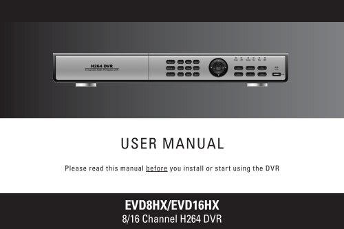
USER MANUAL<br />
Please read this manual before you install or start using the DVR<br />
EVD8HX/EVD16HX<br />
8/16 Channel H264 DVR
Digital Video Recorder <strong>User</strong> <strong>Manual</strong><br />
CAUTION<br />
2<br />
• Please read this user manual carefully to ensure that you can use the device correctly and safely<br />
• We do not warrant all the content is correct. The contents of this manual are subject to change without notice<br />
• This device should be operated only from the type of power source indicated on the marking label. The voltage<br />
of the power must be verified before using. If not in use for a long time, pull out the plug from the socket<br />
• Do not install this device near any heat sources such as radiators, heat registers, stoves or other device that<br />
produce heat<br />
• Do not install this device near water. Clean only with a dry cloth<br />
• Do not block any ventilation openings. And ensure well ventilation around the machine<br />
• Do not power off the DVR at normal recording condition! The correct operation to shut off DVR is to stop<br />
recording firstly, and then select “shut-down” button at the right of the menu bar to exit, and finally to cut off the<br />
power.<br />
• This machine is indoor using equipment. Do not expose the machine in rain or moist environment. In case any<br />
solid or liquid get into the machine’s case, please cut off the power supply immediately, and ask for qualified<br />
technicians to check the machine before restart<br />
• Refer all servicing to qualified service personnel. No any parts repaired by yourself without technical aid or<br />
approval.<br />
• This manual is suitable for 4-channel,8-channel and 16-channel digital video recorders. All examples and<br />
pictures used in the manual are from 16-channel DVR. For 8-channel DVR, its function is conforming to 16-channel<br />
DVR.
Digital Video Recorder <strong>User</strong> <strong>Manual</strong><br />
Table of Contents<br />
CHAPTER 1 Introduction ......................................................................................................................................................... 1<br />
1.1 DVR Introduction ................................................................................................................................................................ 1<br />
1.2 Main Features ..................................................................................................................................................................... 1<br />
CHAPTER 2 Hardware Installation ........................................................................................................................................... 4<br />
2.1 Install Hard Drive &DVD Writer ........................................................................................................................................... 4<br />
2.1.1 Install Hard Drive ......................................................................................................................................................................................... 4<br />
2.1.2 Install DVD Writer ......................................................................................................................................................................................... 5<br />
2.2 Front Panel Instruction ........................................................................................................................................................ 6<br />
2.3 Rear Panel Instruction ........................................................................................................................................................ 7<br />
2.3.1 Rear Panel Interface .................................................................................................................................................................................... 7<br />
2.3.2 Install Sensor &Alarm.................................................................................................................................................................................. 11<br />
2.4 Remote Controller ............................................................................................................................................................ 12<br />
2.5 Control with Mouse ........................................................................................................................................................... 15<br />
2.5.1 Connect Mouse .......................................................................................................................................................................................... 15<br />
2.5.2 Use Mouse ................................................................................................................................................................................................ 15<br />
CHAPTER 3 Basic Function Instruction .................................................................................................................................. 17<br />
3.1 Power On/Off .................................................................................................................................................................... 17<br />
3.2 Login &<strong>User</strong> Management ................................................................................................................................................ 19<br />
3.3 Recording ......................................................................................................................................................................... 23<br />
3.3.1 Record Setup ............................................................................................................................................................................................. 23<br />
3.3.2 <strong>Manual</strong> Recording ...................................................................................................................................................................................... 24<br />
3.3.3 Timer Recording ......................................................................................................................................................................................... 25<br />
3.3.4 Motion Detection Recording ....................................................................................................................................................................... 26<br />
3.3.5 Alarm Recording ........................................................................................................................................................................................ 29<br />
3.4 Playback ........................................................................................................................................................................... 30<br />
3.5 Backup &View................................................................................................................................................................... 34<br />
i
Digital Video Recorder <strong>User</strong> <strong>Manual</strong><br />
3.6 PTZ Control ...................................................................................................................................................................... 42<br />
CHAPTER 4 Menu Setup Guide .............................................................................................................................................. 46<br />
4.1 Menu Navigation ............................................................................................................................................................... 46<br />
4.2 Main Menu Setup ............................................................................................................................................................. 47<br />
4.2.1 Basic Configuration .................................................................................................................................................................................... 49<br />
4.2.2 Live Configuration ...................................................................................................................................................................................... 50<br />
4.2.3 Record Configuration ................................................................................................................................................................................. 51<br />
4.2.4 Schedule Configuration .............................................................................................................................................................................. 53<br />
4.2.5 Alarm Configuration .................................................................................................................................................................................... 54<br />
4.2.6 Motion Configuration .................................................................................................................................................................................. 56<br />
4.2.7 Network Configuration ................................................................................................................................................................................ 57<br />
4.2.8 P.T.Z Configuration ..................................................................................................................................................................................... 60<br />
4.2.9 <strong>User</strong> Configuration ..................................................................................................................................................................................... 62<br />
4.2.10 Tools Configuration .................................................................................................................................................................................. 63<br />
CHAPTER 5 Manage DVR ..................................................................................................................................................... 65<br />
5.1 Format Hard Disk ............................................................................................................................................................. 65<br />
5.2 Update Firmware .............................................................................................................................................................. 66<br />
5.3 Load Default Setup ........................................................................................................................................................... 67<br />
5.4 Check System Information ................................................................................................................................................ 68<br />
5.5 Check System Log ........................................................................................................................................................... 70<br />
5.6 Check On-line Network <strong>User</strong>s .......................................................................................................................................... 72<br />
5.7 Lock &Delete Files ............................................................................................................................................................ 73<br />
CHAPTER 6 Remote Surveillance ........................................................................................................................................ 75<br />
6.1 Accessing DVR ................................................................................................................................................................. 75<br />
6.1.1 On LAN ...................................................................................................................................................................................................... 75<br />
6.1.2 On WAN .................................................................................................................................................................................................... 76<br />
6.2 Remote Preview ............................................................................................................................................................... 77<br />
6.3 Remote Playback &Backup .............................................................................................................................................. 82<br />
6.3.1 Remote Playback ....................................................................................................................................................................................... 82<br />
6.3.2 Remote Backup ......................................................................................................................................................................................... 86<br />
6.4 Remote Menu Configuration ............................................................................................................................................. 87<br />
6.5 Remote DVR Management ............................................................................................................................................... 89<br />
ii
Digital Video Recorder <strong>User</strong> <strong>Manual</strong><br />
6.5.1 Check System Log Remotely ..................................................................................................................................................................... 89<br />
6.5.2 Lock &Delete Files Remotely ..................................................................................................................................................................... 91<br />
CHAPTER 7 Mobile Surveillance ............................................................................................................................................ 93<br />
7.1 By Phones with WinCE ..................................................................................................................................................... 93<br />
7.2 By Phones with Symbian .................................................................................................................................................. 97<br />
7.3 The operation method for iPhone mobile clients ............................................................................................................. 100<br />
Appendix A FAQ ................................................................................................................................................................. 108<br />
Appendix B Calculate Recording Capacity ...................................................................................................................... 114<br />
Appendix C Compatible Devices ....................................................................................................................................... 116<br />
Appendix D DVR Specifications (4-channel) .................................................................................................................... 117<br />
Appendix E DVR Specifications (8-channel) .................................................................................................................... 118<br />
Appendix F DVR Specifications (16-channel).................................................................................................................. 119<br />
iii
Digital Video Recorder <strong>User</strong> <strong>Manual</strong><br />
CHAPTER 1 Introduction<br />
1.1 DVR Introduction<br />
This DVR adopts high performance video processing chips and embedded Linux system. It utilizes many most advanced<br />
technologies, such as standard H.264 with low bit rate, Dual stream, SATA interface, VGA output mouse supported, IE<br />
browser supported with full remote control, mobile view(by phones), etc. it has very powerful functions and high stability. It<br />
can be widely used in bank, tele<strong>com</strong>munication, transportation, factories, warehouse, irrigation, etc.<br />
1.2 Main Features<br />
COMPRESSION FORMAT<br />
• Standard H.264 <strong>com</strong>pression with low bit rate.<br />
LIVE SURVEILLANCE<br />
• Support VGA output<br />
• Support channel security by hiding live display<br />
• Display the local record state and basic information<br />
• Support USB or PS/2 mouse to make full control<br />
RECORD MEDIA<br />
• Support 2 X SATA HDD to record to save long time, without limitation limited<br />
1
Digital Video Recorder <strong>User</strong> <strong>Manual</strong><br />
BACKUP<br />
• Support USB devices to backup<br />
• Support built-in SATA DVD writer to backup<br />
• Support saving recorded files with AVI standard format to a remote <strong>com</strong>puter through internet<br />
RECORD & PLAYBACK<br />
• Record modes: <strong>Manual</strong>, Schedule, Motion detection and Sensor alarm recording<br />
• Support recycle after HDD full<br />
• Resolution, frame rate and picture quality are adjustable<br />
• 64MB for every video file packaging<br />
• 4 audio channels available<br />
• Two record search mode: time search and event search<br />
• Support single and 4 screen playback<br />
• Support deleting and locking the recorded files one by one<br />
• Support remote playback in Network Client through LAN or internet<br />
ALARM<br />
• 4/816 channel alarm input and 1/4 channel alarm output available<br />
• Support schedule for motion detection and sensor alarm<br />
• Support pre-recording and post recording<br />
• Support linked channels recording once motion or alarm triggered on certain channel<br />
• Support linked PTZ preset and auto cruise of the corresponding channel<br />
PTZ CONTROL<br />
• Support various PTZ protocols<br />
• Support various PTZ presets and 32 auto cruise tracks<br />
• Support remote PTZ control through internet<br />
2
Digital Video Recorder <strong>User</strong> <strong>Manual</strong><br />
SECURITY<br />
• Two level user group management: advance and normal, rights authorized by administrator<br />
• Support one administrator and 15 users.<br />
• Support event log recording and checking, events unlimited<br />
NETWORK<br />
• Support TCP/IP, DHCP, PPPoE, DDNS protocol<br />
• Support IE browser to do remote view<br />
• Support max 5 connection simultaneously<br />
• Support dual stream. Network stream adjustable independently to fit the network bandwidth and environment.<br />
• Support picture snap and color adjustment in remote live<br />
• Support remote time and event search, mouse drag search, single channel playback with picture snap<br />
• Support remote PTZ control with preset and auto cruise<br />
• Support remote full menu setup, changing all the DVR parameters remotely<br />
• Support mobile surveillance by smart phones or PDA with WinCE OS, 3G network available<br />
• Support CMS to manage multi devices on internet (pending)<br />
3
Digital Video Recorder <strong>User</strong> <strong>Manual</strong><br />
CHAPTER 2 Hardware Installation<br />
Notice: Check the unit and the accessories after getting the DVR.<br />
Please disconnect the power before being connected to other devices. Don't hot plug in/out<br />
2.1 Install Hard Drive &DVD Writer<br />
2.1.1 Install Hard Drive<br />
Notice: 1. Support two SATA hard drive. Please use the hard drive the manufacturers re<strong>com</strong>mend specially for security and safe field.<br />
2. Please calculate HDD capacity according to the recording setting. Please refer to “Appendix B Calculate Recording Capacity”.<br />
STEP1 Unscrew and Open the top cover<br />
STEP2 Connect the power and data cables. Place the HDD onto the bottom case as below.<br />
Fig 2.1 Connect HDD<br />
STEP3 Screw the HDD as below.<br />
Note: For the convenience to install, please connect the power and data cables firstly, and then screw to fix.<br />
4
Digital Video Recorder <strong>User</strong> <strong>Manual</strong><br />
Fig 2.2 Screw HDD<br />
2.1.2 Install DVD Writer<br />
Notice: 1. The writers must be the <strong>com</strong>patible devices we re<strong>com</strong>mend. Please refer to “Appendix C Compatible Devices”<br />
2. This device is only for backup<br />
STEP1 Unscrew and Open the top cover<br />
STEP2 Connect the power and data cables. Place the DVD writer onto the bottom case as below.<br />
STEP3<br />
Screw the DVD writer as below.<br />
Fig 2.3 Connect the DVD Writer<br />
5
Digital Video Recorder <strong>User</strong> <strong>Manual</strong><br />
2.2 Front Panel Instruction<br />
Fig 2.4 Screw the Writer<br />
The Front Panel interface is shown as Fig 2.5 Front Panel.<br />
Fig 2.5 Front Panel for4-channel, 8-channel and 16-channel DVR<br />
6
Digital Video Recorder <strong>User</strong> <strong>Manual</strong><br />
Item Name Function<br />
1 -/Backup<br />
1. Decrease the value in setup<br />
2. Enter backup mode in live<br />
2 10+ Input number 10 and the above number together with other digital keys<br />
3 Digital button Input digitals or choose camera<br />
4 Enter button Confirm selection<br />
5<br />
Direction/Multi-screen 1. Direction buttons. Move cursor in setup or pan/tilt PTZ<br />
button<br />
2. Change screen display like single, 4, 9 and 16 screens<br />
6 SEARCH Enter search mode<br />
7 REW Rewind key;<br />
8 FF/PTZ<br />
1. Fast forward<br />
2. Enter PTZ mode in live<br />
9 STOP/ESC<br />
1. Quit play mode<br />
2. Exit the current interface or status<br />
10 PLAY Enter play interface;<br />
11 USB port To connect external USB devices like USB flash, USB HDD for backup or update firmware<br />
12 +/Menu button<br />
1. Increase the value in setup<br />
2. Enter menu from live view<br />
13 RECORD Record manually,<br />
14 Indicators Working indicators of power and networks, etc<br />
15 IR RECEIVER For remote controller<br />
Tab 2.1 Definition of Front Panel Buttons<br />
2.3 Rear Panel Instruction<br />
2.3.1 Rear Panel Interface<br />
1. The rear Panel for 4-channel DVR is shown as Fig 2.6 Rear Panel.<br />
7
Digital Video Recorder <strong>User</strong> <strong>Manual</strong><br />
Fig 2.6 Rear Panel for 4-channel DVR<br />
Item Name Description<br />
1 Video out Connect to monitor<br />
2 VGA port VGA output, connect to monitor<br />
3 POWER INPUT DC 12V<br />
4 SPOT Connect to monitor as an AUX output channel by channel. only video display, no menu show<br />
5 Video in Video input channels from 1-4<br />
6 Audio in Audio input from 1-4<br />
7 Audio out Audio output, connect to the sound box<br />
8 USB MOUSE Only for USB mouse<br />
9 LAN Connected to internet<br />
10 ALARM IN Connect to external sensor1-4.<br />
11 ALARM OUT Relay output1-4. Connect to external alarm.<br />
12 +5V and GND +5 Voltage and Ground<br />
13 RS485 Connected to speed domes<br />
14 FAN For cooling the device<br />
Tab 2.2 Definition of Rear Panel<br />
8
Digital Video Recorder <strong>User</strong> <strong>Manual</strong><br />
2. The rear Panel for 8-channel DVR is shown as Fig 2.7 Rear Panel.<br />
Fig 2.7 Rear Panel for 8-channel DVR<br />
Item Name Description<br />
1 VIDEO OUT Connect to monitor<br />
2 SPOT OUT Connect to monitor as an AUX output channel by channel. only video display, no menu show<br />
3 AUDIO IN 8-channel Video input<br />
4 S-VIDEO S-Video output, connect to monitor<br />
5 PS/2 port Connect to PS/2 mouse<br />
6 USB MOUSE port Only for USB mouse<br />
7 RJ45 port Connected to internet<br />
8 VGA port VGA output, connect to monitor<br />
9 ALARM IN Connect to external sensor 1-8. Please refer to 2.3.2 Install Sensor &Alarm<br />
10 ALARM OUT Relay output 1-4. Connect to external alarm. Please refer to 2.3.2 Install Sensor &Alarm<br />
11 POWER INPUT 12V/3A<br />
12 COM port For debug<br />
13 AUDIO OUT Audio output, connect to the sound box<br />
14 VIDEO IN Connect camera<br />
Tab 2.3 Definition of Front Panel<br />
9
Digital Video Recorder <strong>User</strong> <strong>Manual</strong><br />
3. The rear Panel for 16-channel DVR is shown as Fig 2.8 Rear Panel.<br />
Fig 2.8 Rear Panel for 16-channel DVR<br />
Item Name Description<br />
10<br />
1 VIDEO OUT Connect to monitor<br />
2 SPOT Connect to monitor as an AUX output channel by channel. only video display, no menu show<br />
3 VIDEO IN 16ch Video input<br />
4 AUDIO OUT Audio output, connect to the sound box<br />
5 AUDIO IN Audio input, connect to MIC or other audio capture devices<br />
6 S-VIDEO S-Video output, connect to monitor<br />
7 PS/2 port Connect to PS/2 mouse<br />
8 USB port Only for USB mouse<br />
9 RJ45 port Connected to internet<br />
10 VGA port VGA output, connect to monitor<br />
11 COM port For debug<br />
12 ALARM IN Connect to external sensor1-16. Please refer to 2.3.2 Install Sensor &Alarm<br />
13 +5V and GND +5 Voltage and Ground<br />
14 ALARM OUT Relay output1-4. Connect to external alarm. Please refer to 2.3.2 Install Sensor &Alarm<br />
15 RS485 Connected to speed domes<br />
16 FAN For cooling the device<br />
17 POWER INPUT 12V/5A<br />
Tab 2.4 Definition of Rear Panel
Digital Video Recorder <strong>User</strong> <strong>Manual</strong><br />
2.3.2 Install Sensor &Alarm<br />
The DVR has 16 channel alarm input and 4-channel alarm output.<br />
Alarm Input:<br />
The alarm input is triggered by electric level (High: 5V, Low: 0V). <strong>User</strong>s can connect external sensors, like gas detector,<br />
smoke detector and infrared detector. Once the DVR detect that the electric level meet the setting users make, it will<br />
trigger DVR recording or alarm out.<br />
For example, a sensor is connected to alarm input1 as Fig 2.1. Cable A and B will be connected once the sensor detect<br />
event. <strong>User</strong>s set Device type as NC (Normal Close), please refer to Fig 2.1. It will input +5V (high level) to input1 when<br />
events happen. DVR is triggered.<br />
Alarm output:<br />
Fig 2.9 Sensor Connection<br />
The DVR has 4-channel relay alarm output, which just give on/off signal to external alarm. The status of these pin are<br />
illustrated as 2.10.<br />
11
Before alarm<br />
Digital Video Recorder <strong>User</strong> <strong>Manual</strong><br />
N. O.<br />
COM<br />
N. C.<br />
After alarm<br />
Fig 2.10 Relay Output Status<br />
N. O.<br />
COM<br />
N. C.<br />
<strong>User</strong>s need connect their alarm according to the NO or NC type of the alarm. One connection example as Fig 2.11<br />
Fig 2.11 Alarm Output Connection<br />
Notice: The power in series must be 277VAC/10A or 30VDC/10A or below<br />
2.4 Remote Controller<br />
It uses two AAA size batteries and works after loading batteries as below<br />
12
Digital Video Recorder <strong>User</strong> <strong>Manual</strong><br />
STEP1 Open the battery cover of the Remote Controller<br />
STEP2 Place batteries. Please take care the poles (+ and -)<br />
STEP3 Replace the battery cover<br />
Notice: Frequently defect checking as following<br />
1. Check batteries poles<br />
2. Check the remaining charge in the batteries<br />
3. Check IR controller sensor is mask<br />
If it doesn't still work, Please change a new remote controller to try, or contact your dealers<br />
The interface of remote controller is shown in Fig 2.12 Remote Controller<br />
13
Digital Video Recorder <strong>User</strong> <strong>Manual</strong><br />
Fig 2.12 Remote Controller<br />
14<br />
Item Name Function<br />
1 Power Button Soft switch off to stop firmware running. Do it before power off.<br />
2 INFOR Button Get information about the DVR like firmware version, HDD information<br />
3 REC Button To record manually<br />
4 Digital Button Input digital or choose camera<br />
5<br />
Multi Screen<br />
Button<br />
To choose multi screen display mode<br />
6 SEARCH Button To enter search mode<br />
7 MENU Button To enter menu<br />
8 ENTER Button To confirm the choice or setup
Digital Video Recorder <strong>User</strong> <strong>Manual</strong><br />
Item Name Function<br />
9 Direction Button Move cursor in setup or pan/title PTZ<br />
10 +/- Button To increase or decrease the value in setup<br />
11<br />
Playback Control<br />
Button<br />
To control playback. Fast forward/rewind/stop/single frame play<br />
12 AUDIO Button To enable audio output in live mode<br />
13 Auto Dwell Button To enter auto dwell mode<br />
14 BACKUP Button To enter backup mode<br />
15<br />
PTZ Control<br />
Button<br />
To control PTZ camera. Move camera/ZOOM/FOCUS/IRIS/SPEED control<br />
Tab 2.5 Definition of Remote Controller<br />
2.5 Control with Mouse<br />
2.5.1 Connect Mouse<br />
It supports PS/2 or USB mouse through the ports on the rear panel, please refer to Fig 2.12 Remote Controller.<br />
Notice: If mouse is not detected or doesn't work, check as below<br />
1. Unplug/re-plug several times<br />
2. Power off/on several times<br />
3. Change a mouse to try<br />
2.5.2 Use Mouse<br />
The structure of the main menu is shown in Fig 2.12 Remote Controller.<br />
In live:<br />
Click left button on one camera to be full screen display. Click again to return to the previous screen display.<br />
Click right button to show the control bar at the bottom of the screen as Fig 2.12 Remote Controller. Here are all control<br />
and setup. Click right mouse again to hide the control bar.<br />
In setup:<br />
Click left button to enter. Click right button to cancel setup, or return to the previous.<br />
If want to input the value, move cursor to the blank and click. An input window will appear as Fig 2.12 Remote Controller.<br />
15
It supports digitals, letters and symbols input.<br />
Digital Video Recorder <strong>User</strong> <strong>Manual</strong><br />
Fig 2.13 Input dialog box<br />
<strong>User</strong>s can change some value by the wheel, such as time. Move cursor onto the value, and roll the wheel when the value<br />
blinks.<br />
It supports mouse drag. I.e. Set motion detection area: click customized, hold left button and drag to set motion detection<br />
area. Set schedule: hold left button and drag to set schedule time<br />
In playback:<br />
Click left button to choose the options. Click right button to return to searching mode.<br />
In backup:<br />
Click left button to choose the options. Click right button to return to live.<br />
In PTZ control:<br />
Click left button to choose the buttons to control the PTZ. Click right button to return to searching mode.<br />
Notice: Mouse is the default tool in all the operation below unless Exceptional indication.<br />
16
Digital Video Recorder <strong>User</strong> <strong>Manual</strong><br />
CHAPTER 3 Basic Function Instruction<br />
3.1 Power On/Off<br />
Notice: Before you power on the unit, please make sure all the connection is good.<br />
Connect with the source power, switch on POWER button, and the system will be loaded. The screen show as Fig 3.1<br />
System Loading<br />
Fig 3.1 System Loading<br />
After that, it will enter live in 16 screens. The meaning of letters or symbols on screen is as the form below.<br />
17
Digital Video Recorder <strong>User</strong> <strong>Manual</strong><br />
Fig 3.2 Preview<br />
Symbol Meaning Symbol Meaning<br />
Enable audio in live<br />
Disable audio in live<br />
(green) <strong>Manual</strong> record (blue) Timer record<br />
(yellow) Motion detection record (red) Alarm record<br />
HDD Current working HDD Space Size of current HDD<br />
Free Free space of current USB devices connected<br />
HDD full<br />
Tab 3.1 Symbols in Live<br />
18
Digital Video Recorder <strong>User</strong> <strong>Manual</strong><br />
Power off safely, please follow the below. <strong>User</strong>s can close the unit by remote controller, front panel and mouse.<br />
By remote controller:<br />
STEP1<br />
Press POWER button, the screen below will appear.<br />
STEP2<br />
STEP3<br />
Fig 3.3 Shut down<br />
Choose OK to enter. The unit will power off automatically after a while<br />
Disconnect the power<br />
By front panel or mouse:<br />
STEP1 Press ENTER button or click right mouse to show menu bar, referring to Fig 4.1 Control Bar.<br />
STEP2 Click Shut down button, referring to Fig 3.3 Shut down<br />
STEP3 Click OK to enter on the pop-up window. The unit will power off automatically after a while<br />
STEP4 Disconnect the power<br />
3.2 Login &<strong>User</strong> Management<br />
<strong>User</strong>s can logout and login the DVR system. <strong>User</strong>s cannot do any other operations except changing the multi screen<br />
display once logout. It is in logout once it starts or restarts.<br />
Login:<br />
19
Digital Video Recorder <strong>User</strong> <strong>Manual</strong><br />
If it is in logout, please press right mouse to show the control bar. Press Login, Search or System etc. A login window will<br />
appear, asking for ID and password as Fig 3.4 Login.<br />
Notice: The default is admin and 123456.<br />
Fig 3.4 Login<br />
Change password:<br />
Every one can change his own password.<br />
STEP1 In login state, click Log in/out on the control bar. A window will appear with two options. One is for logout,<br />
another for password modification. Click Password, the window will appear as Fig 3.5 Change Password.<br />
20
Digital Video Recorder <strong>User</strong> <strong>Manual</strong><br />
STEP2<br />
STEP3<br />
Fig 3.5 Change Password<br />
Input the old password. Then input new password 2 times.<br />
Press OK button to change.<br />
Add &Delete users:<br />
This unit has a default administrator and two user groups, advance and normal user. It supports 1 administrator and 15<br />
users totally. Administrator can add or delete other users, and change their group level. Administrator cannot be added or<br />
deleted.<br />
Press right mouse to show the control bar. Enter Menu---->System.<br />
STEP1<br />
Enter USER configuration. Click Add button, please see Fig 3.6 Add <strong>User</strong>.<br />
21
Digital Video Recorder <strong>User</strong> <strong>Manual</strong><br />
Fig 3.6 Add <strong>User</strong><br />
STEP2 Input user name and password. Choose the user group.<br />
STEP3 Click OK button to add a new user<br />
STEP4 Choose a user, a symbol will display at the end of the user information. Click Authority button to change the<br />
group level.<br />
STEP5 Press Delete button to delete the user. A security window will appear as below.<br />
22
STEP6<br />
Click OK button to delete the user<br />
Digital Video Recorder <strong>User</strong> <strong>Manual</strong><br />
3.3 Recording<br />
Notice: illumination of users’ rights<br />
Administrator: have all rights to do every thing.<br />
Advance: do others except entering USER to manage users<br />
Normal: do others except entering SYSTEM to change the settings.<br />
The user name and password are the <strong>com</strong>bination of digitals, letters, or symbols. The number of characters must be one or above.<br />
3.3.1 Record Setup<br />
<strong>User</strong>s need install and format a HDD, and set all the recording parameters before recording. It has four recording modes.<br />
<strong>User</strong>s can enable them simultaneously. However, they have different priorities as below.<br />
Motion detection recording > Sensor recording > <strong>Manual</strong> recording > Timer recording<br />
Press right mouse to show the control bar, referring to Fig 4.1 Control Bar. Enter Menu---->System.<br />
STEP1<br />
Enter RECORD configuration, referring to Fig 3.7 Record Setup. Select cameras.<br />
23
Digital Video Recorder <strong>User</strong> <strong>Manual</strong><br />
24<br />
Fig 3.7 Record Setup<br />
STEP2 Set Video quality, Frame rate, and Resolution.<br />
STEP3 Have Audio checked if you input audio and want to record. Check Time stamp to record<br />
STEP4 Enable recording function for cameras in Record option.<br />
Notice: If have camera uncheck here, it will not record in any recording mode.<br />
STEP5 Set Alarm record hold time. It is for post alarm recording.<br />
STEP6 Enable Recycle. It covers old video once HDD full. If you have it unchecked, it will stop recording auto once<br />
HDD full<br />
STEP7 Click OK to finish<br />
Notice: The higher the used storage of every hour, the higher the value of Video quality, Frame rate and Resolution.<br />
This Unit supports pre-alarm recording. But no option to set the pre-alarm recording time, the default is 10 seconds<br />
3.3.2 <strong>Manual</strong> Recording<br />
Just press REC button on the front panel after quitting system setup. Press Stop button to stop recording.<br />
Or press REC button on remote controller, click again to stop.
Digital Video Recorder <strong>User</strong> <strong>Manual</strong><br />
Or click REC button on the control bar with mouse, click again to stop.<br />
3.3.3 Timer Recording<br />
<strong>User</strong>s can set different schedule time for every day in one week. If you want a special schedule for one day, you can use<br />
Holiday function.<br />
STEP1 Enter SCHEDULE configuration. Select channels and Always, see Fig 3.8 Schedule Setup.<br />
Fig 3.8 Schedule Setup<br />
STEP2 The volume means the 7 days of one week. The row means 24 hours. Set the schedule time.<br />
Green means checked. Transparence means unchecked.<br />
STEP3 Press Add button to select the date if you want a special schedule for a certain day. A window will appear as Fig<br />
3.9 Calendar.<br />
25
Digital Video Recorder <strong>User</strong> <strong>Manual</strong><br />
Fig 3.9 Calendar<br />
STEP4 Select the date and set the schedule time. If want to delete this special schedule, click Delete button<br />
STEP5 Click OK button to finish<br />
Then the DVR will auto record once it goes to the time you set.<br />
3.3.4 Motion Detection Recording<br />
This unit supports recording channels and PTZ linking. This means it will record any cameras, or trigger any speed<br />
dome to preset or do auto cruise once motion detected.<br />
STEP1<br />
Enter MOTION configuration, see Fig 3.10 Motion Detection Setup. Select cameras<br />
26
Digital Video Recorder <strong>User</strong> <strong>Manual</strong><br />
Fig 3.10 Motion Detection Setup<br />
STEP2 Enable Detection first. Enter Area to set Sensitivity and detection Area. In detection area, red means unchecked,<br />
transparence means available, see Fig 3.11 Motion Detection Area Setup.<br />
STEP3<br />
Fig 3.11 Motion Detection Area Setup<br />
Enter Trigger configuration, see Fig 3.12 Alarm Out Setup<br />
27
Digital Video Recorder <strong>User</strong> <strong>Manual</strong><br />
Fig 3.12 Alarm Out Setup<br />
STEP4 Select alarm out and recording channels. It can trigger any alarm out and cameras to record once motion<br />
detected.<br />
STEP5 Enable or disable Buzzer on board. Select speed dome and enable preset or auto cruise. Press OK to save<br />
STEP6 Set Hold time. It is the interval time between the two adjacent efficient motions. If a second motion is detected in<br />
Hold time again, it is recognized as a continuous motion. If a second motion is detected after hold time, this motion and the<br />
previous are recognized as two different motion events.<br />
STEP7 Click OK to save settings<br />
STEP8 Enter SCHEDULE configuration. Select Motion and relative cameras to set, referring to chapter 3.3.3 Timer<br />
Recording.<br />
Notice: About preset and auto cruise, users can only select one at same time.<br />
The actual post-alarm record time equals Hold time in RECORD and Hold time in MOTION<br />
28
Digital Video Recorder <strong>User</strong> <strong>Manual</strong><br />
3.3.5 Alarm Recording<br />
This unit supports recording channels and PTZ linking after alarm.<br />
STEP1<br />
Enter ALARM configuration, see Fig 3.13 Sensor Alarm Setup. Select cameras<br />
Fig 3.13 Sensor Alarm Setup<br />
STEP2 Enable Detection first. Set Device type.<br />
STEP3 Enter Trigger configuration. Set alarm out, recording cameras and linked PTZ, referring to 3.3.4 Motion<br />
Detection Recording STEP4-5<br />
STEP4 Set Alarm in hold time. It is the interval time between the two adjacent efficient alarms. This is similar with Hold<br />
time in MOTION configuration.<br />
STEP5 Set Alarm out hold time and Buzzer hold time. Click OK to save settings<br />
STEP6 Enter SCHEDULE configuration. Select Sensor and relative cameras to set, referring to chapter 3.3.3 Timer<br />
Recording.<br />
Notice: About preset and auto cruise, users can only select one at same time.<br />
The actual post alarm record time equals Hold time in RECORD and Hold time in MOTION<br />
29
3.4 Playback<br />
Digital Video Recorder <strong>User</strong> <strong>Manual</strong><br />
This unit supports time search and event search. It displays full or 4 screens in playback. Click right mouse to show the<br />
control bar, referring to Fig 4.1 Control Bar. Click Search, the window below will appear on screen.<br />
Fig 3.14 Search Menu<br />
Time search:<br />
STEP1 Enter Search configuration, select Time search. A window will appear as Fig 3.15 Calendar Search. If it<br />
recorded in a day, the date will show highlight.<br />
30
Digital Video Recorder <strong>User</strong> <strong>Manual</strong><br />
STEP2<br />
Fig 3.15 Calendar Search<br />
Choose a day in the time search interface, as Fig 3.16 Time Search.<br />
31
Digital Video Recorder <strong>User</strong> <strong>Manual</strong><br />
Fig 3.16 Time Search<br />
STEP3 This unit has full and four-screen playback. Select the screen display mode and the channels.<br />
STEP4 If want to change the date, press Date button. Set hour and minutes of start time. If it recorded at that time, the<br />
boxes will show green.<br />
STEP5 Click Play button. It will play from the time point you set.<br />
STEP6 Click the relative buttons on the screen to do fast forward/backward, pause, stop, and change the screen mode<br />
and re-search, See Fig 3.17 Playback.<br />
32
Digital Video Recorder <strong>User</strong> <strong>Manual</strong><br />
Fig 3.17 Playback<br />
Event search:<br />
STEP1 Enter Search---->Event search. The calendar window will appear as that of time search<br />
STEP2 Choose a day in the event search interface, as Fig 3.18 Event Search<br />
33
Digital Video Recorder <strong>User</strong> <strong>Manual</strong><br />
34<br />
STEP3<br />
STEP4<br />
3.5 Backup &View<br />
Fig 3.18 Event Search<br />
Choose camera and event type, motion or sensor.<br />
Double click one video file to play.<br />
This unit supports backup by built-in SATA DVD Writer, with USB Flash, USB HDD, and USB DVD writer through the<br />
USB port on the front panel. <strong>User</strong>s can also make backup by IE browser via internet, referring to 6.3.2 Remote Backup.<br />
Take USB flash backup as an example. Press right mouse to show the control bar, referring to Fig 4.1 Control Bar.<br />
At DVR location:
STEP1<br />
Digital Video Recorder <strong>User</strong> <strong>Manual</strong><br />
Enter Backup interface, see Fig 3.19 Backup Setup<br />
Fig 3.19 Backup Setup<br />
STEP2 Choose the camera. And set the start and end time. Click Date button to change the date.<br />
STEP3 Enable “Attach record player”, it will save a special player simultaneously when backup. With this player, users<br />
can make time search and event search when checking the backup.<br />
STEP4 Click OK button. A window will appear as Fig 3.20 Backup Information.<br />
35
Digital Video Recorder <strong>User</strong> <strong>Manual</strong><br />
Fig 3.20 Backup Information<br />
Notice: If users install built-in DVD writer and USB device, it will show USB device in previous.<br />
It will show CD-ROM even though users install DVD writer<br />
STEP5 Press OK button. It will begin to write video from HDD inside DVR to backup device, and show the process as<br />
below.<br />
STEP6<br />
It will show “Backup <strong>com</strong>plete” after finished, as below.<br />
36
Digital Video Recorder <strong>User</strong> <strong>Manual</strong><br />
Check &View:<br />
<strong>User</strong>s can view the backup with the third software like realplay, windows media player directly. <strong>User</strong>s can also check with<br />
the special software attached when backup. Below are the steps of view the backup with the special software.<br />
STEP1 Remove the backup device to a <strong>com</strong>puter. Enter the backup folder and open the viewer.<br />
37
Digital Video Recorder <strong>User</strong> <strong>Manual</strong><br />
Fig 3.21 Backup Player<br />
1 Search area<br />
2 video display area<br />
3 Video data area<br />
4 Control area<br />
5 AVI converting<br />
STEP2 Click Browse to choose the folder which contains the video backup, as Fig 3.22 Choose Backup Folder.<br />
38
Digital Video Recorder <strong>User</strong> <strong>Manual</strong><br />
Fig 3.22 Choose Backup Folder<br />
STEP3 Set the date and channels. It will show the recorded video in area3 with green at the bottom as Fig 3.23<br />
Backup Data Search.<br />
Fig 3.23 Backup Data Search<br />
If using event search, it will list event files at the bottom of area1<br />
STEP4 Drag the slide bar to the start time point, click play button to view. It supports multi screen display. <strong>User</strong>s can do<br />
fast forward/backward, record, play audio etc, as below.<br />
39
Digital Video Recorder <strong>User</strong> <strong>Manual</strong><br />
Fig 3.24 Play Backup Files<br />
Index Definition Index Definition Index Definitio Inde Definition<br />
n x<br />
1 Play 2 Pause 3 Stop 4 Next frame<br />
5 Forward/ 6 Snap 7 Volume 8 Screen mode<br />
Rewind<br />
Tab 3.2 Backup View Control<br />
40
Digital Video Recorder <strong>User</strong> <strong>Manual</strong><br />
STEP5 It supports AVI converter. Click “Change File to AVI”. The converter will appear.<br />
STEP6 Click Browse to choose the folder which contains the video backup first. Set the start/end time, select the<br />
channels, and then Click search button. It will show backup files in the file display area as Fig 3.25 AVI Converter<br />
STEP7<br />
STEP8<br />
Fig 3.25 AVI Converter<br />
Select the files. Click Change button, it will start converting the files and show the process at the bottom.<br />
It is finished when the process show 100%. <strong>User</strong>s can play the AVI files with the third player directly.<br />
41
Digital Video Recorder <strong>User</strong> <strong>Manual</strong><br />
About network backup, please refer to 6.3.2 Remote Backup.<br />
3.6 PTZ Control<br />
Please connect speed domes to the DVR via RS485 first, referring to 2.3.1 Rear Panel Interface. And make sure the<br />
speed dome has the protocols this DVR supports and set the parameters according to its manual.<br />
STEP1 Press right mouse to show the control bar. Enter Menu---->System--->P.T.Z, see Fig 3.26.<br />
Fig 3.26 PTZ Setup<br />
STEP2 Set protocol, baudrate, address according to the parameters of the speed dome.<br />
STEP3 Click Set button at right of Preset. Here users can set presets as Fig 3.27 Set Presets. Adjust the speed dome.<br />
Select a preset and click Save to a preset. <strong>User</strong>s can set 16 presets totally.<br />
42
Digital Video Recorder <strong>User</strong> <strong>Manual</strong><br />
Fig 3.27 Set Presets<br />
STEP4 Click Set button at right of Cruise. Here users can set cruise track, as Fig 3.28 Set Cruise. Choose the preset,<br />
set stay time of every preset. Click + button to add the preset to the left preset for cruise track.<br />
43
Digital Video Recorder <strong>User</strong> <strong>Manual</strong><br />
Fig 3.28 Set Cruise<br />
STEP5 Select a preset in left preset list, click – button to delete the preset. Click ↑,↓,↑,↓ to adjust the sequence of<br />
the presets in the auto cruise. Click Save to save and return to the previous interface.<br />
STEP6 Click OK button to save and exit. Press right mouse to show the control bar. Click PTZ to enter PTZ control, as<br />
Fig 3.29 PTZ Control.<br />
44
Digital Video Recorder <strong>User</strong> <strong>Manual</strong><br />
Fig 3.29 PTZ Control<br />
STEP7 Select the speed dome. Click the direction buttons to move the camera. Click the relative + and – buttons to<br />
adjust zoom, focus, IRIS and speed. Click □ button to stop the change.<br />
STEP8 Select the preset, the speed dome will go to the point directly. Select Cruise, it will do auto cruise.<br />
45
Digital Video Recorder <strong>User</strong> <strong>Manual</strong><br />
CHAPTER 4 Menu Setup Guide<br />
4.1 Menu Navigation<br />
Menu Option Menu Option<br />
Device name &ID<br />
Camera name<br />
Video format<br />
Camera mask<br />
Language<br />
Basic<br />
Live Name &time switch<br />
Date &time setup<br />
SPOT out switch<br />
Live audio switch<br />
Color adjustment<br />
Authorization check switch<br />
Video quality<br />
Frame rate<br />
Recording schedule<br />
Record switch<br />
Record<br />
Schedule Motion schedule<br />
Resolution<br />
Sensor schedule<br />
Recycle switch<br />
Post alarm record time<br />
Alarm Switch<br />
Motion switch<br />
Sensor type<br />
Sensitivity &detection area setup<br />
Alarm<br />
Motion<br />
Alarm out &out time setup<br />
Alarm out &out time setup<br />
Recorded cameras and PTZ linking<br />
Recorded cameras and PTZ linking<br />
46
Network<br />
<strong>User</strong><br />
4.2 Main Menu Setup<br />
HTTP &server ports<br />
IP address setup<br />
PPPoE<br />
Network video setup<br />
DDNS<br />
Add users<br />
Delete users<br />
Change authorization<br />
Digital Video Recorder <strong>User</strong> <strong>Manual</strong><br />
PTZ<br />
Disk manager<br />
Tools Update<br />
Load default<br />
Tab 4.1 Menu Navigation<br />
Protocol, baud rate and address<br />
Speed setup<br />
Presets setup<br />
Cruise setup<br />
Click right mouse, or press ENTER button on the front panel, the control bar will show on the bottom of the<br />
screen as Fig 4.1 Control Bar.<br />
Fig 4.1 Control Bar<br />
Move the cursor to Menu and click, the up list menu will show as Fig 4.2 Up-listed Menu<br />
47
Digital Video Recorder <strong>User</strong> <strong>Manual</strong><br />
Fig 4.2 Up-listed Menu<br />
Select System. A graphic user interface will show as Fig 4.3 System Setup.<br />
Fig 4.3 System Setup<br />
48
Digital Video Recorder <strong>User</strong> <strong>Manual</strong><br />
Press MENU button on the front panel or remote controller. The interface above will also appear.<br />
Notice: Only administrator and advance user can enter system setup and do setup.<br />
It need reboot after some parameters changed, like video format.<br />
4.2.1 Basic Configuration<br />
Click BASIC to enter basic configuration as Fig 4.4 Basic .<br />
Fig 4.4 Basic Configuration<br />
Here users can set video system, menu language, audio, time and authorization check. The following are the definitions of<br />
every option.<br />
Device name: The name of the unit. It may display on the client end or CMS, which help users to recognize the unit<br />
remotely. Now it does not work.<br />
Device ID: It is used to multi devices at the same place. <strong>User</strong>s can manage them by remote controller. Now it does not<br />
work.<br />
49
Digital Video Recorder <strong>User</strong> <strong>Manual</strong><br />
Video format: It has PAL and NTSC. <strong>User</strong>s make the choice according to that of that of cameras.<br />
Language: set the menu language.<br />
Authorization check: It needs user name and password when user want system setup, playback, backup etc, if enable<br />
this.<br />
Audio: enable audio in live. <strong>User</strong>s can choose a random channel.<br />
Date format: three formats, YY-MM-DD, DD-MM-YY, MM-DD-YY.<br />
System time: set the time. If the unit is recording, users cannot change the time. When recording, click Adjust button, a<br />
security window will appear.<br />
4.2.2 Live Configuration<br />
Click LIVE to enter live configuration as Fig 4.5 Live Configuration<br />
50<br />
Fig 4.5 Live Configuration<br />
Here users can set name/time display, picture color and hide cameras. The following are the definitions of every option.<br />
Camera name: set camera name. it is the <strong>com</strong>bination of digitals, letters and symbols.<br />
Show name: display camera name in live.<br />
Hide: hide the picture in live. Unauthorized users cannot view the camera. But it still works in the background, like record.
Show time: display time in live.<br />
Digital Video Recorder <strong>User</strong> <strong>Manual</strong><br />
Dwell time: it is available for both Sequence and SPOT simultaneously. This unit has 2ch video output, referring to 2.3.1<br />
Rear Panel Interface. One is main output, and the other is spot output. <strong>User</strong>s can set the display time of cameras in auto<br />
dwell and spot out.<br />
SPOT enable: enable spot output.<br />
Click Set button, a window will appear as Fig 4.6 Color Adjustment.<br />
Fig 4.6 Color Adjustment<br />
Adjust Brightness, Hue, Saturation, and Contrast in live here.<br />
Default: set the color to the default value.<br />
4.2.3 Record Configuration<br />
Click RECORD to enter record configuration as Fig 4.7 Record Configuration.<br />
51
Digital Video Recorder <strong>User</strong> <strong>Manual</strong><br />
Fig 4.7 Record Configuration<br />
Here users can set record quality, frame rate, resolution, and recycle. The following are the definitions of every option.<br />
Video quality: it has 5 options from lowest to highest. The higher the value is, the clearer the recorded picture is.<br />
Frame rate: set recorded frame rate.<br />
Audio: enable audio to record.<br />
Time stamp: record the current time to video file if checked.<br />
Record: Switch on/off recording function for every camera. It records the camera only if having the camera checked here.<br />
Then you can use manual, timer, motion detection, and sensor alarm recording.<br />
Resolution: it supports CIF and D1. Now only CIF works.<br />
Alarm record hold time(S): set the post record time after alarm finishes. It has 4 options, 30, 60, 120, and 180.<br />
Recycle: enable recycle. It unchecked here, it will stop recording when HDD full.<br />
52<br />
Notice: Video quality, frame rate, and resolution are tightly related with the used storage. The higher the value is, the higher the bit rate and the
used storage are.<br />
Digital Video Recorder <strong>User</strong> <strong>Manual</strong><br />
4.2.4 Schedule Configuration<br />
Click SCHEDULE to enter schedule configuration as Fig 4.8 Schedule Configuration.<br />
Fig 4.8 Schedule Configuration<br />
Here users can set schedule for timer, motion detection, and sensor alarm respectively. The following are the definitions of<br />
every option<br />
Always, Motion and Sensor: refer to record schedule, motion schedule and alarm schedule respectively.<br />
The volume means the 7 days of one week from Monday to Sunday. The row refers to 24 hours. Click the boxes or hold<br />
mouse to drag to set the schedule time. Green means checked. Transparence means unchecked.<br />
Add: users can set schedule for a certain day by date. Click Add to add date as Fig 3.9 Calendar.<br />
Delete: delete holiday schedule.<br />
53
Digital Video Recorder <strong>User</strong> <strong>Manual</strong><br />
4.2.5 Alarm Configuration<br />
Click ALARM to enter alarm configuration as Fig 4.9 Alarm Configuration.<br />
Fig 4.9 Alarm Configuration<br />
Here users can set sensor type, alarm trigger and alarm time. The following are the definitions of every option.<br />
Device type: NC and NO (Normal Close and Normal Open). Set the value according to the alarm signal level of the<br />
sensors.<br />
Enable: enable sensor alarm.<br />
Trigger: set alarm output, recording channel and speed dome linking. Click Set button, a window will appear as Fig 4.10<br />
Alarm Out Configuration.<br />
54
Digital Video Recorder <strong>User</strong> <strong>Manual</strong><br />
Fig 4.10 Alarm Out Configuration<br />
Alarm out: set relay alarm out channel. You can select any alarm channels.<br />
To record: set recording channels. You can select any record channels. It will record the cameras you choose here when<br />
alarm triggered.<br />
Buzzer: enable buzzer on board for alarm.<br />
To P.T.Z CH: set linked preset and cruise for alarm. You can select any channel and multi channels as linked channels.<br />
Alarm in hold time(S): the interval time between the two adjacent efficient sensor alarms. If a second alarm is detected in<br />
Hold time again, it is recognized as a continuous alarm. If a second alarm is detected after hold time, this alarm and the<br />
previous are recognized as two different alarm events.<br />
Alarm out hold time(S): set relay alarm out time after alarm triggered.<br />
Buzzer hold time(S): set on board buzzer time after alarm triggered.<br />
55
Digital Video Recorder <strong>User</strong> <strong>Manual</strong><br />
4.2.6 Motion Configuration<br />
Click MOTION to enter motion configuration as Fig 4.11 Motion Configuration.<br />
Fig 4.11 Motion Configuration<br />
Here users can set motion sensitivity, detection area and alarm out. The following are the definitions of every option.<br />
Enable: enable motion detection.<br />
Trigger: setup similar with that of sensor alarm. But linked speed domes must be different front current channel. I.e. now<br />
users enable motion detection of camera1, the linked speed domes must be camera2-16.<br />
Area: set sensitivity and motion detection area. It supports multi detection area as Fig 4.12 Detection Area Configuration.<br />
Click the blocks or drag mouse to enable or disable. Red means unchecked, transparence means available. Click Save to<br />
save and exit.<br />
56
Digital Video Recorder <strong>User</strong> <strong>Manual</strong><br />
Fig 4.12 Detection Area Configuration<br />
Sensitivity: set detection sensitivity from 1-8. The default is 4.<br />
Exit: quit without saving<br />
Hold time(S): the interval time between the two adjacent efficient motions, similar with that of sensor alarm.<br />
4.2.7 Network Configuration<br />
Click NETWORK to enter network configuration as Fig 4.13 Network Configuration.<br />
57
Digital Video Recorder <strong>User</strong> <strong>Manual</strong><br />
58<br />
Fig 4.13 Network Configuration<br />
This unit supports DHCP, PPPoE, DDNS. <strong>User</strong>s enable network function, and configure IP address, DDNS, transmission<br />
video parameters here. The following are the definitions of every option.<br />
HTTP port: the default is 80. If users change the value, they need add the port number when typing IP address in IE<br />
address blank. I.e. set HTTP port to 82, IP address to 192.168.0.25. <strong>User</strong>s need input http://192.168.0.25:82 in IE browser.<br />
Server port: <strong>com</strong>munication port.<br />
DHCP: enable DHCP. It wants this feature work, need enable DHCP in the router or virtual server. The unit will get IP<br />
address automatically, not inputting IP, Subnet, Gateway manually.<br />
IP, Subnet, Gateway, DNS1 and 2: IP address information. If users don’t enable DHCP, it is necessary to input the value<br />
manually here.<br />
PPPoE: enable PPPoE. If users connect the DVR to internet directly by ADSL, not through a router or a virtual server,<br />
please enable it.<br />
<strong>User</strong> name, Password: account information of PPPoE. Input what you get from your ISP.
Digital Video Recorder <strong>User</strong> <strong>Manual</strong><br />
Click DDNS, a window will appear as Fig 4.14 DDNS Configuration. Now it supports DNS2P and 88IP. <strong>User</strong>s need register<br />
at www.dns2p.<strong>com</strong> or www.88IP.net. Then input register ID and password here. Click OK button. the unit will connect<br />
DNS2P or 88IP.<br />
Server: select DDNS server.<br />
<strong>User</strong> name and Password: input register information.<br />
Fig 4.14 DDNS Configuration<br />
This unit supports dual stream. <strong>User</strong>s can set picture quality, frame rate, and resolution separately for network, according<br />
to the network bandwidth. Click Video to enter the configuration interface as Fig 4.15 Network Video Configuration.<br />
59
Digital Video Recorder <strong>User</strong> <strong>Manual</strong><br />
Video quality: network picture quality.<br />
Frame rate: it has two options, 1, and 3 fps.<br />
Resolution: now it only has CIF.<br />
Time stamp: display time in remote preview.<br />
Fig 4.15 Network Video Configuration<br />
4.2.8 P.T.Z Configuration<br />
Click P.T.Z to enter PTZ configuration as Fig 4.16 PTZ Configuration.<br />
60
Digital Video Recorder <strong>User</strong> <strong>Manual</strong><br />
Fig 4.16 PTZ Configuration<br />
Here users can set protocol, baud rate, address, presets and auto cruise track here. The following are the definitions of<br />
every option.<br />
Protocol, Baud rate, Address: please set the value according to the settings of the speed dome.<br />
Speed: set the speed of speed domes.<br />
Preset, Name: select a preset and rename it. Click Set, a window will appear as Fig. 4.17. Select a preset, and adjust the<br />
speed dome. Click Save button to save it and exit.<br />
61
Digital Video Recorder <strong>User</strong> <strong>Manual</strong><br />
Fig 4.17 Set Presets<br />
Cruise, Name: select a cruise track and rename it. Click Set in Cruise row. A window will appear as 3.6 PTZ Control.<br />
Notice: It has 16 presets and 16 cruise tracks totally<br />
4.2.9 <strong>User</strong> Configuration<br />
Click USER to enter user management interface as Fig 4.18 <strong>User</strong> Configuration.<br />
62
Digital Video Recorder <strong>User</strong> <strong>Manual</strong><br />
Fig 4.18 <strong>User</strong> Configuration<br />
Administrator can add, delete users, and change their authorization. Please refer to 3.2 Login &<strong>User</strong> Management.<br />
Notice: It supports one administrator and max 15 users.<br />
4.2.10 Tools Configuration<br />
Click TOOLS to enter tools configuration as Fig 4.19 Tools Manager.<br />
63
Digital Video Recorder <strong>User</strong> <strong>Manual</strong><br />
Fig 4.19 Tools Manager<br />
Disk manager: please refer to 5.1 Format Hard Disk.<br />
Update: please refer to 5.2 Update Firmware.<br />
Load default: please refer to 5.3 Load Default Setup.<br />
64
Digital Video Recorder <strong>User</strong> <strong>Manual</strong><br />
CHAPTER 5 Manage DVR<br />
5.1 Format Hard Disk<br />
If wanting to record, it is necessary to format the hard disk at first. If not being formatted, it will show the position of the disk;<br />
free space and total space show 0M at the bottom of screen.<br />
STEP1 Enter USER configuration, referring to 4.2.10 Tools Configuration. Press Disk manager, a window will pop up as<br />
Fig 5.1 Disk Manager.<br />
65
Digital Video Recorder <strong>User</strong> <strong>Manual</strong><br />
Fig 5.1 Disk Manager<br />
STEP2 If a disk has never been formatted, Status will show “new”. Select hard disks, press Format button to begin.<br />
STEP3 A security window will remind user that this will delete all data on HDD. Press OK to continue. A process will<br />
display on the screen as below.<br />
66<br />
STEP4<br />
It will return to the previous automatically after finished. And status will show “normal” after formatted.<br />
Notice: All recorded files will be lost after formatted.<br />
5.2 Update Firmware<br />
Now it only supports USB update. Get the firmware from your dealer, and Make sure the firmware is corresponding with<br />
the DVR. <strong>User</strong>s can check USB information in disk manager, please refer to Fig 5.1 Disk Manager.<br />
STEP1<br />
Plug an USB flash to the <strong>com</strong>puter. Copy the firmware to the flash. The extension of firmware is tar.
STEP2<br />
STEP3<br />
update.<br />
STEP4<br />
Digital Video Recorder <strong>User</strong> <strong>Manual</strong><br />
Remove the USB flash to the DVR. Enter TOOLS configuration, referring to 4.2.10 Tools Configuration.<br />
Click Update. A window will appear, which reminds users that it will automatically load default settings after<br />
Press OK to begin. The process bar will display on the screen during update.<br />
STEP5<br />
After finished, the unit needs restart.<br />
Notice: If a “no device or no file” error appears, it is possible that the USB device is in<strong>com</strong>patible. Please change an USB flash.<br />
Please be patient to wait. It will take 2-3 minutes to update.<br />
5.3 Load Default Setup<br />
The DVR has different setup blocks, like Basic, Record, Schedule, Motion etc. <strong>User</strong>s can choose any block to do default,<br />
as Fig 5.2 Reset Blocks.<br />
STEP1<br />
Fig 5.2 Reset Blocks<br />
Enter TOOLS configuration, referring to 4.2.10 Tools Configuration.<br />
67
Digital Video Recorder <strong>User</strong> <strong>Manual</strong><br />
STEP2 Click Load default. Select setup blocks; please refer to Fig 5.2 Reset Blocks.<br />
STEP3 Press OK to do default. It will return to TOOLS interface after finished.<br />
5.4 Check System Information<br />
<strong>User</strong>s can check system information like firmware version, IP address etc.<br />
STEP1 Press right mouse to show the control bar. Click Menu, referring to Fig 4.2 Up-listed Menu.<br />
STEP2 Click Info, the window below will appear.<br />
STEP3<br />
Fig 5.3 Status Interface<br />
Click System, the window below will display. Check firmware version, recording parameters here.<br />
68
Digital Video Recorder <strong>User</strong> <strong>Manual</strong><br />
Fig 5.4 System Information.<br />
STEP4 Return to the previous interface, and click Network. The window below will display. Check IP address, DVR Mac<br />
address, network video quality.<br />
69
Digital Video Recorder <strong>User</strong> <strong>Manual</strong><br />
5.5 Check System Log<br />
Fig 5.5 Network Information.<br />
This unit supports system log. It records its working state and operation automatically. And it divides the record to two<br />
groups, events ands operation. The form below is the details of the two groups.<br />
STEP1<br />
Group<br />
Events<br />
Operation<br />
Motion, Video Loss, Alarm<br />
Details<br />
Delete File, Lock File, Search, Login, Enable check, Boot, Shutdown, Reset, Start<br />
Record, Stop Record, Setup Basic, Setup Live, Setup Record, Setup Schedule,<br />
Setup Alarm, Setup Network, Setup P.T.Z<br />
Tab 5.1 Details of System Log<br />
Press right mouse to show the control bar. Click Menu---->Status---->Events, the window below will appear.<br />
70
Digital Video Recorder <strong>User</strong> <strong>Manual</strong><br />
Fig 5.6 Events LOG<br />
STEP2 Click Date to change date by a calendar. Click Type to select the event type. Then click Search button. It will<br />
refresh the event list.<br />
STEP3 Click ←, ←, →, → to do pgdn or pgup<br />
STEP4 Click right mouse to return to the previous interface. Click Operation to search operation Log<br />
71
Digital Video Recorder <strong>User</strong> <strong>Manual</strong><br />
STEP5<br />
The operating is similar with searching events log.<br />
Fig 5.7 Operation Log<br />
Notice: The log files are saved to the HDD inside. If HDD not installed, it won’t record any thing.<br />
The number of log files is unlimited.<br />
5.6 Check On-line Network <strong>User</strong>s<br />
Press right mouse to show the control bar. Click Menu---->Online users. It will show the details of the current connections<br />
as below.<br />
72
Digital Video Recorder <strong>User</strong> <strong>Manual</strong><br />
5.7 Lock &Delete Files<br />
Fig 5.8 Details of Current Network Connections<br />
<strong>User</strong>s can control every video file, locking and deleting them. Once users lock an important file, it cannot be covered or<br />
deleted. But the locked files can still be cleared by formatting.<br />
STEP1<br />
STEP2<br />
Press right mouse to show the control bar. Click Menu, referring to Fig 4.2 Up-listed Menu.<br />
Click Search----->File manager, the window below will appear.<br />
73
Digital Video Recorder <strong>User</strong> <strong>Manual</strong><br />
Fig 5.9 File Manager<br />
STEP3 Click Date to change date by a calendar, click Search to refresh the list. The files found will be listed in the file<br />
area of file manager at bottom. It show the details of every file, like start/end time, lock state.<br />
STEP4 Select the files and click Lock, it will lock the selected files. At this time, a letter “L” display at the end of the file<br />
rows as Fig 5.9 File Manager.<br />
STEP5 Select the files which is unlocked, click Delete. A window display and remind users. Click Ok to delete them.<br />
74
Digital Video Recorder <strong>User</strong> <strong>Manual</strong><br />
CHAPTER 6 Remote Surveillance<br />
6.1 Accessing DVR<br />
If want to make remote view, the DVR must be connect to LAN or internet. And then enable network server in the unit.<br />
Please refer to 4.2.7 Network Configuration.<br />
This unit supports IE browser, not any client software installed. And it supports XP and Vista.<br />
6.1.1 On LAN<br />
STEP1 Input IP address, Subnet, Gateway. If using DHCP, please enable DHCP in both the DVR and router.<br />
STEP2 Enter Video to set network video parameters like resolution, frame rate etc.<br />
STEP3 Open IE browser on a <strong>com</strong>puter on the same LAN. Input the IP address of the DVR in IE address blank and<br />
enter.<br />
STEP4 IE will download activeX automatically. Then a window pops up and asks for user name and password.<br />
STEP5 Input name and password correctly, and enter. It will show the picture as below.<br />
75
Digital Video Recorder <strong>User</strong> <strong>Manual</strong><br />
Fig 6.1 View with IE browser<br />
76<br />
Notice: If HTTP port is not 80, other number instead, need add the port number after IP address. For example, set HTTP port as 82, need input<br />
IP address like 192.168.0.25:82.<br />
<strong>User</strong> name and password here are the same with that used on the DVR. The default are admin and 123456.<br />
6.1.2 On WAN<br />
There are two ways that the DVR is connected to internet.
Digital Video Recorder <strong>User</strong> <strong>Manual</strong><br />
1. connect the DVR to internet through a router or virtual server.<br />
STEP1<br />
STEP2<br />
STEP3<br />
Input IP address, Subnet, Gateway. If using DHCP, please enable DHCP in both the DVR and router.<br />
Enter Video to set network video parameters like resolution, frame rate etc.<br />
Forward IP address and port number in Virtual Server setup of the router or virtual server. Close firewall.<br />
Notice: Forwarding block may be different in different routers and server, please check your router manual.<br />
STEP4 If users want to utilize dynamic domain name, need apply for a domain name in a DNS server supported by the<br />
DVR or router. Then add to the DVR or router.<br />
Now this unit only supports www.dns2p.<strong>com</strong> or www.88IP.net.<br />
About the router, please check in the router manual.<br />
STEP5 Open IE browser, input IP address, or dynamic domain name and enter. If HTTP port is not 80, add the port<br />
number after IP address or domain name.<br />
STEP6 IE will download activeX automatically. Then a window pops up and asks for user name and password.<br />
STEP7 Input name and password correctly, and enter to view.<br />
Notice: If you cannot download and install activeX, please refer to Appendix A FAQ Q7.<br />
2. Connect the DVR to internet directly.<br />
STEP1 Input IP address, Subnet, Gateway gotten from your ISP. If using ADSL, please input user name and password,<br />
and click OK. The DVR will connect the server and show “connection succeeds”.<br />
STEP2 The following steps are the same as STEP4-7 of the connection way above.<br />
6.2 Remote Preview<br />
It will first enter remote preview interface as below.<br />
77
Digital Video Recorder <strong>User</strong> <strong>Manual</strong><br />
Fig 6.2 Remote Preview Interface<br />
1 Full screen, 4/9/16 screens display mode.<br />
2 Camera indicators<br />
3 Picture snapshot<br />
4 Remote preview: adjust the color of cameras, control PTZ by this.<br />
78
Digital Video Recorder <strong>User</strong> <strong>Manual</strong><br />
5 Remote playback and backup: make remote playback and backup, check system log. Please refer to 6.3 Remote<br />
Playback &Backup.<br />
6 Remote menu setup: set the parameters remotely. Please refer to 6.4 Remote Menu Configuration.<br />
4, 5, and 6 are the function blocks. When one is active, the button will show orange.<br />
Snap pictures:<br />
STEP1<br />
Click on a channel to choose. Click the button, a window will appear as Fig 6.3 Preview Snap.<br />
Fig 6.3 Preview Snap<br />
STEP2 Select frames captured one time. Enable Title and Time, it will capture title and time simultaneously.<br />
STEP3 Click Snap to capture pictures.<br />
STEP4 Click Browse to set saving path. Click Save to save pictures to HDD on the <strong>com</strong>puter. And the saving folder<br />
window will pop up.<br />
79
STEP5<br />
Click Exit to return to live preview interface.<br />
Digital Video Recorder <strong>User</strong> <strong>Manual</strong><br />
Color adjustment:<br />
Click on a channel to choose. Drag the slide bar to adjust Brightness, Contrast, Hue, and Saturation. Click Default to reset<br />
them to original value.<br />
PTZ control:<br />
Click P.T.Z to enter the interface as below. Click on a channel to select the speed dome.<br />
Fig 6.4 Remote PTZ control<br />
80
1 Move the speed dome.<br />
2 Stop adjustment.<br />
3 Adjust zoom, focus, Iris, Speed.<br />
Digital Video Recorder <strong>User</strong> <strong>Manual</strong><br />
4 Go to the preset. Click to rename the preset.<br />
5 Select and do auto cruise.<br />
Click right mouse, a pull-down menu will appear as below.<br />
Fig 6.5 Preview Control Menu<br />
Audio: enable remote audio transmission. <strong>User</strong>s can hear the audio from the DVR.<br />
Full screen: the picture will fill the screen, without tools bar display. Double click or click right mouse to return to the<br />
previous interface.<br />
Set cruise: select this function to set, the window below will appear.<br />
81
Digital Video Recorder <strong>User</strong> <strong>Manual</strong><br />
Fig 6.6 Set Cruise<br />
Double click Add to add presets for the selected cruise. Click the preset, a down list menu will pop up. <strong>User</strong>s can select<br />
presets to add. Double click Time to set display time in auto cruise. Click Delete or Clear all to delete the presets. Click OK<br />
to save and exit.<br />
Fast stream: enable the master stream. This DVR supports dual stream, sub stream and master stream. Sub stream has<br />
low frame rate, max 3fps for every channel, referring to 4.2.7 Network Configuration. It requires low network bandwidth.<br />
Master stream has higher frame rate, max 30fps for every channel. But it needs higher network bandwidth simultaneously.<br />
Therefore, users can select the stream according to their bandwidth.<br />
Refresh: update the picture on the channel. Sometime the picture on one channel will freeze due to network block. At this<br />
time, users can refresh the pictures.<br />
6.3 Remote Playback &Backup<br />
6.3.1 Remote Playback<br />
Click Search to enter the playback and backup block as below, where users can make remote playback, remote backup<br />
and remote video file management.<br />
82
Digital Video Recorder <strong>User</strong> <strong>Manual</strong><br />
Fig 6.7Remote Playback &Backup Interface<br />
This DVR supports remote time search, event search and one channel playback. The above is the default interface after<br />
entering Playback &Backup block.<br />
By time search:<br />
STEP1 Select the date in calendar area1, select the channel in channel area2.<br />
STEP2 Click Search button to update the search result. All the recorded found will display in video data area3.<br />
STEP3 In area3, the top bar refers to hours and minutes in a day. The left column refers to cameras. Drag the slide bar<br />
to a time point.<br />
83
Digital Video Recorder <strong>User</strong> <strong>Manual</strong><br />
Click right mouse on of the slide bar. It will zoom in 10 times, which is helpful for users to point the start<br />
time of playback accurately.<br />
STEP4 Click Play button to do remote playback, referring to Fig 6.8 Remote Playback.<br />
84<br />
Fig 6.8 Remote Playback<br />
STEP5 <strong>User</strong>s can make fast forward/backward, pause, stop playback and snap pictures. About snap feature, it is the<br />
same as that in remote preview, referring to Fig 6.3 Preview Snap.<br />
STEP6 Click to return to search interface.
Digital Video Recorder <strong>User</strong> <strong>Manual</strong><br />
By event search:<br />
STEP1 Click Event search, the window will display as below.<br />
Fig 6.9 Remote Event Search<br />
STEP2 Select the date, channel and event type. Then click Search. All the files found will be listed in left area.<br />
STEP3 Select a file, and click Play button to do remote playback. The following steps are the same as SETP5-6 of time<br />
search above.<br />
85
Digital Video Recorder <strong>User</strong> <strong>Manual</strong><br />
6.3.2 Remote Backup<br />
<strong>User</strong>s can download the recorded files from the DVR through network. Click Backup to enter the interface as below.<br />
STEP1<br />
STEP2<br />
STEP3<br />
STEP4<br />
Fig 6.10 Remote Backup Interface<br />
Select the date, channel. Then click Search button. It will list all the files recorded in the day in left area.<br />
Click Browse button. Set the saving path.<br />
Select files in left file area. Holding shift button, you can select multi files with mouse simultaneously.<br />
Click Backup to do remote backup. It will show the process on the bottom of the screen as below.<br />
86
Digital Video Recorder <strong>User</strong> <strong>Manual</strong><br />
Notice: the backup file is AVI format. <strong>User</strong>s can play with the third player directly.<br />
6.4 Remote Menu Configuration<br />
Except network parameters, users can set all the parameters like resolution, schedule remotely through network, not going<br />
to the DVR. Click Setup to enter the interface as below.<br />
87
Digital Video Recorder <strong>User</strong> <strong>Manual</strong><br />
Fig 6.11 Remote Menu Setup<br />
The sub menu lists and the options in every sub menu are similar with those on the DVR. Please refer to 4.2 Main Menu<br />
Setup to do setup.<br />
Click Save to save the change. Some changes may pop up a dialog box as below and need restart.<br />
88
Digital Video Recorder <strong>User</strong> <strong>Manual</strong><br />
6.5 Remote DVR Management<br />
6.5.1 Check System Log Remotely<br />
<strong>User</strong>s can check system log remotely. About the details of system log, please refer to Tab 5.1 Details of System Log.<br />
STEP1<br />
Click Search---->Log, the window below will appear. Event log search is the default interface.<br />
89
Digital Video Recorder <strong>User</strong> <strong>Manual</strong><br />
STEP2<br />
STEP3<br />
STEP4<br />
Fig 6.12 Remote System LOG Search<br />
Select the date, channel and event type. Then click Search.<br />
The entire log found will be listed in left area.<br />
Click Operation to enter operation Log search interface<br />
90
Digital Video Recorder <strong>User</strong> <strong>Manual</strong><br />
STEP5<br />
Fig 6.13 Remote Operation Log Search<br />
Select the date and click Search. It will list all the log files in the day in left area.<br />
6.5.2 Lock &Delete Files Remotely<br />
<strong>User</strong>s can lock and delete video files through network. About the details of this feature please refer to 5.7 Lock &Delete<br />
Files.<br />
STEP1<br />
Click Search---->Playback---->File manager, the window below will appear.<br />
91
Digital Video Recorder <strong>User</strong> <strong>Manual</strong><br />
Fig 6.14 Remote File manager<br />
STEP2 Select dates and channels, then click Search. All the files found will be listed in the day in left area.<br />
STEP3 The relative status will show “Lock” if the file is locked. “Writing” means the file is still in being written.<br />
STEP4 Select the files which is unlocked, click Delete. A security window will display to remind users. Click Ok to delete<br />
them.<br />
Notice: In all calendar search areas above, the date will be highlighted if there is data recorded.<br />
92
Digital Video Recorder <strong>User</strong> <strong>Manual</strong><br />
CHAPTER 7 Mobile Surveillance<br />
This DVR supports mobile surveillance by PDA or smart phones with WinCE and symbian OS. At the same time, it<br />
supports 3G network. We tested Dopod D600 (WM5) and Dopod S1 (WM6), which work fine with the DVR.<br />
It wants to make mobile surveillance, need first enable network service on the DVR, referring to 4.2.7 Network<br />
Configuration. The below is the use instructions on mobile client end for two OS.<br />
Notice: It supports only live view by mobile devices and on channel at a time.<br />
7.1 By Phones with WinCE<br />
Please use the PDA or smart phones with WinCE version supported by this unit.<br />
STEP1<br />
STEP2<br />
Firstly, activate the network access on mobile phone. And then run “Internet Explorer”.<br />
Input the DVR server’s address and the connection is built up shown as below.<br />
93
Digital Video Recorder <strong>User</strong> <strong>Manual</strong><br />
STEP3<br />
Click on the software name. A dialog box pops up.<br />
STEP4<br />
Click “Yes” to download and install.<br />
94
Digital Video Recorder <strong>User</strong> <strong>Manual</strong><br />
STEP5<br />
PCam will be opened after installed.<br />
STEP6 Input the server’s address, ID and password respectively in the columns of “Server”, “<strong>User</strong>” and “Password”.<br />
And click “Go” to login the DVR. It will show the picture if access successfully.<br />
95
Digital Video Recorder <strong>User</strong> <strong>Manual</strong><br />
STEP7<br />
Camera1 is the default display after login. Change the camera in rolling-down menu of “Channel”.<br />
Notice: <strong>User</strong> name and password here are the same with that used on the DVR. The default is admin and 123456.<br />
96
7.2 By Phones with Symbian<br />
Digital Video Recorder <strong>User</strong> <strong>Manual</strong><br />
Please use the smart phones with symbian version supported by this unit.<br />
STEP1 Firstly, enable the network access on mobile phone. Then run Web browser.<br />
STEP2 Input the DVR server’s IP address in a new-built bookmark. Click this bookmark to connect to the DVR.<br />
STEP3<br />
A wel<strong>com</strong>e window will pop up and requires a package. Click “install package” to download.<br />
STEP4<br />
The security windows will pop up after downloading and ask if install the package. Click YES to install.<br />
97
Digital Video Recorder <strong>User</strong> <strong>Manual</strong><br />
STEP5<br />
A Scam shortcut icon appears on the system menu after finish.<br />
STEP6<br />
Run Scam program.<br />
98
Digital Video Recorder <strong>User</strong> <strong>Manual</strong><br />
STEP7<br />
Click Options--->Settings to enter login interface.<br />
STEP8<br />
Input the server’s address, ID and password respectively. And click OK to login the DVR.<br />
99
Digital Video Recorder <strong>User</strong> <strong>Manual</strong><br />
STEP9<br />
It will show the camera after access successfully.<br />
100<br />
Notice: <strong>User</strong> name and password here are the same with that used on the DVR. The default is admin and 123456.<br />
7.3 The operation method for iPhone mobile clients<br />
At present, the software only supports version of iPhone os2.2 and above, if phone firmware lower than this version please<br />
upgrade it.
Step1:Enter into App Store function of iPhone<br />
Digital Video Recorder <strong>User</strong> <strong>Manual</strong><br />
Step 2: Enable “search”<br />
search box<br />
function to search “SuperCam”, the required programs will be displayed on the top of<br />
101
Digital Video Recorder <strong>User</strong> <strong>Manual</strong><br />
Step 3: Click SuperCam, enter into “introduce” interface and click FREE”, it will change into “INSTALL”<br />
Step 4: Enter into iTunes Store password, click “OK”will display below interface<br />
Note: if it was the first time for user to operate please enter into user ID; if there is no Store account, user need to apply<br />
one.<br />
102
Digital Video Recorder <strong>User</strong> <strong>Manual</strong><br />
Step 5: Just be patient to download and install. After installed, SuperCam icon will display. Click this icon, a function<br />
interface will appear<br />
103
Digital Video Recorder <strong>User</strong> <strong>Manual</strong><br />
Step 6: Click “System setting”, enter into login interface. Enter into server’s IP address (or domain name), user’s ID and<br />
password. Click Back to save.<br />
Step 7: Click Live View, the default Cam1 picture will be displayed. Click to capture picture. Click to enter PTZ<br />
mode.<br />
104
Digital Video Recorder <strong>User</strong> <strong>Manual</strong><br />
Step 8: On function interface, click Image View to view the captured picture. Click or to switch to next or previous<br />
picture. Click to delete the current picture.<br />
Iphone help<br />
105
Digital Video Recorder <strong>User</strong> <strong>Manual</strong><br />
Live View<br />
106<br />
Pic1 Pic2 Pic3 Pic4<br />
After successfully installed SuperCam software, Click on System Setting (Pic 1), and then input Server IP address or<br />
Domain, <strong>User</strong> name and password to log in (Pic 2). If connected successfully, it will go to Live View of CH1 as default (Pic<br />
3), please choose other desired channels from channel button underneath. Meanwhile, please note below functions:<br />
1. : switch channels<br />
2. : picture snap.<br />
3. : ptz control (if server camera is PTZ Camera only) (pic 4)<br />
PTZ Control buttons:<br />
1 : pan
2 : Zoom Zoom in Zoom out<br />
3 : Focus. Long Focus Short Focus<br />
4 : IRIS Lighter Darker<br />
5 : return to live<br />
Image View<br />
Digital Video Recorder <strong>User</strong> <strong>Manual</strong><br />
Pic 5 Pic 6<br />
1. : Previous picture 2. : Next Picture<br />
3. : The first Picture 4. : The last picture<br />
5. : Delete 6. : Search Pictures, search page as Pic 6<br />
107
Digital Video Recorder <strong>User</strong> <strong>Manual</strong><br />
Appendix A FAQ<br />
Q1. Why the DVR cannot start after connected to the power<br />
a. The adapter has been damaged. Please change an adapter<br />
b. The power of the adapter is not enough. Please remove the HDD to check<br />
c. Hardware problem<br />
Q2. The indicator of the DVR lights, but no output. Why<br />
a. The power of the adapter is not enough. Please remove the HDD or change an adapter to try.<br />
b. The video format of the DVR is different from that of the monitor.<br />
c. Connection problem. Please check the cable and the ports of monitor and DVR.<br />
Q3. Why are no images displayed on parts or all of the channels of the DVR<br />
a. Connection problem. Please check the cable and the ports of camera and DVR.<br />
b. Camera problem. Please check the cameras.<br />
c. The video format of the DVR is different from that of the cameras. Please change DVR system format.<br />
Q4. Cannot find HDD<br />
a. The power of the adapter is not enough. Please change an adapter to try.<br />
b. Connection problem. Please check the power and data cables.<br />
c. The HDD is damaged. Change a new one.<br />
108
Q5. Cannot record<br />
a. Don't format HDD. Please format it manually first.<br />
Digital Video Recorder <strong>User</strong> <strong>Manual</strong><br />
b. Don't enable record function or incorrect setup. Please refer to 3.3 Recording.<br />
c. HDD is full and not enables recycle function. Please refer to 4.2.3 Record Configuration. Chang a new HDD or enable<br />
recycle.<br />
d. The HDD is damaged. Change a new one.<br />
Q6. Cannot use mouse.<br />
a. wait 5 minutes after mouse connected.<br />
b. Not detected. Plug/unplug several times.<br />
c. The mouse is in<strong>com</strong>patible. Please change a mouse.<br />
Q7. Cannot download ActiveX control.<br />
a. IE browser blocks activeX. Please do setup following below.<br />
1 Open IE browser. Click Tools-----Internet Options….<br />
109
Digital Video Recorder <strong>User</strong> <strong>Manual</strong><br />
2 select Security------Custom Level….Refer to Fig 7-1<br />
3 Enable all the sub options under “ActiveX controls and plug-ins” refer to Fig 7-2<br />
4 Then click ok to finish setup.<br />
b. Other plug-ins or anti-virus block activeX. Please uninstall or close them.<br />
110
Digital Video Recorder <strong>User</strong> <strong>Manual</strong><br />
Fig7-1<br />
Q8: How to deal with when DVR starts, it displays “please wait…”all the time<br />
First possible reason: hard-disk cable and data cable are not well connected.<br />
Fig7-2<br />
Solution: Please check the connection of hard-disk cable and data cable and make sure they are well connected; If still not<br />
working, please unplug them and then try re-plugging again;<br />
Second possible reason: It is forced to stop because hard disk has disabled track which causes the system checking hard<br />
111
112<br />
disk cannot skip<br />
Digital Video Recorder <strong>User</strong> <strong>Manual</strong><br />
Solution: Change another new hard disk or reformat the broken one<br />
Q9: The mouse inserting into the front USB jack does not work<br />
Hereby the front USB jack is only for backup of U disk, USB DVD writer etc., and not support USB mouse. Please use the<br />
USB jack in the rear panel if using mouse to operate.<br />
Q10: How to input password and digital numbers<br />
The method to input password and digital numbers is to click the box behind password or items needing to input by<br />
numbers, and then the small keyboard will appear. Please select number or letter to input (the initial password is 123456),<br />
or you can use the digital keys in the front panel, or the digital keys on the remote controller.<br />
Q11: How to upgrade when added new functions or revised software<br />
After getting the upgraded software from manufacturer, please copy it into U disk, and then select “upgrade” in the menu. If<br />
upgrading the kernel procedure, please refer to the following method: firstly insert U disk into DVR, and then input<br />
“adwsws” in the password of system login and the system will upgrade kernel procedure automatically. After finished,<br />
please restart DVR to achieve.<br />
Notice: Do not power off in the system upgrading process! Otherwise, it may cause that DVR cannot start.<br />
Q12: Why is the hard disk used in a DVR identified a new hard disk if directly used to another same type DVR And<br />
why must we format it again<br />
When DVR only uses one hard disk, the hard disk removed from one to another same type DVR can work normally without<br />
format. However, when a DVR adds to a new hard disk, it will identify the hard disk as a new one and inquire whether to<br />
format no matter whether this hard disk used or not in another same type DVR before. In this condition, it can be used<br />
normally after formatted according to the guide; if two or more hard disks used in different DVRs, when used in another<br />
DVR with the same type, they will be identified to be two or more new hard disks, and all of them need to format. In general,<br />
please do not try using more disks removed from different DVRs into another one in case the data lose.<br />
Q13: When users need to add a hard disk or DVD writer, please follow the connecting method shown below (only for<br />
16-ch DVR):
Digital Video Recorder <strong>User</strong> <strong>Manual</strong><br />
Q14: What is the minimum configuration of PC for clients connecting<br />
PC Module<br />
Parameters<br />
CPU Intel Celeron 2.4G<br />
Motherboard Intel 845<br />
HDD<br />
RAM<br />
VGA<br />
OS<br />
80G<br />
512M<br />
DirectX 9.0<br />
NVIDIA GeForce MX440/FX5200<br />
ATIRADEON 7500/X300<br />
Windows 2000(SP4 above) /Windows XP(SP2 above) /VISTA<br />
113
Digital Video Recorder <strong>User</strong> <strong>Manual</strong><br />
Appendix B Calculate Recording Capacity<br />
<strong>User</strong>s can calculate the size of hard disk according to the saving time and DVR recording settings. The DVR uses fixed video bit<br />
rate. The below are the details at different settings.<br />
Video<br />
Format<br />
Resolution<br />
Frame Rate<br />
Totally(FPS)<br />
PAL CIF 25<br />
NTSC CIF 15<br />
Video Quality Bit Rate (kbps) Used Space(MB/h)<br />
Highest 640 281<br />
Higher 512 225<br />
Medium 384 168.7<br />
Lower 256 112.5<br />
Lowest 128 56<br />
Highest 314.9 141.7<br />
Higher 251.5 112.5<br />
Medium 188.3 84.7<br />
Lower 125.4 56.4<br />
Lowest 93.4 42<br />
The calculation format is:<br />
Total Recording capacity =Used space per hour (MB/h) (coverage rate of hard disk)<br />
× recording time (hour) ×channel numbers<br />
114
Digital Video Recorder <strong>User</strong> <strong>Manual</strong><br />
For instance, one customer uses NTSC cameras, set resolution to CIF, video quality to Lower, frame rate to 240 fps for<br />
enabling total 16 channels. He wants the unit to record continuously in a month. Below is the calculation:<br />
Total Recoding capacity =56.4 (mb/h) X 24(hours/day) X30(days) X16(channels)<br />
= 649728(MB)<br />
≈650(GB)<br />
Therefore, customers just install two SATA HDDs with 320GB, it can almost record for one month.<br />
For 8-channel DVR, its recording capacity is half of the 16-channel.<br />
115
Digital Video Recorder <strong>User</strong> <strong>Manual</strong><br />
Appendix C Compatible Devices<br />
1. Compatible USB drive after test.<br />
Brand<br />
SSK<br />
Netac<br />
Kingston<br />
Aigo<br />
Smatter vider<br />
Scandisk<br />
Capacity<br />
512MB, 1G, 2GB<br />
4GB<br />
2GB<br />
2GB<br />
1GB<br />
4GB<br />
Tab C.1 Compatible USB drive<br />
2. Compatible SATA CD/DVD writers after test<br />
Brand<br />
Model<br />
SAMSUNG<br />
TS-H653B<br />
LITEN-ON<br />
DH-20A6S01C<br />
Tab C.1 Compatible CD/DVD writers<br />
116
Digital Video Recorder <strong>User</strong> <strong>Manual</strong><br />
Appendix D DVR Specifications (4-channel)<br />
Compression format<br />
Standard H.264 Baseline<br />
Video output<br />
Composite:1.0V p-p/75Ω,BNC×2 , VGAX1<br />
Video input<br />
Composite:1.0V p-p/75Ω,BNC×4<br />
Display Resolution<br />
720*576 (PAL), 720*480 (NTSC)<br />
Record Resolution<br />
352*288 , 704*576 (PAL), 352*240 , 704*480 (NTSC)<br />
Display Frame Rate 100FPS (PAL), 120FPS (NTSC)<br />
Record Frame Rate<br />
100FPS, 25FPS (PAL) ; 120FPS, 30FPS (NTSC)<br />
Audio input<br />
-8dB~ 22k, RCA X4<br />
Audio output<br />
-8Db~92dB, RCA X1<br />
Alarm input<br />
NO or NC 4CH<br />
Alarm output:<br />
1CH<br />
Record Mode<br />
<strong>Manual</strong> / Sensor /Timer / Motion detection<br />
Simplex/Duplex/Triplex Pentaplex<br />
Network Interface<br />
RJ45 (LAN, INTERNET)<br />
PTZ control<br />
YES<br />
Communication interface RS485, USB2.0 x 2(one for backup, another for USB mouse)<br />
Hard disk info SATA x 2<br />
Remote controller<br />
YES<br />
Power supply<br />
12V 4A<br />
117
Digital Video Recorder <strong>User</strong> <strong>Manual</strong><br />
Appendix E DVR Specifications (8-channel)<br />
118<br />
Compression format<br />
Standard H.264 Baseline<br />
Video output<br />
Composite:1.0V p-p/75Ω,BNC×2, VGAX1<br />
Video input<br />
Composite:1.0V p-p/75Ω,BNC×8<br />
Display Resolution<br />
720*576 (PAL), 720*480 (NTSC)<br />
Record Resolution<br />
352*288 , 704*576 (PAL), 352*240 , 704*480 (NTSC)<br />
Display Frame Rate 200FPS (PAL), 240FPS (NTSC)<br />
Record Frame Rate<br />
200FPS, 50FPS (PAL) ; 240FPS, 60FPS (NTSC)<br />
Audio input<br />
-8dB~ 22k, RCA X4<br />
Audio output<br />
-8Db~92dB, RCA X1<br />
Alarm input<br />
NO or NC 8CH<br />
Alarm output:<br />
1CH<br />
Record Mode<br />
<strong>Manual</strong> / Sensor /Timer / Motion detection<br />
Simplex/Duplex/Triplex Pentaplex<br />
Network Interface<br />
RJ45 (LAN, INTERNET)<br />
PTZ control<br />
YES<br />
Communication interface RS485, USB2.0 x 2(one for backup, another for USB mouse)<br />
Hard disk info SATA x 2<br />
Remote controller<br />
YES<br />
Power supply<br />
12V 4A
Digital Video Recorder <strong>User</strong> <strong>Manual</strong><br />
Appendix F DVR Specifications (16-channel)<br />
Compression format<br />
Standard H.264 Baseline<br />
Video output<br />
Composite:1.0V p-p/75Ω,BNC×2 S-VIDEOX1, VGAX1<br />
Video input<br />
Composite:1.0V p-p/75Ω,BNC×16<br />
Display Resolution<br />
720*576 (PAL), 720*480 (NTSC)<br />
Record Resolution<br />
352*288 , 704*576 (PAL), 352*240 , 704*480 (NTSC)<br />
Display Frame Rate 400FPS (PAL), 480FPS (NTSC)<br />
Record Frame Rate<br />
400FPS, 100FPS (PAL) ; 480FPS, 120FPS (NTSC)<br />
Audio input<br />
-8dB~ 22k, RCA X4<br />
Audio output<br />
-8Db~92dB, RCA X1<br />
Alarm input<br />
NO or NC 16CH<br />
Alarm output:<br />
4CH<br />
Record Mode<br />
<strong>Manual</strong> / Sensor /Timer / Motion detection<br />
Simplex/Duplex/Triplex Pentaplex<br />
Network Interface<br />
RJ45 (LAN, INTERNET)<br />
PTZ control<br />
YES<br />
Communication interface RS485, USB2.0 x 2(one for backup, another for USB mouse), PS/2 x 1<br />
Disk info SATA x 2+DVD-RW x 1<br />
Remote controller<br />
YES<br />
Power supply<br />
12V5A<br />
119
TECHNICAL SUPPORT:<br />
For Technical Support for this product please contact your local distributor.<br />
LIMITED WARRANTY:<br />
This product is supplied with a 1 Year warranty. The Warranty excludes products that have been misused, (including<br />
accidental damage) and damage caused by normal wear and tear. In the unlikely event that you encounter a problem<br />
with this product, it should be returned to the place of purchase.