Back-UPS ® Pro 1200/1500 230V Installation and ... - APC Media
Back-UPS ® Pro 1200/1500 230V Installation and ... - APC Media
Back-UPS ® Pro 1200/1500 230V Installation and ... - APC Media

Create successful ePaper yourself
Turn your PDF publications into a flip-book with our unique Google optimized e-Paper software.
<strong>Back</strong>-<strong>UPS</strong> ® <strong>Pro</strong> <strong>1200</strong>/<strong>1500</strong> <strong>230V</strong><br />
<strong>Installation</strong> <strong>and</strong> Operation<br />
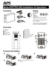
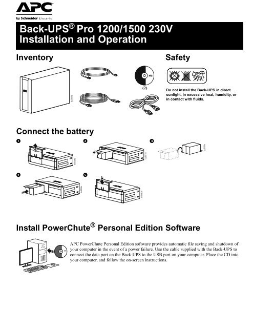
Inventory<br />
Safety<br />
bu001a<br />
(2)<br />
Do not install the <strong>Back</strong>-<strong>UPS</strong> in direct<br />
sunlight, in excessive heat, humidity, or<br />
in contact with fluids.<br />
Connect the battery<br />
<br />
bu059a<br />
<br />
<br />
bu058a<br />
bu060a<br />
bu055a<br />
bu057a<br />
Install PowerChute ® Personal Edition Software<br />
<strong>APC</strong> PowerChute Personal Edition software provides automatic file saving <strong>and</strong> shutdown of<br />
your computer in the event of a power failure. Use the cable supplied with the <strong>Back</strong>-<strong>UPS</strong> to<br />
connect the data port on the <strong>Back</strong>-<strong>UPS</strong> to the USB port on your computer. Place the CD into<br />
your computer, <strong>and</strong> follow the on-screen instructions.
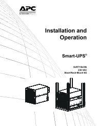
Connect the equipment<br />
Battery <strong>Back</strong>up <strong>and</strong> Surge <strong>Pro</strong>tected outlets<br />
When the <strong>Back</strong>-<strong>UPS</strong> is receiving input power, the<br />
Battery <strong>Back</strong>up with Surge <strong>Pro</strong>tection outlets will<br />
supply power to connected equipment. During a<br />
power outage or other utility problems, the Battery<br />
<strong>Back</strong>up outlets receive power for a limited time from<br />
the <strong>Back</strong>-<strong>UPS</strong>.<br />
Connect equipment such as printers, fax machines,<br />
scanners, or other peripherals that do not need<br />
battery backup power to the Surge <strong>Pro</strong>tection Only<br />
outlets. These outlets provide full-time protection<br />
from surges even if the <strong>Back</strong>-<strong>UPS</strong> is switched OFF.<br />
Master <strong>and</strong> Controlled outlets<br />
To conserve electricity, when the device connected<br />
to Master Outlet goes into Sleep or St<strong>and</strong>by mode, or<br />
turns Off, the Controlled device(s) will shut down as<br />
well, saving electricity.<br />
Connect a master device, such as a desktop<br />
computer or audio/visual receiver to the Master<br />
outlet. Connect peripheral devices such as a printer, speakers, or a scanner to the Controlled outlets.<br />
bu146a<br />
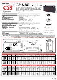
USB <strong>and</strong> Serial Data port<br />
Telephone cable surgeprotected<br />
ports<br />
Ground screw<br />
Surge <strong>Pro</strong>tected outlets,<br />
controlled by the Master<br />
outlet<br />
Surge <strong>Pro</strong>tected outlets<br />
AC power outlet<br />
Battery <strong>Back</strong>up outlets with<br />
Surge <strong>Pro</strong>tection<br />
Battery <strong>Back</strong>up outlet with<br />
Surge <strong>Pro</strong>tection, controlled<br />
by the Master outlet<br />
To use PowerChute Personal Edition, connect a serial cable or USB cable.<br />
Connect a telephone cable to the IN port, <strong>and</strong> connect a modem to the OUT port.<br />
Connect the ground lead of additional surge suppression devices such as network <strong>and</strong> data line<br />
surge protectors.<br />
These outlets are protected from electrical surges, <strong>and</strong> will disconnect from utility power during<br />
a power outage, or if the Master device goes into Sleep or St<strong>and</strong>by mode.<br />
These outlets provide full-time protection from surges, even if the <strong>Back</strong>-<strong>UPS</strong> is off. Connect<br />
equipment such as printers <strong>and</strong> scanners that do not require battery backup protection.<br />
Connect the unit to utility power, use the supplied power cord.<br />
During a power outage or other utility problems, the Battery <strong>Back</strong>up outlets receive power for a<br />
limited time from the <strong>Back</strong>-<strong>UPS</strong>. Connect critical equipment such as desktop computer,<br />
computer monitor, modem or other data sensitive devices into these outlets.<br />
These outlets will supply battery power to the connected equipment during a power outage.<br />
Power will be disconnected to these outlets if the Master device goes into Sleep or St<strong>and</strong>by<br />
mode. Connect equipment such as a computer monitor to these outlets.<br />
Master outlet<br />
External Battery Pack<br />
<br />
connector (BR<strong>1500</strong>GI only)<br />
In & Out Ethernet surgeprotected<br />
ports<br />
Connect the master device to this outlet, in most scenarios, this will be the main computer.<br />
Connect an external battery pack to provide additional battery backup runtime (<strong>Back</strong>-<strong>UPS</strong> <strong>Pro</strong><br />
<strong>1500</strong> only).<br />
Use an ethernet cable to connect a cable modem to the IN port, <strong>and</strong> connect a computer to the<br />
OUT port.<br />
2<br />
<strong>Back</strong>-<strong>UPS</strong> <strong>Pro</strong> <strong>1200</strong> & <strong>1500</strong> 230 V <strong>Installation</strong> <strong>and</strong> Operation
Operation<br />
Power-Saving Function<br />
To conserve electricity, configure the <strong>Back</strong>-<strong>UPS</strong> to recognize a Master device, such as a desktop<br />
computer or an A/V receiver, <strong>and</strong> Controlled peripheral devices, such as a printer, speakers, or a scanner.<br />
When the Master device goes into Sleep or St<strong>and</strong>by mode, or is switched OFF, the Controlled device(s)<br />
will be switched off as well, saving electricity.<br />
Enable the Power-Saving function. Press <strong>and</strong> hold MUTE <strong>and</strong> DISPLAY simultaneously for two seconds. The<br />
<strong>Back</strong>-<strong>UPS</strong> will beep to indicate that the feature is enabled. The leaf icon on the display will illuminate.<br />
Disable the Power-Saving function. Press <strong>and</strong> hold MUTE <strong>and</strong> DISPLAY simultaneously for two seconds. The<br />
<strong>Back</strong>-<strong>UPS</strong> will beep to indicate that the feature is disabled. The leaf icon on the display will darken.<br />
Setting the threshold. The amount of power used by a device in Sleep or St<strong>and</strong>by mode varies between devices. It<br />
may be necessary to adjust the threshold at which the Master outlet signals the Controlled outlets to shut down.<br />
1. Ensure a master device is connected to the Master outlet. Put that device into Sleep or St<strong>and</strong>by mode, or turn it<br />
OFF.<br />
2. Press DISPLAY <strong>and</strong> MUTE simultaneously <strong>and</strong> hold for six seconds, until the leaf icon flashes three times <strong>and</strong> the<br />
<strong>Back</strong>-<strong>UPS</strong> beeps three times.<br />
3. The <strong>Back</strong>-<strong>UPS</strong> will now recognize the threshold level of the Master device <strong>and</strong> save it as the new threshold setting.<br />
Power-Saving Display<br />
The display interface can be configured to be continuously illuminated, or to save energy, it can be configured to<br />
darken after a period of inactivity.<br />
1. Full Time Mode: Press <strong>and</strong> hold DISPLAY for two seconds. The display will illuminate <strong>and</strong> the <strong>Back</strong>-<strong>UPS</strong> will beep<br />
to confirm the Full-Time mode.<br />
2. Power-Saving Mode: Press <strong>and</strong> hold DISPLAY for two seconds. The display will darken <strong>and</strong> the <strong>Back</strong>-<strong>UPS</strong> will<br />
beep to confirm the Power-Saving mode. While in Power-Saving Mode, the display will illuminate if a button is<br />
pressed, it then darkens after 60 seconds of no activity.<br />
Unit sensitivity<br />
Adjust the sensitivity of the <strong>Back</strong>-<strong>UPS</strong> to control when it will switch to battery power; the higher the sensitivity, the<br />
more often the <strong>Back</strong>-<strong>UPS</strong> will switch to battery power.<br />
1. Ensure the <strong>Back</strong>-<strong>UPS</strong> is connected to utility power, but is OFF.<br />
2. Press <strong>and</strong> hold the POWER button for six seconds. The LOAD CAPACITY bar will flash on <strong>and</strong> off, indicating that the<br />
<strong>Back</strong>-<strong>UPS</strong> is in programming mode.<br />
3. Press POWER again to rotate through the menu options. Stop at selected sensitivity. The <strong>Back</strong>-<strong>UPS</strong> will beep to<br />
confirm the selection.<br />
Low sensitivity Medium sensitivity (Default) High sensitivity<br />
156-300 Vac 176-294 Vac 176-288 Vac<br />
Input voltage is extremely low or<br />
high. (Not recommended for<br />
computer loads.)<br />
The <strong>Back</strong>-<strong>UPS</strong> frequently switches to<br />
battery power.<br />
The connected equipment is<br />
sensitive to voltage fluctuations.<br />
<strong>Back</strong>-<strong>UPS</strong> <strong>Pro</strong> <strong>1200</strong> & <strong>1500</strong> 230 V <strong>Installation</strong> <strong>and</strong> Operation 3
Front Panel Buttons <strong>and</strong> Display Interface<br />
Use the three buttons on the front panel of the <strong>Back</strong>-<strong>UPS</strong> <strong>and</strong> the display interface to configure the <strong>Back</strong>-<strong>UPS</strong>.<br />
Front panel<br />
Mute button<br />
Power On/Off button<br />
Display button<br />
Display interface<br />
bu044a<br />
bu002a<br />
On Line—The <strong>Back</strong>-<strong>UPS</strong> is supplying conditioned utility power to connected equipment<br />
Power-Saving—Master <strong>and</strong> Controlled outlets are enabled, saving power when the master device goes into<br />
sleep or st<strong>and</strong>by mode<br />
Load Capacity—The load is indicated by the number of sections illuminated, one to five. Each bar represents<br />
20% of the load.<br />
Battery Charge—The battery charge level is indicated by the number of sections illuminated. When all five<br />
blocks are illuminated, the <strong>Back</strong>-<strong>UPS</strong> is at full charge. When one block is filled, the <strong>Back</strong>-<strong>UPS</strong> is near the end of<br />
its battery capacity, the indicator will flash <strong>and</strong> the <strong>Back</strong>-<strong>UPS</strong> will beep continuously.<br />
Overload—The power dem<strong>and</strong> from the load has exceeded the capacity of the <strong>Back</strong>-<strong>UPS</strong>.<br />
Event—The event counter shows the number of events that occurred that caused the <strong>Back</strong>-<strong>UPS</strong> to switch to<br />
on-battery operation.<br />
Automatic Voltage Regulation—The <strong>Back</strong>-<strong>UPS</strong> can compensate for high or low input voltage.<br />
When illuminated, the <strong>Back</strong>-<strong>UPS</strong> is compensating for low input voltage.<br />
Input voltage.<br />
Output voltage.<br />
When illuminated, the <strong>Back</strong>-<strong>UPS</strong> is compensating for high input voltage.<br />
System Faults—The system has a fault. The fault number will illuminate on the display interface. See “System<br />
Faults” on page 5.<br />
Mute—If the line through the speaker icon is illuminated, the audible alarm has been turned off.<br />
Replace Battery—The battery is not connected or is nearing the end of its useful life. Replace the battery.<br />
On Battery—The <strong>Back</strong>-<strong>UPS</strong> is supplying battery backup power to the connected equipment, it will beep four<br />
times every 30 seconds.<br />
4<br />
<strong>Back</strong>-<strong>UPS</strong> <strong>Pro</strong> <strong>1200</strong> & <strong>1500</strong> 230 V <strong>Installation</strong> <strong>and</strong> Operation
Warnings <strong>and</strong> System Faults<br />
Audible Warnings<br />
Four Beeps Every 30 Seconds<br />
Continuous Beeping<br />
Continuous tone<br />
Chirps for 1 Minute every 5 hours<br />
<strong>Back</strong>-<strong>UPS</strong> is running on battery. You should consider saving any work in progress.<br />
Low battery condition <strong>and</strong> battery run-time is very low. <strong>Pro</strong>mptly save any work in progress, exit<br />
all open applications, <strong>and</strong> shut down the operating system.<br />
Battery <strong>Back</strong>up outputs are overloaded.<br />
Battery fails the automatic diagnostic test <strong>and</strong> should be replaced.<br />
Warning Icons<br />
If these icons are<br />
illuminated...<br />
This may be the problem.<br />
The <strong>Back</strong>-<strong>UPS</strong> is operating on utility power, but is overloaded. Disconnect one of the items<br />
connected to the <strong>Back</strong>-<strong>UPS</strong>. If the Overload icon stops flashing, the <strong>Back</strong>-<strong>UPS</strong> is no longer<br />
overloaded <strong>and</strong> will continue to operate normally.<br />
The <strong>Back</strong>-<strong>UPS</strong> is operating on battery power, but is overloaded. Disconnect one of the items<br />
connected to the <strong>Back</strong>-<strong>UPS</strong>. If the Overload icon stops flashing, the <strong>Back</strong>-<strong>UPS</strong> is no longer<br />
overloaded <strong>and</strong> will continue to operate normally.<br />
The <strong>Back</strong>-<strong>UPS</strong> is operating on utility power, but the battery is not functioning properly. Contact <strong>APC</strong><br />
Customer Service to order a replacement battery. See “Replacement Battery” on page 8.<br />
The <strong>Back</strong>-<strong>UPS</strong> is operating on battery power <strong>and</strong> the battery power is getting low. Shut down all<br />
connected equipment to avoid losing an unsaved data. When possible, connect the <strong>Back</strong>-<strong>UPS</strong> to<br />
utility power to recharge the batter.<br />
System Faults<br />
The <strong>Back</strong>-<strong>UPS</strong> will display these fault messages. For faults F01 <strong>and</strong> F02, contact <strong>APC</strong> Technical Support.<br />
bu088a<br />
F01 On-Battery Overload Turn the <strong>Back</strong>-<strong>UPS</strong> off. Disconnect non-essential<br />
equipment from the Battery <strong>Back</strong>up outlets <strong>and</strong> the turn<br />
<strong>Back</strong>-<strong>UPS</strong> on.<br />
F02 On-Battery Output Short Turn the <strong>Back</strong>-<strong>UPS</strong> off. Disconnect non-essential<br />
equipment from the Battery <strong>Back</strong>up outlets <strong>and</strong> the turn<br />
<strong>Back</strong>-<strong>UPS</strong> on.<br />
F03 On-Battery Xcap Overload<br />
F04 Clamp Short<br />
F05<br />
F06<br />
F07<br />
F08<br />
F09<br />
Charge Fault<br />
Relay Welding<br />
Temperature<br />
Fan Fault<br />
Internal Fault<br />
Faults F03-F09 cannot be corrected by the user, contact<br />
<strong>APC</strong> Technical Support for assistance.<br />
<strong>Back</strong>-<strong>UPS</strong> <strong>Pro</strong> <strong>1200</strong> & <strong>1500</strong> 230 V <strong>Installation</strong> <strong>and</strong> Operation 5
Function Button Quick-Reference<br />
Function<br />
Button<br />
Timing<br />
(seconds)<br />
<strong>UPS</strong><br />
Status<br />
Description<br />
Power<br />
Power On 0.2 Off Press POWER to start receiving input utility power. If A/C input<br />
power is not available, the <strong>Back</strong>-<strong>UPS</strong> will run on battery power.<br />
Power Off 2 On The <strong>Back</strong>-<strong>UPS</strong> is not receiving input utility power, but is providing<br />
surge protection.<br />
Display<br />
Status Inquiry 0.2 On Verify the status or condition of the <strong>Back</strong>-<strong>UPS</strong>. The LCD will<br />
illuminate for 60 seconds.<br />
Full-Time/Power-<br />
Saving mode<br />
2 On The LCD will illuminate <strong>and</strong> the <strong>Back</strong>-<strong>UPS</strong> will beep to confirm the<br />
Full-Time mode. The LCD will darken <strong>and</strong> the <strong>Back</strong>-<strong>UPS</strong> will beep<br />
to confirm the Power-Saving mode. While in Power-Saving Mode,<br />
the LCD will illuminate if a button is pressed, then darkens after 60<br />
seconds of no activity.<br />
Mute<br />
Event Specific 0.2 On Disable any audible alarms caused by an event.<br />
General Status Enable/<br />
Disable<br />
2 On Enable or disable the audible alarms. The Mute icon will illuminate<br />
<strong>and</strong> the <strong>Back</strong>-<strong>UPS</strong> will beep one time. The Mute function will not<br />
activate unless the <strong>Back</strong>-<strong>UPS</strong> is operating on battery power.<br />
Sensitivity 6 Off The Load Capacity icon will blink, indicating that the <strong>Back</strong>-<strong>UPS</strong> is<br />
in programming mode. Use the POWER button to scroll through<br />
Low, Medium, <strong>and</strong> High, stop at selected sensitivity. The <strong>Back</strong>-<br />
<strong>UPS</strong> will beep to confirm selection. See Configuration for details.<br />
Master/Controlled<br />
outlet Enable/Disable<br />
Master/Enable<br />
Threshold Calibration<br />
2 On The leaf icon will darken indicating that the Master Outlet feature is<br />
disabled or illuminate to indicate the Master Outlet feature is<br />
enabled. The <strong>Back</strong>-<strong>UPS</strong> will beep once.<br />
6 On While calibrating the threshold setting, the device connected to the<br />
Master Outlet should be turned off or placed in St<strong>and</strong>by or Sleep<br />
mode. Upon completion, Power-Saving icon will flash 3 <strong>and</strong> beep<br />
3 times.<br />
Self-Test (manual) 6 On The <strong>Back</strong>-<strong>UPS</strong> will perform a test of the internal battery. Note: This<br />
will happen automatically when the <strong>Back</strong>-<strong>UPS</strong> is turned ON.<br />
Event Reset 0.2 On When the Event screen is visible, press <strong>and</strong> hold DISPLAY, then<br />
press POWER, to clear the utility failure event counter.<br />
Fault Reset 2 Fault After a fault has been identified, press POWER to remove the<br />
visual indication <strong>and</strong> return to st<strong>and</strong>by status.<br />
6<br />
<strong>Back</strong>-<strong>UPS</strong> <strong>Pro</strong> <strong>1200</strong> & <strong>1500</strong> 230 V <strong>Installation</strong> <strong>and</strong> Operation
Troubleshooting<br />
<strong>Pro</strong>blem Possible Cause Corrective Action<br />
<strong>Back</strong>-<strong>UPS</strong> will not switch on.<br />
The <strong>Back</strong>-<strong>UPS</strong> does not<br />
provide power during a utility<br />
power outage.<br />
The <strong>Back</strong>-<strong>UPS</strong> is operating on<br />
battery power, while connected<br />
to utility power.<br />
The <strong>Back</strong>-<strong>UPS</strong> is not connected to utility<br />
power.<br />
The circuit breaker has been tripped.<br />
The internal battery is not connected.<br />
The utility input voltage is out of range.<br />
Ensure that essential equipment is not<br />
plugged into a SURGE ONLY outlet.<br />
The plug has partially pulled out of the wall<br />
outlet, the wall outlet is no longer receiving<br />
utility power, or the circuit breaker has been<br />
tripped.<br />
The <strong>Back</strong>-<strong>UPS</strong> is performing an automatic<br />
self test.<br />
The utility input voltage is out of range, the<br />
frequency is out of range, or the waveform<br />
is distorted.<br />
The <strong>Back</strong>-<strong>UPS</strong> does not Battery <strong>Back</strong>up outlets may be fully or<br />
provide the expected amount of improperly loaded.<br />
backup time.<br />
The battery was recently discharged due to a<br />
power outage <strong>and</strong> has not fully recharged.<br />
The battery has reached the end of its useful<br />
life.<br />
The REPLACE BATTERY<br />
indicator is illuminated.<br />
The OVERLOAD indicator is<br />
illuminated.<br />
The SYSTEM FAULT indicator is<br />
illuminated, all the front panel<br />
indicators are flashing.<br />
Power is not supplied to some<br />
outlets.<br />
The battery has reached the end of its useful<br />
life.<br />
The equipment connected to the <strong>Back</strong>-<strong>UPS</strong><br />
is drawing more power than the <strong>Back</strong>-<strong>UPS</strong><br />
can provide.<br />
There is an internal fault.<br />
Power to the Controlled outlets has<br />
intentionally been turned off.<br />
The Controlled outlets are not The Master Outlet threshold may be<br />
supplying power, even though incorrectly set.<br />
the Master device is not in sleep<br />
mode.<br />
Ensure that the <strong>Back</strong>-<strong>UPS</strong> is securely connected<br />
to an AC outlet.<br />
Disconnect non-essential equipment from the<br />
<strong>Back</strong>-<strong>UPS</strong>. Reset the circuit breaker. Re-connect<br />
equipment one item at a time. If the circuit<br />
breaker is tripped again, disconnect the device<br />
that caused the trip.<br />
Connect the battery.<br />
Adjust the transfer voltage <strong>and</strong> sensitivity range.<br />
Disconnect equipment from the SURGE ONLY<br />
outlet <strong>and</strong> re-connect to a Battery <strong>Back</strong>up outlet.<br />
Ensure that the plug is fully inserted into the<br />
wall outlet. Ensure that the wall outlet is<br />
receiving utility power by checking it with<br />
another device.<br />
No action is necessary.<br />
Adjust the transfer voltage <strong>and</strong> sensitivity range.<br />
Disconnect non-essential equipment from the<br />
Battery <strong>Back</strong>up outlets <strong>and</strong> connect the<br />
equipment to SURGE ONLY outlets.<br />
Charge the battery cartridge for 16 hours.<br />
Replace the battery.<br />
Replace the battery.<br />
Disconnect non-essential equipment from the<br />
Battery <strong>Back</strong>up outlets <strong>and</strong> connect the<br />
equipment to SURGE ONLY outlets.<br />
Determine which internal fault message is<br />
displayed by matching the number displayed on<br />
the LCD with the corresponding Fault Message<br />
(see System Faults) <strong>and</strong> contact <strong>APC</strong> Technical<br />
Support.<br />
Confirm that the correct peripherals are<br />
connected to Controlled outlets. If this feature is<br />
not desired, disable the Power-Saving Master<br />
<strong>and</strong> Controlled outlets.<br />
Adjust the threshold when the Master outlet<br />
signals the Controlled outlets to shut down.<br />
<strong>Back</strong>-<strong>UPS</strong> <strong>Pro</strong> <strong>1200</strong> & <strong>1500</strong> 230 V <strong>Installation</strong> <strong>and</strong> Operation 7
Specifications<br />
t<br />
Model BR<strong>1200</strong>GI BR<strong>1500</strong>GI<br />
VA <strong>1200</strong> VA <strong>1500</strong> VA<br />
Maximum Load 720 W 865 W<br />
Nominal Input Voltage 230 V<br />
Online Input Voltage Range 176 - 294 V<br />
Automatic Voltage Regulation (188-216) +11.2%<br />
(252-282) -11.2%<br />
Frequency Range<br />
50/60 Hz ± 1 Hz<br />
On-battery Waveshape Step-approximated sine-wave<br />
Typical Recharge Time 8 hours<br />
Transfer Time<br />
10 ms, maximum<br />
Operating Temperature 0 to 40C (32 to 104F)<br />
Storage Temperature -15 to 45C (23 to 113F)<br />
Unit Dimensions<br />
30.1 × 11.2 × 38.2 cm (11.9 × 4.4 × 15.0 in)<br />
Unit Weight<br />
12.8 kg (28.2 lbs) 13.4 kg (29.5 lbs)<br />
Interface<br />
Serial, USB<br />
On-Battery Runtime Go to: www.apc.com<br />
Replacement Battery<br />
The battery cartridge typically lasts 3 to 6 years, a shorter<br />
period if subjected to frequent outages or elevated<br />
temperatures. Battery replacement part for <strong>Back</strong>-<strong>UPS</strong> <strong>Pro</strong> <strong>1200</strong><br />
<strong>and</strong> <strong>1500</strong> is <strong>APC</strong>RBC124. Please recycle spent battery<br />
cartridges.<br />
Service<br />
If the <strong>Back</strong>-<strong>UPS</strong> arrived damaged, notify the carrier.<br />
If the <strong>Back</strong>-<strong>UPS</strong> requires service, do not return it to the dealer.<br />
1. Consult the Troubleshooting section to eliminate common<br />
problems.<br />
2. If the problem persists, go to http://www.apc.com/support/.<br />
3. If the problem still persists, contact <strong>APC</strong> Technical Support.<br />
Have the <strong>Back</strong>-<strong>UPS</strong> model number, serial number <strong>and</strong> date of<br />
purchase available. Be prepared to troubleshoot the problem<br />
with an <strong>APC</strong> Technical Support representative.<br />
If this is not successful, <strong>APC</strong> will issue a Return Merch<strong>and</strong>ise<br />
Authorization (RMA) number <strong>and</strong> a shipping address.<br />
EMI Classification<br />
Approvals<br />
CE, C-Tick, KETI<br />
CE, TUV-GS, GOST, A-Tick, KETI, TISI<br />
Warranty<br />
The st<strong>and</strong>ard warranty is three (3) years from the date of purchase, valid in European Community. For all other regions, the st<strong>and</strong>ard warranty<br />
is two (2) years from the date of purchase. <strong>APC</strong>’s st<strong>and</strong>ard procedure is to replace the original unit with a factory reconditioned unit.<br />
Customers who must have the original unit back due to the assignment of asset tags <strong>and</strong> set depreciation schedules must declare such a need at<br />
first contact with an <strong>APC</strong> Technical Support representative. <strong>APC</strong> will ship the replacement unit once the defective unit has been received by<br />
the repair department, or cross-ship upon the receipt of a valid credit card number. The customer pays for shipping the unit to <strong>APC</strong>. <strong>APC</strong> pays<br />
ground freight transportation costs to ship the replacement unit to the customer.<br />
<strong>APC</strong> Worldwide Customer Support<br />
Internet<br />
http://www.apc.com<br />
Worldwide +1 888 272-3858<br />
Customer support <strong>and</strong> warranty information is available at the <strong>APC</strong> Web site, www.apc.com.<br />
© 03/2010 <strong>APC</strong> by Schneider Electric. All trademarks are owned by Schneider Electric Industries S.A.S., American<br />
Power Conversion Corporation, or their affiliated companies.<br />
990-3889A<br />
3/2010