Drawing Requirements
Drawing Requirements
Drawing Requirements

Create successful ePaper yourself
Turn your PDF publications into a flip-book with our unique Google optimized e-Paper software.
DRAWING REQUIREMENTS<br />
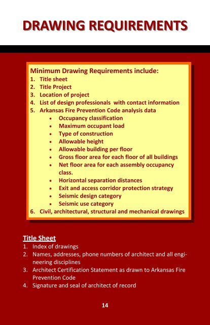
Minimum <strong>Drawing</strong> <strong>Requirements</strong> include:<br />
1. Title sheet<br />
2. Title Project<br />
3. Location of project<br />
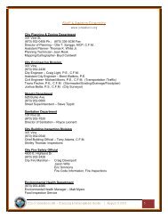
4. List of design professionals with contact information<br />
5. Arkansas Fire Prevention Code analysis data<br />
Occupancy classification<br />
Maximum occupant load<br />
Type of construction<br />
Allowable height<br />
Allowable building per floor<br />
Gross floor area for each floor of all buildings<br />
Net floor area for each assembly occupancy<br />
class.<br />
Horizontal separation distances<br />
Exit and access corridor protection strategy<br />
Seismic design category<br />
Seismic use category<br />
6. Civil, architectural, structural and mechanical drawings<br />
Title Sheet<br />
1. Index of drawings<br />
2. Names, addresses, phone numbers of architect and all engineering<br />
disciplines<br />
3. Architect Certification Statement as drawn to Arkansas Fire<br />
Prevention Code<br />
4. Signature and seal of architect of record<br />
14
DRAWING REQUIREMENTS<br />
Topographical Survey/Plot Plan<br />
1. Prepared by a Registered Land Surveyor<br />
2. Property lines, setbacks, right of ways, easements, existing utility<br />
locations<br />
Civil Site <strong>Drawing</strong>s<br />
1. Location of building, dimensioned<br />
2. Location of all improvements; walks, drives, out buildings,<br />
fences<br />
3. Site development details<br />
Landscape <strong>Drawing</strong>s<br />
1. Locations, size and number of all plants, trees, mulch/ground<br />
cover and lawn/sod area<br />
2. Plant schedule<br />
Fire Service Access/Life Safety <strong>Drawing</strong><br />
1. Show route of access on site for fire fighting apparatus<br />
2. Floor plan, indicate location of fire walls and required exits<br />
3. Detail of construction of fire walls with cooresponding U.L.<br />
number<br />
Demolition <strong>Drawing</strong>s<br />
1. Indicate existing building floor plan, clearly delineate items to<br />
be demolished and portions of building to remain<br />
Architectural <strong>Drawing</strong>s<br />
1. Floor plan<br />
Dimensioned to indicate room sizes, overall building size, and<br />
15
DRAWING REQUIREMENTS<br />
room names<br />
Room finish schedule<br />
2. Exterior elevations of building<br />
Note all exterior materials (i.e. brick, aluminum with glass,<br />
metal siding, etc.)<br />
Dimension building, canopy, and other appurtenances heights<br />
and size<br />
3. Roof plan<br />
Indicate slope of roof, roofing material, drains, gutters, rooftop<br />
equipment<br />
4. Building sections<br />
Indicate heights of ceilings, roofs, parapets, floor to floor<br />
height<br />
5. Wall sections<br />
Indicate makeup of each wall of building<br />
Clearly state each material, i.e. 2X4 wood studs, 5/8” gypsum<br />
board, R-19 Batt insulation, brick veneer, metal siding, etc.<br />
6. Stair sections<br />
Each stair configuration shall be shown<br />
Tread width, riser height, type construction<br />
Handrail details<br />
Structural <strong>Drawing</strong>s<br />
1. Foundation plan, dimensioned to correspond with floor plan<br />
Details of footings and foundations, including reinforced steel<br />
Floor construction noted, reinforcing<br />
2. Structural framing plan, dimensioned<br />
All framing members noted as to size<br />
Connection notations<br />
Decking size, pattern attachment<br />
16
DRAWING REQUIREMENTS<br />
3. Provide design load, capacity for foundation, floors, roof<br />
4. Details as required to explain structural intent<br />
MPE/Utilities Site Plan<br />
1. Locate all new and existing utility services<br />
2. Indicate site lighting<br />
Mechanical <strong>Drawing</strong>s<br />
1. H.V.A.C. floor plan with ductwork, grilles and registers located<br />
and sized<br />
2. Locate mechanical units, show size, physical requirements<br />
Plumbing <strong>Drawing</strong>s<br />
1. Plumbing floor plan, show fixtures, pipe locations and size for<br />
waste and supply lines<br />
2. Provide riser diagram for all piping<br />
Fire Protection <strong>Drawing</strong>s<br />
1. Sprinkler floor plan, indicate main runs, laterals, head locations<br />
and type<br />
2. Detail riser<br />
3. Prior to final acceptance shop drawings by licensed installer to<br />
be provided to building inspector<br />
Electrical <strong>Drawing</strong>s<br />
Electrical power plan, indicate panel location, size, panel riser,<br />
electrical outlets with wiring diagram showing circuits<br />
Electrical lighting plan, indicating switching and circuits<br />
Provide lighting fixture schedule<br />
17