Create successful ePaper yourself
Turn your PDF publications into a flip-book with our unique Google optimized e-Paper software.
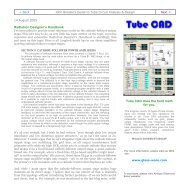
Back John Broskie's Guide to <strong>Tube</strong> Circuit Analysis & Design Next ><br />
17 April 2005<br />
Support the <strong>Tube</strong> <strong>CAD</strong> <strong>Journal</strong><br />
<strong>Only</strong> <strong>$12.95</strong><br />
to start designing tube-based<br />
crossovers and much more...<br />
TCJ Filter Design<br />
Class-AB auto-bias circuits<br />
If the usual DC servo circuit did not work perfectly with a class-A amplifier, what<br />
hope do we have for an auto-bias circuit for class-AB amplifiers A few techniques<br />
have been tried. At the complex end, we could build a circuit that only sampled the<br />
bias current when no signal was present or a circuit that ignored error signals<br />
beyond the class-A mode of operation. This approach would work best with a small<br />
CPU-based circuit that would monitor the current at startup, while the input was<br />
shorted to ground, and then would lock the bias via digital potentiometer until the<br />
amplifier was turned off. Of course, some amplifiers never are turned off and idle<br />
current can drift over a relatively short amount of time. The alternative, throwing<br />
away correction signals that occur beyond class-A is much simpler to implement,<br />
as it only requires a few extra diodes.
The above circuit appeared in Siliconix’s MOSPOWER Applications Handbook,<br />
1984; and originally appeared in a paper in the June 1982 IREE (ICCE). If the<br />
circuit does not make any sense to you, you are not alone. The first time I saw the<br />
circuit, I felt that it was time to tear up my big-brain club card, as I could not see<br />
how this circuit could work. If the top input on the OpAmp is the inverting, then<br />
the OpAmp amplifies positive-going errors in bias positively! Watch out; amplifier<br />
on fire! If the top input on the OpAmp is the non-inverting, then the OpAmp<br />
applies positive feedback to the non-inverting input, which must also spell D-A-N-<br />
G-E-R. The circuit that should have appeared is shown below. The transistor at the<br />
OpAmp’s output inverts the OpAmp’s output, making the whole circuit work, as the<br />
OpAmp’s non-inverting input effective becomes the servo’s inverting input.<br />
The <strong>Tube</strong> <strong>CAD</strong> <strong>Journal</strong>'s first<br />
companion program, TCJ Filter Design<br />
lets you design a filter or crossover<br />
(passive, solid-state or tube) without<br />
having to check out thick textbooks<br />
from the library and without having to<br />
breakout the scientific calculator. This<br />
program's goal is to provide a quick<br />
and easy display not only of the<br />
frequency response, but also of the<br />
resistor and capacitor values for a<br />
passive and active filters and<br />
crossovers.<br />
TCJ Filter Design is easy to use, but<br />
not lightweight, holding over 60<br />
different filter topologies and up to<br />
four filter alignments:<br />
Bessel,<br />
Butterworth,<br />
Gaussian,<br />
and Linkwitz-Riley.<br />
While the program’s main concern is<br />
active filters, solid-state and tube, it<br />
also does passive filters. In fact, it can<br />
be used to calculate passive<br />
crossovers for use with speakers by<br />
entering 8 ohms as the terminating<br />
resistance. <strong>Tube</strong> crossovers are a<br />
major part of this program; both<br />
buffered and un-buffered tube based
filters along with mono-polar and<br />
bipolar power supply topologies are<br />
covered. . Downloadable version (4<br />
Megabytes file).<br />
Download or CD ROM<br />
Windows 95/98/Me/NT/2000/XP<br />
For more information...<br />
To purchase , please visit our Yahoo Store:<br />
http://store.yahoo.com/glassware<br />
How does it work The voltage reference is derived from halving the voltage drop<br />
across the diode at the extreme right. Since class-A operation ends when the output<br />
stage current exceeds twice the idle current, we need to bisect the clipping voltage<br />
produced by the shunting diodes. The two 100k resistors define a 50% voltage<br />
divider that yields exactly half of the clipping voltage. As long as the amplifier is<br />
run in class-A, the shunting diodes never become forward biased and, thus, never<br />
conduct, effectively falling out of the circuit. Under these conditions, the DC servo<br />
strives to maintain an average idle current equal to the reference voltage divided by<br />
resistor Rs.<br />
When the amplifier is called upon to produce more than a small fraction of a watt<br />
(when it falls out of class-A), the shunting diodes become forward biased and<br />
conduct, clipping the maximum voltage that can be presented to the OpAmp’s noninverting<br />
input. Since the clipping voltage is twice the reference voltage, won’t the<br />
capacitor at the OpAmp’s non-inverting input become charged to that value No, it
cannot; as the input signal presented to it looks like a square wave with a peak<br />
magnitude equal to twice the reference voltage, which averages outs to close to the<br />
voltage reference. Interestingly enough, this circuit works best when the amplifier<br />
is putting out almost all of its potential power, as at lower signal levels the square<br />
wave looks more like half-wave rectified sine waves. So, how well does this circuit<br />
work Not that bad, after some tweaking. The bias voltage does drift during<br />
prolonged signal bursts, but with careful selection of the resistors feeding the<br />
shunting diodes, the drift can be reduced substantially.<br />
What about tubes Enough already with MOSFETs. The same circuit can easily be<br />
used with triodes, tetrodes, pentodes, FETs, IGBTs, and transistors—after suitable<br />
bias arrangements have been made, such as a negative bias voltage for the tubes<br />
and FETs. The circuit below works quite well and only uses one shunting diode.<br />
Over ten years ago, Morgan Jones has created an extremely clever class-AB autobias<br />
circuit specifically for tubes that works on the same principle of clipping the<br />
error signal. His circuit uses an OpAmp to amplify the voltage across a 1-ohm<br />
cathode resistor by a hundredfold. This magnified signal is then clipped at an<br />
adjustable level and fed back into an OpAmp that feeds a grounded-emitter<br />
amplifier, which inverts the voltage. Very slick, however, it too experiences bias<br />
drift under sustained signal bursts.<br />
(I would do his circuit differently, of course, as I even do my own circuits<br />
differently the next time I build them. I would include the PNP grounded-emmiter<br />
amplifier in the OpAmp's AC feedback loop, which would simplify the design<br />
slightly.)
The future<br />
So far, we have seen that no auto-bias circuit is perfect, with each bringing its own<br />
set of problems. Living in pure class-A and driving purely resistive loudspeaker is<br />
not practical. What we need is circuit that can adapt to the demands made on the<br />
amplifier and still produce a steady bias. Such a circuit exists. But it will have to<br />
wait until the next blog entry, as I am way over my typing limit.<br />
//JRB
Back www.tubecad.com Copyright © 1999-2005 GlassWare All Rights Reserved Next >


