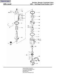
Maintenance Manual - Central States Industrial Equipment ...
Maintenance Manual - Central States Industrial Equipment ...
Maintenance Manual - Central States Industrial Equipment ...

Create successful ePaper yourself
Turn your PDF publications into a flip-book with our unique Google optimized e-Paper software.
Sanifl o Series<br />
Engineering<br />
Operation &<br />
<strong>Maintenance</strong><br />
Refine your process<br />
Drum<br />
Unloader<br />
System<br />
WIL-12071-E-01
TABLE OF CONTENTS<br />
SECTION 1 CAUTIONS—READ FIRST! . . . . . . . . . . . . . . . . . . . . . . . . . . . . . . . . . . . . . . . . . . . . . .1<br />
SECTION 2 DESIGNATION SYSTEM. . . . . . . . . . . . . . . . . . . . . . . . . . . . . . . . . . . . . . . . . . . . . . . . .2<br />
SECTION 3 DIMENSIONAL DRAWINGS . . . . . . . . . . . . . . . . . . . . . . . . . . . . . . . . . . . . . . . . . . . . .3<br />
SECTION 4 TROUBLESHOOTING . . . . . . . . . . . . . . . . . . . . . . . . . . . . . . . . . . . . . . . . . . . . . . . . . . . .4<br />
SECTION 5 ASSEMBLY . . . . . . . . . . . . . . . . . . . . . . . . . . . . . . . . . . . . . . . . . . . . . . . . . . . . . . . . . . . . .5<br />
SECTION 6 SCHEMATICS<br />
A. Operation . . . . . . . . . . . . . . . . . . . . . . . . . . . . . . . . . . . . . . . . . . . . . . . . . . . . . . . . . . . . .9<br />
B. Cleaning . . . . . . . . . . . . . . . . . . . . . . . . . . . . . . . . . . . . . . . . . . . . . . . . . . . . . . . . . . . . .13<br />
A. Control Box . . . . . . . . . . . . . . . . . . . . . . . . . . . . . . . . . . . . . . . . . . . . . . . . . . . . . . . . . .16<br />
B. Hose Schematic . . . . . . . . . . . . . . . . . . . . . . . . . . . . . . . . . . . . . . . . . . . . . . . . . . . . . . .18<br />
SECTION 9 EXPLODED VIEW & PARTS LISTING . . . . . . . . . . . . . . . . . . . . . . . . . . . . . . . . . . . .20<br />
Drum Unloader System . . . . . . . . . . . . . . . . . . . . . . . . . . . . . . . . . . . . . . . . . . . . . . . . . . .20
Section 1<br />
Drum Unloader System<br />
CAUTIONS—READ FIRST!<br />
CAUTION: Always wear safety glasses and appropriate safety<br />
gear when operating the Saniflo DUS unit.<br />
CAUTION: Always perform an inspection of the entire system<br />
before each use. Ensure that all parts are in good working<br />
condition and do not show signs of wear.<br />
WARNING: Prior to installing a Saniflo DUS into an application,<br />
you must first ensure that the DUS components are compatible<br />
with the process media and any cleaning or sanitation<br />
products.<br />
WARNING: Never attempt to modify the Saniflo DUS unit.<br />
Modification will change the dynamics of the DUS and could<br />
damage the unit, result in failure of the unit, or cause harm to<br />
anyone in the area.<br />
CAUTION: Always disconnect the main air supply to the Saniflo<br />
DUS before service or repairs are attempted. Failure to do so<br />
could result in harm to anyone in the area.<br />
CAUTION: The Saniflo DUS unit must be properly secured<br />
while in use. Failure to properly secure the system while in use<br />
could result in harm to anyone in the area.<br />
CAUTION: When using the Saniflo DUS unit, it is extremely<br />
important to note that the retracting downward movement can<br />
cause a pinch point at two areas of the unit.<br />
1. A pinch point is located at the bottom of the structure when<br />
the ram plate is lowered to the base assembly. To avoid injury<br />
to anybody operating this equipment or to anyone in the area<br />
of the equipment, keep hands, arms and head clear of plate and<br />
drum edge.<br />
2. Another pinch point is located at the area where the ram<br />
support bar comes in the vicinity of the header plate. To avoid<br />
injury to anybody operating this equipment or to anyone in the<br />
area of the equipment when it is in operation, a safe distance<br />
must be kept from the ram support bar/header plate area.<br />
CAUTION: Do not exceed 8.6 bar (125 psig) air pressure to the<br />
Saniflo DUS unit.<br />
Do not exceed 1.7 bar (25 psig) air pressure to the RAM DOWN.<br />
For normal operation, 1.0 bar (15 psig) is suggested.<br />
Do not exceed 5.5 bar (80 psig) air pressure to the RAM UP. For<br />
normal operation, 4.1 bar (60 psig) is suggested.<br />
CAUTION: Before attaching an air source to the DUS unit, inspect<br />
all hose connections to ensure they are secure.<br />
CAUTION: The E-stop can be used in any situation to stop all<br />
movement of the system. If the E-stop is activated while in ram<br />
down mode the ram plate with stop and retract slightly<br />
CAUTION: After the E-stop (Emergency shut-off) has been<br />
activated or air supply has been interrupted, first reset the E-<br />
stop by turning clock-wise. Then reset the system by depressing<br />
the air supply reset button.<br />
CAUTION: The DUS unit should anchored to the floor using the<br />
4 bolt holes in the base plate to comply with local and company<br />
codes.<br />
CAUTION: DUS Moving – Movement of the DUS unit should only<br />
be carried out by qualified and/or trained personnel. Removable<br />
casters are provided with the DUS. Verify with companies safety<br />
policy if permitted. Remove casters if not permitted.<br />
Pump<br />
CAUTION: Moving - When moving the DUS unit, be sure that the<br />
pump and ram are in the down position.<br />
CAUTION: Before operating Saniflo DUS unit, attach drum<br />
retention hooks to secure drum during operation. Failure to<br />
do so will result in drum being moved and/or lifted when ram<br />
assembly is moved upward. The drum retention device chain<br />
should be tight and not allow any movement of the drum of the<br />
base/floor.<br />
WARNING: It is important to follow the assembly instructions<br />
provided when building the Saniflo DUS unit. Altering the<br />
steps or changing the process may result in operation issues<br />
including improper rise and fall of the follower plate assembly.<br />
NOTE: Pump not included with Saniflo DUS.<br />
separately.<br />
Pump sold<br />
CAUTION: Do not apply compressed air to the exhaust port<br />
– pump will not operate.<br />
CAUTION: Do not exceed 8.6 bar (125 psig) air supply<br />
pressure.<br />
CAUTION: Do not over-lubricate air supply. Excessive lubrication<br />
will reduce pump performance.<br />
TEMPERATURE LIMITS:<br />
Neoprene –17.7°C to 93.3°C 0°F to 200°F<br />
Buna-N –12.2°C to 82.2°C 10°F to 180°F<br />
EPDM –51.1°C to 137.8°C –60°F to 280°F<br />
Viton ® –40.0°C to 176.7°C –40°F to 350°F<br />
Saniflex –28.9°C to 104.4°C –20°F to 220°F<br />
Polytetrafluoroethylene (PTFE)<br />
4.4°C to 104.4°C 40°F to 220°F<br />
Polyurethane –12.2°C to 65.6°C 10°F to 150°F<br />
CAUTION: Maximum temperature limits are based upon mechanical<br />
stress only. Certain chemicals will significantly reduce maximum<br />
safe operating temperatures. Consult Chemical Resistance Guide<br />
(E4) for chemical compatibility and temperature limits.<br />
WARNING: Prevention of static sparking – if static sparking<br />
occurs, fire or explosion could result. Pump, valves, and<br />
containers must be grounded to a proper grounding point when<br />
handling flammable fluids and whenever discharge of static<br />
electricity is a hazard.<br />
CAUTION: The process fluid and cleaning fluids must be<br />
chemically compatible with all wetted pump components.<br />
Consult Chemical Resistance Guide (E4).<br />
CAUTION: Do not exceed 82.2°C (180.0°F) air inlet temperature<br />
for Pro-Flo V models.<br />
CAUTION: Pumps should be thoroughly flushed before installing<br />
into process lines. FDA and USDA approved pumps should be<br />
cleaned and/or sanitized before use.<br />
CAUTION: If diaphragm rupture occurs, material being pumped<br />
may be forced out air exhaust.<br />
CAUTION: Before any maintenance or repair is attempted, the<br />
compressed air line to the pump should be disconnected and all<br />
air pressure allowed to bleed from pump. Disconnect all intake,<br />
discharge and air lines. Drain pump by turning it upside down<br />
and allowing any fluid to flow into a suitable container.<br />
WIL-12071-E-01 1 WILDEN PUMP & ENGINEERING, LLC
Section 2<br />
WILDEN DESIGNATION SYSTEM<br />
DRUM UNLOADER<br />
SYSTEM<br />
LEGEND<br />
DUSXX/ XXXX / XXX/ XXXX<br />
MODEL<br />
PUMP SIZE / TYPE<br />
SPECIALTY CODE (if applicable)<br />
DRUM SIZE<br />
GASKET MATERIAL<br />
FRAME MATERIAL<br />
FOLLOW PLATE MATERIAL<br />
CYLINDER MATERIAL<br />
BASE TYPE<br />
SANIFLO TM DUS MATERIAL CODES<br />
MODEL<br />
BASE TYPE<br />
DUS = DRUM UNLOADER<br />
SYSTEM<br />
PUMP SIZE / TYPE<br />
FD = 38mm (1-1/2”) FDA 1,2<br />
HS = 51mm (2”) SANIFLO HS 1,2<br />
B = BASE PLATE MOUNTED<br />
CYLINDER MATERIAL<br />
S = STAINLESS STEEL<br />
FOLLOW PLATE MATERIAL<br />
S = STAINLESS STEEL<br />
GASKET MATERIAL<br />
FB = SANITARY BUNA-N<br />
DRUM SIZE<br />
K = 508 mm – 584 mm<br />
(20.0” – 23.0”)<br />
FRAME MATERIAL<br />
S = STAINLESS STEEL<br />
NOTE:<br />
1. Refer to recommended pump list for pumps and specialty codes for use with the Saniflo DUS<br />
2. All recommended pumps use the single point exhaust option<br />
3. Pump models used on the DUS require a matching ram plate (Ref. the bill of materials)<br />
SPECIALTY CODES<br />
PUMP RECOMMENDATIONS<br />
Recommended DUS pump configurations:<br />
* Select either 1.5” FDA, 1.5” original series, or 2” HS pump to match the DUS configuration.<br />
* Configure pump with stainless steel center section if caustic based cleaners are used and or long durability is desired.<br />
* Utilize a chemically compatible long stroke diaphragm material such as Saniflex or Wilflex to maximize suction.<br />
* Utilize a heavy ball such as PTFE or Stainless Steel which are best for viscous products. Avoid light balls like Saniflex or Wilflex.<br />
* Select chemically compatible gasket that seals well such as Buna, EPDM, or Viton. Avoid PTFE.<br />
* Air motor should be single point exhaust (submersible). See pump specialty codes.<br />
WILDEN PUMP & ENGINEERING, LLC 2 WIL-12071-E-01
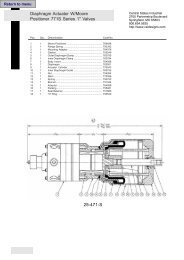
Section 3<br />
DIMENSIONAL DRAWING<br />
DIMENSIONS<br />
ITEM MM INCHES<br />
A 1057 41.6<br />
B 750 29.5<br />
C 2503 98.5<br />
D 1118 44.0<br />
E 1402 55.2<br />
F 1307 51.5<br />
MOUNTING BASE DIMENSIONS<br />
G 986 38.8<br />
H 333 13.1<br />
J 803 31.6<br />
K 15 DIA. 0.6 DIA.<br />
WIL-12071-E-01 3 WILDEN PUMP & ENGINEERING, LLC
Section 4<br />
TROUBLESHOOTING<br />
Uneven ram cylinder movement.<br />
1. Ensure that the ram cylinder down pressure is not<br />
excessive. Generally, no more than 1.0 bar (15 psig) is<br />
required to move the ram cylinders in the downward<br />
direction.<br />
2. Check to determine whether or not the ram cylinder<br />
air hoses are connected properly. Refer to airline<br />
schematic if the ram cylinder air hoses are not<br />
connected properly, the ram cylinders will fill<br />
unevenly, causing the ram cylinder movement to<br />
be inconsistent.<br />
3. Check for cylinder mis-alignment that could be<br />
causing binding. If so, determine if cylinders or<br />
cylinder mounting could be causing an issue.<br />
4. Make sure that air cylinder stops are adjusted<br />
correctly. The adjustment screws are located in top<br />
and bottom of cylinders.<br />
Pump runs but little or no product flows.<br />
1. Check for pump cavitation; slow pump speed to<br />
allow thick material to flow into liquid chambers.<br />
2. Check for sticking ball check valves. If material being<br />
pumped is not compatible with pump elastomers,<br />
swelling may occur. Replace ball check valves and<br />
seats with proper elastomers. Also, as the check<br />
valve balls wear out, they become smaller and can<br />
become stuck in the seats. In this case, replace<br />
balls and seats.<br />
NOTE: Heavy check balls such as PTFE work best.<br />
(Saniflex or Wilflex are considered light)<br />
3. Check to ensure that there is sufficient air pressure<br />
supplied by the ram down regulator on the control<br />
panel.<br />
4. Slow down pump to allow it to prime. Do this by<br />
reducing air pressure to the control box. If high<br />
discharge pressure is needed add a needle valve<br />
right on pump inlet to reduce air flow.<br />
Excessive drum contents leaking past gaskets.<br />
1. Ensure that the correct gasket size is being used in<br />
accordance with the drum size.<br />
NOTE: The gaskets are NOT designed to completely<br />
seal against sides of drum. Under normal operating<br />
conditions, there will be some weeping of drum<br />
contents.<br />
After evacuating drum contents, ram cylinders are<br />
struggling with upward movement.<br />
1. Check to determine whether or not drum vent<br />
button is activated. This will inject air under the<br />
ram plate and break the vacuum caused when<br />
removing the ram plate from the drum.<br />
2. Verify "Ram Up" pressure is sufficient.<br />
Pump air valve freezes.<br />
1. Check for excessive moisture in compressed<br />
air. Either install a dryer or hot air generator<br />
for compressed air. Alternatively, a coalescing<br />
filter may be used to remove the water from the<br />
compressed air in some applications.<br />
Air bubbles in pump discharge.<br />
1. Check for ruptured diaphragm.<br />
2. Check tightness of outer pistons.<br />
3. Check tightness of fasteners and integrity of<br />
o-rings and seats, especially at intake manifold.<br />
4. Ensure pipe connections are airtight.<br />
Product comes out air exhaust.<br />
1. Check for diaphragm rupture.<br />
2. Check tightness of outer pistons to shaft.<br />
WILDEN PUMP & ENGINEERING, LLC 4 WIL-12071-E-01
Section 7 Assembly / disassembly<br />
Section 5<br />
ASSEMBLY<br />
Tools Required :<br />
• 10 mm Wrench<br />
• Adjustable Wrench<br />
NOTE: It is also recommended that an appropriate anti-seize is used on all stainless<br />
steel fasteners during assembly.<br />
Although some air fittings may come with a pipe sealant already applied, it is<br />
recommended that a pipe sealant be used with all additional air fittings during<br />
assembly.<br />
It is important to follow the assembly instructions provided when building the<br />
Saniflo DUS unit. Altering the steps or changing the process may result in<br />
operation issues including improper rise and fall of the follower plate assembly.<br />
Step 1<br />
Install the main air filter, regulator,<br />
and shut off valve on the back of the<br />
control panel header plate with the<br />
fastener provided.<br />
Step 2<br />
Install air control panel with<br />
fasteners provided to the header<br />
plate using a 10mm wrench.<br />
Step 3<br />
Using the supplied tubing, connect<br />
the air filter/regulator to the control<br />
box via the main air supply port<br />
located on the bottom of the control<br />
box as shown.<br />
NOTE: Simply push the tubing into<br />
the connection to lock the tubing in<br />
place.<br />
WIL-12071-E-01 5 WILDEN PUMP & ENGINEERING, LLC
ASSEMBLY<br />
Step 4:<br />
Step 5:<br />
Step 6:<br />
Make the remaining 4 connections<br />
as shown. NOTE: The labels on the<br />
control panel are color coded with<br />
the tubing color.<br />
If using a Wilden Hygienic Series<br />
pump, you may order it minus the<br />
inlet manifold and stand. All Wilden<br />
FDA pumps will require the removal<br />
of the inlet manifold at this time.<br />
Ensuring you have the correct<br />
pump for the ram plate is essential.<br />
The Saniflo FDA and Saniflo HS<br />
EHEDG pumps use different ram<br />
plates. After verifying the correct<br />
ram plate, move the ram plate to the<br />
full down position. Note: You must<br />
read all cautions, and operating<br />
instructions before doing this.<br />
Step 7:<br />
With the ram plate in the down<br />
position you may prepare to install<br />
the pump by locating the seat<br />
gaskets, check balls, and clamps as<br />
shown.<br />
Step 8:<br />
Mount the pump using the provided<br />
clamp bands shipped with the<br />
pump. The air inlet must face the<br />
ram plate vent as shown (with the<br />
muffler facing away from the ram<br />
plate vent) to provide sufficient<br />
clearance.<br />
Step 9:<br />
Install the exhaust discharge elbow<br />
and hose vertically, with the muffler<br />
threaded through the eyelet in the<br />
ram support bracket.<br />
WILDEN PUMP & ENGINEERING, LLC 6 WIL-12071-E-01
ASSEMBLY<br />
Step 10:<br />
Step 11:<br />
Step 12<br />
Install the air inlet reducer bushing<br />
and fitting to the air inlet of the<br />
pump. Connect the “air to pump”<br />
connection from the control box to<br />
the air inlet of the pump with the<br />
supplied tubing.<br />
Install the ram plate vent assembly<br />
onto the ram vent port behind the<br />
pump. Use the provided clamp<br />
band and gasket. Connect to the<br />
control box using the supplied<br />
green tubing.<br />
Install the two (2) pieces of the main<br />
wiper seal assembly onto the bolts<br />
of the follower plate.<br />
NOTE: This seal should be<br />
approximately 1/2" - 1" larger in<br />
diameter than your drum.<br />
Step 13<br />
Install the two (2) pieces of the<br />
smaller wiper support seal on top<br />
of the main wiper seal. NOTE: Be<br />
sure to rotate the seams between<br />
the two gasket sets to avoid direct<br />
alignment.<br />
Step 14<br />
Install stainless steel retaining<br />
rings on the follower plate and use<br />
the provided sanitary wing nuts to<br />
secure.<br />
Step 15<br />
In order to set the drum alignment<br />
guides properly, center a drum<br />
under the complete follower plate.<br />
To do this, hook up air supply to<br />
the system and press the “MAIN<br />
AIR SUPPLY RESET” button on<br />
the control panel, then use the ram<br />
plate control lever to move the ram<br />
plate above the drum.<br />
WIL-12071-E-01 7 WILDEN PUMP & ENGINEERING, LLC
ASSEMBLY<br />
Step 16<br />
Step 17<br />
Step 18<br />
Now that the drum is centered<br />
on the follower plate, adjust the<br />
alignment guides to match the drum<br />
size. NOTE: Repeat steps 33 and 34<br />
for a new drum size or if the guides<br />
are inadvertently moved.<br />
Install user supplied discharge<br />
hose on the pump using the<br />
necessary reducer, clamp band and<br />
o-rings.<br />
NOTE: A 64mm (2-1/2") or 76mm<br />
(3") Hose is suggested for best<br />
performance. (Reducer not<br />
included)<br />
Thread discharge hose through<br />
support loop on the bottom of the<br />
ram support bar.<br />
WILDEN PUMP & ENGINEERING, LLC 8 WIL-12071-E-01
Section 5A<br />
OPERATION<br />
Safety <strong>Equipment</strong><br />
Suggestions:<br />
• Safety Glasses<br />
• Protective Clothing<br />
• Safety Shoesv or<br />
Boots<br />
• Gloves<br />
CAUTION: Always read and familiarize yourself with these operation instructions<br />
prior to using the Saniflo DUS system. Improper use or misapplication could<br />
result in bodily injury or death.<br />
Step 1<br />
Before initial use, or after cleaning<br />
and reassembly, always inspect all<br />
liquid and air connections. Also,<br />
ensure that all frame and pneumatic<br />
cylinder connections are tight.<br />
Step 2<br />
Install discharge hose to discharge<br />
of pump. A 64 mm (2-1/2”) or<br />
76 mm (3”) hose is suggested for best<br />
performance.<br />
Step 3<br />
Check pump inlet air supply to<br />
ensure that regulator is set to less<br />
than the maximum of 8.6 bar (125<br />
psig).<br />
WIL-12071-E-01 9 WILDEN PUMP & ENGINEERING, LLC
OPERATION<br />
Step 4<br />
Step 5<br />
Step 6<br />
Move drum into position under ram<br />
assembly, ensuring that the drum<br />
guides on the bottom of the frame<br />
stop the drum directly centered<br />
under the plate.<br />
Check to ensure the proper gasket set is<br />
installed for the drum being unloaded.<br />
NOTE: The larger gasket included in the<br />
gasket set should be approx. 1⁄2” to 1”<br />
larger than the drum diameter and the<br />
smaller gasket should be the same size<br />
as the drum diameter. In some drum types<br />
such as conical drums or large diameter<br />
pumps, all three gaskets sets should be<br />
installed. The largest gasket should be<br />
placed between the two smaller sizes. For<br />
conical drums with narrow bottoms, the<br />
small gasket should go on the bottom.<br />
The gaskets are NOT designed to completely<br />
seal against sides of drum. Under<br />
normal operating conditions, there will be<br />
some slight weeping of drum contents.<br />
Remove the drum lid to expose product<br />
being pumped and hook drum retainer<br />
hooks over upper edge of the drum. If<br />
a plastic drum liner is used, the liner<br />
should be draped over the drum lip and<br />
then held down with same clamp that<br />
is used to hold the drum lid. Tighten<br />
drum retainer hooks to secure the drum<br />
in the down position during operation.<br />
When adjusted and tightened properly,<br />
the drum should not move. The hook<br />
can be placed on a different chain link if<br />
further adjustment is needed.<br />
Step 7<br />
To active or reset the DUS unit, press the<br />
green reset button any time the E-stop has<br />
been pushed or the air supply has been<br />
interrupted. NOTE: It is not necessary to<br />
reset (start) the unit before each use, only<br />
after the air supply has been interrupted.<br />
Note: the red E-stop button is a safety feature<br />
that will stop the unit at any time in<br />
operation. It is recommended you press the<br />
E-stop any time the unit is left un-attended to<br />
prevent accidental use of the DUS.<br />
Step 8<br />
When moving the ram in the down direction,<br />
stand towards the right of the unit and grab<br />
the ram plate support rod with your left<br />
hand to guide the ram plate into position.<br />
Step 9<br />
To begin process of adjusting RAM<br />
DOWN air supply, first set regulator<br />
to 0 bar (0 psig). Then increase air<br />
pressure until the ram plate comes<br />
in contact with the surface of the<br />
drum contents. Never exceed a<br />
maximum of 1.7 bar (25 psig).<br />
WILDEN PUMP & ENGINEERING, LLC 10 WIL-12071-E-01
OPERATION<br />
Step 10<br />
Step 11<br />
Step 12<br />
To move the ram plate down onto the<br />
product surface, pull the red lever to the<br />
down position. This will take several<br />
seconds as the pneumatic cylinders<br />
come up to operating pressure. Ideally,<br />
the pressure should be set so that the ram<br />
plate stops automatically when coming<br />
into contact with product surface.<br />
Check RAM UP air supply and<br />
ensure that regulator is set for<br />
normal operation (ram lifting speed).<br />
Ideally, the pressure should be set<br />
so that the ram plate will slowly<br />
move upward and out of the drum.<br />
Never exceed 5.5 bar (80 psig).<br />
The pump can be started after the<br />
ram plate has come into contact<br />
with the product surface. To start<br />
the pump, pull out the black button<br />
on the side of the control panel.<br />
Step 13<br />
Once the volume of product desire<br />
has been removed from the drum,<br />
or the drum is empty push in on the<br />
black knob to stop pump. NOTE:<br />
The ram control lever can remain in<br />
the down position even if the pump<br />
is not running.<br />
Step 14<br />
In preparation for removing the ram<br />
plate from the drum, move the ram<br />
ram control level to the middle (off)<br />
position.<br />
Step 15<br />
Pull the green ram vent knob out to<br />
allow positive pressure below the<br />
ram plate to assist with removal.<br />
WIL-12071-E-01 11 WILDEN PUMP & ENGINEERING, LLC
OPERATION<br />
Step 16<br />
Step 17<br />
Step 18<br />
To remove the ram plate from the<br />
drum, move the ram control lever<br />
to the up position. Return to the<br />
middle (off) position once the ram<br />
plate has retracted to its full height.<br />
NOTE: Ensure the drum retainers<br />
are in place before starting this<br />
action.<br />
Once the ram has cleared the upper<br />
edge of the drum, push in on the<br />
green ram vent knob to stop the air<br />
flow coming through the ram vent.<br />
Remove drum retention hooks<br />
so that the empty drum can be<br />
removed from the system to make<br />
way for a new drum.<br />
WILDEN PUMP & ENGINEERING, LLC 12 WIL-12071-E-01
Section 7 Assembly / disassembly<br />
Section 5B<br />
CLEANING<br />
Safety <strong>Equipment</strong><br />
Suggestions:<br />
• Safety Glasses<br />
• Protective Clothing<br />
• Safety Shoes or Boots<br />
• Gloves<br />
CAUTION: Always read and familiarize yourself with these operation instructions<br />
prior to using the Saniflo DUS system. Improper use or misapplication could<br />
result in bodily injury or death.<br />
Do not use cleaners containing chlorides such as bleach. Consult cleaning chemical<br />
supplier for cleaning agents compatible with stainless steel and the elastomer<br />
materials used in the pump. Cleaning agents containing caustics and light acids<br />
are generally approved for stainless steel.<br />
Pumps configured for submersible use are recommended to facilitate cleaning and<br />
reduce maintenance costs.<br />
While the components are designed for direct contact with water, for longest life,<br />
avoid excessive direct water pressure contact to the control panel and the ram<br />
cylinder seals.<br />
Step 1<br />
Before starting the cleaning process,<br />
remove the product drum from the<br />
system.<br />
Step 2<br />
Before starting detailed cleaning of<br />
the unit, wash down the system to<br />
remove any build up on ram plate,<br />
exterior of pump, hoses and/or<br />
frame.<br />
Step 3<br />
Remove gasket retaining ring and<br />
both gasket sets from the ram plate<br />
and clean each item and entire<br />
area.<br />
WIL-12071-E-01 13 WILDEN PUMP & ENGINEERING, LLC
CLEANING<br />
Step 4<br />
Step 5<br />
Step 6<br />
Remove ram vent assembly, then<br />
clean and inspect.<br />
Lower ram plate with pump down<br />
into clean, empty drum. Stop the<br />
ram plate approximately 50 mm<br />
(2")-125 mm (5") from the bottom of<br />
the drum. NOTE: To pre-rinse the<br />
pump, pump water out to a suitable<br />
drain while continuing to add water<br />
to the drum. Flush out to drain until<br />
the discharge water runs clean.<br />
Add water with cleaning solution<br />
to the drum and start pump by<br />
pulling black pump knob out on<br />
control panel. NOTE: The pump<br />
can be submerged during this<br />
cleaning process if you're using the<br />
recommended submersible Pro-Flo<br />
V or Pro-Flo X model.<br />
Step 7<br />
Continue to supply water and<br />
cleaning solution to the pump,<br />
allowing the pump to run until the<br />
discharge of the pump/system runs<br />
clear.<br />
Step 8<br />
Once the water runs clear, put the<br />
discharge hose back in the drum to<br />
recirculate. Hot water (caution) and<br />
cleaning chemicals can be added at<br />
this point to help clean/sanitize the<br />
pump and hose. Caution should<br />
be used handling the hot water and<br />
chemicals.<br />
Step 9<br />
After circulating cleaning solution<br />
for a minimum of ten minutes,<br />
discharge remaining fluid to a<br />
suitable drain or collection system.<br />
Refill the drum one more time with<br />
clean water and optional sanitizer<br />
and allow pump to flush system<br />
until all fluid is removed.<br />
WILDEN PUMP & ENGINEERING, LLC 14 WIL-12071-E-01
CLEANING<br />
Step 10<br />
Step 11<br />
Step 12<br />
Raise the ram plate while the pump<br />
continues to run. This will help<br />
remove any remaining water from<br />
the pump and discharge lines. Once<br />
above the rim of the drum, turn the<br />
pump off.<br />
Reinstall the ram vent and gasket.<br />
If the unit will not be used on another<br />
product immediately, lower the ram<br />
plate to the floor for safety and turn<br />
the air supply off.<br />
Step 13<br />
As each product is different,<br />
and each application may have<br />
different cleaning requirements, it<br />
may be necessary to remove and<br />
disassemble the pump to ensure<br />
proper cleaning. If no further<br />
cleaning is necessary you may<br />
reinstall the wiper seals as shown<br />
in the assembly portion of this<br />
manual.<br />
WIL-12071-E-01 15 WILDEN PUMP & ENGINEERING, LLC
Section 6A<br />
CONTROL BOX SCHEMATICS<br />
9<br />
E-Stop<br />
18<br />
9<br />
9<br />
Pump<br />
Main<br />
27<br />
10<br />
9<br />
9<br />
28<br />
9<br />
Reset<br />
17<br />
9<br />
8<br />
8<br />
12 12<br />
8 8<br />
24<br />
20<br />
7<br />
9 30<br />
Cylinders<br />
16<br />
9<br />
9<br />
21<br />
9<br />
9<br />
9<br />
7<br />
9<br />
Pump<br />
15<br />
9<br />
6 6<br />
4<br />
9<br />
8<br />
19<br />
7<br />
9<br />
Vent<br />
14<br />
9<br />
4<br />
9<br />
5<br />
2<br />
11 11 11 10<br />
1<br />
28<br />
28<br />
28 29 29<br />
7<br />
7<br />
7<br />
25<br />
24<br />
23<br />
3<br />
22<br />
7<br />
26<br />
WILDEN PUMP & ENGINEERING, LLC 16 WIL-12071-E-01
Section 8A<br />
CONTROL BOX SCHEMATICS<br />
DUSHS CONTROL BOX COMPONETS<br />
ITEM DESCRIPTION QTY. PART NUMBER<br />
1 1/2” TUBE X 1/2” NPT FEMALE BULKHEAD 1 DUS-4025<br />
2 1/2” TUBE X 1/2” NPT OFFSET “T” 1 DUS-4026<br />
3 1/2” TUBE X 1/2” NPT MALE 1 DUS-4022<br />
4 1/4” TUBE X 1/8” NPT DUAL BANJO ELBOW 2 DUS-4028<br />
5 1/2” TUBE X 1/4” TUBE PLUG-IN REDUCER 1 DUS-4029<br />
6 MANIFOLD 1 DUS-2028<br />
7 1/4” TUBE X 1/4” NPT BANJO ELBOW 8 DUS-4006<br />
8 1/2” TUBE X 1/2” NPT BANJO ELBOW 6 DUS-4047<br />
9 1/4” TUBE X 1/8” NPT BANJO ELBOW 22 DUS-4027<br />
10 1/2” TUBE X 1/2” TUBE BULKHEAD 1 DUS-4030<br />
11 1/4” TUBE X 1/4” TUBE BULKHEAD 3 DUS-4031<br />
12 VALVE: PILOT OPERATED 2 DUS-4032<br />
13 VALVE: PILOT OPERATED 1 DUS-4033<br />
14 VALVE: PUSH BUTTON, GREEN 1 DUS-4034<br />
15 VALVE: PUSH BUTTON, BLACK 1 DUS-4035<br />
16 VALVE: LEVER OPERATED, RED 1 DUS-4036<br />
17 VALVE: PUSHBUTTON, SPRING RETURN, GREEN 1 DUS-4037<br />
18 VALVE: PALM BUTTON, RED 1 DUS-4038<br />
19 REGULATOR: 1/4” WITH GAUGE, 0 - 2 BAR 1 DUS-4039<br />
20 REGULATOR - 1/4” WITH GUAGE 0 - 4 BAR 1 DUS-4040<br />
21 VALVE: PILOT OPERATED 1 DUS-4041<br />
22 1/2” FILTER/REGULATOR WITH AUTO DRAIN, GUAGE, BRACKET 1 DUS-4021<br />
23 1/2” TUBE X 1/2” NPT ELBOW 1 DUS-4024<br />
24 1/4” TUBE X 1/4” NPT CHECK FITTING 2 DUS-4023<br />
25 1/4” TUBE “Y” 1 DUS-4042<br />
26 1/4” TUBE TEE 1 DUS-4043<br />
27 1/8” HEX NIPPLE 1 DUS-6055<br />
28 1/4” TUBE SOCKET ELBOW 4 DUS-4044<br />
29 1/2” TUBE SOCKET ELBOW 2 DUS-4045<br />
CAUTION: Before performing maintenance on the DUS control panel, ensure that all<br />
air pressure is removed from system.<br />
All boldface items are primary wear parts<br />
WIL-12071-E-01 17 WILDEN PUMP & ENGINEERING, LLC
Section 6B<br />
HOSE SCHEMATIC<br />
CAUTION: Prior to operating the DUS unit, ensure that<br />
the air hoses are connected and secured properly.<br />
CAUTION: Always wear safety glasses when operating<br />
the DUS unit.<br />
WILDEN PUMP & ENGINEERING, LLC 18 WIL-12071-E-01
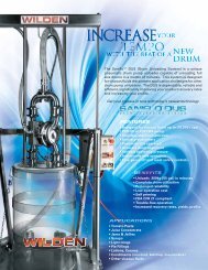
Finding<br />
Spares<br />
Nightmare<br />
A<br />
<br />
Sleep easier with<br />
PRODUCTS:<br />
AODDP<br />
(Air Operated Double<br />
Diaphragm Pumps)<br />
• Warren-Rupp ®<br />
• ARO ®<br />
• Other<br />
PUMP PARTS<br />
(Low Cost)<br />
• Diaphragms<br />
• Valve balls<br />
• Valve seats<br />
Spectrom is not your typical after market part<br />
supplier. We do not simply sell pump parts; we<br />
provide value added procurement solutions.<br />
Our unique network enables us to purchase<br />
effectively, resulting in low cost<br />
solutions. We also know that low purchase<br />
price is not enough - quality, integrity and<br />
inventory are also important. Spectrom is structured<br />
to provide Pre and Post sales support, giving<br />
our customers value added application and pump<br />
knowledge.<br />
Contact us to have a procurement solution<br />
developed for you. We don’t just fit you<br />
into a generic system, we develop specific<br />
solutions that achieve results.<br />
Spectrom will ship your order from<br />
our facility within 3 working days!<br />
KNOWLEDGE<br />
& SERVICE<br />
• Competitive pricing<br />
• Delivery<br />
• Service<br />
• Inventory<br />
WARNING: These parts may exhibit<br />
better life than OEM parts.<br />
1-909-512-1261 www.spectromparts.com
Section 9<br />
EXPLODED VIEW AND PARTS LISTING<br />
DRUM UNLOADER SYSTEM<br />
EXPLODED VIEW<br />
WILDEN PUMP & ENGINEERING, LLC 20 WIL-12071-E-01
EXPLODED VIEW AND PARTS LISTING<br />
DRUM UNLOADER SYSTEM<br />
PARTS LISTING<br />
Item No. Description Qty Part No.<br />
1 Coupling, 1” Npt 1 DUS-6020<br />
2 Street Elbow, 1” Npt 1 DUS-6021<br />
3 1” Sanitary Cap With 1/4” Npt 1 DUS-6045<br />
4 1” Sanitary Tri-clamp Gasket 1 DUS-6046<br />
5 1” Tri-clamp With Wing Nut 1 DUS-3006<br />
6 1/2” Filter Reg With Bracket 1 DUS-4021<br />
7 1/2” Tube X 1/2” Npt Banjo Elbow 1 DUS-4047<br />
8 1/2” Tube X 1/2” Npt Fitting 1 DUS-4022<br />
9 M6 X 1.0 X 20mm Hex Bolt 17 DUS-6035<br />
10 1/4 Tube X 1/4” Npt Banjo Elbow 4 DUS-4006<br />
11 1/4” Tube X 1/4” Npt Check Valve 1 DUS-4023<br />
12 1/4”-20 Hex Nut 4 DUS-6039<br />
13 1/4”x 20 X 3.5” Hex Bolt 2 DUS-6036<br />
14 1/8” 304 Ss Chain-25” 2 DUS-6015<br />
15 3/16” Quick Link, 304 Ss 4 DUS-6016<br />
16 3/4” X 1/2” Reducer Bushing 1 DUS-6052<br />
17 5/16” Sanitary Wing Nut 10 DUS-6047<br />
18 Eyebolt, 5/16” X 3.25” 2 DUS-6014<br />
19 Barrel Centering Device 2 DUS-2018<br />
20 Caster 2 DUS-6056<br />
21 Control Box Assembly 1 DUS-4000<br />
22 Control Box Support Plate 1 DUS-2021<br />
23 Drum Guide Support Plate, Left 1 DUS-2019<br />
24 Drum Guide Support Plate,right 1 DUS-2020<br />
25 Drum Retaining Hook 2 DUS-2015<br />
26 Floor Plate 1 DUS-2022<br />
27 & 28 Gasket - Split, 21-1/2” Dia 2 DUS-2023<br />
27 & 28 Gasket - Split, 22-1/2” Dia 2 DUS-2024<br />
27 & 28 Gasket - Split, 23” Dia 2 DUS-2025<br />
29 Gasket Retaining Ring 4 DUS-2026<br />
30 Header Plate 1 DUS-2027<br />
31 M10 Cap Nut 8 DUS-6037<br />
32 Flat Washer, M10 8 DUS-6003<br />
33 M10 Lock Washer 8 DUS-6049<br />
34 Bolt, Hex, M10 X 1.5 X 20mm 8 DUS-6002<br />
35 M12 Cap Nut 4 DUS-6038<br />
36 M12 Lock Washer 14 DUS-6054<br />
37 Nut, Hex, M12 X 1.75 12 DUS-6005<br />
38 Bolt, Hex, M12 X 1.75 X 30mm 10 DUS-6004<br />
39 M18 Hex Nut 4 DUS-6040<br />
40 M18 Lock Washer 2 DUS-6050<br />
41 M6 Lock Washer 16 DUS-6053<br />
42 Hex Nut, M6 X 1.00 13 DUS-6009<br />
43 Muffler 1 15-3510-99R<br />
44 Hose - 1”, Muffler Extension 1 DUS-6017<br />
45 Pump 1 Call Factory<br />
46 Ram Cyclinder Cross Bar 1 DUS-6041<br />
47 Ram Cylinder With Mount Flange 2 DUS-4046<br />
48 Ram Plate Rod 2 DUS-6044<br />
49 RAM PLATE, PV4 FDA 1 DUS-6042<br />
49 Ram Plate, Pv8 Hs 1 DUS-6043<br />
50 1/4” Pan Head Screw, Pan 3 DUS-6048<br />
51 Support Brace 2 DUS-2017<br />
All boldface items are primary wear parts<br />
WIL-12071-E-01 21 WILDEN PUMP & ENGINEERING, LLC
NOTES<br />
WILDEN PUMP & ENGINEERING, LLC 22 WIL-12071-E-01
NOTES<br />
WIL-12071-E-01 23 WILDEN PUMP & ENGINEERING, LLC
NOTES<br />
WILDEN PUMP & ENGINEERING, LLC 24 WIL-12071-E-01
WARRANTY<br />
Each and every product manufactured by Wilden Pump and Engineering, LLC is built to meet the highest<br />
standards of quality. Every pump is functionally tested to insure integrity of operation.<br />
Wilden Pump and Engineering, LLC warrants that pumps, accessories and parts manufactured or supplied by<br />
it to be free from defects in material and workmanship for a period of five (5) years from date of installation or<br />
six (6) years from date of manufacture, whichever comes first. Failure due to normal wear, misapplication, or<br />
abuse is, of course, excluded from this warranty.<br />
Since the use of Wilden pumps and parts is beyond our control, we cannot guarantee the suitability of any pump<br />
or part for a particular application and Wilden Pump and Engineering, LLC shall not be liable for any consequential<br />
damage or expense arising from the use or misuse of its products on any application. Responsibility is limited<br />
solely to replacement or repair of defective Wilden pumps and parts.<br />
All decisions as to the cause of failure are the sole determination of Wilden Pump and Engineering, LLC.<br />
Prior approval must be obtained from Wilden for return of any items for warranty consideration and must be<br />
accompanied by the appropriate MSDS for the product(s) involved. A Return Goods Tag, obtained from an<br />
authorized Wilden distributor, must be included with the items which must be shipped freight prepaid.<br />
The foregoing warranty is exclusive and in lieu of all other warranties expressed or implied (whether written or oral)<br />
including all implied warranties of merchantability and fitness for any particular purpose. No distributor or other<br />
person is authorized to assume any liability or obligation for Wilden Pump and Engineering, LLC other than expressly<br />
provided herein.<br />
PLEASE PRINT OR TYPE AND FAX TO WILDEN<br />
PUMP INFORMATION<br />
Item # Serial #<br />
Company Where Purchased<br />
YOUR INFORMATION<br />
Company Name<br />
Industry<br />
Name<br />
Title<br />
Street Address<br />
City State Postal Code Country<br />
Telephone Fax E-mail Web Address<br />
Number of pumps in facility<br />
Number of Wilden pumps<br />
Types of pumps in facility (check all that apply): Diaphragm Centrifugal Gear Submersible Lobe<br />
Other<br />
Media being pumped<br />
How did you hear of Wilden Pump Trade Journal Trade Show Internet/E-mail Distributor<br />
Other<br />
ONCE COMPLETE, FAX TO (909) 783-3440<br />
NOTE: WARRANTY VOID IF PAGE IS NOT FAXED TO WILDEN<br />
WILDEN PUMP & ENGINEERING, LLC