Download Complete Valves, Clamps, & Accessories ... - HYDAC USA
Download Complete Valves, Clamps, & Accessories ... - HYDAC USA
Download Complete Valves, Clamps, & Accessories ... - HYDAC USA

You also want an ePaper? Increase the reach of your titles
YUMPU automatically turns print PDFs into web optimized ePapers that Google loves.
Hydraulic <strong>Accessories</strong><br />
<strong>Valves</strong>, <strong>Clamps</strong> & Reservoir <strong>Accessories</strong>
<strong>HYDAC</strong> Products<br />
About <strong>HYDAC</strong><br />
<strong>HYDAC</strong> stands for worldwide presence and accessibility to the customer. <strong>HYDAC</strong> has over 1000 distributors<br />
worldwide and more than 40 wholly owned branches. The HYCON Division of <strong>HYDAC</strong> is an industry leader in the<br />
manufacture of hydraulic valves, clamps, reservoir accessories, filters, and elements for both mobile and industrial<br />
applications. The HYCON Division has been providing standard products and custom solutions to the fluid power<br />
industry for more than 30 years.<br />
The <strong>Valves</strong>, <strong>Clamps</strong>, & <strong>Accessories</strong> group manufactures highly engineered high<br />
pressure ball valves, which guarantee safe and reliable operation. A complete range<br />
of DIN 3015 clamps for mounting hoses, tubes, and pipes is complimented by our<br />
specialty and completely custom mounting solutions. Reservoir accessories round<br />
out our product line, and put the finishing touches on your system.<br />
<strong>HYDAC</strong> Quality<br />
<strong>HYDAC</strong> stands for quality and customer satisfaction. To ensure that our products are<br />
as innovative as possible, they are developed, manufactured, and tested by qualified<br />
personnel using state of the art equipment and technology.<br />
<strong>HYDAC</strong> Customer Service<br />
Our internal staff and worldwide distribution network take care of the important<br />
matter of customer service. <strong>HYDAC</strong> values high standards, professional ethics,<br />
and mutual respect in all transactions with customers, vendors, and employees.<br />
We invest in our relationships by providing expertise, quality, dependability, and<br />
accessibility to foster growth and a sense of partnership. Our customer service<br />
representatives are committed to serving the customers’ needs.<br />
Applications<br />
<strong>HYDAC</strong> has over 40 years of global experience in applying hydraulic components in both mobile and industrial systems. The industries served<br />
includes, but is in no way limited to:<br />
Mobile Hydraulics<br />
• Construction vehicles<br />
• Agricultural vehicles<br />
• Aerospace<br />
• Lift equipment<br />
• Shipbuilding<br />
Industrial Hydraulics<br />
• Pulp & paper mills<br />
• Steel mills.& heavy industry<br />
• Plastics<br />
• Power generation & wind energy<br />
• Offshore oil<br />
• Chemical processing<br />
• Food processing<br />
About this Catalog<br />
Please review the information below to familiarize yourself with the conventions used in this catalog, as well as some general information about<br />
ordering the <strong>HYDAC</strong> products within.<br />
Part Numbers and Model Codes<br />
Every <strong>HYDAC</strong> Product has a Model Code and an eight digit Part Number. A Part Number is simply a unique, computer<br />
generated number that identifies a product. A Model Code is a sequence of codes that contains a complete<br />
description of the product, with each portion of the code defining some variable or option. BOTH Model Code and<br />
Part Number are listed in this catalog, whenever possible. It is recommended that you use BOTH Model Code and<br />
Part Number when communicating with <strong>HYDAC</strong>.<br />
When options are limited, we have created charts that contain ALL possible combinations, or available products.<br />
In cases where the options create too many combinations to list, we have provided a Model Code Tree, which is<br />
used to create a complete Model Code which specifies the product as well as all options that are desired. Part Number<br />
are subject to change if <strong>HYDAC</strong> processes change, or design revisions are implemented by <strong>HYDAC</strong>. In this case,<br />
<strong>HYDAC</strong> Customer Service will refer you to the new part number.<br />
Standard vs. Non-standard Products<br />
Since <strong>HYDAC</strong> offers such a vast number of options for many product lines, it becomes necessary to differentiate<br />
between Standard and Non-standard configurations. Standard products are the most common configurations, which<br />
are continually supported by <strong>HYDAC</strong> in regular production. Non-standard configurations are less commonly ordered,<br />
and may require minimum orders and/or extended delivery times.<br />
Throughout this catalog we have distinguished Non-standard products or options from the Standard, by listing the<br />
them in red. In model code trees, any red option selected will cause that configuration to be considered Nonstandard.<br />
In charts that contain complete model codes, the entire model code will be in red for Non-standard products.
Table of Contents<br />
<strong>Valves</strong><br />
Overview ...............................1<br />
High Pressure Ball <strong>Valves</strong><br />
Overview ...............................3<br />
2-way SAE & NPT Threaded [KHB, KHM] .....5<br />
2-way Split Flange [KHB, KHM] .............7<br />
Specialty Ball <strong>Valves</strong> Overview .............9<br />
2-way BSPP Threaded [KHB, KHM] ........10<br />
2-way Steel Ball Seals [KHB, KHM] .........11<br />
2-way Stainless Steel [KHM] ..............12<br />
3-way Diverter [KHB3K] ..................13<br />
2-way Manifold Mount [KHP] ..............15<br />
Multiway Threaded [KH3, KH4] ............17<br />
Actuators [EDA] ........................19<br />
Locking Devices & Limit Switches ..........21<br />
Seal Kits ..............................23<br />
Handles ...............................24<br />
Engineering Data .......................24<br />
Direct Mount SAE Flange [KHF3/6] .........25<br />
Direct Mount SAE Flange [KHF3] ...........26<br />
3 Piece Ball Valve [KHM3H] ...............27<br />
Process & Automated <strong>Valves</strong><br />
Overview ..............................29<br />
Low Pressure Stainless Steel [KHNVN] ......30<br />
Inline Isolation Valve + Actuator [HVA] .......31<br />
Angle Seat Valve [ASV] ...................33<br />
Automated 2 Piece Ball Valve [KHL] ........35<br />
Automated 3 Piece Ball Valve [KHM3L] ......37<br />
Solenoid <strong>Valves</strong> ........................39<br />
Flow Control <strong>Valves</strong><br />
Overview ..............................41<br />
Needle <strong>Valves</strong> [DV, DVE, DVP] .............43<br />
Flow Control <strong>Valves</strong> [DVR, DRVP] ..........47<br />
Pressure Compensated Flow Ctrls [SRVR] ...51<br />
Check <strong>Valves</strong> [RV, RVP] ..................53<br />
Stainless Steel<br />
Flow Control <strong>Valves</strong> [DV, DRV, RV] .........55<br />
Cartridge <strong>Valves</strong><br />
Overview ..............................56<br />
Hose Break <strong>Valves</strong> [RB} ..................57<br />
Shuttle <strong>Valves</strong> [WVE} ....................61<br />
Automatic Air Vent <strong>Valves</strong> [AEV} ...........62<br />
2-way Solenoid [WSM} ...................63<br />
3-way Solenoid [WSE3} ..................67<br />
Pressure Relief [DB4} ....................69<br />
<strong>Clamps</strong><br />
Overview ..............................71<br />
DIN 3015 <strong>Clamps</strong><br />
Overview ..............................73<br />
Technical Specifications .................74<br />
Standard Duty [HRL] ....................75<br />
Heavy Duty [HRS] .......................77<br />
Twin [HRZ] ............................79<br />
Std. Duty w/Rubber Inserts [HREL] .........81<br />
Heavy Duty w/Rubber Inserts [HRES] .......83<br />
S.S. Metal Components [HRL, HRS] ........85<br />
Parts for Standard Duty [HRL] .............87<br />
Parts for Heavy Duty [HRS] ...............88<br />
Parts for Twin [HRZ] .....................89<br />
Standard <strong>Clamps</strong><br />
HOM Series .............................<br />
Cushion <strong>Clamps</strong> [CUSH] .................91<br />
Buegu <strong>Clamps</strong> [HRBGS] .................93<br />
U-bolt <strong>Clamps</strong> [HRRBS] ..................95<br />
HUB Series ............................96<br />
Oval <strong>Clamps</strong> [HROS] ....................97<br />
HSPN Series ...........................98<br />
Quick Release Swivel Bolt [HRGKSM] .......99<br />
Custom <strong>Clamps</strong><br />
Series Strip [HRRL, HRRLE] .............101<br />
Band Straps ..........................102<br />
<strong>Accessories</strong><br />
Breathers<br />
Overview .............................103<br />
Overview .............................105<br />
BF Series ............................109<br />
Spin-on Breathers [BL] ..................119<br />
Drymicron [BD] ........................121<br />
Filler Breathers [ELF] ...................127<br />
Other <strong>Accessories</strong><br />
Suction Strainers [SFE, MSS, HTMS] ......135<br />
Fluid Level Indicators [FSK, FSA] ..........139<br />
Gauge isolators [MA, MSL, MS] ...........143<br />
Test Points ...........................147<br />
Gauges and Split Flanges ...............151<br />
All information is subject to change without notice.<br />
INNOVATIVE FLUID POWER
<strong>Valves</strong><br />
Overview<br />
Standard Solutions<br />
<strong>HYDAC</strong> manufactures a complete line of valves. Our standard product offerig includes:<br />
High Pressure Ball <strong>Valves</strong><br />
(see pages 3 - 28)<br />
Nominal sizes from 1/4” to 2”<br />
Flow Control <strong>Valves</strong><br />
(see pages 41 - 55)<br />
Needle <strong>Valves</strong>, Flow Control <strong>Valves</strong>, Check <strong>Valves</strong><br />
(Inline, Manifold Mount, Cartridge)<br />
Process / Automated <strong>Valves</strong><br />
(see pages 29 - 40)<br />
Cartridge <strong>Valves</strong><br />
(see pages 56 - 70)<br />
Hose Break <strong>Valves</strong>, Shuttle <strong>Valves</strong>, Automatic Air Vent <strong>Valves</strong>,<br />
2-way Solenoid Cartridge <strong>Valves</strong>, 3-way Solenoid Cartridge <strong>Valves</strong>,<br />
Pressure Relief <strong>Valves</strong><br />
1<br />
INNOVATIVE FLUID POWER
<strong>Valves</strong><br />
Custom Solutions<br />
<strong>HYDAC</strong> is also a market leader in providing custom valve solutions. Our engineers work with yours to develop unique solutions that save<br />
time and money by simplifying inventory and installation. From simple modifications of standard product to complete custom manifolds,<br />
we will provide you a successful solution for your application. For more information on custom solutions, please contact product management<br />
at 1-877-GO <strong>HYDAC</strong>.<br />
<strong>HYDAC</strong> <strong>Accessories</strong> GmbH has done significant work in the Automotive Paint Industry.<br />
Many custom and product developments are in the works. Contact <strong>HYDAC</strong> for additional information<br />
INNOVATIVE FLUID POWER 2
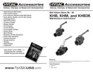
High Pressure Ball <strong>Valves</strong><br />
Overview<br />
2-way Ball <strong>Valves</strong><br />
KHB Series (see pages 5 - 11)<br />
Block Bodies<br />
Sizes 1/4” - 1”<br />
2-way Ball <strong>Valves</strong><br />
KHM Series (see pages 5 -12)<br />
Forged Bodies<br />
Sizes 1 1/4” - 2”<br />
2-way Manifold Mounted Ball <strong>Valves</strong><br />
KHP Series (see page 15)<br />
Sizes 3/8” - 2”<br />
3-way Diverter Ball <strong>Valves</strong><br />
KHB3K Series (see page 13)<br />
Sizes 1/4” - 1”<br />
Multiway Ball <strong>Valves</strong><br />
KH3 & KH4 Series (see page 17)<br />
Sizes 1/4” - 3/4”<br />
Direct Mount SAE Flange<br />
KHF3/6 Series (see page 25)<br />
Sizes 1/2” - 2”<br />
Direct Mount SAE Flange<br />
KHF3 Series (see page 26)<br />
Sizes 2 1/2” - 4”<br />
Ball Valve Actuators<br />
For KHB & KHM Series (see page 19)<br />
Pneumatic Operation<br />
3 Piece Ball <strong>Valves</strong><br />
KHM3H Series (see page 27)<br />
Designed in accordance with ANSI B16.34 and BS5351<br />
Sizes 1/2” - 4”<br />
3<br />
INNOVATIVE FLUID POWER
High Pressure Ball <strong>Valves</strong><br />
Standard Ball Valve Design Features & Options<br />
KHB, KHM, KHP, KHB3K Series<br />
Handle<br />
Limit Washer<br />
Stop Pin<br />
O-Ring with Back-up Ring<br />
Connection Adapter<br />
Housing<br />
Thrust Washer<br />
Spindle<br />
Chrome Plated Ball<br />
Ball Seal<br />
O-ring (valve sizes 06-25)<br />
O-ring & back-up ring (valve sizes 32-50)<br />
Description<br />
The <strong>HYDAC</strong> family of dependable high pressure ball valves provides<br />
full, unrestricted flow and positive shut-off of fluids and gases under<br />
extreme service conditions. Models are available to accommodate<br />
system pressures up to 7,250 PSI. Since a variety of materials are<br />
available, <strong>HYDAC</strong> valves can be used with various fluids and gases<br />
including petroleum based oils and some water glycols.<br />
Valve Design<br />
The design of <strong>HYDAC</strong> ball valves is based on the “floating ball”<br />
principle which allows the ball to turn freely between the ball seals.<br />
A positive seal is attained by fluid pressure acting on the upstream<br />
surface of the ball and producing a constant uniform contact<br />
between the downstream ball seal and the ball. The ball is operated<br />
by a sealed spindle with a projecting square end to which the control<br />
handle or optional actuator is attached. Ball valves are intended to be<br />
used as on/off flow control devices and are not to be used to throttle<br />
fluid flow. The valves should always be either fully open or closed.<br />
Product Features<br />
• Full passage for unrestricted flow of medium<br />
• Floating ball provides positive seal<br />
• Direction of flow indicated by milled slot in control spindle<br />
• Valve positioning controlled by a stop pin and limit washer<br />
• Fluoroelastomer O-rings (standard)<br />
• Phosphate coated carbon steel valve body (standard)<br />
Available Options<br />
<strong>HYDAC</strong> can furnish ball valves with special options including:<br />
• Locking devices<br />
• Stainless steel valve bodies<br />
• Pneumatic or electrical actuators<br />
• Limit switch<br />
• Off-set or straight control handles<br />
• Custom solutions - Contact <strong>HYDAC</strong><br />
INNOVATIVE FLUID POWER 4
KHB & KHM Series<br />
High Pressure Ball <strong>Valves</strong><br />
2-way Ball <strong>Valves</strong> with SAE & NPT Connections<br />
Specifications<br />
• 1/4” - 2” Full Port Design<br />
• NPT or SAE O-Ring connections<br />
• Polyacetal Ball Seals (standard)<br />
• FPM (Fluoroelastomer) O-Rings (standard)<br />
• Carbon Steel Housing<br />
• Block Housing - Sizes 06 - 25<br />
• Forged Housing - Sizes 32 - 50<br />
• Operating Pressure to 7250 psi Depending<br />
on Valve Size and Seal Materials Selected<br />
• Temp Range: 14˚F to 176˚F with Standard materials (1114) up<br />
to max. pressure rating. Extended Temperature range -40˚F to<br />
392˚F on request with special materials and reduced pressure<br />
rating (see page 24).<br />
KHB Series<br />
Block Housing<br />
KHM Series<br />
Forged Housing<br />
Model Code<br />
Housing Type<br />
KHB = Block Housing, Carbon Steel - Sizes 06 - 25<br />
KHM = Forged Housing, Carbon Steel - Sizes 32 - 50<br />
KHM = Forged Housing, Stainless Steel - Sizes 06 - 50 (see page 12 for details)<br />
Nominal Sizes<br />
Nom SAE NPT<br />
Size Tube Size Thread Size Pipe Size Pipe øD<br />
06 -4 7/16-20 UNF 1/4” 0.540”<br />
10 -6 9/16-18 UNF 3/8” 0.675”<br />
16 -8 3/4-16 UNF 1/2” 0.840”<br />
20 -12 1-1/16-12 UN 3/4” 1.050”<br />
25 -16 1-5/16-12 UN 1” 1.315”<br />
32 -20 1-5/8-12 UN 1-1/4” 1.660”<br />
40 -24 1-7/8-12 UN 1-1/2” 1.900”<br />
50 -32 2-1/2-12 UN 2” 2.375”<br />
Connection Type<br />
NPT = ANSI/ASME 1.20.1 Taper Pipe Thread<br />
SAE = SAEJ1926 Ports with ISO 725 Threads and O-Ring Sealing<br />
Body Material<br />
1 = Carbon Steel (phosphate coated)<br />
3 = Stainless Steel (see page 12 for ordering details)<br />
Spindle and Ball Material<br />
1 = Carbon Steel (ball is chrome plated, spindle is zinc plated)<br />
3 = Stainless Steel<br />
Ball Seal Material<br />
1 = Polyacetal (standard)<br />
3 = PTFE (1500 psi max)<br />
8 = PEEK<br />
O-Ring Material<br />
2 = NBR (Buna)<br />
3 = PTFE Spindle Seals and FPM (fluoroelastomer) O-Rings (1500 psi max)<br />
4 = FPM (fluoroelastomer) (standard)<br />
5 = EPR<br />
Handle Codes<br />
09x = Without Handle (see page 24 to order handle separately)<br />
11x = Straight Aluminum, Sizes 06-25<br />
16x = Offset Steel, Sizes 32-50<br />
Locking Device Option<br />
L = Locking Device (see page 21 to order locking device separately)<br />
LS = Locking Device with 5 amp Limit Switch, Available for sizes 20-50 (Not available with PTFE Spindle Seals)<br />
KHB - 16 NPT - 1 1 1 4 - 11X - L<br />
Model Codes containing selections listed in RED are non-standard items – Minimum quantities will apply – Contact <strong>HYDAC</strong> for information and availability<br />
Not all combinations are available<br />
5<br />
INNOVATIVE FLUID POWER
High Pressure Ball <strong>Valves</strong><br />
Dimensions<br />
A1<br />
16X, Standard Handle<br />
sizes 32 to 50<br />
SQ<br />
H2<br />
H4<br />
H1<br />
H<br />
11X - Standard Handle<br />
sizes 06 to 25<br />
H4<br />
H3<br />
B<br />
øD<br />
L<br />
NPT Port<br />
Internal Thread<br />
SAE Port<br />
Straight Thread<br />
O-Ring Boss<br />
Thread<br />
Thread<br />
Model Thread max. psi* A1 B øD H H1 H2 H3 H4 L SQ Weight<br />
KHB-06SAE 7/16-20UNF (SAE 4)<br />
5.91 0.98 0.24 1.89 1.38 0.28 0.51 1.65 2.72 0.35 0.66<br />
7250<br />
KHB-06NPT 1/4” NPT<br />
(150) (25) (6) (48) (35) (7) (13) (42) (69) (9) (0.3)<br />
KHB-10SAE 9/16-18UNF (SAE 6)<br />
5.91 1.26 0.39 2.09 1.57 0.33 0.67 1.69 2.83 0.35 1.10<br />
7250<br />
KHB-10NPT 3/8” NPT<br />
(150) (32) (10) (53) (40) (8.5) (17) (43) (72) (9) (0.5)<br />
KHB-16SAE 3/4-16UNF (SAE 8)<br />
6.88 1.50 0.63 2.48 1.77 0.43 0.75 2.01 3.27 0.47 1.65<br />
5800<br />
KHB-16NPT 1/2” NPT<br />
(175) (38) (16) (63) (45) (11) (19) (51) (83) (12) (0.75)<br />
KHB-20SAE 1-1/16-12UN (SAE 12)<br />
7.88 1.89 0.79 2.95 2.24 0.43 0.96 2.28 3.74 0.55 2.87<br />
5000<br />
KHB-20NPT 3/4” NPT<br />
(200) (48) (20) (75) (57) (11) (24.5) (58) (95) (14) (1.3)<br />
KHB-25SAE 1-5/16-12UN (SAE 16)<br />
7.88 2.24 0.98 3.23 2.52 0.43 1.12 2.40 4.45 0.55 4.41<br />
5000<br />
KHB-25NPT 1” NPT<br />
(200) (57) (25) (82) (64) (11) (28.5) (61) (113) (14) (2.0)<br />
KHM-32SAE 1-5/8-12UN (SAE 20)<br />
12.00 2.95 1.18 4.06 3.35 0.47 1.48 5.94 4.33 0.67 6.84<br />
5000<br />
KHM-32NPT 1-1/4” NPT<br />
(305) (75) (30) (103) (85) (12) (37.5) (151) (110) (17) (3.1)<br />
KHM-40SAE 1-7/8-12UN (SAE 24)<br />
12.00 3.35 1.50 4.49 3.78 0.47 1.67 6.18 5.12 0.67 9.70<br />
5000<br />
KHM-40NPT 1-1/2” NPT<br />
(305) (85) (38) (114) (96) (12) (42.5) (157) (130) (17) (4.4)<br />
KHM-50SAE 2-1/2-12UN (SAE 32)<br />
12.00 4.13 1.89 5.18 4.43 0.47 2.07 6.46 5.51 0.67 14.55<br />
5000<br />
KHM-50NPT 2” NPT<br />
(305) (105) (48) (131.5) (112.5) (12) (52.5) (164) (140) (17) (6.6)<br />
INNOVATIVE FLUID POWER 6
KHB & KHM Series<br />
High Pressure Ball <strong>Valves</strong><br />
2-way Ball <strong>Valves</strong> with Split Flange Connections<br />
Specifications<br />
KHB Series<br />
Block Housing<br />
Model Code<br />
Housing Type<br />
KHB = Block Housing, Carbon Steel - Sizes 16-25<br />
KHM = Forged Housing, Carbon Steel - Sizes 32-50<br />
KHM = Forged Housing, Stainless Steel - Sizes 06 - 50 (see page 12 for details)<br />
Nominal Sizes<br />
Valve Size Nominal Flange Size Flange Dash Size<br />
16 1/2” -8<br />
20 3/4” -12<br />
25 1” -16<br />
32 1-1/4” -20<br />
40 1-1/2” -24<br />
50 2” -32<br />
Connection Type<br />
SAE J518 Four bolt split flange type:<br />
F3 = Standard Pressure Series, Code 61<br />
F6 = High Pressure Series, Code 62<br />
Body Material<br />
1 = Carbon Steel (phosphate coated)<br />
3 = Stainless Steel (see page 12 for ordering details)<br />
Spindle and Ball Material<br />
1 = Carbon Steel (ball is chrome plated, spindle is zinc plated)<br />
3 = Stainless Steel<br />
Ball Seal Material<br />
1 = Polyacetal (standard)<br />
3 = PTFE (1500 psi max)<br />
8 = PEEK<br />
O-Ring Material<br />
2 = NBR (Buna N)<br />
3 = PTFE Spindle Seals and FPM (fluoroelastomer) O-Rings (1500 psi max)<br />
4 = FPM (fluoroelastomer) (standard)<br />
5 = EPR<br />
Split Flange Material<br />
X = Without Split Flanges (order split flanges separately see page 151)<br />
Handle Codes<br />
09X = Without Handle, Sizes 16-50<br />
12X = Offset Aluminum, Sizes 16-25<br />
16X = Offset Steel, Sizes 32-50<br />
KHM Series<br />
Forged Housing<br />
• 1/2” - 2” Full Port Design<br />
• SAE Code 61 and 62 Split Flange Connections<br />
• Carbon Steel Housing<br />
• Block Housing - Sizes 16 - 25<br />
• Forged Housing - Sizes 32 - 50<br />
• Polyacetal Ball Seals (standard)<br />
• FPM (Fluoroelastomer) O-Rings (standard)<br />
• Operating Pressure to 5800 psi Depending on<br />
• Valve Size and Seal Materials Selected<br />
• Temp Range: 14˚F to 176˚F with Standard materials (1114) up<br />
to max. pressure rating. Extended Temperature range -40˚F to<br />
392˚F on request with special materials and reduced pressure<br />
rating (see page 24).<br />
Locking Device Option<br />
L = Locking Device (see page 21 to order locking device separately)<br />
LS = Locking Device with 5 amp Limit Switch, Available for Sizes 20-50 (Not available with PTFE Spindle Seals)<br />
KHB - 20 F3 - 1 1 1 4 X - 12X - L<br />
Model Codes containing selections listed in RED are non-standard items – Minimum quantities will apply – Contact <strong>HYDAC</strong> for information and availability<br />
Not all combinations are available<br />
7<br />
INNOVATIVE FLUID POWER
High Pressure Ball <strong>Valves</strong><br />
Dimensions<br />
A1<br />
SQ<br />
H2<br />
C<br />
12x standard sizes 16-25<br />
16x standard sizes 32-50<br />
H4<br />
H1<br />
H<br />
øD1<br />
H3<br />
B<br />
øD<br />
For dimensional information on flanges, see page 151<br />
øD2<br />
L<br />
SAE Code 61 [...F3]<br />
Model<br />
max.<br />
psi*<br />
KHB-16 F3 5000 1/2”<br />
KHB-20 F3 5000 3/4”<br />
KHB-25 F3 5000 1”<br />
KHM-32 F3 4000 1-1/4”<br />
KHM-40 F3 3000 1-1/2”<br />
KHM-50 F3 3000 2”<br />
SAE Code 62 [...F6]<br />
Model<br />
max.<br />
psi*<br />
KHB-16 F6 5800 1/2”<br />
KHB-20 F6 5000 3/4”<br />
KHB-25 F6 5000 1”<br />
KHM-32 F6 5000 1-1/4”<br />
KHM-40 F6 5000 1-1/2”<br />
KHM-50 F6 5000 2”<br />
Size A1 B C øD øD1 øD2 H H1 H2 H3 H4 L SQ Weight<br />
6.42<br />
(163)<br />
7.20<br />
(183)<br />
7.20<br />
(183)<br />
12.01<br />
(305)<br />
12.01<br />
(305)<br />
12.01<br />
(305)<br />
1.50<br />
(38)<br />
1.89<br />
(48)<br />
2.24<br />
(57)<br />
2.95<br />
(75)<br />
3.35<br />
(85)<br />
4.13<br />
(105)<br />
0.27<br />
(6.8)<br />
0.27<br />
(6.8)<br />
0.31<br />
(8)<br />
0.31<br />
(8)<br />
0.31<br />
(8)<br />
0.38<br />
(9.6)<br />
0.51<br />
(13)<br />
0.75<br />
(19)<br />
0.98<br />
(25)<br />
1.18<br />
(30)<br />
1.50<br />
(38)<br />
1.89<br />
(48)<br />
1.19<br />
(30.2)<br />
1.50<br />
(38.1)<br />
1.75<br />
(44.45)<br />
2.00<br />
(50.8)<br />
2.38<br />
(60.35)<br />
2.81<br />
(71.4)<br />
0.94<br />
(24)<br />
1.24<br />
(31.5)<br />
1.50<br />
(38)<br />
1.69<br />
(43)<br />
1.97<br />
(50)<br />
2.44<br />
(62)<br />
2.44<br />
(62)<br />
2.95<br />
(75)<br />
3.23<br />
(82)<br />
4.06<br />
(103)<br />
4.49<br />
(114)<br />
5.18<br />
(131.5)<br />
1.77<br />
(45)<br />
2.24<br />
(57)<br />
2.52<br />
(64)<br />
3.35<br />
(85)<br />
3.78<br />
(96)<br />
4.43<br />
(112.5)<br />
0.43<br />
(11)<br />
0.43<br />
(11)<br />
0.43<br />
(11)<br />
0.47<br />
(12)<br />
0.47<br />
(12)<br />
0.47<br />
(12)<br />
0.75<br />
(19)<br />
0.96<br />
(24.5)<br />
1.12<br />
(28.5)<br />
1.48<br />
(37.5)<br />
1.67<br />
(42.5)<br />
2.07<br />
(52.5)<br />
3.27<br />
(83)<br />
3.62<br />
(92)<br />
3.74<br />
(95)<br />
5.94<br />
(151)<br />
6.18<br />
(157)<br />
6.46<br />
(164)<br />
5.94<br />
(151)<br />
6.69<br />
(170)<br />
6.95<br />
(176.5)<br />
7.54<br />
(191.4)<br />
9.09<br />
(231)<br />
9.21<br />
(234)<br />
0.47<br />
(12)<br />
0.55<br />
(14)<br />
0.55<br />
(14)<br />
0.67<br />
(17)<br />
0.67<br />
(17)<br />
0.67<br />
(17)<br />
2.4<br />
(1.1)<br />
4.0<br />
(1.8)<br />
5.1<br />
(2.3)<br />
9.0<br />
(4.1)<br />
13.1<br />
(5.9)<br />
19.2<br />
(8.7)<br />
Size A1 B C øD øD1 øD2 H H1 H2 H3 H4 L SQ Weight<br />
6.41<br />
(163)<br />
7.20<br />
(183)<br />
7.20<br />
(183)<br />
12.01<br />
(305)<br />
12.01<br />
(305)<br />
12.01<br />
(305)<br />
1.50<br />
(38)<br />
1.89<br />
(48)<br />
2.24<br />
(57)<br />
2.95<br />
(75)<br />
3.35<br />
(85)<br />
4.13<br />
(105)<br />
0.31<br />
(7.8)<br />
0.35<br />
(8.8)<br />
0.37<br />
(9.5)<br />
0.41<br />
(10.3)<br />
0.50<br />
(12.6)<br />
0.50<br />
(12.6)<br />
0.51<br />
(13)<br />
0.75<br />
(19)<br />
0.98<br />
(25)<br />
1.18<br />
(30)<br />
1.50<br />
(38)<br />
1.89<br />
(48)<br />
1.25<br />
(31.8)<br />
1.63<br />
(41.3)<br />
1.87<br />
(47.6)<br />
2.13<br />
(54)<br />
2.50<br />
(63.5)<br />
3.13<br />
(79.4)<br />
0.94<br />
(24)<br />
1.26<br />
(32)<br />
1.50<br />
(38)<br />
1.73<br />
(44)<br />
2.01<br />
(51)<br />
2.64<br />
(67)<br />
2.44<br />
(62)<br />
2.95<br />
(75)<br />
3.23<br />
(82)<br />
4.06<br />
(103)<br />
4.49<br />
(114)<br />
5.18<br />
(131.5)<br />
1.77<br />
(45)<br />
2.24<br />
(57)<br />
2.52<br />
(64)<br />
3.35<br />
(85)<br />
3.78<br />
(96)<br />
4.43<br />
(112.5)<br />
0.43<br />
(11)<br />
0.43<br />
(11)<br />
0.43<br />
(11)<br />
0.47<br />
(12)<br />
0.47<br />
(12)<br />
0.47<br />
(12)<br />
0.75<br />
(19)<br />
0.96<br />
(24.5)<br />
1.12<br />
(28.5)<br />
1.48<br />
(37.5)<br />
1.67<br />
(42.5)<br />
2.07<br />
(52.5)<br />
3.27<br />
(83)<br />
3.62<br />
(92)<br />
3.72<br />
(95)<br />
5.94<br />
(151)<br />
6.18<br />
(157)<br />
6.46<br />
(164)<br />
5.94<br />
(151)<br />
6.69<br />
(170)<br />
7.81<br />
(198.5)<br />
8.80<br />
(223.4)<br />
11.06<br />
(281)<br />
12.40<br />
(315)<br />
0.47<br />
(12)<br />
0.55<br />
(14)<br />
0.55<br />
(14)<br />
0.67<br />
(17)<br />
0.67<br />
(17)<br />
0.67<br />
(17)<br />
2.4<br />
(1.1)<br />
4.0<br />
(1.8)<br />
5.4<br />
(2.4)<br />
10.6<br />
(4.8)<br />
15.4<br />
(7.0)<br />
22.5<br />
(10.2)<br />
INNOVATIVE FLUID POWER 8
High Pressure Ball <strong>Valves</strong><br />
New Programs / Specialty Ball <strong>Valves</strong><br />
<strong>HYDAC</strong> has received feedback from customers stating that they prefer charts with model codes and part numbers rather than model code trees.<br />
As we release new programs, especially within the KHB and KHM product offering, we will include separate pages with tables including model<br />
codes and part numbers provided in tables.<br />
2-way Ball <strong>Valves</strong> with BSPP Threads<br />
KHB & KHM Series (see page 10)<br />
Sizes from G1/4” to G2”<br />
2-way Stainless Steel Ball <strong>Valves</strong><br />
KHM Series (see page 12)<br />
Nominal Sizes from 1/4” to 2”<br />
2-way Ball <strong>Valves</strong> with Steel Ball Seals<br />
KHB & KHM Series (see page 11)<br />
Nominal Sizes from 1/4” to 2”<br />
Global Replacement Business<br />
<strong>HYDAC</strong> <strong>Accessories</strong> GmbH is located in Germany and produces Ball <strong>Valves</strong> for the<br />
Global Market. Some of the product that they produce is not listed in this catalog.<br />
In some cases you will call <strong>HYDAC</strong> customer service and the part<br />
number will not be in our computer system. In these cases we will provide you<br />
a replacement quote in a few days. For additional details visit www.hydac.com<br />
and click on support, downloads, brochures, <strong>Accessories</strong> and<br />
check out the literature.<br />
9<br />
INNOVATIVE FLUID POWER
High Pressure Ball <strong>Valves</strong><br />
KHB & KHM Series<br />
2-way Ball <strong>Valves</strong> with BSPP Threads<br />
Specifications<br />
• 1/8” - 2” Full Port Design<br />
• Whitworth Internal Thread to ISO 228<br />
• Carbon Steel Housing<br />
• 1/8” - 1” Zinc Plated (represented by “- G” at end of model code)<br />
• 1 1/4” - 2” Phosphate Coated<br />
• Chrome Plated Steel Ball, Zinc Plated Steel Spindle<br />
• Polyacetal Ball Seals and NBR (Buna-N) O-Rings<br />
• Temperature Range: 14˚ to 176˚F at full pressure<br />
KHB Series<br />
Block Housing<br />
KHM Series<br />
Forged Housing<br />
Dimensions<br />
A1<br />
16X, Standard Handle<br />
sizes 32 to 50<br />
SQ<br />
H2<br />
H4<br />
H1<br />
H<br />
11X - Standard Handle<br />
sizes 06 to 25<br />
H4<br />
H3<br />
B<br />
øD<br />
L<br />
Model Code Part<br />
Number<br />
KHB-G1/8-1112-11X-G<br />
02079550<br />
KHB-G1/4-1112-11X-G<br />
02079551<br />
KHB-G3/8-1112-11X-G<br />
02079552<br />
KHB-G1/2-1112-11X-G<br />
02079553<br />
KHB-G3/4-1112-11X-G<br />
02079554<br />
KHB-G1-1112-11X-G<br />
02079555<br />
KHM-G11/4-1112-16X<br />
02079556<br />
KHM-G11/2-1112-16X<br />
02079557<br />
KHM-G2-1112-16X<br />
02079558<br />
*MAX<br />
PSI<br />
7250 G1/8”<br />
7250 G1/4”<br />
7250 G3/8”<br />
5800 G1/2”<br />
5000 G3/4”<br />
5000 G1”<br />
5000 G1-1/4”<br />
5000 G1-1/2”<br />
5000 G2”<br />
Thread A1 B øD H H1 H2 H3 H4 L SQ Weight<br />
5.91<br />
(150)<br />
5.91<br />
(150)<br />
5.91<br />
(150)<br />
6.88<br />
(175)<br />
7.88<br />
(200)<br />
7.88<br />
(200)<br />
12.00<br />
(305)<br />
12.00<br />
(305)<br />
12.00<br />
(305)<br />
0.98<br />
(25)<br />
0.98<br />
(25)<br />
1.26<br />
(32)<br />
1.50<br />
(38)<br />
1.89<br />
(48)<br />
2.24<br />
(57)<br />
2.95<br />
(75)<br />
3.35<br />
(85)<br />
4.13<br />
(105)<br />
0.24<br />
(6)<br />
0.24<br />
(6)<br />
0.39<br />
(10)<br />
0.63<br />
(16)<br />
0.79<br />
(20)<br />
0.98<br />
(25)<br />
1.18<br />
(30)<br />
1.50<br />
(38)<br />
1.89<br />
(48)<br />
1.89<br />
(48)<br />
1.89<br />
(48)<br />
2.09<br />
(53)<br />
2.48<br />
(63)<br />
2.95<br />
(75)<br />
3.23<br />
(82)<br />
4.06<br />
(103)<br />
4.49<br />
(114)<br />
5.18<br />
(131.5)<br />
1.38<br />
(35)<br />
1.38<br />
(35)<br />
1.57<br />
(40)<br />
1.77<br />
(45)<br />
2.24<br />
(57)<br />
2.52<br />
(64)<br />
3.35<br />
(85)<br />
3.78<br />
(96)<br />
4.43<br />
(112.5)<br />
Dimensions are for general information only, all critical dimensions should be verified by requesting a certified print.<br />
Dimensions are in inches/(mm) and lbs./(kg.)<br />
*Dependent upon valve and seal materials selected.<br />
Model Codes containing selections listed in RED are non-standard items – Minimum quantities will apply – Contact <strong>HYDAC</strong> for information and availability<br />
0.28<br />
(7)<br />
0.28<br />
(7)<br />
0.33<br />
(8.5)<br />
0.43<br />
(11)<br />
0.43<br />
(11)<br />
0.43<br />
(11)<br />
0.47<br />
(12)<br />
0.47<br />
(12)<br />
0.47<br />
(12)<br />
0.51<br />
(13)<br />
0.51<br />
(13)<br />
0.67<br />
(17)<br />
0.75<br />
(19)<br />
0.96<br />
(24.5)<br />
1.12<br />
(28.5)<br />
1.48<br />
(37.5)<br />
1.67<br />
(42.5)<br />
2.07<br />
(52.5)<br />
1.65<br />
(42)<br />
1.65<br />
(42)<br />
1.69<br />
(43)<br />
2.01<br />
(51)<br />
2.28<br />
(58)<br />
2.40<br />
(61)<br />
5.94<br />
(151)<br />
6.18<br />
(157)<br />
6.46<br />
(164)<br />
2.72<br />
(69)<br />
2.72<br />
(69)<br />
2.83<br />
(72)<br />
3.27<br />
(83)<br />
3.74<br />
(95)<br />
4.45<br />
(113)<br />
4.33<br />
(110)<br />
5.12<br />
(130)<br />
5.51<br />
(140)<br />
0.35<br />
(9)<br />
0.35<br />
(9)<br />
0.35<br />
(9)<br />
47<br />
(12)<br />
0.55<br />
(14)<br />
0.55<br />
(14)<br />
0.67<br />
(17)<br />
0.67<br />
(17)<br />
0.67<br />
(17)<br />
0.66<br />
(0.3)<br />
0.66<br />
(0.3)<br />
1.10<br />
(0.5)<br />
1.65<br />
(0.75)<br />
2.87<br />
(1.3)<br />
4.41<br />
(2.0)<br />
6.84<br />
(3.1)<br />
9.70<br />
(4.4)<br />
14.55<br />
(6.6)<br />
INNOVATIVE FLUID POWER 10
KHB & KHM Series<br />
High Pressure Ball <strong>Valves</strong><br />
2-way Ball <strong>Valves</strong> with Steel Ball Seals For Abrasive Media<br />
Specifications<br />
• 1/4” - 2” Full Port Design<br />
• NPT Threads<br />
• Carbon Steel Zinc Plated Housing and Spindle<br />
• Chrome Plated Steel Ball<br />
• Steel Ball Seals and Viton O-Rings<br />
• Temperature Range: 14˚ to 176˚F at full pressure<br />
• Silicon Free (SF in Model Code)<br />
KHB Series<br />
Block Housing<br />
KHM Series<br />
Forged Housing<br />
Dimensions<br />
A1<br />
16X, Standard Handle<br />
sizes 32 to 50<br />
SQ<br />
H2<br />
H4<br />
H1<br />
H<br />
11X - Standard Handle<br />
sizes 06 to 25<br />
H4<br />
H3<br />
B<br />
øD<br />
L<br />
Part Number Model Code<br />
KHB-06NPT-111114-11X-G-SF<br />
03203692<br />
KHB-10NPT-111114-11X-G-SF<br />
03203716<br />
KHB-16NPT-111114-11X-G-SF<br />
03203717<br />
KHB-20NPT-111114-11X-G-SF<br />
03203718<br />
KHB-25NPT-111114-11X-G-SF<br />
03203719<br />
KHM-32NPT-111114-16X-G-SF<br />
03203720<br />
KHM-40NPT-111114-16X-G-SF<br />
03203721<br />
KHM-50NPT-111114-16X-G-SF<br />
03203722<br />
*MAX<br />
PSI<br />
NPT<br />
Thread<br />
7250 1/4”<br />
7250 3/8”<br />
5800 1/2”<br />
5000 3/4”<br />
5000 1”<br />
5000 1 1/4”<br />
5000 1 1/2”<br />
5000 2”<br />
A1 B øD H H1 H2 H3 H4 L SQ WGT<br />
5.91<br />
(150)<br />
5.91<br />
(150)<br />
6.88<br />
(175)<br />
7.88<br />
(200)<br />
7.88<br />
(200)<br />
12.00<br />
(305)<br />
12.00<br />
(305)<br />
12.00<br />
(305)<br />
0.98<br />
(25)<br />
1.26<br />
(32)<br />
1.50<br />
(38)<br />
1.89<br />
(48)<br />
2.24<br />
(57)<br />
2.95<br />
(75)<br />
3.35<br />
(85)<br />
4.13<br />
(105)<br />
0.24<br />
(6)<br />
0.39<br />
(10)<br />
0.63<br />
(16)<br />
0.79<br />
(20)<br />
0.98<br />
(25)<br />
1.18<br />
(30)<br />
1.50<br />
(38)<br />
1.89<br />
(48)<br />
1.89<br />
(48)<br />
2.09<br />
(53)<br />
2.48<br />
(63)<br />
2.95<br />
(75)<br />
3.23<br />
(82)<br />
4.06<br />
(103)<br />
4.49<br />
(114)<br />
5.18<br />
(131.5)<br />
1.38<br />
(35)<br />
1.57<br />
(40)<br />
1.77<br />
(45)<br />
2.24<br />
(57)<br />
2.52<br />
(64)<br />
3.35<br />
(85)<br />
3.78<br />
(96)<br />
4.43<br />
(112.5)<br />
0.28<br />
(7)<br />
0.33<br />
(8.5)<br />
0.43<br />
(11)<br />
0.43<br />
(11)<br />
0.43<br />
(11)<br />
0.47<br />
(12)<br />
0.47<br />
(12)<br />
0.47<br />
(12)<br />
0.51<br />
(13)<br />
0.67<br />
(17)<br />
0.75<br />
(19)<br />
0.96<br />
(24.5)<br />
1.12<br />
(28.5)<br />
1.48<br />
(37.5)<br />
1.67<br />
(42.5)<br />
2.07<br />
(52.5)<br />
1.65<br />
(42)<br />
1.69<br />
(43)<br />
2.01<br />
(51)<br />
2.28<br />
(58)<br />
2.40<br />
(61)<br />
5.94<br />
(151)<br />
6.18<br />
(157)<br />
6.46<br />
(164)<br />
2.72<br />
(69)<br />
2.83<br />
(72)<br />
3.27<br />
(83)<br />
3.74<br />
(95)<br />
4.45<br />
(113)<br />
4.33<br />
(110)<br />
5.12<br />
(130)<br />
5.51<br />
(140)<br />
0.35<br />
(9)<br />
0.35<br />
(9)<br />
47<br />
(12)<br />
0.55<br />
(14)<br />
0.55<br />
(14)<br />
0.67<br />
(17)<br />
0.67<br />
(17)<br />
0.67<br />
(17)<br />
0.66<br />
(0.3)<br />
1.10<br />
(0.5)<br />
1.65<br />
(0.75)<br />
2.87<br />
(1.3)<br />
4.41<br />
(2.0)<br />
6.84<br />
(3.1)<br />
9.70<br />
(4.4)<br />
14.55<br />
(6.6)<br />
Dimensions are for general information only, all critical dimensions should be verified by requesting a certified print.<br />
Dimensions are in inches/(mm) and lbs./(kg.)<br />
*Dependent upon valve and seal materials selected.<br />
Model Codes containing selections listed in RED are non-standard items – Minimum quantities will apply – Contact <strong>HYDAC</strong> for information and availability<br />
11<br />
INNOVATIVE FLUID POWER
High Pressure Ball <strong>Valves</strong><br />
KHM Series<br />
2-way Stainless Steel Ball <strong>Valves</strong><br />
Specifications:<br />
• 1/4” to 2” Full Port Design<br />
• Connection types available:<br />
NPT: Tapered Pipe Threads, ANSI/ASME B.1.20.1<br />
SAE: SAE J1926/1 Straight Thread O-ring Boss Port<br />
F3: SAE J518 (Code 61), split flange halves not included.<br />
F6: SAE J518 (Code 62), split flange halves not included.<br />
• Materials:<br />
Housing, Ball and Spindle made of 1.4571 SS (~316 SS)<br />
Polyacetal (POM + MoS2) Ball Seals<br />
Flurocarbon (FPM) O-rings<br />
• Offset Zinc-plated Steel Handles<br />
• Temperature Range: -4° to 176°F at full pressure<br />
Dimensions<br />
A1<br />
H2<br />
16X, Standard Handle 16X, Standard Handle<br />
H4<br />
H4<br />
H1<br />
H3<br />
H<br />
Nom.<br />
Size<br />
L<br />
Connection<br />
Size/Type<br />
Model Code<br />
B<br />
Part Number<br />
Press<br />
Rating<br />
Dimensions in millimeters<br />
A1 B øD H H1 H2 H3 H4 L<br />
DN 06 1/4” NPT KHM-06NPT-3314-16X 02078586 7250 101 28 6 49 37 8 14 54 69<br />
(1/4”) SAE-4 KHM-06SAE-3314-16X 02078587 7250 101 28 6 49 37 8 14 54 69<br />
DN 10 3/8” NPT KHM-10NPT-3314-16X 02078588 7250 101 36 10 53 41 8 18 54 72<br />
(3/8”) SAE-6 KHM-10SAE-3314-16X 02077119 7250 101 36 10 53 41 8 18 54 72<br />
1/2” NPT KHM-16NPT-3314-16X 02078589 5800 175 46 16 66 49 8 23 91 83<br />
DN 16 SAE-8 KHM-16SAE-3314-16X 02066415 5800 175 46 16 66 49 11 23 91 83<br />
(1/2”) 1/2” code 61 KHM-16F3-3314X-16X 02077118 5000 175 46 16 66 49 11 23 91 150.8<br />
1/2” code 62 KHM-16F6-3314X-16X 02078590 5800 175 46 16 66 49 11 23 91 150.8<br />
3/4” NPT KHM-20NPT-3314-16X 02066406 5000 175 56 20 78 60 12 28 98 95<br />
DN 20 SAE-12 KHM-20SAE-3314-16X 02078591 5000 175 56 20 78 60 12 28 98 95<br />
(3/4”) 3/4” code 61 KHM-20F3-3314X-16X 02078592 5000 175 56 20 78 60 12 28 98 169.8<br />
3/4” code 62 KHM-20F6-3314X-16X 02068045 5000 175 56 20 78 60 12 28 98 169.8<br />
1” NPT KHM-25NPT-3314-16X 02078593 5000 175 65 25 83 66 12 30 101 113<br />
DN 25 SAE-16 KHM-25SAE-3314-16X 02078594 5000 175 65 25 83 66 12 30 101 113<br />
(1”) 1” code 61 KHM-25F3-3314X-16X 02070901 5000 175 65 25 83 66 12 30 101 176.5<br />
1” code 62 KHM-25F6-3314X-16X 02073032 5000 175 65 25 83 66 12 30 101 198.5<br />
1-1/4” NPT KHM-32NPT-3314-16X 02062809 5000 306 78 30 104 86 12 39 151 110<br />
DN 32 SAE-20 KHM-32SAE-3314-16X 02078359 5000 306 78 30 104 86 12 39 151 110<br />
(1-1/4”) 1-1/4” code 61 KHM-32F3-3314X-16X 02077117 4000 306 78 30 104 86 12 39 151 191.4<br />
1-1/4” code 62 KHM-32F6-3314X-16X 02078595 5000 306 78 30 104 86 12 39 151 223.4<br />
1-1/2” NPT KHM-40NPT-3314-16X 02062807 5000 306 91 38 117 99 12 46 157 130<br />
DN 40 SAE-24 KHM-40SAE-3314-16X 02070209 5000 306 91 38 117 99 12 46 157 130<br />
(1-1/2”) 1-1/2” code 61 KHM-40F3-3314X-16X 02069236 3000 306 91 38 117 99 12 46 157 231<br />
1-1/2” code 62 KHM-40F6-3314X-16X 02073038 5000 306 91 38 117 99 12 46 157 281<br />
2” NPT KHM-50NPT-3314-16X 02065778 5000 306 109 48 133 115 12 55 164 140<br />
DN 50 SAE-32 KHM-50SAE-3314-16X 02078596 5000 306 109 48 133 115 12 55 164 140<br />
(2”) 2” code 61 KHM-50F3-3314X-16X 02078597 3000 306 109 48 133 115 12 55 164 234<br />
2” code 62 KHM-50F6-3314X-16X 02072531 5000 306 109 48 133 115 12 55 164 315<br />
Dimensions are for general information only, all critical dimensions should be verified by requesting a certified print.<br />
Dimensions are in mm.<br />
For information on stainless steel code 61 & 62 flanges, see page 151.<br />
Model Codes containing selections listed in RED are non-standard items – Minimum quantities will apply – Contact <strong>HYDAC</strong> for information and availability<br />
øD<br />
L<br />
INNOVATIVE FLUID POWER 12
High Pressure Ball <strong>Valves</strong><br />
KHB3K Series<br />
3-way Diverter Ball <strong>Valves</strong><br />
Specifications<br />
• 1/4” - 1” Full Port Design<br />
• 2 Position<br />
• Carbon Steel Housing<br />
• NPT or SAE O-Ring Connections<br />
• Polyacetal Ball Seals (standard)<br />
• FPM (Fluoroelastomer) O-Rings (standard)<br />
• Operating Pressure to 7250 psi Depending on Valve Size and<br />
Seal Materials Selected<br />
• Temp Range: 14˚ to 176˚F with Standard materials (1114) up to<br />
max. pressure rating. Extended Temperature range -40˚ to 392˚F<br />
on request with special materials and reduced pressure rating<br />
(see page 24).<br />
Model Code<br />
Housing Type<br />
KHB3K =<br />
Three-Way Diverter Ball Valve<br />
Nominal Sizes<br />
Nom SAE NPT<br />
Size Tube Thread Pipe Size Pipe OD<br />
06 -4 7/16-20 UNF 1/4” 0.540”<br />
10 -6 9/16-18 UNF 3/8” 0.675”<br />
16 -8 3/4-16 UNF 1/2” 0.840”<br />
20 -12 1-1/16-12 UN 3/4” 1.050”<br />
25 -16 1-5/16-12 UN 1” 1.315”<br />
32 -20 1-5/8-12 UN 1-1/4” 1.660”<br />
40 -24 1-7/8-12 UN 1-1/2” 1.900”<br />
50 -32 2-1/2-12 UN 2” 2.375”<br />
Connection Type<br />
NPT = ANSI/ASME 1.20.1 Taper Pipe Thread<br />
SAE = SAEJ1926 Ports with ISO 725 Threads and O-Ring Sealing<br />
Ball Drilling<br />
L = standard<br />
Body Material<br />
1 = Carbon Steel (phosphate coated)<br />
Spindle and Ball Material<br />
1 = Carbon Steel (ball is chrome plated, spindle is zinc-plated)<br />
3 = Stainless Steel<br />
Ball Seal Material<br />
1 = Polyacetal (standard)<br />
3 = PTFE (1500 psi max)<br />
O-Ring Material<br />
2 = NBR (Buna N)<br />
3 = PTFE Spindle Seals and FPM (Fluoroelastomer) O-Rings (1500 psi max)<br />
4 = FPM (Fluoroelastomer) (standard)<br />
Handle Codes<br />
09x = Without Handle<br />
11x = Straight Aluminum, Sizes 06-25<br />
16x = Offset Steel Handle, Sizes 32-50<br />
KHB3K - 16 NPT - L - 1 1 1 4 - 11X - L<br />
Locking Device Option<br />
L = Locking Device (see page 21 to order locking device separately)<br />
LS = Locking Device with 5 amp Limit Switch, Available for Sizes 20-50 (Not available with PTFE Spindle Seals)<br />
Model Codes containing selections listed in RED italics are non-standard items – Minimum quantities will apply – Contact <strong>HYDAC</strong> for information and availability<br />
Not all combinations are available<br />
13<br />
INNOVATIVE FLUID POWER
High Pressure Ball <strong>Valves</strong><br />
Dimensions<br />
Sizes 06 - 25 Sizes 32 - 50<br />
SQ<br />
SQ<br />
B<br />
B<br />
B<br />
B<br />
S<br />
S<br />
SQ<br />
SQ<br />
S<br />
S<br />
A<br />
A<br />
A<br />
A<br />
H3<br />
H3<br />
H2<br />
øD<br />
H2<br />
øD<br />
H3<br />
H3<br />
H1<br />
H1<br />
øD<br />
H2<br />
øD<br />
H2<br />
L1<br />
L<br />
L1<br />
L<br />
H1<br />
H1<br />
L1<br />
L<br />
L1<br />
L<br />
Ball Drilling<br />
L<br />
L<br />
Function Diagrams<br />
2<br />
3<br />
L<br />
2<br />
3<br />
*<br />
2<br />
3<br />
2<br />
3<br />
2<br />
3<br />
2<br />
3<br />
1<br />
1<br />
1<br />
1<br />
1<br />
1<br />
Notes: Pressure port 1 should always<br />
be the highest pressure port<br />
At intermediate position flow will not be completely shut off.<br />
Notes: Valve is not designed to be used as a flow control<br />
valve. Valve should not be left in an intermediate<br />
position to avoid seal damage.<br />
Model Port Threads Max. psi* A B øD H1 H2 H3 L L1 SQ S Weight<br />
KHB3K-06SAE...<br />
KHB3K-06NPT...<br />
KHB3K-10SAE...<br />
KHB3K-10NPT...<br />
KHB3K-16SAE...<br />
KHB3K-16NPT...<br />
KHB3K-20SAE...<br />
KHB3K-20NPT...<br />
KHB3K-25SAE...<br />
KHB3K-25NPT...<br />
KHB3K-32SAE...<br />
KHB3K-32NPT...<br />
KHB3K-40SAE...<br />
KHB3K-40NPT...<br />
KHB3K-50SAE...<br />
KHB3K-50NPT...<br />
7/16”-20 UNF<br />
1/4” NPT<br />
9/16”-18 UNF<br />
3/8” NPT<br />
3/4”-16 UNF<br />
1/2” NPT<br />
1-1/16”-12 UN<br />
3/4” NPT<br />
1-5/16”-12 UN<br />
1” NPT<br />
1-5/8”-12 UNF<br />
1-1/4” NPT<br />
1-7/8”-12 UN<br />
1-1/2” NPT<br />
2-1/2”-12 UN<br />
2” NPT<br />
7250<br />
7250<br />
5800<br />
4500<br />
4500<br />
5000<br />
5000<br />
5000<br />
5.90<br />
(150)<br />
5.90<br />
(150)<br />
6.89<br />
(175)<br />
7.87<br />
(200)<br />
7.87<br />
(200)<br />
9.00<br />
(228)<br />
9.00<br />
(228)<br />
9.00<br />
(228)<br />
1.02<br />
(26)<br />
1.26<br />
(32)<br />
1.50<br />
(38)<br />
1.93<br />
(49)<br />
2.28<br />
(58)<br />
4.35<br />
(110.5)<br />
4.69<br />
(119)<br />
5.73<br />
(145.5)<br />
0.24<br />
(6)<br />
0.39<br />
(10)<br />
0.63<br />
(16)<br />
0.79<br />
(20)<br />
0.98<br />
(25)<br />
1.18<br />
(30)<br />
1.38<br />
(35)<br />
1.73<br />
(44)<br />
0.51<br />
(13)<br />
0.67<br />
(17)<br />
0.75<br />
(19)<br />
1.08<br />
(27.5)<br />
1.16<br />
(29.5)<br />
1.70<br />
(43.3)<br />
1.71<br />
(43.5)<br />
2.35<br />
(59.8)<br />
1.26<br />
(32)<br />
1.57<br />
(40)<br />
1.77<br />
(45)<br />
2.36<br />
(60)<br />
2.56<br />
(65)<br />
3.54<br />
(90.0)<br />
3.79<br />
(96.2)<br />
4.72<br />
(120)<br />
1.65<br />
(42)<br />
1.69<br />
(47)<br />
2.01<br />
(51)<br />
2.28<br />
(58)<br />
2.40<br />
(61)<br />
5.47<br />
(139)<br />
5.71<br />
(145)<br />
6.02<br />
(153)<br />
2.72<br />
(69)<br />
2.83<br />
(72)<br />
3.27<br />
(83)<br />
3.74<br />
(95)<br />
4.45<br />
(113)<br />
4.53<br />
(115)<br />
5.31<br />
(135)<br />
5.91<br />
(150)<br />
1.46<br />
(37)<br />
1.65<br />
(42)<br />
1.85<br />
(47)<br />
2.36<br />
(60)<br />
2.56<br />
(65)<br />
2.99<br />
(76)<br />
3.35<br />
(85)<br />
4.72<br />
(120)<br />
0.35<br />
(9)<br />
0.35<br />
(9)<br />
0.47<br />
(12)<br />
0.55<br />
(14)<br />
0.55<br />
(14)<br />
0.67<br />
(17)<br />
0.67<br />
(17)<br />
0.67<br />
(17)<br />
1.36<br />
(34.5)<br />
1.42<br />
(36)<br />
1.64<br />
(41.5)<br />
1.87<br />
(47.5)<br />
2.22<br />
(56.5)<br />
2.76<br />
(70)<br />
2.95<br />
(75)<br />
3.35<br />
(85)<br />
0.88<br />
(0.4)<br />
1.32<br />
(0.6)<br />
1.76<br />
(0.8)<br />
3.31<br />
(1.5)<br />
4.85<br />
(2.2)<br />
7.7<br />
(3.5)<br />
11<br />
(5)<br />
16.5<br />
(7.5)<br />
INNOVATIVE FLUID POWER 14
High Pressure Ball <strong>Valves</strong><br />
KHP Series<br />
2-way Manifold Mounted Ball <strong>Valves</strong><br />
Specifications<br />
• Sizes 3/8” - 2”<br />
• Carbon Steel Housing<br />
• Polyacetal Ball Seals (standard)<br />
• FPM (Fluoroelastomer) O-Rings (standard)<br />
• Operating Pressure to 5000 psi Depending on<br />
• Seal Materials Selected<br />
• Temp Range: 14˚ to 176˚F with Standard materials (1114) up to<br />
max. pressure rating. Extended Temperature range -40˚ to 392˚F<br />
on request with special materials and reduced pressure rating<br />
(see page 24).<br />
Model Code<br />
Housing Type<br />
KHP = Block Housing for Manifold mounting<br />
Nominal Sizes<br />
Valve Nominal<br />
Size Size<br />
10 3/8”<br />
16 1/2”<br />
20 3/4”<br />
25 1”<br />
32 1-1/4”<br />
40 1-1/2”<br />
50 2”<br />
Body Material<br />
1 = Carbon Steel (phosphate coated)<br />
Spindle and Ball Material<br />
1 = Carbon Steel (ball is chrome plated, spindle is zinc-plated)<br />
3 = Stainless Steel<br />
Ball Seal Material<br />
1 = Polyacetal (standard)<br />
3 = PTFE (1500 psi max)<br />
O-Ring Material<br />
2 = NBR (Buna N)<br />
3 = PTFE Spindle Seals and FPM (fluoroelastomer) O-Rings (1500 psi max)<br />
4 = FPM (fluoroelastomer) (standard)<br />
5 = EPR<br />
Handle Codes<br />
09x = Without Handle<br />
12x = Offset Aluminum sizes 10 - 25<br />
16x = Offset Steel sizes 32 - 50<br />
Locking Device Option<br />
L = Locking Device (see page 21 to order locking device separately)<br />
LS = Locking Device with 5 amp Limit Switch (Sizes 20, 25 only) (Not available with PTFE Spindle Seals)<br />
KHP - 20 - 1 1 1 4 - 12X - L<br />
Model Codes containing selections listed in RED are non-standard items – Minimum quantities may apply – Contact <strong>HYDAC</strong> for information and availability<br />
Not all combinations are available<br />
15<br />
INNOVATIVE FLUID POWER
High Pressure Ball <strong>Valves</strong><br />
Dimensions<br />
L4<br />
L5<br />
L6<br />
L7<br />
B<br />
B1<br />
Plug for<br />
sizes 10-32<br />
L<br />
L3<br />
Plate for<br />
sizes 40-50<br />
L1<br />
L2<br />
L8<br />
12x Offset Aluminum Handle<br />
for sizes 10-25<br />
16x Offset Steel Handle<br />
for sizes 32-50<br />
SQ<br />
øD<br />
øD1<br />
H1<br />
A<br />
H<br />
S<br />
O-ring<br />
øD2<br />
HEX<br />
Model<br />
KHP-10<br />
KHP-16<br />
KHP-20<br />
KHP-25<br />
KHP-32<br />
KHP-40<br />
KHP-50<br />
øD3<br />
Max.<br />
psi (1 A B B1 ø D ø D1 ø D2 ø D3 HEX H H1 O-ring Weight<br />
5000<br />
5000<br />
5000<br />
5000<br />
5000<br />
5000<br />
5000<br />
0.08<br />
(2)<br />
0.08<br />
(2)<br />
0.12<br />
(3)<br />
0.12<br />
(3)<br />
0.12<br />
(3)<br />
0.12<br />
(3)<br />
0.12<br />
(3)<br />
2.17<br />
(55)<br />
2.36<br />
(60)<br />
2.76<br />
(70)<br />
3.15<br />
(80)<br />
3.94<br />
(100)<br />
5.12<br />
(130)<br />
5.91<br />
(150)<br />
1.575<br />
(40)<br />
1.772<br />
(45)<br />
2.008<br />
(51)<br />
2.362<br />
(60)<br />
3.071<br />
(78)<br />
3.740<br />
(95)<br />
4.409<br />
(112)<br />
0.35<br />
(9)<br />
0.35<br />
(9)<br />
0.41<br />
(10.5)<br />
0.41<br />
(10.5)<br />
0.51<br />
(13)<br />
0.69<br />
(17.5)<br />
0.87<br />
(22)<br />
0.55<br />
(14)<br />
0.55<br />
(14)<br />
0.65<br />
(16.5)<br />
0.65<br />
(17)<br />
0.75<br />
(19)<br />
1.02<br />
(26)<br />
1.30<br />
(33)<br />
0.374<br />
(9.5)<br />
0.630<br />
(16)<br />
0.787<br />
(20)<br />
0.925<br />
(23.5)<br />
1.260<br />
(32)<br />
1.496<br />
(38)<br />
1.89<br />
(48)<br />
0.591<br />
(15)<br />
0.984<br />
(25)<br />
1.181<br />
(30)<br />
1.378<br />
(35)<br />
1.551<br />
(39.4)<br />
1.906<br />
(48.4)<br />
2.181<br />
(55.4)<br />
1 3/16<br />
(30)<br />
1 7/16<br />
(36)<br />
1 5/8<br />
(41)<br />
2<br />
(50)<br />
2 9/16<br />
(65)<br />
_<br />
_<br />
1.77<br />
(45)<br />
2.17<br />
(55)<br />
2.76<br />
(70)<br />
3.15<br />
(80)<br />
3.94<br />
(100)<br />
3.94<br />
(100)<br />
4.33<br />
(110)<br />
3.58<br />
(91)<br />
4.45<br />
(113)<br />
5.16<br />
(131)<br />
5.55<br />
(141)<br />
8.07<br />
(205)<br />
8.07<br />
(205)<br />
8.46<br />
(215)<br />
10x2.6<br />
20.3x2.6<br />
23.4x3.5<br />
28.2x3.5<br />
32.9x3.5<br />
42x3.5<br />
49x3.5<br />
2.6<br />
(1.2)<br />
4.6<br />
(2.1)<br />
8.2<br />
(3.7)<br />
12.3<br />
(5.6)<br />
23.4<br />
(10.6)<br />
38.6<br />
(17.5)<br />
43.7<br />
(19.8)<br />
Model L L1 L2 L3 L4 L5 L6 L7 L8 S SQ Bolt Size (2 Torque (2<br />
KHP-10 2.76<br />
(70)<br />
KHP-16 3.94<br />
(100)<br />
KHP-20 4.61<br />
(117)<br />
KHP-25 5.32<br />
(135)<br />
KHP-32 6.50<br />
(165)<br />
KHP-40 7.09<br />
(180)<br />
KHP-50 8.66<br />
(220)<br />
0.295<br />
(7.5)<br />
0.335<br />
(8.5)<br />
0.394<br />
(10)<br />
0.394<br />
(10)<br />
0.472<br />
(12)<br />
1.122<br />
(28.5)<br />
1.496<br />
(38)<br />
1.083<br />
(27.5)<br />
1.634<br />
(41.5)<br />
1.909<br />
(48.5)<br />
2.264<br />
(57.5)<br />
2.677<br />
(68)<br />
2.205<br />
(56)<br />
2.677<br />
(68)<br />
0.39<br />
(10)<br />
0.39<br />
(10)<br />
0.39<br />
(10)<br />
0.39<br />
(10)<br />
0.43<br />
(11)<br />
0.98<br />
(25)<br />
0.98<br />
(25)<br />
1.14<br />
(29)<br />
1.73<br />
(44)<br />
2.01<br />
(51)<br />
2.44<br />
(62)<br />
2.95<br />
(75)<br />
3.33<br />
(84.6)<br />
4.17<br />
(106)<br />
5.51<br />
(140)<br />
6.42<br />
(163)<br />
7.20<br />
(183)<br />
7.20<br />
(183)<br />
12.00<br />
(305)<br />
12.00<br />
(305)<br />
12.00<br />
(305)<br />
0.394<br />
(10)<br />
0.669<br />
(17)<br />
0.787<br />
(20)<br />
0.945<br />
(24)<br />
1.142<br />
(29)<br />
1.122<br />
(28.5)<br />
1.496<br />
(38)<br />
Dimensions are for general information only, all critical dimensions should be verified by requesting a certified print. Dimensions are in inches/(mm) and lbs./(kg.)<br />
1) Dependent upon valve and seal materials selected.<br />
2) Bolt size and torque provided as reference only. Manifold designs must take all factors (materials, pressure, etc.) into consideration.<br />
Consult <strong>HYDAC</strong> Engineering for more information<br />
1.732<br />
(44)<br />
2.284<br />
(58)<br />
2.717<br />
(69)<br />
3.189<br />
(81)<br />
3.780<br />
(96)<br />
4.409<br />
(112)<br />
5.354<br />
(136)<br />
2.165<br />
(55)<br />
3.268<br />
(83)<br />
3.819<br />
(97)<br />
4.528<br />
(115)<br />
5.354<br />
(136)<br />
4.409<br />
(112)<br />
5.354<br />
(136)<br />
1.42<br />
(36)<br />
1.81<br />
(46)<br />
2.34<br />
(59.5)<br />
2.72<br />
(69)<br />
3.31<br />
(84)<br />
3.25<br />
(82.5)<br />
3.48<br />
(88.5)<br />
0.35<br />
(9)<br />
0.47<br />
(12)<br />
0.55<br />
(14)<br />
0.55<br />
(14)<br />
0.67<br />
(17)<br />
0.67<br />
(17)<br />
0.67<br />
(17)<br />
5/16” - 18<br />
UNC x 2”<br />
5/16” - 18<br />
UNC x 2 1/4”<br />
3/8” - 16<br />
UNC x 3”<br />
3/8” - 16<br />
UNC x 3 1/4”<br />
7/16” - 14<br />
UNC x 4”<br />
5/8” - 11<br />
UNC x 4 1/4”<br />
3/4” - 10<br />
UNC x 4 1/2”<br />
26 ft/lb<br />
26 ft/lb<br />
45 ft/lb<br />
45 ft/lb<br />
75 ft/lb<br />
220 ft/lb<br />
400 ft/lb<br />
INNOVATIVE FLUID POWER 16
High Pressure Ball <strong>Valves</strong><br />
KH3 & KH4 Series<br />
Multiway Ball <strong>Valves</strong><br />
Note: <strong>Valves</strong> use a trunion design, rather<br />
than the “floating ball” design used<br />
on all other ball valves.<br />
Specifications<br />
• Sizes 1/4” to 3/4”<br />
• 2 Positions, 90˚ Switching Standard<br />
• Carbon Steel Housing<br />
• L and T Ball Drilling - KH3<br />
• L, T and X Ball Drilling - KH4<br />
• NPT or SAE O-Ring Connections<br />
• Polyacetal Ball Seals (standard)<br />
• Fluoroelastomer O-Rings (standard)<br />
• Operating Pressure to 7250 PSI Depending on<br />
• Valve Size and Seal Materials Selected<br />
• Temp Range: 14˚ to 176˚F with Standard materials (1114) up to<br />
max. pressure rating. Extended Temperature range -40˚ to 392˚F<br />
on request with special materials and reduced pressure rating<br />
(see page 24).<br />
Model Code<br />
Housing Type<br />
KH3 = Three-Way<br />
KH4 = Four-Way<br />
Nominal Sizes<br />
Nom SAE NPT<br />
Size Tube Thread Pipe Size Pipe OD<br />
06 -4 7/16-20 UNF 1/4” 0.540”<br />
10 -6 9/16-18 UNF 3/8” 0.675”<br />
12 -8 3/4-16 UNF 1/2” 0.840”<br />
20 -12 1-1/16-12 UN 3/4” 1.050”<br />
Connection Type<br />
NPT<br />
SAE<br />
Ball Drilling<br />
L = standard for KH3<br />
T = (optional)<br />
X = standard for KH4<br />
Body Material<br />
1 = Carbon Steel (phosphate coated)<br />
Spindle and Ball Material<br />
1 = Carbon Steel (ball is chrome plated, spindle is zinc-plated)<br />
3 = Stainless Steel<br />
Ball Seal Material<br />
1 = Polyacetal (standard)<br />
3 = PTFE (1500 psi max)<br />
O-Ring Material<br />
2 = NBR (Buna N)<br />
4 = FPM (Fluoroelastomer) (standard)<br />
Handle Codes<br />
09x = Without Handle<br />
12x = Offset Aluminum (standard)<br />
Locking Device Option<br />
L = Locking Device (see page 21 to order locking device separately)<br />
KH3 - 12 NPT - L - 1 1 1 4 - 12X - L<br />
Model Codes containing selections listed in RED are non-standard items – Minimum quantities will apply – Contact <strong>HYDAC</strong> for information and availability<br />
Not all combinations are available<br />
17<br />
INNOVATIVE FLUID POWER
High Pressure Ball <strong>Valves</strong><br />
Dimensions<br />
A<br />
L3<br />
L4<br />
KH4<br />
KH3<br />
H2<br />
H5<br />
H1<br />
H3<br />
L1<br />
L4<br />
L2<br />
H4<br />
L3<br />
SQ<br />
d1<br />
L1<br />
øL-T for L & T ball drilling<br />
øX for X ball drilling<br />
HEX<br />
Handle Not Shown<br />
ød2<br />
Ball Drilling<br />
L<br />
Function Diagrams<br />
3-Way Ball Valve L-Bore<br />
2<br />
2<br />
90° Switch<br />
3<br />
1<br />
3<br />
1<br />
T<br />
1 3<br />
1 3<br />
4-Way Ball Valve X-Bore<br />
2<br />
90° Switch<br />
2<br />
2 4<br />
2 4<br />
2 4<br />
4<br />
4<br />
3<br />
1<br />
3<br />
1<br />
X<br />
1 3<br />
1 3<br />
1 3<br />
Notes: These are positive overlap valves. At approximately<br />
45° rotation, flow will be blocked to all ports.<br />
For “T” function diagram, contact <strong>HYDAC</strong>.<br />
2<br />
2<br />
Model<br />
KH...06SAE<br />
KH...06NPT<br />
KH...10SAE<br />
KH...10NPT<br />
KH...12SAE<br />
KH...12NPT<br />
KH...20SAE<br />
KH...20NPT<br />
d1<br />
7/16”-20 UNF<br />
1/4” NPT<br />
9/16”-18 UNF<br />
3/8” NPT<br />
3/4”-16 UNF<br />
1/2” NPT<br />
1 1/16”-12 UN<br />
3/4” NPT<br />
Max.<br />
psi*<br />
7250 6.42<br />
(163)<br />
7250 7.20<br />
(183)<br />
5800 7.20<br />
(183)<br />
4500 8.94<br />
(227)<br />
A L1 L2 L3 L4 H1 H2 H3 H4 H5 ød2 SQ HEX øL-T øX Wt.<br />
3.94<br />
(100)<br />
4.53<br />
(115)<br />
5.32<br />
(135)<br />
5.67<br />
(144)<br />
1.67<br />
(42.5)<br />
1.81<br />
(46)<br />
2.20<br />
(56)<br />
2.26<br />
(57.5)<br />
2.76<br />
(70)<br />
3.15<br />
(80)<br />
3.94<br />
(100)<br />
3.94<br />
(100)<br />
2.17<br />
(55)<br />
2.56<br />
(65)<br />
3.15<br />
(80)<br />
3.35<br />
(85)<br />
2.28<br />
(58)<br />
2.72<br />
(69)<br />
3.11<br />
(79)<br />
3.68<br />
(93.5)<br />
0.51<br />
(13)<br />
0.55<br />
(14)<br />
0.55<br />
(14)<br />
0.61<br />
(15.5)<br />
1.57<br />
(40)<br />
1.97<br />
(50)<br />
2.36<br />
(60)<br />
2.87<br />
(73)<br />
0.87<br />
(22)<br />
1.06<br />
(27)<br />
1.22<br />
(31)<br />
1.42<br />
(36)<br />
2.48<br />
(63)<br />
2.95<br />
(75)<br />
3.46<br />
(88)<br />
3.82<br />
(97)<br />
0.26<br />
(6.5)<br />
0.26<br />
(6.5)<br />
0.35<br />
(9)<br />
0.35<br />
(9)<br />
0.47<br />
(12)<br />
0.55<br />
(14)<br />
0.55<br />
(14)<br />
0.67<br />
(17)<br />
0.95<br />
(24)<br />
1.18<br />
(30)<br />
1.42<br />
(36)<br />
1.81<br />
(46)<br />
0.20<br />
(5)<br />
0.35<br />
(9)<br />
0.47<br />
(12)<br />
0.71<br />
(18)<br />
0.18<br />
(4.5)<br />
0.24<br />
(6)<br />
0.39<br />
(10)<br />
0.55<br />
(14)<br />
3.5<br />
(1.6)<br />
5.3<br />
(2.4)<br />
9.5<br />
(4.3)<br />
13.2<br />
(6.0)<br />
INNOVATIVE FLUID POWER 18
High Pressure Ball <strong>Valves</strong><br />
Ball Valve Actuators<br />
Pneumatic Operation<br />
Model Code<br />
KHB-25SAE-1114 - A 5 1 A A<br />
Ball Valve<br />
Available for both KHB & KHM Series<br />
(See pages 5 - 17 for details on ball valve model codes)<br />
Note: OMIT the Handle code rather than entering<br />
the code for no handle.<br />
Actuator Type<br />
A = Pneumatic - single (ESA) or double acting (EDA)<br />
Size*<br />
1 = 12 (recommended for valves KHB-06... & KHB-10)<br />
2 = 25 (recommended for valves KHB-16... & KHB-20)<br />
3 = 40<br />
4 = 65<br />
5 = 100 (recommended for valves KHB-25... & KHM-32)<br />
6 = 200<br />
7 = 350 (recommended for valves KHM-40... & KHM-50)<br />
Operation<br />
1 = All Double acting (air to A to open, air to B to close)<br />
2 = #2 Spring Set (balances with 40 psi)<br />
3 = #3 Spring Set (balances with 60 psi)<br />
4 = #4 Spring Set (balances with 80 psi)<br />
5 = #5 Spring Set (balances with 100 psi)<br />
6 = #6 Spring Set (balances with 120 psi)<br />
Single acting,<br />
spring return<br />
(air to A to open,<br />
spring to close)<br />
Limit Switches<br />
A = none<br />
B = Standard Limit Switch Module (2 SPDT)<br />
Additional Options<br />
A = none<br />
B = Control Valve: 120V AC<br />
C = Control Valve: 24V DC<br />
Model Codes containing selections listed in RED are non-standard items<br />
– Minimum quantities will apply -<br />
Contact <strong>HYDAC</strong> for information and availability<br />
Not all combinations are available<br />
Description<br />
The <strong>HYDAC</strong> dependable rack and pinion pneumatic actuators are<br />
compact and efficient components with a trouble-free, high-cycle<br />
service life.<br />
The double piston design allows significantly reduced cylinder<br />
diameter and overall size as compared to single piston design.<br />
Each piston has a gear rack that applies an equal force at two points<br />
directly across the diameter of a common pinion gear.<br />
This feature, combined with the patented suspension system,<br />
creates a symmetrically balanced, center-mount actuator with a<br />
short, powerful stroke, rapid response, and fully concentric operating<br />
loads for optimum life expectancy and performance in control valve<br />
applications.<br />
Product Features<br />
• Reliable rack and pinion design.<br />
• High output torque and compactness<br />
• Integrated air manifold and internal porting<br />
• A solenoid valve can be mounted directly onto actuator body thus<br />
external piping is simplified<br />
• Double-acting and single-acting (spring return) models are<br />
available<br />
• Self-lubricating bands reduce friction and smooth piston travel,<br />
and increase efficiency<br />
• Limit switch available<br />
Ordering<br />
Pneumatic Actuators (double acting) & Mounting Kits<br />
Valve Size<br />
Actuator<br />
Model Code<br />
Actuator Part<br />
Number<br />
Mounting Kit<br />
Part Number<br />
KHB-06 (1/4”) EDA-12 02700204 02061508<br />
KHB-10 (3/8”) EDA-12 02700204 02061508<br />
KHB-16 (1/2”) EDA-25 02700205 02061509<br />
KHB-20 (3/4”) EDA-25 02700205 02061510<br />
KHB-25 (1”) EDA-100 02700206 02061511<br />
KHM-32 (1 1/4”) EDA-100 02700206 02061512<br />
KHM-40 (1 1/2”) EDA-350 02700207 02061513<br />
KHM-50 (2”) EDA-350 02700207 02061513<br />
Optional <strong>Accessories</strong> (model code / part number)<br />
Limit Switch Box (2 SPDT switches)<br />
ACTUATOR LIMIT SWITCH HDN/2 02700282<br />
Limit Switch Mounting Kit (for EDA-12)<br />
ACTUATOR LIMIT SWITCH MTG KIT MKN-12 02700283<br />
Limit Switch Mounting Kit (for EDA-25 thru EDA-350)<br />
ACTUATOR LIMIT SWITCH MTG KIT MKN-25/350 02700284<br />
Solenoid Control Valve (1 (120 VAC) 3-Way (for ESA) 02082888<br />
4-Way (for EDA) 02082890<br />
Solenoid Control Valve (1 (24 VDC) 3-Way (for ESA) 02082887<br />
4-Way (for EDA) 02082889<br />
*Recommendations for actuator size are based on a typical application: Double acting actuator, 3000 psi max. pressure, mineral based hydraulic fluid, 80-100 psi<br />
shop air, and a moderate duty cycle. Applications with Spring Return actuators, higher system pressures, low lubricity fluids, or infrequent cycling (< once/hr.) may<br />
require a larger size actuator. Please consult <strong>HYDAC</strong> Engineering Department for assistance sizing actuators for these applications.<br />
1) See pages 39 - 40 for information on solenoid valves.<br />
19<br />
INNOVATIVE FLUID POWER
High Pressure Ball <strong>Valves</strong><br />
Dimensions<br />
Clearance Required<br />
to Remove Cover<br />
2.7"<br />
Optional Limit Switch<br />
Enclosure: NEMA 4, includes 2 SPDT switches plus visual indicator.<br />
Switches: up to 250 V AC or DC. Contacts: N/O and N/C<br />
Temperature: -4˚ to 175˚F<br />
Housing Material: Aluminum housing, polyurethane finish.<br />
6.3"<br />
CLOSED<br />
Visual Indicator<br />
(standard)<br />
A L2<br />
ø 1.8"<br />
1.00"<br />
B<br />
1/4" NPT<br />
(2 places)<br />
B<br />
H2<br />
1.26"<br />
A<br />
0.95"<br />
H3<br />
2.00"<br />
UNC10-24x.31<br />
(4 places)<br />
H4<br />
Actuator<br />
Operating Pressure: 120 psi max.<br />
Rotation: 90° Pressurize port “A” for counter-clockwise<br />
rotation (opening the valve)<br />
Temperature: -4˚ to 175˚F<br />
Materials: Aluminum housing and shaft, polyurethane finish.<br />
Service Life: up to one million cycles<br />
Mounting: Bottom flange and square drive to ISO 5211<br />
Top and solenoid flange to VDE-VDI 3845 NAMUR<br />
B2<br />
H1<br />
Mounting Kit<br />
L1<br />
KHM (forged) type valve shown<br />
Tie Bar Design<br />
Used With: KHB & KHB3K sizes -06, -10, -16, -20, -25<br />
B3<br />
B1<br />
Ball Valve /<br />
Actuator Size<br />
H1 H2 H3 H4 L1 L2 B1 B2 B3<br />
Dimensions are for general information only, all critical dimensions should be verified by requesting a certified print.<br />
Dimensions are in inches and lbs.<br />
*Dependent upon valve and seal materials selected.<br />
Operating<br />
Time (sec)<br />
Air Cons.<br />
(in3/1atm)<br />
KHB-06 / EDA-12 2.2 2.4 6.6 5.3 2.8 4.1 1.0 2.4 1.9 0.4 4 3.5<br />
KHB-10 / EDA-12 2.2 2.4 6.6 5.3 2.9 4.1 1.3 2.4 1.9 0.4 4 4<br />
KHB-16 / EDA-25 2.5 3.2 7.7 6.2 3.3 6.3 1.5 2.9 1.8 0.5 7 6.5<br />
KHB-20 / EDA-25 3.2 3.2 8.4 6.5 3.8 6.3 1.9 2.9 1.8 0.5 7 8<br />
KHB-25 / EDA-100 3.5 4.7 10.2 8.1 4.5 8.7 2.3 4.3 2.5 1.2 30 14<br />
KHM-32 / EDA-100 3.4 4.7 10.1 8.6 4.4 8.7 3.0 4.3 2.5 1.2 30 16<br />
KHM-40 / EDA-350 3.8 7.1 12.9 11.2 5.2 12.0 3.4 6.8 3.7 3.6 120 37<br />
KHM-50 / EDA-350 4.5 7.1 13.6 11.5 5.6 12.0 4.2 6.8 3.7 3.6 120 42<br />
Weight<br />
(lbs.)<br />
INNOVATIVE FLUID POWER 20
High Pressure Ball <strong>Valves</strong><br />
Ball Valve Locking Devices<br />
Description<br />
In situations where the opening or closing of a ball valve can<br />
cause severe damage or personal injury, <strong>HYDAC</strong> recommends the<br />
installation of a locking device. Locking devices are available for our<br />
entire range of high pressure ball valves. Two different styles are<br />
available to accommodate the different valve body styles. All <strong>HYDAC</strong><br />
high pressure ball valves can be ordered with a locking device.<br />
Locking devices can also be ordered separately using the chart<br />
below.<br />
Material note: All lock plates and lock bars are made of<br />
Zinc plated Steel.<br />
Operation<br />
KHM...<br />
(forged valve bodies)<br />
KHB..., KHP..., KH3..., KH4..., KHB3K...<br />
(block valve bodies)<br />
CLOSED<br />
CLOSED<br />
OPEN<br />
CLOSED<br />
CLOSED<br />
CLOSED<br />
OPEN<br />
CLOSED<br />
OPEN<br />
OPEN<br />
Apply Pad Lock (not supplied)<br />
here to lock in OPEN Postition<br />
Apply Pad Lock (not supplied)<br />
here to lock in OPEN Postition<br />
Apply Pad Lock (not supplied)<br />
here to lock in CLOSED Postition<br />
Apply Pad Lock (not supplied)<br />
here to lock in CLOSED Postition<br />
Apply Pad Lock (not supplied)<br />
here to lock in OPEN Postition<br />
Apply Pad Lock (not supplied)<br />
here to lock in OPEN Postition<br />
Apply Pad Lock (not supplied)<br />
here to lock in CLOSED Postition<br />
Apply Pad Lock (not supplied)<br />
here to lock in CLOSED Postition<br />
Installation<br />
Ordering<br />
To order a ball valve with a locking device, simply add “-L” to the end of the model code. See the model code page for that particular valve to<br />
create a complete code. To order a locking device separately, use the chart below.<br />
Size KHB KHM KHP KH3 & KH4 KHB3K<br />
6 02061169 02061169 N/A 02061172 02061175<br />
10 02061169 02061169 02061169 02061173 02061175<br />
12 N/A N/A N/A 02061173 N/A<br />
16 02061170 02061170 02061170 N/A 02061176<br />
20 02061171 02061171 02061171 02061174 02061177<br />
25 02061171 02061171 02061171 N/A 02061177<br />
32 N/A 02055711 02063434 N/A N/A<br />
40 N/A 02055711 02063434 N/A N/A<br />
50 N/A 02055711 02063434 N/A N/A<br />
21<br />
INNOVATIVE FLUID POWER
High Pressure Ball <strong>Valves</strong><br />
Ball Valve Locking Devices with Limit Switches<br />
Description:<br />
When remote indication of the valve position is required, a limit switch<br />
can be added to the valve assembly.<br />
• A reliable single pole, double throw (SPDT) switch to indicate either<br />
open or closed position of a two-way valve<br />
• Hermetically sealed<br />
• Can be wired as Normally Open (N/O), or Normally Closed (N/C)<br />
• Available for <strong>HYDAC</strong> valve sizes 20 through 50<br />
• Mounting brackets serve as locking devices<br />
Ordering:<br />
To Order a valve with Limit Switch, Add “-LS” to end of Valve Model<br />
Code, i.e.: KHM-32NPT-1114-16X-LS<br />
Operation<br />
KHB..., KHP..., KH3..., KH4..., KHB3K... (block valve bodies, sizes 20 & 25)<br />
Valve Retrofit kit<br />
Part #: 02067694<br />
KHM... (forged valve bodies, sizes 32 through 50)<br />
Valve Retrofit kit<br />
Part #: 02063537<br />
Wiring Details<br />
Electrical Specifications<br />
• NEMA 3, 4, 13 and IEC IP 67<br />
• 5A- up to 250 VAC, 30 VDC<br />
• Temperature range: 14 to 158˚F<br />
• UL listed<br />
Replacement Switch<br />
Part #: 02700009<br />
INNOVATIVE FLUID POWER 22
High Pressure Ball <strong>Valves</strong><br />
Seal Kits<br />
O-Ring with Back-up Ring<br />
Thrust Washer<br />
Ball Seal<br />
O-Ring size 06-25<br />
O-Ring with Back-up Ring size 32-50<br />
<strong>Complete</strong> maintenance instructions are available on our web site:<br />
Model Code<br />
Part Number<br />
SEAL KIT KHB-06NPT/SAE-XX14 02061479<br />
SEAL KIT KHB-10NPT/SAE-XX14 02061467<br />
SEAL KIT KHB-16F3/F6-XX14 02061469<br />
SEAL KIT KHB-16NPT/SAE-XX14 02061468<br />
SEAL KIT KHB-20F3/F6-XX14 02061471<br />
SEAL KIT KHB-20NPT/SAE-XX14 02061470<br />
SEAL KIT KHB-25F3/F6-XX14 02061473<br />
SEAL KIT KHB-25NPT/SAE-XX14 02061472<br />
SEAL KIT KHM-32F3/F6-XX14 02061481<br />
SEAL KIT KHM-32NPT/SAE-XX14 02061480<br />
SEAL KIT KHM-40F3/F6-XX14 02061483<br />
SEAL KIT KHM-40NPT/SAE-XX14 02061482<br />
SEAL KIT KHM-50F3/F6-XX14 02061485<br />
SEAL KIT KHM-50NPT/SAE-XX14 02061484<br />
SEAL KIT KHP-06-XX14 00554029<br />
SEAL KIT KHP-10-XX14 02061486<br />
SEAL KIT KHP-16-XX14 02061487<br />
SEAL KIT KHP-20-XX14 02061507<br />
SEAL KIT KHP-25-XX14 02061488<br />
SEAL KIT KHP-32-XX14 02061489<br />
SEAL KIT KHP-40-XX14 02061505<br />
SEAL KIT KHP-50-XX14 02061506<br />
Model Code<br />
SEAL KIT KHB - 06 NPT/SAE - XX14<br />
Seal Kit<br />
Valve Body Type<br />
KHB = Block Housing<br />
KHM = Forged Housing<br />
KH3/4 = 3-Way & 4-Way <strong>Valves</strong><br />
KHP = Manifold Mount<br />
Valve Size<br />
06, 10, 16, 20, 25, 32, 40,50<br />
Connection Type<br />
(omit) = Manifold Mount (KHP)<br />
NPT/SAE = NPT or SAE<br />
F3/F6 = F3 or F6 Split Flange<br />
Materials<br />
Body Material<br />
X = Body material does not affect seal kits<br />
Spindle and Ball Material<br />
X = Spindle and ball material does not affect seal kits<br />
Ball Seal Material<br />
1 = Polyacetal (standard)<br />
3 = PTFE<br />
8 = PEEK<br />
O-Ring Material<br />
2 = NBR (Buna N)<br />
3 = PTFE Spindle Seals and FPM (Fluoroelastomer) O-Rings<br />
4 = FPM (Fluoroelastomer) (standard)<br />
5 = EPDM<br />
Model Codes containing selections listed in RED are non-standard items – Minimum quantities will apply – Contact <strong>HYDAC</strong> for information and availability<br />
Not all combinations are available<br />
23<br />
INNOVATIVE FLUID POWER
Handles<br />
DN<br />
Sizes<br />
Description<br />
Designation<br />
High Pressure Ball <strong>Valves</strong><br />
Model<br />
Code<br />
Spindle<br />
Square Size<br />
Model Code<br />
Part Number<br />
06, 10 Straight Aluminum 11X SW09 HANDLE STR AL SW09 00270099<br />
06, 10 Offset Aluminum 12X SW09 HANDLE OFS AL SW09 00271423<br />
06, 10 Offset Steel 16X SW09 HANDLE KIT OFS STL SW09 02064265*<br />
16 Straight Aluminum 11X SW12 HANDLE STR AL SW12 00270100<br />
16 Offset Aluminum 12X SW12 HANDLE OFS AL SW12 00270381<br />
16 Offset Steel 16X SW12 HANDLE KIT OFS STL SW12 02064266*<br />
20, 25 Straight Aluminum 11X SW14 HANDLE STR AL SW14 00270101<br />
20, 25 Offset Aluminum 12X SW14 HANDLE OFS AL SW14 00270382<br />
20, 25 Offset Steel 16X SW14 HANDLE KIT OFS STL SW14 02064267*<br />
32, 40, 50 Offset Steel 16X SW17 HANDLE KIT OFS STL SW17 16X 02064268*<br />
32, 40, 50 Offset Aluminum 12X SW17 HANDLE OFS AL SW17 00270383<br />
32, 40, 50 Straight Aluminum 11X SW17 HANDLE STR AL SW17 00270311<br />
* These handles require the additional mounting hardware which is included<br />
Engineering Data<br />
Housing<br />
Block Type (KHB) Carbon Steel (standard) 14˚F Min temp<br />
Forged Type (KHM) Forged Steel (standard) 14˚F Min temp<br />
Stainless Steel (optional) -40˚F Min temp<br />
Coatings<br />
Standard Models Phosphate Coated<br />
(Others available on Request)<br />
Ball<br />
Chrome Plated Steel (standard)<br />
Stainless Steel (optional)<br />
Spindle<br />
Zinc Plated Steel (standard)<br />
Stainless Steel (optional)<br />
Handles (see above)<br />
11X<br />
Straight Aluminum, Red Anodized<br />
12X<br />
Offset Aluminum, Red Anodized<br />
16X<br />
Offset Steel, Galvanized<br />
Ball Seal<br />
Polyacetal (POM) Standard for Hydraulic Oils, Water Glycol<br />
Maximum Pressure: to 7250 psi (500 bar)<br />
Temperature Range: -22° to 212°F (-30° to 100°C)<br />
PTFE For Corrosive Media<br />
Maximum Pressure: to 1500 psi (100 bar)<br />
Temperature Range: -328° to 212°F (-200° to 100°C)<br />
Temperature to 392°F (200°C) at reduced Pressure<br />
(see chart at right for pressure-temperature profile)<br />
NBR For Gaseous Media<br />
Maximum Pressure: to 1500 psi (100 bar)<br />
Temperature Range: -13° to 212°F (-25° to 100°C)<br />
(see chart at right for pressure-temperature profile)<br />
PEEK High Temperature Seal<br />
Maximum Pressure: to 7250 psi (500 bar)<br />
Temperature Range: -238° to 212°F (-150° to 100°C)<br />
Better high temperature profile than PTFE<br />
Temperature to 482°F (250°C) at reduced Pressure<br />
(see chart at right for pressure-temperature profile)<br />
Spindle Seal & O-rings<br />
Fluorocarbon (FPM) Standard for hydraulic oils and many acids<br />
Maximum Pressure:<br />
Temperature Range:<br />
to 7250 psi (500 bar)<br />
-4° to 392°F (-20° to 200°C)<br />
NBR Seal for hydraulic oils, lubricants, greases<br />
Maximum Pressure:<br />
Temperature Range:<br />
PTFE for corrosive media and bases<br />
Maximum Pressure:<br />
Temperature Range:<br />
to 7250 psi (500 bar)<br />
-13° to 212°F (-25° to 100°C)<br />
to 1500 psi (100 bar)<br />
-328° to 212°F (-200° to 100°C)<br />
Temperature to 392°F (200°C) at reduced pressure<br />
EPR Ethylene Propylene Rubber for some phosphate esters<br />
Maximum Pressure: to 7250 psi (500 bar)<br />
Temperature Range: -58° to 300°F (-50° to 150°C)<br />
Special Seals<br />
Other materials are available for<br />
special applications.<br />
Consult <strong>HYDAC</strong> for your specific application.<br />
Pressure (psi)<br />
8000<br />
7000<br />
6000<br />
5000<br />
4000<br />
3000<br />
2000<br />
1000<br />
0<br />
Press-Temp curve<br />
for different Ball Seal materials<br />
valve size 6-10<br />
valve size 16<br />
valve size 20-50<br />
POM (standard)<br />
Buna (all sizes)<br />
PTFE<br />
(all sizes)<br />
Peek<br />
0 100 200 300 400<br />
Temp (F)<br />
INNOVATIVE FLUID POWER 24
High Pressure Ball <strong>Valves</strong><br />
KHF3/6 Series<br />
Direct Mount SAE Flange 1/2” to 2”<br />
Features<br />
• Compact, space saving design<br />
• Full passage for unrestricted flow of medium<br />
• Floating ball provides positive seal<br />
• Valve positioning controlled by a stop pin and limit washer<br />
• Phosphate coated valve body<br />
Specifications<br />
• Connection: Dual bolt pattern fits Code 61 and 62 SAE flanges<br />
• Operating Pressure: to 6000 psi<br />
• Ball Seal Material: Polyacetal<br />
• O-ring Material: Fluoroelastomer (FPM)<br />
• Housing Material: Carbon Steel<br />
• Temperature Range: 14˚ to 176˚F<br />
Dimensions<br />
ªA C<br />
SW<br />
E3<br />
øD3<br />
ªH<br />
H1<br />
G3<br />
K6<br />
H2<br />
øD6<br />
øLW<br />
øB<br />
L<br />
E6<br />
Code 62<br />
Code 61<br />
G6<br />
K3<br />
Size<br />
Model Code<br />
Code 61 Code 62<br />
K3 G3 øD3 E3 MAWP (psi)* K6 G6 øD6 E6 MAWP (psi)*<br />
1/2” KHF3/6-16-1114-16X-UNC 1.50 0.69 5/16”-18UNC 0.63 5000 1.59 0.72 5/16”-18UNC 0.63 6000<br />
3/4” KHF3/6-20-1114-16X-UNC 1.87 0.88 3/8”-16UNC 0.71 5000 2.00 0.94 3/8”-16UNC 0.71 6000<br />
1” KHF3/6-25-1114-16X-UNC 2.06 1.03 3/8”-16UNC 0.71 5000 2.25 1.09 7/16”-14UNC 0.83 6000<br />
1 1/4” KHF3/6-32-1114-36X-UNC 2.31 1.19 7/16”-14UNC 0.71 4000 2.62 1.25 1/2”-13UNC 0.83 6000<br />
1 1/2” KHF3/6-40-1114-36X-UNC 2.75 1.41 1/2”-13UNC 1.02 3000 3.12 1.44 5/8”-11UNC 1.02 6000<br />
2” KHF3/6-50-1114-36X-UNC 3.06 1.69 1/2”-13UNC 1.02 3000 3.87 1.75 3/4”-10UNC 1.18 6000<br />
Size Model Code øB H1 H2 øLW L H C SW (mm) A Weight<br />
1/2” KHF3/6-16-1114-16X-UNC 3.11 1.34 2.81 0.51 2.95 5.08 1.28 12 7.00 5.5<br />
3/4” KHF3/6-20-1114-16X-UNC 3.90 1.73 3.54 0.75 3.15 5.79 1.35 14 7.00 8.6<br />
1” KHF3/6-25-1114-16X-UNC 4.69 1.85 4.02 0.98 3.46 6.30 1.50 14 7.00 13.2<br />
1 1/4” KHF3/6-32-1114-36X-UNC 5.47 2.32 4.88 1.18 3.94 8.31 1.73 17 12.0 25.6<br />
1 1/2” KHF3/6-40-1114-36X-UNC 6.30 2.56 5.51 1.50 4.33 8.94 2.01 17 12.0 36.2<br />
2” KHF3/6-50-1114-36X-UNC 7.05 2.86 6.17 1.89 4.57 9.61 2.13 17 12.0 54.9<br />
* Pressure rating listed is valve pressure only. Pressure ratings for available flanges may be less.<br />
Consult flange manufacturer and ISO 6162 for flange pressure rating.<br />
Dimensions are for general information only, all critical dimensions should be verified by requesting a certified print.<br />
Dimensions are in inches and lbs.<br />
Model Codes containing selections listed in RED are non-standard items – Minimum quantities will apply – Contact <strong>HYDAC</strong> for information and availability<br />
Not all combinations are available<br />
25<br />
INNOVATIVE FLUID POWER
High Pressure Ball <strong>Valves</strong><br />
KHF3 Series<br />
Direct Mount SAE Flange 2 1/2” to 4”<br />
Features<br />
• Compact, space saving design<br />
• Full passage for unrestricted flow of medium<br />
• Floating ball provides positive seal<br />
• Phosphate coated valve body<br />
• Individually tested for leakage free performance<br />
Specifications<br />
• Connection: Bolt pattern fits code 61 SAE flanges<br />
• Operating Pressure: to 2500 psi<br />
• Ball Seal Material: Polyacetal<br />
• O-ring Material: Fluoroelastomer (FPM)<br />
• Housing Material: Carbon Steel<br />
• Temperature Range: 14˚ to 176˚F<br />
Dimensions<br />
K<br />
H1<br />
B<br />
H<br />
øLW<br />
øD<br />
L<br />
J<br />
T<br />
UNC<br />
A<br />
Size Model Code øLW L J H1 H øD A B UNC T K MAWP (psi)* Weight<br />
2 1/2” KHF3-065-1114-05X-UNC 2.48 5.90 2.95 3.70 10.8 7.80 2.00 3.50 1/2”-13UNC 0.75 36 2500 73<br />
3” KHF3-080-1114-05X-UNC 2.99 5.51 2.76 4.09 11.4 8.27 2.44 4.19 5/8”-11UNC 0.95 36 2000 88<br />
4” KHF3-100-1114-05X-UNC 3.94 6.69 3.35 4.80 13.1 10.16 3.06 5.13 5/8”-11UNC 0.95 36 500 132<br />
* Pressure rating listed is valve pressure only. Pressure ratings for available flanges may be less.<br />
Consult flange manufacturer and ISO 6162 for flange pressure rating.<br />
Dimensions are for general information only, all critical dimensions should be verified by requesting a certified print.<br />
Dimensions are in inches and lbs.<br />
Model Codes containing selections listed in RED are non-standard items – Minimum quantities will apply – Contact <strong>HYDAC</strong> for information and availability<br />
Not all combinations are available<br />
INNOVATIVE FLUID POWER 26
High Pressure Ball <strong>Valves</strong><br />
KHM3H Series<br />
3 Piece Ball Valve<br />
Specifications<br />
• 1/2” - 4” Standard Port<br />
• 1/2” - 2” Class 2500 ANSI (up to 6000 psi)<br />
3” - 4” Class 1500 ANSI (up to 3800 psi)<br />
• Blow-out proof stem<br />
• Handle operated or actuated<br />
• Applications - Offshore, Oil & Gas, Chemical, Petrochemical,<br />
Refining, Energy<br />
• Media - Liquid or Gas<br />
• Material - Stainless Steel<br />
• End Connections - Socket weld and threaded.<br />
Other options available (consult factory)<br />
Model Code<br />
Series Type<br />
KHM3H = High Pressure 3 Piece Ball Valve<br />
Port<br />
SP = Standard Port<br />
Connection Size (inches)<br />
1/2, 3/4, 1, 1 1/4, 1 1/2, 2, 3, 4<br />
Connection Type<br />
SW = Socket Weld<br />
NPT = Tapered Pipe Threads<br />
Body Material<br />
3 = Stainless Steel<br />
Spindle & Ball Material<br />
3 = Stainless Steel<br />
Ball Seal Material<br />
1 = POM (polyacetal) (standard)<br />
8 = PEEK for higher temperature applications (see chart below)<br />
Body Seal Material<br />
2 = NBR (used with POM ball seal) (standard)<br />
8 = Graphite (used with PEEK ball seal) for higher temperature applications<br />
0 0<br />
Model Codes containing selections listed in RED are non-standard items – Minimum quantities -50may 0apply 50– Contact 100 150 <strong>HYDAC</strong> 200 for 250information 300 350 and 400availability<br />
450 500 °F<br />
Pressure<br />
bar<br />
400<br />
300<br />
200<br />
100<br />
psi<br />
7000<br />
6000<br />
5000<br />
4000<br />
3000<br />
2000<br />
1000<br />
Not all combinations are available<br />
Class 2500<br />
Class 1500<br />
KHM3H - SP - 1 SW - 3 3 1 2<br />
POM<br />
POM<br />
0 50<br />
PEEK<br />
PEEK<br />
100 150<br />
Temperature<br />
200<br />
250<br />
°C<br />
Pressure/Temperature Graph<br />
Pressure<br />
bar<br />
400<br />
300<br />
200<br />
100<br />
psi<br />
7000<br />
Class 2500<br />
6000<br />
5000<br />
4000<br />
Class 1500<br />
3000<br />
2000<br />
1000<br />
POM<br />
POM<br />
PEEK<br />
PEEK<br />
0 0<br />
-50 0 50 100 150 200 250 300 350<br />
0 50<br />
100 150<br />
Temperature<br />
400 450 500 °F<br />
200<br />
250<br />
°C<br />
Torque/Pressure Graph<br />
Torque<br />
in. lbs. Nm<br />
1000 120<br />
2”<br />
900<br />
700<br />
700<br />
600<br />
100<br />
80<br />
1 1/2”<br />
500 60<br />
1 1/4”<br />
400<br />
300<br />
200<br />
100<br />
0<br />
40<br />
20<br />
0<br />
1”<br />
3/4”<br />
1/2”<br />
0<br />
1000 2000 3000 4000 5000 6000<br />
psi<br />
0 50 100 150 200 250 300 350 400 bar<br />
Pressure<br />
27<br />
in. lbs.<br />
Nm<br />
INNOVATIVE FLUID POWER<br />
1000 120<br />
2”
High Pressure Ball <strong>Valves</strong><br />
Parts & Materials<br />
Item Description Material<br />
1 Body Stainless Steel 316<br />
2 End Connector Stainless Steel 316<br />
3 Ball Stainless Steel 316 (17-4PH 1/2”-3/4”)<br />
4 Stem Stainless Steel 17-4PH<br />
5* Ball Seal POM / PEEK<br />
6* Body Seal NBR / Graphite<br />
7* Stem Thrust Seal PA (Nylon) / PEEK<br />
8 Stop Pin Stainless Steel<br />
9* Gland Packing PTFE - 25% Carbon Filled/Graphite<br />
10 Gland Stainless Steel<br />
11 Disc Spring Stainless Steel<br />
12 Gland Nut Stainless Steel<br />
13 Tab Washer Stainless Steel<br />
14 Handle Stainless Steel<br />
15 Serrated Washer Stainless Steel<br />
16 Handle Nut Stainless Steel<br />
17 Body Bolts Stainless Steel<br />
18 Body Nuts Stainless Steel<br />
Dimensions<br />
Size 1/2” - 2”<br />
M Across<br />
Flat<br />
Size 3” - 4”<br />
Size Port A B C G øD H M N S T W L Wgt<br />
1/2” 0.44 3.07 0.81 1.06 1.50 2.76 1.81 0.22 3/8” UNF 7.05 M5 - 1.34 3.5<br />
3/4” 0.56 3.35 0.97 1.18 1.59 3.15 1.89 0.22 3/8” UNF 7.05 M5 0.59 1.34 5.3<br />
1” 0.81 4.25 1.25 1.50 2.22 3.86 2.40 0.30 7/16” UNF 7.56 M5 0.94 1.65 10<br />
1 1/4” 1.00 4.76 1.63 1.69 2.40 4.13 2.60 0.30 7/16” UNF 7.56 M5 0.94 1.65 12<br />
1 1/2” 1.25 5.16 1.91 1.97 2.91 5.12 3.15 0.34 9/16” UNF 11.30 M6 1.42 1.57 21<br />
2” 1.50 5.59 2.22 2.17 3.06 5.71 3.31 0.34 9/16” UNF 11.30 M6 1.57 2.28 29<br />
3” 2.50 8.82 3.28 2.76 5.71 8.46 7.28 0.74 1” UNS 15.75 M12 2.36 5.51 86<br />
4” 3.25 10.55 4.28 3.54 6.34 9.84 7.91 0.74 1” UNS 24.02 M12 2.76 5.91 141<br />
Dimensions are for general information only, all critical dimensions should be verified by requesting a certified print.<br />
Dimensions are in inches and lbs.<br />
INNOVATIVE FLUID POWER 28
Process & Automated <strong>Valves</strong><br />
Overview<br />
Introduction<br />
Traditionally the <strong>HYDAC</strong> product offering existed of high pressure<br />
manual valves. As we grow and are exposed to new industries we<br />
are adding to our product offering.<br />
Low Pressure Ball <strong>Valves</strong><br />
KHNVN Series (see page 30)<br />
Nominal Sizes from 1/4” to 2”<br />
Description<br />
<strong>HYDAC</strong> Automated <strong>Valves</strong> are pneumatically operated. Actuators<br />
allow valves to be operated automatically by a control system or<br />
manually from a remote location. Valve automation brings significant<br />
advantages to a plant in the areas of process quality, efficiency,<br />
safety, and productivity. Electric or hydraulically actuated valves<br />
available on special request.<br />
Automated 2 Piece Ball <strong>Valves</strong><br />
KHL Series (see page 35)<br />
Nominal Sizes from 1/4” to 2”<br />
Inline Isolation Valve + Actuator<br />
HVA Series (see page 31)<br />
Nominal Sizes from 3/8” to 2”<br />
Automated 3 Piece Ball <strong>Valves</strong><br />
KHM3L Series (see page 37)<br />
Nominal Sizes from 1/4” to 2”<br />
Angle Seat <strong>Valves</strong><br />
ASV Series (see page 33)<br />
Nominal Sizes from 3/8” to 2”<br />
Solenoid <strong>Valves</strong><br />
Namur 3-way & 4-way (see page 39)<br />
29<br />
INNOVATIVE FLUID POWER
Process & Automated <strong>Valves</strong><br />
KHNVN Series<br />
Low Pressure Stainless Steel<br />
Specifications<br />
Max. Temperature:<br />
• 400°F<br />
End Connections<br />
• NPT Threaded (female)<br />
Max. Pressure:<br />
• 1000 psig (up to 100˚F)<br />
• 2000 psig available<br />
(Contact <strong>HYDAC</strong> for details)<br />
Dimensions<br />
E<br />
1/4<br />
S (Conn. Flats)<br />
H<br />
Description<br />
The KHNVN Series manual ball valves are full port, 316 stainless<br />
steel, NPT threaded manual ball valves. They are equipped with a<br />
manual handle with a locking device.<br />
Features<br />
• Full port ball drilling for unrestricted flow<br />
• Investment cast 2-piece SS body<br />
• Blow-out proof stem<br />
• Compact assembly<br />
• Locking device<br />
Materials of Construction<br />
Body & End Cap<br />
• ASTM A351 Cast SS<br />
Grade CF8M<br />
Stem Seals<br />
• PTFE<br />
Seats:<br />
• PTFE<br />
Ball & Stem:<br />
• 316 SS<br />
Stem Nut & Washer:<br />
• 304 SS<br />
Handle & Locking Device:<br />
• 304 SS<br />
Handle Sleeve:<br />
• Vinyl<br />
Pressure in PSIG<br />
1000<br />
800<br />
600<br />
400<br />
200<br />
0<br />
0<br />
L<br />
PTFE<br />
øC<br />
Pressure vs. Temperature Curve<br />
100 200 300 400<br />
Temperature in Fahrenheit<br />
Size Model Code DN øC E H L S Weight (lbs.)<br />
1/4” KHNVN-1/4 NPT-3333 02089401 0.45 3.90 2.03 1.91 0.83 0.54<br />
3/8” KHNVN-3/8 NPT-3333 02089402 0.49 3.90 2.03 1.91 0.83 0.51<br />
1/2” KHNVN-1/2 NPT-3333 02089403 0.59 4.13 2.09 2.20 1.06 0.74<br />
3/4” KHNVN-3/4 NPT-3333 02089404 0.79 4.13 2.20 2.56 1.28 0.98<br />
1” KHNVN-1 NPT-3333 02089405 0.98 4.76 2.60 2.95 1.57 1.51<br />
1 1/4” KHNVN-1-1/4 NPT-3333 02089406 1.26 5.39 2.91 3.43 1.89 2.38<br />
1 1/2” KHNVN-1-1/2 NPT-3333 02089407 1.50 6.30 3.27 3.86 2.13 3.75<br />
2” KHNVN-2 NPT-3333 02089408 1.97 7.48 3.62 4.92 2.68 6.39<br />
Dimensions are for general information only, all critical dimensions should be verified by requesting a certified print.<br />
Dimensions are in inches/(mm) and lbs./(kg.)<br />
INNOVATIVE FLUID POWER 30
Process & Automated <strong>Valves</strong><br />
HVA Series<br />
Inline Isolation Valve + Actuator<br />
Specifications<br />
• Temperature range: -4° to 302°F (-20° to 83°C)<br />
• Maximum pressure: 225 psi<br />
• Vacuum rating: 740mm Hg (97% vacuum)<br />
• Seats & Seals: VITON = High compatibility with majority of fluids,<br />
not advised for steam.<br />
• Air pressure required: 40 to 125 psi for double acting,<br />
60 to 125 psi for spring return<br />
• Body and Internals: Electroless Nickel Plated Brass<br />
Description<br />
• The HVA Series combines a pneumatic actuator and isolation<br />
valve into one body, which acts as a automated on/off valve.<br />
Features and Benefits<br />
• Compact assembly / Saves space<br />
• High CV / Less restriction (low pressure drop)<br />
• Integrated actuators / Less parts to order and no mounting kits<br />
• Integral NAMUR solenoid mounting pad<br />
Models Available<br />
• NC: spring return, normally closed<br />
• NO: spring return, normally open<br />
• DA: double acting<br />
Model Code<br />
Series<br />
HVA = Valve + Actuator<br />
Port Size (NPT)<br />
3/8”, 1/2”, 3/4”, 1”, 1 1/4”, 1 1/2”, 2”<br />
HVA - 3/8 NPT - NO - 24VDC<br />
Function<br />
NO = Spring return, Normally open, Air to close<br />
NC = Spring return, Normally closed, Air to open<br />
DA = Double acting<br />
Solenoid Valve Options<br />
(omit) = No solenoid valve included<br />
24VDC = 24 VDC solenoid valve included<br />
120VAC = 120 VAC solenoid valve included<br />
Note: see page 39 - 40 for information on solenoid valves<br />
Model Codes containing selections listed in RED are non-standard items –<br />
Minimum quantities will apply –<br />
Contact <strong>HYDAC</strong> for information and availability<br />
Stroke Time (based on 80 psi actuating pressure)<br />
Size<br />
Spring Return<br />
Double Acting<br />
Spring Air Opening Air Closing Air<br />
3/8” 20 mS 10 mS 10 mS 10 mS<br />
1/2” 20 mS 10 mS 10 mS 10 mS<br />
3/4” 30 mS 20 mS 20 mS 20 mS<br />
1” 40 mS 20 mS 20 mS 20 mS<br />
1 1/4” 70 mS 40 mS 30 mS 30 mS<br />
1 1/2” 110 mS 60 mS 60 mS 60 mS<br />
2” 130 mS 70 mS 70 mS 70 mS<br />
31<br />
INNOVATIVE FLUID POWER
Process & Automated <strong>Valves</strong><br />
Cutaway View<br />
Dimensions<br />
1/8 NPT<br />
Ports<br />
(2 places)<br />
#10-24 UNC<br />
Threads<br />
(4 places)<br />
Namur Interface<br />
øB<br />
E<br />
A<br />
C<br />
NPT Ports<br />
NPT Port Size Cv A B C E Wt Air Consumption<br />
3/8" 8 2.11 1.81 3.60 1.21 1.90 0.73 cu. inches<br />
1/2" 10 2.33 2.00 4.21 1.31 2.30 1.05 cu. inches<br />
3/4" 13 2.76 2.10 4.92 1.51 3.70 1.90 cu. inches<br />
1" 17 3.00 2.72 5.31 1.63 4.15 2.45 cu. inches<br />
1 1/4" 28 3.59 3.39 6.02 1.90 7.50 4.58 cu. inches<br />
1 1/2" 57 4.00 3.78 6.73 2.12 8.15 6.70 cu. inches<br />
2" 81 4.50 4.29 7.51 2.35 12.75 9.50 cu. inches<br />
Dimensions are for general information only, all critical dimensions should be verified by requesting a certified print.<br />
Dimensions are in inches and lbs<br />
INNOVATIVE FLUID POWER 32
Process & Automated <strong>Valves</strong><br />
ASV Series<br />
Angle Seat Valve<br />
ASV...2333<br />
Bronze<br />
ASV...3333<br />
Stainless Steel<br />
Specifications<br />
Ambient Temperature Range<br />
• 14º to 140ºF (-10º to 60ºC)<br />
Fluid Temperature Range<br />
• -14º to 358ºF (-25º to 181ºC)<br />
Pressure/Viscosity Ratings<br />
• From 0 to 230 psi<br />
• Steam to 150 psi, Max 358°F<br />
• Max Viscosity 600CST<br />
• Required Air Pressure - 80 to 110 psi<br />
ASV...2333<br />
• Bronze Body & SS Plug<br />
• PTFE seats & seals<br />
ASV...3333<br />
• 316 SS Body & Plug<br />
• PTFE seats & seals<br />
Leakage rate<br />
• ANSI Class VI Shut off<br />
Description<br />
The Angle Seat Valve is a 2-way pneumatically actuated plug valve,<br />
which provides for automatic isolation of liquids, gases, steam and<br />
some aggressive fluids. Available with stainless steel or bronze<br />
bodies with plastic actuator housings.<br />
Features and Benefits<br />
• Self aligning stem seal reduces potential leak points<br />
• High cycle life, provides long service life<br />
• Compact assembly / Saves space<br />
• Internal flow path designed to minimize pressure drop<br />
• NAMUR Solenoid mounting pad<br />
Easy Installation<br />
The Angle Seat Valve can be mounted in any position. The actuator<br />
rotates 360° allowing for the selective positioning of the pneumatic<br />
inlet port.<br />
Models Available<br />
• Spring Return N.C. Bi-directional Flow<br />
• Double Acting Bi-directional Flow<br />
Stroke Time<br />
Valve Size<br />
Actuator<br />
Function<br />
Closed to<br />
Open (mS)<br />
Open to<br />
Closed (mS)<br />
3/8” NC 15 25<br />
3/8” DA 5 5<br />
1/2” NC 15 25<br />
1/2” DA 5 5<br />
3/4” NC 15 25<br />
3/4” DA 5 5<br />
1” NC 60 100<br />
1” DA 10 10<br />
1 1/4” NC 60 100<br />
1 1/4” DA 10 10<br />
1 1/2” NC 150 225<br />
1 1/2” DA 15 15<br />
2” NC 150 225<br />
2” DA 15 15<br />
Model Code<br />
ASV - 1 NPT - 3333 - DA - 24DC<br />
Series<br />
ASV = Angle Seat Valve<br />
Port Size (NPT)<br />
3/8”, 1/2”, 3/4”, 1”, 1 1/4”, 1 1/2”, 2”<br />
Materials<br />
2333 = Bronze body & SS plug,<br />
PTFE seats & seals<br />
3333 = 316SS body & plug,<br />
PTFE seats & seals<br />
Function<br />
NC = Spring return, normally closed<br />
DA = Double acting<br />
Solenoid Valve Options<br />
(omit) = No solenoid valve included<br />
24VDC = 24 VDC solenoid valve included<br />
120VAC = 120 VAC solenoid valve included<br />
Note: see page 39 - 40 for information on solenoid valves<br />
Model Codes containing selections listed in RED are non-standard items –<br />
Minimum quantities will apply –<br />
Contact <strong>HYDAC</strong> for information and availability<br />
Cutaway View<br />
33<br />
INNOVATIVE FLUID POWER
Process & Automated <strong>Valves</strong><br />
Dimensions<br />
Actuator can be<br />
rotated 360°<br />
A<br />
16<br />
16<br />
øE<br />
D<br />
12<br />
M5<br />
12<br />
1/8” BSP*<br />
*NPT adapter is provided -<br />
If you purchase ASV<br />
without solenoid valve<br />
C<br />
B<br />
45°<br />
G<br />
F<br />
NPT<br />
ASV...3333 (316 SS)<br />
ASV...2333 (Bronze)<br />
Type Port CV<br />
Wgt<br />
Size<br />
A B C D ø E F G A B C D ø E F G<br />
NC/DA 3/8” 6 7.48 6.14 6.65 1.73 2.76 3.35 0.98 6.42 5.51 6.02 1.73 2.76 2.56 1.06 2.2<br />
NC/DA 1/2” 7 7.48 6.14 6.65 1.73 2.76 3.35 0.98 6.42 5.51 6.02 1.73 2.76 2.56 1.06 2.2<br />
DA 3/4” 12 7.68 6.30 6.93 1.73 2.76 3.74 1.22 6.81 5.79 6.42 1.73 2.76 2.95 1.08 2.6<br />
NC 3/4” 12 7.68 6.30 6.93 1.73 2.76 3.74 1.22 6.81 5.79 6.42 1.73 2.76 2.95 1.08 2.6<br />
DA 1” 23 8.62 7.17 7.95 1.99 3.32 4.13 1.50 8.11 6.93 7.72 1.99 3.32 3.54 1.61 3.5<br />
NC 1” 23 8.62 7.17 7.95 1.99 3.32 4.13 1.50 8.11 6.93 7.72 1.99 3.32 3.54 1.61 3.7<br />
DA 1 1/4” 33 8.90 7.32 8.23 1.99 3.32 4.72 1.85 8.46 7.09 8.07 1.99 3.32 4.33 1.97 4.2<br />
NC 1 1/4” 33 10.47 8.90 9.80 2.61 4.58 4.72 1.85 10.04 8.66 9.65 2.61 4.58 4.33 1.97 6.6<br />
DA 1 1/2” 54 10.67 9.06 10.16 2.61 4.58 5.12 2.13 10.63 9.25 10.39 2.61 4.58 4.72 2.28 7.9<br />
NC 1 1/2” 54 12.09 10.47 11.57 3.05 5.54 5.12 2.13 12.05 10.67 11.81 3.05 5.54 4.72 2.28 8.8<br />
DA 2” 78 11.22 9.45 10.79 2.61 4.58 5.91 2.60 11.02 9.45 10.83 2.61 4.58 5.91 2.76 9.5<br />
NC 2” 78 12.64 10.87 12.20 3.05 5.54 5.91 2.60 12.44 10.87 12.24 3.05 5.54 5.91 2.76 11.7.<br />
Dimensions are for general information only, all critical dimensions should be verified by requesting a certified print.<br />
Dimensions are in inches and lbs<br />
INNOVATIVE FLUID POWER 34
Process & Automated <strong>Valves</strong><br />
KHL Series<br />
Automated 2 Piece Ball Valve<br />
Specifications<br />
• Ball Valve 316SS body, ball and stem<br />
• Blow out proof stem<br />
• RPTFE Seats<br />
• PTFE seals<br />
• Viton stem O-ring<br />
• NPT threaded end connection<br />
Temperature Range<br />
• -30° to 400°F max<br />
Pressure Rating<br />
• 1/4” to 1” 2000 psi (-30° to 100°F)<br />
• 1 1/4” to 2” 1500 psi (-30° to 100°F)<br />
• 0 psi @ 400°F<br />
Description<br />
The KHL is a full port, 316 stainless steel, NPT threaded end<br />
automated ball valve.<br />
It can be equipped with a manual handle or with direct mount<br />
pneumatic actuators.<br />
Features and Benefits<br />
• Compact direct mount assembly / Saves space<br />
since there is no bracket<br />
• High CV / Less restriction (low pressure drop)<br />
• No stem packing to adjust / Reduces maintenance<br />
Models Available<br />
• Spring Return Actuator, normally closed<br />
• Double Acting Actuator<br />
Actuators<br />
• Compact direct mount<br />
• Anodized aluminum actuator<br />
• NAMUR solenoid mounting adapter<br />
• ISO 5211 mounting standard<br />
• Visual position indicators<br />
• High duty cycle<br />
• Permanent lubrication<br />
• Pneumatic double acting and spring return<br />
• Min. 80 psi, Max. 120 psi air supply required<br />
• Pneumatic solenoid valves sold separately<br />
Note: see page 39 - 40 for information on solenoid valves<br />
Contact <strong>HYDAC</strong> for more information on electric actuators.<br />
Pressure Vs. Temperature Chart<br />
Pressure Rating<br />
psi<br />
0<br />
2000<br />
10<br />
1/4" to 1"<br />
38 66 93 121 149 177 204<br />
138<br />
1500<br />
104<br />
1 1/4" to 2"<br />
1000<br />
500<br />
0<br />
69<br />
35<br />
0<br />
32 50 100 150 200 250 300 350 400<br />
Temperature<br />
bar<br />
35<br />
INNOVATIVE FLUID POWER
Process & Automated <strong>Valves</strong><br />
Dimensions with normally closed spring return pneumatic actuator (NPT threaded end connection, 2 pc. body)<br />
B<br />
D<br />
C<br />
E<br />
F<br />
A<br />
CV Size NPT A B C D E F Wgt. Model Code Part No.<br />
13 1/4” 2.56 8.62 4.85 2.15 1.65 2.28 3.9 KHL-1/4NPT-3333-NC 02083087<br />
13 3/8” 2.56 8.62 4.85 2.15 1.65 2.34 3.9 KHL-3/8NPT-3333-NC 02083090<br />
23 1/2” 2.95 8.62 4.85 2.15 1.65 2.35 3.9 KHL-1/2NPT-3333-NC 02083093<br />
70 3/4” 3.15 9.36 5.36 2.54 1.77 2.71 5.7 KHL-3/4NPT-3333-NC 02083096<br />
116 1” 3.54 11.47 5.99 2.81 2.05 3.05 7.5 KHL-1NPT-3333-NC 02083099<br />
151 1 1/4” 4.33 11.47 6.22 2.81 2.28 3.63 8.6 KHL-1 1/4NPT-3333-NC 02083102<br />
197 1 1/2” 4.72 12.48 7.32 3.12 2.68 4.33 13.0 KHL-1 1/2NPT-3333-NC 02083105<br />
325 2” 5.51 13.92 8.10 3.51 3.07 4.85 18.5 KHL-2NPT-3333-NC 02083108<br />
Dimensions with double acting pneumatic actuator (NPT threaded end connection, 2 pc. body)<br />
B<br />
D<br />
C<br />
E<br />
F<br />
A<br />
CV Size NPT A B C D E F Wgt.<br />
Model Code<br />
Part No.<br />
13 1/4” 2.56 5.07 4.85 2.15 1.65 2.28 3.2 KHL-1/4NPT-3333-DA 02083088<br />
13 3/8” 2.56 5.07 4.85 2.15 1.65 2.34 3.2 KHL-3/8NPT-3333-DA 02083091<br />
23 1/2” 2.95 5.07 4.85 2.15 1.65 2.35 3.3 KHL-1/2NPT-3333-DA 02083094<br />
70 3/4” 3.15 5.07 4.97 2.15 1.77 2.71 3.5 KHL-3/4NPT-3333-DA 02083097<br />
116 1” 3.54 5.62 5.48 2.34 2.05 3.05 5.0 KHL-1NPT-3333-DA 02083100<br />
151 1 1/4” 4.33 5.62 5.71 2.34 2.28 3.63 6.1 KHL-1 1/4NPT-3333-DA 02083103<br />
197 1 1/2” 4.72 6.59 6.62 2.81 2.68 4.33 9.4 KHL-1 1/2NPT-3333-DA 02083106<br />
325 2” 5.51 6.59 7.01 2.81 3.07 4.92 12.4 KHL-2NPT-3333-DA 02083109<br />
Note: Actuators are sized for 300 psi ∆P<br />
Dimensions are for general information only, all critical dimensions should be verified by requesting a certified print. Dimensions are in inches and lbs<br />
Model Codes containing selections listed in RED are non-standard items – Minimum quantities will apply – Contact <strong>HYDAC</strong> for information and availability<br />
INNOVATIVE FLUID POWER 36
Process & Automated <strong>Valves</strong><br />
KHM3L Series<br />
Automated 3 Piece Ball Valve<br />
Specifications<br />
• Ball Valve 316SS body, ball and stem<br />
• Blow out proof stem<br />
• RPTFE seats<br />
• PTFE seals<br />
• Viton stem o-ring<br />
Temperature Range<br />
• -30° to 400°F max<br />
Pressure Rating<br />
• 1000 psi @ -30° to 100°F<br />
• 0 psi @ 400°F<br />
Description<br />
The KHM3L is a full port, 316 stainless steel, 3 piece ball valve. It is<br />
available with NPT threads or socket weld connectors.<br />
It can be equipped with a manual handle or with direct mount<br />
pneumatic actuators.<br />
Features and Benefits<br />
• Compact direct mount assembly / Saves space<br />
since there is no bracket<br />
• High CV / Less restriction (low pressure drop)<br />
• No stem packing to adjust / Reduces maintenance<br />
• 3 piece design allows inline maintenance for<br />
socket weld connections<br />
Models Available<br />
• Spring Return Actuator, normally closed<br />
• Double Acting Actuator<br />
• Manual Handle (contact <strong>HYDAC</strong>)<br />
Pressure Vs. Temperature Chart<br />
1200<br />
Pressure in PSI<br />
1000<br />
800<br />
600<br />
400<br />
200<br />
0<br />
-30 0 100 200 300 400 500<br />
Temperature in °F<br />
Actuators<br />
• Compact direct mount<br />
• Anodized aluminum actuator<br />
• NAMUR solenoid mounting adapter<br />
• ISO 5211 mounting standard<br />
• Visual position indicators<br />
• High duty cycle<br />
• Permanent lubrication<br />
• Pneumatic double acting and spring return<br />
• Min. 80 psi, Max. 120 psi air supply required<br />
• Pneumatic solenoid valves sold separately<br />
Note: see page 39 - 40 for information on solenoid valves<br />
Contact <strong>HYDAC</strong> for more information on electric actuators.<br />
37<br />
INNOVATIVE FLUID POWER
Process & Automated <strong>Valves</strong><br />
F<br />
E<br />
C<br />
Dimensions with normally closed spring return pneumatic A actuator<br />
B<br />
D<br />
C<br />
F<br />
E<br />
CV Size A B C D D E F Wt Threaded Model Code Part No. Socket Weld Model Code Part No.<br />
13 1/4” 2.56 8.62 4.85 2.15 1.65 2.60 4.3<br />
13 3/8” 2.56 8.62 4.85 2.15 1.65 2.60 4.3<br />
23 1/2” 2.95 8.62 4.85 2.15 1.65 2.60 4.3<br />
70 3/4” 3.15 9.36 5.36 2.54 1.77 2.75 6.2<br />
116 1” 3.54 11.47 5.99 2.81 2.05 3.32 8.4<br />
151 1 1/4” 4.33 11.47 6.22 2.81 2.28 3.68 9.4<br />
197 1 1/2” 4.72 12.48 7.32 3.12 2.68 4.30 14.3<br />
325 2” 5.51 13.92 8.10 3.51 3.07 4.85 20.1<br />
A<br />
KHM3L-1/4NPT-3333-NC<br />
02083039<br />
KHM3L-3/8NPT-3333-NC<br />
02083045<br />
KHM3L-1/2NPT-3333-NC<br />
02083051<br />
B<br />
KHM3L-3/4NPT-3333-NC<br />
02083057<br />
KHM3L-1NPT-3333-NC<br />
02083063<br />
KHM3L-1 1/4NPT-3333-NC<br />
02083069<br />
KHM3L-1 1/2NPT-3333-NC<br />
02083075<br />
KHM3L-2NPT-3333-NC<br />
02083081 F<br />
E<br />
C<br />
KHM3L-1/4SW-3333-NC<br />
02083042<br />
KHM3L-3/8SW-3333-NC<br />
02083048<br />
KHM3L-1/2SW-3333-NC<br />
02083054<br />
KHM3L-3/4SW-3333-NC<br />
02083060<br />
KHM3L-1SW-3333-NC<br />
02083066<br />
KHM3L-1 1/4SW-3333-NC<br />
02083072<br />
KHM3L-1 1/2SW-3333-NC<br />
02083078<br />
KHM3L-2SW-3333-NC<br />
02083084<br />
Dimensions with double acting pneumatic actuator<br />
B<br />
A<br />
D<br />
C<br />
F<br />
E<br />
CV Size A B C D E F Wt Threaded Model Code Part No. Socket Weld Model Code Part No.<br />
13 1/4” 2.56 5.07 4.85 2.15 1.65 2.60 3.5<br />
13 3/8” 2.56 5.07 4.85 2.15 1.65 2.60 3.5<br />
23 1/2” 2.95 5.07 4.85 2.15 1.65 2.60 3.6<br />
70 3/4” 3.15 5.07 4.97 2.15 1.77 2.75 3.9<br />
116 1” 3.54 5.62 5.48 2.34 2.05 3.32 5.9<br />
151 1 1/4” 4.33 5.62 5.71 2.34 2.28 3.68 7.2<br />
197 1 1/2” 4.72 6.59 6.62 2.81 2.68 4.30 10.1<br />
325 2” 5.51 6.59 7.01 2.81 3.07 4.85 13.5<br />
A<br />
D<br />
KHM3L-1/4NPT-3333-DA<br />
02083040<br />
KHM3L-3/8NPT-3333-DA<br />
02083046<br />
KHM3L-1/2NPT-3333-DA<br />
02083052<br />
KHM3L-3/4NPT-3333-DA<br />
02083058<br />
KHM3L-1NPT-3333-DA<br />
02083064<br />
KHM3L-1 1/4NPT-3333-DA<br />
02083070<br />
KHM3L-1 1/2NPT-3333-DA<br />
02083076<br />
KHM3L-2NPT-3333-DA<br />
02083082<br />
KHM3L-1/4SW-3333-DA<br />
02083043<br />
KHM3L-3/8SW-3333-DA<br />
02083049<br />
KHM3L-1/2SW-3333-DA<br />
02083055<br />
KHM3L-3/4SW-3333-DA<br />
02083061<br />
KHM3L-1SW-3333-DA<br />
02083067<br />
KHM3L-1 1/4SW-3333-DA<br />
02083073<br />
KHM3L-1 1/2SW-3333-DA<br />
02083079<br />
KHM3L-2SW-3333-DA<br />
02083085<br />
Note: Actuators are sized for 300 psi ∆P<br />
Dimensions are for general information only, all critical dimensions should be verified by requesting a certified print. Dimensions are in inches and lbs<br />
Model Codes containing selections listed in RED are non-standard items – Minimum quantities will apply – Contact <strong>HYDAC</strong> for information and availability<br />
INNOVATIVE FLUID POWER 38
Process & Automated <strong>Valves</strong><br />
Solenoid <strong>Valves</strong><br />
Namur 3-way and 4-way<br />
3-Way<br />
Connector<br />
Water tight, NEMA 4/4X, mini-DIN, Cord Grip PG9 connection<br />
1.99”<br />
(50.6mm)<br />
1.24”<br />
(31.5mm) 0.89”<br />
(22.5mm)<br />
4-Way<br />
Namur Pattern<br />
(4) Mounting Bolts<br />
10-24 or M5<br />
16mm<br />
(2) 1/8” or 1/4”<br />
for Air Supply<br />
16mm<br />
12mm<br />
12mm<br />
Model Code Use With Connectors Nominal Coil Power Part Number<br />
Solenoid Valve Namur, 3-way, 24 VDC, Mini DIN<br />
NO / NC valves<br />
with Spring Return<br />
02082887<br />
Solenoid Valve Namur, 3-way, 120 VDC, Mini DIN<br />
NO / NC valves<br />
with Spring Return<br />
Mini-DIN<br />
Cord Grip PG9<br />
AC = 8.5 watts<br />
DC = 10.5 watts<br />
02082888<br />
Solenoid Valve Namur, 4-way, 24 VDC, Mini DIN Double Acting valves 02082889<br />
Solenoid Valve Namur, 4-way, 120 VDC, Mini DIN Double Acting valves 02082890<br />
39<br />
INNOVATIVE FLUID POWER
Process & Automated <strong>Valves</strong><br />
Dimensions<br />
3-way Solenoid Valve used with N.O. or N.C. <strong>Valves</strong><br />
2 Sets of bolts provided: #10-24 and M5<br />
1.75<br />
1.51<br />
0.25<br />
0.53<br />
1.57<br />
0.74<br />
B<br />
2.04<br />
1.94<br />
0.88<br />
1.00<br />
0.25<br />
1.19<br />
0.05<br />
0.34<br />
IN<br />
VENT<br />
1.94<br />
2.50<br />
A<br />
1.00<br />
0.88<br />
O-Ring (2) Supplied<br />
Hydraulic Symbol<br />
A<br />
A<br />
0.67 0.56<br />
1/4 NPT (2) Ports<br />
IN VENT IN VENT<br />
4-way Solenoid Valve used with Double Acting <strong>Valves</strong><br />
2 Sets of bolts provided: #10-24 and M5<br />
0.94<br />
0.94<br />
IN<br />
1.56<br />
Standard Push Type<br />
Manual Override<br />
1.87<br />
0.38<br />
5.02<br />
0.58<br />
0.58<br />
0.67<br />
EA<br />
EB<br />
1.59<br />
1.38<br />
0.75<br />
0.75<br />
1/4” NPT (3 places)<br />
Hydraulic Symbol<br />
B A B<br />
A<br />
O-Ring (2) Supplied<br />
0.47 0.47<br />
B A<br />
1.26<br />
0.78<br />
3<br />
4<br />
EB IN EA<br />
EB IN EA<br />
ø 0.228 Locating Hole<br />
0.15<br />
Dimensions are for general information only, all critical dimensions should be verified by requesting a certified print.<br />
Dimensions are in inches<br />
INNOVATIVE FLUID POWER 40
Flow Control <strong>Valves</strong><br />
Overview<br />
Needle <strong>Valves</strong><br />
DV, DVE & DVP Series (see page 43)<br />
Flow Control <strong>Valves</strong><br />
DRV & DRVP Series (see page 47)<br />
Pressure Compensated Flow Control <strong>Valves</strong><br />
SRVR Series (see page 51)<br />
Check <strong>Valves</strong><br />
RV & RVP Series (see page 53)<br />
Stainless Steel Flow Control <strong>Valves</strong><br />
DV, DRV & RV Series (see page 55)<br />
41<br />
INNOVATIVE FLUID POWER
Flow Control <strong>Valves</strong><br />
Flow Control Valve Design Features and Options<br />
Color<br />
Coded<br />
Flow<br />
Indicator<br />
1<br />
2<br />
3<br />
4<br />
5<br />
Safety Screw<br />
and Spindle<br />
Knob<br />
Locking<br />
Set Screw<br />
Threaded Spindle<br />
Housing for Panel<br />
Mounting Kit<br />
Slotted<br />
Spindle<br />
B<br />
A<br />
Guided<br />
Poppet<br />
NPT, SAE or<br />
BSPP Ports<br />
Introduction<br />
Our complete line of flow control valves are designed and<br />
manufactured by our ISO 9001 certified FLUTEC Division.<br />
Description<br />
• The <strong>HYDAC</strong> family of flow control valves permit safe, simple and<br />
repeatable control of hydraulic fluids at operating pressures to<br />
5000 psi.<br />
• The standard slotted control spindle allows for a wide range<br />
of infinitely variable flow adjustments with excellent flow<br />
characteristics.<br />
• Precise adjustment of flow is achieved by a micrometer style<br />
adjustment knob featuring a color coded flow indicator for<br />
accurate, easy-to read visual flow reference.<br />
• Design modifications and special materials are available for<br />
corrosive fluids such as phosphate ester, acids and caustics.<br />
Product Features<br />
• Phosphate coated steel valve body<br />
• FPM (Fluoroelastomer) seals<br />
• Slotted control spindle for precise and linear flow adjustments<br />
• Exclusive safety spindle design<br />
• Color coded spindle for accurate flow control<br />
• Guided poppets for smoother, chatter free operation<br />
Available Options<br />
• Panel mounting kit<br />
• 25 and 65 PSI cracking pressure springs (7 psi standard)<br />
• Zinc Plated Body. Consult <strong>HYDAC</strong> for price and delivery<br />
Valve Design<br />
<strong>HYDAC</strong> flow control valves can be adjusted easily and precisely<br />
by means of the control knob. Increasing the number of turns from<br />
the fully closed position provides a steady increase of the flow rate.<br />
The colored scale permits accurate repetition of settings and the<br />
colored triangle on the rising spindle provides a visual indication of<br />
the increasing cross section of the flow area. A set screw on the side<br />
locks the knob at the desired setting.<br />
<strong>HYDAC</strong> flow control valves include a unique safety spindle design<br />
feature. As the valve spindle is turned counter-clockwise, the spindle<br />
shoulder will engage the safety screw limiting the travel of the<br />
spindle. The hardened, high-strength steel safety screw is sealed in<br />
position to discourage tampering.<br />
INNOVATIVE FLUID POWER 42
Flow Control <strong>Valves</strong><br />
DV, DVE, & DVP Series<br />
Needle <strong>Valves</strong><br />
DV Series<br />
Inline Mounting<br />
DVP Series<br />
Manifold Mounting<br />
Specifications<br />
• 5000 psi operating Pressure<br />
• 8 Sizes, 1/8” - 1-1/2”<br />
• SAE O-Ring, NPT or BSPP Threaded Connections;<br />
Manifold Mounting; and Cartridge Type<br />
• Flows to 80 gpm<br />
• Carbon steel housing<br />
• FPM (Fluoroelastomer) O-Rings (standard)<br />
• Color coded spindle for accurate flow control<br />
• Provision for panel mounting<br />
• Unique safety spindle design<br />
• Temperature Range: -4˚ to 212˚F at full pressure<br />
Hydraulic Symbol<br />
A<br />
B<br />
Model Code<br />
DVE Series<br />
Cartridge Valve<br />
Needle Valve<br />
DV = Inline Mounting<br />
DVP = Manifold Mounting<br />
DVE = Cartridge Valve<br />
Nominal Sizes<br />
DV & DVP SAE (DV only) NPTF (DV Only) BSPP (DV Only)<br />
Nom. Size Tube Size Thread Size Pipe Size Pipe OD Thread Size<br />
06 = 1/8” 0.405” G1/8<br />
08 = -4 7/16-20 UNF 1/4” 0.540” G1/4<br />
10 = -6 9/16-18 UNF 3/8” 0.675” G3/8<br />
12 = -8 3/4-16 UNF 1/2” 0.840” G1/2<br />
16 = -12 1-1/16-12 UN 3/4” 1.050” G3/4<br />
20 = -16 1-5/16-12 UN 1” 1.315” G1<br />
25 = -20 1-5/8-12 UN 1-1/4” 1.660” G1 1/4<br />
30 = -24 1-7/8-12 UN 1-1/2” 1.900 G1 1/2<br />
DVE<br />
Nom Size SAE Cavity BSPP Cavity<br />
08 = 3/4-16 UNF G1/2<br />
10 = 7/8-14 UNF G1/2<br />
12 = 1-1/16-12 UN G3/4<br />
16 = 1-5/16-12 UN G1<br />
Housing Material<br />
01 = Carbon Steel<br />
DV - 06 - 01 .X / 5 - S - M<br />
Modification Number<br />
Port Configuration<br />
(omit) = DVP Only<br />
5 = NPTF - ANSI B1.20.3<br />
12 = SAE - SAEJ1926 Ports with ISO 725 Threads and O-Ring Sealing<br />
0 = BSPP to DIN 3852, Part 2-X<br />
Supplementary Details<br />
S = Panel Mounting Kit (not available in sizes 20, 25, 30)<br />
Model Codes containing selections listed in RED are non-standard items – Minimum quantities will apply – Contact <strong>HYDAC</strong> for information and availability<br />
Not all combinations are available<br />
43<br />
INNOVATIVE FLUID POWER
Flow Control <strong>Valves</strong><br />
Pressure Drop Curves<br />
DV, DVP, DRV, DRVP Series<br />
Flow Direction: A to B / Throttled Flow<br />
Size 06<br />
Flow setting in turns<br />
1 1.5 2 2.5<br />
3<br />
100<br />
Size 08<br />
100<br />
Flow setting in turns<br />
1 2 3 4<br />
56<br />
7<br />
Size 10<br />
100<br />
Flow setting in turns<br />
1 2 3 4<br />
5<br />
∆p (bar)<br />
80<br />
60<br />
40<br />
20<br />
4<br />
5<br />
∆p (bar)<br />
80<br />
60<br />
40<br />
20<br />
∆p (bar)<br />
80<br />
60<br />
40<br />
20<br />
6<br />
7<br />
0<br />
0<br />
2<br />
4<br />
6<br />
8<br />
10<br />
12<br />
14 16 18 20<br />
0<br />
0 10 20 30 40 50<br />
0<br />
0 10 20 30 40 50 60<br />
Q (l/min)<br />
Q (l/min)<br />
Q (l/min)<br />
Size 12<br />
Flow setting in turns<br />
1 2 3 4 5 6 7<br />
100<br />
8<br />
Size 16<br />
Flow setting in turns<br />
1 2 3 4 5 6 7<br />
100<br />
8<br />
Size 20, 25, 30<br />
Flow setting in turns<br />
100<br />
1 2 3 4 5<br />
6<br />
∆p (bar)<br />
80<br />
60<br />
40<br />
20<br />
∆p (bar)<br />
80<br />
60<br />
40<br />
20<br />
9<br />
10<br />
∆p (bar)<br />
80<br />
60<br />
40<br />
20<br />
7<br />
8<br />
9<br />
0<br />
0 15 30 45 60 75 90<br />
Q (l/min)<br />
0<br />
0 30 60 90 120 150 180<br />
Q (l/min)<br />
0<br />
0 50 100 150 200 250 300<br />
Q (l/min)<br />
DVE Cartridge Flow Control <strong>Valves</strong><br />
Flow Direction: A to B / Throttled Flow<br />
Size 08<br />
Flow setting in turns<br />
0.5 1 1.5 2 3<br />
50<br />
Size 10<br />
Flow setting in turns<br />
0.5 1 1.5 2 3 4<br />
50<br />
5<br />
40<br />
40<br />
∆p (bar)<br />
30<br />
20<br />
4<br />
∆p (bar)<br />
30<br />
20<br />
6<br />
10<br />
0<br />
0<br />
10<br />
20<br />
30<br />
40<br />
50<br />
5<br />
6<br />
7<br />
7<br />
10<br />
8<br />
9<br />
0<br />
0 10 20 30 40 50 60 70 80<br />
Q (l/min)<br />
Q (l/min)<br />
Size 12<br />
Flow setting in turns<br />
1 2 3 4 5 6<br />
50<br />
Size 16<br />
Flow setting in turns<br />
1 2 3 4 5 6<br />
50<br />
∆p (bar)<br />
40<br />
30<br />
20<br />
10<br />
8<br />
9<br />
10<br />
0<br />
0 20 40 60 80 100 140 120 160<br />
Q (l/min)<br />
7<br />
∆p (bar)<br />
40<br />
30<br />
20<br />
10<br />
9<br />
10<br />
0<br />
0 20 40 60 80 100 120 140 160<br />
Q (l/min)<br />
Pressure Drop curves were established by using mineral oil with kinematic viscosity 165 SUS at 112°F / 50°C<br />
INNOVATIVE FLUID POWER 44<br />
7<br />
8
Flow Control <strong>Valves</strong><br />
Dimensions<br />
DV Series Inline Needle Valve<br />
Hex extension<br />
1<br />
2<br />
3<br />
4<br />
5<br />
E<br />
Knob for<br />
Sizes 20-40<br />
has Hex extension<br />
for wrench<br />
F<br />
øG<br />
1<br />
2<br />
3<br />
4<br />
5<br />
Knob for<br />
sizes 6-16<br />
B<br />
closed<br />
Panel Mount Kit<br />
(Nut, Washer, Lock Washer)<br />
øH required hole size<br />
in panel<br />
J<br />
A<br />
open<br />
Thickness<br />
of panel<br />
1/4" max.<br />
D<br />
C<br />
Model<br />
Code<br />
Port Size<br />
NPTF SAE<br />
DV-06 1/8” 5/16-24UNF<br />
DV-08 1/4” 7/16-20UNF<br />
DV-10 3/8” 9/16-18UNF<br />
DV-12 1/2” 3/4-16UNF<br />
DV-16 3/4” 1-1/16-12UN<br />
DV-20 1” 1-5/16-12UN<br />
DV-25 1-1/4” 1-5/8-12UN<br />
DV-30 1-1/2” 1-7/8-12UN<br />
A B C D E F øG øH J 1) Hex Weight<br />
2.16<br />
(55)<br />
2.83<br />
(72)<br />
2.91<br />
(74)<br />
3.62<br />
(92)<br />
4.17<br />
(105)<br />
5.71<br />
(145)<br />
5.91<br />
(150)<br />
6.10<br />
(155)<br />
1.97<br />
(50)<br />
2.56<br />
(65)<br />
2.64<br />
(67)<br />
3.23<br />
(82)<br />
3.78<br />
(96)<br />
5.04<br />
(128)<br />
5.24<br />
(133)<br />
5.43<br />
(138)<br />
0.31<br />
(8)<br />
0.49<br />
(12.5)<br />
0.59<br />
(15)<br />
0.69<br />
(17.5)<br />
0.89<br />
(22.5)<br />
0.98<br />
(25)<br />
1.18<br />
(30)<br />
1.38<br />
(35)<br />
0.63<br />
(16)<br />
0.98<br />
(25)<br />
1.18<br />
(30)<br />
1.38<br />
(35)<br />
1.77<br />
(45)<br />
1.97<br />
(50)<br />
2.36<br />
(60)<br />
2.76<br />
(70)<br />
0.75<br />
(19)<br />
0.94<br />
(24)<br />
1.14<br />
(29)<br />
1.34<br />
(34)<br />
1.53<br />
(39)<br />
2.13<br />
(54)<br />
2.13<br />
(54)<br />
2.13<br />
(54)<br />
1.50<br />
(38)<br />
1.89<br />
(48)<br />
2.28<br />
(58)<br />
2.68<br />
(68)<br />
3.07<br />
(78)<br />
4.25<br />
(108)<br />
4.25<br />
(108)<br />
4.25<br />
(108)<br />
0.94<br />
(24)<br />
1.14<br />
(29)<br />
1.14<br />
(29)<br />
1.50<br />
(38)<br />
1.50<br />
(38)<br />
1.93<br />
(49)<br />
1.93<br />
(49)<br />
1.93<br />
(49)<br />
0.51<br />
(13)<br />
0.75<br />
(19)<br />
0.75<br />
(19)<br />
0.91<br />
(23)<br />
0.91<br />
(23)<br />
1.50<br />
(38)<br />
1.50<br />
(38)<br />
1.50<br />
(38)<br />
Pg 7<br />
thread<br />
Pg 11<br />
thread<br />
Pg 11<br />
thread<br />
Pg 16<br />
thread<br />
Pg 16<br />
thread<br />
Pg 29<br />
thread<br />
Pg 29<br />
thread<br />
Pg 29<br />
thread<br />
-<br />
-<br />
-<br />
-<br />
-<br />
3/4<br />
(19)<br />
3/4<br />
(19)<br />
3/4<br />
(19)<br />
0.26<br />
(0.12)<br />
0.55<br />
(0.25)<br />
0.88<br />
(0.40)<br />
1.5<br />
(0.70)<br />
2.6<br />
(1.2)<br />
4.6<br />
(2.1)<br />
6.2<br />
(2.8)<br />
7.7<br />
(3.5)<br />
Panel Mount Kits<br />
Size Model Code Part Number<br />
6 Kit Panel Mount DV06 00705300<br />
8/10 Kit Panel Mount DV08 00705310<br />
12/16 Kit Panel Mount DV12 00705302<br />
1) Note: Pg style thread per DIN 40430<br />
Dimensions are for general information only, all critical dimensions should be verified by requesting a certified print.<br />
Dimensions are in inches/(mm) and lbs./(kg.)<br />
*Dependent upon valve and seal materials selected.<br />
45<br />
INNOVATIVE FLUID POWER
Flow Control <strong>Valves</strong><br />
Dimensions<br />
DVP Manifold Mount Needle Valve<br />
T<br />
øF<br />
1<br />
2<br />
3<br />
4<br />
5<br />
Knob for<br />
sizes 6 - 16<br />
U<br />
øC<br />
B<br />
closed<br />
A<br />
open<br />
S<br />
E<br />
øO<br />
øP<br />
øD<br />
M<br />
N<br />
Hex<br />
1<br />
2<br />
3<br />
4<br />
R<br />
G<br />
H<br />
J<br />
K<br />
L<br />
5<br />
Knob for<br />
Sizes 20-40<br />
has Hex extension<br />
for wrench<br />
Model<br />
Code<br />
DVP-06 1/8”<br />
DVP-08 1/4”<br />
DVP-10 3/8”<br />
DVP-12 1/2”<br />
DVP-16 3/4”<br />
DVP-20 1”<br />
Nom.<br />
Size<br />
2.48<br />
(63)<br />
3.11<br />
(79)<br />
3.31<br />
(84)<br />
3.90<br />
(99)<br />
A B øC øD E øF G (1 H J K L M N øO øP R S T U (2 Hex Wt.<br />
4.45<br />
(113)<br />
6.5<br />
(165)<br />
DVP-25 1 1/4” 6.5<br />
(165)<br />
DVP-30 1 1/2” 6.69<br />
(170)<br />
2.28<br />
(58)<br />
2.83<br />
(72)<br />
3.03<br />
(77)<br />
3.50<br />
(89)<br />
4.05<br />
(103)<br />
5.83<br />
(148)<br />
5.83<br />
(148)<br />
6.02<br />
(153)<br />
.43<br />
(11)<br />
.43<br />
(11)<br />
.43<br />
(11)<br />
.43<br />
(11)<br />
.55<br />
(14)<br />
.55<br />
(14)<br />
.71<br />
(18)<br />
.79<br />
(20)<br />
.26<br />
(6.6)<br />
.26<br />
(6.6)<br />
.26<br />
(6.6)<br />
.26<br />
(6.6)<br />
.35<br />
(9.0)<br />
.35<br />
(9.0)<br />
.63<br />
(16)<br />
.79<br />
(20)<br />
.98<br />
(25)<br />
.98<br />
(25)<br />
1.18<br />
(30)<br />
1.77<br />
(45)<br />
.45 1.77<br />
(11.5) (45)<br />
.55<br />
(14)<br />
1.97<br />
(50)<br />
.94<br />
(24)<br />
1.14<br />
(29)<br />
1.14<br />
(29)<br />
1.50<br />
(38)<br />
1.50<br />
(38)<br />
198<br />
(49)<br />
1.93<br />
(49)<br />
193<br />
(49)<br />
–<br />
–<br />
–<br />
–<br />
1.496<br />
(38)<br />
1.870<br />
(47.5)<br />
2.362<br />
(60)<br />
.748<br />
(19)<br />
1.378<br />
(35)<br />
1.319<br />
(33.5)<br />
1.496<br />
(38)<br />
2.992<br />
(76)<br />
3.740<br />
(95)<br />
4.744<br />
(120.5)<br />
2.815 5.630<br />
(71.5) (143)<br />
1.38<br />
(35)<br />
1.112<br />
(28.5)<br />
1.87 1.319<br />
(47.5) (33.5)<br />
2.01<br />
(51)<br />
2.95<br />
(75)<br />
1.496<br />
(38)<br />
1.752<br />
(44.5)<br />
3.68 2.126<br />
(93.5) (54)<br />
4.37<br />
(111)<br />
2.362<br />
(60)<br />
1.63 0.059 .630<br />
(41.5) (1.5) (16)<br />
1.81<br />
(46)<br />
2.01<br />
(51)<br />
0.177<br />
(4.5)<br />
0.165<br />
(4.2)<br />
1.004<br />
(25.5)<br />
0.197<br />
(5)<br />
0.276<br />
(7)<br />
0.382<br />
(9.7)<br />
0.315<br />
(8)<br />
0.500 0.256<br />
(12.7) (6.5)<br />
1.004 0.394 0.614 0.335<br />
(25.5) (10) (15.6) (8.5)<br />
2.26 0.157 1.181 0.512 0.732 0.728<br />
(57.5) (4.0) (30) (13) (18.6) (18.5)<br />
2.76<br />
(70)<br />
3.01<br />
(76.5)<br />
0.433<br />
(11)<br />
0.753<br />
(19.1)<br />
2.126<br />
(54)<br />
2.244<br />
(57)<br />
0.669<br />
(17)<br />
0.965<br />
(24.5)<br />
0.335<br />
(8.5)<br />
0.866 1.201 0.315<br />
(22) (30.5) (8)<br />
5.63 2.992 3.94 0.819 3.130 1.122 1.472 0.433<br />
(143) (76) (100) (20.8) (79.5) (28.5) (37.4) (11)<br />
6.73 3.622 4.53 0.937 3.740 1.378 1.709<br />
(171) (92) (115) (23.8) (95) (35) (43.4)<br />
.591<br />
(15)<br />
0.35<br />
(9)<br />
0.51<br />
(13)<br />
0.71<br />
(18)<br />
0.71<br />
(18)<br />
0.83<br />
(21)<br />
1.42<br />
(36)<br />
1.34<br />
(34)<br />
1.46<br />
(37)<br />
0.37<br />
(9.5)<br />
0.47<br />
(12)<br />
0.55<br />
(14)<br />
0.89<br />
(22.5)<br />
0.77<br />
(19.5)<br />
1.24<br />
(31.5)<br />
1.81<br />
(46)<br />
1.53<br />
(39)<br />
Pg 7<br />
thread<br />
Pg 11<br />
thread<br />
Pg 11<br />
thread<br />
Pg 16<br />
thread<br />
Pg 16<br />
thread<br />
Pg 29<br />
thread<br />
Pg 29<br />
thread<br />
Pg 29<br />
thread<br />
–<br />
–<br />
–<br />
–<br />
–<br />
3/4<br />
(19)<br />
3/4<br />
(19)<br />
3/4<br />
(19)<br />
0.44<br />
(0.2)<br />
0.88<br />
(0.4)<br />
1.3<br />
(0.6)<br />
2.2<br />
(1.0)<br />
3.7<br />
(1.7)<br />
8.0<br />
(3.6)<br />
12.1<br />
(5.5)<br />
16.6<br />
(7.5)<br />
DVE Cartridge Valve<br />
øG<br />
Size A B C D øE øF øG H Hex Wt.<br />
DVE-08<br />
DVE-10<br />
DVE-12<br />
DVE-16<br />
1.00<br />
(26)<br />
1.18<br />
(30)<br />
1.57<br />
(40)<br />
1.71<br />
(43.5)<br />
1.85<br />
(47)<br />
2.52<br />
(64)<br />
2.56<br />
(65)<br />
2.56<br />
(65)<br />
1.57<br />
(40)<br />
2.13<br />
(54)<br />
2.17<br />
(55)<br />
2.17<br />
(55)<br />
0.472<br />
(12)<br />
0.492<br />
(12.5)<br />
0.531<br />
(13.5)<br />
0.689<br />
(17.5)<br />
0.177<br />
(4.5)<br />
0.315<br />
(8)<br />
0.375<br />
(9.5)<br />
0.433<br />
(11)<br />
0.559<br />
(14.2)<br />
0.622<br />
(15.8)<br />
0.807<br />
(20.5)<br />
1.060<br />
(26.9)<br />
1.14<br />
(29)<br />
1.50<br />
(38)<br />
1.50<br />
(38)<br />
1.50<br />
(38)<br />
3/4-16UNF<br />
1 1/16<br />
(27)<br />
7/8-14UNF<br />
1 1/16<br />
(27)<br />
1-1/16-12UNF 1 5/16<br />
(32)<br />
1-5/16-12UNF<br />
1 5/8<br />
(41)<br />
0.33<br />
(0.15)<br />
0.55<br />
(0.25)<br />
1.10<br />
(0.50)<br />
1.54<br />
(0.70)<br />
Hex<br />
OUT<br />
1<br />
2<br />
3<br />
4<br />
5<br />
C<br />
closed<br />
B<br />
open<br />
D<br />
A<br />
1) Only 4 mounting holes are used on sizes 06, 08, 10, and 12<br />
2) Pg Style Thread per DIN 40430<br />
Note: Contact factory for certified drawing of cartridge valve cavity.<br />
Dimensions are for general information only, all critical dimensions should be verified by requesting a certified print.<br />
Dimensions are in inches/(mm) and lbs./(kg.)<br />
IN<br />
øE<br />
øF<br />
H<br />
INNOVATIVE FLUID POWER 46
Flow Control <strong>Valves</strong><br />
DRV & DRVP Series<br />
Flow Control <strong>Valves</strong><br />
Specifications<br />
• 5000 psi operating pressure<br />
• 8 sizes, 1/8” - 1-1/2”<br />
• NPTF or SAE O-Ring threaded connections,<br />
or manifold mounting<br />
• Flows to 80 GPM<br />
• Carbon steel housing<br />
• FPM (Fluoroelastomer) O-Rings (standard)<br />
• Color coded spindle for accurate flow control<br />
• Provision for panel mounting<br />
• Unique safety spindle design<br />
• Temperature Range: -4° to 212°F at full pressure<br />
Hydraulic Symbol<br />
DRV Series<br />
Inline Mounting<br />
DRVP Series<br />
Manifold Mounting<br />
A<br />
B<br />
Model Code<br />
Flow Control Valve<br />
DRV = Inline Mounting<br />
DRVP = Manifold Mounting<br />
Nominal Sizes<br />
Nominal Size SAE (DRV only) NPTF (DRV Only) BSPP (DRV Only)<br />
(DRV + DRVP) Tube Size Thread Size Pipe Size Pipe OD Thread Size<br />
06 = -2 5/16-24 UNF 1/8” 0.405” G1/8<br />
08 = -4 7/16-20 UNF 1/4” 0.540” G1/4<br />
10 = -6 9/16-18 UNF 3/8” 0.675” G3/8<br />
12 = -8 3/4-16 UNF 1/2” 0.840” G1/2<br />
16 = -12 1-1/16-12 UN 3/4” 1.050” G3/4<br />
20 = -16 1-5/16-12 UN 1” 1.315” G1<br />
25 = -20 1-5/8-12 UN 1-1/4” 1.660” G1 1/4<br />
30 = -24 1-7/8-12 UN 1-1/2” 1.900” G1 1/2<br />
Housing Material<br />
01 = Carbon Steel<br />
DRV - 06 - 01 . X / 5 - 25 - S-M<br />
Modification Number<br />
Port Configuration<br />
(omit) = DRVP only<br />
0 = BSPP to DIN 3852, Part 2 -X<br />
5 = NPTF (ANSI B1.20.3)<br />
12 = SAE - SAEJ1926 Ports with ISO 725 Threads and O-Ring Sealing<br />
Cracking Pressure<br />
(omit) = 7 PSI standard<br />
25 = 25 PSI optional<br />
65 = 65 PSI optional<br />
Supplementary Details<br />
S = Panel Mounting Kit (not available in sizes 20, 25, 30)<br />
Model Codes containing selections listed in RED are non-standard items – Minimum quantities will apply – Contact <strong>HYDAC</strong> for information and availability<br />
Not all combinations are available<br />
47<br />
INNOVATIVE FLUID POWER
Flow Control <strong>Valves</strong><br />
Pressure Drop Curves<br />
Flow Direction: A to B / Throttled Flow<br />
Size 06<br />
Flow setting in turns<br />
1 1.5 2 2.5<br />
100<br />
3<br />
Size 08<br />
100<br />
Flow setting in turns<br />
1 2 3 4<br />
56<br />
7<br />
Size 10<br />
100<br />
Flow setting in turns<br />
1 2 3 4<br />
5<br />
∆p (bar)<br />
80<br />
60<br />
40<br />
20<br />
4<br />
5<br />
∆p (bar)<br />
80<br />
60<br />
40<br />
20<br />
∆p (bar)<br />
80<br />
60<br />
40<br />
20<br />
6<br />
7<br />
0<br />
0<br />
2<br />
4<br />
6<br />
8<br />
10<br />
12<br />
14 16 18 20<br />
0<br />
0 10 20 30 40 50<br />
0<br />
0 10 20 30 40 50 60<br />
Q (l/min)<br />
Q (l/min)<br />
Q (l/min)<br />
Size 12<br />
Flow setting in turns<br />
1 2 3 4 5 6 7<br />
100<br />
8<br />
Size 16<br />
Flow setting in turns<br />
1 2 3 4 5 6 7<br />
100<br />
8<br />
Size 20, 25, 30<br />
Flow setting in turns<br />
100<br />
1 2 3 4 5<br />
6<br />
∆p (bar)<br />
80<br />
60<br />
40<br />
20<br />
∆p (bar)<br />
80<br />
60<br />
40<br />
20<br />
9<br />
10<br />
∆p (bar)<br />
80<br />
60<br />
40<br />
20<br />
7<br />
8<br />
9<br />
0<br />
0 15 30 45 60 75 90<br />
Q (l/min)<br />
0<br />
0 30 60 90 120 150 180<br />
Q (l/min)<br />
0<br />
0 50 100 150 200 250 300<br />
Q (l/min)<br />
Flow Direction: B to A / Free Flow Through Check Valve<br />
DRV-06-01.X to DRV-16-01.X<br />
Size 08<br />
10<br />
Flow setting in turns<br />
50<br />
0.5 1 1.5 28<br />
3<br />
6<br />
40<br />
4<br />
∆p (bar)<br />
∆p (bar)<br />
30<br />
2<br />
30<br />
20<br />
4<br />
6<br />
0<br />
20<br />
0 20 40 60 80 100 120 140 160 180 200<br />
Q (L/min)<br />
7<br />
10<br />
5 10<br />
DRV-20-01.X to DRV-40-01.X<br />
8<br />
6<br />
9<br />
7<br />
DRV 20 DRV 25<br />
0<br />
10<br />
0<br />
0 10 20 30 40 50<br />
0 10 20 30 40 50 60 70 80<br />
8<br />
Q (l/min)<br />
Q (l/min)<br />
6<br />
DRV 30<br />
4<br />
Size 16<br />
DRV 40<br />
Flow setting 2 in turns<br />
Flow setting in turns<br />
50<br />
1 2 3 4 5 6<br />
1 2 3 4 5 6<br />
0<br />
50<br />
0 50 100 150 200 250 300 350 400 450 500 550 600<br />
Q (L/min)<br />
40<br />
40<br />
DRVP-06-01.X to DRVP-40-01.X<br />
7<br />
DRVP 06 DRVP 08 DRVP 10 DRVP 12 DRVP 16<br />
30<br />
10<br />
30<br />
7<br />
Size 12<br />
∆p (bar)<br />
∆p (bar)<br />
8<br />
8<br />
20<br />
20<br />
DRVP 20<br />
9<br />
6<br />
10<br />
8<br />
10<br />
10<br />
4<br />
DRVP 25<br />
9<br />
10<br />
0<br />
2<br />
0<br />
DRVP 30<br />
0 20 40 60 80 100 140 120 160<br />
0 20 40 60 80 DRVP 100 40120<br />
140 160<br />
0<br />
Q (l/min) 0 25 50 75 100 125 150 175 200 225 250 Q 275 (l/min) 300<br />
Q (L/min)<br />
∆p (bar)<br />
∆p (bar)<br />
∆p (bar)<br />
Size 10<br />
DRV 06 DRV 08 DRV 10 DRV 12<br />
50<br />
40<br />
Flow setting in turns<br />
0.5 1 1.5 2 3 4<br />
Pressure Drop curves were established by using mineral oil with kinematic viscosity 335 SUS at 86°F / 30°C<br />
DRV 16<br />
INNOVATIVE FLUID POWER 48<br />
5
Flow Control <strong>Valves</strong><br />
Dimensions<br />
DRV Series<br />
1<br />
2<br />
3<br />
4<br />
5<br />
6<br />
Hex<br />
Knob for sizes 20-30<br />
(use hexagon<br />
for adjustment)<br />
F<br />
E<br />
øG<br />
1<br />
2<br />
3<br />
4<br />
5<br />
Knob for sizes 6-16<br />
A<br />
open<br />
Panel Mount Kit<br />
(Nut, Washer, Lock Washer)<br />
øH required hole size<br />
in panel<br />
J<br />
B<br />
closed<br />
Thickness<br />
of panel<br />
1/4" max.<br />
D<br />
B<br />
A<br />
C<br />
Model<br />
Code<br />
NPTF<br />
Port Size<br />
SAE<br />
DRV-06 1/8” 5/16-24UNF (SAE-2)<br />
DRV-08 1/4” 7/16-20UNF (SAE-4)<br />
DRV-10 3/8” 9/16-18UNF (SAE-6)<br />
DRV-12 1/2” 3/4-16UNF (SAE-8)<br />
DRV-16 3/4” 1 1/16-12UN (SAE-12)<br />
DRV-20 1” 1 5/16-12UN (SAE-16)<br />
DRV-25 1 1/4” 1 5/8-12UN (SAE-20)<br />
DRV-30 1 1/2” 1 7/8-12UN (SAE-24)<br />
A B C D E F øG øH<br />
2.17<br />
(55)<br />
2.84<br />
(72)<br />
2.91<br />
(74)<br />
3.62<br />
(92)<br />
4.17<br />
(106)<br />
5.71<br />
(145)<br />
5.91<br />
(150)<br />
6.10<br />
(155)<br />
1.97<br />
(50)<br />
2.56<br />
(65)<br />
2.64<br />
(67)<br />
3.23<br />
(82)<br />
3.78<br />
(96)<br />
5.04<br />
(128)<br />
5.24<br />
(133)<br />
5.43<br />
(138)<br />
0.31<br />
(8)<br />
0.49<br />
(12.5)<br />
0.59<br />
(15)<br />
0.69<br />
(17.5)<br />
0.89<br />
(22.5)<br />
0.98<br />
(25)<br />
1.18<br />
(30)<br />
1.38<br />
(35)<br />
0.63<br />
(16)<br />
0.98<br />
(25)<br />
1.18<br />
(30)<br />
1.38<br />
(35)<br />
1.77<br />
(45)<br />
1.97<br />
(50)<br />
2.36<br />
(60)<br />
2.76<br />
(70)<br />
1.02<br />
(26)<br />
1.32<br />
(33.5)<br />
1.61<br />
(41)<br />
1.73<br />
(44)<br />
2.24<br />
(57)<br />
3.03<br />
(77)<br />
3.66<br />
(93)<br />
4.25<br />
(108)<br />
1.77<br />
(45)<br />
2.17<br />
(55)<br />
2.56<br />
(65)<br />
2.87<br />
(73)<br />
3.46<br />
(88)<br />
5.00<br />
(127)<br />
5.63<br />
(143)<br />
5.63<br />
(143)<br />
0.94<br />
(24)<br />
1.14<br />
(29)<br />
1.14<br />
(29)<br />
1.50<br />
(38)<br />
1.50<br />
(38)<br />
1.93<br />
(49)<br />
1.93<br />
(49)<br />
1.93<br />
(49)<br />
0.51<br />
(13)<br />
0.75<br />
(19)<br />
0.75<br />
(19)<br />
0.91<br />
(23)<br />
0.91<br />
(23)<br />
1.50<br />
(38)<br />
1.50<br />
(38)<br />
1.50<br />
(38)<br />
J 1)<br />
thread<br />
Pg 7<br />
Pg 11<br />
Pg 11<br />
Pg 16<br />
Pg 16<br />
Hex<br />
_<br />
_<br />
_<br />
_<br />
_<br />
Pg 29 3/4 (19)<br />
Pg 29 3/4 (19)<br />
Pg 29 3/4 (19)<br />
Weight<br />
0.29<br />
(0.13)<br />
0.66<br />
(0.30)<br />
0.99<br />
(0.45)<br />
1.76<br />
(0.80)<br />
2.87<br />
(1.30)<br />
5.29<br />
(2.40)<br />
7.72<br />
(3.50)<br />
10.14<br />
(4.60)<br />
Panel Mount Kits<br />
Size Model Code Part Number<br />
6 Kit Panel Mount DV06 00705300<br />
8/10 Kit Panel Mount DV08 00705310<br />
12/16 Kit Panel Mount DV12 00705302<br />
1) Pg style thread per DIN 40430<br />
Dimensions are for general information only, all critical dimensions should be verified by requesting a certified print.<br />
Dimensions are in inches/(mm) and lbs./(kg.)<br />
49<br />
INNOVATIVE FLUID POWER
Flow Control <strong>Valves</strong><br />
Dimensions<br />
DRVP Series<br />
V<br />
øG<br />
1<br />
2<br />
3<br />
4<br />
5<br />
Knob for<br />
sizes 6-16<br />
W<br />
øD<br />
U<br />
B closed<br />
A open<br />
B<br />
O<br />
P<br />
A<br />
M<br />
N<br />
1<br />
2<br />
3<br />
4<br />
5<br />
6<br />
Hex<br />
Knob for sizes 20-30<br />
(use hexagon<br />
for adjustment)<br />
C<br />
F<br />
B<br />
øR<br />
øS<br />
A<br />
X<br />
øE<br />
T<br />
H<br />
J<br />
K<br />
L<br />
Model<br />
Code<br />
Nominal<br />
Size<br />
DRVP-06 1/8”<br />
DRVP-08 1/4”<br />
DRVP-10 3/8”<br />
DRVP-12 1/2”<br />
DRVP-16 3/4”<br />
DRVP-20 1”<br />
DRVP-25 1 1/4”<br />
DRVP-30 1 1/2”<br />
A B C øD øE F øG H (1 J K L<br />
2.48<br />
(63)<br />
3.11<br />
(79)<br />
3.31<br />
(84)<br />
4.17<br />
(106)<br />
5.04<br />
(128)<br />
6.69<br />
(170)<br />
6.89<br />
(175)<br />
7.68<br />
(195)<br />
2.28<br />
(58)<br />
2.83<br />
(72)<br />
3.03<br />
(77)<br />
3.78<br />
(96)<br />
4.65<br />
(118)<br />
6.02<br />
(153)<br />
6.22<br />
(158)<br />
7.01<br />
(178)<br />
0.31<br />
(8)<br />
0.39<br />
(10)<br />
0.49<br />
(12.5)<br />
0.63<br />
(16)<br />
0.89<br />
(22.5)<br />
0.98<br />
(25)<br />
1.08<br />
(27.5)<br />
1.48<br />
(37.5)<br />
0.43<br />
(11)<br />
0.43<br />
(11)<br />
0.43<br />
(11)<br />
0.43<br />
(11)<br />
0.55<br />
(14)<br />
0.55<br />
(14)<br />
0.71<br />
(18)<br />
0.79<br />
(20)<br />
0.26<br />
(6.6)<br />
0.26<br />
(6.6)<br />
0.26<br />
(6.6)<br />
0.26<br />
(6.6)<br />
0.35<br />
(9)<br />
0.35<br />
(9)<br />
0.45<br />
(11.5)<br />
0.55<br />
(14)<br />
0.63<br />
(16)<br />
0.79<br />
(20)<br />
0.98<br />
(25)<br />
1.26<br />
(32)<br />
1.77<br />
(45)<br />
1.97<br />
(50)<br />
2.16<br />
(55)<br />
2.95<br />
(75)<br />
0.94<br />
(24)<br />
1.14<br />
(29)<br />
1.14<br />
(29)<br />
1.50<br />
(38)<br />
1.50<br />
(38)<br />
1.93<br />
(49)<br />
1.93<br />
(49)<br />
1.93<br />
(49)<br />
_<br />
_<br />
_<br />
_<br />
1.496<br />
(38)<br />
1.870<br />
(47.5)<br />
2.362<br />
(60)<br />
2.815<br />
(71.5)<br />
7.48<br />
(19)<br />
1.378<br />
(35)<br />
1.319<br />
(33.5)<br />
1.496<br />
(38)<br />
2.992<br />
(76)<br />
3.740<br />
(95)<br />
4.744<br />
(120.5)<br />
5.630<br />
(143)<br />
1.63<br />
(41.5)<br />
2.50<br />
(63.5)<br />
2.76<br />
(70)<br />
3.15<br />
(80)<br />
4.09<br />
(104)<br />
5.00<br />
(127)<br />
6.50<br />
(165)<br />
7.32<br />
(186)<br />
1.81<br />
(46)<br />
2.64<br />
(67)<br />
2.91<br />
(74)<br />
3.33<br />
(84.5)<br />
4.31<br />
(109.5)<br />
5.24<br />
(133)<br />
6.77<br />
(172)<br />
7.72<br />
(196)<br />
Model<br />
Code<br />
Nominal<br />
Size<br />
DRVP-06 1/8”<br />
DRVP-08 1/4”<br />
DRVP-10 3/8”<br />
DRVP-12 1/2”<br />
DRVP-16 3/4”<br />
DRVP-20 1”<br />
DRVP-25 1 1/4”<br />
DRVP-30 1 1/2”<br />
M N O P øR øS T U V<br />
1.122<br />
(28.5)<br />
1.319<br />
(33.5)<br />
1.496<br />
(38)<br />
1.752<br />
(44.5)<br />
2.126<br />
(54)<br />
2.362<br />
(60)<br />
2.992<br />
(76)<br />
3.622<br />
(92)<br />
1.63<br />
(41.5)<br />
1.81<br />
(46)<br />
2.01<br />
(51)<br />
2.26<br />
(57.5)<br />
2.76<br />
(70)<br />
3.01<br />
(76.5)<br />
3.94<br />
(100)<br />
4.53<br />
(115)<br />
0.63<br />
(1.6)<br />
0.189<br />
(4.8)<br />
0.157<br />
(4)<br />
0.157<br />
(4)<br />
0.433<br />
(11)<br />
0.748<br />
(19)<br />
0.811<br />
(20.6)<br />
0.937<br />
(23.8)<br />
0.630<br />
(16)<br />
1.004<br />
(25.5)<br />
1.004<br />
(25.5)<br />
1.181<br />
(30)<br />
2.126<br />
(54)<br />
2.244<br />
(57)<br />
3.130<br />
(79.5)<br />
3.740<br />
(95)<br />
0.20<br />
(5)<br />
0.28<br />
(7)<br />
0.39<br />
(10)<br />
0.51<br />
(13)<br />
0.67<br />
(17)<br />
0.87<br />
(22)<br />
1.12<br />
(28.5)<br />
1.38<br />
(35)<br />
0.382<br />
(9.7)<br />
0.500<br />
(12.7)<br />
0.614<br />
(15.6)<br />
0.732<br />
(18.6)<br />
0.965<br />
(24.5)<br />
1.201<br />
(30.5)<br />
1.472<br />
(37.4)<br />
1.709<br />
(43.4)<br />
0.252<br />
(6.4)<br />
0.559<br />
(14.2)<br />
0.709<br />
(18)<br />
0.827<br />
(21)<br />
0.551<br />
(14)<br />
0.630<br />
(16)<br />
0.591<br />
(15)<br />
0.591<br />
(15)<br />
0.28<br />
(7)<br />
0.28<br />
(7)<br />
0.28<br />
(7)<br />
0.28<br />
(7)<br />
0.35<br />
(9)<br />
0.35<br />
(9)<br />
0.43<br />
(11)<br />
0.51<br />
(13)<br />
0.53<br />
(13.5)<br />
1.22<br />
(31)<br />
1.16<br />
(29.5)<br />
1.44<br />
(36.5)<br />
1.93<br />
(49)<br />
1.93<br />
(49)<br />
3.03<br />
(77)<br />
3.35<br />
(85)<br />
W (2<br />
thread<br />
Pg 7<br />
Pg 11<br />
Pg 11<br />
Pg 16<br />
Pg 16<br />
Pg 29<br />
Pg 29<br />
Pg 29<br />
Hex<br />
_<br />
_<br />
_<br />
_<br />
_<br />
3/4<br />
(19)<br />
3/4<br />
(19)<br />
3/4<br />
(19)<br />
Weight<br />
0.57<br />
(0.26)<br />
1.10<br />
(0.50)<br />
1.76<br />
(0.80)<br />
2.42<br />
(1.10)<br />
5.51<br />
(2.50)<br />
8.60<br />
(3.90)<br />
14.77<br />
(6.70)<br />
24.25<br />
(11.0)<br />
1) Only 4 mounting holes are used on sizes 06, 08, 10, & 12<br />
2) Pg style thread per DIN 40430<br />
Dimensions are for general information only, all critical dimensions should be verified by requesting a certified print.<br />
Dimensions are in inches/(mm) and lbs./(kg.)<br />
INNOVATIVE FLUID POWER 50
SRVR Series<br />
Flow Control <strong>Valves</strong><br />
Pressure Compensated Flow Control <strong>Valves</strong><br />
Specifications<br />
B<br />
• 4 sizes, 1/4” - 3/4”<br />
• Working Pressure:<br />
Inlet: 102 psi min. / 3045 psi max.<br />
Outlet: 0 psi min. / 2944 psi max.<br />
• Flows to 24 gpm<br />
• NPTF Connections<br />
• Carbon Steel Housing<br />
• FPM (Fluoroelastomer) O-Rings (standard)<br />
• Color coded spindle for accurate flow control<br />
• Provision for panel mounting<br />
• Unique safety spindle design<br />
• Temperature Range: -4˚ to 212˚F at full pressure<br />
• Viscosity Range: 13 SUS min. / 1781 SUS max.<br />
A<br />
Hydraulic Symbol<br />
A<br />
B<br />
Model Code<br />
Pressure Compensated Flow Control Valve<br />
SRVR = Flow Control Valve (with internal check valve)<br />
Nominal Size<br />
NPTF Only<br />
Pipe Size Pipe OD<br />
08 = 1/4” 0.540”<br />
10 = 3/8” 0.675”<br />
12 = 1/2” 0.840”<br />
16 = 3/4” 1.050”<br />
Housing Material<br />
01 = Carbon Steel<br />
SRVR - 08 - 01 .X / 5 - S<br />
Modification Number<br />
Port Configuration<br />
0 = BSPP to DIN 3852, Part 2 -X<br />
5 = NPTF (ANSI B1.20.3)<br />
Supplementary Details<br />
S = Panel Mounting Kit<br />
Model Codes containing selections listed in RED are non-standard items – Minimum quantities will apply – Contact <strong>HYDAC</strong> for information and availability<br />
Not all combinations are available<br />
51<br />
INNOVATIVE FLUID POWER
5<br />
4<br />
3<br />
2<br />
1<br />
Flow Control <strong>Valves</strong><br />
Pressure Drop Curves<br />
Flow Direction: A to B / Throttled Flow<br />
Size 08<br />
Q (L/min)<br />
12<br />
10<br />
8<br />
6<br />
4<br />
2<br />
approx. 4.5 turns<br />
approx. 4turns<br />
approx. 3 turns<br />
approx. 2 turns<br />
approx. 1 turns<br />
0<br />
0 50 100 150 200<br />
∆p (bar)<br />
Q (L/min)<br />
Size 10<br />
approx.6.5 turns<br />
22<br />
20<br />
approx. 6 turns<br />
18<br />
16<br />
approx. 5 turns<br />
14<br />
approx. 4turns<br />
12<br />
10<br />
approx. 3 turns<br />
8<br />
6<br />
approx. 2 turns<br />
4<br />
approx. 1 turns<br />
2<br />
0<br />
0 50 100 150 200<br />
∆p (bar)<br />
Q (L/min)<br />
Size 12<br />
approx. 9 turns<br />
55<br />
50<br />
approx. 8 turns<br />
45<br />
40<br />
approx.7 turns<br />
35<br />
approx. 6 turns<br />
30<br />
approx. 5 turns<br />
25<br />
approx. 4turns<br />
20<br />
15<br />
approx. 3 turns<br />
10<br />
approx. 2 turns<br />
5<br />
approx. 1 turns<br />
0<br />
0 50 100 150 200<br />
∆p (bar)<br />
Q (L/min)<br />
Size 16<br />
approx. 8 turns<br />
90 approx.7 turns<br />
approx. 6 turns<br />
80<br />
70<br />
approx. 5 turns<br />
60<br />
50<br />
approx. 4turns<br />
40<br />
30<br />
approx. 3 turns<br />
20<br />
approx. 2 turns<br />
10<br />
approx. 1 turns<br />
0<br />
0 50 100 150 200<br />
∆p (bar)<br />
Q (L/min)<br />
160<br />
140<br />
120<br />
100<br />
80<br />
60<br />
40<br />
20<br />
0<br />
0<br />
Flow Direction: B to A / Free Flow Through Check Valve<br />
7<br />
6<br />
5<br />
SRVR-08<br />
SRVR-10<br />
SRVR-12<br />
SRVR-16<br />
p (bar)<br />
4<br />
3<br />
2<br />
1<br />
Dimensions<br />
0<br />
0 10 20 30 40 50 60 70 80 90 100<br />
Q (L/min)<br />
øG<br />
Panel<br />
Mount<br />
Kit<br />
ØH<br />
Hole required<br />
in panel<br />
B<br />
closed<br />
A<br />
open<br />
Hex<br />
J<br />
Thickness<br />
of panel<br />
1/4" max.<br />
D<br />
C<br />
F<br />
E<br />
A<br />
B<br />
Model Code Size A B C D E F Ø G ØH<br />
SRVR-08<br />
SRVR-10<br />
SRVR-12<br />
SRVR-16<br />
1/4” NPTF<br />
3/8” NPTF<br />
1/2” NPTF<br />
3/4” NPTF<br />
2.91<br />
(74)<br />
3.62<br />
(92)<br />
4.17<br />
(106)<br />
4.27<br />
(108.5)<br />
2.64<br />
(67)<br />
3.23<br />
(82)<br />
3.78<br />
(96)<br />
3.88<br />
(98.5)<br />
0.59<br />
(15)<br />
0.69<br />
(17.5)<br />
0.89<br />
(22.5)<br />
0.98<br />
(25)<br />
1.18<br />
(30)<br />
1.38<br />
(35)<br />
1.77<br />
(45)<br />
1.97<br />
(50)<br />
0.69<br />
(17.5)<br />
0.71<br />
(18)<br />
0.83<br />
(21)<br />
1.02<br />
(26)<br />
3.62<br />
(92)<br />
4.13<br />
(105)<br />
4.92<br />
(125)<br />
5.51<br />
(140)<br />
1.14<br />
(29)<br />
1.50<br />
(38)<br />
1.50<br />
(38)<br />
1.50<br />
(38)<br />
0.75<br />
(19)<br />
0.91<br />
(23)<br />
0.91<br />
(23)<br />
0.91<br />
(23)<br />
J (1<br />
thread<br />
Pg 11<br />
Pg 16<br />
Pg 16<br />
Pg 16<br />
Hex<br />
0.94<br />
(24)<br />
1.06<br />
(27)<br />
1.26<br />
(32)<br />
1.61<br />
(41)<br />
Weight<br />
1.3<br />
(0.6)<br />
2.0<br />
(0.9)<br />
3.8<br />
(1.7)<br />
4.9<br />
(2.2)<br />
Panel Mount Kits<br />
Size Model Code Part Number<br />
08 Kit Panel Mount DV08 00705310<br />
10/12/16 Kit Panel Mount DV12 00705302<br />
1) Pg style thread per DIN 40430<br />
Dimensions are for general information only, all critical dimensions should be verified by requesting a certified print.<br />
Dimensions are in inches/(mm) and lbs./(kg.)<br />
INNOVATIVE FLUID POWER 52
Flow Control <strong>Valves</strong><br />
RV & RVP Series<br />
Check <strong>Valves</strong><br />
Specifications<br />
• 5000 psi operating pressure<br />
• 9 Sizes, 1/8” - 2”<br />
• NPT or SAE O-Ring connections and manifold mounting<br />
• Flows to 150 gpm<br />
• Carbon Steel Housing<br />
• FPM (Fluoroelastomer) O-Rings (for RVP series)<br />
• Metal to metal seal design for poppet<br />
• Hardened and ground steel poppet<br />
• 3 Cracking Pressures: 7 psi (standard), 25 psi and 65 psi (optional)<br />
• Temperature Range: -4° to 212°F at full pressure<br />
RV Series<br />
Inline Mounting<br />
RVP Series<br />
Manifold Mounting<br />
Hydraulic Symbol<br />
B<br />
A<br />
Model Code<br />
Check Valve<br />
RV = Inline Mounting<br />
RVP = Manifold Mounting<br />
Nominal Sizes<br />
Nom Size SAE (RV Only) NPTF (RV Only) BSPP (RV Only)<br />
(RV + RVP) Tube Size Thread Size Pipe Size Pipe OD Thread Size<br />
06 = -2 5/16-24 UNF 1/8” 0.405” G1/8<br />
08 = -4 7/16-20 UNF 1/4” 0.540” G1/4<br />
10 = -6 9/16-18 UNF 3/8” 0.675” G3/8<br />
12 = -8 3/4-16 UNF 1/2” 0.840” G1/2<br />
16 = -12 1-1/16-12 UN 3/4” 1.050’ G3/4<br />
20 = -16 1-5/16-12 UN 1” 1.315” G1<br />
25 = -20 1-5/8-12 UN 1-1/4” 1.660” G1 1/4<br />
30 = -24 1-7/8-12 UN 1-1/2” 1.900” G1 1/2<br />
40 = -32 2-1/2-12 UN 2” 2.375” G2<br />
Housing Material<br />
01 = Carbon Steel<br />
RV - 06 - 01 .X / 5 - 25<br />
Modification Number<br />
Port Configuration<br />
(omit) = RVP only<br />
0 = BSPP to DIN 3852, Part 2-X<br />
5 = NPTF - ANSI/ASME 1.20.3 Taper Pipe Thread<br />
12 = SAE - SAEJ1926 Ports with ISO 725 Threads and O-Ring Sealing<br />
Cracking Pressure<br />
(omit) = 7 psi (standard)<br />
25 = 25 psi<br />
65 = 65 psi<br />
Note: Not recommended for high-cycle applications!<br />
Model Codes containing selections listed in RED are non-standard items – Minimum quantities will apply – Contact <strong>HYDAC</strong> for information and availability<br />
Not all combinations are available<br />
53<br />
INNOVATIVE FLUID POWER
Flow Control <strong>Valves</strong><br />
Pressure Drop Curves<br />
Flow Direction: B to A / Free Flow Through Check Valve (A to B is <strong>Complete</strong>ly Blocked)<br />
RV-06... to RV-16...<br />
RV-20... to RV-40...<br />
RVP-06... to RVP-16...<br />
∆p (bar)<br />
10<br />
8<br />
6<br />
4<br />
2<br />
RV-06 RV-08<br />
RV-10<br />
RV-12<br />
RV-16<br />
0<br />
0 40 80 120 160 200<br />
Q (l/min)<br />
Dimensions<br />
RV Inline Check <strong>Valves</strong><br />
RVP Manifold Mounted Check <strong>Valves</strong><br />
Model<br />
Code<br />
∆p (bar)<br />
10<br />
RVP-06 1.63<br />
(41.5)<br />
RVP-08 1.81<br />
(46)<br />
RVP-10 2.01<br />
(51)<br />
RVP-12 2.26<br />
(57.5)<br />
RVP-16 2.76<br />
(70)<br />
RVP-20 3.01<br />
(76.5)<br />
RVP-25 3.94<br />
(100)<br />
RVP-30 4.53<br />
(115)<br />
RVP-40 5.51<br />
(140)<br />
8<br />
6<br />
4<br />
2<br />
Model<br />
Code<br />
1) Only 4 mounting holes are used on sizes 06, 08, 10, & 12<br />
Dimensions are for general information only, all critical dimensions should be verified by requesting a certified print.<br />
Dimensions are in inches/(mm) and lbs./(kg.)<br />
Port Size<br />
NPT SAE<br />
RV-06 1/8” 5/16-24 UNF<br />
Hex L Weight<br />
11/16<br />
(17)<br />
RV-08 1/4” 7/16-20 UNF 3/4 (19)<br />
RV-10 3/8” 9/16-18 UNF 1 (24)<br />
RV-12 1/2” 3/4-16 UNF<br />
1 1/4<br />
(30)<br />
RV-16 3/4” 1 1/16-12 UN 1 7/16<br />
(36)<br />
RV-20 1” 1 5/16-12 UN 1 13/16<br />
(46)<br />
RV-25 1-1/4” 1 5/8-12 UN<br />
2 3/8<br />
(60)<br />
RV-30 1-1/2” 1 7/8-12 UN<br />
2 9/16<br />
(65)<br />
RV-40 2” 2 1/2-12 UN<br />
3 3/16<br />
(80)<br />
1.77<br />
(45)<br />
2.17<br />
(55)<br />
2.60<br />
(65)<br />
2.87<br />
(73)<br />
3.46<br />
(88)<br />
5.00<br />
(127)<br />
5.63<br />
(143)<br />
5.63<br />
(143)<br />
6.50<br />
(165)<br />
0.22<br />
(0.1)<br />
0.44<br />
(0.2)<br />
0.44<br />
(0.2)<br />
0.66<br />
(0.3)<br />
1.1<br />
(0.5)<br />
2.4<br />
(1.1)<br />
4.0<br />
(1.8)<br />
5.7<br />
(2.6 )<br />
9.7<br />
(4.4)<br />
A B C D E F (1 G H J K L M N O R Wt.<br />
1.12<br />
(28.5)<br />
1.32<br />
(33.5)<br />
1.50<br />
(38)<br />
1.75<br />
(44.5)<br />
2.13<br />
(54)<br />
2.36<br />
(60)<br />
2.99<br />
(76)<br />
3.62<br />
(92)<br />
4.37<br />
(111)<br />
1.31<br />
(46)<br />
2.64<br />
(67)<br />
2.81<br />
(74)<br />
3.33<br />
(84.5)<br />
4.31<br />
(109)<br />
5.24<br />
(133)<br />
6.77<br />
(172)<br />
7.72<br />
(196)<br />
7.91<br />
(201)<br />
RV-20<br />
RV-25<br />
1.63<br />
(41.5)<br />
2.5<br />
(63.5)<br />
2.76<br />
(70)<br />
3.15<br />
(80)<br />
4.09<br />
(104)<br />
5.00<br />
(127)<br />
6.50<br />
(165)<br />
7.32<br />
(186)<br />
7.56<br />
(192)<br />
RV-30<br />
RV-40<br />
0<br />
0 100 200 300 400 500 600<br />
Q (l/min)<br />
0.75<br />
(19)<br />
1.38<br />
(35)<br />
1.32<br />
(33.5)<br />
1.50<br />
(38)<br />
2.99<br />
(76)<br />
3.74<br />
(95)<br />
4.74<br />
(120.5)<br />
5.63<br />
(143)<br />
5.26<br />
(133.5)<br />
0<br />
0 40 80 120 160 200<br />
Q (l/min)<br />
Pressure Drop curves were established by using mineral oil with kinematic viscosity 335 SUS at 86°F / 30°C<br />
G<br />
B<br />
H<br />
Ø L<br />
Ø K<br />
F<br />
Hex<br />
J<br />
E<br />
D<br />
C<br />
Ø M<br />
A<br />
Ø R<br />
N<br />
B<br />
O<br />
A<br />
B<br />
L<br />
∆p (bar)<br />
20<br />
18<br />
16<br />
14<br />
12<br />
10<br />
8<br />
6<br />
4<br />
2<br />
–<br />
–<br />
–<br />
–<br />
1.50<br />
(38)<br />
1.87<br />
(47.5)<br />
2.36<br />
(60)<br />
2.81<br />
(71.5)<br />
2.64<br />
(67)<br />
RVP-06<br />
A<br />
RVP-08<br />
0.25<br />
(6.4)<br />
0.56<br />
(14.2)<br />
0.71<br />
(18)<br />
0.83<br />
(21)<br />
0.55<br />
(14)<br />
0.63<br />
(16)<br />
0.59<br />
(15)<br />
0.59<br />
(15)<br />
0.63<br />
(16)<br />
RVP-10<br />
0.06<br />
(1.6)<br />
0.19<br />
(4.8)<br />
0.16<br />
(4)<br />
0.16<br />
(4)<br />
0.43<br />
(11)<br />
0.75<br />
(19)<br />
0.81<br />
(20.6)<br />
0.94<br />
(23.8)<br />
1.00<br />
(25.5)<br />
0.63<br />
(16)<br />
1.00<br />
(25.5)<br />
1.00<br />
(25.5)<br />
1.18<br />
(30)<br />
2.13<br />
(54)<br />
2.24<br />
(57)<br />
3.13<br />
(79.5)<br />
3.74<br />
(95)<br />
3.50<br />
(89)<br />
RVP-12<br />
RVP-16<br />
0.38<br />
(9.7)<br />
0.50<br />
(12.7)<br />
0.61<br />
(15.6)<br />
0.73<br />
(18.6)<br />
0.96<br />
(24.5)<br />
1.20<br />
(30.5)<br />
1.47<br />
(37.4)<br />
1.71<br />
(43.4)<br />
2.25<br />
(57.2)<br />
RVP-20... to RVP-40...<br />
∆p (bar)<br />
0.2<br />
(5)<br />
0.28<br />
(7)<br />
0.39<br />
(10)<br />
0.51<br />
(13)<br />
0.67<br />
(17)<br />
0.87<br />
(22)<br />
1.12<br />
(28)<br />
1.38<br />
(35)<br />
1.85<br />
(47)<br />
0<br />
0 100 200 300 400 500 600<br />
Q (l/min)<br />
0.43<br />
(11)<br />
0.43<br />
(11)<br />
0.43<br />
(11)<br />
0.43<br />
(11)<br />
0.55<br />
(14)<br />
0.55<br />
(14)<br />
0.71<br />
(18)<br />
0.79<br />
(20)<br />
0.79<br />
(20)<br />
0.35<br />
(9)<br />
0.51<br />
(13)<br />
0.71<br />
(18)<br />
0.98<br />
(25)<br />
1.42<br />
(36)<br />
1.61<br />
(41)<br />
1.73<br />
(44)<br />
2.44<br />
(62)<br />
3.43<br />
(87)<br />
0.63<br />
(16)<br />
0.79<br />
(20)<br />
0.98<br />
(25)<br />
1.26<br />
(32)<br />
1.77<br />
(45)<br />
1.97<br />
(50)<br />
2.17<br />
(55)<br />
2.95<br />
(75)<br />
3.94<br />
(100)<br />
0.26<br />
(6.6)<br />
0.26<br />
(6.6)<br />
0.26<br />
(6.6)<br />
0.26<br />
(6.6)<br />
0.35<br />
(9)<br />
0.35<br />
(9)<br />
0.45<br />
(11.5)<br />
0.55<br />
(14)<br />
0.55<br />
(14)<br />
0.4<br />
(0.2)<br />
0.9<br />
(0.4)<br />
1.1<br />
(0.5)<br />
2.2<br />
(1.0)<br />
4.6<br />
(2.1)<br />
7.3<br />
(3.3)<br />
12.8<br />
(5.8)<br />
22.7<br />
(10.3)<br />
39.5<br />
(17.9)<br />
INNOVATIVE FLUID POWER 54<br />
10<br />
8<br />
6<br />
4<br />
2<br />
RVP-20<br />
RVP-25<br />
RVP-30<br />
RVP-40
Flow Control <strong>Valves</strong><br />
DV, DRV, & RV Series<br />
Stainless Steel Flow Control <strong>Valves</strong> - Available with BSPP Ports<br />
DV Series<br />
Inline Mounting<br />
Needle <strong>Valves</strong><br />
DRV Series<br />
Inline Mounting<br />
Flow Control <strong>Valves</strong><br />
RV Series<br />
Inline Mounting<br />
Check valves<br />
Model Code Part Number Dimensions<br />
RV-06-30.X/0 00705859<br />
RV-08-30.X/0 00705861<br />
RV-10-30.X/0 00705863<br />
RV-12-30.X/0 00705865<br />
RV-16-30.X/0 00705867<br />
Same as Standard Product<br />
See Page 53<br />
RV-20-30.X/0 00705869<br />
RV-25-30.X/0 00705895<br />
RV-30-30.X/0 00707521<br />
DV-06-30.X/0 00705134<br />
DV-08-30.X/0 00705142<br />
DV-10-30.X/0 00705150<br />
DV-12-30.X/0 00705158<br />
DV-16-30.X/0 00705166<br />
Same as Standard Product<br />
See Page 43<br />
DV-20-30.X/0 00705174<br />
DV-25-30.X/0 00707424<br />
DV-30-30.X/0 00705295<br />
DRV-06-30.X/0 00705634<br />
DRV-08-30.X/0 00705642<br />
DRV-10-30.X/0 00705650<br />
DRV-12-30.X/0 00705658<br />
Same as Standard Product<br />
See Page 47<br />
DRV-16-30.X/0 00705666<br />
DRV-20-30.X/0 00705674<br />
Model Codes containing selections listed in RED are non-standard items – Minimum quantities will apply – Contact <strong>HYDAC</strong> for information and availability<br />
Not all combinations are available<br />
55<br />
INNOVATIVE FLUID POWER
Cartridge <strong>Valves</strong><br />
Overview<br />
Hose Break <strong>Valves</strong><br />
RB Series & RBE Series (see pages 57 - 60)<br />
2-Way Solenoid Cartridge <strong>Valves</strong><br />
WSM Series (see pages 63 - 66)<br />
Shuttle <strong>Valves</strong><br />
WVE Series (see page 61)<br />
3-Way Solenoid Cartridge <strong>Valves</strong><br />
WSE Series (see pages 67 - 68)<br />
Automatic Air Vent <strong>Valves</strong><br />
AEV Series (see page 62)<br />
Pressure Relief <strong>Valves</strong><br />
DB4 Series (see pages 69 - 70)<br />
Global Replacement Business<br />
<strong>HYDAC</strong> Fluidtechnik GmbH is located in Germany and produces Cartridge <strong>Valves</strong><br />
for the Global Market. The majority of the product that they produce is in the Metric<br />
standard. <strong>HYDAC</strong> Technology Corporation has a division in Chicago, called HHD<br />
or the Hydraulic Division, that manufactures Coolers, Power Units, and UNF<br />
Cartridge <strong>Valves</strong>. <strong>HYDAC</strong> <strong>Accessories</strong> Bethlehem supports the metric cartridge<br />
valve sales in the United States.<br />
For additional information on <strong>HYDAC</strong>’s UNF Cartridge Valve offering<br />
please refer to the <strong>HYDAC</strong> Cartridge Valve Catalog #02080105.<br />
In some cases you will call <strong>HYDAC</strong> customer service and the part number will not be in our<br />
computer system. In these cases we will provide you a replacement quote in a few days. For<br />
additional details visit www.hydac.com and click on support, downloads, brochures, Compact<br />
Hydraulics and check out the literature.<br />
INNOVATIVE FLUID POWER 56
Cartridge <strong>Valves</strong><br />
RB Series<br />
Hose Break <strong>Valves</strong><br />
Hydraulic Symbol<br />
1<br />
2<br />
1-2 Free Flow<br />
2-1 Operating Direction; Valve<br />
closes if flow exceeds<br />
adjusted flow rate.<br />
RB...<br />
Housing <strong>Valves</strong><br />
Model Code<br />
RB E - SAE1-1/16-12 - X - 120L/MIN<br />
Hose Break Valve<br />
Housing Type<br />
Refer to “code” column below<br />
Size of Connection<br />
Refer to “Size of Connection” below<br />
Modification Number<br />
X = Latest Revision<br />
Closing Flow Rate<br />
XXXL/MIN = Standard<br />
Max. closing flow rate listed below in L/min<br />
XXXGPM = Factory Set<br />
Customer specifies closing flow rate in GPM<br />
Type and Size Codes<br />
Description<br />
Code Housing Type Connection 1 Connection 2<br />
E 1<br />
XB<br />
XB<br />
XX<br />
CC<br />
1<br />
1<br />
1<br />
1<br />
1<br />
1<br />
1<br />
1<br />
1<br />
1<br />
RBE...<br />
Cartridge <strong>Valves</strong><br />
2<br />
2<br />
2<br />
2<br />
2<br />
2<br />
2<br />
2<br />
2<br />
2<br />
Cartridge<br />
Only<br />
Cartridge<br />
Valve in<br />
Housings<br />
<strong>HYDAC</strong> Hose Break <strong>Valves</strong> eliminate uncontrolled movements of the<br />
actuator in case of line rupture. They are commonly applied with dead<br />
weight cylinders.<br />
These valves are volume limiting flat seat valves.<br />
At normal flow, the poppet is held open by a spring with enough force<br />
to counteract the force on the poppet created by the flow.<br />
When the supply line is ruptured, the flow from 2 to 1 exceeds the<br />
specified flow rate, the P across the poppet creates a force greater<br />
than the spring force and closes the valve. This closing flow rate is<br />
adjustable. The valve opens automatically by pressurizing connection<br />
1.<br />
Depending on the pressure P, the leakage rate through the valve is<br />
approximately 0 to 6 in 3 / min. If this is excessive, the valve threads<br />
can be sealed and made leak-free.<br />
The valves are installed between actuators and possible line<br />
breakage points.<br />
A cartridge-type valve can be installed into an actuator port.<br />
A housing-type valve can be installed close to the actuator or even<br />
directly into the actuator itself.<br />
Size of Connections<br />
Dependent on Desired Closing Flow Rate (see below)<br />
– – SAE 9/16-18 SAE 3/4-16 SAE 1 1/16-12<br />
SAE Straight<br />
Thread Port<br />
NPT Port<br />
SAE Straight<br />
Thread Port<br />
NPT Male<br />
Connector<br />
Closing Flow Rate (min - max)<br />
(from 2 to 1)<br />
To avoid the activation of hose break<br />
valves on flow surges, the closing flow rate<br />
should be at least 20% above the normal<br />
flow rate.<br />
SAE Straight<br />
Thread Stud End<br />
NPT Male<br />
Connector<br />
SAE Straight<br />
Thread Port<br />
NPT Male<br />
Connector<br />
GPM<br />
L/min<br />
SAE 9/16-18 SAE 3/4-16 SAE 1 1/16-12<br />
NPT 3/8 or NPT<br />
1/2<br />
– NPT 1<br />
– SAE 1 1/16-12<br />
– NPT 3/4 –<br />
1-4<br />
4-15<br />
1.6-12<br />
6-45<br />
6.5-32<br />
25-120<br />
<strong>Valves</strong> are shipped with maximum closing flow setting.<br />
Closing flow can be adjusted according to curves on next<br />
page. If closing flow must be set by factory, please specify<br />
when ordering.<br />
57<br />
INNOVATIVE FLUID POWER
Cartridge <strong>Valves</strong><br />
Adjustment Curves for Closing Flow Rate<br />
The closing flow rate is dependent on the dimensions “H”.<br />
After loosening the lock nut, set the GAP to dimension “H” with a thickness gauge.<br />
The lock nut must be tightened after adjustment.<br />
Adjusting Nut<br />
Lock Nut<br />
Gauge Thickness “H”<br />
Gauge<br />
Gap in mm<br />
3.0<br />
2.0<br />
1.0<br />
Gap in inches<br />
0.12<br />
0.08<br />
0.04<br />
SAE 9/16-18<br />
SAE 3/4-16<br />
SAE 1 1/16-12<br />
After Adjustment,<br />
Pinch Thread At Point<br />
Immediately Behind Lock Nut<br />
0<br />
0 5 10 15 20 25 30<br />
Q in gpm<br />
0 20 40 60 80 100 120<br />
Q in l/min<br />
The adjustment curves are valid for cartridge RBE...and for all housing valves RB... in accordance with “Type and Size Codes” charts on previous<br />
page. For model RB... the cartridge must be removed from the housing for adjustment.<br />
See special tool for installation and removal on page 60.<br />
Dimensions<br />
Cartridges<br />
øK<br />
øL<br />
C<br />
D<br />
F<br />
E<br />
1 2<br />
øH<br />
øJ<br />
øG<br />
Hex<br />
Valve Type C D E F øG øH øJ øK øL Hex<br />
RBE-SAE 9/16<br />
RBE-SAE 3/4<br />
RBE-SAE 1 1/16<br />
0.866<br />
(22)<br />
1.063<br />
(27)<br />
1.614<br />
(41)<br />
0.453<br />
(11.5)<br />
0.531<br />
(13.5)<br />
0.925<br />
(23.5)<br />
0.138<br />
(3.5)<br />
0.197<br />
(5)<br />
0.256<br />
(6.5)<br />
0.13<br />
(3)<br />
0.14<br />
(3.5)<br />
0.17<br />
(4)<br />
9/16-18UNF-2B<br />
3/4-16UNF-2B<br />
1 1/16-12UNF-2B<br />
0.374<br />
(9.5)<br />
0.472<br />
(12)<br />
0.709<br />
(18)<br />
Dimensions are for general information only, all critical dimensions should be verified by requesting a certified print.<br />
Dimensions are in inches/(mm) and lbs./(kg.)<br />
0.460<br />
(11.7)<br />
0.640<br />
(16.3)<br />
0.930<br />
(23.6)<br />
0.315<br />
(8)<br />
0.394<br />
(10)<br />
0.630<br />
(16)<br />
0.098<br />
(2.5)<br />
0.138<br />
(3.5)<br />
0.256<br />
(6.5)<br />
0.197<br />
(5)<br />
0.217<br />
(5.5)<br />
0.276<br />
(7)<br />
RBXX-SAE 1-1/16-12<br />
0.75"<br />
19mm<br />
3.25"<br />
83mm<br />
0.75"<br />
19mm<br />
RBCC-NPT 3/4 Housing Valve<br />
1.00"<br />
25mm<br />
2.44"<br />
62mm<br />
1.00"<br />
25mm<br />
1 1/16-12UN2B 1 1/16-12UN2B<br />
1 2<br />
1 2<br />
3/4 NPT 3/4 NPT<br />
Hex 1.5"<br />
38mm<br />
Hex 1.25"<br />
32mm<br />
INNOVATIVE FLUID POWER 58
Cartridge <strong>Valves</strong><br />
Dimensions<br />
D<br />
RBXB-... SAE<br />
C<br />
E<br />
RBXB-... NPT<br />
C<br />
D<br />
F<br />
1 2<br />
F<br />
E<br />
1 2<br />
E<br />
Hex<br />
Hex<br />
Housing Type C D E F Hex<br />
RBXB-SAE 9/16-18 2.13 (54) 0.50 (13) 0.39 (10) 9/16-18UNF-2B 0.75 (19)<br />
RBXB-SAE 3/4-16 2.38 (60) 0.56 (14) 0.44 (11) 3/4-16UNF-2B 1.00 (25)<br />
RBXB-SAE 1 1/16-12 3.25 (83) 0.75 (19) 0.59 (15) 1 1/16-12UNF-2B 1.50 (38)<br />
RBXB-NPT 3/8 2.09 (53) 0.59 (15) 3/8 NPT 0.88 (22)<br />
RBXB-NPT 1/2 2.75 (70) 0.78 (20) 1/2 NPT 1.00 (25)<br />
RBXB-NPT 1 3.31 (84) 0.98 (25) 1 NPT 1.75 (44)<br />
SAE Cavity<br />
E<br />
C<br />
D<br />
0.010 Y<br />
L ± 1°<br />
F<br />
100<br />
øK<br />
2<br />
45°<br />
1<br />
øJ<br />
øH<br />
Y<br />
øG<br />
30°<br />
63<br />
0.002 Y<br />
0.002 Y<br />
0.005 Y<br />
∆P in psi<br />
Housing Type C D E F øG øH øJ øK Min L<br />
RBE-SAE 9/16 1.250 1.188 1.56 0.106 0.618 9/16"-18UNF-2B 0.435 0.297 12˚<br />
RBE-SAE 3/4 1.375 1.312 1.69 0.106 0.813 3/4"-16UNF-2B 0.600 0.422 15˚<br />
RBE-SAE 1 1/16 2.000 1.938 2.44 0.138 1.150 1-1/16"-12UN-2B 0.890 0.609 15˚<br />
Dimensions are for general information only, all critical dimensions should be verified by requesting a certified print.<br />
Dimensions are in inches. Port dimensions per SAE J1926/1 unless noted otherwise.<br />
Nominal Flow Curves<br />
Flow rate is dependent on operating setting “H”. See “Adjusting Curves for Closing Flow Rates - Settings”. Curves are valid for Cartridges<br />
RBE and Housing RB... in accordance with charts on previous page. Limit Lines indicate the maximum closing flow rates. These rates cannot be<br />
exceeded. Curves were established at 150 SUS.<br />
RBE-SAE 9/16 - 18 RBE-SAE 3/4 - 16 RBE-SAE 1-1/16 - 12<br />
Q in l/min<br />
0<br />
50<br />
5 10 15 20<br />
40<br />
30<br />
20<br />
H=.016"<br />
H=.024"<br />
H=.035"<br />
H=.059"<br />
3.0<br />
2.0<br />
1.0<br />
∆P in bar<br />
∆P in psi<br />
Q in l/min<br />
0 10 20 30 40 50<br />
50<br />
40<br />
30<br />
20<br />
H=.020"<br />
H=.028"<br />
H=.039"<br />
H=.079"<br />
3.0<br />
2.0<br />
1.0<br />
∆P in bar<br />
∆P in psi<br />
Q in l/min<br />
0 20 40 60 80 100 120<br />
50<br />
40<br />
30<br />
20<br />
H=.020"<br />
H=.039"<br />
H=.060"<br />
H=.079"<br />
H=.108"<br />
3.0<br />
2.0<br />
1.0<br />
∆P in bar<br />
10<br />
0<br />
0 1 2 3 4 5<br />
Q in gpm<br />
10<br />
0 2 4 6 8 10<br />
0<br />
12<br />
Q in gpm<br />
10<br />
0 5 10 15 20 25<br />
0<br />
30<br />
Q in gpm<br />
59<br />
INNOVATIVE FLUID POWER
Cartridge <strong>Valves</strong><br />
Engineering Data<br />
Design<br />
Flat Seat Valve<br />
Mounting Method RBE Cartridge<br />
RB.. Housing Valve for In-line<br />
Installation<br />
Connection Refer to charts on page 37<br />
Mounting Position<br />
Optional<br />
Direction of Flow 1 to 2 Free Flow<br />
2 to 1 Free Flow; valve<br />
automatically closes if flow<br />
exceeds preset level<br />
Fluid<br />
General purpose hydraulic<br />
oil. Consult <strong>HYDAC</strong> for other<br />
media<br />
Operating Pressure P Max: 5000 psi (350 bar)<br />
Ratings<br />
P Min: 145 psi / 10 bar<br />
Fluid Temperature Range<br />
-4° to 176°F (-20° to 80°C)<br />
Weights<br />
RBE<br />
lbs.<br />
SAE 9/16-18 0.02<br />
SAE 3/4-16 0.04<br />
SAE 1 1/16-12 0.13<br />
RBXB<br />
lbs.<br />
SAE 9/16-18<br />
0.17<br />
3/8 NPTF<br />
SAE 3/4-16<br />
0.24<br />
1/2 NPTF<br />
SAE 1 1/16-12<br />
0.88<br />
1 NPTF<br />
RBXX<br />
lbs.<br />
SAE 1 1/16-12 0.92<br />
RBCC<br />
lbs.<br />
3/4 NPTF 0.37<br />
Recommendations<br />
Hose break valves, type RBE must only be used to safeguard users in the event of hose breaks. They must not be used as switching valves for<br />
repeated closing actions.<br />
If closing actions occur during normal operation, the setting of the hose break valve is not suitable for the operating parameters of the system.<br />
The hose break valve must be replaced by a new one with a modified setting.<br />
In order to prevent hose break valves reacting to flow rate fluctuations inherent in the system, e.g. due to switching of directional valves, the<br />
actuating flow rate should be at least 20% above the normal maximum system flow rate. If high viscosity fluctuations occur, the valves must be<br />
set to a higher actuating flow rate to ensure trouble-free operation at high viscosity. However, the valves must still react at a low viscosity. Since<br />
this range depends largely on the system, whose operational flow rate fluctuations can also depend on viscosity, the appropriate setting for the<br />
valve is best determined on site.<br />
Sizing Hose Break <strong>Valves</strong><br />
In order for a hose break valve to work properly there must be a difference between the normal operating flow rate (from pump) and the<br />
emergency flow rate created by a hose or line break. The emergency flow rate must be significantly higher than the normal operating flow. Why<br />
The hose break valve is designed to only be closed in an emergency situation. These valves should not be cycled (opened and closed) with the<br />
system. Cycling the valve and/or excessive vibrations will lead to premature failure of the valve components.<br />
How do you determine the emergency flow rate You must perform a test with the actual system in a hose break simulation. This test should be<br />
run with the minimum load on the cylinder/lift to determine the minimum emergency flow rate for the system. To test, break the line open or open<br />
a directional valve and allow gravity to pull down the cylinder/lift. The flow rate measured during this test is the emergency flow rate.<br />
The hose break closing flow rate setting is adjustable and should be set to close at a flow rate between the normal flow rate and the emergency<br />
flow rate. The closing flow rate should be set at least 20% higher than the normal flow rate, and should be set at least 20% below the emergency<br />
flow rate.<br />
How do you set the closing flow rate for the valve The gap between the poppet and the valve body is adjustable by means of the lock nut and<br />
adjustment nut on the end of the poppet. The larger the gap, the higher the closing flow rate for the valve.<br />
Installation Tools<br />
Cartridge Size<br />
Part Number<br />
9/16-18 00161421<br />
3/4-16 00160561<br />
1-1/16-12 00164180<br />
Model Codes containing selections listed in RED are non-standard items –<br />
Minimum quantities will apply –<br />
Contact <strong>HYDAC</strong> for information and availability<br />
Not all combinations are available<br />
INNOVATIVE FLUID POWER 60
Cartridge <strong>Valves</strong><br />
WVE Series<br />
Shuttle <strong>Valves</strong><br />
Description<br />
The <strong>HYDAC</strong> WVE series are shuttle valves with two inlets and one<br />
outlet. The inlet with the higher pressure is automatically connected<br />
to the outlet. The other inlet is closed. This complies with DIN-ISO<br />
1219. The shuttle valves are cartridge type valves for installation into<br />
manifolds and control blocks. The shuttle valves are ball-seat type<br />
valves without leakage<br />
Model Code<br />
WVE-1/2-20UNF-0<br />
Part Number<br />
00710128<br />
Hydraulic Symbol<br />
2<br />
Technical Data<br />
Design<br />
• Seat Valve<br />
Mounting Method<br />
• Cartridge<br />
Nominal Size<br />
• (SAE-5) 1/2”-20 UNF<br />
Weight<br />
• (SAE-5) 1/2”-20 UNF...12g<br />
Mounting Position<br />
• Optional<br />
Material<br />
• Carbon Steel<br />
Direction of Flow<br />
• Optional<br />
Operating Pressure Range<br />
• P max. 5000 psi = 350 bar<br />
Temperature Range<br />
• -4° to 104°F (-20° to 80°C)<br />
Cross-Over Effect on Shut-off<br />
• negligible<br />
Flow Rate<br />
• Max flow rate 5 gpm (20 lpm)<br />
∆P approx 175 psi (12 bar)<br />
at 5 gpm, 168 SSU, 104°F oil<br />
1 3<br />
Dimensions<br />
17<br />
9.5<br />
23<br />
6<br />
6<br />
Hex Socket<br />
Installation Diagram<br />
Torque Cartridge<br />
15 +3 Nm<br />
Standard SAE-5 Plug<br />
(Not Included)<br />
ø 11<br />
ø 10.5<br />
1/2-20UNF-2A<br />
O-Ring 6x1<br />
O-Ring 9x1<br />
Cavity Diagram<br />
0.1 A<br />
1.6<br />
40±0.2<br />
Ø 5<br />
X<br />
Ø 5<br />
32 +1 0<br />
Finished Depth<br />
60˚<br />
33 +0.5<br />
0<br />
Ø 5<br />
26 0<br />
-0.2<br />
23.5 min.<br />
Thread Depth<br />
14.5<br />
1/2"-20UNF-2B IN.<br />
SAE-5 Port<br />
0.1 A<br />
Ø 10.8 Min.<br />
Predrill<br />
Detail X<br />
A<br />
1.6<br />
Ø 11<br />
+0.028<br />
R 0.2 Max.<br />
0<br />
1.6<br />
Dimensions are for general information only, all critical dimensions should be verified by requesting a certified print.<br />
Dimensions are in mm<br />
61<br />
INNOVATIVE FLUID POWER
Cartridge <strong>Valves</strong><br />
AEV Series<br />
Automatic Air Vent <strong>Valves</strong><br />
Description<br />
The <strong>HYDAC</strong> Air Vent Valve eliminates air bubbles which accumulate in<br />
hydraulic systems immediately after start-up or after long periods of<br />
shut-down of the system.<br />
The Air Vent Valve remains open until the valve reaches a 45 psi<br />
differential pressure.<br />
Pressure must be maintained above 45 psi to keep valve closed.<br />
This type of operation of the <strong>HYDAC</strong> Air Vent Valve allows for easy<br />
start-up of hydraulic systems.<br />
Due to the compact design the Air Vent Valve requires minimum<br />
space.<br />
Model Code<br />
AEV - 6 / 5<br />
Part Number<br />
00230223<br />
Technical Data<br />
Operating Pressure Range<br />
• P min 43 psi (3 bar)<br />
• P max 8700 psi (600 bar)<br />
Material<br />
• Carbon Steel<br />
Operating Flow Range<br />
• Q min 0.25 gpm (1 l/min)<br />
• Q max 15 gpm (57 l/min)<br />
to achieve higher flow rates,<br />
parallel connection is possible<br />
Mounting<br />
The inlet port is connected to the pressure line and the outlet port<br />
should be connected back into the non-pressurized reservoir.<br />
For ventilation of pumps the valve should be mounted adjacent to the<br />
pump outlet. For system ventilation the valve should be mounted at<br />
the system’s highest point.<br />
Mounting Positions<br />
Optional - see figures A and B.<br />
The return line must be connected to reservoir below the<br />
minimum oil level.<br />
A<br />
B<br />
Dimensions<br />
2.28"<br />
(58mm)<br />
1/4" NPT<br />
(both ports)<br />
AEV-6<br />
0.87"<br />
(22mm)<br />
Dimensions are for general information only, all critical dimensions should be verified by requesting a certified print.<br />
Dimensions are in inches/(mm)<br />
INNOVATIVE FLUID POWER 62
Cartridge <strong>Valves</strong><br />
WSM Series<br />
2-Way Solenoid Cartridge <strong>Valves</strong><br />
Features<br />
• Long life and low noise level due to oil-immersed solenoid<br />
armature.<br />
• Electro-magnetic actuation in all standard international DC and<br />
AC voltages and many electrical connection types available.<br />
• Minimal wear and long life due to hardened and polished control<br />
elements.<br />
• In the closed position the flow paths are shut off by means of a<br />
cone seat.<br />
• Solenoid coils can be rotated through 360˚ and replaced without<br />
opening the hydraulic system.<br />
• Surfaces are zinc-plated.<br />
• Built-in seals protect solenoid coils from water penetration.<br />
• Compact construction enables space-saving installation in<br />
connection housings and control blocks.<br />
Specifications<br />
Operating Pressure<br />
max. 350 bar (see pages 65-66 for limits)<br />
Flow rate<br />
max. 40 l/min (see pages 65-66 for limits)<br />
Internal leakage<br />
leakfree<br />
Fluid Temperature Range<br />
-4° to 248°F (-20° to 120°C)<br />
Ambient Temperature Range<br />
-4° to 140°F (-20° to 60°C)<br />
Type of Voltage<br />
DC solenoid,<br />
AC voltage is rectified using a bridge rectifier built into the coil<br />
Nominal Current Draw (at 20˚C)<br />
1.5 A at 12 V DC<br />
0.8 A at 24 V DC<br />
0.2 A at 115 V AC<br />
Voltage Tolerance<br />
-15% to 15%<br />
Switch-on Time<br />
100% (continuous)<br />
Switching Time<br />
see pages 65-66<br />
Operating Fluid<br />
hydraulic oil to DIN 51524 Part 1 and 2<br />
Viscosity Range<br />
10 mm2/s to 420 mm2/s is recommended<br />
Filtration<br />
max. permissible contamination level of the operating fluid<br />
to ISO 4406 Class 21/19/16<br />
Mounting position<br />
optional<br />
Materials<br />
Valve Body: high tensile steel<br />
Closing Elements: hardened and polished steel<br />
Seals:<br />
NBR (standard)<br />
FKM (optional)<br />
back-up ring in PTFE<br />
Cavity<br />
06020<br />
Weight<br />
Valve <strong>Complete</strong>: 0.37 kg<br />
Coil Only: 0.19 kg<br />
Valve w/out Coil: 0.18 kg<br />
Seal Kits<br />
Includes<br />
2 O-rings<br />
1 Back-up Ring<br />
NBR: Part #03119017<br />
FPM: Part #02083918<br />
O-Ring<br />
O-Ring<br />
Back-Up Ring<br />
63<br />
INNOVATIVE FLUID POWER
Cartridge <strong>Valves</strong><br />
Model Code<br />
WSM 06020 Y - 01 - C - N - 24DG - Z4<br />
Series<br />
WSM = Directional 2-Way Solenoid Cartridge Valve<br />
Cavity Designation<br />
Function Code<br />
Y, Z, YR, ZR, W, V (see next pages for details)<br />
Modification Number<br />
Latest Version Always Supplied<br />
Manual Override<br />
(omit) = No manual override<br />
M = Manual overide<br />
Configuration<br />
C = Cartridge Only<br />
SS6 = Steel inline block, Zinc Plated, SAE-6 Ports, 06020 Cavity (see page 70 for more information)<br />
Seal Material<br />
N = NBR<br />
V = FPM (Special Order Only)<br />
Coil Rating (Male DIN 43650)<br />
12DG = 12V DC (03000489 Replacement Coil Part Number)<br />
24DG = 24V DC (03000249 Replacement Coil Part Number)<br />
115AG = 115V AC (03003156 Replacement Coil Part Number)<br />
230AG = 230V AC (03002594 Replacement Coil Part Number)<br />
DIN 43560 Electrical Connector<br />
(omit) = Standard EN 175301-803 (Male DIN 43650) Z4 Plug not included<br />
Z4 = With plug (Female DIN 43650) Special Order Only - Part Number 00394287 to order separately<br />
Model Codes containing selections listed in RED are non-standard items – Minimum quantities will apply – Contact <strong>HYDAC</strong> for information and availability<br />
Not all combinations are available<br />
Dimensions Cavity 06020<br />
Note:<br />
For Y, YR, W and V:<br />
Manual override is<br />
standard push button.<br />
For Z and ZR:<br />
Remove coil nut and turn<br />
knob counterclockwise for<br />
manual override.<br />
Plug Connection:<br />
DIN 43650<br />
1 2<br />
Cartridge Form Tools<br />
Tools<br />
Stock No.<br />
Countersink (shank MK3) 170033<br />
Reamer (shank MK2) 1000768<br />
Dimensions are for general information only, all critical dimensions should be verified by requesting a certified print.<br />
Dimensions are in mm<br />
INNOVATIVE FLUID POWER 64
Cartridge <strong>Valves</strong><br />
WSM06020Y-01<br />
Normally open, Uni-Directional<br />
When the solenoid coil is not energized there is free flow through<br />
the valve from port 2 to port 1. Flow from port 1 to port 2 is severely<br />
restricted in this mode. When the solenoid coil is energized the valve<br />
is closed from port 2 to port 1. In the reverse direction there is free<br />
flow through the valve when the pressure force on the spool exceeds<br />
the solenoid force (approx. 9 to 20 bar).<br />
Switch Time<br />
On: approx 50ms Up to 40 l/min<br />
Off: approx 35ms Up to 350 bar<br />
Hydraulic Symbol<br />
2<br />
Pressure Drop<br />
Pressure drop (bar)<br />
8<br />
6<br />
4<br />
2<br />
Measured at 34 cSt<br />
T oil<br />
= 46°C<br />
1<br />
2→1 non-energized<br />
0<br />
0 5 10 15 20 25 30 35 40<br />
Flow rate (l/min)<br />
WSM06020Z-01<br />
Normally closed, Uni-Directional<br />
When the solenoid coil is not energized the valve is closed from port<br />
2 to port 1. In the reverse direction there is free flow through the<br />
valve. The valve spool opens at a differential pressure of approx. 1.5<br />
bar (check function). When the solenoid coil is energized, there is free<br />
flow through the valve from port 2 to port 1. Flow from port 1 to port 2<br />
is severely restricted in this mode.<br />
Switch Time<br />
On: approx 35ms Up to 40 l/min<br />
Off: approx 50ms Up to 350 bar<br />
Hydraulic Symbol<br />
2<br />
Pressure Drop<br />
Pressure drop (bar)<br />
1<br />
Measured at 34 cSt<br />
T oil<br />
= 46°C<br />
8<br />
6<br />
2→1 energized<br />
4 1→2<br />
non-energized<br />
2<br />
0<br />
0 5 10 15 20 25 30 35 40<br />
Flow rate (l/min)<br />
NOTE: The information in this brochure relates to the operating conditions and applications described.<br />
For applications or operating conditions not described, please contact the relevant technical department. Subject to technical modifications.<br />
65<br />
INNOVATIVE FLUID POWER
Cartridge <strong>Valves</strong><br />
WSM06020YR-01<br />
Normally open, with reverse flow<br />
When the solenoid coil is not energized there is free flow through the<br />
valve in both directions. When the solenoid coil is energized the valve<br />
is closed from port 2 to port1. In the reverse direction there is free<br />
flow through the valve when the pressure force on the spool exceeds<br />
the solenoid force (approx. 9 to 20 bar).<br />
Switch Time<br />
On: approx 50ms<br />
Off: approx 35ms<br />
Up to 40 l/min<br />
Up to 350 bar<br />
Hydraulic Symbol<br />
2<br />
WSM06020V-01<br />
Normally open, Bi-directional<br />
When the solenoid coil is not energized there is free flow through the<br />
valve in both directions. When the solenoid coil is energized the valve<br />
is closed in both directions.<br />
Switch Time<br />
On: approx 40ms Up to 20 l/min<br />
Off: approx 60ms Up to 350 bar<br />
Hydraulic Symbol<br />
2<br />
Pressure Drop<br />
Pressure drop (bar)<br />
8<br />
6<br />
4<br />
2<br />
Measured at 34 cSt<br />
T oil<br />
= 46°C<br />
1<br />
1→2 non-energized<br />
2→1 non-energized<br />
0<br />
0 5 10 15 20 25 30 35 40<br />
Flow rate (l/min)<br />
Pressure Drop<br />
Pressure drop (bar)<br />
1<br />
Measured at 34 mm 2 /s<br />
T oil<br />
= 46°C<br />
8<br />
1→2 non-energized<br />
6<br />
4<br />
2→1 non-energized<br />
2<br />
0<br />
0 5 10 15 20<br />
Flow rate (l/min)<br />
WSM06020ZR-01<br />
Normally closed, with reverse flow<br />
When the solenoid coil is not energized the valve is closed from port<br />
2 to port 1. In the reverse direction there is free flow through the<br />
valve. The valve spool opens at a differential pressure of approx. 1.5<br />
bar (check function). When the solenoid coil is energized there is free<br />
flow through the valve in both directions.<br />
Switch Time<br />
On: approx 35ms<br />
Off: approx 50ms<br />
Up to 40 l/min<br />
Up to 350 bar<br />
Hydraulic Symbol<br />
2<br />
WSM06020W-01<br />
Normally closed, Bi-directional<br />
When the solenoid coil is not energized the valve is closed in both<br />
directions. When the solenoid coil is energized there is free flow<br />
through the valve in both directions.<br />
Switch Time<br />
On: approx 35ms<br />
Off: approx 50ms<br />
Up to 19 l/min<br />
Up to 350 bar<br />
Hydraulic Symbol<br />
2<br />
Pressure Drop<br />
Pressure drop (bar)<br />
8<br />
6<br />
4<br />
Measured at 34 cSt<br />
T oil<br />
= 46°C<br />
1→2 non-energized<br />
1<br />
2→1 energized<br />
2<br />
1→2<br />
energized<br />
0<br />
0 5 10 15 20 25 30 35 40<br />
Flow rate (l/min)<br />
Pressure Drop<br />
Pressure drop (bar)<br />
1<br />
Measured at 34 cSt<br />
T oil<br />
= 46°C<br />
14<br />
12<br />
2→1 energized<br />
10<br />
8<br />
1→2 energized<br />
6<br />
4<br />
2<br />
0<br />
0 5 10 15 20<br />
Flow rate (l/min)<br />
INNOVATIVE FLUID POWER 66
Cartridge <strong>Valves</strong><br />
WSE3 Series<br />
3-Way Solenoid Cartridge <strong>Valves</strong><br />
Features<br />
• Leakfree poppet design<br />
• No dynamic seals<br />
• Excellent heat dissipation<br />
• Low operating noise level<br />
• Fully encapsulated coil<br />
• DIN 43650 connector standard<br />
• Fluoroelastomer seals standard<br />
Hydraulic Symbols<br />
2<br />
1<br />
Normally Open 1-2<br />
(Configuration D)<br />
Model Code<br />
2<br />
3 1<br />
3<br />
Normally Closed 1-2<br />
(Configuration C)<br />
Connections<br />
1 = Pressure Line<br />
2 = Actuator<br />
3 = Tank Line<br />
Specifications<br />
Maximum Operating Pressure<br />
7,000 psi (500 bar)<br />
P1 ≥ P2 ≥ P3<br />
Nominal Flow<br />
3 gpm (12 l/min) (flow only in direction of arrows shown)<br />
Fluid Temperature Range<br />
-4° to 176°F (-20° to 80°C)<br />
Ambient Temperature Range<br />
-4° to 104°F (-20° to 40°C)<br />
Recommended Media<br />
General Purpose Hydraulic Fluid<br />
Viscosity Range<br />
59 SUS to 1,760 SUS<br />
Filtration Required<br />
20 Micron Absolute Rating<br />
Internal Leakage<br />
Leakfree<br />
Duty Cycle<br />
Continuous at 110% Rated Voltage<br />
Solenoid Current (nominal)<br />
24 VDC, 1.04 Amps<br />
110 VAC, 0.26 Amps<br />
Solenoid Coil Power (nominal)<br />
26 Watts<br />
Voltage Tolerance<br />
+10%, -5%<br />
Materials<br />
Valve Body: High Strength Carbon Steel<br />
Valve Poppet: Hardened and Polished Alloy Steel<br />
Line Body: Carbon Steel<br />
Switch Time<br />
On: approx. 40ms<br />
Off: approx. 45ms<br />
WSE 3 E 0 C . X / G12 - Z4 - 1/4 NPT<br />
Directional Control Valve<br />
WSE<br />
Size<br />
3 = 3 gpm (12 l/min)<br />
Type of Connection<br />
E = Cartridge Valve Only<br />
R = Valve with Line Body<br />
Type<br />
Configuration<br />
C = Normally Closed Port 1-2<br />
D = Normally Open Port 1-2<br />
Modification Number (latest version always supplied)<br />
Solenoid<br />
G12 = 12 VDC (Replacement Coil Kit - P/N 00715001 - Coil Kit G12-Z4)<br />
G24 = 24 VDC (Replacement Coil Kit - P/N 00715003 - Coil Kit G24-Z4)<br />
W110 = 110 VAC (Replacement Coil Kit - P/N 00715033 - Coil Kit W110-ZW4)<br />
W230 = 230 VAC (Replacement Coil Kit - P/N 00715037 - Coil Kit W230-ZW4)<br />
Electrical Connections<br />
Z4 = DIN 43650 Connector (standard)<br />
Line Body<br />
(omit) = None (if E was chosen in Type of Connection above)<br />
SAE-4 = SAE 4 (if R was chosen in Type of Connection above)<br />
Model Codes containing selections listed in RED are non-standard items – Minimum quantities will apply – Contact <strong>HYDAC</strong> for information and availability<br />
Not all combinations are available<br />
67<br />
INNOVATIVE FLUID POWER
Cartridge <strong>Valves</strong><br />
Pressure Drop vs. Flow<br />
Configuration Flow Direction Curve<br />
C energized 1 to 2 a<br />
– de-energized 2 to 3 a<br />
D de-energized 1 to 2 b<br />
– energized 2 to 3 b<br />
Dimensions<br />
Ref: Install in <strong>HYDAC</strong> Cavity 03230<br />
ø 1.42"<br />
(36 mm)<br />
D Pressure (bar)<br />
50<br />
40<br />
30<br />
20<br />
10<br />
Dp/Q curves<br />
Measured at v = 34 mm 2 /s<br />
WSE 3 E<br />
0<br />
0 2 4 6 8 10 12<br />
Q - Flow (l/min)<br />
3.15"<br />
(80 mm)<br />
PG1 1<br />
connector socket<br />
4 x 90˚ displacable<br />
a<br />
b<br />
After loosening nut<br />
coil can be rotated<br />
through 360°<br />
4.55"<br />
(115.5 mm)<br />
3.03"<br />
(77 mm)<br />
0.354"<br />
(9 mm)<br />
Hex 0.94"<br />
(24 mm)<br />
Torque<br />
18-22 ft-lbs<br />
25-30 Nm<br />
ø 0.93"<br />
(2 3.5 mm)<br />
M20 x 1.5<br />
0.118"<br />
(3 mm)<br />
1.52"<br />
(38.5 mm)<br />
Line Body<br />
0.59"<br />
(15mm)<br />
1.24"<br />
(31.5mm)<br />
1.18"<br />
(30mm)<br />
0.59"<br />
(15mm)<br />
3<br />
1<br />
2.36"<br />
(60mm)<br />
3<br />
1<br />
2.36"<br />
(60mm)<br />
1.18"<br />
(30mm)<br />
Cavity<br />
Centerline<br />
2<br />
1.18"<br />
(30mm)<br />
0.394"<br />
(10 mm)<br />
0.59"<br />
(15mm)<br />
2<br />
1.00"<br />
(25.4mm)<br />
Port 1/4" NPT<br />
or SAE-4<br />
(3 places)<br />
1.42"<br />
(36mm)<br />
2 Mounting Holes<br />
ø 0.34” (8.5mm)<br />
0.47"<br />
(12mm)<br />
Block with SAE-4 Ports: 02580401<br />
(Blocks are not normally stocked items)<br />
Dimensions are for general information only, all critical dimensions should be verified by requesting a certified print.<br />
Dimensions are in inches/(mm) and lbs./(kg.)<br />
INNOVATIVE FLUID POWER 68
Cartridge <strong>Valves</strong><br />
DB4 Series<br />
Pressure Relief <strong>Valves</strong><br />
Specifications<br />
Operating Pressure Range<br />
Inlet (Port 1): to 9,000 psi (630 bar)<br />
Outlet (Port 2): to 5,000 psi (350 bar)<br />
Nominal Flow<br />
8 gpm (30 l/min)<br />
Operating Temperature Range<br />
-4° to 176°F (-20° to 80°C)<br />
Recommended Media<br />
General Purpose Hydraulic Fluid<br />
Viscosity Range<br />
35 SUS to 3700 SUS<br />
Filtration Rating<br />
20 Micron Absolute<br />
Materials<br />
Valve Body: High Strength Carbon Steel<br />
Valve Poppet: Hardened and Polished Alloy Steel<br />
Line Body: Carbon Steel<br />
Cavity<br />
06020 Cavity (see page 64 for more information)<br />
Features<br />
• Direct acting Poppet design<br />
• Low noise level<br />
• Fast response<br />
• Low Hysteresis<br />
• Long service life<br />
• Fluoroelastomer seal standard<br />
Hydraulic Symbol<br />
1 (INLET)<br />
2 (OUTLET)<br />
Model Code<br />
Pressure Relief Valve<br />
DB4 = Pressure Relief Valve<br />
Type of Connection<br />
E = Relief Valve cartridge only<br />
R = Relief Valve with line body<br />
Type Number<br />
01 = (standard)<br />
Modification Number (latest version always supplied)<br />
Pressure Range<br />
100 = up to 1500 psi (100 bar)<br />
200 = up to 3000 psi (200 bar)<br />
350 = up to 5000 psi (350 bar)<br />
630 = up to 9000 psi (630 bar)<br />
Type of Adjustments<br />
V = Adjustable with tool (standard)<br />
S = Scaled Knob, Adjustable by Hand<br />
F = Set by Factory (supply set pressure in bar)<br />
Line Body Port Size<br />
(omit) = None (if E was chosen in Type of Connection above)<br />
3/8NPT = 3/8” NPT<br />
(if R was chosen in Type of Connection above)<br />
SAE-6 = SAE 6<br />
DB4 E - 01 X - 100 V .<br />
Model Codes containing selections listed in RED are non-standard items – Minimum quantities will apply – Contact <strong>HYDAC</strong> for information and availability<br />
Not all combinations are available<br />
69<br />
INNOVATIVE FLUID POWER
Cartridge <strong>Valves</strong><br />
Adjustment Curves for Nominal Flow Rates<br />
Viscosity = 170 SUS @ 120˚F<br />
Q - Flow (l/min)<br />
0<br />
1800<br />
1500<br />
5 10 15 20 25 30<br />
120<br />
100<br />
1200<br />
80<br />
900<br />
60<br />
600<br />
40<br />
300<br />
20<br />
0<br />
0<br />
0 1 2 3 4 5 6 7 8<br />
Q - Flow (gpm)<br />
Inlet Pressure (psi)<br />
application<br />
Inlet Pressure (bar)<br />
Inlet Pressure (psi)<br />
Q - Flow (l/min)<br />
0<br />
3500<br />
3000<br />
2500<br />
2000<br />
1500<br />
1000<br />
500<br />
0<br />
5 10 15 20 25 30<br />
240<br />
200<br />
160<br />
120<br />
80<br />
40<br />
0<br />
0 1 2 3 4 5 6 7 8<br />
Q - Flow (gpm)<br />
Inlet Pressure (bar)<br />
Inlet Pressure (psi)<br />
Q - Flow (l/min)<br />
0 5 10 15 20 25 30<br />
6000<br />
400<br />
5250<br />
4500<br />
3750<br />
300<br />
3000<br />
200<br />
2250<br />
1500<br />
100<br />
750<br />
0<br />
0<br />
0 1 2 3 4 5 6 7 8<br />
Q - Flow (gpm)<br />
Inlet Pressure (bar)<br />
Inlet Pressure (psi)<br />
Q - Flow (l/min)<br />
0 5 10 15 20 25 30<br />
10500<br />
700<br />
9000<br />
7500<br />
6000<br />
4500<br />
3000<br />
1500<br />
0<br />
600<br />
500<br />
400<br />
300<br />
200<br />
100<br />
0<br />
0 1 2 3 4 5 6 7 8<br />
Q - Flow (gpm)<br />
Inlet Pressure (bar)<br />
Dimensions<br />
Relief Valve<br />
2.36"<br />
(60 mm)<br />
1.12"<br />
(28.5 mm)<br />
0.12"<br />
(3 mm)<br />
ø 0.94"<br />
(24 mm)<br />
0.16"<br />
(4 mm)<br />
Hex Socket<br />
0.51"<br />
(13 mm)<br />
Hex<br />
0.83"<br />
(21 mm)<br />
Width<br />
between flats<br />
Torque<br />
18-22 ft-lbs<br />
25-30 Nm<br />
2 (outlet)<br />
Valve Line Body, 06020 Cavity<br />
2.00<br />
(51 mm)<br />
1<br />
1.26"<br />
( 32 mm)<br />
cavity<br />
centerline<br />
2<br />
1.575"<br />
(40 mm)<br />
2 Mounting Holes<br />
ø 0.25"<br />
(6.35 mm)<br />
1.26"<br />
( 32 mm)<br />
1.25"<br />
(31.8 mm)<br />
0.197"<br />
(5 mm)<br />
0.59"<br />
(15 mm)<br />
2<br />
0.594"<br />
(15.1 mm)<br />
Port 3/8" NPT<br />
or SAE-6<br />
(2 Places)<br />
ø0.59"<br />
(15 mm)<br />
M20 x 1.5<br />
ø<br />
0.93"<br />
(23.5 mm)<br />
1 (inlet)<br />
Block with 3/8” NPT Ports: 02056007<br />
Block with SAE-6 Ports: 02580404<br />
Dimensions are for general information only, all critical dimensions should be verified by requesting a certified print.<br />
Dimensions are in inches/(mm)<br />
1<br />
0.594"<br />
(15.1 mm)<br />
1.188<br />
(30.2 mm)<br />
INNOVATIVE FLUID POWER 70
<strong>Clamps</strong><br />
Overview<br />
Standard Solutions<br />
<strong>HYDAC</strong> Manufactures a complete line of hose, tube, and pipe<br />
mounting components. For many years, these products have been<br />
successfully applied, worldwide. Our standard product offering<br />
includes:<br />
U-Bolt <strong>Clamps</strong><br />
HRRBS Series (see page 95)<br />
Line Sizes from 3/4” to 16” O.D.<br />
DIN 3015 <strong>Clamps</strong><br />
HRL, HRS, HRZ, HREL, & HRES Series (see pages 73 - 89)<br />
Line Sizes from 1/4” to 16” O.D.<br />
U-Bolt with Cushion <strong>Clamps</strong><br />
HUB Series (see pages 96)<br />
Line Sizes from 1/4” to 12” O.D.<br />
Oval <strong>Clamps</strong><br />
HROS Series (see page 97)<br />
Line Sizes from 1/4” to 1” O.D.<br />
Flat Cushion <strong>Clamps</strong><br />
HOM Series (see page 90)<br />
Line Sizes from 1/4” to 2” O.D.<br />
“P” Style <strong>Clamps</strong><br />
HSPN Series (see page 98)<br />
Line Sizes from 1/4” to 3” O.D.<br />
Cushion <strong>Clamps</strong><br />
CUSH Series (see pages 91 - 92)<br />
Line Sizes from 1/4” to 3 1/2” O.D.<br />
Mount on standard 1 5/8” x 7/8” unistrut mounting rail<br />
Quick Release Swivel Bolt <strong>Clamps</strong><br />
HRGKSM Series (see pages 99 - 100)<br />
Line Sizes from 1.54” to 17.87” O.D.<br />
Buegu<br />
HRBGS Series (see pages 93 - 94)<br />
Line Sizes from 1/4” to 3/4” O.D.<br />
NEW!<br />
Clamp Sample Kit<br />
P/N 00265928<br />
71<br />
INNOVATIVE FLUID POWER
<strong>Clamps</strong><br />
Custom Solutions<br />
<strong>HYDAC</strong> is also a market leader in providing custom mounting solutions. Our engineers work with yours to develop unique solutions that save time<br />
and money by simplifying inventory and installation. From simple modifications of standard product to custom bracketry, we will provide you a<br />
successful solution for your application. For more information on custom solutions, please contact product management at 1-877-GO <strong>HYDAC</strong>.<br />
Series Strip <strong>Clamps</strong><br />
HRRL & HRRLE Series (see page 101)<br />
Line Sizes from 6 to 25.4 mm O.D.<br />
Band Straps (see page 102)<br />
Length Ranges from 187 to 1511 mm<br />
Series Strip Clamp &Custom Bracketry<br />
Custom Molded Hose Bundle<br />
Stacking Series Strip Run<br />
Cylinder / Tube Clamp<br />
Series Strip Clamp &<br />
Custom Mounting Plates<br />
INNOVATIVE FLUID POWER 72
DIN 3015 <strong>Clamps</strong><br />
Overview<br />
<strong>HYDAC</strong> manufactures a complete line of hose, tube, and pipe<br />
mounting components according to the DIN 3015 standard.<br />
<strong>HYDAC</strong> clamps assure a simple, reliable dampening support for<br />
lines which absorb shock, dampen vibration, and reduce noise in<br />
plumbing systems.<br />
Series<br />
HRL – Standard Duty (see pages 75 - 76)<br />
• Available to 2” tube outside diameter.<br />
• Recommended for systems with less<br />
than 1500 PSI operating pressure and no<br />
dynamic loads.<br />
Bore Styles<br />
Standard duty, heavy duty, and twin series are available with either<br />
ribbed bores (standard) or smooth bore (special order). When<br />
ordering a smooth bore arrangements or clamp pairs, a “G” is<br />
inserted in the code directly after the “HR” i.e. HRGL, HRGS,<br />
and HRGZ<br />
HRS – Heavy Duty (see pages 77 - 78)<br />
• Available to 16” nominal pipe size<br />
• Recommended for systems with greater than<br />
1500 PSI operating pressure, operations with<br />
pressure surges and applications with wide<br />
temperature fluctuations.<br />
Ribbed Bore<br />
(standard)<br />
Arrangements<br />
Various arrangements are available in each series.<br />
Smooth Bore<br />
smooth surface and chamfered edge<br />
prevent chaffing of hose (special)<br />
HRZ – Twin (see pages 79 - 80)<br />
• Available to 1-1/4” nominal pipe size<br />
• Recommended for systems with less<br />
than 1500 PSI operating pressure and no<br />
dynamic loads<br />
HREL - Standard Duty w/ Rubber Insert (see pages 81 - 82)<br />
• Available to 2” tube outside diameter<br />
• Recommended for systems with less<br />
than 1500 PSI operating pressure and no<br />
dynamic loads<br />
• Provide for greater noise reduction and<br />
resistance to axial movement<br />
HRES - Heavy Duty w/ Rubber Insert (see pages 83 - 84)<br />
• Heavy duty available to 5 1/4” bore diameter<br />
• Provide for greater noise reduction and<br />
resistance to axial movement<br />
Weld Plate C-rail Stacking<br />
Mounting Mounting Modules & Kits<br />
Materials<br />
Metal components are carbon steel (standard). Stainless steel is also<br />
available (see page 85 for details). Metal components to be welded (weld<br />
plates and c-rails) and heavy duty top plates size 5-8 are phosphate<br />
coated, while all other metal components are zinc plated. Clamp pairs<br />
are polypropylene (standard). Polyamide and aluminum clamp pairs<br />
are also available.<br />
For specifications on these materials, see page 74.<br />
Ordering<br />
<strong>Clamps</strong> can be ordered as complete arrangements, or separate<br />
components. See each series for details.<br />
73<br />
INNOVATIVE FLUID POWER
L<br />
Technical Specifications<br />
DIN 3015 <strong>Clamps</strong><br />
Mounting Guidelines<br />
• The first clamp should be mounted directly after the threaded<br />
connection or coupling. This protects the connection from<br />
vibrations.<br />
• Bends in the line should be clamped on BOTH sides of the bend.<br />
• The line should be clamped directly before and after any inline<br />
valves.<br />
• Proper Torquing of the clamp L bolts is important, and is part of<br />
the DIN 3015 Standard<br />
(see the chart below right for torque information)<br />
L<br />
Distance Between <strong>Clamps</strong><br />
Pipe Size Distance (L) Tube Size Distance (L)<br />
1/4” 4’ 1/16” 3’<br />
1/2” 4’ 1/8” 3’<br />
3/4” 5’ 1/4” 3’<br />
1” 5’ 3/8” 3’<br />
1 1/4” 7’ 1/2” 3’<br />
1 1/2” 8’ 5/8” 4’<br />
2” 10’ 3/4” 4’<br />
2 1/2” 10’ 7/8” 4’<br />
3” 12’ 1” 5’<br />
4” 13’ 1 1/4” 7’<br />
5” 13’ 1 1/2” 7’<br />
6” 14’ 1 3/4” 7’<br />
2” 7’<br />
Bolt Tightening Torque Specifications<br />
Series Size Thread PP PA AL<br />
HRL (Std. Duty) 0 to 6 1/4-20 8 10 12<br />
1 & 2 3/8-16 12 20 30<br />
3 3/8-16 15 25 35<br />
4 7/16-14 30 40 55<br />
5 5/8-11 45 55 120<br />
HRS<br />
6 3/4-10 80 150 220<br />
(Heavy Duty)<br />
7 7/8-9 110 200 250<br />
8 M30 180 350 500<br />
9 M30 200 370 500<br />
10 M30 270 470 600<br />
1 1/4-20 5 6 –<br />
HRZ (Twin) 2 to 4 5/16-18 12 12 –<br />
5 5/16-18 8 8 –<br />
Note: Torque is given in Nm (Nm x 0.7376 = Ft-lbs)<br />
Properties of Materials (clamp pairs)<br />
Properties Polypropylene PP Polyamide PA Aluminum AL<br />
Mechanical Properties<br />
Tensile Strength 4200 psi 7800-11500 psi –<br />
Flexural Yield Strength 7600 psi 20500 psi –<br />
Impact Strength<br />
(Izod Method)<br />
No Failure No Failure –<br />
Tensile Test – – 28000 psi<br />
Brinell Hardness No. – – 60 BHN<br />
Modules of Elasticity – – 9.7 x 10 6 - 11.1 x 10 6 psi<br />
Thermal Properties<br />
Continuous Service<br />
Temperature Range<br />
Electrical Properties<br />
Volume Resistivity<br />
Chemical Properties<br />
Chemical Resistance<br />
-22° to 194°F<br />
-30° to 90°C<br />
-40° to 284°F<br />
-40° to 140°C<br />
-67° to 500°F<br />
-55° to 260°C<br />
10 15 Ohm-cm 10 15 Ohm-cm –<br />
Resistant to most aqueous solutions of<br />
inorganic salts, minerals, and organic<br />
acids, even at high temperatures.<br />
Resistant to organic solvents, dilute acids,<br />
and bases. Resistant to radiation.<br />
Resistant to neutral and sea water,<br />
organic acids, esters, oils, and inorganic<br />
salt solutions.<br />
INNOVATIVE FLUID POWER 74
HRL Series<br />
Standard Duty <strong>Clamps</strong><br />
DIN 3015 <strong>Clamps</strong><br />
1<br />
2<br />
5<br />
4<br />
6<br />
D<br />
7<br />
5<br />
3<br />
A<br />
Single Clamp with<br />
Weld Plate<br />
A1<br />
Single Clamp without<br />
Weld Plate<br />
A1TM<br />
Single Clamp for<br />
C-Rail Mounting<br />
(order C-Rail separately)<br />
D<br />
Single Clamp<br />
Stacking Module<br />
(size 1 to 6 only)<br />
A + D<br />
Order one A (red)<br />
arrangement and<br />
one D (black)<br />
arrangement separately.<br />
A maximum of 3 stacking modules is recommended<br />
Parts Legend (see page 87 to order parts separately)<br />
1 Hex Head Bolt 5 Clamp Pair<br />
2 Top Plate 6 Stacking Bolt<br />
3 Weld Plate 7 C-Rail Nut<br />
4 Safety Plate<br />
Model Code<br />
Series<br />
HRL = Standard duty single clamp with ribbed bore<br />
HRGL = Standard duty single clamp with smooth bore<br />
Size Family<br />
0 to 8 (refer to table A on next page) (size 7 and 8 available in Metric only)<br />
Arrangement<br />
A = Single clamp with top plate and weld plate<br />
A1 = Single clamp without weld plate<br />
A1TM = C-Rail mounted clamp<br />
D = Single clamp stacking module (size 1-6 only)<br />
Bore Size (in mm)<br />
(refer to table A on next page)<br />
Clamp Material<br />
PP = Polypropylene<br />
PA = Polyamide<br />
AL = Aluminum (not available for size 0)<br />
Metal Component Material<br />
(omit) = Carbon Steel<br />
A2 = 304 Stainless Steel<br />
A4 = 316 Stainless Steel<br />
Thread Type<br />
UNC = Standard<br />
M = Metric<br />
HRL 2 A 12.7 PP<br />
UNC<br />
Model Codes containing selections listed in RED italics are non-standard items – Minimum quantities will apply – Contact <strong>HYDAC</strong> for information and availability.<br />
Not all combinations are available.<br />
75<br />
INNOVATIVE FLUID POWER
Dimensions<br />
DIN 3015 <strong>Clamps</strong><br />
1/4" -20 UNC<br />
Size 0 Sizes 1-6 C-Rail Nut C-Rail<br />
.96<br />
(24.5)<br />
Plastic Cap<br />
39<br />
(10)<br />
.59<br />
(15)<br />
.12<br />
(3)<br />
A3<br />
.39<br />
(10) .37<br />
(9.5)<br />
.12<br />
(3)<br />
A3<br />
A1<br />
1/4" -20 UNC<br />
39<br />
(10)<br />
.20<br />
(5)<br />
ø .39<br />
(ø 10)<br />
.43<br />
(11)<br />
H2<br />
ø D<br />
H2<br />
ø D<br />
H1<br />
.96<br />
(24.5)<br />
Plastic Cap<br />
.08<br />
(2)<br />
.43<br />
(11)<br />
.12<br />
(3)<br />
Table A<br />
Size<br />
0<br />
1<br />
2<br />
3<br />
4<br />
5<br />
6<br />
7<br />
A2<br />
H1<br />
1.18<br />
(30)<br />
Recommended<br />
øD Bore Size<br />
Nominal Size Bolt Size Weight<br />
A1 A2 A3 H1 H2<br />
1.10Arrangement<br />
in mm Tube O.D. Pipe A B<br />
0.24 6 – –<br />
0.25 6.4 1/4” –<br />
0.31 8.0 5/16” –<br />
0.37 9.5 3/8” –<br />
0.39 10.0 – 1/8”<br />
0.47 12.0 – –<br />
0.24 6 – –<br />
0.25 6.4 1/4” –<br />
0.31 8.0 5/16” –<br />
0.37 9.5 3/8” –<br />
0.39 10.0 – 1/8”<br />
0.47 12.0 – –<br />
0.50 12.7 1/2” –<br />
0.54 13.7 – 1/4”<br />
0.55 14.0 – –<br />
0.59 15.0 – –<br />
0.63 16.0 5/8” –<br />
0.67 17.1 – 3/8”<br />
0.71 18.0 – –<br />
0.75 19.0 3/4” –<br />
0.79 20.0 – –<br />
0.84 21.3 – 1/2”<br />
0.87 22.0 – –<br />
0.91 23.0 – –<br />
0.98 25.0 – –<br />
1.00 25.4 1” –<br />
1.05 26.6 – 3/4”<br />
1.10 28.0 – –<br />
1.18 30.0 – –<br />
1.26 32.0 1-1/4” –<br />
1.33 33.7 – 1”<br />
1.38 35.0 – –<br />
1.50 38.0 1-1/2” –<br />
1.57 40.0 – –<br />
1.65 42.0 – 1-1/4”<br />
1.75 44.5 1-3/4” –<br />
1.90 48.3 – 1-1/2”<br />
2.00 50.8 2” –<br />
2.37 60.3 – 2<br />
2.5 63.5 2 1/2” –<br />
2.87 73 – 2 1/2”<br />
3 76.1 3” –<br />
.12<br />
(3)<br />
8 3.5 88.9 – 3” 4.72 (120) 5.8 (148)<br />
A2<br />
N/A 1.18 (30) 1.10 (28) 0.63 (16) 1.26 (32)<br />
0.79 (20) 1.42 (36) 1.34 (34) 0.63) (16) 1.26 (32)<br />
1.02 (26) 1.65 (42) 1.57 (40) 0.77 (19.5) 1.53 (39)<br />
1.30 (33) 1.97 (50) 1.89 (48) 0.85 (21.5) 1.69 (43)<br />
1.57 (40) 2.32 (59) 2.24 (57) 0.94 (24) 1.89 (48)<br />
2.05 (52) 2.83 (72) 2.75 (70) 1.26 (32) 2.52 (64)<br />
2.60 (66) 3.46 (88) 3.38 (86) 1.42 (36) 2.83 (72)<br />
1/4-20 x 1-1/4<br />
(M6 x 30)<br />
1/4-20 x 1-1/4<br />
(M6 x 30)<br />
1/4-20 x 1-1/2<br />
(M6 x 35)<br />
1/4-20 x 1-1/2<br />
(M6 x 40)<br />
1/4-20 x 1-3/4<br />
(M6 x 45)<br />
1/4-20 x 2-1/2<br />
(M6 x 60)<br />
1/4-20 x 2-3/4<br />
(M6 x 70)<br />
0.14 (0.06) 0.12 (0.05)<br />
0.18 (0.08) 0.13 (0.06)<br />
0.27 (0.12) 0.16 (0.07)<br />
0.31 (0.14) 0.22 (0.10)<br />
0.33 (0.15) 0.27 (0.12)<br />
0.42 (0.19) 0.31 (0.14)<br />
0.53 (0.24) 0.40 (0.18)<br />
3.7 (94) 4.8 (122) 4.64 (118) 2.15 (54.5) 4.17 (106) (M6 x 100) – (–) – (–)<br />
5.67<br />
(143.96)<br />
2.66 (67.6) 5.16 (131) (M6 x 125) – (–) – (–)<br />
Note: Other bore diameters are available — Consult factory for details.<br />
Dimensions are for general information only, all critical dimensions should be verified by requesting a certified print. Dimensions are in inches/(mm) and lbs/(kg).<br />
1.18<br />
(30)<br />
.20<br />
(5)<br />
ø .39<br />
(ø 10)<br />
.08<br />
(2)<br />
.43<br />
(11)<br />
(28)<br />
.59<br />
(15)<br />
.43<br />
(11)<br />
INNOVATIVE FLUID POWER 76<br />
1.10<br />
(28)
DIN 3015 <strong>Clamps</strong><br />
HRS Series<br />
Heavy Duty <strong>Clamps</strong><br />
1<br />
2<br />
5<br />
4<br />
A<br />
6<br />
5<br />
3<br />
S<br />
Single Clamp<br />
with Weld Plate<br />
S1<br />
Single Clamp<br />
without Weld Plate<br />
S1TM<br />
Single Clamp for<br />
C-Rail Mounting<br />
(size 1 to 4 only)<br />
(order C-Rail separately)<br />
A<br />
Single Clamp<br />
Stacking Module<br />
(size 1 to 5 only)<br />
S + A<br />
Order one S (red)<br />
arrangement and one<br />
A (black) arrangement<br />
separately.<br />
A maximum of 3 stacking modules is recommended<br />
Parts Legend (see page 88 to order parts separately)<br />
1 Hex Head Bolt 5 Clamp Pair<br />
2 Top Plate 6 Stacking Bolt<br />
3 Weld Plate 7 C-Rail Nut<br />
4 Safety Plate<br />
Model Code<br />
Series<br />
HRS = Heavy duty single clamp with ribbed bore<br />
HRGS = Heavy duty single clamp with smooth bore<br />
Size Family<br />
1 to 10 (refer to table B on next page)<br />
Arrangement<br />
S = Single clamp with top plate & weld plate<br />
S1 = Single clamp without weld plate<br />
S1TM = C-Rail mounted clamp (sizes 1-4 only)<br />
A = Single clamp stacking module (sizes 1-5 only)<br />
Bore Size (in mm)<br />
(refer to table B on next page)<br />
Clamp Material<br />
PP = Polypropylene<br />
PA = Polyamide<br />
AL = Aluminum<br />
Metal Component Material<br />
(omit) = Carbon Steel<br />
A4 = 316 Stainless Steel<br />
Thread Type<br />
UNC = Standard<br />
M = Metric<br />
HRS 1 S 12.7 PP __ UNC<br />
Model Codes containing selections listed in RED italics are non-standard items – Minimum quantities will apply – Contact <strong>HYDAC</strong> for information and availability.<br />
Not all combinations are available.<br />
77<br />
INNOVATIVE FLUID POWER
DIN 3015 <strong>Clamps</strong><br />
Dimensions<br />
All Sizes C-Rail Nut (sizes 1-3) C-Rail Nut (size 4) C-Rail (all sizes)<br />
A3<br />
S<br />
ø .71<br />
(ø 18)<br />
3/8" -16 UNC<br />
ø .79<br />
(ø 20)<br />
7/16" -14 UNC<br />
.50<br />
(12.7)<br />
H2<br />
ø D<br />
H1<br />
.79<br />
(20)<br />
.45<br />
(11.5)<br />
.24<br />
(6)<br />
.91<br />
(23)<br />
.45<br />
(11.5)<br />
S<br />
.24<br />
(6)<br />
.87<br />
(22)<br />
.28<br />
(7)<br />
.33<br />
(8.5)<br />
Table B<br />
Size<br />
1<br />
2<br />
3<br />
4<br />
5<br />
6<br />
7<br />
8<br />
9<br />
10<br />
A1<br />
A2<br />
øD Bore Size Recommended Nominal Size<br />
in mm Tube O.D. Pipe<br />
0.24<br />
0.25<br />
0.32<br />
0.37<br />
0.39<br />
0.41<br />
0.50<br />
0.54<br />
0.55<br />
0.59<br />
0.63<br />
0.67<br />
0.71<br />
0.75<br />
0.79<br />
0.84<br />
0.87<br />
0.98<br />
1.00<br />
1.05<br />
1.10<br />
1.18<br />
0.98<br />
1.18<br />
1.26<br />
1.33<br />
1.38<br />
1.50<br />
1.57<br />
1.65<br />
1.18<br />
1.50<br />
1.65<br />
1.75<br />
1.90<br />
2.00<br />
2.13<br />
2.24<br />
2.37<br />
2.50<br />
2.56<br />
2.75<br />
1.50<br />
2.60<br />
2.76<br />
2.87<br />
3.00<br />
3.50<br />
2.56<br />
3.78<br />
4.00<br />
4.25<br />
4.50<br />
3.54<br />
5.35<br />
5.50<br />
6.61<br />
7.63<br />
8.62<br />
10.75<br />
12.75<br />
14.00<br />
16.00<br />
6.0<br />
6.4<br />
8.0<br />
9.5<br />
10.0<br />
10.3<br />
12.7<br />
13.7<br />
14.0<br />
15.0<br />
16.0<br />
17.1<br />
18.0<br />
19.0<br />
20.0<br />
21.3<br />
22.0<br />
25.0<br />
25.4<br />
26.7<br />
28.0<br />
30.0<br />
25.0<br />
30.0<br />
32.0<br />
33.7<br />
35.0<br />
38.0<br />
40.0<br />
42.0<br />
30.0<br />
38.0<br />
42.0<br />
44.5<br />
48.3<br />
50.8<br />
54.0<br />
57.0<br />
60.3<br />
63.5<br />
65.0<br />
70.0<br />
38.0<br />
66.0<br />
70.0<br />
73.0<br />
76.1<br />
88.9<br />
65.0<br />
96.0<br />
101.6<br />
108.0<br />
114.3<br />
90.0<br />
136.0<br />
139.7<br />
168.0<br />
193.7<br />
219.1<br />
273.0<br />
323.9<br />
355.6<br />
406.4<br />
–<br />
1/4”<br />
5/16”<br />
3/8”<br />
–<br />
–<br />
1/2”<br />
–<br />
–<br />
–<br />
5/8”<br />
–<br />
–<br />
3/4”<br />
–<br />
–<br />
7/8”<br />
–<br />
1”<br />
–<br />
–<br />
–<br />
–<br />
–<br />
1-1/4”<br />
–<br />
–<br />
1-1/2”<br />
–<br />
–<br />
–<br />
1-1/2”<br />
–<br />
1-3/4”<br />
–<br />
2”<br />
–<br />
2-1/4”<br />
–<br />
2-1/2”<br />
–<br />
2-3/4”<br />
1-1/2”<br />
–<br />
–<br />
–<br />
3”<br />
–<br />
–<br />
–<br />
–<br />
–<br />
1/8”<br />
–<br />
1/4”<br />
–<br />
–<br />
–<br />
3/8”<br />
–<br />
–<br />
–<br />
1/2”<br />
–<br />
–<br />
–<br />
3/4”<br />
–<br />
–<br />
–<br />
–<br />
–<br />
1”<br />
–<br />
–<br />
–<br />
1-1/4”<br />
–<br />
–<br />
1-1/4”<br />
–<br />
1-1/2”<br />
–<br />
–<br />
–<br />
2”<br />
–<br />
–<br />
–<br />
–<br />
––<br />
2-1/2”<br />
–<br />
– 3”<br />
–<br />
–<br />
4”<br />
4-1/4”<br />
4-1/2”<br />
–<br />
–<br />
–<br />
–<br />
7-5/8”<br />
–<br />
–<br />
–<br />
–<br />
–<br />
B1<br />
–<br />
–<br />
3-1/2”<br />
–<br />
4”<br />
–<br />
–<br />
5”<br />
6”<br />
7”<br />
8”<br />
10”<br />
12”<br />
14”<br />
16”<br />
ø .98<br />
(ø 25)<br />
A1 A2 A3 B1 H1 H2 S Bolt Size<br />
1.30<br />
(33)<br />
1.77<br />
(45)<br />
2.36<br />
(60)<br />
3.56<br />
(90.5)<br />
4.80<br />
(122)<br />
6.61<br />
(168)<br />
8.07<br />
(205)<br />
10.43<br />
(265)<br />
15.55<br />
(395)<br />
21.06<br />
(535)<br />
Note: Other bore diameters are available — Consult factory for details.<br />
Dimensions are for general information only, all critical dimensions should be verified by requesting a certified print. Dimensions are in inches/(mm) and lbs/(kg).<br />
2.87<br />
(73)<br />
3.35<br />
(85)<br />
3.94<br />
(100)<br />
5.51<br />
(140)<br />
7.09<br />
(180)<br />
8.86<br />
(225)<br />
10.63<br />
(270)<br />
13.39<br />
(340)<br />
20.47<br />
(520)<br />
26.77<br />
(680)<br />
2.17<br />
(55)<br />
2.76<br />
(70)<br />
3.35<br />
(85)<br />
4.52<br />
(115)<br />
5.98<br />
(152)<br />
8.07<br />
(205)<br />
9.92<br />
(252)<br />
12.60<br />
(320)<br />
18.35<br />
(466)<br />
24.80<br />
(630)<br />
ø .98<br />
(ø 25)<br />
1.18<br />
(48)<br />
1.18<br />
(30)<br />
1.18<br />
(30)<br />
1.77<br />
(45)<br />
2.36<br />
(60)<br />
3.15<br />
(80)<br />
3.54 (90)<br />
4.72<br />
(120)<br />
6.30<br />
(160)<br />
7.09<br />
(180)<br />
0.94<br />
(24)<br />
1.26<br />
(32)<br />
1.50<br />
(38)<br />
2.17<br />
(55)<br />
2.76<br />
(70)<br />
3.94<br />
(100)<br />
4.53<br />
(115)<br />
6.30<br />
(160)<br />
9.25<br />
(235)<br />
11.61<br />
(295)<br />
1.89<br />
(48)<br />
2.52<br />
(64)<br />
2.99<br />
(76)<br />
4.33<br />
(110)<br />
5.51<br />
(140)<br />
7.87<br />
(200)<br />
9.06<br />
(230)<br />
12.60<br />
(320)<br />
18.50<br />
(470)<br />
23.23<br />
(590)<br />
INNOVATIVE FLUID POWER 78<br />
1.57<br />
(40)<br />
0.31<br />
(8)<br />
0.31<br />
(8)<br />
0.31<br />
(8)<br />
0.39<br />
(10)<br />
0.39<br />
(10)<br />
0.59<br />
(15)<br />
0.59<br />
(15)<br />
0.98<br />
(25)<br />
1.18<br />
(30)<br />
1.18<br />
(30)<br />
.20<br />
(5)<br />
3/8-16 x 1-3/4<br />
(M10 x 45)<br />
3/8-16x2-1/4<br />
(M10 x 60)<br />
3/8-16 x 2-3/4<br />
(M10 x 70)<br />
7/16-14 x 4<br />
(M12 x 100)<br />
5/8-11 x 5-1/2<br />
(M16 x 130)<br />
3/4-10x7-1/2<br />
(M20 x 190)<br />
7/8-9x8-1/2<br />
(M20 x 220)<br />
M30 x 300<br />
M30 x 450<br />
M30 x 560
DIN 3015 <strong>Clamps</strong><br />
HRZ Series<br />
Twin <strong>Clamps</strong><br />
1<br />
2<br />
5<br />
4<br />
D<br />
6<br />
5<br />
3<br />
A<br />
Twin Clamp<br />
with Weld Plate<br />
A1<br />
Twin Clamp<br />
without Weld Plate<br />
A1TM<br />
Twin Clamp for<br />
C-Rail Mounting<br />
(order C-Rail separately)<br />
D<br />
Twin Clamp<br />
Stacking Module<br />
A + D<br />
Order one A (red)<br />
arrangement and<br />
one D (black)<br />
arrangement separately.<br />
A maximum of 3 stacking modules is recommended<br />
Parts Legend (see page 89 to order parts separately)<br />
1 Hex Head Bolt 5 Clamp Pair<br />
2 Top Plate 6 Stacking Bolt<br />
3 Weld Plate 7 C-Rail Nut<br />
4 Safety Plate<br />
79<br />
Model Code<br />
Series<br />
HRZ = Standard duty twin clamp with ribbed bore<br />
HRGZ = Standard duty twin clamp with smooth bore<br />
Size Family<br />
0 to 5 (refer to table C on next page)<br />
Arrangement<br />
A = Twin clamp with weld plate<br />
A1 = Twin clamp without weld plate<br />
A1TM = C-Rail mounted twin clamp<br />
D = Twin clamp stacking module<br />
Bore Size (in mm)<br />
(refer to table C on next page)<br />
Clamp Material<br />
PP = Polypropylene<br />
PA = Polyamide<br />
INNOVATIVE FLUID POWER<br />
HRZ 1 A 9.5 - 9.5 PP UNC<br />
Thread Type<br />
UNC = Standard<br />
M = Metric<br />
Model Codes containing selections listed in RED italics are non-standard items – Minimum quantities will apply – Contact <strong>HYDAC</strong> for information and availability.<br />
Not all combinations are available.
DIN 3015 <strong>Clamps</strong><br />
.96<br />
(24.5)<br />
Plastic Cap<br />
39<br />
(10)<br />
Dimensions<br />
H3<br />
All Sizes C-Rail Nut C-Rail<br />
H2<br />
ø ø dD<br />
ø ø dD<br />
1/4" -20 UNC<br />
.96<br />
(24.5)<br />
Plastic Cap<br />
39<br />
(10)<br />
.20<br />
(5)<br />
ø .39<br />
(ø 10)<br />
.08<br />
(2)<br />
.43<br />
(11)<br />
H1<br />
.59<br />
(15)<br />
.43<br />
(11)<br />
.20<br />
(5)<br />
A1<br />
A3<br />
A2<br />
1.18<br />
(30)<br />
.20<br />
(5)<br />
ø .39<br />
(ø 10)<br />
.43<br />
(11)<br />
.59<br />
(15)<br />
1.10<br />
(28)<br />
.08<br />
(2)<br />
.43<br />
(11)<br />
Table C<br />
Size<br />
1<br />
2<br />
3<br />
4<br />
5<br />
Ød Bore Size<br />
Recommended<br />
Nominal Size A1 A2 A3 H1 H2 H3 Bolt Size<br />
in mm Tube O.D. Pipe<br />
0.24 6.0 – –<br />
0.25 6.4 1/4” –<br />
0.32 8.0 5/16” –<br />
0.37 9.5 3/8” –<br />
0.39 10.0 – 1/8”<br />
0.41 10.3 – 1/8”<br />
0.47 12.0 – –<br />
0.50 12.7 1/2” –<br />
0.54 13.7 – 1/4”<br />
0.55 14.0 – –<br />
0.59 15.0 – –<br />
0.63 16.0 5/8” –<br />
0.67 17.1 – 3/8”<br />
0.75 19.0 3/4” –<br />
0.79 20.0 – –<br />
0.84 21.3 – 1/2”<br />
0.87 22.0 7/8” –<br />
0.91 23.0 – –<br />
0.98 25.0 – –<br />
1.00 25.4 1” –<br />
1.05 26.7 – 3/4”<br />
1.10 28.0 – –<br />
1.18 30.0 – –<br />
1.26 32.0 1-1/4” –<br />
1.33 33.7 – 1”<br />
1.38 35.0 – –<br />
1.50 38.0 1-1/2” –<br />
1.65 40.0 – –<br />
1.65 42.0 – 1-1/4”<br />
0.79<br />
(20)<br />
1.14<br />
(29)<br />
1.42<br />
(36)<br />
1.77<br />
(45)<br />
2.20<br />
(56)<br />
Note: Other bore diameters are available — Consult factory for details.<br />
Dimensions are for general information only, all critical dimensions should be verified by requesting a certified print. Dimensions are in inches/(mm) and lbs/(kg).<br />
1.46<br />
(37)<br />
2.17<br />
(55)<br />
2.76<br />
(70)<br />
3.35<br />
(85)<br />
4.33<br />
(110)<br />
1.42<br />
(36)<br />
2.09<br />
(53)<br />
2.64<br />
(67)<br />
3.23<br />
(82)<br />
4.17<br />
(106)<br />
1.10<br />
(28)<br />
0.73<br />
(18.5)<br />
0.71<br />
(18)<br />
0.93<br />
(23.5)<br />
1.02<br />
(26)<br />
1.26<br />
(32)<br />
1.06<br />
(27)<br />
1.02<br />
(26)<br />
1.46<br />
(37)<br />
1.65<br />
(42)<br />
2.13<br />
(54)<br />
1.69<br />
(43)<br />
1.71<br />
(43.5)<br />
2.15<br />
(54.5)<br />
2.34<br />
(59.5)<br />
2.81<br />
(71.5)<br />
1/4-20 x 1-1/2<br />
(M6 x 35)<br />
5/16-18 x 1-1/4<br />
(M8 x 35)<br />
5/16-18 x 1-3/4<br />
(M8 x 45)<br />
5/16-18 x 2<br />
(M8 x 50)<br />
5/16-18 x 2-1/2<br />
(M8 x 60)<br />
INNOVATIVE FLUID POWER 80
DIN 3015 <strong>Clamps</strong><br />
HREL Series<br />
Standard Duty <strong>Clamps</strong> with Rubber Inserts<br />
1<br />
2<br />
8<br />
5<br />
4<br />
6<br />
8<br />
8<br />
8<br />
8<br />
8<br />
5<br />
7<br />
3<br />
A<br />
Single Clamp<br />
with Weld Plate<br />
A1<br />
Single Clamp<br />
without Weld Plate<br />
A1TM<br />
Single Clamp<br />
for C-Rail Mounting<br />
(order C-Rail separately)<br />
D<br />
Single Clamp<br />
Stacking Module<br />
(not available for size 0)<br />
A + D<br />
Order one A (red)<br />
arrangement and<br />
one D (black)<br />
arrangement separately.<br />
A maximum of 3 stacking modules is recommended<br />
Parts Legend (see page 87 to order parts separately)<br />
1 Hex Head Bolt 5 Clamp Pair<br />
2 Top Plate 6 Stacking Bolt<br />
3 Weld Plate 7 C-Rail Nut<br />
4 Safety Plate 8 Rubber Insert<br />
81<br />
Model Code<br />
INNOVATIVE FLUID POWER<br />
HREL 4 A 12.7 PP<br />
Series<br />
Size Family<br />
4, 6 (refer to table D on next page)<br />
Arrangement<br />
A = Single clamp with top plate and weld plate<br />
A1 = Single clamp stacking kit<br />
A1TM = C-Rail mounted clamp<br />
D = Single clamp stacking module (not available for size 0)<br />
Bore Size (in mm)<br />
(refer to table D on next page)<br />
Clamp Material<br />
PP = Polypropylene<br />
PA = Polyamide<br />
Metal Components Materials<br />
(omit) = Carbon Steel<br />
A2 = 304 Stainless Steel<br />
A4 = 316 Stainless Steel<br />
Thread Type<br />
UNC = Standard<br />
M = Metric<br />
Model Codes containing selections listed in RED italics are non-standard items – Minimum quantities will apply – Contact <strong>HYDAC</strong> for information and availability.<br />
Not all combinations are available.<br />
UNC
DIN 3015 <strong>Clamps</strong><br />
.96<br />
(24.5)<br />
Plastic Cap<br />
39<br />
(10)<br />
Dimensions<br />
All Sizes C-Rail Nut C-Rail<br />
H1<br />
A3<br />
A1<br />
A2<br />
øD<br />
øD1<br />
øD2<br />
1.18<br />
(30)<br />
S<br />
S<br />
H2<br />
1/4" -20 UNC<br />
.20<br />
(5)<br />
.96<br />
(24.5)<br />
Plastic Cap<br />
ø .39<br />
(ø 10)<br />
.43<br />
(11)<br />
39<br />
(10)<br />
.59<br />
(15)<br />
.20<br />
(5)<br />
ø .39<br />
(ø 10)<br />
.08<br />
(2)<br />
.43<br />
(11)<br />
1.10<br />
(28)<br />
.59<br />
(15)<br />
.43<br />
(11)<br />
Table D<br />
EE-Rubber Insert Recommended Nominal Size<br />
Clamp<br />
Size Bore Size øD Tube Pipe Hose O.D.<br />
Size<br />
in mm O.D. Min (in) Max (in)<br />
0.24 6 – – 0.22 0.24<br />
0.32 8 5/16” – 0.30 0.32<br />
0.39 10 – 1/8” 0.37 0.39<br />
0.47 12 – – 0.45 0.47<br />
4 2/4 L<br />
0.50 12.7 1/2” – 0.48 0.50<br />
0.55 14 – – 0.53 0.55<br />
0.59 15 – – 0.57 0.59<br />
0.63 16 5/8” – 0.61 0.63<br />
0.68 17.2 – 3/8” 0.66 0.68<br />
0.75 19 3/4” – 0.73 0.75<br />
0.79 20 – 1/2” 0.77 0.79<br />
0.87 22 7/8” – 0.85 0.87<br />
0.98 25 1” – 0.96 0.98<br />
6 3/6 L 1.06 26.9 – 3/4” 1.04 1.06<br />
1.10 28 – – 1.08 1.10<br />
1.18 30 – – 1.16 1.18<br />
1.26 32 1 1/4” – 1.24 1.26<br />
øD1 øD2 H1 H2 A1 A2 A3 S Bolt Size<br />
1.10<br />
(28)<br />
Note: Other bore diameters are available — Consult factory for details.<br />
Dimensions are for general information only, all critical dimensions should be verified by requesting a certified print. Dimensions are in inches/(mm) and lbs/(kg).<br />
1.00<br />
(25.5)<br />
1.54<br />
(39)<br />
1.22<br />
(31)<br />
1.81<br />
(46)<br />
0.925<br />
(23.5)<br />
1.40<br />
(35.5)<br />
.08<br />
(2)<br />
1.85<br />
(47)<br />
2.80<br />
(71)<br />
1.57<br />
(40)<br />
2.60<br />
(66)<br />
.43<br />
(11)<br />
2.32<br />
(59)<br />
3.46<br />
(88)<br />
2.24<br />
(57)<br />
3.39<br />
(86)<br />
0.118<br />
(3)<br />
0.118<br />
(3)<br />
1/4-20 x 1 3/4<br />
(M6 x 45)<br />
1/4-20x2 3/4<br />
(M6 x 70)<br />
Parts<br />
KP = Clamp Pair<br />
EE = Rubber Insert (Santoprene TPE 73)<br />
Series<br />
Size<br />
HREL 4 KP PP<br />
KP 4, 6 (refer EEto table above) KP EE<br />
Clamp Pair<br />
Clamp Material<br />
PP = Polypropylene<br />
PA = Polyamide<br />
HRES 2/4 L EE 12<br />
Series*<br />
Size<br />
2/4 L, 3/6 L (refer to table above)<br />
Rubber Insert<br />
Bore Size (in mm)<br />
(refer to table above)<br />
Model Codes containing selections listed in RED italics are non-standard items – Minimum quantities will apply – Contact <strong>HYDAC</strong> for information and availability.<br />
Note: All other components for these clamps are the same as for HRL series standard duty single clamps. Refer to page 87 for details.<br />
* HREL series use the same rubber inserts as the HRES series, therefore the model code for them is HRES.<br />
INNOVATIVE FLUID POWER 82
DIN 3015 <strong>Clamps</strong><br />
HRES Series<br />
Heavy Duty <strong>Clamps</strong> with Rubber Inserts<br />
1<br />
2<br />
8<br />
5<br />
4<br />
6<br />
8<br />
8<br />
8<br />
8<br />
8<br />
5<br />
7<br />
3<br />
S<br />
Single Clamp<br />
with Weld Plate<br />
S1<br />
Single Clamp<br />
without Weld Plate<br />
S1TM<br />
Single Clamp for<br />
C-Rail Mounting<br />
(size 1 to 4 only)<br />
(order C-Rail separately)<br />
A<br />
Single Clamp<br />
Stacking Module<br />
(size 1 to 5 only)<br />
S + A<br />
Order one S (red)<br />
arrangement and one<br />
A (black) arrangement<br />
separately.<br />
A maximum of 3 stacking modules is recommended<br />
Parts Legend (see page 88 to order parts separately)<br />
1 Hex Head Bolt 5 Clamp Pair<br />
2 Top Plate 6 Stacking Bolt<br />
3 Weld Plate 7 C-Rail Nut<br />
4 Safety Plate 8 Rubber Insert<br />
83<br />
Model Code<br />
INNOVATIVE FLUID POWER<br />
HRES 4 S 35 PP<br />
Series<br />
Size Family<br />
2 to 7 (refer to table E on next page)<br />
Arrangement<br />
S = Single clamp with weld plate<br />
S1 = Single clamp stacking kit<br />
S1TM = C-Rail mounted clamp<br />
A = Single clamp stacking module<br />
Bore Size (in mm)<br />
(refer to table E on next page)<br />
Clamp Material<br />
PP = Polypropylene<br />
PA = Polyamide<br />
Metal Component Material<br />
(omit) = Carbon Steel<br />
A4 = 316 Stainless Steel<br />
Thread Type<br />
UNC = Standard<br />
M = Metric<br />
Model Codes containing selections listed in RED italics are non-standard items – Minimum quantities will apply – Contact <strong>HYDAC</strong> for information and availability.<br />
Not all combinations are available.<br />
UNC
DIN 3015 <strong>Clamps</strong><br />
Dimensions<br />
All Sizes C-Rail Nut (sizes 1-3) C-Rail Nut (size 4) C-Rail (all sizes)<br />
A3<br />
A1<br />
øD<br />
S<br />
ø .71<br />
(ø 18)<br />
3/8" -16 UNC<br />
ø .79<br />
(ø 20)<br />
7/16" -14 UNC<br />
.50<br />
(12.7)<br />
H1<br />
øD1<br />
øD2<br />
H2<br />
.79<br />
(20)<br />
.45<br />
(11.5)<br />
.24<br />
(6)<br />
.91<br />
(23)<br />
.45<br />
(11.5)<br />
.28<br />
(7)<br />
.33<br />
(8.5)<br />
.24<br />
(6)<br />
.87<br />
(22)<br />
Table E<br />
Clamp<br />
Size<br />
2 2/4 L<br />
3 3/6 L<br />
4 4<br />
5 5<br />
6 6<br />
7 7<br />
A2<br />
EE-Rubber Insert Recommended Nominal Size<br />
Size Bore Size øD Tube Pipe Hose O.D.<br />
in mm O.D.<br />
Min (in) Max (in)<br />
Note: Other bore diameters are available — Consult factory for details.<br />
Dimensions are for general information only, all critical dimensions should be verified by requesting a certified print. Dimensions are in inches/(mm) and lbs/(kg).<br />
Model Code<br />
KP = Clamp Pair<br />
0.24<br />
0.32<br />
0.39<br />
0.47<br />
0.50<br />
0.55<br />
0.59<br />
0.63<br />
0.68<br />
0.75<br />
0.79<br />
0.87<br />
0.98<br />
1.06<br />
1.10<br />
1.18<br />
1.26<br />
1.33<br />
1.38<br />
1.50<br />
1.58<br />
1.65<br />
1.79<br />
1.89<br />
2.01<br />
2.10<br />
2.22<br />
2.36<br />
2.56<br />
2.76<br />
2.87<br />
2.99<br />
3.27<br />
3.50<br />
3.70<br />
3.98<br />
4.26<br />
4.49<br />
5.24<br />
6<br />
8<br />
10<br />
12<br />
12.7<br />
14<br />
15<br />
16<br />
17.2<br />
19<br />
20<br />
22<br />
25<br />
26.9<br />
28<br />
30<br />
32<br />
33.7<br />
35<br />
38<br />
40<br />
42<br />
45.5<br />
48<br />
51<br />
53.4<br />
56.4<br />
Series<br />
Size<br />
–<br />
5/16”<br />
–<br />
–<br />
1/2”<br />
–<br />
–<br />
5/8”<br />
–<br />
3/4”<br />
–<br />
7/8”<br />
1”<br />
–<br />
–<br />
–<br />
1 1/4”<br />
-<br />
-<br />
1 1/2”<br />
-<br />
-<br />
-<br />
-<br />
2”<br />
-<br />
-<br />
–<br />
–<br />
1/8”<br />
–<br />
–<br />
–<br />
–<br />
–<br />
3/8”<br />
–<br />
1/2”<br />
–<br />
–<br />
3/4”<br />
–<br />
–<br />
–<br />
1”<br />
-<br />
-<br />
-<br />
-<br />
-<br />
1 1/2”<br />
-<br />
-<br />
-<br />
60 - 2”<br />
65 --- -<br />
70<br />
-<br />
73<br />
2 1/2”<br />
76 3” -<br />
83<br />
89<br />
94<br />
101<br />
108<br />
114<br />
133<br />
B<br />
-<br />
3 1/2”<br />
-<br />
4”<br />
-<br />
-<br />
-<br />
S<br />
-<br />
3”<br />
-<br />
3 1/2”<br />
-<br />
4”<br />
0.22<br />
0.30<br />
0.37<br />
0.45<br />
0.48<br />
0.53<br />
0.57<br />
0.61<br />
0.66<br />
0.73<br />
0.77<br />
0.85<br />
0.96<br />
1.04<br />
1.08<br />
1.16<br />
1.24<br />
1.31<br />
1.36<br />
1.48<br />
1.56<br />
1.63<br />
1.77<br />
1.87<br />
1.99<br />
2.08<br />
2.20<br />
2.34<br />
2.54<br />
2.74<br />
2.85<br />
2.97<br />
3.19<br />
3.43<br />
3.62<br />
3.90<br />
4.17<br />
4.41<br />
- 5.16<br />
HRES 3 KP PP<br />
KP 2 to 7 (refer EE to table KPabove)<br />
EE<br />
Clamp Pair<br />
Clamp Material<br />
PP = Polypropylene<br />
PA = Polyamide<br />
ø .98<br />
(ø 25)<br />
0.24<br />
0.32<br />
0.39<br />
0.47<br />
0.50<br />
0.55<br />
0.59<br />
0.63<br />
0.68<br />
0.75<br />
0.79<br />
0.87<br />
0.98<br />
1.06<br />
1.10<br />
1.18<br />
1.26<br />
1.33<br />
1.38<br />
1.50<br />
1.58<br />
1.65<br />
1.79<br />
1.89<br />
2.01<br />
2.10<br />
2.22<br />
2.36<br />
2.56<br />
2.76<br />
2.87<br />
2.99<br />
3.27<br />
3.50<br />
3.70<br />
3.98<br />
4.26<br />
4.49<br />
5.24<br />
øD1 øD2 B H1 H2 A1 A2 A3 S Bolt Size<br />
1.00<br />
(25.5)<br />
1.54<br />
(39)<br />
2.56<br />
(65)<br />
3.50<br />
(89)<br />
4.57<br />
(116)<br />
6.06<br />
(154)<br />
EE = Rubber Insert (Santoprene TPE 73 - sizes 2-4)<br />
(Buna NBR 70 - sizes 5-7)<br />
HRES 3/6 L EE 26.9<br />
Series<br />
Size<br />
2/4 L to 7 (refer to table above)<br />
Rubber Insert<br />
Bore Size (in mm)<br />
(refer to table above)<br />
Model Codes containing selections listed in RED italics are non-standard items – Minimum quantities will apply – Contact <strong>HYDAC</strong> for information and availability.<br />
Not all combinations are available.<br />
Note: All other components for these clamps are the same as for HRS series heavy duty single clamps. Refer to page 88 for details.<br />
* HREL series use the same rubber inserts as the HRES series, therefore the model code for them is HRES.<br />
1.22<br />
(31)<br />
1.81<br />
(46)<br />
2.91<br />
(74)<br />
3.86<br />
(98)<br />
5.20<br />
(132)<br />
6.61<br />
(168)<br />
1.18<br />
(30)<br />
1.18<br />
(30)<br />
1.77<br />
(45)<br />
2.36<br />
(60)<br />
3.15<br />
(80)<br />
3.54<br />
(90)<br />
ø .98<br />
(ø 25)<br />
0.925<br />
(23.5)<br />
1.40<br />
(35.5)<br />
2.11<br />
(53.5)<br />
2.70<br />
(68.5)<br />
3.88<br />
(98.5)<br />
4.47<br />
(113.5)<br />
1.85<br />
(47)<br />
2.80<br />
(71)<br />
4.21<br />
(107)<br />
5.39<br />
(137)<br />
7.76<br />
(197)<br />
8.94<br />
(227)<br />
1.57<br />
(40)<br />
2.60<br />
(66)<br />
3.56<br />
(90.5)<br />
4.80<br />
(122)<br />
6.61<br />
(168)<br />
8.07<br />
(205)<br />
2.32<br />
(59)<br />
3.46<br />
(88)<br />
5.51<br />
(140)<br />
7.09<br />
(180)<br />
8.86<br />
(225)<br />
10.63<br />
(270)<br />
2.24<br />
(57)<br />
3.39<br />
(86)<br />
4.53<br />
(115)<br />
5.98<br />
(152)<br />
8.07<br />
(205)<br />
9.92<br />
(252)<br />
0.118<br />
(3)<br />
0.118<br />
(3)<br />
0.39<br />
(10)<br />
0.39<br />
(10)<br />
0.59<br />
(15)<br />
0.59<br />
(15)<br />
.20<br />
(5)<br />
1/4-20 x 1<br />
3/4 (M6 x 45)<br />
1/4-20x2 3/4<br />
(M6 x 70)<br />
7/16-14x4<br />
(M12 x 100)<br />
5/8-11x5 1/2<br />
(M16 x 130)<br />
3/4-10x7 1/2<br />
(M20 x 190)<br />
7/8-9x8 1/2<br />
(M20 x 220)<br />
INNOVATIVE FLUID POWER 84<br />
1.57<br />
(40)
DIN 3015 <strong>Clamps</strong><br />
HRL & HRS Series<br />
with Stainless Steel Metal Components<br />
HRL – Standard Duty<br />
Description<br />
HRS – Heavy Duty<br />
<strong>Clamps</strong> with stainless steel metal components are available for<br />
corrosive environments. Our complete line of DIN 3015 clamps are<br />
available in stainless steel. Some models are special order, which<br />
may require minimum quantities, and/or extended delivery times.<br />
Listed here are the standard duty and heavy duty single clamps with<br />
weld plate.<br />
304 Stainless Steel: (A2)<br />
• Available from stock<br />
• UNC bolts<br />
316 Stainless Steel: (A4)<br />
• Salt water resistance<br />
• HRL sizes 1-5 in UNC - available from stock<br />
• HRS sizes 1-4 in UNC<br />
• Larger sizes in metric only<br />
Typical Arrangement<br />
Single Clamp with Weld Plate<br />
(HRL...A...) for Standard Duty<br />
(HRS...S...) for Heavy Duty<br />
Hex Head Bolts<br />
(SCREW H)<br />
Top Plate<br />
(DP)<br />
Clamp Pair<br />
(KP)<br />
Weld Plate<br />
(AP)<br />
Perfect for your<br />
Offshore<br />
Applications!<br />
316 Stainless Steel UNC Stocked Program<br />
Light Duty Series (HRL)<br />
Size Model Code Part Number<br />
Arrangements (complete with PP clamp pair)<br />
1<br />
2<br />
3<br />
4<br />
5<br />
1<br />
2<br />
3<br />
4<br />
5<br />
1<br />
2<br />
3<br />
4<br />
5<br />
1<br />
2<br />
3<br />
4<br />
5<br />
HRL 1 A XX PP A4 UNC<br />
HRL 2 A XX PP A4 UNC<br />
HRL 3 A XX PP A4 UNC<br />
HRL 4 A XX PP A4 UNC<br />
HRL 5 A XX PP A4 UNC<br />
Weld Plates<br />
HRL 1 AP A4 UNC<br />
HRL 2 AP A4 UNC<br />
HRL 3 AP A4 UNC<br />
HRL 4 AP A4 UNC<br />
HRL 5 AP A4 UNC<br />
Top Plates<br />
HRL 1 DP A4<br />
HRL 2 DP A4<br />
HRL 3 DP A4<br />
HRL 4 DP A4<br />
HRL 5 DP A4<br />
Ext Hex Screws<br />
Screw H 1/4-20 x 1.25 SS316<br />
Screw H 1/4-20 x 1.50 SS316<br />
Screw H 1/4-20 x 1.50 SS316<br />
Screw H 1/4-20 x 1.75 SS316<br />
Screw H 1/4-20 x 2.50 SS316<br />
XX = bore diameter<br />
A unique part number exists<br />
for each individual clamp bore<br />
diameter. A complete model<br />
code is sufficient for ordering.<br />
Use the dimensions table for<br />
standard HRL clamps on page<br />
76 for available bore sizes.<br />
00268617<br />
03001899<br />
00261220<br />
00261221<br />
00261222<br />
00261108<br />
00261109<br />
00261110<br />
00261111<br />
00261112<br />
02700627<br />
02700906<br />
02700906<br />
02700157<br />
02700646<br />
Heavy Duty Series (HRS)<br />
Size Model Code Part Number<br />
Arrangements (complete with PP clamp pair)<br />
1<br />
2<br />
3<br />
4<br />
5<br />
1<br />
2<br />
3<br />
4<br />
5<br />
1<br />
2<br />
3<br />
4<br />
5<br />
1<br />
2<br />
3<br />
4<br />
5<br />
HRS 1 S XX PP A4 UNC<br />
HRS 2 S XX PP A4 UNC<br />
HRS 3 S XX PP A4 UNC<br />
HRS 4 S XX PP A4 UNC<br />
HRS 5 S XX PP A4 UNC<br />
Weld Plates<br />
HRS 1 AP A4 UNC<br />
HRS 2 AP A4 UNC<br />
HRS 3 AP A4 UNC<br />
HRS 4 AP A4 UNC<br />
HRS 5 AP A4 UNC<br />
Top Plates<br />
HRS 1 DP A4<br />
HRS 2 DP A4<br />
HRS 3 DP A4<br />
HRS 4 DP A4<br />
HRS 5 DP A4<br />
Ext Hex Screws<br />
Screw H 1/4-20 x 1.25 SS316<br />
Screw H 1/4-20 x 1.50 SS316<br />
Screw H 1/4-20 x 1.50 SS316<br />
Screw H 1/4-20 x 1.75 SS316<br />
Screw H 1/4-20 x 2.50 SS316<br />
XX = bore diameter<br />
A unique part number exists<br />
for each individual clamp bore<br />
diameter. A complete model<br />
code is sufficient for ordering.<br />
Use the dimensions table for<br />
standard HRS clamps on page<br />
78 for available bore sizes.<br />
00268617<br />
03001899<br />
00261220<br />
00261221<br />
00261222<br />
00261108<br />
00261109<br />
00261110<br />
00261111<br />
00261112<br />
02700627<br />
02700906<br />
02700906<br />
02700157<br />
02700646<br />
C-Rail Nuts<br />
(TM)<br />
C-Rail<br />
(TS)<br />
Model Codes containing selections listed in RED italics are non-standard items – Minimum quantities will apply – Contact <strong>HYDAC</strong> for information and availability.<br />
85<br />
INNOVATIVE FLUID POWER
DIN 3015 <strong>Clamps</strong><br />
HRL Standard Duty<br />
304 stainless steel (A2) metal components<br />
Size Model Code Part Number<br />
Arrangements (complete with PP clamp pair)<br />
1<br />
2<br />
3<br />
4<br />
5<br />
6<br />
1<br />
2<br />
3<br />
4<br />
5<br />
6<br />
1<br />
2<br />
3<br />
4<br />
5<br />
6<br />
1<br />
2<br />
3<br />
4<br />
5<br />
6<br />
HRL 1 A XX PP A2 UNC<br />
HRL 2 A XX PP A2 UNC<br />
HRL 3 A XX PP A2 UNC<br />
HRL 4 A XX PP A2 UNC<br />
HRL 5 A XX PP A2 UNC<br />
HRL 6 A XX PP A2 UNC<br />
Weld Plates<br />
HRL 1 AP A2 UNC<br />
HRL 2 AP A2 UNC<br />
HRL 3 AP A2 UNC<br />
HRL 4 AP A2 UNC<br />
HRL 5 AP A2 UNC<br />
HRL 6 AP A2 UNC<br />
Top Plates<br />
HRL 1 DP A2<br />
HRL 2 DP A2<br />
HRL 3 DP A2<br />
HRL 4 DP A2<br />
HRL 5 DP A2<br />
HRL 6 DP A2<br />
Ext Hex Screws (316 Stainless Steel)<br />
SCREW H 1/4-20 x 1.25 SS316<br />
SCREW H 1/4-20 x 1.50 SS316<br />
SCREW H 1/4-20 x 1.50 SS316<br />
SCREW H 1/4-20 x 1.75 SS316<br />
SCREW H 1/4-20 x 2.50 SS316<br />
SCREW H 1/4-20 x 2.75 SS316<br />
XX = bore diameter<br />
A unique part number exists<br />
for each individual clamp bore<br />
diameter. A complete model<br />
code is sufficient for ordering.<br />
Use the dimensions table for<br />
standard HRL clamps on page<br />
76 for available bore sizes.<br />
02701275<br />
02701276<br />
02701277<br />
02701278<br />
02701279<br />
02701280<br />
02701283<br />
02701284<br />
02701285<br />
02701286<br />
02701287<br />
02701288<br />
02700627<br />
02700906<br />
02700906<br />
02700157<br />
02700646<br />
02701205<br />
HRL C-Rail<br />
1 HRL TS 28 x 11 A4 2M 00261229<br />
HRL C-Rail Nuts<br />
1 HRL 0-6 TM 1/4 UNC A4 03035720<br />
316 stainless steel (A4) metal components<br />
Size Model Code Part Number<br />
Arrangements (complete with PP clamp pair)<br />
1<br />
2<br />
3<br />
4<br />
5<br />
6<br />
1<br />
2<br />
3<br />
4<br />
5<br />
6<br />
1<br />
2<br />
3<br />
4<br />
5<br />
6<br />
1<br />
2<br />
3<br />
4<br />
5<br />
6<br />
HRL 1 A XX PP A4 M<br />
HRL 2 A XX PP A4 M<br />
HRL 3 A XX PP A4 M<br />
HRL 4 A XX PP A4 M<br />
HRL 5 A XX PP A4 M<br />
HRL 6 A XX PP A4 M<br />
Weld Plates<br />
HRL 1 AP A4 M<br />
HRL 2 AP A4 M<br />
HRL 3 AP A4 M<br />
HRL 4 AP A4 M<br />
HRL 5 AP A4 M<br />
HRL 6 AP A4 M<br />
Top Plates<br />
HRL 1 DP A4<br />
HRL 2 DP A4<br />
HRL 3 DP A4<br />
HRL 4 DP A4<br />
HRL 5 DP A4<br />
HRL 6 DP A4<br />
Hex Head Bolts<br />
SCREW H M6X30 A4<br />
SCREW H M6X35 A4<br />
SCREW H M6X40 A4<br />
SCREW H M6X45 A4<br />
SCREW H M6X60 A4<br />
SCREW H M6X70 A4<br />
XX = bore diameter<br />
A unique part number exists<br />
for each individual clamp bore<br />
diameter. A complete model<br />
code is sufficient for ordering.<br />
Use the dimensions table for<br />
standard HRL clamps on page<br />
76 for available bore sizes.<br />
00268508<br />
00268509<br />
00268510<br />
00268511<br />
00261215<br />
00261216<br />
00261108<br />
00261109<br />
00261110<br />
00261111<br />
00261112<br />
00261113<br />
00603039<br />
00602136<br />
00602138<br />
00602140<br />
00602142<br />
00602144<br />
HRS Heavy Duty<br />
316 stainless steel (A4) metal components<br />
Size Model Code Part Number<br />
1<br />
2<br />
3<br />
4<br />
5<br />
6<br />
Arrangements (complete with PP clamp pair)<br />
HRS 1 S XX PP A4 M<br />
HRS 2 S XX PP A4 M<br />
HRS 3 S XX PP A4 M<br />
HRS 4 S XX PP A4 M<br />
HRS 5 S XX PP A4 M<br />
HRS 6 S XX PP A4 M<br />
XX = bore diameter<br />
A unique part number exists<br />
for each individual clamp bore<br />
diameter. A complete model<br />
code is sufficient for ordering.<br />
Use the dimensions table for<br />
standard HRS clamps on page<br />
78 for available bore sizes.<br />
Weld Plates<br />
1<br />
2<br />
3<br />
4<br />
5<br />
6<br />
HRS 1 AP A4 M<br />
HRS 2 AP A4 M<br />
HRS 3 AP A4 M<br />
HRS 4 AP A4 M<br />
HRS 5 AP A4 M<br />
HRS 6 AP A4 M<br />
00263646<br />
00263647<br />
00263648<br />
00267902<br />
00263700<br />
00263701<br />
Top Plates<br />
1<br />
2<br />
3<br />
4<br />
5<br />
6<br />
HRS 1 DP A4<br />
HRS 2 DP A4<br />
HRS 3 DP A4<br />
HRS 4 DP A4<br />
HRS 5 DP A4<br />
HRS 6 DP A4<br />
00262018<br />
00262019<br />
00262020<br />
00262021<br />
00262022<br />
00262023<br />
Hex Head Bolts<br />
1<br />
2<br />
3<br />
4<br />
5<br />
6<br />
SCREW H M10X45 A4<br />
SCREW H M10X60 A4<br />
SCREW H M10X70 A4<br />
SCREW H M12X100 A4<br />
SCREW H M16X130 A4<br />
SCREW H M20X190 A4<br />
00602151<br />
00602153<br />
00602155<br />
00602157<br />
00602160<br />
00602163<br />
HRS C-Rail<br />
1 HRS TS 40X22 A4 2M 00263359<br />
HRS C-Rail Nuts<br />
1<br />
2<br />
HRS TM 10 A4 M<br />
HRS TM 12 A4 M<br />
00262736<br />
00262739<br />
Model Codes containing selections listed in RED italics are non-standard items – Minimum quantities will apply – Contact <strong>HYDAC</strong> for information and availability.<br />
INNOVATIVE FLUID POWER 86
DIN 3015 <strong>Clamps</strong><br />
HRL Series<br />
Parts<br />
All metal components are carbon steel. For stainless steel metal components please refer to page 85 - 86.<br />
ST = Carbon Steel, BL = Phosphate coated, ZN = Zinc Plated<br />
2<br />
3<br />
1<br />
UNC Threads<br />
UNC Hex Head Bolts<br />
Size<br />
Model Code<br />
0 SCREW H 1/4 - 20 x 1.25 GR2<br />
1 SCREW H 1/4 - 20 x 1.25 GR2<br />
2 SCREW H 1/4 - 20 x 1.50 GR2<br />
3 SCREW H 1/4 - 20 x 1.50 GR2<br />
4 SCREW H 1/4 - 20 x 1.75 GR2<br />
5 SCREW H 1/4 - 20 x 2.50 GR2<br />
6 SCREW H 1/4 - 20 x 2.75 GR2<br />
DP = Top Plate<br />
Size<br />
Model Code<br />
0 HRL 0 DP ST ZN<br />
1 HRL 1 DP ST ZN<br />
2 HRL 2 DP ST ZN<br />
3 HRL 3 DP ST ZN<br />
4 HRL 4 DP ST ZN<br />
5 HRL 5 DP ST ZN<br />
6 HRL 6 DP ST ZN<br />
AP = Weld Plate<br />
Size<br />
Model Code<br />
0 HRL 0 AP ST UNC BL<br />
1 HRL 1 AP ST UNC BL<br />
2 HRL 2 AP ST UNC BL<br />
3 HRL 3 AP ST UNC BL<br />
4 HRL 4 AP ST UNC BL<br />
5 HRL 5 AP ST UNC BL<br />
6 HRL 6 AP ST UNC BL<br />
4 SIP = Safety Plate<br />
Size<br />
Model Code<br />
0-6 HRL 0-6 SIP ST ZN<br />
1<br />
Metric Threads<br />
6<br />
UNC Threads<br />
Metric Hex Head Bolts<br />
Size<br />
Model Code<br />
0 SCREW H M6 X 30 - 8.8<br />
1 SCREW H M6 X 30 - 8.8<br />
2 SCREW H M6 X 35 - 8.8<br />
3 SCREW H M6 X 40 - 8.8<br />
4 SCREW H M6 X 45 - 8.8<br />
5 SCREW H M6 X 60 - 8.8<br />
6 SCREW H M6 X 70 - 8.8<br />
AF = Stacking Bolt<br />
Size<br />
Model Code<br />
1 HRL 1 AF ST UNC<br />
2 HRL 2 AF ST UNC<br />
3 HRL 3 AF ST UNC<br />
4 HRL 4 AF ST UNC<br />
5 HRL 5 AF ST UNC<br />
6 HRL 6 AF ST UNC<br />
7 TM = C-Rail Nut<br />
Size<br />
Model Code<br />
0 - 6 HRL 0-6 TM1/4 ST UNC KAP<br />
0 - 6 HRL 0-6 TM ST ZN KAP<br />
TS = C-Rail<br />
Size<br />
Model code<br />
39” HRL TS 28x11 ST BL 1M<br />
78” HRL TS 28x11 ST BL 2M<br />
Parts Legend<br />
1 Hex Head Bolt 5 Clamp Pair<br />
2 Top Plate 6 Stacking Bolt<br />
3 Weld Plate 7 C-Rail Nut<br />
4 Safety Plate 8 Rubber Insert<br />
Model Code<br />
KP = Clamp Pair EE = Rubber Insert (Santoprene TPE 73)<br />
HRL 1 KP 10 PP<br />
5<br />
Series<br />
Size<br />
0 to 6 (refer to table A, page 76)<br />
Clamp Pair<br />
Bore Size (in mm)<br />
(refer to table A, page 76)<br />
Clamp Material<br />
8<br />
PP = Polypropylene<br />
PA = Polyamide<br />
AL = Aluminum<br />
HRES 2/4 L EE 12<br />
Series<br />
Size<br />
2/4 L, 3/6 L (refer to table page 82)<br />
Rubber Insert<br />
Bore Size (in mm)<br />
(refer to table page 82)<br />
Model Codes containing selections listed in RED italics are non-standard items – Minimum quantities will apply – Contact <strong>HYDAC</strong> for information and availability.<br />
Not all combinations are available.<br />
87<br />
INNOVATIVE FLUID POWER
DIN 3015 <strong>Clamps</strong><br />
HRS Series<br />
Parts<br />
All metal components are carbon steel. For stainless steel metal components please refer to page 85 - 86.<br />
ST = Carbon Steel, BL = Phosphate coated, ZN = Zinc Plated<br />
2<br />
3<br />
4<br />
1<br />
UNC Threads<br />
UNC Hex Head Bolts<br />
Size<br />
Model Code<br />
1 SCREW H 3/8 - 16 x 1.75 GR5<br />
2 SCREW H 3/8 - 16 x 2.25 GR5<br />
3 SCREW H 3/8 - 16 x 2.75 GR5<br />
4 SCREW H 7/16 - 14 x 4.00 GR5<br />
5 SCREW H 5/8 - 11 x 5.50 GR5<br />
6 SCREW H 3/4 - 10 x 7.50 GR5<br />
7 SCREW H 7/8 - 9 x 8.50 GR5<br />
8 N/A (size 8 metric only)<br />
DP = Top Plate<br />
Size<br />
Model Code<br />
1 HRS 1 DP ST ZN<br />
2 HRS 2 DP ST ZN<br />
3 HRS 3 DP ST ZN<br />
4 HRS 4 DP ST ZN<br />
5 HRS 5 DP ST ZN<br />
6 HRS 6 DP ST BL<br />
7 HRS 7 DP ST BL<br />
8 HRS 8 DP ST BL<br />
AP = Weld Plate<br />
Size<br />
Model Code<br />
1 HRS 1 AP ST UNC BL<br />
2 HRS 2 AP ST UNC BL<br />
3 HRS 3 AP ST UNC BL<br />
4 HRS 4 AP ST UNC BL<br />
5 HRS 5 AP ST UNC BL<br />
6 HRS 6 AP ST UNC BL<br />
7 HRS 7 AP ST UNC BL<br />
8 HRS 8 AP ST UNC BL<br />
SIP = Safety Plate<br />
Size<br />
Model Code<br />
1 HRS 1 SIP ST ZN<br />
2 HRS 2 SIP ST ZN<br />
3 HRS 3 SIP ST ZN<br />
4 HRS 4 SIP ST ZN<br />
5 HRS 5 SIP ST ZN<br />
1<br />
Metric Threads<br />
6<br />
UNC Threads<br />
Metric Hex Head Bolts<br />
Size<br />
Model Code<br />
1 SCREW H M10 X 45 - 8.8<br />
2 SCREW H M10 X 60 - 8.8<br />
3 SCREW H M10 X 70 - 8.8<br />
4 SCREW H M12 X 100 - 8.8<br />
5 SCREW H M16 X 130 - 8.8<br />
6 SCREW H M20 X 190 - 8.8<br />
7 SCREW H M20 X 220 - 8.8<br />
8 SCREW H M30 X 300 - 8.8<br />
AF = Stacking Bolt w/ Washer<br />
Size<br />
Model Code<br />
1 HRS 1 AF ST UNC<br />
2 HRS 2 AF ST UNC<br />
3 HRS 3 AF ST UNC<br />
4 HRS 4 AF ST UNC<br />
5 HRS 5 AF ST UNC<br />
7 TM = C-Rail Nut<br />
Size<br />
Model Code<br />
1-3 HRS 1-3 TM3/8 ST UNC BL<br />
4 HRS 4 TM7/16 ST UNC BL<br />
TS = C-Rail<br />
Size<br />
Model Code<br />
39” HRS TS 40x22 ST BL 1M<br />
78” HRS TS 40x22 ST BL 2M<br />
Parts Legend<br />
1 Hex Head Bolt 5 Clamp Pair<br />
2 Top Plate 6 Stacking Bolt<br />
3 Weld Plate 7 C-Rail Nut<br />
4 Safety Plate 8 Rubber Insert<br />
Model Code<br />
KP = Clamp Pair EE = Rubber Insert (Santoprene TPE 73 - sizes 2-4)<br />
(Buna NBR 70 - sizes 5-7)<br />
HRS 1 KP 12.7 PP<br />
HRES 3/6 L EE 26.9<br />
5<br />
Series<br />
Size<br />
1 to 8 (refer to table B, page 78)<br />
Clamp Pair<br />
8<br />
Series<br />
Size<br />
2/4 L to 7 (refer to table page 84)<br />
Rubber Insert<br />
Bore Size (in mm)<br />
(refer to table B, page 78)<br />
Clamp Material<br />
PP = Polypropylene<br />
PA = Polyamide<br />
AL = Aluminum<br />
Bore Size (in mm)<br />
(refer to table page 84)<br />
Model Codes containing selections listed in RED italics are non-standard items – Minimum quantities will apply – Contact <strong>HYDAC</strong> for information and availability.<br />
Not all combinations are available.<br />
INNOVATIVE FLUID POWER 88
HRZ Series<br />
Parts<br />
DIN 3015 <strong>Clamps</strong><br />
1<br />
UNC Threads<br />
2<br />
3<br />
UNC Hex Head Bolts<br />
Size<br />
Model Code<br />
1 SCREW H 1/4 - 20 x 1.5 GR2<br />
2 SCREW H 5/16 - 18 x 1.25 GR2<br />
3 SCREW H 5/16 - 18 x 1.75 GR2<br />
4 SCREW H 5/16 - 18 x 2.00 GR2<br />
5 SCREW H 5/16 - 18 x 2.50 GR2<br />
DP = Top Plate<br />
Size<br />
Model Code<br />
1 HRZ 1 DP ST ZN<br />
2 HRZ 2 DP ST ZN<br />
3 HRZ 3 DP ST ZN<br />
4 HRZ 4 DP ST ZN<br />
5 HRZ 5 DP ST ZN<br />
AP = Weld Plate<br />
Size<br />
Model Code<br />
1 HRZ 1 AP ST UNC BL Anti-Turn<br />
2 HRZ 2 AP ST UNC BL Anti-Turn<br />
3 HRZ 3 AP ST UNC BL Anti-Turn<br />
4 HRZ 4 AP ST UNC BL<br />
5 HRZ 5 AP ST UNC BL<br />
4 SIP = Safety Plate<br />
Size<br />
Model Code<br />
1 HRZ 1 SIP ST ZN<br />
2-5 HRZ 2/5 SIP ST ZN<br />
1<br />
Metric Threads<br />
6<br />
UNC Threads<br />
Metric Hex Head Bolts<br />
Size<br />
Model Code<br />
1 SCREW H M6x35 MM - 8.8 DIN 933<br />
2 SCREW H M8x35 MM - 8.8 DIN 933<br />
3 SCREW H M8x45 MM - 8.8 DIN 933<br />
4 SCREW H M8x50 MM - 8.8 DIN 933<br />
5 SCREW H M8x60 MM - 8.8 DIN 933<br />
AF = Stacking Bolt w/ Washer<br />
Size<br />
Model Code<br />
1 HRZ 1 AF ST UNC<br />
2 HRZ 2 AF ST UNC<br />
3 HRZ 3 AF ST UNC<br />
4 HRZ 4 AF ST UNC<br />
5 HRZ 5 AF ST UNC<br />
7 TM = C-Rail Nut<br />
Size<br />
Model Code<br />
1 HRZ 1 TM1/4 ST UNC KAP<br />
2-5 HRZ 2/5 TM5/16 ST UNC O-Ring<br />
TS = C-Rail<br />
Size<br />
Model Code<br />
39” HRL TS 28x11 ST BL 1M<br />
78” HRL TS 28x11 ST BL 2M<br />
Parts Legend<br />
1 Hex Head Bolt 5 Clamp Pair<br />
2 Top Plate 6 Stacking Bolt<br />
3 Weld Plate 7 C-Rail Nut<br />
4 Safety Plate<br />
Model Code<br />
KP = Clamp Pair<br />
5<br />
HRZ 1 KP 9.5-9.5 PP<br />
Series<br />
Size<br />
0 to 5<br />
(refer to table C, page 80)<br />
Clamp Pair<br />
Bore Size (in mm)<br />
(refer to table C, page 80)<br />
Clamp Material<br />
PP = Polypropylene<br />
PA = Polyamide<br />
Model Codes containing selections listed in RED italics are non-standard items – Minimum quantities will apply – Contact <strong>HYDAC</strong> for information and availability.<br />
Not all combinations are available.<br />
89<br />
INNOVATIVE FLUID POWER
Standard <strong>Clamps</strong><br />
HOM Series<br />
F<br />
Dimensions<br />
D<br />
E<br />
A<br />
B<br />
C<br />
Description<br />
The interlock edge insures that the<br />
cushion remains in place. The HOM<br />
Series clamp assembly retains, guides,<br />
protects and uniformly spaces line runs.<br />
They go up fast, lines are rigid, and<br />
look neat.<br />
Features<br />
Attached with two standard* fasteners<br />
to any flat surface, the HOM Series<br />
clamp eliminates the use of specials<br />
channels, providing a savings in both<br />
space and cost.<br />
• Low profile for limited space<br />
applications.<br />
Materials<br />
The Clamp<br />
Available in steel (with electro-dichromate<br />
finish), and 304 stainless steel (A2 in the<br />
model code denotes 304 stainless steel).<br />
The Cushion<br />
Manufactured from a thermoplastic<br />
elastomer, it’s built tough to withstand<br />
the effects of most oils, chemical and<br />
industrial cleaning compounds, in<br />
temperatures from -50° to 275°F.<br />
*Note: Fasteners not provided.<br />
Model Code<br />
Part<br />
Number<br />
HOM 1/4T 02080747<br />
HOM 1/4T A2 02080768<br />
Copper<br />
& Steel<br />
Tubing<br />
O.D.<br />
Copper<br />
Water<br />
Pipe<br />
Pipe<br />
Size<br />
A B C D E F<br />
1/4” – – 0.25” 0.48” 0.60” 0.22” 0.26” 0.78”<br />
HOM 3/8T 02080748<br />
HOM 3/8T A2 02080769<br />
3/8” 1/4” – 0.37” 0.62” 0.66” 0.31” 0.26” 0.81”<br />
HOM 1/2T - 1/4P 02080749<br />
1/2” 3/8” 1/4” 0.50” 0.81” 0.83” 0.40” 0.26” 0.98”<br />
HOM 1/2T - 1/4P A2 02080770<br />
HOM 5/8-3/8P 02080750<br />
HOM 5/8-3/8P A2 02080771<br />
5/8” 1/2” 3/8” 0.62” 0.93” 0.85” 0.46” 0.26” 0.98”<br />
HOM 3/4T 02080751<br />
HOM 3/4T A2 02080772<br />
3/4” 5/8” – 0.75” 1.02” 0.90” 0.50” 0.26” 0.98”<br />
HOM 7/8 - 1/2P 02080752<br />
HOM 7/8 - 1/2P A2 02080773<br />
7/8” 3/4” 1/2” 0.87” 1.12” 1.03” 0.53” 0.26” 0.98”<br />
HOM 1T 02080753<br />
HOM 1T A2 02080774<br />
1” – – 1.00” 1.24” 1.04” 0.59” 0.26” 0.98”<br />
HOM 3/4P 02080754<br />
HOM 3/4P A2 02080775<br />
– – 3/4” 1.05” 1.40” 1.11” 0.70” 0.26” 0.98”<br />
HOM 1 1/8T 02080755<br />
HOM 1 1/8T A2 02080776<br />
1 1/8” 1” – 1.12” 1.40” 1.17” 0.70” 0.26” 0.98”<br />
HOM 1 1/4T 02080756<br />
HOM 1 1/4 A2 02080777<br />
1 1/4” – – 1.25” 1.60” 1.20” 0.77” 0.26” 1.56”<br />
HOM 1P 02080757<br />
HOM 1P A2 02080778<br />
– – 1” 1.31” 1.71” 1.28” 0.81” 0.26” 1.56”<br />
HOM 1 3/8T 02080758<br />
HOM 1 3/8T A2 02080779<br />
1 3/8” 1 1/4” – 1.37” 1.71” 1.28” 0.83” 0.26” 1.56”<br />
HOM 1 1/2T 02080759<br />
HOM 1 1/2T A2 02080780<br />
1 1/2” – – 1.50” 1.85” 1.36” 0.90” 0.26” 1.56”<br />
HOM 1 5/8T 02080760<br />
HOM 1 5/8T A2 02080781<br />
1 5/8” 1 1/2” – 1.62” 1.95” 1.43” 0.96” 0.26” 1.56”<br />
HOM 1 1/4P 02080761<br />
HOM 1 1/4P A2 02080782<br />
– – 1 1/4” 1.66” 2.12” 1.55” 0.99” 0.34” 1.56”<br />
HOM 1 3/4T 02080762<br />
HOM 1 3/4T A2 02080783<br />
1 3/4” – – 1.75” 2.12” 1.55” 1.02” 0.34” 1.56”<br />
HOM 1 7/8T - 1 1/2P 02080763<br />
HOM 1 7/8T - 1 1/2P A2 02080784<br />
1 7/8” – 1 1/2” 1.87” 2.25” 1.64” 1.09” 0.34” 1.56”<br />
HOM 2T 02080764<br />
HOM 2T A2 02080785<br />
2” – – 2.00” 2.38” 1.69” 1.15” 0.34” 1.56”<br />
HOM 2 1/8T 02080765<br />
HOM 2 1/8T A2 02080786<br />
2 1/8” – – 2.12” 2.62” 1.86” 1.27” 0.34” 1.56”<br />
HOM 2 3/8T - 2P 02080766<br />
HOM 2 3/8T - 2P A2 02080787<br />
2 3/8” – 2” 2.37” 2.88” 1.94” 1.41” 0.34” 1.56”<br />
HOM 5 1/8T 02080767 5 1/8” 5” – 5.12” 5.82” 3.55” 2.84” 0.43” 1.56”<br />
Dimensions are for general information only, all critical dimensions should be verified by requesting a<br />
certified print. Dimensions are in inches/(mm) and lbs./(kg.)<br />
Model Codes containing selections listed in RED italics are non-standard items – Minimum quantities will apply – Contact <strong>HYDAC</strong> for information and availability<br />
Not all combinations are available<br />
INNOVATIVE FLUID POWER 90
Standard <strong>Clamps</strong><br />
CUSH Series<br />
Cushion <strong>Clamps</strong><br />
Dimensions<br />
1 5/8"<br />
7/8"<br />
1"<br />
øA<br />
C<br />
Description<br />
Cushion clamps are ideal for multiple line<br />
runs, while absorbing shock and vibration,<br />
reducing unwanted noise and preventing<br />
galvanic corrosion.<br />
Features<br />
• Distortion free clamping<br />
• Shock and vibration reduction<br />
• Elimination of rotation<br />
• Retrofit without disassembly<br />
• Easy installation<br />
• Control squeeze shoulder bolt prevents<br />
over tightening of the clamp assembly,<br />
preventing the possibility of crushing<br />
the tube.<br />
• Fits standard 1-5/8” wide mounting rail<br />
Materials<br />
• Clamp - carbon steel<br />
(with electrodichromate finish)<br />
• Cushion - thermoplastic elastomer<br />
• Cushion material withstands the effect<br />
of most oils, chemicals and industrial<br />
cleaning solvents at temperatures -40° to<br />
275°F.<br />
Mounting Rail<br />
• Part Number: 02073325<br />
• Model Code: Cush Rail 1” x 4’ Galvanized<br />
• Material: Low gauge carbon steel<br />
• Finish: Galvanized<br />
• Length: 4’<br />
Application<br />
Dimensions<br />
Copper Copper Nom.<br />
& Steel Water Pipe Pipe Size<br />
Model Code Tubing in. (nom.) in. in. ø A in. B in. C in. Part No.<br />
CUSH 1/4T 1/4 0.25 0.62 0.98 02073330<br />
CUSH 3/8T 3/8 1/4 0.37 0.82 1.13 02073331<br />
CUSH 1/2T 1/2 3/8 0.50 0.94 1.34 02073332<br />
CUSH 1/4P 1/4 0.54 0.98 1.34 02073361<br />
CUSH 5/8T 5/8 1/2 0.62 1.06 1.54 02073333<br />
CUSH 3/8P 3/8 0.67 1.13 1.54 02073362<br />
CUSH 3/4T 3/4 5/8 0.75 1.20 1.68 02073334<br />
CUSH 1/2P 1/2 0.84 1.29 1.82 02073363<br />
CUSH 7/8T 7/8 3/4 0.87 1.31 1.82 02073335<br />
CUSH 1T 1 1.00 1.44 1.95 02073336<br />
CUSH 3/4P 3/4 1.05 1.50 1.95 02073364<br />
CUSH 1-1/8T 1 1/8 1 1.12 1.57 2.08 02073337<br />
CUSH 1-1/4T 1 1/4 1.25 1.70 2.21 02073338<br />
CUSH 1P 1 1.31 1.76 2.34` 02073365<br />
CUSH 1-3/8T 1 3/8 1 1/4 1.37 1.82 2.34 02073339<br />
CUSH 1-1/2T 1 1/2 1.50 1.95 2.47 02073340<br />
CUSH 1-5/8T 1 5/8 1 1/2 1.62 2.07 2.60 02073341<br />
CUSH 1-1/4P 1 1/4 1.66 2.17 2.73 02073366<br />
CUSH 1-3/4T 1 3/4 1.75 2.20 2.73 02073342<br />
CUSH 1-7/8T 1 7/8 1.87 2.32 2.86 02073343<br />
CUSH 1-1/2P 1 1/2 1.90 2.35 2.86 02073367<br />
CUSH 2T 2 2.00 2.45 3.04 02073344<br />
CUSH 2-1/8T 2 1/8 2.12 2.57 3.23 02073345<br />
CUSH 2-3/8T 2 3/8 2.37 2.82 3.67 02073346<br />
CUSH 2P 2 2.37 2.82 3.67 02073368<br />
CUSH 2-5/8T 2 5/8 2.62 3.07 3.92 02073348<br />
CUSH 2-1/2P 2 1/2 2.87 3.32 4.17 02073369<br />
CUSH 3-1/8T 3 1/8 3.12 3.57 4.42 02073351<br />
CUSH 3P 3 3.50 3.95 4.79 02073370<br />
CUSH 4P 4 4.50 4.95 5.95 02073372<br />
CUSH 5P 5 5.56 6.01 6.92 02073373<br />
CUSH 6P 6 6.62 7.07 8.23 02073374<br />
Tube Series: T = with Controlled Squeeze Shoulder Bolt (sizes 1 3/8” and smaller)<br />
Pipe Series: P = without Controlled Squeeze Bolt<br />
Dimensions are for general information only, all critical dimensions should be verified by requesting a<br />
certified print. Dimensions are in inches/(mm) and lbs/(kg)<br />
Model Codes containing selections listed in RED italics are non-standard items – Minimum quantities will apply – Contact <strong>HYDAC</strong> for information and availability<br />
Not all combinations are available<br />
B<br />
91<br />
INNOVATIVE FLUID POWER
Standard <strong>Clamps</strong><br />
Dimensions<br />
B<br />
1 5/8"<br />
7/8"<br />
øA<br />
13/16"<br />
Materials<br />
• Clamp - Stainless steel 304<br />
• Cushion - thermoplastic elastomer<br />
Mounting Rail<br />
• Model Code: Cush Rail 13/16” x 10’ A2<br />
• Part Number: 02701588<br />
• Material: Stainless steel 304<br />
• Length: 10’0”<br />
C<br />
Model Code Part No. Size A B C<br />
CUSH 1/4T A2 02080701 1/4” 0.25” 0.62” 0.98”<br />
CUSH 3/8T A2 02080702 3/8” 0.37” 0.82” 1.13”<br />
CUSH 1/2T A2 02080703 1/2” 0.50” 0.94” 1.34”<br />
CUSH 5/8T A2 02080704 5/8” 0.62” 1.06” 1.54”<br />
CUSH 3/4T A2 02080705 3/4” 0.75” 1.20” 1.68”<br />
CUSH 7/8T A2 02080706 7/8” 0.87” 1.31” 1.82”<br />
CUSH 1T A2 02080707 1” 1.00” 1.44” 1.95”<br />
CUSH 1 1/8T A2 02080708 1 1/8” 1.12” 1.57” 2.08”<br />
CUSH 1 1/4T A2 02080709 1 1/4” 1.25” 1.70” 2.21”<br />
CUSH 1 3/8T A2 02080710 1 3/8” 1.37” 1.82” 2.34”<br />
CUSH 1 1/2T A2 02080711 1 1/2” 1.50” 1.95” 2.47”<br />
CUSH 1 5/8T A2 02080712 1 5/8” 1.62” 2.07” 2.60”<br />
CUSH 1 3/4T A2 02080713 1 3/4” 1.75” 2.20” 2.73”<br />
CUSH 1 7/8T A2 02080714 1 7/8” 1.87” 2.32” 2.86”<br />
CUSH 2T A2 02080715 2” 2.00” 2.45” 3.04”<br />
CUSH 2 1/8T A2 02080716 2 1/8” 2.12” 2.57” 3.23”<br />
CUSH 2 1/4T A2 02080717 2 1/4” 2.37” 2.82” 3.67”<br />
CUSH 2 3/8T A2 02080718 2 3/8” 2.37” 2.82” 3.67”<br />
CUSH 2 1/2T A2 02080719 2 1/2” 2.50” 2.94” 3.79”<br />
CUSH 2 5/8T A2 02080720 2 5/8” 2.62” 3.07” 3.92”<br />
CUSH 2 7/8T A2 02080721 2 7/8” 2.87” 3.32” 4.17”<br />
CUSH 3T A2 02080722 3” 3.00” 3.57” 4.42”<br />
CUSH 3 1/8T A2 02080723 3 1/8” 3.12” 3.57” 4.42”<br />
CUSH 3 5/16T A2 02080724 3 5/16” 3.31” 3.96” 4.75”<br />
CUSH 3 1/2T A2 02080725 3 1/2” 3.50” 3.95” 4.79”<br />
CUSH 3 5/8T A2 02080726 3 5/8” 3.62” 4.20” 5.11”<br />
CUSH 4T A2 02080727 4” 4.00” 4.45” 5.11”<br />
CUSH 4 1/8T A2 02080728 4 1/8” 4.12” 4.57” 5.54”<br />
CUSH 4 1/2T A2 02080729 4 1/2” 4.50” 4.95” 5.92”<br />
CUSH 5 1/8T A2 02080730 5 1/8” 5.12” 5.57” 6.54”<br />
CUSH 6T A2 02080731 6” 6.12” 6.57” 7.54”<br />
CUSH 6 1/8T A2 02080732 6 1/8” 6.12” 6.57” 7.54”<br />
CUSH 1/4P A2 02080733 1/4” 0.54” 0.98” 1.34”<br />
CUSH 3/8P A2 02080734 3/8” 0.67” 1.13” 1.54”<br />
CUSH 1/2P A2 02080735 1/2” 0.84” 1.29” 1.82”<br />
CUSH 3/4P A2 02080736 3/4” 1.05” 1.57” 2.08”<br />
CUSH 1P A2 02080737 1” 1.31” 1.76” 2.34”<br />
CUSH 1 1/4P A2 02080738 1 1/4” 1.66” 2.17” 2.73”<br />
CUSH 1 1/2P A2 02080739 1 1/2” 1.90” 2.35” 2.86”<br />
CUSH 2P A2 02080740 2” 2.37” 2.82” 3.67”<br />
CUSH 2 1/2P A2 02080741 2 1/2” 2.87” 3.32” 4.17”<br />
CUSH 3P A2 02080742 3” 3.50” 3.95” 4.79”<br />
CUSH 3 1/2P A2 02080743 3 1/2” 4.00” 4.45” 5.11”<br />
CUSH 4P A2 02080744 4” 4.50” 4.95” 5.92”<br />
CUSH 5P A2 02080745 5” 5.56” 6.01” 6.92”<br />
CUSH 6P A2 02080746 6” 6.62” 7.07” 8.23”<br />
Dimensions are for general information only, all critical dimensions should be verified by requesting a<br />
certified print. Dimensions are in inches/(mm) and lbs./(kg.)<br />
Model Codes containing selections listed in RED italics are non-standard items – Minimum quantities will apply – Contact <strong>HYDAC</strong> for information and availability<br />
Not all combinations are available<br />
INNOVATIVE FLUID POWER 92
Standard <strong>Clamps</strong><br />
HRBGS Series<br />
Buegu <strong>Clamps</strong><br />
Dimensions<br />
Size: 0A & 0B<br />
slotted<br />
0.120"<br />
3mm<br />
ØD1<br />
H2<br />
H1<br />
Description<br />
Buegu clamps are ideal for mobile applications<br />
where space is limited. They absorb shock and<br />
vibration, and reduce noise.<br />
Features<br />
• Low Profile Design<br />
• Shock and vibration reduction<br />
• Easy installation<br />
Materials<br />
• Stirrup & Weld Plate - carbon steel<br />
• Clamp Body - thermoplastic elastomer<br />
(Santoprene TPE 73)<br />
0.120"<br />
3mm<br />
Size: 1 and 2<br />
ØD1<br />
0.354"<br />
9mm<br />
A1<br />
A2<br />
ØD2<br />
slotted<br />
H1<br />
H2<br />
0.120"<br />
3mm<br />
Temp Specifications<br />
• -40° to 257°F (-40° to 125°C)<br />
A1<br />
A 2<br />
0.120"<br />
3mm 0.780"<br />
20mm<br />
1) Consult Factory for sizes 1 and 2 with different bore diameters<br />
Dimensions are for general information only, all critical dimensions should be verified by requesting a certified print. Dimensions are in inches/(mm) and lbs/(kg.)<br />
93<br />
Clamp<br />
Size<br />
0A<br />
0B<br />
1<br />
2<br />
Bore Diameter 1<br />
Tube Pipe<br />
Clamp Assembly<br />
Dimensions<br />
øD1 øD2<br />
Size Size<br />
Model Code<br />
Part No.<br />
in mm in mm A 1 A 2 H 1 H 2<br />
1/4” - 0.250 6.4 - - HRBGS 0A A 6.4 STM 02063638 mm 15 34 10 23<br />
3/8” - 0.375 9.5 - - HRBGS 0A A 9.5 STM 02063639<br />
- 1/8” 0.394 10.0 - - HRBGS 0A A 10.0 STM 02063640<br />
1/2” - 0.500 12.7 - - HRBGS 0B A 12.7 STM 02063641<br />
- 1/4” 0.540 13.7 - - HRBGS 0B A 13.7 STM 02063642<br />
5/8” - 0.625 16.0 - - HRBGS 0B A 16.0 STM 02063643<br />
- 3/8” 0.675 17.1 - - HRBGS 0B A 17.1 STM 02063644<br />
3/4” - 0.750 19.0 - - HRBGS 0B A 19.0 STM 02063645<br />
1/4” - 0.250 6.4 0.250 6.4 HRBGS 1 A 6.4-6.4 STM 02063646<br />
3/8” - 0.375 9.5 0.375 9.5 HRBGS 1 A 9.5-9.5 STM 02063647<br />
-” 1/8” 0.394 10.0 0.394 10.0 HRBGS 1 A 10-10 STM 02063648<br />
1/2” - 0.500 12.7 0.500 12.7 HRBGS 1 A 12.7-12.7 STM 02063649<br />
5/8” - 0.625 16.0 0.625 16.0 HRBGS 2 A 16-16 STM 02063650<br />
- 3/8” 0.675 17.1 0.675 17.1 HRBGS 2 A 17.1-17.1 STM 02063651<br />
Model Codes containing selections listed in RED italics are non-standard items – Minimum quantities will apply – Contact <strong>HYDAC</strong> for information and availability<br />
Not all combinations are available<br />
INNOVATIVE FLUID POWER<br />
in 0.59 1.34 0.39 0.91<br />
mm 18 39 12 27<br />
in 0.71 1.54 0.47 1.06<br />
mm 30 50 10 23<br />
in 1.18 1.97 0.39 0.91<br />
mm 35 59 12 27<br />
3/4” - 0.750 19.0 0.750 19.0 HRBGS 2 A 19-19 STM 02063652 in 1.38 2.32 0.47 1.06<br />
Hex<br />
Head<br />
Bolt<br />
M6 x 25
Standard <strong>Clamps</strong><br />
Buegu Clamp Parts<br />
Hex Head Bolt for use with Weld Plate<br />
Sizes Model Code Part Number<br />
0A, 0B, 1, 2 SCREW H M6x25-8.8 DIN933 02700852<br />
BUE = Stirrup<br />
Sizes Model Code Part Number<br />
Hex Head Bolt<br />
0A HRBGS 0A BUE ST ZN 00263306<br />
0B HRBGS 0B BUE ST ZN 00263307<br />
1 HRBGS 1 BUE ST ZN 00263316<br />
2 HRBGS 2 BUE ST ZN 00263309<br />
BUE = Stirrup<br />
Size 1,2<br />
Size 0<br />
GT = Rubber Body<br />
HUE= Sleeve<br />
Bore Diameter 1<br />
Clamp<br />
øD1 øD2 GT = Clamp Body<br />
Size<br />
in mm in mm Model Code Part No.<br />
0.250 6.4 - - HRBGS 0A GT 6.4 00268169<br />
0A 0.375 9.5 - - HRBGS 0A GT 9.5 00268170<br />
0.394 10.0 - - HRBGS 0A GT 10.0 00263296<br />
0.500 12.7 - - HRBGS 0B GT 12.7 00268171<br />
0.540 13.7 - - HRBGS 0B GT 13.7 00268172<br />
0B 0.625 16.0 - - HRBGS 0B GT 16.0 00263298<br />
0.675 17.1 - - HRBGS 0B GT 17.1 00268173<br />
0.750 19.0 - - HRBGS 0B GT 19.0 00264713<br />
0.250 6.4 0.250 6.4 HRBGS 1 GT 6.4-6.4 00268174<br />
1<br />
0.375 9.5 0.375 9.5 HRBGS 1 GT 9.5-9.5 00268175<br />
0.394 10.0 0.394 10.0 HRBGS 1 GT 10-10 00263313<br />
0.500 12.7 0.500 12.7 HRBGS 1 GT 12.7-12.7 00264011<br />
0.630 16.0 0.625 16.0 HRBGS 2 GT 16-16 00263304<br />
2 0.675 17.1 0.675 17.1 HRBGS 2 GT 17.1-17.1 00268176<br />
0.750 19.0 0.750 19.0 HRBGS 2 GT 19-19 00268177<br />
1) Consult Factory for sizes 1 and 2 with different bore diameters.<br />
HUE = Sleeve for use with Weld Plate<br />
Sizes Model Code Part Number<br />
0A HRBGS 0A/1 HUE 11.5 ZN 00263418<br />
0B HRBGS 0B/2 HUE 15.5 ZN 00263419<br />
1 HRBGS 0A/1 HUE 11.5 ZN 00263418<br />
2 HRBGS 0B/2 HUE 15.5 ZN 00263419<br />
HUE = Sleeve for use without Weld Plate<br />
0A HRBGS 0A/1 HUE 18 ZN 00263310<br />
0B HRBGS 0B/2 HUE 22 ZN 00263311<br />
1 HRBGS 0A/1 HUE 18 ZN 00263310<br />
2 HRBGS 0B/2 HUE 22 ZN 00263311<br />
AP = Weld Plate<br />
AP = Weld Plate<br />
Sizes Model Code Part Number<br />
0A HRBGS 0A AP ST M BL VS 03280090<br />
0B HRBGS 0B AP ST M BL VS 03280089<br />
1 HRBGS 1 AP ST M BL VS 03280087<br />
2 HRBGS 2 AP ST M BL VS 03278493<br />
Dimensions are for general information only, all critical dimensions should be verified by requesting a<br />
certified print. Dimensions are in inches/(mm) and lbs/(kg.)<br />
Model Codes containing selections listed in RED italics are non-standard items – Minimum quantities will apply – Contact <strong>HYDAC</strong> for information and availability<br />
Not all combinations are available<br />
INNOVATIVE FLUID POWER 94
Standard <strong>Clamps</strong><br />
HRRBS Series<br />
U-bolt <strong>Clamps</strong><br />
Dimensions<br />
Pipe ø<br />
H1<br />
A<br />
B<br />
H2 H3<br />
Description<br />
U-bolt clamps are a simple solution for<br />
securing pipes and other cylindrical objects.<br />
The clamps consist of a threaded “U” and a<br />
contoured saddle.<br />
Features<br />
• Metric Threads<br />
• Easy installation<br />
Materials<br />
• Threaded “U” - zinc-plated carbon steel<br />
• Saddle - polypropylene<br />
D1<br />
E1<br />
L2<br />
B1<br />
Size Model Code Part No. Pipe or Tube<br />
Dimensions are for general information only, all critical dimensions should be verified by requesting a certified print. Dimensions are in inches/(mm) and lbs/(kg)<br />
Model Codes containing selections listed in RED italics are non-standard items – Minimum quantities will apply – Contact <strong>HYDAC</strong> for information and availability<br />
Not all combinations are available<br />
U-Bolt<br />
Pipe support long version<br />
A B D1 E1 H1 H2 H3 L2 B1 Pipe Ø<br />
1 HRRBS 1 L 21.3 PP ST ZN 02072678 1/2” Pipe 23 40 M10 33 65 5 10 60 25 21.3<br />
2 HRRBS 2 L 26.9 PP ST ZN 02065150 3/4” Pipe 30 40 M10 40 70 5 12 75 30 26.9<br />
3 HRRBS 3 L 33.7 PP ST ZN 02065151 1” Pipe 38 40 M10 48 75 5 12 80 30 33.7<br />
4 HRRBS 4 L 42.4 PP ST ZN 02065152 - 46 50 M10 56 86 5 12 90 30 42.4<br />
5 HRRBS 5 L 48.3 PP ST ZN 02065153 1 1/2” Pipe 52 50 M10 62 92 5 15 95 35 48.3<br />
6 HRRBS 6 L 60.3 PP ST ZN 02065154 2” Pipe 64 60 M12 76 109 5 15 110 35 60.3<br />
7 HRRBS 7 L 76.1 PP ST ZN 02065155 3” Tube 82 60 M12 94 125 5 15 135 35 76.1<br />
8 HRRBS 8 L 88.9 PP ST ZN 02065156 3” Pipe 94 60 M12 106 138 10 20 145 40 88.9<br />
9 HRRBS 9 L 108 PP ST ZN 02065157 - 120 80 M16 136 171 10 20 190 40 108<br />
9 HRRBS 9 L 114.3 PP ST ZN 02065158<br />
4” Pipe /<br />
4 1/2” Tube<br />
120 80 M16 136 171 10 20 190 40 114.3<br />
10 HRRBS 10 L 139.7 PP ST ZN 02065159 5” Pipe 148 80 M16 164 191 10 20 220 40 139.7<br />
11 HRRBS 11 L 159 PP ST ZN 02065160 - 176 80 M16 192 217 12 25 250 50 159<br />
11 HRRBS 11 L 168.3 PP ST ZN 02065161 6” Pipe 176 80 M16 192 217 12 25 250 50 168.3<br />
13 HRRBS 13 L 219.1 PP ST ZN 02065162 8” Pipe 228 100 M20 248 283 12 25 315 50 219.1<br />
14 HRRBS 14 L 273 PP ST ZN 02065163 10” Pipe 282 100 M20 302 334 12 25 370 50 273<br />
17 HRRBS 17 L 406.4 PP ST ZN 02068318 16” Pipe 428 100 M24 452 487 15 30 540 60 406.4<br />
95<br />
INNOVATIVE FLUID POWER
Standard <strong>Clamps</strong><br />
HUB Series<br />
Dimensions<br />
B<br />
A<br />
E<br />
B<br />
Description<br />
Designed for the tough jobs, the HUB Series<br />
secures pipe runs to any flat surface. The<br />
U-Bolt traps and secures the cushion in place<br />
to prevent lateral movement, while nylon insert<br />
locknuts provide a positive lock.<br />
Features<br />
The cushion design provides total load<br />
distribution, allowing the U-Bolt to become<br />
a full contact hanger, eliminating knife-edge<br />
loading. Extremely cost effective, especially<br />
in larger sizes.<br />
Materials<br />
• U-Bolt - Steel with electro-galvanized<br />
finish or 316 stainless steel*<br />
• Cushion - Thermoplastic elastomer,<br />
rated from -50˚ to 275˚F<br />
* The A4 in the model code denotes 316<br />
stainless steel<br />
Model Code<br />
G<br />
Part<br />
Number<br />
HUB 1/2P 02080788<br />
HUB 1/2P A4 02080803<br />
HUB 3/4P 02080789<br />
HUB 3/4P A4 02080804<br />
HUB 1P 02080790<br />
HUB 1P A4 02080805<br />
Pipe<br />
Size<br />
C<br />
ø A<br />
B<br />
radius<br />
C D E F G H<br />
1/2” 0.84” 0.80” 1.60” 1.50” 0.67” 0.68” 1/4<br />
3/4” 1.05” 0.90” 1.80” 1.60” 0.78” 0.68” 1/4<br />
1” 1.31” 1.02” 2.05” 1.70” 0.91” 0.68” 1/4<br />
F<br />
1/4-20<br />
UNC-2B<br />
1/4-20<br />
UNC-2B<br />
1/4-20<br />
UNC-2B<br />
HUB 1 1/4P 02080791 1 1/4” 1.66” 1.27” 2.55” 2.10” 1.08” 1.24” 3/8<br />
3/8-16<br />
UNC-2B<br />
HUB 1 1/4P A4 02080806<br />
HUB 1 1/2P 02080792 1 1/2” 1.90” 1.40” 2.80” 2.20” 1.19” 1.24” 3/8<br />
3/8-16<br />
UNC-2B<br />
HUB 1 1/2P A4 02080807<br />
HUB 2P 02080793<br />
HUB 2P A4 02080808<br />
2” 2.37” 1.67” 3.35” 2.50” 1.45” 1.24” 3/8<br />
3/8-16<br />
UNC-2B<br />
HUB 2 1/2P 02080794 2 1/2” 2.87” 1.95” 3.90” 3.00” 1.69” 1.24” 1/2<br />
1/2-13<br />
UNC-2B<br />
HUB 2 1/2P A4 02080809<br />
HUB 3P 02080795<br />
HUB 3P A4 02080810<br />
3” 3.50” 2.27” 4.55” 3.30” 2.00” 1.24” 1/2<br />
1/2-13<br />
UNC-2B<br />
HUB 3 1/2P 02080796 3 1/2” 4.00” 2.52” 5.05” 3.70” 2.25” 1.24” 1/2<br />
1/2-13<br />
UNC-2B<br />
HUB 3 1/2P A4 02080811<br />
HUB 4P 02080797<br />
HUB 4P A4 02080812<br />
HUB 5P 02080798<br />
HUB 5P A4 02080813<br />
HUB 6P 02080799<br />
HUB 6P A4 02080814<br />
HUB 8P 02080800<br />
HUB 8P A4 02080815<br />
HUB 10P 02080801<br />
HUB 10P A4 02080816<br />
HUB 12P 02080802<br />
HUB 12P A4 02080817<br />
4” 4.50” 2.75” 5.50” 3.90” 2.50” 1.24” 1/2<br />
5” 5.56” 3.25” 6.56” 4.50” 3.03” 1.24” 1/2<br />
6” 6.62” 3.87” 7.75” 5.40” 3.56” 1.44” 5/8<br />
8” 8.82” 4.85” 9.82” 6.40” 4.56” 1.44” 5/8<br />
10” 10.75” 6.08” 12.16” 7.70” 5.68” 1.65” 3/4<br />
12” 12.75” 7.13” 14.25” 8.70” 6.68” 1.65” 3/4<br />
1/2-13<br />
UNC-2B<br />
1/2-13<br />
UNC-2B<br />
5/8-11<br />
UNC-2B<br />
5/8-11<br />
UNC-2B<br />
3/4-10<br />
UNC-2B<br />
3/4-10<br />
UNC-2B<br />
Dimensions are for general information only, all critical dimensions should be verified by requesting a<br />
certified print. Dimensions are in inches/(mm) and lbs/(kg)<br />
Model Codes containing selections listed in RED italics are non-standard items – Minimum quantities will apply – Contact <strong>HYDAC</strong> for information and availability<br />
Not all combinations are available<br />
INNOVATIVE FLUID POWER 96
Standard <strong>Clamps</strong><br />
HROS Series<br />
Oval <strong>Clamps</strong><br />
Dimensions<br />
Size 0<br />
A1<br />
B<br />
øD1<br />
Description<br />
Oval clamps are ideal for mobile applications<br />
where space is limited. One-piece, hinged<br />
polypropylene clamp body.<br />
Features<br />
• Low Profile Design<br />
• Easy installation<br />
Materials<br />
• PP - Polypropylene (standard)<br />
• PA or others may be available<br />
Temp Specifications<br />
-22° to 194°F (-30° to 90°C)<br />
Size 1-4<br />
øD1<br />
ø6.5<br />
A2<br />
A1<br />
ø6.5<br />
A2<br />
øD2<br />
14.5<br />
H1<br />
*D1 and D2 may be different bore sizes. Dimensions listed are standard.<br />
Dimensions are for general information only, all critical dimensions should be verified by requesting a certified print. Dimensions are in inches/(mm) and lbs/(kg)<br />
97<br />
Model Code Part No. Size<br />
HROS 0a KP 6.0 PP 00264377<br />
Tube<br />
Size<br />
Model Codes containing selections listed in RED italics are non-standard items – Minimum quantities will apply – Contact <strong>HYDAC</strong> for information and availability<br />
Not all combinations are available<br />
INNOVATIVE FLUID POWER<br />
Pipe<br />
Size<br />
– –<br />
HROS 0a KP 6.4 PP 00267926 0A 1/4” –<br />
HROS 0a KP 8 PP 00266455 5/16” –<br />
HROS 0b KP 8 PP 00267982<br />
5/16” –<br />
HROS 0b KP 9.5 PP 00267981 0B 3/8” –<br />
HROS 0b KP 12.7 PP 00267931 1/2” –<br />
HROS 0c KP 10 PP 00267993<br />
– 1/8”<br />
HROS 0c KP 12.7 PP 00267991 0C 1/2” –<br />
HROS 0c KP 16 PP 00264380 5/8” –<br />
HROS 0d KP 14 PP 00268008<br />
– –<br />
HROS 0d KP 16 PP 00268004 5/8” 3/8”<br />
0D<br />
HROS 0d KP 19 PP 00267999 3/4” 1/2”<br />
HROS 0d KP 25.4 PP 00268217 1” –<br />
HROS 1 KP 6 - 6 PP 00268231<br />
– –<br />
HROS 1 KP 6.4 - 6.4 PP 00268230 1 1/4” –<br />
HROS 1 KP 8 - 8 PP 00268229 5/16” –<br />
HROS 2 KP 8 - 8 PP 00268236<br />
5/16” –<br />
HROS 2 KP 9.5 - 9.5 PP 00268237 2 3/8” –<br />
HROS 2 KP 12.7 - 12.7 PP 00268241 1/2” –<br />
HROS 3 KP 10 - 10 PP 00268250<br />
– 1/8”<br />
HROS 3 KP 12.7 - 12.7 PP 00268253 3 1/2” –<br />
HROS 3 KP 16 - 16 PP 00268257 5/8” –<br />
HROS 4 KP 14 - 14 PP 00268270<br />
– –<br />
HROS 4 KP 16 - 16 PP 00268272 5/8” 3/8”<br />
4<br />
HROS 4 KP 19 - 19 PP 00268275 3/4” 1/2”<br />
HROS 4 KP 25.4 - 25.4 PP 00268280 1” –<br />
A1 A2 B<br />
9 22.8 7<br />
11 27.2 7<br />
15 33.5 6.7<br />
19 40 5.7<br />
18 32 N/A<br />
22 40.5 N/A<br />
30 53.6 N/A<br />
38 68.3 N/A<br />
øD1* &<br />
øD2*<br />
6.0<br />
6.4<br />
8.0<br />
8.0<br />
9.5<br />
12.7<br />
10<br />
12.7<br />
16<br />
14<br />
16<br />
19<br />
25.4<br />
6-6<br />
6.4-6.4<br />
8-8<br />
8-8<br />
9.5-9.5<br />
12.7-12.7<br />
10-10<br />
12.7-12.7<br />
16-16<br />
14-14<br />
16-16<br />
19-19<br />
25.4-25.4<br />
øD1* &<br />
øD2*<br />
H1<br />
6 to 8 13.5<br />
8 to 12.7 18.5<br />
10 to 16 23.6<br />
14 to 25.4 30.6<br />
6 to 8 13.5<br />
8 to 12.7 18.5<br />
10 to 16 23.6<br />
14 to 25.4 30.6
Standard <strong>Clamps</strong><br />
HSPN Series<br />
Dimensions<br />
0.156”<br />
(4.0mm)<br />
D<br />
E<br />
Description<br />
0.562”<br />
(14.3mm)<br />
0.031”<br />
(0.8mm)<br />
0.156”<br />
(4.0mm)<br />
0.26”<br />
(6.6mm)<br />
0.5”<br />
(12.7mm)<br />
ø0.26<br />
(ø6.6mm)<br />
P style clamp used for mounting a multitude of<br />
light duty applications including cables,<br />
pnuematic lines, and conduit.<br />
Features<br />
HSPN clamps provide electrical insulation and<br />
vibration absorbtion.<br />
Materials<br />
• EPDM cushion<br />
• Steel clamps are zinc electroplated for<br />
corrosion resistance<br />
• Color- Silver with black EPDM cushion<br />
• The A2 in the model code denotes 304<br />
stainless steel<br />
Model Code Part No. Holding Dia. D E<br />
HSPN-3 02080818 3/16” (4.8) 3/8” (9.5)<br />
HSPN-4 02080819<br />
HSPN-4 A2 02080844<br />
1/4” (6.4) 13/32” (10.3)<br />
HSPN-5 02080820<br />
HSPN-5 A2 02080845<br />
5/16” (7.9) 7/16” (11.1)<br />
HSPN-6 02080821<br />
HSPN-6 A2 02080846<br />
3/8” (9.5) 15/32” (11.9)<br />
HSPN-7 02080822<br />
HSPN-7 A2 02080847<br />
7/16” (11.1) 1/2” (12.7)<br />
HSPN-8 02080823<br />
HSPN-8 A2 02080848<br />
1/2” (12.7) 17/32” (13.5)<br />
HSPN-9 02080824<br />
HSPN-9 A2 02080849<br />
9/16” (14.30) 9/16” (14.3)<br />
HSPN-10 02080825<br />
HSPN-10 A2 02080850<br />
5/8” (15.9) 19/32” (15.1)<br />
HSPN-11 02080826 11/16” (17.5) 5/8” (15.9)<br />
HSPN-12 02080827<br />
HSPN-12 A2 02080852<br />
3/4” (19.1) 3/4” (19.1)<br />
HSPN-14 02080829<br />
HSPN-14 A2 02080854<br />
7/8” (22.2) 13/16” (20.6)<br />
HSPN-16 02080831<br />
HSPN-16 A2 02080856<br />
1” (25.4) 7/8” (22.2)<br />
HSPN-18 02080832<br />
HSPN-18 A2 02080857<br />
1-1/8” (28.6) 15/16” (23.8)<br />
HSPN-20 02080833<br />
HSPN-20 A2 02080858<br />
1-1/4” (31.8) 1” (25.4)<br />
HSPN-22 02080834 1-3/8” (34.9) 1-5/32” (29.3)<br />
HSPN-24 02080835<br />
HSPN-24 A2 02080860<br />
1-1/2” (38.1) 1-7/32” (30.9)<br />
HSPN-26 02080836 1-5/8” (41.3) 1-9/32” (32.5)<br />
HSPN-28 02080837<br />
HSPN-28 A2 02080862<br />
1-3/4” (44.5) 1-11/32” (34.1)<br />
HSPN-30 02080838 1-7/8” (47.6) 1-13/32” (35.7)<br />
HSPN-32 02080839<br />
HSPN-32 A2 02080864<br />
2” (50.8) 1-15/32” (37.2)<br />
HSPN-34 02080840 2-1/8” (54.0) 1-17/32” (38.8)<br />
HSPN-40 02080841 2-1/2” (63.5) 1-23/32” (43.6)<br />
HSPN-48 02080842 3” (76.2) 1-31/32” (50.1)<br />
Model Codes containing selections listed in RED italics are non-standard items – Minimum quantities will apply – Contact <strong>HYDAC</strong> for information and availability<br />
Not all combinations are available<br />
INNOVATIVE FLUID POWER 98
Standard <strong>Clamps</strong><br />
HRGKSM Series<br />
Quick Release Swivel Bolt <strong>Clamps</strong><br />
Dimensions (continued on next page)<br />
Swivel<br />
Point<br />
M<br />
T<br />
Clamping width<br />
X-thickness<br />
C<br />
H<br />
Rotates 270°<br />
D<br />
Easy Access<br />
to Bolts<br />
Polyethylene<br />
Profile<br />
A<br />
S<br />
Support<br />
Base<br />
Description<br />
E<br />
D<br />
The HRGKS is a clamp designed to mount<br />
cylindrical components. It is similar to the<br />
<strong>HYDAC</strong> HYRAC clamp, which is designed<br />
for accumulators, with some additional<br />
benefits that make it more practical for<br />
non-accumulator applications.<br />
L<br />
B<br />
Features / Benefits<br />
• Swivel Assembly Provides for simple<br />
installation and a tight fit<br />
• Support Base Provides easy access to<br />
bolts / unit easy to install<br />
• The clamp rotates ~270° / Easy access<br />
• Polyethylene profile does not compress<br />
Clamp stays tight over time<br />
Materials<br />
Description<br />
Support Base<br />
Polyethylene Profile<br />
Quick Release Swivel Bolt<br />
Band Strap<br />
Material / Coating<br />
Zinc Plated Steel<br />
Polyethylene<br />
Zinc-Plated Steel<br />
Stainless Steel<br />
HRGKSM vs. HYRAC*<br />
Difference HRGKSM HYRAC<br />
Profile Material Polyethylene Rubber<br />
Capability to Rotate Can be rotated 270° Fixed at 90 deg<br />
Fit in clamp<br />
Component sits flat<br />
Two nubs ensure H dimension<br />
is consistent with other <strong>HYDAC</strong><br />
Accumulator <strong>Clamps</strong><br />
*HYRAC clamp sizes 96-100 and under have the same construction as the HRGKSM Series<br />
For more detailed information on the<br />
HYRAC <strong>Clamps</strong> please refer to the<br />
<strong>HYDAC</strong> Accumulator Catalog<br />
99<br />
INNOVATIVE FLUID POWER
Standard <strong>Clamps</strong><br />
Model Code Part No. C Max D* M T A S L B E d Wt.<br />
HRGKSM 0 R 40-43/44 ST 03018436 66.5 40-43<br />
0.15<br />
HRGKSM 0 R 44-46/47 ST 03018437 66.5 44-46 0.15<br />
HRGKSM 0 R 47-50/50 ST 03018439 70.5 47-50 0.15<br />
HRGKSM 0 R 51-54/55 ST 03018440 74.5 51-54 0.15<br />
HRGKSM 0 R 55-58/59 ST 03018441 78.5 55-58 0.16<br />
HRGKSM 0 R 58-61/62 ST 03018442 85 58-61 0.16<br />
HRGKSM 0 R 62-65/65 ST 00444911 85 62-65 0.20<br />
HRGKSM 0 R 66-69/69 ST 03018443 89 66-69 0.21<br />
M 6 X 50 20x0.8 120 3 8 85 40 9<br />
HRGKSM 0 R 70-73/73 ST 03018444 93 70-73 0.21<br />
HRGKSM 0 R 73-76/76 ST 00444912 96 73-76 0.22<br />
HRGKSM 0 R 77-80/80 ST 03018445 100 77-80 0.22<br />
HRGKSM 0 R 81-84/85 ST 03018446 104 81-84 0.23<br />
HRGKSM 0 R 85-88/89 ST 03018447 108 85-88 0.23<br />
HRGKSM 0 R 89-92/93 ST 00444913 112 89-92 0.24<br />
HRGKSM 0 R 92-95/96 ST 00444995 115 92-95 0.24<br />
HRGKSM 0 R 96-100/100 ST 00444953 120 96-100 0.24<br />
HRGKSM 1 R 101-109/106 ST 00444827 137 101-109<br />
0.34<br />
HRGKSM 1 R 110-118/115 ST 00444584 146 110-118 0.35<br />
HRGKSM 1 R 119-127/124 ST 00444505 154 119-127 0.36<br />
HRGKSM 1 R 128-136/133 ST 03013551 163 128-136 0.37<br />
HRGKSM 1 R 137-145/142 ST 00444653 172 137-145 M 8 X 80 25x1.0 156 3 18 100 50 9 0.38<br />
HRGKSM 1 R 146-154/151 ST 00444321 181 146-154 0.39<br />
HRGKSM 1 R 150-158/154 ST 00444399 181 150-158 0.39<br />
HRGKSM 1 R 155-163/160 ST 00444940 190 155-163 0.40<br />
HRGKSM 1 R 164-172/169 ST 03008433 190 164-172 0.40<br />
HRGKSM 2 R 163-171/169 ST 00444400 200 163-175<br />
0.57<br />
HRGKSM 2 R 167-175/173 ST 00444401 204 167-175 0.58<br />
HRGKSM 2 R 172-180/178 ST 00444402 209 172-180 0.58<br />
HRGKSM 2 R 181-192/187 ST 00444467 217 181-192 0.59<br />
HRGKSM 2 R 186-194/192 ST 00444403 222 186-194 M 8 X 80 25x1.0 236 3 32 152 60 9 0.60<br />
HRGKSM 2 R 199-207/205 ST 00444433 235 199-207 0.61<br />
HRGKSM 2 R 208-216/214 ST 03132903 243 208-216 0.62<br />
HRGKSM 2 R 217-225/223 ST 03001691 252 217-225 0.63<br />
HRGKSM 2 R 226-234/231 ST 03001914 261 226-234 0.64<br />
HRGKSM 3 R 235-246/243 ST 00444379 279 235-246<br />
0.97<br />
HRGKSM 3 R 248-259/256 ST 00444410 292 248-259 0.99<br />
HRGKSM 3 R 261-272/269 ST 00444917 304 261-272 1.00<br />
HRGKSM 3 R 268-279/276 ST 00444835 309 268-279 1.01<br />
HRGKSM 3 R 274-285/282 ST 00444585 317 274-285 1.02<br />
M 10 X 90 30x1.0 300 4 32 214 60 11<br />
HRGKSM 3 R 287-298/295 ST 00444826 295 287-298 1.03<br />
HRGKSM 3 R 293-304/301 ST 03083992 330 293-304 1.04<br />
HRGKSM 3 R 300-311/308 ST 00444411 342 300-311 1.05<br />
HRGKSM 3 R 313-324/321 ST 00444819 355 313-324 1.06<br />
HRGKSM 3 R 326-337/334 ST 00444923 368 326-337 1.08<br />
HRGKSM 4 R 339-350/347 ST 03025962 385 339-350<br />
1.47<br />
HRGKSM 4 R 343-354/351 ST 03066064 385 343-354 1.48<br />
HRGKSM 4 R 352-363/360ST 00444795 398 352-363 1.49<br />
HRGKSM 4 R 378-389/386 ST 00444760 424 378-389 1.52<br />
HRGKSM 4 R 391-402/399 ST 00444506 435 391-402 M 10 X 90 30x1.5 400 4 32 314 60 11 1.54<br />
HRGKSM 4 R 404-415-412 ST 00444924 448 404-415 1.56<br />
HRGKSM 4 R 417-428/425 ST 00444857 461 417-428 1.58<br />
HRGKSM 4 R 430-441/438 ST 03187768 474 430-441 1.60<br />
HRGKSM 4 R 443-454-451 ST 03010052 485 443-454 1.62<br />
*Diameter range is noted in the model code. Example: HRGKSM 0 R 40-43/44 ST.<br />
Dimensions are for general information only, all critical dimensions should be verified by requesting a certified print. Dimensions are in millimeters and kilograms.<br />
Model Codes containing selections listed in RED italics are non-standard items – Minimum quantities will apply – Contact <strong>HYDAC</strong> for information and availability<br />
Not all combinations are available<br />
INNOVATIVE FLUID POWER 100
Custom <strong>Clamps</strong><br />
HRRL & HRRLE Series<br />
Series Strip <strong>Clamps</strong><br />
Description<br />
For OEM’s requiring solutions for multiple line runs <strong>HYDAC</strong> offers customized Weld series Plate strips. Mounting These clamps C-Rail reduce Mounting inventory and installation time,<br />
while providing a more compact solution than multiple DIN 3015 clamps. The design and dimensions are based on the DIN 3015 specifications<br />
set forth for single and twin clamps. The Series Strip Program, echoes that of the DIN 3015 <strong>Clamps</strong> in that it offers similar arrangements, sizes,<br />
options, and model coding.<br />
Arrangements<br />
HRRL Series: Standard Duty<br />
Arrangements<br />
HRRLE Series: Heavy Duty with Rubber Inserts<br />
Stacking<br />
Weld Plate Mounting<br />
C-Rail Mounting<br />
Weld Plate Mounting<br />
C-Rail Mounting<br />
Stacking<br />
Number of Lines & Bolts<br />
HRRL Series: Standard Duty<br />
(diameter range: 6 to 25.4 mm)<br />
Number of Lines & Bolts<br />
HRRLE Series: Heavy Duty with Rubber Inserts<br />
(diameter range: 6 to 56.4 mm)<br />
2 Lines / 2 Bolts (HRRL...2 2 Lines X.../2...) / 2 Bolts (HRRL...2 X.../2...) 2 Lines / 1 Bolt (HRRLE...2 2 Lines X.../1...) / 1 Bolt (HRRLE...2 X.../1...)<br />
Stacking<br />
Check out my<br />
Sizing Program at<br />
www.hydacusa.com<br />
3 Lines / 2 Bolts (HRRL...3 3 Lines X.../2...) / 2 Bolts (HRRL...3 X.../2...) 2 Lines / 2 Bolts (HRRLE...2 2 Lines X.../2...) / 2 Bolts (HRRLE...2 X.../2...)<br />
Weld Plate 4 Mounting Lines / 2 Bolts (HRRL...4 C-Rail 4 Lines X.../2...) Mounting / 2 Bolts (HRRL...4 X.../2...) 3 Lines / 2 Bolts (HRRLE...3 3 Lines X.../2...) / 2 Bolts (HRRLE...3 X.../2...)<br />
4 Lines / 3 Bolts (HRRL...4 4 Lines X.../3...) / 3 Bolts (HRRL...4 X.../3...) 4 Lines / 2 Bolts (HRRLE...4 4 Lines X.../2...) / 2 Bolts (HRRLE...4 X.../2...)<br />
Stacking<br />
6 Lines / 3 Bolts (HRRL...6 6 Lines X.../3...) / 3 Bolts (HRRL...6 X.../3...) 4 Lines / 3 Bolts (HRRLE...4 4 Lines X.../3...) / 3 Bolts (HRRLE...4 X.../3...)<br />
10 Lines / 5 Bolts (HRRL...10 Lines X.../5...) / 5 Bolts (HRRL...10 X.../5...) 6 Lines / 3 Bolts (HRRLE...6 6 Lines X.../3...) / 3 Bolts (HRRLE...6 X.../3...)<br />
Series Strip Program<br />
Now ordering a Series Strip Clamp has become easier than ever<br />
before. Click on www.hydacusa.com and try out our new Series<br />
Strip Sizing Program. When you are finished you will have a model<br />
code, drawings and everything you need to place your order.<br />
Ordering<br />
Series Strip <strong>Clamps</strong> are a custom product which must be quoted<br />
on an individual project basis. As with DIN 3015 <strong>Clamps</strong>, the<br />
Series Strip <strong>Clamps</strong> can be ordered as complete arrangements or<br />
as individual components. Series Strip <strong>Clamps</strong> are available with<br />
differing bore sizes. Contact <strong>HYDAC</strong> at 1.877.GO.<strong>HYDAC</strong> with your<br />
specifications to request a quotation.<br />
101<br />
INNOVATIVE FLUID POWER
Custom <strong>Clamps</strong><br />
Band Straps<br />
Description<br />
For OEM’s requiring mounting solutions to secure non-cylindrical<br />
objects such as plastic fuel tanks, <strong>HYDAC</strong> offers steel band straps.<br />
Item<br />
Description/Material<br />
1 Clamping Band, Stainless Steel<br />
2 Metric Zinc-Plated Steel Socket Head Bolts (Note: other bolt and connection styles are available based on customer’s specifications)<br />
3 Nuts, Zinc Plated Steel<br />
4 Swivel Sleeve, Zinc Plated Steel<br />
5 Rubber Profile<br />
Width<br />
2 1<br />
5<br />
4 3<br />
Thickness<br />
Length<br />
Dimensions<br />
Width x Thickness<br />
Length Range (L1)<br />
Light Range 25 x 1 187 - 921 mm<br />
Heavy Range 30 X 1 232 - 1511 mm<br />
Heavy II Range 30 X 1.5 232 - 1511 mm<br />
Ordering<br />
35 ± 15<br />
h = 8 to 10<br />
H = D/2+h<br />
Band Straps are a custom product which must be quoted on an individual project basis. Band Straps are available with various lengths, widths,<br />
connecting hardware, and with or without rubber profiles. Contact <strong>HYDAC</strong> at 1-877-GO <strong>HYDAC</strong> with your specifications to request a quotation.<br />
L1<br />
Diameter Range<br />
INNOVATIVE FLUID POWER 102
<strong>Accessories</strong><br />
Overview of Reservoir <strong>Accessories</strong><br />
The reservoir of a hydraulic system can be a significant source of contamination. At the same time, the reservoir is an ideal location for<br />
correcting adverse fluid conditions. The application of proper <strong>HYDAC</strong> reservoir accessories will allow for the monitoring and control of oil<br />
cleanliness, temperature, and level.<br />
Breathers are commonly overlooked, or regarded as a commodity,<br />
and selected based solely upon price. This mistake can cause system<br />
inefficiency and component failure, resulting in lost production and<br />
costly repairs, especially when harsh environmental conditions<br />
exist. Using high quality <strong>HYDAC</strong> breathers and filler breathers will<br />
effectively combat the ingression of airborne contamination and<br />
moisture, therefore increasing the efficiency and reliability of the<br />
system.<br />
The addition of new oil to a reservoir is yet another opportunity for<br />
contaminant to enter the system. Sometimes large contaminant,<br />
which will undoubtabley cause catastrophic damage to the pump.<br />
<strong>HYDAC</strong> filler breathers will ensure that large contaminant do not<br />
enter the tank during filling, and suction strainers will keep any large<br />
contaminant that do exist in the reservoir from entering the supply<br />
line. New oil also contains more fine particle contaminant than<br />
recommended for most systems. That’s right... most new oil is “dirty.”<br />
Removal of these fine particles is easily accomplished by using<br />
<strong>HYDAC</strong> portable filter carts, or hand held filtration units.<br />
Fluid level must also be monitored to avoid starving the pump.<br />
<strong>HYDAC</strong> offers fluid level indicators (sometimes called sight gauges)<br />
which allow for the oil level to be viewed outside of the tank. These<br />
indicators are also available with electric switches which can be used<br />
to trigger alarms. Thermometers and thermal probes are additional<br />
options in <strong>HYDAC</strong>’s line of fluid level indicators.<br />
The reservoir provides an excellent opportunity to remove solid<br />
contamination as well as water through the use of offline filtration<br />
loops. <strong>HYDAC</strong> manufactures offline filtration units for both types<br />
of contamination. The application of such units will increase<br />
system reliability, and increase the service life of the system’s other<br />
filter elements by capturing a large percentage of total system<br />
contamination. These units provide the added benefit of being<br />
serviceable during system operation.<br />
If excessive heat becomes a problem, <strong>HYDAC</strong> manufactures a wide<br />
range of coolers (both air-cooled and water-cooled) to remove this<br />
heat. Cooling packages are also available complete with filters,<br />
providing a compact solution to remove both heat<br />
and contamination.<br />
Level & Temperature Sensor*<br />
In-Tank Return<br />
Line Filter*<br />
Filler Breather<br />
Oil Cooler*<br />
Offline Filter*<br />
Weld Flange<br />
Suction Strainer<br />
Fluid Level Indicator<br />
*Products Not Included in This Catalog<br />
For additional information on these products please refer to:<br />
Hydraulic &<br />
Cooling<br />
Lube<br />
Systems<br />
Oil Filters<br />
• In-Tank<br />
• Inside Tank<br />
• Inline<br />
• Duplex<br />
• Return Line<br />
• Air Cooled<br />
Oil Coolers<br />
• Water Cooled<br />
Oil Coolers<br />
• Mobile Coolers<br />
• Industrial<br />
Coolers<br />
Filter Systems<br />
• Portable Filters<br />
• Offline Filtration<br />
• Contamination<br />
Monitors &<br />
Diagnostics<br />
• Water Content<br />
Control<br />
• Fluid Analysis<br />
Electronics<br />
• Pressure &<br />
Temperature<br />
Transducers &<br />
Switches<br />
• Flow Rate Meters<br />
• Digital Displays<br />
• Portable Data<br />
Recorders<br />
103<br />
INNOVATIVE FLUID POWER
<strong>Accessories</strong><br />
Breathers & Filler Breathers<br />
BF, BL & BLT, BD, BDR, BDZ, HBRP, HBRM, & ELF Series<br />
(see pages 105 - 134)<br />
Air Flow Rates from 80 to 1600 GPM<br />
Various connection types<br />
Pressurized or free flowing<br />
Suction Strainers<br />
SFE, HTMS, MSS Series (see pages 135 - 138)<br />
In-tank models (SFE) mount to an internal fitting on reservoir<br />
Tank Mount models (HTMS) mount through the tank wall and<br />
act as the external fitting for connecting supply line hoses<br />
Flow rates from 3 to 100 GPM<br />
NPT and SAE connections<br />
models available with bypass<br />
Fluid Level Indicators<br />
FSK & FSA Series (see pages 139 - 142)<br />
3” to 5” sight tubes<br />
Electric level switches available<br />
Pressurized or free flowing<br />
thermometers and temperature probes available<br />
Gauge Isolators<br />
MA, MSL & MS Series (see pages 143 - 146)<br />
Gauges<br />
HPG Series (see page 151)<br />
Test Points<br />
1620 & 1215 Series (see pages 147 - 150)<br />
Install these for measuring pressure,<br />
or fluid sampling while system is in operation,<br />
without fluid loss.<br />
Split Flanges<br />
SAE Code 61 & 62 (see page 151)<br />
INNOVATIVE FLUID POWER 104
Breathers<br />
Overview<br />
Breather & Filler Breather Product Range<br />
BF10 ELF10 BF4 ELF4 BF30 ELF30 BF3 ELF3 BF7 ELF7 BF72<br />
Model<br />
Techical Details BF10 ELF10 BF4 ELF4 BF30 ELF30 BF3 ELF3 BF7<br />
GPM (cfm)<br />
(at ∆p = 0.01 bar)<br />
GPM (cfm)<br />
(at ∆p = 0.04 bar)<br />
53 (7) 53 (7) 33 (4.4) 33 (4.4) 105 (14) 105 (14) 105 (14) 105 (14) 260 (35)<br />
100 (13) 100 (13) 90 (12) 90 (12) 230 (31) 230 (31) 230 (31) 230 (31) 475 (63)<br />
Cap Material Polyamide Polyamide Steel Steel Polyamide Polyamide Steel Steel Polyamide<br />
Strainer Material N/A Polyamide N/A Polyamide N/A Polyamide N/A Polyamide N/A<br />
Replaceable<br />
Element<br />
No No No No No No No No Yes<br />
Connection Type Threaded Flanged Threaded Flanged Threaded Flanged Threaded Flanged Threaded<br />
Connection<br />
Size(s)<br />
Element Media<br />
G 1/4,<br />
1/2 NPT, M22,<br />
SAE-12<br />
3 μm<br />
paper<br />
3 hole<br />
flange<br />
3 μm<br />
paper<br />
G1/4<br />
3 or 10 μm<br />
paper<br />
3 hole<br />
flange<br />
3 or 10 μm<br />
paper<br />
Options<br />
G 3/4, 3/4 NPT,<br />
1 NPT, M42,<br />
SAE-12<br />
3 or 10 μm<br />
paper<br />
6 hole<br />
flange<br />
3 or 10 μm<br />
paper<br />
G 3/8, G 1/2,<br />
G 3/4,<br />
3/4 NPT<br />
3 or 10 μm<br />
paper<br />
6 hole<br />
flange<br />
3 or 10 μm<br />
paper<br />
G 1,<br />
3/4 NPT,<br />
SAE-16<br />
3 or 10 μm<br />
paper<br />
Clogging<br />
Indicator<br />
N/A N/A N/A N/A N/A N/A N/A N/A Optional<br />
Relief Valve Optional Optional N/A N/A Optional Optional Optional Optional N/A<br />
Antisplash Optional Optional N/A N/A Optional Optional N/A N/A Optional<br />
Dipstick Optional Optional N/A N/A Optional Optional Optional Optional N/A<br />
For sizes BF/ELF 10 thru BF/ELF 72 we recommend you size the breathers at Δp = 0.01 bar but in optimal conditions you may size the breathers at up to Δp = 0.04 bar<br />
(Call <strong>HYDAC</strong> if you have any questions).<br />
See other Breather options available on page 107.<br />
105<br />
INNOVATIVE FLUID POWER
Breathers<br />
ELF72 BF5 ELF5 BF52 ELF52 BF8 BF9<br />
Model<br />
ELF7 BF72 ELF72 Techical Details BF5 ELF5 BF52 ELF52 BF8 BF9<br />
260 (35) 315 (42) 315 (42)<br />
475 (63) 555 (74) 555 (74)<br />
GPM (cfm)<br />
(at v = 20 m/s)<br />
GPM (cfm)<br />
(at ∆p = 0.01 bar)<br />
690 (92) 690 (92) 950 (127) 950 (127) 1450 (193) 2550 (340)<br />
790 (105) 790 (105) 1320 (176) 1320 (176) 2640 (352) 3960 (528)<br />
Polyamide Polyamide Polyamide Cap Material Steel Steel Steel Steel Steel Steel<br />
Polyamide N/A Polyamide Strainer Material N/A Steel N/A Steel N/A N/A<br />
Yes Yes Yes<br />
Replaceable<br />
Element<br />
Yes Yes Yes Yes Yes Yes<br />
Flanged Threaded Flanged Connection Type Threaded Flanged Threaded Flanged Flanged Flanged<br />
6 hole<br />
flange<br />
3 or 10 μm<br />
paper<br />
G1<br />
3 or 10 μm<br />
paper<br />
6 hole<br />
flange<br />
3 or 10 μm<br />
paper<br />
Connection<br />
Size(s)<br />
Element Media<br />
G 2-1/2<br />
female<br />
3 or 10 μm<br />
paper<br />
Options<br />
G 2-1/2, G 3<br />
male<br />
3 or 10 μm<br />
paper<br />
G 2-1/2<br />
female<br />
3 or 10 μm<br />
paper<br />
G 2-1/2, G3<br />
male<br />
3 or 10 μm<br />
paper<br />
DN93<br />
4 hole<br />
flange<br />
1 or 2 μm<br />
betamicron<br />
DN125<br />
8 hole<br />
flange<br />
2 μm<br />
betamicron<br />
Optional Optional Optional<br />
Clogging<br />
Indicator<br />
N/A N/A N/A N/A Optional Optional<br />
N/A N/A N/A Relief Valve Optional N/A N/A N/A N/A N/A<br />
Optional N/A N/A Antisplash N/A N/A N/A N/A N/A N/A<br />
N/A N/A N/A Dipstick N/A N/A N/A N/A N/A N/A<br />
For sizes BF/ELF 5 thru BF/ELF 9 we recommend you size the breathers at v = 20 m/s but in optimal conditions you may size the breathers at up to ∆p = 0.01 bar<br />
(Call <strong>HYDAC</strong> if you have any questions).<br />
See other Breather options available on page 107.<br />
INNOVATIVE FLUID POWER 106
Breathers<br />
BL Series (pages 119-120)<br />
Specifications:<br />
• Maximum flow rate: 110 SCFM/850 GPM<br />
• 3 or 10 micron<br />
• Steel Canister<br />
• 10 micron Betamicron ®<br />
• Replaceable element<br />
BD Series (pages 121-126)<br />
Specifications<br />
• Durable ABS plastic and impact-modified Plexiglas<br />
• 2 micron, 100% efficiency<br />
• Airflow up to 100 scfm (750 gpm)<br />
107<br />
INNOVATIVE FLUID POWER
Breathers & Filler Breather Technical Overview<br />
Importance of Breathers<br />
Breathers<br />
Breathers are a integral component in any Hydraulic system. Breathers provide protection from contamination found in harsh industrial<br />
environments. It is well advised to address both contaminant exclusion and removal. An old rule of thumb states that it cost 10 times as much<br />
to REMOVE a particle from your system as it does to EXCLUDE it. Since this is true, it is easy to see that the benefits of using a high quality<br />
breather greatly out-weigh the costs.<br />
Recommendations<br />
1) <strong>HYDAC</strong> recommends selecting a breather with a filtration rating (micron rating)<br />
that is equivalent to or finer than your finest system filter.<br />
2) Breathers do get clogged over time. <strong>HYDAC</strong> recommends the following change-out schedules:<br />
For breathers without pressure gauges<br />
• Change your breather annually or with every service interval<br />
For breathers with pressure gauges<br />
• Change your breathers at a 3 psi pressure drop, at 7 psi pressure drop the pump can cavitate<br />
<strong>HYDAC</strong> High Quality Breathers<br />
<strong>HYDAC</strong> Breathers use HIGH quality filtration.<br />
• For 3µm breathers: d99.85 = 3 µm The d100 rating means that 100% of 10 µm particles<br />
• For 10µm breathers: d100 = 10 µm are captured by the breather during a standard ISO single pass test.<br />
Standard elements are made of phenolic resin impregnated paper, which provides resistance to moisture,<br />
ensuring proper filtration over the operational service life of your breather.<br />
Pressurized Breathers<br />
The use of pressurized breathers adds certain benefits:<br />
• Provides additional protection from moisture which can condense in your tank,<br />
causing oil degradation and tank erosion<br />
• Provides positive pressure to pump suction line<br />
• Increased breather service life due to less breathing<br />
• Performs anti-splash function<br />
It cost 10X as<br />
much to REMOVE<br />
a particle from<br />
your system,<br />
as it<br />
does to<br />
EXCLUDE it.<br />
Tank Pressure Using a Standard Breather<br />
Tank Pressure Using a Pressurized Breather<br />
Tank Pressure<br />
Tank Pressure<br />
Positive Pressure<br />
(tank (tank breathes breathes out) out)<br />
Vacuum<br />
(tank (tank breathes breathes in) in)<br />
Atmospheric Atmospheric<br />
Pressure Pressure<br />
Tank Pressure<br />
Tank Pressure<br />
Positive Pressure Above Above Cracking Pressure<br />
No No Breathing Takes Place<br />
Time Time<br />
Time Time<br />
(tank (tank breathes breathes out) out)<br />
Breather Breather<br />
Cracking Cracking Pressure Pressure<br />
Vacuum<br />
(tank (tank breathes breathes in) in)<br />
Atmospheric Atmospheric<br />
Pressure Pressure<br />
When fluid level rises, the tank pressure rises and air is immediately<br />
expelled through the breather whenever positive pressure exists.<br />
When fluid level lowers, the tank pressure drops and air is<br />
immediately drawn in through the breather whenever a vacuum<br />
exists.<br />
Air is constantly moving through the breather in order to<br />
maintain atmospheric pressure.<br />
When fluid level rises, the existing air volume is compressed, and<br />
no air is expelled until the cracking pressure is surpassed.<br />
When fluid level lowers, the tank pressure drops until a vacuum is<br />
created at which point, air will be drawn in through the breather.<br />
Air is only expelled when the tank pressure is above the cracking<br />
pressure, and air is only drawn in below atmospheric pressure.<br />
The majority of the operational cycle will take place between<br />
these two conditions.<br />
INNOVATIVE FLUID POWER 108
Breathers<br />
BF...3 & BF...4 Series<br />
Hydraulic Symbols<br />
standard<br />
Specifications<br />
• Maximum flow rate - 31 scfm / 230 gpm at 0.04 bar<br />
• Epoxy coated steel cap<br />
• Zinc-plated internals<br />
• 3 or 10 micron<br />
• Threaded connection<br />
• Pressurized breather with relief valve (optional - BF3 only)<br />
• Phenolic resin impregnated filter element<br />
with relief valve (BF3 only)<br />
Model Code<br />
BF P 3 G 10 W 1.0 / .<br />
Filter Type<br />
BF = Breather<br />
Filter Element Material<br />
P = Phenolic Resin<br />
Impregnated Paper<br />
Size<br />
3 = 31 scfm (230 gpm) max.<br />
4 = 12 scfm (90 gpm) max.<br />
Type of Connection<br />
G = Threaded<br />
Filtration Rating (micron)<br />
3 = 3µm Air Filtration<br />
10 = 10µm Air Filtration<br />
Gauge Options<br />
W = Without Indicator<br />
Modification Number<br />
Connection Type<br />
G (BSPP)<br />
N (NPT)<br />
Thread Rel. Press. Thread Rel. Press.<br />
BF 3…1.0 = G 3/4 – 3/4 NPT –<br />
BF 3…2.0 = G 3/8 – – –<br />
BF 3…3.0 = G 1/2 – – –<br />
BF 3…4.0 = G 3/4 0.4 bar 3/4 NPT 0.4 bar<br />
BF 3…5.0 = G 3/4 0.7 bar 3/4 NPT 0.7 bar<br />
BF 3…6.0 = G 3/4 0.2 bar 3/4 NPT 0.2 bar<br />
BF 4…1.0 = G 1/4 – – –<br />
Supplementary Details<br />
(omit) = standard<br />
RV = Relief Valve (for use on pressurized tanks) (BF3 only)<br />
Model Codes containing selections listed in RED italics are<br />
non-standard items – Minimum quantities will apply<br />
Contact <strong>HYDAC</strong> for information and availability<br />
Not all combinations are available<br />
Dimensions<br />
HEX<br />
ø D1<br />
D2<br />
H3<br />
H1<br />
Size ø D1 D2 (male) H1 H3 HEX<br />
BF 3...1.0<br />
BF 3...RV<br />
BF 3...2.0<br />
BF 3...3.0<br />
BF 4...1.0<br />
2.99”<br />
(76mm)<br />
2.99”<br />
(76mm)<br />
2.99”<br />
(76mm)<br />
1.73”<br />
(44mm)<br />
G 3/4<br />
(ISO 228)<br />
G 3/8<br />
(ISO 228)<br />
G 1/2<br />
(ISO 228)<br />
G 1/4<br />
(ISO 228)<br />
3.11”<br />
(79mm)<br />
2.83”<br />
(72mm)<br />
2.99”<br />
(76mm)<br />
2.44”<br />
(62mm)<br />
0.63”<br />
(16mm)<br />
0.47”<br />
(12mm)<br />
0.55”<br />
(14mm)<br />
0.53”<br />
(13.5mm)<br />
1 7/16”<br />
(36mm)<br />
7/8”<br />
(22mm)<br />
1 1/16”<br />
(27mm)<br />
11/16”<br />
(17mm)<br />
Dimensions are for general information only, all critical dimensions should be verified by requesting a certified print.<br />
Dimensions are in inches/(mm) and lbs./(kg.)<br />
109<br />
INNOVATIVE FLUID POWER
Breathers<br />
BF...10 Series<br />
Hydraulic Symbols<br />
standard<br />
Specifications<br />
• Maximum Flow Rate 13 scfm / 100 gpm at 0.04 bar<br />
• Durable synthetic material (PA6)<br />
• Filtration Rating 3 µm<br />
• Buna N O-Ring<br />
• Optional dipstick (contact factory)<br />
• Optional customer logo (contact factory)<br />
• Optional pressurized breather with relief valve<br />
• Optional anti-splash device<br />
• -22° to 212°F (-30° to 100°C)<br />
• Phenolic resin impregnated filter element<br />
with relief valve<br />
Model Code<br />
BF P 10 G 3 W 1.0 / - RV0.4<br />
Filter Type<br />
BF = Breather<br />
Filter Element Material<br />
P = Phenolic Resin<br />
Impregnated Paper<br />
Size<br />
10<br />
Type of Connection<br />
G = BSPP<br />
N = NPT<br />
U = SAE<br />
M = Metric threads<br />
Filtration Rating (micron)<br />
3 = 3µm Air Filtration<br />
Gauge Option<br />
W = Without Indicator<br />
Modification Number<br />
Connection Type<br />
G (BSPP) N (NPT) U (SAE) M (Metric)<br />
1.0 = G 1/4 1/2 NPT – M22x1.5<br />
2.0 = G 1/2 – – M18x1.5<br />
3.0 = – – SAE-12 –<br />
Options<br />
(omit) = None<br />
RV0.2 = Relief Pressure 3 psi (0.2 bar)<br />
RV0.4 = Relief Pressure 6 psi (0.4 bar)<br />
RV0.7 = Relief Pressure 10 psi (0.7 bar)<br />
AS = Anti-splash protection (only for version without RV)<br />
Model Codes containing selections listed in RED italics are<br />
non-standard items – Minimum quantities will apply<br />
Contact <strong>HYDAC</strong> for information and availability<br />
Not all combinations are available<br />
Dimensions<br />
ø 2.48”<br />
(63mm)<br />
ø 0.98”<br />
(25mm) ø 0.53”<br />
(13.5mm)<br />
ø 1.93”<br />
(49mm)<br />
See Connection Type<br />
in Model Code<br />
O-Ring<br />
Dimensions are for general information only, all critical dimensions should be verified by requesting a certified print.<br />
Dimensions are in inches/(mm) and lbs./(kg.)<br />
INNOVATIVE FLUID POWER 110
BF...30 Series<br />
Breathers<br />
Hydraulic Symbols<br />
standard<br />
Specifications<br />
• Maximum flow rate - 31 scfm / 230 gpm at 0.04 bar<br />
• Durable synthetic material (PA6)<br />
• 3 or 10 micron<br />
• Buna N O-Ring<br />
• Threaded breather connection<br />
• Optional dipstick (contact factory)<br />
• Optional customer logo (contact factory)<br />
• Optional pressurized breather with relief valve<br />
• Optional anti-splash device<br />
• -22° to 212°F (-30° to 100°C)<br />
• Phenolic resin impregnated filter element<br />
with relief valve<br />
Model Code<br />
Filter Type<br />
BF = Breather<br />
Filter Element Material<br />
P = Phenolic Resin<br />
Impregnated Paper<br />
Size<br />
30<br />
Type of Connection<br />
G = BSPP<br />
N = NPT<br />
U = SAE<br />
M = Metric Threads<br />
BF P 30 G 3 W 1.0 / .<br />
Dimensions<br />
0.55”<br />
(14mm)<br />
0.63”<br />
(16mm)<br />
ø 3.27”<br />
(83mm)<br />
SW32<br />
2.36”<br />
(60mm)<br />
O-Ring<br />
Filtration Rating (micron)<br />
3 = 3µm Air Filtration<br />
10 = 10µm Air Filtration<br />
Gauge Options<br />
W = Without Indicator<br />
Modification Number<br />
Connection Type<br />
G (BSPP) N (NPT) U (SAE) M (Metric)<br />
1.0 = G 3/4 3/4 NPT SAE-12 M42x2<br />
2.0 = – 1 NPT – M30x1.5<br />
Options<br />
(omit) = none<br />
RV0.4 = Relief Pressure 6 psi (0.4 bar)<br />
AS = Anti-Splash protection (only for version without RV)<br />
Anti-Splash<br />
G 3/4 male<br />
(ISO 228)<br />
Model Codes containing selections listed in RED italics are<br />
non-standard items – Minimum quantities will apply<br />
Contact <strong>HYDAC</strong> for information and availability<br />
Not all combinations are available<br />
Air Oil Oil<br />
Dimensions are for general information only, all critical dimensions should be verified by requesting a certified print.<br />
Dimensions are in inches/(mm) and lbs./(kg.)<br />
111<br />
INNOVATIVE FLUID POWER
Breathers<br />
BF...7 Series<br />
Hydraulic Symbols<br />
standard<br />
Specifications<br />
• Maximum flow rate - 63 scfm / 475 gpm at 0.04 bar<br />
• Durable synthetic material (PA6)<br />
• 3 or 10 micron<br />
• Replaceable element Phenolic resin impregnated paper<br />
• Threaded breather cap connection<br />
• Differential gauge (optional)<br />
• -22° to 212°F (-30° to 100°C)<br />
with indicator<br />
Model Code<br />
BF P 7 G 3 K 1.0 / __<br />
Filter Type<br />
BF = Breather<br />
Filter Element Material<br />
P = Phenolic Resin<br />
Impregnated Paper<br />
Size<br />
7<br />
Type of Connection<br />
G = Threaded BSPP<br />
N = Threaded NPT (consult factory)<br />
U = Threaded SAE (consult factory)<br />
Filtration Rating (micron)<br />
3 = 3µm Air Filtration<br />
10 = 10µm Air Filtration<br />
Gauge Options<br />
W = Without Indicator<br />
K = With Indicator -<br />
Range: -14.5 to 9 psi (-1 to 0.6 bar)<br />
Modification Number<br />
Connection Type<br />
G (BSPP) N (NPT) U (SAE)<br />
1.0 = G 1 3/4 NPT SAE-16<br />
Options<br />
AS = Anti-Splash protection<br />
Model Codes containing selections listed in RED italics are<br />
non-standard items – Minimum quantities will apply<br />
Contact <strong>HYDAC</strong> for information and availability<br />
Not all combinations are available<br />
Replacement Elements<br />
Micron Model Code Part No.<br />
3 0007L003P 00310948<br />
Dimensions<br />
ø 4.72”<br />
(120mm)<br />
Clearance Required for<br />
Element Removal<br />
2.36”<br />
(60mm)<br />
4.33”<br />
(110mm)<br />
0.71”<br />
(18mm)<br />
ø 4.57”<br />
(116mm)<br />
ø 1.73”<br />
(44mm)<br />
Optional<br />
Gauge<br />
1 5/8” HEX<br />
(41mm)<br />
G 1”<br />
ISO 228<br />
male<br />
10 0007L010P 00310485<br />
Dimensions are for general information only, all critical dimensions should be verified by requesting a certified print.<br />
Dimensions are in inches/(mm) and lbs./(kg.)<br />
INNOVATIVE FLUID POWER 112
Breathers<br />
BF...7/72 Series<br />
Breathers with Visual Indicator<br />
Hydraulic Symbols<br />
with indicator<br />
Specifications<br />
• Maximum flow rate - up to 74 scfm / 555 gpm at 0.04 bar<br />
• Durable synthetic material (PA6)<br />
• 3 or 10 micron<br />
• Replaceable element<br />
• Phenolic resin impregnated paper<br />
• Threaded or flanged breather connection<br />
• Visual indicator (see below)<br />
• -22° to 212°F (-30° to 100°C)<br />
Model Code<br />
Filter Type<br />
BF = Breather<br />
Filter Element Material<br />
P = Phenolic Resin<br />
Impregnated Paper<br />
Size<br />
7 (63 scfm / 475 gpm)<br />
72 (74 scfm / 555 gpm)<br />
Type of Connection<br />
F = Flanged<br />
G = Threaded<br />
Filtration Rating (micron)<br />
3 = 3μm Air Filtration<br />
10 = 10μm Air Filtration<br />
BF P 7 F 3 UBM 0 . 0<br />
Gauge Options<br />
UBM = Visual Indicator of Vacuum Pressure<br />
with Manual Reset - Range to 0.5 psi (0.035 bar)<br />
Tank Connection<br />
0 = with 6 hole flange to DIN 24557/2 (F connection)<br />
2 = 3/4” BSPP male (G connection)<br />
3 = 1 1/2-16 UN-2B female (G connection)<br />
(use with BL 160 adapters - see page 118)<br />
Modification Number<br />
0 = Standard<br />
Model Codes containing selections listed in RED italics are<br />
non-standard items – Minimum quantities will apply<br />
Contact <strong>HYDAC</strong> for information and availability<br />
Not all combinations are available<br />
Replacement Elements<br />
Micron Model Code Part No.<br />
3 0072L003P 03269023<br />
10 0072L010P 03190037<br />
3 0007L003P 00310948<br />
10 0007L010P 00310485<br />
Dimensions<br />
BFP7F...0.0 version shown with 6 hole flange<br />
ø 4.73"<br />
120mm<br />
5.12"<br />
130mm<br />
3.19"<br />
81mm<br />
Visual Indicator<br />
2.36" Clearance Required for<br />
60mm Element Removal<br />
ø 4.57"<br />
116 mm<br />
ø 1.81"<br />
46mm<br />
ø 3.54"<br />
90mm<br />
The visual indicator shows by percentage the increase in vacuum<br />
pressure drop across the element. The percentage remains visible<br />
even when the system is turned off. When the element is changed<br />
a manual reset button must be pressed.<br />
Model Code<br />
VMF 0.035 UBM.X<br />
Part Number<br />
01279244<br />
Dimensions are for general information only, all critical dimensions should be verified by requesting a certified print.<br />
Dimensions are in inches/(mm) and lbs./(kg.)<br />
113<br />
INNOVATIVE FLUID POWER
Breathers<br />
BF...72 Series<br />
Hydraulic Symbols<br />
standard<br />
Specifications<br />
• Maximum flow rate - 74 scfm / 555 gpm at 0.04 bar<br />
• Durable synthetic material (PA6)<br />
• 3 or 10 micron<br />
• Replaceable element<br />
• Phenolic resin impregnated paper<br />
• Removable lid to access fill port<br />
• Threaded breather cap connection<br />
• Differential gauge (optional)<br />
• -22° to 212°F (-30° to 100°C)<br />
Model Code<br />
BF P 72 G 3 W 1 . 0<br />
Filter Type<br />
BF = Breather<br />
Filter Element Material<br />
P = Phenolic Resin Impregnated Paper<br />
Size<br />
72<br />
Type of Connection<br />
G = Threaded BSPP<br />
N = Threaded NPT (consult factory)<br />
Filtration Rating (micron)<br />
3 = 3μm Air Filtration<br />
10 = 10μm Air Filtration<br />
Gauge Options<br />
W = Without Indicator<br />
Tank Thread Connection (ISO 228)<br />
1 = G 1 (1” BSPP)<br />
Modification Number<br />
0 = Standard<br />
Model Codes containing selections listed in RED italics are<br />
non-standard items – Minimum quantities will apply<br />
Contact <strong>HYDAC</strong> for information and availability<br />
Not all combinations are available<br />
Dimensions<br />
BFP7G...1.0 version shown<br />
ø 4.73”<br />
120mm<br />
Clearance Required for<br />
Element Removal<br />
2.36”<br />
60mm<br />
ø 4.57”<br />
116mm<br />
6.38”<br />
162mm<br />
Replacement Elements<br />
Micron Model Code Part No.<br />
3 0072L003P 03269023<br />
0.71”<br />
18mm<br />
1 5/8”<br />
41mm HEX<br />
G 1”<br />
ISO 228<br />
male<br />
10 0072L010P 03190037<br />
Dimensions are for general information only, all critical dimensions should be verified by requesting a certified print.<br />
Dimensions are in inches/(mm) and lbs./(kg.)<br />
INNOVATIVE FLUID POWER 114
BF...5 Series<br />
Breathers<br />
Hydraulic Symbols<br />
Specifications<br />
• Maximum flow rate - 105 scfm / 790 gpm at 0.01 bar<br />
• Steel housing<br />
• 3 or 10 micron<br />
• Replaceable element<br />
• G2 1/2 female threaded connection<br />
• Phenolic resin impregnated filter element<br />
standard<br />
with relief valve<br />
Model Code<br />
BF P 5 G 3 W 1 . 0 / .<br />
Filter Type<br />
BF = Breather<br />
Filter Element Material<br />
P = Phenolic Resin<br />
Impregnated Paper<br />
Size<br />
5<br />
Type of Connection<br />
G = Threaded<br />
Filtration Rating (micron)<br />
3 = 3µm Air Filtration<br />
10 = 10µm Air Filtration<br />
Gauge Options<br />
W = Without Indicator<br />
Tank Thread Connection (ISO 228)<br />
1 = G 2 1/2 (standard)<br />
Modification Number<br />
0 = Standard<br />
Options<br />
RV0.4 = Relief Pressure 6 psi (0.4 bar)<br />
Model Codes containing selections listed in RED italics are<br />
non-standard items – Minimum quantities will apply<br />
Contact <strong>HYDAC</strong> for information and availability<br />
Not all combinations are available<br />
Dimensions<br />
ø6.97”<br />
(177mm)<br />
G 2 1/2”<br />
(ISO 228)<br />
female<br />
Clearance Required<br />
for Element Removal<br />
4.21”<br />
(107mm)<br />
3.54”<br />
(90mm)<br />
Replacement Elements<br />
Micron Model Code Part No.<br />
3 0005L003P 00309450<br />
10 0005L010P 00306097<br />
Dimensions are for general information only, all critical dimensions should be verified by requesting a certified print.<br />
Dimensions are in inches/(mm) and lbs./(kg.)<br />
115<br />
INNOVATIVE FLUID POWER
Breathers<br />
BF...52 Series<br />
Hydraulic Symbols<br />
Specifications<br />
• Maximum flow rate - 176 scfm / 1320 gpm at 0.01 bar<br />
• Steel housing<br />
• 3 or 10 micron<br />
• Replaceable element<br />
(uses 2 of the standard size 5 elements)<br />
• Phenolic resin impregnated paper<br />
• G 2 1/2” female threaded connection<br />
Model Code<br />
BF P 52 G 3 W 1 . 0<br />
Filter Type<br />
BF = Breather<br />
Filter Element Material<br />
P = Phenolic Resin<br />
Impregnated Paper<br />
Size<br />
52<br />
Type of Connection<br />
G = Threaded<br />
Filtration Rating (micron)<br />
3 = 3μm Air Filtration<br />
10 = 10μm Air Filtration<br />
Gauge Options<br />
W = Without Indicator<br />
Connection Type<br />
1 = G 2 1/2 (standard)<br />
Modification Number<br />
0 = Standard<br />
Model Codes containing selections listed in RED italics are<br />
non-standard items – Minimum quantities will apply<br />
Contact <strong>HYDAC</strong> for information and availability<br />
Not all combinations are available<br />
Dimensions<br />
ø 6.97”<br />
(177mm)<br />
G 2 1/2”<br />
(ISO 228)<br />
female<br />
ClearanceRequired<br />
for Element Removal<br />
7.40”<br />
(188mm)<br />
3.54”<br />
(90mm)<br />
Replacement Elements<br />
Micron Model Code Part No. Qty Req.<br />
3 0005L003P 00309450 2<br />
10 0005L010P 00306097 2<br />
Dimensions are for general information only, all critical dimensions should be verified by requesting a certified print.<br />
Dimensions are in inches/(mm) and lbs./(kg.)<br />
INNOVATIVE FLUID POWER 116
BF...8 Series<br />
Breathers<br />
Hydraulic Symbols<br />
Specifications<br />
• Maximum flow rate - 352 scfm / 2640 gpm at 0.01 bar<br />
• Steel housing<br />
• 1 micron Air FIlter<br />
• Replaceable element<br />
• 4 bolt DN 93 flange<br />
standard<br />
with indicator<br />
Model Code<br />
Filter Type<br />
BF = Breather<br />
BF BN 8 F 1 A 1.0<br />
Dimensions<br />
6.97”<br />
(177mm)<br />
Filter Element Material<br />
BN = Betamicron ®<br />
Size<br />
8<br />
Type of Connection<br />
F = Flanged (DN 93, 4 bolt)<br />
Filtration Rating (micron)<br />
1 = 1μm Air Filtration<br />
2 = 2µm Air Filtration<br />
14.37”<br />
(365mm)<br />
19.63”<br />
(499mm)<br />
Gauge Options<br />
A = Without Indicator<br />
K = With Indicator Gauge (-1 bar to 0.6 bar)<br />
Modification Number<br />
1.0 = Standard<br />
Indicator<br />
(optional)<br />
Model Codes containing selections listed in RED italics are<br />
non-standard items – Minimum quantities will apply<br />
Contact <strong>HYDAC</strong> for information and availability<br />
Not all combinations are available<br />
DN 93<br />
4 Bolt Flange<br />
ø 7.87”<br />
(200mm)<br />
ø 6.30”<br />
(160mm)<br />
Bolt Circle<br />
4x ø 0.71”<br />
(18mm)<br />
Replacement Elements<br />
ø 3.66”<br />
(93mm)<br />
Micron Model Code Part No.<br />
1 0008L001BN4 01266598<br />
2 0008L002BN4 01265021<br />
Dimensions are for general information only, all critical dimensions should be verified by requesting a certified print.<br />
Dimensions are in inches/(mm) and lbs./(kg.)<br />
117<br />
INNOVATIVE FLUID POWER
Breathers<br />
BF...9 Series<br />
Breathers with Oil Mist Trap<br />
Hydraulic Symbols<br />
Specifications<br />
• Maximum flow rate - 528 scfm / 3960 gpm at 0.01 bar<br />
• Aluminum housing<br />
• Replaceable element<br />
• 2 µm Air Filter<br />
• 8 bolt DN 125 flange<br />
standard<br />
with indicator<br />
Oil Mist Trap<br />
The oil mist in the filter is collected<br />
in a “drip tray” and is returned safely<br />
to the tank, or it can be drained via<br />
an oil drain plug.<br />
No oil runs down onto the top of<br />
the tank.<br />
Model Code<br />
Filter Type<br />
BF = Breather<br />
Filter Element Material<br />
BN = Betamicron ® Element<br />
Size<br />
9<br />
Type of Connection<br />
F = Flanged<br />
Filtration Rating (micron)<br />
2 = 2μm Air Filtration<br />
BF BN 9 F 2 A 1.0<br />
Gauge Options<br />
A = Without Indicator<br />
K = With Indicator - Range: -14.5 to 9 psi (-1 to 0.6 bar)<br />
Modification Number<br />
1.0 = Standard<br />
Model Codes containing selections listed in RED italics are<br />
non-standard items – Minimum quantities will apply<br />
Contact <strong>HYDAC</strong> for information and availability<br />
Not all combinations are available<br />
Dimensions<br />
18.66”<br />
(474mm)<br />
Clearance Required<br />
for Element Removal<br />
13”<br />
(330mm)<br />
6.30”<br />
(160mm)<br />
9.84”<br />
(250mm)<br />
6.97”<br />
(177mm)<br />
Drain<br />
Indicator<br />
(optional)<br />
DN 125<br />
8 Hole Flange<br />
ø 9.84”<br />
(250mm)<br />
Replacement Elements<br />
Micron Model Code Part No.<br />
2 0009L002BN 01287471<br />
8.27”<br />
(210mm)<br />
ø 4.92”<br />
(125mm)<br />
8x ø 0.71”<br />
(18mm)<br />
Dimensions are for general information only, all critical dimensions should be verified by requesting a certified print.<br />
Dimensions are in inches/(mm) and lbs./(kg.)<br />
INNOVATIVE FLUID POWER 118
Breathers<br />
BL Series<br />
Spin-on Breathers<br />
Hydraulic Symbols<br />
H3<br />
Clearance needed<br />
for removal<br />
Ø D1<br />
Specifications:<br />
• Maximum flow rate: 110 scfm /850 gpm<br />
• 3 or 10 micron<br />
• Steel Canister<br />
• 10 micron Betamicron ®<br />
• Replaceable element<br />
Mounting Hole Pattern for Flange Connection (F)<br />
(Flange Interface to DIN 24557/T2)<br />
H1<br />
H2<br />
ø 2.87" ø 2.36"<br />
(73mm) (60mm)<br />
ø 0.18"<br />
(4.5mm)<br />
(6 places)<br />
Model Code<br />
Dimensions<br />
D3<br />
BL P 160 G 10 W 2 . 0<br />
H3 D2<br />
Clearance needed<br />
Filter Type<br />
F Connection G Connection for removal S Ø Connection D1<br />
BL = Spin-on Breather<br />
BLT = Spin-on Breather with<br />
Dehumidifying Element<br />
(size 160 only)(in 3 micron only)<br />
Filter Element Material<br />
P = Impregnated Paper<br />
BN = Betamicron ®<br />
M = Desiccant (type BLT only)<br />
H2<br />
Size<br />
080 = 35 scfm (250 gpm) max.<br />
160 = 110 scfm (850 gpm) max.<br />
180 = 110 scfm (850 gpm) max.<br />
Type of Connection<br />
G = Threaded<br />
F = Flanged (gasket included, does<br />
not include mounting hardware)<br />
S = Weld Fitting<br />
Filtration Rating (micron)<br />
3 = 3µm Air Filtration (paper only)<br />
10 = 10µm Air Filtration<br />
Gauge Options<br />
W = Without Indicator<br />
Type Number<br />
H3<br />
Clearance needed<br />
for removal<br />
Available in<br />
sizes BL 160<br />
H2<br />
and BL 180<br />
Only<br />
H1<br />
Size Tank Connection<br />
1 = BLT 160 1 1/4” NPT Thread, Flange, or Weld Fitting<br />
2 = 160/180 1 1/4” NPT Thread, Flange, or Weld Fitting<br />
3 = 080 3/4” NPT Thread<br />
Modification Number (standard)<br />
Model Codes containing selections listed in RED italics are<br />
non-standard items – Minimum quantities will apply<br />
Contact <strong>HYDAC</strong> for information and availability<br />
Not all combinations are available<br />
Ø D1<br />
D3<br />
Size<br />
ø D1<br />
BL...80<br />
3.67<br />
(93)<br />
BL...160<br />
5.00<br />
(127)<br />
BL...180<br />
5.00<br />
(127)<br />
BLT...160 5.33<br />
(136)<br />
H1<br />
Mounting Hole Pattern for Flange Connection (F)<br />
(Flange Interface to DIN 24557/T2)<br />
ø 2.87" ø 2.36"<br />
(73mm) (60mm)<br />
D2<br />
NPT<br />
D2<br />
D3<br />
H1<br />
(F or<br />
S)<br />
3/4” 1”-12UNF-2B -<br />
1 1/4” 1 1/2”-16UN-2B<br />
9.25<br />
(235)<br />
1 1/4” 1 1/2”-16UN-2B 13.25<br />
(337)<br />
1 1/4” 1 1/2”-16UN-2B<br />
F Connection<br />
9.25<br />
(235)<br />
ø 0.18"<br />
(4.5mm)<br />
F Connection G Connection S Connection<br />
(6 places)<br />
H1<br />
(G)<br />
7<br />
(178)<br />
8.75<br />
(222)<br />
12.75<br />
(324)<br />
8.75<br />
(222)<br />
Dimensions are for general information only, all critical dimensions should be<br />
verified by requesting a certified print.<br />
Dimensions are in inches/(mm)<br />
D3<br />
Mounting Hole Pattern for F<br />
(Flange Interface to D<br />
H2<br />
5.4<br />
(137)<br />
7<br />
(178)<br />
11<br />
(279)<br />
7<br />
(178)<br />
ø 2.87"<br />
(73mm)<br />
H3<br />
0.75<br />
(19)<br />
1.00<br />
(25.4)<br />
1.00<br />
(25.4)<br />
1.00<br />
(25.4)<br />
ø 2.36"<br />
(60mm)<br />
G Connection<br />
D2<br />
119<br />
INNOVATIVE FLUID POWER
Breathers<br />
Breather Components<br />
Replacement Elements<br />
Size<br />
10 micron<br />
Paper<br />
3 micron<br />
Paper<br />
10 micron<br />
Betamicron ®<br />
3 micron<br />
BLT Desiccant<br />
80<br />
0080MA010P<br />
02058058<br />
0080MA003P<br />
02058079<br />
0080MA010BN<br />
02059424<br />
N/A<br />
160<br />
0160MA010P<br />
02058116<br />
0160MA003P<br />
02058114<br />
0160MA010BN<br />
02059436<br />
0160MU003M<br />
01265765<br />
180<br />
0180MA010P<br />
02058121<br />
0180MA003P<br />
02057912<br />
0180MA010BN<br />
02059440<br />
N/A<br />
Adapters<br />
Fiber Gasket Sold Separately<br />
Order Part Number 00247102<br />
Size G Threaded Adapter F Flanged Adapter S Welded Adapter<br />
80<br />
160<br />
180<br />
ADAPTER BL 080G 3/4” NPT NBR<br />
02064393<br />
ADAPTER BL 160/180 G 1 1/4” NPT NBR<br />
02064394<br />
N/A<br />
ADAPTER BL 160/180 F (PHOS)<br />
00407646 (w/out Gasket)<br />
02073864 (w/ Gasket)<br />
N/A<br />
ADAPTER BL 160/180 S (PHOS)<br />
00416311<br />
Weights<br />
Model lbs. kg.<br />
ELF 3 0.55 0.25<br />
ELF E RV 0.66 0.30<br />
ELF 4 0.44 0.20<br />
ELF 5 (type no. 2) 5.95 2.70<br />
ELF 5 (type no. 3) 6.83 3.10<br />
ELF 7 0.84 0.38<br />
BF 3 0.62 0.28<br />
BF 3 RV 0.73 0.33<br />
BF 4 0.18 0.08<br />
BF 5 4.41 2.00<br />
BF 7 0.88 0.40<br />
BL 160 4.63 2.10<br />
BL 80G 1.40 0.60<br />
BL 160G 2.60 1.20<br />
BL 180G 3.48 1.58<br />
BL 160S 3.86 1.75<br />
BL 180S 4.22 1.91<br />
BLT 160 5.31 2.41<br />
Spin-on BL80,<br />
BL160 and BL180<br />
Engineering Data for Breathers (Models ELF, BF & BL)<br />
Mounting Position:<br />
Air Filter Material:<br />
Temperature Range:<br />
Fluid Compatibility:<br />
(ISO 2943)<br />
Adapter Spin-on to Bayonet<br />
Part Number 02701342<br />
ELF & BF<br />
BL (spin-ons)<br />
Bayonet Flange shown<br />
on page 128.<br />
Part Number 00002680<br />
Vertical (max. 30° off vertical axis)<br />
Vertical or Horizontal<br />
Phenolic Resin Impregnated Paper<br />
Note: None of the air filter elements can be cleaned.<br />
-22° to 212°F (-30° to 100°C)<br />
Please contact <strong>HYDAC</strong> for information on extreme low or<br />
high temperature applications<br />
Compatible with all petroleum oils.<br />
Contact <strong>HYDAC</strong> office for information on other fluids.<br />
INNOVATIVE FLUID POWER 120
Breathers<br />
BD Series<br />
Drymicron<br />
Operational Features<br />
Bi-directional Air Flow<br />
• Air entering is cleaned and dried. Expelled air partially<br />
regenerates the silica gel and “backflushes” the particulate filter<br />
to prolong the life of the breather.<br />
Durable Construction<br />
• DRYMICRON is manufactured from rugged ABS plastic and<br />
impact-modified Plexiglas.<br />
Water Vapor Adsorbent<br />
• Silica gel is chemically inert, non-toxic, and non-corrosive. The<br />
internal structure is composed of interconnected microscopic<br />
pores that adsorb up to 40% of its weight.<br />
Color Indicator<br />
• When maximum adsorption is reached, the silica gel turns from<br />
gold to green to indicate that replacement of the breather is<br />
required.<br />
ACTIVE<br />
GOLD<br />
GREEN<br />
DARK GREEN<br />
Safety Sealed<br />
• Seals keep moisture from entering the units until they are placed<br />
in service. They are easily removed without tools or sharp<br />
instruments.<br />
REPLACE<br />
Description<br />
Drymicron breathers use a three-stage filtration design to ensure<br />
optimum protection by removing water vapor and solid contaminant<br />
before they enter the fluid system.<br />
Drymicron Breathers replace the standard breather cap or vent tube<br />
on a tank or reservoir. They are easy to install using one of several<br />
adapters designed for different applications.<br />
When the fluid in the system is lowered, or pressure changes occur,<br />
air is drawn in through openings under the breather cap. First, air<br />
passes through a fine, 2 micron solid particle filter. The air then<br />
passes through a diffuser to ensure maximum effectiveness within<br />
the silica gel chamber.<br />
Next, water vapor is removed as the air travels through a bed of silica<br />
gel — the highest capacity adsorbent available. After being dried, the<br />
air passes through a second 2 micron solid particle filter and enters<br />
the reservoir clean and dry!<br />
Advantages<br />
Drymicron Breathers protect expensive equipment, increase<br />
operation efficiency, and reduce maintenance costs by:<br />
• Eliminating corrosion<br />
• Extending life of hydraulic, lubrication, and process fluids<br />
• Minimizing component wear, downtime, and repairs<br />
• Eliminating oil oxidation, additive depletion, and freezing<br />
• Extending oil filter life<br />
Applications<br />
• Hydraulic Reservoirs<br />
• Gear Boxes<br />
• Storage Tanks<br />
A<br />
ø 5"<br />
(128 mm)<br />
Solid Contaminant<br />
Filter (2 µm)<br />
Air Diffuser<br />
360˚ Air Flow<br />
1.25"<br />
(32 mm)<br />
BD 100, 200, 400<br />
standard 1" friction fit<br />
(see adapter selection guide)<br />
BD 800<br />
2"NPT male only<br />
(no adapter needed)<br />
Unit Selection Guide (adapters sold separately)<br />
CLEAN DRY AIR<br />
High Capacity<br />
Water Vapor<br />
Adsorbent<br />
Solid Contaminant<br />
Filter (2 mm)<br />
Model Code<br />
Part No.<br />
Height<br />
(A)<br />
Weight<br />
Max. H2O<br />
Capacity<br />
lbs (ltr)<br />
BD 100 X 2 W 0.0 02074253 3.5 (90) 1.3 (0.6) 0.2 (0.1)<br />
BD 200 X 2 W 0.0 02074254 5 (128) 1.9 (0.9) 0.4 (0.2)<br />
BD 400 X 2 W 0.0 02074465 8 (205) 3.3 (1.5) 0.9 (0.4)<br />
BD 800 X 2 W 0.0 02075158 10 (254) 4.9 (2.2) 1.3 (0.6)<br />
Dimensions are for general information only,<br />
all critical dimensions should be verified by requesting a certified print.<br />
Dimensions are in inches/(mm) and lbs./(kg.)<br />
121<br />
INNOVATIVE FLUID POWER
Breathers<br />
Product Specifications<br />
Performance<br />
Nominal Air Flow Rate<br />
Solid Contamination Filtration Level<br />
BD 100-400<br />
BD 800<br />
Specification<br />
Solid Contamination Filtration Surface area 20.6 in 2 / 133 cm 2<br />
Operating Temperature Range<br />
35 scfm (990 l/min) Equivalent of 260 gpm of fluid volume change<br />
100 scfm (2850 l/min) Equivalent of 750 gpm of fluid volume change<br />
2 micron, 100% efficiency @ 35 scfm air flow<br />
-26˚ to 200˚F (-32˚ to 93˚C)<br />
Silica Gel: Adsorption Up to 40% of its weight of water<br />
Chemical Resistance<br />
acids, salt water, and mineral or synthetic oils<br />
Resistant to alkalis, hydrocarbons, non-oxidizing<br />
Flow Rate vs Pressure Drop<br />
∆P (PSI)<br />
1.0<br />
0.8<br />
0.6<br />
0.4<br />
0.2<br />
GPM<br />
37 75 112 150 187 225 262 300<br />
0<br />
0 5 10 15 20 25 30 35 40<br />
SCFM<br />
Adapters Selection Guide (adapters sold separately - Note: no adapter needed for BD 800)<br />
Bayonet Adapter<br />
Part No. 02074251<br />
Plastic Threaded Adapter<br />
Part No. 02074248 (3/4" NPT)<br />
Part No. 02074249 (1" NPT)<br />
Plastic Threaded<br />
Standpipe Adapter<br />
Part No. 02077124<br />
Plastic Flange Adapter<br />
Part No. 02074250 (not drilled)<br />
Part No. 02075193 (pre-drilled)<br />
1" Friction fit<br />
1" Friction fit<br />
gasket not provided<br />
1 1/2-16 UN-2B<br />
Existing Standpipe<br />
or <strong>HYDAC</strong>: 00416311<br />
ADAPTER BL 160/180 S (PHOS)<br />
Mounting Hole Pattern<br />
for Pre-drilled Adapter<br />
(Flange Interface to DIN 24557/T2)<br />
ø 2.874"<br />
73mm<br />
Bayonet Flange Kit with 3.5" Steel Basket<br />
Part No. 02079076<br />
1 Bayonet Fitting<br />
1 gasket<br />
1 Filler Basket<br />
Plastic Bypass Adapter Part No. 01278016<br />
1" Friction Fit to<br />
Drymicron Breather<br />
0.3 psi spring in<br />
both check valves<br />
Vent to<br />
atmosphere<br />
ø 0.18"<br />
4.5mm<br />
(6 places)<br />
ø 2.36"<br />
60mm<br />
1” Friction Fit<br />
1 gasket<br />
6 Screws<br />
for Installation<br />
1" Friction Fit to any<br />
Drymicron Adapter<br />
1 1/4” NPT<br />
Female<br />
Plastic Adapter<br />
Part No. 02081637<br />
INNOVATIVE FLUID POWER 122
Breathers<br />
BD 900 Series<br />
Designed for high airflow requirements<br />
DRYMICRONS help stop oil contamination<br />
and protect your expensive equipment!<br />
Description<br />
A disposable desiccant cartridge screws into the top cap assembly<br />
for economical replacement when the breather has reached the<br />
end of its useful life. The BD 900 is designed for applications with<br />
airflow requirements up to 250 scfm (1875 gpm). Operating at this<br />
flow rate produces a pressure drop of less than 1 psi. Water and<br />
abrasive particles are removed before the air enters the system.<br />
Replacement Cartridge (top cap not included)<br />
BD 900 G 2W 1.0 / Cartridge<br />
Part Number<br />
02081633<br />
ø 6"<br />
(152mm)<br />
14.25"<br />
(362mm)<br />
1.5"<br />
(38mm)<br />
3“ Male<br />
NPT<br />
Cap (not included)<br />
Replacement Cartridge<br />
Model Code Part Number Rated Airflow H2O Capacity Mounting Weight<br />
BD 900 G 2 W 1.0 02080979 250 cfm / 1875 gpm 1.2 lbs / 0.54 liter 3” Male NPT 6.5 (2.9)<br />
123<br />
INNOVATIVE FLUID POWER
Breathers<br />
BDR Series<br />
Mobile DRYMICRON<br />
DRYMICRONS help stop oil contamination<br />
and protect your expensive equipment!<br />
Description<br />
<strong>HYDAC</strong> BDR Series breathers are designed for applications where<br />
gearboxes and reservoirs are subjected to continuous vibration<br />
such as railroad maintenance equipment, off-road vehicles, mining<br />
equipment, and many more.<br />
The units are easily attached to the equipment by rugged steel<br />
pipe threads.<br />
Features<br />
The metal reinforced base of the unit remains on the gearbox or<br />
reservoir, and a replacement cartridge is threaded into the base.<br />
Components<br />
Benefits<br />
• Minimize rust & acid corrosion<br />
• Reduce component wear<br />
• Reduce maintenance cost<br />
• Prolong fluid life<br />
• Reduce oil oxidation<br />
• Enhance lubrication<br />
Replacement Cartridge<br />
Re-usable Bottom Cap<br />
Dimensions<br />
A<br />
0.5”<br />
(12.7mm)<br />
5.0”<br />
(127mm) Model Part No. A B C D Air Flow<br />
5.2”<br />
(132mm)<br />
BDR 100 G 2 W 1.0 02080971 5.0” 5.2” 4.0” 5.0”<br />
BDR 200 G 2 W 1.0 02080972 5.0” 5.2” 5.5” 6.5”<br />
BDR 400 G 2 W 1.0 02080973 5.0” 5.2” 8.5” 9.5”<br />
BDR 800 G 2 W 1.0 02080974 5.0” 5.2” 10.5 12.0”<br />
BDR 100 X 2 W 0.0/Cartridge 02080975 5.0” – 3.75” –<br />
BDR 200 X 2 W 0.0/Cartridge 02080976 5.0” – 5.0” –<br />
BDR 400 X 2 W 0.0/Cartridge 02080977 5.0” – 8.0” –<br />
BDR 800 X 2 W 0.0/Cartridge 02080978 5.0” – 10.0” –<br />
260 gpm<br />
35 scfm<br />
260 gpm<br />
35 scfm<br />
260 gpm<br />
35 scfm<br />
750 gpm<br />
100 scfm<br />
260 gpm<br />
35 scfm<br />
260 gpm<br />
35 scfm<br />
260 gpm<br />
35 scfm<br />
750 gpm<br />
100 scfm<br />
H 2<br />
O<br />
lbs (ltr)<br />
0.2<br />
(0.1)<br />
0.4<br />
(0.2)<br />
0.9<br />
(0.4)<br />
1.3<br />
(0.6)<br />
0.2<br />
(0.1)<br />
0.4<br />
(0.2)<br />
0.9<br />
(0.4)<br />
1.3<br />
(0.6)<br />
BDR Series breathers are attached to the reservoir, gearbox, or tank by<br />
1” male NPT(Models BDR 100, BDR 200, & BDR 400), and by a 2” male NPT (Models BDR 800).<br />
Dimensions are for general information only, all critical dimensions should be verified by requesting a certified<br />
print. Dimensions are in inches and lbs<br />
INNOVATIVE FLUID POWER 124<br />
Wt.<br />
2.5<br />
3.2<br />
4.5<br />
5.5<br />
1.8<br />
2.0<br />
3.3<br />
4.6
BDX Series<br />
Breathers<br />
Extreme Operating Environment Drymicron<br />
DRYMICRONS help stop oil contamination<br />
and protect your expensive equipment!<br />
Description<br />
The BDX Series is ideal for certain extreme operating<br />
environments such as paper mill, steam cleaning rooms, etc.<br />
The humidity level far exceeds that which is experienced in<br />
normal industrial applications. In these situations, lubricants and<br />
other fluids stored in tanks and reservoirs need the protection<br />
of a desiccant breather even more. However, small temperature<br />
variations draw in the humid air and unnecessarily reduce the life<br />
of the breather.<br />
<strong>Complete</strong> Assembly Cartridge Cap<br />
Features<br />
Two check valves<br />
• One to control airflow into the protected reservoir<br />
• One to control airflow out<br />
• These valves establish thresholds of vacuum and pressure.<br />
Benefits<br />
• Reduced breathing cycles extend product life span, air to flow<br />
through the breather only when needed to protect the integrity<br />
of the tank<br />
• The rugged design includes a reusable top cap which allows<br />
the economic replacement of the desiccant cartridge<br />
Hydraulic Symbols<br />
Dimensions<br />
A<br />
ø 5.2"<br />
(132mm)<br />
Air<br />
In<br />
0.3 PSI 2.1 PSI<br />
Air<br />
Out<br />
B<br />
C<br />
Model Code<br />
Part No.<br />
Connection<br />
(C)<br />
Height<br />
(A)<br />
Clearance<br />
(B)<br />
Rated Airflow<br />
Dimensions are for general information only, all critical dimensions should be verified by requesting a certified print.<br />
Dimensions are in inches/(mm)<br />
H20 Capacity<br />
(lbs)<br />
BDX 200 X 2 W 0.0/RV 0.3/2.1 02084491 1” press fit 7 (178) 1.25 (32) 35 scfm / (260 gpm) 0.4 0.3 2.1<br />
BDX 400 X 2 W 0.0/RV 0.3/2.1 02084492 1” press fit 10 (254) 1.25 (32) 35 scfm / (260 gpm) 0.9 0.3 2.1<br />
BDX 200 G 2 W 1.0/RV 0.3/2.1 02084493 2” male NPT 7 (178) 1.5 (38) 35 scfm / (260 gpm) 0.4 0.3 2.1<br />
BDX 400 G 2 W 1.0/RV 0.3/2.1 02084494 2” male NPT 10 (254) 1.5 (38) 35 scfm / (260 gpm) 0.9 0.3 2.1<br />
BDX 200 X 2 W 0.0/Cartridge 02084495 1” press fit 5 (127) 1.25 (32) 35 scfm / (260 gpm) 0.4 0.3 2.1<br />
BDX 400 X 2 W 0.0/Cartridge 02084496 1” press fit 8 (203) 1.25 (32) 35 scfm / (260 gpm) 0.9 0.3 2.1<br />
BDX 200 G 2 W 1.0/Cartridge 02084497 2” male NPT 5 (127) 1.5 (38) 35 scfm / (260 gpm) 0.4 0.3 2.1<br />
BDX 400 G 2 W 1.0/Cartridge 02084498 2” male NPT 8 (203) 1.5 (38) 35 scfm / (260 gpm) 0.9 0.3 2.1<br />
In<br />
(psi)<br />
Out<br />
(psi)<br />
125<br />
INNOVATIVE FLUID POWER
Breathers<br />
BDZ Series<br />
Mini DRYMICRON<br />
Description<br />
<strong>HYDAC</strong> BDZ Series breathers are designed for applications when<br />
space is limited. They can replace all standard breather caps.<br />
<strong>HYDAC</strong> BDZ Series breathers prevent dirt and water vapor from<br />
entering the gearbox or hydraulic system.<br />
Features<br />
• 1/2” NPT female threaded mounting hole (1.0 models only)<br />
• 3/4” NPT male fitting (2.0 model only)<br />
• All models are rated for 10 scfm airflow.<br />
Benefits<br />
• Minimize rust & acid corrosion<br />
• Reduce component wear<br />
• Reduce maintenance cost<br />
• Prolong fluid life<br />
• Reduce oil oxidation<br />
• Enhance lubrication<br />
• Rated Airflow - 75 gpm / 10 scfm<br />
Dimensions<br />
B<br />
A<br />
1/2” NPT Female Connection<br />
02082356 has 3/4” male connection<br />
Model<br />
H2O Capacity<br />
lbs (ltr)<br />
Part Number A B<br />
Weight<br />
(lbs)<br />
BDZ 015 G 2 W 1.0 0.032 (0.015) 02080980 2.00” 2.25” 0.19<br />
BDZ 025 G 2 W 1.0 0.056 (0.025) 02080981 2.00” 3.50” 0.27<br />
BDZ 045 G 2 W 1.0 0.104 (0.047) 02080982 3.25” 2.25” 0.50<br />
BDZ 085 G 2 W 1.0 0.180 ( 0.082) 02080983 3.25” 3.50” 0.75<br />
BDZ 085 G 2 W 2.0 0.180 (0.082) 02082356 3.25” 3.50” 0.75<br />
Dimensions are for general information only, all critical dimensions should be verified by requesting a certified print.<br />
Dimensions are in inches and lbs<br />
INNOVATIVE FLUID POWER 126
Filler Breathers<br />
ELF...3 & ELF...4 Series<br />
Filler Breathers<br />
Hydraulic Symbols<br />
standard<br />
Specifications<br />
• Maximum flow rate - 31 scfm / 230 gpm at 0.04 bar<br />
• Epoxy coated steel cap<br />
• Zinc-plated internals<br />
• 3 or 10 micron<br />
• 500 micron plastic filler basket<br />
• Bayonet connection to access fill port<br />
• Installs via 3 or 6 bolt circle (bolts included)<br />
• Locking tabs (optional - ELFL 3 only)<br />
• Pressurized breather with relief valve (optional - ELF3 only)<br />
• Phenolic resin impregnated filter element<br />
with relief valve (ELF3 only)<br />
Model Code<br />
ELF P 3 F 10 W 1 . 0 / .<br />
Filter Type<br />
ELF = Filler Breather<br />
ELFL = Lockable Filler Breather<br />
(not available for size 4)<br />
Filter Element Material<br />
P = Phenolic Resin<br />
Impregnated Paper<br />
Size<br />
3 = 31 scfm (230 gpm) max.<br />
4 = 12 scfm (90 gpm) max.<br />
Type of Connection<br />
F = Flanged<br />
Filtration Rating (micron)<br />
3 = 3µm Air Filtration<br />
10 = 10µm Air Filtration<br />
Gauge Options<br />
W = Without Indicator<br />
Type<br />
1 = ELF 3 and 4<br />
4 = ELF 3 RV; Reseat Pressure 6 psi (0.4 bar)<br />
5 = ELF 3 RV; Reseat Pressure 10 psi (0.7 bar)<br />
6 = ELF 3 RV; Reseat Pressure 3 psi (0.2 bar)<br />
Modification Number<br />
.0 = Standard<br />
Supplementary Details<br />
RV = Relief Valve (for use on Pressurized Tanks; ELFP3 only)<br />
SO169H3.5 = 3.5 inch plated steel filler basket<br />
SO169H6 = 6 inch plated steel filler basket<br />
(ELFP3 only)<br />
SO169H8 = 8 inch plated steel filler basket<br />
Model Codes containing selections listed in RED are<br />
non-standard items – Minimum quantities will apply<br />
Contact <strong>HYDAC</strong> for information and availability<br />
Not all combinations are available<br />
H1<br />
H3<br />
H2<br />
Dimensions<br />
ELF<br />
H1<br />
H3<br />
H2<br />
øD2<br />
øD1<br />
øD3<br />
øD2<br />
øD1<br />
øD3<br />
ø 0.18”<br />
(4.5mm)<br />
Pilot holes, 6 places<br />
2.66”<br />
(67.5mm)<br />
ø0.31”<br />
2.26” (8mm)<br />
(57.5mm)<br />
Thread Forming Screw<br />
M5 x 12 (DIN (52mm) 7500) (159mm) ø0.18” ø0.31”<br />
(4.5mm)<br />
(8mm)<br />
Pilot holes, 3 places<br />
ø 0.18”<br />
(4.5mm)<br />
Pilot holes, 6 places<br />
ø2.36”<br />
(60mm)<br />
Thread Forming Screw<br />
M5 x 12 (DIN 7500)<br />
ø2.36”<br />
(60mm)<br />
ø2.87”<br />
(73mm)<br />
ø2.87”<br />
(73mm)<br />
Mounting Hole Patterns<br />
ELF 3<br />
(flange interface to DIN 24557/T2)<br />
ELFL (with locking tab)<br />
ELF4<br />
2.66”<br />
(67.5mm)<br />
2.26”<br />
(57.5mm)<br />
ø0.18”<br />
(4.5mm)<br />
Pilot holes, 3 places<br />
Tab Thickness<br />
0.08”<br />
(2mm)<br />
1.22”<br />
(31mm)<br />
0.83”<br />
(21mm)<br />
Tab Thickness<br />
0.08”<br />
(2mm)<br />
1.22”<br />
(31mm)<br />
Size ø D1 ø D2 ø D3 H1 H2 H3<br />
2.99” 3.27” 2.05” 6.26” 3.80” 0.83”<br />
ELF 3<br />
(21mm)<br />
(76mm) (83mm)<br />
(96.5mm)<br />
ELF 4<br />
1.73”<br />
(44mm)<br />
1.97”<br />
(50mm)<br />
1.10”<br />
(28mm)<br />
5.32”<br />
(135mm)<br />
3.21”<br />
(81.5mm)<br />
ø1.18”<br />
(30mm)<br />
ø1.18”<br />
(30mm)<br />
2.46”<br />
(62.5mm)<br />
2.11”<br />
(53.5mm)<br />
ø1.63<br />
(41.3mm)<br />
ø1.63<br />
(41.3mm)<br />
127<br />
INNOVATIVE FLUID POWER
Filler Breathers<br />
ELF 3 Series<br />
Filler Breather Parts<br />
ELF 3 Breather Caps<br />
Breather Cap<br />
Part Model Code Part No.<br />
Breather Cap ELF P 3 CAP 10 W 1.0 W/CHAIN 02080124<br />
Breather Cap with 3 psi relief valve ELF P 3 CAP 10 W 6.0/RV W/CHAIN 02080125<br />
6 bolt Bayonet Flange<br />
Thread Forming<br />
Screws<br />
M5x12 (DIN 7500)<br />
Bayonet Flange<br />
Gaskets<br />
1 for under basket<br />
1 for on top of basket<br />
Bayonet Flange Kit<br />
Part Model Code Part No.<br />
Bayonet Flange Kit ELF3 BAYONET FLANGE KIT ASSY 00002680<br />
Note: Parts not sold separately<br />
Part Model Code Part No.<br />
3.5” Steel Filler Basket ELF3 STRAINER BASKET 3.5” PLATED STEEL 02701474<br />
6” Steel Filler Basket ELF3 STRAINER BASKET 6” PLATED STEEL 02701475<br />
8” Steel Filler Basket ELF3 STRAINER BASKET 8” PLATED STEEL 02701441<br />
4” Plastic Filler Basket ELF3 STRAINER BASKET 4” PLASTIC 01202916<br />
6-bolt Filler Basket<br />
Weld Neck Bayonet Flange<br />
Installation<br />
Cross Section<br />
Weld Neck<br />
Bayonet Flange<br />
Part Model Code Part No.<br />
Weld Neck ELF3 WELD NECK W/CHAIN 02080126<br />
Drop-in Strainer ELF3 WELD NECK STRAINER 02078939<br />
Reservoir Wall<br />
Drop-in Filler Basket<br />
INNOVATIVE FLUID POWER 128
Filler Breathers<br />
ELF...10 Series<br />
Filler Breathers<br />
Hydraulic Symbols<br />
standard<br />
Specifications<br />
• Maximum Flow Rate - 13 scfm / 100 gpm at 0.04 bar<br />
• Durable synthetic material (PA6)<br />
• Filtration rating 3 µm<br />
• Buna N O-Ring<br />
• Threaded connection to access fill<br />
ø1.18”<br />
port<br />
(30mm)<br />
• Optional dipstick (contact factory)<br />
• Optional customer logo (contact factory)<br />
• Optional pressurized breather with relief valve<br />
ø1.63”<br />
(41.3mm)<br />
• Optional anti-splash device<br />
• -22° to 212°F (-30° to 100°C)<br />
• Phenolic resin impregnated filter element<br />
Pilot holes<br />
3 places<br />
ø0.18”<br />
(4.5mm)<br />
with relief valve<br />
Model Code<br />
Filter Type<br />
ELF = Filler Breather<br />
Filter Element Material<br />
P = Phenolic Resin<br />
Impregnated Paper<br />
Size<br />
10<br />
Connection<br />
F = Flanged connection<br />
Filtration Rating (micron)<br />
3 = 3µm air filtration<br />
Gauge Option<br />
W = without indicator<br />
ELF P 10 F 3 W 1.0 / - RV0.4<br />
Type<br />
1 = Flanged connection (see dimensions above)<br />
Modification Number<br />
.0 = Standard<br />
Options<br />
(omit) = Standard<br />
RV0.2 = Relief Pressure, 3 psi (0.2 bar)<br />
RV0.4 = Relief Pressure, 6 psi (0.4 bar)<br />
RV0.7 = Relief Pressure, 10 psi (0.7 bar)<br />
AS = Anti-splash protection (only for version without RV)<br />
Model Codes containing selections listed in RED are<br />
non-standard items – Minimum quantities will apply<br />
Contact <strong>HYDAC</strong> for information and availability<br />
Not all combinations are available<br />
Replacement Cap Only (with M22x1.5 thread)<br />
Model<br />
Part No.<br />
BF P 10 M 3 W 1.0 01284377<br />
BF P 10 M 3 W 1.0 /-AS 01284378<br />
BF P 10 M 3 W 1.0 /-RV0.2 01284379<br />
BF P 10 M 3 W 1.0 /-RV0.4 01284380<br />
BF P 10 M 3 W 1.0 /-RV0.7 01284381<br />
Dimensions<br />
ø2.76”<br />
(70mm)<br />
ø6.10”<br />
(155mm)<br />
ø0.79”<br />
(20mm)<br />
ø0.08”<br />
(2mm)<br />
M22 x 1.5<br />
Thread<br />
ø0.63”<br />
(16mm)<br />
Thread Forming<br />
Screw<br />
M5 x 12<br />
(DIN 7500)<br />
Mounting Hole Pattern<br />
ø1.63”<br />
(41.3mm)<br />
ø2.17”<br />
(55mm)<br />
ø1.93”<br />
(49mm)<br />
ø 0.91”<br />
(23mm)<br />
ø 1.10”<br />
(28mm)<br />
ø 2.01”<br />
(51mm)<br />
ø1.18”<br />
(30mm)<br />
ø0.03”<br />
(1mm)<br />
ø0.03”<br />
(1mm)<br />
Pilot holes<br />
3 places<br />
ø0.18”<br />
(4.5mm)<br />
129<br />
INNOVATIVE FLUID POWER
Filler Breathers<br />
ELF...30 Series<br />
Filler Breathers<br />
Hydraulic Symbols<br />
standard<br />
Specifications<br />
• Maximum flow rate - 31 scfm / 230 gpm at 0.04 bar<br />
• Durable synthetic material (PA6)<br />
• 3 or 10 micron<br />
• Buna N O-Ring<br />
• Threaded connection to access fill port<br />
• Installs via 6-bolt circle (bolts included)<br />
• Optional dipstick (contact factory)<br />
• Optional customer logo (contact factory)<br />
• Optional pressurized breather with relief valve<br />
• Optional anti-splash device<br />
• -22° to 212°F (-30° to 100°C)<br />
• Phenolic resin impregnated filter element<br />
with relief valve<br />
Model Code<br />
ELF P 30 F 3 W 1 . 0 / .<br />
Filter Type<br />
ELF = Filler Breather<br />
Filter Element Material<br />
P = Phenolic Resin<br />
Impregnated Paper<br />
Size<br />
30<br />
Type of Connection<br />
F = Flanged Connection<br />
Filtration Rating (micron)<br />
3 = 3µm Air Filtration<br />
10 = 10µm Air Filtration<br />
Gauge Options<br />
W = Without Indicator<br />
Type<br />
1 = Flanged Connection to DIN 24557/T2<br />
Modification Number<br />
.0 = Standard<br />
Supplementary Details<br />
(omit) = Standard<br />
RV0.2 = Relief Pressure, 3 psi (0.2 bar)<br />
RV0.4 = Relief Pressure, 6 psi (0.4 bar)<br />
RV0.7 = Relief Pressure, 10 psi (0.7 bar)<br />
AS = Anti-splash protection (only for version without RV)<br />
Model Codes containing selections listed in RED are<br />
non-standard items – Minimum quantities will apply<br />
Contact <strong>HYDAC</strong> for information and availability<br />
Dimensions<br />
2.44”<br />
(62mm)<br />
3.35” 2.44”<br />
(85mm) (62mm)<br />
3.35”<br />
(85mm)<br />
approx.<br />
7.28”<br />
(185mm)<br />
approx.<br />
7.28” 3.94”<br />
(185mm)(100mm)<br />
3.94”<br />
(100mm)<br />
ø3.27”<br />
(83mm)<br />
ø3.27”<br />
(83mm)<br />
1.93”<br />
(49mm)<br />
1.93”<br />
(49mm)<br />
M42 x 2<br />
Thread<br />
M42 x 2<br />
Thread<br />
Thread Forming<br />
Screw<br />
M5 x 12 (DIN 7500)<br />
Thread Forming<br />
Screw<br />
M5 x 12 (DIN 7500)<br />
Not all combinations are available<br />
Replacement Cap Only (with M42x2 thread)<br />
Model<br />
Part No.<br />
BF P 30 M 3 W 1.0 01286298<br />
BF P 30 M 3 W 1.0 /-AS 03246445<br />
BF P 30 M 3 W 1.0 /-RV0.2 01291009<br />
BF P 30 M 3 W 1.0 /-RV0.4 01290498<br />
BF P 30 M 3 W 1.0 /-RV0.7 01294026<br />
Mounting Hole Pattern (flange interface to DIN 24557/T2)<br />
ø2.36”<br />
(60mm)<br />
ø2.36”<br />
(60mm)<br />
ø0.18”<br />
(4.5mm)<br />
Pilot holes 6 places<br />
ø0.18”<br />
(4.5mm)<br />
Pilot holes 6 places<br />
ø2.874”<br />
(73mm)<br />
ø2.874”<br />
(73mm)<br />
INNOVATIVE FLUID POWER 130
Filler Breathers<br />
ELF...7 Series<br />
Filler Breathers<br />
Hydraulic Symbols<br />
without indicator<br />
Specifications<br />
• Maximum flow rate - 63 scfm / 475 gpm at 0.04 bar<br />
• Durable synthetic material (PA6)<br />
• 3 or 10 micron<br />
• 500 micron plastic filler basket<br />
• Replaceable element Phenolic resin impregnated paper<br />
• Removable lid to access fill port<br />
• Installs via 6-bolt circle (bolts included)<br />
• Differential gauge (optional)<br />
• -22° to 212°F (-30° to 100°C)<br />
Model Code<br />
with indicator<br />
ELF P 7 F 3 K 1 . 0<br />
Filter Type<br />
ELF = Filler Breather<br />
Filter Element Material<br />
P = Phenolic Resin Impregnated Paper<br />
Size<br />
7<br />
Type of Connection<br />
F = Flanged<br />
Filtration Rating (micron)<br />
3 = 3µm Air Filtration<br />
10 = 10µm Air Filtration<br />
Gauge Options<br />
W = Without Indicator<br />
K = With Gauge (Range: -14.5 to 9 psi)<br />
Connection Type<br />
1 = Flange interface to DIN 24557/T2<br />
Modification Number<br />
.0 = Standard<br />
Model Codes containing selections listed in RED are<br />
non-standard items – Minimum quantities will apply<br />
Contact <strong>HYDAC</strong> for information and availability<br />
Not all combinations are available<br />
Dimensions<br />
ø4.72”<br />
(120mm)<br />
ø4.72”<br />
(120mm)<br />
Clearance Required<br />
For Element Removal<br />
2.36”<br />
Clearance Required<br />
(60mm)<br />
For Element Removal<br />
2.36” ø4.57”<br />
(60mm) (116mm)<br />
ø4.57”<br />
1.73” (116mm)<br />
(44mm)<br />
1.73”<br />
(44mm)<br />
3.31”<br />
(84mm)<br />
3.31”<br />
(84mm)<br />
7.13”<br />
(181mm)<br />
7.13”<br />
(181mm)<br />
3.82”<br />
(97mm) 3.82”<br />
(97mm)<br />
Optional<br />
Indicator<br />
Optional<br />
Indicator<br />
Counter Sunk<br />
Slotted Counter Screw Sunk<br />
M5 Slotted x 16 (DIN Screw 963)<br />
M5 x 16 (DIN 963)<br />
Replacement Elements<br />
Micron Model Code Part No.<br />
3 0007L003P 00310948<br />
ø 1.93”<br />
(49mm) ø 1.93”<br />
(49mm)<br />
Mounting Hole Pattern<br />
(flange interface to DIN 24557/T2<br />
10 0007L010P 00310485<br />
ø2.36” ø2.36”<br />
(60mm) (60mm)<br />
ø2.87” ø2.87”<br />
(73mm) (73mm)<br />
M5 Thread M5 Thread<br />
6 places 6 places<br />
131<br />
INNOVATIVE FLUID POWER
Filler Breathers<br />
ELF...72 Series<br />
Filler Breathers<br />
Model Code<br />
Filter Type<br />
ELF = Filler Breather<br />
Filter Element Material<br />
P = Phenolic Resin Impregnated Paper<br />
Size<br />
72<br />
Type of Connection<br />
F = Flanged<br />
Filtration Rating (micron)<br />
3 = 3μm Air Filtration<br />
10 = 10μm Air Filtration<br />
Gauge Options<br />
W = Without Indicator<br />
K = With Gauge (Range: -14.5 to 9 psi)<br />
Connection Type<br />
1 = Flange interface to DIN 24557/T2<br />
Modification Number<br />
.0 = Standard<br />
ELF P 72 F 3 W 1 . 0<br />
Model Codes containing selections listed in RED are<br />
non-standard items – Minimum quantities will apply<br />
Contact <strong>HYDAC</strong> for information and availability<br />
Not all combinations are available<br />
Replacement Elements<br />
Hydraulic Symbols<br />
without indicator<br />
with indicator<br />
Micron Model Code Part No.<br />
Specifications<br />
• Maximum flow rate - 74 scfm / 555 gpm at 0.04 bar<br />
• Durable synthetic material (PA6)<br />
• 3 or 10 micron<br />
• 500 micron plastic filler basket<br />
• Replaceable element<br />
• Phenolic resin impregnated paper<br />
• Removable lid to access fill port<br />
• Installs via 6-bolt circle (bolts included)<br />
• Differential gauge (optional)<br />
• -22° to 212°F (-30° to 100°C)<br />
Optional<br />
Indicator<br />
Dimensions<br />
ø4.72”<br />
(120mm)<br />
ø4.73”<br />
(120mm)<br />
Clearance Required<br />
For Element Removal<br />
Clearance 2.36” Required for<br />
Element (60mm) Removal<br />
2.36” ø4.57”<br />
60mm<br />
(116mm)<br />
ø4.57”<br />
(116mm)<br />
1.73”<br />
(44mm)<br />
3.31”<br />
5.48”<br />
(84mm)<br />
(139mm)<br />
9.30”<br />
7.13” (236mm)<br />
(181mm)<br />
3.82”<br />
(97mm)<br />
3.82”<br />
(97mm)<br />
Mounting Hole Pattern<br />
(flange interface to DIN 24557/T2<br />
ø 1.93”<br />
(49mm) ø1.93”<br />
(49mm)<br />
Optional<br />
Indicator<br />
Counter Sunk<br />
Slotted Screw<br />
M5 x 16 (DIN 963)<br />
Counter Sunk<br />
Slotted Screw<br />
M5 x 16<br />
(DIN 963)<br />
3 0072L003P 03269023<br />
10 0072L010P 03190037<br />
ø2.36”<br />
(60mm)<br />
ø2.87”<br />
(73mm)<br />
M5 Thread<br />
6 places<br />
INNOVATIVE FLUID POWER 132
Filler Breathers<br />
ELF...5 Series<br />
Filler Breathers<br />
Hydraulic Symbols<br />
Specifications<br />
• Maximum flow rate - 105 scfm / 790 gpm at 0.01 bar<br />
• Steel element housing<br />
• 240 mm Zinc-plated metal filler basket<br />
• 3 or 10 micron<br />
• Replaceable element<br />
• Removable Lid to access fill port<br />
• Installs via threaded connection (weld ring optional)<br />
• Phenolic resin impregnated filter element<br />
Model Code<br />
Filter Type<br />
ELF = Filler Breather<br />
Filter Element Material<br />
P = Phenolic Resin<br />
Impregnated Paper<br />
Size<br />
5<br />
Type of Connection<br />
G = Threaded (matching threaded weld ring<br />
available see supplementary details below)<br />
Filtration Rating (micron)<br />
3 = 3µm Air Filtration<br />
10 = 10µm Air Filtration<br />
Gauge Options<br />
W = Without Indicator<br />
Connection Type<br />
2 = G 2 1/2 threaded connection<br />
3 = G 3 threaded connection<br />
Modification Number<br />
.0 = Standard<br />
Supplementary Details<br />
NO WELD RING = without weld ring<br />
W/ WELD RING = with weld ring<br />
ELF P 5 G 3 W 2 . 0 / .<br />
Model Codes containing selections listed in RED are<br />
non-standard items – Minimum quantities will apply<br />
Contact <strong>HYDAC</strong> for information and availability<br />
Not all combinations are available<br />
Replacement Elements<br />
Weld Rings<br />
Micron Model Code Part No. Qty Req.<br />
3 0005L003P 00309450 1<br />
10 0005L010P 00306097 1<br />
Size Model Code Part No.<br />
G 2 1/2 RING WELD ELF 5 G 2 1/2 02065053<br />
G 3 RING WELD ELF 5 G 3 02065054<br />
Dimensions<br />
4.13"<br />
(105mm)<br />
0.98"<br />
(25mm)<br />
9.45"<br />
(240mm)<br />
3.54" Clearance Required For<br />
(90mm) Element Removal<br />
ø 6.97"<br />
(177mm)<br />
ø 2.68"<br />
(68mm)<br />
G3<br />
ELF5...3.0<br />
G2 1/2<br />
ELF5...2.0<br />
Reservoir opening<br />
for weld ring<br />
ELF5...2.0<br />
ø 3.46"<br />
(88mm)<br />
ELF5...3.0<br />
ø 3.98"<br />
(101mm)<br />
HEX<br />
3.54"<br />
(90mm)<br />
13.78"<br />
(350mm)<br />
ELF5...2.0<br />
2.56"<br />
(65mm)<br />
ELF5...3.0<br />
2.80"<br />
(71mm)<br />
Dimensions are for general information only, all critical dimensions should be<br />
verified by requesting a certified print.<br />
Dimensions are in inches/(mm)<br />
133<br />
INNOVATIVE FLUID POWER
Filler Breathers<br />
ELF...52 Series<br />
Filler Breathers<br />
Hydraulic Symbols<br />
Specifications<br />
• Maximum flow rate - 176 scfm / 1320 gpm at 0.01 bar<br />
• Steel housing<br />
• 3 or 10 micron<br />
• Replaceable element<br />
(uses 2 of the standard size 5 elements)<br />
• Phenolic resin impregnated paper<br />
• Installs via threaded connection<br />
(weld ring optional)<br />
Model Code<br />
Filter Type<br />
ELF = Breather<br />
Filter Element Material<br />
P = Phenolic Resin<br />
Impregnated Paper<br />
Size<br />
52<br />
Type of Connection<br />
G = Threaded<br />
Filtration Rating (micron)<br />
3 = 3μm Air Filtration<br />
10 = 10μm Air Filtration<br />
Gauge Options<br />
W = Without Indicator<br />
Connection Type<br />
2 = G 2 1/2 Threaded Connection<br />
3 = G 3 Threaded Connection<br />
Modification Number<br />
.0 = Standard<br />
Supplemental Details<br />
NO WELD RING = Without Weld Ring<br />
W/ WELD RING = With Weld Ring<br />
ELF P 52 G 3 W 1 . 0 / .<br />
Model Codes containing selections listed in RED are<br />
non-standard items – Minimum quantities will apply<br />
Contact <strong>HYDAC</strong> for information and availability<br />
Not all combinations are available<br />
Dimensions<br />
3.54"<br />
90mm<br />
7.72"<br />
196mm<br />
9.45"<br />
240mm<br />
0.98"<br />
25mm<br />
Clearance Required<br />
For Element Removal<br />
ø 6.97"<br />
177mm<br />
HEX<br />
3.54"<br />
90mm<br />
17.17"<br />
436mm<br />
Replacement Elements<br />
Weld Rings<br />
Micron Model Code Part No. Qty Req.<br />
3 0005L003P 00309450 2<br />
10 0005L010P 00306097 2<br />
Size Model Code Part No.<br />
G 2 1/2 RING WELD ELF 5 G 2 1/2 02065053<br />
G 3 RING WELD ELF 5 G 3 02065054<br />
2.68"<br />
68mm<br />
G3<br />
(ELF5...3.0)<br />
G2 1/2<br />
(ELF5...2.0)<br />
Dimensions are for general information only, all critical dimensions should be<br />
verified by requesting a certified print.<br />
Dimensions are in inches/(mm)<br />
INNOVATIVE FLUID POWER 134
Suction Strainers<br />
SFE Series<br />
In-Tank Suction Strainer Element<br />
Model Code<br />
SFE 11 G 125 A 1 .0 / .<br />
Type of Element<br />
SFE = In-Tank Suction<br />
Strainer Element<br />
Size<br />
11 = 3 gpm<br />
15 = 5 gpm<br />
25 = 8 gpm<br />
50 = 10 gpm<br />
80 = 20 gpm<br />
100 = 30 gpm<br />
180 = 50 gpm<br />
280 = 75 gpm<br />
380 = 100 gpm<br />
Type of Connection<br />
G = NPT Threaded Connection<br />
Nominal Filtration Rating (micron)<br />
125 = 149 µm – 100 Mesh Screen<br />
74 = 74 µm – 200 Mesh Screen<br />
Clogging Indicator (not applicable)<br />
A = No clogging indicator<br />
Type Number<br />
1<br />
Modification Number (latest version always supplied)<br />
.0<br />
Bypass Valve<br />
(omit) = Without Bypass-Valve<br />
BYP = With Bypass Valve (3 psi) (not available for size 11)<br />
Dimensions<br />
øA<br />
Model Codes containing selections listed in RED italics are<br />
non-standard items – Minimum quantities will apply<br />
Contact <strong>HYDAC</strong> for information and availability<br />
Not all combinations are available<br />
B<br />
Optional Bypass-Valve<br />
C<br />
NPT Threaded<br />
Connection<br />
D Hex<br />
Description<br />
<strong>HYDAC</strong> Suction Strainer Elements are designed for installation into<br />
suction lines of pumps. Extra caution should be taken to ensure that<br />
the suction elements are always mounted below the minimum oil level<br />
of the reservoir.<br />
The suction strainer elements can be supplied with a bypass valve<br />
to reduce high pressure drops caused by contaminated elements or<br />
high viscosity fluids during cold starting. The bypass valve opens at<br />
3 psi. for best results, suction strainer elements should be sized for<br />
clean element pressure drops of no higher than 0.5 to 0.7 psi.<br />
<strong>HYDAC</strong> suction Strainer Elements are manufactured using stainless<br />
steel wire screen media, plastic nut cap, and plated steel end cap<br />
and support tube.<br />
Suction strainer elements are only intended to protect hydraulic<br />
pumps against catastrophic failure caused by coarse contaminant.<br />
Suction strainer elements should be inspected and cleaned regularly.<br />
Suction strainer elements should not be used as the only filtration<br />
elements in a hydraulic system. Pressure filters and return line filters,<br />
with reasonable dirt holding capacity, must be installed to provide<br />
protection against component damage caused by fine contaminants.<br />
Cleaning Procedure<br />
Remove external build-up of contaminant with cleaning fluid in<br />
separate tank.<br />
Flush element with clean solvent and blow through wire screen media<br />
with air.<br />
Hydraulic Data<br />
Pressure Drop vs. Flow:<br />
• Pressure drop will be < 2 psi when strainers are used within the<br />
recommended flow range, and with a standard hydraulic fluid<br />
with a viscosity of 141 SSU and specific gravity of 0.86.<br />
Temperature:<br />
• 15° to 180°F (-9° to 82°C)<br />
Hydraulic Symbols<br />
Size<br />
Without Bypass-Valve<br />
Nominal<br />
Flow<br />
(gpm)<br />
ØA<br />
With Bypass-Valve<br />
Dimensions are for general information only, all critical dimensions should be<br />
verified by requesting a certified print. Dimensions are in inches.<br />
B<br />
C<br />
(NPT)<br />
D<br />
HEX<br />
Media Area<br />
(sq. in.)<br />
SFE 11 3 1.95 2.68 3/8 1.00 15<br />
SFE 15 5 1.95 4.19 1/2 1.00 25<br />
SFE 25 8 2.67 3.55 3/4 1.43 50<br />
SFE 50 10 2.67 5.25 1 1.62 90<br />
SFE 80 20 3.47 6.62 1 1/4 2.00 135<br />
SFE 100 30 3.47 8.01 1 1/2 2.38 195<br />
SFE 180 50 4.03 9.88 2 2.78 260<br />
SFE 280 75 5.19 10.25 2 1/2 3.25 325<br />
SFE 380 100 5.19 11.75 3 3.75 410<br />
135<br />
INNOVATIVE FLUID POWER
Suction Strainers<br />
MSS Series<br />
Magnetic Suction Separators<br />
Standard<br />
Outer Screen<br />
SS20<br />
Mesh Screen<br />
Description<br />
With the use of <strong>HYDAC</strong>’s Magnetic Suction Separators, suction line<br />
filtration is provided without starving the pump. They offer unique<br />
protection for pumps from all sizes of ferrous particles, some of<br />
which have the potential of destroying a pump in a single pass. Large<br />
ceramic magnets are spaced along the length of the separator. All<br />
hydraulic fluid entering the pump must move at low velocity through<br />
a powerful magnetic field. This field traps large quantities of micronic<br />
ferrous particles. The viscous properties of the fluid can cause some<br />
non-ferrous particles to adhere to the magnetically trapped particles.<br />
The MSS series is available in sizes ranging from one to three<br />
inches. The chart below shows the part numbers, specifications, and<br />
dimensions of available models.<br />
The standard outer screen has adequate open area (0.079 inch<br />
diameter perforations) to eliminate the possibility of pump starvation.<br />
All models are also available with a pleated 20 mesh screen (850<br />
micron) by adding SS20 to the model number. (Example MSS-1 SS20).<br />
All units have a removable outer screen that can be cleaned and reused<br />
to extend service life and minimize pressure drop.<br />
Dimensions<br />
C<br />
A<br />
B<br />
Connection<br />
size<br />
Model Number<br />
Part No.<br />
Connection<br />
Size<br />
Max. Flow<br />
gpm (lpm)<br />
∆ psi at<br />
Max. gpm<br />
Dimensions<br />
A B C<br />
MSS-1 02082431 1” NPT 15 (55) 0.05 5.25” (133) 3.25” (83) 1.62” (41)<br />
MSS-1 1/4 02082432 1 1/4” NPT 25 (95) 0.05 8.25” (210) 3.50” (89) 3.00” (76)<br />
MSS-1 1/2 02082433 1 1/2” NPT 35 (135) 0.08 8.25” (210) 3.50” (89) 3.00” (76)<br />
MSS-2 02082434 2” NPT 50 (190) 0.10 8.25” (210) 3.50” (89) 3.00” (76)<br />
MSS-3 02082435 3” NPT 100 (380) 0.02 10” (254) 3.50” (89) 4.00” (102)<br />
* B Dimension larger for SS20 versions<br />
Dimensions are for general information only, all critical dimensions should be verified by requesting a certified print. Dimensions are in inches.<br />
INNOVATIVE FLUID POWER 136
Suction Strainers<br />
HTMS Series<br />
Tank Mounted Suction Strainer Elements<br />
SAE O-ring<br />
D<br />
Thread A<br />
(O-ring Included)<br />
Thread B<br />
C<br />
Model Code<br />
Series<br />
Thread Type<br />
Thread B Size<br />
Mesh Size<br />
100 = 100 Mesh (149 micron)<br />
Options<br />
(omit) = Standard (no bypass)<br />
RV3 = 3 psi bypass Valve<br />
HTMS SAE 16 100 .<br />
Model Code<br />
Hose Barb<br />
Part No.<br />
L<br />
L2<br />
L1<br />
ø E<br />
Per SAEJ514<br />
Screen Area<br />
Dimensions<br />
Hex Size GPM*<br />
THD A THD B (Sq. In.) C D ØE<br />
HTMS SAE 16 100 02078472 2-1/2”-12 1-5/16”-12 2.13 9 90 9.00” 0.75” 2.24”<br />
HTMS SAE 20 100 02078473 2-1/2”-12 1-5/8”-12 2.13 14 90 9.00” 0.75” 2.24”<br />
HTMS SAE 24 100 02078474 3-3/8”-12 1-7/8”-12 2.50 21 230 8.80” 0.90” 3.22”<br />
HTMS SAE 32 100 02078475 3-3/8”-12 2-1/2”-12 3.00 39 230 9.30” 0.98” 3.22”<br />
ø O.D.<br />
L3<br />
Thread A<br />
(O-Ring Included)<br />
Model Code<br />
HTMS HB 1/1.25 100 .<br />
Series<br />
Connection Type<br />
Connection / Hex Size<br />
Mesh<br />
100 = 100 Mesh (149 micron)<br />
Options<br />
(omit) = Standard (no bypass)<br />
RV3 = 3 psi Bypass Valve<br />
ø E<br />
Model Code Part No. Thread A ø O.D. Hex Size GPM*<br />
Dimensions<br />
L L1 L2 L3 ø E<br />
HTMS HB 1 / SAE 24 100 02078485 1-7/8”-12 1.00” 1.25” 8 9.30” 7.30” 2.00” 1.25” 1.65”<br />
HTMS HB 1.25 / SAE 32 100 02078486 2-1/2”-12 1.25” 1.50” 14 10.00” 8.00” 2.00” 1.25” 2.12”<br />
HTMS HB 1.5 / SAE 48 100 02078487 3-3/8”-12 1.50” 2.00” 21 10.30” 7.82” 2.48” 1.50” 3.22”<br />
HTMS HB 2 / SAE 48 100 02078488 3-3/8”-12 2.00” 2.50” 40 10.80” 7.84” 2.97” 2.00” 3.22”<br />
Weld Flange (SAE)<br />
C<br />
ØA<br />
ØB<br />
D<br />
ØE<br />
PORT SIZE<br />
(PER SAE J514)<br />
Model Code Part No. Port Size<br />
Dimensions<br />
ØA ØB C D ØE<br />
HTMS TWF-6 02078493 9/16”-18 1.50” 0.93” 0.56” 0.31” 1.00”<br />
HTMS TWF-8 02078494 3/4”-16 1.50” 0.93” 0.56” 0.31” 1.00”<br />
HTMS TWF-12 02078495 1-1/16”-12 2.13” 1.38” 0.69” 0.44” 1.44”<br />
HTMS TWF-16 02078496 1-5/16”-12 2.38” 1.66” 0.75” 0.50” 1.75”<br />
HTMS TWF-20 02078497 1-5/8”-12 2.69” 2.00” 0.75” 0.50” 2.13”<br />
HTMS TWF-24 02078482 1-7/8”-12 3.00” 2.25” 0.75” 0.50” 2.38”<br />
HTMS TWF-32 02078483 2-1/2”-12 3.50” 2.63” 0.84” 0.59” 2.88”<br />
HTMS TWF-48 02078484 3-3/8”-12 4.63” 3.66” 1.00” 0.81” 3.94<br />
137<br />
INNOVATIVE FLUID POWER
Suction Strainers<br />
NPT<br />
Model Code<br />
HTMS NPT 1/2 100 .<br />
Thread B<br />
Series<br />
D<br />
Thread Type<br />
Thread A<br />
C<br />
Thread B Size<br />
Mesh<br />
100 Mesh (149 micron)<br />
Options<br />
(omit) = Standard (no bypass)<br />
RV5 = 5 psi Bypass Valve<br />
ø E<br />
Model Code Part No. GPM*<br />
Screen Area<br />
Dimensions<br />
THD A THD B Hex Size<br />
(Sq. In.)<br />
C D ø E<br />
HTMS NPT 1/2 100 02078460 5 35 1” NPT 1/2” NPT 1.43 5.38” 1.10” 1.18”<br />
HTMS NPT 3/4 100 02078461 10 64 1 1/4” NPT 3/4” NPT 1.81 7.50” 1.20” 1.14”<br />
HTMS NPT 1 100 02078462 15 86 1 1/2” NPT 1” NPT 2.00 8.25” 1.30” 1.65”<br />
HTMS NPT 1 1/4 100 02078463 25 125 2” NPT 1 1/4” NPT 2.55 10.00” 1.30” 2.12”<br />
HTMS NPT 2 100 02078464 50 260 3” NPT 2” NPT 3.30 10.25” 1.70” 3.03”<br />
HTMS NPT 3 100 02078465 100 315 4” NPT 3” NPT 5.00 11.30” 1.80” 3.78”<br />
Male NPT Ports<br />
L2<br />
Thread B<br />
Model Code<br />
HTMS NPTM 2 100 .<br />
Series<br />
Thread A<br />
Thread Type<br />
L<br />
L1<br />
Thread B Size<br />
Mesh Size<br />
100 Mesh (149 micron)<br />
Options<br />
(omit) = Standard (no bypass)<br />
RV3 = 3 psi bypass Valve<br />
ø E<br />
Dimensions<br />
Model Code Part No. GPM* THD A THD B Hex Size<br />
L L1 L2 ø E<br />
HTMS NPTM 2 100 02078480 50 2” NPT 2” NPT 2.75” 13.50” 10.75” 2.70” 2.12”<br />
Dimensions are for general information only, all critical dimensions should be verified by requesting a certified print.<br />
Dimensions are in inches/(mm) and lbs./(kg.)<br />
*Flow ratings listed are nominal flow ratings for typical applications. High viscosity, low temperature applications may require a strainer with a higher flow rating.<br />
Consult <strong>HYDAC</strong> Engineering for more information.<br />
INNOVATIVE FLUID POWER 138
Fluid Level Indicators<br />
FSK Series<br />
with Electric Level Switch<br />
Electric Level Switch<br />
FSK...C (open at normal level)<br />
2<br />
1<br />
ground<br />
FSK...C<br />
FSK...O (closed at normal level)<br />
Contacts CLOSE<br />
when fluid level drops<br />
BELOW switching level<br />
Model Code<br />
FSK - 127 - 2 . 4 / 0 / / 12 .<br />
Fluid Level<br />
Indicator<br />
FSK = Electrical<br />
and visual<br />
level indicator<br />
Size (Mounting Hole Centers)<br />
127 = 5 inches<br />
176 = 7 inches<br />
254 = 10 inches<br />
381 = 15 inches<br />
Seals<br />
2 = Fluorocarbon<br />
Modification Number<br />
4 = FSK (Determined by Manufacturer)<br />
Electrical Switch<br />
C = Open at Normal Level<br />
O = Closed at Normal Level<br />
Thermometer<br />
(omit) = No Thermometer (standard)<br />
FT 100 = Probe Thermometer (100mm-3.94”LG)<br />
FT 200 = Probe Thermometer (200mm-7.87”LG)<br />
FT 300 = Probe Thermometer (300mm-11.87”LG)<br />
TS... = Thermo Switch (see chart on page 141)<br />
Hex Head Bolt<br />
12 = M12 x 1.75 Bolt<br />
Sight Tube<br />
(omit) = Polyamide construction<br />
(not suitable for water glycols or high water based fluids)<br />
SO14 = Glass tube construction<br />
Model Codes containing selections listed in RED italics are<br />
non-standard items – Minimum quantities will apply<br />
Contact <strong>HYDAC</strong> for information and availability<br />
Not all combinations are available<br />
2<br />
1<br />
ground<br />
Electrical Specifications<br />
Contact Ratings<br />
• Max. 8W<br />
Maximum Voltage<br />
• 50V AC or DC<br />
Maximum Current<br />
FSK...O<br />
• 200 mA<br />
Magnetic Float inside tube trips switch when fluid level drops<br />
within 50mm of lower bolt. (see illustration)<br />
Dimensions<br />
max. 0.31”<br />
max. (8mm)<br />
M 12<br />
(torque to<br />
10 Nm)<br />
Clearance Hole<br />
ø 0.51 (13mm)<br />
0.12”<br />
(3mm)<br />
0.79”<br />
(20mm)<br />
0.20”<br />
(5mm)<br />
127<br />
5.00”<br />
(127mm)<br />
176<br />
6.93”<br />
(176mm)<br />
254<br />
10.00”<br />
(254mm)<br />
381<br />
15.00”<br />
(381mm)<br />
127<br />
8.46”<br />
(215mm)<br />
176<br />
10.39”<br />
(264mm)<br />
254<br />
13.66”<br />
(347mm)<br />
381<br />
18.66”<br />
(474mm)<br />
Contacts OPEN<br />
when fluid level drops<br />
BELOW switching level<br />
1.34”<br />
(34.3mm)<br />
SWITCH<br />
LEVEL<br />
1.97”<br />
(50mm)<br />
2.85”<br />
(72.5mm)<br />
Dimensions are for general information only, all critical dimensions should be verified by requesting a certified print.<br />
Dimensions are in inches/(mm) and lbs./(kg.)<br />
0.83”<br />
(21mm)<br />
1.77”<br />
(35mm)<br />
1.93”<br />
(49mm)<br />
2.05”<br />
(52mm)<br />
2.85”<br />
(72.5mm)<br />
For Switch<br />
Removal<br />
139<br />
INNOVATIVE FLUID POWER
Fluid Level Indicators<br />
FSA Series<br />
Model Code<br />
Fluid Level Indicator<br />
FSA = Visual level indicator<br />
Size (Mounting Hole Centers)<br />
76 = 3 inches<br />
127 = 5 inches<br />
176 = 7 inches<br />
254 = 10 inches<br />
381 = 15 inches<br />
Seals<br />
1 = NBR<br />
2 = Fluorocarbon<br />
FSA 127 - 1 . 1 / T / 12 - .<br />
Housing Material<br />
0 = Steel (only for SO14 glass tube construction)<br />
1 = Aluminum<br />
2 = ABS Plastic<br />
Thermometer<br />
(omit) = No Thermometer<br />
T = Built-in Tube<br />
FT 100 = Probe Thermometer (100mm-3.94”LG)<br />
FT 200 = Probe Thermometer (200mm-7.87”LG)<br />
FT 300 = Probe Thermometer (300mm-11.87”LG)<br />
TS... = Thermo Switch (see chart on page 141)<br />
Hex Head Bolt<br />
12 = M12 x 1.75 Bolt<br />
Sight Tube Material<br />
(omit) = Polyamide construction<br />
(not suitable for water glycols or high water based fluids)<br />
SO14 = Glass tube construction<br />
Model Codes containing selections listed in RED italics are<br />
non-standard items – Minimum quantities will apply<br />
Contact <strong>HYDAC</strong> for information and availability<br />
Dimensions<br />
M 12<br />
Clearance Hole<br />
ø.51 (13mm)<br />
0.12”<br />
(3mm)<br />
0.79”<br />
(20mm)<br />
1.77”<br />
(45mm)<br />
Not all combinations are available<br />
4.25”<br />
76<br />
(108mm)<br />
6.26”<br />
127<br />
(159mm)<br />
8.19”<br />
176<br />
(208mm)<br />
11.26”<br />
254<br />
(286mm)<br />
16.26”<br />
381<br />
(413mm)<br />
Dimensions are for general information only, all critical dimensions should be verified by requesting a certified print.<br />
Dimensions are in inches/(mm) and lbs./(kg.)<br />
max. 0.31”<br />
max. (8mm)<br />
20”<br />
(5mm)<br />
INNOVATIVE FLUID POWER 140<br />
L2<br />
L<br />
L1<br />
<strong>HYDAC</strong><br />
ºC ºF<br />
80- -180<br />
70- -160<br />
60- -140<br />
50- -120<br />
40- -100<br />
30-<br />
-80<br />
20-<br />
-60<br />
10-<br />
-40<br />
0-<br />
-10- -20<br />
1.34”<br />
(34mm)<br />
Size L L1 L2<br />
1.46”<br />
(37mm)<br />
2.99”<br />
(76mm)<br />
4.92”<br />
(125mm)<br />
7.99”<br />
(203mm)<br />
12.99”<br />
(330mm)<br />
2.99”<br />
(76mm)<br />
5.00”<br />
(127mm)<br />
6.93”<br />
(176mm)<br />
10.00”<br />
(254mm)<br />
15.00”<br />
(381mm)
Fluid Level Indicators<br />
Options<br />
Electric Thermo Switch / TS<br />
ground<br />
1 2<br />
TS...<br />
Contacts OPEN<br />
when fluid temperature rises<br />
ABOVE switching temperature<br />
Electrical Specifications<br />
Maximum Voltage<br />
• 50 VAC or DC<br />
Minimum Current<br />
• 50 mA<br />
Contact<br />
• Normally Closed<br />
Switching Tolerance<br />
• ±10°F<br />
Hysterisis<br />
• TS 60/70<br />
• TS 80<br />
27°F (15°C)<br />
36°F (20°C)<br />
Expected Life Cycle<br />
• at 25 A / 50 V 10,000 cycles<br />
• at 0.5 A / 50 V 100,000 cycles<br />
Thermo Switch - TS...<br />
Detail of Lower Connection<br />
for Probe Thermometer (FT...) see chart below<br />
Thermo Switches (Normally Closed Contact)<br />
Thermo Switch Code Model Code Part Number Switch Opens @ Switch Closes @ Mounting Thread<br />
TS60 TS-L-60/X/12 THERMO-SWITCH 03252752 60°C/140°F 45°C/113°F M 12<br />
TS70 TS-L-70/X/12 THERMO-SWITCH 03252766 70°C/158°F 55°C/131°F M 12<br />
TS80 TS-L-80/X/12 THERMO-SWITCH 03252767 80°C/176°F 60°C/140°F M 12<br />
Probe Thermometer / FT Features<br />
• Analog dial type 0.67” thermometer SQ for visual temperature indication<br />
SW 17<br />
Temperature Range (Dual Scale)<br />
M 12<br />
• 0° to 212°F<br />
• 0° to 100°C<br />
1.93”<br />
(49mm)<br />
Detail of Lower Connection<br />
~ø 1.51”<br />
(40mm)<br />
0.63”<br />
(16mm)<br />
3.62”<br />
(92mm)<br />
3.94” or 7.87” or<br />
(100mm) (200mm)<br />
Special M12 Bolt<br />
with 1/16" NPT Port<br />
for Probe Thermometer<br />
11.87”<br />
(300mm)<br />
Probe Thermometers Temperature Range 32° to 212°F (0° to 100°C)<br />
Thermo Switch Code Model Code Part Number Mounting Thread<br />
FT100 FT-100 TEMP PROBE W/M12 BOLT 02067556 M 12<br />
FT200 FT-200 TEMP PROBE W/M12 BOLT 00086740 M 12<br />
FT300 FT-300 TEMP PROBE W/M12 BOLT 00086741 M 12<br />
141<br />
INNOVATIVE FLUID POWER
Fluid Level Indicators<br />
Technical Data<br />
Material<br />
Housing<br />
Sight Tube<br />
Seals<br />
Nuts / Bolts<br />
Fluid Temperature<br />
Maximum Pressure<br />
Thermometer Range<br />
Type T (FSA only)<br />
Type FT100<br />
Type FT200<br />
Type FT300<br />
Bolting Torque<br />
Anodized Aluminum or ABS Plastic<br />
Polyamide or Glass<br />
Fluorocarbon, NBR<br />
Steel, Zinc plated<br />
-4° to 176°F (-20° to 80°C)<br />
14.5 PSI (1 BAR)<br />
14° to 176°F (-10° to 80°C)<br />
32° to 212°F (0° to 100°C)<br />
32° to 212°F (0° to 100°C)<br />
32° to 212°F (0° to 100°C)<br />
Max. 8 LB-FT+1 (10 Nm +2) see installation instructions below<br />
Recommended Installation Process<br />
1. Drill mounting holes (13 mm) according to dimension L2.<br />
2. Torque the Nut, item 9, to 8+ 1 LB-FT. If it is not possible to torque the nut, the bolt head must be torqued.<br />
To avoid damaging the indicator a washer is recommended to be used under the bolt head.<br />
This washer is available from <strong>HYDAC</strong>: Part Number 00001689.<br />
Washer Dimensions: øD 18.8 mm, ID 13.10 mm, 0.5 mm thick<br />
Component Parts<br />
Item Description<br />
Part No.<br />
Quantity<br />
FSA FSK<br />
1 Housing - 1 1<br />
2 Name Plate - 1 -<br />
3 Tube - 1 1<br />
4*<br />
O-ring<br />
13X2.5<br />
FPM-70 (Fluorocarbon) 00601916<br />
NBR-70 (Buna) 00601047<br />
2 2<br />
5 Tube Connector - 2 2<br />
6*<br />
O-ring FPM-70 (Fluorocarbon) 00601531<br />
12.3X2.4 NBR-70 (Buna) 00601045<br />
2 2<br />
7*<br />
Washer FPM (Fluorocarbon) 22183158<br />
FSA/FSK NBR (Buna) 00271948<br />
2 2<br />
8* Bolt M12 SW17 FSA 22183153 2 2<br />
9* Nut Hex M12 FSA 22183151 2 2<br />
10 Thermometer (In Tube) - 1 -<br />
11* Probe Thermometer<br />
See pg.<br />
141<br />
1 1<br />
12*<br />
Bolt FSA/K M12 SW17 for FT Temp<br />
Probe<br />
03126743 1 1<br />
13 Magnetic Float - - 1<br />
14 Base Assembly w/Type “C” Switch - - 1<br />
15 Base Assembly w/Type “O” Switch - - 1<br />
16* Washer FSA/FSK Steel 00001689 2 2<br />
* items may be purchased individually.<br />
Items listed in RED are not sold as spare parts.<br />
FSA & FSK<br />
FSK Only<br />
2<br />
10<br />
1<br />
9<br />
3<br />
4<br />
5<br />
6<br />
8<br />
7<br />
reservoir wall<br />
reservoir wall<br />
13<br />
14<br />
or<br />
15<br />
INNOVATIVE FLUID POWER 142
Gauge Isolators<br />
MA Series<br />
Single Gauge Isolator<br />
Hydraulic Symbol<br />
Push<br />
to read<br />
M Gauge Port<br />
P<br />
T<br />
Model Code<br />
MA 1 . A 1 0 / 5 V<br />
Gauge Isolator Single Station<br />
Design<br />
1 = Push/Rotating Control Knob<br />
Connection<br />
A = Threaded<br />
Type Number<br />
Modification Number<br />
Port Configuration<br />
0 = BSPP Thread (G1/4) Part No. 02057942<br />
5 = 1/4” NPT Thread Part No. 02057940<br />
12 = SAE-5 (1/2”-20 UNF) Part No. 02057941<br />
Seals<br />
V = Fluoroelastomer Seals (standard)<br />
Model Codes containing selections listed in RED italics are<br />
non-standard items – Minimum quantities will apply<br />
Contact <strong>HYDAC</strong> for information and availability<br />
Not all combinations are available<br />
Description<br />
• Gauge life is extended by using the MA 1 when reading pressure.<br />
When not reading pressure, the gauge is vented to tank to protect<br />
the gauge against pressure from the system.<br />
• There are two ways to operate the MA 1:<br />
Push to read (spring return)<br />
Push and rotate clockwise to lock in for continuous pressure<br />
reading<br />
Specifications<br />
Mounting<br />
• Panel installation maximum 0.39”<br />
Connections<br />
• 1/4” NPT, SAE-5, or G1/4 (Ports M, P, T)<br />
Weight<br />
• 0.88 lbs./0.4 kg<br />
Mounting Position<br />
• Horizontal or Vertical<br />
Operating Fluid<br />
• Mineral Oils<br />
Hydraulic Data<br />
Operating Pressure<br />
• P max. 5075 psi/350 bar (T-Port max. 145 psi/10 bar)<br />
Temperature Range<br />
• -4° to 176°F (-20° to 80°C)<br />
Dimensions<br />
SW 36<br />
1 7/16"<br />
3.150"<br />
(80mm)<br />
Cover Plate<br />
0.394" Max Panel<br />
(10mm) Thickness<br />
Push to Read<br />
Push Knob and<br />
Turn Clockwise 90<br />
for Continuous Reading<br />
M30x1.5<br />
3.465"<br />
(88mm)<br />
M<br />
P<br />
2.035"<br />
(51.7mm)<br />
ø 1.220"<br />
(31mm)<br />
Hole Required<br />
in Panel<br />
1.169"<br />
(29.7mm)<br />
T<br />
ø 1.024"<br />
(26mm)<br />
1.268"<br />
(32.2mm)<br />
1.083"<br />
(27.5mm)<br />
1.299"<br />
(33mm)<br />
Dimensions are for general information only, all critical dimensions should be verified by requesting a certified print.<br />
Dimensions are in inches/(mm) and lbs./(kg.)<br />
143<br />
INNOVATIVE FLUID POWER
MSL Series<br />
Gauge Isolators<br />
Zero Leakage Multi-Station Gauge Isolators with Integral Gauge<br />
Hydraulic Symbol<br />
1 2 3<br />
T<br />
4 5 6<br />
Model Code<br />
MSL 2 G 2 . 0 / 315 V<br />
Multi-Station Gauge Isolator<br />
MSL = Zero Leakage Model<br />
Model<br />
2 = with Built-in Pressure Gauge<br />
Type and Size of Connection (All Ports)<br />
G = 1/4” NPT<br />
H = SAE-4 (7/16”-20 UNF)<br />
A = BSPP (G1/4)<br />
Type Number<br />
Modification Number<br />
Gauge Indication Range<br />
Size<br />
Operating Pressure Zone<br />
(Black Scale)<br />
Over Pressure Zone<br />
(Red Scale)<br />
40 0 - 570 psi (0 - 40 bar) 570 - 900 psi (40 - 63 bar)<br />
63 0 - 900 psi (0 - 63 bar) 900 -1400 psi (63 - 100 bar)<br />
100 0 - 1400 psi (0 - 100 bar) 1500 - 2300 psi (100 - 160 bar)<br />
180 0 - 2600 psi (0 - 180 bar) 2600 - 3600 psi (180 - 250 bar)<br />
315 0 - 4500 psi (0 - 315 bar) 4500 - 5700 psi (315 - 400 bar)<br />
Supplementary Details<br />
(omit) = Buna Seals<br />
V = Viton Seals<br />
Model Codes containing selections listed in RED italics are<br />
non-standard items – Minimum quantities will apply<br />
Contact <strong>HYDAC</strong> for information and availability<br />
Not all combinations are available<br />
Dimensions<br />
2<br />
0<br />
0<br />
3<br />
0<br />
4<br />
200<br />
100 300<br />
0<br />
90°<br />
400<br />
45°<br />
0<br />
0<br />
5<br />
ø 4.72”<br />
(120mm)<br />
ø 2.83”<br />
(72mm)<br />
0.55”<br />
(14mm)<br />
General<br />
Mounting Method<br />
• Flange mounting via four 1/4” bolts. It is recommended that the<br />
measuring points with pressures of over 1450 psi (100 bar) be<br />
arranged symmetrically. Ports not in use should be plugged.<br />
Weight<br />
• 3.8 lbs. / 1.7 kg.<br />
Mounting Position<br />
• Optional<br />
Fluids<br />
• General purpose hydraulic oil. For other fluids,<br />
contact <strong>HYDAC</strong> for information.<br />
Type of Connections<br />
• 6 measuring points<br />
• 1 tank connection<br />
Hydraulic Data<br />
Operating Pressure Range<br />
• Max. operating pressure at measuring points 1- 6<br />
4500 psi (315 bar)<br />
• Max. Tank connection pressure 145 psi (10 bar)<br />
Fluid Temperature Range<br />
• - 5° to 160°F (-20° to 70°C)<br />
Gauge Accuracy<br />
• Built-in gauge accuracy is ±1.6% of the max. scale value at 68°F<br />
(20°C). The error per additional 50°F (10°C) temperature increase<br />
is +0.3% and 50°F (10°C) temperature reduction is -0.3%. Values<br />
are based on red scale indication.<br />
4.29”<br />
(109mm)<br />
5.08”<br />
(129mm)<br />
2.20”<br />
(56mm)<br />
Adaptor for<br />
tank connection<br />
ø 2.95”<br />
(75mm)<br />
60°<br />
TYP.<br />
5<br />
4<br />
6<br />
T<br />
3<br />
1<br />
Adaptor for<br />
tank connection<br />
2<br />
1<br />
0<br />
ø 4.01”<br />
(102mm)<br />
6<br />
Use any "0" Position to<br />
connect gauge to tank<br />
ø 0.43”<br />
(11mm)<br />
0.28”<br />
(7mm)<br />
ø 0.26”<br />
(6.6mm)<br />
DO NOT REMOVE PLUGS!<br />
Make all connections in rear<br />
facing ports shown below.<br />
Dimensions are for general information only, all critical dimensions should be verified by requesting a certified print.<br />
Dimensions are in inches/(mm) and lbs./(kg.)<br />
Connections 1-6 for<br />
measuring connections<br />
INNOVATIVE FLUID POWER 144
Gauge Isolators<br />
MS Series<br />
Multi-Station Gauge Isolators<br />
Model Code<br />
MS 4 A 2 . 1 / 5 V<br />
Multi-Station Gauge Isolator<br />
Model<br />
4 = Turn and press to read (6 positions)<br />
5 = Turn to read (5 positions)<br />
6 = Turn and press to read (9 positions)<br />
7 = Turn to read (8 positions)<br />
Type and Size of Connections<br />
A = Threaded Connections<br />
Type Number<br />
Modification Number<br />
Port Type<br />
5 = NPT Port (1/4” for MS 4 & 5 only)<br />
12 = SAE Port (SAE-4 for MS 4 & 5 only)<br />
0 = BSPP (1/4” for MS 4 & 5 and 1/8” for MS 6 & 7)<br />
Seals<br />
(omit) = Buna N<br />
V = Fluoroelastomer Seals<br />
Model Codes containing selections listed in RED italics are<br />
non-standard items – Minimum quantities will apply<br />
Contact <strong>HYDAC</strong> for information and availability<br />
Not all combinations are available<br />
General<br />
Mounting Method<br />
• Flange mounting via four 1/4” bolts. It is recommended that<br />
the measuring points with pressures of over 1450 PSI / 100<br />
BAR be arranged symmetrically. Ports not in use should be<br />
plugged.<br />
Weights<br />
• MS 4 & MS 5 3.1 lbs. / 1.4 kg.<br />
• MS 6 & MS 7 4.2 lbs. / 1.9 kg.<br />
Mounting Position<br />
• Optional<br />
Fluids<br />
• General purpose hydraulic oil. For other fluids,<br />
contact the <strong>HYDAC</strong> office for information.<br />
Types of Connections<br />
• MS 4 / MS 6<br />
1 gauge connection (M)<br />
1 tank connection (T)<br />
• MS 5 / MS 7<br />
1 gauge connection (M)<br />
1 tank connection (T)<br />
1 leakage connection (L)<br />
Hydraulic Data<br />
Operating Pressure Range<br />
• MS 4 / MS 5 / MS 6 / MS 7<br />
Max. operating pressure range at measuring points<br />
4500 PSI / 315 BAR<br />
• Max. tank and leakage connection pressure<br />
145 PSI / 10 BAR<br />
Fluid Temperature Range<br />
• - 5° to 160°F (-20° to 70°C)<br />
Hydraulic Symbol<br />
M = Gauge (measuring) connectione<br />
T = Tank connection<br />
L = Leakage connection<br />
Type MS 4<br />
Push<br />
to read<br />
1 2 3<br />
M<br />
Type MS 6<br />
Push<br />
to read<br />
1 3 5 7 9<br />
M<br />
M = Gauge (measu<br />
T = Tank connectio<br />
L = Leakage conn<br />
T<br />
T<br />
4 5 6<br />
2 4 6 8<br />
Type MS 5<br />
Type MS 7<br />
1 2 3<br />
1 3 5 7 L<br />
M<br />
M<br />
T<br />
T<br />
4 5 L<br />
2 4 6 8<br />
145<br />
INNOVATIVE FLUID POWER
Gauge Isolators<br />
Dimensions<br />
Type MS 4 Type MS 5<br />
90° 90°<br />
2<br />
2<br />
45°<br />
45°<br />
90° 90°<br />
3<br />
3<br />
4<br />
4<br />
1 5<br />
1<br />
6<br />
5<br />
M 6<br />
T<br />
M<br />
ø 2.95”<br />
(75mm)<br />
T<br />
ø 2.95”<br />
Push to<br />
(75mm)<br />
read presure,<br />
release to connect<br />
Push gauge to back read to presure, tank<br />
release to connect<br />
gauge back to tank<br />
2<br />
2<br />
45°<br />
45°<br />
3<br />
3<br />
4<br />
1 5<br />
4<br />
1 5<br />
0<br />
M<br />
L<br />
T0<br />
M<br />
ø 2.95” L<br />
(75mm) T<br />
ø 2.95”<br />
Turn to<br />
(75mm)<br />
"0" position<br />
to connect<br />
gauge Turn to back "0" position to tank<br />
to connect<br />
gauge back to tank<br />
ø 3.54”<br />
(90mm)<br />
ø 3.54”<br />
(90mm)<br />
ø 1.97”<br />
(50mm)<br />
ø 1.97”<br />
(50mm)<br />
ø 0.26”<br />
(6mm)<br />
ø 0.26”<br />
(6mm)<br />
ø 0.43”<br />
(11mm)<br />
0.55”<br />
(14mm)<br />
0.55”<br />
(14mm)<br />
ø 0.43”<br />
(11mm)<br />
0.28”<br />
(7mm)<br />
0.28”<br />
(7mm)<br />
4.92”<br />
(125mm)<br />
4.92”<br />
(125mm) 3.50”<br />
(89mm)<br />
3.50”<br />
2.36” (89mm)<br />
(60mm)<br />
2.36”<br />
(60mm)<br />
2.36”<br />
(60mm)<br />
2.36”<br />
(60mm)<br />
ø 0.98 (25mm) typical<br />
Ports L, M, T<br />
(spot surface finish)<br />
are in this area<br />
ø 0.98 (25mm) typical<br />
Ports 1-6 are<br />
Ports L, M, T in this area (spot surface finish)<br />
are in this area<br />
All Ports are the same Ports 1-6 thread are type<br />
-4 SAE, 1/4"NPTF, in this area or G1/4<br />
All Ports (specified are the by model same code) thread type<br />
-4 SAE, 1/4"NPTF, or G1/4<br />
(specified by model code)<br />
Type MS 6 Type MS 7<br />
3<br />
45°<br />
45°<br />
4<br />
4<br />
90° 90°<br />
90° 90°<br />
5<br />
5<br />
6<br />
3<br />
6<br />
2 7<br />
2 7<br />
1 8<br />
9<br />
M<br />
1 8 T<br />
9<br />
ø 2.95”<br />
M<br />
T<br />
(75mm)<br />
ø 2.95”<br />
Push to read presure,<br />
(75mm)<br />
release to connect<br />
Push gauge to back read to presure, tank<br />
release to connect<br />
gauge back to tank<br />
3<br />
45°<br />
45°<br />
4<br />
4<br />
5<br />
5<br />
6<br />
3<br />
6<br />
2 7<br />
2 7<br />
1 8<br />
0<br />
M 1 8<br />
0<br />
L<br />
T<br />
ø 2.95”<br />
M<br />
L<br />
(75mm) T<br />
ø 2.95”<br />
Turn to "0" position<br />
(75mm)<br />
to connect<br />
gauge Turn to back "0" position to tank<br />
to connect<br />
gauge back to tank<br />
ø 3.54”<br />
(90mm)<br />
ø 3.54”<br />
(90mm)<br />
ø 1.97”<br />
(50mm)<br />
ø 1.97”<br />
(50mm)<br />
ø 0.26”<br />
(6mm)<br />
ø 0.26”<br />
(6mm)<br />
ø 0.43”<br />
(11mm)<br />
0.55”<br />
(14mm)<br />
0.55”<br />
(14mm)<br />
ø 0.43”<br />
(11mm)<br />
0.28”<br />
(7mm)<br />
0.28”<br />
(7mm)<br />
6.02”<br />
(153mm)<br />
6.02”<br />
(153mm) 4.61”<br />
(117mm)<br />
4.61” 1.10”<br />
(117mm) (28mm)<br />
1.10”<br />
(28mm)<br />
Ports L, M, T<br />
are in this area<br />
Ports L, M, T<br />
Ports 1-9 are<br />
in this area<br />
1.02”<br />
(26mm)<br />
1.02”<br />
(26mm)<br />
2.36”<br />
(60mm)<br />
2.36”<br />
(60mm)<br />
are in All this Ports area are Ports the 1-9 same are thread type<br />
in this area<br />
G1/8 only<br />
All Ports (specified are the by model same code) thread type<br />
G1/8 only<br />
(specified by model code)<br />
ø 0.67 (17mm) typical<br />
(spot surface finish)<br />
ø 0.67 (17mm) typical<br />
(spot surface finish)<br />
Dimensions are for general information only, all critical dimensions should be verified by requesting a certified print.<br />
Dimensions are in inches/(mm) and lbs./(kg.)<br />
INNOVATIVE FLUID POWER 146
Test Points<br />
1620 Series<br />
Test Points & Micro Bore Flex Hoses<br />
Description<br />
<strong>HYDAC</strong> series 1620, guided piston design, Test Points are compact,<br />
self sealing couplings that provide access to hydraulic and pneumatic<br />
systems for pressure measurement to 9000 psi. Mating adapters<br />
or hose connections can be connected without loss of fluid while<br />
the system is operating. Test Points can also be used to take oil<br />
samples or to bleed air from hydraulic systems. They are available<br />
in 1620 (M16x2.0) connection threads with a variety of screw-in port<br />
configurations.<br />
Features<br />
• Can be coupled and uncoupled under pressure<br />
without system shutdown or fluid loss<br />
• Patented guided piston design for leak free<br />
performance at operating pressure to 9000 psi<br />
• <strong>HYDAC</strong> guided piston design provides the following advantages<br />
over ball seal design:<br />
- Higher working Pressure<br />
- Better sealing characteristics particularly under high vibration<br />
- Less susceptible to fluid contamination<br />
- Can be used for gas as well as fluid<br />
Technical Data<br />
Maximum Working Pressure<br />
• 9000 psi (630 bar)<br />
(see pressure utilization factor to adjust for operating temperature)<br />
Fluid Compatibility<br />
• Suitable for petroleum based fluids and gaseous media<br />
Materials<br />
• Zinc plated steel body (standard)<br />
• Zinc plated metal cap (standard)<br />
Seals<br />
• Buna-N (standard)<br />
• Fluorelastomer (standard)<br />
Temperature Range<br />
• With metal cap and Buna-N seals:<br />
-22° to 248°F (-30° to 120°C)<br />
Options<br />
• Anti-vibration seal for metal cap<br />
Series 1620 Test Point<br />
Applications<br />
• Pressure measurement with gauges or sensors<br />
• Fluid sampling<br />
• Air bleeding<br />
Guided Piston Design<br />
147<br />
INNOVATIVE FLUID POWER
Test Points<br />
1620 Series<br />
Dimensions<br />
Standard 1620 Test Point Connection with Cap<br />
Selected desired connection<br />
in the chart to the right<br />
Note: All Test Points have a male connection thread (G)<br />
Micro Bore Flexible Hoses<br />
Carbon Steel Test Points (Zinc-Plated, Buna N Seals)<br />
Thread G P max H (mm) T (mm) SW (mm) Part No.<br />
1/8 NPTF 5800 psi (400 bar) 33 13 17 06003734<br />
1/4 NPTF 5800 psi (400 bar) 33 16.5 17 00639645<br />
7/16-20 UNF 9000 psi (630 bar) 37 9 17 06003735<br />
9/16-18 UNF 9000 psi (630 bar) 36 10 19 06003737<br />
M 8x1 3600 psi (250 bar) 41 8.5 17 06003731<br />
M 10x1 3600 psi (250 bar) 37.5 8.5 17 00629237<br />
M 12x1.5 9000 psi (630 bar) 36 10 17 00632615<br />
M 14x1.5 9000 psi (630 bar) 36 10 19 00632248<br />
M 16x1.5 9000 psi (630 bar) 36 10 22 06003732<br />
ISO 228-G 1/8 5800 psi (400 bar) 38 8 17 00689901<br />
ISO 228-G 1/4 9000 psi (630 bar) 36 10 19 00680107<br />
ISO 228-G 3/8 9000 psi (630 bar) 36 10 22 06003733<br />
ISO 7/I-R 1/8 5800 psi (400 bar) 33 13 17 06003738<br />
ISO 7/I-R 1/4 9000 psi (630 bar) 33 13 17 06003739<br />
Carbon Steel Test Points (Zinc-Plated, Fluorelastomer Seals)<br />
Thread G P max H (mm) T (mm) SW (mm) Part No.<br />
1/8 NPTF 5800 psi (400 bar) 33 13 17 06007199<br />
1/4 NPTF 5800 psi (400 bar) 33 13 17 06007200<br />
7/16-20 UNF 9000 psi (630 bar) 37 9 17 06007029<br />
9/16-18 UNF 9000 psi (630 bar) 36 10 19 06007030<br />
ISO 228-G 1/4 9000 psi (630 bar) 36 10 19 00606304<br />
Stainless Steel Test Points (Fluorelastomer Seals)<br />
Thread G P max H (mm) T (mm) SW (mm) Part No.<br />
1/4 NPTF 5800 psi (400 bar) 33 13 17 02701487<br />
7/16-20 UNF 5800 psi (400 bar) 33 16.5 17 02701486<br />
Dimensions are for general information only, all critical dimensions should be verified<br />
by requesting a certified print.<br />
* for port configuration drawings contact <strong>HYDAC</strong>.<br />
L<br />
M16x2<br />
ø2 mm<br />
ø5 mm<br />
M16x2<br />
L (inches) L (mm) Part No.<br />
8 200 06003723<br />
12 300 06003724<br />
16 400 00632633<br />
20 500 06003725<br />
25 630 06003726<br />
31 800 00682857<br />
39 1000 00632634<br />
49 1250 06003727<br />
59 1500 00682858<br />
79 2000 00682859<br />
98 2500 00682860<br />
126 3200 06003728<br />
157 4000 06003729<br />
197 5000 06003730<br />
236 6000 02701721<br />
394 10,000 02701722<br />
Pressure Utilization Factor for Hoses<br />
Operating Temp. Factor Max. Pressure<br />
122°F (50°C) 100% 9000 psi<br />
176°F (80°C) 86% 7740 psi<br />
212°F (100°C) 77% 6930 psi<br />
Specifications<br />
• Maximum working pressure 9000 psi (630 bar) at 122°F (50°C)<br />
(see pressure utilization factor to adjust for higher temperatures)<br />
• Suitable for petroleum based fluids<br />
• Temperature range -4° to 122°F (-20° to 50°C) at max. pressure<br />
• Polyamid core with polyester braid reinforcement and polyamid jacket<br />
• Plastic dust cap<br />
• 1620 female connection at both ends<br />
• Bending radius: min. 20mm<br />
• Hose ID ø 2mm<br />
• Custom Hose Assemblies Available:<br />
NPT Male Thread, NPT Female Thread, JIC Male Hose, JIC Female swivel hose ends<br />
Model Codes containing selections listed in RED italics are non-standard items – Minimum quantities will apply – Contact <strong>HYDAC</strong> for information and availability<br />
Not all combinations are available<br />
INNOVATIVE FLUID POWER 148
Test Points<br />
1620 Series Adapters<br />
Direct Gauge Adapter<br />
Test DGA 1620 (thread G)<br />
Thread G Pmax SW Part No.<br />
ISO 228-G 1/4 9000 psi (630 bar) 19 06003824<br />
ISO 228-G 1/2 9000 psi (630 bar) 27 06003825<br />
1/4 NPT 9000 psi (630 bar) 19 06003769<br />
SAE-4 7/16-20 UNF 9000 psi (630 bar) 9 02083643<br />
Note: There is no check valve inside of this adapter. For permanent gauge installation only.<br />
Hose to Gauge Bulkhead Adapter (with provisions for panel mounting)<br />
Test HGA Bulk 1620 (thread G)<br />
Thread G Pmax L SW Part No.<br />
ISO 228-G 1/4 9000 psi (630 bar) 38.5 19 06003822<br />
ISO 228-G 1/2 9000 psi (630 bar) 39.5 27 06003823<br />
1/4 NPT 9000 psi (630 bar) 38.5 19 06003768<br />
Note: There is no check valve inside of this adapter. For permanent gauge installation only.<br />
Straight Coupling for Hose to Hose Connections<br />
Test HHA 1620 (thread G)<br />
Thread G Pmax L SW Part No.<br />
M 16x2.0 9000 psi (630 bar) 42 22 00687889<br />
Note: There is no check valve inside of this adapter.<br />
Standpipe Adapter 37° JIC Fitting<br />
Standard 1620<br />
Test Point<br />
connection with cap<br />
Test 37DEG 1620 (thread G)<br />
Thread G Pmax L SW Part No.<br />
7/16”-20 UNF 9000 psi (630 bar) 55 17 06003792<br />
1/2”-20 UNF 6000 psi (420 bar) 56.5 17 06003793<br />
9/16”-18 UNF 4500 psi (315 bar) 57.5 19 06003794<br />
3/4”-16 UNF 4500 psi (315 bar) 60.5 22 06003795<br />
Dimensions are for general information only, all critical dimensions should be verified by requesting a certified print.<br />
Model Codes containing selections listed in RED italics are non-standard items – Minimum quantities will apply – Contact <strong>HYDAC</strong> for information and availability<br />
Not all combinations are available<br />
149<br />
INNOVATIVE FLUID POWER
Test Points<br />
1620 Series<br />
Test Point Kits<br />
3 Gauge Kit<br />
5 Gauge Kit<br />
Model Code<br />
Part Number<br />
3 Gauge<br />
Quantity<br />
5 Gauge<br />
Quantity<br />
Test Point Kit 1620 3 Gauge 02081635 - -<br />
Test Point Kit 1620 5 Gauge 02081636 - -<br />
HPG-63-1000-LM 02701547 1 1<br />
HPG-63-1500-LM 02701548 0 1<br />
HPG-63-2000-LM 02701549 1 1<br />
HPG-63-3000-LM 02701550 0 1<br />
HPG-63-5000-LM 02701551 1 1<br />
TEST HOSE 1620 12” 06003724 1 2<br />
TEST HOSE 1620 39” 00632634 1 2<br />
TEST HOSE 1620 79” 00682859 1 2<br />
Test Point 1620 (1/4 NPTF) MC/NBR 00639645 2 4<br />
Test Point 1620 (7/16-20 UNF) MC/NBR 06003735 2 4<br />
Test Point 1620 (9/16-18 NPTF) MC/NBR 06003737 2 4<br />
TEST DGA 1620 (1/4 NPT) 06003769 1 3<br />
TEST HGA BULK 1620 (1/4 NPT) 06003768 1 3<br />
TEST HHA 1620 00687889 1 3<br />
1215 Series<br />
Test Points (M12 x 1.5 Threads)<br />
Standard design is zinc plated steel, buna seals, plastic cap and integrated safety device against vibration.<br />
Test Hoses<br />
L(in) Model Code Part No.<br />
25 Test Hose 1215 25” 02701307<br />
59 Test Hose 1215 59” 02701377<br />
Dimensions<br />
1215<br />
M12 x 1.5<br />
ø5 mm<br />
L<br />
ø2 mm<br />
1215<br />
M12 x 1.5<br />
Thread (G) p (max) H I SW Model Code Part Number<br />
ISO 228-G 1/8 400 bar (5800 psi) 33 8 14 Test Point 1215 (G1/8) PC/NBR –<br />
ISO 228-G 1/4 630 bar (9000 psi) 32 10 19 Test Point 1215 (G1/4) PC/NBR –<br />
1/8 NPTF 400 bar (5800 psi) 29 12 14 Test Point 1215 (1/8 NPT) PC/NBR –<br />
1/4 NPTF 630 bar (9000 psi) 29 15 14 Test Point 1215 (1/4 NPT) PC/NBR 02701305<br />
7/16-20 UNF 630 bar (9000 psi) 32 9 17 Test Point 1215 (7/16-20 UNF) PC/NBR 02701293<br />
9/16-18 UNF 630 bar (9000 psi) 32 10 19 Test Point 1215 (9/16-18 UNF) PC/NBR 02701335<br />
Dimensions are for general information only, all critical dimensions should be verified by requesting a certified print. Dimensions are in inches/(mm) and lbs./(kg.)<br />
Model Codes containing selections listed in RED italics are non-standard items – Minimum quantities will apply – Contact <strong>HYDAC</strong> for information and availability<br />
Not all combinations are available<br />
INNOVATIVE FLUID POWER 150
Gauges and Split Flanges<br />
Gauges<br />
2 1/2 inch face - 1/4”NPT Connection<br />
Specifications<br />
Split Flanges<br />
SAE Code 61 & 62<br />
Accuracy: ±1.5% of span<br />
Scale:PSI outside in black<br />
BAR inside in red<br />
Connection: 1/4” NPT male<br />
Materials<br />
Case: Stainless Steel<br />
Ring: Polished SS, crimped<br />
Wetted Parts: Copper Alloy<br />
Window: Polycarbonate<br />
Dial: White ABS<br />
Pointer: Black Aluminum<br />
Liquid Filling: Glycerine<br />
Model Code<br />
Part<br />
Number<br />
Pressure<br />
Range<br />
HPG-63-1000-LM 02701547 0 to 1000 psi<br />
HPG-63-1500-LM 02701548 0 to 1500 psi<br />
HPG-63-2000-LM 02701549 0 to 2000 psi<br />
HPG-63-3000-LM 02701550 0 to 3000 psi<br />
HPG-63-5000-LM 02701551 0 to 5000 psi<br />
HPG-63-2000-CBM 02701552 0 to 2000 psi<br />
Materials<br />
• Plated Carbon Steel<br />
• Stainless Steel<br />
Connection -<br />
1/4” NPT<br />
Lower Mount<br />
(LM)<br />
Lower Mount<br />
(LM)<br />
Lower Mount<br />
(LM)<br />
Lower Mount<br />
(LM)<br />
Lower Mount<br />
(LM)<br />
Center Back<br />
Mount (CBM)<br />
Pressure Rating<br />
• Code 61: 3000 psi<br />
• Code 62: 5000 psi<br />
Dimensions<br />
øK<br />
F<br />
J<br />
DB<br />
øG<br />
øH<br />
front view<br />
back view<br />
Code 61 Split Flanges (sold in pairs - each pair makes a single connection)<br />
Size<br />
Part Number<br />
(Carbon Steel)<br />
Part Number<br />
(Stainless Steel)<br />
A B D E F ØG ØH J ØK<br />
0.50 02701585 02701539 0.86 2.12 1.50 0.75 0.50 1.22 0.96 0.245 0.344<br />
0.75 02055588 02701540 0.98 2.56 1.88 0.88 0.56 1.53 1.27 0.245 0.406<br />
1.00 02055704 02700970 1.11 2.75 2.06 0.94 0.62 1.78 1.52 0.295 0.406<br />
1.25 02055715 02701541 1.39 3.12 2.31 0.88 0.56 2.03 1.72 0.295 0.469<br />
1.50 02055720 02700919 1.58 3.69 2.75 1.00 0.62 2.41 2.00 0.295 0.531<br />
2.00 02055735 02701542 1.86 4.00 3.06 1.03 0.62 2.84 2.47 0.355 0.531<br />
Code 62 Split Flanges (sold in pairs - each pair makes a single connection)<br />
Size<br />
Part Number<br />
(Carbon Steel)<br />
Part Number<br />
(Stainless Steel)<br />
A B D E F ØG ØH J ØK<br />
0.50 02701585 02701537 0.89 2.22 1.59 0.88 0.62 1.28 0.97 0.285 0.344<br />
0.75 02055882 02700540 1.14 2.81 2.00 1.12 0.75 1.66 1.28 0.325 0.406<br />
1.00 02055883 02700916 1.33 3.19 2.25 1.31 0.94 1.91 1.53 0.355 0.469<br />
1.25 02055889 02701538 1.48 3.75 2.63 1.50 1.06 2.16 1.75 0.385 0.531<br />
1.50 02055890 02700544 1.83 4.44 3.13 1.69 1.19 2.53 2.03 0.475 0.656<br />
2.00 02055891 02700847 2.20 5.25 3.81 2.06 1.44 3.16 2.66 0.475 0.781<br />
Model Codes containing selections listed in RED italics are non-standard items – Minimum quantities will apply – Contact <strong>HYDAC</strong> for information and availability<br />
Not all combinations are available<br />
Dimensions are for general information only, all critical dimensions should be verified by requesting a certified print.<br />
Dimensions are in inches.<br />
A<br />
E<br />
151<br />
INNOVATIVE FLUID POWER
<strong>HYDAC</strong> <strong>Clamps</strong> currently service<br />
applications, worldwide, including:<br />
• Wind Energy<br />
• Mobile Equipment<br />
• Heavy Industry Equipment<br />
• Transportation Equipment<br />
• Petro-Chemical<br />
• Gas and Mining<br />
• Off-Shore<br />
• Railways<br />
<strong>HYDAC</strong>’s Family of<br />
Clamp Products Includes:<br />
• DIN 3015 (STD, HVY, & TWIN)<br />
• Series Strip<br />
• Cushion<br />
• Buegu<br />
• Oval<br />
• U-Bolt<br />
• U-Bolt w/ Cushion<br />
• Quick Release Swivel<br />
• Band Straps for Cylinder / Tube<br />
• Custom Moldings<br />
• Custom Mounting Solutions<br />
To ensure customer satisfaction,<br />
<strong>HYDAC</strong> provides unparalleled services:<br />
• Quality Products<br />
• Timely Deliveries<br />
• Years of Experience<br />
• World Class Customer<br />
Service & Support
Accumulators<br />
Filters<br />
Process Filtration<br />
Filter Systems<br />
<strong>Valves</strong><br />
<strong>Clamps</strong><br />
<strong>Accessories</strong><br />
Electronics<br />
Cooling Systems<br />
Compact Hydraulics<br />
Mobile Directional<br />
Control <strong>Valves</strong><br />
Mobile Systems<br />
<strong>USA</strong><br />
<strong>HYDAC</strong> TECHNOLOGY CORPORATION<br />
HYCON Division<br />
Electronic Division<br />
2260 City Line Road<br />
Bethlehem, PA 18017<br />
+1.610.266.0100<br />
<strong>HYDAC</strong> TECHNOLOGY CORPORATION<br />
Hydraulic Division<br />
Cooling Systems Group<br />
445 Windy Point Drive<br />
Glendale Heights, IL 60139<br />
+1.630.545.0800<br />
<strong>HYDAC</strong> TECHNOLOGY CORPORATION<br />
Mobile Hydraulic Division<br />
1660 Enterprise Parkway • Suite E<br />
Wooster, OH 44691<br />
+1.610.266.0100 ext 1902<br />
<strong>HYDAC</strong> CORPORATION<br />
<strong>HYDAC</strong> TECHNOLOGY CORPORATION<br />
Sales Office<br />
1718 Fry Road • Suite 100<br />
Houston, TX 77084<br />
+1.281.579.8100<br />
Canada<br />
<strong>HYDAC</strong> CORPORATION<br />
14 Federal Road<br />
Welland, Ontario, Canada L3B 3P2<br />
+1.905.714.9322<br />
<strong>HYDAC</strong> CORPORATION<br />
Sales Office<br />
Montreal, Québec, Canada J2M 1K9<br />
+1.877.539.3388<br />
Mexico<br />
<strong>HYDAC</strong> INTERNATIONAL SA DE CV<br />
Av. Industria No. 102 Nave V<br />
Los Reyes Ixtacala Tlalnepantla De Baz<br />
Edo. de Mexico, Mexico 54090<br />
+52.5.55565.8511<br />
www.<strong>HYDAC</strong>usa.com<br />
<strong>HYDAC</strong> CORPORATION<br />
Accumulator Division<br />
2280 City Line Road<br />
Bethlehem, PA 18017<br />
+1.610.266.0100<br />
<strong>HYDAC</strong> TECHNOLOGY CORPORATION<br />
Hydraulic Division<br />
Compact Hydraulics Group<br />
450 Windy Point Drive<br />
Glendale Heights, IL 60139<br />
+1.630.545.0800<br />
<strong>HYDAC</strong> TECHNOLOGY CORPORATION<br />
Cooling System Division<br />
Sales Office<br />
9836-B Northcross Center Court<br />
Huntersville, NC 28078<br />
+1.704.895.5977<br />
<strong>HYDAC</strong> CORPORATION<br />
<strong>HYDAC</strong> TECHNOLOGY CORPORATION<br />
Sales Office<br />
12606 NE 95th Street<br />
Building VC, Suite 100<br />
Vancouver WA 98682<br />
+1.360.882.0977<br />
www.<strong>HYDAC</strong>.ca<br />
<strong>HYDAC</strong> CORPORATION<br />
Sales Office<br />
101 - 18207 114 AVE W<br />
Edmonton, Alberta, Canada T5S 2P6<br />
+1.780.484.4228<br />
www.<strong>HYDAC</strong>mex.com<br />
© Copyright 2010 <strong>HYDAC</strong> TECHNOLOGY CORPORATION • Catalog - Hydraulic <strong>Accessories</strong> #02080105 / 09.10 ACC0909-1197