2- and 3-Way Flow Control Valves - Bucher Hydraulics GmbH
2- and 3-Way Flow Control Valves - Bucher Hydraulics GmbH
2- and 3-Way Flow Control Valves - Bucher Hydraulics GmbH

You also want an ePaper? Increase the reach of your titles
YUMPU automatically turns print PDFs into web optimized ePapers that Google loves.
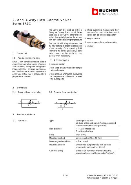
2- <strong>and</strong> 3-<strong>Way</strong> <strong>Flow</strong> <strong>Control</strong> <strong>Valves</strong><br />
Series SR3C<br />
1 General<br />
1.1 Product description<br />
SR3C... flow control valves are used to<br />
control the operating speed of motors<br />
<strong>and</strong> cylinders, the speed being load -<br />
independent i.e. pressure compensated.<br />
The flow rate is varied by means of<br />
a slit -type orifice that is actuated by a<br />
proportional solenoid.<br />
2 Symbols<br />
2.1 2-way flow controller<br />
P A<br />
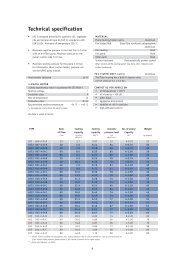
3 Technical data<br />
The valve can be used as either a<br />
2 -way or 3 -way flow control. When<br />
used as a 3 -way valve, either the controlled<br />
flow (priority) port or the surplus<br />
flow port can be at the higher pressure.<br />
The special orifice layout ensures that<br />
the flow setting is largely independent<br />
of the viscosity of the operating fluid.<br />
Thanks to the cartridge design, a complete<br />
valve can be replaced very<br />
quickly when necessary.<br />
1.2 Advantages<br />
S compact design<br />
S flow rates are unaffected by temperature<br />
changes<br />
S flow rates are unaffected by reversal<br />
of the pressure differential between<br />
the outlet ports<br />
2.2 3-way flow controller<br />
P A<br />
B<br />
S where customers manufacture their<br />
own manifold blocks, the flow control<br />
valves can be ordered separately<br />
S easy to service<br />
S several types of manual overrides<br />
S reliable<br />
3.1 General Type cartridge valve with<br />
slit -type orifice <strong>and</strong> parallel/series connected<br />
pressure compensator (hydrostat)<br />
<strong>Flow</strong> direction P -> A controlled flow<br />
P -> B surplus flow<br />
Seals Viton (FPM)<br />
Mounting method screw -in valve (MA =50Nm)<br />
De -energised condition orifice closed<br />
Mounting attitude unrestricted but preferably with solenoid<br />
underneath (automatic air bleed)<br />
Commissioning bleed all air from the system (if possible,<br />
operate valve several times under ’no load’)<br />
1 / 8 Classification: 430.30.30.10<br />
Reference: 100 -P -000044 -E -05 / 12.04
3.2 Electrical Type pressure tight, oil immersed<br />
(proportional solenoid) Operating voltage Volt DC 12 or 24, from electronic controller<br />
Power consumption<br />
Watt<br />
27 with 12V coil<br />
22.2 with 24V coil<br />
Dither frequency required Hz 50 - 150<br />
Duty cycle % 100<br />
Enclosure protection IP54 when connector plug is<br />
correctly fitted<br />
Electrical connector pins to suit DIN 43650 plug<br />
Response time<br />
(pressure dependent)<br />
ms 100 (at 100 bar)<br />
3.3 Hydraulic <strong>Control</strong>led flow ranges l/min 06, 10, 16, 25, 32, 40, 50, 63, 80 1)<br />
Inlet flow l/min max. 100 1)<br />
Operating pressure bar max. 315<br />
Leakage<br />
Pressure at B 10 bar<br />
100 bar<br />
200 bar<br />
300 bar<br />
Minimum pressur drop<br />
(compensator / hydrostat)<br />
<strong>Control</strong> accuracy at constant<br />
temperature <strong>and</strong> constant<br />
inlet flow rate<br />
cm 3 /min<br />
22 1)<br />
100<br />
200<br />
400<br />
bar 5to8<br />
% ± 3,5 2)<br />
Fluids mineral oils to DIN 51524 <strong>and</strong><br />
51525 (other fluids - contact <strong>Bucher</strong><br />
<strong>Hydraulics</strong>)<br />
Fluid temperature °C -20 ... +80<br />
Viscosity range mm 2 /s 10 ... 300<br />
Filtration NAS 1638 class 9, ISO / DIN 4406 class 18/14<br />
achievable with filter rating of ß10 ≧ 75<br />
1) values refer to an oil viscosity of 35<br />
mm 2 /s (cSt)<br />
2) values refer to the flow range chosen<br />
100 -P -000044 -E -05 / 12.04 2/8
4 Characteristic curves<br />
4.1 Q - I characteristic 4.2 Pressure drops<br />
Nominal flow Q [%]<br />
at 12V<br />
at 24V<br />
100<br />
75<br />
50<br />
25<br />
0<br />
850<br />
400<br />
1150<br />
600<br />
1500<br />
800<br />
2000<br />
1000<br />
Solenoid current I [mA] ±6%<br />
4.3 <strong>Control</strong> accuracy<br />
Q[l/min] Q nom<br />
∆ Q Hysteresis
5.2 Valve cavity<br />
66<br />
3,2<br />
52<br />
1,5 - max 5<br />
30<br />
22<br />
1,6<br />
1,6<br />
Port B is not required for 2 -way flow<br />
controllers.<br />
6 Ordering code<br />
∅57<br />
M42 x 1,5<br />
18,5 20<br />
∅37 +0,05<br />
∅35 +0,05<br />
<strong>Flow</strong> control cartridge valve SR3C<br />
30°<br />
30°<br />
24 - 0,2<br />
46 - 0,2<br />
∅0,025<br />
∅0,025<br />
0,025<br />
max. ∅12<br />
<strong>Control</strong>led (priority) flow ranges<br />
adjustable flow models (operator types S, T, N <strong>and</strong> A)<br />
0-06 / -10 / -16 / -25 / -32 / -40 / -50 / -63 / -80 l/min = e.g. 50<br />
adjustable flow model (operator type H)<br />
VA (0 -12 l/min), VB (0 -25 l/min), VC (0 -50 l/min) = e.g. VB<br />
VD (0 -63 l/min)<br />
adjustable fixed flow setting (operator type F) = **<br />
Operator type Solenoid = S<br />
Solenoid + manual override = T<br />
Solenoid + override = N<br />
Solenoid + man. override + cover = A<br />
Manual = H<br />
Fixed flow setting = F<br />
-<br />
Design number (inserted by the factory)<br />
Nominal voltage of proportional solenoid 12 V DC = G12<br />
24 V DC = G24<br />
not required for operator types F + H = ***<br />
/<br />
Variants / special features (to be inserted by the factory)<br />
7) for fixed flow rate versions, the constant flow rate required must be specified in plain text<br />
Z<br />
Detail Z<br />
M5:1<br />
100 -P -000044 -E -05 / 12.04 4/8<br />
3,2<br />
3.1 +0,4<br />
1,6<br />
49<br />
44.4 +0,1<br />
(M42x1,5)<br />
- 0,3<br />
S R 3 C 5 0 S - 0 G 1 2 / Q=... 7)<br />
0,1<br />
0,1
7 Mounting bodies<br />
For aluminium bodies p max = 250 bar<br />
SR3CVM1-****-0M22***<br />
Ordering no.: 100020947<br />
P<br />
T<br />
P<br />
90<br />
45<br />
35<br />
35<br />
Material: aluminium<br />
B<br />
A<br />
SR3CVM1-2***-0M22*** with pressure relief<br />
Ordering no.: 100020948 (with X port)<br />
90<br />
45<br />
35<br />
35<br />
18,5<br />
20<br />
B<br />
A<br />
18,5<br />
20<br />
Optional<br />
orifice<br />
Ø8,4<br />
Ø8,4<br />
Port threads:<br />
P, A <strong>and</strong> B= M22 x 1,5<br />
105<br />
95<br />
105<br />
A<br />
47,5<br />
B<br />
25,5<br />
192<br />
SR3CVM1-2***-0M18*** with pressure relief<br />
Ordering no.: 100022081 (with X port)<br />
Material: aluminium<br />
X<br />
Optional<br />
orifice<br />
020948<br />
022081<br />
95<br />
A<br />
10<br />
47,5<br />
25,5<br />
10<br />
25,5<br />
192<br />
Ø8,4<br />
Port threads:<br />
P, T, A <strong>and</strong> B = M22 x 1,5<br />
X = M12 x 1,5<br />
Port threads:<br />
P <strong>and</strong> T = M22 x 1,5<br />
A <strong>and</strong> B = M18 x 1,5<br />
X<br />
Ø8,4<br />
B P<br />
100 -P -000044 -E -05 / 12.04 5/8<br />
90<br />
90<br />
60<br />
45<br />
P<br />
137<br />
T<br />
21
SR3CVM2-2**4-0M22*** with service line pressure relief <strong>and</strong> anti -cavitation make -up 8)<br />
Ordering no.: 100021036<br />
SR3CVM2-2***-0M22*** with service line pressure relief, without anti -cavitation make -up 8)<br />
Ordering no.: 100 021873<br />
T<br />
P<br />
SR3CVM3-***2-0M22*** with anti -cavitation make -up 8)<br />
Ordering no.: 100020809<br />
T B<br />
P<br />
Optional service line<br />
pressure<br />
M1<br />
Material: aluminium<br />
M<br />
Optional service line<br />
pressure relief<br />
B<br />
A<br />
B<br />
A<br />
A<br />
B<br />
A<br />
B<br />
A<br />
150<br />
192<br />
218<br />
Material:<br />
continuously cast GGG40<br />
(a nodular ductile iron)<br />
140<br />
131<br />
92.5<br />
61<br />
128<br />
154<br />
Port threads:<br />
P <strong>and</strong> T = M22 x 1,5<br />
A <strong>and</strong> B = M18 x 1,5<br />
M1 = M10 x 1<br />
22.5<br />
15<br />
Port threads:<br />
P <strong>and</strong> T = M22 x 1,5<br />
A <strong>and</strong> B = M18 x 1,5<br />
M = M10 x 1<br />
90<br />
64<br />
25.5<br />
B<br />
M<br />
B<br />
50<br />
90<br />
A<br />
A<br />
47.5<br />
75<br />
90<br />
25.5<br />
45<br />
B<br />
B<br />
B<br />
47.5<br />
175<br />
100 -P -000044 -E -05 / 12.04 6/8<br />
A<br />
A<br />
A<br />
25.5<br />
175<br />
87<br />
41<br />
194<br />
13<br />
38<br />
88<br />
110<br />
61<br />
P<br />
89<br />
157<br />
110<br />
P<br />
T<br />
T<br />
46<br />
192.5
SR3CVR1-***L-0M22***<br />
Ordering no.: 100020494<br />
Open for LS<br />
applications<br />
X<br />
55<br />
Material:<br />
continuously cast GG25<br />
(a grey cast iron)<br />
P<br />
T<br />
20<br />
Plugged for LS<br />
applications<br />
8) service line pressure relief <strong>and</strong><br />
anti -cavitation make -up can be<br />
optionally plugged off.<br />
59<br />
110<br />
X<br />
Port threads:<br />
P <strong>and</strong> T = M22 x 1,5<br />
X = M14 x 1,5<br />
GEROTOR--MOTOR<br />
RF--..29..0<br />
100 -P -000044 -E -05 / 12.04 7/8<br />
30<br />
75<br />
90<br />
176
8 Ordering code<br />
S R 3 C V M2 - 2 * * 2 - M 2 2 * * * /<br />
Type Separate unit single = M1, double = M2<br />
Motor mtg. (RS29) single = R1, double = R2<br />
Inlet section = E*<br />
Intermediate section = Z*<br />
End section = A*<br />
Bolt -on section = AP<br />
Service line relief for 1st controller in P in A<br />
None =* =*<br />
Pressure range 3 - 30 bar 9) Pressure range 30 - 70 bar<br />
=0 =4<br />
10) =1 =5<br />
Pressure range 70 - 200 bar = 2 = 6<br />
Pressure range 200 - 300 bar = 3 = 7<br />
Service line relief for 2nd controller in P in A<br />
None =* =*<br />
Pressure range 3 - 30 bar 9) Pressure range 30 - 70 bar<br />
=0 =4<br />
10) =1 =5<br />
Pressure range 70 - 200 bar = 2 = 6<br />
Pressure range 200 - 300 bar = 3 = 7<br />
Service line relief for 3rd controller in P in A<br />
None =* =*<br />
Pressure range 3 - 30 bar 9) =0 =4<br />
Pressure range 30 - 70 bar 10) Mounting body for SR3C cartridge valve<br />
0<br />
=1 =5<br />
Pressure range 70 - 200 bar = 2 = 6<br />
Pressure range 200 - 300 bar = 3 = 7<br />
Additional functions<br />
None = *<br />
For use with LS pump = L<br />
With bypass check valve = R<br />
With anti -cavitation for 1st controller = 1<br />
2nd controller = 2<br />
3rd controller = 3<br />
1st <strong>and</strong> 2nd controller = 4<br />
1st <strong>and</strong> 3rd controller = 5<br />
2nd <strong>and</strong> 3rd controller = 6<br />
1st, 2nd <strong>and</strong> 3rd controller = 7<br />
Design no. (to be inserted by the factory)<br />
Port threads DIN 3852 - M22 x 1,5 = M22<br />
(other threads - contact <strong>Bucher</strong> <strong>Hydraulics</strong>)<br />
Nominal voltage of proportional solenoid (for bodies with solenoid operated valves)<br />
12 V DC = G12<br />
24 V DC = G24<br />
none = ***<br />
Variants / special features (to be inserted by the factory)<br />
9) only to Qmax = 25 l/min 10) only to Qmax =40l/min<br />
The flow control valves must be ordered separately as detailed in section 6<br />
BUCHER HYDRAULICS www.bucherhydraulics.com<br />
Germany<br />
Phone +49 7742 85 20<br />
Fax +49 7742 71 16<br />
info.de@bucherhydraulics.com<br />
Switzerl<strong>and</strong><br />
Phone +41 33 67 26 11 1<br />
Fax+41336726103<br />
info.ch@bucherhydraulics.com<br />
France<br />
Phone +33 389 64 22 44<br />
Fax +33 389 65 28 78<br />
info.fr@bucherhydraulics.com<br />
Italy<br />
Phone +39 0522 92 84 11<br />
Fax +39 0522 51 32 11<br />
info.it@bucherhydraulics.com<br />
We reserve the right of modification without prior notice.<br />
Netherl<strong>and</strong>s<br />
UK<br />
Phone +31 79 34 26 24 4 Phone +44 24 76 35 35 61<br />
Fax+31793426288 Fax +44 24 76 35 35 72<br />
info.nl@bucherhydraulics.com info.uk@bucherhydraulics.com<br />
Austria<br />
China<br />
Phone +43 6216 44 97 Phone +86 512 6 322 12 99<br />
Fax+43621644974 Fax +86 512 6 322 10 33<br />
info.at@bucherhydraulics.com info.sh@bucherhydraulics.com<br />
USA<br />
Phone +1 262 605 82 80<br />
Fax +1 262 605 82 78<br />
info.wi@bucherhydraulics.com<br />
Product Center (Elevator)<br />
Phone +41 41 757 03 33<br />
Fax +41 41 755 16 49<br />
info.nh@bucherhydraulics.com<br />
100 -P -000044 -E -05 / 12.04 8/8