Air Oil Coolers Oiltech LOC Datasheet
Air Oil Coolers Oiltech LOC Datasheet
Air Oil Coolers Oiltech LOC Datasheet

You also want an ePaper? Increase the reach of your titles
YUMPU automatically turns print PDFs into web optimized ePapers that Google loves.
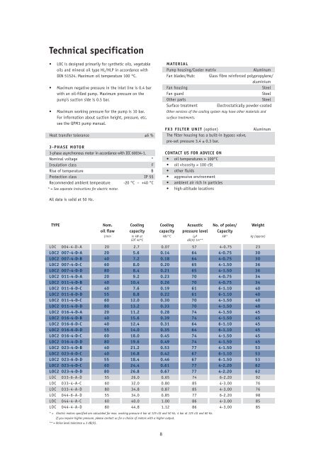
Technical specification<br />
• <strong>LOC</strong> is designed primarily for synthetic oils, vegetable<br />
oils and mineral oil type HL/HLP in accordance with<br />
DIN 51524. Maximum oil temperature 100 °C.<br />
• Maximum negative pressure in the inlet line is 0.4 bar<br />
with an oil-filled pump. Maximum pressure on the<br />
pump’s suction side is 0.5 bar.<br />
• Maximum working pressure for the pump is 10 bar.<br />
For information about suction height, pressure, etc.<br />
see the QPM3 pump manual.<br />
Heat transfer tolerance ±6 %<br />
3-PHASE MOTOR<br />
3-phase asynchronous motor in accordance with IEC 60034-1.<br />
Nominal voltage *<br />
Insulation class F<br />
Rise of temperature B<br />
Protection class IP 55<br />
Recommended ambient temperature<br />
* = See separate instructions for electric motor.<br />
-20 °C – +40 °C<br />
All data is valid at 50 Hz.<br />
<strong>LOC</strong> 004-4-D-A 20 2.7 0.07 57 4-0.75 23<br />
<strong>LOC</strong>2 007-4-D-A 20 5.6 0.14 64 4-0.75 30<br />
<strong>LOC</strong>2 007-4-D-B 40 7.2 0.18 64 4-0.75 30<br />
<strong>LOC</strong>2 007-4-D-C 60 8.0 0.20 65 4-1.50 36<br />
<strong>LOC</strong>2 007-4-D-D 80 8.4 0.21 65 4-1.50 36<br />
<strong>LOC</strong>2 011-4-D-A 20 9.2 0.23 70 4-0.75 34<br />
<strong>LOC</strong>2 011-4-D-B 40 10.4 0.26 70 4-0.75 34<br />
<strong>LOC</strong>2 011-6-D-C 40 7.6 0.19 61 6-1.10 40<br />
<strong>LOC</strong>2 011-6-D-D 55 8.8 0.22 61 6-1.10 40<br />
<strong>LOC</strong>2 011-4-D-C 60 12.0 0.30 70 4-1.50 40<br />
<strong>LOC</strong>2 011-4-D-D 80 13.2 0.33 70 4-1.50 40<br />
<strong>LOC</strong>2 016-4-D-A 20 11.2 0.28 74 4-1.50 45<br />
<strong>LOC</strong>2 016-4-D-B 40 15.6 0.39 74 4-1.50 45<br />
<strong>LOC</strong>2 016-6-D-C 40 12.4 0.31 64 6-1.10 45<br />
<strong>LOC</strong>2 016-6-D-D 55 14.0 0.35 64 6-1.10 45<br />
<strong>LOC</strong>2 016-4-D-C 60 18.0 0.45 74 4-1.50 45<br />
<strong>LOC</strong>2 016-4-D-D 80 19.6 0.49 74 4-1.50 45<br />
<strong>LOC</strong>2 023-4-D-B 40 21.2 0.53 77 4-1.50 53<br />
<strong>LOC</strong>2 023-6-D-C 40 16.8 0.42 67 6-1.10 53<br />
<strong>LOC</strong>2 023-6-D-D 55 18.4 0.46 67 6-1.50 53<br />
<strong>LOC</strong>2 023-4-D-C 60 24.4 0.61 77 4-2.20 62<br />
<strong>LOC</strong>2 023-4-D-D 80 26.8 0.67 77 4-2.20 62<br />
<strong>LOC</strong> 033-6-A-D 55 26.0 0.65 74 6-2.20 92<br />
<strong>LOC</strong> 033-4-A-C 60 32.0 0.80 85 4-3.00 76<br />
<strong>LOC</strong> 033-4-A-D 80 34.8 0.87 85 4-3.00 76<br />
<strong>LOC</strong> 044-6-A-D 55 34.0 0.85 77 6-2.20 98<br />
<strong>LOC</strong> 044-4-A-C 60 40.0 1.00 86 4-3.00 85<br />
<strong>LOC</strong> 044-4-A-D 80 44.8 1.12 86 4-3.00 85<br />
* = Electric motors specified are calculated for max. working pressure 6 bar at 125 cSt and 50 Hz, 4 bar at 125 cSt and 60 Hz.<br />
If you require higher pressure, please contact us for a choice of motors with a higher output.<br />
** = Noise level tolerance ± 3 dB(A).<br />
MATERIAL<br />
Pump housing/Cooler matrix Aluminum<br />
Fan blades/Hub: Glass fibre reinforced polypropylene/<br />
aluminium<br />
Fan housing Steel<br />
Fan guard Steel<br />
Other parts Steel<br />
Surface treatment Electrostatically powder-coated<br />
Other versions of the cooling system may have other materials and<br />
surface treatments.<br />
FX3 FILTER UNIT (option) Aluminum<br />
The filter housing has a built-in bypass valve,<br />
pre-set pressure 3.4 ± 0.3 bar.<br />
CONTACT US FOR ADVICE ON<br />
• oil temperatures > 100°C<br />
• oil viscosity > 100 cSt<br />
• other fluids<br />
• aggressive environment<br />
• ambient air rich in particles<br />
• high-altitude locations<br />
TYPE Nom. Cooling Cooling Acoustic No. of poles/ Weight<br />
oil flow capacity capacity pressure level Capacity<br />
l/min in kW at kW/°C LpA kW* kg (approx)<br />
EDT 40°C dB(A) 1m**<br />
8
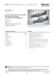
With - type . T bypass<br />
Bypass type T<br />
Thermo contact<br />
E<br />
C<br />
Bypass type S<br />
B<br />
A<br />
F (3x)<br />
#<br />
Min. space<br />
for ( filter #! 0<br />
replacement 0 1 #<br />
4” = $) 120 * +,2mm<br />
8” = ") 220 * ,,2mm<br />
4” = $) 184 * +"$ mm<br />
8” = ") 283 * ," mm<br />
Pump inlet<br />
G1 1/2 on<br />
opposite side<br />
'<br />
M ( (4x) $<br />
TYPE A B C D E F G H I J K L M O⁄<br />
<strong>LOC</strong> 004-4-D-A 267 134 135 284 73 G1 420 90 164 163 488 58 9<br />
<strong>LOC</strong>2 007-4-D-A 365 203 105 395 42 G1 510 160 215 225 558 50 9<br />
<strong>LOC</strong>2 007-4-D-B 365 203 105 395 42 G1 510 160 215 225 571 50 9<br />
<strong>LOC</strong>2 007-4-D-C 365 203 105 395 42 G1 510 160 215 225 620 50 9<br />
<strong>LOC</strong>2 007-4-D-D 365 203 105 395 42 G1 510 160 215 225 633 50 9<br />
<strong>LOC</strong>2 011-4-D-A 440 203 103 470 41 G1 510 230 252 249 582 50 9<br />
<strong>LOC</strong>2 011-4-D-B 440 203 103 470 41 G1 510 230 252 249 595 50 9<br />
<strong>LOC</strong>2 011-6-D-C 440 203 103 470 41 G1 510 230 252 249 643 50 9<br />
<strong>LOC</strong>2 011-6-D-D 440 203 103 470 41 G1 510 230 252 249 657 50 9<br />
<strong>LOC</strong>2 011-4-D-C 440 203 103 470 41 G1 510 230 252 249 644 50 9<br />
<strong>LOC</strong>2 011-4-D-D 440 203 103 470 41 G1 510 230 252 249 657 50 9<br />
<strong>LOC</strong>2 016-4-D-A 496 203 107 526 46 G1 510 230 285 272 640 50 9<br />
<strong>LOC</strong>2 016-4-D-B 496 203 107 526 46 G1 510 230 285 272 653 50 9<br />
<strong>LOC</strong>2 016-6-D-C 496 203 107 526 46 G1 510 230 285 272 665 50 9<br />
<strong>LOC</strong>2 016-6-D-D 496 203 107 526 46 G1 510 230 285 272 678 50 9<br />
<strong>LOC</strong>2 016-4-D-C 496 203 107 526 46 G1 510 230 285 272 665 50 9<br />
<strong>LOC</strong>2 016-4-D-D 496 203 107 526 46 G1 510 230 285 272 678 50 9<br />
<strong>LOC</strong>2 023-4-D-B 580 356 104 610 40 G1 610 305 322 287 668 50 14<br />
<strong>LOC</strong>2 023-6-D-C 580 356 104 610 40 G1 610 305 322 287 722 50 14<br />
<strong>LOC</strong>2 023-6-D-D 580 356 104 610 40 G1 610 305 322 287 722 50 14<br />
<strong>LOC</strong>2 023-4-D-C 580 356 104 610 40 G1 610 305 322 287 709 50 14<br />
<strong>LOC</strong>2 023-4-D-D 580 356 104 610 40 G1 610 305 322 287 722 50 14<br />
<strong>LOC</strong> 033-6-A-D 692 356 99 722 32 G1 1 ⁄4 610 406 378 318 754 70 14<br />
<strong>LOC</strong> 033-4-A-C 692 356 99 722 32 G1 1 ⁄4 610 406 378 318 727 70 14<br />
<strong>LOC</strong> 033-4-A-D 692 356 99 722 32 G1 1 ⁄4 610 406 378 318 741 70 14<br />
<strong>LOC</strong> 044-6-A-D 692 356 99 866 49 G1 1 ⁄4 610 584 450 343 779 70 14<br />
<strong>LOC</strong> 044-4-A-C 692 356 99 866 49 G1 1 ⁄4 610 584 450 343 750 70 14<br />
<strong>LOC</strong> 044-4-A-D 692 356 99 866 49 G1 1 ⁄4 610 584 450 343 762 70 14<br />
9<br />
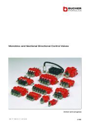
K&<br />
G<br />
J%<br />
! "<br />
Stone # guard max. ! $ 34 mm.<br />
L/<br />
AIR<br />
H Dust guard max. 8 mm.
Key for <strong>LOC</strong> and<br />
<strong>LOC</strong>2 cooling systems<br />
All positions must be filled in when ordering.<br />
EXAMPLE:<br />
<strong>LOC</strong>2-011-6-A-C-L-50-S20-D-E0-0<br />
1 2 3 4 5 6 7 8 9 10/11 12<br />
1. TYPE OF COOLING SYSTEM = <strong>LOC</strong>/<strong>LOC</strong>2<br />
2. COOLER SIZE<br />
004, 007, 011, 016, 023, 033, 044<br />
3. NUMBER OF POLES, MOTOR<br />
4-pole = 4<br />
6-pole = 6<br />
4. VOLTAGE AND FREQUENCY<br />
Three-phase 220-240/380-420V 50 Hz * = A<br />
Three-phase 440-480V 60 Hz* = B<br />
Three-phase 220-240/380-420V 50 Hz 440/480V 60 Hz** = D<br />
Three-phase 500V 50 Hz = E<br />
Three-phase 400/690V 50 Hz 440-480 60 Hz = F<br />
Three-phase 525V 50 Hz = G<br />
Motor for special voltage (stated in plain language) = X<br />
* for <strong>LOC</strong> 033 to <strong>LOC</strong> 044<br />
** for <strong>LOC</strong> 004 – <strong>LOC</strong>2 023<br />
5. PUMP SIZE<br />
Displacement 15 cm 3 /r = A<br />
Displacement 30 cm 3 /r = B<br />
Displacement 45 cm 3 /r = C<br />
Displacement 60 cm 3 /r = D<br />
Special = X<br />
6. BYPASS VALVE, PUMP<br />
No bypass valve = 0<br />
Built-in bypass valve, 5 bar internal = L<br />
Built-in bypass valve, 10 bar internal = H<br />
Built-in bypass valve, 5 bar external = K<br />
Built-in bypass valve, 10 bar external = M<br />
7. THERMO CONTACT<br />
For temperature alarm, not for direct control of electric motor.<br />
No thermo contact = 00<br />
40 °C = 40<br />
50 °C = 50<br />
60 °C = 60<br />
70 °C = 70<br />
80 °C = 80<br />
90 °C = 90<br />
8. COOLER MATRIX<br />
Standard = 000<br />
Two-pass<br />
Built-in, pressure-controlled bypass valve, single-pass<br />
= T00<br />
2 bar = S20<br />
5 bar = S50<br />
8 bar<br />
Built-in, pressure-controlled bypass valve, two-pass*<br />
= S80<br />
2 bar = T20<br />
5 bar = T50<br />
8 bar = T80<br />
10<br />
Built-in temperature and pressure-controlled bypass valve, single-pass<br />
50 °C, 2.2 bar = S25<br />
60 °C, 2.2 bar = S26<br />
70 °C, 2.2 bar = S27<br />
90 °C, 2.2 bar<br />
Built-in temperature and pressure-controlled bypass valve, two-pass*<br />
= S29<br />
50 °C, 2.2 bar = T25<br />
60 °C, 2.2 bar = T26<br />
70 °C, 2.2 bar = T27<br />
90 °C, 2.2 bar<br />
* = Not valid for <strong>LOC</strong> 004<br />
= T29<br />
9. MATRIX GUARD<br />
No guard = 0<br />
Stone guard = S<br />
Dust guard = D<br />
Dust and stone guard = P<br />
10. FX3 FILTER UNIT (sizing, see page 6)<br />
No filter unit = 0<br />
Filter unit with 4” element HP = A<br />
Filter unit with 4” element LP = B<br />
Filter unit with 8” element HP = E<br />
Filter unit with 8” element LP = F<br />
11.PRESSURE DROP INDICATOR<br />
No pressure drop indicator = 0<br />
Visual pressure drop indicator<br />
with manual reset. = D<br />
Visual pressure drop indicator<br />
with thermo guard and manual reset.<br />
No signal below 0 o<br />
C, signal above +29 o<br />
C. = P<br />
Electric pressure drop indicator with automatic reset.<br />
Connection in accordance with DIN 43650<br />
ISO 4400 (Hirschmann) IP 65. = M<br />
Electric pressure drop indicator<br />
with 2-pole AMP contact. = U<br />
12. STANDARD/SPECIAL<br />
Standard = 0<br />
Special = Z<br />
SPARE PARTS<br />
Art. no. Description<br />
58920102 Filter element 04” HP<br />
58920103 Filter element 04” LP<br />
58920302 Filter element 08” HP<br />
58920303 Filter element 08” LP<br />
589310 O-ring for filter housing cover