The use of sliding pendulum isolators for the C.A.S.E. ... - Alga S.p.A.
The use of sliding pendulum isolators for the C.A.S.E. ... - Alga S.p.A.
The use of sliding pendulum isolators for the C.A.S.E. ... - Alga S.p.A.

You also want an ePaper? Increase the reach of your titles
YUMPU automatically turns print PDFs into web optimized ePapers that Google loves.
<strong>The</strong> <strong>use</strong> <strong>of</strong> <strong>sliding</strong> <strong>pendulum</strong> <strong>isolators</strong> <strong>for</strong> <strong>the</strong> C.A.S.E. project in L’Aquila<br />
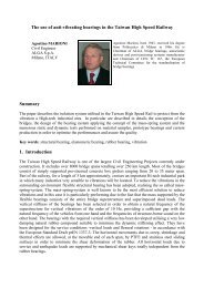
Agostino MARIONI<br />
Civil Engineer<br />
C.E.O. ALGA SpA<br />
Milano, ITALY<br />
a.marioni@alga.it<br />
Agostino Marioni, born 1943,<br />
received his civil engineering degree<br />
from Politecnico di Milano, Italy in<br />
1966. He is <strong>the</strong> Managing Director <strong>of</strong><br />
<strong>Alga</strong> SpA, Milano, he is also <strong>the</strong><br />
Chairman <strong>of</strong> CEN TC 167, <strong>the</strong><br />
European Technical Commettee <strong>for</strong><br />
<strong>the</strong> Structural Bearings Standard and<br />
member <strong>of</strong> CEN TC 340 <strong>for</strong><br />
Antiseismic Devices<br />
Summary<br />
C.A.S.E is <strong>the</strong> largest base isolation project ever executed in <strong>the</strong> world. It consist <strong>of</strong> 185 3-story<br />
apartment buildings made with different construction methods, including prefabricated concrete,<br />
steel and wood. In total 4600 apartments <strong>for</strong> approximately 17.000 persons to recover <strong>the</strong> homeless<br />
after <strong>the</strong> 6 th April 2009 earthquake in L’Aquila. Each building is erected on a rein<strong>for</strong>ced concrete<br />
slab <strong>of</strong> 18x54x0,5m which is supported by 40 steel columns provided on top with seismic <strong>isolators</strong>.<br />
So in total <strong>the</strong>re are 7400 base <strong>isolators</strong> in <strong>the</strong> project. Peculiar aspect <strong>of</strong> <strong>the</strong> project is <strong>the</strong> fact that it<br />
has been completed in less than 9 months after <strong>the</strong> day <strong>of</strong> <strong>the</strong> earthquake.<br />
<strong>The</strong> paper describes <strong>the</strong> general structural design and <strong>the</strong> details <strong>of</strong> <strong>the</strong> <strong>sliding</strong> <strong>pendulum</strong> <strong>isolators</strong><br />
adopted <strong>for</strong> <strong>the</strong> project: design, production, installation and testing.<br />
Keywords: Base isolation, Sliding <strong>pendulum</strong> <strong>isolators</strong>, Friction coefficient, Energy dissipation<br />
1. Introduction<br />
C.A.S.E is <strong>the</strong> largest base isolation project ever executed in <strong>the</strong> world. It consist <strong>of</strong> 185 3-story<br />
apartment buildings made with different construction methods, including prefabricated concrete,<br />
steel and wood. In total 4600 apartments <strong>for</strong> approximately 17.000 persons to recover <strong>the</strong> homeless<br />
after <strong>the</strong> 6 th April 2009 earthquake in L’Aquila. Each building is erected on a rein<strong>for</strong>ced concrete<br />
slab <strong>of</strong> 18x54x0,5m which is supported by 40 steel columns provided on top with seismic <strong>isolators</strong>.<br />
So in total <strong>the</strong>re are 7400 base <strong>isolators</strong> in <strong>the</strong> project. Peculiar aspect <strong>of</strong> <strong>the</strong> project is <strong>the</strong> fact that it<br />
has been completed in less than 9 months after <strong>the</strong> day <strong>of</strong> <strong>the</strong> earthquake.<br />
<strong>The</strong> buildings are located in 19 different sites around L’Aquila as shown in fig, 1<br />
<strong>The</strong> execution <strong>of</strong> this project in <strong>the</strong> <strong>for</strong>eseen schedule has been a big challenge <strong>for</strong> all <strong>the</strong> actors<br />
involved: <strong>the</strong> owner from one side –<strong>the</strong> Italian government itself represented by <strong>the</strong> Protezione<br />
Civile- and all <strong>the</strong> suppliers, including <strong>the</strong> seismic <strong>isolators</strong> manufacturers.<br />
<strong>The</strong> author <strong>of</strong> this paper has been involved with <strong>the</strong> company by him managed <strong>for</strong> <strong>the</strong> supply <strong>of</strong><br />
more than 2/3 <strong>of</strong> all <strong>the</strong> <strong>isolators</strong>.<br />
In <strong>the</strong> limited time available <strong>for</strong> <strong>the</strong> supply <strong>of</strong> nearly 5000 <strong>isolators</strong> (three months) it was necessary<br />
to select <strong>the</strong> technical solution <strong>for</strong> <strong>the</strong> <strong>isolators</strong>, develop <strong>the</strong> construction drawings, organize <strong>the</strong><br />
manufacturing, set up a dedicated testing equipment and per<strong>for</strong>m <strong>the</strong> required tests.<br />
Due to <strong>the</strong> variety <strong>of</strong> constructions <strong>for</strong>eseen on top <strong>of</strong> <strong>the</strong> rein<strong>for</strong>ced concrete slabs and <strong>the</strong> different<br />
possible values and distributions <strong>of</strong> <strong>the</strong> masses, <strong>sliding</strong> <strong>pendulum</strong> <strong>isolators</strong> immediately appeared to<br />
be <strong>the</strong> best possible solution, granting constant isolation parameters and displacements<br />
independently from <strong>the</strong> location <strong>of</strong> <strong>the</strong> masses. Whit this kind <strong>of</strong> isolator <strong>the</strong>re was no need to take
into account any torsion movement around <strong>the</strong> vertical axis, hence minimizing <strong>the</strong> design<br />
displacement <strong>of</strong> <strong>the</strong> <strong>isolators</strong>.<br />
Fig. 1 – <strong>The</strong> location <strong>of</strong> <strong>the</strong> 19 sites around L’Aquila where <strong>the</strong> 185 buildings <strong>of</strong> <strong>the</strong> C.A.S.E.<br />
project have been erected<br />
<strong>The</strong> <strong>for</strong>eseen isolation parameters, natural period 3,3 s and equivalent viscous damping 20%,<br />
required <strong>the</strong> <strong>use</strong> <strong>of</strong> a <strong>sliding</strong> material with friction coefficient <strong>of</strong> 3%, slightly different from <strong>the</strong><br />
materials experienced be<strong>for</strong>e by ALGA. <strong>The</strong> suitable material was found and tested in few days<br />
only after <strong>the</strong> tender award thanks to <strong>the</strong> co-operation with Politecnico di Milano.<br />
<strong>The</strong> production could start two weeks after <strong>the</strong> award <strong>of</strong> <strong>the</strong> tender and continued <strong>for</strong> 12 weeks at<br />
<strong>the</strong> incredible rhythm <strong>of</strong> 400 <strong>isolators</strong> per week, with 4 trucks per week reaching <strong>the</strong> sites <strong>of</strong><br />
L’Aquila and two teams <strong>of</strong> specialized workers involved in two shifts <strong>for</strong> <strong>the</strong> installation.<br />
<strong>The</strong> <strong>isolators</strong> have been designed and tested in accordance with <strong>the</strong> Italian “Norme Tecniche per le<br />
Costruzioni (NTC)” issued in January 2008 but also in accordance with <strong>the</strong> new European Standard<br />
EN 15129, at <strong>the</strong> time <strong>of</strong> <strong>the</strong> tender in <strong>for</strong>mal vote stage, successively approved in August 2009<br />
and published in <strong>the</strong> following November.<br />
<strong>The</strong> Standards required <strong>the</strong> execution <strong>of</strong> 2 prototype tests and routine test on 5% (EN) or 20% <strong>of</strong> <strong>the</strong><br />
<strong>isolators</strong> (NTC). It was decided to per<strong>for</strong>m <strong>the</strong> prototype tests and 5% dynamic routine tests at<br />
Eucentre and <strong>the</strong> remaining 15% routine tests on an expressly developed testing machine at ALGA<br />
laboratory. In addition several in situ dynamic tests has been per<strong>for</strong>med by <strong>the</strong> client applying<br />
dynamic excitations to entire apartment buildings.<br />
2. <strong>The</strong> structural design<br />
2.1 General<br />
<strong>The</strong> structural design <strong>of</strong> <strong>the</strong> buildings constitutes <strong>the</strong> fundamental element that allowed <strong>the</strong><br />
development <strong>of</strong> <strong>the</strong> entire project and is extremely simple in its basic logic: two rein<strong>for</strong>ced concrete<br />
plates separated by columns and <strong>isolators</strong>, <strong>the</strong> lower one being in contact with <strong>the</strong> soil and <strong>the</strong> upper
one with <strong>the</strong> building (see Fig. 2).<br />
Fig. 2 – <strong>The</strong> conceptual design <strong>of</strong> <strong>the</strong> buildings <strong>for</strong> <strong>the</strong> C.A.S.E. project<br />
<strong>The</strong> plates were designed without knowing <strong>the</strong> local soil properties, nor <strong>the</strong> weight and plan<br />
distribution <strong>of</strong> <strong>the</strong> buildings that had a great variability within <strong>the</strong> 185 different cases. <strong>The</strong>re<strong>for</strong>e, <strong>for</strong><br />
both aspects conservative assumptions were <strong>use</strong>d, to be verified case by case.<br />
<strong>The</strong> 2 rein<strong>for</strong>ced concrete slabs are characterized by similar flexural actions induced by gravity.<br />
<strong>The</strong>y are both <strong>of</strong> 500 mm thickness. <strong>The</strong> total weight to be supported <strong>for</strong> each building supported<br />
by 40 columns was estimated between 30 and 40 MN, so an average weight <strong>for</strong> each column <strong>of</strong> 1<br />
MN.<br />
In reality 50% <strong>of</strong> <strong>the</strong> buildings were in wood, 30% in prefabricated concrete and 20% in steel.<br />
<strong>The</strong> design period <strong>of</strong> vibration <strong>of</strong> <strong>the</strong> isolation system was selected in <strong>the</strong> range <strong>of</strong> 4 s.<br />
2.2 Seismic action<br />
<strong>The</strong> seismic action and in particular <strong>the</strong> spectral demands in acceleration and displacement are<br />
represented <strong>for</strong> an event with a 1000 years return period in L’Aquila according to <strong>the</strong> Italian code,<br />
soil category B and E, damping 5% in <strong>the</strong> following diagrams (see fig. 3)<br />
Fig. 3 – Acceleration and displacement spectra <strong>of</strong> an event with 1000 years return period in<br />
L’Aquila according to <strong>the</strong> Italian code, soil category B and E, damping 5%<br />
It is important to note that <strong>the</strong> fundamental parameter to be assessed <strong>for</strong> a proper design <strong>of</strong> <strong>the</strong><br />
isolation system is <strong>the</strong> maximum displacement demand at a period <strong>of</strong> around 4 s. <strong>The</strong> spectra<br />
derived from <strong>the</strong> registrations <strong>of</strong> April 6 th 2009 show generally displacement demand <strong>of</strong> less than
120 mm, with one exception <strong>for</strong> one registration only, <strong>for</strong> which <strong>the</strong> demand is close to 250 mm.<br />
<strong>The</strong> code spectra <strong>for</strong> events with return periods <strong>of</strong> 1000 years, to be <strong>use</strong>d <strong>for</strong> <strong>the</strong> design <strong>of</strong> <strong>the</strong><br />
isolation system, have values <strong>of</strong> about 300 mm <strong>for</strong> soils type B and 400 mm <strong>for</strong> soils type E. <strong>The</strong>se<br />
values can be significantly reduced in presence <strong>of</strong> energy dissipation, as a function <strong>of</strong> an<br />
appropriate equivalent damping, according to <strong>the</strong> factor:<br />
10<br />
η = 5 + ξ<br />
Where is <strong>the</strong> equivalent viscous damping that could be <strong>of</strong> <strong>the</strong> order <strong>of</strong> 10 to 16% <strong>for</strong> High<br />
Damping Rubber Bearings and 20% <strong>for</strong> <strong>sliding</strong> <strong>pendulum</strong> <strong>isolators</strong>.<br />
2.3 <strong>The</strong> base isolation system<br />
<strong>The</strong> design and <strong>the</strong> verification <strong>of</strong> <strong>the</strong> isolation system was carried out considering <strong>the</strong> possibility <strong>of</strong><br />
adopting two different configurations, characterized by different devices: one based on <strong>the</strong> <strong>use</strong> <strong>of</strong> 12<br />
elastomeric <strong>isolators</strong> toge<strong>the</strong>r with 28 free <strong>sliding</strong> bearings <strong>for</strong> each plate; <strong>the</strong> o<strong>the</strong>r on <strong>the</strong> <strong>use</strong> <strong>of</strong> 40<br />
<strong>sliding</strong> <strong>pendulum</strong> <strong>isolators</strong>.<br />
Both choices were compatible with <strong>the</strong> project requirements, in different ways. Actually <strong>the</strong> smaller<br />
dissipation capacity <strong>of</strong> <strong>the</strong> system with elastomeric <strong>isolators</strong> and <strong>the</strong> fact that it was not possible to<br />
avoid some eccentricity <strong>of</strong> <strong>the</strong> mass in respect <strong>of</strong> <strong>the</strong> barycentre <strong>of</strong> <strong>the</strong> <strong>isolators</strong> brought <strong>the</strong><br />
displacement demand <strong>for</strong> this kind <strong>of</strong> <strong>isolators</strong> to 360 mm with soil type E. Instead <strong>the</strong> displacement<br />
demand <strong>for</strong> <strong>the</strong> <strong>sliding</strong> <strong>pendulum</strong> <strong>isolators</strong>, due to <strong>the</strong> higher value <strong>of</strong> <strong>the</strong> equivalent viscous<br />
damping and to <strong>the</strong> fact that <strong>the</strong> mass and stiffness barycentres are always coincident thanks to <strong>the</strong><br />
proportionality between mass and stiffness <strong>for</strong> this kind <strong>of</strong> <strong>isolators</strong>, was limited to 260 mm <strong>for</strong> <strong>the</strong><br />
soil type E.<br />
This fact had an impact on <strong>the</strong> cost <strong>of</strong> <strong>the</strong> two possible solutions and oriented <strong>the</strong> choice to <strong>the</strong><br />
<strong>sliding</strong> <strong>pendulum</strong> <strong>isolators</strong> <strong>for</strong> both tenderers.<br />
With this kind <strong>of</strong> <strong>isolators</strong> <strong>the</strong> <strong>for</strong>ce corresponding to a displaced position is defined by <strong>the</strong><br />
following equation:<br />
Mg <br />
F = Mgµ + d<br />
R <br />
In which M is <strong>the</strong> mass, g <strong>the</strong> gravity R <strong>the</strong> radius <strong>of</strong> <strong>the</strong> spherical surface <strong>of</strong> <strong>the</strong> <strong>sliding</strong> <strong>pendulum</strong><br />
<strong>isolators</strong> selected as 4,0m, µ <strong>the</strong> friction coefficient selected as 0,03 and d <strong>the</strong> displacement.<br />
<strong>The</strong> least favourable conditions <strong>for</strong> <strong>the</strong> verification <strong>of</strong> <strong>the</strong> displacement capacity <strong>of</strong> <strong>the</strong> isolation<br />
system versus <strong>the</strong> corresponding demand are likely to be those <strong>of</strong> a rigid and heavy superstructure,<br />
i.e. those <strong>of</strong> a large participating mass and de<strong>for</strong>mations concentrated in <strong>the</strong> isolation system. With a<br />
configuration <strong>of</strong> this sort, <strong>the</strong> system global characteristics (40 pieces) resulted to be as follows:<br />
Effective stiffness secant to <strong>the</strong> design displacement<br />
K eff<br />
= 14,615kN<br />
/ m<br />
Corresponding period <strong>of</strong> vibration <strong>of</strong> <strong>the</strong> isolation system<br />
M<br />
T = 2 π = 3,29s<br />
K<br />
eff<br />
Corresponding equivalent viscous damping
2µ<br />
Mg<br />
ξ =<br />
πK<br />
d<br />
eff<br />
= 0,201 = 20,1%<br />
Fig. 4 – Force – displacement response <strong>of</strong> a system <strong>of</strong> 40 <strong>sliding</strong> <strong>pendulum</strong> <strong>isolators</strong> and heavy<br />
superstructure<br />
3. <strong>The</strong> <strong>isolators</strong><br />
3.1 General features<br />
Sliding <strong>pendulum</strong> <strong>isolators</strong> have been invented in <strong>the</strong> U.S.A in 1985. <strong>The</strong> patent expired in 2005<br />
and from that date a few European manufacturers started developing <strong>the</strong>ir solutions.<br />
As it is well known <strong>sliding</strong> <strong>pendulum</strong> <strong>isolators</strong> utilize <strong>the</strong> physical law <strong>of</strong> <strong>the</strong> <strong>pendulum</strong> to act as an<br />
harmonic oscillator placed between <strong>the</strong> structure and <strong>the</strong> foundation suitable to increase <strong>the</strong> natural<br />
period <strong>of</strong> <strong>the</strong> structure.<br />
<strong>The</strong> basic scheme <strong>of</strong> a <strong>sliding</strong> <strong>pendulum</strong> is shown in fig. 5 (Single Sliding Pendulum SSP). <strong>The</strong><br />
main component (marked with A) is a couple <strong>of</strong> mating spherical surfaces <strong>sliding</strong> one on <strong>the</strong> o<strong>the</strong>r<br />
and having <strong>the</strong> double function: to dissipate energy through friction and to generate <strong>the</strong> re-centring<br />
<strong>for</strong>ce thanks to <strong>the</strong> action <strong>of</strong> <strong>the</strong> gravity. <strong>The</strong> relative rotations required by <strong>the</strong> <strong>sliding</strong> on <strong>the</strong><br />
spherical surface as well as <strong>the</strong> relative structural rotation are allowed by <strong>the</strong> spherical hinge<br />
(marked with B). Disregarding <strong>the</strong> friction <strong>the</strong> movement between <strong>the</strong> two main surfaces<br />
corresponds to <strong>the</strong> movement <strong>of</strong> a <strong>pendulum</strong> with period T equal to:<br />
T<br />
= 2π<br />
R<br />
g<br />
being R <strong>the</strong> radius <strong>of</strong> <strong>the</strong> surfaces. <strong>The</strong> period is independent from <strong>the</strong> isolated mass with great<br />
advantage <strong>for</strong> <strong>the</strong> isolation <strong>of</strong> building with not perfectly known mass distribution like in <strong>the</strong><br />
C.A.S.E. project.
An evolution <strong>of</strong> <strong>the</strong> above feature is <strong>the</strong> Double Sliding Pendulum (DSP), having two spherical<br />
surfaces and a spherical articulation between <strong>the</strong>m (see fig.6). In certain cases <strong>the</strong> intermediate<br />
spherical articulation may be missing and <strong>the</strong> relative rotation is taken by <strong>sliding</strong> <strong>of</strong> <strong>the</strong> main <strong>sliding</strong><br />
surface. This solution however generates higher parasitic moments due to rotation and practically<br />
can be adopted only if <strong>the</strong> friction coefficient is very low (say 0,03)<br />
Figure 5. Single Sliding Pendulum (SSP). A:<br />
main <strong>sliding</strong> surfaces; B: spherical hinge; e:<br />
eccentricity; d: displacement between<br />
superstructure and base<br />
Figure 6. Double Sliding Pendulum (DSP). e:<br />
eccentricity; d: displacement between<br />
superstructure and base<br />
This solution (DSP) allows to halve <strong>the</strong> displacement <strong>of</strong> <strong>the</strong> resultant <strong>for</strong> <strong>the</strong> superstructure and <strong>the</strong><br />
infrastructure and reduces <strong>the</strong> overall dimensions <strong>of</strong> <strong>the</strong> device.<br />
For <strong>the</strong> C.A.S.E. project ALGA selected <strong>the</strong> SSP solution<br />
<strong>The</strong> behaviour <strong>of</strong> <strong>the</strong> <strong>sliding</strong> <strong>pendulum</strong> isolator is determined by <strong>the</strong> properties <strong>of</strong> <strong>the</strong> main <strong>sliding</strong><br />
surfaces: <strong>the</strong>ir radius <strong>of</strong> curvature and <strong>the</strong> friction coefficient. In particular <strong>the</strong> static friction<br />
coefficient determines <strong>the</strong> necessary <strong>for</strong>ce to start <strong>the</strong> movement and is <strong>the</strong> fundamental parameter<br />
to design <strong>the</strong> isolator, its fixing and <strong>the</strong> adjacent structure; <strong>the</strong> dynamic friction is <strong>the</strong> mechanism<br />
through which <strong>the</strong> energy is dissipated. <strong>The</strong> choice <strong>of</strong> <strong>the</strong> dynamic friction shall be done<br />
considering many factors: as higher is <strong>the</strong> coefficient <strong>of</strong> friction as higher is <strong>the</strong> energy dissipated<br />
but higher also <strong>the</strong> heat generated and lower <strong>the</strong> re-centring capability <strong>of</strong> <strong>the</strong> device<br />
3.2 Sliding material<br />
At <strong>the</strong> state <strong>of</strong> <strong>the</strong> art in 2005 <strong>the</strong> <strong>sliding</strong> surfaces in <strong>the</strong> <strong>sliding</strong> <strong>pendulum</strong> <strong>isolators</strong> were made<br />
mating a metallic surface in stainless steel or chromium plated and a plastic material, normally<br />
PolyTetraFluorEthylene (PTFE) or <strong>the</strong>ir composite materials. <strong>The</strong> behaviour <strong>of</strong> <strong>the</strong> PTFE-stainless<br />
steel or chromium surfaces has been widely studied by many authors and is well known. However<br />
<strong>the</strong> <strong>use</strong> <strong>of</strong> PTFE <strong>for</strong> <strong>the</strong>se application is not optimal <strong>for</strong> <strong>the</strong> following reasons:<br />
Very low friction coefficient, not suitable to get great energy dissipation<br />
Fur<strong>the</strong>r reduction <strong>of</strong> <strong>the</strong> friction coefficient due to <strong>the</strong> heat generated by <strong>the</strong> energy dissipation<br />
Great reduction <strong>of</strong> <strong>the</strong> bearing capacity due to <strong>the</strong> heating<br />
In addition to that, composite materials based on PTFE after severe dynamic tests showed some<br />
time separation <strong>of</strong> particles due to <strong>the</strong> deterioration <strong>of</strong> <strong>the</strong> binder <strong>for</strong> <strong>the</strong> effect <strong>of</strong> heat.<br />
<strong>The</strong> <strong>use</strong> <strong>of</strong> syn<strong>the</strong>tic materials based on PoliEthylene (PE) or Ultra High Molecular Weight<br />
PoliEthylene (UHMWPE) represented an improvement in comparison with PTFE but also in this<br />
case <strong>the</strong> reduction <strong>of</strong> bearing capacity due to <strong>the</strong> heating strongly limit <strong>the</strong>ir per<strong>for</strong>mance<br />
To overcome <strong>the</strong>se inconveniences ALGA started developing new <strong>sliding</strong> materials that could better<br />
fit <strong>the</strong> purposes <strong>of</strong> <strong>the</strong> <strong>sliding</strong> <strong>pendulum</strong>, appointing Politecnico di Milano and <strong>the</strong>ir specialists (Pr<strong>of</strong>.<br />
Carlo Poggi, Pr<strong>of</strong>. Virginio Quaglini and Ing. Charlotte Tavecchio) to execute a research program in
this sense. <strong>The</strong> research program started in year 2006 and as a partial result two new materials<br />
based on <strong>the</strong>rmoplastic syn<strong>the</strong>tics resins were found to fit in a very good way <strong>the</strong> requirements <strong>of</strong><br />
<strong>the</strong> <strong>sliding</strong> <strong>pendulum</strong> <strong>isolators</strong>:<br />
XLIDE MTF. This material is suitable to provide a dynamic friction <strong>of</strong> 6% and its behaviour is well<br />
described in <strong>the</strong> paper mentioned in <strong>the</strong> references as [2]<br />
HOTSLIDE: This is <strong>the</strong> material utilized <strong>for</strong> <strong>the</strong> C.A.S.E project and its properties are described<br />
here below.<br />
An important testing campaign has been per<strong>for</strong>med on <strong>the</strong> HOTSLIDE material to verify all its<br />
mechanical and physical characteristics to assess its suitability not only <strong>for</strong> <strong>the</strong> <strong>use</strong> in <strong>sliding</strong><br />
<strong>pendulum</strong> <strong>isolators</strong> but also <strong>for</strong> standard structural bearings subjected to high temperatures or to<br />
important wear problems. For <strong>the</strong> latter purpose HOTSLIDE has been provided with dimples and<br />
lubricating grease.<br />
<strong>The</strong> tests have been executed partly in Politecnico di Milano utilizing <strong>the</strong> equipment shown in Fig.<br />
3 and partly at ALGA laboratory. For <strong>the</strong> purpose <strong>of</strong> this paper we limit to show <strong>the</strong> main results<br />
obtained <strong>for</strong> <strong>the</strong> application in <strong>sliding</strong> <strong>pendulum</strong> <strong>isolators</strong> in general and <strong>for</strong> <strong>the</strong> C.A.S.E. project in<br />
particular. For this application has been <strong>use</strong>d undimpled, unlubricated HOTSLIDE mated with a<br />
stainless steel surface <strong>of</strong> X5CrNiMo1712 with mirror finish (roughness Rz < 1 µm).<br />
CHARACTERISTIC STRENGTH (MPa)<br />
250<br />
200<br />
150<br />
100<br />
50<br />
0<br />
20 30 40 50 60 70 80<br />
TEMPERATURE (°C)<br />
PTFE<br />
UHMWPE<br />
HOTSLIDE<br />
Figure 7. Testing equipment <strong>for</strong> <strong>the</strong> friction<br />
coefficient at Politecnico di Milano: A-actuator<br />
to apply <strong>the</strong> contact pressure; B horizontal<br />
actuator; C – load cells; D controlled<br />
temperature chamber<br />
Figure 8. Compared compressive strength <strong>of</strong><br />
different <strong>sliding</strong> materials at high temperatures<br />
<strong>The</strong> tests were conducted on circular sheets <strong>of</strong> 75 mm diameter, 6,7 mm thickness recessed <strong>for</strong> 4,5<br />
mm in a steel backing plate. <strong>The</strong> mating surface was a sheet <strong>of</strong> austenitic steel in accordance with<br />
EN 1337-2. <strong>The</strong> test program consisted <strong>of</strong> cycles <strong>of</strong> movement at different <strong>sliding</strong> velocities, ei<strong>the</strong>r<br />
at constant velocity or with a sinusoidal pr<strong>of</strong>ile. <strong>The</strong> contact pressure was 57 MPa and <strong>the</strong><br />
temperature 21±1°C.<br />
In non seismic conditions, at 0,5 mm/ velocity Hoslide showed a dynamic friction µ dyn =0,30 and a<br />
static friction µ st =0,37 at breakaway.<br />
In seismic conditions, at average velocities varying between 40 and 100 mm/s and peak velocity up<br />
to 157 mm/s, <strong>for</strong> all <strong>the</strong> 40 <strong>sliding</strong> cycles <strong>for</strong>eseen <strong>the</strong> dynamic friction µ dyn was always included<br />
between 0,025 and 0,30 showing a very good constancy and meeting <strong>the</strong> design requirements (0,30)<br />
and <strong>the</strong> variation tolerance <strong>for</strong>eseen by <strong>the</strong> Italian Code NTC 2008 (± 25%).<br />
An o<strong>the</strong>r series <strong>of</strong> tests aimed to verify <strong>the</strong> characteristic compressive strength at various<br />
temperatures. <strong>The</strong> evaluation <strong>of</strong> <strong>the</strong> compressive strength has been executed in accordance with
CUAP 03.01/35 [3]. <strong>The</strong> compressive strength is very high, starting from 220 MPa at ambient<br />
temperature and remaining considerably higher than o<strong>the</strong>r materials even at 80°C. <strong>The</strong> comparison<br />
<strong>of</strong> <strong>the</strong> compressive strength <strong>for</strong> HOTSLIDE and o<strong>the</strong>r materials, PTFE and UHMWPE is shown in<br />
figure 4<br />
3.3 Production<br />
<strong>The</strong> production <strong>of</strong> <strong>the</strong> <strong>isolators</strong> have been a great challenge. <strong>The</strong> award <strong>of</strong> <strong>the</strong> contracts was<br />
primarily based on <strong>the</strong> delivery time proposed by <strong>the</strong> manufacturer but <strong>the</strong> penalty in case <strong>of</strong> delay<br />
was extremely high in order to prevent excessively optimistic declarations. Being ALGA awarded<br />
two contracts <strong>the</strong> client did not accept to add <strong>the</strong> <strong>for</strong>eseen delivery times <strong>The</strong>re<strong>for</strong>e ALGA had to<br />
organize to produce <strong>the</strong> <strong>isolators</strong> <strong>for</strong> <strong>the</strong> 2 contract in parallel in order to avoid a penalty that could<br />
raise up to 70.000 per day <strong>of</strong> delay.<br />
Of course, with such a great deterrent, <strong>the</strong> production has been completed ahead schedule,<br />
supplying 4000 <strong>isolators</strong> in <strong>the</strong> first 10 weeks from <strong>the</strong> order and <strong>the</strong> remaining ones in <strong>the</strong><br />
following 4 weeks<br />
Some phases <strong>of</strong> <strong>the</strong> production that reached a peak <strong>of</strong> over 100 <strong>isolators</strong> per day are shown in<br />
Figures 9 and 10<br />
Figure 9 – Assembling <strong>of</strong> a <strong>sliding</strong> <strong>pendulum</strong><br />
isolator<br />
Figure 10 – <strong>The</strong> assembling line reached a peak <strong>of</strong><br />
over 100 <strong>isolators</strong> per day<br />
According to <strong>the</strong> design data given with <strong>the</strong> tender <strong>the</strong> <strong>isolators</strong> had <strong>the</strong> following characteristics:<br />
• Radius <strong>of</strong> <strong>the</strong> spherical <strong>sliding</strong> surface 4000 mm<br />
• Friction coefficient <strong>of</strong> <strong>the</strong> <strong>sliding</strong> material 0,03±25%<br />
• Design displacement at collapse limit state (SLC) ±260 mm<br />
• Equivalent viscous damping 20%<br />
• Effective period 3,32 s<br />
3.4 Testing<br />
<strong>The</strong> only applicable Standard in Italy at <strong>the</strong> time <strong>of</strong> award <strong>of</strong> <strong>the</strong> tenders was <strong>the</strong> Norme Tecniche<br />
per le Costruzioni (NTC 2008). However <strong>the</strong> European Standard EN 15129 was in <strong>the</strong> phase <strong>of</strong><br />
<strong>for</strong>mal vote and has been approved on 18 August 2009, will be <strong>for</strong>mally applicable on 1 August<br />
2010 and compulsory on 1 August 2011.<br />
<strong>The</strong> Client decided to fulfil <strong>the</strong> requirements <strong>of</strong> both Standards, considering that <strong>the</strong> European<br />
Standard, <strong>the</strong> most updated and advanced in <strong>the</strong> world, could not be ignored.
Both standards require <strong>the</strong> execution <strong>of</strong> tests on two prototypes and <strong>the</strong> execution <strong>of</strong> routine tests on<br />
5% <strong>of</strong> <strong>the</strong> production (EN 15129) or 20% (NTC 2008), so it was decided by <strong>the</strong> Client to per<strong>for</strong>m 2<br />
+ 2 prototype tests and routine test on 5% <strong>of</strong> <strong>the</strong> <strong>isolators</strong> according to EN 15129 plus 15%<br />
according to NTC 2008. In <strong>the</strong> following tables <strong>the</strong> tests required by both standards are listed<br />
TEST TYPE V (kN) D (mm) F (Hz) v (mm/s) Cycles<br />
Settlement test 2000 0 1<br />
Load bearing capacity 4000 0 1<br />
Frictional resistance <strong>for</strong>ce test 2000 6 0,1 Ramp<br />
Service condition test 2000 ±25 0,05 5 20<br />
Benchmark test 2000 ±260 0,096 50 3<br />
Dynamic test D1 2000 ±65 1,0 260 3<br />
Dynamic test D2 2000 ±130 0,5 260 3<br />
Dynamic test D3 2000 ±260 0,25 260 3<br />
Seismic test E1 1250 ±260 0,25 260 3<br />
Seismic test E2 3000 ±260 0,25 260 3<br />
Bidirectional test B1 3000 ±260 0,25 260 3<br />
Bidirectional test B2 (rot. 90°) 3000 ±260 0,25 260 3<br />
Property verification P2 3000 ±260 0,25 260 3<br />
After aging test P3 3000 ±260 0,096 50 3<br />
Table 1 – Prototypes test required be <strong>the</strong> EN 15129. Evidenced in grey <strong>the</strong> routine test required on<br />
5% <strong>of</strong> <strong>the</strong> production<br />
TEST TYPE V (kN) D (mm) F (Hz) v (mm/s) Cycles<br />
Static evaluation <strong>of</strong> <strong>the</strong> 1250 25<br />
3<br />
friction coefficient<br />
2000 25<br />
3<br />
Dynamic evaluation <strong>of</strong> <strong>the</strong><br />
friction coefficient<br />
Dynamic test with 10 cycles<br />
at design displacement<br />
3000<br />
1250<br />
2000<br />
3000<br />
1250<br />
2000<br />
3000<br />
25<br />
±260<br />
±260<br />
±260<br />
±260<br />
±260<br />
±260<br />
0,175<br />
0,25<br />
0,325<br />
182<br />
260<br />
338<br />
0,25 260<br />
Table 2 – Prototypes test required be <strong>the</strong> NTC 2008. Evidenced in grey <strong>the</strong> routine test required on<br />
20% <strong>of</strong> <strong>the</strong> production<br />
Dynamically testing <strong>the</strong> <strong>sliding</strong> <strong>pendulum</strong> <strong>isolators</strong> implies <strong>the</strong> dynamic control on two axes and <strong>the</strong><br />
only available facility in Europe at <strong>the</strong> time <strong>of</strong> <strong>the</strong> tender was Eucentre. However <strong>the</strong> very large<br />
amount <strong>of</strong> tests required by <strong>the</strong> NTC 2008, implying 980 units to be tested in 3 months <strong>for</strong> <strong>Alga</strong><br />
only, was not compatible with <strong>the</strong> testing capacity <strong>of</strong> Eucentre. So <strong>Alga</strong> was <strong>for</strong>ced to develop his<br />
own facility, upgrading <strong>the</strong> already owned equipments.<br />
<strong>The</strong> special testing equipment, shown in Figure 11 consists <strong>of</strong> a steel frame resisting to <strong>the</strong> vertical<br />
load, a vertical actuator with 5000 kN capacity and two horizontal actuators with 200 kN capacity<br />
each and 1300 mm stroke. <strong>The</strong> vertical actuator is connected to a series <strong>of</strong> accumulators partially<br />
filled with nitrogen. <strong>The</strong> pressure <strong>of</strong> <strong>the</strong> oil <strong>of</strong> <strong>the</strong> vertical actuator is set up to <strong>the</strong> necessary value to<br />
obtain <strong>the</strong> required vertical load. <strong>The</strong> accumulators can compensate little displacements <strong>of</strong> <strong>the</strong><br />
piston <strong>of</strong> <strong>the</strong> vertical actuator with a minimum variation <strong>of</strong> pressure. So <strong>the</strong> vertical load could be<br />
kept constant within a tolerance <strong>of</strong> ±2% with <strong>the</strong> vertical movements given by <strong>the</strong> <strong>sliding</strong> <strong>pendulum</strong><br />
moving horizontally. With this system <strong>the</strong> power required is minimized and <strong>the</strong> entire oil flow<br />
available can be utilized by <strong>the</strong> horizontal actuators.<strong>The</strong> horizontal actuators were connected to a<br />
pump giving an oil flow up to 600 l/min at 210 bar so providing a maximum velocity <strong>of</strong> 500 mm/s.<br />
3<br />
3<br />
3<br />
3<br />
10<br />
10<br />
10
Fig. 11 – Dynamic testing equipment <strong>for</strong> <strong>sliding</strong> <strong>pendulum</strong> <strong>isolators</strong> at ALGA laboratory<br />
Figure 12 – Typical test result <strong>of</strong> <strong>the</strong> <strong>sliding</strong> <strong>pendulum</strong> <strong>isolators</strong> under <strong>the</strong> following conditions:<br />
Vertical load 2850 kN; Amplitude ±260 mm; Test frequency 0,16 Hz; Peak velocity 260 mm/s. <strong>The</strong><br />
average friction value is 0,034
With this equipment it was possible to per<strong>for</strong>m a dynamic test in 20 minutes only, including <strong>the</strong><br />
time required to install and disinstall <strong>the</strong> isolator.<br />
In Figure 12 is shown one typical plot <strong>of</strong> a dynamic test.<br />
In addition to <strong>the</strong> 980 acceptance and <strong>the</strong> 4 qualification tests executed in Eucentre and <strong>Alga</strong><br />
laboratories, some field test has been per<strong>for</strong>med applying to an entire building dynamic horizontal<br />
load. <strong>The</strong> load has been applied utilizing actuators reacting on a steel frame anchored to <strong>the</strong> steel<br />
columns in <strong>the</strong> basement <strong>of</strong> <strong>the</strong> building as shown in Figure 9. <strong>The</strong> pumping system was able to<br />
move <strong>the</strong> buildings at a maximum velocity <strong>of</strong> 100 mm/s<br />
All <strong>the</strong> tests per<strong>for</strong>med could confirm <strong>the</strong> suitability <strong>of</strong> <strong>the</strong> <strong>isolators</strong> and <strong>the</strong> correct choice <strong>of</strong> <strong>the</strong><br />
<strong>sliding</strong> material<br />
Figure 13 – <strong>The</strong> reaction frames applied to a building <strong>for</strong> <strong>the</strong> execution <strong>of</strong> <strong>the</strong> in situ<br />
dynamic test<br />
4. Conclusions<br />
<strong>The</strong> C.A.S.E. project has been a great challenge and its success was possible thanks to <strong>the</strong><br />
collaboration <strong>of</strong> all partners involved.<br />
In particular in <strong>the</strong> field <strong>of</strong> <strong>the</strong> base isolation it represents <strong>the</strong> largest project ever executed in <strong>the</strong><br />
world.<br />
<strong>The</strong> very wide amount <strong>of</strong> tests per<strong>for</strong>med on <strong>the</strong> <strong>sliding</strong> material, on complete <strong>isolators</strong> and in situ,<br />
shoved <strong>the</strong> reliability <strong>of</strong> <strong>the</strong> system and <strong>the</strong> stability <strong>of</strong> <strong>the</strong> results.<br />
5. References<br />
[1] CALVI G. M., SPAZIANTE V., “Rein<strong>for</strong>ced Concrete Dimensioning based on Element
Nodal Forces”, ASCE Journal <strong>of</strong> Structural Engineering, Vol. 120, No. 6, 2002, pp. 1718-<br />
1731.<br />
[2] [2] Quaglini V., Poggi C., Manzoni G., Marioni A. (2009). “Sperimentazione su isolatori a<br />
pendolo scorrevole e materiali componenti” – A.N.I.D.I.S. Congress, Bologna, 2009<br />
[3] [3] CUAP 03.01/35 “Spherical bearings with special <strong>sliding</strong> materials” (Second amendment,<br />
February 2009)