Grade Crossing Pro Instructions - Logic Rail Technologies
Grade Crossing Pro Instructions - Logic Rail Technologies
Grade Crossing Pro Instructions - Logic Rail Technologies

Create successful ePaper yourself
Turn your PDF publications into a flip-book with our unique Google optimized e-Paper software.
RAIL<br />
RAIL<br />
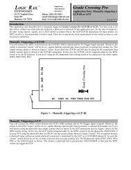
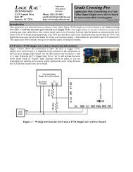
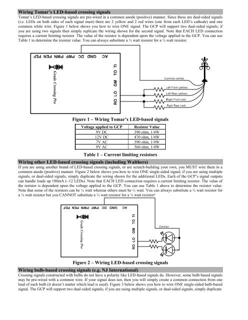
Wiring Tomar’s LED-based crossing signals<br />
Tomar’s LED-based crossing signals are pre-wired in a common anode (positive) manner. Since these are dual-sided signals<br />
(i.e. LEDs on both sides of each signal mast) there are 2 yellow and 2 red wires (one from each LED’s cathode) and one<br />
common white wire. Figure 1 below shows you how to wire ONE signal. The GCP will support two dual-sided signals; if<br />
you are using two signals then simply replicate the wiring shown for the second signal. Note that EACH LED connection<br />
requires a current limiting resistor. The value of the resistor is dependent upon the voltage applied to the GCP. You can use<br />
Table 1 to determine the resistor value. You can always substitute a ½ watt resistor for a ¼ watt resistor.<br />
CROSSI<br />
ROAD<br />
NG<br />
Figure 1 – Wiring Tomar’s LED-based signals<br />
Voltage applied to GCP Resistor Value<br />
9V DC 390 ohm, 1/4W<br />
12V DC 470 ohm, 1/4W<br />
7V AC 390 ohm, 1/4W<br />
9V AC 560 ohm, 1/4W<br />
Table 1 – Current limiting resistors<br />
Wiring other LED-based crossing signals (including Walthers)<br />
If you are using another brand of LED-based crossing signals, or are scratch-building your own, you MUST wire them in a<br />
common anode (positive) manner. Figure 2 below shows you how to wire ONE single-sided signal; if you are using multiple<br />
signals, or dual-sided signals, simply duplicate the wiring shown for the additional LEDs. Each of the GCP’s signal outputs<br />
can handle loads up 180mA (~12 LEDs). Note that EACH LED connection requires a current limiting resistor. The value of<br />
the resistor is dependent upon the voltage applied to the GCP. You can use Table 1 above to determine the resistor value.<br />
Note that some of the resistors can be ¼ watt whereas others must be ½ watt. You can always substitute a ½ watt resistor for<br />
a ¼ watt resistor but you CANNOT substitute a ¼ watt resistor for a ½ watt resistor!<br />
CROSSI<br />
ROAD<br />
NG<br />
Figure 2 – Wiring LED-based crossing signals<br />
Wiring bulb-based crossing signals (e.g. NJ International)<br />
<strong>Crossing</strong> signals constructed with bulbs do not have a polarity like LED-based signals do. However, some bulb-based signals<br />
may be pre-wired with a common wire. If your signal does not, then you will simply create a common connection from one<br />
lead of each bulb (it doesn’t matter which lead is used). Figure 3 below shows you how to wire ONE single-sided bulb-based<br />
signal. The GCP will support two dual-sided signals; if you are using multiple signals, or dual-sided signals, simply duplicate