ease diagnostics win ce/pocket pc scan tool user's manual
ease diagnostics win ce/pocket pc scan tool user's manual
ease diagnostics win ce/pocket pc scan tool user's manual

Create successful ePaper yourself
Turn your PDF publications into a flip-book with our unique Google optimized e-Paper software.
EASE DIAGNOSTICS<br />
WIN CE/POCKET PC SCAN TOOL<br />
USER’S MANUAL<br />
Rev 091603<br />
COPYRIGHT<br />
This document and accompanying software are copyrighted and all rights are reserved by EASE Simulation,<br />
Inc. Copying of this document or software for other than backup purposes is illegal. No part of this document<br />
and accompanying software may be reprodu<strong>ce</strong>d, translated, stored in a retrieval system, or transmitted in any<br />
form by any means, electronic, mechanical, photoreproductive, recording, or otherwise without the expressed<br />
prior written permission of EASE Simulation, Inc.<br />
All products and trade names described within are mentioned for identification purposes only. No affiliation with<br />
or endorsement of the manufacturer is made or implied. Product names appearing in this <strong>manual</strong> are registered<br />
trademarks of their respective companies.<br />
Information furnished by EASE Simulation, Inc. is believed to be accurate and reliable. However, EASE<br />
Simulation, Inc. assumes no responsibility for the use of such information or for any infringements of patents or<br />
other rights of third parties that may result from its use. No li<strong>ce</strong>nse is granted by implication or otherwise under<br />
any patent rights of EASE Simulation, Inc. No representation or warranties regarding the fitness of this<br />
document for any use are made or implied by EASE Simulation, Inc. We reserve the right to revise this<br />
document or make any changes in the specification of the product described therein at any time without noti<strong>ce</strong><br />
and without obligation to notify any person of such revision or change.<br />
TRADEMARK ACKNOWLEDGMENTS<br />
EASE and PocketScan are trademarks of EASE Simulation, Inc.<br />
All other trademarks property of their respective owners.<br />
_____________________________________________________<br />
EASE WIN CE/Pocket PC Scan Tool User’s Manual<br />
Copyright (C) 2002-03 EASE Simulation, Inc.<br />
All rights reserved. Printed in the United States of America.
TABLE OF CONTENTS<br />
I. SAFETY PRECAUTIONS ______________________________________________________ 4<br />
II. SOFTWARE LICENSE AGREEMENT ____________________________________________ 5<br />
III. LIMITED WARRANTY ________________________________________________________ 6<br />
IV. TECHNICAL SUPPORT ______________________________________________________ 6<br />
V. PDA REQUIREMENTS ________________________________________________________ 7<br />
How do I know what version of Windows CE and which pro<strong>ce</strong>ssor my PDA is using? 7<br />
VI. STEP-BY-STEP SOFTWARE INSTALLATION INSTRUCTIONS _______________________ 8<br />
VII. PRODUCT ACCESS CODES __________________________________________________ 9<br />
How do I enter text on my WIN CE/Pocket PC devi<strong>ce</strong>? _________________________ 10<br />
VIII. UNINSTALLING THE SOFTWARE____________________________________________ 10<br />
IX. VEHICLE REQUIREMENTS___________________________________________________ 10<br />
X. SETUP PROCEDURES ______________________________________________________ 11<br />
1.0 What Comes With An EASE PDA Scan Tool Package? ___________________________ 11<br />
2.0 Step-By-Step Instructions For Setting Up The EASE PDA Scan Tool _______________ 11<br />
2.1 Connecting the EASE PDA Vehicle Interfa<strong>ce</strong> to a WIN CE/Pocket PC Devi<strong>ce</strong> ___ 12<br />
2.2 Connecting the EASE PDA Vehicle Interfa<strong>ce</strong> to a Vehicle___________________ 12<br />
2.3 Using the EASE PDA Scan Tool Software to Scan Vehicle Data _____________ 13<br />
XI. AUTOMOBILE ON-BOARD COMPUTERS AND DIAGNOSTIC TROUBLE CODES ______ 14<br />
1.0 OBD II _____________________________________________________________ 14<br />
2.0 Automobile On-board Computers ______________________________________ 14<br />
3.0 Malfunction Indicator Lamp (MIL) ______________________________________ 14<br />
4.0 Freeze Frame Data ___________________________________________________ 14<br />
5.0 Diagnostic Trouble Codes or DTCs _____________________________________ 15<br />
6.0 OBD II Inspection and Maintenan<strong>ce</strong> (I/M) Readiness Monitors _______________ 15<br />
XII. SOFTWARE OPERATION ___________________________________________________ 16<br />
1.0 Software Toolbar_____________________________________________________ 16<br />
2.0 Vehicle Communications__________________________________________ 17<br />
2.1 Vehicle Communications Lost__________________________________________ 17<br />
3.0 Real Time Data Grid ______________________________________________ 18<br />
4.0 Meters _________________________________________________________ 18<br />
5.0 Graphs ________________________________________________________ 18<br />
6.0 Diagnostic Trouble Codes (DTC) ___________________________________ 19<br />
6.1 DTC Library ________________________________________________________ 19<br />
7.0 Freeze Frame___________________________________________________ 20<br />
2
8.0 Oxygen Sensor Locations and Test Results Screens __________________ 20<br />
9.0 Inspection and Maintenan<strong>ce</strong> Monitors _______________________________ 20<br />
10.0 Recording Vehicle Data__________________________________________ 22<br />
10.1 Step-by-Step Instructions for Recording Data ______________________ 22<br />
10.2 Record Toolbar _______________________________________________ 22<br />
10.3 Save Recording Screen ___________________________________ 22<br />
11.0 Playing Back Recordings ________________________________________ 23<br />
11.1 Step-by-Step Instructions for Playing Back a Recording _____________ 23<br />
11.2 Playback Toolbar _____________________________________________ 23<br />
11.3 Recordings Screen ____________________________________________ 23<br />
11.4 Step-by-Step Instructions for Uploading a File To The PC Scan Tool ___ 24<br />
12.0 Reset Scan Buffer_______________________________________________ 24<br />
13.0 Preferen<strong>ce</strong>s Screen _____________________________________________ 24<br />
14.0 Safety Precautions Screen ___________________________________________ 24<br />
15.0 Exit Program_______________________________________________________ 24<br />
Appendix A – Serial Cable Part Numbers__________________________________________ 25<br />
3
I. SAFETY PRECAUTIONS<br />
BEFORE WORKING ON ANY VEHICLE, PLEASE READ THIS!<br />
♦ To avoid possible personal injury and damage to the vehicle, pl<strong>ease</strong> refer to<br />
the appropriate vehicle manufacturer's servi<strong>ce</strong> pro<strong>ce</strong>dures and safety<br />
instructions.<br />
♦ Objects can be propelled by moving engine parts. These objects and high<br />
pressure fluids and liquids can cause serious injury. ALWAYS wear an<br />
ANSI approved eye protection.<br />
♦ Ensure all sparks, lighted cigarettes, open flames, or any other devi<strong>ce</strong><br />
capable of producing a high temperature are not utilized near automotive<br />
batteries. Automotive batteries contain sulfuric acid and produ<strong>ce</strong> explosive<br />
gases.<br />
♦ Ensure a safe distan<strong>ce</strong> from all moving engine components during servicing.<br />
Test equipment, clothing, and parts of your body can be seriously damaged<br />
or injured.<br />
♦ An operating engine produ<strong>ce</strong>s carbon monoxide, which is an odorless,<br />
colorless, poisonous gas that can lead to serious injury or death. ALWAYS<br />
servi<strong>ce</strong> an operating engine in a well-ventilated area.<br />
♦ Fuel systems are typically under high pressure. Ensure the area is well<br />
ventilated and free of all sparks or other ignition sour<strong>ce</strong>s to avoid the<br />
possibility of fire.<br />
♦ Ensure the parking brake is engaged, the vehicle’s drive wheels are<br />
blocked, and the gear selector is in neutral for <strong>manual</strong> transmissions and in<br />
park for automatics.<br />
♦ Never set <strong>tool</strong>s on a vehicle’s battery. You may short the terminals together<br />
causing harm to yourself, the <strong>tool</strong>s or the battery.<br />
♦ NEVER attempt to operate this software and drive the vehicle at the same<br />
time. ALWAYS have another person to use the software while the vehicle is<br />
being driven.<br />
♦ Do not leave your vehicle unattended while running tests.<br />
4
II. SOFTWARE LICENSE AGREEMENT<br />
PLEASE READ ALL OF THE TERMS OF THIS AGREEMENT PRIOR TO INSTALLING THE SOFTWARE.<br />
BY INSTALLING THE SOFTWARE, YOU ACCEPT THE TERMS AND CONDITIONS OF THIS AGREEMENT.<br />
1. Grant of Li<strong>ce</strong>nse: In consideration of payment of the LICENSE fee, which is a part of the pri<strong>ce</strong> you paid for this product, EASE<br />
Simulation, Inc. ("EASE"), as Li<strong>ce</strong>nser, grants to you, the LICENSEE, a non-exclusive right to use and display this copy of an EASE<br />
Software Program (hereinafter to "Software") on a single COMPUTER, (i.e., with a single CPU) at a single location. "Software" includes all<br />
software that resides on the included media, any installed software/files from this media, and all firmware and microcode within the<br />
accompanying Hardware, and all printed materials. “Hardware” includes the interfa<strong>ce</strong> hardware, data logger, and any and all other hardware<br />
that may be used with the Software. If the single computer on which you use the software is a multi-user system, the Li<strong>ce</strong>nse covers all<br />
users on that single system. EASE reserves all rights not expressly granted to LICENSEE.<br />
2. Ownership of Software: As the LICENSEE, you own the magnetic or other physical media on which the Software is originally or<br />
subsequently recorded or fixed, but EASE retains title, ownership and copyrights of the Software recorded on the original disk copy(ies) and<br />
all subsequent copies of the Software or derivative works, regardless of the form or media in or on which the original and other copies may<br />
exist. This li<strong>ce</strong>nse is not a sale of the original Software or any copy.<br />
3. Copy Restrictions: This Software and the accompanying written materials are copyrighted. Unauthorized copying of the Software,<br />
including Software that has been modified, merged, or included with other software, or the written materials is expressly forbidden. The<br />
Firmware or Microcode within the Hardware contains copyrighted material, trade secrets and other proprietary material and may not be<br />
copied under any circumstan<strong>ce</strong>s. You may be held legally responsible for any copyright infringement that is caused or encouraged by your<br />
failure to abide by the terms of this Li<strong>ce</strong>nse. Subject to these restrictions, you may make one (1) copy of the Software (ex<strong>ce</strong>pt the Firmware<br />
and Microcode) for backup purposes. Any permitted copies must include the same proprietary and copyright noti<strong>ce</strong>s as were affixed to the<br />
original. You may not copy the disk(s), disk contents, the firmware or microcode or accompanying printed material to sell or distribute to<br />
others.<br />
4. Use Restrictions: As the LICENSEE, you may physically transfer the Software from one computer to another provided that the Software<br />
is used on only one computer at a time. You may not electronically transfer the Software from one computer to another over a network. You<br />
may not distribute copies of the Software or accompanying written materials to others.<br />
The Software and Hardware contains copyrighted material, trade secrets and other proprietary material. In order to protect them, and ex<strong>ce</strong>pt<br />
as permitted by applicable legislation, you may not , translate, reverse engineer, disassemble, decompile or otherwise redu<strong>ce</strong> the Software<br />
or Hardware to a human-per<strong>ce</strong>ivable form. You may not modify, network, rent, l<strong>ease</strong>, loan, distribute or create derivative works based upon<br />
the Software or Hardware in whole or in part.<br />
5. Transfer Restrictions: You may not transfer this Software to anyone else unless (1) the recipient ac<strong>ce</strong>pts all of the terms of this Li<strong>ce</strong>nse<br />
agreement, and (2) you permanently transfer all copies of the Software and written materials and destroy all other complete or partial copies<br />
of the Software and written materials residing on any medium or storage devi<strong>ce</strong>.<br />
6. Termination: This Li<strong>ce</strong>nse is in effect until terminated. You may terminate this Li<strong>ce</strong>nse at any time by properly transferring or destroying<br />
all copies of the Software and accompanying written materials in your possession. This Li<strong>ce</strong>nse will terminate immediately without noti<strong>ce</strong><br />
from EASE Simulation, Inc. if you fail to comply with any provision of this Li<strong>ce</strong>nse.<br />
7. Export Law Assuran<strong>ce</strong>s: You agree and <strong>ce</strong>rtify that neither the Software nor any other technical data re<strong>ce</strong>ived from EASE, nor the<br />
direct product thereof, will be exported outside the United States ex<strong>ce</strong>pt as authorized and as permitted by the laws and regulations of the<br />
United States. If the Software has been rightfully obtained by you outside of the United States, you agree that you will not re-export the<br />
Software nor any other technical data re<strong>ce</strong>ived from EASE, nor the direct product thereof, ex<strong>ce</strong>pt as permitted by the laws and regulations of<br />
the United States and the laws and regulations of the jurisdiction in which you obtained the Software.<br />
8. U.S. Government Provision: This Software and related written materials were developed at private expense. No portion of this<br />
software or documentation is in the public domain and in all respects is proprietary to EASE Simulation, Inc. If you are acquiring the<br />
Software on behalf of any unit or agency of the United States Government, the follo<strong>win</strong>g provisions apply. The Government agrees: (1) if<br />
the Software is supplied to the Department of Defense (DOD), the Software is classified as "Commercial Computer Software" and the<br />
government is acquiring only "restricted rights" in the Software and it's related documentation as that term is defined in the DOD Supplement<br />
to the Federal Acquisition Regulations, Clause 252.227-7013(c)(1) and (2) if the Software and related documentation is supplied to any unit<br />
or agency of the United States government other than DOD, the Government rights in the Software and its related documentation will be as<br />
defined in Clause 52-227-19(c)(2) of the FAR or, in the case of NASA, in Clause 18-52.227-86(d) of the NASA Supplement to the FAR and<br />
(3) Use, duplication, or disclosure by the government is subject to restrictions as set forth in subparagraph (c)(1)(iii) of the Rights in<br />
Technical Data and Computer Software clause 52.227-7013. Manufacturer is EASE Simulation, Inc., State Route 492 Box 3011, New<br />
Milford, PA 18834.<br />
9. Controlling Law and Severability: This Li<strong>ce</strong>nse and Limited Warranty shall be governed by and construed in accordan<strong>ce</strong> with the laws<br />
of the United States and the Commonwealth of Pennsylvania, as applied to agreements entered into and to be performed entirely within<br />
Pennsylvania between Pennsylvania residents. If for any reason a court of competent jurisdiction find any portion of this Li<strong>ce</strong>nse, or portion<br />
thereof to be unenfor<strong>ce</strong>able, that provision of the Li<strong>ce</strong>nse shall be enfor<strong>ce</strong>d to the maximum extent permissible so as to effect the intent of<br />
the parties, and the remainder of this Li<strong>ce</strong>nse shall continue in full for<strong>ce</strong> and effect.<br />
10. Complete Agreement: This Li<strong>ce</strong>nse constitutes the entire agreement between the parties with respect to the use of the Software and<br />
related documentation, and supersedes all prior or contemporaneous understandings or agreements, written or oral, regarding such subject<br />
matter. No amendment or modification of this Li<strong>ce</strong>nse will be binding unless in writing and signed by a duly authorized representative of<br />
EASE Simulation, Inc.<br />
Should you have any questions con<strong>ce</strong>rning this Agreement, pl<strong>ease</strong> call or write the manufacturer: EASE<br />
Simulation, Inc., State Route 492 Box 3011, New Milford, PA 18834 USA 570-465-9060.<br />
5
III. LIMITED WARRANTY<br />
EASE Simulation, Inc. (EASE) warrants to the original li<strong>ce</strong>nsee that the diskette(s) on which the software is<br />
recorded be free from defects in materials and workmanship under normal use and servi<strong>ce</strong> for a period of ninety<br />
(90) days from the date of delivery as eviden<strong>ce</strong>d by a copy of your re<strong>ce</strong>ipt. If a defect in the disk(s) should occur<br />
during this period, you may return the disk to EASE and we will repla<strong>ce</strong> the disk(s) without charge. EASE<br />
warrants that for a period of thirty (30) days from the date of delivery to you the li<strong>ce</strong>nsee, the software shall<br />
materially conform to the specifications defined in pertinent documentation relating thereto (<strong>manual</strong>s, guides,<br />
exclusion documents, and computer-aided instructions).<br />
EASE does not warrant that the operation of the software will be uninterrupted or error free. Further, EASE<br />
does not warrant or guarantee the use of, or the results of the use of, the software in terms of correctness,<br />
accuracy, reliability, currentness, or otherwise; you rely on the software and results solely at your own risk. The<br />
li<strong>ce</strong>nsee’s sole and exclusive remedy for failure of the software to materially conform to the specifications<br />
defined in the pertinent documentation is for the li<strong>ce</strong>nsee to return the software to EASE and notify EASE in<br />
writing of such non-conformity within thirty (30) days of delivery to the li<strong>ce</strong>nsee. EASE’s sole obligation shall be,<br />
at EASE’s option, within a reasonable time after EASE re<strong>ce</strong>ives noti<strong>ce</strong> of non-conformity, to either provide the<br />
li<strong>ce</strong>nsee with software, which conforms to the express warranty above, or refund to the li<strong>ce</strong>nsee the li<strong>ce</strong>nsee fee<br />
paid therefore. In the event of a refund, this agreement shall be considered terminated and the li<strong>ce</strong>nsee, if they<br />
have any copies of the software or related materials, shall promptly deliver to EASE and/or destroy all such<br />
copies (including that in memory or data storage apparatus) and warrant in writing to EASE within thirty (30)<br />
days of termination that the li<strong>ce</strong>nsed software, related materials and all copies thereof have been either returned<br />
and/or destroyed.<br />
To the original purchaser only, EASE warrants the supplied hardware products to be free from defects in<br />
materials and workmanship under normal use for a period of one (1) year from the date of purchase as<br />
eviden<strong>ce</strong>d by a copy of the sales re<strong>ce</strong>ipt. EASE makes no other express warranty on the hardware products.<br />
The purchaser’s sole remedy in the event of a breach of warranty is expressly limited to repair or repla<strong>ce</strong>ment of<br />
the defective hardware or, if repla<strong>ce</strong>ment is not possible, a refund of the purchase pri<strong>ce</strong>. Repair parts and<br />
repla<strong>ce</strong>ment hardware products will be provided on an exchange basis and will be either reconditioned or new.<br />
All repla<strong>ce</strong>d parts become property of EASE. This limited warranty does not cover damage to the products<br />
resulting from misuse, accident, disaster, abuse, negligen<strong>ce</strong>, improper maintenan<strong>ce</strong>, or modification and/or<br />
repair of the hardware product other than by EASE.<br />
Limitation of Liability - Neither EASE nor its authorized dealer(s) shall be liable for any defect, indirect,<br />
incidental, special, or consequential damages, whether in an action in contract or tort (including negligen<strong>ce</strong> and<br />
strict liability), such as, but not limited to, loss of anticipated profits or benefits resulting from the use of this<br />
software and/or hardware product or any breach of any warranty, even if EASE or its authorized dealer(s) has<br />
been advised of the possibilities of such damages. In no event will EASE or its authorized dealer’s liability<br />
ex<strong>ce</strong>ed the pri<strong>ce</strong> paid for the product.<br />
Note: Some states do not allow the exclusion or limitation of incidental or consequential damages, so the above<br />
exclusions or limitations may not apply to you.<br />
The information presented in this <strong>manual</strong> is believed to be accurate. Responsibility for errors, omission of<br />
information, or consequen<strong>ce</strong>s resulting from the use of this information cannot be assumed by EASE. EASE<br />
retains all rights to make changes to specifications at any time without noti<strong>ce</strong>.<br />
How to reach EASE<br />
• Customer Servi<strong>ce</strong> is available at 888-366-3273 from 9:00 am to 5:00 PM Eastern Standard Time. Pl<strong>ease</strong><br />
have your sales order or invoi<strong>ce</strong> number available when you call.<br />
• By Telephone: 570-465-9060.<br />
• By Fax: 570-465-9061<br />
• By Mail: EASE Diagnostics State Route 492 Box 3011, New Milford, PA 18834 USA<br />
• By e-mail info@obd2.com. Our website is located at www.obd2.com<br />
IV. TECHNICAL SUPPORT<br />
If you have questions about the use of this product, first check the relevant portion of the Users Manual, the<br />
EASE Software Help System or refer to the EASE website. If you cannot find the answer in these pla<strong>ce</strong>s, call<br />
our Technical support line at 570-465-9062 ext 252. This support line is answered Monday through Friday from<br />
9:00 am to 5:30 PM Eastern Standard Time. At other times, pl<strong>ease</strong> leave a message and the call will be<br />
returned. Also, you can e-mail your questions or comments to techsupport@obd2.com.<br />
6
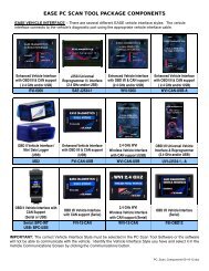
V. PDA REQUIREMENTS<br />
The Scan Tool software supports the follo<strong>win</strong>g WIN CE/PocketPC devi<strong>ce</strong>s*.<br />
IMPORTANT: All devi<strong>ce</strong>s must be running Windows CE 3.0 or higher, Pocket PC 2002 or Pocket PC 2003 and<br />
they must have an SH3, MIPS, StrongARM or X-Scale pro<strong>ce</strong>ssor.<br />
• HP Jornada Pocket PC- All series<br />
• IPAQ <strong>pocket</strong> PC- All series<br />
• Audiovox Maestro Pocket PC’s<br />
• Intermec Pocket PC’s<br />
• Symbol PDT & PPT Pocket PC’s<br />
• Toshiba e570 Pocket PC<br />
• Casio Cassiopeia E-200 series, E-125, EG-800 Series, EM 500 Series, IT-70 Series, IT-700 Series<br />
• Dell Axim X5<br />
If your PDA is not listed, contact EASE for more information at 888-366-3273. If your PDA is running Windows<br />
CE Version 3.0, Pocket PC 2002 or Pocket PC 2003, has an SH3, StrongARM or X-Scale pro<strong>ce</strong>ssor, and has a<br />
serial (9-pin) cable, then it should work with the EASE WIN CE Scan Tool software.<br />
How do I know what version of Windows CE and which pro<strong>ce</strong>ssor my PDA is using?<br />
To determine what version of Windows CE and which pro<strong>ce</strong>ssor it is using do the follo<strong>win</strong>g.<br />
1. From the Start menu choose Settings.<br />
2. Tap on the System tab on the bottom of the Settings Screen.<br />
3. Tap the About icon.<br />
4. Tap the Version tab on the bottom of the About Screen.<br />
In the About screen the Microsoft Windows CE version is listed and the Pro<strong>ce</strong>ssor. If your<br />
PDA is running Windows CE Version 3.0 or Pocket PC 2002 and has an SH3 or StrongARM<br />
pro<strong>ce</strong>ssor then it should work with the EASE WIN CE Scan Tool software.<br />
*IMPORTANT: In addition to a supported devi<strong>ce</strong>, the Scan Tool software requires a serial (9-<br />
pin) cable to connect the PDA Vehicle Interfa<strong>ce</strong> to the WIN CE/Pocket PC Devi<strong>ce</strong>. If you use<br />
a docking cradle or a USB cable to transfer files between the desktop PC and WIN<br />
CE/Pocket PC Devi<strong>ce</strong>, you must purchase a serial cable for your devi<strong>ce</strong> in order to use the<br />
Scan Tool software to connect to a vehicle. This cable is not the same for all manufacturers<br />
or models. You must purchase the cable specified for your devi<strong>ce</strong>. A list of supported WIN<br />
CE/Pocket PC models and their correct serial cable part numbers is listed in Appendix A.<br />
7
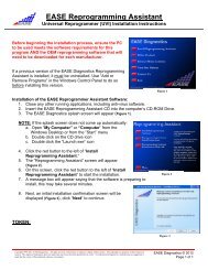
VI. STEP-BY-STEP SOFTWARE INSTALLATION INSTRUCTIONS<br />
Use the follo<strong>win</strong>g instructions to install the EASE Scan Tool software on your WIN<br />
CE/PocketPC devi<strong>ce</strong>.<br />
1. Connect the CE/POCKET PC devi<strong>ce</strong> to the PC. The devi<strong>ce</strong> must be powered on.<br />
IMPORTANT: You must have ActiveSync installed on your PC. Microsoft ActiveSync is used to<br />
transfer files from your PC to your hand held devi<strong>ce</strong>. This software is included when you purchase a<br />
CE/Pocket PC devi<strong>ce</strong>.<br />
2. Pla<strong>ce</strong> the EASE software installation CD in your desktop PC CD-ROM drive. The CD will start automatically.<br />
NOTE: If the CD does not start automatically, double-click the My Computer icon on the Windows desktop.<br />
Locate the CD-ROM drive in the <strong>win</strong>dow, double-click the drive letter to display the contents of the CD, and the<br />
double-click SETUP.EXE.<br />
3. In this screen the installation software will determine which type<br />
of pro<strong>ce</strong>ssor your CE/Pocket PC devi<strong>ce</strong> has. Select the Next<br />
button to continue.<br />
4. Choose the products you wish to install and select the Install<br />
button. In addition to the PocketScan Application, you must select<br />
at least one of the Scan Tool Versions.<br />
NOTE: (Not Installed) is displayed after the product name if it is<br />
not currently installed on the connected CE/Pocket PC devi<strong>ce</strong>.<br />
(Installed) is displayed if it is.<br />
5. The Welcome Screen is displayed next. Press the Next button<br />
to continue with the install.<br />
6. Pl<strong>ease</strong> read the Software Li<strong>ce</strong>nse Agreement. This agreement<br />
can also be found in Section II of the User’s Manual. If you ac<strong>ce</strong>pt<br />
the terms of the Li<strong>ce</strong>nse Agreement, select Yes to continue.<br />
7. At this point, the installation program has enough information to<br />
start copying files to the CE/Pocket PC devi<strong>ce</strong>. Press Yes to begin<br />
the copy pro<strong>ce</strong>ss.<br />
Each program that you chose to install will be installed individually.<br />
Press Yes to begin the copy pro<strong>ce</strong>ss for each one.<br />
8
8. At this time, pl<strong>ease</strong> check the CE/Pocket PC devi<strong>ce</strong> to see if<br />
there are any additional steps that are ne<strong>ce</strong>ssary to complete the<br />
installation.<br />
NOTE: If more than one program is being installed, you will be<br />
returned to step 7.<br />
9. At this time, installation is complete. Select OK to close the<br />
installation software.<br />
10. To start the EASE Software, pick PocketScan from the Start<br />
Menu on your CE/Pocket PC devi<strong>ce</strong>.<br />
IMPORTANT: BEFORE YOU CAN USE THE EASE SCAN TOOL SOFTWARE TO CONNECT TO A<br />
VEHICLE, YOU MUST CALL EASE AT 888-366-EASE (3273) FOR A PRODUCT ACCESS CODE.<br />
See the next section for more information on product ac<strong>ce</strong>ss codes.<br />
VII. PRODUCT ACCESS CODES<br />
IMPORTANT: BEFORE YOU CAN USE THE EASE SCAN TOOL SOFTWARE TO CONNECT TO A<br />
VEHICLE, YOU MUST CALL EASE AT 888-366-EASE (3273) FOR A PRODUCT<br />
ACCESS CODE.<br />
To obtain a product ac<strong>ce</strong>ss code:<br />
1. Start your Scan Tool Software.<br />
2. Select [View] \ Product Ac<strong>ce</strong>ss… from the menubar of the Scan Tool Software to<br />
open the Product Ac<strong>ce</strong>ss Screen.<br />
3. Enter your Serial Number. This number begins with CE- followed by an 8-digit<br />
number with a dash mark inserted after the first 4 digits. It can be found on a<br />
label on the installation software CD case.<br />
4. Contact EASE by phone, fax or email. Be sure to have your Scan Tool Software opened to the Product<br />
Ac<strong>ce</strong>ss Screen or have your Security Code and Serial Number available. The software generates the<br />
Security Code automatically.<br />
a. Phone – Call EASE at 888-366-EASE (3273) or 570-465-9060.<br />
b. Fax – Send a fax listing your Name, Company Name, Address and Phone Number along with<br />
your Security Code and Serial Number to 570-465-9061.<br />
c. Email - Send an email listing your Name, Company Name, Address and Phone Number along<br />
with your Security Code and Serial Number to info@obd2.com.<br />
5. After you obtain your Verification Code and Ac<strong>ce</strong>ss Code, carefully type them into the appropriate box<br />
in the Product Ac<strong>ce</strong>ss Screen. Both the verification code and ac<strong>ce</strong>ss code are 8 digits with a dash<br />
mark inserted after the first 4 digits. All letters are capitalized and 0 is always the number zero – never<br />
the letter O.<br />
NOTE: The letter O is never used in any entry. It is always the number zero.<br />
6. Tap the Ok button. A message box will display if your upgrade was suc<strong>ce</strong>ssful. If you<br />
were unsuc<strong>ce</strong>ssful, try re-entering your ac<strong>ce</strong>ss code. Also verify that your software<br />
serial number and verification code are correct. If you are unable to upgrade your<br />
software, call EASE for assistan<strong>ce</strong>.<br />
Tap the Add-Ons button to view which products you currently have ac<strong>ce</strong>ss to. To<br />
purchase additional features for your software, contact EASE at 888-366-EASE (3273).<br />
9
How do I enter text on my WIN CE/Pocket PC devi<strong>ce</strong>?<br />
To enter text in the Product Ac<strong>ce</strong>ss Screen – tap in the entry box that you want to enter<br />
text in; the on-board keyboard will be displayed automatically. Tap the characters that<br />
you want to enter and then tap the keyboard icon to close the keyboard.<br />
If the keyboard does not open automatically, tap the keyboard icon that is displayed on the bottom right<br />
hand side of the Product Ac<strong>ce</strong>ss software screen. The on-screen keyboard will be displayed. Tap the icon<br />
again to close the keyboard.<br />
VIII. UNINSTALLING THE SOFTWARE<br />
To uninstall the Scan Tool Software from the CE/Pocket PC devi<strong>ce</strong><br />
1. Connect your CE/POCKET PC Devi<strong>ce</strong> to your PC. The devi<strong>ce</strong> must be powered<br />
on.<br />
IMPORTANT: You must have ActiveSync installed on your PC. Microsoft ActiveSync is used to transfer files<br />
from your PC to your hand held devi<strong>ce</strong>. This software is included when you purchase a CE/Pocket PC devi<strong>ce</strong>.<br />
2. Pla<strong>ce</strong> the EASE software installation CD in your PC CD-ROM drive. The CD will start automatically.<br />
NOTE: If the CD does not start automatically, double-click the My Computer icon on the Windows desktop.<br />
Locate the CD-ROM drive in the <strong>win</strong>dow, double-click the drive letter to display the contents of the CD, and the<br />
double-click SETUP.EXE.<br />
3. In this screen the installation software will determine which type of pro<strong>ce</strong>ssor<br />
your CE/Pocket PC devi<strong>ce</strong> has. Select the Next button to continue.<br />
4. Choose the products you wish to uninstall. Then tap the Remove button.<br />
NOTE: (Not Installed) is displayed after the product name if it is not currently<br />
installed on the connected CE/Pocket PC devi<strong>ce</strong>. (Installed) is displayed if it is.<br />
IX. VEHICLE REQUIREMENTS<br />
This product is designed to work with all OBD II compliant vehicles.<br />
• 1996 or newer OBD II Compliant Vehicle (Includes All Domestic, Asian and European Vehicles)<br />
• Some 1994 and 1995 vehicles are OBD II Compliant<br />
For your vehicle to be OBD II compliant it must have a 16 pin DLC under the dash and the vehicle Emission<br />
Control Information label must state that the vehicle is OBD II compliant. This label is located on the inside of<br />
the hood on most vehicles. An example of this label is shown below. Note the last line of the label states that<br />
the vehicle is OBD II <strong>ce</strong>rtified.<br />
Vehicle Emission<br />
Control Information<br />
(Figure Above) DLC- Data Link Connector - a 16 position<br />
connector located under the driver side dash of most vehicles.<br />
(Figure to Right) Vehicle Emission Control Information Label -<br />
located inside the hood of most vehicles. Use it to identify<br />
whether or not the vehicle is OBD II <strong>ce</strong>rtified.<br />
This vehicle is equipped with electronic<br />
control systems. Engine idle<br />
speed, idle mixture and ignition timing<br />
are not adjustable. See Powertrain<br />
Control/Emissions Diagnosis Manual<br />
for additional information.<br />
This vehicle conforms to U.S. EPA and<br />
California regulations applicable to 1998 model<br />
year new LEV passenger cars <strong>ce</strong>rtified for sale<br />
in California. HSC 39037.05 Low Emission<br />
Motor Vehicle. OBD II Certified.<br />
OBD II Certified<br />
10
X. SETUP PROCEDURES<br />
NOTICE<br />
THIS PRODUCT IS DESIGNED TO OPERATE AT A VEHICLE’S NORMAL BATTERY VOLTAGE: 11-15<br />
VOLTS DC. ANY OTHER VOLTAGE MAY DAMAGE THE EASE POCKETSCAN TOOL UNIT!<br />
This section includes the follo<strong>win</strong>g:<br />
1. What comes with an EASE PDA Scan Tool?<br />
2. Step by step instructions for setting up the EASE PDA Scan Tool<br />
a. Connecting EASE PDA Scan Tool to a WIN CE/Pocket PC devi<strong>ce</strong><br />
b. Connecting the EASE PDA Scan Tool to the Vehicle<br />
c. Using the EASE PDA Scan Tool Software to <strong>scan</strong> vehicle data.<br />
1.0 What Comes With An EASE PDA Scan Tool Package?<br />
An EASE PDA Scan Tool Package is provided with the follo<strong>win</strong>g:<br />
EASE PDA Vehicle Interfa<strong>ce</strong> – Black interfa<strong>ce</strong> box<br />
with a DB25 pin connector on one end and a DB9<br />
pin connector. This unit can be used to connect to<br />
all OBD II compliant vehicles.<br />
Vehicle Interfa<strong>ce</strong> Cable (CABLE-OBD II) – A cable<br />
with an OBD II connector on one end and a DB25 on<br />
the other. This cable is used to connect to the<br />
vehicle’s diagnostic connector.<br />
Installation Software – Software used to install the<br />
PDA Scan Tool on the PDA Devi<strong>ce</strong>.<br />
2.0 Step-By-Step Instructions For Setting Up The EASE PDA Scan Tool<br />
The EASE PDA Vehicle Interfa<strong>ce</strong> must be connected between the vehicle and PDA devi<strong>ce</strong> to operate. The<br />
follo<strong>win</strong>g sections explain how to make the proper connections.<br />
11
2.1 Connecting the EASE PDA Vehicle Interfa<strong>ce</strong> to a WIN CE/Pocket PC Devi<strong>ce</strong><br />
Connect the PDA’s Serial Cable* to the communication port on the WIN CE/Pocket PC devi<strong>ce</strong>. Connect the<br />
other end to the 9-pin “PDA” connector on the PDA Vehicle Interfa<strong>ce</strong>.<br />
WIN CE/Pocket PC Devi<strong>ce</strong><br />
WIN CE/Pocket PC Serial Cable<br />
*To connect the EASE PDA Vehicle Interfa<strong>ce</strong> to the WIN CE/Pocket PC Devi<strong>ce</strong>, a serial<br />
cable that connects to your WIN CE/Pocket PC Devi<strong>ce</strong> is required. If you use a docking<br />
cradle or a USB cable to transfer files between the desktop PC and WIN CE/Pocket PC<br />
Devi<strong>ce</strong>, you must purchase a serial cable for your devi<strong>ce</strong> in order to use the Scan Tool<br />
software to connect to a vehicle. This cable is not the same for all manufacturers or models.<br />
You must purchase the cable specified for your devi<strong>ce</strong>. A list of supported WIN CE/Pocket<br />
PC models and their correct serial cable part numbers is listed in Appendix A.<br />
2.2 Connecting the EASE PDA Vehicle Interfa<strong>ce</strong> to a Vehicle<br />
To connect the PDA Vehicle Interfa<strong>ce</strong> to the vehicle, you must first locate the vehicle’s diagnostic connector.<br />
The diagnostic connector is a 16-pin connector and is referred to as the Data Link Connector (DLC). This<br />
connector supplies power to the PDA Vehicle Interfa<strong>ce</strong>.<br />
After you have located the vehicle’s DLC, connect one end of the OBD II Vehicle Interfa<strong>ce</strong> Cable to the vehicle's<br />
diagnostic connector. Connect the other end of the cable to the 25-pin “OBD II Vehicle” connector on the PDA<br />
Vehicle Interfa<strong>ce</strong>.<br />
Where do I find the vehicle’s DLC connector? On most OBD II vehicles the diagnostic connector is located<br />
under the driver’s side dashboard in full view. In some vehicles it may be re<strong>ce</strong>ssed behind a panel. Remove<br />
this panel for ac<strong>ce</strong>ss to the connector. Other vehicles have a cap labeled “Diagnostic Connector” over the<br />
connector. Remove this cap to connect the PDA Vehicle Interfa<strong>ce</strong>. Repla<strong>ce</strong> this cover when you are finished.<br />
To be OBD II compliant: if the diagnostic connector is not located under the driver's side dashboard, a label<br />
should be pla<strong>ce</strong>d there to notify the owner where it is located. If you are unable to find the diagnostic connector,<br />
consult the vehicle’s servi<strong>ce</strong> <strong>manual</strong> for the exact location.<br />
OBD II DLC- Data Link Connector - A 16-position connector<br />
located under the driver side dash of most OBD II vehicles.<br />
12
2.3 Using the EASE PDA Scan Tool Software to Scan Vehicle Data<br />
SAFETY FIRST!!!<br />
Review Section I. Safety Precautions.<br />
1. Connect the PDA Devi<strong>ce</strong> to the EASE PDA Vehicle Interfa<strong>ce</strong>. Connect the PDA’s Serial Cable to the<br />
serial port of the WIN CE/Pocket PC devi<strong>ce</strong>. Connect the other end to the 9-pin “PDA” connector on the<br />
PDA Vehicle Interfa<strong>ce</strong>.<br />
2. Connect the vehicle to the EASE PDA Vehicle Interfa<strong>ce</strong>. Connect one end of the Vehicle Interfa<strong>ce</strong><br />
Cable to the vehicle's diagnostic connector. Connect the other end of the cable to the 25-pin “OBD II<br />
Vehicle” connector on the PDA Vehicle Interfa<strong>ce</strong>.<br />
3. Start the WIN CE/Pocket PC Scan Tool Software.<br />
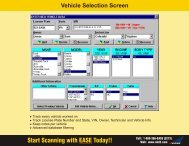
4. In the Vehicle Communications Screen select the make of the vehicle that<br />
you are connecting to in the Make box.<br />
5. Turn the vehicle’s ignition switch to the “ON” position or start the vehicle.<br />
6. Tap the Connect button in the Vehicle Communications Screen. If the<br />
Connect button is not selectable, verify that the Cable Status is “Connected”. If<br />
it is not, verify all cable connections.<br />
NOTE: If the Cable Status is “Connected” and the Connect button is not<br />
selectable, you may not have permission to ac<strong>ce</strong>ss this data. If you have an<br />
ac<strong>ce</strong>ss code, enter it on the Product Ac<strong>ce</strong>ss screen. If you do not have an<br />
ac<strong>ce</strong>ss code, contact EASE Diagnostics for more information.<br />
7. At this time the software will connect to the vehicle and begin the communication pro<strong>ce</strong>ss. The<br />
status of this connection is shown in Tool Status. If the software suc<strong>ce</strong>ssfully linked to the vehicle, the<br />
Cable Status will be “Connected” and the Tool Status will be “Scanning Data…”.<br />
If the software did not link, check all cable connections, make sure the ignition is ON, and that the OBD II<br />
connector is powering the EASE PDA Vehicle Interfa<strong>ce</strong>. Also check that the PDA devi<strong>ce</strong> battery power is<br />
not low.<br />
On<strong>ce</strong> the software is <strong>scan</strong>ning data, you can view the data parameters in grid, graph or meter format, look<br />
at DTCs, I/M monitors and O2 Test Results. See the Section XII. Software Operation for more information<br />
on using the software.<br />
13
XI. AUTOMOBILE ON-BOARD COMPUTERS AND DIAGNOSTIC TROUBLE CODES<br />
The follo<strong>win</strong>g section provides information on<br />
1. OBD II<br />
2. Automobile on-board computers<br />
3. The Malfunction Indicator Lamp (MIL)<br />
4. Freeze Frame Data<br />
5. Diagnostic Trouble Codes (DTC)<br />
6. Inspection and Maintenan<strong>ce</strong> (I/M) Readiness Monitors<br />
1.0 OBD II<br />
Federal law required all vehicle manufacturers to meet On Board Diagnostics, Second Generation or<br />
OBD II standards by 1996. In order to meet this standard, the automobile’s on-board computer must monitor<br />
and perform diagnostic tests on vehicle emissions to ensure that the vehicle is operating at an ac<strong>ce</strong>ptable<br />
(legal) emission level. The maximum allowable emission level is set by the Federal Test Pro<strong>ce</strong>dure (FTP).<br />
All 1996 and newer passenger vehicles are OBD II compliant. All OBD II vehicles have the same 16 pin<br />
diagnostic connector or DLC. This eliminates the need to have a manufacturer specific connector to connect to<br />
your vehicle. (Some 1994 and 1995 vehicles have this connector, however, this does not mean that the vehicle<br />
is OBD II compliant. )<br />
2.0 Automobile On-board Computers<br />
Automobile on-board computers control engines, transmissions, brakes, traction and many other components.<br />
These computers have several names and acronyms depending upon the manufacturer and components they<br />
control. The most common name is PCM or Powertrain Control Modules. Other examples are Body Control<br />
Modules (BCM), Transmission Control Modules (TCM), Electronic Brake Control Module (EBCM) and Air<br />
Conditioning Control Module (ACM).<br />
A variety of sensors, such as the oxygen sensor, throttle position sensor and manifold air temperature sensor,<br />
provide information to the on-board computer regarding the vehicle’s engine operating conditions. Air<br />
Conditioning systems, vehicle air bags, and anti-lock brake systems also report to on-board computers.<br />
On-board computers have a built in self testing system called self-diagnosis which means the on-board<br />
computer will monitor many or all of the vehicle’s sensors and controlled devi<strong>ce</strong>s for proper operation. A<br />
diagnostic trouble code or DTC is detected and set when one of the monitored devi<strong>ce</strong>s is not functioning<br />
properly. This malfunction is stored into the on-board computer’s memory as a DTC number that is related to a<br />
specific sensor or other problem. The computer can later be ac<strong>ce</strong>ssed using the EASE software or other <strong>scan</strong><br />
<strong>tool</strong>s and code reading devi<strong>ce</strong>s to obtain the codes stored in the on-board computer memory.<br />
3.0 Malfunction Indicator Lamp (MIL)<br />
The Malfunction Indicator Lamp (MIL) is located in the instrument panel on the dashboard and is either a red or<br />
yellow labeled lamp. The MIL is normally off and will illuminate if a system or component either fails or<br />
deteriorates to the point where the vehicle emissions could rise 1.5 times above the FTP set emissions level.<br />
4.0 Freeze Frame Data<br />
When the first emissions related powertrain DTC becomes stored, the PCM will capture (save) a block of<br />
current engine parameters. This list of parameters is called Freeze Frame Data and consists of a fixed list of<br />
parameters. For vehicles, which do not support all parameters, only the applicable ones are stored. When<br />
DTCs are cleared, the Freeze Frame Data is cleared from the vehicle’s PCM.<br />
14
5.0 Diagnostic Trouble Codes or DTCs<br />
In the past malfunction code numbers varied between manufacturers, years, makes and models. OBD II<br />
requires that all vehicle manufacturers use a common Diagnostic Trouble Code or DTC numbering System.<br />
There is a generic DTC listing that all manufacturers must use. Sin<strong>ce</strong> the generic listing was not specific<br />
enough, most manufacturers came up with their own DTC listing, which are called manufacturer specific codes.<br />
Both generic and manufacturer specific codes are 5 digits.<br />
The first digit is a letter, which identifies the function of the devi<strong>ce</strong>, which has the fault. This digit can be either<br />
P Powertrain<br />
B Body<br />
C Chassis<br />
U Network or data link code<br />
The second digit is either a 0 or 1 and indicates whether the code is<br />
generic or manufacturer specific.<br />
0 Generic<br />
1 Manufacturer Specific<br />
The third digit represents the specific vehicle system that has the fault.<br />
Listed below are the number identifiers for the powertrain system.<br />
1 Fuel and Air Metering<br />
2 Fuel and Air Metering (Injector Circuit Malfunctions Only)<br />
3 Ignition System or Misfire<br />
4 Auxiliary Emission Control<br />
5 Vehicle Speed Control and Idle Control System<br />
6 Computer and Auxiliary Outputs<br />
7 Transmission<br />
8 Transmission<br />
The last two digits indicate the specific fault index.<br />
On OBD II vehicles there are two different types of DTCs: Stored and Pending. For a DTC to become Stored,<br />
<strong>ce</strong>rtain malfunction conditions must occur. The condition(s) required to Store a code are different for every DTC<br />
and vary by vehicle manufacturer. In order for some DTCs to become Stored, a malfunction condition has to<br />
happen more than on<strong>ce</strong>. If the malfunction conditions are required to occur more than on<strong>ce</strong>, the potential<br />
malfunction is called a Pending DTC. The DTC remains Pending until the malfunction condition occurs the<br />
required number of times to make the code Stored. If the malfunction condition does not occur again after a set<br />
time the Pending DTC will be cleared.<br />
6.0 OBD II Inspection and Maintenan<strong>ce</strong> (I/M) Readiness Monitors<br />
A monitor is a pie<strong>ce</strong> of software in one of the vehicle’s on-board computers that has the job of monitoring a<br />
specific pie<strong>ce</strong> of the engine. There are two types of monitors: continuous and non-continuous. A continuous<br />
monitor runs continuously during vehicle operation. A non-continuous monitor requires enabling criteria to<br />
make it run. Some examples of enabling criteria are vehicle ac<strong>ce</strong>leration/de<strong>ce</strong>leration to a <strong>ce</strong>rtain speed,<br />
engine temperature and driving the vehicle at a <strong>ce</strong>rtain speed for a period of time.<br />
For OBD II vehicles, there is a fixed list of 11 monitors: 3 continuous and 8 non-continuous. The 11 monitors<br />
are not applicable for all vehicles. The Inspection & Maintenan<strong>ce</strong> screen of the software lists the availability and<br />
status of your vehicles monitors. In order to pass an emission inspection all of the supported monitors must be<br />
completed.<br />
The Continuous Monitors are:<br />
• Misfire • Fuel System • Components<br />
The Non-Continuous Monitors are:<br />
• Catalyst • Secondary Air System • Oxygen Sensor<br />
• Heated Catalyst • A/C System • Oxygen Sensor Heater<br />
• Evaporative System • EGR System<br />
15
XII. SOFTWARE OPERATION<br />
1.0 Software Toolbar<br />
Displayed at the bottom of the software screens, the Toolbar provides a quick and handy way to navigate. Just<br />
tap on the screen you wish to view. A description of each <strong>tool</strong>bar icon is given below followed by the section<br />
number where more information on the screen can be found.<br />
Vehicle Communications – Section 2.0<br />
Real Time Data Grid - Section 3.0<br />
Meters – Section 4.0<br />
Graphs – Section 5.0<br />
Diagnostic Trouble Codes – Section 6.0<br />
Freeze Frame – Section 7.0<br />
Oxygen Sensor Test Results – Section 8.0<br />
Inspection and Maintenan<strong>ce</strong> Monitors – Section 9.0<br />
Recording Data – Section 10.0<br />
Playing Back Recordings - Section 11.0<br />
Reset Scan Buffer – Section 12.0<br />
Preferen<strong>ce</strong>s – Section 13.0<br />
16
2.0 Vehicle Communications<br />
The Vehicle Communications Screen displays information on the status of the software<br />
connection with the vehicle. To connect to the vehicle, tap on the Connect button. During<br />
the communication initialization the software will do the follo<strong>win</strong>g:<br />
• Determine if there are multiple modules on the vehicle bus<br />
• Determine all the capabilities of the vehicle<br />
• Obtain I/M Readiness Status data<br />
• Obtain Oxygen Sensor Location and O2 test data<br />
• Obtain any DTCs if present<br />
• Obtain Freeze Frame data if present<br />
Cable Status<br />
• Connected is displayed if the EASE PDA Vehicle Interfa<strong>ce</strong> is properly connected to the vehicle and<br />
PDA.<br />
• Disconnected is displayed if the EASE PDA Vehicle Interfa<strong>ce</strong> is not connected to the vehicle and PDA.<br />
Interfa<strong>ce</strong> - This is the OBD II communication interfa<strong>ce</strong> type of the current connected vehicle.<br />
• ISO 9141-2 - International Standardization Organization<br />
• PWM - Pulse Width Modulation<br />
• VPW - Variable Pulse Width<br />
• ISO 14230 (KWP 2000) – Key Word Protocol 2000<br />
Tool Status - The current status of the <strong>tool</strong> is displayed here.<br />
• Browse: The software is currently not communicating with the vehicle.<br />
• Scanning Protocols: The software is determining the communication protocol of the vehicle.<br />
• Getting Capabilities: The software is communicating with and determining the capabilities of the<br />
vehicle.<br />
• Scanning Data: The software is communicating with and re<strong>ce</strong>iving data from the vehicle.<br />
• Play Back: The software is currently replaying previously recorded vehicle data.<br />
Make - The Make of the vehicle can be selected here. This information does not have to be entered to connect<br />
to an OBD II vehicle. However, the correct Make must be selected to ac<strong>ce</strong>ss enhan<strong>ce</strong>d data and to ensure the<br />
proper diagnostic trouble code description is displayed.<br />
Module # - This is the bus address of the vehicle’s on-board computer. The PID (Parameter Identification)<br />
count is also displayed here, which is the number of supported parameters for the on-board computer.<br />
Sometimes an OBD II vehicle will have more than one controller (on-board computer). If multiple controllers are<br />
detected during the initial communications <strong>scan</strong>, the software will list them in the Module # drop down box. The<br />
User can then select which controller they want to <strong>scan</strong> by selecting the desired controller from the drop down<br />
box. The software will default to the controller that contains the highest PID count. Normally the Controller<br />
Address with the highest PID Count is the engine controller and the second highest is the transmission<br />
controller.<br />
DTC Alert - The DTC Alert is flashed when a DTC has been detected on the vehicle. Tap on this button to go<br />
to the DTC Screen to view the active DTC(s).<br />
Connect/Disconnect button - Tap on this button to connect or disconnect communications from the software<br />
to the vehicle. This button is only selectable when the Cable Status is Connected.<br />
NOTE: If the Cable Status is “Connected” and the Connect button is not selectable (grayed out), you may not<br />
have permission to ac<strong>ce</strong>ss this data. If you have an ac<strong>ce</strong>ss code, enter it on the Product Ac<strong>ce</strong>ss screen. If you<br />
do not have an ac<strong>ce</strong>ss code, contact EASE Diagnostics for more information.<br />
2.1 Vehicle Communications Lost<br />
The Vehicle Communications Lost screen is displayed whenever communications have been<br />
lost to the vehicle. Check all cable connections, ensure the ignition key is on or the vehicle is<br />
running, and double check that the vehicle is OBD II compatible. Also, be sure that the battery<br />
power of the PDA devi<strong>ce</strong> is not low. Low battery power could cause erratic and unreliable<br />
communication with the vehicle.<br />
17
3.0 Real Time Data Grid<br />
This screen contains a data grid for vehicle data parameters to be viewed while updating<br />
in real time (live). Displayed in the grid are the parameter descriptions, values, and units.<br />
Parameters can be viewed in either English or Metric units. Use the Preferen<strong>ce</strong>s<br />
Screen to change the unit system. One to all the available parameters can be added to<br />
the grid to be <strong>scan</strong>ned or recorded. If all the parameters do not fit in the data grid, use the<br />
scroll bar on the right to scroll through the list.<br />
NOTE: In OBD II the more parameters you select to view, the slower the data updates.<br />
For the best sampling rate, limit the parameters that you add to the grid to be <strong>scan</strong>ned.<br />
Reorder Buttons - The red arrows are used to reorder the parameters in the<br />
data grid. Select the parameter that you want to move by tapping it. Then tap on the red<br />
up or down arrow to move the highlighted parameter to the desired position.<br />
Add Button - To add a parameter to the grid, tap on the Add button to open the Add<br />
Parameter screen. Tap on the desired parameter(s) in the Add Parameter Screen to<br />
highlight them. Then tap on the Add button to add the highlighted parameters to the grid.<br />
NOTE: If you want to add enhan<strong>ce</strong>d parameters to the grid, tap on the down arrow at the<br />
top of the screen to select an enhan<strong>ce</strong>d parameter listing. The correct vehicle Make must<br />
be selected in the Vehicle Communications Screen and you must have permission to<br />
ac<strong>ce</strong>ss this data. See Section VII Product Ac<strong>ce</strong>ss Codes for more information.<br />
Remove Button - To remove a parameter from the data grid, tap on the desired parameter(s) to highlight them.<br />
Then tap on the Remove button to remove them from the grid.<br />
4.0 Meters<br />
The meters are used to display the data parameters in a larger format. Two parameters<br />
can be displayed on the Meters screen at one time.<br />
To change the data parameter displayed in a specific meter,<br />
select on the down arrow to the right of the parameter<br />
description to open a drop down box displaying the parameters.<br />
Tap on the parameter you want displayed in the meter. To<br />
close the drop down box without making any changes, select<br />
on the down arrow again.<br />
5.0 Graphs<br />
The Graph screen allows the user to view the data parameters in graphical format. The<br />
data parameter values are plotted on the vertical axis in referen<strong>ce</strong> to seconds on the<br />
horizontal axis. The bold vertical blue line is the frame cursor. The value of the parameter<br />
at the frame cursor is shown above each graph beside the parameter name. The position<br />
of the frame cursor can be moved, just select it and move it to the desired position.<br />
To change the data parameter displayed in a specific graph, select on the down arrow to<br />
the right of the parameter description to open a drop down box displaying the parameters.<br />
Tap on the parameter you want displayed in the graph.<br />
Double click on a graph to open the graph options. For each graph, you<br />
can select to display the data points and/or to have the graph auto size.<br />
Data Points - Select this option to have the data points (sample points) displayed in the<br />
graph line.<br />
Auto Size – Select this option to put the graph in auto size mode. In this mode the<br />
vertical axes of the graphs are automatically adjusted to fit the data.<br />
Pause Button -While <strong>scan</strong>ning data, tap on the pause button to temporarily stop <strong>scan</strong>ning data. Tap the<br />
play button to resume <strong>scan</strong>ning.<br />
18
6.0 Diagnostic Trouble Codes (DTC)<br />
The Trouble Codes Screen displays the vehicle’s MIL Status, DTC Count, Stored DTCs<br />
and Pending DTCs.<br />
What is a DTC? Automobile on-board computers have a built in self testing system called<br />
self-diagnosis which means the on-board computer will monitor many or all of the vehicle’s<br />
sensors and controlled devi<strong>ce</strong>s for proper operation. A diagnostic trouble code (DTC) is<br />
detected and set when one of the monitored devi<strong>ce</strong>s is not functioning properly. On OBD<br />
II vehicles there are two different types of DTCs: Stored and Pending. See Section XI. for<br />
more information on DTCs.<br />
MIL Status - The status of the vehicle’s MIL (Malfunction Indicator Lamp) is displayed here.<br />
DTC Count - Displays the total number of emission related DTCs currently stored in the vehicle.<br />
Stored DTCs - All of the vehicle’s stored DTCs are listed in this section.<br />
Pending DTCs - All of the vehicle’s pending DTCs are listed in this section.<br />
NOTE: The Make setting in the Vehicle Communications screen is used for determining the description of<br />
manufacturer specific DTCs. If manufacturer specific DTCs are displayed (P1XXX), the correct Make must be<br />
selected in the Vehicle Communications screen to ensure that the correct description is being displayed in the<br />
Trouble Code grids. See section 2.0 Vehicle Communications for more information on selecting the vehicle’s<br />
Make. See Section XI. for more information on DTCs.<br />
Clear DTCs Button - Tap on this button to clear (erase) the Stored and Pending DTCs, Freeze<br />
Frame Data, Oxygen Sensor Test Data, and Inspection and Maintenan<strong>ce</strong> Monitors from the<br />
vehicle’s on-board computer. After tapping this button, a confirmation screen is displayed to<br />
inform the user which vehicle information will be erased. Make sure that the vehicle’s ignition<br />
key is in the ON position and the vehicle’s engine is not running. For some vehicles unless<br />
these conditions are met the DTCs will not be cleared. Tap on the Yes button to continue with<br />
the clearing pro<strong>ce</strong>ss or No to can<strong>ce</strong>l.<br />
Freeze Frame Button - Tap on this button to display the vehicle’s Freeze Frame data. See<br />
section 7.0 Freeze Frame for more information.<br />
DTC Library Button - Tap on this button to display the DTC Library screen. See the section 6.1 for more<br />
information.<br />
6.1 DTC Library<br />
The DTC Library Screen allows you to look up the description for a DTC Number. Both<br />
generic and manufacturer specific DTCs can be looked up. Use the DTC Library button in<br />
the DTC Screen or View\DTC Library from the menubar to open the DTC Library. See<br />
Section XI. for more information on DTCs.<br />
Make - Tap on the arrow to the right of the box to open a drop down box listing vehicle<br />
makes. It is important that you select the correct make if you are looking up a<br />
manufacturer specific DTCs (P1XXX) because manufacturer specific DTC’s descriptions<br />
may differ between manufacturers. Choose Generic as the make to look up generic<br />
(P0XXX) codes.<br />
the grid below.<br />
Search - Type in a DTC number, word that you are looking for or start of a word or DTC in<br />
this box and then tap on the Search button. The results of the search will be displayed in<br />
NOTE: Delete the text you entered in the Search box and then select the Search button to return to the original<br />
look up.<br />
DTC Code and Description grid - The DTC number and corresponding description is displayed in the grid.<br />
The scroll bar to the right of the DTC grid can be used to <strong>manual</strong>ly scroll through the DTC and description list.<br />
The scroll bar on the bottom of the grid can be used to move the grid left and right in order to see the complete<br />
description.<br />
19
7.0 Freeze Frame<br />
The Freeze Frame Data Screen displays the vehicle’s freeze frame data, if any.<br />
What is Freeze Frame? In OBD II vehicles, when the first emissions related powertrain<br />
DTC occurs, the PCM will snapshot (save) a block of current engine parameters. This list<br />
of parameters is called Freeze Frame Data and consists of a fixed list of parameters.<br />
Vehicles may not support every parameter on the fixed list.<br />
NOTE: When DTCs are cleared, the Freeze Frame data is also cleared.<br />
Freeze Frame DTC - The DTC that caused the freeze frame is displayed here. N/A is<br />
displayed if there is no Freeze Frame data present on the vehicle.<br />
Description and Value Grid - The grid displays a description of the freeze frame parameters and the values of<br />
the parameters at the time the DTC occurred. The scroll bar to the right of the grid can be used to <strong>manual</strong>ly<br />
scroll through the freeze frame parameter list. The scroll bar on the bottom of the grid can be used to move the<br />
grid left and right in order to see the complete descriptions and values.<br />
NOTE: N/A is displayed for all the parameters if there is no Freeze Frame data. If there is Freeze Frame Data,<br />
N/A is displayed for a specific parameter if the vehicle does not support it.<br />
8.0 Oxygen Sensor Locations and Test Results Screens<br />
The Oxygen Sensor Locations Screen shows which Oxygen Sensors (O2) are present<br />
and which ones are not available on the current vehicle.<br />
NOTE: Not all vehicles support Oxygen Sensor Tests.<br />
Bank and Sensor Columns – Lists the oxygen sensor’s bank and sensor location<br />
number.<br />
Status Column – Lists whether or not an oxygen sensor is present on the vehicle.<br />
• Present… is displayed if an Oxygen Sensor is present on the vehicle. Tapping on<br />
this status opens the Oxygen Sensors Test Results Screen for that sensor.<br />
• Not Available is displayed for locations without an oxygen sensor.<br />
The Oxygen Sensor Test Results Screen shows the on-board oxygen sensor monitoring<br />
test results. Selecting Present… in the Status column of an O2 sensor listed in the Oxygen<br />
Sensor Locations Screen opens this screen.<br />
Description - The available oxygen sensor test parameters are displayed in this column.<br />
Result – The results of the oxygen sensor tests are displayed in this column. A value of<br />
Not Available is listed for tests not supported on the current vehicle.<br />
Ok button- Tap on the Ok button to close the Oxygen Sensor Test Results screen and<br />
return to the Oxygen Sensor Locations screen.<br />
9.0 Inspection and Maintenan<strong>ce</strong> Monitors<br />
The Inspection and Maintenan<strong>ce</strong> Monitors Screen displays the status of the vehicle’s<br />
inspection and maintenan<strong>ce</strong> (I/M) monitors.<br />
What are I/M Monitors? A monitor is a pie<strong>ce</strong> of software in one of the vehicle’s on-board<br />
computers that has the job of monitoring a specific pie<strong>ce</strong> of the engine. There are two<br />
types of monitors: continuous and non-continuous. A continuous monitor runs<br />
continuously during vehicle operation. A non-continuous monitor requires enabling criteria<br />
to make it run. Some examples of enabling criteria are vehicle ac<strong>ce</strong>leration/de<strong>ce</strong>leration to<br />
a <strong>ce</strong>rtain speed, engine temperature and driving the vehicle at a <strong>ce</strong>rtain speed for a period<br />
of time. For OBD II vehicles, there is a fixed list of 11 monitors: 3 continuous and 8 noncontinuous.<br />
See Section XI. for more information on monitors.<br />
20
MIL Status - The status of the vehicle’s MIL (Malfunction Indicator Lamp) is displayed here.<br />
DTC Count - Displays the total number of emission related DTCs currently stored in the vehicle.<br />
I/M Monitors Column - This column displays the title of the monitor. For OBD II vehicles, there is a fixed list of<br />
11 monitors: 3 continuous (Misfire, Fuel System, and Comprehensive Component) and 8 non-continuous<br />
(Catalyst, Heated Catalyst, Evaporative System, Secondary Air System, A/C System, Oxygen Sensor, Oxygen<br />
Sensor Heater, EGR System).<br />
I/M Monitor Status - This column displays the availability and status of the I/M Monitor.<br />
• Complete – The monitor is supported and complete<br />
• Not Complete – The monitor is supported and not complete<br />
• Not Supported – The monitor is not supported by the current vehicle<br />
NOTE: When DTCs are cleared, the Inspection and Maintenan<strong>ce</strong> Monitors are also cleared.<br />
General Information Button – Select this button to display the General Information<br />
Screen. This screen contains mis<strong>ce</strong>llaneous vehicle status information. All vehicles do not<br />
support this information.<br />
MIL Status - The status of the vehicle’s MIL (Malfunction Indicator Lamp) is displayed<br />
here.<br />
DTC Count - Displays the total number of emission related DTCs currently stored in<br />
the vehicle.<br />
General Information Grid - the description and possible Status states of the General<br />
Information grid items are listed below.<br />
OBD Type<br />
• OBD II (California ARB)<br />
• OBD (Federal EPA)<br />
• OBD and OBD II<br />
• OBD 1<br />
• Not intended to meet any OBD requirements<br />
Fuel System 1 Status and Fuel System 2 Status<br />
• Open loop (1) - has not yet satisfied conditions to go closed loop<br />
• Closed loop (1) - using oxygen sensor(s) as feedback for fuel control<br />
• Open loop (2) – open loop due to driving conditions (power enrichment, de<strong>ce</strong>leration<br />
enleanment)<br />
• Open loop (3) – open loop due to detected system fault<br />
• Closed loop (2) – closed loop but fault with at least one oxygen sensor - may be using<br />
single oxygen sensor for fuel control<br />
Secondary Air Status<br />
• Upstream of first catalytic converter<br />
• Downstream of first catalytic converter inlet<br />
• Atmosphere/off<br />
Power Take Off<br />
• PTO OFF<br />
• PTO ON<br />
Ok button - Tap on the Ok button to close the General Information screen and return to the I/M Screen.<br />
21
10.0 Recording Vehicle Data<br />
The Scan Tool Software can record, playback and save an unlimited amount of vehicle data. While connected<br />
to a vehicle, tap on the record icon in the bottom <strong>tool</strong> bar to enter record mode. The bottom part of the <strong>tool</strong>bar<br />
will change to indicate that the <strong>scan</strong> <strong>tool</strong> is in record mode. Saved recording files can be played back with the<br />
CE Scan Tool or exported and played back using the EASE PC Scan Tool Software.<br />
10.1 Step-by-Step Instructions for Recording Data<br />
1. Connect to the vehicle.<br />
2. Go to the Data Grid and Add the parameters that you want to record.<br />
3. Tap the record icon to enter record mode (Important: The software is not recording data at this<br />
time)<br />
4. Tap the record button in the record <strong>tool</strong>bar to start recording.<br />
5. Tap the save button to save the recording.<br />
10.2 Record Toolbar<br />
The bottom menu of the software changes depending on what mode the software is in. When the record icon<br />
is tapped, the record <strong>tool</strong>bar is displayed. The record icon is only selectable when the software is connected to<br />
a vehicle.<br />
Scanning Data Mode Record Toolbar – Pause Mode Record Toolbar – Record Mode<br />
Record Icon – Tap on this icon to enter record mode. The record icon is only selectable when the<br />
software is connected to a vehicle.<br />
Record Data Button – Tap this button to start or resume recording vehicle data.<br />
Pause Indicator – This indicator flashes when the software is paused in record mode. The software<br />
is not recording data at this time.<br />
Record Indicator – This indicator flashes when the software is recording vehicle data.<br />
Pause Button - Tap on this button to pause the current recording.<br />
Save Button – Tap on this button to save the record session.<br />
10.3 Save Recording Screen<br />
Tap on the Save button to save the current record session. The Save Recording screen<br />
will be displayed. In this screen you can assign the recording name and enter notes on<br />
the recording.<br />
Default Button – Tap on the Default button to name the current recording with a<br />
default name. The default name consists of the current date and time. To name the<br />
recording otherwise, enter the desired name in the box below the Default button.<br />
Notes – You can enter notes on the record session here.<br />
Existing Recordings – All recordings currently saved in the PDA are listed here.<br />
Save button – Tap on the Save button to save the recording.<br />
Can<strong>ce</strong>l button – Tap on the Can<strong>ce</strong>l button to exit the screen without saving the current recording.<br />
22
11.0 Playing Back Recordings<br />
Tap the icon to display the Recordings screen. A list of the recordings currently<br />
saved on the CE Devi<strong>ce</strong> is displayed in the recordings grid. In this screen you can choose<br />
to play back a recording using the WIN CE Scan Tool or to upload it to the PC to view it<br />
with the EASE PC Scan Tool or to share it with other users.<br />
11.1 Step-by-Step Instructions for Playing Back a Recording<br />
1. Tap the Playback icon to open the Recordings Screen.<br />
2. Choose a recording from the Recordings grid and then tap the Play button.<br />
3. After the recording loads, tap the grid, graph or meter icon.<br />
4. In the Real Time Data Grid, Graph, or Meters Screen tap the Playback button to start playback.<br />
5. During playback,<br />
a. Tap the pause button to temporarily stop playback.<br />
b. Use the track bar to scroll forward and back through the recording.<br />
c. Use the forward and backward arrows to step thru the recording frame by frame.<br />
6. Tap the End Playback button in the Vehicle Communications Screen to end playback.<br />
11.2 Playback Toolbar<br />
The Playback Toolbar is displayed during recording playback in the<br />
Real Time Data Grid Screen, Graph Screen and Meters Screen.<br />
11.3 Recordings Screen<br />
Playback Button – Tap this button to playback the recording.<br />
Pause Button – Tap this button to temporarily stop the playback.<br />
Previous Frame – While the recording is paused, tap this button to go to the previous<br />
frame of recorded data.<br />
Track Bar – While the recording is paused, use the track bar to quickly scroll forward or<br />
back through the recorded data.<br />
Next Frame – While the recording is paused, tap this button to go to the next frame of<br />
recorded data.<br />
Frame Counter – This is the time of the frame currently being played back. The time is<br />
shown in seconds and represents the time from the start of the recording.<br />
Recordings grid – A list of recordings currently stored on the CE devi<strong>ce</strong> is displayed in the grid. The Uploaded<br />
column shows the upload status of the corresponding recording. If the recording has never been uploaded to a<br />
PC, the status shows No.<br />
Notes – If any notes were entered when the selected recording was saved, they are displayed in this box.<br />
Play button - Tap on the desired recording and then tap the Play button in order to playback the selected<br />
recording using the WIN CE Scan Tool.<br />
Upload button – The upload button is a feature that allows the CE devi<strong>ce</strong> to be used as a companion devi<strong>ce</strong> to<br />
the EASE PC Based Scan Tool. See Section 11. 4 for more information.<br />
Remove button - Tap on the desired recording and then tap the Remove button to delete that recording from<br />
the CE devi<strong>ce</strong>. Multiple recordings can be selected and deleted at the same time.<br />
23
11.4 Step-by-Step Instructions for Uploading a File To The PC Scan Tool<br />
1. Connect the CE devi<strong>ce</strong> to the PC COM port using a serial cable or cradle.<br />
IMPORTANT: Microsoft Active Sync cannot be configured to use the PC port that you are connecting the<br />
CE Devi<strong>ce</strong> to.<br />
2. In the EASE PC Scan Tool OBD II Generic Scan Tool software, open the Data Logger Screens by<br />
clicking the Data Logger icon from the <strong>tool</strong>bar. Go to the Retrieve Recorded Data tab screen.<br />
3. In the WIN CE Scan Tool Recordings Screen, tap the recordings you want to upload to the PC Scan<br />
Tool and then tap the Upload button. Multiple recordings can be selected and uploaded at the same<br />
time<br />
4. The uploaded recordings will be displayed in the Data Logger’s Retrieve Recorded Data tab screen on<br />
the PC.<br />
5. Recordings can be viewed and saved using the PC Scan Tool.<br />
12.0 Reset Scan Buffer<br />
Tap on the Reset Scan Buffer icon to reset or clear the <strong>scan</strong> buffer. When the <strong>scan</strong> <strong>tool</strong> is <strong>scan</strong>ning real time<br />
vehicle data, it stores previous <strong>scan</strong> data in a buffer so that the user can quickly review it in the graphs screen.<br />
Select this button to clear all the frames of data from the data buffer. This will reset the frame number counter.<br />
13.0 Preferen<strong>ce</strong>s Screen<br />
This screen allows the user to set program preferen<strong>ce</strong>s.<br />
Unit Display – Parameter units can be displayed in English or Metric. Tap on the circle<br />
next to your desired unit of measure.<br />
Product Ac<strong>ce</strong>ss – Tap this button to open the Product Ac<strong>ce</strong>ss Screen. See Section VII.<br />
for more information.<br />
Word Wrap – If a data parameter or DTC description is too long to fit on a single line in<br />
the Real Time Data Grid or DTC Library, the text will wrap into multiple lines so that the<br />
entire name is shown in the grid. To turn off this feature, deselect this checkbox. When<br />
this feature is turned off all descriptions are limited to a single line and you may not be<br />
able to see the entire description.<br />
Create Dump File – You may be directed by technical support to use this feature.<br />
14.0 Safety Precautions Screen<br />
After starting the Scan Tool Software, the user is first informed of safety precautions to<br />
follow when working around vehicles. Tap on the Ok button to continue. See Section I<br />
Safety Precautions for a listing of vehicle safety precautions.<br />
IMPORTANT: NEVER ATTEMPT TO OPERATE THIS SOFTWARE AND DRIVE THE<br />
VEHICLE AT THE SAME TIME.<br />
15.0 Exit Program<br />
To exit the Program, select [Vehicle]\Exit from the menubar.<br />
24
Appendix A – Serial Cable Part Numbers<br />
To connect the EASE PDA Vehicle Interfa<strong>ce</strong> to the WIN CE/Pocket PC handheld a serial cable is required. If<br />
you use a docking cradle or a USB cable to transfer files between the desktop PC and WIN CE/Pocket PC<br />
Devi<strong>ce</strong>, you must purchase a serial cable for your devi<strong>ce</strong> in order to use the Scan Tool software to connect to a<br />
vehicle. This cable is not the same for all manufacturers or models. You must purchase the cable specified for<br />
your devi<strong>ce</strong>. A list of supported WIN CE/Pocket PC models and their correct serial cable part numbers follows.<br />
If your PDA is not listed, contact EASE for more information at 888-366-3273. If your PDA is running Windows<br />
CE Version 3.0, Pocket PC 2002 or Pocket PC 2003, has an SH3, MIPS, StrongARM or X-Scale pro<strong>ce</strong>ssor, and<br />
has a serial (9-pin) cable, then it should work with the EASE WIN CE Scan Tool software.<br />
Supported PDA<br />
Serial Cable Part Numbers<br />
HP Jornada 520/540 Series<br />
F1819A<br />
HP Jornada 560 Series<br />
F1819A<br />
Compaq IPAQ H 3100 Series 191008-B21<br />
Compaq IPAQ H 3600 Series 191008-B21<br />
Compaq IPAQ H 3700 Series 191008-B21<br />
Compaq IPAQ H 3800 Series 250178-B21<br />
Audiovox Maestro PDA1032C<br />
CRS1032B (Serial Cradle)<br />
Intermec Model 70 871-13-030<br />
Intermec 700 Series 226-999-001<br />
Symbol PPT 2800<br />
25-38383-01(Cable only)<br />
CBL2700-100U (Kit)<br />
Symbol PDT 8100<br />
25-38383-01(Cable only)<br />
CBL2700-100U (Kit)<br />
Toshiba Model e570<br />
PA3150U-1ETC<br />
Casio Cassiopeia E-200 Series JK-580CA<br />
Casio Cassiopeia E-125<br />
JK-580CA<br />
Casio Cassiopeia EM 500 Series JK-580CA<br />
Casio Cassiopeia EG-800 Series JK-580CA<br />
Casio Cassiopeia IT-70 Series<br />
JK-580CA<br />
Casio Cassiopeia IT-700 Series JK-580CA<br />
25