Falcon 9 Launch Vehicle Payload User's Guide - SpaceX
Falcon 9 Launch Vehicle Payload User's Guide - SpaceX
Falcon 9 Launch Vehicle Payload User's Guide - SpaceX

Create successful ePaper yourself
Turn your PDF publications into a flip-book with our unique Google optimized e-Paper software.
AXIAL (G)<br />
-2, 3.5<br />
-2, -1.5<br />
-0.5, 6 0.5, 6<br />
6<br />
-0.5, 4<br />
-0.5, -1.5<br />
-0.5, -2<br />
<strong>Falcon</strong> 9 User’s <strong>Guide</strong><br />
0<br />
-2.5 -2 -1.5 -1 -0.5 0 0.5 1 1.5 2 2.5<br />
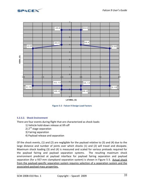
5.2.3.2. Shock Environment<br />
7<br />
5<br />
4<br />
3<br />
2<br />
1<br />
-1<br />
-2<br />
-3<br />
LATERAL (G)<br />
SCM 2008‐010 Rev. 1 Copyright ‐‐ <strong>SpaceX</strong> 2009 33<br />
0.5, 4<br />
0.5, -1.5<br />
0.5, -2<br />
Figure 5‐2 ‐ <strong>Falcon</strong> 9 Design Load Factors<br />
There are four events during flight that are characterized as shock loads:<br />
1) <strong>Vehicle</strong> hold‐down release at lift‐off<br />
2) 2 nd stage separation<br />
3) Fairing separation<br />
4) <strong>Payload</strong> release and separation<br />
Of the shock events, (1) and (2) are negligible for the payload relative to (3) and (4) due to the<br />
large distance and number of joints over which shocks (1) and (2) will travel and dissipate.<br />
Maximum shock loading (3) and (4) is measured and scaled for various preloads required for<br />
the payload fairing and payload separation systems. The resulting maximum shock<br />
environment predicted at payload interface for payload fairing separation and payload<br />
separation (for a 937‐mm clampband separation system) is shown in Figure 5‐3. Actual shock<br />
from the payload‐specific separation system requires selection of a separation system and the<br />
associated payload mass properties.<br />
2, 3.5<br />
2, -1.5