
You also want an ePaper? Increase the reach of your titles
YUMPU automatically turns print PDFs into web optimized ePapers that Google loves.
<strong>User</strong> <strong>Manual</strong>QT SERIESH.264 NETWORK DVR1
About this <strong>Manual</strong>Thank You for Choosing a Q-<strong>See</strong> Product!All of our products are backed by a conditional service warranty covering all hardware for 12months from the date of purchase. Additionally, our products also come with a free exchangepolicy that covers all manufacturing defects for one month from the date of purchase.Permanent upgrading service is provided for the software and is available at www.Q-<strong>See</strong>.com.Be certain to make the most of your warranty by completing the registration form online. Inaddition to warranty and technical support benefits, you’ll receive notifications of productupdates along with free downloadable firmware updates for your DVR. Register today atwww.Q-<strong>See</strong>.com!Please see the back of this manual for exclusions.This manual is written for the QT family of DVRs. Not all features and capabilities are sharedacross all models so you may see features described which are not applicable or available onyour machine. In addition you may see screen images that do not exactly match those on yourdisplay.This manual was accurate at the time it was completed. However, because of our ongoingeffort to constantly improve our products, features and functions may have been addedor changed since that time and on-screen displays may change. We encourage you tovisit our website at www.Q-<strong>See</strong>.com to check for the latest firmware updates and productannouncements.Throughout the manual we have highlighted warnings and other important information that willassist you in operating your new system in a safe and trouble-free manner. Please take thetime to read and follow all instructions and pay attention to alerts as shown below:IMPORTANT! Red boxes with this icon indicate warnings. To preventpossible injury or damage to the product, read all warnings before use.NOTE! Text in blue boxes with the Information icon offer additional guidanceand explanations about how to make the most out of your system.© 2010, 2012 Q-<strong>See</strong>. Reproduction in whole or in part without written permission isprohibited. All rights reserved. This manual and software and hardware described herein, inwhole or in part, may not be reproduced, translated, or reduced to any machine-readableform without prior written approval.Trademarks: All brand names and products are trademarks or registered trademarks of theirrespective owners.Q-<strong>See</strong> is a registered trademark of DPS, Inc.Disclaimer: The information in this document is subject to change without notice. Themanufacturer makes no representations or warranties, either express or implied, of any kindwith respect to completeness of its contents.Manufacturer shall not be liable for any damages whatsoever from misuse of this product.Rev. 3.0 1/24/20122 3
TABLE OF CONTENTS1. INTRODUCTION 7For Your Safety 7Features 82. CONNECTIONS AND CONTROLS 102.1 DVR Functions and Connections 102.2 Mouse 342.3 Remote Control 353. BASIC FUNCTIONS 363.1 Power On/Off 36Power On and Login 36Power Off 363.2 The Control Bar 373.3 Live Viewing and Recording 40Switching Video Output 40Live Viewing 40Recording 403.4 Quick Playback 414. MAIN MENU SETUP 444.1 Basic Configuration 44Menu Navigation 44Setup 444.2 Live Configuration 474.3 Record Configuration 494.4 Schedule Configuration 524.5 Network Configuration 534.6 <strong>User</strong> Management 57Time Search 59Event Search 60File Management 60Image 615. BACKUP 626. DVR MANAGEMENT 646.1 Information 64Event Information 65Log Information 65Network Information 65Online <strong>User</strong> Information 666.2 <strong>Manual</strong> Alarm 676.3 Disk Management 676.4 Upgrade 686.5 Logoff 696.6 Shut Down 697. PAN/TILT/ZOOM CAMERAS 707.1 Connecting a PTZ Camera 707.2 Pan-Tilt-Zoom (PTZ) Configuration 718. ALARMS 748.1 Alarm Input 748.2 Alarm Output 768.3 Alarm Configuration 77Sensor 77Motion 78Video Loss 79Other Alarm 79Alarm Out 809. HARD DISK DRIVE 819.1 Installation/Removal 819.2 Calculating the Recording Capacity of a Hard disk Drive 83APPENDIX 84A.1 Troubleshooting 84A.2 Specifications 87A.3 Rack Mounting 92Q-SEE PRODUCT WARRANTY 93Questions or Comments? Contact Us 944 5
INTRODUCTION CHAPTER 1FOR YOUR SAFETYTo prevent damage to your Q-<strong>See</strong> product or injury to yourself or to others, read andunderstand the following safety precautions in their entirety before installing or using thisequipment. Keep these safety instructions where all those who use the product will read them.WARNING! ELECTRIC SHOCK RISK!• Check the unit and any accessories included in the package immediately after opening. Ifitems are missing or damaged, repackage and return to the point of purchase.• Use the proper power source. Only use the power adapter supplied with your system. Donot use this product with a power source that applies more than the specified voltage (100-240V AC).• Never insert anything metallic into the DVR. Inserting anything into the DVR or its case canbe a source of dangerous electric shock.• Do not operate in dusty areas. Avoid placing the DVR in places that are dusty.• Do not expose this product to rain or use near water. If this product accidentally gets wet,unplug it and contact Q-<strong>See</strong> immediately.• Keep product surfaces clean and dry. To clean the outside case of the DVR, gently wipeusing a lightly dampened cloth (only use water, do not use solvents).• Do not operate this DVR without the cover securely in place. Do not attempt to do anyrepairs to the DVR yourself. If there are unusual sounds or smells coming from the DVR,unplug it immediately and contact Q-<strong>See</strong> technical support. Under no circumstancesshould the cover be removed while the device is connected to a power source. You shouldonly remove the cover to install/replace the hard disk drive (<strong>See</strong> Chapter 9) or replace thestandard 3v lithium cell battery on the motherboard. These are the only user serviceableparts. You may need to replace the battery if the internal clock resets itself after a poweroutage• Handle the DVR carefully. If you accidentally drop your DVR on any hard surface, it maycause a malfunction. If the DVR doesn’t work properly due to physical damage, contact anauthorized dealer for repair or exchange.• Make sure there is proper air circulation around the unit. This DVR system uses a hard drivefor video storage which generates heat during operation. Do not block air holes located onthe bottom, top, sides and back of the DVR as they are designed to keep the system coolwhile running. Install or place this product in an area where there is ample air circulation.• Provide proper ventilation. This DVR has a built-in fan that properly ventilates the system.Do not cover or impede this fan.6 7
FEATURESThis DVR uses high-performance video processing chips and an embedded Linux operatingsystem for quality image recording and ease of use. It utilizes numerous advancedtechnologies including the industry-standard H.264 compression to deliver high-quality,smooth videos and dual stream capability for remote viewing. A SATA hard-drive interfaceoffers upgradability and VGA output allows users to connect to any TV or monitor with VGAinput for viewing.Local control of the system utilizes a mouse and graphical user interface (GUI) as well as aremote control. <strong>User</strong>s can also remotely monitor and control their system using a web browseror select mobile device.This DVR uses cutting-edge technology without compromising stability and reliability making itideal for home use as well as in warehouse, factory, retail and other similar environments.COMPRESSION FORMATStandard H.264 compression with low bit rate and high image qualityLIVE SURVEILLANCESupports VGA outputSupports channel security by hiding live displayDisplays the local record state and basic informationSupports full control with USB mouseSupports digital zoom on live and playback viewRECORDING MEDIABACKUPSupports SATA hard disk drives up to 2TB each for longer recording times.Supports backing up to USB 2.0 devicesSome models support eSATA external hard drivesSupports saving recorded files with AVI format to a remote computer throughinternetRECORDING & PLAYBACKRecord modes: <strong>Manual</strong>, Schedule, Motion detection and Sensor alarm recordingSupports recycle after HDD is fullResolution, frame rate and picture quality are adjustable128MB for every video file packagingUp to 16 audio channels available depending on modelTwo record search modes: time search and event searchSupports multi-screen simultaneous playbackSupports deleting and locking the recorded files one by oneSupports remote playback in Network Client through LAN or internetSupports recording in CIF and D1 resolutions.ALARMPTZ CONTROLSECURITY1-4 channel alarm output and up to 16-channel (depending on model ) alarm inputavailableSupports scheduling for motion detection and sensor alarmSupports pre-recording and post recordingSupports linked channels recording once motion or alarm is triggered ondesignated channelSupports linked PTZ preset, and auto cruiseSupports multiple PTZ protocols (PelcoP, PelcoD, LILIN, MINKING, NEON, STAR,VIDO, DSCP, VISCA, and RANGE)Supports 128 PTZ presets and 8 auto cruise tracksSupports remote PTZ control through internetCustomize user rights: log search, system setup, two way audio, file management,disk management, remote login, live view, manual record, playback, PTZ controland remote live viewSupports 1 administrator and 15 users.Supports event log recording and checking, events unlimitedNETWORKSupports TCP/IP, DHCP, PPPoE, DDNSSupports Internet Explorer and Safari browsers to do remote viewingSupports a maximum of 10 user connections simultaneouslySupports dual stream. Network stream is adjustable independently to fit thenetwork bandwidth and environment.Supports picture snap and color adjustment in remote live viewSupports remote time and event search, and channel playback with picture snapSupports remote PTZ control with preset and auto cruiseSupports remote full menu setup, changing all the DVR parameters remotelySupports mobile surveillance by smart phones, Win Mobile Pro, Win 7 Mobile,Symbian, and iPhones, iPads, Android, and Blackberry on 3G networksSupports CMS to manage multiple devices over the internetAdministrator can limit user access to specific camerasAdministrator can disconnect online usersNOTE! Depending on your point of purchase, your DVR may have the harddisk drive already installed. If your drive was packaged separately or if youwish to upgrade to up to a 2TB drive, please see Chapter 9 at the back ofthis manual which covers installing the drive.8 9
CONNECTIONS AND CONTROLS CHAPTER 2You may view this DVR using a standard 19” (or larger) VGA monitor or a television. Theformer is connected using the VGA port on the back panel while the television utilizes theBNC “Video Out” port on the back. Your DVR is configured to use the VGA port as the maindisplay. To use a TV, you will need to press and hold the STOP/ESC, EXIT or VGA/TV button(depending on model) for approximately 10 seconds until you hear a beep indicating that thevideo mode has been switched. A display connected to the other port will not show the menu.REAR PANEL1 23 4 5 6 7 8 9 10 112.1 DVR FUNCTIONS AND CONNECTIONSQT454FRONT PANEL12 3 4 2 5 6 7 8 910 11ITEM NAME FUNCTION1 POWER Power On/Off2 NUMBER Select individual channels and enter data where requiredBUTTONS3 DIRECTION Navigates through selections in menusSelects viewing mode - Full Screen or 4-Channel Multi-ScreenView4 ENTER Confirm Selection5 MENU Opens the Main MenuIncreases the value in Setup mode6 PLAYBACKCONTROLS7 SEARCH/ZOOM8 INDICATORLIGHT9 INFRAREDWINDOWIn addition to normal DVR playback and record operation, thefollowing have additional functions:RECORD Controls Focus in PTZ modeREVERSE Controls Speed in PTZ modeSTOP/ESC Exits current interface or statusAlso switches video output mode.Enter Search modeControls Zoom function in PTZ modeShows power status of the DVRReceives signals from the remote control10 BACKUP Enter Backup modeDecreases the value in Setup mode11 USB PORT Used for external USB backup devices.12 13ITEM NAME FUNCTION1 AUDIO IN 4 Channels of audio input2 VIDEO IN Video input from up to 4 cameras3 AUDIO OUT Audio output for amplified speaker4 SPOT OUT Connect to another monitor as an auxiliary output channel. Thismonitor will only display video and will have no menu access.5 VIDEO OUT BNC connector for TV or monitor6 PTZ Connections for Pan-Tilt-Zoom speed dome cameras. Y = “+” Z= “-”7 K/B Connector for a PTZ keyboard8 ALARM OUT 1 Channel relay output for external alarms9 ALARM IN 4 Channel input for external sensors and alarms10 LAN Network (ethernet) port11 USB PORT For the USB mouse12 VGA PORT VGA output for 19” or larger monitor13 DC IN Power input for 12V DC power supply10 11
QT474FRONT PANELREAR PANEL1 2 31 2 3 4 5QT474REC Net Power TV/VGAVGA113VIDEO OUT2AUDIO IN24AUDIO OUTVIDEO IN LAN USB DC 12VITEM NAME FUNCTION1 INDICATOR Shows the recording, network and power status of the DVR.LIGHTS2 INFRAREDWINDOWReceives signals from the remote control3 VIDEO MODEBUTTONPress and hold 10 seconds (or until you hear a beep) to switchvideo output from the VGA port (default) to the BNC video outport.4 USB PORT Used for external USB backup devices.4ITEM NAME FUNCTION1 AUDIO IN 2 Channels of audio input2 VIDEO IN Video input from up to 4 cameras3 VIDEO OUT BNC connector for TV or monitor4 VGA PORT VGA output for 19” or larger monitor5 POWERSWITCH6 7 8 9 10Use to turn on the DVR as well as to turn off after poweringdown from within the GUI6 AUDIO OUT BNC Audio output for amplified speaker7 LAN Network (ethernet) port8 USB PORT For the USB mouse9 PTZ Connections for Pan-Tilt-Zoom speed dome cameras.10 DC IN Power input for 12V DC power supply12 13
SVQT426FRONT PANEL1 2REAR PANEL12 3 45ALARM OUT1 2 3 4RS485P/Z K/BALARM INY Z A B 1 3 5 7 9 11 13 15 NETVIDEO OUT1 3 5 7 9 11 13 15DC 12V3 4 5 6 7 8 9 10 111267NOCOMGNDALARM OUTVGASPOT2 4 6 8 10 12 14 16 USB8 9 10 11 122 4 6 8 10 12 14 16VIDEO IN13 14ITEM NAME FUNCTION1 LEDShow status of power, HDD, record, etc.INDICATORS2 IR RECEIVER Receives signals from remote control3 RECORD <strong>Manual</strong>ly begins recording4 PLAY Launches PLAYBACK window5 REW Rewind key6 FF Fast Forward7 +/MENU Increase the value in SETUP/Enter menu in LIVE VIEW8 -/BACKUP Decrease the value in SETUP/Enter backup mode in LIVE VIEW9 STOP/ESC Quit PLAYBACK mode/Exit the current window or statusAlso switches video output mode.10 ENTER Confirm selection11 DIRECTION/MULTISCREEN1. Navigate through on-screen options2. Change screen display mode between 1, 4, 9 and 16channels12 USB USB port to connect USB flash or external hard drives toupdate firmware or back up recordingsITEM NAME FUNCTION1 AUDIO Connection for audio output – connect to an amplified speakerOUTPUT2 AUDIO IN 4-Channel audio input for cameras equipped with audio3 VGA PORT Video output for connecting to monitor4 VIDEO OUT Video output for connecting to TV (BNC) or monitor5 RS485 Connect to Pan-Tilt-Zoom camera to control motion6 K/B Connect to keyboard7 ALARM Output for alarmOUTPUT8 +5 AND GND +5 and grounding9 ALARM IN Connect to up to sixteen external sensors10 USB PORT Connect USB mouse11 NET Network (ethernet) port12 SPOT Connect to another monitor as an auxiliary output channel. Thismonitor will only display video and will have no menu access.13 VIDEO IN Video input from up to 16 cameras14 DC +12V Power input14 15
QT428FRONT PANEL1 2 3 4 5 6 7 8 9REAR PANEL12 3 45VIDEO INVIDEOOUTSPOTAUDIOOUT1 2 3 4 5 6 7 8P/ZY ZK/BA BGNDGNDCOMNOALARM INITEM NAME FUNCTION1 RECORD <strong>Manual</strong>ly begins recording2 PLAY Launches PLAYBACK window3 REW Rewind4 FF Fast Forward10 11 125 +/MENU Increase the value in SETUP/Enter menu in LIVE VIEW6 -/BACKUP Decrease the value in SETUP/Enter backup mode in LIVE VIEW7 STOP/ESC Quit PLAYBACK mode/Exit the current window or statusAlso switches video output mode.8 LEDShow status of power, HDD, record, etc.INDICATORS9 IR RECEIVER Receives signals from remote control10 DIRECTION/MULTISCREEN1. Navigate through on-screen options2. Change screen display mode between 1, 4, and 9 channels11 ENTER Confirm selection12 USB USB port to connect USB flash or external hard drives toupdate firmware or back up recordingsVGALANUSBRS485 1 2 3 4 5 6 7 81 2 3 4AUDIO IN6 7 8 9 10 11 12 13ITEM NAME FUNCTION1 VIDEO OUT Video output for connecting to TV (BNC) or monitor2 SPOT Connect to another monitor as an auxiliary output channel. Thismonitor will only display video and will have no menu access.3 AUDIO Connection for audio output – connect to an amplified speakerOUTPUT4 VIDEO IN Video input from up to 8 cameras5 DC +12V Power input6 VGA PORT Video output for connecting to monitor7 LAN Network (ethernet) port8 USB PORT Connect USB mouse9 RS485 Connect to Pan-Tilt-Zoom camera to control motion10 K/B Connect to keyboard11 ALARM Output for alarmOUTPUT12 ALARM IN Connect to up to eight external sensors13 AUDIO IN 4-Channel audio input for cameras equipped with audio16 17
QT446FRONT PANELBACK PANEL1 2 3 4 5 6 78 91 2 3 4510 11 12 13 14 15 16 17 166 7 8 9 10 11 12 13 14 15 16 17 18ITEM NAME FUNCTION1 POWER (Behind flip-downpanel)Puts the DVR into standby mode or wakes it up fromstandby mode.2 USB PORTUsed for external USB backup devices.(Behind flip-down panel)3 NUMBER PAD Enter channel numbers.4 MENU Opens the Main Menu5 BACKUP Opens Backup Menu6 DIRECTION Navigates through selections in menus7 RECORD Begins manually recording on all channels8 SEARCH Enters Search Mode9 INDICATOR LIGHTS Shows status of the DVR Functions and the HardDrive10 VIEWING MODE Change between 1, 4, 8 and 16-screen viewing mode11 10+ BUTTON Input channels numbers above 10 by pushing thisbutton followed by the second digit.12 PTZ Enter PTZ mode in live view13 AUDIO Turn audio on or off in live view if audio input devicesare attached.14 INFO Displays system information15 ENTER Confirms selection in menus or input in fields16 PLAYBACK CONTROLS REW - RewindPLAY - Opens the Playback interface. Pauses orresumes playbackFF - Fast ForwardSTOP - Quits Playback modeAlso switches video output mode.17 CONTROL KNOB Outer ring navigates through menusInner knob increases or decreases speed of fastforward or rewind.ITEM NAME FUNCTION1 VIDEO OUT BNC connector for TV or monitor2 VIDEO IN BNC connectors for up to 16 cameras3 eSATA (2) Connection for external eSATA hard drive for backup4 POWER SOCKET Attachment point for power cord5 LOOP OUT (2) Output each channel to a separate monitor. Each porthandles 8 channels.6 SPOT OUT Connect to another monitor as an auxiliary outputchannel. This monitor will only display video and willhave no menu access.7 AUDIO IN 16 channels of audio input8 AUDIO OUT Audio output for amplified speaker9 MICROPHONE IN Connect a microphone for two-way audio10 VGA PORT VGA output for 19” or larger monitor11 USB PORT For the USB mouse12 LAN Network (ethernet) port13 ALARM IN Connect up to 16 external sensors14 ALARM OUT 4 Channel relay output for external alarms15 PTZ Connections for Pan-Tilt-Zoom speed dome cameras.Y = “+” Z = “-”16 K/B Connector for a PTZ keyboard17 POWER SWITCH Use to turn on the DVR as well as to turn off afterpowering down from within the GUI18 FAN Cooling fan exhaust port. This should not be blocked.18 19
QT4332 QT4532FRONT PANELBACK PANEL1 2 3 4 5 6 78 91 210 11 12 13 14 15 16 17 16ITEM NAME FUNCTION1 POWER (Behind flipdownpanel)Puts the DVR into standby mode or wakes it up fromstandby mode.2 USB PORTUsed for external USB backup devices.(Behind flip-down panel)3 NUMBER PAD Enter channel numbers.4 MENU Opens the Main Menu5 BACKUP Opens Backup Menu6 DIRECTION Navigates through selections in menus7 RECORD Begins manually recording on all channels8 SEARCH Enters Search Mode9 INDICATOR LIGHTS Shows status of the DVR Functions and the Hard Drive10 VIEWING MODE Change between 1, 4, 8, 16 and 32-screen viewingmode11 10+ BUTTON Input channels numbers above 10 by pushing thisbutton followed by the second digit.12 PTZ Enter PTZ mode in live view13 AUDIO Turn audio on or off in live view if audio input devices areattached.14 INFO Displays system information15 ENTER Confirms selection in menus or input in fields16 PLAYBACKCONTROLSREW - RewindPLAY - Opens the Playback interface. Pauses orresumes playbackFF - Fast ForwardSTOP - Quits Playback modeAlso switches video output mode.17 CONTROL KNOB Outer ring navigates through menusInner knob increases or decreases speed of fast forwardor rewind.3 4 5 6 7 8 9 10 11 12 13 14 15 16 17 18ITEM NAME FUNCTION1 VIDEO OUT BNC connector for TV or monitor2 VIDEO IN BNC connectors for up to 32 cameras3 SPOT OUT Connect to another monitor as an auxiliary outputchannel. This monitor will only display video and willhave no menu access.4 AUDIO OUT Audio output for amplified speaker5 MICROPHONE IN Connect a microphone for two-way audio6 VGA PORT VGA output for 19” or larger monitor7 HDMI HDMI video output8 USB PORT For the USB mouse9 LAN Network (ethernet) port10 eSATA (2) Connection for external eSATA hard drive for backup11 ALARM IN Connect up to 16 external sensors12 ALARM OUT 4 Channel relay output for external alarms13 PTZ Connections for Pan-Tilt-Zoom speed dome cameras.Y = “+” Z = “-”14 K/B Connector for a PTZ keyboard15 AUDIO IN Attachment point for audio dongle which allows up to16 channels of audio input.16 POWER SOCKET Attachment point for power cord17 POWER SWITCH Use to turn on the DVR as well as to turn off afterpowering down from within the GUI18 FAN Cooling fan exhaust port. This should not be blocked.20 21
QT504FRONT PANELBACK PANEL1 2 3 4 5 6 7 8 912 3 45ITEM NAME FUNCTION10 11 121 RECORD Begins manual recordingControls Focus in PTZ mode2 PLAY Begins playback3 REWIND Rewinds videoControls camera speed in PTZ mode4 FAST FORWARD Advances playback speed5 MENU/+ Opens the Main MenuIncreases the value in Setup mode6 BACKUP/- Opens Backup MenuDecreases the value in Setup mode7 STOP/ESC Ends video playback.Exits current interface or statusSwitches video output mode.8 INDICATOR LIGHTS Shows status of the DVR Functions and the HardDrive9 IR RECEIVER Receives signals from remote control10 DIRECTION Selects multi-screen viewing modeNavigates through selections in menus11 RETURN Confirms selection12 USB PORT Used for external USB backup devices.6 7 8 9 10 11 12 13ITEM NAME FUNCTION1 VIDEO OUT BNC connector for TV or monitor2 SPOT OUT Connect to another monitor as an auxiliary outputchannel. This monitor will only display video and willhave no menu access.3 AUDIO OUT Audio output for amplified speaker4 VIDEO IN BNC connectors for up to 4 cameras5 DC IN Power input for 12V DC power supply6 VGA PORT VGA output for 19” or larger monitor7 NET Network (ethernet) port8 USB PORT For the USB mouse9 PTZ Connections for Pan-Tilt-Zoom speed dome cameras.Y = “+” Z = “-”10 K/B Connector for a PTZ keyboard11 +5V and GND +5V and grounding12 ALARM IN/OUT 4 Channel input and output for external sensors andalarms13 AUDIO IN 4 channels of audio input22 23
QT526FRONT PANELBACK PANEL1 23 4 56 723 4 56 7 8 9 101ITEM NAME FUNCTION1 IR RECEIVER Receives signals from remote control8 9 10 11 12 132 NUMBER BUTTONS Select individual channels for full screen view3 DIRECTION Selects multi-screen viewing modeNavigates through selections in menus4 ENTER Confirm Selection5 INDICATOR LIGHTS Shows status of the DVR Functions and the HardDrive6 MENU Opens the Main MenuIncreases the value in Setup mode7 USB PORT Used for external USB backup devices.8 PLAYBACK CONTROLS In addition to normal DVR playback and recordoperation, the following have additional functions:RECORD Controls Focus in PTZ modeREVERSE Controls Speed in PTZ modeSTOP/ESC Exits current interface or statusAlso switches video output mode.9 SEARCH/ZOOM Enter Search modeControls Zoom function in PTZ mode10 INFO Displays system information11 BACKUP Enter Backup modeDecreases the value in Setup mode12 AUDIO Mutes or unmutes audio13 PTZ Enter PTZ mode11 12 13 14 15 16ITEM NAME FUNCTION1 PTZ Connections for Pan-Tilt-Zoom speed dome cameras.Y = “+” Z = “-”2 K/B Connector for a PTZ keyboard3 ALARM IN Connections for up to 16 external sensors4 NET Network (ethernet) port5 VGA PORT VGA output for 19” or larger monitor6 VIDEO OUT BNC connector for TV or monitor7 VIDEO IN BNC connectors for up to 16 cameras8 AUDIO IN 4 channels of audio input9 AUDIO OUT Audio output for amplified speaker10 POWER Power On/Off11 +5V and GND +5V and grounding12 ALARM OUT 1 Channel relay output for external alarm13 USB PORT For the USB mouse14 SPOT OUT Connect to another monitor as an auxiliary outputchannel. This monitor will only display video and willhave no menu access.15 DC IN Power input for 12V DC power supply16 FAN Cooling fan exhaust port. This should not be blocked.24 25
QT528FRONT PANEL1 23 4 56 7BACK PANEL23 4 56 7 8 9 1018 9 10 11 12 13ITEM NAME FUNCTION1 IR RECEIVER Receives signals from remote control2 NUMBER BUTTONS Select individual channels for full screen view3 DIRECTION Selects multi-screen viewing modeNavigates through selections in menus4 ENTER Confirm Selection5 INDICATOR LIGHTS Shows status of the DVR Functions and the HardDrive6 MENU Opens the Main MenuIncreases the value in Setup mode7 USB PORT Used for external USB backup devices.8 PLAYBACK CONTROLS In addition to normal DVR playback and recordoperation, the following have additional functions:RECORD Controls Focus in PTZ modeREVERSE Controls Speed in PTZ modeSTOP/ESC Exits current interface or statusAlso switches video output mode.9 SEARCH/ZOOM Enter Search modeControls Zoom function in PTZ mode10 INFO Displays system information11 BACKUP Enter Backup modeDecreases the value in Setup mode12 AUDIO Mutes or unmutes audio13 PTZ Enter PTZ mode11 12 13 14 15 16ITEM NAME FUNCTION1 PTZ Connections for Pan-Tilt-Zoom speed dome cameras.Y = “+” Z = “-”2 K/B Connector for a PTZ keyboard3 ALARM IN Connections for up to 8 external sensors4 NET Network (ethernet) port5 VGA PORT VGA output for 19” or larger monitor6 VIDEO OUT BNC connector for TV or monitor7 VIDEO IN BNC connectors for up to 8 cameras8 AUDIO IN 4 channels of audio input9 AUDIO OUT Audio output for amplified speaker10 POWER Power On/Off11 +5V and GND +5V and grounding12 ALARM OUT 1 Channel relay output for external alarm13 USB PORT For the USB mouse14 SPOT OUT Connect to another monitor as an auxiliary outputchannel. This monitor will only display video and willhave no menu access.15 DC IN Power input for 12V DC power supply16 FAN Cooling fan exhaust port. This should not be blocked.26 27
QT518FRONT PANELBACK PANEL1 2 3 4 5 6 78 91 2 3 45ITEM NAME FUNCTION10 11 12 13 14 15 16 17 161 POWER (Behind flip-downpanel)Puts the DVR into standby mode or wakes it up fromstandby mode.2 USB PORTUsed for external USB backup devices.(Behind flip-down panel)3 NUMBER PAD Enter channel numbers.4 MENU Opens the Main Menu5 BACKUP Opens Backup Menu6 DIRECTION Navigates through selections in menus7 RECORD Begins manually recording on all channels8 SEARCH Enters Search Mode9 INDICATOR LIGHTS Shows status of the DVR Functions and the HardDrive10 VIEWING MODE Change between 1, 4, and 8-screen viewing mode11 10+ BUTTON Input channels numbers above 10 by pushing thisbutton followed by the second digit.12 PTZ Enter PTZ mode in live view13 AUDIO Turn audio on or off in live view if audio input devicesare attached.14 INFO Displays system information15 ENTER Confirms selection in menus or input in fields16 PLAYBACK CONTROLS REW - RewindPLAY - Opens the Playback interface. Pauses orresumes playbackFF - Fast ForwardSTOP - Quits Playback modeAlso switches video output mode.17 CONTROL KNOB Outer ring navigates through menusInner knob increases or decreases speed of fastforward or rewind.6 7 8 9 10 11 12 13 14 15 16 17 18 19ITEM NAME FUNCTION1 VIDEO OUT BNC connector for TV or monitor2 HDMI HDMI video output3 VIDEO IN BNC connectors for up to 8 cameras4 eSATA Connection for external eSATA hard drive for backup5 LOOP OUT Output each channel to a separate monitor6 SPOT OUT Connect to another monitor as an auxiliary outputchannel. This monitor will only display video and willhave no menu access.7 AUDIO OUT Audio output for amplified speaker8 MICROPHONE IN Connect a microphone for two-way audio9 VGA PORT VGA output for 19” or larger monitor10 USB PORT For the USB mouse11 LAN Network (ethernet) port12 AUDIO IN 8 channels of audio input13 ALARM IN Connect up to 8 external sensors14 ALARM OUT 4 Channel relay output for external alarms15 PTZ Connections for Pan-Tilt-Zoom speed dome cameras.Y = “+” Z = “-”16 K/B Connector for a PTZ keyboard17 POWER SOCKET Attachment point for power cord18 POWER SWITCH Use to turn on the DVR as well as to turn off afterpowering down from within the GUI19 FAN Cooling fan exhaust port. This should not be blocked.28 29
QT5116FRONT PANEL1 2 3 4 5 6 78 9BACK PANEL1 2 3 4 5ITEM NAME FUNCTION10 11 12 13 14 15 16 17 161 POWER (Behind flip-downpanel)Puts the DVR into standby mode or wakes it up fromstandby mode.2 USB PORTUsed for external USB backup devices.(Behind flip-down panel)3 NUMBER PAD Enter channel numbers.4 MENU Opens the Main Menu5 BACKUP Opens Backup Menu6 DIRECTION Navigates through selections in menus7 RECORD Begins manually recording on all channels8 SEARCH Enters Search Mode9 INDICATOR LIGHTS Shows status of the DVR Functions and the HardDrive10 VIEWING MODE Change between 1, 4, 8 and 16-screen viewing mode11 10+ BUTTON Input channels numbers above 10 by pushing thisbutton followed by the second digit.12 PTZ Enter PTZ mode in live view13 AUDIO Turn audio on or off in live view if audio input devicesare attached.14 INFO Displays system information15 ENTER Confirms selection in menus or input in fields16 PLAYBACK CONTROLS REW - RewindPLAY - Opens the Playback interface. Pauses orresumes playbackFF - Fast ForwardSTOP - Quits Playback modeAlso switches video output mode.17 CONTROL KNOB Outer ring navigates through menusInner knob increases or decreases speed of fastforward or rewind.6 7 8 9 10 11 12 131415 16ITEM NAME FUNCTION1 HDMI HDMI video output2 AUDIO OUT Audio output for amplified speaker3 AUDIO IN 16 channels of audio input4 eSATA Connection for external eSATA hard drive for backup5 FAN Cooling fan exhaust port. This should not be blocked.6 PTZ Connections for Pan-Tilt-Zoom speed dome cameras.Y = “+” Z = “-”7 K/B Connector for a PTZ keyboard8 ALARM IN Connect up to 16 external sensors9 LAN Network (ethernet) port10 USB PORT For the USB mouse11 VGA PORT VGA output for 19” or larger monitor12 VIDEO OUT BNC connector for TV or monitor13 SPOT OUT Connect to another monitor as an auxiliary outputchannel. This monitor will only display video and willhave no menu access.14 VIDEO IN BNC connectors for up to 16 cameras15 POWER SOCKET Attachment point for power cord16 POWER SWITCH Use to turn on the DVR as well as to turn off afterpowering down from within the GUI30 31
QT536FRONT PANELBACK PANEL1 2 3 4 5 6 78 91 23ITEM NAME FUNCTION10 11 12 13 14 15 16 17 161 POWER (Behind flip-downpanel)Puts the DVR into standby mode or wakes it up fromstandby mode.2 USB PORTUsed for external USB backup devices.(Behind flip-down panel)3 NUMBER PAD Enter channel numbers.4 MENU Opens the Main Menu5 BACKUP Opens Backup Menu6 DIRECTION Navigates through selections in menus7 RECORD Begins manually recording on all channels8 SEARCH Enters Search Mode9 INDICATOR LIGHTS Shows status of the DVR Functions and the HardDrive10 VIEWING MODE Change between 1, 4, 8 and 16-screen viewing mode11 10+ BUTTON Input channels numbers above 10 by pushing thisbutton followed by the second digit.12 PTZ Enter PTZ mode in live view13 AUDIO Turn audio on or off in live view if audio input devicesare attached.14 INFO Displays system information15 ENTER Confirms selection in menus or input in fields16 PLAYBACK CONTROLS REW - RewindPLAY - Opens the Playback interface. Pauses orresumes playbackFF - Fast ForwardSTOP - Quits Playback modeAlso switches video output mode.17 CONTROL KNOB Outer ring navigates through menusInner knob increases or decreases speed of fastforward or rewind.4 5 6 7 8 9 10 11 12 13 14 15 16 17 18 19ITEM NAME FUNCTION1 VIDEO OUT BNC connector for TV or monitor2 VIDEO IN BNC connectors for up to 16 cameras3 LOOP OUT (2) Output each channel to a separate monitor. Each porthandles 8 channels.4 SPOT OUT Connect to another monitor as an auxiliary outputchannel. This monitor will only display video and willhave no menu access.5 AUDIO IN 16 channels of audio input6 AUDIO OUT Audio output for amplified speaker7 MICROPHONE IN Connect a microphone for two-way audio8 VGA PORT VGA output for 19” or larger monitor9 HDMI HDMI video output10 USB PORT For the USB mouse11 LAN Network (ethernet) port12 eSATA (2) Connection for external eSATA hard drive for backup13 ALARM IN Connect up to 16 external sensors14 ALARM OUT 4 Channel relay output for external alarms15 PTZ Connections for Pan-Tilt-Zoom speed dome cameras.Y = “+” Z = “-”16 K/B Connector for a PTZ keyboard17 POWER SOCKET Attachment point for power cord18 POWER SWITCH Use to turn on the DVR as well as to turn off afterpowering down from within the GUI19 FAN Cooling fan exhaust port. This should not be blocked.32 33
In addition to the buttons on the front of the DVR, your system can be controlled through theUSB mouse and the remote control. We have found that the majority of our customers preferto operate their DVRs using the USB mouse because of its ease of use and flexibility and ourmanual is set up with this in mind.2.2 MOUSEThe mouse is the default tool for navigating through the menus. Specific instructions for its usewithin a function appear in the appropriate sections of the manual, but a basic overview is below:In Live View:Double-click the left button on any cameraview in split-screen mode to bring it to fullscreendisplay.Double-click again to return to split-screenmode.Right-click to show the control bar at thebottom of the screen.Right-clicking again will hide the control bar.In Setup:Left-click to make a selection. Right-click tocancel setup or return to previous screen.To Input Values:Move the cursor to a blank field and click. A virtual keyboard will appear which supportsnumbers, letters and symbols. The Shift function will access symbols in addition to upper caseletters.Certain values, such as time settings, can be changed using the mouse wheel.2.3 REMOTE CONTROLThe remote control allows you to perform most of theday-to-day functions from a convenient distance. Itfunctions as a typical remote control with additionalbuttons allowing you to navigate through menus andcontrol functions. We recommend that you configureyour DVR using the mouse controls, reserving theremote control for operations such as live viewing, filesearch and playback.It uses two AAA-sized batteries. If the remote’sperformance degrades, check the batteries aswell as that the IR receiver window on the DVR isunobstructed.Item Button Function1 POWER2 INFO3 REC Begin recording4 NumbersSoft power down switch. Use thisbefore unplugging the DVRGet information about the DVR suchas HDD space and firmware versionInput numbers in fields or selectcamera5 Multi-Screen Choose multi-screen display mode6 MENU Opens MENU window7 SEARCH Enter SEARCH mode8 DirectionalMove cursor in set up or control PTZcamera9 ENTER Confirm choice or settings10 SET +/-11 PlaybackIncrease or decrease value inSETUP modeControls playback functions, includingstop, single-frame, fast forward,etc.12 AUDIO Enable audio input in live mode13 SEQReturns to auto dwell displaysequence14 BACKUP Enters BACKUP menu15PTZControlsControls PTZ camera includingzoom, focus, iris and speed1 2 345678910111213141534 35
BASIC FUNCTIONS CHAPTER 33.1 POWER ON/OFFBefore turning on the DVR, ensure that all connections are good.POWER ON AND LOGINConnect the power supply and the DVR will power up. The LED labelled POWER on the frontwill illuminate and the DVR will display the live image from Channel 1.Before you can proceed, you will need to log into the DVR.STEP 1. Right-click with the mouse anywhere on the screenSTEP 2. Press the MENU button on the remote or press the STOP/ESC button on thefront of the DVR to open the Control Bar which will appear at the bottom of thescreen (Picture 3-3).STEP 3. Once the Control Bar appears, click the Menu icon on the far left to open theMain Menu (Picture 3-2).STEP 4. The Login screen will appear.Enter the <strong>User</strong> Name and Password,admin and 123456 respectivelyusing the Virtual Keyboard describedin the last chapter. Click ENTERon the keyboard. You can changethe password later as described inSection 4.6 <strong>User</strong> Management.PICTURE 3-1You are now logged in.IMPORTANT! If you are logging into the DVR for the first time, it is essentialthat you set your DVR to the proper date and time at this point. Doing sowill allow you to search for events based on when they occurred as well asavoiding complications by having multiple recorded files with the same date and time if youwait to make those settings. Complete instructions can be found in Section 4.1 BasicConfiguration.3.2 THE CONTROL BARWhen a user is logged in, pressing the ESC button on the DVR or right-clicking on the screenwith the mouse will display the CONTROL BAR on the bottom of the screen.MenuScreen DisplayModeDwellColorPICTURE 3-3MoveZoom PTZ Record Control BarVolume Snapshot PlaybackThe functions of the Control Bar are listed below. Screen Display Modes are covered on thenext page and the other functions will be covered in more detail in the following chapters.Menu: Opens the Main Menu.Screen Display Mode: Choose the number of channels you wish to view at once. Channelswithout attached cameras will display “Video Loss.” Clicking on the upward pointing arrowsto the right of each icon will allow you to select which channels to view in that mode.Dwell: Enable/disable automatic cycling between channels.Color: Adjust the brightness, hue, saturation and contrast for any channel.Zoom: Available in single screen display mode, this digitally enlarges a section of the display.Volume: Adjust volume. This is only available if you have attached a microphone or audiocapablecamera to the DVR.PTZ: Opens the controls for optional Pan-Tilt-Zoom cameras.Snapshot: Captures a still image from all channels and saves it to the hard drive.Record: Begin manual recording on all channels.Playback: Switches to Playback mode and brings up the Playback Control Bar.Move Control Bar: Clicking this will allow you to reposition the Control Bar anywhere on thescreen. Right clicking on the screen will hide the Control Bar.POWER OFFThe DVR will power down to a standbymode when the POWER button on theremote control is pressed, or when theSYSTEM SHUT DOWN icon is selectedfrom within the MENU. In both cases, theSHUT DOWN window will appear and usersmust select OK to confirm. The hard drivewill stop spinning and the system will shutdown. For extended periods of inactivity, it isrecommended that the DVR be disconnectedfrom power either by turning off the power atthe surge protector or unplugging the device.PICTURE 3-236 37
DISPLAY MODEBy clicking on the display mode buttons on in the Control Bar you can quickly configurehow your cameras’ video feeds are displayed. The settings here will temporarily overridethe default configuration made in the Main Monitor tab in the Live menu (see Section4.2 Live Configuration). You can select whether to view a single channel at a time, twochannels in a picture in picture format, or view multiple channels in a split screen mode. Inaddition, users have the option to select how many channels to view at once as well as whichchannels will be shown in that multi-channel display. The number of display mode optionsand their configuration will depend up on the model of your DVR. With the exception of thenine-channel viewing mode on an eight-channel system, your DVR will not have the optionto display more channels than it supports. If you have fewer than the maximum number ofcameras connected to your DVR, the channels without cameras will remain black and displaya “Video Loss” message.Picture in PictureIf you wish to only monitor two channels at a time, most QT DVRs (excluding the QT536)feature the Picture-in-Picture mode. The icon for this display mode is shown at the far right ofPicture 3-4.15None2637PICTURE 3-64815263175None4286PICTURE 3-7Clicking on the Picture-in-Picture button will open a pop-up window (Picture 3-6) allowingyou to select which channel will be the main video feed. Clicking on the button in the lower leftof that window will open a second pop-up window (Picture 3-7) allowing you to select thechannel that will be displayed within the larger image. Note that the channel currently beingused for the larger display will be darkened and not selectable.3748PICTURE 3-4Click the icon beside the desired screendisplay mode to open the CHANNELSELECT menu.<strong>User</strong>s can check any or all channels todisplay the live feeds (depending on thedisplay mode chosen and the number ofchannels on the DVR). Click the boxto confirm the settings before closing theCHANNEL SELECT menu by clicking on thebutton.PICTURE 3-5You can move camera views to a new position by clicking and dragging the desired channel’sdisplay. When a channel’s view is dragged into another area, the view that it replaces will moveto the vacated location.Double-clicking on any of the channels being displayed will bring that camera’s video to fullscreen. Right clicking anywhere within the image will return the display to its previous mode.Asymmetric DisplayWith the exception of the four-channel DVRs in this series and the QT536, users have theoption of viewing cameras using an asymmetric display mode. This modes consists of onelarge image plus several smaller images. As described above, a camera’s display can bedragged from one of the smaller windows into the larger window for easier viewing whilemaintaining a multi-channel display.38 39
3.3 LIVE VIEWING AND RECORDINGSWITCHING VIDEO OUTPUTThe DVR is normally configured to output video signal to a 19” or larger monitor throughthe VGA port on the back. However, if you have attached a television to the Video Out portinstead, then you will need to press and hold the ESCAPE, EXIT or STOP button (dependingon model) on the front of the DVR for 10 seconds or until you hear a beep to indicate that thevideo mode has been changed. On the QT474, the video mode can be changed by pushingand holding the VGA/TV button.LIVE VIEWINGThe normal mode of the DVR is to display the live feed from the cameras. Configuring whichchannels will be displayed, naming the cameras and other display settings will be covered inSECTION 4.2.3.4 QUICK PLAYBACKPushing the playback button on the DVR or remote will enable you to play back what hasbeen recently recorded by launching Quick Playback.Playback ButtonClicking on the Playback button within theControl Bar will begin the Quick Playbackprocess as well.The time period for the Quick Playback canbe set by clicking the upward-pointing arrowicon next to the Playback button. You canchose to go back 2-, 5- or 10 minutes. Thissetting will apply whether you’ve selectedplayback on the remote, the front of the DVRor by clicking on the Playback button.PICTURE 3-92 5 10[Minutes]PICTURE 3-10Only channels with recorded video will display their feeds and those without will be dark.As shown on the next page, a toolbar will appear below the display showing the playbackcontrols. If you are using the mouse, clicking on the various controls will affect the videoplayback in a similar manner to using the front panel buttons or remote control.There may be additional video recorded before your starting point and you can go back tothe beginning of the recording within this playback. You will, however, need to use the searchfeature described in Section 4.8 to locate video event recordings from other days, or earliertimes.PICTURE 3-8In addition to the camera images, the DVR will display symbols regarding the status of eachcameraSymbol Meaning Symbol Meaning Symbol MeaningScheduledRecordingAlarmRecording<strong>Manual</strong>RecordingMotion DetectionAudio EnabledRECORDINGYour DVR is configured to record whenever motion is detected. It is also set to record at thebest setting possible. These settings work for most users, but each user’s situation will bedifferent and directions for adjusting these settings can be found in Section 4.3 RecordConfiguration.40 41
PLAYBACK CONTROL BARThe controls operate in a similar fashion to those of a conventional DVR or other videoplayback device but with a few additional commands available to you:Play/FrameRewindPauseAdvanceStopPreviousRecord08/19/2011 12:02:00FastForwardScreen DisplayModeZoom ColorTrim Backup>>1 XPlaybackSpeedPICTURE 3-11PlaybackProgress BarVolumeExitHideTool BarNextRecordPrevious/Next Record: Moves to the prior or following recorded event, respectively.Fast Forward/Rewind: In addition to their normal operation, clicking on these buttonsmultiple times will speed up or slow down the rate or progression - forwards or backwards- through the file. The speed can also be selected directly by clicking on the small upwardpointing arrows to the right of each button. You can select from 1/4 speed to 16-timesnormal speed forward and rewind speeds of 8-times, 16-times and 32-times normal speed.The current speed will be displayed at the bottom center of the Playback bar.Screen Display Mode: As with the Control Bar, these icons allow you to choose thenumber of channels you wish to view in playback. Clicking on the upward pointing arrows tothe right of each icon will allow you to select which channels to view in that mode. Channelswith no recordings will appear blank.Zoom: Available in single screen display mode, this digitally enlarges a section of the display.Select this tool and then click-and-drag to select a portion of the video feed to enlarge it.Clicking and dragging within the zoomed-in area will allow you to move to other areas of theimage. Right-clicking will return the video to regular display mode.Color: Adjust the brightness, hue, saturation and contrast for any channel. Please note thatthis will only effect the playback for this channel on the DVR itself. It will not change therecording.Playback Progress Bar: The slider moves along the Playback Progress Bar as the videoplays. Moving this with the mouse will go to another segment of the video. You can move toanother point in a single video by first clicking on that channel and then moving the slider tothe desired time. Other channels will continue progressing normally.Trim: Using this tool allows you to save a segment of the video record rather than having toback up the entire file.To select a segment move the PlaybackProgress Bar to before the desiredlocation in the video and begin playback.Once you reach the desired startingpoint, click on the Trim button to set thebeginning of the clip. The button’s iconwill flip indicating that it is waiting for youto select the ending point. When youhave reached that point, click the buttonagain to complete your edit. The startingand ending times will be displayed at thebottom of the Playback Control Bar.Backup: Once you have created your videoclip, the Backup button will turn whiteindicating that you can save your clipdirectly to a USB drive connected to theUSB port on the front of the DVR. The drivemust be connected before clicking on theBackup button.When the Backup button is clicked,the Backup window will open. It willlist details about the file and the storagemedia that you have connected. If youhave more than one drive connected -including ESATA, USB CD/DVD burners orother external media, you can chose thedesired destination in the Storage Mediapull-down.If you do not have enough space on thedisk to save your file, you may select DiskCleanup to remove all files from that disk.BeginClipPICTURE 3-12PICTURE 3-13PICTURE 3-14EndClip>>1 X 00:00:17-00:01:19BACKUP INFORMATIONStart TimeEnd TimeThe Number of FilesSize [GB]Storage MediaFree [GB]Backup PlayerSave File Type0%Disk Cleanup08/19/2011 01:24:1208/19/2011 01:29:361.258USB-10.946AVIStartCancelChose the format in which you want to save your video clip. The .DVR format requires aspecial player program which will be included in a second folder on the drive. The .AVIformat will work with most standard media playback software on PC or Mac computers. Ifselecting .AVI as the format for your files then you should deselect the Backup Player box.Click Start to begin the download and the progress bar at the bottom will fill up as the file istransferred.For more information regarding backing up files, please see Chapter 5.42 43
MAIN MENU SETUP CHAPTER 44.1 BASIC CONFIGURATIONThis chapter is intended to help you get your DVR up and running before you activate anyadvanced features which are covered in later chapters. You can use the mouse, remotecontrol and the buttons on the front of the DVR to operate your system, but for convenience,we will be discussing operations using the mouse. Information on P.T.Z. cameras and alarmswill be found in their own chapters, Chapters 7 and 8, respectively.MENU NAVIGATIONNavigation through the user interface is point and click. Double-clicking on an icon within agiven menu will open that menu, or a submenu. The Main Menu is the starting point to reachall of the DVR’s settings and features. Selecting the Menu icon on the left of the Control Baror pressing the Menu button on the DVR and remote control open the Main Menu.Main MenuClicking on any icon will open the relevantmenu.SETUPFrom the Setup menu select the Basic menuby clicking on its icon.PICTURE 4-1PICTURE 4-2BASIC MENUThere are three tabs covering System, Date & Time and Daylight Savings Time (DST). Inthe first tab, System you will set the date, time along with other desired settings.System TabThe following settings can be changed in this menu:Device Name: This will display when youaccess the DVR remotely via yourmobile device, a web browser orthrough the CMS software. Namingthe device will help users recognizethe device when monitoringnumerous DVRs remotely.Device ID: If you have multiple systems, youcan give this device a numerical ID.Video Format: Select between NTSC (NorthAmerica) or PAL (Europe) videostandards.Password Check: By enabling this, auser will need to enter nameand password when performingconfiguration operations.BASICSystem Date & TimeDSTDevice NameDevice IDVideo FormatPassword CheckShow System TimeMax Online <strong>User</strong>sVideo OutputLanguageLogout After [Minutes]No Image When LogoutDefaultEDVR0NTSCPICTURE 4-410VGA 1280x1024English5ApplyShow Time: Displays the time on-screen in Live View.Max Network <strong>User</strong>s: Set the maximum number of network connections - up to 10.VGA Output: Chose the configuration that best fits your monitor. Options are: VGA800*600,VGA1024*768 (Default), VGA1280x1024 and CVBS. NOTE: VGA is for VGA monitorswhile CVBS is for TV monitors connected using a BNC/RCA adaptor. Switchingbetween VGA and CVBS will change the menu output mode. Please be sure to havethe correct monitor on hand when changing output mode.Language: Select your preferred menu language. The DVR will have to restart for this changeto take effect.Logout After... : You can have the DVR automatically log a user out after a period of inactivity.The period can range from 30 seconds (.5), 1, 3 or 5 minutes or never.No Image When Logout: The monitor will not display the Live View when this box isunchecked.ExitPICTURE 4-3NOTE! When configuring your settings, you will always need to click Apply to save yourcurrent settings before closing the window with Exit otherwise your changes will be lost.You may click Exit or the close window box (X) in the upper right of the window to closewithout saving changes but an alert will pop up asking if you wish to save changes. ClickOK to save changes or Cancel to continue without saving. You may select the Defaultbutton to restore your settings to those set at the factory.IMPORTANT! After changing the Language or Video Format, the device willneed to be restarted.44 45
Date & Time TabSet date, time, time format and related configurations in this menu.IMPORTANT! To maintain the integrity of recorded video, you should setthe DVR to the correct date and time before making changes in other menus.Setting the correct date and time before proceeding is essential to maintaining the integrityof your video records - especially for purposes of evidence. Making these straightforwardsettings should be your first priority before proceeding further within this manual. Changing thedate and time after important videos have been recorded could result in the loss of those files.Most of the options within this menu areself-explanatory. If you are unsure of yourtime zone, the date and time settings onyour computer or searching online for “TimeZones” will quickly provide you with theinformation you need.NTP Server: Using Network Time Protocolwill keep your system’s clock currentby allowing it to occasionally receiveupdates from the selected server.Your DVR must be connected tothe Internet for this feature to work.Please see the Remote MonitoringGuide for instructions.DST TabBASICSystemDate & TimeDSTDate FormatTime FormatTime ZoneSync Time with NTP ServerNTP ServerSystem DateSystem TimeBASICSystemDate & TimeDSTDaylight Saving TimeTime Offset [Hours]ModeFromUntilDefaultMM-DD-YY24 HourGMTtime.windows.comUpdate Now03/04/201112 : 43 : 13Save NowPICTURE 4-5DefaultPICTURE 4-61MarchThe 2ndSunday02:00:00NovemberThe 1stSunday02:00:0025MAYApplyThis setting allows your system to adjust for time changes due to Daylight Savings Time.Again, your system must be connected to the Internet for this feature to work. As of thiswriting, Daylight Savings Time begins in most areas of North America on the 2nd Sundayin March and ends on the first Sunday in November. Both changeovers happen at 2 am.Allowing the DVR to make the change automatically ensures that files will not be lost as couldhappen by manually changing the hour.Checking the box marked Daylight SavingTime will enable the DVR to switch the hourautomatically.The starting and ending periods must beset using the pull down options along withentering the hour manually. The Week radiobutton should be selected for this method.If your region switches to and from DST ona specific date, then chose the Date radiobutton and enter the needed information.Click Apply to save your settings and Exit toclose the menu.WeekApplyDateExitExit4.2 LIVE CONFIGURATIONLive configuration includes four submenus: Live, Main Monitor, Spot and Mask.Live TabUse this menu to set camera names and adjust picture colors, brightness, hue saturation andcontrast for optimal picture results.You can individually name cameras byhighlighting the field for each camera. Thevirtual keyboard will appear allowing you toenter characters, numbers and symbols withcase sensitivity. ENTER will save the nameand return to the LIVE menu. ESCAPE willexit the keyboard without saving.You can enable or disable the display of thecameras’ names and recording status (seeSection 3.3) by using the check boxes.You can configure the color settings for eachchannel individually. Adjust image saturation,hue, brightness, and contrast by clicking onthe Setting button for each individual cameraor for all of them simultaneously by selectingthe All button before making the settings. Thiswindow can also be reached by clicking thecolor button on the Control Bar.Main Monitor TabSelect the configuration of your display.Split Mode allows you to choose fromsingle view, 2x2, 2x3, 3x3, 4x4 (dependingon model) views on a screen at one time.You can also select which channels will bedisplayed.Channels can be grouped and the display willcycle between groups. Any individual channelcan be shown in more than one group.Dwell Time: This is the time interval thedisplay will spend showing a groupbefore moving on to the next group.LIVELiveMain MonitorSpot MaskCH Camera Name Show Name Color1234AllCAMERA01CAMERA02CAMERA03CAMERA04DefaultPICTURE 4-7PICTURE 4-8PICTURE 4-9ApplySettingSettingSettingSettingRecording StatusSettingNOTE! If viewing remotely on a computer with dual monitors, the display mustbe on the main monitor.Exit46 47
Spot TabThis allows select feeds to be viewed on a separate monitor that is connected to the DVR butmay be in another room, for example. There will be no menu access on this auxiliary display.Only one channel can be displayed at atime on this monitor. You can choose whichchannels (each channel is a “group”), theorder and their dwell time. The left and rightarrows allow you to move to the next group. Achannel can appear in more than one group.PICTURE 4-10Mask TabSet up masks on individual cameras to block out select areas on each screen. This is to grantprivacy in situations when other users may be able to view the camera feeds and you wish torestrict viewing of certain areas or activities.Click on the Setting button next to a givencamera to apply a mask to its view.4.3 RECORD CONFIGURATIONQT4 Series DVRs are set to record in real-time (30 frames per second) in the CIF format.Depending on the model, one or more channels may be set to record in the higher resolutionin real-time, or all channels may record in D1, but at a reduced frame rate. QT5 Series DVRs,along with the QT454, are configured to record in real-time on all channels in the highresolutionD1 format. The QT2124 can only record in the CIF format. There are five sets ofoptions; Enable, Record Bitrate, Time, Stamp and Recycle Record.Enable TabSelect some or all of the cameras to recordto the DVR. Depending on your DVR model,you can set up to 16 cameras to recordaudio in addition to video. This will requirecameras equipped with microphones orseparate microphones co-located with thecamera(s). You can globally select all thecameras regardless of their individual settingsby selecting the All box below each column.PICTURE 4-13Record Bitrate TabSet up the resolution, quality, encoding,quality and maximum bitrate of the videostream according to your needs. You can seteach camera individually, or globally by usingthe All function at the bottom of the window.RECORDEnableRecord BitrateTimeStampRecycle RecordSnapCH Resolution fps Encode Quality Max Bitrate1D130CBRHigher1536 kbps2D130CBRHigher1536 kbps3D130CBRHigher1536 kbps4D130CBRHigher1536 kbpsAllRemaining : 0 (CIF), 0 (D1).D130 CBRHigher1536 kbpsDefaultPICTURE 4-14ApplyExitPICTURE 4-11NOTE! While each camera can have its resolution and frame rate setindependently of the other cameras, the DVR may limit the frame rate availableto a camera based on the settings of other cameras.Up to three areas may be masked in animage. Simply click and drag to cover thearea. To delete, double-click on a mask.Parameter Options What it MeansResolution D1, CIFD1 = Full TV resolution, CIF = 1/2 D1. D1 takes moreroom on the hard drive than CIFRight-click to exit the screen, your masks willbe saved.The masks will appear on that channel’simage in the live area as well as onrecordings.PICTURE 4-12FPS 1-30EncodeQualityVBR, CBRLowest– HighestFrames per second. More frames makes for smoothervideo but takes up more room on the hard drive.Variable Bit Rate versus Constant Bit Rate. VBR providesbetter image quality for video with motion in it, but at theexpense of a larger file size.Only available when VBR is selected. The higher thequality, the more drive space required. CBR’s defaultsetting is for higher quality.Max Bitrate256-2084kbpsThis sets the maximum bitrate that each camera willrecord at with VBR encoding selected.48 49
Time TabYou can set the length of time the DVRs record an event before and after a motion detectionor alarm is triggered as well as how long an individual record is preserved.Pre-alarm record time: This sets the lengthof time showing events prior to amotion detection or sensor-triggeredevent that is included in the record.Post-alarm record: Sets the length of time -from 10 to 60 seconds - that isadded to the record after the event isfinished.Expire time: The time - up to 60 days - thatan event is saved on the drive beforeit could be overwritten (<strong>See</strong> RecycleRecord below).PICTURE 4-15You can set up all channels with same values by selecting All and then configuring onechannel.Snap TabIn this tab, you can configure how many still images are taken, the quality of the images andthe timing between them when the Snapshot button is pushed on the Control Bar.RECORDEnableRecord BitrateResolutionQualitySnap Time Interval [S]Snap NumberTimeStampRecycle RecordDefaultPICTURE 4-18Recycle Record TabThis is selected by default. Recycle record allows the DVR to record over old events whenthe hard drive is full. Otherwise, the DVR will stop recording when there is no more spaceavailable.CIFMedium21SnapApplyExitStamp TabSelect which cameras will display their ID and date stamp and where it’ll appear on the screen.Drag and drop the location of the cameraname and date/time stamp to your desiredlocation on the screen. This can be doneindividually or globally. A “Before” and “After”example is shown below.PICTURE 4-16PICTURE 4-1750 51
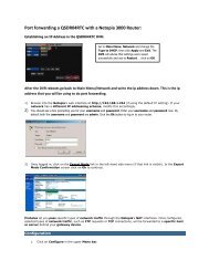
4.4 SCHEDULE CONFIGURATIONYour DVR is configured to record whenever motion is detected. If this is your desired settingthen you will not need to make any changes. However, you may configure each channel torecord at specific times based on time of day, motion detection or other sensor input. Thereare three tabs; Schedule, Motion and SensorSchedule TabThe schedule for automatic recording can be set either of two ways.1. By highlighting individual hours for specificdays by using the pencil tool in the upperright of the window. The adjacent erasertool removes the highlighting in a block.Double click on either the pencil or erasertool to turn them off. Settings can becopied and applied to any or all of thechannels and to any other day.2. Blocks of time to be recorded can alsobe set up by double clicking on a fieldadjacent to a day. Multiple schedules canbe created and saved with start and stoptimes down to the minute. These can thenbe applied to multiple days and cameras.Schedules made in one mode can be alteredin another mode.PICTURE 4-19PICTURE 4-20Motion TabMotion detected during the highlighted hours will cause the DVR to start recording. Setup issimilar to that used in Schedule above. The default mode is for 24/7.4.5 NETWORK CONFIGURATIONThe Network Configuration window is used to control how your DVR works in a networkedenvironment. This section offers a brief overview of how to set up your DVR so that it can beremotely monitored from another computer on your network, over the Internet or from mobilewireless devices. Full, in-depth instructions on the functions and settings available in thiswindow are presented in the Remote Monitoring Guide which is on the disk that came withyour system or which can be downloaded from our website at www.Q-<strong>See</strong>.com/Support.The four tabs in this window are Network, Sub-Stream, Email and Other Settings. If youwill only be monitoring the DVR from another computer on your network, you will only need touse the first three tabs.It is important that your DVR is connected to your network router and that the router ispowered on before proceeding.This window displays the information on the DVR’s local network and Internet addresseswhich will allow you to access the DVR on a network. As discussed in the Remote MonitoringGuide, you will use the local network address to access your system from the same wirelessor intranet network that the DVR is connected to. When you are outside of that area, you willuse the Internet address shown (see below) or the DDNS address that you will set up.IMPORTANT! The majority of routers available on the market since 2008 haveUniversal Plug and Play (UPnP) capability, which allows the DVR to connectautomatically to the network. Consult the Quick Networking Poster or theRemote Monitoring Guide before changing Network settings.Network TabHTTP Port – This is the port the DVR willuse to communicate through therouter. When accessing the DVRremotely from the Internet, you willneed to enter your network’s remoteIP address (obtained in the next step)in the address bar of an InternetExplorer window. For example:http://88.116.0.25NETWORKNetworkSubstreamEmailOther SettingsHTTP Port80Server Port6036Obtain an IP address automaticallyIP Address192 . 168 . 001 . 100Subnet Mask255 . 255 . 255 . 000Gateway192 . 168 . 001 . 001Preferred DNS Server000 . 000 . 000 . 000Alternate DNS Server000 . 000 . 000 . 000PPPoE<strong>User</strong> NamePasswordTestDefaultPICTURE 4-23ApplyExitPICTURE 4-21Sensor TabThis enables the DVR to record based on input from other sensors connected to the DVR. Likemotion detection, it is default scheduled to be able to record at any time. It is also configuredin the same manner as explained under Schedule.PICTURE 4-22NOTE! The default value is 80. If port 80 is already occupied by another deviceon the network, then another port will need to be selected. Choose anothernumber in the same range; 81-89. In this case, you will have to add the port tothe IP address when entering it into the Internet Explorer window. For example,if the port is now 82, then you will need to enter http://88.116.0.25:82Obtain IP Address Automatically – Clicking this box will obtain the IP address, subnet mask,and gateway IP from the router.PPPOE – Selecting this enables Point-to-Point Protocol over Ethernet (PPPoE) which allowsyou to directly connect your DVR to the Internet through your modem. Do not use thisunless you are connected to a modem instead of a router. Contact your ISP for youraccount information including user name and password. The TEST button will verifythat your information is correct.52 53
Definitions and descriptions of network configuration:Parameter DefinitionHTTP Port The network port number for accessing the DVR from a remote location.The default port is 80Server Port The port number for data. The default port is 6036Static IPIP Address The IP address of the DVR on your networkSubnet Mask The server’s subnet maskGateway The gateway of the routerDNS Server The address of the Domain Name System (DNS) serverPPPoE<strong>User</strong> Name <strong>User</strong> name of the broadband accountPassword Password for broadband accountSubstream TabThe substream is the data that is sent to remote monitoring devices. Due to bandwidthconcerns, these data streams are generally smaller than those sent directly to the DVR itself.These streams run in parallel with the main stream sent to the hard drive and they do notaffect each other.Substream settings are configured in thesame manner as that used for the primarystream settings in the Record Bitratetab in Section 4.3 Certain settings will begrayed out and cannot be changed due tothroughput concerns. The definitions arerepeated for your convenience:PICTURE 4-24Parameter Options What it MeansResolution D1, CIFD1 = Full TV resolution, CIF = 1/2 D1. D1 takes moreroom on the hard drive than CIFFPS 1-30EncodeQualityMax BitrateVBR, CBRLowest– Highest256-2084kbpsFrames per second. More frames makes for smoothervideo but takes up more room on the hard drive.Variable Bit Rate versus Constant Bit Rate. VBR providesbetter image quality for video with motion in it, but at theexpense of a larger file size.Only available when VBR is selected. The higher thequality, the more drive space required. CBR’s defaultsetting is for higher quality.This sets the maximum bitrate that each camera willrecord at with VBR encoding selected.Email TabThis tab allows you to set how your DVR will send out e-mail alerts. You will be able to sende-mail alerts to three addresses.NOTE! Depending upon your settings, the system can generate a lot of e-mailalerts. For that reason, we recommend setting up a dedicated e-mail addressspecifically for the system to send alert notices. If you do not have your owne-mail system (such as a corporate mail server) you should consider using afree e-mail provider. However, because many free e-mail services allow onlya limited amount of e-mail traffic we specifically recommend using Google’sGmail service with its higher limit. Similarly, you will want the alert e-mails to go to a differentaccount than the one sending them. This will ease your management of these alerts and helpkeep your mail account from overflowing.If you do not have your own e-mail system, please set up a free account which the DVR canuse to send out alerts before proceeding.For the example below, we will use Gmail. The settings can be found under Options whenlogged into your Gmail account.Clicking on any of the fields will bring up the virtual keyboard allowing you to enter the data.The virtual keyboard is capable of handling upper and lower case letters as well as numbersand symbols. Click the ENTER button to enter your input or ESC to exit the field withoutapplying any changes.SMTP Server: smtp.gmail.comPort: 465 (standard port for Gmail - othersmay vary)SSL Check: You will need to select this forGmail. Other ISPs may vary.Send Address: Enter your new address. Thiswill appear on alert e-mails sent fromthe DVRPassword: Enter the password you createdfor this account. Remember, it will becase-sensitive.Receive Addresses: You may set up to threee-mail addresses to receive alerts. ItPICTURE 4-25is strongly advised that you do notuse the same address that the DVR isusing to send alerts.AdvancedAttaching Image Amount: The alert e-mails can include up to three imagesSnap Time Interval: The interval of the images can range from every second to every fiveseconds.54 55
Other SettingsCommercial ISPs provide their customers with dynamic addresses (IP numbers). Thesenumbers can change from time to time depending upon your service provider. When they do,you will lose the ability to remotely access your DVR from your mobile phone or other out-ofnetworkdevice. To prevent this from happening, we recommend using a Dynamic DomainName Service (DDNS). This will give you a domain name that can be linked to your IP addressand will automatically – and invisibly – forward remote connections to your network when theIP address changes.Q-<strong>See</strong> offers DDNS for free at MyQ-<strong>See</strong>.com. Create a domain name, user name andpassword before proceeding. DynDNS.com also offers a similar free service. This is coveredin-depth in the Remote Monitoring Guide.Select the box in the DDNS field to enableDDNS. You will then enter the user name,domain name and password you created intothe appropriate fields. You can also select theinterval in days at which the DDNS checks tosee whether your IP address has changed.Intervals range from every 30 minutes to oncea day.NETWORKNetworkSubstreamEmail Other SettingsDDNSDDNS Server<strong>User</strong> NamePasswordHost DomainDDNS Update [Hours]UPnPMyQ-<strong>See</strong>.commyname@myemailaddress.commyqseeaccountpasswordmyaccount.myq-see.com3DefaultPICTURE 4-26ApplyYou can now access the DVR remotely by inputting that domain name into the web browser.TestExit4.6 USER MANAGEMENTYou can set up accounts for each individual user and grant them control of select parts ofthe surveillance system. An administrator account is already created on the DVR. Additionalaccounts can be created for users but only one administrator account is allowed.PICTURE 4-27To add a user select the Add button and the ADD USER window will open. It will have twotabs; General and AuthorityGeneral TabInput the name, password and select thetype of user – normal or advance.If you only want this user to be able to accessthe DVR from a specific computer on thenetwork then select the Binding PC MACAddress option and then enter the MACaddress of that computer.Authority TabIn this tab you can give this user access to allor part of the system and its functions.PICTURE 4-28PICTURE 4-29Setup button – Modify user’s name, type, binding PC Mac address and etc. The Adminaccount may not be modified.Delete button –Remove a user from the systemChange Password button – Modify a user’s password. The admin password may bechanged. The default is 123456.To change a password, simply click on the button and enter the current password in thepop-up window, along with the desired new password in the New Password and ConfirmPassword fields before clicking OK to save and Exit to close the window.56 57
EVENT SEARCHSelecting this tab will bring up a list of recorded events. Your DVR is configured by defaultto record when motion is detected. You can choose whether to display events triggered byMotion, Sensor or both. These files are saved as events.Select the date you wish to search and clickthe Search button. You will be presented witha list of recorded events.Select the channel and click the Double-clickthe event file you wish to play back.ImageIMAGEThis tab functions much as the Event Search tab by allowing you to search for and view thestill images captured when you click on the Snapshot icon on the Control Bar. These imagesare stored on the DVR’s hard drive just as with video files.Select the date to search, along with the start and end times to search between. You can alsoselect which channels you want to include in the search. Clicking the Search button in theupper right of the window will bring up a list of available images.SEARCHTime SearchEvent Search File ManagementImageSearchStart Time12 / 23 / 2010 2500 : 00 : 00End Time12 / 23 / 2010 2523 : 59 : 59PICTURE 4-36152 3 46 7 8FILE MANAGEMENTFrom within this tab you can lock, unlock or delete recorded events from the drive.Clicking the Search button in the upper right of the window will bring up a list of events to bedisplayed. Results can be filtered by selecting date and channels if desired.3/13DeleteLockSaveSave AllPICTURE 4-38After the search is completed, a count of available images will be displayed along with the firststill image. The buttons at the bottom of this tab allow you to navigate through the images aswell as save them for use outside the DVR.DELETE – This will remove an unwanted image from the hard drive.LOCK – This will prevent a file from being deleted. If a file is locked, this button will readUNLOCK.SAVE/SAVE ALL – These buttons allow you to save individual or all of the images in the groupto an external USB flash drive inserted in the USB port on the front of the DVR.ARROW BUTTONS – Navigate to the first, last previous or next image in the group.PICTURE 4-37LOCK – Selecting a file and then clicking the Lock button will protect the event from beingoverwritten or deleted unless the entire drive is reformattedUNLOCK – This will remove the file protection and the event recording can be deleted oroverwritten normallyDELETE – If the event is not Locked, this will remove the selected event from the DVR.NOTE! If the status shows “Writing” it means that the sector on the hard drivewhere the file is located is still being written to. You cannot delete the file untilthe file is completed and the word “Writing” disappears.60 61
BACKUP CHAPTER 5This DVR supports backing up files to USB flash drives, USB hard drives and USB DVDburners through the USB port on the front panel. Remote backups can be performed over theInternet. Refer to Section 2.4 Remote Backup in the Remote Monitoring Guide.NOTE! External USB hard drives used for backing up data will need to bein the FAT32 format. Most new drives will need to be reformatted before usewith this DVR.FORMATTING A USB DRIVE IN FAT32To format a USB flash drive with FAT32, plug it into a PC running Windows XP or later. Goto My Computer to locate the drive’s icon. Right click on it and select Format in the list ofavailable options. Select FAT32 and check the box marked Quick Format before clickingStart.For USB drives over 32GB in size, you should use a FAT32 format utility such as thoseavailable through CNET.com.BACKING UP A FILESelecting BACKUP in the Main Menu will open the Backup configuration window.The search for files to backup is much like the method used to search for files to play back aswas covered in the previous chapter.Save File Type: Choose between DVR and AVI. The former will save the video in aproprietary format while the latter will create a standard .avi file usable by most mediaplayback software. If you choose the DVR format, you need to select the Backup Playeroption (see Picture 5-2) as well. This will save a stand-alone playback program in a separatefolder labeled Video Play on the same drive.Clicking on the Start button will begin the backup and the progress bar will display theprogress.PLAYING BACK A VIDEO FILE ON A COMPUTERWindows PC - You may play AVI formatted files using Windows Media Player, QuickTime,DIVXplayer or other media players. The files can be opened and played in a similar mannerto any other media file. You may need to download and install the K-Lite Codec as describedabove.The Superplay.msi program is a PC-only application and is saved onto the same drive asvideo files when the Backup Player option is selected. Launch the software in the normalmanner and then click on Open Path and navigate to the folder containing the video files andselect the file you wish to play back.Apple Macintosh - At this time, you must use the Remote Backup feature to save thefile to your computer through the remote viewing software. <strong>See</strong> section 2.4 of the RemoteMonitoring Guide for instructions on this process.You MUST select the AVI format when backing up the video file for playback on a Maccomputer. You can use the QuickTime player or other video player and open the video file inthe normal manner.Set the start and end times as well aschannel(s) you wish to back up. Clicking theSearch button will bring up the search resultsin the Data Backup list box.PICTURE 5-1Select specific events or select the All button. Clicking the Backup button will bring up theBackup Information window:This window will present a summary of thenumber of files, starting and ending times,total size of the files and whether you havespace available on the receiving storagemedia. Disk Cleanup will erase the contentsof the storage media to make room. You canselect which type of device you are recordingto as well as what type of file you will becreating.BACKUP INFORMATIONStart TimeEnd TimeThe Number of FilesSize [GB]Storage MediaFree [GB]Backup PlayerSave File Type0%Disk Cleanup08/19/2011 01:24:1208/19/2011 01:29:361.258USB-10.946AVIPICTURE 5-2StartCancel62 63
DVR MANAGEMENT CHAPTER 66.1 INFORMATIONEVENT INFORMATIONThis window lists recorded events. This list can be searched by date, time, type of event andchannel.PICTURE 6-1This window enables the user to monitor the status of the system, its network connection,online users, history and events through five submenus: System, Event, Log, Network andOnline <strong>User</strong>s.LOG INFORMATIONThis window lists user activity within the system.PICTURE 6-4INFORMATIONSystemEventLogNetworkOnline <strong>User</strong>sRecordExitPICTURE 6-5This record can be searched by type of operation, date and time, and etcetera. It can also beexported to external USB storage devices using the backup function.PICTURE 6-2NETWORK INFORMATIONThis window shows the status of the DVR on the network including its assigned port, andother networking configurations.SYSTEM INFORMATIONData on the system’s hardware, MCU (MicroController Unit), kernel (if applicable) and firmwareversions can be found here along with the device’s name and ID.PICTURE 6-6PICTURE 6-364 65
ONLINE USER INFORMATIONInformation on remote users currently connected is displayed in this window.6.2 MANUAL ALARMThis displays the configuration of the manual alarm. <strong>See</strong> Chapter 8 for information onconnecting and setting up alarms.PICTURE 6-7Refresh – Updates the list of online usersDisconnect – The Administrator can disconnect a selected user from the DVR. That PC willnot be able to access the device for five minutes thereafter.RECORD INFORMATIONThis window provides information on your camera’s recording resolution, the recording speedand what mode the camera is operating in. At the bottom is a bar indicating the percentage ofthe hard drive’s capacity that has been used.PICTURE 6-96.3 DISK MANAGEMENTThis window displays information on the drive or drives mounted within the DVR including size,available space and status.RECORDCH Resolution fps Sensor Motion <strong>Manual</strong> Schedule1 D1 302 D1 303 D1 C1 304 D1 305 D1 306 D1 307 CIF 308 CIF 30DiskIDStatusPICTURE 6-8119%PICTURE 6-10The drive can be set to read only, which will disable recording, but will preserve the datacurrently stored within it.If you have upgraded your system by installing a new drive (<strong>See</strong> Chapter 9) you will need tofirst format the new hard disk before recording. You can reformat the current drive if desired byselecting the Format option in the drop down menu.WARNING! Reformatting the drive will delete all recorded files stored on thehard disk regardless of whether they are Locked!Refresh will update the information about the drive.66 67
6.4 UPGRADEThis window will display firmware updates that are loaded on a USB flash drive in the frontUSB port.6.5 LOGOFFLogging out of the DVR is recommended when there are multiple users or when physicalaccess to the DVR is not restricted. Clicking on the Logoff icon will bring up a window askingfor confirmation.After logging off, a user can log back in by clicking on the Menu icon and entering their username and password.6.6 SHUT DOWNThis is a “soft power down” of the DVR. It shuts down the firmware and hard drive, but doesnot power down the DVR itself.PICTURE 6-11Firmware upgrades are available from Q-<strong>See</strong> at www.Q-<strong>See</strong>.com/Support and may befound by looking up your specific model. Firmware should only be upgraded to fix a specificproblem or add features as ongoing development may result in features being removed.The firmware download should be loaded onto an empty USB flash drive from thedownloading computer and then transferred to the DVR using a USB port.WARNING! It is vital that the DVR be instructed to shut down using the ShutDown menu option prior to unplugging the device in order to avoid damagingthe firmware or hard drive itself.IMPORTANT! Please make note of your settings before updating thefirmware on a QT426 or QT446 as the upgrade process will restore factorydefaults. Other models will retain their user settings.NOTE! While a Macintosh computer can read and write to a drive in theFAT32 format, it cannot reformat a USB flash drive to that standard. Wesuggest that you use a PC to reformat your USB flash drive to FAT32 and it isrecommended that you download firmware updates on a PC. Beginning withversion 3.1.71, you can use the Upgrade feature in the Remote Monitoringsoftware (see Section 2.5 of the Remote Monitoring Guide) to upgradewithout a USB flash drive.WARNING! Updating the firmware incorrectly or using the wrong updatecan permanently damage the chipset on the DVR and render it unusable.Updates are written to either resolve issues or add features to the DVR. If youare not experiencing performance issues or do not need a feature added bythe update, we recommend not running the update.68 69
PAN/TILT/ZOOM CAMERAS CHAPTER 77.1 CONNECTING A PTZ CAMERAAll QT-Series DVRs can support one or more Pan/Tilt/Zoom, or PTZ cameras. These camerasconnect to the DVR through the same ports as a conventional camera, but the control wiresconnect through the RS485 block on the back of the DVR. Picture 7-1, below, is onlya representation and your actual connector may look different. Please consult Chapter 2Connections and Controls to find the diagram representing your model for the location ofyour connector block.The RS485 connector uses a single-direction protocol meaning that it can send commandsout to the camera(s) but not receive any data back from the unit meaning that video imageswill be delivered through the video cable as with any other camera.The DVR is set by default for RS485 to be disabled for each channel. Therefore, PTZ settingsmust be enabled before PTZ cameras can be utilized. This system supports 26 of the mostcommon protocols including Pelco-D and Pelco-P.When connecting a PTZ camera, the following should be taken into account:• The 485 port of this DVR cannot parallel connect with the 485 port of another device• The voltage between the A and B lines of the camera should be less than 5V.STEP 1. The data cable from the PTZcamera must be connected tothe ports highlighted in Picture7-1. Multiple PTZ cameras can beconnected to this port, but you mayrequire an expander port to do so.STEP 2. Connect the other end ofthe cable to the proper pins in theconnector on the cameraSTEP 3. Connect the camera video andpower cables as you would any othercamera.1NO C2NO CCNTRL12VA1 2 3 4 5 6 7 8PICTURE 7-1RS-485B7.2 PAN-TILT-ZOOM (PTZ) CONFIGURATIONIf you are connecting optional Pan-Tilt-Zoom cameras, the controls are set from this window inthe Serial Port and Advanced tabs.Serial Port TabSerial PortAdvancedCH Enable Address Baud Rate Protocol Simulative CruiseYou will need to consult your PTZ camera’s112400PELCOD229600PELCOPmanual for details regarding protocol and339600PELCOPbaud rate. Please note that the DVR may449600PELCOPsupport more features than your cameraAlloffers including protocol and number of9600 PELCOPpreset programs.DefaultApplyExitPICTURE 7-2Cameras can be individually configured or a global set-up can be implemented through the Allbutton.Simulative Cruise is for use with PTZ cameras using an unsupported protocol to allow you touse at least some of the features.PTZ Definitions and Descriptions:Parameter Settings What it MeansAddress 1-255 The address of the PTZ cameraBaud Rate 110-21600 The speed that data is transmittedProtocolThe communication protocol used by the camera.Supported protocols are; NULL, PELCOP, PELCOD, LILIN,MINKING, NEON, STAR, VIDO, DSCP, VISCA, SAMSUNG,RM110, HYAdvanced TabYou can set your camera to follow a presetprogram or set cruising or tracking behaviorsby selecting the Setting button in the Preset,Cruise or Track columns respectively.P.T.ZPICTURE 7-370 71
PresetClicking a Setting button in the Presetcolumn will bring up another windowName Symbol What it DoesAddOpens a window to allow the user to set the speed and time of a newpreset pointDeleteDeletes a preset pointModifyArrowsOpens the settings window for the selected preset point allowing youto change the settingsEnables the user to alter the position of a setting in the cruise order.Move a preset point all the way to the top of the orderPICTURE 7-4Move a preset point up one position in the listAnd, selecting Setting will bring up thecamera view along with a control panel toprogram the camera’s motion.PICTURE 7-5The dome’s rotation can be controlled vertically, horizontally and diagonally along with itsspeed. The lens zoom, focus and iris (light level) can be set as well. Select the number youwant to assign to this set of actions and click the Save button to save your preset. You canhide the control panel by clicking on the “-” button or right-clicking on the screen. The controlpanel can be unhidden by right-clicking on the screen again. The X button will exit the controlinterface.CruiseSelecting a Setting button from the Cruise column will open the Cruise window.Move a preset point down one position in the listMove a preset point to the bottom of the orderTrackThis interface is used to program the tracking routine for the camera. Clicking on the Trackbutton will bring up the live view for that camera plus a control panel:PICTURE 7-8The user can control the dome’s rotation direction, plus speed as well as the zoom, focus andiris.Select Add or double-click on an existing lineto modify and the CRUISE PRESET windowwill open.Delete will remove a selected cruise lineClear All will remove all of the cruise lines.Start Record – The system will begin recording the sequence of movements you perform onthe PTZ control panel. Clicking this again will stop the recording.Start Track – This will play back the tracking sequence you just recorded. Clicking on thisbutton again will stop the playback.PICTURE 7-6The set of icons to the right of the screen areused to configure each cruise setting.Preview – Preview the cruise to ensure thatyou have the desired results.PICTURE 7-772 73
ALARMS CHAPTER 8Many QT Series DVRs feature connections for external alarms – both input and output. Pleaseconsult Chapter 2 Connections and Controls to determine whether your model includesthis feature and where the connection block is located. The alarm connector block shown inPicture 8-1 is only a representation and your actual connector may look different.When an event is detected the system can notify local users or send notification to amonitoring service. At the same time, the system can accept signals from motion detectors,smoke detectors or other alarms and begin recording based on that input and your settings.You will need to have the manual for your alarm(s) handy to ensure the proper settings withinthe DVR.8.1 ALARM INPUTWhen attaching alarms, the following criteriamust be met:1. The alarm input must be grounded.2. A grounding signal is required for thealarm input3. When connecting the DVR to anotherdevice - including another DVR - throughthe alarm input, a relay should be used toseparate them.1NO CALARM IN2NO CCNTRL12V1 2 3 4 5 6 7 8PICTURE 8-1ABThe accompanying diagram (Picture 8-2), along with your alarm’s manual should beconsulted to ensure proper connection.• Normal open or Normal close type• Parallel connect COM end and GND end of the alarm detector (Provide external power tothe alarm detector).• Parallel connect the Ground of the combo DVR and the ground of the alarm detector.• Connect the NC port of the alarm sensor to the combo DVR alarm input(ALARM)• Use the same ground with that of combo DVR if you use external power to the alarm device.Alarm input public end should jump out with device power end.Alarm Device Connection Terminal+12V GND COM PC+12V GNDPICTURE 8-2Alarm DeviceConnection TerminalALARMGNDParameterAlarm Input1-NO C2-NO CCTRL 12VGrounding AlarmGround line1, 2, …, 8 becomes valid in low voltage.Two NO activation outputs.Controls the power outputYou need to close the device power tocancel the alarm.74 75
8.2 ALARM OUTPUTThe alarm output port should not be directly connected to a higher power load (greater than1A) to avoid high current which may damage the relay. Use the co-contactor to establish theconnection between the alarm output port and the load.• 2 way relay alarm output (NO contact). Provides external power to external alarm device.• To avoid overloading, please read the following relay parameters sheet carefully.• RS485 A/B cable is for the A/B cable of the PTZ camera(s).Model:Material of the contactJRC-27FSilverRelay SpecificationRating (Resistance Load) Rated switch capacity 30VDC 2A, 125VAC 1AMaximum switch powerMaximum switch voltageMaximum switch currency125VA 160W250VAC, 220VDCInsulation Between contacts with same polarity 1000VAC 1minuteBetween contacts with different 1000VAC 1minutepolarityBetween contacts and winding 1000VAC 1minuteSurge voltage Between contacts with same polarity 1500V (10×160us)Length of open time 3ms maxLength of close time 3ms maxLongevity Mechanical 50×106 times (3Hz)Electrical200×103 times (0.5Hz)Temperature-40°C ~+70°C (-40°F to +158°F)1A8.3 ALARM CONFIGURATIONAlarm configuration allows the DVR to begin recording based on input from other remotesensors such as infrared motion detectors or contact alarms which are connected to it.There are five submenus; Sensor, Motion, Video Loss, Other, and Alarm Out.SENSORIn this window you can setup optional external sensors to cause the DVR to begin recording.There are three tabs in this window: Basic, Alarm Handling and Schedule.Basic TabThis allows you to enable the input fromattached sensors. You can also identify thesensors by name for ease in determininglocation.Set the alarm type according to whether thealarm is NO (Normally Open) or NC (NormallyClosed). <strong>See</strong> your alarm’s manual for details.Alarms can be individually configured orglobally set using the All button.Alarm Handling TabConfigure how you want the DVR to handlethe input from an activated alarm. Eachsensor input can be set to launch individualsequences of action or they may be globallyset through the All button to have the sameresults.Hold Time: determines the time allowedbetween consecutive alarm events.If the alarm is triggered again withinthis time, it will be treated as a singleevent and the DVR will continuerecording before stopping.Trigger: This is what the DVR will do onceactivated by an alarm. SelectingSetting will open a new window withthree tabs; Alarm, To Record, ToPTZAlarm allows you to set whether abuzzer will sound, which camera (ifany) will display in full screen mode,whether an e-mail will be sent andwhether a signal will be sent via theALARM OUT port.PICTURE 8-3PICTURE 8-4PICTURE 8-576 77
To Record allows you to determine which cameras will begin recording. Cameras canbe set to record individually, in blocks, or all cameras can be activated.To PTZ activates preset, cruise or track functions on selected Pan-Tilt-Zoomcameras. Depending on your model of PTZ camera, one of up to 128 pre-set actionscan be engaged. Check your camera’s manual for details.Schedule TabSet by default to always on, the schedule can be altered in the same manner as that used inSchedule in SECTION 4.4.Test your settings by moving somethingor someone through the grid area in thecamera’s view. Motion should not be detectedoutside of this area but you should see ayellow humanoid figure appear in the screenonce the DVR detects movement within thegrid. Removing the grid where there is a flagor trees that frequently move in the wind willprevent false alerts. Click on the Disk buttonto save your settings before exiting the setupprocess by clicking on the X button.Sensitivity: 6PICTURE 8-9PICTURE 8-6MOTIONMotion TabAs with the Alarm function above, it incorporates hold time and can trigger procedures.Select which cameras you wish to start recording on motion detection. Set the holding timewhich determines the length of time the cameras continue recording after motion stops.In the Trigger setting, you can set multiplechannels to record when motion is detectedby a camera that has been set to activateupon motion detection.For example: If Camera 1 detects motion,you can have it trigger Cameras 2 and 3 tobegin recording as well.PICTURE 8-7In addition, the user can set the sensitivity of certain areas within the field of view by clickingon the Select button selecting the Area field for the respective camera.Specific areas can be made sensitive byapplying a blue grid to the desired section ofthe screen. The blue grid can be applied tothe entire screen – signifying that the entirefield of view is sensitive - by clicking onthe star button. The trash can button willremove the grid completely. Click and dragwith the mouse on the screen to draw orerase the grid in select areas.Sensitivity: 6PICTURE 8-8As sensitivity is influenced by color and light level, you can adjust its values according to yourspecific conditions. The default value is “4.” A setting of “8” is most sensitive while a setting of“1” is minimally sensitive.Right-clicking in the screen will show or hide the control menu at the bottom of the screen.Schedule TabThis is also set to be on all the time by default and it can be adjusted in the same manner asthe Schedule configuration in SECTION 4.4.PICTURE 8-10VIDEO LOSSIn the event that signal is lost by one camera, others can be activated to record whileadditional devices can also be triggered.Like the Trigger tab in the Alarm Handlingsection of the Sensor menu, you can selectthe events that you wish to occur in theevent that a video input is lost. Both Alarmsand PTZ events can be scheduled as in theSensor menu above.PICTURE 8-11OTHER ALARMIn this menu you can set the DVR to alert you to a full Hard Drive, IP Conflict on the network ora Disconnection.You can set the response as well as at whatthreshold of remaining disk space you wish tobe alerted.PICTURE 8-1278 79
NOSVALARM OUTSet how the alarms are handled and transmitted in this window. This controls any deviceattached to the ALARM OUT port on the back of the DVR. There are three tabs; Alarm Out,Schedule and Buzzer.Alarm Out TabYou can set the relay alarm out name as well as the hold time. Hold time is the intervalbetween consecutive alarm activations so multiple events within the interval will not cause thealarm to sound again.PICTURE 8-13Schedule TabThe default setting is for the ALARM OUT to be active all the time, but this can be changedto meet your particular requirements in a similar manner to Schedule in SECTION 4.4.Buzzer TabAs with the Alarm Out hold time, the internal buzzer can be enabled and given a hold time.HARD DISK DRIVE CHAPTER 9Your DVR uses a standard desktop or 3.5” SATA (Serial Advanced Technology Attachment)hard disk drive and will support drives up to 2TB (terabytes). These drives are the currentindustry standard and may be purchased wherever computer parts are sold. Depending onwhere you purchased your DVR, your hard drive may already be installed. But, we recognizethat you may wish to upgrade or replace your drive in the future so this DVR is designed tomake installation and replacement easy for the average user. A 5400RPM drive will work but a7200RPM drive is recommended for optimal performance.It should be noted that while this is the only user-serviceable part within the case besides thebattery and you will not void your warranty by installing or upgrading your hard disk drive, caremust be taken to avoid damage to the other components within the case. Such damage willnot be covered.WARNING! ELECTRIC SHOCK RISK!The DVR MUST be unplugged from all power sources as well as fromthe cameras before opening the case. Failure to do so can result indamage to the DVR or its components as well as injury or death.9.1 INSTALLATION/REMOVALIt is strongly advised against opening the case when atmospheric conditions present the riskof static discharge which can damage electronic components.Whether installing the drive for the first time or removing the old one to install a new one, thesteps are largely the same:STEP 1. Disconnect the DVR from the power source as well as any other connections.STEP 2. Remove screws (the number will vary depending on your model) from the sideand rear of your DVR as indicated in Picture 9-1Remove ScrewsALARM OUT1 2 3 4RS485P/Z K/BALARM INY Z A B 1 3 5 7 9 11 13 15 NETVIDEO OUT1 3 5 7 9 11 13 15DC 12VGNDCOM2 4 6 8 10 12 14 16ALARM OUTSTEP 3. Remove the case by sliding itbackwards and then lifting off.STEP 3A. If removing a hard drive, youwill need to unscrew the four drivemounting screws at the bottom of theDVR or on the internal mounting rack.USBVGASPOT2 4 6 8 10 12 14 16VIDEO INPICTURE 9-1Holes forHard Disk DriveMounting ScrewsPICTURE 9-280 81
STEP 4. Connect the power and datacables. Press firmly, but do notforce them onto the pins or you maydamage them. The connectors are“keyed” to ensure they are connectedin the proper position.STEP 5. Attach hard drive to the base ofthe DVR with screws using the fourmounting holes.HARD DRIVE9.2 CALCULATING THE RECORDING CAPACITY OF AHARD DISK DRIVEWhile the physical data capacity of a hard drive is fixed, how much video you can record uponit depends on your recording configurations. Higher quality recordings will take up more spaceon the drive and setting the DVR to record for more frequently will fill it up more rapidly.To determine the optimal capacity for your purposes, the chart below to estimate the size ofhard drive that you’ll need.VIDEOFORMATRESOLUTIONFRAMERATE(FPS)VIDEOQUALITYBITRATE(kbps)SPACEUSED(MB/h)STEP 6. Replace the DVR cover andsecure.MOUNTING HOLESFOR HARD DRIVEDATACABLEPICTURE 9-3POWERCABLENTSC CIF 30 Highest 1000k 465Higher 768k 297Medium 512k 230Low 384k 173Lower 256k 115Lowest 128k 56D1 7.5 Highest 500k 228Higher 375k 128Medium 250k 117Lower 192k 75Lowest 128k 61PAL CIF 25 Highest 1000k 466Higher 768k 295Medium 512k 235Low 384k 175Lower 256k 112Lowest 128k 56.4D1 7.5 Highest 500k 228Higher 375k 128Medium 250k 117Lower 192k 75Lowest 128k 61The formula for calculating the required disk space is:Total Recording Capacity = Used space per hour (MB/h) x Recording time (hour) xnumber of channelsExample: A customer is using the NTSC format (30 frames per second), CIF resolutionwith video quality set to Lowest and a total of 16 Channels. He wants the unit to recordcontinuously for a month. Therefore, the calculation will look like this:56(MB/h), x 24 (hours/day) x 30 (days) x 16 (channels) = 645,120MB or 650GBInstalling a 750GB SATA hard drive should provide enough space for one month’s continuousrecording time at those settings.82 83
APPENDIXA.1 TROUBLESHOOTING1. The DVR does not start after connecting the power, what is wrong?a. The power adapter may have been damaged, or is not providing enough power. Pleasechange the adapter.b. The DVR may not be getting enough power from the outlet or surge protector it isattached to.c. There could be a problem with the system board on the DVR2. The indicator lights of the DVR are on, but no output. Why?a. The power adapter may have been damaged, or is not providing enough power. Pleasechange the adapterb. The video format of the DVR is different from that of the monitor.c. Connection problem. Please check the cable and the ports of the monitor and DVR.3. Why are no images displayed on some or all of the channels of the DVR?a. Connection problem. Please check the cables and the ports of camera and DVR.b. Camera problem. Please check the cameras by attaching them directly to TV or workingport on DVR.c. The video format (NTSC/PAL) of the DVR is different from that of the cameras. Pleasechange DVR video format.4. The DVR cannot find the hard disk drive.a. The power adapter is not providing enough power, or the adapter is not getting enoughpower from the outletb. Connection problem. Please check the power and data cables on the HDD.c. The HDD is damaged and will need to be replaced.5. I cannot record, what could be the problem?a. The HDD is not formatted. Please format it manually first.b. The record function is not enabled or setup correctly. Please refer to Section 4.3Record Configuration.c. The HDD is full and recycle function is not enabled. Please refer to Section 4.3 RecordConfiguration and the Recycle Record Tab in the Record Menu.d. The HDD is damaged and will need to be replaced.6. I cannot use the mouse, what could be the problem?a. Wait 5 minutes after connecting the mouse and then try again.b. The mouse is not securely connected. Plug/unplug several times.c. The mouse is incompatible with the system. Please try another mouse.7 What can I do when the DVR starts and displays “please wait……”all the time?a. First possible reason: hard drive power cable and/or data cable are not securelyconnected.Solution: Please check the cable connections and make sure they are secure; if still notworking, please unplug them and then plug them in again.b. Second possible reason: The system is having problems reading the hard drive.Solution: Try reformatting the current drive or re-placing it.c. Solution: Try connecting the DVR to a different surge protector and power outlet.8. How do I input letters and numbers?To input letters (such as passwords) andnumbers click the box behind wheretext is to be entered, and then a smallkeyboard will appear. Please selectnumber or letter to input (the defaultpassword is 123456), or you can usethe digital keys on the front panel, or thedigital keys on the remote control.PICTURE A-19. How do I upgrade the firmware on the DVR?After you download the new firmware from the Q-<strong>See</strong> website at www.Q-<strong>See</strong>.com/Support and copy it onto a USB flash drive. Then select Upgrade in the menu.WARNING! Do not turn the system power off during the upgrade process!Doing so may damage the chipset and prevent the DVR from starting.10. I can get a live image on the display but I can’t get the menu to display. How can Ipull up the menu?Hold down the ESC key to wait for login dialog box to appear.11. I hooked the DVR up to a TV through the BNC video out port and I do not seeanything on the screen. How do I get the video to display?By default the DVR is setup to use a VGA monitor, if you want to use a TV instead thenpush the ESC button on the front panel and hold it until you hear a beep, if you still donot get a display then hold the ESC button down again until you hear a beep, the displayshould come up.12. What is the minimum configuration of a PC for remote connection?COMPONENT MINIMUM REQUIREDCPU Intel Celeron 2.4GMOTHERBOARD Intel 845HDD80GRAM1GBVGA512MB Video RAMNVIDIA GeForce MX440/FX5200ATIRADEON 7500/X300OSWindows XP(SP2 above) /VISTA/Win7DIRECTX 9.084 85
13. What are the PC configurations for 16-channel real time access with fully openmainstream channel?PC MODULEPARAMETERSCPUIntel Core(TM)2 Duo CPU E4600MOTHERBOARDG41/P41 chipHDD80GRAM1GBVGA GMA3100/NVIDIA GeForce 8400/ATI RADEON HD3450, 512MB Video RAMOSWindows XP(SP2 above)/ VISTA/Win7,DIRECTX 9.014. On Vista and Win7 I am getting an error message that Codec can’t be installed or ismissing, how do I solve that?There are two ways to fix it:a. In Windows, go to your Control Panel select <strong>User</strong> Account and Family Safety andthen choose <strong>User</strong> Account Control.Click Turn <strong>User</strong> Account On or Off. Uncheck the box next to Use <strong>User</strong> AccountControl (UAC) to help protect your computer.b. Right-click on an Internet Explorerbrowser window. Select Run asAdministrator to run browser.PICTURE A-2A.2 SPECIFICATIONSParameter QT454 QT426 QT428COMPRESSION CompressionFormatStandard H.264 BaselineVIDEO Video In Composite 1.0Vp-p/75Ω,BNC x 4Composite 1.0Vp-p/75Ω,BNC x 16Composite 1.0Vp-p/75Ω,BNC x 8Video Out COMPOSITE 1.0V p-p/75Ω, BNC x 2, VGA x 1VGA Resolution 1280x1024, 1024x768, 800x600RecordResolutionNTSC: 352x240, 704x480PAL: 352x288, 704x576Display Frame 704x480 at 30FPSRate(per camera)Record FrameRateNTSC: D1 7.5FPS CIF 30FPSPAL: D1 6.25FPS CIF 25FPS(per camera)AUDIO Audio Input -8dB~ 22k, RCA X4Audio Output -8dB~92dB, RCA X1ALARM Alarm Input NO or NC 4CH NO or NC NO or NC 8CH16CHAlarm Output 1CHSTORAGE Record Mode <strong>Manual</strong>/Sensor/Timer/Motion DetectionMulti-Function MultiplexINTERFACE Network RJ45 (LAN, Internet)InterfaceCommunicationInterfaceRS485,USB 2.0 x 2 (One for Backup, One for USB Mouse)CONTROLS PTZ Control YesRemote Control YesDISK INFO Disk Type SATA x 1 (up to 2TB)OTHER INFO Voltage 12V3A 12V4A 12V4AOptimalTemperaturePowerConsumption50°F to 104°F 10°C to 40°C10% to 90% Humidity10W 20W 10WPICTURE A-386 87
Parameter QT474 QT446 QT4332COMPRESSION CompressionFormatStandard H.264 BaselineVIDEO Video In Composite 1.0Vp-p/75Ω,BNC x 4/Video OutCOMPOSITE1.0V p-p/75Ω,BNC x 1, VGAx 1Composite 1.0Vp-p/75Ω,BNC x 16/75Ω,BNC x 8COMPOSITE1.0V p-p/75Ω,BNC x 1, VGA x1 Loop Out x 2Composite 1.0Vp-p/75Ω,BNC x 32COMPOSITE1.0V p-p/75Ω,BNC x 1, VGA x1, HDMI x 1VGA Resolution 1280x1024, 1024x768, 800x600 1920x10801280x1024,1024x768,800x600RecordResolutionDisplay FrameRate(per camera)Record FrameRate(per camera)NTSC: 352x240, 704x480PAL: 352x288, 704x576704x480 at 30FPSAUDIO Audio Input -8dB~ 22k,RCA X2Audio Output -8dB~92dB,BNC X1NTSC: D1 7.5FPS CIF 30FPSPAL: D1 6.25FPS CIF 25FPS-8dB~ 22k,RCA X16-8dB~92dB,RCA X1NTSC: D1 7.5FPSCIF 30FPS4CH D1 30FPS ifothers CIFPAL: D1 6.25FPSCIF 25FPS-8dB~ 22k,RCA X16-8dB~92dB,RCA X1ALARM Alarm Input 0 NO or NC 16CH NO or NC 16CHAlarm Output 0 1CH 4CHSTORAGE Record Mode <strong>Manual</strong>/Sensor/Timer/Motion DetectionMulti-Function MultiplexINTERFACE NetworkInterfaceRJ45 (LAN, Internet)CommunicationInterfaceRS485,USB 2.0 x 2(One forBackup, One forUSB Mouse)eSATA x2 RS485,USB 2.0 x 2(One for Backup, One for USBMouse)CONTROLS PTZ Control YesRemote Control YesDISK INFO Disk Type SATA x 1 (up to2TB)SATA x 4 (up to2TB each)SATA x 4 (up to2TB each)OTHER INFO Voltage 12V3A 110/220OptimalTemperaturePowerConsumption50°F to 104°F 10°C to 40°C10% to 90% Humidity10W 22W 42WParameterCOMPRESSIONCompressionFormatQT4532Standard H.264 BaselineVIDEO Video In Composite 1.0Vp-p/75Ω,BNC x 32Video Out COMPOSITE1.0V p-p/75Ω,BNC x 1, VGA x1, HDMI x 1VGA Resolution 1920x10801280x1024,1024x768,800x600RecordResolutionDisplay FrameRate(per camera)Record FrameRate(per camera)NTSC: 352x240, 704x480PAL: 352x288, 704x576704x480 at 30FPSNTSC: D17.5FPS CIF30FPS4CH D1 30FPS ifothers CIFPAL: D1 6.25FPSCIF 25FPSAUDIO Audio Input -8dB~ 22k,RCA X16Audio Output -8dB~92dB,RCA X1ALARM Alarm Input NO or NC 16CHAlarm Output 4CHSTORAGE Record Mode <strong>Manual</strong>/Sensor/Timer/Motion DetectionMulti-Function MultiplexINTERFACE NetworkInterfaceRJ45 (LAN, Internet)CommunicationInterfaceeSATA x2RS485,USB 2.0 x 2(One forBackup, One forUSB Mouse)CONTROLS PTZ Control YesRemote Control YesDISK INFO Disk Type SATA x 8 (up to2TB each)OTHER INFO Voltage 110/220OptimalTemperaturePowerConsumption50°F to 104°F 10°C to 40°C10% to 90% Humidity42W88 89
Parameter QT528 QT526 QT504COMPRESSION CompressionFormatStandard H.264 BaselineVIDEO Video In Composite 1.0Vp-p/75Ω,BNC x 8Composite 1.0Vp-p/75Ω,BNC x 16Composite1.0V p-p/75Ω,BNC x 4Video Out COMPOSITE 1.0V p-p/75Ω, BNC x 2, VGA x 1VGA Resolution 1280x1024, 1024x768, 800x600RecordResolutionNTSC: 352x240, 704x480PAL: 352x288, 704x576Display Frame 704x480 at 30FPSRate(per camera)Record FrameRateNTSC: D1 30FPS CIF 30FPSPAL: D1 25FPS CIF 25FPS(per camera)AUDIO Audio Input -8dB~ 22k, RCA X4Audio Output -8dB~92dB, RCA X1ALARM Alarm Input NO or NC 8CH NO or NC NO or NC 4CH16CHAlarm Output 1CHFUNCTION Record Mode <strong>Manual</strong>/Sensor/Timer/Motion DetectionMulti-Function Simultaneously Record, View Live or Recorded Video,Playback, Back-up files, Monitor RemotelyINTERFACE Network RJ45 (LAN, Internet)InterfaceCommunicationInterfaceRS485,USB 2.0 x 2 (One for Backup, One for USB Mouse)CONTROLS PTZ Control YesRemote Control YesDISK INFO Disk Type SATA x 2 (up to 2TB each) SATA x 1 (up to2TB)OTHER INFO Voltage 12V4A 12V5A 12V3AOptimalTemperatureAverage PowerConsumption32°F to 122°F 10°C to 50°C10% to 90% Humidity18W 30W 10WParameter QT518 QT5116 QT536COMPRESSION CompressionFormatStandard H.264 BaselineVIDEO Video In Composite 1.0Vp-p/75Ω,BNC x 8Video Out COMPOSITE1.0V p-p/75Ω,BNC x 2, VGAx 1, HDMI,Loopout x 8VGA ResolutionRecordResolutionDisplay FrameRate(per camera)Record FrameRate(per camera)AUDIO Audio Input -8dB~ 22k,RCA X8Composite 1.0Vp-p/75Ω,BNC x 16COMPOSITE1.0V p-p/75Ω,BNC x 2, VGA x1, HDMI,1920x1080, 1280x1024, 1024x768, 800x600NTSC: 352x240, 704x480PAL: 352x288, 704x576704x480 at 30FPSNTSC: D1 30FPS CIF 30FPSPAL: D1 25FPS CIF 25FPS-8dB~ 22k, RCAX16Composite 1.0Vp-p/75Ω,BNC x 16COMPOSITE1.0V p-p/75Ω,BNC x 2, VGAx 1, HDMI,Loopout x 16-8dB~ 22k,RCA X16Audio Output -8dB~92dB, RCA X4 -8dB~92dB,RCA X1ALARM Alarm Input NO or NC 8CH NO or NC 16CH NO or NC 16CHAlarm Output 4CH 4CH 1CHFUNCTION Record Mode <strong>Manual</strong>/Sensor/Timer/Motion DetectionMulti-Function Simultaneously Record, View Live or Recorded Video,Playback, Back-up files, Monitor RemotelyINTERFACE NetworkInterfaceRJ45 (LAN, Internet)CommunicationInterfaceRS485, eSATA, MicrophoneUSB 2.0 x 2 (One for Backup, Onefor USB Mouse)RS485, eSATAx 2, MicrophoneUSB 2.0 x2 (One forBackup, One forUSB Mouse)CONTROLS PTZ Control YesRemote Control YesDISK INFO Disk Type SATA x 3 (up to 2TB each) SATA x 8 (up to2TB each)OTHER INFO Voltage 110/230VOptimalTemperatureAverage PowerConsumption50°F to 104°F 10°C to 40°C10% to 90% Humidity22W 36W 50W90 91
A.3 RACK MOUNTINGThe QT446, QT4332, QT4532, QT518, QT5116 and QT536 all use 2U cases and includebrackets and screws allowing them to be secured in a standard server rack or server cabinet.These DVRs are designed for horizontal mounting only.The DVR must rest on a shelf sufficient to hold its weight. The included mounting brackets areonly intended to keep the system from shifting and they are not sufficient to suspend the DVRalone. You will also need to provide bolts to attach the brackets to the rack.Two mounting brackets and four screwsare contained in the accessory box thataccompanied your DVR. Some brackets willhave three holes but only two screws arerequired to mount the bracket to the DVR.The flanges to secure the DVR to the rackshould be towards the front.Q-SEE PRODUCT WARRANTYQ-<strong>See</strong> is proud to back all of our products with a conditional service warranty covering allhardware for 12 months from the date of purchase. Additionally, our products also come witha free exchange policy that covers all manufacturing defects for one month from the date ofpurchase. Permanent upgrading service is provided for the software.Liability Exclusions:Any product malfunction or abnormalities in operation or damage caused by the followingreasons are not within the free service scope of our company:1. Equipment damage caused by improper operation.2. Improper equipment operation environment and conditions (e.g., improper power,extreme environmental temperatures, humidity, lightning and sudden surges ofelectricity).3. Damage caused by acts of nature (e.g., earthquake, fire, etc).4. Equipment damage caused by the maintenance of personnel not authorized by Q-<strong>See</strong>.5. Product sold over 12 months ago.In order to fulfill the terms of your warranty, you must complete the registration process afterpurchasing our product. To do this, simply fill out the <strong>User</strong>’s Information Card on our websiteat www.Q-<strong>See</strong>.comThe DVR must have sufficient support wheninstalled. The brackets are only to keep theDVR from moving. Ensure that all four holeson the two mounting brackets line up withholes in the rack.If you will have limited access to the backof the DVR, it is best to make sure that allcamera and other cable connections on theback of the DVR are secure before boltingthe brackets to the rack.92 93
QUESTIONS OR COMMENTS? CONTACT USPRODUCT SUPPORT, DOWNLOADS,FIRMWARE UPDATES & MANUALS24/7 Technical ResourcesLive Chat (M-F, 9-5 PST)www.Q-<strong>See</strong>.com/SupportDigital Peripheral Solutions, Inc.8015 E. Crystal DriveAnaheim, CA 9280794 95