Range Rover Workshop Manual - System Description and Operation ...
Range Rover Workshop Manual - System Description and Operation ...
Range Rover Workshop Manual - System Description and Operation ...

Create successful ePaper yourself
Turn your PDF publications into a flip-book with our unique Google optimized e-Paper software.
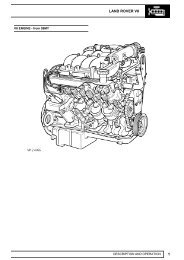
ENGINE – TD6ENGINE DESCRIPTION – Td6 AND OPERATION<strong>Description</strong>GeneralTd 6 — External ViewM12 7758The Td6 diesel engine is a 3.0 litre, 6 cylinder, in-line direct injection unit, with 4 valves per cylinder, operated by twooverhead camshafts. The engine emissions comply with ECD3 (European Commission Directive) legislativerequirements <strong>and</strong> employs a catalytic converter electronic engine management control, positive crankcase ventilation<strong>and</strong> exhaust gas recirculation to limit the emission of pollutants. The unit is water cooled <strong>and</strong> turbo-charged. The fuelinjection system features common rail technology.The cylinder block is of cast iron construction with a cast aluminium stiffening plate bolted to the bottom of the blockto improve lower structure rigidity. The cylinder head is cast aluminium with a moulded plastic camshaft cover. Thesingle-piece oil sump is also cast aluminium. The exhaust manifold is mounted on the right side of the engine <strong>and</strong> amoulded plastic acoustic cover is fitted over the upper engine to reduce engine generated noise.DESCRIPTION AND OPERATION 12-1-1
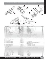
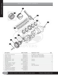
ENGINE – TD6A port is included at the rear right h<strong>and</strong> side of the cylinder block which connects to the turbocharger oil drain pipe toreturn lubrication oil to the sump.A plug sealing the lubrication cross-drilling gallery is located at the front right h<strong>and</strong> side of the cylinder block. Plugsfor the main lubrication gallery are included at the front <strong>and</strong> rear of the cylinder block.Connecting RodsThe connecting rods are machined, H-sectioned steel forgings. The big-end bearing shells are plain split halves. Theupper half of the bearing shell is treated using the sputtering process (cathodic surface coating process) to improveits resistance to wear.The small-end of the connecting rod has a bushed solid eye which is free to move on the gudgeon pin. The small-endbush is a h<strong>and</strong>-push transition fit.Connecting Rod <strong>and</strong> PistonPistonsThe six pistons are gravity die cast with graphite-compound coated aluminium alloy skirts. Although the piston issimilar to that fitted to the Td4 engine the lobe in the piston crown bowl is higher.The combustion chamber is designed on a swirl chamber principle.The swirl chamber partly contains the inlet air during the combustion process <strong>and</strong> helps provide turbulence for efficientair/fuel mixture to promote complete combustion. This reduces fuel consumption, exhaust emission <strong>and</strong> smokeproduced at full load. The four recesses in the piston's crown also provide clearance for the valve heads.The pistons are attached to the small-end of the connecting rods by fully floating gudgeon pins which are retained inthe piston by circlips.The pistons incorporate an oil cooling channel for piston <strong>and</strong> gudgeon pin cooling, oil being supplied under pressurefrom the piston lubrication jets.Piston RingsEach piston is fitted with two compression rings <strong>and</strong> an oil control ring. The top compression ring is located in a steelinsert ring carrier which helps to provide a minimal reaction to compression forces.The top ring is a 10° chromium-plated keystone ring. The 2nd compression ring is a tapered compression ring <strong>and</strong>the lower ring is a chromium-plated spring loaded bevelled ring.DESCRIPTION AND OPERATION 12-1-3
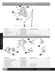
ENGINE – TD6Oil Pressure SwitchThe oil pressure switch is located in a port in the oil filter housing. If the oil pressure drops below a given value theswitch operates the warning lamp in the instrument packHigh Pressure Fuel PumpThe high pressure fuel pump supplies fuel to the fuel rail <strong>and</strong> is fixed to a flange on the front LH side of the cylinderblock. The pump is a 3 radial piston type controlled by the EDC engine management system <strong>and</strong> chain driven fromthe crankshaft at 0.75 times engine speed.For more information on the EDC operation, refer to the Engine Management – Td6 section of this workbook.Crankshaft Position (CKP) SensorThe crankshaft position (CKP) sensor is mounted on the rear LH side of the cylinder block. The sensor is an inductivetype which acts on a reluctor on the flywheel.For more information on the EDC operation, refer to the Engine Management – Td6 section of this workbook.Crankshaft <strong>and</strong> Sump ComponentsThe crankshaft <strong>and</strong> sump <strong>and</strong> oil pump components are described below:CrankshaftCrankshaft Drive1 No 1 Piston2 No 6 Piston3 Incremental wheelArrow denotes front of engine.DESCRIPTION AND OPERATION 12-1-5
ENGINE – TD6The crankshaft is manufactured from high tensile steel. The bearing surfaces <strong>and</strong> radii are inductively hardened fortoughness <strong>and</strong> fatigue resistance. It is supported on 7 main bearings with a flanged thrust bearing located betweenNo 5 <strong>and</strong> No 6 cylinders. Dynamic balancing is achieved by the use of twelve balance weights.Cross-drillings in the crankshaft between the adjoining main <strong>and</strong> big-end bearings are used to divert the lubricationoil to the big-end bearings.Crankshafts are available in three sizes:l St<strong>and</strong>ardl Undersize 1l Undersize 2.Colour coding identifies the size of the journal.NOTE: For information on colour coding <strong>and</strong> journal sizes, refer to the General Data section of the workshop manual.At the front of the crankshaft is a four-hole threaded connection, used to attach the axially vibration damper <strong>and</strong>cooling fan. The engine RPM signal is taken from the reluctor “target” attached to the crankshaft.The crankshaft oil seals are manufactured from PTFE.Main BearingsThe main crankshaft bearing shells have oil grooves <strong>and</strong> a drilling in the upper bearing shell, to provide oil via thecrankshaft drillings to the connecting rod big-end bearings.SumpThe one-piece aluminium die-cast sump, with an integral tunnel for the differential drive shaft, is sealed to the lowercrankcase extension using a rubber metal-backed gasket. The sump is fixed to the lower crankcase extension using25 bolts. An oil deflector plate is attached to the crankcase reinforcing shell above the sump.Oil PumpThe oil pump assembly is bolted to the bottom of the cylinder block <strong>and</strong> is located in front of the engine block stiffenerplate. The pump is an internal gear-type with sintered rotors <strong>and</strong> is driven through a chain <strong>and</strong> sprocket system fromthe crankshaft.A pressure relief valve is included at the outlet side of the oil pump to control oil pressure at high engine speeds byrecirculating oil through the relief valve back around the pump to the inlet. The relief valve <strong>and</strong> spring is a plunger type;when oil pressure is great enough to lift the plunger, oil is allowed to escape past the plunger to relieve pressure <strong>and</strong>prevent any further rise in pressure.Oil is delivered to the pump from the pick-up pipe, <strong>and</strong> the outlet side of the oil pump delivers pressurised oil flow tothe engine block main oil delivery gallery.FlywheelLocated between the engine <strong>and</strong> transmission the flywheel is of sheet metal laminated construction.12-1-6 DESCRIPTION AND OPERATION
ENGINE – TD6Camshaft Timing ComponentsChain drive1 Camshaft2 Guide rail3 Crankshaft4 Common rail high pressure pump5 Oil pump6 Tensioning rail7 Chain tensionerDESCRIPTION AND OPERATION 12-1-7
ENGINE – TD6Inlet Port Configuration312456M12 776971 Exhaust ports2 Exhaust valves3 Fuel injector4 Inlet swirl port5 Inlet valves6 Inlet tangential port7 Glow plugThe aluminium cylinder head houses the chain driven overhead camshafts, valve gear, fuel injectors <strong>and</strong> glow plugs.The Td6 engine has a 4–valve arrangement, similar to the Td4. There are two exhaust ports, combined in the cylinderhead, a tangential inlet <strong>and</strong> a swirl inlet port. The common fuel injector rail is centrally mounted with the glow plugfitted to the inlet side.Coolant flow enters the head from the exhaust side <strong>and</strong> exits, between No 3 <strong>and</strong> No 4 cylinder, the inlet side to theheater matrix <strong>and</strong> radiator. The Engine Coolant Temperature (ECT) sensor is screwed into an aperture at the rear LHside of the cylinder head.For more information on the EDC operation, refer to the Engine Management – Td6 section of this workbook.For more information on the Cooling system operation, refer to the Cooling system – Td6 section of this workbook.Cylinder Head CoverThe plastic moulded cylinder head cover is used to seal off the oil chamber in the cylinder head. It shields oil sprayfrom the camshaft <strong>and</strong> the chain drive gear, <strong>and</strong> acts as a housing for the valve gear.An oil separator for the crankcase ventilation system is mounted at the top of the cover. This provides preliminary oilseparation by cyclone, <strong>and</strong> fine separation using an internal yarn wrap. The separator unit also contains a pressurecontrol valve.The camshaft cover includes an integrated air filter housing which is de-coupled from the cylinder head to absorb <strong>and</strong>minimise the transmission of engine noise. The camshaft cover also provides a mounting for the mass air-flow (MAF)sensor.DESCRIPTION AND OPERATION 12-1-9
ENGINE – TD6Cylinder Head GasketThe multi-layed steel cylinder head gasket has cylinder specific water flow cross-sections for uniform coolant flow.There are three thicknesses of gasket available, selected according to the determined piston clearance. The thicknessof the gasket is identified by the number of identification holes, one hole being the thinnest <strong>and</strong> three holes being thethickest.Vacuum PumpThe vacuum pump is located on a support bracket at the front RH side of the cylinder head <strong>and</strong> is driven from theexhaust camshaft.CamshaftsThere are two camshafts, exhaust (right) <strong>and</strong> intake (left). Each camshaft is located in seven bearings <strong>and</strong> maintainedin position by seven bearing caps. Each bearing cap is fixed to the cylinder head by two bolts. The camshafts aremade using the clear chill casting process <strong>and</strong> are hollow cast. The cam lobes have a negative cam radius. Thecamshafts are driven from the crankshaft using a simplex chain <strong>and</strong> sprocket arrangement.Each camshaft has twelve machined lobes for operating the inlet <strong>and</strong> exhaust valves through lash adjusters <strong>and</strong> rollertypefinger levers.Inlet <strong>and</strong> Exhaust ValvesValve gear layoutM12 7768The inlet <strong>and</strong> exhaust valves are identical <strong>and</strong> have ground, solid one-piece head <strong>and</strong> stems made from Nimonic alloymaterial.12-1-10 DESCRIPTION AND OPERATION
ENGINE – TD6The valve springs are made from spring steel <strong>and</strong> are of the parallel single-coil type. The bottom end of each springrests on the flange of a spring retainer which has an integral valve stem seal. The top end of the spring is held in placeby a spring retainer which is held in position at the top end of the valve stem by split taper collets. The taper colletshave grooves on the internal bore that locate to grooves ground into the upper stems of the valves.Valve seats <strong>and</strong> valve guides are an interference fit in the cylinder head.Hydraulic Lash Adjusters <strong>and</strong> Roller Finger RockersThe valves are operated through roller-type finger rockers <strong>and</strong> hydraulic lash adjusters, actuated by the camshaftlobes. When the camshaft lobe presses down on the top of a finger rocker, roller mechanism, the respective valve isforced down, opening the affected inlet or exhaust port. The use of this type of actuation method helps reduce frictionin the valve timing mechanism.The body of the hydraulic lash adjusters contains a plunger <strong>and</strong> two chambers for oil feed <strong>and</strong> pressurised oil. Thepressurised oil is supplied to the lash adjusters via the main oil galleries in the cylinder head <strong>and</strong> through a hole in theside of the lash adjuster body. The oil passes into a feed chamber in the lash adjuster <strong>and</strong> then through to a separatepressure chamber via a one way ball valve.Oil flow from the pressure chamber is determined by the amount of clearance between the lash adjuster outer body<strong>and</strong> the centre plunger. Oil escapes up the side of the plunger every time the lash adjuster is operated, the downwardpressure on the plunger forcing a corresponding amount of oil in the lash adjuster body to be displaced. When thedownward pressure from the camshaft <strong>and</strong> finger rocker is removed (i.e. after the trailing flank of the camshaft lobehas passed), oil pressure forces the lash adjuster's plunger up again. This pressure is not sufficient to effect the valveoperation, but eliminates the clearance between the finger rocker <strong>and</strong> top of the valve stem.Electronic Fuel InjectorsThere are six electronic fuel injectors (one for each cylinder), each located in the centre of a cylinder's four valves.The electronic fuel injectors are supplied with fuel from the fuel rail <strong>and</strong> deliver finely atomised fuel directly into thefuel chambers.For more information on the Fuel injector operation, refer to the Engine Management – Td6 section of this workbook.Ancillary Components <strong>and</strong> Belt DrivesThe ancillary components, which comprise the torsional vibration damper, alternator, A/C compressor, steering pump<strong>and</strong> water pump, are driven by the engine crankshaft via the ancillary drive belts.The belts, which are maintenance free poly-V type belts, are automatically pre-loaded by the tensioning rollers <strong>and</strong>are routed over deflection pulleys in order to maintain sufficient adhesion about the drive wheels. This ensures slipfreedrive of the ancillary components.DESCRIPTION AND OPERATION 12-1-11
ENGINE – TD6Belt Drive1234756M12 776321 Water pump2 Tensioning pulley3 Power steering pump4 Alternator pulley5 Idler pulley6 Torsional vibration damper7 A/C compressorTorsional Vibration DamperThe torsional vibration damper with decoupled belt pulley suppresses longitudinal vibration <strong>and</strong> reduces noise. It ismounted to the forward end of the crankshaft with 4 central bolts torque loaded to 45 Nm.Tensioning PulleyThe tensioning pulley or idler pulley is a spring-loaded element.LubricationThe lubrication system is a wet sump, pressure fed type. It lubricates the engine sliding surfaces, dissipates heat,absorbs fuel combustion residue <strong>and</strong> seals off the gap between the cylinder <strong>and</strong> piston.12-1-12 DESCRIPTION AND OPERATION
ENGINE – TD6Lubrication Circuit324115561314128711109M12 77641 Pressure supply to upper chain lubrication2 Camshaft bearing3 Runout stop — Hydraulic Valve Adjuster gallery4 Hydraulic valve lash adjuster gallery (HVA)5 Piston spray nozzle — hook-type nozzle6 Cylinder block main oil gallery feed forcrankshaft bearings7 Oil filter with oil cooler8 Oil gallery after oil filter — main oil gallery9 Oil intake pipe10 Unfiltered oil duct11 Oil pump12 Pressure supply for upper chain lubrication13 Pressure supply to Turbo-charger14 Riser to cylinder head15 Pressure supply to vacuum pump<strong>Operation</strong>Oil from the sump is drawn up through a fabricated metal pick-up pipe which contains a mesh to filter out any relativelylarge pieces of material which could cause damage to the oil pump. The head of the pick-up is centrally immersed inthe sump oil which is delivered to the inlet side of the eccentric rotary pump.DESCRIPTION AND OPERATION 12-1-13
ENGINE – TD6The oil pump is driven from the crankshaft by a chain <strong>and</strong> sprocket system. Pressurised oil from the pump is passedthrough a port in the bottom of the cylinder block <strong>and</strong> is directed up to the oil inlet port of the oil cooler <strong>and</strong> filter housingvia a port in the RH side of the cylinder block. The oil pump contains an oil pressure relief valve which opens to allowoil to be recirculated back around the pump if the oil pressure increases to a high enough level.The inlet port of the oil cooler <strong>and</strong> filter housing has an integral non-return valve which allows flow into the filter, butprevents unfiltered oil draining back out of the filter housing when oil pressure is reduced.The oil passes through the oil filter element <strong>and</strong> out to the oil cooler. The percentage of oil flow passed through to theoil cooler is dependent on a thermostatic by-pass valve which is integrated into the oil filter housing. An increase inoil temperature causes the by-pass valve to open <strong>and</strong> allow a greater percentage of oil flow to be directed through theoil cooler. The remainder of the oil flow from the outlet side of the filter element is directed to the outlet port of the oilfilter housing where it combines with the oil flow being returned from the oil cooler before being passed back into thecylinder block.An oil pressure switch is included in the outlet port of the oil filter housing to sense the oil pressure level before the oilflow enters the main oil gallery in the engine block. A warning lamp in the instrument pack is switched on if the oilpressure is detected to be too low.For more information on the oil pressure warning lamp refer to the Instruments section of this workbook.Oil entering the cylinder block main gallery passes through drillings to the crankshaft main bearings <strong>and</strong> cross drillingsin the crankshaft direct oil to the big-end bearings. An additional four drillings in the cylinder block supply oil at reducedpressure to the lubrication jets for piston <strong>and</strong> cylinder cooling <strong>and</strong> gudgeon pin lubrication.A cross channel from the LH main oil gallery crosses to the RH side of the cylinder block where there is an outlet portwhich provides a pressurised oil supply to the turbocharger bearings via a banjo connection <strong>and</strong> external piping.Riser channels at the front RH side <strong>and</strong> rear LH side of the cylinder block are used to channel oil to mating ports inthe cylinder head <strong>and</strong> provide a source for cylinder head lubrication <strong>and</strong> operating pressure for the lash adjusters.Oil is fed through oil galleries at the LH <strong>and</strong> RH side of the engine <strong>and</strong> six cross channels from each gallery directsoil to the camshaft bearings. Lubrication oil fed to the lash adjusters passes up through the lash adjuster's body to thefinger rockers for lubrication of the surfaces between the finger rockers <strong>and</strong> the camshaft lobes.Tapered plugs seal the cylinder head oil galleries at the rear of the cylinder head, <strong>and</strong> an additional tapered plug isincluded inside the cylinder head at the front of the RH gallery.An additional riser channel from the cylinder block LH main oil gallery is used to supply lubrication to the timing chainsystem through several outlet ports at the front of the cylinder block <strong>and</strong> cylinder head.12-1-14 DESCRIPTION AND OPERATION
ENGINE – TD6Engine Mounts<strong>System</strong> Layout1 Right hydraulic damper2 Right engine mounting3 Left engine mounting4 Left hydraulic damper5 Vacuum supply pipe6 Engine mount damping control actuatorTwo hydraulically dampened engine mounts are fitted between the engine support brackets <strong>and</strong> engine sub-frame toreduce the level of transmitted engine vibration <strong>and</strong> noise.The damping characteristics of the mounts are regulated by controlling the rate of hydraulic fluid transfer between twointernal chambers.The system consists of two hydraulic mounts, with variable damping regulated by a vacuum, a control actuator,electric <strong>and</strong> vacuum lines. The vacuum, controlled by the electrical control actuator, is supplied via a distributor in thevacuum line between the vacuum pump <strong>and</strong> brake booster. The system is controlled by the EDC <strong>System</strong>.DESCRIPTION AND OPERATION 12-1-15
ENGINE – TD6Hydraulic Engine Mount6578491031121121314M12 77661 Vacuum connection2 Bellows3 Nozzle4 Annular channel5 Diaphragm6 Upper hydraulic chamber7 Orifice8 Upper nozzle plate9 Nozzle10 Lower nozzle plate11 Lower hydraulic chamber12 Support cup13 Spring14 Channel<strong>Operation</strong>By applying a vacuum, the Engine Control Module (ECM) controls the engine damping mounting in two stages :“Hard” Engine MountIn the basic setting no vacuum is applied to the hydraulic mount. The spring (13) acts on the support cup (12) to closethe U-bellows against the upper nozzle plate (8). Hydraulic fluid flows from the upper hydraulic chamber (6) via thenozzle (9), the annular channel (4) <strong>and</strong> via nozzle (3) into the lower hydraulic chamber (11).12-1-16 DESCRIPTION AND OPERATION
ENGINE – TD6The annular channel extends over approximately 300 degrees. Due to the length of the annular channel <strong>and</strong> the smallnozzle orifice hydraulic oil flows between the upper <strong>and</strong> lower hydraulic chamber only in the case of vibrations up tothe natural frequency of the engine (approximately. 10 Hz), thus producing a vibration absorber effect.At higher frequencies, the equalisation between the hydraulic chambers is inhibited by the length of the annularchannel <strong>and</strong> the small nozzle orifices. In practical terms, equalisation between the upper <strong>and</strong> lower hydraulic chamberdoes not take place.Diaphragms (5) are fitted in the holes (7) of the nozzle plates in order to achieve good acoustic characteristics at highfrequencies with small amplitude."Soft" Engine MountAt idling speed <strong>and</strong> in the speed range close to idling, the spring (13) is pulled down by applying vacuum at vacuumconnection (1). The channel (14) in the centre of the upper nozzle plate now acts as a bypass between the upper <strong>and</strong>lower hydraulic chamber. This allows the hydraulic fluid to flow unrestricted between the upper <strong>and</strong> lower chambers.The increase in the fluid flow rate softens the damping action of the hydraulic mount, reducing the dynamic rigidity ofthe engine mount.EDC ParametersThe ECM controls the engine mounts based on the following parameters:Engine SpeedVehicle speedSwitching Value900 RPM60 km/h (36 MPH)DESCRIPTION AND OPERATION 12-1-17
ENGINE – TD6Vacuum SupplyDistributorThe vacuum necessary for activating the engine mounts is obtained via a distributor located in the vacuum linebetween the vacuum pump <strong>and</strong> brake booster.For this purpose, the vacuum line of the damping-controlled hydraulic mount is connected to the long outlet of thedistributor.The vacuum varies within the pressure range from 0.5 to 0.9 bar. It is switched by means of a damping controlactuator.12-1-18 DESCRIPTION AND OPERATION