Create successful ePaper yourself
Turn your PDF publications into a flip-book with our unique Google optimized e-Paper software.
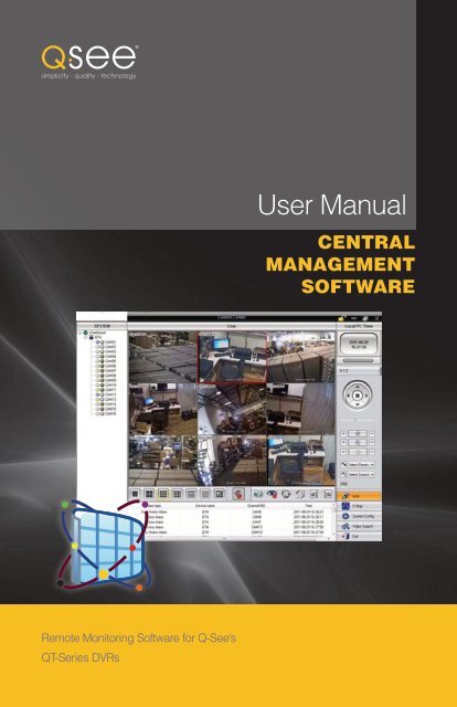
SYSTEM REQUIREMENTSSOFTWAREThe table below lists the versions of the Windows operating system that are compatible with<strong>CMS</strong> along with any updates and which version of DirectX you will need to be running.Operating SystemWindows XPCommentsSP2 or later DirectX 9.0c or laterGETTING STARTEDCHAPTER 1 CHAPTER 22.1 INSTALLING <strong>CMS</strong><strong>CMS</strong> can be installed by clicking on theInstall <strong>CMS</strong> Software button on the CDincluded with your DVR, or by clicking on thefile Setup.exe in the <strong>CMS</strong> folder.Windows 2000Windows VistaWindows 7SP4, DirectX 9.0c or laterDirectX 10.0c or laterDirectX 10.0c or laterHARDWAREThe following shows the minimum hardware requirements necessary to ensure a stableoperating experience depending on the number of channels being monitored simultaneouslywith CIF resolution and real-time 30 frames per second speed. Up to 64 channels can beviewed simultaneously, at a slower frame-rate. The actual number of channels that can bemonitored – along with their speed – is dependent upon bandwidth, the nature of your internetconnection (both at your location and the location of each DVR), and the capabilities of yourcomputer’s video card.Channels CPU Memory Hard Drive SizeIMPORTANT! Turn off any anti-virus software currently running on yourcomputer before beginning installation to avoid software conflicts.If launching the installer from the CD, aninformation window will pop up. Click OK tocontinue.4 Intel Pentium 3.0 GHzAMD 3000+8 Intel Core 2 Duo 1.8 GHzAMD Dual Core 3800+16 Intel Core 2 Duo 2.2 GHzAMD Dual Core 3800+1GB160GB1GB2GB250GB500GBThe Setup window will open advising youto close all other programs. Click on Next toproceed.INTERNET CONNECTION SPEEDSThe minimum speed on the internet connection is 1Mbps download and 1Mbps upload for 4and 8 channels, and 2Mbps download and upload for 16 channels. This applies to the Internetconnections both at the DVR and the computer you are monitoring from. If you are monitoringmultiple DVRs, your computer’s bandwidth needs will increase proportionately if you wishto monitor a large number of channels simultaneously. You can check the speed of yourconnection at both ends by going www.SpeedTest.net from both a computer attached to thesame router as the DVR as well as the remote computer which you will be using.COMPATIBLE NETWORK SECURITY SYSTEMSThe following Q-<strong>See</strong> products can be accessed and controlled using <strong>CMS</strong>. They must beset up and properly configured for remote monitoring before attempting to access them with<strong>CMS</strong>.QT4 SERIES – Includes: QT426, QT428, QT446, QT454, QT474 and QT4332.QT5 SERIES – Includes: QT504, QT518, QT526, QT528, QT536 and QT5116.This list was complete at the time of its writing but any new QT-series DVR purchased after therevision date noted at the bottom of page 3 will be compatible with the latest version of <strong>CMS</strong>.The next window will allow you to selectwhere to install the <strong>CMS</strong> Control Centerapplication. By default, it will install in theProgram Files folder on your computer, butyou may click on Browse to choose anotherdestination. Click on Next to proceed.6 7
You will be asked where you want theprogram to add its icons. Select a specificlocation if desired. Click on Next to proceed.2.2 LOGGING INTo launch <strong>CMS</strong>, double click on the <strong>CMS</strong> icon on your computer desktop, orselect it from the program menu available by clicking on the Windows icon atthe lower left corner of your computer screen.When you first launch the program, it willask you to create a password. You cannotchange the field labelled “System.”The installer will display a progress bar as itinstalls the program onto the hard drive.The next window will ask you to re-enter thepassword along with giving you the option toinput an e-mail address where the passwordcan be sent in the event you forget it.When installation is complete, you will receivea completion notice at which time you canclick on Finish to close the installer.Once you have entered the information, theactual log in screen will appear. When youaccess the software in the future, this will bethe starting window.You will only need to enter your passwordand it is here where the button to e-mail youyour password is located.The default user name is SYSTEM and thedefault password is 123456UNINSTALLING <strong>CMS</strong>If you need to uninstall <strong>CMS</strong> for any reason you may do so by using Windows’ Add orRemove Programs (XP, 2000) or the Programs and Features (Vista, 7) control panels. Youmay also use the unistaller which can be found when selecting Control Center from the AllPrograms menu.When you log in, you will beshown the Control CenterOperation Interface with thePreview Window in the center.This is the main window formonitoring your DVR(s). Thewindow will be blank until youhave added your systems to theprogram.8 9
2.3 CONTROL CENTER OPERATION INTERFACE2 3 415 67891011 12 13 14 15 161718Item Name Description1 Device List Shows the connected DVRs and available cameras. This canbe switched to show groups of specific channels by clickingon the Channel Group tab at the bottom.2 Lock/Unlock Locks the current configuration. When locked, one must enterthe user name and password to make any changes.3 Minimize/Maximize Minimize or maximize the Control Center’s window.4 Close You can close the program by clicking on the X or the Exitbutton at the bottom.5 Preview Window Displays the live video from selected cameras. The channelwith the red surround is the camera currently being controlled(if applicable). Double clicking on a channel will bring it to fullscreen.6 Local PC Time Displays the local time of the monitoring PC.7 Drive Capacity Shows the amount of space remaining in the partition on thecomputer’s hard drive that has been set to save recorded videos.8 PTZ Controls Clicking on the directional controls will move a connected PTZcamera.9 Zoom/Focus/Iris Allows you to adjust the zoom, focus and light level (iris) of thecamera.10 Preset/Cruise Allows you to activate pre-set PTZ functions11 Display Mode Choose the number of cameras you wish to view at once.12 Audio Turn audio on or off. You must have a microphone or otheraudio input device connected to listen to audio.13 Snapshot Take up to 10 still images from selected camera (highlightedin red)14 Close Preview Closes all currently displayed video streams.15 Dwell Allows you to automatically switch between channel groups.Depending on display mode settings, Dwell will:Proceed through each camera in sequenceSwitch to the next set of channels if more areavailable than can be displayed at once.16 Previous/Next <strong>Manual</strong>ly switch to the prior or next group of channels.Group17 Alarm Display Shows activity, such as the beginning and ending of motiondetection events or video loss, along with camera number,alarm type, and device name.18 Mode Buttons Live - Live viewing modeE-Map - Opens a user-created map showing location ofcameras and sensors.System Config - Add systems, create Channel Groups, etc.Video Search - Switches to video search modeExit - Exits <strong>CMS</strong>10 11
STEP 4. Once you have set up your region, you can add one or more DVRs or IPcameras to it by clicking on the Add Device icon.STEP 5. To view your DVRs, click on theLive button at the lower right of theOperation Interface.STEP 6. You will see your connecteddevices listed to the left of the viewingwindow. You can drag and drop theDVR’s icon onto the blank OperationInterface window to open the feedsfrom the attached cameras.Device Name - You can name the device (DVR or camera) anything you chose but it isgenerally helpful to use a descriptive term that will help you quickly identify it. There isa 32 character limit.Server - The Internet IP or DDNS address which allows you to access your DVRfrom outside of your Local Area Network (LAN). Please see your DVR’s RemoteMonitoring Guide or camera’s manual for instructions on how to configure yourDVR for access over the Internet.Data Port - Typically 6036 for the QT-series unless you had to configure it differentlyduring setup.<strong>User</strong> Name and Password - These are the same as you use to log into your DVR. Bydefault, they are admin and 123456.Search Device - Use this only if you are connecting to DVRs connected to the samerouter as your computer. It will not bring up devices located outside of your LAN.CHANNEL GROUPSChannel groups are any collection of channels that you have grouped together for yourconvenience. They can be selected channels from one DVR or a few channels from multiplesystems.Channel groups are set up in the Device Manager console after you’ve added systems tothe Device List. Again, there is a 32-character limit for names.When you have successfully added a device,it will show up in the selected region alongwith a list of cameras available for viewing.Repeat the steps above to add more devices(if any).Use the Modify tool to rename or modifythe settings for the region or any connectedsystems. If you change the password or username on your DVR, you will need to updatethat information within <strong>CMS</strong> using this tool.Delete can be used to remove systems orregions as needed.14 15AddGroupModifyGroupDeleteDwellSetupAdd Group - Creates a new channel groupModify Group - Change the group’s name.Delete - Remove a channel group from the listDwell Setup - Set the time that the system will display a channel group (between 5seconds and 2 minutes) before moving to the next channel group.
STEP 1. Click on the Add Group iconSTEP 2. Enter the name of your group and click OK.STEP 3. With the channel group’s icon highlighted, click on an available camera in theDevice List and then press the >> button in the middle to add that camera to thegroup.MONITORING USING <strong>CMS</strong> CHAPTER 3LIVE VIEWINGOnce you have added your DVR(s) to the Device Manager, you can view the camerasattached to those systems in the Control Center Operation Interface.To begin viewing you will need to be in LiveViewing mode which can be entered byclicking on the Live button at the lower rightof your screen.Next, drag and drop a system’s icon from the Device Manager onto the blank PreviewWindow and <strong>CMS</strong> will populate the screen with the cameras’ video feeds. Alternately, youcan drag and drop individual cameras (from the same DVR or multiple DVRs) onto individualsegments of the multi-channel display.If you have multiple groups and you want<strong>CMS</strong> to automatically switch betweenthem, then you will need to set up the timedelay between groups using Dwell Setup.Otherwise, you can manually switch usingthe Previous Group and Next Groupbuttons (items 16 in Section 2.3).You will need to place a check mark beforeeach group you want to cycle through. And,you are able to individually set the dwelltime of each group from five seconds to twominutes.You can also use this same method to viewcameras in a channel group. You must firstclose out the current video feeds by pressingthe Close Preview button. Afterwards, youcan select the Channel Group tab at thebottom left of the Control Center Interfaceand select a group.DISPLAY MODEYou can choose how many camera streams you wish to view at once by selecting the desiredmulti-screen configuration from the row below the Preview Window.1 Ch. 4 Ch. 9 Ch. 16 Ch. 25 Ch. 36 Ch. 6-256 Ch.There are six pre-configured modes rangingfrom a single camera to 32 channels ondisplay at the same time. The last mode is adrop-down which allows you to chose a 6-,8-, 13-, 49-, or 64-channel display. You candrag and drop the channels into any of theother positions on the screen. You can alsodrag a camera name from the Device Liston the left onto an on-screen position.In the 6-, 8- and 13-channel displays, youwill get one large display surrounded by theremaining channels in smaller displays.16 17
Clicking on a camera in the multi-channel view so that it has a red outline and then clickingon the 1-channel display mode button will cause the Preview Window to only display thatchannel. You can also double click on a screen to bring it to single camera view.Right-clicking on a channel will bring up a dialog box allowing you to take several actions:SNAPSHOTYou can take up to 10 still frames from asingle camera by pressing the Snapshotbutton. Click on any channel in the on-screenPreview Window to chose it. The chosencamera will have a red outline.Once you have selected the camera and pressed the Snapshot button, the Snap Picturewindow will open.Turn off live view - This allows you to turn off viewing of this channel alone.Start <strong>Manual</strong> Record - This records the video of the selected channel to your computer’shard drive.Stop <strong>Manual</strong> Record - Ends manual recording.Enable Audio - If you have a microphone or audio-capable camera connected to thischannel, you can turn the audio on. You can also do this in single-camera displaymode by pressing the Enable Audio button below the Preview Window.Full Screen - This will bring the Preview Window to full screen mode for easier viewing.The rest of the Control Center Operation Interface will be hidden. Right-clickingthis screen will return it to normal viewing. If you have more than one display, you willbe given the choice of which monitor on which to display the video.ChannelFrameSnapTitleTimeExitSave ToBrowseSavePrintFunctionsWhich camera will be used. You can select a camera using the drop down.The number of still images (1-10) that will be taken.This refreshes the images. Use this if you’ve selected a different camera.This will display the camera’s name in the upper left of the image.This will display the time the image was taken.Closes the window without taking pictures.Shows where the files will be saved.Chose a different destination for the files.Saves the imagesYou may print the currently displayed images as you would any otherdocument. You have the option to preview the printed document, changeyour printer settings, and print more than one image to a page.The images will be saved with the file names shown below each picture. The files are savedin the bitmap (BMP) format with the file name format showing the DVR’s name, the camera’sname, the date and the time the image was captured. The first image above would have thefile name: QT4--CAM11.2011.08.30.17.01.14.708.bmp18 19
PAN-TILT-ZOOM (P.T.Z.) CAMERA OPERATIONIf you have a PTZ camera connected to a system you are monitoring, you can control it usingthe interface on the right side of the Control Center Operation Interface. These controlsoperate in the same manner as those on your DVR, giving you the ability to position thecamera, adjust the zoom, focus and light level.Directional controls - rotates the dome in the direction indicated bythe arrow with the central button stopping the dome.Rotation Speed - This slider adjusts the dome’s speed.SYSTEM CONFIGURATION CHAPTER 4In addition to adding DVRs to <strong>CMS</strong> as covered in Chapter 2, System Configuration givesyou access to configure how your computer uses and saves video, manage who has accessto <strong>CMS</strong>, as well as adding or removing monitored systems.Enter the System Configuration mode byclicking on the System Config button at thelower right of your screen.This will take you back to the ControlCenter window which you used to addsystems to monitor.Iris - Increase or decrease the amount of light entering the lensZoom - Zoom in (+) or out (-)Focus - Adjust the focus of the lens to give the clearest image.Select Preset - This drop-down allows you to direct the camera toany previously configured location.Select Cruise - This drop-down instructs the camera to begin a tourof pre-set locations.PTZ preset locations and cruises must be configured on the DVR itself or remotely using theWebClient plug in on Internet Explorer. <strong>CMS</strong> can only be used to access these settings butnot to program new ones.ALARM DISPLAYThis area below the Preview Window shows alarms (events) as they happen. It will display thetype of event (motion detection, video loss, etc.), the name of the system recording it, whichcamera triggered the alarm as well as the time.4.1 DEVICE MANAGERBy default, this window will open up in the Device Manager mode allowing you to add, removeor modify systems. This was covered in Section 2.4 Basic Configuration. The AlarmDisplay will continue to operate underneath the main display.20 21
4.2 LOCAL CONFIGURATIONThis area allows you to change how <strong>CMS</strong> interacts with the computer you are using. Thesesettings only apply to that specific computer and do not alter any of the settings on any of theDVRs being monitored, nor do they change any other computers that you use to run <strong>CMS</strong>.There are three tabs in this window: Local Basic Configuration, Local ScheduleConfiguration and Local Alarm Configuration.Record ConfigurationThis allows you to determine where your video will be recorded on your computer system.<strong>CMS</strong> will detect attached drives which you may select or deselect for use. You may selectmultiple partitions to record video and the system will seemlessly utilize the partitions forrecording and playback. The Recycle Record feature allows you to write over old files. If thisis not selected, <strong>CMS</strong> will stop recording when it has filled the drives.Local Alarm ConfigurationThis consists of two settings:The first, Alarm Holding Time, determines how long the system will delay “closing out” theevent. With a longer delay time, any subsequent triggering of the alarm within that time periodwill be included in the original event. This holding time can be set from 10 seconds to twominutes.Post-Alarm Time is the length of time after the alarm-triggering event occurs that <strong>CMS</strong> willcontinue to record.Log List MaintenanceThis too consists of two settings:Alarm log list save lets you set the period at which <strong>CMS</strong> saves a journal of all alarm events.Your options are weekly, twice a month or monthly.Operator log save sets the frequency that the user activity log is saved. This log shows loginsand logouts, PTZ operation, and other user activities. Again, you have the choice of weekly,twice monthly or monthly.Both of these logs can be accessed using the Log Query button further down the SystemConfiguration column.LOCAL BASIC CONFIGURATIONIn this tab, you can control aspects such as where video is recorded on your computer, howalarms are handled and whether you want your PC to auto restart among other settings.Dwell TimeThis is differs from the Dwell Time setting available in the Device Manager (Section 2.4Basic Configuration). Instead of switching between groups of cameras, this will only switchbetween full-screen views from a single DVR. You cannot have Group Dwell active at thesame time.In Title, you can chose whether the on-screen display shows the DVRs name as well as thechannel, just the channel or no additional title. This information could overlay similar displayspresented by the DVR.Snap picture number - this allows you to determine the number of snapshots taken whenusing the Snapshot button (see Snapshot in the previous chapter). This can beoverridden in the Snapshot dialogue box, but it will remain the default setting for future uses.Other ConfigurationThis feature is for use if you have an alarm out sensor connected to your PC via the serial port.The settings allow you to indicate which serial port it is connected to as well as the baud rateof the sensor. You can chose to use the PC’s internal clock or set another time.PC Restart ConfigurationWindows PCs need to be restarted from time to time to maintain operational stability. Theoptions available in this section enable you to allow <strong>CMS</strong> to automatically restart the computersystem at a scheduled time and after a period of 5 to 30 days.Version InformationThis area shows which version of <strong>CMS</strong> you are running. You can check www.Q-<strong>See</strong>.com/support for free updates.22 23
LOCAL SCHEDULE CONFIGURATIONIn this tab you can set your computer to record on a schedule that is separate from that seton the DVR itself.STEP 1. Select a camera from those available on the left.STEP 2. Select the pencil tool and click on the time you want to start recording on the dayyou wish to schedule. Click and drag to set the recording period. A yellow-green box willappear to the left to indicate the start and end times you are selecting. Scheduled areas willappear in blue and you can add onto an existing block of time.If you make a mistake and need tochange the hours selected, use the erasertool to delete the desired block of time.Each day of the week - and each channel - can be independently scheduled to record.Holidays can be given their own special schedule which will override the regular configuration.The time “ruler” has marks for each hour in the day, which in turn are broken up into15-minute sections.Setting a ScheduleBlocks of recording times are set or changed using the pencil and eraser tools at the upperright of the schedule window. Clicking and dragging the tool will add or erase blocks of timerespectively.STEP 3. Once you have completed a weekly schedule for a camera, you can choose tocopy that schedule to other cameras - even those on a different system - using the “ApplySettings to” option at the bottom of the window.PencilCreates a block of timeEraserDeletes an existing block of recording timeUse the pull-downs to select which device(s) to apply the schedule to and/or which otherchannels will use the same schedule. Pressing the Copy button will copy the schedule to theselected devices and channels.24 25
Holiday ScheduleYou can create special schedules that override the regular settings to take into accountholidays or other events.STEP 1. Like a regular schedule, you must have first selected a channel to schedule.STEP 2. Click on each section of the date to modify using the up and down arrows.STEP 3. Once the date has been set, click on Add to add it to the list of dates.LOCAL ALARM CONFIGURATIONLike Local Schedule Configuration, above, this Local Alarm Configuration allows you torecord events directly onto your computer regardless of what the settings are on the actualDVR. However, this tab will cause the system to record only when motion is detected or whenvideo loss occurs.STEP 4. Set the schedule for that date in the normal manner.STEP 5. You can copy that schedule to other systems or channels using the “Apply Settingsto” area discussed above.STEP 1. Select a cameraSTEP 2. Select the type of alarm - Motion Detection or Video loss. Both can be used, buteach will type is handled differently and so must be set individually.STEP 3. Select what activity each type of alarm will trigger - Motion Detection can triggeran audible alarm on the computer, a flashing notification on the E-Map (discussed later inSection 4.4) and/or cause the camera - and other cameras to start recording. Video loss cantrigger an audio alarm and/or an E-map notification.STEP 4. If you have selected Chanel Record as a triggered events, you will be given a listof cameras that can be set to record when the camera you are configuring detects motion.Check all those cameras you wish to record when triggered.STEP 5. Once you have completed configuring a camera, you can copy the settings to othercameras using the “Apply Settings to” drop-down and pressing Copy.26 27
Sensors<strong>CMS</strong> can also monitor sensors connected tothe DVR and they can be set to trigger alarmsor cause cameras to record in the same waycameras can trigger actions.Sensors, however, do not appear on theE-Map.Clicking on the DVR itself in the list ofconnected devices will produce a list ofavailable sensor ports. Clicking on the sensorport will allow you to select which event(s)will be triggered by that sensor. If there isn’ta sensor actually connected to that port,nothing will happen even though you canconfigure an action.4.4 E-MAP CONFIGURATION<strong>User</strong>s have the option to add a map showing the locations of the cameras being monitored inorder to quickly show the location of an alarm event. The maps can be a floorplan of a singlebuilding or they can show the location of DVRs within a city. The map display size is 1100pixels by 1100 pixels and the maps themselves must be created in a graphic program such asPainter, Photoshop or GIMP and saved in the .BMP or .JPG format and in RGB or grayscalecolor mode in order for <strong>CMS</strong> to be able to use them. Use of the E-Map while monitoring yoursystem(s) is covered in Section 2.4 E-Map.4.3 SERVER CONFIGURATIONWhere the previous windows allowed you to create settings for the <strong>CMS</strong> system and thecomputer it is operating on without changing the settings on the DVR, Server Configurationlets you alter the settings on a selected DVR as you would from within the DVR itself.When you first select ServerConfiguration, you will be presented witha message directing you to select a device(DVR) from the list of systems on the left ofthe Control Center.Once you have selected a system, a menuof available settings will be presented. Thisis the same set of options available fromwithin the DVR’s menu and they can beadjusted in the same manner as on theDVR.Please consult the manual thataccompanied your DVR . The manualis also available at www.Q-<strong>See</strong>.com/support.You can have multiple maps stored in <strong>CMS</strong>. These can be both first-level (or “sibling” in <strong>CMS</strong>)which show a large area and second-level sub-maps (called “son maps” in <strong>CMS</strong>) which showa smaller, more detailed area.Auto FunctionsJust above the map window are two check boxes labeled Auto preview when alarm andAuto switch alarm map. Selecting either of these will cause the system to perform specificactions when motion is detected and/or when an alarm is activated, respectively.Auto preview when alarm will open a single camera view of the camera that detectedmotion - even when <strong>CMS</strong> has been minimized.Auto switch alarm map will open the map containing an activated sensor. If you haveselected a camera to activate when that alarm is triggered in Local Alarm Configuration, apop-up window will show that camera’s view.28 29
ADDING MAPSSTEP 1. Click on the Map Config button.STEP 2. Right click on the Map icon andselect Add Map.MAP CONFIGURATIONYou must have Map Config selected in addition to the map you want to configure. Click anddrag cameras from those available on the left side of the screen to their approximate locationson the map. It is also important to ensure that the E-Map button is checked in the LocalAlarm Config window (<strong>See</strong> Section 4.2).STEP 3. Locate the map file you havecreated in the normal manner by selectingthe Browse button. You will also have theopportunity to name this map to a descriptiveor location name. This name can onlyhave letters or numbers and no spaces orsymbols.IMPORTANT! Cameras can not be placed on more than one map.You can add other maps at this time orproceed to configuring your map. If you wishto add other locations merely click on theMap icon again and repeat the procedure.If you wish to add a sub-map - showing asmaller section, for instance - right click onthe larger scale “parent” map and add thenew map as normal.Deleting a MapRight-clicking on a map’s icon will give you the option to delete it from the list.Hovering the mouse over a camera’s icon on the map will reveal its name.You also have the ability to change thecamera’s icon which can help you quicklyidentify the type of camera - such as aPTZ unit - which has more features than astandard camera.IMPORTANT! Deleting a map will delete all sub-maps associated with thatmap.Changing Map NamesRight-clicking on a map’s icon also allows you the option of changing the name of the map(“node”) should you so desire.30 31
4.6 LOG INQUIRY<strong>CMS</strong> keeps a log of all events occurring in the system, including alarm events and useractivities. This log can be searched by date, time and channel. The event log can be useful innarrowing down times to search for events in the Video Search function (Chapter 5).1 2 3 45VIDEO SEARCH CHAPTER 5Next to live remote viewing, the most important feature of <strong>CMS</strong> is the ability to search and playback recorded video of events. Playback - along with backing up important video records foruse elsewhere - is handled within the Video Search area.Video Search allows you to review files savedlocally on the computer running <strong>CMS</strong> as wellas video files stored on any systems monitoredby <strong>CMS</strong>.There are two sections to the Video Searchwindow; Playback and Backup.To search the logSTEP 1. Select the type of log you wish tosearch - Alarm, Operations (user activities)or All from the pull-down. If you selectAlarm or Operations, use the pull-downimmediately below to select the specific typeof alarm or operation you are searching for.You can also choose to search all alarms oroperations.35.1 PLAYBACKWhen you open the Video Search window, Playback is the default mode. In Playback, youcan chose to search files recorded directly onto the PC running <strong>CMS</strong> or you can search filesrecorded on the DVR itself.Playback divides these two searches into separate tabs - Local Playback and RemotePlayback. In both, searches are conducted in a similar manner as is playback. Like the LiveView window, you can view multiple screens simultaneously. A third tab, Picture Playback,is for viewing still images captured by an IP camera and will be covered at the end of thissection.STEP 2. Select the start time and date. You’llonly be able to search one day at a time.Clicking on the date will open a calendarallowing you to select the specific date. Toselect the start and end times for the search,click on the hour, minute, second and/or AM/PM segments of the time and enter the valuewith the keyboard.STEP 3. Select the channel(s) to be searched. Clicking on the Select Channel button willopen the Select Channel window (above). You can select channels individually or you canselect all channels by putting a check mark in the box corresponding to that system.To include user activity in your search, select Control Center Log in the Other Relatedportion of the window. Click OK to enter your settings.STEP 4. Click on the Search button to have the system check the log for the events thatmeet your criteria. The results will be displayed in the area below the search settings (#5 inthe image at the top of this page).34 35
FILE SEARCHTo search files recorded onto your computer’s hard drive, select the Local Playback tab andset the parameters of your search - type of record, the date of the event, and the channels youwant to review.Selecting files for playbackOnce you have clicked the Search button, a streaming bar will appear above the PreviewWindow to show that the search is progressing. If there are video records that meet yourcriteria, you will see the time periods that the videos were recorded appear as yellow blocksof time in the Playback Timeline at the bottom of the Control Center window. On the rightedge of the Preview Window, there is a vertical tab which will slide to the left when youhover your mouse over it. This will show the exact time and nature of the alert that triggeredthe recording along with the camera that recorded it.Searching for files stored on monitored DVRs is done through the Remote Playback tab andrequires you to also select which system will be searched.Due to bandwidth concerns, you can onlysearch four cameras at a time in RemotePlayback regardless of how many screensare selected in the viewing mode.Local Playback also gives you the optionof searching files recorded onto thehard drive by systems that are no longerbeing monitored by <strong>CMS</strong>. These files canbe accessed by selecting the formerlyconnected system’s name in the DeletedDevice Channel area at the bottom of theSearch Channel Window.When selecting the date in the drop-downcalendar, dates that have recorded events willbe shown in bold.You can begin playback of a record in a single screen by clicking on it.Alternatively, you can move the playback indicator along the timeline to watch the video fromall the channels that recorded at that time.Please note that search times may be longer when searching for files on monitored systemsas opposed to files stored locally on your computer. Your network connection speed at bothyour computer and the DVR can affect the amount of time it takes to conduct the search aswell as loading a file for playback.Once you have selected the type of record,the date of the event and the channels,(along with which system to search in theRemote Playback search) press the Searchbutton.36 37
VIDEO PLAYBACKOnce you have selected the video(s) you wish to view, playback will begin when the Playbutton is pressed. <strong>CMS</strong>’ playback operates like other conventional computer video playbackapplications. However, there are certain extra controls as well.1 2 35 6No. Name FunctionPlay - begins or resumes playbackPause - interrupts playback until play button is pressed1Playback Stop - ends playbackControls Fast Forward - controls playback speed; 1/4X, 1/2X, 2x, 4xNext Frame - After pausing video, switch to single screen view andthen press Next Frame to resume playback one frame at a time.2 SnapshotTake up to 10 still images from selected camera (highlighted in red).Operates exactly as the Snapshot feature in Live View described onPage 18 of this manual.3 Display Mode Choose the number of cameras you wish to view at once.Allow you to select a segment of a video recording to save tobackup.4Backup Start - Sets the beginning of the segmentStamps End - Sets the endpoint of the video segmentErase - Deletes the beginning or endpoint.Backup - Saves the video segment to a computer drive.56PlaybackTimelinePlaybackProgress BarShows the time and duration of video records. It is divided into24-hour segmentsShows the progress through the video playback. It can be clickedand dragged to a specific place on the timeline.Clicking on the bar will show the precise time of its current location.Right-clicking on the triangle at the top of the bar will change thescale of the timeline to show segments of an hour.4PICTURE PLAYBACKIf you have an IP (Internet Protocol) camera connected to your network which is beingmonitored by <strong>CMS</strong>, you can view still images saved to the SD card within the camera.When you select a connected IP camerafrom the Select Device pull-down, you canthen choose the type of event (Motion and/or Sensor) and the date to search. A dateshown in red within the calendar indicatesthat a recording was made on that day.Clicking on the Search button will generate alist of events that were recorded, along withthe type of event they are.Once the list is populated, click on View tosee thumbnails of the available images.Clicking on an image in the thumbnail display will present it in the larger viewing window.Below the window, a 24-hour time line shows when pictures were taken. Images captured bya sensor alarm are shown in red while motion detection events are denoted with yellow. Rightclickingon the progress bar will change the scale to show events occurring within an hour.You can view the images as a slide show as well as zoom in or out of a picture using thecontrols located between the thumbnail and single picture viewing window. Other controlsin this area allow you to close some or all of the pictures in the thumbnail view, save a singleimage or all open images to the PC’s hard drive and adjust the size of the image on display.38 39
5.2 BACKUPClicking on the Backup icon on the far right of the Video Search windowwill change the interface to support backing up files from your computer orfrom monitored DVR systems to a connected hard drive of your choice.As with the Video Search function, Backup is divided into Local andRemote operations on separate tabs. Both are operated in the samemanner and both provide the option to save based on when the recordswere created or by the type of record.TROUBLESHOOTING APPENDIX 1If instead of seeing video images in Live View once you have added systems to <strong>CMS</strong> or, if thecamera images flash then it is likely that the computer’s video card’s VGA driver is not currentor does not have full DirectX support.To resolve this issue in Windows 2003 Server, 2007, XP or Vista click on the on the WindowsStart button at the lower left of the computer screen.Enter “dxdiag” into the run column and press Enter. The DirectX Diagnostic Tool windowwill open.BACKING UP BY EVENTUsing this setting allows you to chose which type of alarm events you wish to back up. Youcan select to backup scheduled, manually recorded, motion and/or sensor-triggered events.STEP 1. Chose the beginning and end dates and times of the records you wish tobackup. This is pre-configured to be a one-month period prior to the current date, butthese can be changed either through use of the pull down calendar or by clicking onthe date or time segment and manually entering the numeric value.STEP 2. Chose the type of event(s) you wish to record.STEP 3. Select the channel(s) whose recordings you wish to backup. In the case of aremote backup, you’ll also have to select which system you will be backing up.STEP 4. Click on the Search button to see the list of records that meet your criteria. Whenthe search is completed, you will be given a list of records. Check the box in front ofthe records you wish to backup.The default save path for your files is set in the System Configuration window (see Section4-2 Local Configuration) but it can be temporarily changed by clicking the Browse buttonto set a new destination for saved files.STEP 5. Click on the Backup button to begin the process. A progress bar at the bottomof the window will show the status.BACKING UP BY TIMEThis process is virtually identical to that used when backing up by event (above), but itdispenses with the search for files. You simply enter the start and end dates and time for thefiles that will be backed up, choose the channels (and DVR if necessary) and then click on theBackup button to complete the operation. All files recorded between those two times will besaved to disk.Click on the Display tab to check that the VGA, device and driver information is all correct.The field “Approx. Total Memory” should show a minimum of 64MB. The function state forDirectDraw acceleration and Direct3D acceleration must both be enabled.If the VGA driver is not current, or lacks full DirectDraw and/or DirectX support it will need tobe updated. You will need to check for updated drivers on the website for the manufacturer ofyour graphics card.Windows 2003 Server and VistaDirectX acceleration is not enabled by default in either Windows 2003 Server or Vista. You willneed to enable these functions:Hardware acceleration: Right click on the Desktop to open the pop-up menu. ChooseSettings, click on Advanced and then Troubleshoot. Drag the Hardware scroll bar all theway over and press OK. The monitor may go blank for less than a minute before asking you toconfirm the settings.DirectX Acceleration: Open the DirectX Diagnostic Tool window in the same manner asdescribed earlier. Enable DirectDraw, Direct3D and AGP on the Display interface.40 41
IP TOOL APPENDIX 2IP Tool is not part of <strong>CMS</strong>, but a separate program that was installed atthe same time as part of the package. The shortcut icon to this programcan be found on your desktop. You do not need to have <strong>CMS</strong> running inorder to run IP Tool.This program is intended for advanced users who need the ability todetermine or change IP addresses on networked DVRs and cameras. Itcan also be used to upgrade the firmware on a connected IP camera.QUESTIONS OR COMMENTS? CONTACT US24/7 TECHNICAL RESOURCES,KNOWLEDGE BASE AND MOREwww.Q-<strong>See</strong>.com/SupportWhen you launch IP Tool by clicking on itsicon, it will look for other devices on thesame network as the computer running theprogram and it will populate the list.You can upgrade the software and kernel ofan IP camera by downloading the requiredfiles and then right-clicking on the camerafrom the list and then selecting the desiredaction.If the first three segments of the IP address are not the same as that of the computer you areusing, then you will need to modify the address. Right-click and then select Network Setupwhich will open a window allowing you to change the IP address.On Q-<strong>See</strong> brand IP cameras, the default user name is admin and the default password is123456. Please check your camera’s manual for more information.CAUTION! When upgrading the software or kernel on a connected camerado not disconnect either the device or the PC before receiving the UpdateSuccess message or you could damage your camera.Once you have received the Update Success! message, click OK and the device will restart42 43
Digital Peripheral Solutions, Inc.8015 E. Crystal DriveAnaheim, CA 9280744


