APOLLO PRO LITE LX.pdf - Qvis Security
APOLLO PRO LITE LX.pdf - Qvis Security
APOLLO PRO LITE LX.pdf - Qvis Security
- No tags were found...

You also want an ePaper? Increase the reach of your titles
YUMPU automatically turns print PDFs into web optimized ePapers that Google loves.
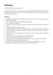
ENHANCE YOUR DVR WITH OUR WIDERANGE OF CAMERASOUR <strong>PRO</strong>DUCTS ARE FULLYTESTED TO WORK TOGETHEREYEBALL DOMESP400 CAMERASVANDAL DOMESPTZ CAMERAS INTERNAL DOMES MINI CAMERASDONT SETTLE FOR LESS,ALL OUR <strong>PRO</strong>DUCTS CARRYLOGOS
Directory1 Welcome ...................................................................................... 52 Open-package check and cable connections ....................................62.1 Initial check ............................................................62.2 Hard disk installation ...........................................................62.3 Rack mount .........................................................................72.4 Front panel .........................................................................72.5 Rear panel ..........................................................................92.6 Installation sketch ................................................................92.7 Audio and video input and output connections ........................102.7.1 Video input connections ..................................................102.7.2 Video output connections and options ...............................102.7.3 Audio signal input ........................................................102.7.4 Audio signal output .......................................................112.8 Alarm Input & output connections ......................................112.8.1 Alarm input port specifications .......................................122.8.2 Alarm output port specifications ...............................122.8.3 Alarm output port relay perameters .................................132.9 Speed dome connections ....................................................133 Basic operation ............................................................................143.1 Turn on ............................................................................143.2 Turn off ............................................................................143.3 System Login ....................................................................143.4 Preview ............................................................................153.5 Desktop shortcut menu ......................................................153.5.1 Main menu ..................................................................163.5.2 Playback .....................................................................173.5.3 Record Mode ...............................................................193.5.4 Alarm output ................................................................203.5.5 PTZ control ..................................................................203.5.6 Color setting .................................................................243.5.7 Output adjust ................................................................253.5.8 Logout .........................................................................253.5.9 Window switch .............................................................254 Main menu .................................................................................264.1 Main menu navigation ........................................................264.2 Record .............................................................................274.2.1 Record Config ..............................................................274.2.2 Playback ......................................................................284.2.3 Snapshot storeage .........................................................284.2.4 Backup ........................................................................294.3 Alarm ...............................................................................304.3.1 Motion Detect ..............................................................304.3.2 Video Blind ...................................................................324.3.3 Video Loss ....................................................................334.3.4 Alarm input ....................................................................334.3.5 Alarm output ...............................................................334.3.6 Abnormal .....................................................................333
4.4 System .............................................................................344.4.1 General ........................................................................344.4.2 Encode .........................................................................354.4.3 Network ......................................................................364.4.4 NetSevice ...................................................................364.4.5 GUI Display .................................................................424.4.6 PTZ .............................................................................434.4.7 RS232 set up ................................................................434.4.8 Tour setup .....................................................................444.5 Advanced ..........................................................................444.5.1 HDD Manage ...............................................................444.5.2 Account .......................................................................454.5.3 Online user ...................................................................474.5.4 TV adjustment ..............................................................474.5.5 Auto maintain ..............................................................474.5.6 Restore .......................................................................474.5.7 Upgrade ......................................................................484.5.8 Device Info ...................................................................484.6 Info ..................................................................................484.6.1 HDD info ....................................................................484.6.2 BPS ............................................................................494.6.3 Log .............................................................................494.6.4 Version ........................................................................504.7 Shut down system .............................................................505 FAQ and maintenance ..................................................................515.1 FAQ .................................................................................515.2 Maintenance .....................................................................55Appendix 1.Remote controller operation .............................................56Appendix 2.Mouse operation ............................................................56Appendix 3.Technique parameters ......................................................574
1. WelcomeThank you for purchasing our DVR!This manual is designed to be a reference tool for the installation and operationof your <strong>Qvis</strong> DVR series DVR system.You will find information about this <strong>Qvis</strong> DVRseries DVR's features and functions,as well as a detailed menu tree.Before you begin installation and operation please read the following safeguardsand warnings carefully!Important Safeguards and WarningsDo not place heavy objects on the DVR.Please ensure no solid or liquid fall into or infiltrate the DVR.Please brush printed circuit boards, connectors, fans, machine box and so onregularly.Before cleaning however, please switch off the power supply and unplug it fromthe mains.Do not attempt to disassemble or repair the DVR by yourself. Do not attempt toreplace any components by yourself.EnvironmentPlease position and use the DVR in a dry environment between 0 o and 40 o .Do not position or use in direct sunlight or near a heat source..Do not install the DVR in damp, smoky or dusty environment.Avoid shocks or physical damage to the DVR.Please insure the DVR is level and in a stable workplace.Please install in a well ventilated environment. Keep the vents clean.Use within the rating input and output scope.5
2 Initial check and cable connections2.1 Initial checkWhen you first receive your DVR, please check the following:1. Please check whether there is any visible damage to the packageappearance. The protective materials used for the package of the DVR canprotect the DVR against most accidental damage during transportation.2. Please open the box and get rid off the plastic protective materials. Checkwhether there is any visible damage to the DVR itself.3. Please open the machine crust and check the data wire in the front panel,power wire and the connection between the fan power and the main board.Front and rear panel• The key functions on the front panel and the interface specification for thereal panel are in the specification.• Please check the product type described on the front panel whether is theproduct type you ordered.The label on the real panel is very important for after sales service. Pleaseprotect it carefully. If you have to contact us for after sales service, pleaseprovide the product type and serial number from this label.2.2 Hard disk installationBefore you first use the DVR, please install the hard disk as follows:-1). Undo the side screws 2). Lift off the cover3). Screw on the hard disk 4). Screw on the hard disk6
5). Connect SATA data wire 6). Connect the power wire7). Put the top back on 8). Screw on the cover2.3 Rack mount installationThis series of DVR is in a standard 1.5U case, so it can be rack mounted.Step:1. Make sure the room temperature is lower than 35°C (95°f)2. Keep at least 15cm space around the DVR to allow air to flow3. Installation is from bottom to top2.4 Front panel (may vary on some models)(1) Play/Pause/5 (2) Slow play/6 (3) Fast play/7 (4) Playback pause/8(5) Playback stop.9 (6) Record (7) Power switch (8) USB(9) MainMenu/0 (A) Screen switch/1 (B) Record search/2 (C) PTZ control/3(D) Assist/4 (E) Shift (F) Cancel (G) IR signal receiver(H) Direction/OK (I) Light indicator7
Front panel function tableSerial NO Key Mark Function1 Play/Pause II Play or Pause when playbackPress 5 on the Remote controller2 Slow Play Slow play when playbackPress 6 on the Remote controller3 Fast Play Fast play when playbackPress 7 on the Remote controller4 PlaybackPauseIIPlayback record file and pause;Press 8 on the Remote controller6 record REC Start/stop record,use direction button to choose any recordchannels what you want7 PowerSwitchEFunctionSwitchSHIFTPower on/offSwitch different functions among numbers,character andothersF Cancel ESC Return to former menu, cancel current operation ;Return to preview status when playbackH Direction In the Menu,press up or down to move CursorChange configuration in the Drop-down menPress up or down to select record file in the playback statusIn the Preview screen,press up or down to go into 1/4/8/9/16multiple channels screen In the Menu,press left or right to move CursorIn the playback status,press left or right to move cursor offunction buttonIEnter Enter EnterEnter into main menuHDD HDD Shows HDD working statusindicationlightRecordindicationlightAlarmindicationlightShiftindicationlightPowerindicationlightRECIALARMSHIFTPOWERShows Record working statusShows Alarm working statusShows Shift working statusShows Power working status8
2.5 Rear panelNote: This is the interface for a 4 channel rear panel of a DVR. See Appendix 3on page 57 for more details for specific models.1 2 3 4 5 6 7 8 9 10(1) Video Input (2) Audio Input (3) Video Output (4) Audio Output(5) USB (6) Network (7) VGA (8) Alarm In & Out & RS232(9) Power Supply (10) Power Switch2.6 Installation sketch map9
2.7 Audio and video input and output connections2.7.1 Video input connectionsThe video input port is a BNC connector plug. The type of input signal is PAL/NTSC BNC(1.0VP-P,75Ω).The video signal must be of the correct standard and have a high signal to noiseratio, low aberration and low interference. The image must be clear and havenatural color and brightness in the environment in which it is to operate.Insure the monitor signal is stable and credibleThe monitor should be installed in a suitable location where is away frombacklighting and low illumination or uses backlighting and low illuminationcompensation.The earth and power supply of the monitor and the DVR should be shared andstable.Insure the transmission line is stableThe video transmission line should be a high quality coaxial pair which is suitablefor the transmission distance. If the transmission distance is too great, you shoulduse shielded twisted pair, video compensation equipment or transmit by fiberoptics to insure the signal quality.The video signal line should be away from all electro magnetic Interference andother signal line equipment. High voltage current should be especially avoided.Insure the connection is stableThe signal and shield lines should be connected with a tight connection whichwill help avoid false signals, joint welding and oxidation.2.7.2 Video output connections and optionsThe video output is divided into PAL/NTSC BNC(1.0VP-P,75Ω) and VGA output(selective configuration).If you replace your <strong>Qvis</strong> monitor with a computer display, there are some issuesto take note of.1). Do not leave the display turned on for a long time.2). To ensure normal working demagnetize regularly.3). Keep the display away from electro magnetic Interference.A TV is not a suitable replacement for a video output. It can only be used for ashort period of time and is particuarly suseptabler to nearby interferance. The TVcan also damage other equipment.2.7.3 Audio signal inputThe audio port is a BNC connection.As the input impedance is high, the tone arm must be active.The audio signal line should be strong and away from any electro magneticInterference and with a credible connection which should avoid false signals andjoint welding and oxidation. High voltage current should be especially avoided.10
2.7.4 Audio signal outputCommonly the output parameter of a DVR audio signal is greater than 200mv1KΩ(BNC) which can connect a low impedance earphone and active sound boxor other audio output equipments through a power amplifier. If the sound box andthe tone arm can not be isolated, a howling phenomena is often experienced.Here are some methods to deal with this phenomena.1). Adopt a better directional tone arm.2). Adjust the sound box volume to below the threshold that produces thehowling phenomena.3). Use fitment materials that absorb the sound to reduce the reflection of thesound.4). Adjust the layout of the sound box and the tone arm.2.8 Alarm input and output connections1. Alarm inputA. Alarm input is grounding alarm input.B. Alarm input demand is the grounding voltage signal.C. When the alarm is connected with two DVRs or connected with DVRand other equipments, it should be isolated by relay.2. Alarm outputAlarm output can not be connected with high-power load(no more than 1A).When forming the output loop it must prevent the big current from relay damage.Use the contact isolator when there is a high-power load3. PTZ decoder connectionsA. The earth for the PTZ decoder and DVR must be shared otherwisethe common-mode voltage will lead to the PTZ control failure. Shieldedtwisted pair is recommended.B. Avoid high voltage. Take precaution against the thunder and lightning.C. At the outlying end connect a parallel 120Ω resistance to ensure thesignal quality.D. The 485 AB lines of the DVR can not connected with other 485 outputequipment in parallel.E. The voltage between the AB lines of the decoder must be less than 5V.4. Front equipment earthing noteBad earthing can lead to burnout of the chip.5. Alarm input type unlimitedThe DVR alarm output port is constant opening type.11
(1) alarm input (2) grounding (3) RS232 (4) alarm output (5) RS485ParameterGMeaninggrounding (earth)C1, NO1 Alarm output interface(constant open type)T, R RS232 portA, B 485communication interface which is connected with the recordingcontrol equipments such as the decoder2.8.1 Alarm input port specification1 channels alarm input. Alarm input type unlimited.The earth and the com port of the alarm sensor are parallel (The alarm sensorhas an external power supply) .The earth of the alarm and the DVR should be shared.The NC port of the alarm sensor must be connected with the DVR alarm inputport.The earth of the power supply and the alarm sensor must be shared when usedin an external power supply.2.8.2 Alarm output port specification2 channels alarm output. There is an external power supply when using theexternal alarm equipment.Please refer to the relevant relay parameters to avoid overloading that damagesthe DVR.12
2.8.3 Alarm output port relay parametersType: JRC-27FInterface materialRating(resistance load)SilverRating switch capacityMaximal switch powerMaximal switch voltageMaximal switch current30VDC 2A, 125VAC 1A125VA 160W250VAC, 220VDCIsolation Homo-polarity interface 1000VAC 1minuteInhomo-polarity interfaceInterface and winding1A1000VAC 1 minute1000VAC 1 minuteSurge voltage Homo-polarity 1500VAC (10×160us)Turn-on timeTurn-off time3ms max3ms maxlongevity Mechanical 50×106 MIN (3Hz)Environment temperatureElectric2.9 Speed dome connections-40~+70 o C200×103 MIN (0.5Hz)1. Connect the 485 lines of the speed dome with the DVR 485 interface.R4852. Connect the video line with the DVR video input.3. Connect the speed dome to a power supply.Note: The speed dome A, B port and the DVR A, B port should be a correspondingconnection, A is +, B is -13
3 Basic operationNote: The button in gray display indicates nonsupport.3.1 Turn onPlug in and turn on the power supply switch. If the Power supply indicator lightlights up then the video recorder has turned on. After startup you will hear abeep. The default setting of the video output is a multiple-window outputmode. If the startup time is within a set video recording time, the timing videorecording function will start up automatically. Then the video indicator light of thecorresponding channel will light up to let you know the DVR is working normally.Note:1). Make sure that the input voltage corresponds with the switch of the DVRpower supply.2). Power supply demands: 220V±10% /50Hz.We suggest using UPS to protect the power supply under suitable conditions.3.2 Turn offThere are two methods to turn off the DVR. Entering [main menu] and choosing[turn off] in the [turn off the system] option is called soft switch. Pressing thepower supply switch is called hard switch.Illumination:1). Auto resume after power failureIf the DVR is shut down abnormally, it can automatically backup video andresume the previous working status after a power failure.2). Replace the hard diskBefore replacing the hard disk, the power supply switch in the rear panel mustbe turned off.3). Replace the batteryBefore replacing the battery, the setting information must be saved and the powersupply switch in the rear panel must be turned off. The DVR uses a buttonbattery. The system time must be checked regularly. If the time is not correct youmust replace the battery, we recommend replacing the battery every year andusing the same battery type.Note: The setting information must be saved before replacing the batteryotherwise information will be lost.3.3 System LoginWhen the DVR boots up, the user must login and the system provides thecorresponding functions in the user preview. There are three user settings. Thenames are admin, guest and default and these names have no password. Adminis the super user preview; guest and default’s permissions are preview and videoplayback.User admin and guest’s password can be revised, while their permissions can’tbe revised; user default is the default login user whose permission can be revisedbut not its password.14
Picture 3.1 System LoginPassword protection: If the password is entered continuously wrong for threetimes, the alarm will start. If the password is continuously wrong five times, theaccount will be locked. (Through a reboot or after half an hour, the account canbe unlocked automatically).For your system security, please modify your password after first login.3.4 PreviewYou can right click mouse to choose the switch between the windows.The system date, time and channel name are shown in each viewing window.The surveillance video and the alarm status are shown in each window.1 Recording status 3 Video loss2 Motion detect 4 Camera lockTable 3.1 Preview icon3.5 Desktop shortcut menuIn preview mode you can right click your mouse to get a desktop shortcutmenu. The menu includes: main menu, record mode, playback, PTZ control,High Speed PTZ, Alarm Output, Color Setting, Output adjust, Logout, View1/4/8/9/16 screens.15
3.5.1 Main menuPicture 3.2 Shortcut MenuWhen you login, the system main menu is shown as below.Picture 3.3 Main Menu16
3.5.2 PlaybackThere are two methods for you to play the video files in the hard disk.1). In the desktop shortcut menu.2). Main menu>Record->PlaybackNote: The hard disk that saves the video files must be set as read-write or readonlystate. (4.5.1)Picture 3.4 video playback1). Listed files 2). File information 3). File searching4). File backup 5). Operation hint 6). Playback control(Listed files) Look up the listed files that accord with the searching criteria.(File information) Look up the found file information.(File backup) Backup the chosen file. Click the button and operate as followed.Note: The storage must be installed before the file backup. If the backup isterminated, the files already backedup can playback individually.Picture 3.5 detect the storage17
Detect: Detect the storage connected with the DVR such as hard disk or universal disk.Erasure: Choose the file to delete and click erasure to delete the file.Stop: Stop the backup.Backup: Click backup button and the dialog box is popped up. You can choosethe backup file according to the type, channel and time.Picture 3.6 recording backupRemove: Clear the file information.Add: Show the file information satisfying the set file attributes.Start/Pause: Click the play button to start the backup and click the pause buttonto stop the backup.Cancel: During backup you can exit the page layout to carry out other functions.(File searching) Search the file according to the searching parameter.Picture 3.7 file searchingFile type: Set the searching file type.Channel: Set the searching channel.Start Time: Set the searching time scan.End Time: Set the end time of the file searchPlay Mode: Select different play mode, Skip Decode,Average Decode and Full Decode.Sync Mode: Select it for playback all chosen channels at the same time(Playback control) Refer to the following sheet for more information.18
Button Function Button Function/ Play/pause BackwardStopFast playNext frameNext fileFull screenTable 3.2 Playback control keySlow playPrevious framePrevious fileCirculationNote: Frame by frame playback is only performed in the pause playback state.(Operation hint) Display the function of the cursor place.Special functions:Accurate playback: Input time (h/m/s) in the time column and then click theplay button. The system can operate accurate playback according to thesearching time.Local zoom: When the system is in single-window full-screen playback mode,you can drag your mouse in the screen to select a section and then left click yourmouse to view this in local zoom. You can right click your mouse to exit.3.5.3 Record ModePlease check the current channel status: “” means it is not in recording mode,“•” means it is in recording mode.You can use the desktop shortcut menu or click [main menu]> [recordingfunction]> [recording set] to enter the recording control interface.Picture 3.8 Record ModeSchedule: Record according to the configuration.Manual: Click the all button and the according channel is recording no matter thechannel in any state.Stop: Click the stop button and the according channel stops recording no matterthe channel in any state.19
3.5.4 Alarm outputPlease check current channel status: “o” means it is not in alarming status, “•”means it is in alarming status.You can use desktop shortcut menu or click [main menu]> [alarm function]>[alarm output] to enter the alarm output interface.Picture 3.9 alarm output(Configuration) Alarm is on according to the configuration.(Manual) Click the all button and the according channel is alarming no matterthe channel in any state.(Stop) Click the stop button and the according channel stops alarming no matterthe channel in any state.3.5.5 PTZ controlThe PTZ Operation interface is as followed. The functions include: PTZ directioncontrol, step, zoom, focus, iris, setup operation, patrol between spots, trail patrol,boundary scan, assistant switch, light switch, level rotation and so on.Note:1). Decoder A(B) line connects with the DVR A (B) line. The connection is right.2). Click [main menu] >[system configuration] >[PTZ setup] to set the PTZ parameters.3). The PTZ functions are decided by the PTZ protocols.Picture 3.10 PTZ setup20
Speed: Set the PTZ rotation range. Default range: 1 ~ 8.Zoom: Click / button to adjust the zoom multiple of the camera.Focus: Click / button to adjust the focus of the camera .Iris: Click / button to adjust the iris of the camera.Direction control: Control the PTZ rotation. 8 directions control is supportive.(4 directions in Front panel is supported )High speed PTZ: Full-screen shows channel image. Left mouse click to controlthe PTZ rotation and orientation. Left click mouse and then rotate the mouse toadjust the zoom multiple of the camera.Set: Enters the function operation menu.Page switch: Switchs between different pages.Special functions:1). PresetTo set a preset location, call up the preset points and the PTZ will automaticallyturn to the setting position1). Preset optionTo set a location for the preset, the procedure is as follows:Step 1: In Picture 3.10, use the direction button to turn the PTZ to the presetposition, click the Settings button to enter Picture 3.11.Step 2: Click on the preset button and then enter the preset point number inthe preset box (shows 0 in box below),Step 3: Click the Set button to return to Picture 3.10 to complete the setup,check that the preset points and preset position corresponds.Clear Preset: Input preset points, click Remove button to remove a preset.Preset ButtonPreset pointinput blankPicture 3.11 Preset Settings2). To go to a Preset PointIn Picture 3.10, click Page Switch button, enter PTZ control interface as shown inPicture 3.12. In the input No, type the preset point, then click the preset button,the PTZ will turn to the corresponding preset point.21
Value input blankPicture 3.12 PTZ Control2: Cruise between PointsA PTZ camera can be set to cruise between a series of preset points. This is calleda cruise. To set the PTZ up to do this is as follows:1). Cruise Between Points SettingsA cruise line is a set up of multiple preset connected points, the setup procedureis as follows:Step 1: In Picture 3.10, use the Direction key to turn the PTZ to a designatedlocation, click the settings button to enter Picture 3.13,Step 2: Click the Tour button, enter the tour number into the Patrol Numberbox if it isn't already showing and then click Add preset. The numberof presets in the tour will show in the Preset box.Step 3: repeat steps 1 and 2, until you have set out all the preset designatedcruise positionsRemove Preset: Please input the preset value in the blank, click Remove Presetbutton, then remove the preset points.Remove Cruise Line: Input the number of cruise line, click Remove Cruise Linesbutton, then remove the cruise lines set.Cruise ButtonPreset pointsblankCruise lineblankPicture 3.13 Cruise Between Points Settings2). To view Cruise between PointsIn Picture 3.10, click the Page Shift button to enter the PTZ control menu asshown in Picture 3.12. Please input the patrol number of the cruise in the valueblank, then click the Cruise between Points button. The PTZ will cruise from pointto point on the cruise line. Click the Stop button to stop the cruise.22
3: ScanThe PTZ can also work on the preset scan line repeatedly.1). Scan setupStep 1: In Picture 3.10, click the Setup button, which takes you to Picture 3.14;Step 2: Click the Pattern button and input a patrol value in the pattern valueblank;Step 3: Click the begin button and enter Picture 3.10, here you can set thefollowing items: Zoom, Focus, Aperture, Direction and so on. Click Setbutton to go back Picture 3.14;Step 4: Click the End button to complete the setup, Click the right button ofthe mouse to exit.Scan value blankScan buttonPicture 3.14 Scan Setup2). Scan CallsIn Picture 3.10, click the Page Shift button to enter the PTZ control menu asshown in Picture 3.12.Please input the number of the scan in the value blank , then click the AutoScanbutton, the PTZ will begin to work on the scan line . Click the stop button to stop.4: Boundary Scan1). Boundary Scan setupStep 1: In Picture 3.10, click the multi arrow direction button to turn the PTZto a left hand boundary position, then click Set button to enter Picture3.15, select the left boundary, return to Picture 3.10;Step 2: Please click the multi arrow direction button to adjust the PTZ to theright boundary, click Set button to enter Picture 3.15, then select theright boundary, return to Picture 3.10;Step 3: Complete setup, the position of left and right boundary are now set.right button click to exit.Line scanbutton borderPicture 3.15 Boundary Scan Setup23
2). Boundary Scan CallsIn Picture 3.10, click the Page Shift button to enter the PTZ control menu asshown in Picture 3.12.Please input the number of the scan in the value blank , then click the AutoScanbutton, the PTZ will begin to work on the scan line . Click the stop button to stop.5: Rotating the HorizontalClick the Horizontally Rotating button and the PTZ will begin to rotate horizontally(relative to the original position of the camera). Click the Stop button to stop.6: RotateClick on the horizontal rotating button and the PTZ will turn around.7: ResetThe PTZ will restart and clear all the data back to 0.8: Page ShiftIn Picture 3.12, click the Page-Switch button to go to Picture 3.16 (setting theauxiliary function). Set the auxiliary number corresponding to auxiliary switch onthe decoder.Picture 3.16 Auxiliary Function Control(Intuitive Auxiliary Operation) choose auxiliary equipment, select Open or Closebutton as the switch control.(Auxiliary Number) The operation of the corresponding auxiliary switch accordingto the PTZ agreement.(Page Shift) In Picture 3.16 click Page Switch button to enter Picture 3.17 PTZMain Menu, the menu itself can be control by the menu control buttons3.5.6 Color settingSet the selective image parameters (the current channel for the single windowdisplay and cursor placed for the multi-window display). You can use the desktopshortcut menu to enter the interface. The image parameters include: tonality,brightness, contrast, saturation. You can set different parameters at different timesections.24
Picture 3.18 Color Setting3.5.7 Output AdjustAdjust TV output area parameters. You can use the desktop shortcut menu orenter [main menu]> [management tools]> [Output adjust].3.5.8 LogoutPicture 3.19 Output AdjustTo logout, shut down the system or reboot the system. You can use the desktopshortcut menu or enter [main menu].Picture 3.20 Logout/ Shutdown/ Reboot the system(Logout) Quit the menu. Re-enter the password to log back in.(Shut down) Quit the system. Turn off the power supply. When you press theshut down button, there is a schedule hint. After three seconds, the system shutsdown. If you attempt to cancel midway through it will have no effect.(Reboot) Quit the system. Reboot up the system..3.5.9 Window switchPreview in a single window/four windows/eight windows/nine windows/sixteenwindows/thirty two windows according to your choice.25
4 Main menu4.1 Main menu navigationMain menu Sub menu FunctionRecord Config Set the recording configuration, recording type, recordingtime sectionPlaybackBackupSnapshot StorageSet recording look-up, recording play, video file storageDetect or format backup equipment, back the selective filesSet Pre snapshot,record and record timeAlarm Motion detection Set motion detect alarm channel, sensitivity, area,linkage parameters: defending time section, alarmoutput, screen hint, recording, PTZ, patrolSystemConfigurationVideo blindVideo lossAlarm inputAlarm outputAbnormalityGeneralconfigurationEncodeconfigurationNetworkconfigurationNetServiceGUI displayPTZ configurationSerial port Configuration(RS232)TourSet camera mask alarm channel, sensitivity, linkageparameters: defending time section, alarm output, screenhint, recording, PTZ, patrolSet video loss alarm channel, linkage parameters: defendingtime section, alarm output, screen hint, recording, PTZ, patrolSet alarm input channel, equipment type, linkageparameters: defending time section, alarm output, screenhint, recording, PTZ, patrolSet alarm mode: configuration, manual, shut downSet alarm actived by no disk,disk error and disk no spaceSet system time, data format, language, hard disk fulltime operation, machine number, video format, outputmode, summertime, stay timeSet main(assistant)coding parameter: code mode, resolvingability, frame rate, code stream control, image quality type,code stream value, frame between value, video/audio enableSet basic network parameters, DHCP and DNS parameters,network high speed downloadPPPOE, NTP, Email, IP purview, DDNS parameterSet channel name, preview hint icon state, transparency,cover area, time title, channel time foldSet channel, PTZ protocol, address, baud rate, date bit,stop bit, checkSet serial port function, baud rate, date bit, stop bit,checkSet patrol mode and interval time26
Main menu Sub menu FunctionManagementtoolsSysteminformationShut downHard diskmanagementUser managementOnline userTV adjustAutomatic maintenanceRestoreUpgradeDevice InfoHard disk informationCode stream statisticsLog informationEdition informationSet appointed hard disk as read-write disc, read-only discor redundant disc, clear data, resume date and so onModify user, team or password. Add user or team. Deleteuser or team.Break the connection with the already login user. Lockthe account after break until booting up again.Adjust TV upside, downside, nearside, starboard distanceSet automatic reboot system and automatic deleting files.Resume setup state: common setup, code setup, recordingsetup, alarm setup, network setup, network service,preview playback, serial port setup, user managementUpgrade the device by USB portShow device video,audio and alarm portsDisplay hard disk capability and recording timeDisplay code stream informationClear all log information according to the log video and timeDisplay edition informationLogout or reboot4.2 Record4.2.1 Record ConfigurationTo set the recording parameters in the surveillance channel. The system is setup for 24 hours consecutive recording in the first startup. You can enter [mainmenu]> [recording function]> [recording setup] to set.Note:There must be at least one read-write hard disk.(refer to chapter 4.5.1)Picture 4.1 Record Config(Channel) Choose the corresponding channel number to set the channel. Choosethe all option to set every channel to the same.(Redundancy) Choose the redundancy function option to implement the filedouble backup function. Double backup is writing the video files to two harddisks. When you do the double backup, make sure that there are two hard disksinstalled. One is read-write disk and the other is redundant disk. (refer to 4.5.1)(Length) Set the time length of each video file. 60 minutes is the default value.27
(PreRecord) Record 1-30 seconds before the action. (time length is decided bythe code stream)(Record mode) Set the video state: schedule, manual or stop.Schedule: Record according to the set video type (common, detection and alarm)and time section.Manual: Click the button and the relevant channel will start recording no matterwhat else the channel has been set to do.Stop: Click the stop button and the relevant channel stops recording no matterwhat else the channel has been set to do.(Period) Set the time section for common recording, The recording will start onlywithin the set range.(Record type) Set recording type: regular, detection or alarm.Regular: Perform regular recording in the set time section. The video file type is“R”.Detect: Trigger the “motion detect”, “camera mask” or “video loss” signal. Whenthe above alarm is set as the opening recording, the “detection recording” stateis on. The video file type is “M”.Alarm: This triggers the external alarm signal in the set time section. When theabove alarm is set as the opening recording, the “detection recording” state is setto on. The video file type is “A”.Note: Refer to chapter 4.3 to set corresponding alarm function.4.2.2 PlaybackRefer to chapter 3.5.2.4.2.3 Snapshot StorageSetup snapshot parameters for different channels.At first time it's set for 24hourssnapshot continuously, pls go to Main Menu->Record->Snapshot Storage forappropriate settings.Note: If normal snapshot storage,pls setup Snap at Main Menu->Advanced->Snapshot (pls refer to chapter 4.5.1 HDD Manage)Picture 4.2(Channel) Select the related channel to set,click "all" to set all channels.(Presnap) Setup presnap picture quantity before recording, default is 5 pieces.(Record) Set record status,"Schedule","Manual" and "Stop"Schedule: Will take a snapshot according to the record type setting (regular,detect and alarm) and time setting period.28
Manual: No matter what the present channel is doing, once you choose the"manual" button, it will only take a snapshot when you tell it to.Stop: No matter what the present channel is in a state, once you choose the"stop" button, it will stop the snapshot function.(Period) Set normal record period, (Sets the frequency that a Snapshot is taken).(Type) Three types: regular, detect and alarm (sets the trigger for a shapshot).(Record type) Three types: regular, detect and alarmRegular: snapshot at set periodDetect: snapshot at set period when motion detect, video blind and video loss areset as the trigger to activate a snapshot.Alarm: snapshot at set period when alarm in which is preset for snapshot enable.Note: for related alarm function, pls refer to chapter 4.3.4.2.4 BackupYou can backup the video files to external storage through setup.Note: The storage must be installed before the file backup starts. If the backupis terminated, the files already backed up can be played back individually.Picture 4.3 Backup(Detect) Detects the storage connected with the DVR such as hard disk oruniversal disk.(Erase) Choose the file to delete and click erasure to delete the file.(Stop) Stop the backup.(Backup) Click backup button and the dialog box pops up. You can choose thebackup file according to type, channel and time recorded.Picture 4.4 File Backup29
Remove: Clear the file information.Add: Show the file information to satisfy the set file attributes.Start/pause: Click the play button to start the backup and click the pause buttonto stop the backup.Cancel: During backup you can exit the page layout to carry out other functions.4.3 Alarm FunctionAlarm functions include: motion detect, video blind, video loss, alarm input andalarm output.4.3.1 Motion DetectWhen the system detects a motion signal that reaches the set level of sensitivity,the motion detect alarm is switched on and the linkage function is turned on.Picture 4.4 Motion Detect(Channel) Choose the set motion detect channel.(Enable) • means that the motion detect function is on.(Sensitivity) Choose in the six options according to the sensitivity.(Region) Click setup and enter the set area. The area is divided into PAL 8x8.Green block means the current cursor area. Yellow block means the dynamicdetect defensive area. Black block means the unfenced area. You can set the areaas followed, Drag the mouse and draw the area.Picture 4.5 Region30
(Period) Trigger the motion detect signal in the set time section. You can setaccording to week or set uniformly. Each day is divided into four time sections.• means the setup is valid.Picture 4.6 set the time section(Interval) Only one alarm signal is turned on even if there are several motiondetection signals in the set interval.(Alarm output) Starts the external equipment of the linked alarm when the motiondetect alarm is turned on.(Delay) Delay a few moments and stop when the alarm state is turned off. Therange is 10~300 seconds.(Record channel) Choose the recording channel (multiple options are supported).Trigger the video signal when the alarm is turned on.Note: Set in the [recording setup] and perform the linked recording. Start detectingvideo files in the corresponding time section.(Tour) • means that the selected channel is a single window alternate patrolpreview. The interval is set in the [MainMenu]>[System] > [Tour].(Snapshot) Choose record channels, when the alarm activates, the systemtriggers the related channels for a snapshot signal.Note: For snapshot activation, please go to set period, detect and alarm enable atMainMenu->Record->Record config,(PTZ Activation) Set the PTZ activation when the alarm is turned on.Note: PTZ activation is set in the [shortcut menu] >[ PTZ control]. Set the patrolbetween spots, trail patrol and so on.Picture 4.8 PTZ Activation(Delay) When alarm is over, recording will last a few seconds(10~300sec),thenstop.(Show message) Pops the alarm information dialog box into the local hostcomputer screen.31
(Send EMAIL) means sending an email to the user when the alarm is turned on.Note: Set in the [NetService] and send email.4.3.2 Video BlindWhen the video image is influenced by environmental factors such as excessivebrightness or reaching the set sensitivy parameter, the camera mask function andthe linkage function are turned on.Picture 4.9 Video BlindSet method: refer to chapter 4.3.1. Motion detectNote: "Advanced" button is the same as right-click.4.3.3 Video LossWhen the equipment can not obtain the channel video signal, the video lossalarm is turned on and the linkage function is turned on.Picture 4.10 Video lossSet method: refer to chapter 4.3.1. Motion detectNote: "Advanced" button is the same as rightclick.32
4.3.4 Alarm inputWhen the system gets an external alarm signal, the alarm function is turned on.Picture 4.11 Alarm inputSet method: refer to chapter 4.3.1. Motion detectNote:"Advanced" button is the same as right-click.4.3.5 Alarm output4.3.4 AbnormalRefer to chapter 3.5.4.Analysing and inspecting current software and hardware of the device: Whensome abnormal events happen, the device will make a relative explanation suchas show a message and sound a buzzer.Picture 4.12 Abnormal(Event Type) Selecting the abnormity you want to inspect(Enable) Select it to make sure the abnormal function works(Show message) Automatically an alarm cue dialog box comes up on the mainscreen(Buzzer) The device will have a “di di” noise when the alarm is sounding33
4.4 System setupSet the system parameters such as General, Encode, NetWork, NetService,GUI Display, PTZ Config, RS232 and Tour Setup.4.4.1 GeneralPicture 4.13 General setup(System time) Set the system data and time.(Date format) Choose the data format: YMD, MDY, DMY.(Date Separator) Choose list separator of the data format.(Time Format) Choose time format: 24-hour or 12-hour.(Language) Arabic, Czech, English, Finnish, Greek, Indonesian, Italian, Japanese,Portuguese, Russian, Thai, T-Chinese, S-Chinese, Turkish, Brazilian, Bulgarian,Farsi, French, German, Hebrew, Hungarian, Polish, Romanian, Spanish, Swedish,Vietnamese(HDD full) Choose stop record: Stop recording when the hard disk is full Chooseoverwrite: Cover the earliest recording files and continue recording when thehard disk is full.(DVR No.) Only when the address button in the remote controller and thecorresponding DVR number is matched, the remote operation is valid.(Video Standard) PAL or NTSC.(Auto Logout) Set the latency time in 0-60. 0 means no latency time.(DST) Choose the summer time option and pop the dialog box as followed.Picture 4.14 DST (week)Picture 4.15 DST (date)34
4.4.2 Encode setupSet the video/audio code parameters: video file, remote monitoring and so on.Set every independent channel’s coding parameter in the left part, and set thecombine encode parameter in the right part.Note: Combine encode introduces video compression technique which combinesand compresses multi-channel’s video to a special channel. Applying for multichannelplayback simultaneously, Dial-up multi-channel real-time monitor,mobile monitor and so on.Picture 4.16 Encode setup(Channel) Choose the channel number.(Compression) Standard H.264 main profile.(Resolution) Resolution type:D1/ HD1/CIF / QCIF.(Frame Rate) P:1 frame/s~25 frame/s; N: 1 frame/s~30 frame/s(Bit Rate Type) You can choose limited code stream or variable code stream.When you choose the variable code stream there are six image quality options.(Bit Rate) Set the code stream value to modify the image quality. The larger codestream value the better image quality.D1(512~2560kbps), HD1(384~2048kbps), CIF(64~1024kbps), QCIF(64~512kbps)(Video/Audio) When the icons are all displayed in reverse, the video file is videoand audio multiplex stream.Combine Enable(Combine Enable) When the icons are all in reverse displayed, openingcombination coding functions.(Mode) multi-channel playback is used in all channels to playback simultaneously,and the narrowband transmission is used in multi-channel real-time remotemonitoring simultaneously at narrowband state, especially used with a mobilescreen.35
4.4.3 Network setupPicture4.17 Network(Net Card) You can choose cable network card or wireless network card.(DHCP Enable) Obtain IP address automatically (not suggested)Note: DHCP server is preinstalled.(IP address) Set the IP address. Default: 192.168.1.10.(Subnet mask) Set the subnet mask code. Default: 255.255.255.0.(Gateway) Set the default gateway. Default: 192.168.1.1.(DNS setup) Domain Name Server. It translates the domain name into IP address.The IP address is offered by network provider. The address must be set andreboot then it works.(TCP port) Default: 34567.(HTTP port) Default: 80.(HS Download)(Transfer Policy) There are three strategies: self-adaption, image qualityprecedence and fluency precedence. The code stream will adjust according to thesetup. Self-adaption is the tradeoff between the image quality precedence andfluency precedence. Fluency precedence and self-adaption are valid only whenthe assistant code stream is turned on. Otherwise the image quality precedenceis valid.4.4.4 NetServiceChoose the network service option and click the set button to configure theadvanced network functions or double click the service button to configure theparameters.Picture 4.18 NetService36
(PPPoE setup)Picture 4.19 PPPOEInput the user name and password that the ISP (Internet service provider)provides. After saving it reboot your system. Then the DVR will build a networkconnection based on PPPoE. The IP address will change into a dynamic IPaddress after the above operation is done.Operation: After PPPoE dialing is successfully look up the IP address in the [IPaddress] and obtain the current IP address. Then use this IP address to visit theDVR through user port.(NTP setup)Picture 4.20 NTPThe NTP server must be installed in the PC.Host computer IP: Input the IP address installed NTP server.Port:Default: 123. You can set the port according to NTP server.Time zone: London GMT+0, Berlin GMT +1, Cairo GMT +2, Moscow GMT +3,New Delhi GMT +5, Bangkok GMT +7, Hongkong Beijing GMT +8, Tokyo GMT+9, Sydney GMT +10, Hawaii GMT-10, Alaska GMT-9, Pacific time GMT-8,American mountain time GMT-7, American mid time GMT-6, American easterntime GMT-5, Atlantic time GMT-4, Brazil GMT-3, Atlantic mid time GMT-2.Update Period:The same with the NTP server check interval. Default: 10minutes.37
(EMAIL setup)If the alarm is turned on or the alarm linkage photos are taken, the system cansend an email of the alarm information and the photos to an appointed address.Picture 4.21 EMAILSMTP server: Email server address. This could be an IP address or a domainname. A domain name can only be used if it has the correct DNS configuration.Port: Email server port number.SSL: Decide whether to use Secure Socket Layer protocol to login.User Name: Apply the email server user name.Password: Input the user password.Sender: Set the senders email address.Receiver: Send the email to the appointed receiver(s) when the alarm is turnedon. You can set up to three receivers.Title: You can set this as you wish.(IP Filter setup)When choosing from the white list, only those IP addresses listed can connect tothe DVR. Up to 64 IP addresses are supported in this white list.When choosing from the black list, only these listed IP addresses cannot connectto the DVR. Up to 64 IP addresses are supported in this black list.You can delete the set IP address by √ in the options.Note: When the same IP address is in the white and black list at the same time,the black list takes precedence.Picture 4.22 IP IP FILTER38
(DDNS) (dynamic domain name server).Local domain name: Insert the domain name registered by the DDNS.User name: Insert the user name.Password: Insert the password.When the DDNS is successfully configured and started, you can connect thedomain name in the IE address column to visit.Note: The DNS setup must be configured correctly in the network setup.Picture 4.23 DDNS setup(FTP setup)FTP is available only when an alarm happens, or an alarm activates a record andtakes a snapshot, it will then upload the related records and snapshot picturesto the FTP server.Picture 4.24 FTP setup(Enable) Click Enable, to activate all settings(Server IP) The IP address for the FTP server(Port) Domain Port of FTP, the default is 21(User Name) User name of the FTP(Password) Password of user(Max File Length) Max length for upload files at every packed, default 128M(DirName) Directory of uploading files39
(ARSP)Startup DDNS server to add devices and manage it in the DDNS serverType: choose "DNS"Enable: • means it is chosenSever IP: IP address of DDNS serverPort:(Wireless Config) ADSL through 3G net card, use CMS to visit and config the devicePicture 4.25 Wireless Config(Enable) Choose Enable to make all settings available(Type) Dial type,default AUTO(Wireless AP) 3G access point(Dial Number) 3G Dial Number(User Name) User name of 3G(Password) Password of dial user(IP Address) IP address,got from dial.(Mobile Monitor Setup) To view the device on a mobile, please make a routermapping of this port and use CMS to monitor and operate it by this protocol.Picture 4.26 Mobile Monitor Setup40
(Enable) Select this to make sure the abnormal function is working(Port) This is the port to enable mobile monitoring. You will need to make a routermap of it if you want to view everything by mobile(UPNP) UPNP protocol can set auto port forwarding on the router, make sureUPNP is running on the router before useing it.Picture 4.27(Enable) Choose Enable to make sure all UPNP settings available(HTTP) Route will automatically distribute HTTP port for the device,when IEviewing,it need this port(eg. 60.12.9.26:66)(TCP) Router will automatically distribute TCP port for the device,when monitoringvia CMS,it need this port.(MobilePort) Router will automatically distribute Mobile Port for the device,whenmobile monitor,it need this port.(WIFI) Through wireless network to connect with the DVR.(Search) search SSID of wireless LAN(Enable) Select it to enable the function(SSID) SSID name(Password) password of WIFI(IP Address) IP address of WIFI(Subnet Mask) Subnet mask of WIFI(Gateway) Gateway of WIFI41
4.4.5 GUI DisplayConfigure the video output parameters including the front output mode and codeoutput mode.Front output: In the local preview mode and includes: channel title, time display,record status, alarm status, bitrate info, transparency and region cover.Code output:In the network surveillance and video file mode include: channeltitle, time display, record status, alarm status, bitrate info, transparency andregion cover.Picture 4.28 GUI Display(Channel Title) Click the channel name modify button and enter the channelname menu. Modify the channel name as required.(Time Display) means the selected state. This displays the system data and timein the surveillance window.(Channel Title) means the selected state. This displays the system channelnumber in the surveillance window.(Record Status) means the selected state. This displays the system recordingstatus in the surveillance window.(Alarm Status) means the selected state. This displays the system alarm statusin the surveillance window.(Bitrate info) means the selected state. The ninth window displays the codestream information in the nine-window preview status.(Transparency) Choose the background image level of transparency. The rangeis 128~255.(Resolution) set the display resolution.(Channel) Choose the set code for the output channel number.(Region Cover) means the selected state. Click the cover area button and enterthe corresponding channel window. You can cover arbitarily using the mouse.(the black region is for output)(Time display)(Channel Title)42
4.4.6 PTZ setupPicture 4.29 PTZ setup(Channel) Choose the dome camera input channel.(Protocol) Choose the corresponding dome protocol. (PELCOD as an example)(Address) Set as the corresponding dome address. Default: 1.(Note: The address must be consistent with the dome address.)(Baud rate) Choose the corresponding dome baud rate length. You can controlthe PTZ and monitor. Default: 115200.(Data bits) Include 5-8 options. Default: 8.(Stop bits) Include 2 options. Default: 1.(Parity) Include odd check, even check, sign check, blank check. Default: void.4.4.7 RS232 setupPicture 4.30 RS232 setup(Serial Port Function) Common serial port is used to debug and update programor set up specific serial port.(Baud rate) Choose the corresponding baud rate length.(Data bits) Include 5-8 options.(Stop bits) Include 2 options.(Parity) Include odd, even, mark, space.43
4.4.8 Tour setupSet the patrol display. • means that the tour mode is turned on. You can choosethe single window, four windows, nine windows, sixteen windows patrol displayor single display.Picture 4.31 tour setup(Interval) Set the patrol switch interval. The set range is 5-120 seconds.Note: / means turn off/on the patrol.4.5 Advanced4.5.1 HDD ManageConfigure and manage the hard disk. The menu displays current hard diskinformation: hard disk number, input port, type, status and overall capability. Theoperation include: setup the write-read disk, read-only disk, redundant disk, harddisk format, resume default. Choose the hard disk and click the right functionbutton to execute.Note: Read/Write Disk:The equipment can write or read data.Read-only Disk:The equipment can read data but can not write data.Redundant Disk:Double backup the video files in the write-read disk.Picture 4.32 HDD Manage44
4.5.2 AccountManage the user purview.Note: 1. The maximum character length is 8 bytes for the following user anduser team name. A blank ahead of or behind a character string isinvalid. A middle blank in the character string is valid. Legalcharacters include: letters, numbers, underline, subtraction sign, dot.2. There is no limit to the number of users or user groups.You can add or delete a user group according to the user definition.The factory setup includes: user\admin. You can set the team as youwish. The user can appoint the purview in the group.3. User management includes: group/ user. The group and user namecan not be the same. Each user only belongs to one group.Picture 4.33 Account(Modify User) Modify the existed user attribute.(Modify Group) Modify the existed team attribute.(Modify Password) Modify a user password. You can set 1-6 bit passwords. Ablank at the beginning or end of the attribute is invalid. A blank in the middle ofthe attribute is valid.Note:The user who possesses the user control authority can modify his/her ownor other users passwords.Picture 4.34 Modify Password45
(Add user) To add a user to the team and set the user authority. Enter the menuinterface and input the user name and password. Choose the team and choosewhether cover using is to be activated. Cover using means that the account can beused by multiple users at the same time.Once you choose the team, the user authority is in the subclass of that team.We recommend that the common user’s authority is lower than the advanced user.Picture 4.35 add user(Add Group) To add a new user team and set their authority. There are 36different authorities: shut down the equipment, real time surveillance, playback,recording setup, video file backup and so on.Picture 4.36 Add Group(Delete User) Delete the current user. Choose the user and click delete userbutton.(Delete Group) Delete the current group. Choose the group and click delete groupbutton.Picture 4.37 Delete Group46
4.5.3 Online UserLook up the network user information in the local DVR. You can choose thenetwork user and cut the connection. Then the user is locked until next bootstrap.Picture 4.38 Online User4.5.4 TV adjustRefer to chapter 3.5.7.4.5.5 Auto MaintainThe user can set the auto reboot time and auto file deleting time limit.4.5.6 RestorePicture 4.39 Auto maintainThe system is restored to the default setup. You can choose the items accordingto the menu.Picture 4.40 Restore47
4.5.7 UpgradePicture 4.41 Upgrade(Upgrade) choose USB interface.(Upgrade file) choose the file which needs upgraded.4.5.8 Device InfoProvide device interface info like audio in,alarm in/out to be conveniently usedfor user.4.6 Info4.6.1 HDD infoPicture 4.42 Device Info.Display the hard disk state: hard disk type, overall capability, residual capability,the recording time and so on.Picture 4.43 HDD Info48
Clue: means that the hard disk is normal.X means that the hard disk is not working.- means that there is no hard disk.If the user needs to change the damaged hard disk then you must shut down theDVR and remove all the damaged hard disks before installing a new one.* behind serial number means the current working disk such as 1*. If thecorresponding disk is damaged, the information will show as “?”.4.6.2 BPSDisplays the code stream (Kb/S) and hard disk capability (MB/H) in real time. Itdisplays as a wave sketch map.4.6.3 LOGPicture 4.44 BPSLook up the system log according to the set mode.Log information includes: the system operation, the configuration operation,data management, alarm affairs, recording operations, user management, filemanagement and so on. Set the time section to look up and then click the lookup button. The log information will display as a list. (one page is 128 items) PressPage up or Page down button to look up and press delete button to clear all thelog information.Picture 4.45 LOG49
4.6.4 VersionDisplay the basic information such as hardware information, software edition,issue data and so on.4.7 Shut down systemRefer to chapter 3.5.8.Picture 4.46 Version50
5 FAQ and maintenance5.1 FAQIf your problems is not listed, please contact your local installer for service.1). The DVR does not boot up normally.Possible reasons are as followed:1 The power supply is not correct.2 Switch power supply line is not in good connection.3 Switch power supply is damaged.4 The program updating is wrong.5 The hard disk is damaged or the hard disk lines are broken.6 The front panel is damaged.7 The main board of the DVR is damaged.2). The DVR reboots automatically or stops working a few minutes afterboot up.Possible reasons are as followed:1 The input voltage is unstable or too low.2 The hard disk is damaged or the hard disk lines are broken.3 The power of the switch power supply is low.4 Frontal video signal is not stable.5 Bad heat radiator or too much dust or bad running circumstance for the DVR.6 The hardware of the DVR is damaged.3). System cannot detect a hard disk.Possible reasons are as followed:1 The hard disk power supply line is not connected.2 The cables of the hard disk are damaged.3 The hard disk is damaged.4 The SATA port of main board is damaged.4). There are no video outputs in single channel, multiple channels andall channels.Possible reasons are as followed:1 The program is not matched. Please update the program.2 The image brightness is all 0. Please restore the default setup.3 There is no video input signal or the signal is too weak.4 The channel protection or the screen protection is set.5 The hardware of the DVR is damaged.51
5). Real-time image problems such as the image color or the brightnessdistortion.Possible reasons are as followed:1 When using the BNC output, the option between the N mode or PALmode is wrong and the image becomes black and white.2 The DVR is not matched the monitor impedance.3 The video transmission distance is too far or the loss of the video transmission line is too large.4 The color and brightness setting of the DVR is wrong.6). I can not find the video files in local playback mode.Possible reasons are as followed:1 The data line of the hard disk is damaged.2 The hard disk is damaged.3 Update the different program with the origin program files.4 The video files to look up are covered.5 The recording is not on.7). The local video is not clear.Possible reasons are as followed:1 The image quality is too bad.2 The reading program is wrong. Reboot up the DVR.3 The data line of the hard disk is damaged.4 The hard disk is damaged.5 The hardware of the DVR is damaged.8). There is no audio signal in the surveillance window.Possible reasons are as followed:1 It is not an active tone arm.2 It is not an active sound box.3 The audio lines are damaged.4 The hardware of the DVR is damaged.9). There is an audio signal in the surveillance window but no audiosignal in the playback state.Possible reasons are as followed:1 Setting issues: the audio option is not chosen.2 The according channel is not connected with the video.10). The time is wrong.Possible reasons are as followed:1 Setting is wrong..2 The battery is in bad connection or the voltage is too low.3 The oscillation is damaged.52
11). The DVR can not control the PTZ.Possible reasons are as followed:1 There is something wrong with the frontal PTZ.2 The setting, connection or the installation of the PTZ decoder is notcorrect.3 The connections are not correct.4 The PTZ setting of the DVR is not correct.5 The protocols of the PTZ decoder and the DVR are not matched.6 The address of the PTZ decoder and the DVR are not matched.7 When multiple decoders are connected, the far port of the PTZ decoderline A(B) must connect a 120 Ω resistance to reduce the reflectionotherwise the PTZ control is not stable.8 The distance is too far.12). The motion detect is not working.Possible reasons are as followed:1 The time range set is not correct.2 The motion detect area set is not correct.3 The sensitivity is too low.4 Limited by some hardware edition.13). I can not login via web or CMS.Possible reasons are as followed:1 The system is windows 98 or win me. We recommend updating to windows 2000sp4 or higher Version or installing the software for lowedition.2 ActiveX is hold back.3 The version is not exceeded dx8.1. Update the display card driver.4 Network connection failure.5 Network setting issues.6 Invalid password or user name.7 The CMS is not matched the DVR program version.14). The image is not clear or there is no image in network preview stateor video file playback state.Possible reasons are as followed:1 Network is not stable.2 The user machine is resource limited.3 Choose the play-in-team mode in the network setup of DVR.4 The region shelter or channel protection is set.5 The user has no surveillance purview.6 The real-time image of the hard disk recording machine itself is notclear.53
15). Network connection is unstable.Possible reasons are as followed:1 Network is not stable.2 IP address is conflicted.3 MAC address is conflicted.4 The net card of the DVR is bad.16). There is something wrong with the USB backup or writing a CD.Possible reasons are as followed:1 The rewritable machine and the hard disk are shared the same datalines.2 The data is too much. Please stop recording and backup.3 The data exceeds the backup storage.4 The backup equipment is not compatible.5 The backup equipment is damaged.17). The keyboard can not control the DVR.Possible reasons are as followed:1 The serial port of the DVR is not set correctly.2 The address is not correct.3 When multiple transformers are connected, the power supply is notlarge enough. Please give each transformer individual power supply.4 The distance is too far.18). Alarm cannot be recessional.Possible reasons are as followed:1 The setting of the alarm is not correct.2 The alarm output is turned on manually.3 The input machine is damaged or the connections are not correct.4 There are some problems for specific program edition, Please update the program.19). Alarm is not working.Possible reasons are as followed:1 The setting of the alarm is not correct.2 The connection of the alarm is not correct.3 The alarm input signal is not correct.4 A alarm is connected with two loops synchronously.20). The remote controller is not working.Possible reasons are as followed:1 The remote control address is not correct.2 The remote control distance is too far or the angle is too large.3 The battery is used up.4 The remote controller or the front panel of the recording machine isdamaged.54
21). The storage time is not enough.Possible reasons are as followed:1 Front monitor quality is bad. The lens is too dirty. The monitor is inback lighting installation.2 The hard disk capability is not enough.3 The hard disk is damaged.22). The downloading files can not play.Possible reasons are as followed:1 There is no media player.2 There is no DX8.1 software or higher edition.3 There is no DivX503Bundle.exe file to play AVI video files.4 The DivX503Bundle.exe and ffdshow-2004 1012 .exe files must beinstalled in the windows xp system.23). I can not remember the advanced code or network code in the localmenu operation.Please contact the local service or call the HQ service. We will offerthe service according the machine type and the program edition.5.2 Maintenance1 Please brush the printed circuit boards, connectors, fans, machine box andassociated parts regularly.2 Please keep the earth well conected to prevent the video or audio signalfrom interfering with the DVR and from static or inductive electricity.3 Do not pull out the video signal line or RS-232 port or RS-485 port withthe power on.4 Do not use a TV in the local video output port(VOUT) of the DVR. It willeasily damage the video output circuit.5 Do not turn off the power directly. Please use the turn-off function in themenu or press the turn-off button in the panel (3 seconds or longer) toprotect the hard disk.6 Please keep the DVR away from any heat resource.7 Please keep the DVR well ventilated for better heat radiation.8 Please check the system and maintain regularly.55
Appendix 1.Remote controller operation(6)(1) (5) (8)(7) (4) (3) (2)Serial Number Name Function1 Multi-window button Same function as Multi-window button in the front panel2 Numeric button Code input/number input/channel switch3 (Esc) Same function as (Esc) button in the front panel4 Direction button Same function as direction button in the front panel5 Record control Control the record6 Record mode Same function as “Record mode”7 ADD Input the number of DVR to control it8 FN Assistant functionAppendix 2.Mouse operation*Take right hand as an exampleThe mouse in USB connection is supported.OperationDouble left clickLeft clickRight clickPress middlebuttonMove mouseDrag mouseFunctionDouble click one item in the file list to playback the videoDouble click the playback video to zoom in or out the screenDouble click the channel to make it full screen displaydouble click again to resume the multi-window displayChoose the according function in the menuPop desktop shortcut menu in preview stateCurrent shortcut menu in the menuAdd or subtract number in the number settingSwitch the items in the combo boxPage up or down in the listChoose the widget or move the item in the widgetSet the motion detect areaSet the cover area56
Appendix 3.Technique parametersType 8ch 16chSystem Main processor High performance embedded microprocessorOperation systemSystem resourcesEmbedded LINUX operation systemPentaplex function: live, recording, playback, backup &remote accessInterface Operation interface 16 bit true color graphical menu interface, mouse operationsupportivedisplay1/4/8/9 imagedisplay1/4/8/9/16 image displayVideo Video standard PAL 625line,50 f/s;NTSC 525 line,60 f/sSurveillance imagequalityPlayback imagequalityVideo compressionVideo controlRecording speedMotion detect200/240fps(CIF),50/60fps D1PAL, D1(704x576);NTSC, D1(704x480)PAL,D1(704×576);NTSC, D1(704*480)H.264 main profile6 options400/480fps CIF, 100/120fps D1192(16×12) detection areas, multiple sensitivityAudio Audio compression G711ARecordAndPlaybackStorageAndbackupBidrectional TalkRecording modePlaybackSearch modeSupportmanual >alarm>motion detect>timing8/8 channels playback simultaneously, pause, stop, rewind,fast play, slow play, next file, previous file, repeat, shuffle,backup selectionTime/Date, Alarm, Motion Detection & exact search (accurateto second)Space Occupation Audio28.8MB/H/1ch Video: CIF: 4-5G/24hours/1chVideo:D1:16-20G/24hours/1chRecording storageBackup modeHard disk, networkNetwork, USB flash, USB movable HDDPort Video input 8 ch 16 chVideo output2 channel TV output BNC,1 VGA output, HDMIAudio input 8 ch 16 chAudio outputAlarm inputAlarm outputNetwork portPTZ control portUSB portHard disk port1 channel8 channel1 channelRJ45 100M/100M1 RS485,1 RS2322* USB 2.0 ports2 SATA port57
Type 8ch 16chOther Power supply 12V/4A external power supplyPower consumptionWorkingtemperature