


You also want an ePaper? Increase the reach of your titles
YUMPU automatically turns print PDFs into web optimized ePapers that Google loves.
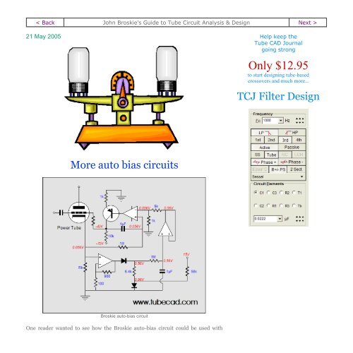
power output tubes; above is a more fleshed-out version of the Broskie auto-biascircuit that would work well with a set of power tubes like the 6L6, EL34, KT88 or2A3—or even a single output tube. One reader asked if the clipping or Broskie autobiascircuits were suitable for single-ended amplifiers. The answer is yes, as SEamplifiers often (almost always is closer to the mark) exhibit a rectification effect,unless a great deal of feedback is applied. The graph below compares the genericDC servo auto-bias circuit against the Broskie auto-bias circuit. The tube is a single6DJ8 and it falls out of class-A operation after 1V of input signal, so we should onlylook at the first few input volts of the graph to compare the two circuits use in asingle-ended amplifier.The <strong>Tube</strong> <strong>CAD</strong> <strong>Journal</strong>'s firstcompanion program, TCJ Filter Designlets you design a filter or crossover(passive, solid-state or tube) withouthaving to check out thick textbooksfrom the library and without having tobreakout the scientific calculator. Thisprogram's goal is to provide a quickand easy display not only of thefrequency response, but also of theresistor and capacitor values for apassive and active filters andcrossovers.Below is a closeup of the first two volts of input signal.TCJ Filter Design is easy to use, butnot lightweight, holding over 60different filter topologies and up tofour filter alignments:Bessel,Butterworth,Gaussian,and Linkwitz-Riley.While the program’s main concern isactive filters, solid-state and tube, italso does passive filters. In fact, it canbe used to calculate passivecrossovers for use with speakers byentering 8 ohms as the terminatingresistance. <strong>Tube</strong> crossovers are amajor part of this program; bothbuffered and un-buffered tube based
Blumlein "garter" circuitHow well does it work? Better than you might expect, but with a few caveats. Ashootout between the Blumlein garter circuit and two alternatives is needed. I usedSPICE and I created a greatly mismatched set of output tubes by using two tubes inparallel, effectively creating a new tube with the same mu, but twice the gm andhalf the rp. (No bypass capacitors were added, as no AC signal was used in thesimulation.)Ideally, when both output tubes are perfectly matched, the idle current shouldequal 9.86mA in the Blumlein circuit. As shown in figure (A) below, one tubeconducts 10.2mA, while the other conducts 11.07mA, a mismatch of 0.87mA, or8.5%; not too bad, considering the grotesque mismatch in tubes. Using separatecathode resistors (B) yields poorer results: a mismatch of 2.12mA, or 21.5%. Andusing a single common cathode resistor (C) produces the worst results: a mismatchof 7.43mA, or 100%.
So, given these results, which topology do you think has found the widestacceptance? The single common cathode resistor is the winner; it is immenselypopular, much more so than the dual cathode resistors, and Blumlein's circuit is allbut forgotten. Why use only one shared cathode resistor? Because it cheaper toimplement, with only one bypass capacitor needed, and because far too manybelieve that using a single common cathode resistor will transform any amplifierinto a class-A amplifier, regardless of the resulting idle current. Unbelievable, butsadly true. Just ask a musician and see what he tells you. Of course in a worldwherein a circlotron amplifier is seen as being a dual, single-ended, class-A-bynecessitydesign by many audiophiles…but I won't go on.Unfortunately, Blumlein’s circuit displaces B+ voltage that could be used to createmore power output. Additionally, it requires the bypass capacitors to be rated twiceas high in voltage than otherwise would be used.A modern approach to bias balanceBlumlein didn’t have access to transistors and OpAmps; we do. (I know that someare already getting nervous. But why not take advantage of a technology that’scheap, effective, doesn’t wear out, and, most importantly, isn’t in the audio signal
path? Anxiety or arrogance? Fashion or foolishness?) A single OpAmp can be usedto ensure idle current balance between two output tubes; and nine OpAmps can beused with ten output tubes, as each OpAmp finds the same reference voltage: thecathode voltage of the lead tube, whose idle current is set with a potentiometer.Because the time constant is the same for both the voltage reference’s RC circuit(1M and 0.1µF) and the OpAmp’s RC feedback circuit (1M and 0.1µF), this circuithandles class-AB and class-B output stages quite well.Note that in the schematic that OpAmp connects directly to the leftmost triode’sgrid resistor. This arrangement only works when efficient output tubes are used,which need a grid voltage that goes down to –15 volts but no farther. Twoworkarounds are possible: use an asymmetric power supply for the OpAmp or adda PNP transistor to the OpAmp’s output, as in the Broskie auto-bias circuit shownat the top of this page. Usually, an OpAmp is attached to a bipolar power supply of+/- 15 to 20 volts. However, we can use a skewed power supply, with +5 and –25volts to –35 volts, as the OpAmp will only see the same voltage differential betweenits power supply pins. (Actually, we might even get away with forgoing the positivepower supply rail altogether, as several OpAmps can accept positive input signalsthat extend beyond their positive power supply voltage, for example the BiMOSCA3140:
Absolute Maximum RatingsDC Supply Voltage (Between V+ and V- Terminals) . . . . . . . . . . . 36VDifferential Mode Input Voltage . . . . . . . . . . . . . . . . . . . . . . . . 8VDC Input Voltage . . . . . . . . . . . . . . . . . . . . . . . . . . . . . . . . . .(V+ +8V) To (V- -0.5V)Input Terminal Current . . . . . . . . . . . . . . . . . . . . . . . . . . . . . . . . 1mAOutput Short Circuit Duration. (Note 2) . . . . . . . . . . . . . . . . . . . . .IndefiniteAlternatively, a current mirror can be used in place of the OpAmp. In the schematicbelow we see the leftmost output tube following the rightmost idle current.The rightmost transistor is wired as a diode (and could be replaced with a diode,such as the 1N4001), so the effective cathode resistor used by the rightmost outputtube is a 293-ohm resistor with a solid-state diode in series with it. The leftmosttransistor works to establish the same emitter voltage that the rightmost transistordoes, which ensures that the same idle current is experienced by both output tubes.
Or, we can replace the OpAmp with a simple transistor-based differentialamplifier, with a long tail that extends up to the output stage’s B+ voltage. (The360k resistor is as good as a constant-current source in this circuit because of itslarge value.) Diode, D1, is a high-voltage rectifier that exhibits a forward voltagedrop of 7 volts (internally, seven diodes are wired in series). This diode is used hereas a low-current voltage reference, which is important because we do not want thedifferential amplifier to draw more than 1mA total. (Zener diodes require far toomuch current conduction to break at such a low voltage.) This diode's forwardvoltage drop sets the range of possible negative voltage adjustment, as the diffamplifier’soutput cannot swing below ground in this circuit. (If a negative powersupply is available, then much smaller cathode resistors can be used and the diffamplifier’sout could swing down to the negative power supply voltage.)A more-fleshed out version is shown below. The zeners are used to limit therectification effect of the output tubes undergo in heavy use. The added capacitorsfilter away the AC signal that might be present on the cathodes. All in all, not a badcircuit—particularly, when no negative power supply is available.
Of course, a differential amplifier can be made from a single transistor (orMOSFET or JFET). Below we see one transistor doing all the work of keeping theoutput tubes in idle current balance.
Since this diff-amplifier draws its power primarily through the rightmost outputtube, the leftmost tube must see an equal load current, otherwise our balancingcircuit will in itself unbalance the output stage; thus, the connection of the 30kresistor and high-voltage diode to the left output tube’s cathode and ground. (The1.4k resistor should be bypassed with a capacitor, as should be diode, D1, as theseadded capacitors will slow the turn on for the output tubes and shunt away extraAC signals.Next timeAre we done? There are many more circuits and many more side topics, but nexttime we will move on to some interesting circlotron topologies that reader,Johannes, sent in.Speacial thanksSpeacial thanks must be given to Robert McIntyre who sent me a lot of goodinformation on the Blumlein circuit. (You might remember that Mr. McIntyrewrote those excellent articles on tube circuit fundamentals for Audio Amateur backin its golden days.)
JRB
Back www.tubecad.com Copyright © 1999-2005 GlassWare All Rights Reserved Next >


