detailing-of-concrete-reinforcement-315-99

Create successful ePaper yourself
Turn your PDF publications into a flip-book with our unique Google optimized e-Paper software.
Details and Detailing <strong>of</strong> Concrete Reinforcement<br />
(ACI <strong>315</strong>-<strong>99</strong>)<br />
Reported by ACI Committee <strong>315</strong><br />
ACI <strong>315</strong>-<strong>99</strong><br />
Ronald D. Flach<br />
Chairman<br />
Anthony L. Felder<br />
Secretary<br />
Michael Baynard Paul Gordon A. Murray Lount<br />
Miguel R. Casias Edward S. H<strong>of</strong>fman Peter Meza<br />
Robert E. Doyle David W. Johnston Vasant C. Mistry<br />
Gustav G. Erlemann Robert W. Johnson Roy H. Reiterman<br />
Gerald E. Goettsche Harry B. Lancelot, III Milton R. Sees<br />
Douglas D. Lee<br />
This document provides standards <strong>of</strong> practice for both the architect/engineer<br />
(A/E) and reinforcing steel detailer in showing reinforcing steel<br />
details. It is divided into three parts: one addressed to the A/E, one for the<br />
detailer, and a third providing a reference table and figures. It defines the<br />
responsibilities <strong>of</strong> both the A/E and detailer. It then establishes certain<br />
standards <strong>of</strong> practice for both the structural and placing drawings.<br />
Keywords: beams (supports); bending (reinforcing steels); bridges (structures);<br />
buildings; columns (supports); <strong>concrete</strong> slabs; <strong>detailing</strong>; drafting<br />
(drawing); fabrication; floor systems; foundations; hooked reinforcing<br />
steels; microcomputers; placing drawings; reinforced <strong>concrete</strong>; reinforcing<br />
steels; splicing; stirrups; structural design; structural drawings; ties; tolerances<br />
(mechanics); walls; welded-wire fabric.<br />
CONTENTS<br />
Part A—Responsibilities <strong>of</strong> the architect/engineer<br />
Chapter 1—Structural drawings, p. <strong>315</strong>-2<br />
1.1—General<br />
1.2—Drawing standards<br />
1.3—Structural drawings—Buildings and other structures<br />
1.4—Structural drawings—Highway and transportation<br />
structures<br />
Chapter 2—Standards <strong>of</strong> practice, p. <strong>315</strong>-3<br />
2.1—General<br />
2.2—Tolerances<br />
2.3—Bar lengths<br />
2.4—Hooks and bends<br />
2.5—Beams and girders<br />
2.6—Columns<br />
2.7—Development and splices <strong>of</strong> reinforcing steel<br />
2.8—Joint details<br />
2.9—Reinforcing steel supports<br />
2.10—Special details for seismic design <strong>of</strong> frames, joints,<br />
walls, diaphragms, and two-way slabs<br />
2.11—Corrosion-resistant coatings for reinforcing steel<br />
Part B—Responsibilities <strong>of</strong> the detailer<br />
Chapter 3—Placing drawings, p. <strong>315</strong>-10<br />
3.1—Definition<br />
3.2—Scope<br />
3.3—Procedure<br />
3.4—Drawing standards<br />
3.5—Building drawings<br />
3.6—Highway drawings<br />
3.7—Detailing to fabricating standards<br />
Chapter 4—Fabricating practice standards, p. <strong>315</strong>-15<br />
4.1—Fabrication<br />
4.2—Extras<br />
4.3—Tolerances<br />
Chapter 5—Supports for reinforcing steel, p. <strong>315</strong>-16<br />
5.1—General<br />
5.2—Types <strong>of</strong> bar supports<br />
5.3—Side form spacers and beam bolsters<br />
5.4—Placing reinforcing steel supports<br />
Chapter 6—Computer-assisted <strong>detailing</strong>, p. <strong>315</strong>-16<br />
6.1—Use <strong>of</strong> computers in <strong>detailing</strong><br />
6.2—Placing drawings<br />
6.3—Ordering procedures<br />
Chapter 7—Recommended practices for location<br />
<strong>of</strong> bars designated only by size/spacing, p. <strong>315</strong>-17<br />
ACI <strong>315</strong>-<strong>99</strong> supersedes ACI <strong>315</strong>-92 and became effective August 31, 1<strong>99</strong>9.<br />
Copyright © 1<strong>99</strong>9, American Concrete Institute.<br />
All rights reserved including rights <strong>of</strong> reproduction and use in any form or by any<br />
means, including the making <strong>of</strong> copies by any photo process, or by electronic or<br />
mechanical device, printed, written, or oral, or recording for sound or visual reproduction<br />
or for use in any knowledge or retrieval system or device, unless permission in<br />
writing is obtained from the copyright proprietors.<br />
<strong>315</strong>-1
<strong>315</strong>-2<br />
ACI STANDARD<br />
Chapter 8—Glossary, p. <strong>315</strong>-17<br />
Chapter 9—References, p. <strong>315</strong>-18<br />
9.1—Reference standards<br />
9.2—Cited references<br />
Chapter 10—Notations, p. <strong>315</strong>-19<br />
Part C—Figures and tables, p. <strong>315</strong>-20<br />
FOREWORD<br />
Increased use <strong>of</strong> computers has led to sophisticated techniques<br />
<strong>of</strong> structural analysis and has increased manufacturing<br />
and fabrication capabilities. This added degree <strong>of</strong><br />
sophistication has resulted in more complex structures being<br />
designed and built with structural members that have long<br />
spans, shallow depths, and contain a high percentage <strong>of</strong> reinforcing<br />
steel.<br />
In the past, during the course <strong>of</strong> developing placing drawings,<br />
the detailer <strong>of</strong>ten suggested solutions in areas where the details<br />
were incomplete and where the reinforcing steel appeared to<br />
have constructibility problems. Usually these solutions were<br />
used only after their acceptance by the architect/engineer (A/E).<br />
Unfortunately, many problems do not surface during the <strong>detailing</strong><br />
phase but rather occur during construction. The A/E<br />
and the contractor, working together, then solve the problem.<br />
The A/E prepares the structural design to meet the requirements<br />
<strong>of</strong> the applicable building code and provides sufficient<br />
definition through the contract documents to convey all the requirements<br />
for <strong>detailing</strong> reinforcing steel. It is then the detailer’s<br />
responsibility to develop all <strong>of</strong> the dimensions and quantities <strong>of</strong><br />
the reinforcing steel to conform with the structural drawings and<br />
project specifications <strong>of</strong> the A/E.<br />
As the complexity <strong>of</strong> design and construction increases, it<br />
is imperative that both the A/E and detailer understand their<br />
responsibilities clearly. The responsibilities <strong>of</strong> the A/E and<br />
the detailer, as they apply to the reinforced-<strong>concrete</strong> industry,<br />
are stated more clearly by the following separate sections.<br />
This standard presents values in inch-pound and SI units.<br />
Hard metric values are usually not exact equivalents; therefore,<br />
each system is to be used independently <strong>of</strong> the other.<br />
Combining inch-pound and hard metric values can result in<br />
nonconformance with the standard. S<strong>of</strong>t metric values are<br />
exact equivalents, so combining inch-pound and s<strong>of</strong>t metric<br />
values conforms to the standard.<br />
PART A—RESPONSIBILITIES OF THE<br />
ARCHITECT/ENGINEER<br />
CHAPTER 1—STRUCTURAL DRAWINGS<br />
1.1—General<br />
Structural drawings are those prepared by the A/E for the<br />
owner or purchaser <strong>of</strong> engineering services. The structural<br />
drawings and the project specifications form a part <strong>of</strong> the<br />
contract documents. Structural drawings must contain an adequate<br />
set <strong>of</strong> notes and all other essential information in a<br />
form that can be quickly and correctly interpreted. These<br />
drawings must convey definite instructions and show reinforcing<br />
bars and welded-wire fabric. Structural and placing<br />
drawings may be combined. *<br />
The responsibility <strong>of</strong> the A/E is to furnish a clear statement<br />
<strong>of</strong> design requirements to the detailer. The A/E’s project<br />
specifications or structural drawings must not merely refer<br />
the detailer to an applicable building code for information to<br />
use in preparing the placing drawings. Instead, this information<br />
shall be interpreted by the A/E and shown in the form <strong>of</strong><br />
specific design details or notes for the detailer to follow.<br />
Where omissions, ambiguities, or incompatibilities are discovered,<br />
additional information, clarifications, or corrections<br />
shall be requested by the detailer and provided by the<br />
A/E. The A/E should require in the specifications that placing<br />
drawings be submitted for approval.<br />
Section 1.2.1 <strong>of</strong> ACI 318 (318M), Building Code Requirements<br />
for Structural Concrete, lists the information that shall<br />
be presented on the structural drawings or in the project<br />
specifications, which includes the following:<br />
1. Anchorage length <strong>of</strong> reinforcing steel and location and<br />
length <strong>of</strong> lap splices; and<br />
2. Type and location <strong>of</strong> mechanical and welded splices <strong>of</strong><br />
reinforcing steel.<br />
1.2—Drawing standards<br />
1.2.1 Materials—The minimum standard media for production<br />
<strong>of</strong> structural drawings should be penciled on tracing<br />
paper. Other media providing improved reproducibility or<br />
durability, such as micr<strong>of</strong>ilm, electronic files, ink, tracing<br />
cloth, or polyester film, can also be used.<br />
1.2.2 Sizes—Drawings should be made in standard sizes.<br />
All sheets in any one set <strong>of</strong> drawings should be the same size.<br />
There are two well-recognized sets <strong>of</strong> standard sizes.<br />
Commercial standards:<br />
18 x 24 in. (457 x 610 mm)<br />
24 x 36 in. (610 x 914 mm)<br />
27 x 36 in. (686 x 914 mm)<br />
30 x 42 in. (762 x 1067 mm)<br />
Federal agencies:<br />
17 x 22 in. (432 x 559 mm)<br />
22 x 34 in. (559 x 864 mm) + 2 in. (51 mm) binding<br />
(AASHTO)<br />
28 x 40 in. (711 x 1016 mm) + 2 in. (51 mm) binding<br />
30 x 42 in. (762 x 1067 mm)<br />
All dimensions are to the cutting line outside the margin.<br />
Border lines are inside these dimensions. Requirements for<br />
placing drawings are in Part B, addressed to the detailer.<br />
1.2.3 Direction—An arrow indicating the direction <strong>of</strong> North<br />
should be placed on every drawing that contains a plan view.<br />
1.2.4 Scales—The scales used should be indicated on all<br />
structural drawings, preferably under the title <strong>of</strong> each view.<br />
Drawings that can be enlarged or reduced in reproduction<br />
should show a graphic scale, as well as a descriptive one, to<br />
aid the user.<br />
1.2.5 Lettering—All lettering must be clear and legible. If reduced-scale<br />
photographic prints are made for field use, lettering<br />
* Requirements for placing drawings are in Part B, addressed to the detailer.
DETAILS AND DETAILING OF CONCRETE REINFORCEMENT<br />
<strong>315</strong>-3<br />
must be correspondingly larger and meet micr<strong>of</strong>ilming standards<br />
in accordance with the Association for Information and<br />
Image Management (formerly the National Micr<strong>of</strong>ilm Association)<br />
publication “Modern Drafting Techniques for Quality<br />
Microreproductions.”<br />
1.3—Structural drawings—Buildings and other<br />
structures<br />
1.3.1 General—Structural drawings and project specifications<br />
for elements such as beams, girders, columns, walls,<br />
and foundations shall show the type and grade <strong>of</strong> reinforcing<br />
steel, any special coatings, service live load, partition, ceiling<br />
and hanging loads, or any special dead loads other than<br />
the self-weight (mass) and <strong>concrete</strong> strength. Structural<br />
drawings and project specifications shall also show <strong>concrete</strong><br />
dimensions, anchorage length <strong>of</strong> reinforcing steel and location<br />
and length <strong>of</strong> lap splices, type and location <strong>of</strong> mechanical<br />
and welded splices <strong>of</strong> reinforcing steel, <strong>concrete</strong> cover for<br />
the reinforcing steel, required joints, and any other information<br />
needed for the preparation <strong>of</strong> the placing drawings.<br />
Sleeve locations and any special reinforcing steel around<br />
sleeves or openings shall be indicated by the A/E. See Fig. 1,<br />
2, 3, 4, 5, 6, and 7 (in Part C—Figures and Tables), for examples.<br />
In addition to these requirements, structural drawings<br />
<strong>of</strong> beams, girders, and columns must also show the<br />
information presented below.<br />
1.3.2 Beams and girders—Schedules for beams and girders<br />
must contain the beam mark, size <strong>of</strong> member, number<br />
and size <strong>of</strong> straight and bent bars, special notes on bending,<br />
number, size, and spacing <strong>of</strong> stirrups or stirrup-ties, location<br />
<strong>of</strong> top bars, and any special information, such as the requirement<br />
<strong>of</strong> two layers <strong>of</strong> reinforcing steel. Show sections for<br />
beam-column joints, where necessary.<br />
In continuous beams, the number and spacing <strong>of</strong> top bars<br />
to be placed in T-beam flanges (slabs) for crack control shall<br />
be shown, if so required by the design.<br />
1.3.3 Columns—Column designs shall show the size <strong>of</strong> columns,<br />
number, locations, grade, and size <strong>of</strong> reinforcing steel,<br />
and all necessary details where column section or <strong>reinforcement</strong><br />
changes. Method <strong>of</strong> splicing shall always be defined<br />
clearly, showing arrangement <strong>of</strong> splices, type (lap, mechanical<br />
or welded), length (if lap splice), and stagger. Orientation<br />
<strong>of</strong> reinforcing steel in two-way symmetrical columns shall be<br />
shown when reinforcing steel is not two-way symmetrical.<br />
1.4—Structural drawings—Highway and<br />
transportation structures *<br />
1.4.1 Dimensions—Because the structural drawings for<br />
highway structures usually are a combination <strong>of</strong> structural<br />
and placing drawings from which the structure will be built,<br />
all dimensions must be shown clearly. Drawings must show<br />
the dimensions <strong>of</strong> <strong>concrete</strong> protection for all reinforcing<br />
steel. † Where separate placing drawings are prepared, structural<br />
dimensions may be omitted, following the same practice<br />
as for buildings (see Section 3.5).<br />
1.4.2 Reinforcing steel—Combination structural-placing<br />
drawings shall show the size, spacing, and location <strong>of</strong> the<br />
bars and welded-wire fabric in the structure. The list <strong>of</strong> bars<br />
must show the number <strong>of</strong> pieces, size, length, mark <strong>of</strong> bars,<br />
and bending details <strong>of</strong> all bent bars. The list <strong>of</strong> welded wire<br />
fabric must show the mark, style, width, length, and number<br />
<strong>of</strong> pieces.<br />
Reinforcing steel for larger structures is sometimes detailed,<br />
fabricated, and delivered by units, for example, footings,<br />
abutments, piers, and girders. The reinforcing steel list<br />
may be subdivided similarly. If the structure is sufficiently<br />
large, a separate drawing and reinforcing steel list is usually<br />
made for each unit.<br />
Reinforcing steel for foundations, piers, abutments, wing<br />
walls, and slabs are usually shown on a plan, section, or elevation<br />
view on the drawings. Cross sections must be provided<br />
for clarification where necessary. The reinforcing steel<br />
list is a complete summary <strong>of</strong> materials required. All bars<br />
should appear at least once in a plan or elevation view and in<br />
a sectional view, or both.<br />
For reference data on reinforcing bars and welded wire<br />
fabric from industry sources, refer to the Supporting Reference<br />
Data section. This section includes specific information<br />
on applicable ASTM specifications, coated reinforcing bars,<br />
common styles and design data for welded wire fabric, and<br />
reinforcing bar supports.<br />
CHAPTER 2—STANDARDS OF PRACTICE<br />
2.1—General<br />
This chapter provides the A/E with minimum standards for<br />
application during the development <strong>of</strong> the design. Information<br />
presented here is a collection <strong>of</strong> notes derived from ACI<br />
318 (318M); ACI 343R; AREMA Manual for Railway Engineering,<br />
Chapter 8, “Concrete Structures and Foundations;”<br />
and AASHTO “Standard Specifications for Highway Bridges,”<br />
industry practice, practical considerations, and research results<br />
current at the time <strong>of</strong> this report. Reinforcing steel for<br />
structures designed under the provisions <strong>of</strong> ACI 349, ACI<br />
359, and other similar documents can generally incorporate<br />
the direction given in this standard unless otherwise prohibited<br />
by the provisions <strong>of</strong> the respective related documents.<br />
2.2—Tolerances<br />
ACI 117 provides standard tolerances for <strong>concrete</strong> construction.<br />
Practical limitations <strong>of</strong> equipment and production efficiency<br />
have led to the establishment <strong>of</strong> certain fabrication tolerances<br />
that can be met with standard shop equipment. These standard<br />
tolerances are shown in Fig. 8 and 9 (in Part C) for both straight<br />
and bent bars. Where more restrictive tolerances are required<br />
than those shown in the referenced figures, they shall be indicated<br />
in the contract documents. The effects <strong>of</strong> tolerances on<br />
cover, strength, constructibility, and serviceability <strong>of</strong> the structure<br />
should be considered by the A/E.<br />
2.3—Bar lengths<br />
Placing drawings and bar lists must show all bar dimensions<br />
as out-to-out with bar lengths as the sum <strong>of</strong> all detailed<br />
dimensions, including hooks A and G (Table 1 in Part C).<br />
* The term “highway and transportation structures” used herein includes bridges,<br />
drainage, and related structures.<br />
† Subject to requirements <strong>of</strong> ACI 318 (318M), Section 7.7, or the AASHTO bridge<br />
specifications, Articles 8.22 and 9.26.
<strong>315</strong>-4<br />
ACI STANDARD<br />
2.4—Hooks and bends<br />
Hooks and bends are specified to standardize the fabrication<br />
procedure and to limit the <strong>concrete</strong> stresses in the<br />
area <strong>of</strong> the hooks. See Table 1 and Fig. 10 in Part C.<br />
2.5—Beams and girders<br />
2.5.1 Beam widths—To permit satisfactory placing <strong>of</strong> <strong>concrete</strong><br />
and to furnish adequate <strong>concrete</strong> protection, the A/E<br />
must provide for adequate clear distance between parallel<br />
bars and between bars and forms.<br />
The A/E must specify the required <strong>concrete</strong> protection for the<br />
reinforcing steel. The A/E must also specify the distance between<br />
bars for development and <strong>concrete</strong> placing. For buildings,<br />
the clear space is the larger <strong>of</strong> one bar diameter, 1-1/3 the maximum<br />
size <strong>of</strong> coarse aggregate to be used, and 1 in. (25 mm). For<br />
cast-in-place bridges, required clear space is the larger <strong>of</strong> 1.5 bar<br />
diameters, 1.5 maximum size aggregate, and 1.5 in. (40 mm).<br />
Tables in the supporting reference data section give a wide<br />
range <strong>of</strong> beam widths and the maximum number <strong>of</strong> bars permitted<br />
in a single layer for 3/4 and 1 in. (20 and 25 mm) maximum<br />
aggregate size as provided by ACI 318 (318M).<br />
Other tables in the supporting reference data section similarly<br />
give the same information for beams designed under<br />
the provisions <strong>of</strong> the AASHTO bridge specifications. These<br />
tables are provided for the use <strong>of</strong> the A/E; the detailer is not<br />
in a position to determine whether bars should be permitted<br />
to be placed in more than a single layer.<br />
2.5.2 Stirrup anchorage—The A/E shall show or specify<br />
by notes the sizes, spacings, location, and types <strong>of</strong> all stirrups.<br />
These types include open stirrups and closed stirrups<br />
(or stirrup-ties) (Fig. 11 and 12 in Part C). Stirrups are most<br />
<strong>of</strong>ten fabricated from reinforcing bars, but may also be fabricated<br />
from welded-wire fabric.<br />
There are various permissible methods <strong>of</strong> anchorage, but<br />
the most common is to use one <strong>of</strong> the standard stirrup-tie<br />
types as shown in Fig. 10. Types S1 through S6, T1, T2, and<br />
T6 through T9 standard tie and stirrup hooks are shown in<br />
Table 1. Where stirrup support bars are required, they must<br />
be specified by the A/E. In designing the anchorage, allowance<br />
must be made to ensure that the ends <strong>of</strong> the stirrup hook<br />
are fully encased in <strong>concrete</strong>, as when hooks turn outward<br />
into shallow slabs.<br />
Where the design requires closed stirrup-ties for shear, the<br />
closure may consist <strong>of</strong> overlapped, standard 90 degree end<br />
hooks <strong>of</strong> one- or two-piece stirrups, or properly spliced pairs<br />
<strong>of</strong> U-stirrups. Where the design requires closed ties for torsion,<br />
the closure may consist <strong>of</strong> overlapped, standard 135 degree<br />
hooks <strong>of</strong> one- or two-piece ties enclosing a longitudinal<br />
bar. At least one longitudinal bar shall be located inside each<br />
corner <strong>of</strong> the stirrups or ties, the diameter <strong>of</strong> this bar to be<br />
equal to at least the diameter <strong>of</strong> the stirrup (No. 4 [No. 13]<br />
minimum). Ties provided to resist radial forces resulting<br />
from bar or tendon curvature shall be anchored adequately.<br />
2.5.3 Spacings <strong>of</strong> bundled bars—When bars are placed in<br />
contact with each other in groups <strong>of</strong> two, three, or four—<br />
known as bundled bars—the minimum clear space provided<br />
between bundles for buildings under ACI 318 (318M) shall<br />
be equal to the diameter <strong>of</strong> a single, round bar having an area<br />
equivalent to the area <strong>of</strong> the bundle. For bridge design, the<br />
AREMA design manual and the AASHTO bridge specifications<br />
require a minimum spacing equal to 1.5 times diameter<br />
<strong>of</strong> a single, equivalent area bar.<br />
2.6—Columns<br />
2.6.1 Column verticals—In selecting reinforcing steel for<br />
columns, consideration shall be given to the minimum spacing<br />
<strong>of</strong> bars or bundles required by ACI 7.6.3. * Tables in the<br />
supporting reference data section show the maximum number<br />
<strong>of</strong> bars for round columns and the maximum number <strong>of</strong><br />
bars that can be placed in one face <strong>of</strong> a rectangular column.<br />
Splice arrangements shall be shown. For butt-spliced systems,<br />
an allowance must be included for an increase in diameter<br />
at mechanical splices and for access to welding. Special<br />
end preparation required for bars must be shown or specified.<br />
Where the reinforcing steel area required above is different<br />
from that in the column below, the structural drawings<br />
must clearly show the extension required (if any) <strong>of</strong> all reinforcing<br />
bars above and below the floor level (see also Section<br />
2.7).<br />
2.6.2 Offset between column faces—Where there is a<br />
change in size <strong>of</strong> a column, the structural drawings must<br />
show how the vertical bars are to be <strong>of</strong>fset, or separate dowels<br />
must be shown (see Section 3.7.7.2). The slope <strong>of</strong> the inclined<br />
portion providing the <strong>of</strong>fset shall not exceed one in<br />
six. See Fig. 4 for recommended splicing details.<br />
Where column verticals are <strong>of</strong>fset bent, additional ties are<br />
required and shall be placed not more than 6 in. (150 mm)<br />
from the point <strong>of</strong> the bend. For practical purposes, three<br />
closely spaced ties are usually used, one <strong>of</strong> which may be<br />
part <strong>of</strong> the regularly spaced ties, plus two extra ties. General<br />
arrangements <strong>of</strong> vertical bars and all tie requirements shall<br />
be established by the structural drawings.<br />
In addition to showing size and regular spacing <strong>of</strong> column<br />
ties, the A/E shall also show any additional ties required for<br />
special conditions, such as splices and <strong>of</strong>fset bends.<br />
2.6.3 Changing bar arrangement between floors—When the<br />
bar arrangement is changed at a floor, the bars may extend<br />
through, terminate, or require separate dowels. Reinforcing<br />
steel at least equal in area to that in the column above must<br />
be extended from the column below to lap bars above by the<br />
required lap length or butt splices must be provided. Vertical<br />
bars from the column below, terminated for any reason, are<br />
cut <strong>of</strong>f within 3 in. (75 mm) <strong>of</strong> the top <strong>of</strong> the finished floor unless<br />
otherwise indicated on the structural drawing. The A/E<br />
shall determine what, if any, additional extension <strong>of</strong> discontinued<br />
column verticals is required for adequate embedment,<br />
and show this information on the structural drawings.<br />
2.6.4 Spirals—Pitch or spacing <strong>of</strong> spirals should be given<br />
to the nearest 1/4 in. (5 mm). According to ACI 318 (318M),<br />
the clear spacing between spiral turns shall not exceed 3 in.<br />
(80 mm) or be less than 1 in. (25 mm) or 1-1/3 times the maximum<br />
size <strong>of</strong> coarse aggregate used. Spirals shall be provided<br />
with 1-1/2 extra turns at both top and bottom. If necessary to<br />
* Reference to ACI 318 (318M) is given as “ACI” followed by the number <strong>of</strong> the section.
DETAILS AND DETAILING OF CONCRETE REINFORCEMENT<br />
<strong>315</strong>-5<br />
splice a spiral, it shall be done by a lap splice <strong>of</strong> 48d b or by<br />
welding.<br />
Minimum diameters to which standard spirals can be<br />
formed and minimum diameters that are considered collapsible<br />
are shown below for various sizes <strong>of</strong> spiral bars. Plain or<br />
deformed bars or wire can be used to manufacture spirals.<br />
Spiral bar<br />
diameter, in.<br />
(mm)<br />
Minimum outside<br />
diameter that can be<br />
formed, in. (mm)<br />
Minimum outside<br />
diameter <strong>of</strong> collapsible<br />
spiral, in. (mm)<br />
3/8 (10) 9 (225) 14 (350)<br />
1/2 (13) 12 (300) 18 (450)<br />
5/8 (16) 15 (375) 24 (600)<br />
3/4 (19) 30 (750) —<br />
Spirals are used primarily for columns, piers, and drilled<br />
caissons, but are also used in piles. Continuously wound, reinforcing<br />
steel in the form <strong>of</strong> a circular helix not meeting<br />
ACI 318 (318M) definition <strong>of</strong> a spiral may be used in these<br />
structures as tie <strong>reinforcement</strong>. Such reinforcing steel, sometimes<br />
referred to as continuous ties, is usually specified with<br />
a large pitch.<br />
2.6.5 Column ties—The vertical bars in tied columns shall<br />
be tied together laterally. Standard arrangements <strong>of</strong> ties for<br />
various numbers <strong>of</strong> vertical bars are shown in Fig. 13 and 14<br />
in Part C. The A/E may also specify welded-wire fabric with<br />
an equivalent area <strong>of</strong> reinforcing steel for column ties. The<br />
arrangements <strong>of</strong> one-piece ties shown in Fig. 13 provide<br />
maximum rigidity for column cages preassembled on the site<br />
before erection. Preassembly is preferred only for the common<br />
designs employing one-story-length vertical bars all lap<br />
spliced at or near one point above the floor line. See Section<br />
2.7.3 for lap splice restrictions.<br />
With staggered butt splices on large vertical bars in twostory<br />
lengths, practical erection limitations usually require<br />
that column ties be assembled on free-standing vertical bars.<br />
Standard arrangements for two-piece column ties shown in<br />
Fig. 13 and 14 are recommended to facilitate field assembly.<br />
They are universally applicable to any splice arrangement required<br />
by the A/E. If access to the interior <strong>of</strong> a column or a<br />
pier is necessary, or if the A/E prefers, some other pattern <strong>of</strong><br />
ties may be substituted, provided that the tie arrangement<br />
meets ACI 318 (318M) requirements.<br />
The spacing <strong>of</strong> ties depends on the sizes <strong>of</strong> vertical bars,<br />
columns, and <strong>of</strong> ties. The maximum spacings permitted are<br />
shown in a table in the supporting reference data section.<br />
In addition to showing size and regular spacing <strong>of</strong> column<br />
ties, the A/E shall also show any additional ties required for<br />
other special conditions such as at splices, and <strong>of</strong>fset bends<br />
(see also Section 2.10 for seismic details).<br />
If the design requires lateral <strong>reinforcement</strong> in the column<br />
between the top <strong>of</strong> the main spiral and the floor level above,<br />
it may be provided by a stub spiral (short section <strong>of</strong> spiral) or<br />
circular column ties to permit placing <strong>of</strong> the reinforcing steel<br />
in the floor system, and the arrangement shall be shown.<br />
2.6.6 Bundled bars—Bundled bars can be used as column<br />
verticals. A bundle is defined as a group <strong>of</strong> parallel bars bundled<br />
in contact to act as a unit. Not more than four bars can<br />
be grouped into one bundle. Butt splices or separate splice<br />
bars should be used.<br />
Bundled bars must be tied, wired, or otherwise fastened to<br />
ensure that they remain in position. All bundles <strong>of</strong> column<br />
verticals must be held by additional ties above and below the<br />
end-bearing mechanical splices and any short splice bars<br />
added for tension should be tied as part <strong>of</strong> the bundle within<br />
the limitation <strong>of</strong> the number <strong>of</strong> bars in a bundle. Bundled bars<br />
shall be enclosed within ties. Ties smaller than No. 4 (No. 13)<br />
for bundled bars shall not be used. Design and detail information<br />
on bundled bars as column verticals is provided in a<br />
table in the supporting reference data section.<br />
2.7—Development and splices <strong>of</strong> reinforcing steel<br />
2.7.1 General—In ACI 318 (318M), development and lap<br />
splice lengths for deformed reinforcing bars can be calculated<br />
using one <strong>of</strong> two optional approaches. A previous calculation<br />
approach, from ACI 318-89 (318M-89) also remains acceptable.<br />
With multiple code-compliant approaches to<br />
calculation existing, choice, interpretation, and application<br />
are the A/E’s responsibilities. Sufficient information shall be<br />
presented on the structural drawings and in the project specifications<br />
to allow <strong>detailing</strong> <strong>of</strong> bars at splices and embedment<br />
locations without referencing back to the code.<br />
Tables in the supporting reference data section give values<br />
<strong>of</strong> tension development lengths and tension lap splice lengths<br />
<strong>of</strong> straight bars. Values <strong>of</strong> tension l d and tension lap splice<br />
lengths in the tables are based on the provisions in ACI 12.2.2.<br />
All tabulated data are for Grade 60 (420) reinforcing bars in<br />
normalweight <strong>concrete</strong> with the <strong>concrete</strong> compressive<br />
strength, f ′ c , ranging from 3000 to 8000 psi (21 to 56 MPa).<br />
The tables use the terminology Cases 1 and 2. Cases 1 and<br />
2, which depend on the type <strong>of</strong> structural element, <strong>concrete</strong><br />
cover, and the center-to-center spacing <strong>of</strong> the bars, are also<br />
defined in the tables.<br />
Separate tables are included for uncoated and epoxy-coated<br />
bars. There are no special development requirements in<br />
ACI 318 (318M) for zinc-coated (galvanized) bars and they<br />
should be treated as uncoated bars. For lightweight aggregate<br />
<strong>concrete</strong>, the values in the tables would have to be modified<br />
by the applicable factor (ACI 12.2.4).<br />
ACI 1.2.1 requires that anchorage length <strong>of</strong> <strong>reinforcement</strong><br />
and location and length <strong>of</strong> lap splices be shown on the structural<br />
drawings. This information can be shown by dimensioning<br />
cut-<strong>of</strong>f locations and including tables <strong>of</strong> applicable<br />
lap splice lengths.<br />
2.7.2 Splices, general—In beams or girders that require<br />
bars longer than can be carried in stock, splices shall be specified.<br />
The A/E shall show or specify by notes how the splicing<br />
is to be realized; namely, lap splices, mechanical splices,<br />
or welded splices.<br />
The A/E shall also show, by details on structural drawings,<br />
the location and length <strong>of</strong> all splices. In beams or girders,<br />
splices should preferably be made where the stress in the bar
<strong>315</strong>-6<br />
ACI STANDARD<br />
is minimum, that is, at the point <strong>of</strong> inflection. Splices where<br />
the critical design stress is tensile should be avoided by the<br />
A/E wherever possible. Lapped bars may be either in contact<br />
or separated. The A/E shall show or note on the structural<br />
drawings whether splices are to be staggered or made at the<br />
same location. Bars to be spliced by noncontact lap splices in<br />
flexural members shall not be spaced transversely more than<br />
the smaller <strong>of</strong> one-fifth the length <strong>of</strong> lap and 6 in. (150 mm).<br />
2.7.3 Lap splices—It is necessary for the A/E to show the<br />
location and length <strong>of</strong> lap splices because the strength <strong>of</strong> a<br />
lap splice varies with the bar diameter, <strong>concrete</strong> strength, bar<br />
spacing, <strong>concrete</strong> cover, position <strong>of</strong> the bar, distance from<br />
other bars, and the type <strong>of</strong> stress (compressive or tensile).<br />
Where bars <strong>of</strong> two sizes are lap spliced, the A/E must indicate<br />
the appropriate lap splice length. Lap splices are not permitted<br />
for No. 14 and 18 (No. 43 and 57) bars, except for<br />
transferring compression to smaller size dowels that are anchored<br />
into footings for buildings. Lap splices for bars larger<br />
than No. 11 (No. 36) are not permitted by the AREMA design<br />
manual or the AASHTO bridge specifications.<br />
At column bar splice locations, sufficient bars (or dowels)<br />
from the lower columns must extend into the upper column<br />
to provide not less than the cross-sectional area <strong>of</strong> the required<br />
bars in the upper column. These bars must extend the<br />
minimum distance required for lap splices. The A/E should<br />
note that unless otherwise specified or shown on structural<br />
drawings, the detailer will detail the remaining bars in the<br />
lower column extending to within 3 in. (75 mm) <strong>of</strong> the top <strong>of</strong><br />
the floor or other member transmitting the additional load to<br />
the column. Where the top ends <strong>of</strong> column bars are less than<br />
6 ft (1800 mm) above the top <strong>of</strong> footings or pedestals, the<br />
bars should extend into the footings or pedestals. Normally,<br />
dowels will be used only if specifically noted on structural<br />
drawings.<br />
Dowels for lap splices at column <strong>of</strong>fsets should have a<br />
cross-sectional area at least equal to that <strong>of</strong> the bars above<br />
and they shall extend both above and below the splice locations,<br />
as specified by the A/E.<br />
The A/E should also be aware that it is a standard practice<br />
in the industry when <strong>detailing</strong> column verticals to use the appropriate<br />
lap splice length for the bars in the column above.<br />
This applies regardless <strong>of</strong> differences in bar sizes.<br />
For columns, the arrangement <strong>of</strong> bars at a lap splice is<br />
shown in Fig. 4. It should be noted that the amount <strong>of</strong> <strong>of</strong>fset<br />
<strong>of</strong> the bars is greater for rectangular columns than for round<br />
columns. Column verticals to be lap spliced in square or rectangular<br />
columns, where column size does not change, are usually<br />
shop <strong>of</strong>fset bent into the column above, unless otherwise<br />
shown by the A/E. The A/E shall indicate which vertical bars<br />
are to be <strong>of</strong>fset bent for round columns in those cases where<br />
the column size doesn’t change.<br />
Where the depth <strong>of</strong> the footing, or footing and pedestal<br />
combined, is less than the minimum length <strong>of</strong> embedment required<br />
for dowels <strong>of</strong> a certain size, the size <strong>of</strong> dowel should<br />
be decreased and the number <strong>of</strong> dowels increased to give an<br />
equivalent area. This should also be shown on the structural<br />
drawings. Hooks at the ends <strong>of</strong> the bars can be desirable to<br />
resist tension, but the hook may not be considered in determining<br />
the embedment provided for compression.<br />
Separate splice bars (dowels) are necessary for splicing<br />
column bars where the column section changes 3 in. (80 mm)<br />
or more, where the placing <strong>of</strong> parts <strong>of</strong> the structure is delayed,<br />
or between various units <strong>of</strong> structures. Except for special<br />
cases, separate splice bars (dowels) should be the same<br />
number, size, and grade as the bars joined and should be <strong>of</strong><br />
proper length to splice with the main bars, and shall be specified<br />
by the A/E.<br />
Lap splices for deformed welded-wire fabric shall be<br />
shown by the A/E. * ACI 318 (318M) requires that, for deformed<br />
welded-wire fabric, the splice shall be at least 1.3<br />
times the development length (8 in. [200 mm] minimum).<br />
The A/E shall indicate the required splice dimension(s).<br />
Lap splices for plain welded-wire fabric shall also be<br />
shown by the A/E. * ACI 318 (318M) requires that the splice<br />
length, as measured between outermost cross wires <strong>of</strong> each<br />
fabric sheet, shall be not less than one spacing <strong>of</strong> cross wires<br />
plus 2 in. (50 mm) nor less than 1.5 l d (6 in. [150 mm] minimum)<br />
when A s provided/A s required < 2. When A s provided/<br />
A s required > 2, only the requirement <strong>of</strong> 1.5 l d (2 in. [50 mm]<br />
minimum) will apply. Therefore, the A/E can either show the<br />
required splice dimension or indicate a typical detail showing<br />
the lap splice length equal to one spacing <strong>of</strong> cross wires<br />
plus 2 in. (50 mm), if that controls.<br />
2.7.4 Butt splices—Mechanical splices or welded splices<br />
can be specified or, for compression only, end-bearing splices<br />
can be specified as butt splices for vertical column bars. For<br />
No. 14 and 18 (No. 43 and 57) bars, butt splices shall be<br />
used. Special preparation <strong>of</strong> the ends <strong>of</strong> the vertical bars is<br />
usually required for butt splices. Where a mechanical splice<br />
is used, both ends <strong>of</strong> the bar can be either square cut, flame<br />
cut, or standard shear cut, depending on the type <strong>of</strong> splice<br />
used. Because mechanical splices are usually staggered between<br />
alternate vertical bars and their location depends on<br />
the design requirements, the A/E must indicate the types <strong>of</strong><br />
mechanical splices permissible, their location, and end preparation<br />
required. Where bars are welded, the most common<br />
practice is to provide a square-cut end at the top <strong>of</strong> the lower bar<br />
and a double-beveled end on the bottom <strong>of</strong> the upper bar. Field<br />
preparation <strong>of</strong> ends by flame cutting is satisfactory. All welding<br />
<strong>of</strong> reinforcing bars shall conform to AWS D1.4.<br />
2.8—Joint details<br />
2.8.1 Rigid frame corners —The A/E shall exercise care in designing<br />
the corner joint <strong>of</strong> a rigid frame. All main reinforcing<br />
steel that passes through the joint shall be free <strong>of</strong> any kinks<br />
or discontinuous bending. The center <strong>of</strong> radius <strong>of</strong> the bend<br />
must be kept within the joint. This point is important in splicing<br />
the top bars from the girder to the outside bars in the column.<br />
The A/E must provide complete information, showing<br />
the radius <strong>of</strong> any nonstandard bends and location and dimensions<br />
<strong>of</strong> lap splices. If a mechanical or welded splice is to be<br />
used, a physical description must be provided. Tension in the<br />
* Supplementary data on welded wire fabric appears in Chapter 2 (“Welded Wire<br />
Fabric”) <strong>of</strong> the supporting reference data section.
DETAILS AND DETAILING OF CONCRETE REINFORCEMENT<br />
<strong>315</strong>-7<br />
<strong>concrete</strong> surrounding the reinforcing steel where the steel<br />
changes direction must be considered.<br />
2.8.2 Wall intersections and corners—All horizontal wall<br />
reinforcing steel in one, or sometimes both, faces <strong>of</strong> a wall<br />
shall be sufficiently extended past a corner or intersection to<br />
be fully developed (Fig. 15 in Part C). The A/E shall indicate<br />
which, if any, horizontal reinforcing steel must be extended,<br />
how far it must be extended, and how it must be anchored at<br />
intersections and corners <strong>of</strong> walls and footings. In areas<br />
where the applicable building code requires earthquake-resistant<br />
design, standard practice requires adequate anchorage <strong>of</strong> all<br />
horizontal bars.<br />
Walls with loads that open corner intersections must be reinforced<br />
differently than walls with loads that close such intersections.<br />
Typical details are shown in Fig. 15 for<br />
resistance against loads from outside or inside, with the reinforcing<br />
steel from the appropriate face or faces anchored.<br />
Precautions to restrain radial tension are similar to those for<br />
rigid frame corners.<br />
2.8.3 Closed stirrups—Where the structural drawings<br />
show closed stirrups, these stirrups may be closed by twopiece<br />
stirrups using overlapping standard 90 degree end<br />
hooks enclosing a longitudinal bar, or by properly spliced<br />
pairs <strong>of</strong> U-stirrups or a standard one-piece Type T1 or T2<br />
stirrup tie. At least one longitudinal bar must be located at<br />
each corner <strong>of</strong> the section, the size <strong>of</strong> this bar to be at least<br />
equal to the diameter <strong>of</strong> the stirrup but not less than a No. 4<br />
(No. 13). These details shall be shown by the A/E. (see Fig.<br />
12). It should be noted that the use <strong>of</strong> 90 degree hooks and<br />
lap splices in closed stirrups is not considered effective in situations<br />
where the member is subjected to high torsional<br />
stress. Tests (Reference 1) have shown premature failure<br />
caused by spalling <strong>of</strong> the <strong>concrete</strong> covering and consequent<br />
loss <strong>of</strong> anchorage in the 90 degree hooks and lap splices in<br />
these situations (see Fig. 16 in Part C).<br />
2.8.4 Structural integrity—Specific details for continuity<br />
<strong>of</strong> reinforcing steel to meet structural integrity requirements<br />
shall be incorporated in the design details by the A/E. Continuity<br />
is required in cast-in-place construction for joists,<br />
beams, and two-way slabs. Continuity <strong>of</strong> selected flexural<br />
<strong>reinforcement</strong> is achieved by making bars continuous or providing<br />
Class A tension lap splices and terminating bars with<br />
standard hooks at noncontinuous supports. Certain proportions<br />
<strong>of</strong> top and bottom flexural <strong>reinforcement</strong> in perimeter<br />
beams shall be made continuous around the structure and<br />
confined with closed stirrups. See ACI 7.13 and Fig. 2 and 3,<br />
for example details for structural integrity.<br />
2.9—Reinforcing steel supports<br />
The A/E is responsible for specifying acceptable materials,<br />
and corrosion protection required for reinforcing steel<br />
supports, or both, and if required, for side form spacers, as<br />
well as the particular structural elements or areas in which<br />
each is to be used. Specifications for the use <strong>of</strong> reinforcing<br />
steel supports usually are based on established industry practice.<br />
* For more details on bar supports and side form spacers,<br />
see Chapter 5.<br />
2.10—Special details for seismic design <strong>of</strong> frames,<br />
joints, walls, diaphragms, and two-way slabs<br />
2.10.1 Introduction—In designs for high seismic risk (such<br />
as NEHRP Seismic Performance Categories D and E) † reinforced-<strong>concrete</strong><br />
members shall satisfy ACI 318 (318M),<br />
Chapters 1 through 17 and Sections 21.2 through 21.7 <strong>of</strong><br />
Chapter 21 to provide a structural system with adequate details<br />
to permit nonlinear response without critical loss <strong>of</strong><br />
strength.<br />
In designs for moderate seismic risk (such as NEHRP<br />
Seismic Performance Category C), † reinforced-<strong>concrete</strong><br />
frames and two-way slabs shall satisfy ACI 318 (318M),<br />
Chapters 1 through 18 and Section 21.8 <strong>of</strong> Chapter 21.<br />
The provisions <strong>of</strong> Chapters 1 through 18 <strong>of</strong> ACI 318<br />
(318M) apply to the design and <strong>detailing</strong> <strong>of</strong> reinforced <strong>concrete</strong><br />
structures in regions <strong>of</strong> low or no seismic risk (such as<br />
NEHRP Seismic Performance Categories A and B). †<br />
For seismic design, member sizes should be selected and<br />
reinforcing steel arranged to avoid congestion <strong>of</strong> the <strong>reinforcement</strong>.<br />
Careful selection <strong>of</strong> member size and reinforcing<br />
steel arrangement will help to avoid difficulties in the placement<br />
<strong>of</strong> the <strong>reinforcement</strong> and <strong>concrete</strong>.<br />
The requirements <strong>of</strong> Chapter 21 <strong>of</strong> ACI 318 (318M) are<br />
used to illustrate what the A/E shall convey to the detailer<br />
(and to familiarize the detailer with the seismic reinforcing<br />
steel details). Much information can be shown by schematic<br />
diagrams as shown in Fig. 5, 6, 7, 17 and 18 (in Part C).<br />
These special seismic details are, in principle, applicable to<br />
flexural frame members and frame members subjected to<br />
both bending and axial load in regions <strong>of</strong> high seismic risk.<br />
It is important for the A/E to examine the reinforcing steel<br />
layouts carefully in three dimensions and give the detailer the<br />
proper information. This examination will show congestion at<br />
beam-column joints <strong>of</strong> beam, column, and hoop <strong>reinforcement</strong>.<br />
Large scale drawings, models, or mock-ups <strong>of</strong> the joint<br />
details, such as those shown in Fig. 7, may be worthwhile to<br />
ensure that a design can be assembled and <strong>concrete</strong> can be<br />
placed.<br />
When subjected to reversals <strong>of</strong> lateral overloads, joints in<br />
frames and boundary members <strong>of</strong> walls must be capable <strong>of</strong><br />
developing plastic hinging and continuing to resist loads after<br />
yielding <strong>of</strong> the reinforcing steel without crushing or brittle<br />
failure <strong>of</strong> the <strong>concrete</strong>. To develop this ductility, <strong>concrete</strong><br />
in these members, including the joints, shall be confined by<br />
transverse <strong>reinforcement</strong> consisting <strong>of</strong> rectangular or circular<br />
hoops (see Fig. 5, 6, 7, 17, and 18).<br />
2.10.2 Concrete— ACI 318 (318M) requires that the specified<br />
<strong>concrete</strong> strength f ′ c shall not be less than 3000 psi (20 MPa). For<br />
lightweight aggregate <strong>concrete</strong>, f ′ c shall not exceed 4000 psi<br />
(30 MPa).<br />
* Established industry practices recommended for general use <strong>of</strong> bar supports issued<br />
by the Concrete Reinforcing Steel Institute are reprinted in the supporting reference<br />
data section.<br />
† “NEHRP Recommended Provisions for the Development <strong>of</strong> Seismic Regulation<br />
for New Buildings” prepared by the Building Seismic Safety Council for the Federal<br />
Emergency Management Agency, issued in 1<strong>99</strong>4, referred to as NEHRP. Seismic performance<br />
categories in ASCE 7 are similar to NEHRP. Regions <strong>of</strong> high earthquake<br />
risk correspond to Zones 3 and 4, regions <strong>of</strong> moderate earthquake risk to Zone 2, and<br />
low or no risk in Zone 1 in the Uniform Building Code.
<strong>315</strong>-8<br />
ACI STANDARD<br />
2.10.3 Reinforcing steel—Longitudinal <strong>reinforcement</strong>, resisting<br />
earthquake-induced flexural and axial forces in frame<br />
members and in wall boundary members, shall comply with<br />
ASTM A 706/A 706M. ASTM A 615/A 615M Grade 60 and<br />
Grade 40 (420 and 300) can be used, provided that actual<br />
yield strength does not exceed the specified yield strength by<br />
more than 18,000 psi (120 MPa), and tensile strength is at<br />
least 25% greater than the actual yield strength.<br />
In regions <strong>of</strong> moderate seismic risk, standard ASTM<br />
A615/A615M Grade 60 and 40 (420 and 300) can be used.<br />
Test results indicate that welded-wire fabric hoops designed<br />
according to ACI 318 (318M) requirements are effective<br />
in confining the <strong>concrete</strong> in the joints (Reference 2).<br />
2.10.4 Beams—High seismic risk * —At least two bars, top<br />
and bottom, shall be provided as continuous longitudinal <strong>reinforcement</strong><br />
for beams. For beams framing into two opposite<br />
sides <strong>of</strong> a column, these bars shall extend through the column<br />
core at least twice the beam depth without splices (see Fig. 5)<br />
and shall develop the bars beyond their theoretical cut-<strong>of</strong>f<br />
points.<br />
At joint faces, the positive moment strength <strong>of</strong> the beam<br />
shall be equal to or greater than one-half the negative moment<br />
strength. At other locations in the beam, the positive<br />
and negative moment strengths shall be equal to or greater<br />
than one-fourth the negative moment strength at the face <strong>of</strong><br />
either joint. The A/E shall indicate quantities <strong>of</strong> reinforcing<br />
steel, cut-<strong>of</strong>f points, and length and location <strong>of</strong> splices to satisfy<br />
these multiple code requirements.<br />
Continuous top bars must be spliced near the center <strong>of</strong> a<br />
span in frames where moments are usually minimum and<br />
gravity load moments do not usually produce tensile stresses.<br />
Bottom bars shall not be spliced at the columns because<br />
<strong>of</strong> possible reversal <strong>of</strong> beam stresses.<br />
At beam-column joints, the A/E shall indicate where and<br />
how the bars, straight or hooked, are to be terminated.<br />
Where beams frame into only one side <strong>of</strong> a column, as at<br />
exterior columns, top and bottom beam reinforcing steel<br />
must have a 90 degree hook that extends to the far face <strong>of</strong> the<br />
confined region (core) and bends into the joint. † The development<br />
length <strong>of</strong> the hook for tension shall not be less than<br />
8d b , 6 in. (150 mm), or ƒ y d b / (65 √f ′ c ) [ƒ y d b / (5.4 √f ′ c )].<br />
Hoops shall be provided in frame members over twice the<br />
member depth from the faces <strong>of</strong> the supports and toward<br />
midspan. If inelastic yielding can occur elsewhere, the A/E<br />
shall indicate location and hoop spacing requirements on<br />
both sides <strong>of</strong> the sections where the inelastic yielding can occur.<br />
Hoop spacing requirements are shown in Fig. 5.<br />
Where hoops are not required by the A/E, stirrups shall be<br />
provided, spaced at not more than d/2 throughout the remaining<br />
length <strong>of</strong> the member and detailed as shown by the A/E.<br />
2.10.5 Beams—Moderate seismic risk * —ACI 318 (318M)<br />
requires that, at joint faces, the positive moment strength <strong>of</strong><br />
the beam shall be equal to or greater than one-third the negative<br />
moment strength. At other locations in the beam, the<br />
* A frame member is defined as a beam if the factored compressive axial load is not<br />
greater than (A g f ′ c ) / 10.<br />
† Core. This term is indirectly defined in ACI 10.0 by the term “A c ” (area <strong>of</strong> core) =<br />
area within outside dimension <strong>of</strong> the confining <strong>reinforcement</strong>.<br />
positive and negative moment strengths shall be equal to or<br />
greater than one-fifth the negative moment strength at the<br />
face <strong>of</strong> either joint. The A/E shall indicate quantities <strong>of</strong> reinforcing<br />
steel required to satisfy ACI 318 (318M), cut-<strong>of</strong>f<br />
points, and length and location <strong>of</strong> splices.<br />
Stirrups shall be provided for a minimum length <strong>of</strong> twice<br />
the member depth from the support at an initial spacing <strong>of</strong> 2<br />
in. (50 mm) and a remaining spacing not more than d/4, 8d b<br />
<strong>of</strong> the smallest enclosed longitudinal bar, 24 diameters <strong>of</strong> the<br />
stirrup bar, or 12 in. (300 mm). For the remaining beam<br />
length, stirrups shall be spaced at not more than d/2.<br />
2.10.6 Columns—High seismic risk ‡ —Transverse <strong>reinforcement</strong><br />
consisting <strong>of</strong> single or overlapping rectangular<br />
hoops for rectangular columns, and single, circular hoops or<br />
spirals for round columns are required (see Fig. 6). A rectangular<br />
hoop is closed by overlapping 135 degree hooks having<br />
tail extensions <strong>of</strong> six bar diameters (3 in. [75 mm]<br />
minimum) inside the core <strong>of</strong> the hoop.<br />
Crossties <strong>of</strong> the same bar size and spacing <strong>of</strong> hoops may<br />
be used, but each end <strong>of</strong> the crosstie shall engage a peripheral<br />
vertical bar. See Fig. 6 and 17.<br />
Hoops at a maximum spacing not exceeding one-quarter<br />
<strong>of</strong> the minimum column dimension and 4 in. (100 mm) shall<br />
be provided within the joint and above and below the joint<br />
for a distance not less than the column depth, one-sixth the<br />
column clear height, and 18 in. (450 mm). ACI 318 (318M)<br />
provisions regulate the size and spacing <strong>of</strong> the hoops. Outside<br />
this region, hoops shall be as required for nonseismic<br />
columns, including requirements for shear, and spacing shall<br />
not exceed six times the diameter <strong>of</strong> the longitudinal column<br />
bars or 6 in (150 mm).<br />
Column verticals can be spliced by lap splices, mechanical<br />
splices, or welded splices. Lap splices are permitted only<br />
within the center half <strong>of</strong> the column length and shall be designed<br />
as tension splices. ACI 318 (318M) requires that mechanical<br />
splices or welded splices shall be staggered at least<br />
24 in. (600 mm) and applied to alternate verticals. Offsets <strong>of</strong><br />
longitudinal <strong>reinforcement</strong> is not recommended within the<br />
joint.<br />
2.10.7 Columns—Moderate seismic risk ‡ —Tie spacing s o<br />
over a length l o from the face <strong>of</strong> the member shall not exceed<br />
the smaller <strong>of</strong> eight diameters <strong>of</strong> the smallest enclosed bar,<br />
24 diameters <strong>of</strong> the tie bar, one-half the smallest cross-sectional<br />
column dimension, and 12 in. (300 mm). Length l o<br />
shall not be less than one-sixth <strong>of</strong> the clear span (height) <strong>of</strong><br />
the member, maximum cross-sectional dimension <strong>of</strong> the<br />
member, and 18 in. (450 mm). The first tie shall be spaced<br />
not more than s o /2 from the joint face and the remaining ties<br />
shall be spaced not more than s o .<br />
2.10.8 Walls and diaphragms—High and moderate seismic<br />
risk—Walls and diaphragms, if designed as parts <strong>of</strong> the forceresisting<br />
system, are relatively stiff members compared with<br />
ductile beam-column frames. Because walls may or may not<br />
be designed as part <strong>of</strong> the primary lateral-load resisting system,<br />
it is most important that the A/E provide a complete description<br />
<strong>of</strong> the requirements for wall <strong>reinforcement</strong>. Usually<br />
‡ A frame member is defined as a beam if the factored compressive axial load is<br />
greater than (A g f ′ c ) / 10.
DETAILS AND DETAILING OF CONCRETE REINFORCEMENT<br />
<strong>315</strong>-9<br />
this task can be accomplished by identifying structural walls<br />
and diaphragms and reference to typical details (see Fig. 18).<br />
The vertical and horizontal <strong>reinforcement</strong> shall be placed<br />
in at least two curtains if the in-plane factored shear force exceeds<br />
2A cv √f ′ c [(1/6)A cv √f ′ c ]. The <strong>reinforcement</strong> ratio in<br />
each direction shall be equal to or greater than 0.0025 with a<br />
maximum bar spacing <strong>of</strong> 18 in. (450 mm).<br />
When the compressive force in a boundary member exceeds<br />
0.2 f ′ c A g , the member shall be reinforced as a column<br />
in a high seismic risk area with closely spaced hoops extending<br />
until the compressive force is less than 0.15 f ′ c A g . Transverse<br />
<strong>reinforcement</strong> from wall and diaphragm members shall<br />
be fully developed within the confined cores <strong>of</strong> boundary<br />
members.<br />
2.10.9 Joints—High seismic risk frames—Forces in longitudinal<br />
beam reinforcing steel at joint faces shall be based on<br />
a flexural tension stress <strong>of</strong> 1.25f y and a corresponding increase<br />
in balancing compressive stresses and shear. Transverse<br />
hoop <strong>reinforcement</strong>, as for high-risk seismic columns,<br />
shall be provided in the joints. If the joint is confined by<br />
structural members meeting special requirements, lesser<br />
amounts <strong>of</strong> transverse <strong>reinforcement</strong> can be used. The A/E<br />
shall evaluate requirements for confinement and end anchorage<br />
<strong>of</strong> longitudinal beam <strong>reinforcement</strong>. These requirements<br />
can <strong>of</strong>ten be shown by typical details (see Fig. 5, 6, 7, and 17).<br />
2.10.10 Two-way slabs without beams—Moderate seismic<br />
risk —Reinforcing steel for the fraction <strong>of</strong> M u to be transferred<br />
by moment (Eq. (13-1), ACI 318 [318M]), but not less<br />
than half the total <strong>reinforcement</strong> required for the column<br />
strip, shall be placed in the width <strong>of</strong> slab between lines 1.5<br />
times slab or drop panel thickness on opposite faces <strong>of</strong> the<br />
column. (This width equals 3h + c 2 for edge and interior columns<br />
or 1.5h + c 2 for corner columns.) The A/E shall show<br />
the reinforcing steel to be concentrated in this critical width.<br />
See Fig. 19(d) in Part C for typical detail used for locating<br />
other bars in nonseismic areas. *<br />
A minimum <strong>of</strong> one-fourth <strong>of</strong> the column strip top reinforcing<br />
steel shall be continuous throughout the span.<br />
Continuous column strip bottom reinforcing steel shall be<br />
not less than one-third <strong>of</strong> the total column strip top <strong>reinforcement</strong><br />
at the support. A minimum <strong>of</strong> one-half <strong>of</strong> all bottom <strong>reinforcement</strong><br />
at midspan shall be continuous and developed at<br />
the faces <strong>of</strong> the supports.<br />
All top and bottom reinforcing steel shall be developed at<br />
discontinuous edges.<br />
2.11—Corrosion-resistant coatings for reinforcing<br />
steel<br />
2.11.1 General<br />
2.11.1.1 Specification—Coated reinforcing steel provides<br />
a corrosion-protection system for reinforced-<strong>concrete</strong><br />
structures. Structural drawings for structures or elements <strong>of</strong><br />
structures that contain coated reinforcing steel shall include<br />
all <strong>of</strong> the essential information noted previously for uncoated<br />
<strong>reinforcement</strong>. The A/E must be cognizant that coated reinforcing<br />
steel undergoes further processing as compared with<br />
* Even more necessary for moderate seismic risk, wind, or other lateral load.<br />
uncoated <strong>reinforcement</strong>. The coating process adds time to<br />
the normal delivery cycle. Replacement reinforcing steel or<br />
additional <strong>reinforcement</strong> to correct oversights may not be<br />
readily available. Therefore, it is important that the A/E convey<br />
specific complete instructions in the project specifications<br />
or on the structural drawings for the use <strong>of</strong> coated<br />
reinforcing steel.<br />
2.11.1.2 Provisions to be included in project specifications—Provisions<br />
to be included are:<br />
1. Mechanical splices—Specify requirements for repair <strong>of</strong><br />
damaged coating after installation <strong>of</strong> mechanical splices.<br />
2. Welded splices—Specify any desired or more stringent<br />
requirements for preparation or welding, such as removal <strong>of</strong><br />
coating, beyond those contained in AWS D1.4; specify requirements<br />
for repair <strong>of</strong> damaged coating after completion <strong>of</strong><br />
welding.<br />
3. Field bending <strong>of</strong> coated bars partially embedded in <strong>concrete</strong>—If<br />
permitted by the A/E, specify requirements for repair<br />
<strong>of</strong> damaged coating after completion <strong>of</strong> bending<br />
operations.<br />
4. Cutting <strong>of</strong> coated bars in the field—This practice is not<br />
recommended, but if required and permitted by the A/E,<br />
specify requirements for coating the ends <strong>of</strong> the bars.<br />
5. Limits on coating damage—Specify limits on permissible<br />
coating damage caused by handling, shipment, and placing<br />
operations, and when required, the repair <strong>of</strong> damaged<br />
coating.<br />
2.11.1.3 Usage—For overall economy, maximize the<br />
use <strong>of</strong> straight bars and use the fewest possible different bar<br />
sizes for a project. On projects where uncoated and coated<br />
bars are used, to avoid confusion, be precise in identifying<br />
those bars that are to be coated. It is seldom sufficient to call<br />
for coated reinforcing bars in an element with a general note.<br />
Reinforcing bars projecting into the element must be identified<br />
if they are to be coated.<br />
2.11.2 Epoxy-coated reinforcing bars<br />
2.11.2.1 Material specification—See “Standard Specification<br />
for Epoxy-Coated Reinforcing Steel Bars”<br />
(ASTM A 775/A 775M). To meet ACI 318 (318M), the reinforcing<br />
bars that are to be epoxy-coated shall conform to<br />
the requirements <strong>of</strong> ACI 3.5.3.1.<br />
2.11.2.2 Identification—Epoxy-coated bars are identified<br />
with a suffix (E), or with an asterisk (*) and a note stating<br />
that all bars marked are to be epoxy-coated.<br />
2.11.2.3 Compatible tie wire and bar supports—Coated<br />
tie wire or other acceptable materials must be specified for<br />
fastening epoxy-coated reinforcing bars. Suitable coatings<br />
are nylon, epoxy, or vinyl. Bar supports should be made <strong>of</strong><br />
dielectric material or wire bar supports should be coated with<br />
dielectric material, such as epoxy or vinyl compatible with<br />
<strong>concrete</strong>, for a minimum distance <strong>of</strong> 2 in. (50 mm) from the<br />
point <strong>of</strong> contact with the epoxy-coated reinforcing bars. Reinforcing<br />
bars used as support bars should be epoxy-coated.<br />
2.11.3 Zinc-coated (galvanized) reinforcing bars<br />
2.11.3.1 Material specification—See “Standard Specification<br />
for Zinc-Coated (Galvanized) Steel Bars For Concrete<br />
Reinforcement” (ASTM A 767/A 767M). To meet ACI 318
<strong>315</strong>-10<br />
ACI STANDARD<br />
(318M) requirements, the reinforcing bars that are to be zinccoated<br />
(galvanized) shall conform to ACI 3.5.3.1.<br />
2.11.3.2 Supplementary requirements—There are three<br />
Supplementary Requirements in ASTM A 767/A 767M:<br />
Supplementary Requirement S1 requires sheared ends to be<br />
coated with a zinc-rich formulation; when bars are fabricated<br />
after galvanizing, S2 requires damaged coating to be repaired<br />
with a zinc-rich formulation; and if ASTM A 615/A<br />
615M billet-steel bars are being supplied, S3 requires that a<br />
silicon analysis <strong>of</strong> each heat <strong>of</strong> steel be provided. S1 and S2<br />
should be specified when fabrication after galvanization includes<br />
cutting and bending. S2 should be specified when fabrication<br />
after galvanization includes only bending.<br />
2.11.3.3 Coating weights (mass)—Table 1 <strong>of</strong> ASTM A 767<br />
has two classes <strong>of</strong> coating weights (mass). Class 1 (3.5 oz/ft 2<br />
[1070 g/m 2 ]) is normally specified for general construction.<br />
2.11.3.4 Other embedded metals—No uncoated reinforcing<br />
steel, nor any other embedded metal dissimilar to zinc,<br />
should be permitted in close proximity to galvanized reinforcing<br />
bars except as part <strong>of</strong> a cathodic protection system.<br />
2.11.3.5 Identification—Bars are usually galvanized after<br />
fabrication. Bars that require special finished bend diameters<br />
(usually smaller bar sizes for stirrups and ties) should<br />
be identified. Maintenance <strong>of</strong> identification to the point <strong>of</strong><br />
shipment during the galvanizing process is the responsibility<br />
<strong>of</strong> the galvanizer. Regular tags plus metal tags should be attached<br />
to each bar bundle. (The regular tag is <strong>of</strong>ten consumed<br />
in the galvanizing process, leaving the metal tag for<br />
permanent identification.) Zinc-coated (galvanized) bars are<br />
identified with a suffix (G) and a note stating that all bars<br />
marked as such are to be zinc-coated (galvanized).<br />
2.11.3.6 Compatible tie wire and bar supports—No dissimilar<br />
metals nor uncoated bars should be permitted in the<br />
same reinforced-<strong>concrete</strong> element with galvanized bars. Galvanized<br />
bars must not be coupled to uncoated bars. Zinccoated<br />
tie wire or nonmetallic coated tie wire should be used.<br />
Wire bar supports and support bars should be galvanized or<br />
coated with dielectric material, or bar supports should be<br />
made <strong>of</strong> dielectric material.<br />
PART B—RESPONSIBILITIES OF THE DETAILER<br />
CHAPTER 3—PLACING DRAWINGS<br />
3.1—Definition<br />
Placing drawings are working drawings that show the<br />
number, size, length, and location <strong>of</strong> the reinforcing steel<br />
necessary for the placement and fabrication <strong>of</strong> the material.<br />
Placing drawings can comprise plans, details, elevations,<br />
schedules, material lists, and bending details. They can be<br />
prepared manually or by computer.<br />
3.2—Scope<br />
Placing drawings are intended to convey the A/E’s intent as<br />
covered in the contract documents. The contract documents<br />
plus any additions, such as addenda issued by the A/E (per<br />
terms agreed on in the contract if issued after the contract is<br />
made), constitute the sole authority for information in placing<br />
drawings. The placing drawings must include all information<br />
necessary for complete fabrication and placing <strong>of</strong> all<br />
reinforcing steel.<br />
3.3—Procedure<br />
Placing drawings are prepared by a detailer in accordance<br />
with the A/E’s instructions contained in the contract documents.<br />
Any necessary, additional information must be supplied<br />
by the contractor concerning field conditions, field<br />
measurements, construction joints, and sequence <strong>of</strong> placing<br />
<strong>concrete</strong>. After approval by the A/E, including necessary revisions,<br />
the drawings may be used by the fabricator and placer.<br />
3.4—Drawing standards<br />
Placing drawings are prepared according to the same general<br />
standards as structural drawings.<br />
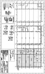
3.4.1 Layout—Drawings usually show a plan, elevations,<br />
sections, and details <strong>of</strong> a structure, accompanied by schedules<br />
for footings, columns, beams, and slabs. The plan normally<br />
is drawn in the upper left corner <strong>of</strong> the sheet, with the<br />
elevations and details below and to the right <strong>of</strong> the plan.<br />
Schedules (and bending details) are normally placed in the<br />
upper right corner <strong>of</strong> the drawing. A figure in the supporting<br />
reference data section presents a recommended layout.<br />
An arrow indicating the direction <strong>of</strong> North should be<br />
placed beside every plan view.<br />
3.4.2 Symbols and notation—Common symbols and abbreviations<br />
for placing drawings are shown in the supporting<br />
reference data section.<br />
Where unusual details or conditions require use <strong>of</strong> other<br />
(special) symbols or abbreviations, the drawings must provide<br />
explanations <strong>of</strong> the notation applied.<br />
3.4.3 Schedules—The reinforcing steel <strong>of</strong> floors and many<br />
other parts <strong>of</strong> structures can best be shown in tabular form<br />
commonly referred to as a schedule. A schedule is a compact<br />
summary <strong>of</strong> all the bars complete with the number <strong>of</strong> pieces,<br />
shape and size, lengths, marks, grades, coating information,<br />
and bending details from which bar lists can be written easily<br />
and readily. Although these schedules usually include the<br />
bending details for bent bars, separate bending detail schedules<br />
can be used.<br />
3.4.4 Coated reinforcing bars—When coated reinforcing<br />
bars are detailed along with uncoated reinforcing bars, the<br />
coated reinforcing bars must be identified in some manner,<br />
such as with a suffix (E) or (G) or with an asterisk (*), and a<br />
note stating that all reinforcing bars marked as such are to be<br />
epoxy-coated or galvanized. Epoxy-coated reinforcing bars<br />
listed with uncoated reinforcing bars in schedules or bills <strong>of</strong><br />
materials must also be marked with (E) or (*). The designation<br />
(G) is appropriate for galvanized reinforcing bars.<br />
3.5—Building drawings<br />
Placing drawings, ordinarily prepared by the fabricator,<br />
show details for fabrication and for the placing <strong>of</strong> reinforcing<br />
steel. They are not for use in constructing formwork (except<br />
joist forms when these are supplied by the same fabricator),<br />
and consequently the only required dimensions are those<br />
necessary for the proper location <strong>of</strong> the reinforcing steel.<br />
Building dimensions are shown on the placing drawing only if
DETAILS AND DETAILING OF CONCRETE REINFORCEMENT<br />
<strong>315</strong>-11<br />
necessary to locate reinforcing steel properly, as the detailer becomes<br />
responsible for accuracy <strong>of</strong> dimensions, when given.<br />
The placing drawings must be used with the structural drawings.<br />
Bending details can be shown on a separate drawing instead<br />
<strong>of</strong> on the placing drawings.<br />
3.5.1 General requirements—On receipt <strong>of</strong> the structural<br />
drawings, the fabricator takes the following steps:<br />
1. Prepares placing drawings (including bending details);<br />
2. Submits placing drawings, if required by the project<br />
specifications, to the specified authority for review and approval;<br />
3. Prepares bar lists (bills <strong>of</strong> materials);<br />
4. Fabricates reinforcing steel;<br />
5. Provides coated bars if specified;<br />
6. Provides bar supports per customer requirements; and<br />
7. Tags, bundles, and delivers the fabricated reinforcing<br />
bars to the job site.<br />
It should be noted that the general term fabricator, as used<br />
in this document, refers to a company that employs detailers,<br />
estimators, and shop personnel. In this regard, it is actually<br />
the detailer who performs steps 1, 2, and 3, whereas the shop<br />
personnel do steps 4, 5, 6, and 7.<br />
Placing drawings must show the size, shape, grade, and location<br />
<strong>of</strong> coated and uncoated bars in the structure, including<br />
bar supports, if supplied by the fabricator. They also serve as<br />
the basis for preparing bar lists.<br />
Where approval <strong>of</strong> placing drawings is required, the placing<br />
drawings should be submitted before reinforcing bar fabrication<br />
is begun.<br />
For the convenience <strong>of</strong> both the contractor and fabricator,<br />
reinforcing steel is detailed, fabricated, and delivered by<br />
units, which generally consist <strong>of</strong> building components, such<br />
as footings, walls, columns, each floor, and ro<strong>of</strong>. A separate<br />
placing drawing and bar list are usually made for each component.<br />
For small structures, all reinforcing steel can be handled<br />
as one unit. For large projects, the contractor may desire<br />
a unit, such as a single floor, to be divided to correspond with<br />
the construction schedule. Such arrangements, between the<br />
contractor and fabricator, with the A/E’s approval, are made<br />
before the <strong>detailing</strong> is begun. All sections should be kept as<br />
large as practical because it is more economical to detail and<br />
fabricate for large units, especially where there is apt to be a<br />
duplication <strong>of</strong> bars.<br />
3.5.2 Marks —Slabs, joists, beams, girders, and sometimes<br />
footings that are alike on structural drawings are given the<br />
same designation mark. Where possible, the same designations<br />
should be used on the placing drawings as on the structural<br />
drawings. When members alike on the structural<br />
drawings are slightly different on the placing drawings, a<br />
suffix letter is added to the designation to differentiate the<br />
numbers. If some <strong>of</strong> the beams marked 2B3 on the structural<br />
drawing actually differ from the others, the placing drawing<br />
would show some <strong>of</strong> the beams as 2B3 and the others as<br />
2B3A. In reinforced-<strong>concrete</strong> joist floors, there can be so<br />
many variations from the basic joists shown on the structural<br />
drawings that it is necessary to change the basic designations<br />
(for example, from prefix J to prefix R, for rib).<br />
Columns, and generally footings, are numbered consecutively<br />
or are designated by a system <strong>of</strong> coordinates on the<br />
structural drawings. The same designations should be used<br />
on placing drawings.<br />
The described marking systems identify individual, reinforced-<strong>concrete</strong><br />
members <strong>of</strong> a structure. Reinforcing bars<br />
must be individually identified on placing drawings. Only<br />
bent bars are given a mark to assist the placer in selecting the<br />
proper bars for each member. The straight bar size and length<br />
is its own identification.<br />
3.5.3 Schedules—Reinforcing steel in elements <strong>of</strong> a structure<br />
can be drawn on placing drawings either on the plan, elevation,<br />
or section, or can be listed in a schedule. It is<br />
acceptable practice to detail footings, columns, beams, and<br />
slabs in schedules. There is no standard format for schedules.<br />
They take the place <strong>of</strong> a drawing, such as a beam elevation,<br />
and must clearly indicate to the placer exactly where and<br />
how all the material listed is to be placed.<br />
3.5.4 Responsibility <strong>of</strong> the detailer—The responsibility <strong>of</strong><br />
the detailer in preparing a placing drawing is to carry out all<br />
instructions on the contract documents.<br />
The A/E must furnish a clear statement <strong>of</strong> the requirements.<br />
The detailer must carry out the requirements supplied<br />
by the A/E. The A/E, in either the project specifications or<br />
structural drawings, may not refer the detailer to an applicable<br />
building code for information to use in preparing placing<br />
drawings. This information must be interpreted by the A/E<br />
and must be shown in the form <strong>of</strong> specific design details or<br />
notes for the detailer to follow.<br />
3.5.5 Beams and joists —For beams, joists, and girders, reinforcing<br />
steel is usually shown in schedules. Bending details<br />
may be separate or incorporated in the schedule. The detailer<br />
must show number, mark, and size <strong>of</strong> members; number, size,<br />
and length <strong>of</strong> straight bars; number, size, mark, and length <strong>of</strong><br />
bent bars and stirrups; spacing <strong>of</strong> stirrups; <strong>of</strong>fsets <strong>of</strong> bars; lap<br />
splices; bar supports; and any other special information necessary<br />
for the proper fabrication and placement <strong>of</strong> the reinforcing<br />
steel.<br />
Among the special items that must be noted are:<br />
1. Overall length <strong>of</strong> bar;<br />
2. Height <strong>of</strong> hook where such dimensions are controlling;<br />
3. Lap splice lengths;<br />
4. Offset dimensions, if any; and<br />
5. Location <strong>of</strong> bar with respect to supporting members<br />
where the bar is not dimensioned symmetrically on each side<br />
<strong>of</strong> the support.<br />
3.5.6 Slabs—Reinforcing steel for slabs can be shown in<br />
plan views, in a schedule, and sometimes even in section.<br />
The schedule and bending details for slabs are similar to<br />
those for beams.<br />
Panels that are exactly alike are given an identifying letter<br />
and reinforcing steel is shown for only one panel <strong>of</strong> each<br />
kind. In skewed panels, such as for the quadrant <strong>of</strong> a circle,<br />
the bars are fanned out so that they are placed at the required<br />
spacing at a specific location, usually at the midspan. Additional<br />
bars around openings, if required, must be shown.<br />
3.5.7 Columns —Placing drawings for columns generally<br />
use a schedule form for <strong>detailing</strong>. The detailer must not only
<strong>315</strong>-12<br />
ACI STANDARD<br />
interpret the structural drawing, but clearly convey this interpretation<br />
to the placer. The detailer must show the quantity,<br />
size, and length or mark <strong>of</strong> all bars, including dowels, principal<br />
vertical bars, and ties. The detailer must also include<br />
plan sketches <strong>of</strong> typical bar arrangements for all but the simplest<br />
conditions. The detailer must clearly show length and<br />
location <strong>of</strong> lap splices, location <strong>of</strong> mechanical splices or<br />
welded splices, and position <strong>of</strong> <strong>of</strong>fset bars.<br />
3.5.8 Dowels—Dowels should be detailed, preferably,<br />
with the reinforcing steel in the element that is placed first.<br />
They must be ordered with the element to be available for<br />
placement at the proper time.<br />
3.5.9 Reinforcing steel supports—Reinforcing steel supports<br />
specified in the contract documents, including quantities<br />
and description, can be shown on the placing drawings.<br />
Bar support placing layouts for typical panels are required for<br />
two-way reinforcing steel and wherever needed to clarify placing<br />
sequence or quantities required. These layouts can be shown<br />
on the placing drawing or given by reference to the CRSI Manual<br />
<strong>of</strong> Standard Practice. Support bars, when required, must be<br />
shown clearly and identified on the placing drawings.<br />
3.6—Highway drawings<br />
Unlike the customary practice in the field <strong>of</strong> reinforced<strong>concrete</strong><br />
buildings, many state highway departments prepare<br />
a combination structural and placing drawing. The combination<br />
drawing includes a list <strong>of</strong> reinforcing steel materials<br />
from which the fabricator prepares bar lists. The placer uses<br />
the combination drawing to place the reinforcing bars. Highway<br />
departments that do not use combination drawings follow<br />
the procedures <strong>of</strong> Section 3.5.<br />
3.6.1 Marks—Usually, each highway structure is identified<br />
by a bridge number, street name, or a station number (each<br />
station being 100 linear ft [30 m]) that designates its location<br />
on the project. This station identification or bridge number<br />
must be shown on all bundle tags and shipping papers to facilitate<br />
proper distribution <strong>of</strong> reinforcing bars on delivery.<br />
For small, simple structures such as culverts, slab bridges,<br />
manholes, and catch basins, a station number in addition to<br />
the title description <strong>of</strong> the structure is sufficient identification<br />
without dividing the structure into smaller units by further<br />
marking.<br />
Larger structures, such as reinforced-<strong>concrete</strong> deck girders,<br />
I-beam bridges, continuous-type bridges, and arches,<br />
consist <strong>of</strong> small units that together make up a complete structure.<br />
These units are referred to as end bents, intermediate<br />
bents, abutments, piers, retaining walls, end spans, intermediate<br />
spans, etc., and must be designated by markings. The<br />
construction units <strong>of</strong> unusually long culverts with more than<br />
one design <strong>of</strong> barrel, for varying load conditions or, where<br />
construction joints are required across the barrel, can be identified<br />
by section numbers. Schedules <strong>of</strong> reinforcing bars are<br />
used to divide a structure into parts enabling the fabricator to<br />
make it more convenient for the placer by delivering the bars<br />
in lots as required.<br />
For highway structures, both straight and bent bars are given<br />
an individual mark. In highway structures, such as culverts<br />
and bridge spans, the arrangement <strong>of</strong> bars is the same, regardless<br />
<strong>of</strong> size or length. Standardized marks are sometimes<br />
used for bars occurring in the same relative position in culverts.<br />
Any system <strong>of</strong> letters and numerals is acceptable. Some A/E’s<br />
not only provide individual bar markings, but also indicate,<br />
by the mark, where the bar is placed in the structure.<br />
3.6.2 Schedules —Highway structural drawings most <strong>of</strong>ten<br />
show details <strong>of</strong> the various elements directly on the plan or<br />
elevation. Schedules are sometimes used for piers, small<br />
structures, and even retaining walls. Highway structural<br />
drawings usually include, when detailed completely, a type<br />
<strong>of</strong> schedule that is really a bill <strong>of</strong> material, sometimes segregated<br />
by elements <strong>of</strong> a structure. These drawings are used by<br />
the fabricator to prepare shop bar lists.<br />
3.6.3 Dimensions—When the drawings for highway structures<br />
are a combination <strong>of</strong> structural and placing drawings<br />
from which the structure will be built, all dimensions must be<br />
shown clearly. The contractor should not have to compute<br />
any needed dimensions. Drawings must show the dimensions<br />
<strong>of</strong> <strong>concrete</strong> protection for all reinforcing steel. For example,<br />
they must plainly show whether the cover dimension<br />
specified on a girder is the clear distance from the main reinforcing<br />
steel or the clear distance from the stirrups. Where<br />
separate placing drawings are prepared, structural dimensions<br />
may be omitted following the same practice as for<br />
buildings.<br />
3.6.4 Reinforcing steel —Drawings must show the grade,<br />
size, spacing, splices, and location <strong>of</strong> the coated and uncoated<br />
bars in the structure. The bar schedule (combined drawing)<br />
must show the number <strong>of</strong> pieces, size, length, mark <strong>of</strong><br />
bars, and bending details <strong>of</strong> all bent bars.<br />
Reinforcing steel for larger structures is usually detailed,<br />
fabricated, and delivered by units for the convenience <strong>of</strong><br />
both the contractor and fabricator; for example, footings,<br />
abutments, piers, and girders. The bar list is then similarly<br />
subdivided. If the structure is sufficiently large, a separate<br />
drawing and bar list is made for each unit.<br />
Reinforcing bars for foundations, piers, abutments, wing<br />
walls, and slabs are usually shown on plan, section, or elevation<br />
views. Reinforcing steel can be shown in the simplest<br />
and clearest manner, however, the bar list must be a complete<br />
summary.<br />
To be certain that all <strong>of</strong> the reinforcing steel is properly<br />
placed or positioned in a unit, a cross section is frequently required<br />
in addition to the plan and elevation <strong>of</strong> the unit where<br />
the bars are shown.<br />
3.6.5 Reinforcing steel supports—Plain metal supports are<br />
used widely as a means <strong>of</strong> securely holding reinforcing steel<br />
in proper position while the <strong>concrete</strong> is being placed. Plastic<br />
coated or stainless legs can be specified to avoid possible<br />
rusting at points <strong>of</strong> exposure. Precast <strong>concrete</strong> blocks are<br />
used in some states, particularly in the western United States.<br />
Other types <strong>of</strong> proprietary supports are available and may be<br />
suitable. Support bars, when furnished, should be shown<br />
clearly and identified.<br />
Where an exposed <strong>concrete</strong> surface is to receive special<br />
finishing treatments, such as sandblasting, bush-hammering,<br />
or any other removal <strong>of</strong> surface mortar, special consideration
DETAILS AND DETAILING OF CONCRETE REINFORCEMENT<br />
<strong>315</strong>-13<br />
must be given to such things as selecting bottom bar supports<br />
and side form spacers that will not rust or otherwise impair<br />
the finished surface appearance.<br />
Class <strong>of</strong> wire bar support, precast <strong>concrete</strong> blocks, or other<br />
proprietary supports, and locations where each is to be employed,<br />
should be specified or shown in the contract documents.<br />
The detailer should identify the specified types and<br />
show locations where each is to be used.<br />
3.7—Detailing to fabricating standards<br />
It is standard practice in the industry to show all bar dimensions<br />
as out-to-out and consider the bar lengths as the<br />
sum <strong>of</strong> all detailed dimensions, including Hooks A and G<br />
(see Table 1).<br />
3.7.1 Bending—To avoid creating excessive stresses during<br />
bending, bars must not be bent too sharply. Controls are<br />
established by specifying the minimum inside radius or inside<br />
diameter <strong>of</strong> bend that can be made for each size <strong>of</strong> bar.<br />
The radius or diameter <strong>of</strong> the bend is usually expressed as a<br />
multiple <strong>of</strong> the nominal diameter <strong>of</strong> the bar d b . The ratio <strong>of</strong><br />
diameter <strong>of</strong> bend to diameter <strong>of</strong> bar is not a constant because<br />
it has been found by experience that this ratio must be larger<br />
as the bar size increases.<br />
The minimum diameters <strong>of</strong> bend specified by ACI 318<br />
(318M) for reinforcing bars, measured on the inside <strong>of</strong> the<br />
bar, are:<br />
Bar sizes, No.<br />
3, 4, 5<br />
(10, 13, 16)<br />
6, 7, 8<br />
(19, 22, 25)<br />
9, 10, 11<br />
(29, 32, 36)<br />
14, 18<br />
(43, 57)<br />
Other than<br />
ties/stirrups<br />
6d b<br />
6d b<br />
Ties or stirrups<br />
4d b<br />
6d b<br />
8d b —<br />
10d b —<br />
The inside diameter <strong>of</strong> bends <strong>of</strong> welded-wire fabric (plain<br />
or deformed) for stirrups and ties, as specified by ACI 318<br />
(318M), shall not be less than 4d b for deformed wire larger<br />
than D6 (MD38.7) and 2d b for all other wires. Bends with inside<br />
diameter <strong>of</strong> less than 8d b shall not be less than 4d b from<br />
the nearest welded intersection.<br />
3.7.2 Hooks—ACI 318 (318M), Section 7.2 specifies minimum<br />
bend diameters for reinforcing bars. It also defines<br />
standard hook (Section 7.1) to mean the following:<br />
a) A 180 degree bend plus an extension <strong>of</strong> at least 4d b, but<br />
not less than 2-1/2 in. (60 mm), at the free end <strong>of</strong> the bar; or<br />
b) A 90 degree bend plus an extension <strong>of</strong> at least 12d b at<br />
the free end <strong>of</strong> the bar; or<br />
c) For stirrup and tie hooks only, either a 90 degree bend<br />
plus 6d b extension for No. 3, 4, 5 (No. 10, 13, 16), and 12d b<br />
extension for No. 6, 7, and 8 (No. 19, 22, and 25), or a 135<br />
degree bend plus an extension <strong>of</strong> at least 6d b at the free end<br />
<strong>of</strong> the bar. For closed ties, defined as hoops in Chapter 21 <strong>of</strong><br />
ACI 318 (318M), a 135 degree bend plus an extension <strong>of</strong> at<br />
least 6d b but not less than 3 in. (75 mm).<br />
The minimum bend diameter <strong>of</strong> hooks shall meet the foregoing<br />
provisions. The standard hooks (Table 1) were developed<br />
such that the minimum requirements were met, but at<br />
the same time the need to allow for springback in fabrication<br />
and maintaining a policy <strong>of</strong> production fabrication pin size<br />
no smaller than the ASTM A615/A615M bend test pin size<br />
was recognized as well. In the Table, the extra length <strong>of</strong> bar<br />
allowed for the hook is designated as A or G and shown to the<br />
nearest 1 in. (25 mm) for end hooks and to the nearest 1/4 in.<br />
(5 mm) for stirrup and tie hooks.<br />
Where the physical conditions <strong>of</strong> the job are such that either<br />
J, A, G, or H <strong>of</strong> the hook is a controlling dimension, it<br />
must be so noted on the drawings, schedules, and bar lists.<br />
3.7.3 Stirrup anchorage<br />
3.7.3.1 There are several permissible methods for stirrup<br />
anchorage. The most common is to use one <strong>of</strong> the hooks<br />
shown in Table 1. Types Sl to S6 in Fig. 10 illustrate not only<br />
the uses <strong>of</strong> the two types <strong>of</strong> hooks, but also the directions in<br />
which the hooks can be turned. In <strong>detailing</strong> the anchorage,<br />
care must be taken that the ends <strong>of</strong> stirrup hooks that are<br />
turned outward into shallow slabs have adequate cover. If<br />
not, the hooks should be turned inward and this change<br />
brought to the A/E’s attention.<br />
3.7.3.2 Where the free ends <strong>of</strong> stirrups cannot be tied to<br />
longitudinal bars, or where there are no longitudinal bars,<br />
stirrup support bars should be specified by the A/E. *<br />
3.7.4 Standard bar bends<br />
3.7.4.1 To list the various types <strong>of</strong> bent bars in a schedule,<br />
it is necessary to have diagrams <strong>of</strong> the bars with the<br />
lengths <strong>of</strong> the portions <strong>of</strong> the bars designated by letters. A<br />
chart <strong>of</strong> such standard bar bends is shown in Fig. 10.<br />
3.7.4.2 Dimensions given for Hooks A and G are the additional<br />
length <strong>of</strong> bar allowed for the hook as shown in Table<br />
1. For straight portions <strong>of</strong> the bar, the distance is measured to<br />
the theoretical intersection <strong>of</strong> the outside edge line extended<br />
to the outside edge line <strong>of</strong> the adjacent straight portion, or to<br />
the point <strong>of</strong> tangency to a curve, from which point the length<br />
<strong>of</strong> the latter is tabulated, as in Types 10 and 11 in Fig. 10.<br />
Truss bar dimensioning is special and is shown in large-scale<br />
detail in Fig. 10.<br />
3.7.5 Radius bending—When reinforcing bars are used<br />
around curved surfaces, such as domes or tanks, and no special<br />
requirement is established in the contract documents,<br />
bars prefabricated to a radius equal or less than those in the<br />
following table are prefabricated by the reinforcing bar fabricator.<br />
In the smaller sizes, the bars are sprung to fit varying<br />
job conditions, such as location <strong>of</strong> splices, vertical bars, jack<br />
rods, window openings, and other blocked out areas in the<br />
forms. The larger size bars, which are more difficult to spring<br />
into desired position, are ordinarily employed in massive structures<br />
where placing tolerances are correspondingly larger.<br />
* These decisions should be shown on the structural drawings. If not, the detailer<br />
may suggest solutions, but only when subject to review and approval by the A/E. The<br />
final decision on these design problems is the A/E’s responsibility.
<strong>315</strong>-14<br />
ACI STANDARD<br />
When radial prefabrication is required<br />
Bars are to be prefabricated when either radius or bar length is less<br />
than tabulated value<br />
Bar size, No. Radius, ft (mm) Bar length, ft (mm)<br />
3 (10) 5 (1500) 10 (3000)<br />
4 (13) 10 (3000) 10 (3000)<br />
5 (16) 15 (4500) 10 (3000)<br />
6 (19) 40 (12,000) 10 (3000)<br />
7 (22) 40 (12,000) 10 (3000)<br />
8 (25) 60 (18,000) 30 (9000)<br />
9 (29) 90 (27,000) 30 (9000)<br />
10 (32) 110 (33,000) 30 (9000)<br />
11 (36) 110 (33,000) 60 (18,000)<br />
14 (43) 180 (54,000) 60 (18,000)<br />
18 (57) 300 (90,000) 60 (18,000)<br />
Radially prefabricated bars <strong>of</strong> any size tend to relax the radius<br />
originally prefabricated as a result <strong>of</strong> time and normal<br />
handling. The last few feet involved in the lap splice area <strong>of</strong>ten<br />
appear as a tangent rather than a pure arc, due to limitations <strong>of</strong><br />
standard bending equipment. For these reasons, final adjustments<br />
are a field placing problem to suit conditions and tolerance<br />
requirements <strong>of</strong> a particular job. See Fig. 8 and 9 for radial<br />
tolerances and Section 4.2(c)3. Bars requiring a larger radius<br />
or length than shown in the table are sprung in the field without<br />
prefabrication.<br />
The presence <strong>of</strong> the tangent end does not create any problem<br />
on bar sizes No. 3 through 11 (No. 10 through 36) as<br />
they are generally lap spliced and tangent ends are acceptable.<br />
No. 14 and 18 (No. 43 and 57) bars cannot be lap<br />
spliced, however, and are usually spliced using a proprietary<br />
mechanical splice or a butt weld. It is a problem to place a<br />
radially bent bar when using a mechanical splice sleeve because<br />
<strong>of</strong> the tangent ends on bars bent to small radii. To<br />
avoid this problem, all No. 14 and 18 (No. 43 and 57) bars<br />
bent to a radius <strong>of</strong> 20 ft (6000 mm) or less should be furnished<br />
with an additional 18 in. (450 mm) added to each end.<br />
This 18 in. (450 mm) tangent end is to be removed in the<br />
field by flame cutting. Bars bent to radii greater than 20 ft<br />
(6000 mm) will be furnished to the detailed length with no<br />
consideration given to the tangent end. The ends <strong>of</strong> these<br />
bars generally are saw cut.<br />
Shop removal <strong>of</strong> tangent ends can be made by special arrangement<br />
with the reinforcing bar supplier.<br />
3.7.6 Slants—To determine the length <strong>of</strong> the straight bar<br />
necessary to form a truss bar, the length <strong>of</strong> the slant portion<br />
<strong>of</strong> the bar must be known. The standard angle is 45 degrees<br />
for truss bars, with any other angles being special. Slants and<br />
increments are calculated to the closest 1/2 in. (10 mm) so<br />
that for truss bars with two slants, the total increment will be<br />
in full inches (25 mm). This makes the computation easier<br />
and is within the tolerances permitted. It is important to note<br />
that when the height <strong>of</strong> the truss is too small, 45 degree bends<br />
become impossible. This condition requires bending at a<br />
lesser angle and lengthens the slant portion.<br />
3.7.7 Column verticals<br />
3.7.7.1 General—The A/E shall indicate the grade <strong>of</strong> reinforcing<br />
steel required on the structural drawings or in the<br />
project specifications. The detailer shall show special specification<br />
requirements for grade in listing column verticals for<br />
each story. In multistory columns, lower stories are sometimes<br />
designed for higher strength grades. Special requirements<br />
for bars to be butt-spliced can also be included.<br />
A table in the supporting reference data section shows the<br />
number <strong>of</strong> bars that can be placed within spiral <strong>reinforcement</strong><br />
in conformance with ACI 318 (318M). Three splice arrangements<br />
are shown: butt-splices, radially lapped splices<br />
with verticals or dowels from below inside <strong>of</strong> bars above,<br />
and circumferentially lapped splices with dowels from below<br />
the bars above. Spacing for the latter also applies to buttspliced<br />
two-bar bundles.<br />
Maximum number <strong>of</strong> bars for the two lap splice arrangements<br />
assumes all bars are spliced at the same cross section.<br />
For the butt-splice arrangement, no allowance was included<br />
for increase in diameter at couplers or end-bearing devices,<br />
or for access to butt weld.<br />
3.7.7.2 Offset between column faces—Where a column is<br />
smaller than the one below, vertical bars from below must be<br />
<strong>of</strong>fset to come within the column above, or separate dowels<br />
must be used. The slope <strong>of</strong> the inclined portion shall not exceed<br />
1 to 6. In <strong>detailing</strong> <strong>of</strong>fset column bars, a bar diameter plus<br />
clearance must be added to the desired <strong>of</strong>fset. In the corners<br />
<strong>of</strong> columns, bars are usually <strong>of</strong>fset on the diagonal, which requires<br />
that the <strong>of</strong>fset be increased accordingly.<br />
For any <strong>of</strong>fset between column faces less than 3 in. (80 mm),<br />
the vertical bar should be <strong>of</strong>fset bent. When the <strong>of</strong>fset is 3 in.<br />
(80 mm) or more, the vertical bars in the column below<br />
should be terminated at the floor slab and separate straight<br />
dowels provided.<br />
3.7.7.3 Lap splices —Typical arrangement <strong>of</strong> bars at a<br />
lap splice is shown in Fig. 4. Unless special details are provided<br />
on the structural drawings, all column verticals to be<br />
lap spliced in square or rectangular columns must be shop<br />
<strong>of</strong>fset bent into the column above except as noted in Section<br />
3.7.7.2. General practice is to use the <strong>of</strong>fset for the corner<br />
bars that must be bent diagonally as the typical <strong>of</strong>fset dimension<br />
for all the bars in the column. Column verticals in round<br />
columns where column sizes do not change must be <strong>of</strong>fset<br />
bent only if a maximum number <strong>of</strong> lap spliced bars is desired<br />
in the column above (see table in the supporting reference<br />
data section).<br />
3.7.8 Column spirals<br />
3.7.8.1 General—Spirals shall be provided with 1-1/2<br />
extra turns at both top and bottom. The height (or length) <strong>of</strong><br />
a spiral is defined as the distance out-to-out <strong>of</strong> coils, including<br />
the finishing turns top and bottom, with a tolerance <strong>of</strong><br />
plus or minus 1-1/2 in. (40 mm). Where a spiral cannot be<br />
furnished in one piece, it may be furnished in two or more<br />
sections to be field welded, or with additional length at each <strong>of</strong><br />
the ends <strong>of</strong> each section to be lapped in the field, 48 diameters<br />
minimum, but not less than 12 in. (300 mm). The sections must be<br />
identified properly by mark numbers to ensure proper assembly.
DETAILS AND DETAILING OF CONCRETE REINFORCEMENT<br />
<strong>315</strong>-15<br />
Spacers are sometimes used for maintaining the proper<br />
pitch and alignment <strong>of</strong> the spiral and, when used, must conform<br />
to the minimum requirements <strong>of</strong> a table in the supporting<br />
reference data section. Maximum length <strong>of</strong> spacers is<br />
that <strong>of</strong> the spiral plus one pitch. One alternative method to<br />
using spacers is to ship the spiral as a compressed coil and tie<br />
it in place in the field. The project specifications or subcontract<br />
agreements should be written clearly to cover the supply<br />
<strong>of</strong> spacers or field tying <strong>of</strong> the spiral <strong>reinforcement</strong>.<br />
The height <strong>of</strong> one-piece assembled spirals for fabrication<br />
and shipping is limited to 25 ft (7500 mm) unless special<br />
handling arrangements are made. For greater heights, spirals<br />
must be field spliced by lapping or welding. Spacers can be<br />
provided. Spirals are also used in piles, but these do not fall<br />
within ACI 318 (318M) definition <strong>of</strong> a spiral and are usually<br />
made <strong>of</strong> light wire and relatively large pitch.<br />
3.7.8.2 Spiral details—Unless otherwise specifically<br />
provided, spirals should be detailed as extending from the<br />
floor level or top <strong>of</strong> footing or pedestal to the level <strong>of</strong> the<br />
lowest horizontal <strong>reinforcement</strong> in the slab, drop panel, or<br />
beam above. In a column with a capital, the spiral shall extend<br />
to the plane at which the diameter or width <strong>of</strong> the capital<br />
is twice that <strong>of</strong> the column. See Detail 2, Fig. 4. If the structural<br />
drawings require lateral <strong>reinforcement</strong> in the column<br />
between the top <strong>of</strong> the main spiral and the floor level above,<br />
it should be provided by a stub spiral (short section <strong>of</strong> spiral)<br />
or by circular column ties. Where stub spirals are used, they<br />
must be attached to the main spiral for shipment or fully<br />
identified by mark numbers.<br />
3.7.9 Dowels—Dowels will be provided by the detailer as<br />
specified in the contract documents for the following:<br />
1. Column footings to columns;<br />
2. Wall footings to walls;<br />
3. Wall intersections;<br />
4. Stairs to walls;<br />
5. Construction joints in footings, walls, and slabs;<br />
6. Columns at floor levels where the vertical <strong>reinforcement</strong><br />
cannot be <strong>of</strong>fset bent and extended; and<br />
7. Other places where it is not possible or desirable to extend<br />
the reinforcing steel continuously through a joint.<br />
Dowels, preferably, should be detailed with that portion <strong>of</strong><br />
the structure where <strong>concrete</strong> is placed first. They should always<br />
be ordered with that portion.<br />
3.7.10 Bar lists—Bar lists used in cutting, bending, tagging,<br />
shipping, and invoicing are prepared from placing<br />
drawings. Bars are grouped separately on the bar list as follows:<br />
1. Straight;<br />
2. Bent, including stirrups and ties; and<br />
3. Spirals.<br />
The grade <strong>of</strong> reinforcing steel for all items must be shown.<br />
Straight bars are usually grouped according to size, with<br />
the largest size first and those <strong>of</strong> the same size listed in the<br />
order <strong>of</strong> their length with the longest bar first.<br />
Bent bars, stirrups, and ties are usually listed in a similar<br />
manner.<br />
Spirals may be subdivided and listed in groups by the size<br />
<strong>of</strong> bar, diameter <strong>of</strong> spiral, pitch <strong>of</strong> spiral, and length. See the<br />
bar list example in the supporting reference data section.<br />
CHAPTER 4—FABRICATING PRACTICE<br />
STANDARDS<br />
4.1—Fabrication<br />
A fabricated reinforcing bar is any deformed or plain steel<br />
bar for <strong>concrete</strong> reinforcing steel, conforming to ASTM<br />
specifications A 615/A 615M, A 616/A 616M, A 617/A<br />
617M, or A 706/A 706M, which is cut to a specified length<br />
or cut and bent to a specified length and configuration.<br />
Welded-plain- and deformed-wire fabric meeting ASTM A<br />
185 or A 497, respectively, and spirals formed from cold<br />
drawn wire conforming to ASTM A 82 or A 496, are also<br />
considered <strong>concrete</strong> <strong>reinforcement</strong> within this definition.<br />
Other materials used as <strong>concrete</strong> <strong>reinforcement</strong> and processes<br />
other than cutting and bending are not included in this definition.<br />
4.2—Extras<br />
Reinforcing bars are sold on the basis <strong>of</strong> their theoretical<br />
weights (mass) computed from the values given in the<br />
ASTM specifications, as calculated from the detailed placing<br />
drawings, lists, or purchase orders. In determining the<br />
weight (mass) <strong>of</strong> a bent bar, it is standard practice in the industry<br />
to show all bar dimensions as out-to-out and consider<br />
the bar lengths required for fabrication as the sum <strong>of</strong> all detailed<br />
dimensions, including Hooks A and G (see Fig. 10).<br />
Charges for extras can be added to the base price per hundredweight.<br />
In this event, the principal extra charges are:<br />
a) Size extras—vary as bar size changes;<br />
b) Grade extras—are added to some grades <strong>of</strong> bars; and<br />
c) Bending extras—are added for all shop bending.<br />
Bending extra charges are separated into three classes as<br />
follows:<br />
1. Light bending—All No. 3 (No. 10) bars, stirrups,<br />
hoops, supplementary ties, and ties, and all bars No. 4<br />
through 18 (No. 13 through 57) that are bent at more<br />
than six points in one plane, or bars that are bent in more<br />
than one plane (unless special bending, see below), all<br />
one-plane radius bending with more than one radius in<br />
any bar (three maximum), or a combination <strong>of</strong> radius<br />
and other type bending in one plane (radius bending being<br />
defined as all bends having a radius <strong>of</strong> 12 in. [300<br />
mm] or more to inside <strong>of</strong> bar);<br />
2. Heavy bending—Bar sizes No. 4 through 18 (No. 13<br />
through 57) that are bent at not more than six points in<br />
one plane (unless classified as light bending or special<br />
bending) and single radius bending; and<br />
3. Special bending—All bending to special tolerances<br />
(tolerances closer than those shown in Fig. 8 and 9), all<br />
radius bending in more than one plane, all multiple<br />
plane bending containing one or more radius bends, and<br />
all bending for precast units.<br />
d) Services and special fabrication—Extra charges for services<br />
and special fabrication may be computed individually<br />
to suit conditions for each product on items such as:<br />
1. Detailing, listing, or both;
<strong>315</strong>-16<br />
ACI STANDARD<br />
2. Owner’s quality assurance/control requirements;<br />
3. Transportation;<br />
4. Epoxy coating and galvanizing;<br />
5. Painting, dipping, or coating;<br />
6. Spirals and continuous hoops;<br />
7. Shearing to special tolerances;<br />
8. Square (saw-cut) ends;<br />
9. Beveled ends or ends not otherwise defined;<br />
10. Bar threading;<br />
11. Special bundling and tagging;<br />
12. Overlength bars, and overwidth bars, or both; and<br />
13. Welding.<br />
4.3—Tolerances<br />
There are established, standard industry fabricating tolerances<br />
that apply unless otherwise shown in the project<br />
specifications or structural drawings. Fig. 8 and 9 define these<br />
tolerances for the standard bar bends shown in Fig. 10. Note<br />
that tolerances more restrictive than these may be subject to an<br />
extra charge. For further tolerance information, see ACI 117.<br />
CHAPTER 5—SUPPORTS FOR REINFORCING<br />
STEEL<br />
5.1—General<br />
The contract documents usually outline the need and requirements<br />
for reinforcing steel supports. The following requirements<br />
are applicable to supports for reinforcing bars,<br />
and may be applicable to supports for wire or welded-wire<br />
fabric.<br />
5.1.1 General requirements—When the contract documents<br />
specify merely that reinforcing steel “shall be accurately<br />
placed and adequately supported before the <strong>concrete</strong> is<br />
placed, and shall be secured against displacement within permitted<br />
tolerances,” the contractor is free to select and purchase<br />
the type and class <strong>of</strong> wire bar supports, precast block,<br />
or other materials for each area.<br />
5.1.2 Specific requirements—When the contract documents<br />
specify types or material for bar supports in different areas,<br />
the detailer for the supplier must indicate these materials and<br />
areas in which they are to be used, number, size, type, arrangement,<br />
and quantities required. These details must be<br />
outlined or referenced to a generally accepted document that<br />
shows such arrangements. *<br />
5.2—Types <strong>of</strong> bar supports<br />
5.2.1 Wire bar supports—Descriptions <strong>of</strong> wire bar supports<br />
and examples <strong>of</strong> their usage are available as industry<br />
recommendations in the CRSI Manual <strong>of</strong> Standard Practice,<br />
which is revised periodically to reflect the latest practice.<br />
Caution: When multiple layers <strong>of</strong> unusually heavy reinforcing<br />
bars are to be supported on wire bar supports, the number<br />
<strong>of</strong> wire bar supports may need to be increased to prevent penetration<br />
<strong>of</strong> support legs into the form material, especially<br />
where the surface is exposed to view or corrosion.<br />
5.2.2 Precast <strong>concrete</strong> bar supports—Descriptions <strong>of</strong><br />
commonly used types and sizes are available in the CRSI<br />
* Suggested sizes, styles, and placing <strong>of</strong> bar supports are shown in Chapter 3 (Bar<br />
Supports) <strong>of</strong> the supporting reference data section.<br />
Manual <strong>of</strong> Standard Practice. Requirements for texture and<br />
color to suit job conditions should be added if necessary.<br />
Caution: If the finished surface will be subjected to sandblasting,<br />
bush-hammering, or chemical removal <strong>of</strong> external<br />
mortar, the different texture <strong>of</strong> the exposed precast blocks<br />
(unless part <strong>of</strong> a planned pattern) may be objectionable.<br />
5.2.3 Other types <strong>of</strong> bar supports—CRSI’s Manual <strong>of</strong><br />
Standard Practice contains descriptions <strong>of</strong> one other type <strong>of</strong><br />
bar supports, all-plastic bar supports. See the supporting reference<br />
data section for more information.<br />
5.3—Side form spacers and beam bolsters<br />
All reinforcing steel must be firmly held in place before<br />
and during casting <strong>of</strong> <strong>concrete</strong> by means <strong>of</strong> precast <strong>concrete</strong><br />
blocks, metallic or plastic supports, spacer bars, wires, or other<br />
devices adequate to ensure against displacement during<br />
construction and to keep the reinforcing steel at the proper<br />
distance from the forms. Selection <strong>of</strong> the type <strong>of</strong> spacer traditionally<br />
has been the responsibility <strong>of</strong> the contractor. Detailing<br />
<strong>of</strong> side form spacers is not a standard requirement and<br />
is performed only when specifically required by the contract<br />
documents. The reinforcing bar placing drawings need only<br />
show, and the fabricator will only be responsible to supply,<br />
those side form spacers that are equal to the standard bar supports<br />
referred to in Section 5.2.<br />
Beam bolsters are typically placed transversely to the<br />
beam. Beam bolsters placed longitudinally with the beam are<br />
supplied only upon special arrangements between the contractor<br />
and the supplier, if approved by the A/E.<br />
5.4—Placing reinforcing steel supports<br />
5.4.1 General—Reinforcing steel must be accurately located<br />
in the forms and firmly held in place before and during<br />
the placing <strong>of</strong> <strong>concrete</strong>. Adequate supports are necessary to<br />
prevent displacement during construction and to keep the reinforcing<br />
steel at a proper distance from the forms. Bar supports<br />
are sometimes specified to be “sufficient in number<br />
and strength to carry properly the reinforcing steel they support.”<br />
The detailer should show bar supports as required. * Bar<br />
supports are detailed for shrinkage-temperature reinforcing<br />
steel in top slabs <strong>of</strong> reinforced <strong>concrete</strong> joist construction only<br />
if specifically required in the contract documents.<br />
Bar supports are not intended to and should not be used to<br />
support runways for <strong>concrete</strong> buggies or similar loads.<br />
5.4.2 Supports for bars in reinforced <strong>concrete</strong> cast on<br />
ground—Bar supports are detailed for the top bars only in<br />
slabs on grade, grade beams, footings, and foundation mats<br />
4 ft (1200 mm) or less in thickness, in quantities not to exceed<br />
an average spacing <strong>of</strong> 4 ft (1200 mm) in each direction.<br />
Separate support bars are detailed only if so indicated by the<br />
A/E or on special arrangements with the contractor, as principal<br />
<strong>reinforcement</strong> is assumed to be used for support.<br />
Bar supports will be furnished by the reinforcing-steel supplier<br />
for bottom bars in grade beams or slabs on ground and<br />
for the bars in singly reinforced slabs on ground only if specifically<br />
required in the contract documents. There are so<br />
many ways <strong>of</strong> supporting top bars in footings and foundation
DETAILS AND DETAILING OF CONCRETE REINFORCEMENT<br />
<strong>315</strong>-17<br />
mats more than 4 ft (1200 mm) thick that suppliers furnish<br />
supports for such purposes only by special arrangement.<br />
CHAPTER 6—COMPUTER-ASSISTED DETAILING<br />
6.1—Use <strong>of</strong> computers in <strong>detailing</strong><br />
The computer system for <strong>detailing</strong> reinforcing bars has<br />
been devised to use digital computers and other data processing<br />
equipment to speed up the preparation <strong>of</strong> placing drawings,<br />
to facilitate neater and more compact drawings, and to<br />
relieve the detailer <strong>of</strong> tedious and time-consuming computations<br />
that can be performed efficiently by a computer.<br />
Computer-aided drafting, commonly called CAD, is also<br />
being used in the drawing and <strong>detailing</strong> <strong>of</strong> placing drawings.<br />
This system gives the detailer speed, accuracy, and an expeditious<br />
way <strong>of</strong> making changes when necessary.<br />
6.2—Placing drawings<br />
The detailer prepares the graphical part <strong>of</strong> the placing<br />
drawing in a conventional manner. All the listing <strong>of</strong> quantities<br />
and other descriptive printing, however, is performed by the<br />
computer’s output device (that is, plotter, matrix printer, laser<br />
printer). While producing the placing drawings, the detailer<br />
may directly or indirectly input information into the computer<br />
for processing. When the input data have been processed, the<br />
drawing is completed by attaching to it the printed output<br />
from the computer. It contains all the necessary descriptive<br />
information pertaining to the reinforcing steel as well as the<br />
bending details. Computer output can be printed on transparent<br />
paper so that bar lists and bending details will be reproduced<br />
as part <strong>of</strong> the placing drawing.<br />
The “label system” is <strong>of</strong>ten used to reference the bars on<br />
the drawing with its attached machine printout. Under this<br />
system, the detailer assigns a label number to each separate<br />
bar placing operation comprising either an individual bar or<br />
a group <strong>of</strong> bars. This label number, indicating the designated<br />
bars, is shown clearly on the drawing and is also written on<br />
the input sheet along with other pertinent data, such as bar<br />
size and spacing. The output from the computer prints the label<br />
number and then lists the descriptions <strong>of</strong> the various bars<br />
under each label. In this way, a quick reference can be made<br />
between the graphical section <strong>of</strong> the drawing and the machine<br />
printed bar descriptions.<br />
6.3—Ordering procedures<br />
When the placing drawings have been approved, preparation<br />
<strong>of</strong> shop orders is greatly simplified by using the data already<br />
generated for the label list or column or beam and slab<br />
schedule and bending details. All the detailer must indicate<br />
are the labels or the portions there<strong>of</strong> that are to be ordered<br />
from a particular drawing, and the data processing equipment<br />
weighs and sorts and lists the material by grade, tag<br />
color, type <strong>of</strong> bending, and size and length in descending order<br />
on the bar list. The equipment can also produce the shipping<br />
tags and all manifest documents.<br />
CHAPTER 7—RECOMMENDED PRACTICES FOR<br />
LOCATION OF BARS DESIGNATED ONLY BY<br />
SIZE/SPACING<br />
Especially in slabs and walls designed for a given area <strong>of</strong><br />
reinforcing steel per running foot, required <strong>reinforcement</strong><br />
commonly is designated by size and spacing combinations to<br />
the nearest 1/2 in. (10 mm) for spacing. If the structural<br />
drawing specifically shows the positions <strong>of</strong> the first bar per<br />
panel, or for a given length shows the total number <strong>of</strong> bars,<br />
no problem is created—the detailer simply follows the specific<br />
requirements. Therefore, design notes, such as 20-No. 4<br />
(20-No. 13) in a designated length, or No. 4 at 12 (No. 13 at<br />
300 mm) with location <strong>of</strong> the starting bar shown, requires no<br />
further interpretation to complete a placing drawing or to<br />
calculate total number <strong>of</strong> bars required. When the structural<br />
drawing shows No. 4 at 12 (No. 13 at 300 mm) with no further<br />
instructions in the general notes or in the project specifications,<br />
the procedures shown in Fig. 19 (in Part C) are<br />
recommended.<br />
CHAPTER 8—GLOSSARY<br />
Architect/engineer—The architect, engineer, architectural<br />
firm, engineering firm, or architectural and engineering<br />
firm, issuing project drawings and specifications, or administering<br />
work under the contract documents.<br />
Bar placing subcontractor—A contractor or subcontractor<br />
who handles and places <strong>reinforcement</strong> and bar supports,<br />
<strong>of</strong>ten colloquially referred to as a bar placer or placer.<br />
Bar supports—Devices <strong>of</strong> formed wire, plastic or precast<br />
<strong>concrete</strong> to support, hold, and space reinforcing bars.<br />
Butt-welded splice—Reinforcing bar splice made by<br />
welding the butted ends <strong>of</strong> the reinforcing bars.<br />
Contract documents—Documents, including the project<br />
drawings and project specifications, covering the required<br />
work.<br />
Contractor—Person, firm, or corporation with whom the<br />
owner enters into an agreement for construction <strong>of</strong> the work.<br />
Coupler—Threaded device for joining reinforcing bars<br />
for the purpose <strong>of</strong> providing transfer <strong>of</strong> either axial compression<br />
or axial tension or both from one bar to the other.<br />
Coupling sleeve—Nonthreaded device fitting over the<br />
ends <strong>of</strong> two reinforcing bars for the eventual purpose <strong>of</strong> providing<br />
transfer <strong>of</strong> either axial compression or axial tension or<br />
both from one bar to the other.<br />
Detailer—Drafter who prepares reinforcing bar placing<br />
drawings and bar lists.<br />
Fabricator—A bar company that is capable <strong>of</strong> preparing<br />
placing drawings, bar lists, and storing, shearing, bending,<br />
bundling, tagging, loading, and delivering reinforcing bars.<br />
Mechanical splice—The complete assembly <strong>of</strong> an endbearing<br />
sleeve, a coupler, or a coupling sleeve, and possibly<br />
additional materials or parts to accomplish the connection <strong>of</strong><br />
reinforcing bars.<br />
Owner—Corporation, association, partnership, individual,<br />
or public body or authority with whom the contractor enters<br />
into agreement, and for whom the work is provided.<br />
Placing drawings—Detailed drawings or sketches that<br />
give the size, location, and spacing <strong>of</strong> the bars, and all other<br />
information required by the contractor to place the reinforcing<br />
steel.<br />
Project drawings—The drawings which, along with project<br />
specifications, complete the descriptive information for con-
<strong>315</strong>-18<br />
ACI STANDARD<br />
structing the work required or referred to in the contract documents.<br />
Project specifications—The written documents that specify<br />
requirements for a project in accordance with the service<br />
parameters and other specific criteria established by the<br />
owner.<br />
Schedule—Table on placing drawings to give the size,<br />
shape, and arrangement <strong>of</strong> similar items.<br />
Sleeve—A tube that encloses such items as a bar, dowel,<br />
or anchor bolt.<br />
Splice—Connection <strong>of</strong> one reinforcing bar to another by<br />
lapping, mechanical coupling or welding; the lap between<br />
sheets or rolls <strong>of</strong> welded-wire fabric.<br />
Structural drawings—Drawings that show all framing<br />
plans, sections, details, and elevations required to construct<br />
the work. For reinforced-<strong>concrete</strong> structures, they include<br />
the sizes and general arrangement <strong>of</strong> all the <strong>reinforcement</strong><br />
from which the fabricator prepares the placing drawings.<br />
Welded splice—A means <strong>of</strong> joining two reinforcing bars<br />
by electric arc welding. Reinforcing bar may be lapped, butted,<br />
or joined with splice plates or angles.<br />
Work—The entire construction, or separately indentifiable<br />
parts there<strong>of</strong>, which are required to be furnished under<br />
the contract documents. Work is the result <strong>of</strong> performing services,<br />
furnishing labor, and furnishing and incorporating materials<br />
and equipment into the construction, as required by<br />
the contract documents.<br />
CHAPTER 9—REFERENCES<br />
9.1—Referenced standards<br />
The documents <strong>of</strong> the various organizations referred to in<br />
this standard are listed below with their serial designation,<br />
including year <strong>of</strong> adoption or revision. The documents listed<br />
were the latest edition at the time this standard was revised.<br />
Because some <strong>of</strong> these documents are revised frequently,<br />
generally in minor detail only, the user <strong>of</strong> this standard<br />
should check directly with the sponsoring group if it is desired<br />
to refer to the latest revision.<br />
American Association <strong>of</strong> State Highway and Transportation<br />
Officials<br />
AASHTO Standard Specifications for Highway Bridges,<br />
16th Edition 1<strong>99</strong>6<br />
American Concrete Institute<br />
117-90 Standard Tolerances for Concrete Construction<br />
and Materials<br />
318-95 Building Code Requirements for Structural<br />
Concrete<br />
318M-95 Building Code Requirements for Structural<br />
Concrete (Metric)<br />
343R-95 Analysis and Design <strong>of</strong> Reinforced Concrete<br />
Bridge Structures<br />
349-97 Code Requirements for Nuclear Safety Related<br />
Concrete Structures<br />
359-92 Code for Concrete Reactor Vessels and Containments<br />
American Railway Engineering and Maintenance-<strong>of</strong>-Way<br />
Association<br />
Manual for Railway Engineering, Chapter 8, Concrete Structures<br />
and Foundations, 1<strong>99</strong>6<br />
American Society for Testing and Materials<br />
A 82-97a Standard Specification for Steel Wire, Plain,<br />
for Concrete Reinforcement<br />
A 185-97 Standard Specification for Steel Welded<br />
Wire Fabric, Plain, for Concrete<br />
Reinforcement<br />
A 496-97a Standard Specification for Steel Wire,<br />
Deformed, for Concrete Reinforcement<br />
A 497-97 Standard Specification for Steel Welded<br />
Wire Fabric, Deformed, for Concrete<br />
Reinforcement<br />
A 615/ Standard Specification for Deformed and<br />
A 615M-96a Plain Billet-Steel Bars for Concrete<br />
Reinforcement<br />
A 616/ Standard Specification for Rail-Steel<br />
A 616M-96a Deformed and Plain Bars for Concrete<br />
Reinforcement<br />
A 617/ Standard Specification for Axle-Steel<br />
A 617M-96a Deformed and Plain Bars for Concrete<br />
Reinforcement<br />
A 706/ Standard Specification for Low-Alloy<br />
A 706M-96b Steel Deformed and Plain Bars for Concrete<br />
Reinforcement<br />
A 767/ Standard Specification for Zinc-Coated<br />
A 767M-97 (Galvanized) Steel Bars for Concrete<br />
Reinforcement<br />
A 775/ Standard Specification for Epoxy-Coated<br />
A 775M-97 Reinforcing Steel Bars<br />
American Society <strong>of</strong> Civil Engineers<br />
ASCE 7-95 Minimum Design Loads for Buildings and<br />
Other Structures<br />
American Welding Society<br />
Dl.4-98 Structural Welding Code—Reinforcing<br />
Steel<br />
Association for Information and Image Management<br />
Modern Drafting Techniques for Quality Microreproductions<br />
Building Seismic Safety Council<br />
NEHRP-97 NEHRP Recommended Provisions for<br />
Seismic Regulations for New Buildings<br />
Concrete Reinforcing Steel Institute<br />
Manual <strong>of</strong> Standard Practice, 26th Edition, 2nd Printing, 1<strong>99</strong>8<br />
Reinforcement Anchorages and Splices, 4th Edition 1<strong>99</strong>7<br />
International Conference <strong>of</strong> Building Officials<br />
Uniform Building Code, 1<strong>99</strong>7<br />
These publications can be obtained from the following<br />
organizations:<br />
American Association <strong>of</strong> State Highway and Transportation<br />
Officials<br />
444 North Capitol Street, N.W., Suite 249<br />
Washington, D.C. 20001
DETAILS AND DETAILING OF CONCRETE REINFORCEMENT<br />
<strong>315</strong>-19<br />
American Concrete Institute<br />
P.O. Box 9094<br />
Farmington Hills, Mich. 48333-9094<br />
American Railway Engineering and Maintenance-<strong>of</strong>-Way<br />
Association<br />
50 F Street, N.W.<br />
Washington, D.C. 20001<br />
American Society for Testing and Materials<br />
100 Barr Harbor Drive<br />
West Conshohocken, Pa. 19428<br />
American Society <strong>of</strong> Civil Engineers<br />
1801 Alexander Bell Drive<br />
Reston, Va. 20191<br />
American Welding Society<br />
550 N.W. LeJeune Road<br />
Miami, Fla. 33126<br />
Association for Information and Image Management<br />
1100 Wayne Avenue, Suite 1100<br />
Silver Springs, Md. 20910<br />
Building Seismic Safety Council<br />
1015 15th Street, N.W., Suite 700<br />
Washington, D.C. 20005<br />
Concrete Reinforcing Steel Institute<br />
933 North Plum Grove Road<br />
Schaumburg, Ill. 60173<br />
International Conference <strong>of</strong> Building Officials<br />
5360 South Workman Mill Road<br />
Whittier, Calif. 90601<br />
9.2—Cited references<br />
1. Collins, M. P., and Mitchell, D., “Detailing for Torsion,” ACI JOURNAL,<br />
Proceedings V. 73, No. 9, Sept. 1976, pp. 506-511.<br />
2. Guimaraes, G. N.; Kreger, M. E.; and Jirsa, J. O., “Reinforced Concrete<br />
Frame Connections Constructed Using High-Strength Materials,” University<br />
<strong>of</strong> Texas at Austin, Aug. 1989 (PMFSEL Report No. 89-1).<br />
CHAPTER 10—NOTATIONS<br />
A c = area <strong>of</strong> core <strong>of</strong> spirally reinforced compression<br />
member measured to outside diameter <strong>of</strong> spiral,<br />
in. 2 (mm 2 )<br />
A cv = net area <strong>of</strong> <strong>concrete</strong> section bounded by web<br />
thickness and length <strong>of</strong> section in the direction <strong>of</strong><br />
shear force considered, in. 2 (mm 2 )<br />
A g = gross area <strong>of</strong> section, in. 2 (mm 2 )<br />
A s = area <strong>of</strong> nonprestressed tension<br />
<strong>reinforcement</strong>, in. 2 (mm 2 )<br />
b w = web width, in. (mm)<br />
c 2 = size <strong>of</strong> rectangular or equivalent rectangular<br />
column, capital, or bracket measured transverse<br />
to the direction <strong>of</strong> the span for which moments<br />
are being determined, in. (mm)<br />
d = distance from extreme compression fiber to<br />
centroid <strong>of</strong> tension <strong>reinforcement</strong>, in. (mm)<br />
d b = bar diameter, in. (mm)<br />
f c ′ = specified compressive strength <strong>of</strong> <strong>concrete</strong>, psi (MPa)<br />
f y = specified yield strength <strong>of</strong> nonprestressed<br />
<strong>reinforcement</strong>, psi (MPa)<br />
h = overall thickness <strong>of</strong> member, in. (mm)<br />
l d = development length, in. (mm)<br />
l dh = development length for a bar with a standard<br />
hook, in. (mm)<br />
l 0 = minimum length, measured from joint face along<br />
axis <strong>of</strong> structural member, over which transverse<br />
<strong>reinforcement</strong> must be provided, in. (mm)<br />
M u = factored moment at section<br />
s = spacing <strong>of</strong> shear or torsion <strong>reinforcement</strong> in<br />
direction parallel to longitudinal <strong>reinforcement</strong>,<br />
in. (mm)<br />
s o = maximum spacing <strong>of</strong> transverse <strong>reinforcement</strong>,<br />
in. (mm)<br />
ρ = ratio <strong>of</strong> nonprestressed tension <strong>reinforcement</strong><br />
ρ v = A sv /A cv ; where A sv is the projection on A cv <strong>of</strong> area<br />
<strong>of</strong> distributed shear <strong>reinforcement</strong> crossing the<br />
plane <strong>of</strong> A cv
<strong>315</strong>-20<br />
ACI STANDARD<br />
PART C—FIGURES AND TABLES<br />
Note: Unless noted otherwise, tables and figures are based on ACI 318 (318M). Concrete cover shown is minimum and should be increased for more severe<br />
conditions. Except for single span slabs where top steel is unlikely to receive construction traffic, top bars lighter than No. 4 at 12 in. (No. 13 at 300 mm) are not recommended.<br />
For a discussion <strong>of</strong> bar support spacing, see Section 5.4 <strong>of</strong> this standard. See also Chapter 12 <strong>of</strong> ACI 318 (318M). Bar cut<strong>of</strong>f details must be verified<br />
to provide required development <strong>of</strong> <strong>reinforcement</strong>.<br />
Fig. 1—Typical details for one-way solid slabs.
DETAILS AND DETAILING OF CONCRETE REINFORCEMENT<br />
<strong>315</strong>-21<br />
Note: Check available depth, top and bottom, for required cover on ACI standard hooks. At each end support, add top bar 0.25L in length to equal area <strong>of</strong> bars<br />
required. See also Chapter 12 and Chapter 21 <strong>of</strong> ACI 318 (318M). Bar cut<strong>of</strong>f details must be verified to provide required development <strong>of</strong> <strong>reinforcement</strong>.<br />
Fig. 2—Typical details for beams.
<strong>315</strong>-22<br />
ACI STANDARD<br />
Note: See also Chapter 12 and Section 7.13 <strong>of</strong> ACI 318 (318M). Bar cut<strong>of</strong>f details must be verified to provide required development <strong>of</strong> <strong>reinforcement</strong>.<br />
Fig. 3—Typical details for one-way joist construction.
DETAILS AND DETAILING OF CONCRETE REINFORCEMENT<br />
<strong>315</strong>-23<br />
Note: Where column size above is unchanged from below, “upside down” <strong>of</strong>fset bars are effective in maintaining full moment capacity<br />
at end <strong>of</strong> column. In U.S. practice, this unusual detail is rare, and should be fully illustrated on structural drawings to avoid misunderstandings,<br />
whenever its use is deemed necessary. For maximum tie spacing, see table in Supporting Reference Data section.<br />
Fig. 4—Column splice details.
<strong>315</strong>-24<br />
ACI STANDARD<br />
Fig. 5—Typical seismic-resistant details: flexural members.
DETAILS AND DETAILING OF CONCRETE REINFORCEMENT<br />
<strong>315</strong>-25<br />
Fig. 6—Typical seismic-resistant details: columns.
<strong>315</strong>-26<br />
ACI STANDARD<br />
Fig. 7(a)—Typical seismic-resistant joint details—Case 1: For regions <strong>of</strong> high seismic risk. Interior and spandrel beams<br />
narrower than column.
DETAILS AND DETAILING OF CONCRETE REINFORCEMENT<br />
<strong>315</strong>-27<br />
Fig. 7(b)—Typical seismic-resistant joint details—Case 2: For regions <strong>of</strong> moderate seismic risk. Interior beam wider than<br />
column; spandrel beams narrower than column.
<strong>315</strong>-28<br />
ACI STANDARD<br />
Fig. 7(c)—Typical seismic-resistant joint details—Case 3: For regions <strong>of</strong> moderate seismic risk. Interior beam wider than<br />
column; spandrel beam is same width as column.
DETAILS AND DETAILING OF CONCRETE REINFORCEMENT<br />
<strong>315</strong>-29<br />
1 = ±1/2 in. (15 mm) for bar size No. 3, 4, and 5 (No. 10, 13, and 16)<br />
(gross length < 12 ft. 0 in. (3650 mm))<br />
1 = ±1 in. (25 mm) for bar size No. 3, 4, and 5 (No. 10, 13, and 16)<br />
(gross length ≥ 12 ft. 0 in. (3650 mm))<br />
1 = ±1 in. (25 mm) for bar size No. 6, 7, and 8 (No. 19, 22, and 25)<br />
2 = ± 1 in. (25 mm)<br />
3 = + 0, -1/2 in. (15 mm)<br />
4 = ±1/2 in. (15 mm)<br />
5 = ±1/2 in. (15 mm) for diameter ≤ 30 in. (760 mm)<br />
5 = ±1 in. (25 mm) for diameter > 30 in. (760 mm)<br />
6 = ± 1.5% × “O” dimension, ≥ ± 2 in. (50 mm) minimum<br />
Note: All tolerances single plane and as shown.<br />
* Dimensions on this line are to be within tolerance shown but are not to differ<br />
from the opposite parallel dimension more than 1/2 in. (15 mm).<br />
** Angular deviation—maximum ± 2-1/2 degrees or ± 1/2 in./ft (40 mm/m),<br />
but not less than 1/2 in. (15 mm) on all 90 degree hooks and bends.<br />
*** If application <strong>of</strong> positive tolerance to Type 9 results in a chord length ≥ the<br />
arc or bar length, the bar may be shipped straight.<br />
Tolerances for Types S1-S6, S11, T1-T3, T6-T9 apply to bar size No. 3<br />
through 8 (No. 10 through 25) inclusive only.<br />
Fig. 8—Standard fabricating tolerances for bar sizes No. 3 through 11 (No. 10 through 36).
<strong>315</strong>-30<br />
ACI STANDARD<br />
TOLERANCE SYMBOLS<br />
1 = ±1/2 in. (15 mm) for bar size No. 3, 4, and 5 (No. 10, 13, and 16)<br />
(gross length < 12 ft. 0 in. (3650 mm))<br />
1 = ±1 in. (25 mm) for bar size No. 3, 4, and 5 (No. 10, 13, and 16)<br />
(gross length ≥ 12 ft. 0 in. (3650 mm))<br />
1 = ±1 in. (25 mm) for bar size No. 6, 7, and 8 (No. 19, 22, and 25)<br />
2 = ± 1 in. (25 mm)<br />
3 = + 0, -1/2 in. (15 mm)<br />
4 = ±1/2 in. (15 mm)<br />
5 = ±1/2 in. (15 mm) for diameter ≤ 30 in. (760 mm)<br />
5 = ±1 in. (25 mm) for diameter > 30 in. (760 mm)<br />
6 = ± 1.5% × “O” dimension, ≥ ± 2 in. (50 mm) minimum<br />
Note: All tolerances single plane and as shown.<br />
* Dimensions on this line are to be within tolerance shown but are not to<br />
differ from the opposite parallel dimension more than 1/2 in. (15 mm).<br />
** Angular deviation—maximum ± 2-1/2 degrees or ± 1/2 in./ft (40 mm/m),<br />
but not less than 1/2 in. (15 mm) on all 90 degree hooks and bends.<br />
*** If application <strong>of</strong> positive tolerance to Type 9 results in a chord length ≥<br />
the arc or bar length, the bar may be shipped straight.<br />
Tolerances for Types S1-S6, S11, T1-T3, T6-T9 apply to bar size No.<br />
3 through 8 (No. 10 through 25) inclusive only.<br />
Fig. 8 (cont.)—Standard fabricating tolerances for bar sizes No. 3 through 11 (No. 10 through 36).
DETAILS AND DETAILING OF CONCRETE REINFORCEMENT<br />
<strong>315</strong>-31<br />
TOLERANCE SYMBOLS<br />
Symbol No. 14 (No. 43) No. 18 (No. 57)<br />
7 = 2 1/2 in. (65 mm) ± 3 1/2 in. (90 mm)<br />
8 ± 2 in. (50 mm) ± 2 in. (50 mm)<br />
9 ± 1 1/2 in. (40 mm) ±2 in. (50 mm)<br />
10 = 2% × “O”<br />
dimension, ≥<br />
± 21/2 in. (65 mm) min. ± 31/2 in. (90 mm) min.<br />
Note: All tolerances single plane as shown.<br />
* Saw-cut both ends—Overall length ± 1/2 in. (15 mm).<br />
** Angular deviation—Maximum ± 2 1/2 degrees or ± 1/2 in./ft (40 mm/m) on all 90 degree hooks and bends.<br />
*** If application <strong>of</strong> positive tolerance to Type 9 results in a chord length ≥ the arc or bar length, the bar may be shipped<br />
straight.<br />
Fig. 9—Standard fabricating tolerances for bar sizes No. 14 and 18 (No. 43 and 57).
<strong>315</strong>-32<br />
ACI STANDARD<br />
Notes:<br />
1. All dimensions are out-to-out <strong>of</strong> bar except “A” and “G” on standard 180<br />
and 135 degree hooks.<br />
2. “J” dimensions on 180 degree hooks to be shown only where necessary to<br />
restrict hook size, otherwise ACI standard hooks are to be used.<br />
3. Where “J” is not shown, “J” will be kept equal or less than “H” on Types 3,<br />
5, and 22. Where “J” can exceed “H,” it should be shown.<br />
4. “H” dimension stirrups to be shown where necessary to fit within <strong>concrete</strong>.<br />
5. Where bars are to be bent more accurately than standard fabricating tolerances,<br />
bending dimensions that require closer fabrication should have limits<br />
indicated.<br />
6. Figures in circles show types.<br />
7. For recommended diameter “D” <strong>of</strong> bends and hooks, see Section 3.7.1; for<br />
recommended hook dimensions, see Table 1.<br />
8. Unless otherwise noted, diameter “D” is the same for all bends and hooks<br />
on a bar (except for Types 11 and 13).<br />
Fig. 10—Typical bar bends.
DETAILS AND DETAILING OF CONCRETE REINFORCEMENT<br />
<strong>315</strong>-33<br />
Notes:<br />
1. All dimensions are out-to-out <strong>of</strong> bar except “A” and “G” on standard 180<br />
and 135 degree hooks.<br />
2. “J” dimensions on 180 degree hooks to be shown only where necessary to<br />
restrict hook size, otherwise ACI standard hooks are to be used.<br />
3. Where “J” is not shown, “J” will be kept equal or less than “H” on Types 3,<br />
5, and 22. Where “J” can exceed “H,” it should be shown.<br />
4. “H” dimension stirrups to be shown where necessary to fit within <strong>concrete</strong>.<br />
5. Where bars are to be bent more accurately than standard fabricating tolerances,<br />
bending dimensions that require closer fabrication should have limits<br />
indicated.<br />
6. Figures in circles show types.<br />
7. For recommended diameter “D” <strong>of</strong> bends and hooks, see Section 3.7.1; for<br />
recommended hook dimensions, see Table 1.<br />
8. Type S1 through S6, S11, T1 through T3, T6 through T9: apply to bar sizes<br />
No. 3 through 8 (No. 10 through 25).<br />
9. Unless otherwise noted, diameter “D” is the same for all bends and hooks<br />
on a bar (except for Types 11 and 13).<br />
Fig. 10 (cont.)—Typical bar bends.
<strong>315</strong>-34<br />
ACI STANDARD<br />
Fig. 11—ACI requirements for anchorage <strong>of</strong> open stirrups.<br />
Fig. 12—Recommended two-piece closed single and multiple U-stirrups.
DETAILS AND DETAILING OF CONCRETE REINFORCEMENT<br />
<strong>315</strong>-35<br />
A different pattern <strong>of</strong> ties may be substituted<br />
provided that details <strong>of</strong> the requirements are<br />
shown on the contract drawings. Single-leg tie<br />
arrangements instead <strong>of</strong> the one piece diamond<br />
tie shown are an acceptable alternate.<br />
Notes:<br />
1. Alternate position <strong>of</strong> hooks in placing successive sets <strong>of</strong> ties.<br />
2. Minimum lap shall be 12 in. (300 mm).<br />
3. B indicates bundled bars. Bundles shall not exceed four bars.<br />
4. Elimination <strong>of</strong> tie for center bar in groups <strong>of</strong> three limits clear spacing to be<br />
6 in. (150 mm) maximum. Unless otherwise specified, bars should be so<br />
grouped.<br />
5. Note to Architect/Engineer: Accepted practice requires that design drawings<br />
show all requirements for splicing column verticals, that is, type <strong>of</strong> splice,<br />
lap length if lapped, location in elevation, and layout in cross section.<br />
6. Note to Detailer: Dowel erection details are required for any design<br />
employing special large vertical bars, bundled vertical bars, staggered splices,<br />
or specially grouped vertical bars as shown.<br />
7. Bars must be securely supported to prevent displacement during concreting.<br />
8. Tie patterns shown may accommodate additional single bars between tied<br />
groups provided clear spaces between bars do not exceed 6 in. (150 mm).<br />
9. Minimum cover to ties, 11/2 in. (40 mm) for nonprestressed cast-in-place<br />
<strong>concrete</strong>.<br />
10. Spaces between corner bars and interior groups <strong>of</strong> three and between<br />
interior groups may vary to accommodate average spacing > 6 in. (150 mm).<br />
11. For average spacing < 6 in. (150 mm), one untied bar may be located<br />
between each tied group <strong>of</strong> three and between a tied group and a corner bar.<br />
Fig. 13—Standard column ties applicable for either preassembled cages or field erection.
<strong>315</strong>-36<br />
ACI STANDARD<br />
Notes:<br />
1. Alternate position <strong>of</strong> hooks in placing successive sets <strong>of</strong> ties.<br />
2. Minimum lap shall be 12 in. (300 mm).<br />
3. Elimination <strong>of</strong> tie for center bar in groups <strong>of</strong> three limits clear spacing to be<br />
6 in. (150 mm) maximum. Unless otherwise specified, bars should be so<br />
grouped.<br />
4. Note to Architect/Engineer: Accepted practice requires that design drawings<br />
show all requirements for splicing column verticals, that is, type <strong>of</strong> splice,<br />
lap length if lapped, location in elevation, and layout in cross section.<br />
5. Note to Detailer: Dowel erection details are required for any design<br />
employing special large vertical bars, bundled vertical bars, staggered splices,<br />
or specially grouped vertical bars as shown.<br />
6. Bars must be securely supported to prevent displacement during concreting.<br />
7. Bars shown as open circles may be accommodated provided clear spaces<br />
between bars do not exceed 6 in. (150 mm).<br />
8. Tie patterns shown may accommodate additional single bars between tied<br />
groups provided clear spaces between bars do not exceed 6 in. (150 mm).<br />
9. Minimum cover to ties, 1 1/2 in. (40 mm) for nonprestressed cast-in-place<br />
<strong>concrete</strong>.<br />
10. Spaces between corner bars and interior groups <strong>of</strong> three and between<br />
interior groups may vary to accommodate average spacing > 6 in. (150 mm).<br />
11. For average spacing < 6 in. (150 mm), one untied bar may be located<br />
between each tied group <strong>of</strong> three and between a tied group and a corner bar.<br />
Fig. 14—Standard column ties applicable for either preassembled cages or field erection, special-shaped columns, and<br />
columns with bars in two faces only.
DETAILS AND DETAILING OF CONCRETE REINFORCEMENT<br />
<strong>315</strong>-37<br />
Notes: all 90 degree bends as shown unless otherwise indicated on structural drawings. Vertical bars shown at hooks only. Bends<br />
are shown as sharp angles for clarity.<br />
* This dimension must be shown or specified by the Architect/Engineer.<br />
** If other than a standard 90 degree end hook, this dimension must be shown by the Architect/Engineer.<br />
Fig. 15—Typical wall details shown in horizontal cross section.<br />
Notes: These styles are NOT RECOMMENDED for those members to be subjected to high torsional stress. Note lack <strong>of</strong> confinement<br />
when compared with similar members with confinement shown in Fig. 12.<br />
Fig. 16—Not recommended; closed stirrup styles considered ineffective for members subjected to high<br />
torsion stress (based on tests by Collins and Mitchell).
<strong>315</strong>-38<br />
ACI STANDARD<br />
Fig. 17—Typical seismic resistant details: transverse <strong>reinforcement</strong> in columns.<br />
Fig. 18—Typical seismic-resistant details: boundary members.
DETAILS AND DETAILING OF CONCRETE REINFORCEMENT<br />
<strong>315</strong>-39<br />
Fig. 19(a)—Location <strong>of</strong> first bar designated only by size and spacing, one-way slab main flexural reinforcing bars.
<strong>315</strong>-40<br />
ACI STANDARD<br />
Fig. 19(b)—Location <strong>of</strong> first bar designated only by size and spacing, one-way slab shrinkage and temperature reinforcing<br />
bars.
DETAILS AND DETAILING OF CONCRETE REINFORCEMENT<br />
<strong>315</strong>-41<br />
Fig. 19(c)—Location <strong>of</strong> first bar designated only by size and spacing, reinforcing bars in walls.
<strong>315</strong>-42<br />
ACI STANDARD<br />
Fig. 19(d)—Location <strong>of</strong> first bar designated only by size and spacing, two-way slab reinforcing bars.
DETAILS AND DETAILING OF CONCRETE REINFORCEMENT<br />
<strong>315</strong>-43<br />
Table 1—Standard hooks: All specific sizes recommended meet minimum<br />
requirements <strong>of</strong> ACI 318<br />
RECOMMENDED END HOOKS<br />
All grades<br />
D = Finished bend diameters<br />
Bar size, No. D, * in (mm)<br />
180 degree hook 90 degree hook<br />
A or G, ft-in (mm) J, ft-in. (mm) A or G, ft-in. (mm)<br />
3 (10) 2 1/4 (60) 5 (125) 3 (80) 6 (155)<br />
4 (13) 3 (80) 6 (155) 4 (105) 8 (200)<br />
5 (16) 3 3/4 (95) 7 (180) 5 (130) 10 (250)<br />
6 (19) 4 1/2 (115) 8 (205) 6 (155) 1-0 (300)<br />
7 (22) 5 1/4 (135) 10 (250) 7 (175) 1-2 (375)<br />
8 (25) 6 (155) 11 (275) 8 (205) 1-4 (425)<br />
9 (29) 9 1/2 (240) 1-3 (375) 11 3/4 (300) 1-7 (475)<br />
10 (32) 10 3/4 (275) 1-5 (425) 1-1 1/4 (335) 1-10 (550)<br />
11 (36) 12 (305) 1-7 (475) 1-2 3/4 (375) 2-0 (600)<br />
14 (43) 18 1/4 (465) 2-3 (675) 1-9 3/4 (550) 2-7 (775)<br />
18 (57) 24 (610) 3-0 (925) 2-4 1/2 (725) 3-5 (1050)<br />
*Finished bend diameters include “spring back” effect when bars straighten out slightly after being bent and are<br />
slightly larger than minimum bend diameters in 3.7.2.
<strong>315</strong>-44<br />
ACI STANDARD<br />
Table 1(cont.)—Standard hooks: All specific sizes recommended meet minimum requirements <strong>of</strong> ACI 318<br />
STIRRUP<br />
(TIES SIMILAR)<br />
STIRRUP AND TIE HOOK DIMENSIONS<br />
ALL GRADES<br />
Bar size, No. D, * in. (mm) 90 degree hook 135 degree hook<br />
Hook A or G, ft-in. (mm) Hook A or G, ft-in. (mm) H approx., ft-in. (mm)<br />
3 (10) 1 1/2 (40) 4 (105) 4 (105) 2 1/2 (65)<br />
4 (13) 2 (50) 4 1/2 (115) 4 1/2 (115) 3 (80)<br />
5 (16) 2 1/2 (65) 6 (155) 5 1/2 (140) 3 3/4 (95)<br />
6 (19) 4 1/2 (115) 1-0 (305) 8 (205) 4 1/2 (115)<br />
7 (22) 5 1/4 (135) 1-2 (355) 9 (230) 5 1/4 (135)<br />
8 (25) 6 (155) 1-4 (410) 10 1/2 (270) 6 (155)<br />
135 DEGREE SEISMIC STIRRUP/TIE<br />
HOOK DIMENSIONS<br />
ALL GRADES<br />
Bar size,<br />
135 degree hook<br />
No.<br />
D, * in. (mm)<br />
Hook A or G, ft-in. (mm) H approx., ft-in. (mm)<br />
3 (10) 1 1/2 (40) 4 1/4 (110) 3 (80)<br />
4 (13) 2 (50) 4 1/2 (115) 3 (80)<br />
5 (16) 2 1/2 (65) 5 1/2 (140) 3 3/4 (95)<br />
6 (19) 4 1/2 (115) 8 (205) 4 1/2 (115)<br />
7 (23) 5 1/4 (135) 9 (230) 5 1/4 (135)<br />
8 (25) 6 (155) 10 1/2 (270) 6 (155)<br />
*Finished bend diameters include “spring back” effect when bars straighten out slightly after being bent and are slightly larger than minimum bend diameters in<br />
3.7.2.