Wiring Manual 2008 - Moeller
Wiring Manual 2008 - Moeller
Wiring Manual 2008 - Moeller

Create successful ePaper yourself
Turn your PDF publications into a flip-book with our unique Google optimized e-Paper software.
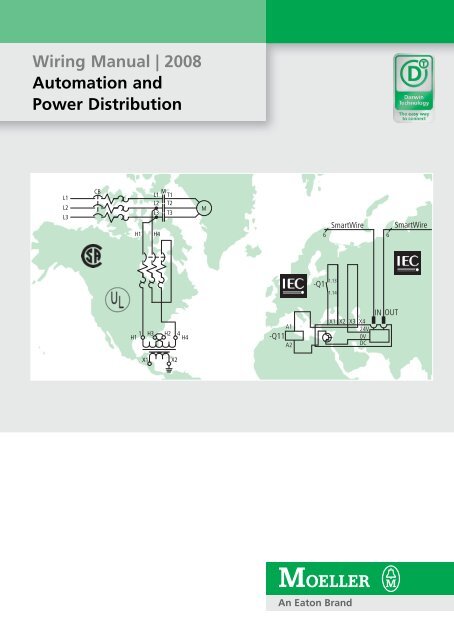
<strong>Wiring</strong> <strong>Manual</strong> | <strong>2008</strong><br />
Automation and<br />
Power Distribution<br />
L1<br />
L2<br />
L3<br />
CB<br />
L1<br />
L2<br />
L3<br />
H1 H4<br />
M<br />
T1<br />
T2<br />
T3<br />
1 H3 H2 4<br />
H1 H4<br />
X1 X2<br />
M<br />
A1<br />
-Q11<br />
A2<br />
SmartWire SmartWire<br />
6<br />
6<br />
1.13<br />
-Q1<br />
1.14<br />
IN OUT<br />
X1 X2 X3 X4<br />
24V<br />
0V<br />
DC
All brand and product names are trade marks<br />
or registered trademarks of the owner concerned<br />
Updated edition <strong>2008</strong>, publication date 02/08<br />
© <strong>2008</strong> by <strong>Moeller</strong> GmbH, Bonn<br />
Editor: Heidrun Riege<br />
Translator: globaldocs GmbH<br />
All the circuits are designed according to our best expertise and have<br />
been carefully tested. They serve as practical examples. <strong>Moeller</strong> GmbH<br />
refuses to accept liability for any errors.<br />
All rights reserved, including those of the translation.<br />
No part of this manual may be reproduced in any form (printed, photocopy,<br />
microfilm or any other process) or processed, duplicated or distributed<br />
by means of electronic systems without the written permission of<br />
<strong>Moeller</strong> GmbH, Bonn, Germany.<br />
Subject to alterations without notice.<br />
Printed on bleached cellulose, 100 % free from chlorine and acid.
The <strong>Moeller</strong> <strong>Wiring</strong> <strong>Manual</strong><br />
<strong>Moeller</strong> <strong>Wiring</strong> <strong>Manual</strong> 02/08<br />
chapter<br />
The <strong>Moeller</strong> <strong>Wiring</strong> <strong>Manual</strong> 0<br />
Switching, control, visualisation 1<br />
Electronic motor starters and drives 2<br />
Control circuit devices 3<br />
Rotary switches 4<br />
Contactors and relays 5<br />
Motor-protective circuit-breakers 6<br />
Circuit-breakers 7<br />
All about Motors 8<br />
Export to the world market and to North America 9<br />
Standards, formulae, tables 10<br />
Index 11<br />
0-1<br />
0
0<br />
The <strong>Moeller</strong> <strong>Wiring</strong> <strong>Manual</strong><br />
0-2<br />
<strong>Moeller</strong> <strong>Wiring</strong> <strong>Manual</strong> 02/08<br />
Page<br />
What's new in this edition? 0-3<br />
<strong>Moeller</strong> – Competence and Experience from<br />
a Single Source 0-4<br />
The <strong>Moeller</strong> Support Portal 0-5<br />
Online Training Center 0-6<br />
Electronic Catalogue 0-8<br />
<strong>Moeller</strong> Field Service 0-9<br />
<strong>Moeller</strong> Darwin technology 0-11<br />
<strong>Moeller</strong> power distribution equipment 0-14
The <strong>Moeller</strong> <strong>Wiring</strong> <strong>Manual</strong><br />
What's new in this edition?<br />
Export to the world market and to North<br />
America<br />
The target markets of machine and system<br />
builders are international. <strong>Moeller</strong> knows these<br />
markets and is a competent partner worldwide<br />
in all issues relating to the export of switchgear<br />
and power distribution systems. The export of<br />
products to North America (USA and Canada)<br />
and the special requirements involved are taking<br />
on increasing importance.<br />
We have streamlined and expanded the existing<br />
content for you and collated it in a separate new<br />
chapter 9. The remaining content from the<br />
previous chapter 9 is now provided in<br />
chapter 10.<br />
<strong>Moeller</strong> <strong>Wiring</strong> <strong>Manual</strong> 02/08<br />
The way to a safe machine<br />
easySafety – Fulfills the highest safety demands.<br />
The safety of people and machines must be<br />
taken into account for the total lifecycle of a<br />
machine/system. For personnel protection safety<br />
components such as position switches, light<br />
curtains, two-hand control switches or<br />
emergency-stop pushbuttons come into use. The<br />
safety information is monitored and evaluated<br />
by the new easySafety control relay which<br />
complies to the highest safety requirements.<br />
a section "The way to the safe machine",<br />
page 1-10<br />
Always up-to-date<br />
We make every effort to adapt and update every<br />
new edition of the <strong>Wiring</strong> <strong>Manual</strong> according to<br />
the ever increasing requirements of the markets.<br />
The many example circuits in particular are<br />
continually being updated by our specialists to<br />
the best of their knowledge and carefully tested.<br />
They are provided solely as examples from<br />
practice. <strong>Moeller</strong> GmbH does not accept any<br />
liability for any errors.<br />
0-3<br />
0
0<br />
0-4<br />
<strong>Moeller</strong> <strong>Wiring</strong> <strong>Manual</strong> 02/08<br />
The <strong>Moeller</strong> <strong>Wiring</strong> <strong>Manual</strong><br />
<strong>Moeller</strong> – Competence and Experience from a Single Source<br />
www.moeller.net – The <strong>Moeller</strong> Home Page<br />
<strong>Moeller</strong> offers you a range of products and<br />
services that can be optimally combined with<br />
one another. Visit our site on the Internet. There<br />
you will find everything about <strong>Moeller</strong>, such as:<br />
Up-to-date information about <strong>Moeller</strong><br />
products<br />
The addresses of the <strong>Moeller</strong> sales offices and<br />
representatives worldwide<br />
www.moeller.net/en/support/ – The <strong>Moeller</strong> Support Portal<br />
You can receive technical support for all <strong>Moeller</strong><br />
products just by a mouse click. And tips and<br />
tricks, Frequently Asked Questions (FAQs),<br />
updates, software modules, PDF downloads,<br />
Information about the <strong>Moeller</strong> Company<br />
Group<br />
Publications in the press, specialist press<br />
References<br />
Exhibition dates and events<br />
Technical support in the <strong>Moeller</strong> Support<br />
Portal<br />
demo programs and much more.<br />
You can also subscribe to the <strong>Moeller</strong><br />
Newsletters.
The <strong>Moeller</strong> <strong>Wiring</strong> <strong>Manual</strong><br />
The <strong>Moeller</strong> Support Portal<br />
Uncomplicated and quick way of finding the<br />
information you need:<br />
PDF Downloads<br />
– Catalogues<br />
– <strong>Manual</strong>s and installation instructions<br />
– Product information, such as<br />
brochures, selection aids, technical essays,<br />
declarations of conformity and of course<br />
– The <strong>Moeller</strong> <strong>Wiring</strong> <strong>Manual</strong><br />
Software Downloads<br />
– Demo versions<br />
– Updates<br />
– Software and application modules<br />
<strong>Moeller</strong> <strong>Wiring</strong> <strong>Manual</strong> 02/08<br />
Selection aids<br />
– Motor starters a section "Selection aids",<br />
page 8-3<br />
– Frequency inverters a section "Selection<br />
aids", page 2-28<br />
You can also find a link to the <strong>Moeller</strong> Field<br />
Service via the Support Portal (a section<br />
"<strong>Moeller</strong> Field Service", page 0-9).<br />
You can send your queries directly to the<br />
Technical Support/pre-sales service by e-mail.<br />
Simply select the e-mail form that meets your<br />
requirements to the -<strong>Moeller</strong> experts.<br />
0-5<br />
0
0<br />
The <strong>Moeller</strong> <strong>Wiring</strong> <strong>Manual</strong><br />
Online Training Center<br />
http://trainingscenter.moeller.net<br />
<strong>Moeller</strong> has now fully developed a web-based<br />
information and training platform for its<br />
well-known and successful easy control relay as<br />
well as the easyHMI multi-function display. This<br />
presents fully programmed and documented<br />
applications from a wide range of sectors.<br />
Comprehensive information on all aspects of the<br />
easy and easyHMI is also provided with<br />
additional links to more in-depth topics.<br />
Tips and tricks are presented in the FAQ area<br />
and you can share your experience with over<br />
1,600 easy users in the easy forum<br />
(www.easy-forum.net). A full text search facility<br />
offers support in finding the information you are<br />
looking for.<br />
0-6<br />
<strong>Moeller</strong> <strong>Wiring</strong> <strong>Manual</strong> 02/08<br />
The online training center is divided into the 6<br />
areas “Products”, “Basics”, “Functions”,<br />
“Applications”, “References” and “Software”.<br />
The Products area provides:<br />
An overview of the device series and<br />
accessories,<br />
mounting instructions, operating manuals<br />
and product information for download as PDF<br />
files.<br />
The Basics area gives you the chance to learn<br />
about programming and networking devices at<br />
entry level. Special descriptions are provided<br />
depending on whether you wish to work with<br />
easySoft or with easySoft-CoDeSys.
The <strong>Moeller</strong> <strong>Wiring</strong> <strong>Manual</strong><br />
Online Training Center<br />
The Programming section of the Basics area also<br />
explains how to use the programming system by<br />
means of example projects.<br />
The "Networking" section provides examples<br />
on networking the devices.<br />
The Functions area provides 54<br />
preprogrammed functions with:<br />
a complete function description,<br />
example program that you can load directly<br />
onto your easy or test beforehand with<br />
easySoft, and if necessary adapt it to your<br />
required application,<br />
small Flash animations that illustrate how to<br />
create the function in easySoft,<br />
sorted according to device class<br />
easy500/700/800 and easyHMI.<br />
The Applications area shows typical<br />
applications with easy such as temperature<br />
controls in greenhouses or stairway lighting<br />
controls as well as examples of graphic display<br />
applications with easyHMI. These applications<br />
are:<br />
“ready to use”: simply load the completed<br />
programs onto your easy and put them into<br />
operation,<br />
tested and fully documented.<br />
<strong>Moeller</strong> <strong>Wiring</strong> <strong>Manual</strong> 02/08<br />
The References area shows you that <strong>Moeller</strong><br />
products are used in a wide range of areas and<br />
are in use worldwide. To obtain a short overview<br />
of their versatility look at some of the<br />
applications for the easy family on the page<br />
presented in PDF format.<br />
The Software area provides information and<br />
downloads for:<br />
the easySoft operating and programming<br />
software,<br />
the OPC server, supplied free-of-charge with<br />
easySoft<br />
the Labeleditor for the customised labelling of<br />
the easyHMI,<br />
Fieldbus interfaces with the necessary device<br />
master data,<br />
CAD files for electrical engineering design.<br />
0-7<br />
0
0<br />
The <strong>Moeller</strong> <strong>Wiring</strong> <strong>Manual</strong><br />
Electronic Catalogue<br />
The efficient way to detailed product<br />
information<br />
From detailed product information right up to<br />
the enquiry for your products by email or fax<br />
from your <strong>Moeller</strong> product supplier. All this and<br />
more you can find in the Electronic Catalogue.<br />
This gives you fast access to new innovations as<br />
well as extensive information on the current<br />
<strong>Moeller</strong> ranges.<br />
Industrial switchgear,<br />
Drives,<br />
Automation systems, drives,<br />
Power distribution systems.<br />
0-8<br />
<strong>Moeller</strong> <strong>Wiring</strong> <strong>Manual</strong> 02/08<br />
Create a comprehensive data sheet for a product<br />
and save it as a PDF document or print it out.<br />
In product groups that contain a large number of<br />
products, special selection tools are provided in<br />
the ranges so that you can identify specifically a<br />
few products on the basis of the product<br />
features you require.<br />
A number of links to additional product<br />
information and all aspects of it enable you to<br />
ensure optimum use of the product:<br />
Application examples and project design<br />
notes,<br />
approvals<br />
installation instructions,<br />
manuals,<br />
software, etc.<br />
Choose “Your” Electronic Catalogue on the<br />
Internet http://int.catalog.moeller.net/en.<br />
The Electronic Catalogue on the Internet is<br />
updated regularly.
The <strong>Moeller</strong> <strong>Wiring</strong> <strong>Manual</strong><br />
<strong>Moeller</strong> Field Service<br />
Our services for your success.<br />
Helpline<br />
Onsite Service<br />
Repairs<br />
Online Service<br />
<strong>Moeller</strong> Helpline<br />
Break-Down Service<br />
You will receive competent and quick<br />
telephone assistance in the event of<br />
unscheduled machine stops and plant<br />
down-times, system faults and device<br />
break-downs around the clock.<br />
Consulting Service<br />
During business hours, you will receive support<br />
for commissioning, application queries right<br />
through to fault analysis, which can also be<br />
carried out by remote diagnosis.<br />
Specialists are available in the areas of<br />
automation, drives, low-voltage power<br />
distribution or switchgear.<br />
<strong>Moeller</strong> Onsite Service<br />
Troubleshooting onsite<br />
Qualified technicians and specialists can visit<br />
you in order to rectify faults quickly and reliably.<br />
Inspection and maintenance<br />
DIN VDE 0105 part 100 (clause 5.3) requires the<br />
recurrent testing of electrical equipment in order<br />
to ensure their proper condition. German work<br />
safety law A3 stipulates that repeat inspections<br />
on fixed electrical systems and equipment must<br />
be carried out at least every 4 years by electrical<br />
specialists.<br />
<strong>Moeller</strong> <strong>Wiring</strong> <strong>Manual</strong> 02/08<br />
Further information is available from our<br />
website.<br />
The Field Service therefore offers appropriate<br />
services for circuit-breakers, distribution boards<br />
(xEnergy, MODAN, ID2000, other distribution<br />
boards etc.).<br />
We support you in the inspection and<br />
maintenance of the circuit-breakers and<br />
low-voltage distribution boards supplied by<br />
<strong>Moeller</strong>, determine the condition of your<br />
systems and carry out the necessary work. If<br />
required, thermography or network analysis are<br />
also carried out with this work.<br />
Mounting and commissioning support<br />
Contact us if you require fast and competent<br />
support in installing and commissioning tasks.<br />
Conversions and expansions<br />
Whether with controllers, circuit-breakers or<br />
other components, we can bring your machines<br />
and plants up to the latest state-of-the-art.<br />
Thermography<br />
Thermography gives us an efficient way of<br />
analysing your electrical systems and controls<br />
during operation.<br />
Network analysis<br />
Network analysis provides clear information<br />
about the specific state of your networks<br />
without the need for lengthy and expensive<br />
troubleshooting.<br />
0-9<br />
0
0<br />
The <strong>Moeller</strong> <strong>Wiring</strong> <strong>Manual</strong><br />
<strong>Moeller</strong> Field Service<br />
Bus monitoring<br />
If required we can inspect the communication<br />
networks of your systems with the latest<br />
technical equipment.<br />
<strong>Moeller</strong> Repairs<br />
Direct exchange<br />
In the event of a fault, the direct exchange<br />
service for selective <strong>Moeller</strong> products<br />
considerably reduces the downtime of your<br />
production plant.<br />
Repairs<br />
The repair of <strong>Moeller</strong> products in our Service<br />
Center is an inexpensive alternative for fault<br />
rectification.<br />
<strong>Moeller</strong> Online Service<br />
Online troubleshooting<br />
We can provide special assistance if you wish to<br />
analyse and rectify faults on products. You can<br />
carry out interactive troubleshooting via the<br />
Internet with direct access to the Field Service<br />
database.<br />
FAQ - Frequently Asked Questions<br />
There are some questions about our products<br />
that our customers very often ask. You can<br />
benefit from the answers. You can read<br />
frequently asked questions with the<br />
corresponding answers on all aspects of<br />
automation.<br />
Downloads<br />
You're at the right place here if you require<br />
updates, software, documentation and<br />
declarations of conformity. Visit the <strong>Moeller</strong><br />
Download Center to obtain all the information<br />
you require.<br />
0-10<br />
<strong>Moeller</strong> <strong>Wiring</strong> <strong>Manual</strong> 02/08<br />
Contact<br />
Faults hotline<br />
For field service contact your <strong>Moeller</strong> agent<br />
www.moeller.net/address<br />
or the <strong>Moeller</strong> Field Service directly<br />
Tel.: +49 (0) 180 522 3822 (de, en)<br />
(round the clock)<br />
Consulting service<br />
Tel.: +49 (0) 228 602 3640<br />
(Mo. - Fr. 08:00 - 16:00 CET)<br />
Email<br />
fieldservice@moeller.net<br />
Internet<br />
www.moeller.net/fieldservice
The <strong>Moeller</strong> <strong>Wiring</strong> <strong>Manual</strong><br />
<strong>Moeller</strong> Darwin technology<br />
Darwin. The technological quantum spring.<br />
Protecting<br />
Switching<br />
The conventional switch cabinet is changing<br />
fundamentally. Darwin has established a bridge<br />
between the automation world and the world of<br />
switchgear. Switching devices are merging<br />
together with automation equipment and the<br />
conventional control wiring, such as between<br />
I/O modules and switching devices, is being<br />
replaced by a new, simple connection<br />
technology.<br />
Controlling<br />
<strong>Moeller</strong> <strong>Wiring</strong> <strong>Manual</strong> 02/08<br />
Drives<br />
HMI<br />
This project covers the entire <strong>Moeller</strong> product<br />
world for the switch cabinet in single<br />
evolutionary steps:<br />
Control,<br />
switching,<br />
contactors,<br />
operating and monitoring,<br />
Drives.<br />
0-11<br />
0
0<br />
The <strong>Moeller</strong> <strong>Wiring</strong> <strong>Manual</strong><br />
<strong>Moeller</strong> Darwin technology<br />
Evolution of the control panel<br />
Before Today<br />
In the past each sensor and actuator was<br />
hardwired to an input and output of the main<br />
PLC. The result was a high wiring complexity,<br />
large control panels and a high potential for<br />
wiring errors.<br />
Today sensors and actuators are wired to a<br />
remote preprocessing point and from there to<br />
the central PLC through a fieldbus.<br />
0-12<br />
<strong>Moeller</strong> <strong>Wiring</strong> <strong>Manual</strong> 02/08<br />
This use of remote I/O and fieldbus technology<br />
significantly reduces wiring complexity.<br />
The control system is distributed over several<br />
small control panels located in various positions<br />
on the machine. The number of hardwired<br />
inputs and outputs however, has remained the<br />
same; only the spaces between the control<br />
panels is bridged by fieldbus lines.
The <strong>Moeller</strong> <strong>Wiring</strong> <strong>Manual</strong><br />
<strong>Moeller</strong> Darwin technology<br />
The current SmartWire technology lets you, for<br />
example, connect motor starters directly to the<br />
PLC. This intelligent wiring aid reduces both<br />
hard wiring and the number of central and<br />
remote I/Os as well as removing the potential for<br />
wiring errors.<br />
The inputs and outputs are placed exactly where<br />
they are required – immediately next to the<br />
switching devices.<br />
<strong>Moeller</strong> <strong>Wiring</strong> <strong>Manual</strong> 02/08<br />
Today with SmartWire Tomorrow with SmartWired<br />
SmartWire Darwin will completely replace the<br />
control wiring between PLC and switchgear.<br />
All devices connected with SmartWire Darwin<br />
operate as local or remote inputs/outputs of<br />
easyControl. The system is fully self-configuring.<br />
Further information<br />
a section "Connect, don't wire", page 5-8<br />
and a section "SmartWire Gateway",<br />
page 1-43.<br />
0-13<br />
0
0<br />
The <strong>Moeller</strong> <strong>Wiring</strong> <strong>Manual</strong><br />
<strong>Moeller</strong> power distribution equipment<br />
Low-voltage switchgear systems for infrastructure<br />
System range xEnergy<br />
xEnergy is a modular system range of power<br />
distribution boards designed specifically for<br />
infrastructures up to 4000 A.<br />
<strong>Moeller</strong>’s xEnergy products are optimized for<br />
safe and reliable power distribution.<br />
The system range xEnergy integrates switching<br />
and protective devices, mounting and enclosure<br />
systems and control panel components into a<br />
coherent, cost-effective system.<br />
0-14<br />
<strong>Moeller</strong> <strong>Wiring</strong> <strong>Manual</strong> 02/08<br />
It consists of:<br />
Switching and protective devices,<br />
the modular enclosure system,<br />
the control panel complete with planning and<br />
calculation tools.<br />
Being optimized for housing <strong>Moeller</strong> switchgear,<br />
the control panel components allow a flexible,<br />
time-saving installation.
The <strong>Moeller</strong> <strong>Wiring</strong> <strong>Manual</strong><br />
<strong>Moeller</strong> power distribution equipment<br />
Type-testing of the complete<br />
switchgear–enclosure–control panel assemblies<br />
to IEC EN 60439 ensures a high safety level.<br />
xEnergy is a modular system consisting of<br />
matched function units that have been<br />
type-tested to IEC 60439. Available from Form 1<br />
to Form 4, the system can be designed to<br />
conform to any applicable installation standard<br />
(DIN VDE, CEI, NF, UNE) and all relevant<br />
switchgear combinations to the respective<br />
protection type up to 4000 A have been<br />
type-tested.<br />
<strong>Moeller</strong> <strong>Wiring</strong> <strong>Manual</strong> 02/08<br />
Product features<br />
Clear segregation into functional areas up to<br />
Form 4b<br />
Enclosures for combination- and separate<br />
mounting,<br />
Enclosure protection IP31 or IP55<br />
Main busbars at the rear up to 4000 A<br />
Main busbars at the top up to 3200 A<br />
All components fitted as TTA<br />
Mains system types TN-C, TN-C-S, TN-S, TT, IT<br />
Products<br />
XPower Panels<br />
Incomers/feeders, outgoers or bus-couplers<br />
with circuit-breakers NZM4 or IZM up to<br />
4000A Fixed mounted or withdrawable<br />
3 or 4 pole circuit-breakers<br />
Cable or busbar trunking connection from top<br />
or bottom<br />
0-15<br />
0
0<br />
The <strong>Moeller</strong> <strong>Wiring</strong> <strong>Manual</strong><br />
<strong>Moeller</strong> power distribution equipment<br />
0-16<br />
<strong>Moeller</strong> <strong>Wiring</strong> <strong>Manual</strong> 02/08<br />
XFixed Panels<br />
Outgoers with circuit-breakers PKZ or NZM up<br />
to 630 A<br />
Fixed mounted or withdrawable<br />
3 or 4 pole circuit-breakers<br />
Cable connection from top or bottom<br />
XFixed Panels<br />
Outgoers with fuse combination units SASIL<br />
up to 630 A, plug-in units, vertically or<br />
horizontally fitted<br />
Outgoers with fuse-strip units SL up to 630 A,<br />
fixed mounted, vertically fitted<br />
3 pole<br />
Cable connection from top or bottom
The <strong>Moeller</strong> <strong>Wiring</strong> <strong>Manual</strong><br />
<strong>Moeller</strong> power distribution equipment<br />
<strong>Moeller</strong> <strong>Wiring</strong> <strong>Manual</strong> 02/08<br />
XGeneral Panels<br />
Mounting systems for rail-mounted service<br />
installation devices<br />
Customized fixed mounted units on mounting<br />
plates up to 630 A, e.g. soft starters,<br />
frequency inverters, power factor correction<br />
Automation engineering<br />
Control technology adapter systems xStart<br />
Incoming busbar 3, 4 pole and TP + N<br />
0-17<br />
0
0<br />
The <strong>Moeller</strong> <strong>Wiring</strong> <strong>Manual</strong><br />
<strong>Moeller</strong> power distribution equipment<br />
Sheet steel wall-mounting enclosure CS<br />
With mounting plate<br />
45 enclosure sizes are available for selection<br />
from 250 × 200 × 150 to 1200 × 1200 × 250<br />
mm.<br />
The stable CS enclosure series made from solid<br />
sheet steel is used in applications wherever<br />
effective protection against the direct contact of<br />
live parts is required.<br />
The high IP55 degree of protection allows<br />
installed equipment to be protected from most<br />
harmful ambient conditions.<br />
0-18<br />
<strong>Moeller</strong> <strong>Wiring</strong> <strong>Manual</strong> 02/08<br />
A continuous sponge polyurethane seal provides<br />
the necessary seal tightness. The surrounding<br />
rain channel profile offers protection against the<br />
ingress of liquid such as water or oil as well as<br />
dirt when the door is opened.<br />
The classification of impact resistance code IK10<br />
to EN 62262 also protects the inside of the<br />
cabinet from mechanical damage.<br />
CS enclosures can be mounted as wall<br />
enclosures.
The <strong>Moeller</strong> <strong>Wiring</strong> <strong>Manual</strong><br />
<strong>Moeller</strong> power distribution equipment<br />
Their powder coated surface provides an<br />
abrasion and corrosion resistant protection.<br />
The enclosure door can be removed easily for<br />
other mechanical measures. Inside hinges that<br />
are covered can thus be undone simply and the<br />
door stop exchanged from right to left or vice<br />
versa.<br />
<strong>Moeller</strong> can also provide customised solutions<br />
on request. This includes for example:<br />
other RAL colour tones,<br />
other dimensions,<br />
cutouts in doors and side panels, e.g. for<br />
mounting command and signalling devices,<br />
touch panels, meters and cable glands.<br />
<strong>Moeller</strong> <strong>Wiring</strong> <strong>Manual</strong> 02/08<br />
0-19<br />
0
0<br />
The <strong>Moeller</strong> <strong>Wiring</strong> <strong>Manual</strong><br />
<strong>Moeller</strong> power distribution equipment<br />
Terminal K<br />
The connection terminal consists of a<br />
combination of several very stable terminal<br />
blocks. It is used for connecting two or more<br />
conductors.<br />
A very wide range is available as standard with<br />
6 sizes and terminal cross-sections from 16 to<br />
3 x 240 mm² (160 to 1000 A).<br />
0-20<br />
<strong>Moeller</strong> <strong>Wiring</strong> <strong>Manual</strong> 02/08<br />
Copper conductors can be inserted easily and<br />
quickly into the box terminals from above<br />
without bending.<br />
The <strong>Moeller</strong> terminals are designed for copper<br />
strips or busbars as well as copper conductors.<br />
Each terminal pair is moulded in a plastic<br />
Duroplast shell. Each of the 6 sizes is available<br />
from stock as a 1-pole, 3-pole, 4-pole or 5-pole<br />
terminal combination.<br />
Accessories such as the transparent plastic<br />
cover, auxiliary conductor terminals or<br />
conversion kits also enable the creation of your<br />
own terminal variants.
The <strong>Moeller</strong> <strong>Wiring</strong> <strong>Manual</strong><br />
<strong>Moeller</strong> power distribution equipment<br />
CI insulated distribution boards, totally insulated<br />
The assembly of the CI system demonstrates its<br />
flexibility. Whether as an individual enclosure,<br />
wall-mounted or free-standing distribution<br />
board of any size, the modular CI insulated<br />
distribution system up to 630 A always offers the<br />
right solution in harsh ambient conditions.<br />
The modular system makes it easy to adapt to a<br />
wide range of conditions.<br />
IP65 protection ensures protection from dust,<br />
humidity and water jets,<br />
pressure relief by means of liftable covers with<br />
spring-loaded locking bolts,<br />
<strong>Moeller</strong> <strong>Wiring</strong> <strong>Manual</strong> 02/08<br />
"Total insulation" provides maximum<br />
personnel protection and operational safety.<br />
Transparent neutral cover allows unrestricted<br />
view,<br />
Floor-standing distribution boards with base<br />
covers for routing, fastening or covering large<br />
cable cross sections.<br />
Enclosed distribution boards are type-tested<br />
assemblies (TTA) in accordance with VDE 0660<br />
part 500 or Type Tested Assemblies (TTA) to IEC<br />
60 439.<br />
0-21<br />
0
0<br />
The <strong>Moeller</strong> <strong>Wiring</strong> <strong>Manual</strong><br />
<strong>Moeller</strong> power distribution equipment<br />
SASY60i busbar system for the world market<br />
The SASY60i modular busbar system from<br />
<strong>Moeller</strong> is designed for effective energy<br />
distribution in the control panel.<br />
Thanks to the innovative mounting technology<br />
feeder and outgoing circuit-breakers can be<br />
mounted quickly and compactly. SASY60i is safe<br />
and reliable.<br />
In conjunction with the latest generation of<br />
<strong>Moeller</strong> motor protective circuit-breakers and<br />
other circuit-breakers, the SASY 60i provides a<br />
universal, UL certified solution for switching,<br />
controlling, protecting and distributing energy.<br />
Together with the appropriate switching and<br />
protective devices, the busbar system is<br />
designed for worldwide use.<br />
0-22<br />
<strong>Moeller</strong> <strong>Wiring</strong> <strong>Manual</strong> 02/08<br />
The larger air and creepage distances required in<br />
compliance with the UL 508A in America have<br />
been considered in the construction of the<br />
busbar components.<br />
When used in North America, the insulated<br />
bottom plate must be mounted under the<br />
system. Components approved for IEC such as<br />
h.b.c. fuse switch-disconnectors or D busbar<br />
mounting fuses can also suitable for perfectly<br />
matched fitting.<br />
As SASY60i requires few system components<br />
the new <strong>Moeller</strong> busbar system also reduces the<br />
stock-keeping and ordering required.
Notes<br />
<strong>Moeller</strong> <strong>Wiring</strong> <strong>Manual</strong> 02/08<br />
0-23<br />
0
0<br />
Notes<br />
0-24<br />
<strong>Moeller</strong> <strong>Wiring</strong> <strong>Manual</strong> 02/08
Switching, control, visualisation<br />
<strong>Moeller</strong> <strong>Wiring</strong> <strong>Manual</strong> 02/08<br />
Page<br />
Timing relays 1-2<br />
EMR4 measuring and monitoring relays 1-6<br />
The way to the safe machine 1-10<br />
System overview E 1-12<br />
Engineering E 1-20<br />
Programming E 1-50<br />
Overview of automation products 1-67<br />
Compact PLC, PS4 1-68<br />
Modular PLC, XC100/XC200 1-70<br />
HMI systems 1-72<br />
Networking 1-73<br />
Engineering PS4 1-75<br />
Engineering EM4 and LE4 1-78<br />
Engineering XC100, XC200 1-79<br />
1-1<br />
1
1<br />
Switching, control, visualisation<br />
Timing relays<br />
Electronic timing relays are used in contactor<br />
control systems which require short reset times,<br />
high repetition accuracy, high switching<br />
frequency, and a long component lifespan.<br />
Times between 0.05 s and 100 h can be easily<br />
selected and set.<br />
The switching capacity of electronic timing<br />
relays corresponds to the utilisation categories<br />
AC -15 and DC -13.<br />
In terms of the actuating voltages there are with<br />
timing relays the following differences :<br />
Version A (DILET… and ETR4) Universal<br />
devices:<br />
DC 24 to 240 V<br />
AC 24 to 240 V, 50/60 Hz<br />
Version W (DILET… and ETR4)<br />
AC devices:<br />
AC 346 to 440 V, 50/60 Hz<br />
ETR2… (as row mounting device to<br />
DIN 43880)<br />
Universal device:<br />
DC 24 to 48 V<br />
AC 24 to 240 V, 50/60 Hz<br />
The functions of each of the timing relays are as<br />
follows:<br />
DILET11, ETR4-11,ETR2-11 Function 11 (ondelayed)<br />
ETR2-12<br />
Function 12 (off-delayed)<br />
ETR2-21<br />
Function 21 (fleeting contact on<br />
energisation)<br />
ETR2-42<br />
Function 42 (flashing, pulse initiating)<br />
1-2<br />
<strong>Moeller</strong> <strong>Wiring</strong> <strong>Manual</strong> 02/08<br />
ETR2-44<br />
Function 44 (flashing, two speeds; can be set<br />
to either pulse initiating or pause initiating)<br />
Multifunction relays DILET70, ETR 4-69/70<br />
Function 11 (on-delayed)<br />
Function 12 (off-delayed)<br />
Function 16 (on- and off-delayed)<br />
Function 21(fleeting contact on<br />
energisation)<br />
Function 22 (fleeting contact on deenergisation)<br />
Function 42 (flashing, pulse initiating)<br />
Function 81 (pulse generating)<br />
Function 82 (pulse shaping)<br />
ON, OFF<br />
Multifunction relays ETR2-69<br />
Function 11 (on-delayed)<br />
Function 12 (off-delayed)<br />
Function 21 (fleeting contact on<br />
energisation)<br />
Function 22 (fleeting contact on deenergisation)<br />
Function 42 (flashing, pulse initiating)<br />
Function 43 (flashing, pause initiating)<br />
Function 82 (pulse shaping)<br />
Star-delta timing relays ETR4-51<br />
Function 51 (on-delayed)<br />
With both DILET70 and ETR4-70 an external<br />
potentiometer can be connected. Upon<br />
connection, both timing relays automatically<br />
recognize that a potentiometer is fitted.<br />
The ETR4-70 has a special feature. Equipped<br />
with two changeover contacts which can be<br />
converted to two timing contacts 15-18 and 25-<br />
28 (A2-X1 bridged) or one timing contact 15-18<br />
and a non-delayed contact 21-24 (A2-X1 not<br />
bridged). If the link A2–X1 is removed, only the<br />
timed contact 15–18 carries out the functions<br />
described below.
Switching, control, visualisation<br />
Timing relays<br />
Function 11<br />
On-delayed<br />
t<br />
The control voltage Us is applied to terminals A1<br />
and A2 through an actuating contact.<br />
After the set delay time the changeover contact<br />
of the output relay goes to position 15-18 (25-<br />
28).<br />
Function 12<br />
Off-delayed<br />
After the control voltage has been applied to<br />
terminals A1 and A2, the changeover contact of<br />
the output relay remains in the original position<br />
15–16 (25–26). If terminals Y70 and Y1 in the<br />
DILET2 are linked with a floating NO contact or,<br />
in the case of the ETR4-69/70 or ETR2-69, a<br />
potential is applied to B1, the changeover<br />
contact changes to position 15-18 (15-28)<br />
immediately.<br />
If the connection between terminals Y1–Y1 is<br />
now interrupted or B2 is isolated from voltage,<br />
the changeover contact returns to its original<br />
position 1-1 (15-25) once the set time has<br />
elapsed.<br />
t<br />
A1-A2<br />
15-18<br />
A1-A2<br />
Y1-Y2<br />
B1<br />
15-18<br />
(25-28)<br />
<strong>Moeller</strong> <strong>Wiring</strong> <strong>Manual</strong> 02/08<br />
Function 16<br />
On- and Off-delayed<br />
The control voltage Us is applied directly to<br />
terminals A1 and A2. If terminals Y1 and Y2 in<br />
the DILET70 are linked by a floating contact, or<br />
in the case of of the ETR4-69/70 a potential is<br />
applied to B1, the changeover contact goes to<br />
the position 15-18 (25-28) after a set time t.<br />
If connection Y1-Y1 is now interrupted or B2 is<br />
separated from the potential, the changeover<br />
contact goes back to its original position 1–1<br />
(15–25) after the same time t.<br />
Function 21<br />
Fleeting contact on energization<br />
t<br />
t t<br />
A1-A2<br />
Y1-Y2<br />
B1<br />
15-18<br />
(25-28)<br />
A1-A2<br />
15-18<br />
(25-28)<br />
After the voltage Us has been applied to A1 and<br />
A2, the changeover contact of the output relay<br />
goes to position 15–18 (25–28) and remains<br />
actuated for the set fleeting contact time.<br />
A fleeting pulse (terminals 1–2, 15–18) of<br />
defined duration is therefore produced from a<br />
two-wire control process (voltage on A25/A28)<br />
by this function.<br />
1-3<br />
1
1<br />
Switching, control, visualisation<br />
Timing relays<br />
Function 82<br />
Pulse forming<br />
After the control voltage has been applied to A1<br />
and A2, the changeover contact of the output<br />
relay remains in the rest position 15–16<br />
(25–26). If terminals Y70 and Y1 in the DILET2<br />
are linked through a floating contact, or in the<br />
case of the ETR4-69/70 or ETR2-69, a potential<br />
is applied to B1, the changeover contact<br />
changes to the position 15–18 (25–28)<br />
immediately.<br />
If Y1–Y2 is now opened again or B1 is isolated<br />
from voltage, the changeover contact remains<br />
actuated until the set time has elapsed. If,<br />
instead, Y1–Y2 remain closed or B1 is separated<br />
from the potential for a longer period, the<br />
output relay likewise changes back to its rest<br />
position after the set time. An output pulse of<br />
precisely defined duration is thus produced in<br />
the pulse-forming function, irrespective of<br />
whether the input pulse via Y1–Y2 or B1 is<br />
shorter or longer than the set time.<br />
The actuating voltage is applied to terminals A1<br />
and A2 via an actuating contact. After the set<br />
delay time has elapsed the changeover contact<br />
of the output relay goes to position 15-18 (25-<br />
28) and returns to its original position 0.5-15<br />
1-4<br />
t<br />
A1-A2<br />
Y1-Y2<br />
B1<br />
15-18<br />
(25-28)<br />
Function 81<br />
Pulse generating with fixed pulse<br />
t 0.5 s<br />
A1-A2<br />
15-18<br />
(25-28)<br />
<strong>Moeller</strong> <strong>Wiring</strong> <strong>Manual</strong> 02/08<br />
(16-25) after 26 s. This function is therefore a<br />
fleeting pulse with a time delay.<br />
Function 22<br />
Fleeting contact on de-energization<br />
The control voltage Us is applied directly to A1<br />
and A2. If terminals Y1 and Y2 on DILET70 that<br />
are shorted at any time beforehand (DILET-70:<br />
floating) and then reopened (or for ETR4-69/70<br />
or ETR2-69 contact B1 is floating), contact 15-<br />
18 (25-28) closes for the duration of the set<br />
time.<br />
Function 42<br />
Flashing, pulse initiating<br />
t t t t<br />
A1-A2<br />
Y1-Y2<br />
B1<br />
15-18<br />
(25-28)<br />
After the voltage Us has been applied to A1 and<br />
A2, the changeover contact of the output relay<br />
changes to position 15–18 (25–28) and remains<br />
actuated for as long as the set flashing time. The<br />
subsequent pause duration corresponds to the<br />
flashing time.<br />
t<br />
A1-A2<br />
15-18<br />
(25-28)
Switching, control, visualisation<br />
Timing relays<br />
Function 43<br />
Flashing, pause initiated<br />
t<br />
t t t t<br />
After the voltage Us has been applied to A1 and<br />
A2 the changeover contact of the output relay<br />
stays in position 15-16 for the set flashing time<br />
and, after this time, goes to position 15-18 (the<br />
cycle begins with a pause phase).<br />
Function 44<br />
Flashing, two speeds<br />
t1t2t1t2t 1 t 2<br />
t1 t 2 t 1 t 2 t 1 t 2<br />
A1-A2<br />
15-18<br />
After the voltage Us has been applied to A1 and<br />
A2 the changeover contact of the output relay<br />
goes to position 15-18 (pulse begin). By bridging<br />
the contacts A1 and Y1 the relay can be<br />
switched to pause begin. The times t1 and t2 can<br />
be set to different times.<br />
LED<br />
A1-A2<br />
A1-B1<br />
15-18<br />
Rel LED<br />
A1-B1<br />
15-18<br />
Rel LED<br />
<strong>Moeller</strong> <strong>Wiring</strong> <strong>Manual</strong> 02/08<br />
Function 51 Star-delta<br />
On-delayed<br />
t u<br />
If the control voltage Us is applied to A1 and A2,<br />
the instantaneous contact switches to position<br />
17-18. After the set time the instantaneous<br />
contact opens; the timing contact 17-28 closes<br />
after a changeover time tu of 50 ms.<br />
On-Off Function<br />
OFF ON<br />
OFF<br />
t<br />
A1-A2<br />
17-18<br />
17-28<br />
A1-A2<br />
15-18<br />
(25-28)<br />
LED<br />
The On-Off function allows the operation of a<br />
control system to be tested and is an aid, for<br />
example, for commissioning. The Off function<br />
allows the output relay to be de-energized so<br />
that it no longer reacts to the functional<br />
sequence. The On function energizes the output<br />
relay. This function is dependent on the supply<br />
voltage being applied to the terminals A1/A2.<br />
The LED indicates the operational status.<br />
Further information sources<br />
Installation instructions<br />
DILET…: AWA2527-1587<br />
ETR4…: AWA2527-1493, AWA2527-1485<br />
ETR2…: AWA2527-2372<br />
Main catalogue for industrial switchgear,<br />
Section 4 “Timing relays”<br />
1-5<br />
1
1<br />
Switching, control, visualisation<br />
EMR4 measuring and monitoring relays<br />
General<br />
For the various applications measurement amd<br />
monitoring relays are necessary. With the new<br />
EMR4 range <strong>Moeller</strong> covers a large number of<br />
requirements:<br />
general use, current monitor EMR4-I<br />
space saving monitoring of the rotary field<br />
phase sequence relay EMR4-F<br />
protection against destruction or damage of<br />
single system parts, phase monitoring relay<br />
EMR4-W<br />
safe recognition of phase failure, phase<br />
imbalance monitoring relay EMR4-A<br />
increased safety by motor current principle,<br />
level relay EMR4-N<br />
increased operational safety, insulation<br />
monitoring relay EMR4-R<br />
Current monitoring relay EMR4-I<br />
The current monitoring relay EMR4-I is suitable<br />
for monitoring AC as well as DC current. With<br />
the definable low and high current limits, pumps<br />
and drill machines can be monitored. That is due<br />
to the selectable under or over limit.<br />
1-6<br />
<strong>Moeller</strong> <strong>Wiring</strong> <strong>Manual</strong> 02/08<br />
There are two versions, each with three<br />
measuring ranges (30/100/1000 mA,<br />
1.5/5/15 A). The multi-voltage coil allows<br />
universal use of the relay. The two auxiliary<br />
changeover contacts allow a direct feedback.<br />
Selected bridging of short current peaks<br />
By using the selected time delay of between<br />
0.05 and 30 s short current peaks can be<br />
bridged.<br />
EMR4-W phase monitoring relay<br />
The phase monitoring relay EMR4-W monitors<br />
the voltage height as well as the field rotation to<br />
provide protection against destruction or<br />
damage of single system parts. That means<br />
protection against destruction or damage of<br />
single system parts. Here the minimum low<br />
voltage and also the maximum overvoltage can<br />
be easily set to the required voltage within a<br />
defined range.<br />
An ON- or Off delay can be set. In the On-delay<br />
position short voltage breaks can be bridged.<br />
The off-delay position allows a failure storage<br />
for the set time.
<strong>Moeller</strong> <strong>Wiring</strong> <strong>Manual</strong> 02/08<br />
Switching, control, visualisation<br />
EMR4 measuring and monitoring relays<br />
The delay time can be set between 0.1 and 10 s.<br />
The relay activates with the correct rotation and<br />
voltage. After drop-out the device reactivates<br />
when a the voltage exceeds a 5 % hysteresis.<br />
Phase sequence relay EMR4-F<br />
The phase sequence relay with a width of only<br />
22.5 mm monitors the rotating field of portable<br />
motors for which the rotation direction is<br />
important (such as pumps, saws, drilling<br />
machines). This protects the motor from<br />
damage. The narrow mounting width saves<br />
space in the control panel.<br />
With a correctly rotating field the changeover<br />
contact switches the control voltage of the<br />
motor switching device. The EMR4-F500-2<br />
covers the total voltage range from 200 to<br />
500 V AC.<br />
Phase imbalance relay EMR4-A<br />
The 22.4 mm wide EMR-4-A phase imbalance<br />
relay provides protection against phase to<br />
protect motors against destruction.<br />
Because the phase failure is determined through<br />
the phase shift, it can also be reliably detected to<br />
prevent motor overload in the event of a high<br />
motor feedback. The relay protects motors with<br />
a rated voltage of Un = 380 V, 50 Hz.<br />
Level monitoring relay EMR4-N<br />
The level monitoring relay EMR4-N is used<br />
mostly as dry running protection for pumps or<br />
for level regulation of liquids. It operates with<br />
sensors that measure conductivity. A sensor is<br />
required for the maximum and also a sensor for<br />
the minimum level. A third sensor is used for<br />
earth potential.<br />
The 22.5 mm wide device EMR4-N100 is<br />
suitable for conductive liquids. It can be<br />
switched from level regulation to dry running<br />
protection. The safety is increased as in both<br />
cases the motor current principle is used.<br />
1-7<br />
1
1<br />
<strong>Moeller</strong> <strong>Wiring</strong> <strong>Manual</strong> 02/08<br />
Switching, control, visualisation<br />
EMR4 measuring and monitoring relays<br />
The level monitoring relay EMR4-N500 has a<br />
higher sensitivity and is suitable for less<br />
conductive liquids. Due to an integrated rise and<br />
fall delay of between 0.1 and 10 s moving<br />
liquids can also be monitored.<br />
EMR4-R insulation monitoring relay<br />
EN 60204 “Safety of machines” provides<br />
increased operational safety by monitoring the<br />
control voltage circuit for earth-fault using an<br />
insulation monitor. This is the main application<br />
for the EMR4-R. There are similar requirements<br />
in medical applications.<br />
1-8<br />
An earth-fault is signalled via a changeover<br />
contact so that a fault can be cleared without<br />
expensive down time.<br />
The device has a selectable fault memory so that<br />
the fault must be acknowledged after its<br />
removal. A Test button allows the device to be<br />
checked for correct operation at any time.<br />
AC or DC control voltage<br />
Devices for AC and for DC are available, which<br />
cover the total control voltage range. The DC<br />
device has a multi-voltage source and can<br />
therefore also be used for AC.<br />
Multifunctional EMR4-AW(N) threephase<br />
monitors<br />
The multifunctional three-phase monitors<br />
provide space saving monitoring of rotating<br />
fields. They feature a range of phase parameter<br />
measuring functions for phase sequence, phase<br />
failure, phase imbalance as well as undervoltage<br />
and overvoltage.<br />
Depending on device type, the threshold value<br />
for phase imbalance can be set between 2 and<br />
15 %. The threshold values for undervoltage<br />
and overvoltage are fixed or adjustable.
<strong>Moeller</strong> <strong>Wiring</strong> <strong>Manual</strong> 02/08<br />
Switching, control, visualisation<br />
EMR4 measuring and monitoring relays<br />
The different options and setting values are<br />
explained in the applicable installation<br />
instructions. The function “with neutral<br />
conductor monitoring” is a new feature of the<br />
EMR4-AWN... models.<br />
Further information sources<br />
Installation instructions<br />
Phase imbalance monitoring relay EMR4-<br />
A400-1 AWA2431-1867<br />
Insulation monitoring relay EMR4-RAC-1-A<br />
AWA2431-1866<br />
Insulation monitoring relay EMR4-RDC-1-A<br />
AWA2431-1865<br />
Level monitoring relay EMR4-N100-1-B<br />
AWA2431-1864<br />
Phase sequence relay EMR4-F500-2<br />
AWA2431-1863<br />
Phase monitoring relay EMR4-W…<br />
AWA2431-1863<br />
Current monitoring relay EMR4-I…<br />
AWA2431-1862<br />
Measuring/monitoring relays: 3-phase<br />
monitors EMR4-A…, EMR4-AW…, EMR4-<br />
AWN…, EMR4-W…<br />
AWA2431-2271<br />
Main catalogue Industrial Switchgear, Section 4<br />
“monitoring relays”.<br />
1-9<br />
1
1<br />
Switching, control, visualisation<br />
The way to the safe machine<br />
The international standard EN ISO 12100-1<br />
“Safety of machinery - Basic concepts, general<br />
principles for design” provide the design<br />
engineer with detailed assistance in the<br />
identification of hazards and the resulting risks<br />
to be assessed.<br />
This therefore lays down the technical measures<br />
for the reduction of hazards.<br />
The parts of machine control systems that<br />
handle safety tasks are defined as the “safetyrelated<br />
parts of control systems” (SRP/CS).<br />
Safety-related control systems comprise the<br />
entire safety function consisting of the input<br />
level (sensor), the logic (safety signal processing)<br />
and the output level (actuator).<br />
For reducing risks by means of SRP/CS, <strong>Moeller</strong><br />
offers the right components with safety<br />
technology in accordance with the most<br />
stringent requirements stipulated in the safety<br />
standards EN 954-1, EN ISO 13849-1 and EN<br />
IEC 62061/61508. The appropriate safety<br />
functions are used according to the application<br />
field and the necessary hazard protection.<br />
Further information on the previous and the new<br />
international safety standards as well as circuit<br />
examples for a wide range of applications are<br />
provided in the latest version of the <strong>Moeller</strong><br />
Safety Applications Technical Guide TB0200-<br />
009.<br />
1-10<br />
<strong>Moeller</strong> <strong>Wiring</strong> <strong>Manual</strong> 02/08<br />
The safety manual helps you by means of<br />
practical safety circuit examples and the<br />
associated calculations to determine safety<br />
performance in accordance with EN ISO 13849-<br />
1 and EN IEC 62061.<br />
Further technical information on the individual<br />
safety products is provided at<br />
www.moeller.net/Safety.
Switching, control, visualisation<br />
The way to the safe machine<br />
Fast and secure detection<br />
Input<br />
Safe monitoring and processing<br />
Logic<br />
Reliable shutdown<br />
Output<br />
<strong>Moeller</strong> <strong>Wiring</strong> <strong>Manual</strong> 02/08<br />
Detecting hazards quickly with RMQ-Titan and<br />
FAK emergency-stop buttons.<br />
Motion safety under control with LS-Titan®<br />
position switches.<br />
Safe switching, disconnection and control with T<br />
rotary switches and P switch-disconnectors.<br />
Safe monitoring and processing with ESR safety<br />
relays and easySafety control relay.<br />
Reliable disconnection with DILM contactors and<br />
CMD contactor monitoring relay.<br />
1-11<br />
1
1<br />
Switching, control, visualisation<br />
System overview E<br />
eRelay<br />
1-12<br />
2<br />
1 3<br />
4 5<br />
7<br />
8<br />
4<br />
9 10<br />
8<br />
5<br />
9<br />
<strong>Moeller</strong> <strong>Wiring</strong> <strong>Manual</strong> 02/08<br />
POW<br />
BUS<br />
6<br />
POWER<br />
COM-ERR<br />
ADR<br />
ESC<br />
DEL<br />
11 12 13 14<br />
ALT<br />
OK<br />
ERR<br />
ESC<br />
MS<br />
NS<br />
2<br />
6
Switching, control, visualisation<br />
System overview E<br />
1) Detachable display MFD-80… and MFD(-<br />
AC)-CP4-500<br />
2) Ethernet-Gateway EASY209-SE<br />
3) Detachable display MFD-80… and MFD(-<br />
AC)-CP4-800<br />
4) Basic device easy500<br />
5) Basic device easy700, expandable<br />
6) Basic unit easy800, expandable,<br />
networkable via easyNet<br />
7) EASY202-RE output expansion<br />
8) easy410 I/O expansion<br />
9) easy6… I/O expansion<br />
10) Coupling unit EASY200-EASY for remote<br />
expansion of easy700, easy800<br />
11) Expansion unit for networking PROFIBUS-<br />
DP EASY204-DP<br />
12) Expansion unit for networking AS-Interface<br />
EASY205-ASI<br />
13) Expansion unit for networking CANopen<br />
EASY221-CO<br />
14) Expansion unit for networking DeviceNet<br />
EASY222-DN<br />
<strong>Moeller</strong> <strong>Wiring</strong> <strong>Manual</strong> 02/08<br />
1-13<br />
1
1<br />
Switching, control, visualisation<br />
System overview E<br />
eHMI<br />
1-14<br />
5<br />
6<br />
7<br />
6<br />
8<br />
7<br />
<strong>Moeller</strong> <strong>Wiring</strong> <strong>Manual</strong> 02/08<br />
POW<br />
BUS<br />
9<br />
2<br />
10<br />
POWER<br />
COM-ERR<br />
ADR<br />
ERR<br />
11<br />
3<br />
4<br />
MS<br />
NS<br />
1<br />
12
Switching, control, visualisation<br />
System overview E<br />
1) Ethernet gateway EASY209-SE<br />
2) I/O module with or without temperature<br />
measuring for MFD-Titan<br />
3) Power supply unit/CPU MFD(-AC)-CP8…<br />
4) Display/operating unit MFD-80…<br />
5) EASY202-RE output expansion<br />
6) easy410 I/O expansion<br />
7) easy6… I/O expansion<br />
8) Coupling unit EASY200-EASY for remote<br />
expansion of MFD(-AC)-CP8…<br />
9) Expansion unit for networking PROFIBUS-<br />
DP EASY204-DP<br />
10) Expansion unit for networking AS-Interface<br />
EASY205-ASI<br />
11) Expansion unit for networking CANopen<br />
EASY221-CO<br />
12) Expansion unit for networking DeviceNet<br />
EASY222-DN<br />
<strong>Moeller</strong> <strong>Wiring</strong> <strong>Manual</strong> 02/08<br />
1-15<br />
1
1<br />
Switching, control, visualisation<br />
System overview E<br />
eControl<br />
1-16<br />
1<br />
1<br />
3<br />
4<br />
4<br />
ESC<br />
DEL<br />
ALT ALT<br />
OK OK<br />
ESC<br />
3<br />
<strong>Moeller</strong> <strong>Wiring</strong> <strong>Manual</strong> 02/08<br />
9<br />
POW<br />
BUS<br />
5<br />
2<br />
10<br />
2<br />
11<br />
6<br />
POWER<br />
COM-ERR<br />
ADR<br />
10<br />
ERR<br />
7<br />
MS<br />
NS<br />
8<br />
12<br />
11
Switching, control, visualisation<br />
System overview E<br />
1) CANopen connection for MFD-80… and<br />
MFD-CP4-CO<br />
2) Detachable display MFD-80… and MFD(-<br />
AC)-CP4-800<br />
3) Basic device EC4P-200<br />
4) CANopen I/O expansion EC4E…<br />
5) Expansion unit for networking PROFIBUS-<br />
DP EASY204-DP<br />
6) Expansion unit for networking AS-Interface<br />
EASY205-ASI<br />
7) Expansion unit for networking CANopen<br />
EASY221-CO<br />
8) Expansion unit for networking DeviceNet<br />
EASY222-DN<br />
9) EASY202-RE output expansion<br />
10) easy410 I/O expansion<br />
11) easy6… I/O expansion<br />
12) Coupling unit EASY200-EASY for remote<br />
expansion of EC4P-200<br />
<strong>Moeller</strong> <strong>Wiring</strong> <strong>Manual</strong> 02/08<br />
1-17<br />
1
1<br />
Switching, control, visualisation<br />
System overview E<br />
Functions e<br />
e500 and e700<br />
easy500 and easy700 have the same functions.<br />
easy700 offers more inputs and outputs, is<br />
expandable and can be connected to a standard<br />
bus system. The series and parallel linking of<br />
contacts and coils takes place in up to 128<br />
current paths. The units have three contacts and<br />
a coil in series. The display of 16 operating and<br />
report texts is via an internal or external display.<br />
The main functions are:<br />
Multi-function timing relay,<br />
current impulse relay,<br />
counters<br />
– forwards and backwards,<br />
– fast counter,<br />
– frequency counters,<br />
– operational time counter,<br />
analog value comparator,<br />
week and year time switch,<br />
automatic summertime changeover,<br />
retentive actual values of markers, numbers<br />
and timing relays.<br />
easy500 and easy700 can be custom-labelled.<br />
1-18<br />
<strong>Moeller</strong> <strong>Wiring</strong> <strong>Manual</strong> 02/08<br />
MFD(-AC)-CP8… and e800<br />
MFD…CP8… and easy800 have the same<br />
functions. With its degree of protection MFD-<br />
80...with IP65 can also be used in harsh<br />
environments. In addition for expansion and<br />
connection to standard bus systems eight<br />
easy800 or MFD-Titan units can be networked<br />
via easyNet. The series and parallel linking of<br />
contacts and coils takes place in up to 256<br />
current paths. The units have four contacts and<br />
a coil in series. The display of 32 operating and<br />
report texts is via an internal or external display.<br />
In addition to the functions offered by easy700<br />
the easy800 and the MFD-Titan feature:<br />
PID controller,<br />
arithmetic modules,<br />
value scaling,<br />
and much more.<br />
MDF-80 and easy800 can be custom-labelled.
Switching, control, visualisation<br />
System overview E<br />
eControl: EC4P-200<br />
easyControl is the obvious successor to the<br />
easyRelay. The easyControl EC4P-200 can be<br />
used for implementing both small and mediumsized<br />
automation solutions. The easyControl can<br />
be combined with the standard easyRelaysystem<br />
as well as with virtually all automation devices<br />
via the integrated CANopen interface.<br />
With Ethernet on board, additional requirements<br />
such as OPC server and network programming<br />
are provided for.<br />
The easyControl EC4P-200 comes with a<br />
powerful CPU and an internal 256 KByte<br />
program memory.<br />
The EC4P-200 is programmed with easySoft-<br />
CoDeSys (ECP-SOFT) based on IEC 61131-3.<br />
<strong>Moeller</strong> <strong>Wiring</strong> <strong>Manual</strong> 02/08<br />
“Detachable” display – text display for<br />
eRelay, eSafety and eControl<br />
with IP65 protection<br />
easy500<br />
easy700<br />
easy800<br />
ES4P-200<br />
EC4P-200<br />
The plug & play functionality allows you to<br />
connect the MFD-80.. display to the easyRelay,<br />
easySafety or easyControl via MFD-CP4.. power<br />
supply and communication module. The MFD-<br />
CP4.. has an integrated 5 m connection cable<br />
which can be shortened as required. This has the<br />
advantage that no software or drivers are<br />
required for connection. The MFD-CP4.. offers<br />
genuine plug & play capabilities. The inputs and<br />
outputs are wired on the easyRelay, easySafety<br />
and easyControl. The MFD-80.. is mounted<br />
using 22.5 mm fixing holes. The IP65 display is<br />
backlit and offers a easy to read display. The<br />
display can be labelled to individual<br />
requirements.<br />
1-19<br />
1
1<br />
Switching, control, visualisation<br />
Engineering E<br />
1-20<br />
<strong>Moeller</strong> <strong>Wiring</strong> <strong>Manual</strong> 02/08<br />
Power supply connection<br />
for AC devices for DC devices<br />
L<br />
+<br />
N<br />
> 1A<br />
L N N<br />
L.1<br />
Basic devices<br />
Basic devices<br />
EASY512-AB-… 24 V AC<br />
EASY512-DA-… 12 V DC<br />
EASY719-AB-… 24 V AC<br />
EASY719-DA-… 12 V DC<br />
EASY512-AC-… 115/230 V AC EASY512-DC-… 24 V DC<br />
EASY719-AC-… 115/230 V AC EASY7…-DC-… 24 V DC<br />
EASY819-AC-… 115/230 V AC EASY819-DC-… 24 V DC<br />
EASY82.-DC-… 24 V DC<br />
ES4P-… 24 V DC<br />
EC4P-200 24 V DC<br />
MFD-AC-CP8-… 115/230 V AC MFD-CP8-… 24 V DC<br />
Expansion devices<br />
Expansion devices<br />
EASY618-AC… 115/230 V AC EASY410-DC… 24 V DC<br />
EASY618-DC… 24 V DC<br />
EASY620-DC… 24 V DC<br />
–<br />
> 1A<br />
+...V 0 0<br />
+.1
Switching, control, visualisation<br />
Engineering E<br />
Digital input connection of the AC devices<br />
L.1<br />
N<br />
1N4007<br />
a Input signal via relay contact e.g. DILER<br />
b Input signal via pushbutton RMQ Titan<br />
c Input signal via position switch e.g. LS-Titan<br />
d Conductor length 40 to 100 m for input<br />
without additional switching (e.g. easy700<br />
I7, I8 already has addition switching,<br />
possible conductor length 100 m)<br />
e Increased input current<br />
f Limiting the input current<br />
g Increasing the input current with EASY256-<br />
HCI<br />
h EASY256-HCI ballast device<br />
100 nF<br />
/275 V h<br />
<strong>Moeller</strong> <strong>Wiring</strong> <strong>Manual</strong> 02/08<br />
100 nF<br />
/275 V h<br />
a b c d e f<br />
g h<br />
1 kO<br />
1 N<br />
Note<br />
Due to the input circuitry the drop-out time of<br />
the input is increased.<br />
Length of input conductor without additional<br />
circuit F 40 m, with additional circuit F 100<br />
m.<br />
1-21<br />
1
1<br />
Switching, control, visualisation<br />
Engineering E<br />
Digital input connection of the DC devices<br />
+.1<br />
–<br />
a Input signal via relay contact e.g. DILER<br />
b Input signal via pushbutton RMQ Titan<br />
c Input signal via position switch e.g. LS-Titan<br />
d Proximity switch, three-wire<br />
e Proximity switch, four-wire<br />
1-22<br />
p p<br />
<strong>Moeller</strong> <strong>Wiring</strong> <strong>Manual</strong> 02/08<br />
a b c d e<br />
Note<br />
• Consider the voltage drop across the used<br />
conductor length.<br />
Because of the high residual currents, twowire<br />
proximity switches should not be used.
Switching, control, visualisation<br />
Engineering E<br />
Analog inputs<br />
Depending upon the device two or four 0 to 10<br />
V inputs are available.<br />
The resolution is 10-bit = 0 to 1023.<br />
The following applies:<br />
I7 = IA01<br />
I8 = IA02<br />
I11 = IA03<br />
I12 = IA04<br />
EASY512-AB/DA/DC…<br />
EASY719-AB/DA/DC…<br />
EASY721-DC…<br />
EASY819/820/821/822-DC…<br />
MFD-R16, MFD-R17,<br />
MFD-T16, MFD-TA17<br />
EC4P-200<br />
Caution!<br />
Analog signals are more sensitive to interference<br />
than digital signals so that more care must be<br />
taken when laying and connecting the signal<br />
cables. Incorrect switching states may occur if<br />
they are not connected correctly.<br />
• Use shielded twisted pair cables to prevent<br />
interference with the analog signals.<br />
<strong>Moeller</strong> <strong>Wiring</strong> <strong>Manual</strong> 02/08<br />
With short cable lengths, ground the shield at<br />
both ends using a large contact area. If the<br />
cable length is more than around 30 m,<br />
grounding at both ends can result in<br />
equalisation currents between the two<br />
grounding points and thus in the interference<br />
of analog signals. In this case, only ground the<br />
cable at one end.<br />
Do not lay signal lines parallel to power<br />
cables.<br />
Connect inductive loads to be switched via the<br />
easy outputs to a separate power feed, or use<br />
a suppressor circuit for motors and valves.<br />
Supplying loads such as motors, solenoid<br />
valves or contactors and easy from the same<br />
power supply may cause interference of the<br />
analog input signal when switching.<br />
1-23<br />
1
1<br />
Switching, control, visualisation<br />
Engineering E<br />
1-24<br />
<strong>Moeller</strong> <strong>Wiring</strong> <strong>Manual</strong> 02/08<br />
Connecting power supply and analog inputs for e…AB device<br />
F1<br />
L<br />
N<br />
Note<br />
L01h<br />
N01 h<br />
L N N I1<br />
~<br />
With easy.... AB devices that process analog<br />
signals, the device power must be supplied<br />
through a transformer so that the device is<br />
isolated from the mains supply. The neutral<br />
conductor and the reference potential of DCsupplied<br />
analog sensors must be electrically<br />
connected.<br />
0 V<br />
EASY200-POW<br />
+12 V<br />
I7<br />
I8<br />
Ensure that the common reference potential is<br />
earthed or monitored by an earth fault<br />
monitoring device. Observe the applicable<br />
regulations.
Switching, control, visualisation<br />
Engineering E<br />
<strong>Moeller</strong> <strong>Wiring</strong> <strong>Manual</strong> 02/08<br />
Connecting analog inputs of e…DA/DC-… or MFD-R…/T… or EC4P-200<br />
+<br />
–<br />
+.1<br />
+...V 0 V<br />
0 V<br />
a b c<br />
a Setpoint potentiometer via separate power<br />
supply and potentiometer F1kO, e.g.<br />
1kO, 0.25 W<br />
b Setpoint potentiometer with upstream<br />
resistor 1.3 kO, 0.25 W, potentiometer<br />
1kO, 0.25 W (values for 24 V DC)<br />
c Temperature monitoring via temperature<br />
sensor and transducer<br />
d Sensor 4 to 20 mA with resistor 500 O<br />
Note<br />
Pay attention to the differing number and<br />
designation of the analogue inputs of each<br />
device type.<br />
h<br />
+12 V 0 V<br />
a<br />
4...20 mA<br />
(0...20 mA)<br />
+..V<br />
-0 V<br />
Out<br />
0...10 V -35...55 ˚C<br />
500 O<br />
d<br />
Connect the 0 V of the or the MFD-Titan with<br />
the 0 V of the power supply of the analogue<br />
encoder.<br />
Sensor of 4(0) to 20 mA and a resistance of<br />
500 O give the following approx. values:<br />
–4mA Q 1.9 V,<br />
–10mA Q 4.8 V,<br />
–20mA Q 9.5 V.<br />
Analogue input 0 to 10 V, resolution 10-bit, 0<br />
to 1023.<br />
1-25<br />
1
1<br />
Switching, control, visualisation<br />
Engineering E<br />
Connecting Pt100/Ni1000 with MFD-T(A)P…<br />
Note<br />
Cable length, shielded < 10 m.<br />
1-26<br />
a b<br />
a Three wire connection b Two wire connection<br />
MFD-TAP13-PT-A<br />
MFD-TP12-PT-A<br />
MFD-TAP13-NI-A<br />
MFD-TP12-NI-A<br />
MFD-TAP13-PT-B<br />
MFD-TP12-PT-B<br />
-40 °C ... +90 °C<br />
0 °C ... +250 °C<br />
0 °C ... +400 °C<br />
0 °C ... +250 °C<br />
-40 °C ... +90 °C<br />
0 °C ... +850 °C<br />
-200 °C ... +200 °C<br />
<strong>Moeller</strong> <strong>Wiring</strong> <strong>Manual</strong> 02/08
Switching, control, visualisation<br />
Engineering E<br />
<strong>Moeller</strong> <strong>Wiring</strong> <strong>Manual</strong> 02/08<br />
Connecting “high-speed counters”, “frequency generators” and “incremental<br />
encoders” on e…DA/DC devices or MFD-R…/-T… or EC4P-200<br />
+<br />
–<br />
+.1<br />
p<br />
a b<br />
a High-speed counters, square wave signal via<br />
proximity switch, mark to space ratio should<br />
be 1:1<br />
easy500/700 max. 1 kHz<br />
easy800 max. 5 kHz<br />
MFD-R/T… max. 3 kHz<br />
EC4P-200 max. 50 kHz<br />
b Square wave signal via frequency generator,<br />
mark to space ratio 1:1<br />
easy500/700 max. 1 kHz<br />
easy800 max. 5 kHz<br />
MFD-R/T… max. 3 kHz<br />
EC4P-200 max. 50 kHz<br />
+<br />
–<br />
+.1<br />
A B<br />
c<br />
c Square wave signals via 24 V DC<br />
incremental encoder<br />
easy800-DC… and MFD-R/T… max. 3 kHz<br />
EC4P-200 max. 40 kHz<br />
Note<br />
Observe the different number and designation of<br />
the inputs of the “fast counter”, “frequency<br />
generator” and “incremental encoder” for each<br />
device type.<br />
1-27<br />
1
1<br />
Switching, control, visualisation<br />
Engineering E<br />
1-28<br />
<strong>Moeller</strong> <strong>Wiring</strong> <strong>Manual</strong> 02/08<br />
Connecting relay outputs on EASY…R, MFD…R and EC4P-…MR, ES4P…<br />
1<br />
Fuse protection switch potential L..<br />
F 8A/B16<br />
2<br />
Possible AC voltage range:<br />
24 to 250 V, 50/60 Hz<br />
e.g. L1, L2, L3 phase to zero conductor<br />
Possible DC voltage range:<br />
12 to 300 V DC<br />
1 2 1 2 1 2 1 2<br />
L… L… L… L… L…<br />
M<br />
a b c d e<br />
a Lamp, max. 1000 W at 230/240 V AC<br />
b Fluorescent tube, max. 10 x 28 W with<br />
electronic starter, 1 x 58 W with<br />
conventional starter at 230/240 V AC<br />
c AC motor<br />
d Valve<br />
e Coil
Switching, control, visualisation<br />
Engineering E<br />
<strong>Moeller</strong> <strong>Wiring</strong> <strong>Manual</strong> 02/08<br />
Connecting transistor outputs on EASY…T, MFD-T… and EC4P…MT, ES4P…<br />
f 2.5 A<br />
F 10.0 A<br />
24 V DC<br />
+ 24 V 0 V<br />
a Contactor coil with zener diode as<br />
suppressor, 0.5 A at 24 V DC<br />
b Valve with diode as protective<br />
element,<br />
0,5 A at 24 V DC<br />
c Resistor,<br />
0.5 A at 24 V DC<br />
d Indicator lamp 3 or 5 W at 24 V DC,<br />
Output dependant upon device types<br />
and outputs<br />
Note<br />
Please note the following when switching off<br />
inductive loads:<br />
Suppressed inductive loads cause less<br />
interference in the entire electrical system. It is<br />
generally recommended that the suppressor is<br />
connected as close as possible to the inductive<br />
load.<br />
a b c d<br />
If inductive loads are not suppressed, the<br />
following applies:<br />
Several inductive loads should not be switched<br />
off simultaneously to avoid overheating the<br />
driver blocks in the worst possible case. If in the<br />
event of an emergency stop the +24 V DC power<br />
supply is to be switched off by means of a<br />
contact, and if this would mean switching off<br />
more than one controlled output with an<br />
inductive load, these inductive loads must be<br />
provided with a suppressor circuit.<br />
1-29<br />
1
1<br />
Switching, control, visualisation<br />
Engineering E<br />
Parallel connection<br />
0 V<br />
a Resistor<br />
1-30<br />
a<br />
<strong>Moeller</strong> <strong>Wiring</strong> <strong>Manual</strong> 02/08<br />
Note<br />
The outputs must be connected only in parallel<br />
within a group (Q1 to Q4 or Q5 to Q8, S1 to S4<br />
or S5 to S8); Q1 and Q3 or Q5, Q7 and Q8.<br />
Parallel outputs must be activated<br />
simultaneously.<br />
if 4 outputs in parallel,<br />
max. 2 A at 24 V DC<br />
if 4 outputs in parallel,<br />
max. 2 A at 24 V DC<br />
Inductance without suppression<br />
max. 16 mH<br />
12 or 20 W at 24 V DC<br />
Output dependant upon device types and<br />
outputs
Switching, control, visualisation<br />
Engineering E<br />
<strong>Moeller</strong> <strong>Wiring</strong> <strong>Manual</strong> 02/08<br />
Connecting analog output on EASY820-DC-RC…, EASY822-DC-TC…, MFD-RA…, MFD-<br />
TA…, EC4P…MTA, EC4P…MRA…<br />
+<br />
–<br />
+.1<br />
a Servo valve control<br />
b Set value sekection for drive control<br />
Note<br />
• Analog signals are more sensitive to<br />
interference than digital signals, greater care<br />
must be therefore taken when routing signal<br />
cables. Incorrect switching states may occur if<br />
they are not connected correctly.<br />
Analogue output 0 to 10 V, Resolution 10-bit,<br />
0-1023.<br />
0 V I A<br />
+...V 0 V 0 V 0 V Q A1 0 V Q A1<br />
a b<br />
1-31<br />
1
1<br />
Switching, control, visualisation<br />
Engineering E<br />
Input/output expansion e<br />
Central expansion, up to 40 I/O<br />
easy700, easy800, MFD(-AC)-CP8… as well as<br />
EC4P-200 can be expanded with easy202,<br />
easy410, easy618 or easy620. This provides you<br />
with up to 24 inputs and 16 outputs. One<br />
expansion device per basic unit is possible,<br />
a section "Central and remote expansion<br />
e", page 1-33.<br />
Remote expansion, up to 40 I/O<br />
easy700, easy800, EC4P-200 and MFD-Titan<br />
are expanded with easy410, easy618 or<br />
easy620 using the EASY200-EASY coupling<br />
module. The expansion device can be operated<br />
up to 30 m from the basic device. There are a<br />
maximum of 24 inputs and 16 outputs available.<br />
One expansion device per basic unit is possible,<br />
a section "Central and remote expansion<br />
e", page 1-33.<br />
Networking via eNet, up to 320 I/O<br />
Up to eight stations can be interconnected by<br />
expanding the inputs and outputs via easyNet.<br />
An expansion device can be added to each<br />
easy800, MFD(-AC)-CP8… or EC4P-200. A<br />
network length of up to 1000 m is possible.<br />
There are two types of operation:<br />
A master (position 1, station address 1) and<br />
up to 7 other stations. The program is<br />
contained in the master.<br />
A master (space 1, station address 1) and up<br />
to 7 other “intelligent” or “dumb” stations.<br />
Each “intelligent” station has a program.<br />
a section "eNet, “loop through the<br />
device” network connection", page 1-34<br />
1-32<br />
<strong>Moeller</strong> <strong>Wiring</strong> <strong>Manual</strong> 02/08<br />
Networking via CANopen (eControl)<br />
easyControl makes it possible to create<br />
networks via CANopen. For this the digital or<br />
analog I/O expansion modules EC4E… can be<br />
used. Another easy expansion module can be<br />
then connected to this (e.g. easy410, easy618,<br />
easy620). Observe the CANopen specification!<br />
a section "Network connection, CANopen",<br />
page 1-39
Switching, control, visualisation<br />
Engineering E<br />
Central and remote expansion e<br />
I 1 - I...<br />
Q 1 - Q...<br />
easy700<br />
easy800<br />
EC4P-200<br />
ES4P<br />
I 1 - I...<br />
Q 1 - Q...<br />
easy700<br />
easy800<br />
EC4P-200<br />
ES4P<br />
MFD<br />
MFD-AC-CP8...<br />
MFD-CP8...<br />
MFD<br />
1 2<br />
1 2<br />
MFD-AC-CP8...<br />
MFD-CP8...<br />
EASY-LINK-DS<br />
R 1 - R...<br />
S 1 - S...<br />
easy202...<br />
easy410...<br />
easy618...<br />
easy620...<br />
E+ E-<br />
easy200<br />
R 1 - R...<br />
S 1 - S...<br />
F 30 m<br />
easy202...<br />
easy410...<br />
easy618...<br />
easy620...<br />
E+ E-<br />
easy200<br />
F 30 m<br />
E+ E-<br />
R 1 - R...<br />
S 1 - S...<br />
easy410...<br />
easy618...<br />
easy620...<br />
E+ E-<br />
R 1 - R...<br />
S 1 - S...<br />
easy410...<br />
easy618...<br />
easy620...<br />
<strong>Moeller</strong> <strong>Wiring</strong> <strong>Manual</strong> 02/08<br />
Central expansion<br />
Remote expansion<br />
Central expansion<br />
Remote expansion<br />
1-33<br />
1
1<br />
Switching, control, visualisation<br />
Engineering E<br />
1-34<br />
<strong>Moeller</strong> <strong>Wiring</strong> <strong>Manual</strong> 02/08<br />
eNet, “loop through the device” network connection<br />
EASY-NT-R<br />
(124 O<br />
PIN1+2)<br />
easy800<br />
EC4P-200<br />
ES4P<br />
easy800<br />
EC4P-200<br />
ES4P<br />
MFD-AC-CP8<br />
MFD-CP8<br />
easy800<br />
easyNet<br />
easy410<br />
easy618<br />
easy620<br />
easy200<br />
easy202<br />
EASY-LINK-DS<br />
easy410<br />
easy618<br />
easy620<br />
Adressing the stations:<br />
– Automatic addressing of from station 1 or via<br />
easySoft… from the PC, physical location =<br />
station,<br />
– Single addressing on the corresponding device or<br />
via easySoft… on each station, geographic<br />
location and station can be different.<br />
Geographic<br />
location,<br />
position 1)<br />
Station<br />
Example 1 Example 2<br />
1 1 1<br />
2 2 3<br />
3 3 8<br />
8 8 2<br />
1) 1)The geographic location/place 1 always has the<br />
device address 1.<br />
The maximum length easyNet is 1000 m.<br />
Should easyNet be interrupted or a device is not<br />
operational, the network is no longer active from the<br />
interrupted point.<br />
Unscreened 4-core cable, each two cores twisted.<br />
Characteristic impedance of the cable must be 120 O.
Switching, control, visualisation<br />
Engineering E<br />
eNet, network connection “T piece with spur cable”<br />
EASY-NT-R<br />
(124 O<br />
PIN1+2)<br />
easy800<br />
EC4P-200<br />
ES4P<br />
easy800<br />
EC4P-200<br />
ES4P<br />
MFD-AC-CP8<br />
MFD-CP8<br />
easy800<br />
easy410<br />
easy618<br />
easy620<br />
easy200<br />
easy202<br />
EASY-LINK-DS<br />
easyNet<br />
F 0.3 m<br />
F 0.3 m<br />
easy410<br />
easy618<br />
easy620<br />
Adressing the stations:<br />
– Single addressing on corresponding device or via<br />
easySoft… on every device.<br />
The max. total length, including spur cables, with<br />
easyNet is 1000 m.<br />
The max. length of T pieces for easy800 or for MFD-<br />
Titan is 0,30 m.<br />
<strong>Moeller</strong> <strong>Wiring</strong> <strong>Manual</strong> 02/08<br />
Geographic<br />
location,<br />
position 1)<br />
Station<br />
Example 1 Example2<br />
1 1 1<br />
2 2 3<br />
3 3 8<br />
8 8 2<br />
1) The geographic location/place 1 always has the<br />
station address 1.<br />
If easyNet is interrupted between the T piece and the<br />
device, or a device is not operational, the network is<br />
still active for the remaining devices.<br />
Unscreened 4-core cable, each two cores twisted.<br />
Three cores are required. Characteristic impedance of<br />
the cable must be 120 O.<br />
1-35<br />
1
1<br />
Switching, control, visualisation<br />
Engineering E<br />
Network connection eNet<br />
RJ 45 sockets and plugs<br />
Connection layout of RJ45 socket on easy and<br />
MFD-Titan.<br />
Connection layout of the RJ45 plug on the easy,<br />
MFD(-AC)-CP8…, EC4P-200 and ES4P.<br />
a Cable entry side<br />
8-pole RJ45, EASY-NT-RJ45<br />
Pin assignment for eNet<br />
PIN 1; ECAN_H; Data conductor; conductor<br />
pair A<br />
PIN 2; ECAN_L; Data conductor; conductor<br />
pair A<br />
PIN 3; GND; ground conductor; conductor pair B<br />
PIN 4; SEL_IN; Select conductor; conductor<br />
pair B<br />
1-36<br />
1<br />
2<br />
3<br />
4<br />
5<br />
6<br />
7<br />
8<br />
1<br />
2<br />
3<br />
4<br />
5<br />
6<br />
7<br />
8<br />
<strong>Moeller</strong> <strong>Wiring</strong> <strong>Manual</strong> 02/08<br />
Assembly of the network cable for<br />
eNet<br />
The characteristic impedance of the cable must<br />
be 120 O.<br />
The network cable does not require a screen<br />
braid.<br />
If a network cable with shield braid is used, the<br />
braid does not have to be connected to PE. If a<br />
PE connection is required nevertheless, the<br />
screen braid must be connected to PE at only<br />
one end.<br />
Note<br />
Cable lengths and cross-sections a table,<br />
page 1-38.<br />
The minimum operation with easyNet functions<br />
with cables ECAN_H, ECAN_L, GND. The<br />
SEL_IN cable is used only for automatic<br />
addressing.<br />
a A 1 ECAN_H<br />
A 2 ECAN_L<br />
B 3 GND (Ground)<br />
B 4 SEL_IN<br />
Bus terminating resistor<br />
A bus terminal resistor must be connected to the<br />
physically first and last device in the network:<br />
Rating of the bus terminal resistor 124 O,<br />
connect to PIN 1 and PIN 2 of the RJ-45 plug,<br />
connection plug : EASY-NT-R.
Switching, control, visualisation<br />
Engineering E<br />
Prefabricated cables, RJ45 plug at both<br />
ends<br />
Cable length [cm] Type designation<br />
30 EASY-NT-30<br />
80 EASY-NT-80<br />
150 EASY-NT-150<br />
User prepared cables<br />
100 m 4 x 0.14 mm2; twisted pair:<br />
EASY-NT-CAB<br />
RJ45 plug:<br />
EASY-NT-RJ45<br />
Crimping tool for RJ45 plug: EASY-RJ45-TOOL.<br />
Calculating cross-section with known<br />
cable lengths<br />
The minimum cross-section is determined for the<br />
known maximum expansion of the network.<br />
l = Length of conductor in m<br />
Smin = minimum cross-section in mm2 rcu = specific resistance of copper, unless<br />
otherwise stated 0.018 Omm2 /m<br />
Smin =<br />
l x rcu<br />
12.4<br />
Note<br />
If the result of the calculation is not a standard<br />
cross-section, use the next highest standard<br />
cross-section.<br />
<strong>Moeller</strong> <strong>Wiring</strong> <strong>Manual</strong> 02/08<br />
Calculating length with known cable<br />
cross-section<br />
For a known conductor cross section the<br />
maximum conductor length is calculated.<br />
lmax = Length of conductor in m<br />
S = Conductor cross-section in mm2 rcu = specific resistance of copper, when<br />
nothing else state 0.018 Omm2 /m<br />
lmax =<br />
S x 12.4<br />
rcu<br />
1-37<br />
1
1<br />
Switching, control, visualisation<br />
Engineering E<br />
Permissible network lengths with eNet<br />
Total cable<br />
length of<br />
eNet<br />
1-38<br />
Transmission<br />
speed<br />
<strong>Moeller</strong> <strong>Wiring</strong> <strong>Manual</strong> 02/08<br />
Conductor cross-section,<br />
standardised<br />
EN AWG<br />
m Kbaud mm2 mm2 F 6 F1000 0.14 26 0.10<br />
F 25 F 500 0.14 26 0.10<br />
F 40 F 250 0.14 26 0.10<br />
F 125 F 1251) 0.25 24 0.18<br />
F 175 F 50 0.25 23 0.25<br />
F 250 F 50 0.38 21 0.36<br />
F 300 F 50 0.50 20 0.44<br />
F 400 F 20 0.75 19 0.58<br />
F 600 F 20 1.0 17 0.87<br />
F 700 F 20 1.5 17 1.02<br />
F 1 000<br />
1) Factory setting<br />
=10 1.5 15 1.45<br />
Bus conductor,<br />
minimum conductor<br />
cross-section
Switching, control, visualisation<br />
Engineering E<br />
Network connection, CANopen<br />
Loop through the device T piece with spur line<br />
124 O<br />
EC4P-200<br />
XC100/200<br />
MFD<br />
DF51/DV51 DF51/DV51<br />
124 O<br />
DE51-<br />
NET-<br />
CAN<br />
124 O<br />
124 O<br />
EC4P-200<br />
DE51-<br />
NET-<br />
CAN<br />
<strong>Moeller</strong> <strong>Wiring</strong> <strong>Manual</strong> 02/08<br />
XC100/200<br />
F 0.3 m<br />
MFD<br />
F 0.3 m<br />
F 0.3 m<br />
6<br />
5<br />
4<br />
3<br />
2<br />
1<br />
5<br />
4<br />
3<br />
2<br />
1<br />
9<br />
8<br />
7<br />
6<br />
1 2 3 4 5<br />
1 CAN-H<br />
2 CAN-L<br />
3 GND<br />
4<br />
5<br />
6<br />
7<br />
8<br />
GND<br />
CAN-L<br />
CAN-H<br />
GND<br />
CAN-L<br />
CAN-H<br />
CAN-H<br />
GND<br />
CAN-L<br />
CAN-H<br />
GND<br />
CAN-L<br />
1-39<br />
1
1<br />
Switching, control, visualisation<br />
Engineering E<br />
Bus terminating resistors<br />
The ends of the network link must be terminated<br />
with 120 O bus termination resistors.<br />
Terminals 1 and 4 , 2 and 5 , 3 and 6 are internally<br />
connected.<br />
Properties of the CANopen cable<br />
Use only a cable that is approved for CANopen<br />
with the following characteristics:<br />
Surge impedance 120 O<br />
Capacitance per unit length < 60 pF/m<br />
The specifications for cable, connector and bus<br />
termination resistor are defined in ISO 11898.<br />
Some requirements and specifications for the<br />
CANopen network are listed below.<br />
The length of the CANopen bus cable depends<br />
on the conductor cross-section and the number<br />
of bus stations connected. The following table<br />
includes values for the bus length in relation to<br />
the cross-section and the connected bus<br />
stations, which guarantee a secure bus<br />
connection (table corresponds with the<br />
requirements of the ISO 11898).<br />
1-40<br />
6<br />
5<br />
4<br />
3<br />
2<br />
1<br />
CAN_L<br />
CAN_H<br />
6<br />
5<br />
4<br />
3<br />
2<br />
1<br />
<strong>Moeller</strong> <strong>Wiring</strong> <strong>Manual</strong> 02/08<br />
120 O 120 O<br />
Cable<br />
crosssection<br />
[mm]<br />
If the bus length is greater than 250 m and/or<br />
are more than 64 stations connected, the ISO<br />
11898 demands a residual ripple of the supply<br />
voltage of F 5 %.<br />
6<br />
5<br />
4<br />
3<br />
2<br />
1<br />
Maximum length [m]<br />
n = 32 n = 64 n = 100<br />
0.25 200 170 150<br />
0.5 360 310 270<br />
0.75 550 470 410<br />
n = number of connected bus users
Switching, control, visualisation<br />
Engineering E<br />
<strong>Moeller</strong> <strong>Wiring</strong> <strong>Manual</strong> 02/08<br />
Network connection with cable cross-sections > 0.14 mm2 , AWG26<br />
Network connect “through the device”. Network connection “T piece with spur<br />
cable”<br />
Example A, with terminals<br />
Example A, with terminals<br />
RJ45<br />
a<br />
RJ45<br />
easy800 ES4P<br />
MFD-CP8 EC4P-200<br />
1<br />
2<br />
3<br />
4<br />
1<br />
2<br />
3<br />
4<br />
a Recommendation F 0.3 m<br />
Example B, with interface element<br />
RJ45<br />
2<br />
4<br />
6<br />
8<br />
1<br />
b<br />
RJ45<br />
RJ45 RJ45<br />
2<br />
4<br />
6<br />
8<br />
easy800 ES4P<br />
MFD-CP8 EC4P-200<br />
b Recommendation F 0.3 m (EASY-NT-30)<br />
1<br />
3<br />
5<br />
7<br />
3<br />
5<br />
7<br />
Note Sreening is required for CANopen.<br />
IN<br />
OUT<br />
IN<br />
OUT<br />
c<br />
RJ45<br />
easy800 ES4P<br />
MFD-CP8 EC4P-200<br />
c F 0.3 m (3-core)<br />
Example B, with interface element<br />
d<br />
RJ45<br />
RJ45<br />
2<br />
4<br />
6<br />
8<br />
easy800 ES4P<br />
MFD-CP8 EC4P-200<br />
d F 0.3 m (EASY-NT-30)<br />
1<br />
2<br />
3<br />
4<br />
1<br />
3<br />
5<br />
7<br />
IN<br />
OUT<br />
IN<br />
OUT<br />
1-41<br />
1
1<br />
Switching, control, visualisation<br />
Engineering E<br />
Expansion units for networking<br />
A network module can be connected with<br />
easy700, easy800, MFD(-AC)-CP8… and EC4P-<br />
200. The network module must be included as a<br />
slave in the configuration.<br />
The inputs and output points can be expanded<br />
via easyNet<br />
(a section "eNet, network connection “T<br />
piece with spur cable”", page 1-35 and<br />
a section "eNet, network connection “T<br />
piece with spur cable”", page 1-35).<br />
1-42<br />
<strong>Moeller</strong> <strong>Wiring</strong> <strong>Manual</strong> 02/08<br />
EASY204-DP EASY221-C0 EASY222-DN EASY205-ASI<br />
easy700, easy800 EC4P-200<br />
MFD…CP8… ES4P<br />
Further information can be found in the<br />
following manuals:<br />
AWB2528-1508GB<br />
easy500, easy700 control relay,<br />
AWB 2528-1423GB<br />
easy800, control relay,<br />
GBAWB2528-1480GB<br />
MFD-Titan, multi-function display,<br />
AWB2724-1584GB<br />
EC4-200,<br />
AWB 2528-1401GB<br />
EASY204-DP,<br />
AWB2528-1479GB<br />
EASY221-CO,<br />
AWB2528-1427GB<br />
EASY222-DN.
Switching, control, visualisation<br />
Engineering E<br />
SmartWire Gateway<br />
The gateway allows the communication<br />
between 16 SmartWire modules and easy-NET<br />
compatible or CANopen compatible PLCs. It has<br />
a selector switch to select either easy-NET or<br />
CANopen operating mode. The gateway delivers<br />
the supply voltage for the electronic supply of<br />
the SmartWire modules and for the power<br />
element of the switchgear, e.g. the contactor<br />
coil actuation. The voltage is supplied to the<br />
modules via the SmartWire connection cable.<br />
Operating mode eNet<br />
In easyNET mode the gateway acts as a station<br />
on easyNET and the SmartWire master at the<br />
same time. Up to 8 stations on the easyNET can<br />
be intelligently connected with each other.<br />
EC4P<br />
a<br />
g<br />
SmartWire<br />
b<br />
c<br />
easyNet<br />
MFD Titan<br />
e<br />
a Head-end controller (easy800, MFD-CP8-<br />
NT, EC4P-200, ES4P, XC201)<br />
b SmartWire Gateway<br />
c easyNet<br />
d easyNet station, e.g. easy800, ES4P<br />
e easyNet station, e.g. MFD-CP8-NT<br />
f SmartWire module, e.g.: for xStart<br />
g SmartWire connection cable<br />
easy 800<br />
d<br />
1 2 3 4 5<br />
f<br />
16<br />
<strong>Moeller</strong> <strong>Wiring</strong> <strong>Manual</strong> 02/08<br />
CANopen operating mode<br />
CANopen mode allows communication between<br />
SmartWire modules and controllers with<br />
CANopen interface such as EC4--200 or<br />
XC100/200. In addition to standard fieldbus<br />
modules such as remote I/O systems or<br />
visualisation devices, this allows a number of<br />
switchgear devices can be networked directly<br />
with the PLC. Up to 126 stations can be<br />
connected to a CANopen network, depending<br />
on the performance level of the CANopen<br />
fieldbus master.<br />
a<br />
f<br />
SmartWire<br />
b<br />
CANopen<br />
a CANopen PLC e.g. EC4P-200,<br />
XC100/XC200<br />
b SmartWire Gateway<br />
c CANopen PLC, e.g. EC4P-200<br />
d CANopen station, e.g. MI4/MFD4<br />
e SmartWire module, e.g.: for xStart<br />
f SmartWire connection cable<br />
easy 800<br />
c d<br />
1 2 3 4 5<br />
16<br />
e<br />
1-43<br />
1
1<br />
Switching, control, visualisation<br />
Engineering E<br />
Detachable display with protection type IP65<br />
The display screen of the easyRelay or<br />
easyControl is shown on the MFD-80…<br />
“detachable display”.<br />
MFD-80-B can also be used to operate<br />
easyRelay and easyControl.<br />
No extra software or programming is necessary<br />
to operate the “remote display”.<br />
The connection cable MFD-CP4-…-CAB5 can<br />
be shortened.<br />
1-44<br />
+ L.1<br />
–<br />
> 1 A<br />
+ 24 V 0 V<br />
MFD...CP4...<br />
MFD-80...<br />
L L.1<br />
N<br />
> 1 A<br />
MFD-CP4-800-CAB5<br />
L N<br />
115/230 V<br />
50/60 Hz<br />
F 5 m<br />
easy800<br />
easy500<br />
<strong>Moeller</strong> <strong>Wiring</strong> <strong>Manual</strong> 02/08<br />
DEL ALT<br />
ESC OK<br />
F 5 m<br />
ES4P<br />
F 5 m<br />
EC4P-200<br />
easy700<br />
DEL ALT<br />
ESC OK<br />
MFD-CP4-500-CAB5<br />
F 5 m
Switching, control, visualisation<br />
Engineering E<br />
Communication connections e<br />
easy500<br />
easy700<br />
DEL ALT<br />
ESC OK<br />
easy800 MFD...CP8...<br />
EASY800-MO-CAB<br />
1) only EC4P-222… and XC200<br />
<strong>Moeller</strong> <strong>Wiring</strong> <strong>Manual</strong> 02/08<br />
EASY-PC-CAB<br />
DEL ALTa<br />
ESC OK<br />
EASY-SOFT-BASIC<br />
MFD-CP4-500-CAB5<br />
MFD-CP4-800-CAB5<br />
EASY800-USB-CAB<br />
EASY209-SE<br />
a b e<br />
b e<br />
EASY800-PC-CAB<br />
XT-CAT5-X...<br />
ES4P c<br />
EASY-USB-CAB<br />
b EASY-SOFT-PRO<br />
c ESP-SOFT<br />
d ECP-SOFT(CoDeSys)<br />
e OPC<br />
d<br />
e<br />
EC4P-200<br />
XT-CAT5-X... 1)<br />
EU4A-RJ45-USB-CAB<br />
EU4A-RJ45-CAB1<br />
1-45<br />
1
1<br />
Switching, control, visualisation<br />
Engineering E<br />
EASY209-SE standard connection<br />
g<br />
f<br />
a Ethernet connection (RJ45 socket)<br />
b Status LED (POW/RUN)<br />
c COM terminal, cage clamp terminal 5-pole<br />
d RESET button<br />
e Device power supply 24 V DC V<br />
f Device label<br />
g Strain relief<br />
24 V connection<br />
+24 V<br />
0 V<br />
1-46<br />
> 1 A<br />
+24 V 0 V<br />
a<br />
b<br />
c<br />
d<br />
e<br />
<strong>Moeller</strong> <strong>Wiring</strong> <strong>Manual</strong> 02/08<br />
Ethernet connection<br />
2<br />
1<br />
COM connection<br />
1<br />
2<br />
3<br />
4<br />
5<br />
6<br />
7<br />
8<br />
1 press – 2 insert – 3<br />
remove<br />
1 = grey, 2 = brown, 3 = yellow, 4 = white,<br />
5 = green<br />
3<br />
2<br />
1<br />
2<br />
3<br />
4<br />
5<br />
TX+<br />
TX–<br />
RX+<br />
RX–<br />
1
Switching, control, visualisation<br />
Engineering E<br />
COM-LINK connection<br />
POW-Side<br />
The COM-LINK is a point-to-point connection<br />
that uses the serial interface. Via this interface<br />
the status of the inputs and outputs are read,<br />
and marker areas read and written. Twenty<br />
marker double words read or written are<br />
possible. Reading and writing are freely<br />
selectable. This data can be used for reference<br />
value input or for display functions.<br />
The stations of the COM-LINK have different<br />
functions. The active device is always a<br />
MFD…CP8… and controls the complete<br />
interface.<br />
<strong>Moeller</strong> <strong>Wiring</strong> <strong>Manual</strong> 02/08<br />
MFD-80… MFD…CP8… easy800 MFD…CP8…<br />
MFD..T../R..<br />
MFD..T../R..<br />
Remote stations can be easy800 or an<br />
MFD…CP8…. The remote station responds to<br />
the requests of the active station. It does not<br />
recognise the difference whether COM-LINK is<br />
active or a PC with EASY-SOFT-PRO is using the<br />
interface.<br />
The devices of the COM-LINK can be centralised<br />
or decentralised extended with easy expansion<br />
devices.<br />
The remote device can also be a device in the<br />
easyNet.<br />
1-47<br />
1
1<br />
Switching, control, visualisation<br />
Engineering E<br />
1-48<br />
<strong>Moeller</strong> <strong>Wiring</strong> <strong>Manual</strong> 02/08<br />
Connecting and operating the e800 on the serial log printer<br />
An SP (SP = serial protocol) function block can<br />
be used to send data directly via the serial PC<br />
interface on the front of the device. More<br />
information is provided in the EASY-SOFT-PRO<br />
help.<br />
easy800<br />
EASY800-MO-CAB<br />
Pin assignment of EASY800-MO-CAB:<br />
2 white T x D<br />
3 brown R x D<br />
5 green GND<br />
1 2 3 4 5 1 2 3 4 5<br />
6 7 8 9<br />
6 7 8 9<br />
For information about EASY800-MO-CAB, see also AWA2528-2345.<br />
Serially<br />
controlled printer
Switching, control, visualisation<br />
Engineering E<br />
Connection and modem operation with e or MFD<br />
easy500<br />
DEL ALT<br />
ESC OK<br />
easy700<br />
DEL ALT<br />
ESC OK<br />
For information about EASY800-MO-CAB, see<br />
also AWA2528-2345.<br />
<strong>Moeller</strong> <strong>Wiring</strong> <strong>Manual</strong> 02/08<br />
easy800<br />
OPC<br />
MFD...CP8...<br />
EASY800-PC-CAB<br />
EASY-PC-CAB EASY800-MO-CAB<br />
Modem 1 Modem 2<br />
PC Fax e-mail SMS Pager<br />
1-49<br />
1
1<br />
Switching, control, visualisation<br />
Programming E<br />
Programming instead of wiring<br />
Circuit diagramms are the basis of all<br />
electrotechnical applications. In practice<br />
electrical devices are wired to each other. With<br />
control relay easy this can be done simply.<br />
Simple menu operation in many languages<br />
simplify the input. That saves time and therefore<br />
costs. easy and MFD-Titan are the professional<br />
devices for the world market.<br />
1-50<br />
<strong>Moeller</strong> <strong>Wiring</strong> <strong>Manual</strong> 02/08<br />
S1 K1<br />
S4<br />
S5<br />
K3 K3<br />
S6<br />
K1 K2 K3<br />
Contacts, coils, function modules, operands<br />
Operand Description easy500,<br />
easy700<br />
easy800 MFD(-AC)-CP8…<br />
I Bit input, basic unit x x x<br />
nI Bit input, basic unit via easyNET – x x<br />
IA Analogue input x x x<br />
R Bit input, expansion device1) x x x<br />
nR Bit input, expansion device via easyNET – x x<br />
Q Bit output, basic unit x x x<br />
nQ Bit output, basic unit via easyNET – x x<br />
QA Analogue output – X x<br />
S Bit output, expansion device x x x<br />
nS Bit output, expansion device via easyNET – x x<br />
ID Diagnostic alarm – x x<br />
1ID COM-Link diagnostic alarm – – x<br />
LE Bit output display backlight + Front LEDs – – x<br />
M Marker x x x<br />
1M Marker COM-Link – – x<br />
MB Marker Byte – x x<br />
MD Marker double word – x x<br />
MW Marker word – x x<br />
1MB/1MW<br />
/1MD<br />
Marker operand COM-Link – – x<br />
N Marker x – –<br />
P x x x
Switching, control, visualisation<br />
Programming E<br />
<strong>Moeller</strong> <strong>Wiring</strong> <strong>Manual</strong> 02/08<br />
Operand Description easy500,<br />
easy700<br />
easy800 MFD(-AC)-CP8…<br />
: Jump x x x<br />
nRN Bit input via easyNET – x x<br />
nSN Bit output via easyNET easyNET – x x<br />
A Analog value comparator x x x<br />
AR Arithmetic – x X<br />
BC Block comparison – X x<br />
BT Block transfer – x x<br />
BV Boolean sequence – X x<br />
C Counter relays X X x<br />
CF Frequency counters X2) X x<br />
CH High-speed counters X2) X x<br />
CI Incremental counters – X x<br />
CP Comparators – X x<br />
D (reverse order) x x –<br />
DB Data function block – x x<br />
DC PID controllers – X x<br />
FT PT1 signal smoothing filter – X x<br />
GT Get value from easyNet – X x<br />
Ö H/HW (clock)/Week time clock X X x<br />
Y/HY Year time switch X X x<br />
JC Conditional jump – x x<br />
LB Jump label – x x<br />
LS Value scaling – x x<br />
Z/MR Master reset x x x<br />
MX Data multiplexer – x –<br />
NC Numerical converters – X x<br />
O/OT Operating hours counters X X x<br />
PO Pulse output – x –<br />
PW Pulse width modulation – X x<br />
SC Sychronise clock via network – X x<br />
ST Set cycle time – X x<br />
SP Serial protocol – x –<br />
SR Shift register – x x<br />
T Timing relays X X x<br />
TB Table function – x x<br />
VC Value limitation – X x<br />
1) With easy700, easy800 and MFD…CP8…<br />
2) With easy500 and easy700 programmable as operation type.<br />
n = NET station 1…8<br />
1-51<br />
1
1<br />
Switching, control, visualisation<br />
Programming E<br />
Coil functions<br />
The switching behaviour of the relay coil is<br />
determined by the selected coil function. In the<br />
wiring diagram, the specified function should be<br />
used only once for each relay coil.<br />
1-52<br />
<strong>Moeller</strong> <strong>Wiring</strong> <strong>Manual</strong> 02/08<br />
Unused outputs Q and S can also be used as<br />
markers like M and N.<br />
Circuit diagram symbol e Display Coil function Example<br />
Ä Contactor function ÄQ1, ÄD2,<br />
ÄS4, Ä:1,<br />
ÄM7<br />
Å Contactor function with<br />
negated result<br />
ÅQ1, ÅD2,<br />
ÅS4<br />
è Cycle pulse on falling edge èQ3, èM4,<br />
èD8, èS7<br />
È Cycle pulse on rising edge ÈQ4, ÈM5,<br />
ÈD7, ÈS3<br />
ä Surge function äQ3, äM4,<br />
äD8, äS7<br />
S Latch (set) SQ8, SM2,<br />
SD3, SS4<br />
R Reset (unlatching) RQ4, RM5,<br />
RD7, RS3
Switching, control, visualisation<br />
Programming E<br />
<strong>Moeller</strong> <strong>Wiring</strong> <strong>Manual</strong> 02/08<br />
Parameter sets for times<br />
Example based on EASY512<br />
T1 Relay no.<br />
Depending up on the programme the following<br />
parameters can be set:<br />
Switching function,<br />
Time range,<br />
Parameter display,<br />
Time 1 and<br />
Time 2.<br />
I1 Time setpoint 1<br />
I2 Time setpoint 2<br />
# Output switch status:<br />
# N/O contact open,<br />
â N/C contact closed<br />
ü Switching function<br />
S Time range<br />
T1<br />
I1<br />
I2<br />
#<br />
ü S<br />
30.000<br />
I7<br />
T:00<br />
+<br />
+ Parameter display<br />
30.000 constant as value, e. g. 30 s<br />
I7 Variable, e. g. Analoge value I7<br />
T:00 clock time<br />
Possible coil functions:<br />
Trigger = TT..<br />
Reset = RT..<br />
Halt = HT..<br />
Parameters Switch function<br />
X<br />
?X<br />
â<br />
?â<br />
Xâ<br />
?Xâ<br />
ü<br />
Ü<br />
Switch with on-delay<br />
Switch with on-delay and random time range<br />
Switch with off-delay<br />
Switch with off-delay and random time range<br />
Switching with On-delay and Off-delay<br />
Switching with On-delay and Off-delay with random time<br />
Single-pulse switching<br />
Switching with flashing<br />
1-53<br />
1
1<br />
Switching, control, visualisation<br />
Programming E<br />
Basic circuits<br />
The easy circuit configuration is input in ladder<br />
diagram. This section includes a few circuit<br />
examples which are intended to demonstrate<br />
the possibilities for your own circuit diagrams.<br />
The values in the logic table have the following<br />
meanings for switching contacts:<br />
0 = N/O contact open, N/C contact closed<br />
1 = N/O contact closed, N/C contact open<br />
For relay coils Qx”<br />
0 = Coil not energized<br />
1 = Coil energized<br />
Note<br />
The examples shown are based on easy500 and<br />
easy700. easy800 and MFD…CP8… provide<br />
four contacts and one coil per rung.<br />
1-54<br />
<strong>Moeller</strong> <strong>Wiring</strong> <strong>Manual</strong> 02/08<br />
Parameters Time range and setpoint time Resolution<br />
S 00.000 Seconds: 0.000 to 99.999 s easy500, easy700 10 ms<br />
easy800, MFD…CP8… 5 ms<br />
M:S 00:00 Minutes: Seconds 00:00 to 99:59 1s<br />
H:M 00:00 Hours: Minutes, 00:00 to 99:59 1 min.<br />
Parameters Displaying the parameter set via menu item “Parameter”<br />
+<br />
-<br />
Call enabled<br />
Access disabled<br />
Negation<br />
Negation means that the contact opens rather<br />
than closes when it is actuated (NOT circuit).<br />
In the easy circuit<br />
diagram, press the<br />
I1-------ÄQ1<br />
ALT button to<br />
toggle contact I1<br />
between N/C and<br />
N/O contact.<br />
Logic table<br />
I1 Q1<br />
1 0<br />
0 1
Switching, control, visualisation<br />
Programming E<br />
Series connection<br />
Q1 is controlled<br />
by a series circuit<br />
I1-I2-I3-ÄQ1<br />
consisting of<br />
three make I1-I2-I3-ÄQ2<br />
contacts (AND<br />
circuit).<br />
Q2” is actuated<br />
via three normally closed contacts connected in<br />
series (NAND circuit).<br />
In the easy circuit diagram, you can connect up<br />
to three make or break contacts in series within<br />
a rung. Use M marker relays if you need to<br />
connect more than three make contacts in<br />
series.<br />
Logic table<br />
I1 I2 I3 Q1 Q2<br />
0 0 0 0 1<br />
1 0 0 0 0<br />
0 1 0 0 0<br />
1 1 0 0 0<br />
0 0 1 0 0<br />
1 0 1 0 0<br />
0 1 1 0 0<br />
1 1 1 1 0<br />
<strong>Moeller</strong> <strong>Wiring</strong> <strong>Manual</strong> 02/08<br />
Parallel switching<br />
Q1 is controlled via<br />
a parallel circuit of<br />
several normally<br />
open contacts (OR<br />
circuit).<br />
A parallel circuit of<br />
normally closed<br />
contacts controls<br />
Q2 (NOR circuit).<br />
I1u------ÄQ1<br />
I2s<br />
I3k<br />
I1u------ÄQ2<br />
I2s<br />
I3k<br />
Logic table<br />
I1 I2 I3 Q1 Q2<br />
0 0 0 0 1<br />
1 0 0 1 1<br />
0 1 0 1 1<br />
1 1 0 1 1<br />
0 0 1 1 1<br />
1 0 1 1 1<br />
0 1 1 1 1<br />
1 1 1 1 0<br />
1-55<br />
1
1<br />
Switching, control, visualisation<br />
Programming E<br />
Self-latching<br />
A combination of a<br />
series and parallel<br />
connection is used<br />
to wire a latching<br />
circuit.<br />
Latching is<br />
established by<br />
contact Q1 which is<br />
connected in<br />
parallel to I1. When<br />
I1 is actuated and<br />
reopened, the current flows via contact Q1 until<br />
I2 is actuated.<br />
1-56<br />
<strong>Moeller</strong> <strong>Wiring</strong> <strong>Manual</strong> 02/08<br />
Changeover circuit<br />
Logic table<br />
A two-way circuit<br />
I1 I2 Contact Coil Q1<br />
is made in easy<br />
using two series<br />
connections that<br />
I1-I2u---ÄQ1<br />
I1-I2k<br />
0 0<br />
Q1<br />
0 0<br />
are combined to<br />
form a parallel<br />
circuit (XOR).<br />
1<br />
0<br />
0<br />
1<br />
0<br />
0<br />
0<br />
0<br />
An XOR circuit stands for an “Exclusive Or” 1 1 0 1<br />
circuit. Only when a contact is closed, is the coil<br />
energized.<br />
1 0 1 0<br />
Logic table<br />
0 1 1 1<br />
I1 I2 Q1<br />
1 1 1 1<br />
0 0 0<br />
The hold-on (self-maintaining) circuit is used to<br />
switch machines on and off. The machine is<br />
1 0 1<br />
switched on at the input terminals via normally<br />
0 1 1<br />
open contact S1 and is switched off via normally<br />
closed contact S2.<br />
1 1 0<br />
S1 normally open<br />
contact on I1 S2<br />
normally closed contact<br />
on I2<br />
I1uI2----ÄQ1<br />
Q1k<br />
S2 breaks the connection to the control voltage<br />
in order to switch off the machine. This ensures<br />
that the machine can be switched off, even in<br />
the event of a wire break. I2 is always closed<br />
when not actuated.<br />
A self-latching<br />
circuit with wire<br />
break monitoring<br />
can alternatively be<br />
wired using the Set<br />
and Reset coil<br />
functions.<br />
S1 normally open contact<br />
on I1 S2 normally closed<br />
contact on I2<br />
I1-------SQ1<br />
I2-------RQ1
Switching, control, visualisation<br />
Programming E<br />
Coil Q1 latches if I1 is activated. I2 inverts the<br />
break contact signal of S2 and only switches if<br />
S2 is activated in order to disconnect the<br />
machine or in the event of a wire break.<br />
Keep to the order that each coil is wired in the<br />
easy circuit diagram: first wire the “S”-coil, and<br />
then the“R”-coil. This will ensure that the<br />
machine will be switched off when I2 is<br />
actuated, even if I1 is switched on.<br />
Impulse relays<br />
An impulse relay is<br />
often used for<br />
controlling lighting<br />
such as for stairwell<br />
lighting.<br />
S1 normally open contact<br />
on I1<br />
I1-------äQ1<br />
Logic table<br />
I1 Status of Q1 Q1<br />
0 0 0<br />
1 0 1<br />
0 1 1<br />
1 1 0<br />
<strong>Moeller</strong> <strong>Wiring</strong> <strong>Manual</strong> 02/08<br />
On-delayed timing relays<br />
The on-delay can be<br />
used to override a<br />
short impulse or<br />
with a machine, to<br />
start a further<br />
operation after a<br />
time delay.<br />
Permanent contact<br />
To energize a relay<br />
coil continuously,<br />
---------ÄQ1<br />
make a connection<br />
of all contact fields<br />
from the coil to the<br />
leftmost position.<br />
Logic table<br />
--- Q1<br />
1 1<br />
S1 normally open contact<br />
on I1<br />
I1-------TT1<br />
T1-------ÄM1<br />
1-57<br />
1
1<br />
Switching, control, visualisation<br />
Programming E<br />
<strong>Wiring</strong> of contacts and relays<br />
Hardwired<br />
t<br />
Star-delta starting<br />
You can implement two star-delta circuits with<br />
easy. The advantage of easy is that it is possible<br />
to select the changeover time between star and<br />
.<br />
S1<br />
S2<br />
K1<br />
L<br />
N<br />
1-58<br />
S1<br />
S2<br />
Q12<br />
K1<br />
K1<br />
P1<br />
Q11<br />
Q11<br />
Q11<br />
Q13<br />
Q12<br />
K1<br />
<strong>Moeller</strong> <strong>Wiring</strong> <strong>Manual</strong> 02/08<br />
<strong>Wiring</strong> with easy<br />
t<br />
K1<br />
P1<br />
S1 S2<br />
delta contactors, and also the time delay<br />
between switching off the star contactor and<br />
switching on the delta contactor.<br />
Q12<br />
Q13
Switching, control, visualisation<br />
Programming E<br />
L<br />
N<br />
S1<br />
S2<br />
N<br />
Q11<br />
Q11<br />
L N<br />
Q1 Q2<br />
1 2 1 2<br />
Function of the e circuit diagram<br />
Start/Stop of circuit<br />
with the external<br />
I1u------TT1<br />
actuators S1 and<br />
S2. The mains<br />
dT1----ÄQ1<br />
contactor starts the dT1----TT2<br />
timing relay in the hT2----ÄQ2<br />
logic relay.<br />
I1: Mains contactor switched on<br />
Q1: Star contactor ON<br />
Q2: Delta contactor ON<br />
T1: Changeover time star/delta (10 to 30 s)<br />
T2: Wait time between star off, delta on (30, 40,<br />
50, 60 ms)<br />
I1<br />
Q12 Q13<br />
<strong>Moeller</strong> <strong>Wiring</strong> <strong>Manual</strong> 02/08<br />
K1<br />
If your easy has an integral time switch, you can<br />
combine star-delta starting with the time switch<br />
function. In this case, use easy to also switch the<br />
mains contactor.<br />
1-59<br />
1
1<br />
Switching, control, visualisation<br />
Programming E<br />
Stairway lighting<br />
For a conventional circuit a minimum of five<br />
elements are required. An impulse relay, two<br />
timing relays, two auxiliary relays.<br />
N L<br />
1-60<br />
S1<br />
S2<br />
S3<br />
K1 K2<br />
K3 K1<br />
K3<br />
Important note<br />
Four such stairway circuits can be implemented<br />
with one easy device.<br />
K3<br />
5 s 6 min<br />
Q12<br />
Q11<br />
K2<br />
E1<br />
E2<br />
E3<br />
Q12<br />
<strong>Moeller</strong> <strong>Wiring</strong> <strong>Manual</strong> 02/08<br />
easy requires only four space units. With five<br />
connections and the easy circuit the stairway<br />
lighting is operational.<br />
Q12<br />
Q11
Switching, control, visualisation<br />
Programming E<br />
N L<br />
S1<br />
S2<br />
S3<br />
L N<br />
Q1<br />
1 2<br />
I1<br />
K1<br />
<strong>Moeller</strong> <strong>Wiring</strong> <strong>Manual</strong> 02/08<br />
Button pressed briefly Light On or Off, the impulse changeover relay function is<br />
able to switch off continuous lighting where required.<br />
Light Off after 6 min. Switched off automatically. With continuous lighting this<br />
function is not active.<br />
Button pressed for more than 5 s Continuous light<br />
E1<br />
E2<br />
E3<br />
1-61<br />
1
1<br />
Switching, control, visualisation<br />
Programming E<br />
The easy circuit configuration for the function<br />
below looks like this:<br />
I1-------TT2<br />
T2-------SM1<br />
I1u------äQ1<br />
T3k<br />
Q1-M1----TT3<br />
Q1-------RM1<br />
The enhanced easy circuit diagram: after four<br />
hours, the continuous lighting is also switched<br />
off.<br />
I1------uTT1<br />
hTT2<br />
T2-------SM1<br />
T1u------äQ1<br />
T3s<br />
T4k<br />
Q1uM1----TT3<br />
h------TT4<br />
Q1-------RM1<br />
1-62<br />
<strong>Moeller</strong> <strong>Wiring</strong> <strong>Manual</strong> 02/08<br />
Meaning of the contacts and relays used:<br />
I1: ON/OFF pushbutton<br />
Q1: Output relay for light ON/OFF<br />
M1:Marker relay.This is used to block the<br />
“switch off automatically after 6 minutes”<br />
function for continuous lighting.<br />
T1: Cyclical impulse for switching Q1 ON/OFF,<br />
( ü,<br />
impulse with value 00.00 s)<br />
T2: Scan to determine how long the button was<br />
pressed. When pressed for longer than 5 s, it<br />
changes to continuous lighting. ( X,<br />
ondelayed,<br />
value 5 s)<br />
T3: Switch off after the light has been on for von<br />
6 min. ( X,<br />
on-delayed, value 6:00 min.)<br />
T4: Switch off after 4 hours continuously on. ( X,<br />
on-delayed, value 4:00 h)
Switching, control, visualisation<br />
Programming E<br />
4-way shift register<br />
A shift register can be used for storing an item of<br />
information – e.g. sorting of items into “good”<br />
or “bad” – two, three or four transport steps<br />
further on.<br />
A shift pulse and the value (0” or 1”) to be<br />
shifted are required for the shift register.<br />
Values which are no longer required are deleted<br />
via the reset input of the shift register. The<br />
values in the shift register pass through the<br />
register in the following order:<br />
1st, 2nd, 3rd, 4th storage position.<br />
Block diagram of the 4-way shift register<br />
a b c<br />
a Pulse<br />
b Value<br />
c Reset<br />
d Storage position<br />
d<br />
1 2 3 4<br />
<strong>Moeller</strong> <strong>Wiring</strong> <strong>Manual</strong> 02/08<br />
Function:<br />
Pulse Value Storage position<br />
1 2 3 4<br />
1 1 1 0 0 0<br />
2 0 0 1 0 0<br />
3 0 0 0 1 0<br />
4 1 1 0 0 1<br />
5 0 0 1 0 0<br />
Reset = 1 0 0 0 0<br />
Allocate the value 0 with the information<br />
content bad. Should the shift register be<br />
accidently deleted, no bad parts will be reused.<br />
I1: Shift pulse (PULSE)<br />
I2: Information (good/bad) to be shifted<br />
(VALUE)<br />
I3: Clear content of the shift register (RESET)<br />
M1: 1st storage location<br />
M2: 2nd storage location<br />
M3: 3rd storage location<br />
M4: 4th storage location<br />
M7: Marker relay for cycle pulse<br />
M8: Cyclical pulse for shift pulse<br />
1-63<br />
1
1<br />
Switching, control, visualisation<br />
Programming E<br />
1-64<br />
I1uM7----ÄM8<br />
h------ÄM7<br />
M8uM3----SM4<br />
dM3----RM4<br />
dM2----SM3<br />
dM2----RM3<br />
dM1----SM2<br />
dM1----RM2<br />
dI2----SM1<br />
hI2----RM1<br />
I3------uRM1<br />
dRM2<br />
dRM3<br />
hRM4<br />
Generate shift pulse<br />
4th memory position, set<br />
4th memory position, delete<br />
3rd memory position, set<br />
3rd memory position, delete<br />
2nd memory position, set<br />
2nd memory position, delete<br />
1st memory position, set<br />
1st memory position, delete<br />
Delete all memory positions<br />
<strong>Moeller</strong> <strong>Wiring</strong> <strong>Manual</strong> 02/08
Switching, control, visualisation<br />
Programming E<br />
<strong>Moeller</strong> <strong>Wiring</strong> <strong>Manual</strong> 02/08<br />
Display text and actual values , display and edit set values<br />
easy500 and easy700 can display 16, easy800<br />
can display 32 freely editable texts. These texts<br />
can be triggered by the actual values of function<br />
relays such as timing relays, counters, operating<br />
hours counters, analog value comparators, date,<br />
time or scaled analog values. The setpoints of<br />
timing relays, counters, operating hours<br />
counters, analog value comparators can be<br />
modified when the text is displayed.<br />
RUNTIME M:S<br />
T1 :012:46<br />
C1 :0355 ST<br />
PRODUCED<br />
The text output unit D (D = Display) functions in<br />
the circuit diagram like a normal marker M.<br />
Should a text be attached to a marker this would<br />
be shown at condition 1 of the coil in the easy<br />
display. A precondition is that the easy is in RUN<br />
mode and before the texts are displayed the<br />
status display is shown.<br />
D1 is defined as alarm text and has therefore<br />
priority over other displays.<br />
SWITCHING;<br />
CONTROL;<br />
DISPLAY;<br />
ALL EASY!<br />
Example of a text display:<br />
The text display can display the following:<br />
Line 1, 12 characters<br />
Line 2, 12 characters, a setpoint or actual value<br />
Line 3, 12 characters, a setpoint or actual value<br />
Line 4, 12 characters<br />
D2 to D16/D32 are displayed when activated.<br />
When several displays are activated they are<br />
shown one after the other every 4 seconds.<br />
When a set value is edited the corresponding<br />
display remains shown until the value transfer.<br />
Several values, such as actual and setpoint<br />
values from function relays, analog input values<br />
or time and date can be incorporated. The set<br />
values can be edited:<br />
easy500 and easy700, two values,<br />
easy800, four values.<br />
1-65<br />
1
1<br />
Switching, control, visualisation<br />
Programming E<br />
Visualisation with eHMI<br />
The visualisation with easyHMI is by “screens”,<br />
on which the display is shown.<br />
Example of a “screen”:<br />
The following screen elements can be combined.<br />
Graphic elements<br />
–Bit display<br />
–Bitmap<br />
– Bargraph<br />
– Message bitmap<br />
1-66<br />
S1 S2<br />
S3<br />
M<br />
3 h<br />
<strong>Moeller</strong> <strong>Wiring</strong> <strong>Manual</strong> 02/08<br />
Pushbutton elements<br />
– Latching button<br />
– Button field<br />
Text elements<br />
– Static text<br />
–Message text<br />
– Screen menu<br />
– Running text<br />
– Rolling text<br />
Value display elements<br />
– Date and time display<br />
– Numerical value<br />
– Timing relay value display<br />
Value entry elements<br />
– Value entry<br />
– Timing relay value entry<br />
– Date and time entry<br />
– 7-day time switch input<br />
– Year time switch entry
Switching, control, visualisation<br />
Overview of automation products<br />
The requirements placed on automation systems<br />
today range from the special manufacturing of<br />
single units up to the series production of<br />
millions of units. These call for flexible, open and<br />
modular automation products which meet these<br />
requirements.<br />
<strong>Moeller</strong> can offer an optimum range of products<br />
and services that can be combined for your<br />
control and visualization tasks. This allows us to<br />
provide more efficient solutions and optimise<br />
the efficiency of your machines and electrical<br />
systems. <strong>Moeller</strong> offers worldwide economical<br />
solutions for the automation of production<br />
processes and machines.<br />
Compact PLC, PS4 series<br />
Compact PLCs are programmable logic<br />
controllers which offer outstanding basic<br />
features by means of the large number of<br />
hardware and software functions. They can be<br />
used for many applications for regulating,<br />
controlling and measuring. If the integrated<br />
functions are insufficient, the devices can be<br />
expanded locally or via networks.<br />
<strong>Moeller</strong> <strong>Wiring</strong> <strong>Manual</strong> 02/08<br />
Modular PLC, XC100/XC200<br />
The outstanding feature of modular PLCs is their<br />
scalable design. This offers a high level of<br />
flexibility for designing individual automation<br />
systems.<br />
Another benefit is their ability to be integrated in<br />
modern communication concepts. Access via<br />
Ethernet is indispensable for many applications.<br />
Firstly to enable efficient communication<br />
between controllers and secondly for data<br />
exchange with higher-level control systems<br />
using communication standards such as OPC.<br />
HMI systems<br />
<strong>Moeller</strong> offers a wide range of products for<br />
communication between human and machine,<br />
allowing you to implement optimum solutions<br />
quickly. The offer range includes graphical text<br />
operator panels (a section "MFD4-5-XRC-<br />
30", page 1-72) and touch operator panels.<br />
1-67<br />
1
1<br />
Switching, control, visualisation<br />
Compact PLC, PS4<br />
Compact PLCs are devices which offer<br />
outstanding basic features by means of the large<br />
number of hardware and software functions and<br />
can be used for many applications involving<br />
regulating, controlling and measuring tasks. If<br />
additional functions are required the devices can<br />
easily be expanded locally or via networks.<br />
The PS4 compact PLCs have the following<br />
system characteristics:<br />
Standard programming,<br />
Remote and local expansion options,<br />
Integrated fieldbus interface (Suconet),<br />
Plug-in screw terminals,<br />
Small, compact in size.<br />
1-68<br />
PS4C<br />
Compact PLC<br />
EM4<br />
Expansion module<br />
<strong>Moeller</strong> <strong>Wiring</strong> <strong>Manual</strong> 02/08<br />
The controllers in this range are very versatile<br />
with a wide range of features, such as<br />
integrated setpoint potentiometers, analog<br />
inputs/outputs and memory expansion modules<br />
(from PS4-150).<br />
The range consists of:<br />
Compact PLC PS4,<br />
LE4 local expansion modules,<br />
EM4 remote expansion modules.<br />
All compact PLCs are networkable and can be<br />
networked and programmed via the integrated<br />
fieldbus. The common programming software is<br />
Sucosoft S40, a user-friendly programming<br />
package conforming to IEC 61131-3.<br />
LE4L<br />
ocal expansion module
Switching, control, visualisation<br />
Compact PLC, PS4<br />
PS4-141/151 – the universal genius<br />
Universal use, outstanding series features.<br />
Inputs/outputs<br />
– 16 digital inputs<br />
– 14 (PS4-151: 8)digital outputs<br />
– 2 analog inputs<br />
– 1 analog output<br />
Program memory<br />
– 24 kByte (+32 kByte optional)<br />
– Recipe memory (optional): 32 KByte<br />
Expandable by<br />
– Remote with EM4 modules<br />
–Networking:<br />
Suconet, Ethernet<br />
PS4-201 – the adaptable PLC<br />
Flexible for standard solutions, locally and<br />
remotely expandable for a wide range of<br />
configuration options.<br />
Inputs/outputs<br />
– 8 digital inputs<br />
– 6 digital outputs<br />
– 2 analog inputs<br />
– 1 analog output<br />
Program memory<br />
– 24 kByte (+32 kByte optional)<br />
– Recipe memory (optional): 32 KByte<br />
Expandable by<br />
–Local with LE4 modules<br />
– Remote with EM4 modules<br />
–Networking:<br />
Suconet , PROFIBUS-D, Ethernet<br />
<strong>Moeller</strong> <strong>Wiring</strong> <strong>Manual</strong> 02/08<br />
PS4-271 – The building services specialist<br />
Locally and remotely expandable for AC<br />
applications.<br />
Inputs/outputs<br />
– 12 digital inputs<br />
– 8 digital outputs (12 A)<br />
– 8 analog inputs, of which 2 for<br />
PT1000/Ni1000)<br />
– 2 analog outputs<br />
Program memory<br />
(+optional expansion)<br />
– 24 kByte (+32 kByte)<br />
– Recipe memory (optional): 32 KByte<br />
Expandable by<br />
–Local with LE4 modules<br />
– Remote with EM4 modules<br />
–Networking:<br />
Suconet, PROFIBUS-DP, Ethernet<br />
PS4-341 – the high-speed PLC<br />
Even more speed and larger program and data<br />
memory.<br />
Inputs/outputs<br />
– 16 digital inputs<br />
– 14 digital outputs<br />
– 2 analog inputs<br />
– 1 analog output<br />
Program memory<br />
(+optional expansion)<br />
– 512 kByte<br />
– Recipe memory (optional): 512 KByte<br />
Expandable by<br />
–Local with LE4 modules<br />
– Remote with EM4 modules<br />
–Networking:<br />
Suconet, PROFIBUS-DP, Ethernet<br />
1-69<br />
1
1<br />
Switching, control, visualisation<br />
Modular PLC, XC100/XC200<br />
XC100<br />
The modular PLC of the XC100 series is a<br />
powerful automation system for small and<br />
medium-sized applications. Locally expandable<br />
by up to 15 XI/OC modules. The integrated<br />
CANopen fieldbus interface provides the<br />
interface to the remote periphery. The OPC<br />
server also simplifies the connection with<br />
standard OPC client applications.<br />
1-70<br />
0 1 2 3<br />
4 5 6 7<br />
0 1 2 3<br />
4 5 14 15<br />
XC-CPU101<br />
0 1 2 3<br />
4 5 6 7<br />
0 1 2 3<br />
4 5 14 15<br />
XC-CPU201<br />
1<br />
2<br />
<strong>Moeller</strong> <strong>Wiring</strong> <strong>Manual</strong> 02/08<br />
XC200<br />
The modular PLCs of the XC200 series offer a<br />
high processing performance and outstanding<br />
communications capabilities. This includes the<br />
integrated Ethernet interface in addition to an<br />
RS 232 interface and a CANopen fieldbus<br />
interface. The OPC server also supplies the<br />
connection with standard OPC client<br />
applications. All XC201..-XV devices also<br />
feature an integrated WEB server as a<br />
technological highlight.<br />
0 1 2 3<br />
4 5 6 7<br />
8 9 10 11<br />
12 13 14 15<br />
DC INPUT EH-XD16<br />
0 1 2 3<br />
4 5 6 7<br />
8 9 10 11<br />
12 13 14 15<br />
DC INPUT EH-XD16<br />
0 1 2 3<br />
4 5 6 7<br />
8 9 10 11<br />
12 13 14 15<br />
DC INPUT EH-XD16<br />
0 1 2 3<br />
4 5 6 7<br />
8 9 10 11<br />
12 13 14 15<br />
DC INPUT EH-XD16<br />
3
Switching, control, visualisation<br />
Modular PLC, XC100/XC200<br />
System components<br />
Modular PLCs<br />
– XC100 a<br />
8 DI, 6 DO, CANopen, RS 232, 4 interrupt<br />
inputs<br />
Slot for multimedia memory card, 64 – 256<br />
KByte program/data memory, 4/8 KByte for<br />
retentive data, 0.5 ms/1000 instructions<br />
– XC200 b<br />
8 DI, 6 DO, CANopen, RS 232, Ethernet,<br />
2 counters, 2 interrupt inputs, WEB/OPC<br />
server, USB, locally expandable with XI/OC<br />
I/O modules, 256 – 512 KByte<br />
program/data memory, 0.05 ms/1000<br />
instructions<br />
XI/OC input/output modules c<br />
– Can be fitted to the XC100/200<br />
(max. 15 modules)<br />
– Plug-in terminals with screw or<br />
springloaded terminal<br />
easySoft-CoDeSys<br />
– Programming, configuring,<br />
testing/commissioning in a single tool<br />
<strong>Moeller</strong> <strong>Wiring</strong> <strong>Manual</strong> 02/08<br />
For further information see the following<br />
product overview and manuals:<br />
– XC100 hardware and engineering<br />
(AWB2724-1453)<br />
– XC200 hardware and engineering<br />
(AWB2724-1491)<br />
– XI/OC hardware and engineering<br />
(AWB2725-1452)<br />
– XV100 hardware and engineering<br />
(AWB2726-1461)<br />
– easySoft-CoDeSys PLC program<br />
development (AWB2700-1437)<br />
– Function blocks for easySoft-CoDeSys<br />
(AWB2786-1456); including data handling<br />
function blocks for text display PLCs<br />
The latest version can be found at:<br />
www.moeller.net/support.<br />
Enter the numbers shown in brackets as the<br />
search criterion e.g. “AWB2725-1453”.<br />
1-71<br />
1
1<br />
Switching, control, visualisation<br />
HMI systems<br />
Text operator panel MI4<br />
The MI4 text operator panels are designed for<br />
simple and economical machine operation. The<br />
high contrast LCD displays come with a durable<br />
LED backlight. All displays have graphics<br />
capability. This enables the display of different<br />
character sets, graphics and bargraphs. All<br />
buttons can be configured by project. Insert<br />
labels can be provided for function buttons for<br />
individual labelling.<br />
1-72<br />
<strong>Moeller</strong> <strong>Wiring</strong> <strong>Manual</strong> 02/08<br />
MFD4-5-XRC-30<br />
The 5.7" touch panel is a colour STN device<br />
based on resistive touch technology. It can be<br />
used solely as an HMI or also as an HMI with<br />
integrated PLC functionality and integrated web<br />
server. The display screens are created with the<br />
easySoft-CoDeSys programming software. A<br />
separate design tool is therefore unnecessary.<br />
The Ethernet, CANopen and RS232 interfaces<br />
are integrated on the touch panel.
Switching, control, visualisation<br />
Networking<br />
PS40 Series<br />
Networking PS40 series<br />
Modbus<br />
Ethernet<br />
CANopen<br />
PROFIBUS<br />
Suconet<br />
XC series<br />
Networking XC series<br />
Modbus<br />
Ethernet<br />
CANopen<br />
PROFIBUS<br />
Suconet<br />
max. 6 LE4<br />
<strong>Moeller</strong> <strong>Wiring</strong> <strong>Manual</strong> 02/08<br />
Part no. Interfaces<br />
PS4-141-MM1<br />
PS4-151-MM1<br />
PS4-201-MM1<br />
PS4-271-MM1<br />
PS4-341-MM1<br />
LE4-501-BS1<br />
LE4-504-BS1<br />
LE4-504-BT1<br />
COBOX<br />
EM4-101-...<br />
EM4-111-...<br />
EM4-201-DX2<br />
EM4-204-DX1<br />
Part no.<br />
XC-CPU101-xx<br />
XIOC-SER<br />
XIOC-NET-SK-M<br />
XIOC-NET-DP-M<br />
XIOC-NET-DP-S<br />
XC-CPU201-xx<br />
XIOC-SER<br />
XIOC-NET-SK-M<br />
XIOC-NET-DP-M<br />
XIOC-NET-DP-S<br />
Suconet K + RS 232<br />
Suconet K + RS 232<br />
Suconet K + RS 232<br />
Suconet K + RS 232<br />
Suconet K + RS 232<br />
Suconet K, master or slave<br />
PROFIBUS-DP, master<br />
PROFIBUS-DP, slave<br />
Ethernet<br />
Suconet K/K1<br />
Suconet K/K1<br />
Suconet K<br />
PROFIBUS-DP<br />
Interfaces<br />
RS232, CANopen<br />
1 serial interface with<br />
RS232C, 485, 422 Suconet K slave<br />
Modbus master, slave<br />
Suconet K master<br />
PROFIBUS DP master<br />
PROFIBUS DP slave<br />
Ethernet, RS232, CANopen, USB<br />
1 serial interface with<br />
RS232C, 485, 422 Suconet K slave<br />
Modbus master, slave<br />
Suconet K master<br />
PROFIBUS DP master<br />
PROFIBUS DP slave<br />
1-73<br />
1
1<br />
Switching, control, visualisation<br />
Networking<br />
Display and operator panels<br />
Display and operator units<br />
1-74<br />
CANopen<br />
PROFIBUS<br />
MPI<br />
Suconet<br />
Ethernet<br />
CANopen<br />
easyNet<br />
serial<br />
Part no. Resolution<br />
Text operator panel MI4<br />
MI4-110-KC1<br />
MI4-110-KD1<br />
MI4-110-KG1/2<br />
MI4-117-KC1<br />
MI4-117-KD1<br />
Touch operator panel MI4<br />
<strong>Moeller</strong> <strong>Wiring</strong> <strong>Manual</strong> 02/08<br />
120 X 32<br />
120 X 32<br />
120 X 32<br />
120 X 32<br />
120 X 32<br />
MI4-130-TA1 3,8” 320 X 240<br />
MI4-137-KD1 3,8” 320 X 240<br />
MFD4-5-XRC-30 5,7” 320 X 240<br />
STN mono<br />
STN mono<br />
STN color
Switching, control, visualisation<br />
Engineering PS4<br />
Compact PLC PS4-151-MM1<br />
<strong>Wiring</strong> for a 230 V AC supply circuit<br />
Relay contacts with different potentials: 230 V<br />
AC and 24 V DC<br />
Q1<br />
L1<br />
L2<br />
L3<br />
N<br />
PE<br />
1 3 5<br />
Q2<br />
X1<br />
**<br />
L1<br />
N<br />
A1<br />
I > I ><br />
I ><br />
2 4 6<br />
T1<br />
MM<br />
1<br />
F1<br />
2<br />
PRG Suconet K<br />
1<br />
2.5 mm 2<br />
2<br />
* Insulation monitoring must be provided<br />
where the control circuits are not earthed<br />
(EN 60204-1 and VDE 0100-725).<br />
*<br />
I<br />
<strong>Moeller</strong> <strong>Wiring</strong> <strong>Manual</strong> 02/08<br />
24 V DC inputs from an external power supply<br />
unit, earthed operation<br />
+24 V<br />
B1<br />
0 V<br />
A<br />
0 V<br />
F2<br />
T2<br />
+24 V<br />
+24 V<br />
B2<br />
2<br />
L1 N PE<br />
.0<br />
.1<br />
.2<br />
.3<br />
.4<br />
.5<br />
.6<br />
.7<br />
24 V<br />
0 V<br />
.0<br />
.1<br />
.2<br />
.3<br />
.4<br />
.5<br />
.6<br />
.7<br />
24 V<br />
0 V<br />
R<br />
IA/QA<br />
U0<br />
U1<br />
U10<br />
I<br />
R<br />
.0 .1 .2 .3 .4 .5 .6 .7<br />
F3 F4<br />
Q11<br />
P1<br />
A1<br />
A2<br />
X1<br />
X2<br />
Q12<br />
F5<br />
P2<br />
A1<br />
A2<br />
F6<br />
A1<br />
A2<br />
Q13<br />
** IEC/EN 60204-1 specifies that a control<br />
transformer is required.<br />
F7<br />
A1<br />
A2<br />
1<br />
A<br />
M1<br />
0 V<br />
0 V<br />
Q14<br />
A1<br />
A2<br />
A1<br />
A2<br />
*<br />
1-75<br />
1
1<br />
Switching, control, visualisation<br />
Engineering PS4<br />
PS4-201-MM1 compact PLC<br />
• Shared power supply for PLC and<br />
inputs/outputs<br />
L1<br />
L2<br />
L3<br />
N<br />
PE<br />
* For operation without insulation<br />
monitoring, 0 V must be linked with the PE<br />
potential in the control circuits.<br />
1-76<br />
Q1<br />
1 3 5<br />
1<br />
I > I > I ><br />
C1 F1<br />
C1<br />
2 4 6<br />
2<br />
13 23 33<br />
43<br />
Q11 Q11<br />
14 24 34<br />
44<br />
L1 L2 L3 PE<br />
L1 N PE<br />
T1<br />
3<br />
T2<br />
+24 V<br />
A1<br />
0 V<br />
F4<br />
1<br />
2<br />
24 V<br />
0 V<br />
1<br />
+24 V<br />
S3<br />
F5<br />
PRG Suconet K<br />
2<br />
+24 V<br />
0 V<br />
1<br />
2<br />
13<br />
14<br />
<strong>Moeller</strong> <strong>Wiring</strong> <strong>Manual</strong> 02/08<br />
Non-earthed operation with insulation<br />
monitoring<br />
S2<br />
1<br />
F2<br />
2<br />
21<br />
S1<br />
22<br />
13 12 14<br />
P1<br />
14 11<br />
Q11<br />
+24 V 0 V<br />
13<br />
B4<br />
14<br />
0 V<br />
.0<br />
.1<br />
.2<br />
.3<br />
.4<br />
.5<br />
.6<br />
.7<br />
24 V<br />
0 V<br />
.0<br />
.1<br />
.2<br />
.3<br />
.4<br />
.5<br />
I<br />
Q<br />
A1<br />
A1<br />
Q12 Q13 M1<br />
A2<br />
A2<br />
A<br />
U0<br />
U1<br />
U10<br />
0 V<br />
A1<br />
A2<br />
A1<br />
A2<br />
F3<br />
P1<br />
1<br />
2<br />
A1<br />
A2<br />
*
Switching, control, visualisation<br />
Engineering PS4<br />
PS4-341-MM1 compact PLC<br />
Shared power supply for PLC and<br />
inputs/outputs<br />
L1<br />
L2<br />
L3<br />
N<br />
PE<br />
Q1<br />
1 3 5<br />
1<br />
I > I > I ><br />
C1 F1<br />
C1<br />
2 4 6<br />
2<br />
13 23 33<br />
43<br />
Q11<br />
Q11<br />
14 24 34<br />
44<br />
L1 L2 L3 PE<br />
L1 N PE<br />
T1<br />
3<br />
T2<br />
+24 V<br />
0 V<br />
+24 V<br />
+24 V<br />
* For operation without insulation<br />
monitoring, 0 V must be linked with the PE<br />
potential in the control circuits.<br />
0 V<br />
0 V<br />
<strong>Moeller</strong> <strong>Wiring</strong> <strong>Manual</strong> 02/08<br />
Non-earthed operation with insulation<br />
monitoring<br />
S2<br />
1<br />
F2<br />
2<br />
21<br />
S1<br />
22<br />
13 12 14<br />
P1<br />
14 11<br />
F4 F5 F6<br />
24 V<br />
0 V<br />
PRG Suconet K<br />
1 2<br />
.0<br />
.1<br />
.2<br />
.3<br />
.4<br />
.5<br />
.6<br />
.7<br />
Digital Input<br />
Digital Output<br />
Digital Input<br />
Q11<br />
A1<br />
A2<br />
0 VI<br />
.0<br />
.1<br />
.2<br />
.3<br />
.4<br />
.5<br />
.6<br />
.7<br />
Digital Input<br />
Digital Output<br />
.0<br />
.1<br />
.2<br />
.3<br />
.4<br />
.5<br />
U0<br />
U1<br />
U10 0 VA .0<br />
.1<br />
.2<br />
.3<br />
.4<br />
.5<br />
.6<br />
.7<br />
24 V<br />
0 VQ<br />
F3<br />
0 VI<br />
P1<br />
1<br />
2<br />
A1<br />
A2<br />
*<br />
1-77<br />
1
1<br />
Switching, control, visualisation<br />
Engineering EM4 and LE4<br />
* Insulation monitoring must be provided<br />
where the control circuits are not earthed.<br />
1-78<br />
<strong>Moeller</strong> <strong>Wiring</strong> <strong>Manual</strong> 02/08<br />
EM4-201-DX2 expansion module and LE4-116-XD1 local expansion module<br />
Inputs and outputs have a separate power<br />
supply<br />
Q1<br />
L1<br />
L2<br />
L3<br />
N<br />
Earthed operation<br />
PE<br />
Q2<br />
1 3 5<br />
Q3<br />
1 3 5<br />
F1<br />
A1<br />
1<br />
2<br />
1<br />
T1<br />
24 V<br />
0 V<br />
+24 V<br />
I > I > I ><br />
2 4 6<br />
Suconet K1/K<br />
L1 N PE<br />
2<br />
0 V<br />
K1<br />
Q18<br />
15<br />
18<br />
.0<br />
.1<br />
.2<br />
.3<br />
.4<br />
.5<br />
.6<br />
.7<br />
.8<br />
.9<br />
.10<br />
.11<br />
.12<br />
.13<br />
.14<br />
.15<br />
13<br />
14<br />
*<br />
I<br />
I<br />
13 11 11<br />
Q15 Q16 Q17<br />
14 12 12<br />
K1<br />
Q12<br />
F2<br />
0 V<br />
.0<br />
.1<br />
.2<br />
.3<br />
.4<br />
.5<br />
.6<br />
.7<br />
24 V<br />
0 V<br />
Q<br />
Q<br />
.8<br />
.9<br />
.10<br />
.11<br />
.12<br />
.13<br />
.14<br />
.15<br />
24 V<br />
0 V<br />
13 A1<br />
X1<br />
Q19 Q14 P1<br />
14 A2<br />
X2<br />
A1<br />
A2<br />
A1<br />
A2<br />
T2<br />
I > I ><br />
I ><br />
2 4 6<br />
+24 V<br />
L1 N PE<br />
1<br />
2<br />
0 V<br />
*
Switching, control, visualisation<br />
Engineering XC100, XC200<br />
Device arrangement<br />
Install the rack and the PLC horizontally in the<br />
control cabinet as shown in the following figure.<br />
a<br />
b<br />
c<br />
a b<br />
a b<br />
Terminal assignments<br />
The terminals for the power supply and the local<br />
I/O have the following assignment:<br />
%IX 0.0<br />
%IX 0.2<br />
%IX 0.4<br />
%IX 0.6<br />
%QX 0.0<br />
%QX 0.2<br />
%QX 0.4<br />
24 VQ 24 V<br />
%IX 0.1<br />
%IX 0.3<br />
%IX 0.5<br />
%IX 0.7<br />
%QX 0.1<br />
%QX 0.3<br />
%QX 0.5<br />
0 V Q<br />
0 V<br />
a<br />
b<br />
<strong>Moeller</strong> <strong>Wiring</strong> <strong>Manual</strong> 02/08<br />
a Kerning > 50 mm<br />
b Kerning > 75 mm to<br />
active elements<br />
c Cable duct<br />
Example of power supply wiring<br />
The voltage terminal 0VQ/24VQ is only used for<br />
the power supply of the local 8 inputs and 6<br />
outputs, and is potentially isolated from the bus.<br />
Outputs 0 to 3 can be loaded with 500 mA and<br />
outputs 4 and 5 with 1 A, each with a 100 %<br />
duty factor (DF) and a simultaneity factor of 1.<br />
The wiring example shows the wiring with a<br />
separate power supply for the PLC and the IO<br />
terminals. If only one supply is used, then the<br />
following terminals must be connected together:<br />
24 V to 24VQ and 0 V to 0VQ.<br />
1-79<br />
1
1<br />
Switching, control, visualisation<br />
Engineering XC100, XC200<br />
1-80<br />
Serial interface RS 232<br />
This interface is used by the XC100/XC200 to<br />
communicate with the PC. The physical<br />
connection is implemented via an RJ -45<br />
interface. The interface is not electrically<br />
isolated. The connector has the following<br />
assignment:<br />
8<br />
7<br />
6<br />
5<br />
4<br />
3<br />
2<br />
1<br />
0<br />
2<br />
4<br />
6<br />
0<br />
2<br />
4<br />
1<br />
3<br />
5<br />
7<br />
1<br />
3<br />
5<br />
Pin RS232<br />
(XC-CPU101/<br />
201)<br />
8 RxD –<br />
7 GND –<br />
6 – Rx–<br />
5 TxD –<br />
4 GND –<br />
3 – Rx+<br />
2 – Tx–<br />
1 – Tx+<br />
+ 24 V H<br />
0 V H<br />
+ 24 V Q H<br />
0 V Q H<br />
ETH<br />
(XC-CPU201)<br />
You can use the COM1 or COM2 interface on<br />
the PC.<br />
<strong>Moeller</strong> <strong>Wiring</strong> <strong>Manual</strong> 02/08<br />
You use the XT-SUB-D/RJ45 programming cable<br />
for the physical connection.<br />
CANopen interface<br />
Assignment of the 6-pole Combicon connector:<br />
6<br />
5<br />
4<br />
3<br />
2<br />
1<br />
Terminal Signal<br />
6 GND<br />
5 CAN_L<br />
4 CAN_H<br />
3 GND<br />
2 CAN_L<br />
1 CAN_H<br />
Use only a cable that is permissible for CANopen<br />
with the following properties:<br />
• Surge impedance 108 to 132 O<br />
Capacitance per unit length < 50 pF/m<br />
Baud rate [Kbit/s]<br />
CAN_H<br />
CAN_L<br />
CAN_GND<br />
Length [m]<br />
120 O<br />
Core crosssection<br />
[mm2] 120 O<br />
Loop resistance<br />
[O/km]<br />
20 1000 0.75 – 0.80 16<br />
125 500 0.50 – 0.60 40<br />
250 250 0.50 – 0.60 40<br />
500 100 0.34 – 0.60 60<br />
1000 40 0.25 – 0.34 70<br />
CAN_H<br />
CAN_L<br />
CAN_GND
Notes<br />
<strong>Moeller</strong> <strong>Wiring</strong> <strong>Manual</strong> 02/08<br />
1-81<br />
1
1<br />
Notes<br />
1-82<br />
<strong>Moeller</strong> <strong>Wiring</strong> <strong>Manual</strong> 02/08
Electronic motor starters and drives<br />
<strong>Moeller</strong> <strong>Wiring</strong> <strong>Manual</strong> 02/08<br />
Page<br />
General 2-2<br />
Basics of drives engineering 2-7<br />
DS soft starters 2-29<br />
DM soft starters 2-33<br />
DS6 connection examples 2-37<br />
DS4 connection examples 2-40<br />
Connection examples, DM4 2-56<br />
Frequency inverters DF, DV 2-70<br />
DF51, DV51 connecting examples 2-74<br />
DF6 connecting examples 2-80<br />
DV6 connecting examples 2-82<br />
Rapid Link system 2-88<br />
2-1<br />
2
2<br />
Electronic motor starters and drives<br />
General<br />
2-2<br />
<strong>Moeller</strong> <strong>Wiring</strong> <strong>Manual</strong> 02/08<br />
The complete power supply and control programme for motors<br />
As the applications differ, so do the<br />
requirements made of the electric drives:<br />
• In the simplest case, the motor is switched<br />
with an electromechanical contactor.<br />
Combinations consisting of motor<br />
protection and line protection are termed<br />
motor starter.<br />
If frequent and/or silent switching is<br />
required, contactless semiconductor<br />
contactors are used. In addition to<br />
conventional line, short-circuit and overload<br />
protection, superfast semiconductor fuses<br />
are required for type “1” coordination and<br />
may be needed for type “2” coordination.<br />
Protection<br />
Switching<br />
Control<br />
M<br />
3~<br />
Switching<br />
Short-circuit,<br />
overload<br />
Electro<br />
mechanical<br />
M<br />
3~<br />
Frequent<br />
and<br />
silent switching<br />
Short-circiuit,<br />
overload,<br />
semi-conductor<br />
Electronic<br />
M<br />
3~<br />
Three-phase asynchronous motor<br />
A drive task first requires a drive motor whose<br />
characteristics with regard to speed, torque<br />
and control options are in accord with the set<br />
task.<br />
During DOL starting (star-delta, reversing<br />
starter or pole-switching), unwanted current<br />
and torque peaks occur. Soft starters<br />
eliminate these to ensure gentle starting<br />
and prevent an excessive burden on the<br />
power source.<br />
Where an infinitely adjustable speed or a<br />
torque adjustment is necessary, frequency<br />
inverters (U/f inverters, vector frequency<br />
inverters, servo) are used today.<br />
As a general rule, the application determines<br />
the drive.<br />
Power distribution<br />
Soft<br />
starting<br />
Short-circiuit,<br />
overload,<br />
semi-conductor<br />
Electro<br />
mechanical<br />
Electronic<br />
starter<br />
M<br />
3~<br />
Speed control<br />
Short-circuit,<br />
semi-conductor<br />
Electro<br />
mechanical<br />
Frequencyinverter<br />
Motor protection<br />
M<br />
3~<br />
The three-phase asynchronous motor is the<br />
world’s most common electric motor. Its<br />
popularity is the result of a rugged, simple<br />
construction, high degrees of protection,<br />
standardized sizes and low cost.
<strong>Moeller</strong> <strong>Wiring</strong> <strong>Manual</strong> 02/08<br />
Electronic motor starters and drives<br />
General<br />
Three-phase motors have typical starting<br />
characteristics, with starting torque MA, pullup<br />
torque MS, pull-out torque MK and rated<br />
load torque MN.<br />
M, I IA<br />
The three-phase motor contains three phase<br />
windings that are offset from one another by<br />
120 °/p (p = number of pole pairs). To<br />
generate a rotating field in the motor, an<br />
alternating voltage is applied to each phase in<br />
turn at a time delay of 120 °.<br />
0<br />
M A<br />
M N<br />
I N<br />
0<br />
M s<br />
M M<br />
M B<br />
M k<br />
M L<br />
L1 L2 L3<br />
90°<br />
180°<br />
270°<br />
360°<br />
n N n S n<br />
120° 120° 120°<br />
The effect of induction produces the rotating<br />
field and a torque in the rotor winding. The<br />
motor speed is determined by the number of<br />
L1<br />
pole pairs and the frequency of the supply<br />
voltage. The direction of rotation can be<br />
reversed by swapping over two of the supply<br />
phases:<br />
ns =<br />
f x 60<br />
p<br />
ns = Revolutions per minute<br />
f = Frequency of voltage in Hz<br />
p = Number of pole pairs<br />
Example: 4-pole motor (number of pole pairs =<br />
2), mains frequency = 50 Hz, n = 1500 r.p.m.<br />
(synchronous speed, speed of rotating field)<br />
Because of the induction effect, the<br />
asynchronous motor’s rotor can not reach the<br />
rotating field’s synchronous speed even at<br />
idle. The difference between synchronous<br />
speed and rotor speed is termed slip.<br />
Slip speed:<br />
s =<br />
ns – n<br />
ns<br />
Speed of an asynchronous machine:<br />
n =<br />
f x 60<br />
p<br />
(1 – s)<br />
The output power is as follows:<br />
P2 =<br />
M x n<br />
h =<br />
The motor’s electrical and mechanical rating<br />
are recorded on its nameplate.<br />
P2<br />
9550 P1<br />
P1 = U x I xW3 x cos v<br />
P1 = Electrical rating in kW<br />
P2 = Mechanical shaft rating in kW<br />
M = Torque in Nm<br />
n = Speed in rpm<br />
h = Efficiency<br />
2-3<br />
2
2<br />
<strong>Moeller</strong> <strong>Wiring</strong> <strong>Manual</strong> 02/08<br />
Electronic motor starters and drives<br />
General<br />
Typ<br />
Motor & Co GmbH<br />
160 l<br />
3 ~ Mot. Nr. 12345-88<br />
D y 400/690 V 29/17 A<br />
S1 15 kW y 0,85<br />
1430 U/min 50Hz<br />
Iso.-Kl. IP 54<br />
t<br />
IEC34-1/VDE 0530<br />
As a rule, three-phase asynchronous motors<br />
are connected to their power supply with six<br />
Notes<br />
In continuous operation, the mains voltage<br />
must be the same as the motor’s rated voltage.<br />
2-4<br />
terminal bolts. There are basically two<br />
connection configurations: star and delta.<br />
W2 U2 V2<br />
F U1 V1 W1<br />
Star connection Delta connection<br />
L3<br />
L2<br />
L1<br />
V1<br />
U LN<br />
I LN<br />
W2<br />
U2<br />
V2<br />
W1<br />
ULN = W3 x UW ILN = IW ULN = UW ILN = W3 x IW<br />
U1 V1 W1<br />
W2 U2 V2<br />
U1<br />
L3<br />
L2<br />
L1<br />
U LN<br />
I LN<br />
V1<br />
U2<br />
U1 V1 W1<br />
V2<br />
W2 U2 V2<br />
U1<br />
W1<br />
W2
<strong>Moeller</strong> <strong>Wiring</strong> <strong>Manual</strong> 02/08<br />
Electronic motor starters and drives<br />
General<br />
Starting and operating methods<br />
The most important starting and operating<br />
methods for three-phase asynchronous motors<br />
include:<br />
DOL starters<br />
(electromechanical)<br />
M<br />
3 h<br />
Star-delta circuit<br />
(electromechanical)<br />
M<br />
3 h<br />
D y<br />
M ~ I, n = constant My ~ l Md, n = constant<br />
U<br />
100 %<br />
n N<br />
I N<br />
M N<br />
t<br />
U<br />
100 %<br />
58 %<br />
D<br />
y<br />
y<br />
n N<br />
I N<br />
M N<br />
D<br />
t<br />
2-5<br />
2
2<br />
<strong>Moeller</strong> <strong>Wiring</strong> <strong>Manual</strong> 02/08<br />
Electronic motor starters and drives<br />
General<br />
Soft starter and solid state contactor<br />
(electronic)<br />
2-6<br />
M<br />
3 h<br />
Frequency inverter<br />
(electronic)<br />
M ~ U 2 , n = constant M ~ U/f, n = variable<br />
U<br />
100 %<br />
U Boost<br />
30 %<br />
t Ramp<br />
n N<br />
I N<br />
M N<br />
UBoost = Start pedestal (adjustable)<br />
tRamp = Ramp time (adjustable)<br />
t<br />
M<br />
3 h<br />
I O<br />
Hz<br />
A<br />
RUN<br />
PRG<br />
PRG ENTER<br />
M N<br />
n 0 n 1 n 2 ... n N ... nmax<br />
100 %<br />
U<br />
U 2<br />
U Boost<br />
t Ramp<br />
U2 = Output voltage (adjustable)<br />
UBoost = Start pedestal (adjustable)<br />
tRamp = Ramp time (adjustable)<br />
POWER<br />
ALARM<br />
I N<br />
t
Electronic motor starters and drives<br />
Basics of drives engineering<br />
Power electronics devices<br />
The power electronics devices provide<br />
infinitely variable adjustment of physical<br />
variables – such as speed or torque – to the<br />
application process. The power is drawn from<br />
the electrical mains, converted in the power<br />
electronics apparatus and fed to the consumer<br />
(i.e. the motor).<br />
Semiconductor contactors<br />
Semiconductor contactor allow fast, silent<br />
switching of three-phase motors and resistive<br />
loads. Switching takes place automatically at<br />
the ideal point in time and suppresses<br />
unwanted current and voltage peaks.<br />
Soft starters<br />
Soft starters ramp the voltage fed to the motor<br />
up to 100% of the mains voltage. The motor<br />
starts virtually jerk-free. The voltage reduction<br />
causes a quadratic torque reduction in relation<br />
to the motor's normal starting torque. Soft<br />
starters are therefore especially well suited to<br />
starting loads with a quadratic speed or torque<br />
characteristic (e.g. pumps or fans).<br />
<strong>Moeller</strong> <strong>Wiring</strong> <strong>Manual</strong> 02/08<br />
Frequency inverters<br />
Frequency inverters convert the AC or threephase<br />
system with its constant voltage and<br />
frequency into a new, three-phase system with<br />
variable voltage and frequency. This<br />
voltage/frequency control enables stepless<br />
speed control of three-phase motors. The<br />
controlled drive can be operated at rated-load<br />
torque even at low speeds.<br />
Vector frequency inverters<br />
While conventional frequency inverters control<br />
three-phase motors using a charactieristiccontrolled<br />
U/f (voltage/frequency)<br />
relationship, vector frequency inverters work<br />
using a sensorless, flow-oriented control of the<br />
motor’s magnetic field. The controlled variable<br />
is the motor current. This allows an opimized<br />
control of the torque for demanding<br />
applications (mixers and agitators, extruders,<br />
transport and conveying installations).<br />
2-7<br />
2
2<br />
<strong>Moeller</strong> <strong>Wiring</strong> <strong>Manual</strong> 02/08<br />
Electronic motor starters and drives<br />
Basics of drives engineering<br />
<strong>Moeller</strong> drives<br />
Designation Part no. Rated<br />
operational<br />
current<br />
[A]<br />
2-8<br />
Mains supply<br />
voltage<br />
[V]<br />
Assigned motor<br />
rating<br />
Semiconductor<br />
contactor<br />
for resistive and<br />
inductive load<br />
DS4-340-M 11–41 3AC 110–500 –<br />
Soft starters DS4-340-M 6–23 3 AC 110 – 500 2.2 –11 (400 V)<br />
Soft starter with<br />
bidirectional operation<br />
DS4-340-MR 6–23 3 AC 110 – 500 2.2 –11 (400 V)<br />
Soft starter with internal<br />
bypass relay<br />
Soft starter with bypass<br />
relay and bidirectional<br />
operation<br />
Soft starters (in-line<br />
connection type)<br />
Soft starters (delta<br />
connection type)<br />
[kW]<br />
DS4-340-MX 16–23 3 AC 110 – 500 7.5 – 15 (400 V)<br />
DS6-340-MX 41–200 3 AC 230 – 460 18.5–110 (400 V)<br />
DS4-340-MXR 16–31 3 AC 110 – 500 7.5 – 15 (400 V)<br />
DM4-340 16–900 3 AC 230 – 460 7.5 – 500 (400 V)<br />
DM4-340 16–900 3 AC 230 – 460 11–900 (400 V)<br />
Frequency inverters DF51-322 1.4–10 1/3 AC 230 0.25–2.2 (230 V)<br />
DF51-320 15.9–32 3 AC 230 4–7.5 (230 V)<br />
DF51-340 1.5–16 3 AC 400 0.37–7.5 (400 V)<br />
DF6-340 22–230 3 AC 400 11–132 (400 V)<br />
Vector frequency<br />
inverters<br />
DV51-322... 1.6–11 1/3 AC 230 0.18–2.2 (230 V)<br />
DV51-320... 17.5–32 3 AC 230 4–7.5 (230 V)<br />
DV51-340... 1.5–16 3 AC 400 0.37–7.5 (400 V)<br />
DV6-340... 2.5–260 3 AC 400 0.75 – 132 (400<br />
V)
<strong>Moeller</strong> <strong>Wiring</strong> <strong>Manual</strong> 02/08<br />
Electronic motor starters and drives<br />
Basics of drives engineering<br />
DS4 soft starters DF frequency inverters<br />
DM soft starter DV vector frequency inverters<br />
I O<br />
Hz<br />
A<br />
RUN<br />
PRG<br />
PRG ENTER<br />
POWER<br />
ALARM<br />
2-9<br />
2
2<br />
<strong>Moeller</strong> <strong>Wiring</strong> <strong>Manual</strong> 02/08<br />
Electronic motor starters and drives<br />
Basics of drives engineering<br />
DOL start<br />
In the simplest case, and especially at low<br />
rated output (up to about 2.2 kW), the threephase<br />
motor is connected directly to mains<br />
voltage. In most applications, the connection<br />
is made with an electromechanical contactor.<br />
In this control mode – on the mains at fixed<br />
voltage and frequency – the speed of the<br />
asynchronous motor is only slightly below the<br />
I<br />
I e<br />
Features of DOL starting<br />
For low- and medium-power three-phase<br />
motors<br />
Three connection lines (circuit layout: star or<br />
delta)<br />
High starting torque<br />
Very high mechanical load<br />
High current peaks<br />
Voltage dips<br />
Simple switching devices<br />
If an application demands frequent and/or<br />
silent switching, or if adverse environmental<br />
2-10<br />
7<br />
6<br />
5<br />
4<br />
3<br />
2<br />
1<br />
0.25 0.5 0.75 1<br />
n/nN I/I e : 6...10<br />
synchronous speed ns ~ f.<br />
Due to rotor slippage, the operating speed [n]<br />
deviates from this value in relation to the<br />
rotating field: n = ns x (1 – s), slippage being<br />
s=(ns – n)/ns.<br />
On starting (s = 1) a high starting current<br />
occurs, reaching up to ten times the rated<br />
current Ie.<br />
M<br />
2<br />
MN 1<br />
0.25 0.5 0.75 1<br />
n/nN M/M N : 0.25...2.5<br />
M L<br />
conditions prevent the effective use of<br />
electromechanical switching elements,<br />
electronic semiconductor contactors are<br />
required. In addition to short-circuit and<br />
overload protection, the semiconductor<br />
contactor must be protected with a superfast<br />
fuse. According to IEC/EN 60947, type “2”<br />
coordination requires the use of a superfast<br />
semiconductor fuse. For type “1”<br />
coordination, – the majority of cases – a<br />
superfast semiconductor fuse is not necessary.
<strong>Moeller</strong> <strong>Wiring</strong> <strong>Manual</strong> 02/08<br />
Electronic motor starters and drives<br />
Basics of drives engineering<br />
Here are a few examples:<br />
Building services management:<br />
– Reversing drive for lift doors<br />
– Starting heat-exchanger units<br />
– Starting conveyor belts<br />
In critical atmospheres:<br />
– Controlling filling station petrol pump<br />
motors<br />
Motor start in star-delta configuration<br />
Most commonly used for starting three-phase<br />
motors in the star-delta circuit layout.<br />
The completely factory prewired SDAINL stardelta<br />
combination from <strong>Moeller</strong> provides<br />
.<br />
I<br />
I e<br />
7<br />
6<br />
5<br />
4<br />
3<br />
2<br />
1<br />
0.25 0.5 0.75 1<br />
n/nN I/Ie: 1.5...2.5<br />
Features of star-delta starting<br />
For low- to high-power three-phase<br />
motors<br />
Reduced starting current<br />
Six connection cables<br />
– Controlling pumps in paint processing<br />
plants.<br />
Other applications: Non-motor-driven loads,<br />
such as<br />
– Heater elements in extruders<br />
– Heater elements in kilns<br />
– Controlling lighting systems.<br />
convenient motor control. The customer saves<br />
on expensive wiring and installation time and<br />
reduces the likelihood of faults.<br />
M 2<br />
MN 1<br />
M L<br />
0.25 0.5<br />
M/MN : 0.5<br />
0.75 1<br />
n/nN Reduced starting torque<br />
Current peak on changeover from star to<br />
delta<br />
Mechanical load on changeover from star to<br />
delta<br />
2-11<br />
2
2<br />
<strong>Moeller</strong> <strong>Wiring</strong> <strong>Manual</strong> 02/08<br />
Electronic motor starters and drives<br />
Basics of drives engineering<br />
Soft starters (electronic motor start)<br />
The characteristic curves for DOL and stardelta<br />
starting show sudden current and torque<br />
changes, which have a number of negative<br />
effects, especially at medium and high motor<br />
ratings:<br />
High mechanical machine loads<br />
Rapid wear<br />
Increased servicing costs<br />
High supply costs from the power supply<br />
companies (peak current calculation)<br />
High mains and generator load<br />
Voltage dips with a negative effect in other<br />
consumers<br />
I<br />
I e<br />
Features of the soft starters<br />
For low- to high-power three-phase motors<br />
No current peaks<br />
Zero maintenance<br />
Reduced adjustable starting torque<br />
2-12<br />
7<br />
6<br />
5<br />
4<br />
3<br />
2<br />
1<br />
0.25 0.5 0.75 1<br />
n/nN I/I e : 1...5<br />
The ideal scenario of a smooth torque build-up<br />
and a controlled current reduction in the<br />
starting phase is made possible by the<br />
electronic soft starter. Providing infinitely<br />
variable control of the three-phase motor’s<br />
supply voltage in the starting phase, it<br />
matches the motor to the load behaviour of<br />
the driven machine and accelerates it<br />
smoothly. This avoids mechanical jolting and<br />
suppresses current peaks. Soft starters present<br />
an electronic alternative to the conventional<br />
star-delta switch.<br />
M<br />
2<br />
MN 1<br />
0.25 0.5 0.75 1<br />
n/nN M/M N : 0.15...1<br />
M L
<strong>Moeller</strong> <strong>Wiring</strong> <strong>Manual</strong> 02/08<br />
Electronic motor starters and drives<br />
Basics of drives engineering<br />
Parallel connection of several motors to<br />
a single soft starter<br />
You can also use soft starters to start several<br />
motors connected in parallel. This does not,<br />
however, allow the behaviour of the individual<br />
motors to be controlled. Each motor must be<br />
separately fitted with suitable overload<br />
protection.<br />
Note<br />
The total current consumption of the<br />
connected motors must not exceed the soft<br />
starter’s rated operational current Ie.<br />
Note<br />
You must, however, protect each motor with<br />
thermistors and/or overload relays.<br />
Caution!<br />
Switching must not take place in the soft<br />
starter’s output as the resulting voltage peaks<br />
can damage the thyristors in the power<br />
section.<br />
Problems may arise during starting if there are<br />
significant differences in the connected<br />
motors' ratings (e.g. 1.5 kW and 11 kW) which<br />
are connected in parallel to the output of a soft<br />
starter. The lower-rated motors may not be<br />
able to reach the required torque due to the<br />
relatively large ohmic resistance of these<br />
motors’ stators, requiring a higher voltage<br />
during starting.<br />
It is advisable to use this circuit type only with<br />
motors of a similar rating.<br />
L1<br />
L2<br />
L3<br />
Q1<br />
Q11<br />
Q21<br />
F11<br />
L1 L2 L3<br />
T1 T2 T3<br />
F12<br />
M<br />
M1 M2<br />
3<br />
F1<br />
M<br />
3<br />
2-13<br />
2
2<br />
<strong>Moeller</strong> <strong>Wiring</strong> <strong>Manual</strong> 02/08<br />
Electronic motor starters and drives<br />
Basics of drives engineering<br />
Using a soft starter with pole-changing<br />
motors<br />
Soft starters can be connected in the supply<br />
line before pole-changing, a section "Polechanging<br />
motors", page 8-53.<br />
2-14<br />
Using soft starters for motors with<br />
power-factor correction<br />
Caution!<br />
No capacitive loads must be connected at the<br />
soft starter’s output.<br />
Note<br />
Power-factor corrected motors or motor<br />
All changeovers (high/low speed) must take groups must not be started with soft starters.<br />
place at standstill.<br />
Mains-side compensation is permissible when<br />
The start signal must be issued only when a the ramp time (starting phase) has completed<br />
contact sequence has been selected and a (i.e. the TOR (Top of Ramp) signal has been<br />
start signal for pole-changing was set. issued) and the capacitors exhibit a series<br />
inductance.<br />
Control is comparable to cascade control with<br />
the difference that the changeover is made not<br />
to the next motor but to the other winding Note<br />
(TOR = top-of-ramp signal).<br />
If electronic devices (such as, soft starters,<br />
frequency inverters or UPS), use capacitors and<br />
Using soft starters with three-phase correction circuits only with a choke fitted<br />
slipring motors<br />
upstream.<br />
When upgrading or modernizing older a figure, page 2-16<br />
installations, contactors and rotor resistors of<br />
multistage three-phase stator automatic<br />
starters can be replaced with soft starters. This<br />
is done by removing the rotor resistors and<br />
assigned contactors and short-circuiting the<br />
sliprings of the motor’s rotor. The soft starter<br />
is then connected into the incomer and<br />
provides stepless starting of the motor.<br />
a figure, page 2-15
<strong>Moeller</strong> <strong>Wiring</strong> <strong>Manual</strong> 02/08<br />
Electronic motor starters and drives<br />
Basics of drives engineering<br />
L1 L2 L3<br />
L1 L2 L3<br />
F1<br />
13<br />
14<br />
1 3 5<br />
F1<br />
1 3 5 13<br />
14<br />
I > I > I ><br />
2 4 6<br />
Q1<br />
I > I > I ><br />
2 4 6<br />
Q1<br />
1 3 5<br />
2 4 6<br />
1 3 5 1 3 5<br />
1 3 5<br />
2 4 6<br />
Q11 Q43 Q42 Q41<br />
2 4 6<br />
2 4 6<br />
2 4 6<br />
1 3 5<br />
Q11<br />
L1 L2 L3<br />
Q21<br />
T1 T2 T3<br />
U V W<br />
PE<br />
U V W<br />
K<br />
L<br />
M<br />
R1<br />
R3 R2<br />
M<br />
3<br />
U1<br />
U2<br />
U3<br />
V1<br />
V2<br />
W2<br />
V3<br />
K<br />
L<br />
M<br />
W2<br />
W3<br />
M1<br />
M<br />
3<br />
M1<br />
2-15<br />
2
2<br />
<strong>Moeller</strong> <strong>Wiring</strong> <strong>Manual</strong> 02/08<br />
Electronic motor starters and drives<br />
Basics of drives engineering<br />
2-16<br />
L1<br />
L2<br />
L3<br />
L1<br />
L2<br />
L3<br />
L1<br />
L2<br />
L3<br />
Q1<br />
Q1<br />
Q1<br />
Q11<br />
Q11<br />
Q12<br />
Q11<br />
L1 L2 L3<br />
Q21<br />
T1 T2 T3<br />
L1 L2 L3<br />
Q21<br />
TOR<br />
T1 T2 T3<br />
M<br />
M1<br />
M<br />
Caution!<br />
Not permissible<br />
M1<br />
M<br />
3<br />
M1<br />
3<br />
3
<strong>Moeller</strong> <strong>Wiring</strong> <strong>Manual</strong> 02/08<br />
Electronic motor starters and drives<br />
Basics of drives engineering<br />
Soft starters and classification type to<br />
IEC/EN 60947-4-3<br />
The following classification types are defined<br />
in IEC/EN 60947-4-3, 8.2.5.1:<br />
Type 1 coordination<br />
In type “1” coordination, the contactor or soft<br />
starter must not endanger persons or the<br />
installation in the event of a short-circuit and<br />
does not have to be capable of continued use<br />
without repairs or parts replacements.<br />
L1<br />
L2<br />
L3<br />
PE<br />
Q1<br />
Q21<br />
M1<br />
F3<br />
I > I > I ><br />
L1 L2 L3<br />
T1 T2 T3<br />
M<br />
3<br />
F3: Superfast semiconductor fuse<br />
L1<br />
L2<br />
L3<br />
PE<br />
Q1<br />
Q21<br />
F3<br />
Type 2 coordination<br />
In type “2” coordination, the contactor or soft<br />
starter must not endanger persons or the<br />
installation in the event of a short-circuit and<br />
must be capable of continued use without<br />
repairs or parts replacements. For hybrid<br />
control devices and contactors, there is a risk<br />
of contact welding. In this case the<br />
manufacturer must provide appropriate<br />
maintenance instructions.<br />
The coordinated short-circuit protection device<br />
(SCPD) must trip in the event of a short-circuit.<br />
Blown fuses must be replaced. This is part of<br />
normal operation (for the fuse), also for type<br />
“2” coordination.<br />
I > I > I ><br />
L1 L2 L3<br />
T1 T2 T3<br />
M<br />
M1 3<br />
2-17<br />
2
2<br />
<strong>Moeller</strong> <strong>Wiring</strong> <strong>Manual</strong> 02/08<br />
Electronic motor starters and drives<br />
Basics of drives engineering<br />
Design and mode of operation of frequency inverters<br />
Frequency inverters provide variable, stepless<br />
speed control of three-phase motors.<br />
Frequency inverters convert constant mains<br />
voltage and frequency into a DC voltage. from<br />
which they generate a new three-phase supply<br />
with variable voltage and frequency for the<br />
three-phase motor. The frequency inverter<br />
2-18<br />
Energy flow<br />
U, f, (I)<br />
Constant<br />
U, f, I<br />
Variable<br />
M<br />
3~<br />
M, n<br />
m<br />
F<br />
v<br />
J<br />
Mains Electronic actuator Motor Load<br />
L1, L1<br />
L2, N<br />
L3<br />
a Rectifier<br />
b DC link<br />
P el = U x I x √3 x y<br />
a<br />
Driving Braking<br />
b<br />
d<br />
I ~ M<br />
f ~ n<br />
M x n<br />
P L = 9550<br />
draws almost only active power (p.f. ~ 1) from<br />
the supplying mains. The reactive power<br />
needed for motor operation is supplied by the<br />
DC link. This eliminates the need for p.f.<br />
correction on the mains side.<br />
c<br />
c Inverter with IGBT<br />
d Open-/closed-loop control<br />
IGBT<br />
M<br />
3~
<strong>Moeller</strong> <strong>Wiring</strong> <strong>Manual</strong> 02/08<br />
Electronic motor starters and drives<br />
Basics of drives engineering<br />
The frequency-controlled three-phase motor is<br />
today a standard component for infinitely<br />
variable speed and torque regulation,<br />
providing efficient, energy-saving power either<br />
as an individual drive or as part of an<br />
automated installation.<br />
I<br />
I e<br />
7<br />
6<br />
5<br />
4<br />
3<br />
2<br />
1<br />
I<br />
I N<br />
0.25 0.5 0.75 1<br />
n/nN I/I e : 0...1.8<br />
Modulation procedure of inverters<br />
An inverter basically consists of six electronic<br />
switches and is today usually made with IGBTs<br />
(insulated gate bipolar transistors). The<br />
control circuit switches the IGBTs on and off<br />
Sensorless vector control<br />
The switching patterns for the inverter are<br />
calculated with the PWM (pulse width<br />
modulation) switching patterns. In voltage<br />
vector control mode, the amplitude and<br />
frequency of the voltage vector are controlled<br />
in relation to slippage and load current. This<br />
allows large speed ranges and highly accurate<br />
speeds to be achieved without speed<br />
The possibilities for individual or plant-specific<br />
coordination are determined by the specific<br />
features of the inverters and by the modulation<br />
procedure used.<br />
2<br />
M<br />
M N<br />
1<br />
M<br />
M N<br />
0.25 0.5 0.75 1<br />
n/nN M/M N : 0.1...1.5<br />
M L<br />
according to various principles (modulation<br />
procedures) to change the frequency inverter’s<br />
output frequency.<br />
feedback. This control method (U/f control) is<br />
the preferred method on a frequency inverter<br />
with the parallel operation of several motors.<br />
In flow-regulated vector control, the active<br />
and reactive current components are<br />
calculated from the measured motor currents,<br />
compared with the values from the motor<br />
model and, if necessary, corrected. The<br />
2-19<br />
2
2<br />
<strong>Moeller</strong> <strong>Wiring</strong> <strong>Manual</strong> 02/08<br />
Electronic motor starters and drives<br />
Basics of drives engineering<br />
amplitude, frequency and inclination of the<br />
voltage vector are controlled directly. This<br />
allows operation at the current limit and the<br />
achievement of large speed ranges and highly<br />
accurate speeds. Especially noteworthy is the<br />
drive’s dynamic output at low speeds, for<br />
example in lifting and winding applications.<br />
The key advantage of sensorless vector<br />
technology is that the motor current can be<br />
a<br />
a Stator<br />
b Air gap<br />
c Rotor<br />
b c<br />
d Rotor flow-oriented<br />
e Stator-oriented<br />
In sensorless vector control, the fluxgenerating<br />
current iµ and the torquegenerating<br />
current iw are calculated from the<br />
measured stator voltage u1 and stator current<br />
i1. The calculation is performed with a dynamic<br />
motor model (electrical equivalent circuit of<br />
the three-phase motor) with adaptive current<br />
regulators, taking into account the saturation<br />
of the main field and the iron loss. The two<br />
current components are set according to their<br />
value and phase in a rotating coordinate<br />
system (o to the stator reference system (a,<br />
b).<br />
2-20<br />
u 1<br />
X 1<br />
i 1<br />
R 1<br />
i m<br />
X h<br />
X'2<br />
i w<br />
R' 2<br />
s<br />
regulated to match the motor’s rated current.<br />
This allows dynamic torque regulation to be<br />
implemented for three-phase asynchronous<br />
motors.<br />
The following illustration shows a simplified<br />
equivalent circuit diagram for the<br />
asynchronous motor and associated current<br />
vectors:<br />
im~ V<br />
b o<br />
i1 iw i b<br />
i a<br />
i m<br />
d<br />
e<br />
i1 = Stator current (phase current)<br />
iµ = Flux-generating current component<br />
iw = Torque-generating current component<br />
R’2 /s = Slip-dependent rotor resistance<br />
The physical motor data required for the model<br />
is formed from the entered and measured<br />
(self-tuning) parameters.
<strong>Moeller</strong> <strong>Wiring</strong> <strong>Manual</strong> 02/08<br />
Electronic motor starters and drives<br />
Basics of drives engineering<br />
EMC-compliant connection of frequency inverters<br />
Network<br />
Cable protection<br />
Switching<br />
Main choke<br />
Interference filters<br />
Frequency inverters<br />
Motor cable<br />
K<br />
T<br />
Motor<br />
M<br />
F<br />
Q<br />
R<br />
M<br />
3~<br />
The EMC-compliant mounting and connection is described in detail in the respective devices’<br />
manuals (AWB).<br />
3~<br />
3<br />
I O<br />
PRG ENTER<br />
2-21<br />
2
2<br />
<strong>Moeller</strong> <strong>Wiring</strong> <strong>Manual</strong> 02/08<br />
Electronic motor starters and drives<br />
Basics of drives engineering<br />
Notes about correct installation of frequency inverters<br />
For an EMC-compliant installation, observe Measures for EMC-compliant installation are:<br />
the following information. Electrical and<br />
magnetic disturbance fields can be limited to<br />
the required levels. The necessary measures<br />
work only in combination and should be taken<br />
into consideration at the engineering stage. To<br />
subsequently modify an installation to meet<br />
Earthing measures<br />
Screening measures<br />
Filtering measures<br />
Chokes<br />
They are described in more detail below.<br />
EMC requirements is possible only at Earthing measures<br />
considerable additional cost.<br />
These must be implemented to comply with<br />
the legal standards and are a prerequisite for<br />
EMC compliance<br />
The EMC (electromagnetic compatibility) of a<br />
device is its ability to withstand electrical<br />
interference (i.e. its immunity) while itself not<br />
emitting excessive electromagnetic<br />
interference into the environment.<br />
the effective use of further measures such as<br />
filters and screening. All conducting metallic<br />
enclosure sections must be electrically<br />
connected to the earth potential. For EMC, the<br />
important factor is not the cable’s crosssection,<br />
but its surface, since this is where high<br />
frequency current flows to earth. All earthing<br />
The IEC/EN 61800-3 standard describes the points must be low-impedance, highly<br />
limit values and test methods for emitted conductive and routed directly to the central<br />
interference and noise immunity for variable- earthing point (potential equalization bar or<br />
speed electrical drives (PDS = Power Drives star earth). The contact points must be free<br />
System).<br />
from paint and rust. Use galvanized mounting<br />
The tests and values are based not on<br />
individual components but on a typical<br />
complete drive system.<br />
plates and materials.<br />
K1 = Radio interference<br />
filter<br />
T1 = Frequency inverter<br />
2-22<br />
T1 K1<br />
Tn Kn<br />
PE<br />
PE<br />
M1<br />
M<br />
3h<br />
PE<br />
e<br />
PE PE<br />
Mn<br />
M<br />
3h
<strong>Moeller</strong> <strong>Wiring</strong> <strong>Manual</strong> 02/08<br />
Electronic motor starters and drives<br />
Basics of drives engineering<br />
Screening measures<br />
L1<br />
L2<br />
L3<br />
PE<br />
a<br />
b<br />
e d c<br />
F 300 mm<br />
M<br />
3<br />
Four-core screened motor supply cable:<br />
a Copper screen braid, earth at both ends<br />
with large-area connections<br />
b PVC outer sheath<br />
c Drain wire (copper, U, V, W, PE)<br />
d PVC cable insulation 3 x black,<br />
1 x green/yellow<br />
e Textile and PVC fillers<br />
2-23<br />
2
2<br />
<strong>Moeller</strong> <strong>Wiring</strong> <strong>Manual</strong> 02/08<br />
Electronic motor starters and drives<br />
Basics of drives engineering<br />
Screening reduces emitted interference (noise<br />
immunity of neighbouring systems and devices<br />
against external influences). Cables laid<br />
between the frequency inverter and the motor<br />
must be screened, but the screen must not be<br />
considered a replacement for the PE cable.<br />
Four-wire motor cables are recommended<br />
(three phases plus PE). The screen must be<br />
connected to earth (PES) at both ends with a<br />
large-area connection. Do not connect the<br />
screen with pigtails. Interruptions in the<br />
screen, such as terminals, contactors, chokes,<br />
etc., must have a low impedance and be<br />
bridged with a large contact area.<br />
To do this, sever the screen near the module<br />
and establish a large-area contact with earth<br />
potential (PES, screen terminal). Free,<br />
unscreened cables should not be longer than<br />
about 100 mm.<br />
Example: Screen attachment for maintenance<br />
switch<br />
2-24<br />
4.2 x 8.2<br />
o 4.1 o 3.5<br />
MBS-I2<br />
e<br />
Note<br />
Maintenance switches at of frequency inverter<br />
outputs must be operated only at zero current.<br />
Control and signal lines must be twisted and<br />
can be double-screened, the inner screen<br />
being connected to the voltage source at one<br />
end and the outer screen at both ends. The<br />
motor cable must be laid separately from the<br />
control and signal lines (>10 cm) and must not<br />
run parallel to any power cables.<br />
b a<br />
f 100<br />
a Power cables: mains, motor, internal DC<br />
link, braking resistance<br />
b Signal cables: analog and digital control<br />
signals<br />
Inside control panels, too, cables should be<br />
screened if they are more than 30 cm long.
<strong>Moeller</strong> <strong>Wiring</strong> <strong>Manual</strong> 02/08<br />
Electronic motor starters and drives<br />
Basics of drives engineering<br />
Example for screen earth kit and signal cables:<br />
F 20 m<br />
H O L<br />
2 1 P24<br />
4K7<br />
M M<br />
R1 REV FWD<br />
PES<br />
Example for a standard connection of frequency inverter DF5, with reference value potentiometer<br />
R1 (M22-4K7) and mounting accessories ZB4-102-KS1<br />
Filtering measures<br />
Radio interference filters and line filters<br />
(combinations of radio interference filter and<br />
mains choke) protect against conducted highfrequency<br />
interference (noise immunity) and<br />
reduce the frequency inverter’s high-frequency<br />
interference, which is transmitted through or<br />
emitted from the mains cable, and which must<br />
be limited to a prescribed level (emitted<br />
interference).<br />
Filters should be installed as closely as possible<br />
to the frequency inverter to keep the length of<br />
the connecting cable between frequency<br />
inverter and filter short.<br />
PES<br />
PE<br />
1<br />
15<br />
ZB4-102-KS1<br />
3<br />
2<br />
Cu 2.5 mm<br />
M4<br />
Note<br />
The mounting surfaces of frequency inverters<br />
and radio interference filters must be free from<br />
paint and must have good HF conductivity.<br />
I O<br />
2<br />
2-25<br />
2
2<br />
<strong>Moeller</strong> <strong>Wiring</strong> <strong>Manual</strong> 02/08<br />
Electronic motor starters and drives<br />
Basics of drives engineering<br />
Filters produce leakage currents which, in the<br />
event of a fault (such as phase failure or load<br />
unbalance), can be much larger than the rated<br />
values. To prevent dangerous voltages, the<br />
filters must be earthed. As the leakage<br />
currents are high-frequency interference<br />
sources, the earthing connections and cables<br />
must have a low resistance and large contact<br />
surfaces.<br />
L1<br />
L2<br />
L3<br />
PE<br />
With leakage currents f 3.5 mA, EN 60335<br />
states that one of the following conditions<br />
must be fulfilled:<br />
the protective conductor must have a crosssection<br />
f 10 mm2 , or<br />
the protective conductor must be opencircuit<br />
monitored, or<br />
an additional conductor must be fitted.<br />
2-26<br />
E<br />
Z1 G1<br />
L1<br />
L2<br />
L3<br />
e<br />
E<br />
R2<br />
S2<br />
T2<br />
L/L1<br />
L2<br />
N/L3<br />
e<br />
E<br />
U<br />
V<br />
W<br />
M<br />
3h<br />
E<br />
Chokes<br />
Fitted on the frequency inverter’s input side,<br />
chokes reduce the current-dependent phase<br />
effect and improve the power factor. This<br />
reduces the current harmonics and improves<br />
the mains quality. The use of mains chokes is<br />
especially recommended where several<br />
frequency inverters are connected to a single<br />
mains supply point when other electronic<br />
devices are also connected to the same supply<br />
network.<br />
A reduction of the mains current interference is<br />
also achieved by installing DC chokes in the<br />
frequency inverter’s DC link.<br />
At the frequency inverter’s output, chokes are<br />
used if the motor cables are long and if<br />
multiple motors are connected in parallel to<br />
the output. They also enhance the protection<br />
of the power semiconductors in the event of an<br />
earth fault or short-circuit, and protect the<br />
motors from excessive rates of voltage rise<br />
(> 500 V/µs) resulting from high pulse<br />
frequencies.
<strong>Moeller</strong> <strong>Wiring</strong> <strong>Manual</strong> 02/08<br />
Electronic motor starters and drives<br />
Basics of drives engineering<br />
Example: EMC-compliant mounting and connection<br />
PE<br />
c<br />
a Metal plate, e. g. MSB-I2<br />
b Earthing terminal<br />
c Maintenance switches<br />
a<br />
PES<br />
b<br />
PES<br />
15<br />
W2 U2 V2<br />
U1 V1 W1<br />
PE<br />
PES<br />
PES<br />
PES<br />
2-27<br />
2
2<br />
<strong>Moeller</strong> <strong>Wiring</strong> <strong>Manual</strong> 02/08<br />
Electronic motor starters and drives<br />
Basics of drives engineering<br />
Mounting instructions<br />
Electronic devices such as soft starters and<br />
frequency inverters must normally be fitted<br />
vertically.<br />
To ensure adequate air circulation for cooling,<br />
a clear space of at least 100 mm should be<br />
maintained both above and below the device.<br />
a Free space at the sides depends on the<br />
device series.<br />
Detailed information on the individual device<br />
series is provided in the installation<br />
instructions (AWA) and manuals (AWB).<br />
2-28<br />
F 30° F 30°<br />
F 30°<br />
a<br />
f 100<br />
f 100<br />
F 30°<br />
a<br />
Selection aids<br />
The selector slide allows a fast and clear<br />
configuration of the individual drive solution<br />
components required without the need for a<br />
PC or any other tool. The slide shows<br />
immediately the components of a complete<br />
drive train, from the mains supply to the motor<br />
feeder. This includes the mains fuse and mains<br />
contactor, as well as the mains choke,<br />
suppressor, frequency inverter, motor choke<br />
and sinusoidal filter. Once the required motor<br />
rating is set, the assigned products are shown<br />
immediately. A range of different mains<br />
voltages as well as open-loop and closed-loop<br />
control of frequency inverters are shown. All<br />
information is available in German and English<br />
so that the slide can be used internationally.<br />
The selector slide can be obtained free of<br />
charge. If you prefer to use the selection tool<br />
online, this is available at:<br />
www.moeller.net/en/support/slider/index.jsp
Electronic motor starters and drives<br />
DS soft starters<br />
DS4 product features<br />
Construction, mounting and connection as<br />
for contactor<br />
Automatic control voltage detection<br />
–24VDC g 15 %<br />
– 110 to 240 V AC g 15 %<br />
– safe starting at 85 % Umin<br />
Operation indication by LED<br />
Individually adjustable start and stop ramps<br />
(0.5 to 10 s)<br />
Adjustable start pedestal (30 to 100 %)<br />
Relay contact (N/O contact): operating<br />
signal, TOR (top of ramp)<br />
t-Start (s)<br />
U-Start (%)<br />
t-Stop (s)<br />
0,5<br />
40<br />
1<br />
50<br />
0,5<br />
1<br />
0<br />
30<br />
0<br />
2<br />
10<br />
60<br />
100<br />
2<br />
10<br />
5<br />
80<br />
5<br />
<strong>Moeller</strong> <strong>Wiring</strong> <strong>Manual</strong> 02/08<br />
DS6 product features<br />
Design and terminals in power section as per<br />
circuit-breaker (NZM)<br />
External control voltage<br />
– 24 V DC g 15 %; 0.5 A<br />
– safe starting at 85 % Umin<br />
Operation indication by LED<br />
Individually adjustable start and stop ramps<br />
(1 to 30 s)<br />
Adjustable start pedestal (30 to 100 %)<br />
Two relays (NO contact): Ready and TOR<br />
(top of ramp)<br />
U-Start<br />
U<br />
t-Start t-Stop<br />
t<br />
2-29<br />
2
2<br />
<strong>Moeller</strong> <strong>Wiring</strong> <strong>Manual</strong> 02/08<br />
Electronic motor starters and drives<br />
DS soft starters<br />
Example: Setting values and applications<br />
Power section versions<br />
2-30<br />
t-Start, t-Stop<br />
U-Start<br />
L1 L2 L3<br />
L1 L2 L3<br />
DS<br />
T1 T2 T3<br />
M<br />
3<br />
l 10 s<br />
l 1 s<br />
l 30 %<br />
l 60 – 90 %<br />
DOL Starters DOL starter<br />
with bypass<br />
DS4-340-...-M DS4-340-...-MX<br />
DS6-340-...-MX<br />
Reversing<br />
starters<br />
J l 0<br />
J l L<br />
Reversing starter<br />
with internal bypass<br />
DS4-340-...-MR DS4-340-...-MXR
<strong>Moeller</strong> <strong>Wiring</strong> <strong>Manual</strong> 02/08<br />
Electronic motor starters and drives<br />
DS soft starters<br />
Connecting star points when using soft starters or semiconductor contactors<br />
Note<br />
The connection of a three-phase load in the<br />
DS4 and DS6 soft starters are two-phase star point at PE or the N conductor is not<br />
controlled.<br />
permissible.<br />
Example DS4:<br />
Q21<br />
M1<br />
R1<br />
L1 L2 L3<br />
L1 L2 L3<br />
T1 T2 T3<br />
M<br />
3<br />
1L1 3L2 5L3 PE<br />
2T1 4T2 6T3<br />
PE<br />
M<br />
3 ~<br />
L1 L2 L3<br />
L1 L2 L3<br />
T1 T2 T3<br />
L1 L2 L3<br />
L1 L2 L3<br />
T1 T2 T3<br />
Caution!<br />
Not permissible:<br />
Danger!<br />
Dangerous voltage.<br />
Risk of death or serious injury.<br />
When the power supply (ULN) is<br />
switched on, a dangerous voltage is also<br />
present in the OFF/STOP state.<br />
2-31<br />
2
2<br />
<strong>Moeller</strong> <strong>Wiring</strong> <strong>Manual</strong> 02/08<br />
Electronic motor starters and drives<br />
DS soft starters<br />
LED displays<br />
Example DS4:<br />
Red LED Green LED Function<br />
Lit Lit Init, LEDs lit only briefly, Init itself takes about 2 seconds<br />
Depending on device:<br />
– All devices: LED briefly lit once<br />
– DC devices: after a brief pause, the LEDs briefly light up again<br />
OFF OFF Device is off<br />
OFF Flashing at 2 s<br />
intervals<br />
Ready for operation, power supply OK, but no start signal<br />
OFF Flashing at 0.5 s Device in operation, ramp is active (soft start or soft stop); on M(X)R<br />
interval<br />
the current rotating field direction is also indicated.<br />
OFF Lit Device in operation, top-of-ramp reached; on M(X)R the current<br />
rotating field direction is also indicated.<br />
Flashing at<br />
0.5 s interval<br />
OFF Error<br />
2-32<br />
U<br />
Ue<br />
A1, A2<br />
FWD, REV, 0<br />
U = 100 %<br />
out<br />
Run-<br />
(FWD/REV-) LED<br />
Error-LED<br />
Initialization Fault Ready for operation In ramp Top of ramp
Electronic motor starters and drives<br />
DM soft starters<br />
Product features<br />
DM4 is a three-phase controlled soft starter<br />
Configurable, communications-capable soft<br />
starter with plug-in control signal terminals<br />
and interface for optional units:<br />
– Operator control and programming unit<br />
– Serial interface<br />
– Fieldbus connection<br />
Application selector switch with userprogrammable<br />
parameter sets for 10<br />
standard applications<br />
I2t controller<br />
– Current limitation<br />
– Overload protection<br />
– Idle/undercurrent detection (e.g. belt<br />
breakage)<br />
Kickstarting and heavy starting<br />
Automatic control voltage detection<br />
3 relays, e.g. fault signal, TOR (top of ramp)<br />
Ten preprogrammed parameter sets for typical<br />
applications can be simply called up with a<br />
selector switch.<br />
Additional plant-specific settings can be<br />
defined with an optional keypad.<br />
In three-phase regulator control mode, for<br />
example, three-phase resistive and inductive<br />
loads – heaters, lighting systems, transformers<br />
– can be controlled with the DM4. Both openloop<br />
and – with measured value feedback –<br />
closed-loop control are possible.<br />
<strong>Moeller</strong> <strong>Wiring</strong> <strong>Manual</strong> 02/08<br />
Instead of the keypad, intelligent interfaces<br />
can also be used:<br />
Serial RS 232/RS 485 interface<br />
(configuration through PC software)<br />
Suconet K fieldbus module (interface on<br />
every <strong>Moeller</strong> PLC)<br />
PROFIBUS DP fieldbus module<br />
The DM4 soft starters provide the most<br />
convenient method of implementing soft<br />
starting. In addition to phase failure and motor<br />
current monitoring, the motor winding<br />
temperature is signalled through the built-in<br />
thermistor input, so that the soft starters do<br />
not require additional, external components,<br />
such as motor protective relays. DM4 complies<br />
with the IEC/EN 60947-4-2 standard.<br />
With the soft starter, reducing the voltage<br />
results in a reduction of the high starting<br />
currents of the three-phase motor, although<br />
the torque is also reduced [Istartup ~ U] and<br />
[M ~ U2]. After starting, the motor reaches its<br />
rated speed with all of the solutions described<br />
above. For starting motors at rated-load<br />
torque and/or for motor operation at a motor<br />
speed that is independent of the supply<br />
frequency, a frequency inverter is required.<br />
2-33<br />
2
2<br />
<strong>Moeller</strong> <strong>Wiring</strong> <strong>Manual</strong> 02/08<br />
Electronic motor starters and drives<br />
DM soft starters<br />
The application selector switch enables direct<br />
assignment without parameter entry.<br />
2-34<br />
0 - standard<br />
1 - high torque<br />
2 - pump<br />
3 - pump kickstart<br />
4 - light conveyor<br />
5 - heavy conveyor<br />
6 - low inertia fan<br />
7 - high inertia fan<br />
8 - recip compressor<br />
9 - screw compressor<br />
flash<br />
on<br />
fault<br />
c/l supply<br />
run<br />
a<br />
b<br />
0 - standard<br />
1 - high torque<br />
2 - pump<br />
3 - pump kickstart<br />
4 - light conveyor<br />
5 - heavy conveyor<br />
6 - low inertia fan<br />
7 - high inertia fan<br />
8 - recip compressor<br />
9 - screw compressor
<strong>Moeller</strong> <strong>Wiring</strong> <strong>Manual</strong> 02/08<br />
Electronic motor starters and drives<br />
DM soft starters<br />
Standard applications (selector switch)<br />
Labelling on<br />
device<br />
Indication on<br />
keypad<br />
In-delta circuit<br />
As a rule, soft starters are connected directly in<br />
series with the motor (in line). The DM4 soft<br />
starters also allow a delta connection.<br />
Advantage:<br />
This circuit is cheaper because the soft<br />
starter has to be laid out for only 58 % of<br />
the motor full load current.<br />
Disadvantages over in-line connection:<br />
As in a star-delta circuit, the motor must be<br />
connected with six conductors.<br />
Meaning Notes<br />
Standard Standard Standard Default settings, suitable without adaptation<br />
for most applications<br />
High torque1) High Torque High<br />
breakaway<br />
torque<br />
Drives with higher friction torque at standstill<br />
Pump Small pump Small pump Pump drives up to 15 kW<br />
Pump<br />
Kickstart<br />
Large pump Large pump Pump drives over 15 kW longer startup times<br />
Light<br />
conveyor<br />
LightConvey Light conveyor<br />
Heavy<br />
conveyor<br />
Low inertia<br />
fan<br />
High inertia<br />
fan<br />
Recip<br />
compressor<br />
Screw<br />
compressor<br />
HeavyConvey Heavy-duty<br />
conveyor<br />
LowInert.fan Low-inertia fan Fan drive with relatively small mass inertia<br />
moment of up to 15 times the motor’s inertia<br />
moment<br />
HighInertfan High-inertia fan Fan drive with relatively large mass inertia<br />
moment of over 15 times the motor’s inertia<br />
moment. Longer ramp-up times.<br />
RecipCompres Reciprocal<br />
compressor<br />
ScrewCompres Screw<br />
compressor<br />
Higher start pedestal, p.f. optimization<br />
matched<br />
Increased current consumption, no current<br />
limitation<br />
1) For the “High Torque” setting, the soft starter must be able to supply 1.5 times the motor’s rated current.<br />
The DM4’s overload protection is active only<br />
in one line. so that additional motor<br />
protection must be fitted in the parallel<br />
phase or in the supply cable.<br />
Note<br />
The delta connection is more cost-effective at<br />
motor ratings over 30 kW and when replacing<br />
star-delta switches.<br />
2-35<br />
2
2<br />
<strong>Moeller</strong> <strong>Wiring</strong> <strong>Manual</strong> 02/08<br />
Electronic motor starters and drives<br />
DM soft starters<br />
In-Line<br />
ULN 400 V<br />
In-Delta<br />
2-36<br />
NZM7-125N<br />
NZM7-125N-OBI<br />
I<br />
I<br />
I<br />
I<br />
I<br />
I<br />
DILM115<br />
DILM115<br />
100 A<br />
3<br />
100 A<br />
DM4-340-30K<br />
(59 A)<br />
DM4-340-55K<br />
(105 A)<br />
U1 V1 W1<br />
400 / 690 V 100 / 59 A<br />
S1 55 kW cos ϕ 0.86<br />
1410 rpm<br />
50 Hz<br />
M<br />
3 ~<br />
M<br />
3 ~<br />
U1 V1 W1<br />
W2 U2 V2<br />
W2 U2 V2<br />
55 kW<br />
400 V<br />
55 kW<br />
400 V
Electronic motor starters and drives<br />
DS6 connection examples<br />
Compact motor starter<br />
The devices of the DS6 series in conjunction<br />
with the mounting and connection accessories<br />
of the NZM circuit-breaker series offer the<br />
features of the compact electronic motor<br />
starters up to 110 kW.<br />
Standard connection of the DS6-340-MX<br />
Q1<br />
Q21<br />
L1<br />
L2<br />
L3<br />
PE<br />
1L1<br />
2T1<br />
F3<br />
M1<br />
I > I > I ><br />
3L2<br />
4T2<br />
M<br />
3 ~<br />
5L3<br />
6T3<br />
PE<br />
PE<br />
<strong>Moeller</strong> <strong>Wiring</strong> <strong>Manual</strong> 02/08<br />
The terminals of NZM can be optimally<br />
adapted to those of the DS6 by using NZM1/2-<br />
XAB spacers.<br />
TOR Ready<br />
0 V + 24 - A2 EN + A1 13 14 23 24<br />
Q1<br />
+ 24 V<br />
0 V<br />
2-37<br />
2
2<br />
<strong>Moeller</strong> <strong>Wiring</strong> <strong>Manual</strong> 02/08<br />
Electronic motor starters and drives<br />
DS6 connection examples<br />
Compact motor starter<br />
DS6 soft starter, NZM circuit-breaker and P3<br />
maintenance switch<br />
2-38<br />
ON<br />
Trip<br />
OFF<br />
NZM1<br />
DS6<br />
P3<br />
L1<br />
L2<br />
L3<br />
PE<br />
Q1<br />
Q21<br />
1L1<br />
2T1<br />
Q32<br />
F3<br />
M1<br />
I > I > I ><br />
3L2<br />
4T2<br />
M<br />
3 ~<br />
5L3<br />
PE<br />
6T3<br />
PE<br />
1 3 5 7<br />
2 4 6<br />
U V W<br />
Ready<br />
0 V +24 -A2 EN +A1<br />
13 14 23 24<br />
8<br />
+ 24 V<br />
0 V<br />
TOR<br />
Start/Stopp
<strong>Moeller</strong> <strong>Wiring</strong> <strong>Manual</strong> 02/08<br />
Electronic motor starters and drives<br />
DS6 connection examples<br />
DS6-340-…-MX and NZM circuit-breaker with emergency-stop function to<br />
IEC/EN 60204 and VDE 0113 Part 1<br />
Q1<br />
U><br />
D2<br />
b<br />
Q21<br />
L1<br />
L2<br />
L3<br />
PE<br />
a<br />
D1 3.13<br />
1L1<br />
2T1<br />
3.14<br />
F3<br />
M1<br />
I ><br />
n Emergency-Stop<br />
Q1: Power and motor protection<br />
(NZM1, NZM2)<br />
Q21:DS6 soft starters<br />
M1:motor<br />
F3: Superfast semiconductor fuses<br />
(optional)<br />
3L2<br />
4T2<br />
I > I ><br />
M<br />
3 ~<br />
5L3<br />
PE<br />
6T3<br />
PE<br />
TOR Ready<br />
0 V +24 -A2 EN +A1 13 14 23 24<br />
Q1<br />
+ 24 V<br />
0 V<br />
a Control circuit terminal<br />
b Undervoltage release with early-make<br />
auxiliary contact<br />
S3<br />
3 AC, 230 V NZM1-XUHIV208-240AC<br />
NZM2/3-XUHIV208-240AC<br />
3 AC, 400 V NZM1-XUHIV380-440AC<br />
NZM2/3-XUHIV380-440AC<br />
2-39<br />
2
2<br />
Electronic motor starters and drives<br />
DS4 connection examples<br />
Linking the overload relay into the control system<br />
We recommend using an external overload<br />
relay instead of a motor-protective circuitbreaker<br />
with built-in overload relay. This<br />
allows controlled ramping down of the soft<br />
starter through the control section in the event<br />
of an overload.<br />
Note:<br />
Connecting the motor directly to mains power<br />
can cause overvoltage and destruction of the<br />
soft starter’s semiconductors.<br />
Note:<br />
The overload relay’s signalling contacts are<br />
linked into the On/Off circuit.<br />
Minimum connection of DS4-340-M(X)<br />
L1<br />
L2<br />
L3<br />
PE<br />
2-40<br />
Q1<br />
F2<br />
F3<br />
Q21<br />
M1<br />
I I I<br />
1L1<br />
3L2<br />
5L3<br />
2T1<br />
4T2<br />
6T3<br />
M<br />
3~<br />
TOR<br />
13 14<br />
<strong>Moeller</strong> <strong>Wiring</strong> <strong>Manual</strong> 02/08<br />
In the event of a fault, the soft starter<br />
decelerates for the set ramp time and stops.<br />
Standard connection, unidirectional<br />
rotation<br />
In standard operation the soft starter is<br />
connected into the motor supply line. A central<br />
switching element (contactor or main switch)<br />
with isolating properties to isolate the mains<br />
according to EN 60947-1 section 7.1.6 and for<br />
working on the motor is required according to<br />
EN 60204-1 section 5.3. No contactors are<br />
required to operate individual motor feeders.<br />
S3<br />
01<br />
Q21<br />
F2<br />
A1<br />
A2<br />
0: Off/soft stop, 1: Start/soft start<br />
n Emergency-Stop
<strong>Moeller</strong> <strong>Wiring</strong> <strong>Manual</strong> 02/08<br />
Electronic motor starters and drives<br />
DS4 connection examples<br />
Softstarter DS4-340-M<br />
L01/L+<br />
L1<br />
L2<br />
L3<br />
PE<br />
K1<br />
K2t<br />
K1<br />
t > tStop + 150 ms<br />
Q1<br />
I I I<br />
F2<br />
Q11<br />
Soft Start<br />
Soft Stop<br />
S1<br />
F2<br />
F3<br />
1L1<br />
3L2<br />
5L3<br />
Q11<br />
S2<br />
Ready<br />
Q21<br />
13 14<br />
2T1<br />
4T2<br />
6T3<br />
A1<br />
A2<br />
Q21<br />
Q11<br />
K2t<br />
K1<br />
M<br />
3~<br />
M1<br />
L00/L–<br />
b<br />
S1: Q11 off (unguided deceleration)<br />
S2: Q11 on<br />
b: Activation withQ11/K2t optional<br />
F3: Semiconductor fuse for type 2 coordination<br />
Additional to Q1<br />
Q21: Soft starter<br />
M1: Motor<br />
Q1: Line protection<br />
Q11:Mains contactor (optional)<br />
F2: Motor-protective relay<br />
2-41<br />
2
2<br />
<strong>Moeller</strong> <strong>Wiring</strong> <strong>Manual</strong> 02/08<br />
Electronic motor starters and drives<br />
DS4 connection examples<br />
Soft starter without mains contactor<br />
L1<br />
L2<br />
L3<br />
PE<br />
Q1:Line protection<br />
F2: Overload relays<br />
F3: Semiconductor fuse for type 2<br />
coordination, in addition to Q1 (optional)<br />
Q21: Soft starters<br />
M1: Motor<br />
2-42<br />
Q1<br />
F3<br />
Q21<br />
F2<br />
M1<br />
I I I<br />
1L1<br />
3L2<br />
5L3<br />
2T1<br />
4T2<br />
6T3<br />
M<br />
3~<br />
TOR<br />
13 14<br />
L01/L+<br />
L00/L–<br />
S2<br />
K1<br />
F2<br />
S1<br />
n Emergency-Stop<br />
S1: Soft stop<br />
S2: Soft start<br />
K1<br />
K1<br />
Q21<br />
A1<br />
A2
<strong>Moeller</strong> <strong>Wiring</strong> <strong>Manual</strong> 02/08<br />
Electronic motor starters and drives<br />
DS4 connection examples<br />
Connection of soft starter with mains contactor<br />
L01/L+<br />
K1<br />
L1<br />
L2<br />
L3<br />
PE<br />
Soft Stop<br />
Q1<br />
I I I<br />
F2<br />
Q11<br />
K3<br />
K3<br />
Soft Start<br />
K2t<br />
t = 10 s<br />
K1<br />
S1<br />
F2<br />
F3<br />
K1<br />
S2<br />
1L1<br />
3L2<br />
5L3<br />
TOR<br />
Q21<br />
A1<br />
K1 K2t Q11<br />
K3 Q21<br />
13 14<br />
2T1<br />
4T2<br />
6T3<br />
A2<br />
L00/L–<br />
M<br />
3~<br />
M1<br />
K1, K3: contactor relays<br />
K2t: Timing relay (off-delayed)<br />
S1: Q11 off<br />
S2: Q11 on<br />
F3: Semiconductor fuse for type 2 coordination,<br />
in addition to Q1 (optional)<br />
n Emergency-stop<br />
M1: Motor<br />
Q1: Line protection<br />
Q11: Mains contactor (optional)<br />
Q21: Soft starters<br />
F2: Overload relays<br />
2-43<br />
2
2<br />
<strong>Moeller</strong> <strong>Wiring</strong> <strong>Manual</strong> 02/08<br />
Electronic motor starters and drives<br />
DS4 connection examples<br />
Reversing circuit standard connection,<br />
bidirectional rotation<br />
Note:<br />
The device of the DS4-...-M(X)R series have a<br />
built-in electronic reversing contactor<br />
Minimum connection of DS4-340-M(X)R<br />
L1<br />
L2<br />
L3<br />
PE<br />
Q1:Line protection<br />
Q21: Soft starters<br />
F2: Overload relays<br />
F3: Semiconductor fuse for type 2<br />
coordination, in addition to Q1<br />
2-44<br />
Q1<br />
F3<br />
Q21<br />
F2<br />
M1<br />
I I I<br />
1L1<br />
3L2<br />
5L3<br />
2T1<br />
4T2<br />
6T3<br />
M<br />
3~<br />
TOR<br />
13 14<br />
function. You need to only specify the required<br />
direction of rotation. The DS4 then internally<br />
ensures the correct control sequence.<br />
S3<br />
102<br />
Q21<br />
F2<br />
M1: Motor<br />
n: Emergency-Stop<br />
0: Off/Soft stop<br />
1: FWD<br />
2: REV<br />
FWD<br />
0 V<br />
REV
<strong>Moeller</strong> <strong>Wiring</strong> <strong>Manual</strong> 02/08<br />
Electronic motor starters and drives<br />
DS4 connection examples<br />
Reversing starter without mains contactor<br />
L01/L+<br />
L1<br />
L2<br />
L3<br />
PE<br />
Q1<br />
F2<br />
I I I<br />
Q11<br />
S1<br />
K2<br />
K1<br />
F2<br />
K2<br />
S3<br />
K1<br />
S2<br />
F3<br />
1L1<br />
3L2<br />
5L3<br />
TOR<br />
Q21<br />
K2 K1<br />
13 14<br />
2T1<br />
4T2<br />
6T3<br />
REV<br />
FWD<br />
K1 K2 Q21<br />
0 V<br />
L00/L–<br />
M<br />
3~<br />
M1<br />
n: Emergency-Stop<br />
S1: Soft stop<br />
S2: Soft start FWD<br />
S2: Soft start REV<br />
Q21: Soft starters<br />
M1: Motor<br />
K1, K2: Contactor relays<br />
Q1:Line protection<br />
F2: Overload relays<br />
F3: Semiconductor fuse for type 2 coordination, in<br />
addition to Q1<br />
2-45<br />
2
2<br />
<strong>Moeller</strong> <strong>Wiring</strong> <strong>Manual</strong> 02/08<br />
Electronic motor starters and drives<br />
DS4 connection examples<br />
Reversing soft starter with mains<br />
contactor<br />
L1<br />
L2<br />
L3<br />
PE<br />
Q1:Line protection<br />
Q11:Mains contactor (optional)<br />
Q21:Soft starters<br />
F2: Overload relays<br />
F3: Semiconductor fuse for type 2<br />
coordination, in addition to Q1 (optional)<br />
M1:Motor<br />
2-46<br />
Q1<br />
Q11<br />
Q21<br />
F2<br />
M1<br />
F3<br />
I I I<br />
1L1<br />
3L2<br />
5L3<br />
2T1<br />
4T2<br />
6T3<br />
M<br />
3~<br />
TOR<br />
13 14
<strong>Moeller</strong> <strong>Wiring</strong> <strong>Manual</strong> 02/08<br />
Electronic motor starters and drives<br />
DS4 connection examples<br />
L01/L+<br />
K1<br />
Soft Stop<br />
F2<br />
K4<br />
K3<br />
K2t<br />
t = 10 s<br />
K1<br />
S1<br />
K4<br />
Soft Start<br />
REV<br />
K3<br />
Soft Start<br />
FWD<br />
K1<br />
S2<br />
K4 K3<br />
REV<br />
FWD<br />
K2t Q11<br />
K3 K4 Q21<br />
K1<br />
0 V<br />
L00/L–<br />
Emergency-Stop<br />
Q11 Off (unguided deceleration)<br />
Q11 On<br />
Clockwise rotation<br />
Anticlockwise rotating field<br />
n:<br />
S1:<br />
S2:<br />
FWD:<br />
REV:<br />
2-47<br />
2
2<br />
<strong>Moeller</strong> <strong>Wiring</strong> <strong>Manual</strong> 02/08<br />
Electronic motor starters and drives<br />
DS4 connection examples<br />
External bypass, one direction of<br />
rotation<br />
Caution!<br />
The DS4-...-MX(R) devices have built-in bypass<br />
contacts. The following types therefore only<br />
apply to DS4-...-M. If an external bypass for<br />
devices with reversing function (DS 4 -...-MR)<br />
is to be fitted, you must include an additional<br />
bypass contactor for the second direction of<br />
rotation as well as additional interlocks to<br />
prevent a short-circuit through the bypass<br />
contactors!<br />
The bypass connection allows a direct<br />
connection of the motor to the mains to<br />
suppress heat dissipation through the soft<br />
starter. The bypass contactor is actuated once<br />
2-48<br />
the soft starter has completed the acceleration<br />
phase (i.e. once mains voltage<br />
is reached). By default, the Top-of-Ramp<br />
function is mapped to relay 13/14. The soft<br />
starter controls the bypass contactor so that<br />
no further user action is required. Because the<br />
bypass contactor is switched only at zero<br />
current and does not, therefore, have to switch<br />
the motor load, an AC1 layout can be used.<br />
If an Emergency-Stop requires an immediate<br />
disconnection of the voltage, the bypass may<br />
have to switch under AC3 conditions (for<br />
example if the Enable signal is removed with a<br />
command or the soft stop ramp time is 0). In<br />
this case, the circuit must be laid out so that<br />
either a higher-priority isolating element trips<br />
first or the bypass must be laid out to AC3.
<strong>Moeller</strong> <strong>Wiring</strong> <strong>Manual</strong> 02/08<br />
Electronic motor starters and drives<br />
DS4 connection examples<br />
Q22<br />
S3:<br />
Q1:<br />
Q21:<br />
Q22:<br />
F2:<br />
L1<br />
L2<br />
L3<br />
PE<br />
Q1<br />
Q21<br />
F2<br />
F3<br />
M1<br />
Soft start/stop<br />
Cable protection<br />
Soft starters<br />
Bypass contactor<br />
Overload relays<br />
I< I< I<<br />
1L1<br />
3L2<br />
5L3<br />
2T1<br />
4T2<br />
6T3<br />
M<br />
3~<br />
TOR<br />
13 14<br />
S3<br />
0 1<br />
Q21<br />
F2<br />
A1<br />
Q21<br />
TOR<br />
A2 Q22<br />
13<br />
14<br />
A1<br />
A2<br />
F3: Semiconductor fuse for<br />
Additional type 2 coordination in<br />
addition to Q1<br />
M1: (optional)<br />
Motor<br />
2-49<br />
2
2<br />
<strong>Moeller</strong> <strong>Wiring</strong> <strong>Manual</strong> 02/08<br />
Electronic motor starters and drives<br />
DS4 connection examples<br />
Pump control, single direction of<br />
rotation, continuous operation<br />
In pump applications the bypass contactor is<br />
often required to provide emergency operation<br />
capability. This is achieved with a service<br />
switch that allows a changeover from soft<br />
starter operation to DOL starting through the<br />
bypass contactor. In the latter setting the soft<br />
Pump<br />
Q22<br />
2-50<br />
L1<br />
L2<br />
L3<br />
PE<br />
Q1<br />
F3<br />
Q11<br />
Q21<br />
F2<br />
Q31<br />
M1<br />
I I I<br />
1L1<br />
3L2<br />
5L3<br />
2T1<br />
4T2<br />
6T3<br />
M<br />
3~<br />
TOR<br />
13 14<br />
starter is fully bypassed. But because the<br />
output circuit must not be opened during<br />
operation, the interlocks ensure that<br />
changeovers take place only after a stop.<br />
Note<br />
In contrast to simple bypass operation, the<br />
bypass contactor must be laid out to AC3 here.<br />
Q1:Line protection<br />
Q11:Mains contactor (optional)<br />
Q21:Soft starters<br />
Q22:Bypass contactor<br />
Q31:Motor contactor<br />
F2: Overload relays<br />
F3: Semiconductor fuse for<br />
type 2 coordination, in addition to<br />
Q1<br />
(optional)<br />
M1:Motor
<strong>Moeller</strong> <strong>Wiring</strong> <strong>Manual</strong> 02/08<br />
Electronic motor starters and drives<br />
DS4 connection examples<br />
Pump control, single direction of rotation, continuous operation<br />
K1<br />
S1<br />
S4<br />
Q22<br />
S2<br />
13<br />
Q21 TOR K2<br />
K6t<br />
S5 K5 K5<br />
K3 K4<br />
K1 K3 K2<br />
14<br />
a<br />
K2<br />
K4<br />
S3 K1<br />
Q31<br />
A1<br />
E2<br />
Q22<br />
K4<br />
K6t<br />
Q21<br />
K5<br />
Q31 Q11<br />
K3<br />
K2<br />
Q21<br />
K1<br />
A2<br />
39<br />
c d e f g<br />
b<br />
f RUN<br />
g Bypass<br />
c Hand<br />
d Auto<br />
e Soft start/soft stop<br />
n Emergency-Stop<br />
a t > t-Stop + 150 ms<br />
b Enable<br />
2-51<br />
2
2<br />
<strong>Moeller</strong> <strong>Wiring</strong> <strong>Manual</strong> 02/08<br />
Electronic motor starters and drives<br />
DS4 connection examples<br />
Starting several motors sequentially<br />
with a soft starter (cascaded control)<br />
When starting several motors one after the<br />
other using a soft starter, keep to the following<br />
changeover sequence:<br />
Start using soft starter<br />
Switch on bypass contactor<br />
Disable soft starter<br />
Switch soft starter output to the next motor<br />
Restart<br />
a section "Soft starter with motor cascade,<br />
control section part 1", page 2-54<br />
n Emergency-Stop<br />
S1: Q11 Off<br />
S2: Q11 On<br />
a Soft start/soft stop<br />
b Simulation of RUN relay<br />
Timing relay K2T simulates the RUN signal<br />
of the DS4. The set off-delay time must be<br />
greater than the ramp time. To be on the<br />
safe side, use 15 s.<br />
c RUN<br />
2-52<br />
d Off-time monitoring<br />
Set the timing relay K1T so that the soft<br />
starter is not thermally overloaded:<br />
calculate the time from the soft starter’s<br />
permissible operating frequency or select a<br />
soft starter that allows the required time to<br />
be reached.<br />
e Changeover monitoring<br />
Set the timing relay to a return time of<br />
about 2 s. This ensures that the next motor<br />
branch can not be connected as long as<br />
the soft starter is running.<br />
a section "Soft starter with motor cascade,<br />
control section part 2", page 2-55<br />
a Motor 1<br />
b Motor 2<br />
c Motor n<br />
i Switching off individual motors<br />
The Off switch results in all motors being<br />
switched off at the same time. To switch off<br />
individual motors, you need to make use of<br />
N/C contact i.<br />
Observe the thermal load on the soft starter<br />
(starting frequency, current load). If motors are<br />
to be started at short intervals, you may have<br />
to select a soft starter with a higher load cycle.
<strong>Moeller</strong> <strong>Wiring</strong> <strong>Manual</strong> 02/08<br />
Electronic motor starters and drives<br />
DS4 connection examples<br />
Soft starter with motor cascade<br />
Q11: Mains contactor (optional)<br />
F3: Semiconductor fuse for type 2 coordination (optional)<br />
Q21: Soft starters<br />
M1, 2,...: Motor<br />
L1<br />
L2<br />
L3<br />
N<br />
PE<br />
Q11<br />
F3<br />
1L1<br />
2L2<br />
3L3<br />
TOR<br />
Q21<br />
13 14<br />
2T1<br />
4T2<br />
6T3<br />
Qm<br />
Q25 Qn<br />
Q15 Q24<br />
Q14<br />
Qn3<br />
Q23<br />
Q13<br />
I> I> I> I> I> I><br />
I> I> I><br />
M<br />
3~<br />
Mn<br />
M<br />
3~<br />
M2<br />
M<br />
3~<br />
M1<br />
2-53<br />
2
2<br />
<strong>Moeller</strong> <strong>Wiring</strong> <strong>Manual</strong> 02/08<br />
Electronic motor starters and drives<br />
DS4 connection examples<br />
Soft starter with motor cascade, control section part 1<br />
2-54<br />
K4<br />
K1T<br />
Q1<br />
S1<br />
Qn1<br />
Q14 Q24<br />
K2T<br />
13<br />
Kn2 K2 Q21 TOR<br />
K4 K4<br />
K1 K4 K12 K22<br />
S2 K1<br />
14<br />
A1<br />
K1T K4T<br />
K4<br />
K3<br />
K2T<br />
Q21<br />
K2<br />
Q11<br />
K1<br />
A2<br />
e<br />
a b c d<br />
a section "Starting several motors sequentially with a soft starter (cascaded control)", page 2-52
<strong>Moeller</strong> <strong>Wiring</strong> <strong>Manual</strong> 02/08<br />
Electronic motor starters and drives<br />
DS4 connection examples<br />
Soft starter with motor cascade, control section part 2<br />
i i<br />
i<br />
Qm<br />
Qm<br />
Qn<br />
K(n-1)2<br />
Q25<br />
Q25<br />
Q24<br />
K12<br />
Q15<br />
Q15<br />
Q14<br />
Q11<br />
K3<br />
Kn2<br />
K3<br />
K22<br />
K3<br />
K12<br />
Q(n-1)1<br />
Q14<br />
K4T<br />
K4T<br />
Qn<br />
Q41<br />
Kn2<br />
Qm<br />
Qn<br />
K22<br />
Q25<br />
Q24<br />
K12<br />
Q15<br />
Q14<br />
c<br />
a b<br />
a section "Starting several motors sequentially with a soft starter (cascaded control)", page 2-52<br />
2-55<br />
2
2<br />
Electronic motor starters and drives<br />
Connection examples, DM4<br />
2-56<br />
<strong>Moeller</strong> <strong>Wiring</strong> <strong>Manual</strong> 02/08<br />
Enable/immediate stop without ramp function (e.g. for Emergency-Stop)<br />
The digital input E2 is programmed in the<br />
factory so that it has the "Enable" function.<br />
The soft starter is enabled only when a High<br />
signal is applied to the terminal. The soft<br />
starter cannot be operated without enabling<br />
signal.<br />
In the event of wire breakage or interruption of<br />
the signal by an Emergency-Stop circuit, the<br />
regulator in the soft starter is immediately<br />
blocked and the power circuit disconnected,<br />
and after that the "Run“ relay drops out.<br />
Normally the drive is always stopped via a<br />
ramp function. When the operating conditions<br />
S1<br />
S2<br />
K1<br />
K1<br />
K1<br />
Q21<br />
E2<br />
39<br />
require an immediate de-energization, this is<br />
effected via the enabling signal.<br />
Caution!<br />
You must in all operating conditions always<br />
first stop the soft starter ("Run“ relay<br />
scanning), before you mechanically interrupt<br />
the power conductors. Otherwise a flowing<br />
current is interrupted – thus resulting in<br />
voltage peaks, which in rare cases may destroy<br />
the thyristors of the soft starter.<br />
n Emergency-Stop<br />
S1: Off<br />
S2: On<br />
Q21:Soft starters (E2 = 1 a enabled)
<strong>Moeller</strong> <strong>Wiring</strong> <strong>Manual</strong> 02/08<br />
Electronic motor starters and drives<br />
Connection examples, DM4<br />
Linking the overload relay into the control system<br />
We recommend using an external overload<br />
relay instead of a motor-protective circuitbreaker<br />
with built-in overload relay. This<br />
allows controlled ramping down of the soft<br />
starter through the control section in the event<br />
of an overload.<br />
S1<br />
S2 K1<br />
K1<br />
F1<br />
K1<br />
a b<br />
Q21<br />
E2<br />
39<br />
Caution!<br />
Connecting the motor directly to mains power<br />
can cause overvoltage and destruction of the<br />
soft starter’s semiconductors.<br />
There are two options, which are shown in the<br />
following diagram:<br />
n Emergency-Stop<br />
S1: Off<br />
S2: On<br />
Q21:Soft starters, enablr (E2 = 1 h enabled)<br />
a The overload relay’s signalling contacts<br />
are incorporated in the On/Off circuit. In<br />
the event of a fault, the soft starter<br />
decelerates for the set ramp time and<br />
stops.<br />
b The signalling contacts of the overload<br />
relay are linked into the enabling circuit. In<br />
the event of a fault, the soft starter’s<br />
output is immediately de-energized. The<br />
soft starter switches off but the mains<br />
contactor remains on. To de-energize the<br />
mains contactor as well, include a second<br />
contact of the overload relay in the On/Off<br />
circuit.<br />
2-57<br />
2
2<br />
<strong>Moeller</strong> <strong>Wiring</strong> <strong>Manual</strong> 02/08<br />
Electronic motor starters and drives<br />
Connection examples, DM4<br />
With separate contactor and overload<br />
relay<br />
L1<br />
L2<br />
L3<br />
N<br />
PE<br />
2-58<br />
Q1<br />
Q21<br />
Q11<br />
F2<br />
F3<br />
I> I> I><br />
1L1<br />
2L2<br />
3L3<br />
2T1<br />
4T2<br />
6T3<br />
M<br />
3~<br />
L<br />
~ =<br />
+ Thermistor<br />
– Thermistor<br />
N<br />
T1 T2<br />
Standard connection<br />
For isolation from the mains, either a mains<br />
contactor upstream of the soft starter or a<br />
central switching device (contactor or main<br />
switch) is necessary.<br />
Actuation<br />
S2<br />
S1<br />
K1<br />
K1<br />
Q21<br />
K1<br />
E2<br />
Q21<br />
39<br />
a b<br />
S1: Soft start<br />
S2: Soft stop<br />
F3: Superfast semiconductor fuses<br />
(optional)<br />
a Enable<br />
b Soft start/soft stop<br />
E1<br />
39
<strong>Moeller</strong> <strong>Wiring</strong> <strong>Manual</strong> 02/08<br />
Electronic motor starters and drives<br />
Connection examples, DM4<br />
Without mains contactor<br />
L1<br />
L2<br />
L3<br />
N<br />
PE<br />
Q1 Q2<br />
Q21<br />
PE<br />
F2<br />
I> I> I> I> I> I><br />
1L1<br />
3L2<br />
2T1<br />
4T2<br />
M<br />
3~<br />
M1<br />
~ =<br />
F3: Superfast semiconductor fuses<br />
(optional)<br />
a Control voltage through Q1 and F11 or<br />
separately via Q2<br />
b See Control section<br />
c Motor current indication<br />
5L3<br />
6T3<br />
F1<br />
a<br />
+ Thermistor<br />
L N E1 E2 39<br />
- Thermistor<br />
T1 T2<br />
⎧<br />
⎪<br />
⎨<br />
⎪<br />
⎩<br />
Start/Stop<br />
Enable<br />
K1;RUN K2;TOR K3 K4<br />
13<br />
b<br />
0 V (E1;E2)<br />
14 23 24 33 34 43<br />
0 V Analog<br />
7<br />
0 V Analog<br />
7<br />
+12 V DC<br />
~ =<br />
I<br />
+12 8 1<br />
mot<br />
REF 1: 0–10 V<br />
REF 2: 4–20 mA<br />
Analog Out 1<br />
Analog Out 2<br />
62 63<br />
c<br />
2-59<br />
2
2<br />
<strong>Moeller</strong> <strong>Wiring</strong> <strong>Manual</strong> 02/08<br />
Electronic motor starters and drives<br />
Connection examples, DM4<br />
Soft starters with separate mains<br />
contactor<br />
L1<br />
L2<br />
L3<br />
N<br />
PE<br />
T1: + Thermistor<br />
T2: – Thermistor<br />
E1: Start/stop<br />
E2: Enable<br />
2-60<br />
Q1<br />
Q21<br />
PE<br />
Q11<br />
F3<br />
I > I > I ><br />
1L1<br />
3L2<br />
2T1<br />
4T2<br />
M<br />
3~<br />
5L3<br />
6T3<br />
F11<br />
M1<br />
b<br />
+ Thermistor<br />
L N E1 E2 39<br />
~ =<br />
- Thermistor<br />
T1 T2<br />
K1;RUN K2;TOR K3 K4<br />
13<br />
Q2<br />
⎧<br />
⎪<br />
⎨<br />
⎪<br />
⎩<br />
Start/Stop<br />
Freigabe<br />
a<br />
0 V (E1;E2)<br />
I > I > I ><br />
14 23 24 33 34 43<br />
0 V Analog<br />
~ =<br />
a See Control section<br />
b Control voltage through Q1 and F11 or<br />
through Q2<br />
c Motor current indication<br />
7<br />
0 V Analog<br />
7<br />
+12 V DC<br />
I<br />
+12 8 1<br />
mot<br />
REF 1: 0–10 V<br />
REF 2: 4–20 mA<br />
Analog Out 1<br />
Analog Out 2<br />
62 63<br />
c
<strong>Moeller</strong> <strong>Wiring</strong> <strong>Manual</strong> 02/08<br />
Electronic motor starters and drives<br />
Connection examples, DM4<br />
Soft starters with separate mains<br />
contactor<br />
Actuation<br />
Q1<br />
S1<br />
S2<br />
Q21 OK<br />
(no error)<br />
K1<br />
33<br />
34<br />
K1<br />
Q11<br />
K1<br />
E2<br />
39<br />
a b<br />
n Emergency-Stop<br />
S1: Off (unguided deceleration)<br />
S2: On<br />
S3: Soft start<br />
S4: Soft stop (deceleration ramp)<br />
a Enable<br />
b Soft start/soft stop<br />
K1<br />
S3<br />
S4<br />
K2<br />
K2<br />
E1<br />
39<br />
Q21 K2 Q21 Q11<br />
K1 Q21 RUN<br />
13<br />
14<br />
2-61<br />
2
2<br />
<strong>Moeller</strong> <strong>Wiring</strong> <strong>Manual</strong> 02/08<br />
Electronic motor starters and drives<br />
Connection examples, DM4<br />
Bypass circuit<br />
L1<br />
L2<br />
L3<br />
N<br />
PE<br />
Q22<br />
T1: + Thermistor<br />
T2: – Thermistor<br />
E1: Start/stop<br />
E2: Enable<br />
2-62<br />
Q1 Q1<br />
Q11<br />
F3<br />
Q21<br />
M1<br />
I> I> I> I> I> I><br />
1L1<br />
3L2<br />
2T1<br />
4T2<br />
M<br />
3~<br />
5L3<br />
6T3<br />
F11<br />
b<br />
+ Thermistor<br />
L N E1 E2 39<br />
~ =<br />
- Thermistor<br />
T1 T2<br />
K1;RUN K2;TOR K3 K4<br />
13<br />
⎧<br />
⎪<br />
⎨<br />
⎪<br />
⎩<br />
Start/Stop<br />
Freigabe<br />
a<br />
0 V (E1;E2)<br />
14 23 24 33 34 43<br />
0 V Analog<br />
7<br />
0 V Analog<br />
7<br />
~ =<br />
Imot<br />
+12 8<br />
a See Control section<br />
b Control voltage through Q1 and F11 or<br />
through Q2<br />
c Motor current indication<br />
+12 V DC<br />
REF 1: 0–10 V<br />
REF 2: 4–20 mA<br />
Analog Out 1<br />
1<br />
Analog Out 2<br />
62 63<br />
c<br />
PE
<strong>Moeller</strong> <strong>Wiring</strong> <strong>Manual</strong> 02/08<br />
Electronic motor starters and drives<br />
Connection examples, DM4<br />
Bypass circuit<br />
After completion of the acceleration phase<br />
(full mains voltage reached), the soft starter<br />
M4 actuates the bypass contactor. Thus, the<br />
motor is directly connected with the mains.<br />
Advantage:<br />
The soft starter’s heat dissipation is reduced<br />
to the no-load dissipation.<br />
The limit values of radio interference class<br />
Actuation<br />
S1<br />
S2<br />
Q21 OK<br />
(no error)<br />
K1<br />
33<br />
34<br />
K1<br />
E2<br />
39<br />
K1<br />
Q21 K2 Q21<br />
a b<br />
n Emergency-Stop<br />
S1: Off (unguided deceleration)<br />
S2: On<br />
a Enable<br />
b Soft start/soft stop<br />
S3<br />
"B“ are adhered to.<br />
The bypass contactor is now switched to a noload<br />
state and can therefore be AC-1 rated.<br />
If an immediate voltage switch-off is required<br />
due to an emergency stop the bypass<br />
contactor must also switch the motor load. In<br />
this case it must be AC-3 rated.<br />
13<br />
K1 Q22 S4 K2 K2 K1 Q21 RUN Q21 TOR<br />
14<br />
E1<br />
39<br />
Q11<br />
Q22<br />
23<br />
24<br />
2-63<br />
2
2<br />
<strong>Moeller</strong> <strong>Wiring</strong> <strong>Manual</strong> 02/08<br />
Electronic motor starters and drives<br />
Connection examples, DM4<br />
In-delta circuit<br />
L1<br />
L2<br />
L3<br />
N<br />
PE<br />
a Control voltage through Q1 and F11 or<br />
through Q2<br />
b See Control section<br />
2-64<br />
Q1<br />
Q21<br />
Q11<br />
F3<br />
M1<br />
I > I > I ><br />
1L1<br />
3L2<br />
5L3<br />
2T1<br />
4T2<br />
6T3<br />
W1<br />
V1<br />
U1<br />
M<br />
3~<br />
W2<br />
V2<br />
U2<br />
F11<br />
+ Thermistor<br />
a<br />
L N E1 E2 39<br />
~ =<br />
0 V (E1;E2)<br />
K1;RUN K2;TOR K3 K4<br />
T1 T2 13 14 23 24 33 34 43<br />
d<br />
Thermistor<br />
–<br />
Start/Stop<br />
Q2<br />
b<br />
Enable<br />
I > I > I ><br />
0 V Analog<br />
~ =<br />
c Motor current indication<br />
d Thermistor connection<br />
7<br />
0 V Analog<br />
7<br />
+12 V DC<br />
I<br />
+12 8<br />
mot<br />
REF 1: 0–10 V<br />
REF 2: 4–20 mA<br />
Analog Out 1<br />
1<br />
Analog Out 2<br />
62 63<br />
c<br />
PE
<strong>Moeller</strong> <strong>Wiring</strong> <strong>Manual</strong> 02/08<br />
Electronic motor starters and drives<br />
Connection examples, DM4<br />
A delta connection allows the use of a soft<br />
starter with a lower rating than the motor it is<br />
used to control. Connected in series with each<br />
motor winding, the current the soft starter<br />
needs to supply is reduced by a factor of W3.<br />
This layout has the drawback that six motor<br />
supply cables are needed. Apart from that<br />
Actuation<br />
Q1<br />
S1<br />
S2<br />
Q21 OK<br />
(no error)<br />
K1<br />
33<br />
34<br />
K1<br />
n Emergency-Stop<br />
S1: OFF<br />
S2: ON<br />
a Enable<br />
b Soft start/soft stop<br />
E2: Enable<br />
K1 S4 K2 K2<br />
E2<br />
39<br />
K1<br />
S3<br />
there are no restrictions. All soft starter<br />
functions remain available.<br />
For this you have to connect the motor in delta<br />
and the voltage in this connection method<br />
must agree with the mains voltage. For 400 V<br />
mains voltage the motor must therefore be<br />
marked with 400 V/690 V.<br />
a b<br />
E1<br />
39<br />
Q21 RUN<br />
Q21 K2 Q21 Q11<br />
13<br />
14<br />
2-65<br />
2
2<br />
<strong>Moeller</strong> <strong>Wiring</strong> <strong>Manual</strong> 02/08<br />
Electronic motor starters and drives<br />
Connection examples, DM4<br />
Starting several motors sequentially<br />
with a soft starter (cascaded control)<br />
When starting several motors one after the<br />
other using a soft starter, keep to the following<br />
sequence when changing over:<br />
Start using soft starter<br />
Switch on bypass contactor<br />
Block soft starter<br />
Switch soft starter output to the next motor<br />
Restart<br />
a section "Control section part 1",<br />
page 2-68<br />
n Emergency-Stop<br />
S1: Q11 Off<br />
S2: Q11 On<br />
a Soft start/soft stop<br />
b RUN<br />
c Off-time monitoring<br />
Set the timing relay K1T so that the soft<br />
starter is not thermally overloaded:<br />
calculate the time from the soft starter’s<br />
permissible operating frequency or select a<br />
soft starter that allows the required time to<br />
be reached.<br />
d Changeover monitoring<br />
Set the timing relay to a return time of<br />
about 2 s. This ensures that the next motor<br />
branch can not be connected as long as<br />
the soft starter is running.<br />
2-66<br />
a section "Control section part 2",<br />
page 2-69<br />
a Motor 1<br />
b Motor 2<br />
c Motor n<br />
i Switching off individual motors<br />
The Off switch results in all motors being<br />
switched off at the same time. To switch off<br />
individual motors, you need to make use of<br />
N/C contact i.<br />
Observe the thermal load on the soft starter<br />
(starting frequency, current load). If motors are<br />
to be started at short intervals, you may have<br />
to select a soft starter with a higher load cycle.
<strong>Moeller</strong> <strong>Wiring</strong> <strong>Manual</strong> 02/08<br />
Electronic motor starters and drives<br />
Connection examples, DM4<br />
Cascade<br />
Q2<br />
L1<br />
L2<br />
L3<br />
F11<br />
I> I> I><br />
N<br />
PE<br />
Q1<br />
F3<br />
N<br />
L<br />
3L3<br />
2L2<br />
1L1<br />
~<br />
PE<br />
=<br />
Q21<br />
– Thermistor<br />
+ Thermistor<br />
T1 T2<br />
6T3<br />
4T2<br />
2T1<br />
Qn5<br />
Q25 Qn4<br />
Q15 Q24<br />
Q14<br />
Qn3<br />
Q23<br />
Q13<br />
I> I> I> I> I> I> I> I> I><br />
M<br />
3~<br />
Mn<br />
M<br />
3~<br />
M2<br />
M<br />
3~<br />
M1<br />
2-67<br />
2
2<br />
<strong>Moeller</strong> <strong>Wiring</strong> <strong>Manual</strong> 02/08<br />
Electronic motor starters and drives<br />
Connection examples, DM4<br />
Control section part 1<br />
2-68<br />
K4<br />
K1T<br />
Q1<br />
33<br />
34<br />
Q21 OK<br />
(no error)<br />
S1<br />
Qn<br />
Q14 Q24<br />
Q21 23 Q21 13<br />
Kn2 K2<br />
K4 K4<br />
TOR 24 RUN 14<br />
K12 K22<br />
K1 K4<br />
S2 K1 K1<br />
E2<br />
E1<br />
Q11 K2<br />
Q21 K3 K4 K1T K4T<br />
39<br />
39<br />
a b c d<br />
Q21<br />
K1<br />
a section "Starting several motors sequentially with a soft starter (cascaded control)", page 2-66
<strong>Moeller</strong> <strong>Wiring</strong> <strong>Manual</strong> 02/08<br />
Electronic motor starters and drives<br />
Connection examples, DM4<br />
Control section part 2<br />
i<br />
i i<br />
Qm<br />
Qm<br />
Qn<br />
K(n-1)2<br />
Q25<br />
Q25<br />
Q24<br />
K12<br />
Q15<br />
Q15<br />
Q14<br />
Q11<br />
K3<br />
Kn2<br />
K3<br />
K22<br />
K3<br />
K12<br />
Q(n-1)1<br />
Q14<br />
Qn<br />
K4T<br />
K4T<br />
Q24<br />
Kn2<br />
Qm<br />
Qn<br />
K22<br />
Q25<br />
Q24<br />
K12<br />
Q15<br />
Q14<br />
c<br />
a b<br />
a section "Starting several motors sequentially with a soft starter (cascaded control)", page 2-66<br />
2-69<br />
2
2<br />
Electronic motor starters and drives<br />
Frequency inverters DF, DV<br />
Features of DF frequency inverters<br />
Infinitely variable speed control through<br />
voltage/frequency control (U/f)<br />
High starting and acceleration torque<br />
Constant torque in motor’s rated range<br />
EMC measures (optional: radio interference<br />
filter, screened motor cable)<br />
Additional features of sensorless vector<br />
control for frequency inverters DV51 and<br />
DV6<br />
Infinitely variable torque control, also at<br />
zero speed<br />
Low torque control time<br />
Increased concentricity and constancy of<br />
speed<br />
Internal brake chopper<br />
Speed control (options for DV6: control<br />
module, pulse generator)<br />
General<br />
The DF and DV frequency inverters are factorypreset<br />
for their assigned motor rating,<br />
allowing drives to be started immediately after<br />
installation.<br />
2-70<br />
<strong>Moeller</strong> <strong>Wiring</strong> <strong>Manual</strong> 02/08<br />
Individual settings can be made with an<br />
optional keypad. Various control modes can be<br />
selected and configured in a number of layers.<br />
For applications with pressure and flow<br />
control, all devices contain a built-in PID<br />
controller that can be matched to any system.<br />
A further advantage of the frequency inverters<br />
is that they eliminate the need for external<br />
components for monitoring and motor<br />
protection. On the mains side, only a fuse or<br />
circuit-breaker (PHKZ) is needed for line and<br />
short-circuit protection. The frequency<br />
inverter’s inputs and outputs are monitored<br />
internally by measurement and control circuits,<br />
such as overtemperature, earth fault, shortcircuit,<br />
motor overload, motor blockage and<br />
drive belt monitoring. Temperature<br />
measurement in the motor winding can also<br />
be incorporated in the frequency inverter’s<br />
control circuit through a thermistor input.
<strong>Moeller</strong> <strong>Wiring</strong> <strong>Manual</strong> 02/08<br />
Electronic motor starters and drives<br />
Frequency inverters DF, DV<br />
h<br />
e<br />
f<br />
POWER<br />
ALARM<br />
RUN<br />
OPE<br />
RBUS<br />
1 2<br />
OFF<br />
I O<br />
POWER<br />
Hz<br />
ALARM<br />
A<br />
RUN<br />
PRG<br />
PRG ENTER<br />
b<br />
a<br />
a DV51 vector frequency inverter<br />
b DEX-L2… EMC filter<br />
c DF51 frequency inverters<br />
d DF6 frequency inverters<br />
e DEX-BR1... braking resistors<br />
g<br />
I O<br />
Hz<br />
A<br />
RUN<br />
PRG<br />
PRG ENTER<br />
POWER<br />
ALARM<br />
c<br />
d<br />
f DEX-LN… mains choke, DEX-LM… motor<br />
choke, SFB… sinusoidal filter<br />
g DEX-CBL-… connection cables<br />
h Keypads DEX-KEY-…<br />
2-71<br />
2
2<br />
<strong>Moeller</strong> <strong>Wiring</strong> <strong>Manual</strong> 02/08<br />
Electronic motor starters and drives<br />
Frequency inverters DF, DV<br />
Block diagram, DF51, DV51<br />
2-72<br />
+24 V<br />
1<br />
PE<br />
N<br />
L<br />
FWD<br />
REV<br />
FF1<br />
FF2<br />
2CH<br />
3<br />
CM2<br />
6 4 3 2 1<br />
P24<br />
PE<br />
L3<br />
L2<br />
L1<br />
RJ 45<br />
ModBus<br />
–<br />
+<br />
L+<br />
DC+<br />
DC–<br />
R Br<br />
–<br />
+<br />
BR<br />
AM H O OI L 12 11<br />
5 L<br />
K11<br />
K12 K14<br />
PE<br />
W<br />
V<br />
U<br />
FA1<br />
RUN<br />
0 V<br />
4...20 mA<br />
0...10 V<br />
+10 V<br />
0...10 V<br />
0 V<br />
*<br />
i<br />
e<br />
M<br />
3 ~<br />
RST<br />
* PNU C005 = 19 (PTC)<br />
BR* DV51 only<br />
6* DV51 only<br />
5* Input RST for DF51
<strong>Moeller</strong> <strong>Wiring</strong> <strong>Manual</strong> 02/08<br />
Electronic motor starters and drives<br />
Frequency inverters DF, DV<br />
Block diagram DF6<br />
+24 V<br />
FWD<br />
REV<br />
FF1<br />
FF2<br />
AT<br />
RST<br />
3<br />
1 2 3 4 5 FW P24<br />
PE<br />
L3<br />
L2<br />
L1<br />
RJ 45<br />
RS 422<br />
–<br />
+<br />
L+<br />
SN<br />
RP<br />
RS 485<br />
DC+<br />
DC–<br />
SN<br />
SP<br />
R Br<br />
–<br />
+<br />
K2 K3<br />
K1<br />
BR*<br />
PLC CM1 TH FM AMI AM H O OI L O2<br />
K23 K24 K33 K34<br />
K11<br />
K12 K14<br />
PE<br />
W<br />
V<br />
U<br />
–10 V...+10 V<br />
0 V<br />
4...20 mA<br />
0...10 V<br />
+10 V<br />
0...+10 V<br />
4...20 mA<br />
10 V (PWM)<br />
PTC<br />
i<br />
e<br />
M<br />
3 ~<br />
BR* DF6-320-11K, DF6-340-11K and DF6-340-15K only<br />
2-73<br />
2
2<br />
Electronic motor starters and drives<br />
DF51, DV51 connecting examples<br />
Basic control<br />
DILM12-XP1<br />
DILM<br />
2-74<br />
Q11<br />
S1<br />
S2<br />
Q11<br />
(4th pole can be broken off)<br />
A1<br />
A2<br />
<strong>Moeller</strong> <strong>Wiring</strong> <strong>Manual</strong> 02/08<br />
2<br />
Example 1Reference input through<br />
potentiometer R1<br />
Enable (START/STOP) and direction control<br />
through terminals 1 and 2 with internal<br />
control voltage<br />
n Emergency-Stop circuit<br />
S1: OFF<br />
S2: ON<br />
Q11: Mains contactor<br />
F1: Line protection<br />
PES:Cable screen PE connection<br />
M1:230 V 3-phase motor<br />
Note:<br />
For EMC-conformant mains connection,<br />
suitable radio interference suppression<br />
measures must be implemented according<br />
to product standard IEC/EN 61800-3.<br />
1 3 5 13<br />
4 6<br />
14
<strong>Moeller</strong> <strong>Wiring</strong> <strong>Manual</strong> 02/08<br />
Electronic motor starters and drives<br />
DF51, DV51 connecting examples<br />
<strong>Wiring</strong><br />
L<br />
N<br />
PE<br />
F1<br />
Q11<br />
T1<br />
1 h 230 V, 50/60 Hz<br />
L N<br />
L+ DC+ DC– U V W PE H O L 2 1 P24<br />
X1<br />
M1<br />
M<br />
3 ~<br />
PES<br />
PES<br />
PES<br />
– Single-phase frequency inverter DF51-322-...<br />
– Directional control through terminals 1 and 2<br />
– External reference input from potentiometer R1<br />
PE<br />
PE<br />
PES<br />
PE<br />
4K7<br />
e R11<br />
f<br />
FWD<br />
REV<br />
M<br />
M<br />
PES<br />
REV FWD<br />
FWD: Clockwise rotating field enable<br />
REV: Anticlockwise rotating field<br />
enable<br />
M<br />
M<br />
t<br />
2-75<br />
2
2<br />
<strong>Moeller</strong> <strong>Wiring</strong> <strong>Manual</strong> 02/08<br />
Electronic motor starters and drives<br />
DF51, DV51 connecting examples<br />
DF5-340-... frequency inverters with EMC-conformant connection<br />
Actuation<br />
Example 2<br />
Setpoint entry via potentiometer R11 (fs) and<br />
fixed frequency (f1, f2, f3) via terminal 3 and 4<br />
with internal control voltage<br />
Enable (START/STOP) and rotation direction<br />
selection via terminal 1<br />
n Emergency-Stop circuit<br />
Q1<br />
S1: OFF<br />
S2: ON<br />
Q11:Mains contactor<br />
R1: Main choke<br />
S1<br />
K1: RFI filter<br />
Q1:Line protection<br />
PES: Cable screen PE connection<br />
S2 Q11<br />
M1:400 V 3-phase motor<br />
FWD: Clockwise rotating field enable,<br />
reference frequency fS<br />
FF1: Fixed frequency f1<br />
FF2: Fixed frequency f2<br />
FF1+ FF2: Fixed frequency f3<br />
2-76<br />
Q11
<strong>Moeller</strong> <strong>Wiring</strong> <strong>Manual</strong> 02/08<br />
Electronic motor starters and drives<br />
DF51, DV51 connecting examples<br />
<strong>Wiring</strong><br />
L1<br />
L2<br />
L3<br />
PE<br />
Q1<br />
Q11<br />
R1<br />
K1<br />
T1<br />
3 h 400 V, 50/60 Hz<br />
I<br />
U1<br />
U2<br />
I<br />
V1<br />
V2<br />
I<br />
W1<br />
W2<br />
L1 L2 L3<br />
PE<br />
PE<br />
L1 L2 L3 PE<br />
L+ DC+ DC– U V W PE H O L 4 3 1 P24<br />
X1<br />
M1<br />
M<br />
3 ~<br />
PES<br />
PES<br />
PE<br />
PES<br />
e<br />
PES<br />
f<br />
FF1<br />
FF2<br />
FWD<br />
PE<br />
f1<br />
R11<br />
f2<br />
f3<br />
fs = fmax<br />
FF2<br />
FF1<br />
FWD<br />
2-77<br />
2
2<br />
<strong>Moeller</strong> <strong>Wiring</strong> <strong>Manual</strong> 02/08<br />
Electronic motor starters and drives<br />
DF51, DV51 connecting examples<br />
Version A: Motor in delta circuit<br />
Motor: P = 0.75 kW<br />
Mains: 3/N/PE 400 V 50/60 Hz<br />
The 0.75 kW motor described<br />
below can be delta-connected<br />
to a single-phase 230 V mains<br />
(version A) or star-connected to<br />
a 3-phase 400 V mains.<br />
Select the appropriate<br />
frequency inverter for your<br />
mains voltage:<br />
2-78<br />
DF51-322 for 1 AC 230 V<br />
DF51-340 for 3 AC 400 V<br />
Model-specific accessories for<br />
EMC-complaint connection.<br />
230 / 400 V 4.0 / 2.3 A<br />
S1 0,75 kW cos ϕ 0.67<br />
1410 rpm 50 Hz<br />
FAZ-1N-B16<br />
L<br />
N<br />
PE<br />
DILM7<br />
+DILM12-XP1<br />
DEX-LN1-009<br />
DE51-LZ1-012-V2<br />
DF51-322-075<br />
DV51-322-075<br />
230 V<br />
4 A<br />
0.75 kW<br />
F1<br />
Q11<br />
R1<br />
K1<br />
T1<br />
1 h 230 V, 50/60 Hz<br />
L<br />
1<br />
2<br />
PE<br />
L N<br />
N<br />
PE<br />
PE<br />
L+ DC+ DC– U V W PE<br />
U1 V1 W1<br />
W2 U2 V2<br />
X1<br />
M1<br />
M<br />
3 ~<br />
PES<br />
PES<br />
PES<br />
PES<br />
e
<strong>Moeller</strong> <strong>Wiring</strong> <strong>Manual</strong> 02/08<br />
Electronic motor starters and drives<br />
DF51, DV51 connecting examples<br />
Version B: Motor in star circuit<br />
PKM0-10<br />
DILM7<br />
L1<br />
L2<br />
L3<br />
PE<br />
DEX-LN3-004<br />
Q11<br />
DE51-LZ3-007-V4<br />
DF51-340-075<br />
DV51-340-075<br />
400 V<br />
2.3 A<br />
0.75 kW<br />
Q1<br />
R1<br />
K1<br />
T1<br />
3 h 400 V, 50/60 Hz<br />
I<br />
U1<br />
U2<br />
U1 V1 W1<br />
W2 U2 V2<br />
I<br />
V1<br />
V2<br />
I<br />
L1 L2 L3<br />
W1<br />
W2<br />
L1 L2 L3<br />
PE<br />
PE<br />
L+ DC+ DC– U V W PE<br />
X1<br />
M1<br />
M<br />
3 ~<br />
PE<br />
PES<br />
PES<br />
PES<br />
PES<br />
e<br />
2-79<br />
2
2<br />
Electronic motor starters and drives<br />
DF6 connecting examples<br />
DF6-340-... frequency inverters<br />
Actuation<br />
Example: Temperature regulation for<br />
ventillation system. When the room<br />
temperature rises, the fan speed must<br />
increase. The target temperature can be set<br />
with potentiometer R11 (e.g. 20 °C)<br />
2-80<br />
Q11<br />
Q1<br />
S1<br />
S2<br />
Q11<br />
n Emergency-Stop circuit<br />
S1: OFF<br />
S2: ON<br />
Q1: Line protection<br />
Q11: Mains contactor<br />
PES: Cable screen PE connection<br />
K1: Radio interference suppression filter<br />
<strong>Moeller</strong> <strong>Wiring</strong> <strong>Manual</strong> 02/08
<strong>Moeller</strong> <strong>Wiring</strong> <strong>Manual</strong> 02/08<br />
Electronic motor starters and drives<br />
DF6 connecting examples<br />
<strong>Wiring</strong><br />
L1<br />
L2<br />
L3<br />
PE<br />
Q11<br />
T1<br />
Q1<br />
K1<br />
3 h 400 V, 50/60 Hz<br />
I<br />
L1 L2 L3<br />
PE<br />
L1 L2 L3 PE<br />
PID<br />
L+ DC+ DC– U V W PE OI H<br />
X1<br />
M1<br />
I<br />
I<br />
M<br />
3 ~<br />
PES<br />
PES<br />
PES<br />
e<br />
PES<br />
PE<br />
PE<br />
i<br />
50 ˚C 100 %<br />
20 ˚C 40 %<br />
4...20 mA<br />
B1<br />
4 mA 10.4 mA<br />
O L FW P24<br />
PES<br />
4K7<br />
R11<br />
M<br />
FWD<br />
20 mA<br />
2-81<br />
2
2<br />
Electronic motor starters and drives<br />
DV6 connecting examples<br />
Block diagram DV6<br />
2-82<br />
+24 V<br />
FWD<br />
REV<br />
FF1<br />
FF2<br />
2CH<br />
FRS<br />
JOG<br />
AT<br />
RST<br />
P24<br />
7 8 FW<br />
1 2 3 4 5 6<br />
RJ 45<br />
RS 422<br />
3<br />
L1 L2 L3 PE RO TO<br />
J51<br />
SN<br />
RP<br />
RS 485<br />
–<br />
+<br />
L+<br />
SN<br />
SP<br />
DC+<br />
DC–<br />
R Br<br />
–<br />
+<br />
K1<br />
BR*<br />
PLC CM1 TH FM AMI AM H O OI L O2<br />
CM2<br />
13 14 15<br />
11 12<br />
K11<br />
K12 K14<br />
PE<br />
W<br />
V<br />
U<br />
<strong>Moeller</strong> <strong>Wiring</strong> <strong>Manual</strong> 02/08<br />
–10 V...+10 V<br />
0 V<br />
4...20 mA<br />
0...10 V<br />
+10 V<br />
0...+10 V<br />
4...20 mA<br />
10 V (PWM)<br />
PTC<br />
IP<br />
QTQ<br />
OL<br />
RUN<br />
FA1<br />
i<br />
e<br />
M<br />
3 ~<br />
P24<br />
+24 V<br />
BR* DV6-340-075, DV6-340-11K and DV6-320-11K only
<strong>Moeller</strong> <strong>Wiring</strong> <strong>Manual</strong> 02/08<br />
Electronic motor starters and drives<br />
DV6 connecting examples<br />
Block diagram: speed control circuit, vector frequency inverter DV6 with encoder interface module DE6-IOM-ENC<br />
FFWG<br />
VF<br />
u'<br />
+<br />
i'<br />
PWM<br />
Vi<br />
Vn<br />
–<br />
i<br />
v' +<br />
+<br />
+<br />
o' + e<br />
KREF<br />
VG<br />
– G<br />
–<br />
v<br />
o<br />
KFB<br />
ACR<br />
APR ASR<br />
M<br />
3 h<br />
FB<br />
2-83<br />
2
2<br />
<strong>Moeller</strong> <strong>Wiring</strong> <strong>Manual</strong> 02/08<br />
Electronic motor starters and drives<br />
DV6 connecting examples<br />
DV6-340-... vector frequency inverters with built-in encoder module (DE6-IOM-ENC)<br />
and external DE4-BR1-... braking resistor<br />
Actuation<br />
Example:<br />
Hoisting gear with speed regulation, control<br />
and monitoring through PLC<br />
Motor with thermistor (PTC resistor)<br />
n Emergency-Stop circuit<br />
S1: OFF<br />
S2: ON<br />
Q1:Line protection<br />
Q11:mains contactor<br />
K2: Control contactor enable<br />
RB: Braking resistance<br />
B1: Encoder, 3 channels<br />
2-84<br />
Q11<br />
Q1<br />
S1<br />
S2<br />
K3<br />
Q11<br />
Q11<br />
PLC<br />
Enable<br />
R B<br />
G1<br />
K2<br />
K2 M11<br />
TI<br />
T2<br />
K11<br />
K12<br />
PES:Cable screen PE connectionirmes<br />
M11:Holding brake
<strong>Moeller</strong> <strong>Wiring</strong> <strong>Manual</strong> 02/08<br />
Electronic motor starters and drives<br />
DV6 connecting examples<br />
<strong>Wiring</strong><br />
3 h 400 V, 50/60 Hz<br />
L1<br />
L2<br />
L3<br />
PE<br />
Q1<br />
I<br />
I<br />
I<br />
Q11<br />
L1 L2 L3<br />
PE<br />
K1<br />
T1 T2 PE<br />
L1 L2 L3 PE<br />
i<br />
DE6-IOM-ENC<br />
DE4-BR1...<br />
EG5 EAPEAN EBP EBN EZP EZN<br />
EP5<br />
1 2 3 8 FW P24<br />
L+ DC+ DC– BR U V W PE Th CM1 CM2 11 12 13<br />
2<br />
1<br />
T1<br />
RB<br />
PES<br />
I.. I.. Q.. Q.. Q.. Q.. Q.. P24<br />
Encoder<br />
n1 n2 n3 REV FWD<br />
b<br />
a<br />
I..<br />
CM2<br />
PES<br />
PES PES<br />
M11<br />
M<br />
3 ~<br />
i<br />
M1<br />
e<br />
m<br />
B1<br />
2-85<br />
2
2<br />
<strong>Moeller</strong> <strong>Wiring</strong> <strong>Manual</strong> 02/08<br />
Electronic motor starters and drives<br />
DV6 connecting examples<br />
Installing encoder interface module DE6-IOM-ENC<br />
2-86<br />
1<br />
2<br />
M3 x 8 mm<br />
1<br />
0.4 – 0.6 Nm<br />
3<br />
4
<strong>Moeller</strong> <strong>Wiring</strong> <strong>Manual</strong> 02/08<br />
Electronic motor starters and drives<br />
DV6 connecting examples<br />
F 20 m<br />
EP5<br />
–<br />
EG5<br />
EG5<br />
TTL (RS 422)<br />
A A B B C C<br />
EG5 EAP EAN EBP EBN EZP EZN<br />
+<br />
5 V H<br />
15<br />
1<br />
ZB4-102-KS1<br />
M<br />
3 h<br />
2<br />
3<br />
M4<br />
Order ZB4-102-KS1<br />
separately!<br />
2-87<br />
2
2<br />
Electronic motor starters and drives<br />
Rapid Link system<br />
System Rapid Link<br />
Rapid Link is a modern automation system for<br />
material handling systems. Because the Rapid<br />
Link modules can be simply fitted into a power<br />
and data bus, it allows electrical drives to be<br />
installed and taken into operation much more<br />
quickly than with conventional methods. A<br />
time-saving installation is implemented with<br />
.<br />
2-88<br />
e<br />
g<br />
f<br />
a<br />
b<br />
j<br />
h<br />
c<br />
Function modules:<br />
a Interface control unit r the interface to<br />
the open field bus<br />
b Disconnect control unit r power infeed<br />
with lockable rotary handle;<br />
r circuit-breaker to protect from overload<br />
and short-circuits<br />
i<br />
k<br />
<strong>Moeller</strong> <strong>Wiring</strong> <strong>Manual</strong> 02/08<br />
the aid of a power and data bus in which the<br />
rapid link modules are installed.<br />
Note<br />
The Rapid Link system must not be<br />
commissioned without referring to the manual<br />
AWB2190-1430. This publication is available<br />
for download as PDF file from the <strong>Moeller</strong><br />
Support Portal.<br />
d<br />
i<br />
k<br />
c Motor control unit r 3-phase electronic<br />
overload protection with DOL starter,<br />
expandable DOL starter or reversing<br />
starter function<br />
d Speed control unitr controls three-phase<br />
asynchronous motors with four fixed<br />
speeds, bidirectional operation and soft<br />
starting
<strong>Moeller</strong> <strong>Wiring</strong> <strong>Manual</strong> 02/08<br />
Electronic motor starters and drives<br />
Rapid Link system<br />
Power and data bus:<br />
e AS interface ® flat cable<br />
f Link for M12 connector cables<br />
g Flexible busbar for 400 V h and 24 V<br />
h Power feed for flexible busbar<br />
i Plug-in power link for flexible busbar<br />
j Round cable for 400 V h and 24 V<br />
k Plug-in power link for round cable<br />
Engineering<br />
The Rapid Link function modules are installed<br />
immediately adjacent to the drives. They can<br />
be connected to the power and data bus at any<br />
point without having to interrupt the bus.<br />
The AS-Interface ® data bus is a system<br />
solution for networking different modules. AS-<br />
Interface ® networks are quick and easy to<br />
implement.<br />
AS-Interface ® uses a geometrically coded,<br />
unscreened flat cable with a cross-section of 2<br />
x 1.5 mm2. It is used to transfer both power<br />
and all data traffic between the PLC and I/O<br />
and also supplies the connected devices with<br />
energy to a certain extent.<br />
The installation meets the usual requirements.<br />
Engineering is simplified by full flexibility in<br />
system layout and mounting.<br />
When a link is connected to the flat cable, two<br />
metal pins pierce through the cable’s jacket<br />
and into the two cores to establish a contact<br />
with the AS-Interface ® cable. There is no need<br />
to cut and strip cables, apply ferrules or<br />
connect individual cores.<br />
2<br />
b<br />
a a<br />
+ –<br />
a Piercing pins<br />
b Flat cable, protected against polarity<br />
reversal<br />
The power bus supplies the Rapid Link<br />
function modules with main and auxiliary<br />
power. Plug-in tap-off points can be quickly<br />
and safely connected at any point along the<br />
bus. The power bus can consist either of a<br />
flexible busbar (flat cable) or standard round<br />
cables:<br />
• The flexible busbar RA-C1 is a 7-core flat<br />
cable (cross-section 4 mm2 ) and has the<br />
following structure:<br />
M<br />
L+<br />
PE<br />
N<br />
L3<br />
L2<br />
L1<br />
10<br />
6.5<br />
4<br />
• For the power bus you can also use<br />
conventional round cables (cross-section<br />
7 x 2.5 mm 2 or 7 x 4mm 2 , outer core<br />
diameter < 5 mm, flexible copper conductor<br />
to IEC/EN 60228) with round cable feeders<br />
2-89<br />
2
2<br />
<strong>Moeller</strong> <strong>Wiring</strong> <strong>Manual</strong> 02/08<br />
Electronic motor starters and drives<br />
Rapid Link system<br />
2-90<br />
RA-C2. The cable can have an external<br />
diameter of 10 to 16 mm.<br />
Danger!<br />
• Rapid Link must be operated only on threephase<br />
systems with earthed star point and<br />
separate N and PE conductors (TN-S<br />
network). It must not be operated<br />
unearthed.<br />
• All devices connected to the power and data<br />
bus must also meet the requirements for<br />
e<br />
M<br />
3h<br />
Disconnect control unit RA-DI protects the<br />
cable from overload and provides short-circuit<br />
protection for the cable as well as all<br />
connected RA-MO motor control units.<br />
The combination of RA-DI and RA-MO fulfills<br />
the requirements of IEC/EN 60947-4-1 as<br />
e<br />
safe isolation according to IEC/EN 60947-1<br />
Annex N or IEC/EN 60950. The 24 V DC<br />
power supply unit must be earthed on the<br />
secondary side. The 30 V DC PSU for the AS-<br />
Interface ® -/RA-IN-power supply must meet<br />
the safe isolation requirements according to<br />
SELV.<br />
The power sections are supplied through<br />
disconnect control unit RA-DI (see illustration<br />
below) with:<br />
• Ie = 20 A/400 V at 2.5 mm 2<br />
• Ie = 20 to 25 A/400 V at 4 mm 2 .<br />
Round cables up to 6 mm 2 can be used to feed<br />
power to disconnect control unit RA-DI.<br />
3 AC 400 Vh,<br />
24 V H<br />
50/60 Hz<br />
RA-DI F 6 mm<br />
Disconnect<br />
Control Unit RA-DI<br />
Q1<br />
2<br />
1.5 mm 2 1.5 mm 2<br />
RA-MO RA-SP RA-MO<br />
e<br />
M<br />
3h<br />
⎧<br />
⎨<br />
⎩<br />
1.5 mm 2 1.5 mm 2<br />
PES<br />
PES<br />
2.5 mm 2 / 4 mm 2<br />
1.5 mm2 RA-SP<br />
M<br />
3h<br />
1.5 mm 2<br />
e<br />
1.5 mm 2<br />
Motor/Speed<br />
Control Units<br />
1.5 mm<br />
M<br />
3h<br />
2<br />
PES<br />
PES<br />
starter with type “1” coordination. That<br />
means that the contactor’s contacts in the RA-<br />
MO are allowed to weld in the event of a<br />
short-circuit in the motor terminal strip or the<br />
motor supply cable. This arrangement also<br />
conforms to IEE wiring regulations.
<strong>Moeller</strong> <strong>Wiring</strong> <strong>Manual</strong> 02/08<br />
Electronic motor starters and drives<br />
Rapid Link system<br />
The affected RA-MO motor control unit must<br />
be replaced after a short-circuit!<br />
When you configure a power bus with a<br />
disconnect control unit, observe the following:<br />
• Even in the event of a 1-pole short-circuit at<br />
the line end, the short-circuit current must<br />
exceed 150 A.<br />
The total current of all running and<br />
simultaneously starting motors must not<br />
exceed 110 A.<br />
The total load current (about 6 x mains<br />
current) of all connected speed control units<br />
must not exceed 110 A.<br />
2<br />
Z i dt<br />
2<br />
[A s]<br />
105 8<br />
6<br />
4<br />
2<br />
1.5<br />
10 4<br />
8<br />
6<br />
4<br />
2<br />
1.5<br />
10 3<br />
8<br />
6<br />
4<br />
3<br />
FAZ-B<br />
FAZ-C<br />
0.5 1 1.5 2 3 4 5 6 7 8 9 10<br />
Icc rms [kA]<br />
15<br />
Observe the voltage drop in your specific<br />
application.<br />
Instead of the disconnect control unit, you can<br />
use a 3-pole miniature circuit-breaker In F 20<br />
A and B or C characteristic. Here, you must<br />
observe the following:<br />
The let-through energy J in the event of a<br />
short-circuit must not exceed 29800 A2s. Therefore the short-circuit current Icc at the<br />
mounting location must not exceed 10 kA<br />
a characteristic curve.<br />
63 A<br />
50 A<br />
40 A<br />
32 A<br />
25 A<br />
20 A<br />
16 A<br />
13 A<br />
10 A<br />
6 A<br />
4 A<br />
3 A<br />
2 A<br />
FAZ-...-B4HI<br />
1 A<br />
0.5 A<br />
2-91<br />
2
2<br />
<strong>Moeller</strong> <strong>Wiring</strong> <strong>Manual</strong> 02/08<br />
Electronic motor starters and drives<br />
Rapid Link system<br />
Motor Control Unit<br />
Motor control unit RA-MO allows the direct<br />
bidirectional operation of three-phase motors.<br />
The rated current is adjustable from 0.3 to<br />
6.6 A (0.09 to 3 kW).<br />
Connections<br />
Motor control unit RA-MO is supplied ready for<br />
installation. The connection to the AS-<br />
Interface® data bus and the motor is<br />
described below. The connection to the power<br />
bus is described in the earlier general section<br />
“Rapid Link system”.<br />
3 h 400 V PE<br />
50/60 Hz<br />
24 V H<br />
2-92<br />
400 V<br />
F 2.2 kW<br />
M<br />
3 h<br />
The unit is connected to AS-Interface®<br />
through an M12 plug with the following PIN<br />
assignment:<br />
M12 plug PIN Function<br />
1 ASi+<br />
2 –<br />
3 ASi–<br />
4 –<br />
External sensors are connected through an<br />
M12 socket.<br />
PIN Function<br />
1 L+<br />
2 I<br />
3 L–<br />
4 I<br />
On the RA-MO the motor feeder features a<br />
plastic-encapsulated socket. The length of the<br />
motor cable is limited to 10 m.<br />
The motor is connected through a halogenfree,<br />
8 x 1.5 mm2, unscreened, DESINAconformant<br />
motor supply cable with a length<br />
of 2 m (SET-M3/2-HF) or 5 m (SET-M3/5-HF).<br />
Alternatively you can assemble your own<br />
motor supply cable with plug SET-M3-A with 8<br />
x 1,5 mm2 1 4 6<br />
PE 7<br />
3 5 8
<strong>Moeller</strong> <strong>Wiring</strong> <strong>Manual</strong> 02/08<br />
Electronic motor starters and drives<br />
Rapid Link system<br />
Motor connection without thermistor<br />
:<br />
SET-M3/...<br />
1 1 U – –<br />
If motors are connected without PTC<br />
thermistor (thermoclick), cables 6 and 7 must<br />
be linked at the motor; otherwise the RA-MO<br />
issues a fault message.<br />
– – – –<br />
3 3 W – –<br />
4 5 – – B1 (h/–)<br />
5 6 – T1 –<br />
6 4 – – B2 (h/+)<br />
7 2 V – –<br />
8 7 – T2 –<br />
PE PE PE – –<br />
5 8 1 7 3 PE<br />
6 7 1 2 3 *<br />
T1 T2<br />
U V W PE<br />
M<br />
3 h<br />
e<br />
Motor connection with thermistor<br />
:<br />
M<br />
3h<br />
i<br />
5 8 1 7 3 PE<br />
6 7 1 2 3 *<br />
T1 T2<br />
U V W PE<br />
M 3 h<br />
i<br />
e<br />
2-93<br />
2
2<br />
<strong>Moeller</strong> <strong>Wiring</strong> <strong>Manual</strong> 02/08<br />
Electronic motor starters and drives<br />
Rapid Link system<br />
Note<br />
The two connections illustrated below apply<br />
only for motor control unit RA-MO.<br />
Connecting a 400 V AC brake:<br />
:<br />
2-94<br />
1 7 3 PE<br />
1 2 3 *<br />
M<br />
3 h<br />
PE<br />
e<br />
Connecting a 400 V AC brake with rapid<br />
braking:<br />
4 6 1 7 3 PE<br />
5 4 1 2 3 *<br />
B1<br />
B2<br />
M<br />
3 h<br />
For controlling braking motors, their<br />
manufacturers provide braking rectifiers,<br />
which are fitted in the motor terminal strip. If<br />
the DC circuit is opened at the same time, the<br />
voltage at the braking coil drops off much<br />
quicker, causing the motor to also brake more<br />
quickly.<br />
U<br />
V<br />
W<br />
PE<br />
e
<strong>Moeller</strong> <strong>Wiring</strong> <strong>Manual</strong> 02/08<br />
Electronic motor starters and drives<br />
Rapid Link system<br />
Speed Control Unit RA-SP<br />
Speed control unit RA-SP is used for electronic<br />
variable speed control of three-phase motors.<br />
Notes<br />
Unlike the other Rapid Link system devices,<br />
the RA-SP speed control unit’s enclosure is<br />
fitted with a heat sink and requires an<br />
EMC-conformant mounting and connection.<br />
Connections<br />
Speed control unit RA-SP is supplied ready for<br />
connection. The connection to the AS-<br />
Interface® data bus and the motor is<br />
described below. The connection to the power<br />
bus is described in the earlier general section<br />
“Rapid Link system”.<br />
.<br />
3 h 400 V PE<br />
50/60 Hz<br />
400 V<br />
M<br />
3 h<br />
The unit is connected to AS-Interface®<br />
through an M12 plug with the following PIN<br />
assignment:<br />
M12 plug PIN Function<br />
1 ASi+<br />
2 –<br />
3 ASi–<br />
4 –<br />
On the RA-SP the motor feeder features a<br />
metal-encapsulated socket. To meet EMC<br />
requirements, this is connected with PE and<br />
heat sink over a large area. The matching plug<br />
is also metal-encapsulated and the motor<br />
cable is screened. The length of the motor<br />
cable is limited to 10 m. The motor cable’s<br />
screen must have a large-area connection with<br />
PE at both ends, and the motor connection<br />
terminals must also, therefore, meet EMC<br />
requirements.<br />
The motor is connected through a halogenfree<br />
4 x 1.5 mm2 + 2 x (2 x 0.75 mm2 ),<br />
screened, DESINA-conformant motor supply<br />
cable with a length of 2 m, (SET-M4/2-HF) or<br />
5 m, (SET-M4/5-HF).<br />
Alternatively you can assemble your own<br />
motor supply cable with plug SET-M4-A, with<br />
4 x 1.5 mm2 + 4 x 0.75 mm2 contact.<br />
1 4 6<br />
PE 7<br />
3 5 8<br />
2-95<br />
2
2<br />
<strong>Moeller</strong> <strong>Wiring</strong> <strong>Manual</strong> 02/08<br />
Electronic motor starters and drives<br />
Rapid Link system<br />
EMC correct installation of motor conductors SET-M4/...<br />
2-96<br />
Servo cable SET-<br />
M4/...<br />
RA-SP2-...<br />
341-...<br />
400 V AC<br />
1 1 U – – –<br />
– – – – –<br />
3 3 W – – –<br />
341(230)-...<br />
230 V AC<br />
4 5 – – B1 (h) B1 (h)<br />
5 7 – T1 – –<br />
6 6 – – B2 (h) B2 (h)<br />
M<br />
3h<br />
7 2 V – – –<br />
8 8 – T2 – –<br />
PE PE PE – – –<br />
1<br />
2<br />
B1/B2 T1/T2<br />
U1, V1, W1, PE<br />
3<br />
4<br />
i
<strong>Moeller</strong> <strong>Wiring</strong> <strong>Manual</strong> 02/08<br />
Electronic motor starters and drives<br />
Rapid Link system<br />
5 8 1 7 3 PE<br />
T1 T2<br />
U V W PE<br />
M 3 h<br />
i<br />
e<br />
230 / 400 V 3.2 / 1.9 A<br />
S1 0.75 kW cos ϕ 0.79<br />
1430 rpm 50 Hz<br />
5 8 1 7 3 PE<br />
For controlling braking motors, their<br />
manufacturers provide braking rectifiers,<br />
which are fitted in the motor terminal strip.<br />
PES<br />
PES<br />
PES<br />
T1 T2 U V W PE<br />
e<br />
M<br />
3 h<br />
PES<br />
U1 V1 W1<br />
W2 U2 V2<br />
5 8 1 7 3 PE<br />
T1 T2<br />
U V W PE<br />
M 3 h<br />
i<br />
e<br />
400 / 690 V 1.9 / 1.1 A<br />
S1 0.75 kW cos ϕ 0.79<br />
1430 rpm 50 Hz<br />
4 6<br />
B1 B2<br />
PES<br />
5 8 1 7 3 PE<br />
T1 T2<br />
PES F 10 m<br />
U V W PE<br />
M 3 h<br />
i<br />
RA-SP2-341-...<br />
RA-SP2-341(230)-...<br />
U1 V1 W1<br />
W2 U2 V2<br />
e<br />
Notes<br />
When using speed control unit RA-SP, do not<br />
connect the braking rectifier directly to the<br />
motor terminals (U/V/W)!<br />
PES<br />
PES<br />
2-97<br />
2
2<br />
<strong>Moeller</strong> <strong>Wiring</strong> <strong>Manual</strong> 02/08<br />
Electronic motor starters and drives<br />
Rapid Link system<br />
EMC correct assembly of speed control unit RA-SP<br />
2-98<br />
PE<br />
e<br />
PES
Notes<br />
<strong>Moeller</strong> <strong>Wiring</strong> <strong>Manual</strong> 02/08<br />
2-99<br />
2
2<br />
Notes<br />
2-100<br />
<strong>Moeller</strong> <strong>Wiring</strong> <strong>Manual</strong> 02/08
Control circuit devices<br />
<strong>Moeller</strong> <strong>Wiring</strong> <strong>Manual</strong> 02/08<br />
Page<br />
RMQ 3-2<br />
Signal Towers SL 3-11<br />
LS-Titan ® position switches 3-13<br />
Electronic position switches LSE-Titan® 3-24<br />
Analog electronic position switches 3-25<br />
Inductive proximity switches LSI 3-27<br />
Optical proximity switches LSO 3-29<br />
Capacitive proximity switches LSC 3-30<br />
3-1<br />
3
3<br />
Control circuit devices<br />
RMQ<br />
Commands and signals are the fundamental<br />
functions for controlling machines and<br />
processes. The required control signals are<br />
produced either manually by control circuit<br />
devices or mechanically by position switches.<br />
The respective application governs the degree of<br />
protection, the shape and colour.<br />
Advanced technology has been used<br />
consistently in the development of the new<br />
control circuit devices RMQ-Titan ®. The use of<br />
LED elements and laser inscription throughout<br />
offer maximum reliability, efficiency and<br />
flexibility. In detail, this means:<br />
• High-quality optics for a uniform appearance,<br />
Highest degree of protection up to IP67 and<br />
IP69K (suitable for steam-jet cleaning),<br />
Clear contrast using LED element lighting,<br />
even in daylight,<br />
100,000 h, i.e.machine lifespan,<br />
Impact and vibration resistant,<br />
LED operating voltage from 12 to 500 V,<br />
Low power consumption – only 1/6 of<br />
filament lamps,<br />
Expanded operating temperature range -<br />
25 to +70 °C,<br />
Light testing circuit,<br />
Built-in safety circuits for highest operational<br />
reliability and accessibility,<br />
Abrasion-proof and clearly contrasting laser<br />
inscription,<br />
Customer-specific symbols and inscriptions<br />
from 1 off,<br />
Text and symbols can be freely combined,<br />
Terminations using screws and Cage Clamp1) throughout,<br />
Spring-loaded Cage Clamp terminals for<br />
reliable and maintenance free contact,<br />
Switching contacts suitable for use with<br />
electronic devices to EN 61131-2: 5 V/1 mA,<br />
3-2<br />
<strong>Moeller</strong> <strong>Wiring</strong> <strong>Manual</strong> 02/08<br />
Freely programmable switching behaviour on<br />
all selector switch actuators: springreturn/stay-put,<br />
All actuators in illuminated and nonilluminated<br />
version,<br />
Emergency-Stop actuators with pull and turnto-release<br />
function,<br />
Emergency-Stop buttons with lighting option<br />
for active safety,<br />
Contacts switch differing potentials,<br />
For use also in safety-related circuits using<br />
positive operation and positively opening<br />
contacts,<br />
Complying with industry Standard<br />
IEC/EN60947.<br />
1) Cage Clamp is a registered trade mark of Messrs.<br />
WAGO Kontakttechnik GmbH, Minden.<br />
RMQ16
Control circuit devices<br />
RMQ<br />
RMQ-Titan ® system overview<br />
ATEX<br />
<strong>Moeller</strong> <strong>Wiring</strong> <strong>Manual</strong> 02/08<br />
ATEX<br />
3-3<br />
3
3<br />
Control circuit devices<br />
RMQ<br />
RMQ-Titan ®<br />
Four-way pushbutton<br />
<strong>Moeller</strong> has added more operator elements to its<br />
highly successful range of control circuit devices<br />
RMQ-Titan. It has a modular design. Contact<br />
elements from the RMQ-Titan range are used.<br />
The front rings and front frames are of the<br />
familiar RMQ-Titan format and colour.<br />
Four-way pushbutton<br />
The four-way pushbuttons enable users to<br />
control machines and systems in four directions<br />
of movement, with each direction of movement<br />
being assigned one contact element. The<br />
actuator has four individual button plates. They<br />
can be specifically selected for various<br />
applications and can be laser-inscribed to suit<br />
the customer's requirements.<br />
Joystick with double contact<br />
The joystick allows the control of up to four<br />
directions of movement on machines. Different<br />
variants of the joystick have 2/4 positions and<br />
other variants have 2 settings for each position.<br />
This allows for example two speed settings for<br />
each direction. For this a standard make open<br />
contact and an early-make contact are fitted in<br />
series. Momentary contact and latching contact<br />
versions are available.<br />
3-4<br />
<strong>Moeller</strong> <strong>Wiring</strong> <strong>Manual</strong> 02/08<br />
0<br />
1<br />
Selector switch actuators<br />
The selector switch actuators have four<br />
positions. The actuator is available either as a<br />
rotary button or as a thumb-grip. One contact<br />
element is assigned to each On and each Off<br />
position.<br />
Labels<br />
<strong>Moeller</strong> offers various types of labels for all<br />
operating elements. Versions available are:<br />
Blank,<br />
With direction arrows,<br />
With inscription 0–1–0–2–0–3–0–4.<br />
Customised inscriptions are also possible. The<br />
Labeleditor software enables customized<br />
inscriptions to be designed and these can<br />
subsequently be permanently applied to the<br />
labels by laser and are wipe-proof..<br />
0<br />
1<br />
2
Control circuit devices<br />
RMQ<br />
Contact versions<br />
Screw<br />
terminals<br />
Springloaded<br />
terminals<br />
Front<br />
fixing<br />
x x x x<br />
x x x –<br />
x x x x<br />
x – x –<br />
– x x –<br />
– x x –<br />
– x x –<br />
1) Stroke in connection with front element.<br />
2) N/C: Positive opening safety function according to IEC/EN 60947-5-1.<br />
<strong>Moeller</strong> <strong>Wiring</strong> <strong>Manual</strong> 02/08<br />
Base fixing Contact Contact travel<br />
diagram 1)<br />
.1<br />
.2<br />
.5<br />
.6<br />
.1<br />
.2<br />
.1<br />
.2<br />
.3<br />
.4<br />
.7<br />
.8<br />
.3<br />
.4<br />
.1<br />
.2<br />
.3<br />
.4<br />
.3<br />
.4<br />
0 2.8 5.5<br />
M22-(C)K(C)10<br />
0 1.2 5.5<br />
M22-(C)K(C)01<br />
0 2.8 5.5<br />
M22-(C)K01D 2)<br />
0 1.8 5.5<br />
M22-K10P<br />
0 3.6 5.5<br />
M22-CK20<br />
0 1.2 5.5<br />
M22-CK02<br />
M22-CK112) 0 1.2 3.6 5.5<br />
3-5<br />
3
3<br />
Control circuit devices<br />
RMQ<br />
3-6<br />
<strong>Moeller</strong> <strong>Wiring</strong> <strong>Manual</strong> 02/08<br />
Terminal markings and function numbers (conventional number/circuit symbol),<br />
EN 50013<br />
10<br />
20<br />
30<br />
13<br />
14<br />
13<br />
14<br />
13<br />
14<br />
23<br />
24<br />
23<br />
24<br />
33<br />
34<br />
Voltage versions with series elements<br />
1<br />
1<br />
2<br />
21<br />
1<br />
11<br />
M22-XLED60/<br />
M22-XLED220<br />
2<br />
1<br />
1<br />
2<br />
13<br />
14<br />
13<br />
14<br />
U e h/H<br />
2<br />
21<br />
22<br />
21<br />
22<br />
33<br />
34<br />
12<br />
12 – 30 V h/H<br />
X1<br />
Ue h<br />
85 – 264 V h,<br />
50 – 60 Hz<br />
2<br />
X1<br />
X2<br />
13<br />
14<br />
21<br />
22<br />
M22-(C)LED(C)-...<br />
M22-XLED230-T M22-(C)LED(C)230-...<br />
X2<br />
31<br />
32<br />
01<br />
21<br />
22<br />
02 11<br />
12<br />
03 11 21 31<br />
12 22 32<br />
M22-XLED601) Ue FAC/DC<br />
1x 60 V<br />
2x 90 V<br />
3x 120 V<br />
... ...<br />
7x 240 V<br />
M22-XLED220 Ue F<br />
1 x 220 VDC<br />
1) For increasing the voltage AC/DC.<br />
M22-XLED230-T 1) Ue F<br />
1x 400 V~<br />
2x 500 V~<br />
1) AC– for increasing the voltage<br />
50/60 Hz.<br />
21<br />
22
Control circuit devices<br />
RMQ<br />
Circuit for light test<br />
The test button is used to check operation of the<br />
indicator lights independently of the respective<br />
control state. Decoupling elements prevent<br />
voltage feedback.<br />
12 – 240 V h/H<br />
13<br />
14<br />
X1<br />
X2<br />
a Test button<br />
1) Only for elements 12 to 30 V.<br />
1<br />
2<br />
1<br />
2<br />
2 1<br />
M22-XLED60/<br />
M22-XLED220<br />
13<br />
14<br />
1<br />
2<br />
1<br />
2<br />
X1<br />
X2<br />
2 1<br />
<strong>Moeller</strong> <strong>Wiring</strong> <strong>Manual</strong> 02/08<br />
M22-XLED-T for Ue = 12 to 240 V AC/DC (also<br />
for light test with signal towers SL)<br />
M22-XLED60/<br />
M22-XLED220<br />
13<br />
14<br />
1<br />
2<br />
1<br />
2<br />
X1<br />
X2<br />
a<br />
2 1<br />
3<br />
4<br />
M22-XLED-T<br />
M22-XLED60/<br />
M22-XLED220<br />
M22-(C)LED(C)-... 1)<br />
3-7<br />
3
3<br />
Control circuit devices<br />
RMQ<br />
M22-XLED230-T for Ue = 85 to 264 V AC/50 –<br />
60 Hz<br />
L1<br />
85 – 264 V h/50 – 60 Hz<br />
X2<br />
X2<br />
N<br />
a Test button<br />
1) For elements 85 to 264 V.<br />
3-8<br />
13<br />
14<br />
X1<br />
2 1<br />
13<br />
14<br />
X1<br />
2 1<br />
13<br />
14<br />
X1<br />
X2<br />
2 1<br />
<strong>Moeller</strong> <strong>Wiring</strong> <strong>Manual</strong> 02/08<br />
a<br />
3<br />
4<br />
M22-XLED230-T<br />
M22-(C)LED(C)230-... 1)<br />
1<br />
2
Control circuit devices<br />
RMQ<br />
Labeleditor<br />
Customised inscription of devices using<br />
the Labeleditor software<br />
You can label your device to your individual<br />
requirements in four simple steps:<br />
Download the inscription software:<br />
www.moeller.net/support, keyword:<br />
“Labeleditor”<br />
Creation of label template (menu-guided in<br />
the software)<br />
Send the label template to the factory by<br />
email. The email address is automatically set<br />
for the selected product by the program.<br />
When your template is sent, the Labeleditor<br />
issues a file name such as<br />
“RMQ_Titan_12345.zip”. This file name is<br />
part of the article to be ordered (see Ordering<br />
examples).<br />
Send order to the <strong>Moeller</strong> sales office or the<br />
electrical wholesalers.<br />
Ordering examples<br />
M22-XST insert plate for M22S-ST-X legend<br />
plate mount with special inscription<br />
Basic type: M22-XST-*<br />
* = File name generated by Labelditor<br />
Please order:<br />
1 x M22-XST-RMQ_Titan_xxxxxx.zip<br />
Button plate in green with special inscription<br />
Basic type: M22-XDH-*<br />
<strong>Moeller</strong> <strong>Wiring</strong> <strong>Manual</strong> 02/08<br />
1. * = Colour (here "G" for green),<br />
2.* = File name generated by Labeleditor<br />
Please order:<br />
1 x M22-XDH-G-RMQ_Titan_xxxxx.zip<br />
Double pushbutton actuator with white<br />
button plates and special symbols<br />
Basic type: M22-DDL-*-*-*<br />
1. * = Colour (here "W" for white),<br />
2. and 3. * = File name assigned by Labeleditor;<br />
must be stated here 2 x<br />
Please order:<br />
1 x M22-DDL-W-RMQ_Titan_xx<br />
xxx.zip-RMQ_Titan_xxxxx.zip<br />
Key-operated button, 2 positions, individual<br />
lock mechanism no. MS1, individual symbol<br />
Basic type: M22-WRS*-MS*-*<br />
WRS*: * = Number of positions,<br />
MS*: * = Number of individual lock mechanism,<br />
-*: * = File number assigned in Labeleditor<br />
Please order:<br />
1 x M22-WRS2-MS1-RMQ_Titan_xxxxxx.zip<br />
3-9<br />
3
3<br />
Control circuit devices<br />
RMQ<br />
ATEX approval<br />
a ATEX equipment code<br />
Note<br />
What does ATEX stand for? a section,<br />
page 4-17.<br />
<strong>Moeller</strong> supplies devices from the RMQ-Titan<br />
and FAK range in compliance with the ATEX<br />
directive for manufacturers: 94/9/EC (binding<br />
from 06/2003).<br />
The switches are approved for device group II,<br />
the application “everything, except for mining”<br />
and for category 3 (normal safety). The approval<br />
has the test number BVS 06 ATEX E023U and<br />
BVS 06 ATEX E024X.<br />
The housings, pushbutton actuators, indicator<br />
lights, and foot and palm switches etc. have the<br />
equipment code Ex II3D IP5X T85°C.<br />
ATEX directive for operators 1999/92/EC<br />
(binding from 06/2006) allows approved devices<br />
with the above test number to be used in dust<br />
environments, zone 22, category 3.<br />
3-10<br />
<strong>Moeller</strong> <strong>Wiring</strong> <strong>Manual</strong> 02/08<br />
Surface-mounted devices with ATEX approval<br />
are used for example in areas laden with<br />
explosive dust such as in milling facilities, metal<br />
and wood processing plants, cement works, in<br />
the aluminium industry, animal feed industry,<br />
grain storage and preparation, agriculture and<br />
the pharmaceutical industry.<br />
The basic devices listed in our Main Catalogue<br />
can be ordered with approval in accordance with<br />
the ATEX directive 94/9/EC.<br />
Pushbutton actuators, flush and extended<br />
Mushroom-headed pushbutton<br />
Selector switch actuators<br />
Keyswitches<br />
Illuminated pushbuttons<br />
Indicator light lens assemblies, conical<br />
Double actuators<br />
Illuminated selector switch actuators<br />
Joystick<br />
4-way pushbuttons<br />
Emergency-Stop pushbuttons<br />
Foot and palm switches<br />
Potentiometer<br />
Order<br />
Order with the designation M22-<br />
COMBINATION-* with the suffix M22-ATEX or<br />
FAK-COMBINATION-* with the suffix FAK-<br />
ATEX.<br />
* User-definable customer code, max. 10<br />
characters.<br />
Further information is provided in the Main<br />
Catalogue for Industrial Switchgear.<br />
www.moeller.net/en/support/pdf_katalog.jsp
Control circuit devices<br />
Signal Towers SL<br />
<strong>Moeller</strong> <strong>Wiring</strong> <strong>Manual</strong> 02/08<br />
Signal Towers SL – everything under visual control at all times<br />
Signal towers SL indicate machine states using<br />
visible and acoustic signals. Mounted on control<br />
panels or on machines, they can be reliably<br />
recognized as continuous light, flashing light,<br />
strobe light or acoustic indicator even from a<br />
distance, and dealt with as necessary.<br />
Product features<br />
Continuous light, flashing light, strobe light<br />
and acoustic indicator can be combined as<br />
required.<br />
Free programmability permits the actuation of<br />
five addresses.<br />
Simple assembly without tools by bayonet<br />
fitting.<br />
Automatic contacting by built-in contact pins.<br />
Excellent illumination by specially shaped<br />
lenses with Fresnel effect.<br />
Use of filament bulbs or LEDs as required.<br />
A large number of complete units simplifies<br />
selection, ordering and stock holding for<br />
standard applications.<br />
The various colours of the light elements<br />
indicate the operating status in each case to<br />
IEC/EN 60204-1 an:<br />
RED:<br />
Dangerous state – immediate action necessary<br />
YELLOW:<br />
Abnormal status – monitor or -action<br />
GREEN:<br />
Normal status – no action necessary<br />
BLUE:<br />
Discontinuity – action mandatory<br />
WHITE:<br />
Other status – can be used as required.<br />
3-11<br />
3
3<br />
Control circuit devices<br />
Signal Towers SL<br />
Programmability<br />
Five signal lines from a terminal strip in the basic<br />
module run through each module. The module is<br />
addressed via a wire link (jumper) on each<br />
printed circuit board. Five different addresses<br />
can also be allocated several times.<br />
Thus, for example, a red strobe light and in<br />
parallel with it an acoustic indicator can indicate<br />
and announce the dangerous status of a<br />
machine. Insert both jumpers into the same<br />
position on the pcb – and it's done!<br />
(a section "Circuit for light test", page 3-7.)<br />
3-12<br />
3<br />
4<br />
2<br />
5<br />
BA15d F 7 W<br />
N<br />
0<br />
1<br />
0 5 4 3 2 1<br />
<strong>Moeller</strong> <strong>Wiring</strong> <strong>Manual</strong> 02/08<br />
1...5 Ue = 24 – 230 Vh/H�<br />
5 �<br />
4 �<br />
3 �<br />
2 �<br />
1 �<br />
4<br />
3<br />
5<br />
2<br />
1
Control circuit devices<br />
LS-Titan ® position switches<br />
New combinations for your solutions with LS-Titan®<br />
a<br />
a Operating heads in four positions, each<br />
turned by 90°, can be fitted subsequently.<br />
RMQ-Titan<br />
Actuating devices RMQ-Titan® simply<br />
snap fitted<br />
Another unique feature is the possibility to<br />
combine control circuit devices from the RMQ-<br />
Titan range with the position switches LS-Titan.<br />
Pushbuttons, selector switches or Emergency-<br />
Stop buttons can all be directly snapped on to<br />
any position switch as operating head. The<br />
complete unit then has at least the high degree<br />
of protection IP66 at front and rear.<br />
<strong>Moeller</strong> <strong>Wiring</strong> <strong>Manual</strong> 02/08<br />
LS-Titan<br />
In addition, all the operating heads and the<br />
adapter for accepting the RMQ-Titan actuators<br />
have a bayonet fitting that enables quick and<br />
secure fitting. Using the bayonet fitting, the<br />
heads can be attached in any of the four<br />
directions (4 x 90°).<br />
3-13<br />
3
3<br />
Control circuit devices<br />
LS-Titan ® position switches<br />
Overview<br />
LS, LSM LS4…ZB<br />
3-14<br />
<strong>Moeller</strong> <strong>Wiring</strong> <strong>Manual</strong> 02/08<br />
LSR… LS…ZB LS…ZBZ
Control circuit devices<br />
LS-Titan ® position switches<br />
Safety position switches LS4…ZB, LS…ZB<br />
<strong>Moeller</strong> safety position switches have been<br />
specially designed for monitoring the position of<br />
protective guards such as doors, flaps, hoods<br />
and grilles. They meet the requirements of the<br />
German Trade Association for the testing of<br />
positively opening position switches for safety<br />
functions (GS-ET-15). These reqquirements<br />
include:<br />
“Position switches for safety functions must be<br />
designed so that the safety function cannot be<br />
bypassed manually or with simple tools.” Simple<br />
tools are: pliers, screwdrivers, pins, nails, wire,<br />
scissors, penknives etc.<br />
In addition to these requirements, LS...ZB<br />
position switches offer additional manipulation<br />
safety by means of an operating head which can<br />
rotate but cannot be removed.<br />
Positive opening<br />
Mechanically operated position switches in<br />
safety circuits must have positively opening<br />
contacts (see EN 60947-5-1/10.91). Here, the<br />
term positive opening is defined as follows: “The<br />
execution of a contact separation as the direct<br />
result of a predetermined motion of the<br />
actuating element of the switch via non-spring<br />
operated parts (e.g. not dependent on a<br />
spring)“.<br />
<strong>Moeller</strong> <strong>Wiring</strong> <strong>Manual</strong> 02/08<br />
Positive opening is an opening movement by<br />
which it is ensured that the main contacts of a<br />
switch have attained the open position at the<br />
same time as the actuating element assumes the<br />
Off position. <strong>Moeller</strong> position switches all meet<br />
these requirements.<br />
Certification<br />
All <strong>Moeller</strong> safety position switches are certified<br />
by the German employers liability insurance<br />
association or by the Technical Monitoring<br />
Service (TÜV), Rheinland, and the Swiss accident<br />
prevention authority (SUVA).<br />
BG PRÜFZERT<br />
ET 06183<br />
Sicherheit geprüft<br />
tested safety<br />
LS4…ZB LS…ZBZ LS…ZB<br />
BG PRÜFZERT<br />
ET 06165<br />
Sicherheit geprüft<br />
tested safety<br />
LSR-ZB…<br />
BG PRÜFZERT<br />
BGIA 0603010<br />
Sicherheit geprüft<br />
tested safety<br />
BG PRÜFZERT<br />
ET 07014<br />
Sicherheit geprüft<br />
tested safety<br />
3-15<br />
3
3<br />
Control circuit devices<br />
LS-Titan ® position switches<br />
3-16<br />
<strong>Moeller</strong> <strong>Wiring</strong> <strong>Manual</strong> 02/08<br />
“Personnel protection” by monitoring the protective device<br />
LS…ZB LS4…ZB<br />
LS…ZB<br />
a<br />
b<br />
closed open<br />
21 22<br />
13 14<br />
21 22<br />
13 14<br />
Door closed a Safety contact (21 – 22) closed<br />
Signalling contact (13-14) open<br />
Door open a Safety contact (21 – 22) open<br />
Signalling contact (13-14) closed<br />
STOP<br />
a Safety contact<br />
b Signalling contact<br />
Door open<br />
LS...ZB disconnects<br />
power<br />
No danger
Control circuit devices<br />
LS-Titan ® position switches<br />
<strong>Moeller</strong> <strong>Wiring</strong> <strong>Manual</strong> 02/08<br />
"Enhanced personnel protection" with separate signal for door position<br />
LS…ZBZ<br />
Stop signal<br />
Waiting time<br />
Machine is stopped<br />
Protective device open<br />
No danger<br />
LS…FT-ZBZ, spring-powered interlock (closed-circuit current principle)<br />
LS-S02-…FT-ZBZ<br />
a<br />
b<br />
A1<br />
A2<br />
21 22<br />
11 12<br />
A1<br />
US A2<br />
21 22<br />
11 12<br />
STOP<br />
c d e<br />
A1<br />
US<br />
A2<br />
21 22<br />
11 12<br />
a Safety contact<br />
b Signalling contact<br />
c Interlocked<br />
d Released<br />
e open<br />
Door closed and a Coil at (A1, A2) de-energized also Door open a Both contacts in the open position<br />
interlocked with mains failure or wire break:<br />
Door interlocked = safe state<br />
Safety contact (21-22) closed<br />
Signalling contact (11-12) closed<br />
tamperproof against simple tools<br />
Door released a Apply voltage to coil (A1, A2)<br />
e.g. via zero-speed monitor<br />
Safety contact (21 – 22) opens<br />
Signalling contact (11 - 12) remains<br />
closed<br />
Door open a Only possible once it is released<br />
Signalling contact (11 - 12) opens.<br />
Close door a Signalling contact (11 – 12) closes<br />
Interlock door a Disconnect the voltage from coil<br />
(A1, A2)<br />
1st actuator interlocked<br />
2nd safety contact (21-22) closes<br />
3-17<br />
3
3<br />
Control circuit devices<br />
LS-Titan ® position switches<br />
LS-S11-…FT-ZBZ<br />
c d e<br />
a<br />
b<br />
3-18<br />
A1<br />
A2<br />
21 22<br />
13 14<br />
A1<br />
US A2<br />
21 22<br />
13 14<br />
A1<br />
US<br />
A2<br />
21 22<br />
13 14<br />
Door closed and a Coil de-energised (A1, A2)<br />
interlocked even with mains failure or wire<br />
breakage:<br />
Door interlocked = safe state<br />
Safety contact (21-22) closed<br />
Signalling contact (13-14) open<br />
<strong>Moeller</strong> <strong>Wiring</strong> <strong>Manual</strong> 02/08<br />
a Safety contact<br />
b Signalling contact<br />
c Interlocked<br />
d Released<br />
e open<br />
Door open a Safety contact (21 - 22) open<br />
Signalling contact (13-14) closed<br />
Door released a Apply voltage to coil (A1, A2)<br />
e.g. via zero-speed monitor<br />
Safety contact (21 – 22) opens<br />
Signalling contact (13-14) remains open<br />
Close door a Signalling contact (13 - 14) opens.<br />
Door open a Only possible once it is released<br />
Signalling contact (13 - 14) closes.<br />
Interlock door a Disconnect the voltage from coil<br />
(A1, A2)<br />
1st actuator interlocked<br />
2nd safety contact (21-22) closes
Control circuit devices<br />
LS-Titan ® position switches<br />
<strong>Moeller</strong> <strong>Wiring</strong> <strong>Manual</strong> 02/08<br />
"Process protection and enhanced personnel protection" with separate signal for door<br />
position<br />
LS…ZBZ<br />
LS…MT-ZBZ, magnet-powered interlock (operating current principle)<br />
LS-S02-…MT-ZBZ<br />
c d e<br />
a<br />
b<br />
A1<br />
US A2<br />
21 22<br />
11 12<br />
A1<br />
A2<br />
21 22<br />
11 12<br />
A1<br />
A2<br />
STOP<br />
21 22<br />
11 12<br />
Door closed and a Voltage on coil (A1, A2)<br />
interlocked Safety contact (21-22) closed<br />
Signalling contact (11 - 12) closed<br />
Door released a Coil de-energised (A1, A2)<br />
e.g. via zero-speed monitor,<br />
Safety contact (21 – 22) opens<br />
Signalling contact (11 - 12) remains<br />
closed<br />
Door open a Only possible once it is released<br />
Signalling contact (11 - 12) opens.<br />
Stop signal<br />
Waiting time<br />
Process sequence halted<br />
Protective device open<br />
Product OK<br />
a Safety contact<br />
b Signalling contact<br />
c Interlocked<br />
d Released<br />
e open<br />
Door open a Both contacts in the open position<br />
tamperproof against simple tools<br />
Close door a Signalling contact (11 – 12) closes<br />
Interlock door a Apply voltage to coil (A1, A2)<br />
1st actuator interlocked<br />
2nd safety contact (21-22) closes<br />
3-19<br />
3
3<br />
Control circuit devices<br />
LS-Titan ® position switches<br />
LS-S11-…MT-ZBZ<br />
a<br />
b<br />
3-20<br />
A1<br />
US<br />
A2<br />
c d e<br />
21 22<br />
13 14<br />
A1<br />
A2<br />
21 22<br />
13 14<br />
A1<br />
A2<br />
21 22<br />
13 14<br />
Door closed and a Voltage on coil (A1, A2)<br />
interlocked Safety contact (21-22) closed<br />
Signalling contact (13-14) open<br />
Releasing of doora Coil de-energised (A1, A2)<br />
e.g. via zero-speed monitor,<br />
Safety contact (21 – 22) opens<br />
Door open a Only possible once it is released<br />
Signalling contact (13 - 14) closes.<br />
<strong>Moeller</strong> <strong>Wiring</strong> <strong>Manual</strong> 02/08<br />
a Safety contact<br />
b Signalling contact<br />
c Interlocked<br />
d Released<br />
e open<br />
Door open a Safety contact (21 - 22) open<br />
Signalling contact (13-14) closed<br />
Close door a Signalling contact (13 - 14) opens.<br />
Interlock door a Apply voltage to coil (A1, A2)<br />
1st actuator interlocked<br />
2nd safety contact (21-22) closes
Control circuit devices<br />
LS-Titan ® position switches<br />
<strong>Moeller</strong> <strong>Wiring</strong> <strong>Manual</strong> 02/08<br />
“Personnel protection” by monitoring of the protective mechanism<br />
LSR…I(A) /TKG LSR…I(A)/TS<br />
LSR…TKG, LSR…TS<br />
Closed open<br />
a<br />
b<br />
21 22<br />
13 14<br />
21 22<br />
13 14<br />
Hinged a Safety contact (21 – 22) closed<br />
protective cover Signalling contact (13-14) open<br />
closed<br />
Hinged a Safety contact (21 – 22) open<br />
protective cover Signalling contact (13-14) closed<br />
open<br />
STOP<br />
a Safety contact<br />
b Signalling contact<br />
Hinged protective<br />
cover open<br />
LSR... disconnects<br />
power<br />
No danger<br />
3-21<br />
3
3<br />
Control circuit devices<br />
LS-Titan ® position switches<br />
3-22<br />
<strong>Moeller</strong> <strong>Wiring</strong> <strong>Manual</strong> 02/08<br />
LS, LSM LS4…ZB<br />
Standards IEC 60947, EN 60947,<br />
VDE 0660<br />
a EN 50047<br />
Dimensions<br />
Fixing dimensions<br />
Switching points<br />
Minimum IP65<br />
Suitable<br />
applications<br />
Also for use in safety circuits, by positive<br />
operation and positively opening<br />
contacts<br />
Actuation Plunger (centre fixing)<br />
Plunger head (centre fixing)<br />
Rotary lever<br />
Angled roller lever<br />
Adjustable roller lever<br />
Actuating rod<br />
Spring-rod<br />
Operating heads adjustable in 90° steps<br />
IEC 60947, EN 60947,<br />
VDE 0660<br />
a EN 50041<br />
Dimensions<br />
Fixing dimensions<br />
Switching points<br />
IP65<br />
Safety position switches for protection<br />
of personnel<br />
With separate actuating element for<br />
protective guards<br />
Positive operation and positively<br />
opening contacts<br />
Approval of German Trade Association<br />
Coded actuating element<br />
Operating head:<br />
– Can be rotated by 90°<br />
– Can be actuated from both sides<br />
Actuating element<br />
– Convertible for vertical and horizontal<br />
fixing<br />
With triple coding
Control circuit devices<br />
LS-Titan ® position switches<br />
<strong>Moeller</strong> <strong>Wiring</strong> <strong>Manual</strong> 02/08<br />
LS…ZB LS…ZBZ<br />
Standards IEC 60947, EN 60947,<br />
VDE 0660<br />
IP65<br />
Suitable<br />
applications<br />
Safety position switches for protection<br />
of personnel<br />
With separate actuating element for<br />
protective guards<br />
Positive operation and positively<br />
opening contacts<br />
Approval of German Trade Association<br />
Actuation Coded actuating element<br />
Operating head:<br />
– Can be rotated by 90°<br />
– Can be actuated from four sides and<br />
from above<br />
IEC 60947, EN 60947,<br />
VDE 0660<br />
IP65<br />
Safety position switches for protection<br />
of personnel<br />
With separate actuating element for<br />
protective guards<br />
Positive operation and positively<br />
opening contacts<br />
Electromagnetic interlocking<br />
Approval of German Trade Association<br />
Coded actuating element<br />
Operating head:<br />
– Can be rotated by 90°<br />
– Can be actuated from four sides<br />
3-23<br />
3
3<br />
Control circuit devices<br />
Electronic position switches LSE-Titan®<br />
Switching point variably adjustable<br />
The switching point on electronic position<br />
switches LSE-Titan is adjustable and variable.<br />
Two high-speed and bounce-free PNP switching<br />
outputs enable high switching frequencies.<br />
The position switch is overload as well as<br />
conditionally short-circuit proof and has snapaction<br />
switching behaviour. This ensures a<br />
defined and reproduceable switching point. The<br />
switching point lies in the range from 0.5 to<br />
5.5 mm (supplied as = 3 mm).<br />
Adjustment to a new switching point is carried<br />
out as follows:<br />
Move the plunger from the original to the new<br />
switch position. For this purpose, press the<br />
setting button for 1 s. The LED now flashes with<br />
a high pulse frequency and the new switching<br />
point is retentively set.<br />
The LSE-11 and LSE-02 devices can be used in<br />
safety-oriented circuits. They have the same<br />
function as electromechanical position switches.<br />
Note<br />
This means that all the devices are also suitable<br />
for safety applications designed for personnel or<br />
process protection.<br />
3-24<br />
<strong>Moeller</strong> <strong>Wiring</strong> <strong>Manual</strong> 02/08<br />
adjust<br />
LSE-02<br />
LED<br />
adjust<br />
fasten<br />
TÜV<br />
Rheinland<br />
adjust<br />
Q1<br />
0 V<br />
Bauart geprüft<br />
Functional<br />
Safety<br />
Type approved<br />
electron.<br />
Q2<br />
1 s<br />
f max F 2 N<br />
Contact travel diagram<br />
LSE-11 +Ue 0.5 5.5 6.1<br />
+U e<br />
Q1<br />
0 V<br />
electron.<br />
Q2<br />
0<br />
Q1<br />
Q2<br />
Q1<br />
Q2<br />
default = 3.0<br />
0<br />
0.5 5.5 6.1<br />
default = 3.0
Control circuit devices<br />
Analog electronic position switches<br />
Analog electronic position switches<br />
Two types are available:<br />
• LSE-AI with current output,<br />
LSE-AU with voltage output.<br />
Analog, mechanically actuated position<br />
switches directly linked with the world of<br />
automation<br />
Analog position switches LSE-AI (4 to 20 mA)<br />
and LSE-AU (0 to 10 V) represent another<br />
innovation in electronic position switches. Using<br />
them, it is now possible for the first time to<br />
monitor the actual position of a flue gas valve or<br />
an actuator continuously. The actual position is<br />
converted in analog fashion into voltage (0 to<br />
10 V) or current (4 to 20 mA) and then<br />
continuously signalled to the electronics. Even<br />
objects of varying sizes or thicknesses, such as<br />
brake shoes, can be scanned and the results<br />
processed further.<br />
Simple rotational-speed dependent control<br />
systems of fan motors or smoke-venting blowers<br />
signal the opening angle of the air damper<br />
(e.g. 25, 50 or 75 %) and thus save power and<br />
Connection diagram<br />
LSE-AI<br />
+Ue<br />
diagnosis +Q2<br />
analog<br />
+Q1<br />
0 V<br />
+24 V (–15 / +20 %)<br />
0 V<br />
4 – 20 mA<br />
A<br />
<strong>Moeller</strong> <strong>Wiring</strong> <strong>Manual</strong> 02/08<br />
material wear. The analog position switches also<br />
have a diagnosis output for further processing of<br />
data. This means that the safe status can be<br />
monitored and analysed at all times. The<br />
position switch also has a self-test function. The<br />
outputs Q1 and Q2 are constantly scanned for<br />
overload, short circuit against 0 V and short<br />
circuit against +Ue.<br />
Contact travel diagram<br />
LSE-AI<br />
20<br />
4<br />
0<br />
I [mA]<br />
LSE-AU<br />
10<br />
0<br />
U [V]<br />
F 200 mA<br />
< 400 O<br />
Q U e<br />
100<br />
100<br />
S [%]<br />
S [%]<br />
3-25<br />
3
3<br />
Control circuit devices<br />
Analog electronic position switches<br />
Contact diagram<br />
Normal scenario<br />
LSE-AI LSE-AU<br />
Q1 4 – 20 mA 0 – 10 V<br />
Q2<br />
LED<br />
Q Ue Q Ue<br />
Fault scenario<br />
3-26<br />
LED<br />
LSE-AU<br />
+Ue<br />
diagnosis +Q2<br />
analog +Q1<br />
0 V<br />
+24 V (–15 / +20 %)<br />
0 V<br />
F 10 mA<br />
t<br />
V<br />
<strong>Moeller</strong> <strong>Wiring</strong> <strong>Manual</strong> 02/08<br />
F 200 mA<br />
0 V – 10 V Q U e<br />
LED<br />
LSE-AI LSE-AU<br />
Q1 0mA 0V<br />
Q2<br />
LED<br />
0V 0V<br />
Reset<br />
LED<br />
+U e<br />
> 1 s<br />
t<br />
t<br />
LED<br />
+U e<br />
> 1 s<br />
t<br />
t<br />
t
Control circuit devices<br />
Inductive proximity switches LSI<br />
The inductive proximity switch operates on the<br />
principle of the attenuated LC oscillator: When<br />
metal enters the response range of the proximity<br />
switch, power is withdrawn from the system.<br />
The metal part causes an energy loss, which is<br />
caused by the formation of eddy currents. The<br />
eddy current losses are related to the size and<br />
nature of the metal part.<br />
The change in the oscillation amplitude of the<br />
oscillator results in a current change, which is<br />
evaluated in the downstream electronics and is<br />
converted into a defined switching signal. A<br />
steady-state signal is available at the output of<br />
the unit, for the duration of the attenuation.<br />
a b c d<br />
a Oscillator<br />
b Rectifier<br />
c Amplifier<br />
d Output<br />
e Power supply<br />
e<br />
Properties of inductive proximity<br />
switches<br />
The following details apply to all inductive<br />
proximity switches:<br />
• Protective insulation to IEC 346/VDE 0100 or<br />
IEC 536,<br />
Protection type IP67,<br />
High operating frequency or switching<br />
frequency,<br />
Maintenance and wear-free (long service life),<br />
<strong>Moeller</strong> <strong>Wiring</strong> <strong>Manual</strong> 02/08<br />
Resistant to vibration,<br />
Any required mounting position<br />
LED display indicates the switching or output<br />
status and simplifies adjustment during<br />
installation,<br />
Operational temperature range<br />
–25 to +70 °C<br />
Oscillating load: Cycle time 5 minutes,<br />
amplitude 1 mm in the frequency range 10 to<br />
55 Hz,<br />
Comply with IEC 60947-5-2,<br />
Have a steady-state output which remains<br />
activated as long as the unit is being<br />
attenuated<br />
Bounce-free switching behaviour in the microseconds-range<br />
(10 –6 s).<br />
Switching interval S<br />
The switching distance is the distance at which<br />
a metal part approaching the active surface<br />
effects a signal change at the output. The<br />
switching distance depends on:<br />
Approach direction<br />
Size<br />
Material of the metal part<br />
The following correction factors must be used<br />
for different materials:<br />
Steel (St 37) 1,00 x Sn<br />
Brass 0.35 – 0.50 x Sn<br />
Copper 0.25 – 0.45 x Sn<br />
Aluminium 0.35 – 0.50 x Sn<br />
Stainless steel 0.60 – 1.00 x Sn<br />
Sn = Rated switching distance<br />
3-27<br />
3
3<br />
Control circuit devices<br />
Inductive proximity switches LSI<br />
AC operating mode<br />
AC inductive proximity switches have two<br />
terminals. The load is connected in series with<br />
the sensor.<br />
DC voltage mode<br />
DC inductive proximity switches have three<br />
terminals and are operated with a protective low<br />
voltage.<br />
The switching behaviour can be determined<br />
more precisely, because the load is actuated via<br />
a separate output, and is independent of the<br />
load.<br />
3-28<br />
<strong>Moeller</strong> <strong>Wiring</strong> <strong>Manual</strong> 02/08<br />
U<br />
Sensor<br />
Sensor<br />
R<br />
Load<br />
USupply<br />
U, I Load<br />
N<br />
U Sensor U<br />
Sensor<br />
Supply<br />
U, ILoad<br />
R<br />
Load<br />
L1<br />
+<br />
–
Control circuit devices<br />
Optical proximity switches LSO<br />
Working principle<br />
The optoelectronic sensors in the switch operate<br />
using modulated infrared light. Visible light<br />
therefore cannot affect their operation. Infrared<br />
light can penetrate even severe dirt on the<br />
optics, and thus ensures reliable operation.<br />
Proximity switch transmitters and receivers are<br />
matched to one another. The sensor receiver has<br />
an integral bandpass filter to amplify primarily<br />
the transmitted frequency. All other frequencies<br />
are attenuated. This gives the units good<br />
resistance to extraneous light. Precision plastic<br />
optics ensure long range and long sensing<br />
distances. There are two types of optical<br />
proximity switch, distinguished by their function.<br />
Reflected-light beam<br />
a Object<br />
a<br />
The reflected-light beam transmits infrared light<br />
to the object being scanned, which reflects this<br />
light in all directions. The portion of this light<br />
which strikes the receiver ensures a switching<br />
signal is produced, assuming adequate intensity.<br />
Evaluation takes place of “Reflection“ and “No<br />
reflection“. These states mean the same as<br />
presence or absence of an object in the sensing<br />
range. The degree of reflection of the object<br />
surface to be monitored affects the operating<br />
range Sd.<br />
The following correction factors apply to<br />
different reflecting material characteristics.<br />
<strong>Moeller</strong> <strong>Wiring</strong> <strong>Manual</strong> 02/08<br />
Material Factor app.<br />
Paper, white, matt,<br />
200 g/m<br />
Sd = Operating range<br />
2<br />
1 x Sd<br />
Metal, gloss 1.2 – 1.6 x Sd<br />
Aluminium, black,<br />
anodized<br />
1.1 – 1.8 x Sd<br />
Polystyrene, white 1 x Sd<br />
Cotton, white 0.6 x Sd<br />
PVC, grey 0.5 x Sd<br />
Wood, untreated 0.4 x Sd<br />
Card, black, gloss 0.3 x Sd<br />
Card, black, matt 0.1 x Sd<br />
Reflected-light barrier<br />
a Object<br />
b Reflector<br />
b<br />
a<br />
The unit transmits a pulsed infrared light beam,<br />
which is reflected by a triple reflector or mirror.<br />
The interruption in the light beam causes the<br />
unit to switch. Light barriers identify objects<br />
irrespective of their surface, as long as they do<br />
not have a gloss finish. The reflector size must be<br />
chosen such that the object to be detected<br />
virtually completely interrupts the light beam.<br />
Reliable detection is always achieved if the<br />
object is the same size as the reflector. The unit<br />
can also be set to detect transparent objects.<br />
3-29<br />
3
3<br />
Control circuit devices<br />
Capacitive proximity switches LSC<br />
Working principle<br />
The active area of a capacitive proximity switch<br />
LSC is formed by two concentrically arranged<br />
metal electrodes. You can imagine these as the<br />
electrodes of a capacitor that are opened up.<br />
The electrode surfaces of this capacitor are<br />
arranged in the feed-back branch of a highfrequency<br />
oscillator circuit. This is adjusted such<br />
that it will not oscillate when the surface is clear.<br />
When an object approaches the active surface of<br />
the proximity switch, it enters the electric field in<br />
front of the electrode surfaces. This effects a rise<br />
in the coupling capacitance between the plates<br />
and the oscillator begins to respond. The<br />
oscillation amplitude is monitored via an<br />
evaluation circuit and converted into a switching<br />
command.<br />
a Oscillator<br />
b Evaluation circuit<br />
c Amplifier<br />
d Output<br />
e Power supply<br />
A, BMain electrodes<br />
C Auxiliary electrodes<br />
3-30<br />
A+<br />
B–<br />
C<br />
B<br />
A<br />
B<br />
C<br />
a<br />
b<br />
e<br />
c d<br />
<strong>Moeller</strong> <strong>Wiring</strong> <strong>Manual</strong> 02/08<br />
Effects<br />
Capacitive proximity switches are activated both<br />
by conductive as well as non-conductive objects.<br />
Metals achieve the greatest switching distances<br />
due to their high conductivity. Reduction factors<br />
for various metals, such as are necessary with<br />
inductive proximity switches, need not be taken<br />
into account.<br />
Actuation by objects made of non-conductive<br />
materials (insulators):<br />
When an insulator is brought between the<br />
electrodes of a capacitor, the capacitance rises<br />
relative to the dielectric constant e of the<br />
insulator. The dielectric constant for all solid and<br />
liquid materials is greater than that for air.<br />
Objects made of non-conductive materials affect<br />
the active surface of a capacitive proximity<br />
switch in the same way. The coupling<br />
capacitance is increased. Materials with a high<br />
dielectric constant achieve great switching<br />
distances.<br />
Note<br />
When scanninng organic materials (wood,<br />
grain, etc.) it must be noted that the attainable<br />
switching distance is greatly dependent on their<br />
water content. (eWater = 80!)<br />
Influence of environmental conditions<br />
As can be seen from the following diagram, the<br />
switching distance Sr is dependent on the<br />
dielectric constant er of the object to be<br />
monitored.<br />
Metal objects produce the maximum switching<br />
distance (100 %).<br />
With other materials, it is reduced relative to the<br />
dielectric constant of the object to be monitored.
Control circuit devices<br />
Capacitive proximity switches LSC<br />
80<br />
60<br />
30<br />
10<br />
1<br />
e r<br />
10 20 40 60 80 100<br />
sr [%]<br />
The following table lists the dielectric constants<br />
er of some important materials. Due to the high<br />
dielectric value of water, the fluctuations with<br />
wood can be significant. Damp wood therefore<br />
is registered much more effectively by capacitive<br />
proximity switches than dry wood.<br />
<strong>Moeller</strong> <strong>Wiring</strong> <strong>Manual</strong> 02/08<br />
Material er<br />
Air, vacuum 1<br />
Teflon 2<br />
Wood 2 to 7<br />
Paraffin 2.2<br />
Kerosene 2.2<br />
Oil of terpentine 2.2<br />
Transformer oil 2.2<br />
Paper 2.3<br />
Polyethylene 2.3<br />
Polypropylene 2.3<br />
Cable insulation 2.5<br />
Soft rubber 2.5<br />
Silicone rubber 2.8<br />
Polyvinyl chloride 2.9<br />
Polystyrene 3<br />
Celluloid 3<br />
Perspex 3.2<br />
Araldite 3.6<br />
Bakelite 3.6<br />
Silica glass 3.7<br />
Hard rubber 4<br />
Oil-impregnated paper 4<br />
Chipboard 4<br />
Porcelain 4.4<br />
Laminated paper 4.5<br />
Quartz sand 4.5<br />
Glass 5<br />
Polyamide 5<br />
Mica 6<br />
Marble 8<br />
Alcohol 25.8<br />
Water 80<br />
3-31<br />
3
3<br />
Notes<br />
3-32<br />
<strong>Moeller</strong> <strong>Wiring</strong> <strong>Manual</strong> 02/08
Rotary switches<br />
<strong>Moeller</strong> <strong>Wiring</strong> <strong>Manual</strong> 02/08<br />
Page<br />
Overview 4-2<br />
ON-Off switches, main switches,<br />
maintenance switches 4-3<br />
Changeover switches, reversing switches 4-5<br />
(Reversing) star-delta switches 4-6<br />
Multi-Speed Switches 4-7<br />
Interlock circuits 4-11<br />
Single-phase starting switches 4-12<br />
Meter selector switches 4-13<br />
Heater switches 4-14<br />
Step switches 4-15<br />
Rotary switches and switch-disconnectors<br />
with ATEX approval 4-17<br />
4-1<br />
4
4<br />
Rotary switches<br />
Overview<br />
Use and mounting forms<br />
<strong>Moeller</strong> rotary switches and<br />
switch-disconnectors are used as:<br />
a Main switches, main switches used as<br />
Emergency-Stop devices,<br />
b ON-OFF switches,<br />
c Safety switches,<br />
d Changeover switches,<br />
e Reversing switches, star-delta switches,<br />
multi-speed switches,<br />
f Step switches, control switches, coding<br />
switches, meter selector switches.<br />
4-2<br />
<strong>Moeller</strong> <strong>Wiring</strong> <strong>Manual</strong> 02/08<br />
The following mounting forms are available:<br />
g Flush mounting,<br />
h Centre mounting,<br />
i Surface mounting,<br />
j Service distribution board mounting,<br />
k Rear mounting.<br />
Refer to the latest issue of our Main Catalogue<br />
for “Industrial Switchgear”.<br />
Other contact arrangements are listed in the<br />
K115D/F/GB specialist catalogue (order no.<br />
077643) in addition to the switches listed in the<br />
Main Catalogue.<br />
Basic ATEX Iu Use as Mounting form<br />
type<br />
[A] a b c d e f g h i j k<br />
TM – 10 – x – x – x k k – k –<br />
T0 j 20 x x – x x x + k k k +<br />
T3 j 32 x x – x x – + k k k +<br />
T5b j 63 x x x x x – + – k – +<br />
T5 j 100 x – x x – – + – k – +<br />
T6 – 160 x – – x – – – – + – +<br />
T8 – 3151 )<br />
x – – x – – – – + – +<br />
P1-25 j 25 x x x – – – + k + k +<br />
P1-32 j 32 x x x – – – + k + k +<br />
P3-63 j 63 x x x – – – + – + k +<br />
P3-100 j 100 x x x – – – + – + k +<br />
P5-125 – 125 x x – – – – + – – – +<br />
P5-160 – 160 x x – – – – + – – – +<br />
P5-250 – 250 x x – – – – + – – – +<br />
P5-315 – 315 x x – – – – + – – – +<br />
Iu = max. rated uninterrupted current<br />
1) In enclosed version (surface mounting), max. 275 A.<br />
kDependent on the number of contact units, function and contact sequence.<br />
+ Irrespective of the number of contact units, function and contact sequence.
<strong>Moeller</strong> <strong>Wiring</strong> <strong>Manual</strong> 02/08<br />
Rotary switches<br />
ON-Off switches, main switches, maintenance switches<br />
On-Off switchs, main switches<br />
T0-2-1<br />
P1-25<br />
P1-32<br />
P3-63<br />
P3-100<br />
P5-125<br />
P5-160<br />
P5-250<br />
P5-315<br />
OFF<br />
ON<br />
FS 908<br />
Maintenance switches (safety switches)<br />
with auxiliary contacts<br />
T0-3-15680<br />
OFF<br />
FS 908<br />
P1-25/.../<br />
P1-32/.../<br />
P3-63/.../<br />
P3-100/.../<br />
...N/NHI11<br />
OFF<br />
ON<br />
ON<br />
L1<br />
L2<br />
L3<br />
L1<br />
L2<br />
L3<br />
N<br />
L1<br />
L2<br />
L3<br />
N<br />
FS 908<br />
1) Load shedding contact<br />
N<br />
N<br />
1<br />
2<br />
3<br />
4<br />
5<br />
6<br />
1<br />
2<br />
3<br />
4<br />
5<br />
6<br />
7<br />
8<br />
9<br />
10<br />
11<br />
12<br />
1<br />
2<br />
3<br />
4<br />
5<br />
6<br />
N<br />
N<br />
13<br />
14<br />
21<br />
22<br />
0 1<br />
0 1<br />
0 1<br />
1)<br />
1)<br />
These switches can also be used as<br />
switch-disconnectors for lighting, heating or<br />
combined loads.<br />
Main switches to IEC/EN 60 204 for rear<br />
mounting switches with door interlock,<br />
padlocking feature, finger-proof incoming<br />
terminals, N and PE terminal, red thumb-grip<br />
handle (black, if required), warning label.<br />
If it is not clear which drive is associated with<br />
which main switch, an additional maintenance<br />
switch is required close to each drive.<br />
Maintenance switches are fitted to electrical<br />
machines or installations to provide safe<br />
working conditions in accordance with the<br />
safety regulations.<br />
By attaching their own padlock to the SVB<br />
padlocking feature, electricians can protect<br />
himself against anyone switching on without<br />
authorization (a section "Circuit diagram<br />
example for maintenance switches with a load<br />
shedding contact and (or) switch position<br />
indicator", page 4-4).<br />
4-3<br />
4
4<br />
<strong>Moeller</strong> <strong>Wiring</strong> <strong>Manual</strong> 02/08<br />
Rotary switches<br />
ON-Off switches, main switches, maintenance switches<br />
Circuit diagram example for maintenance<br />
switches with a load shedding contact<br />
and (or) switch position indicator<br />
L1<br />
L2<br />
L3<br />
N<br />
Q11<br />
Q1<br />
P1: On<br />
P2: Off<br />
Q11: Load shedding<br />
T0(3)-3-15683 circuit diagram<br />
1-2,3-4,5-6<br />
7-8,11-12<br />
9-10<br />
4-4<br />
F1<br />
F2<br />
1<br />
2<br />
3<br />
4<br />
5<br />
6<br />
1 3 5<br />
2 4 6<br />
U V W<br />
M<br />
3<br />
7 9 11<br />
8 10 12<br />
P1 P2<br />
F0<br />
F2<br />
O<br />
I<br />
Q11<br />
T0(3)-3-15683 maintenance switch<br />
FAZ-<br />
B4/1-HS<br />
95<br />
96<br />
21<br />
22<br />
13<br />
Q11<br />
14<br />
A1<br />
A2<br />
13<br />
14<br />
Function<br />
Load shedding: When<br />
switching on, the main<br />
current contacts close<br />
first, then the contactor is<br />
activated via the<br />
late-make N/O contact.<br />
When switching off, the<br />
contactor is first<br />
disconnected by opening<br />
the early-break contact,<br />
then the main contacts<br />
isolate the motor supply.<br />
Switch position<br />
indication: The position<br />
of the switch can be<br />
signalled to the control<br />
panel or mimic diagram<br />
panel via additional make<br />
and NC contacts.
Rotary switches<br />
Changeover switches, reversing switches<br />
Changeover switches<br />
T0-3-8212<br />
T3-3-8212<br />
T5B-3-8212<br />
T5-3-8212<br />
T6-3-8212<br />
T8-3-8212<br />
0<br />
1 2<br />
FS 684<br />
Reversing switches<br />
T0-3-8401<br />
T3-3-8401<br />
T5B-3-8401<br />
T5-3-8401<br />
0<br />
1 2<br />
FS 684<br />
<strong>Moeller</strong> <strong>Wiring</strong> <strong>Manual</strong> 02/08<br />
L1 L2 L3<br />
L1 L2 L3<br />
1<br />
2<br />
3<br />
4<br />
5<br />
6<br />
7<br />
8<br />
9<br />
10<br />
1<br />
2<br />
3<br />
4<br />
5<br />
6<br />
7<br />
8<br />
9<br />
10<br />
11<br />
12<br />
102<br />
1 0 2<br />
4-5<br />
4
4<br />
Rotary switches<br />
(Reversing) star-delta switches<br />
Star-delta switches<br />
T0-4-8410<br />
T3-4-8410<br />
Y<br />
0<br />
FS 635<br />
Reversing star-delta switches<br />
T0-6-15877<br />
T3-6-15877<br />
0<br />
Y Y<br />
FS 638<br />
4-6<br />
T5B-4-8410<br />
T5-4-8410<br />
<strong>Moeller</strong> <strong>Wiring</strong> <strong>Manual</strong> 02/08<br />
W1<br />
W2<br />
W2<br />
W1<br />
V2<br />
L1 L2 L3<br />
V2<br />
U1<br />
U2<br />
V1<br />
L1L2L3<br />
U1<br />
U2<br />
V1<br />
1<br />
2<br />
3<br />
4<br />
5<br />
6<br />
7<br />
8<br />
9<br />
10<br />
11<br />
12<br />
13<br />
14<br />
15<br />
16<br />
1<br />
SOND 28 ) 2<br />
3<br />
4<br />
5<br />
6<br />
7<br />
8<br />
9<br />
10<br />
11<br />
12<br />
13<br />
14<br />
15<br />
16<br />
17<br />
18<br />
19<br />
20<br />
21<br />
22<br />
23<br />
24<br />
1<br />
0YΔ<br />
Y 0 Y<br />
1) Standard contactor interlock a section<br />
"Interlock circuits", page 4-11
Rotary switches<br />
Multi-Speed Switches<br />
2 speeds, non-reversing<br />
Tapped winding<br />
T0-4-8440<br />
T3-4-8440<br />
T5B-4-8440<br />
T5-4-8440<br />
1<br />
0 2<br />
FS 644<br />
2 separate windings<br />
T0-3-8451<br />
T3-3-8451<br />
T5B-3-8451<br />
T5-3-8451<br />
1<br />
0 2<br />
FS 644<br />
<strong>Moeller</strong> <strong>Wiring</strong> <strong>Manual</strong> 02/08<br />
L1L2L3<br />
1U<br />
2W 2V<br />
2U<br />
1W 1V<br />
1<br />
2<br />
3<br />
4<br />
5<br />
6<br />
7<br />
8<br />
9<br />
10<br />
11<br />
12<br />
13<br />
14<br />
15<br />
16<br />
�<br />
a without connections<br />
1U<br />
1W 1V<br />
L1L2L3<br />
2U<br />
2W 2V<br />
0 1 2<br />
1<br />
2<br />
3<br />
4<br />
5<br />
6<br />
7<br />
8<br />
9<br />
10<br />
11<br />
12<br />
0<br />
12<br />
4-7<br />
4
4<br />
Rotary switches<br />
Multi-Speed Switches<br />
2 speeds, reversing<br />
Tapped winding<br />
T0-6-15866<br />
T3-6-15866<br />
0<br />
1 1<br />
2 2<br />
FS 629<br />
2 separate windings, reversing<br />
T0-5-8453<br />
T3-5-8453<br />
0<br />
1 1<br />
2 2<br />
FS 629<br />
4-8<br />
<strong>Moeller</strong> <strong>Wiring</strong> <strong>Manual</strong> 02/08<br />
1W<br />
1U<br />
2W<br />
1W 1V<br />
L1 L2 L3<br />
2U<br />
1U<br />
2V<br />
1V<br />
L1L2L3<br />
2U<br />
2W 2V<br />
1<br />
2<br />
3<br />
4<br />
5<br />
6<br />
7<br />
8<br />
9<br />
10<br />
11<br />
12<br />
13<br />
14<br />
15<br />
16<br />
17<br />
18<br />
19<br />
20<br />
21<br />
22<br />
23<br />
24<br />
1<br />
2<br />
3<br />
4<br />
5<br />
6<br />
7<br />
8<br />
9<br />
10<br />
11<br />
12<br />
13<br />
14<br />
15<br />
16<br />
17<br />
18<br />
19<br />
20<br />
2 1 0 1 2<br />
2 1 0 1 2
Rotary switches<br />
Multi-Speed Switches<br />
3 speeds, non-reversing<br />
Tapped winding arrangement, single<br />
winding for low speed<br />
T0-6-8455<br />
T3-6-8455<br />
T5B-6-8455<br />
T5-6-8455<br />
1 2<br />
0 3<br />
FS 616<br />
<strong>Moeller</strong> <strong>Wiring</strong> <strong>Manual</strong> 02/08<br />
1U<br />
1W 1V<br />
L1 L2 L3<br />
A B<br />
1U<br />
2W 2V<br />
2U<br />
1W 1V<br />
0-(A)y- (B)d = (B)y y<br />
1<br />
2<br />
3<br />
4<br />
5<br />
6<br />
7<br />
8<br />
9<br />
10<br />
11<br />
12<br />
13<br />
14<br />
15<br />
16<br />
17<br />
18<br />
19<br />
20<br />
21<br />
22<br />
23<br />
24<br />
0 123<br />
4-9<br />
4
4<br />
Rotary switches<br />
Multi-Speed Switches<br />
3 speeds, non-reversing<br />
Tapped winding arrangement, single<br />
winding for high speed<br />
T0-6-8459<br />
T3-6-8459<br />
1 2<br />
0 3<br />
FS 616<br />
T5B-6-8459<br />
T5-6-8459<br />
1<br />
0<br />
FS 420<br />
4-10<br />
2<br />
3<br />
<strong>Moeller</strong> <strong>Wiring</strong> <strong>Manual</strong> 02/08<br />
1U<br />
1W 1V<br />
L1 L2 L3<br />
A B<br />
1U<br />
2W 2V<br />
2U<br />
1W 1V<br />
0-(B)d- (B)y y -(A)y<br />
1<br />
2<br />
3<br />
4<br />
5<br />
6<br />
7<br />
8<br />
9<br />
10<br />
11<br />
12<br />
13<br />
14<br />
15<br />
16<br />
17<br />
18<br />
19<br />
20<br />
21<br />
22<br />
23<br />
24<br />
0 123
Rotary switches<br />
Interlock circuits<br />
Interlock circuits between rotary switches and<br />
contactors with overload relays provide neat and<br />
economical solutions for many switching drive<br />
tasks. The following points are common to all<br />
interlock circuits:<br />
Without mains disconnection (SOND 27)<br />
Mains disconnection only by contactor<br />
primarily for star-delta circuit<br />
Q11<br />
M<br />
3~<br />
F0<br />
F2<br />
S0<br />
Q11<br />
Q11<br />
012 Interlock with contactor (SOND 29)<br />
Contactor can be energized only when switch is<br />
in an operating position<br />
Q11<br />
M<br />
3~<br />
F0<br />
F2<br />
S0<br />
Q11<br />
Q11<br />
S1<br />
Q1<br />
Q1<br />
012 Control section<br />
SOND 27<br />
Power section<br />
without mains<br />
disconnection<br />
Circuit as required<br />
Control section<br />
SOND 29<br />
Power section<br />
Circuit as<br />
required<br />
<strong>Moeller</strong> <strong>Wiring</strong> <strong>Manual</strong> 02/08<br />
• Protection against automatic restarting after a<br />
motor overload or power failure<br />
The facility for remote disconnection (e.g.<br />
emergency-stop) can be provided by one or<br />
more Off pushbuttons.<br />
With mains disconnection (SOND 28)<br />
Mains disconnection by contactor and switch<br />
Q11<br />
M<br />
3~<br />
F0<br />
F2<br />
S0<br />
Q11<br />
Q11<br />
Q1<br />
012 Control section<br />
SOND 28<br />
Power section<br />
without mains<br />
disconnection<br />
Circuit as required<br />
Interlock with contactor (SOND 30)<br />
Contactor can be energized only when switch is<br />
in an operating position<br />
Q11<br />
M<br />
3~<br />
F0<br />
F2<br />
S0<br />
S1<br />
Q11<br />
Q11<br />
Q1<br />
012 Control section<br />
SOND 30<br />
Power section<br />
Circuit as<br />
required<br />
4-11<br />
4
4<br />
Rotary switches<br />
Single-phase starting switches<br />
Meter selector switches enable you to measure<br />
currents, voltages and power in three-phase<br />
systems with only one measuring device.<br />
Voltmeter changeover switch<br />
T0-3-8007<br />
3 x phase to phase<br />
3 x phase to neutral with “0” position<br />
0<br />
L1-L2 L1-N<br />
L2-L3 L2-N<br />
L3-L1 L3-N<br />
FS 1410759<br />
Ammeter selector switches<br />
T0-5-15925<br />
T3-5-15925<br />
For direct measurement<br />
4-12<br />
V<br />
1<br />
2<br />
3<br />
4<br />
5<br />
6<br />
7<br />
8<br />
9<br />
10<br />
11<br />
12<br />
L3-L1<br />
L2-L3<br />
L1-L2<br />
0<br />
L1-N<br />
L2-N<br />
L3-N<br />
<strong>Moeller</strong> <strong>Wiring</strong> <strong>Manual</strong> 02/08<br />
L1L2L3 N L1-L2<br />
L2-L3<br />
0 L1L2 L3<br />
L3 L1<br />
0 L1L2L3 0<br />
1<br />
L2<br />
FS 9440<br />
2<br />
3<br />
4<br />
5<br />
6<br />
7<br />
8<br />
9<br />
A<br />
10<br />
11<br />
12<br />
13<br />
14<br />
15<br />
16<br />
17<br />
18<br />
L1L2L3<br />
Numerous circuits are possible for the different<br />
measurements. Some of the most common ones<br />
are shown below.<br />
T0-2-15922<br />
3 x phase to neutral without “0”<br />
position<br />
L3-L1<br />
FS 164854<br />
V<br />
L1L2L3<br />
1<br />
2<br />
3<br />
4<br />
5<br />
6<br />
7<br />
8<br />
L1-L2<br />
L2-L3<br />
L3-L1
Rotary switches<br />
Meter selector switches<br />
Ammeter changeover switch<br />
T0-3-8048<br />
T3-3-8048<br />
For measurement via transformers, complete rotation possible<br />
L3<br />
0<br />
L1<br />
L2<br />
FS 9440<br />
Wattmeter selector switches<br />
T0-5-8043<br />
T3-5-8043<br />
Two-phase method (Aron circuit) for three-cable<br />
installations loaded as required. The total<br />
wattage is calculated by adding together the<br />
two wattages.<br />
0<br />
1 2<br />
FS 953<br />
<strong>Moeller</strong> <strong>Wiring</strong> <strong>Manual</strong> 02/08<br />
L1<br />
L2<br />
L3<br />
A<br />
1<br />
2<br />
3<br />
4<br />
5<br />
6<br />
7<br />
8<br />
9<br />
10<br />
11<br />
12<br />
0 L1L2L3 0<br />
The Aron circuit will give a correct result for<br />
four-cable systems only when the sum of the<br />
currents equals zero, i.e. only when the<br />
four-cable system is balanced.<br />
L1<br />
L2<br />
L3<br />
W<br />
1 2 3 11<br />
1<br />
2<br />
3<br />
4<br />
5<br />
6<br />
7<br />
8<br />
9<br />
10<br />
11<br />
12<br />
13<br />
14<br />
15<br />
16<br />
17<br />
18<br />
1 0 2<br />
4-13<br />
4
4<br />
Rotary switches<br />
Heater switches<br />
1-pole disconnection, 3 steps<br />
T0-2-8316<br />
T3-2-8316<br />
T5B-2-8316<br />
1<br />
0<br />
FS 420<br />
T0-2-15114, complete rotation possible<br />
4-14<br />
2<br />
3<br />
1<br />
0 1+2<br />
2<br />
FS 193840<br />
L1 L2 L3<br />
I<br />
<strong>Moeller</strong> <strong>Wiring</strong> <strong>Manual</strong> 02/08<br />
II<br />
III<br />
1<br />
2<br />
3<br />
4<br />
5<br />
6<br />
7<br />
8<br />
1<br />
2<br />
3<br />
4<br />
5<br />
6<br />
7<br />
8<br />
011+22 0<br />
0123<br />
Further heater switches, 2- and 3-pole, with alternative<br />
circuitry, output stages, and number of steps are<br />
described in the <strong>Moeller</strong> Main Catalogue, Industrial<br />
Switchgear and in the catalogue K 115.<br />
1<br />
2<br />
3<br />
I II III
Rotary switches<br />
Step switches<br />
<strong>Moeller</strong> <strong>Wiring</strong> <strong>Manual</strong> 02/08<br />
One step closed in each position, complete rotation possible<br />
T0-6-8239<br />
T3-6-8239<br />
1<br />
FS 301<br />
23 4 5 6<br />
7<br />
12 8<br />
1110<br />
9<br />
1<br />
2<br />
3<br />
4<br />
5<br />
6<br />
7<br />
8<br />
9<br />
10<br />
11<br />
12<br />
13<br />
14<br />
15<br />
16<br />
17<br />
18<br />
19<br />
20<br />
21<br />
22<br />
23<br />
24<br />
1 2 3 4<br />
5 6 7 8 9 10 1112<br />
4-15<br />
4
4<br />
Rotary switches<br />
Step switches<br />
Stay-put switches<br />
On-Off stay-put switch<br />
1-pole: T0-1-15401<br />
2-pole: T0-1-15402<br />
3-pole: T0-2-15403<br />
FS 415<br />
Changeover switches<br />
1-pole: T0-1-15421<br />
2-pole: T0-2-15422<br />
3-pole: T0-3-15423<br />
On-Off stay-put switches<br />
4-16<br />
0 1<br />
0<br />
2 1<br />
FS 429<br />
1<br />
2<br />
3<br />
4<br />
5<br />
6<br />
7<br />
8<br />
9<br />
10<br />
11<br />
12<br />
2 01<br />
1-pole: T0-1-15521<br />
2-pole: T0-2-15522<br />
3-pole: T0-3-15523<br />
With pulsed contact in the intermediate position<br />
OFF<br />
ON<br />
FS 908<br />
<strong>Moeller</strong> <strong>Wiring</strong> <strong>Manual</strong> 02/08<br />
1<br />
2<br />
3<br />
4<br />
5<br />
6<br />
0 1<br />
1-pole: T0-1-15431<br />
2-pole: T0-2-15432<br />
3-pole: T0-3-15433<br />
0<br />
HAND AUTO<br />
FS 1401<br />
1<br />
2<br />
3<br />
4<br />
5<br />
6<br />
7<br />
8<br />
9<br />
10<br />
11<br />
12<br />
0 1<br />
1<br />
2<br />
3<br />
4<br />
5<br />
6<br />
7<br />
8<br />
9<br />
10<br />
11<br />
12<br />
HAND 0 AUTO
<strong>Moeller</strong> <strong>Wiring</strong> <strong>Manual</strong> 02/08<br />
Rotary switches<br />
Rotary switches and switch-disconnectors with ATEX approval<br />
What does ATEX stand for?<br />
ATmosphéres EXplosibles = ATEX<br />
For operators: 1999/92/EC (binding from<br />
06/2006)<br />
Explosive atmospheres<br />
Gas Dust<br />
Explosion risk assessment<br />
Gas, steam, Dust<br />
mist<br />
Ex risk<br />
Zone 0 Zone 20 permanent, frequent, long periods<br />
Zone 1 Zone 21 occasional<br />
Zone 2 Zone 22 normally not, but then for<br />
short time<br />
Selection of devices and protective<br />
systems by categories<br />
Gas, steam,<br />
mist<br />
Zone 0, 1, 2<br />
Zone 1, 2<br />
Zone 2<br />
Dust<br />
Zone 20, 21, 22<br />
Zone 21, 22<br />
Zone 22<br />
Category<br />
1<br />
1, 2<br />
1, 2, 3<br />
Two standards<br />
For manufacturers: 94/9/EC<br />
(binding from 06/2003)<br />
Device groups<br />
Group<br />
I<br />
II<br />
Application<br />
Mining<br />
Everything, except mining<br />
Selection of devices by device<br />
groups<br />
Group<br />
I<br />
I<br />
II<br />
II<br />
II<br />
Category<br />
M1<br />
M2<br />
1<br />
2<br />
3<br />
Safety<br />
Very high<br />
High<br />
Very high<br />
High<br />
Normal<br />
4-17<br />
4
4<br />
<strong>Moeller</strong> <strong>Wiring</strong> <strong>Manual</strong> 02/08<br />
Rotary switches<br />
Rotary switches and switch-disconnectors with ATEX approval<br />
ATEX approval for <strong>Moeller</strong><br />
<strong>Moeller</strong> offers T rotary switches (from 20 to 100<br />
A) and P switch-disconnectors (from 25 to 100<br />
A) in accordance with the binding ATEX<br />
Directive 94/6 EC (binding from 06/2006). The<br />
switches are provided with the equipment<br />
marking Ex II3D IP5X T90°C and are approved<br />
for the Ex zone 22 in explosive dust<br />
atmospheres.<br />
Explosive dust atmospheres are present in:<br />
Mills,<br />
Metal polishing workshops,<br />
Woodworking facilities,<br />
Cement industry,<br />
Aluminium industry,<br />
Animal feed industry,<br />
Grain storage and preparation,<br />
Agriculture,<br />
Pharmacy etc.<br />
The ATEX switches are used as:<br />
Main switches<br />
Maintenance switches<br />
Repair switches,<br />
General installation and application notes<br />
Only suitable cable glands may be used for<br />
category 3D!<br />
Use only temperature resistant cables (><br />
90°C)!<br />
The maximum surface temperature is 90°C!<br />
Operation only permissible at an ambient<br />
temperature between –20 and +40°C!<br />
Observe the technical data of the switch used!<br />
4-18<br />
ON-OFF switches or,<br />
Changeover switches.<br />
The following ATEX switches are available:<br />
Current<br />
range<br />
T rotary<br />
switches<br />
P switch-disconnectors<br />
20 A T0-…/I1 –<br />
25 A – P1-25/I2<br />
32 A T3-.../I2 P1-32/I2<br />
63 A T5B-.../I4 P3-63/I4<br />
100 A T5-.../I5 P3-100/I5<br />
Note<br />
<strong>Moeller</strong> ATEX switches have passed the EC<br />
prototype test for main, maintenance and<br />
manual override switches for the current ranges<br />
from 20 to 100 A. They are approved for<br />
explosive dust atmospheres in accordance with<br />
category II 3D, with the test number: BVS 04E<br />
106X.<br />
For further information see installation<br />
instructions AWA1150-2141.<br />
Never open the device in dust explosive<br />
atmospheres!<br />
Observe the requirements of EN 50281-1-2!<br />
Check that the device is free of dust prior to<br />
assembly!<br />
Do not open the device while it is energized!
Contactors and relays<br />
<strong>Moeller</strong> <strong>Wiring</strong> <strong>Manual</strong> 02/08<br />
Page<br />
Contactor relays 5-2<br />
SmartWire 5-8<br />
Contactors DIL, overload relays Z 5-24<br />
Contactors DIL 5-30<br />
Overload relays Z 5-35<br />
ZEV electronic motor-protective system 5-38<br />
Thermistor machine protection device EMT6 5-45<br />
CMD contactor monitoring device 5-48<br />
5-1<br />
5
5<br />
Contactors and relays<br />
Contactor relays<br />
Contactor relays<br />
Contactor relays are often used in control and<br />
regulating functions. They are used in large<br />
numbers for the indirect control of motors,<br />
valves, clutches and heating equipment.<br />
In addition to the simplicity which they offer in<br />
project engineering, panel building,<br />
commissioning and maintenance, the high level<br />
of safety which they afford is a major factor in<br />
their favour.<br />
Safety<br />
The contactor relay contacts themselves<br />
constitute a considerable safety feature. By<br />
design and construction they ensure electrical<br />
isolation between the actuating circuit and the<br />
operating circuit, in the de-energized state,<br />
5-2<br />
<strong>Moeller</strong> <strong>Wiring</strong> <strong>Manual</strong> 02/08<br />
between the contact input and output. All<br />
<strong>Moeller</strong> contactor relays have double-break<br />
contacts.<br />
The German Trade Associations demand that,<br />
for control systems of power-driven metalwork<br />
presses, the contacts of contactors must be<br />
interlocked and opposing. Interlocking means<br />
that the contacts are mechanically connected to<br />
one another such that N/C contacts and N/O<br />
contacts can never be closed simultaneously. At<br />
the same time, it is necessary to ensure that the<br />
contact gaps are at least 0.5 mm over the entire<br />
life, even when defective (e.g. when a contact is<br />
welded). The contactor relays DILER and DILA<br />
fulfil this requirement.<br />
<strong>Moeller</strong> contactor relays<br />
<strong>Moeller</strong> offers two ranges of contactor relays as<br />
a modular system:<br />
Contactor relays DILER,<br />
Contactor relays DILA.<br />
Modules with auxiliary functions<br />
Auxiliary contact modules have 2 or 4 contacts.<br />
The combination of normally open contacts and<br />
normally closed contacts comply with<br />
and the modules are described on the following<br />
pages.<br />
EN 50011. The auxiliary contact modules of the<br />
contactors DILEM and DILM cannot be snapped<br />
onto the basic device to prevent duplication of<br />
terminal markings e.g. contact 21/22 on the<br />
Modular system<br />
basic unit and 21/22 on the add-on auxiliary<br />
The modular system has many advantages for contact module.<br />
the user. The system is formed around basic The DILA and DILM7 to DILM32 contactors of<br />
units, which are equipped with additional the DILA-XHIR11 auxilary contact are available<br />
functions by means of modules. Basic units are specially for switching very low signals for<br />
intrinsically functional units, consisting of an AC<br />
or DC drive and four auxiliary contacts.<br />
electronic applications.
Contactors and relays<br />
Contactor relays<br />
The system and the Standard<br />
European Standard EN 50011 “Terminal<br />
markings, reference numbers and reference<br />
letters for certain contactor relays” has a direct<br />
bearing on the use and application of the<br />
modular system. There are various types, which<br />
the Standard differentiates between by means<br />
of reference numbers and reference letters,<br />
depending on the number and position of the<br />
make and N/C contacts in the device, and their<br />
terminal markings.<br />
Ideally devices with the reference letter E should<br />
be used. The basic devices DILA-40, DILA-31,<br />
DILA-22 as well as DILER-40, DILER-31 and<br />
DILER-22 comply with the E version.<br />
<strong>Moeller</strong> <strong>Wiring</strong> <strong>Manual</strong> 02/08<br />
Example 1 Example 2 Example 3<br />
DILA-XHI04 DILA-XHI13 DILA-XHI22<br />
51 61 71 81 53 61 71 81<br />
52 62 72 82<br />
+<br />
DILA-40<br />
A1 13 23 33 43<br />
q 44 E<br />
DILA40/04<br />
54 62 72 82<br />
+<br />
DILA-31<br />
A1 13 21 33 43<br />
q 44 X<br />
DILA31/13<br />
For 6 and 8 pole contactor relays, the “E”<br />
version means that four make contacts must be<br />
arranged in the lower/rear contact level. If, for<br />
example, the available auxiliary contact modules<br />
are used in the DILA-22 and DILA-31, they result<br />
in contact combinations with reference letters X<br />
and Y.<br />
Below are 3 examples of contactors with 4<br />
normally open and 4 normally closed contacts<br />
with different reference letters. Version E is to be<br />
preferred.<br />
53 61 71 83<br />
54 62 72 84<br />
+<br />
DILA-22<br />
A1 13 21 31 43<br />
A2 14 24 34 44<br />
A2 14 22 34 44<br />
A2<br />
14 22 32 44<br />
q 44 Y<br />
DILA22/22<br />
5-3<br />
5
5<br />
Contactors and relays<br />
Contactor relays<br />
Coil connections<br />
On the top positioned terminals A1–A2 of the<br />
contactor DILER the following accessories are<br />
connected to limit the relay coil switch off<br />
voltage peaks:<br />
RC suppressors<br />
Diode suppressors<br />
Varistor suppressors<br />
5-4<br />
A1<br />
A2<br />
DILER DILA<br />
Suppressor circuit<br />
Electronic equipment is today being increasingly<br />
used in combination with conventional<br />
switching devices such as contactors. This<br />
equipment includes programmable logic<br />
controllers (PLCs), timing relays and coupling<br />
modules, whose operation can be adversely<br />
affected by disturbances from interactions<br />
between all the components.<br />
One of the disturbance factors occurs when<br />
inductive loads, such as coils of electromagnetic<br />
switching devices, are switched off. High cut-off<br />
induction voltages can be produced when such<br />
devices are switched off and, under some<br />
circumstances, can destroy adjacent electronic<br />
devices or, via capacitive coupling mechanisms,<br />
can generate interference voltage pulses and<br />
thus cause disruptions in operation.<br />
A1<br />
A2<br />
<strong>Moeller</strong> <strong>Wiring</strong> <strong>Manual</strong> 02/08<br />
On the contactor relay DILA the coil connection<br />
A1 is at the top and A2 at the bottom. As<br />
suppressor circuits the following are connected<br />
on the front:<br />
RC suppressors<br />
Varistor suppressors<br />
The DC operated contactors DILER and DILA<br />
have an integrated suppressor circuit.<br />
Since interference-free disconnection is<br />
impossible without an accessory, the coils may<br />
be connected to a suppressor module,<br />
depending on the application. The advantages<br />
and disadvantages of the various suppressor<br />
circuits are explained in the following table.
Notes<br />
<strong>Moeller</strong> <strong>Wiring</strong> <strong>Manual</strong> 02/08<br />
5-5<br />
5
5<br />
Contactors and relays<br />
Contactor relays<br />
Circuit diagram Load current and<br />
voltage responses<br />
+<br />
–<br />
+<br />
–<br />
5-6<br />
D<br />
D<br />
ZD<br />
VDR<br />
R<br />
C<br />
i<br />
0<br />
0<br />
I 0<br />
u U0<br />
i<br />
0<br />
u<br />
0<br />
i<br />
0<br />
u<br />
0<br />
i<br />
0<br />
U<br />
I 0<br />
U 0<br />
I 0<br />
U 0<br />
I 0<br />
U<br />
u U0 0<br />
t 0<br />
t 0<br />
t 1<br />
t 0<br />
t 1<br />
t 2<br />
t1 t 2<br />
U<br />
T 1<br />
t2<br />
t<br />
t<br />
t<br />
t<br />
t<br />
t<br />
<strong>Moeller</strong> <strong>Wiring</strong> <strong>Manual</strong> 02/08<br />
t<br />
t<br />
Proof<br />
against<br />
incorrect<br />
connection<br />
also<br />
for AC<br />
Additional<br />
dropout<br />
delay<br />
– Very long 1 V<br />
– Medium UZD<br />
yes Short UVDR<br />
yes Short –<br />
Induction<br />
voltage<br />
limiting<br />
defined
Contactors and relays<br />
Contactor relays<br />
Circuit diagram Damping<br />
also<br />
below<br />
+<br />
–<br />
+<br />
–<br />
D<br />
D<br />
ZD<br />
VDR<br />
R<br />
C<br />
ULIMIT<br />
Increased<br />
rating<br />
with circuitry<br />
<strong>Moeller</strong> <strong>Wiring</strong> <strong>Manual</strong> 02/08<br />
Notes<br />
– – Advantages:<br />
– –<br />
Disadvantage:Advantages:<br />
– –<br />
Disadvantage:Advantages:<br />
yes yes<br />
Disadvantage:Advantages:<br />
Disadvantage:<br />
Dimensioning uncritical,<br />
minimum possible<br />
induction voltage, very<br />
simple and reliable<br />
Long drop-out delay<br />
Very short drop-out<br />
delay. Dimensioning<br />
uncritical. Simple<br />
construction<br />
No damping below UZD<br />
Dimensioning uncritical.<br />
High energy absorption.<br />
Very simple<br />
construction<br />
No damping below<br />
UVDR<br />
HF damping due to<br />
stored energy,<br />
immediate<br />
de-energisation, highly<br />
suitable for AC.<br />
Precise dimensioning<br />
required<br />
5-7<br />
5
5<br />
Contactors and relays<br />
SmartWire<br />
Connect, don't wire<br />
The heart of a modern machine control system is<br />
the PLC (programmable logic controller).<br />
Typically the PLC is mounted in a control panel<br />
in a central position of the system. The<br />
switchgear is connected with special cables to<br />
the input and output terminals of the PLC for the<br />
control and return signals.<br />
In a distributed system the connections between<br />
the switchgear and the remote input/output<br />
system are of a similar type.<br />
5-8<br />
<strong>Moeller</strong> <strong>Wiring</strong> <strong>Manual</strong> 02/08<br />
The system SmartWire system is used for the<br />
connection between the switchgear and the<br />
PLC.<br />
The inputs/outputs of the PLC are relocated to<br />
the switchgear and connected with a plug-in<br />
cable. The switchgear is supplied, as much as<br />
possible, by the connection cable. This saves<br />
time with control wiring, saves space in the<br />
control panel (because cable trunking is no<br />
longer requiered) and reduces the necessary<br />
inputs/outputs on the PLC.
Contactors and relays<br />
SmartWire<br />
Overview SmartWire<br />
The SmartWire system consists of the following<br />
components:<br />
1<br />
1 Gateway for easyNet and CANopen<br />
2 Gateway for PROFIBUS-DP<br />
3 XI/ON gateway<br />
4 SmartWire-I/O module<br />
5 DOL starter MSC-D up to 32 A<br />
6 DOL starter MSC-D up to 15.5 A<br />
7 SmartWire power module<br />
8 SmartWire connection cable<br />
9 SmartWire module for DILM<br />
10 Reversing starter MSC-R up to 12 A<br />
6<br />
2<br />
10<br />
8<br />
<strong>Moeller</strong> <strong>Wiring</strong> <strong>Manual</strong> 02/08<br />
7<br />
I/ON<br />
X<br />
9<br />
6<br />
3<br />
The SmartWire system connects the switching<br />
device with the PLC.<br />
SmartWire modules for DILM are mounted<br />
directly on relays, contactors or the contactors of<br />
the motor starters.<br />
The SmartWire module for DILM takes over the<br />
functions of several inputs/outputs.<br />
The SmartWire module is connected with a<br />
gateway via a SmartWire connection cable. The<br />
gateway then connects the SmartWire system<br />
with the superimposed field bus and therefore<br />
5<br />
4<br />
5-9<br />
5
5<br />
Contactors and relays<br />
SmartWire<br />
allows communication with various field bus<br />
systems.<br />
The SmartWire system can consist of a line with<br />
up to 16 slaves. The slaves can be eithar<br />
SmartWire modules for DILM or SmartWire I/O<br />
modules.<br />
SmartWire module for DILM<br />
The SmartWire module for DILM is fixed directly<br />
onto a contactor DILM7 to DILM32, a relay DILA<br />
or a motor starter MSC.<br />
The SmartWire module for DILM allows a<br />
contactor or a motor starter to be directly<br />
controlled from a PLC and the return signals to<br />
be monitored. For this purpose the 6 pole<br />
SmartWire connection cable is connected via the<br />
sockets IN and OUT.<br />
As well as the communication signals a 24 V<br />
supply for the contactor coil is also transmitted<br />
via the SmartWire connection cable.<br />
SmartWire-I/O module<br />
5-10<br />
<strong>Moeller</strong> <strong>Wiring</strong> <strong>Manual</strong> 02/08<br />
The SmartWire I/O module provides digital<br />
inputs and outputs in the SmartWire system. Via<br />
the 4 inputs various sensors can be integrated<br />
into the SmartWire system via floating contacts.<br />
Both digital relay outputs Q1 c and Q2 g can be<br />
used in the actuation of actuators up to a rated<br />
current of AC-15, 3 A at 250 V.<br />
SmartWire power module<br />
With a SmartWire power module a second<br />
connection for the contactor coil control voltage<br />
can be made at another position in the<br />
SmartWire chain.<br />
The power module has two applications:<br />
Exceeding the power capacity of the<br />
contactors in the total SmartWire chain of<br />
72 W/3 A,<br />
Requirement of selective safety switch-off of<br />
individual contactor groups or motor starter<br />
groups.
Contactors and relays<br />
SmartWire<br />
Assembly SmartWire system<br />
24 V<br />
0 V<br />
24 V DC<br />
24 V<br />
0 V<br />
g Gate- Aux f b<br />
d<br />
h<br />
24 V<br />
0 V<br />
24 V<br />
0 V<br />
way<br />
a<br />
M M M<br />
a SmartWire module for DILM: SWIRE-DIL<br />
b Gateway<br />
c SmartWire power module: SWIRE-PF<br />
d SmartWire connection cable:<br />
SWIRE-CAB-…<br />
e SmartWire end plug: SWIRE-CAB-000<br />
f Field bus<br />
g Programmable logic controller<br />
h Earth<br />
i Fuse<br />
j SmartWire I/O module: SWIRE-4DI-2DO-R<br />
j<br />
<strong>Moeller</strong> <strong>Wiring</strong> <strong>Manual</strong> 02/08<br />
i<br />
24 V<br />
0 V<br />
d<br />
c<br />
M M M M M M<br />
e<br />
5-11<br />
5
5<br />
Contactors and relays<br />
SmartWire<br />
5-12<br />
<strong>Moeller</strong> <strong>Wiring</strong> <strong>Manual</strong> 02/08<br />
DOL starters<br />
Star-delta starters<br />
The SmartWire module for DILM controls the with 3 SmartWire modules for DILM<br />
contactor so the terminals A1-A2 must not be They control the contactors so the terminals<br />
wired. Also a return signal is fed back to the A1-A2 of the contactors do not have to be<br />
SmartWire system via the SmartWire module for wired. Also a return signal to the system is fed<br />
DILM.<br />
for each of the SmartWire system modules for<br />
The terminals X3-X4 are supplied with a DILM.<br />
bridging connection. If in the application The terminals X3-X4 are supplied with a<br />
electrical interlocking is required the bridge can bridging connection. For the electrical<br />
be removed and the floating contacts<br />
interlocking of both contactors this bridge is<br />
connected.<br />
removed and the normally closed auxiliary<br />
A return signal to the PLC is available at contact (21-22) of the other contactor is<br />
terminals X1-X2. When required, a floating connected as floating contact.<br />
auxiliary contact of the PKZ motor-protective a figure, page 5-16<br />
circuit-breaker can be connected here.<br />
with SmartWire-I/O module<br />
a figure, page 5-13<br />
The SmartWire I/O module actuates contactor<br />
Q11 via digital relay output Q1. The further<br />
Reversing starters<br />
operation is the same as that of a conventional<br />
The reversing starter is assembled from a PKZM0<br />
and two contactors DILM7 to DILM32. A<br />
SmartWire module for DILM is mounted on each<br />
contactor.<br />
star-delta starter. The inputs of the SmartWire<br />
I/O module are used to implement return signals<br />
to the SmartWire system.<br />
a figure, page 5-17<br />
The SmartWire module for DILM controls the With SmartWire module for DILM and<br />
contactors so the terminals A1-A2 of the ETR4-51 timing relay<br />
contactors must not be wired. Also a return The SmartWire module for DILM controls mains<br />
signal will be given back for each to the system contactor Q11 so that terminals A1-A2 do not<br />
SmartWire via the SmartWire module for DILM. have to be wired. A return signal is also fed back<br />
Terminals X3-X4 are supplied with a bridging to the SmartWire system via the SmartWire<br />
connection. For the electrical interlocking of module for DILM. The PLC and the changeover<br />
both contactors this bridge is removed and the between star contactor and delta contactor have<br />
auxiliary break contact (21-22) of the other the same wiring and function as the<br />
contactor is connected as floating contact. conventional star-delta starter assembly.<br />
a figure, page 5-14 and<br />
a figure, page 5-15<br />
a figure, page 5-18
Contactors and relays<br />
SmartWire<br />
Circuit diagram DOL starters<br />
SmartWire SmartWire<br />
6<br />
6<br />
L1<br />
L2<br />
L3<br />
1.13<br />
-Q1<br />
1.14<br />
1.21<br />
1 3 5 1.13<br />
1.14<br />
-Q1<br />
IN OUT<br />
1.22<br />
X1 X2 X3 X4<br />
24V<br />
0V<br />
DC<br />
A1<br />
-Q11<br />
A2<br />
I> I> I><br />
2 4 6<br />
<strong>Moeller</strong> <strong>Wiring</strong> <strong>Manual</strong> 02/08<br />
1 3 5<br />
2 4 6<br />
-Q11<br />
PE<br />
U V W PE<br />
X1<br />
U V W PE<br />
M<br />
3~<br />
-M1<br />
5-13<br />
5
5<br />
Contactors and relays<br />
SmartWire<br />
Circuit diagram for reversing starter with DILM7 to DILM12 with electrical interlock bridge<br />
5-14<br />
SmartWire SmartWire<br />
6<br />
SmartWire<br />
6<br />
6<br />
L1<br />
L2<br />
L3<br />
1.21<br />
1 3 5 1.13<br />
1.14<br />
-Q1<br />
1.22<br />
21<br />
-Q12<br />
21<br />
-Q11<br />
22<br />
22<br />
I> I> I><br />
2 4 6<br />
1.13<br />
-Q1<br />
<strong>Moeller</strong> <strong>Wiring</strong> <strong>Manual</strong> 02/08<br />
1.14<br />
1 3 5<br />
2 4 6<br />
-Q12<br />
1 3 5<br />
2 4 6<br />
-Q11<br />
IN OUT<br />
IN OUT<br />
X1 X2 X3 X4<br />
24V<br />
0V<br />
DC<br />
A1<br />
-Q12<br />
A2<br />
X1 X2 X3 X4<br />
24V<br />
0V<br />
DC<br />
A1<br />
-Q11<br />
A2<br />
PE<br />
U V W PE<br />
X1<br />
U V W PE<br />
M<br />
3~<br />
-M1
Contactors and relays<br />
SmartWire<br />
Circuit diagram for reversing starter with DILM17 to DILM32<br />
SmartWire<br />
SmartWire<br />
SmartWire<br />
6<br />
6<br />
6<br />
L1<br />
L2<br />
L3<br />
1.21<br />
1 3 5 1.13<br />
1.14<br />
-Q1<br />
1.22<br />
21<br />
-Q11<br />
21<br />
-Q12<br />
22<br />
22<br />
I> I> I><br />
2 4 6<br />
1.13<br />
<strong>Moeller</strong> <strong>Wiring</strong> <strong>Manual</strong> 02/08<br />
-Q1<br />
1.14<br />
1 3 5<br />
2 4 6<br />
-Q12<br />
1 3 5<br />
2 4 6<br />
-Q11<br />
IN OUT<br />
IN OUT<br />
X1 X2 X3 X4<br />
24V<br />
0V<br />
DC<br />
A1<br />
-Q12<br />
A2<br />
X1 X2 X3 X4<br />
24V<br />
0V<br />
DC<br />
A1<br />
-Q11<br />
A2<br />
PE<br />
U V W PE<br />
X1<br />
U V W PE<br />
M<br />
3~<br />
-M1<br />
5-15<br />
5
5<br />
Contactors and relays<br />
SmartWire<br />
Circuit diagram for star-delta starter with 3 SmartWire modules for DILM<br />
5-16<br />
SmartWire SmartWire<br />
6<br />
SmartWire<br />
SmartWire<br />
6<br />
6<br />
6<br />
L1<br />
L2<br />
L3<br />
1 3 5 1.53<br />
1.54<br />
-Q1<br />
1.53<br />
I> I> I><br />
2 4 6<br />
-Q1<br />
1.54<br />
IN OUT<br />
X1 X2 X3 X4<br />
24V<br />
0V<br />
DC<br />
-Q11<br />
1 3 5<br />
-Q13<br />
2 4 6<br />
1 3 5<br />
2 4 6<br />
-Q12<br />
1 3 5<br />
2 4 6<br />
-Q11<br />
<strong>Moeller</strong> <strong>Wiring</strong> <strong>Manual</strong> 02/08<br />
21<br />
-Q13<br />
22<br />
IN OUT<br />
X1 X2 X3 X4<br />
24V<br />
0V<br />
DC<br />
PE<br />
-Q12<br />
V2 W2 U2<br />
21<br />
-Q12<br />
22<br />
IN OUT<br />
U1 V1 W1 PE<br />
X1<br />
U1 V1 W1 PE<br />
-M1 M<br />
3~<br />
X1 X2 X3 X4<br />
24V<br />
0V<br />
DC<br />
V2 W2 U2<br />
-Q13
Contactors and relays<br />
SmartWire<br />
Circuit diagram for star-delta starter with SmartWire I/O module<br />
L01<br />
L1<br />
L2<br />
-Q1 1.54<br />
1.53<br />
L3<br />
13<br />
1.61<br />
-K2 14<br />
1 3 5 1.53<br />
1.54<br />
-Q1<br />
SmartWire<br />
SmartWire<br />
1.62<br />
6<br />
6<br />
I> I> I><br />
2 4 6<br />
-Q11 14<br />
13<br />
67<br />
-K1<br />
-K1 58<br />
57<br />
68<br />
1 3 5<br />
-Q13<br />
2 4 6<br />
1 3 5<br />
2 4 6<br />
-Q12<br />
1 3 5<br />
2 4 6<br />
-Q11<br />
<strong>Moeller</strong> <strong>Wiring</strong> <strong>Manual</strong> 02/08<br />
1.61<br />
-Q1 1.62<br />
22<br />
-Q13 21<br />
22<br />
-Q12 21<br />
PE<br />
IN OUT<br />
V+ I1 I2 I3 I4 V+<br />
Q1<br />
Q2<br />
13 14<br />
V2 W2 U2<br />
-K2<br />
A1<br />
-Q12<br />
A2<br />
A1<br />
-Q13<br />
A2<br />
A1<br />
-Q11 -K1<br />
A2<br />
24<br />
23<br />
U1 V1 W1 PE<br />
X1<br />
U1 V1 W1 PE<br />
-M1 M<br />
3~<br />
L02<br />
V2 W2 U2<br />
5-17<br />
5
5<br />
Contactors and relays<br />
SmartWire<br />
Circuit diagram for star-delta starter with SmartWire I/O module for DILM and ETR4-51 timing relay<br />
5-18<br />
L01<br />
L1<br />
L2<br />
-Q1 1.54<br />
1.53<br />
L3<br />
13<br />
1.61<br />
-Q11 14<br />
1 3 5 1.53<br />
1.54<br />
-Q1<br />
1.62<br />
I> I> I><br />
2 4 6<br />
17<br />
28<br />
17<br />
-K1 -K1<br />
18<br />
SmartWire SmartWire<br />
6<br />
6<br />
1 3 5<br />
-Q13<br />
2 4 6<br />
1 3 5<br />
2 4 6<br />
-Q12<br />
1 3 5<br />
2 4 6<br />
-Q11<br />
<strong>Moeller</strong> <strong>Wiring</strong> <strong>Manual</strong> 02/08<br />
22<br />
-Q13 21<br />
22<br />
-Q12 21<br />
1.61<br />
-Q1<br />
1.62<br />
PE<br />
IN OUT<br />
V2 W2 U2<br />
A1<br />
-Q12<br />
A2<br />
A1<br />
-Q13<br />
A2<br />
A1<br />
-K1<br />
A2<br />
X1 X2 X3 X4<br />
24V<br />
0V<br />
DC<br />
-Q11<br />
U1 V1 W1 PE<br />
X1<br />
U1 V1 W1 PE<br />
-M1 M<br />
3~<br />
L02<br />
V2 W2 U2
Contactors and relays<br />
SmartWire<br />
SmartWire system for safety-relevant<br />
applications<br />
In most applications an emergency stop function<br />
and power-off when a guard or protective door<br />
is opened is required in addition to normal<br />
operational switching.<br />
Although the SmartWire system is not designed<br />
for transmitting safety-relevant signals, it can be<br />
laid out to provide safety shutdown functionality<br />
using the configuration described below.<br />
In an emergency, the control voltage for the<br />
contactor coils can be switched off through the<br />
safety relay’s Enable circuit.<br />
Additional SmartWire power modules can be<br />
combined into contactor groups that can be<br />
switched off together in an emergency. With this<br />
circuit layout, controllers up to EN 954-1 safety<br />
category 1 can be set up.<br />
a figure, page 5-20 and<br />
a figure, page 5-21<br />
<strong>Moeller</strong> <strong>Wiring</strong> <strong>Manual</strong> 02/08<br />
Measures to achieve a higher safety<br />
category<br />
In many applications PLCs with safety category<br />
3 or 4 according to EN 954-1 are required.<br />
Category 3 controllers can be built with an<br />
additional series-connected group contactor<br />
upstream of the motor outgoers.<br />
In an emergency, the safety relay isolates the<br />
control voltages for both the group contactor<br />
and the motor contactors. With this redundant<br />
isolation the circuit fulfills the requirements for<br />
category 3 PLCs.<br />
a figure, page 5-22 and<br />
a figure, page 5-23<br />
5-19<br />
5
5<br />
Contactors and relays<br />
SmartWire<br />
Circuit diagram for safety power-off<br />
5-20<br />
L1<br />
L2<br />
L3<br />
PE<br />
-Q02<br />
-Q01<br />
I> I> I><br />
400 0<br />
2h<br />
H<br />
24 0<br />
I> I> I><br />
-T01<br />
-F01<br />
<strong>Moeller</strong> <strong>Wiring</strong> <strong>Manual</strong> 02/08<br />
13<br />
-K01<br />
-K01<br />
14<br />
24V 0V 24V 0V<br />
-K02<br />
-K03<br />
Gateway<br />
Power-Module<br />
In<br />
NET<br />
Out<br />
Out<br />
23<br />
-F02 -F03<br />
-F04<br />
24<br />
24V 0V<br />
Aux<br />
SmartWire<br />
NET<br />
Power-Aux<br />
U Aux<br />
Ready<br />
SmartWire<br />
In Out<br />
21<br />
22<br />
-S01<br />
NOT AUS<br />
41<br />
33<br />
21<br />
-S02<br />
22 RESET<br />
A1 A2 Y1 Y2 Y3 13 23<br />
-K01<br />
RESET<br />
K1<br />
6<br />
6<br />
SmartWire<br />
6<br />
CONTROL-LOGIC<br />
6<br />
6<br />
6<br />
K1<br />
POWER<br />
IN OUT<br />
A1 X1 X2<br />
IN OUT<br />
A1 X1 X2<br />
IN OUT<br />
A1 X1 X2<br />
IN OUT<br />
A1 X1 X2<br />
IN OUT<br />
A1 X1 X2<br />
-Q15<br />
X3 X4<br />
A2<br />
-Q14<br />
X3 X4<br />
A2<br />
-Q13<br />
X3 X4<br />
A2<br />
-Q12<br />
X3 X4<br />
A2<br />
-Q11<br />
X3 X4<br />
A2<br />
42<br />
34<br />
24<br />
14
Contactors and relays<br />
SmartWire<br />
Mains circuit for safety relevant switch-offs<br />
L1<br />
L2<br />
L3<br />
PE<br />
1 3 5<br />
1 3 5<br />
1 3 5<br />
1 3 5<br />
1 3 5<br />
-Q5<br />
-Q4<br />
-Q3<br />
-Q2<br />
-Q1<br />
I> I> I><br />
2 4 6<br />
I> I> I><br />
2 4 6<br />
I> I> I><br />
2 4 6<br />
I> I> I><br />
2 4 6<br />
I> I> I><br />
2 4 6<br />
1 3 5<br />
2 4 6<br />
-Q15<br />
1 3 5<br />
2 4 6<br />
-Q14<br />
1 3 5<br />
2 4 6<br />
-Q13<br />
1 3 5<br />
2 4 6<br />
-Q12<br />
1 3 5<br />
2 4 6<br />
-Q11<br />
<strong>Moeller</strong> <strong>Wiring</strong> <strong>Manual</strong> 02/08<br />
PE<br />
U V W PE<br />
U V W PE<br />
U V W PE<br />
U V W PE<br />
U V W PE<br />
U V W PE<br />
M<br />
3~<br />
-M1<br />
-M5<br />
U V W PE<br />
M<br />
3~<br />
-M1<br />
-M4<br />
U V W PE<br />
M<br />
3~<br />
-M1<br />
-M3<br />
U V W PE<br />
M<br />
3~<br />
-M1<br />
-M2<br />
U V W PE<br />
M<br />
3~<br />
-M1<br />
-M1<br />
5-21<br />
5
5<br />
Contactors and relays<br />
SmartWire<br />
Control circuit for redundant switch-offs<br />
5-22<br />
L1<br />
L2<br />
L3<br />
PE<br />
-Q01<br />
-Q02<br />
I> I> I><br />
400 0<br />
2h<br />
H<br />
24 0<br />
I> I> I><br />
-T01<br />
-F01<br />
13<br />
-K01 14 -K01<br />
24V<br />
-K02<br />
-K03<br />
Gateway<br />
Power-Module<br />
In<br />
NET<br />
Out<br />
Out<br />
23<br />
-K01<br />
24<br />
0V 24V 0V<br />
33<br />
-F02 -F03 -F04<br />
34<br />
24V 0V<br />
Aux<br />
SmartWire<br />
NET<br />
Power-Aux<br />
U Aux<br />
Ready<br />
SmartWire<br />
In Out<br />
21<br />
21<br />
-Q15 22 -Q14<br />
22<br />
21 -Q11<br />
22<br />
22<br />
-Q13 21 -Q12<br />
21<br />
22<br />
21<br />
22<br />
-Q16<br />
<strong>Moeller</strong> <strong>Wiring</strong> <strong>Manual</strong> 02/08<br />
13<br />
14<br />
-S02<br />
RESET<br />
33<br />
13 23<br />
S34 S35<br />
A1 A2<br />
RESET<br />
K1<br />
6<br />
6<br />
SmartWire<br />
6<br />
CONTROL-LOGIC<br />
6<br />
6<br />
6<br />
K1<br />
IN OUT<br />
A1 X1 X2<br />
A1 X1 X2 IN OUT<br />
A2 X3 X4<br />
-Q14<br />
IN OUT<br />
A1 X1 X2<br />
A1 X1 X2 IN OUT<br />
A2 X3 X4<br />
-Q12<br />
IN OUT<br />
A1 X1 X2<br />
A1<br />
-Q16<br />
A2<br />
-Q15<br />
X3 X4<br />
A2<br />
-Q13<br />
X3 X4<br />
A2<br />
-Q11<br />
X3 X4<br />
A2<br />
34<br />
24<br />
14<br />
POWER<br />
CH1 CH2<br />
– + + + –<br />
S21 S12 S12 S33 S31 S22<br />
1.31 1.21<br />
-S01<br />
NOT AUS 1.32 1.22
Contactors and relays<br />
SmartWire<br />
Main circuit for redundant switch-offs<br />
L1<br />
L2<br />
L3<br />
PE<br />
1 3 5<br />
1 3 5<br />
1 3 5<br />
1 3 5<br />
1 3 5<br />
-Q5<br />
-Q4<br />
-Q3<br />
-Q2<br />
-Q1<br />
-F1<br />
I> I> I><br />
2 4 6<br />
I> I> I><br />
2 4 6<br />
I> I> I><br />
2 4 6<br />
I> I> I><br />
2 4 6<br />
I> I> I><br />
2 4 6<br />
1 3 5<br />
2 4 6<br />
-Q15<br />
1 3 5<br />
2 4 6<br />
-Q14<br />
1 3 5<br />
2 4 6<br />
-Q13<br />
1 3 5<br />
2 4 6<br />
-Q12<br />
1 3 5<br />
2 4 6<br />
-Q11<br />
1 3 5<br />
2 4 6<br />
-Q16<br />
<strong>Moeller</strong> <strong>Wiring</strong> <strong>Manual</strong> 02/08<br />
PE<br />
U V W PE<br />
U V W PE<br />
U V W PE<br />
U V W PE<br />
U V W PE<br />
U V W PE<br />
M<br />
3~<br />
-M1<br />
-M5<br />
U V W PE<br />
M<br />
3~<br />
-M1<br />
-M4<br />
U V W PE<br />
M<br />
3~<br />
-M1<br />
-M3<br />
U V W PE<br />
M<br />
3~<br />
-M1<br />
-M2<br />
U V W PE<br />
M<br />
3~<br />
-M1<br />
-M1<br />
5-23<br />
5
5<br />
Contactors and relays<br />
Contactors DIL, overload relays Z<br />
Overview of DIL contactors, 3-pole<br />
5-24<br />
<strong>Moeller</strong> <strong>Wiring</strong> <strong>Manual</strong> 02/08<br />
DILM7 … DILM15 DILM17 … DILM38 DILM40 …DILM72 DILM80 … DILM170<br />
DILM185 … DILM250 DILM300 … DILM500<br />
DILM580 … DILM1000<br />
DILH1400<br />
DILM1600<br />
DILH2000<br />
DILH2200
Contactors and relays<br />
Contactors DIL, overload relays Z<br />
Overview DILP contactors, 4 pole<br />
DILEM4<br />
<strong>Moeller</strong> <strong>Wiring</strong> <strong>Manual</strong> 02/08<br />
DILMP20 DILMP32 … DILMP45 DILMP63 … DILMP80 DILMP125 … DILMP200<br />
Part no. Rated operational current<br />
50 – 60 Hz open<br />
AC-1 open<br />
40 °C 50 °C 60 °C Ith = Ie<br />
A A A A<br />
DILEM4 22 20 191) 20<br />
DILMP20 22 21 20 20<br />
DILMP32-10 32 30 28 32<br />
DILMP45-10 45 41 39 45<br />
DILMP63 63 60 54 63<br />
DILMP80 80 76 69 80<br />
DILMP125 125 116 108 125<br />
DILMP160 160 150 138 160<br />
DILMP200<br />
1) At 55 °C<br />
200 188 172 200<br />
conventional<br />
free air thermal current<br />
Ith = Ie AC-1<br />
5-25<br />
5
5<br />
Contactors and relays<br />
Contactors DIL, overload relays Z<br />
Rated operating<br />
current Ie [A]<br />
At 400 V<br />
5-26<br />
<strong>Moeller</strong> <strong>Wiring</strong> <strong>Manual</strong> 02/08<br />
max. rating [kW] AC-3 Conventional free air<br />
220 V,<br />
230 V<br />
380 V,<br />
400 V<br />
660 V,<br />
690 V<br />
1000 V<br />
thermal current Ith =<br />
Ie [A]<br />
AC-1 at 60 °C<br />
Part no.<br />
6.6 1.5 3 3 – 20 DILEEM<br />
9 2.2 4 4 – 20 DILEM<br />
7 2.2 3 3.5 – 20 DILM7<br />
9 2.5 4 4.5 – 20 DILM9<br />
12 3.5 5.5 6.5 – 20 DILM12<br />
15.5 4 7.5 7 – 20 DILM15<br />
17 5 7.5 11 – 35 DILM17<br />
25 7.5 11 14 – 40 DILM25<br />
32 10 15 17 – 40 DILM32<br />
38 11 18.5 17 – 40 DILM38<br />
40 12.5 18.5 23 – 50 DILM40<br />
50 15.5 22 30 – 65 DILM50<br />
65 20 30 35 – 80 DILM65<br />
72 25 37 35 – 80 DILM72<br />
80 25 37 63 – 90 DILM80<br />
95 30 45 75 – 110 DILM95<br />
115 37 55 90 – 130 DILM115<br />
150 48 75 96 – 160 DILM150<br />
170 52 90 140 – 185 DILM170
Contactors and relays<br />
Contactors DIL, overload relays Z<br />
Part no. Auxiliary contact blocks Motor<br />
For surface<br />
mounting<br />
For side mounting<br />
overload<br />
relay<br />
DILEEM 02DILEM<br />
DILEM<br />
11DILEM<br />
22DILEM<br />
DILM7 DILA-XHI(V)…<br />
DILM9<br />
DILM32-XHI…<br />
DILM12<br />
– ZE-0.16<br />
up to<br />
ZE-9<br />
– ZB12-0.16<br />
up to<br />
ZB12-16<br />
<strong>Moeller</strong> <strong>Wiring</strong> <strong>Manual</strong> 02/08<br />
DILM15 ZEV<br />
DILM17 DILM32-XHI11-S ZB32-0.16<br />
DILM25<br />
DILM32<br />
up to<br />
ZB32-38<br />
DILM38<br />
DILM40 DILM150-XHI(V)… DILM1000-XHI(V)… ZB65-10<br />
DILM50<br />
DILM65<br />
up to<br />
ZB65-75<br />
DILM72<br />
DILM80 ZB150-35<br />
DILM95<br />
DILM115<br />
up to<br />
ZB150-175<br />
DILM150<br />
DILM170<br />
Electronic motor protection<br />
system ZEV<br />
+<br />
ZEV-XSW-25<br />
ZEV-XSW-65<br />
ZEV-XSW-145<br />
ZEV-XSW-820<br />
5-27<br />
5
5<br />
Contactors and relays<br />
Contactors DIL, overload relays Z<br />
Rated operating<br />
current Ie [A]<br />
At 400 V<br />
5-28<br />
<strong>Moeller</strong> <strong>Wiring</strong> <strong>Manual</strong> 02/08<br />
max. rating [kW] AC-3 Conventional free air<br />
220 V,<br />
230 V<br />
380 V,<br />
400 V<br />
660 V,<br />
690 V<br />
1000 V<br />
thermal current Ith =<br />
Ie [A]<br />
AC-1 at 60 °C<br />
Part no.<br />
185 55 90 175 108 275 DILM185<br />
225 70 110 215 108 315 DILM225<br />
250 75 132 240 108 350 DILM250<br />
300 90 160 286 132 400 DILM300<br />
400 125 200 344 132 500 DILM400<br />
500 155 250 344 132 700 DILM500<br />
580 185 315 560 600 800 DILM580<br />
650 205 355 630 600 850 DILM650<br />
750 240 400 720 800 900 DILM750<br />
820 260 450 750 800 1000 DILM820<br />
1000 315 560 1000 1100 1000 DILM1000<br />
1600 500 900 1600 1) 1800 DILM1600<br />
1400 – – – – 1400 DILH1400<br />
2000 – – – – 2000 DILH2000<br />
2200<br />
1) Please enquire<br />
– – – – 2200 DILH2200
Contactors and relays<br />
Contactors DIL, overload relays Z<br />
Part no. Auxiliary contact blocks Motor<br />
For surface<br />
mounting<br />
For side mounting<br />
overload<br />
relay<br />
DILM185 – DILM1000-XHI… Z5-70/FF250<br />
DILM225<br />
DILM250<br />
up to<br />
Z5-250/FF250<br />
DILM300 ZW7-63<br />
DILM400<br />
up to<br />
ZW7-630<br />
<strong>Moeller</strong> <strong>Wiring</strong> <strong>Manual</strong> 02/08<br />
Electronic motor protection<br />
system ZEV<br />
DILM500 ZEV<br />
DILM580<br />
+<br />
ZEV-XSW-25<br />
DILM650<br />
ZEV-XSW-65<br />
DILM750 –<br />
ZEV-XSW-145<br />
ZEV-XSW-820<br />
DILM820<br />
DILM1000 – –<br />
DILM1600<br />
DILH1400 – –<br />
DILH2000<br />
DILH2200 – –<br />
5-29<br />
5
5<br />
Contactors and relays<br />
Contactors DIL<br />
Accessories<br />
5-30<br />
<strong>Moeller</strong> <strong>Wiring</strong> <strong>Manual</strong> 02/08<br />
Device DILE(E)M DIL7 to DILM170 DILM185<br />
AC DC<br />
to<br />
DILM500<br />
Suppressor circuit – – j j j<br />
RC suppressors j j – – –<br />
Varistor suppressors j j – – –<br />
Motor suppressor<br />
module<br />
– to DILM15 to DILM15 – –<br />
Star-point bridge j j j j –<br />
Paralleling link j j j to<br />
DILM185<br />
–<br />
DILM580<br />
to<br />
DILM2000<br />
Mechanical interlock j j j j j<br />
Sealable shroud j – – – –<br />
Cable terminals – – – j to DILM820<br />
Individual coils – from DILM17 from DILM17 j j<br />
Electronic modules – – – j j<br />
Electronic modules<br />
including coils<br />
– – – j j<br />
Terminal cover – – – j j 1)<br />
Timer module to DILM32 to DILM32<br />
1) Terminal cover to DILM1000.
Contactors and relays<br />
Contactors DIL<br />
Contactors DILM<br />
These are designed and tested to<br />
IEC/EN 60 947. For every motor rating between<br />
3 kW and 900 kW there is a suitable contactor<br />
available.<br />
Equipment features<br />
Magnet system<br />
Due to the new electronic operation the DC<br />
contactors from 17 to 72 A have a sealing<br />
power of only 0.5 W. Even for 170 A is only<br />
2.1 W necessary.<br />
Accessible control voltage connections<br />
The coil connections are on the front of the<br />
contactor. They are not covered by the main<br />
current wiring.<br />
Can be controlled directly from the PLC<br />
The contactors DILA and DILM to 32 A can be<br />
controlled directly from the PLC.<br />
Intergrated suppressor DC<br />
With all DC contactors DILM a suppressor is<br />
integrated in the electronics.<br />
Plug-in suppressors AC<br />
With all AC contactors DILM up to 170 A a<br />
suppressor can be simply plugged in on the<br />
front when required.<br />
Control of the contactors DILM185 to<br />
DILM2000 by three different methods:<br />
– Conventionally via coil terminals A1-A2<br />
– Directly from a PLC via terminals A3-A4<br />
– By a low power contact via terminals<br />
A10-A11.<br />
Conventional control of contactors<br />
DILM185-S to DILM500-S via coil terminals<br />
A1-A2. There are two coil terminals (110 to<br />
120 V 50/60 Hz and 220 to 240 V 50/60 Hz).<br />
All contactors up to DILM170 are finger and<br />
back-of-hand proof to IEC 536 (VDE 0160 part<br />
100). Additional terminal covers are available<br />
from DILM185 onwards.<br />
<strong>Moeller</strong> <strong>Wiring</strong> <strong>Manual</strong> 02/08<br />
Double-frame terminal for contactors DILM7<br />
to DILM170<br />
With the new double frame-clamp the<br />
connection area is not limited by the screw.<br />
They give total security with varying cross<br />
sections and have protection against incorrect<br />
insertion to ensure safe connection.<br />
Integrated auxiliary contact<br />
The contactors up to DILM32 have an<br />
integrated auxiliary contact as N/O or N/C<br />
contact.<br />
Screw or spring terminals<br />
The contactors DILE(E)M and DILA/DILM12,<br />
including the corresponding auxiliary<br />
contacts, up to 2000 A, are available with<br />
screw or spring terminals.<br />
Contactors with screwless terminals<br />
They have spring terminals in the mains<br />
current circuit as well as for the coil terminals<br />
and auxiliary contacts. The shake proof and<br />
maintenance free spring terminals can<br />
terminate two conductors each of 0.75 to<br />
2.5 mm 2 with or without ferrules.<br />
Terminals<br />
Up to DILM72 the connection terminals for all<br />
auxiliary contacts and coils as well as for main<br />
conductors can be tightened with a Pozidriv<br />
screwdriver size 2.<br />
For contactors DILM80 to DILM170 Allen<br />
screws are used.<br />
Mounting<br />
All contactors can be fitted on to a mounting<br />
plate with fixing screws. DILE(E)M and DILM<br />
up to 72 A can also be snapped on to a<br />
35 mm top-hat rail to IEC/EN 60715.<br />
Mechanical interlock<br />
With two connectors and a mechanical<br />
interlock an interlocked contactor<br />
combination up to 150 A can be achieved<br />
5-31<br />
5
5<br />
Contactors and relays<br />
Contactors DIL<br />
5-32<br />
without extra space requirement. The<br />
mechanical interlock ensures that both<br />
connected contactors cannot be<br />
similtaneously be operated. Even with a<br />
mechanical shock the contacts of both<br />
contactors cannot close similtaneously.<br />
In addition to individual contactors, complete<br />
contactor combinations are also available from<br />
<strong>Moeller</strong>:<br />
DIUL reversing contactors from 3 to<br />
75 kW/400 V<br />
SDAINL star-delta starters from 5.5 to 132<br />
kW/400 V<br />
xStart DC-actuated contactors<br />
The market for DC actuated contactors is<br />
growing due to the increasing use of electronics.<br />
Whilst AC contactors were used 20 years ago<br />
with additional resistors and specially wound DC<br />
coils with a lot of copper were used till recently,<br />
the next quantum leap has started. Electronic<br />
components are now in use for the drives of DC<br />
actuated contactors.<br />
The xStart contactor series DILM7 to DILM170<br />
has been particularly optimized in the<br />
development of DC actuated contactors. The<br />
DILM17 to DILM170 DC contactors are no<br />
longer switched on or off in the conventional<br />
way using a coil but by means of an electronic<br />
unit.<br />
The integration of electronics in the contactor<br />
drives makes different technical features<br />
possible which enable the contactors to offer<br />
outstanding performance in their daily use.<br />
<strong>Moeller</strong> <strong>Wiring</strong> <strong>Manual</strong> 02/08<br />
Universal voltage coils<br />
The DILM17 to DILM170 DC actuated<br />
contactors cover the entire DC control voltage<br />
range with only 4 control voltage variants.<br />
Rated actuation voltage<br />
RDC24 24…27 V DC<br />
RDC60 48…60 V DC<br />
RDC130 110…130 V DC<br />
RDC240 200…240 V DC<br />
Voltage tolerance<br />
Contactors are built in compliance with the<br />
IEC/EN 60947-4-1 standard. The requirement<br />
for operational safety even with small mains<br />
supply fluctuations is implemented with the<br />
reliable switching of contactors at between 85<br />
to 110 % of the rated actuation voltage. The DC<br />
actuated DILM17 to DILM170 contactors now<br />
cover an even wider range in which they switch<br />
reliably. They allow reliable operation between<br />
0.7 x Ucmin and 1.2 x Ucmax of the rated<br />
actuation voltage. The greater voltage tolerance<br />
than stipulated by the standard increases<br />
operating safety even with less stable mains<br />
conditions.
Contactors and relays<br />
Contactors DIL<br />
Integrated suppressor<br />
Conventionally operated contactors generate<br />
voltage peaks at the coil to current change dI/dt<br />
which can have a negative effect on other<br />
components in the same control circuit. To<br />
prevent damage, contactor coils are often<br />
connected in parallel with additional suppressor<br />
circuits (RC elements, varistors or diodes).<br />
Thanks to their electronics, the DC actuated<br />
contactors DILM17 to DILM170 switch without<br />
any effect on the network. An additional<br />
suppressor is therefore unnecessary since the<br />
coils do not generate any external overvoltages.<br />
The otherDILM7 to DILM15 DC operated<br />
contactors have a built-in suppressor circuit.<br />
When using DC operated contactors from<br />
<strong>Moeller</strong> in the project design, the issue of<br />
overvoltage protection in control circuits is<br />
therefore unnecessary since all DC operated<br />
contactors are free of system disturbance or are<br />
provided with a suppressor circuit.<br />
Contactor dimensions<br />
The electronic circuit provides the coil with a<br />
high making capacity, which it reduces to the<br />
required holding power after startup. This allows<br />
the design of AC- and DC-operated contactors<br />
with the same physical dimensions, which can<br />
then also be used with the same accessories.<br />
Pick-up and holding power<br />
The pickup of DC-operated contactors DILM17<br />
to DILM170 is electronically controlled. A<br />
sufficiently high power is provided for the pickup<br />
to ensure that the contactor switches reliably.<br />
The low power needed to hold the contactor is<br />
also controlled by the electronics.<br />
<strong>Moeller</strong> <strong>Wiring</strong> <strong>Manual</strong> 02/08<br />
Rated<br />
power 1)<br />
7.5…<br />
15 kW<br />
18.5…<br />
37 kW<br />
37…<br />
45 kW<br />
55…<br />
90 kW<br />
1) AC-3 at 400 V<br />
Contactor<br />
DILM17<br />
DILM25<br />
DILM32<br />
DILM38<br />
DILM40<br />
DILM50<br />
DILM65<br />
DILM72<br />
DILM80<br />
DILM95<br />
DILM115<br />
DILM150<br />
DILM170<br />
Power consumption<br />
Pick-up Holding<br />
12 W 0.5 W<br />
24 W 0.5 W<br />
90 W 1.3 W<br />
149 W 2.1 W<br />
For project design, the reduced sealing power<br />
also means a considerable reduction in the heat<br />
dissipation in the control panel. This allows side<br />
by side mounting of the contactors in the control<br />
panel.<br />
5-33<br />
5
5<br />
Contactors and relays<br />
Contactors DIL<br />
Applications<br />
The three-phase motor dominates the electric<br />
motor sector. Apart from individual low-power<br />
drives, which are often switched directly by<br />
hand, most motors are controlled using<br />
contactors and contactor combinations. The<br />
power rating in kilowatts (kW) or the current<br />
rating in amperes (A) is therefore the critical<br />
feature for correct contactor selection.<br />
Physical motor design means that rated currents<br />
for the same rating sometimes differ widely.<br />
Furthermore it determines the ratio of the<br />
transient peak current and the locked-rotor<br />
current to the rated operational current (Ie).<br />
Switching electrical heating installations,<br />
lighting fittings, transformers and power factor<br />
correction installations, with their typical<br />
individual characteristics, increases the wide<br />
range of different uses for contactors.<br />
The switching frequency can vary greatly in<br />
every application. The difference can be, for<br />
example, from less than one operation per day<br />
up to a thousand operations or more per hour.<br />
Quite often, in the case of motors, a high<br />
switching frequency coincides with inching and<br />
plugging duty.<br />
Contactors are actuated manually or<br />
automatically, using various types of command<br />
devices, depending on the travel, time, pressure<br />
or temperature. Any interrelationships required<br />
between a number of contactors can easily be<br />
produced by means of interlocks via their<br />
auxiliary contacts.<br />
5-34<br />
<strong>Moeller</strong> <strong>Wiring</strong> <strong>Manual</strong> 02/08<br />
The auxiliary contact of the contactor DILM can<br />
be used as mirror contact to IEC/EN 60947-4-1<br />
Appendix F to show the condition of the main<br />
contacts. A mirror contact is a normally closed<br />
contact that cannot be similtaneously closed<br />
with the normally open main contacts.<br />
Other applications<br />
Capacitor contactors for power factor<br />
compensation DILK for 12.5 to 50 kvar/400 V.<br />
Lighting contactors DILL for 12 to 20 A/400 V<br />
(AC-5a) or 14 to 27 A/400 V (AC-5b).
Contactors and relays<br />
Overload relays Z<br />
Motor protection using Z thermal overload relays<br />
Overload relays are included in the group of<br />
current-dependent protective devices. They<br />
monitor the temperature of the motor winding<br />
indirectly via the current flowing in the supply<br />
cables, and offer proven and cost-efficient<br />
protection from destruction as a result of:<br />
Non starting,<br />
Overload,<br />
Phase-failure.<br />
Overload relays operate by using the<br />
characteristic changes of shape and state of the<br />
bimetal when subjected to heating. When a<br />
specific temperature is reached, they operate an<br />
auxiliary switch. The heating is caused by<br />
resistances through which the motor current<br />
flows. The equilibrium between the reference<br />
�<br />
�<br />
S<br />
97 95<br />
98 96<br />
<strong>Moeller</strong> <strong>Wiring</strong> <strong>Manual</strong> 02/08<br />
and actual value occurs at various temperatures<br />
depending on the magnitude of the current.<br />
Tripping occurs when the reference temperature<br />
is reached. The tripping delay depends on the<br />
magnitude of the current and preloading of the<br />
relay. Whatever the current, the relay must trip<br />
out before the motor insulation is endangered,<br />
which is why EN 60947 states maximum<br />
response times. To prevent nuisance tripping,<br />
minimum times are also given for the limit<br />
current and locked-rotor current.<br />
Phase-failure sensitivity<br />
Overload relays Z offer, due to their design, an<br />
effective protection against phase failure. They<br />
have phase failure sensitivity to IEC 947-4-1 and<br />
VDE 0660 part 102 and therefore can also<br />
provide protection for EEx e motors (a<br />
following diagramms).<br />
Normal operation (no fault) Three phase overload One phase drops out<br />
a Trip bridge<br />
b Differential bar<br />
c Differential travel<br />
97 95<br />
98 96<br />
�<br />
97 95<br />
98 96<br />
5-35<br />
5
5<br />
Contactors and relays<br />
Overload relays Z<br />
When the bimetallic strips in the main current<br />
section of the relay deflect as a result of<br />
three-phase motor overloading, all three act on<br />
a trip bar and a differential bar. A shared trip<br />
lever switches over the auxiliary contact when<br />
the limits are reached. The trip and differential<br />
bars lie against the bimetallic strips with uniform<br />
pressure. If, in the event of phase failure for<br />
instance, one bimetallic strip does not deflect (or<br />
recover) as strongly as the other two, then the<br />
trip and differential bars will cover different<br />
Tripping characteristics<br />
The overload relays ZE, ZB12, ZB32, ZB65 and<br />
the ZB150 up to 150 A are, due to the German<br />
Physical/Technical Bureau (PTB), suitable for<br />
protection of EEx e-motors to the<br />
ATEX-Guidelines 94/9 EG. In the relevant<br />
manual all tripping characteristics are printed for<br />
all currents.<br />
2h<br />
100<br />
60<br />
40<br />
20<br />
10<br />
6<br />
4<br />
2<br />
1<br />
40<br />
20<br />
10<br />
6<br />
4<br />
2<br />
1<br />
Seconds Minutes<br />
5-36<br />
0.6<br />
2-phase<br />
ZB12, ZB32,<br />
ZB65, ZE<br />
3-phase<br />
1 1.5 2 3 4 6 8 10 15 20<br />
x Setting current<br />
<strong>Moeller</strong> <strong>Wiring</strong> <strong>Manual</strong> 02/08<br />
distances. This differential movement is<br />
converted in the device by a step-up mechanism<br />
into a supplementary tripping movement, and<br />
thus accelerates the tripping action.<br />
Design note a section "Motor protection in<br />
special applications", page 8-8;<br />
Further information to motor protection<br />
a section "All about Motors", page 8-1.<br />
These tripping characteristics are mean values of<br />
the scatter bands at an ambient temperature of<br />
20 °C from cold. The tripping time is dependant<br />
upon the current. When units are warm, the<br />
tripping delay of the overload relay drops to<br />
about a quarter of the value shown.<br />
2h<br />
100<br />
ZB150<br />
60<br />
40<br />
20<br />
10<br />
6<br />
4<br />
2<br />
1<br />
40<br />
3-phase<br />
20<br />
10<br />
6<br />
4<br />
2-phase<br />
2<br />
1<br />
0.6<br />
1 1.5 2 3 4 6 8 1015 20<br />
x Setting current<br />
Seconds Minutes
Contactors and relays<br />
Overload relays Z<br />
2 h<br />
100<br />
60<br />
40<br />
20<br />
10<br />
64<br />
Minutes<br />
Seconds<br />
2<br />
1<br />
40<br />
20<br />
10 64<br />
Minimum<br />
ZW7<br />
Maximum<br />
2<br />
1<br />
0.6<br />
1 1.5 2 3 4 6 8 1015 20<br />
x Setting current<br />
<strong>Moeller</strong> <strong>Wiring</strong> <strong>Manual</strong> 02/08<br />
5-37<br />
5
5<br />
Contactors and relays<br />
ZEV electronic motor-protective system<br />
Operating principle and control<br />
Like overload relays operating on the bimetallic<br />
strip principle, electronic motor-protective relays<br />
are current-dependent protective devices.<br />
The acquisition of the actual flowing motor<br />
current in the three external conductors of the<br />
motor connections is with motor protection<br />
system ZEV with seperate push-through sensors<br />
or a sensor belt. These are combined with an<br />
evaluation unit so that seperate arrangement of<br />
the current sensor and the evaluation unit is<br />
possible.<br />
The current sensor is based on the Rogowski<br />
principle from the measurement technology. The<br />
sensor belt has no iron core, unlike a current<br />
transformer, therefore it doesn´t become<br />
saturated and can measure a very wide current<br />
range.<br />
Due to this inductive current detection, the<br />
conductor cross-sections used in the load circuit<br />
have no influence on the tripping accuracy. With<br />
electronic motor-protective relays, it is possible<br />
to set higher current ranges than is possible with<br />
electromechanical thermal overload relays. In<br />
the ZEV System, the entire protected range from<br />
1 to 820 A is covered using only an evaluator.<br />
The ZEV electronic motor-protective system<br />
carries out motor protection both by means of<br />
indirect temperature measurement via the<br />
current and also by means of direct temperature<br />
measurement in motors with thermistors.<br />
Indirectly, the motor is monitored for overload,<br />
phase failure and unbalanced current<br />
consumption.<br />
5-38<br />
<strong>Moeller</strong> <strong>Wiring</strong> <strong>Manual</strong> 02/08<br />
With direct measurement, the temperature in<br />
the motor winding is detected by means of one<br />
or more PTC thermistors. In the event of<br />
excessive temperature rise, the signal is passed<br />
to the tripping unit and the auxiliary contacts are<br />
actuated. A reset is not possible until the<br />
thermistors cool to less than the response<br />
temperature. The built-in thermistor connection<br />
allows the relay to be used as complete motor<br />
protection.<br />
In addition, the relay protects the motor against<br />
earth faults. Small currents flow out even in the<br />
event of minor damage to the motor winding<br />
insulation. These earth faults currents are<br />
registered on an external summation current<br />
transformer, which adds together the currents in<br />
the phases, evaluats them and reports<br />
earth-fault currents to the microprocessor in the<br />
relay.<br />
Selecting one of the eight tripping classes<br />
(CLASS) allows the motor to be protected to be<br />
adapted from normal to extended starting<br />
conditions. This allows the thermal reserves of<br />
the motor to be used safely.<br />
The motor-protective relay is supplied with an<br />
auxiliary voltage. The evaluator has a<br />
multi-voltage version, which enables all voltages<br />
between 24 V and 240 V AC or DC to be applied<br />
as supply voltage. The devices have monostable<br />
behaviour; they trip out as soon as the supply<br />
voltage fails.
<strong>Moeller</strong> <strong>Wiring</strong> <strong>Manual</strong> 02/08<br />
Contactors and relays<br />
ZEV electronic motor-protective system<br />
In addition to the usual N/C contact (95-96) and<br />
the N/O contact (97-98) for overload relays the<br />
motor protection relay ZEV is equipped with a<br />
programmable N/O contact (07-08) and a<br />
programmable N/C contact (05-06). The above<br />
mentioned, usual contacts react directly via<br />
thermistors or indirectly via the current, to the<br />
detected temperature rise of the motor,<br />
including phase-failure sensitivity.<br />
The programmable contacts can be assigned to<br />
various signals, such as<br />
Earth-fault,<br />
Pre-warning at 105 % thermal overload,<br />
Separate indication of thermistor tripping<br />
Internal device fault<br />
The function assignment is menu-guided using a<br />
display. The motor current is entered without<br />
tools using the keypad, and can be clearly<br />
verified on the display.<br />
In addition the display allows a differential<br />
diagnosis of tripping causes, and therefore a<br />
faster error handling is possible.<br />
ZEV electronic motor-protective system<br />
Evaluation device<br />
1 to 820 A<br />
Current sensors<br />
1 to 25 A<br />
3 to 65 A<br />
10 to 145 A<br />
Tripping in the event of a 3 pole balanced<br />
overload at x-times the set current takes place<br />
within the time specified by the tripping class.<br />
The tripping delay in comparison with the cold<br />
state is reduced as a function of the preloading<br />
of the motor. Very good tripping accuracy is<br />
achieved and the tripping delays are constant<br />
over the entire setting range.<br />
If the motor current imbalance exceeds 50 %,<br />
the relay trips after 2.5 s.<br />
The accredition exists for overload protection of<br />
explosion proof motors of the explosion<br />
protection “increased safety” EEx e to Directive<br />
94/9/EC as well as the report of the German<br />
Physical/Technical Bureaux (PTB report )<br />
(EG-Prototype test certificate number PTB 01<br />
ATEX 3233). Further information can be found in<br />
the manual AWB2300-1433G “Motor<br />
protection system ZEV, overload monitoring of<br />
motors in EEx e areas”.<br />
Sensor belt<br />
40 to 820 A<br />
5-39<br />
5
5<br />
<strong>Moeller</strong> <strong>Wiring</strong> <strong>Manual</strong> 02/08<br />
Contactors and relays<br />
ZEV electronic motor-protective system<br />
Tripping characteristics Tripping characteristics for 3 phase loads<br />
t A<br />
Tripping limits for 3 pole balanced load<br />
Response time<br />
< 30 min. at up to 115 % of the set current<br />
> 2 h at up to 105 % of the set current from<br />
cold<br />
5-40<br />
Minutes<br />
Seconds<br />
100<br />
50<br />
20<br />
10<br />
5<br />
2<br />
1<br />
CLASS 40<br />
35<br />
30<br />
25<br />
20<br />
20<br />
10<br />
5<br />
2<br />
15<br />
10<br />
CLASS 5<br />
1<br />
0.7 1 2 5 8<br />
x I e<br />
ZEV<br />
These tripping characteristics show the<br />
relationship between the tripping time from cold<br />
to the current (multiples of set current IE ). After<br />
preloading with 100 % of the set current and<br />
the temperature rise to the operational warm<br />
state associated with it, the stated tripping<br />
delays tA are reduced to approx. 15 %.
<strong>Moeller</strong> <strong>Wiring</strong> <strong>Manual</strong> 02/08<br />
Contactors and relays<br />
ZEV electronic motor-protective system<br />
Electronic motor-protective system ZEV with earth-fault protection and thermistor<br />
monitored motor<br />
L1<br />
L2<br />
L3<br />
N<br />
PE<br />
Q11<br />
d<br />
M<br />
3~<br />
A<br />
Z1<br />
Z2<br />
D<br />
T1 <<br />
T2<br />
C1 C2<br />
I µP<br />
a Fault<br />
b Programmable contact 1<br />
c Programmable contact 2<br />
d Current sensor with A/D transducer<br />
e Self hold-in of the contactor prevents an<br />
automatic re-start after the control voltage<br />
has failed and then returned (important for<br />
EEx e applications, a AWB2300-1433G)<br />
f Remote reset<br />
><br />
f<br />
Y1 Y2 A1 A2 PE<br />
Reset<br />
Mode<br />
Test<br />
Reset<br />
L1 L2 L3<br />
Class<br />
Up<br />
%<br />
Down<br />
~<br />
=<br />
a<br />
b<br />
c<br />
S1 e<br />
S2 Q11<br />
Q11<br />
95 97 05 07<br />
96 98 06 08<br />
5-41<br />
5
5<br />
<strong>Moeller</strong> <strong>Wiring</strong> <strong>Manual</strong> 02/08<br />
Contactors and relays<br />
ZEV electronic motor-protective system<br />
Thermistor protection<br />
With thermistor motor protection, to DIN 44081<br />
and DIN 44082, up to six PTC thermistor<br />
TNF= Nominal response temperature<br />
a Tripping range IEC 60947-8<br />
b Re-switch on range IEC 60947-8<br />
c Tripping at 3200 Og 5%<br />
d Re-switch on at 1500 O +10 %<br />
The ZEV switches off at R = 3200 Og15 % and<br />
switches on again at R =1500O +10 %. With<br />
switch off due to thermistor<br />
5-42<br />
R [ ]<br />
12000<br />
4000<br />
1650<br />
750<br />
a<br />
b<br />
TNF<br />
–20°<br />
TNF<br />
–5°<br />
TNF<br />
temperature sensors with a thermistor<br />
resistance of RK F 250 O or nine with a RK F<br />
100 O can be connected to terminals T1-T2.<br />
c<br />
d<br />
TNF<br />
+5°<br />
TNF<br />
+15°<br />
i [°C]<br />
input contacts 95-96 and 97-98 switch over.<br />
Additionally, the thermistor tripping can be<br />
programmed to different trip messages on<br />
contacts 05-06 or 07-08.<br />
With temperature monitoring with thermistors,<br />
no dangerous condition can occur should a<br />
sensor fail as the device would directly switch<br />
off.
<strong>Moeller</strong> <strong>Wiring</strong> <strong>Manual</strong> 02/08<br />
Contactors and relays<br />
ZEV electronic motor-protective system<br />
Electronic motor-protective system ZEV with short-circuit monitoring at the thermistor<br />
input<br />
L1<br />
L2<br />
L3<br />
N<br />
PE<br />
Q11<br />
K1<br />
M<br />
3~<br />
A<br />
Z1<br />
Z2<br />
D<br />
T2 <<br />
T1<br />
IN1 IN2 IN3 11<br />
M<br />
A1 A2 12 14<br />
C1 C2<br />
I µP<br />
a<br />
Short-circuits in the thermistor circuit can be<br />
detected if required by the additional use of a<br />
current monitor K1 (e.g. type EIL 230 V AC from<br />
Crouzet).<br />
Basic data<br />
Short-circuit current in the sensor circuit F<br />
2.5 mA,<br />
max. cable length to sensor 250 m<br />
(unscreened),<br />
><br />
Y1 Y2 A1 A2 PE<br />
Reset<br />
Mode<br />
Test<br />
Reset<br />
L1 L2 L3<br />
Class<br />
Up<br />
%<br />
Down<br />
~<br />
=<br />
S1<br />
S2 Q11<br />
Q11<br />
95 97 05 07<br />
96 98 06 08<br />
Total PTC thermistor sensor resistance F<br />
1500 O<br />
Programming ZEV: “Auto reset”,<br />
Setting current monitor:<br />
– Device to lowest current level,<br />
– Overload tripping,<br />
– Store the tripping,<br />
Confirmation of the short-circuit after clearing<br />
with pushbutton S3.<br />
S3<br />
5-43<br />
5
5<br />
<strong>Moeller</strong> <strong>Wiring</strong> <strong>Manual</strong> 02/08<br />
Contactors and relays<br />
ZEV electronic motor-protective system<br />
Device mounting<br />
The mounting of the device is very simple due to<br />
the clip-on and the push-through mounting.<br />
Mounting details of every device can be found in<br />
the mounting instructions AWA2300-1694 or<br />
the manual AWB2300-1433D.<br />
ZEV mounting and current sensor<br />
Place the ZEV in the desired mounting<br />
position.<br />
Click the ZEV on the current sensor.<br />
Position motor conductors through the<br />
current sensor.<br />
Mounting on the current conductors<br />
Due to the fixing band the Rogowski sensor<br />
ZEV-XSW-820 is particularly easy to mount. And<br />
this saves the user time and money.<br />
5-44<br />
3<br />
2<br />
1<br />
1 Wrap the band around the current<br />
conductors.<br />
2 Engage the fixing pin.<br />
3<br />
Pull the fixing band tight and close with the<br />
velcro fastener.<br />
Attaching the sensor coils a following<br />
diagram.
Contactors and relays<br />
Thermistor machine protection device EMT6<br />
EMT6 for positive temperature coefficient thermistor<br />
L<br />
N<br />
L<br />
N<br />
U S<br />
US<br />
A1<br />
A2<br />
A1<br />
A2<br />
Power Tripped<br />
PTC<br />
Power Tripped<br />
PTC<br />
Method of operation<br />
T1 T2<br />
T1 T2<br />
21 13<br />
22 14<br />
Y1 Y2 21 13<br />
The output relay is actuated when the control<br />
voltage is switched on and the resistance of the<br />
PTC thermistor temperature sensor is low. The<br />
auxiliary contacts operate. On reaching the<br />
nominal actuation temperature (NAT), the<br />
sensor resistance becomes high and causes the<br />
+24 V<br />
Reset<br />
22 14<br />
<strong>Moeller</strong> <strong>Wiring</strong> <strong>Manual</strong> 02/08<br />
output relay to drop out. The defect is indicated<br />
by an LED. As soon as the sensors have cooled<br />
enough so that the respective smaller resistance<br />
is reached the EMT6-(K) switches automatically<br />
on again. With the EMT6-(K)DB(K) the<br />
automatic re-switch on can be defeated by<br />
switching the device to “Hand”. The unit is reset<br />
using the reset button.<br />
The EMT6-K(DB) and EMT6-DBK are fitted with<br />
a short-cicuit in sensor circuit monitor. Should<br />
the resistance in the sensor circuit fall below 20<br />
ohms it trips. The EMT6-DBK also has a zero<br />
voltage safe, re-switch on lock-out and stores<br />
the fault by a loss of voltage. Switching on again<br />
is possible only after the fault has been rectified<br />
and the control voltage is present again.<br />
Since all the units use the closed-circuit<br />
principle, they also respond to a broken wire in<br />
the sensor circuit.<br />
The thermistor machine protection relays<br />
EMT6… are accredited for protection of EEx e<br />
motors to ATEX Directive 94/9 EG by the<br />
German Physical/Technical Bureaux. For<br />
protection of EEx e motors the ATEX Directives<br />
require short-circuit monitoring in the sensor<br />
circuit. Because of their integrated short-circuit<br />
monitoring the EMT6-K(DB) and EMT6-DBK are<br />
especially suitable for this application.<br />
5-45<br />
5
5<br />
<strong>Moeller</strong> <strong>Wiring</strong> <strong>Manual</strong> 02/08<br />
Contactors and relays<br />
Thermistor machine protection device EMT6<br />
EMT6 as contact protection relay<br />
L1<br />
L2<br />
L3<br />
N<br />
Functional description<br />
For this see circuit page 5-47.<br />
Switching on the heater<br />
The heater can be switched on provided main<br />
switch Q1 is switched on, the safety thermostat<br />
F4 has not tripped and the condition T F Tmin is<br />
satisfied. When S1 is actuated, the control<br />
voltage is applied to contactor relay K1, which<br />
maintains itself via a N/O contact. The<br />
changeover contact of the contact thermometer<br />
has the position I-II. The low resistance sensor<br />
circuit of the EMT6 guarantees that Q11 is<br />
actuated via K2 N/O contact 13-14; Q11 goes to<br />
self-maintain.<br />
5-46<br />
-Q1<br />
-Q11<br />
3 400 V 50 Hz<br />
b<br />
I > I > I ><br />
A1 1 3 5<br />
A2 2 4 6<br />
U V W<br />
L1<br />
400 V 50 Hz<br />
a<br />
Application example<br />
Control of a storage tank heater<br />
a Control circuit<br />
b Heater<br />
Q11: Heater protection<br />
Switching off the heater<br />
The heater circuit-breaker Q11 stays in self<br />
maintain until main switch Q1 is switched off,<br />
the pushbutton S0 is pressed, the thermostat<br />
trips or T = Tmax.<br />
When T = Tmax the changeover contact of the<br />
contact thermometer has the position I-III. The<br />
sensor circuit of the EMT6 (K3) is low resistance,<br />
the N/C contact K3/21-22 open. Main<br />
circuit-breaker Q11 drops out.
<strong>Moeller</strong> <strong>Wiring</strong> <strong>Manual</strong> 02/08<br />
Contactors and relays<br />
Thermistor machine protection device EMT6<br />
Open-circuit protection<br />
A safety thermostat ensures fault isolation in the<br />
event of an open circuit in the sensor circuit of<br />
230 V 50 Hz<br />
L1<br />
N<br />
-F1<br />
4AF<br />
-S0<br />
-S1<br />
-K1<br />
-F4<br />
A1<br />
A2<br />
-K1<br />
- H1<br />
a Contact thermometer changeover contact<br />
I-II position at T F Tmin<br />
I-III position at T F Tmax<br />
S0: Off<br />
S1: Start<br />
F4: Safety thermostat<br />
X1<br />
X2<br />
13<br />
23<br />
-K1 14<br />
24<br />
a<br />
K3. If, for example, limit value Tmax is not<br />
detected, the thermostat’s N/C contact F4 opens<br />
to switch off the power.<br />
II III<br />
T1 T2 A1<br />
-K3<br />
T2 T1 A1<br />
EMT6 A2<br />
EMT6 A2<br />
-K2 -Q11<br />
K1: Control voltage "On"<br />
K2: Switch-on at T F Tmin<br />
K3: Switch-off at Tmax<br />
-K2<br />
-K3<br />
13<br />
14<br />
21<br />
22<br />
A1<br />
A2<br />
-Q11<br />
13<br />
14<br />
5-47<br />
5
5<br />
Contactors and relays<br />
CMD contactor monitoring device<br />
5-48<br />
<strong>Moeller</strong> <strong>Wiring</strong> <strong>Manual</strong> 02/08<br />
can be used for monitoring tasks. The PKZ2<br />
motor-protective circuit-breakers can be used as<br />
backup motor-protective circuit-breakers or<br />
switch-disconnectors when fitted with a U-PKZ2<br />
(18VDC) undervoltage release. This also applies<br />
to NZM1 to NZM4 circuit-breakers or N1 to N4<br />
switch-disconnectors with an NZM..-XUV<br />
undervoltage release.<br />
Operating principle<br />
Applications<br />
These combinations are used in safety-oriented<br />
The CMD (Contactor Monitoring Device) applications. Previously the series connection of<br />
monitors the main contacts of a contactor for two contactors was recommended for circuits of<br />
welding. It compares the contactor control safety category 3. Now one contactor and<br />
voltage with the state of the main contactors <strong>Moeller</strong>'s CMD is enough. The CMD contactor<br />
and indicates this reliably with a mirror contact monitoring relay is used for Emergency-stop<br />
(IEC EN 60947-4-1 Ann. F). If the contactor coil applications in compliance with EN 60204-1. It<br />
is de-energized and the contactor does not drop can also be used in the US automotive industry<br />
out, the CMD trips the backup circuit-breaker, where solutions are required that can reliably<br />
motor-protective circuit-breaker or<br />
detect the welding of the motor starters and<br />
switch-disconnector via an undervoltage safely disconnect the motor feeder.<br />
release.<br />
The CMD is approved as a safety module by the<br />
The CMD also monitors the functioning of the German employers' liability association. It also<br />
internal relay using an additional auxiliary make has UL and CSA approval for the North<br />
contact of the monitored contactor. For this the American market.<br />
auxiliary make and break contact is positively<br />
driven. The break contact is designed as a mirror<br />
contact.<br />
Further information can be found in the manuals<br />
• CMD(24VDC)<br />
AWB2441-1595<br />
CMD(110-120VAC), CMD(220-240VAC)<br />
Approved switchgear combinations<br />
To ensure the functional reliability of the entire<br />
unit, consisting of contactor, circuit-breaker and<br />
CMD, the CMD is only approved for use with<br />
specific <strong>Moeller</strong> contactors as well as<br />
motor-protective circuit-breakers or<br />
switch-disconnectors. CMD can be used for<br />
monitoring the welding of all DILEM,<br />
S(E)-(A)-PKZ2 and DILM7 to DILH2000<br />
contactors. All auxiliary break contacts of these<br />
contactors are designed as mirror contacts and<br />
AWB2441-1600
Contactors and relays<br />
CMD contactor monitoring device<br />
Circuit for DOL starters<br />
L1 L1 L01 L01<br />
L2<br />
L2<br />
-F1<br />
L3<br />
L3<br />
L1 L2 L3 1.13<br />
-Q1<br />
1.14<br />
-Q11 21<br />
22<br />
-Q1<br />
I > I > I ><br />
T1 T2 T3<br />
-K<br />
a<br />
-Q11 33<br />
34<br />
b<br />
21<br />
-S1<br />
22<br />
TEST<br />
13<br />
14<br />
-S3 21<br />
22<br />
-Q11 13<br />
14<br />
-S2 13<br />
14<br />
1 3 5<br />
-Q11<br />
2 4 6<br />
<strong>Moeller</strong> <strong>Wiring</strong> <strong>Manual</strong> 02/08<br />
L S21 S22 S13 S14 S31 S32<br />
A1<br />
-F2<br />
CMD<br />
PE<br />
U V W PE<br />
PE<br />
-X1<br />
U < -Q1 D1<br />
A2<br />
D2<br />
-Q11<br />
D2<br />
A1<br />
A2<br />
L02 L02<br />
M<br />
3<br />
˜<br />
-M1<br />
a Switching by safety relay or safety PLC<br />
b Signal contact to PLC evaluation<br />
5-49<br />
5
5<br />
Contactors and relays<br />
CMD contactor monitoring device<br />
Circuit for reversing starters<br />
5-50<br />
L01 L01<br />
-F1<br />
L1<br />
L2<br />
L3<br />
L1<br />
L2<br />
L3<br />
L1 L2 L3 1.13<br />
-Q1<br />
1.14<br />
21<br />
-Q12<br />
22<br />
21<br />
-Q11<br />
22<br />
-Q1<br />
I > I > I ><br />
T1 T2 T3<br />
43<br />
-Q12<br />
44<br />
b<br />
43<br />
-Q11<br />
44<br />
TEST<br />
13<br />
14<br />
21<br />
-S4<br />
22<br />
a -K<br />
21<br />
-S1<br />
22<br />
13<br />
13<br />
13 -Q11 13 -Q12<br />
-S2 14<br />
14<br />
14<br />
14<br />
21<br />
21<br />
-S3<br />
22<br />
22<br />
1 3 5<br />
-Q12<br />
2 4 6<br />
1 3 5<br />
-Q11<br />
2 4 6<br />
<strong>Moeller</strong> <strong>Wiring</strong> <strong>Manual</strong> 02/08<br />
A1 L S21 S22 S13 S14 S31 S32<br />
A1 L S21 S22 S13 S14 S31S32<br />
-F2<br />
-F3<br />
31<br />
31<br />
-Q12 -Q11 CMD<br />
CMD<br />
32<br />
32<br />
D1 D2<br />
A1<br />
A1<br />
A2<br />
D1 D2<br />
A2<br />
U <<br />
-Q11 -Q12 -Q1<br />
A2<br />
A2<br />
D2<br />
L02 L02<br />
PE PE<br />
U V W PE<br />
-X1<br />
M<br />
3 ˜<br />
-M1<br />
a Switching by safety relay or safety PLC<br />
b Signal contact to PLC evaluation
Notes<br />
<strong>Moeller</strong> <strong>Wiring</strong> <strong>Manual</strong> 02/08<br />
5-51<br />
5
5<br />
Notes<br />
5-52<br />
<strong>Moeller</strong> <strong>Wiring</strong> <strong>Manual</strong> 02/08
Motor-protective circuit-breakers<br />
<strong>Moeller</strong> <strong>Wiring</strong> <strong>Manual</strong> 02/08<br />
Page<br />
Overview 6-2<br />
PKZM01, PKZM0 and PKZM4 6-4<br />
PKZM01, PKZM0 and PKZM4 – auxiliary<br />
contacts 6-7<br />
PKZM01, PKZM0 and PKZM4 – releases 6-8<br />
PKZM01, PKZM0 and PKZM4 – operating<br />
principle schematics 6-9<br />
PKZ2 – overview 6-12<br />
PKZ2 – remote operator 6-14<br />
PKZ2 – release 6-16<br />
PKZ2 – auxiliary switches, trip-indicating<br />
auxiliary contacts 6-17<br />
PKZ2 – operating principle schematics 6-18<br />
6-1<br />
6
6<br />
Motor-protective circuit-breakers<br />
Overview<br />
Definition<br />
Motor-protective circuit-breakers are<br />
circuit-breakers used for switching, protection<br />
and isolation of circuits primarily associated with<br />
motor loads. At the same time, they protect<br />
these motors against destruction from<br />
locked-motor starting, overload, short-circuit<br />
and phase-failure in three-phase power<br />
supplies. They have a thermal release for<br />
protection of the motor winding (overload<br />
6-2<br />
<strong>Moeller</strong> <strong>Wiring</strong> <strong>Manual</strong> 02/08<br />
protection) and an electromagnetic release<br />
(short-circuit protection).<br />
The following accessories can be fitted to<br />
motor-protective circuit-breakers:<br />
undervoltage releases,<br />
Shunt release,<br />
Auxiliary contact,<br />
Trip-indicating auxiliary contact.<br />
<strong>Moeller</strong> motor-protective circuit-breakers<br />
PKZM01<br />
The major system modules are:<br />
The motor-protective circuit-breaker PKZM01<br />
reintroduces the pushbutton actuation up to<br />
16 A which was very popular with customers.<br />
The mushroom actuator for Emergency-Stop<br />
operation on simple machines is also being<br />
reintroduced. The PKZM01 is preferably<br />
installed in surface-mount or flush-mount<br />
Motor-protective circuit-breakers<br />
Transformer-protective circuit-breaker<br />
(High-capacity) contact modules<br />
Description a section "The motor-protective<br />
circuit-breakers PKZM01, PKZM0 and PKZM4",<br />
page 6-4.<br />
enclosures. Many accessory parts from the<br />
PKZM0 can be used.<br />
PKZ2<br />
PKZ2 for motor and distribution circuit<br />
Major system module: motor-protective protection<br />
circuit-breaker<br />
The PKZ2 is a modular and efficient system for<br />
PKZM4<br />
protecting, switching, signalling and remote<br />
The PKZM4 system is a modular and efficient operation of motors and systems in low-voltage<br />
system for switching and protecting motor loads switchgear systems up to 40 A.<br />
up to 63 A. It is the “big brother” of the PKZM0 The major system modules are:<br />
and can be used with almost all PKZM0<br />
Motor-protective circuit-breakers<br />
accessory parts.<br />
System-protective circuit-breakers<br />
Major system modules: motor-protective (High-capacity) contact modules<br />
circuit-breakers<br />
Description a section "Motor and system<br />
PKZM0<br />
The PKZM0 motor-protective circuit-breaker is a<br />
modular and efficient system for switching and<br />
protecting motor loads up to 32 A and<br />
transformers up to 25 A.<br />
protection", page 6-12.
Motor-protective circuit-breakers<br />
Overview<br />
PKZM01<br />
Circuit-breaker<br />
in surface mounting<br />
enclosure<br />
PKZ2<br />
Compact starter<br />
PKZM0<br />
Circuit-breaker<br />
MSC-D<br />
DOL Starters<br />
<strong>Moeller</strong> <strong>Wiring</strong> <strong>Manual</strong> 02/08<br />
PKZM4<br />
Circuit-breaker<br />
MSC-R<br />
Reversing starters<br />
PKZ2<br />
Circuit-breaker<br />
6-3<br />
6
6<br />
Motor-protective circuit-breakers<br />
PKZM01, PKZM0 and PKZM4<br />
6-4<br />
<strong>Moeller</strong> <strong>Wiring</strong> <strong>Manual</strong> 02/08<br />
The motor-protective circuit-breakers PKZM01, PKZM0 and PKZM4<br />
PKZM01, PKZM0 and PKZM4 use bimetallic<br />
releases which are delayed depending on the<br />
magnitude of the current to offer a proven,<br />
technical solution for motor protection. The<br />
releases are sensitive to phase failure and are<br />
temperature-compensated. The rated current<br />
with the PKZM0 up to 32 A is split into<br />
15 ranges, for the PKZM01 it is split into<br />
12 ranges and for the PKZM4 up to 63 A into<br />
7 ranges. The installation (motor) and the supply<br />
cable are reliably protected by short-circuit<br />
releases, permanently set to 14 x Iu. The motor<br />
start is also guaranteed in every operational<br />
situation. The phase-failure sensitivity of PKZM0<br />
Motor starter combinations<br />
The motor-starter combinations MSC are<br />
available up to 32 A. Motor starters up to 16 A<br />
consist of a motor-protective circuit-breaker<br />
PKZM0 and a contactor DILM. Both can be<br />
mechanically connected without the use of<br />
tools. Furthermore, a plug-in electrical<br />
connector is used to establish the connection<br />
with the main circuit wiring. The<br />
motor-protective circuit-breaker PKZM0 and the<br />
contactor DILM up to 16 A feature the respective<br />
interfaces for this purpose.<br />
The motor-starter combination MSC from 16 A<br />
consists of a motor-protective circuit-breaker<br />
PKZM0 and a contactor DILM. Both are fitted to<br />
a top-hat rail and mechanically and electrically<br />
interconnected by a connector element.<br />
and PKZM4 can be used to protect EEx e motors.<br />
An ATEX certificate has been awarded. The<br />
motor-protective circuit-breakers are set to the<br />
rated motor current in order to protect the<br />
motors.<br />
The following accessories complement the<br />
motor-protective circuit-breaker for the various<br />
secondary functions:<br />
Undervoltage release U,<br />
Shunt release A,<br />
Standard auxiliary contact NHI,<br />
Trip-indicating auxiliary contact AGM.<br />
The MSC is available as direct-on-line starter<br />
MSC-D and as reversing starter MSC-R.<br />
The compact starters and high-capacity compact<br />
starters with the PKZ2 (up to 18.5 kW/400 V) are<br />
available for motor ratings of more than 5.5<br />
kW/400 V or the combination of PKZM4 with<br />
the proven contactor DILM.
Motor-protective circuit-breakers<br />
PKZM01, PKZM0 and PKZM4<br />
<strong>Moeller</strong> <strong>Wiring</strong> <strong>Manual</strong> 02/08<br />
Motor-protective circuit-breakers for starter combinations<br />
PKM0<br />
used for protection of resistive loads where no<br />
The PKM0 motor-protective circuit-breaker is a overloading is to be expected.<br />
protective switch for starter combinations or for These protective switches are also used in<br />
use as a basic unit in a short-circuit protective motor-starter combinations with and without<br />
switch in the range 0.16 A to 32 A. The basic automatic reset, where an overload relay or a<br />
unit is without overload release, but equipped<br />
with short-circuit release. This circuit-breaker is<br />
thermistor overload relay is used as well.<br />
Transformer-protective circuit-breakers and current limiters<br />
PKZM0-T<br />
The transformer-protective circuit-breaker is<br />
designed for protecting transformer primaries.<br />
The short-circuit releases in the types from<br />
0.16 A to 25 A are permanently set to 20 x Iu.<br />
The response ranges of the short-circuit releases<br />
are higher here than with motor-protective<br />
circuit-breakers in order to cope with the even<br />
higher inrush currents of idling transformers<br />
without tripping. The overload release in the<br />
PKZM0-T is set to the rated current of the<br />
transformer primary. All the PKZM0 system<br />
accessories can be combined with the PKZM0-T.<br />
PKZM0-...-C<br />
The PKZM0 features a version with springloaded<br />
terminals. A version with springloaded terminals<br />
on both sides, and a combined version which<br />
features springloaded terminals on the outgoer<br />
side only can be chosen. The conductors can be<br />
connected here without ferrules. The<br />
connections are maintenance-free.<br />
CL-PKZ0<br />
The current limiter module CL-PKZ0 is a<br />
short-circuit protective device specially<br />
developed for the PKZM0 and PKZM4 for<br />
non-intrinsically-safe areas. The CL module has<br />
the same base area and uses the same<br />
terminations as the PKZM0. When they are<br />
mounted on a top-hat rail alongside one<br />
another, it is possible to connect them using<br />
B3...-PKZ0 three-phase commoning links. The<br />
switching capacity of the series connected<br />
PKZM0 or PKZM4 + CL is 100 kA at 400 V. In<br />
the event of a short-circuit, the contacts of the<br />
motor-protective circuit-breaker and CL will<br />
open. While the current limiter returns for the<br />
closed rest position, the motor protective-circuit<br />
breaker trips via the instantaneous release and<br />
produces a permanent isolating gap. The system<br />
is ready to operate again, once any defect has<br />
been rectified. The current limiter can conduct<br />
an uninterrupted current of 63 A. The module<br />
may be used for individual or group protection.<br />
Any feed direction may be used.<br />
6-5<br />
6
6<br />
Motor-protective circuit-breakers<br />
PKZM01, PKZM0 and PKZM4<br />
Individual and group protection with<br />
CL-PKZ0<br />
Examples:<br />
6-6<br />
l> l> l><br />
I u = 63 A<br />
l> l> l> l> l> l> l> l> l><br />
PKZM0-16,<br />
PKZM4-16<br />
or<br />
4 x 16 A x 0.8<br />
= 51.2 A<br />
PKZM0-16/20,<br />
PKZM4-16/20<br />
or<br />
2 x (16 A + 20 A)<br />
x 0.8 = 57.6 A<br />
<strong>Moeller</strong> <strong>Wiring</strong> <strong>Manual</strong> 02/08<br />
PKZM0-20,<br />
PKZM4-20<br />
or<br />
3 x 20 A x 0.8<br />
= 50 A<br />
Use the BK25/3-PKZ0 for<br />
terminals > 6/4 mm 2<br />
For grouped connection with<br />
three-phase commoning link<br />
B3...PKZ0.<br />
Note utilization factors to<br />
IEC/EN 0660 500.<br />
PKZM0-25,<br />
PKZM4-25<br />
3 x 25 A x 0.8<br />
= 60 A
Motor-protective circuit-breakers<br />
PKZM01, PKZM0 and PKZM4 – auxiliary contacts<br />
<strong>Moeller</strong> <strong>Wiring</strong> <strong>Manual</strong> 02/08<br />
Auxiliary switches and standard auxiliary contacts NHI for PKZM01, PKZM0 and PKZM4<br />
They switch at the same time as the main<br />
contacts. They are used for remote indication of<br />
the operating state, and interlocking of switches<br />
Side mounted:<br />
Integrated:<br />
I ><br />
1.13 1.21<br />
1.14 1.22<br />
against one another. They are available with<br />
screw terminals or springloaded terminals.<br />
Trip-indicating auxiliary contacts AGM for PKZM01, PKZM0 and PKZM4<br />
These provide information about the reason for<br />
the circuit-breaker having tripped. In the event<br />
of a voltage/overload release (contact 4.43-4.44<br />
or 4.31-4.32) or short-circuit release (contact<br />
I ><br />
1.53 1.61<br />
1.54 1.62<br />
"+" "I >"<br />
4.43 4.13<br />
4.44 4.14<br />
1.13 1.21 1.31<br />
1.14 1.22 1.32<br />
I ><br />
1.13 1.21 1.33<br />
1.14 1.22 1.34<br />
1.53<br />
1.54<br />
4.13-4.14 or 4.21-4.22) two potential-free<br />
contacts are actuated independently of one<br />
another. It is thus possible to indicate the<br />
difference between short-circuit and overload.<br />
"+"<br />
4.31<br />
"I >"<br />
4.21<br />
4.32 4.22<br />
6-7<br />
6
6<br />
Motor-protective circuit-breakers<br />
PKZM01, PKZM0 and PKZM4 – releases<br />
6-8<br />
<strong>Moeller</strong> <strong>Wiring</strong> <strong>Manual</strong> 02/08<br />
Voltage releases<br />
These operate according to the electromagnetic<br />
Shunt releases<br />
principle and act on the switch mechanism of<br />
the circuit-breaker.<br />
These switch the circuit-breaker off when they<br />
are connected to voltage. Shunt releases can be<br />
provided in interlock circuits or for remote<br />
Undervoltage releases<br />
releases where voltage dips or interruptions are<br />
These switch the circuit-breaker off when no not to lead to unintentional switch off.<br />
voltage is present. They are used for safety tasks.<br />
C1<br />
The undervoltage release U-PKZ20, which is<br />
connected to voltage via the early-make<br />
auxiliary contacts VHI20-PKZ0 or VHI20-PKZ01,<br />
allows the circuit-breaker to be switched on. In<br />
the event of power failure, the undervoltage<br />
release switches the circuit-breaker off via the<br />
switch mechanism. Uncontrolled restarting of<br />
machines is thus reliably prevented. The safety<br />
C2<br />
circuits are proof against wire breaks.<br />
The VHI-PKZ0 can be used together with the<br />
PKZM4!<br />
D1<br />
U <<br />
D2
<strong>Moeller</strong> <strong>Wiring</strong> <strong>Manual</strong> 02/08<br />
Motor-protective circuit-breakers<br />
PKZM01, PKZM0 and PKZM4 – operating principle schematics<br />
Motor-protective circuit-breakers PKZM01, PKZM0 and PKZM4<br />
<strong>Manual</strong>ly operated motor-starter<br />
-Q1<br />
L1 L2 L3<br />
I > I > I ><br />
T1 T2 T3<br />
6-9<br />
6
6<br />
<strong>Moeller</strong> <strong>Wiring</strong> <strong>Manual</strong> 02/08<br />
Motor-protective circuit-breakers<br />
PKZM01, PKZM0 and PKZM4 – operating principle schematics<br />
Motor-protective circuit-breakers with auxiliary switches and trip-indicating auxiliary<br />
contacts<br />
PKZM01(PKZM0-...)(PKZM4...) + NHI11-PKZ0 +<br />
AGM2-10-PKZ0<br />
-Q1<br />
For differential fault message<br />
(Overload or short-circuit)<br />
L1<br />
N<br />
6-10<br />
-Q1<br />
-X1 1<br />
L1 L2 L3 1.13 1.21<br />
I > I > I ><br />
T1 T2 T3<br />
1.13<br />
1.14<br />
E1: circuit-breaker ON<br />
E2: circuit-breaker OFF<br />
1.14 1.22<br />
4.43 4.31 4.21 4.13<br />
4.44 4.32 4.22 4.14<br />
-Q1<br />
1.21<br />
1.22<br />
4.43<br />
-Q1 -Q1<br />
-E1 -E2 -E3 -E4<br />
X2 X2 X2<br />
X2<br />
-X1 5<br />
X1 X1 X1 X1<br />
4.44<br />
-X1 2 -X1 3 -X1 4<br />
4.13<br />
4.14<br />
E3: general fault, overload release<br />
E4: short-circuit release
<strong>Moeller</strong> <strong>Wiring</strong> <strong>Manual</strong> 02/08<br />
Motor-protective circuit-breakers<br />
PKZM01, PKZM0 and PKZM4 – operating principle schematics<br />
Remote switch off via shunt release<br />
High-capacity compact starter with auxiliary contact and shunt release<br />
PKZM0-.../S00-.. + A-PKZ0<br />
Q11: Contact module<br />
-Q11<br />
L1<br />
-Q1<br />
-S1<br />
-S2<br />
-Q11<br />
N<br />
A1<br />
A2<br />
1.13<br />
-Q1<br />
C1<br />
C2<br />
1.14<br />
21<br />
22<br />
13<br />
14<br />
A1<br />
A2<br />
13 21<br />
14 22<br />
-X1<br />
-K1<br />
L1 L2 L3 1.13 1.21<br />
I > I > I ><br />
I>> I>> I>><br />
T1 T2 T3<br />
1 2 3<br />
U1 V1 W1<br />
M<br />
3<br />
-M1<br />
13<br />
14<br />
1.14 1.22<br />
PE<br />
-S3<br />
-Q1<br />
13<br />
14<br />
C1<br />
C2<br />
S1: Off<br />
S2: On<br />
S3: Circuit-breaker On<br />
6-11<br />
6
6<br />
Motor-protective circuit-breakers<br />
PKZ2 – overview<br />
Motor and system protection<br />
The PKZ2 achieves its modularity by combining<br />
the motor or system-protective circuit-breaker<br />
with various accessories. This results in<br />
numerous application options and adaptation to<br />
widely differing requirements.<br />
Special motor-protective trip block<br />
ZMR-...-PKZ2<br />
This trip block features an overload relay<br />
function which allows the following interesting<br />
application:<br />
6-12<br />
<strong>Moeller</strong> <strong>Wiring</strong> <strong>Manual</strong> 02/08<br />
In the event of an overload, the circuit-breaker<br />
does not trip. Instead, a normally closed contact<br />
(95–96) is actuated which switches off the<br />
contactor in the control circuit (contactors up to<br />
18.5 kW, AC-3). At the same time, a normally<br />
open contact (97–98) is actuated, which ensures<br />
remote indication. The normally closed contact<br />
and normally open contact are suitable for<br />
carrying two different potentials.<br />
The trip block has a manual and an automatic<br />
position:<br />
Automatic position: The normally closed<br />
contact and normally open contact<br />
automatically return to the original position<br />
after the bimetallic strips have cooled down.<br />
The contact can be actuated again by<br />
actuation, for example, of a pushbutton.<br />
<strong>Manual</strong> position: An acknowledgement<br />
locally, at the unit, moves the contacts back to<br />
the original position after tripping.<br />
The circuit-breaker<br />
The circuit-breaker PKZ2/ZM... consists of:<br />
Basic device,<br />
Plug-in trip block.<br />
There is a choice of trip blocks:<br />
Motor-protective trip blocks (11 versions for<br />
the range from 0.6 to 40 A)<br />
System-protective trip blocks (5 versions for<br />
the range from 10 to 40 A)<br />
All trip blocks are equipped with adjustable<br />
overload and short-circuit releases.<br />
Overload from ... to...:<br />
Motor-protective trip blocks: 8.5 to 14 x Ie<br />
Motor-protective trip blocks: 5 to 8.5 x Ie<br />
Important note!<br />
Standards<br />
For an EEx e application, the normally closed<br />
The PKZ2 motor-protective circuit-breaker contact 95–96 must be used to shed the contact<br />
complies with the IEC 947, EN 60947 and EN module or contactor, to achieve disconnection.<br />
60947 standards. The circuit-breaker has a<br />
switching capacity of 30 kA/400 V. It is<br />
inherently short-circuit proof up to a rated<br />
operational current of 16 A. The PKZ2 also<br />
complies with the requirements stipulated in<br />
EN 60204 for disconnectors and main switches.
Motor-protective circuit-breakers<br />
PKZ2 – overview<br />
(High-capacity) contact module S-...-PKZ2<br />
A compact starter combination is produced by<br />
combining a contact module S-...-PKZ2<br />
(contactor) featuring the same contours with the<br />
PKZ2:<br />
Switch + standard contact module<br />
SE1A-...-PKZ2. The contact module features<br />
the same functions and properties of a<br />
standard contactor. It can be used for<br />
operational switching of 1 x 10⁶ AC-3<br />
operations.<br />
2<br />
T1<br />
Switch + S-PKZ2... high-capacity contact<br />
module. A high-capacity compact starter is<br />
obtained by using a motor-protective<br />
circuit-breaker (PKZ2/ZM...) as the switch,<br />
and a combination circuit-breaker is produced<br />
by using a circuit-breaker (PKZ2/ZM-...-8) as<br />
the switch.<br />
The high-capacity contact module increases the<br />
switching capacity of the combination to<br />
100 kA/400 V, and is suitable for 1 x 10 6 AC-3<br />
operations.<br />
2<br />
T1<br />
4<br />
T2<br />
4<br />
T2<br />
6<br />
T3<br />
6<br />
T3<br />
A1 13 21<br />
A2 14 22<br />
A1 13 21<br />
A2 14 22<br />
<strong>Moeller</strong> <strong>Wiring</strong> <strong>Manual</strong> 02/08<br />
(High-capacity) contact module for 24 V<br />
DC control voltage<br />
An actuating voltage of 1 V DC can be used with<br />
the contact module SE2A-G-PKZ24 (2 V DC) and<br />
the high-capacity contact module S-G-PKZ24<br />
(24 V DC). It is necessary to take account of:<br />
Pick-up capacity: 150 VA,<br />
Pick-up current 6.3 A (16 – 22 ms)<br />
Holding power: 2.7 W,<br />
Holding current: 113 mA.<br />
2<br />
T1<br />
4<br />
T2<br />
6<br />
T3<br />
A1<br />
A2<br />
Current limiters CL-PKZ2<br />
A specially developed current-limiter module<br />
which can be attached and featuring the same<br />
contours is available to increase the switching<br />
capacity of the circuit-breaker to 100 kA/400 V.<br />
In the event of a short-circuit the contacts of the<br />
PKZ2 and CL-PKZ2 will open. The PKZ2 trips via<br />
the magnetic release and remains in this<br />
position. The CL-PKZ2 returns to the rest<br />
position after the short-circuit. Both units are<br />
ready for operation again after the fault.<br />
I >> I >> I >><br />
2<br />
T1<br />
4<br />
T2<br />
6<br />
T3<br />
13<br />
14<br />
+24 V<br />
6-13<br />
6
6<br />
Motor-protective circuit-breakers<br />
PKZ2 – remote operator<br />
The remote operator allows the PKZ2 to be<br />
switched on and off remotely during operation.<br />
After tripping, it can be reset to 0 by the remote<br />
operator.<br />
The PKZ2 system has two remote operators:<br />
In the RE-PKZ2 – the electronic remote<br />
operator for standard applications – both<br />
CONTROL and LINE are separate inputs, but<br />
with the same reference potential. This allows<br />
actuation using low current units, e.g. control<br />
circuit devices.<br />
The electronic remote operator RS-PKZ2 can<br />
be actuated directly, without any coupling<br />
elements, from the semiconductor outputs of<br />
a PLC (24 V DC).<br />
Electrical isolation between the CONTROL and<br />
LINE allows it to take power for the switching<br />
6-14<br />
<strong>Moeller</strong> <strong>Wiring</strong> <strong>Manual</strong> 02/08<br />
process from a separate power supply (e.g.<br />
230 V 50 Hz).<br />
Both remote operators must be supplied with<br />
the mains supply of 72 W/VA for 74 ms at the<br />
terminals 700–30 during the switching<br />
operation (On/Off/Reset). Twelve voltage<br />
versions are available per remote operator.<br />
These cover a wide application range. The<br />
remote operators can optionally be set for<br />
manual or automatic operation.<br />
<strong>Manual</strong> position: remote switching on is<br />
reliably electrically interlocked.<br />
Automatic position: remote switching is<br />
possible.<br />
An integrated normally open contact (33–34)<br />
when closed indicates the automatic position of<br />
the remote operator.<br />
Minimum command time for the remote operators RE-PKZ2 and RS-PKZ2<br />
ON<br />
OFF/RESET<br />
CONTROL<br />
CONTROL<br />
LINE<br />
I<br />
0<br />
I<br />
0<br />
CONTROL<br />
0<br />
I<br />
ON<br />
ON<br />
OFF<br />
f 15<br />
f 300<br />
Main contact<br />
OFF/RESET<br />
F 30 F 30<br />
t (ms)<br />
f 15 t (ms)<br />
t (ms)
Motor-protective circuit-breakers<br />
PKZ2 – remote operator<br />
Remote operator RE-PKZ2<br />
I ><br />
L 72 74<br />
T A20 A40 B20<br />
Remote operator RS-PKZ2<br />
I ><br />
L 72 74<br />
T A20 A30 A0<br />
ON<br />
<strong>Moeller</strong> <strong>Wiring</strong> <strong>Manual</strong> 02/08<br />
Off and Reset separate Off equals Reset<br />
L(+) N(-)<br />
72 74<br />
I<br />
A20<br />
0<br />
LINE<br />
CONTROL<br />
A40 B20<br />
ON OFF RESET<br />
33<br />
34<br />
Off equals Reset<br />
L(+) N(-)<br />
A20<br />
72 74<br />
LINE<br />
CONTROL<br />
A30 A0<br />
OFF/<br />
RESET<br />
33<br />
34<br />
–<br />
24 V<br />
+<br />
L(+) N(-)<br />
72 74<br />
LINE<br />
CONTROL<br />
A20 A40 B20<br />
I 0<br />
ON OFF RESET<br />
A20<br />
I 0<br />
ON<br />
L(+) N(-)<br />
72 74<br />
LINE<br />
CONTROL<br />
A30 A0<br />
33<br />
34<br />
33<br />
34<br />
OFF/<br />
RESET 24 V~/<br />
6-15<br />
6
6<br />
Motor-protective circuit-breakers<br />
PKZ2 – release<br />
Voltage releases<br />
Undervoltage release U<br />
Undervoltage releases trip the circuit-breaker in<br />
the event of a power failure and prevent<br />
restarting when the power returns. Three<br />
versions are available:<br />
Non-delayed,<br />
With/without early-make auxiliary contact,<br />
With 200 ms dropout delay.<br />
6-16<br />
D1<br />
U <<br />
D2 2.14<br />
2.13 2.23<br />
Shunt release A<br />
2.24<br />
Shunt releases trip the circuit-breaker when a<br />
voltage is applied. These are an economic<br />
option for switching off remotely.<br />
Shunt releases are suitable for AC and DC, and<br />
one version covers a wide voltage range.<br />
<strong>Moeller</strong> <strong>Wiring</strong> <strong>Manual</strong> 02/08<br />
Undervoltage releases which switch off without<br />
delay are suitable for Emergency-Stop circuits.<br />
The undervoltage release can be energized early<br />
by an additional link (see circuit diagram).<br />
Undervoltage release with a 200 ms dropout<br />
delay.<br />
D1 2.13<br />
U <<br />
D2<br />
C1<br />
C2<br />
2.14
<strong>Moeller</strong> <strong>Wiring</strong> <strong>Manual</strong> 02/08<br />
Motor-protective circuit-breakers<br />
PKZ2 – auxiliary switches, trip-indicating auxiliary contacts<br />
NHI standard auxiliary contacts<br />
The NHI is available in two versions.<br />
NHI for circuit-breakers, fitted and featuring the<br />
same contours, for indicating the position of the<br />
main contacts of the switch.<br />
PKZ 2(4)/ZM...<br />
I ><br />
NHI11<br />
or<br />
NHI22<br />
1.13 1.21<br />
1.14 1.22<br />
1.13 1.21<br />
1.31 1.43<br />
1.14 1.22 1.32 1.44<br />
Trip-indicating auxiliary contact AGM<br />
The trip-indicating auxiliary contact is of<br />
particular importance. Two separate contact<br />
pairs signal that the circuit-breaker is in the<br />
tripped position. One contact pair (normally<br />
open & normally closed) signals general tripping<br />
and one pair signals tripping in the event of a<br />
short circuit. If the normally open contact<br />
4.43/4.44 and the normally closed contact<br />
4.21/4.22 are connected in series, then it is also<br />
possible to indicate overload tripping<br />
differentially.<br />
13<br />
14<br />
NHI ... S for the starter combination, featuring<br />
the same contours, for indication of the position<br />
of the main contacts of the contactor and/or<br />
those of the circuit-breaker.<br />
22<br />
21<br />
PKZ 2(4)/ZM.../S<br />
I ><br />
I >><br />
A1<br />
A2<br />
I ><br />
1.21 1.43 1.21 43<br />
1.13 1.21 1.13 1.31 1.13 31<br />
1.14 1.22 1.14 1.32 1.14 32<br />
1.22 1.44 1.22 44<br />
NHI 11S NHI 22S NHI 2-11S<br />
"+"<br />
"I >"<br />
4.43 4.31 4.21 4.13<br />
4.44 4.32 4.22 4.14<br />
PKZ 2(4)/ZM... AGM 2-11<br />
6-17<br />
6
6<br />
Motor-protective circuit-breakers<br />
PKZ2 – operating principle schematics<br />
Motor-protective circuit-breaker consisting of:<br />
6-18<br />
PKZ2 basic unit<br />
Plug-in trip block Z<br />
-Q1<br />
L1 L2 L3<br />
I > I > I ><br />
T1 T2 T3<br />
Compact starter, consisting of:<br />
Basic device<br />
Trip block<br />
Contact module SE1A...-PKZ2, which can be<br />
attached and has the same contours, for<br />
operational switching<br />
A1<br />
A2<br />
–Q1<br />
13 21<br />
14 22<br />
L1 L2 L3<br />
I > I > I ><br />
T1<br />
T2 T3<br />
<strong>Moeller</strong> <strong>Wiring</strong> <strong>Manual</strong> 02/08<br />
High-capacity compact starter, consisting<br />
of:<br />
Basic device<br />
Trip block<br />
High-capacity contact module fitted with<br />
same contour profile<br />
A1<br />
A2<br />
-Q1<br />
13 21<br />
14 22<br />
L1 L2 L3<br />
I >> I >> I >><br />
I >> I >> I >><br />
T1<br />
T2 T3<br />
Circuit-breaker with current limiter fitted<br />
-Q1<br />
L1 L2 L3<br />
I > I > I ><br />
I >> I >> I >><br />
T1<br />
T2 T3
Motor-protective circuit-breakers<br />
PKZ2 – operating principle schematics<br />
<strong>Moeller</strong> <strong>Wiring</strong> <strong>Manual</strong> 02/08<br />
On-off switching with remote operator<br />
Separate actuation of OFF and RESET Circuit-breaker with remote operator, standard<br />
version.<br />
Example 1: PKZ2/ZM-.../RE(...)<br />
-X1 3<br />
-S11<br />
L1<br />
N<br />
13<br />
14<br />
-Q1<br />
-X1<br />
-X1<br />
-S01<br />
1 2<br />
72 74<br />
A20 A40 B20<br />
4 5 6<br />
� � �<br />
a Separate actuation of OFF and Reset<br />
b Reset<br />
c OFF<br />
d ON<br />
Actuation by control circuit devices (for<br />
example pushbuttons NHI, AGM, VS3, EK...SPS<br />
with floating contacts).<br />
13<br />
14<br />
-S21<br />
13<br />
14<br />
A20 A40 B20<br />
-Q1<br />
72 74 33<br />
�<br />
-X1 7<br />
33<br />
34<br />
-X1 8<br />
-Q1<br />
Auxiliary switch for signalling the<br />
manual/automatic position of the remote<br />
operator. Indicates the automatic position<br />
when closed.<br />
34<br />
L1 L2 L3<br />
I > I > I ><br />
T1 T2 T3<br />
6-19<br />
6
6<br />
Motor-protective circuit-breakers<br />
PKZ2 – operating principle schematics<br />
Common actuation of OFF and RESET<br />
Circuit-breaker with remote operator, standard<br />
version.<br />
11<br />
-X1<br />
� �<br />
a Off = Reset<br />
b Off/Reset<br />
c ON<br />
Actuation by control circuit devices (for<br />
example pushbuttons NHI, AGM, VS3, EK...SPS<br />
with floating contacts).<br />
6-20<br />
-S12<br />
L1<br />
N<br />
13<br />
14<br />
-Q2<br />
-X1<br />
9 10<br />
72 74<br />
A20 A40 B20<br />
12 13<br />
-X1<br />
-S02<br />
13<br />
14<br />
<strong>Moeller</strong> <strong>Wiring</strong> <strong>Manual</strong> 02/08<br />
Example 2: PKZ2/ZM-.../RS(...)<br />
-Q2<br />
�<br />
-X1 14<br />
33<br />
34<br />
-X1 15<br />
72 74 33<br />
A20 A40 B20<br />
-Q2<br />
Auxiliary switch for signalling the<br />
manual/automatic position of the remote<br />
operator. Indicates the automatic position<br />
when closed.<br />
34<br />
L1 L2 L3<br />
I > I > I ><br />
T1 T2 T3
Motor-protective circuit-breakers<br />
PKZ2 – operating principle schematics<br />
<strong>Moeller</strong> <strong>Wiring</strong> <strong>Manual</strong> 02/08<br />
Circuit-breaker with remote operator, 24 V DC version with electronic outputs<br />
For direct actuation by a programmable logic Example 3: PKZ2/ZM-.../RS(...)<br />
controller (PLC).<br />
ON<br />
L1<br />
N<br />
-Q3<br />
-X2<br />
-X2 3<br />
OFF/<br />
RESET<br />
1 2<br />
72 74<br />
A20 A30 B20<br />
Actuation by PLC with 24 V DC electronic<br />
outputs.<br />
Auxiliary switch for signalling the<br />
manual/automatic position of the remote<br />
operator.<br />
4<br />
24 V<br />
-Q3<br />
A20 A40 B20 34<br />
-X2 5<br />
33<br />
34<br />
-X2 6<br />
72 74 33<br />
-Q3<br />
L1 L2 L3<br />
I > I > I ><br />
T1 T2 T3<br />
Indicates the automatic position when closed.<br />
6-21<br />
6
6<br />
Motor-protective circuit-breakers<br />
PKZ2 – operating principle schematics<br />
Circuit-breaker with remote operator<br />
6-22<br />
<strong>Moeller</strong> <strong>Wiring</strong> <strong>Manual</strong> 02/08<br />
Actuation by control circuit devices. Example 4: PKZ2/ZM-.../RS(...)<br />
L1<br />
N<br />
-Q4<br />
13<br />
-S22 -S23<br />
14<br />
7 8<br />
-X2<br />
72 74<br />
A20 A30 A0<br />
9 10<br />
-X2<br />
S22: On<br />
S23: Off/Reset<br />
Actuation by control circuit devices via<br />
24 V AC/DC.<br />
Auxiliary switch for signalling the<br />
manual/automatic position of the remote<br />
operator. Indicates the automatic position<br />
when closed.<br />
13<br />
24 V~/<br />
-Q1<br />
A20 A40 B20 34<br />
-X1 11<br />
14 34<br />
72 74 33<br />
33<br />
-X2 12<br />
-Q4<br />
L1 L2 L3<br />
I > I > I ><br />
T1 T2 T3
Motor-protective circuit-breakers<br />
PKZ2 – operating principle schematics<br />
Indication by auxiliary switches<br />
Circuit-breaker with auxiliary contact and<br />
trip-indicating auxiliary contact.<br />
-Q1<br />
L1 L2 L3 1.13 1.21<br />
I > I > I ><br />
T1 T2 T3<br />
1.14 1.22<br />
4.43 4.31 4.21 4.13<br />
For differential fault indication.<br />
L1<br />
N<br />
4.44 4.32 4.22 4.14<br />
1.13<br />
1.21<br />
4.43<br />
-Q1 -Q1 -Q1 -Q1<br />
1.14<br />
1.22<br />
4.44<br />
E1: Circuit-breaker On<br />
E2: Circuit-breaker Off<br />
E3: General fault, Overload tripping<br />
E4: Short-circuit tripping<br />
<strong>Moeller</strong> <strong>Wiring</strong> <strong>Manual</strong> 02/08<br />
1 2 3 4<br />
-X1 -X1 -X1 -X1<br />
X1<br />
X1<br />
-E1 -E2 -E3 -E4<br />
X2 X2 X2 X2<br />
-X1 5<br />
Example: PKZ2/ZM-... + NHI11-PKZ2 +<br />
AGM2-11-PKZ2<br />
X1<br />
4.13<br />
4.14<br />
X1<br />
6-23<br />
6
6<br />
Motor-protective circuit-breakers<br />
PKZ2 – operating principle schematics<br />
6-24<br />
<strong>Moeller</strong> <strong>Wiring</strong> <strong>Manual</strong> 02/08<br />
Use of the undervoltage release in the Emergency-Stop circuit<br />
Motor-protective circuit-breaker with<br />
auxiliary contact and undervoltage release.<br />
L1<br />
N<br />
-Q1<br />
D1 2.13<br />
U ><br />
D2 2.14<br />
-Q1<br />
-S1<br />
-S2<br />
L1 L2 L3 1.13 1.21 1.31 1.43<br />
I > I > I ><br />
T1 T2 T3<br />
1 2 3<br />
-X1<br />
2.13<br />
2.14<br />
21<br />
22<br />
21<br />
22<br />
U1 V1 W1<br />
M<br />
3<br />
-M1<br />
1.14 1.22 1.32 1.44<br />
PE<br />
-Q1<br />
U <<br />
D1<br />
D2<br />
Example: PKZ2/ZM... + NHI22-PKZ2 +<br />
UHI-PKZ2<br />
All poles of the Emergency-Stop circuit are<br />
isolated from the mains supply in the event<br />
of a power failure.<br />
S1: Emergency-Stop<br />
S2: Emergency-Stop
Motor-protective circuit-breakers<br />
PKZ2 – operating principle schematics<br />
Remote switch off via shunt release<br />
High-capacity compact starter with<br />
auxiliary contact and shunt release<br />
-Q11<br />
L1<br />
N<br />
-Q1<br />
-S1<br />
-S2<br />
-Q11<br />
-Q1<br />
C2<br />
L1 L2 L3 1.13 1.21<br />
C1 1.14 1.22<br />
I > I > I ><br />
A1 13 21<br />
A2 14 22<br />
I>> I>> I>><br />
T1 T2 T3<br />
1.13<br />
1.14<br />
21<br />
22<br />
A1<br />
A2<br />
1 2 3<br />
-X1<br />
U1 V1 W1<br />
M<br />
3<br />
-M1<br />
-S3<br />
-Q1<br />
PE<br />
13<br />
14<br />
C1<br />
C2<br />
<strong>Moeller</strong> <strong>Wiring</strong> <strong>Manual</strong> 02/08<br />
Example: PKZ2/ZM-.../S-PKZ2 + A-PKZ2<br />
Q11: High-capacity contact module<br />
S1: Off<br />
S2: On<br />
S3: Circuit-breaker Off<br />
6-25<br />
6
6<br />
Motor-protective circuit-breakers<br />
PKZ2 – operating principle schematics<br />
6-26<br />
<strong>Moeller</strong> <strong>Wiring</strong> <strong>Manual</strong> 02/08<br />
High-capacity compact starter with maximum number of auxiliary contacts fitted<br />
Example: PKZ2/ZM.../S-PKZ2 +<br />
NHI2-11S-PKZ2<br />
-Q11<br />
L1<br />
-Q1<br />
13 21<br />
A1<br />
A2<br />
14 22<br />
-X1<br />
K1: Circuit-breaker On<br />
K2: Circuit-breaker Off<br />
K3: Contact module Off<br />
L1 L2 L3 1.13 1.21 31 43<br />
I > I > I ><br />
I>> I>> I>><br />
T1 T2 T3 1.14 1.22 32 44<br />
1 2 3<br />
U1 V1 W1<br />
M<br />
3<br />
-M1<br />
-Q1<br />
1.13<br />
-Q1<br />
1.21<br />
-Q1<br />
31<br />
-Q1<br />
1.14<br />
1.22<br />
32<br />
-K1<br />
N<br />
13<br />
21<br />
31<br />
43<br />
A1<br />
A2<br />
14<br />
22<br />
32<br />
44<br />
-K2<br />
13<br />
21<br />
31<br />
43<br />
A1<br />
A2<br />
14<br />
22<br />
32<br />
44<br />
-K3<br />
13<br />
21<br />
31<br />
43<br />
PE<br />
A1<br />
A2<br />
14<br />
22<br />
32<br />
44<br />
-K4<br />
13<br />
21<br />
31<br />
43<br />
43<br />
44<br />
A1<br />
A2<br />
14<br />
22<br />
32<br />
44<br />
13<br />
-Q11<br />
14<br />
-K5<br />
13<br />
21<br />
31<br />
43<br />
A1<br />
A2<br />
14<br />
22<br />
32<br />
44<br />
21<br />
-Q11<br />
22<br />
-K6<br />
13<br />
21<br />
31<br />
43<br />
K4: Contact module On<br />
K5: Contact module On<br />
K6: Contact module Off<br />
A1<br />
A2<br />
14<br />
22<br />
32<br />
44
Motor-protective circuit-breakers<br />
PKZ2 – operating principle schematics<br />
<strong>Moeller</strong> <strong>Wiring</strong> <strong>Manual</strong> 02/08<br />
Remotely actuated circuit-breaker with switch status indication<br />
Motor-protective circuit-breaker with remote<br />
operator + auxiliary contact (1 NO, 1 NC) + trip<br />
indicating auxiliary contact<br />
72 74 33<br />
A20 A40 B20 34<br />
L1<br />
-Q1<br />
L1 L2 L3 1.13 1.21<br />
I > I > I ><br />
T1 T2 T3<br />
13<br />
14<br />
13<br />
14 -S1<br />
-S5<br />
-S2<br />
13<br />
14<br />
-S2<br />
21 72 74<br />
-Q1<br />
22<br />
A20 A40 B20<br />
N<br />
1.14 1.22<br />
4.43 4.31 4.21 4.13<br />
4.44 4.32 4.22 4.14<br />
-Q1<br />
S1: On<br />
S2: Off<br />
S5: Reset<br />
Q1: Auxiliary contact, indication: manual-auto<br />
K1: Circuit-breaker On<br />
K2: Circuit-breaker Off<br />
K3: Overload indication<br />
K4: Short-circuit indication<br />
Example: PKZ2/ZM.../RE + NHI11-PKZ2 +<br />
AGM2-11-PKZ2<br />
1.13<br />
1.14<br />
-K1 A1<br />
A2<br />
13<br />
21<br />
22<br />
43<br />
14<br />
31<br />
32<br />
44<br />
-Q1<br />
-K2<br />
13<br />
21<br />
22<br />
43<br />
1.21<br />
-Q1<br />
1.22<br />
A1<br />
A2<br />
14<br />
31<br />
32<br />
44<br />
-K3<br />
13<br />
21<br />
22<br />
43<br />
4.43<br />
4.44<br />
A1<br />
A2<br />
14<br />
31<br />
32<br />
44<br />
-Q1<br />
-K4<br />
13<br />
21<br />
22<br />
43<br />
4.13<br />
4.14<br />
A1<br />
A2<br />
14<br />
31<br />
32<br />
44<br />
6-27<br />
6
6<br />
Motor-protective circuit-breakers<br />
PKZ2 – operating principle schematics<br />
6-28<br />
<strong>Moeller</strong> <strong>Wiring</strong> <strong>Manual</strong> 02/08<br />
Circuit-breaker with current limiter in separate mounting<br />
Example: PKZ2/ZM... + NHI11-PKZ2 with<br />
CL/EZ-PKZ2<br />
-Q1<br />
-Q2<br />
L1 L2 L3 1.13 1.21<br />
I > I > I ><br />
T1 T2 T3<br />
L1 L2 L3<br />
I>> I>> I>><br />
T1 T2 T3<br />
1 2 3<br />
-X1<br />
U1 V1 W1<br />
M<br />
3<br />
1.14 1.22<br />
PE<br />
-M1<br />
Q2: Current limiter, separate mounting<br />
L1<br />
-Q1<br />
-K1<br />
N<br />
13<br />
21<br />
31<br />
43<br />
1.13<br />
1.14<br />
A1<br />
A2<br />
14<br />
22<br />
32<br />
44<br />
K1: Circuit-breaker On<br />
K2: Circuit-breaker Off<br />
-Q1<br />
-K2<br />
13<br />
21<br />
31<br />
43<br />
1.21<br />
1.22<br />
A1<br />
A2<br />
14<br />
22<br />
32<br />
44
Motor-protective circuit-breakers<br />
PKZ2 – operating principle schematics<br />
<strong>Moeller</strong> <strong>Wiring</strong> <strong>Manual</strong> 02/08<br />
ZMR-...-PKZ2 special trip block with overload relay function<br />
For switching off a contactor in the control<br />
circuit in the event of an overload by means of a<br />
trip block ZMR-...PKZ2 with an overload relay<br />
function and with simultaneous indication. The<br />
-Q11<br />
A1<br />
A2<br />
-Q1<br />
97<br />
13 21<br />
14 22<br />
L1 L2 L3 1.13 1.21<br />
I > I > I ><br />
I>> I>> I>><br />
Q11: High-capacity contact module<br />
95<br />
98 96<br />
-X1<br />
T1 T2 T3<br />
T1 T2 T3<br />
1 2 3<br />
U1 V1 W1<br />
M<br />
3<br />
-M1<br />
1.14 1.22<br />
PE<br />
circuit-breaker thumb-grip remains in the “On”<br />
position. Circuit-breaker with trip block ZMR,<br />
high-capacity contact module S and<br />
NHI11-PKZ2.<br />
L1<br />
N<br />
-Q1 -Q1<br />
96<br />
-Q1<br />
-Q11<br />
95<br />
1.13<br />
1.14<br />
A1<br />
A2<br />
Q11: Shutdown<br />
E1: Overload indication<br />
-X1<br />
-E1<br />
97<br />
98<br />
4<br />
X1<br />
X2<br />
-X1 5<br />
6-29<br />
6
6<br />
Notes<br />
6-30<br />
<strong>Moeller</strong> <strong>Wiring</strong> <strong>Manual</strong> 02/08
Circuit-breakers<br />
<strong>Moeller</strong> <strong>Wiring</strong> <strong>Manual</strong> 02/08<br />
Page<br />
Overview 7-2<br />
Shunt releases 7-4<br />
Undervoltage releases 7-5<br />
Contact diagrams of the auxiliary contacts 7-6<br />
Internal circuit diagrams 7-8<br />
Remote switch-off with voltage releases 7-11<br />
Application of the undervoltage release 7-13<br />
Shutdown of the undervoltage release - 7-14<br />
Indication of the switch position 7-15<br />
Short-time delayed circuit-breaker –<br />
internal circuit diagrams 7-16<br />
Mesh network circuit-breakers 7-17<br />
Remote operation with motor operator 7-18<br />
as a transformer switch 7-19<br />
with residual current device 7-20<br />
IZM circuit-breakers 7-26<br />
7-1<br />
7
7<br />
Circuit-breakers<br />
Overview<br />
NZM circuit-breakers<br />
These circuit-breakers protect electrical<br />
equipment against thermal overloading and<br />
short circuits. They cover the rated current range<br />
from 20 to 1600 A.<br />
Depending on the version, they have additional<br />
protective functions such as fault-current<br />
protection, earth-fault protection or the<br />
capability for energy management by<br />
recognition of load peaks, and deliberate load<br />
shedding.<br />
Circuit-breakers NZM are distinguished by their<br />
compact shape and their current-limiting<br />
characteristics.<br />
Switch-disconnectors without overload or<br />
tripping units are available in the same sizes as<br />
the circuit-breakers and can be fitted with<br />
Note<br />
The NZM7, NZM10 and NZM14 circuit-breakers<br />
are no longer included in <strong>Moeller</strong>'s product<br />
range. They have been replaced by the new<br />
device generation. This chapter provides<br />
information about these devices.<br />
7-2<br />
<strong>Moeller</strong> <strong>Wiring</strong> <strong>Manual</strong> 02/08<br />
additional shunt or undervoltage releases to suit<br />
the respective versions.<br />
Circuit-breakers NZM and switch-disconnectors<br />
are built and tested according to standard<br />
IEC/EN 60947.<br />
They feature isolating characteristics. In<br />
conjunction with a locking device, they are<br />
suitable for use as main switches according to<br />
IEC/EN 60204/VDE 0113, part 1.<br />
The electronic releases of frame sizes NZM2,<br />
NZM3 and NZM4 feature communication<br />
capabilities.<br />
The current states of the circuit-breaker on site<br />
can be visualized via a Data Management<br />
Interface (DMI) or via digital output signals.<br />
Additionally, the circuit-breakers can be<br />
connected to a network, e.g. PROFIBUS-DP.<br />
NZM1 NZM2 NZM3 NZM4
Circuit-breakers<br />
Overview<br />
IZM circuit-breakers<br />
The IZM offers a circuit-breaker for use in the<br />
high rated current range from 630 A. IZM<br />
circuit-breakers and IN switch-disconnectors<br />
offer the main switch isolating characteristics in<br />
accordance with IEC/EN 60204-1 as they are<br />
lockable in the OFF position. They can therefore<br />
be used as supply disconnection devices. IZM<br />
circuit-breakers are built and tested in<br />
accordance with IEC/EN 60947.<br />
Depending on the type of equipment to be<br />
protected, main application areas can be<br />
implemented by different settings of the trip<br />
electronics:<br />
• System protection,<br />
Motor protection,<br />
Transformer protection,<br />
Generator protection.<br />
IZM devices offer different tripping electronics,<br />
for applications ranging from simple system<br />
protection with overload and short-circuit<br />
release to digital releases with a graphical<br />
display and the possibility of creating selective<br />
networks.<br />
IZM1 IZM2 IZM3<br />
<strong>Moeller</strong> <strong>Wiring</strong> <strong>Manual</strong> 02/08<br />
They can be adapted to a wide range of<br />
requirements by means of a comprehensive<br />
range of mounted accessories such as auxiliary<br />
contacts, trip-indicating auxiliary contacts,<br />
motor operators or voltage releases,<br />
fixed-mounted or withdrawable units.<br />
With their communication-capability, the IZM<br />
circuit-breakers open up new possibilities in<br />
power distribution. Important information can<br />
be passed on, collected and evaluated, also for<br />
preventative maintenance. They thus increase<br />
the transparency of the system. For example, by<br />
enabling rapid intervention in processes, system<br />
downtimes can be reduced or even prevented.<br />
The basic selection criteria of an IZM<br />
circuit-breaker are:<br />
Max. short-circuit current Ikmax,<br />
Rated operational current In,<br />
Ambient temperature,<br />
3 or 4-pole design,<br />
Protective function,<br />
Min. short-circuit current.<br />
Detailed information about the IZM<br />
circuit-breaker is provided in AWB1230-1407.<br />
7-3<br />
7
7<br />
Circuit-breakers<br />
Shunt releases<br />
Shunt releases A (Q1)<br />
7-4<br />
Q1<br />
E1<br />
-Q1<br />
C1<br />
C2<br />
L1<br />
(L+)<br />
-S11<br />
0<br />
-Q1<br />
N<br />
(L-, L2)<br />
C1<br />
C2<br />
<strong>Moeller</strong> <strong>Wiring</strong> <strong>Manual</strong> 02/08<br />
Shunt releases are solenoids that actuate a<br />
tripping mechanism when a voltage is applied<br />
to them. When de-energized, the system is in<br />
its rest position. A normally open contact<br />
actuates the system. If the shunt release is<br />
rated for intermittent duty (overexcited shunt<br />
release with 5% DF), the intermittent operation<br />
must be ensured by positioning appropriate<br />
auxiliary contacts (supplied) upstream of the<br />
circuit-breaker. This measure is not required<br />
when using a shunt release with 100 % DF.<br />
Shunt releases are used for remote tripping<br />
when an interruption in the voltage is not<br />
intended to lead to automatic disconnection.<br />
Tripping does not occur in the event of wire<br />
breakage, loose contacts or undervoltage.
Circuit-breakers<br />
Undervoltage releases<br />
Undervoltage release U (Q1)<br />
Q1 U<<br />
E1<br />
-Q1<br />
D1<br />
D2<br />
L1<br />
(L+)<br />
D1<br />
-Q1 U<<br />
D2<br />
N<br />
(L-, L2)<br />
Off-delayed undervoltage release UV (Q1)<br />
Q1<br />
U<<br />
E1<br />
-Q1<br />
D1<br />
D2<br />
-S11<br />
0<br />
L1<br />
(L+)<br />
-S11<br />
0<br />
D1<br />
-Q1 U<<br />
D2<br />
N<br />
(L-, L2)<br />
<strong>Moeller</strong> <strong>Wiring</strong> <strong>Manual</strong> 02/08<br />
Undervoltage releases are solenoids that<br />
actuate a tripping mechanism upon interruption<br />
of the voltage. The system is in the rest position<br />
when energized. Actuation is produced by a<br />
normally closed contact. Undervoltage releases<br />
are always designed for uninterrupted<br />
operation. These are the ideal tripping elements<br />
for totally reliable interlocking tasks (e.g.<br />
Emergency-Stop).<br />
Undervoltage releases trip the circuit-breaker<br />
when the power fails in order, for example, to<br />
prevent motors from restarting automatically.<br />
They are also suitable for very reliable<br />
interlocking and remote switching off since<br />
disconnection always occurs in the event of a<br />
fault (e.g. wire breakage in the control circuit).<br />
The circuit-breakers cannot be closed when the<br />
undervoltage releases are de-energized.<br />
The off-delayed undervoltage release is a<br />
combination of a separate delay unit (UVU) and<br />
the respective release. This release is used to<br />
prevent brief interruptions in power leading to<br />
disconnection of the circuit-breaker. The delay<br />
time is adjustable between 0.06 and 16 s.<br />
7-5<br />
7
7<br />
Circuit-breakers<br />
Contact diagrams of the auxiliary contacts<br />
Auxiliary contact – standard HIN<br />
L1L2L3<br />
HIN<br />
L1L2L3<br />
HIN<br />
L1L2L3<br />
HIN<br />
Auxiliary contact – trip-indicating HIA<br />
L1L2L3<br />
HIA<br />
L1L2L3<br />
HIA<br />
L1L2L3<br />
HIA<br />
0 r I<br />
Switch-on<br />
0 R I<br />
Switch-off<br />
+ R I<br />
Trip<br />
Q contacts closed<br />
q contacts opened<br />
7-6<br />
I<br />
+<br />
I<br />
+<br />
+ I<br />
+<br />
+ I<br />
I<br />
+<br />
+<br />
+ I<br />
<strong>Moeller</strong> <strong>Wiring</strong> <strong>Manual</strong> 02/08<br />
Used to provide command or signal<br />
outputs from processes which are governed<br />
by the position of the contacts. They can be<br />
used for interlocking with other switches,<br />
and for the remote indication of the<br />
switching state.<br />
• Standard auxiliary contacts behave like<br />
main switch contacts<br />
Switch position indication<br />
Interlock<br />
Disconnection of the shunt release<br />
Used to provide command and signal<br />
output relating to electrical tripping of the<br />
circuit-breaker (trip position +) as is<br />
required, for example, for mesh network<br />
switches. No pulse is produced when the<br />
switch is opened or closed manually, or by<br />
a motor operator.<br />
Indication that the switch is in the<br />
tripped position<br />
Switch position indication only if tripping<br />
is caused by, for example, overcurrent,<br />
short-circuit, test or voltage release. No<br />
fleeting contact when switched on or off<br />
manually or switched off with the motor<br />
(exception: manual switch off with motor<br />
operator NZM2, 3, 4).
<strong>Moeller</strong> <strong>Wiring</strong> <strong>Manual</strong> 02/08<br />
Circuit-breakers<br />
Contact diagrams of the auxiliary contacts<br />
Auxiliary contact – early make HIV<br />
NZM1, NZM 1, 2, 2, 3, 37<br />
L1L2L3<br />
HIV<br />
L1L2L3<br />
HIV<br />
L1L2L3<br />
HIV<br />
NZM 10<br />
L1L2L3<br />
HIV<br />
L1L2L3<br />
HIV<br />
L1L2L3<br />
HIV<br />
NZM 4<br />
L1L2L3<br />
HIV<br />
L1L2L3<br />
HIV<br />
L1L2L3<br />
HIV<br />
+<br />
+<br />
+ +<br />
+<br />
+<br />
I<br />
I<br />
I<br />
I<br />
I<br />
+ I<br />
+<br />
I<br />
+<br />
I<br />
+<br />
+ I<br />
+<br />
Used to provide command or signal outputs from<br />
processes which are initiated before the closure or<br />
opening of the main contact system. Because they<br />
close early, they can be used for interlocks with<br />
other switches. Furthermore, they allow a switch<br />
position indication.<br />
With the circuit-breaker in the Tripped position, the<br />
HIV is in the same position as it is at OFF. Because of<br />
its early-make characteristic, it can be used to apply<br />
voltage to the undervoltage release (a section<br />
"Undervoltage releases", page 7-5, a section<br />
"Remote switch-off with voltage releases",<br />
page 7-11, a section "Application of the<br />
undervoltage release", page 7-13).<br />
0 r I<br />
Switch-on<br />
0 R I<br />
Switch-off<br />
+ R I<br />
Trip<br />
Q contacts closed<br />
q contacts opened<br />
7-7<br />
7
7<br />
Circuit-breakers<br />
Internal circuit diagrams<br />
NZM1<br />
-Q1<br />
Maximum configuration:<br />
NZM2<br />
7-8<br />
L1<br />
L2<br />
L3<br />
I> I> I><br />
HIN<br />
T1<br />
T2<br />
T3<br />
1.13<br />
1.23<br />
1.11<br />
1.21<br />
1.14<br />
1.24<br />
1.12<br />
1.22<br />
HIN: 1 NO, 1 NC, 2 NO, 2 NC or<br />
1NO/1NC<br />
HIA: 1 NO, 1 NC, 2 NO, 2 NC or<br />
1NO/1NC<br />
4.13<br />
4.23<br />
4.11<br />
4.21<br />
HIA HIV<br />
4.14<br />
4.24<br />
4.12<br />
4.22<br />
NZM<br />
<strong>Moeller</strong> <strong>Wiring</strong> <strong>Manual</strong> 02/08<br />
3.13<br />
3.14<br />
3.23<br />
3.24<br />
1 2 3 4<br />
1 2 3 3<br />
1 1 1 2<br />
HIV: 2 S 1 1 1 1<br />
-Q1<br />
L1<br />
L2<br />
L3<br />
I> I> I><br />
HIN<br />
T1<br />
T2<br />
T3<br />
1.13<br />
...<br />
1.14<br />
1.43<br />
1.44<br />
...<br />
1.12 1.11<br />
1.42<br />
1.41<br />
4.14<br />
4.13<br />
4.24<br />
4.23<br />
4.12<br />
4.11<br />
4.22<br />
4.21<br />
3.14<br />
3.13<br />
3.24<br />
3.23<br />
HIA HIV<br />
Contact elements M22-K10 (K01,<br />
K20, K02, K11) from the RMQ-Titan<br />
range from <strong>Moeller</strong> are used for the<br />
auxiliary contacts. Two early-make<br />
auxiliary contacts (2 NO) are also<br />
available.<br />
Details about the auxiliary<br />
contacts: a section<br />
"Maximum<br />
configuration:", page 7-8
Circuit-breakers<br />
Internal circuit diagrams<br />
NZM3<br />
-Q1<br />
NZM4<br />
-Q1<br />
NZM7<br />
-Q1<br />
L1<br />
L2<br />
L3<br />
I> I> I><br />
HIN<br />
T1<br />
T2<br />
T3<br />
L1<br />
L2<br />
L3<br />
I> I> I><br />
HIN<br />
T1<br />
T2<br />
T3<br />
L1<br />
L2<br />
L3<br />
1.13<br />
1.14<br />
1.13<br />
1.14<br />
1.13<br />
...<br />
1.63<br />
1.64<br />
1.63<br />
1.11<br />
1.12<br />
...<br />
1.11<br />
1.61<br />
1.62<br />
1.61<br />
4.13<br />
4.23<br />
4.11<br />
4.21<br />
4.14<br />
<strong>Moeller</strong> <strong>Wiring</strong> <strong>Manual</strong> 02/08<br />
HIA HIV<br />
4.24<br />
4.12<br />
4.22<br />
4.13<br />
... ... ...<br />
1.64<br />
1.11<br />
1.12<br />
4.11<br />
1.62<br />
3.13<br />
I> I> I><br />
NHI RHI VHI<br />
1.14<br />
1.12<br />
4.12<br />
3.14<br />
4.14<br />
4.43<br />
4.44<br />
4.11<br />
4.12<br />
...<br />
3.13<br />
3.14<br />
4.41<br />
4.42<br />
3.23<br />
3.24<br />
HIA HIV<br />
3.33<br />
3.34<br />
3.13<br />
3.14<br />
Details about the<br />
auxiliary contacts:<br />
a section "Maximum<br />
configuration:",<br />
page 7-8<br />
3.23<br />
3.24<br />
Details about<br />
the auxiliary<br />
contacts:<br />
a section<br />
"Maximum<br />
configuration:",<br />
page 7-8<br />
In the NZM7 two auxiliary contact modules can<br />
be fitted as NHI (NC or NO) as well as a<br />
trip-indicating auxiliary contact RHI (NC or NO).<br />
Contact elements EK01/EK10 are used from the<br />
<strong>Moeller</strong> RMQ range of control circuit devices.<br />
Early-make auxiliary contacts (2 NO) are also<br />
available.<br />
7-9<br />
7
7<br />
Circuit-breakers<br />
Internal circuit diagrams<br />
NZM10<br />
NZM14<br />
7-10<br />
-Q1<br />
I><br />
ZM(M)-<br />
-Q1<br />
I><br />
I><br />
L1<br />
L2<br />
L3<br />
L1<br />
L2<br />
L3<br />
NHI<br />
1.13<br />
1.21<br />
1.43<br />
1.31<br />
1.14<br />
1.22<br />
1.44<br />
1.32<br />
NRHI<br />
003<br />
1.12<br />
1.14<br />
1.22<br />
1.24<br />
4.12<br />
4.14<br />
1.11<br />
1.21<br />
<strong>Moeller</strong> <strong>Wiring</strong> <strong>Manual</strong> 02/08<br />
4.13<br />
4.21<br />
4.43<br />
4.31<br />
RHI VHI<br />
4.14<br />
4.22<br />
4.44<br />
4.32<br />
4.11<br />
3.21<br />
3.13<br />
3.33<br />
3.22<br />
3.14<br />
3.34
Circuit-breakers<br />
Remote switch-off with voltage releases<br />
Remote switch-off with undervoltage releases<br />
-Q1<br />
D1<br />
D2<br />
L1 N<br />
(L+) (L-, L2)<br />
-S.<br />
L1<br />
(L+)<br />
-S.<br />
D1<br />
-Q1 U<<br />
D2<br />
N<br />
(L-, L2)<br />
Remote switch-off with shunt releases<br />
-Q1<br />
C1<br />
C2<br />
1.13<br />
1.14<br />
L1 N<br />
(L+) (L-, L2)<br />
-S.<br />
L1<br />
(L+)<br />
-S.<br />
1.13<br />
-Q1<br />
HIN 1.14<br />
-Q1<br />
N<br />
(L-, L2)<br />
C1<br />
C2<br />
<strong>Moeller</strong> <strong>Wiring</strong> <strong>Manual</strong> 02/08<br />
1.11<br />
-Q1<br />
1.12<br />
1.14<br />
Terminal designation with NZM14<br />
When the switch is in the Off position, the entire<br />
control circuit is live.<br />
In order to de-energize the entire control circuit<br />
when using a shunt release, the control voltage<br />
must be connected downstream of the switch<br />
terminals.<br />
7-11<br />
7
7<br />
<strong>Moeller</strong> <strong>Wiring</strong> <strong>Manual</strong> 02/08<br />
Circuit-breakers<br />
Remote switch-off with voltage releases<br />
Main switch application in processing machines with Emergency-Stop function conform<br />
to the standard IEC/EN 60204-1, VDE 0113 part 1<br />
7-12<br />
-S.<br />
NZM<br />
-S.<br />
NZM<br />
D1<br />
HIV<br />
-Q1<br />
D2<br />
-Q1 U<<br />
3.13<br />
3.14<br />
D2<br />
E1<br />
-Q1 U<<br />
E1<br />
D1<br />
HIV<br />
-Q1<br />
L1 L2 L3 N<br />
L1 L2 L3<br />
-Q1<br />
-Q1<br />
With the main switch in its OFF position all<br />
control elements and control cables which exit<br />
the control panel are voltage free. The only live<br />
components are the control-voltage tap-offs<br />
with the control lines to the early-make<br />
auxiliary contact.
Circuit-breakers<br />
Application of the undervoltage release<br />
Switch-off of the undervoltage release<br />
-Q1<br />
D1<br />
D2<br />
3.13<br />
3.14<br />
L1 N<br />
(L+) (L-, L2)<br />
L1<br />
(L+)<br />
HIV<br />
-Q1<br />
D1<br />
-Q1 U<<br />
D2<br />
N<br />
(L-, L2)<br />
3.13<br />
3.14<br />
Starting interlock of the undervoltage release<br />
D1<br />
D2<br />
1.13<br />
1.14<br />
L1 N<br />
(L+) (L-, L2)<br />
-S6 -S5<br />
L1<br />
(L+)<br />
-S5<br />
1.13<br />
-S6 -Q1 1.14<br />
D1<br />
-Q1 U<<br />
D2<br />
N<br />
(L-, L2)<br />
<strong>Moeller</strong> <strong>Wiring</strong> <strong>Manual</strong> 02/08<br />
The early-make auxiliary contact HIV (Q1) can<br />
– as shown above – disconnect the<br />
undervoltage release from the control voltage<br />
when the circuit-breaker is in the Off position.<br />
If the undervoltage release is to be<br />
disconnected in two poles, then a further<br />
normally open contact of Q2 must be<br />
connected between terminals D1 and N. The<br />
early-make auxiliary contact HIV (Q1) will<br />
always apply voltage to the undervoltage<br />
release in time to permit closure.<br />
Circuit-breakers with undervoltage release<br />
produce a positive Off position in conjunction<br />
with interlocking auxiliary contacts on the<br />
starter (S5), ancillary devices on the motor (e.g.<br />
brush lifting, S6) or on all switches in<br />
multi-motor drives.<br />
The circuit-breaker cannot be closed unless the<br />
starter or switch is in the zero or Off position.<br />
7-13<br />
7
7<br />
Circuit-breakers<br />
Shutdown of the undervoltage release -<br />
7-14<br />
<strong>Moeller</strong> <strong>Wiring</strong> <strong>Manual</strong> 02/08<br />
Interlocking of several circuit-breakers using an undervoltage release<br />
D1<br />
D2<br />
1.21<br />
-Q1<br />
1.22<br />
1.11<br />
-Q1/Q2<br />
L1 N<br />
(L+) (L-, L2)<br />
1.12<br />
1.14<br />
Terminal marking for NZM14<br />
D1<br />
D2<br />
1.21<br />
-Q2<br />
1.22<br />
L1<br />
(L+)<br />
N<br />
(L-, L2)<br />
-Q2<br />
1.21<br />
1.22<br />
D1<br />
D2<br />
-Q1 U<<br />
-Q1<br />
1.21<br />
1.22<br />
D1<br />
D2<br />
-Q2 U<<br />
When interlocking three or more<br />
circuit-breakers, each circuit-breaker must be<br />
interlocked with the series-connected normally<br />
closed contacts of the auxiliary contacts on the<br />
other circuit-breakers using one contactor relay<br />
– for contact duplication – per auxiliary<br />
contact. If one of the circuit-breakers is closed,<br />
the others cannot be closed.
Circuit-breakers<br />
Indication of the switch position<br />
<strong>Moeller</strong> <strong>Wiring</strong> <strong>Manual</strong> 02/08<br />
ON and OFF indication with auxiliary contact – standard HIN (Q1)<br />
P1: On<br />
P2: Off<br />
-F0<br />
1.21<br />
1.22<br />
-Q1<br />
1.13<br />
1.14<br />
Tripped indication using trip-indicating auxiliary contact HIA (Q1)<br />
Trip-indicating auxiliary contacts for mesh network<br />
switches<br />
-F0<br />
4.13<br />
4.14<br />
-Q1<br />
P1: Tripped<br />
L1<br />
(L+)<br />
L1<br />
(L+)<br />
-P2<br />
X1 X2<br />
-P1<br />
X1 X2<br />
N<br />
(L-, L2)<br />
-P1 X1<br />
X2<br />
N<br />
(L-, L2)<br />
L1 -F0<br />
(L+)<br />
-Q1<br />
-P1<br />
N<br />
(L-, L+)<br />
L1<br />
(L+)<br />
-F0<br />
-Q1<br />
1.13<br />
1.14<br />
X1<br />
-P1 -P2<br />
X2<br />
N<br />
(L-, L+)<br />
4.13<br />
4.14<br />
X1<br />
X2<br />
4.11<br />
1.21<br />
1.22<br />
X1<br />
X2<br />
-Q1<br />
4.12<br />
4.14<br />
L1<br />
-F0<br />
(L+)<br />
1.14<br />
X1<br />
-P1 -P2<br />
X2<br />
N<br />
(L-, L+)<br />
Terminal designation with NZM14<br />
1.11<br />
1.12<br />
X1<br />
X2<br />
7-15<br />
7
7<br />
7-16<br />
<strong>Moeller</strong> <strong>Wiring</strong> <strong>Manual</strong> 02/08<br />
Circuit-breakers<br />
Short-time delayed circuit-breaker – internal circuit diagrams<br />
Time-discriminating network topology<br />
Short-time delayed circuit-breakers<br />
NZM2(3)(4)/VE, NZM10/ZMV and NZM14<br />
enable a time-discriminating network design<br />
with variable stagger times.<br />
Where the prospective short-circuit currents are<br />
extremely high, additional installation<br />
protection is achieved by instantaneous<br />
releases, which respond without any delay.<br />
-Q1<br />
I><br />
I><br />
L1<br />
L2<br />
L3<br />
NZM2(3)(4)...-VE...<br />
Trip block VE<br />
Adjustable short-time delay:<br />
0, 20, 60, 100, 200, 300, 500, 750, 1000 ms<br />
NZM10../ZMV..<br />
Trip-block ZMV only for circuit-breaker types<br />
NZM10N<br />
NZM10S<br />
Adjustable short-time delay:<br />
0, 10, 50, 100, 150, 200, 300, 500, 750,<br />
1000 ms<br />
NZM14-... S(H)<br />
Standard circuit-breakers<br />
NZM14-...S<br />
NZM14-...H<br />
Adjustable short-time delay:<br />
100, 150, 200, 250, 300 ms
Circuit-breakers<br />
Mesh network circuit-breakers<br />
NZM1, NZM2, NZM3, NZM4, NZM7, NZM10, NZM14<br />
Circuit with capacitor unit and shunt release 230<br />
V, 50 Hz.<br />
The capacitor unit which provides the energy for<br />
the shunt release of the mesh network<br />
18<br />
19<br />
20<br />
21<br />
L1<br />
19<br />
18<br />
20<br />
230 V<br />
50/60 Hz<br />
N 21<br />
NZM-XCM<br />
a Mesh network relay<br />
24<br />
23<br />
22<br />
24<br />
23<br />
22<br />
a<br />
HIN-NZM...<br />
51 (C1)<br />
53 (C2)<br />
<strong>Moeller</strong> <strong>Wiring</strong> <strong>Manual</strong> 02/08<br />
circuit-breaker can be configured independently<br />
of the circuit-breaker.<br />
Connect NZM-XCM to the supply side!<br />
USt<br />
24 V H<br />
b 18<br />
L1<br />
19<br />
20<br />
230 V<br />
50/60 Hz<br />
N<br />
21<br />
NZM-XCM<br />
b Mesh network relay with low power contacts<br />
24<br />
23<br />
22<br />
HIN-NZM...<br />
51 (C1)<br />
53 (C2)<br />
7-17<br />
7
7<br />
Circuit-breakers<br />
Remote operation with motor operator<br />
7-18<br />
<strong>Moeller</strong> <strong>Wiring</strong> <strong>Manual</strong> 02/08<br />
Two-wire control<br />
NZM2, 3, 4 and NZM7, 10<br />
Three-wire control Three-wire control with<br />
automatic return to the Off<br />
position after tripping<br />
L1<br />
(L+)<br />
N<br />
(L-, L2)<br />
NZM14<br />
L1<br />
(L+)<br />
N<br />
(L-, L2)<br />
0 I<br />
0 I<br />
70 71<br />
NZM-XR<br />
74<br />
70 71<br />
R-NZM14<br />
74<br />
72<br />
72<br />
75<br />
P1<br />
L1<br />
(L+)<br />
0<br />
N<br />
(L-, L2)<br />
L1<br />
(L+)<br />
N<br />
(L-, L2)<br />
0<br />
I<br />
70 71<br />
NZM-XR<br />
I<br />
74<br />
70 71<br />
R-NZM14<br />
74<br />
72<br />
72<br />
75<br />
P1<br />
L1<br />
(L+)<br />
HIA<br />
N<br />
(L-, L2)<br />
L1<br />
(L+)<br />
RHI<br />
N<br />
(L-, L2)<br />
0<br />
0<br />
I<br />
70 71<br />
NZM-XR<br />
I<br />
70 71<br />
74<br />
R-NZM14<br />
74<br />
72<br />
72<br />
75<br />
P1
Circuit-breakers<br />
as a transformer switch<br />
Faults upstream of the low-voltage<br />
circuit-breaker, e.g. in the transformer itself, are<br />
disconnected by suitable protective devices (e.g.<br />
a Buchholz relay) on the high-voltage side. The<br />
S7 auxiliary contact of the high-voltage<br />
circuit-breaker trips out the NZM transformer<br />
switch on the low-voltage side in order to<br />
prevent feedback to the high-voltage network.<br />
S7 thus isolates the transformer from the<br />
network on both sides. This interlocking with the<br />
N<br />
(L-, L2)<br />
<strong>Moeller</strong> <strong>Wiring</strong> <strong>Manual</strong> 02/08<br />
high-voltage circuit-breaker must always be<br />
provided when transformers are being operated<br />
in parallel.<br />
If only one normally open contact is available as<br />
the auxiliary contact, an undervoltage release<br />
must be used instead of the shunt release. At the<br />
same time, this provides protection against<br />
undervoltage.<br />
Circuit-breakers with shunt releases Q1 Circuit-breakers with undervoltage<br />
releases Q1<br />
L1 N<br />
(L+) (L-, L2)<br />
-S7<br />
L1<br />
(L+)<br />
-S7<br />
L1 N<br />
(L+) (L-, L2)<br />
L1<br />
(L+)<br />
C1<br />
-S7<br />
-S7<br />
C2<br />
D1<br />
Q1<br />
D2<br />
-Q1<br />
C1<br />
C2<br />
Q1<br />
D1<br />
-Q1<br />
U<<br />
D2<br />
N<br />
(L-, L2)<br />
7-19<br />
7
7<br />
Circuit-breakers<br />
with residual current device<br />
Residual current releases combined with<br />
circuit-breakers are used for protection against<br />
the effects of leakage currents. These device<br />
combinations fulfill the following tasks:<br />
Overload protection,<br />
Short-circuit protection,<br />
Fault-current protection.<br />
Depending on type the residual current releases<br />
protect the following:<br />
Persons against direct contact (basic<br />
protection),<br />
Persons against indirect contact (fault<br />
protection),<br />
Dangers of an earth fault (fire etc.)<br />
Part no. Rated<br />
current<br />
range<br />
7-20<br />
<strong>Moeller</strong> <strong>Wiring</strong> <strong>Manual</strong> 02/08<br />
These kinds of residual current releases can be<br />
attached to the NZM1 and NZM2<br />
circuit-breakers. No auxiliary voltage is required.<br />
In the event of a fault, the residual current<br />
release trips the circuit-breaker, i.e. the main<br />
contacts are opened. The circuit-breaker and the<br />
residual current release must be reset to restore<br />
the supply.<br />
The main functions and the associated values<br />
are shown in the following table.<br />
Ue IDn tv Sensitivity<br />
A V A ms<br />
NZM1(-4)-XFI30(R)(U) 15 – 125 200 – 415 0.03 – pulsat-<br />
NZM1(-4)-XFI300(R)(U) 15 – 125 200 – 415 0.3 –<br />
ingcurrent NZM1(-4)-XFI(R)(U) 15 – 125 200 – 415 0.03; 0.1; 0.3<br />
0.5; 1; 3<br />
10; 60; 150;<br />
300; 450<br />
NZM2-4-XFI301) 15 – 250 280 – 690 0.03 –<br />
NZM2-4-XFI1) 15 – 250 280 – 690 0.1; 0.3; 1; 3 60; 150;<br />
300; 450<br />
NZM2-4-XFI30A1) 15 – 250 50–400 0.03 – AC/DC<br />
NZM2-4-XFIA1) 15 – 250 50–400 0.1; 0.3; 1 60; 150;<br />
300; 450<br />
1) Devices are not dependent on the supply voltage.
Circuit-breakers<br />
with residual current device<br />
They can be used in three-phase and<br />
single-phase systems.<br />
With 2-pole operation it must be ensured that<br />
voltage is applied to both terminals required for<br />
test functions.<br />
0 + I<br />
I n<br />
t v<br />
a<br />
a<br />
a Test button (T)<br />
b NZM1-(4)..., NZM2-4...<br />
c +NZM2-4-XFI<br />
d NZM1-(4)-XFI<br />
N L1 L2 L3<br />
I> I> I> I><br />
Q1<br />
b<br />
c<br />
d<br />
<strong>Moeller</strong> <strong>Wiring</strong> <strong>Manual</strong> 02/08<br />
Trip indication is implemented via auxiliary<br />
contacts. The NZM2-4-XFI… has fixed contacts.<br />
The NZM1(-4)-XFI… allows two M22-K…<br />
contact elements from the <strong>Moeller</strong> RMQ-Titan<br />
range to be clipped in.<br />
Contact representation for “not released”<br />
NZM1(-4)-XFI…<br />
M22-K10 M22-K02<br />
NZM2-4-XFI…<br />
6.13<br />
6.14<br />
6.21<br />
6.22<br />
7-21<br />
7
7<br />
Circuit-breakers<br />
with residual current device<br />
Residual-current relays PFR with ring-type transformers<br />
The area of application for the relay/transformer<br />
combination ranges – depending on the<br />
standards involved – from personnel protection<br />
to fire prevention to general protection of<br />
systems for 1- to 4-pole electrical power<br />
networks.<br />
There are three different relay types and seven<br />
different transformer types available. They cover<br />
operating currents ranging from 1 to 1800 A.<br />
The three relay types are:<br />
Rated fault current 30 mA, permanently set,<br />
Rated fault current 300 mA, permanently set,<br />
Rated fault current from 30 mA to 5 A and a<br />
delay time from 20 ms to 5 s which is variable<br />
in stages.<br />
230 V AC g 20 %<br />
50/60 Hz<br />
3 V A<br />
7-22<br />
N L<br />
5 6 7 8<br />
1 2 3 4<br />
NO C NC<br />
50/60 Hz 250 V AC 6 A<br />
> 3 m – 50 m<br />
<strong>Moeller</strong> <strong>Wiring</strong> <strong>Manual</strong> 02/08<br />
The fault current relay indicates when a fault<br />
current has exceeded the predefined fault<br />
current by using a changeover contact. The<br />
contact signal can be processed further as a<br />
signal in programmable logic controllers or can<br />
initiate a trip via the undervoltage release of a<br />
circuit-breaker/switch-disconnector. The<br />
compact ring-type transformer is placed without<br />
any particular space requirement at a suitable<br />
position in the power chain.<br />
1S1<br />
1S2<br />
L1 L2 L3 N<br />
LOAD
Circuit-breakers<br />
with residual current device<br />
<strong>Moeller</strong> <strong>Wiring</strong> <strong>Manual</strong> 02/08<br />
Trip of circuit-breakers with shunt release and possible external reset of the relay by a<br />
pushbutton (NC contact)<br />
5 6 7 8<br />
1 2 3 4<br />
-S.<br />
1S1<br />
1S2<br />
6 A<br />
NZM.-XA... C2<br />
C1<br />
N L1 L2 L3<br />
LOAD<br />
PFR-W<br />
7-23<br />
7
7<br />
Circuit-breakers<br />
with residual current device<br />
7-24<br />
<strong>Moeller</strong> <strong>Wiring</strong> <strong>Manual</strong> 02/08<br />
Trip of circuit-breakers with undervoltage release and possible external reset of the<br />
relay by a pushbutton (NC contact)<br />
5 6 7 8<br />
1 2 3 4<br />
-S.<br />
1S1<br />
1S2<br />
6 A<br />
NZM.-XU... D2<br />
U <<br />
D1<br />
N L1 L2 L3<br />
LOAD<br />
PFR-W
Notes<br />
<strong>Moeller</strong> <strong>Wiring</strong> <strong>Manual</strong> 02/08<br />
7-25<br />
7
7<br />
Circuit-breakers<br />
IZM circuit-breakers<br />
Terminal assignment of the control circuit plug<br />
7-26<br />
<strong>Moeller</strong> <strong>Wiring</strong> <strong>Manual</strong> 02/08<br />
Control circuit plug IZM-XKL(-AV) for customer connection<br />
Control circuit plugs X8, X7, X6, X5 are identical<br />
X8: Optional control circuit plug<br />
(Standard for IZM...-U... XFR remote reset L/L+<br />
and IZM...-D...) Us<br />
G transformer S2 N/L-<br />
G transformer S1 e. g. 1)<br />
Internal Terminals External<br />
X8<br />
14<br />
13<br />
12<br />
11<br />
a Electronic IZM-XW(C) N current transformer Jumper with no<br />
10<br />
overload release IZM-XW(C) N current transformer N-converter<br />
9<br />
external voltage transformer, star 8<br />
L1<br />
External voltage transformer L3 7<br />
L2<br />
External voltage transformer L2 a<br />
6<br />
L3<br />
External voltage transformer L1 5<br />
N<br />
0 V DC 4<br />
24 V LDC external<br />
24 V DC 3<br />
Power supply<br />
Internal system bus +<br />
2<br />
Internal system bus – 1<br />
Terminating resistor, 120 O no<br />
external<br />
X7: Optional control circuit plug<br />
X7 system bus module<br />
Not available with<br />
14<br />
communication Tripped signalling switch XHIA<br />
13<br />
function IZM-<br />
12<br />
XCOM-DP. Signal state 11<br />
IZM-XCOM-DP<br />
At the position of Spring-operated stored energy<br />
10<br />
X7 a communications module XEE electrically “ON” 9<br />
L/L+ Us<br />
is located.<br />
8<br />
7<br />
XHIS signalling switch on<br />
6<br />
second voltage release<br />
5<br />
4<br />
3<br />
XHIS signalling switch on<br />
2<br />
second voltage release<br />
1<br />
1) current transformers in<br />
transformer´s star point or<br />
summation current<br />
transformers 1200 A/1 A<br />
DPWrite Free<br />
IN Enable<br />
Free<br />
– +<br />
Close<br />
– +<br />
Open<br />
– + OUT<br />
XE XA,<br />
External<br />
Internal<br />
1 2 3 4 5 6 7 8<br />
XU<br />
9
Circuit-breakers<br />
IZM circuit-breakers<br />
X6: Standard control circuit plugs<br />
X6 L/L+<br />
XE/A first shunt release 14<br />
Us N/L-<br />
13<br />
12<br />
Standard auxiliary switch XHI: S1 "N/C"<br />
11<br />
10<br />
Standard auxiliary switch XHI: S1 "N/O"<br />
9<br />
8<br />
N/L-<br />
Closing release XE/A 7<br />
US<br />
L/L+<br />
6<br />
“Ready to close” auxiliary switch XHIB<br />
5<br />
4<br />
Standard auxiliary switch XHI: S2 “N/O”<br />
3<br />
2<br />
Standard auxiliary switch XHI: S2 “N/C”<br />
1<br />
<strong>Moeller</strong> <strong>Wiring</strong> <strong>Manual</strong> 02/08<br />
X5: Optional control circuit plug<br />
X5<br />
Only XUV “non-delayed trip”Only XUV 14<br />
Emergency-Stop or short<br />
13<br />
XU, XUV or XA1 second voltage release 12<br />
L/L+<br />
11<br />
US<br />
N/L-<br />
10<br />
Standard auxiliary contact XHI11/XHI22/XHI31: S3 “NO”, XHI40: S7<br />
9<br />
8<br />
7<br />
Standard auxiliary contact XHI11/XHI22/XHI31: S3 “NC”, XHI40: S7<br />
6<br />
5<br />
4<br />
Standard auxiliary contact XHI22: S4 “NC”, XHI31/XH40: S8 “NO”<br />
3<br />
a b<br />
Motor operator M<br />
2<br />
L/L+<br />
a black-white, b brown 1<br />
US<br />
Optional motor cut-off switch XMS N/L-<br />
Standard auxiliary contact XHI22: S4 “NO”, XHI31/XHI40: S8 “NO”<br />
7-27<br />
7
7<br />
Circuit-breakers<br />
IZM circuit-breakers<br />
Auxiliary switches<br />
7-28<br />
XHI11(22)(31): S3, XHI22: S4 oder XHI40: S7, XHI40: S8<br />
optionale Zusatz-Hilfsstromschalter<br />
Optional auxiliary switches<br />
XHI: S1, XHI: S2<br />
Standard-Hilfsstromschalter<br />
Standard auxiliary switches<br />
Klemmen<br />
Terminals<br />
Leitungsnummer<br />
Wire no.<br />
<strong>Moeller</strong> <strong>Wiring</strong> <strong>Manual</strong> 02/08<br />
Intern<br />
Internal<br />
Leitungsnummer<br />
Wire no.<br />
Klemmen<br />
Terminals
Circuit-breakers<br />
IZM circuit-breakers<br />
Signalling switches<br />
XHIB XHIF XHIS XHIS1<br />
XHIA<br />
Meldeschalter<br />
Meldeschalter<br />
Ausgelösterster<br />
Spannungsauslöser XA zweiter Spannungsauslöser<br />
Melde-<br />
XA1, XU oder XUV<br />
schalter<br />
Speicherzustandsmeldung<br />
Einschaltbereitschaftsmeldung<br />
Bell switch<br />
alarm<br />
Signal 2nd voltage release<br />
XA1, XU or XUV energized<br />
Signal 1st voltage release<br />
energized<br />
“Spring<br />
charged”<br />
signal<br />
“Ready to<br />
close”<br />
signal<br />
X7.14<br />
X7.12<br />
X7.1<br />
X7.3<br />
X7.4<br />
X7.6<br />
X7.10<br />
X6.6<br />
Klemmen<br />
Terminals<br />
X7-10<br />
X6-6<br />
Leitungsnummer<br />
Wire no.<br />
Reset<br />
Trip<br />
energized<br />
de-energized<br />
energized energized<br />
de-energized<br />
color<br />
Farbe /<br />
<strong>Moeller</strong> <strong>Wiring</strong> <strong>Manual</strong> 02/08<br />
XA1<br />
Intern<br />
Internal<br />
XHIA<br />
XU<br />
XHIB XHIF XHIS XA XHIS1<br />
color<br />
XUV<br />
Farbe /<br />
Leitungsnummer<br />
Wire no.<br />
Klemmen<br />
Terminals<br />
7-29<br />
7
7<br />
Circuit-breakers<br />
IZM circuit-breakers<br />
Voltage release/electrical manual reset<br />
7-30<br />
Optional: XA1 zweiter Arbeitsstromauslöser<br />
XU Unterspannungsauslöser oder<br />
XUV Unterspannungsauslöser, verzögert<br />
Option: 2nd shunt release or<br />
undervoltage release or<br />
undervoltage release with delay<br />
XA<br />
erster Arbeitsstromauslöser<br />
1 st shunt release<br />
Klemmen<br />
Terminals<br />
Leitungsnummer<br />
Wire no.<br />
color<br />
Farbe /<br />
<strong>Moeller</strong> <strong>Wiring</strong> <strong>Manual</strong> 02/08<br />
Intern<br />
Internal<br />
XHIS XA XHIS1 XA1 XU XUV<br />
Leitungsnummer<br />
Wire no.<br />
Klemmen<br />
Terminals<br />
Emergency-Stop or short terminals
Circuit-breakers<br />
IZM circuit-breakers<br />
Closing release/electrical ON<br />
XEE XE<br />
Elektrisch "EIN" Einschaltmagnet<br />
Electrical "ON" Closing release<br />
Klemmen<br />
Terminals<br />
Leitungsnummer<br />
Wire no.<br />
4<br />
XEE<br />
3<br />
<strong>Moeller</strong> <strong>Wiring</strong> <strong>Manual</strong> 02/08<br />
XE<br />
Intern<br />
Internal<br />
Leitungsnummer<br />
Wire no.<br />
Klemmen<br />
Terminals<br />
7-31<br />
7
7<br />
Circuit-breakers<br />
IZM circuit-breakers<br />
Motor operator, remote reset magnet<br />
7-32<br />
XFR Fern-Rücksetzmagnet<br />
S13 Abstellschalter für<br />
Fern-Rücksetzung<br />
XM<br />
Motorantrieb<br />
Optional: Motorabstellschalter XMS<br />
XM<br />
Motorantrieb<br />
XFR remote reset coil<br />
S 13 cut-off switch for<br />
remote reset coll<br />
Charging motor<br />
optional: motor cut-off switch XMS<br />
Motor operator<br />
Klemmen<br />
Terminals<br />
Leitungsnummer<br />
Wire no.<br />
color<br />
Farbe /<br />
XMS<br />
<strong>Moeller</strong> <strong>Wiring</strong> <strong>Manual</strong> 02/08<br />
Intern<br />
Internal<br />
XFR<br />
color<br />
Farbe /<br />
Leitungsnummer<br />
Wire no.<br />
Klemmen<br />
Terminals
Circuit-breakers<br />
IZM circuit-breakers<br />
Protective circuits for overcurrent release with breaker status sensor and metering module<br />
Interner Systembus<br />
Messmodul<br />
Elektronischer<br />
Überstromauslöser<br />
Auslösemagnet für<br />
Überstromauslösung<br />
Breaker Status Sensor Internal system bus<br />
Metering module<br />
Overcurrent<br />
release<br />
Trip magnet for<br />
overcurrent<br />
release<br />
1)<br />
Klemmen<br />
Terminals<br />
+<br />
-<br />
Spannungswandler<br />
Voltage transformer<br />
Messmodul<br />
Metering module<br />
G-Wandler N-Wandler<br />
G sensor N sensor<br />
<strong>Moeller</strong> <strong>Wiring</strong> <strong>Manual</strong> 02/08<br />
-<br />
+<br />
Interner Systembus<br />
Internal system bus<br />
Intern<br />
Internal<br />
XZM...<br />
BSS-Modul<br />
BSS module<br />
S42/S43 S45<br />
1)Termination resistor on X8-1/X8-2, if no external system bus module.<br />
2)When no metering module and also no BSS module is used: direct connection X8 to XZM...<br />
7-33<br />
7
7<br />
Circuit-breakers<br />
IZM circuit-breakers<br />
Protective circuits for overcurrent release, metering module only<br />
7-34<br />
Interner Systembus<br />
Internal system bus<br />
Messmodul<br />
Elektronischer<br />
Überstromauslöser<br />
Auslösemagnet für<br />
Überstromauslösung<br />
Metering module<br />
Overcurrent<br />
release<br />
Trip magnet for<br />
overcurrent<br />
release<br />
1)<br />
Klemmen<br />
Terminals<br />
+<br />
-<br />
Spannungswandler<br />
Voltage transformer<br />
Messmodul<br />
Metering module<br />
G-Wandler N-Wandler<br />
G sensor N sensor<br />
<strong>Moeller</strong> <strong>Wiring</strong> <strong>Manual</strong> 02/08<br />
-<br />
+<br />
Interner Systembus<br />
Internal system bus<br />
Intern<br />
Internal<br />
XZM...<br />
1)Termination resistor on X8-1/X8-2, if no external system bus module (a figure, page 7-26).
Circuit-breakers<br />
IZM circuit-breakers<br />
Protective circuits for overcurrent release, breaker status sensor only<br />
Interner Systembus<br />
Breaker Status Sensor<br />
Elektronischer<br />
Überstromauslöser<br />
Auslösemagnet für<br />
Überstromauslösung<br />
Internal system bus<br />
Breaker Status Sensor<br />
Overcurrent<br />
release<br />
1)<br />
Trip magnet for<br />
overcurrent<br />
release<br />
Klemmen<br />
Terminals<br />
+<br />
-<br />
G-Wandler<br />
N-Wandler<br />
G sensor N sensor<br />
<strong>Moeller</strong> <strong>Wiring</strong> <strong>Manual</strong> 02/08<br />
-<br />
+<br />
Interner Systembus<br />
Internal system bus<br />
Intern<br />
Internal<br />
XZM...<br />
BSS-Modul<br />
BSS module<br />
1)Termination resistor on X8.1/X8.2, if no external system bus module (a figure, page 7-26).<br />
7-35<br />
7
7<br />
Notes<br />
7-36<br />
<strong>Moeller</strong> <strong>Wiring</strong> <strong>Manual</strong> 02/08
All about Motors<br />
<strong>Moeller</strong> <strong>Wiring</strong> <strong>Manual</strong> 02/08<br />
Page<br />
Motor protection 8-3<br />
Engineering notes 8-14<br />
Circuit documents 8-18<br />
Power supply 8-20<br />
Control circuit supply 8-23<br />
Contactor markings 8-24<br />
Direct-on-line start of three-phase motors 8-25<br />
Direct switch-on with PKZ2<br />
motor-protective circuit-breaker 8-33<br />
Control circuit devices for direct-on-line<br />
start 8-37<br />
Star-delta switching of three-phase motors 8-38<br />
Star-delta starting with motor-protective<br />
circuit-breakers PKZ2 8-48<br />
Control circuit devices for star-delta<br />
starting 8-51<br />
Pole-changing motors 8-53<br />
Motor windings 8-56<br />
Multi-speed contactors 8-59<br />
Multi speed switches of three-phase motors 8-61<br />
Control circuit devices for UPDIUL<br />
multi-speed contactors 8-69<br />
Multi speed switches of three-phase motors 8-74<br />
Multi speed switch with motor-protective<br />
circuit-breakers PKZ2 8-89<br />
8-1<br />
8
8<br />
All about Motors<br />
8-2<br />
<strong>Moeller</strong> <strong>Wiring</strong> <strong>Manual</strong> 02/08<br />
Page<br />
Three-phase current-automatic stator<br />
starters 8-91<br />
Three-phase automatic rotor starters 8-96<br />
Switching of capacitors 8-100<br />
Duplex pump control 8-104<br />
Fully automatic pump control 8-106<br />
Off position interlock of the loads 8-110<br />
Fully automatic main transfer switch with<br />
automatic reset 8-111
All about Motors<br />
Motor protection<br />
Selection aids<br />
The <strong>Moeller</strong> selector slide enables you to<br />
determine quickly and reliably which motor<br />
starter is your most suitable for the application .<br />
All you need the operating voltage, the motor<br />
rating, the various short-circuit ratings and<br />
coordination types.<br />
<strong>Moeller</strong> <strong>Wiring</strong> <strong>Manual</strong> 02/08<br />
The selector slide can be used for dimensioning<br />
devices with short-circuit coordination types 1<br />
and 2. Standard cable cross-sections and<br />
permissible cable lengths are stated for the<br />
tripping of protective devices in compliance with<br />
standards. They can vary according to the<br />
installation requirements. The selector slide has<br />
several variants of the movable section with<br />
numerical values for DOL and reversing starters<br />
or star-delta starters. The selector slide can be<br />
obtained free of charge. If you prefer to use the<br />
selector slide online, this is available on the<br />
Internet at:<br />
www.moeller.net/en/support/slider/index.jsp<br />
8-3<br />
8
8<br />
All about Motors<br />
Motor protection<br />
8-4<br />
<strong>Moeller</strong> <strong>Wiring</strong> <strong>Manual</strong> 02/08<br />
Overload relay with manual reset Backup fuses and instantaneous releases<br />
These should always be used where continuous These are needed to protect not only the motor,<br />
contact devices are required (e.g. pressure and but also the relay, against the effects of short<br />
position switches), to prevent automatic circuits. Their maximum rating is shown clearly<br />
restarting. The reset button can be fitted as an on every relay and must be adhered to without<br />
external feature in order to make it accessible to fail. Higher ratings – chosen for instance<br />
all personnel. <strong>Moeller</strong> overload relays are always according to the cable cross-section – would<br />
supplied with manual reset but can be converted lead to the destruction of the motor and relay.<br />
to automatic reset by the user.<br />
The following important questions and answers<br />
give a further guide to the behaviour of an<br />
Overload relays with automatic reset<br />
These can be used only with pulsed contact<br />
installation with motor protection.<br />
devices (three-wire control) such as pushbuttons To what current must the overload relay<br />
etc., because on these, the cooling of the be set?<br />
bimetal strips cannot lead to automatic<br />
reconnection.<br />
To the rated motor current - no higher, no lower.<br />
A relay set to too low will prevent the full<br />
utilization of the motor; set too high, it will not<br />
Special circuitry<br />
guarantee full overload protection. If a correctly<br />
Special circuitry such as is found in star-delta<br />
starters, individually compensated motors,<br />
current transformer-operated relays etc. may<br />
require that the relay setting deviates from the<br />
set relay trips too frequently, then either the load<br />
on the motor should be reduced or the motor<br />
should be exchanged for a larger one.<br />
rated motor current.<br />
When is it right for the overload relay to<br />
trip?<br />
Frequently recurring operating cycles Only when the current consumption of the<br />
These make motor protection difficult. The relay<br />
should be set higher than the rated motor<br />
current in view of its shorter time constant.<br />
Motors which are rated for a high frequency of<br />
operation will withstand this setting to a certain<br />
degree. Although this will not ensure complete<br />
protection against overload, it will nevertheless<br />
provide adequate protection against<br />
non-starting.<br />
motor increases due to mechanical overloading<br />
of the motor, undervoltage or phase failure<br />
when the motor is at or nearly full load, or when<br />
the motor fails to start due to a stalled rotor.
All about Motors<br />
Motor protection<br />
When does the overload relay fail to trip<br />
in good time although the motor is at<br />
risk?<br />
With changes in the motor which do not cause<br />
an increase in current consumption: Effects of<br />
humidity, reduced cooling due to a reduction in<br />
speed or motor dirt, temporary additional<br />
external heating of the motor or bearing wear.<br />
What causes destruction of the overload<br />
relay?<br />
Destruction will take place only in the event of a<br />
short circuit on the load side of the relay when<br />
the back-up fuse is rated too high. In most cases,<br />
this will also endanger the contactor and motor.<br />
Therefore, always adhere to the maximum fuse<br />
rating specified on every relay.<br />
<strong>Moeller</strong> <strong>Wiring</strong> <strong>Manual</strong> 02/08<br />
3-pole overload relays should be so connected in<br />
the case of single-phase and DC motors so that<br />
all three poles of the overload relay carry the<br />
current, whether in single-pole or 2-pole circuits.<br />
1 pole 2 pole<br />
An important characteristic feature of overload<br />
relays conforming to IEC/EN 947-4-1 are the<br />
tripping classes (CLASS 10 A, 10, 20, 30). They<br />
determine different tripping characteristics for<br />
the various starting conditions of motors<br />
(normal starting to heavy starting).<br />
8-5<br />
8
8<br />
All about Motors<br />
Motor protection<br />
Pick-up times<br />
Response limits of time-delayed overload relays<br />
at all-pole load.<br />
Type of<br />
overload<br />
relay<br />
Non-ambient<br />
temperature<br />
compensated<br />
thermal relays<br />
and magnetic<br />
relays<br />
Ambient<br />
temperature<br />
compensated<br />
relay<br />
In the case of thermal overload relays with a<br />
current setting range, the response limits must<br />
apply equally to the highest and the lowest<br />
setting of the associated current.<br />
8-6<br />
<strong>Moeller</strong> <strong>Wiring</strong> <strong>Manual</strong> 02/08<br />
Multiple of current setting Referenceambienttemperature<br />
A<br />
t > 2 h<br />
starting<br />
from cold<br />
state of<br />
relay<br />
B<br />
t F 2 h<br />
C<br />
Tripping<br />
class<br />
10 A<br />
10<br />
20<br />
30<br />
Tripping<br />
time in<br />
minutes<br />
F 2<br />
F 4<br />
F 8<br />
F 12<br />
D<br />
Tripping<br />
class<br />
10 A<br />
10<br />
20<br />
30<br />
Tripping time<br />
in seconds<br />
2 < T F 10<br />
4 < T F 10<br />
6 < T F 20<br />
9 < T F 30<br />
1.0 1.2 1.5 7.2 + 40 °C<br />
1.05 1.2 1.5 7.2 + 20 °C
All about Motors<br />
Motor protection<br />
Response limits of 3-pole thermal overload<br />
relays at 2-pole load<br />
Type of thermal overload<br />
relay<br />
Ambient temperature<br />
compensated, without<br />
phase-failure sensitivity<br />
Non-ambient temperature<br />
compensated, without<br />
phase-failure sensitivity<br />
Ambient temperature<br />
compensated, with<br />
phase-failure sensitivity<br />
In the case of thermal overload relays with a<br />
current setting range, the response limits must<br />
apply equally to the highest and the lowest<br />
setting of the associated current.<br />
<strong>Moeller</strong> <strong>Wiring</strong> <strong>Manual</strong> 02/08<br />
Multiple of current setting Reference<br />
ambient<br />
temperature<br />
A<br />
t > 2 h, starting<br />
from cold state of<br />
relay<br />
B<br />
t F 2 h<br />
3 poles 1.0 2 poles<br />
1 pole<br />
3 poles 1.0 2 poles<br />
1 pole<br />
2 poles<br />
1 pole<br />
1.0<br />
0.9<br />
2 poles<br />
1 pole<br />
1.32<br />
0<br />
1.25<br />
0<br />
1.15<br />
0<br />
+ 20 °C<br />
+ 40 °C<br />
+ 20 °C<br />
The point of destruction is the point of<br />
intersection between the projected tripping<br />
curves and the multiple of the current.<br />
Overload capacity<br />
Short-circuit rating of the main circuit<br />
With currents that exceed the breaking capacity<br />
Overload relays and releases have heating coils of the motor starter in relation to the utilization<br />
which can be thermally destroyed by<br />
category (EN 60947-1), it is permissible for the<br />
overheating. The making and breaking currents current flowing during the operating time of the<br />
of the motor flow in thermal overload relays protective device to damage the motor starter.<br />
which are used for motor protection. These<br />
currents are between 6 and 12 x Ie (rated<br />
operational current), depending on the<br />
utilization category and the size of the motor.<br />
The permissible behaviour of starters under<br />
short-circuit conditions is defined in the<br />
so-called types of co-ordination (1 and 2). It is<br />
common practice to state in the details of<br />
The point of destruction depends on the frame protective devices which type of co-ordination is<br />
size and design and is usually approximately 12<br />
to 20 x Ie.<br />
ensured by them.<br />
8-7<br />
8
8<br />
All about Motors<br />
Motor protection<br />
Type 1 coordination<br />
In the event of a short circuit the starter must not<br />
endanger persons and installations. It does not<br />
have to be fit for renewed operation without<br />
repair.<br />
Type 2 coordination<br />
In the event of a short circuit the starter must not<br />
endanger persons and installations. It must be<br />
fit for renewed operation. There is a risk of<br />
contact welding for which the manufacturer<br />
must give maintenance instructions.<br />
Motor protection in special applications<br />
Heavy starting duty<br />
An adequate tripping delay is essential in order<br />
to allow a motor to start up smoothly. In the<br />
majority of cases, overload relays ZB,<br />
motor-protective circuit-breakers PKZ(M) or<br />
circuit-breakers NZM can be used. The tripping<br />
delays can be taken from the tripping<br />
characteristics in the <strong>Moeller</strong> Main Catalogue,<br />
Industrial Switchgear.<br />
In the case of especially high-inertia motors,<br />
whose run-up time exceeds the tripping delay of<br />
the above devices, it would be completely wrong<br />
to adjust an overload relay which tripped out<br />
before the run-up time expired, to a current level<br />
higher than the rated motor current. This would,<br />
it is true, solve the starting problem, but the<br />
motor would no longer be adequately protected<br />
during normal operation. However, there are<br />
other solutions to the problem:<br />
Current transformer-operated overload<br />
relays ZW7<br />
The ZW7 consists of three special saturable core<br />
current transformers, supplying an overload<br />
8-8<br />
<strong>Moeller</strong> <strong>Wiring</strong> <strong>Manual</strong> 02/08<br />
The tripping characteristic of the overload relay<br />
must not differ from the given tripping curve<br />
after a short circuit.<br />
Short-circuit withstand strength of the<br />
auxiliary switch<br />
The manufacturer details the required<br />
overcurrent protective device. The combination<br />
is subjected to three test disconnection's at<br />
1000 A prospective current with a power factor<br />
between 0.5 and 0.7 at rated operational<br />
voltage. Welding of the contacts may not occur<br />
(EN 60947-5-1, VDE 0660 Part 200).<br />
relay Z.... It is used principally for medium and<br />
large motors.<br />
Up to two times rated current Ie, the<br />
transformation ratio I1/I2 of the saturable core<br />
current transformers is practically linear. Within<br />
this range it does not differ from the normal<br />
overload relay, i.e. it provides normal overload<br />
protection during normal operation. However,<br />
within the transformer characteristic range (I ><br />
2 x Ie) , the secondary current no longer<br />
increases proportionally to the primary current.<br />
This non-linear increase in the secondary current<br />
produces an extended tripping delay if<br />
overcurrents greater than twice rated current<br />
occur, and hence permits longer starting times.<br />
Adjusting the current<br />
transformer-operated overload relay ZW7<br />
for lower rated motor current<br />
The setting ranges quoted in the <strong>Moeller</strong> Main<br />
Catalogue, Industrial Switchgear apply when<br />
the incoming cable is looped once through the<br />
transformer relay.
All about Motors<br />
Motor protection<br />
If the current transformer-operated overload<br />
relay ZW7 is required to provide protection to a<br />
motor of below 42 A rating (minimum value in<br />
the setting range of 42 A to 63 A), the necessary<br />
range adjustment is achieved by looping the<br />
incomer several times through the aperture in<br />
the relay. The change in the rated motor current<br />
quoted on the rating plate is inversely<br />
proportional to the number of loops.<br />
Example:<br />
With the ZW7-63 relay, which has a setting<br />
range from 42 A to 63 A, a motor rating of 21 A<br />
to 31.5 A can be accommodated by looping the<br />
leads twice through the relay.<br />
Bridging of motor protection during<br />
starting<br />
For small motors the bridging of the motor<br />
protection during starting is more economical.<br />
Because of the additional parallel contactor, the<br />
overload relay does not carry the full current<br />
during starting. Only when the motor has<br />
reached full speed is the bridging contactor<br />
switched off and the full motor current is then<br />
Star-delta starter (y D)<br />
1 operating direction<br />
Changeover time with overload relay in position<br />
<strong>Moeller</strong> <strong>Wiring</strong> <strong>Manual</strong> 02/08<br />
carried by the overload relay. Provided it has<br />
been set correctly to the rated motor current,<br />
this will ensure full motor protection during<br />
operation. Starting must be monitored.<br />
The motor is a limiting factor with regard to the<br />
tripping delay of the current<br />
transformer-operated relay and the bridging<br />
period. One must ensure that the motor is able<br />
to tolerate the high temperature generated by<br />
direct starting, for the prescribed starting time.<br />
Motor and starting procedure have to be<br />
selected carefully when dealing with machines<br />
having a very large rotating mass, which are<br />
practically the only ones subject to this problem<br />
when direct starting is used.<br />
Depending on the operating conditions<br />
adequate protection of the motor winding may<br />
no longer be given by an overload relay. In that<br />
case it must be weighed up whether an<br />
electronic motor-protective relay ZEV or a<br />
thermistor overload relay EMT 6 in conjunction<br />
with an overload relay Z meets the<br />
requirements.<br />
A: < 15 s B: > 15 < 40 s C: > 40 s<br />
Ie Ie B<br />
Ie -Q11<br />
A<br />
-Q15 -Q13<br />
-Q11<br />
-Q15 -Q13<br />
-Q11 -Q15 -Q13<br />
C<br />
Setting of the overload relay<br />
0.58 x Ie 1 x Ie 0.58 x Ie<br />
Full motor protection in Y (star) Only partial motor protection in Motor not protected in Y (star)<br />
position<br />
y position<br />
position<br />
8-9<br />
8
8<br />
All about Motors<br />
Motor protection<br />
Multi-speed switches<br />
2 speeds<br />
2 separate windings<br />
Heavy starting duty<br />
8-10<br />
<strong>Moeller</strong> <strong>Wiring</strong> <strong>Manual</strong> 02/08<br />
One tapped winding 3 speeds<br />
1 x tapped winding<br />
+ 1 winding<br />
-Q17 -Q21 -Q23 -Q17 -Q21 -Q23 -Q17 -Q11 -Q21<br />
Attention must be paid to short-circuit protection of the overload relays.<br />
Separate supply leads should be provided if required.<br />
Current transformer-operated<br />
overload relays ZW7<br />
For medium and large<br />
motors<br />
Bridging of motor protection<br />
during starting<br />
For small motors; no protection<br />
during starting<br />
Bridging during starting using<br />
bridging relay<br />
-Q11 -Q11 -Q12 -Q11 -Q12<br />
Automatic cut out
All about Motors<br />
Motor protection<br />
Individually compensated motor<br />
<strong>Moeller</strong> <strong>Wiring</strong> <strong>Manual</strong> 02/08<br />
Ie = Rated motor operational current [A] Iw = Iexy[ A]<br />
Iw = Active current Proportion of motor<br />
Ib = Reactive current } rated operational current [A]<br />
2 2<br />
Ib = Ie – Iw[ A]<br />
Ic = Rated capacitor current [A] Ic = Ue 3 2πf C 10<br />
IEM = Setting current of overload relay [A] Ic =<br />
6 – × × × × [ A]<br />
Pc 10 3<br />
×<br />
------------------<br />
cos v = Motor power factor<br />
Ue = Rated operational voltage [V]<br />
Pc = Rated capacitor output [kvar]<br />
C = Capacitance of capacitor [mF]<br />
Capacitor connected<br />
to contactor terminals to motor terminals<br />
-Q11<br />
IEM P C<br />
Setting IEM of overload relay<br />
IEM 1 × Ie Capacitor does not relieve loading of cable<br />
between contactor and motor.<br />
-Q11<br />
IEM P C<br />
3 × Ue = IEM I 2 2<br />
w Ib Ic =<br />
+ ( – )<br />
Capacitor relieves loading of cable between<br />
contactor and motor; normal arrangement.<br />
8-11<br />
8
8<br />
All about Motors<br />
Motor protection<br />
Thermistor overload relay for machine protection<br />
Thermistor overload relays are used in<br />
conjunction with temperature-dependent<br />
semiconductor resistors (thermistors) for<br />
monitoring the temperature of motors,<br />
transformers, heaters, gases, oils, bearings etc.<br />
Depending on the application, thermistors have<br />
positive (PTC thermistors) or negative (NTC<br />
thermistors) temperature coefficients. With PTC<br />
thermistors the resistance at low temperature is<br />
small. From a certain temperature it rises<br />
steeply. On the other hand, NTC thermistors<br />
have a falling resistance-temperature<br />
characteristic, which does not exhibit the<br />
pronounced change behaviour of the PTC<br />
thermistor characteristic.<br />
Temperature monitoring of electric<br />
motors<br />
Thermistor overload relays EMT6 comply with<br />
the characteristics for the combination of<br />
protective devices and PTC sensors to VDE 0660<br />
Part 303. They are therefore suitable for<br />
monitoring the temperature of series motors.<br />
When designing motor protection, it is necessary<br />
to differentiate between stator-critical and<br />
rotor-critical motors:<br />
• Stator-critical motors<br />
Motors whose stator winding reaches the<br />
permissible temperature limit quicker than the<br />
rotor. The PTC sensor fitted in the stator<br />
winding ensures that the stator winding and<br />
rotor are adequately protected even with a<br />
stalled rotor.<br />
8-12<br />
<strong>Moeller</strong> <strong>Wiring</strong> <strong>Manual</strong> 02/08<br />
Rotor-critical motors<br />
Squirrel-cage motors whose rotor in the event<br />
of stalling reaches the permissible<br />
temperature limit earlier than the stator<br />
winding. The delayed temperature rise in the<br />
stator can lead to a delayed tripping of the<br />
thermistor overload relay. It is therefore<br />
advisable to supplement the protection of<br />
rotor-critical motors by a conventional<br />
overload relay. Three-phase motors above 15<br />
kW are usually rotor-critical.<br />
Overload protection for motors in accordance<br />
with IEC/EN 60204. These standards specify<br />
that motors above 2 kW used for frequent<br />
starting and stopping should be adequately<br />
protected for this type of duty. This can be<br />
achieved by fitting temperature sensors. If the<br />
temperature sensor is not able to ensure<br />
adequate protection with stalled rotors, an<br />
overcurrent relay must also be provided.<br />
Generally, where there is frequent starting and<br />
stopping of motors, intermittent operation and<br />
excessive frequency of operation, the use of<br />
overload relays in conjunction with thermistor<br />
overload relays is to be recommended. In order<br />
to avoid premature tripping out of the overload<br />
relay in these operating conditions, it is set<br />
higher than the predefined operational current.<br />
The overload relay then assumes stalling<br />
protection; the thermistor protection monitors<br />
the motor winding.<br />
Thermistor overload relays can be used in<br />
conjunction with up to six PTC sensors to DIN<br />
44081 for direct monitoring of temperatures in<br />
EEx e motors compliant to the ATEX directive<br />
(94/9 EC). Copies of PTB certification are<br />
available on request.
All about Motors<br />
Motor protection<br />
<strong>Moeller</strong> <strong>Wiring</strong> <strong>Manual</strong> 02/08<br />
Protection of current and temperature-dependent motor-protective devices<br />
Protection of the motor under the<br />
following conditions<br />
+ Full protection<br />
(+) Partial protection<br />
- No protection<br />
Using<br />
bimetal<br />
Using<br />
thermistor<br />
Overload in continuous operation + + +<br />
Extended starting and stopping (+) + +<br />
Switching to stalled rotor<br />
(stator-critical motor)<br />
+ + +<br />
Switching on stalled rotor (rotor-critical<br />
motor)<br />
(+) (+) (+)<br />
Single-phasing + + +<br />
Intermittent operation – + +<br />
Excessive frequency of operation – + +<br />
Voltage and frequency fluctuations + + +<br />
Increased coolant temperature – + +<br />
Impaired cooling – + +<br />
Using<br />
bimetal and<br />
thermistor<br />
8-13<br />
8
8<br />
All about Motors<br />
Engineering notes<br />
Three-phase automatic starters<br />
I M d<br />
I: Line current<br />
Md: Torque<br />
n: Speed<br />
a Reduction of the line current<br />
b Reduction of the torque<br />
8-14<br />
I M d<br />
I M d<br />
a<br />
b<br />
I<br />
I'<br />
Md 20<br />
M'd 40 60 80 100 %<br />
n<br />
M d<br />
a<br />
b<br />
I<br />
I'<br />
20<br />
M'd 40 60 80 100 %<br />
n<br />
20 40 60 80 100 % n<br />
<strong>Moeller</strong> <strong>Wiring</strong> <strong>Manual</strong> 02/08<br />
Automatic stator starters three-phase current with<br />
startup resistors<br />
Single or multi-step resistors are connected upstream of the<br />
three-phase squirrel-cage motors to reduce the starting<br />
current and torque.<br />
With single-step starters, the starting current is approximately<br />
three times the motor full-load current. With multi-step<br />
starters, the resistors can be so designed that the starting<br />
current is only 1.5 to 2 times the motor full-load current, with<br />
a very low level of starting torque.<br />
Three-phase autotransformer starters with starting<br />
transformers<br />
This type of starting is preferable where the same starting<br />
torque is to be obtained as with the primary resistance starters<br />
but the starting current taken from the mains is to be further<br />
reduced. A reduced voltage Ua (approximately 70 % of the<br />
rated operational voltage) is supplied to the motor when<br />
starting via the starting transformer. Thus, the current taken<br />
from the mains is reduced to approximately half the direct<br />
starting current.<br />
Three-phase automatic rotor starters with starting<br />
resistors<br />
Resistors are connected in the rotor circuit of the motor to<br />
reduce the starting current of motors with slip-ring rotors. The<br />
current taken from the mains is thus reduced. In contrast to<br />
stator resistance starters, the torque of the motor is practically<br />
proportional to the current taken from the mains. The number<br />
of steps of the automatic starter is determined by the<br />
maximum permissible starting current and by the type of the<br />
motor.
All about Motors<br />
Engineering notes<br />
<strong>Moeller</strong> <strong>Wiring</strong> <strong>Manual</strong> 02/08<br />
Important data and features of three-phase automatic starters<br />
1) Type of starter Stator resistance starter (for squirrel-cage motors) Rotor starter (for<br />
slipring rotors)<br />
2) Type of starter Star-delta<br />
switches<br />
3) Number of<br />
starting stages<br />
4) Voltage<br />
reduction at the<br />
motor<br />
5) Starting current<br />
taken from mains<br />
5a) Starting<br />
current at the<br />
motor<br />
With starting<br />
resistors<br />
With starting<br />
transformers<br />
Rotor resistance<br />
starter<br />
1 only Normally 1 Normally 1 Selectable (no<br />
longer selectable<br />
when current or<br />
torque have been<br />
determined)<br />
0.58 x rated<br />
operational<br />
voltage<br />
0.33 x inrush<br />
current at rated<br />
operational<br />
voltage<br />
6) Starting torque 0.33 x<br />
tightening torque<br />
at rated<br />
operational<br />
voltage<br />
7) Current and<br />
torque reduction<br />
8) Approximate<br />
price (for similar<br />
data).<br />
DOL starting =<br />
100 (with<br />
overload relay,<br />
enclosed)<br />
Selectable:<br />
a x rated<br />
operational<br />
voltage<br />
(a < 1) e.g. 0.58<br />
as with yd<br />
starter<br />
a x inrush<br />
current at rated<br />
operational<br />
voltage<br />
a 2 x tightening<br />
torque at rated<br />
operational<br />
voltage<br />
Proportional Current reduction<br />
less than torque<br />
reduction<br />
Selectable:<br />
0.6/0.7/0.75 x Ua<br />
(transformer<br />
tappings)<br />
Selectable (see 4)<br />
0.36/0.49/0.56 x<br />
inrush current at<br />
rated operational<br />
voltage<br />
Selectable (see 4)<br />
0.6/0.7/0.75 x Ie<br />
Selectable (see 4)<br />
0.36/0.49/0.56 x<br />
tightening torque at<br />
rated operational<br />
voltage<br />
none<br />
Selectable: from 0.5<br />
to about 2.5 x<br />
rated current<br />
Selectable (see 5)<br />
from 0.5 to pull-out<br />
torque<br />
Proportional Current reduction<br />
much greater than<br />
torque reduction.<br />
From pull-out torque<br />
to rated speed<br />
almost proportional<br />
150 – 300 350 – 500 500 – 1500 500 – 1500<br />
8-15<br />
8
8<br />
All about Motors<br />
Engineering notes<br />
Switching of capacitors<br />
8-16<br />
<strong>Moeller</strong> <strong>Wiring</strong> <strong>Manual</strong> 02/08<br />
DIL contactors for capacitors – individual switching<br />
Individual compensation Group compensation<br />
L1...3<br />
-F1<br />
-Q11 -Q31<br />
M<br />
3<br />
-M1<br />
-C1<br />
When capacitors are switched on, contactors are<br />
heavily stressed by transient current peaks.<br />
When a single capacitor is switched on, currents<br />
up to 30 times the rated current can occur; these<br />
can, however, be reliably switched by <strong>Moeller</strong><br />
DIL contactors.<br />
When installing capacitors, the VDE<br />
specification 0560 part 4 (Germany) and the<br />
standards which apply to each country should be<br />
observed. According to these, capacitors not<br />
directly connected to an electrical device which<br />
forms a discharge circuit, should be equipped<br />
with a rigidly connected discharge device.<br />
Capacitors connected in parallel to the motor do<br />
not require a discharge device, since discharging<br />
is performed via the motor winding. No<br />
switch-disconnectors or fuses must be installed<br />
between the discharge circuit and the capacitor.<br />
A discharge circuit or discharge device must<br />
reduce the residual voltage of the capacitor to<br />
L1...3<br />
-C1<br />
-Q11<br />
M<br />
3<br />
-M1<br />
-F1<br />
M<br />
3<br />
M<br />
3<br />
-M2 -M3<br />
less than 50 V within a minute of the capacitor<br />
being switched off.
All about Motors<br />
Engineering notes<br />
<strong>Moeller</strong> <strong>Wiring</strong> <strong>Manual</strong> 02/08<br />
Contactor for capacitor DILK… – Individual and group compensation<br />
Group compensation<br />
L1...3<br />
-Q11<br />
-F1<br />
M<br />
3<br />
-F2 -F3<br />
-Q12 -Q13<br />
M<br />
3<br />
M<br />
3<br />
-M1 -M2 -M3<br />
a Additional inductance with standard<br />
contactor<br />
-Q1<br />
I ><br />
In the case of group compensation where<br />
capacitors are connected in parallel, it must be<br />
noted that the charging current is taken not only<br />
from the mains but also from the capacitors<br />
connected in parallel. This produces inrush<br />
current peaks which can exceed 150 times the<br />
rated current. A further reason for these peak<br />
currents is the use of low-loss capacitors as well<br />
as the compact construction, with short<br />
connecting elements between contactor and<br />
capacitor.<br />
Where standard contactors are used, there is<br />
danger of welding. Special contactors for<br />
capacitors such as those available from <strong>Moeller</strong><br />
in the DILK… range, which can control inrush<br />
current peaks of up to 180 times the rated<br />
current, should be used here.<br />
-Q31 -Q32<br />
-C0 -C1 -C2<br />
a<br />
If no special contactors are available, the inrush<br />
currents can be damped by additional<br />
inductance's. This is achieved either by longer<br />
incoming leads to the capacitors or by inserting<br />
an air-cored coil with a minimum inductance of<br />
approximately 6 mH (5 windings, diameter of the<br />
coil approximately 14 cm) between contactor<br />
and capacitor. The use of series resistors is<br />
another way of reducing high inrush currents.<br />
Use of reactors<br />
Frequently the capacitors in group<br />
compensation are provided with reactors to<br />
avoid harmonics. The reactors also act to limit<br />
the inrush current and normal contactor can be<br />
used.<br />
8-17<br />
8
8<br />
All about Motors<br />
Circuit documents<br />
General<br />
Circuit documents serve to explain the function<br />
of circuits or electrical connections. They provide<br />
information for the construction, installation and<br />
maintenance of electrical installations.<br />
The supplier and the operator must agree on the<br />
form in which the circuit documents are to be<br />
produced: paper, film, diskette, etc. They must<br />
also agree on the language or languages in<br />
which the documentation is to be produced. In<br />
the case of machines, user information must be<br />
written in the official language of the country of<br />
use to comply with EN 292-2.<br />
The circuit documents are divided into two<br />
groups:<br />
Classification according to the purpose<br />
Explanation of the mode of operation, the<br />
connections or the physical position of the<br />
components. This support covers:<br />
Explanatory circuit diagrams,<br />
Block diagrams,<br />
Equivalent circuit diagrams,<br />
Explanatory tables or diagrams,<br />
Flow diagrams, tables<br />
Time flow diagrams, tables<br />
<strong>Wiring</strong> diagrams,<br />
Device wiring diagrams,<br />
Interconnection diagrams,<br />
Terminal diagrams,<br />
Assignment diagrams.<br />
8-18<br />
<strong>Moeller</strong> <strong>Wiring</strong> <strong>Manual</strong> 02/08<br />
Classification according to the type of<br />
representation<br />
Simplified or detailed<br />
Single-line or multi-line representation<br />
Connected, semi-connected or separate<br />
representation<br />
Topographical representation<br />
In addition to this, there is the<br />
process-orientated representation with the<br />
function chart (see previous pages).<br />
Examples for drawing up circuit documents are<br />
given in IEC 1082-1, IEC/EN 61082-1.<br />
Circuit diagrams<br />
Diagrams indicate the voltage-free or<br />
current-free status of the electrical installation.<br />
A distinction is drawn between:<br />
Block diagram: Simplified representation of a<br />
circuit with its main parts, which shows how<br />
the electrical installation works and how it is<br />
subdivided.<br />
Circuit diagram: Detailed representation of a<br />
circuit with its individual components, which<br />
shows how the electrical installation works.<br />
Equivalent circuit diagram: Special version of<br />
an explanatory circuit diagram for the analysis<br />
and calculation of circuit characteristics.
All about Motors<br />
Circuit documents<br />
L1, L2, L3<br />
Q1<br />
I ><br />
Q11 Q12<br />
M<br />
3 ~<br />
Circuit diagram: 1-pole and 3-pole representation<br />
<strong>Wiring</strong> diagrams<br />
L1<br />
L2<br />
L3<br />
1 3 5<br />
Q12<br />
2 4 6<br />
U V W<br />
M<br />
3 ~<br />
<strong>Wiring</strong> diagrams show the conductive<br />
connections between electrical components.<br />
They show the internal and/or external<br />
connections but, in general, do not give any<br />
information about the mode of operation.<br />
Instead of wiring diagrams, wiring tables can<br />
also be used.<br />
Unit wiring diagram: Representation of all the<br />
connections within the device or combination<br />
of devices.<br />
Interconnection diagram: Representation of<br />
the connections between the device or<br />
combination of devices within an installation.<br />
Q<br />
Q11<br />
1 3 5<br />
I > I > I ><br />
2 4 6<br />
PE<br />
13<br />
14<br />
<strong>Moeller</strong> <strong>Wiring</strong> <strong>Manual</strong> 02/08<br />
1 3 5<br />
2 4 6<br />
Terminal diagram: Representation of the<br />
connection points of an electrical installation<br />
and the internal and external conductive<br />
connections connected to them.<br />
Assignment diagram (location diagram).<br />
Representation of the physical position of the<br />
electrical equipment, which does not have to<br />
be to scale.<br />
You will find notes on the marking of electrical<br />
equipment in the diagram as well as further<br />
diagram details in the section “Specifications,<br />
Formulae, Tables”.<br />
8-19<br />
8
8<br />
All about Motors<br />
Power supply<br />
4-conductor system, TN-C-S<br />
8-20<br />
L1 L2 L3 N PEN<br />
Overcurrent protective device in the supply is<br />
required for compliance to IEC/EN 60204-1<br />
5-conductor system, TN-S<br />
L1 L2 L3 N PE<br />
�<br />
�<br />
Overcurrent protective device in the supply is<br />
required for compliance to IEC/EN 60204-1<br />
L11<br />
L21<br />
L31<br />
N<br />
PE<br />
L11<br />
L21<br />
L31<br />
N<br />
<strong>Moeller</strong> <strong>Wiring</strong> <strong>Manual</strong> 02/08<br />
a Protective earth conductor<br />
Protective earth terminal in enclosure (not<br />
totally insulated)<br />
a Protective earth conductor<br />
Protective earth terminal in enclosure (not<br />
totally insulated)
All about Motors<br />
Power supply<br />
3-conductor system, IT<br />
L1 L2 L3<br />
L11<br />
L21<br />
L31<br />
Overcurrent protective device is required in the<br />
supply for compliance to IEC/EN 60204-1<br />
For all systems: use the N conductor only with<br />
the agreement of the user<br />
L1<br />
L3<br />
1 3 5<br />
I� I� I�<br />
2 4 6<br />
0<br />
L01<br />
L02<br />
PE<br />
<strong>Moeller</strong> <strong>Wiring</strong> <strong>Manual</strong> 02/08<br />
Separate primary and secondary<br />
protection<br />
Earthed control circuit. In non-earthed control<br />
circuit, remove link and provide insulation<br />
monitoring.<br />
8-21<br />
8
8<br />
All about Motors<br />
Power supply<br />
L1<br />
L3<br />
8-22<br />
1 3 5<br />
I> I> I><br />
2 4 6<br />
0<br />
L01<br />
L02<br />
<strong>Moeller</strong> <strong>Wiring</strong> <strong>Manual</strong> 02/08<br />
Combined primary and secondary<br />
protection<br />
Earthed control circuit. In non-earthed control<br />
circuit, remove link and provide insulation<br />
monitoring.<br />
Maximum ratio of U1/U2 = 1/1.73<br />
Circuit not to be used with STI/STZ (safety and<br />
isolating transformers).
All about Motors<br />
Control circuit supply<br />
L1<br />
L2<br />
L3<br />
L1<br />
L2<br />
L3<br />
Yy0<br />
1 3 5<br />
I. I. I.<br />
2 4 6<br />
0<br />
1 3 5<br />
I� I� I�<br />
2 4 6<br />
L01<br />
– +<br />
A1 15 S1 S2 E<br />
L E 15<br />
R < E<br />
ab<br />
A1 A2 16 18<br />
16 18 L A2<br />
<strong>Moeller</strong> <strong>Wiring</strong> <strong>Manual</strong> 02/08<br />
L011<br />
PE<br />
L02<br />
Separate primary and secondary<br />
protection, with insulation<br />
monitoring on the secondary side<br />
a Clear button<br />
b Test button<br />
DC power supply with<br />
three-phase bridge rectifier<br />
8-23<br />
8
8<br />
All about Motors<br />
Contactor markings<br />
The contactors in contactor combinations have,<br />
in accordance with EN 61346-2 for equipment<br />
and function, the code letter Q, as well as<br />
numerical identification, which shows the<br />
function of the component (e.g. Q22 = mains<br />
Type of<br />
component<br />
With contactor combinations which are made up<br />
of several basic types, the basic type is always<br />
maintained. Thus, the circuit diagram for a<br />
reversing star-delta starter, for example, is<br />
formed by combining the basic circuit of the<br />
reversing contactor and that of the standard<br />
star-delta starter.<br />
8-24<br />
<strong>Moeller</strong> <strong>Wiring</strong> <strong>Manual</strong> 02/08<br />
contactor with anticlockwise rotation for high<br />
speed).<br />
The following table shows the marking used in<br />
this <strong>Wiring</strong> <strong>Manual</strong> and in <strong>Moeller</strong> circuit<br />
documentation.<br />
Mains contactors Step contactors<br />
Standard motor 2 speed/4 speed<br />
3 speed<br />
One speed Low speed High speed<br />
Forward<br />
Up<br />
Hoist<br />
DIL (/Z) Q11<br />
Reverse<br />
Down<br />
Lower<br />
DIUL (/Z) Q11 Q12<br />
Forward<br />
Up<br />
Hoist<br />
Reverse<br />
Down<br />
Lower<br />
Forward<br />
Up<br />
Hoist<br />
Reverse<br />
Down<br />
Lower<br />
Star Delta Starting<br />
stage<br />
SDAINL (/Z) Q11 Q13 Q15<br />
SDAIUL (/Z) Q11 Q12 Q13 Q15<br />
UPIL (/Z/Z) Q17 Q21 Q23<br />
UPIUL (/Z/Z) Q17 Q18 Q21 Q22 Q23<br />
UPSDAINL (/Z) Q17 Q21 Q23 Q19<br />
U3PIL (/Z/Z/Z) Q11 Q17 Q21 Q23<br />
UPDIUL (/Z) Q17 Q21<br />
ATAINL (/Z) Q11 Q13 Q16 to<br />
DAINL Q11<br />
Qn<br />
DDAINL Q11<br />
DIL + discharge<br />
resistors<br />
DIGL + discharge<br />
resistors<br />
Q11 Q14<br />
Q11<br />
Notes<br />
1-n<br />
starting<br />
stages
All about Motors<br />
Direct-on-line start of three-phase motors<br />
Typical circuits with DIL contactors<br />
Fuseless without overload relay<br />
Short-circuit protection1) and overload<br />
protection by means of PKZM motor-protective<br />
circuit-breaker or NZM circuit-breaker.<br />
-Q11<br />
-Q1<br />
L1 L2 L3<br />
1 3 5<br />
I > I > I ><br />
2 4 6<br />
1 3 5<br />
2 4 6<br />
U V W<br />
M<br />
3<br />
13<br />
14<br />
PE<br />
-Q11<br />
-F1<br />
L1 L2 L3<br />
1 3 5<br />
2 4 6<br />
-F2<br />
2 4 6 98 96<br />
U V W<br />
M<br />
3<br />
<strong>Moeller</strong> <strong>Wiring</strong> <strong>Manual</strong> 02/08<br />
Fuses with overload relay<br />
Short-circuit protection2) for contactor and<br />
overload relay by means of fuses F1.<br />
Short-circuit protection3) for contactor by means<br />
of fuses F1.<br />
L1 L2 L3<br />
-M1<br />
-M1<br />
1) Protective device in the supply line in accordance with <strong>Moeller</strong> Main Catalogue, Industrial<br />
Switchgear or AWA installation instructions.<br />
2) Fuse size in accordance with data on the rating plate of the overload relay.<br />
3) Fuse size in accordance with <strong>Moeller</strong> Main Catalogue, Industrial Switchgear (Technical data for<br />
contactors)<br />
PE<br />
97<br />
95<br />
-Q11<br />
-F1<br />
1 3 5<br />
2 4 6<br />
U V W<br />
M<br />
3<br />
-M1<br />
-F2<br />
PE<br />
97<br />
98<br />
95<br />
96<br />
8-25<br />
8
8<br />
<strong>Moeller</strong> <strong>Wiring</strong> <strong>Manual</strong> 02/08<br />
All about Motors<br />
Direct-on-line start of three-phase motors<br />
Typical circuit with bridging of overload relay during starting<br />
Without overload relay with overload relay<br />
N<br />
Control circuit device<br />
I: ON<br />
0: OFF<br />
For connection of further control circuit<br />
devices a section "Pulse encoder",<br />
page 8-37<br />
Method of operation: Actuation of<br />
pushbutton I energizes the coil of contactor Q11.<br />
The contactor switches on the motor and<br />
maintains itself after the button is enabled via its<br />
8-26<br />
L1<br />
(Q11/1)<br />
-Q1 13<br />
14<br />
21<br />
0<br />
22<br />
-S11<br />
13<br />
I<br />
14<br />
-Q11<br />
A1<br />
A2<br />
-F0<br />
-Q11<br />
14<br />
13<br />
F2 Q11 Q11<br />
96 14 13<br />
0 I<br />
21<br />
22<br />
13<br />
14<br />
13 21<br />
14 22<br />
A B<br />
N<br />
-F2<br />
L1<br />
(Q11/1)<br />
The short-circuit capacity of the contacts in the circuit has to be<br />
considered when selecting F0.<br />
Double actuator<br />
95<br />
96<br />
21<br />
0<br />
22<br />
-S11<br />
13<br />
I<br />
14<br />
-Q11<br />
A1<br />
A2<br />
-F0<br />
-Q11<br />
14<br />
13<br />
own auxiliary contact Q11/14-13 and<br />
pushbutton 0 (three-wire control contact).<br />
Contactor Q0 is de-energized, in the normal<br />
course of events, by actuation of pushbutton 11.<br />
In the event of an overload, it is de-energized via<br />
the normally closed contact 95-96 on overload<br />
relay F2.
<strong>Moeller</strong> <strong>Wiring</strong> <strong>Manual</strong> 02/08<br />
All about Motors<br />
Direct-on-line start of three-phase motors<br />
Application on drive motors with heavy<br />
starting duty<br />
-Q11<br />
-F1<br />
-F2<br />
L1 L2 L3<br />
1 3 5<br />
2 4 6<br />
2 4 6<br />
U V W<br />
M<br />
3<br />
-M1<br />
98<br />
PE<br />
-Q14<br />
97 95<br />
96<br />
1 3 5<br />
2 4 6<br />
For connection when used with<br />
motor-protective circuit-breakers PKZM...<br />
and circuit-breakers NZM(H)... a section<br />
"Fuses with overload relays", page 8-29<br />
8-27<br />
8
8<br />
<strong>Moeller</strong> <strong>Wiring</strong> <strong>Manual</strong> 02/08<br />
All about Motors<br />
Direct-on-line start of three-phase motors<br />
-Q14 -K1<br />
-Q11<br />
N<br />
A2<br />
A2<br />
A2<br />
Control circuit device<br />
I: ON<br />
0: OFF<br />
For connection of further control circuit<br />
devices a section "Pulse encoder",<br />
page 8-37<br />
Function<br />
Actuation of pushbutton I energizes bridging<br />
contactor Q14 which then maintains itself via<br />
Q14/13-14. At the same time, voltage is applied<br />
to the timing relay K1. The mains contactor Q11<br />
is closed via Q14/44-43 and maintains itself via<br />
Q11/14-13. When the set time has elapsed,<br />
which corresponds to the starting time of the<br />
motor, bridging contactor Q14 is disconnected<br />
by K1/16-15. K1 is likewise disconnected and,<br />
exactly like Q14, cannot be energized again until<br />
after the motor has been switched off by<br />
pressing pushbutton 0. The normally closed<br />
8-28<br />
-F2<br />
0<br />
-S11<br />
I<br />
-Q11<br />
-K1<br />
L1<br />
(Q11/1)<br />
22<br />
21<br />
16<br />
15<br />
-F0<br />
95<br />
13<br />
-Q1<br />
96<br />
21<br />
22<br />
14<br />
13<br />
14<br />
44<br />
14 13<br />
43<br />
A1<br />
-Q14 -Q14 -Q11<br />
A1<br />
14<br />
13<br />
A1<br />
Q14:Bridging contactor<br />
K1: Timing relays<br />
Q11:Mains contactor<br />
F2<br />
96<br />
0<br />
Q14<br />
14<br />
I<br />
Q11<br />
22<br />
-S11<br />
21<br />
22<br />
21<br />
22<br />
13<br />
14<br />
13<br />
14<br />
A B<br />
contact Q11/22-21 prevents Q14 and K1 closing<br />
whilst the motor is running. In the event of an<br />
overload, normally closed contact 95-96 on<br />
overload relay F2 effects de-energization.
<strong>Moeller</strong> <strong>Wiring</strong> <strong>Manual</strong> 02/08<br />
All about Motors<br />
Direct-on-line start of three-phase motors<br />
Two directions of rotation, DIUL reversing contactor<br />
Fuseless without overload relay<br />
Short-circuit protection and overload protection<br />
by means of motor-protective circuit-breaker<br />
PKZM or circuit-breaker NZM.<br />
Fuse size in the supply line in accordance with<br />
<strong>Moeller</strong> Main Catalogue, Industrial Switchgear<br />
or AWA installation instructions.<br />
-Q1<br />
L1L2L3 1 3 5<br />
I > I > I ><br />
2 4 6<br />
1 3 5<br />
-Q11 -Q12<br />
2 4 6<br />
U V W<br />
M<br />
3<br />
13<br />
14<br />
PE<br />
1 3 5<br />
2 4 6<br />
-F1<br />
L1L2L3 1 3 5<br />
-Q11 -Q12<br />
2 4 6<br />
-F2<br />
2 4 6<br />
U V W<br />
Fuses with overload relays<br />
Short-circuit protection1) for contactor and<br />
overload relay by means of fuses F1.<br />
Short-circuit protection1) for contactor by means<br />
of fuses F1.<br />
-M1<br />
-M1<br />
-M1<br />
1) Fuse size in accordance with data on the rating plate of the overload relay F2<br />
M<br />
3<br />
97 95<br />
98 96<br />
PE<br />
1 3 5<br />
2 4 6<br />
-Q11<br />
-F1<br />
L1L2L3 1 3<br />
5<br />
2 4 6<br />
U V W<br />
M<br />
3<br />
-Q12<br />
-F2<br />
PE<br />
1 3 5<br />
2 4 6<br />
8-29<br />
8
8<br />
<strong>Moeller</strong> <strong>Wiring</strong> <strong>Manual</strong> 02/08<br />
All about Motors<br />
Direct-on-line start of three-phase motors<br />
Changing direction of rotation after actuation of<br />
the 0 push-button<br />
L1<br />
(Q11/1)<br />
-S11<br />
Q11: Mains contactor, clockwise<br />
Q12: Mains contactor, anticlockwise<br />
8-30<br />
II<br />
I<br />
13<br />
-Q1<br />
14<br />
21<br />
0<br />
N<br />
22<br />
21<br />
22<br />
-F0<br />
-Q12<br />
21<br />
-Q11<br />
-F2<br />
95<br />
96<br />
14<br />
II<br />
13<br />
14<br />
14<br />
-Q11 -Q12<br />
13<br />
13<br />
22<br />
A1<br />
A2<br />
-Q12<br />
Q11<br />
13 96<br />
Q12<br />
14<br />
Q12<br />
I 0<br />
-S11<br />
F2<br />
13<br />
II<br />
21<br />
22<br />
13<br />
14<br />
21<br />
22<br />
13<br />
14<br />
A B<br />
21<br />
22<br />
13<br />
14<br />
C<br />
-Q11<br />
I<br />
22<br />
21<br />
A1<br />
A2<br />
22<br />
21<br />
13<br />
14<br />
Control circuit<br />
device<br />
(three-way<br />
pushbutton)<br />
I = Clockwise<br />
0 = Stop<br />
II = Anticlockwise<br />
Changing direction of rotation without<br />
actuation of the 0 push-button<br />
L1<br />
(Q11/1)<br />
II<br />
-S11<br />
I<br />
-Q1<br />
0<br />
N<br />
13<br />
14<br />
21<br />
22<br />
21<br />
22<br />
14<br />
13<br />
-F0<br />
-Q11<br />
-Q11<br />
-Q12<br />
-F2<br />
14<br />
13<br />
22<br />
21<br />
A1<br />
A2<br />
95<br />
96<br />
-Q12<br />
-Q12<br />
-Q11<br />
Q11<br />
14 13<br />
Q12 Q12<br />
Q11<br />
96<br />
F2<br />
21 I 0<br />
13<br />
II<br />
14<br />
-S11<br />
13<br />
22<br />
14<br />
21<br />
22<br />
13<br />
14<br />
A B<br />
21<br />
22<br />
14<br />
13<br />
C<br />
I<br />
II<br />
14<br />
13<br />
22<br />
21<br />
A1<br />
A2<br />
22<br />
21<br />
13<br />
14
<strong>Moeller</strong> <strong>Wiring</strong> <strong>Manual</strong> 02/08<br />
All about Motors<br />
Direct-on-line start of three-phase motors<br />
Operating principle: Actuation of pushbutton<br />
I energizes the coil of contactor Q11. It switches<br />
on the motor running clockwise and maintains<br />
itself after pushbutton I is enabled via its own<br />
auxiliary contact Q11/14-13 and pushbutton 0<br />
(three-wire control contact). The normally closed<br />
contact Q11/22-21 electrically inhibits the<br />
closing of contactor Q12. When pushbutton II is<br />
pressed, contactor Q12 closes (motor running<br />
Operating direction and two speeds (reversing contactor)<br />
Special circuit (tapped winding) for feed drives,<br />
etc.<br />
-F1<br />
L1 L2 L3<br />
1 3 5<br />
2 4 6<br />
1 3 5<br />
2 4 6<br />
-Q17 -Q22 -Q21<br />
-Q23<br />
-F21<br />
M<br />
3<br />
PE<br />
-M1<br />
anticlockwise). Depending on the circuit,<br />
direction can be changed from clockwise to<br />
anticlockwise either after pressing pushbutton<br />
0, or by directly pressing the pushbutton for the<br />
reverse direction. In the event of an overload,<br />
normally closed contact 95-96 of overload relay<br />
F2, normally open contact 13-14 of the<br />
motor-protective circuit-breaker or the<br />
circuit-breaker will switch.<br />
FORWARD: feed or high speed<br />
RETRACT: high speed only<br />
STOP: tapped winding<br />
1 3 5<br />
2 4 6<br />
2 4 6 98 96<br />
2 4 6<br />
1 3 5<br />
2 4 6<br />
97 95<br />
1U<br />
1V<br />
1W<br />
2U<br />
2V<br />
2W<br />
-F2<br />
97 95<br />
98 96<br />
8-31<br />
8
8<br />
<strong>Moeller</strong> <strong>Wiring</strong> <strong>Manual</strong> 02/08<br />
All about Motors<br />
Direct-on-line start of three-phase motors<br />
Operating principle: Forward travel is<br />
initiated by pressing pushbutton I or II according<br />
to the speed required. Pushbutton I switches on<br />
the feed motion via Q17, which maintains itself<br />
via its normally open contact 13-14. If the feed<br />
movement is to occur at high speed, star<br />
contactor Q23 is energized via pushbutton II<br />
which energizes high speed contactor Q21 via<br />
its normally open contact Q23/13-14. Both<br />
contactors are maintained via Q21/13-14. A<br />
direct switch over from feed to high-speed<br />
during the forward travel is possible.<br />
8-32<br />
-F2/F21<br />
III<br />
0<br />
-S11 II<br />
I<br />
L1<br />
(Q17/1)<br />
95<br />
96<br />
21<br />
22<br />
22<br />
21<br />
22<br />
21<br />
14<br />
13<br />
-F0<br />
13<br />
21<br />
-Q17<br />
14<br />
-Q17<br />
22<br />
I<br />
II<br />
21<br />
22<br />
13<br />
-Q21<br />
14<br />
14<br />
13<br />
31<br />
22<br />
22 32<br />
-Q22<br />
32<br />
21<br />
-Q21<br />
22<br />
-Q22<br />
21<br />
-K1 -Q21<br />
21 31<br />
13<br />
-K1<br />
14<br />
43<br />
-K1<br />
44<br />
-Q23<br />
22<br />
21<br />
-Q23<br />
13<br />
14<br />
-Q23<br />
44<br />
43<br />
-Q17<br />
A1<br />
-Q21<br />
A1<br />
-Q23<br />
A1<br />
-K1<br />
A1<br />
-Q22<br />
A1<br />
N<br />
A2<br />
A2<br />
A2 A2<br />
A2<br />
III<br />
13<br />
14<br />
31<br />
-Q17<br />
32<br />
14<br />
-Q22<br />
13<br />
0: Stop<br />
I : Low speed – FORWARD<br />
(Q17)<br />
II: High speed – FORWARD<br />
(Q21 + Q23)<br />
III: High speed – BACK<br />
(Q22 + Q23)<br />
Q17: Feed forward<br />
Q21: High speed forward<br />
Q23: Star contactor<br />
K1: Contactor relay<br />
Q22: Retract high speed<br />
High speed reverse is initiated by pushbutton III.<br />
Contactor relay K1 picks up and energizes star<br />
contactor Q23 via K1/14-13. High-speed<br />
contactor Q22 is energized via normally open<br />
contacts K1/43-44 and Q23/44-43, and is<br />
maintained via Q22/14-13. The reverse motion<br />
can only be stopped via pushbutton 0. Direct<br />
changeover/reversal is not possible.
<strong>Moeller</strong> <strong>Wiring</strong> <strong>Manual</strong> 02/08<br />
All about Motors<br />
Direct switch-on with PKZ2 motor-protective circuit-breaker<br />
Reversing<br />
-Q11<br />
A1<br />
A2<br />
13 21<br />
14 22<br />
-Q1<br />
L1 L2 L3<br />
I>> I>> I>><br />
T1 T2 T3<br />
Instead of the high-capacity contact modules<br />
S-PKZ2, contact module SE1A…-PKZ2 can also<br />
be used provided a switching capacity of the<br />
circuit-breaker of 30 kA/400 V is sufficient.<br />
L1 L2 L3<br />
I > I > I ><br />
-Q12<br />
T1 T2 T3<br />
U V W<br />
M<br />
3<br />
-M1<br />
A1<br />
A2<br />
13 21<br />
14 11<br />
L1<br />
L2<br />
L3<br />
I>> I>> I>><br />
T1 T2 T3<br />
8-33<br />
8
8<br />
<strong>Moeller</strong> <strong>Wiring</strong> <strong>Manual</strong> 02/08<br />
All about Motors<br />
Direct switch-on with PKZ2 motor-protective circuit-breaker<br />
a Stop<br />
8-34<br />
-F0<br />
-Q1<br />
0<br />
-S11 II<br />
I<br />
13<br />
Q12 Q11 Q12 Q12<br />
L1<br />
(Q11/1)<br />
-S11<br />
Q11<br />
13<br />
13<br />
Q11<br />
Q1<br />
1.14<br />
Q12<br />
14 13<br />
14 14<br />
I 0 II<br />
I 0 II<br />
-S11<br />
L1<br />
(Q11/1)<br />
1.13<br />
1.14<br />
21<br />
22<br />
21<br />
22<br />
14<br />
21<br />
13<br />
13<br />
14<br />
-Q11<br />
13<br />
22<br />
-Q12<br />
21<br />
22<br />
14<br />
13 21<br />
14 22<br />
A B C<br />
14<br />
14<br />
-Q12<br />
13<br />
22<br />
-Q11<br />
21<br />
22<br />
21<br />
13<br />
21<br />
13<br />
-Q11<br />
A1<br />
-Q12<br />
A1<br />
-Q11<br />
A1<br />
-Q12<br />
A2<br />
A2<br />
A2<br />
N N<br />
a a<br />
S11 RMQ-Titan, M22-…<br />
Q1 PKZ2/ZM-…<br />
Q12 S/EZ-PKZ2<br />
Q11 S/EZ-PKZ2<br />
F0 FAZ<br />
22<br />
14<br />
-F0<br />
-Q1<br />
-S11 II<br />
I<br />
0<br />
-Q11<br />
1.13<br />
1.14<br />
21<br />
22<br />
21<br />
22<br />
14<br />
13<br />
14<br />
-Q11<br />
13<br />
22<br />
21<br />
13<br />
22<br />
14<br />
-Q12 -Q11<br />
21<br />
14<br />
-Q12<br />
14<br />
13 13<br />
a<br />
22 22<br />
-Q12 -Q11<br />
21 21<br />
21<br />
13<br />
22<br />
14<br />
A B C<br />
a remove links with position switches<br />
22<br />
21<br />
13<br />
14<br />
14<br />
-Q12<br />
13<br />
22<br />
21<br />
A1<br />
A2<br />
21<br />
13<br />
22<br />
14
<strong>Moeller</strong> <strong>Wiring</strong> <strong>Manual</strong> 02/08<br />
All about Motors<br />
Direct switch-on with PKZ2 motor-protective circuit-breaker<br />
Two speeds<br />
-Q17<br />
A1<br />
A2<br />
1U<br />
-Q1<br />
13 21<br />
14 22<br />
1W 1V<br />
L1 L2 L3 1.13 1.21<br />
I > I > I ><br />
n < n ><br />
1.14 1.22<br />
1U<br />
1V<br />
1W<br />
M<br />
3<br />
L1 L2 L3<br />
-M1<br />
-Q2<br />
2U<br />
2V<br />
2W<br />
L1 L2 L3 1.13 1.21<br />
I > I > I ><br />
T1 T2 T3<br />
-Q21<br />
A1<br />
A2<br />
13 21<br />
14 22<br />
I>> I>> I>><br />
I>> I>> I>><br />
T1 T2 T3<br />
T1 T2 T3<br />
2U<br />
2W 2V<br />
1.14 1.22<br />
Instead of the<br />
high-capacity contact<br />
modules S-PKZ2,<br />
contact module<br />
SE1A…-PKZ2 can also<br />
be used provided a<br />
switching capacity of<br />
the circuit-breaker of<br />
30 kA/400 V is<br />
sufficient.<br />
8-35<br />
8
8<br />
<strong>Moeller</strong> <strong>Wiring</strong> <strong>Manual</strong> 02/08<br />
All about Motors<br />
Direct switch-on with PKZ2 motor-protective circuit-breaker<br />
Version 1 Version 2<br />
13<br />
Q21<br />
Q17<br />
L1<br />
(Q17/1)<br />
I<br />
Q2<br />
1.14<br />
0<br />
Q21<br />
14<br />
II<br />
13<br />
Q17<br />
13<br />
L1<br />
(Q17/1)<br />
Q17 Q2<br />
14 1.14<br />
I 0<br />
Q21<br />
14<br />
II<br />
Q21<br />
13<br />
-S11<br />
-S11<br />
-F0<br />
-F0<br />
-Q1<br />
1.13<br />
1.14 A B C<br />
-Q1<br />
1.13<br />
1.14 A B C<br />
-Q2<br />
1.13<br />
1.14<br />
-Q2<br />
1.13<br />
1.14<br />
21<br />
21<br />
0<br />
0<br />
22<br />
22<br />
21<br />
22<br />
21<br />
22<br />
-S11 II<br />
-S11 II<br />
n><br />
22 21<br />
n><br />
22 21<br />
I<br />
14<br />
13<br />
I<br />
14<br />
13<br />
n<<br />
13<br />
14<br />
14<br />
14<br />
n<<br />
13<br />
14<br />
14<br />
14<br />
-Q17<br />
13<br />
-Q21<br />
13<br />
-Q17<br />
13<br />
-Q21<br />
13<br />
22<br />
22<br />
22<br />
22<br />
-Q21<br />
21<br />
-Q17<br />
21<br />
-Q21 21 -Q17 21<br />
-Q17<br />
A1<br />
-Q21<br />
A1<br />
-Q17<br />
A1<br />
-Q21<br />
A1<br />
A2<br />
A2<br />
A2<br />
A2<br />
N<br />
N<br />
Stop n< n><br />
Stop n< n><br />
8-36<br />
21<br />
13<br />
22<br />
14<br />
13 21<br />
14 22<br />
S11 RMQ-Titan, M22-… –<br />
Q1, Q2 PKZ2/ZM-…/S –<br />
Q21 S-PKZ2 n ><br />
Q17 S-PKZ2 n <<br />
S11 RMQ-Titan, M22-… –<br />
21<br />
13<br />
22<br />
14<br />
21<br />
13<br />
22<br />
14<br />
13 21<br />
14 22<br />
21<br />
13<br />
22<br />
14
All about Motors<br />
Control circuit devices for direct-on-line start<br />
13<br />
14<br />
21 13<br />
Illuminated pushbutton<br />
actuators<br />
Double actuator pushbutton<br />
with indicator light<br />
Changeover switch T0-1-15521<br />
with fleeting contact in the<br />
intermediate position<br />
Two two-way pushbuttons<br />
<strong>Moeller</strong> <strong>Wiring</strong> <strong>Manual</strong> 02/08<br />
Typical example of circuits with contactors DILM…<br />
Pulse encoder<br />
0<br />
Q11<br />
14<br />
I<br />
Q11<br />
96<br />
F2<br />
Q11<br />
A2<br />
96<br />
0<br />
Q11<br />
14<br />
Q11<br />
13<br />
I<br />
F2<br />
I 0<br />
-S11<br />
-S11<br />
96<br />
F2<br />
22<br />
21<br />
22<br />
13<br />
14<br />
X1 X2<br />
14<br />
0<br />
22<br />
21<br />
Q11<br />
A2<br />
13<br />
Q11 Q11<br />
14 13<br />
I<br />
22<br />
21<br />
14<br />
13<br />
A B C<br />
Q11 Q11 F2<br />
14 13 96<br />
1<br />
2<br />
3<br />
4<br />
I ON<br />
0<br />
OFF<br />
0 1<br />
S11<br />
21<br />
22<br />
13<br />
14<br />
Q11 Q11 F2<br />
14 13 96<br />
21<br />
22<br />
13<br />
14<br />
T0-1-15511 spring-return<br />
switch with automatic return to<br />
position 1<br />
Maintained contact sensors<br />
Q11<br />
A1<br />
MCS pressure switches<br />
21<br />
22<br />
21<br />
22<br />
13<br />
14<br />
13<br />
14<br />
A B A B<br />
F2<br />
96<br />
2<br />
I 4<br />
P ><br />
1<br />
-S12<br />
1<br />
2<br />
3<br />
4<br />
1<br />
0<br />
Start<br />
0 1 Start<br />
S11<br />
Q11 Q11 F2<br />
14 13 96<br />
1<br />
2<br />
3<br />
4<br />
0 I 1<br />
Start<br />
0 I 1<br />
S11<br />
T0-1-15366 spring-return<br />
switch with automatic return<br />
to rest position<br />
8-37<br />
8
8<br />
All about Motors<br />
Star-delta switching of three-phase motors<br />
Star-delta starters with overload relay<br />
-Q11<br />
-Q11<br />
8-38<br />
-F2<br />
-F1<br />
-F2<br />
1 3 5<br />
2 4 6<br />
2 4 6<br />
U1 V1 W1<br />
2 4 6<br />
1 3 5<br />
2 4 6<br />
U1 V1 W1<br />
97 95<br />
98 96<br />
97 95<br />
98 96<br />
<strong>Moeller</strong> <strong>Wiring</strong> <strong>Manual</strong> 02/08<br />
Arrangement in the motor line<br />
In a standard circuit configuration, the star-delta<br />
starter with overload relay, including a thermally<br />
delayed overcurrent relay are situated in the<br />
cables leading to the motor terminals U1, V1, W1<br />
or V2, W2, U2. The overload relay can also be<br />
operated in a star circuit as it is usually connected<br />
in series with the motor winding and the relay<br />
current flowing through it = rated motor current<br />
x 0.58.<br />
For the complete circuit diagram a section<br />
"Automatic star-delta starters SDAINL",<br />
page 8-40.<br />
Arrangement in the mains supply line<br />
Instead of the arrangement in the motor line, the<br />
overload relay can be placed in the mains<br />
supply line. The section shown here indicates<br />
how the circuit differs from that on a section<br />
"Automatic star-delta starters SDAINL",<br />
page 8-40. For drives where the F2 relay trips out<br />
when the motor is starting in the star circuit, the<br />
F2 relay rated for the rated motor current can<br />
be switched in the mains line. The tripping<br />
delay is thus increased by approximately four to<br />
six times. In the star circuit the current also flows<br />
through the relay but here the relay does not<br />
offer full protection since its limit current is<br />
increased to 1.73 times the phase current. It<br />
does, however, offer protection against<br />
non-starting.
<strong>Moeller</strong> <strong>Wiring</strong> <strong>Manual</strong> 02/08<br />
All about Motors<br />
Star-delta switching of three-phase motors<br />
-Q15<br />
-F2<br />
1 3 5<br />
2 4 6<br />
2 4 6<br />
V2 W2 U2<br />
-Q13<br />
97 95<br />
98 96<br />
1 3 5<br />
2 4<br />
6<br />
Configuration in the delta circuit<br />
Instead of the arrangement in the motor line or<br />
mains supply line, the overload relay can be<br />
placed in the delta circuit. The section shown<br />
here indicates the modified circuit diagram from<br />
a section "Automatic star-delta starters<br />
SDAINL", page 8-40. When heavy, long-starting<br />
procedures are involved (e.g. for centrifuges) the<br />
F2 relay, rated for relay current = rated motor<br />
current x 0.58, can also be connected in the<br />
connecting lines between delta contactor Q15<br />
and star contactor Q13. In the star circuit no<br />
current then flows through relay F2. This circuit is<br />
used wherever exceptionally heavy and long<br />
starting procedures are involved and when<br />
saturable core current transformer-operated<br />
relays react too quickly.<br />
8-39<br />
8
8<br />
<strong>Moeller</strong> <strong>Wiring</strong> <strong>Manual</strong> 02/08<br />
All about Motors<br />
Star-delta switching of three-phase motors<br />
Automatic star-delta starters SDAINL<br />
Arrangement and rating of protective devices<br />
Position A Position B<br />
F2 = 0,58 x Ie<br />
with F1 in position B ta F 15 s<br />
Rating of switchgear<br />
Q11, Q15 = 0.58 x Ie<br />
Q13 = 0.33 x Ie<br />
8-40<br />
B<br />
-Q11<br />
A<br />
-F1<br />
-F2<br />
L1 L2 L3<br />
1 3 5<br />
2 4 6<br />
2 4 6<br />
U1<br />
V1<br />
W1<br />
97 95<br />
98<br />
-Q1<br />
M<br />
3<br />
-Q15<br />
96<br />
-M1<br />
PE<br />
V2<br />
W2<br />
U2<br />
1 3 5<br />
I > I ><br />
I ><br />
2 4 6<br />
1 3 5<br />
2 4 6<br />
Q1 = Ie<br />
ta > 15 – 40 s<br />
Motor protection in y and d configuration Only partial motor protection in y configuration<br />
13<br />
14<br />
21<br />
22<br />
-Q13<br />
1 3 5<br />
2 4 6
<strong>Moeller</strong> <strong>Wiring</strong> <strong>Manual</strong> 02/08<br />
All about Motors<br />
Star-delta switching of three-phase motors<br />
Further notes on the configuration of the overload relay a section "Automatic star-delta starters<br />
SDAINL", page 8-40.<br />
SDAINLM12 to SDAINLM55<br />
Pushbutton actuators<br />
0<br />
S11<br />
I<br />
(–)N<br />
21<br />
22<br />
13<br />
14<br />
Q11<br />
Q11<br />
Q11<br />
Q13<br />
Q15<br />
K1<br />
SDAINLM70 to SDAINLM260<br />
0<br />
S11<br />
I<br />
(–)N<br />
21<br />
22<br />
13<br />
14<br />
Q11<br />
Q11<br />
13<br />
14<br />
54<br />
53<br />
A1<br />
A2<br />
54<br />
53<br />
54<br />
53<br />
K1<br />
Q15<br />
Q13<br />
N Y<br />
Q11<br />
13<br />
14<br />
44<br />
43<br />
Q13<br />
A1<br />
A2<br />
14<br />
13<br />
Q15<br />
14<br />
13<br />
K1<br />
A1<br />
A2<br />
A1<br />
A2<br />
K1<br />
Q15<br />
Q13<br />
N Y<br />
17<br />
18<br />
22<br />
21<br />
A1<br />
A2<br />
17<br />
18<br />
22<br />
21<br />
A1<br />
A2<br />
K1<br />
Q13<br />
Q15<br />
K1<br />
Q13<br />
Q15<br />
17<br />
28<br />
22<br />
21<br />
A1<br />
A2<br />
17<br />
28<br />
22<br />
21<br />
A1<br />
A2<br />
K1: Timing relay approx. 10 s<br />
Q11: Mains contactor<br />
Q13: Star contactor<br />
Q15: Delta contactor<br />
Double actuator<br />
Function<br />
Pushbutton I energizes timing<br />
relay K1. The normally open<br />
contact K1/17-18<br />
(instantaneous contact)<br />
which applies voltage to star<br />
contactor Q13, which closes<br />
and applies voltage to mains<br />
contactor Q11 via normally<br />
open contact Q13/14-13.<br />
Q11 and Q13 maintain<br />
themselves via the normally<br />
open contacts Q11/14–13<br />
and Q11/44–43. Q11 applies<br />
voltage to motor M1 in star<br />
connection.<br />
8-41<br />
8
8<br />
<strong>Moeller</strong> <strong>Wiring</strong> <strong>Manual</strong> 02/08<br />
All about Motors<br />
Star-delta switching of three-phase motors<br />
SDAINLM12 to SDAINLM260<br />
Two-wire control<br />
HAND<br />
Double actuator<br />
Control circuit device<br />
I = ON<br />
0 = OFF<br />
8-42<br />
-S14<br />
-F0<br />
Q<br />
SW<br />
-F2<br />
L1<br />
(Q11/1)<br />
95<br />
96<br />
2<br />
1<br />
-Q11<br />
14<br />
13<br />
44<br />
-S14 P ><br />
MCS<br />
14<br />
2<br />
4<br />
-Q11 -Q13 -Q15<br />
14<br />
43 13<br />
13<br />
-S11<br />
Q11 Q11<br />
96 14 13<br />
F2<br />
0 I<br />
21<br />
22<br />
13<br />
14<br />
21<br />
22<br />
13<br />
14<br />
A B<br />
1<br />
For connection of further control circuit devices<br />
a section "Control circuit devices for<br />
star-delta starting", page 8-51
N<br />
<strong>Moeller</strong> <strong>Wiring</strong> <strong>Manual</strong> 02/08<br />
All about Motors<br />
Star-delta switching of three-phase motors<br />
When the set changeover time has elapsed,<br />
K1/17-18 opens the circuit of Q13 and after 50<br />
ms closes the circuit of Q15 via K1/17-28. Star<br />
contactor Q13 drops out. Delta contactor Q15<br />
closes and switches motor M1 to full mains<br />
voltage. At the same time, normally closed<br />
contact Q15/22-21 interrupts the circuit of Q13<br />
thus interlocking against renewed switching on<br />
while the motor is running. The motor cannot<br />
start up again unless it has previously been<br />
disconnected by pushbutton 0, or in the event of<br />
an overload by the normally closed contact<br />
95-96 of overload relay F2, or via normally open<br />
contact 13-14 of the circuit-breaker.<br />
Automatic star-delta starters SDAINL EM<br />
Pushbutton actuators Maintained contact sensors<br />
-K1<br />
-F2<br />
0<br />
-S11<br />
I<br />
L1<br />
(Q11/1)<br />
95<br />
96<br />
21<br />
22<br />
13<br />
14<br />
A1<br />
A2<br />
-F0<br />
-Q11<br />
-Q1<br />
14<br />
13<br />
13<br />
14<br />
44<br />
14<br />
-Q11 -Q13<br />
43<br />
13<br />
-Q11<br />
K1: Timing relay approx. 10 s<br />
Q11: Mains contactor<br />
Q13: Star contactor<br />
Q15: Delta contactor<br />
A1<br />
A2<br />
-Q15<br />
-Q13<br />
HAND<br />
-K1<br />
22<br />
21<br />
A1<br />
A2<br />
-S14<br />
Q<br />
SW<br />
15<br />
16 18<br />
-F2<br />
-Q15<br />
-F0<br />
-Q13<br />
L1<br />
(Q11/1)<br />
22<br />
21<br />
95<br />
96<br />
1<br />
2<br />
A1<br />
A2<br />
-Q11<br />
-Q11<br />
-S11<br />
14<br />
13<br />
44<br />
43<br />
-S14 P ><br />
MCS<br />
-Q13<br />
14<br />
13<br />
Q11 Q11<br />
96 14 44<br />
F2<br />
0 I<br />
13 21<br />
14 22<br />
13 21<br />
22<br />
14<br />
A B<br />
Double actuator<br />
Control circuit device<br />
I = ON<br />
0 = OFF<br />
2<br />
4<br />
1<br />
8-43<br />
8
8<br />
<strong>Moeller</strong> <strong>Wiring</strong> <strong>Manual</strong> 02/08<br />
All about Motors<br />
Star-delta switching of three-phase motors<br />
For connection of further control circuit<br />
devices a section "Control circuit devices for<br />
star-delta starting", page 8-51<br />
Function<br />
Pushbutton I energizes star contactor Q13,<br />
normally open contact Q13/14-13 applies<br />
voltage to mains contactor Q11, which closes<br />
and applies mains voltage to motor M1 in star<br />
connection. Q11 and Q13 maintain themselves<br />
via normally open contact Q11/14-13 and Q11<br />
additionally via Q11/44-43 and pushbutton 0.<br />
Timing relay Q11 is energized at the same time<br />
as mains contactor K1. When the set<br />
changeover time has elapsed, K1 opens the<br />
circuit of Q13 via changeover contact 15-16 and<br />
closes the circuit of Q15 via 15-18. Star<br />
contactor Q13 drops out.<br />
8-44<br />
Delta contactor Q15 closes and switches motor<br />
M1 to full mains voltage. At the same time,<br />
normally closed contact Q15/22–21 interrupts<br />
the circuit of Q13, thus interlocking against<br />
renewed switching on while the motor is<br />
running.<br />
The motor cannot be started up again unless it<br />
has previously been disconnected by pushbutton<br />
0, or in the event of an overload, by normally<br />
closed contact 95–96 of overload relay F2, or via<br />
the normally open contact 13–14 of the<br />
circuit-breaker.
<strong>Moeller</strong> <strong>Wiring</strong> <strong>Manual</strong> 02/08<br />
All about Motors<br />
Star-delta switching of three-phase motors<br />
Automatic reversing star-delta starter SDAIUL<br />
Reversing<br />
-Q11<br />
-F1<br />
-F2<br />
L1 L2 L3<br />
1 3 5<br />
2 4 6<br />
2 4 6<br />
Rating of switchgear<br />
Q11, Q12: Ie<br />
F2, Q15 : 0,58 x Ie<br />
-Q12<br />
97 95<br />
W1<br />
V1<br />
U1<br />
M<br />
3<br />
-M1<br />
Q13 : 0,33 x Ie<br />
The maximum motor output is limited by the<br />
upstream reversing contactor, and is lower than<br />
with automatic star-delta starters for only one<br />
direction of operation<br />
98<br />
-Q1<br />
96<br />
1 3 5<br />
2 4 6<br />
1 3 5<br />
I > I > I ><br />
2 4 6<br />
PE<br />
-Q15<br />
V2<br />
W2<br />
U2<br />
13<br />
14<br />
21<br />
22<br />
1 3 5<br />
2 4 6<br />
-Q13<br />
1 3 5<br />
2 4 6<br />
Standard version: Relay current = motor rated<br />
current x 0.58<br />
For other arrangements of overload relay<br />
a section "Star-delta starters with overload<br />
relay", page 8-38<br />
8-45<br />
8
8<br />
<strong>Moeller</strong> <strong>Wiring</strong> <strong>Manual</strong> 02/08<br />
All about Motors<br />
Star-delta switching of three-phase motors<br />
Changing direction of rotation after actuation of the 0 pushbutton<br />
L1<br />
(Q11/1)<br />
8-46<br />
-F2<br />
0<br />
95<br />
96<br />
21<br />
22<br />
-F0<br />
13<br />
-Q1<br />
14<br />
21<br />
22<br />
II<br />
-S11<br />
I<br />
22<br />
14<br />
14<br />
13<br />
-Q11 13<br />
-Q11<br />
44<br />
43<br />
-K1<br />
17<br />
-Q12<br />
-K1<br />
44<br />
43<br />
17<br />
I<br />
II<br />
14<br />
-Q12<br />
13<br />
21<br />
13<br />
14<br />
22<br />
18<br />
22<br />
28<br />
22<br />
22<br />
-Q12<br />
21<br />
-Q15<br />
21<br />
-Q13<br />
21<br />
-Q11<br />
21<br />
-Q11<br />
A1<br />
A2<br />
-K1<br />
A1<br />
A2<br />
-Q13<br />
A1<br />
A2<br />
-Q15<br />
A1<br />
-Q12<br />
A2<br />
A1<br />
A2<br />
N<br />
Three-way pushbutton<br />
Control circuit devices<br />
I = Clockwise<br />
0 = Stop<br />
II = Anticlockwise<br />
Q11<br />
13 96<br />
Q12<br />
14<br />
0<br />
F2<br />
I<br />
II<br />
-S11<br />
21<br />
22<br />
21<br />
22<br />
21<br />
13<br />
14<br />
13<br />
14<br />
13<br />
14<br />
A B C<br />
22<br />
13<br />
Q12
<strong>Moeller</strong> <strong>Wiring</strong> <strong>Manual</strong> 02/08<br />
All about Motors<br />
Star-delta switching of three-phase motors<br />
Changing direction of rotation without actuation of the 0 pushbutton<br />
L1<br />
(Q11/1)<br />
For connection of further control circuit devices<br />
a section "Control circuit devices for<br />
star-delta starting", page 8-51<br />
Function<br />
Pushbutton I energizes contactor Q11 (e.g.<br />
clockwise). Pushbutton II energizes contactor<br />
Q12 (e.g. anticlockwise). The contactor first<br />
energized applies voltage to the motor winding<br />
and maintains itself via its own auxiliary contact<br />
14-13 and pushbutton 0. Normally open contact<br />
44-43 fitted to each mains contactor energizes<br />
star contactor Q13, which energizes and<br />
switches on motor M1 in the star connection. At<br />
the same time, timing relay K1 is triggered.<br />
When the set changeover time has elapsed,<br />
K1/17-18 opens the circuit of Q13, which drops<br />
out. K1/17-28 closes the circuit of Q15.<br />
Three-way pushbutton<br />
Control circuit devices<br />
I = Clockwise<br />
0 = Stop<br />
II = Anticlockwise<br />
21<br />
-F2<br />
-F0<br />
95<br />
96<br />
21<br />
13<br />
-Q1<br />
14<br />
0<br />
22<br />
21<br />
22 -S11<br />
II<br />
-S11<br />
I<br />
22<br />
14<br />
14<br />
13<br />
-Q11 13<br />
44<br />
-Q11<br />
43<br />
-K1<br />
17<br />
44<br />
-Q12<br />
43<br />
17<br />
-K1<br />
I<br />
II<br />
14<br />
-Q12 13<br />
21<br />
13<br />
14<br />
22<br />
18<br />
22<br />
28<br />
22<br />
22<br />
-Q12<br />
21<br />
-Q15<br />
21<br />
-Q13<br />
21<br />
-Q11<br />
21<br />
-Q11<br />
A1<br />
-K1<br />
A2<br />
A1<br />
A2<br />
-Q13<br />
A1<br />
A2<br />
-Q15<br />
A1<br />
-Q12<br />
A2<br />
A1<br />
A2<br />
N<br />
Q11 Q11 F2<br />
13 14 96<br />
I 0<br />
21<br />
22<br />
Delta contactor Q15 energizes and switches<br />
motor M1 to the delta configuration, i.e. full<br />
mains voltage. At the same time, normally<br />
closed contact Q15/22–21 interrupts the circuit<br />
of Q13, thus interlocking against renewed<br />
switching on while the motor is running. Motor<br />
direction can be changed, either after pressing<br />
pushbutton 0, or by direct actuation of the<br />
reverse button, depending upon the circuit. In<br />
the event of an overload, disconnection is<br />
effected by normally closed contact 95–96 of<br />
overload relay F2.<br />
13<br />
14<br />
13<br />
14<br />
A B<br />
22<br />
14<br />
Q12<br />
II<br />
21<br />
22<br />
13<br />
14<br />
C<br />
13<br />
Q12<br />
8-47<br />
8
8<br />
8-48<br />
<strong>Moeller</strong> <strong>Wiring</strong> <strong>Manual</strong> 02/08<br />
All about Motors<br />
Star-delta starting with motor-protective circuit-breakers PKZ2<br />
-Q1<br />
L1 L2 L3<br />
L1 L2 L3<br />
I > I > I ><br />
T1 T2 T3<br />
1.13 1.21<br />
1.14 1.22<br />
L1 L2 L3<br />
L1 L2 L3<br />
-Q11<br />
A1 13 21<br />
-Q15<br />
A1 13 21<br />
-Q13<br />
A2 14 22<br />
A2 14 22<br />
I>> I>> I>> I>> I>> I>><br />
T1 T2 T3<br />
T1 T2 T3<br />
1U<br />
1V<br />
1W<br />
M<br />
3<br />
-M1<br />
With Icc > Icn short-circuit proof installation required.<br />
2V<br />
2W<br />
2U<br />
Q13<br />
U F 690 V<br />
L1 L2 L3<br />
A1 13 21<br />
A2 14 22<br />
I>> I>> I>><br />
T1 T2 T3<br />
U F 500 V<br />
1 3 5<br />
2 4 6
<strong>Moeller</strong> <strong>Wiring</strong> <strong>Manual</strong> 02/08<br />
All about Motors<br />
Star-delta starting with motor-protective circuit-breakers PKZ2<br />
-F0<br />
-Q1<br />
L1<br />
(Q11/1)<br />
1.13<br />
1.14<br />
21<br />
22<br />
13<br />
14<br />
-S11 I -Q11<br />
A2<br />
N<br />
0<br />
-K1<br />
-Q11<br />
14<br />
13<br />
44<br />
43<br />
A1<br />
A2<br />
-Q11<br />
14<br />
13<br />
-Q13 -K1<br />
A1<br />
A2<br />
-Q15<br />
-Q13<br />
10 s N Y<br />
2 x RMQ-Titan, M22-… with indicator light M22-L… T0-1-8 rotary switch<br />
Q1 Q11 Q11 Q11<br />
Q11 Q11 Q1<br />
1.14<br />
0<br />
43 A214<br />
I<br />
44<br />
44 14<br />
1.14<br />
S11<br />
21<br />
22<br />
21<br />
22<br />
13 14<br />
13 14<br />
A B<br />
22<br />
21<br />
A1<br />
A2<br />
15<br />
16 18<br />
-Q13<br />
-Q15<br />
22<br />
21<br />
A1<br />
A2<br />
1<br />
2<br />
3<br />
4<br />
0 1<br />
S11<br />
8-49<br />
8
8<br />
<strong>Moeller</strong> <strong>Wiring</strong> <strong>Manual</strong> 02/08<br />
All about Motors<br />
Star-delta starting with motor-protective circuit-breakers PKZ2<br />
S11 RMQ-Titan, M22-…<br />
Q1 PKZ2/ZM-…<br />
dQ15 S/EZ-PKZ2<br />
yQ13 DIL0M Ue F 500 V AC<br />
yQ13 S/EZ-PKZ2 Ue F 660 V AC<br />
K1 ETR4-11-A t t y (s) 15 – 40<br />
Q11 S/EZ-PKZ2 N Motor protection (y) + d<br />
F0 FAZ Setting l<br />
8-50
All about Motors<br />
Control circuit devices for star-delta starting<br />
<strong>Moeller</strong> <strong>Wiring</strong> <strong>Manual</strong> 02/08<br />
Automatic star-delta starters SDAINL<br />
Pulse encoder<br />
F2 Q11 Q11 Q11 Q11<br />
96 13 14 44 A2<br />
0 I<br />
F2<br />
96<br />
0<br />
Q11<br />
14<br />
I<br />
Q11<br />
44<br />
0 I<br />
-S11<br />
-S11 -S11<br />
22<br />
21<br />
13<br />
14<br />
22<br />
21<br />
13<br />
14<br />
X1 X2<br />
Illuminated pushbutton actuators Two two-way pushbuttons<br />
F2<br />
96<br />
-S11<br />
Q11<br />
13<br />
Q11 Q11 Q11<br />
A2 14 44<br />
1<br />
Q11 Q11 F2<br />
14 13 96<br />
0<br />
1<br />
Start<br />
13 21<br />
14 22<br />
21<br />
22<br />
13<br />
14<br />
Changeover switch T0-1-15521<br />
with fleeting contact in the<br />
intermediate position<br />
21<br />
22<br />
13<br />
14<br />
21<br />
22<br />
13<br />
14<br />
Two-wire control<br />
Q11<br />
14 Q11 F2<br />
44 96<br />
e.g. selector switch<br />
Rotary switch T<br />
LS position switches<br />
MCS pressure switches<br />
21<br />
22<br />
21<br />
22<br />
13<br />
14<br />
13<br />
14<br />
A B A B<br />
0 1 Start<br />
Q11 Q11 F2<br />
14 13 96<br />
0 I 1<br />
0 I 1<br />
1<br />
1<br />
2<br />
S11<br />
2<br />
3<br />
3<br />
A B C<br />
4<br />
4<br />
Double actuator pushbutton with Spring-return switch T0-1-15511 Spring-return switch<br />
S11<br />
indicator light<br />
with automatic return to position T0-1-15366 with automatic<br />
1.<br />
return to rest position.<br />
Q11 Q11 F2<br />
14 13 96<br />
1<br />
2<br />
3<br />
4<br />
I ON<br />
0<br />
OFF<br />
0 1<br />
S11<br />
S14<br />
Start<br />
8-51<br />
8
8<br />
<strong>Moeller</strong> <strong>Wiring</strong> <strong>Manual</strong> 02/08<br />
All about Motors<br />
Control circuit devices for star-delta starting<br />
Three-phase reversing contactor DIULRR<br />
Reversing star-delta starter SDAIUL<br />
-S11<br />
Two-way pushbutton 1) without<br />
self-maintaining circuit (inching) for<br />
use only with reversing contactors<br />
Q12<br />
13<br />
Q12<br />
14<br />
Position switches<br />
Connected by removing the links<br />
between contactor terminals Q11/13<br />
and Q12/22 and between Q12/13 and<br />
Q11/22 and interposing the position<br />
switches.<br />
1) Overload relays always with manual reset<br />
8-52<br />
F2<br />
96<br />
Q12 Q11<br />
I II 13 13<br />
21<br />
22<br />
13<br />
14<br />
F2<br />
96<br />
A<br />
Q11<br />
13<br />
1<br />
2<br />
3<br />
4<br />
21<br />
22<br />
13<br />
14<br />
F2 Q12 Q11<br />
96 13 13<br />
B<br />
1 0 2<br />
1<br />
2<br />
3<br />
4<br />
5<br />
6<br />
7<br />
8<br />
START<br />
1 0 2 START<br />
Q11<br />
13<br />
-S11<br />
I<br />
13 21<br />
14 22<br />
A<br />
Q12 F2<br />
A2 21 96 0<br />
21<br />
22<br />
13<br />
14<br />
B C D<br />
Three-way pushbutton with indicator light. Reversing after<br />
actuation of pushbutton 0<br />
0<br />
1 2<br />
FS 4011<br />
Spring-return switch1) Changeover switch<br />
T0-1-8214, without<br />
self-maintaining circuit<br />
(inching)<br />
automatic return to 0 only for<br />
reversing contactors<br />
1)<br />
Switch T0-1-8210 remains<br />
in position 1 or 2<br />
0<br />
1 2<br />
START START<br />
FS 140660<br />
Spring-return switch<br />
T0-2-8177 with automatic<br />
return to position 1 or 2<br />
Q11/13<br />
Q12/22<br />
Q11 Q12 Q12<br />
21 14 II 13<br />
21<br />
22<br />
13<br />
14<br />
E<br />
0<br />
1 2<br />
FS 684<br />
Q12/13<br />
Q11/22
All about Motors<br />
Pole-changing motors<br />
The speed is determined by the number of poles<br />
on induction motors. Several speeds can be<br />
The various tapped winding configurations give<br />
differential output ratios for the two speeds<br />
Type of connection d/y y y/y y<br />
Output ratio 1/1,5–1,8 0,3/1<br />
The d/y y configuration comes nearest to<br />
satisfying the most common requirement for<br />
constant torque. It has the additional advantage<br />
that, because nine terminals are available, y/d<br />
starting can be used to provide smooth starting<br />
or to reduce the starting current for the low<br />
speed condition (a section "Motor windings",<br />
page 8-56).<br />
The code numbers are prefixed to the main<br />
notations to denote increasing speed. Example:<br />
1U, 1V, 1W, 2U, 2V, 2W. Comparable to EN<br />
60034-8.<br />
<strong>Moeller</strong> <strong>Wiring</strong> <strong>Manual</strong> 02/08<br />
obtained by altering the number of poles. The<br />
usual types are:<br />
2 speeds 1:2 1 reversible tapped winding<br />
2 speeds 2 separate windings<br />
3 speeds 1 reversible tapped winding 1:2, 1 separate<br />
winding<br />
4 speeds 2 reversible tapped windings 1:2<br />
2 speeds Tapped winding<br />
Motors with tapped<br />
winding<br />
Motors with separate<br />
windings<br />
The y/y y is preferred for better matching of<br />
the motor to machines in which the torque<br />
increases by a quadratic factor (pumps, fans,<br />
rotary compressors). <strong>Moeller</strong> multi-speed<br />
starters can be used for both types of<br />
connection.<br />
2 speeds – separate windings<br />
In theory, motors with separate windings allow<br />
any combination of speed and any output ratio.<br />
Both windings are arranged in y connection<br />
and are completely independent of one another.<br />
Preferred speed combinations are:<br />
1500/3000 – 750/1500 500/1000<br />
– 1000/1500 – –<br />
Number of poles 4/2 6/4 8/4 12/6<br />
Code no. low/high 1/2 1/2 1/2 1/2<br />
8-53<br />
8
8<br />
All about Motors<br />
Pole-changing motors<br />
3 speeds<br />
The 1:2 speeds - tapped windings - are<br />
supplemented by the speed of the separate<br />
winding. This speed can be below, between or<br />
8-54<br />
<strong>Moeller</strong> <strong>Wiring</strong> <strong>Manual</strong> 02/08<br />
Motor circuit<br />
Circuit A<br />
Circuit B<br />
Circuit C<br />
Selection of low and high Selection of either speed from Selection of either speed from<br />
speed only from zero. No zero. Switching from low to high zero. Switching back and<br />
return to low speed, only to speed possible. Return only to forward between low and high<br />
zero.<br />
zero.<br />
speed (high braking torque).<br />
Return also to zero.<br />
High speed<br />
Low speed<br />
Off (zero)<br />
Switch-on and further switching<br />
Switch-off<br />
above the two tapped winding speeds. The<br />
circuit must consider it (a figure, page 8-84).<br />
Preferred speed combinations are:<br />
Speeds 1000/1500/3000 750/1000/1500 750/1500/3000 = separate<br />
Number of<br />
poles<br />
6/4/2 8/6/4 8/4/2<br />
winding (in<br />
the circuit<br />
diagrams)<br />
Connectio<br />
n<br />
X Y Z
All about Motors<br />
Pole-changing motors<br />
Motor circuit<br />
Circuit A<br />
Circuit B<br />
Selection of any speed only from Selection of any speed from<br />
zero. Return only to zero. zero and from low speed.<br />
Return only to zero.<br />
3rd speed<br />
2nd speed<br />
1st speed<br />
Off (zero)<br />
<strong>Moeller</strong> <strong>Wiring</strong> <strong>Manual</strong> 02/08<br />
4 speeds<br />
The 1:2 speeds - tapped windings - can follow in<br />
sequence or overlap, as the following examples<br />
show:<br />
1st winding<br />
or<br />
500/1000 2nd winding 1500/3000 = 500/1000/1500/3000<br />
1st winding 500/1000 2nd winding 750/1500 = 500/750/1000/1500<br />
For motors with 3 or 4 speeds the<br />
non-connected winding has to be opened at<br />
certain pole ratios to avoid inductive circulating<br />
currents. This is achieved with additional motor<br />
terminals. A range of rotary switches is equipped<br />
with this connection (a section "Multi-Speed<br />
Switches", page 4-7).<br />
Circuit C<br />
Selection of any speed from<br />
zero and from low speed.<br />
Return to low speed (high<br />
braking torque) or to zero.<br />
8-55<br />
8
8<br />
All about Motors<br />
Motor windings<br />
Tapped winding<br />
2 speeds<br />
8-56<br />
<strong>Moeller</strong> <strong>Wiring</strong> <strong>Manual</strong> 02/08<br />
Motor circuit<br />
2 speeds<br />
2 separate windings<br />
Tapped winding<br />
with yd starting at<br />
low speed<br />
Low speed d Low speed y Low speed Low speed y<br />
1U<br />
2W 2V<br />
1W 2U 1V<br />
1U<br />
1U<br />
1U<br />
2W1<br />
2U<br />
2W<br />
2V<br />
2U2<br />
2U1<br />
1W<br />
2V2 2V1<br />
1V<br />
1W 1V<br />
1W 1V<br />
2W2<br />
High speed yy High speed yy High speed Low speed d<br />
2U<br />
2U<br />
2U<br />
2W2 1U<br />
1W 1V<br />
2W<br />
1U<br />
2V<br />
1W<br />
2W<br />
1U<br />
a figure, page 8-61 a figure, page 8-61 a figure, page 8-65<br />
1V<br />
2V<br />
2W 2V<br />
1W<br />
2U1<br />
2V2<br />
2V1<br />
High speed yy<br />
1W<br />
2U2<br />
2U1<br />
2W1<br />
1V<br />
2W2<br />
1V<br />
2U2<br />
1U 2V2<br />
2W1 2V1<br />
a figure, page 8-74
All about Motors<br />
Motor windings<br />
<strong>Moeller</strong> <strong>Wiring</strong> <strong>Manual</strong> 02/08<br />
Tapped winding<br />
3 speeds<br />
Motor circuit X Motor circuit Y Motor circuit Z<br />
2 windings, medium and 2 windings, low and high 2 windings, low and medium<br />
high speed – tapped winding speed – tapped winding speed – tapped winding<br />
2 2 2<br />
2U<br />
3W<br />
3U 3V<br />
2W 2V<br />
or 2 or 2 or 2<br />
2U<br />
3W 3V<br />
2W 3U 2V<br />
Low speed<br />
Separate winding<br />
1<br />
1U<br />
1W 1V<br />
Medium speed<br />
Separate winding<br />
1<br />
High speed<br />
Separate winding<br />
1<br />
a figure, page 8-83 a figure, page 8-85 a figure, page 8-87<br />
1U<br />
3W<br />
3U 3V<br />
1W 1V<br />
1U<br />
3W 3V<br />
1W 3U 1V<br />
2U<br />
2W 2V<br />
1U<br />
2W<br />
2U 2V<br />
1W 1V<br />
1U<br />
2W 2V<br />
1W 2U 1V<br />
3U<br />
3W 3V<br />
8-57<br />
8
8<br />
Notes<br />
8-58<br />
<strong>Moeller</strong> <strong>Wiring</strong> <strong>Manual</strong> 02/08
All about Motors<br />
Multi-speed contactors<br />
Certain operating sequences for multi-speed<br />
motors may be necessary, or undesirable,<br />
depending on the nature of the drive. If, for<br />
example, the starting temperature rise is to be<br />
reduced or high inertia loads are to be<br />
accelerated, it is advisable to switch to low<br />
speed first and then to high speed.<br />
It may be necessary to prevent switching from<br />
high to low speed in order to avoid<br />
oversynchronous braking. In other cases, it<br />
should be possible to switch each speed on and<br />
off directly. The operating sequence and<br />
-F11<br />
L1 L2 L3<br />
1 3 5<br />
-Q17 -Q21<br />
2 4 6<br />
-F1<br />
97 95<br />
-F21 -F2<br />
2 4 6 98 96<br />
<strong>Moeller</strong> <strong>Wiring</strong> <strong>Manual</strong> 02/08<br />
indexing facilities of rotary switches allow for<br />
these possibilities. Multi-speed contactor<br />
starters can achieve these circuits by interlocking<br />
with suitable control circuit devices.<br />
Fuse protection of the overload relays<br />
When a common fuse is used in the supply line,<br />
it must not be larger than the back-up fuses<br />
specified on the rating plate of either overload<br />
relay, otherwise each relay must be protected by<br />
its own back-up fuse, as shown in the diagram.<br />
1 3 5<br />
2 4 6<br />
2 4 6<br />
97<br />
98<br />
95<br />
96<br />
8-59<br />
8
8<br />
All about Motors<br />
Multi-speed contactors<br />
Fuseless surface mounting<br />
Multi-speed motors can be protected against<br />
short circuits and overloads by motor-protective<br />
circuit-breakers PKZ or circuit-breakers NZM,<br />
8-60<br />
-Q1<br />
L1 L2 L3<br />
1<br />
3 5<br />
I > I > I ><br />
2 4 6<br />
13<br />
14<br />
1 3 5<br />
-Q17 -Q21<br />
2 4 6<br />
-Q2<br />
1<br />
I > I > I ><br />
2 4 6<br />
<strong>Moeller</strong> <strong>Wiring</strong> <strong>Manual</strong> 02/08<br />
which provide all the advantages of a fuseless<br />
circuit. Normally, the fuse in the supply line<br />
protects the switches from welding.<br />
3 5<br />
1 3 5<br />
2 4 6<br />
13<br />
14
All about Motors<br />
Multi speed switches of three-phase motors<br />
Tapped winding, non-reversing, 2 speeds<br />
Multi-speed contactors UPIL<br />
Fuseless, without overload relay, with<br />
motor-protective circuit-breaker or<br />
circuit-breaker.<br />
L1 L2 L3<br />
-Q1<br />
1<br />
3 5<br />
I > I > I ><br />
2 4 6<br />
1 3 5<br />
2 4 6<br />
-Q21 -Q17<br />
2U<br />
2V<br />
2W<br />
13<br />
14<br />
M<br />
3<br />
-M1<br />
a section "Motor windings", page 8-56<br />
Synchronous speeds<br />
One multi-speed winding<br />
PE<br />
-Q2<br />
1U<br />
1V<br />
1W<br />
1<br />
1 3 5<br />
2 4 6<br />
<strong>Moeller</strong> <strong>Wiring</strong> <strong>Manual</strong> 02/08<br />
3 5 13<br />
14<br />
I > I > I ><br />
-Q23<br />
1 3 5<br />
2 4 6<br />
8-61<br />
8
8<br />
<strong>Moeller</strong> <strong>Wiring</strong> <strong>Manual</strong> 02/08<br />
All about Motors<br />
Multi speed switches of three-phase motors<br />
Motor terminals 1U, 1V, 1W 2U, 2V, 2W<br />
Number of poles 12 6<br />
rpm 500 1000<br />
Number of poles 8 4<br />
rpm 750 1500<br />
Number of poles 4 2<br />
rpm 1500 3000<br />
Contactors Q17 Q21, Q23<br />
Rating of switchgear<br />
Q2, Q17: I1 (low speed)<br />
Q1, Q21: I2 (high speed)<br />
Q23: 0.5 x I2<br />
8-62
<strong>Moeller</strong> <strong>Wiring</strong> <strong>Manual</strong> 02/08<br />
All about Motors<br />
Multi speed switches of three-phase motors<br />
Circuit A (a figure, page 8-55)<br />
One three-way pushbutton<br />
L1<br />
(Q11/1)<br />
13<br />
-Q1<br />
14<br />
13<br />
-Q2<br />
14<br />
21<br />
0<br />
22<br />
-S11 21<br />
II<br />
22<br />
14<br />
I<br />
13<br />
N<br />
-F0<br />
-Q17<br />
14<br />
13<br />
21<br />
-Q21<br />
22<br />
22<br />
-Q23<br />
21<br />
A1<br />
-Q17 -Q23<br />
A2<br />
A1<br />
A2<br />
-Q21<br />
-Q17<br />
-Q23<br />
-Q21<br />
13<br />
A1<br />
For connection of further control circuit<br />
devices a figure, page 8-69, a figure,<br />
page 8-70, a figure, page 8-71<br />
Function<br />
Pushbutton I energizes mains contactor Q17<br />
(low speed), wich maintains itself via its<br />
normally open contact 13-14. Pushbutton II<br />
energizes star contactor Q23 and via its normally<br />
open contact 13-14 mains contactor Q21. Q21<br />
and Q23 maintain themselves via normally open<br />
contact 13-14 of Q21.<br />
II<br />
14<br />
13<br />
21<br />
I<br />
22<br />
14<br />
A2<br />
22<br />
21<br />
13<br />
14<br />
-S11<br />
Q17 F21 Q21 Q21<br />
13 96 14 13<br />
I 0 II<br />
21<br />
22<br />
21<br />
22<br />
21<br />
22<br />
13<br />
14<br />
13<br />
14<br />
13<br />
14<br />
A B C<br />
Three-way pushbutton<br />
I: Low speed (Q17)<br />
0: Stop<br />
II: high speed<br />
(Q21 + Q23)<br />
Q17: Mains contactor, low speed<br />
Q23: Star contactor<br />
Q21: Mains contactor, high speed<br />
Speed can be changed either after pressing<br />
pushbutton 0 (circuit A) or directly by pressing<br />
the appropriate pushbutton (circuit C),<br />
depending upon the circuit. The motor can be<br />
switched off either by pressing pushbutton 0, or<br />
in the event of an overload, by normally open<br />
contact 13–14 of the circuit-breaker.<br />
8-63<br />
8
8<br />
<strong>Moeller</strong> <strong>Wiring</strong> <strong>Manual</strong> 02/08<br />
All about Motors<br />
Multi speed switches of three-phase motors<br />
Circuit C (a figure, page 8-55)<br />
One three-way pushbutton<br />
N<br />
Q17: Mains contactor, low speed<br />
Q23: Star contactor<br />
Q21: Mains contactor, high speed<br />
For connection of further control circuit<br />
devices a figure, page 8-72<br />
8-64<br />
L1<br />
(Q11/1)<br />
13<br />
-Q1<br />
14<br />
13<br />
-Q2<br />
14<br />
21<br />
0<br />
22<br />
-S11 21<br />
II<br />
22<br />
14<br />
I<br />
13<br />
-F0<br />
-Q17<br />
14<br />
13<br />
22<br />
-Q21<br />
21<br />
21<br />
-Q23<br />
22<br />
A1<br />
-Q17 -Q23<br />
A2<br />
-Q21<br />
II<br />
14<br />
13<br />
21<br />
-Q17<br />
22<br />
14<br />
-Q23<br />
13<br />
A1<br />
A1<br />
-Q21<br />
A2<br />
A2<br />
I<br />
22<br />
21<br />
13<br />
14<br />
Three-way pushbutton<br />
I: Low speed (Q17)<br />
0: Stop<br />
II: High speed (Q21 + Q23)<br />
Q17<br />
14<br />
-S11<br />
Q17 F21<br />
13<br />
I<br />
96<br />
0 II<br />
13 21<br />
14 22<br />
13 21<br />
14 22<br />
13 21<br />
14<br />
22<br />
A B C<br />
Q21<br />
13<br />
Q21<br />
14
<strong>Moeller</strong> <strong>Wiring</strong> <strong>Manual</strong> 02/08<br />
All about Motors<br />
Multi speed switches of three-phase motors<br />
Two separate windings, non-reversing, two speeds<br />
Multi-speed contactor UPDIUL, fuseless without<br />
overload relay<br />
-Q1<br />
L1 L2 L3<br />
1 3 5<br />
-Q17 -Q21<br />
2 4 6<br />
1U<br />
1V<br />
1W<br />
Rating of switchgear<br />
Q1, Q17 = I1 (low speed)<br />
Q2, Q21 = I2 (high speed)<br />
1<br />
3 5<br />
I > I > I ><br />
2 4 6<br />
13<br />
14<br />
PE<br />
M<br />
3<br />
-M1<br />
-Q2<br />
2U<br />
2V<br />
2W<br />
1<br />
3 5<br />
I > I > I ><br />
2 4 6<br />
1 3 5<br />
2 4 6<br />
13<br />
14<br />
Motor windings a section "Motor windings",<br />
page 8-56.<br />
8-65<br />
8
8<br />
<strong>Moeller</strong> <strong>Wiring</strong> <strong>Manual</strong> 02/08<br />
All about Motors<br />
Multi speed switches of three-phase motors<br />
Two separate windings, non-reversing, two speeds<br />
Multi-speed contactor UPDIUL, with fuses and<br />
overload relay<br />
Fuse size in accordance with data on the rating<br />
plate of overload relays F2 and F21. If overload<br />
relays F2 and F21 cannot be protected by a<br />
common fuse, then use circuit a figure,<br />
page 8-59.<br />
Motor windings a section "Motor windings",<br />
page 8-56.<br />
8-66<br />
F1<br />
F1<br />
L1 L2 L3<br />
1 3 5<br />
Q17 Q21<br />
2 4 6<br />
F21 F2<br />
2 4 6<br />
97<br />
98<br />
1U<br />
1V<br />
1W<br />
95<br />
96<br />
M<br />
3<br />
M1<br />
2U<br />
2V<br />
2W<br />
1 3 5<br />
2 4 6<br />
2 4 6<br />
97<br />
98<br />
95<br />
96
<strong>Moeller</strong> <strong>Wiring</strong> <strong>Manual</strong> 02/08<br />
All about Motors<br />
Multi speed switches of three-phase motors<br />
Circuit A (a figure, page 8-55)<br />
One three-way pushbutton<br />
L1<br />
FO<br />
Q1 13<br />
14<br />
13<br />
Q2<br />
14<br />
21<br />
0<br />
22<br />
S11<br />
21<br />
II<br />
22<br />
14<br />
I<br />
13<br />
N<br />
F2<br />
F21<br />
95<br />
96<br />
95<br />
96<br />
14<br />
14<br />
Q17 Q21<br />
13<br />
13<br />
22<br />
22<br />
Q21 Q17<br />
21<br />
21<br />
A1<br />
A1<br />
Q17 Q21<br />
A2<br />
A2<br />
Q17: Mains contactor, low speed<br />
Q21: Mains contactor, high speed<br />
Q17 F21 Q21 Q21<br />
13<br />
I<br />
96<br />
0<br />
14<br />
II<br />
13<br />
-S11<br />
21<br />
22<br />
21<br />
22<br />
13<br />
14<br />
13<br />
14<br />
21<br />
22<br />
13<br />
14<br />
A B C<br />
Three-way pushbutton<br />
I: Low speed (Q17)<br />
0: Stop<br />
II: High speed (Q21 + Q23)<br />
I<br />
II<br />
22<br />
13<br />
21<br />
14<br />
Circuit C (a figure, page 8-55)<br />
One three-way pushbutton<br />
L1<br />
(Q17/1)<br />
-F0<br />
FL1<br />
13<br />
95<br />
-Q1<br />
14<br />
13<br />
-Q2<br />
14<br />
21<br />
0<br />
-F2<br />
-F21<br />
96<br />
95<br />
96<br />
-S11<br />
22<br />
21<br />
II<br />
I<br />
22<br />
14<br />
I II<br />
13<br />
14<br />
14<br />
-Q17<br />
13<br />
-Q21<br />
13<br />
22<br />
22<br />
-Q21 -Q17<br />
21<br />
21<br />
N<br />
Q17<br />
14<br />
-S11<br />
-Q17<br />
Q17<br />
13<br />
13<br />
14<br />
A<br />
F21<br />
96<br />
A1<br />
-Q21<br />
A2<br />
I 0 II<br />
21<br />
22<br />
21<br />
22<br />
21<br />
22<br />
13<br />
14<br />
13<br />
14<br />
B C<br />
A1<br />
A2<br />
For connection of further control circuit<br />
devices a figure, page 8-73.<br />
22<br />
21<br />
13<br />
14<br />
Q21 Q21<br />
13 14<br />
8-67<br />
8
8<br />
<strong>Moeller</strong> <strong>Wiring</strong> <strong>Manual</strong> 02/08<br />
All about Motors<br />
Multi speed switches of three-phase motors<br />
Operating principle<br />
Actuation of pushbutton I energizes the coil of<br />
contactor Q17,which switches on the low speed<br />
of the motor and, after pushbutton I is released,<br />
maintains itself via its auxiliary contact 13-14<br />
and pushbutton 0.<br />
8-68<br />
Speed can be changed either after pressing<br />
pushbutton 0, or directly by pressing the<br />
appropriate pushbutton, depending upon the<br />
circuit. The motor is switched off either by<br />
pressing pushbutton 0, or in the event of an<br />
overload, by normally closed contact 95–96 of<br />
overload relays F2 and F21.
<strong>Moeller</strong> <strong>Wiring</strong> <strong>Manual</strong> 02/08<br />
All about Motors<br />
Control circuit devices for UPDIUL multi-speed contactors<br />
Two separate windings, non-reversing, two speeds<br />
Circuit A (a figure, page 8-55)<br />
One three-way pushbutton with indicator lights<br />
N<br />
-F2/F21<br />
Q17<br />
13<br />
-S11<br />
0<br />
II<br />
I<br />
A<br />
L1<br />
95<br />
96<br />
21<br />
22<br />
21<br />
22<br />
14<br />
13<br />
-F0<br />
-Q17<br />
-Q21<br />
14<br />
13<br />
A1<br />
A2<br />
B -Q17 D<br />
21<br />
22<br />
13<br />
21<br />
22<br />
21<br />
A B C D E<br />
-Q21<br />
-Q17<br />
-Q21<br />
14<br />
13<br />
22<br />
21<br />
I<br />
II<br />
A1<br />
A2<br />
Q21<br />
A2<br />
Q17<br />
21<br />
Q21<br />
14 13<br />
I 21 0<br />
II<br />
Q21<br />
F21<br />
96<br />
14<br />
13<br />
22<br />
14<br />
21<br />
13<br />
22<br />
14<br />
22<br />
21<br />
13<br />
14<br />
B<br />
Control circuit devices<br />
I : Low speed (Q17)<br />
0: Stop<br />
II : High speed (Q21)<br />
8-69<br />
8
8<br />
<strong>Moeller</strong> <strong>Wiring</strong> <strong>Manual</strong> 02/08<br />
All about Motors<br />
Control circuit devices for UPDIUL multi-speed contactors<br />
Circuit A (a figure, page 8-55)<br />
Two three-way pushbuttons<br />
8-70<br />
L1<br />
-F0<br />
95<br />
-F2/F21<br />
96<br />
21<br />
0a<br />
22<br />
21<br />
0b<br />
22<br />
21<br />
IIb<br />
22 Ia<br />
13<br />
Ib<br />
14<br />
IIa<br />
14<br />
13<br />
22<br />
21<br />
IIa<br />
Ib<br />
13<br />
14 IIb<br />
-Q17<br />
14<br />
-Q21<br />
14<br />
13<br />
13<br />
A<br />
-Q21<br />
22<br />
22<br />
-Q17<br />
B<br />
21<br />
21<br />
Ia<br />
21<br />
22<br />
22<br />
21<br />
13<br />
14<br />
Q21<br />
13 96 13<br />
Ia 0a IIa<br />
Ib 0b IIb<br />
Q17<br />
14<br />
Q21<br />
F21<br />
-S11 -S11<br />
21<br />
22<br />
13<br />
14<br />
A<br />
21<br />
22<br />
21<br />
22<br />
13<br />
14<br />
13<br />
14<br />
21<br />
22<br />
13<br />
14<br />
21<br />
22<br />
21<br />
22<br />
13<br />
14<br />
13<br />
14<br />
B C A B C<br />
Control circuit devices<br />
I: Low speed (Q17)<br />
0: Stop<br />
II: High speed (Q21)<br />
Remove existing links and rewire
<strong>Moeller</strong> <strong>Wiring</strong> <strong>Manual</strong> 02/08<br />
All about Motors<br />
Control circuit devices for UPDIUL multi-speed contactors<br />
Circuit A (a figure, page 8-55) T0-1-8210 changeover switch<br />
Always set overload relay to manual reset<br />
L1<br />
Q21 F2 Q17<br />
13 96 13<br />
-F0<br />
-F2/F21<br />
-S12<br />
95<br />
96<br />
1 2 2<br />
-S12<br />
4<br />
1 3<br />
-Q17<br />
13<br />
22<br />
A -Q21 -Q17 B<br />
Circuit B (a figure, page 8-55)<br />
One three-way pushbutton<br />
L1<br />
-F0<br />
14<br />
21<br />
-Q21<br />
14<br />
13<br />
95<br />
-F2/F21<br />
0<br />
96<br />
21<br />
22<br />
II<br />
21<br />
22<br />
II<br />
13<br />
14<br />
14<br />
14<br />
14<br />
I -Q17 -Q21<br />
13<br />
13<br />
13<br />
22<br />
22<br />
A -Q21 -Q17 B<br />
21<br />
21<br />
A1<br />
A1<br />
-Q17 -Q21<br />
N<br />
A2<br />
A2<br />
22<br />
21<br />
1<br />
2<br />
3<br />
4<br />
1 0 2<br />
S12<br />
8-71<br />
8
8<br />
<strong>Moeller</strong> <strong>Wiring</strong> <strong>Manual</strong> 02/08<br />
All about Motors<br />
Control circuit devices for UPDIUL multi-speed contactors<br />
Circuit B(a figure, page 8-55)<br />
Two three-way pushbuttons<br />
-F2(1)<br />
Control circuit device for circuit B<br />
8-72<br />
0a<br />
0b<br />
IIb<br />
IIa<br />
Ib<br />
L1<br />
-F0<br />
95<br />
96<br />
21<br />
22<br />
21<br />
22<br />
21<br />
22<br />
21<br />
22<br />
14<br />
13<br />
Q17<br />
14 Q17<br />
13<br />
Ia<br />
14<br />
14<br />
14<br />
13<br />
22<br />
21<br />
Ia<br />
13 -Q17 13 -Q21<br />
IIa IIb<br />
14<br />
22<br />
A -Q21 -Q17 B<br />
21 22<br />
13 14<br />
A<br />
21<br />
13<br />
F21<br />
96<br />
Q21<br />
13<br />
Q21<br />
14<br />
0a IIa Ib 0b IIb<br />
21 22 21 22<br />
13 14<br />
13 14<br />
B C<br />
13<br />
14<br />
21 22<br />
21 22<br />
21 22<br />
S11 13 14 13 14 13 14 S11<br />
A B C
<strong>Moeller</strong> <strong>Wiring</strong> <strong>Manual</strong> 02/08<br />
All about Motors<br />
Control circuit devices for UPDIUL multi-speed contactors<br />
Circuit C (a figure, page 8-55)<br />
Two three-way pushbuttons<br />
-F2(1)<br />
0a<br />
0b<br />
IIb<br />
IIa<br />
Ib<br />
L1<br />
-F0<br />
95<br />
96<br />
21<br />
22<br />
21<br />
22<br />
21<br />
22<br />
21<br />
22<br />
14Ia<br />
13<br />
14<br />
13<br />
-Q17<br />
14<br />
13<br />
22<br />
21<br />
-Q21<br />
A -Q21 -Q17 B<br />
Control circuit device for circuit C<br />
Q17 Q21<br />
14 13 14<br />
Ia<br />
-S11<br />
F21<br />
96<br />
0a IIa<br />
21<br />
22<br />
21<br />
22<br />
21<br />
22<br />
13<br />
14<br />
A<br />
13<br />
14<br />
13<br />
14<br />
B C<br />
Q21<br />
13<br />
14<br />
13<br />
22<br />
21<br />
Ib<br />
Ia<br />
IIa<br />
-S11<br />
22<br />
21<br />
22<br />
21<br />
13<br />
IIb<br />
14<br />
13<br />
14<br />
Ib 0b IIb<br />
13 21<br />
14 22<br />
13 21<br />
14 22<br />
13 21<br />
14<br />
22<br />
A B C<br />
8-73<br />
8
8<br />
All about Motors<br />
Multi speed switches of three-phase motors<br />
Tapped winding, non-reversing, 2 speeds<br />
Multi-speed contactors UPSDAINL<br />
Star-delta starting at low speed<br />
Fuseless<br />
Without overload relay<br />
-Q23<br />
Rating of switchgear<br />
Q1, Q17 = I1<br />
(low speed)<br />
Q2, Q21 = I2<br />
(high speed)<br />
Q19, Q23 = 0,5 x I2<br />
8-74<br />
1 3 5<br />
2 4 6<br />
-Q19<br />
1 3 5<br />
2 4 6<br />
-Q1<br />
-Q17<br />
2U2<br />
2V2<br />
2W2<br />
<strong>Moeller</strong> <strong>Wiring</strong> <strong>Manual</strong> 02/08<br />
L1 L2 L3<br />
1 3 5<br />
14<br />
-Q2<br />
I > I > I > I > I > I ><br />
2 4 6<br />
2 4 6<br />
1 3 5<br />
2 4 6<br />
1U 1V 1W PE<br />
2U1<br />
3 2V1<br />
Y 2W1<br />
-M1<br />
13<br />
-Q21<br />
1 3 5<br />
1 3 5<br />
2 4 6<br />
13<br />
14
<strong>Moeller</strong> <strong>Wiring</strong> <strong>Manual</strong> 02/08<br />
All about Motors<br />
Multi speed switches of three-phase motors<br />
With fuses and overload relays<br />
-Q23<br />
1 3 5<br />
2 4 6<br />
Rating of switchgear<br />
F2, Q17 = I1<br />
(low speed)<br />
F21, Q21 = I2<br />
(high speed)<br />
Q19, Q23 = 0,5 x I2<br />
F1 = I2<br />
-Q19<br />
1 3 5<br />
2 4 6<br />
-Q17<br />
2U2<br />
2V2<br />
2W2<br />
-F1<br />
L1 L2 L3<br />
1 3 5<br />
2 4 6<br />
-F2 2 4 6<br />
1U 1V 1W PE<br />
2U1<br />
3<br />
Y<br />
2V1<br />
2W1<br />
-Q21<br />
97 95<br />
98 96<br />
1 3 5<br />
2 4 6<br />
-F21<br />
2 4 6<br />
97 95<br />
98 96<br />
-M1<br />
Overload relays F2 and F21 are not used on<br />
multi-speed contactors without motor<br />
protection. If F2 and F21 cannot be protected by<br />
a common fuse, then use circuit on a figure,<br />
page 8-59.<br />
Motor windings a section "Motor windings",<br />
page 8-56.<br />
8-75<br />
8
8<br />
<strong>Moeller</strong> <strong>Wiring</strong> <strong>Manual</strong> 02/08<br />
All about Motors<br />
Multi speed switches of three-phase motors<br />
N<br />
Q17: Mains contactor, low<br />
speed<br />
K3: Timimg relays<br />
Q23: Star contactor<br />
Function<br />
Actuation of pushbutton I energizes the coil of<br />
star contactor Q23. Its normally open contact<br />
13-14 energizes the coil of contactor Q17. The<br />
motor runs in star at low speed. The contactors<br />
are maintained via auxiliary contact Q17/13-14.<br />
At the same time, timing relay K3 is triggered.<br />
When the set time has elapsed, K3/15-16 opens<br />
the circuit of Q23, which drops out, the coil of<br />
delta contactor Q19 is energized and maintains<br />
itself via Q19/13-14. The timing relay is<br />
de-energized via normally closed contact<br />
Q19/32-31.<br />
8-76<br />
21<br />
22<br />
22<br />
-Q21<br />
21<br />
A1<br />
-Q17<br />
A2<br />
L1<br />
(Q17/1)<br />
-F0<br />
13<br />
43<br />
13<br />
15<br />
13<br />
-Q17 -Q17 -Q23 -K3<br />
-Q19<br />
14 44<br />
14<br />
16<br />
14<br />
II<br />
13<br />
95<br />
-Q1<br />
-Q2<br />
-S11<br />
14<br />
13<br />
-F21<br />
14<br />
21<br />
96<br />
95<br />
96<br />
0<br />
22<br />
I<br />
13<br />
14<br />
-K3<br />
-Q19<br />
32 21<br />
31<br />
-Q23 22<br />
-Q19<br />
22<br />
-Q21<br />
14<br />
21 13<br />
A1<br />
-Q23<br />
A2<br />
A1<br />
A2<br />
-Q19<br />
Q19: Delta contactor<br />
Q21:Mains contactor,<br />
high speed<br />
II<br />
A1<br />
A2<br />
13<br />
14<br />
43<br />
-Q21<br />
44<br />
22<br />
-Q17<br />
21<br />
A1<br />
-Q21<br />
A2<br />
Q17<br />
43<br />
-S11<br />
Q17<br />
13<br />
Circuit<br />
Low speed selected<br />
only from zero, high<br />
speed only via low<br />
speed without<br />
actuation of the Stop<br />
button.<br />
Three-way pushbutton<br />
I: Low speed (Q17,<br />
Q19)<br />
0: Stop<br />
II: High speed (Q21,<br />
Q19, Q23)<br />
F21 Q17 Q21 Q19<br />
96 14 22 44 14<br />
I 0 II<br />
21<br />
22<br />
21<br />
22<br />
13<br />
14<br />
A<br />
13<br />
14<br />
21<br />
22<br />
13<br />
14<br />
B C<br />
The motor runs in delta at low speed. Actuation<br />
of pushbutton II de-energizes the coil of Q17<br />
and via Q17/22–21 energizes the coil of Q21.<br />
This state is maintained by Q21/43–44: The coil<br />
of star contactor Q23 is re-energized by normally<br />
open contact Q21/14–13. The motor runs at<br />
high speed.<br />
Pushbutton 0 (= Stop) effects disconnection.
<strong>Moeller</strong> <strong>Wiring</strong> <strong>Manual</strong> 02/08<br />
All about Motors<br />
Multi speed switches of three-phase motors<br />
Tapped winding, reversing, 2 speeds<br />
(direction preselected)<br />
Multi-speed contactors UPIUL<br />
Overload relays F2 and F21<br />
L1 L2 L3<br />
are not used on multi-speed<br />
contactors without motor<br />
protection.<br />
-F1<br />
-Q11<br />
Rating of switchgear -Q17<br />
Q11, Q12 = I2 (low and high<br />
speed)<br />
F2, Q17 = I1 (low speed)<br />
F1, Q21 = I2<br />
Q23 = 0.5 x I2 (high speed)<br />
-F2<br />
1 3 5<br />
2 4 6<br />
1 3 5<br />
2 4 6<br />
2 4 6<br />
97<br />
98<br />
-Q23<br />
1U<br />
1V<br />
1W<br />
-Q12<br />
PE<br />
-M1<br />
2U<br />
2V<br />
2W<br />
1 3 5<br />
2 4 6<br />
1 3 5<br />
-Q21<br />
95<br />
2 4 6<br />
-F21<br />
96 2 4 6<br />
M<br />
3<br />
1 3 5<br />
2 4 6<br />
97<br />
98<br />
95<br />
96<br />
8-77<br />
8
8<br />
<strong>Moeller</strong> <strong>Wiring</strong> <strong>Manual</strong> 02/08<br />
All about Motors<br />
Multi speed switches of three-phase motors<br />
L1<br />
(Q11/1)<br />
-F0<br />
95<br />
-F2<br />
96<br />
95<br />
-F21<br />
96<br />
21<br />
0 22<br />
-S11<br />
21<br />
II 22<br />
I<br />
-S11<br />
Function<br />
Contactor Q11 is energized by pressing<br />
pushbutton I. Contactor Q11 selects the<br />
direction, and maintains itself after release of<br />
pushbutton I via its auxiliary contact 14–13 and<br />
pushbutton 0. Speed-selection buttons III and IV<br />
are made operative by Q11/44–43.<br />
Pushbutton III energizes Q17, which maintains<br />
itself via its contact 14–13. Pushbutton IV<br />
8-78<br />
N<br />
F21<br />
96<br />
14<br />
13<br />
21<br />
-Q11<br />
44<br />
-Q11<br />
43<br />
14<br />
13<br />
IV<br />
21<br />
22<br />
III<br />
14<br />
-Q17<br />
14<br />
13 13<br />
44<br />
-Q12 43<br />
21<br />
13<br />
-Q21<br />
14<br />
-Q21<br />
21<br />
22<br />
-Q17<br />
21<br />
22<br />
22<br />
-Q12 21 -Q23<br />
22<br />
21 -Q23<br />
14<br />
13<br />
-Q11<br />
A1<br />
A2<br />
-Q17<br />
A1<br />
-Q23<br />
A2<br />
A1<br />
-Q21<br />
A2<br />
A1<br />
A2<br />
0<br />
Q11<br />
13<br />
Q12<br />
13<br />
Q12 Q17<br />
14 13<br />
Q11<br />
43<br />
Q17<br />
14<br />
I<br />
Q17<br />
21<br />
II III IV<br />
22<br />
21<br />
22<br />
21<br />
22<br />
13<br />
14<br />
13<br />
14<br />
13<br />
14<br />
21<br />
22<br />
A B C D<br />
21<br />
22<br />
13<br />
14<br />
13<br />
14<br />
E<br />
III<br />
IV<br />
22<br />
13<br />
-Q12<br />
14 II<br />
14<br />
13<br />
I<br />
22<br />
-Q11<br />
21<br />
A1<br />
-Q12<br />
A2<br />
22<br />
21<br />
13<br />
14<br />
Five-way pushbutton<br />
Connection<br />
Change of direction<br />
FORWARD–REVERSE<br />
after actuation of Stop<br />
button, optionally<br />
followed by<br />
SLOW–FAST with no<br />
return to low speed.<br />
Control circuit<br />
device<br />
0: Stop<br />
I: Forward (Q11)<br />
II: Back (Q12)<br />
III: Slow (Q17)<br />
IV: Fast (Q21 + Q23)<br />
energizes high-speed contactors Q23 and Q21.<br />
Auxiliary contact Q17/14–13 makes low-speed<br />
pushbutton III inoperative. Pushbutton 0 must<br />
be pressed before any change in speed or<br />
direction.
<strong>Moeller</strong> <strong>Wiring</strong> <strong>Manual</strong> 02/08<br />
All about Motors<br />
Multi speed switches of three-phase motors<br />
Tapped winding, reversing, 2 speeds<br />
(Direction and speed selected simultaneously)<br />
Multi-speed contactor UPIUL Fuseless without overload relay<br />
-Q17<br />
-Q23<br />
-Q1<br />
L1 L2 L3<br />
1 3 5<br />
I> I> I><br />
2 4 6<br />
1 3 5<br />
2 4 6<br />
1 3 5<br />
2 4 6<br />
Rating of switchgear<br />
Q1, Q17, Q18 = I1<br />
(low speed)<br />
Q2, Q21, Q22 = I2<br />
Q23 = 0.5 x I2<br />
(high speed)<br />
13<br />
14<br />
1U<br />
1V<br />
1W<br />
PE<br />
M<br />
3<br />
-M1<br />
2U<br />
2V<br />
2W<br />
-Q2<br />
1 3 5<br />
I> I> I><br />
2 4 6<br />
13<br />
14<br />
1 3 5 1 3 5 1 3 5<br />
-Q18 -Q21 -Q22<br />
2 4 6 2 4 6 2 4 6<br />
8-79<br />
8
8<br />
<strong>Moeller</strong> <strong>Wiring</strong> <strong>Manual</strong> 02/08<br />
All about Motors<br />
Multi speed switches of three-phase motors<br />
Multi-speed contactor UPIUL<br />
With fuses and overload relays<br />
-Q17<br />
-Q23<br />
Rating of switchgear<br />
F2, Q17, Q18 = I1<br />
(low speed)<br />
F21, Q21, Q22 = I2<br />
Q23 = 0.5 x I2<br />
(high speed)<br />
8-80<br />
-F1<br />
-F2<br />
L1 L2 L3<br />
1 3 5<br />
2 4 6<br />
2 4 6<br />
1 3 5<br />
2 4 6<br />
-Q18<br />
97 95<br />
98 96<br />
1 3 5<br />
2 4 6<br />
1U<br />
1V<br />
1W<br />
PE<br />
M<br />
3<br />
-M1<br />
-Q21<br />
1 3 5<br />
-Q22<br />
2 4 6<br />
2U<br />
2V<br />
2W<br />
-F21 2 4 6<br />
97 95<br />
98 96<br />
Overload relays F2 and F21 are not used on<br />
multi-speed contactors without motor<br />
protection<br />
1 3 5<br />
2 4 6
<strong>Moeller</strong> <strong>Wiring</strong> <strong>Manual</strong> 02/08<br />
All about Motors<br />
Multi speed switches of three-phase motors<br />
Circuit<br />
Simultaneous selection of direction and speed<br />
via one pushbutton. Always operate Stop button<br />
before changeover.<br />
N<br />
II<br />
-S11<br />
I<br />
L1<br />
(Q17/1)<br />
22<br />
-Q23<br />
21<br />
31<br />
-Q22<br />
32<br />
22<br />
-Q21<br />
21<br />
-Q17<br />
A1<br />
A2<br />
Q17:Slow forward<br />
Q18:Slow back<br />
Q21:Fast forward<br />
Q23:Star contactor<br />
K1: Contactor relay<br />
Q22:Fast back<br />
-F0<br />
13<br />
-Q1 -F2<br />
-Q2<br />
0<br />
14<br />
13<br />
14<br />
21<br />
22<br />
-F21<br />
-Q17<br />
95<br />
96<br />
95<br />
96<br />
14<br />
13<br />
-Q18<br />
21<br />
22<br />
I<br />
22<br />
21<br />
14<br />
II<br />
13<br />
13 14<br />
-Q18<br />
A1<br />
A2<br />
14<br />
13<br />
-Q21<br />
-Q22<br />
IV<br />
III<br />
21<br />
22<br />
21<br />
22<br />
14<br />
13<br />
22 21 14<br />
-Q18<br />
21<br />
-Q17<br />
22<br />
-Q23<br />
13<br />
A1<br />
A2<br />
-Q21<br />
-K1<br />
14<br />
13<br />
21<br />
22<br />
-Q22<br />
-Q23<br />
14<br />
13<br />
-Q17<br />
-Q18<br />
III<br />
IV<br />
32<br />
31<br />
31<br />
32<br />
22<br />
21<br />
13<br />
14<br />
32<br />
14<br />
-K1<br />
13<br />
-Q21<br />
31<br />
A1<br />
-K1<br />
A1<br />
A2<br />
A2<br />
-Q23<br />
-Q22<br />
43<br />
-K1<br />
44<br />
8-81<br />
44<br />
43<br />
A1<br />
A2<br />
8
8<br />
<strong>Moeller</strong> <strong>Wiring</strong> <strong>Manual</strong> 02/08<br />
All about Motors<br />
Multi speed switches of three-phase motors<br />
-S11<br />
Function<br />
Desired speed and direction can be selected by<br />
actuation of the appropriate pushbutton.<br />
Contactors Q17, Q18, Q21 and Q23 maintain<br />
themselves by their contact 14–13 and can be<br />
de-energized only by actuation of pushbutton 0.<br />
Contactors Q21 and Q22 can maintain<br />
themselves only when Q23 has picked up and<br />
contact Q23/13/13–14 or 44–43 is closed.<br />
8-82<br />
F21<br />
96<br />
Q23 Q18<br />
22 22<br />
Q21<br />
21<br />
0 I II<br />
21<br />
22<br />
21<br />
22<br />
21<br />
22<br />
13<br />
14<br />
A<br />
13<br />
14<br />
13<br />
14<br />
Q17<br />
21<br />
Q23<br />
14<br />
Q18<br />
32<br />
III IV<br />
21<br />
22<br />
21<br />
22<br />
13<br />
14<br />
13<br />
14<br />
B C D E<br />
Q22<br />
32<br />
Five-way pushbutton<br />
Control circuit device<br />
0: Stop<br />
I: Slow forward (Q17)<br />
II: Slow back (Q18)<br />
III: Fast forward (Q21 + Q23)<br />
IV: Fast back (Q22 + Q23)
<strong>Moeller</strong> <strong>Wiring</strong> <strong>Manual</strong> 02/08<br />
All about Motors<br />
Multi speed switches of three-phase motors<br />
Tapped winding, medium and high speed,<br />
Non reversing, 3 speeds, 2 windings<br />
Multi-speed contactor U3PIL Multi-speed contactor U3PIL with overload<br />
relay a figure, page 8-85<br />
-Q17<br />
-Q23<br />
-Q1<br />
L1 L2 L3<br />
1 3 5<br />
I> I> I><br />
2 4<br />
1 3 5<br />
2 4 6<br />
1 3 5<br />
2 4 6<br />
Synchronous speed<br />
13<br />
14<br />
-Q2<br />
Winding 1 2 2<br />
Motor<br />
terminals<br />
Number of<br />
poles<br />
6<br />
1U, 1V,<br />
1W<br />
2U, 2V,<br />
2W<br />
12 8 4<br />
2U<br />
2V<br />
2W<br />
1 3 5<br />
I> I> I><br />
2 4 6<br />
1 3 5 1 3 5<br />
-Q11 -Q21<br />
2 4 6 2 4 6<br />
3U, 3V,<br />
3W<br />
rpm 500 750 1500<br />
Number of<br />
poles<br />
8 4 2<br />
rpm 750 1500 3000<br />
1U 1V 1W PE<br />
3U<br />
M 3V<br />
3 3W<br />
-M1<br />
13<br />
14<br />
Number of<br />
poles<br />
-Q3<br />
1 3 5<br />
I> I> I><br />
2 4 6<br />
Rating of switchgear<br />
Q2, Q11 : I1 (low speed)<br />
Q1, Q17 : I2 (medium speed)<br />
Q3, Q21 : I3 (high speed)<br />
Q23 : 0.5 x I3<br />
13<br />
14<br />
6 4 2<br />
rpm 1000 1500 3000<br />
Contactors Q11 Q17 Q21,<br />
Q23<br />
8-83<br />
8
8<br />
<strong>Moeller</strong> <strong>Wiring</strong> <strong>Manual</strong> 02/08<br />
All about Motors<br />
Multi speed switches of three-phase motors<br />
Circuit of motor winding: X<br />
Circuit A<br />
L1<br />
(Q17/1)<br />
-F0<br />
-Q1 13<br />
-Q2<br />
-Q3 14<br />
21<br />
0<br />
22<br />
III<br />
-S11<br />
II<br />
22<br />
21<br />
22<br />
21<br />
II<br />
14<br />
13<br />
III<br />
14<br />
13<br />
I<br />
14 13<br />
-Q11<br />
13 14<br />
-Q17<br />
13<br />
14<br />
-Q21<br />
13<br />
14<br />
-Q17<br />
-Q21<br />
22<br />
22<br />
21 -Q11 21<br />
31<br />
21<br />
32 -Q21 22<br />
32<br />
-Q11 31<br />
31<br />
-Q17<br />
32<br />
-Q23<br />
32<br />
31<br />
-Q23<br />
22<br />
21<br />
-Q23<br />
14<br />
13<br />
N<br />
-Q11<br />
A1<br />
-Q17<br />
A2<br />
A1<br />
-Q23<br />
A2<br />
A1<br />
-Q21<br />
A2<br />
A1<br />
A2<br />
Q11: Low speed winding 1<br />
Q17: Medium speed winding 2<br />
Q23: High speed winding 2<br />
Q21: High speed winding 2<br />
Function<br />
Pushbutton I energizes mains contactor Q11<br />
(low speed), pushbutton II mains contactor Q17<br />
(medium speed), pushbutton III star contactor<br />
Q23 and via its normally open contact<br />
Q23/14–13 mains contactor Q21 (high speed).<br />
All contactors maintain themselves by their<br />
auxiliary contact 13–14. Speed sequence from<br />
low to high is optional. Switching in steps from<br />
high to medium or low speed is not possible. The<br />
motor is always switched off by pressing<br />
pushbutton 0. In the event of an overload,<br />
normally open contact 13–14 of the<br />
8-84<br />
Circuit A<br />
Selection of any speed only from zero. No<br />
return to low speed, only to zero.<br />
F22 Q11 Q17<br />
96 14 14<br />
0 I II<br />
21<br />
22<br />
21<br />
22<br />
21<br />
22<br />
13<br />
14<br />
A<br />
13<br />
14<br />
13<br />
14<br />
Circuit B<br />
Selection of any speed from zero or from<br />
low speed. Return only to zero.<br />
F22<br />
96<br />
-S11<br />
21<br />
22<br />
13<br />
14<br />
A<br />
4-way pushbutton<br />
0: Stop<br />
I: Low speed (Q11)<br />
II: Medium speed (Q17)<br />
III: High speed (Q21 + Q23)<br />
motor-protective circuit-breaker or<br />
circuit-breaker can also switch off.<br />
Q21<br />
14<br />
III<br />
21<br />
22<br />
13<br />
14<br />
B C D<br />
Q11 Q11 Q17 Q17<br />
14 13 14 13<br />
0 I II<br />
21<br />
22<br />
13<br />
14<br />
21<br />
22<br />
13<br />
14<br />
Q21<br />
13<br />
Q23<br />
14 III<br />
21<br />
22<br />
13<br />
14<br />
B C D<br />
Q21<br />
13
<strong>Moeller</strong> <strong>Wiring</strong> <strong>Manual</strong> 02/08<br />
All about Motors<br />
Multi speed switches of three-phase motors<br />
Tapped winding, low and high speed,<br />
Non-reversing, 3 speeds, 2 windings<br />
Multi-speed contactor U3PIL<br />
Multi-speed contactor U3PIL without overload<br />
relay a figure, page 8-83<br />
F1<br />
L1 L2 L3<br />
1 3 5<br />
Q17 Q11<br />
2 4 6<br />
Q23<br />
F2<br />
1 3 5<br />
2 4 6<br />
1 3 5<br />
2 4 6<br />
Synchronous speed<br />
97 95<br />
98 96<br />
F3<br />
1U<br />
1V<br />
1W<br />
Winding 2 1 2<br />
Motor<br />
terminals<br />
Number of<br />
poles<br />
1U, 1V,<br />
1W<br />
2U, 2V,<br />
2W<br />
12 8 6<br />
1 3 5<br />
2 4 6<br />
2 4 6<br />
3U 3V 3W<br />
2U<br />
M 2V<br />
3<br />
2W<br />
3U, 3V,<br />
3W<br />
rpm 500 750 1000<br />
Number of<br />
poles<br />
8 6 4<br />
1 3 5<br />
M1<br />
Q21<br />
97 95<br />
98 96<br />
F4<br />
1 3 5<br />
2 4 6<br />
1 3 5<br />
2 4 6<br />
Rating of switchgear<br />
F2, Q17: I1 (low speed)<br />
F3, Q11: I2 (medium speed)<br />
F4, Q21: I3 (high speed)<br />
Q23: 0.5 x I3<br />
97 95<br />
98 96<br />
rpm 750 1000 1500<br />
Contactors Q17 Q11 Q21,<br />
Q23<br />
8-85<br />
8
8<br />
<strong>Moeller</strong> <strong>Wiring</strong> <strong>Manual</strong> 02/08<br />
All about Motors<br />
Multi speed switches of three-phase motors<br />
Circuit of motor winding: Y<br />
Circuit A<br />
L1<br />
F0<br />
F2<br />
F3<br />
F4<br />
S0<br />
0<br />
S3<br />
III<br />
S2<br />
II<br />
S1<br />
I<br />
N<br />
Q17: Low speed winding 1<br />
Q11: Medium speed winding 1<br />
Q23: High speed winding 2<br />
Q21: High speed winding 2<br />
Function<br />
Pushbutton I energizes mains contactor Q17<br />
(low speed), pushbutton II mains contactor Q11<br />
(medium speed), pushbutton III star contactor<br />
Q23 and via its normally open contact<br />
Q23/14–13 mains contactor Q21 (high speed).<br />
All contactors maintain themselves by their<br />
auxiliary contact 13–14.<br />
8-86<br />
95<br />
96<br />
21<br />
22<br />
22<br />
21<br />
21<br />
22<br />
II<br />
14<br />
13<br />
14<br />
Q17<br />
13<br />
Q11<br />
13<br />
Q21<br />
13<br />
13 14<br />
14<br />
14<br />
22<br />
22<br />
32<br />
Q11<br />
21<br />
31<br />
Q17<br />
21<br />
21<br />
Q11<br />
31<br />
31<br />
Q21<br />
Q23<br />
Q17<br />
32<br />
32<br />
31<br />
A1<br />
Q21<br />
Q23<br />
Q11<br />
22<br />
22<br />
21<br />
A1<br />
Q23<br />
A1<br />
Q17<br />
Q23<br />
Q21<br />
32<br />
14<br />
13<br />
A1<br />
A2<br />
A2<br />
A2<br />
A2<br />
III<br />
14<br />
13<br />
Circuit A<br />
Selection of any speed only from zero.<br />
No return to low speed, only to zero.<br />
-S11<br />
F22<br />
96<br />
Q17 Q11<br />
14 14<br />
0 I II<br />
13<br />
14<br />
A<br />
13<br />
14<br />
13<br />
14<br />
Q21<br />
14 III<br />
21<br />
22<br />
21<br />
22<br />
21<br />
22<br />
21<br />
22<br />
13<br />
14<br />
B C D<br />
Q21<br />
13<br />
Circuit B<br />
Selection of any speed from zero or<br />
from low speed. Return only to zero.<br />
4-way pushbutton<br />
0: Stop<br />
I: Low speed (Q17)<br />
II: Medium speed (Q11)<br />
III: High speed (Q21 + Q22)<br />
F22 Q17 Q17 Q11 Q11 Q21<br />
96 14 13 13 14<br />
0 I<br />
14<br />
II III<br />
-S11<br />
21<br />
22<br />
21<br />
22<br />
13<br />
14<br />
13<br />
14<br />
13 21<br />
14 22<br />
13 21<br />
14 22<br />
A B C D<br />
Q21<br />
13<br />
Speed sequence from low to high is optional.<br />
Switching in steps from high to medium or low<br />
speed is not possible. The motor is always<br />
switched off by pressing pushbutton 0. In the<br />
event of an overload, normally closed contact<br />
95–96 of overload relays F2, F21 and F22 can<br />
also switch off.
<strong>Moeller</strong> <strong>Wiring</strong> <strong>Manual</strong> 02/08<br />
All about Motors<br />
Multi speed switches of three-phase motors<br />
Tapped winding, low and medium speed,<br />
Non-reversing, 3 speeds, 2 windings<br />
Multi-speed contactor U3PIL Multi-speed contactor U3PIL without overload<br />
relay a figure, page 8-59<br />
F1<br />
L1 L2 L3<br />
1 3 5<br />
Q17 Q11<br />
2 4 6<br />
Q23<br />
F2<br />
1 3 5<br />
2 4 6<br />
1 3 5<br />
2 4 6<br />
Synchronous speed<br />
97 95<br />
98 96<br />
F3<br />
1U<br />
1V<br />
1W<br />
Winding 2 2 1<br />
Motor<br />
terminals<br />
Number of<br />
poles<br />
1U, 1V,<br />
1W<br />
2U, 2V,<br />
2W<br />
12 6 4<br />
1 3 5<br />
2 4 6<br />
1 3 5<br />
2 4 6<br />
3U 3V 3W<br />
2U<br />
M 2V<br />
3<br />
2W<br />
M1<br />
3U, 3V,<br />
3W<br />
rpm 500 1000 1500<br />
Number of<br />
poles<br />
12 6 2<br />
rpm 500 1000 3000<br />
Q21<br />
97 95<br />
98 96<br />
F4<br />
1 3 5<br />
2 4 6<br />
1 3 5<br />
2 4 6<br />
Rating of switchgear<br />
F2, Q17: I1 (low speed)<br />
F4, Q21: I2 (medium speed)<br />
F3, Q11: I3 (high speed)<br />
Q23: 0.5 x I3<br />
97 95<br />
98 96<br />
Number of<br />
poles<br />
8 4 2<br />
rpm 750 1500 3000<br />
Contactors Q17 Q21,<br />
Q23<br />
Q11<br />
8-87<br />
8
8<br />
<strong>Moeller</strong> <strong>Wiring</strong> <strong>Manual</strong> 02/08<br />
All about Motors<br />
Multi speed switches of three-phase motors<br />
Circuit of motor winding: Z<br />
Circuit A<br />
Function<br />
Pushbutton I energizes mains contactor Q17<br />
(low speed), pushbutton II mains contactor Q23<br />
(low speed) and via its normally open contact<br />
Q23/14-13 mains contactor Q21 (high speed),<br />
pushbutton III mains contactor Q11. All<br />
contactors maintain themselves by their<br />
auxiliary contacts 13-14.<br />
8-88<br />
Circuit A<br />
Selection of any speed from zero. No return to<br />
low speed, only to zero.<br />
F22 Q11 Q17 Q21 Q21<br />
96 14 14<br />
13<br />
0 I II<br />
14<br />
III<br />
-S11<br />
L1<br />
(Q17/1)<br />
-F0<br />
-F2 95<br />
-F21<br />
-F22 96<br />
21<br />
A B C D<br />
0<br />
22<br />
III<br />
-S11<br />
II<br />
I<br />
22<br />
21<br />
22<br />
21<br />
14<br />
-Q17<br />
13<br />
13<br />
14<br />
II<br />
III<br />
14<br />
13<br />
13<br />
-Q21<br />
14<br />
14<br />
13<br />
13<br />
-Q11<br />
14<br />
Circuit B<br />
Selection of any speed from zero or from low<br />
speed. Return only to zero.<br />
F22 Q11 Q11 Q17 Q17 Q23 Q23<br />
96 14 13 14 13 14 13<br />
0 I II III<br />
22<br />
-Q11 21<br />
21<br />
32<br />
-Q11 31<br />
31<br />
-Q17<br />
22<br />
21<br />
31<br />
-S11<br />
-Q21 22<br />
-Q17 32 -Q21 32<br />
22<br />
32<br />
14<br />
-Q23<br />
21<br />
-Q23 13 -Q23 31<br />
A1<br />
A1<br />
A1<br />
A1<br />
-Q17 -Q23 -Q21 -Q11<br />
A2<br />
A2<br />
A2<br />
A2<br />
N<br />
Q17: Low speed winding 1<br />
A B<br />
4-way pushbutton<br />
C D<br />
Q23: Medium speed winding 2<br />
0: Stop<br />
Q21: Medium speed winding 2<br />
I: Low speed (Q17)<br />
Q11: High speed winding 1<br />
II: Medium speed (Q21 + Q23)<br />
III: High speed (Q11)<br />
21<br />
22<br />
21<br />
22<br />
21<br />
22<br />
21<br />
22<br />
13<br />
21<br />
22<br />
14<br />
13<br />
14<br />
13<br />
14<br />
13<br />
21<br />
22<br />
13<br />
14<br />
13<br />
14<br />
21<br />
22<br />
13<br />
14<br />
Speed sequence from low to high is optional.<br />
Switching in steps from high to medium or low<br />
speed is not possible. The motor is always<br />
switched off by pressing pushbutton 0. In the<br />
event of an overload, normally closed contact<br />
95–96 of overload relays F2, F21 and F22 can<br />
also switch off.<br />
14<br />
21<br />
22<br />
13<br />
14
<strong>Moeller</strong> <strong>Wiring</strong> <strong>Manual</strong> 02/08<br />
All about Motors<br />
Multi speed switch with motor-protective circuit-breakers PKZ2<br />
-Q21<br />
A1<br />
A2<br />
-Q1<br />
13 21<br />
14 22<br />
L1 L2 L3<br />
L1 L2 L3 1.13 1.21<br />
I> I> I><br />
I>> I>> I>><br />
T1 T2 T3<br />
1.14 1.22<br />
-Q17<br />
2U<br />
2V<br />
2W<br />
Number of poles 12 6<br />
rpm 500 1000<br />
Number of poles 8 4<br />
rpm 750 1500<br />
Number of poles 4 2<br />
rpm 1500 3000<br />
A1<br />
A2<br />
M<br />
3 h<br />
-M1<br />
-Q2<br />
13 21<br />
14 22<br />
1U<br />
1V<br />
1W<br />
L1 L2 L3 1.13 1.21<br />
I> I> I><br />
I>> I>> I>><br />
T1 T2 T3<br />
-Q23<br />
1.14 1.22<br />
A1<br />
A2<br />
-Q23<br />
U F 690 V<br />
L1 L2 L3<br />
13 21<br />
14 22<br />
I>> I>> I>><br />
T1 T2 T3<br />
U F500 V<br />
1 3 5<br />
2 4 6<br />
8-89<br />
8
8<br />
<strong>Moeller</strong> <strong>Wiring</strong> <strong>Manual</strong> 02/08<br />
All about Motors<br />
Multi speed switch with motor-protective circuit-breakers PKZ2<br />
L1<br />
(Q17/1)<br />
Q17<br />
13<br />
I<br />
Q2<br />
1.14<br />
0<br />
Q21<br />
14<br />
II<br />
Q21<br />
13<br />
L1<br />
(Q17/1)<br />
Q17<br />
13<br />
Q17 Q2<br />
14 1.14<br />
I 0<br />
Q21<br />
14<br />
II<br />
Q21<br />
13<br />
-F0<br />
-S11<br />
-F0<br />
-S11<br />
-Q1<br />
-Q2<br />
1.13<br />
1.14<br />
1.13<br />
A B C<br />
-Q1<br />
-Q2<br />
1.13<br />
1.14<br />
1.13<br />
A B C<br />
1.14<br />
1.14<br />
21<br />
21<br />
0<br />
22<br />
0<br />
22<br />
-S11 II<br />
n ><br />
21<br />
22<br />
22<br />
21<br />
-S11 II<br />
n ><br />
21<br />
22<br />
22<br />
21<br />
I<br />
n <<br />
14<br />
13<br />
13<br />
14<br />
I<br />
n <<br />
14<br />
13<br />
13<br />
14<br />
-Q17<br />
14<br />
13<br />
-Q21<br />
14<br />
13<br />
-Q17<br />
14<br />
13<br />
-Q21<br />
14<br />
13<br />
22<br />
22<br />
22<br />
22<br />
-Q21<br />
21<br />
22<br />
-Q23<br />
21<br />
A1<br />
-Q17 -Q23<br />
A1<br />
-Q17<br />
-Q23<br />
-Q21<br />
21<br />
14<br />
13<br />
A1<br />
-Q21<br />
21<br />
22<br />
-Q23<br />
21<br />
A1<br />
-Q17 -Q23<br />
-Q17<br />
21<br />
14<br />
-Q23<br />
13<br />
A1<br />
A1<br />
-Q21<br />
A2<br />
A2<br />
A2<br />
A2<br />
A2<br />
A2<br />
N<br />
N<br />
Stop n < n ><br />
Stop n < n ><br />
Circuit Aa figure, page 8-55 Circuit Ca figure, page 8-55<br />
8-90<br />
21<br />
22<br />
13<br />
14<br />
21<br />
22<br />
13<br />
14<br />
21<br />
22<br />
13<br />
14<br />
21<br />
22<br />
13<br />
14<br />
21<br />
22<br />
13<br />
14<br />
S11 RMQ-Titan, M22-… – – –<br />
Q1, Q21 PKZ2/ZM-…/S n> – –<br />
Q2, Q17 PKZ2/ZM-…/S n < – –<br />
Q23 DIL0M yn > Ue F 500 V – –<br />
Q23 S/EZ-PKZ yn > Ue F 660 V F0 FAZ<br />
21<br />
22<br />
13<br />
14
All about Motors<br />
Three-phase current-automatic stator starters<br />
<strong>Moeller</strong> <strong>Wiring</strong> <strong>Manual</strong> 02/08<br />
Three-phase automatic stator resistance starter DDAINL with mains contactor and<br />
resistors, 2-stage, 3-phase version<br />
-Q1<br />
L1 L2 L3<br />
1 2 3<br />
I> I> I><br />
2 4 6<br />
13<br />
14<br />
-Q11<br />
1 3 5<br />
-Q17<br />
2 4 6<br />
U V W<br />
M<br />
3<br />
-R2<br />
X<br />
Y<br />
Z<br />
PE<br />
-M1<br />
When using F1 instead of Q1, use F2.<br />
Rating of switchgear:<br />
Starting voltage: 0.6 x Ue<br />
Inrush current: 0.6 x direct switching system<br />
Tightening torque: 0.36 x direct switching system<br />
Q1, Q11: Ie<br />
Q16, Q17: 0.6 x Ie<br />
-F1<br />
1 3 5<br />
2 4 6<br />
-F2<br />
2 4 6<br />
-Q16<br />
U1 -R1 U2<br />
V1 V2<br />
W1 W2<br />
97 95<br />
98 96<br />
1 3 5<br />
2 4 6<br />
8-91<br />
8
8<br />
<strong>Moeller</strong> <strong>Wiring</strong> <strong>Manual</strong> 02/08<br />
All about Motors<br />
Three-phase current-automatic stator starters<br />
DDAINL three-phase automatic stator resistance starter with mains contactor and<br />
resistors, 2-stage, 3-phase version<br />
Q16: Step contactor<br />
K1: Timing relay<br />
Q17: Step contactor<br />
Two-wire control<br />
Always set overload relay to<br />
manual reset<br />
8-92<br />
-Q1<br />
0<br />
-S11<br />
I<br />
-Q11<br />
-Q16<br />
N<br />
L1<br />
(-Q11)<br />
-F0<br />
13<br />
14<br />
21<br />
22<br />
13<br />
14<br />
22<br />
21<br />
A1<br />
A2<br />
-K1<br />
-F2<br />
95<br />
96<br />
A1<br />
A2<br />
-K1<br />
-Q17<br />
15<br />
18<br />
A1<br />
A2<br />
-K2<br />
-Q11<br />
-Q16<br />
-Q17<br />
32<br />
31<br />
14<br />
13<br />
14<br />
13<br />
A1<br />
A2<br />
-Q11<br />
-Q11<br />
K2: Timing relay<br />
Q11: Mains contactor<br />
L1<br />
(Q11/1)<br />
-F0<br />
13<br />
-Q1<br />
14<br />
-S12<br />
22<br />
-Q11<br />
21<br />
14<br />
13<br />
A1<br />
A2<br />
-K2<br />
32<br />
-Q11<br />
31<br />
15<br />
18
<strong>Moeller</strong> <strong>Wiring</strong> <strong>Manual</strong> 02/08<br />
All about Motors<br />
Three-phase current-automatic stator starters<br />
Three-wire<br />
control<br />
Double actuator<br />
I = ON<br />
0 = OFF<br />
-S11<br />
F2 Q11<br />
96 32<br />
0 I<br />
Function<br />
Pushbutton I energizes step contactor Q16 and<br />
timing relay K1. Q16/14-13 – self-maintaining<br />
through Q11, Q11/32-31 and pushbutton 0. The<br />
motor is connected to the supply with rotor<br />
resistors R1 + R2. When the set starting time<br />
has elapsed, normally open contact K1/15-18<br />
energizes Q17. Step contactor Q17 bypasses the<br />
starting stage R1. At the same time, normally<br />
open contact Q17/14-13 energizes K2. When<br />
the set starting time has elapsed, K2/15-18<br />
energizes mains contactor Q11. This bypasses<br />
the second starting stage R2, and the motor runs<br />
at the rated speed. Q11 maintains itself via<br />
21<br />
13<br />
22<br />
14<br />
21<br />
13<br />
A B<br />
22<br />
14<br />
Q11<br />
21<br />
Two-wire<br />
control<br />
-S12<br />
F2<br />
96<br />
Q11<br />
22 Q11<br />
32<br />
Q11/14-13. Q16, Q17, K1 and K2 are<br />
de-energized by normally closed contacts<br />
Q11/22-21 and Q11/32-31. The motor is<br />
switched off with pushbutton 0. In the event of<br />
an overload, normally closed contact 95-96 of<br />
the overload relay F2 or normally open contact<br />
13-14 of the motor-protective circuit-breaker<br />
switch off the motor.<br />
Step contactor Q17, resistor R2 and timing relay<br />
K1 are omitted in single-stage starting circuits.<br />
Timing relay K2 is connected directly to Q16/13<br />
and resistor R2 is connected by means of its<br />
terminals U1, V1 and W1 to Q11/2, 4, 6.<br />
8-93<br />
8
8<br />
<strong>Moeller</strong> <strong>Wiring</strong> <strong>Manual</strong> 02/08<br />
All about Motors<br />
Three-phase current-automatic stator starters<br />
Three-phase automatic stator resistance starter ATAINL with mains contactor and<br />
starting transformer, 1-stage, 3-phase<br />
a<br />
M1<br />
When using F1 instead of Q1, use F2. Rating of switchgear<br />
8-94<br />
Q1<br />
Q11<br />
2 4 6 97 95<br />
98 96<br />
L1 L2 L3<br />
1 3 5<br />
I > I > I ><br />
2 4 6<br />
1 3 5<br />
2 4 6<br />
U V W<br />
M<br />
3<br />
13<br />
14<br />
K1<br />
Q13<br />
2W1<br />
2V1<br />
2U1<br />
F1<br />
1 3 5<br />
2 4 6<br />
1U1<br />
1V1<br />
1W1<br />
U2<br />
V2<br />
W2<br />
1 3 5<br />
2 4 6<br />
Starting voltage = 0.7 x Ue (typical value) Tightening<br />
torque<br />
Inrush current = 0.49 x direct switching<br />
system<br />
Q1, Q11 = Ie<br />
IA/Ie = 6 Q16 = 0.6 x Ie<br />
= 0.49 x direct switching<br />
system<br />
tA = 10 s Q13 = 0.25 x Ie<br />
Ops/h = 30
<strong>Moeller</strong> <strong>Wiring</strong> <strong>Manual</strong> 02/08<br />
All about Motors<br />
Three-phase current-automatic stator starters<br />
Q1<br />
0<br />
S11<br />
I<br />
L1<br />
13<br />
14<br />
21<br />
22<br />
13<br />
14<br />
F0<br />
F2<br />
14<br />
Q13<br />
13<br />
A1<br />
Q16 K1<br />
A2<br />
N<br />
Three-wire control<br />
I: ON<br />
0: OFF<br />
Function<br />
Pressing pushbutton I simultaneously energizes<br />
star contactor Q13, timing relay K1 and, via<br />
normally open contact Q13/13–14, step<br />
contactor Q16, and are maintained via<br />
K1/13-14. When K1 has elapsed, normally<br />
closed contact K1/55–56 de-energizes star<br />
contactor Q13, and – via normally open contact<br />
Q13/13–14 – Q16 de-energizes: The starting<br />
transformer is disconnected, and the motor runs<br />
at the rated speed.<br />
95<br />
96<br />
K1<br />
13<br />
14<br />
Two-wire control<br />
Always set overload relay to manual reset<br />
(automatic reset)<br />
L1<br />
(Q11/1)<br />
-F0<br />
K1<br />
67<br />
K1<br />
55<br />
-S12<br />
68<br />
56<br />
67<br />
22<br />
22<br />
-K1 -K1<br />
Q13<br />
21<br />
Q11<br />
21<br />
68<br />
Q16: Step contactor<br />
A1<br />
A2<br />
Q11<br />
A1<br />
A2<br />
Q13<br />
A1<br />
A2<br />
K1: Timing relay<br />
Q11: Mains contactor<br />
Q13: Star contactor<br />
F2<br />
96<br />
0<br />
K1<br />
13<br />
I<br />
K1<br />
14<br />
-S11<br />
21<br />
13<br />
22<br />
14<br />
21<br />
13<br />
A B<br />
22<br />
14<br />
-F2<br />
95<br />
96<br />
Two-wire<br />
control<br />
-S12<br />
F2<br />
96<br />
55<br />
96<br />
K1<br />
55<br />
The motor cannot start up again unless<br />
previously switched off by actuation of<br />
pushbutton 0, or in the event of an overload, by<br />
normally closed contact 95–96 of the overload<br />
relay F2. With two-wire control, overload relay<br />
F2 must always be set to manual reset. If the<br />
motor has been switched off by F2, the motor<br />
cannot start up again unless the manual reset is<br />
released.<br />
8-95<br />
8
8<br />
All about Motors<br />
Three-phase automatic rotor starters<br />
DAINL three-phase automatic rotor starters<br />
Three stage, rotor three phase<br />
L1 L2 L3<br />
-F2<br />
-M1<br />
When using F1 instead of Q1, use F2.<br />
8-96<br />
2 4 6<br />
-Q1<br />
-Q11<br />
97 95<br />
98 96<br />
1 3 5<br />
I > I > I ><br />
2 4 6<br />
13<br />
14<br />
1 3 5<br />
-Q12<br />
2 4 6<br />
U V W PE<br />
M<br />
3<br />
K<br />
L<br />
M<br />
-F1<br />
<strong>Moeller</strong> <strong>Wiring</strong> <strong>Manual</strong> 02/08<br />
1 3 5 1 3 5<br />
1 3 5<br />
-Q13 2 4 6<br />
2 4 6 -Q14 2 4 6<br />
U3<br />
V3<br />
W3<br />
-R3 -R2<br />
U2<br />
V2<br />
W2<br />
-R1<br />
U1<br />
V1<br />
W2
All about Motors<br />
Three-phase automatic rotor starters<br />
2-stage, rotor 2-phase<br />
-F2<br />
2 4 6<br />
-Q11<br />
97 95<br />
98 96<br />
-Q1<br />
When using F1 instead of Q1, use F2.<br />
Rating of switchgear<br />
L1 L2 L3<br />
1 3 5 13<br />
14<br />
I> I> I><br />
2 4 6<br />
1 3 5<br />
2 4 6<br />
U V W<br />
M<br />
3<br />
-M1<br />
Inrush current = 0.5 – 2.5 x Ie<br />
<strong>Moeller</strong> <strong>Wiring</strong> <strong>Manual</strong> 02/08<br />
1 3 5<br />
-Q12<br />
2 4 6<br />
-Q14<br />
PE<br />
K<br />
L<br />
M<br />
Tightening torque = 0.5 to pull-out torque<br />
Q1, Q11 = Ie<br />
Step contactors = 0.35 x Irotor<br />
Final step contactors = 0.58 x Irotor<br />
-F1<br />
U2<br />
XY<br />
V2<br />
-R2<br />
U1<br />
1 3 5<br />
2 4 6<br />
V1<br />
-R1<br />
8-97<br />
8
8<br />
All about Motors<br />
Three-phase automatic rotor starters<br />
With mains contactor, style 3-stage, rotor 3-phase<br />
Q1<br />
0<br />
S11<br />
I<br />
Q11: Mains contactor<br />
K1: Timing relay<br />
Q14: Step contactor<br />
K2: Timing relay<br />
8-98<br />
N<br />
L1<br />
13<br />
14<br />
21<br />
22<br />
F0<br />
Q11<br />
F2<br />
13<br />
14 Q11 14<br />
13<br />
A1<br />
A2<br />
Double actuator<br />
I: ON<br />
0: OFF<br />
95<br />
96<br />
A1<br />
A2<br />
K1<br />
K1 Q14<br />
-S11<br />
F2<br />
96<br />
Q11<br />
14<br />
0 I<br />
21<br />
22<br />
21<br />
22<br />
13<br />
14<br />
13<br />
14<br />
A B<br />
15<br />
18<br />
A1<br />
A2<br />
Q11<br />
13<br />
K2<br />
Q14<br />
14<br />
13<br />
A1<br />
A2<br />
<strong>Moeller</strong> <strong>Wiring</strong> <strong>Manual</strong> 02/08<br />
Q11 44<br />
43<br />
32<br />
Q13 Q13<br />
31<br />
15<br />
K2<br />
Q12<br />
18<br />
A1<br />
A2<br />
Q13<br />
14<br />
13<br />
A1<br />
A2<br />
Q12: Step contactor<br />
Q13: Final step contactor<br />
K3: Timing relay<br />
U3<br />
15<br />
18<br />
Q12<br />
U3<br />
For connection of further control circuit devices:<br />
a section "Control circuit devices for star-delta<br />
starting", page 8-51<br />
14<br />
13<br />
A1<br />
A2
All about Motors<br />
Three-phase automatic rotor starters<br />
Function<br />
Pushbutton I energizes mains contactor Q11:<br />
normally open contact Q11/14–13 transfers the<br />
voltage, Q11/44–43 energizes timing relay K1.<br />
The motor is connected to the supply with rotor<br />
resistors R1 + R2 + R3 in series. When the set<br />
starting time has elapsed, normally open contact<br />
K1/15–18 energizes step contactor Q14, which<br />
short-circuits starting stage R1 and via<br />
Q14/14–13 energizes timing relay K2. When the<br />
set starting time has elapsed, K2/15–18<br />
energizes step contactor Q12, which<br />
short-circuits starting stage R2 and via<br />
Q12/14–13 energizes timing relay K3. When the<br />
set starting time has elapsed, K3/15–18<br />
energizes final step contactor Q13, which is<br />
maintained via Q13/14–13. Step contactors Q14<br />
and Q12 as well as timing relays K1, K2 and K3<br />
are de-energized via Q13. Final step contactor<br />
<strong>Moeller</strong> <strong>Wiring</strong> <strong>Manual</strong> 02/08<br />
Q13 short-circuits the rotor slip rings: the motor<br />
operates at the rated speed.<br />
The motor is switched off either by pushbutton<br />
0, or in the event of an overload, by normally<br />
closed contact 95–96 of the overload relay F2 or<br />
normally open contact 13–14 of the<br />
motor-protective circuit-breaker or<br />
circuit-breaker.<br />
Step contactor Q13 and Q12 with their resistors<br />
R3, R2 and timing relays K3, K2 are omitted in<br />
single-stage or two-stage starting circuits. The<br />
rotor is then connected to the resistance<br />
terminals U, V, W2 or U, V, W1. The references<br />
for step contactors and timing relays in the<br />
wiring diagrams are then changed from Q13,<br />
Q12 to Q12, Q11 or to Q13, Q11 as appropriate.<br />
When there are more than three stages, the<br />
additional step contactors, timing relays and<br />
resistors have appropriate increasing<br />
designations.<br />
8-99<br />
8
8<br />
All about Motors<br />
Switching of capacitors<br />
8-100<br />
Contactors for capacitors DIL<br />
Individual circuit without<br />
quick-discharge resistors<br />
-Q11<br />
-R1<br />
-F1<br />
L1 L2 L3<br />
L1 L2 L3<br />
1 3 5<br />
2 4 6<br />
-C1<br />
-R1<br />
-R1<br />
<strong>Moeller</strong> <strong>Wiring</strong> <strong>Manual</strong> 02/08<br />
Individual circuit with quick-discharge resistors<br />
-Q11<br />
R1 discharge resistors fitted in capacitorR1 discharge resistors fitted to contactor<br />
-F1<br />
1 3 5<br />
2 4 6<br />
-C1<br />
-R1<br />
21<br />
-Q11 -Q11<br />
22<br />
32<br />
-R1<br />
31
All about Motors<br />
Switching of capacitors<br />
N<br />
-F0<br />
0<br />
-S11<br />
I<br />
-Q11<br />
L1<br />
(Q11/1)<br />
21<br />
22<br />
13<br />
14<br />
A1<br />
A2<br />
-Q11<br />
Maintained contact sensors<br />
In the case of actuation by means of power<br />
factor correction relay, check that this has<br />
sufficient power to actuate the contactor coil.<br />
Interpose a contactor relay if necessary.<br />
Function<br />
Pushbutton I actuates contactor Q11, which<br />
picks up and maintains itself via its own auxiliary<br />
contact 14-13 and pushbutton 0. Capacitor C1<br />
is thus energized. Discharge resistors R1 are not<br />
active when contactor Q11 is energized.<br />
Actuation of pushbutton 0 effects<br />
de-energization. Normally closed contacts<br />
Q11/21–22 then switch discharge resistors R1<br />
to capacitor C1.<br />
14<br />
13<br />
<strong>Moeller</strong> <strong>Wiring</strong> <strong>Manual</strong> 02/08<br />
L1<br />
Q11<br />
14<br />
0 I<br />
21<br />
22<br />
21<br />
A B<br />
Q11<br />
13<br />
22<br />
13<br />
14<br />
13<br />
14<br />
Double actuator<br />
For connection of further control circuit devices:<br />
a section "Control circuit devices for<br />
star-delta starting", page 8-51<br />
-S12<br />
L1<br />
Q11<br />
A1<br />
8-101<br />
8
8<br />
All about Motors<br />
Switching of capacitors<br />
8-102<br />
Capacitor contactor combination<br />
Capacitor contactor with pilot contactor and<br />
series resistors. Individual and parallel circuit<br />
-Q14<br />
A1<br />
A2<br />
21<br />
22<br />
13<br />
14<br />
-R2<br />
1 3 5<br />
2 4 6<br />
On the version without discharge resistors,<br />
resistors R1 and the connections to the auxiliary<br />
contacts 21–22 and 31–32 are omitted.<br />
31<br />
32<br />
43<br />
44<br />
<strong>Moeller</strong> <strong>Wiring</strong> <strong>Manual</strong> 02/08<br />
with and without discharge resistors and with<br />
series resistors.<br />
-Q11<br />
A1<br />
A2<br />
21<br />
22<br />
-R1<br />
-F1<br />
13<br />
14<br />
L1 L2 L3<br />
1 3 5<br />
2 4 6<br />
-C1<br />
-R1<br />
31<br />
32<br />
43<br />
44
All about Motors<br />
Switching of capacitors<br />
N<br />
0<br />
-S11<br />
I<br />
-Q14<br />
-Q11<br />
L1<br />
(Q11/1)<br />
21<br />
22<br />
13<br />
14<br />
14<br />
13<br />
A1<br />
A2<br />
-F0<br />
14<br />
-Q11<br />
13<br />
-Q14<br />
A1<br />
A2<br />
Function<br />
Actuation by two-way pushbutton S11.<br />
Pushbutton I energizes pilot contactor Q14,<br />
which switches capacitor C1 in with bridged<br />
series resistors R2. Normally open contact<br />
Q14/14-13 energizes mains contactor Q11.<br />
Capacitor C1 is then switched in with bridged<br />
series resistors R2. Q14 is maintained via<br />
Q11/14-13 when Q11 has closed.<br />
<strong>Moeller</strong> <strong>Wiring</strong> <strong>Manual</strong> 02/08<br />
L1<br />
(Q11/1)<br />
Q11: Mains contactor<br />
Q14: Pilot contactor<br />
Actuation by two-way pushbutton S11 Actuation by selector switch S13, two-wire<br />
control S12 (power factor correction relay) and<br />
two-way pushbutton S11<br />
N<br />
-S12<br />
-Q14<br />
-Q11<br />
-F0<br />
14<br />
13<br />
A1<br />
A2<br />
0<br />
-S12<br />
I<br />
Discharge resistors R1 are not operative when<br />
Q11 and Q14 are energized. Pushbutton 0<br />
effects de-energization. Normally closed<br />
contacts Q11/21–22 and 31–32 then switch<br />
discharge resistors R1 to capacitor C1.<br />
21<br />
22<br />
13<br />
14<br />
14<br />
-Q11<br />
13<br />
-Q14<br />
T0 (3)-1-15431<br />
1 0 2<br />
1<br />
2<br />
3<br />
4<br />
A1<br />
A2<br />
8-103<br />
8
8<br />
All about Motors<br />
Duplex pump control<br />
8-104<br />
Fully automatic control with two pumps<br />
Starting sequence of pumps 1 and 2 can be<br />
selected by control switch S12<br />
Control circuit wiring with two float switches for<br />
basic and peak loads (operation is also possible<br />
with two pressure switches)<br />
F7<br />
F8<br />
a<br />
a<br />
b<br />
F7: 0<br />
F7: I<br />
F8: 0<br />
F8: I<br />
e<br />
c<br />
d<br />
f<br />
a Cable with float, counterweight, pulleys and<br />
clamps<br />
b Storage tank<br />
c Inlet<br />
d Pressure pipe<br />
e Outlet<br />
0<br />
F7 Q<br />
I<br />
f<br />
0<br />
F8<br />
I<br />
Q<br />
<strong>Moeller</strong> <strong>Wiring</strong> <strong>Manual</strong> 02/08<br />
P1 Auto = Pump 1 constant load,<br />
Pump 2 peak load<br />
P2 Auto = Pump 2 constant load,<br />
Pump 1 peak load<br />
P1 + P2 = Direct operation independent of<br />
float switches (or pressure<br />
switches)<br />
i<br />
j<br />
-Q11<br />
g<br />
h<br />
-Q1<br />
-M1<br />
L1 L2 L3<br />
-F11 -F21<br />
-F12<br />
I > I > I ><br />
U V W<br />
M<br />
3<br />
-Q12<br />
-F22<br />
f Centrifugal or reciprocating pump<br />
g Pump 1<br />
h Pump 2<br />
i Suction pipe with filter<br />
j Well<br />
U V W<br />
-M2 M<br />
3
All about Motors<br />
Duplex pump control<br />
-S12<br />
F11 F0<br />
0<br />
P 1 Auto<br />
P 2 Auto<br />
P 1, P 2<br />
L<br />
1<br />
2<br />
3<br />
4<br />
5<br />
6<br />
7<br />
8<br />
9<br />
10<br />
11<br />
12<br />
13<br />
14<br />
14<br />
14<br />
2<br />
-F8 Q -S21<br />
1<br />
14<br />
-Q11<br />
-Q12<br />
13<br />
13<br />
13<br />
13<br />
2<br />
-S11<br />
1<br />
95<br />
-F7 Q<br />
96<br />
95<br />
-F12 -F22<br />
96<br />
A1<br />
A1<br />
-Q12<br />
A2<br />
EO -Q11<br />
A2<br />
N<br />
<strong>Moeller</strong> <strong>Wiring</strong> <strong>Manual</strong> 02/08<br />
T0(3)-4-15833<br />
Float switch F7 closes before F8 Q11: Pump 1 mains contactor Q12: Pump 2 mains contactor<br />
In position P1 + P2, both pumps are in operation,<br />
independent of the float switches (Caution! Tank may<br />
possibly overflow).<br />
On the version of duplex pump control with automatic<br />
load sharing (T0(3)-4-15915), S12 has a further<br />
position: the sequence of operations is automatically<br />
reversed after each cycle.<br />
the range of F7 (discharge is greater than intake),<br />
F8 starts pump 2 (peak load). When the water<br />
level rises again, F8 is deactivated. Pump 2<br />
continues running until F7 stops both pumps.<br />
The operating sequence of pumps 1 and 2 can be<br />
determined using operating mode selector switch<br />
S12: Position P1 auto or P2 auto.<br />
Function<br />
The duplex pump control is designed for operation of<br />
two pump motors M1 and M2. Control is via float<br />
switches F7 and F8.<br />
Operating mode selector switch S12 in position P1 auto:<br />
The system operates as follows:<br />
When the water level in the storage tank falls or rises, F7<br />
switches pump 1 on or off (basic load). If the water level<br />
drops below<br />
8-105<br />
8
8<br />
All about Motors<br />
Fully automatic pump control<br />
With pressure switch for air tank and domestic<br />
water supply without water failure (run dry)<br />
safety device<br />
8-106<br />
L1<br />
L2<br />
L3<br />
-Q1<br />
a<br />
-F1<br />
I > I ><br />
I ><br />
b<br />
c<br />
P<br />
-F7<br />
d<br />
e<br />
f<br />
U V W<br />
M<br />
3<br />
-M1<br />
<strong>Moeller</strong> <strong>Wiring</strong> <strong>Manual</strong> 02/08<br />
With 3-pole pressure switch MCSN (main circuit)<br />
F1: Fuses (if required)<br />
Q1: Motor-protective switch, manual (z. B. PKZ)<br />
F7: Pressure switch MCSN, 3-pole<br />
M1:Pump motor<br />
a Air or pressure tank<br />
b Non-return valve<br />
c Pressure pipe<br />
d Centrifugal (or reciprocating) pump<br />
e Suction pipe with filter<br />
f Well
All about Motors<br />
Fully automatic pump control<br />
With single-pole pressure switch MCS (control<br />
circuit)<br />
a<br />
L1<br />
L2<br />
L3<br />
N<br />
c<br />
b<br />
d<br />
e<br />
P<br />
-F7<br />
f<br />
-F1<br />
-Q11 1 3 5<br />
2 4 6<br />
95<br />
-F2<br />
96<br />
U V W<br />
M<br />
3<br />
-M1<br />
<strong>Moeller</strong> <strong>Wiring</strong> <strong>Manual</strong> 02/08<br />
F1: Fuses<br />
Q11:Contactor or automatic star-delta starter<br />
F2: Overload relay with reclosing lockout<br />
F7: Pressure switch MCS, 1-pole<br />
M1:Pump motor<br />
a Air or pressure tank<br />
b Non-return valve<br />
c Centrifugal (or reciprocating) pump<br />
d Pressure pipe<br />
e Suction pipe with filter<br />
f Well<br />
8-107<br />
8
8<br />
All about Motors<br />
Fully automatic pump control<br />
With 3-pole float switch SW (main circuit)<br />
8-108<br />
a<br />
HW<br />
b<br />
NW<br />
e<br />
g<br />
L1<br />
L2<br />
L3<br />
c<br />
-Q1<br />
d<br />
f<br />
-F1<br />
I > I ><br />
I ><br />
-F7<br />
U V W<br />
M<br />
3<br />
-M1<br />
Q<br />
<strong>Moeller</strong> <strong>Wiring</strong> <strong>Manual</strong> 02/08<br />
0<br />
I<br />
F1: Fuses (if required)<br />
Q1: Motor-protective circuit-breakers,<br />
manual (z. B. PKZ)<br />
F7: Float switch 3-pole (circuit: pump full)<br />
M1:Pump motor<br />
HW:Highest level<br />
NW:Lowest value<br />
a Cable with float, counterweight,<br />
pulleys and clamps<br />
b Storage tank<br />
c Pressure pipe<br />
d Centrifugal (or reciprocating) pump<br />
e Outlet<br />
f Suction pipe with filter<br />
g Well
All about Motors<br />
Fully automatic pump control<br />
With 1-pole float switch SW (control circuit)<br />
a<br />
b<br />
HW<br />
NW<br />
e<br />
h<br />
L1<br />
L2<br />
L3<br />
N<br />
-F1<br />
-Q11<br />
c<br />
-F2<br />
d<br />
f<br />
1 3 5<br />
2 4 6<br />
95<br />
96<br />
U V W<br />
M<br />
3<br />
I<br />
-F9 Q<br />
g<br />
0<br />
S1<br />
-M1<br />
-F8<br />
0<br />
H<br />
A<br />
<strong>Moeller</strong> <strong>Wiring</strong> <strong>Manual</strong> 02/08<br />
Q<br />
0<br />
I<br />
F1: Fuses<br />
Q11:Contactor or automatic star-delta<br />
starter<br />
F2: Overload relay with reclosing<br />
lockout<br />
F8: Float switch 1-pole (circuit: pump<br />
full)<br />
S1: Changeover switch<br />
MANUAL-OFF-AUTO<br />
F9: Float switch 1-pole (circuit: pump<br />
full)<br />
M1:Pump motor<br />
a Cable with float, counterweight,<br />
pulleys and clamps<br />
b Storage tank<br />
c Pressure pipe<br />
d Centrifugal (or reciprocating)<br />
pump<br />
e Outlet<br />
f Suction pipe with filter<br />
g Water-failure monitoring by<br />
means of a float switch<br />
h Well<br />
8-109<br />
8
8<br />
All about Motors<br />
Off position interlock of the loads<br />
8-110<br />
Solution using NZM circuit-breakers<br />
Off position interlock for control switches<br />
(Hamburg circuit) with auxiliary contact VHI (S3)<br />
-S3<br />
-R1 -R2<br />
U <<br />
51 52<br />
I > I > I ><br />
<strong>Moeller</strong> <strong>Wiring</strong> <strong>Manual</strong> 02/08<br />
and undervoltage release. Cannot be used with<br />
motor operator.<br />
-Q1<br />
-Q2 I > I > I > -Q3 I > I > I > -Q4<br />
I > I > I >
<strong>Moeller</strong> <strong>Wiring</strong> <strong>Manual</strong> 02/08<br />
All about Motors<br />
Fully automatic main transfer switch with automatic reset<br />
Off position interlock for control or master<br />
switches by means of auxiliary contacts VHI (S3),<br />
a<br />
-S3<br />
V<br />
95<br />
96<br />
51<br />
U <<br />
52<br />
-Q1<br />
I > I > I ><br />
-S1<br />
NHI (S1) and undervoltage release. Cannot be<br />
used with motor operator.<br />
a Emergency-Stop<br />
b Off position interlock contacts<br />
on the control or master<br />
switches<br />
10 b<br />
11<br />
10<br />
11<br />
10<br />
11<br />
b<br />
b<br />
8-111<br />
8
8<br />
<strong>Moeller</strong> <strong>Wiring</strong> <strong>Manual</strong> 02/08<br />
All about Motors<br />
Fully automatic main transfer switch with automatic reset<br />
Changeover device to DIN VDE 0108 – Power systems and safety power supply in<br />
buildings for public gatherings:<br />
Automatic resetting, the phase-monitor is set to: Pick-up voltage Uan = 0,95 x Un<br />
Drop-out voltage Ub = 0,85 x Uan<br />
L1<br />
L2<br />
L3<br />
N<br />
a Main supply<br />
b Auxiliary supply<br />
Function<br />
Main switch Q1 is closed first, followed by main<br />
switch Q1.1 (auxiliary supply).<br />
Phase monitor K1 is energized via the main<br />
supply and immediately energizes contactor<br />
relay K2. Normally closed contact K2/21–22<br />
blocks the circuit. Contactor Q12 (auxiliary<br />
8-112<br />
-Q1<br />
13<br />
-K2<br />
14<br />
-Q12<br />
22<br />
21<br />
I > I > I ><br />
A1<br />
-Q11 -K2<br />
A2<br />
-F01<br />
11<br />
11 R<br />
-K1 S<br />
R S T<br />
12 14 T<br />
12 14<br />
A1<br />
A2<br />
a b<br />
5<br />
3<br />
1<br />
6<br />
4<br />
2<br />
-Q11<br />
c<br />
-Q12<br />
5<br />
6<br />
3<br />
4<br />
1<br />
2<br />
L1.1<br />
L2.1<br />
L3.1<br />
N<br />
-F02<br />
c To load<br />
-Q1.1<br />
-Q12<br />
-K2<br />
21<br />
22<br />
22<br />
-Q11 21<br />
A1<br />
A2<br />
I > I > I ><br />
supply) and normally open contact K2/13-14<br />
closes the circuit of contactor Q11, which<br />
energizes and switches the mains supply on the<br />
load. Contactor Q12 is also interlocked against<br />
mains supply contactor Q11 via normally closed<br />
contact Q11/22-21.
<strong>Moeller</strong> <strong>Wiring</strong> <strong>Manual</strong> 02/08<br />
Export to the world market and to North America<br />
Page<br />
Approvals and certificates 9-2<br />
Fuses for circuits in North America 9-4<br />
Approval authorities 9-6<br />
Test authorities and approval stamps 9-10<br />
Marking of electrical equipment for North<br />
America 9-12<br />
Circuit symbols, European – North America 9-21<br />
Circuit diagram examples to North American<br />
specifications 9-33<br />
North American classification for control<br />
switches 9-36<br />
Rated motor currents for North American<br />
motors 9-38<br />
Protection types for electrical equipment<br />
for North America 9-39<br />
North American cable cross-sections 9-41<br />
9-1<br />
9
9<br />
9-2<br />
<strong>Moeller</strong> <strong>Wiring</strong> <strong>Manual</strong> 02/08<br />
Export to the world market and to North America<br />
Approvals and certificates<br />
Approvals for switching and protective devices<br />
or for power distribution systems are national,<br />
regional or application-specific approvals for the<br />
use of these products.<br />
• Additional tests by independent and<br />
nationally approved test bodies are often<br />
required and some approvals require the<br />
regular production monitoring by the approval<br />
authority.<br />
Approvals often require mandatory marking<br />
on the approved products.<br />
Some approvals require the modification of<br />
the permissible technical data of the approved<br />
products.<br />
At present, application restrictions apply to<br />
the approved products.<br />
The flexibility of the manufacturer is restricted<br />
by the fact that each product modification has<br />
to be approved.<br />
Further information is provided in the Main<br />
Catalogue for Industrial Switchgear, in the<br />
chapter “Approvals for the World Market”.<br />
www.moeller.net/en/support/pdf_katalog.jsp<br />
Approved products on their own are not always<br />
enough for successful exporting.<br />
A good knowledge of the relevant standards<br />
and the special characteristics of the market for<br />
the application must be taken into account in<br />
addition to the approved products themselves.<br />
A check list may help to clarify important<br />
questions and take them into account at the<br />
quotation stage. After a system is completed,<br />
any special requirements that were not taken<br />
into account in the engineering stage may<br />
require a high level of cost and time for their<br />
implementation.<br />
Special characteristics for the export to<br />
North America (USA, Canada)<br />
What has become well-established worldwide is<br />
not necessarily also acceptable in North<br />
America. The following should be taken into<br />
account for exports to North America:<br />
North American approvals,<br />
North American product and installation<br />
standards,<br />
Special market practices,<br />
Approval by local inspectors<br />
(AHJ = Authority Having Jurisdiction).<br />
North American practices unknown in the IEC<br />
world:<br />
Device types and main applications,<br />
Product-specific differences in the scope of the<br />
approval,<br />
Different main circuits (feeder circuits, branch<br />
circuits),<br />
Restrictions according to network types,<br />
Application-related differences in device<br />
selection.
<strong>Moeller</strong> <strong>Wiring</strong> <strong>Manual</strong> 02/08<br />
Export to the world market and to North America<br />
Approvals and certificates<br />
Device types in North America<br />
In North America a distinction is made between<br />
devices for energy distribution, such as in<br />
compliance with UL 489 and industrial<br />
switchgear in compliance with UL 508.<br />
UL 489 and CSA-C22.2 No. 5-02 stipulate larger<br />
clearance and creepage distances than the IEC<br />
standards and the relevant harmonised<br />
European standards.<br />
This affects, for example, the European motorprotective<br />
circuit breaker, which now has<br />
additional terminals on the incoming side to<br />
provide the required clearance and creepage<br />
distances.<br />
Distribution Equipment<br />
Circuit breakers<br />
UL 489, CSA-C22.2 No. 5-02<br />
Disconnectors<br />
UL 489, CSA-C22.2 No. 5-02<br />
Switch-disconnectors<br />
UL 98, CSA-C22.2 No. 4<br />
Fuse switch-disconnectors<br />
UL 98, CSA-C22.2 No. 4<br />
Fuses<br />
UL 248, CSA-C22.2 No. 248<br />
Industrial control equipment<br />
UL 508 and CSA-C22.2 No. 14<br />
Contactors<br />
Contactor relays<br />
Overload relays<br />
Rotary switches<br />
Control circuit devices, position switches<br />
Electronic devices/systems<br />
User-programmable controllers<br />
Examples of special device selection for<br />
North America<br />
The type of load that a circuit has is important<br />
for selecting the correct switching and<br />
protective devices.<br />
Motor starters must only switch and protect<br />
motors.<br />
Motor starters on busbar adapters in the<br />
feeder circuit only with large clearance and<br />
creepage distances 1) .<br />
Small clearance and creepage distances are<br />
sufficient for motor starters on busbar<br />
adapters in the branch circuit 1) .<br />
Additional handles required for door coupling<br />
rotary handles used in North America.<br />
1) Example circuit a figure, page 9-34<br />
Comprehensive information and tips on the<br />
export of low-voltage switchgear and systems to<br />
North America can be downloaded free of<br />
charge from the Internet.<br />
www.moeller.net/publications<br />
9-3<br />
9
9<br />
9-4<br />
<strong>Moeller</strong> <strong>Wiring</strong> <strong>Manual</strong> 02/08<br />
Export to the world market and to North America<br />
Fuses for circuits in North America<br />
Selection and application of fuses suitable for<br />
circuits (feeder and branch circuits) in North<br />
America.<br />
Type or design in: Standards<br />
USA Canada<br />
UL, CSA<br />
Class H,<br />
"Code"<br />
Class H,<br />
No. 59<br />
"Code"<br />
UL 248-6/7,<br />
C22.2 248-6/7<br />
Class CC Class CC UL 248-4,<br />
C22.2 248-4<br />
Class G Class G UL 248-5,<br />
C22.2 248-5<br />
Class J Class J<br />
HRCI-J<br />
Class K<br />
K1, K5<br />
Class K<br />
K1, K5<br />
UL 248-8,<br />
C22.2 248-8<br />
UL 248-9,<br />
C22.2 248-9<br />
Class L Class L UL 248-10,<br />
C22.2 248-10<br />
Class R<br />
RK1,<br />
RK5<br />
Class R<br />
HRCI-R<br />
RK1,<br />
RK5<br />
UL 248-12,<br />
C22.2 248-12<br />
Class T Class T UL 248-15,<br />
C22.2 248-15<br />
The characteristics data and the assigned<br />
applications are a rough overview only.<br />
The practice, it is always advisable to find out<br />
both this information and the required fusel type<br />
from the North American end customer.<br />
Fuse<br />
characte<br />
ristics<br />
SCCR Typical<br />
values in A<br />
fast 10 kA, 250 VAC 0…600<br />
fast<br />
slow<br />
fast<br />
slow<br />
fast<br />
slow<br />
fast<br />
slow<br />
fast<br />
slow<br />
fast<br />
slow<br />
10 kA, 600 VAC<br />
200 kA, 600 VAC 0.5…30<br />
100 kA, 480 VAC 21…60<br />
100 kA, 600 VAC 0.5…20<br />
200 kA, 600 VAC 1…600<br />
50 kA/100 kA/ 0…600<br />
200 kA,<br />
600VAC<br />
200 kA, 600 VAC 601…6000<br />
50 kA/100 kA/<br />
200 kA,<br />
600VAC<br />
fast 200 kA, 300 VAC<br />
200 kA, 600 VAC<br />
0…600<br />
0…1200
<strong>Moeller</strong> <strong>Wiring</strong> <strong>Manual</strong> 02/08<br />
Export to the world market and to North America<br />
Fuses for circuits in North America<br />
Fields of application Notes<br />
Primarily domestic Types H, K and No. 59 “Code” fit the same bases and are<br />
therefore interchangeable. There is therefore a risk that<br />
they may be incorrectly used! See also note on K.<br />
fast:<br />
slow:<br />
Extremely compact design!<br />
Current-limiting to UL/CSA!<br />
Protection from<br />
resistive and<br />
inductive loads.<br />
Circuits for<br />
heating,<br />
lighting,<br />
feeders and<br />
branches for<br />
mixed loads.<br />
Protection from<br />
inductive and<br />
highly inductive<br />
loads.<br />
Circuits for<br />
motors,<br />
transformers,<br />
lighting etc.<br />
The NA fuse types are largely tested and suitable<br />
for DC circuits in accordance with UL and CSA.<br />
Compact design.<br />
Current-limiting to UL/CSA!<br />
All other fuse types do not fit into bases.<br />
Compact design.<br />
Current-limiting to UL/CSA!<br />
All other fuse types do not fit into bases.<br />
Not current-limiting to UL/CSA!<br />
In the USA, the K types are therefore being increasingly<br />
replaced by the RK types.<br />
Current-limiting to UL/CSA!<br />
All other fuse types do not fit into bases.<br />
Current-limiting to UL/CSA!<br />
Types RK1, RK5 and HRCI-R fit the same bases. All other<br />
fuse types do not fit into these bases.<br />
RK1 fuses have lower let-through values than RK5.<br />
_ Extremely compact design!<br />
Current-limiting to UL/CSA!<br />
All other fuse types do not fit into bases.<br />
9-5<br />
9
9<br />
9-6<br />
<strong>Moeller</strong> <strong>Wiring</strong> <strong>Manual</strong> 02/08<br />
Export to the world market and to North America<br />
Approval authorities<br />
Code Full title Country<br />
ABS American Bureau of Shipping<br />
Ship classification association<br />
USA<br />
AEI Assoziazione Elettrotechnica ed Elettronica Italiana<br />
Italian electrotechnical industry organisation<br />
Italy<br />
AENOR Asociacion Española de Normalización y Certificación,<br />
Spanish organisation for standards and certification<br />
Spain<br />
ALPHA Gesellschaft zur Prüfung und Zertifizierungvon NiederspannungsgerätenGerman<br />
test laboratories association<br />
Germany<br />
ANSI American National Standards Institute USA<br />
AS Australian Standard Australia<br />
ASA American Standards Association<br />
American association for standards<br />
USA<br />
ASTA Association of Short-Circuit Testing Authorities<br />
Association of the testing authorities<br />
Great Britain<br />
BS British Standard Great Britain<br />
BV Bureau Veritas, Ship´s classification association France<br />
CEBEC Comité Electrotechnique Belge, Belgian electro-technical<br />
product quality mark<br />
Belgium<br />
CEC Canadian Electrical Code Canada<br />
CEI Comitato Elettrotecnico Italiano<br />
Italian standards organisation<br />
Italy<br />
CEI Commission Electrotechnique Internationale<br />
International electrotechnical commission<br />
Switzerland<br />
CEMA Canadian Electrical Manufacturers’ Association<br />
Verband der Kanadischen Elektroindustrie<br />
Canada<br />
CEN Comité Européen de Normalisation<br />
European standards committee<br />
Europe<br />
CENELEC Comité Européen de coordination de Normalisation Électrotechnique,<br />
European committee for electro-technical<br />
standards<br />
Europe
<strong>Moeller</strong> <strong>Wiring</strong> <strong>Manual</strong> 02/08<br />
Export to the world market and to North America<br />
Approval authorities<br />
Code Full title Country<br />
CSA Canadian Standards Association<br />
Canadian standards association, Canadian standard<br />
Canada<br />
DEMKO Danmarks Elektriske Materielkontrol<br />
Danish material control for electrotechnical products<br />
Denmark<br />
DIN Deutsches Institut für Normung German institute for<br />
standardisation<br />
Germany<br />
DNA Deutscher Normenausschuss German standards committee<br />
Germany<br />
DNV Det Norsk Veritas<br />
Ship classification association<br />
Norway<br />
EN European standard Europe<br />
ECQAC Electronic Components Quality Assurance Committee<br />
Committee for components with a verified quality<br />
Europe<br />
ELOT Hellenic Organization for Standardization<br />
Greek organization for standardization<br />
Greece<br />
EOTC European Organization for Testing and Certification<br />
Europäische Organisation für Konformitätsbewertung<br />
Europe<br />
ETCI Electrotechnical Council of Ireland<br />
Irish organization for standardization<br />
Ireland<br />
GL Germanischer Lloyd<br />
Ship classification association<br />
Germany<br />
HD Harmonization document Europe<br />
IEC International Electrotechnical Commission<br />
International Electrotechnical Commission<br />
–<br />
IEEE Institute of Electrical and Electronics Engineers<br />
Verein der Elektro- und Elektronik-Ingenieure<br />
USA<br />
IPQ Instituto Portoguês da Qualidade<br />
Portuguese quality institute<br />
Portugal<br />
ISO International Organization for Standardization<br />
Internationale Organisation für Normung<br />
–<br />
9-7<br />
9
9<br />
<strong>Moeller</strong> <strong>Wiring</strong> <strong>Manual</strong> 02/08<br />
Export to the world market and to North America<br />
Approval authorities<br />
Code Full title Country<br />
JEM Japanese Electrical Manufacturers Association<br />
Electrical industry association<br />
Japan<br />
JIC Joint Industry Conference<br />
Gesamtverband der Industrie<br />
USA<br />
JIS Japanese Industrial Standard Japan<br />
KEMA Keuring van Elektrotechnische Materialen<br />
Testing institute for electrotechnical products<br />
Netherlands<br />
LOVAG Low Voltage Agreement Group –<br />
LRS Lloyd's Register of Shipping<br />
Ship classification association<br />
Great Britain<br />
MITI Ministry of International Trade and Industry Japan<br />
NBN Norme Belge, Belgian standard Belgium<br />
NEC National Electrical Code USA<br />
NEMA National Electrical Manufacturers Association<br />
Electrical industry association<br />
USA<br />
NEMKO Norges Elektrische Materiellkontroll<br />
Norwegian testing institute for electrotechnical products<br />
Norway<br />
NEN Nederlands Norm, Dutch standard Netherlands<br />
NFPA National Fire Protection Association<br />
US-amerikanische Gesellschaft für Brandverhütung<br />
USA<br />
NKK Nippon Kaiji Kyakai<br />
Japanese classification association<br />
Japan<br />
OSHA Occupational Safety and Health Administration USA<br />
ÖVE Österreichischer Verband für Elektrotechnik Austrian<br />
electrotechnical association<br />
Austria<br />
PEHLA Prüfstelle elektrischer Hochleistungsapparate der<br />
Gesellschaft für elektrische Hochleistungsprüfungen<br />
Electrical high-performance apparatus test laboratory of<br />
the association for electrical high-performance testing<br />
Germany<br />
9-8
<strong>Moeller</strong> <strong>Wiring</strong> <strong>Manual</strong> 02/08<br />
Export to the world market and to North America<br />
Approval authorities<br />
Code Full title Country<br />
PRS Polski Rejestr Statków<br />
Ship classification association<br />
Poland<br />
PTB Physikalisch-Technische Bundesanstalt German physical/technical<br />
federal agency<br />
Germany<br />
RINA Registro Italiano Navale<br />
Italian ship classification association<br />
Italy<br />
SAA Standards Association of Australia Australia<br />
SABS South African Bureau of Standards South Africa<br />
SEE Service de l'Energie de l'Etat<br />
Luxemburg authority for standardisation, testing and certification<br />
Luxemburg<br />
SEMKO Svenska Elektriska Materielkontrollanstalten<br />
Swedish test institute for electrotechnical products<br />
SEV Schweizerischer Elektrotechnischer Verein Swiss electrotechnical<br />
association<br />
SFS Suomen Standardisoimisliitlo r.y.<br />
Finnish standardisation association, Finnish standard<br />
STRI The Icelandic Council for Standardization<br />
Isländische Normungsorganisation<br />
SUVA Schweizerische Unfallversicherungs-Anstalt Swiss accident<br />
insurance federal agency<br />
TÜV Technischer Überwachungsverein Technical inspection<br />
association<br />
UL Underwriters' Laboratories Inc.<br />
Vereinigte Versicherungslaboratorien<br />
UTE Union Technique de l'Electricité<br />
Electrotechnical federation<br />
VDE Verband der Elektrotechnik, Elektronik, Informationstechnik<br />
(Verband Deutscher Elektrotechniker)Association of<br />
electrical, electronics and information technology<br />
ZVEI Zentralverband Elektrotechnik- und Elektronikindustrie<br />
Central association of the electrical and electronic industry<br />
Sweden<br />
Switzerland<br />
Finland<br />
Iceland<br />
Switzerland<br />
Germany<br />
USA<br />
France<br />
Germany<br />
Germany<br />
9-9<br />
9
9<br />
9-10<br />
<strong>Moeller</strong> <strong>Wiring</strong> <strong>Manual</strong> 02/08<br />
Export to the world market and to North America<br />
Test authorities and approval stamps<br />
Test authorities and approval stamps in Europe and North America<br />
The standard versions of most <strong>Moeller</strong> devices<br />
are approved for use throughout the world,<br />
including the USA and Canada.<br />
Some devices, such as circuit-breakers, are in<br />
their basic design usable worldwide with the<br />
exception of USA and Canada. For export to<br />
North America devices are available with a<br />
special UL and CSA approval.<br />
In some cases special country specific<br />
installation and operating specifications,<br />
installation materials and types must be taken<br />
into account as well as special circumstances<br />
such as difficult climatic conditions.<br />
Since January 1997 all devices that conform to<br />
the European low-voltage guidelines and are for<br />
sale in the European Union must be marked with<br />
the CE mark.<br />
The CE mark shows that the marked device<br />
corresponds with all relevant requirements and<br />
standards. This marking duty allows unlimited<br />
use of this device within the European economic<br />
area.<br />
As devices provided with the CE mark comply<br />
with the harmonised standards, approval in the<br />
countries of the European Union is unnecessary.<br />
This does not apply to installation material.<br />
Additional marking with a national test mark is<br />
often required for device groups of miniature<br />
and residual current circuit-breakers. The<br />
following table shows a selection of test marks.<br />
Country Test authority Characters<br />
Belgium Comité Electrotechnique Belge<br />
Belgisch Elektrotechnisch Comité (CEBEC)<br />
Denmark Danmarks Elektriske Materielkontrol (DEMKO)<br />
Germany Verband Deutscher Elektrotechniker (VDE)<br />
Finland FIMKO<br />
France Union Technique de l’Electricité (UTE)<br />
v
<strong>Moeller</strong> <strong>Wiring</strong> <strong>Manual</strong> 02/08<br />
Export to the world market and to North America<br />
Test authorities and approval stamps<br />
Country Test authority Characters<br />
Netherlands Naamloze Vennootschap tot Keuring van<br />
Electrotechnische Materialien (KEMA)<br />
Norway Norges Elektriske Materiellkontrol (NEMKO)<br />
Austria Österreichischer Verband für Elektrotechnik (ÖVE)<br />
Russia Goststandart(GOST-)R<br />
Sweden Svenska Elektriska Materielkontrollanstalten<br />
(SEMKO)<br />
Switzerland Schweizerischer Elektrotechnischer Verein (SEV)<br />
USA Underwriters Laboratories<br />
Listing<br />
Recognition<br />
Canada Canadian Standards Association (CSA)<br />
9-11<br />
9
9<br />
9-12<br />
<strong>Moeller</strong> <strong>Wiring</strong> <strong>Manual</strong> 02/08<br />
Export to the world market and to North America<br />
Marking of electrical equipment for North America<br />
Component marking in the USA and Canada to NEMA ICS 19,<br />
ANSI Y32.2/IEEE 315/315 A<br />
In order to differentiate between devices with<br />
similar functions, 3 figures and/or letters can be<br />
added to the marking. When using two or more<br />
of these markings, the function marking is<br />
usually put first.<br />
Example:<br />
The relay which introduces the first jog function<br />
is marked with “1 JCR”. That means here:<br />
1 = numerical specification<br />
J = jog function of the equipment<br />
CR = control relay (contactor relay) – type of<br />
equipment
<strong>Moeller</strong> <strong>Wiring</strong> <strong>Manual</strong> 02/08<br />
Export to the world market and to North America<br />
Marking of electrical equipment for North America<br />
Device or Function Code Letters to NEMA ICS 19-2002<br />
Code letter Device or Function<br />
A Accelerating<br />
AM Ammeter<br />
B Braking<br />
C or CAP Capacitor, capacitance<br />
CB Circuit-breaker<br />
CR Control relay<br />
CT Current transformer<br />
DM Demand meter<br />
D Diode<br />
DS or DISC Disconnect switch<br />
DB Dynamic braking<br />
FA Field accelerating<br />
FC Field contactor<br />
FD Field decelerating<br />
FL Field-loss<br />
F or FWD Forward<br />
FM Frequency meter<br />
FU Fuse<br />
GP Ground protective<br />
H Hoist<br />
J Jog<br />
LS Limit switch<br />
L Lower<br />
M Main contactor<br />
MCR Master control relay<br />
MS Master switch<br />
9-13<br />
9
9<br />
<strong>Moeller</strong> <strong>Wiring</strong> <strong>Manual</strong> 02/08<br />
Export to the world market and to North America<br />
Marking of electrical equipment for North America<br />
Code letter Device or Function<br />
OC Overcurrent<br />
OL Overload<br />
P Plugging, potentiometer<br />
PFM Power factor meter<br />
PB Pushbutton<br />
PS Pressure switch<br />
REC Rectifier<br />
R or RES Resistor, resistance<br />
REV Reverse<br />
RH Rheostat<br />
SS Selector switch<br />
SCR Silicon controlled rectifier<br />
SV Solenoid valve<br />
SC Squirrel cage<br />
S Starting contactor<br />
SU Suppressor<br />
TACH Tachometer generator<br />
TB Terminal block, board<br />
TR Time-delay relay<br />
Q Transistor<br />
UV Undervoltage<br />
VM Voltmeter<br />
WHM Watthour meter<br />
WM Wattmeter<br />
X Reactor, reactance<br />
9-14
<strong>Moeller</strong> <strong>Wiring</strong> <strong>Manual</strong> 02/08<br />
Export to the world market and to North America<br />
Marking of electrical equipment for North America<br />
As an alternative to device designation with<br />
code letter to NEMA ICS 19-2002 the<br />
designation to class designation is permissible.<br />
Class designation marking should simplify<br />
Class designation code letter to ANSI Y32.2/IEEE 315, 315 A<br />
Code<br />
letter<br />
Device or Function<br />
A Separate Assembly<br />
B Induction Machine, Squirrel Cage<br />
Induction Motor<br />
Synchro, General<br />
Control transformer<br />
Control transmitter<br />
Control Receiver<br />
Differential Receiver<br />
Differential Transmitter<br />
Receiver<br />
Torque Receiver<br />
Torque Transmitter<br />
Synchronous Motor<br />
Wound-Rotor Induction Motor or<br />
Induction Frequency Convertor<br />
BT Battery<br />
C Capacitor<br />
Capacitor, General<br />
Polarized Capacitor<br />
Shielded Capacitor<br />
CB Circuit-Breaker (all)<br />
harmonization with international standards. The<br />
code letters used here are, in part, similar to<br />
those of IEC 61346-1 (1996-03).<br />
9-15<br />
9
9<br />
<strong>Moeller</strong> <strong>Wiring</strong> <strong>Manual</strong> 02/08<br />
Export to the world market and to North America<br />
Marking of electrical equipment for North America<br />
Code<br />
letter<br />
D, CR Diode<br />
Bidirectional Breakdown Diode<br />
Full Wave Bridge Rectifier<br />
Metallic Rectifier<br />
Semiconductor Photosensitive<br />
Cell<br />
Semiconductor Rectifier<br />
Tunnel Diode<br />
Unidirectional Breakdown Diode<br />
D, VR Zener Diode<br />
DS Annunciator<br />
Light Emitting Diode<br />
Lamp<br />
Fluorescent Lamp<br />
Incandescent Lamp<br />
Indicating Lamp<br />
E Armature (Commutor and Brushes)<br />
9-16<br />
Device or Function<br />
Lightning Arrester<br />
Contact<br />
Electrical Contact<br />
Fixed Contact<br />
Momentary Contact<br />
Core<br />
Magnetic Core<br />
Horn Gap<br />
Permanent Magnet<br />
Terminal<br />
Not Connected Conductor
<strong>Moeller</strong> <strong>Wiring</strong> <strong>Manual</strong> 02/08<br />
Export to the world market and to North America<br />
Marking of electrical equipment for North America<br />
Code<br />
letter<br />
Device or Function<br />
F Fuse<br />
G Rotary Amplifier (all)<br />
A.C. Generator<br />
Induction Machine, Squirrel Cage<br />
Induction Generator<br />
HR Thermal Element Actuating Device<br />
J Female Disconnecting Device<br />
Female Receptacle<br />
K Contactor, Relay<br />
L Coil<br />
Blowout Coil<br />
Brake Coil<br />
Operating Coil<br />
Field<br />
Commutating Field<br />
Compensating Field<br />
Generator or Motor Field<br />
Separately Excited Field<br />
Series Field<br />
Shunt Field<br />
Inductor<br />
Saturable Core Reactor<br />
Winding, General<br />
LS Audible Signal Device<br />
Bell<br />
Buzzer<br />
Horn<br />
M Meter, Instrument<br />
9-17<br />
9
9<br />
<strong>Moeller</strong> <strong>Wiring</strong> <strong>Manual</strong> 02/08<br />
Export to the world market and to North America<br />
Marking of electrical equipment for North America<br />
Code<br />
letter<br />
P Male Disconnecting Device<br />
Male Receptable<br />
Q Thyristor<br />
NPN-Transistor<br />
PNP-Transistor<br />
R Resistor<br />
Adjustable Resistor<br />
Heating Resistor<br />
Tapped Resistor<br />
Rheostat<br />
Shunt<br />
Instrumental Shunt<br />
Relay Shunt<br />
S Contact<br />
Time Closing Contact<br />
Time Opening Contact<br />
Time Sequence Contact<br />
Transfer Contact<br />
Basic Contact Assembly<br />
Flasher<br />
9-18<br />
Device or Function
<strong>Moeller</strong> <strong>Wiring</strong> <strong>Manual</strong> 02/08<br />
Export to the world market and to North America<br />
Marking of electrical equipment for North America<br />
Code<br />
letter<br />
Device or Function<br />
S Switch<br />
Combination Locking and<br />
Nonlokking Switch<br />
Disconnect Switch<br />
Double Throw Switch<br />
Drum Switch<br />
Flow-Actuated Switch<br />
Foot Operated Switch<br />
Key-Type Switch<br />
Knife Switch<br />
Limit Switch<br />
Liquid-Level Actuated Switch<br />
Locking Switch<br />
Master Switch<br />
Mushroom Head<br />
Operated Switch<br />
Pressure or Vacuum<br />
Operated Switch<br />
Pushbutton Switch<br />
Pushbutton Illuminated Switch,<br />
Rotary Switch<br />
Selector Switch<br />
Single-Throw Switch<br />
Speed Switch<br />
Stepping Switch<br />
Temperature-Actuated Switch<br />
Time Delay Switch<br />
Toggle Switch<br />
Transfer Switch<br />
Wobble Stick Switch<br />
Thermostat<br />
9-19<br />
9
9<br />
<strong>Moeller</strong> <strong>Wiring</strong> <strong>Manual</strong> 02/08<br />
Export to the world market and to North America<br />
Marking of electrical equipment for North America<br />
Code<br />
letter<br />
T Transformer<br />
Current Transformer<br />
Transformer, General<br />
Polyphase Transformer<br />
Potential Transformer<br />
TB Terminal Board<br />
TC Thermocouple<br />
U Inseparable Assembly<br />
V Pentode, Equipotential Cathode<br />
Phototube, Single Unit,<br />
Vacuum Type<br />
Triode<br />
Tube, Mercury Pool<br />
W Conductor<br />
Associated<br />
Multiconductor<br />
Shielded<br />
Conductor, General<br />
X Tube Socket<br />
9-20<br />
Device or Function
<strong>Moeller</strong> <strong>Wiring</strong> <strong>Manual</strong> 02/08<br />
Export to the world market and to North America<br />
Circuit symbols, European – North America<br />
Circuit symbols to DIN EN, NEMA ICS/ANSI/IEEE/CSA<br />
The following comparison of circuit symbols is<br />
based upon the following international/national<br />
specifications:<br />
IEC 60617 graphic symbol database<br />
(DIN EN 60617-2 to DIN EN 60617-12)<br />
NEMA ICS 19-2002, ANSI Y32.2/<br />
IEEE 315/315 A, CSA Z99<br />
Description IEC (DIN EN) NEMA ICS/ANSI/IEEE<br />
Conductors, connectors<br />
Junction of conductors<br />
Connection of conductors (node)<br />
Terminal<br />
Terminal strip/block<br />
Conductors<br />
03-02-04<br />
03-02-01<br />
03-02-02<br />
03-02-05<br />
or or<br />
1 2 3 4 1 2 3 4<br />
03-02-03<br />
03-01-01<br />
9-21<br />
9
9<br />
<strong>Moeller</strong> <strong>Wiring</strong> <strong>Manual</strong> 02/08<br />
Export to the world market and to North America<br />
Circuit symbols, European – North America<br />
Description IEC (DIN EN) NEMA ICS/ANSI/IEEE<br />
Conductor (for later expansion)<br />
Line of application, general<br />
symbol<br />
Line of application, optional,<br />
denoting small interval<br />
Separation between two fields<br />
Line of separation between<br />
functional units<br />
Shielding<br />
Earth, general symbol Ground,<br />
general symbol<br />
Protective earth Protective<br />
ground<br />
Connector with plug and socket<br />
Isolating point, lug, closed<br />
9-22<br />
103-01-01<br />
02-12-01<br />
02-12-04<br />
02-01-06<br />
02-01-06<br />
02-01-07<br />
02-15-01<br />
02-15-03<br />
or<br />
03-03-05 03-03-06<br />
03-03-18<br />
GRD
<strong>Moeller</strong> <strong>Wiring</strong> <strong>Manual</strong> 02/08<br />
Export to the world market and to North America<br />
Circuit symbols, European – North America<br />
Description IEC (DIN EN) NEMA ICS/ANSI/IEEE<br />
Passive components<br />
Resistor, general symbol or or<br />
Resistor with fixed tappings or<br />
Variable resistor, general<br />
Adjustable resistor<br />
Resistor with sliding contact,<br />
potentiometer<br />
Winding, inductance, general or<br />
Winding with fixed tapping<br />
Capacitor, general symbol or or<br />
Variable capacitor<br />
04-01-02 04-01-02<br />
04-01-09<br />
04-01-03<br />
04-01-07<br />
04-03-01 04-03-02<br />
04-03-06<br />
04-02-01 04-02-02<br />
104-02-01<br />
RES<br />
RES<br />
RES<br />
RES<br />
RES<br />
9-23<br />
9
9<br />
<strong>Moeller</strong> <strong>Wiring</strong> <strong>Manual</strong> 02/08<br />
Export to the world market and to North America<br />
Circuit symbols, European – North America<br />
Description IEC (DIN EN) NEMA ICS/ANSI/IEEE<br />
Control circuit devices<br />
Visual indicator, general symbol<br />
*with colour stated<br />
Indicator light, general symbol or or<br />
Buzzers or<br />
Horn, claxon<br />
Drives<br />
<strong>Manual</strong> operation, general use<br />
Operated by pushing<br />
Operated by pulling<br />
Operated by turning<br />
Operated by key<br />
Operated by rollers, sensors<br />
9-24<br />
08-10-01<br />
08-10-11<br />
08-10-05<br />
02-13-01<br />
02-13-05<br />
02-13-03<br />
02-13-04<br />
02-13-13<br />
02-13-15<br />
08-10-10<br />
*with colour stated<br />
ABU<br />
HN
<strong>Moeller</strong> <strong>Wiring</strong> <strong>Manual</strong> 02/08<br />
Export to the world market and to North America<br />
Circuit symbols, European – North America<br />
Description IEC (DIN EN) NEMA ICS/ANSI/IEEE<br />
Stored energy mechanism,<br />
general symbol<br />
Switch mechanism with<br />
mechanical release<br />
Operated by motor<br />
Emergency switch<br />
Operated by electromagnetic<br />
overcurrent protection<br />
Operated by thermal overcurrent<br />
protection<br />
Electromagnetic operation<br />
Control by fluid level<br />
Electromechanical, electromagnetic operating devices<br />
Electromechanical operating<br />
device, general symbol, relay coil,<br />
general symbol<br />
Operating device with special<br />
features, general symbol<br />
02-13-20<br />
102-05-04<br />
M<br />
02-13-26<br />
02-13-08<br />
02-13-24<br />
02-13-25<br />
02-13-23<br />
02-14-01<br />
07-15-01<br />
MOT<br />
OL<br />
×<br />
or or<br />
x device code letter<br />
a table, page 9-13<br />
or or ×<br />
x device code letter<br />
a table, page 9-13<br />
9-25<br />
9
9<br />
<strong>Moeller</strong> <strong>Wiring</strong> <strong>Manual</strong> 02/08<br />
Export to the world market and to North America<br />
Circuit symbols, European – North America<br />
Description IEC (DIN EN) NEMA ICS/ANSI/IEEE<br />
Electromechanical operating<br />
device with On-delay<br />
Electromechanical device with<br />
Off-delay<br />
Electromechanical device with<br />
On- and Off-delay<br />
Electromechanical device of a<br />
thermal relay or<br />
Contacts<br />
N/O contact or or<br />
N/C contact or<br />
Changeover contact with<br />
interruption<br />
Early-make N/O contact of a<br />
contact assembly<br />
Late-break N/C contact of a<br />
contact assembly<br />
9-26<br />
07-15-08<br />
07-15-07<br />
07-15-09<br />
07-15-21<br />
07-02-01 07-02-02<br />
07-02-03<br />
07-02-04<br />
07-04-01<br />
07-04-03<br />
or or<br />
x device code letter<br />
a table, page 9-13<br />
or or ×<br />
x device code letter<br />
a table, page 9-13<br />
or or<br />
x device code letter<br />
a table, page 9-13<br />
or<br />
TC or TDC<br />
T0 or TD0<br />
×<br />
×
<strong>Moeller</strong> <strong>Wiring</strong> <strong>Manual</strong> 02/08<br />
Export to the world market and to North America<br />
Circuit symbols, European – North America<br />
Description IEC (DIN EN) NEMA ICS/ANSI/IEEE<br />
N/O contact, delayed when<br />
closing<br />
N/C contact, delayed when<br />
reclosing<br />
Control devices<br />
Push-button (not stay-put)<br />
Spring-return switches with N/C<br />
contact, manually operated by<br />
pushing, e.g. push-button<br />
Spring-return switches with N/O<br />
and N/C contacts, manually<br />
operated by pushing<br />
Spring-return switches with<br />
latching position and one N/O<br />
contact, manually operated by<br />
pushing<br />
Spring-return switches with<br />
latching position and one N/C<br />
contact, manually operated by<br />
striking (e.g. mushroom button)<br />
Position switches (N/O contacts)<br />
Limit switches (N/O contacts)<br />
Position switches (N/C contacts)<br />
Limit switches (N/C contacts)<br />
Spring-return switches with N/O<br />
contacts, mechanically operated,<br />
N/O contacts closed<br />
or<br />
07-05-02 07-05-01<br />
or<br />
07-05-03 07-05-04<br />
07-07-02<br />
07-08-01<br />
07-08-02<br />
T.C.<br />
T.C.<br />
PB<br />
PB<br />
PB<br />
PB<br />
LS<br />
LS<br />
LS<br />
9-27<br />
9
9<br />
<strong>Moeller</strong> <strong>Wiring</strong> <strong>Manual</strong> 02/08<br />
Export to the world market and to North America<br />
Circuit symbols, European – North America<br />
Description IEC (DIN EN) NEMA ICS/ANSI/IEEE<br />
Spring-return switches with N/C<br />
contacts, mechanically operated,<br />
N/C contacts open<br />
Proximity switches (N/C<br />
contacts), actuated by the<br />
proximity of iron<br />
Proximity switches, inductive,<br />
N/O contacts<br />
Proximity switches, block<br />
diagram<br />
Under-pressure relays, N/O<br />
contacts<br />
Pressure switches, N/C contact or<br />
P<br />
P ><br />
Float switches, N/O contact<br />
Float switches, N/C contact<br />
9-28<br />
Fe<br />
Fe<br />
07-20-04<br />
07-19-02<br />
P<<br />
07-17-03<br />
P<br />
LS<br />
or
<strong>Moeller</strong> <strong>Wiring</strong> <strong>Manual</strong> 02/08<br />
Export to the world market and to North America<br />
Circuit symbols, European – North America<br />
Description IEC (DIN EN) NEMA ICS/ANSI/IEEE<br />
Switchgear<br />
Contactors (N/O contacts)<br />
Three-pole contactor with<br />
bimetal relay (3 thermal<br />
elements)<br />
Three-pole switch-disconnector<br />
Three-pole circuit-breaker<br />
Three-pole breaker with switch<br />
mechanism with three<br />
thermoelectric overcurrent<br />
releases, three electromagnetic<br />
overcurrent releases, motorprotective<br />
circuit-breaker<br />
Fuse, general symbol<br />
Transformers, current transformers<br />
Transformers with two windings<br />
07-13-02<br />
07-13-06<br />
07-13-05<br />
l > l > l ><br />
107-05-01<br />
07-21-01<br />
x x x<br />
or<br />
06-09-02 06-09-01<br />
x code letter<br />
OL<br />
x code letter<br />
FU<br />
DISC<br />
CB<br />
H1 H2<br />
X1 X2<br />
9-29<br />
9
9<br />
<strong>Moeller</strong> <strong>Wiring</strong> <strong>Manual</strong> 02/08<br />
Export to the world market and to North America<br />
Circuit symbols, European – North America<br />
Description IEC (DIN EN) NEMA ICS/ANSI/IEEE<br />
Autotransformer or or<br />
Current transformer or or<br />
(X1)<br />
Machines<br />
Generator or<br />
G<br />
G GEN<br />
DC motor, general symbol<br />
AC motor, general symbol<br />
Three-phase asynchronous motor<br />
with squirrel-cage rotor<br />
Three-phase asynchronous motor<br />
with slip-ring rotor<br />
9-30<br />
06-09-07<br />
06-09-11<br />
06-04-01<br />
06-09-06<br />
06-09-10<br />
Motor, general symbol or<br />
M<br />
M MOT<br />
06-04-01<br />
M<br />
06-04-01<br />
06-04-01<br />
M<br />
3~<br />
06-08-01<br />
M<br />
3~<br />
06-08-03<br />
06-04-01<br />
M<br />
M ~<br />
or<br />
(H1)<br />
CT<br />
M
<strong>Moeller</strong> <strong>Wiring</strong> <strong>Manual</strong> 02/08<br />
Export to the world market and to North America<br />
Circuit symbols, European – North America<br />
Description IEC (DIN EN) NEMA ICS/ANSI/IEEE<br />
Semiconductor components<br />
Static input<br />
Static output<br />
Static input with negation<br />
Static output with negation<br />
Dynamic input, change of status<br />
from 0 to 1 (L/H)<br />
Dynamic input with negation,<br />
change of status from 1 to 0 (H/L)<br />
AND gate, general symbol<br />
OR gate, general symbol<br />
NOT gate, inverter<br />
AND with negated output, NAND<br />
OR with negated output, NOR<br />
12-07-01<br />
12-07-02<br />
12-07-07<br />
12-07-08<br />
&<br />
12-27-02<br />
� 1<br />
12-27-01<br />
1<br />
12-27-11<br />
1<br />
2<br />
13<br />
12-28-01<br />
3<br />
4<br />
5<br />
&<br />
� 1<br />
12-28-02<br />
A<br />
OR<br />
OR<br />
A<br />
OR<br />
9-31<br />
9
9<br />
<strong>Moeller</strong> <strong>Wiring</strong> <strong>Manual</strong> 02/08<br />
Export to the world market and to North America<br />
Circuit symbols, European – North America<br />
Description IEC (DIN EN) NEMA ICS/ANSI/IEEE<br />
Exclusive OR gate, general<br />
RS flip-flop<br />
Monostable gate, cannot be<br />
triggered during the output<br />
pulse, general symbol<br />
Delay, variable with indication of<br />
delay values<br />
Semiconductor diode, general<br />
symbol<br />
Limiting diode Zener diode<br />
Light-emitting diode (LED),<br />
general symbol<br />
Bi-directional diode, diac<br />
Thyristor, general symbol<br />
PNP transistor (A) (K) or (E) (C)<br />
NPN transistor, in which the<br />
collector is connected to the<br />
enclosure<br />
9-32<br />
= 1<br />
12-27-09<br />
S<br />
R<br />
12-42-01<br />
1<br />
12-44-02<br />
02-08-05<br />
05-03-01<br />
05-03-06<br />
05-03-02<br />
05-03-09<br />
05-04-04<br />
05-05-01<br />
05-05-02<br />
OE<br />
S FF 1<br />
T<br />
C 0<br />
SS<br />
TP<br />
Adj.<br />
m/ms<br />
(A) (K)<br />
(T) (T)<br />
(A) (K)<br />
(B)<br />
(K) (A) or (E) (C)<br />
(B)
<strong>Moeller</strong> <strong>Wiring</strong> <strong>Manual</strong> 02/08<br />
Export to the world market and to North America<br />
Circuit diagram examples to North American specifications<br />
Direct motor starters, fuseless with circuit-breakers<br />
Control circuit with fuse<br />
L1<br />
L2<br />
L3<br />
CB<br />
Control circuit, fuseless<br />
L1<br />
L2<br />
L3<br />
CB<br />
L1<br />
L2<br />
L3<br />
T1<br />
T2<br />
T3<br />
H1 H4<br />
1FU 2FU<br />
M<br />
1 H3 H2 4<br />
X1 X2<br />
1 PB<br />
STOP<br />
11 12<br />
L1<br />
L2<br />
L3<br />
H1 H4<br />
M<br />
2 PB<br />
START<br />
13 14<br />
M<br />
13 14<br />
T1<br />
T2<br />
T3<br />
1 H3 H2 4<br />
H1 H4<br />
X1 X2<br />
M<br />
X1 X2<br />
W<br />
A1 A2<br />
M<br />
M<br />
9-33<br />
9
9<br />
<strong>Moeller</strong> <strong>Wiring</strong> <strong>Manual</strong> 02/08<br />
Export to the world market and to North America<br />
Circuit diagram examples to North American specifications<br />
Motor starters to UL<br />
9-34<br />
MTR1<br />
1 M-110 L<br />
b<br />
1 DISC<br />
L 1 L 1 T 1 1 FU-1<br />
L 2 L 2 T 2<br />
1 FU-2<br />
L 3 L 3 T 3<br />
1 FU-3<br />
4 FU-2<br />
4 FU-1<br />
e<br />
1 T<br />
5 FU-1<br />
1 M-1<br />
1 PB-1 1 PB-2<br />
1 FS 1 CR-1<br />
1 M-1<br />
1 M-1 1 CR-1<br />
1 M-2<br />
a<br />
1 M-2 1 SOL<br />
5 FU-2<br />
f<br />
2 T<br />
g<br />
2 FU-1<br />
MTR2<br />
2 PB-1 2 PB-2 2 PB-2 2 M-1 1 LS<br />
3 T<br />
d<br />
c<br />
2 M-120<br />
L<br />
2 M-1<br />
3 FU-2<br />
2 FU-2<br />
g Class 2 Circuit<br />
d Power Transformer<br />
e Control Circuit Transformer<br />
f Class 2 Transformer<br />
a Feeder Circuit<br />
b Branch Circuit 1<br />
c Branch Circuit 2
Notes<br />
<strong>Moeller</strong> <strong>Wiring</strong> <strong>Manual</strong> 02/08<br />
9-35<br />
9
9<br />
9-36<br />
<strong>Moeller</strong> <strong>Wiring</strong> <strong>Manual</strong> 02/08<br />
Export to the world market and to North America<br />
North American classification for control switches<br />
Classification Designation<br />
At maximum rated voltage of<br />
AC voltage 600 V 300 V 150 V A<br />
Heavy Duty A600<br />
A600<br />
A600<br />
A600<br />
Standard Duty B600<br />
B600<br />
B600<br />
B600<br />
C600<br />
C600<br />
C600<br />
C600<br />
DC voltage<br />
–<br />
–<br />
Heavy Duty N600<br />
N600<br />
N600<br />
Standard Duty P600<br />
P600<br />
P600<br />
Q600<br />
Q600<br />
Q600<br />
–<br />
–<br />
–<br />
to UL 508, CSA C 22.2-14 and NEMA ICS 5<br />
A300<br />
A300<br />
–<br />
–<br />
B300<br />
B300<br />
–<br />
–<br />
C300<br />
C300<br />
–<br />
–<br />
D300<br />
D300<br />
N300<br />
N300<br />
–<br />
P300<br />
P300<br />
–<br />
Q300<br />
Q300<br />
–<br />
R300<br />
R300<br />
–<br />
A150<br />
–<br />
–<br />
–<br />
B150<br />
–<br />
–<br />
–<br />
C150<br />
–<br />
–<br />
–<br />
D150<br />
–<br />
N150<br />
–<br />
–<br />
P150<br />
–<br />
–<br />
Q150<br />
–<br />
–<br />
R150<br />
–<br />
–<br />
Thermal<br />
uninterruptedcurrent<br />
10<br />
10<br />
10<br />
10<br />
5<br />
5<br />
5<br />
5<br />
2.5<br />
2.5<br />
2.5<br />
2.5<br />
1<br />
1<br />
10<br />
10<br />
10<br />
5<br />
5<br />
5<br />
2.5<br />
2.5<br />
2.5<br />
1.0<br />
1.0<br />
–
<strong>Moeller</strong> <strong>Wiring</strong> <strong>Manual</strong> 02/08<br />
Export to the world market and to North America<br />
North American classification for control switches<br />
Switching capacity<br />
Rated voltage V Make A Break A Make VA Break VA<br />
120<br />
240<br />
480<br />
600<br />
120<br />
240<br />
480<br />
600<br />
120<br />
240<br />
480<br />
600<br />
120<br />
240<br />
125<br />
250<br />
301 – 600<br />
125<br />
250<br />
301 – 600<br />
125<br />
250<br />
301 – 600<br />
125<br />
250<br />
301 – 600<br />
60<br />
30<br />
15<br />
12<br />
30<br />
15<br />
7.5<br />
6<br />
15<br />
7.5<br />
3.75<br />
3<br />
3.6<br />
1.8<br />
2.2<br />
1.1<br />
0.4<br />
1.1<br />
0.55<br />
0.2<br />
0.55<br />
0.27<br />
0.10<br />
0.22<br />
0.11<br />
–<br />
6<br />
3<br />
1.5<br />
1.2<br />
3<br />
1.5<br />
0.75<br />
0.6<br />
1.5<br />
0.75<br />
0.375<br />
0.3<br />
0.6<br />
0.3<br />
2.2<br />
1.1<br />
0.4<br />
1.1<br />
0.55<br />
0.2<br />
0.55<br />
0.27<br />
0.10<br />
0.22<br />
0.11<br />
–<br />
7200<br />
7200<br />
7200<br />
7200<br />
3600<br />
3600<br />
3600<br />
3600<br />
1800<br />
1800<br />
1800<br />
1800<br />
432<br />
432<br />
275<br />
275<br />
275<br />
138<br />
138<br />
138<br />
69<br />
69<br />
69<br />
28<br />
28<br />
–<br />
720<br />
720<br />
720<br />
720<br />
360<br />
360<br />
360<br />
360<br />
180<br />
180<br />
180<br />
180<br />
72<br />
72<br />
275<br />
275<br />
275<br />
138<br />
138<br />
138<br />
69<br />
69<br />
69<br />
28<br />
28<br />
–<br />
9-37<br />
9
9<br />
9-38<br />
<strong>Moeller</strong> <strong>Wiring</strong> <strong>Manual</strong> 02/08<br />
Export to the world market and to North America<br />
Rated motor currents for North American motors<br />
Motor rated currents for North American three-phase motors 1)<br />
Motor rating Motor rated operational current in amperes 2)<br />
HP 115 V<br />
120 V<br />
1/2<br />
4.4<br />
3/4<br />
6.4<br />
1<br />
8.4<br />
11 /2<br />
12<br />
2<br />
13.6<br />
3<br />
5<br />
71 /2<br />
10<br />
15<br />
20<br />
25<br />
30<br />
40<br />
50<br />
60<br />
75<br />
100<br />
125<br />
150<br />
200<br />
250<br />
300<br />
350<br />
400<br />
450<br />
500<br />
1) Source: 1 /2 – 200 HP<br />
250 – 500 HP<br />
230 V3) 240 V<br />
2.2<br />
3.2<br />
4.2<br />
6.0<br />
6.8<br />
9.6<br />
15.2<br />
22<br />
28<br />
42<br />
54<br />
68<br />
80<br />
104<br />
130<br />
154<br />
192<br />
248<br />
312<br />
360<br />
480<br />
= NEC Code, Table 430-250<br />
= UL 508, Table 45.2<br />
460 V<br />
480 V<br />
1.1<br />
1.6<br />
2.1<br />
3.0<br />
3.4<br />
4.8<br />
7.6<br />
11<br />
14<br />
21<br />
27<br />
34<br />
40<br />
52<br />
65<br />
77<br />
96<br />
124<br />
156<br />
180<br />
240<br />
302<br />
361<br />
414<br />
477<br />
515<br />
590<br />
575 V<br />
600 V<br />
0.9<br />
1.3<br />
1.7<br />
2.4<br />
2.7<br />
3.9<br />
6.1<br />
9<br />
11<br />
17<br />
22<br />
27<br />
32<br />
41<br />
52<br />
62<br />
77<br />
99<br />
125<br />
144<br />
192<br />
242<br />
289<br />
336<br />
382<br />
412<br />
472<br />
2) The motor full-load current values given are approximate values. For exact values consult the<br />
data stated by the manufacturer or the motor rating plates.<br />
3) For motor full-load currents of 208 V motors/200 V motors, use the appropriate values for 230<br />
V motors, increased by 10 – 15 %.
<strong>Moeller</strong> <strong>Wiring</strong> <strong>Manual</strong> 02/08<br />
Export to the world market and to North America<br />
Protection types for electrical equipment for North America<br />
Protection types for electrical equipment for USA and Canada to IEC/EN 60529<br />
(VDE 0470 part 1)<br />
The IP ratings quoted in the table represent a<br />
rough comparison only. A precise comparison is<br />
Designation of the enclosure and the protection type to:<br />
– NFPA 70 (National Electrical Code)<br />
– CEC (Canadian Electrical Code)<br />
– UL 50<br />
– CSA-C22.2 No. 94-M91 (2006)<br />
– NEMA 250 -2003 1)<br />
UL/CSA type 1<br />
General purpose<br />
UL/CSA type 2<br />
Drip-tight<br />
UL/CSA type 3<br />
Dust-tight, rain-tight,<br />
resistant to sleet and ice<br />
UL/CSA type 3 R<br />
Rain-proof, resistant to<br />
sleet and ice<br />
UL/CSA type 3 S<br />
Dust-tight, rain-tight,<br />
resistant to sleet and ice<br />
UL/CSA type 4<br />
dust-tight, water-tight,<br />
rain-tight<br />
1) NEMA = National Electrical Manufacturers<br />
Association<br />
not possible since the degree of protection tests<br />
and the evaluation criteria differ.<br />
Comparable IP<br />
protection types<br />
to IEC/EN<br />
60529<br />
DIN 40050<br />
IP20 UL/CSA type 4 X<br />
dust-tight, watertight,corrosion-resistant,<br />
rain-tight<br />
IP22 UL/CSA type 5<br />
drip-tight, dust-tight<br />
IP55 UL/CSA type 6<br />
rain-tight, water-tight,<br />
immersible, resistant to<br />
hail and ice<br />
IP24 UL/CSA type 12<br />
For use in industry, driptight,<br />
dust-tight<br />
IP55 UL/CSA type 13<br />
dust-tight, oil-tight, driptight<br />
IP66<br />
Comparable IP<br />
protection types<br />
to IEC/EN<br />
60529<br />
DIN 40050<br />
IP66<br />
IP53<br />
IP67<br />
IP54<br />
IP54<br />
9-39<br />
9
9<br />
<strong>Moeller</strong> <strong>Wiring</strong> <strong>Manual</strong> 02/08<br />
Export to the world market and to North America<br />
Protection types for electrical equipment for North America<br />
Terms German/English:<br />
General purpose: general purpose<br />
tropfdicht: drip-tight<br />
staubdicht: dust-tight<br />
regendicht: rain-tight<br />
regensicher: rain-proof<br />
wettersicher: weather-proof<br />
wasserdicht: water-tight<br />
eintauchbar: submersible<br />
eisbeständig: ice resistant<br />
hagelbeständig: sleet resistant<br />
korrosionsbeständig: corrosion resistant<br />
öldicht: oil-tight<br />
9-40
<strong>Moeller</strong> <strong>Wiring</strong> <strong>Manual</strong> 02/08<br />
Export to the world market and to North America<br />
North American cable cross-sections<br />
Conversion of North American cable cross sections into mm 2<br />
USA/Canada Europe<br />
AWG mm2 (exact)<br />
mm 2<br />
22 0.324 0.4<br />
20 0.519 0.5<br />
18 0.823 0.75<br />
16 1.31 1.5<br />
14 2.08<br />
12 3.31 4<br />
10 5.261 6<br />
8 8.367 10<br />
6 13.30 16<br />
4 21.15 25<br />
3 26.67<br />
2 33.62 35<br />
1 42.41<br />
1/0 (0) 53.49 50<br />
2/0 (00) 67.43 70<br />
3/0 (000) 85.01<br />
4/0 (0000) 107.2 95<br />
(nearest standard size)<br />
9-41<br />
9
9<br />
<strong>Moeller</strong> <strong>Wiring</strong> <strong>Manual</strong> 02/08<br />
Export to the world market and to North America<br />
North American cable cross-sections<br />
USA/Canada Europe<br />
kcmil mm2 (exact)<br />
9-42<br />
mm 2<br />
250 127 120<br />
300 152 150<br />
350 177 185<br />
400 203<br />
450 228<br />
500 253 240<br />
550 279<br />
600 304 300<br />
650 329<br />
700 355<br />
750 380<br />
800 405<br />
900 456<br />
(nearest standard size)<br />
1,000 507 500<br />
In addition to “circular mills”, cable sizes are often given in “MCM”: 250 000 circular mills = 250<br />
MCM
Notes<br />
<strong>Moeller</strong> <strong>Wiring</strong> <strong>Manual</strong> 02/08<br />
9-43<br />
9
9<br />
Notes<br />
9-44<br />
<strong>Moeller</strong> <strong>Wiring</strong> <strong>Manual</strong> 02/08
Standards, formulae, tables<br />
<strong>Moeller</strong> <strong>Wiring</strong> <strong>Manual</strong> 02/08<br />
Page<br />
Marking of electrical equipment 10-2<br />
Protective measures 10-5<br />
Overcurrent protection of cables and<br />
conductors 10-13<br />
Electrically critical equipment of machines 10-21<br />
Measures for risk reduction 10-26<br />
Degrees of protection for electrical<br />
equipment 10-28<br />
Utilisation categories for contactors and<br />
motor starters 10-34<br />
Utilisation categories for<br />
switch-disconnectors 10-38<br />
Rated motor currents 10-40<br />
Conductors 10-43<br />
Formulea 10-50<br />
Standard international units 10-54<br />
10-1<br />
10
10<br />
Standards, formulae, tables<br />
Marking of electrical equipment<br />
10-2<br />
<strong>Moeller</strong> <strong>Wiring</strong> <strong>Manual</strong> 02/08<br />
Marking according to DIN EN 61346-2:2000-12 (IEC 61346-2:2000)<br />
<strong>Moeller</strong> has decided to apply the above standard<br />
over a transitional period.<br />
In contrast to the previously used designation, it<br />
is now the function of the electrical apparatus<br />
within the circuit that determines its identifying<br />
letter. This provides a great deal of freedom in<br />
the choice of a device’s identifying letter.<br />
Example for a resistor<br />
Normal current limiter: R<br />
Heater resistor: E<br />
Measuring resistor: B<br />
In addition, <strong>Moeller</strong> has introduced companyspecific<br />
stipulations for implementing the<br />
standard, which deviate from the standard to<br />
some extent.<br />
The marking of connection terminals are not<br />
readable from the right.<br />
A second code letter for the marking of the<br />
use of the equipment is not given,<br />
e. g.: timer relay K1T becomes K1.<br />
Circuit-breakers with the main function of<br />
protection are still marked with Q.<br />
They are numbered from 1 to 10 from the top<br />
left.<br />
Contactors are newly marked with Q and<br />
numbered from 11 to nn.<br />
e. g.: K91M becomes Q21.<br />
Relays remain K and are numbered from<br />
1ton.<br />
The marking appears in a suitable position as<br />
close as possible to the circuit symbol. The<br />
marking forms the link between the equipment<br />
in the installations and the various circuit<br />
documents (wiring diagrams, parts lists, circuit<br />
diagrams, instructions). To simplify<br />
maintenance, the marking can also be applied in<br />
full or in part on or near to the equipment.<br />
Selected equipment with a comparison of the<br />
<strong>Moeller</strong> used code letters old – new a table,<br />
page 10-3.
Standards, formulae, tables<br />
Marking of electrical equipment<br />
<strong>Moeller</strong> <strong>Wiring</strong> <strong>Manual</strong> 02/08<br />
Code letter old Example for electrical equipment Code letter new<br />
B Measuring transducer T<br />
C Capacitors C<br />
D Memory device C<br />
E Electro filter V<br />
F Bimetal release F<br />
F Pressure switches B<br />
F Fuses (fine, HH, signal fuse ) F<br />
G Frequency inverters T<br />
G Generators G<br />
G Soft starters Q<br />
G UPS G<br />
H Lamps E<br />
H Optical and acoustic indicators P<br />
H Signal lamps P<br />
K Auxiliary relays K<br />
K Relay K<br />
K Semiconductor contactors Q<br />
K Contactor Q<br />
K Timing relays K<br />
L Reactor coil R<br />
M Motor M<br />
N Buffer amplifier, inverting amplifier T<br />
P Meters P<br />
10-3<br />
10
10<br />
Standards, formulae, tables<br />
Marking of electrical equipment<br />
10-4<br />
<strong>Moeller</strong> <strong>Wiring</strong> <strong>Manual</strong> 02/08<br />
Code letter old Example for electrical equipment Code letter new<br />
Q Switch-disconnector Q<br />
Q Circuit-breaker for protection Q<br />
Q Motor-protective circuit-breakers Q<br />
Q Star-delta switches Q<br />
Q Disconnectors Q<br />
R Variable resistor R<br />
R Measurement resistor B<br />
R Heating resistor E<br />
S Control circuit devices S<br />
S Pushbutton actuators S<br />
S Position switches B<br />
S Switches S<br />
T Voltage transformers T<br />
T Current transformer T<br />
T Transformers T<br />
U Frequency converter T<br />
V Diodes R<br />
V Rectifier T<br />
V Transistors K<br />
Z EMC filter K<br />
Z Suppressors and arc quenching devices F
Standards, formulae, tables<br />
Protective measures<br />
<strong>Moeller</strong> <strong>Wiring</strong> <strong>Manual</strong> 02/08<br />
Protection against electrical shock to IEC 364-4-41/VDE 0100 Part 410<br />
A distinction is drawn here between protection<br />
against direct contact, protection against<br />
indirect contact and protection against both<br />
direct and indirect contact.<br />
Protection against direct contact<br />
These are all the measures for the protection<br />
of personnel and working animals from<br />
Protection against direct<br />
as well as indirect contact<br />
Protection by extra-low<br />
voltage:<br />
–SELV<br />
–PELV<br />
Protection must be ensured by either a) the<br />
equipment itself or b) the use of protective<br />
Protective measures<br />
Protection against direct<br />
contact<br />
Protection by insulation of<br />
active parts<br />
Protection by covering or<br />
encapsulating<br />
dangers which may arise from contact with<br />
live parts of electrical equipment.<br />
Protection against indirect contact<br />
This is the protection of personnel and<br />
working animals from dangers which may<br />
arise from accidental contact with<br />
components or extraneous conductive parts.<br />
Protection against<br />
indirect contact<br />
Protection by automatic<br />
disconnection of the<br />
power supply<br />
Protective insulation<br />
(Total insulation) k<br />
Protection by partitioning Protection by non-conductive<br />
spaces<br />
Protection by distancing Protection by non-earthed<br />
local equipotential bonding<br />
Protective separation<br />
measures when erecting the installation or c) a<br />
combination of a) and b).<br />
10-5<br />
10
10<br />
Standards, formulae, tables<br />
Protective measures<br />
10-6<br />
<strong>Moeller</strong> <strong>Wiring</strong> <strong>Manual</strong> 02/08<br />
Protection against indirect contact by means of disconnection or indication<br />
The conditions for disconnection are determined<br />
by the type of system in use and the protective<br />
device selected.<br />
Systems to IEC 364-3/VDE 0100 Part 310<br />
Earth continuity type systems Meaning of designation<br />
TN system<br />
TT system<br />
a<br />
a<br />
IT network<br />
a System earth<br />
b Chassis<br />
c Impedance<br />
b<br />
b<br />
PE<br />
c b<br />
PE<br />
L1<br />
L2<br />
L3<br />
N<br />
PE<br />
L1<br />
L2<br />
L3<br />
N<br />
L1<br />
L2<br />
L3<br />
T: Direct earthing of a point (system earth)<br />
N:Chassis directly connected to the system earth<br />
T: Direct earthing of a point (system earth)<br />
T: Chassis directly earthed, independent of the<br />
earthing of the power supply (system earth)<br />
I: All live parts isolated from earth or one point<br />
connected to earth via an impedance<br />
T: Chassis directly earthed, independent of the<br />
earthing of the power supply (system earth)
Standards, formulae, tables<br />
Protective measures<br />
<strong>Moeller</strong> <strong>Wiring</strong> <strong>Manual</strong> 02/08<br />
Protective devices and conditions for disconnection to IEC 364-4-1/VDE 0100 Part 410<br />
Type of<br />
distribution<br />
system<br />
Protection<br />
with<br />
Overcurrent<br />
protective<br />
device<br />
Fuses<br />
Miniature circuit-breakersCircuit-breakers<br />
TN system<br />
Circuit principle Description<br />
so far<br />
TN-S system<br />
separated neutral and earth conductors<br />
throughout the system<br />
L1<br />
L2<br />
L3<br />
N<br />
PE<br />
TN-C system<br />
Neutral conductor and protection<br />
functions are combined throughout<br />
the system in a single PEN conductor.<br />
L1<br />
L2<br />
L3<br />
PEN<br />
Protective<br />
multiple<br />
earthing<br />
Condition for disconnection<br />
Zs X Ia F U0<br />
Zs = Impedance of<br />
the fault circuit<br />
Ia = current, which<br />
causes disconnection<br />
in:<br />
F 5 s<br />
F 0.2 s<br />
in circuits up to 35 A<br />
with sockets and<br />
hand-held components<br />
which can be<br />
moved<br />
U0 = rated voltage<br />
against earthed conductor<br />
10-7<br />
10
10<br />
Standards, formulae, tables<br />
Protective measures<br />
10-8<br />
<strong>Moeller</strong> <strong>Wiring</strong> <strong>Manual</strong> 02/08<br />
Protective devices and conditions for disconnection to IEC 364-4-1/VDE 0100 Part 410<br />
Type of<br />
distribution<br />
system<br />
Protection<br />
with<br />
Overcurrent<br />
protective<br />
device<br />
Residual-currentprotective<br />
device<br />
Residual voltageprotection<br />
device (in<br />
special case)<br />
Insulation<br />
monitoring<br />
device<br />
* a table, page 10-12<br />
TN system<br />
Circuit principle Description<br />
so far<br />
TN-C-S system<br />
Neutral conductor and protection<br />
functions are in a part of the system<br />
combined in a single PEN conductor<br />
L1<br />
L2<br />
L3<br />
N<br />
PE(N)<br />
Residual-<br />
L1<br />
L2 current<br />
L3<br />
N protective<br />
PE(N)<br />
circuit<br />
Condition for disconnection<br />
Zs X IDn F U0<br />
IDn = Rated fault<br />
current<br />
U0 = Maximum permissible<br />
touch voltage*:<br />
(F 50 V AC,<br />
F 120 V DC)
Standards, formulae, tables<br />
Protective measures<br />
<strong>Moeller</strong> <strong>Wiring</strong> <strong>Manual</strong> 02/08<br />
Protective devices and conditions for disconnection to IEC 364-4-1/VDE 0100 Part 410<br />
Type of<br />
distribution<br />
system<br />
* a table, page 10-12<br />
TT system<br />
Protection with Circuit principle Description<br />
so far<br />
Overcurrent<br />
protective<br />
device<br />
Fuses<br />
Miniature circuit-breakersCircuit-breakers<br />
Residual-current<br />
protective<br />
device<br />
Residual-voltage<br />
protective<br />
device (for special<br />
cases)<br />
PE<br />
F1 F1 F1<br />
PE<br />
FU<br />
PE PE<br />
PE<br />
PE<br />
L1<br />
L2<br />
L3<br />
N<br />
PE<br />
L1<br />
L2<br />
L3<br />
N<br />
L1<br />
L2<br />
L3<br />
N<br />
L1<br />
L2<br />
L3<br />
N<br />
Protective<br />
earth<br />
Residual-currentprotective<br />
circuit<br />
Residualvoltageprotective<br />
circuit<br />
Conditions for indication/disconnection<br />
RA X Ia F UL<br />
RA = Earthing resistance<br />
of conductive<br />
parts of the chassis<br />
Ia = Current which<br />
causes automatic disconnection<br />
in F 5 s<br />
UL = Maximum permissible<br />
touch voltage*:<br />
(F 50 V AC,<br />
F 120 V DC)<br />
RA X IΔn F UL<br />
IΔn = Rated fault current<br />
RA: max. 200 O<br />
10-9<br />
10
10<br />
Standards, formulae, tables<br />
Protective measures<br />
10-10<br />
<strong>Moeller</strong> <strong>Wiring</strong> <strong>Manual</strong> 02/08<br />
Protective devices and conditions for disconnection to IEC 364-4-1/VDE 0100 Part 410<br />
Type of<br />
distribution<br />
system<br />
Protection<br />
with<br />
Insulation<br />
monitoring<br />
device<br />
Overcurrent<br />
protective<br />
device<br />
* a table, page 10-12<br />
TT system<br />
Circuit principle Description<br />
so far<br />
–<br />
L1<br />
L2<br />
L3<br />
PE<br />
Feed back<br />
to protectivemultipleearthing<br />
Conditions for indication/disconnection<br />
RA X Id F UL (1)<br />
ZS X Ia F Uo (2)<br />
RA = Earthing resistance<br />
of all conductive<br />
parts connected to an<br />
earth<br />
Id = Fault current in<br />
the event of the first<br />
fault with a negligible<br />
impedance between<br />
a phase conductor<br />
and the protective<br />
conductor or element<br />
connected to it<br />
UL = Maximum permissible<br />
touch voltage*:<br />
F 50 V AC,<br />
F 120 V DC
Standards, formulae, tables<br />
Protective measures<br />
<strong>Moeller</strong> <strong>Wiring</strong> <strong>Manual</strong> 02/08<br />
Protective devices and conditions for disconnection to IEC 364-4-1/VDE 0100 Part 410<br />
Type of<br />
distribution<br />
system<br />
Protection<br />
with<br />
Residual currentprotective<br />
device<br />
Residual voltage<br />
protective<br />
device (for<br />
special cases)<br />
Insulation<br />
monitoring<br />
device<br />
* a table, page 10-12<br />
IT network<br />
Circuit principle Description<br />
so far<br />
L1<br />
L2<br />
L3<br />
Residualcurrentprotectivecir-<br />
F1 F1<br />
cuit<br />
FU<br />
Z<<br />
PE<br />
FU<br />
PE<br />
PE<br />
a additional potential<br />
equalisation<br />
PE<br />
�<br />
L1<br />
L2<br />
L3<br />
L1<br />
L2<br />
L3<br />
PE<br />
Residualvoltageprotectivecircuit<br />
Protectiveconductor<br />
system<br />
Conditions for indication/disconnection<br />
RA X IΔn F UL<br />
IΔn = Rated fault current<br />
RA: max. 200 O<br />
R X Ia F UL<br />
R = Resistance<br />
between components<br />
and extraneous conductive<br />
parts which<br />
can be touched simultaneously<br />
10-11<br />
10
10<br />
Standards, formulae, tables<br />
Protective measures<br />
The protective device must automatically<br />
disconnect the faulty part of the installation. At<br />
no part of the installation must there be a touch<br />
voltage or an effective duration greater than<br />
10-12<br />
<strong>Moeller</strong> <strong>Wiring</strong> <strong>Manual</strong> 02/08<br />
that specified in the table below. The<br />
internationally agreed limit voltage at a<br />
maximum disconnect time of 5 s is 50 V AC or<br />
120 V DC.<br />
Maximum permissible effective duration dependent on touch voltage to IEC 364-4-41<br />
t [s]<br />
5.0<br />
2.0<br />
1.0<br />
0.5<br />
0.2<br />
0.1<br />
0.05<br />
0.02<br />
50 100 200 300 400<br />
U [V]<br />
Anticipated touch voltage Max. permissibledisconnection<br />
time<br />
AC eff DC eff<br />
[V]<br />
< 50<br />
[V]<br />
< 120<br />
[s]<br />
·<br />
50 120 5.0<br />
75 140 1.0<br />
90 160 0.5<br />
110 175 0.2<br />
150 200 0.1<br />
220 250 0.05<br />
280 310 0.03
Standards, formulae, tables<br />
Overcurrent protection of cables and conductors<br />
Overcurrent protective devices must be used to<br />
protect cable and conductors against excessive<br />
<strong>Moeller</strong> <strong>Wiring</strong> <strong>Manual</strong> 02/08<br />
warming, which may result both from<br />
operational overloading and from short-circuit.<br />
Overload protection<br />
Overload protection means providing protective IB Anticipated operating current of the circuit<br />
devices which will interrupt overload currents in IZ Current carrying capacity of conductor or<br />
the conductors of a circuit before they can cause cable<br />
temperature rises which may damage the<br />
conductor insulation, the terminals and<br />
In Rated current of protective device<br />
connections or the area around the conductors. Note:<br />
For the protection of conductors against For adjustable protective devices, In<br />
overload the following conditions must be corresponds to the value set.<br />
fulfilled (source: DIN VDE 0100-430)<br />
I2 The current which causes tripping of the<br />
IB F In F IZ<br />
I2 F 1,45 IZ<br />
protective device under the conditions<br />
specified in the equipment regulations (high<br />
test current).<br />
Charactistics of<br />
protective device<br />
Reference values<br />
of conductor IB Current-carrying capacity I z<br />
Rated- or setting current I n<br />
Operational current<br />
1.45 � I z<br />
Tripping current I 2<br />
Arrangement of protection devices for<br />
overload protection<br />
Protection devices for overload protection must<br />
be fitted at the start of every circuit and at every<br />
point where the current-carrying capacity is<br />
reduced unless an upstream protection device<br />
can ensure protection.<br />
I<br />
A<br />
10-13<br />
10
10<br />
<strong>Moeller</strong> <strong>Wiring</strong> <strong>Manual</strong> 02/08<br />
Standards, formulae, tables<br />
Overcurrent protection of cables and conductors<br />
Note:<br />
Reasons for the current-carrying capacity being<br />
reduced:<br />
Reduction of the conductor cross-section, a<br />
different installation method, different<br />
conductor insulation, a different number of<br />
conductors.<br />
Protective devices for overload protection must<br />
not be fitted if interruption of the circuit could<br />
Short-circuit protection<br />
Short-circuit protection means providing<br />
protective devices which will interrupt shortcircuit<br />
currents in the conductors of a circuit<br />
before they can cause a temperature rise which<br />
may damage the conductor insulation, the<br />
terminals and connections, or the area around<br />
the cables and conductors.<br />
In general, the permissible disconnection time t<br />
for short circuits of up to 5 s duration can be<br />
specified approximately using the following<br />
equation:<br />
t kxor S ⎛ -⎞<br />
⎝ T⎠<br />
2<br />
= I2 x t = k2 x S2 The meaning of the symbols is as follows:<br />
t: Permissible disconnection time in the event<br />
of short-circuit in s<br />
S: Conductor cross-section in mm 2<br />
I: Current in the cast of short-circuit in A<br />
k: Constants with the values<br />
– 115 for PVC-insulated copper conductors<br />
– 74 for PVC-insulated aluminium conductors<br />
– 135 for rubber-insulated copper conductors<br />
– 87 for rubber-insulated aluminium<br />
conductors<br />
– 115 for soft-solder connections in copper<br />
conductors<br />
10-14<br />
prove hazardous. The circuits must be laid out in<br />
such a way that no possibility of overload<br />
currents occurring need be considered.<br />
Examples:<br />
• Energizing circuits for rotating machines<br />
Feeder circuits of solenoids<br />
Secondary circuits of current transformers<br />
Circuits for safety purposes<br />
With very short permissible disconnection times<br />
(< 0,1 s) the product from the equation k2 x S2 must be greater than the I2 x t value of the<br />
current-limiting device stated by manufacturer.<br />
Note:<br />
This condition is met provided that there is a<br />
cable protective fuse up to 63 A rated current<br />
present and the smallest cable cross-section to<br />
be protected is at least 1.5 mm2 Cu.<br />
Arrangement of protective devices for<br />
protection in the event of a short-circuit.<br />
Protective devices for protection in the event of<br />
a short-circuit must be fitted at the start of every<br />
circuit and at every point at which the shortcircuit<br />
current-carrying capacity is reduced<br />
unless a protective device fitted upstream can<br />
ensure the necessary protection in the event of a<br />
short circuit.
<strong>Moeller</strong> <strong>Wiring</strong> <strong>Manual</strong> 02/08<br />
Standards, formulae, tables<br />
Overcurrent protection of cables and conductors<br />
Note:<br />
Causes for the reduction in the short-circuit<br />
current-carrying capacity can be: Reduction of the<br />
conductor cross-section, other conductor<br />
insulation.<br />
Protection of the phase conductors and the neutral conductor<br />
Protection of the phase conductors<br />
Overcurrent protection devices must be provided<br />
in every phase conductor: they must disconnect<br />
the conductor in which the overcurrent occurs,<br />
but not necessarily also disconnect the other live<br />
conductors.<br />
Note:<br />
Where the disconnection of an individual phase<br />
conductor could prove hazardous, as for<br />
example, with three-phase motors, suitable<br />
precautions must be taken. Motor-protective<br />
circuit-breakers and circuit-breakers disconnect<br />
in three poles as standard.<br />
Protection of the neutral conductor:<br />
1. In installations with directly earthed neutral<br />
point (TN or TT systems)<br />
Where the cross-section of the neutral conductor<br />
is less than that of the phase conductors, an<br />
overcurrent monitoring device appropriate to its<br />
cross-section is to be provided in the neutral<br />
conductor; this overcurrent monitoring device<br />
must result in the disconnection of the phase<br />
conductors but not necessarily that of the neutral<br />
conductor.<br />
An overcurrent monitoring device is not<br />
necessary where:<br />
the neutral conductor is protected in the event<br />
of a short circuit by the protective device for<br />
the phase conductors<br />
the largest current which can flow through the<br />
neutral conductor is, in normal operation,<br />
considerably less than the current-carrying<br />
capacity of this conductor.<br />
Short-circuit protection must not be provided<br />
where an interruption of the circuit could prove<br />
hazardous.<br />
Note:<br />
This second condition is met provided that the<br />
power transferred is divided as evenly as possible<br />
among the phase conductors, for example where<br />
the total power consumption of the load<br />
connected between phase and neutral<br />
conductors, lamps and sockets is much less than<br />
the total power transferred via the circuit. The<br />
cross-section of the neutral conductor must not<br />
be less than the values in the table on the next<br />
page.<br />
2.In installations without a directly earthed<br />
neutral point (IT system)<br />
Where it is necessary for the neutral conductor to<br />
be included, an overcurrent monitoring device<br />
must be provided in the neutral conductor of<br />
each circuit, to cause disconnection of all live<br />
conductors in the relevant circuit (including the<br />
neutral conductor).<br />
The overcurrent monitoring device may however<br />
be omitted where the neutral conductor in<br />
question is protected against short circuit by an<br />
upstream protective device, such as in the<br />
incoming section of the installation.<br />
Disconnection of the neutral conductor<br />
Where disconnection of the neutral conductor is<br />
specified, the protective device used must be<br />
designed in such a way that the neutral<br />
conductor cannot under any circumstances be<br />
disconnected before the phase conductors and<br />
reconnected again after them. 4-pole NZM<br />
circuit-breakers always meet these conditions.<br />
10-15<br />
10
10<br />
<strong>Moeller</strong> <strong>Wiring</strong> <strong>Manual</strong> 02/08<br />
Standards, formulae, tables<br />
Overcurrent protection of cables and conductors<br />
Current-carrying capacity and protection of cables and conductors with PVC<br />
insulation to DIN VDE 0298-4, at 25 °C ambient temperature<br />
10-16<br />
NYY, NYCWY, NYKY, NYM,<br />
NYMZ, NYMT, NYBUY,<br />
NHYRUZY<br />
NYM, NYBUY, NHYRUZY, NYIF,<br />
H07V-U, H07V-R, H07V-K, NYIFY<br />
Type of cable or<br />
conductor<br />
A1 B1 B2 C E<br />
On or under the wall surface, under plaster<br />
In heat-insulating walls, In electrical conduit or cable channel<br />
in conduit under the<br />
surface<br />
Single-core cable Multi-core cable Direct installation exposed<br />
Type of<br />
installation<br />
d<br />
d<br />
� 0.3 d<br />
� 0.3 d<br />
Multi-core cable<br />
Spur wiring in the<br />
wall or under plaster<br />
Multi-core cable in<br />
conduit on the wall<br />
surface or on the floor<br />
Single wires in<br />
conduit on the<br />
wall surface<br />
Multi-core cable under<br />
the surface<br />
Number of cores 2 3 2 3 2 3 2 3 2 3<br />
Current-carrying capacity Iz in A for 25 C ambient Ib F In F Iz (Ib: Operating current of the circuit). Circuit-breakers and switch-<br />
temperature and 70 C operating temperature. disconnectors fulfil this condition. For overcurrent protective devices with other tripping<br />
For the allocation of overcurrent protective currents, only the following condition applies:<br />
devices apply the following conditions Ib F In F<br />
Iz and I2 F 1.45 Iz t. For overcurrent protection<br />
devices with a tripping current of I2 F In only 1,45 Iz In F --------- ⋅ In ; =<br />
apply the condition:<br />
x In
<strong>Moeller</strong> <strong>Wiring</strong> <strong>Manual</strong> 02/08<br />
Standards, formulae, tables<br />
Overcurrent protection of cables and conductors<br />
Continue<br />
A1 B1 B2 C E<br />
Type of<br />
installatio<br />
n<br />
2 3 2 3 2 3 2 3 2 3<br />
Number of<br />
cores<br />
Iz In Iz In Iz In Iz In Iz In Iz In Iz In Iz In Iz In Iz In<br />
Copper<br />
conductor<br />
crosssection<br />
in<br />
mm2 1.5 16.5 16 14 13 18.5 16 16.5 16 16.5 16 15 13 21 20 18.5 16 21 20 19.5 16<br />
2.5 21 20 19 16 25 25 22 20 22 20 20 20 28 25 25 25 29 25 27 25<br />
4 28 25 25 25 34 32 30 25 30 25 28 25 37 35 35 35 39 35 36 35<br />
6 36 35 33 32 43 40 38 35 39 35 35 35 49 40 43 40 51 50 46 40<br />
10 49 40 45 40 60 50 53 50 53 50 50 50 67 63 63 63 70 63 64 63<br />
16 65 63 59 50 81 80 72 63 72 63 65 63 90 80 81 80 94 80 85 80<br />
25 85 80 77 63 107 100 94 80 95 80 82 80 119 100 102 100 125 125 107 100<br />
35 105 100 94 80 133 125 118 100 117 100 101 100 146 125 126 125 154 125 134 125<br />
50 126 125 114 100 160 160 142 125 – – – – – – – – – – – –<br />
70 160 160 144 125 204 200 181 160 – – – – – – – – – – – –<br />
95 193 160 174 160 246 200 219 200 – – – – – – – – – – – –<br />
120 223 200 199 160 285 250 253 250 – – – – – – – – – – – –<br />
For overcurrent protective devices whose rated current In does not conform to the values given in the table, select the next lower available rated current value.<br />
10-17<br />
10
10<br />
<strong>Moeller</strong> <strong>Wiring</strong> <strong>Manual</strong> 02/08<br />
Standards, formulae, tables<br />
Overcurrent protection of cables and conductors<br />
Minimum cross section for protective conductors to DIN VDE 0100-510 (1987-06, t),<br />
DIN VDE 0100-540 (1991-11)<br />
Protective conductor or PEN Protective conductor3) laid<br />
Phase con- Insulated power 0,6/1-kV cable Protected Unprotected<br />
ductors cables<br />
with 4 conductors<br />
2)<br />
mm2 mm2 mm2 mm2 mm<br />
Cu Al<br />
2<br />
Cu<br />
up 0.5 0.5 – 2.5 4 4<br />
to<br />
0.75 0.75 – 2.5 4 4<br />
1 1 – 2.5 4 4<br />
1.5 1.5 1.5 2.5 4 4<br />
2.5 2.5 2.5 2.5 4 4<br />
4 4 4 4 4 4<br />
6 6 6 6 6 6<br />
10 10 10 10 10 10<br />
16 16 16 16 16 16<br />
25 16 16 16 16 16<br />
35 16 16 16 16 16<br />
50 25 25 25 25 25<br />
70 35 35 35 35 35<br />
95 50 50 50 50 50<br />
120 70 70 70 70 70<br />
150 70 70 70 70 70<br />
185 95 95 95 95 95<br />
240 – 120 120 120 120<br />
300 – 150 150 150 150<br />
400 – 185 185 185 185<br />
1) PEN conductor f 10 mm 2 Cu or 18 mm 2 Al.<br />
2) It is not permissible to lay aluminium conductors without protection.<br />
3) With phase conductors of f 95 mm 2 or more, it is advisable to use non-insulted conductors<br />
10-18
<strong>Moeller</strong> <strong>Wiring</strong> <strong>Manual</strong> 02/08<br />
Standards, formulae, tables<br />
Overcurrent protection of cables and conductors<br />
Conversion factors<br />
When the ambient temperature is not 30 °C; to<br />
be used for the current-carrying capacity of<br />
wiring or cables in air to VDE 0298 Part 4.<br />
Insulation material1) NR/SR PVC EPR<br />
Permissible operational temperature<br />
60 °C 70 °C 80 °C<br />
Ambient temperature °C Conversion factors<br />
10 1.29 1.22 1.18<br />
15 1.22 1.17 1.14<br />
20 1.15 1.12 1.10<br />
25 1.08 1.06 1.05<br />
30 1.00 1.00 1.00<br />
35 0.91 0.94 0.95<br />
40 0.82 0.87 0.89<br />
45 0.71 0.79 0.84<br />
50 0.58 0.71 0.77<br />
55 0.41 0.61 0.71<br />
60 – 0.50 0.63<br />
65 – – 0.55<br />
70 – – 0.45<br />
1) Higher ambient temperatures in accordance<br />
with information given by the manufacturer<br />
10-19<br />
10
10<br />
<strong>Moeller</strong> <strong>Wiring</strong> <strong>Manual</strong> 02/08<br />
Standards, formulae, tables<br />
Overcurrent protection of cables and conductors<br />
10-20<br />
Converstion factors to VDE 0298 part 4<br />
Grouping of several circuits<br />
Arrangement Number of circuits<br />
1 Embedded or<br />
enclosed<br />
2 Fixed to walls or<br />
floors<br />
1 2 3 4 6 9 12 15<br />
16<br />
1.00 0.80 0.70 0.70<br />
0.65<br />
1.00 0.85 0.80<br />
0.79<br />
3 Fixed to ceilings 0.95 0.80<br />
0.81<br />
4 Fixed to cable<br />
trays arranged<br />
horizontally or<br />
vertically<br />
5 Fixed to cable<br />
trays or consoles<br />
1.00<br />
0.97<br />
0.90<br />
1.00 0.84<br />
0.85<br />
0.70<br />
0.72<br />
0.87<br />
0.80<br />
0.83<br />
0.80<br />
0.55<br />
0.57<br />
0.75 0.70<br />
0.72<br />
0.70<br />
0.68<br />
0.77<br />
0.75<br />
0.81<br />
0.80<br />
0.65<br />
0.64<br />
0.73<br />
0.75<br />
0.79<br />
0.80<br />
0.50 0.45 0.40<br />
0.41<br />
0.70 – – –<br />
0.60<br />
0.61<br />
20<br />
– – –<br />
0.40<br />
0.38<br />
0.72<br />
0.70 – – –<br />
0.78<br />
0.80<br />
– – –
Standards, formulae, tables<br />
Electrically critical equipment of machines<br />
Extract from IEC/EN 60204-1 (VDE 0113 Teil 1)<br />
This world wide binding standard is used for the<br />
electrical equipment of machines, provided that<br />
for the type of machine to be equipped there is<br />
no product standard (Type C).<br />
Safety requirements regarding the protection of<br />
personnel, machines and material according to<br />
the European Machinery Directive are stressed<br />
under the heading “Safety of machines”. The<br />
degree of possible danger is to estimated by risk<br />
assessment (EN 1050). The Standard also<br />
includes requirements for equipment,<br />
engineering and construction, as well as tests to<br />
ensure faultless function and the effectiveness of<br />
protective measures.<br />
The following paragraphs are an extract from<br />
the Standard.<br />
Mains isolating device (main switches)<br />
Every machine must be equipped with a<br />
manually-operated main switch, henceforth<br />
referred to as a mains isolating device. It must be<br />
possible to isolate the entire electrical<br />
equipment of the machine from the mains using<br />
the mains isolating device. The breaking<br />
capacity<br />
Protection against electric shock<br />
The following measures must be taken to<br />
protect personnel against electric shock:<br />
Protection against direct contact<br />
This is understood as meaning protection by<br />
means of an enclosure which can only be<br />
opened by qualified personnel using a key or<br />
special tool. Such personnel is not obliged to<br />
disable the mains isolating device before<br />
opening the enclosure. Live parts must be<br />
protected against direct contact in accordance<br />
with IEC 50274 or VDE 0660 part 514.<br />
<strong>Moeller</strong> <strong>Wiring</strong> <strong>Manual</strong> 02/08<br />
must be sufficient to simultaneously disconnect<br />
the stalled current of the largest motor in the<br />
machine and the total current drawn by all the<br />
other loads in normal operation.<br />
Its Off position must be lockable and must not<br />
be indicated until the specified clearances and<br />
creepage distances between all contacts have<br />
been achieved. It must have only one On and<br />
one Off position with associated stops. Stardelta,<br />
reversing and multi-speed switches are<br />
not permissible for use as mains isolating<br />
devices.<br />
The tripped position of circuit-breakers is not<br />
regarded as a switch position, therefore there is<br />
no restriction on their use as mains isolating<br />
devices.<br />
Where there are several incomers, each one<br />
must have a mains isolating device. Mutual<br />
interlocking must be provided where a hazard<br />
may result from only one mains isolating device<br />
being switched off. Only circuit-breakers may be<br />
used as remotely-operated switches. They must<br />
be provided with an additional handle and be<br />
lockable in the Off position.<br />
Where the mains isolating device is interlocked<br />
with the door, the restrictions mentioned in the<br />
previous paragraph cease to apply because the<br />
door can only be opened when the mains<br />
isolating device is switched off. It is permissible<br />
for an interlock to be removable by an electrician<br />
using a tool, e.g. in order to search for a fault.<br />
Where an interlock has been removed, it must<br />
still be possible to switch off the mains isolating<br />
device.<br />
10-21<br />
10
10<br />
<strong>Moeller</strong> <strong>Wiring</strong> <strong>Manual</strong> 02/08<br />
Standards, formulae, tables<br />
Electrically critical equipment of machines<br />
Where it is possible for an enclosure to be<br />
opened without using a key and without<br />
disconnection of the mains isolating device, all<br />
live parts must at the very least comply with IP<br />
2X or IP XXB degree of protection in accordance<br />
with IEC/EN 60529.<br />
Protection of equipment<br />
Protection in the event of power failure<br />
When the power returns following a failure in<br />
the supply, machines or parts of machines must<br />
not start automatically where this would result<br />
in a dangerous situation or damage to property.<br />
With contactor controls this requirement can<br />
easily be met via self-maintaining circuits.<br />
For circuits with two-wire control, an additional<br />
contactor relay with three-wire control in the<br />
supply to the control circuit can carry out this<br />
function. Mains isolating devices and motorprotective<br />
circuit-breakers with undervoltage<br />
releases also reliably prevent automatic<br />
restarting on return of voltage.<br />
Overcurrent protection<br />
No overcurrent protective device is normally<br />
required for the mains supply cable. Overcurrent<br />
protection is provided by the protective device at<br />
the head of the incoming supply. All other<br />
circuits must be protected by means of fuses or<br />
circuit-breakers.<br />
The stipulation for fuses is that replacement<br />
must be freely obtainable in the country in which<br />
the fuses are used. This difficulty can be avoided<br />
by using circuit-breakers, with the added<br />
benefits of disconnection in all poles, rapid<br />
operational readiness and prevention of singlephasing.<br />
10-22<br />
Protection against indirect contact<br />
This involves prevention of a dangerous touch<br />
voltage resulting from faulty insulation. To meet<br />
this requirement, protective measures in<br />
accordance with IEC 60364 or VDE 0100 must<br />
be used. An additional measure is the use of<br />
protective insulation (protection class II) to<br />
IEC/EN 60439-1 or VDE 0660 Part 500.<br />
Overload protection of motors<br />
Continously operating motors above 0.5 kW<br />
must be protected against overload. Overload<br />
protection is recommended for all other motors.<br />
Motors which are frequently starting and<br />
braking are difficult to protect and often require<br />
a special protective device. Built-in thermal<br />
sensors are particularly suitable for motors with<br />
restricted cooling. In addition, the fitting of<br />
overload relays is always recommended,<br />
particularly as protection by stalled rotor.
<strong>Moeller</strong> <strong>Wiring</strong> <strong>Manual</strong> 02/08<br />
Standards, formulae, tables<br />
Electrically critical equipment of machines<br />
Control functions in the event of a fault<br />
A fault in the electrical equipment must not<br />
result in a dangerous situation or in damage.<br />
Suitable measures must be taken to prevent<br />
danger from arising. The expense of using<br />
appropriate measures can be extremely high if<br />
applied generally. To permit a better assessment<br />
of the magnitude of the risk in conjunction with<br />
the respective application, the standard EN ISO<br />
13849-1 has been published: “Safety-related<br />
parts of control systems Part 1: General rules for<br />
design”.<br />
The use of risk assessment to EN 13849-1 is<br />
dealt with in the <strong>Moeller</strong> manual “Safety<br />
Specifications for Machines and Plant” (Order<br />
No. TB 0-009).<br />
Emergency-Stop device<br />
Every machine which could potentially cause<br />
danger must be equipped with an Emergency-<br />
Stop device which, in a main circuit may be an<br />
Emergency-Stop switch, and in a control circuit<br />
an Emergency-Stop control circuit device.<br />
Actuation of the Emergency-Stop device must<br />
result in all current loads which could directly<br />
result in danger, being disconnected by deenergization<br />
via another device or circuit, i.e.<br />
electromechanical devices such as contactors,<br />
contactor relays or the undervoltage release of<br />
the mains isolating device.<br />
For direct manual operation, Emergency-Stop<br />
control circuit devices must have a mushroomhead<br />
push-button and positively opening<br />
contacts. Once the Emergency-Stop control<br />
circuit device has been actuated, it must only be<br />
possible to restart the machine after local<br />
resetting. Resetting alone must not allow<br />
restarting.<br />
Furthermore, the following apply for both<br />
Emergency-Stop switch and Emergency control<br />
circuit device:<br />
The handle must be red with a yellow<br />
background<br />
Emergency-Stop devices must be quickly and<br />
easily accessible in the event of danger<br />
The Emergency-Stop function must take<br />
precedence over all other functions and<br />
operations<br />
It must be possible to determine functional<br />
capability by means of tests, especially in<br />
severe environmental conditions.<br />
Where there is separation into several<br />
Emergency-Stop areas, it must be clearly<br />
discernible to which area an Emergency-Stop<br />
device applies<br />
Emergency operations<br />
The term Emergency-Stop is short and concise,<br />
and should continue to be used for general<br />
usage.<br />
It is not clear however from the term Emergency-<br />
Stop which functions are carried out with this. In<br />
order to be able to give a more precise definition<br />
here, IEC/EN 60204-1 describes under the<br />
generic term “Emergency operations” two<br />
specific functions:<br />
1. Emergency-Stop<br />
This involves the possibility of stopping<br />
dangerous motions as quickly as possible.<br />
2. Emergency-Off<br />
Where there is a risk of an electric shock by<br />
direct contact, e.g. with live parts in electrical<br />
operating areas, then an Emergency-Off device<br />
shall be provided.<br />
10-23<br />
10
10<br />
<strong>Moeller</strong> <strong>Wiring</strong> <strong>Manual</strong> 02/08<br />
Standards, formulae, tables<br />
Electrically critical equipment of machines<br />
10-24<br />
Colours of push-buttons and their meanings<br />
To IEC/EN 60073, VDE 0199, IEC/EN 60204-1<br />
(VDE 0113 Part 1)<br />
Colour Meaning Typical application<br />
RED Emergency Emergency-Stop<br />
Fire fighting<br />
YELLOW Abnormal condition Intervention, to suppress abnormal<br />
conditions or to avoid unwanted<br />
changes<br />
GREEN Normal Start from safe conditon<br />
BLUE Enforced action Resetting function<br />
WHITE No specific meaning assigned Start/ON (preferred)<br />
Stop/OFF<br />
GREY Start/ON<br />
Stop/OFF<br />
BLACK Start/ON<br />
Stop/Off (preferred)
<strong>Moeller</strong> <strong>Wiring</strong> <strong>Manual</strong> 02/08<br />
Standards, formulae, tables<br />
Electrically critical equipment of machines<br />
Colours of indicator lights and their meanings<br />
To IEC/EN 60073, VDE 0199, IEC/EN 60204-1<br />
(VDE 0113 Part 1)<br />
Colour Meaning Explanation Typical application<br />
RED Emergency Warning of potential danger<br />
or a situation which requires<br />
immediate action<br />
YELLOW Abnormal<br />
condition<br />
GREEN Normal Indication of safe operating<br />
conditions or authorization to<br />
proceed, clear way<br />
BLUE Enforced<br />
action<br />
WHITE No specific<br />
meaning<br />
assigned<br />
(neutral)<br />
Colours of illuminated push-buttons and their meanings<br />
Both tables are valid for illuminated pushbuttons,<br />
Table 1 relating to the function of the<br />
actuators.<br />
Failure of pressure in the<br />
lubricating system<br />
Temperature outside<br />
specified (safe) limits<br />
Essential equipment stopped<br />
by action of a protective<br />
device<br />
Impending critical condition Temperature (or pressure)<br />
different from normal level<br />
Overload, which is<br />
permissible for a limited time<br />
Reset<br />
Cooling liquid circulating<br />
Automatic tank control<br />
switched on<br />
Machine ready to be started<br />
Operator action essential Remove obstacle<br />
Switch over to Advance<br />
Every meaning: may be used<br />
whenever doubt exists about<br />
the applicability of the colours<br />
RED, YELLOW or GREEN; or<br />
as confirmation<br />
Motor running<br />
Indication of operating<br />
modes<br />
10-25<br />
10
10<br />
Standards, formulae, tables<br />
Measures for risk reduction<br />
10-26<br />
Risk avoidance in a malfunction<br />
A fault in the electrical equipment must not<br />
result in a dangerous situation or in damage.<br />
Suitable measures must be taken to prevent<br />
danger from arising.<br />
The use of proven circuits and components<br />
⎧<br />
⎪<br />
⎪<br />
⎪<br />
⎪<br />
�⎨<br />
⎪<br />
⎪<br />
⎪<br />
⎪<br />
⎩<br />
L01<br />
⎧<br />
⎪<br />
�⎨<br />
⎪<br />
⎩<br />
L02<br />
0<br />
I<br />
K1<br />
�<br />
�<br />
a All switching functions on the non-earthed<br />
side<br />
b Use of break devices with positively opening<br />
contacts (not to be confused with<br />
interlocked opposing contacts)<br />
c Shut-down by de-excitation (fail-safe in the<br />
event of wire breakage)<br />
d Circuit engineering measures which make<br />
undesirable operational states in the event<br />
of a fault unlikely (in this instance,<br />
simultaneous interruption via contactor and<br />
position switch)<br />
e Switching of all live conductors to the device<br />
to be controlled<br />
K1<br />
L1<br />
L2<br />
�<br />
�<br />
<strong>Moeller</strong> <strong>Wiring</strong> <strong>Manual</strong> 02/08<br />
The IEC/EN 60204 1 specifies a range of<br />
measures which can be taken to reduce danger<br />
in the event of a fault.<br />
f Chassis earth connection of the control<br />
circuit for operational purposes (not used as<br />
a protective measure)<br />
Redundancy<br />
This means the existence of an additional device<br />
or system which takes over the function in the<br />
event of a fault.
Standards, formulae, tables<br />
Measures for risk reduction<br />
Diversity<br />
The construction of control circuits according to<br />
a range of function principles or using various<br />
types of device.<br />
c<br />
e<br />
a Functional diversity by combination of N/O<br />
and N/C contacts<br />
b Diversity of devices due to use of various<br />
types of device (here, various types of<br />
contactor relay)<br />
c Safety barrier open<br />
d Feedback circuit<br />
e Safety barrier closed<br />
13<br />
14<br />
a<br />
b<br />
K1 K2<br />
<strong>Moeller</strong> <strong>Wiring</strong> <strong>Manual</strong> 02/08<br />
21<br />
22<br />
K1<br />
K2<br />
d<br />
Performance tests<br />
The correct functioning of the equipment can be<br />
tested either manually or automatically.<br />
10-27<br />
10
10<br />
Standards, formulae, tables<br />
Degrees of protection for electrical equipment<br />
10-28<br />
<strong>Moeller</strong> <strong>Wiring</strong> <strong>Manual</strong> 02/08<br />
Degrees of protection for electrical equipment by enclosures, covers and similar to<br />
IEC/EN 60529 (VDE 0470 part 1)<br />
The designation to indicate degrees of enclosure<br />
protection consists of the characteristic letters IP<br />
(Ingress Protection) followed by two<br />
characteristic numerals. The first numeral<br />
indicates the degree of protection of persons<br />
Protection against contact and foreign bodies<br />
against contact with live parts and of equipment<br />
against ingress of solid foreign bodies and dust,<br />
the second numeral the degree of protection<br />
against the ingress of water.<br />
First<br />
nu-<br />
Degree of protection<br />
meral Description Explanation<br />
0 Not protected No special protection of persons against accidental contact with<br />
live or moving parts.<br />
No protection of the equipment against ingress of solid foreign<br />
bodies.<br />
1 Protection against<br />
solid objects<br />
f 50 mm<br />
2 Protection against<br />
solid objects<br />
f 12.5 mm<br />
Protection against contact with live parts with back of hand.<br />
The access probe, sphere 50 mm diameter, must have enough<br />
distance from dangerous parts.<br />
The probe, sphere 12,5 mm diameter, must not fully penetrate.<br />
Protection against contact with live parts with a finger.<br />
The articulated test finger, 12 mm diameter and 80 mm length,<br />
must have suffient distance from dangerous parts.<br />
The probe, sphere 12.5 mm diameter, must not fully penetrate.
<strong>Moeller</strong> <strong>Wiring</strong> <strong>Manual</strong> 02/08<br />
Standards, formulae, tables<br />
Degrees of protection for electrical equipment<br />
Protection against contact and foreign bodies<br />
First<br />
nume<br />
ral<br />
3 Protection against<br />
solid objects<br />
f 2.5 mm<br />
4 Protection against<br />
solid objects<br />
f 1mm<br />
5 Protection against<br />
accumulation of<br />
dust<br />
Degree of protection<br />
Description Explanation<br />
6 Protection against<br />
the ingress of dust<br />
Dust-tight<br />
Protection against contact with live parts with a tool.<br />
The entry probe, 1.0 mm diameter, must not penetrate.<br />
The probe, 2.5 mm diameter, must not penetrate.<br />
Protection against contact with live parts with a wire.<br />
The entry probe, 1.0 mm diameter, must not penetrate.<br />
The probe, 1.0 mm diameter, must not penetrate.<br />
Protection against contact with live parts with a wire.<br />
The entry probe, 1.0 mm diameter, must not penetrate.<br />
The ingress of dust is not totally prevented, but dust does not<br />
enter in sufficient quantity to interfere with satisfactory operation<br />
of the equipment or with safety.<br />
Protection against contact with live parts with a wire.<br />
The entry probe, 1.0 mm diameter, must not penetrate.<br />
No entry of dust.<br />
Example for stating degree of protection: IP 4 4<br />
Characteristic letter<br />
First numeral<br />
Second numeral<br />
10-29<br />
10
10<br />
<strong>Moeller</strong> <strong>Wiring</strong> <strong>Manual</strong> 02/08<br />
Standards, formulae, tables<br />
Degrees of protection for electrical equipment<br />
10-30<br />
Protection against water<br />
Secondnumeral<br />
Degree of protection<br />
Description Explanation<br />
0 Not protected No special protection<br />
1 Protected<br />
against vertically<br />
dripping water<br />
2 Protected<br />
against dripping<br />
water when<br />
enclosure tilted<br />
up to 15?<br />
3 Protected<br />
against sprayed<br />
water<br />
4 Protected<br />
against splashing<br />
water<br />
5 Protected<br />
against water<br />
jets<br />
6 Protected<br />
against powerful<br />
water jets<br />
7 Protected<br />
against the<br />
effects of occasionalsubmersion<br />
Dripping water (vertically falling drops) shall have no harmful<br />
effect.<br />
Dripping water shall have no harmful effect when the enclosure<br />
is tilted at any angle up to 15? from the vertical.<br />
Water falling as a spray at any angle up to 60° from the vertical<br />
shall have no harmful effect.<br />
Water splashed against the enclosure from any direction shall<br />
have no harmful effect.<br />
Water projected by a nozzle against the equipment from any<br />
direction shall have no harmful effect.<br />
Water projected in powerful jets against the enclosure from any<br />
direction shall have no harmful effect.<br />
Ingress of water in harmful quantities shall not be possible when<br />
the enclosure is immersed in water under defined conditions of<br />
pressure and time.
<strong>Moeller</strong> <strong>Wiring</strong> <strong>Manual</strong> 02/08<br />
Standards, formulae, tables<br />
Degrees of protection for electrical equipment<br />
Secondnumeral<br />
Degree of protection<br />
Description Explanation<br />
8 Protected<br />
against the<br />
effects of submersion<br />
9K* Protected during<br />
cleaning using<br />
high-pressure/steam<br />
jets<br />
* This characteristic numeral originates from DIN 40050 9.<br />
Ingress of water in harmful quantities must not be possible when<br />
the equipment is continuously submerged in water under conditions<br />
which are subject to agreement between manufacturer and<br />
user.<br />
These conditions must be more stringent than those for characteristic<br />
numeral 7.<br />
Water which is directed against the enclosure under extremely<br />
high pressure from any direction must not have any harmful<br />
effects.<br />
Water pressure of 100 bar<br />
Water temperature of 80 °C<br />
10-31<br />
10
10<br />
<strong>Moeller</strong> <strong>Wiring</strong> <strong>Manual</strong> 02/08<br />
Standards, formulae, tables<br />
Degrees of protection for electrical equipment<br />
Type of<br />
current<br />
Alternatingcurrent<br />
Direct<br />
current<br />
10-32<br />
Utilisation<br />
catorgory<br />
Typical applications: Normal conditions<br />
of use<br />
I = Switch-on current, Ic = Switch-off current,<br />
Ie = Rated operational current, U = Voltage,<br />
Ue = Rated operational voltage<br />
Ur = Recovery voltage,<br />
t0,95 = Time in ms, until 95 % of the steady-state<br />
current has been reached.<br />
P = Ue x Ie = Rated power in Watts<br />
AC-12 Control of resistive and solid state loads as in<br />
optocoupler input circuits<br />
AC-13 Control of solid state loads with transformer isolation<br />
AC-14 Control of small electromagnetic loads (max. 72<br />
VA)<br />
Switch on<br />
1 1<br />
2 1<br />
6 1<br />
AC-15 Control of electromagnetic loads (above 72 VA) 10 1<br />
I U<br />
DC-12 Control of resistive and solid state loads as in<br />
optocoupler input circuits<br />
1 1<br />
DC-13 Control of electromagnets 1 1<br />
DC-14 Control of electromagnetic loads with economy<br />
resistors in the circuit<br />
10 1<br />
to IEC 60947-5-1, EN 60947-5-1 (VDE 0600 part 200)<br />
I<br />
Ie<br />
Ie<br />
U<br />
Ue<br />
Ue
<strong>Moeller</strong> <strong>Wiring</strong> <strong>Manual</strong> 02/08<br />
Standards, formulae, tables<br />
Degrees of protection for electrical equipment<br />
Abnormal conditions of use<br />
Switch off Switch on Switch off<br />
c I U c I U c I U c<br />
Ie<br />
Ue<br />
Ie<br />
0.9 1 1 0.9 – – – – – –<br />
0.65 1 1 0.65 10 1.1 0.65 1.1 1.1 0.65<br />
0.3 1 1 0.3 6 1.1 0.7 6 1.1 0.7<br />
0.3 1 1 0.3 10 1.1 0.3 10 1.1 0.3<br />
I U<br />
I U<br />
I U<br />
t0,95 T0,95 T0,95 T0,95<br />
Ie Ue<br />
Ie Ue<br />
Ie Ue<br />
1 ms 1 1 1 ms – – – – – –<br />
6 x P 1) 1 1 6 x P 1) 1.1 1.1 6 x P 1) 1.1 1.1 6 x P 1)<br />
15 ms 1 1 15 ms 10 1.1 15 ms 10 1.1 15 ms<br />
1) The value “6 x P” results from an empirical relationship that represents most DC magnetic<br />
loads to an upper limit of P = 50 W, i.e. 6 [ms]/[W] = 300 [ms]. Loads having a power consumption<br />
greater than 50 W are assumed to consist of smaller loads in parallel. Therefore, 300 ms is to be<br />
an upper limit, irrespective of the power consumption.<br />
Ue<br />
Ie<br />
Ue<br />
10-33<br />
10
10<br />
10-34<br />
<strong>Moeller</strong> <strong>Wiring</strong> <strong>Manual</strong> 02/08<br />
Standards, formulae, tables<br />
Utilisation categories for contactors and motor starters<br />
Type of<br />
current<br />
Alternatingcurrent<br />
Utilisation<br />
catorgory<br />
Typical applications:<br />
I = Switch-on current,<br />
Ic = Switch-off current,<br />
Ie = Rated operational current,<br />
U = voltage,<br />
Ue = Rated operational voltage<br />
Ur = Recovery voltage<br />
AC-1 Non-inductive or slightly inductive loads,<br />
resistance furnaces<br />
Verification of electrical<br />
lifespan<br />
Switch on<br />
Ie<br />
A<br />
I U<br />
All values<br />
AC-2 Slip-ring motors: starting, switch-off All values<br />
AC-3 Squirrel-cage motors: stating, switch-off,<br />
switch-off during running4) AC-4 Sqirrel-cage motors: starting, plugging,<br />
reversing, inching<br />
AC-5A Switching of electric discharge lamp controls<br />
AC-5B Switching of incandescent lamps<br />
AC-6A 3) Switching of transformers<br />
AC-6B 3) Switching of capacitor banks<br />
AC-7A Slightly inductive loads in household appliances<br />
and similar applications<br />
AC-7B Motor load for household appliances<br />
AC-8A Switching of hermetically enclosed refrigerant<br />
compressor motors with manual reset<br />
of overload releases5) AC-8B Switching of hermetically enclosed refrigerant<br />
compressor motors with automatic<br />
reset of overload releases 5)<br />
AC-53a Switching of squirrel-cage motor with<br />
semi-conductor contactors<br />
Ie F 17<br />
Ie > 17<br />
Ie F 17<br />
Ie > 17<br />
Ie<br />
1 1<br />
2.5 1<br />
6<br />
6<br />
6<br />
6<br />
Data as supplied<br />
by the<br />
manufacturer<br />
Ue<br />
1<br />
1<br />
1<br />
1
<strong>Moeller</strong> <strong>Wiring</strong> <strong>Manual</strong> 02/08<br />
Standards, formulae, tables<br />
Utilisation categories for contactors and motor starters<br />
Verification of switching capacity<br />
Switch off Switch on Switch off<br />
c Ic Ur c Ie<br />
A<br />
I U c Ic Ur c<br />
0.95 1 1 0.95 All values<br />
0.65 2.5 1 0.65 All values<br />
0.65<br />
0.35<br />
0.65<br />
0.35<br />
Ie<br />
1<br />
1<br />
6<br />
6<br />
Ue<br />
0.17<br />
0.17<br />
1<br />
1<br />
0.65<br />
0.35<br />
0.65<br />
0.35<br />
Ie F 100<br />
Ie > 100<br />
Ie F 100<br />
Ie > 100<br />
Ie<br />
1.5 1.05 0.8 1.5 1.05 0.8<br />
4 1.05 0.65 4 1.05 0.8<br />
8<br />
8<br />
10<br />
10<br />
Ue<br />
1.05<br />
1.05<br />
1.05<br />
1.05<br />
0.45<br />
0.35<br />
0.45<br />
0.35<br />
8<br />
8<br />
10<br />
10<br />
1.05<br />
1.05<br />
1.05<br />
1.05<br />
0.45<br />
0.35<br />
0.45<br />
0.35<br />
3.0 1.05 0.45 3.0 1.05 0.45<br />
1.5 2) 1.05 2) 1.5 2) 1.05 2)<br />
1.5 1.05 0.8 1.5 1.05 0.8<br />
8.0 1.05 1) 8.0 1.05 1)<br />
6.0 1.05 1) 6.0 1.05 1)<br />
6.0 1.05 1) 6.0 1.05 1)<br />
8.0 1.05 0.35 8.0 1.05 0.35<br />
Ie<br />
Ue<br />
10-35<br />
10
10<br />
<strong>Moeller</strong> <strong>Wiring</strong> <strong>Manual</strong> 02/08<br />
Standards, formulae, tables<br />
Utilisation categories for contactors and motor starters<br />
Type of<br />
current<br />
Direct<br />
current<br />
10-36<br />
Utilization<br />
category<br />
Typical applications:<br />
I = Switch-on current,<br />
Ic = Switch-off current,<br />
Ie = Rated operational current,<br />
U = voltage,<br />
Ue = Rated operational voltage,<br />
Ur = Recovery voltage<br />
DC-1 Non-inductive or slightly inductive loads,<br />
resistance furnaces<br />
Verification of electrical<br />
endurance<br />
Switch on<br />
All values 1 1<br />
DC-3 Shunt motors: starting, plugging, reversing,<br />
inching, dynamic braking<br />
All values 2.5 1<br />
DC-5 Series motors: starting, plugging, reversing,<br />
inching, dynamic braking<br />
All values 2.5 1<br />
DC-6 Switching of incandescent lamps<br />
To IEC/EN 947 4-1-60947, VDE 0660 Part 102<br />
1) c = 0,45 for Ie F 100 A; c = 0,35 for Ie > 100 A.<br />
2) Tests must be carried out with an incandescent lamp load connected.<br />
3) Here, the test data are to be derived from the AC-3 or AC-4 test values in accordance with<br />
TableVIIb, IEC/EN 60 947-4-1.<br />
Ie<br />
A<br />
I<br />
Ie<br />
U<br />
Ue
<strong>Moeller</strong> <strong>Wiring</strong> <strong>Manual</strong> 02/08<br />
Standards, formulae, tables<br />
Utilisation categories for contactors and motor starters<br />
L/R<br />
ms<br />
Verification of switching capacity<br />
Switch off Switch on Switch off<br />
Ic<br />
Ie<br />
Ur<br />
Ue<br />
L/R<br />
ms<br />
Ie<br />
A<br />
1 1 1 1 All values 1.5 1.05 1 1.5 1.05 1<br />
2 2.5 1 2 All values 4 1.05 2.5 4 1.05 2.5<br />
7.5 2.5 1 7.5 All values 4 1.05 15 4 1.05 15<br />
I<br />
Ie<br />
L/R<br />
ms<br />
1.5 2) 1.05 2) 1.5 2) 1.05 2)<br />
4) Devices for utilization category AC-3 may be used for occasional inching or plugging during a<br />
limited period such as for setting up a machine; during this limited time period, the number of<br />
operations must not exceed a total of five per minute or more than ten in a ten minute period.<br />
5) Hermetically enclosed refrigerant compressor motor means a combination of a compressor and<br />
a motor both of which are housed in the same enclosure with no external shaft or shaft seals,<br />
the motor running in the refrigerant.<br />
U<br />
Ue<br />
Ic<br />
Ie<br />
Ur<br />
Ue<br />
L/R<br />
ms<br />
10-37<br />
10
10<br />
Standards, formulae, tables<br />
Utilisation categories for switch-disconnectors<br />
Type of<br />
current<br />
Alternatingcurrent<br />
Direct<br />
current<br />
10-38<br />
Utilization<br />
category<br />
<strong>Moeller</strong> <strong>Wiring</strong> <strong>Manual</strong> 02/08<br />
Typical applications:<br />
I = switch-on current,<br />
Ic = Switch-off current,<br />
Ie = Rated operational current,<br />
U = voltage,<br />
Ue = Rated operational voltage,<br />
Ur = Recovery voltage<br />
AC-20 A(B) 1) Making and breaking without load<br />
AC-21 A(B) 1) Switching resistive loads including low overloads<br />
AC-22 A(B) 1) Switching mixed resistive and inductive loads including low overloads<br />
AC-23 A(B) 1) Switching motors and other highly inductive loads<br />
DC-20 A(B) 1) Making and breaking without load<br />
DC-21 A(B) 1) Switching resistive loads including low overloads<br />
DC-22 A(B) 1) Switching mixed resistive and inductive loads, including low overloads<br />
(e.g. shunt motors)<br />
DC-23 A(B) 1) Switching highly inductive loads (e.g. series motors)<br />
1) A: Frequent operation, B: Occassional operation.<br />
For load-break switches, switch-disconnectors and switch-fuse units to<br />
IEC/EN 60947-3 (VDE 0660 part 107).<br />
Switch-disconnectors that are suitable for switching motors are also tested according to the<br />
criteria stated in a section "Utilisation categories for contactors and motor starters",<br />
page 10-34.
<strong>Moeller</strong> <strong>Wiring</strong> <strong>Manual</strong> 02/08<br />
Standards, formulae, tables<br />
Utilisation categories for switch-disconnectors<br />
Verification of switching capacity<br />
Switch on Switch off<br />
Ie I U c Ic Ur c<br />
A Ie Ue<br />
All values 1) 1) 1) 1)<br />
All values 1.5 1.05 0.95 1.5 1.05 0.95<br />
All values 3 1.05 0.65 3 1.05 0.65<br />
Ie F100<br />
Ie > 100<br />
Ie<br />
A<br />
10<br />
10<br />
I<br />
Ie<br />
1.05<br />
1.05<br />
U<br />
Ue<br />
0.45<br />
0.35<br />
L/R<br />
ms<br />
8<br />
8<br />
1.05<br />
1.05<br />
0.45<br />
0.35<br />
L/R<br />
ms<br />
All values 1) 1) 1) 1) 1) 1)<br />
All values 1.5 1.05 1 1.5 1.05 1<br />
All values 4 1.05 2.5 4 1.05 2.5<br />
All values 4 1.05 15 4 1.05 15<br />
Ie<br />
Ic<br />
Ie<br />
Ue<br />
Ur<br />
Ue<br />
10-39<br />
10
10<br />
Standards, formulae, tables<br />
Rated motor currents<br />
10-40<br />
<strong>Moeller</strong> <strong>Wiring</strong> <strong>Manual</strong> 02/08<br />
Rated motor currents of three-phase motors (guideline values for cage motors)<br />
Smallest possible short-circuit protection<br />
for three-phase motor<br />
The maximum value is determined by the<br />
switchgear or overload relay.<br />
The rated motor currents are for standard 1500<br />
r.p.m. motors with normal inner and outer<br />
surface cooling.<br />
D.O.L. starting: Maximum starting current:<br />
6 x rated current Maximum<br />
starting time: 5 sec.<br />
y/d starting: Maximum starting current:<br />
2 x rated current Maximum<br />
starting time: 15 sec.<br />
Motor overload relay in<br />
phase current: set to 0.58<br />
x rated current.<br />
Rated fuse currents for y/d starting also apply<br />
to three-phase motors with slip-ring rotors.<br />
For higher rated currents, starting currents<br />
and/or longer starting times, larger fuses will be<br />
required.<br />
Table applies for time-lag and gL fuses<br />
(VDE 0636).<br />
In the case of low-voltage h.b.c. fuses (NH<br />
type) with aM characteristics, fuses are to<br />
be selected according to their current<br />
rating.
Standards, formulae, tables<br />
Rated motor currents<br />
<strong>Moeller</strong> <strong>Wiring</strong> <strong>Manual</strong> 02/08<br />
10-41<br />
10<br />
Motor rating 230 V 400 V<br />
Rated<br />
motor<br />
current<br />
Fuse Rated<br />
motor<br />
current<br />
Fuse<br />
Direct<br />
starting<br />
y/d Direct<br />
starting<br />
y/d<br />
kW cos v h[%] A A A A A A<br />
0.06<br />
0.09<br />
0.12<br />
0.18<br />
0.7<br />
0.7<br />
0.7<br />
0.7<br />
58<br />
60<br />
60<br />
62<br />
0.37<br />
0.54<br />
0.72<br />
1.04<br />
2<br />
2<br />
4<br />
4<br />
–<br />
–<br />
2<br />
2<br />
0.21<br />
0.31<br />
0.41<br />
0.6<br />
2<br />
2<br />
2<br />
2<br />
–<br />
–<br />
–<br />
–<br />
0.25<br />
0.37<br />
0.55<br />
0.75<br />
0.7<br />
0.72<br />
0.75<br />
0.79<br />
62<br />
66<br />
69<br />
74<br />
1.4<br />
2<br />
2.7<br />
3.2<br />
4<br />
6<br />
10<br />
10<br />
2<br />
4<br />
4<br />
4<br />
0.8<br />
1.1<br />
1.5<br />
1.9<br />
4<br />
4<br />
4<br />
6<br />
2<br />
2<br />
2<br />
4<br />
1.1<br />
1.5<br />
2.2<br />
3<br />
0.81<br />
0.81<br />
0.81<br />
0.82<br />
74<br />
74<br />
78<br />
80<br />
4.6<br />
6.3<br />
8.7<br />
11.5<br />
10<br />
16<br />
20<br />
25<br />
6<br />
10<br />
10<br />
16<br />
2.6<br />
3.6<br />
5<br />
6.6<br />
6<br />
6<br />
10<br />
16<br />
4<br />
4<br />
6<br />
10<br />
4<br />
5.5<br />
7.5<br />
11<br />
0.82<br />
0.82<br />
0.82<br />
0.84<br />
83<br />
86<br />
87<br />
87<br />
14.8<br />
19.6<br />
26.4<br />
38<br />
32<br />
32<br />
50<br />
80<br />
16<br />
25<br />
32<br />
40<br />
8.5<br />
11.3<br />
15.2<br />
21.7<br />
20<br />
25<br />
32<br />
40<br />
10<br />
16<br />
16<br />
25<br />
15<br />
18.5<br />
22<br />
30<br />
0.84<br />
0.84<br />
0.84<br />
0.85<br />
88<br />
88<br />
92<br />
92<br />
51<br />
63<br />
71<br />
96<br />
100<br />
125<br />
125<br />
200<br />
63<br />
80<br />
80<br />
100<br />
29.3<br />
36<br />
41<br />
55<br />
63<br />
63<br />
80<br />
100<br />
32<br />
40<br />
50<br />
63<br />
37<br />
45<br />
55<br />
75<br />
0.86<br />
0.86<br />
0.86<br />
0.86<br />
92<br />
93<br />
93<br />
94<br />
117<br />
141<br />
173<br />
233<br />
200<br />
250<br />
250<br />
315<br />
125<br />
160<br />
200<br />
250<br />
68<br />
81<br />
99<br />
134<br />
125<br />
160<br />
200<br />
200<br />
80<br />
100<br />
125<br />
160<br />
90<br />
110<br />
132<br />
160<br />
0.86<br />
0.86<br />
0.87<br />
0.87<br />
94<br />
94<br />
95<br />
95<br />
279<br />
342<br />
401<br />
486<br />
400<br />
500<br />
630<br />
630<br />
315<br />
400<br />
500<br />
630<br />
161<br />
196<br />
231<br />
279<br />
250<br />
315<br />
400<br />
400<br />
200<br />
200<br />
250<br />
315<br />
200<br />
250<br />
315<br />
400<br />
0.87<br />
0.87<br />
0.87<br />
0.88<br />
95<br />
95<br />
96<br />
96<br />
607<br />
–<br />
–<br />
–<br />
800<br />
–<br />
–<br />
–<br />
630<br />
–<br />
–<br />
–<br />
349<br />
437<br />
544<br />
683<br />
500<br />
630<br />
800<br />
1000<br />
400<br />
500<br />
630<br />
800<br />
450<br />
500<br />
560<br />
630<br />
0.88<br />
0.88<br />
0.88<br />
0.88<br />
96<br />
97<br />
97<br />
97<br />
–<br />
–<br />
–<br />
–<br />
–<br />
–<br />
–<br />
–<br />
–<br />
–<br />
–<br />
–<br />
769<br />
–<br />
–<br />
–<br />
1000<br />
–<br />
–<br />
–<br />
800<br />
–<br />
–<br />
–
Standards, formulae, tables<br />
Rated motor currents<br />
<strong>Moeller</strong> <strong>Wiring</strong> <strong>Manual</strong> 02/08<br />
10-42<br />
10<br />
Motor rating 500 V 690 V<br />
Rated<br />
motor<br />
current<br />
Fuse Rated<br />
motor<br />
current<br />
Fuse<br />
Direct<br />
starting<br />
y/d Direct<br />
starting<br />
y/d<br />
kW cos v h[%] A A A A A A<br />
0.06<br />
0.09<br />
0.12<br />
0.18<br />
0.7<br />
0.7<br />
0.7<br />
0.7<br />
58<br />
60<br />
60<br />
62<br />
0.17<br />
0.25<br />
0.33<br />
0.48<br />
2<br />
2<br />
2<br />
2<br />
–<br />
–<br />
–<br />
–<br />
0.12<br />
0.18<br />
0.24<br />
0.35<br />
2<br />
2<br />
2<br />
2<br />
–<br />
–<br />
–<br />
–<br />
0.25<br />
0.37<br />
0.55<br />
0.75<br />
0.7<br />
0.72<br />
0.75<br />
0.79<br />
62<br />
66<br />
69<br />
74<br />
0.7<br />
0.9<br />
1.2<br />
1.5<br />
2<br />
2<br />
4<br />
4<br />
–<br />
2<br />
2<br />
2<br />
0.5<br />
0.7<br />
0.9<br />
1.1<br />
2<br />
2<br />
4<br />
4<br />
–<br />
–<br />
2<br />
2<br />
1.1<br />
1.5<br />
2.2<br />
3<br />
0.81<br />
0.81<br />
0.81<br />
0.82<br />
74<br />
74<br />
78<br />
80<br />
2.1<br />
2.9<br />
4<br />
5.3<br />
6<br />
6<br />
10<br />
16<br />
4<br />
4<br />
4<br />
6<br />
1.5<br />
2.1<br />
2.9<br />
3.8<br />
4<br />
6<br />
10<br />
10<br />
2<br />
4<br />
4<br />
4<br />
4<br />
5.5<br />
7.5<br />
11<br />
0.82<br />
0.82<br />
0.82<br />
0.84<br />
83<br />
86<br />
87<br />
87<br />
6.8<br />
9<br />
12.1<br />
17.4<br />
16<br />
20<br />
25<br />
32<br />
10<br />
16<br />
16<br />
20<br />
4.9<br />
6.5<br />
8.8<br />
12.6<br />
16<br />
16<br />
20<br />
25<br />
6<br />
10<br />
10<br />
16<br />
15<br />
18.5<br />
22<br />
30<br />
0.84<br />
0.84<br />
0.84<br />
0.85<br />
88<br />
88<br />
92<br />
92<br />
23.4<br />
28.9<br />
33<br />
44<br />
50<br />
50<br />
63<br />
80<br />
25<br />
32<br />
32<br />
50<br />
17<br />
20.9<br />
23.8<br />
32<br />
32<br />
32<br />
50<br />
63<br />
20<br />
25<br />
25<br />
32<br />
37<br />
45<br />
55<br />
75<br />
0.86<br />
0.86<br />
0.86<br />
0.86<br />
92<br />
93<br />
93<br />
94<br />
54<br />
65<br />
79<br />
107<br />
100<br />
125<br />
160<br />
200<br />
63<br />
80<br />
80<br />
125<br />
39<br />
47<br />
58<br />
78<br />
80<br />
80<br />
100<br />
160<br />
50<br />
63<br />
63<br />
100<br />
90<br />
110<br />
132<br />
160<br />
0.86<br />
0.86<br />
0.87<br />
0.87<br />
94<br />
94<br />
95<br />
95<br />
129<br />
157<br />
184<br />
224<br />
200<br />
250<br />
250<br />
315<br />
160<br />
160<br />
200<br />
250<br />
93<br />
114<br />
134<br />
162<br />
160<br />
200<br />
250<br />
250<br />
100<br />
125<br />
160<br />
200<br />
200<br />
250<br />
315<br />
400<br />
0.87<br />
0.87<br />
0.87<br />
0.88<br />
95<br />
95<br />
96<br />
96<br />
279<br />
349<br />
436<br />
547<br />
400<br />
500<br />
630<br />
800<br />
315<br />
400<br />
500<br />
630<br />
202<br />
253<br />
316<br />
396<br />
315<br />
400<br />
500<br />
630<br />
250<br />
315<br />
400<br />
400<br />
450<br />
500<br />
560<br />
630<br />
0.88<br />
0.88<br />
0.88<br />
0.88<br />
96<br />
97<br />
97<br />
97<br />
615<br />
–<br />
–<br />
–<br />
800<br />
–<br />
–<br />
–<br />
630<br />
–<br />
–<br />
–<br />
446<br />
491<br />
550<br />
618<br />
630<br />
630<br />
800<br />
800<br />
630<br />
630<br />
630<br />
630
Standards, formulae, tables<br />
Conductors<br />
<strong>Wiring</strong> and cable entries with grommets<br />
Cable entry into closed devices is considerably<br />
simplified and improved by using cable<br />
grommets.<br />
Membrane<br />
grommets<br />
metric<br />
IP66, with<br />
integrated<br />
pushthrough<br />
diaphragm<br />
PE and<br />
thermoplasti<br />
c elastomer,<br />
halogen free<br />
Cable<br />
entry<br />
Hole<br />
diamter<br />
Detailed information on material properties<br />
a table, page 10-45.<br />
<strong>Moeller</strong> <strong>Wiring</strong> <strong>Manual</strong> 02/08<br />
Cable grommets<br />
For direct and quick cable entry into an<br />
enclosure and as a plug.<br />
Cable<br />
external<br />
diameter<br />
mm mm mm 2<br />
For use with NYM/NYY<br />
cables, 4-core<br />
M16 16.5 1 – 9 H03VV-F3 x 0.75<br />
NYM 1 x 16/3 x 1.5<br />
M20 20.5 1 – 13 H03VV-F3 x 0.75<br />
NYM 5 x 1.5/5 x 2.5<br />
M25 25.5 1 – 18 H03VV-F3 x 0.75<br />
NYM 4x 10<br />
M32 32.5 1 – 25 H03VV-F3 x 0.75<br />
NYM 4 x 16/5 x 10<br />
Cable<br />
grommet<br />
KT-M16<br />
KT-M20<br />
KT-M25<br />
KT-M32<br />
10-43<br />
10
10<br />
Standards, formulae, tables<br />
Conductors<br />
<strong>Wiring</strong> and cable entries with cable glands<br />
Metric cable glands to EN 50262<br />
with 9, 10, 12, 14 or 15 mm long thread.<br />
Detailed information on material properties<br />
a table, page 10-45.<br />
10-44<br />
Cable glands Cable<br />
entry<br />
With lock nut<br />
and built-in<br />
strain relief<br />
IP68 up to 5<br />
bar, polyamide,<br />
halogen-free<br />
Hole<br />
diamter<br />
<strong>Moeller</strong> <strong>Wiring</strong> <strong>Manual</strong> 02/08<br />
Cable<br />
externaldiameter<br />
mm mm mm 2<br />
For use with NYM/NYY<br />
cables, 4-core<br />
M12 12.5 3 –7 H03VV-F3 x 0.75<br />
NYM 1 x 2.5<br />
M16 16.5 4.5 – 10 H05VV-F3 x 1.5<br />
NYM 1 x 16/3 x 1.5<br />
M20 20.5 6 – 13 H05VV-F4 x 2.5/3 x 4<br />
NYM 5 x 1.5/5 x 2.5<br />
M25 25.5 9 – 17 H05VV-F5 x 2.5/5 x 4<br />
NYM 5 x 2.5/5 x 6<br />
Cableglands<br />
Type<br />
V-M12<br />
V-M16<br />
V-M20<br />
V-M25<br />
M32 32.5 13 – 21 NYM 5 x 10 V-M32<br />
M32 32.5 18 – 25 NYM 5 x 16 V-M32G 1)<br />
M40 40.5 16 – 28 NYM 5 x 16 V-M40<br />
M50 50.5 21 – 35 NYM 4 x 35/5 x 25 V-M50<br />
M63<br />
1) Does not correspond to EN 50262.<br />
63.5 34 – 48 NYM 4 x 35 V-M63
Standards, formulae, tables<br />
Conductors<br />
Material characteristics<br />
<strong>Moeller</strong> <strong>Wiring</strong> <strong>Manual</strong> 02/08<br />
KT-M… V-M…<br />
Material Polyethylene and thermoplastic<br />
elastomer<br />
Polyamide, halogen free<br />
Colour Grey, RAL 7035 Grey, RAL 7035<br />
Protection type up to IP66 IP68 up to 5 bar (30 min)<br />
Chemical resistant Resistant to:<br />
Resistant to:<br />
Alcohol,<br />
Acetone,<br />
Animal and plant-based oils, Petrol,<br />
Weak alkalis,<br />
paraffin,<br />
Weak acids,<br />
Diesel oil,<br />
water<br />
Greases,<br />
Oils,<br />
Solvents for paints and lacquers<br />
Danger of stress fracture Relative high low<br />
Heat resistance –40 °C…80 °C, short-time up to –20 °C…100 °C, short-time up to<br />
approx. 100 °C<br />
approx. 120 °C<br />
Flame retardant – Glow wire test 750 °C according to<br />
EN 60695-2-11<br />
Flammability to UL94 – V2<br />
10-45<br />
10
10<br />
Standards, formulae, tables<br />
Conductors<br />
10-46<br />
External diameter of conductors and cables<br />
Number of<br />
conductors<br />
NYM: sheathed conductor<br />
NYY: plastic-sheathed cable<br />
H05RR-F: light rubber-sheathed flexible cable<br />
(NLH + NSH)<br />
<strong>Moeller</strong> <strong>Wiring</strong> <strong>Manual</strong> 02/08<br />
Approximate external diameter (average of various makes)<br />
NYM NYY H05 H07 NYCY<br />
RR-F RN-F NYCWY<br />
Cross-section mm mm mm mm mm<br />
mm 2 max. max. max.<br />
2 x 1.5 10 11 9 10 12<br />
2 x 2.5 11 13 13 11 14<br />
3 x 1.5 10 12 10 10 13<br />
3 x 2.5 11 13 11 12 14<br />
3 x 4 13 17 – 14 15<br />
3 x 6 15 18 – 16 16<br />
3 x 10 18 20 – 23 18<br />
3 x 16 20 22 – 25 22<br />
4 x 1.5 11 13 9 11 13<br />
4 x 2.5 12 14 11 13 15<br />
4 x 4 14 16 – 15 16<br />
4 x 6 16 17 – 17 18<br />
4 x 10 18 19 – 23 21<br />
4 x 16 22 23 – 27 24<br />
4 x 25 27 27 – 32 30<br />
4 x 35 30 28 – 36 31<br />
4 x 50 – 30 – 42 34<br />
4 x 70 – 34 – 47 38<br />
4 x 95 – 39 – 53 43<br />
4 x 120 – 42 – – 46<br />
4 x 150 – 47 – – 52<br />
4 x 185 – 55 – – 60<br />
4 x 240 – 62 – – 70<br />
5 x 1.5 11 14 12 14 15<br />
5 x 2.5 13 15 14 17 17<br />
5 x 4 15 17 – 19 18<br />
5 x 6 17 19 – 21 20<br />
5 x 10 20 21 – 26 –<br />
5 x 16 25 23 – 30 –<br />
8 x 1.5 – 15 – – –<br />
10 x 1.5 – 18 – – –<br />
16 x 1.5 – 20 – – –<br />
24 x 1.5 – 25 – – –<br />
NYCY: cable with concentric conductor and<br />
plastic sheath<br />
NYCWY: cable with concentric wave-form<br />
conductor and plastic sheath
Standards, formulae, tables<br />
Conductors<br />
Cables and wiring, type abbreviation<br />
Identification of specification<br />
Harmonized specification H<br />
Recognized national type<br />
Rated operational voltage UO/U<br />
A<br />
300/300V 03<br />
300/500V 05<br />
450/750V<br />
Insulating material<br />
07<br />
PVC V<br />
Natural and/or synthetic rubber R<br />
Silicon rubber<br />
Sheathing material<br />
S<br />
PVC V<br />
Natural and/or synthetic rubber R<br />
Polychloroprene rubber N<br />
Fibre-glass braid J<br />
Textile braid<br />
Special construction feature<br />
T<br />
Flat, separable conductor H<br />
Flat, non-separable conductor<br />
Type of conductor<br />
H2<br />
Solid -U<br />
Stranded -R<br />
Flexible with cables for fixed installation -K<br />
Flexible with flexible cables -F<br />
Highly flexible with flexible cables -H<br />
Tinsel cord -Y<br />
Number of cores<br />
Protective conductor<br />
...<br />
Without protective conductors X<br />
With protective conductors G<br />
Rated conductor cross-section<br />
...<br />
Examples for complete cable designation<br />
PVC-sheathed wire, 0.75 mm 2 flexible, H05V-K<br />
0.75 black<br />
<strong>Moeller</strong> <strong>Wiring</strong> <strong>Manual</strong> 02/08<br />
Heavy rubber-sheathed cable, 3-core, 2.5 mm 2<br />
without green/yellow protective conductor<br />
A07RN-F3 x 2.5<br />
10-47<br />
10
10<br />
Standards, formulae, tables<br />
Conductors<br />
10-48<br />
<strong>Moeller</strong> <strong>Wiring</strong> <strong>Manual</strong> 02/08<br />
Rated operational currents and short-circuit currents for standard transformers<br />
Rated voltage<br />
Un<br />
400/230 V 525 V<br />
Short-circuit<br />
voltage UK<br />
4 % 6 %<br />
Rating Rated current Short-circuit<br />
current<br />
In IK’’ In<br />
Rated current<br />
kVA A A A A<br />
50 72 1967 – 55<br />
63 91 2478 1652 69<br />
100 144 3933 2622 110<br />
125 180 4916 3278 137<br />
160 231 6293 4195 176<br />
200 289 7866 5244 220<br />
250 361 9833 6555 275<br />
315 455 12390 8260 346<br />
400 577 15733 10489 440<br />
500 722 19666 13111 550<br />
630 909 24779 16519 693<br />
800 1155 – 20977 880<br />
1000 1443 – 26221 1100<br />
1250 1804 – 32777 1375<br />
1600 2309 – 41954 1760<br />
2000 2887 – 52443 2199<br />
2500 3608 – 65553 2749
Standards, formulae, tables<br />
Conductors<br />
690/400 V<br />
<strong>Moeller</strong> <strong>Wiring</strong> <strong>Manual</strong> 02/08<br />
4 % 6 % 4 % 6 %<br />
Short-circuit<br />
current<br />
Rated current Short-circuit<br />
current<br />
IK’’ In IK’’<br />
A A A A A<br />
1498 – 42 1140 –<br />
1888 1259 53 1436 958<br />
2997 1998 84 2280 1520<br />
3746 2497 105 2850 1900<br />
4795 3197 134 3648 2432<br />
5993 3996 167 4560 3040<br />
7492 4995 209 5700 3800<br />
9440 6293 264 7182 4788<br />
11987 7991 335 9120 6080<br />
14984 9989 418 11401 7600<br />
18879 12586 527 14365 9576<br />
– 15983 669 – 12161<br />
– 19978 837 – 15201<br />
– 24973 1046 – 19001<br />
– 31965 1339 – 24321<br />
– 39956 1673 – 30402<br />
– 49945 2092 – 38002<br />
10-49<br />
10
10<br />
Standards, formulae, tables<br />
Formulea<br />
10-50<br />
<strong>Moeller</strong> <strong>Wiring</strong> <strong>Manual</strong> 02/08<br />
Ohm's Law<br />
Resistance of a piece of wire<br />
Copper:<br />
l = Length of conductor [m] Aluminium:<br />
z = Conductivity [m/Omm2 ] Iron:<br />
A = Conductor cross section [mm2 U = I × R [ V]<br />
U<br />
I = -- [ A]<br />
R<br />
U<br />
R = -- [ Ω]<br />
I<br />
l<br />
R = ------------ [ Ω]<br />
χ × A<br />
χ 57<br />
]<br />
Resistors<br />
Zinc:<br />
Transformer<br />
Capacitors<br />
Impedance<br />
L = Inductance [H] f = Frequency [Hz]<br />
C = Capacitance [F]<br />
XL = Inductive impedance [O]<br />
XC = Capacitive impedance [O]<br />
Parallel connection of resistances<br />
v = Phase angle<br />
With 2 parallel resistances: With 3 parallel resistances:<br />
m<br />
Ωmm 2<br />
= -------------χ<br />
33 m<br />
Ωmm 2<br />
= -------------χ<br />
8,3 m<br />
Ωmm 2<br />
= -------------χ<br />
15,5 m<br />
Ωmm 2<br />
= --------------<br />
XL = 2 × π × f × L [ Ω]<br />
1<br />
XC = ----------------------------- [ Ω]<br />
2 × π × f × C<br />
Z R 2<br />
( XL – XC) 2<br />
= +<br />
R<br />
Z = ---------- [ Ω]<br />
cosv<br />
R1 × R2 Rg = ---------------- [ Ω]<br />
R1 + R2 General calculation of resistances:<br />
1 1 1 1<br />
-- = ---- + ---- + ---- + ... [ 1 ⁄ Ω]<br />
R R1 R2 R3 1 1 1 1<br />
-- =<br />
---- + ---- + ---- + ... [ 1 ⁄ Ω]<br />
X X1 X2 X3 R1 × R2 × R3 Rg = -------------------------------------------------------------- [ Ω]<br />
R1 × R2 + R2 × R3 + R1 × R3 1 1 1 1<br />
-- = ---- + ---- + ---- + ... [ 1 ⁄ Ω]<br />
Z Z1 Z2 Z3
Standards, formulae, tables<br />
Formulea<br />
Electric power<br />
Direct current<br />
Single-phase AC<br />
Alternating current<br />
Mechanical force between 2 parallel conductors<br />
2 conductors with currents I1 and I2<br />
0,2 × 1 I × 2 I × s<br />
F2 = ---------------------------------- [ N]<br />
a<br />
s = Support spacing clearance<br />
[cm]<br />
a = Support spacing clearance<br />
[cm]<br />
Mechanical force between 3 parallel conductors<br />
3 conductors with current I<br />
F3 = 0,808 × F2[ N]<br />
F3 = 0,865 × F2[ N]<br />
F3 =<br />
0,865 × F2[ N]<br />
<strong>Moeller</strong> <strong>Wiring</strong> <strong>Manual</strong> 02/08<br />
Power Current consumption<br />
P = U × I [ W]<br />
P = U × I × cosϕ[<br />
W]<br />
P<br />
I = -- [ A]<br />
U<br />
P<br />
I = -------------------- [ A]<br />
U× cosϕ<br />
P = 3 × U × I × cosϕ[<br />
W]<br />
P<br />
I = --------------------------------- [ A]<br />
3 × U× cosϕ<br />
I1<br />
I2<br />
s<br />
a<br />
10-51<br />
10
10<br />
Standards, formulae, tables<br />
Formulea<br />
10-52<br />
Voltage drop<br />
Direct current<br />
Single-phase AC<br />
Alternating current<br />
<strong>Moeller</strong> <strong>Wiring</strong> <strong>Manual</strong> 02/08<br />
Known power Known current<br />
ΔU<br />
ΔU<br />
ΔU<br />
---------------------<br />
2 × l × P<br />
2 × l × l<br />
= [ V]<br />
ΔU<br />
= ----------------- [ V]<br />
z × A × U<br />
z × A<br />
2 × l × P<br />
2 × l × l<br />
= --------------------- [ V]<br />
ΔU<br />
= ----------------- × cosϕ<br />
[ V]<br />
z × A × U<br />
z × A<br />
l × P<br />
= --------------------- [ V]<br />
l × l<br />
z × A × U<br />
ΔU = 3 × ------------ × cosϕ<br />
[ V]<br />
z × A<br />
Calculation of cross-section from voltage drop<br />
Direct current<br />
Known power<br />
Single-phase AC Alternating current<br />
Known current<br />
Power loss<br />
Direct current Single-phase AC<br />
Alternating current<br />
l = Single length of conductor [m];<br />
A = Conductor cross section [mm2 2 × l × P<br />
A ------------------------- mm<br />
z × Δu × U<br />
];<br />
z = Conductivity (copper: z = 57; aluminium: z = 33; iron: z = 8.3 )<br />
Du = Voltage drop<br />
2<br />
= [ ]<br />
2 × l × P<br />
A ------------------------- mm<br />
z × Δu × U<br />
2<br />
= [ ]<br />
l × P<br />
A ------------------------- mm<br />
z × Δu × U<br />
2<br />
=<br />
[ ]<br />
2 × l × l<br />
A ----------------- mm<br />
z × Δu<br />
2<br />
= [ ]<br />
2 × l × l<br />
A ----------------- cosϕ mm<br />
z × Δu<br />
2<br />
= × [ ] A<br />
l × l<br />
3 × --------------- × cosϕ<br />
mm<br />
z × Δu<br />
2<br />
=<br />
[ ]<br />
2 × l × P × P<br />
PVerl = ------------------------------- [ W]<br />
z × A × U × U<br />
2 × l × P × P<br />
PVerl = ------------------------------------------------------------------z<br />
× A × U × U × cosv × cosv<br />
[ W]<br />
l × P × P<br />
PVerl = ------------------------------------------------------------------- [ W]<br />
z × A × U × U × cosv × cosv<br />
m<br />
Omm2 --------------
Standards, formulae, tables<br />
Formulea<br />
Power of electric motors<br />
Direct current<br />
Singlephase<br />
AC<br />
Alternating<br />
current<br />
Number of<br />
poles<br />
<strong>Moeller</strong> <strong>Wiring</strong> <strong>Manual</strong> 02/08<br />
Output Current consumption<br />
P1 = U × l × h [ W]<br />
P1 = U × l × cosv × h [ W]<br />
P1 = (1,73) × U × l × cosv × h [ W]<br />
P1 l = ------------ [ A]<br />
U × h<br />
P1 l = ------------------------------ [ A]<br />
U × cosv×<br />
h<br />
P1 = Rated mechanical power at the motor shaft<br />
P2 = Electrical power consumption<br />
Efficiency<br />
P1 P<br />
h ---- 1<br />
= × (100 %)<br />
P<br />
P 2 =<br />
---- [ W]<br />
2<br />
h<br />
Synchronous speed Full-load speed<br />
2 3000 2800 – 2950<br />
4 1500 1400 – 1470<br />
6 1000 900 – 985<br />
8 750 690 – 735<br />
10 600 550 – 585<br />
Synchronous speed = approx. no-load speed<br />
P1 l = ------------------------------------------------- [ A]<br />
(1,73) × U × cosv × h<br />
10-53<br />
10
10<br />
Standards, formulae, tables<br />
Standard international units<br />
10-54<br />
International Unit System (SI)<br />
Basic parameters<br />
Physical parameters<br />
<strong>Moeller</strong> <strong>Wiring</strong> <strong>Manual</strong> 02/08<br />
Symbol SI basic unit Further related SI units<br />
Length l m (Metre) km, dm, cm, mm, mm,<br />
nm, pm<br />
Mass m kg (Kilogram) Mg, g, mg, mg<br />
Time t s (Second) ks, ms, ms, ns<br />
Electrical current I A (Ampere) kA, mA, mA, nA, pA<br />
Thermo-dynamic<br />
temperature<br />
T K (Kelvin) –<br />
Amount of substance<br />
n mole (Mol) Gmol, Mmol, kmol,<br />
mmol, mmol<br />
Light intensity Iv cd (Candela) Mcd, kcd, mcd<br />
Factors for conversion of old units into SI units<br />
Conversion factors<br />
Size Old unit SI unit exact Approximate<br />
Force 1 kp<br />
9.80665 N<br />
1 dyn<br />
1·10-5 10 N<br />
N<br />
1·10-5 N<br />
Momentum of<br />
force<br />
1 mkp 9.80665 Nm 10 Nm<br />
Pressure 1 at<br />
0.980665 bar 1 bar<br />
1 Atm = 760 Torr 1.01325 bar 1.01 bar<br />
1 Torr<br />
1.3332 mbar 1.33 bar<br />
1 mWS<br />
0.0980665 bar 0.1 bar<br />
1 mmWS<br />
0.0980665 mbar 0.1 mbar<br />
1 mmWS<br />
9.80665 Pa 10 Pa<br />
Tension<br />
Energy 1 mkp<br />
9.80665 J<br />
1 kcal<br />
4.1868 kJ<br />
1 erg<br />
1·10-7 10 J<br />
4.2 kJ<br />
J<br />
1·10-7 1<br />
J<br />
kp<br />
mm 2<br />
--------- 9,80665 N<br />
mm 2<br />
--------- 10 N<br />
mm 2<br />
---------
Standards, formulae, tables<br />
Standard international units<br />
Power<br />
Heat transfer<br />
coefficient<br />
dynamic viscosity<br />
<strong>Moeller</strong> <strong>Wiring</strong> <strong>Manual</strong> 02/08<br />
Conversion factors<br />
Size Old unit SI unit exact Approximate<br />
1.163 W 1.16 W<br />
1 PS 0.73549 kW 0.74 kW<br />
1 Poise<br />
1 Poise 0.1<br />
Kinetic viscosity 1 Stokes<br />
1 kcal<br />
-------- 4,1868<br />
h<br />
kJ<br />
--- 4,2<br />
h<br />
kJ<br />
--h<br />
1 kcal<br />
-------h<br />
1 kcal<br />
m 2 -------------- 4,1868<br />
h°C<br />
kJ<br />
m 2 ------------ 4,2<br />
hK<br />
kJ<br />
m 2 ----------hK<br />
1 kcal<br />
m 2 -------------- 1,163<br />
h°C<br />
W<br />
m 2 --------- 1,16<br />
K<br />
W<br />
m 2 ---------<br />
K<br />
1 10 6 – kps<br />
m 2<br />
⋅ -------<br />
0, 980665 10 5 – Ns<br />
m 2<br />
⋅ ----- 1 10 5 – Ns<br />
m 2<br />
⋅ -----<br />
0,1 Ns<br />
m 2<br />
----- 0,1 Ns<br />
m 2<br />
-----<br />
Pa ⋅ s<br />
1 10 4 – m2<br />
⋅ ----- 1 10<br />
s<br />
4 – m2<br />
⋅ ----s<br />
Angle (flat) 1<br />
1<br />
-------pla<br />
360<br />
2, 78 10<br />
1 gon<br />
1<br />
1 gon<br />
57,296 1 rad<br />
63,662 gon 1 rad<br />
3<br />
⋅<br />
1<br />
-------pla<br />
400<br />
2 5 10 3<br />
, ⋅<br />
π<br />
-------rad<br />
180<br />
17 5 10 3<br />
, ⋅<br />
π<br />
-------rad<br />
200<br />
15, 7 10 3<br />
⋅<br />
– pla<br />
– pla<br />
– rad<br />
– pla<br />
10-55<br />
10
10<br />
Standards, formulae, tables<br />
Standard international units<br />
10-56<br />
<strong>Moeller</strong> <strong>Wiring</strong> <strong>Manual</strong> 02/08<br />
Conversion of SI units, coherences<br />
Conversion of SI units and coherences<br />
Size SI units<br />
name<br />
Symbol Basic unit Conversion of SI units<br />
Force Newton N<br />
kg m<br />
1<br />
Force<br />
momentum<br />
Newtonmetre<br />
Nm<br />
⋅<br />
s 2<br />
⋅ ------------kg<br />
⋅ m2<br />
1<br />
s 2<br />
⋅ ---------------<br />
Pressure Bar bar<br />
Pascal Pa<br />
Energy, heat Joule J kg ⋅ 1 J = 1 Ws = 1 Nm<br />
m2<br />
1<br />
s 2<br />
⋅ ---------------<br />
Power Watt W<br />
5 kg<br />
10<br />
m s 2<br />
------------ 1 bar 10<br />
⋅<br />
5 5 N<br />
Pa 10<br />
m 2<br />
= = -----<br />
kg<br />
1<br />
m s 2<br />
⋅ ------------ 1 Pa 10<br />
⋅<br />
5 – = bar<br />
kg ⋅ m2<br />
1<br />
s 3<br />
⋅ --------------- W = 1<br />
J N m<br />
- 1<br />
s<br />
⋅<br />
= ----------s<br />
Tension<br />
N<br />
mm<br />
Angle (flat) Degree 1<br />
360° = 1 pla = 2p rad<br />
Gon gon<br />
400 gon = 360°<br />
Radian rad<br />
Full circle pla 1 pla = 2p rad = 360°<br />
Voltage Volt V<br />
Resistor Ohm O<br />
Conductivity Siemens S<br />
Electric<br />
charge<br />
Coulomb C 1 · A · s<br />
2<br />
---------<br />
6 kg<br />
10<br />
m s 2<br />
------------<br />
⋅<br />
1 N<br />
mm 2<br />
2 N<br />
--------- 10<br />
cm 2<br />
= -------<br />
1 m<br />
--m<br />
kg ⋅ m2<br />
1<br />
s 3 ⋅ ---------------<br />
⋅ A<br />
W<br />
1 V = 1 ⋅ ---<br />
A<br />
kg ⋅ m2<br />
1<br />
s 3 A 2<br />
⋅ ---------------<br />
⋅<br />
V<br />
1 Ω = 1 -- 1<br />
A<br />
W<br />
A 2<br />
⋅ = ⋅ ----<br />
1 s3 A 2<br />
⋅<br />
kg m 2<br />
⋅ ---------------<br />
⋅<br />
A A<br />
1 S = 1 -- = 1<br />
V<br />
2<br />
⋅ ⋅<br />
----<br />
W
Standards, formulae, tables<br />
Standard international units<br />
Conversion of SI units and coherences<br />
Decimal powers (parts and multiples of units)<br />
<strong>Moeller</strong> <strong>Wiring</strong> <strong>Manual</strong> 02/08<br />
Size SI units<br />
name<br />
Symbol Basic unit Conversion of SI units<br />
Capacity Farad F<br />
s<br />
1<br />
Field<br />
strength<br />
Flux Weber Wb<br />
Flux density Tesla T<br />
Inductance Henry H<br />
4 ⋅ A<br />
kg m 2<br />
⋅ ---------------<br />
⋅<br />
C<br />
1 F = 1 --<br />
s ⋅ A2<br />
⋅ = 1 ⋅ -----------<br />
V W<br />
---<br />
V<br />
m<br />
kg m<br />
1 ⋅<br />
s 3 ⋅ -------------<br />
⋅ A<br />
1 V<br />
--- 1<br />
m<br />
W<br />
= ⋅ -----------<br />
A ⋅ m<br />
kg ⋅ m2<br />
1<br />
s 2 ⋅ ---------------<br />
⋅ A<br />
W s<br />
1 Wb = 1 V s 1 ⋅<br />
⋅ ⋅ = ⋅ ----------<br />
A<br />
kg<br />
1<br />
s 2 ⋅ -----------<br />
⋅ A<br />
Wb 1 T<br />
m 2<br />
------<br />
V s<br />
1 ⋅<br />
m 2<br />
⋅ ---------<br />
W s<br />
1 ⋅<br />
m 2 = = = ⋅ ----------<br />
A<br />
kg ⋅ m2<br />
1<br />
s 2 A 2<br />
⋅ ---------------<br />
⋅<br />
Wb V s<br />
1 H ------ 1<br />
A<br />
⋅ W s<br />
⋅ --------- 1<br />
A<br />
⋅<br />
A 2<br />
= = =<br />
⋅ ----------<br />
Power Prefix Symbol Power Prefix Symbol<br />
10 –18 Atto a 10 –1 Deci d<br />
10 –15 Femto f 10 Deca da<br />
10 –12 Pico p 102 Hecto h<br />
10 –9 Nano n 103 Kilo k<br />
10 –6 Micro m 106 Mega M<br />
10 –3 Milli m 109 Giga G<br />
10 –2 Centi c 1012 Tera T<br />
10-57<br />
10
10<br />
Standards, formulae, tables<br />
Standard international units<br />
10-58<br />
Physical units<br />
Obsolete units<br />
Mechanical force<br />
Pressure<br />
SI unit: Pa (Pascal) bar<br />
(Bar)<br />
<strong>Moeller</strong> <strong>Wiring</strong> <strong>Manual</strong> 02/08<br />
SI unit: N (Newton) J/m<br />
(Joule/m)<br />
Previous unit: kp (kilopond)<br />
dyn (Dyn)<br />
1 N = 1 J/m = 1 kg m/s2 = 0.102 kp = 105 dyn<br />
1 J/m = 1 N = 1 kg m/s2 = 0.102 kp = 105 dyn<br />
1 kg m/s2 = 1 N = 1 J/m = 0.102 kp = 105 dyn<br />
1 kp = 9.81 N = 9.81 J/m = 9.81 kg m/s2 = 0.981 106 dyn<br />
1 dyn = 10 –5 N = 10 –5 J/m = 10 –5 kg m/s2 = 1,02 10 –5 kp<br />
Previous<br />
unit:<br />
at = kp/cm 2 = 10 m Ws<br />
Torr = mm Hg<br />
atm<br />
1 Pa = 1 N/m2 = 10 –5 bar<br />
1 Pa = 10 –5 bar = 10,2 · 10 –6 at = 9,87 · 10 –6 at = 7,5 · 10 –3 Torr<br />
1 bar = 105 Pa = 1.02 at = 0.987 at = 750 Torr<br />
1 at = 98.1 · 103 Pa = 0.981 bar = 0.968 at = 736 Torr<br />
1 atm = 101.3 · 103 Pa = 1.013 bar = 1.033 at = 760 Torr<br />
1 Torr = 133.3 Pa = 1.333 · 10 –3 bar = 1.359 · 10 –3 at = 1.316 · 10 –3 atm
Standards, formulae, tables<br />
Standard international units<br />
Work<br />
Power<br />
SI unit: Nm/s (Newtonmetre/s)<br />
J/s (Joule/s)<br />
<strong>Moeller</strong> <strong>Wiring</strong> <strong>Manual</strong> 02/08<br />
SI unit: J (Joule)<br />
Nm (Newtonmeter)<br />
SI unit:<br />
(as before)<br />
Ws (Wattsecond)<br />
kWh (Kilowatthour)<br />
Previous unit: kcal (Kilocalorie) = cal · 10 –3<br />
1 Ws = 1 J = 1 Nm 107 erg<br />
1 Ws = 278 · 10 –9 kWh = 1 Nm = 1 J = 0.102 kpm = 0.239 cal<br />
1 kWh = 3.6 · 106 Ws = 3.6 · 106 Nm = 3.6 · 106 J = 367 · 106 kpm = 860 kcal<br />
1 Nm = 1 Ws = 278 · 10 –9 kWh = 1 J = 0.102 kpm = 0.239 cal<br />
1 J = 1 Ws = 278 · 10 –9 kWh = 1 Nm = 0.102 kpm = 0.239 cal<br />
1 kpm = 9.81 Ws = 272 · 10 –6 kWh = 9.81 Nm = 9.81 J = 2.34 cal<br />
1 kcal = 4.19 · 103 Ws = 1.16 · 10 –3 kWh = 4.19 · 103 Nm = 4.19 · 103 J = 427 kpm<br />
SI unit:<br />
(as before)<br />
W (Watt)<br />
kW (Kilowatt)<br />
Previous unit: kcal/s (Kilocalorie/sec.) = cal/s · 103 kcal/h (Kilocalorie/hour.) = cal/h · 106 kpm/s (Kilopondmetre/Sec.)<br />
PS (metric horsepower)<br />
1 W = 1 J/s = 1 Nm/s<br />
1 W = 10 –3 kW = 0.102 kpm/s = 1.36 ·10 –3 PS = 860 cal/h = 0.239 cal/s<br />
1 kW = 103 W = 102 kpm/s = 1.36 PS = 860 ·103 cal/h = 239 cal/s<br />
1 kpm/s = 9.81 W = 9.81 · 10 –3 kW = 13.3 ·10 –3 PS = 8.43 ·103 cal/h = 2.34 cal/s<br />
1 PS = 736 W = 0.736 kW = 75 kpm/s = 632 · 103 cal/h = 176 cal/s<br />
1 kcal/h = 1.16 W = 1.16 · 10 –3 kW = 119 · 10 –3 kpm/s = 1.58 ·10 –3 PS = 277.8 · 10 –3 cal/s<br />
1 cal/s = 4.19 W = 4.19 · 10 –3 kW = 0.427 kpm/s = 5.69 · 10 –3 PS = 3.6 kcal/h<br />
10-59<br />
10
10<br />
Standards, formulae, tables<br />
Standard international units<br />
Magnetic field strength<br />
Magnetic field strength<br />
Magnetic flux density<br />
SI unit: T (Tesla)<br />
mT (Millitesla)<br />
10-60<br />
SI unit:<br />
Previous unit: Oe = (Oerstedt)<br />
1 A<br />
--- = 0 001<br />
m<br />
kA<br />
, ----m<br />
1 kA<br />
----- = 1000 ---<br />
A<br />
m<br />
m<br />
1 Oe<br />
---<br />
A<br />
m<br />
= 0.01256 Oe<br />
= 12.56 Oe<br />
Ampere<br />
----------------<br />
Meter<br />
= 79 6 A<br />
, --- = 0 0796<br />
m<br />
kA<br />
, ----m<br />
SI unit Wb (Weber)<br />
mWb (Microweber)<br />
Previous unit: M = Maxwell<br />
1 Wb = 1 Tm2 1 Wb = 106 mWb = 108 M<br />
1 mWb = 10 –6 Wb = 100 M<br />
1 M = 10 –8 Wb = 0.01 mWb<br />
Previous unit: G = Gauss<br />
1 T = 1 Wb/m2 1 T = 103 mT = 104 G<br />
1 mT = 10 –3 T = 10 G<br />
1 G = 0,1 –3 T = 0,1 mT<br />
<strong>Moeller</strong> <strong>Wiring</strong> <strong>Manual</strong> 02/08
Standards, formulae, tables<br />
Standard international units<br />
Conversion of Imperial/American units into SI units<br />
<strong>Moeller</strong> <strong>Wiring</strong> <strong>Manual</strong> 02/08<br />
Length 1 in 1 ft 1 yd 1 mile<br />
Land mile<br />
1 mile<br />
Sea mile<br />
m 25.4 · 10 –3 0.3048 0.9144 1.609 ·10 3 1.852 · 10 3<br />
Weight 1 lb 1 ton (UK)<br />
long ton<br />
1 cwt (UK)<br />
long cwt<br />
1 ton (US)<br />
short ton<br />
1 ounce 1 grain<br />
kg 0.4536 1016 50.80 907.2 28.35 ·10 –3 64.80 ·10 –6<br />
Area 1 sq.in 1 sq.ft 1 sq.yd 1 acre 1 sq.mile<br />
m2 0.6452 · 10 –3 92.90 · 10 –3 0.8361 4.047 · 103 2.590 · 103 Volume 1 cu.in 1 cu.ft 1 cu.yd 1 gal (US) 1 gal (UK)<br />
m3 16.39 · 10 –6 28.32 · 10 –3 0.7646 3.785 · 10 –3 4.546 · 10 –3<br />
Force 1 lb 1 ton (UK) 1 ton (US) 1 pdl<br />
long ton short ton (poundal)<br />
N 4.448 9.964 ·10 3 8.897 ·10 3 0.1383<br />
Speed 1 knot<br />
1 mile<br />
-------- 1<br />
h<br />
ft<br />
-- 1<br />
s<br />
ft<br />
-----min<br />
m--s<br />
0.447 0.5144 0.3048 5.080 ·10 –3<br />
Pressure 1 in Hg 1 ft H2O 1 in H2O<br />
bar 65.95 · 10-3 33.86 · 10-3 29.89 · 10-3 2.491 · 10-3 1 lb<br />
--------- 1 psi<br />
sq.in<br />
Energy,<br />
Work<br />
1 HPh 1 BTU 1 PCU<br />
J 2.684 ·10 6 1.055 · 10 3 1.90 · 10 3<br />
10-61<br />
10
10<br />
Standards, formulae, tables<br />
Standard international units<br />
10-62<br />
Conversion of Imperial/American units into SI units<br />
<strong>Moeller</strong> <strong>Wiring</strong> <strong>Manual</strong> 02/08<br />
Length 1 cm 1 m 1 m 1 km 1 km<br />
0.3937 in 3.2808 ft 1.0936 yd 0.6214 mile<br />
(land mile)<br />
Weight 1 g 1 kg 1 kg 1 t 1 t<br />
15.43 grain 35.27 ounce 2.2046 lb. 0.9842 long<br />
ton<br />
0.5399 mile<br />
(sea mile)<br />
Area 1cm 2 1 m 2 1 m 2 1 m 2 1 km 2<br />
0.155 sq.in 10.7639 sq.ft 1.196 sq.yd 0.2471 · 10 –3<br />
acre<br />
1.1023 short<br />
ton<br />
0.3861<br />
sq.mile<br />
Volume 1cm 3 1 l 1 m 3 1 m 3 1 m 3<br />
0.06102<br />
cu.in<br />
0.03531 cu.ft 1.308 cu.yd 264.2 gal<br />
(US)<br />
Force 1 N 1 N 1 N 1 N<br />
0.2248 lb 0.1003 · 10 –3 long ton<br />
(UK)<br />
0.1123 · 10 –3 short<br />
ton (US)<br />
Speed 1 m/s 1 m/s 1 m/s 1 m/s<br />
3.2808 ft/s 196.08 ft/min 1.944 knots 2.237 mph<br />
Pressure 1 bar 1 bar 1 bar 1 bar<br />
14.50 psi 29.53 in Hg 33.45 ft H2O 401.44 in<br />
H2O<br />
Energy, 1 J 1 J 1 J<br />
Work<br />
0.3725 · 10 –6 HPh 0.9478 · 10 –3 BTU 0.5263 · 10 –3 PCU<br />
219.97 gal<br />
(UK)<br />
7.2306 pdl<br />
(poundal)
Index<br />
<strong>Moeller</strong> <strong>Wiring</strong> <strong>Manual</strong> 02/08<br />
A<br />
AC/DC sensitive ................................................................... 7-20<br />
Accessories contactors ......................................................... 5-30<br />
Air circuit-breakers ................................................................ 7-3<br />
Analog inputs, easy ..................................................1-23…1-26<br />
Analog output, easy ............................................................ 1-31<br />
Approval authorities worldwide ............................................. 9-6<br />
AS-Interface® data bus ....................................................... 2-89<br />
Asynchronous motor .............................................................. 2-2<br />
ATEX approval ..................................................................... 3-10<br />
EMT6 .............................................................................. 8-12<br />
Motor protection system ZEV ......................................... 5-39<br />
Overload relays .............................................................. 5-35<br />
PKZM0, PKZM4 ................................................................ 6-4<br />
RMQ-Titan ...................................................................... 3-10<br />
Rotary switches, switch-disconnectors ........................... 4-17<br />
Thermistor relay for machine protection EMT6 ............... 5-45<br />
Automatic stator starters<br />
Engineering starting resistor ........................................... 8-14<br />
Engineering starting transformer .................................... 8-14<br />
Example resistors ........................................................... 8-91<br />
Example starting transformer ......................................... 8-94<br />
Auxiliary contact module ....................................................... 5-2<br />
Auxiliary switch<br />
PKZ2 .............................................................................. 6-17<br />
Auxiliary switches<br />
Early make ....................................................................... 7-7<br />
PKZM01, PKZM0, PKZM4 ................................................ 6-7<br />
Standard, trip-indicating ................................................... 7-6<br />
Trip-indicating .................................................................. 7-6<br />
B<br />
Basic circuits<br />
Delta, star ......................................................................... 2-4<br />
easy .....................................................................1-54…1-59<br />
Bimetal<br />
Motor protection ............................................................ 8-13<br />
Motor-protective circuit-breakers ..................................... 6-4<br />
Overload relay ................................................................ 5-35<br />
Braking oversynchronous ..................................................... 8-59<br />
Braking resistance ............................................................... 2-84<br />
Break-Down Service ............................................................... 0-9<br />
11-1<br />
11
11<br />
Index<br />
11-2<br />
<strong>Moeller</strong> <strong>Wiring</strong> <strong>Manual</strong> 02/08<br />
Bridging during starting<br />
Heavy starting duty .........................................................8-10<br />
Motor contactor ................................................................8-9<br />
Overload relays ...............................................................8-26<br />
Busbar system ......................................................................0-22<br />
C<br />
Cables ................................................................................10-43<br />
Cage Clamp .........................................................................5-31<br />
CANopen ................................................................. 1-39…1-41<br />
Capacitor<br />
Central compensation, use of reactors ............................8-17<br />
Single, group compensation ...........................................8-16<br />
Capacitor group compensation ............................................8-17<br />
Cascade control ...................................................................2-52<br />
Changeover circuit ...............................................................1-56<br />
Changeover contact<br />
Wattmeter ......................................................................4-13<br />
Changeover switch<br />
Ammeter .........................................................................4-12<br />
Voltmeter ........................................................................4-12<br />
Changeover switches .............................................................4-5<br />
Circuit diagram auxiliary protection .......................................5-6<br />
Circuit diagram Internal circuit diagrams Circuit-breaker .......7-8<br />
Circuit documents general ....................................................8-18<br />
Circuit documents wiring diagram .......................................8-19<br />
Circuit examples<br />
Bridging during starting ..................................................8-26<br />
Contactors DIL ................................................................8-25<br />
Circuit for overload relay 1-pole, 2-pole .................................8-5<br />
Circuit-breaker<br />
Internal circuit diagrams ...................................................7-8<br />
Meshed network circuit-breakers ....................................7-17<br />
Remote operation with motor operator ..........................7-18<br />
Residual current device ...................................................7-20<br />
Switch position ...............................................................7-15<br />
Transformer switches ......................................................7-19<br />
Circuit-breaker remote switching .........................................7-11<br />
Classification types of soft starters .......................................2-17<br />
Coil functions .......................................................................1-52<br />
Coils .....................................................................................1-50<br />
COM-LINK connection ..........................................................1-47<br />
Compact circuit-breakers .......................................................7-2
Index<br />
<strong>Moeller</strong> <strong>Wiring</strong> <strong>Manual</strong> 02/08<br />
Compact PLC, PS4 ............................................................... 1-68<br />
Compensated motor ............................................................ 8-11<br />
Connecting examples<br />
DF51, DV51 .........................................................2-74…2-79<br />
DF6 .....................................................................2-80…2-81<br />
DM4 ....................................................................2-56…2-69<br />
DS4 ................................................................................ 2-55<br />
DS6 .....................................................................2-37…2-39<br />
DV6 .....................................................................2-82…2-87<br />
Connection RA-MO to AS-Interface® .................................. 2-92<br />
Connection RA-SP to AS-Interface® .................................... 2-95<br />
Contact module PKZ2 .......................................................... 6-13<br />
Contact protection relay ...................................................... 5-46<br />
Contactor for capacitor ...................................................... 8-102<br />
Contactor relays circuit diagrams ........................................... 5-6<br />
Contactor relays reference letters .......................................... 5-3<br />
Contactor, marking .............................................................. 8-24<br />
Contactors<br />
DC operated ................................................................... 5-32<br />
DILM .............................................................................. 5-31<br />
Overview .............................................................5-24…5-25<br />
SmartWire ...................................................................... 5-10<br />
Contacts .............................................................................. 1-50<br />
Control circuit devices<br />
For direct-on-line start .................................................... 8-37<br />
For multi-speed contactors ..................................8-69…8-73<br />
For star-delta .................................................................. 8-51<br />
RMQ ................................................................................. 3-2<br />
Control circuit supply motor ................................................. 8-23<br />
Control relays<br />
Basic circuits ................................................................... 1-54<br />
Overview ........................................................................ 1-12<br />
Control relays a easyRelays .............................................. 1-12<br />
Co-ordination type motor protection ..................................... 8-8<br />
Core-balance transformer .................................................... 5-38<br />
Current Limiter<br />
a Current limiter PKZ2 ................................................ 6-28<br />
a Current limiters PKZM0, PKZM4 ................................ 6-5<br />
Current limiter PKZ2 ............................................................ 6-28<br />
Current limiter PKZM0, PKZM4 .............................................. 6-5<br />
Current monitoring relays ...................................................... 1-6<br />
Current transformer-operated overload relays ZW7 ............... 8-8<br />
11-3<br />
11
11<br />
Index<br />
11-4<br />
<strong>Moeller</strong> <strong>Wiring</strong> <strong>Manual</strong> 02/08<br />
D<br />
Darwin ..................................................................... 0-11…0-13<br />
DC motors ..............................................................................8-5<br />
Degrees of protection for electrical equipment ...................10-28<br />
Delta circuit, motor ..............................................................2-78<br />
Delta connection ....................................................................2-4<br />
Digital inputs, easy<br />
AC devices ......................................................................1-21<br />
DC devices ......................................................................1-22<br />
Direct-on-line starter<br />
Motor-protective circuit-breakers ......................................6-3<br />
Disconnect Control Unit .......................................................2-91<br />
DOL starters<br />
Features ..........................................................................2-10<br />
SmartWire .......................................................................5-12<br />
Three-phase asynchronous motors ...................................2-5<br />
With bypass ....................................................................2-30<br />
Double-frame terminal .........................................................5-31<br />
Drives engineering basics .......................................................2-7<br />
E<br />
Early-make auxiliary switches .................................................7-7<br />
Earth-leakage circuit-breaker ...............................................7-22<br />
easy ......................................................................................1-12<br />
easy expansion ......................................................... 1-32…1-43<br />
easy expansion units for networking ....................................1-42<br />
easy inputs ............................................................... 1-21…1-27<br />
easy inputs, MFD<br />
Analog ............................................................................1-23<br />
easy local expansion ............................................................1-32<br />
easy modem operation .........................................................1-49<br />
easy outputs ............................................................. 1-28…1-31<br />
easy power supply ................................................................1-20<br />
easy printer connection ........................................................1-48<br />
easy remote expansion .........................................................1-32<br />
easy system overview ...............................................1-12…1-19<br />
easyControl ..........................................................................1-16<br />
easyHMI ...............................................................................1-14<br />
easyNet .................................................................... 1-34…1-38<br />
easyRelay .............................................................................1-12<br />
EEx e motors<br />
Overload relays ...............................................................5-35<br />
PKZM0, PKZM4 ................................................................6-4
Index<br />
<strong>Moeller</strong> <strong>Wiring</strong> <strong>Manual</strong> 02/08<br />
Electrical connector ................................................................ 6-4<br />
Electrical isolation .................................................................. 5-2<br />
Electronic Catalogue .............................................................. 0-8<br />
Electronic safety relays ......................................................... 1-10<br />
Electronic timing relays .......................................................... 1-2<br />
EMC compliant connection .................................................. 2-21<br />
EMC measures frequency inverters ...................................... 2-22<br />
Emergency-Stop function ..................................................... 7-12<br />
EMR4 measuring and monitoring relays ................................ 1-6<br />
Encoder ............................................................................... 2-84<br />
Engineering<br />
easy .....................................................................1-20…1-49<br />
EM4, LE4 ........................................................................ 1-78<br />
Motor ..................................................................8-14…8-17<br />
PS4 ................................................................................. 1-75<br />
Switching of capacitors .................................................. 8-16<br />
Three-phase automatic starters ...................................... 8-14<br />
XC100, XC200 ............................................................... 1-79<br />
Ethernet module .................................................................. 1-46<br />
Explosive atmospheres ........................................................ 4-17<br />
F<br />
Fault current ........................................................................ 5-38<br />
Fault indication, differential ................................................. 6-10<br />
Flat band conductor ............................................................. 2-89<br />
Floor-standing enclosure ..................................................... 0-21<br />
Free-wheel diode suppressor ................................................. 5-4<br />
Frequency generators .......................................................... 1-27<br />
Frequency inverters, features ............................................... 2-70<br />
FU a Frequency inverter ..................................................... 2-7<br />
Function blocks .................................................................... 1-50<br />
Functions easy ..................................................................... 1-18<br />
Fuseless, Reversing contactor DIUL ...................................... 8-29<br />
G<br />
German Trade Association ................................................... 3-22<br />
Graphic operator panel ........................................................ 1-72<br />
Group compensation ........................................................... 8-16<br />
Group protection Motor-protective circuit-breakers ............... 6-6<br />
H<br />
Hamburg circuit, off position interlock ............................... 8-110<br />
Hazard reduction ................................................................. 1-10<br />
11-5<br />
11
11<br />
Index<br />
11-6<br />
<strong>Moeller</strong> <strong>Wiring</strong> <strong>Manual</strong> 02/08<br />
Heater switches ....................................................................4-14<br />
Heavy starting duty<br />
Bridging during starting ..................................................8-10<br />
Example ..........................................................................8-27<br />
Motor protection ...............................................................8-8<br />
High-capacity compact starters ............................................6-18<br />
High-speed counter ..............................................................1-27<br />
HMI systems .........................................................................1-72<br />
Housing ...................................................................... 0-18, 0-21<br />
I<br />
Impulse relays ......................................................................1-57<br />
Incremental encoders ...........................................................1-27<br />
In-delta circuit ......................................................................2-35<br />
Indication of tripping circuit-breaker ....................................7-15<br />
Individual compensation ......................................................8-16<br />
In-line circuit ........................................................................2-35<br />
Insulation monitoring relays ...................................................1-8<br />
Interface assignment, XC100/XC200 RS ..............................1-80<br />
Interlock circuits, rotary switches .........................................4-11<br />
IZM terminal assignment .....................................................7-26<br />
L<br />
Labeleditor .............................................................................3-9<br />
Let-through energy ...............................................................2-91<br />
Level monitoring relay ............................................................1-7<br />
Load-shedding contact ...........................................................4-4<br />
Low-voltage switchgear systems ..........................................0-14<br />
M<br />
Main switches ......................................................................7-12<br />
Main transfer switch ..........................................................8-111<br />
Maintenance switches, rotary switches ..................................4-4<br />
Markings, contactor .............................................................8-24<br />
Master switch, off position interlock ..................................8-111<br />
Mechanical interlock ............................................................5-32<br />
Mesh network circuit-breaker ..............................................7-17<br />
MFD-Titan ............................................................................1-12<br />
Mirror contact ......................................................................5-34<br />
Modular PLC ........................................................................1-70
Index<br />
<strong>Moeller</strong> <strong>Wiring</strong> <strong>Manual</strong> 02/08<br />
<strong>Moeller</strong> .................................................................................. 0-4<br />
Electronic Catalogue ........................................................ 0-8<br />
Field Service ..................................................................... 0-9<br />
Low-voltage switchgear systems .................................... 0-14<br />
Support Portal .................................................................. 0-4<br />
Monitoring relays ................................................................... 1-6<br />
Motor<br />
Circuit documents .......................................................... 8-18<br />
Control circuit devices for direct-on-line start ................. 8-37<br />
Control circuit supply ...................................................... 8-23<br />
Engineering .........................................................8-14…8-17<br />
Mains changeover ........................................................ 8-111<br />
Motor windings .............................................................. 8-56<br />
Multi speed switch PKZ2 ................................................ 8-89<br />
Multi-speed contactors ................................................... 8-59<br />
Pole-changing .....................................................8-53…8-55<br />
Power supply .................................................................. 8-20<br />
Separate windings .......................................................... 8-53<br />
Star-delta of three-phase motors .........................8-38…8-47<br />
Star-delta with PKZ2 ...........................................8-48…8-50<br />
Starting with PKZ2 ..............................................8-33…8-36<br />
Switching of capacitors .................................. 8-100…8-103<br />
Switching on three-phase motors ........................8-25…8-32<br />
Tapped winding ............................................................. 8-53<br />
Motor connection ................................................................ 2-95<br />
Motor Control Unit .............................................................. 2-92<br />
Motor feeder ......................................................................... 2-2<br />
Motor full-load current ...................................................... 10-40<br />
Motor operator circuit-breaker ............................................ 7-18<br />
Motor overload relay, motor protection ............................... 5-35<br />
Motor power supply ............................................................ 8-20<br />
Motor protection ........................................................8-3…8-13<br />
Motor protection system ZEV ....................................5-38…5-44<br />
Motor rating ........................................................................ 5-31<br />
Motor windings ................................................................... 8-56<br />
Motor-protective circuit-breaker<br />
Operating principle schematics PKZM01, PKZM0, PKZM4 6-9<br />
Motor-protective circuit-breakers<br />
For starter combinations .................................................. 6-5<br />
Operating principle schematics PKZ2 ..................6-18…6-29<br />
Operating principle schematics PKZM01, PKZM0, PKZM4 .....<br />
6-9….............................................................................. 6-11<br />
Motor-protective circuit-breakers, overview .......................... 6-1<br />
11-7<br />
11
11<br />
Index<br />
11-8<br />
<strong>Moeller</strong> <strong>Wiring</strong> <strong>Manual</strong> 02/08<br />
Motor-starter combination MSC .............................................6-4<br />
SmartWire .......................................................................5-10<br />
Multi-function display<br />
Overview .........................................................................1-12<br />
Multi-function display a easyHMI .....................................1-14<br />
Multi-speed contactors .........................................................8-59<br />
Control circuit devices .........................................8-69…8-73<br />
Star-delta ........................................................................8-74<br />
Multi-speed switch Bridging during starting .........................8-10<br />
Multi-speed switch for three-phase motors<br />
Star-delta ............................................................ 8-74…8-88<br />
Multi-speed switch of three-phase motors ............... 8-61…8-68<br />
Multi-speed switch with PKZ2 ..............................................8-89<br />
Multi-speed switches<br />
Rotary switches .................................................................4-7<br />
Multi-speed switching, marking ...........................................8-24<br />
N<br />
Negation ..............................................................................1-54<br />
Networking display and operating devices ...........................1-74<br />
Networking easy ...................................................... 1-32…1-43<br />
Networking PS40 and XC series ...........................................1-73<br />
O<br />
Off-delayed undervoltage release ...........................................7-5<br />
Off-position interlock<br />
Loads ............................................................................8-110<br />
Off-postion interlock<br />
Hamburg circuit ............................................................8-110<br />
Master switch ...............................................................8-111<br />
Ohm's Law .........................................................................10-50<br />
Operands .............................................................................1-50<br />
Operating frequency ...............................................................8-4<br />
Operating principle schematic PKZ2 ......................... 6-18…6-29<br />
Operating principle schematics PKZM01, PKZM0, PKZM4 6-9…<br />
6-11<br />
Overload motor ....................................................................5-38<br />
Overload motor-protective circuit-breaker ..............................6-2<br />
Overload protection contactor ..............................................8-25<br />
Overload protection, Rapid Link ...........................................2-90<br />
Overload relay<br />
Tripping ............................................................................8-4<br />
Overload relay a Motor protection overload relay ............5-35
Index<br />
<strong>Moeller</strong> <strong>Wiring</strong> <strong>Manual</strong> 02/08<br />
Overload relay function ....................................................... 6-12<br />
Overload relay function PKZ2 .............................................. 6-29<br />
Overload relay time-delayed .................................................. 8-6<br />
Overload relays .................................................................... 2-57<br />
In delta circuit ................................................................ 8-39<br />
In motor circuit, in mains line ......................................... 8-38<br />
Oversynchronous braking .................................................... 8-59<br />
Overvoltage ......................................................................... 2-57<br />
P<br />
Parallel circuit ...................................................................... 1-55<br />
Permanent contact .............................................................. 1-57<br />
Personnel protection<br />
Enhanced ....................................................................... 3-17<br />
LS ................................................................................... 3-16<br />
LSR ................................................................................. 3-21<br />
Phase failure ........................................................................ 5-38<br />
Phase imbalance relay ........................................................... 1-7<br />
Phase monitoring relays ........................................................ 1-6<br />
Phase sequence relays ........................................................... 1-7<br />
Phase-failure sensitivity ....................................................... 5-35<br />
Point-to-point connection .................................................... 1-47<br />
Pole-changing motors ...............................................8-53…8-55<br />
Power bus ............................................................................ 2-89<br />
Power electronics .................................................................. 2-7<br />
Process protection ............................................................... 3-19<br />
Programmable contacts ....................................................... 5-39<br />
Programming easy ....................................................1-50…1-66<br />
Protective measures ............................................................. 10-5<br />
Proximity switches ....................................................3-27…3-31<br />
Pt100/Ni1000 inputs, easy .................................................. 1-26<br />
PTC Thermistor, Thermistor machine protection relay .......... 5-45<br />
PTC-Thermistor, motor protection ....................................... 8-12<br />
Pump control ....................................................................... 2-50<br />
Float switches .............................................................. 8-108<br />
Pressure switches ......................................................... 8-106<br />
Two pumps .................................................................. 8-104<br />
Pushbutton control circuit devices ....................................... 8-69<br />
Push-through sensor ZEV ..................................................... 5-39<br />
Q<br />
Quick-discharge resistor .................................................... 8-100<br />
11-9<br />
11
11<br />
Index<br />
11-10<br />
<strong>Moeller</strong> <strong>Wiring</strong> <strong>Manual</strong> 02/08<br />
R<br />
Rapid Link ............................................................................2-88<br />
RC suppressor ........................................................................5-4<br />
Reclosing lockout ...................................................................8-4<br />
Reference letter contactor relays ............................................5-3<br />
Reflected-light barrier, reflected-light beam .........................3-29<br />
Relay outputs, easy ..............................................................1-28<br />
Remote display .....................................................................1-44<br />
Remote operator circuit-breaker ...........................................7-18<br />
Remote operator PKZ2 .........................................................6-14<br />
Remote switch off PKZ2 .......................................................6-25<br />
Remote switch off PKZM01, PKZM0, PKZM4 .......................6-11<br />
Residual-current protection ..................................................7-20<br />
Residual-current protection relays ........................................7-22<br />
Residual-current release circuit-breaker ...............................7-20<br />
Reversing combination a Reversing contactor ..................8-29<br />
Reversing contactor ..............................................................8-29<br />
Reversing soft starter ...........................................................2-45<br />
Reversing star-delta<br />
2 directions of rotation ...................................................8-45<br />
Direction change .............................................................8-46<br />
Rotary switches .................................................................4-6<br />
Reversing starter<br />
Motor-protective circuit-breakers ......................................6-3<br />
SmartWire .......................................................................5-12<br />
Soft starters ....................................................................2-30<br />
Reversing switches .................................................................4-5<br />
Risk reduction .......................................................... 1-10, 10-26<br />
Rogowski principle ...............................................................5-38<br />
Rogowski sensor ..................................................................5-44<br />
Root -3 circuit ......................................................................2-65<br />
Rotary switches<br />
ATEX approval ................................................................4-18<br />
Changeover switches, reversing switches .........................4-5<br />
Heater switches ..............................................................4-14<br />
Interlock circuits ..............................................................4-11<br />
Main switch, maintenance switch .....................................4-3<br />
Meter selector switches ..................................................4-12<br />
Multi speed switches ........................................................4-7<br />
Speed switching ..............................................................8-59<br />
Star-delta, reversing star-delta ..........................................4-6<br />
Step switches ..................................................................4-15<br />
Use, mounting forms ........................................................4-2
Index<br />
<strong>Moeller</strong> <strong>Wiring</strong> <strong>Manual</strong> 02/08<br />
Rotor automatic starter<br />
Engineering starting resistor ........................................... 8-14<br />
Properties of slipring rotor .............................................. 8-15<br />
Slipring rotor .................................................................. 8-96<br />
Rotor-critical motors ............................................................ 8-12<br />
S<br />
Safety category .................................................................... 5-19<br />
Safety of machines .............................................................. 1-10<br />
Safety position switches ...................................................... 3-15<br />
Safety relays ........................................................................ 1-10<br />
Safety technology ................................................................ 1-10<br />
SASY60 ................................................................................ 0-22<br />
Screening measures ..................................................2-23…2-25<br />
Sealing power ...................................................................... 5-31<br />
Selectivity a time selectivity .............................................. 7-16<br />
Self-latching ......................................................................... 1-56<br />
Semiconductor contactors ..................................................... 2-7<br />
Sensor belt ZEV .................................................................... 5-39<br />
Separate windings<br />
Multi speed switch ..............................................8-65…8-68<br />
Speeds ............................................................................ 8-53<br />
Separation galvanic ............................................................... 5-2<br />
Series circuit ........................................................................ 1-55<br />
Shift register ........................................................................ 1-63<br />
Short-circuit current, maximum ........................................... 2-91<br />
Short-circuit monitoring ....................................................... 5-43<br />
Short-circuit protection ........................................................ 8-25<br />
Short-circuit protection, RA-MO .......................................... 2-90<br />
Short-circuit rating ................................................................. 8-7<br />
Short-circuit releases .............................................................. 6-4<br />
Shunt releases<br />
Circuit-breaker remote tripping ........................................ 7-4<br />
Circuit-breakers .............................................................. 7-19<br />
Operating principle schematics PKZ2 ............................. 6-25<br />
PKZM01, PKZM0, PKZM4 ................................................ 6-8<br />
Remote switch off PKZ2 ................................................. 6-16<br />
Remote switch-off .......................................................... 7-11<br />
Single phase motors .............................................................. 8-5<br />
Single-phasing sensitive ........................................................ 6-4<br />
SL signal towers ................................................................... 3-11<br />
Slipring rotor a Rotor automatic starter ............................ 8-96<br />
11-11<br />
11
11<br />
Index<br />
11-12<br />
<strong>Moeller</strong> <strong>Wiring</strong> <strong>Manual</strong> 02/08<br />
SmartWire<br />
Gateway easyNet/CANopen ...........................................1-43<br />
Gateway PROFIBUS-DP .....................................................5-9<br />
Modules ..........................................................................5-10<br />
System .................................................................. 5-8…5-23<br />
Soft starters ............................................................................2-7<br />
Classification types .........................................................2-17<br />
DM4 ...............................................................................2-33<br />
DS4, DS6 .........................................................................2-29<br />
Examples ........................................................................2-13<br />
Features ..........................................................................2-12<br />
Soft starting a Soft starters .................................................2-7<br />
Special purpose relays ............................................................1-2<br />
Speed Control Unit ...............................................................2-95<br />
Speeds, separate windings ...................................................8-53<br />
Spring-loaded terminal .........................................................5-31<br />
Stairwell lighting ..................................................................1-60<br />
Standard auxiliary contact, ON-OFF indication .....................7-15<br />
Standard auxiliary switch .......................................................7-6<br />
PKZ2 ...............................................................................6-17<br />
Star connection ......................................................................2-4<br />
Star connection, motor .........................................................2-79<br />
Star-delta<br />
Bridging during starting ....................................................8-9<br />
easy ................................................................................1-58<br />
Marking ..........................................................................8-24<br />
Motor start .....................................................................2-11<br />
Multi-speed contactors ...................................................8-74<br />
Rotary switches .................................................................4-6<br />
SDAINL ............................................................... 8-40…8-44<br />
Three-phase asynchronous motors ...................................2-5<br />
Three-phase motors ............................................ 8-38…8-47<br />
With PKZ2 ........................................................... 8-48…8-50<br />
Star-delta starters, with overload relays ...............................8-38<br />
Starting with PKZ2 ...................................................8-33…8-36<br />
Stator automatic starters<br />
Properties of squirrel cage rotor ......................................8-15<br />
Support Portal ........................................................................0-5<br />
Suppressor circuit ...................................................................5-4<br />
Suppressor circuit integrated, pluggable ..............................5-31<br />
Switch position indication ......................................................4-4<br />
Switch position indication circuit-breaker .............................7-15<br />
Switch-disconnectors Use, mounting forms ............................4-2<br />
Switch-disconnectors with ATEX approval ...........................4-18
Index<br />
<strong>Moeller</strong> <strong>Wiring</strong> <strong>Manual</strong> 02/08<br />
Switching of capacitors ........................................ 8-100…8-103<br />
Switching on three-phase motors .............................8-25…8-32<br />
System Range xEnergy ......................................................... 0-14<br />
System-protective circuit-breakers ......................................... 6-2<br />
T<br />
Tapped winding ................................................................... 8-10<br />
Feed drive ....................................................................... 8-31<br />
Four speeds .................................................................... 8-55<br />
Marking .......................................................................... 8-24<br />
Multi speed switch ..............................................8-61…8-64<br />
Multi speed switch star-delta ..............................8-74…8-88<br />
Pole-changing motors .................................................... 8-53<br />
Rotary switches .....................................................4-7…4-10<br />
Three speeds .................................................................. 8-54<br />
Temperature compensated .................................................... 6-4<br />
Temperature monitoring ...................................................... 8-12<br />
Test authorities and approval stamps .................................. 9-10<br />
Text display, easy ................................................................. 1-65<br />
Text operator panel ............................................................. 1-72<br />
Thermal overload relays ....................................................... 5-35<br />
Thermistor ........................................................................... 8-12<br />
Thermistor motor protection ................................................ 5-42<br />
Thermistor overload relay for machine protection EMT6 ...... 5-45<br />
Thermistor protection .......................................................... 5-42<br />
Three-phase asynchronous motor .......................................... 2-2<br />
Three-phase automatic rotor starters ........................8-96…8-99<br />
Three-phase automatic starters ........................................... 8-14<br />
Three-phase automatic stator starters ......................8-91…8-95<br />
Three-phase current-automatic stator starters ..................... 8-91<br />
Three-phase motors Multi speed switch ...................8-61…8-68<br />
Three-phase motors star-delta Multi speed switch ...8-74…8-88<br />
Time selectivity circuit-breaker ............................................. 7-16<br />
Timing relay, on-delayed ..................................................... 1-57<br />
Timing relays, functions ......................................................... 1-2<br />
Transformer switch circuit-breaker ....................................... 7-19<br />
Transformer-protective circuit-breaker ................................... 6-5<br />
Trip-indicating auxiliary contact circuit-breaker ..................... 7-6<br />
Trip-indicating auxiliary contact PKZ2 .................................. 6-17<br />
Trip-indicating auxiliary contacts PKZM01, PKZM0, PKZM4 .. 6-7<br />
Tripping characteristics motor protection system ................. 5-40<br />
Tripping characteristics Overload relays ............................... 5-36<br />
Tripping CLASS .................................................................... 5-38<br />
11-13<br />
11
11<br />
Index<br />
11-14<br />
<strong>Moeller</strong> <strong>Wiring</strong> <strong>Manual</strong> 02/08<br />
U<br />
U/f inverters a Frequency inverters .....................................2-7<br />
Unbalanced current consumtion ..........................................5-38<br />
Undervoltage release<br />
Circuit-breakers ..............................................................7-19<br />
Interlocking of multiple switches ....................................7-14<br />
Off-delayed .......................................................................7-5<br />
PKZ2 ...............................................................................6-16<br />
PKZM01, PKZM0, PKZM4 .................................................6-8<br />
Remote switch-off ...........................................................7-11<br />
Starting interlock ............................................................7-13<br />
Switch-off .......................................................................7-13<br />
Use or reactor capacitor .......................................................8-17<br />
Utilisation categories contactors, motor starters ................10-34<br />
Utilisation categories for switch-disconnectors ...................10-38<br />
V<br />
Varistor suppressor ................................................................5-4<br />
Vector control ......................................................................2-70<br />
Visualisation, easyHMI .........................................................1-66<br />
Voltage releases<br />
Interlock with undervoltage releases ..............................7-14<br />
Off-delayed undervoltage release .....................................7-5<br />
PKZ2 ...............................................................................6-16<br />
PKZM01, PKZM0, PKZM4 .................................................6-8<br />
Remote switch-off ...........................................................7-11<br />
Shunt releases ..................................................................7-4<br />
Starting interlock Undervoltage releases .........................7-13<br />
Undervoltage releases ......................................................7-5<br />
W<br />
Wall-mounting distribution system .......................................0-21<br />
Wall-mounting enclosure .....................................................0-18<br />
<strong>Wiring</strong> examples for PS4 .......................................... 1-75…1-77<br />
X<br />
xEnergy ................................................................................0-14<br />
XSoft ....................................................................................1-71<br />
Z<br />
ZEV motor protection system ................................... 5-38…5-44
Notes<br />
<strong>Moeller</strong> <strong>Wiring</strong> <strong>Manual</strong> 02/08<br />
11-15<br />
11
11<br />
Notes<br />
11-16<br />
<strong>Moeller</strong> <strong>Wiring</strong> <strong>Manual</strong> 02/08
<strong>Moeller</strong> addresses worldwide:<br />
www.moeller.net/address<br />
E-mail: info@moeller.net<br />
Internet: www.moeller.net<br />
www.eaton.com<br />
Issued by <strong>Moeller</strong> GmbH<br />
Hein-<strong>Moeller</strong>-Str. 7-11<br />
D-53115 Bonn<br />
© <strong>2008</strong> by <strong>Moeller</strong> GmbH, Germany<br />
Subject to alterations<br />
FB0200-004EN_(02/08) ip/Ins/CPI<br />
Printed in Germany (11/08)<br />
Article No.: 119816<br />
For service issues please contact<br />
your <strong>Moeller</strong> representative or<br />
the <strong>Moeller</strong> Field Service.<br />
Hotline +49(0)180 5 228322 (de, en)<br />
Tel. +49(0)228 602-3640<br />
Fax +49(0)228 602-61400<br />
E-Mail: fieldservice@moeller.net<br />
Internet:<br />
www.moeller.net/fieldservice<br />
Eaton’s electrical business is a global<br />
leader in electrical control, power<br />
distribution, uninterruptible power<br />
supply and industrial automation<br />
products and services.<br />
Eaton’s global electrical brands,<br />
including Cutler-Hammer ® , MGE Office<br />
Protection Systems, Powerware ® ,<br />
Holec ® , MEM ® , Santak and <strong>Moeller</strong>,<br />
provide customer-driven PowerChain<br />
Management ® solutions to serve the<br />
power system needs of the industrial,<br />
institutional, government, utility,<br />
commercial, residential, IT, mission<br />
critical and OEM markets worldwide.<br />
www.eaton.com