Service Bulletin Index - Johnstone Supply
Service Bulletin Index - Johnstone Supply
Service Bulletin Index - Johnstone Supply

Create successful ePaper yourself
Turn your PDF publications into a flip-book with our unique Google optimized e-Paper software.
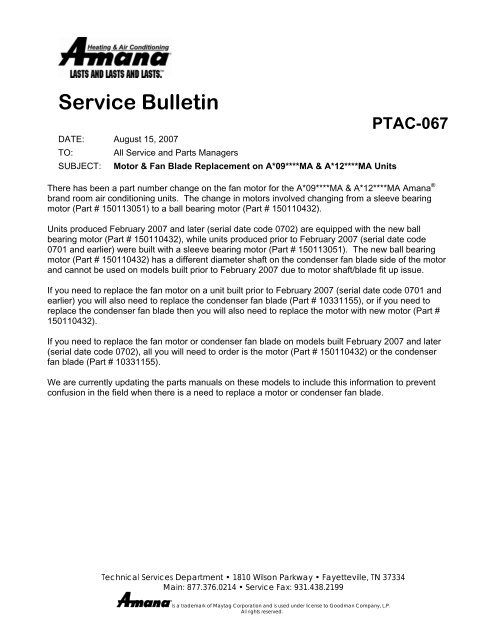
<strong>Service</strong> <strong>Bulletin</strong><br />
DATE: August 15, 2007<br />
TO: All <strong>Service</strong> and Parts Managers<br />
SUBJECT: Motor & Fan Blade Replacement on A*09****MA & A*12****MA Units<br />
Technical <strong>Service</strong>s Department • 1810 Wilson Parkway • Fayetteville, TN 37334<br />
Main: 877.376.0214 • <strong>Service</strong> Fax: 931.438.2199<br />
®<br />
Is a trademark of Maytag Corporation and is used under license to Goodman Company, L.P.<br />
All rights reserved.<br />
PTAC-067<br />
There has been a part number change on the fan motor for the A*09****MA & A*12****MA Amana ®<br />
brand room air conditioning units. The change in motors involved changing from a sleeve bearing<br />
motor (Part # 150113051) to a ball bearing motor (Part # 150110432).<br />
Units produced February 2007 and later (serial date code 0702) are equipped with the new ball<br />
bearing motor (Part # 150110432), while units produced prior to February 2007 (serial date code<br />
0701 and earlier) were built with a sleeve bearing motor (Part # 150113051). The new ball bearing<br />
motor (Part # 150110432) has a different diameter shaft on the condenser fan blade side of the motor<br />
and cannot be used on models built prior to February 2007 due to motor shaft/blade fit up issue.<br />
If you need to replace the fan motor on a unit built prior to February 2007 (serial date code 0701 and<br />
earlier) you will also need to replace the condenser fan blade (Part # 10331155), or if you need to<br />
replace the condenser fan blade then you will also need to replace the motor with new motor (Part #<br />
150110432).<br />
If you need to replace the fan motor or condenser fan blade on models built February 2007 and later<br />
(serial date code 0702), all you will need to order is the motor (Part # 150110432) or the condenser<br />
fan blade (Part # 10331155).<br />
We are currently updating the parts manuals on these models to include this information to prevent<br />
confusion in the field when there is a need to replace a motor or condenser fan blade.
<strong>Service</strong> Letters<br />
All <strong>Service</strong> Letters have been combined into this single Acrobat<br />
document. This allows the user to search by keyword or phrase<br />
for the desired information. There are several ways to search for<br />
letters.<br />
1. The arrows on the Acrobat toolbar allow you<br />
to search one page at a time, or go directly to each end of the<br />
document. This is useful for multi-paged letters.<br />
2. The bookmarks feature. Click on any plus sign to the left of the<br />
model group name . A list of <strong>Service</strong> Letters will drop with<br />
information on that model group. Click on the number of the<br />
<strong>Service</strong> Letter you are looking for and it will go to that particular<br />
page. Use the scroll bar on the left to search up and down for<br />
bookmarks. This feature works well when used with the indexes.<br />
3. The index contains a brief description of each <strong>Service</strong> Letter,<br />
the date it was released, and the corresponding part number. Use<br />
the index to view information for each letter, then click on the<br />
icon of the same name in the bookmarks. Click here to go to<br />
the index pages.<br />
Or<br />
4. To use the search function, click here . In the Acrobat Find<br />
dialog box enter the word or phrase you want to search for, then<br />
press Find. Acrobat will search until it finds the first occurrence<br />
of this word or phrase. To continue searching, press the F3 key<br />
on your keyboard. This can be very valuable when the user does<br />
not know which <strong>Service</strong> Letter contains the desired information.
<strong>Service</strong> <strong>Bulletin</strong> <strong>Index</strong><br />
Svc <strong>Bulletin</strong> Date Subject<br />
SA-007 9/12/07 Disposition of In-Warranty <strong>Service</strong> Parts<br />
SA-006 6/11/07 GE Contactor Part # B1360321<br />
SA-005 5/14/07 B1360321 GE Contactors<br />
SA-004 11/10/06 Amana® Brand and Goodman® Brand Product Information<br />
SA-003 9/1/05 Dirty Sock Syndrome<br />
SA-002 Rev. 3 2/14/07 ECM Motor and End Bell Control Module Kit Cross-Reference List<br />
SA-001 7/29/05 New <strong>Service</strong> <strong>Bulletin</strong> Numbering System
<strong>Service</strong> <strong>Bulletin</strong> <strong>Index</strong><br />
Svc <strong>Bulletin</strong> Date Subject<br />
SF-018 9/6/07 Revised Venting Table for GKS90904CX** Model Furnace<br />
SF-017 6/26/07 LPM-05 LP Gas Conversion Kits<br />
SF-016 7/17/07 GME8 Furnace Wiring Diagram Correction<br />
SF-015 3/7/07 90% Jakel Two–Stage Induced Draft Motor Overload Tripping<br />
SF-014 2/27/07 <strong>Supply</strong> Air Infiltration on 80% Dedicated Down Flow Model Furnaces<br />
SF-013 11/10/06 New Jakel Round Nose Induced Draft Blower Assemblies for 80% Single Stage<br />
Gas Furnaces (Not Backward Compatible)<br />
SF-012 4/18/06 New Ignition Control Board 0130F00005S<br />
SF-011 2/16/05 Induced Draft Motor Rubber Coupling Change for B1859001S Kit<br />
SF-010 2/15/06 B4833000S Kit Shipped With Incorrect Induced Draft Blower<br />
SF-009 2/3/06 0131M00002S <strong>Service</strong> Kit with Incorrect Induced Draft Motor Wheel<br />
SF-008 2/3/06 0230K00001 Mini Igniter <strong>Service</strong> Kit<br />
SF-007 1/12/06 <strong>Service</strong> Igniter Kit Part # 10735003A with Incorrect Igniter<br />
SF-006 1/12/06 Drain Clamp Change for the New Drain Elbow<br />
SF-005 11/8/05 New Drain Elbow - 90% Model Furnaces<br />
SF-004 11/3/05 Incorrectly Wired 9-Pin Harness in B1809913S Ignition Control <strong>Service</strong> Kit<br />
SF-003 11/4/05 Amana ® and Amana ® Distinctions 80% Furnace Door Switch Kit<br />
SF-002 11/8/05 Drain Clamp Change for the New Drain Elbow<br />
SF-001 9/28/05 Mini Igniter Replacement Kit
<strong>Service</strong> <strong>Bulletin</strong> <strong>Index</strong><br />
Svc <strong>Bulletin</strong> Date Subject<br />
SP-016 10/17/07 Sound Quality on Package Units<br />
SP-015 6/15/07 Propeller Type Noise from Condenser Fan Blades<br />
SP-014 5/11/07 A/GPG Ignition Boards<br />
SP-013 5/9/07 Sound Baffle for Multi-position Heat Pumps and Coolers<br />
SP-012 2/14/07 Introduction of New HKR3 Heater Kit for GPH/C 3 Phase Package Units<br />
SP-011 2/14/07 A/GPG15 Adapter Harness<br />
SP-010 11/29/06 LVBK Issues<br />
SP-009 Rev. 1 7/10/06 Vibrating/Noisy Condenser Fan Blades<br />
SP-008 6/16/06 Miswired Crankcase Heater and Defrost Thermostat<br />
SP-007 4/18/06 A/GPG Flue Hood Redesigned<br />
SP-006 4/18/06 GPH and GPC Model Wiring Issues<br />
SP-005 Rev. 1 3/14/06 FasTest Access Fittings and <strong>Service</strong> Tools<br />
SP-004 2/17/06 GPC, GPH Power <strong>Supply</strong> Phasing<br />
SP-003 12/6/05 Replacement Condenser Fan Blade for Package Gas Units<br />
SP-002 Rev. 1 1/6/06 Condensate in APG and GPG Package Unit Heat Exchangers<br />
SP-001 9/12/05 Package Unit Heat Exchanger Baffle
<strong>Service</strong> <strong>Bulletin</strong> <strong>Index</strong><br />
Svc <strong>Bulletin</strong> Date Subject<br />
SR-025 10/19/07 Superheat/Subcooling Calculators and Pressure/Temperature Chart<br />
SR-024 8/29/07 Loss of Charge Switch for R-410A Split System Heat Pumps<br />
SR-023 3/23/07 Condenser Fan Noise on the GSH130241A*, GSH130251A* and GSH130301A*<br />
Heat Pumps<br />
SR-022 3/13/07 Charge Adjustment on ASX16*, SSX16* and GSC14* Units<br />
SR-021 2/26/07 Harmonic Compressor Noise in Split Heat Pumps<br />
SR-020 1/15/07 Redesigned Tops and Louvers on the Goodman® and Amana® Brand Split<br />
System Units<br />
SR-019 1/12/17 Revisions to Long Line Set Guidelines TP-106 and TP-107<br />
SR-018 9/22/06 VCC30C2C Condenser Fan Motor Issue<br />
SR-017 9/22/06 TX5N4 Expansion Valve Kit Label Issue<br />
SR-016 8/23/06 GSC14042 / 048 / 0601AA Discharge Tubes Cracking<br />
SR-015 8/15/06 GSC130361AA/BA Nuisance Tripping of Overcurrent Protection Device<br />
SR-014 6/20/06 ARUF042-1B, ARPT042-1B and AR*F30301BA Air Handler Blower Noise<br />
SR-013 6/15/06 Blower Noise on ARUF049-1B, ARPT049-1B, ADPF30421BA and AR*F36421BA<br />
Air Handlers<br />
SR-012 5/26/06 Release of Revised IO-258B for Amana® Brand Split System Air Conditioners<br />
Equipped with Comfort Alert Module<br />
SR-011 5/26/06 Loose Condenser Fan Motor Mounting Nuts on Amana® Brand Condensers<br />
SR-010 4/29/06 Cleaning “White-Dust” From Amana®-Brand Condenser Coils<br />
SR-009 4/18/06 RTG**C2A/C Heat Pumps with Defrost Issues<br />
SR-008 4/24/06 RTG36C2A/C Units Cycling on High Head Pressure in Heat Mode<br />
SR-007 3/13/06 Crankcase Heaters for Copeland Scroll Compressors<br />
SR-006 Rev. 1 11/7/06 Amana® Brand <strong>Service</strong> Replacement A-Coil Assemblies<br />
SR-005 9/12/05 A90-00 and A120-00 Blower Motor Substitute<br />
SR-004 Rev. 1 10/13/05 Hard Start Kit Information<br />
SR-003 8/11/05 Airflow adjustment to MBE Air Handler and AMV/GMV Furnace using AFE18-60A<br />
All Fuel Kit when Matched with RTG Heat Pump<br />
SR-002 8/3/05 MBE/MBR Air Handler Rework Update<br />
SR-001 8/3/05 Suction Line Fitting Installation on Corporate Coils and Air Handlers
Svc <strong>Bulletin</strong><br />
Date<br />
<strong>Service</strong> <strong>Bulletin</strong> <strong>Index</strong><br />
Subject<br />
CAG-483 5/20/05 ARUF032-001-1B and ARPT032-00C-1B Air Handler Blower Motor Noise<br />
CAG-482 5/6/05 OT18-60A Outdoor Thermostat Set Point Indicator<br />
CAG-481 3/7/05 Corporate Air Handler and Coil Orifice Changes for Amana RSC and RTC<br />
CAG-479 2/17/05 Field Problems with HKR* Heat Kits in AEPT and MBE Models<br />
CAG-478 2/15/05 Copeland Two Step Modulated Scroll Compressor Troubleshooting<br />
CAG-477 2/7/05 Foam Shipping Block on PHB and PHD Large Chassis Package Heat Pumps<br />
CAG-476 2/15/05 Electronic Blower Time Delay Kit for PCA/PCC & PHB/PHD Package Units<br />
CAG-475 Add 12/22/04 Jakel ID Blower Seizing on PGD and APG Model Package /Gas Electric Units<br />
CAG-475 12/20/04 Jakel ID Blower Seizing on PGD and APG Model Package /Gas Electric Units<br />
CAG-474 2/3/05 HKR Heat Kit Installation on MBE and MBR Module Air Handlers<br />
CAG-470 2/14/05 AEF18-60A All Fuel Kit<br />
CAG-469 12/8/04 Change from TXV to Flowrator on Amana brand PGD Package Units<br />
CAG-468 12/8/04 New OT18-60A Outdoor Thermostat<br />
CAG-467 12/8/04 Ranco Replacement Defrost Board Kit for PHB and PHD<br />
CAG-466 1/11/05 Incorrect Capacitor on VHC60C2A and VHC60C2C<br />
CAG-465 11/8/04 Wilspec <strong>Service</strong> Suction Valve<br />
CAG-464 10/26/04 Corporate Air Handler and Coil Orifice Changes<br />
CAG-463 10/25/04 Touch Up Paint<br />
CAG-462 8/2/04 Compressor Return Audit Tag<br />
CAG-461 9/14/04 Condenser Fan Motor Failure<br />
CAG-460 7/30/04 PGD48 & 60C***2* Intermittent Starting Problems<br />
CAG-459 8/12/04 Compressor Cross-Reference List<br />
CAG-458 8/3/04 VCA/VHA-Motor and Fan Blade Changes<br />
CAG-457 8/3/04 RTG Heat Pump Performance Data Specification Sheet Correction<br />
CAG-455 5/27/04 RHE42C2A Condenser Fan Grille Vibration<br />
CAG-454 6/16/04 Differentiation between the BBC**A2C and previous BBC***A2A Variable Speed<br />
Blowers<br />
CAG-453 7/2/04 Door Gasket Kit (Part # RF000179)<br />
CAG-452 5/10/04 High Pressure Switch Nuisance Tripping<br />
CAG-451 5/4/04 Electric Heater Relay Part #11091701<br />
CAG-450 3/30/04 BBC**A2C Incorrect Wiring<br />
CAG-449 12/19/03 Revised Company Warranty Claim Form Process<br />
CAG-447 9/30/03 Warranty Procedure Changes for Project 8554<br />
CAG-446 8/18/03 DFTD-1 Defrost Time Delay Kit<br />
CAG-445 8/7/03 Formicary Corrosion in Evaporator Coils<br />
CAG-444 7/1/03 Improved Coil Corrosion Protection for Pre-Painted Condenser Coils
Svc <strong>Bulletin</strong><br />
Date<br />
<strong>Service</strong> <strong>Bulletin</strong> <strong>Index</strong><br />
Subject<br />
CAG-443 6/24/03 R**C2A Series Remote Condensing Units with Back Seating <strong>Service</strong> Valves<br />
CAG-442 5/19/03 RHA36A2* and RHF42A2* Heat Pump Change Over Noise<br />
CAG-441 4/25/03 Premature Fin Deterioration On Pre-Painted Outdoor Coils<br />
CAG-440 4/15/03 20214302 Defrost Control<br />
CAG-439 7/15/03 Copper vs. Aluminum Conductors<br />
CAG-438 2/28/03 Spec Sheet and Unit Data Plate MOP<br />
CAG-437 2/5/03 Maximum Overcurrent Protection and Minimum Circuit Ampacity<br />
CAG-436 12/19/02 Scroll Compressor Noise and Vibrations<br />
CAG-435 7/23/02 VCA Units with Miswired Compressors<br />
CAG-434 1/25/02 BBA60A2A and BBC60A2A Air Handlers<br />
CAG-433-B 2/1/02 Amana Fossil Fuel Kits FFK03A<br />
CAG-432 4/12/02 New Direct Spark Ignitors for PGA, PGB, and PGD Gas/Electric package Units<br />
CAG-431 4/6/01 BMA Control Board Functions<br />
CAG-430 8/30/01 ECM Motor <strong>Service</strong> Replacement Power Heads<br />
CAG-429-B 5/14/01 Premature Fin Deterioration on Pre-painted Outdoor Coils<br />
CAG-428-B 3/12/01 BMA24 & 30 Blowers installed in the counter-flow position<br />
CAG-427-B 10/5/00 Distributor Tube Leaks on Amana Package Heat Pumps<br />
CAG-426-B 10/19/99 Thermostat Compatibility with PHD42/48C and PHB60C Package Heat Pumps<br />
CAG-425-B 10/14/99 RHE36A2A Heat Pumps with Discharge Tube Breakage<br />
CAG-424-B 10/19/99 Package Heat Pump PHD Models C Chassis, Incomplete Defrost<br />
CAG-423-B 10/19/99 Amana C Design Series Package Units in High Static or Down Discharge<br />
Installations<br />
CAG-422-B 6/22/99 New <strong>Service</strong> Manual Structure<br />
CAG-421-B 6/25/99 Replacement Ignition Controls for Amana C Series Package Gas Units with D<br />
Engineering Revision<br />
CAG-419-B 4/19/99 Touch-up Paints<br />
CAG-418-B 1/25/99 Honeywell 9500 Smart Valves Amana Part # 11112101<br />
CAG-417-B 6/12/98 RCB/RCC Remotes with Tecumseh Compressors<br />
CAG-416-B 6/1/98 Remote units with Potentially Inoperative Pressure Switches<br />
CAG-415-B 1/29/99 Honeywell Smart Valves<br />
CAG-414-B 5/22/98 Element Support Bracket on ECB25C/ECB30C Heater Kits<br />
CAG-413-B 1/28/98 BBA/BBC Blower Insulation<br />
CAG-412-B 1/23/98 PHCB_C1 Heater Kits for Package Units<br />
CAG-411-B 12/4/97 ID Blower/Collector Box Condensate Drain Kit<br />
CAG-410-S 11/12/97 Fossil Fuel Kit FFKO2A Installation Instructions<br />
CAG-409-B 11/3/97 Condenser Fan Operating Sound On Package Heat Pumps
Svc <strong>Bulletin</strong><br />
Date<br />
<strong>Service</strong> <strong>Bulletin</strong> <strong>Index</strong><br />
Subject<br />
CAG-408-B 11/4/97 Pressure Switch Kit For RHD Heat Pumps<br />
CAG-407-B 6/12/97 Insufficient Electric Heat With BBA/BBC Air Handlers<br />
CAG-406-B 7/24/97 TXV Sensing Bulb Clamps<br />
CAG-405-B 2/3/97 RHA_A2B Integrated Defrost Control<br />
CAG-404-B 2/6/97 Sticking Chatliff Orifices<br />
CAG-403-B 2/3/97 Field insulation of A-Coil Drain Pans<br />
CAG-402-B 1/15/97 BBA/BBC Blower Run-on<br />
CAG-401-B 1/15/97 Condenser Fan Noise on Package Gas/Electric Units<br />
CAG-400-B 9/13/96 RHA and RHE Loss of Charge Controls<br />
CAG-399-B 8/27/96 Insulation Support on BBA/BBC Blower Cabinets<br />
CAG-398-B 7/1/96 RCB48A_B and RCC48A_B Discharge Line Vibration<br />
CAG-397-B 6/7/96 Heater Wiring Kit EHK_A<br />
CAG-396 10/19/95 BCA/BHA Blower Coils Installed In Horizontal Right Position<br />
CAG-395 9/13/95 BBA Model Blower Cabinet Control Boards<br />
CAG-394 8/31/95 Restrictor Orifices<br />
CAG-393 8/31/95 RCB/RCE Liquid Line Filter Dryers<br />
CAG-392 6/9/95 RHA/RHD Sticking and/or Noisy Check Valves<br />
CAG-391 6/21/95 RHD42A2A Tube Breakage<br />
CAG-390A-B 3/15/96 RHD Defrost Boards<br />
CAG-389 1/24/95 Flue Screen for SPCG, PGA, and PGB<br />
CAG-387 10/21/94 BCA Wiring Harness when using EHK Heater Kit<br />
CAG-384 10/15/93 Ranco Replacement 4-Way Reversing Valves<br />
CAG-383 8/20/93 Scroll Compressor Hard Start Kits<br />
CAG-382A 8/31/93 Package Unit Sound Reduction Kits for 3.5 to 5 Ton Units<br />
CAG-381A-B 6/25/93 <strong>Service</strong> Replacement A-Coil Assemblies<br />
CAG-380 2/17/93 4 and 5 Ton Package Unit Blower Assemblies<br />
CAG-379 10/30/92 Condensate dripping on 3.5, 4, 5 ton Package Units<br />
CAG-378 10/1/92 PCB/PGB42 Discharge Tube Breakage<br />
CAG-377 10/30/91 Corrections to Parts Manuals R2151-1 and R2051-93 Rev. 1<br />
CAG-376 6/27/91 RO1568-28 Discharge Thermostat for Scroll Compressors<br />
CAG-374 10/11/90 SPCG <strong>Supply</strong> Duct Covers<br />
CAG-373 10/11/90 SPCG Nuisance Auxiliary Limit Trips<br />
CAG-372 10/31/90 Filter Dryer Application<br />
CAG-371 9/21/90 SPCG Fan and Limit Rusting Condition<br />
CAG-370 6/1/90 Safety Notice On ZRCF Scroll Compressors
Svc <strong>Bulletin</strong><br />
Date<br />
<strong>Service</strong> <strong>Bulletin</strong> <strong>Index</strong><br />
Subject<br />
CAG-369 3/28/90 ABCHMBM and EBCC/BCEA Horizontal Drain Pan Kits<br />
CAG-368 1/16/90 Package Units with Condenser Fan Hitting Fan Orifice<br />
CAG-367 9/25/89 New Cap Kit For D99642-01,-02 <strong>Service</strong> Valves<br />
CAG-366 8/15/89 Requirement to install Warning Tags On <strong>Service</strong> Valves<br />
CAG-365 8/10/89 D99642-01,-02 Liquid Line service Valves<br />
CAG-364 8/9/89 EBCC and ABCH Condensate Leakage installed Horizontally<br />
CAG-363A 8/31/89 Parts Manual Corrections R2052-46, R2053-47<br />
CAG-362A 2/9/90 SPCG Intermittent Lockout update<br />
CAG-361 3/30/89 Ranco Reversing Valves to Replace ALCO Valves<br />
CAG-360 11/14/88 Safety Notice-APCG and APCP Rooftops<br />
CAG-359 9/2/88 Functional Parts Lists for the New SPCG Package Cooling and Heating Units<br />
CAG-358 9/2/88 Functional Parts Lists for the New SPCG Package Cooling and Heating Units<br />
CAG-357 8/19/88 Functional Parts Lists for the New 8 and 10 Ton Package Units<br />
CAG-356 7/29/88 ACFH Flow Controls<br />
CAG-355 1/22/88 Safety Notice<br />
CAG-354A 4/9/89 <strong>Service</strong> Valve Caps for D99642 Valves<br />
CAG-353 12/14/87 Fusible Link Failures<br />
CAG-352 9/15/87 <strong>Service</strong> Manual Correction R2043-82<br />
CAG-351 6/12/87 Possible Miswired Compressor ARCF24UO1A<br />
CAG-350 4/23/87 <strong>Service</strong> Replacement Valve Stem Assemblies for Remote Product<br />
CAG-349 3/31/87 Correction to Parts Manual RO205178 Rev1<br />
CAG-348 10/14/86 EBCU in Counterflow Position<br />
CAG-347 8/13/86 ACFC drain Coupling Seal<br />
CAG-346 7/15/86 Functional Parts List for ERHF High Efficiency Remote Heat Pump Units<br />
CAG-345 7/15/86 Package Unit Blower Delay B14126-1<br />
CAG-344A 10/27/86 Cap Seals For service Valves<br />
CAG-343 4/15/86 ARHF and ABCH Capillary Tube Assemblies<br />
CAG-342 4/6/86 Correction to Manual R2054-38<br />
CAG-341 3/4/86 <strong>Service</strong> replacement defrost Timer C63488-01<br />
CAG-340 2/11/86 Add Manufacturing Numbers R2053-70,-69,-68<br />
CAG-337 7/3/85 Suction Line Tubing Inserts for Compressor Valves<br />
CAG-335 4/24/85 <strong>Service</strong> Replacement transformer Assemblies<br />
CAG-332 8/28/84 B13769-1 PTC Resistor Start Assist Device<br />
CAG-330A 11/14/85 Premature Termination of Defrost ERHQ42, 48<br />
CAG-329 6/11/84 Installation Instructions R1570-54,-55.-56 Hard Start Kits
Svc <strong>Bulletin</strong><br />
Date<br />
<strong>Service</strong> <strong>Bulletin</strong> <strong>Index</strong><br />
Subject<br />
CAG-326 2/24/84 Crankcase Heater thermostat B12319-1 and B12319-2<br />
CAG-324 12/5/83 D67491-1 Condenser Fan Blade Subbed to D69278-1<br />
CAG-313 2/18/83 All 9000 Series PTAC Heat Pump Units<br />
CAG-311A 5/19/83 EGHW100DA-3 Solution High Limit<br />
CAG-309 8/23/82 Commercial Rooftop, Blower bearing Assembly<br />
CAG-308 3/11/82 A46202-2, C61716-2, C61716-3 Emergency Heat Kits<br />
CAG-307 3/5/82 Thermostat subbase jumper wire<br />
CAG-306 2/4/82 R1572-88 Module flue outlet gasket<br />
CAG-305 2/4/82 PKG 7.5 and 10 ton parts information<br />
CAG-303 10/1/81 Water leakage in area of module support ring on EG and EPCG<br />
CAG-299 5/5/81 EBCU Slide rail removal and sealing<br />
CAG-298 4/10/81 C61716-01 and C61716-02 Emergency Heat relays<br />
CAG-297 3/17/81 EPHO Water leakage from cabinet top into control panel<br />
CAG-296 1/27/81 R1950-13 OZ Squeeze tubes of thermal mastic<br />
CAG-295 9/22/81 Application of Gas Conversion Burners to Oil furnaces<br />
CAG-282H 10/28/96 Compressor start assist Devices for Amana models and general use
Svc <strong>Bulletin</strong><br />
Date<br />
<strong>Service</strong> <strong>Bulletin</strong> <strong>Index</strong><br />
ERG-75 5/9/05 Glycol Replacement for HTM Units<br />
Subject<br />
ERG-74-B 3/7/97 Robert Shaw HS1000 Ignition Control w/incorrect Mate-N-Lock Connector<br />
ERG-73-B 4/9/96 HTM Diverter Valves<br />
ERG-72 11/29/94 Pump Seals, Housings, and Motor assemblies-EG, EPCG, EGHE<br />
ERG-70-B 4/2/96 Replacement Gas valves for HTM Package Units<br />
ERG-69 3/18/94 EGHW100 and EGHE60 Replacement Gas Valve Kits<br />
ERG-68 3/13/92 Installation of Pump Housing Kit, 10375702, EPCG/EGHE/EG<br />
ERG-67A 8/22/91 Pump Housing Kits<br />
ERG-66 5/17/90 Water Inlet Cap for EGWH0040DA Water Heaters<br />
ERG-65 7/29/88 EGHW100 Furnace, Manual Reset Limit Trip After Module Replacement<br />
ERG-64 5/12/88 EGHW100DA-3 Replacement Recouperator Coil, D69089-02<br />
ERG-63 6/20/88 Optional Post Purge/Flush Delay Relay for EGHW100DA-3 Furnaces<br />
ERG-62 3/26/88 <strong>Service</strong> Replacement Five(5) Airhole 100,000 BTUH Natural Gas Orifice<br />
ERG-61B 12/18/89 D69976-03 B Style Energy Command Electronic Ignition Control<br />
ERG-60 1/22/88 Safety Notice<br />
ERG-59 6/20/88 Energy Command Gas Odor<br />
ERG-58 8/11/87 Energy Command Furnace Heat Transfer Module Replacement Program<br />
ERG-57 8/3/87 Electronic Ignition Furnaces<br />
ERG-56 6/22/87 EGWH Water Heater Heat Exchanger Solution Inlet and Outlet Tubes<br />
ERG-55 5/11/87 D69976-02 Ignition Control<br />
ERG-54 1/8/87 Tin Coated 8 Bolt Hole Heat Exchanger for Water Heater<br />
ERG-53 11/3/86 EGHW100 Noise Control Assembly<br />
ERG-52 9/22/86 RO1565-90 Pump Drain Assembly<br />
ERG-51 8/25/86 New Ignition Control For EGHW100-DB-3<br />
ERG-50A 8/11/86 Flush Valve Vibration Noise, EGHW/EGHE Furnaces<br />
ERG-49 3/4/86 EGHW100DB-3 Information<br />
ERG-48 11/26/85 R1984-63 <strong>Service</strong> Replacement Gas Valve Assembly-EG,EPCG_A&B<br />
ERG-46A 8/28/87 EGHE Pump/Motor Vibration, EGHE/EGHW Combustion Blower Vibration<br />
ERG-45 10/8/85 New Solution Pump Assemblies, Glycol Test Strips, Reinhibitor<br />
ERG-44 9/5/85 Phosphate Dispenser, Replacement Cartridge and Bulk Crystals<br />
ERG-43 7/2/85 Field installed Low Voltage Wiring of Remote HTM Outdoor and Indoor Units<br />
ERG-42 5/23/85 <strong>Service</strong> Replacement Pump Seal assemblies<br />
ERG-41 4/24/85 <strong>Service</strong> Replacement Direct Spark Ignition Control Assembly<br />
ERG-40 4/24/85 Fenwal Ignition Control Diagnostic Tester<br />
ERG-39 4/24/85 Diverter Valve(s) and service Replacement Parts
Svc <strong>Bulletin</strong><br />
Date<br />
<strong>Service</strong> <strong>Bulletin</strong> <strong>Index</strong><br />
Subject<br />
ERG-38 4/24/85 Field service Assemblies to Eliminate Diverter Valve Water Hammer<br />
ERG-37 3/15/85 EGHW100DA-3 <strong>Service</strong> Replacement Wiring Assembly<br />
ERG-36 3/6/85 Optional <strong>Service</strong> Replacement Charging Tee/Hose Assembly-ERGW<br />
ERG-35 2/21/85 <strong>Service</strong> Replacement Solution Pump Front Housings<br />
ERG-33 9/19/84 Amana Water Heaters<br />
ERG-30 8/6/84 EGHW100DA-3 Furnaces installed on Propane<br />
ERG-29 5/1/84 Increased Capacity Solution Pump on ERGW0012-1A Units<br />
ERG-28A 4/12/85 New <strong>Service</strong> Replacement Numbers<br />
ERG-27 3/30/84 Removal of Lime Build Up from Water Tank Heat exchanger<br />
ERG-26 2/24/84 Combustion Blower Fan Blade Mounting Kit<br />
ERG-25 2/24/84 Crankcase Heater Thermostat B12319-01, -02<br />
ERG-24 2/23/84 New Phosphate Crystals and Dispenser/Cartridge Assembly<br />
ERG-23 1/16/84 B12909-03 Time Delay Relay<br />
ERG-22A 4/6/84 Brazed Condensate Drain Tubes<br />
ERG-20A 8/20/84 Robert Shaw Redundant Gas Valves-C62953-01, C94646-01,-03<br />
ERG-19A 2/21/84 BWC Cycles at the end of Hot Water Heating Cycle<br />
ERG-18 5/19/83 B13579-01 Solution High Limit<br />
ERG-17 5/23/83 EGHW0040DA Water Heater<br />
ERG-16 5/2/83 ERGW, EPCG, EGHW Gas Orifice Plates<br />
ERG-15 4/27/83 Vent Cap or Rain Seal on ERGW or EPCG Models<br />
ERG-14 4/5/83 EGWH Water Heater Heat Exchanger, 8 Stud Design<br />
ERG-13 3/31/83 Energy Command Furnace Condensate Hose Leak at Condensate Tee<br />
ERG-12A 12/18/84 See ERG-38<br />
ERG-11B 6/21/83 Add-on Post Purge Time Delay Relay for EGHW100DA-3<br />
ERG-10 2/14/83 Determining the Proper Performance of EGWH Water heater<br />
ERG-9 3/8/83 Superceded by ERG-38<br />
ERG-8 11/22/82 Superceded by ERG-39<br />
ERG-7 9/23/82 Optional Reset Timer Assembly for use on ERGW0012-1A Units<br />
ERG-6 6/7/82 Protective Vinyl Cap for ERGW Unit Gas Valve Pressure Regulator<br />
ERG-5 5/12/82 <strong>Service</strong> Replacement fan Control For EBWC Unit<br />
ERG-4 3/17/82 ERGW Units with Improperly Installed or Assembled Sound Ring Rods<br />
ERG-3 10/22/81 Recreational Vehicle Propylene Glycol Mixtures<br />
ERG-2 5/4/81 ERGW(HTM+) Silicon carbide Igniters
Svc <strong>Bulletin</strong><br />
Date<br />
<strong>Service</strong> <strong>Bulletin</strong> <strong>Index</strong><br />
Subject<br />
GF-179 5/25/05 Blower Wheel Noise on Amana® Brand 80% and 90% Gas Furnaces<br />
GF-178 5/25/05 White-Rodgers G Gas Valve Gas Pressure Test Adapter<br />
GF-177 3/1/05 Clarification for using LP Gas Conversion Kit (LPM-03) for 2-Stage Furnaces<br />
GF-176 2/18/05 Ramping Profile Dip Switch Settings Incorrect in IO on AMV8, ACV9, and<br />
AMV9 Gas Furnaces<br />
GF-175 1/12/05 ECM Motor Not Ramping Properly<br />
GF-174 1/20/05 Pressure Switch Nuisance Tripping on Amana brand 90% ACV90*<br />
Counterflow Model Furnaces<br />
GF-173 12/30/04 Reintroduction of White Rogers G Valve on Single Stage Gas Products<br />
GF-172 1/12/05 HCVK and DCVK Concentric Vent Kits<br />
GF-171 1/20/05 Removal of Nox Screens on 80% Gas Heating Products<br />
GF-170 8/30/04 Horizontal Left Drain Application for New Amana Single Stage 90% Furnace<br />
GF-169 10/29/04 DCVK Concentric Vent Kit Instructions<br />
GF-168 rev 1 11/8/04 ECM Blower Speed Selection Label for New Variable Speed Gas Furnace<br />
GF-168 8/31/04 ECM Blower Speed Selection Label for New Variable Speed Gas Furnace<br />
GF-167 rev 1 1/25/05 Wire Number Reference Removed on Amana Brand 90% Gas Furnace<br />
GF-166 11/11/03 Flood-Damaged Appliances<br />
GF-165 11/11/03 Missing 8 Flash LED Code Information<br />
GF-164 11/11/03 Incorrect Gas Valve Wiring Diagram Information<br />
GF-163 8/6/03 170°F Primary Limit Usage on GUIC045FA30 Model Furnaces<br />
GF-162 3/14/03 Need for Proper Grounding of Silicon Nitride Integrated Ignition Control<br />
System<br />
GF-161 1/31/03 40 80% Single-Stage Gas Furnace Fasco induced Draft Blower Assembly<br />
GF-160 1/3/03 Schedule 40 PVC Cellular Core Plastic Pipe<br />
GF-159 5/29/03 Silicon Nitride Igniter Kit<br />
GF-158 12/26/02 Upflow 40 90% Furnace Vent-Drain Kit<br />
GF-157 3/11/03 White-Rodgers Two-Stage Gas Valves<br />
GF-156 6/7/02 New Propane Low Pressure Kit (LPLP01)<br />
GF-155 4/26/02 Reduction in Clearances to Combustible Material for Amana 40 80% & 90%<br />
Furnaces<br />
GF-154 12/19/01 40 90% Two-Stage Gas Furnace Fasco Induced Draft Blower Assemblies<br />
GF-153 9/21/01 New White-Rodgers Ignition Control Kit, Amana Part # RF000129<br />
GF-152 8/2/01 Fuel Gas Odor Smell in Furnace Burner Area<br />
GF-151-B 8/31/00 GUID <strong>Service</strong> Replacement Induced Draft Blower Assembly<br />
GF-150-B 6/7/00 New <strong>Service</strong> Label for Integrated Ignition Control<br />
GF-149-B 11/9/99 <strong>Service</strong> Tool for Replacement of Damaged Knurled Threaded Inserts<br />
GF-148-S 9/27/99 Direct Vent (Dual Pipe) Venting Table Corrections
Svc <strong>Bulletin</strong><br />
Date<br />
<strong>Service</strong> <strong>Bulletin</strong> <strong>Index</strong><br />
Subject<br />
GF-147-B 7/16/99 White-Rodgers 50A55-288 Integrated Ignition Controls<br />
GF-146-B 12/19/01 <strong>Service</strong> Replacement Heat Exchanger Assemblies for 40" 95% GUVA and<br />
New 92%+ GCVA Furnaces<br />
GF-145-B 7/26/99 <strong>Service</strong> Replacement Motor Mounting Assembly Kit<br />
GF-144-B 3/3/99 Heatcraft HSI-2 Integrated Ignition Controls<br />
GF-143-S 1/7/99 Alternate Horizontal Vent Termination(Dual Pipe) for GUCA/GCCA<br />
GF-142-B 1/20/98 <strong>Service</strong> Replacement Integrated Ignition Controls for GUCA/GCCA<br />
GF-141-B 10/27/98 <strong>Service</strong> Replacement Heat Exchangers for GUCA/GCCA Furnaces<br />
GF-140-B 10/20/98 Flame rectification Kit for GUIB/GCIB Furnaces<br />
GF-139-B 8/31/98 GUCA/GCCA Supplemental Heat Exchanger Warranty<br />
GF-138-B 2/24/98 Correction to Parts Manual #RP6620005 Rev.1<br />
GF-137-B 9/15/97 Correction to Parts Manual #RO205693 Rev.0<br />
GF-136-B 3/6/97 Label Misprint, Amana Thermostat #1213901<br />
GF-135-B 10/14/97 Revised 90% Furnace Venting Tables<br />
GF-134-S 3/6/97 GUIB/GCIB Furnaces radiant Flame Sensors<br />
GF-133-S 11/13/96 GUID070 Furnace, Potential Induced Draft Blower Leakage<br />
GF-132-S 3/21/96 Warranty Certificates for GUIB_CX_ Furnaces<br />
GF-131 2/23/96 90% Furnace Igniter Evaluation<br />
GF-130 11/7/95 Induced Draft Blower Assemblies- GUIC,GCIC, PGB**C<br />
GF-129 8/31/95 Auxiliary Limit Mounting Clip used on GUIC Model Furnaces<br />
GF-128 5/25/95 Furnace Closet Clearance<br />
GF-127 5/25/95 Furnace Minimum Circuit Ampacity and Maximum Overcurrent Protection<br />
GF-125 12/16/94 40" 80% Furnace Induced Draft Blower Assemblies<br />
GF-124A-B 12/23/94 80% Furnace NOx Screens<br />
GF-123 12/23/94 Common Venting 80% Furnace(Induced Draft) with Natural Draft Water Htr.<br />
GF-120 5/27/94 LP Orifices and Conversion Kits<br />
GF-119 4/13/94 White Rodgers 50A50 Ignition Control Troubleshooting Information<br />
GF-118 6/21/93 EGHW100 and EGHE60 Replacement Gas Valves<br />
GF-117 4/28/93 LP Orifices used In LPTK04 Conversion Kits<br />
GF-116 2/17/93 Replacement Capacitors for RO1567-44 Induced Draft Blower Motors<br />
GF-115 1/21/93 Continuous Blower On Furnaces with White-Rodgers 50A50 Control<br />
GF-114 5/22/92 80/90% Furnace Door Latches<br />
GF-113 8/21/91 Universal Ignition Control Tester<br />
GF-112B 8/31/95 Propane Furnace and Package Unit Metal Insert/Turbulator Removal<br />
GF-111 2/12/91 Revised Horizontal Venting Instructions for GUD Furnaces<br />
GF-110 2/13/91 Ignition Control Flame Sensing
Svc <strong>Bulletin</strong><br />
Date<br />
<strong>Service</strong> <strong>Bulletin</strong> <strong>Index</strong><br />
GF-109 10/25/90 GHN Furnace Fan Controls<br />
GF-108 5/16/90 GUC Furnace Limit Control Settings<br />
Subject<br />
GF-107 11/30/89 C64111-02 White Rogers Self Diagnostic Ignition Control<br />
GF-106 11/8/89 LP Conversion of GUC090B(35,50)B and GUC115B50B<br />
GF-105 9/7/89 Replacement Manifold Assemblies for 80/90% Furnaces<br />
GF-104 8/22/89 Pressure Switch Check- All 80/90% and SPCG<br />
GF-103 6/16/89 90% Induced draft Blower Gasket Assembly-RO1821-35,-36,-37<br />
GF-102 6/16/89 GHN Pressure Switches<br />
GF-101 3/1/89 LPTKO2 Propane Conversion Kit Supplied as Part Number B14173-03A<br />
GF-100 12/8/88 Vent Bracket- GHN and GCN Furnaces<br />
GF-99 11/29/88 LPTKO2 Propane Conversion Kit-80%, 90%, SPCG<br />
GF-98 4/7/89 Ignition Control Conversion Kit RO1567-39-GHN, GCN<br />
GF-97 8/29/88 <strong>Service</strong> Blower Isolating Relay Kit RO1566-89- GCN<br />
GF-96 6/3/88 Removal of Blower Motor Shaft Shipping Support Bracket<br />
GF-95 6/10/88 Direct Spark Ignition Furnace parts Obsolescence<br />
GF-94A 4/29/88 Improved White Rogers Ignition Control-GHI, GCI, GSI<br />
GF-93 3/24/88 GHI, GCI, GSI Induced Draft Blower Assemblies<br />
GF-92 8/18/88 GCN Pressure Switch<br />
GF-89 1/6/88 RO1586-50 Drain/Pressure Switch Kit-90% Gas Furnaces<br />
GF-87 11/6/87 Anderol 465 Induced Draft Motor Oil for 80% & 90% Furnaces<br />
GF-86A 12/8/87 Pressure Switch Tripping-GHN 90% Furnace<br />
GF-85 8/3/87 Electronic Ignition Furnace<br />
GF-84 4/13/87 Connection of Igniter Wire to Ignition Control-GSE DN Furnaces<br />
GF-83 3/19/87 RO1984-80 Blower Motor Grommet Mounting Kit<br />
GF-82 2/5/87 Blower Motor Mount GCI70A40-P69832-03F GSI70A40-P69833-03F<br />
GF-81 1/5/87 B14173-01 LP80K Propane Conversion Kit<br />
GF-79 11/7/86 GHI ,GCI, GSI Induced Draft Furnaces<br />
GF-78 5/23/86 GSE "DN" series Gas Horizontal Gas Furnace<br />
GF-76 4/7/86 Air Blower Noise, Conventional Gas fired Furnace<br />
GF-75 1/20/86 GSE "N" series Gas Horizontal Gas Furnace<br />
GF-74 11/19/85 Burner Resonance Noise GH and GC Constant Pilot Furnaces<br />
GF-73 9/18/85 GSE Furnace with Honeywell L4064T Fan and Limit<br />
GF-72 4/24/85 <strong>Service</strong> Replacement DSI Control Assembly R1565-30, C58821-03<br />
GF-71B-B 3/21/96 Unilogic 1 & 2(C94651-1,C94662-1) Ignition Controls<br />
GF-70 1/18/85 Carryover Hold Down Clips GH, GC, GL- "N" Series
Svc <strong>Bulletin</strong><br />
Date<br />
<strong>Service</strong> <strong>Bulletin</strong> <strong>Index</strong><br />
Subject<br />
GF-69A 4/17/86 Pilot Burner Orifice for GLE, GHE, GCE "N" series & all Late Production "M"<br />
GF-68 10/16/84 GSE "DN" series Gas Horizontal Gas Furnace<br />
GF-66 9/26/84 GSE "N" series Gas Horizontal Gas Furnace<br />
GF-64 10/10/83 Shipping Support Bracket-Burner Box Horizontal Gas Furnace<br />
GF-62 5/13/83 Model GSE-DM Series Horizontal Gas Furnaces<br />
GF-59 3/2/83 C84647-01 Flame Sensor Used on Intermittent Pilot Furnaces<br />
GF-57 5/13/82 Testing GHE, GLE, GCE Intermittent Pilot Flame Sensor Operation<br />
GF-56 5/13/82 Noisy Redundant Operator on C94646-01 Robert Shaw Gas Valve<br />
GF-55 4/2/82 Model GSE-DM Series Horizontal Gas Furnaces<br />
GF-52 7/6/81 <strong>Service</strong> Replacement Oil Furnace Combustion Blower<br />
GF-51 6/30/81 Premature Burner failures On GH, GL, and GC Furnaces<br />
GF-50 1/16/81 <strong>Service</strong> Literature, Robert Shaw & White Rogers Intermittent Pilots<br />
GF-40D 9/27/91 <strong>Service</strong> Replacement Fan and Limit Controls<br />
GF-38A 3/12/82 Alternate Time Delay Relays for Older VCB, VBCH, and Elec. Furnaces
<strong>Service</strong> <strong>Bulletin</strong> <strong>Index</strong><br />
Svc <strong>Bulletin</strong> Date Subject<br />
PTAC-067 9/10/07 Motor & Fan Blade Replacement on A*09****MA & A*12****MA Units<br />
PTAC-066 10/2/06 PTAC Control Board Return Policy<br />
PTAC-065 9/27/06 RSKP0006 CONTROL BOARD REPLACEMENT KIT<br />
PTAC-064 10/17/05 Relay Kit For ME**, MH** and PB** Model Units<br />
PTAC-061 4/29/04 Control Board Replacement Kits for “PTH/PTC - *A, *B, *C, *D and *E” Series<br />
PTAC Units.<br />
PTAC-060 4/29/04 Return Parts on 2004 PTAC Units<br />
PTAC-059 12/18/03 Revised Company Warranty Claim Form Process<br />
PTAC-058 12/12/04 Control Board Replacement Kits for “ *A, *B, *C, *D, and *E” Series PTAC<br />
Units<br />
PTAC-056 9/18/03 PTAC Control Boards<br />
PTAC-055 8/4/03 PBE112A**B<br />
PTAC-054 7/22/03 PTC-PTH***B***E Fan Blade Rub<br />
PTAC-053 5/16/03 Installing new PTAC units into existing wall sleeves with internal drain kits.<br />
PTAC-051 4/2/03 PTH15*A***D PTC15*A***D Subcooler Vibration<br />
PTAC-048-B 8/8/01 Toll free number for PTAC technical service<br />
PTAC-046 3/7/01 Control Board Replacement Kits for "AA, AB and AC" Series PTAC Units.<br />
PTAC-044-B 4/4/00 Replacement Control Boards<br />
PTAC-043-B 3/16/00 Control Board Characteristics NT Series<br />
PTAC-041-B Rev 2 9/8/06 PTC-PTH Sealed System Repairs on All “A” Through “M” Series PTAC Units<br />
PTAC-040-B 2/4/99 PTAC Mislabeled Control Boards<br />
PTAC-039B-B 10/26/00 Control Board Characteristics "PTH/C***A***C"<br />
PTAC-039A-B 4/3/00 Control Board Characteristics "AA_BA" Series<br />
PTAC-039-B 1/5/99 Control Board Characteristics<br />
PTAC-037-B 1/22/99 PTAC Sealed System Repair - Prior to January 1, 1996 "J" series PTAC<br />
models<br />
PTAC-035-S 5/4/98 PTAC Sealed System Repair<br />
PTAC-034-S 3/25/98 D9945801 PTAC Wall Thermostat<br />
PTAC-033-S 1/26/98 Control Board Characteristics<br />
PTAC-032-S 10/11/96 Hydronic Heat Kits HWK03 & HVK03<br />
PTAC-31-B 10/28/96 PTAC Cracked Basepans<br />
PTAC-30-B 4/11/96 PTAC Thermistor Clip<br />
PTAC-29-B 4/9/96 "J" Series PTAC Door Bezel Failures<br />
PTAC-25 10/15/93 PTH Reversing Valves Substitution (3-Way to 4-Way)<br />
PTAC-23A 10/18/91 Cracked Elbow and Tubing-PTC12XXXE(R), PTAC12XXG(R) Cond. Inlet<br />
PTAC-22A 5/3/90 Failure to Heat-PTAC "E" Chassis Heatpump
<strong>Service</strong> <strong>Bulletin</strong> <strong>Index</strong><br />
Svc <strong>Bulletin</strong> Date Subject<br />
PTAC-21 10/31/89 PTAC "E" Chassis Water Leakage<br />
PTAC-20 9/20/89 Wall Sleeves- GE, Carrier, McQuay<br />
PTAC-18 5/26/89 PTAC "E" Chassis Power Cords (230/208 Volt)<br />
PTAC-17A 12/18/89 PTAC Warranty, 2nd-5th Year <strong>Service</strong> Rate Reductions<br />
PTAC-16 5/29/89 PTAC "E" Model Indoor Room Thermostat Operation<br />
PTAC-15 3/29/89 265 Volt Circuit Breakers for PTAC Units<br />
PTAC-14 1/31/89 Indoor Thermostat Kits, RO161071<br />
PTAC-13A 6/9/89 PTAC Power Cords- 230/208 Volt "E" Chassis<br />
PTAC-12 4/19/89 Blower Wheel "Ticking" on the PTAC "E" Chassis<br />
PTAC-11 8/29/88 Hydrocarbon Breakdown and Damage of Plastic PTAC Parts<br />
PTAC-10 1/22/88 Safety Notice<br />
PTAC-9 5/12/87 Possible Shock Hazard on PTRCA1 and PTRCB1 Remote Subbases<br />
PTAC-8 5/12/87 Short Cycling<br />
PTAC-7 4/29/87 Flaking Evaporator Coils- Aluminum Hydroxide, White Dust<br />
PTAC-6 9/3/86 Soft and Hard Start Assemblies<br />
PTAC-5 8/28/86 Conditions that Contribute to Failures on Compressors ,Overloads, Heaters<br />
PTAC-3 12/12/85 PTAC Expansion Valve Assemblies<br />
PTAC-2A 10/11/85 Expansion Valve Assemblies for PTAC Heat Pump Units<br />
PTAC-1 7/26/85 All 9000 Series PTAC Heat Pump Units
Svc <strong>Bulletin</strong><br />
Date<br />
<strong>Service</strong> <strong>Bulletin</strong> <strong>Index</strong><br />
Subject<br />
FP-0019 1/26/05 Revised Procedure for Filing Indoor Coil Product Exchanges<br />
FP-0018 8/20/04 PQR (Product Quality Reporting) Procedures<br />
FP-0017 2/6/03 InfoFinder Software Issues<br />
FP-0015 12/19/03 Revised Company Warranty Claim Form Process for Distributors<br />
FP-0014 8/11/03 R*C2A Series Remote Condenser with Back Seating <strong>Service</strong> Valves<br />
FP-0013 5/23/03 Evaporator Coils Manufactured with Aeroquip Distributor<br />
FP-0012 12/19/02 Condensate Blowoff on Amana CCA/CHA Counterflow Coil Application<br />
FP-0010 9/25/02 Reporting of Amana Units w/ Premature Fin Deterioration on Pre-painted<br />
Outdoor Coils<br />
FP-0009 9/25/02 GE Condenser Fan Motors<br />
FP-0007 9/10/01 Special Analysis Parts Return Tag<br />
FP-0006 7/2/01 Combined Master <strong>Service</strong> Parts Price Addendum and Net Price List<br />
FP-0004 4/21/01 New HAC/PTAC Form Numbering<br />
FP-0002 3/13/01 Revised Warranty Claim Form & Parts Return Form<br />
FP-0001 6/7/02 Disposition of In-Warranty HAC & PTAC Defective Parts<br />
<strong>Service</strong> Communication <strong>Bulletin</strong>s<br />
2/13/06 B4833000S Kit Shipped With Incorrect Induced Draft Blower<br />
1/25/06 0131M00002S <strong>Service</strong> Kit with Incorrect Induced Draft Motor Wheel<br />
1/16/06 GMPN Gas Furnace Induced Draft Motor Replacement Kits<br />
1/13/06 Wire Harness Issues with 20224302 Flame Rectification Kit<br />
8/4/04 New Amana Corporate 80% Gas Furnace Door Switch Issue<br />
2/11/03 Evaporator Coils Manufactured with Trace Gas<br />
1/4/02 Possible Ignition Issues on PGA, PGB and PGD Gas/Electric Package Units<br />
2/27/01 Incorrectly Mounted "Mate-n-Lock" Connector on Robertshaw HS1000<br />
Ignition Control Module<br />
2/26/01 Possible Miswiring on PHCB05C1 & PHCB10C1 Heater Kit Harnesses<br />
2/20/01 Possible Delayed Ignition on 48" 90% Model Furnaces<br />
10/29/97 Potential Oil Leakage from Fasco Induced Draft Blowers<br />
8/6/97 Gas Line Hole in Furnace Left Side Panel<br />
10/29/97 Potential Oil Leakage from Fasco Induced Draft Blowers
<strong>Service</strong> Letter <strong>Index</strong><br />
Svc <strong>Bulletin</strong> Date Subject<br />
TP-107C May 2007 Long Line Set Application R-410A<br />
TP-106C May 2007 Long Line Set Application R-22<br />
S-221 5/20/05 ARUF032-00A-1B and ARPT032-00C-1B Air Handler Blower Motor Noise<br />
S-220 5/25/05 Blower Wheel Noise on Goodman® Brand 80% and 90% Gas Furnaces<br />
S-219 5/6/05 B18099-04 Furnace Ignition Control Board Manufacturing Error<br />
S-218 5/25/05 White-Rodgers “G” Gas Valve Gas Pressure Test Adapter<br />
S-217 5/18/05 HK* Model Heat Kit Installation Issue on PH* and PC* Model Package<br />
Units<br />
S-216 5/6/05 OT18-60 and OT18-60A Outdoor Thermostats Set Point Issue<br />
S-214 2/17/05 Field Problem with HKR* Heat Kits in AEPT and MBE Applications<br />
S-213 3/1/05 Clarification for Using LP Gas Conversion Kit (LPM-03) on 2-Stage<br />
Furnace<br />
S-212 2/18/05 Ramping Profile Dip Switch Settings Incorrect on GMV8,GCV9 and GMV9<br />
S-211 2/2/05 High Pitched Motor Noise on PCK, PCKJ, PHK, PHKJ Package Units<br />
S-210 1/12/05 ECM Not Ramping Properly<br />
S-209 1/17/05 Wire Reference Numbers Removed From Wires on Goodman Brand 90%<br />
Gas Furnaces<br />
S-208 ADD 1/22/04 Jakel ID Blowers Seizing on GPG Model Package Gas/Electric Units<br />
S-208 12/20/04 Jakel ID Blowers Seizing on GPG Model Package Gas/Electric Units<br />
S-207 2/3/05 HKR Heat Kit Installation on MBE and MBR Module Air Handlers<br />
S-206 2/14/05 AFE18-60A All Fuel Kit<br />
S-205 2/14/05 New IO for Goodman AH and ACHP Hydronic Air Handlers<br />
S-203 Rev. 1 2/14/05 A-Coil Secondary Drain Issue Revision<br />
S-201 1/20/05 Pressure Switch Nuisance Tripping on Goodman brand 90% GCV*<br />
Counterflow Model Furnaces<br />
S-200 Rev. 2 3/1/05 GUN and GUS – Induced Draft Motor Vibration<br />
S-199 1/11/05 Use of Existing HCVK and VCVK Concentric Vent Kits<br />
S-198 12/5/04 Revised OT18-60A Outdoor Thermostat<br />
S-197 12/30/04 Reintroduction of White Rodgers “G” Valve on Single Stage Gas Products<br />
S-196 2/18/05 Incorrect ECM Motor End Bell on GMV90704CXA Furnace<br />
S-195 11/8/04 ECM Blower Speed Selection Labels for New Variable Speed Gas Furance<br />
S-194 1/20/05 Removal of Nox Screen<br />
S-193 11/9/04 DCVK Concentric Vent Kit Instructions<br />
S-192 11/8/04 Wilspec Suction <strong>Service</strong> Valves<br />
S-191 9/27/04 Horizontal Left Drain Application For New Goodman Single Stage 90%<br />
Furnaces<br />
S-190 9/27/04 Touch Up Paint
<strong>Service</strong> Letter <strong>Index</strong><br />
Svc <strong>Bulletin</strong> Date Subject<br />
S-189 8/31/04 80% GMT and GDT Pressure Port Plugging<br />
S-188 8/2/04 Compressor Return Audit Tag<br />
S-187 8/20/04 PQR Procedures<br />
S-186 7/22/04 90% Jakel Induced Draft Blower Motor Assemblies<br />
S-185 6/22/04 80% Jakel Induced Draft Blower Motor Assemblies<br />
S-184 6/14/04 Compressor Cross-Reference List<br />
S-183 2/26/04 Goodman CPLJ36-1A Condenser Reversing Valve<br />
S-181 12/19/03 Revised Company Warranty Claim Form Process For Distributors<br />
S-180 12/19/03 Revised Company Warranty Claim Form Process<br />
S-178 12/15/03 AER/AEPT Low Voltage Wiring<br />
S-176 11/11/03 Flood-Damaged Appliances<br />
S-175 11/24/03 Package Unit Replacement Condenser and Evaporator Coils<br />
S-174 9/10/03 Presence of Oil in Condenser Base Pan<br />
S-173 8/11/03 Formicary Corrosion in Evaporator Coils<br />
S-172 8/6/03 Nuisance Primary Limit Trips on GMT & GMTH Revision “A” Model<br />
Furnaces<br />
S-171 4/3/03 Goodman CKL090/120 Condenser Filter Drier<br />
S-170 5/13/03 GMTH070-4* Indoor Blower Noise Issues<br />
S-169 4/28/03 Technical <strong>Service</strong>s Product Support<br />
S-168 4/28/03 Sea Level and High Altitude Furnace Applications<br />
S-166 4/15/03 Expanded Technical <strong>Service</strong> Support Hours<br />
S-165 4/11/03 Condenser Coil <strong>Service</strong> Parts<br />
S-163 6/27/03 HKR Circuit Breaker Kits<br />
S-162 8/25/03 New LP Spring Kits for White-Rodgers 36G22Y Gas Valves<br />
S-161 3/27/03 Primary Limit Change on PGB030075-1A<br />
S-160 7/17/03 Nuisance Primary Limit Trips on GMPE075-3*, GMPE100-4* & GMPE125-<br />
5*Model Furnaces<br />
S-159 3/3/03 GMNT Vent Blower Stack Switch<br />
S-158 2/14/03 Compressor Vibration Sound Reduction Kit<br />
S-157 6/27/03 Misapplication of <strong>Service</strong> Replacement GE ECM Motors and End<br />
Bells<br />
S-156 6/27/03 <strong>Service</strong> Coil Improvements<br />
S-155 2/5/03 Maximum Overcurrent Protection (MOP) and Minimum Circuit Ampacity (MCA)<br />
S-154 2/4/03 GMNT Series Collector Box – <strong>Service</strong> <strong>Bulletin</strong>s S-138, S-139 & S-150<br />
S-153 1/22/03 Scroll Compressor Noise<br />
S-151 1/7/03 Schedule 40 PVC Cellular Core Plastic Pipe
<strong>Service</strong> Letter <strong>Index</strong><br />
Svc <strong>Bulletin</strong> Date Subject<br />
S-150 11/13/02 GMNT Series Collector Box – <strong>Service</strong> <strong>Bulletin</strong>s S-138 & S-139<br />
S-149 10/16/02 AR & AWB AIRHANDLER DRAIN PANS<br />
S-148 8/16/02 NEMA 48 Frame Condenser Fan Motors<br />
S-147 8/12/02 AR & AER Blower Wheels<br />
S-146 7/25/02 LG Electronics Return Changes<br />
S-145 7/03/02 Goodman HTPV Support Center<br />
S-144 6/06/02 Reporting White Dust on Coils<br />
S-143 5/23/02 Goodman Technical Product Support<br />
S-142 5/23/02 Blower Bearing Failures on Goodman Light Commercial 7½ and 15-Ton<br />
Package Units<br />
S-141 3/20/02 Freight Damage Report<br />
S-140 3/20/02 Compressor Date Calendars<br />
S-139 3/20/02 GMNT Series Collector Box<br />
S-138 12/4/97 GMNT Series Collector Box – <strong>Service</strong> <strong>Bulletin</strong> S-138<br />
S-137 3/7/02 Cleaning White Dust From Coils<br />
S-136 10/19/01 Labor claims for replacing Time Delay Relay B1370738 & BT1370700<br />
S-135 10/31/01 Labor claims for replacing Time Delay Relay B1370738 & BT1370700<br />
S-134 6/26/01 Supplement to <strong>Bulletin</strong> S-123 and S-133 WMH12-1A Cooling Cycle<br />
Complaints<br />
S-133 5/23/01 RC Filter Solves WMH12-1A Cooling Cycle Complaints<br />
S-132 05/11/01 Cancel Heat Exchanger Returns<br />
S-131 5/3/01 Incorrect Horizontal Drain Pan Knock-outs on AR Airhandlers<br />
S-130 11/3/00 Heat Exchanger Return, Supplement to <strong>Service</strong> <strong>Bulletin</strong> S-120<br />
S-129 5/5/01 Vertical mount electric heat air handlers<br />
S-128 11/3/00 Heat Exchanger Return, Supplement to <strong>Service</strong> <strong>Bulletin</strong> S-120<br />
S-127 11/20/00 Air Handler Blower Wheels<br />
S-126 11/1/00 Vertical Mount Hydronic Air Handlers<br />
S-125 11/3/00 Heat Exchanger Return, Supplement to <strong>Service</strong> <strong>Bulletin</strong> S-120<br />
S-124 9/29/00 Cleaning White Dust from Coils<br />
S-123 9/29/00 HDP12-1 / WMH12-1A Cycling (no cooling) Complaints<br />
S-122 8/4/00 Vertical Mount Electric Heat and Hydronic Air Handlers<br />
S-121 8/31/00 <strong>Service</strong> Compressor Consolidation / Quick Reference Parts Manual /<br />
Recommended Compressor Replacement Procedures<br />
S-120 6/29/00 Equipment Use<br />
S-119 06/7/00 Annual Furnace Inspection<br />
S-118 4/14/00 TECHNICAL CARE CENTER PHONE NUMBER (888) 593-9988
<strong>Service</strong> Letter <strong>Index</strong><br />
Svc <strong>Bulletin</strong> Date Subject<br />
S-117 6/7/03 Annual Furnace Inspection<br />
S-116 10/16/99 2000 PRE-SEASON COOLING PARTS PROGRAM<br />
S-115 9/24/99 Field Applications For Heat Kits (HK05-1, HK08-1, HK10-1, HK15-1, HK20-<br />
1, HK05-3, HK10-3, HK15-3, HK20-3, HK15-4, and HK20-4<br />
S-114 9/16/99 Fax Parts Order Form<br />
S-113 8/2/99 COILS AND AIR HANDLERS WITH BROKEN DRAIN PANS<br />
S-110 5/10/99 DRAIN PAN ALIGNMENT PROBLEM WITH H-60F AND H-61F COILS
<strong>Service</strong> <strong>Bulletin</strong><br />
DATE: October 17, 2007<br />
TO: All <strong>Service</strong> and Parts Managers<br />
SUBJECT: Sound Quality on Package Units<br />
SP-016<br />
In response to field complaints of noise and vibration on Goodman ® and Amana ® brand package<br />
units, several improvements have been implemented in manufacturing. With the implementation of<br />
the improvements, the minor revision in the model number will change for each model receiving<br />
these improvements (See chart below for specific model numbers).<br />
The following chart lists the improved condenser fan grille, condenser fan blade, and condenser<br />
motor combination that are recommended for each installed model that may be experiencing field<br />
complaints of noise or vibration.<br />
Old Model New Model Blade Motor Grille<br />
GPC1330H21AB GPC1330H21AC 0150G00002S 0131M00014PS 0152G00000S*<br />
GPC1336H21AB GPC1336H21AC B1086765S 0131M00014PS 0152G00000S*<br />
GPC1342H21AB GPC1342H21AC B1086765S 0131M00014PS 0152G00000S*<br />
GPH1336H21AB GPH1336H21AC B1086765S 0131M00014PS<br />
GPH1342H21AB GPH1342H21AC B1086765S 0131M00014PS<br />
See <strong>Service</strong><br />
<strong>Bulletin</strong> SP-015<br />
GPC1336M21AA GPC1336M21AB 0150G00002S N/A 0152G00000S*<br />
GPC1348M21AA GPC1348M21AB 0150M00011S N/A 0152G00000S<br />
GPC1360M21AA GPC1360M21AB 0150M00011S N/A 0152G00000S<br />
GPH1324M21AA GPH1324M21AB 0150M00008S 0131M00014PS 0152G00000S*<br />
GPH1330M21AA GPH1330M21AB 0150M00008S 0131M00014PS 0152G00000S*<br />
GPH1336M21AA GPH1336M21AB B1086765S 0131M00014PS 0152G00000S*<br />
GPH1336M23AA GPH1336M23AB B1086765S 0131M00014PS 0152G00000S*<br />
GPH1348M21AA GPH1348M21AB 0150M00011S N/A 0152G00000S<br />
GPH1348M23AA GPH1348M23AB 0150M00011S N/A 0152G00000S<br />
GPH1360M21AA GPH1360M21AB 0150M00011S N/A 0152G00000S<br />
GPH1360M23AA GPH1360M23AB 0150M00011S N/A 0152G00000S<br />
A/GPG1324***1BA A/GPG1324***1BB 0150G00002S 0131M00014PS 0152G00000S*<br />
A/GPG1330***1AB A/GPG1330***1AC 0150G00002S N/A 0152G00000S*<br />
A/GPG1336***1AA A/GPG1336***1AB 0150G00002S 0131M00014PS 0152G00000S*<br />
GPG1336***3AA GPG1336***3AB 0150G00002S 0131M00014PS 0152G00000S*<br />
A/GPG1342***1AA A/GPG1342***1AB 0150G00002S N/A 0152G00000S*<br />
A/GPG1348***1AB A/GPG1348***1AC 0150M00011S N/A 0152G00000S*<br />
GPG1348***3AA GPG1348***3AB 0150M00011S N/A 0152G00000S*<br />
A/GPG1360***1BA A/GPG1360***1BB 0150M00011S N/A 0152G00000S*<br />
GPG1360***3AA GPG1360***3AB 0150M00011S N/A 0152G00000S*<br />
A/GPG1536***41AA A/GPG1536***41AB 0150G00002S 0131M00014PS 0152G00000S*<br />
A/GPG1548***41AA A/GPG1548***41AB 0150M00011S N/A 0152G00000S*<br />
A/GPG1560***41AA A/GPG1560***41AB 0150M00011S N/A 0152G00000S*<br />
*Must adjust fan blade to end of shaft<br />
Page 1 of 2
Technical <strong>Service</strong>s Department • 1810 Wilson Parkway • Fayetteville, TN 37334<br />
Main: 888.593.9988 • <strong>Service</strong> Fax: 931.438.2273<br />
®<br />
Is a trademark of Maytag Corporation and is used under license to Goodman Company, L.P.<br />
All rights reserved.<br />
SP-xxx<br />
*Note: When using the 0152G00000S dome grille on these models, the fan blade must be mounted<br />
flush with the end of the motor shaft in order to keep the blade in approximately the same position in<br />
the orifice. The 0150M00011S and 0150M00002S blades should be installed 3/4" from the motor<br />
face to the blade hub.<br />
Condenser fan grille Part # 0152G00000S is a raised (dome) grille, and is required on all GPH/C<br />
Multi-Position units that use the “swept wing” design fan blade (Part # 0150G00002S and Part #<br />
0150G00011S). The dome grille will allow the “swept wing” blade to clear the “doghouse” in the “M”<br />
model heat pumps and coolers.<br />
For models listing a blade and motor change, both parts must be changed. The motor listed above<br />
will not perform with the original fan blade, and the fan blade listed above will not perform with the<br />
original motor.<br />
For each installed model listed in the chart on the previous page that requires a fan blade and a grille<br />
change, Goodman will pay $75.00. For each installed model listed in the chart on the previous page<br />
that requires a fan blade, a grille, and a motor change, Goodman will pay $100.00.<br />
This claim can be filed on <strong>Service</strong>Bench (preferred) as Warranty Type “Epidemic” using 8600 as the<br />
"authorization" number, or by completing a warranty claim form (RF000007) for each unit requiring<br />
service listed in this bulletin and must reference Project Code 8600 in section 6 (Project Code) on<br />
the warranty claim form. The claim will be paid upon review by the Warranty Department.<br />
All claims for this program must be submitted by December 31, 2008.<br />
The parts listed in the chart on the previous page are available through <strong>Service</strong> Parts by contacting<br />
your Customer <strong>Service</strong> Representative.<br />
Page 2 of 2
<strong>Service</strong> <strong>Bulletin</strong><br />
DATE: June 15, 2007<br />
TO: All <strong>Service</strong> and Parts Managers<br />
SUBJECT: Propeller Type Noise from Condenser Fan Blades<br />
Technical <strong>Service</strong>s Department • 1810 Wilson Parkway • Fayetteville, TN 37334<br />
Main: 888.593.9988 • <strong>Service</strong> Fax: 931.438.2273<br />
®<br />
Is a trademark of Maytag Corporation and is used under license to Goodman Company, L.P.<br />
All rights reserved.<br />
SP-015<br />
Goodman has received reports of a propeller type sound created by the condenser fan blade on<br />
some GPH1336 & 42H21** package heat pumps. To eliminate this sound complaint Goodman has<br />
released a new condenser fan motor, fan blade and compressor sound blanket for the<br />
GPH1336H21.<br />
If you encounter a noisy condenser fan on these models, replace the current condenser fan blade<br />
(Part # B1086775S) and the current condenser fan motor (Part # 0131M00007PS) with the new<br />
condenser fan blade (Part # B1086765S) and condenser motor (Part # 0131M00014PS). On the<br />
GPH1336 also install a compressor sound blanket part number B1488815S.<br />
Manufacturing will implement the change to the models listed above in mid June 2007 (date code<br />
0706). With this change, the minor revision will change from an AB to an AC. NOTE: The first run of<br />
GPH1342H21’s with the changes listed above will still show the AB revision on the traveler label but<br />
will have a blue dot on the carton adjacent to the label with the letters AC written on the dot to signify<br />
these are indeed AC models. The serial plate on the unit correctly identifies these as AC models.<br />
The GPH1342H21’s were also inadvertently built with sound blankets and subsequent production of<br />
this model will not include the sound blanket.<br />
Goodman will pay a $100 labor allowance for field replacement of the condenser fan blade,<br />
condenser motor, and installing the compressor sound blanket on a installed GPH1336H21** and<br />
condenser fan blade and condenser fan motor on a installed GPH1342H21**package heat pump<br />
manufactured prior to July 2007 (serial number prefix 0706 and prior).<br />
This claim can be filed on <strong>Service</strong>Bench (preferred) as Warranty Type “Epidemic” using 8600 as<br />
the "authorization" number, or by completing a warranty claim form (RF000007) for each of the<br />
above listed model units experiencing the propeller type noise and must reference Project Code<br />
8600 in section 6 (Project Code) on the warranty claim form. The claim will be paid upon review by<br />
the Warranty Department.<br />
All claims for this program must be submitted by December 31, 2008.<br />
These parts can be ordered through <strong>Service</strong> Parts by contacting your Customer <strong>Service</strong><br />
Representative.
<strong>Service</strong> <strong>Bulletin</strong><br />
DATE: May 11, 2007<br />
TO: All <strong>Service</strong> and Parts Managers<br />
SUBJECT: A/GPG Ignition Boards<br />
Technical <strong>Service</strong>s Department • 1810 Wilson Parkway • Fayetteville, TN 37334<br />
Main: 888.593.9988 • <strong>Service</strong> Fax: 931.438.2273<br />
®<br />
Is a trademark of Maytag Corporation and is used under license to Goodman Company, L.P.<br />
All rights reserved.<br />
SP-014<br />
This bulletin is being provided in response to field reports of weak or no spark ignition issues on<br />
A/GPG10, A/GPG12, A/GPG13, and A/GPG15 gas/electric package units.<br />
Our investigation has determined the capacitor on the ignition control board to be the cause of the<br />
weak or no spark ignition issues. The affected ignition control boards are part numbers B1809918,<br />
PCB00123, PCBAG123, PCB00100, and PCBAG100. The service ignition control boards (Part #<br />
B1809918S, PCB00123S, PCBAG123S, and PCBAG100S) are also affected.<br />
The affected control boards have a capacitor date code of 636, 637, and 638. Figure 1 below shows<br />
the location of the capacitor on the control board and Figure 2 shows the location of date code on the<br />
capacitor (Note: The date code may be on the opposite side of the capacitor depending on the<br />
installation orientation of the capacitor on the control board).<br />
Figure 1 Figure 2<br />
Distributor inventory should be checked on the above listed ignition control boards for the 636, 637,<br />
and 638 capacitor date codes. Distributors will need to contact their Customer <strong>Service</strong> Representative<br />
and reference <strong>Service</strong> <strong>Bulletin</strong> SP-014 for an RMA to have the ignition control boards with the listed<br />
capacitor date codes returned. All affected controls must be returned by May 31, 2007. Distributors<br />
will need to reorder the quantities needed for their inventory.<br />
All Goodman Production and <strong>Service</strong> Parts inventory of the above listed Ignition Control Boards have<br />
been inspected to ensure there are no 636, 637, or 638 capacitor date codes.
<strong>Service</strong> <strong>Bulletin</strong><br />
DATE: May 9, 2007<br />
TO: All <strong>Service</strong> and Parts Managers<br />
SUBJECT: Sound Baffle for Multi-position Heat Pumps and Coolers<br />
Technical <strong>Service</strong>s Department • 1810 Wilson Parkway • Fayetteville, TN 37334<br />
Main: 888.593.9988 • <strong>Service</strong> Fax: 931.438.2273<br />
®<br />
Is a trademark of Maytag Corporation and is used under license to Goodman Company, L.P.<br />
All rights reserved.<br />
SP-013<br />
Goodman has released a Sound Baffle Kit (Part # 0121G00235S) to improve the sound quality on<br />
the GPH13 Multi-position package heat pumps and GPC13 Multi-position package coolers. This<br />
includes 1 phase and 3 phase models.<br />
WARNING<br />
HIGH VOLTAGE!<br />
Disconnect ALL power before servicing.<br />
Multiple power sources may be present.<br />
Failure to do so may cause property damage,<br />
personal injury or death.<br />
The sound baffle is to be installed at the top of the partition panel as shown in Figure 1 by first<br />
removing the outdoor fan grill. Next, reaching into the fan orifice, remove the two screws shown in<br />
Figure 1 from the partition panel and align the holes in the flange on the sound baffle with the holes<br />
in the partition panel and then reinstall the screws.<br />
Units manufactured after February 2007 (serial date 0703 and later) will have the sound baffle<br />
installed from the factory.<br />
Figure 1<br />
The Sound Baffle Kit (Part # 0121G00235S) may be ordered from <strong>Service</strong> Parts by contacting your<br />
Customer <strong>Service</strong> Representative.
<strong>Service</strong> <strong>Bulletin</strong><br />
Technical <strong>Service</strong>s Department • 1810 Wilson Parkway • Fayetteville, TN 37334<br />
Main: 888.593.9988 • <strong>Service</strong> Fax: 931.438.2273<br />
®<br />
Is a trademark of Maytag Corporation and is used under license to Goodman Company, L.P.<br />
All rights reserved.<br />
SP-012<br />
DATE: February 14, 2007<br />
TO: All <strong>Service</strong> and Parts Managers<br />
SUBJECT: Introduction of New HKR3 Heater Kit for GPH/C 3 Phase Package Units<br />
The HKR3-**A revision heater kits are being replaced with the HKR3-**B revision heater kits to<br />
accommodate installation in the GPH/GPC “M” model 3 phase heat pumps and coolers. The B<br />
revision heater kits have longer wires to allow installation of the contactor to the mounting plate in<br />
the GPH/GPC “M” model 3 phase units.<br />
The HKR3-**A revision heater kit may be used in the GPH/GPC13**M23** model units, but you will<br />
need to replace the blue and white wires from the sequencer coil to the contactor coil with longer<br />
wires.<br />
These wires may be field supplied by using two 18 gauge wires approximately 19” long, terminated<br />
with a ¼” female spade terminal on each end, or if you prefer, you may contact Technical <strong>Service</strong>s<br />
at 888-593-9988 for the installation instructions and the 2 wires.
<strong>Service</strong> <strong>Bulletin</strong><br />
DATE: February 14, 2007<br />
TO: All <strong>Service</strong> and Parts Managers<br />
SUBJECT: A/GPG15 Adapter Harness<br />
Technical <strong>Service</strong>s Department • 1810 Wilson Parkway • Fayetteville, TN 37334<br />
Main: 888.593.9988 • <strong>Service</strong> Fax: 931.438.2273<br />
®<br />
Is a trademark of Maytag Corporation and is used under license to Goodman Company, L.P.<br />
All rights reserved.<br />
SP-011<br />
This bulletin is to inform you of the additional wiring adapter harness included with the first<br />
production of A/GPG15 model package gas/electric units. These units will be equipped with a<br />
control board (Part # PCB00100) that uses 3/16” male terminals for attaching the indoor blower<br />
motor speed taps to the board.<br />
All subsequent units will be produced with a control board (Part # PCBAG100) with a 5 pin plug for<br />
attaching the indoor blower motor speeds. The service replacement control board (Part #<br />
PCBAG100S) will also utilize a 5 pin plug for attaching the indoor blower motor speeds. This<br />
adapter harness will not be needed for units produced with the 5 pin connector on the control<br />
board.<br />
The adapter harness (Figure 1) consist of 4 wires, each wire being terminated on one end with a<br />
3/16” male insulated terminal and the other end terminating in the 5 pin male plug.<br />
Figure 1 Figure 2<br />
The adapter harness is located in the control panel and is wire tied to the existing wires as shown<br />
in Figure 2. There is a label attached to the harness stating the purpose of the harness.<br />
Do not discard the adapter harness. The adapter harness will be necessary should the ignition<br />
control board ever need replacing in the future. If this harness is missing, contact Technical<br />
<strong>Service</strong>s at 888-593-9988.
<strong>Service</strong> <strong>Bulletin</strong><br />
DATE: November 29, 2006<br />
TO: All <strong>Service</strong> and Parts Managers<br />
SUBJECT: LVBK Issues<br />
Technical <strong>Service</strong>s Department • 1810 Wilson Parkway • Fayetteville, TN 37334<br />
Main: 888.593.9988 • <strong>Service</strong> Fax: 931.438.2273<br />
®<br />
Is a trademark of Maytag Corporation and is used under license to Goodman Company, L.P.<br />
All rights reserved.<br />
SP-010<br />
This letter is to inform you of 2 separate issues with the LVBK Louvered Block-off Kits.<br />
The first issue concerns only the LVBK-02 Louvered Block-off Kits. Goodman has determined that<br />
the LVBK-02 Louvered Block-off Kits have the incorrect block-off plate. The LVBK-02 kits have the<br />
9” block-off plate when they should have the 7” block-off plate. Distributors will need to determine<br />
the quantity of block-off plates needed (2 per kit) and call their Customer <strong>Service</strong> Representative to<br />
have the correct block-off plates shipped to them. The correct block-off plate (Part # 0254G00000)<br />
will be provided to distributors at no charge.<br />
The second issue concerns the LVBK-01, LVBK-02, and LVBK-03 Louvered Block-off Kits. Upon<br />
investigation, Goodman has determined the lower flue hood (Figures 1 and 2) and the updated<br />
installation instructions were not added to some of the LVBK-0* kits. These kits should be<br />
inspected immediately to insure the LVBK-0* kit has the lower flue hood and the correct installation<br />
instructions (IO-650A). If the lower flue hood and correct installation instructions are not located in<br />
the kit, the RCK01 kit will need to be added to the LVBK-0*. The RCK01 includes the Lower Flue<br />
Hood and the Installation Instructions for the Lower Flue Hood. The RCK01 will be provided to<br />
distributors at no charge. Distributors will need to determine the quantity of RCK01 kits needed and<br />
call their Customer <strong>Service</strong> Representative to have the RCK01 kits shipped to them.<br />
Any LVBK-0* kits you receive after 11/10/06 will have been reworked if necessary and relabeled as<br />
LVBK-0*A. This is mentioned in service bulletin SP-007, but the kits did not get relabeled after they<br />
were reworked.
<strong>Service</strong> <strong>Bulletin</strong><br />
DATE: July 10, 2006<br />
TO: All <strong>Service</strong> and Parts Managers<br />
SUBJECT: Vibrating/Noisy Condenser Fan Blades<br />
Technical <strong>Service</strong>s Department • 1810 Wilson Parkway • Fayetteville, TN 37334<br />
Main: 888.593.9988 • <strong>Service</strong> Fax: 931.438.2273<br />
®<br />
Is a trademark of Maytag Corporation and is used under license to Goodman Company, L.P.<br />
All rights reserved.<br />
SP-009 Rev. 1<br />
Supersedes SP-009<br />
We have received reports of noisy and/or vibrating condenser fan blades on the GPC1348-60 model<br />
package coolers, GPH1348-60 model package heat pumps, A/GPG1348-60 and A/GPG1260<br />
package gas/electric units.<br />
If you encounter any of these model units with a noisy or vibrating condenser fan blade, replace the<br />
current condenser fan blade (Part # 0150M00003P) with the new condenser fan blade (Part #<br />
0150G00001S).<br />
When installing the new condenser fan blade, it is important to position the blade on the motor shaft<br />
as close to the motor as possible without the blade hitting the motor and still have the set screw on<br />
the flat of the shaft (approximately ¾” between the face of the motor and the fan blade hub).<br />
Manufacturing will implement the use of the new condenser fan blade in the above mentioned<br />
models beginning the first week of July 2006.<br />
Goodman will pay $75.00 for each installed GPC1348-60 model package coolers, GPH1348-60<br />
model package heat pumps, A/GPG1348-60 and A/GPG1260 package gas/electric units. This only<br />
applies to the above mentioned models manufactured between October 2005 (s/n 0510) and July<br />
2006 (s/n 0607) experiencing the noisy and/or vibrating condenser fan blade.<br />
This claim can be filed on <strong>Service</strong>Bench (preferred) as Warranty Type “Epidemic” using SP009 as<br />
the "authorization" number, or by completing a warranty claim form (RF000007) for each unit<br />
requiring the 0150G00001S fan blade and must reference Project Code SP009 in section 6 (Project<br />
Code) on the warranty claim form. The claim will be paid upon review by the Warranty Department.<br />
All claims for this program must be submitted by August 1, 2007.<br />
The new condenser fan blade (Part # 0150G00001S) can be ordered through <strong>Service</strong> Parts by<br />
contacting your Customer <strong>Service</strong> Representative.
<strong>Service</strong> <strong>Bulletin</strong><br />
DATE: June 16, 2006<br />
TO: All <strong>Service</strong> and Parts Managers<br />
SUBJECT: Miswired Crankcase Heater and Defrost Thermostat<br />
Technical <strong>Service</strong>s Department • 1810 Wilson Parkway • Fayetteville, TN 37334<br />
Main: 888.593.9988 • <strong>Service</strong> Fax: 931.438.2273<br />
®<br />
Is a trademark of Maytag Corporation and is used under license to Goodman Company, L.P.<br />
All rights reserved.<br />
SP-008<br />
This letter is to inform you of the possibility of the defrost thermostat and the crankcase heater being<br />
miswired on the GPH1336H21A/AB model heat pumps. Both the defrost thermostat and crankcase<br />
heater wires are red, which was determined to be the root cause for the miswiring issue. On a limited<br />
number of the GPH1336H21A/AB units that were inspected in our warehouse, the defrost thermostat<br />
was wired to the contactor and the crankcase heater was wired to the defrost control.<br />
This issue was corrected on GPH1336H21A/AB units with a serial number of 0604606140 and later.<br />
GPH1336H21A/AB units with a serial number prior to 0604606140 marked with a blue dot next to<br />
the traveler label on the box have been inspected at the factory and reworked if necessary. All<br />
GPH1336H21A/AB model heat pumps with a serial number prior to 0604606140 that do not have the<br />
blue dot next to the traveler label should be inspected at the time of installation to verify proper wiring<br />
of the defrost thermostat and crankcase heater.<br />
To minimize the possibility of miswiring the crankcase heater wires and the defrost thermostat wires<br />
on current production GPH1336H21A/AB model heat pumps, the crankcase heater wires have been<br />
changed to orange with the defrost thermostat wires remaining red.
<strong>Service</strong> <strong>Bulletin</strong><br />
DATE: April 18, 2006<br />
TO: All <strong>Service</strong> and Parts Managers<br />
SUBJECT: A/GPG Flue Hood Redesigned<br />
SP-007<br />
This letter is to inform you of the release of a redesigned flue hood for the A/GPG gas/electric<br />
package units. This new flue hood is in response to field reports of flue gasses being recirculated<br />
on a limited number of A/GPG13 gas/electric package units which have the combustion air louvers<br />
in the burner access panel. There have also been reports of flue gases being recirculated in<br />
A/GPG units that have had an LVBK kit installed. A/GPG gas/electric package units with the<br />
combustion air louvers still located in the partition panel are not affected.<br />
The redesign consists of adding a lower flue hood (Figure 1) to the existing flue hood to redirect<br />
the flue gasses away from the unit.<br />
Beginning in April 2006 (s/n 0604 and later), production of A/GPG13** units will have the<br />
redesigned flue hood with the added lower flue hood packaged in the flue hood assembly.<br />
The LVBK-01, -02, and -03 kits will also begin using the lower flue hood. The LVBK kit part<br />
numbers will change to LVBK-01A, -02A, and -03A with the addition of the lower flue hood.<br />
For field installed units experiencing recirculation, we have created a kit (Part # RCK01) that<br />
consists of installation instructions and a lower flue hood that is easily added to the existing flue<br />
hood. Simply remove the flue hood from the unit, slide the lower flue hood onto the bug screen<br />
(Figures 2 and 3) and reinstall the flue hood (Figure 4).<br />
When installing an LVBK-01, -02, -03 kit (without the lower flue hood), you will also need to install<br />
the RCK01 kit.<br />
Figure 2<br />
Lower Flue Hood<br />
Figure 1<br />
Figure 2<br />
Page 1 of 2
Completed Flue Hood<br />
Figure 3<br />
Flue Hood Installed<br />
Figure 4<br />
Technical <strong>Service</strong>s Department • 1810 Wilson Parkway • Fayetteville, TN 37334<br />
Main: 888.593.9988 • <strong>Service</strong> Fax: 931.438.2273<br />
®<br />
Is a trademark of Maytag Corporation and is used under license to Goodman Company, L.P.<br />
All rights reserved.<br />
SP-007<br />
For distributor inventory of LVBK-01, -02, -03 kits, the RCK01 kit will need to be added to each<br />
LVBK-01, -02, -03 kit. The RCK01 kit will be provided at no cost to the distributor for each LVBK-<br />
01, -02, -03 kit in inventory.<br />
The RCK01 kit can be ordered from <strong>Service</strong> Parts by contacting your customer service order<br />
representative.<br />
Page 2 of 2
<strong>Service</strong> <strong>Bulletin</strong><br />
DATE: April 18, 2006<br />
TO: All <strong>Service</strong> and Parts Managers<br />
SUBJECT: GPH and GPC Model Wiring Issues<br />
Technical <strong>Service</strong>s Department • 1810 Wilson Parkway • Fayetteville, TN 37334<br />
Main: 888.593.9988 • <strong>Service</strong> Fax: 931.438.2273<br />
®<br />
Is a trademark of Maytag Corporation and is used under license to Goodman Company, L.P.<br />
All rights reserved.<br />
SP-006<br />
The purpose of this letter is to address wiring issues with the GPH model heat pumps and GPC<br />
model coolers. The first issue affects 2-4 ton GPC model coolers and 2-4 ton GPH model heat<br />
pumps. The second issue affects a limited quantity of 5 ton GPH model heat pumps.<br />
First is the introduction of an Isolation Relay Kit (Part # IRK001) for 2 through 4 ton GPC13**H21A<br />
and GPH13**H21A revision model cooler and heat pump package units with an HKR electric heater<br />
kit installed. This kit is not for the “AB” revision models of 2 through 4 ton GPC coolers (GPC1324-<br />
48H21AB) or GPH heat pumps (GPH1324-48H21AB), these models already have a factory installed<br />
isolation relay (Blower Interlock Relay). This kit is also not for use on the “A” or “AA” revision models<br />
of 5 ton GPC model coolers (GPC1360H21A/AA) or GPH model heat pumps (GPH1360H21A/AA), as<br />
these models use a GE ® X13 motor and do not require the isolation relay.<br />
This isolation relay kit eliminates the need to match the unit and heater kit power supply phasing on<br />
installation. This isolation relay kit also prevents chattering contactors when the power supply breaker<br />
to the contactor is off and the power supply breaker to the HKR heater kit is on. This is an abnormal<br />
condition and does not occur when both breakers are in the closed position.<br />
The IRK001 Isolation Relay Kit consists of an isolation relay with a 240 volt coil, a new 9 pin heater<br />
kit harness, 2 jumper wires, a wiring diagram for heat pumps (GPH) and a wiring diagram for coolers<br />
(GPC), 2 self tapping screws, and installation instructions (IO-658).<br />
The Isolation Relay Kit (Part # IRK001) can be ordered from <strong>Service</strong> Parts by contacting your<br />
customer service order representative.<br />
Second is a wiring issue with the 9 pin heater kit wiring harness used on all GPH1360H21A revision<br />
model heat pumps and a limited number of GPH1360H21AA revision model heat pumps.<br />
All GPH1360H21A revision model heat pumps and only GPH1360H21AA model heat pumps with a<br />
serial number of 0603796351 and prior have a red wire from pin 2 of the heater kit 9 pin wiring<br />
harness to L2 at the contactor. This wire should be removed and discarded from the 9 pin<br />
connector and L2 at the contactor prior to applying power to these units. This wire is not<br />
needed on the 5 ton GPH/C model units which use the GE ® X13 blower motor. If the power supply to<br />
the contactor and the power supply to the HKR heater kit are not in phase and the red wire is left<br />
connected, a direct short will occur.<br />
The GPH1360H21AA model heat pumps with a serial number later than 0603796351 will have a new<br />
heater kit wiring harness without the red wire in pin 2 of the 9 pin heater kit wiring harness.
<strong>Service</strong> <strong>Bulletin</strong><br />
DATE: August 15, 2006<br />
TO: All <strong>Service</strong> and Parts Managers<br />
SUBJECT: FasTest Access Fittings and <strong>Service</strong> Tools<br />
SP-005<br />
Rev. 1<br />
This letter is to inform you of the use and operation of the FasTest Access System that is used on<br />
all Goodman ® and Amana ® brand package gas/electric units (GPG/APG), package heat pumps<br />
and coolers (GPH/GPC).<br />
There has been some confusion about whether the FasTest fittings are required to service these<br />
package units. The answer is no, the FasTest fitting is not required to service these units.<br />
One benefit the Fastest fitting provides is in replacing the FasTest Core shown in figure 1 below<br />
without having to recover the refrigerant and recharging. If the FasTest Core or “O” Ring is leaking<br />
and you do not have the FasTest fitting you would simply recover the refrigerant, replace the core,<br />
then evacuate and recharge just like any other unit with a leaking Schrader Valve.<br />
Another Benefit to the FasTest Access System is it’s a full flow valve as opposed to the restricted<br />
flow conventional style Schrader valves that have been previously used. The FasTest System<br />
allows for faster refrigerant recovery times and also allows for faster system evacuation and<br />
charging times.<br />
The FasTest Access System consists of a seat that is either soldered to the refrigerant line or<br />
fastened with a locking nut to an access fitting box. The access fitting (core) is then screwed into<br />
the seat. It is very important to note that before inserting the core into the seat, the core and seat<br />
must be free of debris and the “O” Ring must have a thin coating of refrigerant oil applied to it. The<br />
oil is to prevent the “O” Ring from being deformed when the core is tightened completely into the<br />
seat portion of the fitting. The core should be torqued to 8 ft. lb.<br />
Seat "O" Ring<br />
Core<br />
Core Inserted in Seat<br />
Figure 1 Figure 2<br />
Disassembled FasTest Fitting Assembled FasTest Fitting<br />
Page 1 of 2
Technical <strong>Service</strong>s Department • 1810 Wilson Parkway • Fayetteville, TN 37334<br />
Main: 888.593.9988 • <strong>Service</strong> Fax: 931.438.2273<br />
®<br />
Is a trademark of Maytag Corporation and is used under license to Goodman Company, L.P.<br />
All rights reserved.<br />
SP-005 Rev. 1<br />
As with any access fitting, it is very important to ensure that the cap and the refrigerant charging<br />
hose are free of debris before installing them on the core. This is even more important with the full<br />
flow design of the FasTest fittings than it was with the previous Schrader style valves. With the full<br />
flow design, it is easier for debris to enter the core and either lodge between the seal and the “O”<br />
Ring preventing the valve from seating, or allowing the debris to enter the refrigerant system.<br />
We also would like to inform you of the release of the FasTest Core Removal Tool (Part #<br />
SCFT20A) and the HiFlow SnapMate Tool (Part # SCTA07H).<br />
The Core Removal Tool (Figure 3) will allow you to replace the FasTest Access Fitting (Part #<br />
B1373315) without having to recover the refrigerant charge. First, attach the Core Removal Tool to<br />
the seat, then unscrew the core and pull to the rear of the tool. Next, shut off the valve on the Core<br />
Removal Tool and then remove core. To reinstall or replace the core with a new one, simply<br />
reverse the removal process described above.<br />
The HiFlow SnapMate Tool (Figure 4) snaps on and off for quick access under pressure with<br />
minimal refrigerant loss due to an internal automatic valve. Simply attach the manifold hose to the<br />
SnapMate and snap the SnapMate on the access fitting on the unit. Note: The HiFlow SnapMate<br />
tool will also work on standard Schrader style access fittings.<br />
Figure 3 Figure 4<br />
Core Removal Tool HiFlow SnapMate<br />
The service tools and access fitting can be ordered through <strong>Service</strong> Parts by contacting your<br />
customer service order representative.<br />
Page 2 of 2
<strong>Service</strong> <strong>Bulletin</strong><br />
DATE: February 17, 2006<br />
TO: All <strong>Service</strong> and Parts Managers<br />
SUBJECT: GPC, GPH Power <strong>Supply</strong> Phasing<br />
SP-004<br />
This service bulletin is to inform you of the necessity to properly polarize the incoming power<br />
supply wiring when installing electric heat in GPC1324-48H21A model package coolers and<br />
GPH1324-48H21A model package heat pumps. The 5 ton models use a GE ® X13 motor and are<br />
not affected. Only the A revision GPC1324-48H21A and GPH1324-48H21A models are affected.<br />
The AB revision GPC1324-48H21AB model package coolers and GPH1324-48H21AB model<br />
package heat pumps will have an isolation relay added and will not be affected.<br />
The issue only occurs if an HKR model electric heater kit is installed and the compressor power<br />
supply and the heater kit power supply are not in phase. If the power supplies are out of phase, an<br />
electrical short will occur causing the circuit breaker to trip.<br />
The installation instruction supplement on pages 2 and 3 of this bulletin is packaged with each unit<br />
described above. One copy is in the installation literature package, and the other is placed in the<br />
heater kit compartment behind the heater kit cover. There is also a caution label placed in the<br />
heater kit compartment, and another placed over the contactor. One side of the instructions is for<br />
HKR heater kits with circuit breakers in the heater kit, and the other side is for HKR heater kits<br />
without circuit breakers in the heater kit.<br />
You must follow the installation instructions packaged with the unit or attached to this bulletin to<br />
ensure proper phasing of the incoming electrical power supply.<br />
The chart below lists the unit models that are affected.<br />
MODELS<br />
GPH1324H21A GPH1330H21A GPH1336H21A GPH1342H21A GPH1348H21A<br />
GPC1324H21A GPC1330H21A GPC1336H21A GPC1342H21A GPC1348H21A<br />
Page 1 of 3
CAUTION! FOLLOW DIRECTIONS BEFORE APPLYING POWER<br />
POWER SUPPLY L1 AND L2 AT UNIT CONTACTOR MUST BE IN-PHASE WITH POWER SUPPLY L1 AND L2 AT ELECTRIC HEAT KIT OR DIRECT SHORT<br />
WILL OCCUR. THESE DIRECTIONS ARE FOR UNITS WITH ELECTRIC HEAT KITS SUPPLIED WITH CIRCUIT BREAKER(S). SEE REVERSE FOR<br />
ELECTRIC HEAT KITS WITHOUT CIRCUIT BREAKERS.<br />
WARNING<br />
HIGH VOLTAGE!<br />
Disconnect ALL power before servicing. Multiple power sources may be present.<br />
Failure to do so may cause property damage, personal injury or death.<br />
1. TURN OFF POWER SUPPLY BREAKER AT HOUSE.<br />
2. ENSURE ELECTRIC HEAT KIT BREAKER IS IN OFF POSITION.<br />
3. CONNECT POWER TO L1 AND L2 AT UNIT CONTACTOR AND ELECTRIC HEAT BREAKER.<br />
NOTE: SEPARATE OVER-CURRENT PROTECTION MUST BE SUPPLIED FOR EACH<br />
POWER SOURCE.)<br />
4. TURN ON POWER SUPPLY BREAKER AT HOUSE. LEAVE ELECTRIC HEAT KIT<br />
BREAKER OFF.<br />
5. USING A VOLT METER, CHECK FOR VOLTAGE BETWEEN L1 AT THE UNIT CONTACTOR<br />
AND L1 AT THE ELECTRIC HEAT KIT BREAKER.<br />
6. IF THE POWER SUPPLIES ARE IN-PHASE, THERE WILL BE NO VOLTAGE BETWEEN UNIT<br />
CONTACTOR L1 AND ELECTRIC HEAT KIT BREAKER L1.<br />
7. IF THERE IS NO VOLTAGE, THEN THE POWER SUPPLIES ARE IN-PHASE AND THE UNIT<br />
IS WIRED CORRECTLY. SKIP TO STEP 12.<br />
8. IF THE POWER SUPPLIES ARE NOT IN-PHASE, THERE WILL BE LINE VOLTAGE READ<br />
BETWEEN L1 AT UNIT CONTACTOR AND L1 AT ELECTRIC HEAT KIT BREAKER.<br />
9. IF A VOLTAGE IS PRESENT, TURN OFF POWER AT HOUSE BREAKER.<br />
10. SWAP LINES L1 AND L2 AT UNIT CONTACTOR.<br />
11. REPEAT STEPS 4-7 ABOVE. VOLTAGE SHOULD BE ZERO.<br />
12. AFTER VERIFYING THAT THERE IS NO VOLTAGE BETWEEN L1 AT UNIT CONTACTOR<br />
AND L1 AT ELECTRIC HEAT KIT BREAKER WITH SOURCE POWER ON, SWITCH<br />
ELECTRIC HEAT KIT BREAKER TO “ON” POSITION.<br />
13. IF POWER SUPPLIES ARE NOT IN-PHASE, A DIRECT SHORT WILL OCCUR AND<br />
BREAKER(S) WILL TRIP. IF THIS OCCURS, TURN OFF MAIN POWER AND CHECK FOR<br />
DAMAGE TO ELECTRICAL COMPONENTS AND WIRES. IF NONE IS FOUND, REPEAT<br />
STEPS ABOVE TO CHECK POWER SUPPLY PHASING.<br />
CONTROL BOX<br />
PLUG<br />
SP-004<br />
L2<br />
L1<br />
HEAT KIT<br />
L2<br />
L1<br />
Page 2 of 3
CAUTION! FOLLOW DIRECTIONS BEFORE APPLYING POWER<br />
POWER SUPPLY L1 AND L2 AT UNIT CONTACTOR MUST BE IN-PHASE WITH POWER SUPPLY L1 AND L2 AT ELECTRIC HEAT KIT OR DIRECT SHORT<br />
WILL OCCUR. THESE DIRECTIONS ARE FOR UNITS WITH ELECTRIC HEAT KITS SUPPLIED WITHOUT CIRCUIT BREAKER(S). SEE REVERSE FOR<br />
ELECTRIC HEAT KITS WITH CIRCUIT BREAKERS.<br />
WARNING<br />
HIGH VOLTAGE!<br />
Disconnect ALL power before servicing. Multiple power sources may be present.<br />
Failure to do so may cause property damage, personal injury or death.<br />
Technical <strong>Service</strong>s Department • 1810 Wilson Parkway • Fayetteville, TN 37334<br />
Main: 888.593.9988 • <strong>Service</strong> Fax: 931.438.2273<br />
®<br />
Is a trademark of Maytag Corporation and is used under license to Goodman Company, L.P.<br />
All rights reserved.<br />
SP-004<br />
1. TURN OFF POWER SUPPLY BREAKER AT HOUSE.<br />
2. AT HEAT KIT POWER TERMINAL BLOCK, NOTE POSITION OF RED WIRE THAT CONNECTS TO PLUG PIN #2 (PLUG IS SHOWN IN PHOTO ON<br />
REVERSE SIDE.) THE RED WIRE CONNECTS TO L2 AT THE TERMINAL STRIP.<br />
3. REMOVE RED WIRE FROM TERMINAL STRIP AND TAPE END TO INSULATE AND PREVENT SHOCK AND/OR SHORT<br />
4. CONNECT POWER TO L1 AND L2 AT UNIT CONTACTOR AND HEAT KIT POWER TERMINAL BLOCK. (SEPARATE OVER-CURRENT PROTECTION<br />
MUST BE SUPPLIED FOR EACH POWER SOURCE.)<br />
5. TURN ON POWER SUPPLY BREAKER AT HOUSE.<br />
6. USING A VOLT METER, CHECK FOR VOLTAGE BETWEEN L2 AT THE UNIT CONTACTOR AND L2 AT THE HEAT KIT POWER TERMINAL BLOCK.<br />
(SEE CONTROL BOX PHOTO ON REVERSE SIDE FOR CONTACTOR LEAD ORIENTATION.)<br />
7. IF THE POWER SUPPLIES ARE IN-PHASE, THERE WILL BE NO VOLTAGE BETWEEN UNIT CONTACTOR L2 AND HEAT KIT POWER TERMINAL<br />
BLOCK L2.<br />
8. IF THERE IS NO VOLTAGE, THEN THE POWER SUPPLIES ARE IN-PHASE AND THE UNIT IS WIRED CORRECTLY. SKIP TO STEP 12.<br />
9. IF THE POWER SUPPLIES ARE NOT IN-PHASE, THERE WILL BE LINE VOLTAGE READ BETWEEN L2 AT UNIT CONTACTOR AND L2 AT HEAT KIT<br />
POWER TERMINAL BLOCK.<br />
10. IF A VOLTAGE IS PRESENT, TURN OFF POWER AT HOUSE BREAKER.<br />
11. SWAP LINES L1 AND L2 AT UNIT CONTACTOR.<br />
12. REPEAT STEPS 4-7 ABOVE. VOLTAGE SHOULD BE ZERO.<br />
13. AFTER VERIFYING THAT THERE IS NO VOLTAGE BETWEEN L2 AT UNIT CONTACTOR AND L2 AT HEAT KIT POWER TERMINAL BLOCK WITH<br />
SOURCE POWER ON, TURN OFF POWER AT HOUSE AGAIN, AND RE-CONNECT RED WIRE TO HEAT KIT POWER TERMINAL BLOCK AT L2.<br />
14. TURN POWER BACK ON. UNIT IS NOW WIRED CORRECTLY.<br />
15. IF POWER SUPPLIES ARE NOT IN-PHASE, A DIRECT SHORT WILL OCCUR AND BREAKER(S) WILL TRIP. IF THIS OCCURS, TURN OFF MAIN<br />
POWER AND CHECK FOR DAMAGE TO ELECTRICAL COMPONENTS AND WIRES. IF NONE IS FOUND, REPEAT STEPS ABOVE TO CHECK POWER<br />
SUPPLY PHASING.<br />
Page 3 of 3
<strong>Service</strong> <strong>Bulletin</strong><br />
DATE: December 6, 2005<br />
TO: All <strong>Service</strong> and Parts Managers<br />
SUBJECT: Replacement Condenser Fan Blade for Package Gas Units<br />
Technical <strong>Service</strong>s Department • 1810 Wilson Parkway • Fayetteville, TN 37334<br />
Main: 888.593.9988 • <strong>Service</strong> Fax: 931.438.2273<br />
®<br />
Is a trademark of Maytag Corporation and is used under license to Goodman Company, L.P.<br />
All rights reserved.<br />
SP-003<br />
We have received some field reports of the condenser fan blades (Part # B1086774)<br />
coming loose at the rivets that attach the blades to the spider hub. This issue may affect<br />
the following Amana ® and Goodman ® brand package gas/electric units:<br />
MODELS AFFECTED<br />
AMANA GOODMAN<br />
APG12600901A GPG12600901A<br />
APG12601151A GPG12601151A<br />
APG13480701A GPG13480701A<br />
APG13480901A GPG13480901A<br />
APG13481151A GPG13481151A<br />
APG13600901A GPG13600901A<br />
APG13601151A GPG13601151A<br />
APG13601401A GPG13601401A<br />
We have released a new condenser fan blade Part # 0150M00003P to replace the existing<br />
fan blade Part # B1086774.<br />
Units produced beginning mid-October 2005 will be built using the new condenser fan blade<br />
(Part # 0150M00003P).<br />
The new condenser fan blade (Part # 0150M00003P) will be available by mid-December<br />
and can be ordered as a service replacement part by contacting your customer order<br />
representative.
<strong>Service</strong> <strong>Bulletin</strong><br />
SP-002 Rev 1<br />
Supersedes SP-002<br />
DATE: January 6, 2006<br />
TO: All <strong>Service</strong> and Parts Managers<br />
SUBJECT: Condensate in APG and GPG Package Unit Heat Exchangers<br />
In some high humidity applications with long cooling run times it is possible for condensate to<br />
accumulate in the heat exchanger during the cooling season. Small amounts of condensate will<br />
quickly evaporate during the first heating cycle. However, larger accumulations of condensate may<br />
result in the unit failing to ignite or tripping of the roll-out switch.<br />
If you find one or more of the heat exchanger tubes are not drawing the flame into the tube<br />
correctly on the first heating attempt of the season it may be the result of condensate partially<br />
blocking the tube. If this is the case it will be necessary to remove the condensate using a shopvac<br />
or similar device. Once the tubes have been cleared, operate the unit for at least 10 minutes to<br />
thoroughly dry the tubes. The unit should operate normally the remainder of the heating season.<br />
To prevent condensate from accumulating in the heat exchanger on APG and GPG model<br />
package gas units, we have developed a kit for each chassis size to resolve the problem.<br />
To prevent outdoor air from being drawn through the heat exchanger when the condenser fan is in<br />
operation, the current combustion air louvers in the partition panel will be blocked off. To provide<br />
combustion air during the heating mode, a new burner access door with slots will replace the<br />
existing burner access door. Then the rain hood will be installed over the slots.<br />
These kits are intended for use only on units experiencing the issue of condensate in the heat<br />
exchanger. Units with a date code of December 2005 (s/n - 0512) and later have been redesigned<br />
to prevent water from condensing in the heat exchanger. Only units with a date code of November<br />
2005 (s/n - 0511) and prior are affected.<br />
The following chart lists the different APG and GPG unit models and which kit will be needed for<br />
each model. Each kit consists of a new burner access door with slots, a rain hood, 2 block-off<br />
panels, installation instructions, and the necessary hardware to install the kit.<br />
LVBK-01<br />
Kit Part Number<br />
LVBK-02<br />
LVBK-03<br />
Small Chassis Medium Chassis<br />
Large Chassis<br />
*PG1024-30***1A *PG1036-42***1A *PG1048-60***1A *PG1036***3A<br />
*PG1224-30***1A *PG1236-42***1A *PG1248-60***1A *PG1048-60***3A<br />
*PG1324-36***1A *PG1342-60***1A *PG1060***4A<br />
*PG1336-60***3A *PG1336-60***4A<br />
NOTE: First * may be A (Amana) or G (Goodman).<br />
Goodman will pay $75.00 for each kit installed in units experiencing water in the heat exchanger.<br />
A warranty claim form (RF000007) must be completed for each unit requiring the kit and must<br />
reference <strong>Service</strong> <strong>Bulletin</strong> SP-002 in section 6 (Project Code) on the warranty claim form.<br />
These kits can be ordered from service parts by contacting your customer order representative.<br />
Technical <strong>Service</strong>s Department • 1810 Wilson Parkway • Fayetteville, TN 37334<br />
Main: 888.593.9988 • <strong>Service</strong> Fax: 931.438.2273<br />
®<br />
Is a trademark of Maytag Corporation and is used under license to Goodman Company, L.P.<br />
All rights reserved.
Goodman Manufacturing Company, L.P.<br />
Technical <strong>Service</strong>s Department<br />
1810 Wilson Parkway / Fayetteville, TN 37334<br />
(888) 593-9988<br />
FAX (931) 438-2273<br />
DATE: October 12, 2005<br />
TO: All <strong>Service</strong> and Parts Managers<br />
SUBJECT: Package Unit Heat Exchanger Baffle<br />
We have learned that some recent service replacement Heat Exchanger Assemblies part numbers<br />
2921300S and 2921301S for package gas unit models PGB024050-1, PGB024075-1,<br />
PGB030050-1 & -1A and PGB030075-1 & -1A may have been shipped without the 3701253S Air<br />
Baffle.<br />
This baffle was added in production as a minor improvement to the air pattern across the heat<br />
exchanger and the lack of this baffle will not adversely affect the life of the heat exchanger.<br />
We would like for distributors to inspect their inventories of the 2921300S and 2921301S service<br />
replacement heat exchangers to determine if this baffle and instructions for mounting the baffles<br />
are included. Please contact your Order <strong>Service</strong>s agent to order the 3701253S Air Baffle Kit for<br />
any heat exchanger assemblies found to be missing these items. These items will be sent to you at<br />
no charge.<br />
®<br />
Is a trademark of Maytag Corporation and is used under license to Goodman Company, L.P.<br />
All rights reserved.<br />
©2005 Goodman Manufacturing Company, L.P.<br />
Fayetteville, TN 37334<br />
SERVICE<br />
BULLETIN<br />
SP-001
<strong>Service</strong> <strong>Bulletin</strong><br />
DATE: September 6, 2007<br />
TO: All <strong>Service</strong> and Parts Managers<br />
SUBJECT: Revised Venting Table for GKS90904CX** Model Furnace<br />
Technical <strong>Service</strong>s Department • 1810 Wilson Parkway • Fayetteville, TN 37334<br />
Main: 888.593.9988 • <strong>Service</strong> Fax: 931.438.2273<br />
®<br />
Is a trademark of Maytag Corporation and is used under license to Goodman Company, L.P.<br />
All rights reserved.<br />
SF-018<br />
Goodman has recently tested and approved the use of 2” vent pipe on GKS90904CX** model<br />
furnace. As a result of lab testing, it was found that in order to use 2” in place of 3” vent pipe on<br />
this model furnace, a pressure switch change is required. The new part # for pressure switch is<br />
0130F00002P (trip point pressure of -0.95” w.c.).<br />
With this change there has been a minor model revision level change to the furnace model from<br />
GKS90904CXAB, AC & AD which were for use with 3” flue pipe only to GKS90904CXAE for use<br />
with 2” vent pipe.<br />
Note: All previous GKS90904CXAB, AC and AD model furnaces can also utilize the revised<br />
vent tables shown below but will require a change to the new pressure switch 0130F00002P.<br />
Please also note that this is not a warranty replacement issue, switches replaced to allow<br />
the use of 2” vent pipe per the tables below will not be covered under warranty.<br />
Below are the revised vent tables listing the use of 2” vent pipe for Non-Direct and Direct Vent pipe<br />
installations.<br />
Non-Direct Vent (Single Pipe)<br />
Maximum Allowable Length of Vent Pipe (ft)<br />
Number of Elbows<br />
Models Pipe Size<br />
2 3 4 5 6 7 8<br />
090_4 2 37 34 31 28 25 22 19<br />
Direct Vent (Dual Pipe)<br />
Maximum Allowable Length of Vent & Combustion Air Intake Pipe (ft)<br />
Pipe Number of Elbows<br />
Size 2 3 4 5 6 7 8<br />
090_4<br />
Standard<br />
Alternate<br />
2<br />
2<br />
37<br />
24<br />
34<br />
21<br />
31<br />
18<br />
28<br />
15<br />
25<br />
12<br />
22<br />
9<br />
19<br />
6<br />
The Installation and Operation manual has been revised to include the vent pipe revisions (IO-<br />
300D). This letter may be used to inform local code officials and inspectors about the change in<br />
use of 2” instead of 3” vent pipe on these model furnaces.
<strong>Service</strong> <strong>Bulletin</strong><br />
DATE: June 26, 2007<br />
TO: All <strong>Service</strong> and Parts Managers<br />
SUBJECT: LPM-05 LP Gas Conversion Kits<br />
Technical <strong>Service</strong>s Department • 1810 Wilson Parkway • Fayetteville, TN 37334<br />
Main: 888.593.9988 • <strong>Service</strong> Fax: 931.438.2273<br />
®<br />
Is a trademark of Maytag Corporation and is used under license to Goodman Company, L.P.<br />
All rights reserved.<br />
SF-017<br />
Goodman has received reports of the LPM-05 LP Gas Conversion Kits containing only one of the<br />
LP gas valve springs instead of two that are needed for the conversion of the White-Rodgers 36G<br />
two-stage gas valve from natural to LP gas. There should be a packet (part # 0163F00000P) in<br />
the kit that will contain instructions for conversion to LP, an LP sticker and Two (2) springs to be<br />
placed in the gas valve.<br />
The date code of the affected LPM-05 LP Conversion Kits ranges from 0704****** through<br />
0706******. Please inspect your inventory of these kits to determine if there is only one (1) spring<br />
in the White-Rodgers packet part # 0163F00000P, or a single packet with White-Rodgers part<br />
number 92-1008 that contains one (1) spring.<br />
If after inspecting your inventory of LPM-05 LP Gas Conversion kits and you need the additional<br />
spring, you will need to contact your customer service representative to get replacement spring kit<br />
(part # 0163F00000P) sent to you at no charge.
<strong>Service</strong> <strong>Bulletin</strong><br />
DATE: July 17, 2007<br />
TO: All <strong>Service</strong> and Parts Managers<br />
SUBJECT: GME8 Furnace Wiring Diagram Correction<br />
Technical <strong>Service</strong>s Department • 1810 Wilson Parkway • Fayetteville, TN 37334<br />
Main: 888.593.9988 • <strong>Service</strong> Fax: 931.438.2273<br />
®<br />
Is a trademark of Maytag Corporation and is used under license to Goodman Company, L.P.<br />
All rights reserved.<br />
SF-016<br />
We have discovered that the wiring diagram placed in the GME8 model furnaces is<br />
incorrect in regards to wiring for indoor blower cooling and heating speeds. However we<br />
have verified that the furnaces were wired correctly from the factory per the control<br />
assembly drawing being used in manufacturing.<br />
Although the furnaces are wired correctly, the wiring diagram attached to the furnace could<br />
lead to improper cooling or heat speed airflow when changing a blower motor or the main<br />
control board.<br />
The incorrect wiring shown on the diagram is:<br />
High cool (Orange wire) to the Low Heat Relay # 3 terminal.<br />
Low Heat (Blue wire) going to the High Heat Relay # 3 terminal.<br />
High Heat (Black wire) going to the Cool Relay #3 terminal.<br />
The correct wiring of the relays should be:<br />
High Cool (Black wire) to the Cool Relay #3 terminal.<br />
Low Heat (Orange wire) going to the Low Heat Relay #3 terminal.<br />
High Heat (Blue wire) going to the High Heat Relay #3 terminal.<br />
A new wiring diagram Part # 0140F00472 is available upon request at no charge from<br />
service parts by contacting your customer service representative. For your reference, a<br />
copy of the new corrected wiring diagram is attached to this bulletin.<br />
Page 1 of 2
Diagram<br />
Section<br />
with wiring<br />
corrections.<br />
Technical <strong>Service</strong>s Department • 1810 Wilson Parkway • Fayetteville, TN 37334<br />
Main: 888.593.9988 • <strong>Service</strong> Fax: 931.438.2273<br />
®<br />
SF-016<br />
Is a trademark of Maytag Corporation and is used under license to Goodman Company, L.P.<br />
All rights reserved. Page 2 of 2
<strong>Service</strong> <strong>Bulletin</strong><br />
DATE: March 7, 2007<br />
TO: All <strong>Service</strong> and Parts Managers<br />
SUBJECT: 90% Jakel Two–Stage Induced Draft Motor Overload Tripping<br />
Technical <strong>Service</strong>s Department • 1810 Wilson Parkway • Fayetteville, TN 37334<br />
Main: 888.593.9988 • <strong>Service</strong> Fax: 931.438.2273<br />
®<br />
Is a trademark of Maytag Corporation and is used under license to Goodman Company, L.P.<br />
All rights reserved.<br />
SF-015<br />
We have received reports from the field of Jakel Induced Draft Motor (Part # 20245903) used on<br />
the 90% variable speed furnaces shutting down on internal overload. This issue is occurring during<br />
the high-speed operation of the induced draft motor when the furnace is having long run cycles due<br />
to the extremely low outdoor ambient temperature or if there is use of a setback thermostat which<br />
may cause the furnace to have a long second stage run time when coming out of the setback<br />
mode and is aggravated by power supplies in excess of 120 volts.<br />
The models affected are ACV9, GCV9, AMV9 and GMV95 manufactured with date code of August<br />
2006 (serial date code 0608) through January 2007 (serial date code 0701).<br />
Symptoms for this issue include:<br />
1. Pressure switch fault code 3 (low fire pressure switch stuck open).<br />
2. Dwelling not coming up to temperature after night setback or in very cold outside ambient<br />
temperature.<br />
3. Induced Draft Motor shutting down during operation, verified with voltage still provided by<br />
the circuit board to the motor.<br />
Current Jakel Induced Draft Motors (Part # 20245903S) in <strong>Service</strong> Parts Inventory have had a<br />
change made to the internal motor windings to prevent the overload from tripping due to excessive<br />
heat and can be identified by blue on the outside of box and along with date code of 0807M and<br />
later. Units produced after 02/05/2007 starting with serial number 0702****** were built with the<br />
new ID Blower. The Induced Draft Motor (Part # 20245903S) can be ordered through <strong>Service</strong> Parts<br />
by contacting your customer service representative.<br />
Goodman will pay $85.00 labor for each unit that requires replacement of the Jakel Induced Draft<br />
Motor (Part # 20245903). Inducer motors should be claimed under the warranty. A warranty claim<br />
form (RF000007) must be completed for each unit requiring the repair and must reference Project<br />
Code 8590 in section 6 (Project Code) on the warranty claim form. This claim can be filed on<br />
<strong>Service</strong> Bench (preferred) as Warranty Type “Epidemic” using 8590 as the “authorization” number.<br />
The claim will be paid upon review by the Warranty Department.
<strong>Service</strong> <strong>Bulletin</strong><br />
DATE: February 27, 2007<br />
TO: All <strong>Service</strong> and Parts Managers<br />
SUBJECT: <strong>Supply</strong> Air Infiltration on 80% Dedicated Down Flow Model Furnaces<br />
Technical <strong>Service</strong>s Department • 1810 Wilson Parkway • Fayetteville, TN 37334<br />
Main: 888.593.9988 • <strong>Service</strong> Fax: 931.438.2273<br />
®<br />
SF-014<br />
Goodman has received reports on ADH/GDH & ADS/GDS 80% dedicated down flow model<br />
furnaces locking out due to supply air infiltrating into the burner compartment causing loss of flame<br />
sense after the main blower is energized. This issue is due to an air gap that has occurred on<br />
some furnaces at the bottom of the cabinet, allowing supply air to leak into the burner compartment<br />
and disrupting the flame causing loss of flame sense.<br />
Goodman Mfg began installing a gasket in this area on all down flow models as of February 2007<br />
(i.e., serial numbers 0702******).<br />
The point where the blower section and burner section of the furnace connect (refer to following<br />
two images) is the area of focus. The bottom of the furnace where the burner assembly meets the<br />
cabinet may have an air gap at the flange which can allow air to be forced around the burner,<br />
causing loss of flame sense and after repeated retries the furnace eventually goes into lockout.<br />
The field repair for this issue will be to use a high temp RTV silicone sealant to seal the gap<br />
between the burner and blower sections as shown above. When installing the RTV Silicone<br />
Sealant, make sure to fill the gap by running a bead along the entire seam to prevent any internal<br />
air leakage from the main blower compartment into the burner compartment.<br />
Is a trademark of Maytag Corporation and is used under license to Goodman Company, L.P.<br />
All rights reserved.
<strong>Service</strong> <strong>Bulletin</strong><br />
DATE: 11/10/2006<br />
TO: All <strong>Service</strong> and Parts Managers<br />
SUBJECT: New Jakel Round Nose Induced Draft Blower Assemblies for 80% Single<br />
Stage Gas Furnaces (Not Backward Compatible)<br />
Technical <strong>Service</strong>s Department • 1810 Wilson Parkway • Fayetteville, TN 37334<br />
Main: 888.593.9988 • <strong>Service</strong> Fax: 931.438.2273<br />
®<br />
SF-013<br />
Beginning the later part of this month, distributors will need to maintain an inventory of both the<br />
existing square nose Induced Draft Blower Assemblies and a new round nose Induced Draft<br />
Blower. Beginning November 2006 (serial date code 0611), the Induced Draft Blower assembly on<br />
all 80% single stage gas furnaces will have a new look. The Induced Draft Blower that you are<br />
familiar with has a rectangular outlet and is furnished with a two-piece transition (Chimney<br />
Assembly) for connection to the 4-inch flue. This new Induced Draft Blower from Jakel (Part #<br />
0131F00006S) features a single piece drawn housing incorporating the transition right into the<br />
housing. The new assembly has the same 4-point mounting, the same termination outside the<br />
cabinet and can still be rotated for horizontal left and right installations. Also the motor and blower<br />
wheel are exactly the same as in the square nosed induced draft blowers.<br />
Provided below is breakdown of the 80% single stage gas furnaces that use the new round nose<br />
Induced Draft Blower assembly, along with models that use the square nose Induced Draft Blower<br />
assemblies and require the two-piece transition (chimney assembly). The minor revision letter (AB<br />
and BB) in the model number is being used to track this change from the square to round nose<br />
Induced Draft Blower assembly.<br />
Model # Rev<br />
Induced Draft Blower<br />
Part #<br />
Chimney Assembly<br />
Part #<br />
GDS8 AA 0131M00002S 4053501S<br />
GDS8 BB 0131F00006S None Required<br />
GMS8 AA 0131M00002S 4053501S<br />
GMS8 BB 0131F00006S None Required<br />
GHS8 AA 0131M00002S 4053501S<br />
GHS8 BB 0131F00006S None Required<br />
GMH8 AA 0131M00002S 4053501S<br />
GMH8 AB 0131F00006S None Required<br />
GDH8 AA 0131M00002S 4053501S<br />
GDH8 AB 0131F00006S None Required<br />
AMH8 AA 0131M00002S 4053501S<br />
AMH8 AB 0131F00006S None Required<br />
The new round nose Induced Draft Blower (Part # 0131F00006S) is not 100% backwards<br />
compatible with the old square nose design. The new smooth transition on this round nose<br />
Induced Draft Blower changed the internal airflow patterns enough in some cases to require a new<br />
pressure switch.<br />
Is a trademark of Maytag Corporation and is used under license to Goodman Company, L.P.<br />
All rights reserved.
<strong>Service</strong> <strong>Bulletin</strong><br />
DATE: April 18, 2006<br />
TO: All <strong>Service</strong> and Parts Managers<br />
SUBJECT: New Ignition Control Board 0130F00005S<br />
Technical <strong>Service</strong>s Department • 1810 Wilson Parkway • Fayetteville, TN 37334<br />
Main: 888.593.9988 • <strong>Service</strong> Fax: 931.438.2273<br />
®<br />
Is a trademark of Maytag Corporation and is used under license to Goodman Company, L.P.<br />
All rights reserved.<br />
SF-012<br />
During this past heating season we had some reports of slight delays in furnace ignition operation.<br />
The igniter was not staying energized long enough before the gas valve was fully opened causing a<br />
no light situation during the first ignition sequence of the furnace. On subsequent ignition tries the<br />
furnace, in most cases, would light and continue to operate until next ignition cycle.<br />
As a product improvement we have made a change to the Ignition Activation Period (IAP) of the<br />
ignition control on all GMS8, GCS8, GDS8, GMS9, GCS9, GMS95, GCS95, DMS8, DDS8, DHS8,<br />
DMS9, and DCS9 model furnaces from 1 to 2 seconds. This allows for a slightly longer time for the<br />
igniter to stay energized after the gas valve is energized. The Ignition Activation Period is defined<br />
as the amount of time the igniter remains energized after the gas valve has been energized. All<br />
other wiring, connections, timings, etc. are equivalent to the B1809926 ignition control.<br />
With this change, which took effect in production December 15, 2005, the part number of the control<br />
board changed from B1809926 to 0130F00005. All units produced after this date, have the new<br />
control (Part # 0130F00005) with the 2 second Ignition Activation Period (IAP). These ignition<br />
controls are used on Goodman ® single-stage 80%, 90% and 95% model furnaces (GMS8, GCS8,<br />
GDS8, GMS9, GCS9, GMS95, GCS95) along with the Amana ® Distinctions single-stage 80% and<br />
90% model furnaces (DMS8, DDS8, DHS8, DMS9, DCS9).<br />
If a unit experiences a “no light” situation, before arbitrarily making a control board change, the<br />
following checks should be performed to rule them out as a possible cause and only then should<br />
the ignition control be replaced:<br />
1. Poor electrical ground to the equipment: All internal equipment ground wires should be<br />
checked for tight connections. Also, check for voltage between the “LINE N” terminal and<br />
the “C” Common 24 volt terminal on the ignition control board. If you measure 2 volts or less<br />
you have a good ground, more than 2 volts indicates a bad ground at the electrical panel or<br />
ground rod. The gas furnace must be on a dedicated electrical circuit going directly to a<br />
dedicated single-pole breaker in the breaker panel. The ground wire from the furnace should<br />
terminate to a ground rod.<br />
2. Sticking Gas Valve: To check for this condition, apply 24 volts “OFF/ON” several times to<br />
the gas valve directly. Replace the original low voltage wires to the gas valve and then start<br />
the furnace. Adjust the thermostat to call for heat and verify proper ignition.<br />
The new ignition control (Part # 0130F00005S) can be ordered from <strong>Service</strong> Parts by contacting<br />
your customer service order representative.
<strong>Service</strong> <strong>Bulletin</strong> SF-011<br />
DATE: February 16, 2006<br />
TO: All <strong>Service</strong> and Parts Managers<br />
SUBJECT: Induced Draft Motor Rubber Coupling Change for B1859001S Kit<br />
On January 16, 2004, we changed to a Jakel induced draft motor service kit, gray in color, (Part #<br />
B1859001S) used on Goodman GUN and GUS gas furnaces. We have received reports this<br />
heating season of difficulty installing the rubber coupling supplied with this kit.<br />
We are releasing a new rubber coupling (Part # M-1484) which has a larger inside diameter<br />
opening. This can be ordered to replace any existing rubber couplings that fit too tight.<br />
Check your inventory and call your customer service representative for the correct coupling.<br />
Discard the old rubber coupling and place the new coupling in your existing kits when you receive<br />
them.<br />
A new label (shown below) will be placed on the outside of future kits to identify that the new<br />
coupling has been included. The new kits shipped will contain a date code of (0406M and later) for<br />
proper identification. This is the only change made to this service kit.<br />
Technical <strong>Service</strong>s Department • 1810 Wilson Parkway • Fayetteville, TN 37334<br />
Main: 888.593.9988 • <strong>Service</strong> Fax: 931.438.2273
<strong>Service</strong> <strong>Bulletin</strong> SF-010<br />
DATE: February 15, 2006<br />
TO: All <strong>Service</strong> and Parts Managers<br />
SUBJECT: B4833000S Kit Shipped With Incorrect Induced Draft Blower<br />
We have received reports that the single stage induced draft blower kit, Part # B4833000S, was<br />
shipped with an incorrect two-stage induced draft blower, Part # B4833001S, in the box.<br />
The two-stage induced draft blower is easy to identify by looking at the part # (B4833001S) on the<br />
blower label. The blower can be identified by the wiring harness, which has a black, red and white<br />
wire. It has a three-spade Amp connector instead of two individual wires from the motor like on the<br />
single stage blower.<br />
If you have any of these single stage induced draft blowers incorrectly boxed with the two-stage<br />
induced draft blowers you have two options:<br />
(1) Re-label the box with Part # B4833001S, keep the motor and adjust your inventory<br />
accordingly.<br />
(2) Contact your customer service representative for a return authorization to return these<br />
induced draft blower motors.<br />
Technical <strong>Service</strong>s Department • 1810 Wilson Parkway • Fayetteville, TN 37334<br />
Main: 888.593.9988 • <strong>Service</strong> Fax: 931.438.2273
<strong>Service</strong> <strong>Bulletin</strong> SF-009<br />
DATE: February 3, 2006<br />
TO: All <strong>Service</strong> and Parts Managers<br />
SUBJECT: 0131M00002S <strong>Service</strong> Kit with Incorrect Induced Draft Motor Wheel<br />
We have received reports that some single stage Jakel induced draft blowers Part # 0131M00002S<br />
have the wrong rotation blower wheel installed.<br />
The date code (45-05X) located on the induced draft blower label is the date code that has been<br />
reported with the incorrect rotation blower wheel. We have a preliminary serial number range of<br />
88523 to 90092 that you will need to check for the incorrect blower wheel. As we continue to look<br />
into this issue with our supplier Jakel, the serial number range may extend before or after the<br />
numbers we have listed.<br />
To inspect: Remove the induced draft blower from the box and check the direction of the blower<br />
wheel vanes. The direction of rotation is counter-clockwise as viewed from the shaft end of the<br />
motor. (Refer to the figure below for correct blower wheel vane direction and rotation of blower<br />
wheel). The incorrect vanes of the wheel are facing a clockwise direction to the right.<br />
If you have any of these induced draft blowers with the incorrect wheel it will be necessary for you<br />
to contact your customer service representative for a return authorization for return of these<br />
induced draft blowers. The blower wheel cannot be field replaced.<br />
Correct<br />
Blower Wheel<br />
Vane Direction<br />
Counter-Clockwise<br />
Rotation<br />
Technical <strong>Service</strong>s Department • 1810 Wilson Parkway • Fayetteville, TN 37334<br />
Main: 888.593.9988 • <strong>Service</strong> Fax: 931.438.2273<br />
®<br />
Is a trademark of Maytag Corporation and is used under license to Goodman Company, L.P.<br />
All rights reserved.
<strong>Service</strong> <strong>Bulletin</strong> SF-008<br />
DATE: February 3, 2006<br />
TO: All <strong>Service</strong> and Parts Managers<br />
SUBJECT: 0230K00001 Mini Igniter <strong>Service</strong> Kit<br />
<strong>Service</strong> <strong>Bulletin</strong> SF-001 issued in September 2005 released a new Mini Igniter Kit that could be<br />
used to replace the B1401015S and B1401018S silicon carbide igniters on most Goodman 80%<br />
and 90% furnaces. Goodman has recently received a few reports of furnaces not lighting or<br />
inconsistent ignition. We have discovered, due to variations in burner design and manifold<br />
assemblies, the igniter can be positioned further from the burner than desired on some units.<br />
To improve ignition reliability we have released a new igniter bracket (part # 0121K00006). This<br />
moves the igniter .22” closer to the burner. To help identify the new bracket in igniter kits we have<br />
changed the Mini Igniter Kit to a new Part number 0230K00001.<br />
Goodman will be providing the new bracket in all igniter kits produced after February 1, 2006 and<br />
with all Mini Igniter kits shipped after February 6, 2006. If you need the new bracket for igniter kits<br />
in your inventory contact Technical <strong>Service</strong>s at 888-593-9988 or your Order <strong>Service</strong>s<br />
representative to have igniters shipped to you.<br />
NOTE: The mini igniter conversion kit is NOT approved for GSU model furnaces at this time.<br />
Technical <strong>Service</strong>s Department • 1810 Wilson Parkway • Fayetteville, TN 37334<br />
Main: 888.593.9988 • <strong>Service</strong> Fax: 931.438.2273
<strong>Service</strong> <strong>Bulletin</strong> SF-007<br />
DATE: January 12, 2006<br />
TO: All <strong>Service</strong> and Parts Managers<br />
SUBJECT: <strong>Service</strong> Igniter Kit Part # 10735003A with Incorrect Igniter<br />
Some recent shipments of service igniter’s Part # 10735003A contain the wrong igniter in the box.<br />
The igniter that has been incorrectly placed in the box is Part # B1401018S and has the connector<br />
on the end of it as shown in Figure 1 below. This style igniter is used on all Goodman brand<br />
furnaces that use the silicon carbide igniter.<br />
The igniter in Figure 2 (Part # 10735003A) is the correct igniter that should have been shipped in<br />
the box instead of igniter Part # B1401018S. These two igniters look similar except for the plastic<br />
connectors on the end of each igniter.<br />
If you ordered igniter Part # 10735003A and were shipped igniter Part B1401018S as shown in<br />
Figure 1 below, you can either keep these igniters for use on Goodman brand furnaces that use<br />
this style of igniter or return the parts for credit. If you choose to keep these parts, please change<br />
the part number on the igniter box to B1401018S.<br />
Figure 1 – Incorrect Igniter (B1401018S)<br />
Figure 2 – Correct Igniter (10735003A)<br />
If you choose to return these igniters, please contact your customer service parts representative to<br />
obtain a return authorization for return of these parts.<br />
Technical <strong>Service</strong>s Department • 1810 Wilson Parkway • Fayetteville, TN 37334<br />
Main: 888.593.9988 • <strong>Service</strong> Fax: 931.438.2273<br />
®<br />
Is a trademark of Maytag Corporation and is used under license to Goodman Company, L.P.<br />
All rights reserved.
<strong>Service</strong> <strong>Bulletin</strong><br />
DATE: January 12, 2006<br />
TO: All <strong>Service</strong> and Parts Managers<br />
SUBJECT: Drain Clamp Change for the New Drain Elbow<br />
Technical <strong>Service</strong>s Department • 1810 Wilson Parkway • Fayetteville, TN 37334<br />
Main: 888.593.9988 • <strong>Service</strong> Fax: 931.438.2273<br />
®<br />
Is a trademark of Maytag Corporation and is used under license to Goodman Company, L.P.<br />
All rights reserved.<br />
SF-006<br />
The new drain elbow used on current 90% gas furnaces (released August 2005, serial date code<br />
0508 and later) will now use a new 3/4” clamp that connects to the vertical drain leg (Figure 1). The<br />
new drain elbow design has a slightly larger diameter in the vertical drain leg causing a tight fit.<br />
We will now use a new 3/4” clamp (Part # M0119206) in the Standpipe Bag Assemblies (Part #<br />
10195517 and Part # 10195518) effective November 14, 2005.<br />
Figure 1<br />
3/4 " DIAMETER<br />
(SILVER)<br />
HOSE CLAMP<br />
If you encounter an issue in the field with the existing clamp not fitting on the new drain elbow vertical<br />
drain leg, you can order the new 3/4”clamp from service parts by contacting your customer order<br />
representative.
<strong>Service</strong> <strong>Bulletin</strong><br />
DATE: November 8, 2005<br />
TO: All <strong>Service</strong> and Parts Managers<br />
SUBJECT: Schedule 40 PVC Cellular Core (Foam Core) Plastic Pipe<br />
Technical <strong>Service</strong>s Department • 1810 Wilson Parkway • Fayetteville, TN 37334<br />
Main: 888.593.9988 • <strong>Service</strong> Fax: 931.438.2273<br />
®<br />
Is a trademark of Maytag Corporation and is used under license to Goodman Company, L.P.<br />
All rights reserved.<br />
SF-005<br />
We are approving the use of “Schedule 40 PVC Cellular Core (Foam Core) Plastic Pipe” for use as<br />
flue/vent pipe material on all 90% plus model gas furnaces installed only in the United States. The “PVC<br />
Cellular Core (Foam Core) Plastic Pipe” is manufactured under American Society for Testing and Methods<br />
standard ASTM F891.<br />
Schedule 40 PVC Cellular Core (Foam Core) Plastic Pipe is not approved for use in Canada. CSA does not<br />
have a Reference Standard for Cellular Core PVC Plastic Pipe.<br />
Schedule 40 PVC Cellular Core (Foam Core) Plastic Pipe is a coextruded poly (vinyl chloride) (PVC) plastic<br />
pipe with a cellular core (contains numerous cells intentionally introduced, interconnecting or not, distributed<br />
throughout the pipe) and concentric inner and outer solid layers. PVC primer meeting ASTM F656 and PVC<br />
solvent cement meeting ASTM D2564 specifications must be used. Fittings must be DWV type fittings meeting<br />
ASTM D2665 and ASTM D3311. Carefully follow the manufacturer’s instructions for cutting, cleaning and<br />
solvent cementing of PVC.<br />
To ensure proper furnace operation, this Schedule 40 PVC Cellular Core (Foam Core) Plastic Pipe must be<br />
installed in accordance with the installation instructions, all local building codes and ordinances. In their<br />
absence, follow the latest edition of the National Fuel Gas Code (NFPA 54/ANSI Z223.1), and or CAN/CGA<br />
B149 Installation Codes, local plumbing or wastewater codes, and other appliance codes.
<strong>Service</strong> <strong>Bulletin</strong><br />
DATE: November 3, 2005<br />
TO: All <strong>Service</strong> and Parts Managers<br />
SUBJECT: Incorrectly Wired 9-Pin Harness in B1809913S Ignition Control <strong>Service</strong> Kit<br />
Technical <strong>Service</strong>s Department • 1810 Wilson Parkway • Fayetteville, TN 37334<br />
Main: 888.593.9988 • <strong>Service</strong> Fax: 931.438.2273<br />
SF-004<br />
There have been reports of the 9-pin wiring harness used in the B1809913S ignition control service<br />
kit being wired incorrectly. The picture below provides an example of a harness that is incorrectly<br />
wired.<br />
The white wire located at pin location # 7 is incorrect and should have been located at pin # 1<br />
location of the connector. With the white wire in the # 7 pin location, this will cause the 3A fuse to<br />
blow on the control board. The lower middle white wire of the connector located at pin position # 4<br />
is correct.<br />
Please check your inventory of B1809913S ignition control service kits as soon as possible for<br />
these incorrectly wired harnesses. If you have any of the incorrectly wired harnesses, the first<br />
option is to use a pin extractor to relocate the white wire from pin # 7 location to the correct #1 pin<br />
location. Obtaining a pin extractor locally would be the fastest method of resolving this issue. If you<br />
do not have a pin extraction/insertion tool, you will need to order a new harness from service parts<br />
by contacting your customer order representative. Please DO NOT return any of the parts in this<br />
kit.<br />
Pin # 7 Location Pin # 4 Location Pin # 1 Location<br />
Incorrect Correct
<strong>Service</strong> <strong>Bulletin</strong><br />
DATE: November 4, 2005<br />
TO: All <strong>Service</strong> and Parts Managers<br />
SUBJECT: Amana ® and Amana ® Distinctions TM 80% Furnace Door Switch Kit<br />
Technical <strong>Service</strong>s Department • 1810 Wilson Parkway • Fayetteville, TN 37334<br />
Main: 888.593.9988 • <strong>Service</strong> Fax: 931.438.2273<br />
®<br />
Is a trademark of Maytag Corporation and is used under license to Goodman Company, L.P.<br />
All rights reserved.<br />
SF-003<br />
In June 2004 we introduced the new Amana ® brand 80% gas furnaces, models AMS8, DMS8 and DHS8 with a<br />
new deep drawn door panel. Because of this deep drawn door, the door interlock switch did not make proper<br />
contact with the blower access door and prevented the furnace from operating correctly. Units affected are<br />
AMS8, DMS8 and DHS8 model furnaces with serial numbers of 0407673199 and prior.<br />
On July 20, 2004 (serial date code 0407673200 and later) a rubber plug (Part # M0326804S) inserted over the<br />
door switch (See Figure 1) was added in production to allow the door switch to make proper contact with the<br />
blower access door. Also at that time all units in our inventory were reworked by adding the rubber plug and<br />
these units were identified by the green rework dot on the carton adjacent to the traveler label. Additionally, all<br />
distributor locations where these furnaces were shipped were provided with parts and instructions for reworking<br />
their inventories. Effective August 2004 the door interlock switch was moved to the blower deck and standardized<br />
with the 90% furnaces eliminating the need for this switch extension.<br />
Door Switch<br />
w/o Rubber Plug<br />
Door Switch<br />
w/ Rubber Plug<br />
DOOR WITH MAGNET<br />
INSTALLED<br />
Figure 1 Figure 2<br />
Due to varying internal depths in the rubber plugs and high ambient temperatures in some applications, there<br />
have been a few reports of the door switch not making proper contact. In those situations, we are providing the<br />
following alternate repair kit shown in Figure 2. The new repair kit (Part # 0270K00006P) consists of three<br />
magnets applied to the inside blower door and locating instructions allowing proper operation of the door<br />
interlock switch.
<strong>Service</strong> <strong>Bulletin</strong><br />
DATE: November 8, 2005<br />
TO: All <strong>Service</strong> and Parts Managers<br />
SUBJECT: New Drain Elbow - 90% Model Furnaces<br />
Technical <strong>Service</strong>s Department • 1810 Wilson Parkway • Fayetteville, TN 37334<br />
Main: 888.593.9988 • <strong>Service</strong> Fax: 931.438.2273<br />
®<br />
Is a trademark of Maytag Corporation and is used under license to Goodman Company, L.P.<br />
All rights reserved.<br />
SF-002<br />
We have designed a new drain elbow to address condensate disposal issues from the vent pipe<br />
which were, under certain conditions, causing nuisance pressure switch trips on 90% Amana®<br />
brand ACS9, ACV9, AMS9, AMV9, DCS9, DMS9 and Goodman® brand GCS9, GCV9, GMS9,<br />
GMV9 model gas furnaces when installed in a horizontal left position. The new drain elbow Part #<br />
20171802 will be used in production effective August 5, 2005 (serial number 0508xxxxxx).<br />
We previously used the RF000142 drain coupling kit when installing 90% model gas furnaces in<br />
the horizontal left position to address the issue as stated above, and this new drain elbow will take<br />
the place of the RF000142 drain kit. This new elbow allows any condensate in the vent pipe to<br />
drain out the small side port hole when installing the furnace in a horizontal left position. The elbow<br />
is located between the induced draft motor and the flue vent pipe inside the furnace.<br />
The new drain elbow has a tapered plug (Part # B9139949) inserted into the side drain port.<br />
Updated Installation Instructions (IO-244E) Goodman® and (IO-254D) Amana® show how to<br />
connect the hoses when using the new elbow. The drain hose that previously went from the<br />
induced draft blower housing to the drain trap will now go from the new elbow to the drain trap. The<br />
blower wheel port will remain plugged.<br />
NOTE: Gas furnaces still in inventory that DO NOT have the new drain elbow as shown below,<br />
need to use either the RF000142 drain kit or the new drain elbow Part # 20171802 and the<br />
Installation Instructions listed above, only when the furnace is installed in the horizontal left<br />
position.
Goodman Manufacturing Company, L.P.<br />
Technical <strong>Service</strong>s Department<br />
1810 Wilson Parkway / Fayetteville, TN 37334<br />
(888) 593-9988<br />
FAX (931) 438-2273<br />
DATE: September 28, 2005<br />
TO: All Goodman Distributors<br />
FROM: Technical <strong>Service</strong>s Department<br />
SUBJECT: Mini Igniter Replacement Kit<br />
®<br />
Is a trademark of Maytag Corporation and is used under license to Goodman Company, L.P.<br />
All rights reserved.<br />
©2005 Goodman Manufacturing Company, L.P.<br />
Fayetteville, TN 37334<br />
SERVICE<br />
BULLETIN<br />
SF-001<br />
We are introducing a replacement mini igniter kit (Part # 0230K00000S) that converts standard carbide igniters<br />
(Part # B1401015S and B1401018S) used on previous Goodman® brand 80% and 90% model gas furnaces. The<br />
mini igniter conversion kit is NOT approved for GSU model furnaces at this time.<br />
The kit shown below in Figure 1 contains a mounting plate, mini igniter, screw, adapter harness and installation<br />
instructions to upgrade the previous carbide igniters used on the models specified above.<br />
Igniter, Mounting Plate & Screw<br />
Figure 1<br />
Adapter Harness<br />
The picture shown below in Figure 2 indicates how the new mini igniter kit would mount underneath the burner<br />
box. The burner box below was rotated 180° to show you a bottom view installation of the igniter (visual purposes).<br />
(Step 1)<br />
Two Screws<br />
Securing Mounting<br />
Plate<br />
Figure 2<br />
(Step 2)<br />
Single Screw<br />
Securing New Ignitor<br />
to Mounting Plate<br />
WARNING<br />
TO AVOID INJURY, ELECTRICAL SHOCK OR DEATH, DISCONNECT ELECTRICAL<br />
POWER BEFORE SERVICING OR CHANGING ANY ELECTRICAL WIRING.
<strong>Service</strong> <strong>Bulletin</strong><br />
DATE: October 19, 2007<br />
TO: All <strong>Service</strong> and Parts Managers<br />
SUBJECT: Superheat/Subcooling Calculators and Pressure/Temperature Chart<br />
Technical <strong>Service</strong>s Department • 1810 Wilson Parkway • Fayetteville, TN 37334<br />
Main: 888.593.9988 • <strong>Service</strong> Fax: 931.438.2273<br />
®<br />
Is a trademark of Maytag Corporation and is used under license to Goodman Company, L.P.<br />
All rights reserved.<br />
SR-025<br />
To provide our dealers with the necessary technical information to properly install and maintain the<br />
Goodman ® and Amana ® brand HVAC equipment, Technical <strong>Service</strong>s is pleased to announce that<br />
the Superheat/Subcooling Calculators for R-22 and R-410A refrigerants along with the<br />
Pressure/Temperature Charts are available from the <strong>Service</strong> Parts Department at no charge.<br />
The part numbers listed in the table below should be used to order the Superheat/Subcooling<br />
Calculators and the Pressure/Temperature Chart.<br />
<strong>Service</strong> Item Description Part Number<br />
Superheat/Subcooling Calculator for R-22 2006CC-36-R22<br />
Superheat/Subcoling Calculator for R-410A 2006CC-36-R410A<br />
Pressure/Temperature Chart 2003FC-75<br />
Distributors can order these items from <strong>Service</strong> Parts Department by contacting their Customer<br />
<strong>Service</strong> Representative. Please not that shipping charges may apply to these orders.
<strong>Service</strong> <strong>Bulletin</strong><br />
DATE: August 29, 2007<br />
TO: All <strong>Service</strong> and Parts Managers<br />
SUBJECT: Loss of Charge Switch for R-410A Split System Heat Pumps<br />
Technical <strong>Service</strong>s Department • 1810 Wilson Parkway • Fayetteville, TN 37334<br />
Main: 888.593.9988 • <strong>Service</strong> Fax: 931.438.2273<br />
®<br />
Is a trademark of Maytag Corporation and is used under license to Goodman Company, L.P.<br />
All rights reserved.<br />
SR-024<br />
Goodman has received field reports of the loss of charge switch opening at low ambient<br />
temperatures on the Goodman ® and Amana ® brand R-410A split heat pumps (SSZ & ASZ<br />
respectively). The switch is designed to open at 50 PSI and close at 95 PSI. At temperatures below<br />
2º F, the switch will open and shut down the heat pump until the ambient temperature rises to<br />
approximately 30º F. On units experiencing this nuisance loss of charge switch tripping, it will be<br />
necessary to install Loss of Charge <strong>Service</strong> Kit Part # 0130R00000S that contains a new loss of<br />
charge switch (Part # 0130R00000) that is designed to open at 25 PSI and close at 50 PSI.<br />
The Loss of Charge <strong>Service</strong> Kit Part # 0130R00000S consists of a refrigeration tee, wire nuts and<br />
a new loss of charge switch (Part # 0130R00000). The refrigeration tee is equipped with a valve<br />
core and is screwed on the liquid line service valve. The loss of charge switch kit may be obtained<br />
from the <strong>Service</strong> Parts Department by contacting your customer service representative.<br />
WARNING<br />
HIGH VOLTAGE!<br />
Disconnect ALL power before servicing.<br />
Multiple power sources may be present.<br />
Failure to do so may cause property damage,<br />
personal injury or death.<br />
Installation Procedure for Refrigeration Tee and the Loss of Charge Switch:<br />
1. After de-energizing the outdoor heat pump and indoor air handler, remove electrical service<br />
panel cover of the condenser and remove the screws from the electrical panel in order to<br />
swing it open. Next, remove the bottom service valve access panel. Note: Doing this will<br />
provide adequate access to the loss of charge switch in the liquid line.<br />
2. Attach the new loss of charge switch to the refrigeration tee and screw the tee on the liquid<br />
line service valve. (Note: Refer to Installation instructions with the kit.) After the loss of<br />
charge switch (Part# 0130R00000) is installed, check the area for refrigerant leaks using an<br />
electronic leak detector or a liquid leak detector product.<br />
3. Cut the two wire leads connected to the existing loss of charge switch and then strip<br />
approximately ½” of insulation from the end of the wires feeding back to the control panel.<br />
Wire nut the two wire leads from new loss of charge switch previously installed (Note: it<br />
may be necessary to cut additional wire length from existing loss of charge switch leads) to<br />
the wire leads that were previously cut and stripped at the new loss of charge switch.<br />
Page 1 of 2
4. Replace the panels previously removed in Step 1 and then restore power to both the<br />
remote condenser and indoor air handler.<br />
5. Verify that the system is functioning in all modes of operation (cooling & heating).<br />
Technical <strong>Service</strong>s Department • 1810 Wilson Parkway • Fayetteville, TN 37334<br />
Main: 888.593.9988 • <strong>Service</strong> Fax: 931.438.2273<br />
®<br />
Is a trademark of Maytag Corporation and is used under license to Goodman Company, L.P.<br />
All rights reserved.<br />
SR-024<br />
Goodman will pay $75.00 labor for installation of Loss of Charge Kit Part # 0130R00000S on SSZ<br />
& ASZ models experiencing nuisance tripping of loss of charge switch. This Loss of Charge<br />
<strong>Service</strong> Kit Part # 0130R00000S should be claimed under warranty. A warranty claim form<br />
(RF000007) must be completed for each unit requiring the repair and must reference <strong>Service</strong><br />
<strong>Bulletin</strong> SR-024 in section 6 (Project Code) on the warranty claim form. This claim can be filed on<br />
<strong>Service</strong> Bench (preferred) as Warranty claim. The claim will be paid upon review by the Warranty<br />
Department.<br />
Page 2 of 2
<strong>Service</strong> <strong>Bulletin</strong><br />
DATE: March 23, 2007<br />
TO: All <strong>Service</strong> and Parts Managers<br />
SUBJECT: Condenser Fan Noise on the GSH130241A*, GSH130251A* and<br />
GSH130301A* Heat Pumps<br />
Technical <strong>Service</strong>s Department • 1810 Wilson Parkway • Fayetteville, TN 37334<br />
Main: 888.593.9988 • <strong>Service</strong> Fax: 931.438.2273<br />
®<br />
Is a trademark of Maytag Corporation and is used under license to Goodman Company, L.P.<br />
All rights reserved.<br />
SR-023<br />
We have received reports of noisy condenser fan blades on the GSH130241A*, GSH130251A*<br />
and GSH130301A* split heat pumps manufactured January 2007 and February 2007 (serial date<br />
codes 0701 and 0702) that were produced with the Broad Ocean motor. Units manufactured<br />
December 2006 (serial date code 0612) or earlier that were produced with the Regal Beloit motor<br />
and are not affected by this issue.<br />
If you encounter GSH13024 or GSH13030 model unit built with Broad Ocean motor with a noisy<br />
condenser fan blade, replace the current condenser fan blade (Part # B1086775) with condenser<br />
fan blade (Part # B1086750).<br />
When installing the new condenser fan blade, it is important to position the blade on the motor<br />
shaft in the original position and the set screw on the flat of the shaft<br />
Manufacturing has replaced the Broad Ocean motor in the above mentioned models with the Regal<br />
Beloit motor beginning March 9, 2007, until a revised B1086775 fan blade becomes available.<br />
Goodman will pay $75.00 for each installed GSH13024, GSH13025 and GSH13030 split heat<br />
pump that requires a new condenser fan blade. This only applies to the above mentioned models<br />
manufactured January 2007 and February 2007 (serial date codes 0701 and 0702) that experience<br />
the noisy and/or vibrating condenser fan blade.<br />
This claim can be filed on <strong>Service</strong>Bench (preferred), or by completing a warranty claim form<br />
(RF000007) for each unit requiring the B1086750 fan blade. The claim will be paid upon review by<br />
the Warranty Department.<br />
All claims for this program must be submitted by August 1, 2007.<br />
The new condenser fan blade (Part # B1086750) can be ordered through <strong>Service</strong> Parts by<br />
contacting your Customer <strong>Service</strong> Representative.
<strong>Service</strong> <strong>Bulletin</strong><br />
DATE: March 13, 2007<br />
TO: All <strong>Service</strong> and Parts Managers<br />
SUBJECT: Charge Adjustment on ASX16*, SSX16* and GSC14* Units<br />
Technical <strong>Service</strong>s Department • 1810 Wilson Parkway • Fayetteville, TN 37334<br />
Main: 888.593.9988 • <strong>Service</strong> Fax: 931.438.2273<br />
®<br />
Is a trademark of Maytag Corporation and is used under license to Goodman Company, L.P.<br />
All rights reserved.<br />
SR-022<br />
Goodman® has determined that the refrigerant charge in ASX160361AB/AC, ASX160601AB/AC,<br />
SSX160361AB, SSX160481AB, SSX160601AB and GSC140601AB units produced after<br />
November 30, 2006 had to be adjusted to reflect the use of redesigned condenser coils.<br />
The following chart provides the models affected and the charge adjusted made to each unit.<br />
Model # Current Charge (ozs.) New Charge (ozs.)<br />
ASX160361AB 180 160<br />
ASX160361AC 180 160<br />
ASX160601AB 225 200<br />
ASX160601AC 225 200<br />
SSX160361AB 180 160<br />
SSX160481AB 270 250<br />
SSX160601AB 225 200<br />
GSC140601AB 285 255<br />
Units manufactured with serial date code 0611 and earlier were not be affected by this charge<br />
adjustment. If these units need to be charged in the field they should be charged with the<br />
refrigerant charge shown the S&R data plate on the unit.
<strong>Service</strong> <strong>Bulletin</strong><br />
DATE: February 26, 2007<br />
TO: All <strong>Service</strong> and Parts Managers<br />
SUBJECT: Harmonic Compressor Noise in Split Heat Pumps<br />
Technical <strong>Service</strong>s Department • 1810 Wilson Parkway • Fayetteville, TN 37334<br />
Main: 888.593.9988 • <strong>Service</strong> Fax: 931.438.2273<br />
®<br />
Is a trademark of Maytag Corporation and is used under license to Goodman Company, L.P.<br />
All rights reserved.<br />
SR-021<br />
This service bulletin is being released to address field reports of harmonic compressor noise that<br />
has been heard at the indoor coil in the heat mode of operation on some GSH, ASH, ASZ and SSZ<br />
model heat pump units. Our investigation and testing has been determined that if this issue does<br />
occur, a discharge muffler (Part # B1219301) should be installed between the compressor and the<br />
reversing valve to eliminate this noise. The muffler should be installed as close to the compressor<br />
as possible. The discharge muffler (Part # B1219301) can be ordered through <strong>Service</strong> Parts by<br />
contacting your customer service representative.<br />
NOTE: Before making the determination that the discharge muffler needs to be installed, the<br />
system should be thoroughly checked for proper operation (i.e. system pressures, airflow etc.)<br />
along with verification that neither the suction nor discharge lines are touching studs or framing in<br />
the structure or are strapped to these without proper isolation hardware.<br />
Heat Pump models listed below will be manufactured with discharge muffler (Part # B1219301)<br />
starting with units produced after February 23, 2007. Units produced prior to this date may require<br />
the addition of a muffler to resolve any noise issue. Larger tonnage Heat Pump models will have<br />
discharge muffler added in production after testing is completed and we will revise this bulletin as<br />
needed to include these models when the testing is completed.<br />
Model # Model #<br />
GSH130251 ASZ140361<br />
GSH130311 ASZ160361<br />
GSH140361 ASZ140241<br />
ASH130241 ASZ140301<br />
ASH130301 SSZ140361<br />
ASH130361 SSZ140241<br />
Goodman will pay $200.00 labor plus refrigerant recovery and refrigerant for each unit that requires<br />
installation of a discharge muffler. Discharge mufflers should be claimed under the warranty. A<br />
warranty claim form (RF000007) must be completed for each unit requiring the repair and must<br />
reference Project Code 8585 in section 6 (Project Code) on the warranty claim form. This claim can<br />
be filed on <strong>Service</strong> Bench (preferred) as Warranty Type “Epidemic” using 8585 as the<br />
“authorization” number. The claim will be paid upon review by the Warranty Department.
<strong>Service</strong> <strong>Bulletin</strong><br />
DATE: January 15, 2007<br />
TO: All <strong>Service</strong> and Parts Managers<br />
SUBJECT: Redesigned Tops and Louvers on the Goodman ® and Amana ® Brand Split<br />
System Units<br />
Technical <strong>Service</strong>s Department • 1810 Wilson Parkway • Fayetteville, TN 37334<br />
Main: 888.593.9988 • <strong>Service</strong> Fax: 931.438.2273<br />
SR-020<br />
Goodman has redesigned the louvers and tops of the split systems by relocating the holes closer<br />
to the corners of the unit in order to make the units more stable during transportation and<br />
installation.<br />
These changes are designed to improve the fit and appearance of the units. Units manufactured<br />
November 2006 (serial date code 0611) and later will have the newly designed top and louvers.<br />
<strong>Service</strong> replacement louvers and tops shipped after November 2006 will be the redesigned<br />
louvers. When replacing the louvers or top of units produced before November 2006 (serial date<br />
code 0611), it will be necessary to make the following modifications:<br />
WARNING<br />
HIGH VOLTAGE!<br />
Disconnect ALL power before servicing.<br />
Multiple power sources may be present.<br />
Failure to do so may cause property damage,<br />
personal injury or death.<br />
Installation Instructions for Replacing the Condenser Top:<br />
1. Disconnect power to the condensing unit.<br />
2. Remove screws that secure control panel access cover and then remove control panel<br />
access cover.<br />
3. Next disconnect the condenser fan motor wires.<br />
4. Remove the screws that secure the top to the side panels and remove top. Remove the<br />
condenser fan assembly from top panel and install on the new top panel.<br />
5. Reinstall the top with fan assembly and rewire the condenser fan motor. (Refer to wiring<br />
schematic for proper wiring).<br />
6. Reinstall the control panel access cover using screws removed in Step 2.<br />
7. Using self tapping screws, drill new holes in the panels that line up with the holes in the new<br />
top.<br />
8. Turn on power to the unit.<br />
9. Start unit and check for proper operation.<br />
®<br />
Is a trademark of Maytag Corporation and is used under license to Goodman Company, L.P.<br />
All rights reserved. Page1 of 2
Technical <strong>Service</strong>s Department • 1810 Wilson Parkway • Fayetteville, TN 37334<br />
Main: 888.593.9988 • <strong>Service</strong> Fax: 931.438.2273<br />
SR-020<br />
Installation Instructions for Replacing Condenser Panels<br />
1. Disconnect power to the condensing unit.<br />
2. Remove screws that secure control panel access cover and then remove control panel<br />
access cover.<br />
3. Next disconnect the condenser fan motor wires.<br />
4. Remove the screws that secure the top to the side panels and then remove top and set<br />
aside.<br />
5. Remove the screws holding the panels to the base pan saving the screws.<br />
6. Remove panels and install new panels using the screws removed in Step 3.<br />
7. Reinstall top panel and rewire the condenser fan motor. (Refer to wiring schematic for<br />
proper wiring).<br />
8. Reinstall the control panel access cover using screws removed in Step 2.<br />
9. Using self tapping screws, drill new holes in the replacement panels to line up with<br />
existing holes in the top.<br />
10. Turn on power to the unit.<br />
11. Start unit and check for proper operation.<br />
®<br />
Is a trademark of Maytag Corporation and is used under license to Goodman Company, L.P.<br />
All rights reserved. Page2 of 2
<strong>Service</strong> <strong>Bulletin</strong><br />
DATE: January 12, 2007<br />
TO: All <strong>Service</strong> and Parts Managers<br />
SUBJECT: Revisions to Long Line Set Guidelines TP-106 and TP-107<br />
Technical <strong>Service</strong>s Department • 1810 Wilson Parkway • Fayetteville, TN 37334<br />
Main: 888.593.9988 • <strong>Service</strong> Fax: 931.438.2273<br />
®<br />
Is a trademark of Maytag Corporation and is used under license to Goodman Company, L.P.<br />
All rights reserved.<br />
SR-019<br />
Supersedes CAG-448,<br />
CAG-472 and S-177<br />
Goodman ® has revised the long line set guidelines for R-22 and R410A. TP-106A guidelines for R-<br />
22 long line sets replace <strong>Service</strong> <strong>Bulletin</strong>s CAG-448 and S-177. TP-107A guidelines for R410A<br />
long line sets replaces <strong>Service</strong> <strong>Bulletin</strong> CAG-472. The following changes were made to the<br />
additional accessories required section for the long line sets after further testing by Engineering.<br />
Additional Accessories:<br />
1. Crankcase Heater: A long line set application can critically increase the charge level needed<br />
for a system. As a result, the system is very prone to refrigerant migration during its off-cycle<br />
and a crankcase heater will help minimize this risk. A crankcase heater is required for any long<br />
line application (50 watt minimum).<br />
2. TXV Requirement: All line set applications over 50 feet will require a TXV.<br />
3. Hard Start Assist: Increased charge level in long line applications can require extra work from<br />
the compressor at start-up. A hard start assist device may be required to overcome this issue.<br />
4. Liquid Line Solenoid: A long line set application can critically increase the charge level<br />
needed for a system. As a result, the system is very prone to refrigerant migration during its offcycle<br />
and a liquid line solenoid will help minimize this. A liquid line solenoid is recommended for<br />
any long line application on straight cooling units.<br />
5. The requirement for an accumulator has been removed after Engineering determined it is no<br />
longer required in the long line set applications.<br />
Copies of the guidelines are attached with this bulletin. The long line set guidelines can be located<br />
on the company websites at www.goodmanmfg.com and www.amana-hac.com
Goodman Manufacturing Company, L.P.<br />
1810 Wilson Parkway / Fayetteville, TN 37334<br />
(888) 593-9988<br />
FAX (931) 438-2273<br />
LONG LINE SET APPLICATION R22<br />
Only allow qualified, experienced technicians to install or service this unit.<br />
Units must be installed in accordance with Regulations of the National<br />
Fire Protection Association and applicable local codes. Where local<br />
regulations are at a variance with instructions, installer should adhere to<br />
local codes<br />
Before connecting tubing, read the outdoor unit installation manual. Pay<br />
particular attention to all safety precautions.<br />
ATTENTION INSTALLING PERSONNEL<br />
As a professional installer you have an obligation to know the product better than the customer. This includes all safety<br />
precautions and related items.<br />
Prior to actual installation, thoroughly familiarize yourself with these guidelines. Pay special attention to all safety<br />
warnings posted on the equiment. Often during installation or repair it is possible to place yourself in a position which is<br />
more hazardous than when the unit is in operation.<br />
Remember, it is your responsibility to install the product safely and to know it well enough to be able to instruct a<br />
customer in its safe use.<br />
Safety is a matter of common sense...a matter of thinking before acting. Most dealers have a list of specific good safety<br />
practices...follow them.<br />
The precautions listed in this Installation Manual are intended as supplemental to existing practices. However, if there is<br />
a direct conflict between existing practices and the content of this manual, the precautions listed here take precedence.<br />
This long line set application guideline applies to all ARI listed R22 air conditioner and heat pump<br />
split system matches of nominal capacity 18,000 to 60,000 Btuh. This guideline will cover<br />
installation requirements and additional accessories needed for split system installations where<br />
the line set exceeds 50 feet in actual length.<br />
Additional Accessories:<br />
1. Crankcase Heater- a long line set application can critically increase the charge level<br />
needed for a system. As a result, the system is very prone to refrigerant migration during its<br />
off-cycle and a crankcase heater will help minimize this risk. A crankcase heater is<br />
recommended for any long line application (50 watt minimum).<br />
2. TXV Requirement: All line set applications over 50 feet will require a TXV.<br />
3. Hard Start Assist- increased charge level in long line applications can require extra work<br />
from the compressor at start-up. A hard start assist device may be required to overcome<br />
this.<br />
TP-106A October 2006<br />
TECHNICAL<br />
PUBLICATION<br />
TP-106
TP-106A<br />
4. Liquid Line Solenoid - a long line set application can critically increase the charge level<br />
needed for a system. As a result, the system is very prone to refrigerant migration during its<br />
off-cycle and a liquid line solenoid will help minimize this. A liquid line solenoid is<br />
recommended for any long line application on straight cooling units.<br />
Tube Sizing:<br />
1. In long line applications, the “equivalent line length” is the sum of the straight length<br />
portions of the suction line plus losses (in equivalent length) from 45 and 90 degree bends.<br />
Select the proper suction tube size based on equivalent length of the suction line<br />
(see Tables 2 & 3 below) and recalculated system capacity.<br />
TABLE 1.<br />
Equivalent length = Length horizontal + Length vertical + Losses from bends (see Table 3)<br />
Example using ¾” elbow:<br />
150 feet of straight tubing + (four short radius elbows x 1.7) + (2 long radius elbows<br />
x 1.5) = 150 + 3.4 +3 = 156.4 equivalent feet.<br />
2. For any residential split system installed with a long line set, 3/8” liquid line size<br />
must be used. Limiting the liquid line size to 3/8” is critical since an increased refrigerant<br />
charge level from having a larger liquid line could possibly shorten a compressor’s lifespan.<br />
3. Single Stage Condensing Unit: The maximum length of tubing must not exceed 150 feet.<br />
• 50 feet is the maximum recommended vertical difference between the condenser and<br />
evaporator when the evaporator is above the condenser. Equivalent length is not to<br />
exceed 150 feet.<br />
• The vertical difference between the condenser and evaporator when the evaporator is<br />
below the condenser can approach 150 feet, as long as the equivalent length does not<br />
exceed 150 feet.<br />
• The distance between the condenser and evaporator in a completely horizontal<br />
installation in which the indoor and outdoor unit do not differ more than 10 feet in vertical<br />
distance from each other can approach 150 feet, as long as the equivalent length does<br />
not exceed 150 feet.<br />
Most refrigerant tubing kits are supplied with 3/8”-thick insulation on the vapor line. For long line<br />
installations over 50 feet, especially if the line set passes through a high ambient temperature,<br />
½”-thick suction line insulation is recommended to reduce loss of capacity. The liquid line should<br />
be insulated if passing through an area of 120°F or greater. Do not attach the liquid line to any<br />
non-insulated portion of the suction line.<br />
NOTE: TXV requirement. All line set applications over 50 feet require a TXV.<br />
4. Two-Stage Condensing Unit: The maximum length of tubing must not exceed 75 feet<br />
where the indoor coil is located above the outdoor unit.<br />
NOTE: When the outdoor unit is located above the indoor coil, the maximum vertical rise<br />
must not exceed 25 feet. If the maximum vertical rise exceeds 25 feet, premature<br />
compressor failure will occur due to inadequate oil return.<br />
5. Vibration and Noise: In long line applications, refrigerant tubing is highly prone to transmit<br />
noise and vibration to the structure it is fastened to. Use adequate vibration-isolating<br />
hardware when mounting line set to adjacent structure.<br />
Page 2 of 4
TP-106A<br />
Table 2 below lists multiplier values to recalculate system-cooling capacity as a function of a<br />
system’s equivalent line length (as calculated from the suction line) and the selected suction tube<br />
size. Table 3 lists the equivalent length gained from adding bends to the suction line. Properly<br />
size the suction line to minimize capacity loss.<br />
TABLE 2. CAPACITY MULTIPLIERS AS A FUNCTION OF SUCTION LINE SIZE<br />
& EQUIVALENT LENGTH<br />
Nominal<br />
capacity<br />
Btuh<br />
50 75 100 125 150<br />
18,000 3/4 .99 .97 .96 .95 .95<br />
24,000 3/4 1 .99 .99 .98 .97<br />
30,000 3/4 .98 .97 .96 .95 .94<br />
36,000<br />
42,000<br />
48,000<br />
60,000<br />
Vapor line<br />
diameter<br />
(in.)<br />
EQUIVALENT LINE LENGTH (FT)<br />
3/4 .93 .90 .86 .83 .79<br />
7/8 .98 .96 .94 .92 .90<br />
3/4 .93 .90 .87 .83 .80<br />
7/8 .97 .96 .94 .93 .92<br />
1-1/8 1 1 .99 .99 .98<br />
3/4 .90 .86 .82 .78 N/R<br />
7/8 .96 .94 .93 .91 .89<br />
1-1/8 1 1 .99 .99 .98<br />
7/8 .93 .91 .89 .86 .84<br />
1-1/8 .99 .98 .98 .97 .97<br />
NOTE: For a condenser with a liquid valve tube connection less than 3/8” diameter, use<br />
3/8” liquid line tubing for a line set greater than 25 feet.<br />
TABLE 3. LOSSES FROM SUCTION LINE ELBOWS<br />
(EQUIVALENT LENGTH, FT)<br />
Type of elbow fitting<br />
3/4<br />
I.D. (in.)<br />
7/8 1-1/8<br />
90° short radius 1.7 2 2.3<br />
90° long radius 1.5 1.7 1.6<br />
45° 0.7 0.8 1<br />
Installation Requirements<br />
1. In a completely horizontal installation with a long line set where the evaporator is at the<br />
same altitude as (or slightly below) the condenser, the line set should be sloped towards the<br />
evaporator. This helps reduce refrigerant migration to the condenser during a system’s offcycle.<br />
2. For a system installation where the evaporator is above the condenser, an inverted vapor<br />
line trap should be installed on the suction line just before the inlet to the evaporator (see Fig<br />
1). The top of the inverted loop must be slightly above the top of the evaporator coil and can<br />
be created simply by brazing two 90° long radius elbows together, if a bending tool is<br />
unavailable. Properly support and secure the inverted loop to the nearest point on the indoor<br />
unit or adjacent structure.<br />
Fig 1. Evaporator unit with inverted vapor loop<br />
3. An oil trap is required at the evaporator only if the condenser is above the evaporator.<br />
Preformed oil traps are available at most HVAC supply houses, or oil traps may be created<br />
by brazing tubing elbows together (see diagram below). Remember to add the equivalent<br />
Page 3 of 4
TP-106A<br />
length from oil traps to the equivalent length calculation of the suction line. For example, if<br />
you construct an oil trap using two 45° elbows, one short and one long 90° elbow in a ¾”<br />
diameter suction line, the additional equivalent length would be 0.7+ 0.7+1.7+1.5, which<br />
equals 4.6 feet (refer to Table 3).<br />
Fig 2. Oil Trap<br />
4. Low voltage wiring. Verify low voltage wiring size is adequate for the length used since it<br />
will be increased in a long line application.<br />
Initial System Charging<br />
R22 condensers are factory charged for 15 feet of line set. To calculate the amount of extra<br />
refrigerant (in ounces) needed for a line set over 15 feet, multiply the additional length of line set<br />
by 0.6 ounces. Note for the formula below, the linear feet of line set is the actual length of liquid<br />
line (or suction line, since both should be equal) used, not the equivalent length calculated for the<br />
suction line.<br />
Use subcooling as the primary method for final system charging of long line set system<br />
application. A minimum of 10º subcooling is required to ensure a good seal is present at the<br />
indoor TXV.<br />
Extra refrigerant needed = (Linear feet of line set – 15 ft) x X oz/ft.<br />
Where X = 0.6 for 3/8” liquid tubing, 0.4 for 5/16”, or 0.2 for ¼”<br />
Remember, 3/8” liquid tubing is required for all long line set applications.<br />
Heat pumps should be checked in both heating and cooling mode for proper charge level. This<br />
guideline is meant to provide installation instructions based on most common long line set<br />
applications. Installation variables may affect system operation.<br />
NO ADDITIONAL COMPRESSOR OIL IS NEEDED FOR LONG LINE SET APPLICATIONS<br />
ON RESIDENTIAL SPLIT SYSTEMS.<br />
Page 4 of 4
Goodman Manufacturing Company, L.P.<br />
1810 Wilson Parkway / Fayetteville, TN 37334<br />
(888) 593-9988<br />
FAX (931) 438-2273<br />
LONG LINE SET APPLICATION R-410A<br />
Only allow qualified, experienced technicians to install or service this unit.<br />
Units must be installed in accordance with Regulations of the National<br />
Fire Protection Association and applicable local codes. Where local<br />
regulations are at a variance with instructions, installer should adhere to<br />
local codes<br />
Before connecting tubing, read the outdoor unit installation manual. Pay<br />
particular attention to all safety precautions.<br />
ATTENTION INSTALLING PERSONNEL<br />
As a professional installer you have an obligation to know the product better than the customer. T his includes all safety<br />
precautions and related items.<br />
Prior to actual installation, thoroughly familiarize yourself with these guidelines. Pay special at tention to all safety<br />
warnings posted on the equiment. Often during installation or repair it is possible to place yourse lf in a position which is<br />
more hazardous than when the unit is in operation.<br />
Remember, it is your responsibility to install the pro duct safely and to know it well enough to be able to instruct a<br />
customer in its safe use.<br />
Safety is a matter of common sense...a matter of thinking before acting. Most dealers have a list of specific good safety<br />
practices...follow them.<br />
The precautions listed in this Installation Manual are intended as supplemental to existing practic es. However, if there is<br />
a direct conflict between existing practices and the content of this manual, the precautions listed here take precedence.<br />
This long line set application guideline applies to all ARI listed R-410A air conditioner and heat<br />
pump split system matches of nominal capacity 18,000 to 60,000 Btuh. This guideline will cover<br />
installation requirements and additional accessories needed for split system installations where<br />
the line set exceeds 50 feet in actual length.<br />
Additional Accessories:<br />
1. Crankcase Heater- a long line set application can critically increase the charge level<br />
needed for a system. As a result, the system is very prone to refrigerant migration during its<br />
off-cycle and a crankcase heater will help minimize this risk. A crankcase heater is required<br />
for any long line application (50 watt minimum).<br />
2. TXV Requirement: All line set applications over 50 feet will require a TXV.<br />
3. Hard Start Assist- increased charge level in long line applications can require extra work<br />
from the compressor at start-up. A hard start assist device may be required to overcome<br />
this.<br />
TP-107A November 2006<br />
TECHNICAL<br />
PUBLICATION<br />
TP-107
TP-107A<br />
4. Liquid Line Solenoid - a long line set application can critically increase the charge level<br />
needed for a system. As a result, the system is very prone to refrigerant migration during its<br />
off-cycle and a liquid line solenoid will help minimize this. A liquid line solenoid is<br />
recommended for any long line application on straight cooling units.<br />
Tube Sizing:<br />
1. In long line applications, the “equivalent line length” is the sum of the straight length<br />
portions of the suction line plus losses (in equivalent length) from 45 and 90 degree bends.<br />
Select the proper suction tube size based on equivalent length of the suction line<br />
(see Tables 2 & 3) and recalculated system capacity.<br />
TABLE 1.<br />
Equivalent length = Length horizontal + Length vertical + Losses from bends (see Table 3)<br />
Example using ¾” elbow:<br />
150 feet of straight tubing + (four short radius elbows x 1.7) + (2 long radius elbows<br />
x 1.5) = 150 + 3.4 +3 = 156.4 equivalent feet.<br />
2. For any residential split system installed with a long line set, 3/8” liquid line size<br />
must be used. Limiting the liquid line size to 3/8” is critical since an increased refrigerant<br />
charge level from having a larger liquid line could possibly shorten a compressor’s lifespan.<br />
3. Single Stage Condensing Unit: The maximum length of tubing must not exceed 150 feet.<br />
• 50 feet is the maximum recommended vertical difference between the condenser and<br />
evaporator when the evaporator is above the condenser. Equivalent length is not to<br />
exceed 150 feet.<br />
• The vertical difference between the condenser and evaporator when the evaporator is<br />
below the condenser can approach 150 feet, as long as the equivalent length does not<br />
exceed 150 feet.<br />
• The distance between the condenser and evaporator in a completely horizontal<br />
installation in which the indoor and outdoor unit do not differ more than 10 feet in vertical<br />
distance from each other can approach 150 feet, as long as the equivalent length does<br />
not exceed 150 feet.<br />
4. Two-Stage Condensing Unit: The maximum length of tubing must not exceed 75 feet<br />
where indoor coil is located above the outdoor unit.<br />
NOTE: When the outdoor unit is located above the indoor coil, the maximum vertical rise<br />
must not exceed 25 feet. If the maximum vertical rise exceeds 25 feet, premature<br />
compressor failure will occur due to inadequate oil return.<br />
Most refrigerant tubing kits are supplied with 3/8”-thick insulation on the vapor line. For long line<br />
installations over 50 feet, especially if the line set passes through a high ambient temperature,<br />
½”-thick suction line insulation is recommended to reduce loss of capacity. The liquid line should<br />
be insulated if passing through an area of 120°F or greater. Do not attach the liquid line to any<br />
non-insulated portion of the suction line.<br />
5. Vibration and Noise: In long line applications, refrigerant tubing is highly prone to transmit<br />
noise and vibration to the structure it is fastened to. Use adequate vibration-isolating<br />
hardware when mounting line set to adjacent structure.<br />
Page 2 of 4
TP-107A<br />
Table 2 below lists multiplier values to recalculate system-cooling capacity as a function of a<br />
system’s equivalent line length (as calculated from the suction line) and the selected suction tube<br />
size. Table 3 lists the equivalent length gained from adding bends to the suction line. Properly<br />
size the suction line to minimize capacity loss.<br />
TABLE 2. CAPACITY MULTIPLIERS AS A FUNCTION OF SUCTION LINE SIZE<br />
& EQUIVALENT LENGTH<br />
Nominal<br />
capacity<br />
Btuh<br />
50 75 100 125 150<br />
18,000 3/4 .99 .97 .96 .95 .95<br />
24,000 3/4 1 .99 .99 .98 .97<br />
30,000 3/4 .98 .97 .96 .95 .94<br />
36,000<br />
42,000<br />
48,000<br />
60,000<br />
Vapor line<br />
diameter<br />
(in.)<br />
EQUIVALENT LINE LENGTH (FT)<br />
3/4 .93 .90 .86 .83 .79<br />
7/8 .98 .96 .94 .92 .90<br />
3/4 .93 .90 .87 .83 .80<br />
7/8 .97 .96 .94 .93 .92<br />
1-1/8 1 1 .99 .99 .98<br />
3/4 .90 .86 .82 .78 N/R<br />
7/8 .96 .94 .93 .91 .89<br />
1-1/8 1 1 .99 .99 .98<br />
7/8 .93 .91 .89 .86 .84<br />
1-1/8 .99 .98 .98 .97 .97<br />
NOTE: For a condenser with a liquid valve tube connection less than 3/8” diameter, use<br />
3/8” liquid line tubing for a line set greater than 25 feet.<br />
TABLE 3. LOSSES FROM SUCTION LINE ELBOWS<br />
(EQUIVALENT LENGTH, FT)<br />
Type of elbow fitting<br />
3/4<br />
I.D. (in.)<br />
7/8 1-1/8<br />
90° short radius 1.7 2 2.3<br />
90° long radius 1.5 1.7 1.6<br />
45° 0.7 0.8 1<br />
Installation Requirements<br />
1. In a completely horizontal installation with a long line set where the evaporator is at the<br />
same altitude as (or slightly below) the condenser, the line set should be sloped towards<br />
the evaporator. This helps reduce refrigerant migration to the condenser during a system’s<br />
off-cycle.<br />
2. For a system installation where the evaporator is above the condenser, an inverted vapor<br />
line trap should be installed on the suction line just before the inlet to the evaporator (see<br />
Fig 1). The top of the inverted loop must be slightly above the top of the evaporator coil<br />
and can be created simply by brazing two 90° long radius elbows together, if a bending tool<br />
is unavailable. Properly support and secure the inverted loop to the nearest point on the<br />
indoor unit or adjacent structure.<br />
Fig 1. Evaporator unit with inverted vapor loop<br />
Page 3 of 4
TP-107A<br />
3. An oil trap is required at the evaporator only if the condenser is above the evaporator.<br />
Preformed oil traps are available at most HVAC supply houses, or oil traps may be created<br />
by brazing tubing elbows together (see diagram below). Remember to add the equivalent<br />
length from oil traps to the equivalent length calculation of the suction line. For example, if<br />
you construct an oil trap using two 45° elbows, one short and one long 90° elbow in a ¾”<br />
diameter suction line, the additional equivalent length would be 0.7+ 0.7+1.7+1.5, which<br />
equals 4.6 feet (refer to Table 3).<br />
Fig 2. Oil Trap<br />
4. Low voltage wiring. Verify low voltage wiring size is adequate for the length used since it<br />
will be increased in a long line application.<br />
Initial System Charging<br />
R-410A condensers are factory charged for 15 feet of line set. To calculate the amount of extra<br />
refrigerant (in ounces) needed for a line set over 15 feet, multiply the additional length of line set<br />
by 0.6 ounces. Note for the formula below, the linear feet of line set is the actual length of liquid<br />
line (or suction line, since both should be equal) used, not the equivalent length calculated for the<br />
suction line.<br />
Use subcooling as the primary method for final system charging of long line set system<br />
application. A minimum of 10º subcooling is required to ensure a good seal is present at the<br />
indoor TXV.<br />
Extra refrigerant needed = (Linear feet of line set – 15 ft) x X oz/ft.<br />
Where X = 0.6 for 3/8” liquid tubing<br />
Remember, 3/8” liquid tubing is required for all long line set applications.<br />
Heat pumps should be checked in both heating and cooling mode for proper charge level. This<br />
guideline is meant to provide installation instructions based on most common long line set<br />
applications. Installation variables may affect system operation.<br />
NO ADDITIONAL COMPRESSOR OIL IS NEEDED FOR LONG LINE SET APPLICATIONS<br />
ON RESIDENTIAL SPLIT SYSTEMS.<br />
Page 4 of 4
<strong>Service</strong> <strong>Bulletin</strong><br />
DATE: September 22, 2006<br />
TO: All <strong>Service</strong> and Parts Managers<br />
SUBJECT: VCC30C2C Condenser Fan Motor Issue<br />
Technical <strong>Service</strong>s Department • 1810 Wilson Parkway • Fayetteville, TN 37334<br />
Main: 888.593.9988 • <strong>Service</strong> Fax: 931.438.2273<br />
®<br />
Is a trademark of Maytag Corporation and is used under license to Goodman Company, L.P.<br />
All rights reserved.<br />
SR-018<br />
We have received some field reports of nuisance tripping of the internal overload on condenser fan<br />
motors (Part # B13400251) used on Amana® brand VCC30C2C condensing units. Engineering<br />
has determined that in some conditions the condenser fan blade (Part # 10625731) used on these<br />
models can cause the motor to run at higher than normal current draw, resulting in nuisance<br />
tripping of the condenser fan motor internal overload.<br />
If you encounter this issue on any VCC30C2C model, the condenser fan blade (Part # 10625731)<br />
can be replaced with service condenser fan blade (Part # B1086750S) to eliminate this condition.<br />
WARNING<br />
HIGH VOLTAGE!<br />
Disconnect ALL power before servicing.<br />
Multiple power sources may be present.<br />
Failure to do so may cause property damage,<br />
personal injury or death.<br />
Installations Instructions for Replacing Condenser Fan Blade.<br />
1. Disconnect power to the condensing unit and remove screws that secure the fan grille to<br />
the top of the unit.<br />
2. Remove the condenser fan assembly from unit and lay on the top of unit. Note: There<br />
should be enough excess wire to do this but if not it may be necessary to remove the<br />
control panel cover and disconnect the condenser fan wires.<br />
3. Next loosen the set screw and remove the existing blade and replace with new service fan<br />
blade (Part # B1086750S) and then retighten the set screw making sure the blade is in the<br />
original position on the flat of the shaft.<br />
4. Reinstall the fan assembly back in the unit and rewire the condenser fan if wires were<br />
removed in Step 2 (Refer to wiring schematic for proper wiring). If wires were removed and<br />
reconnected, then reinstall the control panel cover.<br />
5. Turn on power on the unit.<br />
6. Set thermostat to call for cooling and check for proper unit operation.
<strong>Service</strong> <strong>Bulletin</strong><br />
DATE: September 22, 2006<br />
TO: All <strong>Service</strong> and Parts Managers<br />
SUBJECT: TX5N4 Expansion Valve Kit Label Issue<br />
Technical <strong>Service</strong>s Department • 1810 Wilson Parkway • Fayetteville, TN 37334<br />
Main: 888.593.9988 • <strong>Service</strong> Fax: 931.438.2273<br />
®<br />
Is a trademark of Maytag Corporation and is used under license to Goodman Company, L.P.<br />
All rights reserved.<br />
SR-017<br />
We have received some field reports that the TX5N4 R-410A Expansion Valve Kits contain<br />
expansion valves with labels incorrectly identifying the valve as an R-22 valve (Figure 1) instead<br />
of an R-410A valve. The part number listed on the label and valve body is correct, and only the<br />
refrigerant type noted on the label is incorrect. Please note that these valves are correct for use<br />
with R-410A refrigerant and this is not an operational issue but only a label marking issue.<br />
Figure 1 Figure 2<br />
TX5N4 Expansion Valve Kits manufactured from October 20, 2005 thru June 9, 2006 will have the<br />
incorrect label, kits manufactured after June 20, 2006 have correctly marked labels identifying the<br />
valves as R-410A. Figure 2 above shows the correctly marked R-410A label.<br />
If you have any incorrectly marked TX5N4 Expansion Valves, new labels can be ordered by<br />
contacting Technical <strong>Service</strong>s and we will have them shipped direct to you from our supplier.
<strong>Service</strong> <strong>Bulletin</strong><br />
DATE: September 18, 2006<br />
TO: All <strong>Service</strong> and Parts Managers<br />
SUBJECT: GSC14042 / 048 / 0601AA Discharge Tubes Cracking<br />
SR-016 Rev 1<br />
Supersedes SR-016<br />
We have received some reports from the field of the discharge tube cracking after initial startup on<br />
GSC140421AA, GSC140481AA and the GSC140601AA model condensing units. Provided below<br />
are new discharge tube part numbers for three specific models that can be ordered from <strong>Service</strong><br />
Parts Department to replace any discharge tube that may have cracked on installed<br />
GSC140421AA, GSC140481AA and the GSC140601AA model condensing units:<br />
Model Part Number<br />
• GSC140421AA 0110R00389<br />
• GSC140481AA 0110R00390<br />
• GSC140601AA 0110R00391<br />
In situations where vibration is reported in connection with the above models, we have developed a<br />
vibration dampening kit (Part # 0270K00019) to prevent the discharge tubes from cracking. The<br />
vibration dampening kit was developed for units that have been installed or existing units in<br />
inventory to prevent having to replace the discharge line. The 0270K00019 kit is for use on<br />
GSC14042-601AA model units. The vibration dampening kit (Part # 0270K00019) can be ordered<br />
through <strong>Service</strong> Parts by contacting your customer service representative.<br />
GSC140421AA and GSC140481AA model units manufactured after August 10, 2006 (serial prefix<br />
0608) and GSC140601AA model units manufactured after August 21, 2006 (serial prefix 0609) will<br />
be produced with the new discharge tube and will not require a vibration dampening kit.<br />
For each GSC140421AA and GSC140481AA model unit manufactured prior to August 10, 2006<br />
(serial prefix 0608) and GSC140601AA model unit manufactured prior to August 21, 2006 (serial<br />
prefix 0609) in inventory, Goodman will pay $25.00 for each kit (Part # 0270K00019) installed.<br />
Goodman will pay $200.00 labor plus refrigerant recovery and refrigerant for each unit repaired<br />
with the revised discharge tube. Discharge tubes should be claimed under the warranty. A<br />
warranty claim form (RF000007) must be completed for each unit requiring the repair and must<br />
reference Project Code 8575 in section 6 (Project Code) on the warranty claim form. This claim can<br />
be filed on <strong>Service</strong> Bench (preferred) as Warranty Type “Epidemic” using 8575 as the<br />
“authorization” number. The claim will be paid upon review by the Warranty Department.<br />
Technical <strong>Service</strong>s Department • 1810 Wilson Parkway • Fayetteville, TN 37334<br />
Main: 888.593.9988 • <strong>Service</strong> Fax: 931.438.2273
<strong>Service</strong> <strong>Bulletin</strong><br />
DATE: August 15, 2006<br />
TO: All <strong>Service</strong> and Parts Managers<br />
SUBJECT: GSC130361AA/BA Nuisance Tripping of Overcurrent Protection Device<br />
Technical <strong>Service</strong>s Department • 1810 Wilson Parkway • Fayetteville, TN 37334<br />
Main: 888.593.9988 • <strong>Service</strong> Fax: 931.438.2273<br />
®<br />
Is a trademark of Maytag Corporation and is used under license to Goodman Company, L.P.<br />
All rights reserved.<br />
SR-015<br />
We have received field reports of GSC130361AA and GSC130361BA model condensing units<br />
experiencing nuisance tripping of the 20 Amp overcurrent protection device. In many cases we<br />
have found that the required HACR type breaker had not been used and once the HACR type<br />
breaker was installed the nuisance tripping was corrected.<br />
After reevaluating the electrical characteristics on these units it was determined that the maximum<br />
overcurrent device could be increased from a 20 Amp to a 25 Amp HACR type breaker or time<br />
delay fuse of the same size. Therefore Goodman is updating the specifications of these units to<br />
approve the use of 25 amp overcurrent protection devices.<br />
Literature and rating plates are being revised to show the 25 Amp maximum overcurrent protection<br />
device for the GSC130361AA and GSC130361BA units only. Note: Any units installed that are<br />
experiencing nuisance tripping of this breaker or fuse should first have the following items checked<br />
prior to making the change from 20 Amp to 25 Amp maximum overcurrent protection device.<br />
WARNING<br />
HIGH VOLTAGE!<br />
Disconnect ALL power before servicing.<br />
Multiple power sources may be present.<br />
Failure to do so may cause property damage,<br />
personal injury or death.<br />
1. Breaker must be a HVAC type breaker or time delay fuse of the same size.<br />
2. Units matched with TXV equipped indoor coils must have the appropriate hard start kit<br />
installed. Refer to <strong>Service</strong> <strong>Bulletin</strong> SR-004, Rev.1 for approved hard start kits.<br />
3. Unit must have the proper charge verified by superheat or subcooling method as<br />
described in the installation instructions.<br />
After checking the above items and the unit continues to experience nuisance tripping of the<br />
overcurrent protection device, the 20 Amp breaker or fuse should be replaced with a 25 Amp<br />
HACR type breaker or time delay fuse of the same size.
<strong>Service</strong> <strong>Bulletin</strong><br />
DATE: June 20, 2006<br />
TO: All <strong>Service</strong> and Parts Managers<br />
SUBJECT: ARUF042-1B, ARPT042-1B and AR*F30301BA Air Handler Blower Noise<br />
SR-014<br />
We have received some reports concerning a high pitched blower noise on some ARUF042-1B,<br />
ARPT042-1B and AR*F30301BA air handlers. After investigating the issue, it has been determined<br />
that the blower wheel/motor combination used in the air handler models listed above, may create a<br />
harmonic noise in certain applications.<br />
If this issue is experienced with any ARUF042-1B, ARPT042-1B or AR*F30301BA air handler<br />
already installed in the field, we are recommending replacement of the blower motor and wheel<br />
with the following Blower Motor/Wheel Kit, Part # 0270K00013.<br />
WARNING<br />
HIGH VOLTAGE!<br />
Disconnect ALL power before servicing.<br />
Multiple power sources may be present.<br />
Failure to do so may cause property damage,<br />
personal injury or death.<br />
Installations Instructions for Blower Motor/Wheel Kit, Part # 0270K00013<br />
1. Disconnect power to the air handler and remove screws from the front panels on the air<br />
handler and remove panels and set aside.<br />
2. Unhook motor electrical leads from fan board and capacitor then remove screws securing<br />
the blower assembly to the air handler and slide blower assembly from unit and set on flat<br />
surface<br />
3. Remove the three bolts holding the motor mount to the blower housing and then loosen the<br />
set screw securing the blower wheel to the motor shaft. Next remove the motor and then<br />
the wheel from the housing.<br />
4. Replace these parts with the new motor and blower wheel supplied in kit, Part #<br />
0270K00013. Refer the following figure (Figure 1) to properly align the blower wheel in the<br />
blower housing.<br />
Page 1 of 2
Technical <strong>Service</strong>s Department • 1810 Wilson Parkway • Fayetteville, TN 37334<br />
Main: 888.593.9988 • <strong>Service</strong> Fax: 931.438.2273<br />
SR014<br />
Figure 1 shows the blower wheel centered in the blower housing. To properly center the blower<br />
wheel in the blower housing, the following adjustments are required.<br />
1. Loosen the set screw and center the wheel in the blower housing maintaining its center line<br />
at a tolerance of ± .125”.<br />
2. Tighten the set screw on the motor shaft taking care that the set screw is tightened on the<br />
flat of the motor shaft to 150-160 in-lbs of torque.<br />
3. Replace blower assembly in the air handler and replace the mounting screws securing the<br />
blower assembly to the air handler. Next reconnect the motor electrical leads to fan board<br />
and capacitor<br />
a. Note: Refer to wiring schematic on unit to properly reconnect these wires.<br />
Center blower wheel in<br />
Blower Housing maintaining<br />
center line at a tolerance<br />
of ±0.125.<br />
Position hub set screw on<br />
flat of shaft on motor and<br />
tighten to 150-160 in-lbs.<br />
Figure 1<br />
4. Install blower door and reconnect electrical power supply.<br />
5. Check blower operation to verify blower noise has been eliminated.<br />
Blower Wheel<br />
®<br />
Is a trademark of Maytag Corporation and is used under license to Goodman Company, L.P.<br />
All rights reserved. Page2 of 2
<strong>Service</strong> <strong>Bulletin</strong><br />
DATE: June 15, 2006<br />
TO: All <strong>Service</strong> and Parts Managers<br />
SUBJECT: Blower Noise on ARUF049-1B, ARPT049-1B, ADPF30421BA and<br />
AR*F36421BA Air Handlers.<br />
SR-013<br />
We have received some reports of excessive blower noise on ARUF049-1B, ARPT049-1B,<br />
ADPF30421BA and AR*F36421BA model air handlers. Our investigation of the problem has<br />
determined the issue to be due to the improper positioning of the motor mount belly band on the<br />
motor along with an incorrectly centered blower wheel that will cause a resonance frequency issue<br />
between the motor/wheel combination and mounting system.<br />
Air handlers experiencing this issue in the field should be inspected for improper motor mount belly<br />
band position along with checking to make sure the blower wheel is centered in the blower housing<br />
and if either is found to be incorrect, they should be adjusted to proper position as indicated in the<br />
following information.<br />
WARNING<br />
HIGH VOLTAGE!<br />
Disconnect ALL power before servicing.<br />
Multiple power sources may be present.<br />
Failure to do so may cause property damage,<br />
personal injury or death.<br />
Figure 1 shows the measurement to properly position the motor mounting belly band on the motor.<br />
The belly band should be 2.375” from the lead end of the motor. If the belly band is not at the<br />
proper measurement, the following adjustment should be made to the motor mount belly band.<br />
1. Disconnect power to the air handler and remove screws from the front panels on the air<br />
handler and remove panels and set aside.<br />
2. Unhook motor electrical leads from fan board and then remove screws securing the blower<br />
assembly to the air handler slide blower assembly from unit and set on flat surface.<br />
3. Remove the three bolts holding the motor mount to the blower housing and then loosen the<br />
set screw securing the blower wheel to the motor shaft. Next remove the motor and mount<br />
from the housing.<br />
4. Loosen the bolt and nut securing the motor mount belly band to the motor and slide the<br />
belly band to the proper position as indicated in Figure 1. Tighten the bolt and reinstall the<br />
motor in the blower housing assembly.<br />
Page 1 of 2
Figure 1<br />
2.375"<br />
Technical <strong>Service</strong>s Department • 1810 Wilson Parkway • Fayetteville, TN 37334<br />
Main: 888.593.9988 • <strong>Service</strong> Fax: 931.438.2273<br />
SR-013<br />
Figure 2 shows the blower wheel centered in the blower housing .If the blower wheel is not<br />
centered in the blower housing the following adjustments are required.<br />
1. Loosen the set screw and center the wheel in the blower housing.<br />
2. Tighten the set screw on the motor shaft taking care that the set screw is tightened on the<br />
flat of the motor shaft.<br />
3. Replace blower assembly in the air handler and replace the mounting screws securing the<br />
blower assembly to the air handler. Next reconnect the motor electrical leads to fan board.<br />
Note: Refer to wiring schematic on unit to properly reconnect these wires.<br />
4. Replace air handler panels and turn power on and check operation of the blower.<br />
Center blower wheel in<br />
Blower Housing maintaining<br />
center line at a tolerance<br />
of ±0.063.<br />
Position hub set screw on<br />
flat of shaft on motor and<br />
tighten to 150-165 in-lbs.<br />
Figure 2<br />
Blower Wheel<br />
®<br />
Is a trademark of Maytag Corporation and is used under license to Goodman Company, L.P.<br />
All rights reserved. Page2 of 2
<strong>Service</strong> <strong>Bulletin</strong><br />
DATE: May 26, 2006<br />
TO: All <strong>Service</strong> and Parts Managers<br />
SUBJECT: Release of Revised IO-258B for Amana® Brand Split System Air<br />
Conditioners Equipped with Comfort Alert Module<br />
SR-012<br />
We have received questions regarding the low voltage wiring on the new Amana® brand split<br />
system air conditioners that are using the Comfort Alert Diagnostic Module. With the initial release<br />
of these units, the installation and operating manual IO-258A being shipped with the units did not<br />
provide the additional low voltage “R” wire needed for use with Comfort Alert.<br />
This has since been corrected with revised installation and operating manual IO-258B showing<br />
three low voltage wires on the single stage condensing unit and four wires on the two stage<br />
condensing units.<br />
NOTE: The wiring schematic provided on the control panel of the units does show the correct<br />
information and requires no corrections.<br />
The wiring diagrams below show the correct wiring for the single stage and two stage condensing<br />
units with the Comfort Alert Module.<br />
Figure 1 shows the single stage unit with three low voltage wires that are required for the Amana®<br />
condensing units. The Comfort Alert Module requires a constant 24 volt power source to the<br />
module to allow the Comfort Alert to monitor and store any fault codes related to the operation of<br />
the unit.<br />
O<br />
Y<br />
Y<br />
C<br />
OD UNIT<br />
G<br />
R<br />
W1<br />
B/C G R W1<br />
R<br />
Y<br />
Figure 1<br />
Thermostat<br />
Single-Stage Heating<br />
with ( Single-Stage Cooling<br />
DEHUM<br />
TWIN<br />
FURNACE OR<br />
AIR HANDLER<br />
Page 1 of 2
Technical <strong>Service</strong>s Department • 1810 Wilson Parkway • Fayetteville, TN 37334<br />
Main: 888.593.9988 • <strong>Service</strong> Fax: 931.438.2273<br />
SR-012<br />
Figure 2 shows the two stage unit with four low voltage wires that are required for the Amana®<br />
condensing units. The Comfort Alert Module requires a constant 24 volt power source to the<br />
module to allow the Comfort Alert to monitor and store any fault codes related to the operation of<br />
the unit.<br />
O YLO/YI Y/Y2<br />
YLO/YI Y/Y2 C<br />
OD UNIT<br />
Y/Y2<br />
YL0/Y1 W2<br />
G<br />
R<br />
W1<br />
B/C G R W1 W2<br />
R<br />
Figure 2<br />
(<br />
Thermostat<br />
Two-Stage Heating<br />
with<br />
Two-Stage Cooling<br />
DEHUM<br />
TWIN<br />
FURNACE OR<br />
AIR HANDLER<br />
Units produced after date code 0606 will have the revised IO-258B installation and operating<br />
instructions shipped with the unit that provides the correct wiring schematics showing the additional<br />
“R” wire to the Comfort Alert Module on both single and two stage units.<br />
®<br />
Is a trademark of Maytag Corporation and is used under license to Goodman Company, L.P.<br />
All rights reserved. Page2 of 2
<strong>Service</strong> <strong>Bulletin</strong><br />
DATE: May 26, 2006<br />
TO: All <strong>Service</strong> and Parts Managers<br />
SUBJECT: Loose Condenser Fan Motor Mounting Nuts on Amana ® Brand<br />
Condensers<br />
®<br />
Is a trademark of Maytag Corporation and is used under license to Goodman Company, L.P.<br />
All rights reserved.<br />
SR-011<br />
We have discovered that some condenser fan motor mounting nuts on certain Amana brand<br />
models were not tightened to proper torque setting. Affected models are ASC13, ASH13, ASX14<br />
and ASZ14 Amana brand Split System units with the Barbeque Style Condenser Fan Grille. This<br />
could result in the fan motor coming loose.<br />
All units with a date code prior to 0605 should be checked at the time of installation and the motor<br />
mounting nuts tightened to 20-27 in/lbs. The motor mounting nuts can be accessed by lifting off the<br />
logo plate to expose the mounting nuts as shown below.<br />
Units manufactured after serial date code 0605 should not have this issue.<br />
Four (4) Condenser<br />
Motor Mounting Nuts
<strong>Service</strong> <strong>Bulletin</strong><br />
DATE: April 28, 2006<br />
TO: All <strong>Service</strong> and Parts Managers<br />
SUBJECT: Cleaning “White-Dust” From Amana®-Brand Condenser Coils<br />
Technical <strong>Service</strong>s Department • 1810 Wilson Parkway • Fayetteville, TN 37334<br />
Main: 888.593.9988 • <strong>Service</strong> Fax: 931.438.2273<br />
®<br />
Is a trademark of Maytag Corporation and is used under license to Goodman Company, L.P.<br />
All rights reserved.<br />
SR-010<br />
Due to various environmental contaminants such as grease, oil, dirt, salt water, UV light, etc., some<br />
Amana®-brand condensing units with pre-painted aluminum fin material have been observed to<br />
acquire a white appearance, sometimes described as a "white-dust" appearance.<br />
This condition may arise with Amana®-brand condensing units with pre-painted aluminum material<br />
built from March 2001 to date (Serial date codes 0103 and later). Amana®-brand products built with<br />
unpainted aluminum coils are not affected (VCB***, PCA**C, PGB**C, and PHB**C models).<br />
This “White-Dust” coil appearance is simply a cosmetic issue. Should you experience this condition<br />
on Amana®-brand condensing units built March 2001 to date (serial date code 0103 and later), we<br />
recommend the use of the following two coil treatment solutions to treat the coils to prevent the<br />
damaging effects of environmental contaminants. These two solutions are Marine Pre-Treat and<br />
Corrosion Guard.<br />
When applying these two solutions to existing Amana®-brand condensing units installed in the field<br />
that are experiencing the “white-dust” coil appearance, Marine Pretreat (Part # PIF 1058) must be<br />
applied first to remove any environmental contaminants from the coil. Next apply Corrosion Guard<br />
(Part # PIF 2120) to the coil to provide a protective coating to prolong the life of the coil and metal<br />
surfaces of the unit. Also, if replacement of a condensing coil is deemed necessary, we recommend<br />
the use of Corrosion Guard solution to be applied to the replacement condenser coil before<br />
installing the coil to help prevent the “white-dust” coil appearance that may occur in corrosive<br />
environments.<br />
NOTE: Please follow the application guidelines for applying either of the two solutions to the<br />
condensing coils.<br />
The solutions Marine Pre-Treat Part # PIF 1058 and Corrosion Guard Part # PIF 2120 can be<br />
ordered directly from Kor-Chem (Telephone (404) 344-9580 or Fax (404) 349-2240). Billing<br />
Procedures are as follows: standard orders can be charged to an American Express, Visa or<br />
MasterCard and for large ongoing orders credit can be established with this supplier by contacting<br />
them for a credit application. These two solutions will be shipped directly from Kor-Chem and can be<br />
ordered in the following container size as indicated below:<br />
DESCRIPTION Container Size Case Pack Pack Wt. (lbs)<br />
MARINE PRETREAT PRODUCT INFORMATION<br />
Part # PIF 1058<br />
CORROSION GUARD PRODUCT INFORMATION<br />
Part # PIF 2120<br />
55 Gallon Drum 1 565<br />
5 Gallon Pail 1 54<br />
1 Gallon Case 4 43<br />
55 Gallon Drum 1 478<br />
5 Gallon Pail 1 46<br />
1 Gallon Case 4 36<br />
CAUTION<br />
MANUFACTURERS’ INSTRUCTIONS FOR THESE PRODUCTS MUST BE STRICTLY<br />
FOLLOWED.<br />
Page 1 of 3
DESCRIPTION<br />
INDUSTRIAL / HVAC/R PRODUCT<br />
MARINE PRETREAT<br />
Formula 1058<br />
Technical <strong>Service</strong>s Department • 1810 Wilson Parkway • Fayetteville, TN 37334<br />
Main: 888.593.9988 • <strong>Service</strong> Fax: 931.438.2273<br />
®<br />
Is a trademark of Maytag Corporation and is used under license to Goodman Company, L.P.<br />
All rights reserved.<br />
SR-010<br />
Marine PreTreat is a metal conditioner and surface treatment formulated using advanced chemistry<br />
for superior results. Marine PreTreat easily and effectively removes salt, dirt, grime, algae, scale,<br />
grease, oil and other contaminants and deposits. Marine PreTreat rejuvenates rusted metal by<br />
stopping the corroding action and preventing future rust formation by converting metal surfaces to a<br />
phosphate coating. Marine PreTreat thoroughly cleans and prepares metal to tightly bond to new<br />
paint or coatings. The fast acting formulation requires very little dwell time and may be applied by<br />
spray, dip, brush or roller applications with excellent coverage rates on any metal surface.<br />
DIRECTIONS<br />
For cleaning metal surfaces, spray on Marine PreTreat and let stand for 15 minutes. Rinse<br />
thoroughly with water and allow to dry before coating with Corrosion Guard. Marine PreTreat can<br />
be applied by brush, spray or roller. Safety glasses and rubber gloves should be used at all times. A<br />
pump-up sprayer can be used to apply Marine PreTreat but care should be taken when applying<br />
Marine PreTreat to avoid contacting plants, shrubs and trees. Plants, shrubs and trees should be<br />
protected to avoid spray mist or product to contact them.<br />
For aluminum, the contact time should be limited to 15 minutes followed by a thorough rinsing. For<br />
steel or iron surfaces, the contact time can be extended to 1 to 2 hours. In the case of highly rusted<br />
steel, the surface should be wire brushed to remove loose rust before the application of Marine<br />
PreTreat.<br />
TYPICAL PRODUCT SPECIFICATIONS<br />
Appearance ------------------------------------------------------------------------ Clear, colorless liquid<br />
Odor --------------------------------------------------------------------------------- Typical<br />
pH, neat ---------------------------------------------------------------------------- 4.0<br />
Specific gravity ------------------------------------------------------------------- 1.18<br />
Weight, per U.S. gallon --------------------------------------------------------- 9.9 lbs.<br />
Flashpoint -------------------------------------------------------------------------- Non-flammable<br />
Chemical stability ---------------------------------------------------------------- Stable<br />
DOT Shipping --------------------------------------------------------------------- Corrosive<br />
CAUTION<br />
Do not mix Marine PreTreat with any other chemicals. Make sure that the spray applicator is well<br />
rinsed before and after use. Corrosion Guard is not compatible with Marine PreTreat in liquid<br />
form. Avoid contact with skin and clothing. Do not take internally. Consult Material Safety Data Sheet<br />
(M.S.D.S.) provided with the product for further information on safety. Marine PreTreat contains<br />
phosphoric acid.<br />
Page 2 of 3
INDUSTRIAL / HVAC/R PRODUCT<br />
CORROSION GUARD<br />
PROTECTIVE COIL & METAL COATING<br />
PIF 2120<br />
Technical <strong>Service</strong>s Department • 1810 Wilson Parkway • Fayetteville, TN 37334<br />
Main: 888.593.9988 • <strong>Service</strong> Fax: 931.438.2273<br />
®<br />
Is a trademark of Maytag Corporation and is used under license to Goodman Company, L.P.<br />
All rights reserved.<br />
SR-010<br />
DESCRIPTION<br />
Corrosion Guard is a unique waterborne coating that when applied to air conditioners and other<br />
metal surfaces will help protect the metal surface from the damaging effects of water, UV light and<br />
salt spray. Corrosion Guard is completely environmentally friendly and contains no solvents or<br />
VOC’s. The coating quickly dries to form a durable, flexible clear coating that expands and contracts<br />
with the metal. Corrosion Guard incorporates anti-deposition technology that resists contaminant<br />
deposits. Buckets, pails and application equipment can be easily cleaned with water. When surfaces<br />
are properly cleaned and prepared, Corrosion Guard can help extend the surface life of an air<br />
conditioning unit.<br />
DIRECTIONS<br />
All surfaces and substrates to be coated must be free of all dirt, dust, grease, oil, soot, mildew,<br />
corrosion, salt deposits and other build-ups or contaminants. Surfaces must be thoroughly cleaned<br />
with Marine PreTreat or recommended cleaner prior to application of Corrosion Guard. Follow all<br />
instructions on product label for cleaning and safety prior to application. Proper cleaning of surfaces<br />
allows Corrosion Guard to tightly bind to and seal targeted surfaces. Allow surfaces sufficient time<br />
to dry before applying coating. Corrosion Guard may be applied to damp but clean surfaces.<br />
Corrosion Guard can be applied using a brush, roller, EZ Sprayer or pump-up sprayer with a fine<br />
mist. Completely coat all surfaces that are to be protected from corrosion (coil, case, grill, etc.). Start<br />
at the top of the target area to be coated and work down to bottom spraying or coating surfaces<br />
evenly. Wipe off any excess material with a brush or soft clean cloth. Do not apply Corrosion Guard<br />
at temperatures below 45°F. See product label for more information.<br />
TYPICAL PRODUCT SPECIFICATIONS<br />
Appearance ------------------------------------------------------------------------ White, non-viscous liquid<br />
Dry Appearance ------------------------------------------------------------------- Clear, slightly glossy film<br />
Odor ---------------------------------------------------------------------------------- Typical<br />
pH, neat ----------------------------------------------------------------------------- 7.1<br />
Weight, per U.S. gallon --------------------------------------------------------- 8.3 lbs.<br />
Chemical Stability ---------------------------------------------------------------- Excellent<br />
Flashpoint -------------------------------------------------------------------------- Non-flammable<br />
DOT Shipping --------------------------------------------------------------------- Non-hazardous<br />
CAUTION<br />
Do not mix Corrosion Guard with any other chemicals. Keep material from freezing and store in a<br />
tightly sealed container when not in use. See Material Safety Data Sheet (M.S.D.S.) provided with<br />
the product for more information.<br />
Page 3 of 3
<strong>Service</strong> <strong>Bulletin</strong><br />
DATE: April 18, 2006,<br />
TO: All <strong>Service</strong> and Parts Managers<br />
SUBJECT: RTG**C2A/C Heat Pumps with Defrost Issues<br />
Technical <strong>Service</strong>s Department • 1810 Wilson Parkway • Fayetteville, TN 37334<br />
Main: 888.593.9988 • <strong>Service</strong> Fax: 931.438.2273<br />
®<br />
Is a trademark of Maytag Corporation and is used under license to Goodman Company, L.P.<br />
All rights reserved.<br />
SR-009<br />
During this past heating season, we received some field reports of defrost issues with the<br />
RTG**C2A/C model heat pump units.<br />
After investigation and further testing in our engineering lab, it has been determined that defrost<br />
cycle time on the defrost board needs to be set to 30 minutes. The jumper on the defrost board is<br />
shipped from the factory set to 30 minutes (Figure 1).This setting will allow the defrost cycle to<br />
properly clear the condenser coil of any build up ice. The defrost sensor will not allow the unit to go<br />
into the defrost cycle unless the condenser coil temperature is below the 30°F setting of the<br />
sensor.<br />
This change in the defrost time improves the defrost board function and ensures the unit will<br />
operate at its designed efficiency.<br />
Defrost Jumper<br />
Setting 30 Minutes
<strong>Service</strong> <strong>Bulletin</strong><br />
DATE: April 24, 2006<br />
TO: All <strong>Service</strong> and Parts Managers<br />
SUBJECT: RTG36C2A/C Units Cycling on High Head Pressure in Heat Mode<br />
Technical <strong>Service</strong>s Department • 1810 Wilson Parkway • Fayetteville, TN 37334<br />
Main: 888.593.9988 • <strong>Service</strong> Fax: 931.438.2273<br />
®<br />
Is a trademark of Maytag Corporation and is used under license to Goodman Company, L.P.<br />
All rights reserved.<br />
SR-008<br />
During this past heating season, we received reports of some RTG36C2A/C units tripping on high<br />
head pressure when started in the heating mode. After investigation and further testing in our<br />
engineering lab, it has been determined that the 3/8” line from the compensator must be relocated<br />
from the discharge line to the liquid line between the filter drier and the TXV on the outdoor unit to<br />
allow for proper compensation of the refrigerant charge in the heating mode.<br />
Units manufactured with serial date code of 0604 and later will not require any field modification,<br />
since they have been manufactured with compensator piped to liquid line. Also units shipped with<br />
brown dot on shipping label have been reworked and will not require any field modification.<br />
The following field modification procedure has been released to correct any units in the field that may<br />
be experiencing this issue.<br />
WARNING<br />
HIGH VOLTAGE!<br />
Disconnect ALL power before servicing.<br />
Multiple power sources may be present.<br />
Failure to do so may cause property damage,<br />
personal injury or death.<br />
1. Turn off all power to the unit.<br />
2. Recover all refrigerant from the unit.<br />
3. Cut the 3/8” line from the compensator at the discharge line (Figure 1), crimp and solder<br />
the line shut at the discharge line (Figure 2). CAUTION: Nitrogen should be swept thru the<br />
tubing while brazing all joints during the field modification of the compensator tube.<br />
4. Cut the liquid line and install a tee in the liquid line between the filter drier and the TXV.<br />
♦ Note: The filter drier should be replaced to eliminate moisture and prevent possible<br />
contamination of the system on any installed unit but is not required on new units<br />
that have not been installed.<br />
Route the 3/8” line from the compensator to the tee in the liquid line. This should require<br />
approximately 24” of tubing to make this connection. Next solder tube into the liquid line<br />
(Figure 3) and then pressurize the system with a nitrogen charge and check for leaks.<br />
5. Evacuate the system to 250 microns or less using suction and liquid service valves. Using<br />
both valves is necessary as some compressors create a mechanical seal separating the<br />
sides of the system.<br />
6. Charge the system by weighing the charge into the unit. The RTG36C2A/C and 15’ line set<br />
requires 300 oz. of refrigerant. Add .55 oz. per foot for line sets over 15 feet.<br />
7. Turn on power to the unit.<br />
8. Set thermostat to call for heating mode of operation and verify proper unit operation. Also<br />
check unit in cooling mode of operation.<br />
Page 1 of 2
Cut and solder shut.<br />
Cut and extend to<br />
liquid line.<br />
Figure 1 Figure 2<br />
Connect to line from<br />
compensator.<br />
Add tee to liquid line and<br />
connect tube from compensator.<br />
Technical <strong>Service</strong>s Department • 1810 Wilson Parkway • Fayetteville, TN 37334<br />
Main: 888.593.9988 • <strong>Service</strong> Fax: 931.438.2273<br />
SR-008<br />
Existing tube soldered shut.<br />
Figure 3<br />
Goodman will provide a “Class D” labor allowance to rework installed units experiencing this issue.<br />
A warranty claim, must be completed for each unit requiring the rework and must reference <strong>Service</strong><br />
<strong>Bulletin</strong> SR-008 in section 6 (Project Code: SR008) on the warranty claim. All claims must be<br />
submitted by May 31, 2007.<br />
®<br />
Is a trademark of Maytag Corporation and is used under license to Goodman Company, L.P.<br />
All rights reserved. Page 2 of 2
<strong>Service</strong> <strong>Bulletin</strong><br />
DATE: March 13, 2006<br />
TO: All <strong>Service</strong> and Parts Managers<br />
SUBJECT: Crankcase Heaters for Copeland Scroll Compressors<br />
Technical <strong>Service</strong>s Department • 1810 Wilson Parkway • Fayetteville, TN 37334<br />
Main: 888.593.9988 • <strong>Service</strong> Fax: 931.438.2273<br />
®<br />
Is a trademark of Maytag Corporation and is used under license to Goodman Company, L.P.<br />
All rights reserved.<br />
SR-007<br />
Goodman is pleased to introduce crankcase heaters for the following Copeland Scroll<br />
compressors. These heaters are required for all long line set applications and some heat pump<br />
and air conditioning installations in cold climates. The crankcase heaters have wire leads in various<br />
lengths to fit the various applications. The kits are matched with the proper scroll compressors<br />
according to wire length, voltage and watts. The following chart shows the correct crankcase<br />
heaters for the scroll compressors listed.<br />
Copeland Model Goodman Part # Volts Watts Leads<br />
ZR16KC/4 - ZR29KC/4<br />
ZR16KA - ZR34KA<br />
0263M00002 240 40 21"<br />
0263M00015 240 40 21"<br />
ZR18K3 - ZR48K3 0263M00017 480 40 21"<br />
ZR26KC - ZR48KC 0263M00018 575 40 21"<br />
ZR38KA - ZR54KA 0263M00009 240 40 48"<br />
0263M00010 480 40 48"<br />
0263M00001 240 40 32"<br />
0263M00000 240 70 32"<br />
0263M00004 400 70 48"<br />
0263M00005 575 70 48"<br />
0263M00006 480 70 48"<br />
ZR54K3 - ZR61K3 0263M00008 240 70 48"<br />
ZR54K3 - ZR81KC 0263M00011 575 70 21"<br />
0263M00012 270 70 21"<br />
0263M00013 480 70 21"<br />
0263M00014 240 70 21"
<strong>Service</strong> <strong>Bulletin</strong><br />
DATE: November 7, 2006<br />
TO: All <strong>Service</strong> and Parts Managers<br />
SUBJECT: Amana ® Brand <strong>Service</strong> Replacement A-Coil Assemblies<br />
Technical <strong>Service</strong>s Department • 1810 Wilson Parkway • Fayetteville, TN 37334<br />
Main: 888.593.9988 • <strong>Service</strong> Fax: 931.438.2273<br />
®<br />
Is a trademark of Maytag Corporation and is used under license to Goodman Company, L.P.<br />
All rights reserved.<br />
SR-006 Rev. 1<br />
Supersedes SR-006<br />
Amana ® brand service replacement A-Coil assemblies are now available in additional assemblies.<br />
These coils will be available through our <strong>Service</strong> Parts department to replace discontinued A-Coils.<br />
These coils will be shipped in the following manner:<br />
1. Coils will have drain pans and will be shipped uncased.<br />
2. Coils will not have a serial number.<br />
3. Field supplied filter drier required, when replacing coils in sealed systems (normal sealed<br />
system repair procedures).<br />
4. Replacement coils will use existing orifices or expansion valves.<br />
5. New Teflon “O”-Rings and TXV Bulb Clamp.<br />
6. If new expansion device is needed, they must be ordered separately from <strong>Service</strong> Parts<br />
Dept.<br />
7. R-410A coils are no longer available as service replacement parts. Please order the current<br />
A-Coils supplied through the sales department.<br />
The following chart identifies the service part numbers for the replacement A-Coils that will be<br />
available through our <strong>Service</strong> Parts department. The discontinued coils are listed to the right of the<br />
new service coil assemblies
Replacement<br />
Coil Part #<br />
Replacement<br />
Coil Height<br />
Replacement<br />
Coil Width<br />
Current<br />
Coil Model #<br />
Current<br />
Coil Height<br />
SR-006 Rev. 1<br />
Technical <strong>Service</strong>s Department • 1810 Wilson Parkway • Fayetteville, TN 37334<br />
Main: 888.593.9988 • <strong>Service</strong> Fax: 931.438.2273<br />
®<br />
Is a trademark of Maytag Corporation and is used under license to Goodman Company, L.P.<br />
All rights reserved.<br />
Cabinet<br />
Height<br />
15 CCA18FSC 12 1/4<br />
15 CCA18FCC 12 1/4<br />
1272400 12 1/2 15 CHA18TSC 12 1/2 14 1/4<br />
15 CCA24FSC 12 1/2<br />
15 CCA24FCC 12 1/2<br />
1272401 16 1/2<br />
15 CHA24TCC 16 1/4<br />
15 CHA24TSC 16 1/2<br />
15 CHA24TXC 16 1/4<br />
15 CHA30TCC 16 1/2<br />
15 CHA30TSC 16 1/4<br />
15 CHA30TXC 16 1/4<br />
15 CCA30FCC 16 1/2<br />
15 CCA30FSC 16 1/4<br />
15 CCF36FCC 16 1/4<br />
15 CCA36FSC 16 1/4<br />
15 CHA36TCC 18 5/8<br />
15 CHA36TSC 18 5/8<br />
1272402 18 5/8 15 CHA36TXC 18 5/8 22 1/4<br />
15 CCA42FSC 18 5/8<br />
15 CCA42FCC 18 5/8<br />
1272403<br />
1272404<br />
1272405<br />
19 CCA30FDC 18 5/8<br />
18 5/8<br />
19<br />
19<br />
CCA36FDC<br />
CCA36FKC<br />
18 5/8<br />
18 5/8<br />
22 1/4<br />
19 CCA42FDC 18 5/8<br />
19 CHA42TSC 20 1/4<br />
19 CHA42TXC 20 1/4<br />
20 1/4<br />
19<br />
19<br />
CHA42TCC<br />
CCA42FDC<br />
20 1/4<br />
20 1/4<br />
22 1/4<br />
19 CCA48FCC 20 1/4<br />
19 CCA48FSC 20 1/4<br />
22<br />
23 CHA48TCC 21 5/8<br />
23 CHA48TSC 20 1/4<br />
23 CCA48FDC 20 1/4<br />
23 CCA54FCC 22<br />
23 CCA54FSC 21 5/8<br />
23 CHA54TCC 22<br />
23 CHA54TSC 22<br />
23 CCA57FCC 21 5/8<br />
23 CCA57FSC 20 1/4<br />
18 1/4<br />
26 1/4<br />
Page 2 of 3
Replacement<br />
Coil Part #<br />
1272406<br />
SR-006 Rev. 1<br />
Replacement Replacement Current Current Cabinet<br />
Coil Height Coil Width Coil Model # Coil Height Height<br />
23 CHA57TCC 24<br />
23 CHA57TSC 24<br />
23 CHA60TCC 24 3/8<br />
24 3/8 23 CHA60TSC 24 3/8 26 1/4<br />
23 CHA60TXC 24 3/8<br />
23 CCA60FCC 24 3/8<br />
23 CCA60FSC 24<br />
15 CHF18TCC<br />
15 CHF24TCC<br />
15 CHF30TCC<br />
1272407 16 1/2<br />
15<br />
15<br />
CHF30TCC<br />
CCF24FCC<br />
16 1/2<br />
15 CCF24FDC<br />
15 CCF30FCC<br />
15 CCF36FCC<br />
1272408<br />
20 1/2<br />
1272409 24 1/2<br />
19 CHF36TCC<br />
19 CHF42TCC<br />
19 CCF24FDC<br />
19 CCF36FDC<br />
19 CCF42FCC<br />
19 CCF48FCC<br />
23 CHF48TCC<br />
23 CHF60TCC<br />
23 CCF48FDC<br />
23 CCF60FCC<br />
23 CCF61FCC<br />
20 1/2 20 1/2<br />
22301405S<br />
CCH24FCD<br />
CCH30FCD<br />
CCH36FCD<br />
CHH24TCD<br />
CHH30TCD<br />
CHH36TCD<br />
30 1/2<br />
22301409S<br />
CCH48FCD<br />
CCH60FCD<br />
CHH48TCD<br />
CHH60TCD<br />
BMA Air Handlers<br />
34 1/2<br />
1272410<br />
16<br />
16<br />
15<br />
15<br />
BMA24<br />
BMA30<br />
12<br />
16<br />
-<br />
-<br />
1272411<br />
18<br />
18<br />
18<br />
18<br />
BMA36<br />
BMA42<br />
18<br />
18<br />
-<br />
-<br />
Technical <strong>Service</strong>s Department • 1810 Wilson Parkway • Fayetteville, TN 37334<br />
Main: 888.593.9988 • <strong>Service</strong> Fax: 931.438.2273<br />
®<br />
Is a trademark of Maytag Corporation and is used under license to Goodman Company, L.P.<br />
All rights reserved.<br />
20 1/2<br />
24 1/2 24 1/2<br />
Page 3 of 3
Goodman Manufacturing Company, L.P.<br />
Technical <strong>Service</strong>s Department<br />
1810 Wilson Parkway / Fayetteville, TN 37334<br />
(888) 593-9988<br />
FAX (931) 438-2273<br />
DATE: October 12, 2005<br />
TO: All <strong>Service</strong> and Parts Managers<br />
SUBJECT: A90-00 and A120-00 Blower Motor Substitute<br />
This letter is to inform you of a parts substitution with the service replacement blower motor used on<br />
A90-00 and A120-00 model air handlers. The original motor part # B13400400, which was a 3450-rpm<br />
motor is no longer available from our supplier and has been replaced by motor part # B13400405 which<br />
is a 1725-rpm motor.<br />
When replacing motor part # B13400400 with the new motor part # B13400405, the fixed sheave on the<br />
blower wheel shaft along with the belt must be replaced. If the fixed sheave and belt are not replaced,<br />
the air handler will not perform as designed.<br />
The A90-00 will require fixed sheave part # B2120010 and belt part # B2110005. The A120-00 will<br />
require fixed sheave part # B2120011 and belt part # B2110006. Refer to the chart below for correct<br />
replacement parts required for each model air handler.<br />
The A90-00 originally used fixed sheave part # B2120002 which is a 10.5” diameter sheave and the new<br />
replacement fixed sheave part # B2120010 is a 5.75” diameter sheave. The original belt part #<br />
B2110000 was 49” long and the new replacement belt part # B2110005 is 40” long.<br />
The A120-00 originally used fixed sheave part # B2120003 which is a 13.25” diameter sheave and the<br />
new replacement fixed sheave part # B2120011 is a 6.75” diameter sheave. The original belt part #<br />
B2110001 was 56” long and the new replacement belt part # B2110006 is 44” long.<br />
Model<br />
Original<br />
Motor<br />
Original Fixed<br />
Sheave<br />
Original<br />
Belt<br />
Replacement<br />
Motor<br />
Replacement Fixed<br />
Sheave<br />
These service replacement parts are currently available from our service parts department and can be<br />
ordered if needed by contacting your customer order representative.<br />
®<br />
Is a trademark of Maytag Corporation and is used under license to Goodman Company, L.P.<br />
All rights reserved.<br />
©2005 Goodman Manufacturing Company, L.P.<br />
Fayetteville, TN 37334<br />
SERVICE<br />
BULLETIN<br />
SR-005<br />
Replacement<br />
Belt<br />
A90-00 B13400400 B2120002 B2110000 B13400405 B2120010 B2110005<br />
A120-00 B13400400 B2120003 B2110001 B13400405 B2120011 B2110006
Goodman Manufacturing Company, L.P.<br />
Technical <strong>Service</strong>s Department<br />
1810 Wilson Parkway / Fayetteville, TN 37334<br />
(888) 593-9988<br />
FAX (931) 438-2273<br />
DATE: October 13, 2005<br />
TO: All <strong>Service</strong> and Parts Managers<br />
SUBJECT: Hard Start Kit Information<br />
As the majority of products supplied by Goodman are matched to achieve their ratings with flowrator<br />
expansion devices, those products do not come equipped with any “Start Components”. Should a<br />
Goodman product be installed on an expansion valve indoor coil in which the pressures do not equalize<br />
within two (2) minutes, a supplemental start kit may be required to prevent non-starting and internal<br />
overload trips. Per Copeland® application bulletin AE4-1329, pressure differentials as low as 2 PSIG<br />
can prevent compressors from starting without start assist.<br />
Low voltage, slow equalization of high to low side pressures, or a tight compressor are the most<br />
common causes for a starting problem. Compressors that are rated 230/208 V. have an operating<br />
range of 253 VAC to 197 VAC. However, during start-up, the voltage can drop 10-15 volts due to high<br />
start up current draw. Units can not be operated and should not be installed where the supply voltage<br />
exceeds 253 V. or the lock rotor voltage is less than 197 V. Contact the local power company and<br />
request a correction of the supply voltage if necessary.<br />
Note: Start assist components are not a cure for low voltage applications and will not prevent<br />
compressor failure due to continuous operation on low voltage supplies.<br />
Start problems created by a tight fitting compressor will normally be corrected after a run in period and<br />
permanent start assist is not necessary.<br />
Field installed Hard Start kits are considered accessory items, and should be purchased as such.<br />
Therefore, attached is a start capacitor and start relay cross-reference chart as they pertain to<br />
Copeland compressors.<br />
As a supplement to this, Goodman offers the following “Compressor Saver” start kits for use on its<br />
HVAC products:<br />
CSR-U-1 1 to 3 Ton<br />
CSR-U-2 3 to 5 Ton<br />
CSR-U-3 4 to 5 Ton Scroll<br />
The specifications for these kits is attached. Use of these kits will NOT void any Goodman warranties.<br />
The CS “Compressor Saver” kits may be purchased through our Goodman <strong>Service</strong> Parts department.<br />
®<br />
Is a trademark of Maytag Corporation and is used under license to Goodman Company, L.P.<br />
All rights reserved.<br />
©2005 Goodman Manufacturing Company, L.P.<br />
Fayetteville, TN 37334<br />
SERVICE<br />
BULLETIN<br />
SR-004 Rev. 1<br />
SUPERCEDES SR-004
Unit Compressor<br />
Capacitor<br />
MFD / Volts<br />
Relay<br />
Pick-up Volts<br />
Relay<br />
Drop-out Volts<br />
Relay<br />
Coil Voltage<br />
CKLB18-1L CR16KFPFV230 145-174 250 190-200 40-105 375<br />
CKLB24-1L CR22KFPFV230 145-174 220 190-200 55-115 383<br />
CKLB30-1L CR28K6PFV220 145-174 220 190-200 55-115 383<br />
CKLB36-1L CR34K6PFV220 189-227 330 190-200 40-105 375<br />
CKL18-1L CR16KFPFV230 145-174 250 190-200 40-105 375<br />
CKL24-1L CR22KFPFV230 145-174 220 190-200 55-115 383<br />
CKL30-1L CR28K6PFV220 145-174 220 190-200 55-115 383<br />
CKL36-1L CR34K6PFV220 189-227 330 190-200 40-105 375<br />
CKL42-1L CR38K6PFV220 189-227 330 190-200 55-115 383<br />
CKL49-1L CR42K6PFV223 189-227 330 240-260 60-121 420<br />
CKL60-1L ZR57KCPFV250 270-324 330 170-180 40-90 332<br />
CKL62-1L ZR61KCPFV250 270-324 330 170-180 40-90 332<br />
CLJ18-1C CR16K6PFV220 145-174 250 190-200 40-105 375<br />
CLJ24-1C CR18K6PFV220 145-174 250 190-200 40-105 375<br />
CLJ30-1C CR24K7PFV230 189-227 330 190-200 40-105 375<br />
CLJ36-1C CR30K6PFV223 145-174 250 190-200 40-105 375<br />
CLJ42-1C CR34K6PFV220 189-227 330 190-200 40-105 375<br />
CLJ48-1C ZR42K3PFV230 88-108 330 170-780 40-90 332<br />
CLJ60-1C ZR54K3PFV230 270-324 330 170-180 40-90 332<br />
CLT24-1B ZR18K4PFV230 88-108 330 170-180 40-90 332<br />
CLT30-1B ZR24K4PFV230 88-108 330 170-180 40-90 332<br />
CLT36-1B ZR32K3PFV230 88-108 330 170-180 40-90 332<br />
CLT42-1B ZR36K3PFV230 88-108 330 170-180 40-90 332<br />
CLT48-1B ZR40K3PFV230 88-108 330 170-180 40-90 332<br />
CLT60-1B ZR48K3PFV235 88-108 330 170-180 40-90 332<br />
CLQ24-1B ZR18K4PFV230 88-108 330 170-180 40-90 332<br />
CLQ30-1B ZR24K4PFV230 88-108 330 170-180 40-90 332<br />
CLQ36-1B ZR28K3PFV230 88-108 330 170-180 40-90 332<br />
CLQ42-1B ZR34K3PFV230 88-108 330 170-180 40-90 332<br />
CLQ48-1B ZR40K3PFV230 88-108 330 170-180 40-90 332<br />
CLQ60-1B ZR48K3PFV235 88-108 330 170-180 40-90 332<br />
CPLE18-1C CR18K6PFV260 145-174 250 190-200 40-105 375<br />
CPLE24-1C CR22KFPFV270 145-174 220 190-200 55-115 383<br />
CPLE30-1C CR28K6PFV260 145-174 220 190-200 55-115 383<br />
CPLE36-1C CR35K6PFV260 189-227 330 190-200 40-105 375<br />
CPLE42-1C CR38K6PFV260 189-227 330 190-200 55-115 383<br />
CPLE48-1C CR42K6PFV260 189-227 330 240-260 60-121 420<br />
CPLE60-1C ZR57KCPFV250 270-324 330 170-180 40-90 332<br />
CPLJ18-1B CR16K6PFV260 145-174 250 190-200 40-105 375<br />
CPLJ24-1B CR20K6PFV260 145-174 220 190-200 55-115 383<br />
CPLJ30-1B ZR28K3PFV230 88-108 330 170-180 40-90 332<br />
CPLJ36-1B ZR32K3PFV230 88-108 330 170-180 40-90 332<br />
CPLJ42-1B ZR36K3PFV230 88-108 330 170-180 40-90 332<br />
CPLJ48-1B ZR42K3PFV230 88-108 330 170-180 40-90 332<br />
CPLJ60-1B ZR54K3PFV230 270-324 330 170-180 40-90 332<br />
CPLT24-1B ZR22K4PFV230 88-108 330 170-180 40-90 332<br />
CPLT30-1B ZR28K3PFV230 88-108 330 170-180 40-90 332<br />
CPLT36-1B ZR32K3PFV230 88-108 330 170-180 40-90 332<br />
CPLT42-1B ZR36K3PFV230 88-108 330 170-180 40-90 332<br />
CPLT48-1B ZR42K3PFV230 88-108 330 170-180 40-90 332<br />
CPLT60-1B ZR48K3PFV235 88-108 330 170-180 40-90 332<br />
Page 2 of 5<br />
SR-004 Rev. 1
Unit Compressor<br />
Capacitor<br />
MFD / Volts<br />
Relay<br />
Pick-up Volts<br />
Relay<br />
Drop-out Volts<br />
Relay<br />
Coil Voltage<br />
VCA18C2C CR16KFPFV230 145-174 250 190-200 40-105 375<br />
VCA24C2C CR22KFPFV230 145-174 220 190-200 55-115 383<br />
VCA30C2C CR28K6PFV220 145-174 220 190-200 55-115 383<br />
VCA36C2C CR34K6PFV220 189-227 330 190-200 40-105 375<br />
VCA42C2C CR38K6PFV220 189-227 330 190-200 55-115 383<br />
VCA48C2C CR42K6PFV223 189-227 330 240-260 60-121 420<br />
VCA60C2C ZR57KCPFV250 270-324 330 170-180 40-90 332<br />
VCC18C2C CR16K7PFV230 145-174 250 190-200 40-105 375<br />
VCC24C2C CR20K6PFV220 145-174 220 190-200 55-115 383<br />
VCC30C2C CR24K6PFV220 145-174 250 190-200 40-105 375<br />
VCC36C2C CR30K6PFV223 145-174 250 190-200 40-105 375<br />
VCC42C2C ZR36K3PFV230 88-108 330 170-180 40-90 332<br />
VCC48C2C ZR42K3PFV230 88-108 330 170-180 40-90 332<br />
VCC60C2C ZR54K3PFV230 270-324 330 170-180 40-90 332<br />
VHA18C2C CR18K6PFV260 145-174 250 190-200 40-105 375<br />
VHA24C2C CR22K6PFV260 145-174 220 190-200 55-115 383<br />
VHA30C2C CR28K6PFV260 145-174 220 190-200 55-115 383<br />
VHA36C2C CR34K6PFV260 189-227 330 190-200 40-105 375<br />
VHA42C2C ZR40KCPFV230 88-108 330 170-180 40-90 332<br />
VHA48C2C CR42K6PFV260 189-227 330 240-260 60-121 420<br />
VHA60C2C ZR57KCPFV250 270-324 330 170-180 40-90 332<br />
VHC18C2C CR18K6PFV260 145-174 250 190-200 40-105 375<br />
VHC24C2C CR20K6PFV260 145-174 220 190-200 55-115 383<br />
VHC30C2C ZR28K3PFV230 88-108 330 170-180 40-90 332<br />
VHC36C2C ZR34K3PFV230 88-108 330 170-180 40-90 332<br />
VHC42C2C ZR40K3PFV230 88-108 330 170-180 40-90 332<br />
VHC48C2C ZR42K3PFV230 88-108 330 170-180 40-90 332<br />
VHC60C2C ZR54K3PFV230 270-324 330 170-180 40-90 332<br />
RCB18C2C CR16KFPFV230 145-174 250 190-200 40-105 375<br />
RCB24C2C CR22KFPFV230 145-174 220 190-200 55-115 383<br />
RCB30C2C CR28K6PFV220 145-174 220 190-200 55-115 383<br />
RCB36C2C CR34K6PFV220 189-227 330 190-200 40-105 375<br />
RCB42C2C CR38K6PFV220 189-227 330 190-200 55-115 383<br />
RCB48C2C CR42K6PFV223 189-227 330 240-260 60-121 420<br />
RCB60C2C ZR57KCPFV250 270-324 330 170-180 40-90 332<br />
RCC18C2C ZR18K4PFV230 88-108 330 170-180 40-90 332<br />
RCC24C2C ZR22K4PFV230 88-108 330 170-180 40-90 332<br />
RCC30C2C ZR24K4PFV230 88-108 330 170-180 40-90 332<br />
RCC36C2C ZR30K3PFV230 88-108 330 170-180 40-90 332<br />
RCC42C2C ZR36K3PFV230 88-108 330 170-180 40-90 332<br />
RCC48C2C ZR42K3PFV230 88-108 330 170-180 40-90 332<br />
RCC60C2C ZR54K3PFV230 270-324 330 170-180 40-90 332<br />
Page 3 of 5<br />
SR-004 Rev. 1
Unit Compressor<br />
Capacitor<br />
MFD / Volts<br />
Relay<br />
Pick-up Volts<br />
Relay<br />
Drop-out Volts<br />
Relay<br />
Coil Voltage<br />
RCE24C2C ZR22K4PFV230 88-108 330 170-180 40-90 332<br />
RCE30C2C ZR24K4PFV230 88-108 330 170-180 40-90 332<br />
RCE36C2C ZR30K3PFV230 88-108 330 170-180 40-90 332<br />
RCE42C2C ZR36K3PFV230 88-108 330 170-180 40-90 332<br />
RCE48C2C ZR40K3PFV230 88-108 330 170-180 40-90 332<br />
RCE60C2C ZR48K3PFV235 88-108 330 170-180 40-90 332<br />
RHA18C2C CR18K6PFV260 145-174 250 190-200 40-105 375<br />
RHA24C2C CR22K6PFV260 145-174 220 190-200 55-115 383<br />
RHA30C2C CR28K6PFV260 145-174 220 190-200 55-115 383<br />
RHA36C2C CR34K6PFV260 189-227 330 190-200 40-105 375<br />
RHA42C2C ZR40KCPFV230 88-108 330 170-180 40-90 332<br />
RHA48C2C CR42K6PFV260 189-227 330 240-260 60-121 420<br />
RHA60C2C ZR57K3PFV250 270-324 330 170-180 40-90 332<br />
RHE18C2C ZR18K4PFV230 88-108 330 170-180 40-90 332<br />
RHE24C2C ZR24K4PFV230 88-108 330 170-180 40-90 332<br />
RHE30C2C ZR28K3PFV230 88-108 330 170-180 40-90 332<br />
RHE36C2C ZR34K3PFV230 88-108 330 170-180 40-90 332<br />
RHE42C2C ZR40K3PFV230 88-108 330 170-180 40-90 332<br />
RHE48C2C ZR47K3PFV235 88-108 330 170-180 40-90 332<br />
RHE60C2C ZR57K3PFV250 270-324 330 170-180 40-90 332<br />
RHF24C2C ZR22K4PFV230 88-108 330 170-180 40-90 332<br />
RHF30C2C ZR26K3PFV230 88-108 330 170-180 40-90 332<br />
RHF36C2C ZR32K3PFV230 88-108 330 170-180 40-90 332<br />
RHF42C2C ZR36K3PFV230 88-108 330 170-180 40-90 332<br />
RHF48C2C ZR42K3PFV230 88-108 330 170-180 40-90 332<br />
RSC24C2C ZP20K3EPFVB30 88-106 330 170-180 40-90 332<br />
RSC30C2C ZP26K3EPFVB30 88-106 330 170-180 40-90 332<br />
RSC36C2C ZP32K3EPFV230 88-106 330 170-180 40-90 332<br />
RSC42C2C ZP36K3EPFV 88-106 330 170-180 40-90 332<br />
RSC48C2C ZP41K3EPFV230 88-106 330 170-180 40-90 332<br />
RSC60C2C ZP54K3EPFV 270-324 330 170-180 40-90 332<br />
RSG36C2C ZPS30K4EPFV 88-108 330 170-180 40-90 332<br />
RSG48C2C ZPS40K4EPFV 88-108 330 170-180 40-90 332<br />
RSG60C2C ZPS51K4EPFV 270-324 330 170-180 40-90 332<br />
RTC24C2C ZP23K3EPFV230 88-106 330 170-180 40-90 332<br />
RTC30C2C ZP26K3EPFV230 88-106 330 170-180 40-90 332<br />
RTC36C2C ZP32K3EPFV230 88-106 330 170-180 40-90 332<br />
RTC42C2C ZP36K3EPFV 88-106 330 170-180 40-90 332<br />
RTC48C2C ZP41K3EPFV230 88-106 330 170-180 40-90 332<br />
RTC60C2C ZP54K3EPFV 270-324 330 170-180 40-90 332<br />
RTG36C2C ZPS30K4EPFV 88-108 330 170-180 40-90 332<br />
RTG48C2C ZPS40K4EPFV 88-108 330 170-180 40-90 332<br />
RTG60C2C ZPS51K4EPFV 270-324 330 170-180 40-90 332<br />
Page 4 of 5<br />
SR-004 Rev. 1
5-2-1 Compressor Saver <br />
Page 5 of 5<br />
SR-004 Rev. 1<br />
CSR-U-1 CSR-U-2 CSR-U-3<br />
For 1 – 3 Tons For 3 – 5 Tons For Scroll 4 – 5 Tons<br />
88 - 108 Mfd 189 - 227 Mfd 270 - 324 Mfd<br />
Figure 1.
Goodman Company, L.P.<br />
Technical <strong>Service</strong>s Department<br />
1810 Wilson Parkway / Fayetteville, TN 37334<br />
(888) 593-9988<br />
FAX (931) 438-2273<br />
DATE: August 11, 2005<br />
TO: All <strong>Service</strong> and Parts Managers<br />
SUBJECT: Airflow adjustment to MBE Air Handler and AMV/GMV Furnace using AFE18-60A All<br />
Fuel Kit when Matched with RTG Heat Pump<br />
We have received field reports of the RTG heat pump cycling on high pressure switch because of a low<br />
airflow issue with MBE air handler and with AMV/GMV variable speed model furnace when using the<br />
AFE18-60A all fuel kit. When the unit is operating in the heat mode, on a call for heat the thermostat<br />
signal from Y1 is bringing the blower on at only 60% airflow, resulting in a nuisance tripping of the high<br />
pressure switch on the RTG heat pump. Only when the thermostat calls for a Y2 signal is the blower<br />
ramping to 100% airflow.<br />
The following field modification procedure has been released to correct any units in the field that may be<br />
experiencing this issue.<br />
1. Disconnect power from indoor and outdoor units at disconnect switch.<br />
2. Remove control panel cover on the RTG unit.<br />
3. Remove the wires from terminals Y2 and High Comp on the two speed fan control board.<br />
4. Install a jumper wire with piggyback terminals between Y2 and High Comp.<br />
5. Replace the wires that were removed from the Y2 and High Comp terminals.<br />
6. Reconnect the power to the indoor and outdoor units.<br />
7. Replace control panel and check operation of the system.<br />
®<br />
Is a trademark of Maytag Corporation and is used under license to Goodman Company, L.P.<br />
All rights reserved.<br />
2005 Goodman Company, L.P.<br />
Fayetteville, TN 37334<br />
SERVICE<br />
BULLETIN<br />
SR-003
Page 2 of 2<br />
SR-003<br />
This procedure will correct the airflow and prevent the nuisance high pressure switch trips on the RTG<br />
heat pump when matched with the MBE air handler or AMV/GMV variable speed model furnace using<br />
the AFE18-60A All Fuel Kit. The application will operate in the following sequence:<br />
Heat Pump Heating Mode<br />
When a "Y1" heating demand is initiated, the condenser fan will run on low speed. The two speed<br />
control board will energize the compressor relay, K2, and provide 24Vac to the "High Comp" terminal to<br />
energize the compressor solenoid to shift to high speed. With the jumper from "High Comp" to "Y2" in<br />
place, 24Vac will be provided to the "Y2" wire and sent back inside to the board in the indoor unit. When<br />
the indoor unit receives the 24Vac at it's "Y2" terminal, the motor will go to high cfm.<br />
A "Y2" heating demand on the RTG has no affect on the unit operation because it is designed to run on<br />
high compressor and low condenser fan for the "Y1" heating demand. The addition of the jumper merely<br />
sends a "Y2" demand from the RTG to the indoor unit to change the blower to high cfm to fix the current<br />
field problems. When the "Y1" demand is satisfied, the compressor and condenser fan will be turned off<br />
and the indoor blower will coast to a stop based on the delay off programming.<br />
Defrost Mode<br />
The installed jumper has no affect on the system during a defrost cycle. Before a defrost cycle is<br />
initiated, the unit will be operating with the compressor on high speed, the condenser fan on low speed,<br />
and the indoor blower on high cfm as described above under Heat Pump Heating Mode. When a defrost<br />
cycle is initiated, the compressor will remain on high speed, the indoor blower will remain on high cfm<br />
and the condenser fan will be turned off. When the defrost cycle is terminated, the reversing valve will<br />
be de-energized and the condenser fan will start to run again on low speed. The unit will now operate as<br />
described under Heat Pump Heating Mode.<br />
Heat Pump Cooling Mode<br />
When a "Y1" cooling demand is initiated, the condenser fan will run on low speed. The two speed<br />
control board will not energize the compressor relay, K2, so the compressor will run on low speed and<br />
no voltage will be supplied to the "High Comp" terminal. With only a Y1 demand present, the indoor<br />
blower will run on low cfm.<br />
When a "Y2" cooling demand is initiated, the fan relay, K1, on the two speed control board will be<br />
energized and switch the condenser fan to high speed. The two speed control board will also energize<br />
the compressor relay, K2, and provide 24Vac to the "High Comp" terminal to energize the compressor<br />
solenoid to shift to high speed. With the jumper from "High Comp" to "Y2" in place, 24Vac will be<br />
provided to the "Y2" wire and sent back inside to the board in the indoor unit. With the "Y2" demand<br />
already initiated by the indoor thermostat, 24Vac will already be at the "Y2" terminal of the indoor unit<br />
and the indoor blower will run on high speed.<br />
With the jumper in place, the system will be locked in second stage operation with the compressor on<br />
high speed, the condenser fan on high speed, and the indoor unit on high cfm until the "Y1" demand is<br />
satisfied. This is the way most if not all electronic thermostats operate in two speed applications. When<br />
a "Y2" demand is initiated, the thermostat will keep "Y2" energized until the "Y1" demand is satisfied.<br />
When the "Y1" demand is satisfied, the compressor and condenser fan will be turned off and the indoor<br />
blower will coast to a stop based on the delay off programming.
Goodman Manufacturing Company, L.P.<br />
Technical <strong>Service</strong>s Department<br />
1810 Wilson Parkway / Fayetteville, TN 37334<br />
(888) 593-9988<br />
FAX (931) 438-2273<br />
DATE: August 3, 2005<br />
TO: All <strong>Service</strong> and Parts Managers<br />
SUBJECT: MBE/MBR Air Handler Rework Update<br />
®<br />
SERVICE<br />
BULLETIN<br />
SR-002<br />
In response to field concerns with various issues like loose insulation, loose blower wheels, and other<br />
issues on the new MBE/MBR model air handlers, we are currently reworking all remaining inventory of<br />
2004 built MBE/MBR model air handlers (serial date code 0407 to 0412). This rework involves all<br />
remaining inventory of MBE/MBR units at all our factory warehouses and involves the following items:<br />
1. New Door with New Insulation.<br />
2. Top Panel Insulation.<br />
3. Improved Wrapper Insulation adhesion.<br />
4. Control Panel Changed (slot for circuit breaker mounting).<br />
5. New Blower Housing Mounting Brackets.<br />
6. Torque Checked on Motor Mounting Bolts.<br />
The MBE/MBR air handlers that have been reworked can be identified by a blue dot on the<br />
traveler label on the unit.<br />
If after inspecting your inventory of MBE/MBR units you have a significant quantity on hand of 2004 built<br />
product (serial date code 0407 to 0412) and would like to have the corrections as indicated above made<br />
to these products, please contact your customer order representative to obtain a return authorization to<br />
have the units returned for rework. All product will be returned to distributor inventory after being<br />
reworked. All products built in 2005 (serial date code 0501 and later) were built with the new processes<br />
and procedures in place to prevent the issues as listed above.<br />
We would like to thank our distributors and dealers for their patience, while we make improvements to<br />
the air handlers in production and rework the inventory to improve the quality of the MBE/MBR air<br />
handlers.<br />
Is a trademark of Maytag Corporation and is used under license to Goodman Company, L.P.<br />
All rights reserved.<br />
©2005 Goodman Manufacturing Company, L.P.<br />
Fayetteville, TN 37334
Goodman Manufacturing Company, L.P.<br />
Technical <strong>Service</strong>s Department<br />
1810 Wilson Parkway / Fayetteville, TN 37334<br />
(888) 593-9988<br />
FAX (931) 438-2273<br />
DATE: August 3, 2005<br />
TO: All <strong>Service</strong> and Parts Managers<br />
SUBJECT: Suction Line Fitting Installation on Corporate Coils and Air Handlers<br />
We have received field reports of problems with the installation of suction line tubing into the suction<br />
fitting on corporate coils and air handlers in certain applications. After investigating the issue and testing<br />
the procedure, the following guidelines have been developed to assist installers when encountering this<br />
issue in the field.<br />
1. Release the holding charge from the coil.<br />
2. Using a good tube cutter, cut the process fitting approximately ½ from the end of the fitting. This<br />
allows the cut to be made on the fitting that is not tapered at the end of the tube (See Figure 1).<br />
3. Slowly cut the tube making sure not to crimp the tube. This will ensure that the end of the tube is the<br />
correct size to allow for ease of insertion of the suction line tubing.<br />
4. Use a deburring tool, carefully remove the burr on the inside of the tube that may have been created<br />
by the cutting process (See Figure 2). NOTE: Make sure to clean all copper shavings from inside<br />
the fitting before inserting the suction line tubing.<br />
5. Next insert the suction line tubing into the fitting while slowly twisting the tube back and forth as it is<br />
inserted into the fitting on the coil.<br />
6. If the tube is difficult to insert into the fitting, it may be necessary to heat the fitting with a torch and<br />
slowly slide the tube into the fitting with a slight twisting action (See Figure 3).<br />
NOTE: Please make sure to properly protect the cased coil or air handler cabinet from the torch which<br />
could burn the paint on the cabinet if installing a painted cased coil or air handler. Also make sure to<br />
wear gloves or other protection to prevent severe burns from the hot tubing when brazing the tubing<br />
into the coil.<br />
Using these guidelines the installer should be able to fit the tubing into the suction line fitting without the<br />
use of a swedging tool or addition of a coupling.<br />
Figure 1 Figure 2 Figure 3<br />
®<br />
Is a trademark of Maytag Corporation and is used under license t o Goodman Company, L.P.<br />
All rights reserved.<br />
2005 Goodman Manufacturing Company, L.P.<br />
Fayetteville, TN 37334<br />
SERVICE<br />
BULLETIN<br />
SR-001
<strong>Service</strong> <strong>Bulletin</strong><br />
DATE: September 12, 2007<br />
TO: All <strong>Service</strong> and Parts Managers<br />
SUBJECT: Disposition of HAC In-Warranty <strong>Service</strong> Parts<br />
Technical <strong>Service</strong>s Department • 1810 Wilson Parkway • Fayetteville, TN 37334<br />
Main: 888.593.9988 • <strong>Service</strong> Fax: 931.438.2273<br />
SA-007<br />
To reduce the incident rate and improve the overall quality of Goodman ® products, we will from<br />
time to time be requesting certain parts be returned to Goodman for analysis. To accomplish this,<br />
we will be enabling a new function in the <strong>Service</strong> Bench online warranty system that will notify the<br />
person entering the warranty claim if they have entered a part that is on this required return list.<br />
If the claim has met all warranty rules when a customer submits a warranty claim for a part number<br />
on the required return list, the claim status will change to “Requires Part” instead of “Approved”<br />
(see Warranty Claim Header on following pages). Next, a popup window will appear stating,<br />
“Some parts require return to the manufacturer. Please go to the Packing List for the<br />
required parts and print the list. Claim Number (GM7xxxxxx) has been submitted. Parts<br />
must be verified for the claim to be approved”. A link to print a packing list will also appear in<br />
the menu. Please include this packing list with each returned part. Credit will be issued to the<br />
Distributor after Goodman receives the parts.<br />
Please notify your Dealers who are entering claims on <strong>Service</strong> Bench of this requirement. The<br />
parts must be returned to the Distributor for consolidation and shipment to Goodman.<br />
• Print the packing list for each part on the “Required Parts Return List”. The packing list will<br />
include the pertinent claim information.<br />
• Return the parts to the address on the packing list.<br />
• Mark the parts “QUALITY PARTS RETURN” attention David Fuller and Tripp Martin<br />
• Credit will be issued upon receipt of the part.<br />
• The distributor will be provided a per-part allowance for freight and handling which will be<br />
included in the claims reimbursement.<br />
• For a current list of parts on the Returned Parts List, follow the instructions below to the “My<br />
News” section in <strong>Service</strong> Bench<br />
o From the Main Menu select “My News”<br />
o View the attachment next to Returned Parts List<br />
®<br />
Is a trademark of Maytag Corporation and is used under license to Goodman Company, L.P.<br />
All rights reserved. Page1 of 4
Technical <strong>Service</strong>s Department • 1810 Wilson Parkway • Fayetteville, TN 37334<br />
Main: 888.593.9988 • <strong>Service</strong> Fax: 931.438.2273<br />
SA-007<br />
For Distributors filing claims using the import option, there is no change in the submission process.<br />
To determine which claims have parts that should be returned follow the steps below:<br />
• From the Main Menu click Import<br />
• Search for the import file by completing the date search fields (this happens automatically<br />
after an import)<br />
• The import files are sorted in date order, click on the “view claims link” to view the claims in<br />
the import file<br />
• The status of each claim is displayed, the parts on the claims with the status “requires part”<br />
should be returned (see Warranty Claim Header on following pages). Select the claim; click<br />
the “Parts Packing List link, then print the packing list to be included with the shipment of<br />
returned parts.<br />
Please forward this bulletin to the appropriate parties in your organization.<br />
Initial List of Parts Requiring Return to Goodman<br />
Note this list will change, refer to “My News” to view the current list.<br />
Original Part # Original PCB Part # New PCB Part # Description<br />
N/A PCB00100 PCBAG100 UTEC DSI Ignition Board (15 SEER A/GPG, 2 Stage)<br />
N/A PCB00100S PCBAG100S UTEC DSI Ignition Board (15 SEER A/GPG, 2 Stage)<br />
B1226008 PCB00101 PCBDM101 Defrost board<br />
B1368274 PCB00102 PCBEM102 ECM Primary VSTB<br />
B1370735 PCB00103 PCBFM103 Electronic Blower Time Delay Relay<br />
B1809921 PCB00104 PCBAM104 DSI Ignition Board (PGB 50 Hz Jumbo)<br />
B1809922 PCB00105 PCBAM105 DSI Aux (PGB 50 Hz Jumbo)<br />
B1809927 PCB00106 PCBBF106 HSI Ignition Board (2 Stage, Furnace)<br />
B1809927S PCB00106S PCBBF106S HSI Ignition Board (2 Stage, Furnace) Kit<br />
20481401 PCB00107 PCBCR107 2 Wire AC Control<br />
20487201 PCB00108 PCBCR108 2 Stage HP Control<br />
0130F00006 PCB00109 PCBBF109 HSI Integrated Ignition Board (2 Stage Furnace)<br />
0130F00007 PCB00110 PCBBF110 HSI Integrated Ignition Board (Furnace)<br />
0130F00005 PCB00112 PCBBF112 HSI Integrated Ignition Control w/Acc (Furnace)<br />
10207707 PCB00113 PCBBF113 HSI Integrated Ignition Control (Furnace)<br />
10207708 PCB00114 PCBBF114 HSI Integrated Ignition Control (2 Stage Furnace)<br />
10207712 PCB00115 PCBBF115 HSI Integrated Ignition Control (2 Stage Furnace)<br />
10207713 PCB00116 PCBBF116 HSI Integrated Ignition Control (2 Stage Furnace)<br />
10207713S PCB00116S PCBBF116S HSI Integrated Ignition Control (2 Stage Furnace)<br />
10207719 PCB00117 PCBBF117 HSI Ignition Control (Used in RF000129)<br />
10207720 PCB00118 PCBBF118 HSI Integrated Ignition Control<br />
10207720S PCB00119S PCBBF118S HSI Integrated Ignition Control Svc Kit<br />
20300003 PCB00120 PCBBF120 HSI Integrated Ignition Control (2 Stage Furnace)<br />
20300006 PCB00121 PCBBF121 HSI Integrated Ignition Control (2 Stage Furnace)<br />
B1226006 PCB00122S PCBDM122S Defrost Timer w/Jiffy Bag, <strong>Service</strong><br />
B1809918 PCB00123 PCBAG123 UTEC Spark Ignition Board (Package)<br />
0130P00012 PCB00124 PCBCP124 Control Board<br />
B1370786 PCB00125 PCBDR125 Defrost Board (DFTD-1 Kit)<br />
®<br />
Is a trademark of Maytag Corporation and is used under license to Goodman Company, L.P.<br />
All rights reserved. Page 2 of 4
Technical <strong>Service</strong>s Department • 1810 Wilson Parkway • Fayetteville, TN 37334<br />
Main: 888.593.9988 • <strong>Service</strong> Fax: 931.438.2273<br />
SA-007<br />
®<br />
Is a trademark of Maytag Corporation and is used under license to Goodman Company, L.P.<br />
All rights reserved. Page 3 of 4
Technical <strong>Service</strong>s Department • 1810 Wilson Parkway • Fayetteville, TN 37334<br />
Main: 888.593.9988 • <strong>Service</strong> Fax: 931.438.2273<br />
SA-007<br />
®<br />
Is a trademark of Maytag Corporation and is used under license to Goodman Company, L.P.<br />
All rights reserved. Page 4 of 4
<strong>Service</strong> <strong>Bulletin</strong><br />
DATE: June 11, 2007<br />
TO: All <strong>Service</strong> and Parts Managers<br />
SUBJECT: GE Contactor Part # B1360321<br />
Technical <strong>Service</strong>s Department • 1810 Wilson Parkway • Fayetteville, TN 37334<br />
Main: 888.593.9988 • <strong>Service</strong> Fax: 931.438.2273<br />
®<br />
Is a trademark of Maytag Corporation and is used under license to Goodman Company, L.P.<br />
All rights reserved.<br />
SA-006<br />
Goodman has received reports from some contractors that they are experiencing higher failure<br />
rates on the GE version, B1360321 Contactor produced and used in some Goodman products<br />
prior to May 1, 2006. Even though the overall incident rate of this part is low, it is higher than what<br />
is acceptable and higher than what we typically see on other similar components.<br />
Due to this unacceptable failure rate, Goodman will provide a $50 labor allowance when replacing<br />
failed B1360321 GE Contactors installed in our products. To receive this labor allowance under<br />
this program the contactor must be returned to Goodman at the address provided below. All<br />
contactors must be returned to receive labor for service performed after June 18, 2007. With prior<br />
approval, Goodman will provide labor for contactors replaced after January 1, 2007 and before<br />
June 18, 2007 without the requirement to return these contactors.<br />
A warranty claim form (RF000007) must be completed for each unit serviced and must reference<br />
Project Code 8595 in section 6 (Project Code) on the warranty claim form. Alternately the claim can<br />
be filed on <strong>Service</strong> Bench (preferred) as Warranty Type "Epidemic" using 8595 as the<br />
'authorization #'. The claim will be paid after receipt of the parts and review of the claim by The<br />
Warranty Department.<br />
Failed Contactors should be addressed and returned to:<br />
Goodman Manufacturing<br />
"PROJECT 8595"<br />
7401 Security Way<br />
Houston, Texas 77040<br />
To file a claim on <strong>Service</strong> Bench the Dealer must be set-up in <strong>Service</strong> Bench (a unique <strong>Service</strong><br />
Bench ID must be used for the Dealer). The Distributor can file for labor on behalf of the Dealer or<br />
the Dealer can file their own claim.<br />
To ensure proper handling of this claim, please include the tracking information (Fed EX, UPS, US<br />
Mail, etc) in the "<strong>Service</strong> Performed" or "comments" section of the claim form. If the part(s) is not<br />
received as described within 45 days, the claim will be rejected.<br />
Labor will not be paid for claims where the failed GE B1360321 contactor is not received by<br />
Goodman except as described above. This program is valid for 5 years from date of product<br />
installation.
<strong>Service</strong> <strong>Bulletin</strong><br />
DATE: May 14, 2007<br />
TO: All <strong>Service</strong> and Parts Managers<br />
SUBJECT: B1360321 GE Contactors<br />
Technical <strong>Service</strong>s Department • 1810 Wilson Parkway • Fayetteville, TN 37334<br />
Main: 888.593.9988 • <strong>Service</strong> Fax: 931.438.2273<br />
®<br />
Is a trademark of Maytag Corporation and is used under license to Goodman Company, L.P.<br />
All rights reserved.<br />
SA-005<br />
Goodman has been using Siemens contactors in production on Goodman ® and Amana ® brand<br />
products since early 2006. For quality assurance and consistency purposes, Goodman is<br />
requesting all distributor inventory of B1360321 GE contactors be returned to Goodman for credit.<br />
Please inspect your inventory of B1360321 contactors and segregate the GE contactors for return<br />
to Goodman. Any inventory you have of Siemens contactors should be retained for service<br />
replacement parts.<br />
The Siemens 25 amp replacement contactor is available from Goodman as part number<br />
CONT1P025024V.<br />
If you have inventory of the B1360321 GE contactors, contact your Customer <strong>Service</strong><br />
representative for an RMA to return theses contactors. All requests for RMA’s must be submitted to<br />
Customer <strong>Service</strong> by June 29 th .
<strong>Service</strong> <strong>Bulletin</strong><br />
DATE: November 10, 2006<br />
TO: All <strong>Service</strong> and Parts Managers<br />
SUBJECT: Amana ® Brand and Goodman ® Brand Product Information<br />
Technical <strong>Service</strong>s Department • 1810 Wilson Parkway • Fayetteville, TN 37334<br />
Main: 888.593.9988 • <strong>Service</strong> Fax: 931.438.2273<br />
®<br />
Is a trademark of Maytag Corporation and is used under license to Goodman Company, L.P.<br />
All rights reserved.<br />
SA-004<br />
Some of you may not be aware of the array of technical information available today on the Goodman ®<br />
brand and Amana ® brand websites. While most of you are aware of the consumer side of the websites,<br />
there are also distributor and dealer toolbox sections which contain a wealth of technical publications.<br />
Some recent additions available through the InfoFinder portion of the toolkits include <strong>Service</strong> Manuals<br />
for all Goodman brand products produced in the last 5 years and Technical Information Manuals for the<br />
new Furnace, Split System and Package equipment.<br />
Repair Parts Manuals are also available in both the ASAP Electronic format under the Model/<strong>Service</strong><br />
Parts Lookup section or in downloadable PDF format under Literature Search. This information can be<br />
found at the following websites:<br />
• www.amana-hac.com<br />
• www.amana-ptac.com<br />
• www.goodmanmfg.com<br />
Some of the information available on the website under the dealer or distributor toolboxes that requires<br />
a username and password includes the following:<br />
• Installation & Operation Manuals<br />
• Kit instructions<br />
• Parts Manuals<br />
• <strong>Service</strong> <strong>Bulletin</strong>s<br />
• <strong>Service</strong> Manuals<br />
• Technical Information Manuals<br />
• Technical Publications<br />
• Users Information Manuals, etc.<br />
This information can also be found on ASAP/InfoFinder CD ROM that can be order from our<br />
publications department by contacting Kristy Tolleson at 931-438-5483 or KTolleson@amanahvac.com.
Goodman Manufacturing Company, L.P.<br />
Technical <strong>Service</strong>s Department<br />
1810 Wilson Parkway / Fayetteville, TN 37334<br />
(888) 593-9988<br />
FAX (931) 438-2273<br />
DATE: September 1, 2005<br />
TO: All <strong>Service</strong> and Parts Managers<br />
SUBJECT: Dirty Sock Syndrome<br />
What is dirty sock syndrome? An unpleasant odor (i.e. wet, dirty sock smell) that comes from micro-organisms<br />
growing on the cooling coil surface, in the crevices of the tubes and fin stock of the indoor coil and in the drain<br />
pan. This growth of mold and bacteria is more susceptible in high-efficiency heat pumps. It occurs when switching<br />
between the cooling cycle and the heat pump cycle (also known as the “defrost mode”) because the heating cycle<br />
is not hot enough to destroy the microorganisms.<br />
In some homes, the spore phases of these microbes accumulate from changes in moisture and temperature,<br />
causing the spore sacks to release gases that result in odors. Poor indoor air quality comes from the release of<br />
these and other gases that build up in the home. Inadequate ventilation can increase indoor pollutant levels by not<br />
bringing in enough outdoor air to dilute emissions from these indoor sources and by not carrying indoor air<br />
pollutants out of the home.<br />
The dirty sock syndrome happens with a very small amount of heat pumps that are installed. The U.S.<br />
Environmental Protection Agency (EPA) confirms the primary problem by saying, “There is no practical way to<br />
eliminate all mold and mold spores in the indoor environment; the way to control indoor mold growth is to control<br />
moisture.” http://www.epa.gov/mold<br />
Homes that have a higher mold spore and moisture content, will add to the possibility of the “dirty sock syndrome.”<br />
Newer homes that are built “tight” (very little infiltration) can suffer from this syndrome. Homes built off the ground,<br />
and enclosed at the bottom, can hold excessive moisture. It may help to install a plastic moisture barrier on the<br />
ground, under the house.<br />
Common Questions?<br />
Does the equipment cause this condition? NO! This condition is not the result of a design or manufacturing<br />
defect.<br />
Why does the odor occur mainly with heat pumps? The indoor coil temperature reaches approximately 120 –<br />
130°F and has a higher humidity at the coil surface area. This is a ideal condition for micro-organisms to thrive. In<br />
most gas fired furnaces, the coil temperature can exceed 160° F. This higher heating temperature is a dry<br />
enough atmosphere to virtually eliminate this condition and destroy the organisms.<br />
What causes the smell and is it dangerous? Spores, molds and fungi may attach themselves to the coil and<br />
water from the drain pan. These substances may be found in systems that have never experienced any odors. In<br />
some homes, the spore phases of these microbes accumulate from changes in moisture and temperature,<br />
causing the spore sacks to release gases that result in odors.<br />
®<br />
Is a trademark of Maytag Corporation and is used under license to Goodman Company, L.P.<br />
All rights reserved.<br />
©2005 Goodman Manufacturing Company, L.P.<br />
Fayetteville, TN 37334<br />
SERVICE<br />
BULLETIN<br />
SA-003
Page 2 of 3<br />
SA-003<br />
There is no medical evidence to establish that the “Dirty Sock” smell is associated with any ailments. It can be a<br />
very pungent smell that is said to resemble “sweaty feet” or a smell similar to that experienced in a gymnasium<br />
locker room.<br />
Why do I have the odor and my neighbors don’t? Duplicate conditions such as the amount of moisture, microorganism<br />
food source and temperature may not be the same.<br />
There are instances in which one home has two heat pump systems, but only one exhibits this condition. It has<br />
been found, when removing a unit from one location having the problem and later re-installing it at another<br />
location that the odor does not come back in the same unit. However, a newly installed unit at the same location<br />
may exhibit the effect.<br />
There are also reports that the odor disappeared for several years after cleaning, sometimes returning and<br />
sometimes never returning.<br />
One thing that appears constant is that this condition affects mostly heat pumps located in high humidity areas of<br />
the country (i.e. Southeastern United States) and a few scattered reports in other areas of the country.<br />
Will Ultra Violet (UVC) lights help? Yes! Properly designed and installed UVC/UVGI lights will help. UVC is a<br />
short-wave ultraviolet radiation, in the “C” band of 200 – 280 nanometers. It has a germicidal ability to destroy<br />
viruses, mold and bacteria. UVGI refers to ultraviolet germicidal irradiation, which is the same as UVC. The key is<br />
to install the lights on the supply side, just above the evaporator coil. It may be necessary to install a dual tube<br />
light to adequately cover the entire coil surface. Additional UVC lights may also be installed downstream in the<br />
main supply duct.<br />
Will a whole house dehumidifier help? Yes. According to the EPA, the ideal level of humidity is 30% to 50%.<br />
The whole house dehumidifier, with a fresh air exchange option is a good combination. Fresh air exchangers,<br />
known as Energy Recovery Ventilators (ERV) are also available for different applications. Exchanging fresh<br />
outdoor air with stale indoor air is important to a healthier home.<br />
What will help reduce the “dirty sock syndrome”? The U.S. Environmental Protection Agency (EPA) in<br />
publication (EPA 402-K-02-003) states: “Keep indoor humidity low. If possible, keep indoor humidity below 60<br />
percent (ideally between 30 and 50 percent) relative humidity. Vent appliances that produce moisture, such as<br />
clothes dryers, stoves . . . to the outside where possible. Run the bathroom fan or open the window when<br />
showering. Use exhaust fans . . . whenever cooking.”<br />
A clean house, with a high quality air tight filter system, changed regularly, is the first line of defense. Most air<br />
filters do not trap tiny particles of mold spores, viruses and bacteria. It is important that the evaporator coil, drain<br />
pan and drain lines are clean. Annual cleaning of the coil, drain pan and drain lines is important because there<br />
may be some air bypass of the filter. Properly designed and installed UVC/UVGI lights will help.<br />
To help assist you, we evaluated products from Controlled Release Technologies and recommend treating<br />
the coil with “Fast Attack” System sanitizer, immediately followed by an application of “First Strike Micro-Coat”.<br />
See their website at http://www.cleanac.com/EPAMoldSolutions.htm click under Disinfection tab.<br />
These chemicals can be purchased directly from “Controlled Release Technologies” at 1-800-766-9057. Another<br />
product called “Klein Shield Mold Encapsulant Plus – Formula 1906” is available from “Kor-Chem, Inc.” at (404)<br />
344-9580. We also recommend kit DS-1 or DS-PG for cleaning as these kits include instructions and all the<br />
chemicals needed to treat one system. The DS-PG in particular includes an additional chemical to help eliminate<br />
any bacteria that may be present in the drain pan. In some cases, this treatment process may need to be<br />
repeated annually. Use of all products must be accomplished using strict adherence to the manufacturer’s<br />
directions.
Conclusion<br />
Page 3 of 3<br />
SA-003<br />
The “Dirty Sock Syndrome” is an indoor air quality problem. It is not caused, nor prevented by, the air conditioning<br />
(Heat Pump) equipment. This problem must be properly recognized and addressed by the homeowner in<br />
cooperation with the installing dealer.<br />
If your home has musty, stale odors you may have a poor indoor environment. Poor indoor air quality can increase<br />
the chances of getting “dirty sock syndrome”.<br />
We recommend considering the following as suggestions for improving this condition:<br />
(1.) Cleaning the indoor coil, drain pan and drain lines.<br />
(2.) Application and proper use of the suggested products in the section above, entitled: What will help reduce the<br />
“dirty sock syndrome”?<br />
(3.) Properly designed and installed UVC/UVGI lights.<br />
(4.) Exchanging stale air for fresh outdoor air. Fresh air exchangers, also known are Energy Recovery Ventilators<br />
(ERV), are also available.<br />
(5.) Keeping the humidity level between 30 – 50% by using a whole house dehumidifier.<br />
(6.) A high quality air filtration system, annual maintenance of the equipment and keeping the indoor home<br />
environment clean.
<strong>Service</strong> <strong>Bulletin</strong><br />
SA-002 Rev 3<br />
Supersedes SA-002 Rev 2<br />
DATE: February 14, 2007<br />
TO: All <strong>Service</strong> and Parts Managers<br />
SUBJECT: ECM/X13 Motor and ECM End Bell Control Module Kit Cross-<br />
Reference List<br />
We are pleased to announce the release of an ECM/X13 Motor and ECM End Bell Control<br />
Module Kit cross-reference list for all variable speed Amana ® and Goodman ® brand furnaces,<br />
package units and air handlers. These lists show the existing service replacement ECM/X13<br />
Motors and ECM End Bell Control Module Kits, and their corresponding replacement.<br />
The following lists on Pages 4, 5, 6 and 7 show the original ECM/X13 Motor for a product and<br />
the history of parts substitution(s) for a specific motor along with corresponding service<br />
replacement ECM End Bell Control Module Kit. These new lists provide new ECM/X13 motor<br />
and ECM End Bell Control Module Kit part numbers for many units on the lists, but some<br />
ECM/X13 Motor numbers will remain the same.<br />
You will notice that in the Amana ® list on Page 4, four of the entries in the list, package cooling and<br />
heat pump units (PCC60C, PHB60/PHD42, 48 & 60C), the ECM Motor and End Bell Control<br />
Module Kits sub over to a <strong>Service</strong> R Kit which contains the designated ECM Motor or End Bell<br />
Control Module Kit along with a Door Gasket Kit (Part # RF000179). These kits (Part #’s<br />
RF000192, 93, 94, 95, 96 & 97) containing the door gasket material were released to help in<br />
reducing infiltration of outdoor ambient air into the conditioned air compartments and improving<br />
overall Indoor Air Quality (IAQ) on the package cooling and heat pump units previously called out.<br />
The Door Gasket Kit (Part # RF000179) can also be ordered as a separate item for those wishing<br />
to add it to package cooling and heat pump units produced prior to the date codes of the units listed<br />
in <strong>Service</strong> <strong>Bulletin</strong> CAG-453.<br />
With the release of the new ECM End Bell Control Module Kits, we have added an identification<br />
label to the ECM End Bell Control Module which provides the part # of the ECM End Bell<br />
Control Module and the ECM Motor that it is programmed for.<br />
In order to simplify the ECM/X13 Motor and ECM End Bell Control Module part substitutions<br />
and prevent incorrect parts orders, we are making changes to our service parts listings located in<br />
ASAP (Amana <strong>Service</strong> Authorized Parts) CD ROM program, Parts Manuals and the <strong>Service</strong> Parts<br />
system. In the past, all ECM Motor part numbers were automatically substituted over to ECM<br />
End Bell Control Module Kits. This was set up this way in the past due to the fact that 99% of the<br />
time the failures were attributed to the ECM End Bell Control Module and not the ECM Motor.<br />
The changes that are currently taking place are the elimination of the automatic substitutions from<br />
the ECM Motor to the ECM End Bell Control Module Kit that were referenced in <strong>Service</strong><br />
<strong>Bulletin</strong> CAG-430 that was released August 30, 2001.<br />
In the previous <strong>Service</strong> <strong>Bulletin</strong> CAG-430, in the unlikely event that a complete ECM Motor was<br />
needed, we required the dealer to contact their Distributor Technical <strong>Service</strong> Manager when<br />
ordering the complete ECM Motor, but this will not be required with the changes currently taking<br />
place. Both the complete ECM Motor assembly and ECM End Bell Control Module Kit will be<br />
listed for a specific unit and it will be necessary for the service technician to determine which<br />
component has failed and not arbitrarily change the entire ECM Motor assembly. The ECM<br />
Page 1 of 7
SA-002 Rev 3<br />
End Bell Control Module will still allow us to be able to offer the homeowners a repair part for the<br />
ECM motor at a cost comparable to a standard motor when it has been determined that this<br />
component has failed and not the motor.<br />
Extensive research by GE and Goodman showed that a failure of the motor portion was extremely<br />
rare and this was the reason for the previous automatic substitution to the ECM End Bell Control<br />
Module, but with improved ECM Motors, troubleshooting information and test equipment, we are<br />
confident that this change in providing both the complete ECM Motor and ECM End Bell<br />
Control Module part numbers will help simplify part(s) orders and eliminate incorrect part(s) orders<br />
that have occurred in the past.<br />
WARRANTY PROCEDURES:<br />
Goodman will continue to pay class “B” labor for ECM End Bell Control Modules replaced with<br />
ASURE or GoodCare labor coverage.<br />
On the few claims where you are claiming warranty on a complete ECM motor assembly, you<br />
must indicate as such on the warranty claim form and include a copy of the invoice for the<br />
complete motor assembly.<br />
MOTOR TESTING:<br />
Troubleshooting information on ECM motors is available on the “InfoFinder” CD ROM. To open<br />
the ECM troubleshooting manual, type in “ECM” in the literature # field (the third field) on the<br />
“Info-Finder opening screen. The ECM troubleshooting manual has extensive testing information<br />
on the ECM Motor and End Bell Control Modules. All of our service manuals are being revised to<br />
also provide detailed troubleshooting information on ECM Motors and the End Bell Control<br />
Modules.<br />
Basically, you are verifying that the signal (24V) from the control is reaching the End Bell Control<br />
Module. If you are not reading a signal (24V) to the motor, the control or interface board is<br />
defective and not the End Bell Control Module.<br />
If you suspect the motor portion of the ECM has failed:<br />
WARNING<br />
HIGH VOLTAGE.<br />
Disconnect ALL power before servicing or installing this unit. Multiple power sources may<br />
be present. Failure to do so may cause property damage, personal injury or death.<br />
1. Disconnect power to the unit. Wait 5 minutes to allow internal capacitor to discharge.<br />
2. Remove the End Bell Control Module (5-pin connector, 16-pin connector, and two screws on<br />
the end of the control module.<br />
3. Between the End Bell Control Module and the motor, there is a 3-pin connector linking the<br />
motor to the control module. Disconnect the 3-pin connector.<br />
4. Using an Ohmmeter, check the motor windings for continuity to ground. Continuity to ground<br />
(3-pin connector to shell) indicates a failed motor and the complete ECM motor assembly<br />
must be replaced.<br />
5. Using an Ohmmeter, check the motor winding for continuity through the windings (pin to pin at<br />
the 3-pin connector). No continuity may indicate the motor is open on internal (thermal)<br />
overload. Allow the motor to cool and retest. If, after allowing the motor to cool, you still have<br />
no continuity, replace the complete ECM motor assembly.<br />
IT IS NORMAL to feel a slight resistance as you rotate the shaft of the ECM motor. This is the<br />
effect of the stator magnets passing through the field windings. This is not an indication of failed<br />
bearings. The motor assembly does not need to be replaced.<br />
Page 2 of 7
SA-002 Rev 3<br />
Provided with each End Bell Control Module Kit are replacement instructions (Part # 20299901 –<br />
ECM Module Replacement), providing specific instructions for replacement of a defective End<br />
Bell Control Module and use of an Ohm Meter for testing for a defective ECM Motor.<br />
CAUTION<br />
Using the wrong End Bell Control Module voids all product warranties and may produce<br />
unexpected results.<br />
NOTE: You MUST have the correct replacement module. The controls are factory programmed for<br />
specific operating modes. Even though they look alike, different End Bell Control Modules may<br />
have completely different functionality.<br />
Also available from Goodman is the GE TECMATEXL service tool (Part # GETECMATEXL),<br />
which is a low cost, easy to use device that will analyze the GE ECM Motor independent of the<br />
HVAC system. It operates in the basic HVAC settings of fan-only, heating, cooling and dehumidification.<br />
This tool is specially designed to detect and isolate motor failures from other HVAC<br />
system failures. To order this service tool, contact <strong>Service</strong> Parts.<br />
Please provide these ECM Motor and ECM End Bell Control Module Kit cross-reference lists<br />
to all your personnel who will be ordering these parts, so they can correctly identify their part<br />
numbers when needing to order any ECM components.<br />
Page 3 of 7
ECM Motor & End Bell Kit Cross Reference List<br />
Amana ® Brand ECM Cross Reference List<br />
SA-002 Rev 3<br />
Mtr/End Bell Mtr/End Bell Mtr/End Bell Mtr/End Bell Mtr/End Bell<br />
Original ECM<br />
Current ECM Previous End Current End ECM Motor<br />
Model<br />
HP<br />
Assy<br />
Assy<br />
Assy<br />
Assy<br />
Assy<br />
Mtr/End Bell<br />
Mtr/End Bell Bell<br />
Bell<br />
with<br />
(Horsepower)<br />
Sub<br />
Sub<br />
Sub<br />
Sub<br />
Sub<br />
Assy Part #<br />
Assy Part # Kit Part # Kit Part # Door Gasket Kit<br />
Part #<br />
Part #<br />
Part #<br />
Part #<br />
Part #<br />
AMV90453BXA 1/2 20508513 20508514 0231K00009A 20509213 20509214<br />
AMV90704CXA 3/4 20509423 20509425 0231K00024A 20510123 20510125<br />
AMV90905DXA 1 20510314 20510317 0231K00036A 20511014 20511017<br />
AMV91155DXA 1 20510315 20510318 0231K00037A 20511015 20511018<br />
ACV90704CXA 3/4 20509424 20509426 0231K00025A 20510124 20510126<br />
ACV90905DXA 1 20510316 20510319 0231K00038A 20511016 20511019<br />
ADV80703BX 1/2 0131F00001P 0131F00001PS 0231K00046 20509216<br />
ADV80905CX 3/4 0131F00002P 0131F00002PS 0231K00050 20510131<br />
ADV81155CX 3/4 B13400914GB B13400914GBS 0231K00049 20510130<br />
AMV80703/4BXA 3/4 B13400909GB B13400912GB B13400912GBS 0231K00047 20510128<br />
AMV80905CXA 3/4 B13400910GB B13400913GB B13400913GBS 0231K00048 20510129<br />
AMV81155CXA 3/4 B13400911GB B13400914GB B13400914GBS 0231K00049 20510130<br />
GUIV070CX/DX40 1/2 10843305 20257702 20508502 0231K00001A 20299302 20509202<br />
GUIV090CX/DX50 3/4 11074704 20257803 20509403 0231K00012A 20299311 20510103<br />
GUIV115/140CX/DX50 3/4 11074705 20257804 20509404 0231K00013A 20299312 20510104<br />
GUIV070FX40 1/2 20257709 20508509 0231K00006A 20509209<br />
GUIV090FX50 3/4 20257815 20509415 0231K00019A 20510115<br />
GUIV115/140FX50 3/4 20257816 20509416 0231K00020A 20510116<br />
GUVA045AX30 1/2 10843307 20257704 20508504 0231K00002A 20299303 20509204<br />
GUVA070AX40 3/4 11074707 20257806 20509406 0231K00014A 20299313 20510106<br />
GUVA090AX50 1 10843404 20257904 20510304 0231K00027A 20299305 20511004<br />
GUVA115AX50 1 10843405 20257905 20510305 0231K00028A 20299306 20511005<br />
GUVA045BX/CX30 1/2 20257708 20508508 0231K00005A 20299322 20509208<br />
GUVA070BX/CX40 3/4 20257810 20509410 0231K00017A 20299323 20510110<br />
GUVA090BX/CX50 1 20257911 20510311 0231K00033A 20299324 20511011<br />
GUVA115BX/CX50 1 20257912 20510312 0231K00034A 20299325 20511012<br />
GCVA070BX/CX40 3/4 20257811 20509411 0231K00018A 20299327 20510111<br />
GCVA090BX/CX50 1 20257913 20510313 0231K00035A 20299326 20511013<br />
BHA24-42TB 1/2 10843301 10843302 20257706 20508506 0231K00003A 20299316 20509206<br />
BHA48/60TB 1 10843401 20257908 20510308 0231K00030A 20299319 20511008<br />
BBC36A2A 1/2 10843304 20257701 20508501 0231K00000A 20299301 20509201<br />
BBC48A2A 3/4 11074703 20257802 20509402 0231K00011A 20299310 20510102<br />
BBC60A2A 3/4 11074702 20257801 20509401 0231K00010A 20299309 20510101<br />
BBC36A2C 1/2 20257712 20508512 0231K00008A 20509212<br />
BBC48A2C 3/4 20257821 20509421 0231K00022A 20510121<br />
BBC60A2C 3/4 20257822 20509422 0231K00023A 20510122<br />
MBE1200AA-1 1/2 BT1340044 BT1340044S 0231K00052 20509215<br />
MBE1600AA-1 3/4 BT1340045 BT1340045S 0231K00052 20510133<br />
MBE2000AA-1 3/4 BT1340046 BT1340046S 0231K00053 20510134<br />
PCC60C 3/4 20257808 20509408 0231K00015A 20299315 20510108 RF000192<br />
PHB60C/PHD48C 3/4 11074706 11074708 20257805 20257807 20257820 20509420 0231K00021A 20299314 20510120 RF000193<br />
PHD42C 1/2 10843308 20257705 20257710 20508510 0231K00007A 20299304 20509210 RF000194<br />
PHD60C 3/4 20257817 20257820 20509420 0231K00021A 20510120 RF000193<br />
PGC24/30/36B 1/2 10843303 20257707 20508507 0231K00004A 20299317 20509207<br />
PGC42/48B 3/4 11074701 20257809 20509409 0231K00016A 20299318 20510109<br />
PGC60B090 1 10843402 20257909 20510309 0231K00031A 20299320 20511009<br />
PGC60B135 1 10843403 20257910 20510310 0231K00032A 20299321 20511010<br />
PGD48/60C/E 1 10843406 20257906 20257907 20510307 0231K00029A 20299308 20511007<br />
APG1348***1A/AA 3/4 B13400915 B13400915S 0231K00051 20510132<br />
APG1360***1A/AA 1 B13400868 B13400868S 0231K00054 20511020<br />
Page 4 of 7
X13 Motor Cross Reference List<br />
Current X13<br />
Motor<br />
Part #<br />
Motor<br />
Sub<br />
Part #<br />
Motor<br />
Sub<br />
Part #<br />
Motor<br />
Sub<br />
Part #<br />
Original X13<br />
Motor Part #<br />
HP<br />
(Horsepower)<br />
Model<br />
Amana ® Brand X13 Cross Reference List<br />
APG1348***1AB 3/4 (X13) 0131M00032 0231K00041<br />
APG1360***1BA 1 (X13) 0131M00031 0231K00040<br />
APG152407041AA 1/2 (X13) 0131M00059 0231K00059<br />
APG153609041AA 1/2 (X13) 0131M00057 0231K00060<br />
APG154811541AA 3/4 (X13) 0131M00058 0231K00062<br />
APG156014041AA 1 (X13) 0131M00056 0231K00061<br />
GPH/C1360H21A/AA 3/4 (X13) 0131M00030 0231K00039<br />
GPH/C1360H21AB 3/4 (X13) 0131M00042 0231K00042<br />
GPH/C1348M2*AA 3/4 (X13) 0131M00036 0231K00043<br />
GPH/C1360M2*AA 1 (X13) 0131M00045 0231K00044<br />
SA-002 Rev 3<br />
Page 5 of 7
ECM Motor & End Bell Kit Cross Reference List<br />
Current End Bell<br />
Kit Part #<br />
Goodman ® Brand ECM Cross Reference List<br />
Mtr/End Bell Assy Mtr/End Bell Assy Mtr/End Bell Assy Current ECM Mtr/End Previous End<br />
Model<br />
HP Original ECM Mtr/End<br />
Sub<br />
Sub<br />
Sub<br />
Bell<br />
Bell<br />
(Horsepower) Bell Assy Part #<br />
Part #<br />
Part #<br />
Part #<br />
Assy Part # Kit Part #<br />
GMV950453BXA 1/2 20508514 0231K00009A 20509214<br />
GMV950704CXA 3/4 20509425 0231K00024A 20510125<br />
GMV950905DXA 1 20510317 0231K00036A 20511017<br />
GMV951155DXA 1 20510318 0231K00037A 20511018<br />
GMV90703BXA 1/2 20508514 0231K00009A 20509214<br />
GMV90704CXA 3/4 20509423 20509425 0231K00024A 20510123 20510125<br />
GMV90904/5CXA 3/4 20509410 20509427 0231K00026A 20510127<br />
GMV90905DXA 1 20510314 20510317 0231K00036A 20511014 20511017<br />
GMV91155DXA 1 20510315 20510318 0231K00037A 20511015 20511018<br />
GCV90704CXA 3/4 20509424 20509426 0231K00025A 20510124 20510126<br />
GCV90905DXA 1 20510316 20510319 0231K00038A 20511016 20511019<br />
GMV80703/4BXA 3/4 B13400909GB B13400912GB B13400912GBS 0231K00047 20510128<br />
GMV80905CXA 3/4 B13400910GB B13400913GB B13400913GBS 0231K00048 20510129<br />
GMV81155CXA 3/4 B13400911GB B13400914GB B13400914GBS 0231K00049 20510130<br />
GMPE075-3* 1/2 13400602BS B13400902GA B13400902GB B13400902GBS 13500902GAS 13500902GBS<br />
GMPE125-5* 1 13400603BS B13400903GA B13400903GB B13400903GBS 13500903GAS 13500903GBS<br />
GMPE100-4* 3/4 B13400904GA B13400904GB B13400904GBS 13500904GAS 13500904GBS<br />
SA-002 Rev 3<br />
GMNTE060-3 1/2 B13400905GB B13400905GBS 13500905GBS<br />
GMNTE080-4 3/4 B13400906GB B13400906GBS 13500906GBS<br />
GMNTE100-4 1 B13400907GB B13400907GBS 13500907GBS<br />
GMNTE120-5 1 B13400908GB B13400908GBS 13500908GBS<br />
AEPT024-00A-1 1/2 B13400702AB B13400702ABS 13500702AAS<br />
AEPT030-00A-1/00C-1A 1/2 B13400702AB B13400702ABS 13500702AAS<br />
AEPT036-00A-1/00C-1A 3/4 B13400704AB B13400704ABS 13500704AAS<br />
AEPT048-00A-1 3/4 B13400704AB B13400704ABS 13500704AAS<br />
AEPT060-00A-1/00C-1A 3/4 B13400704AB B13400704ABS 13500704AAS<br />
AEPF18301AA/BA 1/2 B13400702AB B13400702ABS 13500702AAS<br />
AEPF30361AA/BA 3/4 B13400704AB B13400704ABS 13500704AAS<br />
AEPF42601AA/BA 3/4 B13400704AB B13400704ABS 13500704AAS<br />
AV18-30-05 1/2 13400-602A B13400702ABS 13500702AAS<br />
AV18-30-08 1/2 13400-602A B13400702ABS 13500702AAS<br />
AV18-30-10 1/2 13400-602A B13400702ABS 13500702AAS<br />
AV18-30-15 1/2 13400-602A B13400702ABS 13500702AAS<br />
AV36-60-06 3/4 13400-603A B13400704ABS 13500704AAS<br />
AV36-60-10 3/4 13400-603A B13400704ABS 13500704AAS<br />
AV36-60-15 3/4 13400-603A B13400704ABS 13500704AAS<br />
AV36-60-20 3/4 13400-603A B13400704ABS 13500704AAS<br />
AER24/30* & AE24/30* 1/2 B13400602AS B13400702AA B13400702AB B13400702ABS 13500702AAS<br />
AER36/48* & AE36/48* 3/4 B13400603AS B13400604A2 B13400704AA B13400704AB B13400704ABS 13500704AAS<br />
AER60* 3/4 B13400704AB B13400704ABS 13500704AAS<br />
AE60* 3/4 B13400704AA B13400704AB B13400704ABS 13500704AAS<br />
MBE1200AA-1 1/2 BT1340044 BT1340044S 0231K00045 20509215<br />
MBE1600AA-1 3/4 BT1340045 BT1340045S 0231K00052 20510133<br />
MBE2000AA-1 3/4 BT1340046 BT1340046S 0231K00053 20510134<br />
PGJ024/030* 1/2 B13400602D B13400802PAS 13500802PAS<br />
PGJ036/042/048* 1 B13400603D B13400803PAS 13500803PAS<br />
GPG1348***1A/AA 3/4 B13400915 B13400915S 0231K00051 20510132<br />
GPG1360***1A/AA 1 B13400868 B13400868S 0231K00054 20511020<br />
Page 6 of 7
X13 Motor Kit Cross Reference List<br />
Current X13<br />
Motor<br />
Assy Part #<br />
Motor<br />
Sub<br />
Part #<br />
Motor<br />
Sub<br />
Part #<br />
Motor<br />
Sub<br />
Part #<br />
Original X13<br />
Motor Part #<br />
HP<br />
(Horsepower)<br />
Model<br />
Goodman ® Brand X13 Cross Reference List<br />
GME80704BX 3/4 (X13) 0131F00013 0131F00013S<br />
GME80905CX 1 (X13) 0131F00014 0131F00014S<br />
GME81155CX 1 (X13) 0131F00015 0131F00015S<br />
GPG1348***1AB 3/4 (X13) 0131M00032 0231K00041<br />
GPG1360***1BA 1 (X13) 0131M00031 0231K00040<br />
GPG13480903A/4A 3/4 (X13) 0131M00032 0231K00041<br />
GPG13600903A/1403A 1 (X13) 0131M00031 0231K00040<br />
GPG13600904A/1404A 1 (X13) 0131M00031 0231K00040<br />
GPG152407041AA 1/2 (X13) 0131M00059 0231K00059<br />
GPG153609041AA 1/2 (X13) 0131M00057 0231K00060<br />
GPG154811541AA 3/4 (X13) 0131M00058 0231K00062<br />
GPG156014041AA 1 (X13) 0131M00056 0231K00061<br />
GPH/C1360H21A/AA 3/4 (X13) 0131M00030 0231K00039<br />
GPH/C1360H21AB 3/4 (X13) 0131M00042 0231K00042<br />
GPH/C1348M2*AA 3/4 (X13) 0131M00036 0231K00043<br />
GPH/C1360M2*AA 1 (X13) 0231K00044 0231K00044<br />
Technical <strong>Service</strong>s Department • 1810 Wilson Parkway • Fayetteville, TN 37334<br />
Main: 888.593.9988 • <strong>Service</strong> Fax: 931.438.2273<br />
®<br />
Is a trademark of Maytag Corporation and is used under license to Goodman Company, L.P.<br />
All rights reserved.<br />
SA-002 Rev 3<br />
Page 7 of 7
Goodman Manufacturing Company, L.P.<br />
Technical <strong>Service</strong>s Department<br />
1810 Wilson Parkway / Fayetteville, TN 37334<br />
(888) 593-9988<br />
FAX (931) 438-2273<br />
DATE: June 29, 2005<br />
TO: All <strong>Service</strong> and Parts Managers<br />
SUBJECT: New <strong>Service</strong> <strong>Bulletin</strong> Numbering System<br />
Goodman Technical <strong>Service</strong>s is pleased to announce the release of a new service bulletin numbering<br />
system. The new service bulletin numbering system is divided up into specific product groups (i.e.<br />
remotes, furnaces and package units), and below are the details of how the new numbering system<br />
works:<br />
♦ SA - All Products (Remotes, Furnaces and Package Units)<br />
♦ SF - Furnaces (80% and 90% Furnaces and Accessories)<br />
♦ SP - Package Units (Package Units and Accessories)<br />
♦ SR - Remote Units (Remotes, Air Handlers, Coils and Accessories)<br />
The new service bulletin numbering system has been changed to eliminate the need for producing two<br />
bulletins covering the same issue on Amana® and Goodman® products, since we are one company with<br />
two brands of products. As new bulletins are released, subsequent bulletins will be consistent with this<br />
new numbering system.<br />
We feel this new numbering system will be easier to manage and eliminate the need for us along with<br />
you to maintain the bulletins in two separate locations or distribute the bulletins through separate<br />
distribution channels.<br />
®<br />
Is a trademark of Maytag Corporation and is used under license to Goodman Company, L.P.<br />
All rights reserved.<br />
©2005 Goodman Manufacturing Company, L.P.<br />
Fayetteville, TN 37334<br />
SERVICE<br />
BULLETIN<br />
SA-001
Goodman Manufacturing Company, L.P.<br />
1810 Wilson Parkway / Fayetteville, TN 37334<br />
(888) 593-9988<br />
FAX (931) 438-2273<br />
IMPORTANT PARTS-SERVICE COMMUNICATION<br />
TO: All <strong>Service</strong> and Parts Managers DATE: May 20, 2005<br />
NO: CAG - 483<br />
SUBJECT: ARUF032-00A-1B and ARPT032-00C-1B Air Handler Blower Motor Noise<br />
We have received some field reports concerning a high pitched blower noise on some ARUF032 and<br />
ARPT032 air handlers. After investigating the issue, it has been determined that the blower wheel and motor<br />
combination used in the two air handler models listed above, may create a harmonic noise in certain<br />
applications and under certain circumstances.<br />
If this issue is experienced with any ARUF032-00A-1B or ARPT032-00C-1B air handler already installed in<br />
the field, we are recommending replacement of the blower motor and wheel with the following Blower<br />
Motor/Wheel Kit, Part # 0270A00026S.<br />
WARNING<br />
To avoid property damage, personal injury or death due to electrical shock, disconnect the<br />
electrical power supply before servicing this unit. Some models will have two power<br />
sources, so be certain to disconnect both power sources. This may include the indoor unit<br />
as well as the outdoor unit.<br />
Installations Instructions for Blower Motor/Wheel Kit, Part # 0270A00026S<br />
1. Disconnect blower motor wires from control board and capacitor.<br />
2. Remove blower housing from the air handler.<br />
3. Remove the motor and blower wheel from the blower assembly.<br />
4. Replace these parts with the new motor and blower wheel supplied with kit, Part # 0270A00026S.<br />
5. Reinstall blower assembly in air handler and reconnect wires to control board and capacitor.<br />
Note: Refer to wiring diagram on unit to properly reconnect blower wires to control board and<br />
capacitor.<br />
6. Install blower door and reconnect electrical power supply.<br />
7. Check blower operation to verify blower noise has been eliminated.<br />
®<br />
Is a trademark of Maytag Corporation and is used under license to Goodman Company, L.P.<br />
All rights reserved.<br />
©2005 Goodman Manufacturing Company, L.P.<br />
Fayetteville, TN 37334
HAC Technical <strong>Service</strong>s<br />
Fayetteville, TN. 37334<br />
IMPORTANT PARTS-SERVICE COMMUNICATION<br />
TO: All <strong>Service</strong> and Parts Managers DATE: May 6, 2005<br />
SUBJECT: OT18-60A Outdoor Thermostat Set Point Issue<br />
NO: CAG-482<br />
We have received some field reports of the OT18-60A Kits with Outdoor Thermostats being out of calibration.<br />
After reviewing the issue, it has been determined that the outdoor thermostats are not out of calibration but<br />
the hole in the mounting bracket is too small to see the set point indicator on the thermostat dial and get the<br />
set point properly set to match the setting on the label.<br />
If this issue is experienced with any of the OT18-60 or OT18-60A kits already installed in the field, to properly<br />
adjust the outdoor thermostat set point we are providing two solutions to the issue. The first method is<br />
scribing of a reference line on the setscrew and the second method is an enlargement of the mounting<br />
bracket hole in order to properly set the thermostat to the desired temperature setting.<br />
WARNING<br />
To avoid property damage, personal injury or death due to electrical shock, disconnect the electrical<br />
power supply before servicing this unit. Some models will have two power sources, so be certain to<br />
disconnect both power sources. This may include the indoor unit as well as the outdoor unit.<br />
ADJUSTMENT METHOD (NO ENLARGEMENT OF BRACKET HOLE NECESSARY)<br />
1. Disconnect all electrical power (both indoor and outdoor) to the unit. (Note: It will not be necessary to<br />
remove the outdoor thermostat or any wires from the outdoor thermostat).<br />
2. Leave the outdoor thermostat assembly in the unit.<br />
3. Insert a screwdriver in the slot of the setscrew and rotate the dial counterclockwise to the 45° setting.<br />
4. Scribe a line on the setscrew at the 45° mark using an awl or marker (see Figure 1 below for Set Point<br />
Adjustment Screw with Scribed Mark).<br />
5. Once a line has been scribed on the setscrew, use this mark to set the outdoor thermostat set point to<br />
desired setting.<br />
6. Next, reconnect the electrical power supply to the unit and check for proper unit operation.<br />
Set Point<br />
Adjustment Screw<br />
Set at 45°F<br />
with Scribed Mark<br />
Figure 1<br />
®<br />
Is a trademark of Maytag Corporation and is used under license to Goodman Company, L.P.<br />
All rights reserved.<br />
©2005 Goodman Manufacturing Company, L.P.<br />
Fayetteville, TN 37334
Page 2 of 2<br />
CAG-482<br />
ALTERNATE ADJUSTMENT METHOD - MOUNTING BRACKET HOLE ENLARGEMENT<br />
1. Disconnect all electrical power (both indoor and outdoor) to the unit. (Note: It will not be necessary to<br />
remove any wires from the outdoor thermostat).<br />
2. Remove the complete outdoor thermostat assembly from the unit.<br />
3. Next, remove the outdoor thermostat from the mounting bracket.<br />
4. After removing the outdoor thermostat from the mounting bracket, it will be necessary to enlarge the hole<br />
in the mounting ½” in diameter. This will allow the installer to see the set point scribed on the dial from<br />
the manufacturer (see Figure 2 below)<br />
5. Reinstall the outdoor thermostat on the mounting bracket and then reinstall the outdoor thermostat<br />
assembly in the unit.<br />
6. Next, reconnect electrical power supply to the unit and check for proper unit operation.<br />
315º<br />
Set Point<br />
Adjustment Screw<br />
Figure 2<br />
DEAD<br />
DIAL<br />
45º<br />
Thermostat<br />
Adjustment Range<br />
COLD (Turn Clockwise)<br />
WARM (Turn Counterclockwise)<br />
Set Point<br />
Indicator Mark<br />
(Shown @ Oº F)<br />
All current inventories of the OT18-60A kits will need to have either one of the corrections indicated above<br />
made upon installation in order to properly adjust the set point to the desired setting. An engineering change<br />
notice has been released to correct future production of the OT18-60A kits, by enlarging the mounting<br />
bracket hole so Set Point Indicator Mark on the Set Point Adjustment Screw can be observed to accurately<br />
set the thermostat to the desired temperature.
HAC Technical <strong>Service</strong>s<br />
Fayetteville, TN. 37334<br />
IMPORTANT PARTS-SERVICE COMMUNICATION<br />
TO: All <strong>Service</strong> and Parts Managers DATE: March 7, 2005<br />
NO: CAG-481<br />
SUBJECT: Corporate Air Handler and Coil Orifice Changes for Amana® brand RSC* and RTC* R-410A Units<br />
With the introduction of the new Corporate Air Handler and Corporate Coils, we are issuing this bulletin to<br />
coordinate the change from the Aeroquip distributor assembly used in previous Amana® brand coils to the Chatleff<br />
distributor used in the corporate coils and air handlers. The orifice supplied with the Amana® brand condensing<br />
units will not fit properly into the distributor housing of the corporate coil. The Aeroquip orifice is much smaller than<br />
the corporate orifice made by Chatleff.<br />
The Chatleff brand orifice used in some previous coils can be forced into the corporate distributor housing, but by<br />
doing this, the orifice will not move or seat properly in the distributor housing which in turn will create improper unit<br />
performance. NOTE: The Amana® brand orifice should not be forced into the distributor housing or damage to the<br />
distributor housing or orifice will occur and create problems as previously indicated.<br />
The noticeable difference between the two orifices is as follows; the Amana® brand orifice is equipped with a black<br />
rubber O-Ring located on the end of orifice, while the corporate orifice is equipped with a white Teflon O-Ring on<br />
the end of orifice. These O-Rings are used for sealing purposes.<br />
When installing the RSC**C2A / C2C or the RTC**C2A /C2C remote condensers, it will be necessary to use the<br />
corporate piston kit listed below that matches the remote condenser. Distributors will need to order the corporate<br />
piston kits, to be supplied with Amana® brand condensing units that are in the C2A or C2C series of units. This<br />
bulletin only applies when matching these remote condensers with the Corporate Coils and Air Handlers.<br />
Remote<br />
Condenser<br />
Corporate<br />
Piston Kit<br />
Orifice<br />
Size<br />
Remote<br />
Condenser<br />
Corporate<br />
Piston Kit<br />
®<br />
is a trademark of Maytag Worldwide N.V. and is used under license to Goodman Company, L.P.<br />
All rights reserved.<br />
Orifice<br />
Size<br />
RSC24C2A<br />
RSC24C2C<br />
B17898-55 0.055<br />
RTC24C2A<br />
RTC24C2C<br />
B17898-53 0.053<br />
RSC30C2A<br />
RSC30C2C<br />
B17898-59 0.059<br />
RTC30C2A<br />
RTC30C2C<br />
B17898-59 0.059<br />
RSC36C2A<br />
RSC36C2C<br />
B17898-67 0.067<br />
RTC36C2A<br />
RTC36C2C<br />
B17898-67 0.067<br />
RSC42C2A<br />
RSC42C2C<br />
B17898-71 0.071<br />
RTC42C2A<br />
RTC42C2C<br />
B17898-71 0.071<br />
RSC48C2A<br />
RSC48C2C<br />
B17898-78 0.078<br />
RTC48C2A<br />
RTC48C2C<br />
B17898-78 0.078<br />
RSC60C2A<br />
RSC60C2C<br />
B17898-86 0.086<br />
RTC60C2A<br />
RTC60C2C<br />
B17898-84 0.084<br />
©2005 Goodman Company, L.P.<br />
Fayetteville, TN 37334
HAC Technical <strong>Service</strong>s<br />
Fayetteville, TN. 37334<br />
IMPORTANT PARTS-SERVICE COMMUNICATION<br />
TO: All <strong>Service</strong> and Parts Managers DATE: February 17, 2005<br />
NO: CAG-479<br />
SUBJECT: Field Problems with HKR03, 05, 06, 08 & 10KW Heat Kits in AEPT and MBE Applications<br />
We have received some reports of AEPT and MBE air handlers running a high CFM in the heating mode<br />
with only one stage of heat. Even when the PJ4 jumper is cut on the VSTB (Variable Speed Tap Board)<br />
as instructed, the blower will continue to run a high CFM. In single stage heat applications, the blower<br />
should lower the CFM when the PJ4 jumper is cut.<br />
After our investigation of the issue, we have determined the problem to be on the HKR heaters with 10KW<br />
and below, which are single stage heaters. The brown wire, which is required for second stage heat on multistage<br />
heaters, is also installed on the single stage heaters and is connected between pin #5 of the heater<br />
plug and the sequencer for first stage heat. When first stage heat is energized, 24VAC is fed back from the<br />
sequencer through the brown wire to the VSTB in the AEPT and MBE units causing the blower to run at the<br />
higher CFM. This brown wire is not needed on single stage heaters and as it is right now, it causes the<br />
blower to run at the higher CFM in AEPT and MBE units in AC applications only. In Heat Pump applications,<br />
the blower will run at the higher CFM for heat pump heating and the electric heater becomes the second<br />
stage of heating, so the problem does not exist. The brown wire has no affect on the AR and MBR units since<br />
the use the constant speed motors and the 24VAC feedback can't cause a speed change.<br />
We are currently working to get this issue corrected in manufacturing by removing the brown wire from the<br />
HKR03, 05, 06, 08 & 10KW heaters. Prior to this change, the solution in the field in AC applications with<br />
AEPT and MBE units using single stage heaters is to disconnect the brown wire (see Figure 1) from the heat<br />
sequencer and either cut or use a pin push tool to remove the wire from the 9-pin connector plug on the<br />
heater, thereby preventing the 24VAC from being back fed to the VSTB on a heating demand.<br />
®<br />
Is a trademark of Maytag Corporation and is used under license to Goodman Company, L.P.<br />
All rights reserved.<br />
©2005 Goodman Manufacturing Company, L.P.<br />
Fayetteville, TN 37334<br />
Page 1 of 2
L1<br />
R<br />
BK<br />
L2<br />
BK<br />
R<br />
BK<br />
HTR2<br />
R<br />
0<br />
1<br />
R<br />
TL<br />
HTR1 TL<br />
W<br />
4 2<br />
HKR Heat Kit<br />
8<br />
6<br />
REMOVE BROWN WIRE<br />
BL<br />
BK<br />
BR<br />
PU<br />
R<br />
BK<br />
6 7 8 9<br />
2 3 4 5<br />
1<br />
R PL 1<br />
TO<br />
THERMOSTAT<br />
W1 C Y1 Y/Y2<br />
W2 R G<br />
TO<br />
CONDENSER<br />
O<br />
O<br />
W2<br />
YCON<br />
R C<br />
PK<br />
Y<br />
W BL<br />
BR R<br />
O<br />
Y<br />
O<br />
G<br />
BR<br />
BL<br />
R<br />
4 5 6 7 8 9<br />
3<br />
1 2<br />
PL2<br />
BL<br />
TR<br />
BK<br />
Figure 1<br />
Page 2 of 2<br />
4<br />
240<br />
1<br />
R<br />
BL<br />
R<br />
208<br />
2<br />
BL<br />
Y<br />
R YCON<br />
J1<br />
24V<br />
W<br />
BR<br />
W/W2<br />
CONDENSER HEATPUMP<br />
PN. B1368270 REV. A<br />
5<br />
3<br />
COM<br />
R<br />
OUTDOOR<br />
BL<br />
W<br />
BR<br />
HEATER<br />
COM O W2 ED W1<br />
BL<br />
W2<br />
24 VAC<br />
C R<br />
W<br />
BR<br />
BL<br />
R<br />
Blower Section<br />
R<br />
Y<br />
G<br />
PK<br />
O<br />
BK<br />
VSTB<br />
Y1<br />
R<br />
BL<br />
BR<br />
W<br />
THERMOSTATS<br />
HUMIDISTAT<br />
E\W1 O OTC OT1 OT2 C R Y1 G<br />
HUM<br />
W1<br />
OT1<br />
OT2<br />
HUM<br />
O<br />
BR<br />
W2<br />
PJ4<br />
PJ2<br />
PJ6<br />
Y/Y2<br />
R<br />
J3<br />
DS1<br />
J2<br />
G<br />
CAG-479<br />
EM
HAC Technical <strong>Service</strong>s<br />
Fayetteville, TN. 37334<br />
IMPORTANT PARTS-SERVICE COMMUNICATION<br />
TO: All <strong>Service</strong> and Parts Managers DATE: February 15, 2005<br />
SUBJECT: Copeland ® Two Step Modulated Scroll Compressor Troubleshooting<br />
®<br />
Is a trademark of Maytag Corporation and is used under license to Goodman Company, L.P.<br />
All rights reserved.<br />
©2005 Goodman Manufacturing Company, L.P.<br />
Fayetteville, TN 37334<br />
Page 1 of 2<br />
NO: CAG-478<br />
This letter is in regards to requests we have received for troubleshooting information on the Copeland ® Two<br />
Step Modulated Scroll Compressor.<br />
The following are excerpts from the Copeland ® AE4-1311 Engineering <strong>Bulletin</strong> that provides proper<br />
troubleshooting for the Copeland ® 2 Step Modulating Scroll Compressor:<br />
The basic scroll design has been modified with the addition of an internal unloading mechanism that opens a<br />
by-pass port in the first compression pocket, effectively reducing the displacement of the scroll. The opening<br />
and closing of the by-pass port is controlled by an internal electrically operated solenoid (see Figure 1). The<br />
ZPS/ZRS modulated scroll uses a single step of unloading to go from full capacity to approximately 67%<br />
capacity (see Figure 2). A single speed, high efficiency motor continues to run while the scroll modulates<br />
between the two capacity steps.<br />
©2003 Copeland Corporation. Copeland is a registered trademark of Copeland Corporation. Emerson is a registered trademark and<br />
service mark of Emerson Electric Co.
Page 2 of 2<br />
CAG-478<br />
Unloader Solenoid<br />
A nominal 24-volt direct current coil activates the internal unloader solenoid. The input control circuit voltage<br />
must be 18 to 28 volt ac. The coil power requirement is 20 VA. The external electrical connection is made<br />
with a molded plug assembly (PN 029-0311-00). This plug contains a full wave rectifier to supply direct<br />
current to the unloader coil (see Figure 3).<br />
Unloader Test Procedure<br />
If it is suspected that the unloader is not working, the following methods may be used to verify operation.<br />
1. Operate the system and measure compressor amperage. Cycle the unloader on and off at ten second<br />
intervals. The compressor amperage should go up or down at least 25 percent.<br />
2. If step one does not give the expected results shut unit off. Apply 18 to 28 volt ac to the unloader molded<br />
plug leads and listen for a click as the solenoid pulls in. Remove power and listen for another click as the<br />
unloader returns to its original position.<br />
3. If clicks can’t be heard, shut off power and remove the control circuit molded plug from the compressor<br />
and measure the unloader coil resistance. The resistance should be 32 to 60 ohms, depending on<br />
compressor temperature.<br />
4. Next check the molded plug. Voltage check: Apply control voltage to the plug wires (18 to 28 volt ac). The<br />
measured dc voltage at the female connectors in the plug should be around 15 to 27 vdc. Resistance<br />
check: Measure the resistance from the end of one molded plug lead to either of the two female<br />
connectors in the plug. One of the connectors should read close to zero ohms while the other should<br />
read infinity. Repeat with other wire. The same female connector as before should read zero while the<br />
other connector again reads infinity. Reverse polarity on the ohmmeter leads and repeat. The female<br />
connector that read infinity previously should now read close to zero ohms. Replace plug if either of these<br />
test methods doesn’t show the desired results.
HAC Technical <strong>Service</strong>s<br />
Fayetteville, TN. 37334<br />
IMPORTANT PARTS-SERVICE COMMUNICATION<br />
TO: All <strong>Service</strong> and Parts Managers DATE: February 7, 2005<br />
NO: CAG-477<br />
SUBJECT: Foam Shipping Block on PHB and PHD Large Chassis Package Heat Pumps<br />
We have received reports of refrigerant leaks occurring at the discharge tube entering the bottom of the<br />
reversing valve on a small percentage of large chassis PHD and PHB package heat pumps. After extensive<br />
testing, the root cause of these refrigerant leaks has been determined to be caused by shipping vibration. To<br />
address this issue, two changes are being made: one engineering change and one involving the addition of<br />
an extra shipping bracing (foam block).<br />
The first change will be to shorten the discharge line between the compressor and the reversing valve. This<br />
will lessen the chance for vibration.<br />
The second change, which took effect in mid-January 2005, is the placement of a foam block between the<br />
reversing valve and the condenser partition panel. This foam block prevents the movement of the reversing<br />
valve and tubing during shipping. Note: This is a temporary foam block that must be removed before starting<br />
the unit (See Figures 1 and 2 below).<br />
The models that have the temporary foam shipping block are listed in the chart below.<br />
Models Affected<br />
PHB42C02F1 PHD36C02F1<br />
PHB48C02F1 PHD36CC2F1<br />
PHB60C02F1 PHD42C02F1<br />
PHD60C02F1 PHD48C02F1<br />
Beginning in February 2005, there will be a permanent foam block installed over the end of the reversing<br />
valve and against the condenser partition panel. Note: The permanent foam block will not need to be<br />
removed.<br />
®<br />
Is a trademark of Maytag Corporation and is used under license to Goodman Company, L.P.<br />
All rights reserved.<br />
©2005 Goodman Manufacturing Company, L.P.<br />
Fayetteville, TN 37334
HAC Technical <strong>Service</strong>s<br />
Fayetteville, TN. 37334<br />
IMPORTANT PARTS-SERVICE COMMUNICATION<br />
TO: All <strong>Service</strong> and Parts Managers DATE: February 15, 2005<br />
NO: CAG-476<br />
SUBJECT: Electronic Blower Time Delay Kit for PCA/PCC & PHB/PHD Package Units<br />
This service bulletin is to inform you of the Electronic Blower Time Delay Relay service kit (Part #<br />
22322401S), which has been released to replace the sequencer style blower relay (Part # M0385305).<br />
This kit uses the current Electronic Blower Time Delay Relay (Part # B1370735). This blower control is used<br />
to cycle the indoor blower motor in package heat pumps (Models PHB and PHD) and package cooling units<br />
(Models PCA and PCC) with PSC motors. This kit does not apply to units with ECM motors.<br />
This Electronic Blower Time Delay Relay Kit consists of the following components:<br />
Part # Qty Description<br />
B1370735 1 Electronic Time Delay Relay Board<br />
22322501 1 Installation Instructions<br />
22322601 1 Heat Pump Wiring Diagram<br />
22322701 1 Cooling Wiring Diagram<br />
B1393802 2 Double Prong Stand Off<br />
B1393803 2 Single Prong Standoff<br />
20491439 1 White (WH7) Wire<br />
20491440 1 Red (RD22) Wire<br />
This Electronic Blower Time Delay Board (Part # B1370735) was released for use in production June 2004<br />
replacing the Sequencer Style Relay (Part # M0385305) on Amana® brand package cooling and heat pump<br />
units.<br />
Sequencer Style Relay<br />
M0385305<br />
Electronic Blower Time<br />
Delay Relay<br />
B1370735<br />
®<br />
Is a trademark of Maytag Corporation and is used under license to Goodman Company, L.P.<br />
All rights reserved.<br />
©2005 Goodman Manufacturing Company, L.P.<br />
Fayetteville, TN 37334
HAC Technical <strong>Service</strong>s<br />
Fayetteville, TN. 37334<br />
IMPORTANT PARTS-SERVICE COMMUNICATION<br />
TO: All <strong>Service</strong> and Parts Managers DATE: December 22, 2004<br />
ADDENDUM<br />
CAG-475 Additional Instructions for Filing Claims<br />
SUBJECT: Jakel ID Blowers Seizing on PGD and APG Model Package /Electric Units<br />
We are requiring additional information on the CAG-475 sent out recently in regard to the Jakel I.D. Blowers<br />
seizing.<br />
Distributors:<br />
In order to receive proper credit, the date code of the I.D. Blower Motor MUST BE written on the New<br />
Inspection Sheet that has a (4 column) format included in this addendum on page 2.<br />
This New Inspection Sheet has an additional column, located on the far right side, labeled “ID Blower Date<br />
Code”.<br />
Please do not use the original inspection sheet that has only three columns.<br />
Please see Figure 5 below that shows the location where the Jakel I.D. Blower motors date code is located.<br />
Figure 5<br />
®<br />
Is a trademark of Maytag Corporation and is used under license to Goodman Company, L.P.<br />
All rights reserved.<br />
©2004 Goodman Manufacturing Company, L.P.<br />
Fayetteville, TN 37334<br />
Page 1 of 2
1<br />
2<br />
3<br />
4<br />
5<br />
6<br />
7<br />
8<br />
9<br />
10<br />
11<br />
12<br />
13<br />
14<br />
15<br />
16<br />
17<br />
18<br />
19<br />
20<br />
21<br />
22<br />
23<br />
24<br />
25<br />
26<br />
27<br />
28<br />
29<br />
30<br />
Distrubutor/Dealer Address Phone #<br />
Package Unit<br />
Model Number<br />
INSPECTION CHECK SHEET<br />
Package Unit<br />
Serial Number<br />
Page 2 of 2<br />
I.D. Blower<br />
Clearance<br />
I.D. Blower<br />
Date Code
HAC Technical <strong>Service</strong>s<br />
Fayetteville, TN. 37334<br />
IMPORTANT PARTS-SERVICE COMMUNICATION<br />
TO: All <strong>Service</strong> and Parts Managers DATE: December 20, 2004<br />
®<br />
Is a trademark of Maytag Corporation and is used under license to Goodman Company, L.P.<br />
All rights reserved.<br />
©2004 Goodman Manufacturing Company, L.P.<br />
Fayetteville, TN 37334<br />
Page 1 of 4<br />
NO: CAG-475<br />
SUBJECT: Jakel ID Blowers Seizing on PGD and APG Model Package Gas/Electric Units<br />
We have received reports of Jakel Induced Draft Blowers Part # 20351402 used on PGD24, 30, 36, 42C*G<br />
and Part # 20484701 used on APG10 & 12* model package gas/electric units, seizing up after a short period<br />
of time after the units have been installed.<br />
Our investigation has determined the issue of motors seizing up to be due to an insufficient clearance<br />
between the rotor and bearing strap (see figure 1 below). To immediately address this issue, our supplier has<br />
inspected and verified that the clearance between the rotor and bearing strap, on all current Induced Draft<br />
Blowers, is within design parameters. We have released a new part number for the ID Blowers, Part #<br />
20351403 for PGD*C*G models and Part # 20484702 for APG10* & 12* models (see figure 2 below). Along<br />
with the new part number, the Induced Draft Blower can be identified by a Blue Marking Along the Side of<br />
the Bobbin (see figure 3 below).<br />
FIGURE 1<br />
Insufficient Clearance between<br />
Rotor and Bearing Strap<br />
FIGURE 2<br />
Updated Part #<br />
20484702 & 20351403<br />
FIGURE 3<br />
Blue Marking Along the Side of the Bobbin<br />
All inventory of Jakel ID Blowers (Part #’s 20351402 and 20484701) both production and service have been<br />
sorted and checked in order to verify the correct clearance between the rotor and bearing strap to prevent<br />
this issue.
Page 2 of 4<br />
CAG-475<br />
Based on reports and from our inspection of the Induced Draft Blower, Part # 20351402 used on PGD24, 30,<br />
36 & 42C*G model units, we have seen a very low occurrence of the insufficient clearance between the rotor<br />
and bearing strap and we will not be requiring units in Distributor/Dealer inventory to be inspected or<br />
reworked.<br />
All PGD24, 30, 36 & 42C*G model units manufactured beginning with serial code 0412500575 and later,<br />
have had the Induced Draft Blowers inspected for the correct rotor/bearing strap clearance and should not<br />
experience this issue.<br />
All APG10* &12* model units manufactured beginning with serial date code 0412483581 and later, have<br />
had the Induced Draft Blowers inspected for the correct rotor/bearing strap clearance and should not<br />
experience this issue. These units can be identified by a Blue Dot next to the travel label on the unit.<br />
All installed PGD24, 30, 36 & 42C*G model units manufactured in 2004 prior to the serial date code of<br />
0412500575 and APG10* & 12* model units manufactured in 2004 prior to the serial date code of<br />
0412483581 should be repaired on a fix on fail basis.<br />
Due to the Induced Draft Blower Part # 20484701 used on APG10* & 12* model units seizing up because of<br />
the insufficient clearance between the rotor and bearing strap, we are requiring units in Distributor/Dealer<br />
inventory to be inspected and if the clearance between the rotor and bearing strap does not meet the 0.012”<br />
minimum clearance (see figure 4 below) measured with a feeler gauge, then the Induced Draft Blower must<br />
be replaced.<br />
A final change is being made to the Jakel ID Blower (Part # 20484702), that is used on APG10 &12* model<br />
units, by increasing the clearance between the rotor and bearing strap to prevent any future issues. With this<br />
change we will be releasing a new part number for the Jakel ID Blowers, Part # 20484703. Besides having a<br />
new part number on the Induced Draft Blower, this part will be marked with a new label (blue label with black<br />
print).<br />
Distributors/Dealers should inspect their inventory of service parts of these Induced Draft Blowers (Part #’s<br />
20351402 and 20484701) for the proper 0.012” or greater clearance between the rotor and bearing strap. For<br />
any Induced Draft Blowers that do not meet the minimum 0.012” clearance (see figure 4 below) between the<br />
rotor and bearing strap measured with a feeler gauge, Distributors/Dealers should contact their parts order<br />
representative to obtain a Return Authorization (RA) for return of these parts.<br />
FIGURE 4<br />
0.012" Miinimum Clearance between<br />
Rotor and Bearing Strap
Page 3 of 4<br />
CAG-475<br />
Distributor/Dealer Inventory:<br />
Goodman® will pay $30.00 per unit for inspection only and $45.00 for inspection and replacement of the<br />
Induced Draft Blower (Part # 20484701) if it does not meet the 0.012” minimum rotor/bearing strap clearance<br />
on APG10* & 12* models located in Distributor/Dealer Inventory. There is an Inspection Check Sheet on<br />
page 4 of this letter that must be filled out with the model # and serial # along with the measured rotor/bearing<br />
strap clearance on the Induced Draft Blower for each unit inspected.<br />
Installed Units:<br />
Goodman® will pay $100.00 in home service rate to replace a failed Induced Draft Blower (Part # 20351402<br />
on PGD*C*G) (Part # 20484701 on APG10 & 12*) on installed units. A warranty claim form (RF000007) must<br />
be completed for each unit inspected and repaired.<br />
FILING PROCEDURES:<br />
A claim form (RF000007) must be completed for each installed unit repaired. Project Code 8561 must be<br />
referenced in section 6 of the claim form as the special authorization number to ensure proper claim<br />
processing. All units inspected and repaired that are not installed may be submitted using a single warranty<br />
claim form. List all model and serial numbers serviced in section 7 (parts), or if necessary use an attached<br />
sheet. Please ensure all information is clearly legible. Project Code 8561 must be referenced in Section 6 of<br />
the claim form as the special authorization number. Distributors submitting warranty claims for units from their<br />
inventory are to attach the labor reimbursement copy (yellow copy 2) of the claim to a PRF (Parts Return<br />
Form). The distributor will file the claim online.<br />
Upon receipt of proper documentation by Warranty Administration in Houston, TX, part credit will be issued to<br />
the distributor and labor credit directly to the servicer. In the event the dealer is not set up as an authorized<br />
servicer, labor will be issued to the distributor (at the distributors rate) to pass along to the dealer.<br />
All claims for credit under this program must be submitted online before 05/31/2005. All claims must<br />
reference <strong>Service</strong> <strong>Bulletin</strong> CAG-475 and Project Code 8561.
1<br />
2<br />
3<br />
4<br />
5<br />
6<br />
7<br />
8<br />
9<br />
10<br />
11<br />
12<br />
13<br />
14<br />
15<br />
16<br />
17<br />
18<br />
19<br />
20<br />
21<br />
22<br />
23<br />
24<br />
25<br />
26<br />
27<br />
28<br />
29<br />
30<br />
INSPECTION CHECK SHEET<br />
Distrubutor/Dealer Address Phone #<br />
Model Number Serial Number Clearance<br />
Page 4 of 4<br />
CAG-475
HAC Technical <strong>Service</strong>s<br />
Fayetteville, TN. 37334<br />
IMPORTANT PARTS-SERVICE COMMUNICATION<br />
TO: All <strong>Service</strong> and Parts Managers DATE: February 3, 2005<br />
SUBJECT: HKR Heat Kit Installation on MBE and MBR Module Air Handlers<br />
®<br />
NO: CAG-474<br />
We have received some field reports concerning a mounting problem with the HKR heat kits with<br />
circuit breakers when used in the MBE and MBR modular air handlers. The issue reported is that<br />
the placement of the mounting hole in the control panel does not line up with the circuit breaker<br />
mounting panel in the heat kit. This hole must be relocated closer to the side of the unit.<br />
While the factory tooling is being changed, a field modification to the blowers is necessary for<br />
proper installation of the circuit breaker mounting plate. Follow the instructions shipped with the<br />
heat kit with regards to breaker orientation. However, use the following instructions to mount the<br />
panel in the unit:<br />
1. Instead of using the plastic mounting pin to locate the side of the mounting panel to the side of<br />
the blower wrapper, use two #10 sheet metal screws to attach this panel to the side of the<br />
blower wrapper. Run the screws through the clearance holes on the wrapper into the<br />
engagement holes in the circuit breaker mounting panel (See Figure 1).<br />
2. After this is secured, position the circuit breaker so it protrudes through the front panel, so it<br />
can be accessed with the front door access door in place. Then locate the far left hole on the<br />
base of the mounting plate, and then drill a ¼” (.250) diameter clearance hole in the control<br />
panel at this location. (Note: It will be best to drill from the bottom up since there will be very<br />
little clearance in the control panel area for use of a drill).<br />
3. After creating this clearance hole, use the blunt tip screw provided to pass through the<br />
clearance hole into the engagement hole in the circuit breaker mounting panel (See Figure 2).<br />
Two #10 Sheet Metal<br />
Screws Through Side Of<br />
Wrapper.<br />
Blunt Tip Screw<br />
Through Clearance<br />
Hole Into Circuit Breaker<br />
Mounting Panel.<br />
Figure 1 Figure 2<br />
Is a trademark of Maytag Corporation and is used under license to Goodman Company, L.P.<br />
All rights reserved.<br />
©2005 Goodman Manufacturing Company, L.P.<br />
Fayetteville, TN 37334
HAC Technical <strong>Service</strong>s<br />
Fayetteville, TN. 37334<br />
IMPORTANT PARTS-SERVICE COMMUNICATION<br />
TO: All <strong>Service</strong> and Parts Managers DATE: February 14, 2005<br />
SUBJECT: Long Line Set Application R-410A<br />
NO: CAG - 472<br />
This long line set application guideline applies to all ARI listed R-410A air conditioner and heat pump split<br />
system matches of nominal capacity 18,000 to 60,000 Btuh. This guideline will cover installation requirements<br />
and additional accessories needed for split system installations where the line set exceeds 50 feet in actual<br />
length.<br />
Additional Accessories:<br />
1. Crankcase Heater- a long line set application can critically increase the charge level needed for a<br />
system. As a result, the system is very prone to refrigerant migration during its off-cycle and a<br />
crankcase heater will help minimize this risk. A crankcase heater is recommended for any long line<br />
application (50 watt minimum).<br />
2. Hard Start Assist- increased charge level in long line applications can require extra work from the<br />
compressor at start-up. A hard start assist device may be required to overcome this.<br />
Tube Sizing:<br />
1. In long line applications, the “equivalent line length” is the sum of the straight length portions of the<br />
suction line plus losses (in equivalent length) from 45 and 90 degree bends. Select the proper<br />
suction tube size based on equivalent length of the suction line (see Tables 1 & 2 below) and<br />
recalculated system capacity.<br />
Equivalent length = Length horizontal + Length vertical + Losses from bends (see Table 2)<br />
2. For any residential split system installed with a long line set, the liquid line size must never<br />
exceed 3/8”. Limiting the liquid line size to 3/8” is critical since an increased refrigerant charge level<br />
from having a larger liquid line could possibly shorten a compressor’s lifespan.<br />
3. Single Stage Condensing Unit: The maximum length of tubing must not exceed 150 feet.<br />
• 50 feet is the maximum recommended vertical difference between the condenser and evaporator<br />
when the evaporator is above the condenser. Equivalent length is not to exceed 150 feet.<br />
• The vertical difference between the condenser and evaporator when the evaporator is below the<br />
condenser can approach 150 feet, as long as the equivalent length does not exceed 150 feet.<br />
• The distance between the condenser and evaporator in a completely horizontal installation in which<br />
the indoor and outdoor unit do not differ more than 10 feet in vertical distance from each other can<br />
approach 150 feet, as long as the equivalent length does not exceed 150 feet.<br />
®<br />
Is a trademark of Maytag Corporation and is used under license to Goodman Company, L.P.<br />
All rights reserved.<br />
©2005 Goodman Manufacturing Company, L.P.<br />
Fayetteville, TN 37334<br />
Page 1 of 4
Page 2 of 4<br />
CAG-472<br />
4. Two-Stage Condensing Unit: The maximum length of tubing must not exceed 75 feet where indoor<br />
coil is located above the outdoor unit.<br />
NOTE: When the outdoor unit is located above the indoor coil, the maximum vertical rise must not<br />
exceed 25 feet. If the maximum vertical rise exceeds 25 feet, premature compressor failure will occur<br />
due to inadequate oil return.<br />
5. TXV Requirement: All line set applications over 50 ft will require a TXV.<br />
6. Vibration and Noise: In long line applications, refrigerant tubing is highly prone to transmit noise and<br />
vibration to the structure it is fastened to. Use adequate vibration-isolating hardware when mounting line<br />
set to adjacent structure.<br />
Most refrigerant tubing kits are supplied with 3/8”-thick insulation on the vapor line. For long line installations<br />
over 50 feet, especially if the line set passes through a high ambient temperature, ½”-thick suction line<br />
insulation is recommended to reduce loss of capacity. The liquid line should be insulated if passing through<br />
an area of 120°F or greater. Do not attach the liquid line to any non-insulated portion of the suction line<br />
Table 1 below lists multiplier values to recalculate system-cooling capacity as a function of a system’s<br />
equivalent line length (as calculated from the suction line) and the selected suction tube size. Table 2 lists the<br />
equivalent length gained from adding bends to the suction line. Properly size the suction line to minimize<br />
capacity loss.<br />
TABLE 1. CAPACITY MULTIPLIERS AS A FUNCTION OF SUCTION LINE SIZE &<br />
EQUIVALENT LENGTH<br />
Nominal<br />
capacity<br />
Btuh<br />
50 75 100 125 150<br />
18,000 3/4 .99 .97 .96 .95 .95<br />
24,000 3/4 1 .99 .99 .98 .97<br />
30,000 3/4 .98 .97 .96 .95 .94<br />
36,000<br />
42,000<br />
48,000<br />
60,000<br />
Vapor line<br />
diameter<br />
(in.)<br />
EQUIVALENT LINE LENGTH (FT)<br />
3/4 .93 .90 .86 .83 .79<br />
7/8 .98 .96 .94 .92 .90<br />
3/4 .93 .90 .87 .83 .80<br />
7/8 .97 .96 .94 .93 .92<br />
1-1/8 1 1 .99 .99 .98<br />
3/4 .90 .86 .82 .78 N/R<br />
7/8 .96 .94 .93 .91 .89<br />
1-1/8 1 1 .99 .99 .98<br />
7/8 .93 .91 .89 .86 .84<br />
1-1/8 .99 .98 .98 .97 .97<br />
NOTE: For a condenser with a liquid valve tube connection less than 3/8” diameter, use 3/8” liquid line<br />
tubing for a line set greater than 25 feet.<br />
TABLE 2. LOSSES FROM SUCTION LINE ELBOWS<br />
(EQUIVALENT LENGTH, FT)<br />
Type of elbow fitting<br />
3/4<br />
I.D. (in.)<br />
7/8 1-1/8<br />
90° short radius 1.7 2 2.3<br />
90° long radius 1.5 1.7 1.6<br />
45° 0.7 0.8 1
Installation Requirements<br />
Page 3 of 4<br />
CAG-472<br />
1. In a completely horizontal installation with a long line set where the evaporator is at the same altitude as<br />
(or slightly below) the condenser, the line set should be sloped towards the evaporator. This helps<br />
reduce refrigerant migration to the condenser during a system’s off-cycle.<br />
2. For a system installation where the evaporator is above the condenser, an inverted vapor line trap<br />
should be installed on the suction line just before the inlet to the evaporator (see Fig 1). The top of the<br />
inverted loop must be slightly above the top of the evaporator coil and can be created simply by brazing<br />
two 90° long radius elbows together, if a bending tool is unavailable. Properly support and secure the<br />
inverted loop to the nearest point on the indoor unit or adjacent structure.<br />
Fig 1. Evaporator unit with inverted vapor loop<br />
3. An oil trap is required at the evaporator only if the condenser is above the evaporator. Preformed<br />
oil traps are available at most HVAC supply houses, or oil traps may be created by brazing tubing<br />
elbows together (see diagram below). Remember to add the equivalent length from oil traps to the<br />
equivalent length calculation of the suction line. For example, if you construct an oil trap using two 45°<br />
elbows, one short and one long 90° elbow in a ¾” diameter suction line, the additional equivalent length<br />
would be 0.7+ 0.7+1.7+1.5, which equals 4.6 feet (refer to table 2).<br />
Fig 2. Oil Trap<br />
4. Low voltage wiring. Verify low voltage wiring size is adequate for the length used since it will be<br />
increased in a long line application.
System Charging<br />
CAG-472<br />
R-410A condensers are factory charged for 15 feet of line set. To calculate the amount of extra refrigerant (in<br />
ounces) needed for a line set over 15 feet, multiply the additional length of line set by 0.6 ounces. Note for<br />
the formula below, the linear feet of line set is the actual length of liquid line (or suction line, since both should<br />
be equal) used, not the equivalent length calculated for the suction line.<br />
Extra refrigerant needed = (Linear feet of line set – 15 ft) x X oz/ft.<br />
Where X = 0.6 for 3/8” liquid tubing<br />
Remember, for condensers with a liquid valve connection less than 3/8” diameter, 3/8” liquid tubing is<br />
required for a line set longer than 25 feet.<br />
Follow the charging procedures in the outdoor unit I/O manual to ensure proper superheat and sub-cooling<br />
levels, especially on a system with a TXV installed in the indoor unit. Heat pumps should be checked in both<br />
heating and cooling mode for proper charge level. This guideline is meant to provide installation instructions<br />
based on most common long line set applications. Installation variables may affect system operation.<br />
NO ADDITIONAL COMPRESSOR OIL IS NEEDED FOR LONG LINE SET APPLICATIONS<br />
ON RESIDENTIAL SPLIT SYSTEMS.<br />
Page 4 of 4
HAC Technical <strong>Service</strong>s<br />
Fayetteville, TN. 37334<br />
IMPORTANT PARTS-SERVICE COMMUNICATION<br />
TO: All <strong>Service</strong> and Parts Managers DATE: February 14, 2005<br />
SUBJECT: AFE18-60A All Fuel Kit<br />
NO: CAG-470<br />
Goodman has introduced a new All Fuel Kit (AFE18-60A) that replaces the previous FFK03A Fossil<br />
Fuel Kit. This new kit is designed for use in heat pump applications where the indoor coil is located<br />
above/downstream of a gas or fossil fuel furnace. The new kit will operate with all single and two<br />
stage Amana® heat pumps and single and two stage Amana® gas furnaces (See Figure 1).<br />
The AFE18-60A control will turn the heat pump off when the furnace is turned on. An anti-cycle<br />
short cycle feature is also incorporated which initiates a three minute timed off delay when the<br />
compressor shuts off. On initial power up or loss and restoration of power, this delay will be<br />
initiated. This control includes a five second de-bounce feature on the “Y”, “E, “W1”, and “O”<br />
thermostat inputs. The signal must be present for five seconds before the AFE18-60A control will<br />
respond to the input.<br />
An optional outdoor thermostat, OT18-60A, may be used with the AFE18-60A to switch from heat<br />
pump operation to furnace operation below a specific ambient temperature setting.<br />
NOTE: On the RTG Amana® brand two stage heat pump units, the control in the unit is currently<br />
designed to run the compressor on high speed and the condenser fan on low speed on a “Y”<br />
heating demand. The “Y2” demand has no affect on the RTG unit during a heating demand except<br />
during the defrost cycle. On the RTG two stage heat pumps in the defrost cycle the compressor<br />
and the fan run on low speed. If a thermostat is used which has two heat pump outputs for heating<br />
(“Y” and ”Y2”) and a “Y2” demand is also present, the compressor and fan will run on high speed<br />
during the defrost cycle. This is the only occurrence when a “Y2” demand in the heating mode<br />
will have an affect on the RTG unit.<br />
This new All Fuel Kit will now allow all Amana® two stage gas furnaces to operate with all Amana®<br />
split system heat pumps (single and two stage heat pumps). Provided at the bottom of Page 2 is<br />
the new Wiring Schematic for the AFE18-60A All Fuel Board. The previous FFK03A Fossil Fuel Kit<br />
would not allow two stage furnaces to operate with the RTG two stage heat pump (See Figure 2).<br />
NOTE: There were some FFK03A Fossil Fuel Kits that had revised boards, included “Y2” terminal<br />
that were applicable for use with two stage heat pumps, but this change was done by our supplier<br />
without our notification and occurred around May 2004. There were no revision number changes to<br />
the board, so the only identification of the control is the “Y2” terminal on the board.<br />
®<br />
Is a trademark of Maytag Corporation and is used under license to Goodman Company, L.P.<br />
All rights reserved.<br />
©2005 Goodman Manufacturing Company, L.P.<br />
Fayetteville, TN 37334<br />
Page 1 of 2
Figure1<br />
New AFE18-60A<br />
All Fuel Board<br />
Single & Two Stage<br />
Heat Pump Units<br />
POWER SUPPLY<br />
INPUT<br />
FURNACE DEMAND<br />
OUTPUT<br />
BLOWER FAN DEMAND<br />
OUTPUT<br />
POWER SUPPLY INPUT<br />
(COMMON)<br />
SECOND STAGE FURNACE<br />
DEMAND OUTPUT<br />
COMPRESSOR OUTPUT<br />
SECOND STAGE<br />
COMPRESSOR OUTPUT<br />
REVERSING VALVE<br />
OUTPUT<br />
POWER SUPPLY OUT<br />
TO THERMOSTAT<br />
CALL FOR<br />
REVERSING VALVE<br />
CALL FOR<br />
COMPRESSOR<br />
CALL FOR<br />
EMERGENCY HEAT<br />
CALL FOR<br />
BLOWER FAN<br />
CALL FOR<br />
FURNACE HEAT<br />
POWER SUPPLY COMMON<br />
OUT TO THERMOSTAT<br />
CALL FOR 2ND STAGE<br />
FURNACE HEAT<br />
CALL FOR 2ND STAGE<br />
COMPRESSOR<br />
POWER SUPPLY OUT<br />
TO HP CONTROL<br />
HP CALL FOR FURNACE<br />
(DURING DEFROST)<br />
REVERSING<br />
VALVE OUTPUT<br />
COMPRESSOR<br />
CONTACTOR OUTPUT<br />
POWER SUPPLY COMMON<br />
OUT TO HP CONTROL<br />
ODT (OUTDOOR<br />
THERMOSTAT)<br />
2ND STAGE COMPRESSOR<br />
DEMAND OUTPUT<br />
1 2<br />
F<br />
U<br />
R<br />
N<br />
A<br />
C<br />
E<br />
T<br />
H<br />
E<br />
R<br />
M<br />
O<br />
S<br />
T<br />
A<br />
T<br />
H<br />
E<br />
A<br />
T<br />
P<br />
U<br />
M<br />
P<br />
R<br />
W1<br />
G<br />
C<br />
W2<br />
Y<br />
Y2<br />
O<br />
R<br />
O<br />
Y<br />
E<br />
G<br />
W1<br />
C<br />
W2<br />
Y2<br />
R<br />
W2<br />
O<br />
Y<br />
C<br />
OT-NO<br />
OT-NC<br />
OT-C<br />
Y2<br />
BREAK FOR ODT<br />
P1-8<br />
P1-7<br />
P1-4<br />
P1-6<br />
P1-5<br />
P1-2<br />
P1-3<br />
P1-1<br />
P2-2<br />
P2-1<br />
P2-7<br />
P2-8<br />
P2-5<br />
P2-9<br />
P2-3<br />
P2-4<br />
P2-6<br />
P3-9<br />
P3-8<br />
P3-7<br />
P3-2<br />
P3-6<br />
P3-3<br />
P3-1<br />
P3-4<br />
P3-5<br />
No "Y2"<br />
Terminal<br />
Figure 2<br />
FFK03A<br />
Fossil Fuel Board<br />
Single Stage<br />
Heat Pump Units<br />
AFE18-60A Wiring Schematic<br />
24VAC<br />
24VAC<br />
C<br />
C<br />
F1 3A<br />
24VAC<br />
C<br />
Page 2 of 2<br />
POWER<br />
SUPPLY<br />
1.0K<br />
6.8K<br />
6.8K<br />
+5VDC<br />
E/W1<br />
O<br />
Y<br />
+VDC<br />
+5VDC<br />
"Y2"<br />
Terminal<br />
+VDC<br />
Q1<br />
K1<br />
K2<br />
MICROPROCESSOR<br />
24VAC<br />
+VDC<br />
Q2<br />
K4<br />
Figure 3<br />
FFK03A<br />
Fossil Fuel Board<br />
Single & Two Stage<br />
Heat Pump Units<br />
K3<br />
W1-FURN<br />
W2-HP<br />
G-STAT<br />
G-FURN<br />
Y2-HP<br />
Y2-STAT<br />
Y2-FURN<br />
Y-STAT<br />
Y-FURN<br />
Y-HP<br />
CAG-?
HAC Technical <strong>Service</strong>s<br />
Fayetteville, TN. 37334<br />
TO: All <strong>Service</strong> and Parts Managers DATE: December 8, 2004<br />
SUBJECT: Change From TXV to Flowrator on Amana® brand PGD Package Units<br />
®<br />
is a trademark of Maytag Worldwide N.V. and is used under license to Goodman Company, L.P.<br />
All rights reserved.<br />
©2004 Goodman Manufacturing Company, L.P.<br />
Fayetteville, TN 27334<br />
NO: CAG-469<br />
In late August 2004, we made a change from using a TXV metering device to a Piston (orifice) metering<br />
device on the Amana® brand package gas electric units listed below.<br />
NOTE: Prior to the change in late August from the TXV metering device to the Piston (orifice) metering<br />
device, there were some units built with the Piston (orifice) metering device due to the unavailability of the<br />
TXV metering device. When ordering a metering device for a PGD model unit with the “P” numbers listed<br />
below in the chart on the left, verify whether it has a TXV metering device or a Piston (orifice) metering<br />
device, because the Parts Manual and ASAP will refer to a TXV. If the unit has a Piston (orifice) metering<br />
device, then use the piston part number listed below in the chart on the right.<br />
The model number did not change; however, the “P” number did change. The model and “P” numbers listed<br />
below in the chart on the left were for the previous TXV style. The “P” numbers listed below in the chart to the<br />
right shows the new piston style design and the “P” numbers that identify them. The piston sizes and part<br />
numbers are listed for you information.<br />
This change from the TXV metering device to the Piston (Orifice) metering device was made after extensive<br />
testing. We found there was no material change in unit performance.<br />
TXV<br />
MODEL<br />
TXV<br />
MFG<br />
IMPORTANT PARTS-SERVICE COMMUNICATION<br />
TXV<br />
Part #<br />
PISTON<br />
MODEL<br />
PISTON<br />
MFG<br />
Piston<br />
Size<br />
Piston<br />
Part #<br />
PGD24C0452G P1236514C 11187001 PGD24C0452G P1236522C .059 11076303<br />
PGD24C0702G P1236515C 11187001 PGD24C0702G P1236523C .059 11076303<br />
PGD24C0902G P1236516C 11187001 PGD24C0902G P1236524C .059 11076303<br />
PGD30C0702G P1236517C 11187001 PGD30C0702G P1236525C .062 11076325<br />
PGD30C0902G P1236518C 11187001 PGD30C0902G P1236526C .062 11076325<br />
PGD36C0702G P1236519C 11187002 PGD36C0702G P1236527C .070 11076818<br />
PGD36C0902G P1236520C 11187002 PGD36C0902G P1236528C .070 11076818<br />
PGD42C0902G P1236521C 11187002 PGD42C0902G P1236529C .074 11076821
HAC Technical <strong>Service</strong>s<br />
Fayetteville, TN. 37334<br />
IMPORTANT PARTS-SERVICE COMMUNICATION<br />
TO: All <strong>Service</strong> and Parts Managers DATE: December 8, 2004<br />
SUBJECT: New OT18-60A Outdoor Thermostat<br />
NO: CAG-468<br />
The new OT18-60A outdoor thermostat is a single pole double throw device that is adjustable from 0° to 45°<br />
Fahrenheit and is designed for applications with split or package cooling and heat pump products. This new<br />
outdoor thermostat OT18-60A will replace the previous ATK05 & 06 outdoor thermostats (see figures below).<br />
In addition to using the OT18-60A to control the electric heat as with the ATK05 & 06 outdoor thermostats, it<br />
will also address the defrost problem that could occur in low ambient and high humidity conditions. When<br />
heat pumps are installed in areas with temperatures below 0°F (-18° C) and relative humidities above 50%, a<br />
separate OT18-60A must be installed and set at 0° F on the dial to turn off the compressor. The OT18-60A<br />
will turn the compressor off at 0°F and energize W2 with Y from the thermostat to bring on the electric heat.<br />
This is covered in the installation instructions (IO-510B). You may continue to use the ATK05 & 06 you have<br />
in current inventory to control the electric heat, but for low ambient applications, you will need the OT18-60A.<br />
The ATK01 & 04, which is in the weatherproof box, will still be available as an accessory for the Amana<br />
package units.<br />
New Outdoor Thermostat<br />
OT18-60A<br />
Previous Outdoor Thermostat<br />
ATK05/06<br />
®<br />
Is a trademark of Maytag Corporation and is used under license to Goodman Company, L.P.<br />
All rights reserved.<br />
©2004 Goodman Manufacturing Company, L.P.<br />
Fayetteville, TN 37334
HAC Technical <strong>Service</strong>s<br />
Fayetteville, TN. 37334<br />
IMPORTANT PARTS-SERVICE COMMUNICATION<br />
TO: All <strong>Service</strong> and Parts Managers DATE: December 8, 2004<br />
®<br />
is a trademark of Maytag Worldwide N.V. and is used under license to Goodman Company, L.P.<br />
All rights reserved.<br />
2004 Goodman Manufacturing Company, L.P.<br />
Fayetteville, TN 37334<br />
NO: CAG-467<br />
SUBJECT: Ranco Replacement Defrost Board Kit for PHB and PHD Package Heat Pump Units<br />
The Heatcraft defrost board (Part # 20013701) used on some earlier model PHB and PHD Amana® brand package<br />
heat pump units, is no longer available from the vendor. In order to provide you with a replacement part, we have<br />
set up a defrost board kit (Part # 20214303S).<br />
This kit contains a replacement Ranco defrost board and the necessary wiring diagrams, hardware, and installation<br />
instructions (Part # 22319801) for replacement of the Heatcraft board on units with either a PSC or ECM blower<br />
motor. Both defrost boards feature 30, 60 and 90 minute adjustable defrost cycles with test pins. This change will<br />
affect the following models:<br />
M ODEL # M FG # M ODEL # M FG # M ODEL # M FG # M ODEL # M FG #<br />
PHB24C02D P1214401C PHB24C02E P1204501C PHB24C02E P1220101C PHB24CC2E P1228101C<br />
PHB30C02D P1214402C PHB30C02E P1204502C PHB30C02E P1220102C PHB30CC2E P1228102C<br />
PHB36C02D P1214403C PHB36C02E P1204503C PHB36C02E P1220103C PHB36CC2E P1228103C<br />
PHB42C02E P1220104C<br />
PHB48C02E P1220105C<br />
PHB60C02E P1220106C<br />
M ODEL # M FG # M ODEL # M FG #<br />
PHD24CC2E P1228201C PHD24C02E P1224301C<br />
PHD30CC2E P1228202C PHD30C02E P1224302C<br />
PHD36CC2E P1228203C PHD36C02E P1224303C<br />
PHD42C02E P1224304C<br />
PHD48C02E P1224305C<br />
These kits will be available the first of December and can be ordered from the service parts department by<br />
contacting your customer service representative.
HAC Technical <strong>Service</strong>s<br />
Fayetteville, TN. 37334<br />
IMPORTANT PARTS-SERVICE COMMUNICATION<br />
TO: All <strong>Service</strong> and Parts Managers DATE: January 11, 2005<br />
SUBJECT: Incorrect Capacitor on VHC60C2A and VHC60C2C<br />
NO: CAG-466<br />
The Amana® brand remote heat pump model numbers VHC60C2A and VHC60C2C were shipped with the<br />
incorrect capacitor installed. The incorrectly installed capacitor, 80/5 microfarad 370V capacitor (Part #<br />
B945777600), had an incorrect microfarad rating for the condenser fan motor (5 mfd instead of 12.5 mfd).<br />
The issue that could occur is when the condenser fan motor is loaded (full load RPM torque value) it may not<br />
perform as designed. The correct capacitor is a 80/12.5 microfarad 370V capacitor (Part # D6789044).<br />
All VHC60C2A models produced were built with the incorrect capacitor. If you encounter an issue due to the<br />
incorrect 5 mfd rated capacitor for the condenser fan motor, it may be necessary to replace it with the correct<br />
capacitor of 12.5 mfd. The VHC60C2C models that were built with the incorrect capacitor were built in August<br />
2004 (serial date codes 0408180801 to 0408180900). The following serial numbers 0408180806, 808 and<br />
815 on the VHC60C2C models are NOT affected. These were reworked at the factory with the correct<br />
capacitor. Distributors should check any inventory still in stock with the models and serial numbers listed<br />
above. These units will need the correct capacitor (Part # D6789044) installed.<br />
FILING PROCEDURES:<br />
A claim form (RF000007) must be completed for each installed unit inspected and repaired. All units<br />
inspected and repaired that are not installed may be submitted using a single warranty claim form. List all<br />
model and serial numbers serviced in section 7 (parts), or if necessary use an attached sheet. Please ensure<br />
all information is clearly legible. Distributors submitting warranty claims for units from their inventory are to<br />
attach the labor reimbursement copy (yellow copy 2) of the claim to a PRF (Parts Return Form). The<br />
distributor will file the claim online.<br />
Distributor/Dealer Inventory:<br />
Goodman will pay $20.00 per unit for Distributor/Dealer to change the capacitor per unit in Distributor/Dealer<br />
Inventory. Only one claim per serial number may be submitted. We DO NOT need the parts returned.<br />
Installed Units:<br />
Goodman will pay Class “A” in home service rate to replace the capacitor on an installed unit.<br />
Upon receipt of proper documentation by Warranty Administration in Fayetteville, TN, part credit will be<br />
issued to the distributor and labor credit directly to the servicer. In the event the dealer is not set up as an<br />
authorized servicer, labor will be issued to the distributor (at the distributors rate) to pass along to the dealer.<br />
All claims for credit under this program must be submitted online before 5/31/2005.<br />
®<br />
Is a trademark of Maytag Corporation and is used under license to Goodman Company, L.P.<br />
All rights reserved.<br />
©2005 Goodman Manufacturing Company, L.P.<br />
Fayetteville, TN 37334
HAC Technical <strong>Service</strong>s<br />
Fayetteville, TN. 37334<br />
IMPORTANT PARTS-SERVICE COMMUNICATION<br />
TO: All <strong>Service</strong> and Parts Managers DATE: November 8, 2004<br />
SUBJECT: Wilspec <strong>Service</strong> Suction Valve<br />
®<br />
Is a trademark of Maytag Corporation and is used under license to Goodman Company, L.P.<br />
All rights reserved.<br />
©2004 Goodman Manufacturing Company, L.P.<br />
Fayetteville, TN 37334<br />
Page 1 of 2<br />
NO: CAG-465<br />
We are using a new service suction valve made by Wilspec on all Amana® brand remote condensing units.<br />
This change took place approximately October 25, 2004. We will use these new suction valves in the<br />
following combination sizes of 5/8”, 3/4” and 7/8” in the initial production run. (See picture below).<br />
We noticed that the initial production run of Wilspec suction valves will not allow the use of a Ritchie®<br />
<strong>Service</strong> Wrench and Hex Adapter (Yellow Jacket) # 60609 (below) and the Malco® <strong>Service</strong> Wrench<br />
Adapter. The inside depth is not deep enough for the adapter to physically open the valve. A regular hex<br />
wrench set will open the valve. The use of this initial production run suction valve will continue until<br />
January or February 2005. We will then increase the depth in future production run of service valves.<br />
The following page shows that the Wilspec suction valve will not allow the Yellow Jacket hex adapter to go<br />
all the way down in the service valve.
The hex adapter, where the arrow is pointing, The hex adapter should fit down in the valve<br />
does not fit all the way in the service stem. as shown in picture above.<br />
The Hex Wrench above will work fine with the<br />
the new valve.<br />
Page 2 of 2<br />
CAG-465
HAC Technical <strong>Service</strong>s<br />
Fayetteville, TN. 37334<br />
IMPORTANT PARTS-SERVICE COMMUNICATION<br />
TO: All <strong>Service</strong> and Parts Managers DATE: October 26, 2004<br />
SUBJECT: Corporate Air Handler and Coil Orifice Changes<br />
®<br />
is a trademark of Maytag Worldwide N.V. and is used under license to Goodman Company, L.P.<br />
All rights reserved.<br />
2004 Goodman Manufacturing Company, L.P.<br />
Fayetteville, TN 37334<br />
NO: CAG-464<br />
With the introduction of the new Corporate Air Handler and Corporate Coils we have encountered an issue with the<br />
orifice that is supplied with the Amana® brand condensing unit. The supplied orifice will not fit properly into the<br />
distributor housing of the corporate coil.<br />
Chatleff is the manufacturer of both distributor assemblies. Although there is a slight difference in diameter<br />
specification tolerances between the two orifices, the Amana® brand orifice can be forced into the corporate<br />
distributor housing, but by doing this, the orifice will not move or seat properly in the distributor housing which in<br />
turn will create improper unit performance. NOTE: The Amana® brand orifice should not be forced into the<br />
distributor housing or damage to distributor housing or orifice will occur and create problems as previously<br />
indicated.<br />
The noticeable difference between the two orifices is as follows; the Amana® brand orifice is equipped with a black<br />
rubber O-Ring located on the end of orifice, while the corporate orifice is equipped with a white Teflon O-Ring<br />
on the end of orifice. These O-Rings are used for sealing purposes.<br />
As of August 2004, (Serial Date Code: 0408 and later) orifices provided with the Amana® brand condensers have<br />
been converted to the corporate style. Distributors will need to order corporate orifices, to be supplied with Amana®<br />
brand condensing units that were manufactured prior to August 2004 (Serial Date Code: 0408 and prior) when<br />
being matched with the Corporate Air Handler or Corporate Coils. Below is a list of Amana® brand condensing<br />
units requiring the new corporate orifices and the orifice part number.<br />
Remote<br />
Condenser<br />
Comparable<br />
Corporate<br />
Piston Kit<br />
Orifice<br />
Size<br />
Remote<br />
Condenser<br />
Comparable<br />
Corporate<br />
Piston Kit<br />
Orifice<br />
Size<br />
Remote<br />
Condenser<br />
Comparable<br />
Corporate<br />
Piston Kit<br />
Orifice<br />
Size<br />
RCB18C2A B1789852 0.052 RHE18C2A B1789855 0.055 VHA18C2A B1789855 0.055<br />
RCB24C2A B1789859 0.059 RHE24C2A B1789865 0.065 VHA24C2A B1789862 0.062<br />
RCB30C2A B1789865 0.065 RHE30C2A B1789868 0.068 VHA30C2A B1789865 0.065<br />
RCB36C2A B1789871 0.071 RHE36C2A B1789876 0.076 VHA36C2A B1789871 0.071<br />
RCB42C2A B1789876 0.076 RHE42C2A B1789882 0.082 VHA42C2A B1789876 0.076<br />
RCB48C2A B1789884 0.084 RHE48C2A B1789892 0.092 VHA48C2A B1789884 0.084<br />
RCB60C2A B1789892 0.092 RHE60C2A B1789898 0.098 VHA60C2A B1789892 0.092<br />
RCC18C2A B1789855 0.055 RHF24C2A B1789855 0.055 VHC18C2A B1789855 0.055<br />
RCC24C2A B1789855 0.055 RHF30C2A B1789863 0.063 VHC24C2A B1789865 0.065<br />
RCC30C2A B1789862 0.062 RHF36C2A B1789869 0.069 VHC30C2A B1789865 0.065<br />
RCC36C2A B1789868 0.068 RHF42C2A B1789876 0.076 VHC36C2A B1789876 0.076<br />
RCC42C2A B1789876 0.076 RHF48C2A B1789884 0.084 VHC42C2A B1789878 0.078<br />
RCC48C2A B1789884 0.084 VCA18C2B B1789852 0.052 VHC48C2A B1789884 0.084<br />
RCC60C2A B1789892 0.092 VCA24C2B B1789859 0.059 VHC60C2A B1789892 0.092<br />
RCE24C2A TXV ONLY N/A VCA30C2B B1789865 0.065<br />
RCE30C2A TXV ONLY N/A VCA36C2B B1789871 0.071<br />
RCE36C2A TXV ONLY N/A VCA42C2B B1789876 0.076<br />
RCE42C2A TXV ONLY N/A VCA48C2B B1789882 0.082<br />
RCE48C2A TXV ONLY N/A VCA60C2A B1789892 0.092<br />
RCE60C2A TXV ONLY N/A VCC18C2A B1789852 0.052<br />
RHA18C2A B1789855 0.055 VCC24C2A B1789859 0.059<br />
RHA24C2A B1789862 0.062 VCC30C2A B1789865 0.065<br />
RHA30C2A B1789865 0.065 VCC36C2A B1789871 0.071<br />
RHA36C2A B1789868 0.068 VCC42C2A B1789876 0.076<br />
RHA42C2A B1789874 0.074 VCC48C2A B1789882 0.082<br />
RHA48C2A B1789884 0.084 VCC60C2A B1789890 0.090<br />
RHA60C2A B1789890 0.090
HAC Technical <strong>Service</strong>s<br />
Fayetteville, TN. 37334<br />
IMPORTANT PARTS-SERVICE COMMUNICATION<br />
TO: All <strong>Service</strong> and Parts Managers DATE: October 25, 2004<br />
SUBJECT: Touch Up Paint<br />
NO: CAG-463<br />
We are pleased to announce the NEW touchup spray paint in a 12-ounce can. The ARCHITECTURAL GRAY<br />
paint (Dark Gray) Part # B260S8292 and EXECUTIVE GRAY paint (Light Gray) Part # B260S8293 may now<br />
be ordered by contacting our service parts department.<br />
Some models in the list below use both Architectural and Executive Gray.<br />
Furnaces<br />
Package Units<br />
Remote Units<br />
Coils<br />
Model Numbers<br />
ADS8* AMS8* AMV8* ACV9* AMV9* DDS8*<br />
DMS8* DCS9* DMS9* DDS8* DMS8*<br />
APG* PCA**C02F PCC**C02F PGD**C***G PHB**C02F1 PHD**C02F1<br />
RCB**C2C RHA**C2C RHE**C2C RHF**C2C RSC**C2C RSG**C2C<br />
RTC**C2C RTG**C2C VCA**C2C VCC**C2C VHA**C2C VHC**C2C<br />
CAPF**C CAPX**C CHPF**C CHPX**C<br />
Accessory Kit Model Numbers<br />
PGED090/102-5G<br />
PGED120/180-5G<br />
PGED-1G<br />
PGED-2G<br />
PGED-3G<br />
PGMD1-3G<br />
PGMDM1-3G<br />
PGMD-5G<br />
PGMDM-5G<br />
®<br />
Is a trademark of Maytag Corporation and is used under license to Goodman Company, L.P.<br />
All rights reserved.<br />
©2004 Goodman Manufacturing Company, L.P.<br />
Fayetteville, TN 37334
HAC Technical <strong>Service</strong>s<br />
Fayetteville, TN. 37334<br />
TO: All Distributor & Branch <strong>Service</strong> Managers DATE: August 2, 2004<br />
SUBJECT: Compressor Return Audit Tag<br />
IMPORTANT PARTS-SERVICE COMMUNICATION<br />
NO: CAG-462<br />
In an effort to improve quality Copeland® Corporation, beginning in May 2004, began inserting an orange<br />
Compressor Return Audit sticker in all replacement compressor boxes in hopes of better understanding the types<br />
of reported compressor failures.<br />
To further reduce compressor failure rates and make our products more reliable, Copeland® needs you to tell<br />
them everything you know about the failed compressor. Why did the compressor fail? What was it doing prior to<br />
failure? Was the failure related to a system problem? To help you answer those types of questions the orange<br />
sticker has multiple questions that need to be checked off (please see sample label below).<br />
The orange sticker must be completed and applied to the compressor that is being returned in order to receive<br />
warranty credit. Do not cover the compressor nameplate with the sticker.<br />
Goodman Manufacturing Company L.P. and Copeland® Corporation would like to thank you for helping us<br />
improve our products.<br />
®<br />
Is a trademark of Maytag Corporation and is used under license to Goodman Company, L.P.<br />
All rights reserved.<br />
©2004 Goodman Manufacturing Company, L.P.<br />
Fayetteville, TN 37334
HAC Technical <strong>Service</strong>s<br />
Fayetteville, TN. 37334<br />
TO: All <strong>Service</strong> and Parts Managers DATE: September 14, 2004<br />
SUBJECT: Condenser Fan Motor Failures<br />
®<br />
Is a trademark of Maytag Corporation and is used under license to Goodman Company, L.P.<br />
All rights reserved.<br />
©2004 Goodman Manufacturing Company, L.P.<br />
Fayetteville, TN 37334<br />
Page 1 of 1<br />
NO: CAG-461<br />
Recently we have received reports of Condenser Fan Motors (Part #: 10584313) used on Amana brand remote<br />
cooling and heat pump condensing units with 35” chassis experiencing nuisance tripping of the internal overload.<br />
The reports we have been receiving are only from regions that experience extremely high outdoor ambient<br />
conditions exceeding 110° F.<br />
To immediately address this issue, we are creating a service replacement kit (RF000199). This kit consist of:<br />
Installation Instructions (RF000200), Red Jumper Wire (Part # 20015879), CCW Condenser Fan Motor (Part #<br />
B13400-270), CCW Condenser Fan Blade (Part # 10625735), Wiring Diagram (Part # 20504601) for Cooling<br />
Condensers, and Wiring Diagram (Part #20504701) for Heat Pump Condensers.<br />
When installing the RF000199 kit, the wiring termination from the condenser fan motor will be slightly offset from<br />
the entrance of the conduit located on the condenser fan grille. This should not present an installation problem<br />
when routing the wires to the control panel (Note: Secure the condenser fan motor wires with field supplied wire tie<br />
to condenser coil to prevent the wires from interfering with condenser fan blade operation).<br />
To address this issue in manufacturing, we will be changing from the CW Condenser Fan Motor (Part # 10584313)<br />
to a new CCW Condenser Fan Motor (Part # B13400-272). Along with this motor change, we will also change the<br />
CW Condenser Fan Blade (Part # 10625707) to the CCW Condenser Fan Blade (Part # 10625735). We expect this<br />
change to occur September 1, 2004.<br />
When the B13400-272 motor becomes available the RF000199 kit will be updated to contain this new motor.<br />
FILING PROCEDURES:<br />
Goodman will pay class “B” in home service rate for repair of unit. Claim form (RF000007) must be completed for<br />
each installed unit repaired. Project Code 8561 must be referenced in section 6 of the claim form as the special<br />
authorization number to ensure proper claim processing. Attach the half sheet section of the warranty tag to the<br />
replaced Condenser Fan Motor and send it along with the original white copy plus copy 1 and 2 (Distributor Copies)<br />
of the tag to the distributor. The distributor will summarize the warranty tags on a PRF (Parts Return Form). The<br />
Distributor will file the claim online.<br />
PART RETURN PROCEDURES:<br />
IMPORTANT PARTS-SERVICE COMMUNICATION<br />
Parts must be returned to Goodman Company, Attn: Larry Boyett, Fayetteville TN 37334. The parts must be<br />
returned with a copy of the (RF000007) claim form in order to receive credit.<br />
All claims for credit under this program must be submitted online before 12/31/05. All claims must reference<br />
Project Code 8561.
HAC Technical <strong>Service</strong>s<br />
Fayetteville, TN. 37334<br />
IMPORTANT PARTS-SERVICE COMMUNICATION<br />
TO: All <strong>Service</strong> and Parts Managers DATE: July 30, 2004<br />
SUBJECT: PGD48 & 60C***2* Intermittent Starting Problems<br />
NO: CAG-460<br />
The ECM Motors used in the PGD48C and PGD60C model package gas/electric units have experienced some<br />
starting issues and constant run issues. These are two separate issues and are related to the ECM motor<br />
program. The CONSTANT RUN issue is being addressed first and then the NO START issue.<br />
CONSTANT RUN<br />
In mid 1999, the Honeywell Smartvalve system used in Amana ® brand gas/electric package equipment was<br />
replaced with the United Technologies (UTEC) DSI system. The hardware on the UTEC DSI control is such that<br />
the “R” line to the thermostat is broken under an open limit condition. With a typical ECM motor, breaking the<br />
thermostat “R” line will turn the motor off. This sequence of no blower operation was undesirable with an open limit<br />
condition. Initially we added an additional relay so the ECM motor would run continuously if a safety limit opened.<br />
The motor program was later changed such that the motor operated at the heat speed anytime the thermostat “R”<br />
was removed from the motor. The result is that if the “R” line is removed for any reason (even disconnecting the 16pin<br />
connector), the motor will run. This DOES NOT indicate a faulty ECM Motor. The date this programming<br />
change was first implemented was February 14, 2000 (serial date code 0002)<br />
CONSTANT RUN TROUBLESHOOTING<br />
The calls from the field state that the ECM motor runs constantly even if the sixteen pin is disconnected. This<br />
scenario fits the end bell programming issue described above under CONSTANT RUN issue if “R” is removed the<br />
motor is programmed to run in the heating speed. Probable solutions are to find why “R” is missing. The first step<br />
would be to check and see if any of the limits are open. If none of the limits show open and you have 24VAC at the<br />
control board terminal where the limits terminate (Pins 4&5) and you verify no 24VAC output on “R” terminal (Pin 9),<br />
then troubleshooting the main board would be the next step.<br />
NO START<br />
It was recently discovered that the heating delay profile programmed into the motor MAY cause a NO START<br />
condition in the heating mode. This was corrected by changing the pre-run portion of the delay profile from a No<br />
Run level to a 13% level. With this change, the motor will start and run at 13% of the heating airflow or the<br />
minimum programmed CFM (whichever is greater) during the ignition sequence. The motor will ramp to full speed<br />
after approximately 45 seconds after a call for heat is received. If a no-start condition described herein is<br />
encountered, the issue can be remedied with new replacement End Bell Control Module <strong>Service</strong> Kit Part #<br />
20511007. This kit contains an End Bell Control Module with the revised program as previously described.<br />
NO START TROUBLESHOOTING<br />
If a NO START or intermittent start condition is observed in the heating mode, End Bell Control Module <strong>Service</strong><br />
Kit Part # 20511007, which is an end bell control module replacement, should remedy the issue.<br />
®<br />
Is a trademark of Maytag Corporation and is used under license to Goodman Company, L.P.<br />
All rights reserved.<br />
©2004 Goodman Manufacturing Company, L.P.<br />
Fayetteville, TN 37334
HAC Technical <strong>Service</strong>s<br />
Fayetteville, TN. 37334<br />
IMPORTANT PARTS-SERVICE COMMUNICATION<br />
TO: All <strong>Service</strong> and Parts Managers DATE: August 12, 2004<br />
SUBJECT: Compressor Cross-Reference List<br />
®<br />
Is a trademark of Maytag Corporation and is used under license to Goodman Company, L.P.<br />
All rights reserved.<br />
2004 Goodman Manufacturing Company, L.P.<br />
Fayetteville, TN 37334<br />
Page 1 of 6<br />
NO: CAG-459<br />
We are pleased to announce a new Amana compressor cross-reference list. This list shows<br />
the original factory installed compressors and the replacement. Compressors may substitute<br />
within the same brand, cross over to another brand or both. However, due to piping differences,<br />
electrical changes and possible footprint differences, it is recommended that like brand for like<br />
brand be the first option. Using like brand for like brand is less expensive and leaves fewer<br />
opportunities for installation problems.<br />
(Example: Equipment with original Bristol compressors may have a Bristol and Copeland replacement<br />
available. Altering the tubing and electrical connection on Copeland compressors may be required.)<br />
The list provided gives detailed information on the compressors vendor part number, crankcase<br />
heater usage, compressor capacity, capacitor size, EER, Voltage and substitutions. Copeland<br />
compressor model numbers will be used as our new part number. You can place your order<br />
with the compressor model number listed.<br />
There will be some compressors that are unavailable and have no current match to any other<br />
compressor. This means we have not found an approved replacement for those older<br />
compressors. In some cases, there is not a compressor that fits the base pan mounting holes<br />
or the newer compressors may be too tall to fit in the unit.<br />
You will be able to go to our website, http://www.amana-hac.com and access the compressor<br />
cross-reference material, once it has been updated. In the upper right corner, choose the drop<br />
down box:<br />
I would like information about , click on the down arrow and choose distributor or dealer toolbox<br />
(whichever applies to you). Enter your username and password or go to Account Registration<br />
to get started.<br />
After entering your username and password, you will be taken to the Amana Tool Kit menu.<br />
Under the Product Tools to the left, select Compressor Xref . You will have the option of<br />
searching by equipment model number or the compressor part number. This reference lookup<br />
will be updated periodically as changes occur. Current Amana air conditioning models, in<br />
production, are using Copeland compressors.<br />
This service communication will be added to future Info-Finder revisions.
Bristol<br />
Cap<br />
Vendor Part #<br />
Bristol<br />
to<br />
Bristol<br />
Svc Comp<br />
Bristol<br />
to<br />
Bristol<br />
Cap.<br />
Change<br />
Copeland<br />
Cap<br />
Bristol<br />
to<br />
Copeland<br />
Replacement<br />
Cap<br />
Change<br />
Voltage Status<br />
Comp<br />
EER<br />
BTU/H<br />
Comp<br />
Cap.<br />
BTU/H<br />
Cap<br />
Crankcase<br />
Heater<br />
Part # Vendor Part # Vendor<br />
10003701 H23A323ABCA BRISTOL YES 40/5/370 31700 10.3 230/208-60-1 CURRENT NO MATCH NO B9266233S H23A323ABCA 40/370<br />
10003702 H23A423ABCA BRISTOL YES 40/5/440 42100 10.4 230/208-60-1 CURRENT YES CR42K6PFV960 40/440 NO B9266201AS H23A423ABCA 40/440<br />
10003703 H23A423DBLA BRISTOL YES N/A 42100 10.4 230/200-60-3 CURRENT NO MATCH N/A B9266204AS H23A423DBLA N/A<br />
10003704 H23A423DBEA BRISTOL YES N/A 42100 10.4 460-60-3 CURRENT NO MATCH N/A B9266205AS H23A423DBEA N/A<br />
10003705 H23A463ABCA BRISTOL YES 40/440 46300 10.3 230/208-60-1 CURRENT NO MATCH NO B9266206S H23A463ABCA 40/440<br />
10003706 H23A463DBEA BRISTOL YES N/A 46300 10.5 460-60-3 CURRENT NO MATCH N/A B9266207AS H23A463DBEA N/A<br />
10003707 H23A463DBLA BRISTOL YES N/A 46300 10.5 230/200-60-3 CURRENT NO MATCH N/A B9266296S H23A463DBLA N/A<br />
10107401 ZR23K1-PFV-230 COPELAND NO 30/370 22900 10.9 208/230-60-1 OBSOLETE YES ZR22KCPFV930 35/370<br />
10107402 ZR28K1-PFV-230 COPELAND NO 35/370 28200 10.9 208/230-60-1 OBSOLETE YES ZR28K3PFV930 45/370<br />
10107403 ZR34K1-PFV-230 COPELAND NO 35/440 33900 11.2 208/230-60-1 OBSOLETE YES ZR34K3PFV930 50/370<br />
10107404 ZR40K1-PFV-230 COPELAND NO 35/440 39600 11.2 208/230-60-1 OBSOLETE YES ZR40K3PFV930 55/370<br />
10107405 ZR18K1-PFV-230 COPELAND NO 30/370 18000 10.4 208/230-60-1 OBSOLETE YES ZR18K4PFV930 35/370<br />
10161914 AWC5526EXD TECUMSEH NO 45/370 26000 N/A 208/230-60-1 OBSOLETE NO MATCH<br />
10161917 AWF5516EXN TECUMSEH NO 35/370 16700 10.73 208/230-60-1 CURRENT* YES CR16K6PFV920 25/370 YES B9266217S H23B173ABCA 25/370<br />
10171401 AWA5522EXC TECUMSEH NO 25/370 18200 N/A 240/220-50-1 OBSOLETE NO MATCH<br />
10171402 AWA5528EXC TECUMSEH NO 35/370 23300 N/A 240/220-50-1 OBSOLETE NO MATCH<br />
10171403 AWG5522EVA TECUMSEH NO 25/370 22000 9.79 240/220-50-1 CURRENT* NO MATCH<br />
10171404 AWG5528EXC TECUMSEH NO 35/370 28400 9.58 240/220-50-1 CURRENT* NO MATCH<br />
10289207 ZR46K3-PFV-230 COPELAND NO 60/370 47000 11.2 208/230-60-1 OBSOLETE YES ZR47KCPFV935 45/370<br />
10289208 ZR57K3-PFV-250 COPELAND NO 80/370 58000 11.5 208/230-60-1 CURRENT NO ZR57K3PFV950 80/370<br />
Page 2 of 6<br />
10289209 ZR54K3-PFV-250 COPELAND NO 80/370 55000 11.5 208/230-60-1 CURRENT NO ZR54K3PFV950 80/370<br />
10289210 ZR57K3-TF5-250 COPELAND NO N/A 58500 11.7 200/230-60-3 CURRENT N/A ZR57KCTF5950 N/A<br />
10289211 ZR57KC-PFV-250 COPELAND NO 60/370 57500 11 208/230-60-1 CURRENT NO ZR57KCPFV950 60/370<br />
10289212 ZR57KC-TF5-250 COPELAND NO N/A 57500 11.5 200/230-60-3 CURRENT N/A ZR57KCTF5950 N/A<br />
10289213 ZR57KC-TFD-250 COPELAND NO N/A 57500 11.5 380/460-60-3 CURRENT N/A ZR57KCTFD930 N/A<br />
10289216 ZR28KC-PFV-130 COPELAND NO 35/440 28500 11 208/230-60-1 CURRENT NO ZR28KCPFV830 35/440<br />
10289217 ZR34KC-PFV-130 COPELAND NO 40/370 34300 11 208/230-60-1 CURRENT NO ZR34KCPFV830 40/370<br />
10289218 ZR40KC-PFV-130 COPELAND NO 40/440 40600 11 208/230-60-1 CURRENT NO ZR40KCPFV830 40/440<br />
10289219 ZR45KC-PFV-135 COPELAND NO 40/370 46000 11.1 208/230-60-1 CURRENT NO ZR45KCPFV835 40/370<br />
10289220 ZR45KC-TF5-235 COPELAND NO N/A 46000 11.5 200/230-60-3 CURRENT N/A ZR45KCTF5935 N/A<br />
10289221 ZR22KC-PFV-230 COPELAND NO 35/370 22000 10.9 208/230-60-1 CURRENT NO ZR22KCPFV930 35/370<br />
10289222 ZR28KC-PFV-230 COPELAND NO 35/440 29000 11.1 208/230-60-1 CURRENT NO ZR28KCPFV930 35/440<br />
10289223 ZR34KC-PFV-230 COPELAND NO 40/370 34300 11 208/230-60-1 CURRENT NO ZR34KCPFV930 40/370<br />
10289225 ZR61KC-PFV-250 COPELAND NO 70/370 62000 11.3 208/230-60-1 CURRENT NO ZR61KCPFV950 70/370<br />
10289226 ZR47KC-PFV-235 COPELAND NO 45/370 47500 11.1 208/230-60-1 CURRENT NO ZR47KCPFV935 45/370<br />
10289227 ZR61KC-PFV-250 COPELAND NO 70/370 62000 11.3 208/230-60-1 CURRENT NO ZR61KCPFV950 70/370<br />
10446003 H25A423CBCA BRISTOL YES 45/370 41800 11.4 230/208-60-1 OBSOLETE YES CR42K6PFV960 40/440 NO B9266840AS H29A423CBCA 45/370<br />
CAG-459<br />
10481801 CR42K6-PFV-270 COPELAND YES 40/440 41900 10.9 197/253-60-1 CURRENT NO CR42K6PFV960 40/440<br />
10481802 CR42K6-TF5-270 COPELAND YES N/A 41700 10.9 180/253-60-3 CURRENT N/A CR42K6TF5960 N/A<br />
10481803 CR35K6-PFV-260 COPELAND YES 40/370 35000 10.9 197/253-60-1 CURRENT NO CR35K6PFV960 40/370<br />
10481804 CR24K6-PFV-260 COPELAND YES 35/370 24500 10.9 197/253-60-1 CURRENT NO CR24KFPFV970 35/370<br />
10481805 CR30K6-PFV-260 COPELAND YES 35/370 30000 10.9 197/253-60-1 CURRENT NO CR30K6PFV960 35/370<br />
10481806 CR30K6-TF5-270 COPELAND YES N/A 29800 11 180/253-60-3 CURRENT N/A CR30K6TF5960 N/A<br />
10481807 CR42K6-TFD-270 COPELAND YES N/A 41700 10.9 414/506-60-3 CURRENT N/A CR42K6TFD960 N/A
Bristol<br />
Cap<br />
Vendor Part #<br />
Bristol<br />
to<br />
Bristol<br />
Svc Comp<br />
Bristol<br />
to<br />
Bristol<br />
Cap.<br />
Change<br />
Copeland<br />
Cap<br />
Bristol<br />
to<br />
Copeland<br />
Replacement<br />
Cap<br />
Change<br />
Voltage Status<br />
Comp<br />
EER<br />
BTU/H<br />
Comp<br />
Cap.<br />
BTU/H<br />
Cap<br />
Crankcase<br />
Heater<br />
Part # Vendor Part # Vendor<br />
10481808 CR32K6-PFV-260 COPELAND YES 35/40 32000 10.8 197/253-60-1 CURRENT NO CR32K6PFV960 35/440<br />
10481809 CR32K6-TF5-260 COPELAND YES N/A 31900 11 180/253-60-3 CURRENT N/A CR32K6TF5960 N/A<br />
10481810 CR32K6-TFD-260 COPELAND YES N/A 31900 11 414/506-60-3 CURRENT N/A CR32K6TFD960 N/A<br />
10481811 CR35K6-TF5-260 COPELAND YES N/A 34900 11 180/253-60-3 CURRENT N/A CR35K6TF5960 N/A<br />
10481812 CR35K6-TFD-260 COPELAND YES N/A 34900 11 414/506-60-3 CURRENT N/A CR35K6TFD960 N/A<br />
10481813 CR20K6-PFV-230 COPELAND NO 30/370 19600 10.7 197/253-60-1 CURRENT NO CR20K6PFV960 30/370<br />
10481814 CR24K6-PFV-230 COPELAND NO 35/370 24500 10.9 197/253-60-1 CURRENT YES CR24K7PFV930 40/370<br />
10481815 CR30K6-PFV-230 COPELAND NO 35/370 30000 10.9 197/253-60-1 CURRENT NO CR30K6PFV930 35/370<br />
10481816 CR35K6-PFV-230 COPELAND NO 40/370 35000 10.9 197/253-60-1 CURRENT NO CR35K6PFV960 40/370<br />
10481817 CR32K6-PFV-230 COPELAND NO 35/440 32000 10.8 197/253-60-1 CURRENT NO CR32K6PFV960 35/440<br />
10481818 CR26K6-PFV-230 COPELAND NO 35/370 26200 10.7 197/253-60-1 CURRENT NO CR28K6PFV930 35/370<br />
10481819 CR35K6-PFV-171 COPELAND YES 40/370 35000 10.9 197/253-60-1 CURRENT NO CR35K6PFV877 40/370<br />
10481820 CR35K6-TF5-171 COPELAND YES N/A 34900 11 180/253-60-3 CURRENT N/A CR35K6TF5870 N/A<br />
10481821 CR42K6-PFV-171 COPELAND YES 40/440 41900 10.9 197/253-60-1 CURRENT NO CR42K6PFV870 40/440<br />
10481822 CR22K6-PFV-230 COPELAND NO 30/370 22100 10.8 197/253-60-1 CURRENT NO CR22KFPFV970 30/370<br />
10481823 CR28K6-PFV-230 COPELAND NO 35/370 28200 10.8 197/253-60-1 CURRENT NO CR28K6PFV930 35/370<br />
10481824 CR38K6-PFV-230 COPELAND NO 40/440 38200 10.9 197/253-60-1 CURRENT NO CR38K6PFV960 40/440<br />
10481828 CR16K6-PFV-230 COPELAND NO 25/370 16300 10.6 197/253-60-1 CURRENT NO CR16K6PFV960 25/370<br />
10481829 CR18K6-PFV-230 COPELAND NO 25/370 18000 10.6 197/253-60-1 CURRENT NO CR18K6PFV960 25/370<br />
10595301 H25A62QCBCA BRISTOL YES 60/370 61000 11.2 230/208-60-1 OBSOLETE NO MATCH YES B9266208AS H23A623ABCA 55/440.<br />
Page 3 of 6<br />
10595302 H25A62QDBLA BRISTOL YES N/A 61000 11.3 230/200-60-3 OBSOLETE NO MATCH NO MATCH<br />
10595303 H25A35QCBCA BRISTOL YES 40/370 34900 11.4 230/208-60-1 OBSOLETE N0 CR35K6PFV960 40/370 YES B9266835AS H29B35UABCA 45/370<br />
10595304 H25A42QCBCA BRISTOL YES 45/370 41800 11.4 230/208-60-1 OBSOLETE YES CR42K6PFV960 40/440 NO B9266845AS H29A423CBCA 45/370<br />
10595305 H25A42QDBLA BRISTOL YES N/A 41800 11.4 230/208-60-3 OBSOLETE N/A CR42K6TF5960 N/A N/A B9266204AS H23A423DBLA N/A<br />
10595306 H25A54QCBCA BRISTOL YES 60/370 53500 11.4 230/208-60-1 OBSOLETE NO MATCH YES B9266294AS H23A563ABCA 55/440.<br />
10595307 H25A54QDBLA BRISTOL YES N/A 53500 11.5 230/208-60-3 OBSOLETE NO MATCH N/A B9266295AS H23A563DBLA N/A<br />
10611801 H25B15QABCA BRISTOL YES 30/370 15400 10.7 230/208-60-1 OBSOLETE NO MATCH NO B9266842AS H29B15UABCA 30/370<br />
10611802 H25B17QABCA BRISTOL YES 30/370 16900 10.7 230/208-60-1 OBSOLETE YES CR16K6PFV960 25/370 NO B9266836AS H29B17UABCA 30/370<br />
10611803 H29B24UABCA BRISTOL NO 35/370 24200 10.9 230/208-60-1 CURRENT NO MATCH NO B9266833AS H29B24UABCA 35/370<br />
10611901 AWC5520EXD TECUMSEH YES 35/370 20450 N/A 208/230-60-1 OBSOLETE NO MATCH<br />
10611902 AWC5524EXD TECUMSEH YES 35/370 24000 N/A 208/230-60-1 OBSOLETE NO CR24KFPFV970 35/370<br />
10611903 AWC5528EXD TECUMSEH YES 45/370 28000 N/A 208/230-60-1 OBSOLETE YES CR28KFPFV960 35/370<br />
10611904 AWC5515EXD TECUMSEH YES 35/370 15500 N/A 208/230-60-1 OBSOLETE NO MATCH<br />
10611905 AWD5516EXD TECUMSEH YES 35/370 15500 N/A 208/230-60-1 OBSOLETE NO MATCH<br />
10611906 AWC5522EXD TECUMSEH YES 35/370 21600 N/A 208/230-60-1 OBSOLETE YES CR22KFPFV930 30/370<br />
10611907 AWC5526EXD TECUMSEH YES 45/370 26000 N/A 208/230-60-1 OBSOLETE NO MATCH<br />
CAG-459<br />
10611908 AWD5524EXD TECUMSEH YES 35/370 24300 N/A 208/230-60-1 OBSOLETE NO CR24KFPFV930 35/370<br />
10611909 AWC5532EXD TECUMSEH YES 45/370 31500 N/A 208/230-60-1 OBSOLETE YES CR31K7PFV930 35/440<br />
10611910 AWC5532EXT TECUMSEH YES N/A 31500 N/A 208/230-60-3 OBSOLETE NO MATCH<br />
10611911 AWC5532EXG TECUMSEH YES N/A 31500 N/A 460-60-3 OBSOLETE NO MATCH
Bristol<br />
Cap<br />
Vendor Part #<br />
Bristol<br />
to<br />
Bristol<br />
Svc Comp<br />
Bristol<br />
to<br />
Bristol<br />
Cap.<br />
Change<br />
Copeland<br />
Cap<br />
Bristol<br />
to<br />
Copeland<br />
Replacement<br />
Cap<br />
Change<br />
Voltage Status<br />
Comp<br />
EER<br />
BTU/H<br />
Comp<br />
Cap.<br />
BTU/H<br />
Cap<br />
Crankcase<br />
Heater<br />
Part # Vendor Part # Vendor<br />
10611912 AWC5515EXD TECUMSEH NO 35/370 15500 N/A 208/230-60-1 OBSOLETE NO MATCH<br />
10611913 AWC5522EXD TECUMSEH NO 35/370 21600 N/A 208/230-60-1 OBSOLETE YES CR22KFPFV930 30/370<br />
10611915 AWC5532EXD TECUMSEH NO 45/370 31500 N/A 208/230-60-1 OBSOLETE YES CR31K7PFV930 35/440<br />
10611916 AWF5516EXN TECUMSEH NO 35/370 16700 10.73 208/230-60-1 CURRENT* YES CR16K6PFV920 25/370 YES B9266217S H23B173ABCA 25/370<br />
Page 4 of 6<br />
CAG-459<br />
10611918 AWF5522EXN TECUMSEH NO 35/370 21800 10.79 208/230-60-1 CURRENT* YES CR22KFPFV930 30/370 YES B9266834AS H29B22UABCA 30/370<br />
10611919 AWF5522EXN TECUMSEH NO 35/370 21800 10.79 208/230-60-1 CURRENT* YES CR22KFPFV930 30/370 YES B9266834AS H29B22UABCA 30/370<br />
10611920 AWF5528EXN TECUMSEH NO 45/370 28400 10.8 208/230-60-1 CURRENT* YES CR28K6PFV920 35/370 YES B9266216AS H23B283ABCA 35/370<br />
10611921 AWF5528EXN TECUMSEH NO 45/370 28400 10.8 208/230-60-1 CURRENT* YES CR28K6PFV920 35/370 YES B9266216AS H23B283ABCA 35/370<br />
10611922 AWF5532EXN TECUMSEH YES 45/370 31500 10.69 208/230-60-1 CURRENT* YES CR32K6PFV970 35/440 YES B9266233S H23B323ABCA 40/370<br />
10611923 AWF5532EXN TECUMSEH NO 45/370 31500 10.69 208/230-60-1 CURRENT* YES CR32K6PFV970 35/440 YES B9266233S H23B323ABCA 40/370<br />
10611924 AWF5516EXN TECUMSEH YES 35/370 16100 10.73 208/230-60-1 CURRENT* YES CR16K6PFV920 25/370 YES B9266217S H23B173ABCA 25/370<br />
10611925 AWF5526EXN TECUMSEH YES 45/370 26700 10.77 208/230-60-1 CURRENT* NO MATCH YES B9266644BS H29B26UABCA 35/370<br />
10611926 AWF5524EXN TECUMSEH YES 35/370 24400 10.61 208/230-60-1 CURRENT* NO CR24KFPFV930 35/370 NO B9266215AS H23B243ABCA 35/370<br />
10611927 AWF5532EXT TECUMSEH YES N/A 31600 10.23 200/230-60-3 CURRENT* NO MATCH NO MATCH<br />
10611928 AWF5532EXG TECUMSEH YES N/A 31600 10.23 460-60-3 CURRENT* NO MATCH NO MATCH<br />
10611929 AWF5520EXN TECUMSEH YES 35/370 20200 10.74 208/230-60-1 CURRENT* NO MATCH YES B9266381S H29B20UABCA 30/370<br />
10611930 AWH5522EXN TECUMSEH YES 25/370 22500 10.42 208/230-60-1 CURRENT* YES CR22KFPFV930 30/370 NO MATCH<br />
10611931 AWF5533EXN TECUMSEH NO 45/370 33300 10.7 208/230-60-1 CURRENT* NO MATCH NO MATCH<br />
10677101 H23B243ABCA BRISTOL YES 35/370 24300 10.2 230/208-60-1 CURRENT NO MATCH NO B9266215AS H23B243ABCA 35/370<br />
10679701 AVB5538EXN TECUMSEH YES 45/440 38000 10.92 208/230-60-1 CURRENT* YES CR38K6PFV920 40/440 YES B9266219AS H23A383ABCA 35/440<br />
10679702 AVB5558EXN TECUMSEH YES 45/440 57500 10.49 208/230-60-1 CURRENT* NO MATCH NO MATCH<br />
10679703 AVB5558EXT TECUMSEH YES N/A 57000 10.56 200/230-60-3 CURRENT* NO MATCH N/A B9266295AS H23A563DBLA N/A<br />
10679704 AVB5558EXG TECUMSEH YES N/A 57600 10.87 460-60-3 CURRENT* NO MATCH N/A B9266211AS H23A563DBEA N/A<br />
10679705 AVB5542EXN TECUMSEH YES 45/440 42000 10.82 208/230-60-1 CURRENT* YES CR42K6PFV920 40/440 YES B9266298AS H23A423ABCA 40/440<br />
10679706 AVB5542EXT TECUMSEH YES N/A 41500 10.51 200/230-60-3 CURRENT* N/A CR42K6TF5920 N/A N/A B9266204AS H23A423DBLA N/A<br />
10679707 AVB5542EXG TECUMSEH YES N/A 41500 10.51 460-60-3 CURRENT* NO MATCH N/A B9266205AS H23A423DBEA N/A<br />
10679708 AVD5542EXN TECUMSEH YES 45/440 42400 11.1 208/230-60-1 CURRENT* YES CR42K6PFV920 40/440 YES B9266840AS H29A423CBCA 45/370<br />
10679709 AVD5542EXT TECUMSEH YES N/A 41700 11.06 200/230-60-3 CURRENT* N/A CR42K6TF5920 N/A N/A B9266204AS H23A423DBLA N/A<br />
10679710 AVD5542EXN TECUMSEH YES 50/370 42400 11.1 208/230-60-1 CURRENT* YES CR42K6PFV960 40/440 YES B9266840AS H29A423CBCA 45/370<br />
10679711 AVD5545EXT TECUMSEH YES N/A 41700 11.06 200/230-60-3 CURRENT* N/A CR42K6TF5960 N/A N/A B9266204AS H23A423DBLA N/A<br />
10679712 AVD5545EXG TECUMSEH YES N/A 44800 11.03 460-60-3 CURRENT* NO MATCH N/A B9266207AS H23A463DBEA N/A<br />
10679713 AVB5538EXN TECUMSEH NO 45/440 38000 10.92 208/230-60-1 CURRENT* YES CR38K6PFV920 40/440 YES B9266219AS H23A383ABCA 35/440<br />
10679714 AVB5542EXN TECUMSEH NO 45/440 42000 10.82 208/230-60-1 CURRENT* YES CR42K6PFV920 40/440 YES B9266298AS H23A423ABCA 40/440<br />
10679715 AVB5558EXN TECUMSEH NO 45/440 57500 10.49 208/230-60-1 CURRENT* NO MATCH NO MATCH<br />
10679716 AVD5538EXN TECUMSEH NO 45/370 38500 11.26 208/230-60-1 CURRENT* YES CR38K6PFV960 40/440 YES B9266219AS H23A383ABCA 40/440<br />
10679717 AVD5558EXN TECUMSEH YES 70/370 57500 10.69 208/230-60-1 CURRENT* NO MATCH NO MATCH<br />
10679718 AVB5533EXN TECUMSEH NO 45/370 35000 10.9 208/230-60-1 CURRENT* YES CR35K6PFV960 40/370 YES B9266831AS H29B35UABCA 45/370<br />
10679719 AVB5533EXT TECUMSEH YES N/A 33000 10.61 200/230-60-3 CURRENT* NO MATCH NO MATCH<br />
10679720 AVB5533EXG TECUMSEH YES N/A 33000 10.61 460-60-3 CURRENT* NO MATCH NO MATCH<br />
10679721 AVB5533EXN TECUMSEH NO 45/370 35000 10.9 208/230-60-1 CURRENT* YES CR35K6PFV960 40/370 NO B9266831AS H29B35UABCA 45/370
Bristol<br />
Cap<br />
Vendor Part #<br />
Bristol<br />
to<br />
Bristol<br />
Svc Comp<br />
Bristol<br />
to<br />
Bristol<br />
Cap.<br />
Change<br />
Copeland<br />
Cap<br />
Bristol<br />
to<br />
Copeland<br />
Replacement<br />
Cap<br />
Change<br />
Voltage Status<br />
Comp<br />
EER<br />
BTU/H<br />
Comp<br />
Cap.<br />
BTU/H<br />
Cap<br />
Crankcase<br />
Heater<br />
Part # Vendor Part # Vendor<br />
10679722 AVD5545EXN TECUMSEH NO 50/370 45400 11.05 208/230-60-1 CURRENT* NO MATCH YES B9266206S H23A463ABCA 40/440<br />
10679723 AVD5545EXN TECUMSEH NO 50/370 45400 11.05 208/230-60-1 CURRENT* NO MATCH YES B9266206S H23A463ABCA 40/440<br />
10679724 AVD5558EXN TECUMSEH NO 70/370 57500 10.69 208/230-60-1 CURRENT* NO MATCH NO MATCH<br />
10679725 AVD5558EXT TECUMSEH YES N/A 57600 10.87 200/230-60-3 CURRENT* NO MATCH NO MATCH<br />
10784501 ZR49K3-PFV-230 COPELAND NO 60/370 49200 11.2 197/253-60-1 OBSOLETE NO ZR48K3PFV935 60/440<br />
10784502 ZR61K3-PFV-250 COPELAND NO 80/370 62000 11.4 197/253-60-1 CURRENT YES ZR61KCPFV950 70/370<br />
10784503 ZR61K3-TF5-250 COPELAND NO N/A 62000 11.6 197/253-60-1 CURRENT N/A ZR61KCTF5950 N/A<br />
11012501 ZR34K3-PFV-230 COPELAND NO 50/370 34000 11.2 197/253-60-1 CURRENT NO ZR34K3PFV930 50/370<br />
11012502 ZR40K3-PFV-230 COPELAND NO 55/370 40000 11.2 197/253-60-1 CURRENT NO ZR40K3PFV930 55/370<br />
11012503 ZR28K3-PFV-230 COPELAND NO 45/370 28500 11.1 197/253-60-1 CURRENT NO ZR28K3PFV930 45/370<br />
11012504 ZR42K3-PFV-230 COPELAND NO 60/370 42800 11.3 197/253-60-1 CURRENT NO ZR42K3PFV930 60/370<br />
11012505 ZR36K3-PFV-230 COPELAND NO 50/370 36900 11.2 197/253-60-1 CURRENT NO ZR36K3PFV930 50/370<br />
11012506 ZR32K3-PFV-230 COPELAND NO 45/370 32600 11 197/253-60-1 CURRENT NO ZR32K3PFV930 45/370<br />
11012507 ZR26K3-PFV-230 COPELAND NO 40/370 26600 10.9 197/253-60-1 CURRENT NO ZR26K3PFV930 40/370<br />
11012508 ZR22K3-PFV-230 COPELAND NO 40/370 22000 10.9 197/253-60-1 CURRENT YES ZR22K4PFV930 35/370<br />
11012509 ZR24K3-PFV-230 COPELAND NO 40/370 24000 10.8 197/253-60-1 CURRENT YES ZR24K4PFV930 35/370<br />
11012510 ZR30K3-PFV-230 COPELAND NO 45/370 31100 11.1 197/253-60-1 CURRENT NO ZR30K3PFV930 45/370<br />
11012511 ZR45KC-PFV-235 COPELAND NO 40/370 46000 11.1 197/253-60-1 CURRENT NO ZR45KCPFV935 40/370<br />
11012512 ZR47K3-PFV-235 COPELAND NO 60/440 47500 11.1 197/253-60-1 CURRENT NO ZR47K3PFV935 60/440<br />
11012513 ZR40KC-PFV-230 COPELAND NO 40/440 40600 11.1 197/253-60-1 CURRENT NO ZR40KCPFV930 40/440<br />
Page 5 of 6<br />
11070901 CR26KF-PFV-270 COPELAND YES 35/370 26600 10.7 208/230-60-1 CURRENT NO CR28K6PFV930 35/370<br />
11070902 CR28KF-PFV-270 COPELAND YES 35/370 28600 10.7 208/230-60-1 CURRENT NO CR28K6PFV960 35/370<br />
11070903 CR24KF-PFV-270 COPELAND YES 35/370 24200 10.7 208/230-60-1 CURRENT NO CR24KFPFV970 35/370<br />
11070904 CR18KF-PFV-270 COPELAND YES 25/370 17700 10.5 208/230-60-1 CURRENT NO CR18K6PFV960 25/370<br />
11070905 CR26KF-PFV-230 COPELAND NO 35/370 26600 10.7 208/230-60-1 CURRENT NO CR28K6PFV930 35/370<br />
11070906 CR20KF-PFV-230 COPELAND NO 30/370 19000 10.6 208/230-60-1 CURRENT NO CR20K6PFV960 30/370<br />
11070907 CR18KF-PFV-171 COPELAND YES 25/370 17700 10.5 208/230-60-1 CURRENT NO CR18K6PFV870 25/370<br />
11070908 CR24KF-PFV-171 COPELAND YES 35/370 24200 10.7 208/230-60-1 CURRENT NO CR24K4PFV877 35/370<br />
11070909 CR28KF-PFV-171 COPELAND YES 35/370 28600 10.7 208/230-60-1 CURRENT NO CR28KFPFV877 35/370<br />
11070910 CR22KF-PFV-171 COPELAND YES 30/370 21800 10.7 208/230-60-1 CURRENT NO CR22KFPFV870 30/370<br />
11070911 CR24KF-PFV-230 COPELAND NO 35/370 24200 10.9 208/230-60-1 CURRENT YES CR24KFPFV970 35/370<br />
11100301 AWB5519EXD TECUMSEH NO 25/370 19100 10.4 208/230-60-1 OBSOLETE YES CR20K6PFV960 30/370 YES B9266381S H29B20UABCA 30/370<br />
11100302 AWC5524EXD TECUMSEH NO 35/370 24000 10.8 208/230-60-1 OBSOLETE NO CR24KFPFV970 35/370<br />
11100303 AWF5519EXN TECUMSEH NO 35/370 19000 10.67 208/230-60-1 CURRENT* NO MATCH YES B9266371BS H29B18UABCA 30/370<br />
11100304 AWF5517EXN TECUMSEH NO 35/370 17000 10.63 208/230-60-1 CURRENT* NO MATCH YES B9266854AS H29B17UABCA 30/370<br />
20081701 H23B16SABCX BRISTOL NO 30/370 16300 10.5 230/208-60-1 OBSOLETE NO MATCH WINDOW UNITS NO MATCH<br />
CAG-459<br />
20081702 H23B22SABCX BRISTOL NO 30/370 21550 10.6 230/208-60-1 OBSOLETE NO MATCH WINDOW UNITS NO MATCH<br />
20081703 H25B26QABCX BRISTOL NO 35/370 26900 11 230/208-60-1 OBSOLETE NO MATCH WINDOW UNITS NO MATCH<br />
20081704 H25B35QABCX BRISTOL NO 45/370 35000 11 230/208-60-1 OBSOLETE NO MATCH WINDOW UNITS NO MATCH<br />
20081705 H29B26UABCX BRISTOL NO 35/370 26700 10.9 230/208-60-1 OBSOLETE NO MATCH WINDOW UNITS NO MATCH
Bristol<br />
Cap<br />
Vendor Part #<br />
Bristol<br />
to<br />
Bristol<br />
Svc Comp<br />
Bristol<br />
to<br />
Bristol<br />
Cap.<br />
Change<br />
Copeland<br />
Cap<br />
Bristol<br />
to<br />
Copeland<br />
Replacement<br />
Cap<br />
Change<br />
Voltage Status<br />
Comp<br />
EER<br />
BTU/H<br />
Comp<br />
Cap.<br />
BTU/H<br />
Cap<br />
Crankcase<br />
Heater<br />
Part # Vendor Part # Vendor<br />
20081706 H29B35UABCX BRISTOL NO 45/370 35681 10.9 230/208-60-1 OBSOLETE NO MATCH WINDOW UNITS NO MATCH<br />
20091801 H23B16SABCX BRISTOL NO 30/370 16300 10.5 230/208-60-1 OBSOLETE NO MATCH WINDOW UNITS NO MATCH<br />
20091802 H23B22SABCX BRISTOL NO 30/370 21550 10.6 230/208-60-1 OBSOLETE NO MATCH WINDOW UNITS NO MATCH<br />
20091803 H29B26UABCX BRISTOL NO 35/370 26700 10.9 230/208-60-1 OBSOLETE NO MATCH WINDOW UNITS NO MATCH<br />
20091804 H29B35UABCX BRISTOL NO 45/370 35681 10.9 230/208-60-1 OBSOLETE NO MATCH WINDOW UNITS NO MATCH<br />
20091805 H23B20SABHX BRISTOL NO 30/440 20800 10.5 265-60-1 OBSOLETE NO MATCH WINDOW UNITS NO MATCH<br />
20091806 H23B35SABCX BRISTOL NO 45/370 34800 10.3 230/208-60-1 OBSOLETE NO MATCH WINDOW UNITS NO MATCH<br />
20322701 ZP23K3E-PFV-230 COPELAND NO 40/370 23500 9.8 197/253-60-1 CURRENT NO ZP23K3EPFV930 40/370<br />
20322702 ZP26K3E-PFV-230 COPELAND NO 45/370 25700 9.8 197/253-60-1 CURRENT NO ZP26K3EPFV930 45/370<br />
20322703 ZP32K3E-PFV-230 COPELAND NO 45/370 31300 10 197/253-60-1 CURRENT NO ZP32K3EPFV930 45/370<br />
20322704 ZP36K3E-PFV-230 COPELAND NO 55/370 36300 10 197/253-60-1 CURRENT NO ZP36K3EPFV930 55/370<br />
20322705 ZP41K3E-PFV-230 COPELAND NO 60/370 41000 10.2 197/253-60-1 CURRENT NO ZP41K3EPFV930 60/370<br />
20322706 ZP20K3E-PFV-230 COPELAND NO 35/370 20000 9.8 197/253-60-1 CURRENT NO ZP20K3EPFV930 35/370<br />
20322801 ZP54K3E-PFV-230 COPELAND NO 80/370 54400 10.3 197/253-60-1 CURRENT NO ZP54K3EPFV930 80/370<br />
20369901 ZR22K4-PFV-230 COPELAND NO 35/370 22000 10.8 197/253-60-1 CURRENT NO ZR22K4PFV930 35/370<br />
20369902 ZR24K4-PFV-230 COPELAND NO 35/370 24000 10.8 197/253-60-1 CURRENT NO ZR24K4PFV930 35/370<br />
D6756102 CRJ3-0300-PFV-270 COPELAND YES 35/370 32300 10.3 208/230-60-1 OBSOLETE YES CR37KQPFV980WB 40/370<br />
D6756103 CRJ3-0300-TF5-270 COPELAND YES N/A 31700 10.3 200/230-60-3 OBSOLETE N/A CR37KQTF5980WB N/A<br />
D6902707 CRP5-0450-PFV-270 COPELAND YES 45/440 48900 10.1 208/230-60-1 CURRENT NO CRP50450PFV970 45/440<br />
D6902708 CRP5-0450-TF5-270 COPELAND YES N/A 47800 10.4 200/230-60-3 CURRENT N/A CRP50450TF5970 N/A<br />
D6902709 CRP5-0450-TFD-270 COPELAND YES N/A 57000 10.1 380/460-60-3 CURRENT N/A CRP50450TFD970 N/A<br />
D9895901 CRB4-0175-PFV-270 COPELAND YES NO DATA OBSOLETE CR22KFPFV930 30/370<br />
D9895902 CRD4-0200-PFV-270 COPELAND YES NO DATA OBSOLETE CR24K7PFV930 40/370<br />
Page 6 of 6<br />
*NOTE CURRENT STATUS UNTIL DEPLETION OF INVENTORY ON HAND FOR TECUMSEH COMPRESSORS<br />
CAG-459
HAC Technical <strong>Service</strong>s<br />
Fayetteville, TN. 37334<br />
IMPORTANT PARTS-SERVICE COMMUNICATION<br />
TO: All <strong>Service</strong> and Parts Managers DATE: August 3, 2004<br />
SUBJECT: VCA / VHA - Motor and Fan Blade Changes<br />
®<br />
Is a trademark of Maytag Corporation and is used under license to Goodman Company, L.P.<br />
All rights reserved.<br />
©2004 Goodman Manufacturing Company, L.P.<br />
Fayetteville, TN 37334<br />
Page 1 of 2<br />
NO: CAG-458<br />
The following Amana remote units, VCA18B2D, VCA30B2D, VHA24B2A, VHA30B2A, VHA36B2A,<br />
VHA42B2A, VHA48B2A, VHA60B2A, had a condenser motor and fan blade change in late February 2002.<br />
The fan motor and fan blade originally turned in a (CW) clockwise direction, looking at the back end (lead<br />
end) of the motor.<br />
We later changed, in production, the motor and blade to (CCW) counter clockwise direction. It is possible that<br />
some may have ordered parts for the original fan motor and blade, but received a replacement part with the<br />
opposite rotation parts.<br />
You will see two motors and two blades listed in a future ASAP update. It will show two motors and two fan<br />
blades and include a special note in regards to the date code (0202) range that these changes took effect.<br />
We recommend that you verify from the dealer, on models close to this date code, the rotation looking at the<br />
back end (lead end) of the motor.<br />
Reminder on the motor: Black wire is (common), Brown wire is (capacitor), Violet wire (high speed leg).<br />
The following list shows which fan blade and condenser motor should be used based on the date code that<br />
the change occurred:<br />
Model # Affected ( VCA18B2D )<br />
Parts Used Part #<br />
February 2002<br />
and BEFORE<br />
DATE CODE (0202)<br />
Fan Motor (CW) - Condenser 20181701 X<br />
Fan Blade (CW) - Condenser 10625720 X<br />
Feb. 21, 2002<br />
and AFTER<br />
DATE CODE (0203)<br />
Fan Motor (CCW) - Condenser 20181704 X<br />
Fan Blade (CCW) - Condenser 10625727 X
Model #'s Affected ( VHA24B2A )<br />
Parts Used Part #<br />
Page 2 of 2<br />
February 2002<br />
and BEFORE<br />
DATE CODE (0202)<br />
Fan Motor (CW) - Condenser 20181702 X<br />
Fan Blade (CW) - Condenser 10625718 X<br />
Feb. 21, 2002<br />
and AFTER<br />
DATE CODE (0203)<br />
Fan Motor (CCW) - Condenser 20181704 X<br />
Fan Blade (CCW) - Condenser 10625727 X<br />
Model #'s Affected ( VCA30B2D )<br />
Parts Used Part #<br />
February 2002<br />
and BEFORE<br />
DATE CODE (0202)<br />
Fan Motor (CW) - Condenser 20181702 X<br />
Fan Blade (CW) - Condenser 10625718 X<br />
Feb. 21, 2002<br />
and AFTER<br />
DATE CODE (0203)<br />
Fan Motor (CCW) - Condenser 20181704 X<br />
Fan Blade (CCW) - Condenser 10625725 X<br />
Model #'s Affected ( VHA30B2A, 36B2A, 42B2A, 48B2A, 60B2A )<br />
Parts Used Part #<br />
February 2002<br />
and BEFORE<br />
DATE CODE (0202)<br />
Fan Motor (CW) - Condenser 10584318 X<br />
Fan Blade (CW) - Condenser 10625719 X<br />
Feb. 21, 2002<br />
and AFTER<br />
DATE CODE (0203)<br />
Fan Motor (CCW) - Condenser 10584321 X<br />
Fan Blade (CCW) - Condenser 10625726 X<br />
CAG-458
HAC Technical <strong>Service</strong>s<br />
Fayetteville, TN. 37334<br />
IMPORTANT PARTS-SERVICE COMMUNICATION<br />
TO: All <strong>Service</strong> and Parts Managers DATE: Aug 3, 2004<br />
SUBJECT: RTG Heat Pump Performance Data Specification Sheet Correction<br />
NO: CAG-457<br />
The information provided in the Specification Sheets (Part # 20451339, 40 & 41) Heat Pump Performance Data for<br />
RTG36,48 and 60C2A models was incorrect concerning the HI and LOW refrigerant pressure specifications. This<br />
was a simple problem of the information being transposed into the data sheet incorrectly.. The corrections to this<br />
information have been made and the InfoFinder disk has been updated with the corrected Specification Sheets<br />
(Part # 20451339, 40 & 41). This correction was made in June 2004 and the newly released InfoFinder disk which<br />
was recently shipped out will contain these corrected specification sheets. Provided below are the corrected HI and<br />
LOW refrigerant pressure specifications listed in the Heat Pump Performance Data for RTG36, 48 and 60C2A<br />
models for your reference.<br />
RTG36C2A/ CA42F*B/BBC48***/TXV410A13A<br />
Outdoor Ambient Temperature (°F)<br />
65 60 55 50 47 45 40 35 30 25 20 17 15 10 5 0 -5 -10<br />
⎺T 33 31 29 27 26 25 24 22 21 19 18 17 16 14 13 11 9 8<br />
Amps 15.8 14.7 13.8 13.1 12.6 12.6 12.4 12.3 12.2 12.0 11.9 11.8 11.7 11.6 11.5 11.3 11.2 11.1<br />
HI PR 439 421 404 387 378 374 364 355 346 336 327 323 317 308 298 289 279 270<br />
LO PR 141 131 122 112 106 103 95 87 79 71 63 58 56 48 40 32 24 16<br />
RTG48C2A/ CA60F*B/BBC60***/TXV410A11A<br />
Outdoor Ambient Temperature (°F)<br />
65 60 55 50 47 45 40 35 30 25 20 17 15 10 5 0 -5 -10<br />
⎺T 35 33 31 29 28 27 25 24 21 20 18 17 16 15 13 11 10 8<br />
Amps 21.5 20.0 18.8 17.7 17.1 17.0 16.8 16.7 16.5 16.3 16.1 16.0 15.9 15.7 15.5 15.3 15.1 14.9<br />
HI PR 451 432 416 397 388 384 374 365 355 345 336 332 326 316 307 297 287 277<br />
LO PR 134 124 116 107 101 98 90 83 75 67 60 55 53 45 38 30 23 15<br />
RTG60C2A/ CA60F*B/BBC60***/TXV410A12A<br />
Outdoor Ambient Temperature (°F)<br />
65 60 55 50 47 45 40 35 30 25 20 17 15 10 5 0 -5 -10<br />
⎺T 36 35 33 30 29 28 27 25 22 21 19 18 17 15 14 12 10 8<br />
Amps 28.4 26.4 24.7 23.3 22.5 22.4 22.1 21.9 21.6 21.4 21.1 21.0 20.9 20.6 20.4 20.1 19.8 19.6<br />
HI PR 476 456 439 419 410 406 395 385 375 365 354 350 344 334 324 313 303 293<br />
LO PR 126 117 110 101 95 92 85 78 71 64 57 52 50 43 36 29 21 14<br />
®<br />
Is a trademark of Maytag Corporation and is used under license to Goodman Company, L.P.<br />
All rights reserved.<br />
©2004 Goodman Manufacturing Company, L.P.<br />
Φαψεττεϖιλλε, ΤΝ 37334
HAC Technical <strong>Service</strong>s<br />
Fayetteville, TN. 37334<br />
TO: All <strong>Service</strong> and Parts Managers DATE: May 27, 2004<br />
SUBJECT: RHE42C2A Condenser Fan Grille Vibration<br />
NO: CAG-455<br />
We have received reports that in some applications the RHE42C2A manufactured from March 2003 through April<br />
2004 (Serial Date Code 0303 to 0404) are experiencing excessive vibration which is being generated from the<br />
condenser fan grille. This vibration is being transmitted to the condenser unit and is being mistaken for compressor<br />
vibration, condenser fan motor vibration or condenser fan blade imbalance.<br />
It must be clarified that not all of the units mentioned above are experiencing this condenser fan grille vibration, and<br />
that any of the following installation issues may contribute to excessive condenser vibration:<br />
• Refrigerant lines are strapped tightly to structural members.<br />
• System is overcharged.<br />
• Line set is incorrectly sized creating abnormal loads on the compressor.<br />
• System has long line sets creating abnormal compressor loads.<br />
• Indoor coil is not properly matched to the outdoor condensing unit.<br />
• Unit is being operated in extreme conditions.<br />
WARNING<br />
To avoid property damage, personal injury or death due to electrical shock, disconnect the electrical power<br />
supply before servicing this unit. Some models will have two power sources, so be certain to disconnect<br />
both power sources. This may include the indoor unit as well as the outdoor unit.<br />
To determine if the condenser fan grille is generating the vibration; disable the power to compressor by removing a<br />
compressor lead from contactor (NOTE: tape lead off while performing test) and energize only the condenser<br />
fan motor. If the vibration is still present, then it may be assumed the vibration is being generated from the<br />
condenser fan grille.<br />
Once it has been determined the vibration is being generated from the condenser fan grille. A replacement fan grille<br />
may be ordered from <strong>Service</strong> Parts Department at 1-888-805-0835. When ordering the replacement fan grille, you<br />
may use the current part number of the original fan grille (Part # 20440502), which has been be subbed to the<br />
replacement fan grille (Part # 10589806), or you may order the replacement fan grille using (Part # 10589806).<br />
FILING PROCEDURES:<br />
Installed Units:<br />
Goodman will pay a class “A” in-home service rate to repair RHE42C2A experiencing condenser fan grille vibration<br />
for units installed with date codes prior to May 2004 (i.e. prior to Serial Date Code: 0405). A warranty claim form<br />
(RF000007) must be completed for each unit repaired.<br />
Filing Procedures:<br />
IMPORTANT PARTS-SERVICE COMMUNICATION<br />
A claim form (RF000007) must be completed for each installed unit repaired. <strong>Service</strong> <strong>Bulletin</strong> CAG-455 must be<br />
referenced in section 6 of the claim form as the special authorization number to ensure proper claim processing.<br />
The labor reimbursement copy (yellow copy 2) of the claim is to be mailed to Warranty Administration, 1810 Wilson<br />
Parkway, Fayetteville, TN 37334.<br />
®<br />
Is a trademark of Maytag Corporation and is used under license to Goodman Company, L.P.<br />
All rights reserved.<br />
©2004 Goodman Manufacturing Company, L.P.<br />
Fayetteville, TN 37334
HAC Technical <strong>Service</strong>s<br />
Fayetteville, TN. 37334<br />
TO: All <strong>Service</strong> and Parts Managers DATE: June 16, 2004<br />
®<br />
Is a trademark of Maytag Corporat ion and is used under license to Goodman Company, L.P.<br />
All rights reserved.<br />
2004 GoodmanManufacturing Company, L.P.<br />
Fayetteville, TN 37334<br />
Page 1 of 3<br />
NO: CAG-454<br />
SUBJECT: Differentiation between the BBC**A2C and previous BBC***A2A Variable Speed Blowers<br />
What makes the BBC**A2C different from the BBC**A2A model? The BBC**A2C is designed for single-stage<br />
or two-stage cooling or heat pump applications and uses a different control board (Part # 11074206). The<br />
BBC**A2A model is designed for single-stage cooling or single-stage heat pump applications and uses control<br />
board (Part # 11074204). There was a programming change to the ECM motor for Low and High Stage Cooling<br />
air flows on the BBC**A2C model. The settings on the BBC**A2C interface board below must be followed as<br />
indicated below:<br />
Pin Selector (BBC**A2C) on ECM Speed Tap Board with option for Tonnage, Table 1, or Table<br />
2 , Pin Selector must remain on Tonnage tap.<br />
AMANA<br />
IMPORTANT PARTS-SERVICE COMMUNICATION<br />
RELAY<br />
TBL<br />
SEL<br />
TONNAGE<br />
TABLE 1<br />
TABLE 2<br />
STATUS<br />
TONNAGE<br />
A B C<br />
D<br />
C B A D<br />
TABLE 2<br />
ADJUST<br />
FULL<br />
+ -<br />
D<br />
A B C<br />
TABLE 1<br />
Pin Selectors (BBC**A2C) for Tonnage and Table 2 must be set to the same setting (A, B, C,<br />
or D).<br />
(See Figures 2 & 3 on Page 2 )
Page 2 of 3<br />
CAG-454<br />
SPEED TAP SELECTION<br />
Changing the position of the jumpers on the six-pin headers labeled TONNAGE and TABLE 2 makes speed tap<br />
selection. Each position of the jumpers (A, B, C, or D) gives a different airflow, and the jumpers for TONNAGE<br />
and TABLE 2 should always be set to the same letter setting. The possible jumper positions on the headers are<br />
shown in Figures 2 and 3 below.<br />
A B C<br />
A B C A B C A B C<br />
D D D<br />
D<br />
Position A Position B Position C Position D<br />
Figure 2<br />
Tonnage Jumper Positions<br />
D D D D<br />
C B A C B A C B A C B A<br />
Position A Position B Position C Position D<br />
Figure 3<br />
Table 2 Jumper Positions<br />
Example: If the desired airflow was set to the A position (diagram shown) the Tonnage and Table 2 pin<br />
jumpers are set to the same setting.<br />
The other change in the BBC**A2C is the white #2 wire coming from the 16-pin ECM Motor wiring harness.<br />
This wire is connected to the 16-pin connector on one end, and has a stripped wire lead on the other end.<br />
The 16-pin connector that contains the #2 connection MUST be connected to the end bell of the ECM<br />
motor. The stripped wire lead MUST be connected to the Y terminal of the control board (as shipped<br />
from the factory) for single-speed applications. For two-speed applications, the #2 wire MUST be removed<br />
from the Y terminal of the control board, and wired to the Y2 low voltage connections from the<br />
thermostat and outdoor unit. If this is not done, the motor will operate at first stage cooling airflow<br />
(approx. 70% of nominal airflow) while the compressor operates in second stage cooling, which could<br />
cause evaporator coil freezing and/or compressor reliability issues. Refer to the following diagrams for<br />
low voltage wiring for two-stage applications.
Thermostat Wiring Schematics below, show how the two stage cooling<br />
(Y2) for the remote unit is to be wired.<br />
Cooling Only - Two Stage Cool without Electric Heat<br />
Room Thermostat R W G Y1 Y2<br />
Blower Coil R G O Y C 2 Line 2 From ECM Motor<br />
Remote Unit Y1 C Y2<br />
Cooling Only - Two Stage Cool with Electric Heat<br />
Room Thermostat R W G Y1 Y2<br />
Blower Coil R W G O Y C 2 Line 2 From ECM Motor<br />
Remote Unit Y1 C Y2<br />
Heat Pump - Two Stage Cool without Electric Heat<br />
Room Thermostat<br />
R W2 E G O C Y1 W1 Y2<br />
* Jumper is necessary only when required by the thermostat. See thermostat instructions for details.<br />
Thermostats are shown with required connections only. Thermostats may have other terminals not<br />
shown in the diagrams.<br />
Page 3 of 3<br />
CAG-454<br />
Blower Coil R W2 E G O C Y1 2 Line 2 From ECM Motor<br />
Remote Unit<br />
R W2 O C Y1 Y2<br />
Heat Pump - Two Stage Cool with Electric Heat<br />
Room Thermostat<br />
R W2 E G O C Y1 W1 Y2<br />
Blower Coil R W2 E G O C Y1 2 Line 2 From ECM Motor<br />
Remote Unit<br />
R W2 O C Y1 Y2
HAC Technical <strong>Service</strong>s<br />
Fayetteville, TN. 37334<br />
TO: All <strong>Service</strong> and Parts Managers DATE: July 2, 2004<br />
SUBJECT: Door Gasket Kit (Part # RF000179)<br />
IMPORTANT PARTS-SERVICE COMMUNICATION<br />
NO: CAG-453<br />
In an effort to prevent the infiltration of outdoor ambient air into the conditioned air compartments of the unit and<br />
address any concerns with Indoor Air Quality (IAQ) on Amana® brand Package Cooling and Heat Pump Units, we<br />
have released a Door Gasket Kit (Part # RF000179) that can be installed on the blower, control and evaporator<br />
access panel doors to provide a better seal between the doors and the unit. The Door Gasket Kit consists of 17 of<br />
Gasket Material (Part # 10839803) and Installation Instructions (Part # RF000178).<br />
These gaskets were added to the blower, control and evaporator access panel doors on PH(B/D)48 & 60C02E*<br />
Package Heat Pump units produced after August 2003 (Serial Date Code 0309 and later) and on PCC60C2E*<br />
Package Cooling units produced after January 2004 (Serial Date Code 0402 and later). Also these gaskets are<br />
being added to all other Package Cooling and Heat Pump units not listed above produced after May 2004 (Serial<br />
Date Code 0406 and later).<br />
The Door Gasket Kit (Part # RF000179) is being offered at no charge for those wishing to add it to units produced<br />
prior to the date codes listed above and can be ordered from our <strong>Service</strong> Parts Department at 1-888-805-0835.<br />
This Door Gasket Kit is also being included with service replacement ECM Motor Assemblies and <strong>Service</strong> End<br />
Bell Kits when ordering a service replacement ECM motor assembly or End Bell Kit for any PCC60C02E*<br />
Package Cooling or PH(B,D)48 & 60C02E* Package Heat Pump unit.<br />
®<br />
Is a trademark of Maytag Corporation and is used under license to Goodman Company, L.P.<br />
All rights reserved.<br />
2004 Goodman Manufacturing Company, L.P.<br />
Fayetteville, TN 37334
HAC Technical <strong>Service</strong>s<br />
Fayetteville, TN. 37334<br />
TO: All <strong>Service</strong> and Parts Managers DATE: June 24, 2004<br />
SUBJECT: High Pressure Switch Nuisance Tripping<br />
NO: CAG-452 Rev.1<br />
SUPERCEDES CAG-452<br />
As an alternative to the line tapper valve originally released we have created a service kit RF000191 that relocates<br />
the high pressure switch to the liquid line service valve thus eliminating the need to do any brazing. This kit consists<br />
of the following Items: Installation Instructions, Refrigeration “T”, Auto Reset High Pressure Switch, Wire Nut,<br />
Washer-Teflon and Dill-Valve.<br />
On units experiencing nuisance high-pressure cutout switch tripping, the RF000191 may be installed without<br />
performing a sealed system repair. Labor for installing the RF000191 Pressure Switch Kit will be paid At a Class “A”<br />
labor rate.<br />
Original Letter<br />
We have received reports that in some instances units equipped with manual high-pressure cutout switches located<br />
in the discharge line have experienced nuisance tripping. On units experiencing this nuisance high-pressure cutout<br />
switch tripping, it will be necessary to install a new automatic reset high-pressure cutout switch in the liquid line.<br />
The repair consists of adding a braze-on style line tapper valve and installation of an automatic reset high-pressure<br />
switch, Part # C6453407. These line tapper valves are equipped with a Schrader valve core. Using this type of line<br />
tapper valve eliminates the need to perform a sealed system repair when moving the high-pressure cutout switch<br />
from the discharge line to the condenser liquid line. The automatic reset high-pressure cutout switch may be<br />
obtained from the <strong>Service</strong> Parts Department. The braze-on pressure tapper valve must be purchased locally.<br />
Currently we are in the process of creating a service kit for this repair, and once the kit is available we will issue an<br />
update to this <strong>Service</strong> <strong>Bulletin</strong>.<br />
In December 2003 we moved the high-pressure cutout switch from the compressor discharge line to the condenser<br />
liquid line to prevent the nuisance tripping (Serial Date code: 0312 and later).<br />
Installation Procedure for Liquid Line Pressure Tapper Valve and Automatic Reset High-Pressure Switch:<br />
WARNING<br />
To avoid death, personal injury or property damage due to electrical shock turn off the unit and disconnect<br />
the electrical power supply before servicing this unit.<br />
1. After de-energizing the remote condenser and indoor air handler, remove electrical service panel cover of<br />
the condenser and remove the screws from the electrical panel in order to swing it open. Next, remove<br />
the bottom service valve access panel. Doing this will provide adequate access to the liquid line for<br />
installation of the line tapper valve and the new high-pressure cutout switch.<br />
WARNING<br />
IMPORTANT PARTS-SERVICE COMMUNICATION<br />
High temperature brazing on charged liquid lines must be avoided to prevent burning through<br />
the liquid line and releasing high-pressure refrigerant.<br />
®<br />
Is a trademark of Maytag Corporation and is used under license to Goodman Company, L.P.<br />
All rights reserved.<br />
©2004 Goodman Manufacturing Company, L.P.<br />
Fayetteville, TN 37334
CAG-452 Rev.1<br />
2. Position the line tapper valve between the Liquid <strong>Service</strong> valve and the Condenser manifold. Once the<br />
line tapper valve has been brazed in place (Note: Refer to Installation instructions on Page 2.) and the<br />
automatic reset high-pressure cutout switch (Part #C6453407) is installed, check the area for refrigerant<br />
leaks using an electronic leak detector or a liquid leak detector product.<br />
3. Locate the factory installed Manual Reset High Pressure Cut-Out switch (Note: It will be located on the<br />
compressor discharge line.). Cut the two wire leads connected to manual reset high-pressure switch and<br />
then strip approximately ½” of insulation from the end of the wires feeding back to the control panel. Wire<br />
nut the two wire leads from Automatic Reset High-Pressure Cutout Switch previously installed (Note: it<br />
may be necessary to cut additional wire length from Automatic Reset High-Pressure Cutout Switch<br />
leads.) to the wire leads that were previously cut and stripped at the manual reset high-pressure cutout<br />
switch.<br />
4. Replace the panels previously removed and then restore power to both the remote condenser and indoor<br />
air handler. Verify that the system is functioning in all modes of operation.<br />
FILING PROCEDURES:<br />
Installed Units:<br />
Goodman will pay a class “B” in-home service rate to repair remote condensers experiencing nuisance highpressure<br />
switch tripping for units installed with date codes prior to December 2003 (i.e. prior to Serial Date Code:<br />
0312), and an additional $5.00 will be paid per claim to cover cost of braze-on pressure tapper valve purchased<br />
locally. A warranty claim form (RF000007) must be completed for each unit repaired. If the repair is completed<br />
using the RF000191 Pressure Switch Kit labor will be paid at a Class “A” labor rate.<br />
Filing Procedures:<br />
A claim form (RF000007) must be completed for each installed unit repaired. <strong>Service</strong> <strong>Bulletin</strong> CAG-452 must be<br />
referenced in section 6 of the claim form as the special authorization number to ensure proper claim processing.<br />
The labor reimbursement copy (yellow copy 2) of the claim is to be mailed to Warranty Administration, 1810 Wilson<br />
Parkway, Fayetteville, TN 37334.<br />
The following pictures are of a 3/8” COPPER BRAZE/TAPPER Valve manufactured by J/B Industries (Part<br />
#A32906). There are several manufactures of braze-on service tapper valves similar to this one that could be used<br />
for this correction. Also provided are instructions for providing a leak proof seal when installing the Tapper Valves.<br />
Instructions for a Leak-Proof Seal<br />
1. Remove the body from copper saddle.<br />
2. Clean tubing thoroughly and place the copper saddle over tube and pinch<br />
the ends of saddle with pliers to lock in place.<br />
3. Heat and braze with phos-copper alloy and allow to cool.<br />
4. Apply a small amount of thread sealant to the threads of the piercing quill.<br />
5. Place a backup wrench on the saddle and screw in access piercing quill.<br />
Continue until you feel the line pierced and the seats contact each other.<br />
Continue to tighten 1/16 and 1/8 more turn.<br />
Note: Hexes will have a slight gap between them and should not meet. Do<br />
not over tighten.<br />
6. Valve core is pre-torqued. Replace cap after servicing work is complete.
HAC Technical <strong>Service</strong>s<br />
Fayetteville, TN. 37334<br />
TO: All <strong>Service</strong> and Parts Managers DATE: May 4, 2004<br />
SUBJECT: Electric Heater Relay Part #11091701<br />
®<br />
Is a trademark of Maytag Corporation and is used under license to Goodman Company, L.P.<br />
All rights reserved.<br />
©2004 Goodman Manufacturing Company, L.P.<br />
Fayetteville, TN 37334<br />
Page 1 of 2<br />
NO: CAG-451<br />
We have received negative reports concerning the relay (part #11091701) installed in air-handler electric heater<br />
kits. To address this issue we have returned several failed relays to the vendor for special test analysis.<br />
After extensive research the vendor has determined there were trace amounts of Chlorine and Bromine corrosion<br />
located deep in the coil winding, thus causing the winding to open. Effective December 1, 2003 the vendor changed<br />
bobbin material to increase durability, and address the corrosion issue.<br />
All product containing relay (Part # 11091701) currently at our Fayetteville warehouse has been placed on hold until<br />
the relays can be replaced with the updated version of the relay. The new relay part number is 22307801.<br />
It is our desire to have only the latest electric heater relays available as service replacement parts. Therefore, we<br />
are requesting that any remaining service parts inventory of the 11091701 heater relays be returned for credit. Any<br />
remaining inventory/stock heater kits with the 11091701 heater relay(s) should have the heater relay(s) replaced<br />
prior to installation.<br />
FILING PROCEDURES:<br />
A claim form (RF000007) must be completed for each installed unit inspected and repaired. Project Code 9560<br />
must be referenced in section 6 of the claim form as the special authorization number to ensure proper claim<br />
processing.<br />
All units inspected and repaired that are not installed may be submitted using a single warranty claim form. List all<br />
model and serial numbers serviced in section 7 (parts), or if necessary use an attached sheet. Please ensure all<br />
information is clearly legible. Project Code 9560 must be referenced in Section 6 of the claim form as the special<br />
authorization number. Distributors submitting warranty clams for units from their inventory are to attach the labor<br />
reimbursement copy (yellow copy 2) of the claim to a PRF (Parts Return Form).<br />
The labor reimbursement copy (yellow copy 2) of the claim is to be mailed to Warranty Administration, 1810 Wilson<br />
Parkway, Fayetteville, TN 37334.<br />
Distributor/Dealer Inventory:<br />
Goodman will pay $20.00 per unit for inspection and repair of remote electric heater kits located in<br />
Distributor/Dealer Inventory.<br />
Installed Units:<br />
IMPORTANT PARTS-SERVICE COMMUNICATION<br />
Goodman will pay class “A” in home service rate to repair failed heater relays for units installed prior to June 1,<br />
2004. All units installed after June 1, 2004 should have been inspected and repaired prior to installation. A warranty<br />
claim form (RF000007) must be completed for each unit inspected and repaired.
PART RETURN PROCEDURES:<br />
®<br />
Is a trademark of Maytag Corporation and is used under license to Goodman Company, L.P.<br />
All rights reserved.<br />
©2004 Goodman Manufacturing Company, L.P.<br />
Fayetteville, TN 37334<br />
Page 2 of 2<br />
CAG-451<br />
The following procedure must be followed in order to return and receive credit for relays removed from your<br />
inventory and/or relays removed from electric heater kits. An RMA (Return Material Authorization) must be obtained<br />
by contacting Paula Hargrove via email paula.hargrove@goodmanmfg.com or fax (713) 863-2360. The request<br />
must include the distributor/dealer name, address where the relays are physically located, quantities of relays to be<br />
returned, along with the name and phone number of contact person at the location.<br />
After the RMA is received, the parts must be returned to Goodman Company, Attn: Larry Boyett, Fayetteville TN<br />
37334. The parts must be returned with a copy of the (RF000007) claim form in order to receive credit.
HAC Technical <strong>Service</strong>s<br />
Fayetteville, TN. 37334<br />
TO: All <strong>Service</strong> and Parts Managers DATE: March 30, 2004<br />
SUBJECT: BBC**A2C Incorrect Wiring<br />
IMPORTANT PARTS-SERVICE COMMUNICATION<br />
NO: CAG-450<br />
There have been field reports that some of the BBC**A2C model air handlers may be wired incorrectly. The serial<br />
number range affected is October 2003 – March 2004 (date code: 0310 – 0403). All product currently at the<br />
Amana warehouse will be inspected to ensure it is properly wired prior to being released for shipment. Units that<br />
have been inspected at our warehouse will have a blue color dot located on the exterior of the box.<br />
It will be necessary to inspect all product shipped from Fayetteville prior to March 25, 2004 to determine if the 16pin<br />
variable speed motor connector has been installed improperly. Caution: First disconnect all power to the air<br />
handler before performing the inspection. Once the power has been disconnected locate the white #2 wire from<br />
the 16-pin ECM Motor wiring harness; this wire must be connected to the “Y” terminal of the control board. There<br />
have been reports of this wire being improperly connected to the “O” terminal. If the white #2 wire is connected to<br />
the “O” terminal on the control board it must be relocated to the “Y” terminal.<br />
Next determine which 16 pin connector the white #2 is connected to. If the harness is correctly installed, the white<br />
#2 wire will terminate at the ECM Motor connector. If the white #2 wire terminates at the control board, then<br />
disconnect the 16-pin connector at each end, and rotate the harness 180° so that the white #2 wire terminates at<br />
the ECM Motor.<br />
If the BBC**A2C was wired improperly, as described above, the variable speed motor end bell will not receive a 24<br />
volt signal from the thermostat to allow the motor to operate at nominal CFM. The motor end bell must receive a 24<br />
volt signal from “Y”, “Y2” (white W2) for nominal airflow. If the programmable end bell receives only the “Y” signal,<br />
the motor will operate at 1 st stage cooling airflow (67% of nominal airflow), which could possibly cause evaporator<br />
coil freezing.<br />
While reviewing the current issue it was discovered that there are discrepancies between the ladder-wiring<br />
diagram, and the wiring schematic located in the blower compartment (refer to fig.1). The ladder-wiring diagram<br />
illustrates the white #2 wire going from “Y” terminal to Interface Control Board; this is incorrect. The wiring<br />
schematic illustrates the white #2 wire going from MIB to “Y” this is correct. During inspection process please use a<br />
white correction fluid, and make appropriate corrections (refer to fig.2).<br />
®<br />
Is a trademark of Maytag Corporation and is used under license to Goodman Company, L.P.<br />
All rights reserved.<br />
©2004 Goodman Manufacturing Company, L.P.<br />
Fayetteville, TN 37334<br />
Page 1 of 2
FILING PROCEDURES:<br />
Distributor/Dealer Inventory:<br />
Goodman will pay $20.00 per unit for inspection and repair of BBC**A2C units located in Distributor/Dealer<br />
Inventory.<br />
Installed Units:<br />
Page 2 of 2<br />
CAG-450<br />
Goodman will pay class “A” in home service rate to inspect and repair BBC**A2C air handlers in the abovementioned<br />
date code range for units installed prior to April 1, 2004. All units installed after April 1, 2004 should have<br />
been inspected and repaired prior to installation and will be paid at the $20 labor rate. A warranty claim form<br />
(RF000007) must be completed for each unit inspected and repaired.<br />
Filing Procedures:<br />
A claim form (RF000007) must be completed for each installed unit inspected and repaired. The service letter<br />
CAG-450 must be referenced in section 6 of the claim form as the special authorization number to ensure proper<br />
claim processing.<br />
Distributor and Dealer Inventories; all units inspected and repaired that are not installed may be submitted using a<br />
single warranty claim form. List all model and serial numbers serviced in section 7 (parts), or if necessary use an<br />
attached sheet. Please ensure all information is clearly legible. The service letter CAG-450 must be referenced in<br />
Section 6 of the claim form as the special authorization number. Distributors submitting warranty clams for units<br />
from their inventory are to attach the labor reimbursement copy (yellow copy 2) of the claim to a PRF (Parts Return<br />
Form).<br />
The labor reimbursement copy (yellow copy 2) of the claim is to be mailed to Warranty Administration, 1810 Wilson<br />
Parkway, Fayetteville, TN 37334.<br />
Y<br />
E<br />
W2<br />
O<br />
G<br />
C<br />
R<br />
CONTROL<br />
BOARD<br />
L<br />
O<br />
G<br />
I<br />
C<br />
RC<br />
K1<br />
PWM<br />
FAN COM<br />
FAN<br />
TRANSFORMER<br />
L2<br />
THERMISTOR<br />
COM<br />
240<br />
L2 L1<br />
208<br />
INTERFACE<br />
BOARD<br />
MIB<br />
CONTROL<br />
WIRING WIRING<br />
TO MIB<br />
L1<br />
9 6<br />
L2 L1<br />
Figure 1<br />
Incorrect Ladder Diagram<br />
(Please white this area out)<br />
Y<br />
E<br />
W2<br />
O<br />
G<br />
C<br />
R<br />
CONTROL<br />
BOARD<br />
L<br />
O<br />
G<br />
I<br />
C<br />
RC<br />
K1<br />
PWM<br />
FAN COM<br />
FAN<br />
TRANSFORMER<br />
L2<br />
THERMISTOR<br />
COM<br />
240<br />
L2 L2 L1<br />
208<br />
INTERFACE<br />
BOARD<br />
MIB<br />
CONTROL<br />
WIRING WIRING<br />
TO MIB<br />
L1<br />
9 6<br />
L2 L1<br />
20497801 20497801<br />
Figure 2<br />
Correct Ladder Diagram
HAC Technical <strong>Service</strong>s<br />
Fayetteville, TN. 37334<br />
IMPORTANT PARTS-SERVICE COMMUNICATION<br />
TO: All Dealers & Parts Managers DATE: December 19, 2003<br />
SUBJECT: Revised Company Warranty Claim Form Process<br />
®<br />
Is a trademark of Maytag Worldwide N.V. and is used under license to Goodman Company, L.P.<br />
All rights reserved.<br />
©2003 Goodman Company, L.P.<br />
Fayetteville, TN 37334<br />
NO: CAG-449<br />
As part of Goodman’s commitment to improve the warranty claim process, we have consolidated the warranty claim<br />
forms for the Goodman and Amana brands. The new warranty claim form has been restructured to incorporated<br />
features of both current claim forms into one universal form to be used by all of customers regardless of the brand<br />
of equipment repaired.<br />
The new form has been modified to include more detailed information that is required for claim processing and<br />
warranty reporting. In addition to conforming with our “One Company, Two Brand” theme, the new claim form will<br />
provide more detailed information that will allow Goodman Warranty Departments to address field issues and<br />
process claims faster and more efficiently with fewer rejected claims. The new form includes changes such as<br />
requiring the outdoor unit information for claims on indoor coils and blowers. This information is essential since the<br />
warranties for these serialized units are dependant on the matching outdoor unit. This will reduce the number of<br />
rejected claims requesting outdoor unit information. The new form also requires failure/ component cause coding<br />
that will enable Goodman to respond faster and provide more accurate information to the field on service issues.<br />
The process for filing Amana warranty claims has not changed. Dealer responsibilities remain the same as outlined<br />
in previous manuals. Dealers are responsible for completing the in-warranty or extended service contract service<br />
call. Once the service is complete, the warranty claim form is to be completed (form RF000007 Rev. 1.) in its<br />
entirely. Copy 5 (last copy) of the warranty claim form is to be attached to the defective part(s). Defective part(s),<br />
with copy 5 attached are to be returned to the distributor from whom the replacement parts were purchased. When<br />
the parts are covered by the factory warranty, copy 1 of the warranty claim is also returned to the part source for<br />
processing. When the unit repaired has an extended service contract or is covered by a full factory warranty, the<br />
labor copy of the claim form (copy 2) is to be forwarded directly to Goodman for payment to be issued to the dealer.<br />
If the part replaced is out of factory warranty but covered by an extended service contract, the part reimbursement<br />
copy (copy 1) together with the labor copy (copy 2) of the warranty claim form are to be forwarded directly to<br />
Goodman to be paid to the dealer per the extended service contract.<br />
As with the previous warranty claim form, it is imperative that all sections of the claim form are complete. This will<br />
provide the information necessary to process the warranty claim and minimize claim rejection or delay in<br />
processing. Procedures for completing the warranty claim form have been outlined.<br />
1. Warranty type check boxes -- At the top of the claim form, there are four boxes that identify the type of warranty<br />
claim being filed. It is mandatory that one of these boxes be checked so the claim can be processed correctly.<br />
If requesting part warranty and labor (extended warranty, full factory warranty, or special labor concession), the<br />
appropriate box for each must be checked. The box descriptions are as follows:<br />
a. Product Warranty – this refers to any item (part or labor) covered under the terms of the standard product<br />
warranty as stated in the warranty certificate shipped with the product. Labor is included only on specific<br />
models.<br />
b. Extended Warranty – if the product is covered by a Goodman extended service policy (Asure or Goodcare),<br />
check this box and enter the contract number and expiration date in section 10.
CAG-449<br />
c. Part Warranty – replacement parts purchased by the customer for product no longer covered by the<br />
standard product warranty are covered by a 1-year replacement part warranty. Check this box if the<br />
replacement part is within the 1-year part warranty. Customer’s proof of purchase must be attached<br />
to the warranty claim.<br />
d. Special Labor Allowance – check this box for any labor request that does not fall under the full<br />
product warranty or extended service contract as described above. This includes DOA, concessions,<br />
and special programs offered via <strong>Service</strong> <strong>Bulletin</strong>s. Special labor allowances must be approved prior<br />
to service being performed.<br />
2. Section 1 of the claim form provides the unit install date and the date the service was performed. All of<br />
this information is required to process your warranty claim.<br />
3. Section 2 contains information necessary for processing the claim. In addition to providing space for the<br />
model/serial number of the failed unit, fields have been added to include the model/serial number of the<br />
outdoor unit when servicing an indoor coil or blower cabinet (This applies to HAC equipment ONLY).<br />
This is necessary as some coil warranties are dependent upon the outdoor unit match. If this information<br />
is left blank, the claim will be rejected.<br />
4. Section 3 must list the complete name and address of the service contractor performing the repair. The<br />
appropriate servicer’s account number must be provided as the contractor number. This information<br />
must be listed as it appears on the Authorized <strong>Service</strong> Agreement.<br />
5. Section 4 contains registration information. Before a warranty claim can be processed, the registration<br />
information must be validated in the warranty system. Omitting this information will result in rejection of<br />
the warranty claim. Complete homeowner or property name, street address and city, state, and zip code<br />
are mandatory. The phone number is optional.<br />
6. Section 5 identifies the part source of the dealer performing the warranty repair. If parts are purchased<br />
directly from Goodman, the invoice number must be provided as proof of purchase.<br />
7. Section 6 for Project Code/Special Authorization numbers has been expanded to include Component<br />
Cause Coding. If the repair is covered under a Project Code, list the code number in the space provided.<br />
Special projects and project codes are provided via service bulletins. In some cases a special<br />
authorization may be provided by the factory authorizing repairs outside of the standard warranty. If<br />
provided with a special authorization, it is important to list this authorization number in the space<br />
provided. This concession number allows warranty administration to identify the claim and provides the<br />
necessary information to properly process the claim preventing unnecessary delays in claim processing.<br />
Component/Cause Coding must be completed in order for the claim to be processed. Using the claimcoding<br />
table on the reverse side of Copies 1-4 of the claim form, select the code that best describes the<br />
root cause of the repair. Enter the two – two character codes in the appropriate fields. This field is<br />
mandatory. Warranty claims will not be processed without the appropriate coding on the claim.<br />
8. Section 7 itemizes the failed part and replacement part information. If the failed part and the replacement<br />
part are the same part numbers, enter the part number in the replacement part field and enter “same” in<br />
the failed part field. Including both failed part and replacement part will allow Goodman to track failures<br />
to specific parts. This section also includes a place to record the old and new compressor or motor serial<br />
numbers. When filing a claim for the exchange for equipment authorized by the factory, these same<br />
serial number fields are to be used to record the serial number of the scrapped equipment and the serial<br />
number of the replacement equipment. A refrigerant drier must be replaced and the part number listed<br />
on all sealed system claims where the system is opened to the atmosphere or refrigerant system parts<br />
are replaced. Failure to replace the filter drier will result in rejection of any applicable labor<br />
reimbursement.<br />
9. Section 8 provides for a detailed explanation of the Reason for Failure to be recorded.<br />
10. Section 9 has been changed to record a detailed explanation of the service performed on the unit.<br />
Page 2 of 3
11. Section 10 has been changed to include both the contract number and expiration date of<br />
the extended service contract if the product is covered by an Asure or Goodcare extended<br />
service policy.<br />
12. Section 11 lists the part source and invoice number from which the parts were purchased.<br />
Customers who file part claims directly with the factory are required to provide a copy of the part invoice as<br />
proof of purchase (not required for distributors).<br />
13. Section 12 is to be used by authorized persons to approve DOA labor or a special labor<br />
allowance not covered by a full factory warranty or extended service contract. Some products with full<br />
warranties provide for a cartage allowance and/or mileage. If applicable, the dealer is to enter the cartage<br />
allowance and/or mileage in the space provided.<br />
14. Section 13 provides a space for branch, regional service managers, or factory personnel to<br />
include special instructions for processing claims outside the standard warranty policy. This section is for<br />
Goodman personnel use ONLY.<br />
15. Sections 14 & 15 are provided for signatures of the service technician and the part source<br />
verifying that information contained on the claim form is correct to the best of their<br />
knowledge.<br />
16. The distribution has changed slightly. Copy 1 (white copy) is now the part reimbursement<br />
copy and Copy 2 (yellow copy) is now the labor copy of the claim form. Please refer to the<br />
instructions on the bottom of the claim form for reference.<br />
Page 3 of 3<br />
CAG-449<br />
<strong>Service</strong>rs purchasing parts through a distributor will continue to obtain claim forms through their part source.<br />
Customers purchasing parts directly from Goodman will continue to order the new warranty claim form through the<br />
Parts Department. The part number for the new form is RF000007 Rev. 1.<br />
Goodman will continue to accept the current claim forms for repairs performed on or before December 31 st , 2003.<br />
Repairs performed January 1 st , 2004 or later must be filed on the new warranty claim for.<br />
Please call the appropriate Warranty Administration Department with any questions regarding the new form.
HAC Technical <strong>Service</strong>s<br />
Fayetteville, TN. 37334<br />
TO: All <strong>Service</strong> and Parts Managers DATE: December 4, 2003<br />
SUBJECT: Long Line Set Application<br />
®<br />
is a trademark of Maytag Worldwide N.V. and is used under license to Goodman Company, L.P.<br />
All rights reserved.<br />
©2003 Goodman Company, L.P.<br />
Fayetteville, TN 37334<br />
NO: CAG-448<br />
This long line set application guideline applies to all ARI listed Amana air conditioner and heat pump split system<br />
matches of nominal capacity 18,000 to 60,000 Btuh. This guideline will cover installation requirements and<br />
additional accessories needed for split system installations where the line set exceeds 50 ft in actual length.<br />
This guideline does not apply to any system match for which the outdoor unit has a 2-speed compressor.<br />
Additional Accessories:<br />
1. Crankcase heater- a long line set application can critically increase the charge level needed for a system.<br />
As a result, the system is very prone to refrigerant migration during its off-cycle and a crankcase heater will<br />
help minimize this risk. A crankcase heater is recommended for any long line application (50 watt<br />
minimum).<br />
2. Hard start assist- increased charge level in long line applications can require extra work from the<br />
compressor at start-up. A hard start assist device may be required to overcome this.<br />
3. Accumulator- for any Amana heat pump not equipped with an accumulator, refer to that model’s service<br />
manual regarding installation of an accumulator.<br />
Tubing sizing:<br />
IMPORTANT PARTS-SERVICE COMMUNICATION<br />
1. In long line applications, the “equivalent line length” is the sum of the straight length portions of the suction<br />
line plus losses (in equivalent length) from 45 and 90 degree bends. Select the proper suction tube size<br />
based on equivalent length of the suction line (see Tables 1 & 2 below) and recalculated system<br />
capacity.<br />
Equivalent length = Length horizontal + Length vertical + Losses from bends (see Table 2)<br />
2. For any residential split system installed with a long line set, the liquid line size must never exceed<br />
3/8”. Limiting the liquid line size to 3/8” is critical since an increased refrigerant charge level from having a<br />
larger liquid line could possibly shorten a compressor’s lifespan.<br />
• 50 feet is the maximum recommended vertical difference between the condenser and evaporator when the<br />
evaporator is above the condenser. Equivalent length is not to exceed 150 feet.<br />
• The vertical difference between the condenser and evaporator when the evaporator is below the condenser<br />
can approach 150 feet, as long as the equivalent length does not exceed 150 feet.<br />
• The distance between the condenser and evaporator in a completely horizontal installation in which the<br />
indoor and outdoor unit do not differ more than 10 ft in vertical distance from each other can approach 150<br />
feet, as long as the equivalent length does not exceed 150 feet.
Page 2 of 4<br />
CAG-448<br />
Most refrigerant tubing kits are supplied with 3/8”-thick insulation on the vapor line. For long line installations over<br />
50 ft, especially if the line set passes through a high ambient temperature, ½”-thick suction line insulation is<br />
recommended to reduce loss of capacity. The liquid line should be insulated if passing through an area of 120°F or<br />
greater. Do not attach the liquid line to any non-insulated portion of the suction line.<br />
3. Vibration and noise: In long line applications, refrigerant tubing is highly prone to transmit noise and<br />
vibration to the structure it is fastened to. Use adequate vibration-isolating hardware when mounting line<br />
set to adjacent structure.<br />
Table 1 below lists multiplier values to recalculate system-cooling capacity as a function of a system’s equivalent<br />
line length (as calculated from the suction line) and the selected suction tube size. Table 2 lists the equivalent<br />
length gained from adding bends to the suction line. Properly size the suction line to minimize capacity loss.<br />
TABLE 1. CAPACITY MULTIPLIERS AS A FUNCTION OF SUCTION LINE SIZE & EQUIVALENT LENGTH<br />
Nominal<br />
capacity<br />
Btuh<br />
Vapor line<br />
diameter<br />
EQUIVALENT LINE LENGTH (FT)<br />
(in.) 50 75 100 125 150<br />
18,000 3/4 .99 .97 .96 .95 .95<br />
24,000 3/4 1 .99 .99 .98 .97<br />
30,000 3/4 .98 .97 .96 .95 .94<br />
36,000<br />
3/4<br />
7/8<br />
.93<br />
.98<br />
.90<br />
.96<br />
.86<br />
.94<br />
.83<br />
.92<br />
.79<br />
.90<br />
3/4 .93 .90 .87 .83 .80<br />
42,000 7/8 .97 .96 .94 .93 .92<br />
1-1/8 1 1 .99 .99 .98<br />
3/4 .90 .86 .82 .78 N/R<br />
48,000 7/8 .96 .94 .93 .91 .89<br />
1-1/8 1 1 .99 .99 .98<br />
60,000<br />
7/8<br />
1-1/8<br />
.93<br />
.99<br />
.91<br />
.98<br />
.89<br />
.98<br />
.86<br />
.97<br />
.84<br />
.97<br />
NOTE: For a condenser with a liquid valve tube connection less than 3/8” diameter, use 3/8” liquid line tubing for a<br />
line set greater than 25 ft.<br />
TABLE 2. LOSSES FROM SUCTION LINE ELBOWS (EQUIVALENT LENGTH, FEET)<br />
Type of elbow fitting<br />
3/4<br />
I.D. (in.)<br />
7/8 1-1/8<br />
90° short radius 1.7 2 2.3<br />
90° long radius 1.5 1.7 1.6<br />
45° 0.7 0.8 1
Installation Requirements<br />
Page 3 of 4<br />
CAG-448<br />
1. In a completely horizontal installation with a long line set where the evaporator is at the same altitude as (or<br />
slightly below) the condenser, the line set should be sloped towards the evaporator. This helps reduce<br />
refrigerant migration to the condenser during a system’s off-cycle.<br />
2. For a system installation where the evaporator is above the condenser, an inverted vapor line trap should<br />
be installed on the suction line just before the inlet to the evaporator (see Fig 1). The top of the inverted<br />
loop must be slightly above the top of the evaporator coil and can be created simply by brazing two 90°<br />
long radius elbows together, if a bending tool is unavailable. Properly support and secure the inverted loop<br />
to the nearest point on the indoor unit or adjacent structure.<br />
Fig 1. Evaporator unit with inverted vapor loop<br />
3. Oil traps (required only if the condenser is above the evaporator): Depending on the vertical rise of the<br />
line set, oil traps are required in the suction line. Oil traps should be installed at equal intervals along the<br />
suction line. Install 1 oil trap for a height difference of 15–25 feet between indoor and outdoor units.<br />
Install 2 oil traps for a difference of 26-50 ft, 3 for 51-100 ft, and 4 for 101-150 ft. Preformed oil traps<br />
are available at most HVAC supply houses, or oil traps may be created by brazing tubing elbows together<br />
(see diagram below). Remember to add the equivalent length from oil traps to the equivalent length<br />
calculation of the suction line. For example, if you construct an oil trap using two 45° elbows, one short and<br />
one long 90° elbow in a ¾” diameter suction line, the additional equivalent length would be<br />
0.7+0.7+1.7+1.5, which equals 4.6 feet (refer to table 2).
Page 4 of 4<br />
CAG-448<br />
4. Piston size adjustment: Refer to the chart below to adjust the piston size for the indoor and outdoor units,<br />
based on the height difference between the two. Take the original piston size installed in the indoor and<br />
outdoor unit and add or subtract using the information from Chart 3 to determine the new piston size.<br />
Indoor Piston Size Change Outdoor Piston Size Change<br />
Outdoor unit above Indoor Outdoor unit above Indoor<br />
Height<br />
Piston size change<br />
Height difference<br />
difference (feet) (feet)<br />
Piston size change<br />
26-50 -3 0-50 0<br />
51-75 -5 51-75 +4<br />
76-100 -7 76-100 +6<br />
101-125 -9 101-125 +8<br />
126-150 -10 126-150 +10<br />
Outdoor unit below Indoor<br />
0-25 0<br />
26-50 +4<br />
No outdoor piston change required, if<br />
outdoor unit is below indoor (0-50 ft).<br />
5. Low voltage wiring: Verify low voltage wiring size is adequate for the length used since it will be increased<br />
in a long line application.<br />
System charging<br />
Goodman/Amana condensers are factory charged for 15 ft of line set. To calculate the amount of extra refrigerant<br />
(in ounces) needed for a line set over 15 feet, multiply the additional length of line set by 0.6 ounces. Note for the<br />
formula below, the linear feet of line set is the actual length of liquid line (or suction line, since both should be<br />
equal) used, not the equivalent length calculated for the suction line.<br />
Extra refrigerant needed = (Linear feet of line set – 15 ft) x X oz/ft.<br />
Where X = 0.6 for 3/8” liquid tubing, 0.4 for 5/16”, or 0.2 for ¼”<br />
Remember, for condensers with a liquid valve connection less than 3/8” diameter, 3/8” liquid tubing is required for a<br />
line set longer than 25 feet.<br />
Follow the charging procedures in the outdoor unit I/O manual to ensure proper superheat and sub-cooling levels,<br />
especially on a system with a TXV installed in the indoor unit. Heat pumps should be checked in both heating and<br />
cooling mode for proper charge level. This guideline is meant to provide installation instructions based on most<br />
common long line set applications. It may be necessary to readjust piston sizes after initial system operation if<br />
proper superheat and sub-cooling levels are not achieved (low or no superheat will cause early compressor failure).<br />
Keep in mind that installation variables may affect system operation.<br />
NO ADDITIONAL COMPRESSOR OIL IS NEEDED FOR LONG LINE APPLICATIONS ON RESIDENTIAL
HAC Technical <strong>Service</strong>s<br />
Fayetteville, TN. 37334<br />
IMPORTANT PARTS-SERVICE COMMUNICATION<br />
TO: All <strong>Service</strong> and Parts Managers DATE: September 30, 2003<br />
SUBJECT: Warranty Procedure Changes for Project 8554<br />
®<br />
Is a trademark of Maytag Worldwide N.V. and is used under license to Goodman Company, L.P.<br />
All rights reserved.<br />
NO: CAG - 447<br />
We are announcing a change in warranty claims filing for fin deterioration on pre-painted condenser<br />
coils (Project 8554).<br />
As of September 11, 2003 there will be no need to:<br />
• Fax a “submittal” form for confirmation before replacing condenser coil.<br />
• Wait 72 hours before replacing coil.<br />
• Take pictures of deteriorated coil.<br />
• Retain coil for 45 days after confirmation (coils may be scrapped immediately).<br />
All other aspects of this program will remain unchanged. As referenced in service letters CAG-429 and<br />
CAG-441 Amana will continue to provide the Class D labor rate as specified in these bulletins.<br />
Warranty filing procedures will remain the same. The dealer must complete a warranty tag<br />
(RF000007). Send the original white copy plus copy 1 and 2 (Distributor copies) of the tag to the<br />
distributor. The distributor will summarize the warranty tags on a PRF (Part Return Form). The<br />
Distributor will attach the original white copy of the tag and copy 1 (Distributor copy) of the warranty tag<br />
to the original white copy of the PRF and send to Warranty Administration, Amana, Fayetteville, TN.<br />
Upon receipt of proper documentation by Warranty Administration in Fayetteville, TN part credit will be<br />
issued to the distributor and labor credit directly to the servicer. In the event the dealer is not set up as<br />
an authorized servicer, labor will be issued to the distributor (at the distributors rate) to pass along to<br />
the dealer.<br />
All claims for labor assistance in conjunction with service replacement condenser coils under this<br />
program must reference Project 8554 and be submitted to Warranty Administration, Fayetteville, TN<br />
for processing within 5 years from date of installation.
HAC Technical <strong>Service</strong>s<br />
Fayetteville, TN. 37334<br />
TO: All <strong>Service</strong> and Parts Managers DATE: August 18, 2003<br />
SUBJECT: DFTD-1 Defrost Time Delay kit<br />
IMPORTANT PARTS-SERVICE COMMUNICATION<br />
®<br />
Is a trademark of Maytag Worldwide N.V. and is used under license to Goodman Company, L.P.<br />
All rights reserved.<br />
NO: CAG - 446<br />
We are announcing the release of DFTD-1 (Defrost Time Delay Kit), which is available through the<br />
service parts department. This kit was designed to help eliminate the change over noise generated in<br />
scroll compressors during defrost initiation, and defrost termination.<br />
The DFTD-1 (Defrost Time Delay Kit) is to be used only on scroll bearing heat pump units. The DFTD-<br />
1 kit is not intended for use on reciprocating compressor applications. The addition of the DFTD-1 will<br />
provide compressor shutdown of 20 seconds prior to defrost initiation, and compressor shutdown of 10<br />
seconds prior to defrost termination.<br />
Along with the release of DFTD-1 (Defrost Time Delay Kit), engineering has implemented other<br />
changes to the RHA36C2A and the RHF42C2A to eliminate the change over noise being generated in<br />
the scroll compressor during defrost initiation and termination.<br />
RHA36C2A - An orifice change was implemented. The outdoor orifice was changed from a .053 was to<br />
a .055 (Aeroquip Part# B1443824 – Chatleff Part# 11076302) size orifice. The date code for this<br />
change was August 2003 (serial date code 0308).<br />
RHF42C2A – The production refrigerant charge amount was adjusted by 100 ounces. The previous<br />
refrigerant charge was 270.0 ounces, and it was increased to 370.0 ounces. This increase in charge is<br />
intended to increase the subcooling, this will help eliminate the scroll change over noise during defrost<br />
cycle. Date code for the product charge adjustment is (0308). Upon initial installation of the unit, a final<br />
charge adjustment may be needed to insure that a 15° subcooling is obtained at the liquid service<br />
valve while operating in the cooling mode.
HAC Technical <strong>Service</strong>s<br />
Fayetteville, TN. 37334<br />
IMPORTANT PARTS-SERVICE COMMUNICATION<br />
TO: All <strong>Service</strong> and Parts Managers DATE: August 7, 2003<br />
SUBJECT: Formicary Corrosion in Evaporator Coils<br />
®<br />
Is a trademark of Maytag Worldwide N.V. and is used under license to Goodman Company, L.P.<br />
All rights reserved.<br />
NO: CAG - 445<br />
You may be familiar with the term “formicary corrosion” a.k.a. “ants’ nest corrosion”, which is a type of corrosion<br />
known to attack the copper tubing in evaporator coils. In the last 15+ years, many materials scientists have<br />
studied this phenomenon in Europe, Japan, and the United States. Although formicary corrosion is laboratory<br />
reproducible, many mysteries about it, including question about its random nature, still exist.<br />
Unlike typical copper corrosion that generates radially from a central starting point, formicary corrosion starts on<br />
the outside of a tube and “burrows” inward, by generating a succession of connected micro pits. Outwardly<br />
formicary corrosion can be very difficult to detect, partially due to the minute size of the average breach, but<br />
typically it appear as a dark spot on the copper surface.<br />
Scientists know that three ingredients are required to promote this activity:<br />
• Water<br />
• Oxygen<br />
• A corroding agent (decomposed organic acids)<br />
Although the lack of any of the above agents will prevent the formation of this corrosion, the presence of these<br />
agents does not guarantee that corrosion will occur. Hence the random and infrequent cases that puzzle<br />
researchers. Typically, formicary corrosion is not present in the raw tube form used in our production process,<br />
and it is detected after approximately two years of unit operation. The replacement of the evaporator coil is the<br />
approved (recommended) action when this corrosion is suspected.<br />
In concert with our “War On Leaks” mandate, we are eagerly pursuing a solution that insures our coils are<br />
immune to this problem. We are working with our materials suppliers, corrosion scientists, and the leading<br />
laboratories toward this goal. Included in this analysis is the examination of lubricating oils used in the aluminum<br />
fin production process to confirm the absence of organic acids.<br />
Many articles on this subject are readily available via the Internet. Some of them are highly technical and<br />
intended for material scientist. Listed below are a few we have discovered that present a less technical but still indepth<br />
review of formicary corrosion.<br />
http://www.heatcrafttransfer.com/resources/formicary.asp<br />
http://www.corrosionlab.com/formicary.html<br />
http://www.addison-hvac.com/PDF_Files/indoor%20Coil%20Corrosion.PDF<br />
When additional information becomes available, including the results of our efforts with the material experts we<br />
have retained for this project, we will share that information with you.
HAC Technical <strong>Service</strong>s<br />
Fayetteville, TN. 37334<br />
IMPORTANT PARTS-SERVICE COMMUNICATION<br />
®<br />
Is a trademark of Maytag Worldwide N.V. and is used under license to Goodman Company, L.P.<br />
All rights reserved.<br />
Heating&Air<br />
Conditioning<br />
Comfort. Quality. Trust.<br />
TO: All <strong>Service</strong> and Parts Managers DATE: July 1, 2003<br />
SUBJECT: Improved Coil Corrosion Protection for Pre-Painted Condenser Coils<br />
NO: CAG - 444<br />
In an effort to significantly improve pre-painted coil protection, we are announcing a new material<br />
process for our pre-painted condenser coils.<br />
We have added a Trivalent Chrome Conversion coating to the aluminum fin stock prior to application of<br />
the decorative black coating. The Trivalent Chrome Conversion coating will significantly improve coil<br />
longevity. Trivalent Chrome Conversion coating will increase salt spray performance from 500 hours to<br />
2000 hours, which is a significant improvement over our current condenser coil process.<br />
We anticipate introducing the Trivalent Chrome Conversion coating process into manufacturing the<br />
week of July 14, 2003. The appearance of the condenser coils will not change with this new process.<br />
®
HAC Technical <strong>Service</strong>s<br />
Fayetteville, TN. 37334<br />
IMPORTANT PARTS-SERVICE COMMUNICATION<br />
TO: All <strong>Service</strong> and Parts Managers DATE: August 13, 2003<br />
®<br />
Is a trademark of Maytag Worldwide N.V. and is used under license to Goodman Company, L.P.<br />
All rights reserved<br />
Page 1 of 3<br />
NO: CAG-443 Rev. 1<br />
SUPERSEDES: CAG-443<br />
SUBJECT: “R**C2A” Series Remote Condenser with Back Seating <strong>Service</strong> Valves<br />
We have received reports that back seating service valves may be leaking when the refrigerant lines<br />
are being brazed into them. We believe that in many of these cases the instructions provided below<br />
were not being followed prior to connecting the refrigerant lines. Please ensure that your installers<br />
have been provided with a copy of this bulletin and are familiar with the proper tools and techniques for<br />
opening and closing these back seating service valves.<br />
To prevent these types of refrigerant leaks, it is important that the instructions listed below be followed<br />
on each and every installation. We recommend the servicer check to ensure the valve is closed to the<br />
proper torque in all installations using the back seating service valve, prior to brazing in the lineset.<br />
We have also received complaints of back seating service valves being difficult to open and in some<br />
cases the valve stem has been stripped. In researching this issue, we have torqued the back seating<br />
service valves to the specified value and also to much higher values and tested both conditions before<br />
and after applying heat.<br />
We have found as long as the proper sized tool is used and the valve is not over-tightened (higher than<br />
specified in the following information on Page 2), we have had little difficultly in opening these types of<br />
service valves. Please ensure that the tool being used has a snug fit on the valve stem, (Note: Do not<br />
use any badly worn wrenches as this will ultimately result in damage to the valve stem). Also note that<br />
many service valve wrenches are sized differently depending on which side of the wrench faces up.<br />
Ensure that the proper size is being used at all times when opening these back seating service valves<br />
to prevent damage to the valve stem.<br />
Original Letter<br />
There have been field reports of the back seating service valves on “R**C2A” series remote<br />
condensers (RCB, RCC, RCE, RHA, RHE, RHF & RSG) releasing charge (refrigerant leak) from the<br />
vapor (suction line) service valve after heat has been applied during the brazing process for installing<br />
the line set.<br />
We have evaluated this issue and have determined that the manufacturing torque procedure and<br />
specification should be revised. Manufacturing had been using a “running torque” process, but has<br />
changed to a “dead torque” process, along with increasing the torque specification.<br />
The product affected is all “R**C2A” series remote condensers (serial date code range of 0305 to<br />
0306) which are equipped with back seating service valves.
®<br />
Is a trademark of Maytag Worldwide N.V. and is used under license to Goodman Company, L.P.<br />
All rights reserved.<br />
Page 2 of 3<br />
CAG-443 rev.1<br />
To reduce the potential of charge being released from the service valve during brazing of the line set,<br />
the service valve must be torqued to 26 ft/lbs. This procedure must be done before beginning the line<br />
set brazing process. The vapor line set needs to be brazed to the condenser before the liquid line set.<br />
This will help prevent the pressure from building up in the line set if the vapor service valve should<br />
happen to leak.<br />
NOTE: The service valve body must be quenched by using a wet rag, or use of a thermal heat trap<br />
compound.<br />
Additional Information: Operating Instructions for Back Seating <strong>Service</strong> Valve<br />
Amana “R” series remote condensers are equipped with backseat valves. The unit is shipped with the<br />
valve front seated (downward position) to contain the factory charge in the unit. Like standard sweat<br />
valves, the line set tubing can be brazed to the field connections of the valve and be accessed by the<br />
gauge ports. Unlike standard valves, the backseat valve has the following unique features and<br />
requirements:<br />
� The stem cap is installed finger-tight and does not require torque for sealing the stem.<br />
� The stem is sealed primarily by fully backseating and torquing valve stems per the chart<br />
below.<br />
� Tubing Size Torque (Foot-Pounds)<br />
3/8 9.0<br />
3/4, 7/8 23.5<br />
� The stems have a 5/16” square head on the vapor valve and 1/4” on the liquid valve.<br />
� The stem has a packing seal instead of an O-ring. The packing nut can be tightened if<br />
necessary to prevent leakage during servicing. The torque value for the packing nut is 7.5 ftlbs.<br />
Do not over tighten.<br />
� Gauge hoses can be connected and disconnected without the presence of system pressure.<br />
The gauge port is isolated from the system if the stem is backseated.<br />
� The gauge ports have a standard core valve, which can be removed and replaced while the<br />
stem is backseated.<br />
� The gauge ports have a standard hose connection size<br />
.<br />
Ensure the valve is in the open position before starting the refrigeration system. Always re-install and<br />
tighten stem and gauge port caps to prevent contamination of seals and refrigerant permeation.<br />
Overtorquing the actuation stem or the packing nut can cause distortion and possible damage to the<br />
valve, resulting in refrigerant leakage and possible personal injury. Any attempt to replace valve stem<br />
seals (packing or O-ring) voids the warranty. If a valve stem seal fails, the valve must be replaced.<br />
Back seating service valves are back seated by turning the actuation stem in the counter-clockwise<br />
direction. Parker recommends using a Ratchet with a 4-point socket or crescent wrench when<br />
tightening or loosening the actuation stem. When using a crescent wrench, the wrench must be<br />
square and have full engagement on the flats of the stem. When back seated, refrigerant flows from<br />
the valve’s upper to lower body ports. In the back seat position, the valve’s standard gauge port is<br />
closed to both the upper and lower body ports.
®<br />
Is a trademark of Maytag Worldwide N.V. and is used under license to Goodman Company, L.P.<br />
All rights reserved.<br />
Page 3 of 3<br />
CAG-443 rev.1<br />
The standard charge port in the front seat position is open to the upper port and closed to the lower<br />
port. The charge port is open to both the upper and lower ports when the actuation stem is in the midseat<br />
position. When the actuation stem is in the mid-seat position the packing or o-ring stem seals are<br />
the primary valve seals.<br />
CAUTION: Do not operate system for an extended period of time with the actuation stem in the midseat<br />
position. This may result in refrigerant loss and system damage. The valve is intended for use in<br />
the back-seated position during system operation.<br />
After service is complete, re-install the RB7 Series actuation stem cap. The RB7 Series plastic<br />
actuation stem cap is installed by turning the cap in the clockwise direction until “hand tight.”<br />
Stem Cap<br />
Packing Nut<br />
Packing Composite<br />
Actuation Stem<br />
Gauge Port<br />
Field Installation Tube<br />
Factory Installaion Tube
HAC Technical <strong>Service</strong>s<br />
Fayetteville, TN. 37334<br />
IMPORTANT PARTS-SERVICE COMMUNICATION<br />
®<br />
Is a trademark of Maytag Worldwide N.V. and is used under license to Goodman Company, L.P.<br />
All rights reserved.<br />
Heating&Air<br />
Conditioning<br />
Comfort. Quality. Trust.<br />
TO: All <strong>Service</strong> and Parts Managers DATE: May 19, 2003<br />
SUBJECT: RHA36A2* and RHF42A2* Heat Pump Change Over Noise<br />
NO: CAG - 442<br />
There have been field reports of RHA36A2*, and RHF42A2* heat pumps with excessive noise being<br />
generated by the scroll compressor while the system is going “into” or “out of” defrost.<br />
Amana has evaluated this issue and has defined a process to minimize the change over noise.<br />
To reduce change over noise for RHA36A2* units installed with a CCA42FCC and a BBA36; there<br />
must be a change in the outdoor orifice from a .053 to a .055 (Aeroquip pt# B1443824 – Chatleff pt#<br />
11076302). The charge will remain the same as the data plate rating. Our engineering test results<br />
indicate that the noise issue is virtually eliminated after making these changes.<br />
To reduce change over noise for RHF42A2* units, there must be a change in the total charge amount.<br />
Test results have determined that increasing the charge level to obtain a 15° subcooling will provide<br />
significant noise reduction during defrost change over. To change the total charge amount, refrigerant<br />
must be added while the unit is in cooling mode.<br />
Along with these system changes, we are also creating specifications for a timer that may be added to<br />
the defrost system. This timer will shut the compressor off for approximately 20 seconds when the<br />
system is going into a defrost cycle, and 5 seconds when the unit is coming out of defrost. This would<br />
help eliminate the scroll noise that is occurring while a system’s operating pressure is rapidly changing<br />
during defrost.<br />
When the specifications are determined for a timer engineering will release them. Once that is complete<br />
the timer will be available through service parts, and an updated service bulletin will be released<br />
announcing the service part number.<br />
®
HAC Technical <strong>Service</strong>s<br />
Fayetteville, TN. 37334<br />
TO: All Distributor and Factory <strong>Service</strong>/Parts Managers DATE: April 25, 2003<br />
SUBJECT: Premature Fin Deterioration On Pre-Painted Outdoor Coils<br />
®<br />
IMPORTANT PARTS-SERVICE COMMUNICATION<br />
Is a trademark of Maytag Worldwide N.V. and is used under license to Goodman Company, L.P.<br />
All rights reserved.<br />
NO: CAG-441<br />
This communication is in conjunction with<br />
CAG-429 Rev 1.<br />
Goodman/Amana regretfully announces that we are discontinuing “SRV” condenser assemblies. Changes in<br />
manufacturing make it impractical to manufacture “SRV” units.<br />
When placing an order for premature fin deterioration on pre-painted outdoor coils, the service replacement<br />
condenser coil assembly must be ordered through service parts.<br />
Note: There is some remaining inventory of SRV units. You may wish to check with Order <strong>Service</strong>s for a possible<br />
SRV unit in inventory, before ordering a service replacement coil.<br />
See <strong>Service</strong> <strong>Bulletin</strong> CAG-429 Rev1 for applicable models and manufacturing date code ranges.<br />
Installed Units<br />
Warranty filing procedures will remain the same process as described in CAG-429 rev. 1, except:<br />
1. Do not remove compressor identification tag.<br />
2. The labor rate will be increased from 80% of Class “D” to 100% of Class “D”.<br />
3. The project code will remain 8554.
HAC Technical <strong>Service</strong>s<br />
Fayetteville, TN. 37334<br />
TO: All <strong>Service</strong> and Parts Managers DATE: April 15, 2003<br />
SUBJECT: 20214302 Defrost control<br />
IMPORTANT PARTS-SERVICE COMMUNICATION<br />
NO: CAG-440<br />
In some installations the defrost control (20214302) used in Amana brand equipment may not perform as expected.<br />
In lower outdoor ambient temperatures the control may temporarily lockup. If this condition occurs, the control will<br />
fail to time out.<br />
To address this issue, we have made improvements to the control. In order to track these changes, the part number<br />
has been changed from 20214302 to 20214303. This change occurred August 2002. Heat Pumps manufactured<br />
September 2002 (Date code 0209) and later have the 20214303 defrost controls. Units manufactured prior to<br />
September 2002, but shipped after August 14, 2002 will also have the 20214303 control installed from the factory.<br />
These units can be identified by the Blue dot on the cartons bar code label.<br />
It is our desire to have only the latest defrost control available as service replacement parts. Therefore we are<br />
requesting that any remaining service parts inventory of the 20214302 defrost control boards be returned for credit.<br />
Any remaining inventory/stock units with the 20214302 defrost control should have the defrost control replaced<br />
prior to installation.<br />
The 20300101 “Defrost control kits” manufactured before 8/19/2002, also contains the 20214302 defrost control<br />
and would be subject to the same conditions and remedies as the 20214302 control noted in this letter.<br />
FILING PROCEDURES:<br />
Installed Units<br />
Amana will pay class "A" home service rate to replace a defective 20214302 control with a 20214303 defrost<br />
control that fails before December 31, 2004, the part warranty will remain as specified in the warranty certificate (5years<br />
form date of installation). A warranty tag (A173 or RF000007) must be completed for each unit serviced.<br />
Send the original white (Amana) copy 1 and copy 2 (Distributor copy) of the tag to the distributor. Attach the<br />
cardboard section of the warranty tag to the failed 20214302 controls being returned. The failed 20214302 defrost<br />
control with part tag attached, must be returned to the Distributor to obtain credit.<br />
The distributor will summarize the warranty tags on a PRF (Part Return Form). The Distributor will attach the<br />
original white (Amana) copy of the tag and copy 1 and copy 2 (Distributor copy) of the tag to the original white<br />
(Amana) copy of the PRF and send to Warranty Administration at Amana, Fayetteville. The failed defrost control,<br />
with part tag attached, must be returned to Amana to obtain credit. Distributor will enclose the yellow (Packing<br />
List) copy of the PRF with the corresponding failed 20214302 defrost control boards and ship to Warranty Returns -<br />
Amana, Fayetteville.<br />
Upon receipt of the failed 20214302 defrost control and proper documentation at Amana, Fayetteville, part credit<br />
will be issued to the distributor and labor credit directly to the servicer. (Labor or part credit will not be issued<br />
until the failed 20214302 defrost controls are received at Amana, Fayetteville.) In the event the dealer is not<br />
set up as an authorized servicer, labor will be issued to the distributor (at the distributors rate) to pass along to the<br />
dealer.<br />
All claims for credit under this program must reference Project 8526 and be submitted to Warranty Administration<br />
at Amana Fayetteville for processing by December 31, 2004.
®<br />
Is a trademark of Maytag Worldwide N.V. and is used under license to Goodman Company, L.P.<br />
All rights reserved.<br />
Page 2 of 2<br />
CAG-440<br />
Branch and Distributor Inventory Units<br />
Amana will pay $18.00/unit labor to replace 20214302 Defrost Controls on inventory/stock units in Distributor<br />
inventories. Complete a PRF (Parts Return Form) marked "Project 8526" and list model, manufacturing and serial<br />
number of units on which the defrost control (20214302) was replaced. Box up the replaced defrost control in the<br />
box from the replacement defrost control, and enclose the yellow (packing list) copy of the PRF with the parts and<br />
ship to Amana, Fayetteville. Mail the white copy of the PRF to Warranty Administration, Amana, Fayetteville. (Upon<br />
receipt of parts, labor and part credit will be issued to the distributor.)<br />
Branch and Distributor Part Inventory<br />
Distributor/Branch must fax a listing, referencing "Project 8526" showing quantity of 20214302 defrost controls in<br />
inventory, to Amana Parts Department, attn.: Kim Caples (fax# 713-863-2337). A return authorization will be sent,<br />
giving authorization to return 20214302 defrost controls to Amana, Fayetteville. Upon receipt of parts, part credit<br />
will be issued.<br />
Dealer Inventory Units<br />
Amana will pay $30.00/unit labor to replace 20214302 defrost controls on inventory/stock units in dealer inventory.<br />
A warranty tag (A173-9 or RF000007) must be completed for each unit serviced which is in Dealer inventory. Attach<br />
the cardboard section of the warranty tag to the replaced defrost control. Send the original white (Amana) copy of<br />
the tag, the yellow and pink (Distributor) copy of the tag along with the replaced defrost control to the distributor.<br />
The distributor will summarize the warranty tags on a PRF (Parts Return Form). The Distributor will attach the<br />
original white (Amana) copy 1 of the tag and yellow (Distributor) copy 2 of the tag to the original white (Amana)<br />
copy of the PRF and send to Warranty Administration at Amana, Fayetteville. Distributor will enclose the yellow<br />
copy of the PRF with the defrost control and ship to Warranty Returns - Amana, Fayetteville.<br />
Upon receipt of the 20214302 defrost control and proper documentation at Amana, Fayetteville, part credit will be<br />
issued to the distributor and labor credit directly to the servicer. (Labor or part credit will not be issued until defrost<br />
controls are received at Amana, Fayetteville.) In the event the dealer is not set up as an authorized servicer, labor<br />
will be issued to the distributor (at the distributors rate) to pass along to the dealer.<br />
All claims for credit under this program must reference Project 8526 and be submitted to Warranty Administration<br />
at Amana Fayetteville for processing by December 31, 2004.
HAC Technical <strong>Service</strong>s<br />
Fayetteville, TN. 37334<br />
TO: All <strong>Service</strong> and Parts Managers DATE: July 15, 2003<br />
SUBJECT: Copper vs. Aluminum Conductors<br />
WARNING<br />
IMPORTANT PARTS-SERVICE COMMUNICATION<br />
®<br />
is a trademark of Maytag Worldwide N.V. and is used under license to Goodman Company, L.P.<br />
All rights reserved.<br />
NO: CAG-439<br />
There have been some questions from the field as to the use of Copper vs. Aluminum conductors when installing<br />
our cooling and heating units. The conductor of choice for installing our equipment has been and will continue to<br />
be copper. This is due to the copper conductor’s inherent advantages: lower coefficients of expansion, higher<br />
tensile strength, and improved joint design, which make it a superior material over aluminum conductors.<br />
Copper is and has been throughout its history, a highly suitable metal for electrical installations. Copper is sound<br />
and does not degrade with sunlight or ultraviolet light, neither does it loose strength at temperatures higher than<br />
the environment nor does it turn fragile under lower temperatures. Copper has the highest conductivity among all<br />
metals used in engineering applications. This means that a copper cable, being smaller than an aluminum cable,<br />
has an equivalent current-carrying capacity. When being installed, conductors are subject to inevitable bending<br />
and mechanical abuse. Copper conductors, however, are stronger and more resistant than aluminum conductors.<br />
This is a real advantage both in distribution as well as in terminal boxes, where copper conductors can bend<br />
further, coil tighter and be pulled with greater force without drawing or breaking. To the contrary, aluminum is<br />
softer and has a lower degree of elasticity than copper, due to which it draws in the required area when being<br />
installed under great mechanic tension.<br />
Aluminum conductors have been found to react differently to different metals and in different style terminations.<br />
Copper does not appear to experience the problems connecting to different types of metals or styles of<br />
terminations that affect aluminum. Aluminum conductors require special protection and should not be used as<br />
equivalents to replace copper conductors<br />
Included in the installation instructions supplied with each product is a warning statement similar to the following<br />
statement, which reinforces our stance on the use of copper instead of aluminum conductors:<br />
TO AVOID THE RISK OF FIRE, PROPERTY DAMAGE OR PERSONAL<br />
INJURY, USE ONLY COPPER CONDUCTORS.<br />
NOTE: All wiring must be in accordance with the National Electrical Code or Canadian Electrical Code as well as<br />
all local codes. Use Minimum Circuit Ampacity and type of wire to determine proper wire size. The unit MUST be<br />
properly grounded.
HAC Technical <strong>Service</strong>s<br />
Fayetteville, TN. 37334<br />
IMPORTANT PARTS-SERVICE COMMUNICATION<br />
®<br />
is a trademark of Maytag Worldwide N.V. and is used under license to Goodman Company, L.P.<br />
All rights reserved.<br />
Heating&Air<br />
Conditioning<br />
Comfort. Quality. Trust.<br />
TO: All <strong>Service</strong> and Parts Managers DATE: February 28, 2003<br />
NO: CAG-438<br />
SUBJECT: Specification Sheet and Unit Data Plate Maximum Overcurrent Protection (MOP) Device and<br />
Minimum Circuit Ampacity (MCA) Ratings for RCC**A2E<br />
There is a slight discrepancy between the Maximum Overcurrent Protection (MOP) device and Minimum Circuit<br />
Ampacity (MCA) ratings listed on Product Specification Sheet and Product Data Label (the label on the unit) on<br />
RCC**A2E model units. This issue affects only RCC**A2E model units built between October 2002 and February<br />
2003 (Serial date code range of 0210 through 0302). Where there is a difference, the product data label is<br />
correct.<br />
More specifically, on some models the specification sheet list a smaller Maximum Overcurrent Protection (MOP)<br />
device (breaker/fuse) than the product data label. When installed per the product data label or the specification<br />
sheet recommendations, the unit will function properly and pass all electrical requirements for the installation.<br />
Simply put, the product data label allows for a larger Maximum Overcurrent Protection (MOP) device<br />
(breaker/fuse) to be installed than what is listed in the specification sheet.<br />
The reason for this discrepancy is due to the change in the compressor from a reciprocating to a scroll<br />
compressor on these model units. This will not affect the operation of the equipment or create any service issues<br />
for the equipment.<br />
The table below list the correct Maximum Overcurrent Protection (MOP) device and Minimum Circuit Ampacity<br />
(MCA) ratings for the RCC**A2E models in question, as indicated above.<br />
Specifications<br />
Cooling Capacity,BTUH (Nominal)<br />
Compressor<br />
18,000 24,000 30,000 36,000 42,000 48,000 60,000<br />
R.L. Amps 9.6 10.9 12.18 14.36 17.95 18.33 28.85<br />
L.R. Amps<br />
Condenser Fan Motor<br />
45.00 54.00 67.00 82.00 104.00 109.00 169.00<br />
Horsepower 1/12 1/12 1/12 1/12 1/6 1/6 1/4<br />
R.L. Amps 0.6 0.6 0.6 0.6 1.12 1.1 1.6<br />
L.R. Amps 1.2 1.2 1.2 1.2 2.1 2.1 2.7<br />
Liquid Line, Inches O.D. 3/8 3/8 3/8 3/8 3/8 3/8 3/8<br />
Suction Line, Inches O.D. 5/8 3/4 3/4 7/8 7/8 7/8 1 1/8<br />
Refrigerant Charge (oz.) 84.00 90.00 97.00 115.00 116.00 132.00 175.00<br />
Power supply (volts) 208/230-60-1 208/230-60-1 208/230-60-1 208/230-60-1 208/230-60-1 208/230-60-1 208/230-60-1<br />
Min. Circuit Ampacity 12.6 14.22 15.82 18.55 23.50 24.00 37.70<br />
Max. Overcurrent Device (amps)<br />
Electric Conduit Size (in.)<br />
20.00 25.00 25.00 30.00 40.00 40.00 60.00<br />
Power supply 1/2 or 3/4 1/2 or 3/4 1/2 or 3/4 1/2 or 3/4 1/2 or 3/4 1/2 or 3/4 1/2 or 3/4<br />
Low Voltage 1/2 1/2 1/2 1/2 1/2 1/2 1/2<br />
Approimate Shippping Weight (lbs.) 153 174 174 198 209 210 256<br />
“ THIS NOTICE ONLY APPLIES TO MODELS RCC**A2E WITH SERIAL PLATE DATE CODES OF 0211 TO<br />
0302 INCLUSIVE”<br />
®
HAC Technical <strong>Service</strong>s<br />
Fayetteville, TN. 37334<br />
IMPORTANT PARTS-SERVICE COMMUNICATION<br />
TO: All <strong>Service</strong> and Parts Managers DATE: February 5, 2003<br />
®<br />
is a trademark of Maytag Worldwide N.V. and is used under license to Goodman Company, L.P.<br />
All rights reserved.<br />
NO: CAG-437<br />
SUBJECT: Maximum Overcurrent Protection (MOP) and Minimum Circuit Ampacity (MCA)<br />
There seems to be some confusion over the terminology being used in the specification literature for sizing of circuit<br />
breakers or fuses for use with our cooling and heating equipment. First we must clarify the two terms being used:<br />
Maximum Overcurrent Protection (MOP) and Minimum Circuit Ampacity (MCA), which are both listed on the unit<br />
nameplate. Maximum Overcurrent Protection (MOP) device, which can be in the form of HACR circuit breaker or<br />
fuse, tells the installer the largest overcurrent protection device (circuit breaker or fuse) that can be used on that<br />
particular unit. If a problem should develop which could cause the unit to have a very high current draw, the unit<br />
could be damaged, or the wiring to the unit could overheat. A properly sized and installed overcurrent protection<br />
device will prevent those problems from occurring. Minimum Circuit Ampacity (MCA) gives the minimum currentcarrying<br />
capacity of the conductors or equipment, expressed in amperes.<br />
The installer must use an approved HACR circuit breaker or fuse that will fall between these two ratings, the MOP<br />
and MCA. The protection device is to be sized greater than the unit MCA but not to exceed the MOP. Many times<br />
this range results in several sizes of commercially available devices being acceptable. First and most important,<br />
ALWAYS CHECK THE UNIT NAMEPLATE. NEVER EXCEED THE OVERCURRENT PROTECTION DEVICE<br />
SHOWN ON THE UNIT NAMEPLATE. An overcurrent protection device that is too big will not open to protect the<br />
equipment and the building from damage. In addition, the equipment warranty may be voided.<br />
If an installer uses an overcurrent protection device, which is smaller that what is shown in the specifications on the<br />
unit nameplate, you could be plagued by nuisance trips (and nuisance service calls which are not eligible for<br />
warranty reimbursement) even if nothing is wrong.<br />
Example: The Minimum Circuit Ampacity rating listed on the nameplate of a RHF24A2A is 18.2 amps and the<br />
Maximum Overcurrent Protection (MOP) Device is listed as 30.0 amps. The circuit breaker or fuse size may not be<br />
smaller than 18.2 amps or larger than 30.0 amps. For this application there are multiple choices that may be used,<br />
such as a 20-amp or a 30-amp circuit breaker or fuse.<br />
A properly installed and properly operating unit will have a steady-state amp draw considerably smaller than the<br />
recommended MOP size. For proper amp draw of a system, refer to the specifications listed on the nameplate or in<br />
the specification literature.<br />
IMPORTANT: While the specifications listed on the unit nameplate are presented as a guide, it is very important to<br />
properly size circuit breakers or fuses and wires and make electrical connections in accordance with the National<br />
Electrical Code and/or all local codes.
HAC Technical <strong>Service</strong>s<br />
Fayetteville, TN. 37334<br />
TO: All <strong>Service</strong> and Parts Managers DATE: December 19, 2002<br />
SUBJECT: Scroll Compressor Noise and Vibrations<br />
®<br />
is a trademark of Maytag Worldwide N.V. and is used under license to Goodman Company, L.P.<br />
All rights reserved.<br />
NO: CAG-436<br />
We have received some field complaints regarding excessive noise and vibration from remote condensing units<br />
built with Copeland Scroll compressors.<br />
It has been said many times before, but it bears repeating. Scroll compressors, because of their inherent design<br />
and differences, produce different sounds and vibration frequencies than reciprocating compressors. Still, there are<br />
some installations where the scroll compressors are producing noise and vibrations that some people feel is<br />
objectionable.<br />
To address these installations, a “Suction Line Noise Reduction Kit” (Amana Part # SLSR-01) was released,<br />
which is available from <strong>Service</strong> Parts department. This kit is designed for all Amana products built with Copeland<br />
Scroll compressors.<br />
Please note, while this kit will reduce the scroll compressor vibration, it is not designed to overcome any of the<br />
installation deficiencies listed below:<br />
• Refrigerant lines are strapped tightly to structural members.<br />
• System is overcharged.<br />
IMPORTANT PARTS-SERVICE COMMUNICATION<br />
• Line set is incorrectly sized creating abnormal loads on the compressor.<br />
• Indoor coil is not properly matched to the outdoor condensing unit.<br />
• Unit is being operated in extreme conditions.<br />
The “Suction Line Noise Reduction Kit” will not fully compensate for the noise generated by the conditions listed<br />
above and may not produce satisfactory results.
HAC Technical <strong>Service</strong>s<br />
Fayetteville, TN. 37334<br />
TO: All <strong>Service</strong> and Parts Managers DATE: July 23, 2002<br />
SUBJECT: VCA Units With Miswired Compressors<br />
VT-20<br />
YL-12<br />
C<br />
(L1)<br />
R<br />
(L3)<br />
S<br />
(L2)<br />
INCORRECTLY WIRED COMPRESSOR CORRECTLY WIRED COMPRESSOR<br />
TERMINAL VIEW WITH<br />
TERMINAL VIEW WITH<br />
TERMINAL COVER<br />
TERMINAL COVER<br />
REMOVED<br />
REMOVED<br />
Page 1 of 1<br />
VT-20<br />
RD-10 RD-10<br />
NO: CAG-435<br />
Amana has received field reports of some VCA units in<br />
which the run and start wired to the compressors were<br />
reversed. Amana has not found any compressor in our<br />
inventory to be miswired; however, test performed by the<br />
Amana quality assurance department confirm that it is<br />
possible for a miswired compressor to pass line testing<br />
undetected.<br />
NOTE: A miswired compressor will start and run, but will<br />
trip out on the compressor internal overload. Once the<br />
compressor has tripped on internal overload it may<br />
require 2 hours or more for the overload to reset. Once<br />
the overload has reset and the wiring corrected the<br />
compressor will operate normally.<br />
Operating the condenser with a miswired compressor for<br />
a short amount of time will not cause damage to the<br />
compressor; however, continued operation of the condenser with a miswired compressor can result in<br />
compressor failure.<br />
As a result, Amana is requesting all VCA units be checked for correct compressor wiring at the time of<br />
installation. This is a quick and simple check. Remove the compressor terminal cover and inspect the<br />
compressor terminals for correct connections. The picture & drawing shows a typical miswired compressor and<br />
a correctly wired compressor. Note on the miswired compressor, the yellow wire is connected to the run (R)<br />
terminal and the red wire<br />
is connected to the start<br />
(S) terminal. See<br />
illustration at right.<br />
If you should find a unit in<br />
which the compressor is<br />
miswired, simply move<br />
the yellow wire to the start<br />
(S) terminal and the red<br />
wire to the run (R)<br />
terminal.<br />
IMPORTANT PARTS-SERVICE COMMUNICATION<br />
C<br />
(L1)<br />
R<br />
(L3)<br />
S<br />
(L2)<br />
YL-12
HAC Technical <strong>Service</strong>s<br />
Fayetteville, TN. 37334<br />
IMPORTANT PARTS-SERVICE COMMUNICATION<br />
TO: All <strong>Service</strong> and Parts Managers DATE: January 25, 2002<br />
SUBJECT: BBA60A2A and BBC60A2A Air Handlers<br />
Page 1 of 1<br />
NO: CAG-434<br />
Some Amana Air Handlers, model numbers BBA60A2A & BBC60A2A have been found to have the “element<br />
locator holes” positioned incorrectly. The “element locator holes” are the holes in the back of the air handler that the<br />
heater support rods fit into to support the heater elements.<br />
This issue affects BBA60A2A and BBC60A2A models built in 2001 (serial date code 01XX). Units built in 2001 and<br />
shipped from Amana after January 9, 2002 have been inspected and corrected, if necessary. These units may be<br />
identified by a black rework dot affixed on the bar code label. This issue may make the heater kits in affected units<br />
more difficult to install.<br />
Suspect units may be easily checked and new “element locator holes” drilled to improve the heater kit installation.<br />
To check the locator holes for proper location, measure from the left edge of the “back-support” to the center of the<br />
locator holes. Properly located holes will measure approximately 6-3/4” from the edge of the plate to the center of<br />
the holes. Improperly located holes will measure approximately 6-3/16” from the edge of the plate to the center of<br />
the holes.<br />
If the holes are found to be located incorrectly, measure 9/16” to the right of the existing hole and drill new 1/4”<br />
diameter holes per the drawing below.<br />
Tech Note: The “element locator holes” are centered below the thermistor bracket. Locator holes that are<br />
positioned incorrectly will be visibly off center.<br />
Incorrectly located<br />
holes will measure<br />
6-3/16"<br />
Correctly located<br />
holes will measure<br />
6-3/4"<br />
9/16"<br />
Move 9/16" to the<br />
right and drill 1/4" hole<br />
2 places.<br />
BBA60/BBC60 Back Support<br />
Socket for<br />
Thermistor<br />
Bracket<br />
4-1/4"
HAC Technical <strong>Service</strong>s<br />
Fayetteville, TN. 37334<br />
TO: All <strong>Service</strong> and Parts Managers DATE: February 1, 2002<br />
SUBJECT: Amana Fossil Fuel Kits FFK03A<br />
IMPORTANT PARTS-SERVICE COMMUNICATION<br />
Page 1 of 1<br />
NO: CAG-433-B<br />
The Amana Fossil Fuel Kit “FFK03A”, when installed in furnaces that use the White-Rogers 50A55 ignition controls<br />
(Amana part # 10207709, or 10207714) will not provide “air tempering” in the defrost mode. This is due to the<br />
furnace ignition control having a “cooling priority”; this means when the ignition control receives multiple signals (24<br />
volts on both heating “W” and cooling “Y” low voltage terminals) at the same time, the furnace will go into the<br />
cooling mode. . In order for the FFK03A to provide “air tempering” in the defrost mode it will be necessary to install<br />
an isolation relay to break the “Y” signal in the defrost mode.<br />
In the defrost mode, the furnace will see 24 volts at both the “W” & “Y” terminals. This can, in some circumstances,<br />
cause the FFK03A to enter into a lockout condition. FFK03A’s shipped from Fayetteville after January 1, 2002<br />
contain an additional contact in the “O” circuit to prevent this condition.<br />
If you are experiencing either of these conditions, Amana recommends installing service kit RF000136, which<br />
includes an isolation relay to allow air tempering in the defrost mode and eliminate lockout conditions with the<br />
FFK03A fossil fuel kit.<br />
FILING PROCEDURES:<br />
Amana will pay class “A” in home service rate to install a RF000136 service kit on FFK03A fossil fuel kits installed<br />
on matched Amana Furnace and Amana Heat Pump systems that experience problems described above within<br />
one year from date of installation. Since fossil fuel kits are not serialized product, proof of purchase must be<br />
provided on each claim. A warranty tag (RF000007) must be completed for each unit serviced. Send the original<br />
white (Amana) copy plus copy 1 and 2 (Distributor copies) of the tag to the distributor.<br />
The distributor will summarize the warranty tags on a PRF (Part Return Form). The Distributor will attach the<br />
original white (Amana) copy of the tag and copy 1 (Distributor copy) of the tag to the original white (Amana) copy of<br />
the PRF and send to Warranty Administration at Amana, Fayetteville.<br />
All claims for credit under this program must submitted to Warranty Administration at Amana, Fayetteville for<br />
processing by March 1, 2003.
HAC Technical <strong>Service</strong>s<br />
Fayetteville, TN. 37334<br />
IMPORTANT PARTS-SERVICE COMMUNICATION<br />
Page 1 of 2<br />
Heating&Air<br />
Conditioning<br />
Comfort. Quality. Trust.<br />
TO: All <strong>Service</strong> and Parts Managers DATE: April 12, 2002<br />
NO: CAG-432<br />
SUBJECT: New Direct Spark Igniters for PGA, PGB and PGD Gas/Electric Package Units<br />
Amana has received field reports indicating that the new PGA*C*2E/F, PGB and PGD*C*2E model gas/electric<br />
package units may not light properly after having been converted to Propane Gas. This issue affects units built at<br />
the end of February 2001 through the end of May 2002 (Serial date codes 0102 through 0205). These units were<br />
built using the same burner bracket as used on our current 40" 90% furnaces. This change to the new burner<br />
bracket commonized the burner components and reduced the number of service parts required in the field. To<br />
address this issue Amana has released a new direct spark igniter (Amana Part # 20261708).<br />
Should you receive a field report or complaint of an ignition problem after the unit has been converted to Propane<br />
Gas, check the following items first:<br />
1. Gas pressure - adjust to proper value.<br />
2. Burner positioning - burners should be in locating slots, level front to rear and left to right.<br />
3. Carry over (lighter tube or cross lighter) obstructed - clean.<br />
4. Main burner orifice(s) deformed, or out of alignment to burner - replace.<br />
If after all the above mentioned items (1-4) have been checked and the unit is still not lighting on Propane Gas,<br />
the next thing to do would be to replace the direct spark igniter (Amana Part # 20261706 or 07) with the new<br />
direct spark igniter (Amana Part # 20261708). This new direct spark igniter places the spark in the main burner<br />
stream of burner #1 whereas the previous igniters placed the spark at the crossover between the first and second<br />
burner (refer to the figure below).<br />
#1 Burner<br />
Location of new Direct Spark Igniter<br />
Amana Part # 20261708<br />
Spark moved to main<br />
part of burner #1.<br />
®
Page 2 of 2<br />
CAG-432<br />
PGA, PGB and PGD*C*2E/F gas/electric package units manufactured beginning later part of May 2002 (Serial<br />
date code 0205 and later) will incorporate the new direct spark igniter (Amana Part # 20261708).<br />
Installed Units<br />
Amana will pay class "A" in-home service rate to install a new direct spark igniter (Amana Part # 20261708) on<br />
Amana Gas/Electric Package Units (specific models listed above) built between February 2001 and May 2002<br />
(Serial date codes 0102 through 0205) which experience lighting issues when converted to Propane Gas and it<br />
was determined that the problem was caused by the direct spark igniter.<br />
FILING PROCEDURES:<br />
A warranty tag (A173 or RF000007) must be completed for each unit serviced. Send the original white copy<br />
(Amana copy) plus copy 1 and 2 (Distributor copies) of the tag to the distributor. The distributor will summarize<br />
the warranty tags on a PRF (Part Return Form). The Distributor will attach the original white (Amana) copy of the<br />
tag and copy 1 (Distributor copy) of the warranty tag to the original white (Amana) copy of the PRF and send to<br />
Warranty Administration at Amana, Fayetteville.<br />
Upon receipt of the proper documentation at Amana, Fayetteville, part credit will be issued to the distributor and<br />
labor credit directly to the servicer. In the event the dealer is not set up as an authorized servicer, labor will be<br />
issued to the distributor (at the distributors rate) to pass along to the dealer.<br />
All claims for credit under this program must be submitted to Warranty Administration at Amana, Fayetteville for<br />
processing within the warranty period.
HAC Technical <strong>Service</strong>s<br />
Fayetteville, TN. 37334<br />
IMPORTANT PARTS-SERVICE COMMUNICATION<br />
TO: All <strong>Service</strong> and Parts Managers DATE: April 6, 2001<br />
Page 1 of 1<br />
NO: CAG-431<br />
Heating &Air Conditioning<br />
®<br />
SUBJECT: BMA Control Board Functions<br />
The BMA air-handler released last year features a new electronic control<br />
board with some new operational modes you need to be aware of. The<br />
next update to the remote service manual will detail these changes. In<br />
the interim, this communication will provide the necessary operational<br />
and trouble-shooting information.<br />
BMA Control Board operation<br />
The BMA**F**A model air handlers have a solid state control board which<br />
monitors safety circuits, controls fan operation and heating functions. The<br />
BMA control board contains relays that are operated based on inputs<br />
from the room thermostat. The relays and therefore the blower and<br />
heaters are controlled per the following table.<br />
The BMA control board is programmed for heat priority. What that means<br />
is, a signal (call) for heat will cause the blower to energize the heating<br />
elements, even if there is also a signal (call) for cooling at the same time.<br />
The board will switch on at 10 to 14 Volts and 7 to 10 mA. Therefore<br />
"Power Robbing" thermostats may cause erratic board operation and<br />
should not be used. Only Amana recommended thermostats should be<br />
used in these applications.<br />
The BMA control board has a safety lock out feature. If the limit opens 4<br />
times in a single call for heat, the board will go in to a "hard lockout".<br />
Power must be removed from the board for 60 seconds in order to reset<br />
the board. The thermostat will not reset a “hard lockout”.<br />
BMA Control Board Troubleshooting<br />
1. 1 st Control<br />
(T-stat) State Board Function<br />
Signal<br />
G<br />
G & Y<br />
ON Fan Instant On<br />
Off Fan Instant Off<br />
ON Fan Instant On<br />
Off 60 Second Delay Fan Off<br />
Fan Instant On<br />
ON<br />
Heater 1 Instant On<br />
G & W1<br />
Heater 1 Instant Off<br />
Off<br />
10 Second Delay Fan Off<br />
G & Y<br />
Fan Instant On<br />
ON<br />
Heater 1 Instant On<br />
& W1 Heater 1 Instant Off<br />
Off<br />
60 Second Delay Fan Off<br />
Fan Instant On<br />
Heater 1 Instant On<br />
ON<br />
Heater 2 - 4, 10 Second<br />
Delay On for Each Stage<br />
G & W2 Heater 2, Instant Off<br />
Heater 1 - 4, 0.5 Second<br />
Off Delay<br />
Off for Each Stage<br />
10 Second Delay Fan Off<br />
Fan Instant On<br />
Heater 1 Instant On<br />
ON Heater 2 - 4, 10 Second<br />
remove power to blower.<br />
2. Then inspect the fuse on the control board.<br />
3. Reapply power to blower.<br />
G & Y<br />
& W2<br />
Delay<br />
On for Each Stage<br />
Heater 2, Instant Off<br />
Heater 1 - 4, 0.5 Second<br />
Warning! Line voltage is present!<br />
Off Delay<br />
Using a VOM meter, check for voltage at the 24VAC connections on the<br />
board from the transformer.<br />
4. Check for voltage between G (fan) and C (common). 24 volts<br />
indicates a call for fan and a corresponding activation of the fan<br />
relay.<br />
5. Check for voltage between W2, W3 (heating) and C (common).<br />
24 volts indicates a call for heat and a corresponding activation<br />
of the heat relay(s).<br />
Off for Each Stage<br />
10 Second Delay Fan Off<br />
Fan Instant On<br />
Heater 1 Instant On<br />
ON Heater 2 - 4 10 Second<br />
Delay<br />
G & Y &<br />
On for Each Stage<br />
W1 &<br />
Heater 2, Instant Off<br />
W2<br />
Heater 1 - 4, 0.5 Second<br />
6. Check for voltage between Y (cooling) and C (common). 24 volts<br />
Off Delay<br />
indicates a call for cooling and a corresponding activation of the<br />
Off for Each Stage<br />
fan relay.<br />
10 Second Delay Fan Off<br />
If the board does not respond as noted, it should be replaced. A voltage reading on the terminals without a call from<br />
the thermostat indicates an incompatible thermostat or possibly excessive current through the cooling anticipator.<br />
Replace or correct thermostat. A continuous fan operation (without a call for fan or cooling) indicates a board<br />
lockout. Identify and correct the cause of the board lockout.
HAC Technical <strong>Service</strong>s<br />
Fayetteville, TN. 37334<br />
IMPORTANT PARTS-SERVICE COMMUNICATION<br />
TO: All <strong>Service</strong> and Parts Managers DATE: August 30, 2001<br />
SUBJECT: ECM Motor <strong>Service</strong> Replacement Power Heads<br />
Page 1 of 1<br />
NO: CAG-430<br />
Several Months ago Amana made a service parts substitution from a complete ECM motor to an ECM Power Head<br />
only. Extensive research by GE and Amana showed that a failure of the motor portion was extremely rare.<br />
By subbing to the ECM power head only, Amana and GE are able to offer the homeowners a repair part for the<br />
ECM motor at a cost comparable to a standard motor.<br />
All parts orders for a service replacement ECM motors are automatically subbed to the corresponding replacement<br />
ECM power head. In the unlikely event you require a complete ECM motor, you must contact your Distributor<br />
Technical <strong>Service</strong> Manager for the Complete ECM Motor.<br />
WARRANTY PROCEDURES:<br />
Amana will continue to pay class “B” labor for ECM Power heads replaced with ASURE labor coverage.<br />
As a result of the service parts substitution all warranty claims will be paid at the ECM power head cost. On the few<br />
claims where you are claiming warranty on a complete ECM motor assembly, you must indicate as such on the<br />
warranty claim and include a copy of the invoice for the complete motor assembly.<br />
MOTOR TESTING:<br />
Troubleshooting information on ECM motors is available on the Amana “InfoFinder” CD ROM. To open the ECM<br />
troubleshooting manual, type in “ECM” in the literature # field (the third field) on the “InfoFinder" opening screen.<br />
The ECM troubleshooting manual has extensive testing information on the ECM power heads. The package unit<br />
service manual and Ultron service manual also have extensive troubleshooting information on ECM motors.<br />
Basically, you are verifying that the signal (24V) from the control is reaching the power head. If you are not reading<br />
a signal (24V) to the motor, the control or interface board is defective, not the power head.<br />
If you suspect the motor portion of the ECM has failed:<br />
1. Disconnect power to the unit.<br />
2. Remove the ECM power head (5-pin connector, 16-pin connector, and two screws on the end of the power<br />
head.<br />
3. Between the ECM power head and the motor, there is a 3-pin connector linking the motor to the power<br />
head. Disconnect the 3-pin connector.<br />
4. Using an Ohmmeter, check the motor windings for continuity to ground. Continuity to ground (3-pin<br />
connector to shell) indicates a failed motor and the complete motor assembly must be replaced.<br />
5. Using an Ohmmeter, check the motor winding for continuity through the windings (pin to pin at the 3-pin<br />
connector). No continuity indicates the motor is open on internal (thermal) overload. Allow the motor to cool<br />
and retest.<br />
IT IS NORMAL to feel a slight resistance as you rotate the shaft of the ECM motor. This is the effect of the stator<br />
magnets passing through the field windings. This is not an indication of failed bearings. The motor assembly does<br />
not need to be replaced.
HAC Technical <strong>Service</strong>s<br />
Fayetteville, TN. 37334<br />
TO: All Distributor and Factory <strong>Service</strong>/Parts Managers DATE: May 14, 2001<br />
SUBJECT: Premature Fin Deterioration On Pre-painted Outdoor Coils<br />
Page 1 of 2<br />
NO: CAG-429 Rev 1<br />
This communication supersedes CAG429.<br />
Please remove the original from your files<br />
and replace with this version.<br />
Amana has received field reports indicating the painted aluminum fin material is deteriorating prematurely in some<br />
locations. The products of corrosion (aluminum oxide) causes the coil to acquire a white appearance, sometimes<br />
described as a "snowball" appearance.<br />
This issue affects only coils on Amana built units with pre-painted aluminum material from October 1998 through<br />
July 2000 (Serial date codes 9810 through 0007). Amana product built with unpainted aluminum coils is not<br />
affected (VCB***, PCA**C, PGB**C, and PHB**C models).<br />
Should you experience premature deterioration of the painted fin material on Amana units built between Oct. 1998<br />
and July 2000 (Serial date codes 9810 through 0007), Amana recommends replacement of the outdoor coil with a<br />
replacement condenser assembly. The replacement condenser assemblies will carry the same part number as the<br />
outdoor unit model number except the part number will end in "SRV". <strong>Service</strong> replacement condenser assemblies<br />
will not be available for three phase models and package units, these applications will require a replacement coil.<br />
The list below indicates the appropriate replacement condenser assembly number.<br />
Model # Replacement<br />
Cond Assy #<br />
IMPORTANT PARTS-SERVICE COMMUNICATION<br />
Model # Replacement<br />
Cond Assy #<br />
Model # Replacement<br />
Cond Assy #<br />
Model # Replacement<br />
Cond Assy #<br />
RCB18B2A RCB18SRV RCC36A2B RCC36SRV RHA18B2A RHA18SRV RHE36A2B RHE36SRV<br />
RCB24B2A RCB24SRV RCC42A2B RCC42SRV RHA24B2A RHA24SRV RHE42A2B RHE42SRV<br />
RCB30B2A RCB30SRV RCC48A2B RCC48SRV RHA30B2A RHA30SRV RHE48A2B RHE48SRV<br />
RCB36B2A RCB36SRV RCC60A2B RCC60SRV RHA36B2A RHA36SRV RHE60A2B RHE60SRV<br />
RCB42B2A RCB42SRV RCE24A2A RCE24SRV RHA42B2A RHA42SRV VCA18B2A VCA18SRV<br />
RCB48B2A RCB48SRV RCE30A2B RCE30SRV RHA48B2A RHA48SRV VCA24B2A VCA24SRV<br />
RCB60B2A RCB60SRV RCE36A2A RCE36SRV RHA60B2A RHA60SRV VCA30B2A VCA30SRV<br />
RCC18A2B RCC18SRV RCE42A2A RCE42SRV RHE18A2B RHE18SRV VCA36B2A VCA36SRV<br />
RCC24A2B RCC24SRV RCE48A2A RCE48SRV RHE24A2B RHE24SRV VCA42B2A VCA42SRV<br />
RCC30A2B RCC30SRV RCE60A2A RCE60SRV RHE30A2B RHE30SRV VCA48B2A VCA48SRV<br />
VCA60B2A VCA60SRV<br />
Note: Condenser assemblies are long lead-time parts. Amana recommends identifying units that need<br />
replacement coils and ordering the condenser assemblies with the understanding that these units will be<br />
built "on demand". Every effort will be made to provide condenser assemblies in a timely manner;<br />
however, some low volume models may require 3 to 6 months lead-time to produce.<br />
Installed Units<br />
Amana will pay 80% of a class "C" in home service rate to install a replacement condenser assembly in Amana<br />
units built with pre-painted aluminum coils between Oct. 1998 and July 2000, within 5 years from the date of<br />
installation. Amana will pay class "C" labor to replace a failed coil with a replacement coil on Amana units built with<br />
pre-painted aluminum coils between Oct. 1998 and July 2000, within 5 years from the date of installation.
Page 2 of 2<br />
CAG-429 Rev 1<br />
FILING PROCEDURES:<br />
A warranty tag (A173 or RF000007) must be completed for each unit serviced. The dealer must attach a picture of<br />
the failed condenser and the compressor serial tag from the failed condenser to the warranty claim. Send the<br />
original white (Amana) copy plus copy 1 and 2 (Distributor copies) of the tag to the distributor. The distributor will<br />
summarize the warranty tags on a PRF (Part Return Form). The Distributor will attach the original white (Amana)<br />
copy of the tag and copy 1 (Distributor copy) of the warranty tag to the original white (Amana) copy of the PRF and<br />
send to Warranty Administration at Amana, Fayetteville.<br />
Upon receipt of proper documentation at Amana, Fayetteville, part credit will be issued to the distributor and labor<br />
credit directly to the servicer. In the event the dealer is not set up as an authorized servicer, labor will be issued to<br />
the distributor (at the distributors rate) to pass along to the dealer. All warranty claims must include a picture of<br />
the failed condenser and the compressor serial plate (SRV units). Claims without proper documentation<br />
will be rejected.<br />
All claims for labor assistance in conjunction with service replacement condenser assemblies or replacement coils<br />
under this program must reference Project 8554 and be submitted to Warranty Administration at Amana,<br />
Fayetteville for processing within 5 years from date of installation.
HAC Technical <strong>Service</strong>s<br />
Fayetteville, TN. 37334<br />
IMPORTANT PARTS-SERVICE COMMUNICATION<br />
TO: All <strong>Service</strong> and Parts Managers DATE: March 12, 2001<br />
SUBJECT: BMA24 & 30 Blowers installed in the counter-flow position<br />
NO: CAG-428-B<br />
Heating&Air<br />
Conditioning<br />
®<br />
BMA blowers have an alignment dimples in lower parts of the side panel to provide for correct positioning of the "A coil<br />
support rails", a part of the down-flow kits (DFL**).<br />
If has been found that some of the BMA24 & 30 blowers built August 2000 and earlier (date code 0008 and prior), have the<br />
dimples in the wrong location. This issue affects counter-flow installations only. The alignment dimples are not used in upflow<br />
or horizontal installations.<br />
When installing the down-flow kit<br />
(DFL01) in the BMA24** or BMA30**,<br />
it may be necessary to drill new alignment<br />
holes in the side panel to allow<br />
proper positioning of the A-coil support<br />
rails. The drawing indicates the correct<br />
location of the dimples.<br />
A-COIL<br />
SUPPORT<br />
RAILS<br />
2.697"<br />
from front<br />
16.25"<br />
3.526"
HAC Technical <strong>Service</strong>s<br />
Fayetteville, TN. 37334<br />
IMPORTANT PARTS-SERVICE COMMUNICATION<br />
TO: All <strong>Service</strong> and Parts Managers DATE: September 5, 2000<br />
SUBJECT: Distributor Tube Leaks on Amana Package Heat Pumps<br />
NO: CAG-427-B<br />
Heating<br />
&Air Conditioning<br />
®<br />
Amana package heat pump model numbers PHB36,42,48,60C*, PHD36,42,48C* have long distributor tubes feeding<br />
the outdoor coil. In some instances, the compressor vibration has been transmitted to the distributor causing the distributor<br />
tubes to vibrate and rub against each other, resulting in refrigerant leaks.<br />
To address this issue, Amana has released a service kit, Amana part number RF000003 (Distributor Tube Kit) , which<br />
contains wire ties, grommet, and chaffing strip to secure the distributor tubes.<br />
In some installations, the distributor tube rubbing has resulted in refrigerant leaks. In these installations, Amana<br />
Part # RF000004 "Dist. Tube Repair kit, will be required. RF000004 contains: 10550302 - "Discharge Muffler",<br />
11012001 - "Bi-Flow Liquid Line Filter", and (3)20298901 - "Distributor Tube Couplings". This kit, if required,<br />
will be covered under warranty and this project, but will need to be ordered in addition to the RF000003 service<br />
kit.<br />
Units built after 8/14/2000 or units built before 8/14/2000 but shipped from Amana, Fayetteville after 8/16/2000, have<br />
been updated with the service kit. These units can be identified by the "white w/purple lines" dots on the bar code label.<br />
Installed Units<br />
Amana will pay class "A" in home service rate to install a "Distributor Tube Kit" (RF000003) in Amana Package Heat<br />
Pumps (specific model numbers listed above) on units installed before 10/15/2000.<br />
Amana will pay class "C" in home service rate to repair a distributor tube leak with a "Dist. Tube Repair Kit" (RF000004),<br />
in Amana Package Heat Pumps (specific model numbers listed above) on units installed before 10/15/2000 which have<br />
developed refrigerant leaks due to distributor tube vibration within the 5 year parts warranty period. The "Distributor<br />
Tube Kit" (RF000003) must be installed at the same time.<br />
Branch and Distributor Inventory Units<br />
Amana will pay $15.00/unit labor to install a "Distributor Tube Kit" (RF000003) in Amana Package Heat Pumps (specific<br />
model numbers listed above) units in Branch/Distributor inventories.<br />
FILING PROCEDURES:<br />
A warranty tag (A173) must be completed for each unit serviced. Send the original white (Amana) copy plus copy 1 and<br />
2 (Distributor copies) of the tag to the distributor. The distributor will summarize the warranty tags on a PRF (Part Return<br />
Form). The Distributor will attach the original white (Amana) copy of the tag and copy 1 (Distributor copy) of the warranty<br />
tag to the original white (Amana) copy of the PRF and send to Warranty Administration at Amana, Fayetteville.<br />
Upon receipt of proper documentation at Amana, Fayetteville, part credit will be issued to the distributor and labor credit<br />
directly to the servicer. In the event the dealer is not set up as an authorized servicer, labor will be issued to the<br />
distributor (at the distributors rate) to pass along to the dealer.<br />
All claims for updating units with the service kit (RF000003) under this program must reference Project 8436 and be<br />
submitted to Warranty Administration at Amana, Fayetteville for processing by June 30, 2001.<br />
All claims for repairing units with the service kit(s) (RF000003 and RF00004) under this program must reference Project<br />
8436 and be submitted to Warranty Administration at Amana, Fayetteville for processing within the 5 year warranty<br />
period.
HAC Technical <strong>Service</strong>s<br />
Fayetteville, TN. 37334<br />
IMPORTANT PARTS-SERVICE COMMUNICATION<br />
TO: All <strong>Service</strong> and Parts Managers DATE: October 19, 1999<br />
NO: CAG-426-B<br />
SUBJECT: Thermostat Compatibility with PHD42/48C and PHB60C Package Heat Pumps<br />
Amana package heat pump model numbers PHD42/48C*** and PHB60C*** were initially released with ECM motors<br />
(Amana part numbers 10843306 and 11074706 ) which require 24 volts at the "G" terminal in order for the motor to<br />
operate properly in the heating or cooling mode.<br />
As a result, Amana package heat pumps PHD42/48C*** and PHB60C*** with serial date codes of 9905 and prior, may<br />
not function correctly with some thermostats.<br />
Specifically, Amana thermostats 10636701, 10636702, 10636703, 10636704, and D6853510 will not energize the "G"<br />
terminal in the emergency heat mode, resulting in a dead blower failure mode. DO NOT USE THESE THERMOSTATS<br />
with PHD42/48C*** and PHB60C*** with serial date codes of 9905 and prior!<br />
Amana thermostats D9807605, D9945804, 1213403, 1213404, and 1213405 will energize the "G" terminal in the<br />
emergency heat mode and are approved for use with Amana package heat pumps.<br />
ECM motors, part # 10843306 was replaced by 10843308 and part # 11074706 was replaced by 11074708 in production<br />
beginning with serial date code 9906 and later. These motors (10843308 & 11074708) do not require the "G"<br />
terminal to be energized for proper operation.<br />
Amana package heat pump model numbers PHD42/48C*** and PHB60C*** built after May 1999 (serial date code 9906<br />
and later) will function correctly with all of the above listed thermostats.<br />
Amana thermostats D9807606 and D9945803 have not been tested with Amana package heat pumps PHD42/48C***<br />
and PHB60C***, therefore proper operation cannot be assured.<br />
®
HAC Technical <strong>Service</strong>s<br />
Fayetteville, TN. 37334<br />
IMPORTANT PARTS-SERVICE COMMUNICATION<br />
TO: All <strong>Service</strong> and Parts Managers DATE: October 14, 1999<br />
SUBJECT: RHE36A2A Heat Pumps with Discharge Tube Breakage<br />
NO: CAG-425-B<br />
Amana has received some field reports of RHE36A2A heat pumps in which the discharge tube develops a crack<br />
resulting in a loss of the refrigerant charge. This condition has been seen in RHE36A2A models between serial date<br />
codes 9804 to 9907.<br />
This failure has been identified as occurring when the compressor vibration is transmitted to the discharge tube resulting<br />
in a stress crack in the radius of the bend in the discharge tube. To address this condition, Amana has redesigned<br />
the discharge tube (Amana part # 20278001) for the RHE36A2A with a different bend configuration which eliminates the<br />
potential for this occurrence.<br />
If you should experience a failure as described above, Amana recommends replacing the discharge tube with the new<br />
Amana part # 20278001. Simply repairing the existing discharge tube may not change vibration transmission effect and<br />
the failure could reoccur. The old part # 11030502 has been subbed to the new part # (20278001) in the Amana service<br />
parts system.<br />
RHE36A2A heat pumps manufactured after 8/1/99 (Serial date code 9908 and later) will incorporate the new discharge<br />
tube configuration.<br />
®
HAC Technical <strong>Service</strong>s<br />
Fayetteville, TN. 37334<br />
IMPORTANT PARTS-SERVICE COMMUNICATION<br />
TO: All <strong>Service</strong> and Parts Managers DATE: October 19, 1999<br />
SUBJECT: Package Heat Pump "PHD" Models "C" Chassis, Incomplete Defrost<br />
NO: CAG-424-B<br />
Under extreme ice building conditions, Amana package heat pumps models PHD24/30C02E, may not remove all of the<br />
ice built up on the outdoor coil in a single defrost cycle. Under these same conditions it is also possible for the loss of<br />
charge switch to open, leaving the unit to operate on supplemental electric heat only, until the loss of charge switch<br />
closes and the unit returns to normal operating mode.<br />
If you should experience this issue in field installed units manufactured before May 1999, Amana recommends the<br />
following changes to address this condition:<br />
1. Change the loss of charge switch to Amana part # C6453313 (7 psi setting).<br />
2. Change the defrost setting from 60 minutes to 30 minutes.<br />
3. Repositioning the defrost sensor. See illustrations on page 2.<br />
In some instances, there have been reports of nuisance tripping of the loss of charge switch in PHB42/60C02E and<br />
PHD36/48C02E models also.<br />
To address this possibility, Amana has made the above noted changes to units manufactured after May 1999, (9905<br />
date code). Units manufactured before May 1999 but shipped from Fayetteville after August 30, 1999 have been reworked<br />
to include the changes listed above. These units may be identified by the black dot on the bar code label.<br />
FILING PROCEDURES:<br />
If the 35 psi "Loss of Charge" switch (C6453308) is replaced with a 7 psi "Loss of Charge" switch (C6453313), the<br />
defrost sensor is relocated, and the defrost time adjusted, within the product warranty period, on units with serial<br />
number prefixes of 9904 and prior, Amana will provide labor to replace the "Loss of Charge" switch as described below.<br />
Package Heat Pump units (PHB/PHD**C***2D) manufactured 9905 & later will have the 7 psi "Loss of Charge" switch<br />
(C6453313) factory installed, units manufactured before May 1999 but shipped from Fayetteville after August 30, 1999,<br />
will have the 7 psi "Loss of Charge" switch (C6453313) factory installed. These units may be identified by the black dot<br />
on the bar code label.<br />
All claims for credit under this program must be submitted to Warranty Administration at Amana Iowa for processing<br />
within the warranty period.<br />
Installed Units<br />
Amana will pay class "A" home service rate to install a 7 psi "Loss of Charge" switch (C6453313), relocate defrost<br />
sensor, and adjust defrost time to 30 minutes in package heat pump units which experience a nuisance tripping of the<br />
"Loss of Charge" switch during the product warranty period. A warranty tag (A173) must be completed for each unit<br />
serviced. Send the original white (Amana) copy plus copy 1 and 2 (Distributor copies) of the tag to the distributor.<br />
The distributor will summarize the warranty tags on a PRF (Part Return Form). The Distributor will attach the original<br />
white (Amana) copy of the tag and copy 1 (Distributor copy) of the tag to the original white (Amana) copy of the PRF and<br />
send to Warranty Administration at Amana, Iowa.<br />
Upon receipt of proper documentation at Amana, Iowa, labor credit directly to the servicer. In the event the dealer is not<br />
set up as an authorized servicer, labor will be issued to the distributor (at the distributors rate) to pass along to the<br />
dealer.<br />
Page 1 of 2<br />
®
30/60 Location for Double Row Coils.<br />
30/60 Location for Single Row Coils.<br />
DEFROST SENSOR LOCATIONS<br />
For best defrost performance, on package units with double row coils, the defrost<br />
sensor (30/60 control) should be moved to the location shown. This is the lowest<br />
crossover tube on the coils.<br />
All package heat pumps (PHB/PHD) except for PHB24/30C02D/E are double row<br />
coils.<br />
For best defrost performance, on package units with single row coils, the defrost<br />
sensor (30/60 control) should be located as shown.<br />
PHB24/30C02D/E only have single row coils.<br />
Page 2 of 2
HAC Technical <strong>Service</strong>s<br />
Fayetteville, TN. 37334<br />
IMPORTANT PARTS-SERVICE COMMUNICATION<br />
TO: All <strong>Service</strong> and Parts Managers DATE: October 19, 1999<br />
NO: CAG-423-B<br />
SUBJECT: Amana "C" Design Series Package Units in High Static or Down Discharge Installations<br />
Package Gas Units<br />
When installed in a down-discharge configuration, the<br />
Amana PGB60C***2D/E units provide marginal air flow and<br />
should not be used in this application. While this information<br />
has been provided to the field in the specification sheet<br />
and product data bulletin, we don't feel that everyone has<br />
been made sufficiently aware of this information.<br />
In 5-ton down-discharge or high static horizontal discharge<br />
gas pack installations, Amana recommends using the<br />
PGA60C***2D/E because of it's enhanced blower performance.<br />
When installed in a down-discharge configuration or high<br />
static horizontal discharge application, sufficient internal<br />
static pressures may be created to allow the condensate to<br />
be drawn out of the drain pan and into the return air plenum.<br />
The Amana PGA60C***2D/E package units have a<br />
"Splash Baffle" (Amana part # 20172501) which prevents<br />
the condensate from seeping into the return air plenum in<br />
high static applications. Amana recommends adding the<br />
"Splash Baffle" (Amana part # 20172501) to all package<br />
gas down discharge installations, and all horizontal installations<br />
which will experience total external static pressures<br />
"Splash Baffle" (Amana part # 20172501)<br />
of 0.30" W.C. and greater.<br />
The "Splash Baffle" (Amana part # 20172501) must be sealed to the drain pan to prevent seepage. The baffle can be<br />
sealed with silicone sealant (Amana Part # R9900143).<br />
Notes: The drain pan is sealed along the vertical seam where the drain pan penetrates the partition wall, but not across<br />
the bottom of the drain pan between the coil and drain pan. This vertical seal and the open gap across the bottom of the<br />
coil must be maintained. Exercise care when sealing the "Splash-Baffle" to maintain these appropriate seals and gaps<br />
required for proper drainage.<br />
Amana package gas units are shipped from the factory for the appropriate blower setting for a normal horizontal discharge<br />
installation. In down-discharge or high static installations, the installer should measure the total external static<br />
and review the blower performance charts in the product specification sheet. In some installations it will be necessary to<br />
change the blower speed to provide proper air flow.<br />
Page 1 of 2<br />
®
Package Heat Pump Units<br />
When installed in a down-discharge configuration or a<br />
horizontal discharge with high static pressure (greater<br />
than 0.30" W.C.), it may be possible for the return air<br />
negative static pressure to be of sufficient force to prevent<br />
proper condensate drainage.<br />
In these installations, Amana recommends replacing the<br />
internal drain with an external drain trap as shown and<br />
noted.<br />
The picture at right (top removed for clarity) shows the<br />
drain hose location<br />
Release the hose clamp securing the drain hose to the<br />
drain pan and remove the drain hose. Be sure to save<br />
the hose clamp for reuse.<br />
Use tin snips to notch the existing drain hole down about<br />
1/2” to the top of the basepan rail. (See drawing, below)<br />
Bend the notched portion of the post inward to allow the<br />
new drain to sit directly on the basepan rail.<br />
CUT DRAIN<br />
HOLE TO<br />
TOP OF<br />
BASE RAIL<br />
Construct a “P” trap in which the outlet is at least 1-1/2”<br />
lower than the inlet. Commercially available “P” traps<br />
may be used provided they maintain the minimum<br />
1-1/2” drop.<br />
Prime trap before operating unit.<br />
DO NOT INSTALL ANY VENT(S) BETWEEN THE “P”<br />
TRAP AND THE DRAIN PAN INSIDE THE PACKAGE<br />
UNIT.<br />
Verify system is draining correctly before leaving site.<br />
Page 2 of 2<br />
Using the 3/4” ID drain hose (20222402) measure 1” from the<br />
inside of the 90 degree bend, mark and cut the drain tube (tin<br />
snips will cut the rubber hose smoothly and evenly).<br />
Install the rubber ell with the 1” leg going on to the drain pan.<br />
Secure with hose<br />
clamp.<br />
Cut a piece of 3/4”<br />
PVC 7” in length and<br />
slide into the other leg<br />
of the ell and secure<br />
with clamp.<br />
1-1/2" Minimum<br />
drop at outlet.<br />
Factory condensate drain hose<br />
SAVE THIS<br />
PIECE OF HOSE<br />
1"<br />
CUT HERE
HAC Technical <strong>Service</strong>s<br />
Fayetteville, TN. 37334<br />
TO: All <strong>Service</strong> and Parts Managers DATE: June 22, 1999<br />
SUBJECT: New <strong>Service</strong> Manual Structure<br />
IMPORTANT PARTS-SERVICE COMMUNICATION<br />
BUILT BETTER THAN IT HAS TO BE <br />
Heating ¡ Air Conditioning<br />
NO: CAG-422-B<br />
Amana Technical <strong>Service</strong>s is pleased to announce the release of the new modular style, service and parts manual<br />
system. The new modular manual system is divided up into one service manual for each product group (i.e.. remotes,<br />
package units, furnaces) which details servicing and diagnostic techniques for that product group and product specific<br />
technical manuals for each design series of product. The technical manuals contain all specifications, performance<br />
data and wiring diagrams for that design series of product.<br />
The first group of these manuals to be released is the remote products group which covers all current design remote<br />
products. You will be receiving these manuals in the next service literature mailing. This will be followed by the furnace<br />
product group, then by the package units product group. The remote series of manuals will replace the current A/C and<br />
Heat Pump <strong>Service</strong> manuals RS6100002 (Rev 3) and RS6200002 (Rev 2).<br />
The new manual modular system numbering has been designed so that if the manuals are placed in numerical order,<br />
they will be in model order. As new products are developed and released, subsequent manuals will be consistent with<br />
the numbering system. If the manuals are maintained in numerical order, they will always be in model order.<br />
The schematic below details how the new module system works.<br />
RS6123001<br />
SERVICE NUMBER<br />
S = <strong>Service</strong>, P = Parts<br />
PRODUCT LINE<br />
4 = PTAC<br />
6 = HAC<br />
MODEL CATEGORY<br />
R_6 (HAC) R_4 (PTAC)<br />
1) Remote cooling<br />
2) Remoter Heat Pumps<br />
3) Package Units<br />
2) All<br />
4) Light Commercial Package<br />
5) Light Commercial Split<br />
6) Furnaces<br />
7) Multiuse Accessory<br />
Model Category<br />
1, 2 & 5 above<br />
1 (CONDENSING UNIT)<br />
2 (BLOWER COILS)<br />
3 (COILS)<br />
9 (ACCESSORIES)<br />
Model Category<br />
3 & 4 above<br />
1 (GAS ELECTRIC)<br />
2 (COOLING)<br />
3 (HEAT PUMP)<br />
9 (ACCESSORIES)<br />
TYPE OF UNIT<br />
Model Category<br />
6 Furnaces above<br />
1 (90% +)<br />
2 (80%)<br />
3 (70%)<br />
6 (HTM)<br />
7 (SOURCED)<br />
9 (ACCESSORIES)<br />
SEQUENTIAL MANUAL<br />
NUMBERS<br />
SPECIAL DESIGNATOR<br />
Model Cat 1, 2 & 5 / Type 1<br />
Model Cat 3 & 4 / Type 1, 2 & 3<br />
1 10 - 11 SEER<br />
2 12 - 13 SEER<br />
3 14 - 15 SEER<br />
4 16 - 17 SEER<br />
Model Cat 1, 2 & 5 / Type 2 & 3<br />
Model Cat 6 / Type 1, 2 & 3<br />
1 Standard Efficiency<br />
2 High Efficiency<br />
Model Category<br />
7 Multi Use Accessory<br />
1 (ELECTRONIC AIR<br />
CLEANER)<br />
2 (ZONING)<br />
Model Category<br />
PTAC's (R_42)<br />
1 (COOLING) PTC<br />
2 (HEAT PUMP) PTH<br />
9 (ACCESSORIES)<br />
0 (SERVICE MANUAL
HAC Technical <strong>Service</strong>s<br />
Fayetteville, TN. 37334<br />
TO: All <strong>Service</strong> and Parts Managers DATE: June 25, 1999<br />
NO: CAG-421-B<br />
SUBJECT: Replacement Ignition Controls for Amana "C" Series Package Gas Units with "D" Engineering<br />
Revision<br />
The "Honeywell Smart Valve System" used in the Amana "C" series (PGA/PGB/PGD**C***2D) package units with the<br />
"D" engineering revision, has shown some reliability concerns in areas with high humidity. This condition can be the<br />
result of condensation collecting inside the "Smart Valve" causing the valve to deviate from the standard operating<br />
mode. If this condition occurs the valve may intermittently fail to operate or may cause the auxiliary limit to trip.<br />
This condition can affect Amana Package Gas Units manufactured between September 1995 and June 1999.<br />
If you should receive a service call on an Amana "C" series (PGA/PGB/PGD**C***2D) package unit with the "D"<br />
engineering revision, which experiences intermittent problems as described above, we recommend converting the<br />
package unit to a direct spark ignition (DSI) system using Amana "Direct Spark Ignition Conversion Kit" part # 20268501.<br />
The "Direct Spark Ignition (DSI) Conversion Kit" (20268501) will replace the Smart Valve, Fan Timer Board, Pilot, and<br />
Igniter. The DSI control incorporates an internal diagnostic system with flash codes similar to those used in the Amana<br />
gas furnace line. The actual flash code designation for the "DSI" system is included in the installation instructions for<br />
the "DSI" kit.<br />
FILING PROCEDURES:<br />
If the Honeywell "Smart Valve" system on PGA/PGB/PGD**C***2D model package unit(s), is replaced with a "Direct<br />
Spark Ignition (DSI) Conversion Kit" (20268501), within the product warranty period on units with serial number prefixes<br />
of 9906 and prior, Amana will provide labor to replace the Honeywell "Smart Valve" system as described below.<br />
Package Gas units (PGA/PGB/PGD**C***2E) manufactured 9907 & later will have the "Direct Spark" Ignition system<br />
factory installed.<br />
All claims for credit under this program must reference Project 8499 and be submitted to Warranty Administration at<br />
Amana Iowa for processing within the warranty period.<br />
Installed Units<br />
IMPORTANT PARTS-SERVICE COMMUNICATION<br />
®<br />
Heating ¡ Air Conditioning<br />
A higher standard of comfort<br />
Amana will pay class "B" home service rate to install a "Direct Spark Ignition (DSI) Conversion Kit" (20268501) in<br />
package gas units which experience a Smart Valve failure during the product warranty period. A warranty tag (A173)<br />
must be completed for each unit serviced. Send the original white (Amana) copy plus copy 1 and 2 (Distributor copies)<br />
of the tag to the distributor. Attach the cardboard section of the warranty tag to the failed "Smart Valve" system being<br />
returned. The failed "Smart Valve" system, with part tag attached, must be returned to the Distributor to obtain<br />
credit.<br />
The distributor will summarize the warranty tags on a PRF (Part Return Form). The Distributor will attach the original<br />
white (Amana) copy of the tag and copy 1 (Distributor copy) of the tag to the original white (Amana) copy of the PRF<br />
and send to Warranty Administration at Amana, Iowa. The failed "Smart Valve" system, with part tag attached,<br />
must be returned to Amana to obtain credit. Distributor will enclose the yellow (Packing List) copy of the PRF with<br />
the failed "Smart Valve" system and mail to Amana, Iowa.<br />
Upon receipt of the failed "Smart Valve" system components (Smartvalve, Fan timer board, pilot, igniter, harness) and<br />
proper documentation at Amana, Iowa, part credit will be issued to the distributor and labor credit directly to the<br />
servicer. (Labor or part credit will not be issued until the failed "Smart Valve" system components are received<br />
at Amana, Iowa.) In the event the dealer is not set up as an authorized servicer, labor will be issued to the distributor<br />
(at the distributors rate) to pass along to the dealer.
HAC Technical <strong>Service</strong>s<br />
Fayetteville, TN. 37334<br />
Page 1 of 1<br />
Heating&Air<br />
Conditioning<br />
Comfort. Quality. Trust.<br />
TO: All <strong>Service</strong> and Parts Managers DATE: September 17, 2001<br />
SUBJECT: Touch-up Paints<br />
NO: CAG-419-B Rev. 1<br />
SUPERSEDES: CAG-419-B<br />
Amana has changed the painting process on many of our new products from electro-deposition to pre-paint<br />
process. Because these paint processes are different, the old touch-up paints are not suitable for touching up<br />
scratches on the new pre-painted products. To assure you have the correct color match, Amana has released<br />
new touch-up paints for the pre-painted products.<br />
The touch-up paints are as follows:<br />
Color Amana Product Application Applicable Models<br />
Tan Lacquer<br />
Tan<br />
Driftwood<br />
Dawn Beige<br />
Alabaster<br />
Gray Lacquer *<br />
Gray, backer<br />
finish *<br />
Primer<br />
Clear Coat<br />
Pre-painted heating and air<br />
conditioning products (HAC).<br />
Smooth and textured finishes<br />
Electro-deposition painted<br />
product<br />
Electro-deposition painted<br />
product<br />
Electro-deposition painted<br />
product<br />
IMPORTANT PARTS-SERVICE COMMUNICATION<br />
Prepainted room air conditioning<br />
products (RAC). Smooth and<br />
textured finishes<br />
Pre-painted heating and air<br />
conditioning products (HAC).<br />
Smooth and textured finishes<br />
Pre-painted heating and air<br />
conditioning products (HAC).<br />
Primer coat for electro-disposition<br />
painted products<br />
Seacoast protective coating for<br />
PTAC units<br />
RCB__B2A, RHA__B2A, all "C" series Package<br />
units (P_B__C)<br />
Prepainted Furnace products<br />
Remote products except B2A models, room air<br />
products prior to Oasis models.<br />
All PTAC "J" model units<br />
Brush-in-cap<br />
Touch-up<br />
1 Qt. Can<br />
®<br />
Aerosol<br />
Spray Can<br />
A0050776 A0050774 A0050775<br />
N/A N/A A0050740<br />
All PTAC "A" model units N/A N/A A0050773<br />
Furnace products N/A N/A A0050750<br />
Room air "Oasis Line" A0050779 A0050777 A0050778<br />
VCA__B2A A0050782 A0050780 A0050781<br />
VCA__B2A A0050785 A0050783 A0050784<br />
Remote products except B2A models, room air<br />
products prior to Oasis models, furnace<br />
products, except prepainted models.<br />
N/A N/A A0050768<br />
All PTAC units N/A R0197062 N/A<br />
* The gray "backer" finish is for the hidden or back side of units with gray paint as opposed to the gray "lacquer" paint
HAC Technical <strong>Service</strong>s<br />
Fayetteville, TN. 37334<br />
TO: All <strong>Service</strong> and Parts Managers DATE: January 25, 1999<br />
SUBJECT: Honeywell 9500 Smart Valves Amana Part # 11112101<br />
NO: CAG-418-B<br />
Amana has seen a higher than normal warranty return rate for the Honeywell Smart Valve, Amana part # 11112101,<br />
with date codes of 9546 and prior. Many of the returned valves were tested and found to be a properly functioning valve.<br />
To insure that all returned valves are defective, please review troubleshooting procedures outlined in the Package Unit<br />
<strong>Service</strong> Manual number RS6300002 Rev 1 or service letter CAG-415 before replacing control.<br />
As a demonstration of Amana's commitment to our customers and our product, Amana is extending the factory warranty<br />
on Honeywell Smart Valves, Amana part # 11112101, with date codes of 9546 and prior, to five years from the date of<br />
installation or December 31, 2000, whichever comes first.<br />
All claims for credit under this program must reference Project "8440" and be submitted to Warranty Administration at<br />
Amana, Iowa, for processing no later than December 31, 2000.<br />
FILING PROCEDURES:<br />
Amana will pay a Class "A" labor allowance to replace a failed Honeywell Smart Valve, Amana part # 11112101, with date<br />
codes of 9546 and prior on PGA__C, PGB__C, or PGD__C model package gas units with serial numbers prefixes of<br />
9601 and prior as described below.<br />
A warranty tag (A173) must be completed for each failed “Smart Valve” replaced. Send the original white (Amana) copy<br />
plus copy 1 and 2 (Distributor copies) of the tag to the distributor. Attach the cardboard section of the warranty tag to the<br />
failed gas valve being returned. The gas valve, with part tag attached, must be returned to the Distributor to obtain credit.<br />
The distributor will summarize the warranty tags on a PRF (Part Return Form). The Distributor will attach the original white<br />
(Amana) copy of the tag and copy 1 (Distributor copy) of the tag to the original white (Amana) copy of the PRF and send<br />
to Warranty Administration at Amana, Iowa. The gas valve, with part tag attached, must be returned to Amana to obtain<br />
credit. Distributor will enclose the yellow (Packing List) copy of the PRF with gas valves and mail to Amana, Iowa.<br />
Upon receipt of failed gas valve and proper documentation at Amana, Iowa, part credit will be issued to the distributor and<br />
labor credit directly to the servicer. (Labor or part credit will not be issued until failed gas valve and proper documentation<br />
is received at Amana, Iowa.) In the event the dealer is not set up as an authorized servicer, labor will be issued to the<br />
distributor (at the distributors rate) to pass along to the dealer. All claims for credit under this program must reference<br />
Project "8440" and be submitted to Warranty Administration at Amana, Iowa, for processing no later than December 31,<br />
2000.<br />
This program expires December 31, 2000.<br />
IMPORTANT PARTS-SERVICE COMMUNICATION<br />
®<br />
Heating ¡ Air Conditioning<br />
A higher standard of comfort
HAC Technical <strong>Service</strong>s<br />
Fayetteville, TN. 37334<br />
TO: All <strong>Service</strong> and Parts Managers DATE: June 12, 1998<br />
SUBJECT: RCB/RCC Remotes with Tecumseh Compressors<br />
Noise/Vibration Complaints<br />
NO: CAG-417-B<br />
Amana has received field reports of some RCB__A2B or A2C and RCC__A2B units with Tecumseh compressors<br />
which generate unsatisfactory sound levels in normal operation. Amana has been working closely with Tecumseh to<br />
identify, define, and address these issues. The affect models are as follows;<br />
RCB18A2B RCC18A2B<br />
RCB24A2B RCC24A2B<br />
RCB30A2C RCC30A2B<br />
RCB36A2B<br />
The excessive sound has been identified as a vibration resulting from the discharge pulse of the compressor transmitted<br />
to the condenser chassis. This vibration can be corrected by the installation of a baffled muffler (Amana part<br />
number 11020802) in the discharge line of the compressor. In some cases the vibration can be reduced by adding<br />
gasketing or closed cell foam tape to the top of the condenser coil. Foam gaskets, Amana part number 10839803,<br />
were added to units in production beginning with serial number 9710 and later.<br />
If a baffled muffler (part # 11020802) is required on those models listed above (with Tecumseh AWC or AWF compressors)<br />
within 12 months of date of installation, Amana will provide labor to install the muffler and gaskets as described<br />
below for units with serial number prefixes of 9802 and prior. As with any sealed system repair, the liquid line drier<br />
must be changed using the correct Amana part for the application. All claims for credit under this program must<br />
reference Project "8415" and be submitted to Warranty Administration at Amana, Iowa, for processing no later than<br />
December 31, 1999.<br />
Hard Starting Complaints<br />
IMPORTANT PARTS-SERVICE COMMUNICATION<br />
®<br />
Heating ¡ Air Conditioning<br />
A higher standard of comfort<br />
Additionally there have been some hard start or no start conditions reported with these compressors. In some cases<br />
these were determined to be installation/application related. Some units were installed without a hard start kit when<br />
matched with a TXV-valve indoor coil. Remember, whenever a TXV-valve coil is used with a reciprocating compressor,<br />
the outdoor unit must have a matching Amana hard start kit installed. Other units simply did not have adequate<br />
voltage to reliably start the compressor. The minimum locked rotor voltage that must be supplied for the compressor to<br />
start is 197 VAC, refer to the service manual for testing procedures.<br />
Some compressors however were found to have improper air gaps in the motor which can create a hard starting<br />
condition. If the compressor is seeing the minimum 197 VAC during the locked rotor voltage test and an Amana hard<br />
start is properly installed (if required as specified above) and the compressor still fails to start, then the compressor<br />
must be replaced.<br />
If the compressor is replaced on the models listed above for a no start condition within 12 months from date of<br />
installation, Amana will provide labor as specified below for units with serial number prefixes of 9802 and prior. As with<br />
any sealed system repair, the liquid line drier must be changed using the correct Amana part for the application. All<br />
claims for credit under this program must reference Project "8414" and be submitted to Warranty Administration at<br />
Amana, Iowa, for processing no later than December 31, 1999.
FILING PROCEDURES:<br />
Amana will pay a Class "C" labor allowance to install the<br />
11020801 baffled muffler and add the 10839803 gasket material<br />
on installed units which exhibit excessive vibration/noise.<br />
As with any sealed system repair, the liquid line drier must be<br />
changed using the correct Amana part for the application. All<br />
claims for credit under this program must reference Project<br />
"8415" and include the date code and BOM number from<br />
the compressor on the warranty tag. A warranty tag (A173-9)<br />
must be completed for each unit serviced. Send the original<br />
white (Amana) copy of the tag, the yellow and pink (Distributor)<br />
copy of the tag to the distributor.<br />
Amana will pay a Class "D" labor allowance to replace the<br />
original compressor on units which exhibit a no start condition.<br />
As with any sealed system repair, the liquid line drier<br />
TECUMSEH<br />
Bill of<br />
Material<br />
Number<br />
BILL OF<br />
MATERIAL NO.<br />
4.860<br />
MODEL<br />
NO.<br />
SERIAL NO.<br />
DATE CODE<br />
must be changed using the correct Amana part for the application. All claims for credit under this program must<br />
reference Project "8414". A warranty tag (A173-9) must be completed for each unit serviced. Send the original white<br />
(Amana) copy of the tag, the yellow and pink (Distributor) copy of the tag to the distributor. Attach the cardboard<br />
section of the warranty tag to the replaced compressor. The compressor, with part tag attached, must be returned to<br />
obtain warranty credit.<br />
The distributor will summarize the warranty tags on a PRF (Parts Return Form). The Distributor will attach the original<br />
white (Amana) copy of the tag and yellow (Distributor) copy of the tag to the original white (Amana) copy of the PRF<br />
and send to Warranty Administration at Amana, Iowa. The compressor, with part tag attached, must be returned to<br />
obtain warranty credit. Distributor will enclose the yellow copy of the PRF and mail to Amana, Iowa.<br />
Upon receipt of compressor and proper documentation at Amana, Iowa, part credit will be issued to the distributor and<br />
labor credit directly to the servicer. (Labor or part credit will not be issued until compressor and proper documentation<br />
is received at Amana, Iowa.) In the event the dealer is not set up as an authorized servicer, labor will be issued to the<br />
distributor (at the distributors rate) to pass along to the dealer. This program expires December 31, 1999.
HAC Technical <strong>Service</strong>s<br />
Fayetteville, TN. 37334<br />
TO: All <strong>Service</strong> and Parts Managers DATE: June 1, 1998<br />
SUBJECT: Remote Units with Potentially Inoperative Pressure Switches.<br />
NO: CAG-416-B<br />
Beginning in late February, Amana began using a copper washer between the pressure switch and the dill valve on<br />
all remote units equipped with a pressure switch to reduce the potential for leaks at this joint. We have discovered in<br />
our quality audits that in some units this washer is thick enough to prevent the core depressor in the pressure switch<br />
from fully depressing the valve core in the dill valve, causing unreliable operation of the pressure switch.<br />
The low-pressure switch is a normally open switch that must see a minimum pressure to close. If the valve core for<br />
the low pressure has not been depressed the switch will be open preventing the unit from operating. The highpressure<br />
switch is a normally closed switch that opens at approximately 400 PSIG. If the valve core for the highpressure<br />
switch has not been depressed the switch will not shut down the unit in a high-pressure condition such as<br />
a failed condenser motor. However, the compressor is still protected by the IPR (Internal Pressure Relief) valve and<br />
the compressor overload.<br />
This condition can exist on remote units (RCC__A2A & A2B, RCE__A2A, RHA__A2B, and RHE__A2B) manufactured<br />
between February 24, 1998 (Serial # 9802209398) and May 4, 1998 (Serial # 9805135489). Only units within<br />
the noted serial range are affected. Units shipped from Fayetteville after 5/14/98 have been inspected and can be<br />
identified by the Brown Dot located on/near the carton bar code label.<br />
The copper washer must be removed during product installation to ensure reliable pressure switch operation.<br />
Amana is sending adhesive backed labels to Branch/Distributors to be applied to inventory units to serve as a<br />
reminder to installers. Labor for units installed prior to distribution of this service letter which therefore require a return<br />
trip to the job site will be provided as described below. This labor allowance will only be provided on units installed<br />
prior to June 30, 1998.<br />
Instructions<br />
IMPORTANT PARTS-SERVICE COMMUNICATION<br />
1. WARNING Disconnect power to unit before servicing.<br />
2. Remove Control panel cover. Swing control panel open to access pressure switch/refrigerant tubing. It is not<br />
necessary to pump system down or recover refrigerant to complete this procedure.<br />
2. Remove pressure switch from dill valve fitting using a backup wrench to avoid<br />
bending or damaging the valve or tubing. Remove and discard copper washer.<br />
Note some models have two pressure switches, it is necessary to remove<br />
the washers from both pressure switches.<br />
3. To further reduce the potential for leaks at this joint Amana recommends<br />
applying a drop of Loctite # 242® Threadlock or equal quality refrigerant<br />
sealant on the dill valve seating surface as shown in the illustration. If Locktite<br />
is not available Teflon tape on the dill valve threads may be substituted.<br />
4. Reinstall pressure switch and torque to no more than 90-100 in.lbs (7.5 to<br />
8.33 Ft. lbs).<br />
®<br />
Heating ¡ Air Conditioning<br />
A higher standard of comfort<br />
Apply one drop of sealer<br />
to the seating surface of<br />
the valve.
FILING PROCEDURES:<br />
Installed Units<br />
On units installed prior to receipt of this notification Amana will pay a DOA Class "A" labor allowance to inspect and<br />
remove the copper washers as described above. This labor allowance will not be paid on any unit installed after June<br />
30, 1998. A warranty tag (A173-9) must be completed for each unit. Send the original white (Amana) copy of the tag,<br />
the yellow and pink (Distributor) copy of the tag to Warranty Administration at Amana, Iowa. In the event the dealer is<br />
not set up as an authorized servicer, he/she must submit claims to the distributor for processing.<br />
The distributor will summarize the warranty tags on a PRF (Parts Return Form). The distributor will attach the original<br />
white (Amana) copy of the tag and yellow (Distributor) copy of the tag to the original white (Amana) copy of the PRF<br />
and send to Warranty Administration at Amana, Iowa.<br />
Upon receipt of proper documentation at Amana, Iowa, labor credit will be issued directly to the servicer. (Labor<br />
credit will not be issued until proper documentation is received at Amana, Iowa.) In the event the dealer is not set up<br />
as an authorized servicer, labor will be issued to the distributor (at the distributors rate) to pass along to the dealer.
HAC Technical <strong>Service</strong>s<br />
Fayetteville, TN. 37334<br />
TO: All <strong>Service</strong> and Parts Managers DATE: January 29, 1999<br />
SUBJECT: Honeywell Smart Valves<br />
NO: CAG-415-B<br />
Amana has received several request for additional information in trouble shooting the Honeywell Smart Valve (SV9500<br />
and SV9501) Systems.<br />
We believe you will find the attached Sequence of Operation and Trouble Shooting Guide to be an invaluable tool in<br />
identifying and correcting complaints with the Honeywell Smart Valve Systems.<br />
An important note to remember: Effective August, 1997, Amana changed service replacement gas valves from<br />
the SV9500 valve to the SV9501 Valve. The SV9501 Valve has a few changes in its sequence of operation which has<br />
caused some confusion in the field. These changes are shown in the "Sequence of Operation" flow charts attached.<br />
The single greatest cause of "Failure to Sense Flame" is the position of the pilot relative to the burners. The burners<br />
actually shield some of the wind from the pilot allowing the pilot to sense flame. If the pilot is not positioned directly<br />
behind the burner as shown left, the pilot cannot sense the flame. The burner bracket has an oval shaped hole cut in it.<br />
By looking through the hole, one can view the pilot position relative to the burner.<br />
The Pilot flame should envelop 3/8" to 1/2" of the tip of the flame rod (see figure right). If not, change the pilot adjustment<br />
at gas valve to correct pilot flame.<br />
CORRECT<br />
POSITION<br />
INCORRECT<br />
POSITION<br />
IMPORTANT PARTS-SERVICE COMMUNICATION<br />
MOISTURE:<br />
Dripping water or condensation can cause the valve to<br />
fail. Make sure that water runoff from the roof will not<br />
inundate the unit and drip on to the valve. Check to verify<br />
that the electrical wiring harness does not sag to form a<br />
drip leg directly above the valve. If necessary reposition<br />
harness so that it is not directly above the valve.<br />
Test Kits:<br />
Amana has released 2 test kits to assist in trouble shooting<br />
the Honeywell Smart Valves. R9900026 "Flame<br />
Sense Measurement Kit" is a wiring harness which can<br />
be inserted between the gas valve and the pilot assembly<br />
allowing the flame sensing current to be measured by<br />
either millivolts or milliampere. Kit includes instructions.<br />
R9900027 "Smart Valve Test Harness" is a wiring harness<br />
which can be inserted between the gas valve and<br />
the control board allowing direct voltage readings of gas<br />
valve inputs and outputs. Kit includes instructions.<br />
If the pilot is more than 1/4" off the center line of the<br />
burner, the "Smart Valve" will not sense pilot flame.<br />
®<br />
Heating ¡ Air Conditioning<br />
A higher standard of comfort<br />
3/8" to1/2"<br />
Page 1
Page 2<br />
Start<br />
Self Check<br />
Ignition<br />
Main<br />
Burner<br />
Operation<br />
End<br />
Honeywell Smart Valve Sequence of Operation<br />
SV9500<br />
Power to System<br />
Board checks limit circuit<br />
Limits closed<br />
Thermostat calls for heat<br />
"Smart Valve" checks Igniter<br />
circuit and valve<br />
Igniter and gas<br />
valve check OK<br />
"Smart Valve" powers Igniter,<br />
opens pilot valve.<br />
Pilot Lights, Flame Rod<br />
Senses Flame<br />
Yes<br />
Igniter Off<br />
Main Valve Opens<br />
Main burner Lights<br />
Smart Valve sends signal<br />
(24V) to control board.<br />
Control board times out,<br />
applies power to blower<br />
(ACB) heating speed.<br />
Thermostat Ends "Call<br />
for Heat"<br />
Main and Pilot Valves Close<br />
Control board times out.<br />
De-energizes power to<br />
blower (ACB)<br />
Limit(s) open<br />
Igniter<br />
Missing<br />
or Broken<br />
No<br />
Flame outage<br />
occurs during<br />
run cycle<br />
Igniter<br />
opens<br />
Control board applies power to<br />
Air circulating blower (ACB)<br />
cooling speed. Pilot and Igniter<br />
are locked out.<br />
System shuts down..<br />
Igniter stays on<br />
Pilot valve remains<br />
open<br />
Main valve closes<br />
Pilot and main valves<br />
close.<br />
System shuts down.
Start<br />
Self Check<br />
Trial<br />
For<br />
Ignition<br />
Main<br />
Burner<br />
Operation<br />
End<br />
Honeywell Smart Valve Sequence of Operation<br />
SV9501<br />
Power to System<br />
Board checks limit circuit<br />
Limits closed<br />
Thermostat calls for heat<br />
Flame signal detected<br />
No<br />
"Smart Valve" internal check<br />
(valve and igniter) OK?<br />
Yes<br />
"Smart Valve" powers Igniter,<br />
opens pilot valve.<br />
Pilot Lights, Valve Senses Flame<br />
Yes<br />
Igniter Off Main Valve Opens<br />
Main burner Lights Smart Valve<br />
sends signal (24V) to control<br />
board.<br />
Control board times out, applies<br />
power to blower (ACB) heating<br />
speed.<br />
Flame signal lost<br />
No<br />
Thermostat Ends "Call for Heat"<br />
Main and Pilot Valves Close<br />
Control board times out.<br />
De-energizes power to blower<br />
(ACB)<br />
Yes<br />
No<br />
Yes<br />
Limit(s)<br />
open<br />
Igniter<br />
opens<br />
Control board applies power to<br />
Air circulating blower (ACB)<br />
cooling speed. Pilot and Igniter<br />
are locked out.<br />
Pilot valve and Igniter remain<br />
closed. Valve waits for flame<br />
signal to disappear<br />
No<br />
Pilot valve closes,<br />
Igniter off.<br />
Pilot and main valves close.<br />
EFT (Electronic Fan Timer)<br />
output de-energizes.<br />
Flame signal lost more<br />
than 5 times in one call<br />
for heat<br />
Three second flame<br />
Failure recycle delay<br />
NOTE: 90 Second trial for<br />
ignition. Ignter and pilot<br />
open, after 30 seconds<br />
igniter cycles off pilot stays<br />
on. After 30 Seconds (60<br />
from start), igniter will cycle<br />
on for 30 seconds.<br />
Five minute retry delay<br />
No<br />
Yes<br />
Page 3
Page 4<br />
Start Check<br />
Turn gas supply off.<br />
Set thermostat to call<br />
for heat.<br />
Smart Valve is<br />
powered. (24volt<br />
nominal- 19.5 volts<br />
minimum. 27.5 Max.<br />
YES<br />
Igniter warms up and<br />
glows red.<br />
YES<br />
Turn gas on.<br />
Pilot burner lights<br />
YES<br />
SMART VALVE DIAGNOSTIC / TROUBLE SHOOTING CHART<br />
NO<br />
NO<br />
NO<br />
Check line voltage<br />
Check Voltage @ transformer<br />
Check thermostat & wiring<br />
Check primary, Aux. & roll out limits<br />
Check induced draft blower operation<br />
Check pressure switch operation<br />
Check gas valve<br />
Check igniter<br />
PROCEDURE ACTION<br />
Measure voltage @ L1, L2, & GR.<br />
Measure voltage @ Control board GY-25<br />
& R-1<br />
Measure voltage @ Control board<br />
terminals "W" to C 19.5 Min. 27.5 Max.<br />
Measure voltage @ Control board molex<br />
plug "OR-49 to BR-21. Must read 0 volts<br />
Check Voltage @ Red & Violet Wires to<br />
ID blower @ Control Board(230 volts)<br />
Unplug pilot burner cable<br />
Measure voltage at Terminals 1&2 on<br />
Smart Valve. (19.5 Minimum 27.5 Max.)<br />
Check igniter continuity with Ohm meter<br />
Correct line voltage<br />
Correct low voltage<br />
Repair/replace<br />
thermostat/thermostat<br />
wiring<br />
Reset or replace limit<br />
Replace control board<br />
Replace Smart Valve<br />
Replace Igniter/Flame<br />
sensor assembly<br />
Verify that pilot is positioned in front of the<br />
Check pilot to burner alignment. NO Correct pilot position<br />
burner carry-over<br />
Check pilot assembly<br />
Check gas valve<br />
Check Voltage @ Yel.-11 at Smart valve<br />
(19.5 volts min. 27.5 Max.)<br />
Verify that pilot orifice is free of<br />
obstructions and corectly sized for gas<br />
d d<br />
Verify that pilot adjustment on gas valve is<br />
open and adjusted correctly<br />
NO<br />
NO<br />
NO<br />
NO<br />
NO<br />
YES<br />
NO<br />
NO<br />
NO<br />
NO<br />
NO<br />
Replace I.D. Blower<br />
Repair wiring or re-<br />
place pressure switch<br />
Clear obstruction or<br />
replace pilot orifice<br />
Open or adjust gas<br />
valve pilot
Page 5<br />
Main valve opens<br />
YES<br />
Blower runs after 30<br />
Seconds<br />
YES<br />
Smart Valve system<br />
OK<br />
NO<br />
NO<br />
Check pilot to burner alignment.<br />
Check gas valve<br />
Check flame proving circuits and gas<br />
valve<br />
Check control board<br />
Verify that pilot is positioned in front of the<br />
burner carry-over<br />
Verify that pilot adjustment on gas valve is<br />
open and adjusted correctly<br />
Verify unit is properly grounded?<br />
YES<br />
Verify flames sense circuit. Remove<br />
power to unit and measure ohms from<br />
pilot hood to tramsformer common. 10<br />
ohms max.<br />
YES<br />
Replace Igniter/flame sensor assembly<br />
and restart trouble shooting sequence<br />
Does main burner light?<br />
YES<br />
Discard old Igniter/flame sensor assembly<br />
Check for output from gas valve to control<br />
board. 19.5 volts min. at Blue 34 wire to<br />
transformer common.<br />
YES<br />
Replace control board<br />
NO<br />
NO<br />
NO<br />
NO<br />
NO<br />
NO<br />
Correct pilot position<br />
Open or adjust gas<br />
valve pilot<br />
Correct unit grounding<br />
Repair or clean pilot<br />
mounting or<br />
transformer grounding.<br />
Replace Smart Valve.<br />
Reuse ignitor/flame<br />
sensor assembly<br />
Repair/Replace<br />
harness or gas valve.
HAC Technical <strong>Service</strong>s<br />
Fayetteville, TN. 37334<br />
IMPORTANT PARTS-SERVICE COMMUNICATION<br />
TO: All <strong>Service</strong> and Parts Managers DATE: May 22, 1998<br />
SUBJECT: Element Support Bracket on ECB25C and ECB30C Heater Kits<br />
®<br />
Heating ¡ Air Conditioning<br />
A higher standard of comfort<br />
NO: CAG-414-B<br />
Amana is requesting the return of all ECB25C and ECB30C Heater kits shipped from Fayetteville before April 16,<br />
1998. We have found some of the ECB25C and ECB30C heater kits to have weak weld joints on the support brackets.<br />
This is limited to the "C" series 25 & 30 KW heaters only. Heater kits shipped from Fayetteville after April 16, 1998 will<br />
be inspected for possible weld problems and are not subject to return.<br />
Branch and Distributor Inventory Units<br />
Contact your Amana account representative to arrange for exchange of product inventory with new Heater Kits.<br />
All returned Heater Kits must be marked with: R/A number<br />
Amana Heating and Air Conditioning<br />
1810 Wilson Pkwy<br />
Fayetteville TN 37334<br />
Attention: Paul Delucenay, Quality Assurance<br />
Installed Units<br />
Labor for ECB25C or ECB30C replacement on installed units will be issued at class "A" in home service rates. A<br />
warranty tag (A173-9) must be completed for each unit serviced which is in Dealer inventory or installed. Attach the<br />
cardboard section of the warranty tag to the replaced Heater Kit. Send the original white (Amana) copy of the tag, the<br />
yellow and pink (Distributor) copy of the tag along with the replaced Heater Kit to the distributor.<br />
The distributor will summarize the warranty tags on a PRF (Parts Return Form). The Distributor will attach the original<br />
white (Amana) copy of the tag and yellow (Distributor) copy of the tag to the original white (Amana) copy of the PRF<br />
and send to Warranty Administration at Amana, Iowa. Distributor/Branch will contact account representative to arrange<br />
for R/A of the Heater Kits to Amana, Fayetteville.<br />
Upon receipt of the proper documentation at Amana, Iowa, R/A credit will be issued to the distributor for the heater kit<br />
and labor credit directly to the servicer. (Labor or part credit will not be issued until Heater Kits are received at Amana.)<br />
In the event the dealer is not set up as an authorized servicer, labor will be issued to the distributor (at the distributors<br />
rate) to pass along to the dealer.
HAC Technical <strong>Service</strong>s<br />
Fayetteville, TN. 37334<br />
TO: All <strong>Service</strong> and Parts Managers DATE: January 28, 1998<br />
SUBJECT: BBA/BBC Blower Insulation<br />
IMPORTANT PARTS-SERVICE COMMUNICATION<br />
NO: CAG-413-B<br />
Page 1 of 2<br />
Amana has received a few reports of the foil faced insulation on the Top Panel of the BBA/BBC's pulling loose and<br />
contacting the heater assembly. In some cases the insulation may be loosened when the heater kit was installed either<br />
through direct contact with the insulation or if the top panel was raised or removed during heater installations.<br />
The insulation was lengthened on units produced after 6/1/95 (Serial # 9506217515 and later) so that it could be<br />
sandwiched between the top panel and the heater mounting panel to better secure the insulation. If the top panel is<br />
raise during heater installation, care must be taken to ensure that the insulation remains sandwiched between the top<br />
panel and heater mounting panel. If this is not done the insulation can bunch up or tear away from the top panel where<br />
it may eventually come in contact with the terminals on the heater assembly. High return statics can also contribute to<br />
loose insulation.<br />
To minimize the possibility of the top insulation from pulling loose and contacting the heater terminals, we recommend<br />
adding the insulation retainer to all units manufactured 9710 and prior during the product installation. If the insulation<br />
retainer is added to an installed BBA/BBC model blower, to secure the insulation, Amana will provide labor to install<br />
the blower insulation retainer as described below. Amana has released three brackets to secure the top insulation. The<br />
bracket part numbers are as follows;<br />
BBA/BBC24-36 20208801<br />
BBA/BBC48 20208802<br />
BBA/BBC60 20208803<br />
®<br />
Heating ϒ Air Conditioning<br />
A higher standard of comfort<br />
FILING PROCEDURES:<br />
All claims for credit under this program must be submitted to Warranty Administration at Amana, Iowa for processing<br />
by December 31, 1998.<br />
Amana will pay $20.00/unit labor to install 20208801, -02 or -03 blower insulation retainer on previously installed units.<br />
A warranty tag (A173-9) must be completed for each unit. Send the original white (Amana) copy of the tag, the yellow<br />
and pink (Distributor) copy of the tag to the distributor.<br />
The distributor will summarize the warranty tags on a PRF (Parts Return Form). The Distributor will attach the original<br />
white (Amana) copy of the tag and yellow (Distributor) copy of the tag to the original white (Amana) copy of the PRF<br />
and send to Warranty Administration at Amana, Iowa. Distributor will enclose the yellow copy of the PRF and mail to<br />
Amana, Iowa.<br />
Upon receipt of proper documentation at Amana, Iowa, part credit will be issued to the distributor and labor credit<br />
directly to the servicer. In the event the dealer is not set up as an authorized servicer, labor will be issued to the<br />
distributor (at the distributors rate) to pass along to the dealer.
Installation Procedures<br />
1. Disconnect all power to blower before servicing.<br />
2. Remover blower door.<br />
3. Remover breaker support bracket (if present).<br />
4. Remove the two screws which secure the top panel in place.<br />
5. Raise the top panel about two inches. It is not necessary to disconnect the supply duct, the top will hinge back at<br />
the duct connection.<br />
6. Slide the insulation retainer into place as shown in the illustration. NOTE: The back edge of the retainer must "lip<br />
over" the heater support panel in order to lock the retainer in place.<br />
7. Reassemble the blower in reverse order of disassembly.<br />
6. The back edge of the<br />
insulation retainer must<br />
"lip over" the heater support<br />
to lock the retainer<br />
in place.<br />
Insulation Support Bracket<br />
3. Remove Breaker Support<br />
Bracket, (if present).<br />
4. Remove the two screws which secure<br />
the top panel in place.<br />
Page 2 of 2
HAC Technical <strong>Service</strong>s<br />
Fayetteville, TN. 37334<br />
TO: All <strong>Service</strong> and Parts Managers DATE: January 23, 1998<br />
SUBJECT: PHCB__C1 Heater Kits for Package Units<br />
IMPORTANT PARTS-SERVICE COMMUNICATION<br />
NO: CAG-412-B<br />
Page 1 of 2<br />
Amana has received a few reports of some PHCB10C1 and PHCB15C1 heater kits being wired incorrectly. A<br />
miswired heater kit installed in a PHB Package unit can be quickly identified as follows. If a heater kit is miswired,<br />
the air circulating motor (blower) will run continuously except during a call for resistance heat (W-2). Upon a call for<br />
resistance heat the fan will shut off causing the hi-limit to trip.<br />
The heater kits which may be wired incorrectly are limited to date codes of A9715XXXXX. This date code can be found<br />
on the bar coded label of the kit. Amana recommends that all inventory of suspect PHCB heater kits be inspected for<br />
a possible miswiring condition before being installed in a unit. All PHCB heater kits shipped from Fayetteville inventory<br />
after December 1, 1997, have been inspected for correct wiring.<br />
The wiring diagram below shows the correct wiring and how to correct the kit if miswired.<br />
The blow up at left shows the violet and red<br />
wire connected together on the load side of L-<br />
THERMOSTAT<br />
5<br />
4<br />
GND<br />
BK<br />
BK<br />
L4<br />
2. The kits found to have been miswired have<br />
C BU<br />
3<br />
1<br />
BK<br />
BK<br />
RD CB2<br />
G GY<br />
the violet and black wire together under the<br />
Y YL<br />
BR<br />
BU<br />
BK<br />
1ø load side of L-1.<br />
L3<br />
R RD<br />
5<br />
GND<br />
BK<br />
4<br />
W BR<br />
BK<br />
BK<br />
VT<br />
L2<br />
To correct a miswired kit simply move the<br />
W1 BR<br />
3<br />
1<br />
RD CB1<br />
BK<br />
BK<br />
W2<br />
violet wire to the load side of L-2 (with the<br />
BR<br />
BK<br />
1ø<br />
O<br />
BU<br />
L1<br />
red wire), as shown in the diagram.<br />
GY<br />
1 2 3<br />
4 5 6<br />
7 8 9<br />
BU 0R<br />
RD<br />
BR BK<br />
YL<br />
VT<br />
RD<br />
RD<br />
BK<br />
BK<br />
OL OL<br />
OL OL<br />
While correcting any miswired heater kits, it is advisable to inspect<br />
the heater elements for proper installation and positioning. There have<br />
been a few instances where the installer may have attempted to install<br />
the heater kit without removing the "Heater Box - Baffle" (Amana<br />
Part # 20037201), resulting in air leaks and incorrect positioning of<br />
the elements. Verify that the element assembly fits flush against the<br />
"Heater Box" with the "Heater Box - Baffle" positioned above element<br />
assembly.<br />
Beginning with 1998 production (Serial # 9801 and later) the "Heater<br />
Box - Baffle" was redesigned requiring the "Heater Box - Baffle" to be<br />
removed to install the heater kit and reinstalled after inserting the<br />
heater element(s). The drawing on the following page graphically illustrates<br />
the location of the "Heater Box - Baffle".<br />
Remember, the "Heater Box - Baffle" must be reinstalled after the element is installed.<br />
BK<br />
BK<br />
RD<br />
RD<br />
®<br />
Heating ¡ Air Conditioning<br />
A higher standard of comfort<br />
VT<br />
RD<br />
CB1<br />
L2<br />
BK 1ø<br />
L1<br />
GND
HEATER B0X # 20020701<br />
HEATER BOX-BAFFLE # 20037201<br />
Reinstall after installing heater kit<br />
HEATER BOX-TOP # 20020601<br />
Remove and discard when installing<br />
heater kit.<br />
Page 2 of 2
HAC Technical <strong>Service</strong>s<br />
Fayetteville, TN. 37334<br />
TO: All <strong>Service</strong> Managers DATE: December 4, 1997<br />
SUBJECT: ID Blower/Collector Box Condensate Drain Kit<br />
NO: CAG-411-B<br />
Amana Gas Package Units (SPCG, PGA__B, PGB__A/B, & PGC__B), when installed in areas of high humidity<br />
and with high duct statics may sometimes accumulate condensate in the collector box and induced draft blower<br />
assembly during A/C operation. In corrorsive enviroments this condensate buildup may lead to rusting and premature<br />
failure of the collector box and/or induced draft blower.<br />
To help extend the life of these components under extreme conditions, Amana has released six (6) "Condensate<br />
Drain <strong>Service</strong> Kits". These kits will allow drainage of the condensate buildup in the collector box and induced draft<br />
blower assembly, thereby extending the life of these components.<br />
The Condensate Drain Kits are available from the<br />
Amana <strong>Service</strong> Department by ordering the following<br />
part numbers:<br />
Contents: The Amana Condensate Drain <strong>Service</strong><br />
Kit contains the following parts:<br />
IMPORTANT PARTS-SERVICE COMMUNICATION<br />
®<br />
Heating ¡ Air Conditioning<br />
A higher standard of comfort<br />
Part Number Fits Model<br />
R9700012 45K BTUH MODELS<br />
R9700013 70K BTUH MODELS<br />
R9700014<br />
90K BTUH SMALL CHASSIS<br />
MODELS (I.E. SPCG36C0901A)<br />
R9700015<br />
90K BTUH LARGE CHASSIS<br />
MODELS (I.E. SPCG42-60C0901A)<br />
R9700016 115K BTUH MODELS<br />
R9700017 135K BTUH MODELS<br />
Part Number Quantity Description<br />
B1410314 2 Hose-Pressure Switch<br />
B1410315 1 Hose-Pressure Switch<br />
M0024301 1 Tee-Plastic<br />
20043901 1 Installation-Instructions<br />
D9886203 1 Blower-ID<br />
M0282015 5 Nuts<br />
M0211317 17 Screw-Small<br />
D98639xx 1 Gasket-Collector Box<br />
200345xx 1 Collector Box/Noz. Assy.
HAC Technical <strong>Service</strong>s<br />
Fayetteville, TN. 37334<br />
TO: All <strong>Service</strong> Managers DATE: November 12, 1997<br />
SUBJECT: Fossil Fuel Kit FFK02A Installation Instructions<br />
NO: CAG-410-S<br />
Fossil Fuel Kits (FFK02A) shipped from Amana Fayetteville between Dec. '96 and Nov. '97 were shipped with installation<br />
instructions which may contain an error in the field wiring diagrams. On pages 9 & 10 of the installation instructions<br />
(#10664111 & #10664117), some of the illustrations do not show the "E1" terminal connection at the fossil fuel kit<br />
terminal strip. The adhesive backed wiring diagrams contained within the Fossil Fuel Kit are correct in all kits and will<br />
not need to be replaced.<br />
Amana will be sending a new copy of the FFK02A installation instructions (#10664120) to all Amana distributors and<br />
Branch operations. If needed, additional copies may be requested by the branch or distributor from Technical <strong>Service</strong>s<br />
to replace the installation instructions in FFK02A kits in inventory.<br />
The correct field wiring connections for the FFK02A are as follows:<br />
RHA/RHD/RHE Series Heat Pump with FFK02A Fossil Fuel Kit and Natural Gas or Propane Gas Furnace<br />
OUTDOOR UNIT<br />
FOSSIL FUEL KIT<br />
FFK02A<br />
INDOOR THERMOSTAT<br />
FURNACE<br />
IMPORTANT PARTS-SERVICE COMMUNICATION<br />
ATK<br />
R O Y C/X E W2<br />
R O Y0 YI C/X E0 W G G EI<br />
R O Y C/X E W2 G<br />
®<br />
Heating ¡ Air Conditioning<br />
A higher standard of comfort<br />
R C W G
RHA/RHD/RHE Series Heat Pump with FFK02A Fossil Fuel Kit and Oil Furnace<br />
OUTDOOR UNIT<br />
FOSSIL FUEL KIT<br />
FFK02A<br />
INDOOR THERMOSTAT<br />
FURNACE<br />
ATK<br />
R O Y C/X E W2<br />
R O Y0 YI C/X E0 W G G EI<br />
R O Y C/X E W2 G<br />
R C T T G<br />
*
HAC Technical <strong>Service</strong>s<br />
Fayetteville, TN. 37334<br />
IMPORTANT PARTS-SERVICE COMMUNICATION<br />
TO: All <strong>Service</strong> and Parts Managers DATE: November 3, 1997<br />
SUBJECT: Condenser Fan Operating Sound on Amana Package Heat Pump Units<br />
®<br />
Heating ¡ Air Conditioning<br />
A higher standard of comfort<br />
NO: CAG-409-B<br />
Amana has received some reports of package heat pump units (PHB_C02D) which reportedly produce objectionable<br />
operating sound levels in applications where the sound is baffled or reflected back into occupied areas. In response,<br />
Amana has released a "Fan Orifice Kit" which will reduce the operating sound level measurably.<br />
The "Fan Orifice Kit" consists of a new 22" fan blade, a new orifice ring, seal strips, and a spacer ring. All PHB__C02_<br />
units shipped from Fayetteville after 8/28/97 will have the new fan blade, orifice ring, and sound blanket installed.<br />
These units can be identified by a Brown dot on the bar code label.<br />
Units installed in applications where the operating sound is an issue may be field reworked using the "Fan Orifice Kit",<br />
Amana Part # 20171601.<br />
Note: In addition to the "Fan Orifice Kit", the dealer may elect to install a compressor sound blanket (CSB04A, service<br />
part # 10857101). The compressor sound blanket will reduce the normal sound level of the compressor, which may<br />
further reduce the overall operating sound.<br />
FILING PROCEDURES:<br />
If a "Fan Orifice Kit" or "Fan Orifice Kit" and sound blanket is installed on PHB__C02D model package heat pump to<br />
correct a customer noise complaint, on units with serial numbers prefixes of 9708 and prior, Amana will provide labor<br />
as described below. PHB_C02D units manufactured 9709 and later will have the revised condenser fan blade, orifice,<br />
and sound blanket installed. Units manufactured 9708 and prior, shipped after 8/28/97, will also have the revised<br />
condenser fan blade, orifice and sound blanket installed from the factory. These units can be identified by the brown<br />
dot on the carton adjacent to the bar code label.<br />
All claims for credit under this program must reference Project 8496 and be submitted to Warranty Administration at<br />
Amana Iowa for processing by October 31, 1998.<br />
Installed Units<br />
Labor for "Fan Orifice Kits" on installed units will be issued at class "A" in home service rates. No additional labor will<br />
be paid for installation of the sound blanket. A warranty tag (A173-9) must be completed for each unit serviced. Send<br />
the original white (Amana) copy of the tag, the yellow and pink (Distributor) copy of the tag to the distributor.<br />
The distributor will summarize the warranty tags on a PRF (Parts Return Form). The Distributor will attach the original<br />
white (Amana) copy of the tag and yellow (Distributor) copy of the tag to the original white (Amana) copy of the PRF<br />
and send to Warranty Administration at Amana, Iowa. Distributor will enclose the yellow copy of the PRF and mail to<br />
Amana, Iowa. Distributor may scrap parts locally.<br />
Upon receipt of proper documentation at Amana, Iowa, labor credit will be paid directly to the servicer. (Labor credit<br />
will not be issued until proper documentation is received at Amana, Iowa.) In the event the dealer is not set up as an<br />
authorized servicer, labor will be issued to the distributor (at the distributors rate) to pass along to the dealer.
HAC Technical <strong>Service</strong>s<br />
Fayetteville, TN. 37334<br />
IMPORTANT PARTS-SERVICE COMMUNICATION<br />
TO: All <strong>Service</strong> and Parts Managers DATE: July 22, 1997<br />
SUBJECT: Pressure Switch Kit for RHD Model Heat Pumps<br />
NO: CAG-408<br />
We have received several requests to provide a pressure switch kit for the RHD model heat pumps to provide loss of<br />
charge protection as was done on the RHE models. In response to this request Amana has created a Pressure Switch<br />
Kit part number 20151501 for use on RHD model heat pumps.<br />
This kit consists of a low-pressure switch, 30/60 defrost thermostat, replacement wiring diagram and instructions to<br />
complete installation. This kit has been developed to provide quick installation without the need to open the sealed<br />
system. The low-pressure switch mounts on a refrigerant tee connected to the low-pressure service tap below the<br />
control panel (see illustration below). This provides easy access for installation, yet keeps the pressure switch out of<br />
the way to prevent damage. If your customer wishes to add this optional accessory to their installation the Pressure<br />
Switch Kit part number 20151501 can be ordered from the Amana Parts Department.<br />
LOW PRESSURE CUTOUT
HAC Technical <strong>Service</strong>s<br />
Fayetteville, TN. 37334<br />
TO: TO: All <strong>Service</strong> and Parts Managers DATE: DATE: May 1, 1997<br />
SUBJECT: SUBJECT: Insufficient Heat Issues on BBA and BBC air Handlers<br />
NO: NO: CAG-407-B<br />
It has been determined that under certain conditions, the BBA or BBC air handlers may not allow sufficient heat strips<br />
to energize to maintain suitable supply air temperatures.<br />
To address this condition, all Amana units produced after 5/1/97 (Serial number 9705 and later) will have new control<br />
boards. For Amana units produced before 5/1/97 (Serial number 9704 and prior) has released new control boards for<br />
the BBA and BBC air handlers. NOTE: BBA/BBC units with a serial date code of 9705 and later MUST use the "C"<br />
series heater kits in the 15 & 20 K.W. configuration. (EHK__C or ECB__C)<br />
Because of the additional heating, certain installations will require additional components replaced in order for the<br />
system to perform correctly. Systems with 15 and 20 K.W. heater kits will require changing the heater kit to a corresponding<br />
EHK__C or ECB__C heater kit. Three and four ton systems will require repositioning the blower assembly<br />
with a bracket assembly, This includes BBA36A2A, BBC36A2A, and BBA48A2A.<br />
Before begining any changes, understanding the following limitations of the system.<br />
1. A faulty thermostat will not allow this system to operate satisfactory. Amana thermostats are specified to have 1.5<br />
to 2 degrees between first and second stage heating. If your thermostat has more than 3 degees between first<br />
and second stage heating, the system will not function satisfactory, even with the new board.<br />
2. These changes will not compensate for improper installations or inadaquate duct system. In installation with very<br />
high duct statics, the changes may result in a failure of the fuseable links in the heater kit. Please verify and or<br />
correct any deficiencies in the duct system prior to any control board changes.<br />
The following matrix defines the specific changes required for each air handler / heater kit combination.<br />
MODEL 5 K.W. 7 K.W. 10 K.W.<br />
PART REPLACEMENT MATRIX<br />
HEATER KITS<br />
15 K.W. 20 K.W. 25 K.W. 30 K.W.<br />
BBA24A2A 11074203 BOARD 11074203 BOARD 11074203 BOARD<br />
BBA36A2A<br />
BBA48A2A<br />
11074203 BOARD<br />
20152001 BRACKET<br />
11074203 BOARD<br />
20152002 BRACKET<br />
11074203 BOARD<br />
20152001 BRACKET<br />
11074203 BOARD<br />
20152002 BRACKET<br />
11074203 BOARD<br />
20152001 BRACKET<br />
11074203 BOARD<br />
20152002 BRACKET<br />
BBA60A2A 11074203 BOARD 11074203 BOARD 11074203 BOARD<br />
BBC36A2A<br />
11074204 BOARD<br />
20152001 BRACKET<br />
11074204 BOARD<br />
20152001 BRACKET<br />
11074204 BOARD<br />
20152001 BRACKET<br />
BBC60A2A 11074204 BOARD 11074204 BOARD 11074204 BOARD<br />
IMPORTANT PARTS-SERVICE COMMUNICATION<br />
11074203 BOARD<br />
EHK15C / ECB15C<br />
HEATER KIT<br />
11074203 BOARD<br />
20152001 BRACKET<br />
EHK15C / ECB15C<br />
HEATER KIT<br />
11074203 BOARD<br />
20152002 BRACKET<br />
EHK15C / ECB15C<br />
11074203 BOARD<br />
EHK20C / ECB20C<br />
HEATER KIT<br />
11074203 BOARD<br />
20152001 BRACKET<br />
EHK20C / ECB20C<br />
HEATER KIT<br />
11074203 BOARD<br />
20152002 BRACKET<br />
EHK20C / ECB20C<br />
11074203 BOARD 11074203 BOARD<br />
11074203 BOARD<br />
20152001 BRACKET<br />
11074203 BOARD<br />
20152002 BRACKET<br />
11074203 BOARD<br />
20152001 BRACKET<br />
11074203 BOARD<br />
20152002 BRACKET<br />
HEATER KIT HEATER KIT<br />
11074203 BOARD 11074203 BOARD<br />
EHK15C / ECB15C EHK20C / ECB20C 11074203 BOARD 11074203 BOARD<br />
HEATER KIT HEATER KIT<br />
11074204 BOARD 11074204 BOARD<br />
20152001 BRACKET 20152001 BRACKET 11074204 BOARD 11074204 BOARD<br />
EHK15C / ECB15C EHK20C / ECB20C 20152001 BRACKET 20152001 BRACKET<br />
HEATER KIT HEATER KIT<br />
11074204 BOARD 110742034BOARD<br />
EHK15C / ECB15C EHK20C / ECB20C 11074204 BOARD 11074204 BOARD<br />
HEATER KIT HEATER KIT
INSTALLATION PROCEDURES:<br />
1. Disconnect all power to unit!<br />
NOTE: It may be necessary to turn off more than one circuit breaker if the electric furnace is supplied with multiple<br />
circuits!<br />
2. Remove the blower access door.<br />
3. Disconnect the low voltage thermostat wires, thermistor wires, and the 12 pin connector from the blower control board.<br />
Tag the low voltage wires if necessary to aid in reconnection later.<br />
4. Disconnect the supply wires from the circuit breakers (if equipped) or disconnect the supply wires from the heater<br />
pigtails. Tag the supply wires (L1 through L6, if applicable) to aid in reconnection later. Masking tape can be used to<br />
tag the wires with the connection point written on the tape.<br />
5. Remove the two screws securing the circuit breaker bracket (if equipped) to the blower and leave hanging.<br />
6. Remove the two screws securing the blower assembly and remove the blower assembly while holding the circuit<br />
breakers out of the way to provide clearance.<br />
NOTE: On some models it may be necessary to remove the lower cross brace in order to remove the blower assembly.<br />
If so, remove the coil door and then remove the cross brace.<br />
7. (For systems with 15 & 20 K.W. Heater Kits Only) Remove the four screws securing the electric heater to the<br />
blower unit and remove the electric heater assembly.<br />
8. Install the replacement electric heater and secure with the four screws.<br />
9. Tag the wires that connect to the control board. Disconnect all wires to the control board. Remove the control board<br />
from the blower assembly. It may be easier to disconnect the plastic mounting feet from the control board instead of<br />
disconnecting the mounting feet from the metal mounting plate.<br />
10. Install the new board. Reconnect the wires removed in disassembly.<br />
11. (For BBA36, BBA48, and BBC36 Only) Install<br />
the blower bracket assembly in the outlet of the<br />
blower assembly and secure to the blower assembly<br />
with two #8 X 1/2” drill point screws. See figure<br />
1.<br />
12. Reinstall the blower assembly and secure to the<br />
electric heater panel with two # 8 X 1” sheet metal<br />
screws.<br />
10. Secure the circuit breaker mounting bracket (if<br />
equipped) to the blower unit.<br />
11. Reconnect the low voltage wires, the thermistor<br />
wires, and the 12 position electrical connector.<br />
12. Reconnect the supply wires to the circuit breakers<br />
(if equipped) or to the heater kit pigtails.<br />
13. Double check that all wires are properly reconnected<br />
according to the unit wiring diagram.<br />
14. If removed, reinstall the lower cross brace and the coil door. Reinstall the blower door.<br />
15. Turn on the electrical power and check the unit for normal operation.<br />
BU<br />
YL<br />
T<br />
R<br />
A<br />
N<br />
S<br />
F<br />
O<br />
R<br />
M<br />
E<br />
R<br />
COM<br />
208<br />
240<br />
RD<br />
OR<br />
THERMISTOR<br />
WIRES<br />
BK<br />
FAN<br />
IDLE<br />
FAN<br />
FAN<br />
COM<br />
L2<br />
L1<br />
UNUSED<br />
RD6<br />
BK9<br />
UNUSED<br />
UNUSED<br />
THERMISTOR<br />
YL7 YL7<br />
C R<br />
4<br />
12 PIN<br />
CONNECTOR THERM<br />
R<br />
C<br />
3 2 1<br />
Y<br />
E<br />
6 5 4<br />
LED O<br />
9 8 7<br />
G<br />
W2<br />
12 11 10<br />
BOARD-CONTROL<br />
BK27<br />
BU24<br />
RD26<br />
VT14<br />
INCOMING POWER SUPPLY<br />
IF HEATER KIT IS INSTALLED.<br />
PART OF HEATER KIT<br />
WIRING HARNESS<br />
HI<br />
MED<br />
LOW<br />
M0305208<br />
RESISTOR<br />
CAPACITOR<br />
VT BR<br />
INDOOR<br />
BLOWER<br />
MOTOR<br />
BLOWER BRACKETS<br />
BBA/BBC36<br />
BLOWER ASSY<br />
THERMISTOR<br />
YL7<br />
YL7<br />
0240 2 ´<br />
| REF ´<br />
TRANSFORMER<br />
240 208 COM<br />
OR<br />
RD<br />
BK<br />
RD6<br />
BK9<br />
FIGURE 1<br />
YL<br />
BU<br />
RC<br />
L2 L1<br />
K1<br />
12 PIN<br />
C R<br />
L2<br />
CONNECTOR<br />
3 2 1<br />
THERM<br />
3<br />
R<br />
C<br />
L1 6 5 4<br />
LED<br />
Y<br />
E<br />
PARK<br />
9 8 7<br />
O<br />
12 11 10<br />
G<br />
PWM<br />
W2<br />
BOARD-CONTROL<br />
0250 REF ´<br />
BBA WIRING BBC WIRING<br />
OR6<br />
BLOWER BRACKET<br />
ASSEMBLY<br />
GY3<br />
BBA48A2A<br />
BLOWER ASSY<br />
BK1<br />
RD1<br />
BK4<br />
RD1<br />
VT5<br />
BU2<br />
3 2 1<br />
6 5 4<br />
4<br />
STAT<br />
T A<br />
A B<br />
B<br />
C<br />
2 D<br />
T A<br />
A B<br />
B C<br />
1 D<br />
INTERFACE<br />
BOARD<br />
¨0420´<br />
TON<br />
TAB1<br />
TAB2<br />
A T<br />
B O<br />
C N<br />
D<br />
F A<br />
+ D<br />
- J<br />
INDOOR<br />
BLOWER<br />
MOTOR<br />
SEE<br />
HARNESS<br />
DETAIL<br />
| 0320 ´<br />
| REF ´<br />
0260 REF ´<br />
| 0330 ´<br />
| REF ´
BLOWER ASSY.<br />
BOLTS<br />
12 PIN<br />
CONNECTOR<br />
CONTROL<br />
BOARD<br />
THERMOSTAT<br />
WIRING<br />
CONNECTIONS<br />
LOWER BRACE<br />
MTG. SCREWS<br />
ARE ON BOTTOM<br />
HEATER KIT<br />
FILING PROCEDURES:<br />
If the control (11074201,or -02) and required<br />
associated components per matrix on BBA/<br />
BBCmodel air handlers, is replaced with a<br />
11074203 or -04 control on applicable installations,<br />
the blower brackets and/or heater kits replaced<br />
on units with serial numbers prefixes of<br />
9704 and prior, Amana will provide labor to replace<br />
the controls and required components as<br />
described above.<br />
It is Amana's desire to have only the latest control<br />
boards available as service replacement<br />
parts. Based on this we request any remaining<br />
inventory of the 11074201, or -02 control boards<br />
be returned for credit.<br />
All claims for credit under this program must<br />
reference Project 8486 and be submitted to<br />
Warranty Administration at Amana Iowa for processing<br />
by December 31, 1998.<br />
Installed Units<br />
Amana will pay class "A" in home service rate<br />
labor to replace 11074201, or -02 control boards<br />
on on installed units. A warranty tag (A173-9)<br />
must be completed for each unit serviced which<br />
is in Dealer inventory or installed. Attach the<br />
cardboard section of the warranty tag to the<br />
replaced defrost control. Send the original white<br />
(Amana) copy of the tag, the yellow and pink<br />
(Distributor) copy of the tag along with the replaced<br />
defrost control to the distributor.<br />
The distributor will summarize the warranty tags on a PRF (Parts Return Form). The Distributor will attach the original<br />
white (Amana) copy of the tag and yellow (Distributor) copy of the tag to the original white (Amana) copy of the PRF<br />
and send to Warranty Administration at Amana, Iowa. Distributor will enclose the yellow copy of the PRF with the<br />
defrost control and ship to Amana, Iowa.<br />
Upon receipt of the defrost control and proper documentation at Amana, Iowa, part credit will be issued to the distributor<br />
and labor credit directly to the servicer. (Labor or part credit will not be issued until defrost controls are received at<br />
Amana, Iowa.) In the event the dealer is not set up as an authorized servicer, labor will be issued to the distributor (at<br />
the distributors rate) to pass along to the dealer.
HAC Technical <strong>Service</strong>s<br />
Fayetteville, TN. 37334<br />
TO: All <strong>Service</strong> and Parts Managers DATE: July 24, 1997<br />
SUBJECT: TXV Sensing Bulb Clamps<br />
IMPORTANT PARTS-SERVICE COMMUNICATION<br />
NO: CAG-406-B<br />
Over the next few months Amana will be changing from the traditional style TXV sensing bulb clamps to a machine<br />
applied clamp system on Amana remote heat-pumps and TXV coils. The new clamping system provides a more<br />
consistent and secure method of mounting the TXV sensing bulb.<br />
As a convenience to our servicers, Amana will ship the traditional style (adjustable) clamp inside the literature packet<br />
on all indoor coils, should the sensing bulb need to be moved for installation or servicing. Remote heat pumps will not<br />
be shipped with extra clamps. Amana has also released the traditional style (adjustable) clamp as a service part. The<br />
Amana part number is 20151801 (TXV Bulb Strap Assy), which includes screws and nuts needed for installation. We<br />
recommend servicers maintain a small inventory of these clamp assemblies for service usage.<br />
This clamp assembly is included in service replacement TXVs and sales accessories TXV kits.<br />
Installation Notes<br />
When installing a TXV coil, it is imperative that precautions are taken to protect the valve from damage due to<br />
excessive heat. Temperatures of 250°F or greater at the valve or sensing bulb may damage the power head or<br />
cause TXV failure. Amana recommends using a good quality thermal block paste or wrapping the TXV & sensing<br />
bulb with a wet rag when sweating the coil connections. If neither of these methods are possible at the time of<br />
installation, the TXV sensing bulb should be removed while heat is being applied. If it becomes necessary to remove<br />
the sensing bulb from the tube to test the operation of the TXV or to relocate the sensing bulb, the factory clamps may<br />
be removed with side cutters and replaced with the traditional style sensing bulb clamp.
HAC Technical <strong>Service</strong>s<br />
Fayetteville, TN. 37334<br />
TO: TO: All <strong>Service</strong> and Parts Managers DATE: February 3, 1997<br />
SUBJECT: SUBJECT: RHA__A2B Integrated Defrost Control<br />
IMPORTANT PARTS-SERVICE COMMUNICATION<br />
NO: NO: CAG-405-B<br />
The RHA__A2B heat pumps use a new integrated defrost control, Amana part # 11164401, with many built-in features<br />
which were optional accessories in previous systems.<br />
Short cycle protection - The 11164401 integrated defrost control includes short cycle protection. A five minute lockout<br />
will occur when the 24 VAC power to the contactor is removed by the thermostat demand cycling off or by the<br />
opening of a pressure switch. During the lockout time both LED's will flash alternately. After 5 minutes and with all<br />
pressure switches closed, both LED's will flash at the same time, indicating normal operation.<br />
Pressure switch protection - Pressure switch protection is integrated into the new board, 24 volts from the "Y" terminal<br />
is routed through the pressure switches (PS 1 & PS 2 terminals). When a pressure switch opens, the contactor<br />
is locked out for five minutes, during this time LED # 1 is off and LED # 2 is on. After 5 minutes, if the pressure switch<br />
is closed, normal operation will resume. The RHA__A2B units have a second 30/60 control which bypasses the low<br />
pressure control at the start of the defrost mode to avoid nuisance tripping of the low pressure switches in this phase<br />
of the defrost function.<br />
Three time Lockout Feature - After 3 pressure switch openings within a single heating or cooling cycle, all functions<br />
will be locked out. LED # 1 stays on and LED # 2 will be off. Lockout is reset by cycling off the thermostat or by<br />
removing 24 VAC power to the board. NOTE: The Ranco board requires interrupt of 24 VAC to the board to reset.<br />
Defrost Sequence - The integrated defrost control operates in the same sequence as the RHA__A2A time-temperature<br />
defrost board (part # C6431001). The board can be field adjusted to either a 30, 60, or 90 minute defrost interval.<br />
The time interval is determined by the position of the time select jumper which is factory set to the specific unit design.<br />
The control will default to 90 minutes if the jumper is missing or if the jumper is left in the test position for more than<br />
5 minutes.<br />
The board counts the compressor run time in the heating mode after the 30/60 control closes. If the 30/60 control<br />
opens, the timer will reset. The board will terminate defrost when the 30/60 control opens or after 14 minutes compressor<br />
run time which ever occurs first. If the thermostat is satisfied during the defrost cycle, timing is suspended,<br />
the board does not reset.<br />
NOTE: RHA30 & 36 A2B units are factory set to 30 minutes. It is not recommended to change the defrost times on<br />
these units. All other models are factory set for 90 minutes and can be adjusted to accommodate local conditions.<br />
Test Mode - Placing the jumper in the test position will accelerate the timing by a factor of 128. With the 30/60 control<br />
closed a 90 minute defrost will time out in approximately 42 seconds, a 14 minute defrost will time out in approximately<br />
7 seconds. If the jumper is in the test position at power up of the board, the jumper will be ignored. To re-enter<br />
the test mode briefly remove the jumper and replace in test mode.
HAC Technical <strong>Service</strong>s<br />
Fayetteville, TN. 37334<br />
TO: TO: All <strong>Service</strong> and Parts Managers DATE: DATE: February 6, 1997<br />
SUBJECT: SUBJECT: Sticking Chatleff Orifices<br />
IMPORTANT PARTS-SERVICE COMMUNICATION<br />
NO: NO: CAG-404-B<br />
Amana has had a few reported cases of the Chatleff orifices sticking on CCA___FSC, FDC, FCC coils and on PGB___C<br />
series package units produced through November 1996.<br />
An analysis of returned parts has revealed in some cases the orifice housing was distorted causing the orifice to stick<br />
in the housing. This can be caused by overtightening of the orifice assembly. The proper torque setting on the orifice<br />
assembly is 12-14 ft/lbs. Another cause of sticking orifices is the use of pliers, channel lock pliers or pipe wrenches to<br />
tighten the orifice assembly. This type of wrench causes the housing to become distorted and creates a sticking orifice<br />
condition.<br />
Note: Care must be taken when installing the new orifice not to over torque the assembly. The orifice assembly<br />
torque is to be 12-14 ft/lbs. Chatleff warns against the use of channel lock pliers in the field which has<br />
been the source of problems with other customers.<br />
Starting with November 1996 production (9611) Chatleff enlarged the internal diameter slightly on the orifice housing<br />
to help prevent this condition. If a sticking orifice condition is encountered, the best option is to replace the orifice. In<br />
many situations, this will be all that is required to correct the problem.<br />
Note: Anytime the orifice housing is opened and reassembled the teflon seal inside the housing will need to<br />
be replaced.<br />
If the replacement orifice also appears to hang up when it is inserted into the housing then it will be necessary to<br />
replace the distributor assembly. If you are uncomfortable soldering in the new distributor tubes, then it will be necessary<br />
to replace the coil assembly.
HAC Technical <strong>Service</strong>s<br />
Fayetteville, TN. 37334<br />
TO: TO: All <strong>Service</strong> and Parts Managers DATE: DATE: February 3, 1997<br />
SUBJECT: SUBJECT: Field Insulation of A-Coil Drain Pans<br />
IMPORTANT PARTS-SERVICE COMMUNICATION<br />
NO: NO: CAG-403-B<br />
It has recently come to our attention that occasionally the drain pans of indoor coils are coated with various types of<br />
insulating material to prevent drain pan sweating. One product we have been asked to review is a product called "No<br />
Sweat".<br />
First and most importantly, "No Sweat" contains (Methylene Chloride). The use of any product containing Methylene<br />
Chloride has been banned by Raytheon. Overexposure to Methylene Chloride can raise the level of carbon monoxide<br />
in the blood causing cardiovascular stress, and it is listed as a potential carcinogen by IARC. Therefore, the insulation<br />
can not be applied to the drain pans at Amana and should not be used as a field fix for the drain pan sweat issue. An<br />
alternate insulation without Methylene Chloride has not yet been identified.<br />
Amana does not recommend the use of "No Sweat" in any installation that provides heat in the home. When the unit<br />
is in the cooling mode, the spray insulation is stable. When the unit is in the heating mode, hazardous fumes can be<br />
released from the insulation into the airstream. The recommended use of "No Sweat" is for cold surfaces only.<br />
The most common cause of drain pan sweating is due to improper draining or insufficient airflow. Improper draining is<br />
caused by an unlevel unit or an improper drain trap causing condensate to "stand" in the drain pan, thereby lowering<br />
the pan temperature below the dew point. The drain trap should be per the Installation Instructions and the entire drain<br />
system should be carefully inspected to ensure that no other "traps" exist anywhere in the drain system.<br />
The unit airflow should be carefully measured to ensure that the airflow is a minimum of 350 cfm/ton, and that the<br />
return air configuration is such that we have even air distribution across both sides of the A-Coil.
HAC Technical <strong>Service</strong>s<br />
Fayetteville, TN. 37334<br />
TO: TO: All <strong>Service</strong> and Parts Managers DATE: January 15, 1997<br />
SUBJECT: SUBJECT: BBA/BBC Blower Run-on<br />
IMPORTANT PARTS-SERVICE COMMUNICATION<br />
NO: NO: CAG-402-B<br />
Some combinations of thermostats and equipment can, with the BBA/BBC Blower cabinets allow enough voltage bleed<br />
through on the cooling anticipator to allow a blower run-on condition. Our research indicates this condition occurs more<br />
often when a non-Amana thermostat is used in conjunction with a BBA or BBC blower.<br />
To prevent this condition, all units manufactured after 9/6/96 (Serial prefix 9609 and later) have a bleed resistor Amana<br />
Part # M0305208 installed on the control board between the Y and C terminals. The control board is being revised to<br />
include the resistor in the control board on later units..<br />
Units in the field manufactured prior to 9/6/96 (Serial prefix 9608 and prior) which experience a thermostat related fan<br />
run-on condition may be corrected by adding a bleed resistor (Amana Part # M0305208) as shown below. The resistor<br />
is a 240 Ohm 5 watt resistor which could be purchased locally if necessary.<br />
FAN IDLE<br />
FAN<br />
FAN COM.<br />
UNUSED<br />
L 2<br />
L 1<br />
UNUSED<br />
UNUSED<br />
12 PIN CONNECTOR<br />
LED<br />
THERM<br />
C<br />
R<br />
C<br />
Y<br />
E<br />
O<br />
G<br />
W2<br />
R<br />
ADD RESISTOR<br />
BETWEEN Y & C<br />
TO PREVENT FAN<br />
RUN-ON CONDITION<br />
MODE<br />
LED FLASH CODE<br />
LED ON TIME LED OFF TIME<br />
NORMAL OPERATION 1/2 SECOND 1/2 SECOND<br />
THERMISTOR AND/OR BOARD FAILURE 2 FLASHES 3 SECONDS<br />
THERMISTOR ERROR 4 FLASHES 3 SECONDS<br />
SYSTEM ERROR 6 FLASHES 3 SECONDS<br />
CONTROL BOARD MALFUNCTION CONTINOUS NONE
HAC Technical <strong>Service</strong>s<br />
Fayetteville, TN. 37334<br />
IMPORTANT PARTS-SERVICE COMMUNICATION<br />
TO: TO: All <strong>Service</strong> and Parts Managers DATE: DATE: January 15, 1997<br />
SUBJECT: SUBJECT: Condenser Fan Noise on Package Gas / Electric Units<br />
NO: NO: CAG-401-B<br />
Amana has received a few reported cases of objectionable sound or vibration from the condenser fan assembly on the<br />
new style package units (PGB__D, PGD__E Series). This noise is the result of vibrations from the fan assembly being<br />
transmitted to the chassis assembly.<br />
To prevent this condition, all units manufactured after 10/25/96 will have isolator grommets installed under the fan<br />
motor.<br />
The Amana part number for the isolator grommet and lock nut is as follows:<br />
Amana Part# Description<br />
20042801 GROMMET - ISLR<br />
M0280801 NUT - HEX<br />
Field units which produce objectional noise levels may be corrected by adding one grommet and lock nut on to each<br />
of the four motor studs.<br />
NOTE: The lock nut is to be placed above the grommet to prevent the motor studs from bottoming out in the grom-met.<br />
In addition you will need to lower the fan blade 1/2 to 3/4 “ to compensate for the change in height.<br />
20042801<br />
GROMET - ISLR M0280801<br />
NUT - HEX
HAC Technical <strong>Service</strong>s<br />
Fayetteville, TN. 37334<br />
TO: TO: All <strong>Service</strong> and Parts Managers DATE: DATE: September 13, 1996<br />
SUBJECT: SUBJECT: RHA and RHE Loss of Charge Controls<br />
IMPORTANT PARTS-SERVICE COMMUNICATION<br />
NO: NO: CAG-400-B<br />
RHA and RHE model remote heat pumps have a low pressure switch installed in the suction line which acts as a loss<br />
of charge control. This control will open on a severe loss of refrigerant to prevent the low side of the system from being<br />
drawn into a vacuum and therefore drawing contaminates into the sealed system.<br />
Through our testing, Amana has discovered in some situations the low side pressure can drop low enough at the<br />
beginning of the defrost cycle to cause the pressure switch to open. This in turn will cause the short cycle protector to<br />
open, locking the compressor out for 3 minutes on RHE models. RHA models have a feature built into the defrost<br />
control to prevent repeated cycling of the pressure switch. On these models if the pressure switch opens 3 times during<br />
a single thermostat call, the defrost control will put the unit into lockout, requiring the thermostat to be reset. This is<br />
similar to an ignition control lockout on a furnace.<br />
To prevent this condition, Amana has released the following two service kits.<br />
<strong>Service</strong> Kit Used On<br />
20037801 RHE30-60A2A<br />
20037901 RHA24-48A2B<br />
On RHE models we have modified the low pressure control wiring to remove the control from the circuit during the<br />
defrost cycle. This modification is simply moving the YL-1 wire (this wire runs from terminal 11 on the defrost control,<br />
to "Y" on the low volt terminal board) from the "Y" terminal on the low voltage terminal strip, to the crimp nut (wire nut)<br />
connecting the high and low pressure switches together. This kit contains a new wiring diagram for the unit, a replacement<br />
crimp nut, and instructions.<br />
All RHE30 - 60A2A model heat pumps produced through August 1996 (serial # prefix 9608) and shipped from Fayetteville<br />
prior to August 20, 1996 will require kit# 20037801. Units manufactured 9608 and prior, but shipped from Fayetteville<br />
after August 20, 1996 will have the wiring modification from the factory. These units can be identified by the pink dot<br />
on the bar code label.<br />
RHA models require a pressure switch thermostat to be placed in parallel with the low pressure control. This kit<br />
contains a new wiring diagram for the unit, thermostat, a set of rabbit ear terminals for connecting the low pressure<br />
switch and thermostat to the defrost control and instructions.<br />
RHA24-48A2B model heat pumps produced through August 1996 (serial # prefix 9608) and shipped from Fayetteville<br />
prior to September 1, 1996 will require kit# 20037901. Units manufactured 9608 and prior, but shipped from Fayetteville<br />
after September 1, 1996 will have the pressure control thermostat installed from the factory. These units can be<br />
identified by the yellow dot on the bar code label. RHA24&30A2B units produced in early August (serial # prefix 9608)<br />
and shipped prior to September 1,1996 will have the low pressure control thermostat installed, these units however<br />
may not have the correct wiring diagram on the unit showing the thermostat installed. If this wiring diagram is required<br />
it may be ordered by part number 20033201.
FILING PROCEDURES:<br />
If the RHE Low Pressure Control Wiring Kit, Amana part number 20037801 is installed on RHE30 - 60A2A model<br />
heat pumps with serial numbers prefixes of 9608 and prior, Amana will provide labor as described below. Units<br />
manufactured 9608 and prior, shipped after 8/20/96, will have the wiring modification from the factory. These units can<br />
be identified by the pink dot on the bar code label.<br />
Or if the RHA Low Pressure Control Wiring Kit, Amana part number 20037901 is installed on RHA24 - 48A2B<br />
model heat pumps with serial numbers prefixes of 9608 and prior, Amana will provide labor as described below. Units<br />
manufactured 9608 and prior, shipped after 9/1/96, will have the pressure switch thermostat from the factory. These<br />
units can be identified by the yellow dot on the bar code label.<br />
All claims for credit under this program must reference Project 8443 and be submitted to the Amana Distributor or<br />
Branch for processing by December 31, 1997.<br />
Branch and Distributor Inventory Units<br />
Amana will pay $20.00/unit labor to install the Loss of Charge Wiring kit part number 20037801 or 20037901 on<br />
inventory/stock units in Distributor inventories. Complete a PRF (Parts Return Form) marked "Loss of Charge Wiring<br />
Kit/Project 8443" and list model, manufacturing and serial number of units on which the wiring kit was installed.<br />
Dealer Inventory or Installed Units<br />
Amana will pay $28.00/unit labor to install the Loss of Charge Wiring kit 20037801 or 20037901 on inventory/stock<br />
units in dealer inventory. Labor for installing the wiring kit on installed units will be issued at class "A" in home service<br />
rates. A warranty tag (A173-9) must be completed for each unit serviced which is in Dealer inventory or installed. Send<br />
the original white (Amana) copy of the tag, the yellow and pink (Distributor) copy of the tag to the distributor.<br />
The distributor will summarize the warranty tags on a PRF (Parts Return Form). The Distributor will attach the original<br />
white (Amana) copy of the tag and yellow (Distributor) copy of the tag to the original white (Amana) copy of the PRF<br />
and send to Warranty Administration at Amana, Iowa.<br />
Upon receipt of proper documentation at Amana, Iowa, part credit will be issued to the distributor and labor credit<br />
directly to the servicer. In the event the dealer is not set up as an authorized servicer, labor will be issued to the<br />
distributor (at the distributors rate) to pass along to the dealer.
HAC Technical <strong>Service</strong>s<br />
Fayetteville, TN. 37334<br />
IMPORTANT PARTS-SERVICE COMMUNICATION<br />
TO: TO: All <strong>Service</strong> and Parts Managers DATE: DATE: August 27, 1996<br />
SUBJECT: SUBJECT: Insulation Support on BBA/BBC Blower Cabinets<br />
NO: NO: CAG-399-B<br />
Amana has had a few reported cases of the insulation pulling loose on the BBA and BBC blower cabinets. In some<br />
cases the insulation has been pulled against the side of the blower housing causing a reduction in airflow. This<br />
condition is most susceptible in units installed in the horizontal position.<br />
To prevent this condition Amana has added an Insulation Support to all BBA and BBC models manufactured with a<br />
serial number prefix of 9512 and later. Two Insulation Supports are required for each unit. The Insulation Support part<br />
numbers are as follows:<br />
Amana Part# Where Used<br />
11157901 BBA24-48 and BBC36<br />
11157902 BBA60 and BBC60<br />
Units manufactured 9511 and prior, and shipped from Fayetteville after 6/1/96, will have the insulation support installed<br />
from the factory. Any unit currently being installed should have the insulation support added if not installed from<br />
the factory.
HAC Technical <strong>Service</strong>s<br />
Fayetteville, TN. 37334<br />
IMPORTANT PARTS-SERVICE COMMUNICATION<br />
TO: TO: All <strong>Service</strong> and Parts Managers DATE: DATE: July 1, 1996<br />
SUBJECT: SUBJECT: RCB48A_B & RCC48A_B Discharge Line Vibration<br />
NO: NO: NO: CAG-398-B<br />
Under certain conditions, the discharge line from the compressor may vibrate excessively, this in turn creates a<br />
vibration sound that is transmitted throughout the cabinet. Under extreme conditions this vibration may be of enough<br />
magnitude to, in time, crack the discharge line.<br />
To correct this condition Amana is releasing a Discharge Tube Clamp Kit, Amana part number R0157543. This kit<br />
consists of a bracket and tube clamps to secure the discharge line to the condenser coil header plate. This kit also<br />
includes gasket material to isolate the condenser grille from the unit top to further reduce the potential for vibration or<br />
noise.<br />
In some installations, due to the type of pad the unit is setting on, some sound may still be transmitted through the pad.<br />
Much of this sound can be eliminated by removal of the compressor hold-down bolts, which are only required for<br />
shipping. The removal of these bolts will not constitute a problem on a properly installed unit.<br />
Amana is recommending all RCB48A_B & RCC48A_B units with a serial number prefix of 9606 and prior have the<br />
Discharge Tube Clamp Kit installed. Units manufactured prior to 9606 and shipped from Fayetteville after July 1, 1996<br />
will have the clamp kit installed from the factory.<br />
FILING PROCEDURES:<br />
If the Discharge Tube Clamp Kit, Amana part number R0157543 is installed on RCB48A_B & RCC48A_B units with<br />
serial numbers prefixes of 9606 and prior, Amana will provide labor as described below. Units manufactured 9606 and<br />
prior, shipped after 7/1/96, will have the clamp kit installed from the factory. These units can be identified by the green<br />
dot on the bar code label.<br />
All claims for credit under this program must reference Project 8417 and be submitted to the Amana Distributor or<br />
Branch for processing by December 31, 1997.<br />
Branch and Distributor Inventory Units<br />
Amana will pay $18.00/unit labor to install the clamp kit on inventory/stock units in Distributor inventories. Complete a<br />
PRF (Parts Return Form) marked "Discharge Tube Clamp Kit/Project 8417" and list model, manufacturing and<br />
serial number of units on which the clamp kit was installed.<br />
Dealer Inventory or Installed Units<br />
Amana will pay $30.00/unit labor to install the clamp kit on inventory/stock units in dealer inventory. Labor for installing<br />
the clamp kit on installed units will be issued at class "A" in home service rates. A warranty tag (A173-9) must be<br />
completed for each unit serviced which is in Dealer inventory or installed. Send the original white (Amana) copy of the<br />
tag, the yellow and pink (Distributor) copy of the tag to the distributor.<br />
The distributor will summarize the warranty tags on a PRF (Parts Return Form). The Distributor will attach the original<br />
white (Amana) copy of the tag and yellow (Distributor) copy of the tag to the original white (Amana) copy of the PRF<br />
and send to Warranty Administration at Amana, Iowa.<br />
Upon receipt of proper documentation at Amana, Iowa, part credit will be issued to the distributor and labor credit<br />
directly to the servicer. In the event the dealer is not set up as an authorized servicer, labor will be issued to the<br />
distributor (at the distributors rate) to pass along to the dealer.
HAC Technical <strong>Service</strong>s<br />
Fayetteville, TN. 37334<br />
TO: TO: All <strong>Service</strong> and Parts Managers DATE: DATE: June 7, 1996<br />
SUBJECT: SUBJECT: Heater Kit Wiring EHK__A<br />
IMPORTANT PARTS-SERVICE COMMUNICATION<br />
NO: CAG-397-B<br />
It has been found that some of the EHK__A heater kits manufactured in March and April of 1996, used in the BHA<br />
series air handlers were wired incorrectly.<br />
Please check your inventory for any EHK__A series heater kits with 9603 or 9604 date codes. All EHK__A heater kits<br />
with these date codes should be checked for possible incorrect wiring.<br />
To check the wiring of the heater kit hold the molex connector in your hand looking at the wire end (see figure 1) of the<br />
connector, orient the connector with the locator to the top left as shown below (figure 2). The pins are numbered from<br />
right to left and top to bottom. Verify the correct connections by the attached chart (figure 3).<br />
The pins can be easily removed from the connectors by sliding a pin extractor tool over the pins to release the locking<br />
tabs, then gently pulling the wire/pin from the back of the connector. The wire/pin can then be pushed into their proper<br />
locations. Be certain to push the pins in far enough that the locking pins engage in the molex connector, check by<br />
pulling gently on the wire. If a pin extractor is not available, a ball point pen cartridge works quite well. You may have<br />
to swedge the end of the pen cartridge slightly to allow it to fit over the end of the pin.<br />
The wiring can either be corrected at the distributor/dealer inventory or the heater kit may be returned to Fayetteville<br />
for rework. If you wish to return defective EHK__A heater kits for factory rework, please contact order services at<br />
800-435-5405 with a list of model numbers and quantities for a return authorization.<br />
WIRE END VIEW<br />
LOCATOR TAB<br />
Pin Location Wire Number<br />
1 BLACK 1<br />
2 RED 11<br />
3 BLACK 26<br />
4 GRAY 43<br />
5 BLUE 33<br />
6 GRAY 41<br />
7 RED 1<br />
8 BLACK 21<br />
9 RED 14<br />
FIGURE 1 FIGURE 2<br />
FIGURE 3
Publications 319/622-5511<br />
Amana, Iowa 52204 Fax: 319/622-2837<br />
Amana®<br />
Caloric®<br />
Menumaster®<br />
Modern Maid®<br />
Glenwood/Sunray®<br />
Speed Queen®<br />
TO: All <strong>Service</strong> and Parts Managers DATE: October 19, 1995<br />
SUBJECT: BCA/BHA Model Blower Coils Installed in Horizontal Right Position<br />
NO: CAG-396<br />
When converting BCA/BHA model blower coils to operate in horizontal right position, an additional gasket strip must<br />
be installed on the plastic A-coil drain pan to prevent air and condensate leakage into the blower section. A service kit<br />
has been created, part number 1210201A which provides material and instructions for adding a gasket to units installed<br />
in the horizontal right position.<br />
BCA/BHA model blower coils presently installed in the horizontal right position should be inspected for condensate<br />
leakage and, if required, the gasket must be installed. This gasket, along with an addendum to the installations<br />
instructions for adding this gasket in horizontal right applications will be supplied with all BCA/BHA model blower coils<br />
shipped from Amana Fayetteville after September 15, 1995.<br />
The gasket must be positioned above the slot in the plastic drain pan, and aligned so that the gasket wraps around the<br />
front and back of the pan approximately 5". With the "A" coil in horizontal right, and the horizontal drip pan positioned<br />
beneath the "A" coil as shown below (also see figure 4A of the installation instructions), the gasket must be sandwiched<br />
between the coil drain pan and the horizontal drip pan.<br />
Plastic<br />
Base Pan<br />
Gasket<br />
Horizontal Pan Bracket<br />
IMPORTANT PARTS-SERVICE COMMUNICATION<br />
Install Gasket on pan<br />
above the slot.<br />
10839807<br />
Gasket<br />
5" Typical<br />
Filing Procedures<br />
If a gasket kit part number 1210201A is required, on an installed unit with serial number prefixes of 9509 and prior<br />
and shipped from Amana Fayetteville prior to September 15, 1995, Amana will allow a class "A" in home service rate<br />
for installation of the gasket kit. All BCA/BHA'S shipped after September 15, 1995 will have the gasket and instructions<br />
shipped with the product, and is to be installed at the time of product installation. These units can be identified by the<br />
blue dot on the carton adjacent to the bar code label.<br />
All claims for credit under this program must reference Project 8481 and be submitted to the Amana Distributor or Branch<br />
for processing.
Distributor/Amana Branch must summarize claims on a parts return form (PRF) and submit the yellow (Distributor) copy<br />
and the original white (Amana) copy of the warranty tag (A0017309) to Warranty Administration at Amana Iowa for<br />
processing.<br />
Upon receipt of proper documentation, part credit will be issued to the distributor/branch, or authorized servicer. The<br />
labor credit will be issued to the authorized servicer. In the event the servicer is not set up on an authorized service<br />
agreement, the allowance will be issued to the distributor/branch per their labor rate, to pass on to the servicer.
Publications 319/622-5511<br />
Amana, Iowa 52204 Fax: 319/622-2837<br />
Amana®<br />
Caloric®<br />
Menumaster®<br />
Modern Maid®<br />
Glenwood/Sunray®<br />
Speed Queen®<br />
TO: TO: TO: All <strong>Service</strong> and Parts Managers DATE: DATE: September 13, 1995<br />
SUBJECT: SUBJECT: BBA Model Blower Cabinet Control Boards<br />
IMPORTANT PARTS-SERVICE COMMUNICATION<br />
NO: NO: CAG-395<br />
The control board part number 11074201, used on the BBA model 2 piece blower cabinets have a feature referred to<br />
as "Minimum <strong>Supply</strong> Air Temperature". Another description of this feature could be "Electric Heat Lockout", because<br />
electric heat is locked out on a "W2" call if the supply air temperature is above the Minimum <strong>Supply</strong> Air Temperature<br />
setting. This feature is only used when the BBA is used as the air handler in a heat pump system with electric heat. This<br />
feature allows the installer to set the minimum supply air temperature at either 85°, 90°, 95°, or 100°F, thus eliminating<br />
the need for an outdoor thermostat. Electric heat will be locked out as long as the heat pump satisfies the minimum supply<br />
air temperature.<br />
The electric heat lockout setting (minimum supply air) should be selected based upon customer comfort and/or local<br />
utility requirements. The following chart taken from the installation instructions shows the relationship between minimum<br />
supply air and outdoor temperature. If you would normally set an ATK or outdoor thermostat to 25°F, then the minimum<br />
supply air setting would be 90°F. This control is set at 90°F as shipped from the factory.<br />
Temperature (°F)<br />
Minimum <strong>Supply</strong> Outdoor<br />
85 15<br />
90 25<br />
95 35<br />
100 45<br />
Two conditions must exist for backup electric heat to be activated:<br />
1. There is a "W2" call, and<br />
2. The thermistor is sensing temperatures below the Minimum <strong>Supply</strong> Set Point with the heat pump in operation.<br />
If the heat pump cycle fails to satisfy first stage heat, and the thermostat switches to "W2", the board shifts to integrated<br />
heating operation. In this mode the unit will operate just like the electric heater only operation except that the initial<br />
minimum supply air for the heat pump cycle plus the electric heaters will be 105°F.<br />
Control boards part number 11074201, used on BBA models with serial number prefix of 9508 and prior, and having<br />
a date code on the logic chip of 8/9/95 and prior, were not correctly programmed and the adjustable minimum supply<br />
air temperature settings are not functioning. This control will provide a minimum supply air temperature of 85°F<br />
regardless of the setting selected. Again, this feature is only activated when used with a heat pump outdoor unit, electric<br />
heat will still come on when the supply air drops below 85°F with a "W2" call as described above.<br />
If there is a complaint of low supply air temperature during a "W2" call, and the electric heat is locked out due to the 85°F<br />
minimum supply air temperature setting, the control board will need to be replaced.
Filing Procedures<br />
If a control board part number 11074201 is replaced due to a customer comfort complaint, Amana will allow a class "A"<br />
in home service rate for replacement of the control board on units with serial number prefixes of 9508 and prior and<br />
shipped from Amana Fayetteville prior to August 22, 1995. All BBA's shipped after August 22, 1995 will have the<br />
updated control board. These units can be identified by the blue dot on the carton adjacent to the bar code label. Also<br />
control boards showing a date code of 8/10/95 and later will be the updated control.<br />
All claims for credit under this program must reference Project 8479 and be submitted to the Amana Distributor or Branch<br />
for processing.<br />
Distributor/Amana Branch must summarize claims on a parts return form (PRF) and submit the yellow (Distributor) copy<br />
and the original white (Amana) copy of the warranty tag (A0017309) to Warranty Administration at Amana Iowa for<br />
processing by June 1 1996.<br />
Upon receipt of proper documentation, part credit will be issued to the distributor/branch, or authorized servicer. The<br />
labor credit will be issued to the authorized servicer. In the event the servicer is not set up on an authorized service<br />
agreement, the allowance will be issued to the distributor/branch per their labor rate, to pass on to the servicer.
Publications 319/622-5511<br />
Amana, Iowa 52204 Fax: 319/622-2837<br />
IMPORTANT PARTS-SERVICE COMMUNICATION<br />
Amana®<br />
Caloric®<br />
Menumaster®<br />
Modern Maid®<br />
Glenwood/Sunray®<br />
Speed Queen®<br />
TO: TO: All <strong>Service</strong> and Parts Managers DATE: DATE: August 16, 1995<br />
NO: NO: CAG-394<br />
SUBJECT: SUBJECT: Restrictor Orifices used with CCHxxFCC Horizontal Coils, BHAA-F & ABCH-MBM Blower Coils, and<br />
ACFH-AUM "A" Coils.<br />
We have received several complaints of poor cooling operation or floodback on systems using the CCHxxFCC horizontal<br />
coils. Our investigation has discovered that the CCH coils, serial numbers 9507 and prior, were built with the old flow<br />
control housing used on the BHAA-F & ABCH-MBM Blower Coils, and ACFH-AUM "A" Coils. When this housing is used<br />
with the nonreversible style restrictor orifices used with the RCx/RHx units and ROK01A restrictor orifice kit, the restrictor<br />
does not fully seat in the housing. This essentially gives the effect of having too large an orifice installed.<br />
Restrictor orifices used in the indoor sections listed above must be selected from the following table and are available<br />
from the service parts department. Refer to the outdoor unit specification sheet or the CCH installation instructions for<br />
proper orifice size for matching to the outdoor unit. CCH coils are shipped with the orifice for the matched RCB<br />
condensing unit. When mixmatching it is necessary to choose the correct orifice size for the outdoor section being<br />
installed.<br />
Orifice<br />
Part #<br />
Orifice<br />
Size<br />
Orifice<br />
Part #<br />
Orifice<br />
Size<br />
Orifice<br />
Part #<br />
Orifice<br />
Size<br />
Orifice<br />
Part #<br />
Orifice<br />
Size<br />
10017201 0.047 10017206 0.054 10017211 0.073 10017216 0.089<br />
10017202 0.061 10017207 0.058 10017212 0.076 10017217 0.092<br />
10017203 0.068 10017208 0.063 10017213 0.080 10017218 0.098<br />
10017204 0.065 10017209 0.069 10017214 0.081<br />
10017205 0.051 10017210 0.072 10017215 0.084<br />
An alternative to ordering the orifices above is to file off the tab on the end of each of the 3 orifice flutes (do not file off the<br />
flutes themselves) as shown in the following illustration. Once this is done there is no difference between the B14438 series<br />
orifice used in the RCx/RHx units and ROK01A kit, and the 100172 series orifices listed above.<br />
Aero-Quip Housing & Restrictor Orifice<br />
File off tab<br />
as shown<br />
in inset.<br />
CCH coils produced 9508 and later will have the nonreversible style flow control housing (as used in the CCAxxFUA's<br />
and BHAxxFA's) installed and will use the B14438xx series orifices (as used in the ROK01A orifice kit).<br />
BHAA-F & ABCH-MBM Blower Coils, or ACFH-AUM "A" coils were not rated with the current RCx/RHx outdoor units<br />
because they do not meet the minimum 10 SEER requirement. These indoor sections used the 100172xx series orifice<br />
and the same housing that was used with CCHxxFCC coils of 9507 and prior. If the B14438 series orifice was used from
the RCx/RHx or the ROK01A kit, the orifice must be corrected as described above.<br />
The restrictor orifice must be replaced or filed as described above on all CCH horizontal coils shipped from Amana<br />
Fayetteville prior to August 1, 1995. CCH coils with serial numbers of 9507 and prior, and shipped from Fayetteville after<br />
August 1, 1995 will have the 100172 style orifice installed for the matching RCB outdoor unit. These units can be identified<br />
by the blue dot adjacent to the bar code label. Amana will provide a labor allowance as described below when replacing<br />
or filing the orifice on systems installed prior to October 1, 1995.<br />
Filing Procedures<br />
If the restrictor orifice is replaced or filed on installed systems using the CCH horizontal coils with serial number prefix of<br />
9507 or prior, Amana will allow labor on systems installed prior to October 1, 1995 under the DOA policy described in the<br />
distributor/branch policy book.<br />
All claims for credit under this program must reference Project 8478 and be submitted to the Amana Distributor or Branch<br />
for processing.<br />
Distributor/Amana Branch must summarize claims on a parts return form (PRF) and submit the yellow (Distributor) copy<br />
and the original white (Amana) copy of the warranty tag (A0017309) to Warranty Administration at Amana Iowa for<br />
processing by December 1, 1995.<br />
Upon receipt of proper documentation, part credit will be issued to the distributor/branch (if the orifice was replaced). The<br />
labor credit, along with refrigerant, and refrigerant recapture allowances will be issued to the authorized servicer. In the<br />
event the servicer is not set up on an authorized service agreement, the allowance will be issued to the distributor/branch<br />
per their labor rate, to pass on to the servicer.
Publications 319/622-5511<br />
Amana, Iowa 52204 Fax: 319/622-2837<br />
Amana®<br />
Caloric®<br />
Menumaster®<br />
Modern Maid®<br />
Glenwood/Sunray®<br />
Speed Queen®<br />
TO: TO: All <strong>Service</strong> and Parts Managers DATE: DATE: August 16, 1995<br />
SUBJECT: SUBJECT: RCB/RCE Liquid Line Filter Driers<br />
IMPORTANT PARTS-SERVICE COMMUNICATION<br />
NO: NO: CAG-393<br />
Amana part number 10641502 liquid line filter driers, shipped loose with RCB/RCE36 through 60 models built during<br />
April and May 1995 (9504 & 9505), may contain pinhole leaks in the manufacturers weld joint of the drier.<br />
Although the percentage of leaking driers is very small, about 1% to 2%, Amana is recommending driers on uninstalled<br />
units be replaced before installation to reduce the potential for call backs. These driers must be returned to the Amana<br />
Branch or Distributor for warranty credit, and replacement driers ordered for installation with the unit.<br />
It is also recommended that the driers on installed product be leak checked and replaced if found to be leaking at the<br />
drier weld joint. Labor allowance will be provided only when replacing leaking driers on the above listed product.<br />
Filing Procedures<br />
If a drier on a installed unit is found to be leaking due to the drier weld joint, Amana will allow labor under the DOA policy<br />
described in the distributor/branch policy book.<br />
All claims for credit under this program must reference Project 8414 and be submitted to the Amana Distributor or Branch<br />
for processing.<br />
Distributor/Amana Branch must summarize claims on a parts return form (PRF) and submit the yellow (Distributor) copy<br />
and the original white (Amana) copy of the warranty tag (A0017309) to Warranty Administration at Amana Iowa for<br />
processing by December 1, 1995.<br />
Upon receipt of proper documentation, part credit will be issued to the distributor/branch. The labor credit, along with<br />
refrigerant, and refrigerant recapture allowances will be issued to the authorized servicer. In the event the servicer is<br />
not set up on an authorized service agreement, the allowance will be issued to the distributor/branch per their labor rate,<br />
to pass on to the servicer.
Publications 319/622-5511<br />
Amana, Iowa 52204 Fax: 319/622-2837<br />
IMPORTANT PARTS-SERVICE COMMUNICATION<br />
Amana®<br />
Caloric®<br />
Menumaster®<br />
Modern Maid®<br />
Glenwood/Sunray®<br />
Speed Queen®<br />
TO: TO: All <strong>Service</strong> and Parts Managers DATE: DATE: June 9, 1995<br />
SUBJECT: SUBJECT: RHA/RHD Sticking and/or Noisy Check Valves<br />
NO: NO: CAG-392<br />
Amana has received a few reports of RHA/RHD remote heat pumps pulling very low suction pressures on initial startup.<br />
We have discovered this condition to be due to flux entering the check valve during manufacturing. In the soldering<br />
process this flux hardens causing the check valve to stick. This condition is primarily limited to the lower, straight through<br />
check valve at the condenser coil (subcooling loop in the cooling cycle).<br />
In most cases this condition can be corrected by switching the unit from cooling to heating several time while taping on<br />
the check valve body. Once the check valve sticking has been corrected the flux will pose no further problems.<br />
A second condition can exist, primarily on the RHA36's. This condition is a check valve chatter, or hammer, primarily<br />
heard on startup or shutdown of the unit, and may last for several seconds. This condition also is primarily limited to the<br />
lower, straight through check valve at the condenser coil. RHA36's with serial numbers of 9505 and later will have a<br />
spring loaded check valve installed to prevent this condition.<br />
To correct the chattering check valve condition, or if you are unable to free up a sticking check valve, the check valve<br />
must be replaced. The following is a list of spring loaded check valves that can be used for replacements in the<br />
subcooling circuit.<br />
1209201A Universal check valve kit. This kit has all the components necessary to replace the subcooling circuit check<br />
valve on the RHA and RHD 30, 36, 42, 48 and 60.<br />
11079801 Check valve only. Used with RHD 18 and 24.<br />
The RHA18 will not need a spring loaded check valve, and RHA24's do not have a subcooling circuit.<br />
FILING FILING FILING PROCEDURES<br />
PROCEDURES<br />
All claims for credit under this program must be submitted within one year of the date of installation to Warranty<br />
Administration at Amana, Iowa for processing.<br />
Submit the yellow (Distributor) copy and the original white (Amana) copy of the warranty tag (A0017309) summarized<br />
on a parts return form (PRF).<br />
Upon receipt of proper documentation, part credit will be issued to the distributor, and a class "C" in home service rate<br />
along with refrigerant, and refrigerant recapture allowances will be issued to the authorized servicer. In the event the<br />
servicer is not set up on an authorized service agreement, the allowance will be issued to the distributor at the distributors<br />
class "C" rate, to pass on to the servicer.<br />
As in all sealed system repairs the refrigerant dryer must be replaced to receive credit reimbursement.
Publications 319/622-5511<br />
Amana, Iowa 52204 Fax: 319/622-2837<br />
Amana®<br />
Caloric®<br />
Menumaster®<br />
Modern Maid®<br />
Glenwood/Sunray®<br />
Speed Queen®<br />
TO: TO: All <strong>Service</strong> and Parts Managers DATE: DATE: June 9, 1995<br />
SUBJECT: SUBJECT: RHD42A2A Tube Breakage<br />
IMPORTANT PARTS-SERVICE COMMUNICATION<br />
NO: NO: CAG-391<br />
Amana has received a few reports of RHD42A2A Remote Heat Pumps with cracked or leaking suction service taps, or<br />
cracked suction or discharge tubes. This condition is due to the high starting torque of the compressor in this unit. To<br />
correct this condition new suction and discharge tubes have been developed.<br />
These tubes are available from Amana parts by ordering service kit 1209202A. This kit consists of new suction,<br />
discharge and gauge port tubes.<br />
All RHD42's shipped from Amana after April 17, 1995 have the redesigned tubes installed. Uninstalled units in inventory<br />
should be returned through the local Amana distributor or branch to Amana for rework. All installed units built prior to<br />
April 1995 (9504) must have these tubes replaced using the 1209202A Tubing Kit.<br />
Filing Procedures<br />
All claims for credit under this program must be submitted to Warranty Administration at Amana Iowa for processing by<br />
October 1, 1995.<br />
Submit the yellow (Distributor) copy and the original white (Amana) copy of the warranty tag (A0017309) summarized<br />
on a parts return form (PRF).<br />
Upon receipt of proper documentation, part credit will be issued to the distributor, and a class "C" in home service rate<br />
along with refrigerant, and refrigerant recapture allowances will be issued to the authorized servicer. In the event the<br />
servicer is not set up on an authorized service agreement, the allowance will be issued to the distributor at the distributors<br />
class "C" rate, to pass on to the servicer.<br />
As in all sealed system repairs the refrigerant dryer must be replaced to receive credit reimbursement.
Publications 319/622-5511<br />
Amana, Iowa 52204 Fax: 319/622-2837<br />
Amana®<br />
Caloric®<br />
Menumaster®<br />
Modern Maid®<br />
Glenwood/Sunray®<br />
Speed Queen®<br />
TO: TO: TO: All <strong>Service</strong> and Parts Managers DATE:<br />
DATE: DATE: March 15, 1996<br />
SUBJECT:<br />
SUBJECT: RHD Defrost Control Boards<br />
NO: NO: CAG-390A-B<br />
SUPERSEDES SUPERSEDES CAG-390<br />
Under certain conditions, the Paragon adaptive defrost control used in the RHD model heat pumps may not defrost as<br />
expected. This condition can be the result of electrical interference which can, in some cases, cause the board to<br />
temporarily lockup. If this lockup condition is occurring, the control will fail to initiate defrost or to self test.<br />
To correct this condition Paragon has released a new defrost control Amana part number 10865004. This board has<br />
several software changes to prevent control lockup as described above. To reduce the possible perception of improper<br />
operation due to heavy frost, two additional software changes have been made in the -04 control. These changes<br />
include a maximum defrost interval of 3 hours rather than the 6 hour defrost interval used on previous controls. Also,<br />
if the defrost sensor remains open for 6 hours or longer, the control resets itself to a 90 minutes defrost interval. This<br />
means that after the defrost sensor closes the next defrost will be in 90 minutes, subsequent defrosts will be adaptive.<br />
The 10865004 defrost control was released in January 1996 to correct the electrical interference condition. This<br />
control has performed very well with no failures in our quality testing and field evaluations. This control has been used<br />
for service parts since January and in production units with date codes beginning 9601. In our continuing effort to<br />
improve quality and reliability we have made additional improvements to the control thus creating a new control part<br />
number 10865005. These changes will enhanse the controls ability to adjust the optimum defrost time as required.<br />
This is a running change to the control, there is no need to replace -04 defrost controls.<br />
It is important to remember when using the test terminals to initiate a defrost, it may take up to two minutes before the<br />
unit goes into defrost, (1 sec. test time = 3 mins. run time) and the 30/60 must be closed or jumpered. For additional<br />
information on defrost control operation or troubleshooting, refer to the RHA/RHD service manual.<br />
Adaptive defrost controls are designed to reduce the frequency of defrosts thus improving the operational efficiency<br />
and reliability of the unit. It is normal to see a greater frost build up on these units than with time temperature defrost<br />
controls. The additional frost accumulation does not decrease the overall efficiency or performance of the unit.<br />
NOTE: TO PREVENT POSSIBLE DAMAGE TO THE DEFROST CONTROL, 24VAC MUST BE DISCONNECTED<br />
BEFORE CHANGING THE DEFROST CONTROL.<br />
FILING PROCEDURES:<br />
IMPORTANT PARTS-SERVICE COMMUNICATION<br />
If the defrost control (10865001, -02, or -03) on RHD model heat pumps, is replaced with a Paragon 10865004 or -05<br />
Adaptive defrost control or the C6431001 time temperature defrost control (used on RHA model heat pumps) on units<br />
with serial numbers prefixes of 9512 and prior, Amana will provide labor to replace the defrost controls as described<br />
below. RHD's manufactured 9601 & 9602 will have the revised 10865004 defrost control installed, 9603 and later<br />
production will use the 10865005 control. Units manufactured 9512 and prior, shipped after 3/8/96, will have the<br />
revised defrost control installed from the factory. These units can be identified by the orange dot on the carton adjacent<br />
to the bar code label.
It is Amana's desire to have only the latest defrost control available as service replacement parts. Based on this we<br />
request any remaining inventory of the 10865001, -02, -03 or -04 defrost control boards be returned for credit. Any<br />
remaining inventory/stock units using the 10865001, -02 or -03 should have the defrost control replaced prior to<br />
installation. There is no need to replace the -04 defrost control on inventory stock or installed units.<br />
All claims for credit under this program must reference Project 8486 and be submitted to Warranty Administration at<br />
Amana Iowa for processing by December 31, 1997.<br />
Branch and Distributor Inventory Units<br />
Amana will pay $18.00/unit labor to replace RHD Defrost Controls on inventory/stock units in Distributor inventories.<br />
Complete a PRF (Parts Return Form) marked "RHD Defrost Control/Project 8486" and list model, manufacturing<br />
and serial number of units on which the defrost control (10865001, 10865002 or 10865003) was replaced. Box up the<br />
replaced defrost control in the box from the replacement defrost control, and enclose the yellow (packing list) copy of<br />
the PRF with the parts and ship to Amana, Iowa. Mail the white copy of the PRF to Warranty Administration, Amana,<br />
Iowa. (Upon receipt of parts, labor and part credit will be issued to the distributor.)<br />
Branch and Distributor Part Inventory<br />
Distributor/Branch must fax a listing, referencing "Project 8486" showing quantity of 10865001, -02, -03 & -04 defrost<br />
controls in inventory, to Amana Parts Department, attn.: Rosi Disterhoft (fax # 319-622-2837). A return authorization<br />
will be generated and sent giving authorization to return defrost controls to Amana, Iowa. Upon receipt of parts, part<br />
credit will be issued.<br />
Dealer Inventory or Installed Units<br />
Amana will pay $30.00/unit labor to replace 10865001, -02 or -03 defrost controls on inventory/stock units in dealer<br />
inventory. Labor for defrost control replacement on installed units will be issued at class "A" in home service rates. A<br />
warranty tag (A173-9) must be completed for each unit serviced which is in Dealer inventory or installed. Attach the<br />
cardboard section of the warranty tag to the replaced defrost control. Send the original white (Amana) copy of the tag,<br />
the yellow and pink (Distributor) copy of the tag along with the replaced defrost control to the distributor.<br />
The distributor will summarize the warranty tags on a PRF (Parts Return Form). The Distributor will attach the original<br />
white (Amana) copy of the tag and yellow (Distributor) copy of the tag to the original white (Amana) copy of the PRF<br />
and send to Warranty Administration at Amana, Iowa. Distributor will enclose the yellow copy of the PRF with the<br />
defrost control and ship to Amana, Iowa.<br />
Upon receipt of the defrost control and proper documentation at Amana, Iowa, part credit will be issued to the distributor<br />
and labor credit directly to the servicer. (Labor or part credit will not be issued until defrost controls are received at<br />
Amana, Iowa.) In the event the dealer is not set up as an authorized servicer, labor will be issued to the distributor (at<br />
the distributors rate) to pass along to the dealer.
Publications 319/622-5511<br />
Amana, Iowa 52204 Fax: 319/622-2837<br />
Amana®<br />
Caloric®<br />
Menumaster®<br />
Modern Maid®<br />
Glenwood/Sunray®<br />
Speed Queen®<br />
TO: TO: All <strong>Service</strong> and Parts Managers DATE: DATE: January 17, 1995<br />
SUBJECT:<br />
SUBJECT: SUBJECT: Flue screen for SPCG, PGA and PGB.<br />
IMPORTANT PARTS-SERVICE COMMUNICATION<br />
NO: NO: CAG-389<br />
Amana has been informed that in some parts of the country, certain insects can build nests in the combustion blower<br />
of the gas package unit causing the unit not to operate. Although this is not a fault of the unit, this environmental condition<br />
will cause additional maintenance.<br />
Amana has reviewed these maintenance concerns and offers the following detailed material and dimensional<br />
specifications to construct a flue outlet screen. It is recommended that these specifications be followed without<br />
deviation. This screen will not be available as an Amana part.<br />
FLUE SCREEN SPECIFICATIONS .750"<br />
- .028 WIRE DIA. STAINLESS OR ALUMINIZED STEEL<br />
- 6 x 6 MESH (36 SQUARES PER SQUARE INCH)<br />
- CUT SHEET 5.125" x 6.875" (SHAPE TO FIT)<br />
.750"<br />
5.125" .750"<br />
3.875"<br />
.750"<br />
SCREEN TO BE HELD CAPTIVE<br />
BETWEEN FLUE CAP AND UNIT<br />
SIDE PANEL.
Publications 319/622-5511<br />
Amana, Iowa 52204 Fax: 319/622-2837<br />
Amana®<br />
Caloric®<br />
Menumaster®<br />
Modern Maid®<br />
Glenwood/Sunray®<br />
Speed Queen®<br />
TO: TO: All <strong>Service</strong> and Parts Managers DATE: DATE: October 6, 1994<br />
SUBJECT:<br />
SUBJECT: SUBJECT: BCA wiring harness.<br />
IMPORTANT PARTS-SERVICE COMMUNICATION<br />
NO: NO: CAG-387<br />
In making the EHK heater kits compatible with the new BCA/BHA blower cabinets, and to make the heater kits easier<br />
to install it has been necessary to make changes to the electrical harness used in the EHK heater kits. Due to these<br />
changes it will be necessary, if electric heat is desired, to replace the BCA blower coil wiring harness in models with serial<br />
number of 9404 and prior.<br />
These same models also have incorrect Maximum Overcurrent Device ratings listed for the EHK heater kits on the unit<br />
serial plate. The correct minimum circuit ampacity (MCA) and maximum overcurrent protection device (MOP) are as<br />
listed below. These ratings, as listed below, have been approved by Underwriters Laboratories.<br />
MCA/MOP BCA18T BCA24T BCA30T BCA36T BCA42T BCA48T BCA60T<br />
EHK05A 26.3/30 26.4/30 27.5/30 27.5/30 27.8/30 28.9/30 29.5/30<br />
EHK10A 51.3/60 51.4/60 52.5/60 52.5/60 52.8/60 53.9/60 54.5/60<br />
EHK15A -- 76.4/80 77.5/80 77.5/80 77.8/80 78.9/80 79.5/80<br />
EHK20A -- -- -- 102.5/110 102.8/110 103.9/110 104.5/110<br />
EHK25A -- -- -- -- -- 128.9/150 129.5/150<br />
EHK30A -- -- -- -- -- -- 154.5/175<br />
If electric heat is desired on these units, the updated BCA wiring harness will be required. The wiring harness is available<br />
through the service parts department, part number R0166047. This kit has been developed to aid this installation. The<br />
kit includes a new wiring harness, a wiring diagram and the above rating list along with a copy of the UL letter that<br />
recognizes these ratings.
Publications 319/622-5511<br />
Amana, Iowa 52204 Fax: 319/622-2837<br />
TO: All <strong>Service</strong> and Parts Managers DATE: October 15, 1993<br />
SUBJECT: Ranco Replacement 4-Way Reversing Valves<br />
NO: CAG-384<br />
Ranco 3-way reversing valves are being replaced with Ranco's 4-way valve design. The reversing valve tubing<br />
connections are unchanged, thus eliminating the need for tubing modifications. The 4-way valves feature fewer internal<br />
parts, allowing for a simpler and more efficient valve design. The solenoid coils are color coded for easy identification,<br />
and use a plug in wiring harness to simplify installation.<br />
The solenoid coils for the 4-way valves are not interchangeable with the 3-way design. Therefore, service kits as shown<br />
below have been set up as service replacements when a reversing valve change is required. These kits come with a<br />
reversing valve, solenoid coil, and wiring harness.<br />
To order the proper Reversing Valve Kit, it will be necessary to know the coil voltage of the unit you are servicing. All<br />
ZRHF and SRHF-B models use a 24V solenoid coil, while SRHF-A and all prior remote and all package heat pumps to<br />
date use a 240V solenoid coil.<br />
When ordering, determine the valve and coil voltage of the reversing valve to be replaced, then:<br />
Þ Find the valve to be replaced in the column on the left.<br />
Þ Read to the right and find the coil voltage for your unit.<br />
Þ Read to the right again to find the proper replacement Reversing Valve Kit for your unit.<br />
Reversing Valve Kits may be ordered as follows:<br />
IMPORTANT PARTS-SERVICE COMMUNICATION<br />
VALVE TO SOLENOID COIL VOLTAGE REPLACEMENT REVERSING<br />
BE REPLACED NEW COIL COLOR CODE VALVE KIT VALVE ONLY<br />
B1412701 Ranco<br />
R0156716 Ranco<br />
R0175016 Ranco<br />
D6851701 Alco } 24V<br />
240V<br />
(RED)<br />
(GREEN)<br />
- USE -<br />
- USE -<br />
R0156877<br />
R0156878<br />
10680703<br />
10680703<br />
}<br />
D9668201 Ranco 24V (RED) - USE - R0156879 10681003<br />
R0156736 Ranco 240V (GREEN) - USE - R0156880 10681003<br />
D6972901 Alco<br />
}<br />
}<br />
C6167201 Ranco 24V (RED) - USE - R0156881 10680903<br />
R0156737 Ranco 240V (GREEN) - USE - R0156882 10680903<br />
C6266301 Ranco 240V (GREEN) - USE - R0156883 10680802<br />
R0156717 Ranco 24V (RED) - USE - R0156884 10680802<br />
Solenoid Coil 24V (RED) Amana Part Number 10702201<br />
Solenoid Coil 240V (GREEN) Amana Part Number 10702202<br />
Amana<br />
Caloric<br />
Modern Maid<br />
Glenwood/Sunray
<strong>Service</strong> Publications 319/622-5511<br />
Amana, Iowa 52204 Fax: 319/622-2837<br />
TO: All <strong>Service</strong> and Parts Managers DATE: August 20, 1993<br />
SUBJECT: Scroll Compressor Hard Start Kits<br />
IMPORTANT PARTS-SERVICE COMMUNICATION<br />
NO: CAG-383<br />
Amana<br />
Caloric<br />
Modern Maid<br />
Glenwood/Sunray<br />
Some reports have been received regarding hard starting Scroll compressors. These reports are generally associated<br />
with installations in areas that are unable to maintain minimum voltage to the compressor during starting, or installations<br />
where liquid floodback during the off cycle causes a flooded start condition.<br />
Scroll compressors used by Amana are rated at 208/230 volts. The compressor operating range is from 230 V. + 10%<br />
= 253V., to a minimum of 208 V. - 5% = 197 V.. During start-up, the voltage can drop 10 - 15 volts due to high start-up<br />
current draw. This can especially be true with the large scroll compressors which draw 20 more lock rotor amps than a<br />
comparable reciprocating compressor. Units should not be operated where the lock rotor voltage is less than 197 volts.<br />
If low voltage is the problem, contact the local power company and request them to correct the power supply.<br />
Although a Hard Start Kit is not the answer to a low voltage condition, it will improve the compressor's ability to start.<br />
Therefore, Amana has released two accessory Hard Start Kits that may be used with units using scroll compressors. These<br />
accessory kits are available as follows:<br />
<strong>Service</strong> Kit For Use With Models<br />
R0156872 ZR18 - 40K1 Compressors 18 - 42MBTU<br />
R0156873 ZR46 - 61K2 Compressors 48 - 60MBTU
Publications 319/622-5511<br />
Amana, Iowa 52204 Fax: 319/622-2837<br />
IMPORTANT PARTS-SERVICE COMMUNICATION<br />
TO: All <strong>Service</strong> and Parts Managers DATE: August 31, 1993<br />
SUBJECT: Package Unit Sound Reduction Kits for 3 1/2 to 5 ton Package Units<br />
NO: CAG-382A<br />
Replaces CAG-382<br />
Some complaints have been received of noisy or vibrating tops on Amana Package units. This noise is sometimes<br />
transmitted into the structure and may be described as a droning or humming noise. Other times abnormal vibration or<br />
movement may be seen in the condenser fan blade or motor. This movement may be caused by an out-of-balance fan<br />
blade, or a weak or broken fan grille. If not corrected abnormal vibration can lead to premature motor failure.<br />
In many cases replacement of the fan blade only as listed below will correct the condition described above. If replacement<br />
of the fan blade alone is not sufficient, three (3) kits have been developed containing a new raised condenser fan grille,<br />
steel fan orifice, and a four (4) bladed condenser fan. These parts stiffen the unit's top panel and reduce vibration of the<br />
top panel and condenser divider panel. Units produced with serial numbers beginning 9309 and later will use these parts<br />
in production.<br />
The kits consist of:<br />
Where Used Description Part #<br />
All 3 1/2 to 5 Ton Fan Orifice-Pnt 10705204<br />
Package Units Mtr Lead Cov-Pnt 10701802<br />
" Raised Fan Grille 10700501<br />
" Clip-Guide M0120801<br />
" Clip-Cord M0104101<br />
" Heyco-Bushing A4554806<br />
" Gasket-Foam 160" A3189329<br />
PCA/PCB/PGA/PGB60, PHA48 & 60 Fan Blade SN4L-2422 (24" x 22°) 10699001<br />
PCA/PCB/PGA/PGB48 Fan Blade SN4L-2419 (24" x 19°) 10699002<br />
PCA/PCB/PGA/PGB/PHA42 Fan Blade S4-2418 (24" x 19°) 10699003<br />
The kits may be ordered as follows:<br />
KIT PART# FITS THE FOLLOWING MODELS<br />
R0156864 PCA/PCB/PGA/PGB60, PHA48 & 60<br />
R0156865 PCA/PCB/PGA/PGB48<br />
R0156866 PCA/PCB/PGA/PGB/PHA42<br />
Amana<br />
Caloric<br />
Modern Maid<br />
Glenwood/Sunray
<strong>Service</strong> Publications 319/622-5511<br />
Amana, Iowa 52204 Fax: 319/622-2837<br />
TO: All <strong>Service</strong> and Parts Managers DATE: March 14, 1997<br />
SUBJECT: <strong>Service</strong> Replacement "A" Coil Assemblies<br />
NO: CAG-381A-B<br />
SUPERSEDES CAG-381<br />
<strong>Service</strong> replacement "A" Coil assemblies are now available through the parts department to replace "A" coils no longer<br />
supplied through the sales department. These coils are complete heat pump "A" Coil assemblies containing the expansion<br />
and check valve assemblies for direct replacement into the A Coils and Blower Cabinets listed below. NOTE: These<br />
coils will function correctly in A/C applications as well<br />
as heat pump applications. In applications where the<br />
outdoor unit has a recripocating compressor without a<br />
hardstart device, a hardstart kit will have to be added.<br />
In some cases the replacement "A" Coil may be larger<br />
than the original coil which was removed from some<br />
cooling only blower cabinets. This should not be a<br />
reason for concern, and in some cases this may improve<br />
performance.<br />
Replacement "A" Coil assemblies are as noted right:<br />
WARNING<br />
To prevent compressor damage a Hard Start Kit<br />
must be used with the "A" Coils listed right. Hard<br />
Start Kits, if not factory installed, should be ordered<br />
per service letter CAG-282.<br />
IMPORTANT PARTS-SERVICE COMMUNICATION<br />
SERVICE<br />
PART<br />
NUMBER<br />
REPLACES<br />
COIL<br />
MODEL #<br />
1167604 SCFH24AOVA<br />
1167605 SCFH30AOVA<br />
D9918513 SCFH42AUMA<br />
Amana<br />
Caloric<br />
Modern Maid<br />
Glenwood/Sunray<br />
REPLACES AIR<br />
HANDLER COIL<br />
BCAA18-24C002B<br />
BCAA24T002B<br />
BCAA24T002B<br />
BHAA24T002B<br />
BCAA30-36C002B<br />
BCAA30-36T002B<br />
BHAA30-36T002B<br />
BHAA36F002B<br />
BCEA42T002B<br />
BHEA42T002B<br />
D9918514 SCFH60AUMA BCEA48-60T002B<br />
BHEA48-60T002B
<strong>Service</strong> Publications 319/622-5511<br />
Amana, Iowa 52204 Fax: 319/622-2837<br />
IMPORTANT PARTS-SERVICE COMMUNICATION<br />
Amana<br />
Caloric<br />
Modern Maid<br />
Glenwood/Sunray<br />
TO: TO: All <strong>Service</strong> and Parts Managers DATE: DATE: February 17, 1993<br />
SUBJECT: SUBJECT: 4 and 5 Ton Package Unit Blower Assembly<br />
NO.: NO.: CAG-380<br />
The B1360104 end bell motor mount has been replaced with a new four (4) leg belly band motor mount on PHA, PCA,<br />
PCB 48 and 60, PGA and PGB 48/135 and all PGA and PGB 60 models. With the motor mount change there will also<br />
be a new motor and blower assembly.<br />
Products built with serial numbers beginning with 9301 and later will have the new blower assembly. The exception is<br />
twenty (20) PGB60B0902A's built with the new motor blower assembly in December 1992. The serial numbers on these<br />
twenty (20) units begins with 9212194304 and ends with 9212194323.<br />
Parts are not interchangeable between the old and new blower assemblies. A complete new blower and motor assembly<br />
will work in the previously stated models built prior to 9301.<br />
Listed below are part numbers that make up this new blower assembly. Any components not listed below are also used<br />
in the old assembly prior to 9301.<br />
DESCRIPTION QTY.<br />
D9924205 Blower housing and wheel 1<br />
10441601 Motor mount band 1<br />
10441501 Arm -motor mount 4<br />
M0221461 Screws-TC 4<br />
M0274008 Flat washer 4<br />
A4002701 Grommet 4<br />
D9848002 Blower motor 1<br />
(Used in PGA and PGB 48\135 and all PGA and PGB 60's.)<br />
(230 volt single and three phase)<br />
D9854305 Blower motor 1<br />
(Used in PHA, PCA and PCB 48)<br />
(230 volt single and three phase)<br />
D9854306 Blower motor 1<br />
(used in PHA, PCA and PCB 60)<br />
(230 volt single and three phase)
<strong>Service</strong> Publications 319/622-5511<br />
Amana, Iowa 52204 Fax: 319/622-2837<br />
TO: TO: All <strong>Service</strong> and Parts Managers DATE: DATE: October 30, 1992<br />
NO.: NO.: CAG-379<br />
SUBJECT: SUBJECT: Evaporator Coil Condensate Drippage on 3 1/2, 4, & 5 Ton Package Units<br />
Amana package units installed with down shot duct work may under some conditions experience condensate dripping from<br />
the evaporator coil. If this condition occurs, an auxiliary drip pan kit listed below may be installed to contain the condensate<br />
drippage.<br />
The models where this condition is possible are:<br />
PGA/PGB/SPCG 42, 48, and, 60<br />
PCA/PCB/SPCO 42, 48, and, 60<br />
PHA/SPHO 42, 48, and, 60<br />
The new kits available are:<br />
R0194680 Drip Pan with Instructions only<br />
R0194681 Drip Pan with Internally installed Air Filter<br />
If this condition is observed on "B" series package units (PGA42B1152A) that have the optional internally installed air filter,<br />
a replacement air filter will also be needed. When installing the drip pan on units requiring the internally installed filter,<br />
the R0194681 drip pan should be ordered. If this condition is seen on any other of the models listed above use the<br />
R0194680 kit. Neither kit can be installed on units where the PECE5A economizer has been installed.<br />
Before installing the drip pan the coil should be inspected to ensure that it is clean and free of grease and lint that may<br />
cause the coil to drip condensate. The return air duct system should also be inspected to determine that adequate return<br />
air filter(s) are in place, and are clean.<br />
Where required Amana will provide a class "A" in home service rate for installation of drip pans that are installed in<br />
response to condensate dripping complaints.<br />
FILING PROCEDURES<br />
IMPORTANT PARTS-SERVICE COMMUNICATION<br />
Amana<br />
Caloric<br />
Modern Maid<br />
Glenwood/Sunray<br />
All claims for credit must be submitted to Warranty Administration at Amana Iowa for Processing.<br />
Upon receipt of proper documentation, part credit will be issued to the distributor and a class "A" in home service rate will<br />
be issued to the authorized servicer. In the event the servicer is not set up on an authorized service agreement, the<br />
allowance will be issued to the distributor at the distributors class "A" rate, to pass on to the servicer.
<strong>Service</strong> Publications 319/622-5511<br />
Amana, Iowa 52204 Fax: 319/622-2837<br />
TO: TO: All <strong>Service</strong> and Parts Managers DATE: DATE: October 1, 1992<br />
SUBJECT: SUBJECT: PCB/PGB42 Discharge Tube Breakage<br />
NO.: NO.: NO.: CAG-378<br />
Some 3 1/2 ton package units (models PCB42x0002A & PGB42xxxx2A) built prior to September 1992 (9209 serial<br />
numbers) may encounter a condition where the discharge tube weldment may break at one of the brazed joints. To prevent<br />
this condition, an improved discharge tube weldment has been created with an increased shock loop. If this condition is<br />
encountered the discharge tube weldment must be replaced with a new discharge tube Amana part number 10608401.<br />
When replacing the discharge tube weldment the high pressure control located in the discharge line must be reused. Care<br />
must be taken not to overheat or otherwise damage the high pressure control. Use a wet rag to prevent overheating of<br />
the high pressure control when brazing or unbrazing the control into the discharge line.<br />
Products built prior to 9209 but shipped from Fayetteville after August 24, 1992 will have the new discharge tube weldment.<br />
These units can be identified by the gray dot on the carton adjacent to the bar code label.<br />
Under the limited ten year product warranty, Amana will warranty the part and provide a class "C" service rate for<br />
replacement of the discharge tube weldment on units with serial numbers of 9208 and prior for the above stated models.<br />
Allowance for refrigerant and refrigerant capture will apply to this sealed system repair.<br />
FILING FILING PROCEDURES<br />
PROCEDURES<br />
IMPORTANT PARTS-SERVICE COMMUNICATION<br />
Amana<br />
Caloric<br />
Modern Maid<br />
Glenwood/Sunray<br />
All claims for credit under this program must reference Project 8415 and be submitted to Warranty Administration at<br />
Amana, Iowa for processing.<br />
Upon receipt of proper documentation, part credit will be issued to the distributor and the Class "C" allowance will be issued<br />
to the authorized servicer. In the event the servicer is not set up on an authorized service agreement, the allowance will<br />
be issued to the distributor, to pass on to the servicer.
AMANA REFRIGERATION, INC. • AMANA, IOWA 52204<br />
TO: TO: All <strong>Service</strong> Managers DATE: DATE: October 30, 1991<br />
SUBJECT: SUBJECT: Corrections to Parts Manuals R2151-1 and R2051-93 Rev. 1<br />
Parts manualR2151-1 cove~thefollowing blowercabinets:<br />
BCAA24T001A Pl102008C<br />
BCAA30T001A Pl102009C<br />
BCAA36T001A Pl102010C<br />
NO: NO: NO: CAG-377<br />
The D6965703 Evaporator Fan Motor listed on the Functional List, Page 3 and on Page 7 was incorrectly listed as a 208/<br />
230 V. Motor. This motor should be listed as a 115 V. Motor.<br />
Parts manualR2051-93 Rev. 1 coversthefollowing blowercabinets:<br />
BCEA42T002A Pl101507C BCEA42T002B<br />
BCEA48T002A Pl101508C BCEA42T002B<br />
BCEA60T002A Pl101509C BCEA60T002B<br />
Pl135001C Pl135002C Pl135003C<br />
SER SERVICE SER VICE<br />
LETTER<br />
LETTER<br />
The C6372903 Expansion Valve is listed on the Functional Parts List, Page 3 and on Page 9 for the BCEA48 and 60<br />
models. This expansion valve is no longer used on the BCEA48 models. The new expansion valve is C6372921. This<br />
valve change was made to maximize the performance ratings of some of the mix-matched combinations and will not make<br />
a noticeable operational change in existing units.<br />
Please correct the manuals as listed above. The changes listed above will be corrected in the next revision.<br />
SERVICE<br />
SER SERVICE SER VICE<br />
Pr Product Pr oduct knowledge knowledge and and good good ser service ser vice insur insure insur e customer customer satisfaction.<br />
satisfaction.
AMANA REFRIGERATION, INC. • AMANA, IOWA 52204<br />
TO: TO: All <strong>Service</strong> Managers DATE: DATE: June 27, 1991<br />
SUBJECT: SUBJECT: R0156828 Discharge Thermostat Kit for Scroll Compressors<br />
SER SERVICE SER VICE<br />
LETTER<br />
LETTER<br />
NO: NO: NO: CAG-376<br />
The discharge thermostat is intended to protect the compressor during Iow refrigerant charge operation. Should the<br />
discharge temperature rise to unsafe levels, 290°F., the discharge thermostat will open, de-energize the compressor<br />
contactor, and stop the compressor. The thermostat will reset at 140°F.<br />
If the contactor will not pull in, verify that the discharge thermostat has not opened. If the discharge thermostat has<br />
opened, the compressor must be allowed to cool to 140°F. and retest. If the thermostat continues to read open, it<br />
must be replaced with the R0156828 Discharge Thermostat Kit.<br />
SERVICE<br />
SER SERVICE SER VICE<br />
Pr Product Pr oduct knowledge knowledge and and good good ser service ser vice insur insure insur e customer customer satisfaction.<br />
satisfaction.
AMANA REFRIGERATION, INC. • AMANA, IOWA 52204<br />
TO: TO: All <strong>Service</strong> and Parts Managers DATE: DATE: DATE: October 11, 1990<br />
SUBJECT: SUBJECT: SPCG <strong>Supply</strong> Duct Covers<br />
NO: NO: CAG-374<br />
SPGC package units produced from May-1990 through July 1990 (9005 to 9007) may require a replacement supply duct<br />
cover if the unit is to be installed with vertical or down flow ductwork.<br />
The supply duct covers on the SPCG package units have an additional piece of insulation over the downshot supply duct<br />
cover as shipped from Amana. If the unit is to be converted to downshot ductwork the supply duct cover would be<br />
relocated to the horizontal duct opening and the additional insulation that was over the duct cover would be discarded.<br />
Units Produced from 9005 to 9007 may have this insulation glued to the front of the supply duct cover. If this cover is<br />
then relocated to the horizontal opening there will be insulation and glue residue exposed on the front of the supply duct<br />
cover.<br />
Replacement supply duct covers can be ordered as follows:<br />
SPCG 24-36 D9820302<br />
SPCG 42-60 D9820303<br />
SERVICE<br />
SER SERVICE SER VICE<br />
SER SERVICE SER VICE<br />
LETTER<br />
LETTER<br />
Pr Product Pr oduct knowledge knowledge and and good good ser service ser vice insur insure insur e customer customer satisfaction.<br />
satisfaction.
AMANA REFRIGERATION, INC. • AMANA, IOWA 52204<br />
TO: TO: All <strong>Service</strong> and Parts Managers DATE: DATE: October 11, 1990<br />
SUBJECT: SUBJECT: SPCG Nuisance Auxiliary Limit Trips<br />
NO: NO: CAG-373<br />
Nuisance tripping of the auxiliary limit control located on the evaporator blower housing can occur in areas that<br />
suffer frequent power outages. If an outage of five (5) minutes or more occurs during the initial heat-up period prior<br />
to the air circulation blower starting, tube temperatures will be at their highest and car cause the limit to trip due to<br />
the residual heat from the heat exchanger.<br />
To prevent these nuisances limit trips, we have released new higher temperature auxiliary limit controls. These new<br />
controls should be available by late October 1990. The SPCG48135 and SPCG60135 will require relocating the new<br />
limit control to the 9 o'clock position on the blower housing (90°CCW from straightup). The hole in the blower<br />
housing is already provided for relocating the limit control. All other models require a control change only.<br />
A labor allowance for field replacement of the auxiliary limit control will be paid under class "A' labor rates.<br />
The new auxiliary limit settings and part numbers are as follows:<br />
SERVICE<br />
SER SERVICE SER VICE<br />
SER SERVICE SER VICE<br />
LETTER<br />
LETTER<br />
MODEL NUMBERS<br />
NEW PART<br />
NUMBER<br />
SETTING °F.<br />
OLD NEW<br />
SPCG24045,30045, 36045 M0352011 160 170<br />
SPCG24070, 30070, 36070, 42090,<br />
48090<br />
M0352012 160 180<br />
SPCG24090, 30090, 36090 M0352013 160 190<br />
SPCG48135, 60135 M0352014 160 200<br />
SPCG42115, 48115, 60090, 60115 M0352015 160 210<br />
Pr Product Pr oduct knowledge knowledge and and good good ser service ser vice insur insure insur e customer customer satisfaction.<br />
satisfaction.
AMANA REFRIGERATION, INC. • AMANA, IOWA 52204<br />
TO: TO: All <strong>Service</strong> and Parts Managers DATE: DATE: October 31. 1990<br />
PAGE: PAGE: 1 of 2<br />
NO: NO: CAG-372<br />
SUBJECT: SUBJECT: FILTER DRYER APPLICATION<br />
SER SERVICE SER VICE<br />
LETTER<br />
LETTER<br />
On occasion the question wilt arise about what size Filter Dryer to use on a specific system. To clarify this, refer to the<br />
attached charts to order the proper filter dryer for the system in question.<br />
STANDARD BEAD/DESICCANT & SOLID CORE DRYERS:<br />
An equal or larger filter dryer may be used in either the bead/desiccant style or the solid core type for a specific system.<br />
EXAMPLE: ARHF30D requires a 5 cu. in. filter dryer (B1278303). The S cu. in. filter dryer may be used in either the bead/<br />
desiccant style or the solid core type or an 8 cu. in. filter dryer may be used in either style (providing it physically fits).<br />
The only requirements are: a) These filter dryers can not be used in a biffow application, b) If these filter dryers are<br />
installed in the liquid line outside the unit, the old filter dryer must be removed from the system and a section of tube<br />
installed in place of it. This is because the old filter dryer may contain contaminants that would restrict the flow of<br />
refrigerant in the system.<br />
NOTES 1. The Bi-Flow filter dryers shown on the attached page are only to be used in the SPHO<br />
units.<br />
2. The suction line clean up kit must be installed with a new compressor in those systems that have<br />
had a compressor burn out.<br />
Filter dryers are not shipped with a service replacement compressor because of the many different applications for each<br />
compressor and filter dryer (per the attached chart).<br />
To receive in-warranty or Asure· reimbursement, the Amana filter dryer/strainer must be replaced when service is<br />
performend on the refrigerant (sealed) system<br />
SERVICE<br />
SER SERVICE SER VICE<br />
Pr Product Pr oduct knowledge knowledge and and good good ser service ser vice insur insure insur e customer customer satisfaction.<br />
satisfaction.
AMANA REFRIGERATION, INC. • AMANA, IOWA 52204<br />
TO: TO: All <strong>Service</strong> Managers DATE: DATE: September 21, 1990<br />
SUBJECT: SUBJECT: Potential SPCG Fan & Limit Control Rusting Condition<br />
SER SERVICE SER VICE<br />
LETTER<br />
LETTER<br />
NO: NO: NO: CAG-371<br />
Some SPCG model units that were built prior to Serial Number 8911 may not have had permagum around the wires<br />
that go through the Evaporator Divider Panel. If the permagum is not packed completely around the wires, air is<br />
drawn into the vestibule due to leakage around the wires. In certain extreme conditions of moisture laden air, the<br />
moist air around the fan and limit controlmaY cause rusting ofthis control.<br />
To eliminate potential rusting of the fan and limit control, pack permagum around the wires from the blower compartment<br />
side as shown below. Order Part No. M0275521 permagum for this repair.<br />
SERVICE<br />
SER SERVICE SER VICE<br />
SAFETY SAFETY NO NOTICE NO TICE<br />
Pr Product Pr oduct knowledge knowledge and and good good ser service ser vice insur insure insur e customer customer satisfaction.<br />
satisfaction.
AMANA REFRIGERATION, INC. • AMANA, IOWA 52204<br />
SER SERVICE SER VICE<br />
LETTER<br />
LETTER<br />
TO: TO: All <strong>Service</strong> Managers DATE: DATE: June 1, 1990<br />
PAGE: 1 of 2<br />
NO: CAG-370<br />
SUBJECT: Potential Safety Problem in Field <strong>Service</strong> of ZRCF Remote Condensing Units using the Copeland<br />
ScrollCompressor<br />
TO AVOID FIRE AND/OR SEVERE PERSONAL INJURY, REFRIGERANT MUST BE EVACUATED FROM BOTH THE<br />
HiGH SIDE AND LOW SIDE OF THE REFRIGERATION SYSTEM BEFORE A BRAZING TORCH IS APPUED TO<br />
REFRIGERANT TUBING ON ALL ZRCF REMOTE CONDENSING UNITS USING THE COPELAND SCROLL<br />
COMPRESSOR. IF YOU ARE UNCERTAIN OF ANY DETAIL OF THIS PROCEDURE, STOP AND CALL YOUR<br />
DISTRIBUTOR FOR INSTRUCTION.<br />
The attached notification from Copeland advises of a potential safety problem when repairing scroll condensing unit<br />
sealed systems. 'If the refrigerant charge is removed from a scroll condensing unit by bleeding the high side only, it may<br />
be possible for the scroll flanks to seal, preventing pressure equalfzation through the compressor. This may leave the<br />
Iow side shell and suction line tubing pressurized. IF A BRAZING TORCH IS THEN APPLIED TO THE LOW SIDE<br />
WHILE THE LOW SIDE SHELL AND SUCTION LINE ARE UNDER PRESSURE, THE PRESSURIZED REFRIGER-<br />
ANT AND OIL MIXTURE COULD IGNITE WHEN IT ESCAPES FROM THE SUCTION LINE AND CONTACTS THE<br />
BRAZING TORCH FLAME. THIS COULD RESULT IN A FIRE AND/OR SEVERE PERSONAL INJURY.'<br />
Although the attached Copeland notice is directed towards manufacturing operations, it is important that all field service<br />
operations be aware of the potential hazard which can occur on any sealed refrigeration system with any type of<br />
compressor where both the high and Iow sides are not opened or evacuated prior to applying a brazing torch flame.<br />
The following review is made of the standard refrigeration repair practice contained in Amana service manuals:<br />
ALWAYS REMOVE OR RELEASE THE REFRIGERANT CHARGE BEFORE APPLYING HEAT TO THE SYSTEM.<br />
1. Never open a system that is under vacuum. Air and moisture will be drawn in.<br />
2. Plug or cap all openings.<br />
3. Remove all burrs and clean the brazing surfaces of the tubing with sand cloth or paper. Brazing materials do not<br />
flow well on oxidized or oily surfaces.<br />
4. Clean the inside of all new tubing to remove oils and pipe chips.<br />
5. When brazing, sweep the tubing with dry nitrogen to prevent the formation of oxides on the inside surfaces.<br />
6. Complete any repair by replacing the liquid line drier in the system, evacuate and charge.<br />
SERVICE<br />
SER SERVICE SER VICE<br />
SAFETY SAFETY NO NOTICE NO TICE<br />
WARNING ARNING<br />
DANGER ANGER<br />
Pr Product Pr oduct knowledge knowledge and and good good ser service ser vice insur insure insur e customer customer satisfaction.<br />
satisfaction.
DATE: May 24, 1990<br />
TO: OEM Scroll Customers<br />
SAFETY SAFETY NO NOTICE NO TICE<br />
It has come to our attention that a potential safety problem may occur when scroll condensing units are repaired on<br />
a production line.<br />
When the refrigerant charge is removed from a scroll condensing unit by bleeding the hi_~ side only, it may be<br />
possible for the scroll flanks to seal, preventing pressure equalization through the compressor. This may leave the<br />
Iow side shell and suction line tubing pressurized. IF A BRAZING TORCH IS THEN APPLIED TO THE LOW SIDE<br />
WHILE THE LOW SIDE SHELL AND SUCTION LINE ARE UNDER PRESSURE, THE PRESSURIZED REFRIG-<br />
ERANT AND OIL MIXTURE COULD IGNITE WHEN IT ESCAPES FROM THE SUCTION LINE AND CONTACTS<br />
THE BRAZING TORCH FLAME.<br />
THIS THIS COULD COULD RESUL RESULT RESUL T IN IN A A FIRE FIRE AND/OR AND/OR SEVERE SEVERE PERSONAL PERSONAL INJUR INJUR INJURY. INJUR INJUR<br />
We recommend the following immediate action be taken:<br />
1. Repair station personnel be notified.<br />
2. Repair procedures be modified if necessary to remove charge from both the high and Iow side. This will ensure<br />
pressure equalization.<br />
3. A safety warning be placed in the immediate view of the repair station operator. The warning should specifically<br />
warn of the danger and possible fire hazard.<br />
Copeland is currently studying the problem to determine if design changes can eliminate the problem. We will<br />
immediately advise you if the situation changes.<br />
At this time, we do not feel we have a field service issue. It is not customary to bleed systems from the high side<br />
only. We would also expect most systems, with the possible exception of systems with non-bleed expansion valves<br />
to equalize through the refrigerant metering device. We are continuing to study the field issue and will advise you<br />
immediately if our opinion changes.<br />
COPELAND CORPORATION, 1675 W. CAMPBELL RD., SIDNEY, OHIO 45365-0669 · PHONE {513) 498-3011
AMANA REFRIGERATION, INC. • AMANA, IOWA 52204<br />
TO: TO: All Distributor <strong>Service</strong> Managers DATE: DATE: March 28, 1990<br />
SUBJECT: SUBJECT: ABCHMBM and EBCC/BCEA Horizontal Drain Pan Conversion Kits<br />
NO: NO: NO: CAG-369<br />
A drain pan retrofit kit is now available for ABCHMBM air handlers, with a horizontal drain pan leakage condition.<br />
The retrofit kit will convert the ABCHMBM to the BCAA style drain pan which provides increased drain pan depth<br />
and improved support of the horizontal drain pan. The part numbers for the retrofit kits are as follows:<br />
R0156783 fits ABCH18 & 24 MBM<br />
R0156784 fits ABCH30 & 36 MBM<br />
A replacement drain pan is also available to convert the EBCC/BCEA from the small horizontal drain and drip pans<br />
to a single large horizontal drain pan. If horizontal drain pan leakage occurs on the EBCC/BCEA order the<br />
R0156785 drain pan assembly. This assembly will fit the following models:<br />
EBCC2400MA EBCC2400MBMIMDM BCEA24T00lA<br />
EBCC3600MA EBCC.2400MBM/MDM BCEA30T001A<br />
EBCC3600MBM/MDM BCEA36T00lA<br />
SER SERVICE SER VICE<br />
LETTER<br />
LETTER<br />
Before the horizontal drain pan is replaced it should first be determined that the unit is operating in the correct static<br />
pressure range, the unit and drain pan is level, and that the drain is properly trapped. Refer to the installation<br />
instructions and service manual for additional information.<br />
SERVICE<br />
SER SERVICE SER VICE<br />
Pr Product Pr oduct knowledge knowledge and and good good ser service ser vice insur insure insur e customer customer satisfaction.<br />
satisfaction.
AMANA REFRIGERATION, INC. • AMANA, IOWA 52204<br />
TO: TO: All <strong>Service</strong> Managers DATE: DATE: January 16, 1990<br />
SUBJECT: SUBJECT: Package Units with Condenser Fan Blade Hitting the Fan Orifice<br />
SER SERVICE SER VICE<br />
LETTER<br />
LETTER<br />
NO: NO: NO: CAG-368<br />
Some package units manufactured prior to August 1989 (8908) have been determined to contain fan orifices with<br />
insufficient cure time causing the orifice circumference to distort with a significant change in ambient temperature. This<br />
results in the condenser fan blade hitting the distorted orifice.<br />
Should you experience a condenser fan blade hitting the orifice you may do either one of two repairs to fix the problem.<br />
1. Loosen the set screw on the fan blade and move the blade down no more than one inch (1 ') to prevent the blade<br />
from hitting.<br />
2. If the above solution does not resolve the problem 'then a new fan orifice should be ordered, Part Number D9823002<br />
for the 42, 48, and 60,000 BTUH units and D9823001 for the 24, 30, and 36,000 BTUH units.<br />
The new fan orifices have been manufactured with sufficient cure time to insure a constant orifice circumference.<br />
SERVICE<br />
SER SERVICE SER VICE<br />
Pr Product Pr oduct knowledge knowledge and and good good ser service ser vice insur insure insur e customer customer satisfaction.<br />
satisfaction.
AMANA REFRIGERATION, INC. • AMANA, IOWA 52204<br />
TO: TO: All <strong>Service</strong> Managers DATE: DATE: September 25, 1989<br />
PAGE PAGE: PAGE 1 of 2<br />
NO: CAG-367<br />
SUBJECT: SUBJECT: New Cap Kit for D9964201 and D9964202 Liquid Line <strong>Service</strong> Valves used on All Remote Heat Pump and<br />
Cooling Systems<br />
RE: CAG-365<br />
Aeroquip has made available and recommends placing the valve cap kit number R0175030 on D9964201 and D9964202<br />
valves at the time of installation. Use of this cap kit eliminates the potential problem covered in <strong>Service</strong> Letter CAG-365<br />
dated August 15, 1989.<br />
The instruction sheet and tag contained in the cap kit is attached for your information.<br />
SER SERVICE SER VICE<br />
LETTER<br />
LETTER<br />
The kit will be supplied at no charge by ordering part number R0175030 from the Amana <strong>Service</strong> Parts Department.<br />
Because this kit can be installed or the time of product installation, there will be no labor allowance.<br />
The units affected would be all remote heat pump and cooling systems with serial numbers 8902 through 8907.<br />
SERVICE<br />
SER SERVICE SER VICE<br />
SAFETY SAFETY NO NOTICE NO TICE<br />
Pr Product Pr oduct knowledge knowledge and and good good ser service ser vice insur insure insur e customer customer satisfaction.<br />
satisfaction.
AEROQUIP CORPORATION<br />
VALVE CAP REPLACEMENT INSTRUCTIONS<br />
FD67 (-6 SIZE) LIQUID LINE BASE VALVE<br />
THIS KIT CONTAINS A WASHER, SAFETY CAP, ACCESS PLUG AND TAG TO BE USED DURING UNIT<br />
INSTALLATION TO PROTECT AGAINST THE POSSIBILITY OF VALVE FAILURE DURING VALVE INSTALLATION<br />
AND OPERATION.<br />
1. CONNECT THE LIQUID LINE IN ACCORDANCE WITH THE MANUFACTURER'S INSTRUCTIONS.<br />
2. REMOVE THE VALVE CAP AND SLIP THE ENCLOSED TAG OVER THE OPEN END OF THE VALVE BODY.<br />
3. INSERT THE WASHER FULLY INTO THE VALVE BODY SO IT RESTS AGAINST THE RETAINING RING.<br />
4. INSTALL THE SAFETY CAP FINGER TIGHT. THEN TIGHTEN AN ADDITIONAL 1/3 TURN (2 HEX FLATS).<br />
5. INSERT A 3/16 HEX WRENCH THROUGH THE HOLE IN THE SAFETY CAP AND FULLY INTO THE VALVE<br />
STEM. BACK THE STEM OUT COUNTERCLOCKWISE UNTIL RESISTANCE IS FELT. THE VALVE IS<br />
FULLY OPEN AT THIS POINT.<br />
6. INSTALL THE ACCESS PLUG FINGER TIGHT, THEN TIGHTEN AN ADDITIONAL 1/6 TURN (1 HEX FLAT).<br />
CARE SHOULD BE TAKEN IN INSTALLING THE ACCESS PLUG BECAUSE OF THE FINE THREADS.<br />
Page 2 of 2<br />
Tag to be placed on unit for future service.
AMANA REFRIGERATION, INC. • AMANA, IOWA 52204<br />
SER SERVICE SER VICE<br />
LETTER<br />
LETTER<br />
TO: TO: All <strong>Service</strong> Managers DATE: DATE: August 15, 1989<br />
NO: NO: NO: CAG-366<br />
SUBJECT: SUBJECT: Requirement to Install Warning Tag on <strong>Service</strong> Valve Numbers D9964201 and D9964202 used on all<br />
Remote Heat Pump and Cooling Systems<br />
RE: RE: CAG-365 Attached<br />
The Warning Tag, Part Number B2479001, shown below must be installed on the liquid line service valves, Part Numbers<br />
D9964201 and D9964202, in all Remote Heat Pumps and Cooling units beginning with Serial Number 8902 through 8907<br />
in your inventory. This safety warning tag is required due to the potential stem blow-out condition covered in <strong>Service</strong> Letter<br />
CAG-365. The tag must be installed before units are shipped to your dealer.<br />
A quantity of 125 warning tags and wires is being mailed overnight to your attention with the original copy of this letter<br />
to enable immediate compliance with this safety notice. The balance needed to complete your inventory and dearer<br />
inventory may be ordered from the Amana Parts Department at no charge using Part Number B2479001 (Tag) and<br />
A0331001 (Wire).<br />
Contact Amana's Regional Manager Customer <strong>Service</strong> if you have questions concerning this safety procedure.<br />
SERVICE<br />
SER SERVICE SER VICE<br />
SAFETY SAFETY NO NOTICE NO TICE<br />
Pr Product Pr oduct knowledge knowledge and and good good ser service ser vice insur insure insur e customer customer satisfaction.<br />
satisfaction.
AMANA REFRIGERATION, INC. • AMANA, IOWA 52204<br />
SER SERVICE SER VICE<br />
LETTER<br />
LETTER<br />
TO: TO: All <strong>Service</strong> and Parts Managers DATE: DATE: August 10, 1989<br />
PAGE: PAGE: PAGE: 1 of 2<br />
NO: NO: CAG-365<br />
SUBJECT: SUBJECT: D9964201 and D9964202 Liquid Line <strong>Service</strong> Valves used on all Remote Heat Pump and Cooling<br />
Systems<br />
TO AVOID THE POSSIBILITY OF SEVERE PERSONAL INJURY WHEN INSTALLING<br />
OR SERVICING THE LIQUID LINE VALVE YOU MUST FOLLOW THE ATTACHED<br />
PROCEDURE AND THE PROCEDURES WHICH APPEAR IN THE INSTALLATION AND SERVICING INSTRUC-<br />
TIONS FOR THESE PRODUCTS. IF YOU ARE UNCERTAIN OF ANY DETAIL OF THIS PROCEDURE, STOP AND<br />
CALL YOUR DISTRIBUTOR FOR INSTRUCTIONS.<br />
We have been notified by Aeroquip that the subject valve in all Remote Heat Pump and Cooling Systems with Serial<br />
Numbers beginning 8902 and through and including 8907 has a potential problem. This potential problem is not confined<br />
to Amana products only. Aeroquip has also supplied these valves to many manufacturers in the industry.<br />
These liquid line service valves have a condition of an undersized retaining ring in some valves which, in combination<br />
with certain extreme tolerance conditions, could result in little or no increase in torque resistance occurring when the valve<br />
stem reaches the retaining ring. This valve stem is to be backed out five (5) turns maximum. Continuing to open the valve<br />
will result in refrigerant leakage past the valve stem or in a worst case for the stem to blow out and pressurized refrigerant<br />
to spray out of the system.<br />
SERVICE<br />
SER SERVICE SER VICE<br />
SAFETY SAFETY NO NOTICE NO TICE<br />
WARNING ARNING<br />
Pr Product Pr oduct knowledge knowledge and and good good ser service ser vice insur insure insur e customer customer satisfaction.<br />
satisfaction.
Aeroquip Aeroquip Corporation<br />
Corporation<br />
Air Conditioning and Refrigeration Products Division<br />
1195 Professional Drive<br />
Van Wert, Ohio 45891-2462<br />
419/238-3999<br />
Fax: 419/238-0861<br />
AEROQUIP<br />
FD67 SERIES BASE VALVE<br />
FIELD PROCESSING/OPERATION INSTRUCTIONS<br />
l. Wrap a wet rag around the copper stub before brazing.<br />
2. After brazing - cool joint with wet rag.<br />
A TRINOVA Company<br />
07-31-89<br />
3 THIS IS NOT A BACKSEATING VALVE. (Has valve core inservice port.) Opening or closing valve does<br />
not close service port.<br />
4. Fully insert hex wrench into the stem and BACK OUT COUNTERCLOCKWISE UNTIL VALVE STEM<br />
JUST TOUCHES RETAINING RING.<br />
CAUTION: If visual verification of the valve stem reaching the retaining ring is impossible, STOP<br />
BACKING OUT THE VALVE STEM WHEN THE SLIGHTEST INCREASE IN RESISTANCE IS FELT.<br />
Because of thesmall size and therefore the reduced resistance, BACK OUT THE LIQUID VALVE 5<br />
TURNS MAXIMUM to prevent going past the retaining ring.<br />
If the valve stem is backed out past the retaining ring, the o'ring can be damaged causing leakage or<br />
system pressure could force the valve stem out of the valve body possibly causing personal injury. In<br />
the event the retaining ring is missing, do not attempt to open the valve.<br />
5. Replace valve cap finger tight, then tighten an additional 1/12 turn (1/2 hex flat). Cap must be replaced<br />
to prevent leaks.
AMANA REFRIGERATION, INC. • AMANA, IOWA 52204<br />
TO: TO: All <strong>Service</strong> Managers DATE: DATE: August 9, 1989<br />
PAGE: PAGE: 1 of 4<br />
NO: NO: NO: CAG-364<br />
SUBJECT:<br />
SUBJECT: EBCC and ABCH Condensate Leakage Horizontal Applications Only<br />
EBCC24, EBCC24, 30.36 30.36 MBM MBM Models.<br />
Models.<br />
Water leakage may occur due to misalignment of the horizontal drain pan due to excess weld and insulation. The following<br />
steps will correct the alignment.<br />
1. Remove the excess weld from the horizontal drain pan on the side applicable for installation (right sides of pan for<br />
horizontal left, left side for horizontal right installation). Apply touchup paint to prevent rusting. See Figure 1.<br />
2. Adjust angle on drain pan lip from 90° to 135°. See Figure 2.<br />
3. EBCC24 and 30 only: Trim foil backed insulation on adaptor plate by two inches on side horizontal adaptor plate<br />
is to be attached. See Figure 3.<br />
The above changes have been incorporated into the current EBCCMDM models that replace the MBM's.<br />
ABCH24 ABCH24 and and 36 36 MBM MBM MBM Models.<br />
Models.<br />
Models.<br />
Water leakage may occur due to the pressure difference across the coil driving condensate through the gap between<br />
the pans. To prevent the water pull out a water tight seal must be provided between the two pans. A baa= of RTV should<br />
be applied to seal the gap along the sides and bottom of the pan. See Figure 4.<br />
Water Water Pull Pull Off Off (EBCC (EBCC and and ABCH)<br />
ABCH)<br />
If water pull off from the coil is the problem, the items below should be checked.<br />
SER SERVICE<br />
SER VICE<br />
1. Is the "A' coil installed per the installation instructions. The "A" coil must be inverted for horizontal applications.<br />
2. Is the air flow per the installation instructions. Excess air will pull condensate from coil. Air flow should be at or below<br />
rated CFM. See air flow tables.<br />
3. Are the coil fins oily or dirty. Occasionally you could receive a coil that was not fully degreased. This would cause<br />
a heavy accumulation of water on the coil surface that may be pulled off by the blower. If the coil requires degreasing<br />
a kitchen cleaner like 'Fantastic' may be sprayed onto the coil. Spray both sides of coil thoroughly to provide complete<br />
cleaning of coil and allow proper drainage.<br />
SERVICE<br />
SER SERVICE<br />
SER VICE<br />
LETTER<br />
LETTER<br />
Pr Product Pr oduct knowledge and good ser<br />
service ser<br />
vice insur<br />
insure insur<br />
e customer customer satisfaction.<br />
satisfaction.<br />
satisfaction.
4. The unit must be installed in accordance with theinstallation instructions, the unit must be level and an auxiliary<br />
drain pan must be provided for units installed above finished areas.
AMANA REFRIGERATION, INC. • AMANA, IOWA 52204<br />
TO: TO: All <strong>Service</strong> and Parts Managers DATE: DATE: February9, 1990<br />
PAGE PAGE PAGE: PAGE PAGE 1 of 3<br />
NO: NO: NO: CAG-362A (Supercedes CAG-362)<br />
SUBJECT: SUBJECT: SPCG Intermittent Lockout Update<br />
If intermittent lockouts are experienced on SPCG products the items below should be checked:<br />
1. Check supply voltage Operating Operating<br />
Minimum Minimum Minimum<br />
Maximum Maximum<br />
Maximum<br />
208 197 229<br />
230 207 253<br />
2. Verify gas supply pressure (7' wc for natural and 11 ' wc for propane).<br />
3. Verify manifold pressure (3.5' wc for natural and 10.5' wc for propane).<br />
SER SERVICE SER VICE<br />
LETTER<br />
LETTER<br />
If the above items check within proper specifications and unit still experiences intermittent lockouts, a new manifold<br />
assembly, flue hood, and ignition control capacitor must be installed.<br />
A $65.00 labor allowance will be paid for units having the new manifold assembly, flue hood, and ignition control capacitor<br />
installed. All parts and labor claims must reference "SPCG Lockout" on all P.R.T.'s (parts return tags) and P.R.F.'s (parts<br />
return forms) or credit will not be issued. Defective parts are to be held for inspection by the Regional Manager before<br />
credit will be issued.<br />
The new SPCG flue hood D9870402 should be ordered and installed in place of the existing flue hood. The new flue hood<br />
shown below will help to eliminate flue gas recirculation and icing up of the intake air hood experienced by some units<br />
using the old hood. The new flue hood was implemented in production in January 1990 (9001).<br />
It has been discovered that certain types of line voltage interference may prevent the ignition control from operating<br />
correctly. To correct this a capacitor, Part Number R0160056, should be ordered and connected across the L 2 and Ign 2<br />
terminals of the ignition control as shown above.<br />
SERVICE<br />
SER SERVICE SER VICE<br />
Pr Product Pr oduct knowledge knowledge and and good good ser service ser vice insur insure insur e customer customer satisfaction.<br />
satisfaction.
The manifold assembly kits for the SPCG are:<br />
PART NO. PART NO.<br />
45K BTU Input (Small Cabinet) 1104201A 90K BTU Input (Large Cabinet) 1104204A<br />
70K BTU Input (Small Cabinet) 1104202A 115K BTU Input (Large Cabinet) 1104205A<br />
90K BTU Input (Small Cabinet) 1104203A 135K BTU Input (Large Cabinet) 1104206A<br />
NOTE: The ignitor and gas valve will be reused from the manifold assembly being replaced.<br />
Page 2 of 3<br />
See next page for<br />
Manifold Installation<br />
Instructions.
WARNING ARNING<br />
DlSCONNECT POWER AND GAS SUPPLY BEFORE SERVlCNG UNLESS TESTlNG<br />
REQUIRES IT.<br />
INSTRUCTIONS FOR INSTALLING MANIFOLD ASSEMBUES<br />
1. Shut off and disconnect incoming gas supply. Remove heat shield.<br />
2. Disconnect ignitor leads and flame sensor lead. Remove wire ties from manifold pipe.<br />
3. Remove manifold assembly from partition panel.<br />
4. Install ignitor and gas valve onto new manifold assembly, install the provided flame sensor as shown in<br />
Illustration 1.<br />
5 A. Natural Gas Units Only:<br />
Reinstall new manifold assembly onto partition panel and verify that turbulator tabs are in the 2 o'clock position<br />
and do not protrude through manifold inlet bells.<br />
B. Propane Gas Units Only:<br />
1. Remove propane orifices from original manifold assembly. Carefully inspect orifices and replace any<br />
orifices with burrs or obvious defects.<br />
2. Remove manifold pipe from new assembly.<br />
3. Install propane orifices in new manifold pipe.<br />
4. Reinstall new manifold pipe to new manifold assembly. (DO NOT reuse old manifold pipe.)<br />
5. Reinstall new manifold assembly to partition panel and verify that turbulators are in 2 o'clock portion and<br />
are not protruding through manifold inlet bells.<br />
6. Check burner to ignitor gap (1/8" ± 3/32"). Refer to Illustration 1.<br />
7. Check burner to sensor rod gap and micro amp signal. Refer to Illustration 1.<br />
A. Fiamesensorgapshouidbe 3/16 ± 3/32"<br />
B. Micro amp signal must be a steady 3 to 5 ua<br />
8. Reinstall heat shield, reconnect ignitor leads, flame sensor leads and gas piping. Replace wire ties that were<br />
removed during manifold replacement.<br />
9. Reconnect electrical power and fire unit.<br />
10. Check supply voltage. Voltage must be within the minimum and maximum shown for the operating voltage.<br />
OPERATING OPERATING<br />
MINIMUM MINIMUM MINIMUM<br />
MAXIMUM<br />
MAXIMUM<br />
208 197 229<br />
230 207 253<br />
11. Verify gas supply pressure (7" wc for natural and 11" wc for propane).<br />
12. Verify manifold pressure (3.5" wc for natural and 10.5" for propane).<br />
Page 3 of 3
AMANA REFRIGERATION, INC. • AMANA, IOWA 52204<br />
TO: TO: All <strong>Service</strong> Managers DATE: DATE: March 30, 1989<br />
NO: NO: NO: CAG-361<br />
SUBJECT: SUBJECT: Ranco Replacement Reversing Valves for Alco D6833301,02, D6851701, and D6972901 Reversing Valves<br />
The following information is being provided to eliminate the need for tubing modifications when replacing Alco with the<br />
Ranco Reversing Valves.<br />
D6833302 no longer substo R0156717.<br />
R0156715 Ranco Assembly subs to R0156736 Ranco Assembly.<br />
The correct Ranco Replacement Reversing Valve Assemblies are as follows:<br />
R0156716 Ranco Replacement for D6851701 Alco Valve<br />
R0156736 Ranco Replacement for D6972901 Alco Valve<br />
R0156737 Ranco Replacement for D6833302 Alco Valve<br />
R0156717 Ranco Replacement for D6833301 Alco Valve<br />
SER SERVICE SER VICE<br />
LETTER<br />
LETTER<br />
B1363802 Solenoid Coil Assembly and a R0167137 Terminal are included with Replacement Valves listed above.<br />
SERVICE<br />
SER SERVICE SER VICE<br />
SAFETY SAFETY NO NOTICE NO TICE<br />
Pr Product Pr oduct knowledge knowledge and and good good ser service ser vice insur insure insur e customer customer satisfaction.<br />
satisfaction.
<strong>Service</strong> Publications 319/622-5511<br />
Amana, Iowa 52204 Fax: 319/622-2837<br />
TO: TO: All <strong>Service</strong> and Parts Managers DATE: DATE: October 28, 1996<br />
PAGE: PAGE: 1 of 7<br />
NO.: NO.: CAG-282H(Supersedes CAG-282G)<br />
SUBJECT: SUBJECT: Compressor Start Assist Devices for Amana Models and for General Use, Updated List<br />
Occasionally a compressor unit will have difficulty starting. If it is a new installation the crankcase heater must be energized<br />
for four (4) hours prior to a tempting to start the unit. This will allow the refrigerant to boil off from the oil surrounding the<br />
crank-shaft, assuring that the bearings are properly lubricated, avoiding a flooded start condition.<br />
Low voltage, slow equalization of high to low side pressures, or a tight compressor are the most common causes for a<br />
starting problem.<br />
Compressors that are rated 230/208 V. have an operating range of 253 VAC to 197 VAC. However, during start-up, the<br />
voltage can drop 10-15 volts due to high start up current draw. Units can not be operated and should not be insta led where<br />
the su ply voltage exc eds 253 V. or the lock rotor voltage is le s than 197 V. Contact the local power company and request<br />
a co rection of the su ply voltage.<br />
Note: Note: Note: Start assist components are not a cure for low voltage applications and will not prevent compressor failure due to<br />
continuous operation on low voltage supplies.<br />
System equalization during shut-down is provided by bleed off on capillary systems and on TXV units a "Rapid pressure<br />
Balancing" type valve may or may not be employed. Applications with non-balancing type TXV's will<br />
will require start assist.<br />
Start problems created by a tight fitting compressor will normally be corrected after a run in period and permanent start<br />
assist is not necessary.<br />
On those occasions where conditions require adding a permanent start assist, the attached listing of Hard Start Kits are<br />
available. Field installed Hard Start kits are considered accessory items, and should be purchased as such.<br />
SOFT SOFT SOFT START START KITS KITS - - Consist of a PTC (Positive Temperature Coefficient) device. They are inexpensive and easy to<br />
install. However, they only provide about two-thirds the starting torque of a hard start capacitor. Three (3) minutes "cool"<br />
off time is required to reset. Therefore, they are not recommended for systems exposed to rapid cycling. Since they also<br />
become very hot, caution must be used when selecting a mounting location or when servicing the unit. Soft Start Devices<br />
should be used only on units so equipped from the factory.<br />
HARD HARD START START KITS KITS - Consist of a start capacitor, relay, and instructions. A Water Resistant Box (not water proof) isisisisis<br />
optional optional optional optional and is available under Amana Part Number R0156693. R0156693. Hard Start Kits provide maximum extra starting torque<br />
and no reset time is required. However, installation is more involved than a soft start assembly.<br />
See pages 2 through 7 for a list of start accessories.<br />
IMPORTANT PARTS-SERVICE COMMUNICATION<br />
Amana<br />
Caloric<br />
Modern Maid<br />
Glenwood/Sunray<br />
CAG-282H<br />
1 OF 7
SOFT SOFT START START KIT KIT<br />
AMANA AMANA MODELS<br />
MODELS<br />
C6189001 CR: 1.5, 2, 2.5<br />
HARD HARD START START KITS KITS<br />
AMANA AMANA MODELS<br />
MODELS<br />
R0156630 CR: 1.5<br />
Includes: D9971901 - Start Kit SRCF18-U01A<br />
D9971901 SRCF18-U01B<br />
includes: 10142302 - Start Relay Pickup Volts 170-180 Drop Out 55-115 ARCF18U01A,B,C,& D)<br />
B1104809 - Capacitor 21-25 MFD @ 330 VAC ARHF18U01 (A, B, C, & D)<br />
VRCF18U01 (A, B, C, & D)<br />
R0156631 CR: 2, 2.5, 3, 3.5, 4.5<br />
Includes: D9971902 - Start Kit CRH: 2, 2.5, 3, 3.5, 4.5<br />
D9971902 EPCO24 & 36 - 1E & F)<br />
Includes: 10142302 - Start Relay Pickup Volts 170-180 Drop Out 55-115 EPHO: 2, 2.5, 3, (A, B & C)<br />
B1104804 - Capacitor 88-108 MFD @ 330 VAC EPHO: 3.5, 4, 5 (A, B & C)<br />
EPHO24 & 30 - F Only<br />
EPHO36 - 1E & F Only<br />
EPHR36A<br />
EPCG:2, 2.5, 3 (A, B, C & D)<br />
EPCG:3.5, 4, 5 (A, B, C & D)<br />
EPCG24 - 1D & E Only<br />
SPCO 30, 36 (A)<br />
SPCG 24, 30, 36 (A)<br />
ERCF:2, 2.5, & 3 (A & B)<br />
ERCF:3.5, 4, & 5 (A & B)<br />
ARHF 24, 30 (C * D Series)*<br />
ERHQ: 2, 2.5 (A & B Series)<br />
RHQ: 3, 4, 5 (A Series)<br />
SRCF24, 30 (C Series)<br />
ARCF24, 30 & 36 (A & B)<br />
VRCF24, 30, 36 (A, B, C)<br />
R0156632 SRCF42 & 48 (A Series)<br />
Includes: D9971903 - Start Kit, SRCF42, 48 (*B Series)<br />
D9971903 ERHF48 - A Series<br />
Includes: 10142301 - Start RelayPickup Volts 240-260 Drop Out 75-150 EPCO42 and 48-E and F<br />
B1104805 - Capacitor 124-154 MFD @ 330 VAC EPHO42 and 48-E and F<br />
EPCG42-D and E Series<br />
SPHO48: (A Series)<br />
Tecumseh Compressors<br />
Only<br />
*Factory installed components.<br />
Each Kit also Includes The appropriate Mounting and Wiring Hardware.<br />
CAG-282H<br />
2 OF 7
HARD HARD START START KITS KITS<br />
AMANA AMANA MODELS<br />
MODELS<br />
R0156633 ARCF24U01D and 30U01D<br />
Includes: D9971904 - Start Kit, ARHF24 and 30 (A & B)<br />
D9971904 SRCF24-U01A & B*<br />
Includes: 10142304 - Start Relay Pickup Volts 200-220 Drop Out 60-130 SRCF24U01D*<br />
B1104806 - Capacitor 145-174 MFD @ 330 VAC SRCF30-U01A & B*<br />
SRCF30U01D*<br />
SRCF36-U01A & B*<br />
EPHR24 and 30 A Series<br />
ERHQ18 - 36W01C<br />
EPCO30 - 1E and F Only<br />
EPCG30 - 1D and E Only<br />
EPHO24 & 30 - 1E Only<br />
R0156634 VRCF42, 48 (A, B, & C)<br />
Includes: D9971905 Start Kit ARHF36 - A and B Series<br />
D9971905 ARCF42 and 48-A, B and D*<br />
Includes: 10142303 - Start Relay Pickup Volts 260-280 Drop Out 75-150 SRCF48*, 60 - D* Series<br />
B1104807 - Capacitor 189-227 MFD @ 330 VAC SPCO48U01A,<br />
SPCG48 -U01A<br />
ERHF42-A, ERHQ42-W01C<br />
ERHQ48-W01C<br />
EPCG36 - 1D and E Only<br />
EPCG48 - 1D and E Only<br />
R0156635 ARCF60U01A, B, C, D<br />
Includes: D9971906 - Start Kit VRCF60U01C*<br />
D9971906 ERHF60-1A<br />
Includes: 10142301 - Start Relay Pickup Volts 240-260 Drop Out 75-150 EPHO60-1F<br />
B1104807 - Capacitor 189-227 MFD @ 330 VAC SRCF60U01A & B Series*<br />
Copeland Compressors<br />
Only<br />
R0156636 ERHQ60-W01C Only<br />
Includes: D9971907 - Start Kit EPCO60 - 1E and F Only<br />
D9971907 EPCG60-1D and E Only<br />
Includes: 10142305 - Start Relay Pickup Volts 190-200 Drop Out 50-115 EPHO60-1E Only<br />
B1104808 - Capacitor 216-260 MFD @ 330 VAC<br />
R0156852 ARCF36U01E<br />
Includes: D9971908 - Start Kit SRCF36U01D*<br />
D9971908<br />
Includes: 10142307 - Start Relay Pickup Volts 190-200 Drop Out 40-105<br />
B1104806 - Capacitor 145-174 MFD @ 330 VAC<br />
R0156872 ZRCF18 - 42U01A<br />
Includes: D9971909 - Start Kit PCB/PGB18 - 42Bxxx2x<br />
D9971909<br />
Includes: 10142317 - Start Relay Pickup Volts 240-260 Drop Out 55-125<br />
B1104804 - Capacitor 88-108 MFD @ 330 VAC<br />
*Factory installed components.<br />
Each Kit also Includes The appropriate Mounting and Wiring Hardware.<br />
CAG-282H<br />
3 OF 7
HARD HARD START START KITS KITS<br />
AMANA AMANA MODELS<br />
MODELS<br />
R0156873 ZRCF48 - 60U01A<br />
Includes: D9971910 - Start Kit PCB/PGB60Bxxx2x<br />
D9971910<br />
Includes: 10142318 - Start Relay Pickup Volts 320-340 Drop Out 75-170<br />
B1104812 - Capacitor 270-324 MFD @ 330 VAC<br />
R0150119 RCE18 - 42A2A<br />
Includes: D9971911- Start Kit RHD18 - 42A2A<br />
D9971911<br />
Includes: 10142316 - Start Relay Pickup Volts 170-180 Drop Out 55-115<br />
B1104804 - Capacitor 88-108 MFD @ 330 VAC<br />
R0150120 RCE48 - 60A2A<br />
Includes: D9971912 - Start Kit RHD48 - 60A2A<br />
D9971912<br />
Includes: 10142316 - Start Relay Pickup Volts 170-180 Drop Out 55-115<br />
B1104812 - Capacitor 270-324 MFD @ 330 VAC<br />
HSK02A RCB18 - 30A2A<br />
Includes: 10142302 - Start Relay Pickup Volts 170-180 Drop Out 55-115 RCB18 - 30A2B<br />
B1104804 - Capacitor 88-108 MFD @ 330 VAC Same as R0156631<br />
HSK03A RCB36A2A<br />
Includes: 10142301 - Start RelayPickup Volts 240-260 Drop Out 75-150<br />
B1104806 - Capacitor 145-174 MFD @ 330 VAC<br />
HSK04A RCB42A2A/B<br />
Includes: 10142308 - Start Relay Pickup Volts 210-230 Drop Out 60-121 RCB60A2A/B<br />
B1104805 - Capacitor 124-154 MFD @ 330 VAC RCB48A2B<br />
HSK05A RCB48A2A<br />
Includes: 10142320 - Start Relay Pickup Volts 260-280 Drop Out 75-170<br />
B1104805 - Capacitor 124-154 MFD @ 330 VAC<br />
HSK06A RHA24 - 30A2A<br />
Includes: 10142312 - Start Relay Pickup Volts 200-220 Drop Out 55-115 RCB30A2C<br />
B1104806 - Capacitor 145-174 MFD @ 330 VAC RCB36A2C<br />
HSK07A RHA36A2A<br />
Includes: 10142304 - Start Relay Pickup Volts 200-220 Drop Out 60-130 RHA36A2B<br />
B1104807 - Capacitor 189-227 MFD @ 330 VAC<br />
HSK08A RHA42A2A<br />
Includes: 10142317 - Start Relay Pickup Volts 240-260 Drop Out 55-125<br />
B1104807 - Capacitor 189-227 MFD @ 330 VAC<br />
HSK09A RCB30A2B<br />
Includes: 10142305 - Start Relay Pickup Volts 190-200 Drop Out 55-115 RHA24A2B<br />
B1104806 - Capacitor 145-174 MFD @ 330 VAC RHA30A2B<br />
Each Kit Includes The appropriate Mounting and Wiring Hardware.<br />
CAG-282H<br />
4 OF 7
HARD HARD START START KITS KITS KITS<br />
AMANA AMANA MODELS<br />
MODELS<br />
HSK10A RCC42A2B<br />
Includes: 10142316 - Start Relay Pickup Volts 170-180 Drop Out 55-115 RCE18-42A2A<br />
B1104804 - Capacitor 88-108 MFD @ 330 VAC RHD18-42A2A<br />
Same as R0150119<br />
HSK11A RHA48A2B<br />
Includes: 10142321 - Start Relay Pickup Volts 205-234 Drop Out 55-115<br />
B1104807 - Capacitor 189-227 MFD @ 330 VAC<br />
HSK12A RCE48-60<br />
Includes: 10142316 - Start Relay Pickup Volts 170-180 Drop Out 55-115 RHD48-60<br />
B1104812 - Capacitor 270-324 MFD @ 330 VAC RHE48-60<br />
RCC60A2B<br />
Same as R0150120<br />
HSK13A RCB24A2B<br />
Includes: 10142312 - Start Relay Pickup Volts 200-220 Drop Out 55-115<br />
B1104804 - Capacitor 88-108 MFD @ 330 VAC<br />
Note: HSK* Kits are sales accessories and must be purchased through the sales department.<br />
OPTIONAL OPTIONAL WATER WATER WATER RESISTANT RESISTANT BOX<br />
BOX<br />
R0156693 Used for mounting Hard Start Kits in Units where there is<br />
no water resistant space available.<br />
Amana Amana Start Start Assist Assist Devices Devices may may also also be be sold sold for for general general use use on on the the following following Compressor Compressor Models.<br />
Models.<br />
COMPRESSOR COMPRESSOR COMPRESSOR<br />
COMPRESSOR<br />
HARD HARD START START KIT KIT<br />
MANUFACTURER MANUFACTURER MODEL MODEL NUMBER<br />
NUMBER<br />
R0156630 Tecumseh AB5515H AB5517G<br />
AB5517H AW5519F<br />
AB5515G AW5517E<br />
AW5517F<br />
R0156631 Tecumseh AB5519G AB5524G AW5532E<br />
AB5519H AB5524H AW5520F<br />
AB5520G AB5527H AW5522F<br />
AB5520H AB5528G AW5524F<br />
AB5522G AB5528H AW5528F<br />
AB5522H AB5530G AW5530F<br />
AW5519E AB5530H AW5532F<br />
AW5520E AV5532E<br />
AW5522E AV5532H<br />
AW5524E AV5535E<br />
AW5528E AV5535H<br />
AW5530E<br />
Also all AW55 Models except<br />
AW5519F, AW5517E and AW5517F.<br />
Each Kit Includes The appropriate Mounting and Wiring Hardware.<br />
CAG-282H<br />
5 OF 7
COMPRESSOR<br />
COMPRESSOR COMPRESSOR<br />
COMPRESSOR<br />
COMPRESSOR<br />
HARD HARD START START KIT KIT KIT<br />
MANUFACTURER MANUFACTURER<br />
MODEL MODEL NUMBER<br />
NUMBER<br />
R0156632 Tecumseh AV5538E AG5546E<br />
AV5542E AG5553E<br />
AV5546E AG5561E<br />
AV5546H AG5568E<br />
AV5555E<br />
R0156633 Copeland CRG-0250-PFV CRF-0250-PFV<br />
CRE-0225-PFV CRD-0200-PFV<br />
CRC-0175-PFV CRA-0150-PFV<br />
CRB-0175-PFV CRA1-0150-PFV<br />
CRG1-0250-PFV CRB1-0175-PFV<br />
CRE2-0225-PFV CRC1-0175-PFV<br />
CRF2-0250-PFV CRD1-0200-PFV<br />
CRG3-0250-PFV CRE1-0200-PFV<br />
CRZ-0150-PFV CRE1-0225-PFV<br />
CRB4-0175-PFV CRF-0250-PFV<br />
CRD4-0200-PFV<br />
R0156634 Copeland CRK-0325-PFV CRL-0350-PFV<br />
CRK1-0325-PFV CRH1-0300-PFV<br />
CRL1-0350-PFV CRH3-0300-PFV<br />
CRK3-0325-PFV CRJ3-0300-PFV<br />
R0156635 Copeland CRM1-0400-PFV CRP5-0450-PFV<br />
CRP1-0450-PFV CRM-0400-PFV<br />
CRN1-0500-PFV CRP-0450-PFV<br />
CRN-0500-PFV CR-42K6-PFV<br />
R0156636 Tecumseh AG5546H<br />
AG5553H<br />
AG5561H<br />
R0156852 Bristol H23A323ABCA<br />
R0156872 Copeland ZR-18K1-PFV -ZR-23K1-PFV<br />
ZR-34K1-PFV -ZR-40K1-PFV<br />
R0156873 Copeland ZR-46K2-PFV -ZR-57K2-PFV<br />
R0150119 Copeland ZR18K3 - ZR42K3<br />
R0150120 Copeland ZR46K3 - ZR61K3<br />
CAG-282H<br />
6 OF 7<br />
REPLACES REPLACES REPLACES PREVIOUS<br />
PREVIOUS<br />
PREVIOUS
HARD HARD HARD START START KIT KIT<br />
HARD HARD START START KIT<br />
KIT<br />
R0156630 R0157054<br />
R0156631 R0156539, R0157055, AND R0157056<br />
R0156632 Tecumseh Compressor ONLY R0156543 See above Compressor Model List<br />
R0156633 R0156540<br />
R0156634 R0156541<br />
R0156635 Copeland Compressor ONLY R0156543 See above Compressor Model List<br />
R0156636 R0156542<br />
CAG-282H<br />
7 OF 7
HAC Technical <strong>Service</strong>s<br />
Fayetteville, TN. 37334<br />
IMPORTANT PARTS-SERVICE COMMUNICATION<br />
TO: All <strong>Service</strong> and Parts Managers DATE: May 9, 2005<br />
SUBJECT: Glycol Replacement for HTM Units<br />
NO: ERG-75<br />
We will no longer be stocking the Ethylene or Propylene Glycol solutions for use in the older HTM units (i.e.<br />
EG, EPCG, EGHW, ERGW, etc.). We will fill orders on the Ethylene (Part # C6358302A – Orange Solution)<br />
and Propylene Glycol (Part # C6377302A – Yellow Solution) until our service parts inventory is depleted.<br />
As a replacement solution, we suggest the use of a 50/50 mixture of silicate-free antifreeze and distilled<br />
water. There may be a minimal loss in heat transfer when using a silicate-free antifreeze in place of previous<br />
Ethylene or Propylene Glycol solutions. The silicate-free antifreeze suggestion is due to pump seal wear that<br />
the silicate additive in the conventional antifreeze can cause. Therefore, we do not recommend use of<br />
conventional antifreeze.<br />
IMPORTANT: Before adding or replacing any Glycol solution to the system; FIRST, determine the<br />
type of solution in the system and SECOND, DO NOT mix (Ethylene and Propylene) solutions<br />
together.<br />
Mixing the two solutions in the system will cause an interaction; this will create “Sludge” in the<br />
system, and will make the unit inoperable. Once this “Sludge” has formed in the system, it is nearly<br />
impossible to get the system cleaned out.<br />
®<br />
Is a trademark of Maytag Corporation and is used under license to Goodman Company, L.P.<br />
All rights reserved.<br />
©2005 Goodman Manufacturing Company, L.P.<br />
Fayetteville, TN 37334
HAC Technical <strong>Service</strong>s<br />
Fayetteville, TN. 37334<br />
IMPORTANT PARTS-SERVICE COMMUNICATION<br />
TO: TO: All <strong>Service</strong> and Parts Managers DATE: DATE: March 7, 1997<br />
NO: NO: ERG-74-B<br />
SUBJECT: SUBJECT: Robertshaw HS1000 Ignition Control Module with incorrectly mounted Amp "Mate-N-Lock" Connector<br />
A few Robertshaw HS1000 Ignition Control Modules, Amana <strong>Service</strong> part number R0156767(contains Ignition Control<br />
D6997605 used on the EGHW100__3 Energy Command Furnaces) have been found with the Amp "Mate-N-Lock"<br />
Connector mounted backwards. The modules that have been found so far have a date code that ranges from 9628 to<br />
9650. To distinguish the correct position of the connector, pins 1,3, and 14 ("D" shaped) should line up with the<br />
corresponding numbers on the board.<br />
Due to the manufacturing defect, the defective modules will need to be returned to the Iowa Parts Department so that<br />
they can be returned to Robertshaw for rework. All existing stock should be carefully checked and compared to the two<br />
figures below. Cutaway Figure #1 indicates the incorrect connector position and Figure #2 indicates the correct connector<br />
position.<br />
Distributors/Branch must fax a listing, referencing service letter No: ERG-74-B showing quantity of R0156767 "Ignition<br />
Control Assembly" in stock to Amana Parts Department, Attn. Rosi Disterhoft (Fax# 319-622-2837). A return authorization<br />
will be generated giving authorization to return ignition controls to Amana Iowa. Parts must be unused and in<br />
saleable condition. All request must be received by 4/30/97.<br />
Incorrect Connector Position<br />
1<br />
14<br />
15 13<br />
2<br />
Amp "Mate-N-Lock"<br />
Connector<br />
Figure #1<br />
3<br />
13<br />
14<br />
2 1<br />
15<br />
Amp "Mate-N-Lock"<br />
Connector<br />
3<br />
Correct Connector Position<br />
FOR AMANA USE ONLY<br />
Amana No. D69976-05<br />
WARNING<br />
HIGH VOLTAGE PRESENT<br />
DISCONNECT POWER BEFORE SERVICING<br />
NOT FIELD REPAIRABLE<br />
UNSAFE OPERATION MAY RESULT<br />
Figure #2<br />
Date Code Located Here<br />
First 2 digits = Week<br />
Last 2 digits = Year
HAC Technical <strong>Service</strong>s<br />
Fayetteville, TN. 37334<br />
IMPORTANT PARTS-SERVICE COMMUNICATION<br />
TO: TO: All <strong>Service</strong> and Parts Managers DATE: DATE: April 9, 1996<br />
SUBJECT: SUBJECT: HTM Diverter Valves<br />
NO: NO: ERG-73-B<br />
In our continuing efforts to reduce excess parts inventory and obsolescence, Amana has discontinued suppling the<br />
"Flair" diverter valves. This part will be subbed to the "Honeywell" diverter valve as listed below. For a limited time<br />
Amana will continue to provide replacement components to the "Flair" valves. We urge all contractors to start replacing<br />
any failed "Flair" valve with a complete "Honeywell" diverter valve to ensure availability or service parts in the future.<br />
The substitutions are as follows:<br />
Original Replacement<br />
Flair Part Description Honeywell Part Description<br />
D6917501 Flair Diverter Valve D6822003 Honeywell Diverter Valve<br />
C6356901 Flair Operator w/end switch D6822003 Honeywell Diverter Valve<br />
C6356902 Motor and gear train Flair part still available<br />
C6356903 Paddle assy D6822003 Honeywell Diverter Valve<br />
C6356904 End Switch Only Flair part still available<br />
C6356905 O-Ring only Flair part still available<br />
Refer to the EGHW parts manual R0202003 for additional parts information on the Honeywell diverter valve.
Publications 319/622-5511<br />
Amana, Iowa 52204 Fax: 319/622-2837<br />
IMPORTANT PARTS-SERVICE COMMUNICATION<br />
Amana®<br />
Caloric®<br />
Menumaster®<br />
Modern Maid®<br />
Glenwood/Sunray®<br />
Speed Queen®<br />
TO: TO: All <strong>Service</strong> and Parts Managers DATE: DATE: November 18, 1994<br />
NO: NO: ERG-72<br />
SUBJECT:<br />
SUBJECT: SUBJECT: EG, EPCG AND EGHE60 PUMP SEALS, PUMP HOUSINGS AND PUMP MOTOR ASSEMBLIES.<br />
A design change is now in effect for the pump housing kit and pump seal assembly. Because of these changes, the new<br />
parts will not be compatible with the parts you are currently using.<br />
When ordering either a pump seal kit or pump housing under the old numbers, they will both sub to Amana part number<br />
R0156928. This kit includes both a new housing and seal that must be used together. If either of these components<br />
would later require replacement, they can be ordered individually under the following part numbers:<br />
Pump housing kit 10375703<br />
Pump seal kit 10491702<br />
There are three new pump motor assemblies available with the updated housing and seal. When ordering using any<br />
previous part numbers an automatic substitution will be made to the numbers below:<br />
R0156907 used on all EPCG models<br />
R0156908 used on all EGHE60DA3 models<br />
R0156909 used on EG models<br />
PROCEDURE FOR RETURNING NEW/UNUSED PART INVENTORY.<br />
To receive credit the Distributor must fax a list noting quantity of each part to Amana <strong>Service</strong>. This list must<br />
reference project 8467 and be to the attention of Jan Dostal ( Fax# 319-622-2837 ). A return authorization will be<br />
generated to return items to Amana, IA.<br />
The following is a list of new/unused parts that can be returned for credit:<br />
Pump housing kits 10375702<br />
Pump seal kits 10491701<br />
Pump motor assemblies R0156833, R0156834 and R0156835<br />
All part returns must be handled through your Distributor. Credit will be issued to the Distributor when parts are received<br />
at Amana IA. Part returns under this program must reference project 8467 and be returned by February 1,1995.
Publications 319/622-5511<br />
Amana, Iowa 52204 Fax: 319/622-2837<br />
IMPORTANT PARTS-SERVICE COMMUNICATION<br />
Amana<br />
Caloric<br />
Menumaster<br />
Modern Maid<br />
Glenwood/Sunray<br />
Speed Queen<br />
TO: TO: All <strong>Service</strong> and Parts Managers DATE: DATE: March 2, 1994<br />
SUBJECT:<br />
SUBJECT: SUBJECT: Replacement Gas Valves for HTM Package Units<br />
NO: NO: ERG-70<br />
The Honeywell C6388301 Gas Valve is being discontinued by the manufacturer. The C6388301 Gas Valve is a<br />
combination straight through and side outlet valve. It has been used as a universal replacement valve for all EPCG<br />
package units. The following parts have been created as service replacements for the C6388301 Gas Valve.<br />
Straight through valve applications (which include the EG and EPCG-A & B models) currently use the R0198463 service<br />
kit. This kit contains the C6388301 Gas Valve. The R0198463 and C5882201 Gas Valve will now sub to a R0198576<br />
Gas Valve Kit. The R0198576 Gas Valve Kit will include a Robertshaw 7200DERN gas valve (10287602) and the same<br />
isolation relay as was used in the R0198463 kit.<br />
Side outlet valve applications, (which have been used on the EPCG-C, D, & E models) calling for a C6241801, or 02,<br />
or a C6388201 gas valve have been subing to the C6388301. All side outlet applications which would have used the<br />
previously stated valves will now use the Robertshaw 7200DERN gas valve Amana part number 10287603.<br />
STRAIGHT THRU GAS VALVE KIT R0198576<br />
includes: Straight Thru Gas Valve 10287602<br />
SIDE OUTLET GAS VALVE 10287603
Publications 319/622-5511<br />
Amana, Iowa 52204 Fax: 319/622-2837<br />
IMPORTANT PARTS-SERVICE COMMUNICATION<br />
Amana<br />
Caloric<br />
Menumaster<br />
Modern Maid<br />
Glenwood/Sunray<br />
Speed Queen<br />
TO: TO: All <strong>Service</strong> and Parts Managers DATE: DATE: March 18, 1994<br />
SUBJECT:<br />
SUBJECT: SUBJECT: EGHW100 and EGHE60 Replacement Gas Valve Kits<br />
NO: NO: ERG-69<br />
The Robertshaw 7100DERN Gas Valve, Amana part number C6374101 (used on the EGHW100 and EGHE60 furnaces)<br />
will no longer be available once present stock is depleted. The Robertshaw 7200DERN Gas Valve, Amana part number<br />
10287602 (currently used on the ERGW models), will be available as a service replacement.<br />
Due to the manufacturing differences in these gas valves, two service kits have been set up to provide all the necessary<br />
parts required to install the new gas valve.<br />
The R0156867 is for the EGHW100 furnaces. It comes with a new bracket to hold the gas valve in place and the<br />
necessary pipe fittings to offset the gas valve as shown in the illustration below.<br />
The R0156868 is for the EGHE60 furnace. It comes with a 90° elbow, which is required to allow outlet pressure testing<br />
of the gas valve as shown below.<br />
1/2" X 6" Nipple<br />
M0020022<br />
1/2" Close Nipple<br />
M0020017<br />
1/2" x 3" Nipple<br />
M0020031<br />
1/2" - 45 Deg Elbow<br />
M0023801<br />
TERMINALS<br />
OFF ON<br />
7200DERN<br />
10287602<br />
R0156867 Gas Valve Replacement for EGHW100<br />
Mixer Base<br />
90 Deg Elbow<br />
M0020801<br />
7200DERN<br />
10287602<br />
OFF ON<br />
TERMINALS<br />
Outlet Pressure Tap Plug<br />
Removed from Valve<br />
R0156868 Gas Valve Replacement for EGHE60
AMANA REFRIGERATION, INC. • AMANA, IOWA 52204<br />
SERVICE<br />
SER SERVICE SER VICE<br />
SER SERVICE SER VICE<br />
LETTER<br />
LETTER<br />
TO: TO: All Distributor <strong>Service</strong> Managers DATE: DATE: March 13, 1992<br />
NO: NO: NO: ERG-68<br />
SUBJECT: SUBJECT: Installation of Pump Housing Kit, Amana Part Number 10375702, used on EPCG, EGHE60, and EG Units.<br />
Design requirements in the manufacturing of the pump housing kit ,part number 10375702, does not allow the housing<br />
to fit over the C6399201 pump seal assembly. The part in the seal assembly that causes this condition is the stainless<br />
steel retaining disk. (PLEASE NOTE ILLUSTRATION.)<br />
Amana recommends that when installing the new pump housing that a new pump seal assembly be installed. The<br />
C6399201 seal assembly can be used by removing the stainless steel retaining disk (NOTE ILLUSTRATION). This is<br />
possible because Amana uses a impeller that has a full back shroud. This makes the stainless steel retaining disk a<br />
redundant part that can be removed and discarded.<br />
A new replacement pump seal assembly, Part Number 10491701, is available and replaces the C6399201 pump seal<br />
assembly. This new assembly will not have the stainless steel retain!ng disk.<br />
Please use up your current stock of C6399201 pump seal kits before substitution to the new part number. Current shelf<br />
stock of seal kits are not to be returned to Amana.<br />
Pr Product Pr oduct knowledge knowledge and and good good ser service ser vice insur insure insur e customer customer satisfaction.<br />
satisfaction.
AMANA REFRIGERATION, INC. • AMANA, IOWA 52204<br />
SER SERVICE SER VICE<br />
LETTER<br />
LETTER<br />
TO: TO: All <strong>Service</strong> Managers DATE: DATE: August 22, 1991<br />
SUPERSEDES<br />
NO: ERG-67A ERG-67<br />
SUBJECT: SUBJECT: New Remote HTM & EGHW100 Pump Housing Kit, Part Number 10375701 New EPCG, EGHE60, &<br />
EG Pump Housing Kit, Part Number 10375702<br />
A new pump front housing kit is now available containing a redesigned housing with material that is gray in color. The<br />
new design and material will withstand higher solution temperatures, thereby reducing the potential of failure on units<br />
operating at the maximum solution temperature. The new gray pump front housing can now be replaced on the existing<br />
(black) pumps with no interference problem and is available as Part Number 10375701 and 10375702. This eliminates<br />
the need to use a pump seal kit (or complete pump assembly) when only the pump front housing requires replacement.<br />
Changing only the pump housing kit, Part No. 10375701 and 10375702, will now qualify for reimbursement under the<br />
DESP program. The complete pump seal will not be required to be replaced if the housing change is adequate to complete<br />
the repair.<br />
The new pump front housing is incorporated in all service replacement assemblies as shown below, with the exception<br />
of the C6399201 Pump Seal Kit used on the EPCG and EGHE models which is shipped without the front housing included.<br />
Current Part Subs to New Units<br />
Number Part Number Description Used On<br />
Not 10375701 Pump Housing Kit Energy Command and<br />
Available 10375801 Pump Seal Remote HTM<br />
R0156591 R0156820 Pump Seal Kit Energy Command<br />
R0156592 R0156821 Pump/Motor Assembly Energy Command<br />
C6382602 10375802 Pump Seal Kit Remote HTM<br />
R0156554 R0156822 Pump/Motor Assembly Remote HTM<br />
C6398702 10375702 Pump Housing Kit EPCG & EGHE60 and EG.<br />
C6399201 C6399201 Pump Seal Kit (Does NOT EPCG & EGHE60 & EG<br />
Indude New Housing.)<br />
R0157456 R0156833 Pump/Motor Assembly EPCG<br />
R0157461 R0156834 Pump/Motor Assembl EGHE60<br />
R0157143 R0156835 Pump/Motor Assembly EG<br />
Any stock of current parts is to be used up before substitution to the new parts. No current housings, pumps, or pump/<br />
motor assemblies are to be returned to Amana.<br />
SERVICE<br />
SER SERVICE SER VICE<br />
Pr Product Pr oduct knowledge knowledge and and good good ser service ser vice insur insure insur e customer customer satisfaction.<br />
satisfaction.
AMANA REFRIGERATION, INC. • AMANA, IOWA 52204<br />
TO: TO: All <strong>Service</strong> Managers DATE: DATE: DATE: May 17, 1990<br />
SUBJECT: SUBJECT: Water Inlet Cap for EGWH0040DA Water Heaters<br />
NO: NO: NO: ERG-66<br />
On occasion the water inlet cap will corrode and fall off because of the condition of the water supply. When this occurs<br />
it is best to be sure the system is on a water softener and that the water softener is being maintained properly. What you<br />
may experience when the cap has fallen off is a short cycling of the water heater thermostat resulting in insufficient hot<br />
water. To repair this condition use the replacement cap assembly (R0156791). This will eliminate the short cycling<br />
condition.<br />
This assembly fits the following units:<br />
MODEL MODEL NO. NO.<br />
MFG. MFG. NO.<br />
NO.<br />
EGWH0040XA P6819301F<br />
EGWH0040DA P6864001F<br />
EGWH0040CA P6864002F<br />
EGWH0040LA P6864003F<br />
EGWH0040DB P6864004F<br />
EGWH0040CB P6864005F<br />
SER SERVICE SER VICE<br />
LETTER<br />
LETTER<br />
NOTE: This cap assembly is not needed on the washdown style heat exchanger which is used on EGWH0040DA,<br />
P6864006F or EGWH0040DB, P6864007F.<br />
SERVICE<br />
SER SERVICE SER VICE<br />
Pr Product Pr oduct knowledge knowledge and and good good ser service ser vice insur insure insur e customer customer satisfaction.<br />
satisfaction.
Assembly Contains:<br />
R0158723 INSTRUCTIONS FOR R0156791<br />
REPLACEMENT CAP ASSEMBLY<br />
QTY DESCRIPTION PART NO.<br />
1 Diffuser ---<br />
1 End Cap ---<br />
1 Rivet ---<br />
1 Gasket, Heat Exchanger R0182069<br />
1 Installation Instructions R0158723<br />
1. Remove heat exchanger from water heater by removing eight (8) bolts on bottom of water heater.<br />
2. Remove old gasket from heat exchanger.<br />
3. Remove old cap and diffuser.<br />
4. Insert new diffuser into copper tube.<br />
5. Put on cap and install rivet.<br />
6. Install new gasket on heat exchanger.<br />
7. Install heat exchanger into waterheater.<br />
8. Run system and check for proper operation.
AMANA REFRIGERATION, INC. • AMANA, IOWA 52204<br />
TO: TO: All <strong>Service</strong> Managers DATE: DATE: July 29, 1988<br />
SUBJECT: SUBJECT: EGHW100 Furnace, Manual Reset Limit Trip after Module Replacement<br />
SER SERVICE SER VICE<br />
LETTER<br />
LETTER<br />
NO: NO: NO: ERG-65<br />
To prevent the possible tripping of the above subject units manual reset high limit, the installer should remove the manual<br />
reset limit and mounting bracket from the old module and reinstall both on the side of the new module using thermal mastic<br />
between the limit and the curved surface of the side of the module.<br />
If you used the Combination Igniter/Manual reset limit mounting bracket on the replacement module and if you are<br />
experiencing this problem on a unit at the present time and no longer have the old limit mounting bracket, remove the<br />
thermal mastic from the area between the menual reset limit and the flat base surface of the module. This should lower<br />
the radiant heat sufficiently to allow the unit to perform properly.<br />
SERVICE<br />
SER SERVICE SER VICE<br />
Pr Product Pr oduct knowledge knowledge and and good good ser service ser vice insur insure insur e customer customer satisfaction.<br />
satisfaction.
Goodman Manufacturing Company, L.P.<br />
1810 Wilson Parkway / Fayetteville, TN 37334<br />
(888) 593-9988<br />
FAX (931) 438-2273<br />
IMPORTANT PARTS-SERVICE COMMUNICATION<br />
TO: All <strong>Service</strong> and Parts Managers DATE: May 25, 2005<br />
SUBJECT: Blower Wheel Noise on Amana® Brand 80% and 90% Gas Furnaces<br />
NO: GF-179<br />
We have received reports from the field about a noise-vibration sound on select Amana® brand furnaces.<br />
The reported sound occurs during high-speed blower operation. Our proactive testing revealed that the<br />
blower wheel and motor combination have a close harmonic frequency range.<br />
Depending on various factors combined, a noise-vibration could occur. For those experiencing a noisevibration<br />
situation, we are recommending a blower wheel change on the models listed below. The existing<br />
convex style blower wheel will be replaced with a concave style wheel.<br />
Model numbers AMS80903BNA and AMS80903BXA that experience this condition currently use blower<br />
wheel Part # B1368016. The recommended blower wheel replacement is Part # B1368058S.<br />
Model numbers ACS90453BXA, ACS90703BXA, AMS90453BXA, AMS90703BXA, DCS90703BXA,<br />
DMS90453BXA and DMS90703BXA that experience this condition currently use blower wheel<br />
Part # D6723302. The recommended blower wheel replacement is Part # B1368058S.<br />
We are committed to continual quality improvements and are in the process of making this proactive change<br />
in using this concave style blower wheel in current production models listed above. This change is slated to<br />
occur in manufacturing May 17, 2005.<br />
®<br />
Is a trademark of Maytag Corporation and is used under license to Goodman Company, L.P.<br />
All rights reserved.<br />
©2005 Goodman Manufacturing Company, L.P.<br />
Fayetteville, TN 37334
Goodman Manufacturing Company, L.P.<br />
1810 Wilson Parkway / Fayetteville, TN 37334<br />
(888) 593-9988<br />
FAX (931) 438-2273<br />
IMPORTANT PARTS-SERVICE COMMUNICATION<br />
TO: All <strong>Service</strong> and Parts Managers DATE: May 25, 2005<br />
SUBJECT: White-Rodgers “G” Gas Valve Gas Pressure Test Adapter<br />
NO: GF-178<br />
We now have available a gas pressure test kit for the White-Rodgers “G” gas valve. This will allow<br />
technicians to check the gas valve pressure with ease.<br />
The new part # 0151K00000S can now be ordered from our <strong>Service</strong> Parts department. Included in the kit is a<br />
1/4" x 5/16” connector, clear 5/16” hose, 3/32” hex wrench and instructions. The picture in Figure 1 shows<br />
how the pressure test hose slides over the inlet or outlet pressure boss on the “G” style gas valve.<br />
This gas pressure adapter kit is packaged and sold individually.<br />
®<br />
Is a trademark of Maytag Corporation and is used under license to Goodman Company, L.P.<br />
All rights reserved.<br />
©2005 Goodman Manufacturing Company, L.P.<br />
Fayetteville, TN 37334
HAC Technical <strong>Service</strong>s<br />
Fayetteville, TN. 37334<br />
IMPORTANT PARTS-SERVICE COMMUNICATION<br />
TO: All <strong>Service</strong> and Parts Managers DATE: March 1, 2005<br />
NO: GF-177<br />
SUBJECT: Clarification for using LP Gas Conversion Kit (LPM-03) for 2-Stage Furnaces<br />
LP Gas Conversion Kit LPM-03 and LPM-03A have changed to the LPM-03B. Our original specification sheet<br />
for AMV8*, ACV9* and AMV9* called for the use of the LPM-03 when converting to LP gas. The new LPM-<br />
03B Conversion Kit is available for use on the current Amana® brand AMV8*, ACV9* and AMV9* model gas<br />
furnaces. We have added the # 55 burner orifices to this kit and updated the Installation and Operating<br />
Instructions to IO-590C. In order to standardize these kits, the LP kit LPM-03 and LPM-03A has been<br />
replaced by the LPM-03B.<br />
The new installation instructions in the IO-590C are different from the previous instructions. The current parts<br />
breakdown has been updated in the LPM-03B Conversion Kit Instructions and is listed below.<br />
Description<br />
PARTS LIST<br />
Part Number Qty.<br />
Installation Instructions IO-590C 1<br />
Conversion Label B14933-151 1<br />
Burner Orifices, 1.25 mm B40899-125 6 (1 Pack)<br />
LP Gas Valve B12826-18 1<br />
Burner Orifices, 55 B4089955 6 (1 Pack)<br />
The 1.25 orifices are used for calculating a BTUh input of 20,000 Btu/hr per burner. The # 55 orifices are<br />
used for calculating a BTUh input of 22,500 Btu/hr input per burner. On page 2 of the Kit Instructions, item #<br />
8 shows the firing rate of each orifice. The dealer should determine the natural gas firing rate per burner.<br />
Divide input rate listed on rating plate by number of burners. Based on the firing rate per burner, the dealer<br />
would select the correct LP orifice. 20,000Btu/hr uses 1.25 mm orifice (stamped 125, part number B40899-<br />
125) and 22,500 Btu/hr uses 55 orifices (stamped 55, part number B40899-55).<br />
®<br />
Is a trademark of Maytag Corporation and is used under license to Goodman Company, L.P.<br />
All rights reserved.<br />
©2005 Goodman Company, L.P.<br />
Fayetteville, TN 37334
HAC Technical <strong>Service</strong>s<br />
Fayetteville, TN. 37334<br />
IMPORTANT PARTS-SERVICE COMMUNICATION<br />
TO: All <strong>Service</strong> and Parts Managers DATE: February 18, 2005<br />
NO: GF-176<br />
SUBJECT: Ramping Profile Dip Switch Settings Incorrect in Installation-Operating Manuals on AMV8,<br />
ACV9 and AMV9 Gas Furnaces<br />
The ramping profile dip switch settings in the Installation and Operating Manual for the AMV8* (IO-247) and<br />
ACV9*/AMV9* (IO-253B) are listed incorrectly. The instructions incorrectly displayed the dip switch just the opposite<br />
of what it was suppose to be (i.e. OFF switch shown down when it should have been shown up) and some were<br />
labeled “OFF” when they should have said, “ON”. The charts below show the correct ramping profiles on the left<br />
side and the wrong one used on the right side. The new Installation and Operating Manual for the AMV8* (IO-247A)<br />
and ACV9*/AMV9* (IO-253C) should be used.<br />
Ramping *<br />
Profile<br />
Tap A<br />
Ramping<br />
Profile<br />
Tap B<br />
Ramping<br />
Profile<br />
Tap C<br />
Ramping<br />
Profile<br />
Tap D<br />
CORRECT PROFILE WRONG PROFILE<br />
8 7 6 5 4 3 2 1<br />
O<br />
F<br />
F<br />
8 7 6 5 4 3 2 1<br />
O<br />
F<br />
F<br />
O<br />
N<br />
O<br />
N<br />
O<br />
F<br />
F<br />
O<br />
N<br />
8 7 6 5 4 3 2 1<br />
O<br />
F<br />
F<br />
8 7 6 5 4 3 2 1<br />
O<br />
N<br />
Ramping Profiles<br />
(*indicates factory setting)<br />
Ramping<br />
Profile<br />
Tap A<br />
Ramping<br />
Profile<br />
Tap B<br />
Ramping<br />
Profile<br />
Tap C<br />
Ramping<br />
Profile<br />
Tap D<br />
8 7 6 5 4 3 2 1<br />
Ramping Profiles<br />
(*indicates factory setting)<br />
®<br />
Is a trademark of Maytag Corporation and is used under license to Goodman Company, L.P.<br />
All rights reserved.<br />
©2005 Goodman Company, L.P.<br />
Fayetteville, TN 37334<br />
*<br />
O<br />
F<br />
F<br />
O<br />
F<br />
F<br />
8 7 6 5 4 3 2 1<br />
O<br />
F<br />
F<br />
O<br />
F<br />
F<br />
8 7 6 5 4 3 2 1<br />
O<br />
F<br />
F<br />
O<br />
F<br />
F<br />
8 7 6 5 4 3 2 1<br />
O<br />
F<br />
F<br />
O<br />
F<br />
F
HAC Technical <strong>Service</strong>s<br />
Fayetteville, TN. 37334<br />
IMPORTANT PARTS-SERVICE COMMUNICATION<br />
TO: All <strong>Service</strong> and Parts Managers DATE: January 12, 2005<br />
NO: GF-175<br />
SUBJECT: ECM Motor Not Ramping Properly on Amana® Brand 80% & 90% Variable<br />
Speed Gas Furnaces<br />
There have been reports that the Amana® brand 80% (AMV8*) and 90% (AMV9, ACV9*) variable speed<br />
ECM motors are not ramping up and down. The ECM motor is operating at 100% fan speed on start up<br />
and immediately shutting down when the thermostat cycles the unit off.<br />
We found that the ECM motors, with a date code range (0406 through 0410) had a programming error not<br />
allowing the motor to ramp properly.<br />
The following are instructions to correct this condition when using the variable speed gas furnace by itself and<br />
when using the furnace with a heat pump in a dual fuel application. The ECM motor assembly does not<br />
need to be replaced.<br />
(1) Gas Furnace Only.<br />
Install a jumper wire between the “O” and “Y” terminal on the control board. The “Y” terminal now<br />
receives the “O” terminals programming instructions, which is the same as “Y”. The ramping profile<br />
is now activated and will ramp up and down properly.<br />
Note: In the future, if the gas furnace circuit board is replaced before the ECM end bell is<br />
replaced, the jumper will need to be installed on the new circuit board to maintain the ramping<br />
profile.<br />
(2) Gas Furnace with heat pump (dual fuel application).<br />
First, the “O” wire from the thermostat and the “O” wire from the heat pump should be connected<br />
together with a wire nut. DO NOT connect these two “O” wires to the gas furnace circuit board.<br />
Next, install a jumper wire between the “O” and “Y” terminal on the gas furnace circuit board. The “Y”<br />
terminal now receives the “O” terminals programming instructions, which is the same as “Y”. The<br />
ramping profile is now activated and will ramp up and down properly.<br />
Note: In the future, if the gas furnace circuit board is replaced before the ECM end bell is<br />
replaced, the jumper will need to be installed on the new gas furnace circuit board to maintain<br />
the ramping profile.<br />
®<br />
Is a trademark of Maytag Corporation and is used under license to Goodman Company, L.P.<br />
All rights reserved.<br />
©2005 Goodman Manufacturing Company, L.P.<br />
Fayetteville, TN 37334
HAC Technical <strong>Service</strong>s<br />
Fayetteville, TN. 37334<br />
IMPORTANT PARTS-SERVICE COMMUNICATION<br />
TO: All <strong>Service</strong> and Parts Managers DATE: January 20, 2005<br />
NO: GF-174<br />
SUBJECT: Pressure Switch Nuisance Tripping on Amana® brand 90% ACV90*<br />
Counterflow Model Furnaces<br />
We have had a few reports of nuisance pressure switch tripping on Amana® brand 90%<br />
(ACV9070CXA, ACV90905DXA*) counterflow model furnaces.<br />
Our investigation of the issue has determined the problem to be due to length of the pressure<br />
switch hose from the ID Blower to ID Blower Pressure Switch sagging. In order to address this<br />
issue, we reduced the pressure switch hose length to prevent sagging, which could trap moisture in<br />
the hose and cause nuisance tripping of the pressure switch.<br />
The 8” pressure switch hose (Part # B1410311) has been reduced down to a shorter 4” pressure<br />
switch hose (Part # B1410318), effective November 12, 2004.<br />
The existing hose can be reduced in length (8” to 4”) by the technician if he encounters a nuisance<br />
trip of the pressure switch due to sagging hose.<br />
*<br />
*<br />
*<br />
*<br />
DUAL PRESSURE SWITCH<br />
HOSE TO I.D. BLOWER<br />
®<br />
Is a trademark of Maytag Corporation and is used under license to Goodman Company, L.P.<br />
All rights reserved.<br />
©2005 Goodman Manufacturing Company, L.P.<br />
Fayetteville, TN 37334<br />
*<br />
*<br />
* * *
HAC Technical <strong>Service</strong>s<br />
Fayetteville, TN. 37334<br />
TO: All <strong>Service</strong> and Parts Managers DATE: December 30, 2004<br />
NO: GF-173<br />
SUBJECT: Reintroduction of White Rodgers “G” Valve on Single Stage Gas Products<br />
Beginning November 1, 2004 all Amana® brand single stage gas products (furnace and package units) have<br />
been transitioned from the White-Rodgers "F" series gas valve (Part # B1282614) to the "G" series gas valve.<br />
The "G" series gas valve (Part # B1282628) incorporates many design enhancements by White-Rodgers.<br />
The new gas valve takes on a different appearance from the previous "F" series gas valve. The most<br />
noticeable change being the compact size of the valve along with different methods required for checking<br />
supply and manifold gas pressures. To check supply or manifold gas pressure, the only requirement is to<br />
loosen either the inlet or outlet pressure tap screw and attach a hose over the inlet or outlet boss on top of<br />
the valve.<br />
The "F" and "G" series valves are directly interchangeable. We will continue to use the "F" valve for service<br />
until inventory is depleted.<br />
Gas Valve<br />
On/Off<br />
Selector<br />
Switch<br />
INLET<br />
Inlet Pressure Tap<br />
(Side of Valve)<br />
IMPORTANT PARTS-SERVICE COMMUNICATION<br />
“F” Valve Design “G” Valve Design<br />
Pressure Regulator<br />
Adjustment<br />
(Under Cap Screw)<br />
OUTLET<br />
Outlet (Manifold)<br />
Pressure Tap<br />
®<br />
Is a trademark of Maytag Corporation and is used under license to Goodman Company, L.P.<br />
All rights reserved.<br />
©2004 Goodman Mnaufacturing Company, L.P.<br />
Fayetteville, TN 37334<br />
Gas Valve<br />
On/Off<br />
Selector<br />
Switch<br />
Pressure Regulator<br />
Adjustment<br />
(Under Cap Screw)<br />
INLET OUTLET<br />
Inlet Pressure<br />
Tap<br />
Outlet Pressure<br />
Tap
HAC Technical <strong>Service</strong>s<br />
Fayetteville, TN. 37334<br />
IMPORTANT PARTS-SERVICE COMMUNICATION<br />
TO: All <strong>Service</strong> and Parts Managers DATE: January 12, 2005<br />
SUBJECT: Use of Existing HCVK and VCVK Concentric Vent Kits<br />
NO: GF-172<br />
Concentric Vent Kits HCVK and VCVK are designed to allow the terminations of a direct vent furnace to<br />
be “concentrically” vented through a wall (HCVK) or roof (VCVK). The Concentric Vent Kit Installation<br />
Instructions 20239802 Rev.2 references previous Amana® brand furnaces.<br />
To reduce inventory of existing kits, we are approving the use of the HCVK and VCVK concentric vent kits with the<br />
current (ACS9, ACV9, AMS9, AMV9, DCS9 and DMS9) Amana® brand furnaces.<br />
These kits allow a single penetration to support terminations for both the vent/flue pipe and the combustion<br />
air intake pipe. The HCVK is designed for horizontal, through the wall terminations, while VCVK is designed<br />
for vertical, through the roof terminations. The appropriate kit must be used for a given termination placement<br />
(horizontal or vertical). See Installation Instructions 20239802 Rev. 2 for more details.<br />
Horizontal<br />
(HCVK)<br />
Vertical<br />
(VCVK)<br />
®<br />
Is a trademark of Maytag Corporation and is used under license to Goodman Company, L.P.<br />
All rights reserved.<br />
©2005 Goodman Manufacturing Company, L.P.<br />
Fayetteville, TN 37334
HAC Technical <strong>Service</strong>s<br />
Fayetteville, TN. 37334<br />
IMPORTANT PARTS-SERVICE COMMUNICATION<br />
TO: All <strong>Service</strong> and Parts Managers DATE: January 25, 2005<br />
NO: GF-171<br />
SUBJECT: Removal of NOx Screens on 80% Gas Heating Products When Using LPT-00*<br />
Conversion Kit<br />
The LP gas conversion kit LPT-00* Installation and Operating Instructions do not address the removal of the<br />
NOx Screens from the burner tubes on the 80% AFUE gas heating equipment. This applies to all new 80%<br />
corporate Amana® brand Low NOx model gas furnaces (AMS/ADS/DMS/DDS/DHS/AMV8****XA), where the<br />
X in the nomenclature designates a low NOx model furnace, and gas/electric package units (APG*).<br />
Nuisance tripping could occur if the screens are not removed when using the LPT-00* conversion kit.<br />
We are currently in the process of updating the LPT-00* Installation and Operating Instructions along with the<br />
80% corporate Amana® brand gas furnace and gas/electric package unit Installation and Operating<br />
Instructions that are shipped with the equipment.<br />
NOx Screen<br />
®<br />
Is a trademark of Maytag Corporation and is used under license to Goodman Company, L.P.<br />
All rights reserved.<br />
©2005 Goodman Manufacturing Company, L.P.<br />
Fayetteville, TN 37334
HAC Technical <strong>Service</strong>s<br />
Fayetteville, TN. 37334<br />
TO: All <strong>Service</strong> and Parts Managers DATE: August 30, 2004<br />
NO: GF-170<br />
SUBJECT: Horizontal Left Drain Application for new Amana® Single Stage 90% Furnaces<br />
Amana® brand and Amana® Distinction Single Stage 90% furnaces (ACS9, AMS9, DCS9, DMS9)<br />
produced through July 11, 2004 will require a bushing to be installed on the Induced Draft Blower drain tap<br />
when installed in the horizontal left position. This applies ONLY to furnaces that have the Revcor induced<br />
draft blower motor assembly.<br />
Beginning July 12, 2004, these furnaces were manufactured with a Jakel ID Blower assembly that provides<br />
correct drain port size for connecting the ½” drain.<br />
Step 3<br />
IMPORTANT PARTS-SERVICE COMMUNICATION<br />
Step 1 Step 2<br />
Remove Unused Plug<br />
From Front Recoup Cover<br />
Install Cut Plug Flat End Down<br />
on Revcor<br />
ID Blower Horizontal<br />
Drain Port<br />
Step 4<br />
Cut Plug<br />
at Taper<br />
Install 1/2" Drain<br />
Hose and Secure<br />
with Red Hose Clamp<br />
®<br />
Is a trademark of Maytag Corporation and is used under license to Goodman Company, L.P.<br />
All rights reserved.<br />
©2004 Goodman Manufacturing Company, L.P.<br />
Fayetteville, TN 37334
HAC Technical <strong>Service</strong>s<br />
Fayetteville, TN. 37334<br />
IMPORTANT PARTS-SERVICE COMMUNICATION<br />
TO: All <strong>Service</strong> and Parts Managers DATE: October 29, 2004<br />
SUBJECT: DCVK Concentric Vent Kit Instructions<br />
NO: GF-169<br />
The installation operating instructions (IO-619B) for the Concentric Vent Kit DCVK-20 and DCVK-30<br />
have been updated. The correction shown below is an excerpt from the new Installation and Operating<br />
Instructions.<br />
Description<br />
This kit is designed to allow the terminations of a direct vent furnace to be “concentrically” vented<br />
through a wall or roof. This kit allows a single penetration to support terminations for both the<br />
vent/flue pipe and the combustion air intake pipe.<br />
Use this kit and these instructions for installation of the concentric vent termination kit 40” tall<br />
Goodman ® brand and Amana ® brand condensing furnace models:<br />
We no longer state a specific model number for a particular brand as we did in the previous IO-619 or the<br />
IO-619A instructions. It is possible that you have OLD instructions in the existing DCVK kits that were made<br />
prior to the new instructions. In the future, new instructions will be added to the DCVK kits.<br />
Local inspectors could question the old instructions that refer to old product model numbers listed when<br />
installing the new gray 90% furnaces, currently being produced. Presenting the new IO-619B instructions<br />
should be sufficient for local inspectors. Distributors should assist dealers in acquiring the new instructions<br />
when requested.<br />
We made another change to the new IO-619B on page 3, seperating the single stage and two stage furnaces<br />
maximum allowable length in the vent charts (see below).<br />
GAS INPUT RATE<br />
(KBtu/hr)<br />
2 3 4 5 6 7<br />
45 2" DCVK-20 55 52 49 46 43 40<br />
70 2" DCVK-20 55' 50' 45' 40' NA NA<br />
90 3" DCVK-30 54 51 48 45 42 39<br />
115 3" DCVK-30 55' 50' 45' 40' NA NA<br />
GAS INPUT RATE<br />
(KBtu/hr)<br />
SINGLE STAGE FURNACE<br />
MAXIMUM ALLOWABLE LENGTH OF VENT<br />
AND COMBUSTION AIR PIPE FEET<br />
PIPE<br />
DIAM ETER<br />
TWO-STAGE FURNACE<br />
MAXIMUM ALLOWABLE LENGTH OF VENT<br />
AND COMBUSTION AIR PIPE FEET<br />
PIPE<br />
DIAM ETER<br />
KIT NUM BER<br />
KIT NUM BER<br />
Number of Elbows<br />
Number of Elbows<br />
2 3 4 5 6 7<br />
45 2" DCVK-20 55 52 49 46 43 40<br />
70 2" DCVK-20 33 30 27 24 21 18<br />
70 3" DCVK-30 54 51 48 45 42 39<br />
90 3" DCVK-30 54 51 48 45 42 39<br />
115 3" DCVK-30 32 29 26 23 20 17<br />
®<br />
Is a trademark of Maytag Corporation and is used under license to Goodman Company, L.P.<br />
All rights reserved.<br />
©2004 Goodman Manufacturing Company, L.P.<br />
Fayetteville, TN 37334
HAC Technical <strong>Service</strong>s<br />
Fayetteville, TN. 37334<br />
IMPORTANT PARTS-SERVICE COMMUNICATION<br />
TO: All <strong>Service</strong> and Parts Managers DATE: November 8, 2004<br />
®<br />
Is a trademark of Maytag Corporation and is used under license to Goodman Company, L.P.<br />
All rights reserved.<br />
©2004 Goodman Manufacturing Company, L.P.<br />
Fayetteville, TN 37334<br />
Page 1 of 2<br />
NO: GF-168 Rev. 1<br />
SUPERCEDES GF-168<br />
SUBJECT: ECM Blower Speed Selection Label for New Variable Speed Gas Furnaces<br />
Amana® brand 80% and 90% variable speed gas furnaces (Model # AMV8*, AMV9* and ACV9*) will have a<br />
new ECM Blower Speed Selection Label (Part # 22312804 for AMV8*) and (Part # 22312803 for<br />
AMV9*/ACV9*) model furnaces attached to the inside of the blower access door. With the removal of the<br />
specification sheets that contained the airflow and blower speed selection information, this label was needed<br />
to provide the proper settings for ECM blower speed selections. This new labels will be added to the<br />
variable speed furnaces in the near future.<br />
These new labels provide the dip switch (switches 1-8) settings and speed tap selections (A, B, C, D) for the<br />
cfm airflow that you desire. This will help service technicians to effectively set up the system for maximum<br />
comfort and proper airflow for their design conditions.<br />
We have provided instructions on the label (shown below), on how to make the required settings as follows:<br />
Select model and desired high stage cooling airflow. Determine the corresponding tap (A, B, C, or D). Set<br />
dip switches 1 and 2 (Cool Selection Switches) to the appropriate ON/OFF positions.<br />
Select model and desired low stage heating airflow. Determine the corresponding tap (A, B, C, or D). Set<br />
dip switches 7 and 8 (Heat Selection Switches) to the appropriate ON/OFF positions.<br />
Select the airflow adjustment factor: Tap A is 1; Tap B is +10%; Tap C -10%. Set dip switches 3 and 4<br />
(Adjust Selection Switches) to the appropriate ON/OFF positions.<br />
To set Comfort Mode: Select desired Comfort Mode profile (see profiles section of the label).<br />
Set dip switches 5 and 6 to the appropriate ON/OFF positions.
AMV8* - Label Part # 22312804<br />
AMV9* - ACV9* - Label Part # 22312803<br />
Page 2 of 2<br />
GF-168 Rev. 1
HAC Technical <strong>Service</strong>s<br />
Fayetteville, TN. 37334<br />
IMPORTANT PARTS-SERVICE COMMUNICATION<br />
TO: All <strong>Service</strong> and Parts Managers DATE: January 25, 2005<br />
®<br />
Is a trademark of Maytag Corporation and is used under license to Goodman Company, L.P.<br />
All rights reserved.<br />
©2005 Goodman Manufacturing Company, L.P.<br />
Fayetteville, TN 37334<br />
NO: GF-167 Rev.1<br />
SUPERCEDES: GF-167<br />
SUBJECT: Wire Number Reference Removed from Wires on Amana® brand 90% Gas Furnaces<br />
In our efforts to streamline our manufacturing process on Amana® brand 90% gas furnaces (ACS9*, ACV9*,<br />
AMV9*, DMS9* and DCS9*), we are removing wire number references on the old wire harness assemblies<br />
listed below. The numbers were stamped on each of the wires and shown on the wiring diagram. This change<br />
will take effect January 3, 2005. We will continue color-coding the wiring harness assemblies for ease of<br />
identification on the new wire harness.<br />
The chart below shows the gas furnace model number with the wiring harness that has changed. Wiring<br />
diagrams will also be updated to reflect this change.<br />
Furnace<br />
Model<br />
Old Wire<br />
Harness #<br />
New Wire<br />
Harness #<br />
ACS9* 20276008 20276013<br />
ACV9* - AMV9* 20276009 20276014<br />
ACV9* - AMV9* 20275904 20275905<br />
DCS9* 20276006 20276011<br />
DMS9* 20276005 20276010
HAC Technical <strong>Service</strong>s<br />
Fayetteville, TN. 37334<br />
TO: Distributor Principals and <strong>Service</strong> Managers DATE: November 11, 2003<br />
SUBJECT: Flood-Damaged Appliances<br />
®<br />
is a trademark of Maytag Worldwide N.V. and is used under license to Goodman Company, L.P.<br />
All rights reserved.<br />
Copyright © 2003 Goodman Company, L.P.<br />
NO: GF-166<br />
Due to the unfortunate flooding experienced by many areas of the nation in recent months, GAMA (Gas<br />
Appliance Manufacturers Association, Inc.) issued a newsletter addressing the use of appliances after flood<br />
damage. The following is an excerpt from that GAMA publication and is succeeded by a copy of a press release<br />
sent out by the CPSC (Consumer Protection Safety Commission) regarding safety tips for flood victims. Note that<br />
the CPSC flood release advises victims to have their appliances inspected and cleaned after flooding, as well as<br />
a warning that consumers should replace all gas control valves, circuit breakers, and fuses that have been<br />
submerged.<br />
This information is vital to the safe operation of appliances that have been damaged by water. Therefore, please<br />
read the following carefully and share it with your dealers.<br />
QUOTE<br />
IMPORTANT PARTS-SERVICE COMMUNICATION<br />
Flood-Damaged Appliances Should Be Replaced, Experts Warn.<br />
Arlington, VA, September 17, 2003 — With Hurricane Isabel bearing down on the east coast of the U.S. and<br />
bringing with it the possibility of severe flooding, it is important to remember that all flood-damaged plumbing,<br />
heating, cooling and electrical appliances and related systems should be replaced, rather than repaired. This<br />
warning was issued today by GAMA, the national trade association representing manufacturers of appliances,<br />
components and related products used in space heating and water heating, commercial food service and power<br />
generation. The organization also recommends, that all work on flooded equipment be performed by a qualified<br />
licensed contractor, not by homeowners.<br />
The GAMA warning stems from past reports of accidents resulting from improper do-it-yourself repairs of flooddamaged<br />
appliances. One homeowner, for example, suffered severe burns in a flash fire that occurred when he<br />
tried to re-light the pilot on his flooded gas water heater. The Association stresses that not only gas equipment is<br />
at risk, but also units using oil or electricity as the energy source.<br />
"Controls damaged by flood water are extremely dangerous, "notes GAMA President Evan R. Gaddis. "Attempts<br />
to use equipment with defective gas or oil control devices can result in fires, flashbacks or explosions. And in the<br />
case of electric appliances, the result can be injury or even death from a powerful electric shock. "The GAMA<br />
official noted that devices at risk include water heaters, furnaces, boilers, room heaters and air conditioners.<br />
The Association stresses that the repair of flooded appliances and related systems (including damaged venting<br />
and electrical connections) is not a job for the do-it- yourselfer, no matter how skilled. This is particularly true of<br />
control valves, according to GAMA officials. These components are manufactured to extremely close tolerances.<br />
Once submerged in floodwater, they must be replaced. Field repairs should never be attempted by the<br />
homeowner.
Page 2 of 5<br />
GF-166<br />
Even when controls appear to be operative, the unit should not be used after floodwaters recede. "It may work for<br />
a while, "Gaddis explains, "but it will deteriorate over time. It might take a week, a month, or even a year, but<br />
once any control has been under water, it presents a serious hazard...fire or explosion in the case of gas<br />
controls, fire or shock in the case of electric equipment."<br />
Because so many things can go wrong as a result of floodwater, it's usually cheaper, and always safer to replace,<br />
rather than repair, Gaddis stresses. "You can have a control valve replaced, but there may be damage to other<br />
parts of the unit, like venting, piping, burners and insulation. There are just so many things that can go wrong, the<br />
wise choice is always to start over with new equipment, "the GAMA official declared.<br />
In some instances, government aid may be available to help consumers finance the replacement of flooddamaged<br />
heating equipment. For information, homeowners should contact any of the offices of the Federal<br />
Emergency Management Administration (FEMA), set up to help flood victims.<br />
END QUOTE<br />
Goodman is not responsible for damage as a result of floods, fires, winds, lightning, accidents, corrosive<br />
atmosphere or other conditions beyond the control of Goodman. The warranty provided with each unit gives you<br />
specific legal rights, and you may also have other rights that may vary from state to state.<br />
Units are not covered under the manufacturers warranty or component failures as the result of the above<br />
mentioned damages.<br />
PLEASE NOTE THAT GOODMAN SHALL, IN NO EVENT, BE LIABLE FOR INCIDENTAL OR<br />
CONSEQUENTIAL DAMAGES, INCLUDING BUT NOT LIMITED TO EXTRA UTILITY EXPENSES OR<br />
DAMAGES TO PROPERTY. Some states do not allow for the exclusion or limitation of incidental or<br />
consequential damages, so the above exclusion may not apply to you.
Consumer Product Safety Commission Alert<br />
From the U.S. Consumer Product Safety Commission, Washington, D.C.<br />
20207<br />
Safety Tips for Flood Victims<br />
Page 3 of 5<br />
GF-166<br />
The U.S. Consumer Product Safety Commission (CPSC) recommends several safety tips to the victims of floods.<br />
This safety alert illustrates some dangerous practices which consumers may be tempted to engage in during<br />
efforts to rebuild or while staying in temporary housing, tents, or partially damaged homes. This information is<br />
provided in an effort to prevent injuries and deaths from consumer products as flood survivors make new<br />
beginnings. "We hope this information helps prevent product-related injuries and deaths during these difficult<br />
times."<br />
- Chairman Ann Brown<br />
For more disaster-related information or help with emergency preparedness, visit the Federal Emergency<br />
Management Agency (FEMA).<br />
Do not use electrical appliances that have been wet. Water can damage the motors<br />
in electrical appliances, such as furnaces, freezers, refrigerators, washing machines,<br />
and dryers.<br />
If electrical appliances have been under water, have them dried out and reconditioned by a qualified service<br />
repairman. Do not turn on damaged electrical appliances because the electrical parts can become grounded and<br />
pose an electric shock hazard or overheat and cause a fire. Before flipping a switch or plugging in an appliance,<br />
have an electrician check the house wiring and appliance to make sure it is safe to use.
To prevent a gas explosion and fire, have gas appliances (natural gas and LP gas)<br />
inspected and cleaned after flooding.<br />
Page 4 of 5<br />
GF-166<br />
If gas appliances have been under water, have them inspected and cleaned and their gas controls replaced. The<br />
gas company or a qualified appliance repair person or plumber should do this work. Water can damage gas<br />
controls so that safety features are blocked, even if the gas controls appear to operate properly. If you suspect a<br />
gas leak, don't light a match, use any electrical appliance, turn lights on or off, or use the phone. These may<br />
produce sparks. Sniff for gas leaks, starting at the water heater. If you smell gas or hear gas escaping, turn off<br />
the main valve, open windows, leave the area immediately, and call the gas company or a qualified appliance<br />
repair person or plumber for repairs. Never store flammable materials near any gas appliance or equipment.<br />
Gasoline is made to explode!<br />
Check to make sure your smoke detector is functioning.<br />
Smoke detectors can save your life in a fire. Check the battery frequently to make<br />
sure it is operating. Fire extinguishers also are a good idea.<br />
Never use gasoline around ignition sources such as cigarettes,<br />
matches, lighters, water heaters, or electric sparks. Gasoline vapors<br />
can travel and be ignited by pilot light or other ignition sources. Make<br />
sure that gasoline powered generators are away from easily<br />
combustible materials.
WARNING<br />
Submerged gas control valves, circuit breakers, and<br />
fuses pose explosion and fire hazard!<br />
Replace all gas control valves, circuit breakers, and fuses that have been<br />
under water:<br />
GAS CONTROL VALVES on furnaces, water heaters, and other gas<br />
appliances that have been under water are unfit for continued use. If they<br />
are used, they could cause a fire or an explosion. Silt and corrosion from<br />
flood water can damage internal components of control valves and prevent<br />
proper operation. Gas can leak and result in an explosion or fire. Replace<br />
ALL gas control valves that have been under water.<br />
ELECTRIC CIRCUIT BREAKERS AND FUSES can malfunction when<br />
water and silt get inside. Discard ALL circuit breakers and fuses that have<br />
been submerged.<br />
Page 5 of 5<br />
GF-166
HAC Technical <strong>Service</strong>s<br />
Fayetteville, TN. 37334<br />
TO: All <strong>Service</strong> and Parts Managers DATE: November 11, 2003<br />
SUBJECT: Missing 8 Flash LED Code Information<br />
®<br />
is a trademark of Maytag Worldwide N.V. and is used under license to Goodman Company, L.P.<br />
All rights reserved.<br />
Copyright © 2003 Goodman Company, L.P.<br />
NO: GF-165<br />
We have discovered that the wiring diagram used on 40” 90% GUCA/GCCA-BX and 80% GUIC/GCIC-FA/FX<br />
Silicon Nitride ignition system model furnaces, is missing the “8 Flash LED Code” information on the wiring<br />
diagram. Refer to the chart below for the affected model furnaces along with incorrect and correct wiring diagram<br />
part numbers.<br />
The “8 Flash LED Code” indicates the following fault code:<br />
Symptoms of Abnormal<br />
Operation<br />
• Furnace not<br />
operating.<br />
• Integrated control module<br />
diagnostic LED is flashing<br />
EIGHT (8) flashes.<br />
Associated<br />
LED Code2<br />
IMPORTANT PARTS-SERVICE COMMUNICATION<br />
Model # Mfg. #<br />
8<br />
Fault Description(s) Possible Causes Corrective Action Cautions and Notes<br />
• Problem with igniter<br />
circuit.<br />
Incorrect<br />
Wiring Diagram<br />
Part #<br />
• Improperly connected<br />
igniter<br />
• Bad igniter<br />
• Poor unit ground<br />
Correct<br />
Wiring Diagram<br />
Part #<br />
GUCA***BX** P1241601F -06F 20368501 Rev. 01 20368301 Rev. 01<br />
GCCA***BX** P1241701F - 06F 20368401 Rev. 00 20460801 Rev. 01<br />
GUIC***FA** P1241801F - 08F 20364401 Rev. 00 20460901 Rev. 01<br />
GUIC***FX** P1241901F - 08F 20364401 Rev. 00 20460901 Rev. 01<br />
GCIC***FX** P1234401F - 08F 20364401 Rev. 00 20460701 Rev. 00<br />
• Check and correct<br />
wiring from integrated<br />
control module to igniter.<br />
• Replace bad igniter<br />
• Check and correct unit<br />
ground wiring.<br />
• Turn power OFF prior to repair.<br />
• Replace igniter with proper<br />
silicon nitride replacement<br />
part.<br />
NOTE: For complete troubleshooting information, refer to Troubleshooting Charts and Information in the<br />
installation instructions or service manual.<br />
Several steps have been taken to get this information corrected and prevent the incorrect wiring diagram from<br />
being used on future builds of this model furnace. Both the units wiring diagram and spec sheet wiring diagram<br />
are being changed prior to next production of these furnaces, and also all existing stock of incorrect wiring<br />
diagrams were discarded.<br />
We apologize for any inconvenience this may have caused and continue to strive to provide you with product of<br />
the highest quality.
HAC Technical <strong>Service</strong>s<br />
Fayetteville, TN. 37334<br />
IMPORTANT PARTS-SERVICE COMMUNICATION<br />
TO: All <strong>Service</strong> and Parts Managers DATE: November 11, 2003<br />
SUBJECT: Incorrect Gas Valve Wiring Diagram Information<br />
®<br />
is a trademark of Maytag Worldwide N.V. and is used under license to Goodman Company, L.P.<br />
All rights reserved.<br />
Copyright © 2003 Goodman Company, L.P.<br />
NO: GF-164<br />
We have discovered that the wiring diagram for GUIV -FX model furnaces manufactured February 2003 contains<br />
an error in regards to the wiring of the Main Valve “PM” terminal and Second Stage “HI” terminal on the two-stage<br />
White-Rodgers gas valve (Note: Refer to the list below for the affected model furnaces).<br />
Model # Mfg. #<br />
GUIV070FX40 P1246903F<br />
GUIV090FX50 P1246905F<br />
GUIV115FX50 P1246907F<br />
GUIV140FX50 P1246908F<br />
The incorrect wiring information listed on the diagram is as follows: GY-47 wire<br />
connected to the Second Stage “HI” terminal and the OR-20 wire connected to Main<br />
Valve “PM” terminal (See figure at right). If the furnace is wired according to the<br />
wiring diagram, a call for heat would result in the gas valve being energized with the<br />
vent motor but no igniter function. This would result in the fuel being discharged<br />
through the vent. This condition will not result in a hazard and is exactly the same<br />
failure as an inoperative igniter.<br />
The correct wiring information is a follows: GY-47 wire connected to Main Valve “PM”<br />
terminal and the OR-20 wire connected to Second Stage “HI” terminal (See figure at<br />
right). The assembly line personnel do not use the wiring diagram label (or the spec<br />
sheet diagram), but use the chassis wiring diagram print that does show the correct<br />
wiring to the gas valve. Therefore, the product is wired correctly when manufactured<br />
but incorrect on the wiring diagram as previously indicated.<br />
Several steps have been taken to get this information corrected and prevent the incorrect wiring diagram from<br />
being used on future builds of this model furnace. Both the units wiring diagram and spec sheet wiring diagram<br />
are being changed prior to next production of these furnaces, due October 27, 2003, and also all existing stock of<br />
incorrect wiring diagrams were discarded.<br />
We apologize for any inconvenience this may have caused and continue to strive to provide you with product of<br />
the highest quality.<br />
GAS<br />
VALVE<br />
HI<br />
C<br />
GY-47<br />
BR-21<br />
PM OR-20<br />
GAS<br />
VALVE<br />
PM<br />
C<br />
HI<br />
Incorrect Wiring<br />
to Gas Valve<br />
GY-47<br />
BR-21<br />
OR-20<br />
Correct Wiring<br />
to Gas Valve
HAC Technical <strong>Service</strong>s<br />
Fayetteville, TN. 37334<br />
TO: All <strong>Service</strong> and Parts Managers DATE: August 6, 2003<br />
SUBJECT: 170°F Primary Limit Usage on GUIC045FA30 Model Furnaces<br />
®<br />
is a trademark of Maytag Worldwide N.V. and is used under license to Goodman Company, L.P.<br />
All rights reserved.<br />
NO: GF-163<br />
Beginning March 2003 through June 2003, a 170°F primary limit was used on GUIC045FA30 model furnaces,<br />
part number 10728325. The primary limit that should have been used was part number 10728330 (200°F). This<br />
issue affects only GUIC045FA30 model furnaces, manufacturing number P1241801F, that were built March 2003<br />
through June 2003 (serial date code range 0302 to 0306).<br />
Effective June 20, 2003, we changed to Primary Limit Part # 10728330 (200°F). All GUIC045FA30 model<br />
furnaces, manufacturing number P1241801F, manufactured July 2003 and later (serial date code range 0307<br />
and later) are being built with the 200°F primary limit.<br />
This service communication is being sent out to notify you of this issue in case you might be experiencing<br />
nuisance tripping of the primary limit on the above listed model furnaces, and all factors (i.e. incorrect manifold<br />
gas pressure, high duct static pressure, etc.) that might be causing this condition have been eliminated and the<br />
furnace is still having nuisance primary limit trips.<br />
FILING PROCEDURES:<br />
Installed Units:<br />
Amana will pay class “A” in home service rate to install Primary Limit Part # 10728330 (200°F) on specific models<br />
listed above, which have been determined to be experiencing nuisance primary limit trips due to the<br />
Primary Limit Part # 10728330 (170°F).<br />
Branch and Distributor Inventory Units<br />
Amana will pay $20.00/unit labor to replace Primary Limit (10728325) with Primary Limit (10728330) on<br />
inventory/stock units in Distributor inventories. Complete a PRF (Parts Return Form) and list model,<br />
manufacturing and serial number of units on which the primary limit (10728325) was replaced. Box up the<br />
replaced primary limits in a box and enclose the yellow (packing list) copy of the PRF with the parts and ship to<br />
Warranty Returns - Fayetteville, TN. Mail the white copy of the PRF to Warranty Administration - Fayettevi lle, TN.<br />
(Upon receipt of parts, labor and part credit will be issued to the distributor.)<br />
Dealer Inventory Units<br />
IMPORTANT PARTS-SERVICE COMMUNICATION<br />
Amana will pay $30.00/unit labor to replace Primary Limit (10728325) with Primary Limit (10728330) on<br />
inventory/stock units in dealer inventory. A warranty tag (A173-9 or RF000007) must be completed for each unit<br />
serviced which is in Dealer inventory. Attach the cardboard section of the warranty tag to the replaced primary<br />
limit. Send the original white copy of the tag, the yellow and pink (Distributor) copy of the tag along with the<br />
replaced primary limit to the distributor.<br />
The distributor will summarize the warranty tags on a PRF (Parts Return Form). The Distributor will attach the<br />
original white copy 1 of the tag and yellow (Distributor) copy 2 of the tag to the original white copy of the PRF and<br />
send to Warranty Administration – Fayetteville, TN. Distributor will enclose the yellow copy of the PRF with the<br />
primary limit and ship to Warranty Returns – Fayetteville, TN.<br />
Upon receipt of proper documentation by Warranty Administration in Fayetteville, TN, part credit will be issued to<br />
the distributor and labor credit directly to the servicer. In the event the dealer is not set up as an authorized<br />
servicer, labor will be issued to the distributor (at the distributors rate) to pass along to the dealer. All claims for<br />
credit must be submitted to Warranty Administration in Fayetteville, TN for processing by December 31, 2003.
HAC Technical <strong>Service</strong>s<br />
Fayetteville, TN. 37334<br />
COOL-H PARK PARK LINE-H<br />
E17 E28 E27 E13<br />
HEAT-H EAC-H XFMR-H HUM-H<br />
E16 E18<br />
E14<br />
E20<br />
®<br />
is a trademark of Maytag Worldwide N.V. and is used under license to Goodman Company, L.P.<br />
All rights reserved.<br />
E4<br />
E7<br />
LINE-N<br />
HUM-N<br />
E8<br />
EAC-N<br />
E9<br />
XFMR-N<br />
E10<br />
CIR-N<br />
E11<br />
Heating&Air<br />
Conditioning<br />
Comfort. Quality. Trust.<br />
TO: All <strong>Service</strong> and Parts Managers DATE: March 14, 2003<br />
1<br />
2<br />
OFF ON<br />
0221 P<br />
50A65-288-05<br />
1022077-17<br />
150-0711<br />
MADE IN MEXICO<br />
156-5847<br />
WHITE-RODGERS<br />
&Air Conditioning<br />
Heating<br />
®<br />
RED<br />
DIAGNOSTIC<br />
LED<br />
FUSE<br />
Y W R G C<br />
LOW VOLTAGE<br />
TERMINALS<br />
E1<br />
NO: GF-162<br />
SUBJECT: Need for Proper Grounding of Silicon Nitride Integrated Ignition Control Systems<br />
We have received field complaints of premature Silicon Nitride Igniter failures (Amana Part #’s 11111701 &<br />
11111702), which are used on our 40" 80% and 90% gas furnaces (Models GUIC/GCIC-FA/FX, GUIS/GCIS-<br />
FA/FX, GUCA/GCCA-BX, GUVA/GCVA-BX, and GUSA-BX).<br />
Our investigation of the problem has determined that an Improper or Inadequate Earth Ground Connection<br />
can cause an error in the voltage regulation to the Silicon Nitride Igniter causing excessive voltage output to the<br />
Silicon Nitride Igniter resulting in premature igniter failure.<br />
An improper or inadequate Earth ground can be detected by measuring the voltage between the “Line N” terminal<br />
and the low voltage “C” terminal on the Silicon Nitride Integrated Ignition Control. The measured voltage should<br />
be less than 2 volts.<br />
Some furnaces will have a measured voltage between the “Line N” terminal and low voltage “C” terminal when<br />
the only fault is an inadequate or improper Earth ground. Some integrated furnace ignition controls and the<br />
ECM motors will place a small voltage potential on the ground circuit through the surge protection circuitry, etc.<br />
The path to ground through this circuitry is very high resistance, so a good Earth ground “will pull” this voltage<br />
down to Earth potential and prevent the premature Silicon Nitride Igniter failures.<br />
If the voltage measured between “Line N” terminal and “C” terminal on the Silicon Nitride Integrated Ignition<br />
Control is greater than 2 volts, it will be necessary to correct the ground circuit. Note: This fault should not yield<br />
an “8 flash” lockout but will yield a high output voltage to the igniter thus shortening the igniters life. Refer to the<br />
following figure for an example of<br />
checking the voltage between the<br />
“Line N” terminal and “C” low voltage<br />
terminal on a Silicon Nitride Integrated<br />
Ignition Control.<br />
IMPORTANT PARTS-SERVICE COMMUNICATION<br />
Measure Voltage from<br />
"Line N" to " C" terminal.<br />
®
HAC Technical <strong>Service</strong>s<br />
Fayetteville, TN. 37334<br />
®<br />
is a trademark of Maytag Worldwide N.V. and is used under license to Goodman Company, L.P.<br />
All rights reserved.<br />
Heating&Air<br />
Conditioning<br />
Comfort. Quality. Trust.<br />
TO: All <strong>Service</strong> and Parts Managers DATE: January 31, 2003<br />
NO: GF-161<br />
SUBJECT: 40” 80% Single-Stage Gas Furnace Fasco Induced Draft Blower Assemblies<br />
In some installations the Fasco induced draft blower assembly (Amana Part # 20044402) used on 40" 80%<br />
single-stage gas furnaces models, GUIC/GCIC-EA/EX and FA/FX, GUID-EA/EX and GA, and GUIE-EX, has<br />
been found to produce objectionable sound levels. This noise does not affect the performance or reliability of the<br />
blower.<br />
To eliminate this noise, a new ID blower assembly has been developed that lowers the sound level of the ID<br />
blower. The new ID blower assembly is Amana Part # 20044403. Furnaces manufactured beginning February<br />
2003 (Serial date code of 0302 and later) will incorporate the new ID blower assembly (Amana Part # 20044403).<br />
ID blower assemblies on installed furnaces are to be replaced only when there is a noise complaint attributed to<br />
the ID blower assembly. (See filing procedures below).<br />
In most cases, a new gasket is not required. However, it is recommended that a supply of gaskets (Amana Part #<br />
11142201 for 45/30, 70/30 and 70/40 model furnaces, 11142202 for 90/40 or 90/50 model furnaces and<br />
11142203 for 115/40, 115/50 and 140/50 model furnaces) be kept on hand as required.<br />
All inventory of new and unused ID blower assemblies part number 20044402 should be returned for credit, and<br />
new ID blower assemblies part number 20044403 should be reordered for service replacement. Dealer inventory<br />
of 20044402 ID blower assemblies must be returned to the Distributor from whom they were purchased.<br />
Installed Units:<br />
Amana will pay class “A” in home service rate to install a new ID blower assembly (Amana Part # 20044403) on<br />
Amana single-stage gas furnace (specific models listed above), which have been determined to produce an<br />
objectionable sound as previously described.<br />
Filing Procedures:<br />
IMPORTANT PARTS-SERVICE COMMUNICATION<br />
A warranty tag (A173 or RF000007) must be completed for each unit serviced. Reference Project Code 8557 on<br />
each claim. Attach the half sheet section of the warranty tag to the replaced ID blower assembly and send it<br />
along with the original white copy plus copy 1 and 2 (Distributor copies) of the tag to the distributor. The<br />
distributor will summarize the warranty tags on a PRF (Part Return Form). The Distributor will attach the original<br />
white copy of the tag and copy 1 (Distributor copy) of the warranty tag to the original white copy of the PRF and<br />
send to Warranty Administration, Fayetteville. Distributor will enclose the yellow copy of the PRF with the<br />
replaced ID Blowers and ship to Warranty Returns, Fayetteville, TN.<br />
Upon receipt of proper documentation by Warranty Administration in Fayetteville, TN, part credit will be issued to<br />
the distributor and labor credit directly to the servicer. In the event the dealer is not set up as an authorized<br />
servicer, labor will be issued to the distributor (at the distributors rate) to pass along to the dealer.<br />
All claims for credit under this program must be submitted to Warranty Administration in Fayetteville, TN for<br />
processing by December 31, 2003. All claims must reference Project Code 8557.<br />
®
HAC Technical <strong>Service</strong>s<br />
Fayetteville, TN. 37334<br />
IMPORTANT PARTS-SERVICE COMMUNICATION<br />
®<br />
is a trademark of Maytag Worldwide N.V. and is used under license to Goodman Company, L.P.<br />
All rights reserved.<br />
Heating&Air<br />
Conditioning<br />
Comfort. Quality. Trust.<br />
TO: All <strong>Service</strong> and Parts Managers DATE: January 3, 2003<br />
SUBJECT: Schedule 40 PVC Cellular Core (Foam Core) Plastic Pipe<br />
NO: GF-160<br />
After a much research, we are approving the use of “Schedule 40 PVC Cellular Core (Foam Core) Plastic<br />
Pipe” for use as flue/vent pipe material on all Amana 90% model furnaces installed only in the United States.<br />
The “PVC Cellular Core (Foam Core) Plastic Pipe” is manufactured under American Society for Testing and<br />
Methods standard ASTM F891.<br />
Schedule 40 PVC Cellular Core (Foam Core) Plastic Pipe is not approved for use in Canada. CSA does not have<br />
a Reference Standard for Cellular Core PVC Plastic Pipe.<br />
Schedule 40 PVC Cellular Core (Foam Core) Plastic Pipe is a coextruded poly (vinyl chloride) (PVC) plastic pipe<br />
with a cellular core (contains numerous cells intentionally introduced, interconnecting or not, distributed<br />
throughout the pipe) and concentric inner and outer solid layers. PVC primer meeting ASTM F656 and PVC<br />
solvent cement meeting ASTM D2564 specifications must be used. Fittings must be DWV type fittings meeting<br />
ASTM D2665 and ASTM D3311. Carefully follow the manufacturer’s instructions for cutting, cleaning and solvent<br />
cementing of PVC.<br />
To ensure proper furnace operation, this Schedule 40 PVC Cellular Core (Foam Core) Plastic Pipe must be<br />
installed in accordance with the installation instructions, all local building codes and ordinances. In their absence,<br />
follow the latest edition of the National Fuel Gas Code (NFPA 54/ANSI Z223.1), and or CAN/CGA B149<br />
Installation Codes, local plumbing or wastewater codes, and other appliance codes.<br />
®
HAC Technical <strong>Service</strong>s<br />
Fayetteville, TN. 37334<br />
®<br />
is a trademark of Maytag Worldwide N.V. and is used under license to Goodman Company, L.P.<br />
All rights reserved.<br />
Heating&Air<br />
Conditioning<br />
Comfort. Quality. Trust.<br />
TO: All <strong>Service</strong> and Parts Managers DATE: May 29, 2003<br />
SUBJECT: Silicon Nitride Igniter Kit<br />
IMPORTANT PARTS-SERVICE COMMUNICATION<br />
NO: GF-159<br />
We have received questions from the field in regards to the two different igniter connectors used on the White-<br />
Rodgers 768A Silicon Nitride Igniters (Part #’s 11111701 and 11111702). The first release of the Silicon Nitride<br />
Igniter Part # 11111702 had a male connector and the newer release of Silicon Nitride Igniter Part # 11111701<br />
has a female connector.<br />
In order for our supplier to continue to provide us with a five-year part warranty on the Silicon Nitride Igniter, a<br />
change was made to the igniter connector from a male connector to a female connector. With this change to the<br />
Silicon Nitride Igniter connector, the part # was changed from Part # 11111702 to 11111701. This change was<br />
made to prevent the Silicon Nitride Igniter from being connected to a standard carbide igniter control system. If<br />
connected to standard carbide igniter control system, the Silicon Nitride Igniter would prematurely fail due to the<br />
voltage being applied to the igniter from the standard carbide igniter control system.<br />
The Silicon Nitride Igniter control system in its operation actually varies the voltage to the Silicon Nitride Igniter<br />
during the igniter warm-up period in order to maintain an operating voltage of 80 volts RMS to the igniter<br />
prolonging the life of the igniter, whereas the standard carbide control system would apply a continuous operating<br />
voltage of 120 volts to the Silicon Nitride Igniter during the igniter warm-up period which would in turn cause<br />
premature failure of the Silicon Nitride Igniter due to the continuous application of the 120 volt operating voltage<br />
to the igniter.<br />
In order to eliminate the need to have two different Silicon<br />
Nitride Igniters, we released a Silicon Nitride Igniter Kit (Part #<br />
RF000146) that contains an adapter harness and Silicon<br />
Nitride Igniter Part # 11111701. This new kit was released to<br />
replace Silicon Nitride Igniter Part # 11111702 that had the<br />
male connector, which was used on eighteen furnace models<br />
(Refer to the chart on the right).<br />
Model # Mfg #<br />
GUSA070BX35 P1233902F<br />
GUSA090BX40 P1233904F<br />
GUSA090BX50 P1233905F<br />
GUSA115BX50 P1233906F<br />
GUVA045BX30 P1234701F<br />
GUVA070BX40 P1234703F<br />
GUVA090BX50 P1234705F<br />
GUVA115BX50 P1234706F<br />
GCVA070BX40 P1237403F<br />
GCVA090BX50 P1237405F<br />
GUSA070BX35 P1239502F<br />
GUSA090BX40 P1239504F<br />
GUSA090BX50 P1239505F<br />
GUSA115BX50 P1239506F<br />
GUVA045BX30 P1239601F<br />
GUVA070BX40 P1239603F<br />
GUVA090BX50 P1239605F<br />
GUVA115BX50 P1239606F<br />
®
HAC Technical <strong>Service</strong>s<br />
Fayetteville, TN. 37334<br />
®<br />
is a trademark of Maytag Worldwide N.V. and is used under license to Goodman Company, L.P.<br />
All rights reserved.<br />
Heating&Air<br />
Conditioning<br />
Comfort. Quality. Trust.<br />
TO: All <strong>Service</strong> and Parts Managers DATE: December 26, 2002<br />
SUBJECT: Upflow 40” 90% Furnace Vent-Drain Kit (Amana Part # RF000142)<br />
NO: GF-158<br />
We have discovered that in some installations of the upflow 40” 90% model furnaces (GUCA.GUVA & GUSA)<br />
when installed in the horizontal left application, excessive condensate is collecting in the flue/vent and not<br />
draining properly causing nuisance pressure switch trips.<br />
As an interim corrective action prior to release of final corrective action of redesigned internal rubber elbow, we<br />
have released a “Vent-Drain Kit” (Amana Part # RF000142) that is to be installed in the flue/vent which will<br />
provide additional help in draining any excessive condensate that may build up in the flue/vent preventing<br />
nuisance pressure switch trips. This kit contains a vent-drain, two green hose clamps and instructions for properly<br />
installing the vent -drain on the flue/vent pipe.<br />
Installed Units<br />
We will pay class “A” in home service rate to install a “Vent-Drain Kit” (Amana Part # RF000142) on any upflow<br />
40” 90% model furnace that is exhibiting the condition of nuisance pressure switch trips due to excessive<br />
condensate collecting in the flue/vent and not draining properly.<br />
Filing Procedures:<br />
IMPORTANT PARTS-SERVICE COMMUNICATION<br />
A warranty tag (A173 or RF000007) must be completed for each unit serviced. Send the original white copy plus<br />
copy 1 and 2 (Distributor copies) of the tag to the distributor. The distributor will summarize the warranty tags on<br />
a PRF (Part Return Form). The Distributor will attach the original white copy of the tag and copy 1 (Distributor<br />
copy) of the warranty tag to the original white copy of the PRF and send to Warranty Administration in<br />
Fayetteville, TN.<br />
Upon receipt of proper documentation by Warranty Administration in Fayetteville, TN, part credit will be issued to<br />
the distributor and labor credit directly to the servicer. In the event the dealer is not set up as an authorized<br />
servicer, labor will be issued to the distributor (at the distributors rate) to pass along to the dealer.<br />
All claims for credit under this program must be submitted to Warranty Administration in Fayetteville, TN for<br />
processing by December 31, 2003.<br />
®
HAC Technical <strong>Service</strong>s<br />
Fayetteville, TN. 37334<br />
Page 1 of 2<br />
Heating&Air<br />
Conditioning<br />
Comfort. Quality. Trust.<br />
TO: All <strong>Service</strong> and Parts Managers DATE: March 11, 2003<br />
NO: GF-157<br />
SUBJECT: White-Rodgers Two-Stage Gas Valves (Amana Part #’s C6476906 and C6476909)<br />
Amana has received field complaints of nuisance lockouts on 40" 80% and 90% two-stage gas furnaces (Models<br />
GUIS, GCIS, GUIV, GUVA, GCVA and GUSA). The problem being reported is a steady on LED fault code, which<br />
would tend to indicate an internal ignition control board failure.<br />
Our investigation has determined this complaint to be due to a cracked or loose connector terminal on the PC<br />
Board located inside the gas valve. This problem was found to be created when too much force is applied to the<br />
wiring harness connector as it is being connected to the gas valve causing the connector terminals to break the<br />
solder on the backside of the PC board. This issue affects only two-stage gas valves manufactured with serial<br />
date codes prior to 0215. Refer to the following figure for locating the date code on the gas valve.<br />
To help in troubleshooting this type of problem, it will be necessary to wiggle the connector on top the two-stage<br />
gas valve with the furnace in a call for heat. If the furnace locks out giving a steady on LED fault code, then it<br />
more than likely points to a cracked or loose connector terminal, which will require replacement of the two-stage<br />
gas valve. For further verification of this problem, turn “OFF” the thermostat to the furnace and disconnect all<br />
power to the furnace. Using a pocket screwdriver, carefully remove the switching mechanism (black section on<br />
top of two-stage gas valve with ON/OFF switch) by removing the two TORX Screws that secure it to the gas<br />
valve and inspect backside of PC board for a loose or cracked connector terminal. If any of the three-connector<br />
terminals are loose or cracked, replace the two-stage gas valve and then reapply power and check for proper unit<br />
operation. Note: The two screws holding the switching mechanism onto the two-stage gas valve are TORX<br />
Screws, and as previously mentioned, they can be removed with the use of a standard pocket screwdriver. Refer<br />
to the following figure for an example of the switching mechanism removed showing a cracked connector<br />
terminal.<br />
Date Code of Gas Valve<br />
Located Here (e.g . 0117)<br />
(Top of Solenoid Coil)<br />
IMPORTANT PARTS-SERVICE COMMUNICATION<br />
Switching Mechanism<br />
Switching Mechanism<br />
Removed from Gas Valve<br />
Showing "Cracked Solder Terminal"<br />
To correct this condition, we have implemented procedures to prevent excessive force being applied when<br />
connecting the wiring harness to the gas valve and White-Rodgers has made improvement to the terminal board.<br />
All two-stage gas valves manufactured with a serial date code of 0215 and later include these improvements.<br />
®
®<br />
is a trademark of Maytag Worldwide N.V. and is used under license to Goodman Company, L.P.<br />
All rights reserved.<br />
Page 2 of 2<br />
GF-157<br />
It is not necessary to return your inventory of two-stage gas valves (Amana Part #’s C6476906 or C6476909) for<br />
credit, since we have only received a few reports of this problem and it is not a fault of the gas valve itself but an<br />
assembly issue that has been corrected by us and the supplier.<br />
Installed Units<br />
Amana will pay class “A” in home service rate to install a new Two-Stage Gas Valve (Amana Part # C6476906<br />
or C6476909) on any Amana two-stage gas furnace (specific models listed above), which have been<br />
determined to have a loose or cracked gas valve connector terminal and is giving a steady on LED fault<br />
code.<br />
Filing Procedures:<br />
A warranty tag (A173 or RF000007) must be completed for each unit serviced. Attach the half sheet section of<br />
the warranty tag to the replaced Two-Stage Gas Valve and send it along with the original white copy plus copy 1<br />
and 2 (Distributor copies) of the tag to the distributor. The distributor will summarize the warranty tags on a PRF<br />
(Part Return Form). The Distributor will attach the original white copy of the tag and copy 1 (Distributor copy) of<br />
the warranty tag to the original white copy of the PRF and send to Warranty Administration, Fayetteville.<br />
Distributor will enclose the yellow copy of the PRF with the replaced Two-Stage Gas Valves and ship to Warranty<br />
Returns, Fayetteville, TN.<br />
Upon receipt of proper documentation by Warranty Administration in Fayetteville, TN, part credit will be issued to<br />
the distributor and labor credit directly to the servicer. In the event the dealer is not set up as an authorized<br />
servicer, labor will be issued to the distributor (at the distributors rate) to pass along to the dealer.<br />
All claims for credit under this program must be submitted to Warranty Administration in Fayetteville, TN for<br />
processing by March 31, 2004.
HAC Technical <strong>Service</strong>s<br />
Fayetteville, TN. 37334<br />
Page 1 of 2<br />
Two-Stage<br />
Harness<br />
Heating&Air<br />
Conditioning<br />
Comfort. Quality. Trust.<br />
TO: All <strong>Service</strong> and Parts Managers DATE: June 7, 2002<br />
SUBJECT: New Propane Low Pressure Kit (LPLP01)<br />
NO: GF-156<br />
Throughout the heating industry we have seen 80% and 90% furnaces soot up due to various reasons, one of<br />
which is due to low propane levels in the storage tank causing insufficient gas pressure for the burners to operate<br />
properly which in turn can cause sooting in the heat exchanger. A new accessory, LPLP01 – Propane Low<br />
Pressure Kit, was released December 2001. This new kit is now available for installations with Amana gas<br />
furnaces converted to propane gas. Amana recommends using the LPLP01 kit with propane gas furnace<br />
installations. This LPLP01 kit must be used when a furnace is being replaced due to a sooting issue.<br />
The LPLP01 consists of the following:<br />
IMPORTANT PARTS-SERVICE COMMUNICATION<br />
• Propane Low Pressure Switch<br />
o Switch to Gas Valve Piping<br />
o Close Nipple<br />
• Tee<br />
• Switch to Gas Valve Wiring<br />
o Single Stage Harness<br />
o Two-Stage Harness<br />
• Propane Low Pressure Kit Label<br />
• Wiring Diagram<br />
• Installation Instructions<br />
The following drawing illustrates the LPLP01 in a typical installation.<br />
Gas Valve<br />
Tee<br />
LP Low<br />
Pressure Switch<br />
Plug from<br />
Gas Valve<br />
Temporary<br />
( Pressure Tap)<br />
Location<br />
Typical LPLP01 Installation<br />
Close Nipple<br />
Kit Label<br />
Gas <strong>Supply</strong> Line<br />
Propane Low<br />
Pressure Switch<br />
Wiring Diagram<br />
Tee Pipe<br />
Single-Stage<br />
Harness<br />
®
Page 2 of 2<br />
GF-156<br />
The LPLP01 will monitor the gas line pressure and will disable the gas valve if the line pressure drops below<br />
acceptable levels. This kit provides control over the gas valve by routing the gas valve wiring through the supplied<br />
pressure switch. To enable proper fit-up, the pressure switch kit must be installed before connecting the gas<br />
supply line to the gas valve. For new unit installations, the kit hardware may be fitted to the gas valve while the<br />
gas manifold is removed for LP gas orifice conversion. For existing installations, the gas line must be<br />
disconnected from the gas valve to allow fitting of kit hardware. Note: All threaded connections must be sealed<br />
with Teflon tape or pipe sealant. Pipe sealant must be approved for use with propane gas.<br />
Troubleshooting<br />
If the furnace fails to light after installation of the LP low pressure switch kit, proceed as follows:<br />
Remove jumper harness<br />
from gas valve and gas<br />
valve wiring.<br />
Reconnect furnace wiring<br />
harness to gas valve.<br />
Will<br />
furnace light?<br />
YES<br />
With gas supply on,<br />
measure resistance<br />
between terminals of LP<br />
low pressure switch.<br />
Are<br />
switch contacts<br />
closed?<br />
YES<br />
Check jumper harness<br />
circuits for continuity.<br />
Continuity<br />
checks OK on<br />
jumper harness?<br />
YES<br />
Reconnect jumper<br />
harness. Check jumper<br />
harness connections.<br />
NO<br />
Problem does not<br />
involve the LP low<br />
pressure switch.<br />
Reconnect LP low<br />
pressure switch jumper<br />
harness.<br />
Check gas supply<br />
gas valve wiring, etc.<br />
NO<br />
Is line<br />
pressure above<br />
7.0" w.c.?<br />
NO<br />
NO<br />
YES<br />
Replace faulty LP low<br />
pressure switch.<br />
Reconnect jumper<br />
harness.<br />
Jumper harness problem.<br />
Correct insufficent gas<br />
line pressure problem.<br />
Reconnect jumper<br />
harness.
HAC Technical <strong>Service</strong>s<br />
Fayetteville, TN. 37334<br />
Page 1 of 2<br />
Heating&Air<br />
Conditioning<br />
Comfort. Quality. Trust.<br />
TO: All <strong>Service</strong> and Parts Managers DATE: April 26, 2002<br />
NO: GF-155<br />
SUBJECT: Reduction in Clearances to Combustible Material for Amana 40” 80% & 90% Furnaces<br />
Amana has obtained IAS/AGA/CGA agency approval to reduce the minimum allowable clearances to<br />
combustible material for our 40” 80% and 90% furnace lines.<br />
In the case of our 80% furnace line, the “Front” clearance has been reduced from 6 inches to 5 inches for Closet<br />
applications, the “Top” clearance has been reduced from 6 inches to 1 inch for Alcove installations, and the<br />
“Front” clearance reduced from 3 inches to 1 inch for Closet applications when type B-1 vent connector is used.<br />
For our 90% furnace line, the “Top” clearance has been reduced from 6 inches to 4 inches for Alcove<br />
installations and the “Front” clearance reduced from 3 inches to 1 inch for Closet applications. Other clearances<br />
to combustibles (sides, back, etc.) will remain unchanged.<br />
To summarize, the changes are listed below in the following charts:<br />
Position Front Right Left Rear Top Flue Floor<br />
Upflow 6 1 0 0 0 1 6 2 C<br />
Horizontal Left Alcove 6 12 0 6 6 2<br />
C<br />
Horizontal Right Alcove 12 6 0 6 6 2<br />
C<br />
Reduced from 3" to 1"<br />
IMPORTANT PARTS-SERVICE COMMUNICATION<br />
Amana 80% Upflow Furnaces - Minimum Clearance to Combustible Materials (Inches)<br />
1 = 3 inch when Type B-1 vent is used.<br />
2 = 1 inch when Type B-1 vent is used.<br />
C = If placed on combustible floor, floor MUST be wood ONLY.<br />
Reduced from 6" to 5"<br />
Reduced from 6" to 1"<br />
Amana 80% Counterflow Furnaces - Minimum Clearance to Combustible Materials (Inches)<br />
Position Front Right Left Rear Top Flue Floor<br />
Counterflow 6 1<br />
0 0 0 1 6 2<br />
NC<br />
Horizontal Left Alcove 12 6 0 6 6 2<br />
C<br />
Horizontal Right Alcove 6 12 0 6 6 2<br />
C<br />
1 = 3 inch when Type B-1 vent is used.<br />
2 = 1 inch when Type B-1 vent is used.<br />
C = If placed on combustible floor, floor MUST be wood ONLY.<br />
NC = For installations on non-combustible floors only. A combustible floor subbase must be<br />
used for installations on combustible flooring.<br />
®
Amana 90% Upflow Furnaces - Minimum Clearance to Combustible Materials (Inches)<br />
Position Front Sides Rear Top Flue Floor<br />
Upflow 3 0 0 1 0 C<br />
Horizontal Alcove 6 0 6 0 C<br />
C = If placed on combustible floor, floor MUST be wood ONLY.<br />
Reduced from 3" to 1" Reduced from 6" to 4"<br />
Amana 90% Counterflow Furnaces - Minimum Clearance to Combustible Materials (Inches)<br />
Position Front Sides Rear Top Flue Floor<br />
Counterflow 3 0 0 1 0 NC<br />
Horizontal Alcove 6 0 6 0 C<br />
C = If placed on combustible floor, floor MUST be wood ONLY.<br />
NC = For installations on non-combustible floors only. A combustible floor subbase must be<br />
used for installations on combustible flooring.<br />
This reduced clearance applies to all Amana 40” 80% and 90% model furnaces built to date. These models<br />
include:<br />
80% Models 90% Models<br />
GUIC* GUCA*<br />
GCIC* GCCA*<br />
GUID* GUSA*<br />
GUIE* GUVA*<br />
GUIS* GCVA*<br />
GCIS* ----<br />
GUIV* ----<br />
Page 2 of 2<br />
GF-155<br />
Rating plate information and manuals will be updated with future model releases. AGA/CGA model directories will<br />
reflect this approval in future editions. This approval extends to existing models listed above currently in<br />
distribution.
HAC Technical <strong>Service</strong>s<br />
Fayetteville, TN. 37334<br />
Page 1 of 1<br />
Heating&Air<br />
Conditioning<br />
Comfort. Quality. Trust.<br />
TO: All <strong>Service</strong> and Parts Managers DATE: December 19, 2001<br />
NO: GF-154<br />
SUBJECT: 40” 90% Two-Stage Gas Furnace Fasco Induced Draft Blower Assemblies<br />
In some installations the Fasco induced draft blower assembly (Amana Part # 20245902) used on 40" 90% twostage<br />
gas furnace, models GUVA, GCVA and GUSA, has been found to produce objectionable sound levels,<br />
often described as a droning sound. This droning sound is the result of a vibration induced by the lead end<br />
bearing mounting system in the induced draft blower motor. This vibration does not affect the performance or<br />
reliability of the blower. The vibration may be of sufficient intensity to create a resonance in the sheet metal<br />
components of the furnace, ductwork, or vent system.<br />
To eliminate this vibration, a new ID blower assembly has been developed with different lead end bearing support<br />
that lowers the vibration amplitude. The new ID blower assembly is Amana Part # 20245903. Furnaces<br />
manufactured beginning January 2002 (Serial date code of 0201 and later) will incorporate the new ID blower<br />
assembly (Amana Part # 20245903). ID blower assemblies on installed furnaces are to be replaced only when<br />
there is a noise complaint attributed to the ID blower assembly. (See filing procedures below).<br />
In most cases, a new gasket is not required. However, it is recommended that a supply of gaskets (Amana Part #<br />
20215701 for 45/30 or 70/30 model furnaces, 20215702 for 70/40 or 90/40 model furnaces and 20215703 for<br />
90/50 or 115/50 model furnaces) be kept on hand as required.<br />
All inventory of new and unused ID blower assemblies part number 20245902 should be returned for credit, and<br />
new ID blower assemblies part number 20245903 should be reordered for service replacement. Dealer inventory<br />
of 20245902 ID blower assemblies must be returned to the Distributor from whom they were purchased.<br />
Installed Units<br />
Amana will pay class “A” in home service rate to install a new ID blower assembly (Amana Part # 20245903) on<br />
Amana two-stage gas furnace (specific models listed above), which have been determined to produce an<br />
objectionable sound as previously described.<br />
FILING PROCEDURES:<br />
IMPORTANT PARTS-SERVICE COMMUNICATION<br />
A warranty tag (A173 or RF000007) must be completed for each unit serviced. Attach the half sheet section of<br />
the warranty tag to the replaced ID blower assembly and send it along with the original white copy (Amana copy)<br />
plus copy 1 and 2 (Distributor copies) of the tag to the distributor. The distributor will summarize the warranty tags<br />
on a PRF (Part Return Form). The Distributor will attach the original white (Amana) copy of the tag and copy 1<br />
(Distributor copy) of the warranty tag to the original white (Amana) copy of the PRF and send to Warranty<br />
Administration at Amana, Fayetteville. Distributor will enclose the yellow copy of the PRF with the replaced ID<br />
Blowers and ship to Warranty Returns at Amana, Fayetteville.<br />
Upon receipt of the ID blowers and proper documentation at Amana, Fayetteville, part credit will be issued to the<br />
distributor and labor credit directly to the servicer. In the event the dealer is not set up as an authorized servicer,<br />
labor will be issued to the distributor (at the distributors rate) to pass along to the dealer.<br />
All claims for credit under this program must be submitted to Warranty Administration at Amana, Fayetteville for<br />
processing within the warranty period.<br />
®
HAC Technical <strong>Service</strong>s<br />
Fayetteville, TN. 37334<br />
IMPORTANT PARTS-SERVICE COMMUNICATION<br />
Page 1 of 2<br />
Heating&Air<br />
Conditioning<br />
Comfort. Quality. Trust.<br />
TO: All <strong>Service</strong> and Parts Managers DATE: September 24, 2002<br />
SUBJECT: White-Rodgers Ignition Control Kit, Amana Part # RF000129<br />
NO: GF-153 Rev. 1<br />
SUPERSEDES: GF-153<br />
Amana has discovered that the use of the White-Rodgers 50A55 integrated ignition control (Amana Part #<br />
10207709) as a replacement for the White-Rodgers 50A50 integrated ignition control on 48” 90% model furnaces,<br />
may in some cases cause the furnace to experience delayed ignition. Our testing has shown this condition to be<br />
caused by the adaptive igniter warm up routine of the 50A55 ignition control. To eliminate this condition, the<br />
White-Rodgers 50A55 ignition control (Amana Part # 10207709) has been revised to allow for adjustment of the<br />
igniter warm up routine. The new 50A55 integrated ignition control (Amana Part # 10207719) is being released as<br />
part of a service kit, Amana Part # RF000129. This kit contains the new 50A55 ignition control along with<br />
installation instructions for selecting the proper igniter warm up routine for the model furnace it is being installed<br />
on. Also included in the kit is <strong>Service</strong> Label (Amana Part # 20308501), that must be used when replacing any<br />
White-Rodgers 50A50 ignition control. This new label contains Diagnostic LED information for the new 50A55<br />
ignition control that is not found on the control itself due to its small size.<br />
When replacing the 50A50 ignition control with the new 50A55 ignition control contained in kit RF000129 on any<br />
48” 80% or 90% furnace that has a Norton Silicon Carbide Igniter model 271A or 271N, it will be necessary to set<br />
DIP Selector Switch #3 on the control to the “OFF” position to allow for the fixed 17-second igniter warm-up<br />
routine. If the new 50A55 ignition control is being used to replace an existing 50A55 ignition control on either a<br />
40” 80% or 90% furnace that has a Norton Silicon Carbide Igniter model 271A or 271N or Norton Mini Igniter<br />
model 601T or 601TB, the DIP Selector Switch #3 will need to be set to the “ON” position to allow for the<br />
adaptive igniter warm up routine. Note: The DIP Selector Switch #3 comes from the factory set in the “ON”<br />
position which enables the adaptive igniter warm up routine that has an igniter warm-up time between a 5-second<br />
minimum and 17-second maximum. This switch must be set to the “OFF” position enabling a fixed 17-second<br />
igniter warm up routine when used with any 48” 90% furnace. The following figure shows the location of DIP<br />
Selector Switch #3 on the new 50A55 ignition control.<br />
#3 for Igniter<br />
Warm-up Time<br />
Selection<br />
OFF<br />
COOL-H PARK PARK LINE-H<br />
E17<br />
E28<br />
E27<br />
E13<br />
HEAT-H EAC-H XFMR-H HUM-H<br />
E16 E18<br />
E14<br />
E20<br />
ON<br />
1<br />
2<br />
3<br />
S3 IGNITOR WARM UP<br />
OFF 17 SEC. FIXED<br />
ON ADAPTIVE**<br />
C<br />
FOR USE WITH ALL GASES<br />
HEAT OFF DELAY<br />
R<br />
INPUT: 25V. 60(50)Hz.<br />
S1 S2<br />
M.V. OUTPUT: 1.5A @ 25V.<br />
ON ON 60<br />
IGN. OUTPUT: 6.0A @ 120VAC<br />
IND. OUTPUT: 2.2 FLA. 3.5 LRA @ 120 VAC OFF ON 90**<br />
EAC AND HUM. OUTPUT: 1.0A @ 120 VAC ON OFF 120<br />
CIRC. OUTPUT: 14.5 FLA. 25 LRA @ 120 VAC OFF OFF 180<br />
TRAIL FOR IGNITION: 6 SEC.<br />
**FACTORY SETTING<br />
PREPURGE: 0 SEC. : POSTPURGE: 15 SEC.<br />
RETRIES: 2 ATTEMPTS: 3<br />
CIRC. ON DELAY: HEAT 30 SEC.: COOL 5 SEC.<br />
COOL OFF DELAY: 45 SEC.<br />
A Amana Part NO.<br />
R<br />
102077-19<br />
1 2 3<br />
ON<br />
OFF<br />
50A55-288<br />
WHITE - RODGERS DIV.<br />
EMERSON ELECTRIC CO.<br />
IND IGN<br />
WR<br />
LINE-N<br />
E7<br />
HUM-N<br />
E8<br />
E4<br />
EAC-N<br />
E9<br />
XFMR-N<br />
E10<br />
CIR-N<br />
E11<br />
®
Page 2 of 2<br />
GF-153 Rev. 1<br />
Should you receive a field report or complaint in which a 48" 90% furnace is having delayed ignition, the first<br />
check would be to see what ignition control the furnace has. If the furnace has a 50A55 ignition control (Amana<br />
Part # 10207709) and is having delayed ignition problems, it will be necessary to replace this control with the new<br />
White-Rodgers 50A55 ignition control that has DIP Selector Switch #3 for setting the 17-second fixed igniter<br />
warm up routine. If the furnace has either a 50A50 ignition control or the new 50A55 (Amana Part # 10207719)<br />
ignition control and delayed ignition is occurring, the problem is being caused by some other factor other than the<br />
ignition control and the following should be checked:<br />
1. Improper gas pressure - adjust to proper pressure.<br />
2. Improper burner positioning - burners should be in locating slots, level front to rear and left to right.<br />
3. Carry over (lighter tube or cross lighter) obstructed - clean.<br />
4. Main burner orifice(s) deformed, or out of alignment to burner - replace.<br />
Shown below in the following two figures are the typical models of 40” 80% and 90% furnaces that require the<br />
DIP Selector Switch #3 to be set in the “ON” position for the adaptive igniter warm up routine (minimum of 5seconds<br />
and a maximum of 17-seconds) along with the typical models of 48” 80% & 90% furnaces that require<br />
the DIP Selector Switch #3 to be set in the “OFF” position for the fixed 17-second igniter warm up routine.<br />
40"<br />
Tall<br />
40" Furnace<br />
DIP Selector<br />
Switch #3<br />
Set to "ON"<br />
Position<br />
Typical Models<br />
GUIA,GCIA<br />
GUIB,GCIB<br />
GUIC,GCIC-CA/CX & DA/DX or EA/EX<br />
GUID-CA/CX & DA/DX or EA/EX<br />
GUIE-EA/EX<br />
GUCA,GCCA-AX<br />
48" Furnace<br />
DIP Selector<br />
Switch #3<br />
Set to "OFF"<br />
Position<br />
Typical Models<br />
GUI,GBI<br />
GCI,GSI<br />
GUC,GCC<br />
GUD,GUX<br />
GCD,GDC<br />
48"<br />
Tall
HAC Technical <strong>Service</strong>s<br />
Fayetteville, TN. 37334<br />
TO: All <strong>Service</strong> Managers DATE: August 2, 2001<br />
SUBJECT: Fuel Gas Odor Smell in Furnace Burner Area<br />
CAUTION<br />
IMPORTANT PARTS-SERVICE COMMUNICATION<br />
Any circumstance in which fuel gas odor is noticed should be treated with<br />
appropriate concern for safety and verified as to the odor’s source and volume.<br />
Page 1 of 1<br />
NO: GF-152<br />
In many instances, fuel gas odor in the furnace burner compartment area is being misinterpreted as a gas leak at<br />
the gas valve and may lead to unnecessary gas valve replacement or the furnace being “red tagged” by an<br />
inspector due to suspected gas valve leakage. Residual fuel gas may occur in the furnace main burner area<br />
when the gas valve closes at the end of the heating cycle. Residual fuel gas, evidenced by the presence of fuel<br />
gas odor, at the end of the heating cycle is typical and not unusual. This residual fuel gas typically escapes<br />
naturally out of the manifold orifices at the end of the heating cycle. The American National Standards Institute<br />
(ANSI Z21.21 for Automatic Valves for Gas Appliances) requires that gas valve leakage cannot exceed 200 cc/hr<br />
through the main valve body while in the OFF cycle (Section 2.4.1): nor 235 cc/hr through internal valve leakage<br />
also while in the OFF cycle (Section 2.4.2). These escaping residual amounts of fuel are insignificant and should<br />
not be considered a hazard.<br />
Minute amounts of gas are commonly detected with an electronic gas detector for up to one hour after<br />
termination of the heating cycle. Electronic gas detectors can detect gases emitted from gas valve components<br />
permeated with gas flowing through it or gases used in material manufacture or formation processes. Electronic<br />
detectors are especially sensitive and can detect gas amounts as low as 0.5 cc/hr, well below concentrations<br />
necessary for combustion.<br />
Any noticeable gas odor should be treated with care and necessary caution that includes thorough diagnostics to<br />
determine the gas smell’s source, cause, and volume (level of potential hazard). Typical residual gas verified as<br />
remaining after heating cycle termination is not cause for alarm or gas valve replacement.
HAC Technical <strong>Service</strong>s<br />
Fayetteville, TN. 37334<br />
IMPORTANT PARTS-SERVICE COMMUNICATION<br />
TO: All <strong>Service</strong> and Parts Managers DATE: August 31, 2000<br />
SUBJECT: GUID <strong>Service</strong> Replacement Induced Draft Blower Assembly<br />
Page 1 of 2<br />
NO: GF-151-B<br />
Amana has released a new Fasco "C-Frame" Induced Draft Blower Assembly, Amana Part Number 20044401 that will<br />
be used to replace the Jakel "C-Frame" Induced Draft Blower Assembly, Amana Part Number 20002301, on certain<br />
GUID model furnaces. The use of this new Fasco "C-Frame" Induced Draft Blower Assembly will require a burner box<br />
top cover to be installed on the furnace due to the design of this new blower assembly. If the "Fasco "C-Frame" Induced<br />
Draft Blower Assembly were used without the burner box top cover, the furnace may encounter problems lighting due to<br />
the airflow from the fan on the rear of the induced draft blower assembly. Refer to the figures below.<br />
JAKEL "C-FRAME" INDUCED DRAFT<br />
BLOWER ASSEMBLY<br />
AIRFLOW<br />
Heating&Air<br />
Conditioning<br />
®<br />
AIRFLOW<br />
FASCO "C-FRAME" INDUCED DRAFT<br />
BLOWER ASSEMBLY<br />
Please make sure when replacing the Jakel "C-Frame" Induced Draft Blower Assembly with the Fasco "C-Frame"<br />
Induced Draft Blower Assembly that a burner box top cover is installed. Refer to the figure on the following page.
Burner Box Top Cover<br />
Page 2 of 2<br />
GF-151-B<br />
Listed below are the GUID model furnaces that were built using the Jakel "C-Frame" Induced Draft Blower Assembly.<br />
Also listed in the chart are the part numbers of the burner box top cover and screws required when using the new Fasco<br />
"C-Frame" Induced Draft Blower Assembly to replace the Jakel "C-Frame" Induced Draft Blower Assembly.<br />
Model # MFG #<br />
GUID045CA30<br />
GUID045CX30<br />
GUID070CA30<br />
GUID070CX30<br />
GUID070CA40<br />
GUID070CX40<br />
GUID090CA30<br />
GUID090CX30<br />
GUID090CA50<br />
GUID090CX50<br />
GUID115CA50<br />
GUID115CX50<br />
P1212401F<br />
P1212501F<br />
P1212402F<br />
P1212502F<br />
P1212403F<br />
P1212503F<br />
P1212404F<br />
P1212504F<br />
P1212405F<br />
P1212505F<br />
P1212407F<br />
P1212507F<br />
Burner Box<br />
Top Cover Part #<br />
Screws Part #<br />
(Qty 4)<br />
10734501 M0216529<br />
20177102 M0216529<br />
20177102 M0216529<br />
10734503 M0216529<br />
10734503 M0216529<br />
10734504 M0216529<br />
All current GUID model furnaces are built using the new Fasco "C-Frame" Induced Draft Blower Assembly with a burner<br />
box top cover installed.
HAC Technical <strong>Service</strong>s<br />
Fayetteville, TN. 37334<br />
IMPORTANT PARTS-SERVICE COMMUNICATION<br />
TO: All <strong>Service</strong> and Parts Managers DATE: June 7, 2000<br />
SUBJECT: New <strong>Service</strong> Label for Integrated Ignition Control<br />
NO: GF-150-B<br />
When using the new White-Rodgers 50A55 integrated ignition control (Amana Part # 10207709) as a service replacement<br />
part for any White-Rodgers 50A50 or Heatcraft HSI 1-1A or HSI-2 integrated ignition control on a furnace, it will be<br />
necessary to install <strong>Service</strong> Label (Amana Part # 20308501) over the existing information in the lower right hand corner<br />
of the wiring diagram on the blower access door as shown below.<br />
PLACE SERVICE<br />
LABEL HERE<br />
NOTE: IT IS IMPORTANT TO READ THIS LABEL BEFORE<br />
OPERATING OR SERVICING THIS UNIT.<br />
This new service label contains Diagnostic LED information on the new White-Rodgers 50A55 integrated ignition control<br />
that is not found on the control itself due to its small size. Please make sure that the label is installed on the furnace<br />
anytime a White-Rodgers 50A50 or Heatcraft HSI 1-1A or HSI-2 control is replaced with the new White-Rodgers 50A55<br />
control so that a servicer can identify the correct malfunction of a furnace if needed.<br />
Note: For complete troubleshooting information on these diagnostic flash codes, refer to the TROUBLESHOOTING<br />
CHART on the White-Rodgers 50A55 integrated ignition control in the 80% or 90% furnace service manual.<br />
®
HAC Technical <strong>Service</strong>s<br />
Fayetteville, TN. 37334<br />
IMPORTANT PARTS-SERVICE COMMUNICATION<br />
TO: All Technical <strong>Service</strong> Managers DATE: November 30, 1999<br />
SUBJECT: <strong>Service</strong> Tool for Replacement of Damaged Knurled Threaded Inserts<br />
NO: GF-149-B<br />
Amana has received some reports of the Knurled Threaded Inserts, used on new 40" 90% furnaces, being stripped<br />
upon initial removal of the door screws. These inserts are used in conjunction with the thumb screws to hold the top and<br />
bottom doors on the furnace. If any of the inserts are damaged they can be replaced by using the "Expandable Insert<br />
Tool" (Amana part # R9900486) available from <strong>Service</strong> Parts in Iowa. This tool is ideal for applications such as field<br />
repair.<br />
The installation of a new insert is done in five easy steps, these are as follows:<br />
1. Drill out and remove the damaged insert.<br />
Note: The proper drill bit size to use is 19/64. Use this specified drill bit size to prevent oversizing of the hole.<br />
2. Thread the new insert (Amana part # M0294801) onto tool.<br />
3. Place tool with new insert into hole.<br />
4. Hold the tool body with a wrench to prevent turning.<br />
5. Tighten screw until insert installs. As the insert is installed the knurled body expands 360° filling the hole. This<br />
feature provides exceptional torque strength and vibration resistance. Continued tightening of the installation tool<br />
exerts further load on the insert forming a backside flange.<br />
®
HAC Technical <strong>Service</strong>s<br />
Fayetteville, TN. 37334<br />
TO: All Technical <strong>Service</strong> Managers DATE: September 27, 1999<br />
SUBJECT: Direct Vent (Dual Pipe) Venting Table Corrections<br />
NO: GF-148-S<br />
We have discovered that the Direct Vent (Dual Pipe) Venting Table for the 40" 90% GUCA and GCCA model furnaces<br />
shown in Installation Instructions, Amana Part # 10318729 dated June 1999, and <strong>Service</strong> Manual, Amana Part #<br />
RS6610002 Revision 0 dated October 1998, lists some incorrect vent length information. The following corrected table<br />
includes, Standard Termination (Dual Pipe) using a Tee on the Vent/Flue Termination and 90° Elbows on the Combustion<br />
Air Intake Termination and the Alternate Terminations (Dual Pipe) using 90° Elbows on both the Vent/Flue and<br />
Combustion Air Intake Terminations.<br />
The models these venting applications apply to are:<br />
GUCA***AX**<br />
GCCA***AX**<br />
Note: The correct Direct Vent (Dual Pipe) information was provided in <strong>Service</strong> Letter GF-143-S dated January 7, 1999<br />
(Alternate Horizontal Vent Termination (Dual Pipe) for 40" 90% GUCA and GCCA Furnaces).<br />
Amana is in the process of adding this corrected information to our installation manuals and service manuals. This letter<br />
may be used to inform local code officials and inspectors of the changes to the Direct Vent (Dual Pipe) Venting Table.<br />
Direct Vent (Dual Pipe)<br />
Maximum Allowable Length of Vent/Flue & Combustion<br />
Unit Input<br />
(Btu)<br />
45,000<br />
70,000<br />
90,000<br />
115,000<br />
115,000<br />
IMPORTANT PARTS-SERVICE COMMUNICATION<br />
Vent/Flue/Air Intake<br />
Termination<br />
Air Intake Pipe (ft)<br />
Pipe<br />
Size<br />
(in.) 2 3 4 5 6 7 8<br />
(4)<br />
Number of Elbows (1)(2)(3)<br />
Standard 2 68 65 62 59 56 53 50<br />
Alternate 2 55 52 49 46 43 40 37<br />
Standard 2 68 65 62 59 56 53 50<br />
Alternate 2 55 52 49 46 43 40 37<br />
Standard 2 55 52 49 46 43 40 37<br />
Alternate 2 42 39 36 33 30 27 24<br />
Standard 2 26 23 20 Not Recommended<br />
Alternate 2 7 10 Not Recommended<br />
Standard 3 88 87 80 76 72 68 64<br />
Alternate 3 74 70 66 62 58 54 50<br />
(1) Elbows and/or Tees used in the terminations must be included when determining the number of elbows in the piping system.<br />
(2) Number of elbows tabulated are for each (Vent/Flue & Combustion Air Intake) pipe.<br />
(3) Minimum length of each Vent/Flue & Combustion Air Intake pipe is five feet and one elbow/tee.<br />
(4) 3" diameter pipe can be used in place of 2" diameter pipe.<br />
®
HAC Technical <strong>Service</strong>s<br />
Fayetteville, TN. 37334<br />
IMPORTANT PARTS-SERVICE COMMUNICATION<br />
TO: All <strong>Service</strong> and Parts Managers DATE: July 16, 1999<br />
SUBJECT: White-Rodgers 50A55-288 Integrated Ignition Controls<br />
NO: GF-147-B<br />
Amana has discovered that some White-Rodgers 50A55-288 Ignition Controls (Amana part # 10207709) were produced<br />
with an incorrect resistor at the microprocessor. This defect may cause the ignition control to incorrectly timeout<br />
the ignition sequence and result in a furnace lockout. These controls were used in all furnaces (GUX, GUIC, GCIC,<br />
GUIC, GUCA & GCCA) manufactured from mid May through early July, with the exception of two-stage and variable<br />
speed models (GUIS, GUIV). The serial number range for the affected models is 9905165275 through 9907134186.<br />
These controls can be identified by the date code sticker on the side of the ignition control. A typical date code would<br />
read "9919-E1". Currently all controls in furnaces shipped prior to July 15, 1999 with date codes of 9919 through 9927<br />
are suspect and should be replaced with a new White-Rodgers 50A55-28 Ignition Control (Amana Part # 10207709).<br />
Units shipped from Fayetteville after July 15, 1999 may have ignition controls with date codes of 9919 through 9927<br />
however these units have been inspected and are known good controls.<br />
Units shipped from Fayetteville after July 15, 1999 will have good controls with the correct resistor/microprocessor.<br />
These units can be identified by the "Lime Green" dot on bar code.<br />
Amana has confirmed that no 9919 through 9927 date coded ignition controls were shipped from the Amana Parts<br />
department, therefore any ignition controls received from Amana Parts are known good controls.<br />
FILING PROCEDURES:<br />
All claims for credit under this program must reference "Project 8475". White-Rodgers Ignition Controls must be<br />
returned in the box from the replacement control and in usable, undamaged condition by December 31, 2000.<br />
Branch and Distributor Inventory Units<br />
Amana will pay $25.00/unit labor to replace ignition controls on inventory/stock units in Distributor inventories. Complete<br />
a PRF marked "White-Rodgers Ignition Controls/Project 8475" and list model, manufacturing and serial<br />
number of units on which the ignition control (10207709) was replaced. Box up the replaced ignition control in the box<br />
from the replacement ignition control and enclose the yellow (packing list) copy of the PRF with the parts and ship to<br />
Amana, Iowa. Mail the white copy of the PRF to Warranty Administration, Amana, Iowa. (Upon receipt of parts, labor<br />
and part credit will be issued to the distributor.)<br />
Dealer Inventory or Installed Units<br />
Amana will pay $32.00/unit labor to replace ignition controls on inventory/stock units in dealer inventory. Labor for<br />
installed units will be issued at 75% Class A in home service rate. A warranty tag (A173) must be completed for each<br />
unit serviced. Send the original white (Amana) copy plus copy 1 and 2 (Distributor copies) of the tag to the distributor.<br />
Attach the cardboard section of the warranty tag to the replaced Ignition Control. The Ignition Control, with part tag<br />
attached, must be returned to the Distributor to obtain credit.<br />
Page 1 of 2<br />
®
GF-147-B<br />
The distributor will summarize the warranty tags on a PRF (Part Return Form). The Distributor will attach the original<br />
white (Amana) copy of the tag and copy 1 (Distributor copy) of the tag to the original white (Amana) copy of the PRF<br />
and send to Warranty Administration at Amana, Iowa. The Ignition Control, with part tag attached, must be returned to<br />
Amana to obtain credit. Distributor will enclose the yellow (Packing List) copy of the PRF with ignition controls and mail<br />
to Amana, Iowa.<br />
Upon receipt of failed White-Rodgers 50A55-288 Ignition Control and proper documentation at Amana, Iowa, part<br />
credit will be issued to the distributor and labor credit directly to the servicer. (Labor or part credit will not be issued until<br />
failed ignition control and proper documentation is received at Amana, Iowa.) In the event the dealer is not set up as an<br />
authorized servicer, labor will be issued to the distributor (at the distributors rate) to pass along to the dealer. All claims<br />
for credit under this program must reference "Project 8475" and be submitted to Warranty Administration at Amana,<br />
Iowa, for processing by December 31, 2000.<br />
Page 2 of 2
HAC Technical <strong>Service</strong>s<br />
Fayetteville, TN. 37334<br />
IMPORTANT PARTS-SERVICE COMMUNICATION<br />
TO: All <strong>Service</strong> and Parts Managers DATE: December 19, 2001<br />
NO: GF-146-B Rev. 1<br />
SUPERSEDES: GF-146-B<br />
SUBJECT: <strong>Service</strong> Replacement Heat Exchanger Assemblies for 40" 95% GUVA and New 92%+ GCVA Furnaces<br />
With the improvements in the product design of the new GUVA and GCVA furnaces, the Primary and Secondary Heat<br />
Exchangers can now be replaced as a single unit just like GUCA, GCCA and GUSA model furnaces (see <strong>Service</strong> letter<br />
GF-141A-B dated April 27, 2000). On previous 48” 90% furnaces, when there was a failure of the primary or secondary<br />
heat exchanger, the entire furnace was replaced because that furnace design made removal of the entire heat exchanger<br />
assembly difficult.<br />
The new GUVA and GCVA furnaces carry the same replacement furnace warranty as the 48" 95% GUX furnaces in the<br />
event of a primary or secondary heat exchanger failure. This warranty applies to heat exchangers that fail due to defect in<br />
either materials or workmanship only. Sooted heat exchangers or other failures not the result of defective materials or<br />
workmanship are not covered by this heat exchanger warranty and therefore require the heat exchanger to be replaced<br />
instead of the entire furnace being replaced.<br />
The service replacement heat exchanger assemblies contain the complete heat exchanger assembly, primary and<br />
secondary along with three pieces of gasket material that are used between the heat exchanger assembly and inside<br />
partition rails. There are a total of six Heat Exchanger Replacement Kits available for these model furnaces. The following<br />
chart lists the kit number and the model furnace it is used on.<br />
<strong>Service</strong> Kit # Models Used On<br />
20317313 GUVA045**30<br />
20317314 GUVA070**40<br />
20317315 GUVA090**50<br />
20317316 GUVA115**50<br />
20317309 GCVA070**40<br />
20317311 GCVA090**50<br />
Heating&Air<br />
Conditioning<br />
Comfort. Quality. Trust.<br />
®
HAC Technical <strong>Service</strong>s<br />
Fayetteville, TN. 37334<br />
IMPORTANT PARTS-SERVICE COMMUNICATION<br />
TO: All <strong>Service</strong> and Parts Managers DATE: July 26, 1999<br />
SUBJECT: <strong>Service</strong> Replacement Motor Mounting Assembly Kit<br />
NO: GF-145-B<br />
In some installations the 10X10 blower wheel (Amana part #D6723306) used on GUC090X50B, GUC115X50B,<br />
GUD090X50B, GUD115X50B and GUX090X50B model furnaces, has been found to fail at the center plate-to-blade<br />
interlock. This type of failure can occur when the motor speed frequency coincides with the resonant frequency of the<br />
system. High duct static installations will cause the blower motor to operate at high RPM which can lead to center plateto-blade<br />
interlock failures.<br />
In order to eliminate center plate-to-blade interlock failures, Amana has released a new motor mounting assembly kit<br />
that consists of a stiffer motor mount and grommets for service use and is also currently being used on the furnace<br />
models listed above that are still in production. This new assembly increases the system resonant frequency such that<br />
it is beyond the maximum speed frequency of the motor. Morrison Products, Inc. has changed their manufacturing<br />
processes and implemented quality checks to insure that Amana receives wheels that have a natural frequency above<br />
a predetermined value. Morrison will also be implementing tooling assembly changes that will increase the natural<br />
frequency of the wheel and expects to have the tooling changes completed by October 1, 1999.<br />
If you encounter this condition it will be necessary to replace the motor mounting assembly while replacing the failed<br />
blower wheel to eliminate the potential for future failures. Amana has released a new motor mounting assembly kit<br />
(Amana Part #R9900181) which can be ordered from Amana Parts department as needed. Refer to the drawing below<br />
for a graphical illustration of the installation of the new motor mounting assembly components.<br />
NEOPHRENE WASHER<br />
GROMMET<br />
New Motor Mouting Assembly Installation<br />
FLAT WASHERS<br />
SHOULDER BOLT<br />
Note: Torque to 50 in-lbs<br />
®
HAC Technical <strong>Service</strong>s<br />
Fayetteville, TN. 37334<br />
IMPORTANT PARTS-SERVICE COMMUNICATION<br />
Page 1 of 2<br />
®<br />
Heating n Air Conditioning<br />
A higher standard of comfort<br />
TO: All <strong>Service</strong> and Parts Managers DATE: March 3, 1999<br />
SUBJECT: Heatcraft HSI-2 Integrated Ignition Controls<br />
NO: GF-144-B<br />
Heatcraft HSI-2 Ignition Controls (Amana part number 11184504) used on the new GUCA, GCCA 40" 90% furnaces,<br />
and GUID 40" 80% furnaces, may in some cases experience intermittent lockouts. Our testing has shown this condition<br />
is caused by Electro-Magnetic Interference (EMI), commonly referred to as electrical noise. If the EMI is of sufficient<br />
magnitude it can disrupt the AC power supply causing the controls microprocessor to incorrectly process commands<br />
and therefore lockup.<br />
In this type of lockup the watch-dog feature of the control will fail to reset thereby requiring a power disconnect to reset<br />
the ignition control. If this condition occurs it will be necessary to replace the Heatcraft HSI-2 Ignition Control with the<br />
White-Rodgers 50A55-288 Ignition Control, Amana part number 10207709.<br />
The Heatcraft HSI-2 ignition control (Amana part number 11184504) was only used in a limited number of early<br />
production GUCA models, serial numbers 9805110138 through 9806296004. GUCA models manufactured with serial<br />
numbers 9806295005 and later were built with the White-Rodgers 50A55-288 (Amana part number 10207709) ignition<br />
control.<br />
All GCCA models manufactured from July 1998 through early January 1999, serial numbers 9806280343 through<br />
9901188350, and GUID models manufactured from September 1998 through December 1998, serial numbers<br />
9809125677 through 9901271756, were also built using the Heatcraft HSI-2. GCCA and GUID models manufactured<br />
January 1999 and later are being built using the White-Rodgers 50A55-288 Ignition Control (Amana part number<br />
10207709), until the Heatcraft ignition controls can be requalified for use by Amana.<br />
Due to a higher than normal incident rate with the Heatcraft HSI-2 Ignition Controls in some areas, Amana is extending<br />
the DOA labor allowance on these controls. This extended labor allowance will be equal to the Ignition Control warranty<br />
in the furnace where the control is being replaced and will apply to the orginal replacement control only. The<br />
Ignition Control is warranted for 5 years on GUCA and GCCA models and 2 years on GUID models. Refer to the<br />
warranty certificate for specific details.<br />
FILING PROCEDURES:<br />
All claims for credit under this program must reference "Project 8460". Heatcraft Ignition Controls must be returned in<br />
the box from the replacement control and in usable, undamaged condition.<br />
Extended DOA labor for Heatcraft HSI-2 Ignition Control replacement on installed units will be issued at 75% Class A<br />
in home service rate. A warranty tag (A173) must be completed for each unit serviced. Send the original white (Amana)<br />
copy plus copy 1 and 2 (Distributor copies) of the tag to the distributor. Attach the cardboard section of the warranty tag<br />
to the replaced Ignition Control. The Ignition Control, with part tag attached, must be returned to the Distributor to<br />
obtain credit.
The distributor will summarize the warranty tags on a PRF (Part Return Form). The Distributor will attach the original<br />
white (Amana) copy of the tag and copy 1 (Distributor copy) of the tag to the original white (Amana) copy of the PRF<br />
and send to Warranty Administration at Amana, Iowa. The Ignition Control, with part tag attached, must be returned to<br />
Amana to obtain credit. Distributor will enclose the yellow (Packing List) copy of the PRF with ignition controls and mail<br />
to Amana, Iowa.<br />
Upon receipt of failed Heatcraft HSI-2 Ignition Control and proper documentation at Amana, Iowa, part credit will be<br />
issued to the distributor and labor credit directly to the servicer. (Labor or part credit will not be issued until failed<br />
ignition control and proper documentation is received at Amana, Iowa.) In the event the dealer is not set up as an<br />
authorized servicer, labor will be issued to the distributor (at the distributors rate) to pass along to the dealer. All claims<br />
for credit under this program must reference "Project 8460" and be submitted to Warranty Administration at Amana,<br />
Iowa, for processing.<br />
Page 2 of 2
HAC Technical <strong>Service</strong>s<br />
Fayetteville, TN. 37334<br />
IMPORTANT PARTS-SERVICE COMMUNICATION<br />
TO: All Technical <strong>Service</strong> Managers DATE: January 7, 1999<br />
NO: GF-143-S<br />
SUBJECT: Alternate Horizontal Vent Termination (Dual Pipe) for 40" 90% GUCA and GCCA Furnaces<br />
Amana has received requests to provide alternate horizontal venting terminations when installing the new 40" 90%<br />
GUCA or GCCA model furnaces in a Direct Vent (Dual Pipe) application. Currently shown in the installation instructions<br />
are Standard Horizontal Terminations (Dual Pipe) using a Tee on the Vent/Flue termination and 90° Elbow(s) on the<br />
Combustion Air Intake termination. Amana has reviewed the Standard Horizontal Vent Terminations for the 40" 90%<br />
GUCA and GCCA model furnaces and conducted testing to provide for alternate venting terminations using 90° Elbows<br />
on both the Vent/Flue and Combustion Air Intake Terminations.<br />
The following new venting table includes, Standard Horizontal Terminations (Dual Pipe) using a Tee on the Vent/Flue<br />
Termination and 90° Elbow(s) on the Combustion Air Intake Termination and the Alternate Horizontal Terminations (Dual<br />
Pipe) using 90° Elbows on both the Vent/Flue and Combustion Air Intake Terminations. These Alternate Horizontal<br />
Terminations are shown in the following figures on the next page.<br />
The models that may utilize these alternate venting applications are:<br />
GUCA***AX**<br />
GCCA***AX**<br />
Amana is in the process of adding this information to our installation manuals and service manuals. This letter may be<br />
used to inform local code officials and inspectors about using the alternate Direct Vent (Dual Pipe) furnace venting.<br />
Direct Vent (Dual Pipe)<br />
Maximum Allowable Length of Vent/Flue & Combustion<br />
Air Intake Pipe (ft)<br />
Unit Vent/Flue / Pipe<br />
Input Air Intake Size Number Of Elbows (1) (2) (3)<br />
(BTU) Termination (in) 2 3 4 5 6 7 8<br />
45,000 Standard 2 68 65 62 59 56 53 50<br />
45,000 Alternate 2 55 52 49 46 43 40 37<br />
70,000 Standard 2 68 65 62 59 56 53 50<br />
70,000 Alternate 2 55 52 49 46 43 40 37<br />
90,000 Standard 2 55 52 49 46 43 40 37<br />
90,000 Alternate 2 42 39 36 33 30 27 24<br />
115,000 Standard 2 26 23 20 Not Recommended<br />
115,000 Alternate 2 7 10 Not Recommended<br />
115,000 Standard 3 88 84 80 76 72 68 64<br />
115,000 Alternate 3 74 70 66 62 58 54 50<br />
1) Elbows and/or Tees used in the terminations must be included when determining the number of elbows in the piping system.<br />
(2) Number of elbows tabulated are for each (Vent/Flue & Combustion air intake) pipe.<br />
(3) Minimum length of each Vent/Flue & Combustion Air Intake pipe is five feet and one elbow/tee.<br />
®<br />
Heating n Air Conditioning<br />
A higher standard of comfort
24" MAX<br />
COMBUSTION<br />
AIR INTAKE<br />
90°<br />
MEDIUM<br />
RADIUS<br />
ELBOW<br />
24" MAX<br />
3" MIN<br />
12" MIN<br />
VENT/FLUE<br />
SCREEN<br />
12" MIN<br />
Alternate Horizontal Terminations (Dual Pipe)<br />
90°<br />
MEDIUM<br />
RADIUS<br />
ELBOW<br />
COMBUSTION<br />
AIR INTAKE<br />
VENT/FLUE<br />
Alternate Horizontal Terminations Above Anticipated<br />
Snow Level (Dual Pipe)<br />
24" MAX<br />
COMBUSTION<br />
AIR INTAKE<br />
VENT/FLUE<br />
24" MAX<br />
3" MIN<br />
12" MIN<br />
90°<br />
MEDIUM<br />
RADIUS<br />
ELBOWS<br />
MIN<br />
24" MAX<br />
3" MIN<br />
12" MIN<br />
SCREEN<br />
COMBUSTION<br />
AIR INTAKE<br />
VENT/FLUE<br />
SCREEN<br />
12" MIN<br />
Alternate Horizontal Venting Terminations of Multiple<br />
Units (Dual Pipe)<br />
Notes:<br />
1. All terminal fittings must be either Medium Radius (1/<br />
4" Bend DWV) or Long Radius (Long Sweep 1/4" Bend<br />
DWV) 90° Elbows.<br />
2. Flue pipe must penetrate wall within shaded region as<br />
shown in all three figures.
HAC Technical <strong>Service</strong>s<br />
Fayetteville, TN. 37334<br />
IMPORTANT PARTS-SERVICE COMMUNICATION<br />
®<br />
Heating n Air Conditioning<br />
A higher standard of comfort<br />
TO: All <strong>Service</strong> and Parts Managers DATE: October 20, 1998<br />
NO: GF-142-B<br />
SUBJECT: <strong>Service</strong> Replacement Integrated Ignition Controls for New 40" 90% GUCA and GCCA Furnaces<br />
With the introduction of the new GUCA (upflow/horizontal) and GCCA (counterflow/horizontal) furnaces there are<br />
two new integrated ignition controls being used by Amana. The White-Rodgers 50A55-288 ignition control, Amana<br />
part number 10207709, is being used on the GUCA models and the Heatcraft HSI-2 ignition control, Amana part<br />
number 11184504, is being used on the GCCA models.<br />
However, White-Rodgers was unable to supply the 50A55-288 ignition control in time for first production of the<br />
GUCA due to availability of the control cover. Therefore, the Heatcraft HSI-2 ignition control was substituted in the<br />
GUCA models for the initial production run serial numbers 9805110138 through 9806296004. GUCA models<br />
manufactured with serial number 9806296005 and later will have the White-Rodgers 50A55-288 ignition control.<br />
All GCCA models manufactured used the Heatcraft HSI-2 ignition control. Both ignition controls and suppliers were<br />
certified for use on the new furnaces to insure future availability.<br />
To eliminate the need for two service replacement ignition controls, the White-Rodgers 50A55-288 ignition control,<br />
Amana part number 10207709, has been setup as the service replacement part for both the GUCA and GCCA<br />
models. In the event of an ignition control failure on either model furnace, the White-Rodgers ignition control,<br />
Amana part number 10207709, will be shipped as the replacement.<br />
Note: When using the White-Rodgers 50A55-288 ignition control as a replacement on the GCCA model furnace, it<br />
should be noted that this control has two less diagnostic flash codes than the Heatcraft HSI-2 ignition control. The<br />
two codes that won't be present are number eight (8) which indicates that the pressure switch has opened five<br />
times during a single call for heat and number nine (9) which indicates that the primary limit has opened five times<br />
during a single call for heat. These two flash codes are only additional codes available on the Heatcraft HSI-2<br />
ignition control; all other major codes will be present. For an explanation of the diagnostic flash codes, refer to<br />
wiring diagram on the blower compartment door. For complete troubleshooting information on these diagnostic<br />
flash codes, refer to the TROUBLESHOOTING CHART in the installation instructions or service manual.
HAC Technical <strong>Service</strong>s<br />
Fayetteville, TN. 37334<br />
IMPORTANT PARTS-SERVICE COMMUNICATION<br />
TO: All <strong>Service</strong> and Parts Managers DATE: April 27, 2000<br />
NO: GF-141A-B<br />
SUPERSEDES: GF-141-B<br />
SUBJECT: <strong>Service</strong> Replacement Heat Exchanger Assemblies for New 40" 90% GUCA, GCCA and GUSA<br />
Furnaces<br />
With the improvements in the product design of the new GUCA, GCCA and GUSA furnaces, the Heat Exchanger,<br />
Primary and Secondary, can now be replaced as a single unit thus eliminating the need to replace the entire furnace<br />
due to defect in either material or workmanship. On previous 48” 90% furnaces, when there was a failure of the<br />
primary or secondary heat exchanger, the entire furnace was replaced because the furnace design would not allow for<br />
ease of removal of the entire heat exchanger assembly.<br />
The service replacement heat exchanger assemblies contain the complete heat exchanger assembly, primary and<br />
secondary, along with three pieces of gasket material that are used between the heat exchanger assembly and inside<br />
rails. There are a total of twelve Heat Exchanger Replacement Kits available for these model furnaces. The following<br />
chart lists the kit number and the model furnace it is used on.<br />
<strong>Service</strong> Kit # Used on Models<br />
20317301 GUCA045**30<br />
20317302<br />
GUCA070**30<br />
GUSA070**35<br />
20317303 GUCA070**40<br />
20317304<br />
GUCA090**40<br />
GUSA090**40<br />
20317305<br />
GUCA090**50<br />
GUSA090**50<br />
20317306<br />
GUCA115**50<br />
GUSA115**50<br />
20317307 GCCA045**30<br />
20317308 GCCA070**30<br />
20317309 GCCA070**40<br />
20317310 GCCA090**40<br />
20317311 GCCA090**50<br />
20317312 GCCA115**50<br />
®<br />
Heating n Air Conditioning<br />
A higher standard of comfort<br />
Note: Some GUCA and GCCA model furnaces sold between September 1, 1998 and December 12, 1998 were sold<br />
with a "Supplemental Heat Exchanger Warranty". These furnaces carried a 5 year replacement warranty for the<br />
furnace in the event of a primary or secondary heat exchanger failure (See <strong>Service</strong> Letter GF-136-B dated August 31,<br />
1998). This supplemental warranty applies to heat exchangers that fail due to defect in either materials or workmanship<br />
only. Sooted heat exchangers or other failures not the result of defective materials or workmanship, should be<br />
discussed with your Amana Regional or Branch Technical <strong>Service</strong> Manager to determine resolution.
HAC Technical <strong>Service</strong>s<br />
Fayetteville, TN. 37334<br />
IMPORTANT PARTS-SERVICE COMMUNICATION<br />
TO: All <strong>Service</strong> and Parts Managers DATE: October 27, 1998<br />
NO: GF-141-B<br />
SUBJECT: <strong>Service</strong> Replacement Heat Exchanger Assemblies for New 40" 90% GUCA and GCCA Furnaces<br />
With the improvements in the product design of the new GUCA and GCCA furnaces, the Heat Exchanger, Primary and<br />
Secondary, can now be replaced as a single unit thus eliminating the need to replace the entire furnace due to defect<br />
in either material or workmanship. On previous 48” 90% furnaces, when there was a failure of the primary or secondary<br />
heat exchanger, the entire furnace was replaced because the furnace design would not allow for ease of removal<br />
of the entire heat exchanger assembly.<br />
The service replacement heat exchanger assemblies contain the complete heat exchanger assembly, primary and<br />
secondary, along with three pieces of gasket material that are used between the heat exchanger assembly and inside<br />
rails. The are a total of twelve Heat Exchanger Replacement Kits available for these model furnaces. The following<br />
chart lists the kit number and the model furnace it is used on.<br />
R Kit # Used on Models<br />
R9800656 GUCA045AX30<br />
R9800657 GUCA070AX30<br />
R9800658 GUCA070AX40<br />
R9800659 GUCA090AX40<br />
R9800660 GUCA090AX50<br />
R9800661 GUCA115AX50<br />
R9800662 GCCA045AX30<br />
R9800663 GCCA070AX30<br />
R9800664 GCCA070AX40<br />
R9800665 GCCA090AX40<br />
R9800666 GCCA090AX50<br />
R9800667 GCCA115AX50<br />
®<br />
Heating n Air Conditioning<br />
A higher standard of comfort<br />
Note: Some GUCA and GCCA model furnaces sold between September 1, 1998 and December 12, 1998 were sold<br />
with a "Supplemental Heat Exchanger Warranty". These furnaces carried a 5 year replacement warranty for the<br />
furnace in the event of a primary or secondary heat exchanger failure (See <strong>Service</strong> Letter GF-136-B dated August 31,<br />
1998). This supplemental warranty applies to heat exchangers that fail due to defect in either materials or workmanship<br />
only. Sooted heat exchangers or other failures not the result of defective materials or workmanship are not<br />
covered by this supplemental heat exchanger warranty and therefore require a heat exchanger replacement under the<br />
terms of the standard warranty.
HAC Technical <strong>Service</strong>s<br />
Fayetteville, TN. 37334<br />
TO: All <strong>Service</strong> and Parts Managers DATE: September 21, 2001<br />
SUBJECT: GUIB and GCIB Furnace Conversion Kits<br />
Page 1 of 2<br />
NO: GF-140A-B Rev. 1<br />
SUPERSEDES: GF-140A-B<br />
GF-140-B<br />
The White-Rodgers 50A55 ignition control (Amana Part # 10207709) used in the flame rectification kits for GUIB<br />
and GCIB furnaces has been revised by the manufacturer. Therefore, as a service replacement, Amana will<br />
begin using the new White-Rodgers 50A55 ignition control (Amana Part # 10207714) in flame rectification kits<br />
starting September 2001. The new 50A55 ignition control uses DIP Selector Switch #3 for selecting the igniter<br />
warm up routine. The switch comes from the factory set in the “ON” position which enables the adaptive igniter<br />
warm-up routine that has an igniter warm up time between a 5-second minimum and 17-second maximum. This<br />
switch must be set to the “OFF” position enabling a fixed 17-second igniter warm up routine when used with<br />
these model furnaces. The following figure shows the location of DIP Selector Switch #3 on the revised 50A55<br />
ignition control.<br />
#3 for Igniter<br />
Warm-up Time<br />
Selection<br />
IMPORTANT PARTS-SERVICE COMMUNICATION<br />
OFF<br />
COOL-H PARK PARK LINE-H<br />
E17<br />
E28<br />
E27<br />
E13<br />
HEAT-H EAC-H XFMR-H HUM-H<br />
E16 E18<br />
E14<br />
E20<br />
ON<br />
1<br />
2<br />
3<br />
S3 IGNITOR WARM UP<br />
OFF 17 SEC. FIXED<br />
ON ADAPTIVE**<br />
CIRC. OUTPUT: 14.5 FLA. 25 LRA @ 120 VAC<br />
TRAIL FOR IGNITION: 6 SEC.<br />
PREPURGE: 0 SEC. : POSTPURGE: 15 SEC.<br />
RETRIES: 2 ATTEMPTS: 3<br />
CIRC. ON DELAY: HEAT 30 SEC.: COOL 5 SEC.<br />
COOL OFF DELAY: 45 SEC.<br />
**FACTORY SETTING<br />
1 2 3<br />
ON<br />
OFF<br />
FOR USE WITH ALL GASES<br />
INPUT: 25V. 60(50)Hz.<br />
M.V. OUTPUT: 1.5A @ 25V.<br />
IGN. OUTPUT: 6.0A @ 120VAC<br />
IND. OUTPUT: 2.2 FLA. 3.5 LRA @ 120 VAC<br />
EAC AND HUM. OUTPUT: 1.0A @ 120 VAC<br />
HEAT OFF DELAY<br />
S1 S2<br />
ON ON 60<br />
OFF ON 90**<br />
ON OFF 120<br />
OFF OFF 180<br />
R<br />
50A55-288<br />
R<br />
CA<br />
Amana Part NO.<br />
102077-14<br />
WHITE - RODGERS DIV.<br />
EMERSON ELECTRIC CO.<br />
IND IGN<br />
WR<br />
E4<br />
LINE-N<br />
E7<br />
HUM-N<br />
E8<br />
EAC-N<br />
E9<br />
XFMR-N<br />
E10<br />
The new kit, Amana Part # 20224302, consists of a White-Rodgers 50A55-288 integrated ignition control, flame<br />
sensor, (2) adapter harnesses, installation instructions, conversion label and a replacement wiring diagram.<br />
CIR-N<br />
E11
Page 2 of 2<br />
GF-140A-B Rev. 1<br />
Along with the release of the revised flame rectification conversion kit Amana Part # 20224302, two new kits have<br />
been released.<br />
1. The first kit is a flame rectification conversion kit, Amana Part # 20224303, which contains all the parts as<br />
the kit listed above with the addition of a redundant gas valve. This kit can be used in place of the<br />
previous kit to replace the entire radiant flame proving system including the gas valve if desired.<br />
2. The second kit, Amana Part # 20224304, allows the White-Rodgers 36E35 gas valve (Amana Part #<br />
11002701) used with the radiant flame proving system on GUIB and GCIB furnaces to be converted to a<br />
standard flame proving system using a redundant gas valve. This kit consists of a redundant gas valve,<br />
replacement lighting instruction label and wiring diagram, wire ties and ¼” spade terminals. Important<br />
Note: The GUIB and GCIB model furnace must previously have been converted from radiant sense<br />
flame proving system using Flame Rectification Conversion Kit (Amana Part # 20224302) before the<br />
redundant gas valve can be installed and used with the furnace.<br />
Note: Please make sure that when the GUIB or GCIB furnaces are converted to the flame rectification system,<br />
that the new wiring diagram is placed over the old wiring diagram and that the conversion label is installed to<br />
denote that the furnace has been converted to a flame rectification system.
HAC Technical <strong>Service</strong>s<br />
Fayetteville, TN. 37334<br />
IMPORTANT PARTS-SERVICE COMMUNICATION<br />
TO: All <strong>Service</strong> and Parts Managers DATE: August 31, 1998<br />
SUBJECT: GUCA & GCCA Supplemental Heat Exchanger Limited Warranty<br />
®<br />
Heating ¡ Air Conditioning<br />
A higher standard of comfort<br />
NO: GF-139-B<br />
In celebration of the Introduction of Amana Heating and Air Conditioning's newest series of high quality Gas Furnaces,<br />
we are offering, for a limited time only, the following warranty on the Stainless Steel Primary and Secondary Heat<br />
Exchanger Assemblies.<br />
This supplemental warranty is applicable only to GUCA AND GCCA High Efficiency Furnaces, installed in a primary<br />
residence, during the period September 1, 1998 through December 12, 1998. The supplemental warranty is as follows:<br />
Amana Heating and Air Conditioning will warrant both our Stainless Steel Primary and Secondary (Recuperative Coil)<br />
Heat Exchangers for a full Five (5) years, from date of installation, should they fail due to defect in either material or<br />
workmanship.<br />
In the unlikely event a failure may occur, Amana will provide to the original purchaser, at the residence of initial installation<br />
of a GUCA or GCCA Series, a new Amana Furnace of the same type or of equivalent quality, efficiency, and capacity,<br />
at no charge for the furnace. In addition, Amana will pay the installing Amana Dealer or, if the original installing dealer<br />
is not available, another Amana Dealer, a specific flat rate amount to cover a portion of the labor to remove the existing<br />
furnace and install the new Amana High Efficiency Furnace. This labor allowance may or may not reimburse the dealer<br />
for all of the labor involved in the exchange and specifically does not apply to labor that may be required to change or<br />
otherwise modify ductwork, transitions, other sheetmetal work, and modifications to electrical or gas hookups.<br />
This supplemental warranty applies only to the Heat Exchanger Assembly, both Primary and Secondary, and to no other<br />
components of the furnace.<br />
This supplemental warranty begins on the date of installation, if between September 1, 1998 and December 12, 1998<br />
and expires exactly five (5) years from that date. At expiration of the supplemental warranty the furnace warranty<br />
reverts back to the standard limited warranty shipped with the furnace.<br />
Review the Supplemental Heat Exchanger Limited Warranty for specific wording. A sample of this supplemental warranty<br />
certificate is provided on the following page.<br />
To qualify for warranty under this program:<br />
Ø The Amana technical staff (RTSM or Technical Product Specialist) must be notified of heat exchanger failure due<br />
to defect in material or workmanship, in advance of furnace changeout.<br />
Ø The furnace must be retained and available for inspection by the Amana technical staff.<br />
Ø A completed copy of the Supplemental Heat Exchanger Warranty Certificate must accompany the warranty claim.<br />
Ø Labor for furnace replacements during the first 5 years will be paid at the dealers class “D” Asure labor rate. In the<br />
event the dealer is not set up as an authorized servicer, labor will be issued to the distributor (at the distributors<br />
rate) to pass along to the dealer.<br />
With the design improvements in these models the Heat Exchanger Assembly, primary and secondary, can now be<br />
replaced as a single unit thus eliminating the need to replace the furnace due to a sooted heat exchanger or leaking<br />
recouperator coil. As stated above, this replacement offer is valid for Heat Exchanger Assemblies which fail due to<br />
defects in materials or workmanship. Heat Exchangers (primary or secondary) which fail due to contaminated environments,<br />
fuel supplies or as otherwise specified on the warranty certificate are not eligible for a replacement furnace under<br />
this program. If this condition occurs the furnace Heat Exchanger Assembly must be replaced under the terms of the<br />
standard product warranty.
Certificate<br />
Supplemental<br />
Heat Exchanger Limited Warranty<br />
®<br />
Heating ¡ Air Conditioning<br />
In celebration of the Introduction of Amana Heating and Air Conditioning's newest series of high quality Gas Furnaces, we are offering, for a limited time only, the following<br />
warranty on The Stainless Steel Primary and Secondary Heat Exchanger Assemblies.<br />
This supplemental warranty is applicable only to GUCA AND GCCA High Efficiency Furnaces, installed in a primary residence, during the period September 1, 1998 through<br />
December 12, 1998. The supplemental warranty is as follows:<br />
Amana Heating and Air Conditioning will warrant both our Stainless Steel Primary and Secondary (Recuperative Coil) Heat Exchangers for a full Five (5) years, from date of<br />
installation in your residence, should they fail due to defect in either material or workmanship.<br />
In the unlikely event a failure may occur, Amana will provide to the original purchaser, at the residence of initial installation of a GUCA or GCCA Series, a new Amana Furnace<br />
of the same type or of equivalent quality, efficiency, and capacity, at no charge for the furnace. In addition, Amana will pay to your installing Amana Dealer or, if the original<br />
installing dealer is not available, another Amana Dealer, a specific flat rate amount to cover a portion of the labor to remove the existing furnace and install the new Amana<br />
High Efficiency Furnace. This labor allowance may or may not reimburse the dealer for all of the labor involved in the exchange and specifically does not apply to labor that<br />
may be required to change or otherwise modify ductwork, transitions, other sheetmetal work, and modifications to electrical or gas hookups.<br />
This supplemental warranty applies only to the Heat Exchanger Assembly, both Primary and Secondary, and to no other components of the furnace.<br />
This supplemental warranty begins on the date of installation in your home, if between September 1, 1998 and December 12, 1998 and expires exactly Five (5) years from<br />
that date.<br />
Warranty limitations, voiding of warranty, and owners responsibilities remain unchanged from the Standard Warranty you received with the product. Consult your Standard<br />
Warranty received with your product for additional information regarding your warranty.<br />
Notice to Homeowner: Please retain this supplemental certificate along with your standard warranty in a safe place. In the unlikely event the Heat Exchanger fails, this<br />
certificate will be required by the servicing Amana Dealer to validate your eligibility to receive a replacement Amana Furnace at no charge for the furnace.<br />
Installation Data<br />
GUCA/GCCA<br />
Dealer Name<br />
Model Number Serial Number<br />
Installed Location<br />
Street Address<br />
Street Address<br />
City State Zip<br />
Sample<br />
Installing Amana Dealer<br />
City State Zip<br />
Installation Date<br />
Installer's Signature<br />
Print Customer Name: Customer Signature:
<strong>Bulletin</strong> Date February 24, 1998<br />
No GF-138-B<br />
Type √ Parts Manual Update<br />
Policy Letter<br />
<strong>Service</strong> Information<br />
Attention <strong>Service</strong> Managers<br />
√ <strong>Service</strong> and Parts Managers<br />
Models RP6620005 ALL MODELS<br />
Issue Correction to Parts Manual RP6620005 Rev. 1.<br />
Action Make these corrections in your paper manual as listed. No further notices or revisions will be<br />
provided. Microfiche and CD-ROM information will be updated.<br />
Model/Mfg<br />
No.<br />
Page<br />
No.<br />
Image<br />
No.<br />
Ref<br />
No.<br />
Corrections<br />
ALL MODELS 1 - - Revised model nomenclature to GUIA<br />
ALL MODELS 4 — — Deleted pt. no. 10716003 ORIFICE-PROPANE<br />
ALL MODELS 7 1 99 Added HARNESS-WIRING 11135201<br />
Page 1 of 1<br />
ALL MODELS 13 1 13 Deleted pt. no. 10716003 ORIFICE-PROPANE<br />
Amana Consumer <strong>Service</strong>s • Amana, Iowa, 52204 • 319/622-5511 • 319/622-2837
<strong>Bulletin</strong> Date September 15, 1997<br />
No GF-137-B<br />
Type √ Parts Manual Update<br />
Policy Letter<br />
<strong>Service</strong> Information<br />
Attention <strong>Service</strong> Managers<br />
√ <strong>Service</strong> and Parts Managers<br />
Models GUC115B50B<br />
Issue Correction to Parts Manual R0205693 Revision 0.<br />
Action Make these corrections in your paper manual as listed. No further notices or revisions will be<br />
provided. Microfiche and CD-ROM information will be updated.<br />
Model/Mfg<br />
No.<br />
GUC115B50B<br />
P1106906F<br />
Page<br />
No.<br />
Image<br />
No.<br />
Ref<br />
No.<br />
Corrections<br />
Page 1 of 1<br />
9 — 1 C9443701 Bracket, Motor Mount (add qty 1 for this model)<br />
Amana Consumer <strong>Service</strong>s • Amana, Iowa, 52204 • 319/622-5511 • 319/622-2837
HAC Technical <strong>Service</strong>s<br />
Fayetteville, TN. 37334<br />
TO: TO: All <strong>Service</strong> and Parts Managers DATE: DATE: March 6, 1997<br />
SUBJECT: SUBJECT: Label Misprint, Amana Thermostat # 1213901<br />
IMPORTANT PARTS-SERVICE COMMUNICATION<br />
NO: NO: GF-136-B<br />
The Amana thermostat # 1213901 is a digital electronic setback thermostat released for Zoning systems and 2 stage<br />
furnaces (GUIS series).<br />
On the subbase of the thermostat there is a label which covers the terminal connection. Some thermostats have been<br />
found to have a misprint on this label. The label should read "C TERMINAL MUST BE CONNECTED TO COMMON<br />
SIDE OF TRANSFORMER FOR DEVICE TO OPERATE." The misprint states "B terminal"<br />
Connecting the "B" terminal to the common side of system transformer will result in immediate failure of the<br />
transformer. All 1213901 thermostats shipped from Amana after 3/3/97 have been checked for possible misprint.<br />
The figure below indicates label location<br />
{LABEL}<br />
HEAT OFF COOL FAN ON AUTO<br />
Subbase for Amana thermostat # 1213901<br />
Label should read "C TERMINAL MUST BE CONNECTED TO COMMON SIDE OF SYSTEM TRANSFORMER FOR<br />
DEVICE TO OPERATE."
HAC Technical <strong>Service</strong>s<br />
Fayetteville, TN. 37334<br />
®<br />
Heating n Air Conditioning<br />
A higher standard of comfort<br />
TO: All <strong>Service</strong> and Parts Managers DATE: October 14, 1997<br />
SUBJECT: Revised 90% Furnace Venting Tables<br />
IMPORTANT PARTS-SERVICE COMMUNICATION<br />
NO: GF-135-B<br />
Amana has received several requests to expand the 90% furnace, venting tables. Currently these tables show a<br />
maximum of four (4) 90° elbows and a maximum length of 40 feet. Amana has reviewed the 90% furnace venting tables<br />
and has revised these tables (attached) to allow applications with up to eight (8) 90° medium radius elbows and a<br />
maximum length greater than 40 feet for some models.<br />
Included in the following expanded venting tables are, non-direct vent (one pipe system) applications and direct vent<br />
(two pipe system) applications.<br />
The models that may utilize these expanded tables are;<br />
GUC***X**B<br />
GUX***X**B<br />
GUD***X**B<br />
GDC***X**B<br />
GCD***X**B<br />
The GCD***X**B direct vent (two pipe system) tables will not change from the previous (4) 90° elbows and a maximum<br />
length of 40 feet. These tables have also been included in this letter for reference.<br />
Amana is in the process of adding this information to our installation manuals and service manuals. This letter may be<br />
used to inform local code officials and inspectors about this clarification to the furnace venting capabilities.
# of<br />
Inside<br />
Elbow s<br />
Vent Pipe Diameter for GUC(All Models),<br />
GUX (All Models), and GUD045 (One Pipe System)<br />
5 to10<br />
Fe e t<br />
10 to 15<br />
Fe e t<br />
15 to 20<br />
Fe e t<br />
20 to 25<br />
Fe e t<br />
25 to 30<br />
Fe e t<br />
30 to 35<br />
Fe e t<br />
35 to 40<br />
Fe e t<br />
40 to 45<br />
Fe e t<br />
45 to 50<br />
Fe e t<br />
1 2" 2" 2" 2" 2" 2" 2" 3" 3"<br />
2 2" 2" 2" 2" 2" 2" 2" 3" 3"<br />
3 2" 2" 2" 2" 2" 2" 3" 3" 3"<br />
4 2" 2" 2" 2" 2" 3" 3" 3" 3"<br />
5 2" 2" 2" 2" 2" 3" 3" 3" 3"<br />
6 2" 2" 2" 2" 3" 3" 3" 3" 3"<br />
7 2" 2" 2" 3" 3" 3" 3" 3" 3"<br />
8 2" 2" 3" 3" 3" 3" 3" 3" 3"<br />
# of<br />
Inside<br />
Elbow s<br />
5 to10<br />
Fe e t<br />
10 to 15<br />
Fe e t<br />
Vent Pipe Diameter for GUD070<br />
(One Pipe System)<br />
15 to 20<br />
Fe e t<br />
20 to 25<br />
Fe e t<br />
25 to 30<br />
Fe e t<br />
30 to 35<br />
Fe e t<br />
35 to 40<br />
Fe e t<br />
40 to 45<br />
Fe e t<br />
45 to 50<br />
Fe e t<br />
1 2" 2" 2" 2" 2" 2" 2" 3" 3"<br />
2 2" 2" 2" 2" 2" 2" 2" 3" 3"<br />
3 2" 2" 2" 2" 2" 2" 3" 3" NA<br />
4 2" 2" 2" 2" 2" 3" 3" NA NA<br />
5 2" 2" 2" 2" 2" 3" NA NA NA<br />
6 2" 2" 2" 2" 3" NA NA NA NA<br />
7 2" 2" 2" 3" NA NA NA NA NA<br />
8 2" 2" 3" NA NA NA NA NA NA<br />
# of<br />
Inside<br />
Elbows<br />
# of<br />
Inside<br />
Elbows<br />
5 to10<br />
Feet<br />
5 to10<br />
Feet<br />
Vent Pipe Diameter for GUD090, GUD115<br />
(One Pipe System)<br />
10 to 15<br />
Feet<br />
10 to 15<br />
Feet<br />
15 to 20<br />
Feet<br />
Vent Pipe Diameter for GCD070<br />
(One Pipe System)<br />
15 to 20<br />
Feet<br />
20 to 25<br />
Feet<br />
20 to 25<br />
Feet<br />
25 to 30<br />
Feet<br />
25 to 30<br />
Feet<br />
30 to 35<br />
Feet<br />
30 to 35<br />
Feet<br />
35 to 40<br />
Feet<br />
35 to 40<br />
Feet<br />
40 to 45<br />
Feet<br />
40 to 45<br />
Feet<br />
45 to 50<br />
Feet<br />
1 3" 3" 3" 3" 3" 3" 3" 3" 3"<br />
2 3" 3" 3" 3" 3" 3" 3" 3" 3"<br />
3 3" 3" 3" 3" 3" 3" 3" 3" NA<br />
4 3" 3" 3" 3" 3" 3" 3" NA NA<br />
5 3" 3" 3" 3" 3" 3" NA NA NA<br />
6 3" 3" 3" 3" 3" NA NA NA NA<br />
7 3" 3" 3" 3" NA NA NA NA NA<br />
8 3" 3" 3" NA NA NA NA NA NA<br />
45 to 50<br />
Feet<br />
1 2" 2" 2" 3" 3" 3" 3" 3" 3"<br />
2 2" 2" 3" 3" 3" 3" 3" 3" 3"<br />
3 2" 3" 3" 3" 3" 3" 3" 3" 3"<br />
4 3" 3" 3" 3" 3" 3" 3" 3" 3"<br />
5 3" 3" 3" 3" 3" 3" 3" 3" NA<br />
6 3" 3" 3" 3" 3" 3" 3" NA NA<br />
7 3" 3" 3" 3" 3" 3" NA NA NA<br />
8 3" 3" 3" 3" 3" NA NA NA NA<br />
# of<br />
Inside<br />
Elbows<br />
5 to10<br />
Feet<br />
10 to 15<br />
Feet<br />
Vent Pipe Diameter for GCD090<br />
(One Pipe System)<br />
15 to 20<br />
Feet<br />
20 to 25<br />
Feet<br />
25 to 30<br />
Feet<br />
30 to 35<br />
Feet<br />
35 to 40<br />
Feet<br />
40 to 45<br />
Feet<br />
45 to 50<br />
Feet<br />
1 3" 3" 3" 3" 3" 3" 3" 3" 3"<br />
2 3" 3" 3" 3" 3" 3" 3" 3" 3"<br />
3 3" 3" 3" 3" 3" 3" 3" 3" NA<br />
4 3" 3" 3" 3" 3" 3" 3" NA NA<br />
5 3" 3" 3" 3" 3" 3" NA NA NA<br />
6 3" 3" 3" 3" 3" NA NA NA NA<br />
7 3" 3" 3" 3" NA NA NA NA NA<br />
8 3" 3" 3" NA NA NA NA NA NA<br />
# of<br />
Inside<br />
Elbows<br />
5 to10<br />
Feet<br />
Vent Pipe Diameter GDC (All Models)<br />
Counterflow Installations (One Pipe System)<br />
10 to 15<br />
Feet<br />
15 to 20<br />
Feet<br />
20 to 25<br />
Feet<br />
25 to 30<br />
Feet<br />
30 to 35<br />
Feet<br />
35 to 40<br />
Feet<br />
40 to 45<br />
Feet<br />
45 to 50<br />
Feet<br />
1 2" 2" 2" 2" 2" 2" 2" 2" 3"<br />
2 2" 2" 2" 2" 2" 2" 2" 3" 3"<br />
3 2" 2" 2" 2" 2" 2" 3" 3" 3"<br />
4 2" 2" 2" 2" 3" 3" 3" 3" 3"<br />
5 2" 2" 2" 3" 3" 3" 3" 3" 3"<br />
6 2" 2" 3" 3" 3" 3" 3" 3" 3"<br />
7 2" 3" 3" 3" 3" 3" 3" 3" 3"<br />
8 3" 3" 3" 3" 3" 3" 3" 3" 3"<br />
# of<br />
Inside<br />
Elbows<br />
5 to10<br />
Feet<br />
Vent Pipe Diameter for GDC045, GDC070 and<br />
GDC090 Horizontal Installations (One Pipe System)<br />
10 to 15<br />
Feet<br />
15 to 20<br />
Feet<br />
20 to 25<br />
Feet<br />
25 to 30<br />
Feet<br />
30 to 35<br />
Feet<br />
35 to 40<br />
Feet<br />
40 to 45<br />
Feet<br />
45 to 50<br />
Feet<br />
1 2" 2" 2" 2" 2" 2" 2" 2" 3"<br />
2 2" 2" 2" 2" 2" 2" 2" 3" 3"<br />
3 2" 2" 2" 2" 2" 2" 3" 3" 3"<br />
4 2" 2" 2" 2" 3" 3" 3" 3" 3"<br />
5 2" 2" 2" 3" 3" 3" 3" 3" 3"<br />
6 2" 2" 3" 3" 3" 3" 3" 3" 3"<br />
7 2" 3" 3" 3" 3" 3" 3" 3" 3"<br />
8 3" 3" 3" 3" 3" 3" 3" 3" 3"<br />
# of<br />
Inside<br />
Elbows<br />
5 to10<br />
Feet<br />
Vent Pipe Diameter for GDC115<br />
Horizontal Installations (One Pipe System)<br />
10 to 15<br />
Feet<br />
15 to 20<br />
Feet<br />
20 to 25<br />
Feet<br />
25 to 30<br />
Feet<br />
30 to 35<br />
Feet<br />
35 to 40<br />
Feet<br />
40 to 45<br />
Feet<br />
45 to 50<br />
Feet<br />
1 2" 2" 2" 2" 2" 2" 2" 3" 3"<br />
2 2" 2" 2" 2" 2" 2" 3" 3" 3"<br />
3 2" 2" 2" 2" 3" 3" 3" 3" 3"<br />
4 2" 2" 2" 3" 3" 3" 3" 3" 3"<br />
5 2" 2" 3" 3" 3" 3" 3" 3" 3"<br />
6 2" 3" 3" 3" 3" 3" 3" 3" 3"<br />
7 3" 3" 3" 3" 3" 3" 3" 3" 3"<br />
8 3" 3" 3" 3" 3" 3" 3" 3" 3"<br />
Vent and Combustion Air Pipe Diameter for GCD070<br />
Direct Vent (Two Pipe System)<br />
# of<br />
Inside Feet of Straight Pipe<br />
Vent<br />
Inside 5 to 10 10 to 15 15 to 20 20 to 25 25 to 30 30 to 35 35 to 40<br />
Type<br />
Elbow s Feet Feet Feet Feet Feet Feet Feet<br />
1<br />
2<br />
3<br />
4<br />
Inlet 2" 2" 2" 2" 2" 2" 2"<br />
Exhaust 2" 2" 2" 2" 2" 2" 2"<br />
Inlet 2" 2" 2" 2" 2" 2" 2"<br />
Exhaust 2" 2" 2" 2" 2" 2" 3"<br />
Inlet 2" 2" 2" 2" 2" 2" 2"<br />
Exhaust 2" 2" 2" 2" 2" 3" 3"<br />
Inlet 2" 2" 2" 2" 2" 2" 2"<br />
Exhaust 2" 2" 2" 2" 3" 3" 3"<br />
Vent and Combustion Air Pipe Diameter for GCD090<br />
Direct Vent (Two Pipe System)<br />
# of<br />
Inside Feet of Straight Pipe<br />
Vent<br />
Inside 5 to 10 10 to 15 15 to 20 20 to 25 25 to 30 30 to 35 35 to 40<br />
Type<br />
Elbow s Feet Feet Feet Feet Feet Feet Feet<br />
1<br />
2<br />
3<br />
4<br />
Inlet 2" 2" 2" 2" 2" 2" 3"<br />
Exhaust 2" 2" 3" 3" 3" 3" 3"<br />
Inlet 2" 2" 2" 2" 2" 3" 3"<br />
Exhaust 2" 3" 3" 3" 3" 3" 3"<br />
Inlet 2" 2" 2" 2" 3" 3" 3"<br />
Exhaust 3" 3" 3" 3" 3" 3" 3"<br />
Inlet 2" 2" 2" 3" 3" 3" 3"<br />
Exhaust 3" 3" 3" 3" 3" 3" 3"
Vent and Combustion Air Pipe Diameter for GUD045, GUD070<br />
Direct Vent (Two Pipe System)<br />
# of<br />
Inside<br />
Elbows<br />
Vent<br />
Type<br />
5 to 10<br />
Feet<br />
10 to 15<br />
Feet<br />
15 to 20<br />
Feet<br />
20 to 25<br />
Feet<br />
25 to 30<br />
Feet<br />
30 to 35<br />
Feet<br />
35 to 40<br />
Feet<br />
Inside Feet of Straight Pipe<br />
40 to 45 45 to 50 50 to 55<br />
Feet Feet Feet<br />
55 to 60<br />
Feet<br />
60 to 65<br />
Feet<br />
65 to 70<br />
Feet<br />
70 to 75<br />
Feet<br />
75 to 80<br />
Feet<br />
80 to 85<br />
Feet<br />
85 to 90<br />
Feet<br />
1<br />
Inlet<br />
Exhaust<br />
2"<br />
2"<br />
2"<br />
2"<br />
2"<br />
2"<br />
2"<br />
2"<br />
2"<br />
2"<br />
2"<br />
2"<br />
2"<br />
2"<br />
2"<br />
2"<br />
2"<br />
2"<br />
2"<br />
2"<br />
3"<br />
2"<br />
3"<br />
2"<br />
3"<br />
2"<br />
3"<br />
2"<br />
3"<br />
3"<br />
3"<br />
3"<br />
NA<br />
NA<br />
2<br />
Inlet<br />
Exhaust<br />
2"<br />
2"<br />
2"<br />
2"<br />
2"<br />
2"<br />
2"<br />
2"<br />
2"<br />
2"<br />
2"<br />
2"<br />
2"<br />
2"<br />
2"<br />
2"<br />
2"<br />
2"<br />
3"<br />
2"<br />
3"<br />
2"<br />
3"<br />
2"<br />
3"<br />
2"<br />
3"<br />
3"<br />
3"<br />
3"<br />
NA<br />
NA<br />
NA<br />
NA<br />
3<br />
Inlet<br />
Exhaust<br />
2"<br />
2"<br />
2"<br />
2"<br />
2"<br />
2"<br />
2"<br />
2"<br />
2"<br />
2"<br />
2"<br />
2"<br />
2"<br />
2"<br />
2"<br />
2"<br />
3"<br />
2"<br />
3"<br />
2"<br />
3"<br />
2"<br />
3"<br />
2"<br />
3"<br />
3"<br />
3"<br />
3"<br />
NA<br />
NA<br />
NA<br />
NA<br />
NA<br />
NA<br />
4<br />
Inlet<br />
Exhaust<br />
2"<br />
2"<br />
2"<br />
2"<br />
2"<br />
2"<br />
2"<br />
2"<br />
2"<br />
2"<br />
2"<br />
2"<br />
2"<br />
2"<br />
3"<br />
2"<br />
3"<br />
2"<br />
3"<br />
2"<br />
3"<br />
2"<br />
3"<br />
3"<br />
3"<br />
3"<br />
NA<br />
NA<br />
NA<br />
NA<br />
NA<br />
NA<br />
NA<br />
NA<br />
5<br />
Inlet<br />
Exhaust<br />
2"<br />
2"<br />
2"<br />
2"<br />
2"<br />
2"<br />
2"<br />
2"<br />
2"<br />
2"<br />
2"<br />
2"<br />
3"<br />
2"<br />
3"<br />
2"<br />
3"<br />
2"<br />
3"<br />
2"<br />
3"<br />
3"<br />
3"<br />
3"<br />
NA<br />
NA<br />
NA<br />
NA<br />
NA<br />
NA<br />
NA<br />
NA<br />
NA<br />
NA<br />
6<br />
Inlet<br />
Exhaust<br />
2"<br />
2"<br />
2"<br />
2"<br />
2"<br />
2"<br />
2"<br />
2"<br />
2"<br />
2"<br />
3"<br />
2"<br />
3"<br />
2"<br />
3"<br />
2"<br />
3"<br />
2"<br />
3"<br />
3"<br />
3"<br />
3"<br />
NA<br />
NA<br />
NA<br />
NA<br />
NA<br />
NA<br />
NA<br />
NA<br />
NA<br />
NA<br />
NA<br />
NA<br />
7<br />
Inlet<br />
Exhaust<br />
2"<br />
2"<br />
2"<br />
2"<br />
2"<br />
2"<br />
2"<br />
2"<br />
3"<br />
2"<br />
3"<br />
2"<br />
3"<br />
2"<br />
3"<br />
2"<br />
3"<br />
3"<br />
3"<br />
3"<br />
NA<br />
NA<br />
NA<br />
NA<br />
NA<br />
NA<br />
NA<br />
NA<br />
NA<br />
NA<br />
NA<br />
NA<br />
NA<br />
NA<br />
8<br />
Inlet<br />
Exhaust<br />
2"<br />
2"<br />
2"<br />
2"<br />
2"<br />
2"<br />
3"<br />
2"<br />
3"<br />
2"<br />
3"<br />
2"<br />
3"<br />
2"<br />
3"<br />
3"<br />
3"<br />
3"<br />
NA<br />
NA<br />
NA<br />
NA<br />
NA<br />
NA<br />
NA<br />
NA<br />
NA<br />
NA<br />
NA<br />
NA<br />
NA<br />
NA<br />
NA<br />
NA<br />
Vent and Combustion Air Pipe Diameter for GUD090<br />
Direct Vent (Two Pipe System)<br />
# of<br />
Inside<br />
Elbows<br />
Vent<br />
Type<br />
5 to 10<br />
Feet<br />
10 to 15<br />
Feet<br />
15 to 20<br />
Feet<br />
20 to 25<br />
Feet<br />
25 to 30<br />
Feet<br />
30 to 35<br />
Feet<br />
35 to 40<br />
Feet<br />
Inside Feet of Straight Pipe<br />
40 to 45 45 to 50 50 to 55<br />
Feet Feet Feet<br />
55 to 60<br />
Feet<br />
60 to 65<br />
Feet<br />
65 to 70<br />
Feet<br />
70 to 75<br />
Feet<br />
75 to 80<br />
Feet<br />
80 to 85<br />
Feet<br />
85 to 90<br />
Feet<br />
1<br />
Inlet<br />
Exhaust<br />
3"<br />
2"<br />
3"<br />
2"<br />
3"<br />
2"<br />
3"<br />
2"<br />
3"<br />
2"<br />
3"<br />
3"<br />
3"<br />
3"<br />
3"<br />
3"<br />
3"<br />
3"<br />
3"<br />
3"<br />
3"<br />
3"<br />
3"<br />
3"<br />
3"<br />
3"<br />
3"<br />
3"<br />
3"<br />
3"<br />
3"<br />
3"<br />
NA<br />
NA<br />
2<br />
Inlet<br />
Exhaust<br />
3"<br />
2"<br />
3"<br />
2"<br />
3"<br />
2"<br />
3"<br />
2"<br />
3"<br />
3"<br />
3"<br />
3"<br />
3"<br />
3"<br />
3"<br />
3"<br />
3"<br />
3"<br />
3"<br />
3"<br />
3"<br />
3"<br />
3"<br />
3"<br />
3"<br />
3"<br />
3"<br />
3"<br />
3"<br />
3"<br />
NA<br />
NA<br />
NA<br />
NA<br />
3<br />
Inlet<br />
Exhaust<br />
3"<br />
2"<br />
3"<br />
2"<br />
3"<br />
2"<br />
3"<br />
2"<br />
3"<br />
3"<br />
3"<br />
3"<br />
3"<br />
3"<br />
3"<br />
3"<br />
3"<br />
3"<br />
3"<br />
3"<br />
3"<br />
3"<br />
3"<br />
3"<br />
3"<br />
3"<br />
3"<br />
3"<br />
NA<br />
NA<br />
NA<br />
NA<br />
NA<br />
NA<br />
4<br />
Inlet<br />
Exhaust<br />
3"<br />
2"<br />
3"<br />
2"<br />
3"<br />
2"<br />
3"<br />
3"<br />
3"<br />
3"<br />
3"<br />
3"<br />
3"<br />
3"<br />
3"<br />
3"<br />
3"<br />
3"<br />
3"<br />
3"<br />
3"<br />
3"<br />
3"<br />
3"<br />
3"<br />
3"<br />
NA<br />
NA<br />
NA<br />
NA<br />
NA<br />
NA<br />
NA<br />
NA<br />
5<br />
Inlet<br />
Exhaust<br />
3"<br />
2"<br />
3"<br />
2"<br />
3"<br />
3"<br />
3"<br />
3"<br />
3"<br />
3"<br />
3"<br />
3"<br />
3"<br />
3"<br />
3"<br />
3"<br />
3"<br />
3"<br />
3"<br />
3"<br />
3"<br />
3"<br />
3"<br />
3"<br />
NA<br />
NA<br />
NA<br />
NA<br />
NA<br />
NA<br />
NA<br />
NA<br />
NA<br />
NA<br />
6<br />
Inlet<br />
Exhaust<br />
3"<br />
2"<br />
3"<br />
3"<br />
3"<br />
3"<br />
3"<br />
3"<br />
3"<br />
3"<br />
3"<br />
3"<br />
3"<br />
3"<br />
3"<br />
3"<br />
3"<br />
3"<br />
3"<br />
3"<br />
3"<br />
3"<br />
NA<br />
NA<br />
NA<br />
NA<br />
NA<br />
NA<br />
NA<br />
NA<br />
NA<br />
NA<br />
NA<br />
NA<br />
7<br />
Inlet<br />
Exhaust<br />
3"<br />
3"<br />
3"<br />
3"<br />
3"<br />
3"<br />
3"<br />
3"<br />
3"<br />
3"<br />
3"<br />
3"<br />
3"<br />
3"<br />
3"<br />
3"<br />
3"<br />
3"<br />
3"<br />
3"<br />
NA<br />
NA<br />
NA<br />
NA<br />
NA<br />
NA<br />
NA<br />
NA<br />
NA<br />
NA<br />
NA<br />
NA<br />
NA<br />
NA<br />
8<br />
Inlet<br />
Exhaust<br />
3"<br />
3"<br />
3"<br />
3"<br />
3"<br />
3"<br />
3"<br />
3"<br />
3"<br />
3"<br />
3"<br />
3"<br />
3"<br />
3"<br />
3"<br />
3"<br />
3"<br />
3"<br />
NA<br />
NA<br />
NA<br />
NA<br />
NA<br />
NA<br />
NA<br />
NA<br />
NA<br />
NA<br />
NA<br />
NA<br />
NA<br />
NA<br />
NA<br />
NA<br />
Vent and Combustion Air Pipe Diameter for GUD115<br />
Direct Vent (Two Pipe System)<br />
# of<br />
Inside<br />
Elbows<br />
Vent<br />
Type<br />
5 to 10<br />
Feet<br />
10 to 15<br />
Feet<br />
15 to 20<br />
Feet<br />
20 to 25<br />
Feet<br />
25 to 30<br />
Feet<br />
30 to 35<br />
Feet<br />
35 to 40<br />
Feet<br />
Inside Feet of Straight Pipe<br />
40 to 45 45 to 50 50 to 55<br />
Feet Feet Feet<br />
55 to 60<br />
Feet<br />
60 to 65<br />
Feet<br />
65 to 70<br />
Feet<br />
70 to 75<br />
Feet<br />
75 to 80<br />
Feet<br />
80 to 85<br />
Feet<br />
85 to 90<br />
Feet<br />
1<br />
Inlet<br />
Exhaust<br />
3"<br />
2"<br />
3"<br />
2"<br />
3"<br />
2"<br />
3"<br />
3"<br />
3"<br />
3"<br />
3"<br />
3"<br />
3"<br />
3"<br />
3"<br />
3"<br />
3"<br />
3"<br />
3"<br />
3"<br />
3"<br />
3"<br />
3"<br />
3"<br />
3"<br />
3"<br />
3"<br />
3"<br />
3"<br />
3"<br />
3"<br />
3"<br />
NA<br />
NA<br />
2<br />
Inlet<br />
Exhaust<br />
3"<br />
2"<br />
3"<br />
2"<br />
3"<br />
3"<br />
3"<br />
3"<br />
3"<br />
3"<br />
3"<br />
3"<br />
3"<br />
3"<br />
3"<br />
3"<br />
3"<br />
3"<br />
3"<br />
3"<br />
3"<br />
3"<br />
3"<br />
3"<br />
3"<br />
3"<br />
3"<br />
3"<br />
3"<br />
3"<br />
NA<br />
NA<br />
NA<br />
NA<br />
3<br />
Inlet<br />
Exhaust<br />
3"<br />
2"<br />
3"<br />
3"<br />
3"<br />
3"<br />
3"<br />
3"<br />
3"<br />
3"<br />
3"<br />
3"<br />
3"<br />
3"<br />
3"<br />
3"<br />
3"<br />
3"<br />
3"<br />
3"<br />
3"<br />
3"<br />
3"<br />
3"<br />
3"<br />
3"<br />
3"<br />
3"<br />
NA<br />
NA<br />
NA<br />
NA<br />
NA<br />
NA<br />
4<br />
Inlet<br />
Exhaust<br />
3"<br />
3"<br />
3"<br />
3"<br />
3"<br />
3"<br />
3"<br />
3"<br />
3"<br />
3"<br />
3"<br />
3"<br />
3"<br />
3"<br />
3"<br />
3"<br />
3"<br />
3"<br />
3"<br />
3"<br />
3"<br />
3"<br />
3"<br />
3"<br />
3"<br />
3"<br />
NA<br />
NA<br />
NA<br />
NA<br />
NA<br />
NA<br />
NA<br />
NA<br />
5<br />
Inlet<br />
Exhaust<br />
3"<br />
3"<br />
3"<br />
3"<br />
3"<br />
3"<br />
3"<br />
3"<br />
3"<br />
3"<br />
3"<br />
3"<br />
3"<br />
3"<br />
3"<br />
3"<br />
3"<br />
3"<br />
3"<br />
3"<br />
3"<br />
3"<br />
3"<br />
3"<br />
NA<br />
NA<br />
NA<br />
NA<br />
NA<br />
NA<br />
NA<br />
NA<br />
NA<br />
NA<br />
6<br />
Inlet<br />
Exhaust<br />
3"<br />
3"<br />
3"<br />
3"<br />
3"<br />
3"<br />
3"<br />
3"<br />
3"<br />
3"<br />
3"<br />
3"<br />
3"<br />
3"<br />
3"<br />
3"<br />
3"<br />
3"<br />
3"<br />
3"<br />
3"<br />
3"<br />
NA<br />
NA<br />
NA<br />
NA<br />
NA<br />
NA<br />
NA<br />
NA<br />
NA<br />
NA<br />
NA<br />
NA<br />
7<br />
Inlet<br />
Exhaust<br />
3"<br />
3"<br />
3"<br />
3"<br />
3"<br />
3"<br />
3"<br />
3"<br />
3"<br />
3"<br />
3"<br />
3"<br />
3"<br />
3"<br />
3"<br />
3"<br />
3"<br />
3"<br />
3"<br />
3"<br />
NA<br />
NA<br />
NA<br />
NA<br />
NA<br />
NA<br />
NA<br />
NA<br />
NA<br />
NA<br />
NA<br />
NA<br />
NA<br />
NA<br />
8<br />
Inlet<br />
Exhaust<br />
3"<br />
3"<br />
3"<br />
3"<br />
3"<br />
3"<br />
3"<br />
3"<br />
3"<br />
3"<br />
3"<br />
3"<br />
3"<br />
3"<br />
3"<br />
3"<br />
3"<br />
3"<br />
NA<br />
NA<br />
NA<br />
NA<br />
NA<br />
NA<br />
NA<br />
NA<br />
NA<br />
NA<br />
NA<br />
NA<br />
NA<br />
NA<br />
NA<br />
NA
HAC Technical <strong>Service</strong>s<br />
Fayetteville, TN. 37334<br />
TO: TO: All <strong>Service</strong> and Parts Managers DATE: DATE: March 6, 1997<br />
SUBJECT: SUBJECT: GUIB / GCIB Furnaces Radiant Flame Sensors<br />
NO: NO: GF-134-S<br />
If you should experience a flame sense problem with a GUIB series furnace, it is important to verify correct positioning<br />
and alignment of the components before replacing the flame sensor. The illustration below shows proper positioning<br />
and alignment of the ignitor, radiant shield, and flame sensor. Most flame sensor related lockouts can be attributed to<br />
improper positioning of the ignitor, radiant shield, and or the sensor. NOTE: Any bending, twisting, or distortion of the<br />
electrical tabs on the sensor will adversely affect the calibration of the switch and result in unacceptable performance<br />
of the sensor.<br />
Per <strong>Service</strong> Letter GF-124, for natural gas operation the NOX screens may be removed in all burners except the<br />
burner with the ignitor and sensor. The NOX screen presence improves radiant heat sensing. For propane operation,<br />
all NOX screens must be removed.<br />
In our continuing effort to improve product performance and reliability a change was made to the radiant flame sensors<br />
in May 1995 (date code of 5/95 or later) These changes included heavier contacts, a larger sensor window, and tighter<br />
switch value tolerances. Our testing indicates these changes have measurably improved sensor performance and<br />
reliability.<br />
Radiant shield<br />
The ignitor must be positioned<br />
directly in front of the burner as<br />
shown. The burner flame must<br />
impinge on the ignitor.<br />
IMPORTANT PARTS-SERVICE COMMUNICATION<br />
VIEW A-A<br />
37°<br />
5/16"<br />
Flame Switch (sensor) must be positioned directly above<br />
the burner/ignitor. The sensor window must be positioned<br />
within the hole in the bracket<br />
Radiant shield<br />
Flame Switch<br />
Ignitor<br />
VIEW A-A<br />
Back view of burner
HAC Technical <strong>Service</strong>s<br />
Fayetteville, TN. 37334<br />
IMPORTANT PARTS-SERVICE COMMUNICATION<br />
SAFETY NOTICE<br />
TO: TO: All <strong>Service</strong> and Parts Managers DATE: DATE: November 13, 1996<br />
SUBJECT: SUBJECT: GUID070 Furnace, Potential Induced Draft Blower Leakage<br />
NO: NO: GF-133-S<br />
Amana is instituting a mandatory rework of all GUID070(CA/CX)(30/40) model furnaces manufactured prior to November<br />
1, 1996 (serial number prefix 9611). These furnaces may have a small gap between the ID Blower and the flue<br />
outlet box. This condition, combined with a blocked flue, can allow a minute amount of flue gas spillage prior to the<br />
pressure switch opening.<br />
To prevent this condition a bead of high temperature RTV sealant must be added to seal the gap (2 places) as shown<br />
in the illustration. The illustration shows the ID Blower removed from the furnace and looking at the back side (collector<br />
box side) of the blower. The following procedure lists the steps involved in sealing this gap.<br />
1. Disconnect power supply (if installed) and remove access door.<br />
2. Remove the 5 screws securing the ID Blower to the rotating plate.<br />
3. Carefully remove the ID Blower so as not to tear or<br />
damage the gasket. In most cases the gasket will not<br />
need to be replaced on units that have not been fired.<br />
Those units that have been operated in the heating<br />
mode will need to have a new gasket installed.<br />
4. Apply a 1/4" to 3/8" bead of high temperature RTV silicone<br />
sealer to the locations indicated in the illustration.<br />
Allow the RTV sealant to skin over, approximately 5<br />
minutes before reinstalling the blower.<br />
5. Reinstall the ID Blower using a new gasket if required.<br />
6. If the furnace is installed, reconnect flue and electrical<br />
power and check for proper furnace operation.<br />
It is recommended that a supply of gaskets Amana part number<br />
11142201 be kept on hand for units that have been operated<br />
in the heating mode. Also required is RTV silicone sealer<br />
with a 500°F continuous rating for sealing the transition collar.<br />
Amana has available 732 RTV Sealer, part number M0275597,<br />
in a 3 oz. tube, or part number M0275501 (white) or M0275563<br />
(clear) in 10 oz. tubes for use in caulking guns.<br />
Apply RTV sealant<br />
to the locations shown<br />
FILING PROCEDURES:<br />
If the Induced Draft Blower is sealed as specified above on GUID070's manufactured October 1996 (serial number<br />
prefix 9610) and prior, Amana will provide labor as described below. Units manufactured 9610 and prior, shipped after<br />
11/1/96, will have the Induced Draft Blower sealed from the factory and do not require rework. These units can be<br />
identified by the Brown dot on the bar code label. Units manufactured 9611 and later do not require rework.
All claims for credit under this program must reference Project 8448 and be submitted to Warranty Administration at<br />
Amana Iowa for processing by December 31, 1997.<br />
Branch and Distributor Inventory Units<br />
Amana will pay $25.00/unit labor to seal the ID Blower on inventory/stock units in Distributor inventories. Complete a<br />
PRF (Parts Return Form) marked "GUID ID Blower/Project 8448" and list model, manufacturing and serial number of<br />
units on which the ID Blower was sealed.<br />
Dealer Inventory or Installed Units<br />
Amana will pay $32.00/unit labor to seal the ID Blower on inventory/stock units in dealer inventory. Labor for sealing<br />
the ID Blower on installed units will be issued at class "A" in home service rates. A warranty tag (A173-9) must be<br />
completed for each unit serviced which is in Dealer inventory or installed. Send the original white (Amana) copy of the<br />
tag, the yellow and pink (Distributor) copy of the tag to the distributor.<br />
The distributor will summarize the warranty tags on a PRF (Parts Return Form). The Distributor will attach the original<br />
white (Amana) copy of the tag and yellow (Distributor) copy of the tag to the original white (Amana) copy of the PRF<br />
and send to Warranty Administration at Amana, Iowa.<br />
Upon receipt of proper documentation at Amana, Iowa, part credit will be issued to the distributor (if applicable) and<br />
labor credit directly to the servicer. In the event the dealer is not set up as an authorized servicer, labor will be issued<br />
to the distributor (at the distributors rate) to pass along to the dealer.
Publications 319/622-5511<br />
Amana, Iowa 52204 Fax: 319/622-2837<br />
IMPORTANT PARTS-SERVICE COMMUNICATION<br />
Amana®<br />
Caloric®<br />
Menumaster®<br />
Modern Maid®<br />
Glenwood/Sunray®<br />
Speed Queen®<br />
TO: All <strong>Service</strong> and Parts Managers DATE: March 21, 1996<br />
SUBJECT: Warranty certificates for GUIB__CX__ furnaces<br />
NO: GF-132-S<br />
GUIB__CX series furnaces with serial number prefixes of 9603 and prior were shipped with the incorrect warranty certificate<br />
packaged with the furnace. These furnaces were inadvertently shipped with the 80SSE warranty certificate (part<br />
number 10758005) for the GUIA & GUIC model furnaces. The correct warranty certificate for the 80SV furnace is part<br />
number 10758006. Copies of the certificates are attached for your reference. The 80SSE warranty will be honored on the<br />
80SV (GUIB__CX__) furnaces already installed. On furnaces installed after March 31, 1996 only the 80SV warranty will be<br />
honored. Amana will supply corrected warranty certificates to all branches and distributors for distribution.<br />
Please supply your contractors with these corrected warranty certificates immediately. Request the incorrect warranty<br />
certificate be removed/destroyed and replaced with the correct warranty certificate prior to installation.<br />
If you need additional copies of the new warranty certificates please contact Pat Shaddy at (615) 438-2225 for additional<br />
certificates free of charge.
â<br />
Air Command ® 80SSE Induced Draft Gas Furnaces<br />
Limited Five Year Warranty<br />
Limited Lifetime Warranty on Heat Exchanger<br />
First through Fifth Year (Residential Installation)<br />
Amana Refrigeration, Inc. will provide a free replacement part, f.o.b. Amana, Iowa, for any part which is defective due to<br />
workmanship or materials.<br />
Sixth Year through Lifetime (Residential Installation for as Long as Original Purchaser Owns Residence)<br />
Amana Refrigeration, Inc. will provide a free heat exchanger, f.o.b. Amana, Iowa, for any heat exchanger which is defective due<br />
to workmanship or materials.<br />
Warranty Limitations<br />
• Begins at date of original purchase.<br />
• Applies only to original installation and normal use within the<br />
United States or Canada.<br />
• If subsequent owner in residential installation, lifetime heat<br />
exchanger warranty converts to a 25 year warranty.<br />
• If used in a non-residential application, warranty provides<br />
for a free replacement part, f.o.b. Amana, Iowa for one year<br />
and provides for a free heat exchanger, f.o.b. Amana,<br />
Iowa for 20 years.<br />
• <strong>Service</strong> must be performed by an authorized Amana ®<br />
servicer.<br />
Warranty Is Void If<br />
• Serial plate is defaced or removed.<br />
SAMPLE<br />
• Product has defect or damage due to product alteration,<br />
connection to an improper electrical supply, shipping and<br />
handling, accident, fire, flood, lightning or other conditions<br />
beyond the control of Amana Refrigeration, Inc.<br />
• Product is not installed according to Amana Refrigeration,<br />
Inc.'s instructions and specifications.<br />
• Product is operated in a corrosive environment containing<br />
concentrations of corrosive agents causing deterioration of<br />
metal components.<br />
• Product is used in a non-residential application.<br />
Owner's Responsibilities<br />
• Provide proof of purchase (sales receipt).<br />
• Provide normal care and maintenance.<br />
• Make product reasonably accessible for service.<br />
• Pay for freight, labor and travel.<br />
• Pay for service calls related to product installation.<br />
In no event shall Amana Refrigeration, Inc. be liable for<br />
incidental or consequential damages.*<br />
*This warranty gives you specific legal rights and you may have<br />
others which vary from state to state. For example, some states<br />
do not allow the exclusion or limitation of incidental or consequential<br />
damages so this exclusion may not apply to you.<br />
of Incorrect<br />
Warranty<br />
For answers to questions regarding the above or to locate an authorized servicer, contact: Amana Refrigeration, Inc.<br />
2800 220th Trail<br />
PO Box 8901<br />
Amana, IA 52204-0001<br />
1-800-843-0304 inside U.S.A.<br />
1-319-622-5511 outside U.S.A.<br />
Part No. 10758005 ã 6/95 Amana Refrigeration, Inc.<br />
Printed in U.S.A. Amana, Iowa<br />
52204
â<br />
Air Command ® 80SV Induced Draft Gas Furnaces<br />
Limited Two Year Warranty<br />
Limited Twenty Year Warranty on Heat Exchanger<br />
Residential Installation<br />
First through Second Year<br />
Amana Refrigeration, Inc. will provide a free replacement part, f.o.b. Amana, Iowa, for any part which is defective due to<br />
workmanship or materials.<br />
Third through Twentieth Year<br />
Amana Refrigeration, Inc. will provide a free heat exchanger, f.o.b. Amana, Iowa, for any heat exchanger which is defective due<br />
to workmanship or materials.<br />
Warranty Limitations<br />
• Begins at date of original purchase.<br />
• Applies only to original installation and normal use within the<br />
United States or Canada.<br />
• If used in a non-residential application, warranty provides for<br />
a free replacement part, f.o.b. Amana, Iowa for one year and<br />
provides for a free heat exchanger, f.o.b. Amana,<br />
Iowa for 15 years.<br />
• <strong>Service</strong> must be performed by an authorized Amana ®<br />
servicer.<br />
Warranty Is Void If<br />
• Serial plate is defaced or removed.<br />
• Product has defect or damage due to product alteration,<br />
connection to an improper electrical supply, shipping and<br />
SAMPLE<br />
handling, accident, fire, flood, lightning or other conditions<br />
beyond the control of Amana Refrigeration, Inc.<br />
• Product is not installed according to Amana Refrigeration,<br />
Inc.'s instructions and specifications.<br />
• Product is operated in a corrosive environment containing<br />
concentrations of corrosive agents causing deterioration of<br />
metal components.<br />
• Product is used in a non-residential application.<br />
Owner's Responsibilities<br />
• Provide proof of purchase (sales receipt).<br />
• Provide normal care and maintenance.<br />
• Make product reasonably accessible for service.<br />
• Pay for freight, labor and travel.<br />
• Pay for service calls related to product installation.<br />
In no event shall Amana Refrigeration, Inc. be liable for<br />
incidental or consequential damages.*<br />
*This warranty gives you specific legal rights and you may have<br />
others which vary from state to state. For example, some states<br />
do not allow the exclusion or limitation of incidental or consequential<br />
damages so this exclusion may not apply to you.<br />
of Correct<br />
Warranty<br />
For answers to questions regarding the above or to locate an authorized servicer, contact: Amana Refrigeration, Inc.<br />
2800 220th Trail<br />
PO Box 8901<br />
Amana, IA 52204-0001<br />
1-800-843-0304 inside U.S.A.<br />
1-319-622-5511 outside U.S.A.<br />
Part No. 10758006 ã 6/95 Amana Refrigeration, Inc.<br />
Printed in U.S.A. Amana, Iowa<br />
52204
Publications 319/622-5511<br />
Amana, Iowa 52204 Fax: 319/622-2837<br />
Amana®<br />
Caloric®<br />
Menumaster®<br />
Modern Maid®<br />
Glenwood/Sunray®<br />
Speed Queen®<br />
TO: TO: All <strong>Service</strong> and Parts Managers DATE: DATE: February 8, 1996<br />
SUBJECT: SUBJECT: 90% Furnace Ignitor Evaluation<br />
NO: NO: GF-131<br />
In our continuing effort to improve ignitor reliability and extend the life of hot surface ignitors, Amana is in the process<br />
of producing a limited production field evaluation of two furnace ignitor/ignition control systems. These ignition control<br />
evaluations will be limited to two models of Amana furnaces, they are the GUC090X35BI and GUX070X30BI models.<br />
These furnaces can be identified by the letter "I" as the eleventh or last character of the model number.<br />
The GUC090 furnace uses a Norton 601XB Mini Ignitor. This low mass ignitor is protected by a ceramic housing to<br />
prevent damage. The GUX070 furnace uses a SiNi (Silicon Nitride) ignitor rather than the silicon carbide ignitor used<br />
on other products. The SiNi ignitor is made from a much stronger material making it less<br />
susceptible to breakage due to mishandling. The SiNi ignition control also modulates the<br />
ignitor voltage to keep the ignitor in the optimal range for ignition, without creating excessive<br />
ignitor temperatures which can shorten ignitor life. The ignition controls on both furnaces<br />
have a 5 second post purge of the induced draft blower and an auto reset feature.<br />
This auto reset feature allows the control to reset itself and retry for ignition after 1 hour if<br />
the furnace is in lockout.<br />
The GUC090 model also uses the Robertshaw 7222DER gas valve. If converting this<br />
model to LP it will be necessary to use the LPTK08 propane conversion kit. This kit contains<br />
the LP gas valve spring required to convert this furnace to propane operation.<br />
The following is a list of the new components used in these furnaces and alternate components<br />
that may be used if the originals are not available.<br />
GUC090X35BI<br />
IMPORTANT PARTS-SERVICE COMMUNICATION<br />
Limited Standard Production<br />
Production Component Replacement Component<br />
50A50-288 Ign. Control 50A50-298 Ign Control<br />
(10207706) (10207704)<br />
Norton 601XB Mini Ignitor Norton 271 Ignitor<br />
(11149401) (10735001)<br />
Mini<br />
Ignitor<br />
Robertshaw 7222DER White Rodgers or Honeywell<br />
(11149701) (C6476904 or 10671101)<br />
SiNi<br />
Ignitor
GUX070X30BI<br />
Limited Standard Production<br />
Production Component Replacement Component<br />
SiNi Ign. Control 50A60-288 50A50-298 Ign Control<br />
(10207707) (10207704)<br />
W-R SiNi Ignitor Norton 271 Ignitor<br />
(11111701) (10735001)<br />
Note: The Silicon Nitride (SiNi) ignition system used on the GUX070X30BI is a "system". The SiNi 50A60-288 control<br />
requires a SiNi ignitor and vice versa. Therefore, if swapping components care must be taken to maintain a Silicon<br />
Nitride "system" (limited production components) or a Silicon Carbide "system" (standard production components). A<br />
unique ignitor plug is used on the GUX070X30BI wiring harness to prevent mix ups.<br />
If switching to the silicon carbide "system" it will be necessary to replace the ignitor plug. A service kit part number<br />
R0164258 may be ordered which consists of a replacement molex connector and terminals, or the connectors may be<br />
cut out and the ignitor secured with wire nuts.<br />
All other diagnostic procedures and failure codes remain the same as previous controls. For additional information on<br />
troubleshooting etc. please refer to the furnace service manual.
Publications 319/622-5511<br />
Amana, Iowa 52204 Fax: 319/622-2837<br />
IMPORTANT PARTS-SERVICE COMMUNICATION<br />
Page 1 of 4<br />
Amana®<br />
Caloric®<br />
Menumaster®<br />
Modern Maid®<br />
Glenwood/Sunray®<br />
Speed Queen®<br />
TO: TO: All <strong>Service</strong> and Parts Managers DATE: DATE: DATE: November 7, 1995<br />
SUBJECT: SUBJECT: GUIC/GCIC and PGB**C Induced Draft Blower Assemblies<br />
NO: NO: GF-130<br />
Fasco induced draft blower assemblies (Amana part number 10585402) used on the new GUIC/GCIC 40" 80% furnaces,<br />
and (Amana part number 11096901) used on the new PGB**C package redesign units, were manufactured with an incorrect<br />
washer in the motor bearings from the vendor. This can cause the blower motor to stick, or in some cases the wheel to rub<br />
against the rotating plate causing a loud scraping noise and eventual failure, resulting in a no heat complaint.<br />
To correct this condition it will be necessary to replace the induced draft blower assembly on all GUIC/GCIC furnaces and<br />
PGB**C package gas units to eliminate the potential for future failures.<br />
All inventory of new and unused ID blower assemblies part numbers 10585402 and 11096901 should be returned for<br />
credit, and new ID blowers part numbers 10585403 and 11096902 should be reordered for service replacement. Dealer<br />
inventory of ID blower assemblies must be returned to the Amana Branch or Distributor where they were purchased.<br />
All inventory/stock of GUIC/GCIC furnaces should have the ID blower assemblies replaced with the new 10585403 ID blower<br />
assembly. All inventory/stock of PGB**C package gas units should have the ID blower assemblies replaced with the new<br />
11096902 ID blower assembly. Do not cut the ID blower wiring when removing the defective blower. This will cause the ID<br />
blower to be scrapped, and may result in denial of credit.<br />
All product manufactured with serial number prefix of 9511 and later will have the new ID blower assembly installed as listed<br />
above. Product shipped from Fayetteville after October 27, 1995, and manufactured prior to 9511, will also have the new ID<br />
blower installed. These units can be identified by the gray dot on the carton adjacent to the bar code label.<br />
In most cases, a new gasket will not be required on inventory/stock units. However, it is recommended that a supply of<br />
gaskets (part number 11072601) be kept on hand as required. Also required is RTV silicone sealer with a 500°F continuous<br />
rating for sealing the flue duct transition on the package units. The GUIC/GCIC furnaces do not require RTV between the<br />
blower and flue duct collar. Amana has available 732 RTV Sealer, part number M0275597, in a 3 oz. tube, or part number<br />
M0275501 (white) or M0275563 (clear) in 10 oz. tubes for use in caulking guns.<br />
FILING PROCEDURES:<br />
All claims for credit under this program must reference Project 8482 and be submitted to Warranty Administration at Amana<br />
Iowa for processing by November 1, 1996. Induced Draft Blower Assemblies must be returned in usable, undamaged<br />
condition.<br />
Branch and Distributor Inventory Units<br />
Amana will pay $20.00/unit labor to replace ID blowers on inventory/stock units in Distributor inventories. Complete a PRF<br />
marked "Induced Draft Blower/Project 8482" and list model, manufacturing and serial number of units on which the<br />
induced draft blower (10585402 or 11096901) was replaced. Box up the replaced ID blower in the box from the replacement<br />
ID blower and enclose the yellow (packing list) copy of the PRF with the parts and ship to Amana, Iowa. Mail the white copy<br />
of the PRF to Warranty Administration, Amana, Iowa. (Upon receipt of parts, labor and part credit will be issued to the<br />
distributor.)
Branch and Distributor Part Inventory<br />
Distributor/Branch must fax a listing, referencing "Project 8482" showing quantity of 10585402 and 11096901 ID Blower<br />
assemblies in inventory, to Amana Parts Department, attn.: Jan Dostal (fax # 319-622-2837). A return authorization will<br />
be generated and sent giving authorization to return ID Blowers to Amana, Iowa. Upon receipt of parts, part credit will be<br />
issued.<br />
Dealer Inventory or Installed Units<br />
Amana will pay $32.00/unit labor to replace ID blowers on inventory/stock units in dealer inventory. Labor for ID blower<br />
replacement on installed units will be issued at class "A" in home service rates. A warranty tag (A173-9) must be<br />
completed for each unit serviced which is in Dealer inventory or installed. Attach the cardboard section of the warranty<br />
tag to the replaced ID blower. Send the original white (Amana) copy of the tag, the yellow and pink (Distributor) copy<br />
of the tag along with the replaced ID blower to the distributor.<br />
The distributor will summarize the warranty tags on a PRF (Parts Return Form). The Distributor will attach the original<br />
white (Amana) copy of the tag and yellow (Distributor) copy of the tag to the original white (Amana) copy of the PRF<br />
and send to Warranty Administration at Amana, Iowa. Distributor will enclose the yellow copy of the PRF with the ID blowers<br />
and ship to Amana, Iowa.<br />
Upon receipt of the ID blowers and proper documentation at Amana, Iowa, part credit will be issued to the distributor and<br />
labor credit directly to the servicer. (Labor or part credit will not be issued until ID blowers are received at Amana, Iowa.)<br />
Page 2 of 4
1.<br />
Induced Draft Blower Assembly Replacement - Field Installed Units<br />
2. Remove louvered door from unit.<br />
3. Disconnect Inducer motor wiring, DO NOT CUT WIRES.<br />
4. Disconnect pressure switch hose from inducer assembly.<br />
To avoid electrical shock, injury, or death disconnect<br />
the electrical power before servicing.<br />
5. Disconnect the vent connector from the unit flue collar (indoor furnaces only).<br />
6. Remove the five (5) mounting screws which hold the inducer assembly to the mounting plate. Removal<br />
of the mounting plate is not necessary. Carefully remove blower assembly from gasket face on mounting<br />
plate.<br />
7. Remove the screws which attach the transition collar (furnaces) or flue duct (package units) to the inducer<br />
assembly and scrape off the old RTV from the transition collar or flue duct.<br />
8. Attach the transition collar (furnaces) or flue duct (package units) to the new assembly with the screws<br />
removed in step 7. On package units only, seal the connection on all sides with RTV silicone that has<br />
a 500°F continuous rating.<br />
9. In many cases the assembly can be removed and reinstalled without gasket replacement. Should the<br />
gasket show any signs of tears, replace with new gasket. Be sure to remove all of the old gasket if<br />
replaced.<br />
10. Install the new assembly to the unit using all five (5) screws removed in step 6.<br />
11. Reattach the vent connector (indoor furnaces only), wiring, and pressure switch hose.<br />
12. Allow the RTV to set/skin over. Fire the unit to verify proper operation.<br />
13. The old inducer assembly must be returned in the box from the new assembly.<br />
14. Fill out an Amana Warranty Tag (PRT) with project # 8482 listed in area #6 and return to your distributor<br />
or factory branch.<br />
Page 3 of 4
Induced Draft Blower Assembly Replacement - Inventory Units<br />
1. Remove 2 shipping bands from unit and open carton top.<br />
2. Remove louvered door from unit.<br />
3. Disconnect Inducer motor wiring, DO NOT CUT WIRES.<br />
4. Disconnect pressure switch hose from inducer assembly.<br />
5. For Counterflows - The factory vent connector must be disconnected.<br />
6. Remove the 5 mounting screws which hold the inducer assembly to the rotating plate. Removal of the<br />
rotating plate is not necessary. Carefully remove blower assembly from gasket face on rotating plate.<br />
7. Remove the screws which attach the transition collar (furnaces) or flue duct (package units) to the inducer<br />
assembly and scrape off the old RTV from the transition collar or flue duct.<br />
8. Attach the transition collar (furnaces) or flue duct (package units) to the new assembly with the screws<br />
removed in step 7. On package units only, seal the connection on all sides with RTV silicone that has<br />
a 500°F continuous rating.<br />
9. In many cases the assembly can be removed and reinstalled without gasket replacement. Should the<br />
gasket show any signs of tears, replace with new gasket. Be sure to remove all of the old gasket if<br />
replaced.<br />
10. Install the new assembly to the unit using all five (5) screws removed in step 6.<br />
11. Reattach the vent connector (indoor furnaces only), wiring, and pressure switch hose.<br />
12. The old inducer assembly must be returned in the box from the new assembly.<br />
Page 4 of 4
Publications 319/622-5511<br />
Amana, Iowa 52204 Fax: 319/622-2837<br />
IMPORTANT PARTS-SERVICE COMMUNICATION<br />
Amana®<br />
Caloric®<br />
Menumaster®<br />
Modern Maid®<br />
Glenwood/Sunray®<br />
Speed Queen®<br />
TO: TO: All <strong>Service</strong> and Parts Managers DATE: DATE: August 31, 1995<br />
SUBJECT:<br />
SUBJECT:<br />
SUBJECT: SUBJECT:<br />
Auxiliary Limit Mounting Clip used on GUIC Model Furnaces<br />
NO: NO: GF-129<br />
Amana is instituting a mandatory rework of all GUIC model furnaces manufactured between July 13 and August 7, 1995<br />
serial numbers 9507133880 through 9508174322. These furnaces may have an improperly manufactured Bracket-<br />
Auxiliary Deck Limit part number 10861101. This part was improperly manufactured by the supplier causing it to be<br />
brittle. In some cases the bracket may break which could result in the secondary limit moving out of position in the blower<br />
deck and become inoperative. The terminal connections at the limit are insulated and are part of the 24VAC low voltage<br />
circuit so no shock hazard exists.<br />
All GUIC model furnaces shipped from Amana after August 14, 1995 will have the replacement bracket installed. These<br />
furnaces can be identified by the blue dot on the carton adjacent to the bar code<br />
label.<br />
To replace the Bracket-Auxiliary Deck Limit;<br />
1. Disconnect power supply (if installed).<br />
2. Remove access and blower compartment doors.<br />
3. From underside of blower deck, grasp the Bracket-Auxiliary Limit, and pull<br />
forward to remove.<br />
4. To install the new bracket, hold the limit in position, align tab on new bracket<br />
with slot in blower deck, push bracket towards blower housing until seated.<br />
5. Replace doors and test furnace operation (if installed).<br />
Filing Procedures<br />
All claims for credit under this program must reference Project 8476 and be submitted through the Amana Distributor or<br />
Branch for processing. Brackets will be sent no charge to branch and distributor locations.<br />
Branch and Distributor Inventory Units<br />
Amana will pay $15.00/unit labor to replace the 10861101 Bracket-Auxiliary Deck Limit on inventory/stock units in<br />
Branch and Distributor inventories. Complete a PRF marked "Bracket-Auxiliary Limit/Project 8476" and list model<br />
manufacturing and serial number of units on which the bracket (10861101) was replaced. Submit PRF to Warranty<br />
Administration at Amana Iowa for processing by December 1, 1995.<br />
Upon receipt of PRF, labor credit will be issued to the Distributor. (No part credit is due.)<br />
Dealer Inventory or Installed Units<br />
Amana will pay $25.00/unit labor to replace the 10861101 Bracket-Auxiliary Deck Limit on inventory/stock units in dealer<br />
inventory. Labor for bracket replacement on installed units will be issued at class "A" in home service rates. A warranty<br />
tag (A173-9) must be completed for each unit serviced which is in Dealer inventory or installed. Attach the cardboard<br />
section of the warranty tag to the replaced bracket (10861101). Send the original white (Amana) copy of the tag, the yellow<br />
and pink (Distributor) copy of the tag along with the replaced bracket to the distributor/branch.
The distributor/branch will summarize the warranty tags on a PRF (Parts Return Form). The distributor/branch will attach<br />
the original white (Amana) copy of the tag and yellow (Distributor) copy of the tag to the original white (Amana) copy of<br />
the PRF and send to Warranty Administration at Amana Iowa for processing by December 1, 1995.<br />
Upon receipt of proper documentation labor credit will be issued to the authorized servicer. In the event the servicer is<br />
not set up on an authorized service agreement, the allowance will be issued to the distributor/branch, to pass on to the<br />
servicer. (No part credit is due.)
Publications 319/622-5511<br />
Amana, Iowa 52204 Fax: 319/622-2837<br />
Amana®<br />
Caloric®<br />
Menumaster®<br />
Modern Maid®<br />
Glenwood/Sunray®<br />
Speed Queen®<br />
TO: TO: All <strong>Service</strong> and Parts Managers DATE: DATE: May 9, 1995<br />
SUBJECT:<br />
SUBJECT: SUBJECT: Furnace Closet Clearance<br />
IMPORTANT PARTS-SERVICE COMMUNICATION<br />
NO: NO: GF-128<br />
Amana has obtained IAS/AGA/CGA agency approval to reduce the minumum front clearances to combustable surfaces<br />
in closet applications from 6" to 3" when a type B-1 vent connector is used as detailed below:<br />
With Single Wall With B-1<br />
Vent / Connector Vent / Connector<br />
Front Clearance<br />
To Combustables: 6" 3"<br />
Flue/Vent Clearance<br />
To Combustables: 6" 1"<br />
This reduced clearance applies to all Amana 80% 40" furnaces built to date, and the following 90% and 95% furnaces.<br />
These models include:<br />
80% Furnaces 90%/95% Furnaces<br />
GUIA_A&B GUC_X<br />
GUIB_A&B GUD_X<br />
GCIA_A&B GUX_X<br />
GCIB_A&B GCC_X<br />
Front clearance is 3" minimum for all applications. Rating Plate information and manuals will be updated with future<br />
model releases. AGA/CGA model directories will reflect this approval in future editions. This approval extends to<br />
existing models listed above currently in distribution.
Publications 319/622-5511<br />
Amana, Iowa 52204 Fax: 319/622-2837<br />
IMPORTANT PARTS-SERVICE COMMUNICATION<br />
Amana®<br />
Caloric®<br />
Menumaster®<br />
Modern Maid®<br />
Glenwood/Sunray®<br />
Speed Queen®<br />
TO: TO: All <strong>Service</strong> and Parts Managers DATE: DATE: May 11,1995<br />
NO: NO: GF-127<br />
SUBJECT: SUBJECT: Furnace Minimum Circuit Ampacity and Maximum Overcurrent Protection<br />
There has been some confusion concerning the 1.25 multiplier used to calculate the MCA (minimum circuit ampacity)<br />
and MOP (maximum overcurrent protection). Currently our rating plates list the Full Load Amperes as required by ANSI<br />
Z21.47/CGA 2.3 - 1993. This includes the summation of the maximum amperage of all possible simultaneous loads in<br />
the furnace.<br />
The NEC and CGA codes require that the wiring and circuit breaker be sized for 1.25 times the largest motor load (in<br />
this case the circulator motor) added to all the other loads. If the rating plate FLA is multiplied by 1.25, the wiring and<br />
circuit breaker are needlessly oversized. To properly calculate FLA and MCA refer to the following formulas.<br />
FLA (Full Load Amps) calculated as: Circ. Blwr. Amps + I.D. Blwr. Amps + Ignitor Amps.<br />
MCA (Minimum Circuit Ampacity) calculated as: (1.25 x Circ. Blwr. Amps) + I.D. Blwr. Amps + Ignitor Amps.<br />
The actual MCA (minimum circuit ampacity) and MOP (maximum overcurrent protection) for all our current furnace<br />
models are tabulated in the charts on the following page. All furnaces can be properly protected by 15 and 20 ampere<br />
branch circuit breakers as shown. As the furnace models are revised or updated the MCA and MOP data will be added<br />
to the rating plates.
UPFLOW<br />
FURNACE<br />
MODELS<br />
GUIA, GUIB, GCIA, & GCIB 80% FURNACE MODELS<br />
FULL (1)<br />
LOAD<br />
AMPS<br />
(FLA)<br />
MINIMUM (2)<br />
CIRCUIT<br />
AMPACITY<br />
(MCA)<br />
MAXIMUM<br />
FUSE OR<br />
CIRCUIT<br />
BREAKER<br />
COUNTERFLOW<br />
FURNACE<br />
MODELS<br />
FULL (1)<br />
LOAD<br />
AMPS<br />
(FLA)<br />
MINIMUM (2)<br />
CIRCUIT<br />
AMPACITY<br />
(MCA)<br />
MAXIMUM<br />
FUSE OR<br />
CIRCUIT<br />
BREAKER<br />
GUI(A/B)045*30 12.1 13.6 15 GCI(A/B)045*30 12.1 13.6 15<br />
GUI(A/B)070*30 12.6 14.2 15 GCI(A/B)070*30 12.0 13.5 15<br />
GUI(A/B)070*40 13.7 15.6 20 GCI(A/B)070*40 13.2 15.0 20<br />
GUI(A/B)090*30 11.4 12.7 15 GCI(A/B)090*30 11.4 12.7 15<br />
GUI(A/B)090*50 16.8 19.5 20 GCI(A/B)090*50 16.3 18.8 20<br />
GUI(A/B)115*40 15.3 17.6 20 GCI(A/B)115*40 15.0 17.2 20<br />
GUI(A/B)115*50 15.6 18.0 20 GCI(A/B)115*50 16.1 18.6 20<br />
GUI(A/B)140*50 16.4 19.0 20 GCI(A/B)140*50 16.1 18.6 20<br />
GUC, GCC, GUD, & GUX 90% AND 95% FURNACE MODELS<br />
GUC FURNACE<br />
MODELS<br />
FULL (1)<br />
LOAD<br />
AMPS<br />
(FLA)<br />
MINIMUM (2)<br />
CIRCUIT<br />
AMPACITY<br />
(MCA)<br />
MAXIMUM<br />
FUSE OR<br />
CIRCUIT<br />
BREAKER<br />
GCC FURNACE<br />
MODELS<br />
FULL (1)<br />
LOAD<br />
AMPS<br />
(FLA)<br />
MINIMUM (2)<br />
CIRCUIT<br />
AMPACITY<br />
(MCA)<br />
MAXIMUM<br />
FUSE OR<br />
CIRCUIT<br />
BREAKER<br />
GUC045*30* 14.1 16.3 20 GCC045*30* 14.1 16.3 20<br />
GUC070*30* 13.3 15.3 20 GCC070*30* 13.3 15.3 20<br />
GUC070*40* 16.3 19.0 20 GCC070*40* 14.0 16.1 20<br />
GUC090*35* 14.3 16.7 20 GCC090*40* 13.9 16.2 20<br />
GUC090*50* 16.3 19.2 20 GCC090*50* 16.3 19.2 20<br />
GUC115*50* 16.3 19.2 20 GCC115*50* 16.3 19.2 20<br />
GUD FURNACE<br />
MODELS<br />
FULL (1)<br />
LOAD<br />
AMPS<br />
(FLA)<br />
MINIMUM (2)<br />
CIRCUIT<br />
AMPACITY<br />
(MCA)<br />
MAXIMUM<br />
FUSE OR<br />
CIRCUIT<br />
BREAKER<br />
GUX FURNACE<br />
MODELS<br />
FULL (1)<br />
LOAD<br />
AMPS<br />
(FLA)<br />
MINIMUM (2)<br />
CIRCUIT<br />
AMPACITY<br />
(MCA)<br />
MAXIMUM<br />
FUSE OR<br />
CIRCUIT<br />
BREAKER<br />
GUD045*30A 14.1 16.3 20 GUX045*30A 14.1 16.3 20<br />
GUD070*30A 13.3 15.3 20 GUX070*30A 13.3 15.3 20<br />
GUD070*40A 16.3 19.0 20 GUX070*40A 16.3 19.0 20<br />
GUD090*35A 13.0 15.1 20 GUX090*35A 14.3 16.7 20<br />
GUD090*50A 16.3 19.2 20 GUX090*50A 16.3 19.2 20<br />
GUD115*50A 16.3 19.2 20 GUX115*50A 16.3 19.2 20<br />
Notes:<br />
(1) FLA (Full Load Amps) calculated as: Circ. Blwr. Amps + I.D. Blwr. Amps + Ignitor Amps.<br />
(2) MCA (Miminum Circuit Ampacity) calculated as: (1.25 x Circ. Blwr. Amps) + I.D. Blwr. Amps + Ignitor Amps.
Publications 319/622-5511<br />
Amana, Iowa 52204 Fax: 319/622-2837<br />
IMPORTANT PARTS-SERVICE COMMUNICATION<br />
Page 1 of 4<br />
Amana®<br />
Caloric®<br />
Menumaster®<br />
Modern Maid®<br />
Glenwood/Sunray®<br />
Speed Queen®<br />
TO: TO: All <strong>Service</strong> and Parts Managers DATE: DATE: November 21, 1994<br />
SUBJECT:<br />
SUBJECT: SUBJECT: 40" 80% Furnace Induced Draft Blower Assemblies<br />
NO: NO: GF-125<br />
In some installations the Fasco induced draft blower assembly (Amana part number 11009001) used on the new 40"<br />
80% furnaces has been found to produce objectionable sound levels, often described as a humming sound. This<br />
humming sound has been identified as a vibration caused by shaft motion or hunting in the induced draft blower motor.<br />
On motors where the shaft travel is at or near the outside limits of its tolerance, the motor shaft will hunt back and forth<br />
at a frequency of 120 HZ. This hunting or cycling may cause a vibration of sufficient intensity to create a resonance<br />
in the sheet metal components of the furnace, ductwork, or vent system. Our testing and field inspections have indicated<br />
this condition affects no more than 10% to 15% of installed units.<br />
To eliminate this vibration, a new ID blower assembly has been developed to prevent the shaft hunting. The new ID<br />
blower part number is 11009002. Furnaces produced with a serial number of 9411156538 and later will use the 11009002<br />
ID blower assembly. Furnaces built prior to serial number 9411156538, which have the 11009002 ID blower assembly<br />
installed, can be identified by the label "Inspected By 50" on the carton adjacent to the bar code label.<br />
All inventory of new and unused ID blower assemblies part number 11009001 should be returned for credit, and new<br />
ID blowers part number 11009002 should be reordered for service replacement. Dealer inventory of 11009001 ID blower<br />
assemblies must be returned to the Amana Branch or Distributor from whom they were purchased.<br />
All inventory/stock furnaces should have the ID blower assemblies replaced with the new 11009002 ID blower assembly.<br />
Installed furnaces should be handled on an individual basis. ID blowers assemblies on installed furnaces are to be<br />
replaced only when there is a noise complaint attributed to the ID blower assembly. (See filing procedures below).<br />
In most cases, a new gasket is not required. However, it is recommended that a supply of gaskets be kept on hand as<br />
required. Also required is RTV silicone sealer with a 500°F continuous rating for sealing the transition collar. Amana<br />
has available 732 RTV Sealer, part number M0275597, in a 3 oz. tube, or part number M0275501 (white) or M0275563<br />
(clear) in 10 oz. tubes for use in caulking guns.<br />
FILING PROCEDURES:<br />
All claims for credit under this program must reference Project 8468 and be submitted to Warranty Administration at<br />
Amana Iowa for processing. Induced Draft Blower Assemblies must be returned in usable, undamaged condition.<br />
Branch and Distributor Inventory Units<br />
Amana will pay $15.00/unit labor to replace ID blowers on inventory/stock units in Branch and Distributor inventories.<br />
Complete a PRF marked "Induced Draft Blower/Project 8468" and list model manufacturing and serial number of units<br />
on which the induced draft blower (11009001) was replaced. Box up the replaced ID blower in the box from the<br />
replacement ID blower and enclose the yellow (packing list) copy of the PRF with the parts and ship to Amana Iowa.<br />
Mail the white copy of the PRF to Warranty Administration, Amana Iowa. (Labor or part credit will not be issued until<br />
ID blowers are received.)
Branch and Distributor Part Inventory<br />
Distributor/Branch must fax a listing, referencing "Project 8468" showing quantity of 11009001 ID Blower assemblies<br />
in inventory, to Amana <strong>Service</strong>, attn.: Jan Dostal (fax # 319-622-2837). A return authorization will be generated and<br />
sent giving authorization to return ID Blowers to Amana, Iowa.<br />
Dealer Inventory or Installed Units<br />
Amana will pay $30.00/unit labor to replace ID blowers on inventory/stock units in dealer inventory. Labor for ID blower<br />
replacement on installed units will be issued at class "A" in home service rates. A warranty tag (A173-9) must be<br />
completed for each unit serviced which is in Dealer inventory or installed. Attach the cardboard section of the warranty<br />
tag to the replaced ID blower. Send the original white (Amana) copy of the tag, the yellow and pink (Distributor) copy<br />
of the tag along with the replaced ID blower to the distributor.<br />
The distributor will summarize the warranty tags on a PRF (Parts Return Form). The Distributor will attach the original<br />
white (Amana) copy of the tag and yellow (Distributor) copy of the tag to the original white (Amana) copy of the PRF<br />
and send to Warranty Administration at Amana Iowa. Distributor will enclose the yellow copy of the PRF with the replaced<br />
ID blowers and ship to Amana Iowa.<br />
Upon receipt of the ID blowers and proper documentation at Amana Iowa, part credit will be issued to the distributor and<br />
labor credit directly to the servicer. Labor or part credit will not be issued until ID blowers are received at Amana Iowa.<br />
Page 2 of 4
1.<br />
Induced Draft Blower Assembly Replacement - Field Installed Units<br />
2. Remove louvered door from unit.<br />
3. Disconnect Inducer motor wiring:<br />
Black motor lead from Violet #55 (quick connect tab)<br />
White motor lead from unit electrical box<br />
4. Disconnect pressure switch hose from inducer assembly.<br />
5. Disconnect the vent connector from the unit flue collar.<br />
To avoid electrical shock, injury, or death disconnect<br />
the electrical power before servicing.<br />
6. Remove the 5 mounting screws which hold the inducer assembly to the rotating plate. Removal of the<br />
rotating plate is not necessary. Carefully remove blower assembly from gasket face on rotating plate.<br />
7. Remove the 3 screws which attach the transition collar to the inducer assembly and scrape off the old<br />
RTV from the transition collar.<br />
8. Attach the transition collar to the new assembly with the 3 screws removed in step 7 and seal the<br />
connection on all sides with RTV silicone that has a 500°F continuous rating.<br />
Important Note: A thin layer of RTV should be applied to the back (mounting) face of the transition<br />
collar to the combustion blower to prevent interference with the collector box cover. The blower should<br />
be mounted to the collector box cover while the RTV is still soft. Its is best to allow the RTV to skin<br />
over before mounting to the collector box cover to reduce sticking to the gasket.<br />
9. The assembly should be able to be removed and re-installed without gasket replacement. Should the<br />
gasket show any signs of tears, replace with new gasket. Be sure to remove all of the old gasket if<br />
replaced.<br />
10. Install the new assembly to the unit using all 5 screws removed in step 6.<br />
11. Reattach the vent connector, wiring, and pressure switch hose.<br />
12. Allow the RTV to set/skin over. Fire the unit to verify proper operation.<br />
13. The old inducer assembly must be returned in the box from the new assembly.<br />
14. Fill out an Amana Warranty Tag (PRT) with project # xxxx listed in area #6 and return to your distributor<br />
or factory branch.<br />
Page 3 of 4
Induced Draft Blower Assembly Replacement - Inventory Units<br />
1. Remove 2 shipping bands from unit and open carton top.<br />
2. Remove louvered door from unit.<br />
3. Disconnect Inducer motor wiring:<br />
Black motor lead from Violet #55 (quick connect tab)<br />
White motor lead from unit electrical box<br />
4. Disconnect pressure switch hose from inducer assembly.<br />
5. For Counterflows - The factory vent connector must be disconnected.<br />
6. Remove the 5 mounting screws which hold the inducer assembly to the rotating plate. Removal of the<br />
rotating plate is not necessary. Carefully remove blower assembly from gasket face on rotating plate.<br />
7. Remove the 3 screws which attach the transition collar to the inducer assembly and scrape off the old<br />
RTV from the transition collar.<br />
8. Attach the transition collar to the new assembly with the 3 screws removed in step 7 and seal the<br />
connection on all sides with RTV silicone that has a 500°F continuous rating.<br />
Important Note: A thin layer of RTV should be applied to the back (mounting) face of the transition<br />
collar to the combustion blower to prevent interference with the collector box cover. The blower should<br />
be mounted to the collector box cover while the RTV is still soft. Its is best to allow the RTV to skin<br />
over before mounting to the collector box cover to reduce sticking to the gasket.<br />
9. The assembly should be able to be removed and re-installed without gasket replacement. Should the<br />
gasket show any signs of tears, replace with new gasket. Be sure to remove all of the old gasket if<br />
replaced.<br />
10. Install the new assembly to the unit using all 5 screws removed in step 6.<br />
11. Reattach the wiring and pressure switch hose.<br />
12. The old inducer assembly must be returned in the box from the new assembly.<br />
Page 4 of 4
HAC Technical <strong>Service</strong>s<br />
Fayetteville, TN. 37334<br />
IMPORTANT PARTS-SERVICE COMMUNICATION<br />
TO: TO: All <strong>Service</strong> and Parts Managers DATE: DATE: April 17, 1997<br />
SUBJECT: SUBJECT: 80% Furnace NOx Screens<br />
NO: NO: GF-124A-B<br />
SUPERSEDES: SUPERSEDES: GF-124<br />
Amana has recently received AGA approval allowing the removal of the NOx screens from Amana 40"<br />
80% Furnaces. Removal of the NOx screens from Amana 40" 80% Furnaces will not have an adverse<br />
affect on flue emissions. Our tests have shown that the burner operating sound will be reduced after the<br />
NOx screens have been removed. This communication serves as approval for authorized Amana servicer<br />
to remove the NOx screens in accordance with this notice and local codes.<br />
Models using radiant sense ignition (GUIB and GCIB) installed on natural gas must have one NOx screen<br />
left in place at the burner where the radiant sensor is located. Leaving one NOx screen adjacent to the<br />
radiant sensor ensures that the radiant sense system operates at the optimum point of flame sensitivity.<br />
For propane gas operation, as stated in the LPTK __ installation instructions, all of the NOx screens must<br />
be removed.
Publications 319/622-5511<br />
Amana, Iowa 52204 Fax: 319/622-2837<br />
IMPORTANT PARTS-SERVICE COMMUNICATION<br />
Amana®<br />
Caloric®<br />
Menumaster®<br />
Modern Maid®<br />
Glenwood/Sunray®<br />
Speed Queen®<br />
TO: TO: All <strong>Service</strong> and Parts Managers DATE: DATE: November 4, 1994<br />
NO: NO: GF-123<br />
SUBJECT:<br />
SUBJECT: SUBJECT: Common Venting 80% Furnace (Induced Draft) with Natural Draft Water Heater<br />
Amana allows for common venting of Amana 80% furnaces with natural draft water heaters per the National<br />
Fuel Gas Code NFPA 54/Z223.1. Some utilities have implemented their own additional requirements not<br />
contained in any national code for induced draft furnaces, that being the addition of a "spill switch" on the<br />
draft hood of the water heater to shut the furnace off in the event of a blockage of the flue stack. These "spill<br />
switches" are available by third party manufacturers.<br />
The attached wiring diagrams show the recommended location for field wiring of such a device (single pole,<br />
normally closed, manual reset thermal switch) in our furnace wiring. The local dealer, contractor, or installer<br />
must get the system (furnace, water heater, and spill switch) approved by the local authority to meet their<br />
local code requirements. The spill switch should be wired in series with the primary limit as shown below.<br />
In the event that the spill switch trips, the furnace's inducer blower and circulation air blower will run<br />
continuously.<br />
SPILL SWITCH<br />
MANUAL RESET<br />
(Field<br />
Supplied)<br />
SPILL SWITCH<br />
MANUAL RESET<br />
(Field<br />
Supplied)<br />
GUIA/GCIA MODELS GUIB/GCIB MODELS
Publications 319/622-5511<br />
Amana, Iowa 52204 Fax: 319/622-2837<br />
Amana®<br />
Caloric®<br />
Menumaster®<br />
Modern Maid®<br />
Glenwood/Sunray®<br />
Speed Queen®<br />
TO: TO: All <strong>Service</strong> and Parts Managers DATE: DATE: April 19, 1994<br />
SUBJECT: SUBJECT: LP Orifices and Conversion Kits<br />
IMPORTANT PARTS-SERVICE COMMUNICATION<br />
NO: NO: GF-120<br />
Orifices used in LPTK05, HALP03 , HALP04 and B1417305A conversion kits have not been consistent. These orifices<br />
can cause the fuel supply to miss the spoiler screw in the burner, causing turbulence and/or improper aspiration of air.<br />
When this happens the result may be burn back in the venturi, difficulty lighting, or possible sooting in the heat exchanger.<br />
Parts currently sourced from a new vendor have tested to our specifications.<br />
Any furnace that may have the LPTK05, HALP03, HALP04 or B1417305A kits installed should be inspected for proper<br />
burner operation or sooting whenever a servicer is in a customer's home for service, preseason inspection or<br />
maintenance. If burn back or sooting is discovered, the servicer should first determine that the unit is operating with<br />
the proper gas pressure. Suspected sooting may be confirmed by the presence of a black residue on the inside of the<br />
flue pipe where the pipe exits the furnace. If the gas pressure is correct, then the orifices should be replaced.<br />
Reworked LPTK05, HALP03 and HALP04 LP Conversion Kits are available through the sales department and new<br />
B1417306A Kits through service. These kits can be identified by a red dot on the box. New orifices, part numbers<br />
10716002, 10716009 and 10716010, can be identified by the orifice size stamped numerous times down one side of the<br />
orifice. LPTK03 and prior LP Kits, and future LPTK05, HALP03, HALP04 and B1417306A Kits are not affected.<br />
All field inventory of the LPTK05, HALP03, HALP04 or B1417305A LP Conversion Kits, or individual 10716002<br />
#54,10716009 #55 and 10716010 #56 orifices must be returned for credit. New LP Conversion Kits should be ordered<br />
for your sales and service requirements.<br />
PROCEDURE FOR RETURNING NEW/UNUSED PART INVENTORY.<br />
SERVICE PARTS.<br />
The Distributor must fax a listing showing quantity of each item ( B1417305A, 10716002, 10716009 and 10716010 ) in<br />
inventory to Amana <strong>Service</strong> Attn. Jan Dostal ( Fax# 319-622-2837 ). A return authorization will be generated and sent<br />
giving authorization to return items to Amana, IA.<br />
SALES KITS.<br />
The Distributor must fax a listing showing quantity of each item ( LPTK05, HALP03 and HALP04 ) in inventory to Amana<br />
Logistics, Attn. Diane Nolte ( Fax# 319-622-2957 ). A return authorization will be generated and sent giving authorization<br />
to return items to Fayetteville TN.<br />
All part returns must be handled through your Distributor. Upon receipt of the returned parts, credit will be issued to the<br />
Distributor. Part returns should reference project number 8428 and be returned by August 1,1994.<br />
PROCEDURE FOR REPLACING ORIFICES IN INSTALLED FURNACES.<br />
All claims for replacing orifices in installed furnaces should be submitted to Warranty Administration at Amana, Iowa<br />
for processing. These claims must reference project 8428 and be submitted within 90 days from date of service. Upon<br />
receipt of proper documentation, parts credit will be issued to the distributor and to the authorized servicer. In the event<br />
the servicer does not have an authorized service agreement with Amana, a class A in home service rate will be issued<br />
to the Distributor, to pass on to the servicer. This program expires January 1, 1995.
<strong>Service</strong> Publications 319/622-5511<br />
Amana, Iowa 52204 Fax: 319/622-2837<br />
IMPORTANT PARTS-SERVICE COMMUNICATION<br />
TO: All <strong>Service</strong> and Parts Managers DATE: April 13, 1994<br />
NO: GF-119<br />
SUBJECT: White - Rodgers 50A50 Ignition control trouble shooting information.<br />
Amana<br />
Caloric<br />
Modern Maid<br />
Glenwood/Sunray<br />
Amana is offering a comprehensive video and trouble shooting guide for the White - Rodgers 50A50 ignition control. We<br />
feel this will start you on what will become a essential part of your furnace schools.<br />
The video explains the operation of the 50A50 control and also explains the use of the trouble shooting guide. We feel<br />
that the guide will be beneficial to the technician in determining if the ignition control is at fault. Proper diagnosis of this<br />
control has become a growing concern, especially at a time when Amana is seeing in excesses of sixty percent (60%)<br />
no fault found, in field returned 50A50 ignition controls.<br />
Videos and guides can be ordered from Amana parts department under the following part numbers.<br />
R0158824 50A50 control trouble shooting guide.<br />
R0158825 50A50 control - operation and trouble shooting video.<br />
Because of the need to better understand and diagnose these controls Amana is offering the video and guide at our cost.
Publications 319/622-5511<br />
Amana, Iowa 52204 Fax: 319/622-2837<br />
IMPORTANT PARTS-SERVICE COMMUNICATION<br />
Amana®<br />
Caloric®<br />
Menumaster®<br />
Modern Maid®<br />
Glenwood/Sunray®<br />
Speed Queen®<br />
TO: TO: TO: All <strong>Service</strong> and Parts Managers DATE: DATE: June 21, 1993<br />
SUBJECT: EGHW100 and EGHE60 Replacement Gas Valve Kits<br />
NO: NO: GF-118<br />
The Robertshaw 7100DERN Gas Valve, Amana part number C6374101 used on the EGHWl00 and EGHE60 furnaces<br />
will no longer be available once present stock is used up. The Robertshaw 7200DERN Gas Valve, Amana part number<br />
10287602 (currently used on the ERGW models) will be available as a service replacement.<br />
Due to the manufacturing differences in these gas valves, two service kits have been set up to provide all the<br />
necessary parts required to install the new gas valve.<br />
The R0156867 is fortheEGHW100 furnaces and comes with a new bracket to hold the gasvalve in place, and the<br />
necessary pipe fittings to offset the gas valve as shown in the illustration below.<br />
The R0156868 is for the EGHE60 furnace and is shipped with a 90 ° elbow which is required to allow outlet pressure<br />
testing of the gas valve as shown below.
<strong>Service</strong> Publications 319/622-5511<br />
Amana, Iowa 52204 Fax: 319/622-2837<br />
IMPORTANT PARTS-SERVICE COMMUNICATION<br />
TO:All <strong>Service</strong> and Parts Managers DATE: April 28, 1993<br />
SUBJECT: LP Orifices used in LPTK04 Conversion Kits<br />
NO: GF-117<br />
It has been discovered that the #54 LP orifices part number C6437602 used in the LPTK04 Accessory Kit and<br />
B1417305A LP Conversion Kits were not drilled properly from the manufacturer. This causes the fuel supply<br />
to miss the spoiler screw in the burner causing turbulence and/or improper aspiration of air. When this<br />
happens the result may be burn back in the venturi, difficulty lighting, or possible sooting in the heat exchanger.<br />
Any furnace that may have had the LPTK04 kit installed should be inspected for proper burner operation or<br />
sooting when ever the servicer is in the customer's home for service, pre-season inspection or maintenance.<br />
If burn back or sooting is discovered the servicer should first determine that the unit is operating with the proper<br />
gas pressure. If the gas pressure is correct, then the orifices should be replaced.<br />
Reworked LPTK04 and B1417305A LP Conversion Kits are available through the sales and service<br />
departments and can be identified by a green dot on the box. LPTK03 and prior LP Kits, and future LPTK05<br />
Kits are not affected.<br />
All field inventory of the LPTK04 or B1417305A LP Conversion Kits, or individual C6437602 #54 orifices must<br />
be returned for credit. New LP Conversion Kits should be ordered for your sales and service requirements.<br />
All part returns must be handled through your Distributor.<br />
PROCEDURE FOR RETURNING NEW/UNUSED PART INVENTORY<br />
Amana<br />
Caloric<br />
Modern Maid<br />
Glenwood/Sunray<br />
Distributor must fax a listing showing quantity of each item (LPTK04, B1417305A, or C6437602 ) in inventory<br />
to Amana attn: Lyle Miller (fax# 319-622-2837). A return authorization will be generated and sent to the<br />
distributor giving authorization to return items to Fayetteville, TN. Upon receipt of the returned parts, credit<br />
will be issued to the distributor. All parts must be returned by July 2, 1993.
Publications 319/622-5511<br />
Amana, Iowa 52204 Fax: 319/622-2837<br />
IMPORTANT PARTS-SERVICE COMMUNICATION<br />
Amana®<br />
Caloric®<br />
Menumaster®<br />
Modern Maid®<br />
Glenwood/Sunray®<br />
Speed Queen®<br />
TO: TO: TO: All <strong>Service</strong> and Parts Managers DATE: DATE: February 17, 1993<br />
SUBJECT: Replacement Capacitors for R0156744 Induced Draft Blower Motors<br />
NO: NO: GF-116<br />
What may seem to be a faulty induced draft blower motor may only be a failed capacitor. An indication that the capacitor<br />
has failed could be a bulge in the capacitor body or if it looks like the capacitor has overheated. This motor assembly<br />
is used on the 90,000 and 115,000 BTUH 90 percent efficient furnaces.<br />
A replacement capacitor is available, Amana part number 10668102. This capacitor is in the capacitor box which is<br />
located on the side of the motor. The capacitor is mounted on a threaded stud and held in place with a nut.
Publications 319/622-5511<br />
Amana, Iowa 52204 Fax: 319/622-2837<br />
IMPORTANT PARTS-SERVICE COMMUNICATION<br />
Amana®<br />
Caloric®<br />
Menumaster®<br />
Modern Maid®<br />
Glenwood/Sunray®<br />
Speed Queen®<br />
TO: TO: TO: All <strong>Service</strong> and Parts Managers DATE: DATE: January 21, 1993<br />
SUBJECT: Continuous Blower on Furnaces with White-Rodgers 50A50 Control<br />
NO: NO: GF-115<br />
In a few applications of the 50A50-205 E90 through E92 and 50A50-206 E90 through E92, the blowerwill run continuously.<br />
These controls would have been used on fumaces with a date code of 9210 and prior. The following conditions can create<br />
a potential for thisto happen.<br />
1. If the “Y” circuit from the thermostat is attached to the “Y” terminal of the ignition control but is not attached to the<br />
outdoor unit contactor.<br />
2. If the ‘“Y” circuit is attached to a solid state anti short cycle timer atthe outdoor unit instead of the contactor.<br />
Ifthis condition should exist, the solution isto useAmana part number M0308602. This is a 400ohm resistor rated at 8<br />
watts. The M0308602 should be attached between the ‘~f” and “C” terminals on the 50A50 control. If the condition should<br />
persist after this has been com pieted, a second M0308602 resistor should be attached between the “G” and “C”terminals<br />
on the 50A50 control.
Publications 319/622-5511<br />
Amana, Iowa 52204 Fax: 319/622-2837<br />
Amana®<br />
Caloric®<br />
Menumaster®<br />
Modern Maid®<br />
Glenwood/Sunray®<br />
Speed Queen®<br />
TO: TO: TO: All <strong>Service</strong> and Parts Managers DATE: DATE: May 22, 1992<br />
SUBJECT: 80% and 90% Furnace Door Latches<br />
IMPORTANT PARTS-SERVICE COMMUNICATION<br />
NO: NO: GF-114<br />
Amana has released a new furnace door latch, Part Number B1388803. This improved door latch is dimensionally larger<br />
than the B1388802 latch being replaced. The new latch will hold the furnace doors more securely and eliminate any<br />
problems encountered from loose fitting door latches.<br />
The first generation door latch, B1388801, was black in color while the B1388802 and 03 latches are both brown in color.<br />
The B1388802 and B1388803 door latches can be distinguished by the stamping on the end of the stationary base section<br />
of the door latch (see illustration below). The B1388802 door latch will have “HARTWELL” printed in this location while<br />
the B1388803 door latch will have “AMANA” stamped into the latch.<br />
All field inventory of the B1388802 furnace door latches should be returned to Amana for credit, and B1388803 door<br />
latches should be reordered for service inventory.<br />
Procedure for Returning New/Unused Part Inventory<br />
Complete a PRF (Parts Retum Form A0029002) listing quantity and part number of latches being retumed. Check the<br />
“returned” box and mark “GF-114”. Mail white (Amana) copy of PRF to Parts Sales Dept, Amana Refrigeration, Inc.,<br />
Amana, IA 52204. Box up door latches, enclose yellow (packing list) copy of PRF and ship to Amana Refrigeration, Inc.,<br />
Amana, IA 52204. Upon receipt of parts and proper papaerwork, credit will be issued.
Publications 319/622-5511<br />
Amana, Iowa 52204 Fax: 319/622-2837<br />
Amana®<br />
Caloric®<br />
Menumaster®<br />
Modern Maid®<br />
Glenwood/Sunray®<br />
Speed Queen®<br />
TO: TO: TO: All <strong>Service</strong> and Parts Managers DATE: DATE: August 21, 1991<br />
SUBJECT: SUBJECT: Universal Ignition Control Tester<br />
RE: Installation Instructions Attached<br />
IMPORTANT PARTS-SERVICE COMMUNICATION<br />
NO: NO: GF-113<br />
A wiring harness adaptor kit is now available to modify the R0193558 Fenwal Ignition Control Tester. This wiring harness kit will allow<br />
the existing Fenwal tester to be used to test the Robertshaw and White Rogers ignition controls used on the 80% and 90% furnaces,<br />
as well as the new Fenwal (1128701A) ignition control.<br />
The Fenwal igntion control test kit may be ordered complete with the wiring harness adaptor kit or the wiring harness adaptor<br />
kit may be ordered separately using the following part numbers:<br />
R0193577 Fenwal Ignition Control Tester w/ Wiring Harness Adaptor Kit<br />
10383701 Fenwal Ignition Control Wiring Harness Adaptor Kit Only<br />
NOTE: NOTE: This ignition Control Tester will not test the Robertshaw HS 1000 series ignition controls, part numbers D6997601<br />
through D6997606, used on the "B" and "C" sereis Energy Command Furnaces or the White Rogers WR50A50 integrate<br />
control, part number 10207701, used on the GUD, GUX, And GCC-C model furnaces.
10384201 INSTALLATION INSTRUCTIONS FOR ASSEMBLING A UNIVERSAL<br />
FENWAL GAS IGNITION FIELD TESTER<br />
WARNING<br />
DISCONNECT POWER BEFORE MAKING WIRING<br />
CHANGES LISTED BELOW.<br />
1. Remove screw and cover from ignition control tester.<br />
2. Remove plug from the hole to the right of the ON/OFF switch.<br />
3. lnstall swatch assembly and tighten nut.<br />
4. Remove grommet from back of tester and feed orange wire and green wires from the<br />
switch assembly throught grommet and reinstall grommet.<br />
5. Install cover and tighten screw.<br />
6. Splice orange wire from switch with orange wire from 10383601 female harness provided<br />
in kit.<br />
7. Using crimp connector provided attach green wire form the switch assembly to the green<br />
wire from Fenwal tester.<br />
8. Using crimp connectors provided attach the remaining 7 wires from the 10383601 female<br />
harness in the kit to their matching colored wires on the Fenwal tester. (See diagrams<br />
attached).
,<br />
10384201 INSTALLATION INSTRUCTIONS FOR ASSEMBLING A UNIVERSAL<br />
FENWAL GAS IGNITION FIELD TESTER<br />
WARNING<br />
DISCONNECT POWER REFORE CONNECTING IGNITION CONTROL.<br />
1. Using the harness provided for the control being tested wire according to attached dia<br />
gram.<br />
2. Shut off both flame sense switches and then turn on power switch to tester.<br />
3. Power and Ignitor indicator lights will light.<br />
4. When the indicator light forthe gas valve lights, turn on new flame sense switch.<br />
NOTE: Use original flame sense switch when testing Fenwal ignmon controls.<br />
5. After the normal timing sequence (dependant upon model of control) the ignitor should go<br />
off and the valve should remain energized.<br />
6. If the ignition control does not react as stated above the ignition control is faulty and must<br />
be replaced.
Publications 319/622-5511<br />
Amana, Iowa 52204 Fax: 319/622-2837<br />
Amana®<br />
Caloric®<br />
Menumaster®<br />
Modern Maid®<br />
Glenwood/Sunray®<br />
Speed Queen®<br />
TO: TO: All <strong>Service</strong> and Parts Managers DATE: DATE: August 21, 1995<br />
NO: NO: GF-112B<br />
SUPERSEDES<br />
SUPERSEDES<br />
GF-112A<br />
SUBJECT: SUBJECT: Propane Furnace and Package Unit Metal Insert/Turbulator Removal<br />
When converting Amana furnaces and Package Gas-Electric units from natural gas to propane gas, the most current<br />
installation instructions should be followed.<br />
Today's installation instructions state:<br />
All metal inserts, screens or turbulators must be removed from the entrance of the heat exchanger tubes in all indoor<br />
furnaces and package units being converted to propane gas.<br />
WARNING<br />
IMPORTANT PARTS-SERVICE COMMUNICATION<br />
PERSONAL INJURY HAZARD<br />
All metal inserts, screens or turbulators must be removed from the heat exchanger tubes when using<br />
propane gas. Failure to comply could cause serious personal injury or death. Failure to comply with<br />
this requirement will also void warranty coverage.<br />
The performance of Amana furnaces and package units operating on propane will not be adversely affected if the metal<br />
inserts/turbulators are removed. We further recommend inspecting the heat exchanger to confirm the integrity of the heat<br />
exchanger tubes. Following this inspection, perform the following checks:<br />
1. Proper operating incoming and manifold pressures are:<br />
Natural Gas - 7" w.c. incoming and 3.5" w.c. manifold pressure.<br />
Propane Gas - 11" w.c. incoming and 10" w.c. manifold pressure.<br />
2. Proper gas orifices for the altitude and fuel used.<br />
3. Proper fuel (is the propane mixed with butane?).<br />
If a problem develops on units installed on natural gas, the metal inserts/turbulator should be replaced. In this case it<br />
is important to verify that the metal inserts/turbulator are properly installed and secured in the heat exchanger tubes.<br />
The tab on the burner end of the metal inserts/turbulator must be located between the heat exchanger panel and the<br />
heat shield on the manifold assembly. If the metal inserts/turbulator is not secured in this location, the metal inserts/<br />
turbulator may creep out of the heat exchanger tube.
Publications 319/622-5511<br />
Amana, Iowa 52204 Fax: 319/622-2837<br />
IMPORTANT PARTS-SERVICE COMMUNICATION<br />
Amana®<br />
Caloric®<br />
Menumaster®<br />
Modern Maid®<br />
Glenwood/Sunray®<br />
Speed Queen®<br />
TO: TO: TO: All <strong>Service</strong> and Parts Managers DATE: DATE: February 12, 1991<br />
SUBJECT: SUBJECT: Revised Horizontal Venting Instructions for GUD Direct Vent Furnaces<br />
NO: NO: GF-111<br />
Attached are the revised pages of the installation instructions showing the recommended horizontal vent termination for the direct<br />
vent furnaces. The attached pages replace Pages seven (7) through twelve (12) of the installation instructions. These changes will<br />
also supersede the information provided on Pages 20 through 26 of the GUDIGUX <strong>Service</strong> Manual, R2046-16. It is important to<br />
note the vent pipe sizing charts have not changed.<br />
These revisions are the result of field evaluation that indicates under certain conditions, particulary at subzero temperatures, the<br />
air intake screen may frost over causing the pressure switch to open preventing the furnace from operating.<br />
If the condition develops on a product installed using the old horizontal venting instructions, the venting should be changed to<br />
match the revised instructions attached.<br />
Units with serial numbers beginning with 9102 and later will have the revised installation instructions packaged with the unit. Units<br />
with serial numbers prior to 9102 and shipped after February 1, 1991 will have the revised pages of the installation instructions<br />
inserted through a slit in the side of the carton. These units can be identified by the orange dot adjacent to the bar code label.
IV COMBUSTION AIR AND FLUE PIPING<br />
This section is outlined as follows:<br />
A. GENERAL INFORMATION AND SAFETY PRECAUTIONS<br />
B. MATERIALS TO BE USED<br />
C. LOCATION OF EXHAUST AND INTAKE TERMINATIONS<br />
D. SIZING OF EXHAUST VENT AND COMBUSTION AIR INTAKE PIPES<br />
E. PIPE INSTALLATION<br />
F. ADDITIONAL CANADIAN VENTING REQUIREMENTS<br />
A. GENERAL INFORMATION AND SAFETY PRECAUTIONS<br />
WARNING<br />
Failure to follow these instructions can result<br />
in bodily injury or death from asphyxiation.<br />
Therefore, carefully read and follow all<br />
instructions given in this section.<br />
THIS APPLIANCE HAS BEEN APPROVED FOR DI-<br />
RECT VENT INSTALLATION ONLY. COMMON VENT-<br />
ING OF THIS FURNACE WITH ANOTHER APPLIANCE<br />
(WATER HEATER, ETC.) IS NOT ALLOWED.<br />
Combustion air must be taken from outside the structure<br />
for proper furnace operation.<br />
CAUTION<br />
Terminate the combustion air intake as far as<br />
is practical from the air conditioning unit or<br />
heat pump, swimming pools, swimming pool<br />
pumping units, and dryer vents.<br />
WARNING<br />
Solvent cements are combustible liquids and<br />
should be kept away from all ignition sources.<br />
(Ia sparks, open flames and excessive heat).<br />
Avoid breathing cement vapors or contact<br />
with skin and eyes.<br />
All combustion air and exhaust piping must be installed in<br />
accordance with local codes and these instructions.<br />
When an existing furnace is removed from a venting<br />
system serving other appliances, the venting system may<br />
be too large to properly vent the remaining attached<br />
appliances.<br />
The following steps shall be followed with each appliance<br />
remaining connected to the common venting system placed<br />
in operation, while the other appliances remaining connected<br />
to the common venting system are not in operation.<br />
a) Seal any unused openings in the common venting<br />
system.<br />
b) Visually inspect the venting system for proper<br />
size and horizontal pitch and determine there<br />
is no blockage or restriction, leakage,<br />
corrosion and other deficiencies, which<br />
could cause an unsafe condition.<br />
c) Insofar as is practical, close all building doors and<br />
windows and all doors between the space in which the<br />
appliances remaining connected to the common venting<br />
system are located and other spaces of the building.<br />
Turn on clothes dryers and any appliances not<br />
connected to the common venting system. Turn on<br />
any exhaust fans, such as range hoods and bathroom<br />
exhausts, so they will operate at maximum speed. Do<br />
not operate a summer exhaust fan. Close fireplace<br />
dampers.<br />
d) Follow the lighting instructions. Place the appliance<br />
being inspected in operation. Adjust thermostat so<br />
appliance will operate continuously.<br />
e) Test for spillage at the draft hood relief opening after<br />
5 minutes of main burner operation. Use the flame of<br />
a match or candle, or smoke from a cigarette, cigar, or<br />
pipe.<br />
f) After it has been determined that each appliance<br />
remaining connected to the common venting system<br />
properly vents when tested as outlined above, return<br />
doors, windows, exhaust fans, fireplace dampers and<br />
any other gas burning appliance to their previous<br />
conditions of use.<br />
g) If improper venting is observed during any of the above<br />
tests, the common venting system must be corrected<br />
in accordance with the latest edition of the National<br />
Fuel Gas Code, ANSI Z223.1.<br />
If resizing any portion of the common venting system, use<br />
the appropriate table in Appendix G in the latest edition of<br />
the National Fuel Gas Code, ANSI Z223.1.
This Category IV Direct Vent Furnace is designed to be<br />
vented to the outside of the structure for the intake of<br />
combustion air. Consequently, the venting system must<br />
be done in a different manner and with different materials<br />
than with a conventional system. Two or three inch PVC<br />
Schedule 40 pipe meeting ASTM 1785, PVC primer and<br />
PVC solvent cement meeting ASTM D2564 specifications<br />
must be used. Only DWV type fittings meeting ASTM<br />
D2655 for socket dimensions and ASTM D3311 for exterior<br />
dimensions can be used. Carefully follow the<br />
manufacturer's instructions in cutting, cleaning, and solvent<br />
cementing PVC or ABS pipe.<br />
All 90 degree elbows must be either medium radius (1/4<br />
bend DWV) or long radius (long sweep 1/4 bend DWV)<br />
types conforming to ASTM D3311. A medium radius (1/4<br />
bend) elbow is 3 1/16" minimum from the plane of one<br />
opening to the centerline of the other opening for 2" pipe (4<br />
9/16" for 3" pipe). These dimensions are shown in Figure<br />
5.<br />
This furnace must not be connected to any type B, BW, or<br />
L vent or vent connector and must not be vented into any<br />
portion of a factory built or masonry chimney, except when<br />
used as a pathway for PVC pipe as described below.<br />
Flexible couplings for joining PVC pipe (sometimes called<br />
"no hub connectors") have been used by some installers to<br />
connect the field supplied portion of the flue gas vent<br />
system to the furnace. Amana Refrigeration, Inc. does not<br />
encourage nor recommend using these connectors. How-<br />
B. MATERIALS TO BE USED<br />
ever, if you do choose to use "no-hub connectors", the<br />
connectors must be gas tight, water tight, and able to<br />
withstand continuous exposure to the warm, moist, acidic<br />
flue products of the furnace.<br />
It is the responsibility of the installer to follow the<br />
manufacturer's recommendations and to verify that all flue<br />
pipe connectors used are compatible with the furnace flue<br />
products. In addition, the connectors must possess adequate<br />
structural integrity to prevent flue pipe separations<br />
during furnace operation or foreseeable misuse and abuse.<br />
This furnace is supplied with 2" and 3" air intake terminal<br />
screens. These screens were shipped in the same plastic<br />
sack which held this manual. For both vertical and horizontal<br />
installations, insert the appropriately sized screen into<br />
the air intake terminal until it is firmly secured at the hub of<br />
the terminal elbow. Discard the unused screen.<br />
If the vent (flue) pipe is exposed to extremely cold temperatures<br />
and/or long runs through unheated spaces or outdoors,<br />
insulation may be required on the outside of the vent<br />
pipe to prevent condensate from freezing. Canadian<br />
installers must take note of the "Additional Canadian<br />
Venting Requirements" on Page 28. Where required, use<br />
1/2" thick closed cell foam insulation such as Armaflex or<br />
Insultube.<br />
If the combustion air pipe is to be installed above a<br />
suspended ceiling or other area where dripping of condensation<br />
will be objectionable, insulation of the combustion air<br />
pipe may be required. Where required, use 1/2" thick<br />
closed cell foam insulation such as Armaflex or Insultube.<br />
C. LOCATION OF EXHAUST AND INTAKE TERMINATIONS<br />
1. All Installations<br />
This furnace can be installed with either a vertical or<br />
horizontal direct vent. In either case, the exhaust vent<br />
and the combustion air intake pipe must be located on<br />
the same side of the structure and separated by no less<br />
than 3 inches and no more than 24 inches.<br />
The following points must also be considered when<br />
installing the vent pipe in either a horizontal or vertical<br />
application:<br />
1. The vent termination must be at least 3 feet above any<br />
forced air inlet located within 10 feetException: This<br />
provision shall not apply to the combustion air intake of a<br />
direct vent furnace.<br />
2. The vent termination must be at least 12 inches from<br />
any door, window, or gravity air inlet into any building.<br />
3. The vent must terminate at least 2 feet above ground<br />
level or roof level. If heavy snow accumulation is<br />
expected, this distance will need to be increased.<br />
4. The vent shall not terminate over public walkways or<br />
over an area where condensate or vapor could create<br />
a nuisance or hazard or could be detrimental to the<br />
operation of regulators, relief valves, or other equip<br />
ment.<br />
CAUTION<br />
Do not terminate the combustion air intake<br />
where the air is often heavily contaminated<br />
with compounds containing chlorine or fluorine.<br />
Common residential sources of such<br />
compounds include:<br />
- Swimming pools and swimming pool<br />
pumps/filter<br />
- Clothes dryer vents<br />
- Remote air conditioning or heat pump units<br />
(a refrigerant leak would contaminate the<br />
combustion air.)<br />
- Plumbing vent stacks<br />
- Bathroom or swimming pool exhaust fans<br />
- Undried paint strippers, adhesives, paints,<br />
varnishes, sealers, waxes, and<br />
solvents.these are often used during new<br />
construction or remodeling.<br />
- Various commercial and industrial processes<br />
may also be sources of chlorine/<br />
fluorine compounds.
2. Horizontal Vent/Intake Terminations<br />
Figure 1. Horizontal Vent Termination<br />
Position the combustion air intake terminal away from<br />
obstructions, above anticipated snow accumulations, and<br />
at least 12 inches above grade, as shown in Figure 6.<br />
The exhaust vent must penetrate the wall within the<br />
shaded region as shown in Figure 1.<br />
All exhaust vent and air intake terminal fittings must be<br />
medium radius (1/4 bend DWV) 90 degree elbows.<br />
To prevent unnecessary shutdown of furnace due to<br />
pressure switch trips, always determine anticipated snow<br />
accumulation level, and install the terminals accordingly to<br />
prevent exhaust vent and air intake blockages.<br />
If installation above snow accumulation is required, add<br />
additional elbows as shown in Figure 2. A 12" minimum<br />
clearance between the air intake and the highest anticipated<br />
snow level must be maintained. The exhaust vent<br />
must penetrate the wall within the shaded region as shown<br />
in Figure 2.<br />
Figure 2. Horizontal Vent Termination above<br />
Anticipated Snow Level<br />
DO NOT point terminals into window wells, stairwells,<br />
alcoves, or other recessed areas. It is preferable for the air<br />
intake to terminate on opposite or adjacent sides of the<br />
structure from the dryer vent. If this is not practical,<br />
maintain a 3 foot clearance (residential laundry) or a 10 foot<br />
clearance (commercial laundry).<br />
3. Vertical Vent/Intake Terminations<br />
If the vent and air intake pipes are to be run vertically<br />
through the roof, they must extend at least 12" above the<br />
roof line and shall be no closer than 12" to any vertical wall.<br />
The vent pipe must extend at least 12" above the air intake.<br />
See Figure 3.<br />
Figure 3. Vertical Vent Termination<br />
In areas where heavy snow accumulation is expected,<br />
these distances will need to be increased. The vent and air<br />
intake pipes must be made tight where they pass through<br />
the roof with a proper flashing such as used with a plastic<br />
plumbing vent.<br />
Maintain at least a three foot clearance from the air intake<br />
pipe to plumbing vent stacks.<br />
The vent and air intake pipe may be run through an existing<br />
unused chimney. However, the pipes must be run all the<br />
way through the chimney, with the air intake pipe terminating<br />
at least 12" above the top of the chimney.<br />
The flue pipe must terminate at least 12" above the air<br />
intake. The air intake and exhaust may run side by side or<br />
as far apart as necessary within the chimney.<br />
See Figure 9 for explanation. The open space around the<br />
two pipes must be closed with a weather tight, corrosion<br />
resistant flashing. NEVER VENT WITH AN EXISTING<br />
APPLIANCE OR A VENT USED BY A SOLID FUEL<br />
APPLIANCE.<br />
Figure 4. Venting Through an Existing Chimney
D. SIZING OF EXHAUST VENT AND COMBUSTION AIR INLET PIPES<br />
Consult Tables 3 to 6 to select the proper diameter<br />
exhaust and combustion air piping. The vent and air<br />
intake piping is sized for each unit model number<br />
based on total line length and number of 90° elbows<br />
required. Two 45° elbows are equivalent to one 90°<br />
elbow. For horizontal piping, the elbow(s) used for<br />
vent and air pipe termination outside the structure as<br />
shown in Figure 6 are not counted when using Tables<br />
3 through 6. The additional two 90° elbows as shown<br />
in Figure 7 must be counted. If vertical piping is used,<br />
the two additional 90° elbows on the air intake as<br />
shown in Figure 8 and Figure 9 must be counted.<br />
WHEN THE VENT SYSTEM REQUIRED IS BORDER-<br />
LINE WITH NEXT SIZE COMBINATION CATEGORY,<br />
USE THE NEXT LARGER SIZE.<br />
IMPORTANT: One short radius 90° elbow is equivalent<br />
to 3 1/3 medium radius elbows. For this reason, short<br />
radius 90° elbows must not be used. The proper<br />
centerline-to-centerline dimensions for medium radius<br />
90° elbows are shown below in Figure 5.<br />
Figure 5.<br />
EXAMPLE:<br />
An installation calls for a 45,000 Btuh furnace. It must<br />
be vented 35 feet and use two medium radius 90°<br />
elbows on both inlet and exhaust. With this in mind, we<br />
must look at Table 3 to determine the correct vent and<br />
air intake pipe size. With two elbows and 35 feet of<br />
straight pipe, 3" air intake pipe must be used and 2"<br />
vent pipe.<br />
IMPORTANT: When three inch diameter exhaust pipe<br />
is used, the transition from two inch pipe must be made<br />
in a vertical run. This is necessary for proper condensate<br />
drainage and pressure switch operation.<br />
NOTE: Vent pipe diameters apply for installation from sea<br />
level to 2000ft. For installation above 2000ft. reduce the<br />
maximum pipe length as follows:<br />
2000-5000ft. above sea level-Reduce max. length<br />
allowable by 5 ft.<br />
5001-7000 ft. above sea level-Reduce max. length<br />
allowable by 10 ft.<br />
EXAMPLE: An installation at 6000 ft above sea level will<br />
use a nominal 115,000 Btuh furnace. The installation will<br />
include 20 feet of straight pipe and 3 medium radius 90°<br />
elbows on both inlet and exaust. See table 6. Use the row<br />
for three elbows, and go over to the column for 20 + 10 =<br />
30 straight feet of pipe. This installation will require 3 inch<br />
diameter pipe on botht the inlet and the exaust.
1. Horizontal or Vertical<br />
The size of the vent and air intake pipes is determined by<br />
the heating capacity of the furnace and the length and<br />
number of elbows of the pipe runs. To properly size the<br />
pipes, refer to the previous Section.<br />
Use only the fittings, primer, and solvent cement which are<br />
described on Page 24. An air intake screen (as described<br />
on Page 24) must be installed. This screen is supplied with<br />
the furnace. Do not place a screen in the exhaust vent<br />
termination. It is not needed, and the furnace flue products<br />
could cause it to corrode.<br />
WARNING<br />
SOLVENT CEMENTS ARE COMBUSTIBLE LIQUIDS<br />
AND SHOULD BE KEPT AWAY FROM ALL IGNITION<br />
SOURCES. (IE: SPARKS, OPEN FLAMES, AND<br />
EXCESSIVE HEAT). AVOID BREATHING CEMENT<br />
VAPORS OR CONTACT WITH SKIN AND EYES.<br />
Under some conditions, insulation of some or all of<br />
the vent pipe and/or combustion air pipe may be<br />
required. Do not install insulation until after the<br />
flue system has been inspected for leaks as described<br />
below.<br />
WARNING<br />
UPON COMPLETION OF THE FURNACE INSTALLA-<br />
TION, CAREFULLY INSPECT THE ENTIRE FLUE SYS-<br />
TEM BOTH INSIDE AND OUTSIDE THE FURNACE TO<br />
ASSURE IT IS PROPERLY SEALED. LEAKS IN THE<br />
FLUE SYSTEM CAN RESULT IN SERIOUS PERSONAL<br />
INJURY OR DEATH DUE TO EXPOSURE OF FLUE<br />
PRODUCTS, INCLUDING CARBON MONOXIDE.<br />
E. PIPE INSTALLATION<br />
2. Horizontal Only<br />
For each 2 inch pipe, drill a 2 3/8 inch diameter hole through<br />
the wall at the proper location.<br />
For each 3 inch pipe, drill a 3 1/2 inch diameter hole through<br />
the wall at the proper location.<br />
Cut a piece of PVC (ABS) pipe that is the thickness of the<br />
wall plus the depth of the sockets of the fittings to be<br />
installed on the inside and outside of the walls.<br />
To prevent the vent pipe from moving, and possibly damaging<br />
the connections, locate the fittings on the inside wall<br />
and the elbow on the outside as shown in Figure 11 for the<br />
air intake.<br />
In a basement installation, the vent pipe may be run<br />
between the joist spaces. If the pipes must go below the<br />
joists, then the pipes must run up into the last joist space<br />
to go through the header. Two 45° elbows should be used<br />
rather than 90's.<br />
The horizontal run of exhaust pipe must not have any sag<br />
that can hold condensate and should pitch up at least 1/4"<br />
per foot so that condensate will run back to the unit to drain.<br />
Support the horizontal run at least every three feet.<br />
Allow for some expansion and contraction from temperature<br />
fluctuations. The normal direction changes usually<br />
account for this, but if you have a long run followed by a<br />
short offset of less than 40 inches such as going up into the<br />
last joist space, the pipes should be tightly clamped to<br />
prevent flex loading on the fittings. Seal around the pipe on<br />
the outside wall with silicone caulking material.
F. ADDITIONAL CANADIAN VENTING REQUIREMENTS<br />
ADDITIONAL CANADIAN VENTING REQUIREMENTS<br />
In Canada venting shall conform to the requirements of the<br />
current CANI-B149 Installation Codes.<br />
Use only C.S.A. listed 2" or 3" nominal diameter PVC or<br />
ABS pipe and fittings throughout.<br />
The minimum vent consists of 5 feet of straight 2" pipe and<br />
one elbow.<br />
The maximum vent consists of 40 feet of straight pipe and<br />
six elbows. See chart for diameter.<br />
The minimum air pipe consists of 5 feet of 2" straight pipe<br />
and one elbow.<br />
The maximum air pipe consists of 40 feet of 3" straight pipe<br />
and six elbows.<br />
A single wall vent shall not be run vertically through the<br />
roof. Although, the vent may be run through an existing<br />
unused chimney as described in the previous venting<br />
section provided the space between the vent pipe and the<br />
chimney is insulated and closed with a weather tight,<br />
corrosion resistant flashing.<br />
Cut all vent pipe at right angles. Remove inside and<br />
outside burr at each cut. Use clean pipe and fitting socket.<br />
Use CSA listed cement to fasten pipe and fittings. Follow<br />
manufacturers cleaning and cementing instructions carefully<br />
to avoid leakage.<br />
NOTE: ALL PIPING EXPOSED OUTDOORS OR IN<br />
UNHEATED AREAS MUST BE INSULATED WITH 1/2"<br />
THICK CLOSED CELL FOAM INSULATION SUCH AS<br />
"ARMAFLEX" OR "INSULTUBE".<br />
The vent terminal shall NOT be located:<br />
1. Less than 12" above the finished grade line.<br />
2. Less than 36" from any building opening or any<br />
gas service regulator (for gas service regulators in the<br />
Province of Ontario, 72").<br />
3. Less than 72" from the combustion air inlet of<br />
another appliance.<br />
4. Directly above a gas utility meter or service regulator.<br />
5. Over a walkway unless 84" above grade.
Publications 319/622-5511<br />
Amana, Iowa 52204 Fax: 319/622-2837<br />
Amana®<br />
Caloric®<br />
Menumaster®<br />
Modern Maid®<br />
Glenwood/Sunray®<br />
Speed Queen®<br />
TO: TO: TO: All <strong>Service</strong> and Parts Managers DATE: DATE: February 13. 1991<br />
SUBJECT: SUBJECT: Ignition Control Flame Sensing<br />
IMPORTANT PARTS-SERVICE COMMUNICATION<br />
NO: NO: GF-110<br />
If a flame sensing problem is encountered, it is important that certain checks be made as well as the correct flame sense<br />
current be read for the specific product model involved. The following table and information is provided to help isolate<br />
and eliminate a flame sensing problem.<br />
Control<br />
Part No.<br />
C6411101<br />
Before 8731 *<br />
C6411101<br />
After 8731 *<br />
C6411102<br />
C6455201<br />
C6485802<br />
C648S801<br />
Models Used On<br />
Flame Sense<br />
Currem<br />
(Microamps)<br />
Min. Max.<br />
80% Furnaces 9/85 3 S 35<br />
80/90% Furnaces 9/87 10 14 120<br />
80/90%<br />
Furnaces<br />
Early 90%<br />
Furnaces<br />
Late 90%<br />
Furnaces<br />
SPCG wlo<br />
Fil. Cap.<br />
Approx. Intro.<br />
Date<br />
Approx. Probe<br />
Voltage<br />
7/89 2 4 120<br />
1/87 1 6 120<br />
10/88 1 6 120<br />
1/87 1 6 120<br />
C648S803" ' SPCG wi Fil. Cap. 1190 1 6 120<br />
10207701 GCC, GUD, GUX 11/90 1 4 120<br />
NOTE: *Date Code: 8731 = 31st week of 1987. This was when the control was manufactured.<br />
**Fil. Cap. = Line Voltage Filter Capacitor<br />
The following tests must be made to insure proper operation:<br />
1. CHECK FOR PROPER GROUND:<br />
To perform this test all devices on the furnace circuit must be off. To accomplish this, turn off circuit breaker, remove<br />
the blower compartment door (door interlock switch open). Measure resistance with ohm meter (RX1 scale) from<br />
neutral to ground. If resistance from the neutral lead to the furnace chassis is less than 10 ohms, then this<br />
requirement is satisfied as far as the control is concerned.
GF-110<br />
2. CHECK FOR PROPER UNE POLARITY:<br />
This can be verified by measuring 120 V. from hot (black) lead to furnace chassis and approximately zero volts<br />
from neutral (white) lead to furnace chassis.<br />
3. CHECK FOR PROPER TRANSFORMER PHASING:<br />
This can be verified by measuring approximately 96 volts from L1 (hot) to "R' on the terminal board. If measured<br />
voltage is approximately 14A volts then the phasing is incorrect and can be corrected by reversing the leads to the<br />
primary of the transformer.<br />
After all of the foregoing tests have been completed and a flame sensing problem still exists, the following additional<br />
tests and procedures must be performed.<br />
4. CHECK FOR COATtHO ON FLAME SENSOR.<br />
Measure microamp signal on flame sensor and compare to table provided.<br />
B. If signal is Iow or marginal, clean sensor with emery cloth and check flame sensor to burner gap. The gap must<br />
be 3J16' -+ 1116'.<br />
NOTE: Contaminated fuel or combustion air can create a nearly invisible coating on the flame sensor. This coating<br />
works as an insulator causing a loss in the flame sense signal. If this situation occurs the flame sensor must be<br />
cleaned with emery clotfY or steel wool.<br />
C. Measure microamp signal.<br />
D. If microamp signal did not improve, replace flame sensor.<br />
E. Test for proper operation.
AMANA REFRIGERATION, INC. • AMANA, IOWA 52204<br />
TO: TO: All <strong>Service</strong> and Parts Managers DATE: DATE: October 25, 1990<br />
SUBJECT: SUBJECT: GHN Furnace Fan Controls<br />
NO: NO: GF-109<br />
Some early GHN furnaces using the T.O.D. snap disc type fan control, Part Numbers C6456101 and C6456103,<br />
have experienced short cycling of the air circulation blower at the beginning of the heating cycle. These controls<br />
were used on GHN furnaces built prior to June 1989.<br />
This condition can occur if the bumper gauging within the control was originally gauged on the Iow end of T.O.D.'s<br />
specifications. As bumper wear and contact buildup occurs over time, the control can develop a condition where it<br />
appears to have zero differential. This condition is the result of the original bumper gauging and contact buildup<br />
reducing the contact gap, and the natural tendency for the snap disc to creep just before switching. The blower will<br />
cycle as the snap disc creeps back and forth making and breaking the contacts.<br />
By revising the gauging specifications and bumper sizing of the control, the zero differential condition is eliminated<br />
within the fan control thus preventing short cycling of the air circulation blower.<br />
Labor claims for field replacement of C6456101 and C6456103 T.O.D. fan controls will be paid under class 'A" inhome<br />
service rate. To receive labor reimbursement, submit the white (Amana) copy of the completed warranty tag<br />
(A173-8) to: Amana Refrigeration, Inc., Attn: Warranty Administration, Amana, IA 52204.<br />
The new controls will feature a red label and a new part number to help distinguish them from the old controls. The<br />
new control part numbers are as follows:<br />
C6456104 replaces the C6456101 used on G H N45 through 90<br />
C6456105 replaces the C6456103 used on GHN 115<br />
SERVICE<br />
SER SERVICE SER VICE<br />
SER SERVICE SER VICE<br />
LETTER<br />
LETTER<br />
Pr Product Pr oduct knowledge knowledge and and good good ser service ser vice insur insure insur e customer customer satisfaction.<br />
satisfaction.
AMANA REFRIGERATION, INC. • AMANA, IOWA 52204<br />
TO: TO: All <strong>Service</strong> and Parts Managers DATE: DATE: DATE: May 16, 1990<br />
SUBJECT: SUBJECT: GUC Furnace Limit Control Settings<br />
SER SERVICE SER VICE<br />
LETTER<br />
LETTER<br />
NO: NO: GF-108<br />
Some GUC furnaces have been found to be cycling on the helical limit control even though the furnace is operating in<br />
the prescribed temperature rise range. AGA has now approved higher limit settings for these furnaces. However, before<br />
the limit control is adjusted or replaced the following items should be checked.<br />
1. Verify proper air flow by first checking for loose insulation which may be obstructing the blower, blower wheel<br />
or fan and limit control. Next check the total external duct static and temperature rise to be sure they are within<br />
published limits.<br />
2. Check for contact between the fan and limit control and the heat exchanger tubes. The control can be<br />
repositioned by loosening the two (2) mounting screws and moving the limit side to side, or by tightening down<br />
a mounting screw on one side more than the other.<br />
3. If the problem still persists the control may be adjusted to the alternate limit setting (remember to release a<br />
locking tab before adjusting) or change the control to the alternate part number. In most cases it may be<br />
preferable to use the alternate control because if the limit trips were a result of a limit out of calibration,<br />
resetting the control may not overcome the calibration problem.<br />
Listed below are the old production, current production, and alternate limit controls along with their temperature settings.<br />
The "B' model or furnaces with flame roll out protection will use the limit controls listed in the current production category.<br />
OLD PRODUCTION CURRENT PRODUCTION ALTERNATE<br />
PART NO. SETtING PART NO. SETTING PART NO. SETTTING<br />
GUC045B30A&B M0352920 250' M0352920 250° Node None<br />
GUC070B(30&40) M0352918 200° M0352917 230° M0352920 250°<br />
GUC090B35 M0352917 230° M0352920 250° M0352920 250°<br />
GUC090B50 M0352917 230° M0352917 230° M0352920 250°<br />
GUC115B50 M0352921 160° M0352919 180° M0352918 200°<br />
SERVICE<br />
SER SERVICE SER VICE<br />
Pr Product Pr oduct knowledge knowledge and and good good ser service ser vice insur insure insur e customer customer satisfaction.<br />
satisfaction.
AMANA REFRIGERATION, INC. • AMANA, IOWA 52204<br />
TO: TO: All <strong>Service</strong> and Parts Managers DATE: DATE: November 30, 1989<br />
SUBJECT: SUBJECT: C6411102 White Rogers Self Diagnostic Control<br />
SER SERVICE SER VICE<br />
LETTER<br />
LETTER<br />
NO: NO: GF-107<br />
A new White-Rogers C6411102 Ignition Control has been released to replace the C6411101 control on the Air<br />
Command 80 and 90 furnaces built after September of 1989, 8909 Serial Numbered Units.<br />
This control is equipped with a red indicator light to the left of the terminal strip to aid the servicer in diagnosis of the<br />
furnace complaint.<br />
During normal operation the indicator light will remain off. The red light will also remain off if 24 V. power is not<br />
reaching the control. A solid red light would indicate a failure in the control and should be replaced. A flashing light<br />
would indicate that the control is good and that the servicer should begin checking other areas in the furnace for the<br />
problem.<br />
The C6411102 control requires that the hot side of the 120 volt power supply be connected to the L (or L~) terminal<br />
of the ignition control. If the line polarity is reversed the control will not sense flame and lock out. The C6411101 did<br />
not have this requirement. If a C6411101 is being replaced with a C6411102 and the furnace locks out, (flashing red<br />
light) verify that there is 120 volt to ground from the L (or L1) terminal on the control.<br />
SERVICE<br />
SER SERVICE SER VICE<br />
Pr Product Pr oduct knowledge knowledge and and good good ser service ser vice insur insure insur e customer customer satisfaction.<br />
satisfaction.
AMANA REFRIGERATION, INC. • AMANA, IOWA 52204<br />
TO: TO: All <strong>Service</strong> and Parts Managers DATE: DATE: November 8, 1989<br />
SUBJECT: SUBJECT: LP Conversion of GUC090B (35, 50)B and GUC115B508<br />
SER SERVICE SER VICE<br />
LETTER<br />
LETTER<br />
NO: NO: NO: GF-106<br />
To prevent nuisance roll out limit trips on the GUC090 and GUC115 flame roll out furnaces manufactured beginning<br />
November 1989 (8911), it is necessary to remove the turbulators from the entrance of the heat exchanger tubes, when<br />
installing a propane conversion kit or high attitude conversion kit on propane*. It is not necessary to remove the turbulators<br />
from the GUC045 and 070 or the SPCG flame roll out units. The The turbulators turbulators must must still still be be be removed removed removed from from all all GCC<br />
GCC<br />
furnaces furnaces when when convertinq convertinq to to propane.<br />
propane.<br />
This is a revision to the installation instructions only and does not affect hardware in either the propane or high altitude<br />
conversion kits. Ail kits manufactured after December of 1989 will have the revised instructions. A copy of the revised<br />
installation instruction is attached for your information.<br />
*These flame roll out furnaces can be easily identified by the letter "B" at the end of the model number.<br />
SERVICE<br />
SER SERVICE SER VICE<br />
Pr Product Pr oduct knowledge knowledge and and good good ser service ser vice insur insure insur e customer customer satisfaction.<br />
satisfaction.
AMANA REFRIGERATION, INC. • AMANA, IOWA 52204<br />
TO: TO: All <strong>Service</strong> Managers DATE: DATE: September 7, 1989<br />
NO: NO: NO: GF-105<br />
SUBJECT: SUBJECT: Replacement Manifold Assemblies for Air Command 80% and 90% Furnaces<br />
Replacement Manifold Assemblies are now available for the Air Command 80 and 90 furnaces. The manifold<br />
assembly is a complete bolt on replacement with all necessary shields for use on 80% and 90% furnaces. These<br />
assemblies will not include the gas valve, flame sensor, or ignitor. These items are to be used from the old assembly.<br />
Five assemblies will be available to cover the five furnace sizes 45K thru 140K BTU H. Assemblies are to be<br />
ordered by furnace size as shown below.<br />
AIR COMMAND 80 AND 90 FURNACES ONLY<br />
1107701A 45000 BTUH<br />
1107702A 70000 BTUH<br />
1107703A 90000 BTUH<br />
1107704A 115000 BTUH<br />
1107705A 140000 BTUH 80% Only<br />
Before a manifold assembly is replaced, the items below should first be checked.<br />
1. Are the screws supporting the burners and manifold tight.<br />
2. Is the gas line putting stress on the manifold assembly forcing it to one side or to sag.<br />
3. Is the burner crosslighter gap correctly adjusted (see service manual).<br />
4. Is the ignitor and flame sensor properly positioned (see service manual).<br />
5. Are the inlet and manifold gas pressures properly adjusted.<br />
SERVICE<br />
SER SERVICE SER VICE<br />
SER SERVICE SER VICE<br />
LETTER<br />
LETTER<br />
Pr Product Pr oduct knowledge knowledge and and good good ser service ser vice insur insure insur e customer customer satisfaction.<br />
satisfaction.
AMANA REFRIGERATION, INC. • AMANA, IOWA 52204<br />
TO: TO: All <strong>Service</strong> and Parts Managers DATE: DATE: August 22, 1989<br />
SUBJECT: SUBJECT: All 80/90% and SPCG Furnaces Pressure Switches<br />
NO: NO: NO: GF-104<br />
When completing your regular maintenance program this coming fall or completing any service call on the subject units,<br />
it is important to check every pressure switch to make sure that the electrical switch housing was not cracked when<br />
removing or attaching the wiring harness.<br />
CA CAUTION CA UTION<br />
THE SWITCH.<br />
SER SERVICE SER VICE<br />
LETTER<br />
LETTER<br />
EXTREME CARE MUST BE TAKEN WHEN INSERTING AND REMOV-<br />
ING THE WIRE HARNESS FOR TESTING TO PREVENT CRACKING<br />
The pressure switch must be checked visually and electrically for proper operation. If a pressure switch is found to be<br />
cracked it must be replaced immediately.<br />
SERVICE<br />
SER SERVICE SER VICE<br />
Pr Product Pr oduct knowledge knowledge and and good good ser service ser vice insur insure insur e customer customer satisfaction.<br />
satisfaction.
AMANA REFRIGERATION, INC. • AMANA, IOWA 52204<br />
SER SERVICE SER VICE<br />
TO: TO: All <strong>Service</strong> Managers DATE: DATE: June 16, 1989<br />
SUBJECT: SUBJECT: 90% I.D. Blower Gasket Assembly RE: Attached Instructions<br />
SER SERVICE SER VICE<br />
LETTER<br />
LETTER<br />
NO: NO: NO: GF-103<br />
The first gaskets that were produced were all part of the (D99939) Recuperator Coil Cover Gasket Assembly. It included<br />
a Recuperator Coil Cover Gasket with two gaskets inside of the Recuperator Cover Gasket. Each of these gaskets were<br />
for each side of the I.D. Blower plate.<br />
Now we have a gasket assembly with new gaskets to fit each different model of furnace. The parts numbers are available<br />
as follows:<br />
MODEL USED ON OLD GASKET ASSEMBLY NEW GASKET ASSEMBLY<br />
GHN & GCN45 D9993901 subs to R0182135<br />
GHN & GCN70 D9993902 subs to R0182136<br />
GHN & GCN90 & 115 D9993903 subs to R0182137<br />
If you order the old number as shown in the parts catalog, you will automatically get the new Gasket Assembly.<br />
SERVICE<br />
Pr Product Pr oduct knowledge knowledge and and good good ser service ser vice insur insure insur e customer customer satisfaction.<br />
satisfaction.
R0158703 Installation Instructions for R0182135, R0182136, and R0182137<br />
NOTE: NOTE: Each Gasket Assembly includes all baskets as shown in Figure 1. All other remaining gasket pieces<br />
are to be discarded.<br />
WARNING ARNING<br />
DISCONNECT ELECTRIC AND GAS SUPPLY<br />
WARNING BEFORE SERVIONG.<br />
1. Remove I.D. Blower Assembly, Plate, and Recuperator Cover.<br />
2. Remove all old gaskets from I.D. Blower Plate and Recuperator Coil Cover.<br />
NOTE: You will need to cut the old recuperator coil cover gasket in half with an exacto knife. Run knife edge against<br />
partition panel all the way around the opening. Cut and remove half of the old gasket, leaving the other half<br />
between the partition panel and the recuparator coil. Place new gasket on recuperatorcover. Cut the new<br />
gasket in half to match the old half of the gasket between the recuparator coil and partition panel when the<br />
recuperator coil cover is installed.<br />
3. Peel off removable backing and place donut gasket up against Recuperator Cover side of I.D. Blower Plate and<br />
cover hole in plate.<br />
4. Mount I.D. Blower Plate. (See Figure 1.)<br />
5. Attach (Dg855801) I.D. Blower Plate Gasket to I.D. Blower Plate.<br />
6. Replace I.D. Blower Assembly.<br />
7. Discard allother gasket material not used.<br />
8. Start unit and test for proper operation.
AMANA REFRIGERATION, INC. • AMANA, IOWA 52204<br />
TO: TO: All <strong>Service</strong> and Parts Managers DATE: DATE: June 16, 1989<br />
PAGE: PAGE: 1 of 3<br />
NO: NO: GF-102<br />
SUBJECT: SUBJECT: GHN PressureSwitches<br />
RE: <strong>Service</strong> Letter GF-89; Units that have pressure switch orifice insert, plastic bleed tube, with red<br />
hose and hard plastic drain tube installed.<br />
On occasion a question will come up about what to do with the pressure switch orifice insert and bleed tube with red hose<br />
if the pressure switch should happen to fail.<br />
WARNING<br />
WARNING<br />
DISCONNECT POWER AND GAS SUPPLY BEFORE SERVICING,<br />
UNLESS REQUIRED FOR TESTING.<br />
1. If the ID Blower is above the minimum negative pressure listed, (See S-19 of service manual or attached chart<br />
on Page 3), then you may remove the pressure switch orifice insert and bleed tube with red hose attached. Then<br />
reconnect the standard pressure switch hose to the new pressure switch.<br />
NOTE: The new pressure switch must have it's existing bleed hole open to atmosphere. DO NOTplug bleed hole<br />
with RTV sealer. (This could cause the pressure switch to fill with condensate.)<br />
2. If the ID blower is marginal or below (See S-19 of service manual for or attached chart on Page 3) the minimum<br />
negative pressure (not firing, with flue) listed and not tripping pressure switch, then you must put the pressure<br />
switch orifice insert and bleed tube with red hose back in the system. Attach it to the new pressure switch just<br />
as it was removed from the old one. You must use RTV sealer to plug the new pressure switch bleed hole. NOTE:<br />
Check plastic bleed tube hole to be sure it is open. The hole isto be 1/64" or .016". Drill hole out if required.<br />
3. If Procedure 2 does not keep pressure switch from tripping, then replace the I.D. Blower and install as listed in<br />
Procedure 1.<br />
SERVICE<br />
SER SERVICE SER VICE<br />
SER SERVICE SER VICE<br />
LETTER<br />
LETTER<br />
Pr Product Pr oduct knowledge knowledge and and good good ser service ser vice insur insure insur e customer customer satisfaction.<br />
satisfaction.
GF-102<br />
CHECKING PRESSURE CONTROL<br />
WARNING<br />
WARNING DISCONNECT POWER AND GAS<br />
SUPPLY BEFORE SERVICING<br />
UNLESS REQUIRED FOR TESTING.<br />
With Power OFF;<br />
1. Remove wires from the three (3) electrical termi<br />
nals.<br />
2. Using a VOM, check from common terminal to NC<br />
(Normally Closed) should read closed. Check<br />
from Common to NO (Normally Open) should<br />
read open.<br />
If switches read as above proceed to Step 3, otherwise<br />
replace control.<br />
3. Remove the pressure control hose from the con<br />
trol and inter-connect with an inclined manometer<br />
as shown:<br />
FIGURE 1<br />
Reconnect wires CR-16 to Common and BL-10 to NC<br />
terminals.<br />
With Power ON:<br />
4. Energize furnace for heating cycle. The combustion<br />
relay should become energized and the induced<br />
draft blower motor commences to run.<br />
5. Remove the two (2) electrical wires and using the<br />
YOM check from Common to NC (Normally Closed)<br />
should read open. Check from Common to NO<br />
(Normally Open) should read closed.<br />
6. Reconnect all three wires to the control and place<br />
in a heating cycle.<br />
7. Being to restrict the flue outlet until the pressure<br />
control trips cycling OFF the burner. The trip points<br />
are shown on attached chart for various readings.<br />
8. If not as shown on attached chart, replace control.<br />
The pressure control is a safety device to prevent<br />
the combustion cycle from occurring with inadequate<br />
venting caused by either too many effective<br />
feet of vent pipe or a vent obstruction.<br />
The attached pressure readings must be adhered<br />
to for proper operation.
SERVICING<br />
SERVICING<br />
SEA SEA LEVEL<br />
LEVEL<br />
Model Min. Neg. Pressure Min. Neg. Pressure Pressure Switch<br />
(Not Firing, No Flue) (Not Firing, with Flue) Trip Point<br />
GHN45 -1.50 -1.20 -1.05<br />
GHN70 -1.50 -1.05 -0.90<br />
GHN90 -1.80 -1.35 -1.20<br />
GHN115 -1.60 -0.80 -0.65<br />
GCN45 -1.50 -1.05 -0.90<br />
GCN70 -1.60 -0.90 -0.75<br />
GCN90 -1.80 -1.05 -0.90<br />
GCN115 -1.60 -0.55 -0.40<br />
4000-7000 4000-7000 Feet<br />
Feet<br />
GHN45 -1.30 -0.90 -0.75<br />
GHN70 -1.30 -0.90 -0.75<br />
GHN90 -1.65 -1.05 -0.90<br />
GHN115 -1.45 -0.69 -0.54<br />
GCN45 -1.30 -0.90 -0.75<br />
GCN70 -1.40 -0.69 -0.54<br />
GCN90 -1.65 -0.90 -0.75<br />
GCN115 -1.45 -0.45 -0.30<br />
7000-10000 7000-10000 Feet Feet<br />
Feet<br />
GHN45 -1.05 -0.69 -0.54<br />
GHN70 -1.05 -0.69 -0.54<br />
GHN90 -1.55 -0.80 -0.65<br />
GHN115 -1.35 -0.45 -0.30<br />
GCN45 -1.05 -0.69 -0.54<br />
GCN70 -1.15 -0.57 -0.42<br />
GCN90 -1.55 -0.69 -0.54<br />
GCN115 -1.35 -0.37 -0.22<br />
NOTE:<br />
GF-102<br />
The maximum effective length of flue is 52 feet. With 52 effective feet you should be above the minimum negative static<br />
listed, (Not Firing, with Flue) which is 0.15 greater negative pressure than the pressure switch trip point. If pressure switch<br />
trips and its set point is correct, change I.D. Blower.
AMANA REFRIGERATION, INC. • AMANA, IOWA 52204<br />
TO: TO: All <strong>Service</strong> and Parts Managers<br />
Amana Environment al Products<br />
DATE: DATE: March 1, 1989<br />
NO: NO: NO: GF-101<br />
SUBJECT: SUBJECT: LPTK02 Propane Conversion Kit. Also Supplied as <strong>Service</strong> Part Number B1417303A<br />
SER SERVICE SER VICE<br />
LETTER<br />
LETTER<br />
Some kits may have been shipped with incorrect orifices. Please inspect your inventory immediately and identify<br />
what size orifices are included.<br />
The correct propane orifice is a #54. If the #54 orifices were not included in your kit they may be ordered by Part No.<br />
C6437602. Remove incorrect orifices and replace with correct #54 orifices. Quantity required six (6) per kit. Kits<br />
may also be returned for credit. When returning kits or orifices for credit, please note new and unused on the (PRF)<br />
Parts return tag and reference <strong>Service</strong> Letter GF-101.<br />
SERVICE<br />
SER SERVICE SER VICE<br />
SAFETY SAFETY NO NOTICE NO TICE<br />
Pr Product Pr oduct knowledge knowledge and and good good ser service ser vice insur insure insur e customer customer satisfaction.<br />
satisfaction.
AMANA REFRIGERATION, INC. • AMANA, IOWA 52204<br />
TO: TO: All Amana Environmental Products Dealer <strong>Service</strong> Managers DATE: DATE: December 8, 1989<br />
SUBJECT: SUBJECT: GHN and GCN Series Furnaces<br />
SER SERVICE SER VICE<br />
LETTER<br />
LETTER<br />
NO: NO: NO: GF-100<br />
ALL SAFETY NOTICE LETTERS ARE TO BE READ IMMEDIATELY AND APPROPRIATE ACTION<br />
TAKEN AS REQUIRED.<br />
FAILURE TO INSPECT AND INSTALL THE R0156727 POSITIVE LOCK-<br />
ING BRACKET COULD RESULT IN SERIOUS INJURY OR DEATH..<br />
We have become aware of a potential safety problem relatin9 to the GHN and GCN furnaces. A condition<br />
exists in which the flue vent pipe may inadvertently become disconnected at a joint. If the pipe becomes<br />
disconnected, it is possible for produ.cts of combustion, including carbon monoxide, to build up and circulate<br />
within the building where the furnace is installed.<br />
Because of the possibility of illness or death due to carbon monoxide exposure, it is necessary to locate and<br />
correct all affected furnaces so that the flue vent pipe is mechanically solid and cannot come apart.<br />
This correction is to be done per this letter and the ATTACHED R0158686 INSTRUCTIONS. We began<br />
shipping some R0156727 Assemblies to your Amana Distributor or Amana Branch on December 2, 1988.<br />
The products affected are all GHN and GCN furnaces manufactured before November 23, 1988. This will<br />
include furnaces ending with serial number 8811117395.<br />
All of these units must be located, reworked, and reported back to Amana or your Amana Distributor or<br />
Amana Branch at the earliest possible date. This includes units in your inventory and those which have been<br />
installed. In the items enclosed, you will find forms for your use in r~porting to Amana or your Amana<br />
Distributor or Amana Branch the status of the rework and making claim for payment for the work. It is critical<br />
that Amana or your Amana Distributor or Amana Branch receive back from you quickly the information about<br />
the units which you have corrected.<br />
SERVICE<br />
SER SERVICE SER VICE<br />
SAFETY SAFETY NO NOTICE NO TICE<br />
WARNING ARNING<br />
Pr Product Pr oduct knowledge knowledge and and good good ser service ser vice insur insure insur e customer customer satisfaction.<br />
satisfaction.
Amana has provided information about this situation to the United States Consumer Products Safety<br />
Commission and will continue to do so. Included in that information will be status reports on units which have<br />
been reworked.<br />
This Safety Notice Letter covering this same information has been mailed to all Amana Environmental<br />
Products <strong>Service</strong> Literature subscribers.<br />
If you have questions about this rework program, please direct them to your Amana Distributor or Amana<br />
Branch or to the Amana Customer <strong>Service</strong> Department, at (319) 622-5511.<br />
GHN GHN AND AND GCN GCN FURNACE FURNACE FURNACE VENT VENT VENT INSPECTION INSPECTION AND AND REWORK REWORK PROGRAM PROGRAM PROGRAM REIMBURSEMENT REIMBURSEMENT AND<br />
AND<br />
CLAIM CLAIM FILING FILING PROCEDURES<br />
PROCEDURES<br />
1. Labor Allowances for Inspecting and reworking GHN and GCN Vent Joints<br />
A. $20.00 for units in dealer inventory.<br />
B. $45.00 for installed units.<br />
2. Parts Handling Procedure<br />
A. Parts will be shipped to the distributor at no charge.<br />
3. Inspection Claim Filing Procedures<br />
A. For units in dealer inventory, Amana will accept either a warranty claim tag (form A173-8), or an<br />
itemized listing of the unit serial numbers inspected and repaired under this program.<br />
B. For installed units, reimbursement will only be made from a completed warranty claim tag (form<br />
A173-8).<br />
4. Special Instructions for Claim Filing<br />
A. Clearly mark all claims "GHN/GCN Vent Inspection and Rework Program".<br />
B. Dealers may forward claims directly to Amana for reimb~Jrsement. Dealers must send a copy of<br />
the claim to his Amana Distributor or Amana Branch for tracking units completed under this program.<br />
C. The Amana Dealer and the Amana Distributor or Amana Branch are responsible for completing<br />
the inspection and rework program on all units shipped into the dealer's territory.<br />
D. Complete and return R0158686 GHN and GCN Furnace Vent Inspection Report. No labor<br />
reimbursement will be made unless this report is returned to Amana.<br />
SAFETY NOTICE LETTERS ARE NOT TO BE REPRODUCED. The yellow paper with black lettering is<br />
important in recognizing this as safety material. Additional quantities may be ordered from the Customer<br />
<strong>Service</strong> Publications Department, Amana, Iowa.
R0158686 Installation Instructions<br />
for R0156727 Positive Locking Bracket Assembly<br />
for Installation on GHN and GCN Furnace Vent Pipe<br />
IMPORTANT This positive Lockiiig Ei'acket Assembly must be installed tc prevent the possiblilty cf the vent<br />
pipe being inadvertently pulled apart.<br />
This kit consists of:<br />
Quantity Part Number Description<br />
3 10030501 Bracket vent retainer<br />
4 M0235717 Screw, velit retainer mounting<br />
1 R0158686 Instruction sheet<br />
WARNING ARNING<br />
Shut offelectrical power and gas supply tofurnace<br />
before proceeding.<br />
INSTRUCTIONS<br />
To assure all joints in the 90& furnace vent are systems are secure, inspect and update the vent system<br />
as follows:<br />
1 .Inside the furnace cabinet, visually inspect the 3 inch PVC pipejoints at both the outlet of the 22 1/2° elbow<br />
and the outlet of the 90° elbow. If either of these joints are made using silicon RTV sealed, THE BRACKET<br />
MUST BE INSTALLED<br />
a.Clean excess silicon RTV sealer from the joint, for an area at least one inch wide, to provide clearance<br />
mounting for the bracket.<br />
b.Hold the bracket against the PVC vent with the offset resting against the end of the fitting as illustrated.<br />
Page 1 of 3
(c) Mark the location of the two mounting holes.<br />
(d) Use care when drilling holes at both marks using a 1/8" diameter bit.<br />
December 1, 1988<br />
Rev. 2<br />
(e) Secure the bracket to the PVC pipe and fitting using two M0236717 screws. Do not overtighten. DO NOT<br />
SUBSTITUTE ANY OTHER TYPE OF SCREWS.<br />
(f) Remove the remainder of excess sealer at the joint and reapply a bead of silicon RTV sealer completely<br />
around the joint.<br />
2. On all installed units inspect all joints outside the furnace cabinet. If they are not properly made using PVC cleaner<br />
and cement, orr using an approved "no hub connector", these joints must also be corrected per the furnace<br />
installation instructions and/or the venting installation label on the furnace.<br />
R015S6S6 Page 2 of 3
R0158686 GHN AND GCN FURNACE FLUE INSPECTION REPORT<br />
December 1, 1988<br />
Rev. 3<br />
This questionnaire must be completed and returned with the completed parts return tag to Amana Refrigeration, Inc.,<br />
Amana Customer <strong>Service</strong>s Department before payment for inspection and update of the furnace vent pipe joint is<br />
allowed.<br />
1. Furnace Model ___________________________<br />
2. Manufacturing P# _________________________<br />
3. Serial Number ____________________________<br />
4. Which vent pipe joint was sealed with RTV?<br />
(See Sketch below)<br />
22° elbow __________ "A"<br />
90° elbow __________ "B"<br />
5. Was the joint separated? Yes ________<br />
No ________<br />
6. Added Bracket R0156727 at _______________ "A"<br />
_______________ "B"<br />
Additional Comments?_______________________________________<br />
_________________________________________________________<br />
__________________________________________________________<br />
__________________________________________________________<br />
8. Owner ____________________________________<br />
Address___________________________________<br />
__________________________________________<br />
R0158686 Page 3 of 3<br />
ADDED ADDED BRACKET<br />
BRACKET<br />
R0156727 R0156727<br />
R0156727<br />
22° 22° "A<br />
"A<br />
90° 90° 90° "B" "B"<br />
"B"
AMANA REFRIGERATION, INC. • AMANA, IOWA 52204<br />
TO: TO: All <strong>Service</strong> and Parts Managers DATE: DATE: April 7, 1989<br />
NO: NO: GF-98<br />
SUBJECT: SUBJECT:<br />
GHN and GCN R0156739 Ignition Control <strong>Service</strong> Field Conversion Assembly<br />
RE: Attached Instructions<br />
SER SERVICE<br />
SER VICE<br />
The R0156739 assembly with the C6411101White-Rodgers Ignition Control can be used to replace existing<br />
C6455201 and C6485802 Robertshaw Ignition Controls currently in the 90% Furnaces on an as needed basis.<br />
Should you experience a problem in shipment of parts or operation of the Robertshaw controls, you may use the<br />
R0156739 White-Rodgers as a replacement.<br />
Please use the attached instructions to install the new control and wiring harness and apply the new wiring diagram<br />
over the old diagram located inside the blower compartment door.<br />
SERVICE<br />
SER SERVICE<br />
SER VICE<br />
LETTER<br />
LETTER<br />
Pr Product Pr oduct knowledge knowledge and and good good ser<br />
service ser<br />
vice insur<br />
insure insur<br />
e customer customer satisfaction.<br />
satisfaction.<br />
satisfaction.
R0158682 INSTALLATION INSTRUCTIONS FOR R0156739<br />
GHN AND GCN IGNITION CONTROL FIELD CONVERSION KIT<br />
This kit contains: QTY PART NO. DESCRIPTION<br />
1 C6411101 Ignition Control<br />
1 100143 Ignition Wire Harness<br />
1 D6803598 Gas Valve-Brown Jumper Wire<br />
1 D6803599 Grey Ground Jumper Wire<br />
1 RO158682 Installation Instructions<br />
1 100138 GHN Wiring Diagram Sticker<br />
4 A4E17503 Wire Nuts<br />
1 100146GCN Wiring Diagram Sticker<br />
1 B5720301 Clip<br />
NOTE: New wiring diagrams are included with these instructions.<br />
WARNING<br />
ARNING<br />
ARNING<br />
1. Remove access panel.<br />
TO AVOID THE RISK OF PERSON INJURY, SHOCK OR DEATH,<br />
DISCONNECT ELECTRICAL SUPPLY BEFORE SERVICING.<br />
2. Remove mounting screws from existing control and remove control.<br />
3. Remove wire leads IGN (BC-32) and L2 (WH-23) from existing ignition control terminals. Cut off 1/4" female spade<br />
terminals, strip wire ends and wire nut these wires together.<br />
4. Remove wire leads L1 (BK-17) and IGN (RD-22) from ignition control terminals. Cut off 1/4" female spade terminals,<br />
strip wire ends and wire nut L1 (BK-17) to the black lead and IGN (RD-22) to the red lead on the Molex adapter.<br />
Plug Molex & adapter into new control.<br />
5. Install (GY) grey jumper between MY terminal (next to TR) and GND terminal of new control.<br />
6. Disconnect VALVE wire lead (BR-21) from existing control. Cut off wire terminal, strip wire end, and wire nut to<br />
brown jumper with 3/16" insulated terminal and connect to MV terminal which is farthest from TR terminal. Transfer<br />
GND wires (GY-20 and GY-50) of existing control of TR terminal on new control.<br />
7. Disconnect wire lead TH (OR-19) from existing control and connect to TH of new control.<br />
8. Disconnect wire lead RS of existing control and connect to FP terminal of new control.<br />
9. Attach B5720301 clip to bottom center of control mounting plate and hold control up to mounting plate flush with<br />
right side and up against bottom of control box so clip is holding control in place.<br />
10. Using a pencil, mark plate through upper righthand control mounting hole.<br />
11. Remove control from plate and drill a 1/8" diameter mounting hole through spot in plate previously marked with<br />
pencil.<br />
Paqe 1<br />
R0158662
12 Mount new control with one (1) mounting screw removed previously.<br />
13. Start furnace and test operation.<br />
NOTE: It is recommended to tape all wire nut connections.<br />
Page 2
Publications 319/622-5511<br />
Amana, Iowa 52204 Fax: 319/622-2837<br />
IMPORTANT PARTS-SERVICE COMMUNICATION<br />
Amana®<br />
Caloric®<br />
Menumaster®<br />
Modern Maid®<br />
Glenwood/Sunray®<br />
Speed Queen®<br />
TO: All <strong>Service</strong> and Parts Managers DATE: March 21, 1996<br />
NO: GF-71B-B<br />
(SUPERSEDES GF71-A)<br />
SUBJECT: SUBJECT: Unilogic I (C94651-1), Unilogic II (C94662-1), and Fenwall SP735 (C6391301) Intermittent Pilot Furnace<br />
Ignition Control is no Longer Used.<br />
The above Robershaw Unilogic (C94651-1, C94662-1) and Fenwall SP735 (C6391301) ignition control used on early<br />
production GHE, GCE, and GLE "M and N" series furnaces is now obsolete. Therefore a service replacement ignition<br />
control assembly (Amana part number C6391303) has been made available and may be ordered from our parts department<br />
should a control failure occur.<br />
This service replacement ignition control is of the flame rectification type and is packaged complete with the flame<br />
sensor, all necessary parts and instructions (See copy attached) to quickly complete the service call.
AMANA REFRIGERATION, INC. • AMANA, IOWA 52204<br />
SER SERVICE SER VICE<br />
LETTER<br />
LETTER<br />
TO: TO: All <strong>Service</strong> and Parts Managers DATE: DATE: September 27, 1991<br />
PAGE: PAGE: 1 of 3<br />
SUPERSEDES<br />
NO: GF-40D GF-40C<br />
SUBJECT: SUBJECT: <strong>Service</strong> Replacement Fan and Limit Controls<br />
RE: Attached R0158191 Instructions & Honeywell Installation Instructions<br />
The Amana Fan and Limit Controls listed on the attached pages will be used as <strong>Service</strong> Replacement Fan and Limit<br />
Controls. The controls feature push in wire connectors as well as adjustable limit stop setting. These controls have been<br />
selected to accomplish parts standardization as well as lower inventory requirements at the Factory. Distributor and<br />
Dealer levels.<br />
The Fan and Limit Controls are Honeywell Controls and will be packaged with the Honeywell Installation Instructions.<br />
(See sample attached). The installer will utilize the instructions applicable to the features of the appropriate control.<br />
Amana form number R0158191 Rev. 5 (see sample attached) is also provided with the controls as a quick reference<br />
for determining the proper limit stop setting that must be used to ensure proper operation of the furnace upon completion<br />
of the replacement.<br />
WARNING ARNING<br />
TO AVOID THE RISK OF FIRE, PROPERTY DAMAGE, PERSONAL INJURY, OR DEATH: SET THE LIMIT TO THE<br />
PROPER TEMPERATURE FOR THE FURNACE IT IS BEING USED ON. FAILURE TO PROPERLY SET THE UMIT<br />
COULD RESULT IN FIRE, PROPERTY DAMAGE, PERSONAL INJURY OR DEATH.<br />
WARNING ARNING<br />
TO AVOID THE RISK OF FIRE, PROPERTY DAMAGE, PERSONAL INJURY, OR DEATH: CHECK TO BE SURE<br />
JUMPER (EITHER WIRE OR METAL CUP) IS REMOVED FROM BETWEEN FAN AND LIMIT LINE SIDE FOR LOW<br />
VOLTAGE APPUCATIONS. FAILURE TO REMOVE THE JUMPER FOR LOW VOLTAGE APPUCATIONS COULD<br />
RESULT IN FIRE, PROPERTY DAMAGE, PERSONAL INJURY OR DEATH.<br />
SERVICE<br />
SER SERVICE SER VICE<br />
Pr Product Pr oduct knowledge knowledge and and good good ser service ser vice insur insure insur e customer customer satisfaction.<br />
satisfaction.
R0158191 R0158191 INSTALLATION INSTALLATION INSTRUCTION INSTRUCTION SHEET<br />
SHEET<br />
for for All All Honeywell Honeywell Fan Fan and and Limit Limit Controls<br />
Controls<br />
These Fan and Limit Controls have an adjustable limit which must be set to correspond with the limit setting the<br />
control they replace. To adjust the limit setting follow the instructions set forth in the Honeywell Instructi Sheets<br />
enclosed with the controls.<br />
WARNING ARNING<br />
TO AVOID THE RISK OF FIRE, PROPERTY DAMAGE, PERSONAL INJURY, OR DEATH: SET THE<br />
LIMIT TO THE PROPER TEMPERATURE FOR THE FURNACE IT IS BEING USED ON. FAILURE<br />
TO PROPERLY SET THE UMIT COULD RESULT IN FIRE, PROPERTY DAMAGE, PERSONAL<br />
INJURY OR DEATH.<br />
WARNING ARNING<br />
TO AVOID THE RISK OF FIRE, PROPERTY DAMAGE, PERSONAL INJURY, OR DEATH: CHECK<br />
TO BE SURE JUMPER (EITHER WIRE OR METAL CUP) IS REMOVED FROM BETWEEN FAN AND<br />
UMIT UNE SIDE FOR LOW VOLTAGE APPLICATIONS. FAILURE TO REMOVE THE JUMPER FOR<br />
LOW VOLTAGE APPUCATIONS COULD RESULT IN FIRE, PROPERTY DAMAGE, PERSONAL<br />
INJURY OR DEATH.<br />
The The R0114934 R0114934 Control Control replaces replaces replaces the the foil.wing foil.wing Amana Amana Part Part Part Numbers:<br />
Numbers:<br />
AMANA AMANA AMANA PART PART NUMBER NUMBER<br />
NUMBER<br />
BEING BEING REPLACED REPLACED ADJUST ADJUST ADJUST UMIT UMIT STOP STOP SETTING SETTING TO:<br />
TO:<br />
M0352101 180°<br />
M0352102 220°<br />
M0352103 250°<br />
M0352104 200°<br />
M0352401 170°<br />
M0352402 200°<br />
M035270 170°<br />
R0114925 250°<br />
R0114926 250°<br />
R0114927 250°<br />
R0114919 200°<br />
R0114933 180°<br />
R0114932 180°<br />
The The R0114942 R0114942 R0114942 Control Control Control replaces replaces replaces the the following following Amana Amana Part Part Numbers:<br />
Numbers:<br />
M0352901 200°<br />
M0352903 180°<br />
M0352904 220'<br />
M0352905 250°<br />
M0352915 190°<br />
M0352916 230°<br />
The The R0114946 R0114946 Control Control Control replaces replaces the the following following Amana Amana Pert Pert Numbers:<br />
Numbers:<br />
R0114936 200°<br />
R0158191 Rev. 5<br />
Page 1 of 2
R0158191 R0158191 INSTALLATION INSTALLATION INSTRUCTION INSTRUCTION SHEET<br />
SHEET<br />
for for All All Honeywell Honeywell Fan Fan and and Limit Limit Controls<br />
Controls<br />
The The R0114910 R0114910 Control Control replaces replaces the the following following Amana Amana Part Part Numbers:<br />
Numbers:<br />
AMANA AMANA PART<br />
PART<br />
NUMBER NUMBER BEING BEING BEING REPLACED<br />
REPLACED REPLACED<br />
ADJUST ADJUST LIMIT LIMIT STOP STOP SETTING SETTING TO:<br />
TO:<br />
R0114905 180°<br />
R0114935 200°<br />
R0114917 220°<br />
R0114937 190°<br />
M0351901 220°<br />
R0114903 NOTE: Use Limit Side Contacts Only 200°<br />
R0114904 NOTE: Use Fan Side Contacts Only N/A<br />
The The R0114943 R0114943 Control Control replaces replaces replaces the the following following Amana Amana Part Part Numbers:<br />
Numbers:<br />
M0352906 180°<br />
M0352907 220°<br />
M0352908 250°<br />
M0352909 190°<br />
M0352910 160°<br />
M0352911 230°<br />
M0352912 240°<br />
M0352913 210°<br />
M0352914 200°<br />
The The RO114918Controlreplacesthefollowing RO114918Controlreplacesthefollowing Amana Amana Part Part Numbers: Numbers:<br />
Numbers:<br />
R0114924 180°<br />
R0114923 2oo°<br />
R0114911 220°<br />
R0114929 200°<br />
R0114928 200°<br />
R0114930 180°<br />
R0114931 170°<br />
R0114901 200°<br />
R0114902 200°<br />
R0114908 190°<br />
The The R0114944 R0114944 Control Control raplaces raplaces raplaces the the following following Amana Amana Part Part Numbers:<br />
Numbers:<br />
M0352917 230°<br />
M0352918 200°<br />
M0352919 180°<br />
M0352920 250°<br />
M0352930 180°<br />
M0352931 200°<br />
M0352932 230°<br />
M0352933 250°<br />
The The R0114945 R0114945 Control Control replaces replaces the the the following following Amana Amana Part Part Numbe.:<br />
Numbe.:<br />
M0352924 220°<br />
M0352926 160°<br />
M0352928 190°<br />
M0352929 220°<br />
M0352927 150°<br />
R0158191 Rev. 5<br />
Page 2 of 2
HAC Technical <strong>Service</strong>s<br />
Fayetteville, TN. 37334<br />
IMPORTANT PARTS-SERVICE COMMUNICATION<br />
TO: All Distributor & Branch <strong>Service</strong> Managers DATE: January 26, 2005<br />
NO: FP-0019<br />
SUBJECT: Revised Procedure for Filing Indoor Coil Product Exchanges<br />
In an effort to simplify the filing process and expedite payment, we have revised the process for submitting indoor<br />
coil product exchange requests. The procedure outlined below explains the process of approving and filing this<br />
type of product exchange. Product exchanges for all other equipment must be submitted following the current<br />
procedure.<br />
Coils should only be replaced when there is an unrepairable coil leak (leak in the fin area) or there is an internal<br />
restriction that cannot be repaired. Repairable coil leaks such as a leak at a return bend or distributor tube solder<br />
joint are to be repaired and not replaced. In addition, expansion valve failures are not a valid reason for replacing<br />
a coil, the expansion valve must be replaced and the coil put back into service.<br />
1. The warranty claim form (RF000007) is to be completed by the dealer making the repair and returned<br />
to the distributor.<br />
2. The distributor is to verify all the appropriate information is recorded on the claim form.<br />
3. The failed indoor coil information and the outdoor unit information must be listed in section 2 of the<br />
claim form.<br />
4. The failed coil model number is to be entered in the failed part field, and the replacement model<br />
number is to be entered in the replacement part field of the claim form.<br />
5. The old and new coil serial numbers are to be recorded in section 7 on the line for the failed and new<br />
compressor serial numbers.<br />
6. The reason for the coil replacement must be listed in section 6 of the claim form tag utilizing the<br />
component cause codes. The claim cannot be processed without this information.<br />
7. Upon verification of the pertinent information, the distributor may submit the warranty claim online<br />
through SECURENET.<br />
8. All pertinent information must be entered on the online claim form.<br />
9. All required documentation for each product exchange filed online must be forwarded to the<br />
Goodman Warranty Department. The defective coil serial plate (when a cased coil is used, the serial<br />
plate from the original coil must be submitted) is to be attached to the hard half copy of the warranty<br />
claim form RF000007, the warranty registration card from the replacement product, and the Part<br />
Return Form RF000008 referenced with the online submittal (Note: Please don t intermix with part<br />
returns or scrap parts). List only defective coils on this PRF and forward to:<br />
Goodman Manufacturing Company, L.P.<br />
Warranty Administration<br />
7401 Security Way<br />
Houston, TX 77040<br />
10. The claim will be paid upon receipt of the documentation.<br />
If you have any questions regarding this procedure, please contact Warranty Administration at 1-877-688-9191.<br />
®<br />
Is a trademark of Maytag Corporation and is used under license to Goodman Company, L.P.<br />
All rights reserved.<br />
2005 Goodman Manufacturing Company, L.P.<br />
Fayetteville, TN 37334
HAC Technical <strong>Service</strong>s<br />
Fayetteville, TN. 37334<br />
IMPORTANT PARTS-SERVICE COMMUNICATION<br />
TO: Distributor Principals and Branch <strong>Service</strong> Managers DATE: November 18, 2004<br />
SUBJECT: PQR (Product Quality Reporting) Procedures<br />
NO: FP-0018 Rev. 1<br />
SUPERCEDES: FP-0018<br />
In our efforts to properly address all product quality issues in a timely and efficient manner, we are requesting<br />
that reporting of all product quality issues be reported directly to one of the representatives in the Technical<br />
<strong>Service</strong> Department of Goodman Company, L.P. located in Fayetteville, TN. This can be done via e mail or<br />
fax. Provided below is the contact information for reporting product quality related issues:<br />
Name Phone # Fax # Email Address<br />
Darrin Kramer 931-438-2240 darrin.kramer@amanahvac.com<br />
Steve Perry 931-438-2224 stephen.perry@amanahvac.com<br />
931-438-2273<br />
Ricky Winfree 931-438-2268 ricky.winfree@amanahvac.com<br />
Stan Roberts 931-438-2261 stan.roberts@amanahvac.com<br />
Page 2 of this bulletin provides a PQR Reporting Form that needs to be filled out in its entirety and sent to<br />
one of the Technical <strong>Service</strong> Department representatives listed above when reporting a product quality issue.<br />
This form can either be emailed or faxed to one of Technical <strong>Service</strong> representatives listed above. As<br />
indicated on the form, if this is an operational problem, please include all pert inent system data with this report<br />
(i.e., Test Data Sheet). In the notes section please give specific information as to the nature of the defect and<br />
what if anything was done to correct the customer complaint.<br />
The Technical <strong>Service</strong> Department has and will continue to maintain a PQR (Product Quality Reporting)<br />
database, which allows us to track all product quality related issue from start to end. This database contains<br />
the following information: start date of the problem, detail of the problem as reported, model and serial # of<br />
affected unit(s), specific department(s) and person(s) assigned to address the reported issue(s), along with<br />
the final corrective and/or preventive action(s) taken to address the issue(s).<br />
Not all reported issues are entered into the PQR database, but each and every one is taken very seriously<br />
and will be investigated to determine if in fact it the issue warrants being logged and tracked in our PQR<br />
database. Some issues reported are merely installation related problems and call for on ly more training of the<br />
installers on proper installation procedures or end user training as to proper operation of the equipment, while<br />
others may be related to a real product quality issue (i.e. manufacturing issue, component issue, etc.) and<br />
these will be logged and tracked in the PQR database depending on their frequency and severity as outlined<br />
in our internal PQR procedures.<br />
When a product quality issue is entered into the PQR database, a notification is sent via email or fax to the<br />
originator of the product quality issue as verification that the issue has been logged and assigned to the<br />
appropriate department(s) to be investigated. When the product quality related issue has been resolved, an<br />
action report detailing the corrective and/or preventive ac tion taken to address the issue is provided to the<br />
originator of the reported product quality issue via email or fax.<br />
We appreciate your assistance in this matter and strive to continue to provide you with products of the<br />
highest quality and value.<br />
®<br />
Is a trademark of Maytag Corporation and is used under license to Goodman Company, L.P.<br />
All rights reserved.<br />
2004 Goodman Manufacturing Company, L.P.<br />
Fayetteville, TN 37334
Today Date:<br />
To: Technical <strong>Service</strong>s<br />
Product Quality Report<br />
From:<br />
Phone: 931-438-2224 Address:<br />
931-438-2240<br />
931-438-2261<br />
Fax: 931-438-2273<br />
Model Number<br />
Mfg Number<br />
Serial Number<br />
Unit Information specific to this PQR<br />
Phone #:<br />
Fax #:<br />
Outdoor Unit Furnace / Air Handler Coil Accessories<br />
Customer Is the problem affected<br />
Complaint: by installation. How?<br />
Part: Install Date:<br />
Failure: Date of <strong>Service</strong>:<br />
Number of Are Parts/Unit<br />
Times Seen: being returned?<br />
NOTES:<br />
If this is an operational problem, please include all pertinent system data with this report (i.e., Test Data Sheet). In<br />
the notes section please give specific information as to the nature of the defect and what if anything was done to<br />
correct the customer complaint.<br />
®<br />
Is a trademark of Maytag Corporation and is used under license to Goodman Company, L.P.<br />
All rights reserved.<br />
2004 Goodman Manufacturing Company, L.P.<br />
Fayetteville, TN 37334
Goodman Publications Department<br />
Fayetteville, TN. 37334<br />
TO: InfoFinder Subscribers using Windows 98 or Windows 95 only DATE: February 6, 2003<br />
SUBJECT: InfoFinder Software Issue<br />
Page 1 of 1<br />
NO: FP-0017<br />
There is a software issue in the January 2004 edition (01.01.04) of the InfoFinder program. This<br />
only affects users of Windows 95 and Windows 98. Windows 2000 and XP users will not<br />
be affected. The version of InfoFinder is indicated on the disk.<br />
On some versions of Windows 95 and Windows 98, during installation or update of the<br />
InfoFinder program, the program my unexpectedly restart the computer and/or prevent Windows<br />
from fully loading.<br />
We suggest that you do not use the January edition of the InfoFinder program if you currently<br />
run Windows 95 or Windows 98. Please continue to use the November edition of InfoFinder<br />
until the next edition can be mailed to you.<br />
If you are currently having trouble with your computer, we have small patch for this situation.<br />
Please call Amy Short at 931-438-2207 or Kim Whisenant at 931-438-2225 for the patch and<br />
instructions.<br />
After the patch has been installed, all programs should run normally including the January<br />
InfoFinder.<br />
We apologize for any inconvenience this may have caused.<br />
Goodman Publications Department<br />
Fayetteville, Tennessee<br />
IMPORTANT PARTS-SERVICE COMMUNICATION<br />
®
HAC Technical <strong>Service</strong>s<br />
Fayetteville, TN. 37334<br />
IMPORTANT PARTS-SERVICE COMMUNICATION<br />
TO: All Distributor & Branch <strong>Service</strong> Managers DATE: December 19, 2003<br />
NO: FP-0015<br />
SUBJECT: Revised Company Warranty Claim Form Process For Distributors<br />
As part of Goodman’s commitment to improve the warranty claim process, we have consolidated the warranty<br />
claim forms for the Goodman and Amana brands. The new warranty claim form has been re-structured to<br />
incorporated features of both current claim forms into one universal form to be used by all of customers<br />
regardless of the brand of equipment repaired.<br />
The new claim form contains many changes. Some implemented by Goodman to allow us to better serve our<br />
customers. Several of the changes are the result of comments from dealers or distributors through the years.<br />
The new form has been modified to include more detailed information that is required for claim processing and<br />
warranty reporting. In addition to conforming with our “One Company, Two Brands” theme, the new claim form<br />
will provide additional information that will allow Goodman warranty departments to address field issues and<br />
process claims faster and more efficiently with less rejected claim. This will result in more timely payment to our<br />
customers.<br />
The new form includes several changes. One added field requires the outdoor unit information on claims for<br />
indoor coils and blowers. This information is essential since many of the warranties for these serialized units are<br />
dependant on the matching outdoor unit. This will reduce the number of rejected claims requesting this<br />
information. Failure/ component cause coding has been added. This will enable Goodman to respond faster and<br />
provide more accurate information to the field on service issues.<br />
As with the previous warranty claim form, it is imperative that all sections of the claim form are complete. This will<br />
provide the information necessary to process the warranty claim and prevent claim rejection or delay in<br />
processing. Procedures for completing the warranty claim form have been outlined.<br />
1. Warranty type check boxes -- At the top of the claim form, there are four boxes that identify the type of<br />
warranty claim being filed. It is mandatory that one of these boxes be checked so the claim can be<br />
processed correctly. If requesting part warranty and labor (extended warranty, full factory warranty, or<br />
special labor concession), the appropriate box for each must be checked. The box descriptions are as<br />
follows:<br />
a. Product Warranty – this refers to any item (part or labor) covered under the terms of the standard product<br />
warranty as stated in the warranty certificate shipped with the product. Labor only included on certain<br />
models<br />
b. Extended Warranty – if the product is covered by a Goodman extended service policy (Asure or<br />
Goodcare) check this box and enter the contract number and expiration date in section 10.<br />
c. Part Warranty – replacement parts purchased by the customer for product no longer covered by the<br />
standard product warranty are covered by a 1-year replacement part warranty. Check this box if<br />
replacement part is within the 1-year part warranty. Customer’s proof of purchase must be attached to<br />
the warranty claim.<br />
d. Special Labor Allowance – check this box for any labor request that does not fall under the full product<br />
warranty or extended service contract as described above. This includes DOA, concessions, and special<br />
programs offered via <strong>Service</strong> <strong>Bulletin</strong>s. Subject to policies outlined in the Distributor <strong>Service</strong> Policy<br />
Manual.
Page 2 of 4<br />
FP-0015<br />
2. Section 1 of the claim form provides unit install date, date service was requested and the date the service<br />
was performed. All this information is required to process your warranty claim.<br />
3. Section 2 contains information necessary for processing the claim. In addition to providing space for the<br />
model/serial number of the failed unit, fields have been added to include the model/serial number of the<br />
outdoor unit when servicing an indoor coil or blower cabinet. This is necessary as some coil warranties<br />
are dependent upon the outdoor unit match. If this information is left blank, the claim will be rejected.<br />
4. Section 3 must list the complete name and address of the service contractor performing the repair. The<br />
appropriate servicer’s account number must be provided as the contractor number. This information<br />
must be listed as it appears on the Authorized <strong>Service</strong> Agreement.<br />
5. Section 4 contains registration information. Before a warranty claim can be processed, the registration<br />
information must be validated in the warranty system. Omitting this information will result in rejection of<br />
the warranty claim.<br />
6. Section 5 identifies the part source of the dealer performing the warranty repair.<br />
7. Section 6 for Project Code/Special Authorization numbers has been expanded to include Component<br />
Cause Coding. If the repair is covered under a Project Code, list the code number in the space provided.<br />
Special projects and project codes are provided via service bulletins. In some cases a special<br />
authorization may be provided by the factory authorizing repairs outside of standard warranty. If provided<br />
with a special authorization, it is important to list this authorization number in the space provided. This<br />
concession number allows warranty administration to identify the claim and provides the necessary<br />
information to properly process the claim preventing unnecessary delays in claim processing.<br />
Component/Cause Coding must be completed in order for the claim to be processed. Using the claimcoding<br />
table on the reverse side of Copies 1-4 of the claim form, select the code that best describes the<br />
root cause of the repair. Enter the two – two character codes in the appropriate fields. This field is<br />
mandatory. Warranty claims will not be processed without the appropriate coding on the claim.<br />
8. Section 7 itemizes the failed part and replacement part information. If the failed part and the replacement<br />
part are the same part numbers, enter the part number in the replacement part field and enter “same” in<br />
the failed part field. Including both failed part and replacement part will allow Goodman to track failed to<br />
specific parts. This section also includes a place to record the old and new compressor or motor serial<br />
numbers. When filing a claim for the exchange for equipment authorized by the factory, these same<br />
serial number fields are to be used to record the serial number of the scrapped equipment and the serial<br />
number of the replacement equipment. A refrigerant drier must be replaced and the part number listed<br />
on all sealed system claims where the system is opened to the atmosphere or refrigerant system parts<br />
are replaced. Units from our mini-ptac product line do not contain a filter drier; therefore, the<br />
replacement of the drier requirement will not apply to these models. Failure to replace the filter drier will<br />
result in rejection of any applicable labor reimbursement.<br />
9. Section 8 has been changed to Reason for Failure so a detailed explanation of the unit failure can be<br />
recorded.<br />
10. Section 9 has been changed to record a detailed explanation of the service performed on the unit.<br />
11. Section 10 has been changed to include both the contract number and expiration date of<br />
the extended service contract if the product is covered by an Asure or Goodcare extended<br />
service policy.
12. Section 11 lists the part source and invoice number from which the parts were purchased.<br />
Customer who file part claims directly with the factory are required to provide a copy of the part invoice as<br />
proof of purchase (not required for distributors).<br />
13. Section 12 is to be used by distributors for authorizing DOA labor or a special labor<br />
Allowance not covered by a full factory warranty or extended service contract. Some products with full<br />
warranties provide for a cartage allowance, if applicable the dealer is to enter the cartage allowance in the<br />
space provided.<br />
14. Section 13 provides a space for branch, regional service managers, or factory personnel to<br />
include special instructions for processing claims outside the standard warranty policy.<br />
15. Sections 14 & 15 are provided for signatures of the service technical and the part source<br />
verifying that information contained on the claim form is correct to the best of their<br />
knowledge.<br />
16. The distribution has changed slightly. Copy 1 (white copy) is now the part reimbursement<br />
copy and Copy 2 (yellow copy) is now the labor copy of the claim form. Please refer to the<br />
instructions on the bottom of the claim form for reference.<br />
FP-0015<br />
The process for filing warranty claims has not changed. At the present time, only Goodman warranty claims may<br />
be filed electronically. Amana claims must be submitted manually. We expect to have this capability in place<br />
February 2004. For customer’s currently filing claims electronically, the process remains the same. Only<br />
warranty claims and supporting documentation currently required will be required with the new claim form<br />
implementation.<br />
Distributor and dealer responsibilities remain the same as outlined in previous Goodman and Amana Distributor<br />
manuals. Dealers are responsible for completing the in-warranty or extended service contract service call. Once<br />
the service is complete, the warranty claim form is to be completed (form RF000007 Rev. 1.) in its entirely. Copy<br />
5 (last copy) of the warranty claim form is to be attached to the defective part. Defective parts with copy 5<br />
attached are to be returned to the distributor from whom the replacement parts were purchased. When the parts<br />
are covered by the factory warranty, copy 1 of the warranty claim is also returned to the distributor for processing.<br />
When the unit repaired has an extended service contract or is covered by a full factory warranty, the labor copy of<br />
the claim form (copy 2) is to be forwarded directly to the appropriate warranty department for payment to be<br />
issued to the dealer. If the part replaced is out of factory warranty but covered by an extended service contract,<br />
the part reimbursement copy (copy 1) along with the labor copy (copy 2) of the warranty claim form is to be<br />
forwarded directly to the appropriate warranty department to be paid to the dealer per the extended service<br />
contract.<br />
Distributors are responsible for processing warranty claims for dealers they sell Goodman parts. Upon receipt of<br />
the defective parts and proper paperwork from the dealer, the distributor is to determine which parts are to be<br />
scrapped or returned to the appropriate Goodman facility or manufacturer per the “Disposition of In-Warranty<br />
Parts” policy letters. The Parts Return Form (RF000008), referred to as the PRF or Debit Memo is to be<br />
completed. The types of parts on the claims listed on the PRF or Debit Memo are to be identified. Scrapped and<br />
returned parts must be submitted on separate PRF/Debit Memo forms. If not, the entire PRF/Debit Memo will be<br />
held in the pending file until the parts receipt confirmation is received from the warranty returns area for the parts<br />
being returned. Scrapped parts are to be held by the distributor for 45 days or until part credit is received from<br />
Goodman. In the event there are “scrap” and “return” parts on the same claim form, attach the warranty claim to<br />
a “return” PRF/Debit Memo. Attach the parts reimbursement copy (copy 1) of the warranty claim form to the<br />
white (Amana) copy of the PRF or a copy of the Debit Memo and send to the appropriate Warranty Department<br />
for processing. The white half (last) copy of the warranty claim form attached to the defective part, and the yellow<br />
(packing list) copy of the PRF or copy of the Debit Memo are to be packaged and shipped to the appropriate<br />
address. If shipment-tracking information is available at the time the PRF or Debit Memo with the attached<br />
claims is mailed to the warranty department, include this information at the bottom of the PRF or Debit Memo<br />
(include shipping company and tracking number). If verification of the returned parts is not received in Warranty<br />
Administration within a reasonable period of time, we can trace the shipment on-line. We can verify receipt of the<br />
shipment and process the paperwork without unnecessary delays or additional calls to you.<br />
Page 3 of 4
DO NOT include the PRF or Debit Memo with the attached part reimbursement copies (copy 1) of the<br />
warranty claim form with the returned parts. If the returned parts shipment is lost in transit or delayed in the<br />
returns area, this will cause additional delays in getting credit issued to your account.<br />
NOTE: The distributor is responsible for freight charges.<br />
Page 4 of 4<br />
FP-0015<br />
<strong>Service</strong>rs purchasing parts through a distributor will continue to obtain claim forms through their part source.<br />
Customer purchasing parts directly from Goodman will continue to order the new warranty claim form through<br />
the Parts Department. The part number for the new form is RF000007 Rev. 1.<br />
Goodman will continue to process warranty claims received on the current form until the inventory has been<br />
depleted or December 31 st , 2003. As of January 1 st , 2004, only the corporate claim form will be accepted.<br />
Please call the appropriate Warranty Administration Department with any question regarding the new form.
HAC Technical <strong>Service</strong>s<br />
Fayetteville, TN. 37334<br />
IMPORTANT PARTS-SERVICE COMMUNICATION<br />
®<br />
Is a trademark of Maytag Worldwide N.V. and is used under license to Goodman Company, L.P.<br />
All rights reserved.<br />
Heating&Air<br />
Conditioning<br />
Comfort. Quality. Trust.<br />
TO: All Distributor & Branch <strong>Service</strong> Managers DATE: August 11, 2003<br />
NO: FP-0014<br />
SUBJECT: “R**C2A” Series Remote Condenser with Back Seating <strong>Service</strong> Valves<br />
Amana will cease using back seating service valves in production and revert back to the previous<br />
service valve design. We anticipate this change to take place by September 1, 2003.<br />
Prior to the release of the previous service valve design, please continue to follow the instructions<br />
regarding the back seating service valve as described in <strong>Service</strong> <strong>Bulletin</strong> CAG-443 issued June 24,<br />
2003.<br />
In our discussions with servicers concerning the back seating service valves, we have found that many<br />
are not aware of <strong>Service</strong> <strong>Bulletin</strong> CAG-443. It is of utmost importance that this bulletin along with all<br />
other service bulletins are distributed to all your servicers and installers, and that they are thoroughly<br />
instructed on these bulletins during your regular training meetings.<br />
®
HAC Technical <strong>Service</strong>s<br />
Fayetteville, TN. 37334<br />
IMPORTANT PARTS-SERVICE COMMUNICATION<br />
TO: All HAC Distributors and Factory <strong>Service</strong> Managers DATE: May 23, 2003<br />
SUBJECT: Evaporator Coils Manufactured with Aeroquip Distributor<br />
®<br />
Is a trademark of Maytag Worldwide N.V. and is used under license to Goodman Company, L.P.<br />
All rights reserved.<br />
NO: FP-0013<br />
It has been brought to our attention that a few distributors may have received a shipment of evaporator coils<br />
manufactured with an Aeroquip distributor installed where a Chatleff distributor should have been installed. The<br />
evaporator coils in question are:<br />
Model Serial Number<br />
CCA60FCC 0212125099 - 0212125173<br />
CCA60FSC 0212125274 - 0212125523<br />
CCA54FCC 0212125174 - 0212125273<br />
CCA54FSC 0212125628 - 0212125923<br />
CCA48FSC 0211128751 - 0211129242<br />
Located on the outside of the shipping box is a label that states, “COIL IS NOT TO BE USED IN TXV<br />
APPLICATIONS”. The TXV01A, 02A, and 03A kits cannot be installed with the Aeroquip distributor housing. The<br />
Aeroquip distributor is equipped with the proper size orifice for the high sales volume ARI rating for that particular<br />
coil. The evaporator coil cannot be used for installations that may require a TXV.<br />
If any of these coils listed above in your inventory cannot be used in a flow rater only application, please contact<br />
your customer service representative or call 1-800-645-6586 for return authorization. The Return Authorization<br />
must be received by December 31, 2003.
HAC Technical <strong>Service</strong>s<br />
Fayetteville, TN. 37334<br />
TO: All HAC Distributor and Factory <strong>Service</strong> Managers DATE: December 19, 2002<br />
SUBJECT: Condensate Blowoff on Amana CCA/CHA Counterflow Coil Applications<br />
®<br />
is a trademark of Maytag Worldwide N.V. and is used under license to Goodman Company, L.P.<br />
All rights reserved.<br />
NO: FP-0012<br />
In our continuing efforts to maintain the highest quality products, the following changes have been made to the<br />
CCA/CHA coils to eliminate the condensate blowoff that can occur when these coils are installed in counterflow<br />
applications.<br />
Beginning July 2002, the CCA/CHA coils were being manufactured with a new fin press oil (changed from Oak 50-5<br />
to CFBL-84X3) to improve the wetability of the coils and reduce the potential for condensate blowoff when these<br />
coils were installed in counterflow applications. This change to the new fin press oil has also improved the airflow<br />
by 7% to 10% due to the coils shedding water faster. Also beginning August 2002, the enhanced fins were removed<br />
from CCA/CHA coils and changed to standard wavy fins, which in turn has also helped in preventing the<br />
condensate blowoff on the these coils when installed in counterflow applications.<br />
One thing to note is that counterflow applications are difficult applications and are less forgiving than upflow or<br />
horizontal applications. It is critical to avoid excessive airflow and to ensure that the coil is slightly pitched to the<br />
drain and that a P-Trap of sufficient depth is used to provide proper condensate drainage.<br />
We are requesting distributors audit their inventory of CCA/CHA coils for models built prior to August 2002 (serial<br />
date code 0207 and earlier) and use these coils for upflow applications only. Please ensure that you have an<br />
adequate supply of new CCA/CHA coils (serial date code 0208 and later) that have the changes as mentioned<br />
above for use in counterflow applications.<br />
Installed Units:<br />
We will pay class “C” in home service rate to install a new CCA/CHA coil (serial date code of 0208 and later) in any<br />
counterflow application that is experiencing the condensate blowoff problem on installed units.<br />
Filing Procedures:<br />
IMPORTANT PARTS-SERVICE COMMUNICATION<br />
A warranty tag (A173 or RF000007) must be completed for each unit serviced. Reference Project Code 8556 on<br />
each claim. Send the original white copy plus copy 1 and 2 (Distributor copies) of the tag to the distributor. The<br />
distributor will summarize the warranty tags on a PRF (Part Return Form). The Distributor will attach the original<br />
white copy of the tag and copy 1 (Distributor copy) of the warranty tag to the original white copy of the PRF and<br />
send to Warranty Administration in Fayetteville, TN.<br />
Upon receipt of proper documentation by Warranty Administration in Fayetteville, TN, part credit will be issued to<br />
the distributor and labor credit directly to the servicer. In the event the dealer is not set up as an authorized<br />
servicer, labor will be issued to the distributor (at the distributors rate) to pass along to the dealer.<br />
All claims for labor assistance in conjunction with the Counterflow CCA/CHA Coil Condensate Blowoff Problem<br />
must be submitted to Warranty Administration in Fayetteville, TN for processing on or before December 31, 2003.<br />
All claims must reference Project Code 8556.
HAC Technical <strong>Service</strong>s<br />
Fayetteville, TN. 37334<br />
TO: All HAC Distributor and Factory <strong>Service</strong> Managers DATE: September 25, 2002<br />
Page 1 of 1<br />
NO: FP-0010<br />
SUBJECT: Reporting Of Amana Units with Premature Fin Deterioration on Pre-Painted Outdoor Coils<br />
The supplier of the aluminum fin material experiencing premature deterioration (Norandal), referenced in service<br />
letter CAG-429 and Policy Letter FP-0005 has requested improved access to evaluate coils experiencing<br />
premature fin deterioration. In order to satisfy Norandal‘s request, Amana is placing the following procedures in<br />
effect immediately. The Distributor or Factory <strong>Service</strong> Managers must notify Amana immediately upon<br />
determination that coil is experiencing premature deterioration. Dealer must wait 72 hours before replacing coil.<br />
Exceptions are provided for instances were the system is not functioning. Please read the procedures carefully.<br />
Amana will advise Distributor if coil “site” evaluation is requested. Distributor/Dealer must hold coil for 45 days from<br />
the date unit is reported to Amana. It is important to note, the retention of the failed coils is 45 days from the date<br />
reported, not from the date of coil replacement or warranty claim. Prompt reporting of coils with premature fin<br />
deterioration will, in many cases, allow disposition of the coil before the coil is actually replaced.<br />
These procedures apply only to Amana built units with pre-painted aluminum material from October 1998 through<br />
July 2000 (Serial date codes 9810 through 0007). Amana product built with unpainted aluminum coils are not<br />
affected (VCB***, PCA**C, PGB**C, and PHB**C models). These procedures are in addition to the warranty claim<br />
procedures defined in <strong>Service</strong> Letter CAG-429 & Policy Letter FP-0005.<br />
Prompt reporting of failed coils is the key to successful management of this issue. Stress to your dealers the<br />
importance of reporting failed coils immediately.<br />
REPORTING PROCEDURES:<br />
IMPORTANT PARTS-SERVICE COMMUNICATION<br />
1. Distributor will complete; <strong>Service</strong> Contractor information, Customer information, unit information, and date<br />
submitted on attached “Submittal” form.<br />
2. Distributor will fax completed form to Amana Technical <strong>Service</strong>s at (931) 438-2236 or (931) 438-2273.<br />
3. Amana Technical <strong>Service</strong>s will note confirmation and send reporting form back to Distributor with<br />
confirmation date/time.<br />
4. Amana will contact Distributor within 72 hours of fax transmission if “site” evaluation of unit is desired<br />
before coil is replaced.<br />
5. Dealer/contractor will wait 72 hours from confirmation before proceeding with coil replacement.<br />
6. The confirmation fax (sent back to Distributor) will serve as the “start of timing” mechanism for the 45-day<br />
hold period for evaluation of the coils.<br />
7. Exception: If the HVAC system is down (not functioning) and the repair involves the replacement of the<br />
coil, the Distributor must note this on the Reporting Form. Amana will make every attempt to confirm<br />
transmission and reply back to distributor in a timely basis. Upon receipt of confirmation fax, <strong>Service</strong><br />
Contractor may immediately proceed with repair/replacement of unit. Normally Amana should be able to<br />
complete this operation before the <strong>Service</strong> Contractor can purchase, pick up, and return to job site with a<br />
replacement unit. Therefore this requirement should not impede the prompt repair/replacement of the unit<br />
in a distress situation.
Reporting Form:<br />
Amana units with Premature Fin<br />
Deterioration On Pre-painted<br />
Outdoor Coils<br />
Heating&Air<br />
Conditioning<br />
Comfort. Quality. Trust.<br />
<strong>Service</strong> Contractor: ________________________________<br />
Address :_____________________________________<br />
City / St. / Zip:_____________________/_____/__________<br />
Phone # :________________ Fax #:___________________<br />
Customer Name : _________________________________<br />
Address :_____________________________________<br />
City / St. / Zip:____________________/_____/___________<br />
Model Number :__________________________________<br />
Serial Number :__________________________________<br />
Date installed :__________________________________<br />
Date Submitted :__________________________________<br />
Date Confirmation Received :_______________________<br />
Norandal Reply Date: ________________<br />
� Dispose of coil<br />
� Return coil to Norandal<br />
� Hold exchange for Norandal site visit on ________(date)<br />
®
HAC Technical <strong>Service</strong>s<br />
Fayetteville, TN. 37334<br />
TO: All HAC Distributor and Factory <strong>Service</strong> Managers DATE: August 26, 2002<br />
SUBJECT: GE Condenser Fan Motors<br />
Page 1 of 2<br />
NO: FP-0009<br />
In January 1999, General Electric changed to an industry standard winding / stator varnish on a portion<br />
of their NEMA 48Fr production. This varnish, in some specific outdoor applications, may not be as<br />
resilient to moisture exposure. In October 2001, GE converted back to the previously used varnish<br />
formulation.<br />
In the interest of maintaining the highest level of product quality, Amana is requesting the return all<br />
affected GE motors in Distributor and Dealer replacement parts inventories of the following GE Motors<br />
with serial date codes between 9901XXXXXXX and 0140XXXXXXX.<br />
This is not a product recall. Do not replace functioning GE motors in installed units.<br />
Branch and Distributor Part Inventory<br />
IMPORTANT PARTS-SERVICE COMMUNICATION<br />
Distributor/Branch must contact Darrin Simms at 931-438-4584, you will be asked to fax a listing of motor<br />
part numbers and motor serial date codes showing quantities of 11112805, 11112806, 11112807,<br />
10584307, 10584308, 10584311, 10584313, 10584319, 10584321, 10584405, and 20181704 motors in<br />
inventory, to Amana Parts Department. A return authorization will be sent giving authorization to return<br />
motors to Amana, Fayetteville.<br />
Additionally, we would like to capture all of the above listed motors in dealer inventory. Please contact<br />
you’re stocking dealers and capture any GE motors they have in their parts inventory matching the noted<br />
date codes and have the motors returned to Amana. Do not attempt to return motors without a return<br />
authorization. Upon receipt of the motors and proper documentation at Amana, Fayetteville, part credit<br />
will be issued.<br />
Identifying the Motor Serial Number/Date Code<br />
The motor serial number is printed on the motor label as shown below. The first 4 digits of the serial<br />
number is the date code. Only serial # 9901XXXXXXX to 0140XXXXXXX are included in this letter.<br />
GE GE Motors<br />
ASSM IN MEXICO<br />
HP 1/6<br />
V 208-230<br />
SERIAL NUMBER/DATE CODE<br />
THERMALLY PROTECTED<br />
CL B INS - CONT AIR OVER<br />
ROT CAP 5.00/370<br />
001175001402<br />
VOILET<br />
BRN<br />
RED<br />
CAP<br />
LINE
Failed Motors<br />
If any of the above noted motors should fail within the Amana warranty period, we are requesting these<br />
motors be returned directly to GE for analysis at the following address:<br />
G. E.<br />
2000 Taylor Street<br />
Dock 4<br />
Ft Wayne, Indiana 46802<br />
Attn: Paul Boyer<br />
G.E has issued a RMA (Return Material Authorization) number (“660”) for the return of the noted G. E.<br />
motors. Prepare the motors for return as you would any other warranty return part. Please Fax quantitiy<br />
by part number being returned to GE attention Jeff Brown at 260-439-2776. Complete a PRF (Parts<br />
Return Form RF000008) for each batch of motors to be returned. Do not include any other warranty parts<br />
on this PRF.<br />
Attach the parts copy of the corresponding warranty claim forms to the white copy of the PRF and return<br />
to Warranty Administration in Fayetteville, TN. Attach the last sheet of the warranty claim form (half<br />
sheet) to the motor. The yellow copy of the PRF must be returned with the motors to GE.<br />
The shipping label and PRF on the batch of motors must include the G.E. RMA (“660”) number. When<br />
returning the motors to G. E., please send a copy of the PRF to Technical <strong>Service</strong>s for tracking<br />
purposes. Fax number is 931-438-2236 or 934-438-2273.<br />
Page 2 of 2
HAC Technical <strong>Service</strong>s<br />
Fayetteville, TN. 37334<br />
Page 1 of 1<br />
Heating&Air<br />
Conditioning<br />
Comfort. Quality. Trust.<br />
TO: All HAC & PTAC Distributor and Factory <strong>Service</strong> Managers DATE: September 10, 2001<br />
SUBJECT: Special Analysis Parts Return Tag<br />
NO: FP-0007<br />
Effective immediately, when either parts or a complete unit is to be returned to Amana, Fayetteville for analysis,<br />
the following “Special Analysis Parts Return Tag” must be attached to the outside of the shipping crate of the part<br />
or complete unit being returned for analysis.<br />
Heating&<br />
Air Conditioning<br />
®<br />
SPECIAL ANALYSIS PARTS RETURN TAG<br />
Amana Heating & Air Conditioning<br />
1810 Wilson Parkway<br />
Fayetteville, TN 37334<br />
To Whose Attention in Customer <strong>Service</strong> Dept.<br />
Part No. Model No.<br />
Serial No. Mfg. No.<br />
Return Authorization No.<br />
INSTRUCTIONS 1. Only when special parts analysis is required.<br />
FOR 2. Readable copy of warranty tag also attached.<br />
USE 3. Part to be shipped separately from regular returns.<br />
These tags must be requested from Technical <strong>Service</strong>s and will be sent to you only when approval is given for<br />
return of the part or complete unit for special analysis. The information that is to be provided on the “Special<br />
Analysis Parts Return Tag” is as follows:<br />
1. To Whose Attention in Customer <strong>Service</strong> Dept.<br />
2. Part Number<br />
3. Model Number<br />
4. Serial Number<br />
5. Manufacturing Number<br />
IMPORTANT PARTS-SERVICE COMMUNICATION<br />
6. Return Authorization Number<br />
Also a readable copy of the warranty tag must be sent in with the part or complete unit that is being returned for<br />
special analysis. Any part being returned for special analysis must be shipped separately from regular warranty<br />
returns.<br />
IMPORTANT NOTE: The “Return Authorization #” must be clearly marked on the return label on any complete<br />
unit being returned for analysis in order for the return to be processed correctly.<br />
20343501<br />
®
HAC Technical <strong>Service</strong>s<br />
Fayetteville, TN. 37334<br />
TO: All <strong>Service</strong> and Parts Managers DATE: July 2, 2001<br />
Page 1 of 1<br />
NO: FP0006<br />
Document Title: Combined Master <strong>Service</strong> Parts Price Addendum and Net Price List<br />
Price changes, corrections, and new parts pricing--changes and corrections are effective<br />
August 1, 2001.<br />
Corrections: Supercedes all past price addendums.<br />
Warranty Terms: None<br />
Illustrations: None required<br />
IMPORTANT PARTS-SERVICE COMMUNICATION<br />
Cross reference all items, Code 1,2 and 5 to Net Price List (attached). If the part number is<br />
not listed on the Net Price Policy Letter, it is a standard discount part.<br />
All prices are recommended LIST prices, F.O.B. Houston. Prices and specifications subject<br />
to change without notice.<br />
Contact Amana Fayetteville for pricing of new parts coded 1 with “.00”.<br />
The codes following the parts desription indicate:<br />
1: New PART since the last price list.<br />
2: New PRICE since the last price list.<br />
3: New part SUBSTITUTION.<br />
4: Part made NOT AVAILABLE since the last price list.<br />
5: NET PRICED ITEM (standard discounts do not apply).
HAC Technical <strong>Service</strong>s<br />
Fayetteville, TN. 37334<br />
TO: All <strong>Service</strong> and Parts Managers DATE: March 21, 2001<br />
SUBJECT: New HAC/PTAC Form Numbering<br />
IMPORTANT PARTS-SERVICE COMMUNICATION<br />
NO: FP-0004<br />
Effective immediately:<br />
Due to the separation of Heating and Cooling and Appliance divisions, policy letters from Amana Heating and Air<br />
Conditioning will have a new number sequence. We will now use FP for Fayetteville Policy Letters instead of P for<br />
policy.<br />
Also, we have created several new part numbers for HAC/PTAC forms including a new Parts Return Form, Warranty Cliam<br />
Form, Authorized <strong>Service</strong> Agreement, <strong>Service</strong> Subscription Order Form, Warranty Pocket Reference Guide, and Labor<br />
Payment Schedule.<br />
Please use the following part numbers when ordering HAC/PTAC forms.<br />
Part Name Old Part # New Part #<br />
Warranty Claim Form A0017310 RF000007<br />
Parts Return Form A0029002 RF000008<br />
Authorized <strong>Service</strong> Agreement R0158086 RF000009<br />
<strong>Service</strong> Subscription Order Form R0000010 RF000010<br />
Warranty Pocket Reference Guide R0158933 RF000013*<br />
Labor Payment Schedule R0510160 RF000013*<br />
* Warranty Pocket Reference Guides are being updated to include new warranty information and will<br />
now include the Labor Payment Schedule. We hope to have this booklet updated by next month.<br />
®
HAC Technical <strong>Service</strong>s<br />
Fayetteville, TN. 37334<br />
IMPORTANT PARTS-SERVICE COMMUNICATION<br />
TO: All <strong>Service</strong> and Parts Managers DATE: June 7, 2002<br />
SUBJECT: Revised Handling Procedures for In-Warranty Compressor Returns<br />
Page 1 of 1<br />
Heating & Air Conditioning<br />
®<br />
NO: FP-0003 Rev. 1<br />
SUPERSEDES: FP-0003<br />
Effective immediately, Copeland and Tecumseh compressors are no longer to be returned to Amana for warranty<br />
credit. In-Warranty compressors must be returned directly to the compressor manufacturer for credit. It is<br />
important that you only return compressors with date codes of less than 20 months. Returning compressors with<br />
date codes beyond 20 months only serves to waste money on shipping costs and are subject to a 20% handling<br />
charge.<br />
Note: Amana is requiring the return of compressors on all product exchanges when the compressor is<br />
within the manufacturer’s warranty.<br />
All warranty claims for replacement compressors must clearly show the old and new compressor model and<br />
serial numbers along with the reason for removal (failure) on the warranty claim form. If the compressor is<br />
within 20 months from date of manufacturer;<br />
1. The servicer must complete a warranty claim form and attach the half sheet (Parts Return) of the<br />
warranty claim form to the compressor and return to their parts source.<br />
2. The distributor will summarize the warranty tags on a PRF (Parts Return Form RF000008) attaching the<br />
white (Amana) copy to the yellow (Copy 2/Parts Reimbursement) copy of the warranty claim form and<br />
send to Warranty Administration at Fayetteville, TN 37334.<br />
3. The yellow (Packing List) copy of the PRF must be returned with the compressors to the addresses<br />
shown below. Compressors or boxes must be marked “Amana Warranty Returns”.<br />
4. The refrigerant tubes must be sealed to prevent leakage during transit.<br />
Warranty claims for compressors that fail beyond the 20 months from date of manufacture are to be field<br />
scrapped. To receive credit, the compressor serial tag must be attached to the half sheet of the warranty claim<br />
and returned with the PRF and yellow copy of the warranty claim form to Amana Warranty Administration<br />
Fayetteville TN, 37334.<br />
Compressors must be returned to the addresses shown below for credit.<br />
Note: If you are a Copeland or Tecumseh distributor you must keep your compressor returns separate. Do not<br />
mix Amana and non-Amana compressors in the same return shipment.<br />
Copeland Scroll Copeland CR Series All Tecumseh<br />
Compressors Compressors Compressors<br />
Warranty Returns Warranty Returns Warranty Administration<br />
Copeland Corp, Plant 8 Copeland Corp Tecumseh Products Co.<br />
1675 W. Campbell Rd Thompson Rd @ I-65 100 E. Patterson Street<br />
Sidney, OH 45365 Hartselle, AL 35640 Tecumseh, MI 49286<br />
For Best shipping rates use the following description on the bill of lading. “Gas or Liquid Compressors,<br />
old, used, having an actual value not exceeding $1.50 per pound, in boxes or crates on skids, having a<br />
density in pounds per cubic foot of 30 or greater.” OR “Item 123275-Sub 2, Class 60”.
HAC Technical <strong>Service</strong>s<br />
Fayetteville, TN. 37334<br />
IMPORTANT PARTS-SERVICE COMMUNICATION<br />
Page 1 of 1<br />
Heating&Air<br />
Conditioning<br />
®<br />
Built Better Than It Has To Be<br />
TO: All <strong>Service</strong> and Parts Managers DATE: March 13, 2001<br />
SUBJECT: Revised Warranty Claim Form & Parts Return Form<br />
NO: FP-0002<br />
As part of Amana’s commitment to improve the warranty claim process, we have revised the key<br />
documents, the Parts Return Form and the Warranty Claim. The new forms have been re-structured to<br />
group all required information near the top of the form and eliminate unnecessary fields. In addition, the<br />
improved forms are now NCR, which will provide cleaner, neater pages for the second, third, and fourth<br />
copies of the forms.<br />
The new warranty form numbers are as follow:<br />
Warranty Claim Form RF000007<br />
Parts Return Form (PRF) RF000008<br />
The revised forms will allow Warranty Administration to process claims faster and more efficiently. We<br />
will continue to process claims received on the current Amana forms until stock of these forms has<br />
been depleted. You may call the Warranty Administration Department in Fayetteville at 877-688-9191<br />
to place your orders for these forms as needed.
HAC Technical <strong>Service</strong>s<br />
Fayetteville, TN. 37334<br />
TO: All HAC & PTAC Distributor and Factory <strong>Service</strong> Managers DATE: June 7, 2002<br />
SUBJECT: Disposition of In-Warranty HAC & PTAC Defective Parts<br />
A. IN-WARRANTY RETURNS<br />
Page 1 of 2<br />
NO: FP-0001 Rev. 3<br />
SUPERSEDES: FP-0001 Rev. 2<br />
FP-0001 Rev. 1<br />
FP-0001<br />
Effective immediately, only the following defective items must be returned when claiming in-warranty part credit<br />
on heating and cooling products.<br />
1. Any part (or product) involved in an alleged safety issue and/or property damage and/or personal injury claim<br />
must be retained. IN THE INTEREST OF SAFETY: FIRST consult the Manager of Consumer Affairs at<br />
Fayetteville, TN (phone# 877-254-4729 or fax# 931-438-2922). A Consumer Analyst will fax/send you a<br />
Heating and Cooling Product Liability Claim Report form to complete and return to Fayetteville, TN. Product<br />
involved in a liability issue, if removed from the home, must be retained and you will be directed by a<br />
Consumer Analyst regarding disposition. The part(s) must be retained and returned separately to<br />
Fayetteville, TN with a copy of the completed Heating and Cooling Product Liability Claim Report form.<br />
2. COMPRESSORS<br />
a. Remote & Package product compressors which fail within 20 months from date of manufacture (unit<br />
serial date code) must be returned directly to the compressor manufacturer.<br />
NOTE: Refer to Policy Letter FP-0003 Rev. 1 (Revised Handling Procedures for In-Warranty<br />
Compressor Returns) for a complete step-by-step procedure for returning Remote and Package<br />
product In-Warranty Compressors.<br />
b. Do not return PTAC compressors unless specifically directed to do so.<br />
c. The filter drier or strainer must be replaced in any sealed system repair. The warranty claim must indicate<br />
the appropriate filter drier/strainer was replaced, or the claim will be rejected. Do not return the filter drier<br />
unless specifically directed to do so.<br />
d. Compressors which fail within the product warranty or ASURE coverage, but do not need to be returned<br />
per subsections a & b above, must have the compressor serial plate removed from the compressor and<br />
attached to part 2 (Yellow part) of the warranty claim.<br />
On Tecumseh and Copeland compressors, this is usually a milar label located on the top of the<br />
compressor. On Panasonic (PTAC) compressors, this is usually a label located on the side of the<br />
compressor. Compressor claims which fall outside the return guidelines of subsections a & b above, but<br />
do not have the compressor label attached, will be rejected.<br />
3. REMOTE PRODUCTS<br />
a. Compressors, see Section 2 above.<br />
IMPORTANT PARTS-SERVICE COMMUNICATION<br />
b. BBA/BBC control boards part numbers 110742__ within 18 months from date of product manufacture.<br />
c. All ECM Motors and End Bell Assemblies within 12 months from date of product manufacture.
4. PACKAGE PRODUCTS<br />
a. Compressors, see Section 2.<br />
b. All ECM Motors and End Bell Assemblies within 12 months from date of product manufacture.<br />
Page 2 of 2<br />
FP-0001 Rev. 3<br />
c. All Honeywell Smart Valves replaced within the product warranty period (5 years). See <strong>Service</strong> Letter<br />
CAG-421-B, Project Code 8499.<br />
5. FURNACE PRODUCTS<br />
a. All Ignition Controls within 12 months from date of product manufacture, except as noted below. Part<br />
number 11184504 within product warranty. See Policy Letter P-1051-F and <strong>Service</strong> Letter GF-144-B,<br />
Project Code 8460.<br />
b. All Induced Draft Blowers within 12 months from date of product manufacture.<br />
c. All ECM Motors and End Bell Assemblies within 12 months from date of product manufacture.<br />
d. All Silicon Nitride Igniters within 5 years from date of product manufacture.<br />
6. PTAC PRODUCTS<br />
a. Compressors, see Section 2.<br />
b. All Electronic Control Boards part numbers 110433__ , R9800002, RF000001, RF000005 or 20295502 .<br />
B. PROCESSING<br />
All parts other than those listed above may be field scrapped by the Distributor using the following guidelines:<br />
a. All "scrap" parts must be claimed on a Parts Return Form (A290) clearly checking the scrap designation.<br />
Claims must be sent to Warranty Administration for processing.<br />
b. All "returned" parts must be claimed on a Parts Return Form (A290) clearly checking the return<br />
designation. Claims must be sent to Warranty Administration for processing. Claims requiring part return<br />
will be held until part return has been verified by the Warranty Returns department.<br />
c. All scrap parts must be held for 45 days from date of the Part Return Form, unless other<br />
disposition is requested by Amana. Parts may be disposed of after 45 days or upon receipt of<br />
credit from Amana.<br />
d. In order to receive prompt credit for returned parts, a Bill of Lading number, Proof of Delivery or<br />
UPS tracking number must be provided on the Parts Return Form.<br />
All warranty return parts specified above (except compressors) are to be returned to the<br />
address shown below for credit.<br />
Amana HAC<br />
Attn: Warranty Return Parts<br />
1810 Wilson Parkway<br />
Fayetteville, TN 37334<br />
In-warranty compressors must be returned directly to the compressor manufacturer for credit.<br />
For these addresses refer to Policy Letter FP-0003 Rev. 1.
HAC Technical <strong>Service</strong>s<br />
Fayetteville, TN. 37334<br />
IMPORTANT PARTS-SERVICE COMMUNICATION<br />
®<br />
Heating ¡ Air Conditioning<br />
TO: All HAC & PTAC Distributor and Factory <strong>Service</strong> Managers DATE: August 31, 2000<br />
NO: P-1062-A-B<br />
SUBJECT: Disposition of In-Warranty HAC & PTAC Defective Parts SUPERSEDES (P-1062-B)<br />
1. HAC IN-WARRANTY RETURNS<br />
Effective immediately, only the following defective items must be returned when claiming in-warranty part credit on<br />
heating and cooling product.<br />
1. Any part (or product) involved in an alleged safety issue and/or property damage and/or personal injury claim must<br />
be retained. IN THE INTEREST OF SAFETY: FIRST consult athe Manager of Consumer Affairs at Fayetteville, TN<br />
(phone# 877-254-4729 or fax# 931-438-2922). A Consumer Analyst will fax/send you a Heating and Cooling Product<br />
Liability Claim Report form to complete and return to Fayetteville, TN. Product involved in a liability issue, if<br />
removed from the home, must be retained and you will be directed by a Consumer Analyst regarding disposition.<br />
The part(s) must be retained and returned separately to Fayetteville, TN with a copy of the completed Heating<br />
and Cooling Product Liability Claim Report form.<br />
A. HTM PRODUCTS<br />
1. All water heaters within the first nine (9) months after the date of manufacture.<br />
B. REMOTE PRODUCTS<br />
1. All Compressors within 20 months from date of product manufacture.<br />
Note: The drier or strainer replaced with the compressor must also be submitted with the last copy of the Defective<br />
Parts Tag (A173).<br />
2. Control Boards part numbers 110724__ within 18 months from date of product manufacture.<br />
3. Interface Board part number 11106901 within 18 months from date of product manufacture.<br />
4. Defrost Controls part numbers C6431001, 11164401 & 20214301 within 18 months from date of product manufacture.<br />
5. Paragon Adaptive Defrost Controls part number 108650__ within 18 months from date of product manufacture.<br />
6. All ECM Motors within 18 months from date of product manufacture.<br />
C. PACKAGE PRODUCTS<br />
1. All Compressors within 20 months from date of product manufacture.<br />
Note: The drier or strainer replaced with the compressor must also be submitted with the last copy of the Defective<br />
Parts Tag (A173).<br />
2. Defrost Control part number 20013701 within 18 months from date of product manufacture.<br />
3. All ECM Motors within 18 months from date of product manufacture.<br />
4. Fan Control Board part number 11112201 within 18 months from date of product manufacture.<br />
5. Fasco Induced Draft Blowers part numbers 11096904 and 20028901 within 18 months from date of product manufacture.<br />
6. All Gas Valves within 18 months from date of product manufacture.
Page 2<br />
P-1062-B<br />
7. Interface Boards part number 11063001 within 18 months from date of product manufacture.<br />
8. Speed Tap Board part number 20153901 within 18 months from date of product manufacture.<br />
9. Flame Sensor part number 10735201 within 18 months from date of product manufacture.<br />
10. Spark Ignitor part numbers 20261701 and 20261702 within 18 months from date of product manufacture.<br />
11. Direct Spark Ignition Control part number 20261101 within 18 months from date of product manufacture.<br />
12. Inductor Coil part number 20218901 within 18 months from date of product manufacture.<br />
D. FURNACE PRODUCTS<br />
1. All Ignition Controls within 18 months from date of product manufacture, except as noted below.<br />
Part number 11184504 within product warranty. See policy letter P-1051-F and service letter GF-144-B,<br />
project 8460.<br />
2. Fasco Induced Draft Blowers:<br />
Part number 11009001 within product warranty. See service letter GF-125, project 8468.<br />
Part numbers 10585402 & 11096901 within 18 months from date of product manufacture.<br />
Part numbers 10585404 & 05 within 18 months from date of product manufacture.<br />
Part numbers 20044401 & 20190601 within 18 months from date of product manufacture.<br />
3. All ECM Motors within 18 months from date of product manufacture.<br />
4. Flame Sensor part number 10735201 within 18 months from date of product manufacture.<br />
5. All Gas Valves within 18 months from date of product manufacture.<br />
6. Interface Board part number 20158901 within 18 months from date of product manufacture.<br />
7. Inductor Coil part number 20218901 within 18 months from date of product manufacture.<br />
8. Norton Igniter (Square Base) part number 10735002 within 18 months from date of product manufacture.<br />
9. Norton Mini Igniter part number 20165702 within 18 months from date of product manufacture.<br />
E. PTAC PRODUCTS<br />
1. All Compressors within 20 months from date of product manufacture.<br />
Note: The drier or strainer replaced with the compressor must also be submitted with the last copy of the Defective<br />
Parts Tag (A173).<br />
2. All Electronic Control Boards part number 110433__ and R9800002 .<br />
2. IN-WARRANTY FIELD SCRAPPING<br />
All parts other than those listed above may be field scrapped by the Distributor using the following guidelines:<br />
1. All "scrap" parts must be claimed on a separate Parts Return Form (A290) clearly checking the scrap designation<br />
blank. Those claims must be sent to Warranty Administration for reviewal.<br />
2. Claims involving leak or restriction repair must be submitted to the Regional Manager - Customer <strong>Service</strong> with the<br />
replaced drier/strainer forwarded with the tag and Part Return Form.<br />
3. All scrap parts must be held for 45 days from date of the Part Return Form, unless other disposition is<br />
requested by Amana. Parts may be disposed of after 45 days or upon receipt of credit from Amana.
HAC Technical <strong>Service</strong>s<br />
Fayetteville, TN. 37334<br />
IMPORTANT PARTS-SERVICE COMMUNICATION<br />
®<br />
Heating ¡ Air Conditioning<br />
TO: All HAC & PTAC Distributor and Factory <strong>Service</strong> Managers DATE: March 31, 2000<br />
NO: P-1062-B<br />
SUBJECT: Disposition of In-Warranty HAC & PTAC Defective Parts SUPERSEDES (P-1054-B)<br />
1. HAC IN-WARRANTY RETURNS<br />
Effective immediately, only the following defective items must be returned when claiming in-warranty part credit on<br />
heating and cooling product.<br />
1. Any part (or product) involved in an alleged safety issue and/or property damage and/or personal injury claim must<br />
be retained. IN THE INTEREST OF SAFETY: FIRST consult a QIC Consumer Liability Analyst from the Consumer<br />
Communications Department in Amana, IA (phone# 800-266-3535 or fax# 319/622-2977). A QIC Consumer Liability<br />
Analyst will fax/send you a Heating and Cooling Product Liability Claim Report form to complete and return to<br />
Amana IA. Product involved in a liability issue, if removed from the home, must be retained and you will be directed<br />
by a QIC Consumer Liability Analyst regarding disposition. The part(s) must be retained and returned separately<br />
to Fayetteville, TN with a copy of the completed Heating and Cooling Product Liability Claim Report form.<br />
A. HTM PRODUCTS<br />
1. All water heaters within the first nine (9) months after the date of manufacture.<br />
B. REMOTE PRODUCTS<br />
1. All Compressors within 20 months from date of product manufacture.<br />
Note: The drier or strainer replaced with the compressor must also be submitted with the last copy of the Defective<br />
Parts Tag (A173).<br />
2. Control Boards part numbers 110724__ within 18 months from date of product manufacture.<br />
3. Interface Board part number 11106901 within 18 months from date of product manufacture.<br />
4. Defrost Controls part numbers C6431001, 11164401 & 20214301 within 18 months from date of product manufacture.<br />
5. Paragon Adaptive Defrost Controls part number 108650__ within 18 months from date of product manufacture.<br />
6. All ECM Motors within 18 months from date of product manufacture.<br />
C. PACKAGE PRODUCTS<br />
1. All Compressors within 20 months from date of product manufacture.<br />
Note: The drier or strainer replaced with the compressor must also be submitted with the last copy of the Defective<br />
Parts Tag (A173).<br />
2. Defrost Control part number 20013701 within 18 months from date of product manufacture.<br />
3. All ECM Motors within 18 months from date of product manufacture.<br />
4. Fan Control Board part number 11112201 within 18 months from date of product manufacture.<br />
5. Fasco Induced Draft Blowers part numbers 11096904 and 20028901 within 18 months from date of product manufacture.<br />
6. All Gas Valves within 18 months from date of product manufacture.
Page 2<br />
P-1062-B<br />
7. Interface Boards part number 11063001 within 18 months from date of product manufacture.<br />
8. Speed Tap Board part number 20153901 within 18 months from date of product manufacture.<br />
9. Flame Sensor part number 10735201 within 18 months from date of product manufacture.<br />
10. Spark Ignitor part numbers 20261701 and 20261702 within 18 months from date of product manufacture.<br />
11. Direct Spark Ignition Control part number 20261101 within 18 months from date of product manufacture.<br />
12. Inductor Coil part number 20218901 within 18 months from date of product manufacture.<br />
D. FURNACE PRODUCTS<br />
1. All Ignition Controls within 18 months from date of product manufacture, except as noted below.<br />
Part number 11184504 within product warranty. See policy letter P-1051-F and service letter GF-144-B,<br />
project 8460.<br />
2. Fasco Induced Draft Blowers:<br />
Part number 11009001 within product warranty. See service letter GF-125, project 8468.<br />
Part numbers 10585402 & 11096901 within 18 months from date of product manufacture.<br />
Part numbers 10585404 & 05 within 18 months from date of product manufacture.<br />
Part numbers 20044401 & 20190601 within 18 months from date of product manufacture.<br />
3. All ECM Motors within 18 months from date of product manufacture.<br />
4. Flame Sensor part number 10735201 within 18 months from date of product manufacture.<br />
5. All Gas Valves within 18 months from date of product manufacture.<br />
6. Interface Board part number 20158901 within 18 months from date of product manufacture.<br />
7. Inductor Coil part number 20218901 within 18 months from date of product manufacture.<br />
8. Norton Igniter (Square Base) part number 10735002 within 18 months from date of product manufacture.<br />
9. Norton Mini Igniter part number 20165702 within 18 months from date of product manufacture.<br />
E. PTAC PRODUCTS<br />
1. All Compressors within 20 months from date of product manufacture.<br />
Note: The drier or strainer replaced with the compressor must also be submitted with the last copy of the Defective<br />
Parts Tag (A173).<br />
2. All Electronic Control Boards part number 110433__ and R9800002 .<br />
2. IN-WARRANTY FIELD SCRAPPING<br />
All parts other than those listed above may be field scrapped by the Distributor using the following guidelines:<br />
1. All "scrap" parts must be claimed on a separate Parts Return Form (A290) clearly checking the scrap designation<br />
blank. Those claims must be sent to Warranty Administration for reviewal.<br />
2. Claims involving leak or restriction repair must be submitted to the Regional Manager - Customer <strong>Service</strong> with the<br />
replaced drier/strainer forwarded with the tag and Part Return Form.<br />
3. All scrap parts must be held for 45 days from date of the Part Return Form, unless other disposition is<br />
requested by Amana. Parts may be disposed of after 45 days or upon receipt of credit from Amana.
HAC Technical <strong>Service</strong>s<br />
Fayetteville, TN. 37334<br />
IMPORTANT PARTS-SERVICE COMMUNICATION<br />
TO: All HAC & PTAC Distributor and Factory <strong>Service</strong> Managers DATE: August 31, 2000<br />
NO: P-1062A-B<br />
SUBJECT: Disposition of In-Warranty HAC & PTAC Defective Parts SUPERSEDES (P-1062-B)<br />
1. HAC IN-WARRANTY RETURNS<br />
Effective immediately, only the following defective items must be returned when claiming in-warranty part credit on heating<br />
and cooling product.<br />
1. Any part (or product) involved in an alleged safety issue and/or property damage and/or personal injury claim must be<br />
retained. IN THE INTEREST OF SAFETY: FIRST consult the Manager of Consumer Affairs at Fayetteville, TN<br />
(phone# 877-254-4729 or fax# 931-438-2922). A Consumer Analyst will fax/send you a Heating and Cooling Product<br />
Liability Claim Report form to complete and return to Fayetteville, TN. Product involved in a liability issue, if removed<br />
from the home, must be retained and you will be directed by a Consumer Analyst regarding disposition. The part(s)<br />
must be retained and returned separately to Fayetteville, TN with a copy of the completed Heating and Cooling<br />
Product Liability Claim Report form.<br />
A. REMOTE PRODUCTS<br />
1. All Compressors within 20 months from date of product manufacture.<br />
Note: The drier or strainer replaced with the compressor must also be submitted with the last copy of the Defective<br />
Parts Tag (A173).<br />
2. Control Boards part numbers 110724__ within 18 months from date of product manufacture.<br />
3. Defrost Controls part numbers C6431001, 11164401 & 20214301 within 18 months from date of product manufacture.<br />
4. Paragon Adaptive Defrost Controls part number 108650__ within 18 months from date of product manufacture.<br />
5. All ECM Motors within 18 months from date of product manufacture.<br />
B. PACKAGE PRODUCTS<br />
1. All Compressors within 20 months from date of product manufacture.<br />
Note: The drier or strainer replaced with the compressor must also be submitted with the last copy of the Defective<br />
Parts Tag (A173).<br />
2. Defrost Control part number 20013701 within 18 months from date of product manufacture.<br />
3. All ECM Motors within 18 months from date of product manufacture.<br />
4. Fan Control Board part number 11112201 within 18 months from date of product manufacture.<br />
5. Fasco Induced Draft Blowers part numbers 11096904 and 20028901 within 18 months from date of product manufacture.<br />
6. All Gas Valves within 18 months from date of product manufacture.<br />
7. Spark Ignitor part numbers 20261701 and 20261702 within 18 months from date of product manufacture.<br />
Page 1 of 2<br />
Heating&Air<br />
Conditioning<br />
®<br />
Built Better Than It Has To Be
P-1062A-B<br />
C. FURNACE PRODUCTS<br />
1. All Ignition Controls within 18 months from date of product manufacture, except as noted below.<br />
Part number 11184504 within product warranty. See policy letter P-1051-F and service letter GF-144-B,<br />
project 8460.<br />
2. Fasco Induced Draft Blowers:<br />
Part number 11009001 within product warranty. See service letter GF-125, project 8468.<br />
Part numbers 10585402 & 11096901 within 18 months from date of product manufacture.<br />
Part numbers 10585404 & 05 within 18 months from date of product manufacture.<br />
Part numbers 20044401, 20190601 and 20245902 within 18 months from date of product manufacture.<br />
3. All ECM Motors within 18 months from date of product manufacture.<br />
4. All Gas Valves within 18 months from date of product manufacture.<br />
D. PTAC PRODUCTS<br />
1. All Compressors within 20 months from date of product manufacture.<br />
Note: The drier or strainer replaced with the compressor must also be submitted with the last copy of the Defective<br />
Parts Tag (A173).<br />
2. All Electronic Control Boards part number 110433__ and R9800002 .<br />
2. IN-WARRANTY FIELD SCRAPPING<br />
All parts other than those listed above may be field scrapped by the Distributor using the following guidelines:<br />
1. All "scrap" parts must be claimed on a separate Parts Return Form (A290) clearly checking the scrap designation<br />
blank. Those claims must be sent to Warranty Administration for reviewal.<br />
2. Claims involving leak or restriction repair must be submitted to the Regional Manager - Customer <strong>Service</strong> with the<br />
replaced drier/strainer forwarded with the tag and Part Return Form.<br />
3. All scrap parts must be held for 45 days from date of the Part Return Form, unless other disposition is<br />
requested by Amana. Parts may be disposed of after 45 days or upon receipt of credit from Amana.<br />
Page 2 of 2
HAC Technical <strong>Service</strong>s<br />
Fayetteville, TN. 37334<br />
IMPORTANT PARTS-SERVICE COMMUNICATION<br />
TO: All HAC & PTAC Distributor and Factory <strong>Service</strong> Managers DATE: July 7, 1999<br />
NO: P-1054-B<br />
SUBJECT: Disposition of In-Warranty HAC & PTAC Defective Parts SUPERSEDES (P-1052-B)<br />
1. HAC IN-WARRANTY RETURNS<br />
Effective immediately, only the following defective items must be returned when claiming in-warranty part credit on<br />
heating and cooling product.<br />
1. Any part (or product) involved in an alleged safety issue and/or property damage and/or personal injury claim must<br />
be retained. IN THE INTEREST OF SAFETY: FIRST consult a QIC Consumer Liability Analyst from the Consumer<br />
Communications Department in Amana, IA (phone# 800-266-3535 or fax# 319/622-2977). A QIC Consumer Liability<br />
Analyst will fax/send you a Heating and Cooling Product Liability Claim Report form to complete and return to<br />
Amana IA. Product involved in a liability issue, if removed from the home, must be retained and you will be directed<br />
by a QIC Consumer Liability Analyst regarding disposition. The part(s) must be retained and returned separately<br />
to Fayetteville, TN with a copy of the completed Heating and Cooling Product Liability Claim Report form.<br />
A. HTM PRODUCTS<br />
1. All water heaters within the first nine (9) months after the date of manufacture.<br />
B. REMOTE PRODUCTS<br />
1. All Compressors within 20 months from date of product manufacture.<br />
Note: The drier or strainer replaced with the compressor must also be submitted with the last copy of the Defective<br />
Parts Tag (A173).<br />
2. Control Boards part numbers 110724__ within 18 months from date of product manufacture.<br />
3. Interface Board part number 11106901 within 18 months from date of product manufacture.<br />
4. Defrost Controls part numbers C6431001, 11164401 & 20214301 within 18 months from date of product manufacture.<br />
5. Paragon Adaptive Defrost Controls part number 108650__ within 18 months from date of product manufacture.<br />
6. All ECM Motors within 18 months from date of product manufacture.<br />
C. PACKAGE PRODUCTS<br />
1. All Compressors within 20 months from date of product manufacture.<br />
Note: The drier or strainer replaced with the compressor must also be submitted with the last copy of the Defective<br />
Parts Tag (A173).<br />
2. Defrost Control part number 20013701 within 18 months from date of product manufacture.<br />
3. All ECM Motors within 18 months from date of product manufacture.<br />
4. Fan Control Board part number 11112201 within 18 months from date of product manufacture.<br />
5. Fasco Induced Draft Blowers part numbers 11096904 and 20028901 within 18 months from date of product manufacture.<br />
6. All Gas Valves within 18 months from date of product manufacture.<br />
®
Page 2<br />
P-1054-B<br />
7. Interface Boards part number 11063001 within 18 months from date of product manufacture.<br />
8. Speed Tap Board part number 20153901 within 18 months from date of product manufacture.<br />
9. Flame Sensor part number 10735201 within 18 months from date of product manufacture.<br />
10. Spark Ignitor part numbers 20261701 and 20261702 within 18 months from date of product manufacture.<br />
11. Direct Spark Ignition Control part number 20261101 within 18 months from date of product manufacture.<br />
12. Inductor Coil part number 20218901 within 18 months from date of product manufacture.<br />
D. FURNACE PRODUCTS<br />
1. All Ignition Controls within 18 months from date of product manufacture, except as noted below.<br />
Part number 11184504 within product warranty. See policy letter P-1051-F and service letter GF-144-B,<br />
project 8460.<br />
2. Fasco Induced Draft Blowers:<br />
Part number 11009001 within product warranty. See service letter GF-125, project 8468.<br />
Part numbers 10585402 & 11096901 within 18 months from date of product manufacture.<br />
Part numbers 10585404 & 05 within 18 months from date of product manufacture.<br />
Part numbers 20044401 & 20190601 within 18 months from date of product manufacture.<br />
3. All ECM Motors within 18 months from date of product manufacture.<br />
4. Flame Sensor part number 10735201 within 18 months from date of product manufacture.<br />
5. All Gas Valves within 18 months from date of product manufacture.<br />
6. Interface Board part number 20158901 within 18 months from date of product manufacture.<br />
7. Inductor Coil part number 20218901 within 18 months from date of product manufacture.<br />
8. Norton Igniter (Square Base) part number 10735002 within 18 months from date of product manufacture.<br />
9. Norton Mini Igniter part number 20165702 within 18 months from date of product manufacture.<br />
E. PTAC PRODUCTS<br />
1. All Compressors within 20 months from date of product manufacture.<br />
Note: The drier or strainer replaced with the compressor must also be submitted with the last copy of the Defective<br />
Parts Tag (A173).<br />
2. Electronic Control Boards part number 110433__ and R9800002 within 24 months from date of product manufacture.<br />
2. IN-WARRANTY FIELD SCRAPPING<br />
All parts other than those listed above may be field scrapped by the Distributor using the following guidelines:<br />
1. All "scrap" parts must be claimed on a separate Parts Return Form (A290) clearly checking the scrap designation<br />
blank. Those claims must be sent to Warranty Administration for reviewal.<br />
2. Claims involving leak or restriction repair must be submitted to the Regional Manager - Customer <strong>Service</strong> with the<br />
replaced drier/strainer forwarded with the tag and Part Return Form.<br />
3. All scrap parts must be held for 45 days from date of the Part Return Form, unless other disposition is<br />
requested by Amana. Parts may be disposed of after 45 days or upon receipt of credit from Amana.
<strong>Service</strong> <strong>Bulletin</strong><br />
DATE: September 10, 2007<br />
TO: All <strong>Service</strong> and Parts Managers<br />
SUBJECT: Motor & Fan Blade Replacement on A*09****MA & A*12****MA Units<br />
Technical <strong>Service</strong>s Department • 1810 Wilson Parkway • Fayetteville, TN 37334<br />
Main: 877.376.0214 • <strong>Service</strong> Fax: 931.438.2199<br />
®<br />
Is a trademark of Maytag Corporation and is used under license to Goodman Company, L.P.<br />
All rights reserved.<br />
PTAC-067<br />
There has been a part number change on the fan motor for the A*09****MA & A*12****MA Amana ®<br />
brand room air conditioning units. The change in motors involved changing from a sleeve bearing<br />
motor (Part # 150113051) to a ball bearing motor (Part # 150110432).<br />
Units produced February 2007 and later (serial date code 0702) are equipped with the new ball<br />
bearing motor (Part # 150110432), while units produced prior to February 2007 (serial date code<br />
0701 and earlier) were built with a sleeve bearing motor (Part # 150113051). The new ball bearing<br />
motor (Part # 150110432) has a different diameter shaft on the condenser fan blade side of the motor<br />
and cannot be used on models built prior to February 2007 due to motor shaft/blade fit up issue.<br />
If you need to replace the fan motor on a unit built prior to February 2007 (serial date code 0701 and<br />
earlier) you will also need to replace the condenser fan blade (Part # 10331155), or if you need to<br />
replace the condenser fan blade then you will also need to replace the motor with new motor (Part #<br />
150110432).<br />
If you need to replace the fan motor or condenser fan blade on models built February 2007 and later<br />
(serial date code 0702), all you will need to order is the motor (Part # 150110432) or the condenser<br />
fan blade (Part # 10331155).<br />
We are currently updating the parts manuals on these models to include this information to prevent<br />
confusion in the field when there is a need to replace a motor or condenser fan blade.
<strong>Service</strong> <strong>Bulletin</strong> PTAC-066<br />
DATE: October 2, 2006<br />
TO: All <strong>Service</strong> and Parts Managers<br />
SUBJECT: PTAC Control Board Return Policy<br />
Unless directed by technical services, it is no longer required to return Amana ® brand PTAC control<br />
boards to obtain warranty credit.<br />
When filing your warranty claim, you will still need to provide the invoice number or a copy of the invoice<br />
from which you were billed for the board if the board was purchased from Goodman. If the board was<br />
purchased from another parts source, you must return the part claim and a copy of the invoice to the<br />
parts source to obtain credit for the board.<br />
FILING PROCEDURES:<br />
The yellow (Copy 2 Labor Reimbursement) copy of the warranty claim form must be submitted to<br />
Warranty Administration, 7401 Security Way Houston, TX 77040 for labor payment. The white (Copy 1<br />
Parts Reimbursement) copy of the claim form must be submitted through your part source for part credit.<br />
If parts are purchased directly from Goodman, submit both the part and labor reimbursement copies of<br />
the warranty claim form to Warranty Administration, 7401 Security Way Houston, TX 77040. The<br />
Goodman parts invoice number must be listed in Section 11 of the claim form.<br />
Technical <strong>Service</strong> Department • 1810 Wilson Parkway • Fayetteville, TN 37334<br />
Main: 877.376.0214 • <strong>Service</strong> Fax: 931.438.2199<br />
®<br />
Is a trademark of Maytag Corporation and is used under license to Goodman Company, L.P.<br />
All rights reserved.
<strong>Service</strong> <strong>Bulletin</strong> PTAC-065<br />
DATE: September 27, 2006<br />
TO: All <strong>Service</strong> and Parts Managers<br />
SUBJECT: RSKP0006 CONTROL BOARD REPLACEMENT KIT<br />
The control board replacement kit RSKP0006 will replace the existing RF000185 control board kit. This<br />
kit will be used on PT****A***A through PT****B***J models. Along with a new board, this kit contains<br />
new thermistors, a transformer (off-board mounted), control board cover with touch pad attached and<br />
installation instructions. The two- knob style boards will no longer be available. The RSKP0006 is a<br />
touch pad board with a single- knob thermostat as shown below.<br />
Control board replacement will continue to be paid at a Class “A” service rate.<br />
Technical <strong>Service</strong> Department• 1810 Wilson Parkway • Fayetteville, TN 37334<br />
Main: 877.376.0214 • <strong>Service</strong> Fax: 931.438.2199<br />
®<br />
Is a trademark of Maytag Corporation and is used under license to Goodman Company, L.P.<br />
All rights reserved.
Goodman Manufacturing Company, L.P.<br />
Technical <strong>Service</strong>s Department<br />
1810 Wilson Parkway / Fayetteville, TN 37334<br />
(877) 376-0214<br />
FAX (931) 438-2199<br />
DATE: October 17, 2005<br />
TO: All <strong>Service</strong> and Parts Managers<br />
SUBJECT: Relay Kit For ME**, MH** and PB** Model Units<br />
In certain applications it has been reported that the LCDI power cord will trip the reset button and<br />
continue to trip even after the cord has been reset. The units experiencing this issue are ME**, MH** and<br />
PB** model room air units. The date range on the units that could exhibit this condition were<br />
manufactured beginning August 1, 2004 to present date (serial number range 0408 to 05*). The<br />
corrective action for this condition is to install a relay service kit on these units.<br />
The relay service kit consists of the relay, mounting screws, four wires, wiring diagram and installation<br />
instructions. If a relay service kit needs to be installed, the below is a list of the relay service kit part<br />
numbers and the corresponding model numbers of the units where each kit is to be used.<br />
Relay Kit Part # Unit Model – Where used<br />
RSKC0002 MH09A3PB235, MH12A3PB235 and MH18A3PB335<br />
RSKC0003 ME09A3PB235, ME12A3PB235 and ME18A3PB335<br />
RSKT0001 PBE092A35AC and PBE112A35AC<br />
FILING PROCEDURES:<br />
For installing the relay service kit, Amana will pay Class A labor rate. If there is more than one being<br />
repaired at a location, the remaining claims will be Class A reduced 25 %.<br />
The yellow copy (Copy 2/Labor Reimbursement) of the warranty form must be submitted to Goodman<br />
Manufacturing Company L.P. Warranty Administration 7401 Security Way Houston TX 77040 for labor<br />
payment. The white copy (Copy 1/Parts Reimbursement) of the warranty form must be submitted<br />
through your part source for part credit. If parts are purchased directly from Goodman, submit both the<br />
white and yellow copies of the warranty claim form along with your Goodman parts invoice to the<br />
address listed above.<br />
Upon receipt of proper documentation, labor credit will be issued directly to the servicer.<br />
®<br />
Is a trademark of Maytag Corporation and is used under license to Goodman Company, L.P.<br />
All rights reserved.<br />
©2005 Goodman Manufacturing Company, L.P.<br />
Fayetteville, TN 37334<br />
SERVICE<br />
BULLETIN<br />
PTAC-064
<strong>Service</strong> <strong>Bulletin</strong><br />
DATE: 11/4/2005<br />
TO: All <strong>Service</strong> and Parts Managers<br />
SUBJECT: PTAC Units With Digital Boards (PTH-PTC***B**AG-K)<br />
PTAC-063<br />
All technicians servicing a PTAC unit with a digital control board must call (877)-<br />
376-0214 and speak with a Technician or (Product Specialist) while you are<br />
at the location of the Digital PTAC unit before replacing the board. DO NOT<br />
replace a digital control board until you have spoken with a Technician or Product<br />
Specialist.<br />
We will need the technician to supply the technical service department with the following information:<br />
1) Model and Serial number of the unit<br />
2) Voltage at the receptacle alone with the voltage to the unit and control board<br />
3) A brief description of the problems and symptoms being reported<br />
4) Any warning or diagnostic codes that are displayed on the control board<br />
The technical service department will assist the servicer in diagnosing the PTAC unit while they are at<br />
the location of the unit. If replacement of the digital control is required to repair the unit, we will ship<br />
the part to the servicer or the property.<br />
Technical <strong>Service</strong>s Department • 1810 Wilson Parkway • Fayetteville, TN 37334<br />
Main: 877.376.0214 • <strong>Service</strong> Fax: 931.438.2199<br />
®<br />
Is a trademark of Maytag Corporation and is used under license to Goodman Company, L.P.<br />
All rights reserved.
The control can be configured to operate a wide range of options. The options listed below with the * are the factory default<br />
settings. If these are acceptable, then the unit does not require any additional configuration and is fully operable. To configure the<br />
unit, first select the configuration feature code setting and then an option code to change from the factory default setting.<br />
To enter configuration feature mode:<br />
1. Press and continue to hold the up and down arrow keys and quickly press the OFF key twice within a two (2) second<br />
time frame. The display will alternate between displaying the feature code C1 and the option code 0 (factory default setting).<br />
The lower right dot on the display will flash. To enter the other option codes for C1 (rE and L5) press either the up or down<br />
arrow key.<br />
To select a configuration feature code other than C1, press the HEAT key until the desired configuration comes up. To<br />
scroll to a previously viewed configuration codes press the COOL key.<br />
Once you have scrolled to the correct feature, then to select the option code for your desired configuration, press either the up or<br />
down key to scroll through the options of the selected feature code.<br />
To exit configuration mode:<br />
Configuration Settings<br />
1. Press the OFF key. Configuration feature mode will also exit if no keys are pressed for a period of two (2) minutes.<br />
Below are the most common configuration settings. Additional codes are present and may be accessed within this menu. Contact<br />
the manufacturer for additional information.<br />
Part No. 20228101<br />
Printed in USA<br />
Feature<br />
Code<br />
Description<br />
Option<br />
Code<br />
Description<br />
C1 Interface Usage 0* Unit is only controlled by the touchpad behind the door.<br />
rE<br />
Unit is both controlled by a wireless thermostat<br />
and/or the touchpad behind the door.<br />
L5<br />
Unit is controlled by a wired thermostat only via<br />
on the low voltage terminals.<br />
C2 Fan Operation<br />
Au* The fan only runs with the call for heating or cooling.<br />
On The fan runs continuously except in the OFF position.<br />
C4 Room Indentification first two<br />
digits (00 to 99) 00-99 Set first two digits of room identification<br />
C5 Room Identification last two<br />
digits (00 to 99) 00-99 Set last two digits of room identification<br />
C6 Occupancy<br />
0* "No Occupancy" detection devices<br />
1 Wired Door Switch and Motion Sensor present<br />
18<br />
Enter "No Occupancy" routine 18 hours after last control<br />
selection<br />
C7 Motion Sensor Type<br />
1 Normally Closed Device<br />
0* Normally Open Device<br />
C8 Cooling Temperature Limiting<br />
Select temperature between 60 and 72 for minimum<br />
60-72 (65*)<br />
cooling set point<br />
C9 Heating Temperature Limiting<br />
Select temperature between 74 and 90 for maximum<br />
74-90 (80*)<br />
heating set point<br />
C0 Reverse Cycle "B" or "O"<br />
8* Mating thermostat has a "B" terminal<br />
selection for thermostat<br />
0 Mating thermostat has an "O" terminal<br />
c1 Not used<br />
c2 Wired Unrented Set Back<br />
0* Not Active<br />
A Active<br />
c3 Unrented Cooling Temperature 60-90 (79*) Select temperature between 60 and 90 unrented cooling set point<br />
c4 Unrented Heating Temperature 60-90 (63*) Select temperature between 60 and 90 unrented heating set point<br />
CA Twinned Unit<br />
0* Not Twinned<br />
5 Twinned (Slave)<br />
Cb Dehumidification<br />
0* Not Active<br />
1 Active<br />
U Active in No occupancy / Unrented State<br />
CC Dehumidistat call for a drop in temperature 3-8 3-8<br />
Cd English/Metric Temperature<br />
F* Fahrenheit Scale<br />
C Celsius Scale<br />
CE Freeze Protection<br />
1* On<br />
0 Off<br />
* Indicates factory default.<br />
Effective: April 2004
HAC Technical <strong>Service</strong>s<br />
Fayetteville, TN. 37334<br />
TO: All <strong>Service</strong> and Parts Managers DATE: May 25, 2004<br />
NO: PTAC-061<br />
SUBJECT: Control Board Replacement Kits for “PTH/PTC - *A, *B, *C, *D and *E” Series PTAC Units.<br />
Control board replacement kit RF000185 will replace the current Control Board Kits RF000171 and RF000173,<br />
which were for use with PTH/PTC - *A, *B, *C, *D and *E series PTAC units. The RF000185 kit has a dual volt<br />
transformer, which will accommodate 208/230VAC and 265VAC units. It will no longer be necessary to order the<br />
voltage specific replacement control board kits. The transformer will come prewired on the Load (LOAD) Terminals<br />
and the Common (COM) terminal. The remaining wire will need to be connected to the transformer based on the<br />
voltage (either 230VAC or 265vac) the unit is designed for.<br />
The thermistors, ferrite core and transformer are available as individual service parts, so if one of these parts is<br />
needed for replacement, it can be ordered individually. Listed below are part numbers for each of these individual<br />
components:<br />
20512501 Transformer<br />
20320702 Ferrite Core<br />
20295701 Indoor Ambient Thermistor<br />
20195702 Indoor Coil Thermistor<br />
IMPORTANT PARTS-SERVICE COMMUNICATION<br />
20295704 Outdoor Coil Thermistor (Heat Pump PTH - *A, *B, *C and *D Models Only)<br />
20295705 Outdoor Coil Thermistor (Heat Pump PTH - *E Models Only)<br />
®<br />
Is a trademark of Maytag Corporation and is used under license to Goodman Company, L.P.<br />
All rights reserved.<br />
©2004 Goodman Company, L.P.<br />
Fayetteville, TN 37334
HAC Technical <strong>Service</strong>s<br />
Fayetteville, TN. 37334<br />
TO: All <strong>Service</strong> and Parts Managers DATE: April 29, 2004<br />
SUBJECT: Return Parts on 2004 PTAC Units<br />
®<br />
is a trademark of Maytag Worldwide N.V. and is used under license to Goodman Company, L.P.<br />
All rights reserved.<br />
©2003 Goodman Company, L.P.<br />
Fayetteville, TN 37334<br />
NO: PTAC-060<br />
In an ongoing effort to improve the Amana ® brand PTAC units, we are requiring all parts replaced on any PTAC<br />
units manufactured in 2004 to be returned until further notice<br />
Any parts replaced on PTAC units (serial number 0401 and later) must be returned to the distributor for credit.<br />
FILING PROCEDURES:<br />
IMPORTANT PARTS-SERVICE COMMUNICATION<br />
Copy 5(white ½ sheet) of the claim form is to be attached to the return parts. If the parts are not returned, part and<br />
labor credit may be denied.<br />
The yellow (Copy 2 Labor Reimbursement) copy of the warranty claim form must be submitted to Warranty<br />
Administration, 1810 Wilson Parkway, Fayetteville, TN 37334 for labor payment. The white (Copy 1 Parts<br />
Reimbursement) copy of the claim form must be submitted through your part source for part credit. If parts are<br />
purchased directly from Goodman, submit both the part and labor reimbursement copies of the warranty claim form<br />
to Warranty Administration, 1810 Wilson Parkway, Fayetteville TN 37334. The Goodman parts invoice number<br />
must be listed in Section 11 of the claim form.<br />
Upon receipt of the part and proper documentation at Fayetteville, part credit will be issued to the parts distributor<br />
and labor credit will be issued directly to the servicer.
HAC Technical <strong>Service</strong>s<br />
Fayetteville, TN. 37334<br />
IMPORTANT PARTS-SERVICE COMMUNICATION<br />
TO: All Dealers & Distributor Parts Managers DATE: December 18, 2003<br />
SUBJECT: Revised Company Warranty Claim Form Process<br />
®<br />
is a trademark of Maytag Worldwide N.V. and is used under license to Goodman Company, L.P.<br />
All rights reserved.<br />
©2003 Goodman Company, L.P.<br />
Fayetteville, TN 37334<br />
NO: PTAC-059<br />
As part of Goodman’s commitment to improve the warranty claim process, we have consolidated the warranty claim<br />
forms for the Goodman and Amana brands. The new warranty claim form has been restructured to incorporated<br />
features of both current claim forms into one universal form to be used by all of customers regardless of the brand<br />
of equipment repaired.<br />
The new form has been modified to include more detailed information that is required for claim processing and<br />
warranty reporting. In addition to conforming with our “One Company, Two Brand” theme, the new claim form will<br />
provide more detailed information that will allow Goodman Warranty Departments to address field issues and<br />
process claims faster and more efficiently with fewer rejected claims. The new form includes changes such as<br />
requiring the outdoor unit information for claims on indoor coils and blowers. This information is essential since the<br />
warranties for these serialized units are dependant on the matching outdoor unit. This will reduce the number of<br />
rejected claims requesting outdoor unit information. The new form also requires failure/ component cause coding<br />
that will enable Goodman to respond faster and provide more accurate information to the field on service issues.<br />
The process for filing Amana warranty claims has not changed. Dealer responsibilities remain the same as outlined<br />
in previous manuals. Dealers are responsible for completing the in-warranty or extended service contract service<br />
call. Once the service is complete, the warranty claim form is to be completed (form RF000007 Rev. 1.) in its<br />
entirely. Copy 5 (last copy) of the warranty claim form is to be attached to the defective part(s). Defective part(s),<br />
with copy 5 attached are to be returned to the distributor from whom the replacement parts were purchased. When<br />
the parts are covered by the factory warranty, copy 1 of the warranty claim is also returned to the part source for<br />
processing. When the unit repaired has an extended service contract or is covered by a full factory warranty, the<br />
labor copy of the claim form (copy 2) is to be forwarded directly to Goodman for payment to be issued to the dealer.<br />
If the part replaced is out of factory warranty but covered by an extended service contract, the part reimbursement<br />
copy (copy 1) together with the labor copy (copy 2) of the warranty claim form are to be forwarded directly to<br />
Goodman to be paid to the dealer per the extended service contract.<br />
As with the previous warranty claim form, it is imperative that all sections of the claim form are complete. This will<br />
provide the information necessary to process the warranty claim and minimize claim rejection or delay in<br />
processing. Procedures for completing the warranty claim form have been outlined.<br />
1. Warranty type check boxes -- At the top of the claim form, there are four boxes that identify the type of warranty<br />
claim being filed. It is mandatory that one of these boxes be checked so the claim can be processed correctly.<br />
If requesting part warranty and labor (extended warranty, full factory warranty, or special labor concession), the<br />
appropriate box for each must be checked. The box descriptions are as follows:<br />
a. Product Warranty – this refers to any item (part or labor) covered under the terms of the standard product<br />
warranty as stated in the warranty certificate shipped with the product. Labor is included only on specific<br />
models.<br />
b. Extended Warranty – if the product is covered by a Goodman extended service policy (Asure or Goodcare),<br />
check this box and enter the contract number and expiration date in section 10.
CAG-449<br />
c. Part Warranty – replacement parts purchased by the customer for product no longer covered by the<br />
standard product warranty are covered by a 1 year replacement part warranty. Check this box if the<br />
replacement part is within the 1 year part warranty. Customer’s proof of purchase must be attached to the<br />
warranty claim.<br />
d. Special Labor Allowance – check this box for any labor request that does not fall under the full product<br />
warranty or extended service contract as described above. This includes DOA, concessions, and special<br />
programs offered via <strong>Service</strong> <strong>Bulletin</strong>s. Special labor allowances must be approved prior to service being<br />
performed.<br />
2. Section 1 of the claim form provides the unit install date and the date the service was performed. All of this<br />
information is required to process your warranty claim.<br />
3. Section 2 contains information necessary for processing the claim. In addition to providing space for the<br />
model/serial number of the failed unit, fields have been added to include the model/serial number of the outdoor<br />
unit when servicing an indoor coil or blower cabinet (This applies to HAC equipment ONLY). This is necessary<br />
as some coil warranties are dependent upon the outdoor unit match. If this information is left blank, the claim<br />
will be rejected.<br />
4. Section 3 must list the complete name and address of the service contractor performing the repair. The<br />
appropriate servicer’s account number must be provided as the contractor number. This information must be<br />
listed as it appears on the Authorized <strong>Service</strong> Agreement.<br />
5. Section 4 contains registration information. Before a warranty claim can be processed, the registration<br />
information must be validated in the warranty system. Omitting this information will result in rejection of the<br />
warranty claim. Complete homeowner or property name, street address and city, state, and zip code is<br />
mandatory. The phone number is optional.<br />
6. Section 5 identifies the part source of the dealer performing the warranty repair. If parts are purchased directly<br />
from Goodman, the invoice number must be provided as proof of purchase.<br />
7. Section 6 for Project Code/Special Authorization numbers has been expanded to include Component Cause<br />
Coding. If the repair is covered under a Project Code, list the code number in the space provided. Special<br />
projects and project codes are provided via service bulletins. In some cases a special authorization may be<br />
provided by the factory authorizing repairs outside of the standard warranty. If provided with a special<br />
authorization, it is important to list this authorization number in the space provided. This concession number<br />
allows warranty administration to identify the claim and provides the necessary information to properly process<br />
the claim preventing unnecessary delays in claim processing. Component/Cause Coding must be completed<br />
in order for the claim to be processed. Using the claim coding table on the reverse side of Copies 1-4 of the<br />
claim form, select the code that best describes the root cause of the repair. Enter the two – two character<br />
codes in the appropriate fields. This field is mandatory. Warranty claims will not be processed without the<br />
appropriate coding on the claim.<br />
8. Section 7 itemizes the failed part and replacement part information. If the failed part and the replacement part<br />
are the same part numbers, enter the part number in the replacement part field and enter “same” in the failed<br />
part field. Including both failed part and replacement part will allow Goodman to track failures to specific parts.<br />
This section also includes a place to record the old and new compressor or motor serial numbers. When filing<br />
a claim for the exchange for equipment authorized by the factory, these same serial number fields are to be<br />
used to record the serial number of the scrapped equipment and the serial number of the replacement<br />
equipment. A refrigerant drier must be replaced and the part number listed on all sealed system claims where<br />
the system is opened to the atmosphere or refrigerant system parts are replaced. Failure to replace the filter<br />
drier will result in rejection of any applicable labor reimbursement.<br />
9. Section 8 provides for a detailed explanation of the Reason for Failure to be recorded.<br />
10. Section 9 has been changed to record a detailed explanation of the service performed on the unit.<br />
Page 2 of 3
11. Section 10 has been changed to include both the contract number and expiration date of<br />
the extended service contract if the product is covered by an Asure or Goodcare extended<br />
service policy.<br />
12. Section 11 lists the part source and invoice number from which the parts were purchased.<br />
Customers who file part claims directly with the factory are required to provide a copy of the part invoice as<br />
proof of purchase (not required for distributors).<br />
13. Section 12 is to be used by authorized persons to approve DOA labor or a special labor<br />
allowance not covered by a full factory warranty or extended service contract. Some products with full<br />
warranties provide for a cartage allowance and/or mileage. If applicable, the dealer is to enter the cartage<br />
allowance and/or mileage in the space provided.<br />
14. Section 13 provides a space for branch, regional service managers, or factory personnel to<br />
include special instructions for processing claims outside the standard warranty policy. This section is for<br />
Goodman personnel use ONLY.<br />
15. Sections 14 & 15 are provided for signatures of the service technician and the part source<br />
verifying that information contained on the claim form is correct to the best of their<br />
knowledge.<br />
16. The distribution has changed slightly. Copy 1 (white copy) is now the part reimbursement<br />
copy and Copy 2 (yellow copy) is now the labor copy of the claim form. Please refer to the<br />
instructions on the bottom of the claim form for reference.<br />
Page 3 of 3<br />
CAG-449<br />
<strong>Service</strong>rs purchasing parts through a distributor will continue to obtain claim forms through their part source.<br />
Customers purchasing parts directly from Goodman will continue to order the new warranty claim form through the<br />
Parts Department. The part number for the new form is RF000007 Rev. 1.<br />
Goodman will continue to accept the current claim forms for repairs performed on or before December 31 st , 2003.<br />
Repairs performed January 1 st , 2004 or later must be filed on the new warranty claim for.<br />
Please call the appropriate Warranty Administration Department with any questions regarding the new form.
HAC Technical <strong>Service</strong>s<br />
Fayetteville, TN. 37334<br />
TO: All <strong>Service</strong> and Parts Managers DATE: January 12, 2004<br />
®<br />
is a trademark of Maytag Worldwide N.V. and is used under license to Goodman Company, L.P.<br />
All rights reserved.<br />
NO: PTAC-058<br />
SUBJECT: Control Board Replacement Kits for “ *A, *B, *C, *D, and *E” Series PTAC Units<br />
The current control board replacement kit RF000001 will be changing effective 01/12/04. The new part numbers for<br />
the control board replacement kits will be as follows RF000173 for 208/230v units, RF000171 for 265/277v units<br />
and RF000174 is for 115v units. When ordering or changing a board it is important to ensure the correct control<br />
board kit is installed on the unit. The new control board kits are voltage specific. The following nomenclature will<br />
help identify the correct control board kit.<br />
Model Type<br />
C = Cooler<br />
H = Heat Pump<br />
The new replacement control board kits will have an external transformer and the wiring to connect the transformer<br />
to the control board. Installation instructions are included in the kit. The transformer is available as an individual<br />
part, so if the transformer needs replacing it can be ordered separately. If the transformer is out on a current<br />
version board, the new kit will need to be ordered and the current board replaced. Only units that have the external<br />
transformers will be able to replace just the transformer if it is not functioning. The part numbers for the<br />
transformers are:<br />
B1378501 208/230V<br />
11172101 265V<br />
C6349704 115V<br />
IMPORTANT PARTS-SERVICE COMMUNICATION<br />
PT C 07 3 B 35 A E<br />
Cooling Capacity, BTUH<br />
07 = 7000BTUH<br />
09 = 9000BTUH<br />
12 = 12000BTUH<br />
15 = 15000BTUH<br />
Major Design Series<br />
A<br />
B<br />
Voltage<br />
2 = 115V 60HZ 1 PH<br />
3 = 230/208V 60 HZ 1 PH<br />
4 = 265V 60HZ 1 PH<br />
Engineering<br />
Design Level<br />
A<br />
B<br />
C<br />
D<br />
E
HAC Technical <strong>Service</strong>s<br />
Fayetteville, TN. 37334<br />
TO: All <strong>Service</strong> and Parts Managers DATE: September 18, 2003<br />
SUBJECT: PTAC Control Boards<br />
IMPORTANT PARTS-SERVICE COMMUNICATION<br />
®<br />
is a trademark of Maytag Worldwide N.V. and is used under license to Goodman Company, L.P.<br />
All rights reserved.<br />
NO: PTAC-056<br />
In some applications we have found that if the thermostat knob is not installed correctly, the internal stop on the<br />
thermostat may be broken and require a board replacement. The thermostat on the control board has an internal<br />
stop to prevent the knob from being turned all the way around. If enough pressure is applied, the internal stop may<br />
break and the thermostat will not allow the unit to operate properly. This would require the control board being<br />
replaced. The following illustrations indicate the incorrect and correct way of installing the knob.<br />
Incorrect installation Correct Installation<br />
To ensure that the internal stop does not get broken, it is crucial to make sure that any time the knob is removed<br />
and reinstalled that the knob is fully seated on the thermostat stem. The knob, if correctly seated on the stem,<br />
will not turn beyond the five o’clock position in the clockwise direction or the seven o’clock position in the<br />
counter clockwise direction.<br />
To reduce the potential for this condition, units produced after July 1, 2003 (serial number prefixs 0307 and later)<br />
will have the stop on the control panel raised from 0.130” to 0.150”. For units produced prior to July 1, 2003, the<br />
stop on the control board cover can be raised to help prevent this condition from occurring. After the knobs and<br />
escutcheon have been removed, insert a straight blade screwdriver under the stop. Carefully press down on the<br />
screwdriver handle to raise the stop. Reinstall the escutcheon and knobs.
HAC Technical <strong>Service</strong>s<br />
Fayetteville, TN. 37334<br />
TO: All <strong>Service</strong> and Parts Managers DATE: August 4, 2003<br />
SUBJECT: PBE112A**B<br />
IMPORTANT PARTS-SERVICE COMMUNICATION<br />
®<br />
is a trademark of Maytag Worldwide N.V. and is used under license to Goodman Company, L.P.<br />
All rights reserved.<br />
NO: PTAC-055<br />
In some applications we have found that the indoor coils are freezing. The conditions that can contribute to the coil<br />
freezing could be a result of low refrigerant charge or restricted cap tubes. In order to determine if the unit is low on<br />
refrigerant charge or if the cap tubes are restricted, the Delta T must be taken on the outdoor coil. Based on an<br />
average mid coil condensing temperature of 100 degrees with the entire unit exposed to a 76 degree room, if the<br />
Delta T ( mid condenser coil temperature minus the liquid out temperature ) is less than 15 degrees then the unit<br />
indicates a low charge. If the Delta T is more than 25 degrees then the cap tubes are probably restricted. The<br />
following illustration shows the locations of where to measure the temperatures.<br />
Once the temperatures have been obtained, subtract the liquid line temperature from the condensing temperature<br />
to determine the Delta T. For example, if the condensing temperature is 100 degrees and the liquid line<br />
temperature is 80 degrees, the Delta T would be 20 degrees. 100 – 80 = 20. In this instance, with a 20 degree<br />
Delta T the system would be operating normally. If the Delta T is less than 15 degrees and frost is on the<br />
evaporator fins for more than 10 minutes then the system is low on refrigerant charge. To correct this condition,<br />
recharge unit to name plate specifications. If the Delta T is more than 25 degrees, then the system probably has a<br />
restriction. To correct this condition the cap tube and strainer assembly must be replaced. The part number for the<br />
cap tube and strainer assembly is 20344301.
FILING PROCEDURES:<br />
For replacing the cap weld assemblies, Amana will pay a Class D labor rate. If the property has more than one unit<br />
that is being repaired on the same day, the labor rate will be reduced by 25% of Class A labor rate.<br />
The white copy (Copy 1/Labor Reimbursement) of the warranty form must be submitted to Warranty Administration,<br />
1810 Wilson Parkway, Fayetteville, TN 37334 for labor payment. The yellow copy (Copy 2/Parts Reimbursement)<br />
of the warranty form must be submitted through your part source for part credit. If parts are purchased directly from<br />
Goodman, submit both the white and yellow copies of the warranty claim form along with your Goodman parts<br />
invoice to the address listed above.<br />
Upon receipt of proper documentation at Amana, Fayetteville, labor credit will be issued directly to the servicer.<br />
®<br />
is a trademark of Maytag Worldwide N.V. and is used under license to Goodman Company, L.P.<br />
All rights reserved.<br />
Page 2 of 2
HAC Technical <strong>Service</strong>s<br />
Fayetteville, TN. 37334<br />
TO: All <strong>Service</strong> and Parts Managers DATE: July 22, 2003<br />
SUBJECT: PTC-PTH***B***E Fan Blade Rub<br />
®<br />
is a trademark of Maytag Worldwide N.V. and is used under license to Goodman Company, L.P.<br />
All rights reserved.<br />
NO: PTAC-054<br />
In some applications we have found that the condenser fan can hit or bind against the condenser shroud. This<br />
condition usually results from improperly positioned wall sleeves, obstructions in the wall sleeve, some competitive<br />
sleeves or units that have been damaged during handling.<br />
To correct this condition a washer with a thickness range of .090” - .125” needs to be added to the lower fan motor<br />
mounting tab. Remove the bolt from the lower mounting tab and insert the washer between the tab and the partition<br />
panel and reinstall the screw. The washers may be field supplied or part number 20103201 may be ordered.<br />
To reduce the potential for this condition, units produced after July 28, 2003 (serial number prefixs 0308 and later)<br />
will have the fan motor located higher on the partition panel to provide greater fan clearance.<br />
FILING PROCEDURES:<br />
IMPORTANT PARTS-SERVICE COMMUNICATION<br />
For units where the wall sleeve is properly installed and the fan hits are not the result of a damaged unit Amana will<br />
pay Class A labor rate for installing the washer as described above. If multiple units are being repaired at the same<br />
location on the same day the labor rate will be reduced 25% of the Class A on each additional unit repaired.<br />
The white copy (Copy 1/Labor Reimbursement) of the warranty form must be submitted to Warranty Administration,<br />
1810 Wilson Parkway, Fayetteville, TN 37334 for labor payment. If the washer was purchased, the yellow copy<br />
(Copy 2/Parts Reimbursement) of the warranty form must be submitted through your part source for part credit. If<br />
parts are purchased directly from Goodman, submit both the white and yellow copies of the warranty claim form<br />
along with your Goodman parts invoice to the address listed above.<br />
Upon receipt of proper documentation at Amana, Fayetteville, labor credit will be issued directly to the servicer.
HAC Technical <strong>Service</strong>s<br />
Fayetteville, TN. 37334<br />
IMPORTANT PARTS-SERVICE COMMUNICATION<br />
®<br />
is a trademark of Maytag Worldwide N.V. and is used under license to Goodman Company, L.P.<br />
All rights reserved.<br />
Heating&Air<br />
Conditioning<br />
Comfort. Quality. Trust.<br />
TO: All <strong>Service</strong> and Parts Managers DATE: May 16, 2003<br />
SUBJECT: Installing new PTAC units into existing wall sleeves with internal drain kits.<br />
NO: PTAC-053<br />
If you are installing a new Amana PTAC unit (model PT***B****) into an existing wall sleeve that has an<br />
existing (old style) drain kit installed in the sleeve, it will be necessary to cut the drain kit screws off flush with<br />
the wall sleeve.<br />
Failure to trim the screws flush with the wall sleeve may cause the chassis to not set flat in the wall sleeve<br />
and thereby not be properly leveled.<br />
The drain kit screws must be trimmed flush with the wall sleeve to avoid damaging the chassis base pan.<br />
Screws must be cut off<br />
flush with wall sleeve<br />
®
HAC Technical <strong>Service</strong>s<br />
Fayetteville, TN. 37334<br />
TO: All <strong>Service</strong> and Parts Managers DATE: April 2, 2003<br />
SUBJECT: PTH15*A***D PTC15*A***D Subcooler Vibration<br />
®<br />
is a trademark of Maytag Worldwide N.V. and is used under license to Goodman Company, L.P.<br />
All rights reserved.<br />
NO: PTAC-051<br />
In some installations of the 15,000 BTU Amana Package Terminal A/C units (models PTH15*A***D and<br />
PTC15*A***D), the subcooler assembly may vibrate in a manner that results in objectionable sound complaints and<br />
may rub through the basepan paint. Under extreme conditions this may cause rusting of the base pan and possible<br />
refrigerant leaks.<br />
To address this condition, Amana has released a “Subcooler Vibration Kit”, Amana part # RF000148. The kit<br />
consists of split flex tubing, gaskets and wire ties. This kit is to be installed on the subcooler and secured to the<br />
condenser.<br />
The date code range of the affected units is 0202 through 0304 (February 2002 through April 2003).<br />
If you should receive a complaint with respect to objectionable sound or rub through of the base pan paint on an<br />
Amana PTAC unit (models PTH15*A***D and PTC15*A***D) as a result of vibration in the subcooler assembly,<br />
Amana recommends installing the “Subcooler Vibration Kit”, Amana part # RF000148 to correct this condition.<br />
FILING PROCEDURES:<br />
IMPORTANT PARTS-SERVICE COMMUNICATION<br />
Amana will pay Class A rate to install a “Subcooler Vibration Kit” Part # RF000148, in an Amana PTH15*A***D or<br />
PTC15*A***D PTAC unit which exhibits excessive vibration. A warranty form RF000007 must be completed on<br />
each unit serviced.<br />
The white copy (Copy 1/Labor Reimbursement) of the warranty form must be submitted to Warranty Administration,<br />
1810 Wilson Parkway, Fayetteville, TN 37334 for labor payment. The yellow copy (Copy 2/Parts Reimbursement)<br />
of the warranty form must be submitted through your part source for part credit. If parts are purchased directly from<br />
Goodman, submit both the white and yellow copies of the warranty claim form along with your Goodman parts<br />
invoice to the address listed above.<br />
Upon receipt of proper documentation at Amana, Fayetteville, labor credit will be issued directly to the servicer.<br />
All claims for credit under this program must be submitted to Warranty Administration at Amana Fayetteville for<br />
processing by March 25, 2005.
HAC Technical <strong>Service</strong>s<br />
Fayetteville, TN. 37334<br />
IMPORTANT PARTS-SERVICE COMMUNICATION<br />
TO: All <strong>Service</strong> and Parts Managers DATE: August 8, 2001<br />
SUBJECT: Toll free number for PTAC technical service<br />
Page 1 of 1<br />
NO: PTAC-048-B<br />
The Amana PTAC technical service department has added a toll free technical assistance line to better serve our<br />
customers. This number should be used for any technical questions for PTAC units only. Technical assistance for<br />
HAC product must continue to be routed through the regional HAC distributor. For technical assistance with Major<br />
Appliances and Room Air Conditioners please call 800-843-0304.<br />
When calling for PTAC technical assistance dial 877-376-0214 the prompt will ask you to press 1 if you want to talk<br />
to someone in the technical department. Pressing 2 you will be put in contact with the service contract group. The<br />
service contract group can aid a servicer with questions about their PTAC authorized service agreement or assist in<br />
locating a PTAC servicer for a specific area.<br />
For questions concerning warranty credits or processing call Amana Heating and Air Conditioning Warranty<br />
Administration at 877-688-9191 or send fax to 931-438-2922.<br />
If you need to speak to Consumer Affairs representative call 877-254-4729 or send a fax to 931-438-4362.
HAC Technical <strong>Service</strong>s<br />
Fayetteville, TN. 37334<br />
TO: All <strong>Service</strong> and Parts Managers DATE:<br />
SUBJECT:<br />
IMPORTANT PARTS-SERVICE COMMUNICATION<br />
Built Better Than It Has To Be<br />
NO:<br />
Control Board Replacement Kits for "AA, AB and AC" Series PTAC Units.<br />
Heating&Air<br />
Conditioning<br />
®<br />
March 7, 2001<br />
PTAC-046-B<br />
Control board replacement kit RF000001 will replace the R9800002. This kit will be used on PT****A**AA and PT****A**AB<br />
models. Along with a new control board, this service kit contains new thermistors, a ferrite core (to be attached to the<br />
power cord) and a wiring harness kit for units that have any remote accessories. Installation instructions are included in<br />
the kit.<br />
Control board replacement kit RF000005 will be used on PT****A**AC models. This kit contains the new control board<br />
and installation instructions only.<br />
The thermistors and ferrite core are available as individual parts so if one needs replacing it can be ordered individually.<br />
The part numbers for the thermistors and ferrite core are:<br />
20320702 Ferrite Core<br />
20295701 Indoor Ambient Thermistor<br />
20295702 Indoor Coil Thermistor<br />
20295704 Outdoor Coil Thermistor (Heat pump models only)
HAC Technical <strong>Service</strong>s<br />
Fayetteville, TN. 37334<br />
TO: All <strong>Service</strong> and Parts Managers DATE: April 4, 2000<br />
SUBJECT: Replacement Control Boards<br />
IMPORTANT PARTS-SERVICE COMMUNICATION<br />
NO: PTAC-044-B<br />
Amana PTAC units model number PTC* and PTH* with serial number beginning 9601 and later, use an electronic<br />
control board. Under certain conditions this control board can fail. The control board part number 110433* or R9800002<br />
have a five (5) year part warranty and must be RETURNED to obtain part credit.<br />
FILING PROCEDURES:<br />
A warranty tag (A173) must be completed for each unit serviced. Amana will also accept these "other" warranty forms<br />
Narda form 356 and 360; USA form AC6. The servicer sends the original white (Amana) copy of the warranty tag<br />
(A173) or the original of "other" accepted forms to Amana Appliance Attn. : Warranty Administration, 2800 220th Trail<br />
Amana Iowa 52204. Attach cardboard section of warranty tag (A173) or last copy of "other" accepted form to defective<br />
board. Return defective boards along with copy 1 and 2 (distributor copies) of the warranty tag (A173) or copy 1 and 2<br />
of "other " accepted forms to parts Source (from whom replacement board was obtained).<br />
If Part Source is Amana Distributor: upon receipt of defective board and proper paper work, summarize warranty tags<br />
on the Parts Return Form (PRF). Attach copy 1 of warranty tag to the original (white) copy of PRF. Send this paperwork<br />
to warranty administration at Amana Appliance (address shown above). Box up boards, (leaving last copy of<br />
warranty tag attached to part), enclose yellow (packing list) copy of PRF in box. Make shipment to Amana Appliances,<br />
2800 220th Trail, Amana Iowa 52204. (Do Not send parts to the Attention of Warranty Administration).<br />
Distributor will issue part credit to <strong>Service</strong>r.<br />
If Part Source is Amana Factory <strong>Service</strong> Center: upon receipt of the defective board and proper paperwork, Amana<br />
will verify part purchase. Send copy 1 of Warranty tag or "other" accepted form to warranty Administration at Amana<br />
Iowa. Box up boards (leaving last copy of warranty tag attach to part). Make shipment to Amana Appliances, 2800<br />
220th Trail, Amana Iowa 52204. (Do Not send parts to the Attention of Warranty Administration).<br />
Upon receipt of white (Amana) copy of warranty tag (A173) or original of "other" form, "at Amana Appliance, Warranty<br />
Administration" credit is issued directly to servicer for any labor or mileage.<br />
Upon receipt of copy 1 (distributor copy) of warranty tag (A173) or orginal of "other" form at Amana Appliances,from<br />
Factory <strong>Service</strong> center; credit is issued to the servicer for part, at pricing in effect at time consumer requested service<br />
(as shown on warranty tag).<br />
Upon receipt of original Part Return form (with warranty tags attached) at Amana Appliances from Distributor; this<br />
paperwork is held in pending file awaiting return of defective board.<br />
Upon receipt of part shipment from Distributor, verification is made of parts in shipment versus those shown on<br />
"packing list". Verification is handled by warehouse personnel whom in turn route boards to Fayetteville for evaluation<br />
and possible vendor recovery.<br />
Upon verification of parts in shipment and packing list, the packing list is routed to Warranty Administration, matched<br />
with Part Return Form (from pending file) and credit is issued to Distributor for the parts, at pricing in effect at time<br />
consumer requested service (as shown on warranty tag).<br />
®
HAC Technical <strong>Service</strong>s<br />
Fayetteville, TN. 37334<br />
TO: All <strong>Service</strong> and Parts Managers DATE:<br />
SUBJECT:<br />
IMPORTANT PARTS-SERVICE COMMUNICATION<br />
Control Board Characteristics NT Series<br />
Important Note<br />
®<br />
Heating ¡ Air Conditioning<br />
A higher standard of comfort<br />
Damage to the control board can occur from failure to disconnect power supply voltage.<br />
Damage to this board by not following these instructions is considered misuse and not<br />
covered under either the standard unit warranty or any extended service contract.<br />
Preparing <strong>Service</strong> Replacement Control Board Prior to Installation<br />
Preparation for Differing <strong>Supply</strong> Voltages<br />
265-Volt Units - Remove the "Line Sel" red wire from line one and attach it to 265vac terminal.<br />
230/208-Volt Units - Remove the "Line Sel" red wire from line one and attach it to 230/208vac terminal.<br />
265<br />
VAC<br />
Attach "Line Sel" red wire<br />
to appropriate voltage<br />
terminal.<br />
230<br />
VAC<br />
Line<br />
Sel<br />
DANGER HIGH VOLTAGE<br />
LINE 1<br />
HEATER<br />
HEATER<br />
LINE 2<br />
Preparation for Electric Heat Only Units or Heat Pump/Electric Heat Units<br />
There is no preparation needed for electric heat. Do not remove resistor as on previous board.<br />
COMP<br />
FAN<br />
HIGH<br />
FAN<br />
LOW<br />
REV.<br />
VALVE<br />
NO:<br />
March 16 2000<br />
PTAC-043-B<br />
Page 1of 2
265<br />
VAC<br />
230<br />
VAC<br />
Line<br />
Sel<br />
LINE 1<br />
Control Board Characteristics<br />
Attach "Line Sel" red wire<br />
to appropriate voltage<br />
terminal.<br />
DANGER HIGH VOLTAGE<br />
HEATER<br />
HEATER<br />
• Automatic 3-minute Compressor Lockout - After the compressor cycles off, it will not restart for three minutes.<br />
This feature is enabled in standard or remote thermostat control.<br />
• Automatic 2nd Stage Electric Heat (Heat Pump Models)- If the room temperature falls to 4°F below the set point<br />
temperature, the reverse cycle heat pump is shut off and the strip heat is turned on.<br />
• Automatic Freeze Protection - Whenever power is supplied to the unit, automatic freeze protection is active. If the<br />
thermostatic sensor senses temperature below 40°F, the fan motor and electric strip heat (or hydronic heat, if<br />
applicable) are switched on. The heater and fan will remain on until the thermostatic sensor senses a temperature<br />
of 43°F.<br />
• Random Restart Delay - To help eliminate power surges after a power outage, the unit is equipped with a two to<br />
four minute random restart delay feature. Whenever the unit is plugged in with the mode switch set in the cool or<br />
heat mode, a random restart delay will occur.<br />
* A random restart condition can be avoided by setting the mode switch in the fan only or off position before applying<br />
power to the unit.<br />
.<br />
LINE 2<br />
COMP<br />
FAN<br />
HIGH<br />
FAN<br />
LOW<br />
REV.<br />
VALVE<br />
PTAC-043-B<br />
Page 2
<strong>Service</strong> <strong>Bulletin</strong> PTAC-041-B Rev. 2<br />
Supersedes PTAC-041-B Rev. 1<br />
DATE: September 8, 2006<br />
TO: All <strong>Service</strong> and Parts Managers<br />
SUBJECT: PTC-PTH Sealed System Repairs on All “A” Through “M” Series PTAC Units<br />
To ensure proper unit operation, every time a sealed system is repaired, the following components must<br />
be changed on all “A” through “M “ series PTAC units. Any PTAC unit repaired after 12/01/99 will need to<br />
have the capillary tube assembly replaced or the warranty ticket will be rejected and credit denied. The<br />
following list contains the proper part number of the cap tube assembly and the corresponding model<br />
that it is used on.<br />
Model Assembly Number<br />
PTC07*A**** 20284901<br />
PTC09*A**** 20284902<br />
PTC12*A**** 20284904<br />
PTC15*A**** 20284906<br />
PTH07*A**** 20284907<br />
PTH09*A**** 20284908<br />
PTH12*A**** 20284910<br />
PTH15*A**** 20284912<br />
Model Assembly Number<br />
PTH15*A***C Units Built Prior to Serial # 010214 20284912<br />
PTH15*A***C Units Built After Serial # 010214 RF000034<br />
Model Assembly Number<br />
PTH15*A***D Units with serial #'s beginning with 0201 20284913<br />
PTC15*A***D Units with serial #'s beginning with 0201 20284914<br />
Model Assembly Number<br />
PTC07*B**** 20284915<br />
PTC09*B**** 20284916<br />
PTC12*B**** 20284917<br />
PTC15*B**** 20284918<br />
PTH07*B**** 20284919<br />
PTH09*B**** 20284920<br />
PTH12*B**** 20284921<br />
PTH15*B**** 20284922<br />
Sealed system repair/component replacement will continue to be a Class “D” service rate. On service<br />
performed after December 1, 1999, sealed system warranty claims not showing these parts as being<br />
replaced will be rejected.<br />
Technical <strong>Service</strong>s Department • 1810 Wilson Parkway • Fayetteville, TN 37334<br />
Main: 877.376.0214 • <strong>Service</strong> Fax: 931.438.2199<br />
®<br />
Is a trademark of Maytag Corporation and is used under license to Goodman Company, L.P.<br />
All rights reserved.
HAC Technical <strong>Service</strong>s<br />
Fayetteville, TN. 37334<br />
IMPORTANT PARTS-SERVICE COMMUNICATION<br />
TO: TO: All <strong>Service</strong> and Parts Managers DATE: DATE: February 04 1999<br />
SUBJECT: SUBJECT: PTAC Mislabeled Control Boards<br />
NO: NO: PTAC-040-B<br />
PTH and PTC units manufactured with Ranco.controls, and serial number prefixes between 9812 and 9902,may have<br />
the Line 1 and Line 2, 1/4inch male terminal labels reversed.The internal connections on the board are correct and no<br />
wiring change is required.Therefore when installing accessories or reading a wiring diagram the first 1/4inch male<br />
terminal from the left side of the board is Line 1. The fourth 1/4inch male terminal from the left side of the board is Line<br />
2.<br />
REMOVE FOR<br />
265 VAC<br />
250 MA<br />
Fuse<br />
Incorrect labeling Correct labeling<br />
DANGER HIGH VOLTAGE<br />
LINE 2<br />
LINE 1<br />
HEATER HEATER<br />
RANCO<br />
COMP<br />
MASTER<br />
ON / OFF<br />
C R G W2 B Y/W1 RS FD RC<br />
FAN<br />
HIGH<br />
FAN<br />
LOW<br />
REMOTE/STANDARD<br />
THERMOSTAT<br />
CONTROL<br />
REV.<br />
VALVE<br />
REMOVE FOR<br />
ELEC HEAT<br />
ON / AUTO<br />
FAN CYCLE<br />
REMOVE FOR<br />
265 VAC<br />
250 MA<br />
Fuse<br />
DANGER HIGH VOLTAGE<br />
LINE 1<br />
LINE 2<br />
HEATER HEATER<br />
RANCO<br />
COMP<br />
MASTER<br />
ON / OFF<br />
C R G W2 B Y/W1 RS FD RC<br />
FAN<br />
HIGH<br />
FAN<br />
LOW<br />
REMOTE/STANDARD<br />
THERMOSTAT<br />
CONTROL<br />
REV.<br />
VALVE<br />
REMOVE FOR<br />
EL EC HEA T<br />
ON / AUTO<br />
FAN CYCLE
HAC Technical <strong>Service</strong>s<br />
Fayetteville, TN. 37334<br />
TO: All <strong>Service</strong> and Parts Managers DATE:<br />
SUBJECT:<br />
IMPORTANT PARTS-SERVICE COMMUNICATION<br />
Control Board Characteristics "PTH/C***A***C"<br />
Important Note<br />
Built Better Than It Has To Be<br />
NO:<br />
Heating&Air<br />
Conditioning<br />
®<br />
October 26, 2000<br />
PTAC-039B-B<br />
Page 1 of 3<br />
Damage to the control board can occur from failure to disconnect power supply or failure<br />
to set the master switch (located on the control board) to OFF. Damage to this board by<br />
not following these instructions is considered misuse and not covered under either the<br />
standard unit warranty or any extended service contract.<br />
Preparing <strong>Service</strong> Replacement Control Board Prior to Installation<br />
Preparation for Differing <strong>Supply</strong> Voltages<br />
265-Volt Units - Attach the unconnected side of the "Line Sel" red wire to 265vac terminal.<br />
230/208-Volt Units - Attach the unconnected side of the "Line Sel" red wire to to 230/208vac terminal.<br />
ext<br />
xfrmr<br />
265<br />
vac<br />
230<br />
vac<br />
ON / OFF LED1<br />
MASTER<br />
SWITCH STATUS<br />
Attach Line Sel red wire<br />
to appropriate voltage<br />
terminal.<br />
Line<br />
Sel<br />
EXTERNAL<br />
ON-BOARD<br />
XFRMR<br />
SELECT<br />
DANGER HIGH VOLTAGE<br />
LINE 1<br />
HEATER<br />
HEATER<br />
Preparation for Electric Heat Only Units or Heat Pump/Electric Heat Units<br />
There is no preparation needed for electric heat. Do not remove resistor as on previous board.<br />
LINE 2<br />
COMP<br />
HIGH<br />
HEAT<br />
LOW<br />
HEAT<br />
FAN<br />
FAN<br />
HIGH<br />
HIGH<br />
COOL<br />
LOW<br />
COOL<br />
OFF<br />
FAN<br />
LOW<br />
OUTDOOR<br />
COIL<br />
INDOOR<br />
COIL<br />
INDOOR<br />
AIR<br />
REV.<br />
VALVE<br />
ON C<br />
ON B<br />
ON<br />
RMT/STD ON/AUTO<br />
A<br />
EH IN LSFD1FD2 TF1 TF2 C R GL W2 Y B GH THERMOSTAT FAN ALL OFF D<br />
AUXILIARY REMOTE THERMOSTAT CONTROL CYCLE<br />
P3 P5 P6<br />
BLACK RED BLUE<br />
1 2 3<br />
PTAC-039B-B
Control Board Characteristics<br />
Automatic 3-minute Compressor Lockout - After the compressor cycles off, it will not restart for three minutes.<br />
This feature is enabled in standard or remote thermostat control.<br />
NOTE: This delay may be defeated by shorting the “FD1” and “FD2” terminals together for a minimum of 5 seconds<br />
Compressor lock-in feature- Whenever the compressor is switched from off to on because the room temperature<br />
has risen above or fallen below the specified limit it will remain on for at least four minutes. However , if the thermostat<br />
point is changed during the four minutes this lock in feature is overridden.<br />
Automatic 2nd Stage Electric Heat (Heat Pump Models)- If the room temperature falls to 4°F below the set point<br />
temperature, the reverse cycle heat pump is shut off and the strip heat is turned on.<br />
Automatic Freeze Protection - Whenever power is supplied to the unit and the master switch is in the ON position,<br />
automatic freeze protection is active. If the thermistor senses temperature below 40°F+/- 5°F, the fan motor and<br />
electric strip heat (or hydronic heat, if applicable) are switched on. The heater and fan will remain on until the<br />
thermistor senses a temperature of 43°F.<br />
Fan Advance/ Delay- The advance feature will allow the fan to start six seconds prior to the compressor starting<br />
in either cooling or heating mode. The delay will keep the fan running for thirty seconds after the compressor stops<br />
in either cooling or heating modes.<br />
Remote Thermostats - Always use an approved thermostat supplied by the manufacturer. A wall thermostat that<br />
has not been approved by the manufacturer may not work correctly with this unit.<br />
Remote Functions - All functions are controlled by a wall mounted thermostat.<br />
Remote Fan- When GL terminal is connected to R terminal the remote fan speed is switched to low. GH terminal<br />
connected to the R terminal fan speed is switched to high.<br />
Fuse Protection- The fuse protection has been maximized on the 24 volt circuit so accidental groundings of the<br />
external terminals will not result in a burned out board. The unit may be operated in standard mode if the fuse is blown.<br />
There will be an auxiliary fuse supplied with the board. It will be attached to the main fuse by a plastic clip. The fuse<br />
is a 500ma fuse. When replacing the fuse always use the correct fuse part #M0804205.<br />
Random Delay - When the master switch is turned on or power is reapplied to the control ,all functionality will be<br />
locked out for a random period between two and four minutes, if Y or W inputs are active in remote or the mode switch<br />
is set to HI/LO heat or cool. The delay can be avoided if the front desk terminals are closed for more than two seconds,<br />
or the mode switch is in the off or fan only position.<br />
Transformer Selection- The board comes with the transformer selection set for on-board use, if an external<br />
transformer is utilized move the jumper from "ON-BOARD to EXTERNAL". The wiring for an external transformer<br />
then connects to the "EXT XFRMR" terminals.<br />
Indoor Ambient Thermistor- The Indoor Ambient Thermistor senses actual room temperature.<br />
Indoor/Outdoor Coil Thermistors- In the cooling mode, if the compressor is engaged continuously for 20 minutes<br />
and the Indoor Coil Thermistor is below 30 degrees the compressor is disengaged until the ICT rises above 45<br />
degrees. The Outdoor Coil Thermistor senses coil temperature which correlates to outdoor air temperature. Heat<br />
pump operation can operate as low as 24°F outdoor temperature depending upon humidity conditions and/or the<br />
balance point of the system. After defrost is initiated, the compressor remains off for thirty minutes and resumes<br />
operation when the outdoor coil temperature reaches 33°F. Electric resistance heat will maintain the ambient room<br />
temperature anytime the temperature falls 4°F below the room set point temperature.<br />
Load Shedding-The LS & IN terminals are used for load shedding. A switch can be added to close the circuit to lock<br />
out the compressor and electric heat when the power company or energy management system is trying to reduce<br />
its load for a specified time.<br />
Sample Before Start - The SBS routine is used in the cooling mode. This routine runs the unit fan on low speed<br />
for up to 120 seconds. The sample fan is aborted if compressor demand is detected. To avoid unnecessary sampling<br />
the period between samples will be based on specific room conditions. The default sample before start period after<br />
a power up is 5 minutes ± 20%. The period is corrected every time a sample run is completed without a compressor<br />
demand. The minimum sample period is 5 minutes and the maximum period is 15 minutes.<br />
Remote Temperature Sensor - An auxiliary temperature sensor ( RTS02) may be connected to the control that<br />
senses actual room temperature. This sensor replaces the Indoor Ambient Thermistor and will connect to the Indoor<br />
Air terminals on the control.<br />
PTAC-039B-B<br />
Page 2 of 3
Front Desk Control - The front desk control terminals are FD1 and FD2. These terminals will provide a connection<br />
for a user supplied switch that will allow the operation of the unit to be remotely defeated.<br />
Transfer Fan- A transfer fan may be used if a user supplied relay is connected to TF1 and TF2. Make sure the relay<br />
is a manufactured approved relay. The relay will be energized whenever the blower/fan relay is energized.<br />
Emergency Hydronic Heat - A switch can be added to the EH & IN terminals to close the circuit to enable the fan,<br />
enable the heater relay and lockout the compressor to continue minimum operations with auxiliary power, if the main<br />
power goes out.<br />
On Board Diagnostics -The LED light will flash once every 6 seconds. If an error occurs the LED will flash from<br />
2 to 8 flashes every 6 seconds. Refer to the chart below for possible causes for the flash codes.<br />
Flashes Situation Corrective Action<br />
1Flash ControlOk BoardOK<br />
2 Flashes 24vac Fuse Blown Replace fuse<br />
3 Flashes Indoor Coil Thermister failure Replace Indoor Coil Thermistor<br />
4 Flashes Mode Switch Failure Replace Board<br />
5 Flashes Thermostat Control Replace Board<br />
6 Flashes Bad Thermostat Input Failure Replace Board<br />
8 Flashes Indoor Ambient Thermister Failure Replace Thermistor<br />
Temperature Limiter Switch- A three position dip switch will modify the temperature desired setting by activating<br />
the appropriate switch. Only one switch may be activated at a time.<br />
Cooling Range Heating Range<br />
"A" On 70 78 65 73<br />
"B" On 68 81 68 76<br />
"C" On 66 81 61 78<br />
"D" All Off(Default) 63 88 58 83<br />
Self diagnostic Mode-The diagnostic mode is initiated by the following routine. Set the thermostat in the coolest<br />
position and the mode switch in the off position. Rotate the thermostat counterclockwise to the warmest setting and<br />
rotate the mode switch counterclockwise to the fan only position simultaneously and wait two seconds (or until fan<br />
relay engages). Return the thermostat and mode switch to their starting positions by rotating them both clockwise<br />
simultaneously. The diagnostic routine will run the unit through each mode in the following sequence:<br />
Mode Time<br />
Fan Only 17<br />
Off 1<br />
High Cool 17<br />
3<br />
Off<br />
(reversing valve energize)<br />
High Heat<br />
(rev cycle) 17<br />
Off 1<br />
Low Heat<br />
(elec heat) 5<br />
PTAC-039B-B<br />
Page 3 of 3
HAC Technical <strong>Service</strong>s<br />
Fayetteville, TN. 37334<br />
TO: All <strong>Service</strong> and Parts Managers DATE:<br />
SUBJECT:<br />
IMPORTANT PARTS-SERVICE COMMUNICATION<br />
Control Board Characteristics "AA_BA" Series<br />
Important Note<br />
®<br />
Heating ¡ Air Conditioning<br />
A higher standard of comfort<br />
Damage to the control board can occur from failure to disconnect power supply or failure<br />
to set the master switch (located on the control board) to OFF before removing the low<br />
voltage terminal strip cover from an installed control board. Damage to this board by not<br />
following these instructions is considered misuse and not covered under either the<br />
standard unit warranty or any extended service contract.<br />
Preparing <strong>Service</strong> Replacement Control Board Prior to Installation<br />
Preparation for Differing <strong>Supply</strong> Voltages<br />
265-Volt Units - Remove the "Line Sel" red wire from line one and attach it to 265vac terminal.<br />
230/208-Volt Units - Remove the "Line Sel" red wire from line one and attach it to 230/208vac terminal.<br />
265<br />
VAC<br />
230<br />
VAC<br />
Attach "Line Sel" red wire<br />
to appropriate voltage<br />
terminal.<br />
Line<br />
Sel<br />
DANGER HIGH VOLTAGE<br />
LINE 1<br />
HEATER<br />
HEATER<br />
LINE 2<br />
Preparation for Electric Heat Only Units or Heat Pump/Electric Heat Units<br />
There is no preparation needed for electric heat. Do not remove resistor as on previous board.<br />
COMP<br />
FAN<br />
HIGH<br />
FAN<br />
LOW<br />
REV.<br />
VALVE<br />
NO:<br />
April 3 2000<br />
PTAC-039A-B<br />
Page 1of 6
Fuse - Each control board is fused. The Ranco board has a 250 MA fuse. When replacing the fuse always use the<br />
correct fuse part #M0804205.<br />
265<br />
VAC<br />
230<br />
VAC<br />
Attach "Line Sel" red wire<br />
to appropriate voltage<br />
terminal.<br />
Line<br />
Sel<br />
DANGER HIGH VOLTAGE<br />
LINE 1<br />
Control Board Characteristics<br />
HEATER<br />
HEATER<br />
• Automatic 3-minute Compressor Lockout - After the compressor cycles off, it will not restart for three minutes.<br />
This feature is enabled in standard or remote thermostat control.<br />
NOTE: This delay may be defeated by shorting the “FD” and “RC” terminals together for a minimum of 5 seconds.<br />
• Automatic 2nd Stage Electric Heat (Heat Pump Models)- If the room temperature falls to 4°F below the set point<br />
temperature, the reverse cycle heat pump is shut off and the strip heat is turned on.<br />
NOTE: To override this feature for testing purposes, set the master switch and the mode switch to off, remote /<br />
standard switch to standard. Put the thermostat switch on the coldest setting (fully clockwise). Install a 33k ohm<br />
resistor across the RS and RC terminals on the low voltage board. This resistance will imitate a constant 75°F room<br />
temperature through the remote sensor input. Set the master switch to on and set the mode switch in either heat<br />
position. Slowly rotate the thermostat counterclockwise until the heat pump starts. The unit will continue to run in<br />
the heat pump regardless of the change in room temperature because the 33k ohm resistor causes the board to<br />
sense a constant 75°F. Be sure to remove the resistor before replacing the low voltage terminal strip cover.<br />
• Automatic Freeze Protection - Whenever power is supplied to the unit and the master switch is in the ON position,<br />
automatic freeze protection is active. If the thermostatic sensor senses temperature below 40°F, the fan motor and<br />
electric strip heat (or hydronic heat, if applicable) are switched on. The heater and fan will remain on until the<br />
Thermostatic sensor senses a temperature of 43°F.<br />
• Random Restart Delay - To help eliminate power surges after a power outage, the unit is equipped with a two to<br />
four minute random restart delay feature. Whenever the unit is plugged in with the master switch turned on and the<br />
mode switch set in the cool or heat mode, a random restart delay will occur.<br />
› This feature is enabled in standard or remote thermostat control.<br />
› A random restart condition can be avoided by setting the mode switch in the fan only or off position before applying<br />
power to the unit.<br />
› The use of a front desk control will not disable this feature.<br />
• Remote Thermostats - Always use an approved thermostat supplied by the manufacturer. A wall thermostat that<br />
has not been approved by the manufacturer may not work correctly with this unit.<br />
• Remote Functions - All functions except freeze protection and fan speed are controlled by a wall mounted<br />
thermostat (when used). The unit fan will run at low speed unless a Remote Thermostat High Fan Kit<br />
(P/N RTHFK10A) is installed.<br />
Failure Diagnosis - Control Board Diagnostic Kit<br />
To help field technicians in determining whether the control board is operating correctly, a Control Board Diagnostic<br />
Kit (P/N PBDK01) is available through your sales representative. This kit includes a test box and instructions that<br />
will help determine which component on the unit maybe malfunctioning.<br />
PTAC-039A-B<br />
Page 2 of 6<br />
LINE 2<br />
COMP<br />
FAN<br />
HIGH<br />
FAN<br />
LOW<br />
REV.<br />
VALVE
PTAC<br />
Electronic Control<br />
WARNING<br />
To prevent death, personal injury or property<br />
damage due to electrical shock, only<br />
qualified service personnel are authorized<br />
to use the diagnostic box or this<br />
procedure.<br />
Introduction<br />
The PTAC Control Board Diagnostic Box and accompanying<br />
procedure provide a method of determining if the<br />
unit is functioning properly.<br />
Diagnostic Box<br />
The diagnostics box consists of two switches and six<br />
color coded wires.<br />
Diagnostic Box<br />
Red<br />
White<br />
White<br />
White<br />
Black<br />
The black switch is used to activate the front desk<br />
override function, and the red switch is used to enable<br />
the remote thermostat inputs. The color coded wires are<br />
connected to the PTAC control terminal strip as shown<br />
in Table 1 (Pages 4 - 5) .<br />
Diagnostic Procedure<br />
The procedure outlined in Table 1 steps the unit through<br />
its various functions. In each step, the required control<br />
inputs are shown along with the proper unit outputs.<br />
NOTE: To accurately test a unit with this procedure, the<br />
steps must be followed in the order presented, always<br />
starting with 1.<br />
Unit Preparation<br />
1. Remove the two screws securing the front to the<br />
chassis. NOTE: Not all installations will use these<br />
screws.<br />
Holes to<br />
secure front<br />
Diagnostic<br />
2. Grasp the cabinet front as shown.<br />
3. Pull the bottom of the cabinet front away from the<br />
chassis until the retaining clips disengage.<br />
4. Lift the cabinet front off the chassis.<br />
WARNING<br />
To prevent death, personal injury or<br />
property damage due to electrical<br />
shock, take extreme precautions when<br />
using this procedure. Both high (230/<br />
208 or 265 VAC) and low (24 VAC)<br />
voltages will be present.<br />
5. Remove the terminal strip cover by removing the<br />
screw securing it to the control panel cover.<br />
Thermostat<br />
Mode Switch<br />
Terminal Strip<br />
Cover<br />
6. Follow testing procedure in Table 1. Refer to<br />
page 4 for further details on this diagnostic procedure.<br />
PTAC-039A-B<br />
Page3 of 6
WARNING<br />
To prevent death, personal injury or property damage due to electrical shock, use extreme<br />
caution when the front cover, terminal strip and control panel cover are removed and<br />
electrical power is applied to the unit.<br />
Correct Unit Response<br />
What To Do If Unit Response Is Not Correct<br />
High<br />
Fan<br />
Low<br />
Fan<br />
Reversing<br />
Valve<br />
Compressor<br />
Electric<br />
Strip<br />
Heater<br />
Procedure Control Settings<br />
Test Function<br />
Checked<br />
H.H. H.C.<br />
MASTER THERMOSTAT FAN<br />
SWITCH CONTROL CYCLE<br />
L.C.<br />
L.H.<br />
Any component turns on - Replace control.<br />
1. Set unit controls as shown<br />
2. Turn Master switch OFF for at least 15<br />
seconds<br />
3. Turn Master switch ON<br />
4. Wait 10 seconds - Refer to POWER<br />
UP section on Page 6 for details.<br />
Power Up &<br />
Temperature<br />
Probe<br />
I<br />
ON OFF RMT/STAND ON AUTO<br />
OFF<br />
FAN<br />
WARMER COOLER<br />
Low fan does not come on - Check for line voltage across L1-L2 terminals<br />
and Fan Low-Line 1 terminals - Refer to steps 7 - 9 on Page 6 for<br />
disassembly instructions. If line voltage is present, Control is working<br />
properly. Check wiring, motor, and/or capacitor. If line voltage is not<br />
present<br />
between L1-L2 terminals, power is not being supplied to unit. Check<br />
power<br />
cord and power supply circuit.<br />
High fan does not come on - Check for line voltage across Fan High and<br />
Line 1 terminals<br />
(Steps 7-11 on Page 4 for disassembly instructions).<br />
If line voltage is present - Control is working properly. Check wiring,<br />
motor, capacitor.<br />
If line voltage is not present - Replace control<br />
NOTE: Compressor may turn on if room temperature is greater than<br />
approximately 85° F.<br />
H.H. H.C.<br />
FAN<br />
CYCLE<br />
THERMOSTAT<br />
CONTROL<br />
MASTER<br />
SWITCH<br />
Low Fan with<br />
L.H.<br />
L.C.<br />
Set Mode switch to LOW COOL ON<br />
Standard Control ON OFF RMT/STAND ON AUTO<br />
II<br />
OFF<br />
FAN<br />
WARMER COOLER<br />
H.H. H.C.<br />
MASTER THERMOSTAT FAN<br />
SWITCH CONTROL CYCLE<br />
Table 1<br />
L.C.<br />
L.H.<br />
ON<br />
6. Set Mode switch to High COOL<br />
High Fan with<br />
Standard Control<br />
III<br />
ON OFF RMT/STAND ON AUTO<br />
OFF<br />
FAN<br />
WARMER COOLER<br />
ON Fan does not toggle off - Check that the indoor thermostat is set fully<br />
| CCW.<br />
OFF Replace control.<br />
| NOTE: If the room temperature is greater than approximately 85°F or the<br />
ON compressor is running, the fan should not toggle.<br />
H.H. H.C.<br />
MASTER THERMOSTAT FAN<br />
SWITCH CONTROL CYCLE<br />
L.C.<br />
L.H.<br />
7. Toggle Fan Cycle switch<br />
IV Fan Cycle Switch<br />
ON-AUTO-ON<br />
ON OFF RMT/STAND ON AUTO<br />
OFF<br />
FAN<br />
WARMER COOLER<br />
H.H. H.C.<br />
MASTER THERMOSTAT FAN<br />
SWITCH CONTROL CYCLE<br />
Any unit components turn on -<br />
Replace control.<br />
L.C.<br />
L.H.<br />
8. Set Mode switch to OFF<br />
9. Set Remote/Standard switch to<br />
REMOTE<br />
V Remote Control<br />
ON OFF RMT/STAND ON AUTO<br />
OFF<br />
FAN<br />
WARMER COOLER<br />
C R G W Y B RS FD RC<br />
Low fan does not come on - Check for line voltage across Fan Low and<br />
Line 1 terminals.<br />
If line voltage is present - Control is working properly. Check wiring,<br />
motor, capacitor.<br />
If line voltage is not present - Replace control board.<br />
ON<br />
10. Connect Front Desk switch black wires<br />
to RC and FD terminals<br />
Fan with Remote 11. Connect red wire to R terminal and<br />
Control white wire to G terminal<br />
12. Press red switch for unit operation in<br />
LOW FAN<br />
VI<br />
BLACK<br />
BLACK<br />
WHITE<br />
RED<br />
PTAC-039A-B<br />
Page 4 of 6
NOTE: The room ambient air temperature must be above 40° F for this procedure to work. Below<br />
40° F the board will go into the freeze protection mode, preventing this procedure from operating<br />
properly.<br />
Compressor does not come on - Check floodback protector resistance -<br />
Refer to the FLOODBACK AND OUTDOOR COIL THERMOSTAT<br />
section on page 6<br />
Repeat Step 14 and while pressing the red switch (Step 15), check for<br />
line voltage across<br />
Comp and Line 1 terminals<br />
Control is working properly. Check wiring, compressor, capacitor,<br />
overload.<br />
If line voltage is not present (Make sure the Remote/Standard switch is in<br />
Remote mode) - Replace control.<br />
C R G W Y B RS FD RC<br />
13. Connect white wires to G & Y terminals<br />
14. Press and hold Front Desk switch<br />
Cool with Remote (black switch) for five seconds, then release<br />
Control switch and wait five seconds - Refer to the<br />
SHORT<br />
VII<br />
ON ON<br />
BLACK<br />
BLACK<br />
WHITE<br />
WHITE<br />
RED<br />
Compressor is not on - Check outdoor thermostat resistance -<br />
Refer to the FLOODBACK AND OUTDOOR COIL THERMOSTAT<br />
section on page 6<br />
Repeat Step 17 and while pressing the red switch (Step 18), check for<br />
line voltage across Comp and Line 1 terminals.<br />
If line voltage is present - Control is working properly. Check wiring,<br />
compressor, capacitor, overload.<br />
If line voltage is not present (Make sure the Remote/Standard switch is in<br />
Remote mode) - Replace control.<br />
Reversing valve is not energized - Check for line voltage across REV.<br />
C R G W Y B RS FD RC<br />
ON ON ON<br />
16. Connect white wire to G & Y & B<br />
terminals<br />
17. Press and hold Front Desk switch<br />
Reverse Cycle<br />
(black switch) for five seconds, then release<br />
Heatwith Remote<br />
switch and wait five seconds - Refer to the<br />
Control<br />
SHORT CYCLE COMPRESSOR DELAY<br />
(Heat Pump Units<br />
section for details.<br />
Only)<br />
18. Press red switch for unit operation in<br />
LOW REVERSE CYCLE HEAT<br />
VIII<br />
WHITE<br />
WHITE<br />
RED<br />
Table 1<br />
BLACK<br />
BLACK<br />
WHITE<br />
Electric heat is not on - Check for line voltage across Heater terminals<br />
while pressing the red switch.<br />
If line voltage is present - Control is working properly. Check wiring,<br />
heater thermal protectors, heater element.<br />
If line voltage is not present - Replace control.<br />
C R G W Y B RS FD RC<br />
ON ON<br />
19. Connect white wire to G & W terminal<br />
20. Press red switch for unit operation in<br />
LOW ELECTRIC HEAT<br />
Electric Heat<br />
with Remote<br />
Control<br />
IX<br />
BLACK<br />
BLACK<br />
WHITE<br />
WHITE<br />
RED<br />
PTAC-039A-B<br />
Page 5 of 6
Disassembly to access Control Board Line Voltage<br />
Terminals<br />
7. Disconnect power to the unit.<br />
8. Remove the unit control knobs by pulling the knobs<br />
off the control shafts.<br />
9. Lifting the front edge of the escutcheon, slide the tabs<br />
at the top of the escutcheon out of the retaining holes<br />
and remove the escutcheon.<br />
10. To gain access inside the control cover, after removing<br />
the knobs and escutcheon, remove the two screws<br />
holding control cover in position and remove cover.<br />
Control cover will pivot forward.<br />
11. Restore power to the unit and repeat power up<br />
procedure in Test 1.<br />
WARNING<br />
High Voltage is now present.<br />
Remove Two Screws<br />
To Gain Access Inside<br />
Control Cover<br />
(One On Each Side Of Cover)<br />
Power-up<br />
The master switch must be turned off for 15 seconds and<br />
then turned back on (Test I) to allow the control time to<br />
fully power-down. Waiting 10 seconds after turning the<br />
master switch back on allows the control time for self<br />
diagnosis and timer reset.<br />
Short Cycle Compressor Delay<br />
Activating the front desk override function by pressing the<br />
black switch for approximately 5 seconds resets the 3<br />
minute compressor short cycle timer. This eliminates the<br />
need to wait three minutes between compressor cycles.<br />
NOTE: If the short cycle timer is aborted and there is a<br />
significant high side pressure, restarting the compressor<br />
may open the compressor overload (the automatic resetting<br />
of the overload may take longer than the three minute<br />
compressor short cycle timer).<br />
NOTE: In Tests VII and VIII where the front desk switch<br />
is used to override the three minute short cycle timer, the<br />
black switch must be released before pressing the red<br />
switch.<br />
Floodback Protector and Outdoor Coil<br />
Thermostat<br />
The Floodback Protector, located on the suction tube,<br />
protects the compressor against slugging.<br />
The Outdoor Coil Thermostat, located on the header side<br />
of the outdoor coil, switches the reverse cycle heat off and<br />
the electric heat on to protect the compressor against<br />
slugging.<br />
In Tests VII and VIII of the diagnostic procedure, the<br />
resistance of these controls is listed as a possible reason<br />
for improper functioning. To check these controls, disconnect<br />
them from the board and check the continuity of<br />
the switch. The resistance must be less than 200 ohms<br />
when the switches are closed.<br />
Floodback Protector will open when the temperature<br />
falls below 30° ± 5° F and will close again only when the<br />
temperature rises above 60° ± 5° F.<br />
Outdoor Coil Thermostat will open when the temperature<br />
falls below 25° ± 5° F and will close again only when<br />
the temperature rises above 50° ± 5° F.<br />
Results of the Diagnostic Test<br />
If a unit does not appear to be functioning properly, re-run<br />
the diagnostic procedure beginning with Step 1 before<br />
replacing the control.<br />
NOTE: If any of the tests, I - IX, are performed out of<br />
sequence, the control may not respond as indicated.<br />
PTAC-039A-B<br />
Page 6 of 6
HAC Technical <strong>Service</strong>s<br />
Fayetteville, TN. 37334<br />
TO: All <strong>Service</strong> and Parts Managers DATE:<br />
SUBJECT:<br />
Control Board Characteristics<br />
Important Note<br />
IMPORTANT PARTS-SERVICE COMMUNICATION<br />
®<br />
Heating ¡ Air Conditioning<br />
�Ã������Ã��������Ã��Ã�������Ã<br />
Damage to the control board can occur from failure to disconnect power supply or failure<br />
to set the master switch (located on the control board) to OFF before removing the low<br />
voltage terminal strip cover from an installed control board. Damage to this board by not<br />
following these instructions is considered misuse and not covered under either the<br />
standard unit warranty or any extended service contract.<br />
Preparing <strong>Service</strong> Replacement Control Board Prior to Installation<br />
Preparation for Differing <strong>Supply</strong> Voltages<br />
265-Volt Units - the resistor near the transformer marked “REMOVE FOR 265 VOLTS” must have the leads cut<br />
and the resistor removed from the control board.<br />
230/208-Volt Units - No preparation is needed.<br />
Remove for<br />
265 volts<br />
Thermostat<br />
switch<br />
REMOVE FOR<br />
26 5 VA C<br />
250 MA<br />
Fuse<br />
DANGER HIGH VOLTAGE<br />
LIN E 1<br />
HEATER<br />
HEAT ER<br />
Preparation for Electric Heat Only Units or Heat Pump/Electric Heat Units<br />
Remove the resistor marked “REMOVE FOR ELECTRIC HEAT” when installing the control board in an electric heat<br />
only unit (non-heat pump).<br />
LINE 2<br />
RANCO<br />
COMP<br />
MASTER<br />
SWITCH<br />
ON / OFF<br />
C R G W2 B Y/W1 RS FD RC<br />
FAN<br />
HIGH<br />
FAN<br />
LOW<br />
REV.<br />
VA LVE<br />
VA C<br />
24<br />
24<br />
VAC<br />
OD<br />
TUBE<br />
REMOTE/STANDARD<br />
THERMOSTAT<br />
CONTRO L<br />
NO:<br />
R EMOVE FOR<br />
ELEC HEAT<br />
ON / AUTO<br />
FAN CYCLE<br />
January 05, 1999<br />
PTAC-039-B<br />
Page 1of 4<br />
Replaces PTAC-033-S<br />
Remove for<br />
Electric Heat<br />
Units<br />
Mode<br />
switch
Fuse - Each controll board is fused. The ranco board has a 250 MA fuse and the BSG board has a 500 MA fuse.<br />
When replacing the fuse they must be replaced with Ranco part # M0804204 and BSG part # M0804205.<br />
Remove for<br />
265 volts<br />
Thermostat<br />
switch<br />
R EMO VE FOR<br />
26 5 VA C<br />
500 MA<br />
Fuse<br />
ON / OFF<br />
Control Board Characteristics<br />
DANGER HIGH VOLTAGE<br />
LINE 1<br />
HEATER<br />
HEATER<br />
BSG<br />
LINE 2<br />
COMP<br />
MASTER<br />
SW ITCH C R G W 2 B Y/W1 RS FD RC<br />
• Automatic 3-minute Compressor Lockout - After the compressor cycles off, it will not restart for three minutes.<br />
This feature is enabled in standard or remote thermostat control.<br />
NOTE: This delay may be defeated by shorting the “FD” and “RC” terminals together for a minimum of 5 seconds.<br />
• Automatic 2nd Stage Electric Heat (Heat Pump Models)- If the room temperature falls to 2.5°F below the set point<br />
temperature, the reverse cycle heat pump is shut off and the strip heat is turned on.<br />
NOTE: To override this feature for testing purposes, set the master switch and the mode switch to off, remote sensor,<br />
set the temperature switch to standard. Put the thermostat switch on the coldest setting (fully clockwise). Install a<br />
33k ohm resistor across the RS and RC terminals on the low voltage board.This resistance will imitate a constant<br />
75°F room temperature through the remote sencor input. Set the master switch to on and set the mode switch in<br />
either heat position. Slowly rotate the thermostat counterclockwise until the heat pump starts.The unit will continue<br />
to run in the heat pump regardless of the change in room temperature because the 33k ohm resistor causes the board<br />
to sense a constant 75°F.Be sure to remove the resistor before replacing the low voltage terminal strip cover.<br />
• Automatic Freeze Protection - Whenever power is supplied to the unit and the master switch is in the ON position,<br />
automatic freeze protection is active. If the thermastatic sensor senses temperature below 40°F, the fan motor and<br />
electric strip heat (or hydronic heat, if applicable) are switched on. The heater and fan will remain on until<br />
theThermastatic sencor sense a temperature of 43°F.<br />
• Random Restart Delay - To help eliminate power surges after a power outage, the unit is equipped with a two to<br />
four minute random restart delay feature. Whenever the unit is plugged in with the master switch turned on and the<br />
mode switch set in the cool or heat mode, a random restart delay will occur.<br />
› This feature is enabled in standard or remote thermostat control.<br />
› A random restart condition can be avoided by setting the mode switch in the fan only or off position before applying<br />
power to the unit.<br />
› The use of a front desk control will not disable this feature.<br />
• Remote Thermostats - Always use an approved thermostat supplied by the manufacturer. A wall thermostat that<br />
has not been approved by the manufacturer may not work correctly with this unit.<br />
• Remote Functions - All functions except freeze protection and fan speed are controlled by a wall mounted<br />
thermostat (when used). The unit fan will run at low speed unless a Remote Thermostat High Fan Kit<br />
(P/N RTHFK10A) is installed.<br />
Failure Diagnosis - Control Board Diagnostic Kit<br />
To help field technicians in determining whether the control board is operating correctly, a Control Board Diagnostic<br />
Kit (P/N PBDK01) is available through your sales representative. This kit includes a test box and instructions that will<br />
help determine which component on the unit is malfunctioning.<br />
FAN<br />
HIGH<br />
FAN<br />
LO W<br />
REV.<br />
VA LVE<br />
VA C<br />
24<br />
24<br />
VA C<br />
OD<br />
TUBE<br />
REMOTE/STA NDARD<br />
THERMOSTAT<br />
CON TRO L<br />
ON / AU TO<br />
FAN CYCLE<br />
REMOVE FO R<br />
ELEC HEAT<br />
Remove for<br />
Electric Heat<br />
Units<br />
Mode<br />
switch<br />
PTAC-039-B<br />
Page 2 of 4
WARNING<br />
To prevent death, personal injury or property damage due to electrical shock, use extreme<br />
caution when the front cover, terminal strip and control panel cover are removed and<br />
electrical power is applied to the unit.<br />
Test<br />
I<br />
II<br />
III<br />
Function<br />
Checked<br />
Power Up &<br />
Temperature Probe<br />
Low Fan with<br />
Standard Control<br />
High Fan with<br />
Standard Control<br />
Procedure Control Settings<br />
1. Set unit controls as shown<br />
2. Turn Master switch OFF for at least 15 seconds<br />
3. Turn Master switch ON<br />
4. Wait 10 seconds - Refer to POWER UP section on Page 4 for details.<br />
5. Set Mode switch to LOW COOL<br />
6. Set Mode switch to High COOL<br />
IV Fan Cycle Switch 7. Toggle Fan Cycle switch ON-AUTO-ON<br />
V Remote Control<br />
VI<br />
VII<br />
Fan with Remote<br />
Control<br />
Cool with Remote<br />
Control<br />
8. Set Mode switch to OFF<br />
9. Set Remote/Standard switch to REMOTE<br />
10. Connect Front Desk switch, black wires , to RC and FD terminals<br />
11. Connect red wire to R terminal and white wire to G terminal<br />
12. Press red switch for unit operation in LOW FAN<br />
13. Connect white wires to G & Y terminals<br />
14. Press and hold Front Desk switch (black switch) for five seconds,<br />
then release switch and wait five seconds - Refer to the SHORT<br />
CYCLE COMPRESSOR DELAY section for details.<br />
15. Press red switch for unit operation in LOW COOL<br />
Reverse Cycle Heat<br />
16. Connect white wire to G & Y & B terminals<br />
17. Press and hold Front Desk switch (black switch) for five<br />
seconds, then release switch and wait five seconds - Refer to the<br />
VIII with Remote Control SHORT CYCLE COMPRESSOR DELAY section for details.<br />
(Heat Pump Units<br />
Only)<br />
18. Press red switch for unit operation in LOW REVERSE CYCLE HEAT<br />
IX Electric Heat<br />
with Remote Control<br />
19. Connect white wire to G & W terminal<br />
20. Press red switch for unit operation in LOW ELECTRIC HEAT<br />
WARMER COOLER<br />
WARMER COOLER<br />
WARMER COOLER<br />
WARMER COOLER<br />
WARMER COOLER<br />
L.H.<br />
L.H.<br />
L.H.<br />
L.H.<br />
L.H.<br />
H.H.<br />
FAN<br />
FAN<br />
C R G W Y B RS FD RC<br />
RED<br />
WHITE<br />
BLACK<br />
BLACK<br />
C R G W Y B RS FD RC<br />
RED<br />
WHITE<br />
WHITE WHITE<br />
WHITE<br />
BLACK<br />
BLACK<br />
C R G W Y B RS FD RC<br />
RED<br />
WHITE<br />
WHITE<br />
BLACK<br />
BLACK<br />
C R G W Y B RS FD RC<br />
RED<br />
H.C.<br />
OFF<br />
H.H. H.C.<br />
H.H.<br />
FAN<br />
H.H.<br />
FAN<br />
OFF<br />
H.C.<br />
OFF<br />
H.C.<br />
OFF<br />
H.H. H.C.<br />
FAN<br />
OFF<br />
L.C.<br />
L.C.<br />
L.C.<br />
L.C.<br />
L.C.<br />
WHITE<br />
MASTER THERMOSTAT FAN<br />
SWITCH CONTROL CYCLE<br />
ON OFF RMT/STAND ON AUTO<br />
MASTER THERMOSTAT FAN<br />
SWITCH CONTROL CYCLE<br />
ON OFF RMT/STAND ON AUTO<br />
MASTER THERMOSTAT FAN<br />
SWITCH CONTROL CYCLE<br />
ON OFF RMT/STAND ON AUTO<br />
MASTER THERMOSTAT FAN<br />
SWITCH CONTROL CYCLE<br />
ON OFF RMT/STAND ON AUTO<br />
MASTER THERMOSTAT FAN<br />
SWITCH CONTROL CYCLE<br />
ON OFF RMT/STAND ON AUTO<br />
BLACK<br />
BLACK<br />
PTA-39-B<br />
Page 3 of 4
NOTE: The room ambient air temperature must be above 40° F for this procedure to work. Below<br />
40° F the board will go into the freeze protection mode, preventing this procedure from operating<br />
properly.<br />
Correct Unit Response<br />
Electric<br />
Reversing<br />
Compressor<br />
Strip Heater Valve<br />
Low<br />
Fan<br />
ON<br />
ON<br />
ON ON<br />
ON ON ON<br />
ON ON<br />
High<br />
Fan<br />
ON<br />
ON<br />
|<br />
OFF<br />
|<br />
ON<br />
Any component turns on -<br />
Replace control.<br />
What To Do If Unit Response Is Not Correct<br />
Low fan does not come on -<br />
Check for line voltage across L1-L2 terminals and Fan Low-Line 1 terminals - Refer to steps 7 - 9<br />
on Page 4 for disassembly instructions.<br />
If line voltage is present-<br />
Control is working properly. Check wiring, motor, capacitor.<br />
If line voltage is not present between L1-L2 terminals-<br />
Power is not being supplied to unit. Check power cord and power supply circuit.<br />
If line voltage is not present between L1-Fan Low terminals-<br />
Replace control.<br />
Note: Compressor may turn on if room temperature is greater than approximately 85° F.<br />
High fan does not come on -<br />
Check for line voltage across Fan High and Line 1 terminals (Steps 7-11 on Page 4).<br />
If line voltage is present -<br />
Control is working properly. Check wiring, motor, capacitor.<br />
If line voltage is not present -<br />
Replace control<br />
NOTE: Compressor may turn on if room temperature is greater than approximately 85° F.<br />
Fan does not toggle off -<br />
Check that the indoor thermostat is set fully CCW .<br />
Replace control.<br />
NOTE: If the room temperature is greater than approximately 85°F or the compressor is running, the fan<br />
should not toggle.<br />
Any unit components turn on -<br />
Replace control.<br />
Low fan does not come on -<br />
Check for line voltage across Fan Low and Line 1 terminals.<br />
If line voltage is present -<br />
Control is working properly. Check wiring, motor, capacitor.<br />
If line voltage is not present -<br />
Replace control board.<br />
Compressor does not come on -<br />
Check floodback protector resistance - Refer to the FLOODBACK AND OUTDOOR COIL<br />
THERMOSTAT section for details.<br />
Repeat Step 14 and while pressing the red switch (Step 15), check for line voltage across<br />
Comp and Line 1 terminals.<br />
If line voltage is present -<br />
Control is working properly. Check wiring, compressor, capacitor, overload.<br />
If line voltage is not present (Make sure the Remote/Standard switch is in Remote mode) -<br />
Replace control.<br />
Compressor is not on -<br />
Check outdoor thermostat resistance - Refer to the FLOODBACK AND OUTDOOR COIL<br />
THERMOSTAT section for details.<br />
Repeat Step 17 and while pressing the red switch (Step 18), check for line voltage across Comp and<br />
Line 1 terminals.<br />
If line voltage is present -<br />
Control is working properly. Check wiring, compressor, capacitor, overload.<br />
If line voltage is not present (Make sure the Remote/Standard switch is in Remote mode) -<br />
Replace control.<br />
Reversing valve is not energized -<br />
Check for line voltage across REV. VALVE and Line 1 terminals while pressing red switch.<br />
If line voltage is present -<br />
Control is working properly. Check wiring, solenoid coil.<br />
If line voltage is not present -<br />
Replace control.<br />
Electric heat is not on -<br />
Check for line voltage across Heater terminals while pressing the red switch.<br />
If line voltage is present -<br />
Control is working properly. Check wiring, heater thermal protectors, heater element.<br />
If line voltage is not present -<br />
Replace control.<br />
PTAC-39-B<br />
Page 4 of 4
HAC Technical <strong>Service</strong>s<br />
Fayetteville, TN. 37334<br />
IMPORTANT PARTS-SERVICE COMMUNICATION<br />
TO: All <strong>Service</strong> and Parts Managers DATE:<br />
®<br />
Heating ¡ Air Conditioning<br />
A higher standard of comfort<br />
January 22, 1998<br />
NO: PTAC-037-B<br />
SUPERSEDES<br />
PTAC-35-S<br />
SUBJECT: PTAC Sealed System Repair - Prior to January 1, 1996 (Serial number Prefix 9512 or lower) "J"<br />
series PTAC units<br />
Sealed systems service preformed after January 31,1999 on PTAC units, with serial number prefix prior to January<br />
1, 1996 (9512 or lower), which do not show the following parts being replaced will be rejected and credit<br />
denied.<br />
PTC Models PTH Models<br />
Strainer Strainer*<br />
Capillary Tube Capillary Tubes (2)*<br />
Check Valve*<br />
*A Capillary Tube Weldment<br />
Should Be Used, If Available<br />
Sealed system repair/component replacement will continue to be a "C" service rate. On service performed after<br />
July 1. 1998, sealed system warranty claims not showing these parts as being replaced will be rejected.
HAC Technical <strong>Service</strong>s<br />
Fayetteville, TN. 37334<br />
TO: All <strong>Service</strong> and Parts Managers DATE:<br />
SUBJECT:<br />
IMPORTANT PARTS-SERVICE COMMUNICATION<br />
PTAC Sealed System Repair - Prior to January 1, 1996<br />
Production (Serial Numbers Less Than 9601000001) " J"<br />
series PTAC units<br />
®<br />
Heating ¡ Air Conditioning<br />
A higher standard of comfort<br />
To ensure proper unit operation, every time a sealed system is repaired, the following components must be changed<br />
on all PTAC units with serial numbers prior to January 1, 1996 production (Serial Numbers less than 9601000001) :<br />
PTC Models PTH Models<br />
Strainer Strainer*<br />
Capillary Tube Capillary Tubes (2)*<br />
Capillary Adapter Check Valve*<br />
NO:<br />
*A Capillary Tube Weldment<br />
Should Be Used, If Available<br />
May 4, 1998<br />
PTAC-035-S<br />
Page 1 of 1<br />
Sealed system repair/component replacement will continue to be a "C" service rate. On service performed after July 1.<br />
1998, sealed system warranty claims not showing these parts as being replaced will be rejected.
HAC Technical <strong>Service</strong>s<br />
Fayetteville, TN. 37334<br />
TO: All <strong>Service</strong> and Parts Managers DATE:<br />
SUBJECT:<br />
IMPORTANT PARTS-SERVICE COMMUNICATION<br />
D9945801 PTAC Wall Thermostat<br />
Important Note<br />
®<br />
Heating ¡ Air Conditioning<br />
A higher standard of comfort<br />
Damage to the control board can occur from failure to disconnect power supply or failure<br />
to set the master switch (located on the control board) to OFF before removing the low<br />
voltage terminal strip cover from an installed control board. Damage to this board by not<br />
following these instructions is considered misuse and not covered under either the<br />
standard unit warranty or any extended service contract.<br />
To avoid damaging the unit and ensure proper operation, care must be taken when connecting this thermostat to the<br />
low voltage terminal board on the PTAC unit. Following the wiring diagram below will ensure proper installation.<br />
C<br />
R<br />
G<br />
W2<br />
Y/W1<br />
B<br />
RS<br />
FD<br />
RC<br />
PTAC Unit<br />
Low Voltage<br />
Terminal Board<br />
0<br />
R<br />
G<br />
W2<br />
W1<br />
Y1<br />
B<br />
X1<br />
Thermostat<br />
Connections<br />
NO:<br />
Do Not Use The<br />
"X" or "X1" Terminal<br />
March 25, 1998<br />
PTAC-034-S<br />
Page 1 of 1<br />
CAUTION<br />
A portion of the comment made on Figure 16 in the Installation Instructions shipped with<br />
the thermostat states "Common (X/X1) wire must be connected for proper operation."<br />
When using this thermostat with an Amana PTAC unit, do NOT use the "X/X1" terminal.<br />
Connection the "X/X1" terminal to the common "C" terminal on the PTAC unit provides a<br />
direct short to ground, causing control board failure.<br />
Warranty will be voided for the replacement of all damaged control boards which can be attributed to improper wiring<br />
of this thermostat.
HAC Technical <strong>Service</strong>s<br />
Fayetteville, TN. 37334<br />
TO: All <strong>Service</strong> and Parts Managers DATE:<br />
SUBJECT:<br />
Control Board Characteristics<br />
Important Note<br />
IMPORTANT PARTS-SERVICE COMMUNICATION<br />
®<br />
Heating ¡ Air Conditioning<br />
A higher standard of comfort<br />
Damage to the control board can occur from failure to disconnect power supply or failure<br />
to set the master switch (located on the control board) to OFF before removing the low<br />
voltage terminal strip cover from an installed control board. Damage to this board by not<br />
following these instructions is considered misuse and not covered under either the<br />
standard unit warranty or any extended service contract.<br />
Preparing <strong>Service</strong> Replacement Control Board Prior to Installation<br />
Preparation for Differing <strong>Supply</strong> Voltages<br />
265-Volt Units - the resistor near the transformer marked “REMOVE FOR 265 VOLTS” must have the leads cut<br />
and the resistor removed from the control board.<br />
230/208-Volt Units - No preparation is needed.<br />
REMOVE FOR<br />
265 VAC<br />
LINE 1<br />
Remove for<br />
265 Volt<br />
Units<br />
DANGER HIGH VOLTAGE<br />
HEATER<br />
HEATER<br />
Preparation for Electric Heat Only Units or Heat Pump/Electric Heat Units<br />
LINE 2<br />
COMP<br />
FAN<br />
HIGH<br />
FAN<br />
LOW<br />
REV.<br />
VALVE<br />
REMOVE FOR<br />
ELEC HEAT<br />
NO:<br />
January 26, 1998<br />
PTAC-033-S<br />
Page 1 of 2<br />
Remove for<br />
Electric Heat<br />
Units<br />
Remove the resistor marked “REMOVE FOR ELECTRIC HEAT” when installing the control board in an electric heat<br />
only unit (non-heat pump).
Control Board Characteristics<br />
• Automatic 3-minute Compressor Lockout - After the compressor cycles off, it will not restart for three minutes.<br />
This feature is enabled in standard or remote thermostat control.<br />
NOTE: This delay may be defeated by shorting the “FD” and “RC” terminals together for a minimum of 5 seconds.<br />
• Automatic 2nd Stage Electric Heat (Heat Pump Models)- If the room temperature falls to 2.5°F below the set point<br />
temperature, the reverse cycle heat pump is shut off and the strip heat is turned on.<br />
NOTE: To override this feature for testing purposes, set the master switch to off and the mode switch to remote<br />
sensor, set the temperature control in the 12 o’clock position and install a 33K Ohm resistor across the RS and RC<br />
terminals on the low voltage board. Set the master switch to on. Slowly rotate the control knob counterclockwise<br />
until the heat pump starts. This resistance will imitate a 75°F room temperature when the unit is run in either heating<br />
position. Be sure to remove the resistor before replacing the low voltage terminal strip cover.<br />
• Automatic Freeze Protection - Whenever power is supplied to the unit and the master switch is in the ON position,<br />
automatic freeze protection is active. If the unit senses room temperature below 40°F, the fan motor and electric strip<br />
heat (or hydronic heat, if applicable) are switched on. The heater and fan will remain on until the room temperature<br />
reaches 43°F.<br />
• Random Restart Delay - To help eliminate power surges after a power outage, the unit is equipped with a two to<br />
four minute random restart delay feature. Whenever the unit is plugged in with the master switch turned on and the<br />
mode switch set in the cool or heat mode, a random restart delay will occur.<br />
› This feature is enabled in standard or remote thermostat control.<br />
› A random restart condition can be avoided by setting the mode switch in the fan only or off position before applying<br />
power to the unit.<br />
› The use of a front desk control will not disable this feature.<br />
NOTE: This delay may be defeated by shorting the “FD” and “RC” terminals together for a minimum of 5 seconds.<br />
• Remote Thermostats - Always use an approved thermostat supplied by the manufacturer. A wall thermostat that<br />
has not been approved by the manufacturer may not work correctly with this unit.<br />
• Remote Functions - All functions except freeze protection and fan speed are controlled by a wall mounted<br />
thermostat (when used). The unit fan will run at low speed unless a Remote Thermostat High Fan Kit<br />
(P/N RTHFK10A) is installed.<br />
Failure Diagnosis - Control Board Diagnostic Kit<br />
To help field technicians in determining whether the control board is operating correctly, a Control Board Diagnostic<br />
Kit (P/N PBDK01) is available through your sales representative. This kit includes a test box and instructions that<br />
will help determine which component on the unit is malfunctioning.<br />
PTAC-033-S<br />
Page 2 of 2
HAC Technical <strong>Service</strong>s<br />
Fayetteville, TN. 37334<br />
TO: TO:<br />
All <strong>Service</strong> and Parts Managers DATE: DATE: October 11, 1996<br />
SUBJECT: SUBJECT: Hydronic Heat Kits HWK03 & HVK03<br />
NO: PTAC-032-S<br />
HWK03 & HVK03 hydronic heat kits shipped through October 10, 1996, used in the "A" series Package Terminal Units<br />
may contain a miswire situation that causes the hot water and steam valves to function improperly. A miswired unit<br />
will cause the valve to remain open and will allow the hot water or steam to continually circulate through the coil<br />
regardless of the mode switch or thermostat settings. Before proceeding with any rework procedure, confirm the unit<br />
operates in this improper manner. Kits shipped after October 10 with a serial number of 961000108 and prior have<br />
been corrected and can be identified by a yellow dot adjacent to the bar code label.<br />
If the unit is miswired use the following procedure to correct the wiring at the molex connector.<br />
HWK03 & HVK03 Wiring Correction Procedure<br />
!<br />
WARNING<br />
IMPORTANT PARTS-SERVICE COMMUNICATION<br />
DISCONNECT POWER TO THE UNIT BEFORE SERVICING.<br />
1. Remove the three (3) sided metal front cover to the unit, and set aside.<br />
2. Unplug the six (6) wire harness connector on the front of the chassis control box.<br />
3. Note the red, blue, and black wires between the connector and the freeze protection thermostat located on the<br />
hydronic coil.<br />
4. Refer to figure 1, and view the connector from the pin terminal side. On miswired units, note that the red wire is in<br />
position four (4), and the blue wire is in position six (6).<br />
5. An AMP Contact Extraction Tool No. 458994-2 is required for this procedure. Note that the barrel of this tool is<br />
spring loaded. To remove a wire from the connector, insert the barrel over the pin terminal, and push until the<br />
spring loaded barrel is compressed. Upon compres-<br />
YL13<br />
YL13<br />
sion of this barrel, the wire and pin terminal will pop<br />
loose from the back side of the connector. If a pin<br />
extractor is not available, a ball point pen cartridge<br />
works quite well. You may have to swedge the end of<br />
BU21<br />
BK24 BU21<br />
BK24<br />
the pen cartridge slightly to allow it to fit over the end<br />
1 2 3<br />
1 2 3<br />
of the pin.<br />
4 5 6<br />
4 5 6<br />
6. Using the AMP Extraction Tool, remove the red wire<br />
in position four (4) and the blue wire in position six (6).<br />
Reinsert them in the reverse positions. The red wire<br />
should be in position six (6), and the blue wire should<br />
be in position four (4). Refer to figure 2 for the correct<br />
RD BL BL<br />
RD<br />
positions of the wires within the connector.<br />
BK BK<br />
7. Plug the connector back into the control box, and re-<br />
RD BL<br />
RD BL<br />
place the front of the unit.<br />
Freeze<br />
Thermostat<br />
Freeze<br />
Thermostat<br />
8. Restore power to the unit, and run test to confirm proper<br />
operation.<br />
Figure 1<br />
Improper Wiring<br />
Figure 2<br />
Proper Wiring
HYDRONIC STEAM KITS HVK03 Screw Interference<br />
Steam hydronic heat kits, HVK03, shipped through October 10, 1996, used in the "A" series Package Terminal Units<br />
contain an assembly interference that affects connection of the field installed tubing on the exit side of the coil. The “L”<br />
shaped mounting bracket engagement holes on the bottom side of the top assembly are located just below the exit<br />
manifold on the coil. Due to the slope of the coil, this exit manifold is very close to the bottom side of the top assembly<br />
cabinet. Therefore, the tips of the #8 X 3/8” screws interfere with the connection of the field tubing and may also touch<br />
the manifold on the side opposite from the field connection. Kits shipped after October 10, 1996 with a serial number<br />
of 961000005 and prior have been corrected and can be identified by a black dot adjacent to the bar code label.<br />
HYDRONIC STEAM KITS HVK03<br />
!<br />
WARNING<br />
DISCONNECT POWER TO THE UNIT BE-<br />
FORE SERVICING<br />
1. Remove the three (3) sided metal front cover<br />
to the unit, and set aside.<br />
2. On the left side (while facing the unit) of the<br />
top assembly, locate the two (2) screws connecting<br />
the “L” shaped bracket to the top assembly.<br />
Remove these two (2) #8 X 3/8”<br />
screws, and discard them.<br />
3 a. Option 1 is to replace these two (2) screws<br />
with pop rivets. Be certain the pop rivet<br />
head is sufficiently large enough to hold<br />
properly.<br />
b. Option 2 is to replace these two (2) screws<br />
with sheet metal screw M02189-01. This<br />
screw is a #8 X 3/8” hex washer head<br />
with a 5/16” head.<br />
4. Replace the front of the unit, and restore<br />
power.<br />
Filing Procedures<br />
Slide Rails Before Tightening Screws<br />
Use the 1/4 inch long screws<br />
instead of the 3/8 inch long screws<br />
If a wiring or screw correction is required, on an<br />
installed kit with serial number prefixes of 961000108 (HWK03) or 961000005 (HVK03) and prior and shipped<br />
from Amana Fayetteville prior to October 10, 1996, Amana will allow a class "A" in home service rate for the first<br />
unit and $30.00 for each additional unit at the same location for correction of the wiring and/or screws of the kit. Kits<br />
shipped from Amana Fayetteville after October 10, 1996, have been corrected prior to shipping. These units can be<br />
identified by the yellow dot (HWK03), or the black dot (HVK03) on the carton adjacent to the bar code label.<br />
All claims for credit under this program must be submitted to the Amana Distributor or Branch for processing Before<br />
May 1, 1997.<br />
Distributor/Amana Branch must summarize claims on a parts return form (PRF) and submit the yellow (Distributor)<br />
copy and the original white (Amana) copy of the warranty tag (A0017309) to Warranty Administration at Amana, Iowa<br />
for processing.<br />
Upon receipt of proper documentation, part credit will be issued to the distributor/branch, or authorized servicer. The<br />
labor credit will be issued to the authorized servicer. In the event the servicer is not set up on an authorized service<br />
agreement, the allowance will be issued to the distributor/branch per their labor rate, to pass on to the servicer.
HAC Technical <strong>Service</strong>s<br />
Fayetteville, TN. 37334<br />
TO: TO: All <strong>Service</strong> and Parts Managers DATE: DATE: October 28, 1996<br />
SUBJECT: SUBJECT: PTAC Cracked Basepans<br />
NO: NO: PTAC-31-B<br />
Some PTAC units manufactured January 1996 through February 1996 have been found to have cracks in the basepan.<br />
If water migrates to the front section of the basepan, cracks may allow water to leak from the basepan into the room.<br />
As a precautionary measure, Amana recommends inspecting units with serial number prefixes 9601 and 9602. If a<br />
crack is discovered, it should be repaired immediately using Amana's epoxy repair kit part # 20018301.<br />
Inspection Procedure Inventory/Stock Units:<br />
IMPORTANT PARTS-SERVICE COMMUNICATION<br />
1. Inventory/Stock units; cut banding securing carton and pull staple securing the upper and lower carton sections<br />
from each end of carton.<br />
2. Lift and remove upper section of carton to expose unit.<br />
3. From the front of the unit carefully tip the unit back using care not to damage the condenser coil or tubing.<br />
4. Looking at the bottom of the basepan locate the support rib protruding outward from the pan, approximately 5"<br />
from the front of the pan. See illustration.<br />
5. Carefully inspect the basepan areas indicated on the following illustration for cracks.<br />
Inspection Procedure Installed Units:<br />
1. If installed, disconnect power supply, remove unit from sleeve and proceed as follows.<br />
2. From the front of the unit carefully tip the unit back using care not to damage the condenser coil or tubing.<br />
3. Looking at the bottom of the basepan locate the support rib protruding outward from the pan, approximately 5"<br />
from the front of the pan. See illustration.<br />
4. Carefully inspect the basepan areas indicated on the following illustration for cracks.<br />
Repair Procedure:<br />
1. If a crack is discovered, repair with Epoxy Repair Kit, Amana part # 20018301.<br />
2. Follow warnings and instructions contained in the kit. Cracks on the control panel side may be repaired by<br />
working from the inside of the basepan. Cracks on the coil side of the basepan must be repaired from the<br />
bottom side of the basepan.<br />
FILING PROCEDURES:<br />
All claims for credit under this program must reference Project 8445 and be submitted to the Amana Distributor or<br />
Branch for processing by December 31, 1997.<br />
Inspection of Units<br />
Amana will pay Class A labor for inspection of the first unit at a location and $10.00 for each additional unit at the same<br />
location. A warranty tag (A173-9) must be completed for each location. Send the original white (Amana) copy of the<br />
tag, the yellow and pink (Distributor) copy of the tag to the distributor. Attach a listing of serial numbers inspected.
FILING PROCEDURES:<br />
cont/<br />
The distributor will summarize the warranty tags on a PRF (Parts Return Form). The Distributor will attach the original<br />
white (Amana) copy of the tag and yellow (Distributor) copy of the tag to the original white (Amana) copy of the PRF<br />
and send to Warranty Administration at Amana, Iowa.<br />
Upon receipt of proper documentation at Amana, Iowa, labor credit directly to the servicer. In the event the dealer is<br />
not set up as an authorized servicer, labor will be issued to the distributor (at the distributors rate) to pass along to the<br />
dealer.<br />
Repair of Units<br />
Amana will pay Class A labor for the repair of cracks found. A warranty tag (A173-9) must be completed for each<br />
repair. Send the original white (Amana) copy of the tag, the yellow and pink (Distributor) copy of the tag to the<br />
distributor.Complete a separate warranty tag (A17309) for each unit repaired. Reference project code 8445 on the<br />
warranty tag.<br />
The distributor will summarize the warranty tags on a PRF (Parts Return Form). The Distributor will attach the original<br />
white (Amana) copy of the tag and yellow (Distributor) copy of the tag to the original white (Amana) copy of the PRF<br />
and send to Warranty Administration at Amana, Iowa.<br />
Upon receipt of proper documentation at Amana, Iowa, labor credit directly to the servicer. In the event the dealer is<br />
not set up as an authorized servicer, labor will be issued to the distributor (at the distributors rate) to pass along to the<br />
dealer.<br />
Inspect these areas<br />
for cracks.<br />
Basepan (Bottom View)
HAC Technical <strong>Service</strong>s<br />
Fayetteville, TN. 37334<br />
IMPORTANT PARTS-SERVICE COMMUNICATION<br />
TO: TO: All <strong>Service</strong> and Parts Managers DATE: DATE: April 11, 1996<br />
SUBJECT: SUBJECT: PTAC Thermistor Clip<br />
NO: NO: PTAC-30-B<br />
Amana has found under some conditions the thermistor clip on the new "A" series PTAC can crack, possibly causing<br />
the thermistor to move out of position and therefore not sense the return air temperature properly. To correct this<br />
condition Amana has released a Thermistor Clamp Kit, part number 11195501 to replace the factory installed clip if<br />
required. This kit is only available as a 10 pack and therefore contains the components necessary to replace the clip<br />
on 10 units. The illustrations below show the factory installed thermistor clip (figure1) and the replacement thermistor<br />
clamp (figure 2).<br />
PTAC's manufactured 9404 and later will have this clamp installed in production. Units manufactured 9403 and prior<br />
and shipped after March 15, 1996 will either have the new clamp kit installed or a single clamp kit will be provided in<br />
the box with the PTAC chassis for replacement when the unit is installed.<br />
Figure 1<br />
Factory Installed Thermistor Clip<br />
THERMISTOR<br />
PLASTIC CLIP<br />
THERMISTOR<br />
Align Cable Clamp and<br />
end of Thermistor here<br />
CLAMP (M0108104)<br />
SCREW<br />
Figure 2<br />
Replacement Thermistor Clamp
HAC Technical <strong>Service</strong>s<br />
Fayetteville, TN. 37334<br />
IMPORTANT PARTS-SERVICE COMMUNICATION<br />
TO: All <strong>Service</strong> and Parts Managers DATE: April 9, 1996<br />
SUBJECT: "J" Series PTAC Door Bezel Failures<br />
NO: PTAC-29-B<br />
Amana has received a few reports of the door bezel assembly coming loose in the field. An analysis of these failures<br />
revealed in some cases the "ears" which lock the bezel in place are coming loose. After studying the failures, Amana<br />
recommends the following procedure to secure the bezel assembly in place.<br />
Material Required: Amana Part# M0275181 double-backed tape, (3M # 4046 Scotchmount 1/16" thick x 1" wide).<br />
Procedure:<br />
1 Remove the bezel assembly from the PTAC front.<br />
2 Cut a 2 to 2.5 inch length of tape from the roll.<br />
3 Split the 1 inch tape lengthwise into two (2) 1/2 inch wide strips of tape.<br />
4 Install one piece of tape on each side of the bezel.<br />
5 Remove the backing from each of the strips.<br />
6 Reinstall the bezel assembly by gently pressing the bezel assembly into the front frame.
Publications 319/622-5511<br />
Amana, Iowa 52204 Fax: 319/622-2837<br />
TO: All <strong>Service</strong> and Parts Managers DATE: October 15, 1993<br />
SUBJECT: PTH Reversing Valves Substitution (3-Way to 4-Way)<br />
NO: PTAC-25<br />
Ranco's 3-way reversing valve is no longer available and is being replaced with Ranco's 4-way reversing valve design.<br />
The 4-way valves which feature fewer internal parts, provide for a simpler and more efficient valve design.<br />
A 4-way reversing valve kit will be provided as a service replacement for the 3-way reversing valve since the solenoid<br />
coil of these assemblies are not interchangeable. In some cases the tubing may need to be modified for proper fit, but<br />
in most applications the new valves are a direct replacement.<br />
Production units with the serial number 9308227959 and later will be manufactured with the new 4-way reversing valve<br />
assembly. The exceptions are units with serial numbers 9308228079 to 9308228178 (PTH12350J) and 9309199373 to<br />
9309199506 (PTH15350I) which were produced with the 3-way reversing valve assembly.<br />
To order the proper kit for the unit being serviced, it is necessary to know the coil voltage of the unit. The solenoid<br />
coils are color coded for easy identification. (See below.)<br />
Reversing Valve Kits may be ordered as follows:<br />
PART No. DESCRIPTION<br />
R0156885 24 Volt Reversing Valve Kit (Red) - All Remote Units<br />
R0156886 208/240 Volt Reversing Valve Kit (Green)<br />
R0156887 277 Volt Reversing Valve Kit (Blue)<br />
The kits consist of the below listed components:<br />
IMPORTANT PARTS-SERVICE COMMUNICATION<br />
Amana<br />
Caloric<br />
Modern Maid<br />
Glenwood/Sunray<br />
KIT REVERSING VALVE SOLENOID COIL COIL COVER LOCKNUT COIL HARNESS<br />
R0156885 10702101 10702201 (Red) 10702301 10702401 10685003<br />
R0156886 10702101 10702202 (Green) 10702301 10702401 10685003<br />
R0156887 10702101 10702203 ((Blue) 10702301 10702401 10685003<br />
NOTE: When replacing just the solenoid coil, be sure the proper solenoid coil is used according to the unit voltage.
AMANA REFRIGERATION, INC. • AMANA, IOWA 52204<br />
TO: TO: All <strong>Service</strong> and Parts Managers DATE:<br />
DATE:<br />
DATE: DATE: October 18, 1991<br />
SUPERSEDES<br />
NO: NO: PTAC-23A PTAC-23<br />
Page 1 of 2<br />
SUBJECT: SUBJECT: Cracked Elbow and Tubing PTC12XXXE (R) and PTAC12XXG (R) Condenser Inlet<br />
SER SERVICE<br />
SER VICE<br />
At certain low frequency vibrations during shipment of the subject models, the condenser inlet elbow or condenser inlet<br />
tube may split or crack. The elbow is located between the compressor discharge tube and the condenser (see diagram<br />
on page 2). The condenser inlet tube (hairpin) may crack at the brazed joint where the elbow is connected to the<br />
condenser.<br />
If the elbow is cracked, replace both the elbow (Part Number D9818912) and the compressor discharge tube, using a<br />
new redesigned discharge tube (Part Number 10455401).<br />
If the condenser inlet tube is cracked, replace the condenser using Part Number 10120202 for standard units, or Part<br />
Number D9871912 on Seacoast protected units. Also replace the compressor discharge tube, using the new discharge<br />
tube Part Number 10455401 -<br />
The new compressor discharge tube eliminates the potential of future failure. New products beginning with serial number<br />
91 10069164 will include the new discharge tube. Beginning with October 9, all shipments from factory inventory of units<br />
manufactured prior to serial number 9110069164 include special wood blocks under the compressors to prevent vibration<br />
and potential failure during shipment This wood block must be removed when the unit is installed<br />
The system repair as described herein is covered under the Sealed System Warranty (parts and labor for Serial Numbers<br />
8904-9010. parts, labor, and travel for Serial Numbers after 9011).<br />
PLEASE NOTE: When experiencing cracked or split tubing on any refrigeration system, always replace the tubing<br />
affected.<br />
Do not try to braze the crack or split. The tubing is weakened and though the original crack or split may be sealed, the<br />
tubing could fail elsewhere.<br />
SERVICE<br />
SER SERVICE<br />
SER VICE<br />
LETTER<br />
LETTER<br />
Pr Product Pr oduct knowledge and good ser<br />
service ser<br />
vice insur<br />
insure insur<br />
e customer customer satisfaction.<br />
satisfaction.<br />
satisfaction.
AMANA REFRIGERATION, INC. • AMANA, IOWA 52204<br />
TO: TO: All <strong>Service</strong> and Parts Managers DATE: DATE: May 3, 1990<br />
SUPERCEDES<br />
NO: NO: NO: PTAC-22A PTAC22<br />
SUBJECT: SUBJECT: Failure to Heat - PTAC "E" Chassis Heatpump<br />
In certain circumstances the “E” chassis PTAC will not provide heat when either “HIGH HEAT TM or “LO HEAT” is<br />
pushed on the selector switch. The indoor blower will operate. the compressor and outdoor fan will not start, and the<br />
electric strip heater will not be energized. This will occur when the outdoor ambient temperature is above 26~F. and<br />
the room temperature is below 36"F.<br />
The outdoor thermostat will keep the unit in the heat pump mode (not allowing the electric strip heater to work), and<br />
the floodback protector will open (not allowing the compressor or the outdoor fan to operate) -<br />
To correct this problem on the standard/seacoast unit remove wire VT1O from the “T6” terminal on the selector<br />
switch and connect to the “C” terminal on the OD FAN/COMP capacitor. Be sure wire BK1 1 r~ mains connected to<br />
the “T6” terminal on the selector switch.<br />
To correct this problem on the remote unit remove wire VT1O from the “2” terminal on the reversing r~ lay and<br />
connect to the “C” terminal on the OD FAN/COMP capacitor. Be sure wire BK1 1 remains connected to the “2”<br />
terminal on the reversing relay.<br />
By doing this the floodback protector will be defeated in the heating modes, allowing the compressor and outdoor<br />
fan to operate when the outdoor thermostat is in the heat pump mode. The floodback protector will continue to<br />
protect the inside coil from freezing in the cooling modes.<br />
IMPORTANT WARRANTY LABOR RATE INFORMATION<br />
1. When a single unit requires the above repair, a class “A” labor rate will be paid.<br />
SER SERVICE SER VICE<br />
LETTER<br />
LETTER<br />
2. When there are two through five units on an installation requiring the above repair, a class “A” labor rate will<br />
be paid on one unit and 75% of a class “A” labor rate will be paid for the remaining units (25% travel deduction).<br />
3. On installation where more than five units require the above repair, Amana Technical <strong>Service</strong> must be<br />
contacted to negotiate the labor rate.<br />
4. All claims should be made using the Amana Parts Return Tag (Al 73-8) with the statement “Project 8414” in<br />
section #6 “Complaint” area of the form.<br />
SERVICE<br />
SER SERVICE SER VICE<br />
SAFETY SAFETY NO NOTICE NO TICE<br />
Pr Product Pr oduct knowledge knowledge and and good good ser service ser vice insur insure insur e customer customer satisfaction.<br />
satisfaction.
AMANA REFRIGERATION, INC. • AMANA, IOWA 52204<br />
TO: TO: All <strong>Service</strong> Managers DATE: DATE: DATE: October 31, 1989<br />
SUBJECT: SUBJECT: PTAC E CHASSIS WATER LEAKAGE<br />
NO: NO: NO: PTAC-21<br />
It has been observed that in wet conditions (high humidity or rainfall) water may leak from the unit either outdoors from<br />
the rear of the wall sleeve OR around the bottom flange on the unit to the room's inside wall.<br />
If either one of these water leaks are being experienced check the following:<br />
1. On PTH units the pan drain valve, or on PTC units the drain plug, may have been damaged or mis<br />
aligned during chassis installation due to a stud in the bottom right front of the Amana wall sleeve.<br />
On PTH units make sure the drain valve plunger is properly seated.<br />
NOTE: In normal heat pump operation, condensate water will drain out the rear of the wall sleeve,<br />
unless a drain kit or a condensate removal pump kit has been installed.<br />
On PTC units replace any damaged drain plugs.<br />
CA CAUTION CA UTION<br />
SER SERVICE SER VICE<br />
LETTER<br />
LETTER<br />
WHEN INSTALLING ANY "E" CHASSIS PTAC UNIT IN AN AMANA WALL SLEEVE,<br />
CARE MUST BE TAKEN TO PREVENT DAMAGE TOTHESE COMPONENTS.<br />
WARRANTY NOTE; $15.00 per unit plus one travel charge daily may be claimed for installation of<br />
drain plugs (in PTC units) or adjustment of the drain valve (in PTH units).<br />
2. On PTAC units with serial numbers 8906100182 through 8909037186 three unused holes in the<br />
basepan under the bottom flange may, in rare circumstances, cause water to leak intothe room.<br />
To correct this situation, after removing the chassis from the wall sleeve, remove the bottom flange<br />
from the basepan. Dry the basepan and the flange thoroughly. Apply a bead of RTV sealer the length<br />
of the bottom rail run on the underside of the basepan. Be sure the three unused'holes (# 1, 5, and 8<br />
from left of the base pan) in the basepan have enough sealer to ensure a water tight seal. Replace the<br />
bottom flange and reinstall the chassis.<br />
SERVICE<br />
SER SERVICE SER VICE<br />
Pr Product Pr oduct knowledge knowledge and and good good ser service ser vice insur insure insur e customer customer satisfaction.<br />
satisfaction.
WARRANTY NOTE: An "A' labor rate may be claimed for removing and sealing of the bottom flange.<br />
WARRANTY NOTE: An "A' labor rate may be claimed where both the drain valve/plug needs adjusting/replacing and<br />
the bottom flange needs to be sealed.<br />
All claims must be made using Amana Parts Tag (A173-8), summarized on Amana Parts Return Form (A290-2)<br />
andreferencing <strong>Service</strong> Letter PTAC-21.<br />
Page 2 of 2
AMANA REFRIGERATION, INC. • AMANA, IOWA 52204<br />
TO: TO: All <strong>Service</strong> and Parts Managers DATE: DATE: September 20, 1989<br />
PAGE: I of 3<br />
NO: PTAC-20<br />
SUBJECT: SUBJECT: WALL SLEEVES - GE, CARRIER, MCQUAY<br />
When installing an Amana PTAC "E" chassis in a General Electric, Carrier, or McQuay wall sleeve the installer may<br />
experience the following difficulties.<br />
GENERAL ELECTRIC<br />
DIFFICULTIES:<br />
DIFFICULTIES:<br />
1. When the chassis is installed in the wall sleeve, there is about a 1/4" gap between the chassis flange and the wall<br />
sleeve.<br />
2. The wall sleeve's left bottom rail interferes with the compressor and condensate pump sumps, tilting the chassis<br />
out toward the room, causing air infiltration along the top flange seal.<br />
3. The mounting holes on the sides of the chassis do not align with the mounting<br />
holes on the wall sleeve.<br />
INSTALLATION SUGGESTIONS:<br />
SER SERVICE SER VICE<br />
LETTER<br />
LETTER<br />
1. Remove the gasket material (3/8" hard rubber) from the rear of the wall sleeve. This gasket may be located along<br />
the bottom of the rear flange on the wall sleeve.<br />
SERVICE<br />
SER SERVICE SER VICE<br />
Pr Product Pr oduct knowledge knowledge and and good good ser service ser vice insur insure insur e customer customer satisfaction.<br />
satisfaction.
2. Install the PTAC chassis.<br />
3. Lift chassis high enough to align the side flange mounting holes and secure with the provided mounting screws.<br />
4. If air is infiltratin9 around the chassis top flange, drill 1/8" mounting holes in the to flange opposite the mounting<br />
holes already located in the wall sleeve and secure with mounting screws.<br />
MCQUAY MCQUAY<br />
MCQUAY<br />
FIGURE 2<br />
DIFFICULTIES:<br />
1. The mounting holes on the sides of the chassis flange do not align with the mountin holes on the wall sleeve.<br />
INSTALLATION SUGGESTIONS:<br />
1. After installing the chassis in the sleeve drill a 1/8" hole in the wall sleeve through the chassis flange opposite the<br />
wall sleeve mounting holes and then secure with the provided mounting screws.<br />
CARRIER CARRIER<br />
CARRIER<br />
DIFFICULTIES:<br />
1. The mounting holes on the sides of the chassis flange do not align with the mounting holes on the wall sleeve. The<br />
chassis tends to fall out of the sleeve into the room.<br />
INSTALLATION SUGGESTIONS:<br />
1. Install wall sleeve adaptors inside the carrier wall sleeve next to both sides (see drawing three). The Amana PTAC<br />
chassis will then fit into the sleeve properly.<br />
Page 2 of 3<br />
This wall sleeve adaptor is to be locally manufactured according to figure four.
AMANA REFRIGERATION, INC. • AMANA, IOWA 52204<br />
TO: TO: All <strong>Service</strong> Managers DATE: DATE: May 26, 1989<br />
SUBJECT: SUBJECT: PTAC "E" Chassis Power Cords (230/208 Volt)<br />
NO: NO: NO: PTAC-18<br />
It has been reported, in certain installations, the wall power receptacle is located more than 58 inches from the bottom<br />
right corner of the chassis. To be able to supply power cords that will allow connection to these outlets the following power<br />
cords have been released. These cords have a usable length of 72 inches.<br />
C6132704 250 Volt 15 Amp<br />
C6132604 250 Volt 20 Amp<br />
C6120704 250 Volt 30 Amp<br />
Because of UL requirements, precautions must be taken to insure no more than 72 inches extend beyond the chassis<br />
assembly.<br />
These power cords may be ordered through the Amana Parts Sales Department.<br />
SER SERVICE SER VICE<br />
LETTER<br />
LETTER<br />
Since these power cords are for installations beyond unit specifications, the total cost for the installation of these cords,<br />
including labor, will be paid by the customer. Warranty claims for these cords will not be honored by Amana.<br />
A 72 inch power cord will not be issued for 265 volt units. These units must be connected either to a receptacle in the<br />
subbase or by a hard wire kit, so a longer cord will not be needed.<br />
SERVICE<br />
SER SERVICE SER VICE<br />
Pr Product Pr oduct knowledge knowledge and and good good ser service ser vice insur insure insur e customer customer satisfaction.<br />
satisfaction.
AMANA REFRIGERATION, INC. • AMANA, IOWA 52204<br />
TO: TO: All <strong>Service</strong> and Parts Managers DATE: DATE: DATE: December 18, 1989<br />
PAGE PAGE PAGE: PAGE PAGE 1 of 2<br />
NO: NO: PTAC- 17A (Supercedes PTAC- 17)<br />
SUBJECT: SUBJECT: PTAC Warranty - 2nd - 5th Year <strong>Service</strong> Rate Reductions<br />
A clear understanding of the warranty provisions on all PTAC units manufactured since January 1, 1986 is required to<br />
give our customers proper service while allowing' the servicer to receive all labor and travel charges entitled.<br />
To clear any misunderstanding, the PTAC warranty provisions are:<br />
1. "First year Amana will repaar or replace, free of charge, any part which proves to<br />
be defective due to workmanship or materials." (Amana PTAC Warranty)<br />
Explanation:<br />
1. For the First Year of Installation, all parts free of charge.<br />
2. For the First Year of Installation, labor, and travel paid according to the labor payment schedule and<br />
service rates negotiated on the Authorized <strong>Service</strong> Agreement.<br />
2. "Second Year Amana will provide a free replacement part, including labor, for any electrical part which proves<br />
defective due to workmanship or material." (Amana PTAC Warranty)<br />
Explanation:<br />
SER SERVICE SER VICE<br />
LETTER<br />
LETTER<br />
1. During the Second Year from the time of Installation all electrical components (motors, switches, relays,<br />
etc.) supplied free of charge. The customer is responsible for any freight charges incurred.<br />
2. During the Second Year from the time of Installation, labor involving replacement of electrical<br />
components is covered according to labor payment schedule and service rates negotiated on the<br />
Authorized <strong>Service</strong> agreement. For an explanation of the limited warranty see "Notice" below.<br />
3. Second thru Fifth Years Amana will replace, including labor, any sealed system part (evaporator, condenser,<br />
compressor, capillary lines, reversing valve, and or interconnecting tubing) which proves to be defective due to<br />
workmanship or materials.' (Amana PTAC Warranty)<br />
SERVICE<br />
SER SERVICE SER VICE<br />
Pr Product Pr oduct knowledge knowledge and and good good ser service ser vice insur insure insur e customer customer satisfaction.<br />
satisfaction.
Explanation:<br />
1. For the Second thru Fifth year of Installation Amana will provide any sealed system part free of charge. The<br />
customer will be responsible for any freight or handling charges incurred.<br />
2. For the Second thru Fifth year of Installation, labor involving the replacement of sealed system components<br />
is covered according to labor payment schedule and negotiated service rates shown on Authorized <strong>Service</strong><br />
Agreement. For an explanation of the limited warranty see 'Notice' below.<br />
NOTICE: Under the limited warranty, the owner is responsible for servicer's travel charge, parts freight and cartage,<br />
if required. Amana will reduce the appl,cable service rate by 25 percent of the servicer's in home Class A<br />
service rate, under the limited warranty provision. This amount covers the removal of travel from the service<br />
rate during the 2 - 5 years of limited warranty coverage. Such charges are the customers responsibility and<br />
should be charged accordingly.
AMANA REFRIGERATION, INC. • AMANA, IOWA 52204<br />
TO: TO: All <strong>Service</strong> and Parts Managers DATE: DATE: May 25, 1989<br />
PAGE PAGE: PAGE I of 2<br />
NO: NO: NO: PTAC-16<br />
SUBJECT: SUBJECT: PTAC "E" Model Indoor Room Thermostat Operation<br />
It has been reported that the indoor room thermostat is unable to control the room temperature when the unit is in the<br />
heat mode. This results with the room becoming too warm, with long, or continuous, heating cycles.<br />
Be sure to check the following before replacing any thermostat.<br />
1. Wall sleeve and chassis is properly installed - no outdoor air infiltration.<br />
2. Temperature Limiter on the thermostat is removed.<br />
3. Air vent is closed.<br />
SER SERVICE SER VICE<br />
LETTER<br />
LETTER<br />
4. On early production models, with date codes prior to 8812, possible air infiltration may occur in the following<br />
areas.<br />
1. Center partition, right bottom corner, under the control panel. If so noted, pull the chassis from the wall sleeve<br />
and, from the compressor compartment side, press permagum into the opening to seal the air leak.<br />
SERVICE<br />
SER SERVICE SER VICE<br />
Pr Product Pr oduct knowledge knowledge and and good good ser service ser vice insur insure insur e customer customer satisfaction.<br />
satisfaction.
2. Bottom flange on the chassis, approximately three inches from both sides. Press permagum into the openings<br />
to provide a proper air seal.<br />
Following these procedures will insure proper operation of the indoor room thermostat.<br />
DO NOT adjust the calibration screw on the thermostat. The thermstat may control the room air temperature while in<br />
the heat mode, but will not allow the unit to operate correctly when in the cooling mode.<br />
Page 2 of 2
AMANA REFRIGERATION, INC. • AMANA, IOWA 52204<br />
TO: TO: All Distributor <strong>Service</strong> Managers DATE: DATE: DATE: March 29, 1989<br />
SUBJECT: SUBJECT: 265 V. Circuit Breakers for PTAC Units<br />
NO: NO: PTAC-15<br />
Underwriters' Laboratories (UL) has recently ruled that 265 V. circuit breakers can no longer be used as physical<br />
disconnects for Amana PTAC units. The National Electrical Code (NEC) has stated that 265 Volt circuit breakers of 20<br />
Amp or 30 Amp do not qualify as overcurrent protection devices.<br />
Amana has discontinued the following circuit breakers:<br />
KIT NUMBER AMPERAGE VOLTAGE<br />
CBK415B1 15 265<br />
CBK420B1 20 265<br />
CBK430B1 30 265<br />
This change is for new installations only. An installation prior to this notice need not be reworked.<br />
NEC Requirements (265 V. PTAC)<br />
SER SERVICE SER VICE<br />
LETTER<br />
LETTER<br />
1) HARD WIRE. All 265 Volt PTAC units must be hard wired. This can be accomplished by (1) using the power cord<br />
supplied with the chassis connected to the receptacle enclosed in a subbase or (2) by using a hard wire kit.<br />
2) PHYSICAL DISCONNECT. 'All 265 Volt PTAC units require a physical disconnect of the supply voltage to be within<br />
visible sight on the unit. This physical disconnect may be incorporated as part of the subbase.<br />
3) OVERCURRENT PROTECTION. All 265 Volt PTAC units also require an overcurrent protection, which may be<br />
incorporated as part of the subbase or as a part of the chassis control panel.<br />
The attached table summarizes the ways in which Amana can supply hard wiring enclosures, physical disconnects, and<br />
overcurrent protection for 265 V. PTAC units. Though the table lists kits which can be obtained only through the Sales<br />
Department, all components for these kits are available through the Customer <strong>Service</strong> Department, Parts Sales.<br />
SERVICE<br />
SER SERVICE SER VICE<br />
Pr Product Pr oduct knowledge knowledge and and good good ser service ser vice insur insure insur e customer customer satisfaction.<br />
satisfaction.
265 PTAC "E" SERIES<br />
Hard Wiring Options Physical Diconnect Overcurrent Protection<br />
Electric Heat Subbase Direct Wire Power Fuse Holder<br />
(kW) MOCP(1) P/N Subbase P/N Switch P/N (2) P/N (3)<br />
0, 1.5, 2.5<br />
3.0 15A PTS420B1 PTPWHWK2 PSH04A PHK415A<br />
3.5, 4.0 20A PTSB420B1 BTPWHWK2 PSH04A FHK420A<br />
5.0 30A PTSB430B1 PTPWHWK2 PSH04A FHK430A<br />
1) Maximum overcurrent protection allowed per NEC, sometimes referred to as "amps" of unit.<br />
2) The power switch may be installed in either the PTSB4--B1 subbase or the PTPWHWK2 direct wire subbase.<br />
3) The fuse holder kit may be installed in either the PTSB4-B1 subbase or in the chassis itself. Cartridge style fuses<br />
are required, but not included in the kit.
AMANA REFRIGERATION, INC. • AMANA, IOWA 52204<br />
TO: TO: Distributor <strong>Service</strong> Managers DATE: DATE: January 31, 1989<br />
SUBJECT: SUBJECT: Indoor Thermostat Kits (P/N R0161071)<br />
SER SERVICE SER VICE<br />
LETTER<br />
LETTER<br />
NO: NO: NO: PTAC-14<br />
During the replacing of an Indoor Thermostat on a PTAC units, which has had a thermostat relocation kit installed, the<br />
styrofoam bulb cover and model plastic mounting studs may be damaged or destroyed.<br />
To aid in ordering the replacement parts needed the "Indoor Thermostat Replacement Kit" (P/N R0161071) has been<br />
made. This kit consists of the Indoor Thermostat (P/N C6132801) and the Thermostat Bulb Relocation Kit (P/N<br />
R0156615).<br />
This kit must be order by its part number only - the Indoor Thermostat (P/N C6132801) will NOT be subbed to this kit.<br />
SERVICE<br />
SER SERVICE SER VICE<br />
Pr Product Pr oduct knowledge knowledge and and good good ser service ser vice insur insure insur e customer customer satisfaction.<br />
satisfaction.
AMANA REFRIGERATION, INC. • AMANA, IOWA 52204<br />
TO: TO: All <strong>Service</strong> Managers DATE: DATE: June 9, 1989<br />
PAGE: 1 of 2<br />
NO: PTAC-13A (Supersedes PTAC-13)<br />
SUBJECT: SUBJECT: PTAC Power Cords- 230/208 volt "E" Chassis<br />
On early production "E" Model PTAC units, the power cord supplied on the unit will work for any application where a<br />
subbase is used or the electrical power outlet is located not more than 48" from the right bottom corner of the unit (see<br />
illustration).<br />
When the electrical power outlet is located, as per the Amana installation specification of a maximum of 58" from the right<br />
bottom corner of the unit (see illustration) the following listed applicable power cords must be ordered for replacements.<br />
PART UNIT POWER CORD RATING<br />
NUMBER VOLTAGE VOLTS AMPERAGES<br />
C6132703 230/208V. (250 V.) 15A<br />
C6132603 2301208V. (250 V.) 20A<br />
C6120703 230/208V. (250 V.) 30A<br />
The electrical power outlet can not be located more than 58 inches, as per Amana specifications, from the right bottom<br />
corner of the PTAC unit.<br />
If replacment of the power cord is necessary, the following steps must be taken to obtain the proper power cords and<br />
labor allowance.<br />
1) Notify Amana Technical <strong>Service</strong>s of the following:<br />
A. Location of installation<br />
B. Number of Units<br />
C. When power cords are needed<br />
D. Who will do the power cord replacement rework<br />
2) Amana Technical <strong>Service</strong>s will then:<br />
A. Order the needed power cords (shipped free of charge)<br />
B. Negotiate and authorize a labor rate for the rework<br />
C. Provide follow up and support for the rework<br />
SERVICE<br />
SER SERVICE SER VICE<br />
SER SERVICE SER VICE<br />
LETTER<br />
LETTER<br />
58 IN. MAX.<br />
CORD LEGNTH<br />
REPLACEMENT<br />
(ORDER IF REQUIRED)<br />
48 IN. MAX.<br />
CORD<br />
LEGNTH<br />
SUPPLIED<br />
ON UNIT<br />
Pr Product Pr oduct knowledge knowledge and and good good ser service ser vice insur insure insur e customer customer satisfaction.<br />
satisfaction.
PTAC-13A<br />
3) Upon rework completion the following must be done:<br />
A. Complete one (1) "PRT" (Parts Return Tag) and one (1) "PRF" (Parts Return Form) for the rework.<br />
B. A complete serial number list of all units reworked must be attached to the "Parts Tag."<br />
C. All replaced cords must be returned to Amana (attention: Technical <strong>Service</strong>).<br />
Upon receipt of the above at Amana, labor payment will be made.<br />
NOTE: Please inform your sales department of this cord situation and request that they determine the location of<br />
the electrical power outlet on each particular installation so if the 58' cord is required, cords can be ordered<br />
approximately 4 - 6 weeks prior to installation of the units.<br />
2
AMANA REFRIGERATION, INC. • AMANA, IOWA 52204<br />
TO: TO: All <strong>Service</strong> Managers DATE: DATE: April 19, 1989<br />
SUBJECT: SUBJECT: Blower Wheel "Ticking" on the PTAC "E" Model<br />
SER SERVICE SER VICE<br />
LETTER<br />
LETTER<br />
NO: NO: PTAC-12<br />
It has come to our attention there my be a "ticking" noise upon initial installation and start up of the "E" model PTAC units.<br />
A single "ticking" sound will occur on about every rotation of the blower wheel during indoor fan operation.<br />
The cause of this noise is the bearing shaft plate not being riveted tight enough to the end plate of the blower wheel. When<br />
this condition exists you my or my not notice a movement of the shaft plate during examination of the blower wheel outside<br />
of the blower assembly.<br />
Since corrective action has been taken by the vendor, this should be noticed only on units built during or before<br />
September, 1988. All service stock has been inspected and found to be free of this problem.<br />
If it is determined the blower wheel is causing this noise, remove and replace the wheel. There is no field repair of this<br />
component.<br />
All claims should be made using Amana Parts Return Tag (A173-8) and summarized on Amana Parts Return Form<br />
(A290-2).<br />
SERVICE<br />
SER SERVICE SER VICE<br />
Pr Product Pr oduct knowledge knowledge and and good good ser service ser vice insur insure insur e customer customer satisfaction.<br />
satisfaction.
<strong>Service</strong> Communication<br />
DATE: 1/13/2006<br />
TO: All <strong>Service</strong> and Parts Managers<br />
SUBJECT: Wire Harness Issues with 20224302 Flame Rectification Kit<br />
We have received some field reports of incorrect pin connectors in the 2-pin wire harness and the<br />
12-pin harness on flame rectification kit Part # 20224302 (used on previous Amana® brand<br />
GUIB/GCIB model furnaces to convert from radiant sense to standard flame rectification<br />
flame sense). The 2-pin wire harness (Part # 20219701) and 12-pin wire harness (Part #<br />
20219803) will not plug into the circuit board due to use of male style pins instead of female style<br />
pins. The date range of affected kits built is from only September 17, 2005 through November 28,<br />
2005, and there were only 75 kits built during this timeframe.<br />
The incorrect 2-pin wire harness has a male style pin connector (Figure 1) connected to the wires<br />
but should have a female style pin connector (Figure 2).<br />
Figure 1 Figure 2<br />
(Incorrect) (Correct)<br />
Please check your inventory of these service kits (Part # 20224302) and inspect the 2-wire harness<br />
by looking at the mating end of the connector as shown above. The 12-pin harness should be<br />
checked also (not shown). If incorrect as shown in figure 1, you will need to order new harnesses<br />
(Part # 20219701) shown above and the 12-pin harness (Part # 20219803) from service parts by<br />
contacting your customer order representative.<br />
Technical <strong>Service</strong>s Department • 1810 Wilson Parkway • Fayetteville, TN 37334<br />
Main: 888.593.9988 • <strong>Service</strong> Fax: 931.438.2273<br />
®<br />
Is a trademark of Maytag Corporation and is used under license to Goodman Company, L.P.<br />
All rights reserved.
<strong>Service</strong> Communication<br />
DATE: 2/13/2006<br />
TO: All <strong>Service</strong> and Parts Managers<br />
SUBJECT: B4833000S Kit Shipped With Incorrect Induced Draft Blower<br />
We have received reports that the single stage induced draft blower kit, Part # B4833000S, was<br />
shipped with an incorrect two-stage induced draft blower, Part # B4833001S, in the box.<br />
The two-stage induced draft blower is easy to identify by looking at the part # (B4833001S) on the<br />
blower label. The blower can be identified by the wiring harness, which has a black, red and white<br />
wire. It has a three spade Amp connector instead of two individual wires from the motor like on the<br />
single stage blower.<br />
If you have any of these single stage induced draft blowers incorrectly boxed with the two-stage<br />
induced draft blowers you have two options:<br />
(1) Re-label the box with Part # B4833001S, keep the motor and adjust your inventory<br />
accordingly.<br />
(2) Contact your customer service representative for a return authorization to return these<br />
induced draft blower motors.<br />
Technical <strong>Service</strong>s Department • 1810 Wilson Parkway • Fayetteville, TN 37334<br />
Main: 888.593.9988 • <strong>Service</strong> Fax: 931.438.2273
<strong>Service</strong> Communication<br />
DATE: 1/25/2006<br />
TO: All <strong>Service</strong> and Parts Managers<br />
SUBJECT: 0131M00002S <strong>Service</strong> Kit with Incorrect Induced Draft Motor Wheel<br />
We have received reports that some single stage Jakel induced draft blowers Part # 0131M00002S<br />
have the wrong rotation blower wheel installed.<br />
The date code (45-05X) located on the induced draft blower label is the date code that has been<br />
reported with the incorrect rotation blower wheel. We have a preliminary serial number range of<br />
88523 to 90092 that you will need to check for the incorrect blower wheel. As we continue to look<br />
into this issue with our supplier Jakel, the serial number range may extend before or after the<br />
numbers we have listed.<br />
To inspect remove the induced draft blower from the box and check the direction of the blower<br />
wheel vanes. The direction of rotation is counter-clockwise as viewed from the shaft end of the<br />
motor. (Refer to the figure below for correct blower wheel vane direction and rotation of blower<br />
wheel). The incorrect vanes of the wheel are facing a clockwise direction to the right.<br />
If you have any of these induced draft blowers with the incorrect wheel it will be necessary for you<br />
to contact your customer service representative for a return authorization for return of these<br />
induced draft blowers. The blower wheel cannot be field replaced.<br />
Correct<br />
Blower Wheel<br />
Vane Direction<br />
Counter-Clockwise<br />
Technical <strong>Service</strong>s Department • 1810 Wilson Parkway • Fayetteville, TN 37334<br />
Main: 888.593.9988 • <strong>Service</strong> Fax: 931.438.2273<br />
®<br />
Rotation<br />
Is a trademark of Maytag Corporation and is used under license to Goodman Company, L.P.<br />
All rights reserved.
<strong>Service</strong> Communication<br />
DATE: 1/16/2006<br />
TO: All <strong>Service</strong> and Parts Managers<br />
SUBJECT: GMPN Gas Furnace Induced Draft Motor Replacement Kits<br />
This revised <strong>Service</strong> Communication provides the proper induced draft motor (Part #<br />
B4833000S – single stage) for the GMPN furnaces listed below. We have also added<br />
neoprene bonded washers to the chart below. These three washers should be ordered to<br />
prevent the induced draft blower motor mounting screws from going too deep into the flue<br />
collector box front cover when installing the new replacement induced draft blower.<br />
Discontinue use of the previously distributed <strong>Service</strong> Communication letter dated 12/1/2005<br />
that provided incorrect induced draft blower (Part # B4833001S), which is used on GMNTE<br />
model furnaces.<br />
Due to current induced draft motor parts availability issue for the GMPN model furnaces. During<br />
the interim, the parts listed below can be ordered individually as a replacement for the following<br />
models:<br />
Model ID Blwr Motor Front Cover Kit Washer<br />
GMPN040-3 B4833000S 4810004S B1392920<br />
GMPN060-3 B4833000S 4810004S B1392920<br />
GMPN080-4 B4833000S 4810005S B1392920<br />
GMPN100-4 B4833000S 4810006S B1392920<br />
GMPN120-5 B4833000S 4810007S B1392920<br />
These alternate parts are for those who DO NOT have the existing B2833001S motors in stock.<br />
Note: When changing the front cover, it’s necessary to remove the orifice ring from the<br />
original recuperator coil cover to reuse in the new cover.<br />
The model and parts information listed above should be attached to the furnace by some means<br />
for future reference. Parts ordered from the original parts manual for these model furnaces are not<br />
interchangeable with the parts listed above.<br />
Technical <strong>Service</strong>s Department • 1810 Wilson Parkway • Fayetteville, TN 37334<br />
Main: 888.593.9988 • <strong>Service</strong> Fax: 931.438.2273
HAC Technical <strong>Service</strong>s<br />
Fayetteville, TN. 37334<br />
TO: Distributor Principals and <strong>Service</strong> Managers DATE: August 4, 2004<br />
SUBJECT: New Amana Corporate 80% Gas Furnace Door Switch Issue<br />
On July 22, 2204 we sent out an Important Parts-<strong>Service</strong> Communication pertaining to an interlock door switch<br />
issue encountered on the new Amana 80% Corporate Gas furnaces, models AMS8, DMS8 and DHS8.<br />
Manufacturing was made aware of this issue and implemented a corrective action starting with furnaces produced<br />
July 20, 2004 (serial date code 0407673200 and later) to eliminate this problem. The correction was the use of<br />
rubber plug over the door switch to allow for the blower door to engage the door switch for power when the blower<br />
door was installed on the furnace (refer to the following figures). All AMS8, DMS8 and DHS8 model furnaces in our<br />
inventory are being reworked either by adding the plug (Part # M0326804) or rework kit (Part # M0326804S), which<br />
contains instructions and the rubber plug, to the outside of the blower access door. All reworked furnaces can be<br />
identified by a GREEN rework dot adjacent to the travel label.<br />
After further investigation of the issue, we have made the decision to change the interlock door switch from a<br />
plunger style switch to a rocker style switch and relocate the switch from the junction box in the blower<br />
compartment to the blower deck (refer to the following figure). This new switch is the same style interlock door<br />
switch currently being used on Amana<br />
IMPORTANT PARTS-SERVICE COMMUNICATION<br />
Door Switch<br />
w/o Rubber Plug<br />
Door Switch<br />
w/ Rubber Plug<br />
brand 90% Corporate Gas furnaces. These changes are currently being<br />
implemented and should be released by the end of August 2004. Until these changes occur in production, we will<br />
continue adding the rubber plug to the interlock door switch as previously described above.<br />
New Interlock Door<br />
Switch Located in<br />
Blower Deck<br />
Current Interlock Door<br />
Switch Located in<br />
Junction Box in<br />
Blower Compartment<br />
Again we apologize for any inconvenience this may have caused and continue to strive to provide you with<br />
products of the highest quality and value.<br />
®<br />
Is a trademark of Maytag Corporation and is used under license to Goodman Company, L.P.<br />
All rights reserved.<br />
2004 Goodman Company, L.P.<br />
Fayetteville, TN 37334
HAC Technical <strong>Service</strong>s<br />
Fayetteville, TN. 37334<br />
TO: All <strong>Service</strong> and Parts Managers<br />
DATE: February 11, 2003<br />
IMPORTANT PARTS-SERVICE COMMUNICATION<br />
SUBJECT: Evaporator Coils Manufactured with Trace Gas.<br />
Goodman will begin incorporating the use of trace gases into its Amana brand manufacturing process of evaporator<br />
coils, starting approximately March 7, 2003 (serial date code of 0303). This process will be incorporated into<br />
manufacturing in sequence based upon coil size. Because of this, it is possible that you may see two different sized<br />
coils with the same date code; one would be pressurized to 150 psig, and the other will not. Therefore, we will<br />
attach a statement of notification on the manufacturing label located on the outside of the evaporator coils box<br />
manufactured with the trace gas present.<br />
Evaporator coils with this new process will contain 150 psig of trace gas, which is made up of 25% R-22 and 75%<br />
dry nitrogen. Manufacturing will be using this addition of trace gas for leak check processing.<br />
The evaporator coils containing the trace gas will not have the rubber stopper plugs that were customary to installer<br />
but will have copper caps that are brazed onto the suction manifold and the liquid line connection.<br />
CAUTION must be used when removing the copper<br />
caps. The pressure must be relieved using the method<br />
suggested on the safety tag. The pressure must be<br />
relieved through the suction manifold valve core prior<br />
to removing the copper caps. After the pressure has<br />
been released, the caps can be removed by either<br />
using a cutting tool or torch to remove the caps.<br />
Coils that are sold with TXV’s i.e.: CHA**TCC, will<br />
have the TXV installed on the coil. The equalization<br />
tube will not be connected to the manifold. The TXV<br />
equalization tube will be equipped with a valve coredepressing<br />
pin, so removal of the valve core is not<br />
necessary.<br />
WARNING<br />
This product is shipped from the factory under high pressure.<br />
Pressure must be relieved prior to un-brazing cap(s) or<br />
cutting tubing. Un-brazing cap(s) or cutting tubing prior to<br />
relieving pressure may result in severe personal injury or<br />
property damage. To relieve pressure: Remove any access<br />
panels, remove cap from Schrader valve on manifold<br />
assembly and depress valve core to relieve pressure.<br />
®<br />
is a trademark of Maytag Worldwide N.V. and is used under license to Goodman Company, L.P.<br />
All rights reserved.<br />
20442901<br />
Note: If little or no pressure is present when valve core is<br />
depressed, then coil most likely has a leak.<br />
Once pressure is relieved, un-braze cap(s) or cut tubing.<br />
Models with TXV: Locate TXV equalizer tube. Remove<br />
dust cap from equalizer tube. Without kinking, attach TXV<br />
equalizer tube to Schrader valve. Tighten connection to<br />
10-12 ft-lbs. TXV sensing bulb is close to field braze joint.<br />
Wrap with wet rag or remove when brazing interconnecting tubing.
HAC Technical <strong>Service</strong>s<br />
Fayetteville, TN. 37334<br />
TO: All <strong>Service</strong> and Parts Managers DATE: August 23, 1999<br />
SUBJECT: Warranty Claim Filing Deadline<br />
NO: P-1021A-B<br />
Page 1 of 1<br />
All warranty claims must be filed with Amana within 90 days from date of service per June 28, 1993 service bulletin.<br />
Claims exceeding deadlines will be rejected and no credit or review given.<br />
♦ <strong>Service</strong>r should file part claims with the parts source within 45 days from date of service to allow time for parts<br />
source to file with Amana.<br />
♦ Parts source must file part claims with Amana within 90 days from date of service.<br />
♦ Labor claims must be filed with Amana within 90 days from date of service<br />
♦ Parts discrepancies must be filed with Warranty Administration at Amana, Iowa within 90 days from the day<br />
credit is issued.<br />
♦ Nonpayment inquiries must be made with Warranty Administration at Amana Iowa within 90 days from date<br />
of service.<br />
♦ Rejected and returned claims for incomplete or incorrect information must be corrected and resubmitted to<br />
Warranty Administration at Amana Iowa within 90 days from the rejected date.<br />
Inquire in writing or by telephone to:<br />
Warranty Administration<br />
Amana Heating - Cooling<br />
2800 220th Trail<br />
Amana, IA 52204<br />
1-800-262-6299 in the USA<br />
319-622-5511 Worldwide<br />
319-622-8351 Fax<br />
IMPORTANT PARTS-SERVICE COMMUNICATION<br />
®
HAC Technical <strong>Service</strong> 931/438-2224 or 2268<br />
1810 Wilson Parkway Fax: 931/438-2236 or 2273<br />
Fayetteville, Tn. 37334<br />
TO: All Technical <strong>Service</strong> Managers<br />
DATE: January 4, 2002<br />
IMPORTANT PARTS-SERVICE COMMUNICATION<br />
Heating&Air<br />
Conditioning<br />
®<br />
SUBJECT: Possible Ignition Issues on PGA, PGB and PGD Gas/Electric Package Units<br />
This letter is to inform you of the possibility of the new PGA*C*2E/F, PGB and PGD*C*2E model gas/electric<br />
package units not lighting on Natural or Propane Gas. This issue affects only units built beginning the end of<br />
February 2001 (Serial date code 0102) to date. These units were built using the same burner bracket as used on<br />
our current 40" 90% furnaces. This change to the new burner bracket commonized the burner components and<br />
reduced the number of service parts required in the field. To address these non-lighting issues, Amana is in the<br />
process of releasing a new direct spark igniter that is scheduled to be available the later part of February 2002.<br />
Should you receive a field report or complaint of an ignition problem with a unit on either Natural or Propane Gas<br />
prior to the release of the new spark igniter, the first thing to do would be to check the following items:<br />
1. Improper gas pressure - adjust to proper pressure.<br />
2. Improper burner positioning - burners should be in locating slots, level front to rear and left to right.<br />
3. Carry over (lighter tube or cross lighter) obstructed - clean.<br />
4. Main burner orifice(s) deformed, or out of alignment to burner - replace.<br />
If after all the above mentioned items (1-4) have been checked and the unit is still not lighting, Amana recommends<br />
re-gapping the crossover gap on the #1 burner (crossover gap closest to the spark igniter) from .025" to<br />
.050" by using standard "Dime" (refer to the figures below). This change to #1 burner gap will allow more gas to be<br />
directed at the spark and allow for proper ignition. Once the #1 burner crossover has been re-gapped and the unit<br />
is lighting it will not be necessary to replace the spark igniter when the new igniters are made available the later<br />
part of February 2002.<br />
#1 Burner Crossover<br />
Closest to Spark Igniter<br />
Manifold Assembly<br />
(Front View)<br />
Page 1 of 2<br />
Direct Spark<br />
Igniter<br />
.023" - .027"<br />
Production<br />
Beckett Burner<br />
Crossover Gap<br />
Dimension<br />
.050"<br />
Re-Gapped<br />
Beckett Burner<br />
Crossover Gap<br />
Dimension
I<br />
g<br />
n<br />
i<br />
t<br />
e<br />
r<br />
T<br />
e<br />
m<br />
p<br />
I<br />
g<br />
n<br />
i<br />
t<br />
e<br />
r<br />
T<br />
e<br />
m<br />
p<br />
Ignition Temperature<br />
Min<br />
Gas<br />
valve<br />
opens<br />
Igniter temperature<br />
below ignition temp.<br />
Decreased<br />
Ignition<br />
0 5 ?<br />
17<br />
Igniter Warm Up Time<br />
(5 sec. minimum / 17 sec. Maximum)<br />
Page 2 of 2<br />
3 Second Ignition Activation Period (IAP)<br />
Gas valve is open and igniter<br />
is on – waiting for ignition.<br />
Adaptive<br />
Routine<br />
Silicon Carbide Igniter with "Decreased Igniter" Warm-Up and 3 Second IAP<br />
Figure #1<br />
Ignition Temperature<br />
Min<br />
0 5 ?<br />
17<br />
Igniter Warm Up Time<br />
(17 sec. Fixed)<br />
Max<br />
3 Second Ignition Activation Period<br />
Gas valve is open and igniter<br />
is on – waiting for ignition.<br />
Decreased<br />
Igniter temperature<br />
above ignition temp.<br />
Gas<br />
valve<br />
opens<br />
Max<br />
(Fixed)<br />
Ignition<br />
Silicon Carbide Igniter with "Fixed Igniter" Warm-Up and 3 Second IAP<br />
Figure #2
HAC Technical <strong>Service</strong> 931/438-2224 or 2268<br />
1810 Wilson Parkway Fax: 931/438-2236 or 2273<br />
Fayetteville, Tn. 37334<br />
TO: All Technical <strong>Service</strong> Managers<br />
DATE: February 20, 2001<br />
IMPORTANT PARTS-SERVICE COMMUNICATION<br />
SUBJECT: Possible Delayed Ignition on 48" 90% Model Furnaces<br />
Heating&Air<br />
Conditioning<br />
®<br />
This letter is meant to inform you of the possibility of delayed ignition on 48" 90% model furnaces that have had the<br />
White-Rodgers 50A50-288 Integrated Ignition Control replaced with a new White-Rodgers 50A55-288 Integrated<br />
Ignition Control (Amana Part # 10207709). This delayed ignition problem has been determined to be caused by<br />
the adaptive igniter warm-up timing routine of the 50A55-288 ignition control. Refer to Figure #1 on Page 2 for an<br />
illustration of the adaptive igniter timing that is causing the delayed ignition problem.<br />
Should you receive a field report or complaint in which a 48" 90% furnace is having delayed ignition, the first check<br />
would be to see what ignition control the furnace has. If the furnace has a 50A55-288 ignition control and is having<br />
delayed ignition problems, it will be necessary to replace this control with a 50A50-288 ignition control that has the<br />
fixed igniter warm-up time. Refer to Figure #2 on Page 2 for an illustration of the fixed igniter timing. If the furnace<br />
already has a 50A50-288 ignition control and delayed ignition is occurring, the problem is being caused by some<br />
other factor other than the ignition control and the following should be checked:<br />
1. Improper gas pressure - adjust to proper pressure.<br />
2. Improper burner positioning - burners should be in locating slots, level front to rear and left to right.<br />
3. Carry over (lighter tube or cross lighter) obstructed - clean.<br />
4. Main burner orifice(s) deformed, or out of alignment to burner - replace.<br />
All distributors should check their inventory for 50A50-288 ignition controls and if you have any of these controls<br />
put them on special reserve so they can be used for correcting the delayed ignition problem as described above.<br />
Amana does have a limited supply of 50A50-288 ignition controls, and if a control is needed it can be ordered by<br />
calling either Stan Roberts @ 931-438-2268 or Darrin Simms @ 931-438-5484.<br />
Amana is currently working with White-Rodgers on a revision to the 50A55-288 ignition control. The new 50A55-<br />
288 ignition control will have a "DIP Switch" that can be set for either a fixed igniter warm-up time or adaptive<br />
igniter warm-up time routine. The revised 50A55-288 controls are scheduled to be released sometime in March<br />
2001.<br />
This letter is simply to inform you of this potential condition and the corrective action that is required before your<br />
dealers call and question you.<br />
Page 1 of 2
Installed Units<br />
Amana will pay class "A" in home service rate to inspect and regap the # 1 burner crossover if needed on installed<br />
units.<br />
FILING PROCEDURES:<br />
A warranty tag (A173 or RF000007) must be completed for each unit serviced. Send the original white (Amana)<br />
copy plus copy 1 and 2 (Distributor copies) of the tag to the distributor. The distributor will summarize the warranty<br />
tags on a PRF (Part Return Form). The Distributor will attach the original white (Amana) copy of the tag and copy<br />
1 (Distributor copy) of the warranty tag to the original white (Amana) copy of the PRF and send to Warranty<br />
Administration at Amana, Fayetteville. Also attach a copy of this letter with the warranty paperwork as authorization.<br />
Upon receipt of proper documentation at Fayetteville, TN, labor credit will be issued directly to the servicer. In the<br />
event the dealer is not set up as an authorized servicer, labor will be issued to the distributor (at the distributors<br />
rate) to pass along to the dealer.<br />
Page 2 of 2
HAC Technical <strong>Service</strong> 931/438-2224 or 2268<br />
1810 Wilson Parkway Fax: 931/438-2236 or 2273<br />
Fayetteville, Tn. 37334<br />
TO: All Technical <strong>Service</strong> Managers<br />
DATE: February 27, 2001<br />
IMPORTANT PARTS-SERVICE COMMUNICATION<br />
Heating&Air<br />
Conditioning<br />
®<br />
SUBJECT: Incorrectly Mounted "Mate-n-Lock" Connector on Robertshaw HS1000 Ignition Control Module<br />
(Amana Part # D6996705 used in kit R0156767)<br />
This letter is to inform you of the possibility of the 12-pin "Mate-n-Lock" Connector being mounted backwards on<br />
the Robertshaw HS1000 (Amana Part # D6996705 used in kit R0156767). These controls are for use on<br />
EGHW100__3 Energy Command Furnaces. The modules that have been found so far have date codes ranging<br />
from 9736 to 0007. To distinguish the correct position of the connector, pins 1, 3 and 14 ("D" shaped) should line<br />
up with the corresponding numbers on the control module.<br />
Due to the manufacturing defect, the defective modules will need to be returned to the Amana Fayetteville Parts<br />
Department so that they can be returned to Robertshaw for rework. All existing stock should be carefully checked<br />
and compared to the two figures below. Cutaway Figure #1 indicates the incorrect connector position and Figure<br />
#2 indicates the correct connector position.<br />
Distributors need to fax a listing, referencing this service communication letter showing quantity of R0156767<br />
"Ignition Control Assembly" in stock to Amana Parts Order Entry in Houston, Attn: Lynn Wright (Fax# 1-888-805-<br />
0842. A return authorization will be generated giving authorization to return ignition controls to the following address:<br />
Amana Parts Department<br />
1810 Wilson Parkway<br />
Fayetteville, TN 37334<br />
Attn: Randy Bradford<br />
Make sure that the returned parts are clearly marked "defective parts" in order for them to get to the proper<br />
department for processing. Parts must be unused and in saleable condition. All request must be received by 3/30/<br />
01.<br />
Incorrect Connector Position<br />
1<br />
14<br />
15 13<br />
2<br />
Amp "Mate-N-Lock"<br />
Connector<br />
Figure #1<br />
3<br />
13<br />
14<br />
2 1<br />
15<br />
Amp "Mate-N-Lock"<br />
Connector<br />
3<br />
Correct Connector Position<br />
FOR AMANA USE ONLY<br />
Amana No. D69976-05<br />
WARNING<br />
HIGH VOLTAGE PRESENT<br />
DISCONNECT POWER BEFORE SERVICING<br />
NOT FIELD REPAIRABLE<br />
UNSAFE OPERATION MAY RESULT<br />
Figure #2<br />
Date Code Located Here<br />
First 2 digits = Week<br />
Last 2 digits = Year
HAC Technical <strong>Service</strong> 931/438-2224 or 2268<br />
1810 Wilson Parkway Fax: 931/438-2236 or 2273<br />
Fayetteville, Tn. 37334<br />
TO: All Technical <strong>Service</strong> Managers<br />
DATE: February 26, 2001<br />
IMPORTANT PARTS-SERVICE COMMUNICATION<br />
SUBJECT: Possible Miswiring on PHCB05C1 & PHCB10C1 Heater Kit Harnesses<br />
Heating&Air<br />
Conditioning<br />
®<br />
This letter is to inform you of the possibility of the 9-pin plug connector on PHCB05C1 & PHCB10C1 Electric<br />
Heater Kits being miswired. These kits are for use on PHB and PHD series package heat pump units. We currently<br />
believe this condition to be restricted to current production kits, Model #: PHCB05C1 / Mfg. #: P1219401C<br />
and Model #: PHCB10C1 / Mfg. #: P1219402C, serial number prefix A0048*****, however we recommend you<br />
inspect all your inventory of PHCB heater kits to make sure the plug is wired correctly.<br />
The plug can be inspected as shown in the following<br />
illustration. Plug as viewed from wire side.<br />
If the wires are not in the positions shown, use a<br />
pin extractor to remove the wire from the connector<br />
and replace in the proper position.<br />
Please report the Model and Serial number of any<br />
heater kits found to be miswired to Amana Technical<br />
<strong>Service</strong>s at the numbers listed at the top of<br />
this letter.<br />
1<br />
GY<br />
4<br />
YL<br />
7<br />
VT<br />
2<br />
BU<br />
5<br />
OR<br />
8<br />
BK<br />
3<br />
RD<br />
6<br />
BR<br />
Incorrect Wiring<br />
The following two wires are swapped in connector:<br />
Pin # 4 YL (Yellow) and Pin # 6 BR (Brown)<br />
1<br />
GY<br />
4<br />
BR<br />
7<br />
VT<br />
2<br />
BU<br />
5<br />
OR<br />
8<br />
BK<br />
9<br />
3<br />
RD<br />
6<br />
YL<br />
Correct Wiring<br />
The following two wires correct in connector:<br />
Pin # 4 BR (Brown) and Pin # 6 YL (Yellow)<br />
9
HAC Technical <strong>Service</strong> 931/438-2224 or 2268<br />
1810 Wilson Parkway Fax: 931/438-2236 or 2273<br />
Fayetteville, Tn. 37334<br />
IMPORTANT PARTS-SERVICE COMMUNICATION<br />
TO: All Technical <strong>Service</strong> Managers<br />
DATE: October 29, 1997<br />
SUBJECT: Potential Oil Leakage from Fasco Induced Draft Blowers<br />
®<br />
Heating n Air Conditioning<br />
A higher standard of comfort<br />
Some Fasco Induced Draft blowers used on 90% furnace products may have been over-oiled<br />
from the manufacturer. Because of this over-oiling there may be some visible oil or even a<br />
small amount of leakage during the first 24 to 48 hours of operation.<br />
The affected blower part numbers and furnace model and manufacturing numbers are as<br />
follows.<br />
Induced Draft Blower D9868607 Induced Draft Blower D9868609<br />
Furnace Model Number Furnace Mfg. Numbers Furnace Model Number Furnace Mfg. Numbers<br />
GUC090X35B P1208704F, P1212904F GUX115X50B P1207806F, P1213006F<br />
GUC090X50B P1208705F, P1212905F<br />
GUC115X50B P1208706F, P1212906F<br />
Induced Draft Blower D9868612<br />
GUX090X35B P1207804F, P1213004F Furnace Model Number Furnace Mfg. Numbers<br />
GUX090X50B P1207805F, P1213005F GDC090X40B P1208104F, P1213204F<br />
GUD045X30B P1208001F, P1213101F GDC090X50B P1208105F, P1213205F<br />
GUD070X30B P1208002F, P1213102F GDC115X50B P1208106F, P1213206F<br />
GUD070X40B P1208003F, P1213103F<br />
GUD090X35B P1208004F, P1213104F<br />
GUD090X50B P1208005F, P1213105F<br />
GUD115X50B P1208006F, P1213106F<br />
GCD070X30B P1212802F, P1217602F<br />
GCD090X40B P1212804F, P1217604F<br />
This in no way affects the operation or reliability of these motors and is not a valid reason for<br />
replacement. This letter is simply to inform you of this possible condition and no corrective<br />
action is required.
HAC Technical <strong>Service</strong> 931/438-2224 or 2268<br />
1810 Wilson Parkway Fax: 931/438-2236 or 2273<br />
Fayetteville, Tn. 37334<br />
IMPORTANT PARTS-SERVICE COMMUNICATION<br />
TO: All Technical <strong>Service</strong> Managers<br />
DATE: August 6, 1997<br />
SUBJECT: Gas Line Hole in Furnace Left Side Panel<br />
®<br />
Heating n Air Conditioning<br />
A higher standard of comfort<br />
This letter is meant to inform you of possible gas line alignment questions you may receive<br />
from your dealers. Approximately 900 GUIC and GUID model furnaces were built in July and<br />
August 1997 (9706 & 9707) with the gas line hole in the left side panel about 1" closer to the<br />
front of the furnace than normal. This was caused by an incorrectly positioned punch in the die<br />
after having the die reworked during shutdown.<br />
To correctly align the gas connection with the hole in the side panel two street elbows have<br />
been factory installed in the gas valve to provide proper alignment. This should not cause any<br />
installation difficulties and no corrective action in the field is required. This letter is simply to<br />
inform you of this temporary change before your dealers call and question you.
HAC Technical <strong>Service</strong>s<br />
Fayetteville, TN. 37334<br />
TO: TO: All <strong>Service</strong> and Parts Managers DATE: DATE: April 2, 1996<br />
SUBJECT: SUBJECT: RESTRICTOR ORIFICE CHANGES<br />
The coil redesign of the RHA__A_B remote heatpump models has mandated some changes in the restrictor orifices<br />
used with these units.<br />
The chart below shows the correct orifices to be used with the remote units.<br />
NOTE: The RHA__A_B units are being shipped with the correct AeroQuip AND Chatleff orifices for proper operation.<br />
OUTDOOR<br />
UNIT<br />
Orifice<br />
Size<br />
AeroQuip<br />
ROK01A Kit<br />
Orifice<br />
Size<br />
Chatleff<br />
ROK___A Kits<br />
TXV<br />
SPECIFICATIONS<br />
RHA18A2B 0.051 0.051 non blead TXV<br />
RHA24A2B 0.059 0.059 .026 Blead TXV<br />
RHA30A2B 0.065 0.065 .041 Blead TXV<br />
RHA36A2B 0.071 0.071 .041 Blead TXV<br />
RHA42A2B 0.074 0.074 .063 Blead TXV<br />
RHA48A2B N/A N/A N/A<br />
RHA60A2B N/A N/A N/A<br />
OUTDOOR<br />
UNIT<br />
Orifice<br />
Size<br />
AeroQuip<br />
IMPORTANT PARTS-SERVICE COMMUNICATION<br />
Orifice<br />
Size<br />
Chatleff<br />
TXV<br />
SPECIFICATIONS<br />
ROK01A Kit ROK___A Kits<br />
RHA18A2A 0.054 0.054 non blead TXV<br />
RHA24A2A 0.061 0.061 non blead TXV<br />
RHA30A2A 0.072 0.072 non blead TXV<br />
RHA36A2A 0.076 0.076 non blead TXV<br />
RHA42A2A 0.081 0.081 non blead TXV<br />
RHA48A2A 0.088 0.088 non blead TXV<br />
RHA60A2A 0.098 0.098 non blead TXV
Publications 319/622-5511<br />
Amana, Iowa 52204 Fax: 319/622-2837<br />
Amana®<br />
Caloric®<br />
Menumaster®<br />
Modern Maid®<br />
Glenwood/Sunray®<br />
Speed Queen®<br />
TO: TO: All <strong>Service</strong> and Parts Managers DATE: DATE: March 13, 1995<br />
SUBJECT: SUBJECT: HAC <strong>Service</strong> and Parts Manual Numbering<br />
IMPORTANT PARTS-SERVICE COMMUNICATION<br />
To simplify parts and service manual identification, the manual numbering system is being revised. The<br />
"A" designator on the end of a manual number will no longer be used to indicate a parts manual. The<br />
second digit of the manual number (RP6110001) will now be used to identify the manual as a parts<br />
catalog (P), or a service manual (S).<br />
To reduce the possibility of confusion with the new numbering system, existing manuals using the<br />
previous RA______ numbering system will maintain the same numbering sequence when updated. In<br />
other words, if a RA613003A parts manual is to be updated, the new number would become RP6130003.<br />
If a RA622001 service manual is to be updated the new number would become RS6220001.<br />
The new manual numbering system will go into effect in March 1995, and will be phased in over the next<br />
several months. The attached manual number breakdown shows the methodology for selecting a<br />
manual number.
HEATING & COOLING MANUAL NUMBER SYSTEM<br />
SERVICE NUMBER<br />
S = <strong>Service</strong> P = Parts<br />
PRODUCT LINE (6 = HAC)<br />
MODEL CATEGORY<br />
1 (REMOTE COOLING)<br />
2 (REMOTE HEAT PUMPS)<br />
3 (PACKAGE UNITS)<br />
4 (LIGHT COMMERCIAL {PACKAGE})<br />
5 (LIGHT COMMERCIAL {SPLIT})<br />
6 (FURNACES)<br />
7 (MULTI USE ACCESSORY)<br />
TYPE OF UNIT<br />
Model Category<br />
1 thru 5 above<br />
1 (CONDENSING UNIT)<br />
2 (BLOWER COILS)<br />
3 (COILS)<br />
4 (GAS ELECTRIC)<br />
5 (COOLING)<br />
6 (HEAT PUMP)<br />
7<br />
8<br />
9 (ACCESSORIES)<br />
Model Category<br />
7 MULTI USE ACCESSORY<br />
1 (ELECTRONIC AIR CLEANER)<br />
2<br />
3<br />
SPECIAL DESIGNATOR<br />
SEQUENTIAL MANUAL NUMBERS<br />
Model Category<br />
6 FURNACES above<br />
1 (90% +)<br />
2 (80%)<br />
3 (70%)<br />
4<br />
5<br />
6 (HTM)<br />
7 (SOURCED)<br />
8<br />
9 (ACCESSORIES)<br />
R S 6 1 1 0 001
HAC Technical <strong>Service</strong> 615/438-2223 or 2224<br />
1810 Wilson Parkway Fax: 615/438-2227<br />
Fayetteville, Tn. 37334<br />
IMPORTANT PARTS-SERVICE COMMUNICATION<br />
Amana®<br />
Caloric®<br />
Menumaster®<br />
Modern Maid®<br />
Glenwood/Sunray®<br />
Speed Queen®<br />
TO: TO: All <strong>Service</strong> and Parts Managers DATE: DATE: June 1993<br />
SUBJECT: SUBJECT: Twinning/Tripling of "JR" Remote Control PTAC's<br />
Remote Control Package Terminal Units controlled by a 24V (Class II) wall-mounted room thermostat. Usually, a separate<br />
thermostat is used for each unit. Occasionally, however, the system designer and installer may wish to control two or three<br />
units by a single thermostat.<br />
This bulletin includes schematics for controlling two or three "-JR" series remote control PTACs from a single room<br />
thermostat. Please note that control of multiple units from one thermostat will not be suitable for all installations. It is the<br />
responsibility of the installer to determine the appropriateness of this control scheme for any particular installation.<br />
The 230/208V "-JR" series PTACs include 40VA transformers. 230/208V "-IR" series PTACs were covered in a January<br />
1993 memo. 265V "-JR", 265V "-IR", and versions of Amana remote control PTACs prior to the "-IR" series included 20VA<br />
transformers. 20VA transformers are not adequate for use with these schematics. A list of the standard "-JR" units is<br />
attached.<br />
In addition to the PTAC units, the following electrical components are required:<br />
--One C5200607 Amana Room Thermostat (1 stage heat, 1 stage cool, manual changeover, round. Honeywell<br />
T87F2204 thermostat with Q539A1105 subbase.)<br />
--Three C6409302 relays (Aromat HL2-HTM-AC24V or Midtex 25862Q200) (24V coil, use only the normally open<br />
contacts)<br />
The heat anticipator on the room thermostat must be reset to match the actual amp draw of the system. If using a clamp<br />
on ammeter, see the attached sketch for details.<br />
The three relays must not be mounted within any of the PTAC units. All wiring, relays, and equipment must be installed<br />
in accordance with local codes, or in their absence, with the National Electrical Code. This installation is only to be<br />
performed by a qualified, experienced technician.<br />
These schematics will show only the C5200607 room thermostat. This thermostat has one stage of heat and one stage<br />
of cooling. All the units will operate as a team, with the compressors, fans, or electric heaters coming on simultaneously.<br />
The room occupant will choose high or low speed for the indoor and outdoor fans by adjusting the rocker panel switch<br />
on the unit. It will be possible to run one unit with high speed fans and the other unit(s) with low speed fans, or vice versa.<br />
Please note that if power is removed from the Master unit, none of the units will operate. If power is removed from only<br />
the slave unit(s), the Master unit will be able to operate normally.<br />
The installer should size the thermostat wires to avoid excessive voltage drops. "Length of run" is defined as the greatest<br />
of the following distances:<br />
--Master unit to room thermostat to Master unit to C6409302 relay assembly.<br />
--Slave unit A to C6409302 relay assembly to slave unit A<br />
--Slave unit B (if present) to C6409302 relay assembly to slave unit B.
Use this "length of run" and the following table to size the low voltage wires for the entire system:<br />
Greatest Length of Run Wire Gauge (Copper AWG)<br />
25 Feet 20<br />
50 Feet 18<br />
75 Feet 16<br />
100 Feet 14<br />
125 Feet 14<br />
150 Feet 14<br />
If the units are to operate on 208V power, the primary taps on all transformers must be changed to the 208V tap. Consult<br />
the unit's wiring diagram and installation manual for details.<br />
For all other installation information, consult the unit and accessory installation manuals.<br />
AVAILABLE MODELS<br />
AMANA "JR" REMOTE CONTROL PTACS<br />
PTH07335JR PTC09335JR<br />
PTH09335JR PTC12335JR<br />
PTH12335JR PTC15335JR<br />
Other models may be available as special orders. Contact the Amana-Iowa PTAC Sales Department for details.<br />
10 TURNS OF<br />
THERMOSTAT WIRE<br />
(From "W" on thermostat)<br />
STATIONARY JAW<br />
OF AMPROBE<br />
READS 4 AMPS<br />
CURRENT DRAW<br />
WOULD BE .4 AMPS<br />
Measuring Amp Draw for Setting of Heat Anticipator
Goodman Manufacturing Company, L.P.<br />
1810 Wilson Parkway / Fayetteville, TN 37334<br />
(888) 593-9988<br />
FAX (931) 438-2273<br />
LONG LINE SET APPLICATION R-410A<br />
Only allow qualified, experienced technicians to install or service this unit.<br />
Units must be installed in accordance with Regulations of the National<br />
Fire Protection Association and applicable local codes. Where local<br />
regulations are at a variance with instructions, installer should adhere to<br />
local codes<br />
Before connecting tubing, read the outdoor unit installation manual. Pay<br />
particular attention to all safety precautions.<br />
ATTENTION INSTALLING PERSONNEL<br />
As a professional installer you have an obligation to know the product better than the customer. T his includes all safety<br />
precautions and related items.<br />
Prior to actual installation, thoroughly familiarize yourself with these guidelines. Pay special at tention to all safety<br />
warnings posted on the equiment. Often during installation or repair it is possible to place yourse lf in a position which is<br />
more hazardous than when the unit is in operation.<br />
Remember, it is your responsibility to install the pro duct safely and to know it well enough to be able to instruct a<br />
customer in its safe use.<br />
Safety is a matter of common sense...a matter of thinking before acting. Most dealers have a list of specific good safety<br />
practices...follow them.<br />
The precautions listed in this Installation Manual are intended as supplemental to existing practic es. However, if there is<br />
a direct conflict between existing practices and the content of this manual, the precautions listed here take precedence.<br />
This long line set application guideline applies to all ARI listed R-410A air conditioner and heat<br />
pump split system matches of nominal capacity 18,000 to 60,000 Btuh. This guideline will cover<br />
installation requirements and additional accessories needed for split system installations where<br />
the line set exceeds 80 feet in actual length.<br />
Accessories For Lines Greater Than 80 Feet:<br />
1. Crankcase Heater- a long line set application can critically increase the charge level<br />
needed for a system. As a result, the system is very prone to refrigerant migration during its<br />
off-cycle and a crankcase heater will help minimize this risk. A crankcase heater is required<br />
for any long line application (50 watt minimum).<br />
2. For all line set applications over 80 feet a TXV is recommended. The subcooling should be<br />
6º ± 2º.<br />
3. Hard Start Assist- increased charge level in long line applications can require extra work<br />
from the compressor at start-up. A hard start assist device may be required to overcome<br />
this.<br />
TP-107C May 2007<br />
TECHNICAL<br />
PUBLICATION<br />
TP-107
TP-107C<br />
4. Liquid Line Solenoid - a long line set application can critically increase the charge level<br />
needed for a system. As a result, the system is very prone to refrigerant migration during its<br />
off-cycle and a liquid line solenoid will help minimize this. A liquid line solenoid is<br />
recommended for any long line application on straight cooling units.<br />
Tube Sizing:<br />
1. In long line applications, the “equivalent line length” is the sum of the straight length<br />
portions of the suction line plus losses (in equivalent length) from 45 and 90 degree bends.<br />
Select the proper suction tube size based on equivalent length of the suction line<br />
(see Tables 2 & 3) and recalculated system capacity.<br />
TABLE 1.<br />
Equivalent length = Length horizontal + Length vertical + Losses from bends (see Table 3)<br />
Example using ¾” elbow:<br />
150 feet of straight tubing + (four short radius elbows x 1.7) + (2 long radius elbows<br />
x 1.5) = 150 + 3.4 +3 = 156.4 equivalent feet.<br />
2. For any residential split system installed with a long line set, 3/8” liquid line size<br />
must be used. Limiting the liquid line size to 3/8” is critical since an increased refrigerant<br />
charge level from having a larger liquid line could possibly shorten a compressor’s lifespan.<br />
3. Single Stage Condensing Unit: The maximum length of tubing must not exceed 150 feet.<br />
• 80 feet is the maximum recommended vertical difference between the condenser and<br />
evaporator when the evaporator is above the condenser. Equivalent length is not to<br />
exceed 150 feet.<br />
• The vertical difference between the condenser and evaporator when the evaporator is<br />
below the condenser can approach 150 feet, as long as the equivalent length does not<br />
exceed 150 feet.<br />
• The distance between the condenser and evaporator in a completely horizontal<br />
installation in which the indoor and outdoor unit do not differ more than 10 feet in vertical<br />
distance from each other can approach 150 feet, as long as the equivalent length does<br />
not exceed 150 feet.<br />
4. Two-Stage Condensing Unit: The maximum length of tubing must not exceed 80 feet<br />
where indoor coil is located above the outdoor unit.<br />
NOTE: When the outdoor unit is located above the indoor coil, the maximum vertical rise<br />
must not exceed 25 feet. If the maximum vertical rise exceeds 25 feet, premature<br />
compressor failure will occur due to inadequate oil return.<br />
Most refrigerant tubing kits are supplied with 3/8”-thick insulation on the vapor line. For long line<br />
installations over 80 feet, especially if the line set passes through a high ambient temperature,<br />
½”-thick suction line insulation is recommended to reduce loss of capacity. The liquid line should<br />
be insulated if passing through an area of 120°F or greater. Do not attach the liquid line to any<br />
non-insulated portion of the suction line.<br />
5. Vibration and Noise: In long line applications, refrigerant tubing is highly prone to transmit<br />
noise and vibration to the structure it is fastened to. Use adequate vibration-isolating<br />
hardware when mounting line set to adjacent structure.<br />
Page 2 of 4
TP-107C<br />
Table 2 below lists multiplier values to recalculate system-cooling capacity as a function of a<br />
system’s equivalent line length (as calculated from the suction line) and the selected suction tube<br />
size. Table 3 lists the equivalent length gained from adding bends to the suction line. Properly<br />
size the suction line to minimize capacity loss.<br />
TABLE 2. CAPACITY MULTIPLIERS AS A FUNCTION OF SUCTION LINE SIZE<br />
& EQUIVALENT LENGTH<br />
Nominal<br />
capacity<br />
Btuh<br />
50 75 100 125 150<br />
18,000 3/4 .99 .97 .96 .95 .95<br />
24,000 3/4 1 .99 .99 .98 .97<br />
30,000 3/4 .98 .97 .96 .95 .94<br />
36,000<br />
42,000<br />
48,000<br />
60,000<br />
Vapor line<br />
diameter<br />
(in.)<br />
EQUIVALENT LINE LENGTH (FT)<br />
3/4 .93 .90 .86 .83 .79<br />
7/8 .98 .96 .94 .92 .90<br />
3/4 .93 .90 .87 .83 .80<br />
7/8 .97 .96 .94 .93 .92<br />
1-1/8 1 1 .99 .99 .98<br />
3/4 .90 .86 .82 .78 N/R<br />
7/8 .96 .94 .93 .91 .89<br />
1-1/8 1 1 .99 .99 .98<br />
7/8 .93 .91 .89 .86 .84<br />
1-1/8 .99 .98 .98 .97 .97<br />
NOTE: For a condenser with a liquid valve tube connection less than 3/8” diameter, use<br />
3/8” liquid line tubing for a line set greater than 25 feet.<br />
TABLE 3. LOSSES FROM SUCTION LINE ELBOWS<br />
(EQUIVALENT LENGTH, FT)<br />
Type of elbow fitting<br />
3/4<br />
I.D. (in.)<br />
7/8 1-1/8<br />
90° short radius 1.7 2 2.3<br />
90° long radius 1.5 1.7 1.6<br />
45° 0.7 0.8 1<br />
Installation Requirements<br />
1. In a completely horizontal installation with a long line set where the evaporator is at the<br />
same altitude as (or slightly below) the condenser, the line set should be sloped towards<br />
the evaporator. This helps reduce refrigerant migration to the condenser during a system’s<br />
off-cycle.<br />
2. For a system installation where the evaporator is above the condenser, an inverted vapor<br />
line trap should be installed on the suction line just before the inlet to the evaporator (see<br />
Fig 1). The top of the inverted loop must be slightly above the top of the evaporator coil<br />
and can be created simply by brazing two 90° long radius elbows together, if a bending tool<br />
is unavailable. Properly support and secure the inverted loop to the nearest point on the<br />
indoor unit or adjacent structure.<br />
Fig 1. Evaporator unit with inverted vapor loop<br />
Page 3 of 4
TP-107C<br />
3. An oil trap is required at the evaporator only if the condenser is above the evaporator.<br />
Preformed oil traps are available at most HVAC supply houses, or oil traps may be created<br />
by brazing tubing elbows together (see diagram below). Remember to add the equivalent<br />
length from oil traps to the equivalent length calculation of the suction line. For example, if<br />
you construct an oil trap using two 45° elbows, one short and one long 90° elbow in a ¾”<br />
diameter suction line, the additional equivalent length would be 0.7+ 0.7+1.7+1.5, which<br />
equals 4.6 feet (refer to Table 3).<br />
Fig 2. Oil Trap<br />
4. Low voltage wiring. Verify low voltage wiring size is adequate for the length used since it<br />
will be increased in a long line application.<br />
Initial System Charging<br />
R-410A condensers are factory charged for 15 feet of line set. To calculate the amount of extra<br />
refrigerant (in ounces) needed for a line set over 15 feet, multiply the additional length of line set<br />
by 0.6 ounces. Note for the formula below, the linear feet of line set is the actual length of liquid<br />
line (or suction line, since both should be equal) used, not the equivalent length calculated for the<br />
suction line.<br />
Use subcooling as the primary method for final system charging of long line set system<br />
application.<br />
Extra refrigerant needed = (Linear feet of line set – 15 ft) x X oz/ft.<br />
Where X = 0.6 for 3/8” liquid tubing.<br />
Remember, 3/8” liquid tubing is required for all long line set applications.<br />
Heat pumps should be checked in both heating and cooling mode for proper charge level. This<br />
guideline is meant to provide installation instructions based on most common long line set<br />
applications. Installation variables may affect system operation.<br />
NO ADDITIONAL COMPRESSOR OIL IS NEEDED FOR LONG LINE SET APPLICATIONS<br />
ON RESIDENTIAL SPLIT SYSTEMS.<br />
Page 4 of 4
Goodman Manufacturing Company, L.P.<br />
1810 Wilson Parkway / Fayetteville, TN 37334<br />
(888) 593-9988<br />
FAX (931) 438-2273<br />
LONG LINE SET APPLICATION R22<br />
Only allow qualified, experienced technicians to install or service this unit.<br />
Units must be installed in accordance with Regulations of the National<br />
Fire Protection Association and applicable local codes. Where local<br />
regulations are at a variance with instructions, installer should adhere to<br />
local codes<br />
Before connecting tubing, read the outdoor unit installation manual. Pay<br />
particular attention to all safety precautions.<br />
ATTENTION INSTALLING PERSONNEL<br />
As a professional installer you have an obligation to know the product better than the customer. T his includes all safety<br />
precautions and related items.<br />
Prior to actual installation, thoroughly familiarize yourself with these guidelines. Pay special at tention to all safety<br />
warnings posted on the equiment. Often during installation or repair it is possible to place yourse lf in a position which is<br />
more hazardous than when the unit is in operation.<br />
Remember, it is your responsibility to install the pro duct safely and to know it well enough to be able to instruct a<br />
customer in its safe use.<br />
Safety is a matter of common sense...a matter of thinking before acting. Most dealers have a list of specific good safety<br />
practices...follow them.<br />
The precautions listed in this Installation Manual are intended as supplemental to existing practic es. However, if there is<br />
a direct conflict between existing practices and the content of this manual, the precautions listed here take precedence.<br />
This long line set application guideline applies to all ARI listed R22 air conditioner and heat pump<br />
split system matches of nominal capacity 18,000 to 60,000 Btuh. This guideline will cover<br />
installation requirements and additional accessories needed for split system installations where<br />
the line set exceeds 80 feet in actual length.<br />
Accessories For Lines Greater Than 80 Feet:<br />
1. Crankcase Heater- a long line set application can critically increase the charge level<br />
needed for a system. As a result, the system is very prone to refrigerant migration during its<br />
off-cycle and a crankcase heater will help minimize this risk. A crankcase heater is<br />
recommended for any long line application (50 watt minimum).<br />
2. For all line set applications over 80 feet a TXV is recommended. The subcooling should be<br />
6º ± 2º.<br />
3. Hard Start Assist- increased charge level in long line applications can require extra work<br />
from the compressor at start-up. A hard start assist device may be required to overcome<br />
this.<br />
4. Liquid Line Solenoid - a long line set application can critically increase the charge level<br />
needed for a system. As a result, the system is very prone to refrigerant migration during its<br />
off-cycle and a liquid line solenoid will help minimize this. A liquid line solenoid is<br />
recommended for any long line application on straight cooling units.<br />
TP-106C May 2007<br />
TECHNICAL<br />
PUBLICATION<br />
TP-106
Tube Sizing:<br />
TP-106C<br />
1. In long line applications, the “equivalent line length” is the sum of the straight length<br />
portions of the suction line plus losses (in equivalent length) from 45 and 90 degree bends.<br />
Select the proper suction tube size based on equivalent length of the suction line<br />
(see Tables 2 & 3 below) and recalculated system capacity.<br />
TABLE 1.<br />
Equivalent length = Length horizontal + Length vertical + Losses from bends (see Table 3)<br />
Example using ¾” elbow:<br />
150 feet of straight tubing + (four short radius elbows x 1.7) + (2 long radius elbows<br />
x 1.5) = 150 + 3.4 +3 = 156.4 equivalent feet.<br />
2. For any residential split system installed with a long line set, 3/8” liquid line size<br />
must be used. Limiting the liquid line size to 3/8” is critical since an increased refrigerant<br />
charge level from having a larger liquid line could possibly shorten a compressor’s lifespan.<br />
3. Single Stage Condensing Unit: The maximum length of tubing must not exceed 150 feet.<br />
• 80 feet is the maximum recommended vertical difference between the condenser and<br />
evaporator when the evaporator is above the condenser. Equivalent length is not to<br />
exceed 150 feet.<br />
• The vertical difference between the condenser and evaporator when the evaporator is<br />
below the condenser can approach 150 feet, as long as the equivalent length does not<br />
exceed 150 feet.<br />
• The distance between the condenser and evaporator in a completely horizontal<br />
installation in which the indoor and outdoor unit do not differ more than 10 feet in vertical<br />
distance from each other can approach 150 feet, as long as the equivalent length does<br />
not exceed 150 feet.<br />
Most refrigerant tubing kits are supplied with 3/8”-thick insulation on the vapor line. For long line<br />
installations over 80 feet, especially if the line set passes through a high ambient temperature,<br />
½”-thick suction line insulation is recommended to reduce loss of capacity. The liquid line should<br />
be insulated if passing through an area of 120°F or greater. Do not attach the liquid line to any<br />
non-insulated portion of the suction line.<br />
4. Two-Stage Condensing Unit: The maximum length of tubing must not exceed 80 feet<br />
where the indoor coil is located above the outdoor unit.<br />
NOTE: When the outdoor unit is located above the indoor coil, the maximum vertical rise<br />
must not exceed 25 feet. If the maximum vertical rise exceeds 25 feet, premature<br />
compressor failure will occur due to inadequate oil return.<br />
5. Vibration and Noise: In long line applications, refrigerant tubing is highly prone to transmit<br />
noise and vibration to the structure it is fastened to. Use adequate vibration-isolating<br />
hardware when mounting line set to adjacent structure.<br />
Page 2 of 4
TP-106C<br />
Table 2 below lists multiplier values to recalculate system-cooling capacity as a function of a<br />
system’s equivalent line length (as calculated from the suction line) and the selected suction tube<br />
size. Table 3 lists the equivalent length gained from adding bends to the suction line. Properly<br />
size the suction line to minimize capacity loss.<br />
TABLE 2. CAPACITY MULTIPLIERS AS A FUNCTION OF SUCTION LINE SIZE<br />
& EQUIVALENT LENGTH<br />
Nominal<br />
capacity<br />
Btuh<br />
50 75 100 125 150<br />
18,000 3/4 .99 .97 .96 .95 .95<br />
24,000 3/4 1 .99 .99 .98 .97<br />
30,000 3/4 .98 .97 .96 .95 .94<br />
36,000<br />
42,000<br />
48,000<br />
60,000<br />
Vapor line<br />
diameter<br />
(in.)<br />
EQUIVALENT LINE LENGTH (FT)<br />
3/4 .93 .90 .86 .83 .79<br />
7/8 .98 .96 .94 .92 .90<br />
3/4 .93 .90 .87 .83 .80<br />
7/8 .97 .96 .94 .93 .92<br />
1-1/8 1 1 .99 .99 .98<br />
3/4 .90 .86 .82 .78 N/R<br />
7/8 .96 .94 .93 .91 .89<br />
1-1/8 1 1 .99 .99 .98<br />
7/8 .93 .91 .89 .86 .84<br />
1-1/8 .99 .98 .98 .97 .97<br />
NOTE: For a condenser with a liquid valve tube connection less than 3/8” diameter, use<br />
3/8” liquid line tubing for a line set greater than 25 feet.<br />
TABLE 3. LOSSES FROM SUCTION LINE ELBOWS<br />
(EQUIVALENT LENGTH, FT)<br />
Type of elbow fitting<br />
3/4<br />
I.D. (in.)<br />
7/8 1-1/8<br />
90° short radius 1.7 2 2.3<br />
90° long radius 1.5 1.7 1.6<br />
45° 0.7 0.8 1<br />
Installation Requirements<br />
1. In a completely horizontal installation with a long line set where the evaporator is at the<br />
same altitude as (or slightly below) the condenser, the line set should be sloped towards the<br />
evaporator. This helps reduce refrigerant migration to the condenser during a system’s offcycle.<br />
2. For a system installation where the evaporator is above the condenser, an inverted vapor<br />
line trap should be installed on the suction line just before the inlet to the evaporator (see Fig<br />
1). The top of the inverted loop must be slightly above the top of the evaporator coil and can<br />
be created simply by brazing two 90° long radius elbows together, if a bending tool is<br />
unavailable. Properly support and secure the inverted loop to the nearest point on the indoor<br />
unit or adjacent structure.<br />
Fig 1. Evaporator unit with inverted vapor loop<br />
3. An oil trap is required at the evaporator only if the condenser is above the evaporator.<br />
Preformed oil traps are available at most HVAC supply houses, or oil traps may be created<br />
by brazing tubing elbows together (see diagram below). Remember to add the equivalent<br />
Page 3 of 4
TP-106C<br />
length from oil traps to the equivalent length calculation of the suction line. For example, if<br />
you construct an oil trap using two 45° elbows, one short and one long 90° elbow in a ¾”<br />
diameter suction line, the additional equivalent length would be 0.7+ 0.7+1.7+1.5, which<br />
equals 4.6 feet (refer to Table 3).<br />
Fig 2. Oil Trap<br />
4. Low voltage wiring. Verify low voltage wiring size is adequate for the length used since it<br />
will be increased in a long line application.<br />
Initial System Charging<br />
R22 condensers are factory charged for 15 feet of line set. To calculate the amount of extra<br />
refrigerant (in ounces) needed for a line set over 15 feet, multiply the additional length of line set<br />
by 0.6 ounces. Note for the formula below, the linear feet of line set is the actual length of liquid<br />
line (or suction line, since both should be equal) used, not the equivalent length calculated for the<br />
suction line.<br />
Use subcooling as the primary method for final system charging of long line set system<br />
application.<br />
Extra refrigerant needed = (Linear feet of line set – 15 ft) x X oz/ft.<br />
Where X = 0.6 for 3/8” liquid tubing.”<br />
Remember, 3/8” liquid tubing is required for all long line set applications.<br />
Heat pumps should be checked in both heating and cooling mode for proper charge level. This<br />
guideline is meant to provide installation instructions based on most common long line set<br />
applications. Installation variables may affect system operation.<br />
NO ADDITIONAL COMPRESSOR OIL IS NEEDED FOR LONG LINE SET APPLICATIONS<br />
ON RESIDENTIAL SPLIT SYSTEMS.<br />
Page 4 of 4
Goodman Manufacturing Company, L.P.<br />
1810 Wilson Parkway / Fayetteville, TN 37334<br />
(888) 593-9988<br />
FAX (931) 438-2273<br />
DATE: May 20, 2005<br />
TO: All Goodman Distributors<br />
FROM: Technical <strong>Service</strong>s Department<br />
SERVICE<br />
BULLETIN<br />
S-221<br />
SUBJECT: ARUF032-00A-1B and ARPT032-00C-1B Air Handler Blower Motor Noise<br />
We have received some field reports concerning a high pitched blower noise on some ARUF032<br />
and ARPT032 air handlers. After investigating the issue, it has been determined that the blower<br />
wheel and motor combination used in the two air handler models listed above, may create a<br />
harmonic noise in certain applications and under certain circumstances.<br />
If this issue is experienced with any ARUF032-00A-1B or ARPT032-00C-1B air handler already<br />
installed in the field, we are recommending replacement of the blower motor and wheel with the<br />
following Blower Motor/Wheel Kit, Part # 0270A00026S.<br />
WARNING<br />
To avoid property damage, personal injury or death due to electrical shock, disconnect the<br />
electrical power supply before servicing this unit. Some models will have two power<br />
sources, so be certain to disconnect both power sources. This may include the indoor unit<br />
as well as the outdoor unit.<br />
Installations Instructions for Blower Motor/Wheel Kit, Part # 0270A00026S<br />
1. Disconnect blower motor wires from control board and capacitor.<br />
2. Remove blower housing from the air handler.<br />
3. Remove the motor and blower wheel from the blower assembly.<br />
4. Replace these parts with the new motor and blower wheel supplied with kit, Part #<br />
0270A00026S.<br />
5. Reinstall blower assembly in air handler and reconnect wires to control board and capacitor.<br />
Note: Refer to wiring diagram on unit to properly reconnect blower wires to control board<br />
and capacitor.<br />
6. Install blower door and reconnect electrical power supply.<br />
7. Check blower operation to verify blower noise has been eliminated.<br />
©2005 Goodman Manufacturing Company, L.P.<br />
Fayetteville, TΝ 37334
Goodman Manufacturing Company, L.P.<br />
1810 Wilson Parkway / Fayetteville, TN 37334<br />
(888) 593-9988<br />
FAX (931) 438-2273<br />
DATE: May 25, 2005<br />
TO: All Goodman Distributors<br />
FROM: Technical <strong>Service</strong>s Department<br />
©2005 Goodman Manufacturing Company, L.P.<br />
Fayetteville, TN 37334<br />
SERVICE<br />
BULLETIN<br />
S-220<br />
SUBJECT: Blower Wheel Noise on Goodman® Brand 80% and 90% Gas Furnaces<br />
We have received reports from the field about a noise-vibration sound on select Goodman® brand<br />
furnaces. The reported sound occurs during high-speed blower operation. Our proactive testing<br />
revealed that the blower wheel and motor combination have a close harmonic frequency range.<br />
Depending on various factors combined, a noise-vibration could occur. For those experiencing a<br />
noise-vibration situation, we are recommending a blower wheel change on the models listed below.<br />
The existing convex style blower wheel will be replaced with a concave style wheel.<br />
Model number GMS80903BNA currently uses blower wheel Part # B1368016. The recommended<br />
blower wheel replacement is Part # B1368058S.<br />
Model numbers GCS90453BXA, GCS90703BXA, GMS90453BXA and GMS90703BXA that<br />
experience this condition currently use blower wheel Part # D6723302. The recommended blower<br />
wheel replacement is Part # B1368058S.<br />
We are committed to continual quality improvements and are in the process of making this proactive<br />
change in using this concave style blower wheel in current production models listed above. This<br />
change is slated to occur in manufacturing May 17, 2005.
Goodman Manufacturing Company, L.P.<br />
1810 Wilson Parkway / Fayetteville, TN 37334<br />
(888) 593-9988<br />
FAX (931) 438-2273<br />
DATE: May 6, 2005<br />
TO: All Goodman Distributors<br />
FROM: Technical <strong>Service</strong>s Department<br />
SUBJECT: B18099-04 Furnace Ignition Control Board Manufacturing Error<br />
©2005 Goodman Manufacturing Company, L.P.<br />
Fayetteville, TN 37334<br />
SERVICE<br />
BULLETIN<br />
S-219<br />
We’ve had some reports of the B18099-04 Furnace Ignition Control Boards, (Date Codes<br />
0046/0405/1904/2504) not having the tabs notched out properly on the board. This in turn does not<br />
allow the edge card connector to be connected to the control board and it also does not provide the<br />
break away tabs for the selection of the Venter Cycle Option or the Venter Post Purge Time option.<br />
Please inspect your inventory of service parts for the B18099-04 Furnace Ignition Control Boards<br />
that do not have the notches for Edge Card Connector or the break away tabs for the Venter Cycle<br />
Option or the Venter Post Purge Time option (refer to Figure 1). Figure 2 on the right provides the<br />
correct image of the control board with the properly notched tabs. Contact your service parts order<br />
representative and request a Return Authorization to return these to the address below. Please<br />
make sure to reference <strong>Service</strong> <strong>Bulletin</strong> S-219 when returning these parts. All current service parts<br />
inventory of the control boards have been inspected and incorrect parts pulled and sent back to the<br />
supplier for rework, so any new parts ordered from service parts will be the correct parts with the<br />
notched tabs.<br />
Goodman Manufacturing Co., L.P.<br />
Attn: Scott McDonald<br />
<strong>Service</strong> Parts<br />
7401 Security Way<br />
Houston, TX 77040
Goodman Manufacturing Company, L.P.<br />
1810 Wilson Parkway / Fayetteville, TN 37334<br />
(888) 593-9988<br />
FAX (931) 438-2273<br />
DATE: May 25, 2005<br />
TO: All Goodman Distributors<br />
FROM: Technical <strong>Service</strong>s Department<br />
SUBJECT: White-Rodgers “G” Gas Valve Gas Pressure Test Adapter<br />
©2005 Goodman Manufacturing Company, L.P.<br />
Fayetteville, TN 37334<br />
SERVICE<br />
BULLETIN<br />
S-218<br />
We now have available a gas pressure test kit for the White-Rodgers “G” gas valve. This will allow technicians<br />
to check the gas valve pressure with ease.<br />
The new part # 0151K00000S can now be ordered from our <strong>Service</strong> Parts department. Included in the kit is a<br />
1/4" x 5/16” connector, clear 5/16” hose, 3/32” hex wrench and instructions. The picture in Figure 1 shows how<br />
the pressure test hose slides over the inlet or outlet pressure boss on the “G” style gas valve.<br />
This gas pressure adapter kit is packaged and sold individually.
Goodman Manufacturing Company, L.P.<br />
1810 Wilson Parkway / Fayetteville, TN 37334<br />
(888) 593-9988<br />
FAX (931) 438-2273<br />
DATE: May 18, 2005<br />
TO: All Goodman Distributors<br />
FROM: Technical <strong>Service</strong>s Department<br />
SERVICE<br />
BULLETIN<br />
S-217<br />
SUBJECT: HK* Model Heat Kit Installation Issue on PH* and PC* Model Package Units<br />
This letter is to inform you of an installation issue with HK model heater kits and certain PHK, PHKJ,<br />
PCK, and PCKJ model package units. We received some reports from the field of installations issues<br />
and our investigation revealed that there is a problem with the 2 mounting screws that secure the heat<br />
kit to the blower housing on units using the 9” x 8” and the 10” x 8” diameter blower wheels.<br />
This installation issue affects the PCKJ036* thru PCKJ060*, PC042* thru PC060* and the PCK042*<br />
thru PCK060* model package cooling units. The heat pump models affected are the PH042* thru<br />
PH060*, PHK036* thru PHK060* and the PHKJ036* thru PHKJ060* (See the chart below).<br />
AFFECTED UNITS<br />
COOLERS HEAT PUMPS<br />
PC042-** PCK042-** PCKJ036-** PH042-** PHK036-** PHKJ036-**<br />
PC048-** PCK048-** PCKJ042-** PH048-** PHK042-** PHKJ042-**<br />
PC060-** PCK060-** PCKJ048-** PH060-** PHK048-** PHKJ048-**<br />
PCKJ060-** PHK060-** PHKJ060-**<br />
In these models, the bottom screw that mounts the heat kit to the blower housing does not line up with<br />
the hole in the blower housing.<br />
In the HK10* and larger heat kits, the top hole lines up properly on the units listed in the chart above.<br />
The problem with the top hole is the electric heat sequencer is partially covering the mounting hole in the<br />
heat kit (see Figure 1). There are no problems with the 4 screws that go into the transition duct.<br />
Page 1 of 2
With the PCKJ, PHK, and PHKJ024 thru 30 units, and the PC, PH, and PCK024 thru 36 units, the<br />
blower housing does not come all the way out to the heat kit. Therefore, this is not a problem in these<br />
models because there are no screws that go into the blower housing to mount the heat kit.<br />
To resolve the problem with the top hole, we are adding an additional mounting slot to the heat kit,<br />
away from the sequencer. For the bottom hole, we have added an additional hole in the blower<br />
housing to line up with the lower hole in the heat kit. When these changes are complete, the heat kit<br />
will fit properly with no modifications.<br />
S-217<br />
Until the changes are implemented, the solution to the problem is to remove the 2 screws that hold the<br />
blank plate to the blower housing and discard. Remove the remaining 4 screws holding the blank plate<br />
to the transition duct (save these screws). Install the heat kit and, using the 4 screws previously<br />
removed; secure the heat kit to the transition duct. You will need 2 - #10 x ¾” self-tapping screws (field<br />
supplied), and using the lower mounting hole in the heat kit as a guide, drill one screw into the blower<br />
housing.<br />
The top hole will have to be drilled through the heat kit and the blower housing. Moving 1” directly<br />
above the top of the existing hole in the heat kit (between the sequencer and the breakers), drill the 2 nd<br />
screw through the heat kit and into the blower housing (see Figure 2).<br />
Page 2 of 2
Goodman Manufacturing Company, L.P.<br />
1810 Wilson Parkway / Fayetteville, TN 37334<br />
(888) 593-9988<br />
FAX (931) 438-2273<br />
DATE: May 6, 2005<br />
TO: All Goodman Distributors<br />
FROM: Technical <strong>Service</strong>s Department<br />
SUBJECT: OT18-60 and OT18-60A Outdoor Thermostats Set Point Issue<br />
SERVICE<br />
BULLETIN<br />
S-216<br />
We have received some field reports of the OT18-60 and OT18-60A Kits with Outdoor Thermostats<br />
being out of calibration. After reviewing the issue, it has been determined that the outdoor<br />
thermostats are not out of calibration but the hole in the mounting bracket is too small to see the set<br />
point indicator on the thermostat dial and get the set point properly set to match the setting on the<br />
label.<br />
If this issue is experienced with any of the OT18-60 or OT18-60A kits already installed in the field, to<br />
properly adjust the outdoor thermostat set point we are providing two solutions to the issue. The first<br />
method is scribing of a reference line on the setscrew and the second method is an enlargement of<br />
the mounting bracket hole in order to properly set the thermostat to the desired temperature setting.<br />
WARNING<br />
To avoid property damage, personal injury or death due to electrical shock, disconnect the<br />
electrical power supply before servicing this unit. Some models will have two power sources,<br />
so be certain to disconnect both power sources. This may include the indoor unit as well as<br />
the outdoor unit.<br />
ADJUSTMENT METHOD (NO ENLARGEMENT OF BRACKET HOLE NECESSARY)<br />
1. Disconnect all electrical power (both indoor and outdoor) to the unit. (Note: It will not be<br />
necessary to remove the outdoor thermostat or any wires from the outdoor thermostat).<br />
2. Leave the outdoor thermostat assembly in the unit.<br />
3. Insert a screwdriver in the slot of the setscrew and rotate the dial counterclockwise to the 45°<br />
setting.<br />
4. Scribe a line on the setscrew at the 45° mark using an awl or marker (see Figure 1 on Page 2<br />
for Set Point Adjustment Screw with Scribed Mark).<br />
5. Once a line has been scribed on the setscrew, use this mark to set the outdoor thermostat<br />
set point to desired setting.<br />
6. Next, reconnect the electrical power supply to the unit and check for proper unit operation.<br />
©2005 Goodman Manufacturing Company, L.P.<br />
Fayetteville, TN 37334
Set Point<br />
Adjustment Screw<br />
Set at 45°F<br />
with Scribed Mark<br />
Figure 1<br />
ALTERNATE ADJUSTMENT METHOD - MOUNTING BRACKET HOLE ENLARGEMENT<br />
1. Disconnect all electrical power (both indoor and outdoor) to the unit. (Note: It will not be<br />
necessary to remove any wires from the outdoor thermostat).<br />
2. Remove the complete outdoor thermostat assembly from the unit.<br />
3. Next, remove the outdoor thermostat from the mounting bracket.<br />
4. After removing the outdoor thermostat from the mounting bracket, it will be necessary to<br />
enlarge the hole in the mounting ½” in diameter. This will allow the installer to see the set<br />
point scribed on the dial from the manufacturer (see Figure 2 below)<br />
5. Reinstall the outdoor thermostat on the mounting bracket and then reinstall the outdoor<br />
thermostat assembly in the unit.<br />
6. Next, reconnect electrical power supply to the unit and check for proper unit operation.<br />
315º<br />
Set Point<br />
Adjustment Screw<br />
Figure 2<br />
DEAD<br />
DIAL<br />
45º<br />
Thermostat<br />
Adjustment Range<br />
COLD (Turn Clockwise)<br />
WARM (Turn Counterclockwise)<br />
Set Point<br />
Indicator Mark<br />
(Shown @ Oº F)<br />
All current inventories of the OT18-60A kits will need to have either one of the corrections indicated<br />
above made upon installation in order to properly adjust the set point to the desired setting. An<br />
engineering change notice has been released to correct future production of the OT18-60A kits, by<br />
enlarging the mounting bracket hole so Set Point Indicator Mark on the Set Point Adjustment Screw<br />
can be observed to accurately set the thermostat to the desired temperature.<br />
Page 2 of 2<br />
S-216
Goodman Manufacturing Company, L.P.<br />
1810 Wilson Parkway / Fayetteville, TN 37334<br />
(888) 593-9988<br />
FAX (931) 438-2273<br />
DATE: February 17, 2005<br />
TO: All Goodman Distributors<br />
FROM: Technical <strong>Service</strong>s Department<br />
SERVICE<br />
BULLETIN<br />
S-214<br />
SUBJECT: Field Problem with HKR03, 05, 06, 08 & 10KW Heat Kits in AEPT and MBE<br />
Applications<br />
We have received some reports of AEPT and MBE air handlers running a high CFM in the<br />
heating mode with only one stage of heat. Even when the PJ4 jumper is cut on the VSTB<br />
(Variable Speed Tap Board) as instructed, the blower will continue to run a high CFM. In single<br />
stage heat applications, the blower should lower the CFM when the PJ4 jumper is cut.<br />
After our investigation of the issue, we have determined the problem to be on the HKR heaters with<br />
10KW and below, which are single stage heaters. The brown wire, which is required for second<br />
stage heat on multi-stage heaters, is also installed on the single stage heaters and is connected<br />
between pin #5 of the heater plug and the sequencer for first stage heat. When first stage heat is<br />
energized, 24VAC is fed back from the sequencer through the brown wire to the VSTB in the AEPT<br />
and MBE units causing the blower to run at the higher CFM. This brown wire is not needed on<br />
single stage heaters and as it is right now, it causes the blower to run at the higher CFM in AEPT<br />
and MBE units in AC applications only. In Heat Pump applications, the blower will run at the higher<br />
CFM for heat pump heating and the electric heater becomes the second stage of heating, so the<br />
problem does not exist. The brown wire has no affect on the AR and MBR units since the use the<br />
constant speed motors and the 24VAC feedback can't cause a speed change.<br />
We are currently working to get this issue corrected in manufacturing by removing the brown wire<br />
from the HKR03, 05, 06, 08 & 10KW heaters. Prior to this change, the solution in the field in AC<br />
applications with AEPT and MBE units using single stage heaters is to disconnect the brown wire<br />
(see Figure 1) from the heat sequencer and either cut or use a pin push tool to remove the wire<br />
from the 9-pin connector plug on the heater, thereby preventing the 24VAC from being back fed to<br />
the VSTB on a heating demand.<br />
©2005 Goodman Manufacturing Company, L.P.<br />
Fayetteville, TN 37334<br />
Page 1 of 2
L1<br />
R<br />
BK<br />
L2<br />
BK<br />
R<br />
BK<br />
HTR2<br />
R<br />
0<br />
1<br />
R<br />
TL<br />
HTR1 TL<br />
W<br />
4 2<br />
HKR Heat Kit<br />
8<br />
6<br />
REMOVE BROWN WIRE<br />
BL<br />
BK<br />
BR<br />
PU<br />
R<br />
BK<br />
6 7 8 9<br />
2 3 4 5<br />
1<br />
R PL 1<br />
TO<br />
THERMOSTAT<br />
W1 C Y1 Y/Y2<br />
W2 R G<br />
TO<br />
CONDENSER<br />
O<br />
O<br />
W2<br />
YCON<br />
R C<br />
PK<br />
Y<br />
W BL<br />
BR R<br />
O<br />
Y<br />
O<br />
G<br />
BR<br />
BL<br />
R<br />
4 5 6 7 8 9<br />
3<br />
1 2<br />
PL2<br />
BL<br />
TR<br />
240<br />
1<br />
BK<br />
4<br />
R<br />
BL<br />
BL<br />
Y<br />
J1<br />
Figure 1<br />
R<br />
Page 2 of 2<br />
24V<br />
208<br />
2<br />
W<br />
BR<br />
CONDENSER HEATPUMP<br />
R YCON<br />
W/W2<br />
PN. B1368270 REV. A<br />
5<br />
3<br />
COM<br />
R<br />
OUTDOOR<br />
BL<br />
W<br />
BR<br />
HEATER<br />
COM O W2 ED W1<br />
BL<br />
W2<br />
24 VAC<br />
C R<br />
W<br />
BR<br />
BL<br />
R<br />
Blower Section<br />
R<br />
Y<br />
G<br />
PK<br />
O<br />
BK<br />
VSTB<br />
Y1<br />
R<br />
BL<br />
BR<br />
W<br />
THERMOSTATS<br />
HUMIDISTAT<br />
E\W1 O OTC OT1 OT2 C R Y1 G<br />
HUM<br />
W1<br />
OT1<br />
OT2<br />
HUM<br />
O<br />
BR<br />
W2<br />
PJ4<br />
PJ2<br />
PJ6<br />
Y/Y2<br />
R<br />
J3<br />
DS1<br />
J2<br />
G<br />
S-214<br />
EM
Goodman Manufacturing Company, L.P.<br />
1810 Wilson Parkway / Fayetteville, TN 37334<br />
(888) 593-9988<br />
FAX (931) 438-2273<br />
DATE: March 1, 2005<br />
TO: All Goodman Distributors<br />
FROM: Technical <strong>Service</strong>s Department<br />
SERVICE<br />
BULLETIN<br />
S-213<br />
SUBJECT: Clarification for Using LP Gas Conversion Kit (LPM-03) on 2-Stage Furnaces<br />
LP Gas Conversion Kit LPM-03 and LPM-03A have changed to the LPM-03B. Our original specification sheet<br />
for GMV8*, GCV9* and GMV9* called for the use of the LPM-03 when converting to LP gas. The new LPM-03B<br />
Conversion Kit is available for use on the current Goodman® brand GMV8*, GCV9* and GMV9* model gas<br />
furnaces. We have added the # 55 burner orifices to this kit and updated the Installation and Operating<br />
Instructions to IO-590C. The LPM-03A references older Goodman® brand furnaces such as GSU, GSM and<br />
GMNTE series. In order to standardize these kits, the LP kit LPM-03 and LPM-03A have been replaced by the<br />
LPM-03B.<br />
The new installation instructions in the IO-590C are different from the previous instructions. The current parts<br />
breakdown has been updated in the LPM-03B Conversion Kit and listed below.<br />
Description<br />
PARTS LIST<br />
Part Number Qty.<br />
Installation Instructions IO-590C 1<br />
Conversion Label B14933-151 1<br />
Burner Orifices, 1.25 mm B40899-125 6 (1 Pack)<br />
LP Gas Valve B12826-18 1<br />
Burner Orifices, 55 B4089955 6 (1 Pack)<br />
The 1.25 orifices are used for calculating a BTUh input of 20,000 Btu/hr per burner. The # 55 orifices are used<br />
for calculating a BTUh input of 22,500 Btu/hr input per burner. On page 2 of the Kit Instructions, item # 8 shows<br />
the firing rate of each orifice. The dealer should determine the natural gas firing rate per burner. Divide input<br />
rate listed on rating plate by number of burners. Based on the firing rate per burner, the dealer would select the<br />
correct LP orifice. 20,000Btu/hr uses 1.25 mm orifice (stamped 125, part number B40899-125) and 22,500<br />
Btu/hr uses 55 orifices (stamped 55, part number B40899-55).
Goodman Manufacturing Company, L.P.<br />
1810 Wilson Parkway / Fayetteville, TN 37334<br />
(888) 593-9988<br />
FAX (931) 438-2273<br />
DATE: February 18, 2005<br />
TO: All Goodman Distributors<br />
FROM: Technical <strong>Service</strong>s Department<br />
SERVICE<br />
BULLETIN<br />
S-212<br />
SUBJECT: Ramping Profile Dip Switch Settings Incorrect on GMV8, GCV9 and GMV9<br />
Gas Furnaces<br />
The ramping profile dip switch settings in the Installation and Operating Manual for the GMV8* (IO-241) and<br />
GCV9*/GMV9* (IO-243C) are listed incorrectly. The instructions incorrectly displayed the dip switch just the<br />
opposite of what it was suppose to be (i.e. OFF switch shown down when it should have been shown up) and<br />
some were labeled “OFF” when they should have said, “ON”. The charts below show the correct ramping<br />
profiles on the left side and the wrong one used on the right. The new Installation and Operating Manual for the<br />
GMV8* (IO-241A) and GCV9*/GMV9* (IO-243D) should be used.<br />
Ramping *<br />
Profile<br />
Tap A<br />
Ramping<br />
Profile<br />
Tap B<br />
Ramping<br />
Profile<br />
Tap C<br />
Ramping<br />
Profile<br />
Tap D<br />
CORRECT PROFILE WRONG PROFILE<br />
8 7 6 5 4 3 2 1<br />
O<br />
F<br />
F<br />
8 7 6 5 4 3 2 1<br />
O<br />
F<br />
F<br />
O<br />
N<br />
O<br />
N<br />
O<br />
F<br />
F<br />
O<br />
N<br />
8 7 6 5 4 3 2 1<br />
O<br />
F<br />
F<br />
8 7 6 5 4 3 2 1<br />
O<br />
N<br />
Ramping Profiles<br />
(*indicates factory setting)<br />
Ramping<br />
Profile<br />
Tap A<br />
Ramping<br />
Profile<br />
Tap B<br />
Ramping<br />
Profile<br />
Tap C<br />
Ramping<br />
Profile<br />
Tap D<br />
©2005 Goodman Company, L.P.<br />
Fayetteville, TN 37334<br />
*<br />
8 7 6 5 4 3 2 1<br />
O<br />
F<br />
F<br />
O<br />
F<br />
F<br />
8 7 6 5 4 3 2 1<br />
O<br />
F<br />
F<br />
O<br />
F<br />
F<br />
8 7 6 5 4 3 2 1<br />
O<br />
F<br />
F<br />
O<br />
F<br />
F<br />
8 7 6 5 4 3 2 1<br />
O<br />
F<br />
F<br />
O<br />
F<br />
F<br />
Ramping Profiles<br />
(*indicates factory setting)
Goodman Manufacturing Company, L.P.<br />
1810 Wilson Parkway / Fayetteville, TN 37334<br />
(888) 593-9988<br />
FAX (931) 438-2273<br />
DATE: February 2, 2005<br />
TO: All Goodman Distributors<br />
FROM: Technical <strong>Service</strong>s Department<br />
SERVICE<br />
BULLETIN<br />
S-211<br />
SUBJECT: High Pitched Motor Noise on PCK, PCKJ, PHK, and PHKJ Package Units<br />
Goodman has received a few reports regarding certain PCK, PCKJ, PHK, and PHKJ model package<br />
units producing a high-pitched noise. After thorough investigation and testing, the noise was<br />
determined to be coming from the indoor motor mounting bracket.<br />
To resolve this problem, beginning the first of March 2005 manufacturing will begin using indoor<br />
blower motors with mounting brackets that have rubber grommets installed in the mounting holes.<br />
The motors currently used in production do not have the rubber grommets.<br />
The chart below indicates the model number of the units affected, the current part numbers affected,<br />
and the replacement part numbers. The part number remains the same with the exception of the “S”<br />
added to the end of the service part number.<br />
Unit Model #<br />
Old Motor<br />
Part #<br />
New Motor<br />
Part #<br />
PHKJ024-1C, PHK024-1B, PCK024-1E 11091207 11091207S<br />
PHKJ030-1C, PHK030-MIB, PHK030-1B,<br />
PCK030-1C, PCK036-1C, PCK036-3C,<br />
PCKJ030-1E<br />
11091202 11091202S<br />
If you encounter a unit in the field with the indoor motor producing a high-pitched noise, you will<br />
need to replace the motor with the new motor with the grommets. The motors with the grommets will<br />
be available after the first of March 2005, and can be ordered from the <strong>Service</strong> Parts Department.<br />
If you need a replacement motor prior to the first of March, use the chart below to order the proper<br />
replacement motor. This is to be used only until the replacement motors are available.<br />
Note: You will have to change the capacitor also. The Temporary Replacement Motor uses a<br />
different size capacitor than the original motor.<br />
Unit Model #<br />
Original<br />
Motor Part #<br />
Temporary<br />
Replacement<br />
Motor Part #<br />
Replacement<br />
Capacitor Part #<br />
PHKJ024-1C, PHK024-1B, PCK024-1E 11091207 B13400313 B945650<br />
PHKJ030-1C, PHK030-MIB, PHK030-1B,<br />
PCK030-1C, PCK036-1C, PCK036-3C,<br />
PCKJ030-1E<br />
11091202 B13400312 B945651<br />
©2005 Goodman Manufacturing Company, L.P.<br />
Fayetteville, TN 37334
Goodman Manufacturing Company, L.P.<br />
1810 Wilson Parkway / Fayetteville, TN 37334<br />
(888) 593-9988<br />
FAX (931) 438-2273<br />
DATE: January 12, 2005<br />
TO: All Goodman Distributors<br />
FROM: Technical <strong>Service</strong>s Department<br />
SERVICE<br />
BULLETIN<br />
S-210<br />
SUBJECT: ECM Motor Not Ramping Properly on Goodman® Brand 80% & 90% Variable<br />
Speed Gas Furnaces<br />
There have been reports that the Goodman® brand 80% (GMV8*) and 90% (GMV9, GCV9*) variable speed<br />
ECM motors are not ramping up and down. The ECM motor is operating at 100% fan speed on start up<br />
and immediately shutting down when the thermostat cycles the unit off.<br />
We found that the ECM motors, with a date code range (0406 through 0410) had a programming error not<br />
allowing the motor to ramp properly.<br />
The following are instructions to correct this condition when using the variable speed gas furnace by itself and<br />
when using the furnace with a heat pump in a dual fuel application. The ECM motor assembly does not<br />
need to be replaced.<br />
(1) Gas Furnace Only.<br />
Install a jumper wire between the “O” and “Y” terminal on the control board. The “Y” terminal now<br />
receives the “O” terminals programming instructions, which is the same as “Y”. The ramping<br />
profile is now activated and will ramp up and down properly.<br />
Note: In the future, if the gas furnace circuit board is replaced before the ECM end bell is<br />
replaced, the jumper will need to be installed on the new circuit board to maintain the<br />
ramping profile.<br />
(2) Gas Furnace with heat pump (dual fuel application).<br />
First, the “O” wire from the thermostat and the “O” wire from the heat pump should be connected<br />
together with a wire nut. DO NOT connect these two “O” wires to the gas furnace circuit board.<br />
Next, install a jumper wire between the “O” and “Y” terminal on the gas furnace circuit board. The<br />
“Y” terminal now receives the “O” terminals programming instructions, which is the same as “Y”.<br />
The ramping profile is now activated and will ramp up and down properly.<br />
Note: In the future, if the gas furnace circuit board is replaced before the ECM end bell is<br />
replaced, the jumper will need to be installed on the new gas furnace circuit board to<br />
maintain the ramping profile.
Goodman Manufacturing Company, L.P.<br />
1810 Wilson Parkway / Fayetteville, TN 37334<br />
(888) 593-9988<br />
FAX (931) 438-2273<br />
DATE: January 18, 2005<br />
TO: All Goodman Distributors<br />
FROM: Technical <strong>Service</strong>s Department<br />
SERVICE<br />
BULLETIN<br />
S-209<br />
SUBJECT: Wire Number Reference Removed from Wires on Goodman® Brand 90%<br />
Gas Furnaces<br />
In our efforts to streamline our manufacturing process on Goodman® brand 90% gas furnaces (GCS9*,<br />
GMS9*, GCV9* and GMV9*), we are removing wire number references on the old wire harness assemblies<br />
listed below. The numbers were stamped on each of the wires and shown on the wiring diagram. This change<br />
will take effect January 3, 2005. We will continue color-coding the wiring harness assemblies for ease of<br />
identification on the new wire harness.<br />
The chart below shows the gas furnace model number and the wiring harness that will be changed. Wiring<br />
diagrams will also be updated to reflect this change.<br />
Furnace<br />
Model<br />
Old Wire<br />
Harness #<br />
New Wire<br />
Harness #<br />
GCS9* 20276006 20276011<br />
GMS9* 20276005 20276010<br />
GCV9* - GMV9* 20275904 20275905
Goodman Manufacturing Company, L.P.<br />
1810 Wilson Parkway / Fayetteville, TN 37334<br />
(888) 593-9988<br />
FAX (931) 438-2273<br />
DATE: December 22, 2004<br />
TO: All Goodman Distributors<br />
FROM: Technical <strong>Service</strong>s Department<br />
S-208<br />
Addendum<br />
SUBJECT: Jakel ID Blowers Seizing on GPG Model Package Gas/Electric Units<br />
ADDENDUM<br />
S-208 Additional Instructions for Filing Claims<br />
SUBJECT: Jakel ID Blowers Seizing on GPG Model Package /Electric Units<br />
We are requiring additional information on the S-208 sent out recently in regard to the Jakel I.D. Blowers<br />
seizing.<br />
Distributors:<br />
In order to receive proper credit, the date code of the I.D. Blower Motor MUST BE written on the New<br />
Inspection Sheet that has a (4 column) format included in this addendum on page 2.<br />
This New Inspection Sheet has an additional column, located on the far right side, labeled “ID Blower Date<br />
Code”.<br />
Please do not use the original inspection sheet that has only three columns.<br />
Please see Figure 5 below that shows the location where the Jakel I.D. Blower motors date code is<br />
located.<br />
Figure 5<br />
Page 1 of 2
1<br />
2<br />
3<br />
4<br />
5<br />
6<br />
7<br />
8<br />
9<br />
10<br />
11<br />
12<br />
13<br />
14<br />
15<br />
16<br />
17<br />
18<br />
19<br />
20<br />
21<br />
22<br />
23<br />
24<br />
25<br />
26<br />
27<br />
28<br />
29<br />
30<br />
Distrubutor/Dealer Address Phone #<br />
Package Unit<br />
Model Number<br />
INSPECTION CHECK SHEET<br />
Package Unit<br />
Serial Number<br />
Page 2 of 2<br />
I.D. Blower<br />
Clearance<br />
I.D. Blower<br />
Date Code
Goodman Manufacturing Company, L.P.<br />
1810 Wilson Parkway / Fayetteville, TN 37334<br />
(888) 593-9988<br />
FAX (931) 438-2273<br />
DATE: December 20, 2004<br />
TO: All Goodman Distributors<br />
FROM: Technical <strong>Service</strong>s Department<br />
SERVICE<br />
BULLETIN<br />
S-208<br />
SUBJECT: Jakel ID Blowers Seizing on GPG Model Package Gas/Electric Units<br />
We have received reports of Jakel Induced Draft Blower Part # 20484701 used on GPG10 &12* model<br />
package gas/electric units, seizing up after only after a short period of run time after the units have been<br />
installed.<br />
Our investigation has determined the issue to be due to an insufficient clearance between the rotor and<br />
bearing strap (see figure 1 below). To immediately address this issue, our supplier has inspected and<br />
verified that the clearance between the rotor and bearing strap on all current Induced Draft Blowers is<br />
within design parameters and in doing so we have released a new part # for the Induced Draft Blower,<br />
Part # 20484702 (see figure 2 below). Along with the new part #, the Induced Draft Blowers can be<br />
identified by a Blue Marking Along the Side of the Bobbin (see figure 3 below).<br />
FIGURE 1<br />
Insufficient Clearance between<br />
Rotor and Bearing Strap<br />
FIGURE 2<br />
Updated Part # 20484702<br />
FIGURE 3<br />
Blue Marking Along the Side of the Bobbin<br />
All inventory of Induced Draft Blowers (Part # 20484701) both production and service have been sorted<br />
and checked in order to verify the correct spacing between the rotor and bearing strap to prevent this<br />
issue.<br />
Page 1 of 4
All GPG10 &12* model units manufactured beginning with serial date code 0412483626 and later, have<br />
had the Induced Draft Blowers inspected for the correct rotor/bearing strap clearance and should not<br />
experience this issue. These units can be identified by Blue Dot next to the travel label on the unit.<br />
All installed GPG10 & 12* model units manufactured in 2004 prior to the serial date code of 0412483626<br />
should be repaired on a fix on fail basis.<br />
S-208<br />
Due to the Induced Draft Blower Part # 20484701 used on GPG10* & 12* model units seizing up because<br />
of the insufficient clearance between the rotor and bearing strap, we are requiring units in<br />
Distributor/Dealer inventory to be inspected and if the clearance between the rotor and bearing strap does<br />
not meet the 0.012” minimum clearance (see figure 4 below) measured with a feeler gauge, then the<br />
Induced Draft Blower must be replaced.<br />
Also a final change is being made to the Jakel ID Blower (Part # 20484702), that is used on GPG10 &12*<br />
model units, by increasing the clearance between the rotor and bearing strap to prevent any future issues.<br />
With this change we will be releasing a new part # for the Jakel ID Blowers, Part # 20484703. Besides<br />
having a new part # on the Induced Draft Blower, this part will be marked with a new label (blue label with<br />
black print).<br />
Distributors/Dealers should inspect their inventory of service parts of these Induced Draft Blowers (Part #<br />
20484701) for the proper 0.012” or greater clearance between the rotor and bearing strap. For any<br />
Induced Draft Blowers that do not meet the minimum 0.012” clearance (see figure 4 below) between the<br />
rotor and bearing strap measured with a feeler gauge, Distributors/Dealers should contact their parts order<br />
representative to obtain a Return Authorization (RA) for return of these parts.<br />
FIGURE 4<br />
0.012" Miinimum Clearance between<br />
Rotor and Bearing Strap<br />
Page 2 of 4
S-208<br />
Distributor/Dealer Inventory:<br />
Goodman will pay $30.00 per unit for inspection only and $45.00 for inspection and replacement of the<br />
Induced Draft Blower (Part # 20484701) if it does not meet the 0.012” minimum rotor/bearing strap<br />
clearance on GPG10* & 12* models located in Distributor/Dealer Inventory. There is an Inspection Check<br />
Sheet on page 4 of this letter that must be filled out with the model # and serial # along with the measured<br />
rotor/bearing strap clearance on the Induced Draft Blower for each unit inspected.<br />
Installed Units:<br />
Goodman will pay $100.00 in home service rate to replace a failed Induced Draft Blower (Part #<br />
20484701) on installed units. A warranty claim form (RF000007) must be completed for each unit<br />
inspected and repaired.<br />
FILING PROCEDURES:<br />
A claim form (RF000007) must be completed for each installed unit repaired. Project Code 8620 must be<br />
referenced in section 6 of the claim form as the special authorization number to ensure proper claim<br />
processing. All units inspected and repaired that are not installed may be submitted using a single<br />
warranty claim form. List all model and serial numbers serviced in section 7 (parts), or if necessary use an<br />
attached sheet. Please ensure all information is clearly legible. Project Code 8620 must be referenced in<br />
Section 6 of the claim form as the special authorization number. Distributors submitting warranty clams for<br />
units from their inventory are to attach the labor reimbursement copy (yellow copy 2) of the claim to a PRF<br />
(Parts Return Form). The distributor will file the claim online.<br />
Upon receipt of proper documentation by Warranty Administration in Houston, TX, part credit will be issued<br />
to the distributor and labor credit directly to the servicer. In the event the dealer is not set up as an<br />
authorized servicer, labor will be issued to the distributor (at the distributors rate) to pass along to the<br />
dealer.<br />
All claims for credit under this program must be submitted online before 05/31/2005. All claims must<br />
reference <strong>Service</strong> <strong>Bulletin</strong> S-208 and Project Code 8620.<br />
Page 3 of 4
1<br />
2<br />
3<br />
4<br />
5<br />
6<br />
7<br />
8<br />
9<br />
10<br />
11<br />
12<br />
13<br />
14<br />
15<br />
16<br />
17<br />
18<br />
19<br />
20<br />
21<br />
22<br />
23<br />
24<br />
25<br />
26<br />
27<br />
28<br />
29<br />
30<br />
INSPECTION CHECK SHEET<br />
Distrubutor/Dealer Address Phone #<br />
Model Number Serial Number Clearance<br />
Page 4 of 4<br />
S-208
Goodman Manufacturing Company, L.P.<br />
1810 Wilson Parkway / Fayetteville, TN 37334<br />
(888) 593-9988<br />
FAX (931) 438-2273<br />
DATE: February 3, 2005<br />
TO: All Goodman Distributors<br />
FROM: Technical <strong>Service</strong>s Department<br />
SUBJECT: HKR Heat Kit Installation on MBE and MBR Module Air Handlers<br />
SERVICE<br />
BULLETIN<br />
S-207<br />
We have received some field reports concerning a mounting problem with the HKR heat kits with<br />
circuit breakers when used in the MBE and MBR modular air handlers. The issue reported is that<br />
the placement of the mounting hole in the control panel does not line up with the circuit breaker<br />
mounting panel in the heat kit. This hole must be relocated closer to the side of the unit.<br />
While the factory tooling is being changed, a field modification to the blowers is necessary for<br />
proper installation of the circuit breaker mounting plate. Follow the instructions shipped with the<br />
heat kit with regards to breaker orientation. However, use the following instructions to mount the<br />
panel in the unit:<br />
1. Instead of using the plastic mounting pin to locate the side of the mounting panel to the side<br />
of the blower wrapper, use two #10 sheet metal screws to attach this panel to the side of the<br />
blower wrapper. Run the screws through the clearance holes on the wrapper into the<br />
engagement holes in the circuit breaker mounting panel (See Figure 1).<br />
2. After this is secured, position the circuit breaker so it protrudes through the front panel, so it<br />
can be accessed with the front door access door in place. Then locate the far left hole on<br />
the base of the mounting plate, and then drill a ¼” (.250) diameter clearance hole in the<br />
control panel at this location. (Note: It will be best to drill from the bottom up since there will<br />
be very little clearance in the control panel area for use of a drill).<br />
3. After creating this clearance hole, use the blunt tip screw provided to pass through the<br />
clearance hole into the engagement hole in the circuit breaker mounting panel (See Figure<br />
2).<br />
Two #10 Sheet Metal<br />
Screws Through Side Of<br />
Wrapper.<br />
Blunt Tip Screw<br />
Through Clearance<br />
Hole Into Circuit Breaker<br />
Mounting Panel.<br />
Figure 1 Figure 2<br />
©2005 Goodman Manufacturing Company, L.P.<br />
Fayetteville, TN 37334
Goodman Manufacturing Company, L.P.<br />
1810 Wilson Parkway / Fayetteville, TN 37334<br />
(888) 593-9988<br />
FAX (931) 438-2273<br />
DATE: February 14, 2005<br />
TO: All Goodman Distributors<br />
FROM: Technical <strong>Service</strong>s Department<br />
SUBJECT: AFE18-60A All Fuel Kit<br />
SERVICE<br />
BULLETIN<br />
S-206<br />
Goodman has introduced a new All Fuel Kit AFE18-60A (see Figure 1) that replaces the previous<br />
All Fuel Kit AFE18-60 (see Figure 2). This new kit is designed for use in heat pump applications<br />
where the indoor coil is located above/downstream of a gas or fossil fuel furnace. The new kit will<br />
operate with all single stage Goodman® heat pumps and single and two stage Goodman® gas<br />
furnaces.<br />
The AFE18-60A control will turn the heat pump off when the furnace is turned on. An anti-cycle<br />
short cycle feature is also incorporated which initiates a three minute timed off delay when the<br />
compressor shuts off. On initial power up or loss and restoration of power, this delay will be<br />
initiated. This control includes a five second de-bounce feature on the “Y”, “E, “W1”, and “O”<br />
thermostat inputs. The signal must be present for five seconds before the AFE18-60A control will<br />
respond to the input.<br />
An optional outdoor thermostat, OT18-60A, may be used with the AFE18-60A to switch from heat<br />
pump operation to furnace operation below a specific ambient temperature setting.<br />
Provided at the bottom of Page 2 is the new Wiring Schematic for the AFE18-60A All Fuel Board.<br />
Figure1<br />
New AFE18-60A<br />
All Fuel Board<br />
Single & Two Stage<br />
Heat Pump Units<br />
©2005 Goodman Manufacturing Company, L.P.<br />
Fayetteville, TN 37334<br />
Page 1 of 2<br />
Figure 2<br />
AFE18-60<br />
All Fuel Board<br />
Single Stage<br />
Heat Pump Units
POWER SUPPLY<br />
INPUT<br />
FURNACE DEMAND<br />
OUTPUT<br />
BLOWER FAN DEMAND<br />
OUTPUT<br />
POWER SUPPLY INPUT<br />
(COMMON)<br />
SECOND STAGE FURNACE<br />
DEMAND OUTPUT<br />
COMPRESSOR OUTPUT<br />
SECOND STAGE<br />
COMPRESSOR OUTPUT<br />
REVERSING VALVE<br />
OUTPUT<br />
POWER SUPPLY OUT<br />
TO THERMOSTAT<br />
CALL FOR<br />
REVERSING VALVE<br />
CALL FOR<br />
COMPRESSOR<br />
CALL FOR<br />
EMERGENCY HEAT<br />
CALL FOR<br />
BLOWER FAN<br />
CALL FOR<br />
FURNACE HEAT<br />
POWER SUPPLY COMMON<br />
OUT TO THERMOSTAT<br />
CALL FOR 2ND STAGE<br />
FURNACE HEAT<br />
CALL FOR 2ND STAGE<br />
COMPRESSOR<br />
POWER SUPPLY OUT<br />
TO HP CONTROL<br />
HP CALL FOR FURNACE<br />
(DURING DEFROST)<br />
REVERSING<br />
VALVE OUTPUT<br />
COMPRESSOR<br />
CONTACTOR OUTPUT<br />
POWER SUPPLY COMMON<br />
OUT TO HP CONTROL<br />
ODT (OUTDOOR<br />
THERMOSTAT)<br />
2ND STAGE COMPRESSOR<br />
DEMAND OUTPUT<br />
1 2<br />
F<br />
U<br />
R<br />
N<br />
A<br />
C<br />
E<br />
T<br />
H<br />
E<br />
R<br />
M<br />
O<br />
S<br />
T<br />
A<br />
T<br />
H<br />
E<br />
A<br />
T<br />
P<br />
U<br />
M<br />
P<br />
R<br />
W1<br />
G<br />
C<br />
W2<br />
Y<br />
Y2<br />
O<br />
R<br />
O<br />
Y<br />
E<br />
G<br />
W1<br />
C<br />
W2<br />
Y2<br />
R<br />
W2<br />
O<br />
Y<br />
C<br />
OT-NO<br />
OT-NC<br />
OT-C<br />
Y2<br />
BREAK FOR ODT<br />
P1-8<br />
P1-7<br />
P1-4<br />
P1-6<br />
P1-5<br />
P1-2<br />
P1-3<br />
P1-1<br />
P2-2<br />
P2-1<br />
P2-7<br />
P2-8<br />
P2-5<br />
P2-9<br />
P2-3<br />
P2-4<br />
P2-6<br />
P3-9<br />
P3-8<br />
P3-7<br />
P3-2<br />
P3-6<br />
P3-3<br />
P3-1<br />
P3-4<br />
P3-5<br />
24VAC<br />
24VAC<br />
C<br />
C<br />
AFE18-60A Wiring Schematic<br />
F1 3A<br />
24VAC<br />
C<br />
Page 2 of 2<br />
POWER<br />
SUPPLY<br />
1.0K<br />
6.8K<br />
6.8K<br />
+5VDC<br />
E/W1<br />
O<br />
Y<br />
+VDC<br />
+5VDC<br />
+VDC<br />
Q1<br />
K1<br />
K2<br />
MICROPROCESSOR<br />
24VAC<br />
+VDC<br />
Q2<br />
K4<br />
K3<br />
W1-FURN<br />
W2-HP<br />
G-STAT<br />
G-FURN<br />
S-206<br />
Y2-HP<br />
Y2-STAT<br />
Y2-FURN<br />
Y-STAT<br />
Y-FURN<br />
Y-HP
Goodman Manufacturing Company, L.P.<br />
1810 Wilson Parkway / Fayetteville, TN 37334<br />
(888) 593-9988<br />
FAX (931) 438-2273<br />
DATE: February 14, 2005<br />
TO: All Goodman Distributors<br />
FROM: Technical <strong>Service</strong>s Department<br />
SUBJECT: New I&O for Goodman® AH and ACHP Hydronic Air Handlers<br />
SERVICE<br />
BULLETIN<br />
S-205<br />
We are announcing new installation schematics for AH and ACHP Hydronic Air handlers to comply<br />
with the requirements of The Commonwealth of Massachusetts Board of Examiners of Plumbers<br />
and Gas Fitters. The new Installation and Operating Instructions for the AH model Hydronic Air<br />
Handler is IO-164H and the new Installation and Operating Instructions for the ACHP model<br />
Hydronic Air Handler is IO-175H.<br />
The following changes in the installation schematics are applicable to all Massachusetts sales and<br />
installations of AH and ACHP Hydronic Air Handlers.<br />
1. An Aquathern system must be installed in the hot water supply line, it must include a reverse<br />
acting aquastat to shut off the fan. Also an electronically controlled pump timer must be<br />
wired to the pump that activates every 6 hours for 60 seconds.<br />
2. The Aquatherm system and the electronically controlled pump timer are field supplied items<br />
and are not included with the Goodman® equipment.<br />
Included on the following pages (Pages 2 and 3) of this bulletin are the revised Plumbing<br />
Requirement Schematics per the Commonwealth of Massachusetts Board of State Examiners of<br />
Plumbers and Gas Fitters (Figure 3 and Figure 4).<br />
©2005 Goodman Manufacturing Company, L.P.<br />
Fayetteville, TN 37334<br />
Page 1 of 3
3/4" TEMPERED WATER<br />
TO HOUSE.<br />
BY<br />
T&P VALVE, TIE TO<br />
LOCATION APPROVED<br />
LOCAL CODE<br />
PLUMBING REQUIRMENTS- FIGURE 3<br />
PLUMBING REQUIREMENTS<br />
PER THE COMMONWEALTH OF MASSACHUSETTS<br />
BOARD OF STATE EXAMINERS OF PLUMBERS AND GAS FITTERS<br />
3/4" CHECK VALVE<br />
THERMOMETER<br />
MIXING VALVE *<br />
THERMOMETER<br />
WATER HEATER TO BE IN<br />
GAS DIRECT VENT *<br />
ACCORDANCE WITH THE<br />
MASSACHUSETTS STATE<br />
ENERGY CODE<br />
WATER HEATER<br />
DRAIN PAN INSTALLED<br />
IN ACCORDANCE WITH<br />
THE MASSACHUSETTS<br />
STATE CODE<br />
ATMOSPHERIC<br />
VACUUM BREAKER<br />
MINIMUM 2' DEVELOPED<br />
LENGTH 3/4" TYPE "L"<br />
COPPER FROM WATER<br />
HEATER CONNECTIONS<br />
H<br />
C<br />
TO DRAIN<br />
C<br />
H<br />
3/4" COLD WATER SUPPLY<br />
3/4" SHUT OFF VALVE (TYP.)<br />
CHECK VALVE W/ 1/8" HOLE<br />
PRESSURE GAUGE<br />
EXPANSION<br />
TANK *<br />
AIR BLEED VALVE<br />
WATER SAMPLE TAP<br />
3/4" HWS &<br />
HWR TO HTG<br />
COIL<br />
MINIMUM 2' DEVELOPED<br />
LENGTH 3/4" TYPE "L"<br />
COPPER FROM WATER<br />
HEATER CONNECTIONS<br />
SEE NOTE<br />
ELECTRONICALLY<br />
CONTROLLED PUMP TIMER,<br />
(NOT SUPPLIED BY GOODMAN)<br />
ACTIVATES EVERY 6 HOURS<br />
FOR 60 SECONDS.<br />
WIRE TO PUMP<br />
* AS APPROVED BY THE<br />
BOARD OF STATE EXAMINERS OF<br />
PLUMBERS AND GAS FITTERS OF<br />
THE STATE OF MASSACHUSETTS<br />
50' MAXIMUM<br />
DISTANCE<br />
(FROM WATER HEATER TO AIR HANDLER DEVELOPED LENGTH)<br />
NOTE: NOT SUPPLIED BY GOODMAN<br />
Page 2 of 3<br />
GOODMAN SUPPLIED CHECK<br />
VALVE TO BE INSTALLED IN<br />
HOT WATER SUPPLY TO COIL<br />
FLOW<br />
THIS PAGE IS ONLY APPLICABLE<br />
IF THE PRODUCT IS INSTALLED<br />
IN THE STATE OF MASSACHUSETTS<br />
HYDRONIC COIL<br />
INTERNAL<br />
CHECK VALVE<br />
FLOW<br />
BRONZE<br />
BODIED<br />
PUMP<br />
ALL WATER PIPING SHALL<br />
BE INSULATED IN ACCORDANCE<br />
WITH MASSACHUSETTS STATE<br />
ENERGY CODE<br />
S-205<br />
AQUATHERM SYSTEM<br />
(NOT SUPPLIED BY GOODMAN)<br />
MUST BE INSTALLED<br />
WITH REVERSE ACTING<br />
AQUASTAT TO SHUT<br />
OFF FAN.
3/4" TEMPERED WATER<br />
TO HOUSE.<br />
BY<br />
T&P VALVE, TIE TO<br />
LOCATION APPROVED<br />
LOCAL CODE<br />
PLUMBING REQUIRMENTS- FIGURE 4<br />
PLUMBING REQUIREMENTS<br />
PER THE COMMONWEALTH OF MASSACHUSETTS<br />
BOARD OF STATE EXAMINERS OF PLUMBERS AND GAS FITTERS<br />
3/4" CHECK VALVE<br />
THERMOMETER<br />
MIXING VALVE *<br />
THERMOMETER<br />
WATER HEATER TO BE IN<br />
GAS DIRECT VENT *<br />
ACCORDANCE WITH THE<br />
MASSACHUSETTS STATE<br />
ENERGY CODE<br />
WATER HEATER<br />
DRAIN PAN INSTALLED<br />
IN ACCORDANCE WITH<br />
THE MASSACHUSETTS<br />
STATE CODE<br />
ATMOSPHERIC<br />
VACUUM BREAKER<br />
MINIMUM 2' DEVELOPED<br />
LENGTH 3/4" TYPE "L"<br />
COPPER FROM WATER<br />
HEATER CONNECTIONS<br />
H<br />
C<br />
TO DRAIN<br />
3/4" COLD WATER SUPPLY<br />
3/4" SHUT OFF VALVE (TYP.)<br />
CHECK VALVE W/ 1/8" HOLE<br />
PRESSURE GAUGE<br />
EXPANSION<br />
TANK *<br />
AIR BLEED VALVE<br />
WATER SAMPLE TAP<br />
3/4" HWS &<br />
HWR TO HTG<br />
COIL<br />
MINIMUM 2' DEVELOPED<br />
LENGTH 3/4" TYPE "L"<br />
COPPER FROM WATER<br />
HEATER CONNECTIONS<br />
SEE NOTE<br />
ELECTRONICALLY<br />
CONTROLLED PUMP TIMER,<br />
(NOT SUPPLIED BY GOODMAN)<br />
ACTIVATES EVERY 6 HOURS<br />
FOR 60 SECONDS.<br />
WIRE TO PUMP<br />
* AS APPROVED BY THE<br />
BOARD OF STATE EXAMINERS OF<br />
PLUMBERS AND GAS FITTERS OF<br />
THE STATE OF MASSACHUSETTS<br />
50' MAXIMUM<br />
DISTANCE<br />
(FROM WATER HEATER TO AIR HANDLER DEVELOPED LENGTH)<br />
NOTE: NOT SUPPLIED BY GOODMAN<br />
Page 3 of 3<br />
GOODMAN SUPPLIED CHECK<br />
VALVE TO BE INSTALLED IN<br />
HOT WATER SUPPLY TO COIL<br />
FLOW<br />
THIS PAGE IS ONLY APPLICABLE<br />
IF THE PRODUCT IS INSTALLED<br />
IN THE STATE OF MASSACHUSETTS<br />
HYDRONIC COIL<br />
INTERNAL<br />
CHECK VALVE<br />
FLOW<br />
BRONZE<br />
BODIED<br />
PUMP<br />
ALL WATER PIPING SHALL<br />
BE INSULATED IN ACCORDANCE<br />
WITH MASSACHUSETTS STATE<br />
ENERGY CODE<br />
S-205<br />
AQUATHERM SYSTEM<br />
(NOT SUPPLIED BY GOODMAN)<br />
MUST BE INSTALLED<br />
WITH REVERSE ACTING<br />
AQUASTAT TO SHUT<br />
OFF FAN.
Goodman Manufacturing Company, L.P.<br />
1810 Wilson Parkway / Fayetteville, TN 37334<br />
(888) 593-9988<br />
FAX<br />
(931) 438-2273<br />
DATE: May 6, 2005<br />
TO: All Goodman Distributors<br />
FROM: Technical <strong>Service</strong>s Department<br />
SUBJECT: A-Coil Secondary Drain Connection<br />
SERVICE<br />
BULLETIN<br />
S-203 REV.1<br />
Goodman has received reports from the field regarding the secondary drain openings on some models of A-<br />
Coils not having the internal dam (See Figure 1). Note: Some applications may not require the use of the<br />
secondary drain, and this connection would be capped off and the overflow of condensate from the secondary<br />
drain would not be an issue.<br />
This issue of missing internal dam on secondary drain connection only applies to coils manufactured prior to<br />
Incorrect<br />
Missing Internal Dam<br />
on Secondary Drain Port<br />
Primary & Secondary Drain<br />
Connections<br />
Secondary Primary Secondary<br />
Primary<br />
Correct<br />
Internal Dam on<br />
Secondary Drain Port<br />
Figure 1<br />
the dates below:<br />
1. CA*F018-36A2A coils prior to 5/03/04 (serial date code 0401 to 0404)<br />
2. CA*F018-48B2A coils prior to 4/19/04 (serial date code 0401 to 0403)<br />
3. CA*F042-61C2A coils prior to 4/08/04 (serial date code 0401 to 0403)<br />
4. CA*F049-61D2A coils prior to 3/31/04 (serial date code 0401 to 0402)<br />
Note: The 0163K00000S drain kit can be used on the U* model A-Coils that have experienced a similar<br />
problem in the past with the secondary drain opening not having the internal dam.<br />
In order to prevent condensate draining from the secondary opening, we have released a secondary drain<br />
reduction kit (0163K00000S) for installation on CAUF and CACF coils as indicated above when utilizing the<br />
secondary drain connection. This kit is available from our <strong>Service</strong> Parts department. This kit consists of a<br />
3/4x1/2 reducing bushing and a 1/2x3/4 PVC male adapter (See Figure 2). The application is as follows:<br />
1. The male adapter is screwed into the bushing.<br />
2. The combination is screwed into the secondary drain opening.<br />
3. The PVC pipe is glued into the adapter.<br />
Bushing Adapter<br />
Figure 2<br />
Assembly<br />
©2005 Goodman Manufacturing Company, L.P.<br />
Fayetteville, TN 37334
Goodman Manufacturing Company, L.P.<br />
1810 Wilson Parkway / Fayetteville, TN 37334<br />
(888) 593-9988<br />
FAX (931) 438-2273<br />
DATE: January 20, 2005<br />
TO: All Goodman Distributors<br />
FROM: Technical <strong>Service</strong>s Department<br />
SERVICE<br />
BULLETIN<br />
S-201<br />
SUBJECT: Pressure Switch Nuisance Tripping on Goodman® brand 90% GCV* Counterflow<br />
Model Furnaces<br />
We have had a few reports of nuisance pressure switch tripping on Goodman® brand 90% (GCV9070CXA,<br />
GCV90905DXA*) counterflow model furnaces.<br />
Our investigation of the issue has determined the problem to be due to length of the pressure switch hose<br />
from the ID Blower to ID Blower Pressure Switch sagging. In order to address this issue, we reduced the<br />
pressure switch hose length to prevent sagging of the hose, which could trap moisture in the hose and cause<br />
nuisance tripping of the pressure switch.<br />
The 8” pressure switch hose (Part # B1410311) has been reduced down to a shorter 4” pressure switch hose<br />
(Part # B1410318), effective November 12, 2004.<br />
The existing hose can be reduced in length (8” to 4”) by the technician if he encounters a nuisance trip of the<br />
pressure switch due to sagging hose.<br />
*<br />
*<br />
*<br />
*<br />
*<br />
*<br />
* * *<br />
DUAL PRESSURE SWITCH<br />
HOSE TO I.D. BLOWER
Goodman Manufacturing Company, L.P.<br />
1810 Wilson Parkway / Fayetteville, TN 37334<br />
(888) 593-9988<br />
FAX (931) 438-2273<br />
DATE: March 1, 2005<br />
TO: All Goodman Distributors<br />
FROM: Technical <strong>Service</strong>s Department<br />
SUBJECT: GUN and GUS – Induced Draft Motor Vibration<br />
SERVICE<br />
BULLETIN<br />
S-200 Rev.2<br />
We have had reports of vibration with the Jakel Induced Draft Blower Assembly (Part # B1859001S),<br />
which is used as a service replacement part on 90% single-stage gas furnace models GUN and GUS.<br />
Our investigation of the vibration problem has determined the issue to be due to a blower wheel<br />
balance issue that has been corrected by our supplier.<br />
The date code of affected ID Blower Assemblies ranges from March 2004 to November 2004 (serial<br />
date code 11/04M through 49/04M), which can be found on the ID Blower Assembly data label.<br />
These date codes indicated week and year of production, which is different from our product serial<br />
date code used, production year and month (i.e., 0301 to 0403). If you have any of these Jakel ID<br />
Blower Assemblies in your service parts inventory that fall within this date code range, these will need<br />
to be returned due to the issue previously described above.<br />
The following figure provides a visual of the data label where the date code can be located on the ID<br />
Blower Assembly.<br />
DATE CODE<br />
LOCATION<br />
Please inspect your inventory of service parts, and if they fall within the following date codes: 11/04M<br />
to 49/04M, you will need to contact your service parts order representative and request a Return<br />
Authorization to return these ID Blowers to the address below. Please be sure to make reference to<br />
<strong>Service</strong> <strong>Bulletin</strong> S-200 when returning these parts.<br />
Goodman Manufacturing Co., L.P.<br />
Attn: Scott McDonald<br />
<strong>Service</strong> Parts<br />
7401 Security Way<br />
Houston, TX 77040<br />
Page 1 of 2
Installed Units:<br />
S-200 Rev. 2<br />
Goodman will pay “$50.00” in home service rate to install a new ID Blower Assembly (Part #<br />
B1859001S) on Goodman 90% single-stage gas furnaces models GUN and GUS that have been<br />
determined to have vibration due to the blower wheel balance issue.<br />
FILING PROCEDURES:<br />
A warranty tag (RF000007) must be completed for each unit serviced. Reference <strong>Service</strong> <strong>Bulletin</strong> S-<br />
200 on each claim. Attach the half sheet section of the warranty tag to the replaced ID blower<br />
assembly and send it along with the original white copy plus copy 1 and 2 (Distributor copies) of the<br />
tag to the distributor. The distributor will summarize the warranty tags on a PRF (Part Return Form).<br />
The distributor will file the claim online.<br />
The distributor will enclose the yellow copy of the PRF with the replaced ID Blowers and ship to the<br />
following address:<br />
Goodman Manufacturing Co., L.P.<br />
7401 Security Way<br />
Houston, TX 77040<br />
Upon receipt of proper documentation by Warranty Administration in Houston, TX, part credit will be<br />
issued to the distributor and labor credit directly to the servicer. In the event the dealer is not set up as<br />
an authorized servicer, labor will be issued to the distributor (at the distributors rate) to pass along to<br />
the dealer.<br />
All claims for credit under this program must reference <strong>Service</strong> <strong>Bulletin</strong> S-200 and be<br />
submitted online before 5/31/2005.<br />
Page 2 of 2
Goodman Manufacturing Company, L.P.<br />
1810 Wilson Parkway / Fayetteville, TN 37334<br />
(888) 593-9988<br />
FAX (931) 438-2273<br />
DATE: January 11, 2005<br />
TO: All Goodman Distributors<br />
FROM: Technical <strong>Service</strong>s Department<br />
SUBJECT: Use of Existing HCVK and VCVK Concentric Vent Kits<br />
SERVICE<br />
BULLETIN<br />
S-199<br />
Concentric Vent Kits HCVK and VCVK are designed to allow the terminations of a direct vent furnace to<br />
be “concentrically” vented through a wall (HCVK) or roof (VCVK). The Concentric Vent Kit Installation<br />
Instructions 20239802 Rev.2 references only previous Amana® brand 90% furnaces. There were no Goodman®<br />
brand furnaces referenced in the instructions.<br />
To reduce inventory of existing kits, we are approving the use of the HCVK and VCVK concentric vent kits<br />
with the current (GCS9, GCV9, GMS9 and GMV9) Goodman® brand furnaces.<br />
These kits allow a single penetration to support terminations for both the vent/flue pipe and the combustion<br />
air intake pipe. The HCVK is designed for horizontal, through the wall terminations, while the VCVK is<br />
designed for vertical, through the roof terminations. The appropriate kit must be used for a given termination<br />
placement (horizontal or vertical). See Installation Instructions 20239802 Rev. 2 for more details.<br />
Horizontal<br />
(HCVK)<br />
Vertical<br />
(VCVK)
Goodman Manufacturing Company, L.P.<br />
1810 Wilson Parkway / Fayetteville, TN 37334<br />
(888) 593-9988<br />
FAX (931) 438-2273<br />
DATE: December 8, 2004<br />
TO: All Goodman Distributors<br />
FROM: Technical <strong>Service</strong>s Department<br />
SUBJECT: Revised OT18-60A Outdoor Thermostat<br />
SERVICE<br />
BULLETIN<br />
S-198<br />
The new OT18-60A outdoor thermostat is a single pole double throw device that is adjustable from 0° to 45°<br />
Fahrenheit and is designed for applications with split or package cooling and heat pump products. This<br />
revised outdoor thermostat OT18-60A will replace the previous OT18-60 outdoor thermostat (see figures<br />
below). The new OT18-60A uses the same thermostat as the previous OT18-60 outdoor thermostat. The<br />
major difference in the OT18-60A and the OT18-60 is a new mounting bracket.<br />
In addition to using the OT18-60A to control the electric heat as with the OT18-60, it will also address the<br />
defrost problem that could occur in low ambient and high humidity conditions. When heat pumps are installed<br />
in areas with temperatures below 0°F (-18° C) and relative humidities above 50%, a separate OT18-60A<br />
must be installed and set at 0° F on the dial to turn off the compressor. The OT18-60A will turn the<br />
compressor off at 0°F and energize W2 with Y from the thermostat to bring on the electric heat. This is<br />
covered in the installation instructions (IO-510B). You may continue to use the OT18-60 you have in current<br />
inventory to control the electric heat, but for low ambient applications, you will need the OT18-60A.<br />
Revised Outdoor Thermostat<br />
OT18-60A<br />
Previous Outdoor Thermostat<br />
OT18-60
Goodman Manufacturing Company, L.P.<br />
1810 Wilson Parkway / Fayetteville, TN 37334<br />
(888) 593-9988<br />
FAX (931) 438-2273<br />
DATE: December 30, 2004<br />
TO: All Goodman Distributors<br />
FROM: Technical <strong>Service</strong>s Department<br />
SERVICE<br />
BULLETIN<br />
S-197<br />
SUBJECT: Reintroduction of White Rodgers “G” Valve on Single Stage Gas Products<br />
Beginning November 1, 2004 all Goodman® brand single stage gas products (furnace and package units) have<br />
been transitioned from the White-Rodgers "F" series gas valve (Part # B1282614) to the "G" series gas valve.<br />
The "G" series gas valve (Part # B1282628) incorporates many design enhancements by White-Rodgers.<br />
The new gas valve takes on a different appearance from the previous "F" series gas valve. The most noticeable<br />
change being the compact size of the valve along with different methods required for checking supply and<br />
manifold gas pressures. To check supply or manifold gas pressures, the only requirement is to loosen either the<br />
inlet or outlet pressure tap screw and attach a hose over the inlet or outlet boss on top of the valve.<br />
The "F" and "G" series valves are directly interchangeable. We will continue to use the "F" valve for service until<br />
inventory is depleted.<br />
Gas Valve<br />
On/Off<br />
Selector<br />
Switch<br />
INLET<br />
Inlet Pressure Tap<br />
(Side of Valve)<br />
“F” Valve Design “G” Valve Design<br />
Pressure Regulator<br />
Adjustment<br />
(Under Cap Screw)<br />
OUTLET<br />
Outlet (Manifold)<br />
Pressure Tap<br />
Gas Valve<br />
On/Off<br />
Selector<br />
Switch<br />
Pressure Regulator<br />
Adjustment<br />
(Under Cap Screw)<br />
INLET OUTLET<br />
Inlet Pressure<br />
Tap<br />
Outlet Pressure<br />
Tap
Goodman Manufacturing Company, L.P.<br />
1810 Wilson Parkway / Fayetteville, TN 37334<br />
(888) 593-9988<br />
FAX (931) 438-2273<br />
DATE: February 18, 2005<br />
TO: All Goodman Distributors<br />
FROM: Technical <strong>Service</strong>s Department<br />
SUBJECT: Incorrect ECM Motor End Bell on GMV90704CXA Furnace<br />
SERVICE<br />
BULLETIN<br />
S-196<br />
Goodman® brand GMV90704CXA 90% model gas furnaces produced from June 2004 through September 2004<br />
(serial date code 0406044642 through 0410691285) were manufactured with the incorrect ECM Motor<br />
Assembly Part # 20257810. The correct ECM Motor Assembly, Part # 20509423, should have been used.<br />
The 20257810 ECM Motor results in an increased airflow of approximately 300 cfm. The corrective action is<br />
to replace the ECM Motor End Bell with <strong>Service</strong> End Bell Part # 20510125, which will provide the<br />
designed airflow.<br />
FILING PROCEDURES:<br />
A claim form (RF000007) must be completed for each installed unit inspected and repaired. All units inspected<br />
and repaired that are not installed may be submitted using a single warranty claim form. List all model and serial<br />
numbers serviced in section 7 (parts), or if necessary use an attached sheet. Please ensure all information is<br />
clearly legible. Distributors submitting warranty claims for units from their inventory are to attach the labor<br />
reimbursement copy (yellow copy 2) of the claim to a PRF (Parts Return Form). The distributor will file the claim<br />
online. Credit will be issued when the existing (end bell) is returned.<br />
The distributor will enclose the yellow copy of the PRF with the existing ECM end bell and ship to the<br />
following address:<br />
Goodman Manufacturing Company, L.P.<br />
Attention: Larry Boyett – Warranty Returns<br />
1810 Wilson Parkway<br />
Fayetteville, TN 37334<br />
Distributor/Dealer Inventory:<br />
Goodman will pay $35.00 per unit for the Distributor to replace the ECM End Bell, in Distributor Inventory.<br />
Only one claim per serial number may be submitted.<br />
Installed Units:<br />
Goodman will pay $65.00 in home service rate to replace the ECM End Bell on an installed unit.<br />
Upon receipt of proper documentation by Warranty Administration in Houston, TX, part credit will be issued to<br />
the distributor and labor credit directly to the servicer. In the event the dealer is not set up as an authorized<br />
servicer, labor will be issued to the distributor (at the distributors rate) to pass along to the dealer.<br />
All claims for credit under this program must be submitted online before 5/31/2005.
Goodman Manufacturing Company, L.P.<br />
1810 Wilson Parkway / Fayetteville, TN 37334<br />
(888) 593-9988<br />
FAX (931) 438-2273<br />
DATE: November 8, 2004<br />
TO: All Goodman Distributors<br />
FROM: Technical <strong>Service</strong>s Department<br />
SERVICE<br />
BULLETIN<br />
S-195<br />
SUBJECT: ECM Blower Speed Selection Label for New Variable Speed Gas Furnaces<br />
Goodman® brand 80% and 90% variable speed gas furnaces (Model # GMV8*, GMV9* and GCV9*) will have a<br />
new ECM Blower Speed Selection Label (Part # 22312804 for GMV8*) and (Part # 22312803 for<br />
GMV9*/GCV9*) model furnaces attached to the inside of the blower access door. With the removal of the<br />
specification sheets that contained the airflow and blower speed selection information, this label was needed to<br />
provide the proper settings for ECM blower speed selections. This new labels will be added to the variable<br />
speed furnaces in the near future.<br />
These new labels provide the dip switch (switches 1-8) settings and speed tap selections (A, B, C, D) for the<br />
cfm airflow that you desire. This will help service technicians to effectively set up the system for maximum<br />
comfort and proper airflow for their design conditions.<br />
We have provided instructions on the label (shown below), on how to make the required settings as follows:<br />
Select model and desired high stage cooling airflow. Determine the corresponding tap (A, B, C, or D). Set<br />
dip switches 1 and 2 (Cool Selection Switches) to the appropriate ON/OFF positions.<br />
Select model and desired low stage heating airflow. Determine the corresponding tap (A, B, C, or D). Set<br />
dip switches 7 and 8 (Heat Selection Switches) to the appropriate ON/OFF positions.<br />
Select the airflow adjustment factor: Tap A is 1; Tap B is +10%; Tap C -10%. Set dip switches 3 and 4<br />
(Adjust Selection Switches) to the appropriate ON/OFF positions.<br />
To set Comfort Mode: Select desired Comfort Mode profile (see profiles section of the label).<br />
Set dip switches 5 and 6 to the appropriate ON/OFF positions.<br />
Page 1 of 2
GMV8* - Label Part # 22312804<br />
GMV9* - GCV9* - Label Part # 22312803<br />
Page 2 of 2<br />
S-195
Goodman Manufacturing Company, L.P.<br />
1810 Wilson Parkway / Fayetteville, TN 37334<br />
(888) 593-9988<br />
FAX (931) 438-2273<br />
DATE: January 20, 2005<br />
TO: All Goodman Distributors<br />
FROM: Technical <strong>Service</strong>s Department<br />
SERVICE<br />
BULLETIN<br />
S-194<br />
SUBJECT: Removal of NOx Screens on 80% Gas Heating Products When Using<br />
LPT-00* Conversion Kit<br />
The LP gas conversion kit LPT-00* Installation and Operating Instructions do not address the removal of the<br />
NOx Screens from the burner tubes on the 80% AFUE gas heating equipment. The picture below shows the<br />
location and insertion point of the NOx Screens.<br />
This applies to all new 80% Goodman® brand Low NOx model gas furnaces (GMS/GDS/GHS/GMV8****XA), where<br />
the X in the nomenclature designates a low NOx model furnace, and gas/electric package units (GPG*).<br />
Nuisance tripping could occur if the screens are not removed when using the LPT-00* conversion kit.<br />
We are currently in the process of updating the LPT-00* Installation and Operating Instructions along with the<br />
80% corporate Goodman® brand gas furnace and gas/electric package unit Installation and Operating<br />
Instructions that are shipped with the equipment.<br />
NOx Screen
Goodman Manufacturing Company, L.P.<br />
1810 Wilson Parkway / Fayetteville, TN 37334<br />
(888) 593-9988<br />
FAX (931) 438-2273<br />
DATE: November 9, 2004<br />
TO: All Goodman Distributors<br />
FROM: Technical <strong>Service</strong>s Department<br />
SUBJECT: DCVK Concentric Vent Kit Instructions<br />
SERVICE<br />
BULLETIN<br />
S-193<br />
The installation operating instructions (IO-619B) for the Concentric Vent Kit DCVK-20 and DCVK-30<br />
have been updated. The correction shown below is an excerpt from the new Installation and Operating<br />
Instructions.<br />
Description<br />
This kit is designed to allow the terminations of a direct vent furnace to be “concentrically” vented<br />
through a wall or roof. This kit allows a single penetration to support terminations for both the<br />
vent/flue pipe and the combustion air intake pipe.<br />
Use this kit and these instructions for installation of the concentric vent termination kit 40” tall<br />
Goodman ® brand and Amana ® brand condensing furnace models:<br />
We no longer state a specific model number for a particular brand as we did in the previous IO-619 or the<br />
IO-619A instructions. It is possible that you have OLD instructions in the existing DCVK kits that were made<br />
prior to the new instructions. In the future, new instructions will be added to the DCVK kits.<br />
Local inspectors could question the old instructions that refer to old product model numbers listed when<br />
installing the new gray 90% furnaces, currently being produced. Presenting the new IO-619B instructions<br />
should be sufficient for local inspectors. Distributors should assist dealers in acquiring the new instructions<br />
when requested.<br />
We made another change to the new IO-619B on page 3, seperating the single stage and two stage furnaces<br />
maximum allowable length in the vent charts (see below).<br />
GAS INPUT RATE<br />
(KBtu/hr)<br />
2 3 4 5 6 7<br />
45 2" DCVK-20 55 52 49 46 43 40<br />
70 2" DCVK-20 55' 50' 45' 40' NA NA<br />
90 3" DCVK-30 54 51 48 45 42 39<br />
115 3" DCVK-30 55' 50' 45' 40' NA NA<br />
GAS INPUT RATE<br />
(KBtu/hr)<br />
SINGLE STAGE FURNACE<br />
MAXIMUM ALLOWABLE LENGTH OF VENT<br />
AND COMBUSTION AIR PIPE FEET<br />
PIPE<br />
KIT NUM BER<br />
DIAM ETER<br />
TWO-STAGE FURNACE<br />
MAXIMUM ALLOWABLE LENGTH OF VENT<br />
AND COMBUSTION AIR PIPE FEET<br />
PIPE<br />
KIT NUM BER<br />
DIAM ETER<br />
Number of Elbows<br />
Number of Elbows<br />
2 3 4 5 6 7<br />
45 2" DCVK-20 55 52 49 46 43 40<br />
70 2" DCVK-20 33 30 27 24 21 18<br />
70 3" DCVK-30 54 51 48 45 42 39<br />
90 3" DCVK-30 54 51 48 45 42 39<br />
115 3" DCVK-30 32 29 26 23 20 17
Goodman Manufacturing Company, L.P.<br />
1810 Wilson Parkway / Fayetteville, TN 37334<br />
(888) 593-9988<br />
FAX (931) 438-2273<br />
DATE: November 8, 2004<br />
TO: All Goodman Distributors<br />
FROM: Technical <strong>Service</strong>s Department<br />
SUBJECT: Wilspec Suction <strong>Service</strong> Valves<br />
SERVICE<br />
BULLETIN<br />
S-192<br />
We are using a new service suction valve made by Wilspec on all Goodman® brand remote condensing units. This<br />
change took place approximately October 25, 2004. We will use these new suction valves in the following<br />
combination sizes of 3/4” and 7/8” in the initial production run. (See picture below).<br />
We noticed that the initial production run of Wilspec suction valves will not allow the use of a Ritchie® <strong>Service</strong><br />
Wrench and Hex Adapter (Yellow Jacket) # 60609 (below) and the Malco® <strong>Service</strong> Wrench Adapter. The inside<br />
depth is not deep enough for the adapter to physically open the valve. A regular hex wrench set will open the<br />
valve. The use of this initial production run suction valve will continue until January or February 2005. We will then<br />
increase the depth in future production run of service valves.<br />
The following page shows that the Wilspec suction service valve will not allow the Yellow Jacket hex adapter to go<br />
all the way down in the service valve.<br />
Page 1 of 2
The hex adapter, where the arrow is pointing, The hex adapter should fit down in the valve<br />
does not fit all the way in the service stem. as shown in picture above.<br />
The Hex Wrench above will work fine with the<br />
the new valve.<br />
Page 2 of 2<br />
S-192
Goodman Manufacturing Company, L.P.<br />
1810 Wilson Parkway / Fayetteville, TN 37334<br />
(888) 593-9988<br />
FAX (931) 438-2273<br />
DATE: September 27, 2004<br />
TO: All Goodman Distributors<br />
FROM: Technical <strong>Service</strong>s Department<br />
SERVICE<br />
BULLETIN<br />
S-191<br />
SUBJECT: Horizontal Left Drain Application for new Goodman Single Stage 90% Furnaces<br />
Goodman brand Single Stage 90% furnaces (GMS9, GCS9) produced through July 11, 2004 will require a<br />
bushing to be installed on the Induced Draft Blower drain tap when installed in the horizontal left position.<br />
This applies ONLY to furnaces that have the Revcor induced draft blower motor assembly.<br />
Beginning July 12, 2004, these furnaces were manufactured with a Jakel ID Blower assembly that<br />
provides correct drain port size for connecting the ½” drain.<br />
Step 3<br />
Step 1 Step 2<br />
Remove Unused Plug<br />
From Front Recoup Cover<br />
Install Cut Plug Flat End Down<br />
on Revcor<br />
ID Blower Horizontal<br />
Drain Port<br />
Step 4<br />
Cut Plug<br />
at Taper<br />
Install 1/2" Drain<br />
Hose and Secure<br />
with Red Hose Clamp
Goodman Manufacturing Company, L.P.<br />
1810 Wilson Parkway / Fayetteville, TN 37334<br />
(888) 593-9988<br />
FAX (931) 438-2273<br />
DATE: September 27, 2004<br />
TO: All Goodman Distributors<br />
FROM: Technical <strong>Service</strong>s Department<br />
SUBJECT: New Touch Up Paint<br />
SERVICE<br />
BULLETIN<br />
S-190<br />
We are pleased to announce that you can now purchase the NEW ARCHITECTURAL<br />
GRAY (Dark Gray) touchup spray paint in a 12-ounce can. The Part # B260S8292 is in<br />
parts inventory for you to order.<br />
This is used on the current outdoor models such as: CPLE, CPLJ, CPLT, CKL, CLJ,<br />
CLT and CLQ.<br />
The new gas furnaces (GDS*, GCS*, GMS*, GCV*, GMV*) produced since the middle of<br />
June 2004 will also use this new architectural gray paint.
Goodman Manufacturing Company, L.P.<br />
1810 Wilson Parkway / Fayetteville, TN 37334<br />
(888) 593-9988<br />
FAX (931) 438-2273<br />
DATE: August 31, 2004<br />
TO: All Goodman Distributors<br />
FROM: Technical <strong>Service</strong>s Department<br />
SUBJECT: 80% GMT and GDT Pressure Ports Plugging<br />
There have been isolated cases of the induced draft blower pressure ports plugging up with<br />
“white powder” residue on 80% GMT and GDT model furnaces (045-3 and 075-3). The plugged<br />
pressure port has been determined to be caused by high sulfur content in the natural gas being<br />
supplied to the furnaces. There have been very few cases reported and then only in isolated<br />
areas of the country.<br />
To reduce the potential for this condition we have changed the wheel material of the induced<br />
draft blower from a galvanized material to an aluminized material. The New Induced Draft<br />
Blower Assembly (Part # B4059003S) will replace the existing Induced Draft Blower (Part #<br />
B4059001 & 01S) as the new service replacement part on 80% single-stage gas furnace models<br />
GMT and GDT.<br />
Other causes for a plugged pressure port can be sheetrock dust, insulation or other<br />
contaminates drawn into the heat exchanger during or after construction. Also furnaces installed<br />
in unconditioned spaces with low temperature rises and or short run times can develop<br />
condensate in the combustion blower which can lead to corrosion and plugged pressure ports. In<br />
these cases steps should be taken to increase the temperature rise by lowering the blower<br />
speed and increasing the furnace run time by adjusting the heat anticipator on the room<br />
thermostat.<br />
Page 1 of 1<br />
SERVICE<br />
BULLETIN<br />
S-189
Goodman Manufacturing Company, L.P.<br />
1810 Wilson Parkway / Fayetteville, TN 37334<br />
(888) 593-9988<br />
FAX (931) 438-2273<br />
DATE August 2, 2004<br />
TO: Goodman Distributors<br />
FROM: Technical <strong>Service</strong>s Department<br />
SUBJECT: Compressor Return Audit Tag<br />
SERVICE<br />
BULLETIN<br />
S-188<br />
In an effort to improve quality Copeland® Corporation, beginning in May 2004, began inserting an orange<br />
Compressor Return Audit sticker in all replacement compressor boxes in hopes of better understanding<br />
the types of reported compressor failures.<br />
To further reduce compressor failure rates and make our products more reliable, Copeland® needs you to<br />
tell them everything you know about the failed compressor. Why did the compressor fail? What was it<br />
doing prior to failure? Was the failure related to a system problem? To help you answer those types of<br />
questions the orange sticker has multiple questions that need to be checked off (please see sample label<br />
below).<br />
The orange sticker must be completed and applied to the compressor that is being returned in order to<br />
receive warranty credit. Do not cover the compressor nameplate with the sticker.<br />
Goodman Manufacturing Company L.P. and Copeland® Corporation would like to thank you for helping us<br />
improve our products.
Goodman Manufacturing Company, L.P.<br />
1810 Wilson Parkway / Fayetteville, TN 37334<br />
(888) 593-9988<br />
FAX (931) 438-2273<br />
DATE: August 20, 2004<br />
TO: All Goodman Distributor Principals and Branch <strong>Service</strong> Managers<br />
FROM: Technical <strong>Service</strong>s Department<br />
SUBJECT: PQR (Product Quality Reporting) Procedures<br />
SERVICE<br />
BULLETIN<br />
S-187<br />
In our efforts to properly address all product quality issues in a timely and efficient manner, we are requesting<br />
that reporting of all product quality issues be reported directly to one of the representatives in the Technical<br />
<strong>Service</strong> Department of Goodman Company, L.P. located in Fayetteville, TN. This can be done via email or<br />
fax. Provided below is the contact information for reporting product quality related issues:<br />
Name Phone # Fax # Email Address<br />
Darrin Kramer 931-438-2240 darrin.kramer@amanahvac.com<br />
Scott Lyman 931-438-2224 931-438-2273<br />
scott.lyman@amanahvac.com<br />
Stan Roberts 931-438-2261 stan.roberts@amanahvac.com<br />
Page 2 of this bulletin provides a PQR Reporting Form that needs to be filled out in its entirety and sent to<br />
one of the Technical <strong>Service</strong> Department representatives listed above when reporting a product qualit y issue.<br />
This form can either be emailed or faxed to one of Technical <strong>Service</strong> representatives listed above. As<br />
indicated on the form, if this is an operational problem, please include all pertinent system data with this<br />
report (i.e., Test Data Sheet). In the notes section please give specific information as to the nature of the<br />
defect and what if anything was done to correct the customer complaint.<br />
The Technical <strong>Service</strong> Department has and will continue to maintain a PQR (Product Quality Reporting)<br />
database, which allows us to track all product quality related issue from start to end. This database contains<br />
the following information: start date of the problem, detail of the problem as reported, model and serial # of<br />
affected unit(s), specific department(s) and person(s) assigned to address the reported issue(s), along with<br />
the final corrective and/or preventive action(s) taken to address the issue(s).<br />
Not all reported issues are entered into the PQR database, but each and every one is taken very seriously<br />
and will be investigated to determine if in fact it the issue warrants being logged and tracked in our PQR<br />
database. Some issues reported are merely installation related problems and call for only more training of the<br />
installers on proper installation procedures or end user training as to proper operation of the equipment, while<br />
others may be related to a real product quality issue (i.e. manufacturing issue, component issue, etc.) and<br />
these will be logged and tracked in the PQR database depending on their fre quency and severity as outlined<br />
in our internal PQR procedures.<br />
When a product quality issue is entered into the PQR database, a notification is sent via email or fax to the<br />
originator of the product quality issue as verification that the issue has been l ogged and assigned to the<br />
appropriate department(s) to be investigated. When the product quality related issue has been resolved, an<br />
action report detailing the corrective and/or preventive action taken to address the issue is provided to the<br />
originator of the reported product quality issue via email or fax.<br />
We appreciate your assistance in this matter and strive to continue to provide you with products of the<br />
highest quality and value.
Today Date:<br />
To: Technical <strong>Service</strong>s<br />
Product Quality Report<br />
From:<br />
Phone: 931-438-2224 Address:<br />
931-438-2240<br />
931-438-2261<br />
Fax: 931-438-2273<br />
Accessories<br />
Model Number<br />
Mfg Number<br />
Serial Number<br />
Unit Information specific to this PQR<br />
Phone #:<br />
Fax #:<br />
Outdoor Unit Furnace / Air Handler Coil<br />
Customer Is the problem affected<br />
Complaint: by installation. How?<br />
Part: Install Date:<br />
Failure: Date of <strong>Service</strong>:<br />
Number of Are Parts/Unit<br />
Times Seen: being returned?<br />
NOTES:<br />
If this is an operational problem, please include all pertinent system data with this report (i.e., Test Data Sheet).<br />
In the notes section please give specific information as to the nature of the defect and what if anything was done to correct<br />
the customer complaint.<br />
®<br />
Is a trademark of Maytag Corporation and is used under license to Goodman Company, L.P.<br />
All rights reserved.<br />
2004 Goodman Company, L.P.<br />
Fayetteville, TN 37334
Goodman Manufacturing Company, L.P.<br />
1810 Wilson Parkway / Fayetteville, TN 37334<br />
(888) 593-9988<br />
FAX (931) 438-2273<br />
DATE: July 22, 2004<br />
TO: All Goodman Distributors<br />
FROM: Technical <strong>Service</strong>s Department<br />
SUBJECT: 90% Jakel Induced Draft Blower Motor Assemblies<br />
In some installations the Jakel Induced Draft Blower Assembly (Goodman Part # B1859001S)<br />
used as service replacement part on 90% single-stage gas furnace models GUN and GUS, has<br />
been found to be noisy and have vibration due to the internal baffle coming loose inside the<br />
housing of the ID Blower Assembly.<br />
The date code of affected ID Blower Assemblies ranges from January 2003 to March 2004<br />
(serial date code 03/04M, 06/04M, 07/04M and 10/04M), which can be found on the ID Blower<br />
Assembly data label. These date codes indicated week and year of production, which is different<br />
from our product serial date code used, production year and month (i.e., 0301 to 0403). There<br />
are dates codes that are not listed that fall within the above listed date codes, and, if necessary,<br />
we will revise this bulletin after our inspection of the returned failed ID Blower Assemblies.<br />
Jakel has identified the root cause of loose internal baffle to be due to an incorrect set up of a<br />
press in their manufacturing process. Jakel states that they have corrected this issue. All Jakel<br />
ID Blowers (Goodman Part # B1859001S) manufactured with date codes of 11/04M and later<br />
have the implementation of the revised process to correct the loose baffle problem.<br />
The following figure provides a visual of the Internal Baffle that is coming loose inside the<br />
housing of the ID Blower Assembly.<br />
Internal Baffle<br />
Page 1 of 2<br />
SERVICE<br />
BULLETIN<br />
S-186
The following figure provides a visual of the data label where the date code can be located on<br />
the ID Blower Assembly.<br />
Please inspect your inventory of service parts, and if they fall within the following date codes:<br />
03/04M , 06/04M, 07/04M or 10/04M, you will need to contact your parts order representative<br />
and request a Return Authorization and reference <strong>Service</strong> <strong>Bulletin</strong> S-186.<br />
Page 2 of 2<br />
S-186<br />
Installed Units:<br />
Goodman will pay $50.00 in home service rate to install a new ID Blower Assembly<br />
(Goodman Part # B1859001S) on Goodman single-stage gas furnaces models GUN and GUS<br />
that have been determined to be noisy and have vibration due to the loose internal baffle .<br />
FILING PROCEDURES:<br />
A warranty tag (RF000007) must be completed for each unit serviced. Reference <strong>Service</strong> <strong>Bulletin</strong><br />
S-186 on each claim. Attach the half sheet section of the warranty tag to the replaced ID blower<br />
assembly and send it along with the original white copy plus copy 1 and 2 (Distributor copies) of<br />
the tag to the distributor. The distributor will summarize the warranty tags on a PRF (Part Return<br />
Form). The distributor will file the claim online.<br />
The distributor will enclose the yellow copy of the PRF with the replaced ID Blowers and ship to<br />
the following address:<br />
Goodman Manufacturing Co., L.P.<br />
Attention: Dave Sanyal - Reliability Lab<br />
1502 Greengrass<br />
Houston, TX 77008<br />
DATE CODE<br />
LOCATION<br />
Dave Sanyal will be inspecting all returned Jakel ID Blower Assemblies (Goodman Part #<br />
B1859001S) to verify that they fall within the scope of the failed loose internal baffle for return to<br />
the vendor for credit.<br />
Upon receipt of proper documentation by Warranty Administration in Houston, TX, part credit will<br />
be issued to the distributor and labor credit directly to the servicer. In the event the dealer is not<br />
set up as an authorized servicer, labor will be issued to the distributor (at the distributors rate) to<br />
pass along to the dealer.<br />
All claims for credit under this program must be submitted online before 12/31/2004. All claims<br />
must reference <strong>Service</strong> <strong>Bulletin</strong> S-186.
Goodman Manufacturing Company, L.P.<br />
1810 Wilson Parkway / Fayetteville, TN 37334<br />
(888) 593-9988<br />
FAX (931) 438-2273<br />
DATE: July 22, 2004<br />
TO: All Goodman Distributors<br />
FROM: Technical <strong>Service</strong>s Department<br />
SUBJECT: 80% Jakel Induced Draft Blower Motor Assemblies<br />
In some installations the Jakel Induced Draft Blower Assembly (Goodman Part # B4059000 &<br />
B4059001S) used on 80% single-stage gas furnace models GMT, GDT and GMTH, has been<br />
found to have noise and vibration due to loose bearing bracket/retainer ring allowing the blower<br />
wheel to rub against the internal housing of the ID Blower Assembly.<br />
The date code of affected ID Blower Assemblies ranges from January 2001 to December 2003<br />
(serial date code 0101 to 5203), which can be found on the ID Blower Assembly data label.<br />
These date codes indicated week and year of production, which is different from our product<br />
serial date code used, production year and month (i.e., 0101 to 0312).<br />
Jakel has indicated that the root cause of the loose bearing bracket/retainer ring to be due to a<br />
problem with one of their current measurement methods used in production of these ID Blower<br />
Assemblies. Jakel has stated that they have changed this measurement method to eliminate this<br />
problem on future ID Blower Assemblies.<br />
The following figure provides a visual inspection for determining if in fact the Jakel ID Blower<br />
Assembly has a loose Bearing Bracket/Retainer Ring.<br />
Good Part<br />
Page 1 of 2<br />
Damaged<br />
Part<br />
SERVICE<br />
BULLETIN<br />
S-185
The following figure provides a visual of the data label where the date code can be located on<br />
the ID Blower Assembly.<br />
Page 2 of 2<br />
S-185<br />
Installed Units:<br />
Goodman will pay $50.00 in home service rate to install a new ID Blower Assembly<br />
(Goodman Part # B4059000 or B4059001S) on Goodman single-stage gas furnace models<br />
GMT, GDT, and GMTH that have been determined to have noise and vibration due to the loose<br />
bearing bracket/retainer ring.<br />
FILING PROCEDURES:<br />
A warranty tag (RF000007) must be completed for each unit serviced and reference <strong>Service</strong><br />
<strong>Bulletin</strong> S-185 on each claim. Attach the half sheet section of the warranty tag to the replaced ID<br />
blower assembly and send it along with the original white copy plus copy 1 and 2 (Distributor<br />
copies) of the tag to the distributor. The distributor will summarize the warranty tags on a PRF<br />
(Part Return Form).The distributor will file the claim online.<br />
Ths distributor will enclose the yellow copy of the PRF with the replaced ID Blowers and ship to<br />
the following address:<br />
Goodman Manufacturing Co., L.P.<br />
Attention: Dave Sanyal - Reliability Lab<br />
1502 Greengrass<br />
Houston, TX 77008<br />
DATE CODE<br />
LOCATION<br />
Dave Sanyal will be inspecting all returned Jakel ID Blower Assemblies (Goodman Part #<br />
B4059000 & B4059001S) to verify that they fall within the scope of the failed bearing<br />
bracket/retainer ring for return to vendor for credit.<br />
Upon receipt of proper documentation by Warranty Administration in Houston, TX, part credit will<br />
be issued to the distributor and labor credit directly to the servicer. In the event the dealer is not<br />
set up as an authorized servicer, labor will be issued to the distributor (at the distributors rate) to<br />
pass along to the dealer.<br />
All claims for credit under this program must be submitted online before 12/31/2004. All claims<br />
must reference <strong>Service</strong> <strong>Bulletin</strong> S-185.
Goodman Manufacturing Company, L.P.<br />
1810 Wilson Parkway / Fayetteville, TN 37334<br />
(888) 593-9988<br />
FAX (931) 438-2273<br />
DATE: June 15, 2004<br />
TO: All Goodman Distributors<br />
FROM: Technical <strong>Service</strong>s Department<br />
SUBJECT: Compressor Cross-Reference List<br />
We are pleased to announce a new compressor cross-reference list. This list shows the<br />
original factory installed compressors and the replacement. Compressors may substitute within<br />
the same brand, cross over to another brand or both. However, due to piping differences,<br />
electrical changes and possible footprint differences, it is recommended that like brand for like<br />
brand be the first option. Using like brand for like brand is less expensive and leaves fewer<br />
opportunities for installation problems.<br />
(Example: Equipment with original Bristol compressors may have a Bristol and Copeland replacement<br />
available. Altering the tubing and electrical connection on Copeland compressors may be required.)<br />
The list provided gives detailed information on the compressors vendor part number,<br />
crankcase heater usage, compressor capacity, capacitor size, EER, Voltage and substitutions.<br />
Copeland compressor model numbers will be used as our new part number. You can place<br />
your order with the compressor model number listed.<br />
There will be some compressors that are unavailable and have no current match to any other<br />
compressor. This means we have not found an approved replacement for those older<br />
compressors. In some cases, there is not a compressor that fits the base pan mounting holes<br />
or the newer compressors may be too tall to fit in the unit.<br />
You will be able to go to our website, http://www.goodmanmfg.com and access the<br />
compressor cross-reference material, once it has been updated. In the upper right corner,<br />
choose the drop down box:<br />
I would like information about , click on the down arrow and choose distributor or dealer<br />
toolbox (whichever applies to you). Enter your username and password or go to Account<br />
Registration to get started.<br />
After entering your username and password, you will be taken to the Goodman Tool Kit<br />
menu. Under the Product Tools to the left, select Compressor Xref . You will have the option<br />
of searching by equipment model number or the compressor part number. This reference<br />
lookup will be updated periodically as changes occur. Current Goodman air conditioning<br />
models, in production, are using Copeland compressors.<br />
This <strong>Service</strong> <strong>Bulletin</strong> S-184, containing the compressor cross-reference, will be added to future<br />
Info-Finder revisions in the Goodman <strong>Service</strong> Letters section.<br />
Page 1 of 10<br />
SERVICE<br />
BULLETIN<br />
S-184
Bristol<br />
Cap<br />
Bristol<br />
to<br />
Bristol<br />
Svc Comp<br />
Bristol<br />
to<br />
Bristol<br />
Cap. Change<br />
Copeland<br />
Cap<br />
Bristol<br />
to<br />
Copeland<br />
Replacement<br />
Cap<br />
Change<br />
Voltage Status<br />
Comp<br />
EER<br />
BTU/H<br />
Comp<br />
Cap.<br />
BTU/H<br />
Cap<br />
Crankcase<br />
Heater<br />
Part # Vendor Part # Vendor<br />
B9266200 H23A353DBLA BRISTOL N/A 34900 10.3 230/200-3 CURRENT N/A NO MATCH N/A<br />
B9266201 H23A423ABCA BRISTOL 40/5/440 42100 10.4 230/208-1 CURRENT ---- NO MATCH N/A<br />
B9266201A H23A423ABCA BRISTOL 40/5/440 42100 10.4 230/208-1 CURRENT ---- NO MATCH N/A<br />
B9266202 H23A353DBEA BRISTOL N/A 34900 10.3 460-3 UNAVAILABLE N/A CR35KFTFD970 N/A<br />
B9266203 H24B15QABCA BRISTOL 20/370 14700 8.2 230/208-1 UNAVAILABLE ---- NO MATCH ----<br />
B9266204 H23A423DBLA N/A N/A 35500 10.5 230/200-3 CURRENT NO MATCH N/A<br />
B9266204A H23A423DBLA BRISTOL 35500 10.5 230/200-3 CURRENT NO MATCH N/A<br />
B9266205 H23A423DBEA BRISTOL N/A 42100 10.4 460-3 CURRENT N/A CR41KQTFD980WB N/A<br />
B9266205A H23A423DBEA BRISTOL N/A 42100 10.4 460-3 CURRENT N/A CR41KQTFD980WB N/A<br />
B9266206 H23A463ABCA BRISTOL 40/5/440 46300 10.3 230/208-1 CURRENT ---- NO MATCH N/A<br />
B9266207 H23A463DBEA BRISTOL N/A 46300 10.5 460-3 CURRENT NO MATCH N/A<br />
B9266207A H23A463DBEA BRISTOL N/A 46300 10.5 460-3 CURRENT ---- NO MATCH N/A<br />
B9266208 H23A623ABCA BRISTOL 55/5/440 60800 10 230/208-1 CURRENT ---- NO MATCH N/A<br />
B9266209 H23A623DBLA BRISTOL YES N/A 60800 10.2 230/200-3 UNAVAILABLE ---- NO MATCH N/A<br />
B9266210 H23A623DBEA BRISTOL N/A 60800 10.2 460-3 CURRENT NO MATCH N/A<br />
B9266210A H23A623DBEA BRISTOL N/A 60800 10.2 460-3 CURRENT N/A CRN50500TFD970 N/A<br />
B9266211 H23A563DBEA BRISTOL N/A 55600 10.3 460-3 CURRENT N/A CR53KQTFD980WB N/A<br />
B9266211A H23A563DBEA BRISTOL YES N/A 55600 10.3 460-3 CURRENT N/A CR53KQTFD980WB N/A<br />
B9266213 H23B193ABCA BRISTOL YES 25/5/370 18300 10.2 230/208-1 UNAVAILABLE NO CR18K6PFV960 25/370<br />
B9266214 H23B223ABCA BRISTOL 30/5/370 22800 10.3 230/208-1 CURRENT NO CR22K6PFV960 30/370<br />
B9266214A H23B223ABCA BRISTOL 30/5/370 22800 10.3 230/208-1 CURRENT NO CR22K6PFV960 30/370<br />
B9266215 H23B243ABCA BRISTOL 35/5/370 24300 10.2 230/208-1 CURRENT NO MATCH N/A<br />
B9266215A H23B243ABCA BRISTOL 35/5/370 24300 10.2 230/208-1 CURRENT ---- NO MATCH N/A<br />
B9266216 H23B283ABCA BRISTOL 35/5/370 28500 10.3 230/208-1 CURRENT NO CR28K6PFV970 35/370<br />
B9266216A H23B283ABCA BRISTOL 35/370 28500 10.3 230/208-1 CURRENT NO CR28K6PFV970 35/370<br />
B9266217 H23B173ABCA BRISTOL 25/5/370 16650 10.2 230/208-1 CURRENT NO CR16K6PFV960 25/370<br />
B9266218 H23A383ABCA BRISTOL 35/5/440 37900 10.3 230/208-1 CURRENT YES CR38K6PFV960 40/440<br />
B9266218A H23A383ABCA BRISTOL 35/5/440 37900 10.3 230/208-1 CURRENT YES CR38K6PFV960 40/440<br />
B9266219 H23A383ABCA BRISTOL 35/5/440 37900 10.3 230/208-1 CURRENT YES CR38K6PFV960 40/440<br />
B9266219A H23A383ABCA BRISTOL 35/440 37900 10.3 230/208-1 CURRENT YES CR38K6PFV960 40/440<br />
B9266220 H23B303ABCA BRISTOL 40/5/370 30300 10.1 230/208-1 CURRENT YES CR30K6PFV960 35/370<br />
B9266221 H23B193ABCA BRISTOL 25/370 18300 10.2 230/208-1 UNAVAILABLE NO CR18K6PFV960 25/370<br />
B9266222 H23B303ABCA BRISTOL 40/5/370 30300 10.1 230/208-1 UNAVAILABLE YES CR30K6PFV960 35/370<br />
B9266223 H23A353ABCA BRISTOL 35/5/440 34900 10.1 230/208-1 CURRENT YES CR34K6PFV960 50/370<br />
B9266224 H23A383DBLA BRISTOL N/A 37900 10.4 230/200-3 CURRENT NO MATCH N/A<br />
B9266224A H23A383DBLA BRISTOL N/A 37900 10.4 230/200-3 CURRENT ---- NO MATCH N/A<br />
B9266225 H20B153ABCA BRISTOL YES 20/5/370 14700 8.2 230/208-1 UNAVAILABLE ---- NO MATCH ----<br />
B9266226 H23B173ABCA BRISTOL 25/5/370 16650 10.2 230/208-1 CURRENT NO CR16K6PFV960 25/370<br />
B9266227 H23B283ABCA BRISTOL YES 35/5/370 28500 10.3 230/208-1 UNAVAILABLE NO CR28K6PFV960 35/370<br />
B9266228 H23A383DBEA BRISTOL N/A 37900 10.4 460-3 UNAVAILABLE ---- NO MATCH N/A<br />
B9266230 H23A353DBLA BRISTOL YES N/A 34900 10.3 230/200-3 UNAVAILABLE N/A CR35K6TF5960 N/A<br />
B9266231 H23B223ABCA BRISTOL YES 30/5/370 22800 10.3 230/208-1 UNAVAILABLE N/A CR22K6PFV960 30/370<br />
B9266232 H23B153ABCA BRISTOL YES 25/5/370 15150 9.9 230/208-1 UNAVAILABLE ---- NO MATCH N/A<br />
B9266233 H23A323ABCA BRISTOL 25/5/370 31700 10.3 230/208-1 OBSOLETE ---- NO MATCH N/A<br />
B9266234 H23B153ABCA BRISTOL 25/5/370 15150 9.9 230/208-1 CURRENT NO MATCH N/A<br />
B9266234A H23B153ABCA BRISTOL 25/5/370 15150 9.9 230/208-1 CURRENT ---- NO MATCH N/A<br />
B9266235 H23A423DBLA BRISTOL N/A 42100 10.4 230/200-3 CURRENT NO MATCH N/A<br />
B9266235A H23A423DBLA BRISTOL N/A 42100 10.4 230/200-3 CURRENT ---- NO MATCH N/A<br />
Page 2 of 10
Bristol<br />
Cap<br />
Bristol<br />
to<br />
Bristol<br />
Svc Comp<br />
Bristol<br />
to<br />
Bristol<br />
Cap. Change<br />
Copeland<br />
Cap<br />
Bristol<br />
to<br />
Copeland<br />
Replacement<br />
Cap<br />
Change<br />
Voltage Status<br />
Comp<br />
EER<br />
BTU/H<br />
Comp<br />
Cap.<br />
BTU/H<br />
Cap<br />
Crankcase<br />
Heater<br />
Part # Vendor Part # Vendor<br />
B9266236 H23A423DBEA BRISTOL YES N/A 42100 10.4 460-3 CURRENT NO MATCH N/A<br />
B9266236A H23A423DBEA BRISTOL N/A 42100 10.4 460-3 CURRENT ---- NO MATCH N/A<br />
B9266237 H23A323ABCA BRISTOL 40/5/370 31700 10.3 230/208-1 OBSOLETE ---- NO MATCH N/A<br />
B9266238 H23A503ABCA BRISTOL 40/5/370 49000 10 230/208-1 CURRENT ---- NO MATCH N/A<br />
B9266239 H23A503DBLA BRISTOL YES N/A 49000 10 230/208-3 UNAVAILABLE ---- NO MATCH N/A<br />
B9266240 H2DA923DBLH BRISTOL N/A 92000 N/A 230/200-3 CURRENT ---- NO MATCH ----<br />
B9266241 H2DA124DBLH BRISTOL N/A 124000 N/A 230/200-3 CURRENT ---- NO MATCH ----<br />
B9266242 H2DA923DBEH BRISTOL N/A 92000 N/A 460-3 CURRENT ---- NO MATCH ----<br />
B9266243 H2DA124DBEH BRISTOL N/A 124000 N/A 460-3 CURRENT ---- NO MATCH ----<br />
B9266244 H23A323DBLA BRISTOL N/A 31700 10.4 230/200-3 UNAVAILABLE ---- NO MATCH N/A<br />
B9266245 H23B323DBEA BRISTOL N/A 31700 10.4 460-3 UNAVAILABLE ---- NO MATCH N/A<br />
B9266246 H23A503DBEA BRISTOL YES N/A 49000 10 460-3 UNAVAILABLE ---- NO MATCH N/A<br />
B9266247 H23B193ABC BRISTOL 25/370 18300 10.2 230/208-1 UNAVAILABLE NO CR18K6PFV960 25/370<br />
B9266248 H23B223ABH BRISTOL 25/440 22800 10.1 265-1 UNAVAILABLE ---- NO MATCH N/A<br />
B9266249 H23B243ABC BRISTOL 35/370 24300 10.2 230/208-1 UNAVAILABLE ---- NO MATCH N/A<br />
45900 High spd 10.2 ----<br />
B9266252 H23A463GPDA BRISTOL<br />
N/A 230/208-60-3 CURRENT NO MATCH<br />
N/A<br />
22700 Low spd 9.9 ----<br />
B9266260A H23B223ABCA BRISTOL YES 30/370 22800 10.3 230/208-1 UNAVAILABLE NO CR22K6PFV960 30/370<br />
B9266270 H20B153ABCA BRISTOL 20/5/370 14700 8.2 230/208-1 UNAVAILABLE ---- NO MATCH ----<br />
B9266271 H20B223ABCA BRISTOL 25/370 21800 8.9 230/208-1 UNAVAILABLE NO CR18K6PFV960 25/370<br />
B9266272 H20B283ABCA BRISTOL 35/370 27350 8.9 230/208-1 UNAVAILABLE NO CR28K6PFV960 35/370<br />
B9266280 H20B203ABCA BRISTOL 25/370 19400 8.5 230/208-1 UNAVAILABLE YES CR20K6PFV960 30/370<br />
B9266282 H20B173ABCA BRISTOL YES 25/370 16550 8.2 230/208-1 UNAVAILABLE NO CR16K6PFV960 25/370<br />
B9266283 H20B243ABCA BRISTOL YES 35/370 23200 8.9 230/208-1 UNAVAILABLE YES CR22KFPFV970 30/370<br />
B9266284 H20B293ABCA BRISTOL YES 40/370 29000 8.9 230/208-1 UNAVAILABLE YES CR28K6PFV960 35/370<br />
B9266286 H24B15QABCA BRISTOL 20-370 14700 8.2 230/208-1 CURRENT ---- NO MATCH ----<br />
B9266287 H24B24QABCA BRISTOL 35/370 23200 8.9 230/208-1 UNAVAILABLE YES CR22KFPFV970 30/370<br />
B9266288 H23B283ABH BRISTOL 35/370 28300 9.9 265-1 UNAVAILABLE YES CR28KFPFJ970 35/440<br />
B9266290 H20B243ABCA BRISTOL 35/370 23200 8.9 230/208-1 UNAVAILABLE YES CR22KFPFV970 30/370<br />
B9266294 H23A563ABCA BRISTOL YES 55/5/440 55600 10.1 230/208-1 CURRENT NO MATCH N/A<br />
B9266294A H23A563ABCA BRISTOL 55/5/440 55600 10.1 230/208-1 CURRENT ---- NO MATCH N/A<br />
B9266295 H23A563DBLA BRISTOL N/A 55600 10.3 230/200-3 CURRENT NO MATCH N/A<br />
B9266295A H23A563DBLA BRISTOL N/A 55600 10.3 230/200-3 CURRENT ---- NO MATCH N/A<br />
B9266296 H23A463DBLA BRISTOL N/A 46300 10.5 230/200-3 CURRENT ---- NO MATCH N/A<br />
B9266297 H23A353ABCA BRISTOL 35/5/440 34900 10.1 230/208-1 OBSOLETE YES CR35K6PFV960 40/370<br />
B9266298 H23A423ABCA BRISTOL 40/5/440 42100 10.4 230/208-1 CURRENT NO CR42K6PFV960 40/440<br />
B9266298A H23A423ABCA BRISTOL 40/5/440 42100 10.4 230/208-1 CURRENT NO CR42K6PFV960 40/440<br />
B9266300 CRH3-0275-PFV-230 COPELAND 40/5/370 34700 10.1 230/208-1 UNAVAILABLE YES CR34KQ-PFV-980WB 40/440<br />
B9266301 CRH3-0275-PFV-270 COPELAND 40/370 34700 10.1 230/208-1 UNAVAILABLE YES CR34KQ-PFV-980WB 40/440<br />
B9266302 CRK3-0325-PFV-230 COPELAND 40/5/440 41900 10.1 230/208-1 UNAVAILABLE YES CR41KQ-PFV-980WB 50/440<br />
B9266303 CRK3-0325-PFV-270 COPELAND 40/5/440 41900 10.1 230/208-1 UNAVAILABLE YES CR41KQ-PFV-980WB 50/440<br />
B9266304 CRL3-0350-PFV-270 COPELAND 40/440 47400 10.2 230/208-1 UNAVAILABLE YES CR47KQ-PFV-980WB 45/440<br />
B9266305 CRP1-0450-PFV-270 COPELAND 45/440 57000 N/A 230/208-1 UNAVAILABLE NO CRP5-0450-PFV-970 45/440<br />
B9266306 CRG1-0250-PFV-270 COPELAND 40/370 32700 10.2 230/208-1 UNAVAILABLE YES CR33KQ-PFV-980WB 40/440<br />
B9266307 CRJ1-0300-PFV-270 COPELAND 35/440 36800 N/A 230/208-1 UNAVAILABLE YES CR37KQ-PFV-980WB 40/370<br />
B9266308 BRE2-0750-TFC-211 COPELAND N/A 97100 10.3 230/208-3 UNAVAILABLE N/A BRE2-0750-TFC-901 N/A<br />
B9266309 BRH2-1000-TFC-208 COPELAND N/A 125000 10.0 230/208-3 UNAVAILABLE N/A BRH2-1000-TFC-901 N/A<br />
Page 3 of 10
Bristol<br />
Cap<br />
Bristol<br />
to<br />
Bristol<br />
Svc Comp<br />
Bristol<br />
to<br />
Bristol<br />
Cap. Change<br />
Copeland<br />
Cap<br />
Bristol<br />
to<br />
Copeland<br />
Replacement<br />
Cap<br />
Change<br />
Voltage Status<br />
Comp<br />
EER<br />
BTU/H<br />
Comp<br />
Cap.<br />
BTU/H<br />
Cap<br />
Crankcase<br />
Heater<br />
Part # Vendor Part # Vendor<br />
B9266310 BRE2-0750-TFD-215 COPELAND N/A 97100 10.3 460-3 UNAVAILABLE N/A BRE2-0750-TFD-901 N/A<br />
B9266311 BRH2-1000-TFD-212 COPELAND N/A 125000 10.0 460-3 UNAVAILABLE N/A BRH2-1000-TFD-901 N/A<br />
B9266312 SRD6-0225-PFV-232 COPELAND 35/5/370 28250 N/A 230/208-1 UNAVAILABLE NO CR28KQ-PFV-980WB 35/440<br />
B9266313 CRP1-0450-TF5-270 COPELAND N/A 57000 N/A 200/230-3 UNAVAILABLE N/A CRP5-0450-TF5-970 N/A<br />
B9266314 CRE2-0225-PFV-272 COPELAND 35/370 27800 9.8 230/208-1 UNAVAILABLE YES CR28KQ-PFV-980WB 35/440<br />
B9266315 CRF2-0250-PFV-270 COPELAND 35/370 29800 9.8 230/208-1 UNAVAILABLE YES CR30KQ-PFV-980WB 35/440<br />
B9266316 SRB6-0200-PFV-231 COPELAND 30/370 21850 N/A 230/208-1 UNAVAILABLE YES CR22KQ-PFV-980WB 35/440<br />
B9266317 RES3-0175-PFV-216 COPELAND 25/5/370 16850 N/A 230/208-1 UNAVAILABLE NO RR16K1-PFV-900 25/370<br />
B9266318 CRC1-0175-PFV-270 COPELAND 30/370 22600 9.9 230/208-1 UNAVAILABLE NO CR22KQ-PFV-980WB 30/370<br />
B9266319 CRL1-0350-TF5-270 COPELAND N/A 46300 N/A 200/230-3 UNAVAILABLE N/A CR47KQ-TF5-980WB N/A<br />
B9266320 CRA4-0150-PFV-230 COPELAND 25/370 18200 10.2 230/208-1 UNAVAILABLE YES CR18KQ-PFV-980WB 30/440<br />
B9266321 CRZ4-0150-PFV-230 COPELAND 25/370 16500 10.2 230/208-1 UNAVAILABLE YES CR16KQ-PFV-980WB 25/440<br />
B9266322 CRC4-0175-PFV-230 COPELAND 30/370 22200 10.2 230/208-1 UNAVAILABLE YES CR22KQ-PFV-980WB 35/440<br />
B9266323 CRD4-0200-PFV-230 COPELAND 35/370 24000 10.2 230/208-1 UNAVAILABLE YES CR24KQ-PFV-980WB 35/440<br />
B9266324 CRE4-0225-PFV-230 COPELAND 35/370 27700 10.2 230/208-1 UNAVAILABLE YES CR28KQ-PFV-980WB 35/440<br />
B9266325 CRF4-0250-PFV-230 COPELAND 35/370 29700 10.2 230/208-1 UNAVAILABLE YES CR30KQ-PFV-980WB 35/440<br />
B9266326 CRJ3-0300-PFV-230 COPELAND 35/440 37900 10.1 230/208-1 UNAVAILABLE YES CR37KQ-PFV-980WB 40/370<br />
B9266327 CRG3-0250-PFV-230 COPELAND 40/370 32700 10.2 230/208-1 UNAVAILABLE YES CR33KQ-PFV-980WB 40/440<br />
B9266328 CRG3-0250-PFV-270 COPELAND 40/370 32700 10.2 230/208-1 UNAVAILABLE YES CR33KQ-PFV-980WB 40/440<br />
B9266329 ZR34K1-PFV-230 COPELAND 35/5/440 33900 11.2 230/208-1 UNAVAILABLE YES ZR34K3-PFV-930 50/370<br />
B9266330 ZR28K1-PFV-230 COPELAND 35/5/370 28200 10.9 230/208-1 UNAVAILABLE YES ZR28K3-PFV-930 45/370<br />
B9266331 ZR23K1-PFV-230 COPELAND 30/5/370 22900 10.9 230/208-1 UNAVAILABLE YES ZR24K4-PFV-930 35/370<br />
B9266332 ZR18K1-PFV-230 COPELAND 25/5/370 18000 10.4 230/208-1 UNAVAILABLE YES ZR18KC-PFV-930 35/370<br />
B9266333 ZR40K1-PFV-230 COPELAND 35/5/440 39600 11.2 230/208-1 UNAVAILABLE YES ZR40K3-PFV-930 55/370<br />
B9266334 ZR49K2-PFV-230 COPELAND 40/5/440 49100 11.1 230/208-1 UNAVAILABLE YES ZR48K3-PFV-935 60/440<br />
B9266335 ZR61K2-PFV-250 COPELAND 55/5/440 61000 11.3 230/208-1 UNAVAILABLE YES ZR61K3-PFV-950 80/370<br />
B9266336 ZR61K2-TF5-230 COPELAND N/A 61000 11.5 200/230-3 UNAVAILABLE N/A ZR61K3-TF5-930 N/A<br />
B9266337 ZR61K2-TFD-230 COPELAND N/A 61000 11.5 460-3 UNAVAILABLE N/A ZR61K3-TFD-930 N/A<br />
B9266338 ZR49K3-PFV-230 COPELAND 60/5/370 49200 11.2 230/208-1 UNAVAILABLE NO ZR48K3-PFV-935 60/440<br />
B9266340 CR22K6PFV COPELAND 30/370 22100 10.8 230/208-1 CURRENT NO CR22K6-PFV-960 30/370<br />
B9266341 CR28K6PFV COPELAND 35/370 28200 10.8 230/208-1 CURRENT NO CR28K6-PFV-960 35/370<br />
B9266342 CR42K6-PFV-230 COPELAND 40/5/440 41900 10.9 230/208-1 CURRENT NO CR42K6-PFV-920 40/440<br />
B9266343 CR42K6-TF5-230 COPELAND N/A 41700 10.9 200/230-3 CURRENT N/A CR42K6-TF5-920 N/A<br />
B9266344 CR42K6-TFD-230 COPELAND N/A 41700 10.9 460-3 CURRENT N/A CR42K6-TFD-920 N/A<br />
B9266345 CR38K6-PFV-270 COPELAND YES 40/5/440 38200 10.9 230/208-1 CURRENT NO CR38K6-PFV-960 40/440<br />
B9266346 CR42K6-PFV-270 COPELAND YES 40/5/440 41900 10.9 230/208-1 CURRENT NO CR42K6-PFV-960 40/440<br />
B9266347 CR42K6-TF5-270 COPELAND YES N/A 37900 11.0 200/230-3 CURRENT N/A CR42K6-TF5-960 N/A<br />
B9266348 CR38K6-PFV-230 COPELAND 40/440 38200 10.9 230/208-1 CURRENT NO CR38K6-PFV-920 40/440<br />
B9266349 ZR54K3-PFV-230 COPELAND 80/5/370 55000 11.5 230/208-1 CURRENT NO ZR54K3-PFV-930 80/370<br />
B9266350 ZR54K3-TF5-230 COPELAND N/A 54200 11.5 200/230-3 CURRENT N/A ZR54K3-TF5-930 N/A<br />
B9266351 CR35K6-PFV-223 COPELAND 40/5/370 35000 10.9 230/208-1 CURRENT NO CR35K6-PFV-920 40/370<br />
B9266352 ZR42K3-PFV-230 COPELAND 60/5/370 42800 11.3 230/208-1 CURRENT NO ZR42K3-PFV-930 60/370<br />
B9266353 ZR57KC-TF5-230 COPELAND N/A 57500 11.5 200/230-3 CURRENT N/A ZR57KC-TF5-930 N/A<br />
B9266354 ZR57KC-TFD-230 COPELAND N/A 57500 11.5 460-3 CURRENT N/A ZR57KC-TFD-930 N/A<br />
B9266355 ZR57KC-PFV-250 COPELAND 60/5/370 57500 11.0 230/208-1 CURRENT NO ZR57KC-PFV-950 60/370<br />
B9266356 ZR57K3-PFV-250 COPELAND 80/5/370 58000 11.5 230/208-1 CURRENT NO ZR57K3-PFV-950 80/370<br />
B9266357 ZR57K3-TF5-230 COPELAND N/A 58500 11.7 200/230-3 CURRENT N/A ZR57K3-TF5-930 N/A<br />
Page 4 of 10
Bristol<br />
Cap<br />
Bristol<br />
to<br />
Bristol<br />
Svc Comp<br />
Bristol<br />
to<br />
Bristol<br />
Cap. Change<br />
Copeland<br />
Cap<br />
Bristol<br />
to<br />
Copeland<br />
Replacement<br />
Cap<br />
Change<br />
Voltage Status<br />
Comp<br />
EER<br />
BTU/H<br />
Comp<br />
Cap.<br />
BTU/H<br />
Cap<br />
Crankcase<br />
Heater<br />
Part # Vendor Part # Vendor<br />
B9266358 ZR57K3-TFD-230 COPELAND N/A 58500 11.7 460-3 CURRENT N/A ZR57K3-TFD-930 N/A<br />
B9266359 ZR61KC-PFV-250 COPELAND 70/370 62000 11.3 230/208-1 CURRENT NO ZR61KC-PFV-950 70/370<br />
B9266360 ZR94KC-TF5-250 COPELAND N/A 96500 11.8 200/230-3 CURRENT N/A ZR94KC-TF5-950 N/A<br />
B9266361 ZR94KC-TFD-250 COPELAND N/A 96500 11.8 460-3 CURRENT N/A ZR94KC-TFD-950 N/A<br />
B9266362 ZR125KC-TF5-250 COPELAND N/A 128000 11.7 200/230-3 CURRENT N/A ZR125KC-TF5-950 N/A<br />
B9266363 ZR125KC-TFD-250 COPELAND N/A 128000 11.7 460-3 CURRENT N/A ZR125KC-TFD-950 N/A<br />
B9266364 ZR54KC-TFD-230 COPELAND N/A 55000 11.5 460-3 CURRENT N/A ZR54KC-TFD-930 N/A<br />
B9266365 CR34KF-PFV-230 COPELAND 50/5/370 34100 10.8 230/208-1 CURRENT NO CR34K6PFV920 50/370<br />
B9266366 SQ036KAA LG 45/440 35925 11.1 230/208-1 UNAVAILABLE YES ZR34KCPFV930 50/370<br />
B9266366S H20C373ABCA BRISTOL 35/440 36700 11.0 230/208-1 CURRENT YES ZR36K3PFV930 50/370<br />
B9266367 SQ032KAA LG 45/440 32420 11.0 230/208-1 UNAVAILABLE YES CR31K7PFV930 35/440 NO MATCH<br />
B9266367S H20C343ABCA BRISTOL 35/440 33700 10.9 230/208-1 CURRENT YES ZR32K3PFV930 45/370<br />
B9266368 SQ026KAA LG 40/440 26392 10.9 230/208-1 UNAVAILABLE YES ZR26K3PFV930 40/370<br />
B9266368S H20C303ABCA BRISTOL 35/440 29800 11.0 230/208-1 CURRENT NO ZR28KCPFV930 35/440<br />
B9266370 CR32K6-PFV COPELAND 35/5/440 32000 10.8 230/208-1 CURRENT ---- NO MATCH N/A<br />
B9266371 H27B18QCBCA BRISTOL 25/5/370 18400 11.0 230/208-1 UNAVAILABLE NO CR18K6PFV960 25/370 YES H29B18UABCA 30/370<br />
B9266372 H27B24QCBCA BRISTOL 35/370 24100 11.4 230/208-1 OBSOLETE ---- NO MATCH N/A NO H29B24UABCA 35/370<br />
B9266373 CR30K6-PFV-223 COPELAND 35/5/370 30000 10.9 230/208-1 CURRENT NO CR30K6PFV920 35/370<br />
B9266375 ZR36K3-PFV-230 COPELAND 50/5/370 36900 11.2 230/208-1 CURRENT NO ZR36K3PFV930 50/370<br />
B9266376 H27B22QCBCA BRISTOL 35/5/370 22800 11.4 230/208-1 OBSOLETE YES CR22K6PFV960 30/370 YES H29B22UABCA 30/370<br />
B9266377 H27B30QCBCA BRISTOL 40/5/370 30600 11.4 230/208-1 OBSOLETE YES CR30K6PFV960 35/370 NO H29B30UABCA 40/5/370<br />
B9266378 H27B35QCBCA BRISTOL 45/370 34900 11.3 230/208-1 OBSOLETE YES CR35K6PFV960 40/370 NY H29B35UABCA 45/5/370<br />
B9266379 ZR48K3-PFV-235 Copeland 60/5/370 49800 11.5 230/208-1 CURRENT NO ZR48K3-PFV-935 60/440<br />
B9266380 ZR32K3-PFV-230 COPELAND 45/5/370 32600 11.0 230/208-1 CURRENT NO ZR32K3-PFV-930 45/370<br />
B9266381 H29B20UABCA BRISTOL 30/5/370 20400 10.7 230/208-1 CURRENT NO CR20K6PFV960 30/370<br />
B9266382 ZR84KC-TFD-250 COPELAND N/A 85700 11.8 460-3 CURRENT N/A ZR84KC-TFD-950 N/A<br />
B9266383 ZR84KC-TF5-250 COPELAND N/A 85700 11.8 200/230-3 CURRENT N/A ZR84KC-TF5-950 N/A<br />
B9266384 ZR108KC-TFD-250 COPELAND N/A 109000 11.9 460-3 CURRENT N/A ZR108KC-TFD-950 N/A<br />
B9266385 ZR108KC-TF5-250 COPELAND N/A 109000 11.9 200/230-3 CURRENT N/A ZR108KC-TF5-950 N/A<br />
B9266386 CR35K6-TF5-230 COPELAND N/A 34900 11.0 200/230-3 CURRENT N/A CR35K6-TF5-920 N/A<br />
B9266387 ZR18K4-PFV-230 COPELAND 35/5/370 18000 10.6 230/208-1 CURRENT NO ZR18K4-PFV-930 35/370<br />
B9266388 ZR24K4-PFV-230 COPELAND 35/5/370 24300 11.0 230/208-1 CURRENT NO ZR24K4-PFV-930 35/370<br />
B9266389 ZR40K3-PFV-230 COPELAND 55/5/370 40600 11.2 230/208-1 CURRENT NO ZR40K3-PFV-930 55/370<br />
B9266390 ZR22K4-PFV-230 COPELAND 35/5/370 22000 10.8 230/208-1 CURRENT NO ZR22K4-PFV-930 35/370<br />
B9266391 ZR34K3-PFV-230 COPELAND 50/5/370 34400 11.2 230/208-1 CURRENT NO ZR34K3-PFV-930 50/370<br />
B9266392 ZR47K3-PFV-235 COPELAND 60/5/440 48200 11.5 230/208-1 CURRENT NO ZR47K3-PFV-935 60/440<br />
B9266393 ZR61K3-PFV-250 COPELAND 80/5/370 62000 11.4 230/208-1 CURRENT YES ZR61KC-PFV-950 70/370<br />
B9266394 ZR26K3-PFV-230 COPELAND 40/370 26600 10.9 230/208-1 CURRENT NO ZR26K3-PFV-930 40/370<br />
B9266395 ZR24KC-PFV-230 COPELAND 35/370 24300 11.0 230/208-1 CURRENT NO ZR24KC-PFV-930 35/370<br />
B9266397 ZR40K3-TFD-230 COPELAND N/A 40600 11.4 460-3 CURRENT N/A ZR40K3-TFD-930 N/A<br />
B9266398 ZR40K3-TF5-230 COPELAND N/A 40600 11.4 200/230-3 CURRENT N/A ZR40K3-TF5-930 N/A<br />
B9266399 ZR54K3-TFD-230 COPELAND N/A 54500 11.3 460-3 CURRENT N/A ZR54K3-TFD-930 N/A<br />
B9266502 H23A353ABHA BRISTOL 35/370 28590 9.8 220/240-1-50 CURRENT ---- NO MATCH ----<br />
B9266502A H23A353ABHA BRISTOL 35/370 28590 9.8 220/240-1-50 UNAVAILABLE ---- NO MATCH ----<br />
B9266503 H23A423ABKA BRISTOL 40/440 42100 10.4 220/240-1-50 CURRENT NO MATCH<br />
B9266503A H23A423ABCA BRISTOL 40/440 42100 10.4 230/208-1 CURRENT ---- NO MATCH ----<br />
B9266504 H20B153ABHA BRISTOL 20/370 13000 10 220/240-1-50 UNAVAILABLE ---- NO MATCH ----<br />
Page 5 of 10
Bristol<br />
Cap<br />
Bristol<br />
to<br />
Bristol<br />
Svc Comp<br />
Bristol<br />
to<br />
Bristol<br />
Cap. Change<br />
Copeland<br />
Cap<br />
Bristol<br />
to<br />
Copeland<br />
Replacement<br />
Cap<br />
Change<br />
Voltage Status<br />
Comp<br />
EER<br />
BTU/H<br />
Comp<br />
Cap.<br />
BTU/H<br />
Cap<br />
Crankcase<br />
Heater<br />
Part # Vendor Part # Vendor<br />
B9266505 H20B203ABKA BRISTOL YES 25/370 17200 10 220/240-1-50 UNAVAILABLE ---- NO MATCH ----<br />
B9266506 H20B283ABHA BRISTOL YES 40/370 24200 10 220/240-1-50 UNAVAILABLE ---- NO MATCH ----<br />
B9266507 H24B20QABKA BRISTOL 25/370 16600 8.9 220/240-1-50 UNAVAILABLE ---- NO MATCH ----<br />
B9266509 H24B15QABHA BRISTOL 20/440 14700 8.3 265-1 UNAVAILABLE ---- NO MATCH ----<br />
B9266510 H24B20QABKA BRISTOL YES 25/370 16600 8.9 220/240-1-50 UNAVAILABLE ---- NO MATCH ----<br />
B9266512 H24b20QABKA BRISTOL 25/5/370 16600 8.9 220/240-1-50 CURRENT NO MATCH<br />
B9266512A H24B20QABKA BRISTOL 25/370 16600 8.9 220/240-1-50 CURRENT ---- NO MATCH ----<br />
B9266513 H24B28QABHA BRISTOL 40/370 28250 9.4 265-1 UNAVAILABLE ---- NO MATCH ----<br />
B9266513A H24B28QABHA BRISTOL 40/370 28250 9.4 265-1 UNAVAILABLE ---- NO MATCH ----<br />
B9266514 H24B15QABHA BRISTOL 20/370 14700 8.3 220/240-1-50 UNAVAILABLE ---- NO MATCH ----<br />
B9266514A H24B15QABHA BRISTOL 20/370 14700 8.3 220/240-1-50 UNAVAILABLE ---- NO MATCH ----<br />
B9266515 H24B20QABKA BRISTOL 25/370 16600 8.9 220/240-1-50 UNAVAILABLE ---- NO MATCH ----<br />
B9266516 H24B28QABHA BRISTOL 40/5/370 23300 9.1 220/240-1-50 CURRENT ---- NO MATCH ----<br />
B9266516A H24B28QABHA BRISTOL 40/370 23300 9.1 220/240-1-50 CURRENT ---- NO MATCH ----<br />
B9266517 H24B15QABHB BRISTOL 20/5/370 12500 8.3 220/240-1-50 CURRENT ---- NO MATCH ----<br />
B9266518 H24B22QABHB BRISTOL 30/5/370 18200 8.8 220/240-1-50 CURRENT ---- NO MATCH ----<br />
B9266519 H24B31QABKB BRISTOL 45/5/370 25800 9.1 220/240-1-50 CURRENT ---- NO MATCH ----<br />
B9266522 H20R603ABKA BRISTOL 55/440 48800 11.1 220/240-1-50 CURRENT ---- NO MATCH ----<br />
B9266550 CRH3-0275-PFJ-230 COPELAND 35/5/370 34700 10.1 265-1 OBSOLETE ---- NO MATCH ----<br />
B9266551 CRK3-0325-PFJ-230 COPELAND 40/440 41900 10.1 265-1 OBSOLETE ---- NO MATCH ----<br />
B9266600 H25b17QAB BRISTOL 30/5/370 16900 10.7 230/208-1 OBSOLETE YES CR16K6PFV960 25/370 NO H29B17UABCA 30/5/370<br />
B9266600A H25B17QABCA BRISTOL 30/5/370 16900 10.7 230/208-1 OBSOLETE YES CR16K6PFV960 25/370 NO H29B17UABCA 30/5/370<br />
B9266601 H25B22QAB BRISTOL 30/5/370 22700 11 230/208-1 OBSOLETE NO CR22KFPFV970 30/370 NO H29B22UABCA 30/5/370<br />
B9266601A H25B22QABCA BRISTOL 30/5/370 22700 11 230/208-1 OBSOLETE NO CR22KFPFV970 30/370 NO H29B22UABCA 30/5/370<br />
B9266602 H25B28QAB BRISTOL 35/5/370 28300 11 230/208-1 OBSOLETE NO CR28K6PFV960 35/370 NO H29B28UABCA 35/5/370<br />
B9266602A H25B28QABCA BRISTOL 35/5/370 28300 11 230/208-1 OBSOLETE NO CR28K6PFV960 35/370 NO H29B28UABCA 35/5/370<br />
B9266604 H25B22QABCA BRISTOL 30/5/370 22700 11 230/208-1 OBSOLETE NO CR22KFPFV970 30/370 NO H29B22UABCA 30/5/370<br />
B9266605 H25B28QABCA BRISTOL 35/5/370 28300 11 230/208-1 OBSOLETE NO CR28K6PFV960 35/370 NO H29B28UABCA 35/5/370<br />
B9266606 H25B35QABCA BRISTOL 45/5/370 35000 11 230/208-1 OBSOLETE YES CR35K6PFV960 40/370 NO H29B35UABCA 45/5/370<br />
B9266606A H25B35QABCA BRISTOL 45/5/370 35000 11 230/208-1 OBSOLETE YES CR35K6PFV960 40/370 NO H29B35UABCA 45/5/370<br />
B9266607 H25B20QABCA BRISTOL 30/5/370 20600 10.8 230/208-1 OBSOLETE NO CR20K6PFV960 30/370 NO H29B20UABCA 30/5/370<br />
B9266607A H25B20QABCA BRISTOL 30/5/370 20600 10.8 230/208-1 OBSOLETE NO CR20K6PFV960 30/370 NO H29B20UABCA 30/5/370<br />
B9266608 H25B26QABC BRISTOL 35/370 26900 11 230/208-1 OBSOLETE ---- NO MATCH N/A<br />
B9266609 H25B35QDBL BRISTOL N/A 34300 11 230/200-3 OBSOLETE N/A CR35K6TF5960 N/A N/A H29B35UDBLA N/A<br />
B9266609A H25B35QDBLA BRISTOL N/A 34300 11 230/200-3 OBSOLETE N/A CR35K6TF5960 N/A N/A H29B35UDBLA N/A<br />
B9266610 H25B30QABCA BRISTOL 40/5/370 30300 11 230/208-1 OBSOLETE YES CR30K6PFV960 35/370 NO H29B30UABCA 40/5/370<br />
B9266611A H25B20QABC BRISTOL 30/5/370 20600 10.8 230/208-1 OBSOLETE NO CR20K6PFV960 30/370 NO H29B20UABCB 30/370<br />
B9266611A H25B20QABCA BRISTOL 30/5/370 20600 10.8 230/208-1 CURRENT NO CR20K6PFV960 30/370 NO H29B20UABCB 30/370<br />
B9266613 H25B32QABCA BRISTOL 40/5/370 32200 11 230/208-1 OBSOLETE ---- NO MATCH N/A NO H29B32UABCA 40/370<br />
B9266613A H25B32QABCA BRISTOL 40/370 32200 11 230/208-1 OBSOLETE ---- NO MATCH N/A NO H29B32UABCA 40/370<br />
B9266614A H27A32QCBCA BRISTOL 40/5/370 31500 11.7 230/208-1 OBSOLETE ---- NO MATCH N/A NO H29B32UABCA 40/370<br />
B9266615A H27A35QCBCA BRISTOL 40/5/370 35200 11.9 230/208-1 OBSOLETE NO CR35K6PFV960 40/370 YES H29B35UABCA 45/5/370<br />
B9266616A H27A38QCBCA BRISTOL 45/5/370 38400 11.9 230/208-1 OBSOLETE YES CR38K6PFV960 40/440 YES H23A383ABCA 35/440<br />
B9266617A H27A42QCB BRISTOL 45/370 42600 12 230/208-1 OBSOLETE YES CR42K6PFV960 40/440<br />
B9266637A T26A464BBCA BRISTOL 55/370 TS comp 10 230/208-1 UNAVAILABLE ---- NO MATCH ----<br />
B9266638A T26A564BBCA BRISTOL 55/370 TS comp 10 230/208-1 UNAVAILABLE ---- NO MATCH ----<br />
B9266639A H27B28QCBCA BRISTOL 35/5/370 28500 11.4 230/208-1 OBSOLETE NO CR28K6PFV960 35/370 NO H29B28UABCA 35/5/370<br />
Page 6 of 10
Bristol<br />
Cap<br />
Bristol<br />
to<br />
Bristol<br />
Svc Comp<br />
Bristol<br />
to<br />
Bristol<br />
Cap. Change<br />
Copeland<br />
Cap<br />
Bristol<br />
to<br />
Copeland<br />
Replacement<br />
Cap<br />
Change<br />
Voltage Status<br />
Comp<br />
EER<br />
BTU/H<br />
Comp<br />
Cap.<br />
BTU/H<br />
Cap<br />
Crankcase<br />
Heater<br />
Part # Vendor Part # Vendor<br />
B9266640 H27B32QCBCA BRISTOL 40/370 32900 11.4 230/208-1 UNAVAILABLE ---- NO MATCH N/A<br />
B9266640A H27B32QCBCA BRISTOL 40/5/370 32900 11.4 230/208-1 OBSOLETE ---- NO MATCH N/A<br />
B9266641A H27B35QCBCA BRISTOL 45/5/370 34900 11.3 230/208-1 OBSOLETE YES CR35K6PFV960 40/370 NO H29B35UABCA 45/5/370<br />
B9266642A H27B32QCBCA BRISTOL 40/5/370 32900 11.4 230/208-1 OBSOLETE ---- NO MATCH N/A NO H29B32UABCA 40/370<br />
B9266643A H27B24QCBCA BRISTOL 35/5/370 24100 11.4 230/208-1 OBSOLETE ---- NO MATCH N/A NO H29B24UABCB 35/5/370<br />
B9266644A H27B26QCBCA BRISTOL 35/5/370 27000 11.4 230/208-1 OBSOLETE ---- NO MATCH N/A NO H29B26UABCA 35/370<br />
B9266645A H27B26QCBCA BRISTOL 35/5/370 27000 11.4 230/208-1 OBSOLETE ---- NO MATCH N/A NO H29B26UABCA 35/370<br />
B9266646A H23A423DBEA BRISTOL N/A 42100 10.4 460-3 CURRENT ---- NO MATCH N/A<br />
B9266647A H23A423ABCA BRISTOL 40/5/440 42100 10.4 230/208-1 CURRENT NO CR42K6PFV960 40/440<br />
B9266648A T27B264CBCA BRISTOL 45/440 TS comp 10.3 230/208-1 UNAVAILABLE ---- NO MATCH ----<br />
B9266649A T27B324CBCA BRISTOL 50/440 TS comp 10.5 230/208-1 UNAVAILABLE ---- NO MATCH ----<br />
B9266651 H25A42QCBCA BRISTOL 45/5/370 41800 11.4 230/208-1 OBSOLETE YES CR42K6PFV960 40/440 YES H23A423ABCA 40/440<br />
B9266652 H25A56QCBCA BRISTOL 60/5/370 55600 11.2 230/208-1 OBSOLETE ---- NO MATCH ---- YES H23A563ABCA 55/440<br />
B9266653 H25A35QCBCA BRISTOL 40/5/370 34900 11.4 230/208-1 OBSOLETE NO CR35K6PFV960 40/370 YES H29B35UABCA 45/5/370<br />
B9266655 H25A42QDBEA BRISTOL N/A 41800 11.5 460-3 OBSOLETE ---- NO MATCH N/A N/A H23A423DBEA N/A<br />
B9266656A H25A56QDBLA BRISTOL N/A 55600 11.3 230/200-3 OBSOLETE ---- NO MATCH ---- N/A H23A563DBLA N/A<br />
B9266657 H25A56QDBEA BRISTOL N/A 55600 11.3 460-3 OBSOLETE ---- NO MATCH ---- N/A H23A563DBEA N/A<br />
B9266658 H25A54QCBCA BRISTOL 60/5/370 53500 11.4 230-208-1 OBSOLETE ---- NO MATCH ---- YES H23A563ABCA 55/440<br />
B9266658A H25A54QCBCA BRISTOL 60/5/370 53500 11.4 230/208-1 OBSOLETE ---- NO MATCH ---- YES H23A563ABCA 55/440<br />
B9266659 H25A54QDBLA BRISTOL N/A 53500 11.5 230/200-3 OBSOLETE ---- NO MATCH ---- N/A H23A563DBLA N/A<br />
B9266660 H25A54QDBEA BRISTOL YES N/A 53500 11.5 460-3 OBSOLETE ---- NO MATCH ---- N/A H23A563DBEA N/A<br />
B9266661 H25A50QCBCA BRISTOL 60/5/370 49000 11.4 230/208-1 OBSOLETE ---- NO MATCH ---- YES H23A503ABCA 40/440<br />
B9266662 H25A42QCBCA BRISTOL 45/5/370 41800 11.4 230/208-1 OBSOLETE YES CR42K6PFV960 40/440 YES H23A423ABCA 40/440<br />
B9266662A H25A42QCBCA BRISTOL 45/5/370 41800 11.4 230/208-1 OBSOLETE YES CR42K6PFV960 40/440 YES H23A423ABCA 40/440<br />
B9266663 H25A38QCBC BRISTOL 45/370 37900 11.4 230/208-1 OBSOLETE YES CR38K6PFV960 40/440 YES H23A383ABCA 35/5/370<br />
B9266663A H25A38QCBCA BRISTOL 45/5/370 37900 11.4 230/208-1 OBSOLETE YES CR38K6PFV960 40/440 YES H23A383ABCA 35/440<br />
B9266664 H25A32QCBCA BRISTOL 40/5/370 32000 11.4 230/208-1 OBSOLETE ---- NO MATCH N/A NO H29B32UABCA 40/370<br />
B9266664A H25A32QCBCA BRISTOL 40/5/370 32000 11.4 230/208-1 OBSOLETE ---- NO MATCH N/A NO H29B32UABCA 40/370<br />
B9266666 H25A32QCBC BRISTOL 40/5/370 32000 11.4 230/208-1 OBSOLETE ---- NO MATCH N/A NO H29B32UABCA 40/370<br />
B9266667 H25A35QCBCA BRISTOL 40/5/370 34900 11.4 230/208-1 OBSOLETE NO CR35K6PFV960 40/370 YES H29B35UABCA 45/5/370<br />
B9266667A H25A35QCBCA BRISTOL 40/370 34900 11.4 230/208-1 OBSOLETE NO CR35K6PFV960 40/370 YES H29B35UABCA 45/5/370<br />
B9266669 H24A383ABC BRISTOL 40/5/440 39000 10.8 230/208-1 UNAVAILABLE NO CR38K6PFV960 40/440<br />
B9266670 H24A383DBLA BRISTOL N/A 39000 11.2 230/200-3 CURRENT ---- NO MATCH N/A<br />
B9266672 H24A423ABCA BRISTOL 40/5/440 43000 10.9 230/208-1 OBSOLETE NO CR42K6PFV960 40/440<br />
B9266673 H24A423DBLA BRISTOL N/A 43000 11 230/200-3 OBSOLETE NO MATCH N/A<br />
B9266674 H24A383ABC BRISTOL 40/5/440 39000 10.8 230/208-1 OBSOLETE NO CR38K6PFV960 40/440<br />
B9266674A H24A383ABCA BRISTOL 40/5/440 39000 10.8 230/208-1 CURRENT NO CR38K6PFV960 40/440<br />
B9266675 H27A62QCBCA BRISTOL YES 60/370 62300 11.6 230/208-1 UNAVAILABLE ---- NO MATCH ---- YES H23A623ABCA 55/440<br />
B9266675A H27A62QCBCA BRISTOL 60/5/370 62300 11.6 230/208-1 OBSOLETE ---- NO MATCH ---- YES H23A623ABCA 55/440<br />
B9266676 H27A46QCBCA BRISTOL YES 55/370 46500 11.9 230/208-1 UNAVAILABLE ---- NO MATCH ---- YES H23A463ABCA 40/440<br />
B9266676A H27A46QCBCA BRISTOL 55/5/440 46500 11.9 230/208-1 OBSOLETE ---- NO MATCH ---- YES H23A463ABCA 40/440<br />
B9266677 H27A28QCBCA BRISTOL 35/370 28200 11.7 230/208-1 OBSOLETE NO CR28K6PFV960 35/370 NO H29B28UABCA 35/5/370<br />
B9266677A H27A28QCBCA BRISTOL 35/5/370 28200 11.7 230/208-1 OBSOLETE NO CR28K6PFV960 35/370 NO H29B28UABCA 35/5/370<br />
B9266678A H27A56QCBCA BRISTOL 60/5/370 56800 11.6 230/208-1 OBSOLETE ---- NO MATCH ---- YES H23A563ABCA 55/440<br />
B9266679A H23A423DBLA BRISTOL N/A 42100 10.4 230/200-3 CURRENT ---- NO MATCH N/A<br />
B9266680 H26B26QCBCA BRISTOL 35/5/370 27300 11.3 230/208-1 OBSOLETE NO CR28K6PFV960 35/370 NO H29B26UABCA 35/5/370<br />
B9266680A H26B26QCBCA BRISTOL 35/370 27300 11.3 230/208-1 OBSOLETE NO CR28K6PFV960 35/370 NO H29B26UABCA 35/5/370<br />
Page 7 of 10
Bristol<br />
Cap<br />
Bristol<br />
to<br />
Bristol<br />
Svc Comp<br />
Bristol<br />
to<br />
Bristol<br />
Cap. Change<br />
Copeland<br />
Cap<br />
Bristol<br />
to<br />
Copeland<br />
Replacement<br />
Cap<br />
Change<br />
Voltage Status<br />
Comp<br />
EER<br />
BTU/H<br />
Comp<br />
Cap.<br />
BTU/H<br />
Cap<br />
Crankcase<br />
Heater<br />
Part # Vendor Part # Vendor<br />
B9266681 H26B22QCBCA BRISTOL 35/5/370 22000 11.2 230/208-1 OBSOLETE YES CR22KFPFV970 30/370 YES H29B22UABCA 30/5/370<br />
B9266681A H26B22QCBCA BRISTOL 35/5/370 22000 11.2 230/208-1 OBSOLETE YES CR22KFPFV970 30/370 YES H29B22UABCA 30/5/370<br />
B9266682 H26B18QCB BRISTOL 25/5/370 18300 11.2 230/208-1 OBSOLETE NO CR18K6PFV960 25/370 YES H29B18UABCA 30/5/370<br />
B9266682A H26B18QCBCA BRISTOL 25/5/370 18300 11.2 230/208-1 OBSOLETE NO CR18K6PFV960 25/370 YES H29B18UABCA 30/5/370<br />
B9266683 H26A56QCBCA BRISTOL 60/5/370 55900 11.3 230/208-1 OBSOLETE ---- NO MATCH ---- YES H23A563ABCA 55/440<br />
B9266684 H25B24QAB BRISTOL 35/5/370 24000 11 230/208-1 OBSOLETE ---- NO MATCH ---- NO H29B24UABCA 35/5/370<br />
B9266684A H25B24QABCA BRISTOL 35/5/370 24000 11 230/208-1 OBSOLETE ---- NO MATCH ---- NO H29B24UABCA 35/5/370<br />
B9266685 H25B20QABCB BRISTOL 30/5/370 20600 10.8 230/208-1 OBSOLETE NO CR20K6PFV960 30/370<br />
B9266686 H25B24QABCB BRISTOL 35/5/370 24000 11 230/208-1 OBSOLETE ---- NO MATCH 35/370<br />
B9266687A H26A72QDBEA BRISTOL N/A 71500 11.3 460-3 OBSOLETE ---- NO MATCH ---- N/A H29A723DBVA N/A<br />
B9266688 H25A46QDBLA BRISTOL N/A 46100 11.5 230/200-3 OBSOLETE ---- NO MATCH ---- N/A H23A463DBLA N/A<br />
B9266689 H25A46QCBCA BRISTOL 55/5/370 46100 11.4 230/208-1 OBSOLETE ---- NO MATCH ---- YES H23A463ABCA 40/440<br />
B9266690 H26A32QCBCA BRISTOL 40/5/370 32000 11.4 230/208-1 OBSOLETE ---- NO MATCH ---- NO H29B32UABCA 40/370<br />
B9266690A H26A32QCBCA BRISTOL 40/370 32000 11.4 230/208-1 OBSOLETE ---- NO MATCH ---- NO H29B32UABCA 40/370<br />
B9266691 H26A35QCBCA BRISTOL 40/5/370 34900 11.4 230/208-1 OBSOLETE NO CR35K6PFV960 40/370 YES H29B35UABCA 45/5/370<br />
B9266691A H26A35QCBCA BRISTOL 40/5/370 34900 11.4 230/208-1 OBSOLETE NO CR35K6PFV960 40/370 YES H29B35UABCA 45/5/370<br />
B9266692 H26A38QCBCA BRISTOL YES 45/5/370 37900 11.4 230/208-1 OBSOLETE YES CR38K6PFV960 40/440 YES H23A383ABCA 35/440<br />
B9266692A H26A38QCBCA BRISTOL 45/5/370 37900 11.4 230/208-1 OBSOLETE YES CR38K6PFV960 40/440 YES H23A383ABCA 35/440<br />
B9266693 H26A50QCBCA BRISTOL 55/5/440 49000 11.4 230/208-1 OBSOLETE ---- NO MATCH ---- YES H23A503ABCA 40/440<br />
B9266694 H26A54QCBCA BRISTOL YES 60/5/370 53500 11.4 230/208-1 OBSOLETE ---- NO MATCH ---- YES H23A563ABCA 55/440<br />
B9266695 H26A42QCBCA BRISTOL 45/5/370 41500 11.7 230/208-1 OBSOLETE YES CR42K6PFV960 40/440 YES H23A423ABCA 40/440<br />
B9266695A H26A42QCBCA BRISTOL 45/370 41500 11.7 230/208-1 OBSOLETE YES CR42K6PFV960 40/440 YES H23A423ABCA 40/440<br />
B9266696 H26A32QCBCA BRISTOL 40/5/370 31200 11.6 230/208-1 OBSOLETE ---- NO MATCH ---- NO H29B32UABCA 40/370<br />
B9266697 H26A42QCBCA BRISTOL 45/5/370 41500 11.7 230/208-1 OBSOLETE YES CR42K6PFV960 40/440 YES H23A423ABCA 40/440<br />
B9266698 H25A35QDBLA BRISTOL N/A 41800 11.5 230/200-3 OBSOLETE ---- NO MATCH ---- N/A H29B35UDBLA N/A<br />
B9266699A H26A68QDBEA BRISTOL N/A 68240 11.4 460-3 OBSOLETE ---- NO MATCH ----<br />
B9266700 SF100RT-006-A4 TECUMSEH N/A no data 230/200-3 OBSOLETE ---- NO MATCH ----<br />
B9266701 SF100UT-006-A4 TECUMSEH N/A no data 460-3 OBSOLETE ---- NO MATCH ----<br />
B9266702 SF101RT-007-A4 TECUMSEH N/A no data 230/200-3 OBSOLETE ---- NO MATCH ----<br />
B9266703 SF101UT-007-A4 TECUMSEH N/A no data 460-3 OBSOLETE ---- NO MATCH ----<br />
B9266704 SF103UT-0 TECUMSEH N/A no data 460-3 OBSOLETE ---- NO MATCH ----<br />
B9266705 SF102UT-0 TECUMSEH N/A no data 460-3 OBSOLETE ---- NO MATCH ----<br />
B9266706 SF103RT-0 TECUMSEH N/A no data 230/200-3 OBSOLETE ---- NO MATCH ----<br />
B9266720 RK5490E TECUMSEH no data OBSOLETE ---- NO MATCH ----<br />
B9266721 RK5512E TECUMSEH no data OBSOLETE ---- NO MATCH ----<br />
B9266722 RK5512E TECUMSEH no data OBSOLETE ---- NO MATCH ----<br />
B9266723 RK5515E TECUMSEH no data OBSOLETE ---- NO MATCH ----<br />
B9266724 RK5513E TECUMSEH 25/5/370 13000 230/208-1 CURRENT ---- NO MATCH ----<br />
B9266725 RK5518E TECUMSEH 25/370 no data 115-1-60 OBSOLETE ---- NO MATCH ----<br />
B9266730 AW55/16H TECUMSEH 35/5/370 no data 230/208-1 OBSOLETE ---- NO MATCH ----<br />
B9266731 AW302ET-0 TECUMSEH 35/5/370 no data 230/208-1 OBSOLETE ---- NO MATCH ----<br />
B9266732 AW507ET-0 TECUMSEH 45/5/370 no data 230/208-1 OBSOLETE ---- NO MATCH ----<br />
B9266733 SA5540E TECUMSEH 60/5/370 no data 230/208-1 OBSOLETE ---- NO MATCH ----<br />
B9266734 5535F TECUMSEH 45/5/370 no data 230/208-1 OBSOLETE ---- NO MATCH ----<br />
B9266735 AWH5522E TECUMSEH 30/5/370 no data 230/208-1 OBSOLETE ---- NO MATCH ----<br />
B9266740 2KS224D5DA02 PANASONIC 30/370 no data 220/240-1-50 OBSOLETE ---- NO MATCH ----<br />
B9266741 2PS164D2BA02 PANASONIC 30/370 no data 220/240-1-50 OBSOLETE ---- NO MATCH ----<br />
Page 8 of 10
Bristol<br />
Cap<br />
Bristol<br />
to<br />
Bristol<br />
Svc Comp<br />
Bristol<br />
to<br />
Bristol<br />
Cap. Change<br />
Copeland<br />
Cap<br />
Bristol<br />
to<br />
Copeland<br />
Replacement<br />
Cap<br />
Change<br />
Voltage Status<br />
Comp<br />
EER<br />
BTU/H<br />
Comp<br />
Cap.<br />
BTU/H<br />
Cap<br />
Crankcase<br />
Heater<br />
Part # Vendor Part # Vendor<br />
B9266742 2P14S236A1L PANASONIC 30/370 no data 230/208-1 OBSOLETE ---- NO MATCH ----<br />
B9266743 2P19S3R236A PANASONIC 30/370 no data 230/208-1 OBSOLETE ---- NO MATCH ----<br />
B9266744 2K28S3R236A PANASONIC 45/370 no data 230/208-1 OBSOLETE ---- NO MATCH ----<br />
B9266745 2K32C235SA PANASONIC 40/440 no data 220/240-1-50 OBSOLETE ---- NO MATCH ----<br />
B9266800 H24B17QABCA BRISTOL 25/5/370 16550 8.2 230/208-1 OBSOLETE YES CR16K6PFV960 25/370<br />
B9266801 H24B22QABCA BRISTOL 25/5/370 21800 8.9 230/208-1 OBSOLETE YES CR22KFPFV970 30/370<br />
B9266802 H26B24QCBCA BRISTOL 35/5/370 24000 11.2 230/208-1 OBSOLETE ---- NO MATCH ---- NO H29B24UABCA 35/5/370<br />
B9266803 H27A38QCBCA BRISTOL 45/5/370 38400 11.9 230/208-1 OBSOLETE YES CR38K6PFV960 40/440 YES H23A383ABCA 35/440<br />
B9266804 H27A42QCBCA BRISTOL 45/370 42600 12 230/208-1 OBSOLETE ---- NO MATCH ---- YES H23A423ABCA 40/440<br />
B9266804A H27A42QCBCA BRISTOL 45/5/370 42600 12 230/208-1 OBSOLETE ---- NO MATCH ---- YES H23A423ABCA 40/440<br />
B9266805 H25A50QDBEA BRISTOL N/A 49000 11.5 460-3 OBSOLETE ---- NO MATCH ---- N/A H23A503DBEA N/A<br />
B9266806 H25A62QDBEA BRISTOL N/A 61000 11.3 460-3 OBSOLETE ---- NO MATCH ---- N/A H23A623DBEA N/A<br />
B9266807 H24B17QABCB BRISTOL 25/5/370 16550 8.2 230/208-1 CURRENT NO CR16K6PFV960 25/370<br />
B9266808 H24B22QABCB BRISTOL 25/5/370 21800 8.9 230/208-1 CURRENT YES CR22KFPFV970 30/370<br />
B9266808A H27A32QCB BRISTOL 40/370 31500 11.8 230/208-1 OBSOLETE ---- NO MATCH ---- NO H29B32UABCA 40/370<br />
B9266809A H27A32QCBCA BRISTOL 40/5/370 31500 11.8 230/208-1 OBSOLETE ---- NO MATCH ---- NO H29B32UABCA 40/370<br />
B9266810 H24B19QABCB BRISTOL 25/5/370 18900 8.7 230/208-1 CURRENT NO CR18K6PFV960 25/370<br />
B9266811 H24B24QABCB BRISTOL 35/5/370 23200 8.9 230/208-1 CURRENT NO NO MATCH ----<br />
B9266812A H23B24SABCA BRISTOL 35/370 24500 10.6 230/208-1 CURRENT NO NO MATCH ----<br />
B9266813A H27A35QCBCA BRISTOL 40/5/370 35200 11.9 230/208-1 OBSOLETE NO CR35K6PFV960 40/370 YES H29B35UABCA 45/5/370<br />
B9266814A H23B22SABCA BRISTOL 30/370 21500 10.6 230/208-1 CURRENT NO CR22KFPFV970 30/370<br />
B9266815A H29B35UDBLA BRISTOL N/A 35100 10.8 230/200-3 CURRENT N/A CR35K6TF5960 N/A<br />
B9266830A H29B28UABCA BRISTOL 35/5/370 28215 10.9 230/208-1 CURRENT NO CR28K6PFV960 35/370<br />
B9266831A H29B35UABCA BRISTOL 45/5/370 35330 10.9 230/208-1 CURRENT YES CR35K6PFV960 40/370<br />
B9266832A H29B20UABCA BRISTOL 30/5/370 20400 10.7 230/208-1 CURRENT NO CR20K6PFV960 30/370<br />
B9266833A H29B24UABCA BRISTOL 35/5/370 24250 10.9 230/208-1 CURRENT ---- NO MATCH ----<br />
B9266834A H29B22UABCA BRISTOL 30/370 22500 10.7 230/208-1 CURRENT NO CR22KFPFV970 30/370<br />
B9266835A H29B35UABCA BRISTOL 45/5/370 35330 10.9 230/208-1 CURRENT YES CR35K6PFV960 40/370<br />
B9266836A H29B17UABCA BRISTOL 30/5/370 17200 10.7 230/208-1 CURRENT YES CR18K6PFV960 25/370<br />
B9266837A H29B14UABCA BRISTOL 30/370 14200 10.6 230/208-1 CURRENT ---- NO MATCH ----<br />
B9266838A H29A383CBCA BRISTOL 45/5/370 37800 11.5 230/208-1 CURRENT ---- NO MATCH ----<br />
B9266839A H29A353CBCA BRISTOL 40/5/370 35640 11.5 230/208-1 CURRENT NO CR35K6PFV960 40/370<br />
B9266840A H29A423CBCA BRISTOL 45/5/370 42685 11.6 230/208-1 CURRENT YES CR42K6PFV960 40/440<br />
B9266841A H28A383ABCA BRISTOL 50/5/370 38000 10.8 230/208-1 CURRENT YES CR38K6PFV960 40/440<br />
B9266842A H29B15UABCA BRISTOL 35/370 15700 10.6 230/208-1 CURRENT YES CR16K6PFV960 25/370<br />
B9266843A H29B28UABCA BRISTOL 35/5/370 28215 10.9 230/208-1 CURRENT NO CR28K6PFV960 35/370<br />
B9266844 H29B20UABCA BRISTOL 30/370 20400 10.7 230/208-1 CURRENT NO CR20K6PFV960 30/370<br />
B9266844A H29B20UABCA BRISTOL 30/370 20400 10.7 230/208-1 CURRENT NO CR20K6PFV960 30/370<br />
B9266845A H29A423CBCA BRISTOL YES 45/5/370 42685 11.6 230/208-1 CURRENT YES CR42K6PFV960 40/440<br />
B9266846A H29A353CBCA BRISTOL 40/5/370 35640 11.5 230/208-1 CURRENT NO CR35K6PFV960 40/370<br />
B9266850 H20R583ABCA BRISTOL 55/5/440 57400 11.3 230/208-1 CURRENT ---- NO MATCH ----<br />
B9266851 H20R603DBEA BRISTOL N/A 59400 11.4 460-3 UNAVAILABLE ---- NO MATCH ----<br />
B9266852 H20R753DBYA BRISTOL N/A 74800 11.4 230/200-3 UNAVAILABLE ---- NO MATCH ----<br />
B9266853 H20R753DBYA BRISTOL N/A 74800 11.4 230/200-3 UNAVAILABLE ---- NO MATCH ----<br />
B9266854A H29B17UABCA BRISTOL 30/370 17200 10.7 230/208-1 CURRENT YES CR18K6PFV960 25/370<br />
B9266855A H29A383CBCA BRISTOL 45/5/370 37800 11.5 230/208-1 CURRENT YES CR38K6PFV960 40/440<br />
B9266856A H28A383ABCA BRISTOL 50/370 38000 10.8 230/208-1 CURRENT YES CR38K6PFV960 40/440<br />
Page 9 of 10
Bristol<br />
Cap<br />
Bristol<br />
to<br />
Bristol<br />
Svc Comp<br />
Bristol<br />
to<br />
Bristol<br />
Cap. Change<br />
Copeland<br />
Cap<br />
Bristol<br />
to<br />
Copeland<br />
Replacement<br />
Cap<br />
Change<br />
Voltage Status<br />
Comp<br />
EER<br />
BTU/H<br />
Comp<br />
Cap.<br />
BTU/H<br />
Cap<br />
Crankcase<br />
Heater<br />
Part # Vendor Part # Vendor<br />
B9266861A H20R453DBYA BRISTOL N/A 44600 11.5 230/200-3 UNAVAILABLE N/A ZR45KCTF5935 N/A<br />
B9266862 H20R453DBEA BRISTOL N/A 44600 11.5 460-3 UNAVAILABLE N/A ZR45KCTFD935 N/A<br />
B9266863 H21R483ABCA BRISTOL 60/5/370 48000 11.3 230/208-1 CURRENT YES ZR47KCPFV935 45/370<br />
B9266864A H29B30UABCA BRISTOL 40/5/370 29840 11 230/208-1 CURRENT YES CR30K6PFV960 35/370<br />
B9266865 H20R603DBEA BRISTOL N/A 59400 11.4 460-3 CURRENT N/A ZR57KCTFD930 N/A<br />
B9266865A H29B35UDBLA BRISTOL N/A 35100 10.8 230/200-3 CURRENT N/A CR35K6TF5960 N/A<br />
B9266866 H20R753DBEA BRISTOL N/A 74800 11.4 230/200-3 CURRENT ---- NO MATCH ----<br />
B9266867 H20R753DBYA BRISTOL N/A 74800 11.4 230/200-3 CURRENT ---- NO MATCH ----<br />
B9266868 H20R453DBYA BRISTOL N/A 44600 11.5 230/200-3 CURRENT N/A ZR54K3TF5930 N/A<br />
B9266869 H20R453DBEA BRISTOL N/A 44600 11.5 460-3 CURRENT N/A ZR54KCTFD930 N/A<br />
B9266870 H21R543ABCA BRISTOL 80/370 54100 11.3 230/208-1 UNAVAILABLE NO ZR54K3PFV930 80/370<br />
B9266872A H28A423ABCA BRISTOL 60/370 43350 10.8 230/208-1 CURRENT ---- NO MATCH ----<br />
B9266873A H28A423DBLA BRISTOL N/A 44000 11.2 230/200-3 CURRENT ---- NO MATCH ----<br />
B9266874 H29B15UABCA BRISTOL 30/370 15700 10.6 230/208-1 CURRENT YES CR16K6PFV960 25/370<br />
B9266875 H28A423ABCA BRISTOL 60/370 43350 10.8 230/208-1 CURRENT ---- NO MATCH ----<br />
B9266875A H28A423ABCA BRISTOL 60/370 43350 10.8 230/208-1 CURRENT ---- NO MATCH ---- YES H23A423ABCA 40/440<br />
B9266876 H29A423DBLA BRISTOL N/A 42685 11.6 230/200-3 CURRENT N/A NO MATCH N/A N/A H23A423DBLA N/A<br />
B9266876A H29A423DBLA BRISTOL N/A 42685 11.6 230/200-3 UNAVAILABLE N/A NO MATCH N/A N/A H23A423DBLA N/A<br />
Page 10 of 10
Goodman Manufacturing Company, L.P.<br />
1810 Wilson Parkway / Fayetteville, TN 37334<br />
(877) 593-9988<br />
FAX (931) 438-2273<br />
DATE February 26, 2004<br />
TO: Goodman Distributors<br />
FROM: Technical <strong>Service</strong>s Department<br />
SUBJECT: Goodman CPLJ36-1A Condenser Reversing Valve<br />
Goodman Company, L.P. has identified specific CPLJ36-1A heat pumps with the reversing valve<br />
improperly installed. The problem reported is that the suction port of the reversing valve has been<br />
connected to the vapor service valve, and the vapor service valve port on the reversing valve has been<br />
connected to the suction accumulator. On a three way reversing valve the large center port is designated<br />
as the compressor suction port, which is connected to the accumulator (refer to figure below).<br />
The serial number range of the suspected units is<br />
0402792327 through 0402792710 (February serial<br />
date code 0402). Our records indicate that units<br />
within this specified serial numbers were shipped to<br />
your location (see attached model and serial<br />
numbers).<br />
Please inspect the listed units to verify the<br />
reversing valve is properly installed. Goodman will<br />
provide labor assistance to inspect each heat pump<br />
on the attached list.<br />
If a heat pump has a reversing valve improperly<br />
installed as described in this <strong>Service</strong> <strong>Bulletin</strong>,<br />
immediately isolate the heat pump, and DO NOT<br />
SELL THE UNIT. Please make necessary<br />
arrangement to have the unit repaired locally.<br />
FILING PROCEDURE:<br />
Branch and Distributor Inventory Units<br />
Must be connected<br />
to Condenser Coil<br />
SERVICE<br />
BULLETIN<br />
S-183<br />
Must be connected<br />
to Suction<br />
Accumulator<br />
Must be connceted to<br />
Vapor <strong>Service</strong> Valve<br />
Goodman will pay $30.00/unit labor to inspect inventory/stock units in Distributor inventories for the subject<br />
reversing valves within the noted serial number range. Complete Warranty Claim Form and list the model<br />
and serial number of units that were inspected. Return completed claim form to Goodman Manufacturing<br />
Company, L.P. Warranty Administration, 7401 Security Way, Houston, Texas 77040.<br />
Goodman will pay $150.00/unit labor for removal and proper installation of the reversing valve for units<br />
found with subject reversing valves during inspection process. Complete Warranty Claim Form and list the<br />
model and serial number of units that were repaired. Return completed claim form to Goodman<br />
Manufacturing Company, L.P. Warranty Administration, 7401 Security Way, Houston, Texas 77040
Goodman Manufacturing Company, L.P.<br />
1810 Wilson Parkway / Fayetteville, TN 37334<br />
(888) 593-9988<br />
FAX (931) 438-2273<br />
DATE: December 19, 2003<br />
TO: All Distributors & Parts Managers<br />
FROM: Technical <strong>Service</strong>s Department<br />
SUBJECT: Revised Company Warranty Claim Form Process For Distributors<br />
SERVICE<br />
BULLETIN<br />
S-181<br />
As part of Goodman’s commitment to improve the warranty claim process, we have consolidated the warranty<br />
claim forms for the Goodman and Amana brands. The new warranty claim form has been re-structured to<br />
incorporated features of both current claim forms into one universal form to be used by all of customers<br />
regardless of the brand of equipment repaired.<br />
The new claim form contains many changes. Some implemented by Goodman to allow us to better serve our<br />
customers. Several of the changes are the result of comments from dealers or distributors through the years.<br />
The new form has been modified to include more detailed information that is required for claim processing and<br />
warranty reporting. In addition to conforming with our “One Company, Two Brands” theme, the new claim form<br />
will provide additional information that will allow Goodman warranty departments to address field issues and<br />
process claims faster and more efficiently with less rejected claim. This will result in more timely payment to our<br />
customers.<br />
The new form includes several changes. One added field requires the outdoor unit information on claims for<br />
indoor coils and blowers. This information is essential since many of the warranties for these serialized units are<br />
dependant on the matching outdoor unit. This will reduce the number of rejected claims requesting this<br />
information. Failure/ component cause coding has been added. This will enable Goodman to respond faster and<br />
provide more accurate information to the field on service issues.<br />
As with the previous warranty claim form, it is imperative that all sections of the claim form are complete. This will<br />
provide the information necessary to process the warranty claim and prevent claim rejection or delay in<br />
processing. Procedures for completing the warranty claim form have been outlined.<br />
1. Warranty type check boxes -- At the top of the claim form, there are four boxes that identify the type of<br />
warranty claim being filed. It is mandatory that one of these boxes be checked so the claim can be<br />
processed correctly. If requesting part warranty and labor (extended warranty, full factory warranty, or<br />
special labor concession), the appropriate box for each must be checked. The box descriptions are as<br />
follows:<br />
a. Product Warranty – this refers to any item (part or labor) covered under the terms of the standard product<br />
warranty as stated in the warranty certificate shipped with the product. Labor only included on certain<br />
models<br />
b. Extended Warranty – if the product is covered by a Goodman extended service policy (Asure or<br />
Goodcare) check this box and enter the contract number and expiration date in section 10.<br />
c. Part Warranty – replacement parts purchased by the customer for product no longer covered by the<br />
standard product warranty are covered by a 1-year replacement part warranty. Check this box if<br />
replacement part is within the 1-year part warranty. Customer’s proof of purchase must be attached to<br />
the warranty claim.
d. Special Labor Allowance – check this box for any labor request that does not fall under the full<br />
product warranty or extended service contract as described above. This includes DOA, concessions,<br />
and special programs offered via <strong>Service</strong> <strong>Bulletin</strong>s. Subject to policies outlined in the Distributor<br />
<strong>Service</strong> Policy Manual.<br />
2. Section 1 of the claim form provides unit install date, date service was requested and the date the service<br />
was performed. All this information is required to process your warranty claim.<br />
3. Section 2 contains information necessary for processing the claim. In addition to providing space for the<br />
model/serial number of the failed unit, fields have been added to include the model/serial number of the<br />
outdoor unit when servicing an indoor coil or blower cabinet. This is necessary as some coil warranties<br />
are dependent upon the outdoor unit match. If this information is left blank, the claim will be rejected.<br />
4. Section 3 must list the complete name and address of the service contractor performing the repair. The<br />
appropriate servicer’s account number must be provided as the contractor number. This information<br />
must be listed as it appears on the Authorized <strong>Service</strong> Agreement.<br />
5. Section 4 contains registration information. Before a warranty claim can be processed, the registration<br />
information must be validated in the warranty system. Omitting this information will result in rejection of<br />
the warranty claim.<br />
6. Section 5 identifies the part source of the dealer performing the warranty repair.<br />
7. Section 6 for Project Code/Special Authorization numbers has been expanded to include Component<br />
Cause Coding. If the repair is covered under a Project Code, list the code number in the space provided.<br />
Special projects and project codes are provided via service bulletins. In some cases a special<br />
authorization may be provided by the factory authorizing repairs outside of standard warranty. If provided<br />
with a special authorization, it is important to list this authorization number in the space provided. This<br />
concession number allows warranty administration to identify the claim and provides the necessary<br />
information to properly process the claim preventing unnecessary delays in claim processing.<br />
Component/Cause Coding must be completed in order for the claim to be processed. Using the claimcoding<br />
table on the reverse side of Copies 1-4 of the claim form, select the code that best describes the<br />
root cause of the repair. Enter the two – two character codes in the appropriate fields. This field is<br />
mandatory. Warranty claims will not be processed without the appropriate coding on the claim.<br />
8. Section 7 itemizes the failed part and replacement part information. If the failed part and the replacement<br />
part are the same part numbers, enter the part number in the replacement part field and enter “same” in<br />
the failed part field. Including both failed part and replacement part will allow Goodman to track failed to<br />
specific parts. This section also includes a place to record the old and new compressor or motor serial<br />
numbers. When filing a claim for the exchange for equipment authorized by the factory, these same<br />
serial number fields are to be used to record the serial number of the scrapped equipment and the serial<br />
number of the replacement equipment. A refrigerant drier must be replaced and the part number listed<br />
on all sealed system claims where the system is opened to the atmosphere or refrigerant system parts<br />
are replaced. Units from our mini-ptac product line do not contain a filter drier; therefore, the<br />
replacement of the drier requirement will not apply to these models. Failure to replace the filter drier will<br />
result in rejection of any applicable labor reimbursement.<br />
9. Section 8 has been changed to Reason for Failure so a detailed explanation of the unit failure can be<br />
recorded.<br />
10. Section 9 has been changed to record a detailed explanation of the service performed on the unit.<br />
11. Section 10 has been changed to include both the contract number and expiration date of<br />
the extended service contract if the product is covered by an Asure or Goodcare extended<br />
service policy.<br />
Page 2 of 4<br />
S-181
12. Section 11 lists the part source and invoice number from which the parts were purchased.<br />
Customer who file part claims directly with the factory are required to provide a copy of the part invoice as<br />
proof of purchase (not required for distributors).<br />
13. Section 12 is to be used by distributors for authorizing DOA labor or a special labor<br />
Allowance not covered by a full factory warranty or extended service contract. Some products with full<br />
warranties provide for a cartage allowance, if applicable the dealer is to enter the cartage allowance in the<br />
space provided.<br />
14. Section 13 provides a space for branch, regional service managers, or factory personnel to<br />
include special instructions for processing claims outside the standard warranty policy.<br />
15. Sections 14 & 15 are provided for signatures of the service technical and the part source<br />
verifying that information contained on the claim form is correct to the best of their<br />
knowledge.<br />
16. The distribution has changed slightly. Copy 1 (white copy) is now the part reimbursement<br />
copy and Copy 2 (yellow copy) is now the labor copy of the claim form. Please refer to the<br />
instructions on the bottom of the claim form for reference.<br />
The process for filing warranty claims has not changed. At the present time, only Goodman warranty claims may<br />
be filed electronically. Amana claims must be submitted manually. We expect to have this capability in place<br />
February 2004. For customer’s currently filing claims electronically, the process remains the same. Only<br />
warranty claims and supporting documentation currently required will be required with the new claim form<br />
implementation.<br />
Distributor and dealer responsibilities remain the same as outlined in previous Goodman and Amana Distributor<br />
manuals. Dealers are responsible for completing the in-warranty or extended service contract service call. Once<br />
the service is complete, the warranty claim form is to be completed (form RF000007 Rev. 1.) in its entirely. Copy<br />
5 (last copy) of the warranty claim form is to be attached to the defective part. Defective parts with copy 5<br />
attached are to be returned to the distributor from whom the replacement parts were purchased. When the parts<br />
are covered by the factory warranty, copy 1 of the warranty claim is also returned to the distributor for processing.<br />
When the unit repaired has an extended service contract or is covered by a full factory warranty, the labor copy of<br />
the claim form (copy 2) is to be forwarded directly to the appropriate warranty department for payment to be<br />
issued to the dealer. If the part replaced is out of factory warranty but covered by an extended service contract,<br />
the part reimbursement copy (copy 1) along with the labor copy (copy 2) of the warranty claim form is to be<br />
forwarded directly to the appropriate warranty department to be paid to the dealer per the extended service<br />
contract.<br />
Distributors are responsible for processing warranty claims for dealers they sell Goodman parts. Upon receipt of<br />
the defective parts and proper paperwork from the dealer, the distributor is to determine which parts are to be<br />
scrapped or returned to the appropriate Goodman facility or manufacturer per the “Disposition of In-Warranty<br />
Parts” policy letters. The Parts Return Form (RF000008), referred to as the PRF or Debit Memo is to be<br />
completed. The types of parts on the claims listed on the PRF or Debit Memo are to be identified. Scrapped and<br />
returned parts must be submitted on separate PRF/Debit Memo forms. If not, the entire PRF/Debit Memo will be<br />
held in the pending file until the parts receipt confirmation is received from the warranty returns area for the parts<br />
being returned. Scrapped parts are to be held by the distributor for 45 days or until part credit is received from<br />
Goodman. In the event there are “scrap” and “return” parts on the same claim form, attach the warranty claim to<br />
a “return” PRF/Debit Memo. Attach the parts reimbursement copy (copy 1) of the warranty claim form to the<br />
white (Amana) copy of the PRF or a copy of the Debit Memo and send to the appropriate Warranty Department<br />
for processing. The white half (last) copy of the warranty claim form attached to the defective part, and the yellow<br />
(packing list) copy of the PRF or copy of the Debit Memo are to be packaged and shipped to the appropriate<br />
address. If shipment-tracking information is available at the time the PRF or Debit Memo with the attached<br />
claims is mailed to the warranty department, include this information at the bottom of the PRF or Debit Memo<br />
(include shipping company and tracking number). If verification of the returned parts is not received in Warranty<br />
Administration within a reasonable period of time, we can trace the shipment on-line. We can verify receipt of the<br />
shipment and process the paperwork without unnecessary delays or additional calls to you.<br />
Page 3 of 4<br />
S-181
DO NOT include the PRF or Debit Memo with the attached part reimbursement copies (copy 1) of the<br />
warranty claim form with the returned parts. If the returned parts shipment is lost in transit or delayed in the<br />
returns area, this will cause additional delays in getting credit issued to your account.<br />
NOTE: The distributor is responsible for freight charges.<br />
<strong>Service</strong>rs purchasing parts through a distributor will continue to obtain claim forms through their part source.<br />
Customer purchasing parts directly from Goodman will continue to order the new warranty claim form through<br />
the Parts Department. The part number for the new form is RF000007 Rev. 1.<br />
Goodman will continue to process warranty claims received on the current form until the inventory has been<br />
depleted or December 31 st , 2003. As of January 1 st , 2004, only the corporate claim form will be accepted.<br />
Please call the appropriate Warranty Administration Department with any question regarding the new form.<br />
Page 4 of 4<br />
S-181
Goodman Manufacturing Company, L.P.<br />
1810 Wilson Parkway / Fayetteville, TN 37334<br />
(888) 593-9988<br />
FAX (931) 438-2273<br />
DATE: December 19, 2003<br />
TO: All Dealers & Parts Managers<br />
FROM: Technical <strong>Service</strong>s Department<br />
SUBJECT: Revised Company Warranty Claim Form Process<br />
SERVICE<br />
BULLETIN<br />
S-180<br />
As part of Goodman’s commitment to improve the warranty claim process, we have consolidated the warranty claim<br />
forms for the Goodman and Amana brands. The new warranty claim form has been restructured to incorporated<br />
features of both current claim forms into one universal form to be used by all of customers regardless of the brand<br />
of equipment repaired.<br />
The new form has been modified to include more detailed information that is required for claim processing and<br />
warranty reporting. In addition to conforming with our “One Company, Two Brand” theme, the new claim form will<br />
provide more detailed information that will allow Goodman Warranty Departments to address field issues and<br />
process claims faster and more efficiently with fewer rejected claims. The new form includes changes such as<br />
requiring the outdoor unit information for claims on indoor coils and blowers. This information is essential since the<br />
warranties for these serialized units are dependant on the matching outdoor unit. This will reduce the number of<br />
rejected claims requesting outdoor unit information. The new form also requires failure/ component cause coding<br />
that will enable Goodman to respond faster and provide more accurate information to the field on service issues.<br />
The process for filing Amana warranty claims has not changed. Dealer responsibilities remain the same as outlined<br />
in previous manuals. Dealers are responsible for completing the in-warranty or extended service contract service<br />
call. Once the service is complete, the warranty claim form is to be completed (form RF000007 Rev. 1.) in its<br />
entirely. Copy 5 (last copy) of the warranty claim form is to be attached to the defective part(s). Defective part(s),<br />
with copy 5 attached are to be returned to the distributor from whom the replacement parts were purchased. When<br />
the parts are covered by the factory warranty, copy 1 of the warranty claim is also returned to the part source for<br />
processing. When the unit repaired has an extended service contract or is covered by a full factory warranty, the<br />
labor copy of the claim form (copy 2) is to be forwarded directly to Goodman for payment to be issued to the dealer.<br />
If the part replaced is out of factory warranty but covered by an extended service contract, the part reimbursement<br />
copy (copy 1) together with the labor copy (copy 2) of the warranty claim form are to be forwarded directly to<br />
Goodman to be paid to the dealer per the extended service contract.<br />
As with the previous warranty claim form, it is imperative that all sections of the claim form are complete. This will<br />
provide the information necessary to process the warranty claim and minimize claim rejection or delay in<br />
processing. Procedures for completing the warranty claim form have been outlined.<br />
1. Warranty type check boxes -- At the top of the claim form, there are four boxes that identify the type of warranty<br />
claim being filed. It is mandatory that one of these boxes be checked so the claim can be processed correctly.<br />
If requesting part warranty and labor (extended warranty, full factory warranty, or special labor concession), the<br />
appropriate box for each must be checked. The box descriptions are as follows:<br />
a. Product Warranty – this refers to any item (part or labor) covered under the terms of the standard product<br />
warranty as stated in the warranty certificate shipped with the product. Labor is included only on specific<br />
models.
. Extended Warranty – if the product is covered by a Goodman extended service policy (Asure or<br />
Goodcare), check this box and enter the contract number and expiration date in section 10.<br />
c. Part Warranty – replacement parts purchased by the customer for product no longer covered by the<br />
standard product warranty are covered by a 1-year replacement part warranty. Check this box if the<br />
replacement part is within the 1-year part warranty. Customer’s proof of purchase must be attached<br />
to the warranty claim.<br />
Page 2 of 3<br />
S-180<br />
d. Special Labor Allowance – check this box for any labor request that does not fall under the full<br />
product warranty or extended service contract as described above. This includes DOA, concessions,<br />
and special programs offered via <strong>Service</strong> <strong>Bulletin</strong>s. Special labor allowances must be approved prior<br />
to service being performed.<br />
2. Section 1 of the claim form provides the unit install date and the date the service was performed. All of<br />
this information is required to process your warranty claim.<br />
3. Section 2 contains information necessary for processing the claim. In addition to providing space for the<br />
model/serial number of the failed unit, fields have been added to include the model/serial number of the<br />
outdoor unit when servicing an indoor coil or blower cabinet (This applies to HAC equipment ONLY).<br />
This is necessary as some coil warranties are dependent upon the outdoor unit match. If this information<br />
is left blank, the claim will be rejected.<br />
4. Section 3 must list the complete name and address of the service contractor performing the repair. The<br />
appropriate servicer’s account number must be provided as the contractor number. This information<br />
must be listed as it appears on the Authorized <strong>Service</strong> Agreement.<br />
5. Section 4 contains registration information. Before a warranty claim can be processed, the registration<br />
information must be validated in the warranty system. Omitting this information will result in rejection of<br />
the warranty claim. Complete homeowner or property name, street address and city, state, and zip code<br />
are mandatory. The phone number is optional.<br />
6. Section 5 identifies the part source of the dealer performing the warranty repair. If parts are purchased<br />
directly from Goodman, the invoice number must be provided as proof of purchase.<br />
7. Section 6 for Project Code/Special Authorization numbers has been expanded to include Component<br />
Cause Coding. If the repair is covered under a Project Code, list the code number in the space provided.<br />
Special projects and project codes are provided via service bulletins. In some cases a special<br />
authorization may be provided by the factory authorizing repairs outside of the standard warranty. If<br />
provided with a special authorization, it is important to list this authorization number in the space<br />
provided. This concession number allows warranty administration to identify the claim and provides the<br />
necessary information to properly process the claim preventing unnecessary delays in claim processing.<br />
Component/Cause Coding must be completed in order for the claim to be processed. Using the claimcoding<br />
table on the reverse side of Copies 1-4 of the claim form, select the code that best describes the<br />
root cause of the repair. Enter the two – two character codes in the appropriate fields. This field is<br />
mandatory. Warranty claims will not be processed without the appropriate coding on the claim.<br />
8. Section 7 itemizes the failed part and replacement part information. If the failed part and the replacement<br />
part are the same part numbers, enter the part number in the replacement part field and enter “same” in<br />
the failed part field. Including both failed part and replacement part will allow Goodman to track failures<br />
to specific parts. This section also includes a place to record the old and new compressor or motor serial<br />
numbers. When filing a claim for the exchange for equipment authorized by the factory, these same<br />
serial number fields are to be used to record the serial number of the scrapped equipment and the serial<br />
number of the replacement equipment. A refrigerant drier must be replaced and the part number listed<br />
on all sealed system claims where the system is opened to the atmosphere or refrigerant system parts<br />
are replaced. Failure to replace the filter drier will result in rejection of any applicable labor<br />
reimbursement.<br />
9. Section 8 provides for a detailed explanation of the Reason for Failure to be recorded.<br />
10. Section 9 has been changed to record a detailed explanation of the service performed on the unit.
11. Section 10 has been changed to include both the contract number and expiration date of<br />
the extended service contract if the product is covered by an Asure or Goodcare extended<br />
service policy.<br />
12. Section 11 lists the part source and invoice number from which the parts were purchased.<br />
Customers who file part claims directly with the factory are required to provide a copy of the part invoice as<br />
proof of purchase (not required for distributors).<br />
13. Section 12 is to be used by authorized persons to approve DOA labor or a special labor<br />
allowance not covered by a full factory warranty or extended service contract. Some products with full<br />
warranties provide for a cartage allowance and/or mileage. If applicable, the dealer is to enter the cartage<br />
allowance and/or mileage in the space provided.<br />
14. Section 13 provides a space for branch, regional service managers, or factory personnel to<br />
include special instructions for processing claims outside the standard warranty policy. This section is for<br />
Goodman personnel use ONLY.<br />
15. Sections 14 & 15 are provided for signatures of the service technician and the part source<br />
verifying that information contained on the claim form is correct to the best of their<br />
knowledge.<br />
16. The distribution has changed slightly. Copy 1 (white copy) is now the part reimbursement<br />
copy and Copy 2 (yellow copy) is now the labor copy of the claim form. Please refer to the<br />
instructions on the bottom of the claim form for reference.<br />
<strong>Service</strong>rs purchasing parts through a distributor will continue to obtain claim forms through their part source.<br />
Customers purchasing parts directly from Goodman will continue to order the new warranty claim form through the<br />
Parts Department. The part number for the new form is RF000007 Rev. 1.<br />
Goodman will continue to accept the current claim forms for repairs performed on or before December 31 st , 2003.<br />
Repairs performed January 1 st , 2004 or later must be filed on the new warranty claim for.<br />
Please call the appropriate Warranty Administration Department with any questions regarding the new form.<br />
Page 3 of 3<br />
S-180
Goodman Manufacturing Company, L.P.<br />
1810 Wilson Parkway / Fayetteville, TN 37334<br />
(888) 593-9988<br />
FAX (931) 438-2273<br />
DATE: December 15, 2003<br />
TO: All Goodman Distributors<br />
FROM: Technical <strong>Service</strong>s Department<br />
SUBJECT: AER/AEPT Low Voltage Wiring<br />
SERVICE<br />
BULLETIN<br />
S-178<br />
Recently we have received reports of AER/AEPT low voltage wires being connected improperly during unit<br />
installation. This is primarily occurring when the AER/AEPT is being matched with the CPLT heat pump.<br />
In some cases the yellow “Y1” wire in the AER/AEPT is being connected to the “Y” terminal of the indoor<br />
thermostat.<br />
Connecting the “Y1” terminal to “Y” terminal at thermostat will cause the AER/AEPT blower motor to operate<br />
at a lower CFM, and will supply a half wave voltage signal (approximately 18 volts) to outdoor condenser unit.<br />
The inadequate airflow will cause the indoor coil to freeze up, and possibly send liquid refrigerant back to the<br />
compressor resulting in compressor failure. The low voltage (approximately 18 volts) will possibly cause a<br />
contactor “chatter.”<br />
The correct wiring procedure is for the pink “Y/Y2” wire to be connected to the “Y” terminal of the indoor<br />
thermostat. By correctly wiring the AER/AEPT, the unit will deliver the correct airflow for proper system<br />
operation, and a full 24-volt waveform will be delivered to the outdoor condenser unit contactor. The “Y1” is<br />
available to be used when matching the AER/AEPT with two speed compressor applications.<br />
A caution tag is being created and will be attached to the pink wire on AER/AEPT units in production. The tag<br />
verbiage will state.<br />
“For single stage cooling and heat pump applications, connect the pink wire to the “Y” terminal on<br />
the indoor thermostat. Tape off end of wires not used”
Goodman Manufacturing Company, L.P.<br />
1810 Wilson Parkway / Fayetteville, TN 37334<br />
(888) 593-9988<br />
FAX (931) 438-2273<br />
DATE: December 4, 2003<br />
TO: All Goodman Distributors<br />
FROM: Technical <strong>Service</strong>s Department<br />
SUBJECT: Long Line Set Application<br />
This long line set application guideline applies to all ARI listed Goodman air conditioner and heat pump split<br />
system matches of nominal capacity 18,000 to 60,000 Btuh. This guideline will cover installation<br />
requirements and additional accessories needed for split system installations where the line set exceeds 50 ft<br />
in actual length.<br />
This guideline does not apply to any system match for which the outdoor unit has a 2-speed<br />
compressor.<br />
Additional Accessories:<br />
1. Crankcase heater- a long line set application can critically increase the charge level needed for a<br />
system. As a result, the system is very prone to refrigerant migration during its off-cycle and a<br />
crankcase heater will help minimize this risk. A crankcase heater is recommended for any long line<br />
application (50 watt minimum).<br />
2. Hard start assist- increased charge level in long line applications can require extra work from the<br />
compressor at start-up. A hard start assist device may be required to overcome this.<br />
Tubing sizing:<br />
SERVICE<br />
BULLETIN<br />
S-177<br />
1. In long line applications, the “equivalent line length” is the sum of the straight length portions of the<br />
suction line plus losses (in equivalent length) from 45 and 90 degree bends. Select the proper<br />
suction tube size based on equivalent length of the suction line (see Tables 1 & 2 below) and<br />
recalculated system capacity.<br />
Equivalent length = Length horizontal + Length vertical + Losses from bends (see Table 2)
Page 2 of 4<br />
<strong>Service</strong> <strong>Bulletin</strong> S-177<br />
2. For any residential split system installed with a long line set, the liquid line size must never<br />
exceed 3/8”. Limiting the liquid line size to 3/8” is critical since an increased refrigerant charge level<br />
from having a larger liquid line could possibly shorten a compressor’s lifespan.<br />
• 50 feet is the maximum recommended vertical difference between the condenser and evaporator<br />
when the evaporator is above the condenser. Equivalent length is not to exceed 150 feet.<br />
• The vertical difference between the condenser and evaporator when the evaporator is below the<br />
condenser can approach 150 feet, as long as the equivalent length does not exceed 150 feet.<br />
• The distance between the condenser and evaporator in a completely horizontal installation in which<br />
the indoor and outdoor unit do not differ more than 10 ft in vertical distance from each other can<br />
approach 150 feet, as long as the equivalent length does not exceed 150 feet.<br />
Most refrigerant tubing kits are supplied with 3/8”-thick insulation on the vapor line. For long line installations<br />
over 50 ft, especially if the line set passes through a high ambient temperature, ½”-thick suction line insulation<br />
is recommended to reduce loss of capacity. The liquid line should be insulated if passing through an area of<br />
120°F or greater. Do not attach the liquid line to any non-insulated portion of the suction line.<br />
3. Vibration and noise: In long line applications, refrigerant tubing is highly prone to transmit noise and<br />
vibration to the structure it is fastened to. Use adequate vibration-isolating hardware when mounting<br />
line set to adjacent structure.<br />
Table 1 below lists multiplier values to recalculate system-cooling capacity as a function of a system’s<br />
equivalent line length (as calculated from the suction line) and the selected suction tube size. Table 2 lists the<br />
equivalent length gained from adding bends to the suction line. Properly size the suction line to minimize<br />
capacity loss.<br />
TABLE 1. CAPACITY MULTIPLIERS AS A FUNCTION OF SUCTION LINE SIZE &<br />
EQUIVALENT LENGTH<br />
Nominal<br />
capacity<br />
Btuh<br />
Vapor line<br />
diameter<br />
EQUIVALENT LINE LENGTH (FT)<br />
(in.) 50 75 100 125 150<br />
18,000 3/4 .99 .97 .96 .95 .95<br />
24,000 3/4 1 .99 .99 .98 .97<br />
30,000 3/4 .98 .97 .96 .95 .94<br />
36,000<br />
3/4<br />
7/8<br />
.93<br />
.98<br />
.90<br />
.96<br />
.86<br />
.94<br />
.83<br />
.92<br />
.79<br />
.90<br />
3/4 .93 .90 .87 .83 .80<br />
42,000 7/8 .97 .96 .94 .93 .92<br />
1-1/8 1 1 .99 .99 .98<br />
3/4 .90 .86 .82 .78 N/R<br />
48,000 7/8 .96 .94 .93 .91 .89<br />
1-1/8 1 1 .99 .99 .98<br />
60,000<br />
7/8<br />
1-1/8<br />
.93<br />
.99<br />
.91<br />
.98<br />
.89<br />
.98<br />
.86<br />
.97<br />
.84<br />
.97<br />
NOTE: For a condenser with a liquid valve tube connection less than 3/8” diameter, use 3/8” liquid line<br />
tubing for a line set greater than 25 ft.
TABLE 2. LOSSES FROM SUCTION LINE ELBOWS (EQUIVALENT LENGTH, FEET)<br />
Type of elbow fitting<br />
3/4<br />
I.D. (in.)<br />
7/8 1-1/8<br />
90° short radius 1.7 2 2.3<br />
90° long radius 1.5 1.7 1.6<br />
45° 0.7 0.8 1<br />
Installation Requirements<br />
Page 3 of 4<br />
<strong>Service</strong> <strong>Bulletin</strong> S-177<br />
1. In a completely horizontal installation with a long line set where the evaporator is at the same altitude<br />
as (or slightly below) the condenser, the line set should be sloped towards the evaporator. This helps<br />
reduce refrigerant migration to the condenser during a system’s off-cycle.<br />
2. For a system installation where the evaporator is above the condenser, an inverted vapor line trap<br />
should be installed on the suction line just before the inlet to the evaporator (see Fig 1). The top of the<br />
inverted loop must be slightly above the top of the evaporator coil and can be created simply by<br />
brazing two 90° long radius elbows together, if a bending tool is unavailable. Properly support and<br />
secure the inverted loop to the nearest point on the indoor unit or adjacent structure.<br />
Fig 1. Evaporator unit with inverted vapor loop<br />
3. Oil traps (required only if the condenser is above the evaporator): Depending on the vertical rise<br />
of the line set, oil traps are required in the suction line. Oil traps should be installed at equal intervals<br />
along the suction line. Install 1 oil trap for a height difference of 15–25 feet between indoor and<br />
outdoor units. Install 2 oil traps for a difference of 26-50 ft, 3 for 51-100 ft, and 4 for 101-150 ft.<br />
Preformed oil traps are available at most HVAC supply houses, or oil traps may be created by brazing<br />
tubing elbows together (see diagram below). Remember to add the equivalent length from oil traps to<br />
the equivalent length calculation of the suction line. For example, if you construct an oil trap using two<br />
45° elbows, one short and one long 90° elbow in a ¾” diameter suction line, the additional equivalent<br />
length would be 0.7+0.7+1.7+1.5, which equals 4.6 feet (refer to table 2).
Page 4 of 4<br />
<strong>Service</strong> <strong>Bulletin</strong> S-177<br />
4. Piston size adjustment: Refer to the chart below to adjust the piston size for the indoor and outdoor<br />
units, based on the height difference between the two. Take the original piston size installed in the<br />
indoor and outdoor unit and add or subtract using the information from Chart 3 to determine the new<br />
piston size.<br />
Indoor Piston Size Change Outdoor Piston Size Change<br />
Outdoor unit above Indoor Outdoor unit above Indoor<br />
Height<br />
Piston size change<br />
Height difference<br />
difference (feet) (feet)<br />
Piston size change<br />
26-50 -3 0-50 0<br />
51-75 -5 51-75 +4<br />
76-100 -7 76-100 +6<br />
101-125 -9 101-125 +8<br />
126-150 -10 126-150 +10<br />
Outdoor unit below Indoor<br />
0-25 0<br />
26-50 +4<br />
No outdoor piston change required, if<br />
outdoor unit is below indoor (0-50 ft).<br />
5. Low voltage wiring: Verify low voltage wiring size is adequate for the length used since it will be<br />
increased in a long line application.<br />
System charging<br />
Goodman/Amana condensers are factory charged for 15 ft of line set. To calculate the amount of extra<br />
refrigerant (in ounces) needed for a line set over 15 feet, multiply the additional length of line set by 0.6<br />
ounces. Note for the formula below, the linear feet of line set is the actual length of liquid line (or suction line,<br />
since both should be equal) used, not the equivalent length calculated for the suction line.<br />
Extra refrigerant needed = (Linear feet of line set – 15 ft) x X oz/ft.<br />
Where X = 0.6 for 3/8” liquid tubing, 0.4 for 5/16”, or 0.2 for ¼”<br />
Remember, for condensers with a liquid valve connection less than 3/8” diameter, 3/8” liquid tubing is<br />
required for a line set longer than 25 feet.<br />
Follow the charging procedures in the outdoor unit I/O manual to ensure proper superheat and sub-cooling<br />
levels, especially on a system with a TXV installed in the indoor unit. Heat pumps should be checked in both<br />
heating and cooling mode for proper charge level. This guideline is meant to provide installation instructions<br />
based on most common long line set applications. It may be necessary to readjust piston sizes after initial<br />
system operation if proper superheat and sub-cooling levels are not achieved (low or no superheat will cause<br />
early compressor failure). Keep in mind that installation variables may affect system operation.<br />
NO ADDITIONAL COMPRESSOR OIL IS NEEDED FOR LONG LINE APPLICATIONS ON RESIDENTIAL<br />
SPLIT SYSTEMS
Goodman Manufacturing Company, L.P.<br />
1810 Wilson Parkway / Fayetteville, TN 37334<br />
(888) 593-9988<br />
FAX (931) 438-2273<br />
DATE: November 11, 2003<br />
TO: All Goodman Distributors<br />
FROM: Technical <strong>Service</strong>s Department<br />
SUBJECT: Flood-Damaged Appliances<br />
Due to the unfortunate flooding experienced by many areas of the nation in recent months, GAMA (Gas<br />
Appliance Manufacturers Association, Inc.) issued a newsletter addressing the use of appliances after<br />
flood damage. The following is an excerpt from that GAMA publication and is succeeded by a copy of a<br />
press release sent out by the CPSC (Consumer Protection Safety Commission) regarding safety tips for<br />
flood victims. Note that the CPSC flood release advises victims to have their appliances inspected and<br />
cleaned after flooding, as well as a warning that consumers should replace all gas control valves, circuit<br />
breakers, and fuses that have been submerged.<br />
This information is vital to the safe operation of appliances that have been damaged by water. Therefore,<br />
please read the following carefully and share it with your dealers.<br />
QUOTE<br />
Flood-Damaged Appliances Should Be Replaced, Experts Warn.<br />
Arlington, VA, September 17, 2003 — With Hurricane Isabel bearing down on the east coast of the U.S.<br />
and bringing with it the possibility of severe flooding, it is important to remember that all flood-damaged<br />
plumbing, heating, cooling and electrical appliances and related systems should be replaced, rather than<br />
repaired. This warning was issued today by GAMA, the national trade association representing<br />
manufacturers of appliances, components and related products used in space heating and water heating,<br />
commercial food service and power generation. The organization also recommends, that all work on<br />
flooded equipment be performed by a qualified licensed contractor, not by homeowners.<br />
The GAMA warning stems from past reports of accidents resulting from improper do-it-yourself repairs of<br />
flood-damaged appliances. One homeowner, for example, suffered severe burns in a flash fire that<br />
occurred when he tried to re-light the pilot on his flooded gas water heater. The Association stresses that<br />
not only gas equipment is at risk, but also units using oil or electricity as the energy source.<br />
"Controls damaged by flood water are extremely dangerous, "notes GAMA President Evan R. Gaddis.<br />
"Attempts to use equipment with defective gas or oil control devices can result in fires, flashbacks or<br />
explosions. And in the case of electric appliances, the result can be injury or even death from a powerful<br />
electric shock. "The GAMA official noted that devices at risk include water heaters, furnaces, boilers, room<br />
heaters and air conditioners.<br />
The Association stresses that the repair of flooded appliances and related systems (including damaged<br />
venting and electrical connections) is not a job for the do-it- yourselfer, no matter how skilled. This is<br />
particularly true of control valves, according to GAMA officials. These components are manufactured to<br />
extremely close tolerances. Once submerged in floodwater, they must be replaced. Field repairs should<br />
never be attempted by the homeowner.<br />
Copyright © 2003 Goodman Company, L.P.<br />
SERVICE<br />
BULLETIN<br />
S-176
Page 2 of 5<br />
S-176<br />
Even when controls appear to be operative, the unit should not be used after floodwaters recede. "It may<br />
work for a while, "Gaddis explains, "but it will deteriorate over time. It might take a week, a month, or even<br />
a year, but once any control has been under water, it presents a serious hazard...fire or explosion in the<br />
case of gas controls, fire or shock in the case of electric equipment."<br />
Because so many things can go wrong as a result of floodwater, it's usually cheaper, and always safer to<br />
replace, rather than repair, Gaddis stresses. "You can have a control valve replaced, but there may be<br />
damage to other parts of the unit, like venting, piping, burners and insulation. There are just so many<br />
things that can go wrong, the wise choice is always to start over with new equipment, "the GAMA official<br />
declared.<br />
In some instances, government aid may be available to help consumers finance the replacement of flooddamaged<br />
heating equipment. For information, homeowners should contact any of the offices of the<br />
Federal Emergency Management Administration (FEMA), set up to help flood victims.<br />
END QUOTE<br />
Goodman is not responsible for damage as a result of floods, fires, winds, lightning, accidents, corrosive<br />
atmosphere or other conditions beyond the control of Goodman. The warranty provided with each unit<br />
gives you specific legal rights, and you may also have other rights that may vary from state to state.<br />
Units are not covered under the manufacturers warranty or component failures as the result of the above<br />
mentioned damages.<br />
PLEASE NOTE THAT GOODMAN SHALL, IN NO EVENT, BE LIABLE FOR INCIDENTAL OR<br />
CONSEQUENTIAL DAMAGES, INCLUDING BUT NOT LIMITED TO EXTRA UTILITY EXPENSES OR<br />
DAMAGES TO PROPERTY. Some states do not allow for the exclusion or limitation of incidental or<br />
consequential damages, so the above exclusion may not apply to you.
Consumer Product Safety Commission Alert<br />
From the U.S. Consumer Product Safety Commission, Washington,<br />
D.C. 20207<br />
Safety Tips for Flood Victims<br />
Page 3 of 5<br />
S-176<br />
The U.S. Consumer Product Safety Commission (CPSC) recommends several safety tips to the victims of<br />
floods. This safety alert illustrates some dangerous practices which consumers may be tempted to engage<br />
in during efforts to rebuild or while staying in temporary housing, tents, or partially damaged homes. This<br />
information is provided in an effort to prevent injuries and deaths from consumer products as flood<br />
survivors make new beginnings. "We hope this information helps prevent product-related injuries and<br />
deaths during these difficult times."<br />
- Chairman Ann Brown<br />
For more disaster-related information or help with emergency preparedness, visit the Federal Emergency<br />
Management Agency (FEMA).<br />
Do not use electrical appliances that have been wet. Water can damage the motors in electrical<br />
appliances, such as furnaces, freezers, refrigerators, washing machines, and dryers.<br />
If electrical appliances have been under water, have them dried out and reconditioned by a qualified<br />
service repairman. Do not turn on damaged electrical appliances because the electrical parts can become<br />
grounded and pose an electric shock hazard or overheat and cause a fire. Before flipping a switch or<br />
plugging in an appliance, have an electrician check the house wiring and appliance to make sure it is safe<br />
to use.
To prevent a gas explosion and fire, have gas appliances (natural gas and LP gas) inspected and<br />
cleaned after flooding.<br />
Page 4 of 5<br />
S-176<br />
If gas appliances have been under water, have them inspected and cleaned and their gas controls<br />
replaced. The gas company or a qualified appliance repair person or plumber should do this work. Water<br />
can damage gas controls so that safety features are blocked, even if the gas controls appear to operate<br />
properly. If you suspect a gas leak, don't light a match, use any electrical appliance, turn lights on or off, or<br />
use the phone. These may produce sparks. Sniff for gas leaks, starting at the water heater. If you smell<br />
gas or hear gas escaping, turn off the main valve, open windows, leave the area immediately, and call the<br />
gas company or a qualified appliance repair person or plumber for repairs. Never store flammable<br />
materials near any gas appliance or equipment.<br />
Gasoline is made to explode!<br />
Check to make sure your smoke detector is functioning.<br />
Never use gasoline around ignition sources such as cigarettes,<br />
matches, lighters, water heaters, or electric sparks. Gasoline vapors<br />
can travel and be ignited by pilot light or other ignition sources. Make<br />
sure that gasoline powered generators are away from easily<br />
combustible materials.<br />
Smoke detectors can save your life in a fire. Check the battery<br />
frequently to make<br />
sure it is operating. Fire extinguishers also are a good idea.
WARNING<br />
Submerged gas control valves, circuit breakers, and<br />
fuses pose explosion and fire hazard!<br />
Replace all gas control valves, circuit breakers, and fuses that<br />
have been under water:<br />
GAS CONTROL VALVES on furnaces, water heaters, and<br />
other gas appliances that have been under water are unfit for<br />
continued use. If they are used, they could cause a fire or an<br />
explosion. Silt and corrosion from flood water can damage<br />
internal components of control valves and prevent proper<br />
operation. Gas can leak and result in an explosion or fire.<br />
Replace ALL gas control valves that have been under water.<br />
ELECTRIC CIRCUIT BREAKERS AND FUSES can<br />
malfunction when water and silt get inside. Discard ALL circuit<br />
breakers and fuses that have been submerged.<br />
Page 5 of 5<br />
S-176
Goodman Manufacturing Company, L.P.<br />
1810 Wilson Parkway / Fayetteville, TN 37334<br />
(888) 593-9988<br />
FAX (931) 438-2273<br />
DATE: November 24, 2003<br />
TO: All Goodman Distributors<br />
FROM: Technical <strong>Service</strong>s Department<br />
SERVICE<br />
BULLETIN<br />
S-175<br />
SUBJECT: Package Unit Replacement Condenser and Evaporator Coils<br />
With our continuing improvements to the Goodman Products, we are consolidating our line<br />
of replacement condenser and evaporator coils for the Goodman package gas, package<br />
cooling, and package h/p assemblies. This coil consolidation program should greatly<br />
reduce the distributors/dealers inventory.<br />
Our goal is to deliver a leak-free coil to you, the customer. In order to fulfill this goal we<br />
have implemented the following practices before packaging each coil.<br />
.<br />
• Coils are pressurized and checked for leaks.<br />
• Coils will be shipped with approximately 120 psig of tracer gas.<br />
• Each coil will be packaged and shipped individually in a wooden crate.<br />
• Each coil will be shipped with a filter drier attached with cable ties.<br />
• A piston kit will be provided for evaporator and heat pump applications.<br />
• A warning label will notify installer; “unit has trace gas pressure and no orifice is<br />
installed”.<br />
In the past, in order to change out a coil, the manifold(s) had to be unbrazed from the old<br />
coil(s) then brazed onto the new replacement coil(s). This process will no longer be<br />
necessary; each coil is now being assembled with factory-installed manifolds and flowrators<br />
“if equipped.” While there may need to be a slight adjustment made to the compressor<br />
discharge tube, and/or the liquid line tube, we are confident the addition of the manifolds<br />
and distributor assemblies will greatly reduce the possibility of leaks occurring.<br />
A matrix with the new service coil assembly part numbers, for the condenser and<br />
evaporator coils for package gas, package cooling, and package h/p models are included<br />
with this service bulletin. This matrix should be used to order all package service coils until<br />
new repair parts manuals can be issued. When ordering service coils, model number with<br />
all revisions should be included. (Ex. PGB048125-1A)
SERVICE<br />
COND.COIL ASM.<br />
12625-01<br />
12625-02<br />
12625-03<br />
Package Gas and Package Cooler Replacement Condenser Coils<br />
12625-XX SERIES<br />
UNIT<br />
SERVICE<br />
COND.COIL ASM.<br />
Page 2 of 7<br />
UNIT<br />
SERVICE<br />
COND.COIL ASM.<br />
<strong>Service</strong> <strong>Bulletin</strong> S-***<br />
PGB, PGJ, PGC, PGX, PG, PCB, PCC, PC, PCJ, PCK, PCKJ, CE, CF, CJ, CM, CT, MLE<br />
12625-00<br />
PGB024050-1 PCB090-3 CE42-1E<br />
PGB024075-1 PCB090-4 CE48-1E<br />
PGB030050-1 PCB090-5 CF60-5<br />
PGB030050-1A PCB102-3 CJ36-1<br />
PGB030075-1 PCB102-4 CM60-1E<br />
PGB030075-1A PCC090-3 MLE60-1<br />
PGB036050-1 PCC090-4 PC042-1<br />
PGB036075-1 PGB090210-3 PC042-1A<br />
PGB036075-3 12625-04 PGB090210-4 PC042-3<br />
PGB090210-5 12625-10 PC042-3A<br />
PGB030100-1 PGB0902105 PC048-1<br />
PGB030100-1A PGB102210-3 PC048-3<br />
PGB036100-1A PGB102210-4 PC048-3HL<br />
PGB042075-1 PGC090195-3 PC048-4<br />
PGB042075-1A PGC090195-4 PC048-5<br />
PGB042100-1 PGC090210-3 PC060-1<br />
PGB042100-1A PGC090210-4 PC060-3<br />
PGJ024050-1 PC060-4<br />
PGJ024050-1A PCB120-3 PC060-5<br />
PGJ024075-1 PCB120-4<br />
PGJ024075-1A PCB120-5 CTS36-1<br />
PGJ030050-1 PCB150-3 CTS48-1<br />
PGJ030050-1A PCB150-4 CTS48-3<br />
PGJ030075-1<br />
PGJ030075-1A<br />
PCC120-3<br />
PCC120-4<br />
12625-11<br />
CTS60-1<br />
PC060-1A<br />
PGB042125-1<br />
12625-05<br />
PGB120245-3<br />
PGB120245-4<br />
PC060-3A<br />
PC060-3HL<br />
PGB042125-1A PGB120245-5 PC060-4A<br />
PGB048075-1 PGB150245-3<br />
PGB048075-1A PGB150245-4 CTS60-3<br />
PGB048100-3 PGC120225-3 CTS090-3<br />
PGB048100-3A PGC120225-4 12625-12 CTS090-4<br />
PGB048125-1 PGC120245-3 CTS120-3<br />
PGB048125-1A<br />
PGB048150-1<br />
PGC120245-4 CTS120-4<br />
PGB048150-1A PCB180-3 PCK024-1<br />
PGB048150-3 PCB180-4 PCK030-1<br />
PGB048150-3A PCB180-5 12625-13 PCK036-1<br />
PGB060100-1 12625-06 PC180-5B PCK036-3<br />
PGB060100-3 PGB180245-5 PCK036-3A<br />
PGB060125-1 PGB180280-3<br />
PGB060125-3 PGB180280-4 PCKJ036-1<br />
PGB060150-1 PCKJ036-1A<br />
PGB060150-3 PC024-1 PCKJ042-1<br />
PGB060150-4<br />
PGB060150-5<br />
PGJ036075-1<br />
12625-07<br />
PC030-1<br />
PC036-1<br />
PC036-3<br />
12625-14<br />
PCKJ042-1A<br />
PCKJ042-1D<br />
PCK042-1<br />
PGJ036075-1A PCJ024-1 PCK048-1<br />
PGJ036100-1<br />
PGJ036100-1A<br />
PCJ030-1 PCK048-3<br />
PGJ042075-1 PC060-1B PCK060-1<br />
PGJ042075-1A PC060-3B 12625-15 PCK060-3<br />
PGJ042100-1 PC060-3BHL PCK060-4<br />
PGJ042100-1A PC060-4B<br />
PGJ048075-1 12625-08 PCJ036-1 PC048-5A<br />
PGJ048100-1 PCJ036-1A 12625-16 PC060-5A<br />
PCJ042-1 PCKJ048-1<br />
PGB036050-1A PCJ048-1<br />
PGB036075-1A<br />
PGB036075-3A<br />
PCJ060-1 12625-17 PCKJ060-1<br />
PGB036075-3B<br />
12625-09<br />
PC036-1A<br />
PC036-3A 12625-18<br />
PCKJ024-1<br />
PCKJ024-1A<br />
PCKJ030-1<br />
UNIT
SERVICE<br />
COND.COIL ASM.<br />
<strong>Service</strong> <strong>Bulletin</strong> S-***<br />
Package Gas and Package Cooler Replacement Condenser Coils<br />
12625-XX SERIES<br />
PGB, PGJ, PGC, PGX, PG, PCB, PCC, PC, PCJ, PCK, PCKJ, CE, CF, CJ, CM, CT, MLE<br />
12625-19<br />
12625-20<br />
UNIT<br />
SERVICE<br />
COND.COIL ASM.<br />
Page 3 of 7<br />
UNIT<br />
SERVICE<br />
COND.COIL ASM.<br />
PC090-3 PGX042075-1 PGX060100-4A<br />
PC090-4 PGX042075-1A PG060100-3A<br />
PC090-5 PGX047075-1B PG060125-1A<br />
PC090-5A PGX048075-1 12625-22 PG060125-3A<br />
PC090-5B PGX048075-1A PG060150-1A<br />
PC120-3 PGX048075-1B PG060150-3A<br />
PC120-4 PGX048075-3 PG060150-4A<br />
PC120-5 PGX048075-3A<br />
PC120-5A PGX048075-3B PG060100-3<br />
PGX048075-4A PG060125-1<br />
PGX018040-1<br />
PGX024040-1<br />
PGX048075-4B<br />
PG042100-1<br />
12625-23<br />
PG060125-3<br />
PG060150-1<br />
PGX024040-1A PG042100-1A PG060150-3<br />
PGX024040-1B PG042100-3 PG060150-4<br />
PGX030040-1A PG042100-3A<br />
PGX036050-1A PG042125-1<br />
PGX036050-3A PG042125-1A<br />
PGX036075-1 PG042125-3<br />
PGX036075-1A PG042125-3A<br />
PG018040-1 PG042125-4<br />
PG024040-1 PG042125-4A<br />
PG024040-1A PG048100-3<br />
PG024040-1B PG048100-3A<br />
PG024075-1 PG048100-3B<br />
PG024075-1A PG048125-1<br />
PG024075-1B PG048125-1A<br />
PG030075-1 PG048125-1B<br />
PG030075-1A PG048125-3<br />
PG030100-1 PG048125-3A<br />
PG030100-1A PG048125-3B<br />
PG036075-1 12625-21 PG048125-4<br />
PG036075-1A PG048150-1<br />
PG036075-3 PG048150-1A<br />
PG036075-3A PG048150-1B<br />
PG036100-1 PG048150-3<br />
PG036100-1A PG048150-3A<br />
PG036100-3 PG048150-3B<br />
PG036100-3A PG048150-4<br />
PG036100-4 PG048150-4A<br />
PG036100-4A PG048150-4B<br />
PGX047075-1B<br />
PGX048075-1A<br />
PGX048075-1B<br />
PGX048075-3A<br />
PGX048075-3B<br />
PGX048075-4A<br />
PGX048075-4B<br />
PGX060100-1A<br />
PGX060100-3A<br />
PG048100-3A<br />
PG048100-3B<br />
PG048125-1A<br />
PG048125-1B<br />
PG048125-3A<br />
PG048125-3B<br />
PG048150-1A<br />
PG048150-1B<br />
PG048150-3A<br />
PG048150-3B<br />
PG048150-4A<br />
UNIT
SERVICE EVAP.<br />
COIL ASM.<br />
Package Gas and Package Cooler Replacement Evaporator Coils<br />
12626-XX SERIES<br />
PGB, PGJ, PGC, PGX, PG, PCB, PCC, PC, PCJ, PCK, PCK<br />
UNIT<br />
SERVICE EVAP.<br />
COIL ASM.<br />
UNIT<br />
Page 4 of 7<br />
SERVICE EVAP.<br />
COIL ASM.<br />
<strong>Service</strong> <strong>Bulletin</strong> S-***<br />
12626-00<br />
PGB024050-1<br />
PGB024075-1<br />
PGB060100-1<br />
PGB060100-3<br />
PGX042075-1<br />
PGX042075-1A<br />
PGB060125-1 PG042100-1<br />
PGB030050-1 PGB060125-3 PG042100-1A<br />
12626-01<br />
PGB030050-1A<br />
PGB030075-1<br />
PGB030075-1A<br />
PGB060150-1<br />
PGB060150-3<br />
PGB060150-4<br />
12626-09<br />
PG042100-3<br />
PG042100-3A<br />
PG042125-1<br />
PGB060150-5 PG042125-1A<br />
PGB030100-1 PGX042075-1B PG042125-3<br />
12626-02 PGB030100-1A PGX048075-1A PG042125-3A<br />
PGB036100-1A PGX048075-1B PG042125-4<br />
PGX048075-3A PG042125-4A<br />
PGB036050-1 PGX048075-3B<br />
PGB036075-1 PGX048075-4A PG036075-1<br />
12626-03 PGB036075-1A PGX048075-4B PG030100-1A<br />
PGB036075-3 PG048100-3A PGX036050-1A<br />
PGB036075-3A PG048100-3B PGX036050-3A<br />
PG048125-1A PG036075-1<br />
PGB042075-1 PG048125-1B 12626-10 PGX036075-1<br />
12626-04<br />
PGB042075-1A<br />
PGB042100-1<br />
PGB042100-1A<br />
12626-07<br />
PG048125-3A<br />
PG048125-3B<br />
PG048150-1A<br />
PG036100-1<br />
PG030075-1A<br />
PG036075-3<br />
PG048150-1B PG036100-3<br />
12626-05 PGB042125-1 PG048150-3A<br />
PG048150-3B<br />
PG036100-4<br />
PGB048075-1 PG048150-4A PG024040-1<br />
PGB048075-1A PG048150-4B PGX024040-1<br />
PGB048100-3 PGX060100-1A PG024040-1A<br />
PGB048100-3A PG060100-3A PGX024040-1A<br />
12626-06<br />
PGB048125-1<br />
PGB048125-1A<br />
PGB048150-1<br />
PGX060100-3A<br />
PG060125-1<br />
PG060125-3<br />
12626-11<br />
PG024040-1B<br />
PGX024040-1B<br />
PG024075-1<br />
PGB048150-1A PG060150-1 PG024075-1A<br />
PGB048150-3 PG060150-3 PG024075-1B<br />
PGB048150-3A PG060150-4 PGX030040-1A<br />
PG060100-3 PG030075-1<br />
PGX060100-4A<br />
PG060125-3A<br />
PG030100-1<br />
PG060150-1A<br />
PG060125-1A<br />
PG060150-3A<br />
12626-12<br />
PG018040-1<br />
PGX018040-1<br />
PG060150-4A PG036075-1A<br />
PG036075-1A<br />
PGX048075-1 PGX036075-1A<br />
PGX048075-3 12626-13 PG036075-3A<br />
PG048100-3 PG036100-1A<br />
PG048125-1 PG036100-3A<br />
12626-08 PG048125-3<br />
PG048125-4<br />
PG036100-4A<br />
PG048150-1<br />
PG048150-3<br />
PG048150-4<br />
12626-14<br />
PCB090-3<br />
PCB090-4<br />
PCB090-5<br />
12626-15 PCB102-3<br />
PCB102-4<br />
12626-16<br />
12626-17<br />
UNIT<br />
PCC090-3<br />
PCC090-4<br />
PCB120-3<br />
PCB120-4
SERVICE EVAP.<br />
COIL ASM.<br />
UNIT<br />
Page 5 of 7<br />
SERVICE EVAP.<br />
COIL ASM.<br />
<strong>Service</strong> <strong>Bulletin</strong> S-***<br />
Package Gas and Package Cooler Replacement Evaporator Coils<br />
12626-18<br />
12626-19<br />
12626-20<br />
UNIT<br />
PCB120-5 PC060-1A<br />
PCB150-3<br />
PCB150-4<br />
12626-28<br />
PC060-3A<br />
PC060-3HL<br />
PCC120-3<br />
PCC120-4<br />
PC060-4A<br />
PCB180-3<br />
12626-29 PCK024-1<br />
PCB180-4 12626-30 PCK030-1<br />
PCB180-5 PCKJ036-1<br />
12626-31<br />
PC180-5B PCKJ036-1A<br />
12626-21 PC024-1 PCKJ042-1<br />
12626-32 PCKJ042-1A<br />
12626-22 PC030-1 PCKJ042-1D<br />
12626-23<br />
12626-24<br />
12626-25<br />
12626-26<br />
12626-27<br />
12626-XX SERIES<br />
PGB, PGJ, PGC, PGX, PG, PCB, PCC, PC, PCJ, PCK, PCKJ<br />
PC060-1B<br />
PC060-3B<br />
12626-33 PCK042-1<br />
PC060-3BHL<br />
PC060-4B<br />
PCJ036-1<br />
12626-34<br />
PCK048-1<br />
PCK048-3<br />
PCJ036-1A PCK060-1<br />
PCJ042-1 PCK060-3<br />
PCJ048-1 12626-35 PCK060-4<br />
PCJ060-1<br />
PC036-1A<br />
PCKJ048-1<br />
PCKJ060-1<br />
PC036-3A<br />
PC036-1<br />
PC036-3<br />
12626-36<br />
PC048-5A<br />
PC060-5A<br />
PCJ024-1 PCKJ024-1<br />
PCJ030-1 PCKJ024-1A<br />
12626-37 PCK036-1<br />
PC042-1 PCK036-3<br />
PC042-1A<br />
PC042-3<br />
PCK036-3A<br />
PC042-3A 12626-38 PCKJ030-1<br />
PC048-1 PC090-3<br />
PC048-3<br />
PC048-3HL<br />
12626-39<br />
PC090-4<br />
PC090-5<br />
PC048-4<br />
PC048-5<br />
PC090-5A<br />
PC060-1<br />
12626-40 PC090-5B<br />
PC060-3 PC120-3<br />
PC060-4<br />
PC060-5<br />
12626-41<br />
PC120-4<br />
PC120-5<br />
PC120-5A
Package Heat Pump Replacement Condenser Coils<br />
12627-XX SERIES<br />
PHK, PHKJ, PH, PHJ, PHB<br />
SERVICE<br />
COND.COIL ASM.<br />
12627-00<br />
12627-01<br />
12627-02<br />
12627-03<br />
12627-04<br />
12627-05<br />
12627-06<br />
12627-07<br />
UNIT<br />
SERVICE<br />
COND.COIL ASM.<br />
Page 6 of 7<br />
UNIT<br />
PH024-1<br />
PH030-1<br />
PH030-1A<br />
12627-08<br />
PHB024-1<br />
PHB030-1<br />
PH030-1D PHB042-1<br />
PHB048-1<br />
PHJ036-1 12627-09 PHB048-3<br />
PHJ036-1A PHB060-1<br />
PHJ036-1D<br />
PHJ048-1<br />
PHB060-3<br />
PHJ048-1A<br />
PH042-1<br />
12627-10 PH036-5A<br />
PH048-1A<br />
12627-11 PH048-5A<br />
PH048-3A<br />
PH048-5<br />
12627-12 PH060-5A<br />
PH060-1C<br />
PH060-3C<br />
12627-13 PHKJ036-1A<br />
PH048-1<br />
12627-14 PHK024-1<br />
PH048-3 12627-15 PHK030-1<br />
PHJ060-1<br />
PH060-1B<br />
PH060-3B<br />
12627-16<br />
PHK036-1<br />
PHK036-3<br />
PH060-5<br />
PH060-1<br />
12627-17<br />
PHKJ024-1<br />
PHKJ024-1A<br />
PH060-1A<br />
PH060-3<br />
12627-18 PHKJ030-1<br />
PH060-3A 12627-19 PHK042-1<br />
PHJ024-1 PHKJ036-1<br />
PHJ030-1 12627-20 PHK048-1<br />
PHJ030-1A<br />
PH036-1<br />
PHK048-3<br />
PH036-1A<br />
PH036-1D<br />
PH036-3<br />
12627-21<br />
PHK060-1<br />
PHK060-3<br />
PH036-3A<br />
PH036-5<br />
12627-22<br />
PHKJ048-1<br />
PHKJ048-1A<br />
PHB036-1 PHKJ60-1<br />
12627-23<br />
PHB036-3 PHKJ-60-1A<br />
12627-24 PHKJ042-1<br />
<strong>Service</strong> <strong>Bulletin</strong> S-***
Package Heat Pump Replacement Evaporator Coils<br />
12628-XX SERIES<br />
PHK, PHKJ, PH, PHJ, PHB<br />
SERVICE<br />
EVAP.COIL ASM.<br />
12628-00<br />
UNIT<br />
Page 7 of 7<br />
SERVICE<br />
EVAP.COIL ASM.<br />
<strong>Service</strong> <strong>Bulletin</strong> S-***<br />
UNIT<br />
PH060-1<br />
PH060-3<br />
12628-07 PHB042-1<br />
PH048-1 PHB048-1<br />
PH048-3<br />
PHJ036-1D<br />
12628-08<br />
PHB048-3<br />
PHB060-1<br />
PH048-5<br />
PH060-5<br />
PHB060-3<br />
PHJ036-1<br />
PHJ036-1A<br />
12628-09 PHB024-1<br />
PH042-1 12628-10 PHB030-1<br />
12628-01 PH030-1<br />
PHJ048-1<br />
12628-11<br />
PHB036-1<br />
PHB036-3<br />
PHJ048-1A<br />
PH060-1B<br />
12628-12 PHK024-1<br />
PH060-3B<br />
PH060-1A<br />
12628-13 PHK030-1<br />
12628-02<br />
PH060-3A PHK036-1<br />
PH048-1A PHK036-3<br />
PH048-3A 12628-14 PHKJ024-1<br />
PHJ60-1 PHKJ024-1A<br />
PH060-1C<br />
PH060-3C<br />
PHKJ030-1<br />
PH060-5A<br />
12628-03<br />
PH030-1A<br />
PH030-1D<br />
12628-15<br />
PHKJ036-1A<br />
PHK042-1<br />
PHKJ036-1<br />
12628-04 PH024-1<br />
PHKJ042-1<br />
12628-05 PH048-5A PHK048-1<br />
PHK048-3<br />
PH036-1 PHK060-1<br />
PH036-3 12628-16<br />
PHK060-3<br />
PH036-5 PHKJ048-1<br />
PHJ024-1 PHKJ048-1A<br />
12628-06<br />
PHJ030-1 PHKJ60-1<br />
PHJ030-1A<br />
PH036-1A<br />
PHKJ-60-1A<br />
PH036-1D<br />
PH036-3A<br />
12628-17 PH036-5A
Goodman Manufacturing Company, L.P.<br />
1810 Wilson Parkway / Fayetteville, TN 37334<br />
(888) 593-9988<br />
FAX (931) 438-2273<br />
DATE: September 10, 2003<br />
TO: All Goodman Distributors<br />
FROM: Technical <strong>Service</strong>s Department<br />
SUBJECT: Presence of Oil in Condenser Base Pan<br />
SERVICE<br />
BULLETIN<br />
S-174<br />
Goodman’s service department has recently received several calls regarding oil in the base<br />
pan of our remote condensing units. Please note that this oil is not compressor oil, as<br />
some have assumed, which would tend to indicate a leak somewhere in the refrigeration<br />
system.<br />
Instead, this oil is residue resulting from the manufacturing processes used to produce our<br />
aluminum fin coils. This oil in no way affects the performance of the air conditioning<br />
system. Its only impact is positive, in that its use reduces the number of Volatile Organic<br />
Compounds (VOCs) released into the atmosphere.<br />
The oil you see in the base pan is “cutting oil,” which helps keep the aluminum fins from<br />
sticking to the metal die on the fin press during manufacturing process. Options for cutting<br />
oils range from no-VOC oils to high-VOC oils, which leave little residue behind because<br />
they evaporate and release 80% or more of the total lubricant used into the atmosphere.<br />
The majority of HVAC manufacturers use evaporative (high-VOC) oils during this process.<br />
However, because Goodman’s manufacturing facilities are inside the Houston metropolitan<br />
area, our Houston plant is faced with much tighter VOC emission restrictions than many<br />
other plants. While we could use a somewhat-evaporative lubricant with a moderate level<br />
of VOC emissions and still stay within our VOC emission limit, we have chosen to use<br />
lubricants with no VOC emissions in order to do our part in reducing the number of VOCs<br />
released into our environment.<br />
Again, the oil found in the bottom of Goodman® condensers in no way affects the<br />
performance of the air conditioning system. It is merely a by-product of our using<br />
environmentally friendly lubricants in our manufacturing process.
Goodman Manufacturing Company, L.P.<br />
1810 Wilson Parkway / Fayetteville, TN 37334<br />
(888) 593-9988<br />
FAX (931) 438-2273<br />
DATE: August 11, 2003<br />
TO: All Goodman Distributors<br />
FROM: Technical <strong>Service</strong>s Department<br />
SUBJECT: Formicary Corrosion in Evaporator Coils<br />
You may be familiar with the term “formicary corrosion” a.k.a. “ants’ nest corrosion”, which is a type of<br />
corrosion known to attack the copper tubing in evaporator coils. In the last 15+ years, many materials<br />
scientists have studied this phenomenon in Europe, Japan, and the United States. Although formicary<br />
corrosion is laboratory reproducible, many mysteries about it, including question about its random nature, still<br />
exist.<br />
Unlike typical copper corrosion that generates radially from a central starting point, formicary corrosion starts<br />
on the outside of a tube and “burrows” inward, by generating a succession of connected micro pits. Outwardly<br />
formicary corrosion can be very difficult to detect, partially due to the minute size of the average breach, but<br />
typically it appear as a dark spot on the copper surface.<br />
Scientists know that three ingredients are required to promote this activity:<br />
• Water<br />
• Oxygen<br />
• A corroding agent (decomposed organic acids)<br />
Although the lack of any of the above agents will prevent the formation of this corrosion, the presence of<br />
these agents does not guarantee that corrosion will occur. Hence the random and infrequent cases that<br />
puzzle researchers. Typically, formicary corrosion is not present in the raw tube form used in our production<br />
process, and it is detected after approximately two years of unit operation. The replacement of the evaporator<br />
coil is the approved (recommended) action when this corrosion is suspected.<br />
In concert with our “War On Leaks” mandate, we are eagerly pursuing a solution that insures our coils are<br />
immune to this problem. We are working with our materials suppliers, corrosion scientists, and the leading<br />
laboratories toward this goal. Included in this analysis is the examination of lubricating oils used in the<br />
aluminum fin production process to confirm the absence of organic acids.<br />
Many articles on this subject are readily available via the Internet. Some of them are highly technical and<br />
intended for material scientist. Listed below are a few we have discovered that present a less technical but<br />
still in-depth review of formicary corrosion.<br />
http://www.heatcrafttransfer.com/resources/formicary.asp<br />
http://www.corrosionlab.com/formicary.html<br />
http://www.addison-hvac.com/PDF_Files/indoor%20Coil%20Corrosion.PDF<br />
SERVICE<br />
BULLETIN<br />
S-173<br />
When additional information becomes available, including the results of our efforts with the material experts<br />
we have retained for this project, we will share that information with you.
Goodman Manufacturing Company, L.P.<br />
1810 Wilson Parkway / Fayetteville, TN 37334<br />
(888) 593-9988<br />
FAX (931) 438-2273<br />
DATE: August 6, 2003<br />
TO: All Goodman Distributors<br />
FROM: Technical <strong>Service</strong>s Department<br />
SUBJECT: Nuisance Primary Limit Trips on GMT & GMTH Revision “A” Model<br />
Furnaces<br />
Goodman has received field complaints regarding nuisance tripping of the primary limit<br />
on GMT and GMTH Revision “A” model furnaces. Not every Rev. “A” furnace exhibits<br />
this condition which seems to be a function of the duct static and its effect on airflow<br />
across the heat exchanger.<br />
Our investigation into this matter confirmed inconsistent airflow patterns within the heat<br />
exchanger under varying duct pressures. At certain conditions, the airflow shifted<br />
enough to bypass the primary limit causing it to trip prematurely. To correct this<br />
situation, a filler plate is installed in the blower deck behind the indoor blower assembly.<br />
This repositions the blower assembly directly beneath the heat exchanger and closer to<br />
the primary limit. The new position ensures even air distribution over the heat exchanger<br />
and primary limit at all airflows within the recommended temperature rise for the furnace.<br />
It will be necessary to replace the primary limit with one furnished in the kit.<br />
Filler Plate Kits have been released<br />
and are available from the <strong>Service</strong><br />
Parts Department for installation on<br />
GMT Rev. “A” and GMTH Rev. “A”<br />
furnaces that have been determined to<br />
be experiencing nuisance primary limit<br />
trips. The kits are selected based on<br />
the furnace cabinet width and are listed<br />
in the chart on the right:<br />
MODEL FILLER PLATE NEW LIMIT<br />
GMT045-3 (A) B13701-89<br />
GMT070-3 (A) 4016000 B13701-98<br />
GMTH045-3 (A) B13701-99<br />
MODEL<br />
GMT070-4 (A)<br />
FILLER PLATE NEW LIMIT<br />
GMT090-3 (A)<br />
GMT090-4 (A)<br />
GMTH070-4 (A)<br />
4016001 B13701-98<br />
MODEL FILLER PLATE NEW LIMIT<br />
GMT090-5 (A) B13701-89<br />
GMT115-5 (A)<br />
GMT140-5 (A)<br />
4016002<br />
B13701-87<br />
B13701-98<br />
GMTH090-5 (A) B13701-89<br />
Page 1 of 2<br />
SERVICE<br />
BULLETIN<br />
S-172<br />
4016000S 14” MODELS<br />
4016001S 17.5” MODELS<br />
4016002S 21.5” AND 24” MODELS
Refer to the following figure for properly locating the new filler plate into the indoor<br />
blower assembly.<br />
BLOWER ASSEMBLY<br />
FILLER PLATE<br />
BLOWER DECK<br />
APPROX. 1.000"<br />
EXISTING HOLE<br />
SELF-TAP SCREW (PROVIDED)<br />
SELF-TAP SCREW (PROVIDED)<br />
Page 2 of 2<br />
SELF-TAP SCREW (PROVIDED)<br />
S-172<br />
NEW COMPLETE ASSEMBLY
Goodman Manufacturing Company, L.P.<br />
1810 Wilson Parkway / Fayetteville, TN 37334<br />
(888) 593-9988<br />
FAX (931) 438-2273<br />
DATE: April 30, 2003<br />
TO: Goodman Distributors<br />
FROM: Technical <strong>Service</strong>s Department<br />
SUBJECT: Goodman CKL090/120 Condenser Filter Drier<br />
Goodman Company LP has identified a few CKL090-3, CKL090-4, CKL120-3, and CKL120-4 condensing<br />
units that had the filter drier improperly installed. The filter driers were installed backwards. The current<br />
Goodman Company LP inventory has been inspected, and a 1" diameter blank white label has been<br />
affixed adjacent to the "Made In The U.S.A." markings on opposing sides of each shipping carton (two<br />
labels per carton). All product found to have the<br />
filter drier installed incorrectly have been<br />
reworked. Additionally, we are requesting that<br />
all distributors inspect their current inventory of<br />
these model units as listed above, and any<br />
suspect units that have been installed in the<br />
field. The serial date code of the units in<br />
question ranges from May 2002 through April<br />
2003 (0205 to 0304).<br />
As illustrated in the picture to the right, if the<br />
arrow on the filter drier is pointing upward it is<br />
installed incorrectly; A properly installed filter<br />
drier will have the arrow pointing down,<br />
towards the base pan of the unit.<br />
Goodman Company LP is changing the fittings<br />
on the filter drier to prevent this from occurring<br />
in the future. One end will be equipped with a<br />
female end and the opposite end will be<br />
equipped with a male end fitting.<br />
SERVICE<br />
BULLETIN<br />
S-171<br />
Double Circuit coming<br />
out of Condenser<br />
NOTE: The Filter Drier in picture is installed improperly.<br />
Diectional arrow for<br />
flow of refrigerant<br />
NOTE:<br />
Arrow must point towards<br />
unit basepan (towards<br />
<strong>Service</strong> Valve).<br />
Liquid line copper tubing<br />
going to Liquid <strong>Service</strong> Valve
FILING PROCEDURE:<br />
Branch and Distributor Inventory Units<br />
Page 2 of 2<br />
S-171<br />
Goodman will pay $30.00/unit labor to inspect inventory/stock units in Distributor inventories for improperly<br />
installed filter/driers. Complete a Labor Request Form, this form must be marked "Project 8617" list model<br />
and serial number of units which were inspected. Mail a copy of the Labor Request Form to Warranty<br />
Administration, Houston, Texas, 77092.<br />
Units found with improperly installed filter driers during inspection process, Goodman will pay $150.00/unit<br />
labor for removal and replacement of the filter/drier, this will include refrigerant recovery, and refrigerant<br />
allowance. Complete a Labor Request Form, this form must be marked "Project 8617" list model, and<br />
serial number of units on which the filter/drier was improperly installed. Mail a copy of the Labor Request<br />
Form to Warranty Administration, Houston, Texas, 77092.<br />
Units that filter/driers were replaced must have Warranty Part Claim form filled out, list model, and serial<br />
number of units on which the filter/drier was replaced to receive credit. Electronically file the claim with<br />
Warranty Administration, Houston, Texas 77092.<br />
Installed Units<br />
Goodman will pay $50.00/unit labor to inspect inventory/stock units in Distributor inventories for improperly<br />
installed filter/driers. Complete a Labor Request Form, this form must be marked "Project 8617" list model<br />
and serial number of units which were inspected. Mail a copy of the Labor Request Form to Warranty<br />
Administration, Houston, Texas, 77092.<br />
Units found with improperly installed filter/driers during inspection process, Goodman will pay $250.00/unit<br />
labor for removal and replacement of the filter/drier, this will include refrigerant recovery, and refrigerant<br />
allowance. Complete a Labor Request Form, this form must be marked "Project 8617" list model, and<br />
serial number of units on which the filter/drier was improperly installed. Mail a copy of the Labor Request<br />
Form to Warranty Administration, Houston, Texas, 77092.<br />
Units that filter/driers were replaced must have Warranty Part Claim form filled out, list model, and serial<br />
number of units on which the filter/drier was replaced to receive credit. Electronically file the claim with<br />
Warranty Administration, Houston, Texas 77092.
Goodman Manufacturing Company, L.P.<br />
1810 Wilson Parkway / Fayetteville, TN 37334<br />
(888) 593-9988<br />
FAX (931) 438-2273<br />
DATE: May 13, 2003<br />
TO: All Goodman Distributors<br />
FROM: Technical <strong>Service</strong>s Department<br />
SUBJECT: GMTH070-4* Indoor Blower Noise Issues<br />
Goodman has received reports regarding indoor blower noise issues on GMTH070-4*<br />
model furnaces. Note: Applies to GMTH070-4 models with no revision and Rev. A only.<br />
Our investigation has determined the root cause of the noise is due to the torsional<br />
resonance of the motor/mount being very close to 120Hz frequency. The unit comes<br />
“alive” at high levels of 120Hz frequencies resulting in “high energy” vibrations, which are<br />
causing these noise issues. This is easily corrected by changing to longer motor<br />
mounting arms. The new motor mounting arms drop the 120Hz frequency and its<br />
harmonics by 15dB. It also reduces startup noise significantly by increasing the shaftflexing<br />
modes, which optimizes the wheel life.<br />
If you encounter this condition it will be necessary to change to the longer motor<br />
mounting arms to eliminate this type of noise issue. Three each of the following parts are<br />
needed for changing to the longer motor mounting arms; B1376863 Motor Mounting<br />
Arm (3), B1393322 Mounting Screw (3) and B1392918 Flat Washer (3). These parts<br />
are currently available and can be ordered from Goodman <strong>Service</strong> Parts department.<br />
Refer to the graphical illustrations on page 2 of this bulletin for the installation of the new<br />
motor mounting arms and the proper positioning of the blower wheel.<br />
Note: The positioning of the blower wheel on the shaft is critical (See Blower Wheel<br />
Positioning figure on Page 2 for settings). Equally important are the torque requirements<br />
of the blower wheel setscrew (165 In-Lbs ±5, 160 In-lbs minimum), along with the motor<br />
mounting arms to scroll side (30-45 In-Lbs) and motor band (40-55 In-Lbs.).<br />
Page 1 of 2<br />
SERVICE<br />
BULLETIN<br />
S-170
B1376863<br />
Motor Mounting Arm (3)<br />
New Blower Mounting<br />
Arms Installation<br />
B1393322<br />
Mounting Screw (3)<br />
Page 2 of 2<br />
B1392918<br />
Flat Washer (3)<br />
0.5575<br />
1.0795<br />
S-170<br />
Blower Wheel<br />
Positioning
Goodman Manufacturing Company, L.P.<br />
1810 Wilson Parkway / Fayetteville, TN 37334<br />
(888) 593-9988<br />
FAX (931) 438-2273<br />
DATE: April 28, 2003<br />
TO: All Goodman Distributors<br />
FROM: Technical <strong>Service</strong>s Department<br />
SUBJECT: Technical <strong>Service</strong>s Product Support<br />
SERVICE<br />
BULLETIN<br />
S-169<br />
We have been receiving reports in regards to long wait times and the inability to get in<br />
contact with our Technical <strong>Service</strong>s Product Support Specialist. We apologize for any<br />
inconvenience this may be causing and we are continually looking at ways to improve<br />
our overall customer support services.<br />
We are requesting that you continue to report any problems of getting in contact with our<br />
Technical <strong>Service</strong>s Product Support Specialist to Kristi Brown (Technical <strong>Service</strong>s<br />
Coordinator) at 931-438-5483. Kristi will be keeping a log of these reports and will need<br />
for you to provide her with the following information:<br />
1. Your Name<br />
2. Distributor Name<br />
3. Your Phone Number<br />
4. Phone Number You Called<br />
5. Selections You Made in Our Phone System (i.e., Number 2 for Technical<br />
<strong>Service</strong>s)<br />
One major step in eliminating the problems of long wait times and the inability to get in<br />
contact with our Technical <strong>Service</strong>s Product Support Specialist, a new phone system for<br />
Technical <strong>Service</strong>s is being implemented this year, due June 30, 2003. We feel this<br />
change is necessary to give our customers what they have come to expect, the best<br />
technical service product support in the HVAC industry.
Goodman Manufacturing Company, L.P.<br />
1810 Wilson Parkway / Fayetteville, TN 37334<br />
(888) 593-9988<br />
FAX (931) 438-2273<br />
DATE: April 28, 2003<br />
TO: All Goodman Distributors<br />
FROM: Technical <strong>Service</strong>s Department<br />
SUBJECT: Sea Level and High Altitude Furnace Applications<br />
SERVICE<br />
BULLETIN<br />
S-168<br />
We have received questions in regards to the method of calculating the firing rate of<br />
furnaces at sea level and high altitude applications. A good analogy of this problem<br />
would be; suppose you were expected to do some physical work – running a mile,<br />
perhaps at sea level, and secondly at some high altitude location. If everything else<br />
(temperature, humidity, track conditions) were equal, you would find that running at high<br />
altitudes is more difficult than running at sea level. This is because the air is “thinner” –<br />
each cubic foot of air contains fewer molecules of oxygen. To adapt, you have two<br />
choices: 1) breathe faster (i.e., increase the CFM flow rate to maintain a constant mass<br />
flow rate), or 2) run slower (i.e., decrease the amount of fuel consumed per unit of time).<br />
High altitudes affect a furnace similarly. Since the Air/Fuel mixture does not remain<br />
constant at altitude the furnace may be overfired. Overfiring can result in premature<br />
failure of the heat exchanger. In addition, the air-fuel mixture will be too “rich” and<br />
combustion may be inefficient or inconsistent. The National Fuel Gas Code (ANSI<br />
Z223.1) generally recommends a 4% reduction of heat input for every 1,000 feet above<br />
sea level, beginning at 2,000 feet.<br />
The most common method to accomplish this is to use smaller orifices. (Some gas<br />
utilities will also reduce the heat value per cubic foot of their gas.). Adjustment of<br />
manifold pressure is only for purposes of “fine tuning”, and cannot be used to make large<br />
changes in input if proper combustion is to be maintained. The manifold pressure must<br />
remain at 3.5 inches of water column ±0.3”. The input is controlled by the supply<br />
pressure, orifice size, manifold pressure and heating (caloric) value of the gas.<br />
The furnaces are shipped from the factory equipped for use with natural gas. The<br />
installation and operating instructions are for use with natural gas at altitudes up to 2,000<br />
feet, using a heating value of 1,000 Btu/hr. Should the furnace be converted to L.P., refer<br />
to the instructions included in the factory authorized L.P. Conversion Kit. If for use at<br />
altitudes in excess of 2,000 feet refer to the instructions included in the factory<br />
authorized High Altitude Kit.
Applications for altitudes in excess of 2,000 feet require an orifice change. The orifices<br />
must be selected using the table below. This table is based upon a heating value of<br />
approximately 1,000 Btu/ft3. If the heating value of the natural gas is less than 1000<br />
BTU/ft3, then reorificing may not be required. The high altitude input rate of the furnace<br />
must be determined as shown below.<br />
The input to the furnace must be checked to determine the actual firing rate of the<br />
furnace. To calculate the High Altitude Input Rate and Actual Firing Rate of the furnace,<br />
use the following formulas:<br />
Formula 1 - Calculating the High Altitude Input Rate of Furnace<br />
Series/Rating Plate Input Rate x (1 - Altitude Derate (%)) = High Altitude Input Rate<br />
Example:<br />
90,000 BTUH appliance installed at an altitude of 5,000 ft. utilizing natural gas is<br />
determined by:<br />
90,000 BTUH x (1 - .20) = 72,000 BTUH<br />
This value is the high altitude input rate of the furnace at 5000 feet. The natural gas or<br />
LP supplier may reduce the heating value of the supplied gas to accomplish the required<br />
derate of the furnace.<br />
The actual firing rate of the furnace at sea level and at high altitude utilizing natural gas,<br />
should be calculated by using the following formula:<br />
Formula 2 - Calculating the Actual Firing Rate of Furnace<br />
3600 (constant) x Heating Value of Gas (Btu/ft 3 )<br />
Meter Time (Sec) for 1ft 3 of Gas<br />
Examples:<br />
Natural Gas Orifice Size<br />
Altitude (Feet) Altitude Derate (%) 80% Furnace 90% Furnace<br />
2,000 - 2,999 8% #44 #46<br />
3,000 - 3,999 12% #44 #47<br />
4,000 - 4,999 16% #44 #47<br />
5,000 - 5,999 20% #45 #47<br />
6,000 - 6,999 24% #45 #48<br />
7,000 - 7,999 28% #46 #48<br />
8,000 - 8,999 32% #47 #49<br />
9,000 - 9,999 36% #47 #50<br />
10,000 - 11,000 40% #48 #50<br />
= Actual Firing Rate (BTUH)<br />
90,000 BTUH appliance installed at sea level (0-1,999 feet) utilizing natural gas with a<br />
heating value of 1,000 Btu/ft 3 is determined by:<br />
3600 (constant) x 1000 Btu/ft 3<br />
42 Sec<br />
= 85,714 BTUH<br />
90,000 BTUH appliance installed at 5,000 feet utilizing natural gas with a heating value<br />
of 830 BTU/ft 3 is determined by:<br />
3600 (constant) x 830 Btu/ft 3<br />
42 Sec<br />
= 71,143 BTUH
Goodman Manufacturing Company, L.P.<br />
1810 Wilson Parkway / Fayetteville, TN 37334<br />
(888) 593-9988<br />
FAX (931) 438-2273<br />
DATE: April 15, 2003<br />
TO: All Goodman Distributors<br />
FROM: Technical <strong>Service</strong>s Department<br />
SUBJECT: Expanded Technical <strong>Service</strong> Support Hours<br />
SERVICE<br />
BULLETIN<br />
S-166<br />
Goodman Company LP Technical <strong>Service</strong> is announcing we are expanding our technical<br />
service support hours. Technical <strong>Service</strong> will incorporate a 5/12 program; the phones will<br />
be attended 5 days a week 12 hours a day. (7:00 AM Eastern Time to 7:00 PM Eastern<br />
Time)<br />
With our continuous improvement process we feel this change is necessary to give our<br />
customers what they have come to expect from Goodman Company LP, the best value<br />
and service in the HVAC industry. Our technical service support is available to<br />
distributor, and dealers.<br />
Technical <strong>Service</strong> has a combined total of 147 years experience, and knowledge with<br />
our group of eleven highly motivated technicians. In addition to the technical service<br />
knowledge we also have a fully staffed engineering department that will assist us with<br />
issues that may arise.<br />
Technical <strong>Service</strong> phone number is 1-888-593-9988, after answering there will be a<br />
prompt to make a selection. Select 2 for technical service, and then 2 again for<br />
distributor/dealer service.
Goodman Manufacturing Company, L.P.<br />
1810 Wilson Parkway / Fayetteville, TN 37334<br />
(888) 593-9988<br />
FAX (931) 438-2273<br />
DATE: April 11, 2003<br />
TO: All Goodman Distributors<br />
FROM: Technical <strong>Service</strong>s Department<br />
SUBJECT: Condenser Coil <strong>Service</strong> Parts<br />
SERVICE<br />
BULLETIN<br />
S-165<br />
With our continuous improvement processes, we are consolidating condenser coil<br />
replacement parts. This consolidation of condenser coil replacement parts will greatly<br />
reduce the distributors/dealers inventory. We have taken virtually hundreds of condenser<br />
coil combinations, and reduced it to sixteen remote cooling system condenser coils.<br />
This reduction also affects remote heat pump systems. We have reduced the coil<br />
combinations of remote heat pumps to forty three.<br />
With this reduction of replacement condenser coils; service parts inventory will support only<br />
replacement condenser coils for products ten years old or less (i.e. serial number<br />
9301****** - 0301******).<br />
Our goal is to deliver a leak-free coil to you, the customer. Each coil will be packaged and<br />
shipped individually, in a wooden crate to help prevent shipping damage. Before<br />
packaging, the coils are pressurized with approximately 120 psig of trace gas and checked<br />
for leaks.<br />
Note: The coils will be shipped with approximately 120 psig of trace gas, proper<br />
procedures for removal of the trace gas must be taken before installing the coils.<br />
In the past, in order to change out a condenser coil the manifold had to be brazed into the<br />
coil. This process will no longer be needed; each coil is now being assembled with factoryinstalled<br />
manifolds and flow raters. There may need to be a slight adjustment made to the<br />
compressor discharge tube, and/or the liquid line tube. We are confident this change will<br />
greatly reduce the possibility of leaks occurring.<br />
The replacement coils are categorized by condenser chassis size and coil height. There will<br />
be multiple applications per replacement condenser coil. The service part number, current<br />
condenser model, chassis size, and coil height are included with this service bulletin for<br />
future reference.<br />
Note: Replacement condenser coils ordered from <strong>Service</strong> Parts will be painted coils<br />
regardless of the application; except 35” x 35” coils, they will not be painted.
REMOTE COOLING CONDENSER COIL REPLACEMENT PART NUMBER<br />
Page 2 of 4<br />
<strong>Service</strong> <strong>Bulletin</strong> S-165<br />
<strong>Service</strong> Coil Assembly Pt# Unit Model <strong>Service</strong> Coil Assembly Pt# Unit Model<br />
CK12-1P CK36-1<br />
12621-00<br />
CK12-1T CK36-1A<br />
CK18-1B CK36-1B<br />
CK18-1 CK36-1C<br />
12621-01<br />
CKL18-1B<br />
CKL18-1C<br />
CK36-1T<br />
CK36-3A<br />
CKLB18-1B 12621-04<br />
MK36-1<br />
CK24-1D MK36-1A<br />
CK24-1E CK36-3<br />
MK24-1D CK36-3B<br />
MK24-1E CKH30-1B<br />
CK30-1D CK36-3D<br />
MK30-1D CKL36-1<br />
CKB24-1D CK42-1C<br />
CKB24-1E CK42-1B<br />
CKB30-1D CK42-1<br />
12621-02<br />
CKL24-1D CK42-1A<br />
CKL24-1H MK42-1<br />
CKL24-1F MK42-1A<br />
CK30-1E<br />
CKL30-1D<br />
12621-05<br />
CKH36-1B<br />
CKH36-1B<br />
CKL30-1E CKL42-1<br />
CKL30-1F CKL42-1A<br />
CKLB24-1F CKJ24-1<br />
CKLB24-1G CKJ24-1A<br />
CKLB30-1E CKJ24-1B<br />
CK24-1 CLJ24-1<br />
CK24-1B CK48-1<br />
MK24-1 CK48-1C<br />
MK30-1 CK48-3<br />
MK30-1A 12621-06<br />
CK48-1B<br />
CK30-1 CK48-3B<br />
CK30-1A CK48-3C<br />
CK30-1B MK48-1<br />
MK36-1D CKT24-1<br />
MK36-1E CKT24-1B<br />
CK30-1T CLT24-1<br />
CK36-1D CLT24-1A<br />
CK36-1E 12621-07<br />
CLJ30-1<br />
CK36-3D CKJ30-1<br />
CKH18-1B CKJ30-1A<br />
12621-03<br />
CKH24-1B<br />
CKL24-1<br />
CKJ30-1B<br />
CKJ30-1D<br />
CKL30-1 CKJ36-1<br />
CKL36-1D CKJ36-1A<br />
CKL36-1E CKJ36-1B<br />
CKL36-1F CKJ36-1AB<br />
CKL36-1G CK49-1B<br />
CKL36-1H CK49-3B<br />
CKJ18-1 CK49-1<br />
CKJ18-1D CK49-3<br />
CKJ18-1T<br />
CLJ18-1<br />
12621-08<br />
CKJ36-1D<br />
CKJ42-1<br />
CKL36-3A CKJ42-1A<br />
CKLB36-1H CKJ42-1B<br />
CKLB36-1D CKJ42-1AB<br />
CKLB36-1E CKJ42-1D<br />
CKLB36-3 CKH42-1C<br />
CKH48-1C<br />
MK49-1<br />
MK49-3
Page 3 of 4<br />
<strong>Service</strong> <strong>Bulletin</strong> S-165<br />
REMOTE COOLING CONDENSER COIL REPLACEMENT PART NUMBER<br />
<strong>Service</strong> Coil Assembly Pt# Unit Model <strong>Service</strong> Coil Assembly Pt# Unit Model<br />
CKL49-1 CKT48-1<br />
CKL49-3 CKT48-1A<br />
12621-09<br />
CLT30-1A CKT48-1B<br />
CLJ36-1 CKT60-1<br />
CLJ36-1A CKT60-1A<br />
CK60-1 CKT60-1B<br />
CK60-1A<br />
CK60-3 12621-12<br />
CLT48-1<br />
CLT48-1A<br />
CK60-4 CLT60-1<br />
CKT30-1 CKQ30-1<br />
CKT30-1B CKQ36-1<br />
CKT36-1 CKJ60-1<br />
CKT36-1A CKJ60-1C<br />
CKT36-1B CLJ60-1<br />
CKT36-1AB 12621-13 CLQ42-1<br />
CLT30-1 12621-14 CLQ48-1<br />
CLT36-1<br />
CLT36-1A<br />
CKQ24-1<br />
CKQ30-1A<br />
12621-15<br />
CLQ60-1<br />
CLJ64-1<br />
12621-10<br />
CLQ24-1<br />
CLQ24-1A<br />
CLQ30-1<br />
CLQ30-1A<br />
CKJ42-1T<br />
CLJ42-1<br />
CLJ42-1A<br />
CKJ48-1<br />
CKJ48-1A<br />
CKJ48-1B<br />
CKJ48-1AB<br />
CLJ48-1<br />
CLJ48-1A<br />
CKL60-1<br />
CKL60-3<br />
CKL60-4<br />
CK62-1<br />
CK62-1A<br />
CKH60-1B<br />
CKT42-1<br />
CKT42-1A<br />
12621-11<br />
CKT42-1B<br />
CKT42-1AB<br />
CLT42-1<br />
CLT42-1A<br />
CKQ36-1A<br />
CLQ36-1
Page 4 of 4<br />
<strong>Service</strong> <strong>Bulletin</strong> S-165<br />
REMOTE HEAT PUMP CONDENSER COIL REPLACEMENT PART NUMBER<br />
<strong>Service</strong> Coil Assembly Pt# Unit Model <strong>Service</strong> Coil Assembly Pt# Unit Model<br />
12622-00<br />
12622-01<br />
CPKE18-1<br />
CPKE18-1A<br />
CPLE18-1<br />
CPLE18-1A<br />
12622-23<br />
CPLE48-1<br />
CPLE48-3<br />
CPLE60-1<br />
CPLE60-3<br />
12622-02 CPKH18-1 CPKT36-1<br />
CPKE24-1 12622-24<br />
CPKT42-1<br />
12622-03<br />
CPKE24-1A<br />
MPKE24-1 12622-25<br />
CPKJ42-1<br />
CPKH48-1<br />
MPKE24-1A CPLJ42-1<br />
12622-04<br />
CPKE30-1<br />
MPKE30-1<br />
12622-26<br />
CPLJ42-1A<br />
CPLJ48-1A<br />
12622-05 CPLE24-1 12622-27 CPKH60-1<br />
12622-06<br />
CPLE24-1A<br />
CPKH24-1<br />
12622-28<br />
CPKJ48-1<br />
CPKJ60-1<br />
12622-07<br />
12622-08<br />
CPLE30-1<br />
CPKJ18-1<br />
12622-29<br />
CPLJ48-1<br />
CPLJ60-1<br />
12622-09 CPLJ18-1 12622-30 CPLJ60-1A<br />
12622-10<br />
CPLE36-1<br />
CPLJ24-1<br />
CPKE36-1<br />
CPKE36-1A<br />
12622-31<br />
12622-32<br />
CPLT48-1<br />
CPLT60-1<br />
CPKJ24-1 12623-00 CPE18-1AB<br />
12622-11 CPKJ24-1A 12623-01 CPE24-1AB<br />
CPKJ30-1 12623-02 CPE30-1AB<br />
MPKE36-1 12623-03 CPH18-1AB<br />
MPKE36-1A CPE36-1AB<br />
12622-12<br />
CPKJ30-1A<br />
CPKH30-1<br />
12623-04<br />
CPJ18-1B<br />
CPJ24-1AB<br />
12622-13<br />
CPLT30-1<br />
CPLT30-1A<br />
CPH24-1AB<br />
CPE42-1FB<br />
12622-14 CPLJ30-1 CPE48-1FB<br />
12622-15 CPLT36-1 CPE48-3B<br />
CPKE42-1<br />
CPKE48-1<br />
12623-05<br />
CPH30-1FB<br />
CPH36-1FB<br />
CPKE48-3 CPJ30-1AB<br />
CPKE60-1 CPJ36-1AB<br />
12622-16 CPKE60-1A CPJ42-1AB<br />
CPKE60-3 CPE60-1GB<br />
CPKE60-3A 12623-06<br />
CPE60-3B<br />
CPKJ36-1 CPH42-1GB<br />
MPKE42-1<br />
MPKE48-1<br />
12623-07<br />
CPJ48-1<br />
CPJ60-1C<br />
CPKH36-1 CPJ36-1<br />
12622-17<br />
CPKH42-1<br />
CPKT30-1A<br />
12623-08<br />
CPJ42-1<br />
CPH48-1FB<br />
CPKJ36-1A CPH60-1FB<br />
CPLJ36-1 12623- 09 CPJ48-1AB<br />
12622-18<br />
CPLJ36-1A<br />
CPLT24-1<br />
CPLT24-1A<br />
12622-19 CPKT24-1<br />
12622-20 CPKT30-1<br />
12622-21 CPLE42-1<br />
12622-22 CPLT42-1
Goodman Manufacturing Company, L.P.<br />
1810 Wilson Parkway / Fayetteville, TN 37334<br />
(888) 593-9988<br />
FAX (931) 438-2273<br />
DATE: June 27, 2003<br />
TO: All Goodman Distributors<br />
FROM: Technical <strong>Service</strong>s Department<br />
SUBJECT: HKR Circuit Breaker Kits<br />
HKR accessory electric heat kits used in the AR/AER model air handlers manufactured<br />
prior to 01/14/02 were manufactured with either Siemens or G.E. circuit breakers. HKR<br />
electric heat kits manufactured on and after 01/14/02 were manufactured exclusively with<br />
G.E. circuit breakers.<br />
HKR electric heat kits manufactured with Siemens circuit breakers are not compatible<br />
with G.E. circuit breakers without an additional mounting bracket. We have released<br />
several new replacement breaker kits for HKR electric heat kits. These new kits will<br />
contain a G.E. circuit breaker, additional mounting bracket to be used to replace<br />
Siemens breakers with G.E. breakers, and IO-615 installation instructions.<br />
Below is the description and part number for the HKR replacement circuit breakers kits,<br />
and also for the HK replacement circuit breaker kits. The HK replacement circuit breaker<br />
kits are used in PC/PCK/PH/PHJ package units. These kits are not interchangeable.<br />
HKR Circuit Breaker Kit HK Circuit Breaker Kit<br />
Part # Description Part # Description<br />
B1753510S 30 amp B1753520 30 amp<br />
B1753511S 60 amp B1753522 60 amp<br />
B1753517S 40 amp B1753521 40 amp<br />
Note: G.E. breakers can not be used with HK heater kits.<br />
SERVICE<br />
BULLETIN<br />
S-163
Goodman Manufacturing Company, L.P.<br />
1810 Wilson Parkway / Fayetteville, TN 37334<br />
(877) 593-9988<br />
FAX (931) 438-2273<br />
DATE: August 25, 2003<br />
TO: All Goodman Distributors<br />
FROM: Technical <strong>Service</strong>s Department<br />
SERVICE<br />
BULLETIN<br />
S-162<br />
SUBJECT: New LP Spring Kits for White-Rodgers 36G22Y Gas Valves<br />
Goodman has received field complaints that when some LP installations of Goodman<br />
GMT, GMNT, PGB and PGJ model units that were built using the White-Rodgers<br />
36G22Y Gas Valve (Max Regulation Valves - Goodman Part # B1282628), are<br />
converted to LP gas using the current LP Gas Conversion Kits LPT-00 or LPT-01, the<br />
manifold pressure cannot be adjusted to the proper LP gas manifold pressure (between<br />
9.5” and 10” W.C.).<br />
To address this situation, we have changed the White-Rodgers LP Spring used in these<br />
kits from the current White-Rodgers LP Spring, White-Rodgers Kit # B1880004, to a new<br />
LP Spring, White-Rodgers Kit # B1880007. If you are unable to obtain a LP gas<br />
manifold pressure between 9.5” and 10” W.C., we suggest using the new LP Spring,<br />
White-Rodgers Kit # B1880007.<br />
With the release of this new LP Spring Kit, we have revised our current LP Conversion<br />
Kits to Goodman Part #: LPT-00A and LPT-01A in order to track this change. These<br />
new LP Conversion Kits are available from order services for installation on GMT,<br />
GMNT, PGB and PGJ model units when converting these units to LP gas.<br />
Please inspect your inventory of LP kits (LPT-00 and LPT-01) and provide us with the<br />
quantity of LP kits that you have, so that we can provide you with new LP Spring Kits<br />
(White-Rodgers B188007) for replacing the current LP Spring Kits (White-Rodgers<br />
B1880004) used in your inventory of LPT-00 and LPT-01 LP Kits.<br />
To order the new LP Spring kits, fax your information to the <strong>Service</strong> Parts Department at<br />
1-800-435-5406 and also contact Ruby Gaidsek at 713-861-2500 (Ext. 783).
Goodman Manufacturing Company, L.P.<br />
1810 Wilson Parkway / Fayetteville, TN 37334<br />
(888) 593-9988<br />
FAX (931) 438-2273<br />
DATE: March 17, 2003<br />
TO: All Goodman Distributors<br />
FROM: Technical <strong>Service</strong>s Department<br />
SUBJECT: Primary Limit Change on PGB030075-1A<br />
Goodman has received field complaints regarding nuisance tripping of the 160°F primary<br />
limit (Goodman Part # B13709-09) on some installations of PGB030075-1A model<br />
package units built prior to March 2003 (serial date code 0302 and prior).<br />
Our investigation of the nuisance primary limit trips, has determined the condition to be<br />
caused by the airflow pattern across the primary limit of the package unit due to the<br />
addition of an air baffle.<br />
Note: Do NOT remove the air baffle from these units.<br />
SERVICE<br />
BULLETIN<br />
S-161<br />
In order to eliminate the nuisance primary limit trips, a new 220°F primary limit<br />
(Goodman Part # B13709-11) has been released and is available from <strong>Service</strong> Parts.<br />
The limit is only for use on PGB030075-1A model package units that have been<br />
determined to be experiencing nuisance tripping of the 160°F primary limit. All units built<br />
after March 2003 (serial date code 0303 and later) will be built using the new 220°F<br />
primary limit.<br />
Note: Before arbitrarily replacing the primary limit due to nuisance trips, make sure that<br />
the following factors (e.g. plugged filter, incorrect airflow, incorrect temp rise, etc.) have<br />
been checked and eliminated as the culprit for causing the nuisance primary limit trips.
Goodman Manufacturing Company, L.P.<br />
1810 Wilson Parkway / Fayetteville, TN 37334<br />
(877) 593-9988<br />
FAX (931) 438-2273<br />
DATE: July 17, 2003<br />
TO: All Goodman Distributors<br />
FROM: Technical <strong>Service</strong>s Department<br />
SERVICE<br />
BULLETIN<br />
S-160<br />
SUBJECT: Nuisance Primary Limit Trips on GMPE075-3*, GMPE100-4* &<br />
GMPE125-5*Model Furnaces<br />
Goodman has received field complaints regarding nuisance tripping of the primary limit<br />
on GMPE075-3*, GMPE100-4* and GMPE125-5* model furnaces, which was thought to<br />
be due to an apparent GE ECM blower problem.<br />
Our investigation of the nuisance primary limit trips, has determined the condition to be<br />
caused by the airflow pattern across the primary limit of the furnace. To correct this<br />
condition, Filler Plates were installed behind the indoor blower assembly to reposition the<br />
blower providing better airflow across the primary limit.<br />
In order to eliminate the nuisance primary limit trips, Filler Plate Kits (Goodman Part<br />
#’s: 40160-03S for GMPE075-3* and 40160-04S for GMPE100-4* & GMPE125-5*<br />
models) have been released, which are available from <strong>Service</strong> Parts department for<br />
installation on GMPE075-3*, GMPE100-4* and GMPE125-5* model furnaces that have<br />
been determined to be experiencing nuisance tripping of the primary limit due to this<br />
problem. Refer to the following figure for properly locating the new filler plate into the<br />
indoor blower assembly.<br />
Filler Plate<br />
Self-Tapping<br />
Screw<br />
Filler Plate<br />
Blower Assembly Without Filler Plate Installed Blower Assembly With Filler Plate Installed
Goodman Manufacturing Company, L.P.<br />
1810 Wilson Parkway / Fayetteville, TN 37334<br />
(888) 593-9988<br />
FAX (931) 438-2273<br />
DATE: March 3, 2003<br />
TO: All Goodman Distributors<br />
FROM: Technical <strong>Service</strong>s Department<br />
SUBJECT: GMNT Vent Blower Stack Switch<br />
SERVICE<br />
BULLETIN<br />
S-159<br />
Goodman has received field complaints regarding nuisance tripping of the “140°F Vent<br />
Blower Stack Switch (Goodman Part # B13702-53)” used on GMNT model furnaces built<br />
prior to April 2003 (serial date code 0302 and prior).<br />
In order to prevent nuisance tripping of the vent blower stack switch, a new “160°F Vent<br />
Blower Stack Switch (Goodman Part # B13702-54)” has been released, which is<br />
available from <strong>Service</strong> Parts department for installation on GMNT model furnaces that<br />
may be experiencing nuisance tripping of Vent Blower Stack Switch. All GMNT model<br />
furnaces manufactured April 7, 2003 (serial date code 0304 and later) will be built using<br />
this new Vent Blower Stack Switch. Refer to following figure for location of the “Vent<br />
Blower Stack Switch”.<br />
Vent Blower Stack Switch
Goodman Manufacturing Company, L.P.<br />
1810 Wilson Parkway / Fayetteville, TN 37334<br />
(888) 593-9988<br />
FAX (931) 438-2273<br />
DATE: February 14, 2003<br />
TO: All Goodman Distributors<br />
FROM: Technical <strong>Service</strong>s Department<br />
SUBJECT: Compressor Vibration Sound Reduction Kit<br />
Goodman has received field complaints regarding excessive noise and vibration from<br />
remote condensing units CPLJ42-1, CPLJ48-1 manufactured prior to October 2002.<br />
This service bulletin is addressing only the units listed above.<br />
SERVICE<br />
BULLETIN<br />
S-158<br />
Some compressors generate excessive noise levels due to; unmatched indoor and<br />
outdoor components, refrigerant over charged, refrigerant undercharge, operating in a<br />
“flooded” state, or other conditions that create abnormal loads on the compressor.<br />
The kit listed below will not correct for excessive noise due to inappropriate installations<br />
or operating conditions, any installation issue must be addressed before you can expect<br />
any significant improvement in the noise levels. However, if you are experiencing<br />
excessive noise within a normal installation, the kit listed below will provide a significant<br />
reduction in the noise levels.<br />
Goodman has released a “Compressor Vibration Sound Reduction Kit” (Goodman<br />
Part #CVSR-01). Which is available from Goodman <strong>Service</strong> Parts department; this kit is<br />
designed to reduce compressor noise level.
Goodman Manufacturing Company, L.P.<br />
1810 Wilson Parkway / Fayetteville, TN 37334<br />
(888) 593-9988<br />
FAX (931) 438-2273<br />
DATE: June 27, 2003<br />
TO: All Goodman Distributors<br />
FROM: Technical <strong>Service</strong>s Department<br />
SERVICE<br />
BULLETIN<br />
S-157<br />
SUBJECT: Misapplication of <strong>Service</strong> Replacement GE ECM Motors and End<br />
Bells<br />
There have been reports from the field that GE ECM Motors and replacement End Bells are being<br />
misapplied as service replacement parts. The GE ECM Motors are programmable air circulation motors,<br />
which are programmed for specific applications.<br />
Example: The GE ECM Motor used in an AER30-1 model blower is programmed for maximum<br />
performance and efficiency for its particular application. If installed in any other application, this motor will<br />
NOT function correctly. The same would hold true for the GE ECM Motor used in a GMPE***-*A model<br />
furnace, it is programmed for maximum performance and efficiency for its particular application and would<br />
NOT function correctly if also misapplied.<br />
Note: You cannot use a GE ECM motor from an AER30-1 in an AER60-1 application. These motors<br />
perform the same function of circulating air but the programming in each of these motors is completely<br />
different.<br />
As a service or parts manager you would not substitute a standard 1⁄2 horsepower PSC motor for a 3⁄4<br />
horsepower PSC motor, so why substitute GE ECM motors or end bells? Misapplication of GE ECM<br />
Motors or End Bells will result in improper airflow thus lower system efficiency, performance and possibly<br />
creating a safety or liability issue. In addition, the equipment warranty may be voided!<br />
When replacing a GE ECM Motor or End Bell use the chart below to make certain that the<br />
replacement part is correct for the application.<br />
MODEL PROGRAMMED MOTOR CONTROL MODULE<br />
AER24-1, AER30-1,<br />
AE24-XX, AE30-XX<br />
B13400702AB, 1/2 HP 13500702ABS<br />
AER36-1, AER48-1,<br />
AER60-1, AE36-XX,<br />
AE48-XX, AE60-XX<br />
B13400704AB, 3/4 HP 13500704ABS<br />
GMPE075-3A B13400902GB 1/2 H.P. 13500902GBS<br />
GMPE100-4A B13400904GB 3/4 H.P. 13500904GBS<br />
GMPE125-5A<br />
PGJ024050-1 / -1A,<br />
B13400903GB 1 H.P. 13500903GBS<br />
PGJ024075-1 / -1A,<br />
PGJ030050-1 / -1A,<br />
PGJ030075-1 / -1A<br />
PGJ036075-1 / -1A,<br />
PGJ036100-1 / -1A,<br />
B13400802PA, 1/2 HP 13500802PAS<br />
PGJ042075-1 / -1A,<br />
PGJ042100-1 / -1A,<br />
PGJ048075-1 / -1A,<br />
PGJ048100- 1 / -1A<br />
B13400803PA, 1 HP 13500803PAS
Goodman Manufacturing Company, L.P.<br />
1810 Wilson Parkway / Fayetteville, TN 37334<br />
(888) 593-9988<br />
FAX (931) 438-2273<br />
DATE: June 27, 2003<br />
TO: All Goodman Distributors<br />
FROM: Technical <strong>Service</strong>s Department<br />
SUBJECT: <strong>Service</strong> Coil Improvements<br />
Effective November 2002, we implemented a program aimed at improving the quality of<br />
delivery for our condenser and heat pump service coils. Our goal is to deliver a leak-free<br />
coil to you, the customer, without shipping damage.<br />
This program requires cooperative action for us to see success and continued<br />
improvement. To accomplish this task, we set into motion a new Goodman process:<br />
Each coil is now being assembled with factory-installed manifolds and flowraters.<br />
Before packaging, coils are pressurized and checked for leaks.<br />
SERVICE<br />
BULLETIN<br />
S-156<br />
We improved our packaging, which has already produced significant benefits.<br />
The second part of this ongoing project requires your support. This is a temporary<br />
requirement and will be discontinued after all coils have been addressed.<br />
We will need you to supply the Unit Model Number along with the Revision Level of the<br />
unit when ordering coils.<br />
For example, your coil order will now contain sequencing such as CKL24-1F, where<br />
CKL24-1 is the Unit Model Number and F is the Revision Level.<br />
Thank you for your efforts as we implement further improvements to the service we<br />
provide our customers. Feel free to contact Goodman Technical <strong>Service</strong>s at (888) 593-<br />
9988 if you have any questions or concerns.
Goodman Manufacturing Company, L.P.<br />
1810 Wilson Parkway / Fayetteville, TN 37334<br />
(888) 593-9988<br />
FAX (931) 438-2273<br />
DATE: February 5, 2003<br />
TO: All Goodman Distributor Principals, Regional Branch Managers, and<br />
Regional Managers<br />
FROM: Technical <strong>Service</strong>s Department<br />
SERVICE<br />
BULLETIN<br />
S-155<br />
SUBJECT: Maximum Overcurrent Protection (MOP) and Minimum Circuit<br />
Ampacity (MCA)<br />
There seems to be some confusion over the terminology being used in the specification literature<br />
for sizing of circuit breakers or fuses for use with our cooling and heating equipment. First we<br />
must clarify the two terms being used: Maximum Overcurrent Protection (MOP) and Minimum<br />
Circuit Ampacity (MCA), which are both listed on the unit nameplate. Maximum Overcurrent<br />
Protection (MOP) device, which can be in the form of HACR circuit breaker or fuse, tells the<br />
installer the largest overcurrent protection device (circuit breaker or fuse) that can be used on<br />
that particular unit. If a problem should develop which could cause the unit to have a very high<br />
current draw, the unit could be damaged, or the wiring to the unit could overheat. A properly<br />
sized and installed overcurrent protection device will prevent those problems from occurring.<br />
Minimum Circuit Ampacity (MCA) gives the minimum current-carrying capacity of the conductors<br />
or equipment, expressed in amperes.<br />
The installer must use an approved HACR circuit breaker or fuse that will fall between these two<br />
ratings, the MOP and MCA. The protection device is to be sized greater than the unit MCA but<br />
not to exceed the MOP. Many times this range results in several sizes of commercially available<br />
devices being acceptable. First and most important, ALWAYS CHECK THE UNIT<br />
NAMEPLATE. NEVER EXCEED THE OVERCURRENT PROTECTION DEVICE SHOWN ON<br />
THE UNIT NAMEPLATE. An overcurrent protection device that is too big will not open to protect<br />
the equipment and the building from damage. In addition, the equipment warranty may be<br />
voided.<br />
If an installer uses an overcurrent protection device, which is smaller that what is shown in the<br />
specifications on the unit nameplate, you could be plagued by nuisance trips (and nuisance<br />
service calls which are not eligible for warranty reimbursement) even if nothing is wrong.<br />
Example: The Minimum Circuit Ampacity rating listed on the nameplate of a CPLJ18-1 is 10.9<br />
amps and the Maximum Overcurrent Protection (MOP) Device is listed as 20.0 amps. The circuit<br />
breaker or fuse size may not be smaller than 10.9 amps or larger than 20.0 amps. For this<br />
application there are multiple choices that may be used, such as a 15-amp or a 20-amp circuit<br />
breaker or fuse.<br />
A properly installed and properly operating unit will have a steady-state amp draw considerably<br />
smaller than the recommended MOP size. For proper amp draw of a system, refer to the<br />
specifications listed on the nameplate or in the specification literature.<br />
IMPORTANT: While the specifications listed on the unit nameplate are presented as a guide, it is<br />
very important to properly size circuit breakers or fuses and wires and makes electrical<br />
connections in accordance with the National Electrical Code and/or all local codes.
Goodman Manufacturing Company, L.P.<br />
1810 Wilson Parkway / Fayetteville, TN 37334<br />
(888) 593-9988<br />
FAX (931) 438-2273<br />
DATE: February 4, 2003<br />
TO: All Goodman Distributor Principals, Regional Branch Managers, and<br />
Regional Managers<br />
FROM: Technical <strong>Service</strong>s Department<br />
SERVICE<br />
BULLETIN<br />
S-154<br />
SUBJECT: GMNT Series Collector Box – <strong>Service</strong> <strong>Bulletin</strong>s S-138, S-139 & S-150<br />
You are herby notified of an extension for the rework of the GMNT Series gas furnace<br />
collector box rework to allow those who have not completed the rework to do so. For<br />
reliability of the product, it is essential that these repairs be completed by the date<br />
specified below.<br />
<strong>Service</strong> <strong>Bulletin</strong> S-138, dated March 20, 2002, announced a Goodman-initiated rework<br />
program involving the plastic collector box used on GMNT Series of gas furnaces and<br />
<strong>Service</strong> <strong>Bulletin</strong> S-139, dated March 27, 2002, outlined the program rework details for<br />
distributor, co-distributor and dealer warehouse inventory along with all installed GMNT<br />
Series of gas furnaces.<br />
<strong>Service</strong> <strong>Bulletin</strong> S-150, dated November 13, 2002, announced a completion date of<br />
January 31, 2003 for both inventory and field installed rework in order to qualify for labor<br />
assistance along with a final date of February 28, 2003 for submittal of all claims for<br />
processing.<br />
In order to qualify for labor assistance, rework for both warehouse inventory and field<br />
installed GMNT Series gas furnaces must be completed by April 30, 2003. The products<br />
in question are GMNT040-3, 060-3, 080-4, 100-4 and 120-5 model gas furnaces<br />
manufactured between August 2001 to March 2002, and bear serial number prefixes of<br />
0108 – 0203.<br />
All claims for credit under this program must be submitted for processing by May 31,<br />
2003 to:<br />
Goodman Manufacturing Co., L.P.<br />
1810 Wilson Parkway<br />
Fayetteville, TN 37334<br />
Attn: Stan Roberts<br />
IMPORTANT: All dealer allowances issued by Goodman will be forwarded to your<br />
company for redistribution to the appropriate Dealers, and not the Dealer directly.<br />
It is your company’s responsibility to make sure that the Dealer allowances are<br />
properly distributed. CLAIMS FILED AFTER THE DEADLINES SHOWN ABOVE<br />
WILL NOT QUALIFY FOR LABOR ASSISTANCE.
Goodman Manufacturing Company, L.P.<br />
1810 Wilson Parkway / Fayetteville, TN 37334<br />
(888) 593-9988<br />
FAX (931) 438-2273<br />
DATE: January 22, 2003<br />
TO: All Goodman Distributors<br />
FROM: Technical <strong>Service</strong>s Department<br />
SUBJECT: Scroll Compressor Noise<br />
Goodman has received field complaints regarding excessive noise and vibration from<br />
remote condensing units built with Copeland Scroll compressor.<br />
It has been said many times before, but it hears repeating, Scroll compressors, because<br />
of their inherent design and differences, produce different sounds and vibrations<br />
frequencies than reciprocating compressors. Still there are some installations where the<br />
scroll compressors are producing objectionable noise and vibrations.<br />
To address these installations, Goodman has released a “Suction Line Noise<br />
Reduction Kit” (Goodman Part # SLSR-01), which is available from Goodman <strong>Service</strong><br />
Parts department; this kit is designed for all Goodman products built with Copeland<br />
Scroll compressors.<br />
Please note, while this kit will reduce the scroll compressor vibration, it is not design to<br />
overcome any of the installation deficiencies listed below:<br />
• Refrigeration lines are strapped tightly to structural members.<br />
• System is overcharged<br />
• Line set is incorrectly sized creating abnormal loads on the compressor.<br />
• System has long line sets creating abnormal compressor loads.<br />
• Indoor coil is not properly matched to the outdoor condensing unit.<br />
• Unit is being operated in extreme conditions.<br />
SERVICE<br />
BULLETIN<br />
S-153<br />
The “Suction Line Noise Reduction Kit” will not fully compensate for the noise<br />
generated by the conditions listed above and may not produce satisfactory results.
Goodman Manufacturing Company, L.P.<br />
1810 Wilson Parkway / Fayetteville, TN 37334<br />
(888) 593-9988<br />
FAX (931) 438-2273<br />
DATE: January 7, 2002<br />
TO: All Goodman Distributors<br />
FROM: Technical <strong>Service</strong>s Department<br />
SUBJECT: Schedule 40 PVC Cellular Core (Foam Core) Plastic Pipe<br />
SERVICE<br />
BULLETIN<br />
S-151<br />
After much research, we are approving the use of “Schedule 40 PVC Cellular Core<br />
(Foam Core) Plastic Pipe” for use as flue/vent pipe material on all Goodman 90%<br />
model furnaces installed only in the United States. The “PVC Cellular Core (Foam Core)<br />
Plastic Pipe” is manufactured under American Society for Testing and Methods standard<br />
ASTM F891.<br />
Schedule 40 PVC Cellular Core (Foam Core) Plastic Pipe is not approved for use in<br />
Canada. CSA does not have a Reference Standard for Cellular Core PVC Pipe.<br />
Schedule 40 PVC Cellular Core (Foam Core) Plastic Pipe is a coextruded poly (vinyl<br />
chloride) (PVC) plastic pipe with a cellular core (contains numerous cells intentionally<br />
introduced, interconnecting or not, distributed throughout the pipe) and concentric inner<br />
and outer solid layers. PVC primer meeting ASTM F656 and PVC solvent cement<br />
meeting ASTM D2564 specifications must be used. Fittings must be DWV type fittings<br />
meeting ASTM D2665 and ASTM D3311. Carefully follow the manufacturer’s instructions<br />
for cutting, cleaning and solvent cementing of PVC.<br />
To ensure proper furnace operation, this Schedule 40 PVC Cellular Core (Foam Core)<br />
Plastic Pipe must be installed in accordance with the installation instructions, all local<br />
building codes and ordinances. In their absence, follow the latest edition of the National<br />
Fuel Gas Code (NFPA 54/ANSI Z223.1), and or CAN/CGA B149 Installation Codes,<br />
local plumbing or wastewater codes, and other appliance codes.
Goodman Manufacturing Company, L.P.<br />
1810 Wilson Parkway / Fayetteville, TN 37334<br />
(888) 593-9988<br />
FAX (931) 438-2273<br />
DATE: November 13, 2002<br />
TO: All Goodman Distributor Principals, Regional Branch Managers, and<br />
Regional Managers<br />
FROM: Technical <strong>Service</strong>s Department<br />
SERVICE<br />
BULLETIN<br />
S-150<br />
SUBJECT: GMNT Series Collector Box – <strong>Service</strong> <strong>Bulletin</strong>s S-138 & S-139<br />
<strong>Service</strong> <strong>Bulletin</strong> S-138, dated March 20, 2002, announced a Goodman-initiated rework<br />
program involving the plastic collector box used on GMNT Series of gas furnaces and<br />
<strong>Service</strong> <strong>Bulletin</strong> S-139, dated March 27, 2002, outlined the program rework details for<br />
distributor, co-distributor and dealer warehouse inventory along with all installed GMNT<br />
Series of gas furnaces.<br />
As stated in <strong>Service</strong> <strong>Bulletin</strong> S-138, no safety concern exists. However, it is our belief<br />
that you and your dealers will agree that this program was warranted to insure that we<br />
continue to provide product of the highest quality.<br />
You are herby notified that in order to qualify for labor assistance, rework for both<br />
warehouse inventory and field installed GMNT Series gas furnaces must be completed<br />
by January 31, 2003. The products in question are GMNT040-3, 060-3, 080-4, 100-4<br />
and 120-5 model gas furnaces manufactured between August 2001 to March 2002, and<br />
bear serial number prefixes of 0108 – 0203.<br />
All claims for credit under this program must be submitted for processing by February<br />
28, 2003 to:<br />
Goodman Manufacturing Co., L.P.<br />
1810 Wilson Parkway<br />
Fayetteville, TN 37334<br />
Attn: Stan Roberts<br />
IMPORTANT: All dealer allowances issued by Goodman will be forwarded to your<br />
company for redistribution to the appropriate Dealers, and not the Dealer directly.<br />
It is your company’s responsibility to make sure that the Dealer allowances are<br />
properly distributed. CLAIMS FILED AFTER THE DEADLINES SHOWN ABOVE<br />
WILL NOT QUALIFY FOR LABOR ASSISTANCE.
Goodman Manufacturing Company, L.P.<br />
1810 Wilson Parkway / Fayetteville, TN 37334<br />
(888) 593-9988<br />
FAX (931) 438-2273<br />
DATE: October 16, 2002<br />
TO: All Goodman Distributors<br />
FROM: Technical <strong>Service</strong>s Department<br />
SUBJECT: AR & AWB AIRHANDLER DRAIN PANS<br />
Goodman has received field reports identifying AR & AWB vertical drain pans developing<br />
cracks at the field drain connection points resulting in leaks. Several drain pans were<br />
returned for testing & analysis.<br />
The number one problem continues to be “over tightening of the drain pan fittings”.<br />
We are adding labels in English and Spanish, warning against over tightening of the field<br />
male connector Effective 9/30/2002.<br />
Recent quality improvements include:<br />
SERVICE<br />
BULLETIN<br />
S-149<br />
• Effective 9/23/02, Manufacturing/Quality will verify all threads are of the correct<br />
size.<br />
• Goodman is changing to an improved base plastic material to eliminate brittleness<br />
and deformity issues. This change will be completed by 10/30/02.<br />
Goodman recommends the following procedures be immediately implemented for field<br />
personnel installing AR & AWB air handlers to prevent drain pan cracks and condensate<br />
leaks.<br />
• Drain lines should be hand tightened only. Goodman recommends using a thread<br />
sealant rated for use with PVC. Teflon tape should NOT be used; Teflon tape has<br />
been show to contribute to over tightening and cracking.<br />
• Drain lines should be self-supported. Do not use the drain pan as a means of<br />
supporting a long drain line.<br />
• Do not force drain lines to mate up with the drain pan. If they are not properly<br />
aligned, correct the alignment before making the drain pan connections.<br />
• Check threaded connections for roundness on units built prior to 9/23/02 (date<br />
code 0209 and prior). This is immediately obvious simply by rubbing your finger<br />
around the inside diameter of the threaded connection. Connections that are only<br />
slightly out-of-round may be corrected by running a 3⁄4” NPT pipe tap or “thread<br />
chaser” into the drain connection. Drain connections that a severely out-of-round<br />
will require a new drain pan.
Goodman Manufacturing Company, L.P.<br />
1810 Wilson Parkway / Fayetteville, TN 37334<br />
(888) 593-9988<br />
FAX (931) 438-2273<br />
DATE: August 16, 2002<br />
TO: All Goodman Distributors<br />
FROM: Technical <strong>Service</strong>s Department<br />
SUBJECT: NEMA 48 Frame Condenser Fan Motors<br />
In January 1999, General Electric changed to an industry standard winding / stator varnish on a portion of<br />
their NEMA 48Fr production. This varnish, in some specific outdoor applications, may not be as resilient to<br />
moisture exposure. In October 2001, GE converted back to the previously used varnish formulation.<br />
In the interest of maintaining the highest level of product quality, Goodman is requesting the return all<br />
affected GE motors in Distributor and Dealer replacement parts inventories of the following GE Motors with<br />
serial date codes between 9901XXXXXXX and 0140XXXXXXX.<br />
This is not a product recall. Do not replace functioning GE motors in installed units.<br />
Distributor and Dealer Parts Inventory:<br />
Please inspect your replacement parts inventory. If you have any of the following GE motors within the<br />
9901 to 0140 date codes in your inventory, B13400-247, -251, -252(model KCP39BGP870S, NEMA 48 Fr<br />
Alum End-shield Only), or BT13400-32. Contact James Sisk at 877-381-3920 to obtain a return<br />
authorization. Do not attempt to return motors without a return authorization. Additionally, please capture<br />
any G.E motors in dealer replacement parts inventory, which meet the above criteria, Obtain R/A as noted<br />
above and return to Goodman. Do not fax this bulletin to dealers, as they cannot return parts to Goodman<br />
directly, only distributors can obtain R/As.<br />
Identifying GE serial numbers and date codes:<br />
SERVICE<br />
BULLETIN<br />
S-148<br />
The motor serial number is printed on the motor label as shown below. The first 4 digits of the digits of the<br />
serial number is the date code. Only serial numbers 9901XXXXXXX to 0140XXXXXXX are included in this<br />
letter.<br />
GE GE Motors<br />
ASSM IN MEXICO<br />
HP 1/6<br />
V 208-230<br />
SERIAL NUMBER/DATE CODE<br />
THERMALLY PROTECTED<br />
CL B INS - CONT AIR OVER<br />
ROT CAP 5.00/370<br />
001175001402<br />
PUR<br />
BRN<br />
BLK<br />
CAP<br />
LINE
In Warranty Motors:<br />
GE Motor Return Instructions<br />
If you should have an in-warranty failures of any GE Condenser Fan Motor between the 9901XXXXXXX<br />
and 0140XXXXXXX date codes, Goodman is requesting the return of these motors directly to the vendor<br />
for testing and analysis. Return to G. E. at the following address:<br />
G. E.<br />
2000 Taylor Street<br />
Dock 4<br />
Ft Wayne, Indiana 46802<br />
Attn: Paul Boyer<br />
G.E. has issued a RMA (Return Material Authorization) number ("674") for the return of these motors.<br />
Please fax quantity by part number being returned to 260-439-2731 attention Gloria Smith. This number<br />
needs to be included on each PRF (Part Return Form) being sent with the shipment of motors (Example:<br />
PRF # 002464 - 674).<br />
AO Smith Motor Return Instructions<br />
Goodman is requesting the return of any in-warranty failures of the following A.O. Smith condenser fan<br />
motors (Goodman part # B13400-247 & -251. A. O. Smith motors do not have a date code on the label like<br />
G.E. motors.<br />
A.O. Smith has issued a RMA (Return Material Authorization) number ("TGN100") for the return of motors.<br />
This RMA number needs to be included on each PRF (Part Return Form) being sent with the shipment of<br />
motors (Example: PRF # 002464 – TGN100). Return to A. O. Smith at the following address:<br />
A.O. Smith Electrical Products<br />
531 North 4 th Street<br />
Tipp City, OH. 45371<br />
Attn: Bryan Snipes, Blue Room<br />
When returning motors to G.E or A. O. Smith, please send Technical <strong>Service</strong>s the shipping information<br />
(method of shipment and quantity of parts being returned) for tracking purposes. This can be done by fax<br />
to either of the following numbers: 931-438-2273 or 934-438-2236.
Goodman Manufacturing Company, L.P.<br />
1810 Wilson Parkway / Fayetteville, TN 37334<br />
(888) 593-9988<br />
FAX (931) 438-2273<br />
DATE: August 12, 2002<br />
TO: All Goodman Distributors<br />
FROM: Technical <strong>Service</strong>s Department<br />
SUBJECT: AR & AER Blower Wheels<br />
SERVICE<br />
BULLETIN<br />
S-147<br />
We have been informed of a few blower wheels used on our airhandlers (AR & AER<br />
models) that have not been tightened to the, motor shaft correctly.<br />
This is an issue that is easily detected and addressed during installation and/or start-up<br />
as the blower wheel will frequently slide to one side and rub the blower housing.<br />
Therefore, Goodman is requesting installers to check the AR & AER blower wheels at<br />
the time of installation.<br />
Should you discover a loose blower wheel, simply retighten to 150 - 165 inch pounds (12<br />
to 14 Ft. Lbs) of torque.
Goodman Manufacturing Company, L.P.<br />
2550 North Loop West<br />
Suite 400<br />
Houston, TX 77092<br />
(713) 861-2500<br />
FAX (713) 861-0772<br />
Date: July 25, 2002<br />
To: All Goodman Distributor Principals, Regional Branch Managers,<br />
and Regional Managers<br />
From: Jenny Henry<br />
Subject: LG Electronics Return Changes<br />
Please replace your LG Electronic sheet from the 2002 Distributor Book with the new<br />
sheet attached. LG has changed the location and telephone number for returned<br />
compressors.<br />
Please forward this on to all of your branches for replacement.<br />
SERVICE<br />
BULLETIN<br />
S-146
CENTRAL AIR CONDITIONING<br />
WARRANTY PARTS CLAIMS (Continued)<br />
4. Tecumseh compressors which are eligible to field scrap, but inadvertently returned to<br />
Tecumseh, will be issued credit at the current Distributor price for the part returned.<br />
5. If the Distributor fails to return a compressor to Tecumseh, during the twenty (20) month<br />
period, and returns just the tags to Goodman, after twenty (20) months...credit will be denied.<br />
VIII. WARRANTY PARTS DISPOSITION – LG ELECTRONICS<br />
A. All in-warranty LGE compressors must be returned to LG Electronics Inc.<br />
1. Distributor returns must be expedited. LGE requires receipt of compressors as to be<br />
explained.<br />
2. Pack compressors, with the hard copy of the Warranty Parts Claim Tag attached, in cartons<br />
substantial enough to withstand normal handling.<br />
3. Place the white copy of the Warranty Return Notice in one of the cartons and mark that carton<br />
“Packing List Enclosed”. You must include the LG compressor model number in the<br />
description of the Warranty Return Notice.<br />
4. Enter your debit memo number on each carton to expedite receipt of returned compressors.<br />
NOTE: LGE, Inc. requires the use of The Goodman Manufacturing Co., L.P. Warranty<br />
Part Claim Tag and Warranty Return Notice. Their only means of acknowledging receipt to<br />
Goodman Manufacturing Co., L.P. is your debit memo number. (Improper use of forms or<br />
failure to assign a debit memo number to your return will result in delay or denial of your<br />
credit.)<br />
5. Goodman Distributor is to contact Jamie at FNS, Inc at this number –<br />
(847) 758-8393 or fax (847) 758-8692. Please tell her that a shipment is underway.<br />
Send all shipments FREIGHT AND COLLECT TO:<br />
FNS, Inc<br />
2700 Coyle Avenue<br />
Elk Grove Village, IL 60007<br />
6. The yellow copy of the Warranty Return Notice must be attached to the pink copies of<br />
the Warranty Part Claim Tag and are to b e mailed after shipment to:<br />
Goodman Manufacturing Co., L.P.<br />
2550 North Loop West Suite 400<br />
Houston, TX 77092<br />
ATTN: WARRANTY CONTROL DEPARTMENT<br />
CAC W-28 (Revised 7/02)
Goodman Manufacturing Company, L.P.<br />
1810 Wilson Parkway / Fayetteville, TN 37334<br />
(800) 394-8084<br />
FAX (931) 438-5287<br />
DATE: July 3, 2002<br />
TO: All Goodman Distributors<br />
FROM: Technical <strong>Service</strong>s Department<br />
SUBJECT: Goodman HTPV Support Center<br />
SERVICE<br />
BULLETIN<br />
S-145<br />
On July 1 st , 2002, the Goodman HTPV (High Temperature Plastic Vent Pipe) Support<br />
Center was relocated to Fayetteville, Tennessee. This move creates a consolidated<br />
company wide customer service organization and an overall improvement in customer<br />
support services.<br />
Customers requiring support on Goodman HTPV (High Temperature Plastic Vent Pipe)<br />
installations should call 1-800-394-8084. Or you may reach us by fax at 931-438-5287.<br />
Please direct all communications dealing with HTPV installations to the HTPV Support<br />
Center phone number listed above. Calls received by other departments for HTPV<br />
support will be redirected to the correct department, calls placed to engineering or sales<br />
will only result in additional delays.<br />
The following is a list of Goodman HTPV Support Center representatives and their email<br />
addresses.<br />
Stan Roberts (Program Director) stan.roberts@amanahvac.com<br />
Mary Ann Nolen (Support Center Representative) maryann.nolen@amanahvac.com
Goodman Manufacturing Company, L.P.<br />
1810 Wilson Parkway / Fayetteville, TN 37334<br />
(877) 593-9988<br />
FAX (931) 438-2273<br />
DATE: June 6, 2002<br />
TO: All Goodman Distributors<br />
FROM: Technical <strong>Service</strong>s Department<br />
SUBJECT: Reporting White Dust on Coils<br />
In service bulletins S-124 and S-137 we described how a white dust can accumulate on<br />
the painted surfaces of some outdoor coils manufactured between April and September<br />
of 2000 (serial number prefixes 0004 through 0009) causing these coils to appear lighter<br />
in appearance than normal. In most cases this is simply a cosmetic issue and should be<br />
handled per the service bulletins listed above.<br />
In severe cases where the treatment described in service bulletins S-124 and S-137 was<br />
not followed, embrittlement of the aluminum may result. In this case it will be necessary<br />
to replace the outdoor coil under the provisions of the product warranty.<br />
As stated in bulletin S-137 it is very important to inspect any inventory you have of units<br />
in this serial range and clean and paint the condenser prior to sale.<br />
Whether the coil is cleaned and painted or the coil replaced we need the following<br />
information reported to Technical <strong>Service</strong>s for all units repaired.<br />
Customer Name & Address<br />
Contractor<br />
Distributor<br />
Model Number<br />
Serial Number<br />
Installation Date<br />
Date of <strong>Service</strong><br />
SERVICE<br />
BULLETIN<br />
S-144<br />
This information should be faxed to 931-438-2273, if you have any questions about this<br />
process please call Technical <strong>Service</strong>s at 877-593-9988. Any warranty claims or labor<br />
request forms must be routed through Technical <strong>Service</strong>s in Fayetteville, TN prior to<br />
processing
Goodman Manufacturing Company, L.P.<br />
1810 Wilson Parkway / Fayetteville, TN 37334<br />
(877) 593-9988<br />
FAX (931) 438-2273<br />
DATE: May 23, 2002<br />
TO: All Goodman Distributors<br />
FROM: Technical <strong>Service</strong>s Department<br />
SUBJECT: Goodman Technical Product Support<br />
In January 2002, the Goodman Technical <strong>Service</strong>s group relocated to Fayetteville,<br />
Tennessee. This move creates a consolidated company wide customer service<br />
organization and an overall improvement in customer support services. We have also<br />
increased our technical staff to better serve our customers.<br />
With this move the technical services department is now the focal point for all technical<br />
communications. Customers requiring technical support on Goodman products should<br />
call 1-888-593-9988 and follow the phone prompts. Or you may reach us by fax at 931-<br />
438-2273.<br />
Please direct all technical communications to the Technical <strong>Service</strong>s phone numbers<br />
listed above. Calls received by other departments for technical support will be redirected<br />
to technical services, calls placed to engineering or sales will only result in additional<br />
delays.<br />
The following is a list of Goodman technical representatives and their email addresses.<br />
Fernando DeLao Fernando.DeLao@amanahvac.com<br />
Joel Diaz Joel.Diaz@amanahvac.com<br />
Matt Heller Matt.Heller@amanahvac.com<br />
Chris Trussle Chris.Trussle@amanahvac.com<br />
Jim Kennedy Jim.Kennedy@amanahvac.com<br />
Distributor calls for technical support on Amana products will continue to call 931-438-<br />
2224 or 931-438-2268. You may also contact technical services on both Amana and<br />
Goodman products by fax at either 931-438-2236 or 931-438-2273.<br />
Other Goodman phone numbers to keep handy<br />
SERVICE<br />
BULLETIN<br />
S-143<br />
Parts Order <strong>Service</strong>s 888-805-0835 877-271-9908 fax<br />
Consumer Affairs 888-593-9988 931-438-5281 fax<br />
Literature Orders 713-861-2500 ext 614<br />
Technical Support 888-593-9988 931-438-2273 fax
Goodman Manufacturing Company, L.P.<br />
1810 Wilson Pkwy, Fayetteville TN 37334<br />
(888) 593-9988<br />
FAX (931) 438-2273<br />
DATE: May 23, 2002<br />
TO: All Goodman Distributors<br />
FROM: Technical <strong>Service</strong>s Department<br />
SERVICE<br />
BULLETIN<br />
S-142<br />
SUBJECT: Blower Bearing Failures on Goodman Light Commercial 7½ and 15-Ton Package<br />
Units<br />
Goodman has received field reports of premature failure of the blower bearings on the 12½ and<br />
15 Ton Light Commercial Package Units.<br />
Our investigation of these failures has revealed that excessive blower belt tension is the primary<br />
factor to the premature failure of the bearings.<br />
Quality audits on production units have found that some units have been shipped from the<br />
factory with excessive blower belt tension.<br />
When installing any Goodman Light Commercial Package unit (PCB, PGB 090-180), it is<br />
imperative that the installing contractor verifies and adjust the blower belt tension, in<br />
addition to checking the bearing collar set screws, blower sheave set screws, and belt<br />
alignment, as per our installation instructions (p.19 of IO-156).<br />
Remember: The Goodman installation instructions specify the blower belt tension to be set at<br />
1/8” belt deflection using 5 lbs. force. This is the maximum belt tension setting, not the minimum.<br />
Excessive belt tension will only shorten life span of the blower components; it will not improve<br />
blower efficiency.
Goodman Manufacturing Company, L.P.<br />
2550 North Loop West<br />
Suite 400<br />
Houston, TX 77092<br />
(713) 861-2500<br />
FAX (713) 861-0772<br />
Date: March 20, 2002<br />
To: All Goodman Distributor Principals, Regional Branch Managers, and Regional<br />
Managers<br />
From: Goodman Manufacturing Co., L.P.<br />
Subject: GMNT Series Collector Box – <strong>Service</strong> <strong>Bulletin</strong> S-138<br />
We have discovered a matter that requires our attention involving the plastic collector box used on the GMNT<br />
Series of gas furnaces. A crack may develop in the collector box. The collector box is in a negative pressure<br />
zone. As a result, products of combustion should not escape from the furnace even if a breach develops, and<br />
we believe no safety concerns exist. Notwithstanding, we have determined that a rework program is<br />
appropriate.<br />
This initiative involves your “in-house” inventory (both finished goods and service parts), co-distributors and<br />
contractor inventory, and installed product. The products in question are GMNT040-3, 060-3, 080-4, 100-4,<br />
and 120-5 furnaces manufactured between August 2001 to March 2002, and bear serial numbers 0108 - 0203.<br />
To remedy this condition, the mold used to produce the collector box has been reworked to eliminate the “ribs”<br />
from the existing part as shown below:<br />
Existing Ribbed Collector Box to be<br />
removed. Goodman Part Number<br />
B48100-00, -01, -02, -03<br />
SERVICE<br />
BULLETIN<br />
S-138<br />
New Non-Ribbed Collector Box to be<br />
installed. Goodman Part Number<br />
B48100-04, -05, -06, -07
Although similar in appearance to the collector box used on the GMPN product, the GMNT vent motor<br />
has a different opening and mounting footprint. THE GMPN COLLECTOR BOX CANNOT BE USED<br />
ON A GMNT FURNACE.<br />
Goodman Inventory<br />
Goodman finished product inventory is being reworked. A pink label with the verbiage “C-BOX OK” is<br />
attached to the exterior of the carton indicating that the new “non-ribbed” collector box has been<br />
installed. Similarly, all of the Goodman Parts Department inventory has been purged of the B48100-<br />
00, - 01, - 02, and -03 stock.<br />
Distributor Inventory<br />
Until the subject furnaces have been reworked, no additional GMNT furnaces should be sold.<br />
Goodman is developing a program to compensate your company for a warehouse rework<br />
program to change these collector boxes at your location or at your customer’s location.<br />
Details of this program will be announced shortly.<br />
We are requesting the following inventories be performed with the volumes noted on the attached<br />
“GMNT INVENTORY FORM” and faxed to Jennifer Anders at 713-863-2385:<br />
� Finished Goods in your warehouse. (Do not include any GMNT furnaces that have been<br />
reworked by Goodman and have the pink “C BOX OK” label attached.)<br />
� Finished Goods in your co-distributors’ or contractors’ inventory<br />
� Projected weekly sales of GMNT by model<br />
� <strong>Service</strong> parts (both distributor and co-distributor)<br />
To minimize any possible business impact, it is our intention to make every effort to provide you with<br />
the replacement parts as quickly as possible.<br />
Installed Equipment<br />
Goodman is also developing a program to replace the subject collector boxes on furnaces that have<br />
been installed. Details of this program will be provided shortly.<br />
Summary<br />
Although no safety concerns exist, it is our belief that both you and your dealers will agree that this<br />
program is warranted to insure that we continue to provide product of the highest quality. Please be<br />
assured that within a very short period we will be in position to provide sufficient collector boxes to<br />
accommodate all your needs.<br />
Rework instructions outlining the mechanics of this procedure are attached.
GMNT INVENTORY FORM<br />
Instructions: Please complete a separate form for each branch. This form may be copied as<br />
required. When complete please fax to Jennifer Anders at (713) 863-2385.<br />
DISTRIBUTOR<br />
LOCATION<br />
CONTACT _________________TEL NO. FAX NO.<br />
Distributor Inventory<br />
MODEL QTY<br />
GMNT040-3<br />
GMNT060-3<br />
GMNT080-4<br />
GMNT100-4<br />
GMNT120-5<br />
Co-Distributor and Contractor Inventory<br />
MODEL QTY<br />
GMNT040-3<br />
GMNT060-3<br />
GMNT080-4<br />
GMNT100-4<br />
GMNT120-5<br />
Current <strong>Service</strong> Parts Inventory<br />
GOODMAN PN MODEL QTY<br />
B48100-00 GMNT040-3 & 60-3<br />
B48100-01 GMNT080-4<br />
B48100-02 GMNT100-4<br />
B48100-03 GMNT120-5<br />
IMPORTANT: PROJECTED WEEKLY SALES<br />
MODEL QTY<br />
GMNT040-3<br />
GMNT060-3<br />
GMNT080-4<br />
GMNT100-4<br />
GMNT120-5
GMNT COLLECTOR BOX REWORK INSTRUCTIONS – WAREHOUSE<br />
These instructions are to be followed when removing a GMNT series “ribbed” collector box (Goodman Part<br />
Number B8100-00, -01, -02, or –03) and installing the B48100-04, -05, -06, -07 non-ribbed collector box. DO<br />
NOT USE A COLLECTOR BOX INTENDED FOR USE WITH A GMPN FURNACE. IMPORTANT… When<br />
installing the new collector box and reattaching the vent motor, no power tools are to be used. Failure<br />
to follow this warning may result in excessive torque being applied and fracturing the collector box.<br />
Before installing, you should inspect the new collector box for shipping damage.<br />
Removing the existing collector box<br />
1. Remove the plastic wrap, corner boards,<br />
and carton top. Retain the carton top and<br />
corner boards.<br />
2. Remove the control access door. (See P1<br />
for the location of the screws).<br />
3. Unwire the vent motor. Remove the two (2)<br />
purple wires attached to the vent motor<br />
stack over temp. switch. Remove the black<br />
and white motor leads. (See P2 for the<br />
location.)<br />
4. Disconnect the pressure switch hose. (See<br />
P2 for the location.)<br />
5. The vent motor is attached with three (3)<br />
screws. Remove these screws and retain<br />
the vent motor and screws for future use.<br />
(See P2 for the location of the screws.)<br />
6. The collector box is attached to the inner<br />
front panel with perimeter screws and a<br />
series of screws across the collector box<br />
mid section. Remove these screws and the<br />
collector box. (See P3 for the screw<br />
location.)<br />
7. The existing collector box has two (2) white<br />
condensate plugs, a restrictor orifice, and a<br />
gasket. These items are to be removed<br />
from the existing collector box and reused<br />
on the replacement collector box. (See P3<br />
for the location.)<br />
P3<br />
LOCATION OF:<br />
COLLECTOR BOX<br />
SCREWS<br />
RESTRICTOR ORIFICE<br />
CONDENSATE PLUGS<br />
P1<br />
LOCATION OF:<br />
SCREWS<br />
ATTACHING<br />
ACCESS DOOR<br />
TO FURNACE<br />
P2<br />
LOCATION OF:<br />
PRESSURE<br />
SWITCH HOSE<br />
MOTOR<br />
SCREWS<br />
(2) PURPLE<br />
WIRES<br />
BLACK &<br />
WHITE MTR.<br />
LEADS
Installing the new collector box.<br />
DO NOT USE POWER TOOLS FOR STEPS 9<br />
AND 11. The collector box and vent motor<br />
torque is to be 12-15 in/lbs. The use of a hand<br />
nut driver is appropriate.<br />
The following table is to be used as a guide for<br />
selecting the correct collector box:<br />
MODEL EXISTING<br />
COLLECTOR<br />
BOX<br />
NEW<br />
COLLECTOR<br />
BOX<br />
GMNT040-3 48100-00 48100-04<br />
GMNT060-3 48100-00 48100-04<br />
GMNT080-4 48100-01 48100-05<br />
GMNT100-4 48100-02 48100-06<br />
GMNT120-5 48100-03 48100-07<br />
8. Install the collector box gasket and<br />
condenstate drain plugs on the new<br />
collector box. (See P3 for the location.)<br />
9. Attach the new collector box to the inner<br />
front. (See P3 for the location of the<br />
screws.) DO NOT USE A POWER TOOL<br />
FOR THIS STEP.<br />
10. Install the restrictor orifice. (See P3 for the<br />
location.)<br />
11. Install the vent motor. (See P2 for the<br />
location.) DO NOT USE A POWER TOOL<br />
FOR THIS STEP.<br />
12. Attach the two (2) purple wires to the vent<br />
motor over temp switch. Attach the black<br />
and white vent motor power leads (motor is<br />
not polarity sensitive). Attach the vent<br />
pressure switch hose. (See P2 for the<br />
location of these wires and hose.)<br />
13. Install the control access doors. (See P1<br />
for details.)<br />
14. Repackage the unit. Install the four corner<br />
posts, and carton top.<br />
15. Attach the pink “C-BOX OK” label to the<br />
exterior of the carton. Note: Goodman to<br />
supply this label.<br />
16. Wrap the package in plastic wrap. Note:<br />
Plastic wrap to be field supplied.<br />
17. Record data on “GMNT COLLECTOR BOX<br />
REWORK FORM”<br />
18. The existing collector box (ribbed) is to be<br />
retained by Distributor until advised of a<br />
stock disposition by Goodman.
MODEL SERIAL<br />
NUMBER<br />
GMNT COLLECTOR BOX REWORK PROGRAM<br />
DISTRIBUTOR WAREHOUSE REPORTING FORM<br />
DIST _________________ PHONE NUMBER __________________<br />
DATE TECH<br />
.<br />
TOTAL FOR THIS PAGE:<br />
MODEL SERIAL<br />
NUMBER<br />
GMNT 0 / / 02 GMNT 0 / / 02<br />
GMNT 0 / / 02 GMNT 0 / / 02<br />
GMNT 0 / / 02 GMNT 0 / / 02<br />
GMNT 0 / / 02 GMNT 0 / / 02<br />
GMNT 0 / / 02 GMNT 0 / / 02<br />
GMNT 0 / / 02 GMNT 0 / / 02<br />
GMNT 0 / / 02 GMNT 0 / / 02<br />
GMNT 0 / / 02 GMNT 0 / / 02<br />
GMNT 0 / / 02 GMNT 0 / / 02<br />
GMNT 0 / / 02 GMNT 0 / / 02<br />
GMNT 0 / / 02 GMNT 0 / / 02<br />
GMNT 0 / / 02 GMNT 0 / / 02<br />
GMNT 0 / / 02 GMNT 0 / / 02<br />
GMNT 0 / / 02 GMNT 0 / / 02<br />
GMNT 0 / / 02 GMNT 0 / / 02<br />
GMNT 0 / / 02 GMNT 0 / / 02<br />
GMNT 0 / / 02 GMNT 0 / / 02<br />
GMNT 0 / / 02 GMNT 0 / / 02<br />
GMNT 0 / / 02 GMNT 0 / / 02<br />
GMNT 0 / / 02 GMNT 0 / / 02<br />
GMNT 0 / / 02 GMNT 0 / / 02<br />
GMNT 0 / / 02 GMNT 0 / / 02<br />
GMNT 0 / / 02 GMNT 0 / / 02<br />
MODEL NUMBER QTY<br />
GMNT040-3<br />
GMNT060-3<br />
GMNT080-4<br />
GMNT100-4<br />
GMNT120-5<br />
DATE TECH.
Goodman Manufacturing Company, L.P.<br />
2550 North Loop West<br />
Suite 400<br />
Houston, TX 77092<br />
(713) 331-3232<br />
FAX (713) 863-2388<br />
DATE: September 19, 2001<br />
TO: GOODMAN DISTRIBUTOR PRINCIPALS<br />
FROM: Lynn Hipp<br />
SUBJECT: Labor claims for replacing Time Delay Relay B1370738 & BT1370700<br />
(Supplement to <strong>Bulletin</strong> P-214)<br />
The supplier of this time delay relay has identified an increased failure rate of this part produced<br />
between July, 1999 and November, 2000. This part is a component of all air handler models. The<br />
only relays affected are those produced during this time frame. Replace the relay of any air<br />
handler equipment produced within this date range prior to sale.<br />
Goodman is offering to pay $15.00 labor for the replacement of time delay relays for equipment still<br />
in a Distributor’s inventory. If a failure occurs on installed product, Goodman will authorize the<br />
Distributor to compensate the Dealer at a rate of $30.00 per unit. These labor claims will be<br />
processed like all other claims except that the expenses will not be deducted from a Distributor’s<br />
labor fund balance.<br />
Utilizing the Special Labor Allowance Program Check Request form, write the following in the<br />
reason for check request field; “LABOR FOR TIME DELAY RELAY REPLACEMENT”. Please call<br />
Lynn Wright @ ext. 616 or myself if you have questions on claim filing procedures.<br />
Sincerely,<br />
Lynn Hipp<br />
Director Parts and <strong>Service</strong><br />
SERVICE<br />
BULLETIN<br />
S-136
Goodman Manufacturing Company, L.P.<br />
2550 North Loop West<br />
Suite 400<br />
Houston, TX 77092<br />
(713) 861-2500<br />
(713) 861-7972 FAX<br />
DATE: July 19, 2001<br />
TO: All Goodman Distributors<br />
From: Raul Leal, Chief Engineer<br />
Subject: B13707-38 & BT13707-00 Blower Time Delay Relay<br />
(same part, different part #)<br />
We are now using Texas Instruments to supply blower time delay relays on the following<br />
units:<br />
AR Series Airhandler (Houston, part # B13707-38)<br />
PC/PH Series Package Units (Houston, part # B13707-38)<br />
AC Series Ceiling mount units (Tennessee, part # BT13707-00)<br />
AWB Series Airhandlers (Tennessee, part # BT13707-00)<br />
Texas Instruments relay exhibited an excellent level of reliability during field tests. This<br />
changeover is proceeding as the supply of the new relay for both service and production is<br />
received.<br />
Units with the new Texas Instruments relay can be identified by a 1 x 1 pink fluorescent<br />
sticker. This sticker is located on the outside package of the unit.<br />
Direct any requirements for the new Texas Instrument relay, B13707-38 or BT13707-00,<br />
through the normal ordering procedure of the Parts Department.<br />
We regret any inconvenience this may have caused.<br />
PRODUCT<br />
BULLETIN<br />
P-214<br />
NOTE: Please copy and redistribute to your key personnel. A hard copy will be<br />
mailed out to all Goodman Distributors at a later date.
Goodman Manufacturing Company, L.P.<br />
2550 North Loop West, Suite 400<br />
(713) 861-2500<br />
FAX (713) 861-7972<br />
Date: September 25, 2001<br />
To: GOODMAN DISTRIBUTORS<br />
From: Stan Cushen<br />
Subject: Vertical Mount Electric Heat and Hydronic Air Handlers<br />
SERVICE<br />
BULLETIN<br />
S-135<br />
<strong>Service</strong> complaints have indicated a continuing condensate disposal problem with some<br />
Large Chassis AH and AWB air handlers<br />
Large Chassis AWB and All airhandlers have experienced problems with water dripping<br />
from the face of the evaporator coil particularly Mien the blower shuts down during a normal<br />
cycle. Problems appear to be isolated to areas that experience very high humidity levels<br />
such as the Southeast and coastal areas of the East Coast<br />
In a previous <strong>Service</strong> <strong>Bulletin</strong> S-l22 this issue was addressed, by suggesting that the<br />
evaporator coil be cleaned with a suitable non-acid based coil cleaner in most cases this<br />
eliminated the problem at least initially but it now appears that some units will redevelop a<br />
dripping problem after the evaporator coil has been cleaned<br />
At this time there has been only one complaint of Small Chassis air handlers dripping water<br />
from the face of the coil. We currently believe this is an isolated case but if you do<br />
experience problems the kits referenced below will resolve the issue.<br />
1. For units with front return we recommend the installation of a Drip Shield Kit (DSK-<br />
##). The kit contains a drain pan extension that will collect water that drips from the<br />
coil and direct it to the drain pan. It also contains a filter rack that relocates the filter<br />
Kits DSK-02 and DSK-O3 also include water shields and sealant material.
DSK-00 DSK-01 DSK-02 DSK-02 DSK-03<br />
AH1826-1 Rev B AH3043-1 Rev B AH1826-1 AWB18-05C Rev A AH3043-1<br />
AH2429-1 Rev B AH3645-1 Rev B Ah2429-1 AWB18-08C Rev A AH3645-1<br />
AH1826-1A AWB24-05C Rev A AH3043-1A<br />
AWB18-05C Rev C AWB36-05C Rev B AH2429-1A AWB24-08C Rev A AH3645-1A<br />
AWB18-08C Rev C AWB36-08C Rev B AWB24-I0C Rev A<br />
AWB24-05C Rev C AWB36-I0C Rev B AWB18-05C AWB30-05C RevA AWB36-05C<br />
AWB24-08C Rev C AWB18-08C AWB30-08C Rev A AWB36-08C<br />
AWB24-10C Rev C AWB24-05C AWB30-10C RevA AWB36-I0C<br />
AWB30-05C Rev C AWB24-08C<br />
AWB30-08C Rev C AWB24-10C AWB18-05C Rev B AWB36-05C Rev A<br />
AWB30-10C Rev C<br />
AWB30-05C AWB18-08C Rev B AWB36-08C Rev A<br />
AWB30-08C AWB24-05C Rev B AWBS6-10C Rev A<br />
AWB30-10C AWB24-08C Rev B<br />
AWB24-I0C Rev B<br />
AWB30-05C Rev B<br />
AWB30-08C Rev B<br />
AWB30-I0C Rev B<br />
2. For units with bottom return we suggest converting to front return and adding the<br />
above referenced kits if practical.<br />
3. If conversion is not practical then we suggest that the evaporator coil be thoroughly<br />
cleaned with a suitable non-acid based coil cleaner. The coil should be cleaned by<br />
applying cleaner to the upper side (leaving air side) of the coil allowing cleaner to<br />
drain through the evaporator coil. Do not apply cleaner to the entering air side only<br />
of the coil. This will not thoroughly clean the coil. After the coil has been cleaned we<br />
recommend the installation of kit number LPK-00 for Small Chassis or LPK-01 for<br />
Large Chassis. The kit contains a louvered panel that will be installed between the<br />
evaporator coil and the filter rack. The louvered panel works very well but it does<br />
require that the Installer be careful not to bend the louvers, if the louvers are bent it<br />
will be necessary to readjust them prior to installation.<br />
Kits can be ordered by contacting your Parts Sales Rep or the Goodman Parts<br />
Sales Group at (713) 861-2500 extension 603. When ordering kits this <strong>Service</strong><br />
<strong>Bulletin</strong> should be referenced.<br />
NOTE: Please copy and redistribute to your key personnel. A hard copy will be mailed out<br />
to all Goodman Distributors at a later date.
Goodman Manufacturing Company, L.P.<br />
2550 North Loop West<br />
Suite 400<br />
Houston, TX 77092<br />
(713) 331-3232<br />
FAX (713) 863-2388<br />
DATE: June 26, 2001<br />
TO: ALL GOODMAN DISTRIBUTORS<br />
FROM: Lynn Hipp<br />
SUBJECT: Supplement to <strong>Bulletin</strong> S-123 and S-133 WMH12-1A Cooling Cycle Complaints<br />
Installing a line RC filter in the terminal block will solve the random cooling cycle failures of the<br />
WMH12-1A condenser. Order Part #B1100KIT from your Parts Sales Rep. The kit consists of an<br />
instruction sheet and filters to repair 25 units. The kits will be shipped on a no-charge basis. The<br />
quantity of kits shipped to a distributor can not exceed the number of WMH12-1A units shipped.<br />
Goodman will pay a distributor $15.00 per unit repaired for equipment still in inventory. Complete<br />
the attached form and submit to the attention of Lynn Wright and a credit memo to be issued.<br />
<strong>Bulletin</strong> S-123 outlines steps for removing the redundant condensing unit contactor. This<br />
procedure must be followed when installing the RC filter to prevent future failures.<br />
For installed equipment experiencing cycling problems, Goodman will pay a contractor $55.00 for<br />
each unit repaired. A special labor allowance program check request form should be used to<br />
process contractor claims. Supporting detail from the contractor must accompany this form. The<br />
model/serial number and an explanation of the work performed must be listed on the supporting<br />
detail. The claims must be approved and submitted by the distributor to the attention of Lynn<br />
Wright. Allow four to six weeks processing time for the contractor to receive payment by mail.<br />
Sincerely,<br />
Lynn Hipp<br />
Director Parts and <strong>Service</strong><br />
SERVICE<br />
BULLETIN<br />
S-134
Goodman Manufacturing Company, L.P.<br />
1501 Seamist / Houston, TX 77008<br />
(713) 861-2500<br />
FAX (713) 863-2388<br />
DATE: MAY 23, 2001<br />
TO: ALL GOODMAN DISTRIBUTORS<br />
FROM: Lynn Hipp<br />
SUBJECT: RC Filter Solves WMH12-1A Cooling Cycle Complaints<br />
Installing a line RC filter in the terminal block will solve the random cooling cycle<br />
failures of the WMH12-1A condenser. Order Part #B1100KIT from your Parts Sales<br />
Rep. The kit consists of a filter and instruction sheet. We currently have a limited<br />
quantity of the filters to resolve emergencies.<br />
When we have sufficient on hand inventory of the filter kits we will issue further repair<br />
and labor claim-handling instructions. You will then be able to respond to service<br />
related issues and to repair your existing inventories of the WMH12-1A.<br />
Sincerely,<br />
Lynn Hipp<br />
Director Parts and <strong>Service</strong><br />
SERVICE<br />
BULLETIN<br />
S-133
Goodman Manufacturing Company, L.P. 1501<br />
Seamist / Houston, TX 77008<br />
S-132<br />
(713) 861-2500<br />
FAX (713) 863-2388<br />
Date: May 11, 2001<br />
To: ALL GOODMAN DISTRIBUTORS<br />
From: Lynn Hipp<br />
Subject: Cancel Heat Exchanger Returns<br />
<strong>Bulletin</strong> S-125 requested that distributors return all replaced “Serpentine” shaped heat exchangers to the<br />
factory. Upon the receipt of this bulletin, discontinue the return of all heat exchangers.<br />
Thank you,<br />
Lynn Hipp<br />
SERVICE<br />
BULLETIN
HEAT EXCHANGER RETURN FORM<br />
For Distributor use only<br />
Distributor ______________________________<br />
Address: ______________________________<br />
City: ______________________________<br />
State/Zip: ______________________________<br />
Telephone: ______________________________<br />
Model # _______________ Serial #: ____________________<br />
Model # _______________ Serial #: ____________________<br />
Model # _______________ Serial #: ____________________<br />
Model # _______________ Serial #: ____________________<br />
Model # _______________ Serial #: ____________________<br />
Model # _______________ Serial #: ____________________<br />
Model # _______________ Serial #: ____________________<br />
Model # _______________ Serial #: ____________________<br />
Model # _______________ Serial #: ____________________<br />
Model # _______________ Serial #: ____________________<br />
Model # _______________ Serial #: ____________________<br />
Model # _______________ Serial #: ____________________<br />
Model # _______________ Serial #: ____________________<br />
Model # _______________ Serial #: ____________________<br />
Model # _______________ Serial #: ____________________<br />
Model # _______________ Serial #: ____________________<br />
Model # _______________ Serial #: ____________________<br />
Model # _______________ Serial #: ____________________<br />
Model # _______________ Serial #: ____________________<br />
Model # _______________ Serial #: ____________________<br />
Signed: ______________________________ Date: _____________________<br />
ROUTING INFORMATION<br />
For pallet quantity returns outside the states of Texas, Okla., Ark. and La. Yellow Motor Freight should be<br />
contacted for a Collect shipment to Goodman Mfg. Co., LP Houston, Texas. This can be accomplished by<br />
contacting the Cust. Rep. assigned to the Goodman account @ (800) 610-6500, option 9, ext. 7003.<br />
Within the states of Texas, Okla., Ark. and La., Central Motor Freight should be contacted for pick-up.<br />
Goodman Mfg. Co.<br />
3233 West 11 th St.<br />
Houston, TX 77008<br />
Attn: Heat Exchanger Return<br />
Please ensure that each exchanger is tagged or marked with the serial # and model # prior to shipping. The use of an<br />
unauthorized carrier will result in the freight charges being charged back to the distributor. A copy of this completed form<br />
should be included with shipment and a copy sent to Accounts Receivable for proper account crediting. If you have any<br />
questions regarding this return program, please contact your Goodman Sales Correspondent.<br />
-------------------------------------------------------------------------------------------------------------------------------------------------------<br />
GOODMAN USE ONLY<br />
Approval and Date ________________________ Amount ________________________
Goodman Manufacturing Company, L.P. 1501<br />
Seamist / Houston, TX 77008<br />
S-130<br />
(713) 861-2500<br />
FAX (713) 861-7972<br />
Date: November 3, 2000<br />
To: ALL GOODMAN DISTRIBUTOR PRINCIPALS<br />
From: Lynn Hipp<br />
Duncan McCallum<br />
Subject: Heat Exchanger Return, Supplement to <strong>Service</strong> <strong>Bulletin</strong> S-120<br />
SERVICE<br />
BULLETIN<br />
<strong>Bulletin</strong> S-120 requested that distributors return any replaced “Serpentine” shaped heat exchangers to<br />
the factory. Our quality assurance department has received returned quantities of our products, it is<br />
important for Goodman to be able to inspect the heat exchangers that have been replaced.<br />
Goodman is asking that each distributor return all replaced “Serpentine” shaped heat exchangers to the<br />
address indicated on the Heat Exchanger Return Form. In order for these heat exchangers to be returned<br />
to Goodman for inspection, the distributor is required to label and/or tag each heat exchanger with the<br />
serial and model number of the heating unit the exchanger was removed from. Distributors should hold<br />
and consolidate failed heat exchangers into pallet quantities. Goodman will pay for the return freight<br />
and will therefore select the freight carrier to be used. Please follow the routing instructions on the<br />
attached form.<br />
Goodman will issue a credit of $25 per returned heat exchanger. If heat exchangers are not returned<br />
within 90 days of filling a warranty claim, the distributor will be charged $25 per exchanger. A<br />
completed copy of the attached form should be forwarded to Accounts Receivable for crediting.<br />
NOTE: Please copy and redistribute to your key personnel. A hard copy<br />
will be mailed out to all Goodman Distributors at a later date.
HEAT EXCHANGER RETURN FORM<br />
For Distributor use only<br />
Distributor ______________________________<br />
Address: ______________________________<br />
City: ______________________________<br />
State/Zip: ______________________________<br />
Telephone: ______________________________<br />
Model # _______________ Serial #: ____________________<br />
Model # _______________ Serial #: ____________________<br />
Model # _______________ Serial #: ____________________<br />
Model # _______________ Serial #: ____________________<br />
Model # _______________ Serial #: ____________________<br />
Model # _______________ Serial #: ____________________<br />
Model # _______________ Serial #: ____________________<br />
Model # _______________ Serial #: ____________________<br />
Model # _______________ Serial #: ____________________<br />
Model # _______________ Serial #: ____________________<br />
Model # _______________ Serial #: ____________________<br />
Model # _______________ Serial #: ____________________<br />
Model # _______________ Serial #: ____________________<br />
Model # _______________ Serial #: ____________________<br />
Model # _______________ Serial #: ____________________<br />
Model # _______________ Serial #: ____________________<br />
Model # _______________ Serial #: ____________________<br />
Model # _______________ Serial #: ____________________<br />
Model # _______________ Serial #: ____________________<br />
Model # _______________ Serial #: ____________________<br />
Signed: ______________________________ Date: _____________________<br />
ROUTING INFORMATION<br />
For pallet quantity returns outside the states of Texas, Okla., Ark. and La. Yellow Motor Freight should be<br />
contacted for a Collect shipment to Goodman Mfg. Co., LP Houston, Texas. This can be accomplished by<br />
contacting the Cust. Rep. assigned to the Goodman account @ (800) 610-6500, option 9, ext. 7003.<br />
Within the states of Texas, Okla., Ark. and La., Central Motor Freight should be contacted for pick-up.<br />
Goodman Mfg. Co.<br />
3233 West 11 th St.<br />
Houston, TX 77008<br />
Attn: Heat Exchanger Return<br />
Please ensure that each exchanger is tagged or marked with the serial # and model # prior to shipping. The use of an<br />
unauthorized carrier will result in the freight charges being charged back to the distributor. A copy of this completed form<br />
should be included with shipment and a copy sent to Accounts Receivable for proper account crediting. If you have any<br />
questions regarding this return program, please contact your Goodman Sales Correspondent.<br />
-------------------------------------------------------------------------------------------------------------------------------------------------------<br />
GOODMAN USE ONLY<br />
Approval and Date ________________________ Amount ________________________
Goodman Manufacturing Company, L.P.<br />
1501 Seamist / Houston, TX 77008<br />
(713) 861-2500<br />
FAX (713) 861-7972<br />
DATE: March 5, 2001<br />
TO: Goodman Distributor Principals<br />
FROM: Barth Fine<br />
SUBJECT: Vertical mount electric heat air handlers<br />
In an effort to improve ongoing service of our large chassis AWB air handlers (AWB36-XX).<br />
A method of motor removal has been devised that does not require a technician to remove<br />
the entire blower housing. It is as follows.<br />
1) Remove front access panel.<br />
2) Remove motor leads from terminals.<br />
3) Insert a piece of cardboard on top of evaporator.<br />
4) Remove the three screws that retain blower housing.<br />
5) Lower blower housing carefully onto cardboard.<br />
6) Move blower housing to right of cabinet.<br />
7) Loosen blower set screw.<br />
8) Move blower housing to left of cabinet.<br />
9) Remove motor mounting bolts.<br />
10) Remove motor.<br />
11) Installation is the reverse of removal.<br />
Sincerely,<br />
Barth Fine<br />
CAD Designer<br />
SERVICE<br />
BULLETIN<br />
S-129
Goodman Manufacturing Company, L.P. 1501<br />
Seamist / Houston, TX 77008<br />
S-128<br />
(713) 861-2500<br />
FAX (713) 861-7972<br />
Date: November 3, 2000<br />
To: ALL GOODMAN / PIONEER / GOODMAN MIDWEST BRANCH LOCATIONS<br />
From: Lynn Hipp<br />
Duncan McCallum<br />
Subject: Heat Exchanger Return, Supplement to <strong>Service</strong> <strong>Bulletin</strong> S-120<br />
SERVICE<br />
BULLETIN<br />
<strong>Bulletin</strong> S-120 requested that distributors hold any replaced “Serpentine” shaped heat exchanger for a<br />
period of ninety days from the date they are submitted by the dealer. In an effort to improve the quality<br />
of our products, it is important for Goodman to be able to inspect the heat exchangers that have been<br />
replaced.<br />
Goodman is asking that each distributor return all replaced “Serpentine” shaped heat exchangers to the<br />
address indicated on the Heat Exchanger Return Form. In order for these heat exchangers to be returned<br />
to Goodman for inspection, the distributor is required to label and/or tag each heat exchanger with the<br />
serial and model number of the heating unit the exchanger was removed from. Distributors should hold<br />
and consolidate failed heat exchangers into pallet quantities. Goodman will pay for the return freight<br />
and will therefore select the freight carrier to be used. Please follow the routing instructions on the<br />
attached form.
HEAT EXCHANGER RETURN FORM<br />
For Distributor use only<br />
Distributor ______________________________<br />
Address: ______________________________<br />
City: ______________________________<br />
State/Zip: ______________________________<br />
Telephone: ______________________________<br />
Model # _______________ Serial #: ____________________<br />
Model # _______________ Serial #: ____________________<br />
Model # _______________ Serial #: ____________________<br />
Model # _______________ Serial #: ____________________<br />
Model # _______________ Serial #: ____________________<br />
Model # _______________ Serial #: ____________________<br />
Model # _______________ Serial #: ____________________<br />
Model # _______________ Serial #: ____________________<br />
Model # _______________ Serial #: ____________________<br />
Model # _______________ Serial #: ____________________<br />
Model # _______________ Serial #: ____________________<br />
Model # _______________ Serial #: ____________________<br />
Model # _______________ Serial #: ____________________<br />
Model # _______________ Serial #: ____________________<br />
Model # _______________ Serial #: ____________________<br />
Model # _______________ Serial #: ____________________<br />
Model # _______________ Serial #: ____________________<br />
Model # _______________ Serial #: ____________________<br />
Model # _______________ Serial #: ____________________<br />
Model # _______________ Serial #: ____________________<br />
Signed: ______________________________ Date: _____________________<br />
ROUTING INFORMATION<br />
For pallet quantity returns outside the states of Texas, Okla., Ark. and La. Yellow Motor Freight should be<br />
contacted for a Collect shipment to Goodman Mfg. Co., LP Houston, Texas. This can be accomplished by<br />
contacting the Cust. Rep. assigned to the Goodman account @ (800) 610-6500, option 9, ext. 7003.<br />
Within the states of Texas, Okla., Ark. and La., Central Motor Freight should be contacted for pick-up.<br />
Goodman Mfg. Co.<br />
3233 West 11 th St.<br />
Houston, TX 77008<br />
Attn: Heat Exchanger Return<br />
Please ensure that each exchanger is tagged or marked with the serial # and model # prior to shipping. The use of an<br />
unauthorized carrier will result in the freight charges being charged back to the distributor. A copy of this completed form<br />
should be included with shipment and a copy sent to Accounts Receivable for proper account crediting. If you have any<br />
questions regarding this return program, please contact your Goodman Sales Correspondent.<br />
-------------------------------------------------------------------------------------------------------------------------------------------------------<br />
GOODMAN USE ONLY<br />
Approval and Date ________________________ Amount ________________________
Goodman Manufacturing Company, L.P.<br />
1501 Seamist / Houston, TX 77008<br />
(713) 861-2500<br />
FAX (713) 861-7972<br />
DATE: November 1, 2000<br />
TO: GOODMAN DISTRIBUTORS<br />
FROM: STAN CUSHEN<br />
SUBJECT: Vertical Mount Hydronic Air Handlers<br />
Notice this <strong>Service</strong> <strong>Bulletin</strong> supersedes <strong>Service</strong> <strong>Bulletin</strong> S-112.<br />
<strong>Service</strong> complaints have indicated a thermal siphoning problem with some of the<br />
AH air handlers. It should be noted that a relatively small number of units have<br />
experienced this problem. It appears to be related to variations in plumbing<br />
design, temperatures and pressures.<br />
Thermal siphoning can be diagnosed by 1) isolating the inlet and the outlet of the<br />
hydronic heating coil from the hot water supply and measuring the air handler’s<br />
delta T while in the cooling cycle; 2) then opening the inlet and outlet of the<br />
hydronic heating coil and measuring the delta T again. If thermal siphoning<br />
exists, a significant difference will be seen when comparing delta T’s.<br />
There are two possible thermal siphoning problems:<br />
1. Thermal siphoning is a condition that creates hot water flow in a single<br />
direction through the hydronic heating coil during the cooling cycle.<br />
SERVICE<br />
BULLETIN<br />
S-126<br />
Air handlers built prior to September 12, 1997 with the model numbers<br />
AH1826-1, AH2429-1, AH3043-1, or AH3645-1 were manufactured with a Taco<br />
pump which required a check valve to be factory installed separately from the<br />
pump. The check valve used was a non spring-loaded swing check and has<br />
been found to allow thermal siphoning in some applications.<br />
Note: The Taco pump has no impact on this problem, only the check valve<br />
that was used when Taco pumps were installed contributes to this problem.<br />
Thermal siphoning can be eliminated on units equipped with Taco pumps by<br />
installing check valves in both the inlet and outlet water lines of the hydronic<br />
coil. If the unit already has a check valve added on the outlet waterline per<br />
service bulletin S-112, then it would only be necessary to add a check valve on<br />
the inlet side.
2. Single pipe thermal siphoning is a condition that allows hot water to circulate<br />
in and out of a single pipe. In the AH airhandler, hot water can travel the<br />
length of the hot water supply line until it reaches the check valve on the outlet<br />
water line. At the check valve, hot water will reverse directions and return<br />
through the same line that it entered.<br />
Air handlers built prior to August 7, 2000 with model numbers AH1826-1,<br />
AH2429-1, AH3043-1, AH3645-1, AH1826-1A, AH2429-1A, AH3043-1A and<br />
AH3645-1A may experience single pipe thermal siphoning.<br />
Single pipe thermal siphoning can be eliminated on Taco pump equipped units<br />
by installing check valves in both the inlet and outlet water lines of the<br />
hydronic coil.<br />
Air handlers built after September 12, 1997 with the model numbers AH1826-<br />
1A, AH2429-1A, AH3043-1A, or AH3645-1A were manufactured with a Grundfos<br />
pump that has an internal spring-loaded check valve on the outlet side of the<br />
hydronic coil.<br />
Single pipe thermal siphoning can be eliminated on Grundfos pump-equipped<br />
units by the installation of a check valve in the water inlet line external to the<br />
unit.<br />
It is recommended that any upcoming installations of AH units built prior to<br />
September 1997 should include the installation of check valves on both the water<br />
inlet and water outlet side of the hydronic coil. Units built after September 1997,<br />
but prior to August 2000, should only include the installation of a check valve on<br />
the water inlet side of the hydronic coil. A spring-loaded check valve is located on<br />
the outlet side internal to the Grundfos pump.<br />
A spring-loaded Watts Regulator 600 series ¾” npt check valve is available from<br />
Goodman Manufacturing Company L.P. per part number BT3041502. It can be<br />
installed in a vertical or horizontal position (See the attached schematic for more<br />
detail).<br />
Valves can be ordered by contacting the Goodman Parts Sales Group at<br />
(713) 861-2500, extension 603. Reference this <strong>Service</strong> <strong>Bulletin</strong> when ordering<br />
valves.<br />
Sincerely,<br />
Stan Cushen<br />
Manager Product Engineering<br />
Dayton Tennessee
Goodman Manufacturing Company, L.P. 1501<br />
Seamist / Houston, TX 77008<br />
S-125<br />
(713) 861-2500<br />
FAX (713) 861-7972<br />
Date: November 3, 2000<br />
To: ALL GOODMAN DISTRIBUTOR PRINCIPALS<br />
From: Lynn Hipp<br />
Duncan McCallum<br />
Subject: Heat Exchanger Return, Supplement to <strong>Service</strong> <strong>Bulletin</strong> S-120<br />
SERVICE<br />
BULLETIN<br />
<strong>Bulletin</strong> S-120 requested that distributors hold any replaced “Serpentine” shaped heat exchanger for a<br />
period of ninety days from the date they are submitted by the dealer. In an effort to improve the quality<br />
of our products, it is important for Goodman to be able to inspect the heat exchangers that have been<br />
replaced.<br />
Goodman is asking that each distributor return all replaced “Serpentine” shaped heat exchangers to the<br />
address indicated on the Heat Exchanger Return Form. In order for these heat exchangers to be returned<br />
to Goodman for inspection, the distributor is required to label and/or tag each heat exchanger with the<br />
serial and model number of the heating unit the exchanger was removed from. Distributors should hold<br />
and consolidate failed heat exchangers into pallet quantities. Goodman will pay for the return freight<br />
and will therefore select the freight carrier to be used. Please follow the routing instructions on the<br />
attached form.<br />
Goodman will issue a credit of $25 per returned heat exchanger. If heat exchangers are not returned<br />
within 90 days of filling a warranty claim, the distributor will be charged $25 per exchanger. A<br />
completed copy of the attached form should be forwarded to Accounts Receivable for crediting.<br />
NOTE: Please copy and redistribute to your key personnel. A hard copy<br />
will be mailed out to all Goodman Distributors at a later date.
HEAT EXCHANGER RETURN FORM<br />
For Distributor use only<br />
Distributor ______________________________<br />
Address: ______________________________<br />
City: ______________________________<br />
State/Zip: ______________________________<br />
Telephone: ______________________________<br />
Model # _______________ Serial #: ____________________<br />
Model # _______________ Serial #: ____________________<br />
Model # _______________ Serial #: ____________________<br />
Model # _______________ Serial #: ____________________<br />
Model # _______________ Serial #: ____________________<br />
Model # _______________ Serial #: ____________________<br />
Model # _______________ Serial #: ____________________<br />
Model # _______________ Serial #: ____________________<br />
Model # _______________ Serial #: ____________________<br />
Model # _______________ Serial #: ____________________<br />
Model # _______________ Serial #: ____________________<br />
Model # _______________ Serial #: ____________________<br />
Model # _______________ Serial #: ____________________<br />
Model # _______________ Serial #: ____________________<br />
Model # _______________ Serial #: ____________________<br />
Model # _______________ Serial #: ____________________<br />
Model # _______________ Serial #: ____________________<br />
Model # _______________ Serial #: ____________________<br />
Model # _______________ Serial #: ____________________<br />
Model # _______________ Serial #: ____________________<br />
Signed: ______________________________ Date: _____________________<br />
ROUTING INFORMATION<br />
For pallet quantity returns outside the states of Texas, Okla., Ark. and La. Yellow Motor Freight should be<br />
contacted for a Collect shipment to Goodman Mfg. Co., LP Houston, Texas. This can be accomplished by<br />
contacting the Cust. Rep. assigned to the Goodman account @ (800) 610-6500, option 9, ext. 7003.<br />
Within the states of Texas, Okla., Ark. and La., Central Motor Freight should be contacted for pick-up.<br />
Goodman Mfg. Co.<br />
3233 West 11 th St.<br />
Houston, TX 77008<br />
Attn: Heat Exchanger Return<br />
Please ensure that each exchanger is tagged or marked with the serial # and model # prior to shipping. The use of an<br />
unauthorized carrier will result in the freight charges being charged back to the distributor. A copy of this completed form<br />
should be included with shipment and a copy sent to Accounts Receivable for proper account crediting. If you have any<br />
questions regarding this return program, please contact your Goodman Sales Correspondent.<br />
-------------------------------------------------------------------------------------------------------------------------------------------------------<br />
GOODMAN USE ONLY<br />
Approval and Date ________________________ Amount ________________________
Goodman Manufacturing Company, L.P.<br />
1501 Seamist / Houston, TX 77008<br />
(713) 861-2500<br />
FAX (713) 861-7972<br />
DATE: September 29, 2000<br />
TO: GOODMAN DISTRIBUTORS<br />
FROM: Lynn Hipp<br />
SUBJECT: HDP12-1 / WMH12-1A Cycling (no cooling) Complaints<br />
Random failures of the condenser to cycle properly are resulting in complaints of no<br />
cooling. The circuit board in the evaporator (WMH12-1A) may fail to cycle the<br />
condenser back on after it has cycled off.<br />
The circuit board is being locked out due to “line noise” being generated by the<br />
condensing unit contactor coil. Since the indoor unit (evaporator) has a contactor,<br />
the resolution is to remove the condensing unit contactor from the circuit. This<br />
condition is not a problem with all installations but If it exists, follow the attached<br />
instructions and illustration.<br />
Sincerely,<br />
Lynn Hipp<br />
Director Parts and <strong>Service</strong><br />
SERVICE<br />
BULLETIN<br />
S-123
INSTRUCTIONS FOR CONTACTOR FIELD BYPASS<br />
1. Disconnect and lock out electrical power to the evaporator and condenser unit.<br />
2. Locate wire connecting the “COMP” terminals between the evaporator and the<br />
condenser. Confirm the wire gauge is adequate to carry the condenser current<br />
(minimum 14 gauge).<br />
3. Remove the top panel from the condenser unit exposing the electrical panel.<br />
4. Locate, remove and discard the yellow wire connecting the contactor coil terminal<br />
to the “COMP” terminal on the condenser terminal strip.<br />
5. Locate the red wire connecting terminal “L2”to the open side of the contactor<br />
terminal “L2”. Remove the wire from the contactor terminal “L2” and reconnect on<br />
the load side of the same contactor at “T2”.<br />
6. Locate the red wire connecting the terminal strip “L1” and the contactor terminal<br />
“L1”. Remove the wire from the terminal strip “L1” and reconnect to the terminal<br />
strip terminal “COMP”.<br />
7. Locate the black wire attached to the coil of the contactor. Remove the black wire<br />
and reconnect to the “T2” terminal on the contactor.<br />
8. Replace the condenser top cover. Reapply power to the condenser and<br />
evaporator.<br />
9. Confirm operation of the unit.
Goodman Manufacturing Company, L.P.<br />
1501 Seamist / Houston, TX 77008<br />
(713) 861-2500<br />
FAX (713) 861-7972<br />
DATE: August 4, 2000<br />
TO: GOODMAN DISTRIBUTORS<br />
FROM: STAN CUSHEN<br />
SUBJECT: Vertical Mount Electric Heat and Hydronic Air Handlers<br />
Air handlers built prior to June 14, 2000 with the following model numbers may<br />
experience condensate disposal issues.<br />
Small Chasis - AH1826-1, AH2429-1, AH3043-1, AH1826-1A, AH2429-1A<br />
Large Chasis - AH3043-1A, AH3645-1, AH3645-1A<br />
Small Chasis - AWB18-05C, AWB18-08C, AWB24-05C, AWB24-08C, AWB24-10C,<br />
AWB30-05C, AWB30-08C, AWB30-10C<br />
Large Chasis - AWB36-05C, AWB36-08C, AWB36-10C<br />
Water being siphoned out of the drain pan and water being wicked from the<br />
evaporator coil tubing can be eliminated by the installation of Water Shield Kit<br />
WSK-01 (small chassis) or WSK-02 (large chassis). The kit consists of 2 water<br />
shields, a 12” permagum strip and an installation instruction sheet.<br />
Water dripping from the face of the evaporator coil can be eliminated by cleaning<br />
the coil with a suitable non-acid based coil cleaner.<br />
Sincerely,<br />
Stan Cushen<br />
Design Engineering Manager<br />
Dayton Tennessee<br />
SERVICE<br />
BULLETIN<br />
S-122
Goodman Manufacturing Company, L.P.<br />
1501 Seamist / Houston, TX 77008<br />
(713) 861-2500<br />
FAX (713) 869-3864<br />
DATE: August , 2000<br />
TO: ALL GOODMAN DISTRIBUTORS<br />
FROM: Lynn Hipp<br />
SUBJECT: <strong>Service</strong> Compressor Consolidation / Quick Reference Parts Manual /<br />
Recommended Compressor Replacement Procedures<br />
COMPRESSOR CROSS-REFERENCE<br />
The enclosed cross reference sheets will enable you to increase your on hand compressor<br />
availability while at the same time reduce inventory dollars. Working in conjunction with our vendors<br />
and Engineering Dept. we have reduced the number of different service compressor SKU’s by 67%.<br />
Depletion of Existing Inventories<br />
Using the recommended substitution cross-reference, all original compressors within a<br />
recommended substitution grouping may be used for one another. Within the original compressor<br />
range there may be some slight efficiency variances. Prior to ordering the recommended<br />
substitution parts from Goodman, work to deplete your existing stocks.<br />
Compressor Start Thermistor<br />
Part number B1141658 start thermistor, may be used as needed on all compressors.<br />
SERVICE<br />
BULLETIN<br />
S-121<br />
Compressor Pricing<br />
Any cost variances from the original to the recommended substitution will be offset by the reduction<br />
in inventory dollars. This issue may arise during warranty claim filing process. As a point of<br />
reference price variances are as follows:<br />
79.2% of substitutions prices remain unchanged or are +/- 5% from the original<br />
compressor cost.<br />
20.8% of substitution prices increase 5% to 10% from the original cost.<br />
With the issuance of the 01/01/01 price book we will adjust pricing of the original compressors to<br />
match the replacement compressor.<br />
Efficiency / Quietness Ratings<br />
To maintain the integrity of equipment ratings all recommended substitutions meet or exceed original<br />
equipment specifications.
Internal Crankcase Heaters<br />
If an original compressor had a crankcase heater, all recommended substitutions are equipped with<br />
one. In some cases an original compressor may not have had a crank case heater and the<br />
recommended substitution is equipped with one. In this case, It is optional for the dealer to wire in<br />
the crankcase heater.<br />
Piping Variances<br />
In some cases, a dealer may have to add an elbow to the suction port during installation. This<br />
should be a minor change but be aware that it may become a customer service issue in certain<br />
cases.<br />
Capacitors<br />
If a replacement compressor is different from the original, the capacitor must be replaced. Goodman<br />
recommends that the capacitor always be replaced with a compressor installation.<br />
QUICK REFERENCE PARTS MANUAL (QRP-07 $1.50)<br />
The quick reference guide has been updated to include functional parts for all HVAC product lines.<br />
This guide replaces the Condensing Units & heat Pumps (CAC-SM-05), Gas Furnace (CAC-SM-04),<br />
and Packaged Air Conditioning / Packaged Heat Pumps (CAC-SM-06). QRP-07 may be ordered<br />
through Crystal Jackson in our literature department.<br />
Fax orders to: (713) 861-6484<br />
E-mail orders to: crystal.jackson@goodmanmfg.com.<br />
RECOMMENDED COMPRESSOR REPLACEMENT PROCEDURES<br />
The replacement procedures will be a valuable support tool for your dealers. Feel free to copy and<br />
distribute to your dealers as needed.<br />
For any technical questions regarding this bulletin call our Customer <strong>Service</strong> department at (888)<br />
593-9988. Parts sales related questions you may contact any Parts Sales Representative by calling<br />
(713) 861-2500 ext. 603.<br />
Sincerely,<br />
Lynn Hipp<br />
Director of Parts and <strong>Service</strong>
Goodman Manufacturing Company, L.P.<br />
1501 Seamist / Houston, TX 77008<br />
(713) 861-2500<br />
FAX (713) 861-7972<br />
DATE: June 29, 2000<br />
TO: ALL GOODMAN DISTRIBUTORS<br />
FROM: Lynn Hipp<br />
SUBJECT: Equipment Use<br />
• Vent Inspection<br />
• Ductwork Inspection<br />
• Heat Exchanger Inspection<br />
• Blower Assembly Inspection<br />
• Gas Pressure<br />
SERVICE<br />
BULLETIN<br />
S-120<br />
Vent Inspection – When investigating the furnace vent, particular attention<br />
should be given to the condition of the vent. Any vent found to be corroded or<br />
pitted must be replaced. Attention to the soundness of joints and seams is to be<br />
given with any repairs or replacement of the vent being performed prior to<br />
returning the furnace to operation. The suitability of the vent size is to be<br />
investigated using the AGA/GAMA vent tables as a guide for non-condensing<br />
furnaces and the Appliance Installation Manual used as the source for<br />
condensing furnaces.<br />
Ductwork Inspection – The seal between the furnace and its ductwork (both RA<br />
and OA) is to be sound with no signs of air leakage. Do not rely upon tape to<br />
perform this seal. Taped joints should be supplemented with commercially<br />
available joint compound. When possible, a visual inspection of the interior of<br />
the ductwork should be performed and any obstructions to flow being removed.
Heat Exchanger Inspection – When performing a heat exchanger inspection it<br />
is preferable to first remove the burner from the furnace. Remove any loose<br />
scale, which may be evident in the interior of the heat exchanger. A visual<br />
inspection using a high-intensity light is to be performed paying particular<br />
attention to the seams, general body and closure rings. If a heat exchanger is<br />
found to be not working, it is to be replaced. Goodman will allow a $150.00 labor<br />
fee for the replacement of a “Serpentine”-shaped heat exchanger which is not<br />
working. A DOA labor allowance form is to be submitted indicating a heat<br />
exchanger replacement to ensure correct credit for this procedure.<br />
Blower Assembly Inspection – Remove the blower from the furnace and clean<br />
any dirt build-up/dust from the motor. Hand-spin the blower wheel to ensure the<br />
concentricity of the wheel.<br />
Gas Pressure – When operating, the manifold pressure should be 3.3 – 3.7<br />
inches water column on natural gas and 9.5 – 10 inches water column for LP<br />
installations. Gas pressure data is to be established using a manometer.<br />
NOTE: Please copy and redistribute to your key personnel. A hard copy<br />
will be mailed out to all Goodman Distributors at a later date.
Goodman Manufacturing Company, L.P.<br />
1501 Seamist / Houston, TX 77008<br />
(713) 861-2500<br />
FAX (713) 861-7972<br />
DATE: June 7, 2000<br />
TO: ALL GOODMAN DISTRIBUTORS<br />
FROM: Lynn Hipp<br />
SUBJECT: Annual Furnace Inspection<br />
Goodman Manufacturing has always promoted annual inspections of its gas<br />
furnaces. This inspection is to include, but not limited to:<br />
• Vent Inspection<br />
• Ductwork Inspection<br />
• Heat Exchanger Inspection<br />
• Blower Assembly Inspection<br />
• Gas Pressure<br />
SERVICE<br />
BULLETIN<br />
S-119<br />
Vent Inspection – When investigating the furnace vent, particular attention<br />
should be given to the condition of the vent. Any vent found to be corroded or<br />
pitted must be replaced. Attention to the soundness of joints and seams is to be<br />
given with any repairs or replacement of the vent being performed prior to<br />
returning the furnace to operation. The suitability of the vent size is to be<br />
investigated using the AGA/GAMA vent tables as a guide for non-condensing<br />
furnaces and the Appliance Installation Manual used as the source for<br />
condensing furnaces.<br />
Ductwork Inspection – The seal between the furnace and its ductwork (both RA<br />
and OA) is to be sound with no signs of air leakage. Do not rely upon tape to<br />
perform this seal. Taped joints should be supplemented with commercially<br />
available joint compound. When possible, a visual inspection of the interior of<br />
the ductwork should be performed and any obstructions to flow being removed.
Heat Exchanger Inspection – When performing a heat exchanger inspection it<br />
is preferable to first remove the burner from the furnace. Remove any loose<br />
scale, which may be evident in the interior of the heat exchanger. A visual<br />
inspection using a high-intensity light is to be performed paying particular<br />
attention to the seams, general body and closure rings. If a heat exchanger is<br />
found to be not working, it is to be replaced. Goodman will allow a $150.00 labor<br />
fee for the replacement of a “Serpentine”-shaped heat exchanger which is not<br />
working. A DOA labor allowance form is to be submitted indicating a heat<br />
exchanger replacement to ensure correct credit for this procedure.<br />
Blower Assembly Inspection – Remove the blower from the furnace and clean<br />
any dirt build-up/dust from the motor. Hand-spin the blower wheel to ensure the<br />
concentricity of the wheel.<br />
Gas Pressure – When operating, the manifold pressure should be 3.3 – 3.7<br />
inches water column on natural gas and 9.5 – 10 inches water column for LP<br />
installations. Gas pressure data is to be established using a manometer.<br />
NOTE: Please copy and redistribute to your key personnel. A hard copy<br />
will be mailed out to all Goodman Distributors at a later date.
Goodman Manufacturing Company, L.P.<br />
1501 Seamist / Houston, TX 77008<br />
Tel: (713) 861-2500<br />
Fax: (713) 869-3864<br />
DATE: April 14, 2000<br />
TO: ALL DISTRIBUTORS<br />
FROM: LYNN HIPP<br />
SUBJECT: TECHNICAL CARE CENTER PHONE NUMBER (888) 593-9988<br />
SERVICE<br />
BULLETIN<br />
S-118<br />
A toll free telephone number to our Technical <strong>Service</strong> Representatives is being made available<br />
for Distributors and Dealers. The intent of adding this toll free telephone line is to make<br />
Goodman Technical service representatives accessible to Dealers in the field. This enhanced<br />
method of communication will enable Goodman to improve our responsiveness to technical<br />
inquiries.<br />
Access to the toll free telephone number should be restricted to you and your dealers. The toll<br />
free telephone number should not be given out to consumers because it will limit your access<br />
to our Technical <strong>Service</strong> Representatives. Calls to the Technical Care Center on the toll free<br />
telephone number can not be transferred to any other department, including the Customer Care<br />
Center. The direct telephone number to the Customer Care Center is (713) 331-3232.<br />
Continue to use (713) 861-2500 for Order Entry and all other inquiries. Please distribute this<br />
service bulletin to all of your locations.<br />
Sincerely,<br />
Lynn Hipp<br />
Director of Parts and <strong>Service</strong>
Goodman Manufacturing Company, L.P.<br />
1501 Seamist / Houston, TX 77008<br />
(713) 861-2500<br />
FAX (713) 861-7972<br />
DATE: June 7, 2000<br />
TO: ALL GOODMAN DISTRIBUTORS<br />
FROM: Lynn Hipp<br />
SUBJECT: Annual Furnace Inspection<br />
Goodman Manufacturing has always promoted annual inspections of its gas<br />
furnaces. This inspection is to include, but not limited to:<br />
• Vent Inspection<br />
• Ductwork Inspection<br />
• Heat Exchanger Inspection<br />
• Blower Assembly Inspection<br />
• Gas Pressure<br />
SERVICE<br />
BULLETIN<br />
S-117<br />
Vent Inspection – When investigating the furnace vent, particular attention<br />
should be given to the condition of the vent. Any vent found to be corroded or<br />
pitted must be replaced. Attention to the soundness of joints and seams is to be<br />
given with any repairs or replacement of the vent being performed prior to<br />
returning the furnace to operation. The suitability of the vent size is to be<br />
investigated using the AGA/GAMA vent tables as a guide for non-condensing<br />
furnaces and the Appliance Installation Manual used as the source for<br />
condensing furnaces.<br />
Ductwork Inspection – The seal between the furnace and its ductwork (both RA<br />
and OA) is to be sound with no signs of air leakage. Do not rely upon tape to<br />
perform this seal. Taped joints should be supplemented with commercially<br />
available joint compound. When possible, a visual inspection of the interior of<br />
the ductwork should be performed and any obstructions to flow being removed.
Heat Exchanger Inspection – When performing a heat exchanger inspection it<br />
is preferable to first remove the burner from the furnace. Remove any loose<br />
scale, which may be evident in the interior of the heat exchanger. A visual<br />
inspection using a high-intensity light is to be performed paying particular<br />
attention to the seams, general body and closure rings. If a heat exchanger is<br />
found to be not working, it is to be replaced. Goodman will allow a $150.00 labor<br />
fee for the replacement of a “Serpentine”-shaped heat exchanger which is not<br />
working. A DOA labor allowance form is to be submitted indicating a heat<br />
exchanger replacement to ensure correct credit for this procedure.<br />
Blower Assembly Inspection – Remove the blower from the furnace and clean<br />
any dirt build-up/dust from the motor. Hand-spin the blower wheel to ensure the<br />
concentricity of the wheel.<br />
Gas Pressure – When operating, the manifold pressure should be 3.3 – 3.7<br />
inches water column on natural gas and 9.5 – 10 inches water column for LP<br />
installations. Gas pressure data is to be established using a manometer.<br />
NOTE: Please copy and redistribute to your key personnel. A hard copy<br />
will be mailed out to all Goodman Distributors at a later date.
Goodman Manufacturing Company, L.P.<br />
1440 Greengrass / Houston, TX 77008<br />
Tel: (713) 861-2500<br />
Fax: (713) 869-3864<br />
DATE: OCTOBER 15, 1999<br />
TO: GOODMAN DISTRIBUTOR PRINCIPLES<br />
FROM: LYNN HIPP<br />
SUBJECT: 2000 PRE-SEASON COOLING PARTS PROGRAM<br />
SERVICE<br />
BULLETIN<br />
S-116<br />
It is time to prepare your Cooling Pre-Season Parts order. Your Cooling Parts order is due in<br />
Houston by November 15 th , 1999.<br />
1. All functional parts marketed by Goodman Manufacturing Co., L.P. for use in cooling<br />
equipment are eligible to order.<br />
2. One purchase order per distributor must be received in Houston by November 15, 1999.<br />
Your purchase order must state “Pre-Season Cooling”.<br />
Mail to:<br />
Goodman Manufacturing Co., L.P.<br />
1440 Greengrass<br />
Houston, Texas 77008<br />
ATTN: PARTS SUPERVISOR<br />
3. Due to the large size of Pre-Season orders, we will not overload your fax machines with<br />
a parts order confirmation.<br />
4. Orders will be shipped in the months of January, February, and March 2000, beginning<br />
with the southern most states. Requests for a partial shipment to satisfy interim needs<br />
will not be honored.<br />
5. Payment for your order will be due as follows:<br />
1/3 – July 10 th , 2000<br />
1/3 – August 10 th , 2000<br />
1/3 – September 10 th , 2000<br />
6. Pre-Season Cooling Parts orders will be invoiced at the current distributor parts price in<br />
effect at the time of shipment.<br />
Sincerely,<br />
Lynn Hipp<br />
Director of Parts and <strong>Service</strong>
Goodman Manufacturing Company, L.P.<br />
1501 Seamist / Houston, TX 77008<br />
Tel: (713) 861-2500<br />
Fax: (713) 869-3864<br />
DATE: AUGUST 2, 1999<br />
TO: ALL DISTRIBUTORS<br />
FROM: LYNN HIPP<br />
SUBJECT: COILS AND AIR HANDLERS WITH BROKEN DRAIN PANS<br />
SERVICE<br />
BULLETIN<br />
S-113<br />
We have experienced some failures with drain pans that were made with a polycarbonate resin<br />
material. We are changing to a polypropylene high temperature material to eliminate the<br />
failures.<br />
Please inspect all of your on hand inventories of coils and air handlers, and replace the drain<br />
pans as needed. Reference this bulletin and place an order for the defective drain pans through<br />
the parts department. Drain pans will be shipped at no charge, freight prepaid.<br />
Contact customer service if you have any questions relating to this bulletin.<br />
Sincerely,<br />
Lynn Hipp<br />
Director of Parts and <strong>Service</strong>
LABOR ALLOWANCE REQUEST FORM<br />
Contractor use Only<br />
Contractor Co. Name ______________________________<br />
Address: ______________________________<br />
City: ______________________________<br />
State/Zip: ______________________________<br />
Telephone: ______________________________<br />
By signing this form, I certify that I have replaced a defective burner box assembly that was installed at<br />
the residence<br />
of _______________________________ located at _________________________________ .<br />
This equipment was purchased from ______________________________ Distributors. I am making<br />
this certification to obtain the Goodman Manufacturing Company, L.P. labor allowance of $75.00.<br />
Mod # ____________________________ Serial # _______________________<br />
Signed: ____________________________ Date: _______________________<br />
Complete and return to: 1440 Greengrass / Houston, TX 77008 / ATTN: Lynn Hipp<br />
--------------------------------------------------------------------------------------------------------------------------------------------<br />
GOODMAN USE ONLY<br />
Approval and Date ________________________<br />
Amount ________________________
Goodman Manufacturing Company, L.P.<br />
2550 North Loop West<br />
Suite 400<br />
Houston, TX 77092<br />
(713) 861-2500<br />
(713) 861-7972 Fax<br />
DATE: May 10, 1999<br />
TO: Goodman Distributors<br />
FROM: Lynn Hipp<br />
SUBJECT: Drain Pan Alignment Problem with H-60F and H-61F Coils<br />
There have been some instances where the endplate extensions aren’t correctly aligned with the drain pan.<br />
This situation could cause the drain pan to crack or split. Distributors need to inspect existing inventory that<br />
falls within the following serial number range.<br />
Model: H-60F<br />
Serial Number Range: 9810483056 – 9810483111, 9810484037 – 9810484055,<br />
9810485785 – 9810485893, 9810486054 – 9810486151,<br />
9810486930 – 9810487027, 9811404835 – 9811405045<br />
Model: H-61F<br />
Serial Number Range: 9902498393 – 9902498658, 9902498733 – 9902498940,<br />
9902499902 – 9902500087<br />
The coil illustration indicates what needs to be inspected (see illustration on back). If it is determined that a<br />
drain pan has been damaged an order needs to be placed for the pan, referencing this bulletin.<br />
Replacement pans will be shipped to Distributors at no charge, freight prepaid.<br />
A $10.00 labor allowance will be offered to the Distributor for the replacement of defective drain pans. For<br />
credit, complete the attached Labor Allowance Credit form and return with the defective drain pans (freight<br />
collect) to Goodman for processing (Attn Lynn Hipp).<br />
Contact customer service if you have any questions relating to this bulletin.<br />
Sincerely,<br />
Lynn Hipp<br />
Director of Parts, <strong>Service</strong>, and Training<br />
Attachment<br />
©2005 Goodman Manufacturing Company, L.P.<br />
Fayetteville, TN 37334<br />
SERVICE<br />
BULLETIN<br />
S-110
BULLETIN S-110 LABOR ALLOWANCE REQUEST FORM<br />
For Distributor use only<br />
Distributor: ______________________________<br />
Address: ______________________________<br />
City: ______________________________<br />
State/Zip: ______________________________<br />
Telephone: ______________________________<br />
Serial # __________________ Serial #: __________________<br />
Serial # __________________ Serial #: __________________<br />
Serial # __________________ Serial #: __________________<br />
Serial # __________________ Serial #: __________________<br />
Serial # __________________ Serial #: __________________<br />
Serial # __________________ Serial #: __________________<br />
Serial # __________________ Serial #: __________________<br />
Serial # __________________ Serial #: __________________<br />
Serial # __________________ Serial #: __________________<br />
Serial # __________________ Serial #: __________________<br />
Signed: ________________________ Date: _______________<br />
(valid through 6/30/99)<br />
Page 2 of 2<br />
S-110<br />
Complete and return with defective drain pans to: 1440 Greengrass / Houston, TX 77008 / ATTN: Lynn Hipp<br />
----------------------------------------------------------------------------------------------------------------------------------------<br />
GOODMAN USE ONLY<br />
Approval and Date ________________________<br />
Amount ________________________
Goodman Manufacturing Company, L.P.<br />
2550 North Loop West<br />
Suite 400<br />
Houston, TX 77092<br />
(713) 861-2500<br />
(713) 861-7972 Fax<br />
DATE: March 14, 1997<br />
TO: All Goodman Distributors<br />
FROM: Walter Wolenski<br />
SUBJECT: <strong>Service</strong> Heat Exchangers<br />
The following are the part numbers for the service heat exchangers. These assemblies contain the<br />
heat exchanger sub assembly with an insulated inner front attached.<br />
This bulletin supersedes all others referencing heat exchanger assemblies and/or inner fronts.<br />
Furnaces<br />
Heat Exchanger<br />
Assy Part Number UNIT UNIT UNIT<br />
25213-00S GMP050-3<br />
25213-01S GMP075-3<br />
25213-02S GMP100-3 GMP100-4<br />
25213-03S GMP125-4 GMP125-5 GMPV125-3/5<br />
25213-04S GMP150-5<br />
25213-05S GMP075-4 GMP075-1.5/3<br />
25213-06S GMP100-5 GMPV075-3/5<br />
28213-00S GMPN060-3 GSU060-3 GMN060-3<br />
28213-01S GMPN080-4 GSU080-4 GMN080-3<br />
28213-02S GMPN100-4 GSU100-4 GMN100-4<br />
28213-03S GMPN120-4 GMN120-5<br />
Package Units<br />
Heat Exchanger<br />
Assy Part Number UNIT UNIT UNIT UNIT UNIT UNIT<br />
29213-00S PGB024050-1 PGB030050-1 PGB036050-1<br />
29213-01S PGB024075-1 PGB030075-1 PGB036075-1 PGB036075-3<br />
29213-02S PGJ024050-1 PGJ030050-1<br />
29213-03S PGB042075-1 PGJ024075-1 PGJ030075-1<br />
29213-04S PGB030100-1 PGB036100-1 PGB042100-1<br />
20213-05S PGB048075-1 PGJ030075-1 PGJ042075-1 PGJ048075-1<br />
29213-06S PGB048100-3 PGB060100-1 PGB060100-3 PGJ036100-1 PGJ042100-1 PGJ048100-1<br />
29213-07S PGB042125-1 PGB048125-1 PGB060125-1 PGB060125-3<br />
29213-08S PGB048150-1 PGB048150-3 PGB060150-1 PGB060150-3 PGB060150-4<br />
©2005 Goodman Manufacturing Company, L.P.<br />
Fayetteville, TN 37334<br />
SERVICE<br />
BULLETIN<br />
S-84