Compressed Air Treatment - Wilkerson Corporation
Compressed Air Treatment - Wilkerson Corporation
Compressed Air Treatment - Wilkerson Corporation

Create successful ePaper yourself
Turn your PDF publications into a flip-book with our unique Google optimized e-Paper software.
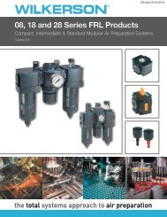
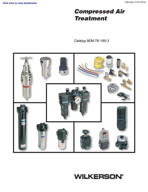
<strong>Compressed</strong> <strong>Air</strong><br />
<strong>Treatment</strong><br />
Catalog 9EM-TK-190-3
First incorporated in August of<br />
1948, <strong>Wilkerson</strong> manufactures a<br />
complete line of compressed air<br />
treatment and control products to<br />
meet a wide variety of industrial,<br />
process, consumer and health<br />
care applications. Today, <strong>Wilkerson</strong><br />
serves over 500 different industries<br />
throughout the world.<br />
Over the years, <strong>Wilkerson</strong> facilities,<br />
manufacturing and engineering<br />
technology have kept pace with<br />
increased sales volume, the growing<br />
need to satisfy customers’ specific<br />
requirements and the demands<br />
placed on production.<br />
<strong>Wilkerson</strong>’s growing leadership in<br />
the industry is due to our determined<br />
commitment to quality; quality of<br />
products, services and people.<br />
Our dedication to the total quality<br />
management process assures our<br />
customers that we can consistently<br />
provide the highest levels of product<br />
quality and customer service<br />
required to meet their needs.<br />
From the very beginning, <strong>Wilkerson</strong><br />
has sold its products through a<br />
world-wide, independent distributor<br />
network. We currently have 200<br />
distributors throughout North<br />
America, plus an expanding network<br />
of international distributors in over<br />
40 countries. Our distributors, who<br />
have many years of experience<br />
in compressed air treatment and<br />
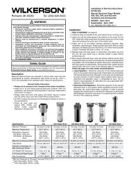
WARNING<br />
control, offer excellent product<br />
knowledge, technical assistance<br />
and local inventory. As a result of<br />
representing other complimentary<br />
products, they are able to satisfy<br />
their customers’ total requirements.<br />
Today’s broad line of <strong>Wilkerson</strong><br />
products is the result of<br />
continuing product innovations<br />
and technology advancements<br />
which frequently become industry<br />
standards. <strong>Wilkerson</strong> is dedicated<br />
to designing and manufacturing<br />
innovative products with features<br />
and operating characteristics that<br />
meet customer requirements for<br />
quality, performance, reliability,<br />
serviceability, safety and value.<br />
FAILURE OR IMPROPER SELECTION OR IMPROPER USE OF THE PRODUCTS AND/OR SYSTEMS DESCRIBED HEREIN<br />
OR RELATED ITEMS CAN CAUSE DEATH, PERSONAL INJURY AND PROPERTY DAMAGE.<br />
This document and other information from The Company, its subsidiaries and authorized distributors provide product and/or<br />
system options for further investigation by users having technical expertise. It is important that you analyze all aspects of your<br />
application including consequences of any failure, and review the information concerning the product or system in the current<br />
product catalog. Due to the variety of operating conditions and applications for these products or systems, the user, through<br />
its own analysis and testing, is solely responsible for making the final selection of the products and systems and assuring that<br />
all performance, safety and warning requirements of the application are met.<br />
The products described herein, including without limitation, product features, specifications, designs, availability and pricing,<br />
are subject to change by The Company and its subsidiaries at any time without notice.<br />
Offer of Sale<br />
The items described in this document are hereby offered for sale by The Company, its subsidiaries or its<br />
authorized distributors. This offer and its acceptance are governed by the provisions stated on the separate page of this<br />
document “Offer of Sale”.<br />
© Copyright 2011, 2008, 2003 Parker Hannifin <strong>Corporation</strong>. All Rights Reserved.<br />
!
DISTRIBUTION NETWORK<br />
<strong>Wilkerson</strong> manufactures and markets a complete line<br />
of compressed air treatment components and control<br />
products. We have a distribution network of over 100<br />
distributors to serve you.<br />
To find the one nearest you, please<br />
visit our DISTRIBUTOR LOCATOR on<br />
www.wilkersoncorp.com
Catalog 9EM-TK-190-3<br />
Notes<br />
A2<br />
Pneumatic Division<br />
Richland, Michigan<br />
www.wilkersoncorp.com<br />
Notes
<strong>Compressed</strong> <strong>Air</strong> Systems<br />
Filters, Regulators, Lubricators<br />
Additional Modular Products<br />
Accessories & Repair Kits<br />
Stainless Steel <strong>Compressed</strong> <strong>Air</strong><br />
<strong>Treatment</strong> Products<br />
Dryers<br />
<strong>Air</strong>line Accessories<br />
Table of Contents<br />
A3<br />
Product Index, Product Selection,<br />
Introduction and Technical Information,<br />
ANSI Symbols, Selection Guide<br />
Particulate Filters, Coalescing Filters,<br />
Afterfilters, Exhaust Mufflers, Exhaust Silencers,<br />
Liquid Separators, External Drains, Regulators,Precision<br />
Regulators, Lubricators, Filter / Regulators,<br />
2 & 3-Unit Combinations<br />
Slow Start, Dump Valves,<br />
Electronic Proportional Regulator,<br />
Electronic Proportional Valve,<br />
Safety Lockout Valves,<br />
Diverter Blocks<br />
08, 12, 18 / 28, 16 / 26, 39 Series,<br />
0X, 1X, 2X, 3X, 4X, 5X Series<br />
Filters, Coalescers, Regulators,<br />
Filter / Regulators, Lubricators<br />
Refrigeration <strong>Air</strong> Dryers, Manual Desiccant Dryers,<br />
Regenerative Desiccant Dryers,<br />
Heatless Desiccant <strong>Air</strong> Dryers,<br />
Modular Membrane Dryers, Automatic Electrical Drain<br />
Valve, Zero <strong>Air</strong> Loss Condensate Drain<br />
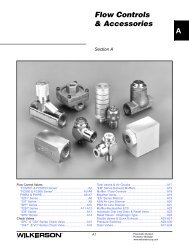
Flow Controls & Accessories, Control Panel Products,<br />
Sensing, LV / EZ, Integrated Fittings, Ball Valves / Plug<br />
Valves / Drain Cocks, Safety Blow Guns, Quick Couplings,<br />
Fittings & Hose, Tubing & Fittings<br />
Safety Guidelines H<br />
Offer of Sale J<br />
Pneumatic Division<br />
Richland, Michigan<br />
www.wilkersoncorp.com<br />
FRL’s <strong>Compressed</strong><br />
<strong>Air</strong> Systems<br />
Additional<br />
Modular Products<br />
Accessories<br />
& Repair Kits<br />
Stainless Steel<br />
Products<br />
Dryers<br />
Offer of Sale Safety Guidelines <strong>Air</strong>line<br />
Accessories<br />
A<br />
B<br />
C<br />
D<br />
E<br />
F<br />
G
A<br />
<strong>Compressed</strong> <strong>Air</strong> Systems<br />
Catalog 9EM-TK-190-3<br />
Product Index<br />
Filters, Regulators, Lubricators .......... B1<br />
Particulate Filters ...........................B3-B5<br />
F01 ........................................................B6<br />
F03 ........................................................B8<br />
F08 ......................................................B10<br />
F12 ......................................................B12<br />
F18 ......................................................B14<br />
F16 ......................................................B16<br />
F28 ......................................................B18<br />
F26 ......................................................B20<br />
F39 ......................................................B22<br />
F30 ......................................................B24<br />
F34 ......................................................B26<br />
F35 ......................................................B28<br />
F43 ......................................................B30<br />
Coalescing Filters........................B33-B35<br />
M03 .....................................................B36<br />
M08 .....................................................B38<br />
M12 .....................................................B40<br />
M18 .....................................................B42<br />
M16 .....................................................B44<br />
M28 .....................................................B46<br />
M26 .....................................................B48<br />
M21 .....................................................B50<br />
M39 .....................................................B52<br />
M30 .....................................................B54<br />
M31 .....................................................B56<br />
M32 .....................................................B58<br />
M35 .....................................................B60<br />
M43 .....................................................B62<br />
M45 .....................................................B64<br />
M55 .....................................................B66<br />
After Filters ......................................... B67<br />
A18 ......................................................B68<br />
A28 ......................................................B70<br />
AF1 ......................................................B72<br />
AF2 ......................................................B74<br />
Exhaust Mufflers<br />
F23 ......................................................B76<br />
F33 ......................................................B77<br />
Exhaust Silencer<br />
XMC ....................................................B78<br />
Liquid Separators<br />
WSA / WSO .........................................B80<br />
WWSA .....................................................B82<br />
External Drains<br />
X01 ......................................................B83<br />
X02 / XB3 ............................................B84<br />
X51 ......................................................B86<br />
Regulators ....................................B88-B91<br />
R03 ......................................................B92<br />
RB3 / RA3 ...........................................B94<br />
RA4 .....................................................B96<br />
R24, R25 .............................................B98<br />
R45, R46 ...........................................B100<br />
R08 ....................................................B102<br />
R12 ....................................................B104<br />
H12 ....................................................B106<br />
(Revised 9-12-11)<br />
R18 ....................................................B108<br />
R16 ....................................................B110<br />
R28 ....................................................B112<br />
R26 ....................................................B114<br />
R39 ....................................................B116<br />
R30 ....................................................B118<br />
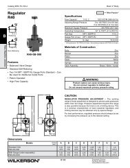
R40 ....................................................B120<br />
Common P1 Regulators ................... B123<br />
R09 ....................................................B124<br />
R19 ....................................................B126<br />
Dial-<strong>Air</strong> Regulators ..............B128-B129<br />
R11 ....................................................B130<br />
R21 ....................................................B132<br />
R31 ....................................................B134<br />
R41 ....................................................B136<br />
Precision Regulators........................ B139<br />
P12 ....................................................B140<br />
P15 / P16 ..........................................B142<br />
P17 ....................................................B144<br />
WRA302 ............................................B146<br />
WRA102 ............................................B148<br />
WRA102BP .......................................B150<br />
WRA171 ............................................B152<br />
WEA632 ............................................B154<br />
WBA208 ............................................B156<br />
WBA45 ..............................................B158<br />
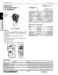
Lubricators ...............................B161-B163<br />
L01 ....................................................B164<br />
L03 ....................................................B166<br />
L08 ....................................................B168<br />
L12 ....................................................B170<br />
L18 ....................................................B172<br />
L16 / L17 ...........................................B174<br />
L28 ....................................................B176<br />
L26 / L27 ...........................................B178<br />
L39 ....................................................B180<br />
L30 ....................................................B182<br />
L31 ....................................................B184<br />
L32 ....................................................B186<br />
L34 ....................................................B188<br />
L40 ....................................................B190<br />
L41 ....................................................B192<br />
L42 ....................................................B194<br />
L50 ....................................................B196<br />
Filter / Regulators ....................B198-B201<br />
B03 ....................................................B202<br />
BB3 / BA3 ..........................................B204<br />
B08 ....................................................B206<br />
B12 ....................................................B208<br />
T12 ....................................................B210<br />
B18 ....................................................B212<br />
CB6 ...................................................B214<br />
PC5 / PC6 .........................................B215<br />
B28 ....................................................B218<br />
B39 ....................................................B220<br />
Combinations – 2-Unit ............B223-B225<br />
D03 ....................................................B226<br />
D08 ....................................................B228<br />
D12 ....................................................B230<br />
A4<br />
CB7 ...................................................B232<br />
D18 ....................................................B234<br />
D28 ....................................................B236<br />
D39 ....................................................B238<br />
Combinations – 3-Unit ............B241-B243<br />
C03 ....................................................B244<br />
C08 ...................................................B246<br />
C12 ...................................................B248<br />
C18 ...................................................B250<br />
C16 / C17 .........................................B252<br />
C28 ...................................................B254<br />
C26 / C27 .........................................B256<br />
C31 ...................................................B258<br />
C39 ...................................................B260<br />
Additional Modular Products ..............C1<br />
Slow-Start / Quick Dump Valves C2-C3<br />
E09 ....................................................C4<br />
E12 ....................................................C6<br />
E18 / E28 ...........................................C8<br />
S18 / S28 .........................................C10<br />
Q09 / Q19 ........................................C12<br />
Electronic<br />
Proportional Regulator ........... C12-C15<br />
ER09, ER19 ....................................C16<br />
ER1 / ER2 .......................................C32<br />
Electronic Proportional Valve .........C35<br />
EPV ................................................C36<br />
Safety Lockout Valves .....................C39<br />
V08 ..................................................C40<br />
V12 ..................................................C41<br />
V18 / V28 .........................................C42<br />
V19 / V29 .........................................C44<br />
V40 / V60 / V73 ...............................C46<br />
Diverter Blocks ........................ C47-C48<br />
N08 ..................................................C49<br />
N12 ..................................................C50<br />
N18 / N28 ........................................C51<br />
NJ8 ..................................................C52<br />
Modular Accessories and<br />
Repair Kits ...................................... D1<br />
Filter Replacement Element Kits .....D2<br />
Filter Replacement Bowl Kits ...........D3<br />
Accessories – Filters .................. D4-D5<br />
Accessories – Regulators .......... D6-D7<br />
Regulator Replacement Kits ............D8<br />
Lubricator Replacement Kits ...........D9<br />
Accessories – Lubricators ..... D10-D11<br />
Filter / Regulator<br />
Replacement Repair Kits ..............D12<br />
Accessories –<br />
Filter / Regulators .................. D13-D15<br />
Accessories – 08 Series .................D16<br />
Accessories – 12 Series .................D17<br />
Accessories – 18 / 28 Series ..........D18<br />
Accessories – 16 / 26 Series ..........D19<br />
Accessories – 39 Series .................D20<br />
Stainless Steel Products .................. E1<br />
Pneumatic Division<br />
Richland, Michigan<br />
www.wilkersoncorp.com<br />
Product Index
Catalog 9EM-TK-190-3<br />
Stainless Steel Particulate Filters ........E3<br />
SF1 ........................................................E4<br />
SF2 ........................................................E6<br />
Stainless Steel Coalescing Filters .......E9<br />
SM1 .....................................................E10<br />
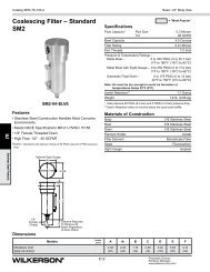
SM2 .....................................................E12<br />
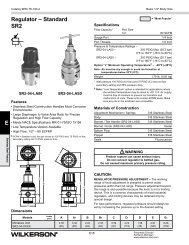
Stainless Steel Regulators .................E15<br />
SR1 .....................................................E16<br />
SR2 .....................................................E18<br />
Stainless Steel Filter / Regulators .....E21<br />
SB1 ......................................................E22<br />
SB2 ......................................................E24<br />
Stainless Steel Lubricator ..................E27<br />
SL2 ......................................................E28<br />
Dryers .....................................................F1<br />
Sources of Contamination ............F2-F4<br />
Purification Technologies ................... F5<br />
Quality Standards .............................. F6<br />
Purity Levels ...................................... F7<br />
Refrigeration <strong>Air</strong> Dryers –<br />
WDRD ......................................F8-F12<br />
Mini Disposable<br />
Inline Desiccant Dryer ................... F13<br />
Manual Disiccant Dryers ................. F15<br />
X06 .........................................F16-F17<br />
X03 / X04 ................................F18-F19<br />
X25 ................................................ F18<br />
X08 ................................................ F21<br />
Regenerative<br />
Desiccant Dryers – WDAS .....F22-F26<br />
Heatless Desiccant <strong>Air</strong> Dryers –<br />
WTW .......................................F27-F30<br />
Modular Membrane Dryer –<br />
MSD ........................................F31-F33<br />
Automatic Electrical Drain Valve –<br />
WDV3-G ........................................ F34<br />
Zero <strong>Air</strong> Loss Condensate Drain –<br />
ED .................................................. F35<br />
<strong>Air</strong>line Accessories .............................. G1<br />
Control Panel Products ........................ G3<br />
Basic Features ............................G4-G5<br />
Push Button,<br />
Selector Switches with Bodies ........G6<br />
Push Buttons .....................................G7<br />
Selector Switches ..............................G8<br />
Valve Bodies & Accessories ..............G9<br />
Dimensions & Assembly ..................G10<br />
Legend Plates, Specifications .........G11<br />
Mounting ..........................................G12<br />
Visual Indicators 22mm (7/8") ........G13<br />
Rotary Selector Switches,<br />
22mm (7/8") ...................................G14<br />
Joystick Operators ...........................G15<br />
Foot Pedal Operated Switches ........G16<br />
Two-Hand Controls ..................G17-G18<br />
Sensing<br />
(Pneumatic Control Components) .... G19<br />
Basic Features –<br />
(Revised 9-12-11)<br />
Pneumatic Sensors .......................... G20<br />
Limit Switches –<br />
3/2 Miniature ............................ G21-G22<br />
3/2 Compact ............................. G23-G24<br />
K Series – Standard Duty ........ G25-G28<br />
J Series – Heavy Duty ............. G29-G31<br />
PWBA Blocking Valves ............... G32-G33<br />
Threshold Sensors ..................... G34-G36<br />
LV / EZ (Lockout Valves) ..................... G37<br />
LV Series ............................................ G38<br />
LV Series Technical Information ......... G39<br />
EZ Series ............................................ G40<br />
EZ” Series Technical Information ........ G41<br />
Flow & Safety Standards .................... G42<br />
Integrated Fittings .............................. G43<br />
Product Index ..................................G44<br />
Compact Flow Control Valves ..........G45<br />
Miniature<br />
Flow Control Valves .......................G46<br />
In-Line<br />
Flow Control Valves ...............G47-G48<br />
Compact Metal<br />
Flow Control Valves .......................G49<br />
Check Valves ...................................G50<br />
Accessories .....................................G51<br />
Tank Valves & <strong>Air</strong> Chucks ................G52<br />
EM Series Exhaust Mufflers ............G53<br />
Muffler / Flow Controls .....................G53<br />
Breather Vents .................................G54<br />
ES Series Silencer...........................G54<br />
ASN <strong>Air</strong> Line Silencer ......................G55<br />
P6M <strong>Air</strong> Line Silencer .....................G56<br />
Muffler-Reclassifier ECS .................G57<br />
Automatic Drip Leg Drain &<br />
Relief Valve ....................................G58<br />
Relief Valves - Diaphragm Type .......G59<br />
Shuttle Valves &<br />
Quick Exhaust .......................G60-G62<br />
<strong>Air</strong>Guard Protection System ....G63-G64<br />
Drain Valves .............................G65-G66<br />
Safety Blow Guns ....................G67-G69<br />
Ball Valves ........................................G71<br />
Product Index ..................................G72<br />
Ball Valves –<br />
Basic Features ...............................G73<br />
Part Numbers & Dimensions .........G74<br />
Stainless Steel Ball Valves ..............G75<br />
Plug Valves –<br />
Basic Features ...............................G76<br />
Part Numbers & Dimensions .........G77<br />
Drain Cocks –<br />
Basic Features ...............................G78<br />
Part Numbers ................................G78<br />
Quick Couplings ..............................G79<br />
Industrial Interchange<br />
Nipples ...................................G80-G81<br />
Sleevmatic Couplers ................G82-G84<br />
Saflomatic Couplers ................G85-G86<br />
A5<br />
Pneumatic Division<br />
Richland, Michigan<br />
www.wilkersoncorp.com<br />
Product Index<br />
Economatic Quick Connect<br />
Couplings ...............................G87-G88<br />
Hose & Fittings ................................G89<br />
General Purpose Hose ....................G90<br />
Push-on Hose Fittings –<br />
Basic Features ...............................G91<br />
Part Numbers &<br />
Dimensions ............................G92-G94<br />
Tubing & Fittings .............................G95<br />
Polyethylene Tubing .................G96-G97<br />
Nylon Tubing ............................G98-G99<br />
Polyurethane Tubing ......................G100<br />
Push-to-Connect, Prestolok<br />
Metal Fittings .....................G102-G113<br />
Pipe Fittings .........................G114-G119<br />
Metric Adapters ...................G120-G121<br />
Safety Guidelines ............................H1-H4<br />
Offer of Sale ...........................................J1<br />
A<br />
<strong>Compressed</strong> <strong>Air</strong> Systems
A<br />
<strong>Compressed</strong> <strong>Air</strong> Systems<br />
Catalog 9EM-TK-190-3<br />
Product Selection Chart<br />
Basic<br />
Unit<br />
F<br />
I<br />
L<br />
T<br />
E<br />
R<br />
S<br />
C<br />
O<br />
A<br />
L<br />
E<br />
S<br />
C<br />
I<br />
N<br />
G<br />
F<br />
I<br />
L<br />
T<br />
E<br />
R<br />
S<br />
Series<br />
(Revised 9-12-11)<br />
Port Size Flange Size Bowls Elements (Micron)<br />
1/8 1/4 3/8 1/2 3/4 1 1-1/4 1-1/2 2 3 4 6 Poly Metal Metal<br />
SG<br />
5 20 40 Adsorber<br />
F01 X Aluminum Body Std. — — — B6<br />
F03 X X X X — Std. — — — B8<br />
F08 X X X X — Std. — — — B10<br />
SF1 X 316 Stainless Steel Opt. Std. — — E4<br />
F12 X X X X X Std. — Opt. Opt. B12<br />
F18 X X X X X — Opt. — Std. — B14<br />
F16 X X X X X — Std. — —. — B16<br />
SF2 X 316 Stainless Steel Opt. — Std. — E6<br />
F28 X X X X X — Std. — — — B18<br />
F26 X X X X X — Std. — — — B20<br />
F39 X X — — X Opt. — Std. — B22<br />
F30 X X X X — Std. — — — B24<br />
F34 X X X X X — Std. — — — B26<br />
F35 X X X — Metal w/ DPI Std. — — — B28<br />
F43 X X — Metal w/ DPI Std. — — — B30<br />
M03 X X X X —<br />
M08 X X X X —<br />
SM1 X 316 Stainless Steel<br />
M12 X X X X X<br />
M18 X X X X X X<br />
M16 X X X X X —<br />
SM2 X 316 Stainless Steel<br />
M28 X X X X X X<br />
M26 X X X X X X<br />
M21 X X — —<br />
M39 X X — — X<br />
M30 X X X X X —<br />
M31 X X X X —<br />
M32 X X — — X<br />
M35 X X X X —<br />
M43 X — X —<br />
M45 X — X —<br />
A6<br />
Type “B”<br />
1.0<br />
Type “B”<br />
1.0<br />
Type “B”<br />
1.0<br />
Type “B”<br />
1.0<br />
Type “B”<br />
1.0<br />
Type “B”<br />
1.0<br />
Type “B”<br />
1.0<br />
Type “B”<br />
1.0<br />
Type “B”<br />
1.0<br />
Type “B”<br />
1.0<br />
Type “B”<br />
1.0<br />
Type “B”<br />
1.0<br />
Type “B”<br />
1.0<br />
Type “B”<br />
1.0<br />
Type “B”<br />
1.0<br />
Type “B”<br />
1.0<br />
Type “B”<br />
1.0<br />
Product Selection Chart<br />
Type “C”<br />
0.01<br />
Type “C”<br />
0.01<br />
Type “C”<br />
0.01<br />
Type “C”<br />
0.01<br />
Type “C”<br />
0.01<br />
Type “C”<br />
0.01<br />
Type “C”<br />
0.01<br />
Type “C”<br />
0.01<br />
Type “C”<br />
0.01<br />
Type “C”<br />
0.01<br />
Type “C”<br />
0.01<br />
Type “C”<br />
0.01<br />
Type “C”<br />
0.01<br />
Type “C”<br />
0.01<br />
Type “C”<br />
0.01<br />
Type “C”<br />
0.01<br />
Type “C”<br />
0.01<br />
Pneumatic Division<br />
Richland, Michigan<br />
www.wilkersoncorp.com<br />
Type “D”<br />
0.003<br />
Type “D”<br />
0.003<br />
Type “D”<br />
0.003<br />
Type “D”<br />
0.003<br />
Type “D”<br />
0.003<br />
Type “D”<br />
0.003<br />
Type “D”<br />
0.003<br />
Type “D”<br />
0.003<br />
Type “D”<br />
0.003<br />
Type “D”<br />
0.003<br />
Page<br />
B36<br />
B38<br />
E10<br />
B40<br />
B42<br />
B44<br />
E12<br />
B46<br />
B48<br />
B50<br />
— B52<br />
Type “D”<br />
0.003<br />
Type “D”<br />
0.003<br />
Type “D”<br />
0.003<br />
Type “D”<br />
0.003<br />
Type “D”<br />
0.003<br />
Type “D”<br />
0.003<br />
M55 X X — X — 1.0 Micron 0.01 Micron — B66<br />
B54<br />
B56<br />
B58<br />
B60<br />
B62<br />
B64
Catalog 9EM-TK-190-3<br />
Basic<br />
Unit<br />
A<br />
F<br />
T<br />
E<br />
R<br />
F<br />
I<br />
L<br />
T<br />
E<br />
R<br />
S<br />
Basic<br />
Unit<br />
S<br />
T<br />
A<br />
N<br />
D<br />
A<br />
R<br />
D<br />
R<br />
E<br />
G<br />
U<br />
L<br />
A<br />
T<br />
O<br />
R<br />
S<br />
D<br />
A<br />
I<br />
I<br />
A<br />
R<br />
L<br />
Basic<br />
Unit<br />
P<br />
R<br />
E<br />
C<br />
I<br />
S<br />
I<br />
O<br />
N<br />
R<br />
E<br />
G<br />
U<br />
L<br />
A<br />
T<br />
O<br />
R<br />
S<br />
Series<br />
Port Size Bowls<br />
1/4 3/8 1/2 3/4 Poly Metal Metal SG<br />
A7<br />
Desiccant Page<br />
A18 X X X X X X Type “B” 5 Micron Element B68<br />
A28 X X X X X X Type “B” 5 Micron Element B70<br />
AF1 X X X X X X Type “B” 5 Micron Element B72<br />
AF2 X X X X X X Type “B” 5 Micron Element B74<br />
Series<br />
Port Size Spring Range<br />
1/8 1/4 3/8 1/2 3/4 1 1-1/4 1-1/2 2 15 25 30 40 60 125 160 180 200 250<br />
R03 X X Opt. — Opt. — Std. Std. — — — — B92<br />
RB3 X — Std. — — Std. Std. — — — — B94<br />
RA3 X — Std. — — Std. Std. — — — — B94<br />
RA4 X X — — Std. — Std. Std. — — — — B96<br />
R24, R25 X X — Std. — — Std. Std. — — — — B98<br />
R45, R46 X X — Std. — — Std. Std. — — — — B100<br />
R08 X X — — Opt. — Opt. Std. — — — — B102<br />
SR1 X — Opt. — — Opt. Std. — — Opt. — E16<br />
R12 X X — — Opt. — Opt. Std. — — Opt. — B104<br />
H12 X X — — — — — — — — — Std. B106<br />
R18 X X X — — Opt. — Opt. Std. — — — Opt. B108<br />
R16 X X X — — — — Opt. Std. — — — Opt. B110<br />
SR2 X — — — — Opt. Std. — — — Opt. E18<br />
R28 X X X — — — — Opt. Std. — — — Opt. B112<br />
R26 X X X — — — — Opt. Std. — — — Opt. B114<br />
R39 X X — — — — Opt. Std. — — — Opt. B116<br />
R30 X X X — — — — — Std. — Opt. — — B118<br />
R40 X X — — — — — Std. — Opt. — — B120<br />
R09 X X — — Opt. — Opt. Std. — — — — B124<br />
R19 X — — Opt. — Opt. Std. — — — Opt. B126<br />
R11 X — — — — Opt. — Std. — — — B130<br />
R21 X X X X — — — Opt. — — Std. — — — B132<br />
R31 X X X — — — — — — Std. — — — B134<br />
R41 X X — — — Opt. — — Std. — — — B136<br />
Series<br />
Port Size Spring Range<br />
Product Selection Chart<br />
1/4 3/8 1/2 2 15 25 30 40 50 60 100 120 125 150<br />
P12 X X — Opt. — Opt. — — Opt. — — Std. — B140<br />
P15 X X X — Opt. — Opt. — Opt. — — — Std. — B142<br />
P16 X X X — Opt. — Opt. — Opt. — — — Std. — B142<br />
P17 X — — — — Opt. — — — Opt. — — B144<br />
WRA302 X — — — X — — X X — — — B146<br />
WRA102 X — — — X — — X — — — X B148<br />
WRA102BP X — — — X — — X — — — X B150<br />
WRA171 X — — — X — — — — — — — B152<br />
WEA632 X — — — — — — X — X — — B154<br />
WBA208 X — — — — — — — — — — — B155<br />
WBA45 X — — — — — — — — — — — B158<br />
Pneumatic Division<br />
Richland, Michigan<br />
www.wilkersoncorp.com<br />
Page<br />
Page<br />
A<br />
<strong>Compressed</strong> <strong>Air</strong> Systems
A<br />
<strong>Compressed</strong> <strong>Air</strong> Systems<br />
Catalog 9EM-TK-190-3<br />
Product Selection Chart<br />
Basic<br />
Unit<br />
L<br />
U<br />
B<br />
R<br />
I<br />
C<br />
A<br />
T<br />
O<br />
R<br />
S<br />
Basic<br />
Unit Series<br />
F<br />
I<br />
L<br />
T<br />
E<br />
R<br />
/<br />
R<br />
E<br />
G<br />
U<br />
L<br />
A<br />
T<br />
O<br />
R<br />
S<br />
Series Type<br />
Port Size Bowls<br />
1/8 1/4 3/8 1/2 3/4 1 Poly Metal Metal<br />
SG<br />
Port Size Bowls<br />
1/8 1/4 3/8 1/2 3/4 1 1-1/4 1-1/2 2 Poly Metal Metal<br />
SG<br />
A8<br />
Elements<br />
(Micron)<br />
Spring Range<br />
Product Selection Chart<br />
Filling Page<br />
L01 Miniature Standard X X Aluminum Body Cannot be filled under pressure B164<br />
L03 Miniature EconOmist X X X X — Cannot be filled under pressure B166<br />
L08 Miniature EconOmist X X X X — Can be filled under pressure B168<br />
L12 Sub-compact AtoMist X X X X X Cannot be filled under pressure B170<br />
L18 Compact EconOmist X X X X X X Can be filled under pressure B172<br />
L16 Compact EconOmist X X X X X X Can be filled under pressure B174<br />
L17 Compact AtoMist X X X X X X Cannot be filled under pressure B174<br />
L28 Standard EconOmist X X X X X X Can be filled under pressure B176<br />
L26 Standard EconOmist X X X X X X Can be filled under pressure B178<br />
L27 Standard AtoMist X X X X X X Cannot be filled under pressure B178<br />
SL2 Standard AtoMist X 316 Stainless Steel Can be filled under pressure E28<br />
L39 Jumbo EconOmist X X — — X Can be filled under pressure B180<br />
L30 Large EconOmist X X X X X Can be filled under pressure B182<br />
L31 Large EconOmist X X X X Can be filled under pressure B184<br />
L32 Large EconOmist X X X X Can be filled under pressure B186<br />
L34 Large EconOmist X X X X X Cannot be filled under pressure B188<br />
L40 Extra Large EconOmist X X X X X Can be filled under pressure B190<br />
L41 Extra Large EconOmist X X X X X Can be filled under pressure B192<br />
L42 Extra Large EconOmist X X X X X Can be filled under pressure B194<br />
L50 Jumbo EconOmist X X X X Can be filled under pressure B196<br />
5 20 40 15 25 30 50 60 125 200 250<br />
B03 X X X X — Std. — — Opt. — Opt. — Opt. Std. — — B202<br />
BB3 X X — — Std. — — — Opt. — — Opt. Std. — — B204<br />
BA3 X X — — Std. — — — Opt. — — Opt. Std. — — B204<br />
B08 X X X X — Std. — — — — Opt. — Opt. Std. — — B206<br />
SB1 X 316 Stainless Steel Std. — — — Opt. — — Opt. Std. — — E22<br />
B12 X X X X X Std. — Opt. — — Opt. — Opt. Std. Opt. — B208<br />
T12 X X X X X Std. — Opt. Opt. — Opt. — Opt. Std. Opt. — B210<br />
B18 X X X X X X Std. — — — — Opt. — Opt. Std. — Opt. B212<br />
SB2 X 316 Stainless Steel Std. — Opt. — — — — Opt. Std. — Opt. E24<br />
CB6 X X X X X X Std. — — — — —. Opt. — Std. — — B214<br />
PC5 X X X X X X Opt. — Std. Opt. — Opt. Opt. — Std. — — B216<br />
PC6 X X X X X X Opt. — Std. Opt. — Opt. Opt. — Std. Opt. — B216<br />
B28 X X X X X X Std. — — — — Opt. — Opt. Std. — Opt. B218<br />
B39 X X — X X Std. — Opt. — — — — Opt. Std. — Opt. B220<br />
Pneumatic Division<br />
Richland, Michigan<br />
www.wilkersoncorp.com<br />
Page
Catalog 9EM-TK-190-3<br />
Basic<br />
Unit Series<br />
C<br />
O<br />
M<br />
B<br />
I<br />
N<br />
A<br />
T<br />
I<br />
O<br />
N<br />
S<br />
T<br />
W<br />
O<br />
U<br />
N<br />
I<br />
T<br />
T<br />
H<br />
R<br />
E<br />
E<br />
U<br />
N<br />
I<br />
T<br />
Basic<br />
Unit<br />
D<br />
E<br />
D<br />
S<br />
R<br />
I<br />
Y<br />
C<br />
E<br />
C<br />
R<br />
A<br />
S<br />
N<br />
T<br />
M<br />
E D<br />
M R<br />
B Y<br />
R E<br />
A R<br />
N S<br />
E<br />
Port Size Bowls<br />
1/8 1/4 3/8 1/2 3/4 1 Poly Metal Metal<br />
SG<br />
A9<br />
Elements<br />
(Micron)<br />
Spring Range<br />
Product Selection Chart<br />
5 20 40 15 25 30 50 60 125 200 250<br />
D03 X X X X — Std. — — Opt. — Opt. — Opt. Std. — — B226<br />
D08 X X X X — Std. — — — — Opt. — Opt. Std. — — B228<br />
D12 X X X X X Std. — Opt. — — Opt. — Opt. Std. Opt. — B230<br />
CB7 X X X X X X Std. — — — — —. Opt. — Std. — — B232<br />
D18 X X X X X X Std. — — — — Opt. — Opt. Std. — Opt. B234<br />
D28 X X X X X X Std. — — — — Opt. — Opt. Std. — Opt. B236<br />
D39 X — — X Std. — Opt. — — — — Opt. Std. — Opt. B238<br />
C03 X X X — — Std. — — Opt. — Opt. — Opt. Std. — — B244<br />
C08 X X X X X Std. — — — — Opt. — Opt. Std. — — B246<br />
C12 X X X X X Std. — Opt. — — Opt. — Opt. Std. Opt. — B248<br />
C18 X X X X X X Std. — — — — Opt. — Opt. Std. — Opt. B250<br />
C16 X X X X X X Std. — — — — —. Opt. — Std. — — B252<br />
C17 X X X X X X Std. — — — — —. Opt. — Std. — — B252<br />
C28 X X X X X X Std. — — — — Opt. — Opt. Std. — Opt. B254<br />
C26 X X X X X — Std. — — — — — — Opt. Std. — Opt. B256<br />
C27 X X X X X — Std. — — — — — — Opt. Std. — Opt. B256<br />
C31 X X X X — Std. — — — — — — Opt. Std. — — B258<br />
C39 X — — X Std. — Opt. — — — — Opt. Std. — Opt. B260<br />
Series<br />
Port Size Bowls<br />
1/4 3/8 1/2 3/4 Poly Metal Metal SG<br />
Pneumatic Division<br />
Richland, Michigan<br />
www.wilkersoncorp.com<br />
Page<br />
Desiccant Page<br />
DD10 X Disposable Polycarbonate — — Non-Toxic F13<br />
X06 X X — — Silica Gel 4A Molecular Sieve Non-Toxic F16<br />
X03 X X X — Silica Gel 4A Molecular Sieve Non-Toxic F18<br />
X04 X X X X — Silica Gel 4A Molecular Sieve Non-Toxic F18<br />
X25 X — X — Silica Gel 4A Molecular Sieve Non-Toxic F20<br />
X08 X X — — Silica Gel — — F21<br />
WDAS — — — DRYFIL ® MS desiccant and a 1µm particulate filter F22<br />
WTW — — — F27<br />
MSD X X — X — Modular Membrane F31<br />
A<br />
<strong>Compressed</strong> <strong>Air</strong> Systems
A<br />
<strong>Compressed</strong> <strong>Air</strong> Systems<br />
Catalog 9EM-TK-190-3<br />
<strong>Compressed</strong> <strong>Air</strong> Systems<br />
<strong>Air</strong> <strong>Treatment</strong> and<br />
Control Components<br />
<strong>Compressed</strong> air is an essential<br />
power source for most industries<br />
today. It is a safe operation,<br />
relatively inexpensive to operate and<br />
very reliable. However, compressed<br />
air is susceptible to various types of<br />
contamination which not only<br />
reduces its value as a power<br />
source, but can seriously affect the<br />
performance of other pneumatic<br />
equipment and, therefore,<br />
productivity.<br />
<strong>Air</strong> valves, air cylinders, logic<br />
control systems and air tools can<br />
malfunction due to air-borne<br />
contamination. <strong>Air</strong> intended for<br />
air-gauging, air conveyors, spray<br />
painting, instrumentation,<br />
automation and food processing can<br />
be rendered unusable. Poor product<br />
quality and system shutdown due to<br />
compressed air contamination can<br />
occur frequently. There are many<br />
other problem areas associated with<br />
compressed air contamination, as<br />
numerous companies in differing<br />
industries can attest to.<br />
With today’s technology, an efficient,<br />
cost-effective compressed air<br />
system can be designed to provide<br />
years of reliable service if the proper<br />
air treatment and control equipment<br />
is installed. Operating and<br />
maintenance costs can be<br />
significantly lowered by removal of<br />
most contaminants (dirt, rust, pipe<br />
scale, oil aerosols, liquid water and<br />
water vapor, microscopic particles<br />
and oil vapor). With a well-designed<br />
air system and the use of quality air<br />
treatment and control products, you<br />
can realize extended service life of<br />
components, increased flow<br />
capacity with minimum pressure<br />
loss and improved production<br />
efficiencies in your manufacturing<br />
processes.<br />
<strong>Air</strong> <strong>Treatment</strong> and<br />
Control<br />
To take the fullest advantage of the<br />
benefits that can be derived from<br />
using compressed air, it must be<br />
correctly and adequately prepared.<br />
Clean, dry, regulated air is the<br />
corner-stone of an efficient air<br />
system. Where necessary,<br />
lubricated air may be required to<br />
provide dependable operation and<br />
satisfactory service life of certain air<br />
tools and components.<br />
Dryers<br />
All atmospheric air contains some<br />
water vapor. When the air is<br />
compressed, the water content for a<br />
given volume of air increases.<br />
Because of the effects of<br />
compression, most of this water<br />
A10<br />
vapor turns into damaging liquid<br />
water in your air system.<br />
Additionally, as air flows through the<br />
compressed air line system, the<br />
water vapor condenses in the<br />
pipeline. This moisture in the<br />
pipeline results in rust, scale,<br />
clogged orifices, malfunctioning of<br />
pneumatic controls, and increased<br />
wear of moving parts as it washes<br />
away the lubricant.<br />
<strong>Compressed</strong> air dryers reduce the<br />
water vapor concentration and can<br />
prevent further liquid water<br />
formation in air lines. Liquid water<br />
and water vapor removal increases<br />
the efficiency of air operated<br />
equipment, prevents corrosion and<br />
clogging, extends the service life of<br />
pneumatic components, prevents air<br />
line freeze-ups and reduces product<br />
rejects.<br />
For more detailed information on<br />
Dryers, refer to Section F.<br />
Filters<br />
<strong>Compressed</strong> <strong>Air</strong> Systems<br />
<strong>Air</strong>-borne contamination from the<br />
atmosphere, such as dust, water<br />
vapor and hydrocarbons enter the<br />
air system through the compressor<br />
intake. The contaminants, usually 4<br />
million particles per cubic foot, can<br />
easily pass through a typical<br />
compressor intake filter since over<br />
80% of these particles are less than<br />
2 microns in size. The compressor<br />
Pneumatic Division<br />
Richland, Michigan<br />
www.wilkersoncorp.com
Catalog 9EM-TK-190-3<br />
also contributes to the problem with<br />
wear particles, oil vapor and fine<br />
aerosols that leak past glands and<br />
seals from the oil sump into the<br />
compression chamber.<br />
Such contamination in the air<br />
system can effect the efficient<br />
operation of various pneumatic<br />
devices and, over time, damage<br />
them. <strong>Compressed</strong> air filters that are<br />
installed upstream of the air devices<br />
will remove most of these<br />
contaminants. In addition, by design<br />
these filters will also remove most<br />
liquid water from the air line.<br />
The need for higher quality air is<br />
more evident today than in the past.<br />
To gain improved production<br />
efficiencies through automation,<br />
more sophisticated, technically<br />
advanced pneumatic equipment and<br />
instrumentation is being used<br />
throughout industry. Due to the<br />
critical nature of these applications,<br />
the need for extremely clean,<br />
virtually oil free air is required.<br />
Coalescing (oil removal) and oil<br />
vapor removal filters should be used<br />
for applications requiring high<br />
quality air.<br />
Regulators<br />
All pneumatic devices are designed<br />
to provide optimum performance<br />
and service life at a specific air<br />
pressure. While it is feasible to<br />
operate these devices at pressures<br />
in excess of the manufacturer’s<br />
recommended operating conditions,<br />
it is not advisable to do so.<br />
Operating at higher pressures can<br />
cause excessive wear and damage<br />
to the device. Further, operating<br />
your compressed air system at a<br />
higher-than-required pressure<br />
wastes energy and is not costeffective.<br />
To obtain the best operation and<br />
service life of your pneumatic<br />
equipment use the proper pressure<br />
level recommended by the<br />
manufacturer. A regulator (pressure<br />
control valve) is normally used to<br />
reduce and maintain a downstream<br />
pressure while the amount of air<br />
required to the device may vary with<br />
the demand.<br />
Filter / Regulators<br />
The integral Filter / Regulator units<br />
combine all the functions and<br />
features of a filter and a regulator,<br />
as discussed above, into one<br />
compact, high performance, spacesaving<br />
unit.<br />
Lubricators<br />
Getting the proper lubrication to the<br />
proper device at the proper time is<br />
A11<br />
<strong>Compressed</strong> <strong>Air</strong> Systems<br />
fundamental to preventative<br />
maintenance, longer service life and<br />
increased productivity. The<br />
efficiency of air motors, control<br />
valves, cylinders and other air<br />
actuators can be greatly enhanced<br />
when the proper amount of<br />
lubrication is supplied.<br />
<strong>Air</strong> line lubricators are specifically<br />
designed to generate and introduce<br />
an oil aerosol (mist) into the<br />
compressed air flow. The air flow<br />
then carries the oil to the pneumatic<br />
devices where the lubricant mist<br />
coats the moving and sliding<br />
surfaces thus reducing friction and<br />
wear.<br />
To provide satisfactory lubrication to<br />
your air devices most lubricators<br />
have a proportional delivery system.<br />
This feature automatically provides<br />
a nearly constant oil-to-air ratio over<br />
a wide range of air flows.<br />
Pneumatic Division<br />
Richland, Michigan<br />
www.wilkersoncorp.com<br />
A<br />
<strong>Compressed</strong> <strong>Air</strong> Systems
A<br />
<strong>Compressed</strong> <strong>Air</strong> Systems<br />
Catalog 9EM-TK-190-3<br />
Filter Technology – Mechanisms of Filtration<br />
Coalescing Filters<br />
Essentially, coalescing filters (Type<br />
B, B1 and C) rely on what is known<br />
as mechanical filtration for their<br />
effectiveness. The main mechanisms<br />
of mechanical filtration are direct<br />
interception, inertial impaction and<br />
diffusion. Electrostatic attraction can<br />
have some bearing although the<br />
efficiency of <strong>Wilkerson</strong> coalescing filters<br />
is not dependent on this mechanism.<br />
Direct Interception occurs when a<br />
particle collides with and adheres to<br />
a fiber of the filter material without<br />
deviating out of the streamline flow. This<br />
mechanism tends to take place on the<br />
surface of the filter material and affects<br />
mainly larger particles over 1 micron in<br />
size.<br />
Inertial Impaction occurs when a particle<br />
is unable to follow the tortuous path<br />
around the filter fibers and eventually<br />
collides with and adheres to one of the<br />
fibers. Typically affecting particles in the<br />
0.3 micron -1 micron size range.<br />
Diffusion or Brownian Movement, as it is<br />
sometimes called, occurs with extremely<br />
small particles which tend to wander<br />
within the gas stream, increasing<br />
their chances of colliding with and<br />
adhering to a fiber. This usually affects<br />
particles below 0.3 micron in size. A<br />
degree of overlap takes place with the<br />
mechanisms, the extent varying on the<br />
conditions.<br />
Above: Clean borosilicate microfiber<br />
seen at a magnification factor of 3900.<br />
Right: The same filter material in a<br />
contaminated state at the same degree<br />
of magnification.<br />
Pollution Size Chart<br />
Fume<br />
Ultraviolet<br />
Visble<br />
Solar Radiation<br />
Near infra red<br />
Mist<br />
To assist in understanding the<br />
parameters of filtration, refer to this<br />
pollution size comparison chart. Look<br />
at the size of a major contaminant,<br />
oil aerosol! It is in the region of 0.01<br />
- 0.8 micron. Tobacco smoke is also<br />
A12<br />
When all mechanisms are combined<br />
and utilized by a deep bed of the<br />
correct type of filter material, removal<br />
of virtually all particles whether liquid<br />
or solid, is achieved.<br />
Far infra red<br />
Dust<br />
0.01 0.1 1 10 100<br />
Silt<br />
<strong>Compressed</strong> <strong>Air</strong> Systems<br />
Spray<br />
Fine Sand<br />
Smog Cloud and Fog Mist Drizzle<br />
Rosin Smoke<br />
Oil Aerosol<br />
Fly Ash<br />
Fertilizer Ground Limestone<br />
Tobacco<br />
Smoke<br />
Metallurgical Dusts and Fumes<br />
Coat Dust<br />
Ammonium Chloride Cement Dust<br />
Fume Sulfuric<br />
Concentrator Mist<br />
Beach Sand<br />
Pulverized Coal<br />
Zinc Oxide Fume<br />
Insecticide Dusts<br />
Colloidal<br />
Silica<br />
Ground Talc<br />
Spray Dried Milk<br />
Alkali Fume<br />
Plant<br />
Spores<br />
Pollens<br />
a liquid aerosol in a similar size band<br />
0.01 -1.2 micron. Observe the smoke<br />
test yourself, appreciate the size of<br />
the problem! The smallest particle the<br />
human eye can see is in the order of<br />
40 microns.<br />
Pneumatic Division<br />
Richland, Michigan<br />
www.wilkersoncorp.com
Catalog 9EM-TK-190-3<br />
Particulate<br />
Filters<br />
For the removal of solid particle contaminants down to 5<br />
microns and the separation of bulk liquids.<br />
This type of filter is generally used in industrial applications<br />
where liquid water and oil, and harmful dirt particles must be<br />
removed from the compressed air system. This type of filter<br />
should also be used as a prefilter for the Coalescing (oil<br />
removal) filter.<br />
Operation<br />
Wet and dirty inlet air is directed downward and outward in a<br />
circular pattern by the turbine-shaped upper baffle. This action<br />
mechanically separates a large amount of the liquid and gross<br />
particles, which then flow down the inside of the bowl, past<br />
the lower baffle, into the quiet zone to be drained away. The<br />
quiet zone baffle prevents the contaminants from re-entering<br />
the air flow stream.<br />
The partially cleansed air then passes through the filter<br />
element. By utilizing depth filtration, the 5 micron filter media<br />
provides superior filtration, exceptional<br />
service life and minimum pressure drop.<br />
AIR IN<br />
Metal Bowl<br />
Guard<br />
Manual<br />
Flex-Drain<br />
Coalescing Filters<br />
(Oil Removal)<br />
AIR OUT<br />
Whirl-Flo<br />
Baffle<br />
5 Micron<br />
Type A<br />
Filter Element<br />
Transparent<br />
Plastic Bowl<br />
Contaminants<br />
Inlet <strong>Air</strong><br />
Outlet <strong>Air</strong><br />
Specifically designed for the removal of solid particles, water<br />
and oil aerosols down to 0.01 micron. Maximum remaining<br />
oil content of air leaving the filter down to 0.01ppm at 70°F<br />
(21°C) at a pressure of 100 PSIG (6,9 bar g) using a typical<br />
compressor lubricant. Two filter element grades are offered to<br />
better meet your air quality requirements.<br />
Grade B and B1 filter elements are used for most air<br />
coalescing applications where the removal of liquid aerosols<br />
and submicronic particles for general air quality is required.<br />
A13<br />
Operation<br />
The filter element design utilizes a borosilicate micro fiber<br />
that provides superior filtration efficiency, quick draining and<br />
minimum pressure drop. Unlike standard particle filters, air<br />
flow is inside to out. The compressed air / gas passes through<br />
the inner layer of the filter element which acts as an integral<br />
pre-filter to remove large contaminants. This gives protection<br />
to the layer of high efficiency filter material which substantially<br />
removes submicronic aerosols and solids from the air flow<br />
stream. Solid particles are permanently trapped within the<br />
filter media.<br />
The fine liquid particles, including aerosols, after initially being<br />
trapped by the fibers of the filter media, begin to collect or<br />
coalesce forming larger droplets. These droplets, along with<br />
other large droplets present, are pushed to the outer surface.<br />
Here, the anti-reentrainment barrier collects the droplets<br />
as they break free from the micro fiber and allow them to<br />
gravitate within its cellular structure forming a “wet band”<br />
around the bottom of the element.<br />
Clean filtered air / gas passes through the anti-reentrainment<br />
barrier above the “wet-band” where the resistance to flow<br />
is less, leaving a quiet zone of no air / gas movement in the<br />
bottom of the filter housing. The separated liquid drops from<br />
the bottom of the filter element and falls through the, without<br />
being re-entrained, to the bottom of the filter housing where it<br />
collects to be removed by a drain.<br />
Differential<br />
Pressure<br />
Indicator<br />
AIR IN<br />
Transparent<br />
Plastic Bowl<br />
Metal Bowl<br />
Guard<br />
<strong>Compressed</strong> <strong>Air</strong> Systems<br />
Protection of components such as air valves, cylinders, as<br />
well as air conveyors, air gaging, air bearings, air control<br />
circuits and paint spraying equipment are examples of specific<br />
end-use applications. This grade of filter element should be<br />
used as a prefilter for the Grade C coalescing filter.<br />
Grade C high-efficiency filter elements are used where the<br />
removal of extremely fine particulate and virtually “oil-free” or<br />
high quality air is necessary. Specific end-use applications<br />
are protection of critical air control circuits, air logic systems,<br />
flow and temperature controllers, food processing, electronics,<br />
health care and film processing. This grade of filter element<br />
should be used as a prefilter for the Grade D oil vapor removal<br />
filter.<br />
AIR OUT<br />
Type C<br />
Coalescing<br />
Element<br />
Automatic<br />
Mechanical<br />
Drain<br />
(Optional)<br />
Contaminants<br />
Inlet <strong>Air</strong><br />
Outlet <strong>Air</strong><br />
Pneumatic Division<br />
Richland, Michigan<br />
www.wilkersoncorp.com<br />
A<br />
<strong>Compressed</strong> <strong>Air</strong> Systems
A<br />
<strong>Compressed</strong> <strong>Air</strong> Systems<br />
Catalog 9EM-TK-190-3<br />
Oil Vapor<br />
Filters<br />
Activated carbon element for the removal of oil vapor and<br />
oil associated odors. Maximum remaining oil content of air<br />
leaving the filter is 0.003 ppm at 70°F (21°C) at a pressure<br />
of 100 PSIG (6,9 bar g). For the Grade D filter element, two<br />
types of designs are used depending on the size and flow<br />
capacity of the filter housing.<br />
An oil vapor filter is used, in conjunction with a Grade C filter<br />
element, where the application requires very high air quality.<br />
Typical applications are food processing and packaging,<br />
pharmaceutical, fermentation, electronics and semi-conductor,<br />
and critical air control.<br />
Operation<br />
While the Grade B, B1 and C filter elements can remove<br />
extremely fine liquid and solid particles, they cannot remove<br />
gaseous contaminants such as oil vapor or odors. To do this<br />
you must employ the physical phenomena of adsorption.<br />
Activated carbon, having an affinity for oil vapor molecules<br />
and with an extremely high surface area, created by its<br />
capillary structure, is used.<br />
Our activated carbon Grade D filter<br />
elements are designed to maximize the adsorption properties<br />
of the carbon. This is achieved by first passing the air through<br />
carbon granules located either in an annular space or tubular<br />
section. The granules provide a very high ratio of surface<br />
area to volume, and when arranged in a deep bed, increases<br />
the dwell time of the air flow. This type of design provides the<br />
benefit of both high efficiency and longer service life of the<br />
activated carbon.<br />
Differential<br />
Pressure<br />
Indicator<br />
Removal Cap<br />
Metal Bowl<br />
Guard<br />
AIR IN<br />
Contaminants<br />
Outlet <strong>Air</strong><br />
AIR OUT<br />
Type D<br />
Element<br />
Activated Carbon<br />
Granules<br />
Transparent<br />
Plastic Bowl<br />
Manual<br />
Flex Drain<br />
A14<br />
Differential Pressure Indicator<br />
(DP2, DP8)<br />
<strong>Compressed</strong> <strong>Air</strong> Systems<br />
The <strong>Wilkerson</strong> direct mounting Differential Pressure Indicator<br />
is equipped standard on most Coalescing Filter models. It<br />
provides a maintenance free means of determining the service<br />
life of the filter element. With a new filter the indicator shows<br />
all green, and progresses to a full red indication a<br />
7-8 PSID, indicating the element should be changed. The<br />
magnified indicator can be easily seen from the top or either<br />
side of the filter, and with only one moving part will provide<br />
reliability and long life.<br />
The Differential Pressure Indicator cannot be retrofitted<br />
to <strong>Wilkerson</strong> filters ordered without it. It is available as a<br />
replacement accessory kit.<br />
Note: The maximum operating pressure for metal or plastic bowls with<br />
this Indicator is 150 PSIG. The maximum operating temperature<br />
is 150°F for metal bowls and 125°F for plastic bowls.<br />
DP3 Differential Pressure Gauge<br />
The <strong>Wilkerson</strong> direct mounting Differential Pressure Gauge<br />
(non-pressurized face) is standard on all mainline filters<br />
and it is available as an accessory in kit form. With a scale<br />
reading to 20 PSID (1370 m bar dp) the gauge gives a quick<br />
indication of the status of the filter element in the filter. The<br />
gauge provides a reliable method to help ensure that the filter<br />
element is changed at the most economical and convenient<br />
time.<br />
Pneumatic Division<br />
Richland, Michigan<br />
www.wilkersoncorp.com
Catalog 9EM-TK-190-3<br />
Coalescing Elements Features and Benefits<br />
Type B, B1 & C<br />
Captive O-ring seal<br />
gives an easy-to-fit<br />
protective seal.<br />
End caps in tough<br />
corrosion resistant<br />
materials.<br />
Stainless steel support<br />
screens provide rigid<br />
fail safe protection<br />
against accidental<br />
shock loads and high<br />
pressure drops in<br />
either direction.<br />
Anti-reentrainment<br />
barrier for collected<br />
liquid drainage<br />
prevents carryover<br />
even in shock<br />
conditions and is<br />
compatible with mineral<br />
or synthetic lubricants.<br />
Pre-filter support fabric<br />
prevents filter<br />
media migration<br />
and increases<br />
element life.<br />
Stainless steel inner<br />
support screens provide<br />
rigid fail safe protection<br />
against accidental<br />
shock loads and high<br />
pressure drops.<br />
Anti re-entrainment<br />
barrier for collected<br />
liquid drainage<br />
prevents carryover<br />
even in shock<br />
conditions and is<br />
compatible with mineral<br />
or synthetic lubricants.<br />
B1 and C Element<br />
B Element<br />
High strength epoxy<br />
sealant provides an<br />
extremely strong<br />
construction and<br />
eliminates any possibility<br />
of filter media bypass.<br />
New 96% voids volume pure<br />
borosilicate glass microfiber<br />
filter media (Type B, B1 & C)<br />
gives high efficiency, high<br />
flow with quick drainage and<br />
low pressure drop.<br />
End caps in<br />
tough corrosion<br />
resistant<br />
materials.<br />
Pre-filter support<br />
fabric prevents<br />
filter media<br />
migration and<br />
increases<br />
element life.<br />
A15<br />
PRESSURE DIFFERENTIAL<br />
psi bar<br />
14 .95<br />
12<br />
10<br />
8<br />
6<br />
4<br />
2<br />
.85<br />
.70<br />
.55<br />
.4<br />
.3<br />
.14<br />
<strong>Compressed</strong> <strong>Air</strong> Systems<br />
How The Elements Work<br />
Using the principles of mechanical<br />
filtration, the filter media removes the<br />
solid particles first in the pre-filter<br />
support layers and then in the actual<br />
filter media. These particles remain<br />
permanently trapped and gradually<br />
cause an increase in pressure drop.<br />
The liquid particles similarly collected<br />
coalesce together forming larger<br />
droplets and as the flow is inside to out,<br />
are pushed to the outer surface. Here,<br />
the anti-reentrainment barrier prevents<br />
them from being introduced back into<br />
the airstream and instead drains them<br />
through its cellular structure to the<br />
bottom of the element. The resultant<br />
“wet-band” on the bottom of the<br />
element, in presenting a high pressure<br />
drop area, ensures that the filtered air<br />
passes through the upper portion of the<br />
element. This creates a “quiet zone” in<br />
the bottom of the filter through which<br />
the liquid falls to the bottom of the<br />
filter bowl and is drained away via the<br />
automatic drain.<br />
As mentioned earlier, solid particles<br />
cause the pressure drop to slowly<br />
increase throughout the working life.<br />
Initially, during the period to reach an<br />
equilibrium saturation, as determined<br />
by the upstream liquid contamination<br />
concentration, the pressure drop<br />
rises sharply as shown below. This is<br />
a typical pressure drop verses time<br />
characteristic for a coalescing filter. The<br />
end of useful and economic service life<br />
is indicated by an accelerating increase<br />
in pressure drop. The element should<br />
be replaced every 12 months or 6000<br />
working hours under normal working<br />
conditions.<br />
TYPICAL COALESCING ELEMENT LIFE CURVE<br />
Filter Element Saturation Point<br />
Time (approximately 6000 hrs.) assuming pre-filtration<br />
Pneumatic Division<br />
Richland, Michigan<br />
www.wilkersoncorp.com<br />
Filter<br />
Element<br />
Change<br />
A<br />
<strong>Compressed</strong> <strong>Air</strong> Systems
A<br />
<strong>Compressed</strong> <strong>Air</strong> Systems<br />
Catalog 9EM-TK-190-3<br />
Adsorption Elements Features and Benefits<br />
Type D<br />
How The Elements<br />
Work<br />
While mechanical filtration employing<br />
the Type C element is capable of<br />
removing extremely fine liquid or solid<br />
particles even as small as 0.01 micron<br />
it cannot remove gaseous contaminants<br />
such as oil vapor or odors. To do<br />
this we must employ the physical<br />
phenomena of adsorption. Activated<br />
carbon, having an affinity for oil vapor<br />
molecules and with an extremely high<br />
surface area, created by its capillary<br />
structure, is used for this.<br />
<strong>Wilkerson</strong> activated carbon elements<br />
are designed to maximize the<br />
adsorption properties of the carbon.<br />
This is achieved by first passing the air<br />
through carbon granules, snow storm<br />
filled* into either an annular space or<br />
tubular section. The granules provide<br />
an extremely high surface area to<br />
volume and when arranged in a deep<br />
bed that increases dwell time gives the<br />
benefit of both efficiency and service<br />
life. After being passed through the<br />
carbon, the air goes through a layer of<br />
microfiber to prevent migration of fine<br />
carbon particles downstream.<br />
Adsorption elements have a limited life<br />
and this is affected by many factors but<br />
principally temperature. Obviously, the<br />
higher the inlet temperature, the more<br />
oil vapor there is present, for example<br />
at 104°F (40°C) there is more than ten<br />
times the oil vapor than at 70°F (21°C).<br />
For this reason, activated carbon filters<br />
are best installed at the lowest possible<br />
system temperature. The type C filter<br />
should always precede a Type D filter.<br />
The typical life of an adsorption element<br />
is in the region of 1000-2000 hours<br />
at 70°F (21°C). Filtration temperature<br />
is based on tests carried out on a<br />
Chlorobenzene test rig, however, this is<br />
best determined in practice by a routine<br />
“odor” check.<br />
Oil vapor has a distinct odor. The least<br />
expensive and very effective way to<br />
check for oil vapor getting through the<br />
filter is to install a small bleed valve<br />
downstream. Periodically crack this<br />
valve and smell the air. The human<br />
nose is extremely sensitive to oil vapor<br />
and at the first hint of this odor, change<br />
the element.<br />
Annular fill of activated<br />
carbon granules gives a<br />
high surface area and<br />
long term dwell time<br />
for efficiency with<br />
low pressure drop.<br />
Snow storm filling* gives<br />
optimum packing<br />
density with no<br />
channeling of granules.<br />
Unique construction<br />
ensures no bypass so<br />
all the carbon is used.<br />
Clear plastic<br />
housing<br />
Oil soluble dye<br />
capsules will<br />
indicate blue<br />
if liquid oil<br />
is present.<br />
Porous plastic<br />
filter insert<br />
D Element (AC Pack)<br />
A16<br />
D Element (AC Element)<br />
Molded<br />
plastic<br />
end cap<br />
Pad<br />
of filter<br />
medium<br />
Activated<br />
carbon<br />
granules<br />
ADSORPTION LIFE - HOURS<br />
10 4<br />
10 3<br />
10 2<br />
10<br />
1<br />
CHARACTERISTICS DETERMINED<br />
AT MAXIMUM RECOMMENDED<br />
FLOW RATES<br />
20<br />
68<br />
<strong>Compressed</strong> <strong>Air</strong> Systems<br />
Pneumatic Division<br />
Richland, Michigan<br />
www.wilkersoncorp.com<br />
Downstream<br />
micron fiber layer<br />
prevents carryover of<br />
carbon particles.<br />
High carbon content<br />
promotes a long<br />
service life.<br />
Typical Adsorption<br />
Element Life Curve<br />
40<br />
104<br />
AC PACK<br />
AC ELEMENT<br />
60<br />
140<br />
TEMPERATURE AT ADSORPTION<br />
80 O C<br />
176 O<br />
F
Catalog 9EM-TK-190-3<br />
Type B Filter<br />
Element<br />
Specifications<br />
Efficiency<br />
99.97% when tested with 0.3 micron<br />
aerosol DOP test Federal Standard<br />
209B. Compatible with mineral and<br />
synthetic oils.<br />
Residual Oil<br />
0.5 ppm / wt (inlet temperature<br />
/ pressure 70°F / 100 PSIG)<br />
when analyzed using infra red<br />
spectrophotometry based on the<br />
Pneurop 6611 procedure.<br />
<strong>Air</strong> Quality Class *<br />
Conforms to ISO 8573 Class 3<br />
or better<br />
Flow<br />
Inside to outside<br />
Filter Media<br />
Resin impregnated borosilicate glass<br />
microfiber<br />
Support Structure<br />
Inner 304 Stainless Steel support<br />
cylinder with outer polymeric sleeve.<br />
End Caps<br />
Glass filled polyamide material<br />
Initial Differential<br />
Pressure Dry — 1.5 PSID<br />
Initial Differential<br />
Pressure Wet — 2.5 PSID<br />
Flow Range — 5 to 4800 SCFM<br />
@ 100 PSIG<br />
Application<br />
Installations as a coalescing prefilter<br />
for general purpose protection or<br />
as a prefilter to a high efficiency<br />
coalescer.<br />
Appearance<br />
White polymeric outer sleeve with<br />
black end caps.<br />
* “M” Series Coalescing Filters, with<br />
Type “B” 0.5 micron elements: All<br />
<strong>Wilkerson</strong> Type “M” Oil Removal (Coalescing)<br />
Filters with Type “B” 0.5 micron elements<br />
exceed ISO Class 2 for maximum particle<br />
size and concentration of solid contaminants,<br />
and exceed Class 3 on maximum oil content<br />
(ppm / wt). 5<br />
Type C Filter<br />
Element<br />
Specifications<br />
Efficiency<br />
99.99998% when testing with 0.3<br />
micron aerosol on dioctyl phylate<br />
(DOP) test according to Federal<br />
Standard 209B. Compatible with<br />
mineral and synthetic oils.<br />
Residual Oil<br />
0.01 ppm / wt (inlet temperature<br />
/ pressure 70°F / 100 PSIG)<br />
when analyzed using infra red<br />
spectrophotometry based on the<br />
Pneurop 6611 procedure.<br />
<strong>Air</strong> Quality Class *<br />
Conforms to ISO 8573, better than<br />
Class 1<br />
Flow<br />
Inside to outside<br />
Filter Media<br />
Pure borosilicate glass microfiber<br />
with a mean strand diameter of<br />
0.5 micron and a voids volume of<br />
96%. Contains no glues or resins.<br />
Support Structure<br />
Inner and outer 304 Stainless Steel<br />
support cylinders.<br />
End Caps<br />
Glass filled polyamide material<br />
Initial Differential<br />
Pressure Dry — 1.25 PSID<br />
Initial Differential<br />
Pressure Wet — 2.25 PSID<br />
Flow Range — 5 to 4800 SCFM<br />
Application<br />
Install where highest quality air is<br />
required; typically instrumentation,<br />
process air, pneumatic gauging,<br />
paint spraying, etc.<br />
* “M” Series Coalescing Filters, with<br />
Type “C” 0.01 micron elements: All<br />
<strong>Wilkerson</strong> Type “M” Oil Removal (Coalescing)<br />
Filters with Type “C” 0.01 micron elements<br />
exceed ISO Class 1 for maximum particle<br />
size and concentration of solid contaminants,<br />
and exceed Class 1 on maximum oil content<br />
(ppm / wt). 5<br />
A17<br />
<strong>Compressed</strong> <strong>Air</strong> Systems<br />
Type D Filter<br />
Element<br />
Specifications<br />
Efficiency<br />
Less than 0.003 ppm / wt maximum<br />
remaining oil content (inlet<br />
temperature / pressure of 70°F /<br />
100 PSIG) when analyzed using<br />
infra red spectrophotometry based on<br />
the Pneurop 6611 procedure; removal<br />
of hydrocarbon vapors and odors.<br />
<strong>Air</strong> Quality Class *<br />
Conforms to ISO 8573, better<br />
than Class 1<br />
Flow<br />
Inside to outside<br />
Filter Media<br />
Snow storm filled activated carbon for<br />
optimum packing density and life.<br />
Support Structure<br />
Model M03 - M28: Clear plastic<br />
housing with molded plastic end cap.<br />
Integral outlet filter.<br />
Model M30 - M45: Inner and outer<br />
304 Stainless Steel support sleeve<br />
cylinders<br />
End Caps<br />
Glass filled polyamide material<br />
Initial Differential<br />
Pressure Dry — M30 - M31: 3 PSID<br />
M32 - M45: 1 PSID<br />
Flow Range — 5 to 4800 SCFM<br />
Application<br />
Installation after high efficiency<br />
coalescer for process air purification,<br />
odor removal, removal of trace vapors<br />
and for critical applications.<br />
* “M” Series Absorption Filters, with<br />
Type “D” activated carbon elements: All<br />
<strong>Wilkerson</strong> Type “M” Absorption Filters with<br />
Type “D” activated carbon elements exceed<br />
ISO Class 1 on maximum oil content<br />
(ppm / wt). 5<br />
Pneumatic Division<br />
Richland, Michigan<br />
www.wilkersoncorp.com<br />
A<br />
<strong>Compressed</strong> <strong>Air</strong> Systems
A<br />
<strong>Compressed</strong> <strong>Air</strong> Systems<br />
Catalog 9EM-TK-190-3<br />
Afterfilters<br />
For the removal of solid particles down to 0.5 micron.<br />
The Afterfilter is designed for use in “dry” systems where it<br />
provides efficient removal of desiccant dust and other solid<br />
contaminants downstream of various types of desiccant<br />
air dryers. These solid contaminants, if not removed, can<br />
damage sensitive downstream instruments and<br />
critical air controls.<br />
Operation<br />
The inlet air is directed downward and outward in a circular<br />
pattern. This action mechanically separates a large amount of<br />
gross particles which fall to the bottom of the housing. The air<br />
then passes through the filter media bed where a significant<br />
number of smaller solid particles and other contaminants are<br />
trapped within the filter media.<br />
ISO 8573.1 System Ratings<br />
ISO 8573.1<br />
System Quality Class Rating Applications<br />
1. 3.7.4 <strong>Air</strong> Tools, <strong>Air</strong> Motors<br />
2. 1.4.1 Automated Equipment, Robotics,<br />
Rough Paintings<br />
3. 1.4.1 Injection Molding, CNC, Electronics<br />
4. 1.2.1 or 1.1.1 Semi-Conductors, Instrumentation<br />
5. 1.2.1 or 1.1.1 Food Processing, Hospital Grade,<br />
Breathing <strong>Air</strong><br />
Applying condensate management systems, dry air storage<br />
and flow controllers.<br />
ISO 8573.1 Quality Class<br />
Solid Contaminants Max. Pressure Max. Oil Content<br />
Quality (max. particle Dew Point (droplets, aerosols<br />
Class size in microns) ºF & vapor) ppm<br />
1 0.1 -94 0.01<br />
2 1 -40 0.1<br />
3 5 -4 1<br />
4 15 37.4 5<br />
5 40 44.6 25<br />
6 — 50 —<br />
7 — not specified —<br />
A18<br />
Differential<br />
Pressure Indicator<br />
Removal Cap<br />
AIR IN<br />
Metal Bowl<br />
Guard<br />
Contaminants<br />
Inlet <strong>Air</strong><br />
Outlet <strong>Air</strong><br />
<strong>Compressed</strong> <strong>Air</strong> Systems<br />
AIR OUT<br />
AF Series Afterfilters, with Type “B” 0.5 micron elements: All <strong>Wilkerson</strong><br />
Type “AF” Afterfilters with 0.5 micron elements exceed ISO Class 2 for<br />
maximum particle size and concentration of solid contaminants, and<br />
exceed Class 3 on maximum oil<br />
Pneumatic Division<br />
Richland, Michigan<br />
www.wilkersoncorp.com<br />
Type B Element<br />
Transparent<br />
Plastic Bowl<br />
Quiet Zone
Catalog 9EM-TK-190-3<br />
Filter Types<br />
All filters and filter elements are suitable<br />
for use in either compressed air or<br />
nitrogen applications.<br />
<strong>Wilkerson</strong> Types B, B1, and C filters are<br />
made of materials acceptable in<br />
processing of compressed air as<br />
defined by regulations of both<br />
the United States and Canadian<br />
Departments of Agriculture.<br />
Type A General<br />
Purpose Filter<br />
Specifications<br />
Particle removal down to 5.0 microns.<br />
Separation of liquid water and aerosols<br />
> 95% at rated flows. Separation of bulk<br />
liquid only.<br />
Purpose<br />
For removal of solid contaminants and<br />
bulk liquids. The Type A can be used<br />
alone as a general purpose filter or as<br />
a pre-filter for Types B, B1 and C<br />
elements to extend their service life.<br />
“F” Series Filters, Type “A” 5 micron<br />
elements: All <strong>Wilkerson</strong> Type “A” 5 micron<br />
elements meet or exceed ISO Class 3 for<br />
maximum particle size and concentration of<br />
solid contaminants. 5<br />
Type AF Prime<br />
Efficiency Filter<br />
Specifications<br />
Solid particle removal down to 0.5<br />
micron. Retention on DOP test ><br />
9911.97%.*2 Designed for use in<br />
“dry” systems.<br />
Purpose<br />
For removal of desiccant dust and other<br />
solid contaminants downstream of Twin<br />
Tower or other desiccant air dryers.<br />
“AF” Series Afterfilters, with Type “B” 0.5<br />
micron elements: All <strong>Wilkerson</strong> Type “AF”<br />
Afterfilters with 0.5 micron elements exceed<br />
ISO Class 2 for maximum particle size and<br />
concentration of solid contaminants, and<br />
exceed Class 3 on maximum oil content<br />
(ppm / wt). 5<br />
Type B1 Prime<br />
Efficiency Coalescer<br />
Specifications<br />
Particle removal down to 1.0 micron.<br />
Maximum downstream remaining<br />
oil content 0.5 ppm / wt* 1. Retention<br />
on DOP test> 99.97%.* 2 “B1” Prime<br />
Efficiency Coalescing Filters meet<br />
ISO Class 2 for maximum particle size<br />
and exceeds Class 3 for maximum oil<br />
content (ppm / wt). 5<br />
Purpose<br />
For removal of aerosols and solid<br />
particles. Is used in coalescing filter<br />
models M32 through M55. Can be used<br />
alone as a coalescing filter or as a prefilter<br />
to the Type C elements to extend<br />
their service life. Usage proves most<br />
economical when preceded by a Type<br />
A filter.<br />
Type B Prime Efficiency<br />
Coalescer<br />
Specifications<br />
Particle removal down to 0.5 micron.<br />
Maximum downstream remaining oil<br />
content 0.5 ppm / wt*1. Retention on<br />
DOP test> 99.97%.2<br />
Purpose<br />
For removal of aerosols and solid<br />
particles. Can be used alone as a<br />
coalescing filter or as a pre-filter for the<br />
Type C elements to extend their service<br />
life. Usage proves most economical<br />
when preceded by a Type A filter.<br />
“M” Series Coalescing Filters, with<br />
Type “B” 0.5 micron elements: All <strong>Wilkerson</strong><br />
Type “M” Oil Removal (Coalescing) Filters with<br />
Type “B” 0.5 micron elements exceed ISO Class<br />
2 for maximum particle size and concentration<br />
of solid contaminants, and exceed Class 3 on<br />
maximum oil content (ppm / wt). 5<br />
Type C Extremely High<br />
Efficiency Coalescer<br />
Specifications<br />
Particle removal down to 0.01 micron.<br />
Maximum downstream remaining oil<br />
content 0.01 ppm / wt*1. Retention on<br />
DOP*2 and Sodium Flame Test 3<br />
> 99.9999% (limit of measurability).<br />
Purpose<br />
For removal of extremely fine oil mists,<br />
oil aerosols and microscopic particles.<br />
The Type C is extremely efficient in the<br />
coalescing of remaining oil mists and<br />
oil aerosols as well as the retention of<br />
solid particles. It is recommended the<br />
Type C filter be installed downstream of<br />
a Type A and / or Type B or B1. This is<br />
very cost effective as it prevents build<br />
up of solid contaminants on the Type C<br />
element and extends service life.<br />
“M” Series Coalescing Filters, with<br />
Type “C” 0.01 micron elements: All<br />
<strong>Wilkerson</strong> Type “M” Oil Removal (Coalescing)<br />
Filters with Type “C” 0.01 micron elements<br />
exceed ISO Class 1 for maximum particle size<br />
and concentration of solid contaminants, and<br />
exceed Class 1 on maximum oil content (ppm<br />
/ wt). 5<br />
A19<br />
Type D Critical<br />
Application<br />
Adsorption Filter<br />
Specifications<br />
Activated carbon element for removal of<br />
oil vapor and associated odors whether<br />
petroleum or synthetic base. Maximum<br />
downstream remaining oil content 0.003<br />
ppm / wt.5<br />
Purpose<br />
For elimination of oil vapor, oil<br />
associated odors whether petroleum or<br />
synthetic base. Type D elements utilize<br />
selected grades of activated carbon<br />
and rely on adsorption to remove oil<br />
associated vapor and odors. The Type<br />
D Filter should be used as the final filter<br />
for critical applications. It should always<br />
have a Type C Filter element installed<br />
upstream to remove oil aerosols and<br />
solids particles.<br />
Note: The Type D element will not remove<br />
carbon dioxide, carbon monoxide, ethane,<br />
methane or other toxic gases.<br />
“M” Series Adsorption Filters, with Type “D”<br />
activated carbon elements: All <strong>Wilkerson</strong><br />
Type “M” adsorption filters with Type “D”<br />
activated carbon elements exceed ISO Class 1<br />
on maximum oil content (ppm / wt).5<br />
Applications Notes<br />
<strong>Compressed</strong> <strong>Air</strong> Systems<br />
1) Based on a compressed air temperature<br />
of 7°F (21°C) at 100 PSIG (6,9 bar g) with<br />
a typical compressor lubricant using the<br />
Pneurop1 Recommended Test Method<br />
No. 6611 / 1984 PART 2. For further<br />
information contact <strong>Wilkerson</strong>. 1 mg/m3 is<br />
approximately 0.83 ppm / wt. (parts per<br />
million by weight).<br />
2) Dioctyl phthalate test generates particles<br />
with mean diameter of between 0.1 and<br />
0.3 micron (most difficult size to remove)<br />
based on USA Federal Standard 209B.<br />
3) Sodium Flame Test using particles with a<br />
mean diameter of 0.65 micron based on<br />
British Standards Institute BS3928.<br />
4) Filtration at a high temperature, although<br />
possible, increases the risk of gaseous<br />
contaminants condensing downstream.<br />
At temperatures above 122°F (50°C), the<br />
amount of water and oil vapor increases<br />
significantly and is more difficult and<br />
costly to remove.<br />
5) All classes above refer to international<br />
standards organization (ISO) standard<br />
8573-1, pertaining to maximum<br />
particle size and concentration of<br />
solid contaminants, and maximum oil<br />
content.<br />
Pneumatic Division<br />
Richland, Michigan<br />
www.wilkersoncorp.com<br />
A<br />
<strong>Compressed</strong> <strong>Air</strong> Systems
A<br />
<strong>Compressed</strong> <strong>Air</strong> Systems<br />
Catalog 9EM-TK-190-3<br />
When Making<br />
Your Selection<br />
1) Generally, install filters downstream<br />
of aftercoolers / separators and air<br />
receivers at the lowest temperature<br />
point and as close to the point of<br />
application as possible. This reduces<br />
the chance of additional water and oil<br />
vapor condensing after the filter.<br />
2) Filters should not be installed<br />
downstream of quick opening valves<br />
and should be protected from possible<br />
reverse flow or other shock conditions.<br />
3) It may be necessary to install a<br />
combination of mainline filtration near<br />
the compressor installation before<br />
entry to the main air distribution<br />
system as well as installing terminal<br />
filtration at the critical application<br />
points.<br />
Remember, especially in existing<br />
installations, the contamination already<br />
in the pipe system downstream of<br />
the filters will take a long time to<br />
disappear and probably never will<br />
completely.<br />
4) Purge all lines leading from the filters<br />
to the final application to be protected.<br />
5) Install filters in a vertical position<br />
ensuring that there is sufficient room<br />
below the filters to facilitate element<br />
change.<br />
6) Provide a facility to drain away<br />
collected liquids from the filter drains<br />
via properly sized tubing, taking care<br />
there are no restrictions in the drain<br />
line.<br />
7) Install <strong>Wilkerson</strong> differential pressure<br />
gauge or pop-up indicator to monitor<br />
the pressure drop across the filters.<br />
This will provide an easy way of<br />
visually monitoring the filter element<br />
condition, indicating when to replace<br />
the element.<br />
If you have a problem on filter<br />
selection or installation, please<br />
contact your local <strong>Wilkerson</strong> stocking<br />
distributor. <strong>Wilkerson</strong> and their<br />
representatives will be pleased to help<br />
you in selecting the proper installation<br />
for your application requirements.<br />
8) For piping convenience and to<br />
minimize air system disruptions, we<br />
recommend piping the system with<br />
by-pass circuits and isolation valves.<br />
General Purpose Protection<br />
• General <strong>Compressed</strong> <strong>Air</strong> System Protection<br />
• Liquid and Solid - Bulk Contamination Removal<br />
• Particle Removal in “Dry” Systems<br />
• Large Pneumatic Tools<br />
• Shot-blasting <strong>Air</strong><br />
• Low Cost Automation—cylinders and valves<br />
• Pre-Filtration for Refrigeration <strong>Air</strong> Dryers<br />
• Pre-Filtration to High Efficiency Dryers<br />
• Pre-Filtration to Adsorption <strong>Air</strong> Dryers in “Oil-Free” Systems<br />
• Pre-Filtration to <strong>Air</strong> Sterilization Filters in “Oil-Free” Systems<br />
• High Speed and / or Miniature Pneumatic Tools<br />
• <strong>Air</strong> Gauging<br />
• <strong>Air</strong> Conveying<br />
• <strong>Air</strong> Motors<br />
• Pipeline Purging<br />
• Pre-Filtration to Adsorption <strong>Air</strong> Dryers in Oil Contaminated Systems<br />
• Pre-Filtration to <strong>Air</strong> Sterilization Filters in Oil Contaminated Systems<br />
Compressor<br />
Aftercooler<br />
A20<br />
Separator<br />
& Drain<br />
Receiver<br />
Drain<br />
Filter<br />
A<br />
<strong>Compressed</strong> <strong>Air</strong> Systems<br />
Refrigerated <strong>Air</strong> Dryer<br />
Pneumatic Division<br />
Richland, Michigan<br />
www.wilkersoncorp.com<br />
®
Catalog 9EM-TK-190-3<br />
Critical Applications — Clean and “Oil-Free”<br />
Where dew point is not required to be less than 36-40°F<br />
(2.2-4.4°C). Ambient temperature should not be below 45°F<br />
(7.2°C). For example, interior of factories.<br />
• Highest Quality - Clean, Oil and Odor Free <strong>Air</strong><br />
• Blow Molding of Plastic e.g. P.E.T. Bottles<br />
• Film Processing<br />
• Critical Instrumentation<br />
• Advanced Pneumatics<br />
• <strong>Air</strong>-Blast Circuit Breakers<br />
• Decompression Chambers<br />
• Cosmetic Production<br />
• Foodstuffs Production / Packaging<br />
• Pharmaceutical Production<br />
• Dairy Production / Packaging / Transport<br />
• Brewery Production / Packaging / Transport<br />
Compressor<br />
Aftercooler<br />
Separator<br />
& Drain<br />
Extremely Low Dew<br />
Point System<br />
Receiver<br />
Where dew point must be below<br />
32°F (0°C). For example, indoor<br />
factory installation of dryer, but where<br />
compressed air is to be used for<br />
outdoor application, or where low<br />
ppm water content in the air is required<br />
by the application.<br />
Compressor<br />
Aftercooler<br />
Separator<br />
& Drain<br />
Receiver<br />
Drain<br />
Filter<br />
A<br />
Filter<br />
A<br />
Filter<br />
C<br />
• Robotics<br />
• <strong>Air</strong> Logic<br />
• Instrumentation<br />
• <strong>Air</strong> Bearings<br />
• Spray Painting<br />
• Temperature Control<br />
Systems<br />
Refrigerated<br />
<strong>Air</strong> Dryer<br />
WDH<br />
Heatless<br />
Regenerative<br />
Dryer<br />
A21<br />
®<br />
AF<br />
C D<br />
<strong>Compressed</strong> <strong>Air</strong> Systems<br />
When Making<br />
Your Selection<br />
Always try to obtain as much<br />
information as possible including flow<br />
rates, inlet pressure, temperature and<br />
pipe size.<br />
Select filtration air quality required<br />
to the application to be protected.<br />
Remember, it is better to over-specify<br />
than not provide enough protection.<br />
Select size of filters by flow rate and<br />
inlet pressure at the point of filtration.<br />
Also keep in mind pressure drop, if this<br />
is critical it may be advisable to oversize<br />
the filters. Generally, for operating<br />
costs, it is best never to undersize<br />
filters. The higher pressure drop caused<br />
by undersizing actually increases<br />
system operating cost.<br />
Be careful to consider working pressure<br />
drops. Although all filters start dry, in<br />
time they become wetted with liquid (a<br />
normal condition) and this increases<br />
pressure drop. Select filters for the<br />
highest flow rate and lowest working<br />
pressure they will operate under.<br />
Check the pipe size of the installation.<br />
If possible, match pipe sizes. This<br />
may involve increasing the size of the<br />
filter. Never reduce the pipe size of<br />
the installation to match the filter. The<br />
restriction caused by this is expensive<br />
in terms of pressure drop and operating<br />
costs and is ongoing. Increasing the<br />
size of the filter on the other hand<br />
reduces pressure drop and increases<br />
the time between element changes.<br />
This more than offsets the initial<br />
higher costs.<br />
Pneumatic Division<br />
Richland, Michigan<br />
www.wilkersoncorp.com<br />
A<br />
<strong>Compressed</strong> <strong>Air</strong> Systems
A<br />
<strong>Compressed</strong> <strong>Air</strong> Systems<br />
Catalog 9EM-TK-190-3<br />
How You Read Flow Charts<br />
Using Filter Graphs<br />
1) From the graph select one of the inlet pressure curves to be<br />
used. 35 PSIG, 60 PSIG, etc.<br />
2) Decide upon the air flow rate requirement for this<br />
application. (Refer to the horizontal air flow rate scale<br />
located at the bottom of the graph.)<br />
3) To find the initial pressure drop draw a vertical line from<br />
the flow rate selected to a point where it crosses the inlet<br />
pressure curve. From this intersection draw a horizontal line<br />
to where it intersects the vertical pressure drop scale.<br />
EXAMPLE:<br />
At 15 SCFM flow rate and 60 PSIG inlet pressure, pressure<br />
drop is about 4.3 PSID.<br />
Using Regulator Graphs<br />
NOTE: Regulator graphs are based upon an inlet pressure of<br />
100 PSIG.<br />
Maximum flow capacity is measured at a point that is 75% of<br />
the initial secondary pressure setting. * (NFPA)<br />
EXAMPLE:<br />
Inlet Pressure = 100 PSIG,<br />
Secondary Pressure @ 0 SCFM = 90 PSIG,<br />
Secondary Pressure @ 21.5 SCFM = 75 PSIG,<br />
Pressure Drop @ 21.5 SCFM = 15 PSID.<br />
1) Using a graph selected by product family and pipe size pick<br />
the secondary pressure curve that fits<br />
2) Determine the air flow rate required from the air flow rate<br />
scale located at the bottom of the graph.<br />
3) To find the pressure drop for this regulator draw a vertical<br />
line from the air flow rate selected to a point where<br />
it crosses the secondary pressure curve. From this<br />
intersection draw a horizontal line to where it intersects<br />
the vertical secondary pressure line. This is the secondary<br />
pressure at the flow rated selected to determine full<br />
pressure drop. Subtract this pressure from the original<br />
secondary pressure used.<br />
The Difference = Pressure Drop<br />
Using Lubricator Graphs<br />
1) From the graph select one of the inlet pressure curves to be<br />
used. 35 PSIG, 60 PSIG, etc.<br />
2) Decide the air flow rate requirement for this application.<br />
(Refer to horizontal air flow rate scale located at the bottom<br />
of the graph.)<br />
3) To determine pressure drop draw a vertical line from<br />
the flow rate selected to the point where it crosses the<br />
inlet pressure curve used. From this intersection draw a<br />
horizontal line to where it intersects the vertical pressure<br />
drop scale.<br />
NOTE: Pressure drop value should not be less than 0.8 PSID.<br />
A22<br />
PRESSURE DROP<br />
SECONDARY PRESSURE<br />
PRESSURE DROP<br />
bar<br />
0,3<br />
0,2<br />
0,1<br />
0,0<br />
bar<br />
7,0<br />
6,0<br />
5,0<br />
4,0<br />
3,0<br />
2,0<br />
1,0<br />
0,0<br />
bar<br />
0,3<br />
0,2<br />
0,1<br />
0,0<br />
psid<br />
5<br />
4<br />
3<br />
2<br />
1<br />
0<br />
psig<br />
100<br />
80<br />
60<br />
40<br />
20<br />
psid<br />
5<br />
4<br />
3<br />
2<br />
1<br />
0<br />
0<br />
0<br />
Inlet Pressure<br />
psig<br />
bar<br />
5<br />
15<br />
1,0<br />
10<br />
35<br />
2,4<br />
0 2 4 6 8 10 12<br />
0<br />
Inlet Pressure 100 psig (7 bar)<br />
0 10<br />
0<br />
Inlet Pressure<br />
psig<br />
bar<br />
0 2<br />
*Termination Point of Test<br />
5<br />
15<br />
60<br />
4,1<br />
AIR FLOW RATE<br />
AIR FLOW RATE<br />
15<br />
1,0<br />
<strong>Compressed</strong> <strong>Air</strong> Systems<br />
35<br />
2,4<br />
AIR FLOW RATE<br />
90 100 120<br />
6,2 7,0 8,2<br />
60<br />
4,1<br />
20<br />
20 30 40<br />
90<br />
6,2<br />
10 15 20<br />
Pneumatic Division<br />
Richland, Michigan<br />
www.wilkersoncorp.com<br />
F08-01-SK00<br />
150<br />
10,3<br />
4 8 12 16 20<br />
25<br />
scfm<br />
dm 3 /s<br />
L08-01-LK00<br />
120<br />
8,2<br />
4 6 8 10<br />
R08-01-F000<br />
scfm<br />
dm 3 /s<br />
150<br />
10,3<br />
scfm<br />
dm 3 /s
Catalog 9EM-TK-190-3<br />
Regulators<br />
General Purpose<br />
Used to provide a convenient and low cost method to reduce<br />
a supplied air pressure to a desired outlet pressure and<br />
transform a fluctuating air supply to a relatively constant<br />
reduced air pressure within the operating range of the<br />
regulator.<br />
This type of regulator is generally used in a wide variety of<br />
applications where reduced pressure is highly desirable for<br />
energy conservation, safety requirements, air circuit control<br />
and air instrumentation.<br />
Operation<br />
Turning the adjusting knob clockwise forces the main spring<br />
downward onto the flexible diaphragm which presses down<br />
onto the valve stem. The diaphragm and valve stem move<br />
downward forcing the balanced valve off its seat, which allows<br />
air to flow past the valve to the outlet side of the regulator and<br />
downstream to the air system. A precisely positioned aspirator<br />
tube communicates secondary pressure to the diaphragm<br />
resulting in instant compensation in order to maintain the<br />
desired secondary set pressure.<br />
The diaphragm, valve stem and valve move upward,<br />
compressing the regulating main spring. Upward movement<br />
stops when the spring force acting on the diaphragm balances<br />
the pressure force acting below the diaphragm. For best<br />
performance, regulated pressure should always be set by<br />
increasing the pressure up to the desired setting.<br />
Non-rising<br />
Adjustment<br />
Knob<br />
Relief Port<br />
Diaphragm<br />
Assembly<br />
AIR IN<br />
Valve<br />
Spring<br />
Adjusting<br />
Knob<br />
Friction<br />
Lock<br />
Main Spring<br />
AIR OUT<br />
Valve<br />
Assembly<br />
Primary <strong>Air</strong><br />
Atmospheric <strong>Air</strong><br />
Outlet <strong>Air</strong><br />
A23<br />
Dial-<strong>Air</strong> Pilot<br />
The Dial-<strong>Air</strong> Pilot is a constant bleed, piston operated<br />
regulator. The pilot controlled pressure reducing valve<br />
provides exceptionally high air flow with steady pressure<br />
control and minimal secondary pressure drop. The non-rising<br />
adjustment knob provides quick selection of the desired<br />
secondary pressure in less than one full turn. The adjustment<br />
knob also can serve as the pressure indicator thereby<br />
eliminating the need for a pressure gauge.<br />
This regulator is specifically designed for applications<br />
requiring more accurate air circuit control, high air flow<br />
capacity with flat performance curves and quick regulator<br />
adjustment. The regulator can be used as a conventional<br />
regulator for standard air circuits or as a pilot regulator to<br />
provide pressure to the control chamber of a pilot operated<br />
(slave) regulator.<br />
Operation<br />
To set the regulator, turn the large dial adjustment knob to<br />
the desired secondary set pressure. This opens the pilot<br />
valve seat allowing air flow into the control chamber which<br />
forces the lower piston downward against the relief seat<br />
and opens the main valve. At the same time, the air in the<br />
control chamber forces the upper piston upward against<br />
Belleville springs which closes the pilot valve seat when the<br />
set pressure is attained. Secondary pressure in the chamber<br />
is now balanced against the control pressure through the<br />
lower piston. If demand flow increases, the constant control<br />
pressure will force the lower piston and the main valve<br />
further downward, and allow more flow downstream. A<br />
higher than desired secondary pressure will force the lower<br />
piston upward, closing the main valve seat and opening<br />
the main relief valve seat thereby allowing air to relieve to<br />
the atmosphere. For best performance, regulated pressure<br />
should always be set by increasing the pressure up to the<br />
desired setting.<br />
Non-rising<br />
Adjustment<br />
Knob<br />
Upper<br />
Piston<br />
Bottom<br />
Piston<br />
AIR IN<br />
20<br />
10<br />
OFF<br />
30<br />
Spring<br />
Valve<br />
Assembly<br />
80<br />
<strong>Compressed</strong> <strong>Air</strong> Systems<br />
Springs<br />
AIR OUT<br />
Primary <strong>Air</strong><br />
Pneumatic Division<br />
Richland, Michigan<br />
www.wilkersoncorp.com<br />
Atmospheric <strong>Air</strong><br />
Outlet <strong>Air</strong><br />
A<br />
<strong>Compressed</strong> <strong>Air</strong> Systems
A<br />
<strong>Compressed</strong> <strong>Air</strong> Systems<br />
Catalog 9EM-TK-190-3<br />
Regulators<br />
Precision Regulator<br />
For use in applications that require reliable performance and<br />
accurate pressure control.This type of regulator is generally<br />
used for material handling systems, flow and temperature<br />
controllers, critical air control circuits, medical and scientific<br />
test equip-ment, and valve positioners.<br />
Operation<br />
Set the desired secondary pressure by turning the adjustment<br />
knob clockwise. This action increases the regulating spring<br />
force against the top of the diaphragm disc. When the spring<br />
force above exceeds the air pressure beneath the diaphragm,<br />
it is transmitted by the valve stem and opens the valve.<br />
<strong>Air</strong>flow through the regulator now occurs.<br />
A precisely designed and positioned aspirator tube constantly<br />
transmits the secondary pressure to the under side of the<br />
diaphragm so that during flow conditions any pressure loss<br />
can be quickly compensated for. When flow is no longer<br />
required, the outlet pressure increases slightly, allowing the<br />
diaphragm to rise, the valve to close, and set pressure to be<br />
maintained.<br />
On self-relieving models, if outlet pressure should increase<br />
above the set pressure, the diaphragm will rise therefore<br />
opening the relief seal between the diaphragm and the<br />
valve. The excess outlet pressure is then vented through<br />
the diaphragm orifice into the bonnet and subsequently to<br />
the atmosphere through an orifice in the bonnet. For best<br />
performance, regulated pressure should always be set by<br />
increasing the pressure to the desired setting.<br />
A24<br />
AIR IN<br />
Valve<br />
Non-rising<br />
Adjustment<br />
Knob<br />
Adjusting Knob<br />
Friction Lock<br />
Diaphragm<br />
Aspirator Tube<br />
Screen<br />
<strong>Compressed</strong> <strong>Air</strong> Systems<br />
AIR OUT<br />
Primary <strong>Air</strong><br />
Pneumatic Division<br />
Richland, Michigan<br />
www.wilkersoncorp.com<br />
Atmospheric <strong>Air</strong><br />
Outlet <strong>Air</strong>
Catalog 9EM-TK-190-3<br />
Lubricators<br />
EconOmist<br />
The EconOmist lubricators inject an oil aerosol into the<br />
flowing air stream to automatically provide the proper amount<br />
of internal lubrication to air operated tools or other pneumatic<br />
devices.<br />
Operation<br />
For proper operation there must be line pressure in the<br />
reservoir bowl. As the air flows through the lubricator, some<br />
of the incoming air passes through the bowl pressure control<br />
valve that then pressurizes the bowl pushing oil upward<br />
through the siphon tube. Most of the air flow passes through<br />
the self-adjusting Flow-Guide® flow sensor in the lubricator<br />
throat creating a slight pressure drop that is proportional to the<br />
rate of air flow. The pressure drop is sensed by the sight dome<br />
and across the adjustment needle valve allowing oil to flow<br />
upward through the siphon tube into the sight dome where it<br />
drips into a nozzle passage and then into the lubricator throat.<br />
The precise amount of oil to be delivered to the air stream is<br />
determined by the oil adjusting needle valve that sets the exact<br />
drip rate.<br />
The oil drops are atomized by the high velocity air flowing<br />
through the lubricator. All of the drops visible in the sight dome<br />
are delivered downstream to the air devices.<br />
The self-adjusting flow sensor automatically maintains a<br />
constant oil-to-air ratio by opening and closing in response to<br />
a wide range of changing air flows. A check valve keeps the<br />
siphon tube full of oil during periods of no flow and prevents oil<br />
carry-over due to the possibility of reverse flow.<br />
The pressurizing valve controls the rate of bowl pressurization<br />
and allows depressurization for refilling the unit without<br />
shutting off the supply air. When the oil fill plug is loosened, a<br />
spring loaded, normally closed 2-way valve closes, allowing the<br />
air pressure in the bowl to be gradually reduced. When the fill<br />
plug is replaced, the bowl repressurizes through the pressure<br />
control valve. Upon initial use, or if unit has been run dry, open<br />
oil adjustment wide open until no air bubbles are visible in sight<br />
dome. Then, reset oil feed adjustment to desired setting.<br />
A25<br />
Large<br />
Fill Port<br />
Bowl Pressure<br />
Control Valve<br />
AIR IN<br />
Flexible<br />
Siphon Tube<br />
Metal Bowl<br />
Guard<br />
Oil<br />
Inlet <strong>Air</strong><br />
Precision Oil<br />
Adjustment<br />
Screw<br />
Outlet <strong>Air</strong><br />
Valve<br />
<strong>Compressed</strong> <strong>Air</strong> Systems<br />
Drip Tube<br />
Pneumatic Division<br />
Richland, Michigan<br />
www.wilkersoncorp.com<br />
Sight Dome<br />
AIR OUT<br />
Atomized Oil<br />
<strong>Air</strong> Mist<br />
Mist<br />
Generator<br />
Flow Guide<br />
Variable Orifice<br />
Oil Filter<br />
Transparent<br />
Plastic Bowl<br />
A<br />
<strong>Compressed</strong> <strong>Air</strong> Systems
A<br />
<strong>Compressed</strong> <strong>Air</strong> Systems<br />
Catalog 9EM-TK-190-3<br />
Lubricators<br />
AtoMist<br />
The AtoMist lubricators inject a micro-mist of oil into the<br />
flowing air stream to automatically provide the correct amount<br />
of internal lubrication for air tools and other pneumatic<br />
devices. This type of lubricator can be precisely adjusted to a<br />
very low oil flow rate because only a portion of the oil drops<br />
seen in the sight dome goes downstream. The lubricator<br />
should be used where only a very minute amount of lubricant<br />
is desirable or where it is necessary for the oil to remain in<br />
suspension in the air stream for long distances.<br />
Lubricating oil is injected into the mist generator by allowing<br />
a portion of the incoming air to bypass the mist generator<br />
and enter the bowl, where it forces the oil up the siphon tube.<br />
The oil then passes the adjustment screw, which meters the<br />
amount of oil that can flow to the drip tube and down into the<br />
mist generator. The oil droplets and air are then sprayed onto<br />
the generator baffle where the oil drops are atomized. The<br />
larger oil particles are baffled out and fall into the bowl to be<br />
reused.<br />
The very fine oil aerosol particles remain airborne and are<br />
swept into the lubricator outlet by the airflow, where they are<br />
carried downstream. Only a small amount of the oil drops<br />
visible in the sight dome are delivered downstream. Generally,<br />
micro-mist lubricators convert about 3% of the liquid oil<br />
“atomized” particles 2 microns or smaller in size.<br />
Once the oil-to-air density ratio has been established and<br />
the drip rate adjustment set, the proportional control of<br />
the patented Flow-Guide® variable orifice permits varying<br />
volumes of air to pass through the lubricator while maintaining<br />
the oil-to-air ratio balance. AtoMistlubricators cannot be<br />
filled manually without turning off and venting the air pressure<br />
from the bowl. The height of the oil level in the bowl is critical<br />
and cannot be allowed higher than the baffle plate.<br />
A26<br />
Large Fill<br />
Port<br />
AIR IN<br />
Flexible<br />
Siphon Tube<br />
Metal<br />
Bowl<br />
Guard<br />
Precision Oil<br />
Adjustment<br />
Screw<br />
Oil Filter<br />
Oil<br />
Inlet <strong>Air</strong><br />
Outlet <strong>Air</strong><br />
<strong>Compressed</strong> <strong>Air</strong> Systems<br />
Sight Dome<br />
Drip Tube<br />
AIR OUT<br />
Oil Mist Particles<br />
2-Microns Or<br />
Smaller<br />
Flow Guide<br />
Variable Orifice<br />
Mist Generator<br />
Baffle Plate<br />
(Max Oil Level)<br />
Pneumatic Division<br />
Richland, Michigan<br />
www.wilkersoncorp.com<br />
Oil Particles Larger<br />
Than 2-Microns Fall<br />
Into Bowl For Reuse<br />
Transparent<br />
Plastic Bowl<br />
Manual Drain<br />
(Optional)
Catalog 9EM-TK-190-3<br />
18 / 28 Series FRL Modular Combination<br />
The vanes provide<br />
controlled rotation<br />
with centrifugal<br />
separation of liquid<br />
water, oil and large<br />
dirt particles<br />
Bowl guard<br />
with multiple<br />
viewing slots<br />
T-Bracket for<br />
wall attachment<br />
A diaphram controlled,<br />
balanced valve with<br />
excellent flow and<br />
regulation characteristics<br />
Manual Drain<br />
5 Micron<br />
Filter Element<br />
A27<br />
2-pc. Modular Joiner Set<br />
Knob with<br />
snap-lock<br />
prevents<br />
accidental<br />
adjustment<br />
Nut for<br />
panel or<br />
bracket<br />
attachment<br />
<strong>Compressed</strong> <strong>Air</strong> Systems<br />
Combination<br />
knob and<br />
sight-dome<br />
for adjusting<br />
the precise<br />
amount of<br />
lubrication<br />
Pneumatic Division<br />
Richland, Michigan<br />
www.wilkersoncorp.com<br />
Bayonet<br />
mount<br />
with lock<br />
for quick<br />
easy<br />
attachment<br />
and removal<br />
Self-adjusting<br />
Flow Guide<br />
valve provides<br />
a finely divided<br />
regulated oil<br />
mist even at<br />
low air flow<br />
rates<br />
A<br />
<strong>Compressed</strong> <strong>Air</strong> Systems
A<br />
<strong>Compressed</strong> <strong>Air</strong> Systems<br />
Catalog 9EM-TK-190-3<br />
Automatic Mechanical Drains<br />
Automatic Drain<br />
(Nitrile and Fluorocarbon Versions)<br />
Operating Range<br />
15 to 250 PSIG (1 to 17 bar)<br />
<strong>Wilkerson</strong> automatic mechanical drains are designed to<br />
remove liquid oil and water contaminants from compressed<br />
air systems automatically. They eliminate the necessity of<br />
someone having to drain accumulated liquids from filters,<br />
separators, receivers, etc. on a daily basis. Instead, only<br />
regular, periodic maintenance and cleaning is needed.<br />
Typically, once a month the drain should be removed from the<br />
housing and cleaned in warm, soapy water (no solvents).<br />
Operation<br />
Automatic Mechanical Drains<br />
A<br />
Use 3/8"<br />
or 10mm<br />
Flex Tubing<br />
B<br />
Automatic Piston<br />
Drain<br />
(08 Series as shown)<br />
Works with cyclical<br />
operation of air system.<br />
Liquid contaminants collected in the bowl cause the float<br />
mechanism to rise. When the liquid reaches a specific level,<br />
the float triggers a mechanism which pilots system pressure<br />
against a large-area piston, driving the piston down. The<br />
piston opens the drain orifice, causing the system pressure<br />
to evacuate the liquid contaminants. As the liquid level falls,<br />
the pilot valve closes, system pressure against the piston<br />
exhausts to atmosphere, and the drain valve snaps closed,<br />
ready to repeat the cycle. At least once a month, the drain<br />
should be removed from service, and cleaned with warm,<br />
soapy water to ensure continued reliable operation.<br />
Typical Installations<br />
At Bottom Of <strong>Air</strong> Tank<br />
C<br />
PRES<br />
TUR<br />
1. Drain air from tank.<br />
2. Remove plug.<br />
3. Using a pipe nipple<br />
attach tank drain.<br />
PRES<br />
TUR<br />
C<br />
B<br />
Alternate <strong>Air</strong> Tank<br />
When drain is installed higher<br />
than normal tank drain outlet<br />
where clearance is limited.<br />
Water in<br />
Tank<br />
A<br />
<strong>Air</strong> Outlet<br />
1. Remove pipe plug (GRP-43-000).<br />
2. Run 1/4" tubing from drain to air<br />
outlet from tank to equalize<br />
air pressure.<br />
A28<br />
Automatic Piston Drains<br />
(used in F03, F08, M03, M08, B03 and B08<br />
filter units)<br />
<strong>Air</strong> enters bowl, and pressure equalizes above and below<br />
piston. The piston has differential areas above and below, with<br />
the top area being larger. This gives a slight downward force,<br />
holding the drain orifice closed, as long as air pressure is<br />
constant. System fluctuations, such as an increased demand<br />
for air downstream, causes the pressure above the piston to<br />
drop slightly. Now the trapped air below the piston is a higher<br />
pressure, and thus pushes the piston up, opening the orifice,<br />
and causing the system pressure to expel to atmosphere any<br />
accumulated liquids. The sudden drop of pressure below the<br />
piston now causes the system pressure to quickly push the<br />
piston down, closing the drain, and resetting the piston for<br />
the next cycle. It is important to note that this type of drain<br />
requires periodic fluctuations in system pressure in order to<br />
operate; in a system where the pressure is constant, the drain<br />
piston will never cycle.<br />
PRES<br />
TUR<br />
Vent line<br />
1/4" tube.<br />
Water will<br />
rise to height<br />
of pipe.<br />
At Bottom Of <strong>Air</strong> Filter<br />
Or Separator<br />
PRES<br />
TUR<br />
1. Vent air filter.<br />
2. Remove drain valve at<br />
bottom of filter and attach.<br />
appropriate pipe nipple.<br />
3. Bush 1/2" hole at top of tank<br />
drain to fit pipe nipple used,<br />
if necessary.<br />
Automatic Mechanical Drains<br />
Pneumatic Division<br />
Richland, Michigan<br />
www.wilkersoncorp.com
Catalog 9EM-TK-190-3<br />
AIR PREPARATION UNITS<br />
Symbol Description<br />
➤<br />
➤<br />
➤<br />
➤<br />
➤<br />
➤<br />
➤<br />
➤<br />
➤<br />
➤<br />
➤<br />
FILTER / SEPARATOR<br />
with manual drain<br />
FILTER / SEPARATOR<br />
with automatic drain<br />
OIL REMOVAL<br />
FILTER<br />
AUTOMATIC DRAIN<br />
LUBRICATOR<br />
less drain<br />
LUBRICATOR<br />
with manual drain<br />
LUBRICATOR<br />
with automatic filling<br />
AIR LINE<br />
PRESSURE<br />
REGULATOR<br />
adjustable, relieving<br />
AIR LINE<br />
PRESSURE<br />
REGULATOR<br />
pilot controlled,<br />
relieving<br />
FILTER / REGULATOR<br />
(piggyback) Manual<br />
Drain Relieving<br />
(With Gauge)<br />
FILTER / REGULATOR<br />
(piggyback) Auto<br />
Drain Relieving<br />
AIR LINE COMBO<br />
F-R-L<br />
simplified<br />
PNEUMATIC VALVES<br />
Symbol Description<br />
CHECK<br />
FLOW CONTROL<br />
RELIEF VALVE<br />
PNEUMATIC VALVES (Cont’d)<br />
Symbol Description<br />
2-POSITION<br />
2-WAY<br />
2-POSITION<br />
3-WAY<br />
2-POSITION<br />
4-WAY<br />
2-POSITION, 4-WAY<br />
5-PORTED<br />
3-POSITION, 4-WAY, APB<br />
ports closed, center pos.<br />
3-POSITION, 4-WAY, CE<br />
5-PORTED<br />
cylinder ports open to<br />
exhaust in center position<br />
3-POSITION, 4-WAY, PC<br />
5-PORTED<br />
pressure ports open to<br />
exhaust in center position<br />
QUICK EXHAUST<br />
SHUTTLE<br />
VALVE ACTUATORS<br />
Symbol Description<br />
MANUAL<br />
general symbol<br />
PUSH BUTTON<br />
LEVER<br />
PEDAL OR TREADLE<br />
MECHANICAL<br />
cam, toggle, etc.<br />
SPRING<br />
DETENT<br />
line indicates which<br />
detent is in use<br />
A29<br />
VALVE ACTUATORS (Cont’d)<br />
Symbol Description<br />
complete simplified<br />
SOLENOID<br />
LINES AND FUNCTIONS<br />
Symbol Description<br />
connected<br />
disconnected<br />
connected<br />
disconnected<br />
connected<br />
disconnected<br />
INTERNAL PILOT<br />
SUPPLY<br />
REMOTE PILOT<br />
SUPPLY<br />
AND / OR COMPOSITE<br />
solenoid and pilot or<br />
manual override<br />
AND / OR COMPOSITE<br />
solenoid and pilot or<br />
manual override and pilot<br />
solid line – MAIN LINE<br />
dashed line – PILOT LINE<br />
dotted line – EXHAUST<br />
OR DRAIN LINE<br />
center line –<br />
ENCLOSURE OUTLINE<br />
LINES CROSSING<br />
(90° intersection<br />
not necessary)<br />
LINES JOINING<br />
(90° intersection<br />
not necessary)<br />
LINES JOINING<br />
FLOW DIRECTION<br />
hydraulic medium<br />
FLOW DIRECTION<br />
gaseous medium<br />
ENERGY SOURCE<br />
LINE WITH FIXED<br />
RESTRICTION<br />
LINE WITH<br />
ADJUSTABLE<br />
RESTRICTION<br />
FLEXIBLE LINE<br />
PLUGGED PORT,<br />
TEST STATION,<br />
POWER TAKE-OFF<br />
QUICK DISCONNECT<br />
WITHOUT CHECKS<br />
QUICK DISCONNECT<br />
WITH CHECKS<br />
QUICK DISCONNECT<br />
WITH ONE CHECK<br />
Pneumatic Division<br />
Richland, Michigan<br />
www.wilkersoncorp.com<br />
ANSI Symbols<br />
A<br />
<strong>Compressed</strong> <strong>Air</strong> Systems
A<br />
<strong>Compressed</strong> <strong>Air</strong> Systems<br />
Catalog 9EM-TK-190-3<br />
Saving Money and Space by Sizing Your Valves Properly<br />
You can “plug” your requirements into the following simple<br />
formula, and determine the Cv needed to do the job. By not<br />
oversizing, you’ll save space and money, and you’ll ensure the<br />
valve you select will do the job.<br />
Converting the Job Requirements Into Cv<br />
(Capacity Co-efficient).<br />
Cylinder Area Cylinder Compression “A”<br />
(Sq. In.) X Stroke X Factor X (Table 2)<br />
Cv = (See Table 1) (In.) (Table 2)<br />
Stroke Time (sec.) x 28.8<br />
Let’s work through an example:<br />
We want to extend a 3-1/4" bore cylinder which has a 12"<br />
stroke in one second, and we have a supply pressure of<br />
80 PSI to do the work. Here’s what we know:<br />
Cylinder Area for a 3-1/4" Bore, from Table 1 ..........8.30 sq. in.<br />
Cylinder Stroke...................................................................12 in.<br />
Stroke Time Required in Seconds ....................................1 sec.<br />
Compression Factor at 80 PSI, from Table 2 ........................6.4<br />
“A” Constant for 80 PSI, from Table 2 ...................................048<br />
Substituting in the formula, we have:<br />
8.30 x 12 x 6.4 x .048<br />
Cv = = 1.06<br />
1 x 28.8<br />
Any valve, therefore, which has a Cv of at least 1.06, will<br />
extend our cylinder the specified distance in the required<br />
time.<br />
Choosing the Valve “Series”<br />
Your next step is to choose a basic valve design to do the job.<br />
For a quick guide to valve designs, see Table 3.<br />
Having selected the basic valve design, consult the Capacity<br />
Co-efficient (Cv) tables which describe the individual valve<br />
capacities.<br />
Selecting the Valve Model, Options and Accessories<br />
Having determined Cv, series, port size, flow-path<br />
configuration (pre-determined by circuit design), and<br />
actuation method, you’re ready to choose the exact valve<br />
model number.<br />
Table 1<br />
Effective Square-Inch Areas for<br />
Standard-Bore-Size Cylinders<br />
Bore<br />
Size<br />
Cylinder Area<br />
(Sq. In.)<br />
Bore<br />
Size<br />
Cylinder Area<br />
(Sq. In.)<br />
3/4" .44 4" 12.57<br />
1" .79 4-1/2" 15.90<br />
1-1/8" .99 5" 19.64<br />
1-1/4" 1.23 6" 28.27<br />
1-1/2" 1.77 7" 38.48<br />
1-3/4" 2.41 8" 50.27<br />
2" 3.14 10" 78.54<br />
2-1/2" 4.91 12" 113.10<br />
3-1/4" 8.30 14" 153.94<br />
3-5/8" 10.32 — —<br />
A30<br />
Table 2<br />
Compression Factors and “A” Constants<br />
Inlet<br />
Pressure<br />
(PSIG)<br />
1 GT<br />
* Tabulated values are the solution of where T is for<br />
22.48 (P1 – P2) P2<br />
68°F and G =1 for <strong>Air</strong>.<br />
Table 3<br />
Characteristics of the Major Valve Designs<br />
A. Poppet 1. High flow capacities<br />
3-Way and 4-Way 2. Minimum lubrication requirements<br />
3. Fast response<br />
4. Self-cleaning poppet seats<br />
5. Pressures of 15 to 150 PSIG<br />
(modifications for vacuum to 250 PSIG)<br />
B. Spool Valves (WCS) 1. Low friction<br />
3-Way and 4-Way 2. Lower operating pressures<br />
3. Fast response<br />
4. Less wear<br />
5. Long Cycle Life - Under pressure,<br />
radial expansion of the seal occurs to<br />
maintain sealing contact with the valve<br />
bore<br />
6. Non-Lube Service - No lubrication<br />
required for continuous valve shifting<br />
7. Bi-Directional Spool Seals - Common<br />
spool used for any pressure, including<br />
vacuum<br />
C. Packed Bore 1. Wide range of flow capacities<br />
4-Way 2. Wide range of flow-path configurations<br />
3. Pilot-operated models available<br />
4. Pressures of vacuum to 150 PSIG<br />
D. Rotary Or 1. Inexpensive<br />
Reciprocating Disc 2. Versatility in manual actuation<br />
4-Way, manually<br />
operated<br />
Cv – Capacity Co-efficients (sometimes called Flow Factors). Each flow path<br />
through the valve has its own Cv value. All Cv ratings for each valve cataloged on<br />
this page are listed on the front side of this sheet.<br />
Cv =<br />
Cv = Q x “A” (Table 2)<br />
Compression<br />
Factor<br />
“A” Constants for Various<br />
Pressure Drop*<br />
2 PSI 5 PSI 10 PSI<br />
rP rP rP<br />
10 1.6 .152 .103 —<br />
20 2.3 .126 .084 .065<br />
30 3.0 .111 .073 .055<br />
40 3.7 .100 .065 .048<br />
50 4.4 .091 .059 .044<br />
60 5.1 .085 .055 .040<br />
70 5.7 .079 .051 .037<br />
80 6.4 .075 .048 .035<br />
90 7.1 .071 .046 .033<br />
100 7.8 .068 .044 .032<br />
110 8.5 .065 .042 .030<br />
120 9.2 .063 .040 .029<br />
130 9.9 .061 .039 .028<br />
140 10.6 .058 .037 .027<br />
150 11.2 .057 .036 .026<br />
160 11.9 .055 .035 .025<br />
170 12.6 .053 .034 .024<br />
180 13.3 .052 .033 .024<br />
190 14.0 .051 .032 .023<br />
200 14.7 .050 .032 .023<br />
Note: Use “A” constant at 5 PSI rP for most applications. On very critical<br />
applications, use “A” at 2 PSI rP. You will find in many cases, a 10 PSI rP is not<br />
detrimental, and can save money and mounting space.<br />
Q GT<br />
22.48 (P1 – P2) P2<br />
Q = Flow in Standard Cubic Feet per minute<br />
(14.7 PSIA at 60°F)<br />
P1 = Inlet Absolute Pressure (gauge pressure + 14.7)<br />
P2 = Outlet Absolute Pressure (gauge pressure + 14.7)<br />
Note: P 2 must be greater than .53 x P 1<br />
G = Specific Gravity of flowing medium (<strong>Air</strong>, G =1)<br />
T = Absolute Temperature of <strong>Air</strong> (460 + °F.)<br />
Pneumatic Division<br />
Richland, Michigan<br />
www.wilkersoncorp.com<br />
Selection Guide
Catalog 9EM-TK-190-3<br />
Particulate Filters ..........B3-B5<br />
F01 .......................................B6<br />
F03 .......................................B8<br />
F08 .....................................B10<br />
F12 .....................................B12<br />
F18 .....................................B14<br />
F16 .....................................B16<br />
F28 .....................................B18<br />
F26 .....................................B20<br />
F39 .....................................B22<br />
F30 .....................................B24<br />
F34 .....................................B26<br />
F35 .....................................B28<br />
F43 .....................................B30<br />
Coalescing Filters.......B33-B35<br />
M03 ....................................B36<br />
M08 ....................................B38<br />
M12 ....................................B40<br />
M18 ....................................B42<br />
M16 ....................................B44<br />
M28 ....................................B46<br />
M26 ....................................B48<br />
M21 ....................................B50<br />
M39 ....................................B52<br />
M30 ....................................B54<br />
M31 ....................................B56<br />
M32 ....................................B58<br />
M35 ....................................B60<br />
M43 ....................................B62<br />
M45 ....................................B64<br />
M55 ....................................B66<br />
After Filters .........................B67<br />
A18 .....................................B68<br />
A28 .....................................B70<br />
AF1 .....................................B72<br />
(Revised 9-12-11)<br />
Filters, Regulators & Lubricators<br />
AF2 .....................................B74<br />
Exhaust Mufflers<br />
F23 .....................................B76<br />
F33 .....................................B77<br />
Exhaust Silencer<br />
XMC ...................................B78<br />
Liquid Separators<br />
WSA / WSO ........................B80<br />
WWSA ................................B82<br />
External Drains<br />
X01 .....................................B83<br />
X02 / XB3 ...........................B84<br />
X51 .....................................B86<br />
Regulators ...................B88-B91<br />
R03 .....................................B92<br />
RB3 / RA3 ..........................B94<br />
RA4 ....................................B96<br />
R24, R25 ............................B98<br />
R45, R46 ..........................B100<br />
R08 ...................................B102<br />
R12 ...................................B104<br />
H12 ...................................B106<br />
R18 ...................................B108<br />
R16 ...................................B110<br />
R28 ...................................B112<br />
R26 ...................................B114<br />
R39 ...................................B116<br />
R30 ...................................B118<br />
R40 ...................................B120<br />
Common P1 Regulators ...B123<br />
R09 ...................................B124<br />
R19 ...................................B126<br />
Dial-<strong>Air</strong><br />
Regulators ...............B128-B129<br />
B1<br />
R11 ...................................B130<br />
R21 ...................................B132<br />
R31 ...................................B134<br />
R41 ...................................B136<br />
Precision Regulators........B139<br />
P12 ...................................B140<br />
P15 / P16 .........................B142<br />
P17 ...................................B144<br />
WRA302 ...........................B146<br />
WRA102 ...........................B148<br />
WRA102BP ......................B150<br />
WRA171 ...........................B152<br />
WEA632 ...........................B154<br />
WBA208 ...........................B156<br />
WBA45 .............................B158<br />
Lubricators ..............B161-B163<br />
L01 ...................................B164<br />
L03 ...................................B166<br />
L08 ...................................B168<br />
L12 ...................................B170<br />
L18 ...................................B172<br />
L16 / L17 ..........................B174<br />
L28 ...................................B176<br />
L26 / L27 ..........................B178<br />
L39 ...................................B180<br />
L30 ...................................B182<br />
L31 ...................................B184<br />
L32 ...................................B186<br />
L34 ...................................B188<br />
L40 ...................................B190<br />
L41 ...................................B192<br />
L42 ...................................B194<br />
L50 ...................................B196<br />
Filter / Regulators ...B198-B201<br />
B03 ...................................B202<br />
Pneumatic Division<br />
Richland, Michigan<br />
www.wilkersoncorp.com<br />
Index<br />
BB3 / BA3 .........................B204<br />
B08 ...................................B206<br />
B12 ...................................B208<br />
T12 ...................................B210<br />
B18 ...................................B212<br />
CB6 ..................................B214<br />
PC5 / PC6 ........................B215<br />
B28 ...................................B218<br />
B39 ...................................B220<br />
Combinations –<br />
2-Unit .......................B223-B225<br />
D03 ...................................B226<br />
D08 ...................................B228<br />
D12 ...................................B230<br />
CB7 ..................................B232<br />
D18 ...................................B234<br />
D28 ...................................B236<br />
D39 ...................................B238<br />
Combinations –<br />
3-Unit .......................B241-B243<br />
C03 ...................................B244<br />
C08 .................................. B246<br />
C12 .................................. B248<br />
C18 .................................. B250<br />
C16 / C17 ........................ B252<br />
C28 .................................. B254<br />
C26 / C27 ........................ B256<br />
C31 .................................. B258<br />
C39 .................................. B260<br />
B<br />
Filters, Regulators, Lubricators
B<br />
Filters, Regulators, Lubricators<br />
Catalog 9EM-TK-190-3<br />
Notes<br />
B2<br />
Pneumatic Division<br />
Richland, Michigan<br />
www.wilkersoncorp.com
Catalog 9EM-TK-190-3<br />
Particulate Filter Numbering System<br />
(12 Series)<br />
1 ISO, R228 (G Series).<br />
Thread Type<br />
0 NPT<br />
C BSPP 1<br />
Type “A” 5 micron elements: All <strong>Wilkerson</strong> Type “A” 5 micron elements<br />
meet or exceed ISO Class 3 for maximum particle size and concentration of<br />
solid contaminants.<br />
Type “D” activated carbon elements: All <strong>Wilkerson</strong> Type “F12” absorption<br />
filters with Type “D” activated carbon elements exceed ISO Class 1 on maximum<br />
oil content (ppm/wt).<br />
NOTe: All classes above refer to International Standards Organization (ISO)<br />
standard 8573-1, pertaining to maximum particle size and concentration<br />
of solid contaminants, and maximum oil content.<br />
B3<br />
Note: When selecting from the options columns, please enter<br />
letters in alphabetical order for positions 7, 8, and 9.<br />
For example:<br />
F 1 2 - 0 2 - S K 0 0<br />
Pneumatic Division<br />
Richland, Michigan<br />
www.wilkersoncorp.com<br />
= “Most Popular”<br />
Unit Thread Pipe Filter Bowls /<br />
Function Family Type Size element Drains Options Options<br />
F 1 2 - 0 2 - S K 0 0<br />
Unit Function<br />
F Filter<br />
Family<br />
12 Sub-Compact<br />
(Revised 06-13-12)<br />
Pipe Size<br />
2 1/4"<br />
3 3/8"<br />
Filter element<br />
F 40 Micron<br />
S 5 Micron<br />
Particulate Filter Numbering System<br />
Options<br />
0 None<br />
Options<br />
0 None<br />
Plastic<br />
Bowls<br />
Metal w/ No Metal w/<br />
Drains w/ Guard Sight Gauge Sight Gauge<br />
Manual Drain K X L<br />
Piston Drain R M S<br />
B<br />
Filters, Regulators, Lubricators
B<br />
Filters, Regulators, Lubricators<br />
Catalog 9EM-TK-190-3<br />
Particulate Filter Numbering System<br />
Unit Thread Pipe Filter Bowls /<br />
Function Family Type Size Element Drains Options Options<br />
F 1 8 - 0 3 - S K 0 0<br />
Unit Function<br />
F Filter<br />
Family<br />
08 Miniature<br />
18 Compact<br />
28 Standard<br />
39 Jumbo<br />
1 Not available on 39 Series.<br />
2 ISO, R228 (G Series).<br />
3 F08 Filter has an all Metal Bowl (No Sight Gauge).<br />
4 Operating Range 15 to 250 PSIG (1 to 17 bar).<br />
Thread Type<br />
0 NPT<br />
C BSPP 2<br />
Code Pipe<br />
Size<br />
“F” Series Filters, Type “A” 5 micron elements: All <strong>Wilkerson</strong> Type “A”<br />
5 micron elements meet or exceed ISO Class 3 for maximum particle size<br />
and concentration of solid contaminants.<br />
NOTE: All classes above refer to International Standards Organization<br />
(ISO) standard 8573-1, pertaining to maximum particle size and<br />
concentration of solid contaminants, and maximum oil content.<br />
Plastic<br />
Bowls<br />
Metal w/ No Metal w/<br />
Drains w/ Guard 1 Sight Gauge Sight Gauge 3<br />
None (08, 18 & 28 Only) C — D<br />
1/8 NPT Female 2 (18 & 28 Only) E U F<br />
Automatic Drain 4<br />
(18, 28 & 39 Only)<br />
G A H<br />
Manual Drain K — L<br />
Piston Drain (08 Series Only) R — S<br />
Flex Drain (18 & 28 Series Only) T — —<br />
B4<br />
Filter Element<br />
S 5 Micron<br />
Series<br />
08 18 28 39<br />
1 1/8" X<br />
2 1/4" X X<br />
3 3/8" X X<br />
4 1/2" X X<br />
6 3/4" X X<br />
8 1" X<br />
Note: When selecting from the options columns, please enter<br />
letters in alphabetical order for positions 7, 8, and 9.<br />
For example:<br />
F 1 8 - 0 3 - S K 0 0<br />
Particulate Filter Numbering System<br />
Options<br />
0 None<br />
L Differential Pressure<br />
Indicator (18 & 28 Only)<br />
R Electronic DPI<br />
(18 & 28 Only)<br />
V Fluorocarbon Seals<br />
(18 & 28 Only)<br />
Pneumatic Division<br />
Richland, Michigan<br />
www.wilkersoncorp.com<br />
= “Most Popular”
Catalog 9EM-TK-190-3<br />
Particulate Filter Numbering System<br />
Unit Thread Pipe<br />
Function Family Type Size Options Options Options<br />
F 1 6 – 0 3 – 0 0 0<br />
Unit Function<br />
F Filter<br />
Family<br />
01 Miniature<br />
03 Miniature<br />
16 Compact<br />
26 Standard<br />
3X Large<br />
4X Extra Large<br />
1 Ports on some units are BSPP-G, others are BSPT-Rc.<br />
Consult specific model page for specifications.<br />
2 Models F35 & F43.<br />
Thread Type<br />
0 NPT<br />
C BSPP<br />
Code Pipe<br />
Size<br />
“F” Series Filters, Type “A” 5 micron elements: All <strong>Wilkerson</strong> Type “A”<br />
micron elements meet or exceed ISO Class 3 for maximum particle size and<br />
concentration of solid contaminants.<br />
NOTE: All classes above refer to International Standards Organization<br />
(ISO) standard 8573-1, pertaining to maximum particle size and<br />
concentration of solid contaminants, and maximum oil content.<br />
Series<br />
01 03 16 26 3X 4X<br />
1 1/8" X<br />
2 1/4" X X X X<br />
3 3/8" X X<br />
4 1/2" X X X<br />
6 3/4" X<br />
8 1" X<br />
A 1-1/4" X<br />
B 1-1/2" X<br />
C 2" X<br />
E 3" X<br />
B5<br />
Particulate Filter Numbering System<br />
Options<br />
Miniature (F03)<br />
0 Standard<br />
D Automatic Drain (Piston Style<br />
E Tire Valve Drain<br />
M Metal Bowl<br />
All Others<br />
0 Standard (Manual Drain)<br />
D Differential Pressure Indicator<br />
DP2<br />
F Auto. Drain (Standard Flow)<br />
G Metal Bowl / With Sight Gauge<br />
H DP Indicator Removed2 (High Pressure Option)<br />
M Metal Bowl / No Sight Gauge<br />
If more than one option is desired, arrange them in alphabetical<br />
order in positions 6, 7, and 8.<br />
NOTE: 000 in position 6, 7, and 8 signifies standard<br />
product.<br />
Pneumatic Division<br />
Richland, Michigan<br />
www.wilkersoncorp.com<br />
= “Most Popular”<br />
B<br />
Filters, Regulators, Lubricators
B<br />
Filters, Regulators, Lubricators<br />
Catalog 9EM-TK-190-3<br />
Particulate Filter<br />
F01<br />
F01-02-000<br />
In-Line Filter<br />
This small, aluminum in-line filter is designed to provide<br />
protection for portable pneumatic hand tools. It weighs<br />
only 2 ounces with a throw-away filter element rated at<br />
5 microns. Either port may be used as the inlet port. Flow<br />
is 17 SCFM (8 dm3 /s) at 90 PSIG (6.2 bar) inlet pressure<br />
with 5 PSIG (0.3 bar) pressure drop.<br />
Dimensions<br />
Standard Unit<br />
F01-02-000<br />
B<br />
C<br />
A<br />
Models<br />
B6<br />
Specifications<br />
Flow Capacity* 17.0 SCFM (8 dm3 /s)<br />
Maximum Supply Pressure 200 PSIG (13.8 bar)<br />
Operating Temperature 32° to 150°F (0° to 65.5°C)<br />
Port Size NPT / BSPT-Rc 1/4<br />
Standard Filtration 5 Micron<br />
Weight .13 lb. (.06 kg)<br />
* Inlet pressure 150 PSIG (10.3 bar). Pressure drop 5 PSID (0.3 bar).<br />
“F” Series Filters, Type “A” 5 micron elements: All <strong>Wilkerson</strong><br />
Type “A” 5 micron elements meet or exceed ISO Class 3 for maximum<br />
particle size and concentration of solid contaminants.<br />
Materials of Construction<br />
Baffle Aluminum<br />
Body Aluminum<br />
Filter Element Sintered Polyethylene<br />
Seals Nitrile<br />
Inches<br />
(mm) A B C<br />
2.50<br />
(63.5)<br />
1.00<br />
(25)<br />
Pneumatic Division<br />
Richland, Michigan<br />
www.wilkersoncorp.com<br />
Basic 1/8" Body<br />
= “Most Popular”<br />
.51<br />
(13)
Catalog 9EM-TK-190-3<br />
Replacement Element Kits<br />
Type “A”, 5 Micron ..................................................... FRP-95-199<br />
Ordering Information<br />
Model Type Port Size Standard Unit<br />
In-Line Filter 1/4 F01-02-000<br />
Options - To order an option supplied with the unit model, add the appropriate coded suffix letter in the designated position of the model number.<br />
B7<br />
PRESSURE DROP<br />
bar<br />
0.3<br />
0.2<br />
0.1<br />
0<br />
PSID<br />
5<br />
4<br />
3<br />
2<br />
1<br />
0<br />
Inlet Pressure<br />
PSIG<br />
bar<br />
30<br />
2.1<br />
60<br />
4.1<br />
Mini Particulate Filter F01<br />
90<br />
6.2<br />
120<br />
8.2<br />
150<br />
10.3<br />
0 5 10 15 20 25<br />
Pneumatic Division<br />
Richland, Michigan<br />
www.wilkersoncorp.com<br />
= “Most Popular”<br />
F01-02-000<br />
SCFM<br />
0 2 4 6 8 10 12 dm 3 /s<br />
AIR FLOW RATE<br />
B<br />
Filters, Regulators, Lubricators
B<br />
Filters, Regulators, Lubricators<br />
Catalog 9EM-TK-190-3<br />
Particulate Filter<br />
F03<br />
Manual Drain<br />
Auto Drain<br />
Accepts 1/8" Tubing<br />
Piston Drain<br />
F03-02-000<br />
Features<br />
• Excellent Water Removal Efficiency<br />
• Unique Deflector Plate that Creates Swirling of the <strong>Air</strong><br />
Stream Ensuring Maximum Water and Dirt Separation<br />
• Easily Disassembled for Servicing Without the Use of<br />
Tools<br />
Dimensions<br />
Standard Unit<br />
F03-XX-000<br />
Piston Drain<br />
F03-XX-D00<br />
Models<br />
A<br />
B<br />
C<br />
D E<br />
Distance Required<br />
F To Remove All Bowls<br />
Regardless Of<br />
Drain Option<br />
Inches<br />
(mm) A B C D E F<br />
B8<br />
Specifications<br />
Flow Capacity* 1/8 22.0 SCFM (10 dm3 /s)<br />
1/4 24.0 SCFM (11 dm3 /s)<br />
Maximum Supply Pressure<br />
Polycarbonate Bowl 0 to 150 PSIG (0 to 10.3 bar)<br />
Metal Bowl 0 to 250 PSIG (0 to 17.2 bar)<br />
Piston Drain 10 to 250 PSIG (0.7 to 17.2 bar)<br />
Operating Temperature<br />
Polycarbonate Bowl 32°F to 125°F (0°C to 52°C)<br />
Metal Bowl 32°F to 175°F (0°C to 80°C)<br />
Piston Drain 32°F to 125°F (0°C to 52°C)<br />
Port Size NPT 1/8, 1/4<br />
Standard Filtration 5 Micron<br />
Weight .41 lb. (.18 kg)<br />
* Inlet pressure 90 PSIG (6.2 bar). Pressure drop 5 PSID (0.3 bar).<br />
“F” Series Filters, Type “A” 5 micron elements: All <strong>Wilkerson</strong><br />
Type “A” 5 micron elements meet or exceed ISO Class 3 for maximum<br />
particle size and concentration of solid contaminants.<br />
Materials of Construction<br />
Body Zinc<br />
Bowls Transparent Polycarbonate<br />
Metal (Without Sight Gauge) Zinc<br />
Deflector, Element Holder & Baffle Plastic<br />
Manual Drain Body & Stem Plastic<br />
Seals Nitrile<br />
Piston Drain Piston & Seals Nitrile<br />
Stem, Seat, Adaptor & Washers Aluminum<br />
Filter Elements 5 Micron Plastic<br />
Seals Nitrile<br />
1.69<br />
(43)<br />
1.69<br />
(43)<br />
1.53<br />
(39)<br />
1.53<br />
(39)<br />
.39<br />
(10)<br />
.39<br />
(10)<br />
3.82<br />
(97)<br />
3.87<br />
(99)<br />
4.21<br />
(107)<br />
4.26<br />
(108)<br />
Pneumatic Division<br />
Richland, Michigan<br />
www.wilkersoncorp.com<br />
Basic 1/8" Body<br />
= “Most Popular”<br />
1.60<br />
(41)<br />
1.60<br />
(41)
Catalog 9EM-TK-190-3<br />
Replacement Bowl Kits<br />
Metal Bowl –<br />
Manual Drain ................................................................PS447B<br />
Piston Drain ..................................................................PS451B<br />
Plastic Bowl –<br />
Manual Drain ..................................................................PS404<br />
Piston Drain ................................................................. PS408B<br />
Replacement Element Kits<br />
5 Micron .............................................................................PS403<br />
Accessories<br />
Filter Element Kit (Bulk Pack, Qty. 12) .....................FRP-96-303<br />
Mounting Bracket Kit ........................................................PS417B<br />
Ordering Information<br />
Model Type Port Size Polycarbonate Bowl Metal Bowl<br />
Manual Drain<br />
Piston Drain<br />
1/8 F03-01-000 F03-01-M00<br />
1/4 F03-02-000 F03-02-M00<br />
1/8 F03-01-D00 F03-01-DM0<br />
1/4 F03-02-D00 F03-02-DM0<br />
Options - To order an option supplied with the unit model, add the appropriate coded suffix letter in the designated position of the model number.<br />
B9<br />
Pressure Drop - bar<br />
Pressure Drop - bar<br />
.6<br />
.5<br />
.4<br />
.3<br />
.2<br />
.1<br />
0<br />
.6<br />
.5<br />
.4<br />
.3<br />
.2<br />
.1<br />
0<br />
Pressure Drop - PSIG<br />
Pressure Drop - PSIG<br />
9<br />
8<br />
7<br />
6<br />
5<br />
4<br />
3<br />
2<br />
1<br />
9<br />
8<br />
7<br />
6<br />
5<br />
4<br />
3<br />
2<br />
1<br />
0<br />
0 5<br />
Flow - SCFM<br />
Pneumatic Division<br />
Richland, Michigan<br />
www.wilkersoncorp.com<br />
= “Most Popular”<br />
Primary Pressure - bar<br />
2.4 bar 6.2 bar 10.3 bar<br />
Primary Pressure - PSIG<br />
35 PSIG 90 PSIG 150 PSIG<br />
Flow Characteristics<br />
F03-01-000<br />
1/8 Inch Ports<br />
10 15 20 25 30 35 40<br />
0 5 10 15<br />
3<br />
Flow - dm /s<br />
n<br />
0<br />
0 5<br />
Primary Pressure - bar<br />
2.4 bar 6.2 bar 10.3 bar<br />
Primary Pressure - PSIG<br />
35 PSIG 90 PSIG 150 PSIG<br />
10 15 20 25 30 35 40<br />
Flow - SCFM<br />
Mini Particulate Filter F03<br />
Flow Characteristics<br />
F03-02-000<br />
1/4 Inch Ports<br />
0 5 10 15<br />
3<br />
Flow - dm /s<br />
n<br />
B<br />
Filters, Regulators, Lubricators
B<br />
Filters, Regulators, Lubricators<br />
Catalog 9EM-TK-190-3<br />
Particulate Filter<br />
F08<br />
Manual Drain<br />
Auto Drain<br />
Features<br />
• Standard 5 Micron Filtration<br />
• Quick-disconnect Bowl<br />
• Bowl Guard<br />
• High Flow Capacity<br />
Automatic<br />
Piston<br />
Drain<br />
A<br />
Dimensions<br />
C<br />
D1<br />
Standard Unit<br />
F08-XX-SK00<br />
Automatic Piston Drain<br />
F08-XX-SR00<br />
F08-01-SK00<br />
E1<br />
E<br />
Bowl<br />
Removal<br />
Clearance<br />
Models<br />
D<br />
F<br />
G<br />
B<br />
Manual<br />
Drain<br />
5/32" (4 mm)<br />
I.D. Tube<br />
Barb Fitting<br />
Inches<br />
(mm) A B C D D1 E E1 F G<br />
1.58<br />
(40)<br />
1.58<br />
(40)<br />
B10<br />
Specifications<br />
Flow Capacity* 1/8 25.0 SCFM (11.8 dm3 /s)<br />
1/4 50.0 SCFM (23.5 dm3 /s)<br />
Maximum Supply Plastic Bowl 150 PSIG (10.3 bar)<br />
Pressure Metal Bowl 250 PSIG (17.2 bar)<br />
Operating Plastic Bowl 14° to 125°F (-10° to 52°C)<br />
Temperature Metal Bowl 14° to 150°F(-10° to 65.5°C)<br />
Port Size NPT / BSPP-G 1/8, 1/4<br />
Standard Filtration 5 Micron<br />
Weight .42 lb. (0.2 kg)<br />
* Inlet pressure 150 PSIG (10.3 bar). Pressure drop 5 PSID (0.3 bar).<br />
“F” Series Filters, Type “A” 5 micron elements: All <strong>Wilkerson</strong><br />
Type “A” 5 micron elements meet or exceed ISO Class 3 for maximum<br />
particle size and concentration of solid contaminants.<br />
Materials of Construction<br />
Baffle Acetal<br />
Body Zinc<br />
Body Cap ABS<br />
Bowl Plastic Bowl Polycarbonate<br />
Metal Bowl Zinc<br />
Bowl Guard Nylon<br />
Element Retainer Acetal<br />
Filter Element Sintered Polyethylene<br />
Seals Plastic Bowl Nitrile<br />
Metal Bowl Nitrile<br />
1.68<br />
(43)<br />
1.68<br />
(43)<br />
.72<br />
(18)<br />
.72<br />
(18)<br />
3.86<br />
(98)<br />
—<br />
—<br />
3.64<br />
(93)<br />
4.58<br />
(116)<br />
—<br />
—<br />
4.36<br />
(111)<br />
1.31<br />
(33)<br />
1.31<br />
(33)<br />
Pneumatic Division<br />
Richland, Michigan<br />
www.wilkersoncorp.com<br />
Basic 1/8" Body<br />
= “Most Popular”<br />
.84<br />
(21)<br />
.84<br />
(21)
Catalog 9EM-TK-190-3<br />
Replacement Bowl Kits<br />
Metal Bowl, Manual Drain .........................................GRP-96-714<br />
Plastic Bowl / Bowl Guard, Manual Drain .................GRP-96-712<br />
Replacement Element Kit<br />
Type “A”, 5 Micron ..................................................... FRP-96-729<br />
Accessories<br />
Automatic Piston Drain .............................................GRP-96-716<br />
Wall Mounting Bracket –<br />
C-Type ................................................................... GPA-97-010<br />
T-Type ....................................................................GPA-96-737<br />
Ordering Information<br />
Model Type Port Size<br />
Manual Drain<br />
Automatic Piston Drain<br />
B11<br />
Plastic Bowl /<br />
Bowl Guard<br />
Compact Modular Particulate Filter F08<br />
0 5 10 15 20 25<br />
Metal Bowl<br />
(No Sight Gauge)<br />
1/8 F08-01-SK00 F08-01-SL00<br />
1/4 F08-02-SK00 F08-02-SL00<br />
1/8 F08-01-SR00 F08-01-SS00<br />
1/4 F08-02-SR00 F08-02-SS00<br />
Options - To order an option supplied with the unit model, add the appropriate coded suffix letter in the designated position of the model number.<br />
PRESSURE DROP<br />
PRESSURE DROP<br />
bar<br />
0.3<br />
0.2<br />
0.1<br />
0<br />
bar<br />
0.3<br />
0.2<br />
0.1<br />
0<br />
PSID<br />
5<br />
4<br />
3<br />
2<br />
1<br />
0<br />
PSID<br />
5<br />
4<br />
3<br />
2<br />
1<br />
0<br />
Inlet Pressure<br />
PSIG<br />
bar<br />
15<br />
1.0<br />
35<br />
2.4<br />
60<br />
4.1<br />
90 100 120<br />
6.2 6.9 8.2<br />
150<br />
10.3<br />
0 2 4 6 8 10 12<br />
AIR FLOW RATE<br />
Inlet Pressure<br />
PSIG<br />
bar<br />
15<br />
1.0<br />
35<br />
2.4<br />
60<br />
4.1<br />
90 100 120<br />
6.2 6.9 8.2<br />
0 10 20 30 40<br />
Pneumatic Division<br />
Richland, Michigan<br />
www.wilkersoncorp.com<br />
= “Most Popular”<br />
F08-01-SK00<br />
SCFM<br />
dm 3 /s<br />
F08-02-SK00<br />
150<br />
10.3<br />
SCFM<br />
0 5 10 15<br />
AIR FLOW RATE<br />
20 25 dm3 /s<br />
B<br />
Filters, Regulators, Lubricators
B<br />
Filters, Regulators, Lubricators<br />
Catalog 9EM-TK-190-3<br />
Particulate Filter<br />
F12<br />
Manual Drain<br />
Auto Drain<br />
Features<br />
• Excellent Water Removal Efficiency<br />
• Unique Deflector Plate and Shroud Creates a Swirling<br />
of the <strong>Air</strong> Stream Ensuring Maximum Water and Dirt<br />
Separation<br />
• Large Filter Element Surface Guarantees Low<br />
Pressure Drop and Increased Element Life<br />
• 5 Micron Standard and Activated Carbon Element<br />
Available<br />
Piston<br />
Drain<br />
NOTE: Barb (Piston<br />
Drain) accepts 3/16"<br />
ID tubing.<br />
Dimensions<br />
Standard Unit<br />
F12-XX-SK00<br />
† With Manual or Piston Drain<br />
F12-02-SK00<br />
A<br />
Manual<br />
Drain<br />
Models<br />
B Dia<br />
C<br />
D<br />
F<br />
E<br />
Bowl Removal<br />
Clearance<br />
B12<br />
Specifications<br />
High Flow Capacity* Port Size 5 Micron<br />
1/4 50 SCFM<br />
3/8 58 SCFM<br />
Maximum Supply Pressure<br />
Without DPI Plastic Bowl 150 PSIG (10.3 bar)<br />
Metal Bowl 250 PSIG (17.2 bar)<br />
With DPI 150 PSIG (10.3 bar)<br />
With Piston Drain 150 PSIG (10.3 bar)<br />
Operating Temperature<br />
Without DPI Plastic Bowl 32° to 125°F (0° to 52°C)<br />
Metal Bowl 32° to 175°F (0° to 80°C)<br />
With DPI 32° to 125°F (0° to 52°C)<br />
With Piston Drain 32° to 125°F (0° to 52°C)<br />
Port Size NPT / BSPP-G 1/4, 3/8<br />
Standard Filtration 5 Micron<br />
Weight 1.2 lb. (0.54 kg)<br />
* Inlet pressure 90 PSIG (6.2 bar) and 5 PSID (0.3 bar) pressure drop.<br />
Materials of Construction<br />
Body Zinc<br />
Bowls Plastic Bowl Polycarbonate<br />
Metal Bowl Zinc<br />
Drain Plastic<br />
Element Holder Acetal<br />
Filter Element Micron Plastic<br />
Adsorber Activated Charcoal<br />
Seals Nitrile<br />
Sight Gauge DPI Polyamide (Nylon)<br />
Pneumatic Division<br />
Richland, Michigan<br />
www.wilkersoncorp.com<br />
= “Most Popular”<br />
Inches<br />
(mm) A B C D † E † F<br />
2.00<br />
(51)<br />
2.06<br />
(52)<br />
.56<br />
(14)<br />
5.35<br />
(136)<br />
Basic 1/4" Body<br />
5.91<br />
(150)<br />
2.25<br />
(57)
Catalog 9EM-TK-190-3<br />
Replacement Bowl Kits<br />
Metal Bowl Guard .................................................... GRP-96-345<br />
Metal Bowl –<br />
Manual Drain ........................................................ GRP-96-348<br />
Piston Drain .......................................................... GRP-96-353<br />
Sight Gauge / Manual Drain ................................. GRP-96-349<br />
Sight Gauge / Piston Drain .................................. GRP-96-352<br />
Plastic Bowl –<br />
Manual Drain ........................................................ GRP-96-347<br />
Piston Drain .......................................................... GRP-96-351<br />
Replacement Element Kits<br />
Adsorber (Activated Carbon) ....................................FRP-96-301<br />
5 Micron ................................................................... GRP-96-344<br />
40 Micron ................................................................. GRP-96-343<br />
Accessories & Repair Kits<br />
DPI Replacement Kit ................................................FRP-96-300<br />
Drain Kit –<br />
Manual Drain ........................................................ GRP-96-340<br />
Piston Drain .......................................................... GRP-96-354<br />
Mounting Bracket Kit ................................................ GPA-96-300<br />
Sight Gauge Kit ....................................................... GRP-96-346<br />
PRESSURE DROP<br />
bar<br />
1.0<br />
0.8<br />
0.6<br />
0.4<br />
0.2<br />
0<br />
PSID<br />
16<br />
14<br />
12<br />
10<br />
8<br />
6<br />
4<br />
2<br />
0<br />
0 10 20 30 40 50 60 70 80 90<br />
0<br />
Ordering Information<br />
F12-02-DK00 (Adsorber)<br />
Inlet Pressure<br />
psig 35 90 150<br />
bar 2.4 6.2 10.3<br />
10 20 30 40<br />
AIR FLOW RATE<br />
Model Type Port Size<br />
Manual Drain<br />
Automatic Piston Drain<br />
SCFM<br />
dm 3 /s<br />
B13<br />
PRESSURE DROP<br />
PRESSURE DROP<br />
bar<br />
0.7<br />
0.6<br />
0.5<br />
0.4<br />
0.3<br />
0.2<br />
0.1<br />
0<br />
bar<br />
0.7<br />
0.6<br />
0.5<br />
0.4<br />
0.3<br />
0.2<br />
0.1<br />
0<br />
PSID<br />
10<br />
9<br />
8<br />
7<br />
6<br />
5<br />
4<br />
3<br />
2<br />
1<br />
0<br />
PSID<br />
10<br />
9<br />
8<br />
7<br />
6<br />
5<br />
4<br />
3<br />
2<br />
1<br />
0<br />
Compact Modular Particulate Filter F12<br />
F12-02-SK00 (5 Micron Element)<br />
0 10 20 30 40 50 60 70 80 90 SCFM<br />
0<br />
Inlet Pressure<br />
psig 35 90 150<br />
bar 2.4 6.2 10.3<br />
10 20 30 40<br />
AIR FLOW RATE<br />
Inlet Pressure<br />
psig 35 90 150<br />
bar 2.4 6.2 10.3<br />
Pneumatic Division<br />
Richland, Michigan<br />
www.wilkersoncorp.com<br />
dm 3/s<br />
F12-03-SK00 (5 Micron Element)<br />
0 20 40 60 80 100 120 140 SCFM<br />
0 10 20 30 40 50 60<br />
Plastic Bowl /<br />
Bowl Guard<br />
AIR FLOW RATE<br />
= “Most Popular”<br />
Metal Bowl /<br />
Sight Gauge<br />
1/4 F12-02-SK00 F12-02-SL00<br />
3/8 F12-03-SK00 F12-03-SL00<br />
1/4 F12-02-SR00 —<br />
3/8 F12-03-SR00 —<br />
Options - To order an option supplied with the unit model, add the appropriate coded suffix letter in the designated position of the model number.<br />
dm<br />
3<br />
/s<br />
B<br />
Filters, Regulators, Lubricators
B<br />
Filters, Regulators, Lubricators<br />
Catalog 9EM-TK-190-3<br />
Particulate Filter<br />
F18<br />
Manual Drain<br />
Auto Drain<br />
F18-02-SK00<br />
Features<br />
• Standard 5 Micron Filtration<br />
• High Flow Capacities<br />
• 1/2" NPT / BSPP-G Over-port<br />
• Quick-disconnect Bowl<br />
• Bowl Guard<br />
• Light Weight<br />
• Barbed Manual Drain Connection with Pipe-away<br />
D2<br />
G1<br />
G<br />
Use 3/8"<br />
or 10mm<br />
Flex Tubing<br />
Automatic<br />
Drain<br />
A<br />
Dimensions<br />
Standard Unit<br />
F18-XX-SK00<br />
Automatic Drain<br />
F18-XX-SG00<br />
Electronic DPI<br />
Models<br />
Differential Pressure Indicator<br />
C<br />
D<br />
E<br />
Electronic Differential Pressure Indicator<br />
E1<br />
Metal Bowl with Sight Gauge / Automatic Drain<br />
Metal Bowl with Sight Gauge / Manual Drain<br />
D1<br />
F Bowl<br />
.18" (4.8 mm)<br />
Removal<br />
I.D. Tube<br />
Clearance<br />
Barb Fitting<br />
B<br />
DPI<br />
E1<br />
Flow<br />
FLOW<br />
Electronic<br />
DPI<br />
Manual<br />
Drain<br />
4.50 Dia.<br />
Inches<br />
(mm) A B C D D1 D2 E E1 F G G1<br />
2.36<br />
(60)<br />
2.36<br />
(60)<br />
2.36<br />
(60)<br />
2.36<br />
(60)<br />
2.36<br />
(60)<br />
2.36<br />
(60)<br />
2.36<br />
(60)<br />
2.36<br />
(60)<br />
2.36<br />
(60)<br />
2.36<br />
(60)<br />
2.7<br />
(69)<br />
2.7<br />
(69)<br />
B14<br />
Specifications<br />
Flow Capacity* 1/4 110 SCFM (51.9 dm3 /s)<br />
3/8 120 SCFM (56.6 dm3 /s)<br />
1/2 145 SCFM (68.4 dm /s)<br />
Maximum Supply Plastic Bowl 150 PSIG (10.3 bar)<br />
Pressure Metal Bowl 250 PSIG (17.2 bar)<br />
Operating Plastic Bowl -13° to 125°F (-25° to 52°C)<br />
Temperature Metal Bowl -13° to 150°F(-25° to 65.5°C)<br />
Port Size NPT / BSPP-G 1/4, 3/8, 1/2<br />
Standard Filtration 5 Micron<br />
Weight 1.08 lb. (0.5 kg)<br />
* Inlet pressure 150 PSIG (10.3 bar). Pressure drop 5 PSID (0.3 bar).<br />
“F” Series Filters, Type “A” 5 micron elements: All <strong>Wilkerson</strong><br />
Type “A” 5 micron elements meet or exceed ISO Class 3 for maximum<br />
particle size and concentration of solid contaminants.<br />
Materials of Construction<br />
Body Zinc<br />
Body Cap ABS<br />
Bowls Plastic Bowl Polycarbonate<br />
Metal Bowl Aluminum<br />
Bowl Guard Nylon<br />
Deflector Polypropylene<br />
Element Retainer / Baffle Acetal<br />
Filter Element Sintered Polyethylene<br />
Seals Plastic Bowl Nitrile<br />
Metal Bowl Nitrile<br />
Sight Gauge Metal Bowl Polyamide (Nylon)<br />
1.02<br />
(26)<br />
1.02<br />
(26)<br />
1.02<br />
(26)<br />
1.02<br />
(26)<br />
1.02<br />
(26)<br />
1.02<br />
(26)<br />
6.40<br />
(163)<br />
5.98<br />
(152)<br />
6.40<br />
(163)<br />
6.40<br />
(163)<br />
6.00<br />
(152)<br />
6.40<br />
(163)<br />
— —<br />
— —<br />
1.90<br />
(48)<br />
—<br />
—<br />
2.69<br />
(68)<br />
— —<br />
— —<br />
7.36<br />
(187)<br />
7.13<br />
(181)<br />
7.36<br />
(187)<br />
7.36<br />
(187)<br />
7.13<br />
(181)<br />
7.36<br />
(187)<br />
—<br />
—<br />
8.23<br />
(209)<br />
9.05<br />
(230)<br />
—<br />
—<br />
1.61<br />
(41)<br />
1.61<br />
(41)<br />
1.61<br />
(41)<br />
1.61<br />
(41)<br />
1.61<br />
(41)<br />
1.61<br />
(41)<br />
1.18<br />
(30)<br />
1.18<br />
(30)<br />
1.18<br />
(30)<br />
1.18<br />
(30)<br />
1.18<br />
(30)<br />
1.18<br />
(30)<br />
Pneumatic Division<br />
Richland, Michigan<br />
www.wilkersoncorp.com<br />
Basic 3/8" Body<br />
= “Most Popular”<br />
—<br />
—<br />
—<br />
.69<br />
(18)<br />
—<br />
—
Catalog 9EM-TK-190-3<br />
Replacement Bowl Kits<br />
Metal Bowl with Sight Gauge,<br />
Automatic Float Drain ........................................... GRP-96-637<br />
Metal Bowl with Sight Gauge, Manual Drain ........... GRP-96-636<br />
Plastic Bowl –<br />
Bowl Guard, Auto Drain ....................................... GRP-96-635<br />
Bowl Guard, Manual Drain ................................... GRP-96-634<br />
Bowl Guard, Closed Bottom ................................. GRP-96-638<br />
Replacement Element Kits<br />
Type “A”, 5 Micron Element only ...............................FRP-96-639<br />
Type “A”, 5 Micron with Retainer, Deflector,<br />
and Bowl O-ring ....................................................FRP-96-641<br />
Accessories<br />
Automatic Drain –<br />
Fluorocarbon ........................................................ GRP-95-981<br />
Nitrile ................................................................... GRP-95-973<br />
DPI Replacement Kit .................................................DP8-01-000<br />
Electronic DPI Conversion Kit .................................. GRP-96-823<br />
(Converts visual DPI to electronic DPI)<br />
Electronic DPI Replacement Kit .............................. GRP-96-824<br />
Manual Drain ............................................................ GRP-96-685<br />
Sight Gauge Kit ........................................................ GRP-96-825<br />
Wall Mounting Bracket –<br />
L-Type ................................................................... GPA-96-604<br />
T-Type ................................................................... GPA-96-602<br />
PRESSURE DROP<br />
bar<br />
0.3<br />
0.2<br />
0.1<br />
0<br />
PSID<br />
5<br />
4<br />
3<br />
2<br />
1<br />
0<br />
Inlet Pressure<br />
PSIG<br />
bar<br />
Ordering Information<br />
Model Type Port Size<br />
Manual Drain<br />
Automatic Drain<br />
15<br />
1.0<br />
35<br />
2.4<br />
60<br />
4.1<br />
90<br />
6.2<br />
0 20 40 60 80 100 120<br />
0 5 10 15 20 25 30 35 40 45 50 55<br />
AIR FLOW RATE<br />
F18-03-SK00<br />
120<br />
8.2<br />
150<br />
10.3<br />
SCFM<br />
dm 3 /s<br />
Plastic Bowl /<br />
Bowl Guard<br />
B15<br />
Metal Bowl /<br />
Sight Gauge<br />
Intermediate Modular Particulate Filter F18<br />
Plastic Bowl / Bowl Guard with<br />
Differential Pressure Indicator<br />
1/4 F18-02-SK00 F18-02-SL00 F18-02-SKL0<br />
3/8 F18-03-SK00 F18-03-SL00 F18-03-SKL0<br />
1/2 F18-04-SK00 F18-04-SL00 F18-04-SKL0<br />
1/4 F18-02-SG00 F18-02-SH00 F18-02-SGL0<br />
3/8 F18-03-SG00 F18-03-SH00 F18-03-SGL0<br />
1/2 F18-04-SG00 F18-04-SH00 F18-04-SGL0<br />
Options - To order an option supplied with the unit model, add the appropriate coded suffix letter in the designated position of the model number.<br />
PRESSURE DROP<br />
PRESSURE DROP<br />
bar<br />
03<br />
02<br />
01<br />
0<br />
bar<br />
0.3<br />
0.2<br />
0.1<br />
0<br />
PSID<br />
5<br />
4<br />
3<br />
2<br />
1<br />
0<br />
PSID<br />
5<br />
4<br />
3<br />
2<br />
1<br />
Inlet Pressure<br />
PSIG<br />
bar<br />
15<br />
1.0<br />
35<br />
2.4<br />
60<br />
4.1<br />
90<br />
6.2<br />
0 20 40 60 80 100<br />
Pneumatic Division<br />
Richland, Michigan<br />
www.wilkersoncorp.com<br />
F18-02-SK00<br />
120<br />
8.2<br />
150<br />
10.3<br />
SCFM<br />
0 10 20 30<br />
AIR FLOW RATE<br />
40 50 dm 3 /s<br />
Inlet Pressure<br />
PSIG<br />
bar<br />
15<br />
1.0<br />
35<br />
2.4<br />
60<br />
4.1<br />
90<br />
6.2<br />
0<br />
0 20 40 60 80 100 120 140 160<br />
SCFM<br />
0 10 20 30 40 50 60 70<br />
AIR FLOW RATE<br />
= “Most Popular”<br />
120<br />
8.2<br />
F18-04-SK00<br />
150<br />
10.3<br />
dm 3 /s<br />
B<br />
Filters, Regulators, Lubricators
B<br />
Filters, Regulators, Lubricators<br />
Catalog 9EM-TK-190-3<br />
Particulate Filter<br />
F16<br />
Manual Drain<br />
Auto Drain<br />
Dimensions<br />
F16-02-000<br />
Features<br />
• Manual Drain<br />
• 5 Micron Rated Element<br />
• Quick-disconnect Bowl Guard with Integral Plastic<br />
Bowl and Safety Latch<br />
A<br />
Models<br />
Standard Unit<br />
F16-XX-000<br />
Differential Pressure Indicator<br />
F16-XX-D00<br />
Automatic Drain<br />
F16-XX-F00<br />
Metal Bowl / Metal Bowl with Sight Gauge<br />
F16-XX-G00<br />
C<br />
D<br />
E<br />
E1<br />
C1<br />
B<br />
F<br />
Inches<br />
(mm) A B C C1 D E E1 F<br />
3.00<br />
(76)<br />
3.00<br />
(76)<br />
3.00<br />
(76)<br />
3.00<br />
(76)<br />
B16<br />
Specifications<br />
Flow Capacity* 1/4 63.0 SCFM (29.7 dm3 /s)<br />
3/8 74.1 SCFM (34.9 dm3 /s)<br />
1/2 80.4 SCFM (37.9 dm3 /s)<br />
Maximum Supply Plastic Bowl 150 PSIG (10.3 bar)<br />
Pressure Metal Bowl 200 PSIG (13.8 bar)<br />
Operating Plastic Bowl 32° to 125°F (0° to 52°C)<br />
Temperature Metal Bowl 32° to 150°F (0° to 65.5°C)<br />
Port Size NPT / BSPP-G 1/4, 3/8, 1/2<br />
Standard Filtration 5 Micron<br />
Weight 1.8 lb. (0.8 kg)<br />
* Inlet pressure 150 PSIG (10.3 bar). Pressure drop 5 PSID (0.3 bar).<br />
“F” Series Filters, Type “A” 5 micron elements: All <strong>Wilkerson</strong><br />
Type “A” 5 micron elements meet or exceed ISO Class 3 for maximum<br />
particle size and concentration of solid contaminants.<br />
Materials of Construction<br />
Baffle Polypropylene<br />
Body Zinc<br />
Bowls Plastic Bowl Polycarbonate<br />
Metal Bowl Zinc<br />
Deflector Polypropylene<br />
Element Retainer Acetal<br />
Filter Element Polyethylene<br />
Seals Plastic Bowl Nitrile<br />
Metal Bowl Fluorocarbon<br />
Sight Gauge Metal Bowl Polycarbonate<br />
2.60<br />
(66)<br />
2.60<br />
(66)<br />
2.60<br />
(66)<br />
2.60<br />
(66)<br />
1.00<br />
(25.4)<br />
1.00<br />
(25.4)<br />
1.00<br />
(25.4)<br />
1.00<br />
(25.4)<br />
—<br />
1.83<br />
(46.5)<br />
—<br />
—<br />
5.50<br />
(139.7)<br />
5.50<br />
(139.7)<br />
5.50<br />
(139.7)<br />
5.50<br />
(139.7)<br />
6.50<br />
(165)<br />
6.50<br />
(165)<br />
6.64<br />
(168.7)<br />
7.09<br />
(180)<br />
—<br />
7.33<br />
(186)<br />
—<br />
—<br />
Pneumatic Division<br />
Richland, Michigan<br />
www.wilkersoncorp.com<br />
Basic 3/8" Body<br />
= “Most Popular”<br />
1.30<br />
(33)<br />
1.30<br />
(33)<br />
1.30<br />
(33)<br />
1.30<br />
(33)
Catalog 9EM-TK-190-3<br />
Replacement Bowl Kits<br />
Metal Bowl –<br />
Automatic Drain .....................................................FRP-95-950<br />
Manual Drain ......................................................... FRP-95-178<br />
Sight Gauge, Manual Drain ...................................GRP-95-133<br />
Plastic Bowl –<br />
Bowl Guard, Automatic Drain ................................ FRP-95-015<br />
Bowl Guard, Manual Drain .................................... FRP-95-014<br />
Manual Drain ......................................................... FRP-95-017<br />
Replacement Element Kits<br />
Type “A”, 5 Micron ..................................................... FRP-95-160<br />
Accessories<br />
Automatic Drain, Nitrile ........................................... GRP-95-973<br />
L-Bracket ...................................................................GPA-95-016<br />
Manual Drain ............................................................. FRP-95-610<br />
Sight Gauge Kit ........................................................ GRP-95-079<br />
PRESSURE DROP<br />
bar<br />
0.3<br />
0.2<br />
0.1<br />
0<br />
PSID<br />
5<br />
4<br />
3<br />
2<br />
1<br />
Inlet Pressure<br />
PSIG<br />
bar<br />
Ordering Information<br />
Model Type Port Size<br />
Manual Drain<br />
Automatic Drain<br />
15<br />
1.0<br />
35<br />
2.4<br />
60<br />
4.1<br />
90<br />
6.2<br />
F16-03-000<br />
120<br />
8.2<br />
0<br />
0 10 20 30 40 50 60 70 SCFM<br />
0 5 10 15 20 25 30 35<br />
150<br />
10.3<br />
AIR FLOW RATE dm 3 /s<br />
Polycarbonate Bowl /<br />
Bowl Guard<br />
B17<br />
Metal Bowl<br />
Metal Bowl /<br />
Sight Gauge<br />
Polycarbonate Bowl /<br />
Bowl Guard /<br />
Differential<br />
Pressure Indicator<br />
1/4 F16-02-000 F16-02-M00 F16-02-G00 F16-02-D00<br />
3/8 F16-03-000 F16-03-M00 F16-03-G00 F16-03-D00<br />
1/2 F16-04-000 F16-04-M00 F16-04-G00 F16-04-D00<br />
1/4 F16-02-F00 F16-02-FM0 F16-02-FG0 F16-02-DF0<br />
3/8 F16-03-F00 F16-03-FM0 F16-03-FG0 F16-03-DF0<br />
1/2 F16-04-F00 F16-04-FM0 F16-04-FG0 F16-04-DF0<br />
Options - To order an option supplied with the unit model, add the appropriate coded suffix letter in the designated position of the model number.<br />
PRESSURE DROP<br />
PRESSURE DROP<br />
bar<br />
0.3<br />
0.2<br />
0.1<br />
0<br />
bar<br />
0.3<br />
0.2<br />
0.1<br />
0<br />
PSID<br />
5<br />
4<br />
3<br />
2<br />
1<br />
0<br />
PSID<br />
5<br />
4<br />
3<br />
2<br />
1<br />
0<br />
Inlet Pressure<br />
PSIG<br />
bar<br />
15<br />
1.0<br />
35<br />
2.4<br />
60<br />
4.1<br />
90<br />
6.2<br />
0 10 20 30 40 50 60<br />
0 5 10 15 20 25<br />
AIR FLOW RATE<br />
Inlet Pressure<br />
PSIG<br />
bar<br />
Intermediate Particulate Filter F16<br />
15<br />
1.0<br />
35<br />
2.4<br />
60<br />
4.1<br />
90<br />
6.2<br />
120<br />
8.2<br />
0 20 40 60 80<br />
0 10 20 30 40<br />
AIR FLOW RATE<br />
Pneumatic Division<br />
Richland, Michigan<br />
www.wilkersoncorp.com<br />
= “Most Popular”<br />
120<br />
8.2<br />
F16-02-000<br />
150<br />
10.3<br />
SCFM<br />
dm 3 /s<br />
F16-04-000<br />
150<br />
10.3<br />
SCFM<br />
dm 3 /s<br />
B<br />
Filters, Regulators, Lubricators
B<br />
Filters, Regulators, Lubricators<br />
Catalog 9EM-TK-190-3<br />
Particulate Filter<br />
F28<br />
Manual Drain<br />
Auto Drain<br />
F28-03-SG00<br />
Features<br />
• Standard 5 Micron Filtration<br />
• High Flow Capacities<br />
• 3/4" NPT / BSPP-G Over-port<br />
• Quick-disconnect Bowl<br />
• Bowl Guard<br />
• Light Weight<br />
• Barbed Manual Drain Connection with Pipe-away<br />
D2<br />
G1<br />
G<br />
Use 3/8"<br />
or 10mm<br />
Flex Tubing<br />
Automatic<br />
Drain<br />
A<br />
Dimensions<br />
Standard Unit<br />
F28-XX-SK00<br />
Automatic Drain<br />
F28-XX-SG00<br />
Electronic DPI<br />
C<br />
D E<br />
E1<br />
D1<br />
B<br />
DPI<br />
E1<br />
F Bowl<br />
.18" (4.8 mm)<br />
Removal<br />
I.D. Tube<br />
Clearance Barb Fitting<br />
Models<br />
Differential Pressure Indicator<br />
Electronic Differential Pressure Indicator<br />
Metal Bowl with Sight Gauge / Automatic Drain<br />
Metal Bowl with Sight Gauge / Manual Drain<br />
Flow<br />
FLOW<br />
Electronic<br />
DPI<br />
Manual<br />
Drain<br />
4.50 Dia.<br />
B18<br />
Specifications<br />
Flow Capacity* 3/8 144 SCFM (68.0 dm3 /s)<br />
1/2 160 SCFM (75.5 dm3 /s)<br />
3/4 165 SCFM (77.9 dm3 /s)<br />
Maximum Supply Plastic Bowl 150 PSIG (10.3 bar)<br />
Pressure Metal Bowl 250 PSIG (17.2 bar)<br />
Operating Plastic Bowl -13° to 125°F (-25° to 52°C)<br />
Temperature Metal Bowl -13° to 150°F(-25° to 65.5°C)<br />
Port Size NPT / BSPP-G 3/8, 1/2, 3/4<br />
Standard Filtration 5 Micron<br />
Weight 1.7 lb. (0.77 kg)<br />
* Inlet pressure 150 PSIG (10.3 bar). Pressure drop 5 PSID (0.3 bar).<br />
“F” Series Filters, Type “A” 5 micron elements: All <strong>Wilkerson</strong><br />
Type “A” 5 micron elements meet or exceed ISO Class 3 for maximum<br />
particle size and concentration of solid contaminants.<br />
Materials of Construction<br />
Body Zinc<br />
Body Cap ABS<br />
Bowls Plastic Bowl Polycarbonate<br />
Metal Bowl Aluminum<br />
Bowl Guard Nylon<br />
Deflector Polypropylene<br />
Element Retainer / Baffle Acetal<br />
Filter Element Sintered Polyethylene<br />
Seals Plastic Bowl Nitrile<br />
Metal Bowl Nitrile<br />
Sight Gauge Metal Bowl Polyamide (Nylon)<br />
Pneumatic Division<br />
Richland, Michigan<br />
www.wilkersoncorp.com<br />
= “Most Popular”<br />
Inches<br />
(mm) A B C D D1 D2 E E1 F G G1<br />
2.90<br />
(73)<br />
2.90<br />
(73)<br />
2.90<br />
(73)<br />
2.90<br />
(73)<br />
2.90<br />
(73)<br />
2.90<br />
(73)<br />
2.90<br />
(73)<br />
2.90<br />
(73)<br />
2.90<br />
(73)<br />
2.90<br />
(73)<br />
3.23<br />
(82)<br />
3.23<br />
(82)<br />
1.02<br />
(26)<br />
1.02<br />
(26)<br />
1.02<br />
(26)<br />
1.02<br />
(26)<br />
1.02<br />
(26)<br />
1.02<br />
(26)<br />
7.40<br />
(188)<br />
7.00<br />
(178)<br />
7.40<br />
(188)<br />
7.40<br />
(188)<br />
7.00<br />
(178)<br />
7.40<br />
(188)<br />
— —<br />
— —<br />
1.90<br />
(48)<br />
—<br />
—<br />
2.69<br />
(68)<br />
— —<br />
— —<br />
8.40<br />
(213)<br />
8.16<br />
(207)<br />
8.40<br />
(213)<br />
8.40<br />
(213)<br />
8.16<br />
(207)<br />
8.40<br />
(213)<br />
—<br />
—<br />
9.25<br />
(235)<br />
10.07<br />
(256)<br />
—<br />
—<br />
2.00<br />
(51)<br />
2.00<br />
(51)<br />
2.00<br />
(51)<br />
2.00<br />
(51)<br />
2.00<br />
(51)<br />
2.00<br />
(51)<br />
Basic 1/2" Body<br />
1.42<br />
(36)<br />
1.42<br />
(36)<br />
1.42<br />
(36)<br />
1.42<br />
(36)<br />
1.42<br />
(36)<br />
1.42<br />
(36)<br />
—<br />
—<br />
—<br />
.43<br />
(11)<br />
—<br />
—
Catalog 9EM-TK-190-3<br />
Replacement Bowl Kits<br />
Metal Bowl with Sight Gauge,<br />
Automatic Float Drain ........................................... GRP-96-645<br />
Metal Bowl with Sight Gauge, Manual Drain ...........GRP-96-644<br />
Plastic Bowl –<br />
Bowl Guard, Auto Drain ....................................... GRP-96-643<br />
Bowl Guard, Manual Drain ................................... GRP-96-642<br />
Bowl Guard, Closed Bottom ................................. GRP-96-652<br />
Replacement Element Kits<br />
Type “A”, 5 Micron with Element ...............................FRP-96-653<br />
Type “A”, 5 Micron with Retainer, Deflector,<br />
and Bowl O-ring ....................................................FRP-96-283<br />
Accessories<br />
Automatic Drain –<br />
Fluorocarbon ........................................................ GRP-95-981<br />
Nitrile ................................................................... GRP-95-973<br />
DPI Replacement Kit .................................................DP8-01-000<br />
Electronic DPI Conversion Kit .................................. GRP-96-823<br />
(Converts visual DPI to electronic DPI)<br />
Electronic DPI Replacement Kit .............................. GRP-96-824<br />
Manual Drain ............................................................ GRP-96-685<br />
Sight Gauge Kit ........................................................ GRP-96-825<br />
Wall Mounting Bracket –<br />
L-Type ................................................................... GPA-96-605<br />
T-Type ................................................................... GPA-96-602<br />
PRESSURE DROP<br />
bar<br />
0.3<br />
0.2<br />
0.1<br />
0<br />
PSID<br />
5<br />
4<br />
3<br />
2<br />
1<br />
0<br />
Inlet Pressure<br />
PSIG<br />
bar<br />
15<br />
1.0<br />
0 20 40 60 80 100 120 140 160<br />
0 10 20 30 40 50 60 70 80 dm 3 /s<br />
Ordering Information<br />
35<br />
2.4<br />
60<br />
4.1<br />
AIR FLOW RATE<br />
90<br />
6.2<br />
Model Type Port Size<br />
F28-04-SK00<br />
120<br />
8.2<br />
150<br />
10.3<br />
SCFM<br />
B19<br />
PRESSURE DROP<br />
PRESSURE DROP<br />
Plastic Bowl /<br />
Bowl Guard<br />
bar<br />
0.3<br />
0.2<br />
0.1<br />
0<br />
bar<br />
0.3<br />
0.1<br />
0.2<br />
0<br />
PSID<br />
4<br />
3<br />
2<br />
1<br />
Inlet Pressure<br />
PSIG<br />
bar<br />
Standard Modular Particulate Filter F28<br />
15<br />
1.0<br />
35<br />
2.4<br />
60<br />
4.1<br />
90<br />
6.2<br />
120<br />
8.2<br />
0<br />
0 20 40 60 80 100 120 140<br />
SCFM<br />
160<br />
PSID<br />
5<br />
4<br />
3<br />
2<br />
1<br />
0 5 10 15 20 25 30 35 40 45 50 55 60 65 70 75<br />
dm<br />
AIR FLOW RATE<br />
3 /s<br />
Inlet Pressure<br />
PSIG<br />
bar<br />
15<br />
1.0<br />
35<br />
2.4<br />
60<br />
4.1<br />
Pneumatic Division<br />
Richland, Michigan<br />
www.wilkersoncorp.com<br />
F28-03-SK00<br />
150<br />
10.3<br />
0<br />
0 20 40 60 80 100 120 140<br />
SCFM<br />
160<br />
0 5 10 15 20 25 30 35 40 45 50 55 60 65 70 75<br />
Metal Bowl /<br />
Sight Gauge<br />
AIR FLOW RATE<br />
= “Most Popular”<br />
90<br />
6.2<br />
F28-06-SK00<br />
120<br />
8.2<br />
150<br />
10.3<br />
dm 3 /s<br />
Plastic Bowl / Bowl Guard with<br />
Differential Pressure Indicator<br />
3/8 F28-03-SK00 F28-03-SL00 F28-03-SKL0<br />
Manual Drain<br />
1/2 F28-04-SK00 F28-04-SL00 F28-04-SKL0<br />
3/4 F28-06-SK00 F28-06-SL00 F28-06-SKL0<br />
3/8 F28-03-SG00 F28-03-SH00 F28-03-SGL0<br />
Automatic Drain<br />
1/2 F28-04-SG00 F28-04-SH00 F28-04-SGL0<br />
3/4 F28-06-SG00 F28-06-SH00 F28-06-SGL0<br />
Options - To order an option supplied with the unit model, add the appropriate coded suffix letter in the designated position of the model number.<br />
B<br />
Filters, Regulators, Lubricators
B<br />
Filters, Regulators, Lubricators<br />
Catalog 9EM-TK-190-3<br />
Particulate Filter<br />
F26<br />
Manual Drain<br />
Auto Drain<br />
F26-02-000<br />
Features<br />
• Manual Drain<br />
• 5 Micron Rated Element<br />
• Quick-disconnect Bowl Guard with Integral Plastic<br />
Bowl and Safety Latch<br />
A<br />
Dimensions<br />
C<br />
D<br />
Models<br />
Standard Unit<br />
F26-XX-000<br />
Differential Pressure Indicator<br />
F26-XX-D00<br />
Automatic Drain<br />
F26-XX-F00<br />
Metal Bowl / Metal Bowl with Sight Gauge<br />
F26-XX-G00<br />
E<br />
E1<br />
C1<br />
B<br />
F<br />
B20<br />
Specifications<br />
Flow Capacity* 1/4 81.3 SCFM (28.3 dm3 /s)<br />
3/8 117.8 SCFM (55.5 dm3 /s)<br />
1/2 149.8 SCFM (70.6 dm3 /s)<br />
Maximum Supply Plastic Bowl 150 PSIG (10,3 bar)<br />
Pressure Metal Bowl 200 PSIG (13,8 bar)<br />
Operating Plastic Bowl 32° to 125°F (0° to 52°C)<br />
Temperature Metal Bowl 32° to 150°F (0° to 65.5°C)<br />
Port Size NPT / BSPP-G 1/4, 3/8, 1/2<br />
Standard Filtration 5 Micron<br />
Weight 2.9 lb. (1.3 kg)<br />
* Inlet pressure 150 PSIG (10.3 bar). Pressure drop 5 PSID (0.3 bar).<br />
“F” Series Filters, Type “A” 5 micron elements: All <strong>Wilkerson</strong><br />
Type “A” 5 micron elements meet or exceed ISO Class 3 for maximum<br />
particle size and concentration of solid contaminants.<br />
Materials of Construction<br />
Baffle Acetal<br />
Body Zinc<br />
Bowls Plastic Bowl Polycarbonate<br />
Metal Bowl Zinc<br />
Deflector Polypropylene<br />
Element Retainer Acetal<br />
Filter Element Polyethylene<br />
Seals Plastic Bowl Nitrile<br />
Metal Bowl Fluorocarbon<br />
Sight Gauge Metal Bowl Polycarbonate<br />
Pneumatic Division<br />
Richland, Michigan<br />
www.wilkersoncorp.com<br />
= “Most Popular”<br />
Inches<br />
(mm) A B C C1 D E E1 F<br />
3.30<br />
(84)<br />
3.30<br />
(84)<br />
3.30<br />
(84)<br />
3.30<br />
(84)<br />
3.00<br />
(76)<br />
3.00<br />
(76)<br />
3.00<br />
(76)<br />
3.00<br />
(76)<br />
1.00<br />
(25.4)<br />
1.00<br />
(25.4)<br />
1.00<br />
(25.4)<br />
1.00<br />
(25.4)<br />
—<br />
1.83<br />
(46.5)<br />
—<br />
—<br />
6.40<br />
(162.6)<br />
6.40<br />
(162.6)<br />
6.40<br />
(162.6)<br />
6.40<br />
(162.6)<br />
7.40<br />
(188)<br />
7.40<br />
(188)<br />
7.54<br />
(191.5)<br />
7.30<br />
(185)<br />
Basic 1/2" Body<br />
—<br />
8.23<br />
(209)<br />
—<br />
—<br />
1.50<br />
(38)<br />
1.50<br />
(38)<br />
1.50<br />
(38)<br />
1.50<br />
(38)
Catalog 9EM-TK-190-3<br />
Replacement Bowl Kits<br />
Metal Bowl –<br />
Automatic Drain .................................................... GRP-95-960<br />
Manual Drain ........................................................ GRP-95-930<br />
Sight Gauge, Manual Drain .................................. GRP-95-931<br />
Plastic Bowl –<br />
Automatic Drain .................................................... GRP-95-948<br />
Bowl Guard, Manual Drain ................................... GRP-95-935<br />
Manual Drain ........................................................ GRP-95-929<br />
Replacement Element Kits<br />
Type “A”, 5 Micron ......................................................FRP-95-115<br />
Accessories<br />
Automatic Drain, Nitrile ........................................... GRP-95-973<br />
Manual Drain ............................................................. FRP-95-610<br />
Sight Gauge Kit ........................................................ GRP-95-079<br />
PRESSURE DROP<br />
bar<br />
0.3<br />
0.2<br />
0.1<br />
0<br />
PSID<br />
5<br />
4<br />
3<br />
2<br />
1<br />
0<br />
0 40 80<br />
120<br />
0<br />
Inlet Pressure<br />
PSIG<br />
bar<br />
15<br />
1.0<br />
Ordering Information<br />
35<br />
2.4<br />
60<br />
4.1<br />
20 40<br />
AIR FLOW RATE<br />
60<br />
Model Type Port Size<br />
Manual Drain<br />
Automatic Drain<br />
90<br />
6.2<br />
120<br />
8.2<br />
150<br />
10.3<br />
F26-03-000<br />
SCFM<br />
dm 3 /s<br />
Polycarbonate Bowl /<br />
Bowl Guard<br />
B21<br />
PRESSURE DROP<br />
PRESSURE DROP<br />
bar<br />
0.3 0,3<br />
0.2<br />
0.1<br />
0<br />
bar<br />
0.3<br />
0.2<br />
0.1<br />
0<br />
PSID<br />
5<br />
4<br />
3<br />
2<br />
1<br />
0<br />
PSID<br />
5<br />
4<br />
3<br />
2<br />
1<br />
0<br />
Inlet Pressure<br />
PSIG<br />
bar<br />
20<br />
15<br />
1.0<br />
35<br />
2.4<br />
40<br />
60<br />
4.1<br />
0 10 20 30 40<br />
60<br />
AIR FLOW RATE<br />
90<br />
6.2<br />
120<br />
8.2<br />
0<br />
0 40 80<br />
120<br />
0<br />
Metal Bowl<br />
Inlet Pressure<br />
PSIG<br />
bar<br />
15<br />
1.0<br />
80<br />
20 40<br />
AIR FLOW RATE<br />
60<br />
Metal Bowl /<br />
Sight Gauge<br />
Standard Particulate Filter F26<br />
35<br />
2.4<br />
60<br />
4.1<br />
Pneumatic Division<br />
Richland, Michigan<br />
www.wilkersoncorp.com<br />
= “Most Popular”<br />
90<br />
6.2<br />
F26-02-000<br />
150<br />
10.3<br />
SCFM<br />
dm 3 /s<br />
F26-04-000<br />
120<br />
8.2<br />
150<br />
10.3<br />
SCFM<br />
dm 3 /s<br />
Polycarbonate Bowl /<br />
Bowl Guard /<br />
Differential<br />
Pressure Indicator<br />
1/4 F26-02-000 F26-02-M00 F26-02-G00 F26-02-D00<br />
3/8 F26-03-000 F26-03-M00 F26-03-G00 F26-03-D00<br />
1/2 F26-04-000 F26-04-M00 F26-04-G00 F26-04-D00<br />
1/4 F26-02-F00 F26-02-FM0 F26-02-FG0 F26-02-DF0<br />
3/8 F26-03-F00 F26-03-FM0 F26-03-FG0 F26-03-DF0<br />
1/2 F26-04-F00 F26-04-FM0 F26-04-FG0 F26-04-DF0<br />
Options - To order an option supplied with the unit model, add the appropriate coded suffix letter in the designated position of the model number.<br />
B<br />
Filters, Regulators, Lubricators
B<br />
Filters, Regulators, Lubricators<br />
Catalog 9EM-TK-190-3<br />
Particulate Filter<br />
F39<br />
Manual Drain<br />
Auto Drain<br />
F39-08-SL00<br />
Features<br />
• Standard 5 Micron Filtration<br />
• High Flow Capacities<br />
• 3/4" and 1" NPT Ports<br />
• Port Blocks for BSPP Thread and 1-1/2" Ports<br />
• Quick-disconnect Bowl<br />
Dimensions<br />
A (PB)<br />
A<br />
B<br />
C<br />
D<br />
F<br />
Models<br />
Standard Unit<br />
F39-XX-SL00<br />
† With Manual Drain or Internal Auto Drain<br />
E<br />
Bowl<br />
Removal<br />
Clearance<br />
B22<br />
Specifications<br />
Flow Capacity* 3/4 270 SCFM (127 dm3 /s)<br />
1 280 SCFM (132 dm3 /s)<br />
Maximum Supply Pressure 250 PSIG (17 bar)<br />
Operating Temperature 32° to 175°F (0° to 80°C)<br />
Port Size NPT 3/4, 1<br />
Standard Filtration 5 Micron<br />
Weight 3.5 lb. (1.6 kg)<br />
* Inlet pressure 100 PSIG (6.9 bar). Pressure drop 5 PSID (0.3 bar).<br />
“F” Series Filters, Type “A” 5 micron elements: All <strong>Wilkerson</strong><br />
Type “A” 5 micron elements meet or exceed ISO Class 3 for maximum<br />
particle size and concentration of solid contaminants.<br />
Materials of Construction<br />
Baffle Plastic<br />
Body Aluminum<br />
Bowls Aluminum<br />
Deflector Plastic<br />
Filter Element Sintered Polyethylene<br />
Seals Nitrile<br />
Sight Gauge Polyamide (Nylon)<br />
Inches<br />
(mm) A A (PB) B C D † E † F<br />
3.62<br />
(92)<br />
5.91<br />
(150)<br />
3.62<br />
(92)<br />
1.38<br />
(35)<br />
9.57<br />
(243)<br />
10.95<br />
(278)<br />
Pneumatic Division<br />
Richland, Michigan<br />
www.wilkersoncorp.com<br />
Basic 1" Body<br />
= “Most Popular”<br />
4.92<br />
(125)
Catalog 9EM-TK-190-3<br />
Replacement Bowl Kits<br />
Metal Bowl –<br />
Sight Gauge / Internal Auto Drain ..................... P3NKA00BSA<br />
Sight Gauge / Manual Drain ..............................P3NKA00BSM<br />
Replacement Element Kits<br />
40 Micron .............................................................. P3NKA00ESG<br />
5 Micron ................................................................ P3NKA00ESE<br />
Activated Carbon ................................................... P3NKA00ESA<br />
Accessories<br />
Bowl Latch Kit ........................................................ P3NKA00RH<br />
Drain Kits –<br />
Internal Auto Drain .........................................................PS506<br />
Manual Drain .................................................................. PS512<br />
Mounting Bracket Kit ............................................. P3NKA00MW<br />
Sight Gauge Kit .......................................................P3NKA00PE<br />
Ordering Information<br />
Model Type Port Size<br />
Manual Drain<br />
Automatic Drain<br />
B23<br />
PRESSURE DROP<br />
PRESSURE DROP<br />
0.5<br />
0.4<br />
0.3<br />
0.2<br />
0.1<br />
0.5<br />
0.4<br />
0.3<br />
0.2<br />
0.1<br />
bar<br />
0<br />
bar<br />
0<br />
7<br />
6<br />
5<br />
4<br />
3<br />
2<br />
1<br />
0<br />
7<br />
6<br />
5<br />
4<br />
3<br />
2<br />
1<br />
0<br />
PSID<br />
PSID<br />
Inlet Pressure PSIG<br />
bar<br />
Hi-Flow Modular Particulate Filter F39<br />
14.5<br />
1.0<br />
43.5<br />
3.0<br />
0 50 100 150 200 250 300<br />
0 20 40 60 80 100 120 140<br />
AIR FLOW RATE<br />
Inlet Pressure PSIG<br />
bar<br />
14.5<br />
1.0<br />
Pneumatic Division<br />
Richland, Michigan<br />
www.wilkersoncorp.com<br />
F39-06-SL00<br />
72.5<br />
5.0<br />
0 50 100 150 200 250 300<br />
0 20 40 60 80 100 120 140<br />
AIR FLOW RATE<br />
Metal Bowl /<br />
Sight Gauge<br />
3/4 F39-06-SL00<br />
1 F39-08-SL00<br />
3/4 F39-06-SH00<br />
1 F39-08-SH00<br />
43.5<br />
3.0<br />
= “Most Popular”<br />
101.5<br />
7.0<br />
SCFM<br />
dm 3 /s<br />
F39-08-SL00<br />
Options - To order an option supplied with the unit model, add the appropriate coded suffix letter in the designated position of the model number.<br />
72.5<br />
5.0<br />
101.5<br />
7.0<br />
SCFM<br />
dm 3 /s<br />
B<br />
Filters, Regulators, Lubricators
B<br />
Filters, Regulators, Lubricators<br />
Catalog 9EM-TK-190-3<br />
Particulate Filter<br />
F30<br />
Manual Drain<br />
Auto Drain<br />
F30-06-000<br />
Features<br />
• Standard Manual Drain<br />
• Standard 5 Micron Rated Element<br />
• Quick-disconnect Clamp Ring for Easy Bowl Removal<br />
• Bowl Guard<br />
A<br />
Press<br />
Turn<br />
Dimensions<br />
Models<br />
Standard Unit<br />
F30-XX-000<br />
Differential Pressure Indicator<br />
F30-XX-D00<br />
Automatic Drain<br />
F30-XX-F00<br />
Metal Bowl<br />
F30-XX-M00<br />
Metal Bowl with Sight Gauge<br />
F30-XX-G00<br />
C<br />
D<br />
E<br />
E1<br />
C1<br />
B<br />
F<br />
Inches<br />
(mm) A B C C1 D E E1 F<br />
4.63<br />
(118)<br />
4.63<br />
(118)<br />
4.63<br />
(118)<br />
4.63<br />
(118)<br />
4.63<br />
(118)<br />
B24<br />
Specifications<br />
Flow Capacity* 3/4 316 SCFM (149.1 dm3 /s)<br />
1 323 SCFM (152.4 dm3 /s)<br />
Maximum Supply Plastic Bowl 150 PSIG (10.3 bar)<br />
Pressure Metal Bowl 200 PSIG (13.8 bar)<br />
Operating Plastic Bowl 32° to 125°F (0° to 52°C)<br />
Temperature Metal Bowl 32° to 150°F (0° to 65.5°C)<br />
Port Size NPT / BSPP-G 3/4, 1<br />
Standard Filtration 5 Micron<br />
Weight 5.5 lb. (2.5 kg)<br />
* Inlet pressure 150 PSIG (10.3 bar). Pressure drop 5 PSID (0.3 bar).<br />
“F” Series Filters, Type “A” 5 micron elements: All <strong>Wilkerson</strong><br />
Type “A” 5 micron elements meet or exceed ISO Class 3 for maximum<br />
particle size and concentration of solid contaminants.<br />
Materials of Construction<br />
Baffle Acetal<br />
Body Zinc<br />
Bowls Plastic Bowl Polycarbonate<br />
Metal Bowl Zinc<br />
Deflector Aluminum<br />
Element Retainer Steel Stud<br />
Filter Element Polyethylene<br />
Seals Plastic Bowl Nitrile<br />
Metal Bowl Fluorocarbon<br />
Sight Gauge Metal Bowl Tempered Glass<br />
4.79<br />
(122)<br />
4.79<br />
(122)<br />
4.79<br />
(122)<br />
4.79<br />
(122)<br />
4.79<br />
(122)<br />
.94<br />
(24)<br />
.94<br />
(24)<br />
.94<br />
(24)<br />
.94<br />
(24)<br />
.94<br />
(24)<br />
—<br />
1.89<br />
(48)<br />
—<br />
—<br />
—<br />
8.96<br />
(228)<br />
8.96<br />
(228)<br />
8.96<br />
(228)<br />
8.96<br />
(228)<br />
8.96<br />
(228)<br />
9.90<br />
(251)<br />
9.90<br />
(251)<br />
10.04<br />
(255)<br />
10.00<br />
(254)<br />
9.90<br />
(251)<br />
—<br />
10.73<br />
(272.5)<br />
—<br />
—<br />
—<br />
Pneumatic Division<br />
Richland, Michigan<br />
www.wilkersoncorp.com<br />
Basic 1" Body<br />
= “Most Popular”<br />
2.40<br />
(61)<br />
2.40<br />
(61)<br />
2.40<br />
(61)<br />
2.40<br />
(61)<br />
2.40<br />
(61)
Catalog 9EM-TK-190-3<br />
Replacement Bowl Kits<br />
Metal Bowl –<br />
Automatic Drain .................................................... GRP-95-970<br />
Sight Gauge, Manual Drain .................................. GRP-95-676<br />
Manual Drain .........................................................FRP-95-593<br />
Plastic Bowl–<br />
Bowl Guard, Automatic Drain ................................ FRP-95-775<br />
Bowl Guard, Manual Drain ....................................FRP-95-832<br />
Manual Drain ......................................................... FRP-96-315<br />
Replacement Element Kits<br />
Type “A”, 5 Micron .....................................................FRP-95-209<br />
Accessories<br />
Automatic Drain, Nitrile ........................................... GRP-95-973<br />
Manual Drain ............................................................. FRP-95-610<br />
Sight Gauge Kit ......................................................... FRP-95-771<br />
Ordering Information<br />
Model Type Port Size<br />
Manual Drain<br />
Polycarbonate Bowl /<br />
Bowl Guard<br />
B25<br />
PRESSURE DROP<br />
PRESSURE DROP<br />
bar<br />
0.3<br />
0.2<br />
0.1<br />
PSID<br />
5<br />
4<br />
3<br />
2<br />
1<br />
Inlet Pressure<br />
PSIG<br />
bar<br />
30<br />
2.1<br />
60<br />
4.1<br />
90<br />
6.2<br />
Pneumatic Division<br />
Richland, Michigan<br />
www.wilkersoncorp.com<br />
F30-06-000<br />
0 0<br />
0 50 100 150 200 250 300 350 SCFM<br />
bar<br />
0.3<br />
0.2<br />
0.1<br />
0<br />
PSID<br />
5<br />
4<br />
3<br />
2<br />
1<br />
0<br />
Metal Bowl<br />
0 20 40 60 80 100 120 140 160<br />
Inlet Pressure<br />
PSIG<br />
bar<br />
AIR FLOW RATE<br />
30<br />
2.1<br />
60<br />
4.1<br />
100<br />
7.0<br />
150<br />
10.3<br />
0 50 100 150 200 250 300<br />
0 20 40 60 80 100 120 140<br />
Metal Bowl /<br />
Sight Gauge<br />
Hi-Flow Particulate Filter F30<br />
AIR FLOW RATE<br />
= “Most Popular”<br />
90<br />
6.2<br />
dm 3 /s<br />
F30-08-000<br />
120 150<br />
8.2 10.3<br />
SCFM<br />
dm 3 /s<br />
Polycarbonate Bowl /<br />
Bowl Guard /<br />
Differential<br />
Pressure Indicator<br />
3/4 F30-06-000 F30-06-M00 F30-06-G00 F30-06-D00<br />
1 F30-08-000 F30-08-M00 F30-08-G00 F30-08-D00<br />
Automatic Drain<br />
3/4<br />
1<br />
F30-06-F00<br />
F30-08-F00<br />
F30-06-FM0<br />
F30-08-FM0<br />
F30-06-FG0<br />
F30-08-FG0<br />
F30-06-DF0<br />
F30-08-DF0<br />
Options - To order an option supplied with the unit model, add the appropriate coded suffix letter in the designated position of the model number.<br />
B<br />
Filters, Regulators, Lubricators
B<br />
Filters, Regulators, Lubricators<br />
Catalog 9EM-TK-190-3<br />
Particulate Filter<br />
F34<br />
Auto Drain<br />
F34-06-000<br />
Features<br />
• Standard Auto. Drain<br />
• Standard 5 Micron Rated Element<br />
• Quick-disconnect Clamp Ring for Easy Bowl Removal<br />
• Bowl Guard<br />
Dimensions<br />
Models<br />
Standard Unit (Automatic Drain Standard)<br />
F34-XX-000<br />
Metal Bowl<br />
A<br />
C<br />
D<br />
E<br />
B<br />
F<br />
Inches<br />
(mm) A B C D E F<br />
B26<br />
Specifications<br />
Flow Capacity* 1/2 190 SCFM (90.4 dm3 /s)<br />
3/4 285 SCFM (134.4 dm3 /s)<br />
1 362 SCFM (171.0 dm3 /s)<br />
Maximum Supply Plastic Bowl 150 PSIG (10.3 bar)<br />
Pressure Metal Bowl 200 PSIG (13.8 bar)<br />
Operating Plastic Bowl 32° to 125°F (0° to 52°C)<br />
Temperature Metal Bowl 32° to 150°F (0° to 65.5°C)<br />
Port Size NPT / BSPP-G 1/2, 3/4, 1<br />
Standard Filtration 5 Micron<br />
Weight 6.4 lb. (2.9 kg)<br />
* Inlet pressure 150 PSIG (10.3 bar). Pressure drop 5 PSID (0.3 bar).<br />
“F” Series Filters, Type “A” 5 micron elements: All <strong>Wilkerson</strong><br />
Type “A” 5 micron elements meet or exceed ISO Class 3 for maximum<br />
particle size and concentration of solid contaminants.<br />
Materials of Construction<br />
Baffle Acetal<br />
Body Zinc<br />
Bowls Plastic Bowl Polycarbonate<br />
Metal Bowl Aluminum<br />
Deflector Aluminum<br />
Element Retainer Steel Stud<br />
Filter Element Polyethylene<br />
Seals Plastic Bowl Nitrile<br />
Metal Bowl Fluorocarbon<br />
4.61<br />
(117)<br />
4.61<br />
(117)<br />
4.80<br />
(122)<br />
4.80<br />
(122)<br />
.94<br />
(24)<br />
.94<br />
(24)<br />
12.96<br />
(329)<br />
12.44<br />
(315.9)<br />
13.90<br />
(353)<br />
13.38<br />
(340)<br />
Pneumatic Division<br />
Richland, Michigan<br />
www.wilkersoncorp.com<br />
Basic 3/4" Body<br />
= “Most Popular”<br />
2.40<br />
(61)<br />
2.40<br />
(61)
Catalog 9EM-TK-190-3<br />
Replacement Bowl Kits<br />
Plastic Bowl –<br />
Bowl Guard, Manual Drain ................................... GRP-95-902<br />
Replacement Element Kits<br />
Type “A”, 5 Micron .....................................................FRP-95-209<br />
Accessories<br />
Float Drain Assembly .........................................FRP-15-487-000<br />
PRESSURE DROP<br />
bar<br />
0.3<br />
0.2<br />
0.1<br />
0,0<br />
PSID<br />
5<br />
4<br />
3<br />
2<br />
1<br />
0<br />
0 50<br />
0<br />
Inlet Pressure<br />
PSIG<br />
bar<br />
20<br />
Ordering Information<br />
Model Type Port Size<br />
Automatic Drain<br />
15<br />
1.0<br />
35<br />
2.4<br />
60<br />
4.1<br />
90<br />
6.2<br />
100 150 200 250<br />
40 60 80 100 120<br />
AIR FLOW RATE<br />
F34-06-000<br />
100 120<br />
7.0 8.2<br />
150<br />
10.3<br />
SCFM<br />
dm 3 /s<br />
B27<br />
Polycarbonate Bowl /<br />
Bowl Guard<br />
Metal Bowl<br />
1/2 F34-04-000 F34-04-M00<br />
3/4 F34-06-000 F34-06-M00<br />
1 F34-08-000 F34-08-M00<br />
Options - To order an option supplied with the unit model, add the appropriate coded suffix letter in the designated position of the model number.<br />
PRESSURE DROP<br />
PRESSURE DROP<br />
bar<br />
0.3<br />
0.2<br />
0.1<br />
0,0<br />
bar<br />
0.3<br />
0.2<br />
0.1<br />
0,0<br />
PSID<br />
5<br />
4<br />
3<br />
2<br />
1<br />
0<br />
PSID<br />
5<br />
4<br />
3<br />
2<br />
1<br />
0<br />
Inlet Pressure<br />
PSIG<br />
bar<br />
0 20 40 60<br />
AIR FLOW RATE<br />
Inlet Pressure<br />
PSIG<br />
bar<br />
15<br />
1.0<br />
50 100 150<br />
15<br />
1.0<br />
Hi-Flow Particulate Filter F34<br />
35<br />
2.4<br />
35<br />
2.4<br />
60<br />
4.1<br />
60<br />
4.1<br />
90 100 120<br />
6.2 7.0 8.2<br />
0 50 100 150 200 250 300 350<br />
0 20 40 60 80 100 120 140 160<br />
AIR FLOW RATE<br />
Pneumatic Division<br />
Richland, Michigan<br />
www.wilkersoncorp.com<br />
= “Most Popular”<br />
90<br />
6.2<br />
F34-04-000<br />
100<br />
7.0<br />
80<br />
120<br />
8.2<br />
F34-08-000<br />
150<br />
10.3<br />
150<br />
10.3<br />
SCFM<br />
dm 3 /s<br />
SCFM<br />
dm 3 /s<br />
B<br />
Filters, Regulators, Lubricators
B<br />
Filters, Regulators, Lubricators<br />
Catalog 9EM-TK-190-3<br />
Particulate Filter<br />
F35<br />
Auto Drain<br />
F35-0B-000<br />
Features<br />
• Heavy-duty Cast Aluminum Housings to Withstand<br />
Operating Pressures Up to 250 PSIG*<br />
• Differential Pressure Indicator to Eliminate the<br />
Guesswork of Element Replacement<br />
• Differential pressure gauge available, order separately,<br />
Kit DP3-01-000<br />
• Unique Drain Mounting Plate Design Offers a Troublefree<br />
Method for Interchanging and Installing<br />
External Drains<br />
G<br />
NOTE: Automatic internal float drain shown is included on F35 filters with<br />
F00 suffix only.<br />
Models with 000 suffix include drain plate with tapped 1/2 NPT /<br />
BSPP-G drain port.<br />
Dimensions<br />
Standard Unit<br />
F35-XX-000<br />
Automatic Drain<br />
F35-XX-F00<br />
A<br />
C<br />
D<br />
E<br />
Models<br />
B<br />
F<br />
B28<br />
Specifications<br />
Flow Capacity* 1-1/4 970 SCFM (458 dm3 /s)<br />
1-1/2 1280 SCFM (604 dm3 /s)<br />
2 1400 SCFM (660 dm3 /s)<br />
Maximum Supply without DPI and with<br />
Pressure Pressure Gauge 250 PSIG (17.2 bar) †<br />
with DPI 150 PSIG (10.3 bar)<br />
Operating Temperature 32° to 150°F (0° to 65.5°C)<br />
Port Size NPT / BSPP-G 1-1/4, 1-1/2, 2<br />
Standard Filtration 5 Micron<br />
Weight 19.3 lb. (8.7 kg)<br />
* Inlet pressure 150 PSIG (10.3 bar). Pressure drop of 5 PSID (0.3 bar).<br />
** Without pressure indicator – Max. supply pressure is 250 PSIG (17.2 bar).<br />
“F” Series Filters, Type “A” 5 micron elements: All <strong>Wilkerson</strong><br />
Type “A” 5 micron elements meet or exceed ISO Class 3 for maximum<br />
particle size and concentration of solid contaminants.<br />
Materials of Construction<br />
Baffle Plated Steel<br />
Body Aluminum<br />
Bowls Aluminum<br />
Deflector Plated Steel<br />
Element Retainer Plated Steel<br />
Filter Element Polyethylene<br />
Seals Fluorocarbon<br />
Stud Plated Steel<br />
Inches<br />
(mm) A B C D E F G<br />
7.80<br />
(198)<br />
7.80<br />
(198)<br />
7.75<br />
(197)<br />
7.75<br />
(197)<br />
2.81<br />
(71)<br />
2.81<br />
(71)<br />
16.24<br />
(412.5)<br />
15.69<br />
(398.5)<br />
19.07<br />
(484)<br />
18.52<br />
470<br />
3.88<br />
(98.6)<br />
3.88<br />
(98.6)<br />
Pneumatic Division<br />
Richland, Michigan<br />
www.wilkersoncorp.com<br />
Basic 1-1/2" Body<br />
= “Most Popular”<br />
.55<br />
(14)<br />
.55<br />
(14)
Catalog 9EM-TK-190-3<br />
Replacement Element Kit<br />
Element, F35, 5 Micron, Fluorocarbon O-rings ........FRP-95-505<br />
Accessories<br />
Cap, Differential Pressure Indicator –<br />
For pressures over 150 PSIG ............................... GRP-95-022<br />
Drain, Automatic, Internal, Fluorocarbon,<br />
1/8 NPT ................................................................ GRP-95-981<br />
Drain Plate Kit –<br />
1/2 NPT tapped drain port ................................... GRP-95-393<br />
5/16 Dia. Drain Port,<br />
For use with Internal Auto Drain .......................... GRP-95-391<br />
Gauge, Differential Pressure ....................................DP3-01-000<br />
Indicator, Differential Pressure.................................. DP2-02-001<br />
Manual Drain Kit<br />
Includes 1/2" Drain Plate, Manual Drain .............. GRP-95-392<br />
Manual Override for Auto Float Drain –<br />
GRP-05-981 Required .........................................GRP-96-000<br />
PRESSURE DROP<br />
bar<br />
0.3<br />
0.2<br />
0.1<br />
0<br />
PSID<br />
5<br />
4<br />
3<br />
2<br />
1<br />
0<br />
Inlet Pressure<br />
PSIG<br />
bar<br />
Ordering Information<br />
Model Type Port Size Metal Bowl<br />
Manual Drain<br />
15<br />
1.0<br />
Automatic Drain<br />
35<br />
2.4<br />
60<br />
4.1<br />
90 100<br />
6.2 7.0<br />
0 200 400 600 800 1000 1200<br />
0 100 200 300 400 500<br />
AIR FLOW RATE<br />
F35-0B-000<br />
120<br />
8.2<br />
150<br />
10.3<br />
SCFM<br />
dm 3 /s<br />
1-1/4 F35-0A-000<br />
1-1/2 F35-0B-000<br />
2 F35-0C-000<br />
1-1/4 F35-0A-F00<br />
1-1/2 F35-0B-F00<br />
2 F35-0C-F00<br />
B29<br />
0 100 200 300 400 500 600 700 800 900 1000<br />
(Includes 1/2 NPT /<br />
BSPP-G Drain Plate)<br />
Options - To order an option supplied with the unit model, add the appropriate coded suffix letter in the designated position of the model number.<br />
PRESSURE DROP<br />
PRESSURE DROP<br />
bar<br />
0.3<br />
0.2<br />
0.1<br />
0<br />
bar<br />
0.3<br />
0.2<br />
0.1<br />
0<br />
PSID<br />
5<br />
4<br />
3<br />
2<br />
1<br />
0<br />
PSID<br />
5<br />
4<br />
3<br />
2<br />
1<br />
0<br />
Inlet Pressure<br />
PSIG<br />
bar<br />
15<br />
1.0<br />
35<br />
2.4<br />
60<br />
4.1<br />
90 100 120<br />
6.2 7.0 8.2<br />
Pneumatic Division<br />
Richland, Michigan<br />
www.wilkersoncorp.com<br />
F35-0A-000<br />
150<br />
10.3<br />
0 100 200 300 400 dm 3 /s<br />
AIR FLOW RATE<br />
Inlet Pressure<br />
PSIG<br />
bar<br />
15<br />
1.0<br />
0 200 400 600 800 1000 1200<br />
0 100 200 300 400 500<br />
Hi-Flow Particulate Filter F35<br />
35<br />
2.4<br />
60<br />
4.1<br />
AIR FLOW RATE<br />
90<br />
6.2<br />
= “Most Popular”<br />
100<br />
7.0<br />
600<br />
SCFM<br />
F35-0C-000<br />
120<br />
8.2<br />
150<br />
10.3<br />
1400 SCFM<br />
dm 3 /s<br />
B<br />
Filters, Regulators, Lubricators
B<br />
Filters, Regulators, Lubricators<br />
Catalog 9EM-TK-190-3<br />
Particulate Filter<br />
F43<br />
F43-0E-000<br />
Features<br />
• Heavy-duty Cast Aluminum Housings to Withstand<br />
Operating Pressures Up to 250 PSIG*<br />
• Differential Pressure Indicator to Eliminate the<br />
Guesswork of Element Replacement<br />
• Differential pressure gauge available, order separately,<br />
Kit DP3-01-000<br />
• Unique Drain Mounting Plate Design Offers a<br />
Trouble-free Method for Interchanging and Installing<br />
External Drains<br />
• 5 Micron High Flow Particulate Element<br />
Dimensions<br />
Standard Unit<br />
F43-0E-000<br />
A<br />
G<br />
C<br />
D E<br />
Models<br />
B<br />
F<br />
B30<br />
Specifications<br />
Flow Capacity* 3 2900 SCFM (1368 dm3 /s)<br />
Maximum Supply without DPI and with<br />
Pressure Pressure Gauge 250 PSIG (17.2 bar) †<br />
with DPI 150 PSIG (10.3 bar)<br />
Operating Temperature 32° to 150°F (0° to 65.5°C)<br />
Port Size NPT / BSPP-G 3<br />
Standard Filtration 5 Micron<br />
Weight 32.8 lb. (14.9 kg)<br />
* Inlet pressure 150 PSIG (10.3 bar). Pressure drop of 5 PSID (0.3 bar).<br />
** Without pressure indicator – Max. supply pressure is 250 PSIG (17.3bar).<br />
“F” Series Filters, Type “A” 5 micron elements: All <strong>Wilkerson</strong><br />
Type “A” 5 micron elements meet or exceed ISO Class 3 for maximum<br />
particle size and concentration of solid contaminants.<br />
Materials of Construction<br />
Baffle Plated Steel<br />
Body Aluminum<br />
Bowls Aluminum<br />
Deflector Plated Steel<br />
Filter Element Polyethylene<br />
Seals Fluorocarbon<br />
Stud Plated Steel<br />
NOTE: Standard filter includes tapped 1/2 NPT / BSPP-G drain plate.<br />
To order internal float drain shown, order drain adapter plate<br />
GRP-95-391 and automatic drain GRP-95-981.<br />
Pneumatic Division<br />
Richland, Michigan<br />
www.wilkersoncorp.com<br />
= “Most Popular”<br />
Inches<br />
(mm) A B C D E F G<br />
8.94<br />
(227)<br />
8.88<br />
(225.5)<br />
3.48<br />
(88)<br />
25.96<br />
(659.4)<br />
29.44<br />
(748)<br />
Basic 3" Body<br />
4.44<br />
(112.8)<br />
.55<br />
(14)
Catalog 9EM-TK-190-3<br />
Replacement Element Kit<br />
Element, F43, 5 Micron, Fluorocarbon O-rings ........FRP-95-508<br />
Accessories<br />
Cap, Differential Pressure Indicator –<br />
For pressures over 150 PSIG ............................... GRP-95-022<br />
Drain, Automatic, Internal, Fluorocarbon,<br />
1/8 NPT ................................................................ GRP-95-981<br />
Drain Plate Kit –<br />
1/2 NPT tapped drain port ................................... GRP-95-393<br />
5/16 Dia. Drain Port,<br />
For use with Internal Auto Drain .......................... GRP-95-391<br />
Gauge, Differential Pressure ....................................DP3-01-000<br />
Indicator, Differential Pressure.................................. DP2-02-001<br />
Manual Drain Kit<br />
Includes 1/2" Drain Plate, Manual Drain .............. GRP-95-392<br />
Manual Override for Auto Float Drain –<br />
GRP-05-981 Required .........................................GRP-96-000<br />
Ordering Information<br />
B31<br />
PRESSURE DROP<br />
bar<br />
0.3<br />
0.2<br />
0.1<br />
0<br />
PSID<br />
5<br />
4<br />
3<br />
2<br />
1<br />
0<br />
Inlet Pressure<br />
PSIG<br />
bar<br />
15<br />
1.0<br />
0 500 1000 1500 2000<br />
0 200 400 600 800<br />
Hi-Flow Particulate Filter F43<br />
35<br />
2.4<br />
AIR FLOW RATE<br />
60<br />
4.1<br />
Pneumatic Division<br />
Richland, Michigan<br />
www.wilkersoncorp.com<br />
= “Most Popular”<br />
90<br />
6.2<br />
F43-0E-000<br />
100<br />
7.0<br />
2500<br />
120<br />
8.2<br />
150<br />
10.3<br />
SCFM<br />
dm 3 1000 1200 /s<br />
Model Type Port Size Metal Bowl<br />
F43 3<br />
F43-0E-000<br />
(Includes 1/2 NPT / BSPP-G Drain Plate)<br />
Options - To order an option supplied with the unit model, add the appropriate coded suffix letter in the designated position of the model number.<br />
B<br />
Filters, Regulators, Lubricators
B<br />
Filters, Regulators, Lubricators<br />
Catalog 9EM-TK-190-3<br />
Notes<br />
B32<br />
Pneumatic Division<br />
Richland, Michigan<br />
www.wilkersoncorp.com
Catalog 9EM-TK-190-3<br />
Coalescing (Oil Removal)<br />
Numbering System (12 Series)<br />
Unit Function<br />
M Coalescing<br />
Filter<br />
Family<br />
12 Sub-Compact<br />
(Revised 06-13-12)<br />
Unit Thread Pipe Filter Bowls /<br />
Function Family Type Size element Drains Options Options<br />
M 1 2 - 0 2 - C K 0 0<br />
Thread<br />
Type<br />
0 NPT<br />
C BSPP 1<br />
1 ISO, R228 (G Series)<br />
2 M12 comes with Differential Pressure Indicator standard, rated up<br />
to 150 PSI.<br />
“M” Series Coalescing Filters, with Type “B” 0.7 micron elements:<br />
All <strong>Wilkerson</strong> Type “M” Oil Removal (Coalescing) Filters with Type “B”<br />
0.7 micron elements exceed ISO Class 2 for maximum particle size and<br />
concentration of solid contaminants, and exceed Class 3 on maximum oil<br />
content (ppm/wt).<br />
“M” Series Coalescing Filters, with Type “C” 0.01 micron elements:<br />
All <strong>Wilkerson</strong> Type “M” Oil Removal (Coalescing) Filters with Type “C”<br />
0.01 micron elements exceed ISO Class 1 for maximum particle size and<br />
concentration of solid contaminants, and exceed Class 1 on maximum oil<br />
content (ppm/wt).<br />
“M” Series Adsorption Filters, with Type “D” activated carbon<br />
elements: All <strong>Wilkerson</strong> Type “M” adsorption filters with Type “D”<br />
0.003 micron activated carbon elements exceed ISO Class 1 on<br />
maximum oil content (ppm/wt).<br />
NOTe: All classes above refer to International Standards Organization (ISO)<br />
standard 8573-1, pertaining to maximum particle size and concentration<br />
of solid contaminants, and maximum oil content.<br />
Pipe Size<br />
2 1/4"<br />
3 3/8"<br />
Coalescing Filter element<br />
B 0.7 Micron, Oil Removing<br />
C 0.01 Micron, Oil Removing<br />
B33<br />
Note: When selecting from the options columns, please<br />
enter letters in alphabetical order, for positions 7, 8, and 9.<br />
For example:<br />
M 1 2 - 0 2 - C K 0 0<br />
Coalescing Filter Numbering System<br />
Options<br />
0 None<br />
Options<br />
0 None<br />
M No Differential Pressure<br />
Indicator<br />
Pneumatic Division<br />
Richland, Michigan<br />
www.wilkersoncorp.com<br />
= “Most Popular”<br />
Plastic<br />
Bowls<br />
Metal w/ No Metal w/<br />
Drains w/ Guard Sight Gauge Sight Gauge<br />
Manual Drain K X L<br />
Piston Drain R M S<br />
B<br />
Filters, Regulators, Lubricators
B<br />
Filters, Regulators, Lubricators<br />
Catalog 9EM-TK-190-3<br />
Coalescing (Oil Removal)<br />
Numbering System<br />
Unit Thread Pipe Filter Bowls /<br />
M 1 8 - 0 3 - C K 0 0<br />
Unit Function<br />
M Coalescing<br />
Filter<br />
Family<br />
08 Miniature<br />
18 Compact<br />
28 Standard<br />
39 Jumbo<br />
Code Pipe<br />
Size<br />
Thread Type<br />
0 NPT<br />
C BSPP 2<br />
Series<br />
08 18 28 39<br />
1 1/8" X<br />
2 1/4" X X<br />
3 3/8" X X<br />
4 1/2" X X<br />
6 3/4" X X<br />
8 1" X<br />
1 “M” Option not available on 08 Series. No DPI is Standard on M08.<br />
2 ISO, R228 (G Series)<br />
3 Only C, D, K, and L Bowl / Drain Configurations Available.<br />
4 M08 Filter has an all Metal Bowl (no Sight Gauge).<br />
5 Not available in 39 Series.<br />
“M” Series Coalescing Filters, with Type “B” 0.5 micron elements:<br />
All <strong>Wilkerson</strong> Type “M” Oil Removal (Coalescing) Filters with Type “B”<br />
0.5 micron elements exceed ISO Class 2 for maximum particle size and<br />
concentration of solid contaminants, and exceed Class 3 on maximum oil<br />
content (ppm/wt).<br />
“M” Series Coalescing Filters, with Type “C” 0.01 micron elements:<br />
All <strong>Wilkerson</strong> Type “M” Oil Removal (Coalescing) Filters with Type “C”<br />
0.01 micron elements exceed ISO Class 1 for maximum particle size and<br />
concentration of solid contaminants, and exceed Class 1 on maximum oil<br />
content (ppm/wt).<br />
“M” Series Adsorption Filters, with Type “D” activated carbon<br />
elements: All <strong>Wilkerson</strong> Type “M” adsorption filters with Type “D”<br />
0.003 micron activated carbon elements exceed ISO Class 1 on<br />
maximum oil content (ppm/wt).<br />
NOTE: All classes above refer to International Standards Organization (ISO)<br />
standard 8573-1, pertaining to maximum particle size and concentration<br />
of solid contaminants, and maximum oil content.<br />
Filter Element<br />
Coalescing — DPI Standard 1<br />
B 0.5 Micron, Oil Removing<br />
C 0.01 Micron, Oil Removing<br />
D 0.003 Micron, Oil Adsorption<br />
Activated Carbon 3, 5<br />
B34<br />
M 1 8 - 0 3 - C K 0 0<br />
Coalescing Filter Numbering System<br />
Pneumatic Division<br />
Richland, Michigan<br />
www.wilkersoncorp.com<br />
= “Most Popular”<br />
Options<br />
0 None<br />
M No Differential Pressure<br />
Indicator1 (For Operating Pressure<br />
Over 150 PSIG (10,3 bar)<br />
R Electronic Differential Pressure<br />
Indicator (18 & 28 Series Only)<br />
V Fluorocarbon Seals<br />
(18 & 28 Series Only)<br />
Plastic w/ Guard<br />
Bowls<br />
5 Metal w/ No Metal w/ Sight Gauge 4, 6<br />
Drains Nitrile Standard Sight Gauge 2 Fluorocarbon Standard<br />
None (08, 18, & 28 Only) C — D<br />
1/8 NPT Female (18, & 28 Only) E U F<br />
Automatic Drain (18, 28 & 39 Only) G A H<br />
Manual Drain K M L<br />
Piston Drain (08 Series Only) R — S<br />
Note: When selecting from the options columns, please enter<br />
letters in alphabetical order for positions 7, 8, and 9.<br />
For example:
Catalog 9EM-TK-190-3<br />
Coalescing Filter Numbering System<br />
Unit Function<br />
M Coalescing<br />
Filter<br />
Family<br />
03 Miniature<br />
16 Compact<br />
2X Standard<br />
3X Large<br />
4X Extra Large<br />
1 Auto Float Drains not available with M16, M26- units with Type “D” Activated<br />
Carbon Elements.<br />
2 Except Models M5X.<br />
3 Units with Type “D” element do not contain DP indicator.<br />
“M” Series Coalescing Filters, with Type “B” 0.5 micron elements: All<br />
<strong>Wilkerson</strong> Type “M” Oil Removal (Coalescing) Filters with Type “B” 0.5 micron<br />
elements exceed ISO Class 2 for maximum particle size and concentration of<br />
solid contaminants, and exceed Class 3 on maximum oil content (ppm/wt).<br />
“M” Series Coalescing Filters, with Type “C” 0.01 micron elements: All<br />
<strong>Wilkerson</strong> Type “M” Oil Removal (Coalescing) Filters with Type “C” 0.01 micron<br />
elements exceed ISO Class 1 for maximum particle size and concentration of<br />
solid contaminants, and exceed Class 1 on maximum oil content (ppm/wt).<br />
“M” Series Adsorption Filters, with Type “D” activated carbon elements:<br />
All <strong>Wilkerson</strong> Type “M” adsorption filters with Type “D” activated carbon elements<br />
exceed ISO Class 1 on maximum oil content (ppm/wt).<br />
NOTE: All classes above refer to International Standards Organization (ISO)<br />
standard 8573-1:1991(E), pertaining to maximum particle size and<br />
concentration of solid contaminants, and maximum oil content.<br />
B35<br />
Coalescing Filter Numbering System<br />
Unit Thread Pipe<br />
Function Family Type Size Options Options Options<br />
M 1 6 – 0 3 – 0 0 0<br />
Thread Type<br />
0 NPT<br />
C BSPP<br />
Code Pipe<br />
Size<br />
Series<br />
03 16 2X 3X 4X<br />
1 1/8" X<br />
2 1/4" X X X<br />
3 3/8" X X<br />
4 1/2" X X X<br />
6 3/4" X<br />
8 1" X<br />
A 1-1/4" X<br />
B 1-1/2" X<br />
C 2" X<br />
E 3" X<br />
Options<br />
Miniature (M03)<br />
0 Standard, Type “C” Element,<br />
0.01 Micron<br />
D Piston Drain<br />
E Tire Valve Drain<br />
M Metal Bowl With Manual Drain<br />
S Type “B” Element, 1.0 Micron<br />
X Type “D” Element, Activated Carbon,<br />
0.003 Micron 1, 3<br />
All Others<br />
0 Standard, Type “C” Element,<br />
0.01 Micron<br />
F Automatic Float Drain (Standard Flow)<br />
G Metal Bowl with Sight Gauge<br />
H DP Indicator Removed 2<br />
(High Pressure Option)<br />
M Metal Bowl, No Sight Gauge<br />
S Type “B” Element,<br />
(0.5 Micron M00-M31;<br />
1.0 Micron M32-M45)<br />
X Type “D” Element<br />
Activated Carbon, 0.003 M 1, 3<br />
If more than one option is desired, arrange them in alphabetical<br />
order in positions 6, 7, and 8.<br />
NOTE: 000 in position 6, 7, and 8 signifies standard product.<br />
Pneumatic Division<br />
Richland, Michigan<br />
www.wilkersoncorp.com<br />
= “Most Popular”<br />
B<br />
Filters, Regulators, Lubricators
B<br />
Filters, Regulators, Lubricators<br />
Catalog 9EM-TK-190-3<br />
Coalescing Filter<br />
M03<br />
Manual Drain<br />
Auto Drain<br />
Dimensions<br />
Standard Unit<br />
M03-XX-000<br />
Piston Drain<br />
M03-XX-D00<br />
M03-02-000<br />
Features<br />
• Removes Liquid Aerosols and Sub-micron Particles<br />
• Liquids Gravitate to the Bottom of the Element and<br />
Will Not Re-enter the <strong>Air</strong>stream<br />
• Oil Free <strong>Air</strong> for Critical Applications, such as <strong>Air</strong><br />
Gauging and Pneumatic Instrumentation and Controls<br />
Accepts 1/8" Tubing<br />
Piston Drain<br />
Models<br />
A<br />
B<br />
C<br />
D E<br />
Distance Required<br />
F To Remove All Bowls<br />
Regardless Of<br />
Drain Option<br />
Inches<br />
(mm) A B C D E F<br />
B36<br />
Specifications<br />
Flow Capacity* 1/8 17.0 SCFM (8 dm3 /s)<br />
1/4 20.0 SCFM (9 dm3 /s)<br />
Maximum Supply Pressure<br />
Polycarbonate Bowl 0 to 150 PSIG (0 to 10.3 bar)<br />
Metal Bowl 0 to 250 PSIG (0 to 17.2 bar)<br />
Piston Drain<br />
Operating Temperature<br />
10 to 250 PSIG (0.7 to 17.2 bar)<br />
Polycarbonate Bowl 32°F to 125°F (0°C to 52°C)<br />
Metal Bowl 32°F to 175°F (0°C to 80°C)<br />
Piston Drain 32°F to 125°F (6°C to 52°C)<br />
Port Size NPT 1/8, 1/4<br />
Standard Filtration Micron (B) 1.0, (C) 0.01<br />
(D) 0.003 ppm / wt**<br />
Weight .41 lb. (.18 kg)<br />
* Inlet pressure 90 PSIG (6.2 bar). Pressure drop 5 PSID (0.3 bar).<br />
** Filtration temperature of 70°F (21°C) @ 100 PSIG (6.9 bar) with typical<br />
compressor lubricating oil and protected by Type C filter.<br />
“M” Series Coalescing Filters, with Type “B” 1 micron elements:<br />
All <strong>Wilkerson</strong> Type “M” Oil Removal (Coalescing) Filters with Type “B”<br />
0.5 micron elements exceed ISO Class 2 for maximum particle size<br />
and concentration of solid contaminants, and exceed Class 3 on<br />
maximum oil content (ppm/wt).<br />
“M” Series Coalescing Filters, with Type “C” 0.01 micron elements:<br />
All <strong>Wilkerson</strong> Type “M” Oil Removal (Coalescing) Filters with Type “C”<br />
0.01 micron elements exceed ISO Class 1 for maximum particle size and<br />
concentration of solid contaminants, and exceed Class 1 on maximum<br />
oil content (ppm/wt).<br />
“M” Series Adsorption Filters, with Type “D” 0.003 micron activated<br />
carbon elements: All <strong>Wilkerson</strong> Type “M” adsorption filters with Type “D”<br />
0.003 micron activated carbon elements exceed ISO Class 1 on maximum<br />
oil content (ppm/wt).<br />
Materials of Construction<br />
Body Zinc<br />
Bowls – Transparent Polycarbonate<br />
Metal (Without Sight Gauge) Zinc<br />
Deflector, Element Holder & Baffle<br />
Drains<br />
Manual Drain –<br />
Plastic<br />
Body & Stem Plastic<br />
Seals<br />
Piston Drain –<br />
Nitrile<br />
Piston & Seals Nitrile<br />
Stem, Seat, Adaptor & Washers Aluminum<br />
Filter Element Plastic<br />
Seals Nitrile<br />
1.69<br />
(43)<br />
1.69<br />
(43)<br />
1.53<br />
(39)<br />
1.53<br />
(39)<br />
.39<br />
(10)<br />
.39<br />
(10)<br />
3.82<br />
(97)<br />
3.87<br />
(99)<br />
4.21<br />
(107)<br />
4.26<br />
(108)<br />
Pneumatic Division<br />
Richland, Michigan<br />
www.wilkersoncorp.com<br />
Basic 1/8" Body<br />
= “Most Popular”<br />
1.60<br />
(41)<br />
1.60<br />
(41)
Catalog 9EM-TK-190-3<br />
Replacement Bowl Kits<br />
Metal Bowl –<br />
Manual Drain ................................................................PS451B<br />
Piston Drain ..................................................................PS447B<br />
Plastic Bowl –<br />
Manual Drain ..................................................................PS404<br />
Piston Drain ................................................................. PS408B<br />
Replacement Element Kits<br />
Type “B”, 1.0 Micron ...........................................................PS456<br />
Type “C”, 0.01 Micron .........................................................PS446<br />
Type “D”, Oil Vapor Removing ...........................................PS452<br />
Accessories<br />
Mounting Bracket Kit ........................................................PS417B<br />
Ordering Information<br />
Model Type<br />
Manual Drain<br />
Port<br />
Size<br />
Polycarbonate Bowl /<br />
“C” Element<br />
B37<br />
Pressure Drop - bar<br />
Pressure Drop - bar<br />
.6<br />
.5<br />
.4<br />
.3<br />
.2<br />
.1<br />
0<br />
.6<br />
.5<br />
.4<br />
.3<br />
.2<br />
.1<br />
0<br />
Pressure Drop - PSIG<br />
Pressure Drop - PSIG<br />
10<br />
9<br />
8<br />
7<br />
6<br />
5<br />
4<br />
3<br />
Primary Pressure - bar<br />
2.4 bar 6.2 bar 10.3 bar<br />
Primary Pressure - PSIG<br />
35 PSIG 90 PSIG 150 PSIG<br />
Pneumatic Division<br />
Richland, Michigan<br />
www.wilkersoncorp.com<br />
= “Most Popular”<br />
2<br />
Flow Characteristics<br />
1<br />
M03-01-000<br />
1/8 Inch Ports<br />
0<br />
0 5 10 15 20 25 30 35 40 45<br />
10<br />
Flow - SCFM<br />
0 5 10 15 20<br />
3<br />
Flow - dm /s<br />
n<br />
9<br />
8<br />
7<br />
6<br />
5<br />
4<br />
3<br />
Metal Bowl /<br />
“C” Element<br />
Primary Pressure - bar<br />
2.4 bar 6.2 bar 10.3 bar<br />
Primary Pressure - PSIG<br />
35 PSIG 90 PSIG 150 PSIG<br />
2<br />
Flow Characteristics<br />
1<br />
M03-02-000<br />
1/4 Inch Ports<br />
0<br />
0 5 10 15 20 25 30 35 40 45<br />
Flow - SCFM<br />
0 5 10 15 20<br />
3<br />
Flow - dm /s<br />
n<br />
Polycarbonate Bowl /<br />
“B” Micron Element<br />
Mini Coalescing Filter M03<br />
Polycarbonate Bowl /<br />
“D” Element<br />
1/8 M03-01-000 M03-01-M00 M03-01-S00 M03-01-X00<br />
1/4 M03-02-000 M03-02-M00 M03-02-S00 M03-02-X00<br />
Options - To order an option supplied with the unit model, add the appropriate coded suffix letter in the designated position of the model number.<br />
B<br />
Filters, Regulators, Lubricators
B<br />
Filters, Regulators, Lubricators<br />
Catalog 9EM-TK-190-3<br />
Coalescing Filter<br />
M08<br />
Coalescing Filter<br />
Auto Drain<br />
M08-02-CK00<br />
Features<br />
• High-efficiency Removal of Water, Oil Aerosols, and<br />
Solid Particulate Contaminants Down to 0.01 ppm / wt<br />
with Minimum Pressure Drop<br />
• Modern Design and Appearance<br />
• Light Weight<br />
• High Flow Capacity<br />
• Bowl Guard<br />
• Quick-disconnect Bowl<br />
Automatic<br />
Piston<br />
Drain<br />
A<br />
Dimensions<br />
C<br />
D1<br />
E1<br />
Standard Unit<br />
M08-XX-CK00<br />
Automatic Piston Drain<br />
M08-XX-CR00<br />
E<br />
Bowl<br />
Removal<br />
Clearance<br />
Models<br />
D<br />
F<br />
G<br />
B<br />
Manual<br />
Drain<br />
5/32" (4 mm)<br />
I.D. Tube<br />
Barb Fitting<br />
B38<br />
Specifications<br />
Flow Capacity* 1/8, 1/4 11.0 SCFM (5.2 dm3 /s)<br />
Maximum Supply Plastic Bowl 150 PSIG (10.3 bar)<br />
Pressure Metal Bowl 250 PSIG (17.2 bar)<br />
Operating Plastic Bowl 14° to 125°F (-10° to 52°C)<br />
Temperature Metal Bowl 14° to 150°F (-10° to 65.5°C)<br />
Port Size NPT / BSPP-G 1/4<br />
Standard Filtration Micron (B) .5, (C) 0.01<br />
(D) 0.003 ppm wt**<br />
Weight .4 lb. (0.2 kg)<br />
* Inlet pressure 150 PSIG (10.3 bar). Pressure drop 3 PSID (0.2 bar)<br />
(dry element).<br />
** Filtration temperature of 70°F (21°C) @ 100 PSIG (6.9 bar) with typical<br />
compressor lubricating oil and protected by Type C filter.<br />
“M” Series Coalescing Filters, with Type “B” 0.5 micron elements:<br />
All <strong>Wilkerson</strong> Type “M” Oil Removal (Coalescing) Filters with Type “B”<br />
0.5 micron elements exceed ISO Class 2 for maximum particle size and<br />
concentration of solid contaminants, and exceed Class 3 on maximum<br />
oil content (ppm/wt).<br />
“M” Series Coalescing Filters, with Type “C” 0.01 micron elements:<br />
All <strong>Wilkerson</strong> Type “M” Oil Removal (Coalescing) Filters with Type “C”<br />
0.01 micron elements exceed ISO Class 1 for maximum particle size and<br />
concentration of solid contaminants, and exceed Class 1 on maximum<br />
oil content (ppm/wt).<br />
“M” Series Adsorption Filters, with Type “D” 0.003 micron activated<br />
carbon elements: All <strong>Wilkerson</strong> Type “M” adsorption filters with Type<br />
“D” 0.003 micron activated carbon elements exceed ISO Class 1 on<br />
maximum oil content (ppm/wt).<br />
Materials of Construction<br />
Body Zinc<br />
Body Cap ABS<br />
Bowl Plastic Bowl Polycarbonate<br />
Metal Bowl Zinc<br />
Filter Element Type “B”, “C” Borosilicate Cloth<br />
Type “D” Activated Carbon<br />
Seals Nitrile<br />
Pneumatic Division<br />
Richland, Michigan<br />
www.wilkersoncorp.com<br />
= “Most Popular”<br />
Inches<br />
(mm) A B C D D1 E E1 F G<br />
1.58<br />
(40)<br />
1.58<br />
(40)<br />
1.68<br />
(43)<br />
1.68<br />
(43)<br />
.72<br />
(18)<br />
.72<br />
(18)<br />
3.86<br />
(98)<br />
—<br />
—<br />
3.64<br />
(93)<br />
4.58<br />
(116)<br />
—<br />
—<br />
4.36<br />
(111)<br />
Basic 1/8" Body<br />
1.31<br />
(33)<br />
1.31<br />
(33)<br />
.84<br />
(21)<br />
.84<br />
(21)
Catalog 9EM-TK-190-3<br />
Replacement Bowl Kits<br />
Metal Bowl, Manual Drain .........................................GRP-96-714<br />
Plastic Bowl / Bowl Guard, Manual Drain .................GRP-96-712<br />
Replacement Element Kits<br />
Type “B”, 0.5 Micron ................................................. MSP-96-732<br />
Type “C”, 0.01 Micron ............................................... MTP-96-649<br />
Type “D”, 0.003 Micron, Activated Carbon .............. MXP-96-222<br />
Accessories<br />
Automatic Piston Drain .............................................GRP-96-716<br />
Wall Mounting Bracket –<br />
C-Type ................................................................... GPA-97-010<br />
T-Type ....................................................................GPA-96-737<br />
Ordering Information<br />
Model Type<br />
Port<br />
Size<br />
Plastic Bowl /<br />
Bowl Guard /<br />
C Element<br />
Plastic Bowl /<br />
Bowl Guard /<br />
B Element<br />
B39<br />
Plastic Bowl /<br />
Bowl Guard /<br />
D Element<br />
Compact Modular Coalescing Filter M08<br />
Metal Bowl /<br />
C Element<br />
Metal Bowl /<br />
B Element<br />
Pneumatic Division<br />
Richland, Michigan<br />
www.wilkersoncorp.com<br />
= “Most Popular”<br />
Metal Bowl /<br />
D Element<br />
Manual Drain 1/4 M08-02-CK00 M08-02-BK00 M08-02-DK00 M08-02-CL00 M08-02-BL00 M08-02-DL00<br />
Automatic Piston Drain 1/4 M08-02-CR00 M08-02-BR00 M08-02-DR00 M08-02-CS00 M08-02-BS00 M08-02-DS00<br />
Options - To order an option supplied with the unit model, add the appropriate coded suffix letter in the designated position of the model number.<br />
PRESSURE DROP<br />
PRESSURE DROP<br />
bar<br />
0.3<br />
0.2<br />
0.1<br />
0<br />
bar<br />
0.3<br />
0.2<br />
0.1<br />
0<br />
PSID<br />
5<br />
4<br />
3<br />
2<br />
1<br />
0<br />
0<br />
PSID<br />
5<br />
4<br />
3<br />
2<br />
1<br />
0<br />
0<br />
0<br />
0<br />
Inlet Pressure<br />
PSIG<br />
bar<br />
Inlet Pressure<br />
PSIG<br />
bar<br />
2<br />
1<br />
2<br />
1<br />
15<br />
1.0<br />
15<br />
1.0 35<br />
2.4<br />
35<br />
2.4<br />
60<br />
4.1<br />
60<br />
4.1<br />
90<br />
6.2<br />
4 6 8 10 12 14 16 18 SCFM<br />
2 3 4 5 6 7 8<br />
AIR FLOW RATE<br />
90<br />
6.2<br />
4 6 8 10 12 14 16 18 SCFM<br />
2 3 4 5 6 7 8<br />
AIR FLOW RATE<br />
120<br />
8.2<br />
150<br />
10.3<br />
M08-01-CK00<br />
M08-02-CK00<br />
120<br />
8.2<br />
dm 3 /s<br />
150<br />
10.3<br />
dm 3 /s<br />
B<br />
Filters, Regulators, Lubricators
B<br />
Filters, Regulators, Lubricators<br />
Catalog 9EM-TK-190-3<br />
Coalescing Filter<br />
M12<br />
Coalescing Filter<br />
Auto Drain<br />
Features<br />
• Removes Liquid Aerosols and Sub-micron Particles<br />
• Liquids Gravitate to the Bottom of the Element and<br />
Will Not Re-enter the <strong>Air</strong>stream<br />
• Oil Free <strong>Air</strong> for Critical Applications, such as <strong>Air</strong><br />
Gauging and Pneumatic Instrumentation and Controls<br />
• Interchangeable Manual and Piston Drains<br />
• Differential Pressure Indicator Standard<br />
Piston<br />
Drain<br />
NOTE: Barb (Piston<br />
Drain) accepts 3/16"<br />
ID tubing.<br />
Dimensions<br />
M12-02-CK00<br />
C1<br />
Electronic<br />
DPI<br />
Models<br />
Standard Unit<br />
M12-XX-CK00<br />
† With Manual or Piston Drain<br />
A<br />
Manual<br />
Drain<br />
B<br />
C<br />
D<br />
F<br />
E<br />
Bowl<br />
Removal<br />
Clearance<br />
Electronic DPI<br />
G<br />
B40<br />
Specifications<br />
High Flow Capacity* “C” Element “B” Element<br />
1/4 30 SCFM 50 SCFM<br />
3/8<br />
Maximum Supply Pressure<br />
30 SCFM 65 SCFM<br />
Without DPI Plastic Bowl 150 PSIG (10.3 bar)<br />
Metal Bowl 250 PSIG (17.2 bar)<br />
With DPI 150 PSIG (10.3 bar)<br />
With Piston Drain<br />
Operating Temperature<br />
150 PSIG (10.3 bar)<br />
Without DPI Plastic Bowl 32° to 125°F (0° to 52°C)<br />
Metal Bowl 32° to 175°F (0° to 80°C)<br />
With DPI 32° to 125°F (0° to 52°C)<br />
With Piston Drain 32° to 125°F (0° to 52°C)<br />
Port Size NPT / BSPP-G 1/4, 3/8<br />
Standard Filtration Micron (C) 0.01<br />
(B) 0.7<br />
Weight 1.2 lb. (0.54 kg)<br />
* Inlet pressure 90 psig (6.2 bar) and 5 psig (0.3 bar) pressure drop.<br />
“M12” Series Coalescing Filters, with Type “B” 0.7 micron elements:<br />
<strong>Wilkerson</strong> Type “M12” Oil Removal (Coalescing) Filters with Type “B” 0.7<br />
micron elements exceed ISO Class 2 for maximum particle size and<br />
concentration of solid contaminants, and exceed Class 3 on maximum<br />
oil content (ppm/wt).<br />
“M” Series Coalescing Filters, with Type “C” 0.01 micron elements:<br />
All <strong>Wilkerson</strong> Type “M” Oil Removal (Coalescing) Filters with Type<br />
“C” 0.01 micron elements exceed ISO Class 1 for maximum particle<br />
size and concentration of solid contaminants, and exceed Class 1 on<br />
maximum oil content (ppm/wt).<br />
Materials of Construction<br />
Body Zinc<br />
Bowls Plastic Bowl Polycarbonate<br />
Metal Bowl Zinc<br />
Drain Plastic<br />
Element Holder Acetal<br />
Filter Element Type “B”, “C” Borosilicate<br />
& Felt Glass Fibers<br />
Seals Nitrile<br />
Sight Gauge DPI Polyamide (Nylon)<br />
Pneumatic Division<br />
Richland, Michigan<br />
www.wilkersoncorp.com<br />
= “Most Popular”<br />
Inches<br />
(mm) A B C C1 D † E † F G<br />
2.00<br />
(51)<br />
2.06<br />
(52)<br />
1.50<br />
(38)<br />
1.86<br />
(47)<br />
5.35<br />
(136)<br />
6.85<br />
(174)<br />
Basic 1/4" Body<br />
1.77<br />
(45)<br />
4.50<br />
(114)
Catalog 9EM-TK-190-3<br />
Replacement Bowl Kits<br />
Metal Bowl Guard .................................................... GRP-96-345<br />
Metal Bowl –<br />
Manual Drain ........................................................ GRP-96-348<br />
Piston Drain .......................................................... GRP-96-353<br />
Sight Gauge / Manual Drain ................................. GRP-96-349<br />
Sight Gauge / Piston Drain .................................. GRP-96-352<br />
Plastic Bowl –<br />
Manual Drain ........................................................ GRP-96-347<br />
Piston Drain .......................................................... GRP-96-351<br />
Replacement Element Kits<br />
Type “B”, 0.7 Micron (Optional)................................ MRP-96-301<br />
Type “C”, 0.01 Micron (Standard) ............................MRP-96-300<br />
Accessories<br />
DPI Replacement Kit ................................................FRP-96-300<br />
Drain Kit –<br />
Manual Drain ........................................................ GRP-96-340<br />
Piston Drain .......................................................... GRP-96-354<br />
Electronic DPI Kit ...............................................................PS764<br />
Mounting Bracket Kit ................................................ GPA-96-300<br />
Sight Gauge Kit ....................................................... GRP-96-346<br />
PRESSURE DROP<br />
bar<br />
0.7<br />
0.6<br />
0.5<br />
0.4<br />
0.3<br />
0.2<br />
0.1<br />
0<br />
PSID<br />
10<br />
9<br />
8<br />
7<br />
6<br />
5<br />
4<br />
3<br />
2<br />
1<br />
0<br />
0<br />
Inlet Pressure<br />
PSIG 35 90 150<br />
bar 2.4 6.2 10.3<br />
0 5 10 15<br />
Ordering Information<br />
M12-02-CK00 (“C” Element)<br />
10 20 30 40 50 60 70 80<br />
20 25 30 35<br />
AIR FLOW RATE<br />
Model Type Port Size<br />
Manual Drain<br />
Automatic Piston Drain<br />
SCFM<br />
dm 3 /s<br />
B41<br />
PRESSURE DROP<br />
PRESSURE DROP<br />
PRESSURE DROP<br />
bar<br />
0.7<br />
0.6<br />
0.<br />
0.4<br />
0.3<br />
0.2<br />
0.1<br />
0<br />
bar<br />
0.7<br />
0.6<br />
0.5<br />
0.4<br />
0.3<br />
0.2<br />
0.1<br />
0<br />
bar<br />
0.7<br />
0.6<br />
0.5<br />
0.4<br />
0.3<br />
0.2<br />
0.1<br />
0<br />
PSID<br />
10<br />
9<br />
8<br />
7<br />
6<br />
5<br />
4<br />
3<br />
2<br />
1<br />
0<br />
PSID<br />
10<br />
9<br />
8<br />
7<br />
6<br />
5<br />
4<br />
3<br />
2<br />
1<br />
0<br />
PSID<br />
10<br />
9<br />
8<br />
7<br />
6<br />
5<br />
4<br />
3<br />
2<br />
1<br />
0<br />
Inlet Pressure<br />
PSIG 35 90 150<br />
bar 2.4 6.2 10.3<br />
0 10 20 30 40 50 60 70 80<br />
0 5 10 15 20 25 35<br />
AIR FLOW RATE<br />
M12-02-BK00 (“B” Element)<br />
0 10 20 30 40 50 60 70 80 90<br />
0 5 10 15<br />
M12-03-CK00 (“C” Element)<br />
Inlet Pressure<br />
PSIG 35 90 150<br />
bar 2.4 6.2 10.3<br />
40<br />
Pneumatic Division<br />
Richland, Michigan<br />
www.wilkersoncorp.com<br />
SCFM<br />
dm<br />
AIR FLOW RATE<br />
3 20 25 30 35 40<br />
/s<br />
M12-03-BK00 (“B” Element)<br />
0 20 40 60 80 100 120 140<br />
0 10 20 30 40 50 60<br />
AIR FLOW RATE<br />
Plastic Bowl /<br />
Bowl Guard<br />
Compact Modular Coalescing Filter M12<br />
Inlet Pressure<br />
PSIG 35 90 150<br />
bar 2.4 6.2 10.3<br />
= “Most Popular”<br />
Metal Bowl /<br />
Sight Gauge<br />
1/4 M12-02-CK00 M12-02-CL00<br />
3/8 M12-03-CK00 M12-03-CL00<br />
1/4 M12-02-CR00 —<br />
3/8 M12-03-CR00 —<br />
Options - To order an option supplied with the unit model, add the appropriate coded suffix letter in the designated position of the model number.<br />
SCFM<br />
dm 3 /s<br />
SCFM<br />
dm 3 /s<br />
B<br />
Filters, Regulators, Lubricators
B<br />
Filters, Regulators, Lubricators<br />
Catalog 9EM-TK-190-3<br />
Coalescing Filter<br />
M18<br />
Coalescing Filter<br />
Auto Drain<br />
M18-02-CK00<br />
Features<br />
• High-efficiency Removal of Water, Oil Aerosols, and<br />
Solid Particulate Contaminants Down to 0.01 ppm / wt<br />
with Minimum Pressure Drop<br />
• Modern Design and Appearance<br />
• Light Weight<br />
• High Flow Capacity<br />
• Bowl Guard<br />
• Quick-disconnect Bowl<br />
D1<br />
G1<br />
G<br />
Use 3/8"<br />
or 10mm<br />
Flex Tubing<br />
Automatic<br />
Drain<br />
A<br />
Dimensions<br />
Standard Unit<br />
M18-XX-CK00<br />
Automatic Drain<br />
M18-XX-CG00<br />
Electronic DPI<br />
E1<br />
B<br />
DPI<br />
C<br />
E<br />
D<br />
F Bowl<br />
.18" (4.8 mm)<br />
Removal I.D. Tube<br />
Clearance Barb Fitting<br />
Models<br />
Electronic Differential Pressure Indicator<br />
Metal Bowl with Sight Gauge / Automatic Drain<br />
Metal Bowl with Sight Gauge / Manual Drain<br />
Flow<br />
FLOW<br />
Electronic<br />
DPI<br />
Manual<br />
Drain<br />
4.50 Dia.<br />
B42<br />
Specifications<br />
Flow Capacity* 1/4 40 SCFM (18.9 dm3 /s)<br />
3/8 44 SCFM (20.3 dm3 /s)<br />
1/2 48 SCFM (22.6 dm3 /s)<br />
Maximum Supply Plastic Bowl 150 PSIG (10.3 bar) †<br />
Pressure Metal Bowl 150 PSIG (10.3 bar) †<br />
Operating Plastic Bowl -13° to 125°F (-25° to 52°C)<br />
Temperature Metal Bowl -13° to 150°F (-25° to 65.5°C)<br />
Port Size NPT / BSPP-G 1/4, 3/8, 1/2<br />
Standard Filtration Micron (B) 0.5, (C) 0.01<br />
(D) 0.003 ppm wt**<br />
Weight 1.1 lb (0.5 kg)<br />
* Inlet pressure 150 PSIG (10.3 bar). Pressure drop 3 PSID (0.2 bar)<br />
(dry element).<br />
** Filtration temperature of 70°F (21°C) @ 100 PSIG (6.9 bar) with<br />
typical compressor lubricating oil and protected by Type C filter.<br />
† Without pressure indicator — max. supply pressure for metal bowl<br />
version is 250 PSIG (17.2 bar).<br />
“M” Series Coalescing Filters, with Type “B” 0.5 micron elements:<br />
All <strong>Wilkerson</strong> Type “M” Oil Removal (Coalescing) Filters with Type “B”<br />
0.5 micron elements exceed ISO Class 2 for maximum particle size and<br />
concentration of solid contaminants, and exceed Class 3 on maximum<br />
oil content (ppm/wt).<br />
“M” Series Coalescing Filters, with Type “C” 0.01 micron elements:<br />
All <strong>Wilkerson</strong> Type “M” Oil Removal (Coalescing) Filters with Type<br />
“C” 0.01 micron elements exceed ISO Class 1 for maximum particle<br />
size and concentration of solid contaminants, and exceed Class 1 on<br />
maximum oil content (ppm/wt).<br />
“M” Series Adsorption Filters, with Type “D” 0.003 micron activated<br />
carbon elements: All <strong>Wilkerson</strong> Type “M” adsorption filters with Type<br />
“D” 0.003 micron activated carbon elements exceed ISO Class 1 on<br />
maximum oil content (ppm/wt).<br />
Materials of Construction<br />
Body Zinc<br />
Body Cap ABS<br />
Bowl Plastic Bowl Polycarbonate<br />
Metal Bowl Aluminum<br />
Filter Element Type “B”, “C” Borosilicate Cloth<br />
Type “D” Activated Carbon<br />
Seals Nitrile<br />
Sight Gauge Metal Bowl Polyamide (Nylon)<br />
Pneumatic Division<br />
Richland, Michigan<br />
www.wilkersoncorp.com<br />
= “Most Popular”<br />
Inches<br />
(mm) A B C D D1 E E1 F G G1<br />
2.36<br />
(60)<br />
2.36<br />
(60)<br />
2.36<br />
(60)<br />
2.36<br />
(60)<br />
2.36<br />
(60)<br />
2.36<br />
(60)<br />
2.36<br />
(60)<br />
2.36<br />
(60)<br />
2.70<br />
(69)<br />
2.70<br />
(69)<br />
1.90<br />
(48)<br />
1.90<br />
(48)<br />
—<br />
1.90<br />
(48)<br />
1.90<br />
(48)<br />
6.32<br />
(161)<br />
5.98<br />
(152)<br />
6.41<br />
(163)<br />
5.98<br />
(152)<br />
6.32<br />
(161)<br />
—<br />
—<br />
2.67<br />
(68)<br />
—<br />
—<br />
8.23<br />
(209)<br />
8.00<br />
(203)<br />
—<br />
8.00<br />
(203)<br />
8.23<br />
(209)<br />
—<br />
—<br />
9.05<br />
(230)<br />
—<br />
—<br />
1.60<br />
(41)<br />
1.60<br />
(41)<br />
1.60<br />
(41)<br />
1.60<br />
(41)<br />
1.60<br />
(41)<br />
Basic 3/8" Body<br />
1.18<br />
(30)<br />
1.18<br />
(30)<br />
1.18<br />
(30)<br />
1.18<br />
(30)<br />
1.18<br />
(30)<br />
—<br />
—<br />
.69<br />
(18)<br />
—<br />
—
Catalog 9EM-TK-190-3<br />
Replacement Bowl Kits<br />
Metal Bowl with Sight Gauge,<br />
Automatic Float Drain ........................................... GRP-96-637<br />
Metal Bowl with Sight Gauge, Manual Drain ........... GRP-96-636<br />
Plastic Bowl –<br />
Bowl Guard, Auto Drain ....................................... GRP-96-635<br />
Bowl Guard, Manual Drain ................................... GRP-96-634<br />
Bowl Guard, Closed Bottom ................................. GRP-96-638<br />
Replacement Element Kits<br />
Type “B”, 0.5 Micron ................................................. MSP-96-647<br />
Type “C”, 0.01 Micron ............................................... MTP-96-646<br />
Type “D”, 0.003 Micron Activated Carbon ............... MXP-96-650<br />
Accessories<br />
Automatic Drain –<br />
Fluorocarbon ........................................................ GRP-95-981<br />
Nitrile ................................................................... GRP-95-973<br />
DPI Replacement Kit .................................................DP8-01-000<br />
Electronic DPI Conversion Kit .................................. GRP-96-823<br />
(Converts visual DPI to electronic DPI)<br />
Electronic DPI Replacement Kit .............................. GRP-96-824<br />
Manual Drain ............................................................ GRP-96-685<br />
Sight Gauge Kit ........................................................ GRP-96-825<br />
Wall Mounting Bracket –<br />
L-Type ................................................................... GPA-96-604<br />
T-Type ................................................................... GPA-96-602<br />
PRESSURE DROP<br />
bar<br />
0.3<br />
0.2<br />
0.1<br />
PSID<br />
5<br />
4<br />
3<br />
2<br />
1<br />
Inlet Pressure<br />
PSIG<br />
bar<br />
15<br />
1.0<br />
0 0<br />
0 10 20 30 40 50 60<br />
0 5 10 15 20 25<br />
AIR FLOW RATE<br />
Ordering Information<br />
Model Type<br />
35<br />
2.4<br />
Port<br />
Size<br />
60<br />
4.1<br />
90<br />
6.2<br />
120<br />
8.2<br />
Plastic Bowl /<br />
Bowl Guard /<br />
C Element<br />
M18-03-CK00<br />
150<br />
10.3<br />
SCFM<br />
dm 3 /s<br />
Plastic Bowl /<br />
Bowl Guard /<br />
B Element<br />
B43<br />
PRESSURE DROP<br />
PRESSURE DROP<br />
bar<br />
0.3<br />
0.2<br />
0.1<br />
PSID<br />
5<br />
4<br />
3<br />
2<br />
1<br />
0 0<br />
bar<br />
0.3<br />
0.2<br />
0.1<br />
PSID<br />
5<br />
4<br />
3<br />
2<br />
1<br />
0 0<br />
Inlet Pressure<br />
PSIG<br />
bar<br />
Plastic Bowl /<br />
Bowl Guard /<br />
D Element<br />
15<br />
1.0<br />
35<br />
2.4<br />
60<br />
4.1<br />
90<br />
6.2<br />
120<br />
8.2<br />
0 10 20 30 40 50 60<br />
0 5 10 15 20 25<br />
AIR FLOW RATE<br />
Inlet Pressure<br />
PSIG<br />
bar<br />
Intermediate Modular Coalescing Filter M18<br />
15<br />
1.0<br />
35<br />
2.4<br />
60<br />
4.1<br />
90<br />
6.2<br />
Pneumatic Division<br />
Richland, Michigan<br />
www.wilkersoncorp.com<br />
M18-02-CK00<br />
150<br />
10.3<br />
120<br />
8.2<br />
0 10 20 30 40 50 60<br />
SCFM<br />
dm 3 /s<br />
M18-04-CK00<br />
150<br />
10.3<br />
SCFM<br />
dm<br />
0 5 10 15 20 25 30<br />
AIR FLOW RATE<br />
3 /s<br />
Metal Bowl /<br />
Sight Gauge /<br />
C Element<br />
Metal Bowl /<br />
Sight Gauge /<br />
B Element<br />
= “Most Popular”<br />
Metal Bowl /<br />
Sight Gauge /<br />
D Element<br />
1/4 M18-02-CK00 M18-02-BK00 M18-02-DK00 M18-02-CL00 M18-02-BL00 M18-02-DL00<br />
Manual Drain 3/8 M18-03-CK00 M18-03-BK00 M18-03-DK00 M18-03-CL00 M18-03-BL00 M18-03-DL00<br />
1/2 M18-04-CK00 M18-04-BK00 M18-04-DK00 M18-04-CL00 M18-04-BL00 M18-04-DL00<br />
1/4 M18-02-CG00 M18-02-BG00 N/A M18-02-CH00 M18-02-BH00 N/A<br />
Automatic Drain 3/8 M18-03-CG00 M18-03-BG00 N/A M18-03-CH00 M18-03-BH00 N/A<br />
1/2 M18-04-CG00 M18-04-BG00 N/A M18-04-CH00 M18-04-BH00 N/A<br />
Options - To order an option supplied with the unit model, add the appropriate coded suffix letter in the designated position of the model number.<br />
B<br />
Filters, Regulators, Lubricators
B<br />
Filters, Regulators, Lubricators<br />
Catalog 9EM-TK-190-3<br />
Coalescing Filter<br />
M16<br />
Coalescing<br />
Filter<br />
Auto Drain<br />
M16-02-000<br />
Features<br />
• Manual Drain<br />
• 0.01 Micron Rated Filter Element<br />
• Quick-disconnect Bowl Guard with Integral Plastic<br />
Bowl and Safety Latch<br />
• Differential Pressure Indicator Standard<br />
A<br />
Dimensions<br />
Standard Unit<br />
M16-XX-000<br />
Automatic Drain<br />
M16-XX-F00<br />
C<br />
D<br />
Models<br />
E<br />
E1<br />
C1<br />
B<br />
F<br />
B44<br />
Specifications<br />
Flow Capacity* 1/4 37.0 SCFM (17.5 dm3 /s)<br />
3/8 44.7 SCFM (21.0 dm3 /s)<br />
1/2 46.1 SCFM (21.7 dm3 /s)<br />
Maximum Supply Plastic Bowl 150 PSIG (10.3 bar)<br />
Pressure Metal Bowl 200 PSIG (13.8 bar)<br />
Operating Plastic Bowl 32° to 125°F (0° to 52°C)<br />
Temperature Metal Bowl 32° to 150°F (0° to 65.5°C)<br />
Port Size NPT / BSPP-G 1/4, 3/8, 1/2<br />
Standard Filtration Micron (B) 0.5, (C) 0.01<br />
(D) 0.003 ppm / wt**<br />
Weight 1.8 lb.(0.8 kg)<br />
* Inlet pressure 150 PSIG (10.3 bar). Pressure drop 3 PSID (0.2 bar).<br />
** Filtration temperature of 70°F (21°C) @100 PSIG (6.9 bar) with typical<br />
compressor lubricating oil and protected by Type “C” filter.<br />
“M” Series Coalescing Filters, with Type “B” 0.5 micron elements:<br />
All <strong>Wilkerson</strong> Type “M” Oil Removal (Coalescing) Filters with Type “B”<br />
0.5 micron elements exceed ISO Class 2 for maximum particle size<br />
and concentration of solid contaminants, and exceed Class 3 on<br />
maximum oil content (ppm/wt).<br />
“M” Series Coalescing Filters, with Type “C” 0.01 micron elements:<br />
All <strong>Wilkerson</strong> Type “M” Oil Removal (Coalescing) Filters with Type “C”<br />
0.01 micron elements exceed ISO Class 1 for maximum particle size and<br />
concentration of solid contaminants, and exceed Class 1 on maximum<br />
oil content (ppm/wt).<br />
“M” Series Adsorption Filters, with Type “D” 0.003 micron activated<br />
carbon elements: All <strong>Wilkerson</strong> Type “M” adsorption filters with Type “D”<br />
0.003 micron activated carbon elements exceed ISO Class 1 on maximum<br />
oil content (ppm/wt).<br />
Materials of Construction<br />
Body Zinc<br />
Bowls Plastic Bowl Polycarbonate<br />
Metal Bowl Zinc<br />
Element Retainer Brass Stud<br />
Filter Elements Type “B”, “C” Borosilicate Cloth<br />
Type “D” Activated Carbon<br />
Seals Fluorocarbon<br />
Pneumatic Division<br />
Richland, Michigan<br />
www.wilkersoncorp.com<br />
= “Most Popular”<br />
Inches<br />
(mm) A B C C1 D E E1 F<br />
3.00<br />
(76)<br />
3.00<br />
(76)<br />
2.60<br />
(66)<br />
2.60<br />
(66)<br />
1.00<br />
(25.4)<br />
1.00<br />
(25.4)<br />
1.83<br />
(46.5)<br />
1.83<br />
(46.5)<br />
5.67<br />
(144)<br />
5.81<br />
(148)<br />
6.67<br />
(169)<br />
6.81<br />
(173)<br />
Basic 3/8" Body<br />
7.50<br />
(190.5)<br />
7.64<br />
(190.5)<br />
1.30<br />
(33)<br />
1.30<br />
(33)
Catalog 9EM-TK-190-3<br />
Replacement Bowl Kits<br />
Metal Bowl –<br />
Automatic Drain .....................................................FRP-95-950<br />
Manual Drain ......................................................... FRP-95-178<br />
Plastic Bowl –<br />
Bowl Guard, Auto Drain ........................................ FRP-95-015<br />
Bowl Guard, Manual Drain .................................... FRP-95-014<br />
Manual Drain ......................................................... FRP-95-017<br />
Replacement Element Kits<br />
Type “B”, 0.5 Micron ................................................. MSP-95-988<br />
Type “C”, 0.01 Micron ............................................... MTP-95-548<br />
Type “D”, Oil Vapor Removing ................................. MXP-95-987<br />
Accessories<br />
Automatic Mechanical Drain .................................... GRP-95-973<br />
Cap, Differential Pressure Indicator –<br />
For pressures over 150 PSIG ............................... GRP-95-020<br />
Differential Pressure Indicator ..................................DP2-02-000<br />
Manual Drain ............................................................. FRP-95-610<br />
Sight Gauge Kit ........................................................ GRP-95-079<br />
Wall Mounting Bracket, L-Type .................................GPA-95-016<br />
PRESSURE DROP<br />
bar<br />
0.2<br />
0.1<br />
0<br />
PSID<br />
3<br />
2<br />
1<br />
Inlet Pressure<br />
PSIG 15<br />
bar<br />
1.0<br />
0<br />
0 10 20 30 40<br />
0 5 10 15 20<br />
AIR FLOW RATE<br />
Ordering Information<br />
Model Type<br />
Manual Drain<br />
Automatic Drain<br />
35<br />
2.4<br />
Port<br />
Size<br />
60<br />
4.1<br />
90<br />
6.2<br />
100<br />
7.0<br />
M16-03-000<br />
120<br />
8.2<br />
150<br />
10.3<br />
SCFM<br />
dm 3 /s<br />
Polycarbonate Bowl /<br />
Bowl Guard /<br />
“C” Element<br />
B45<br />
PRESSURE DROP<br />
PRESSURE DROP<br />
bar<br />
0.2<br />
0.1<br />
0<br />
bar<br />
0.2<br />
0.1<br />
0<br />
PSID<br />
3<br />
2<br />
1<br />
0<br />
PSID<br />
3<br />
2<br />
1<br />
0<br />
Metal Bowl /<br />
“C” Element<br />
0<br />
Inlet Pressure<br />
PSIG 15<br />
bar<br />
1.0<br />
0<br />
0<br />
0<br />
Inlet Pressure<br />
PSIG<br />
bar<br />
10<br />
15<br />
1.0<br />
5<br />
35<br />
2.4<br />
10 20 30<br />
35<br />
2.4<br />
60<br />
4.1<br />
60<br />
4.1<br />
90<br />
6.2<br />
100<br />
7.0<br />
100<br />
7.0<br />
20 30 40<br />
Pneumatic Division<br />
Richland, Michigan<br />
www.wilkersoncorp.com<br />
M16-02-000<br />
120<br />
8.2<br />
5 10<br />
AIR FLOW RATE<br />
15 dm 3 /s<br />
Polycarbonate Bowl /<br />
Bowl Guard /<br />
“B” Element<br />
Intermediate Coalescing Filter M16<br />
90<br />
6.2<br />
M16-04-000<br />
120<br />
8.2<br />
150<br />
10.3<br />
150<br />
10.3<br />
SCFM<br />
SCFM<br />
10<br />
AIR FLOW RATE<br />
15 20 dm3 /s<br />
Polycarbonate Bowl /<br />
Bowl Guard /<br />
“D” Element (No DPI)<br />
1/4 M16-02-000 M16-02-M00 M16-02-S00 M16-02-X00<br />
3/8 M16-03-000 M16-03-M00 M16-03-S00 M16-03-X00<br />
1/2 M16-04-000 M16-04-M00 M16-04-S00 M16-04-X00<br />
1/4 M16-02-F00 M16-02-FM0 M16-02-FS0 —<br />
3/8 M16-03-F00 M16-03-FM0 M16-03-FS0 —<br />
1/2 M16-04-F00 M16-04-FM0 M16-04-FS0 —<br />
= “Most Popular”<br />
Options - To order an option supplied with the unit model, add the appropriate coded suffix letter in the designated position of the model number.<br />
B<br />
Filters, Regulators, Lubricators
B<br />
Filters, Regulators, Lubricators<br />
Catalog 9EM-TK-190-3<br />
Coalescing Filter<br />
M28<br />
Coalescing Filter<br />
Auto Drain<br />
M28-03-CG00<br />
Features<br />
• High-efficiency Removal of Water, Oil Aerosols, and<br />
Solid Particulate Contaminants Down to 0.01 ppm / wt<br />
with Minimum Pressure Drop<br />
• Modern Design and Appearance<br />
• Light Weight<br />
• High Flow Capacity<br />
• Bowl Guard<br />
• Quick-disconnect Bowl<br />
D1<br />
G1<br />
G<br />
Use 3/8"<br />
or 10mm<br />
Flex Tubing<br />
Automatic<br />
Drain<br />
A<br />
Dimensions<br />
Standard Unit<br />
M28-XX-CK00<br />
Automatic Drain<br />
M28-XX-CG00<br />
Electronic DPI<br />
E1<br />
F Bowl<br />
Removal<br />
Clearance<br />
Models<br />
B<br />
DPI<br />
C<br />
E<br />
D<br />
.18" (4.8 mm)<br />
I.D. Tube<br />
Barb Fitting<br />
Electronic Differential Pressure Indicator<br />
Metal Bowl with Sight Gauge / Automatic Drain<br />
Metal Bowl with Sight Gauge / Manual Drain<br />
Flow<br />
FLOW<br />
Electronic<br />
DPI<br />
Manual<br />
Drain<br />
4.50 Dia.<br />
B46<br />
Specifications<br />
Flow Capacity* 3/8 82 SCFM (38.7 dm3 /s)<br />
1/2 90 SCFM (42.5 dm3 /s)<br />
3/4 98 SCFM (46.3 dm3 /s)<br />
Maximum Supply Plastic Bowl 150 PSIG (10.3 bar) †<br />
Pressure Metal Bowl 150 PSIG (10.3 bar) †<br />
Operating Plastic Bowl -13° to 125°F (-25° to 52°C)<br />
Temperature Metal Bowl -13° to 150°F (-25° to 65.5°C)<br />
Port Size NPT / BSPP-G 3/8, 1/2, 3/4<br />
Standard Filtration Micron (B) 0.5, (C) 0.01<br />
(D) 0.003 ppm wt**<br />
Weight 1.7 lb. (0.8 kg)<br />
* Inlet pressure 150 PSIG (10.3 bar). Pressure drop 3 PSID (0.2 bar).<br />
** Filtration temperature of 70°F (21°C) @ 100 PSIG (6.9 bar) with typical<br />
compressor lubricating oil and protected by Type C filter.<br />
† Without pressure indicator—max. supply pressure for metal bowl<br />
version is 250 PSIG (17.2 bar)<br />
“M” Series Coalescing Filters, with Type “B” 0.5 micron elements:<br />
All <strong>Wilkerson</strong> Type “M” Oil Removal (Coalescing) Filters with Type “B”<br />
0.5 micron elements exceed ISO Class 2 for maximum particle size<br />
and concentration of solid contaminants, and exceed Class 3 on<br />
maximum oil content (ppm/wt).<br />
“M” Series Coalescing Filters, with Type “C” 0.01 micron elements:<br />
All <strong>Wilkerson</strong> Type “M” Oil Removal (Coalescing) Filters with Type “C”<br />
0.01 micron elements exceed ISO Class 1 for maximum particle size<br />
and concentration of solid contaminants, and exceed Class 1 on<br />
maximum oil content (ppm/wt).<br />
“M” Series Adsorption Filters, with Type “D” 0.003 micron<br />
activated carbon elements: All <strong>Wilkerson</strong> Type “M” adsorption filters<br />
with Type “D” 0.003 micron activated carbon elements exceed ISO<br />
Class 1 on maximum oil content (ppm/wt).<br />
Materials of Construction<br />
Body Zinc<br />
Body Cap ABS<br />
Bowls Plastic Bowl Polycarbonate<br />
Metal Bowl Aluminum<br />
Filter Element Type “B”, “C” Borosilicate Cloth<br />
Type “D” Activated Carbon<br />
Seals Nitrile<br />
Sight Gauge Metal Bowl Polyamide (Nylon)<br />
Pneumatic Division<br />
Richland, Michigan<br />
www.wilkersoncorp.com<br />
= “Most Popular”<br />
Inches<br />
(mm) A B C D D1 E E1 F G G1<br />
2.90<br />
(74)<br />
2.90<br />
(74)<br />
2.90<br />
(74)<br />
2.90<br />
(74)<br />
2.90<br />
(74)<br />
2.90<br />
(74)<br />
2.90<br />
(74)<br />
2.90<br />
(74)<br />
3.23<br />
(82)<br />
3.23<br />
(82)<br />
1.90<br />
(48)<br />
1.90<br />
(48)<br />
—<br />
1.90<br />
(48)<br />
1.90<br />
(48)<br />
7.35<br />
(187)<br />
6.99<br />
(178)<br />
7.35<br />
(187)<br />
6.99<br />
(178)<br />
7.35<br />
(187)<br />
—<br />
—<br />
2.68<br />
(68)<br />
—<br />
—<br />
9.25<br />
(235)<br />
9.02<br />
(229)<br />
—<br />
9.02<br />
(229)<br />
9.25<br />
(235)<br />
—<br />
—<br />
10.07<br />
(256)<br />
—<br />
—<br />
2.00<br />
(51)<br />
2.00<br />
(51)<br />
2.00<br />
(51)<br />
2.00<br />
(51)<br />
2.00<br />
(51)<br />
Basic 1/2" Body<br />
1.40<br />
(36)<br />
1.40<br />
(36)<br />
1.40<br />
(36)<br />
1.40<br />
(36)<br />
1.40<br />
(36)<br />
—<br />
—<br />
.43<br />
(11)<br />
—<br />
—
Catalog 9EM-TK-190-3<br />
Replacement Bowl Kits<br />
Metal Bowl with Sight Gauge,<br />
Automatic Float Drain ........................................... GRP-96-645<br />
Metal Bowl with Sight Gauge, Manual Drain ...........GRP-96-644<br />
Plastic Bowl –<br />
Bowl Guard, Auto Drain ....................................... GRP-96-643<br />
Bowl Guard, Manual Drain ................................... GRP-96-642<br />
Bowl Guard, Closed Bottom ................................. GRP-96-652<br />
Replacement Element Kits<br />
Type “B”, 0.5 Micron ................................................. MSP-96-649<br />
Type “C”, 0.01 Micron ............................................... MTP-96-648<br />
Type “D”, 0.003 Micron Activated Carbon ............... MXP-96-651<br />
Accessories<br />
Automatic Drain –<br />
Fluorocarbon ........................................................ GRP-95-981<br />
Nitrile ................................................................... GRP-95-973<br />
DPI Replacement Kit .................................................DP8-01-000<br />
Electronic DPI Conversion Kit .................................. GRP-96-823<br />
(Converts visual DPI to electronic DPI)<br />
Electronic DPI Replacement Kit .............................. GRP-96-824<br />
Manual Drain ............................................................ GRP-96-685<br />
Sight Gauge Kit ........................................................ GRP-96-825<br />
Wall Mounting Bracket–<br />
L-Type ................................................................... GPA-96-605<br />
T-Type ................................................................... GPA-96-602<br />
PRESSURE DROP<br />
bar<br />
0.3<br />
0.2<br />
0.1<br />
0<br />
PSID<br />
5<br />
4<br />
3<br />
2<br />
1<br />
Inlet Pressure<br />
PSIG<br />
bar<br />
0<br />
0 25<br />
0 10<br />
15<br />
1.0<br />
Ordering Information<br />
Model Type<br />
35<br />
2.4<br />
60<br />
4.1<br />
50 75 100 125 SCFM<br />
20 30 40 50<br />
AIR FLOW RATE<br />
Port<br />
Size<br />
90<br />
6.2<br />
120<br />
8.2<br />
Plastic Bowl /<br />
Bowl Guard /<br />
C Element<br />
M28-04-CK00<br />
150<br />
10.3<br />
dm 3 /s<br />
Plastic Bowl /<br />
Bowl Guard /<br />
B Element<br />
B47<br />
PRESSURE DROP<br />
PRESSURE DROP<br />
bar<br />
0.3<br />
0.2<br />
0.1<br />
0<br />
bar<br />
0.3<br />
0.2<br />
0.1<br />
0<br />
PSID<br />
5<br />
4<br />
3<br />
2<br />
1<br />
0<br />
PSID<br />
5<br />
4<br />
3<br />
2<br />
1<br />
0<br />
Inlet Pressure<br />
PSIG<br />
bar<br />
0 25<br />
0 10<br />
0 25<br />
0 10<br />
Plastic Bowl /<br />
Bowl Guard /<br />
D Element<br />
Inlet Pressure<br />
PSIG<br />
bar<br />
Standard Modular Coalescing Filter M28<br />
15<br />
1.0<br />
15<br />
1.0<br />
35<br />
2.4<br />
Metal Bowl /<br />
Sight Gauge /<br />
C Element<br />
60<br />
4.1<br />
90<br />
6.2<br />
120<br />
8.2<br />
50 75 100 125<br />
SCFM<br />
20 30 40 50<br />
AIR FLOW RATE<br />
35<br />
2.4<br />
60<br />
4.1<br />
150<br />
10.3<br />
Pneumatic Division<br />
Richland, Michigan<br />
www.wilkersoncorp.com<br />
M28-03-CK00<br />
dm 3 /s<br />
50 75 100 125<br />
SCFM<br />
20 30 40 50<br />
AIR FLOW RATE<br />
= “Most Popular”<br />
90<br />
6.2<br />
Metal Bowl /<br />
Sight Gauge /<br />
B Element<br />
M28-06-CK00<br />
120<br />
8.2<br />
150<br />
10.3<br />
dm 3 /s<br />
Metal Bowl /<br />
Sight Gauge /<br />
D Element<br />
3/8 M28-03-CK00 M28-03-BK00 M28-03-DK00 M28-03-CL00 M28-03-BL00 M28-03-DL00<br />
Manual Drain 1/2 M28-04-CK00 M28-04-BK00 M28-04-DK00 M28-04-CL00 M28-04-BL00 M28-04-DL00<br />
3/4 M28-06-CK00 M28-06-BK00 M28-06-DK00 M28-06-CL00 M28-06-BL00 M28-06-DL00<br />
3/8 M28-03-CG00 M28-03-BG00 N/A M28-03-CH00 M28-03-BH00 N/A<br />
Automatic Drain 1/2 M28-04-CG00 M28-04-BG00 N/A M28-04-CH00 M28-04-BH00 N/A<br />
3/4 M28-06-CG00 M28-06-BG00 N/A M28-06-CH00 M28-06-BH00 N/A<br />
Options - To order an option supplied with the unit model, add the appropriate coded suffix letter in the designated position of the model number.<br />
B<br />
Filters, Regulators, Lubricators
B<br />
Filters, Regulators, Lubricators<br />
Catalog 9EM-TK-190-3<br />
Coalescing Filter<br />
M26<br />
Coalescing<br />
Filter<br />
Auto Drain<br />
M26-02-000<br />
Features<br />
• Manual Drain<br />
• 0.01 Micron Rated Filter Element<br />
• Quick-disconnect Bowl Guard with Integral Plastic<br />
Bowl and Safety Latch<br />
• Differential Pressure Indicator<br />
A<br />
Dimensions<br />
Standard Unit<br />
M26-XX-000<br />
Automatic Drain<br />
M26-XX-F00<br />
C<br />
D<br />
Models<br />
E<br />
E1<br />
C1<br />
B<br />
F<br />
B48<br />
Specifications<br />
Flow Capacity* 1/4 55.0 SCFM (25.9 dm3 /s)<br />
3/8 65.5 SCFM (30.9 dm3 /s)<br />
1/2 79.5 SCFM (37.5 dm3 /s)<br />
Maximum Supply Plastic Bowl 150 PSIG (10.3 bar)<br />
Pressure Metal Bowl 200 PSIG (13.8 bar)<br />
Operating Plastic Bowl 32° to 125°F (0° to 52°C)<br />
Temperature Metal Bowl 32° to 150°F (0° to 65.5°C))<br />
Standard Filtration Micron (B) 0.5, (C) 0.01<br />
(D) 0.003 ppm / wt**<br />
Port Size NPT / BSPP-G 1/4, 3/8, 1/2<br />
Weight 2.4 lb. (1.1 kg)<br />
* Inlet pressure 150 PSIG (10.3 bar). Pressure drop of 3 PSID (0.2 bar).<br />
** Filtration temperature of 70°F (21°C) @100 PSIG (6.9 bar) with typical<br />
compressor lubricating oil and protected by Type “C” filter.<br />
“M” Series Coalescing Filters, with Type “B” 0.5 micron elements:<br />
All <strong>Wilkerson</strong> Type “M” Oil Removal (Coalescing) Filters with Type “B”<br />
0.5 micron elements exceed ISO Class 2 for maximum particle size and<br />
concentration of solid contaminants, and exceed Class 3 on maximum<br />
oil content (ppm/wt).<br />
“M” Series Coalescing Filters, with Type “C” 0.01 micron elements:<br />
All <strong>Wilkerson</strong> Type “M” Oil Removal (Coalescing) Filters with Type “C”<br />
0.01 micron elements exceed ISO Class 1 for maximum particle size and<br />
concentration of solid contaminants, and exceed Class 1 on maximum<br />
oil content (ppm/wt).<br />
“M” Series Adsorption Filters, with Type “D” 0.003 micron activated<br />
carbon elements: All <strong>Wilkerson</strong> Type “M” adsorption filters with Type “D”<br />
0.003 micron activated carbon elements exceed ISO Class 1 on maximum<br />
oil content (ppm/wt).<br />
Materials of Construction<br />
Body Zinc<br />
Bowls Plastic Bowl Polycarbonate<br />
Metal Bowl Zinc<br />
Element Retainer Brass Stud<br />
Filter Elements Type “B”, “C” Borosilicate Cloth<br />
Type “D” Activated Carbon<br />
Seals Fluorocarbon<br />
Pneumatic Division<br />
Richland, Michigan<br />
www.wilkersoncorp.com<br />
= “Most Popular”<br />
Inches<br />
(mm) A B C C1 D E E1 F<br />
3.30<br />
(84)<br />
3.30<br />
(84)<br />
3.00<br />
(76)<br />
3.00<br />
(76)<br />
1.00<br />
(25.4)<br />
1.00<br />
(25.4)<br />
1.83<br />
(46.5)<br />
1.83<br />
(46.5)<br />
6.40<br />
(162.6)<br />
6.54<br />
(166)<br />
7.40<br />
(188)<br />
7.54<br />
(191.5)<br />
Basic 1/2" Body<br />
8.23<br />
(209)<br />
8.37<br />
(212.5)<br />
1.50<br />
(38)<br />
1.50<br />
(38)
Catalog 9EM-TK-190-3<br />
Replacement Bowl Kits<br />
Metal Bowl –<br />
Manual Drain ........................................................ GRP-95-930<br />
Auto Drain ............................................................. GRP-95-960<br />
Plastic Bowl –<br />
Manual Drain ........................................................ GRP-95-929<br />
Bowl Guard, Manual Drain ................................... GRP-95-935<br />
Bowl Guard, Auto Drain ....................................... GRP-95-948<br />
Replacement Element Kits<br />
Type “B”, 0.5 Micron ................................................. MSP-95-989<br />
Type “C”, 0.01 Micron ............................................... MTP-95-549<br />
Type “D”, Oil Vapor Removing ................................. MXP-95-540<br />
Accessories<br />
Automatic Mechanical Drain .................................... GRP-95-973<br />
Cap, Differential Pressure Indicator –<br />
For pressures over 150 PSIG ............................... GRP-95-020<br />
Differential Pressure Indicator ..................................DP2-02-000<br />
Manual Flex-Tip ......................................................... FRP-95-610<br />
Sight Gauge Kit ........................................................ GRP-95-079<br />
Wall Mounting Bracket, L-Type .................................GPA-95-946<br />
PRESSURE DROP<br />
bar<br />
0.2<br />
0.1<br />
0<br />
PSID<br />
3<br />
2<br />
1<br />
0<br />
Inlet Pressure<br />
PSIG<br />
bar<br />
15<br />
1.0<br />
35<br />
2.4<br />
0 10 20 30 40 50 60 70 SCFM<br />
0 5 10 15 20 25 30 dm 3 /s<br />
AIR FLOW RATE<br />
Ordering Information<br />
Model Type<br />
Manual Drain<br />
Automatic Drain<br />
Port<br />
Size<br />
60<br />
4.1<br />
90<br />
6.2<br />
100<br />
7.0<br />
120<br />
8.2<br />
M26-03-000<br />
150<br />
10.3<br />
Polycarbonate Bowl /<br />
Bowl Guard /<br />
“C” Element<br />
B49<br />
PRESSURE DROP<br />
PRESSURE DROP<br />
bar<br />
0.2<br />
0.1<br />
0<br />
bar<br />
0.2<br />
0.1<br />
0<br />
PSID<br />
3<br />
2<br />
1<br />
Inlet Pressure<br />
PSIG<br />
bar<br />
15<br />
1.0<br />
35<br />
2.4<br />
60<br />
4.1<br />
90<br />
6.2<br />
100<br />
7.0<br />
0<br />
0 10 20 30 40 50<br />
PSID<br />
3<br />
2<br />
1<br />
0<br />
Metal Bowl /<br />
“C” Element<br />
0 5 10 15 20<br />
AIR FLOW RATE<br />
Inlet Pressure<br />
PSIG<br />
bar<br />
15<br />
1.0<br />
35<br />
2.4<br />
60<br />
4.1<br />
90 100<br />
6.2 7.0<br />
120<br />
8.2<br />
0 20 40 60 80<br />
Pneumatic Division<br />
Richland, Michigan<br />
www.wilkersoncorp.com<br />
M26-02-000<br />
120<br />
8.2<br />
0 10<br />
20 30 40<br />
AIR FLOW RATE<br />
Polycarbonate Bowl /<br />
Bowl Guard /<br />
“B” Element<br />
Standard Coalescing Filter M26<br />
= “Most Popular”<br />
150<br />
10.3<br />
SCFM<br />
dm 3 /s<br />
M26-04-000<br />
150<br />
10.3<br />
SCFM<br />
dm 3 /s<br />
Polycarbonate Bowl /<br />
Bowl Guard /<br />
“D” Element (No DPI)<br />
1/4 M26-02-000 M26-02-M00 M26-02-S00 M26-02-X00<br />
3/8 M26-03-000 M26-03-M00 M26-03-S00 M26-03-X00<br />
1/2 M26-04-000 M26-04-M00 M26-04-S00 M26-04-X00<br />
1/4 M26-02-F00 M26-02-FM0 M26-02-FS0 —<br />
3/8 M26-03-F00 M26-03-FM0 M26-03-FS0 —<br />
1/2 M26-04-F00 M26-04-FM0 M26-04-FS0 —<br />
Options - To order an option supplied with the unit model, add the appropriate coded suffix letter in the designated position of the model number.<br />
B<br />
Filters, Regulators, Lubricators
B<br />
Filters, Regulators, Lubricators<br />
Catalog 9EM-TK-190-3<br />
Coalescing Filter<br />
M21<br />
Coalescing<br />
Filter<br />
Auto Drain<br />
M21-03-000<br />
Features<br />
• Manual Drain<br />
• 0.01 Micron Rated Filter Element<br />
• Quick-disconnect Bowl Guard with Integral Plastic<br />
Bowl and Safety Latch<br />
• Differential Pressure Indicator<br />
Dimensions<br />
A<br />
PRESS<br />
TURN<br />
Standard Unit<br />
M21-03-000<br />
Automatic Drain<br />
M21-03-F00<br />
C<br />
D<br />
E<br />
Models<br />
B<br />
F<br />
Inches<br />
(mm) A B C D E F<br />
B50<br />
Specifications<br />
Flow Capacity* 3/8 95.4 SCFM (45.0 dm3 /s)<br />
Maximum Supply Plastic Bowl 150 PSIG (10.3 bar)<br />
Pressure<br />
Operating Plastic Bowl 32° to 125°F (0° to 52°C)<br />
Temperature<br />
Port Size NPT / BSPP-G 3/8<br />
Standard Filtration Micron (B) 0.5, (C) 0.01<br />
(D) 0.003 ppm / wt**<br />
Weight 3.7 lb. (1.68 kg)<br />
* Inlet pressure 150 PSIG (10.3 bar). Pressure drop of 3 PSID (0.2 bar).<br />
** Filtration temperature of 70°F (21°C) @100 PSIG (6.9 bar) with typical<br />
compressor lubricating oil and protected by Type “C” filter.<br />
“M” Series Coalescing Filters, with Type “B” 0.5 micron elements:<br />
All <strong>Wilkerson</strong> Type “M” Oil Removal (Coalescing) Filters with Type “B”<br />
0.5 micron elements exceed ISO Class 2 for maximum particle size and<br />
concentration of solid contaminants, and exceed Class 3 on maximum<br />
oil content (ppm/wt).<br />
“M” Series Coalescing Filters, with Type “C” 0.01 micron elements:<br />
All <strong>Wilkerson</strong> Type “M” Oil Removal (Coalescing) Filters with Type “C”<br />
0.01 micron elements exceed ISO Class 1 for maximum particle size and<br />
concentration of solid contaminants, and exceed Class 1 on maximum<br />
oil content (ppm/wt).<br />
“M” Series Adsorption Filters, with Type “D” 0.003 micron activated<br />
carbon elements: All <strong>Wilkerson</strong> Type “M” adsorption filters with Type “D”<br />
0.003 micron activated carbon elements exceed ISO Class 1 on maximum<br />
oil content (ppm/wt).<br />
Materials of Construction<br />
Body Zinc<br />
Bowl Polycarbonate<br />
Element Retainer Brass Stud<br />
Filter Elements Type “B”, “C” Borosilicate Cloth<br />
Type “D” Activated Carbon<br />
Seals Fluorocarbon<br />
3.70<br />
(94)<br />
3.70<br />
(94)<br />
3.79<br />
(96.5)<br />
3.79<br />
(96.5)<br />
1.70<br />
(43.2)<br />
1.70<br />
(43.2)<br />
9.20<br />
(233.7)<br />
9.34<br />
(237)<br />
10.90<br />
276.9)<br />
11.04<br />
(280)<br />
Pneumatic Division<br />
Richland, Michigan<br />
www.wilkersoncorp.com<br />
Basic 3/8" Body<br />
= “Most Popular”<br />
1.89<br />
(48.1)<br />
1.89<br />
(48.1)
Catalog 9EM-TK-190-3<br />
Replacement Bowl Kits<br />
Plastic Bowl –<br />
Bowl Guard, Manual Drain .................................... FRP-95-722<br />
Bowl Guard, Automatic Drain ............................... MRP-95-722<br />
Replacement Element Kits<br />
Type “B”, 0.5 Micron ................................................. MSP-95-990<br />
Type “C”, 0.01 Micron ............................................... MTP-95-550<br />
Type “D”, Oil Vapor Removing ................................. MXP-95-537<br />
Accessories<br />
Automatic Drain ........................................................ GRP-95-973<br />
Cap, Differential Pressure Indicator –<br />
For pressures over 150 PSIG ............................... GRP-95-020<br />
Differential Pressure Indicator ..................................DP2-02-000<br />
Manual Flex-Tip ......................................................... FRP-95-610<br />
Wall Mounting Bracket, U-bolt Pipe Clamp ..................................<br />
GRP-95-734 ..................................................................................<br />
PRESSURE DROP<br />
bar<br />
0.3<br />
0.2<br />
0.1<br />
0<br />
PSID<br />
5<br />
4<br />
3<br />
2<br />
1<br />
0<br />
Inlet Pressure<br />
PSIG<br />
bar<br />
15<br />
1.0<br />
Ordering Information<br />
35<br />
2.4<br />
60<br />
4.1<br />
90<br />
6.2<br />
0 20 40 60 80 100 120<br />
SCFM<br />
0 10 20 30<br />
AIR FLOW RATE<br />
40 50<br />
M21-03-S00<br />
100<br />
7.0<br />
120<br />
8.2<br />
150<br />
10.3<br />
dm 3 /s<br />
Model Type Port Size<br />
B51<br />
Polycarbonate Bowl /<br />
Bowl Guard / “C” Element<br />
Manual Drain 3/8 M21-03-000<br />
Automatic Drain 3/8 M21-03-F00<br />
Options - To order an option supplied with the unit model, add the appropriate coded suffix letter in the designated position of the model number.<br />
PRESSURE DROP<br />
PRESSURE DROP<br />
bar<br />
0.2<br />
0.1<br />
0<br />
bar<br />
0.2<br />
0.1<br />
0<br />
PSID<br />
PSID<br />
3<br />
2<br />
1<br />
3<br />
2<br />
1<br />
0<br />
0 20 40 60 80<br />
0<br />
0<br />
0<br />
Inlet Pressure<br />
PSIG<br />
bar<br />
10<br />
Inlet Pressure<br />
PSIG<br />
bar<br />
15<br />
1.0<br />
15<br />
1.0<br />
Standard Coalescing Filter M21<br />
35<br />
2.4<br />
60<br />
4.1<br />
20 30<br />
AIR FLOW RATE<br />
35<br />
2.4<br />
60<br />
4.1<br />
90<br />
6.2<br />
90<br />
6.2<br />
Pneumatic Division<br />
Richland, Michigan<br />
www.wilkersoncorp.com<br />
M21-03-000<br />
100<br />
7.0<br />
20 40 60 80 100<br />
= “Most Popular”<br />
100<br />
7.0<br />
40<br />
120<br />
8.2<br />
150<br />
10.3<br />
SCFM<br />
dm 3 /s<br />
M21-03-X00<br />
120<br />
8.2<br />
150<br />
10.3<br />
SCFM<br />
AIR FLOW RATE<br />
dm 3 0 10 20 30 40 50 /s<br />
B<br />
Filters, Regulators, Lubricators
B<br />
Filters, Regulators, Lubricators<br />
Catalog 9EM-TK-190-3<br />
Coalescing Filter<br />
M39<br />
Coalescing Filter<br />
M39-08-CL00<br />
Features<br />
• High-efficiency Removal of Water, Oil Aerosols, and<br />
Solid Particulate Contaminants Down to 0.01 ppm/wt<br />
with Minimum Pressure Drop<br />
• Modern Design and Appearance<br />
• Pressure Differential Indicator Standard<br />
• 3/4" and 1" NPT Ports<br />
• High Flow Capacity<br />
• Quick-disconnect Bowl<br />
• Port Blocks for BSPP Thread and 1-1/2" Port<br />
Dimensions<br />
A (PB)<br />
A<br />
B<br />
C<br />
D<br />
F<br />
E<br />
Models<br />
Standard Unit<br />
M39-XX-CL00<br />
† With Manual Drain or Internal Auto Drain<br />
Bowl<br />
Removal<br />
Clearance<br />
B52<br />
Specifications<br />
Flow Capacity* 3/4 115 SCFM (54 dm3 /s)<br />
1 120 SCFM (57 dm3 /s)<br />
Maximum Supply Pressure<br />
Metal Bowl 250 PSIG (17.2 bar)<br />
Operating Temperature 32° to 175°F (0° to 80°C)<br />
Port Size NPT 3/4, 1<br />
Standard Filtration Micron (B) 0.5, (C) 0.01<br />
Weight lb. (kg) 3.5 lb. (1.6 kg)<br />
* Inlet pressure 101.5 PSIG (7 bar). Pressure drop 3 PSID (0.2 bar).<br />
“M39” Series Coalescing Filters, with Type “B” 0.7 micron<br />
elements: <strong>Wilkerson</strong> Type “M39” Oil Removal (Coalescing) Filters with<br />
Type “B” 0.7 micron elements exceed ISO Class 2 for maximum particle<br />
size and concentration of solid contaminants, and exceed Class 3 on<br />
maximum oil content (ppm/wt).<br />
“M” Series Coalescing Filters, with Type “C” 0.01 micron elements:<br />
All <strong>Wilkerson</strong> Type “M” Oil Removal (Coalescing) Filters with Type “C”<br />
0.01 micron elements exceed ISO Class 1 for maximum particle size<br />
and concentration of solid contaminants, and exceed Class 1 on<br />
maximum oil content (ppm/wt).<br />
Materials of Construction<br />
Body Aluminum<br />
Bowls Aluminum<br />
Filter Element Type “B”, “C” Borosilicate<br />
& Felt Glass Fibers<br />
Seals Nitrile<br />
Sight Gauge Polyamide (Nylon)<br />
Pneumatic Division<br />
Richland, Michigan<br />
www.wilkersoncorp.com<br />
= “Most Popular”<br />
Inches<br />
(mm) A A (PB) B C D † E † F<br />
3.62<br />
(92)<br />
5.91<br />
(150)<br />
3.62<br />
(92)<br />
2.30<br />
(58)<br />
9.57<br />
(243)<br />
Basic 1" Body<br />
11.90<br />
(302)<br />
4.92<br />
(125)
Catalog 9EM-TK-190-3<br />
Replacement Bowl Kits<br />
Metal Bowl –<br />
Sight Gauge / Internal Auto Drain ..................... P3NKA00BSA<br />
Sight Gauge / Manual Drain ..............................P3NKA00BSM<br />
Replacement Element Kits<br />
Type “B”, 0.7 Micron ...............................................P3NKA00ES9<br />
Type “C”, 0.01 Micron ............................................ P3NKA00ESC<br />
Accessories<br />
Bowl Latch Kit ........................................................ P3NKA00RH<br />
DPI Replacement Kit ......................................................... PS781<br />
Drain Kit –<br />
Internal Auto Drain .........................................................PS506<br />
Manual Drain .................................................................. PS512<br />
Mounting Bracket Kit ............................................. P3NKA00MW<br />
Sight Gauge Kit .......................................................P3NKA00PE<br />
Ordering Information<br />
Model Type Port Size<br />
Manual Drain<br />
Automatic Drain<br />
B53<br />
PRESSURE DROP<br />
PRESSURE DROP<br />
0.5<br />
0.4<br />
0.3<br />
0.2<br />
0.1<br />
bar<br />
0<br />
0.5<br />
0.4<br />
0.3<br />
0.2<br />
0.1<br />
bar<br />
0<br />
7<br />
6<br />
5<br />
4<br />
3<br />
2<br />
1<br />
0<br />
PSID<br />
7<br />
6<br />
5<br />
4<br />
3<br />
2<br />
1<br />
0<br />
Inlet<br />
Pressure<br />
14.5<br />
1.0<br />
43.5<br />
3.0<br />
72.5<br />
5.0<br />
101.5<br />
7.0<br />
0 50 100 150 200 250<br />
0 20 40 60 80 100 120<br />
AIR FLOW RATE<br />
PSID<br />
Inlet<br />
Pressure<br />
14.5<br />
1.0<br />
43.5<br />
3.0<br />
Pneumatic Division<br />
Richland, Michigan<br />
www.wilkersoncorp.com<br />
M39-06-CL00<br />
PSIG<br />
bar<br />
0 50 100 150 200 250<br />
0 20 40 60 80 100 120<br />
AIR FLOW RATE<br />
Metal Bowl /<br />
Sight Gauge<br />
3/4 M39-06-CL00<br />
1 M39-08-CL00<br />
3/4 M39-06-CH00<br />
1 M39-08-CH00<br />
Hi-Flow Modular Coalescing Filter M39<br />
72.5<br />
5.0<br />
= “Most Popular”<br />
Options - To order an option supplied with the unit model, add the appropriate coded suffix letter in the designated position of the model number.<br />
101.5<br />
7.0<br />
SCFM<br />
dm 3 /s<br />
M39-08-CL00<br />
PSIG<br />
bar<br />
SCFM<br />
dm 3 /s<br />
B<br />
Filters, Regulators, Lubricators
B<br />
Filters, Regulators, Lubricators<br />
Catalog 9EM-TK-190-3<br />
Coalescing Filter<br />
M30<br />
Coalescing<br />
Filter<br />
Auto Drain<br />
M30-04-000<br />
Features<br />
• Manual Drain<br />
• 0.01 Micron Rated Filter Element<br />
• Quick-disconnect Bowl Guard with Integral Plastic<br />
Bowl and Safety Latch<br />
• Differential Pressure Indicator<br />
A<br />
Press<br />
Turn<br />
Dimensions<br />
Standard Unit<br />
M30-XX-000<br />
Automatic Drain<br />
M30-XX-F00<br />
Metal Bowl<br />
M30-XX-M00<br />
C<br />
D<br />
Models<br />
E<br />
E1<br />
C1<br />
B<br />
F<br />
B54<br />
Specifications<br />
Flow Capacity* 1/2 123 SCFM (58.2 dm3 /s)<br />
3/4 173 SCFM (81.0 dm3 /s)<br />
1 203 SCFM (96.0 dm3 /s)<br />
Maximum Supply Plastic Bowl 150 PSIG (10.3 bar)<br />
Pressure Metal Bowl 200 PSIG (13.8 bar)<br />
Operating Plastic Bowl 32° to 125°F (0° to 52°C)<br />
Temperature Metal Bowl 32° to 150°F (0° to 65.5°C)<br />
Port Size NPT / BSPP-G 1/2, 3/4, 1<br />
Standard Filtration Micron (B) 0.5, (C) 0.01<br />
(D) 0.003 ppm / wt**<br />
Weight 5.4 lb. (2.4 kg)<br />
* Inlet pressure 150 PSIG (10.3 bar). Pressure drop of 3 PSID (0.2 bar).<br />
** Filtration temperature of 70°F (21°C) @100 PSIG (6.9 bar) with typical<br />
compressor lubricating oil and protected by Type “C” filter.<br />
“M” Series Coalescing Filters, with Type “B” 0.5 micron elements:<br />
All <strong>Wilkerson</strong> Type “M” Oil Removal (Coalescing) Filters with Type “B”<br />
0.5 micron elements exceed ISO Class 2 for maximum particle size and<br />
concentration of solid contaminants, and exceed Class 3 on maximum<br />
oil content (ppm/wt).<br />
“M” Series Coalescing Filters, with Type “C” 0.01 micron elements:<br />
All <strong>Wilkerson</strong> Type “M” Oil Removal (Coalescing) Filters with Type “C”<br />
0.01 micron elements exceed ISO Class 1 for maximum particle size and<br />
concentration of solid contaminants, and exceed Class 1 on maximum<br />
oil content (ppm/wt).<br />
“M” Series Adsorption Filters, with Type “D” 0.003 micron activated<br />
carbon elements: All <strong>Wilkerson</strong> Type “M” adsorption filters with Type “D”<br />
0.003 micron activated carbon elements exceed ISO Class 1 on maximum<br />
oil content (ppm/wt).<br />
Materials of Construction<br />
Body Zinc<br />
Bowls Plastic Bowl Polycarbonate<br />
Metal Bowl Aluminum<br />
Element Retainer Brass Stud<br />
Filter Elements Type “B”, “C” Borosilicate Cloth<br />
Type “D” Activated Carbon<br />
Seals Fluorocarbon<br />
Pneumatic Division<br />
Richland, Michigan<br />
www.wilkersoncorp.com<br />
= “Most Popular”<br />
Inches<br />
(mm) A B C C1 D E E1 F<br />
4.61<br />
(117)<br />
4.61<br />
(117)<br />
4.61<br />
(117)<br />
4.80<br />
(122)<br />
4.80<br />
(122)<br />
4.80<br />
(122)<br />
.94<br />
(24)<br />
.94<br />
(24)<br />
.94<br />
(24)<br />
1.77<br />
(44.9)<br />
1.77<br />
(44.9)<br />
1.77<br />
(44.9)<br />
9.13<br />
(232)<br />
9.27<br />
(235)<br />
8.73<br />
(221.7)<br />
10.07<br />
(255.8)<br />
10.21<br />
(259)<br />
9.67<br />
(245.6)<br />
Basic 3/4" Body<br />
10.90<br />
(270)<br />
11.04<br />
(273.5)<br />
10.50<br />
(267)<br />
2.40<br />
(61)<br />
2.40<br />
(61)<br />
2.40<br />
(61)
Catalog 9EM-TK-190-3<br />
Replacement Bowl Kits<br />
Metal Bowl –<br />
Manual Drain .........................................................FRP-95-593<br />
Auto Drain ............................................................. GRP-95-970<br />
Plastic Bowl –<br />
Manual Drain ......................................................... FRP-96-315<br />
Bowl Guard, Manual Drain ....................................FRP-95-832<br />
Bowl Guard, Auto Drain ........................................ FRP-95-775<br />
Replacement Element Kits<br />
Type “B”, 0.5 Micron ................................................. MSP-95-992<br />
Type “C”, 0.01 Micron ................................................MTP-95-551<br />
Type “D”, Oil Vapor Removing ................................. MXP-95-532<br />
Accessories<br />
Automatic Mechanical Drain .................................... GRP-95-973<br />
Cap, Differential Pressure Indicator –<br />
For pressures over 150 PSIG ............................... GRP-95-020<br />
Differential Pressure Indicator ..................................DP2-02-000<br />
Manual Flex-Tip ......................................................... FRP-95-610<br />
Sight Gauge Kit ......................................................... LRP-95-771<br />
Wall Mounting Bracket, U-Bolt Pipe Clamp ............. GRP-95-734<br />
PRESSURE DROP<br />
bar<br />
0.2<br />
0.1<br />
0<br />
PSID<br />
3<br />
2<br />
1<br />
0<br />
Inlet Pressure<br />
PSIG<br />
bar<br />
15<br />
1.0<br />
35<br />
2.4<br />
0 50 100 150 200<br />
0 20 40 60 80<br />
AIR FLOW RATE<br />
Ordering Information<br />
Model Type<br />
Manual Drain<br />
Automatic Drain<br />
60<br />
4.1<br />
Port<br />
Size<br />
90<br />
6.2<br />
100 120<br />
7.0 8.2<br />
150<br />
10.3<br />
M30-06-000<br />
SCFM<br />
dm 3 /s<br />
Polycarbonate Bowl /<br />
Bowl Guard /<br />
“C” Element<br />
B55<br />
PRESSURE DROP<br />
PRESSURE DROP<br />
bar<br />
0.2<br />
0.1<br />
0<br />
bar<br />
0.2<br />
0.1<br />
0<br />
PSID<br />
3<br />
2<br />
1<br />
0<br />
PSID<br />
Metal Bowl /<br />
“C” Element<br />
3<br />
2<br />
1<br />
0<br />
Inlet Pressure<br />
PSIG<br />
bar<br />
15<br />
1.0<br />
35<br />
2.4<br />
60<br />
4.1<br />
0 50 100<br />
0 20 40<br />
AIR FLOW RATE<br />
60 dm 3 /s<br />
Inlet Pressure<br />
PSIG<br />
bar<br />
15<br />
1.0<br />
35<br />
2.4<br />
60<br />
4.1<br />
Pneumatic Division<br />
Richland, Michigan<br />
www.wilkersoncorp.com<br />
M30-04-000<br />
90 100 120 150<br />
6.2 7.0 8.2 10.3<br />
90 100<br />
6.2 7.0<br />
0 50 100 150 200<br />
0 20 40 60 80<br />
AIR FLOW RATE<br />
Polycarbonate Bowl /<br />
Bowl Guard /<br />
“B” Element<br />
Hi-Flow Coalescing Filter M30<br />
= “Most Popular”<br />
120<br />
8.2<br />
SCFM<br />
M30-08-000<br />
150<br />
10.3<br />
SCFM<br />
dm 3 /s<br />
Polycarbonate Bowl /<br />
Bowl Guard /<br />
“D” Element (No DPI)<br />
1/2 M30-04-000 M30-04-M00 M30-04-S00 M30-04-X00<br />
3/4 M30-06-000 M30-06-M00 M30-06-S00 M30-06-X00<br />
1 M30-08-000 M30-08-M00 M30-08-S00 M30-08-X00<br />
1/2 M30-04-F00 M30-04-FM0 M30-04-FS0 —<br />
3/4 M30-06-F00 M30-06-FM0 M30-06-FS0 —<br />
1 M30-08-F00 M30-08-FM0 M30-08-FS0 —<br />
Options - To order an option supplied with the unit model, add the appropriate coded suffix letter in the designated position of the model number.<br />
B<br />
Filters, Regulators, Lubricators
B<br />
Filters, Regulators, Lubricators<br />
Catalog 9EM-TK-190-3<br />
Coalescing Filter<br />
M31<br />
Coalescing<br />
Filter<br />
Auto Drain<br />
M31-06-000<br />
Features<br />
• Manual Drain<br />
• 0.01 Micron Rated Filter Element<br />
• Quick-disconnect Bowl Guard with Integral Plastic<br />
Bowl and Safety Latch<br />
• Differential Pressure Indicator<br />
Dimensions<br />
Standard Unit<br />
M31-XX-000<br />
Automatic Drain<br />
M31-XX-F00<br />
Metal Bowl<br />
M31-XX-M00<br />
A<br />
PRESS<br />
TURN<br />
C<br />
D<br />
E<br />
Models<br />
B<br />
F<br />
B56<br />
Specifications<br />
Flow Capacity* 3/4 215 SCFM (101.4 dm3 /s)<br />
1 277 SCFM (130.8 dm3 /s)<br />
Maximum Supply Plastic Bowl 150 PSIG (10.3 bar)<br />
Pressure Metal Bowl 200 PSIG (13.8 bar)<br />
Operating Plastic Bowl 32° to 125°F (0° to 52°C)<br />
Temperature Metal Bowl 32° to 150°F (0° to 65.5°C)<br />
Port Size NPT / BSPP-G 3/4, 1<br />
Standard Filtration Micron (B) 0.5, (C) 0.01<br />
(D) 0.003 ppm / wt**<br />
Weight 6.76 lb. (3.1 kg)<br />
* Inlet pressure 150 PSIG (10.3 bar). Pressure drop of 3 PSID (0.2 bar).<br />
** Filtration temperature of 70°F (21°C) @100 PSIG (6.9 bar) with typical<br />
compressor lubricating oil and protected by Type “C” filter.<br />
“M” Series Coalescing Filters, with Type “B” 0.5 micron elements:<br />
All <strong>Wilkerson</strong> Type “M” Oil Removal (Coalescing) Filters with Type “B”<br />
0.5 micron elements exceed ISO Class 2 for maximum particle size and<br />
concentration of solid contaminants, and exceed Class 3 on maximum<br />
oil content (ppm/wt).<br />
“M” Series Coalescing Filters, with Type “C” 0.01 micron elements:<br />
All <strong>Wilkerson</strong> Type “M” Oil Removal (Coalescing) Filters with Type “C”<br />
0.01 micron elements exceed ISO Class 1 for maximum particle size and<br />
concentration of solid contaminants, and exceed Class 1 on maximum<br />
oil content (ppm/wt).<br />
“M” Series Adsorption Filters, with Type “D” 0.003 micron activated<br />
carbon elements: All <strong>Wilkerson</strong> Type “M” adsorption filters with Type “D”<br />
0.003 micron activated carbon elements exceed ISO Class 1 on maximum<br />
oil content (ppm/wt).<br />
Materials of Construction<br />
Body Zinc<br />
Bowls Plastic Bowl Polycarbonate<br />
Metal Bowl Aluminum<br />
Element Holder Brass Stud<br />
Filter Elements Type “B”, “C” Borosilicate Cloth<br />
Type “D” Activated Carbon<br />
Seals Fluorocarbon<br />
Pneumatic Division<br />
Richland, Michigan<br />
www.wilkersoncorp.com<br />
= “Most Popular”<br />
Inches<br />
(mm) A B C D E F<br />
4.61<br />
(117)<br />
4.61<br />
(117)<br />
4.61<br />
(117)<br />
4.80<br />
(122)<br />
4.80<br />
(122)<br />
4.80<br />
(122)<br />
1.90<br />
(48)<br />
1.90<br />
(48)<br />
1.90<br />
(48)<br />
13.00<br />
(330)<br />
13.14<br />
(333.7)<br />
13.10<br />
(332.7)<br />
14.90<br />
(378)<br />
15.04<br />
(382)<br />
15.00<br />
(381)<br />
Basic 1" Body<br />
2.40<br />
(61)<br />
2.40<br />
(61)<br />
2.40<br />
(61)
Catalog 9EM-TK-190-3<br />
Replacement Bowl Kits<br />
Metal Bowl –<br />
Manual Drain ........................................................MRP-95-939<br />
Plastic Bowl –<br />
Bowl Guard, Manual Drain ...................................MRP-95-938<br />
Bowl Guard, Auto Drain ....................................... MRP-95-941<br />
Manual Drain ........................................................MRP-95-940<br />
Replacement Element Kits<br />
Type “B”, 0.5 Micron ................................................. MSP-95-993<br />
Type “C”, 0.01 Micron ............................................... MTP-95-521<br />
Type “D”, Oil Vapor Removing ................................. MXP-95-522<br />
Accessories<br />
Automatic Mechanical Drain .................................... GRP-95-973<br />
Cap, Differential Pressure Indicator –<br />
For pressures over 150 PSIG ............................... GRP-95-020<br />
Differential Pressure Indicator ..................................DP2-02-000<br />
Manual Flex-Tip ......................................................... FRP-95-610<br />
Wall Mounting Bracket, L-Type .................................GPA-95-734<br />
Ordering Information<br />
Model Type<br />
Manual Drain<br />
Automatic Drain<br />
Port<br />
Size<br />
Polycarbonate Bowl /<br />
Bowl Guard /<br />
“C” Element<br />
B57<br />
PRESSURE DROP<br />
PRESSURE DROP<br />
bar<br />
0.2<br />
0.1<br />
0<br />
bar<br />
0.2<br />
0.1<br />
0<br />
PSID<br />
3<br />
2<br />
1<br />
0<br />
PSID<br />
3<br />
2<br />
1<br />
0<br />
Metal Bowl /<br />
“C” Element<br />
Inlet Pressure<br />
PSIG<br />
bar<br />
15<br />
1.0<br />
35<br />
2.4<br />
60<br />
4.1<br />
0 50 100 150 200<br />
0 20 40 60 80 100<br />
AIR FLOW RATE<br />
Inlet Pressure<br />
PSIG<br />
bar<br />
15<br />
1.0<br />
35<br />
2.4<br />
60<br />
4.1<br />
0 50 100 150 200<br />
0 20 40 60 80 100<br />
Polycarbonate Bowl /<br />
Bowl Guard /<br />
“B” Element<br />
Hi-Flow Coalescing Filter M31<br />
AIR FLOW RATE<br />
Pneumatic Division<br />
Richland, Michigan<br />
www.wilkersoncorp.com<br />
= “Most Popular”<br />
M31-06-000<br />
90 100 120 150<br />
6.2 7.0 8.2 10.3<br />
250<br />
SCFM<br />
dm 3 /s<br />
M31-08-000<br />
90 100<br />
6.2 7.0<br />
120 150<br />
8.2 10.3<br />
SCFM<br />
dm 3 120 /s<br />
Polycarbonate Bowl /<br />
Bowl Guard /<br />
“D” Element (No DPI)<br />
3/4 M31-06-000 M31-06-M00 M31-06-S00 M31-06-X00<br />
1 M31-08-000 M31-08-M00 M31-08-S00 M31-08-X00<br />
3/4 M31-06-F00 M31-06-FM0 M31-06-FS0 —<br />
1 M31-08-F00 M31-08-FM0 M31-08-FS0 —<br />
Options - To order an option supplied with the unit model, add the appropriate coded suffix letter in the designated position of the model number.<br />
B<br />
Filters, Regulators, Lubricators
B<br />
Filters, Regulators, Lubricators<br />
Catalog 9EM-TK-190-3<br />
Coalescing Filter<br />
M32<br />
Coalescing<br />
Filter<br />
Auto Drain<br />
Features<br />
• Heavy-duty Cast Aluminum Housings to Withstand<br />
Operating Pressures Up to 300 PSIG †<br />
M32-08-000<br />
• Differential Pressure Indicator to Eliminate the<br />
Guesswork of Element Replacement<br />
• Manual Drain<br />
• High-flow Filter Elements: Coalescing, 1 Micron and<br />
0.01 Micron<br />
Dimensions<br />
Standard Unit<br />
M32-XX-000<br />
Automatic Drain<br />
M32-XX-F00<br />
A<br />
C<br />
D<br />
E<br />
Models<br />
B<br />
F<br />
B58<br />
Specifications<br />
Flow Capacity* 1 419 SCFM (197 dm3 /s)<br />
1-1/4 741 SCFM (350 dm3 /s)<br />
Maximum Supply without DP2 300 PSIG (20.7 bar) †<br />
Pressure with DP2 150 PSIG (10.3 bar)<br />
Operating Temperature 32° to 150°F (° to 65.5°C)<br />
Port Size NPT / BSPP-G 1, 1-1/4<br />
Standard Filtration Micron (B1) 1.0, (C) 0.01<br />
(D) 0.003 ppm / wt**<br />
Weight 13 lb. (5.9 kg)<br />
* Inlet pressure 150 PSIG (10.3 bar). Pressure drop of 3 PSID (0.2 bar).<br />
** Filtration temperature of 70°F (21°C) @100 PSIG (6.9 bar) with typical<br />
compressor lubricating oil and protected by Type “C” filter.<br />
† Without Differential Pressure Indicator – Max. supply pressure is<br />
300 PSIG (20.7 bar).<br />
“M” Series Coalescing Filters, with Type “B1” 1.0 micron elements:<br />
All <strong>Wilkerson</strong> Type “M” Oil Removal (Coalescing) Filters with Type “B1”<br />
1.0 micron elements exceed ISO Class 2 for maximum particle size and<br />
concentration of solid contaminants, and exceed Class 3 on maximum<br />
oil content (ppm/wt).<br />
“M” Series Coalescing Filters, with Type “C” 0.01 micron elements:<br />
All <strong>Wilkerson</strong> Type “M” Oil Removal (Coalescing) Filters with Type “C”<br />
0.01 micron elements exceed ISO Class 1 for maximum particle size and<br />
concentration of solid contaminants, and exceed Class 1 on maximum<br />
oil content (ppm/wt).<br />
“M” Series Adsorption Filters, with Type “D” 0.003 micron activated<br />
carbon elements: All <strong>Wilkerson</strong> Type “M” adsorption filters with Type “D”<br />
0.003 micron activated carbon elements exceed ISO Class 1 on maximum<br />
oil content (ppm/wt).<br />
Materials of Construction<br />
Body Aluminum<br />
Bowls Aluminum<br />
Element Retainer Brass Nut / Steel Stud<br />
Filter Elements Type “B1”, “C” Borosilicate Cloth<br />
Type “D” Activated Carbon<br />
Seals Fluorocarbon<br />
Inches<br />
(mm) A B C D E F<br />
6.25<br />
(159)<br />
6.25<br />
(159)<br />
6.49<br />
(165)<br />
6.49<br />
(165)<br />
1.95<br />
(50)<br />
1.95<br />
(50)<br />
13.90<br />
(353)<br />
14.04<br />
(356.6)<br />
16.00<br />
(406)<br />
16.14<br />
(410)<br />
Pneumatic Division<br />
Richland, Michigan<br />
www.wilkersoncorp.com<br />
Basic 1" Body<br />
= “Most Popular”<br />
3.25<br />
(83)<br />
3.25<br />
(83)
Catalog 9EM-TK-190-3<br />
Replacement Bowl Kit<br />
Gasket, Bowl, Fluorocarbon (1 per Kit) ................... GRP-95-288<br />
Replacement Element Kits<br />
Type “B1”, 1.0 Micron ............................................MSP-95-873<br />
Type “C”, 0.01 Micron ............................................MTP-95-559<br />
Type “D”, Oil Vapor Removing ..............................MXP-95-558<br />
Accessories<br />
Automatic Mechanical Drain .................................... GRP-95-981<br />
Cap, Differential Pressure Indicator –<br />
For pressures over 150 PSIG, 10,3 bar ............... GRP-95-020<br />
Gauge, Differential Pressure ....................................DP3-01-000<br />
Indicator, Differential Pressure..................................DP2-02-000<br />
Ordering Information<br />
Model Type<br />
Manual Drain<br />
Automatic Drain<br />
Port<br />
Size<br />
Metal Bowl /<br />
“C” Element<br />
B59<br />
0<br />
0 50 100 150 200 250 300 350 400<br />
Metal Bowl /<br />
“B1” Element<br />
Metal Bowl /<br />
“D” Element (No DPI)<br />
1 M32-08-000 M32-08-S00 M32-08-X00<br />
1-1/4 M32-0A-000 M32-0A-S00 M32-0A-X00<br />
1 M32-08-F00 M32-08-FS0 —<br />
1-1/4 M32-0A-F00 M32-0A-FS0 —<br />
Options - To order an option supplied with the unit model, add the appropriate coded suffix letter in the designated position of the model number<br />
PRESSURE DROP<br />
PRESSURE DROP<br />
bar<br />
0.20<br />
0.15<br />
0.10<br />
0.05<br />
0<br />
bar<br />
0.20<br />
0.15<br />
0.10<br />
0.05<br />
0<br />
PSID<br />
3.0<br />
2.5<br />
2.0<br />
1.5<br />
1.0<br />
0.5<br />
PSID<br />
3.0<br />
2.5<br />
2.0<br />
1.5<br />
1.0<br />
0.5<br />
Inlet Pressure<br />
PSIG<br />
bar<br />
15<br />
1.0<br />
30<br />
2.1<br />
60<br />
4.1<br />
90<br />
6.2<br />
0 50 100<br />
AIR FLOW RATE<br />
150<br />
Inlet Pressure<br />
PSIG<br />
bar<br />
15 30<br />
1.0 2.1<br />
Hi-Flow Coalescing Filter M32<br />
60<br />
4.1<br />
Pneumatic Division<br />
Richland, Michigan<br />
www.wilkersoncorp.com<br />
M32-08-F00<br />
120<br />
8.2<br />
150<br />
10.3<br />
SCFM<br />
dm 3 /s<br />
0<br />
0 100 200 300 400 500 600 700 SCFM<br />
0 50 100 150 dm 3 200 250 300 /s<br />
AIR FLOW RATE<br />
90<br />
6.2<br />
= “Most Popular”<br />
M32-0A-F00<br />
120<br />
8.2<br />
150<br />
10.3<br />
B<br />
Filters, Regulators, Lubricators
B<br />
Filters, Regulators, Lubricators<br />
Catalog 9EM-TK-190-3<br />
Coalescing Filter<br />
M35<br />
Coalescing<br />
Filter<br />
Auto Drain<br />
Features<br />
• Heavy-duty Cast Aluminum Housings to Withstand<br />
Operating Pressures Up to 250 PSIG †<br />
M35-0B-000<br />
• Differential Pressure Indicator to Eliminate the<br />
Guesswork of Element Replacement<br />
• Differential Pressure Gauge Available, Order<br />
Separately, Kit DP3-01-000<br />
• Unique Drain Mounting Plate Design Offers Troublefree<br />
Method for Interchanging and Installing External<br />
Drains<br />
• High-flow Filter Elements: Coalescing, 1 Micron and<br />
0.01 Micron<br />
Dimensions<br />
Standard Unit<br />
M35-XX-F00<br />
Without Automatic Drain<br />
M35-XX-000<br />
A<br />
G<br />
C<br />
D<br />
Models<br />
E<br />
B<br />
F<br />
B60<br />
Specifications<br />
Flow Capacity* 1-1/2 710 SCFM (335 dm3 /s)<br />
2 710 SCFM (335 dm3 /s)<br />
Maximum Supply without DPI and with<br />
Pressure Pressure Gauge 250 PSIG (17.2 bar) †<br />
with DPI 150 PSIG (10.3 bar)<br />
Operating Temperature 32° to 150°F (0° to 65.5°C)<br />
Port Size NPT / BSPP-G 1-1/2, 2<br />
Standard Filtration Micron (B1) 1.0, (C) 0.01<br />
(D) 0.003 ppm / wt**<br />
Weight 19.3 lb. (8.7 kg)<br />
* Inlet pressure 150 PSIG (10.3 bar). Pressure drop of 3 PSID (0.2 bar).<br />
** Filtration temperature of 70°F (21°C) @100 PSIG (6.9 bar) with typical<br />
compressor lubricating oil and protected by Type “C” filter.<br />
† Without Differential Pressure Indicator – Max. supply pressure is<br />
250 PSIG (17.2 bar).<br />
“M” Series Coalescing Filters, with Type “B1” 1.0 micron elements:<br />
All <strong>Wilkerson</strong> Type “M” Oil Removal (Coalescing) Filters with Type “B1”<br />
1.0 micron elements exceed ISO Class 2 for maximum particle size and<br />
concentration of solid contaminants, and exceed Class 3 on maximum<br />
oil content (ppm/wt).<br />
“M” Series Coalescing Filters, with Type “C” 0.01 micron elements:<br />
All <strong>Wilkerson</strong> Type “M” Oil Removal (Coalescing) Filters with Type “C”<br />
0.01 micron elements exceed ISO Class 1 for maximum particle size<br />
and concentration of solid contaminants, and exceed Class 1 on<br />
maximum oil content (ppm/wt).<br />
“M” Series Adsorption Filters, with Type “D” 0.003 micron activated<br />
carbon elements: All <strong>Wilkerson</strong> Type “M” adsorption filters with Type “D”<br />
0.003 micron activated carbon elements exceed ISO Class 1 on maximum<br />
oil content (ppm/wt).<br />
Materials of Construction<br />
Body Aluminum<br />
Bowls Aluminum<br />
Filter Elements Type “B1”, “C” Borosilicate Cloth<br />
Type “D” Activated Carbon<br />
Seals Fluorocarbon<br />
Stud Plated Steel<br />
NOTE: Automatic internal float drain shown is included on M35 filters with<br />
F00 suffix only.<br />
Models with 000 suffix include drain plate with tapped 1/2 NPT /<br />
BSPP-G drain port.<br />
Pneumatic Division<br />
Richland, Michigan<br />
www.wilkersoncorp.com<br />
= “Most Popular”<br />
Inches<br />
(mm) A B C D E F G<br />
7.80<br />
(198)<br />
7.80<br />
(198)<br />
7.75<br />
(197)<br />
7.75<br />
(197)<br />
2.81<br />
(71)<br />
2.81<br />
(71)<br />
16.24<br />
(412)<br />
15.69<br />
(398.5)<br />
19.07<br />
(484)<br />
18.52<br />
(470)<br />
Basic 1-1/2" Body<br />
3.88<br />
(99)<br />
3.88<br />
(99)<br />
.55<br />
(14)<br />
.55<br />
(14)
Catalog 9EM-TK-190-3<br />
Replacement Element Kits<br />
Type “B1”, 1.0 Micron ............................................... MSP-95-502<br />
Type “C”, 0.01 Micron ............................................... MTP-95-502<br />
Type “D”, Oil Vapor Removing ................................. MXP-95-502<br />
Accessories<br />
Cap, Differential Pressure Indicator –<br />
(For pressures over 150 PSIG) ............................ GRP-95-022<br />
Drain, Automatic, Internal, Fluorocarbon ................. GRP-95-981<br />
Drain Plate Kit –<br />
1/2 NPT Tapped Drain Port .................................. GRP-95-393<br />
Gauge, Differential Pressure ....................................DP3-01-000<br />
Indicator, Differential Pressure.................................. DP2-02-001<br />
Manual Drain Kit<br />
with 1/2" Drain Plate ............................................. GRP-95-392<br />
Ordering Information<br />
Model Type<br />
Manual Drain<br />
Automatic Drain<br />
Port<br />
Size<br />
Metal Bowl /<br />
“C” Element<br />
B61<br />
PRESSURE DROP<br />
PRESSURE DROP<br />
bar<br />
0.3<br />
0.2<br />
0.1<br />
0<br />
bar<br />
0.3<br />
0.2<br />
0.1<br />
0<br />
PSID<br />
5<br />
4<br />
3<br />
2<br />
1<br />
0<br />
PSID<br />
5<br />
4<br />
3<br />
2<br />
1<br />
0<br />
Inlet Pressure<br />
PSIG<br />
bar<br />
15<br />
1.0<br />
35<br />
2.4<br />
60<br />
4.1<br />
0 200 400 600<br />
0 100 200<br />
300<br />
Inlet Pressure<br />
PSIG<br />
bar<br />
AIR FLOW RATE<br />
0 200 400 600<br />
0 100 200<br />
300<br />
AIR FLOW RATE<br />
Metal Bowl /<br />
“B1” Element<br />
15<br />
1.0<br />
35<br />
2.4<br />
60<br />
4.1<br />
90<br />
6.2<br />
90<br />
6.2<br />
100<br />
7.0<br />
100<br />
7.0<br />
Metal Bowl /<br />
“D” Element<br />
Pneumatic Division<br />
Richland, Michigan<br />
www.wilkersoncorp.com<br />
= “Most Popular”<br />
M35-0B-000<br />
800<br />
120<br />
8.2<br />
400<br />
150<br />
10.3<br />
SCFM<br />
dm 3 /s<br />
M35-0C-000<br />
1-1/2 M35-0B-000 M35-0B-S00 M35-0B-X00 (Includes 1/2 NPT / BSPP-G<br />
M35-0C-X00 Drain Plate)<br />
2 M35-0C-000 M35-0C-S00<br />
1-1/2 M35-0B-F00 M35-0B-FS0 —<br />
2 M35-0C-F00 M35-0C-FS0 —<br />
Hi-Flow Coalescing Filter M35<br />
Options - To order an option supplied with the unit model, add the appropriate coded suffix letter in the designated position of the model number.<br />
800<br />
120<br />
8.2<br />
400<br />
150<br />
10.3<br />
SCFM<br />
dm 3 /s<br />
B<br />
Filters, Regulators, Lubricators
B<br />
Filters, Regulators, Lubricators<br />
Catalog 9EM-TK-190-3<br />
Coalescing Filter<br />
M43<br />
Coalescing<br />
Filter<br />
M43-0E-000<br />
Features<br />
• Heavy-duty Cast Aluminum Housings to Withstand<br />
Operating Pressures Up to 250 PSIG †<br />
• Differential Pressure Indicator to Eliminate the<br />
Guesswork of Element Replacement<br />
• Differential Pressure Gauge Available, Order<br />
Separately, Kit DP3-01-000<br />
• Unique Drain Mounting Plate Design Offers Troublefree<br />
Method for Interchanging and Installing External<br />
Drains<br />
• High-flow Filter Elements: Coalescing, 1 Micron and<br />
0.01 Micron<br />
Dimensions<br />
Standard Unit<br />
M43-0E-000<br />
A<br />
G<br />
C<br />
D<br />
E<br />
Models<br />
B<br />
F<br />
B62<br />
Specifications<br />
Flow Capacity* 3 1770 SCFM (800 dm3 /s)<br />
Maximum Supply without DPI and with<br />
Pressure Pressure Gauge 250 PSIG (17.2 bar) †<br />
with DPI 150 PSIG (10.3 bar)<br />
Operating Temperature 32° to 150°F (0° to 65.5°C)<br />
Port Size NPT / BSPP-G 3<br />
Standard Filtration Micron (B1) 1.0, (C) 0.01<br />
(D) 0.003 ppm / wt**<br />
Weight 32.8 lb. (14.9 kg)<br />
* Inlet pressure 150 PSIG (10.3 bar). Pressure drop of 3 PSID (0.2 bar).<br />
** Filtration temperature of 70°F (21°C) @100 PSIG (6.9 bar) with typical<br />
compressor lubricating oil and protected by Type “C” filter.<br />
† Without Differential Pressure Indicator – Max. supply pressure is<br />
250 PSIG (17.2 bar).<br />
“M” Series Coalescing Filters, with Type “B1” 1.0 micron elements:<br />
All <strong>Wilkerson</strong> Type “M” Oil Removal (Coalescing) Filters with Type “B1”<br />
1.0 micron elements exceed ISO Class 2 for maximum particle size and<br />
concentration of solid contaminants, and exceed Class 3 on maximum<br />
oil content (ppm/wt).<br />
“M” Series Coalescing Filters, with Type “C” 0.01 micron elements:<br />
All <strong>Wilkerson</strong> Type “M” Oil Removal (Coalescing) Filters with Type “C”<br />
0.01 micron elements exceed ISO Class 1 for maximum particle size and<br />
concentration of solid contaminants, and exceed Class 1 on maximum<br />
oil content (ppm/wt).<br />
“M” Series Adsorption Filters, with Type “D” 0.003 micron activated<br />
carbon elements: All <strong>Wilkerson</strong> Type “M” adsorption filters with Type “D”<br />
0.003 micron activated carbon elements exceed ISO Class 1 on maximum<br />
oil content (ppm/wt).<br />
Materials of Construction<br />
Body Aluminum<br />
Bowls Aluminum<br />
Filter Elements Type “B1”, “C” Borosilicate Cloth<br />
Type “D” Activated Carbon<br />
Seals Fluorocarbon<br />
Stud Plated Steel<br />
NOTE: Standard filter includes tapped 1/2 NPT / BSPP-G drain plate.<br />
To order internal float drain shown, order drain adapter plate<br />
GRP-95-391 and automatic drain GRP-95-981.<br />
Pneumatic Division<br />
Richland, Michigan<br />
www.wilkersoncorp.com<br />
= “Most Popular”<br />
Inches<br />
(mm) A B C D E F G<br />
8.94<br />
(227)<br />
9.00<br />
(229)<br />
3.45<br />
(88)<br />
25.96<br />
(660)<br />
29.44<br />
(748)<br />
Basic 3" Body<br />
4.50<br />
(114)<br />
.55<br />
(14)
Catalog 9EM-TK-190-3<br />
Replacement Element Kits<br />
Type “B1”, 1.0 Micron ............................................... MSP-95-876<br />
Type “C”, 0.01 Micron ............................................... MTP-95-562<br />
Type “D”, Oil Vapor Removing ................................. MXP-95-565<br />
Accessories<br />
Cap, Differential Pressure Indicator –<br />
For pressures over 150 PSIG ............................... GRP-95-022<br />
Drain, Automatic, Internal, Fluorocarbon,<br />
1/8 NPT ................................................................ GRP-95-981<br />
Drain Plate Kit –<br />
1/2 NPT tapped drain port ................................... GRP-95-393<br />
5/16 Dia. Drain Port,<br />
For use with Internal Auto Drain .......................... GRP-95-391<br />
Gauge, Differential Pressure ....................................DP3-01-000<br />
Indicator, Differential Pressure.................................. DP2-02-001<br />
Manual Drain Kit<br />
Includes 1/2" Drain Plate, Manual Drain .............. GRP-95-392<br />
Manual Override for Auto Float Drain –<br />
GRP-05-981 Required .........................................GRP-96-000<br />
Ordering Information<br />
Model Type<br />
Port<br />
Size<br />
Metal Bowl /<br />
“C” Element<br />
B63<br />
PRESSURE DROP<br />
bar<br />
0.3<br />
0.2<br />
0.1<br />
0<br />
PSID<br />
5<br />
4<br />
3<br />
2<br />
1<br />
0<br />
Inlet Pressure<br />
PSIG<br />
bar<br />
15<br />
1.0<br />
35<br />
2.4<br />
60<br />
4.1<br />
0 500 1000 1500 2000<br />
0 200 400 600 800<br />
Metal Bowl /<br />
“B1” Element<br />
M43 3 M43-0E-000 M43-0E-S00<br />
Hi-Flow Coalescing Filter M43<br />
AIR FLOW RATE<br />
90 100<br />
6.2 7.0<br />
120<br />
8.2<br />
Pneumatic Division<br />
Richland, Michigan<br />
www.wilkersoncorp.com<br />
= “Most Popular”<br />
M43-0E-000<br />
150<br />
10.3<br />
2500<br />
SCFM<br />
dm 3 1000 1200 /s<br />
Metal Bowl /<br />
“D” Element<br />
M43-0E-X00<br />
(Includes 1/2 NPT / BSPP-G Drain Plate)<br />
Options - To order an option supplied with the unit model, add the appropriate coded suffix letter in the designated position of the model number.<br />
B<br />
Filters, Regulators, Lubricators
B<br />
Filters, Regulators, Lubricators<br />
Catalog 9EM-TK-190-3<br />
Coalescing Filter<br />
M45<br />
Coalescing<br />
Filter<br />
M45-0E-000<br />
Features<br />
• Heavy-duty Cast Aluminum Housings to Withstand<br />
Operating Pressures Up to 300 PSIG †<br />
• Differential Pressure Indicator to Eliminate the<br />
Guesswork of Element Replacement<br />
• Unique Drain Mounting Plate Design Offers Troublefree<br />
Method for Interchanging and Installing External<br />
Drains<br />
• High-flow Filter Elements: Coalescing, 1 Micron and<br />
0.01 Micron<br />
Dimensions<br />
Standard Unit<br />
M45-XX-000<br />
A<br />
G<br />
C<br />
D<br />
Models<br />
E<br />
B<br />
F<br />
B64<br />
Specifications<br />
Flow Capacity* 3 2200 SCFM (1000 dm3 /s)<br />
Maximum Supply without DP2 300 PSIG (20.7 bar) †<br />
Pressure with DP2 150 PSIG (10.3 bar)<br />
Operating Temperature 32° to 150°F (0° to 65.5°C)<br />
Port Size NPT / BSPP-G 3<br />
Standard Filtration Micron (B1) 1.0, (C) 0.01<br />
(D) 0.003 ppm / wt**<br />
Weight 39.0 lb. (17.7 kg)<br />
* Inlet pressure 150 PSIG (10.3 bar). Pressure drop of 3 PSID (0.2 bar).<br />
** Filtration temperature of 70°F (21°C) @100 PSIG (6.9 bar) with typical<br />
compressor lubricating oil and protected by Type “C” filter.<br />
† Without Differential Pressure Indicator – Max. supply pressure is<br />
300 PSIG (20.7 bar).<br />
“M” Series Coalescing Filters, with Type “B1” 1.0 micron elements:<br />
All <strong>Wilkerson</strong> Type “M” Oil Removal (Coalescing) Filters with Type “B1”<br />
1.0 micron elements exceed ISO Class 2 for maximum particle size and<br />
concentration of solid contaminants, and exceed Class 3 on maximum<br />
oil content (ppm/wt).<br />
“M” Series Coalescing Filters, with Type “C” 0.01 micron elements:<br />
All <strong>Wilkerson</strong> Type “M” Oil Removal (Coalescing) Filters with Type “C”<br />
0.01 micron elements exceed ISO Class 1 for maximum particle size and<br />
concentration of solid contaminants, and exceed Class 1 on maximum<br />
oil content (ppm/wt).<br />
“M” Series Adsorption Filters, with Type “D” 0.003 micron activated<br />
carbon elements: All <strong>Wilkerson</strong> Type “M” adsorption filters with Type “D”<br />
0.003 micron activated carbon elements exceed ISO Class 1 on maximum<br />
oil content (ppm/wt).<br />
Materials of Construction<br />
Body Aluminum<br />
Bowls Aluminum<br />
Filter Elements Type “B1”, “C” Borosilicate Cloth<br />
Type “D” Activated Carbon<br />
Seals Fluorocarbon<br />
Stud Plated Steel<br />
NOTE: Standard filter includes tapped 1/2 NPT / BSPP-G drain plate.<br />
To order internal float drain shown, order drain adapter plate<br />
GRP-95-391 and automatic drain GRP-95-981.<br />
Pneumatic Division<br />
Richland, Michigan<br />
www.wilkersoncorp.com<br />
= “Most Popular”<br />
Inches<br />
(mm) A B C D E F G<br />
8.94<br />
(227)<br />
8.88<br />
(225.5)<br />
3.48<br />
(88)<br />
32.52<br />
(826)<br />
36.00<br />
(914)<br />
Basic 3" Body<br />
4.44<br />
(112.8)<br />
.55<br />
(14)
Catalog 9EM-TK-190-3<br />
Replacement Element Kits<br />
Type “B1”, 1.0 Micron ............................................... MSP-95-500<br />
Type “C”, 0.01 Micron ............................................... MTP-95-500<br />
Type “D”, Oil Vapor Removing ................................. MXP-95-500<br />
Accessories<br />
Cap, Differential Pressure Indicator –<br />
For pressures over 150 PSIG ............................... GRP-95-022<br />
Drain, Automatic, Internal, Fluorocarbon,<br />
1/8 NPT ................................................................ GRP-95-981<br />
Drain Plate Kit –<br />
1/2 NPT tapped drain port ................................... GRP-95-393<br />
5/16 Dia. Drain Port,<br />
For use with Internal Auto Drain .......................... GRP-95-391<br />
Gauge, Differential Pressure ....................................DP3-01-000<br />
Indicator, Differential Pressure.................................. DP2-02-001<br />
Manual Drain Kit<br />
Includes 1/2" Drain Plate, Manual Drain .............. GRP-95-392<br />
Manual Override for Auto Float Drain –<br />
GRP-05-981 Required .........................................GRP-96-000<br />
Ordering Information<br />
Model Type<br />
Port<br />
Size<br />
Metal Bowl /<br />
“C” Element<br />
B65<br />
PRESSURE DROP<br />
bar<br />
0.3<br />
0.2<br />
0.1<br />
0<br />
PSID<br />
5<br />
4<br />
3<br />
2<br />
1<br />
0<br />
Inlet Pressure<br />
PSIG<br />
bar<br />
15<br />
1.0<br />
60<br />
4.1<br />
0 500 1000 1500 2000<br />
0 200 400 600 800<br />
AIR FLOW RATE<br />
Metal Bowl /<br />
“B1” Element<br />
M45 3 M45-0E-000 M45-0E-S00<br />
Hi-Flow Coalescing Filter M45<br />
35<br />
2.4<br />
2500<br />
1000 1200<br />
Pneumatic Division<br />
Richland, Michigan<br />
www.wilkersoncorp.com<br />
= “Most Popular”<br />
M45-0E-000<br />
90 100<br />
6.2 7.0<br />
120 150<br />
8.2 10.3<br />
SCFM<br />
dm 3 /s<br />
Metal Bowl /<br />
“D” Element<br />
M45-0E-X00<br />
(Includes 1/2 NPT / BSPP-G Drain Plate)<br />
Options - To order an option supplied with the unit model, add the appropriate coded suffix letter in the designated position of the model number.<br />
B<br />
Filters, Regulators, Lubricators
B<br />
Filters, Regulators, Lubricators<br />
Catalog 9EM-TK-190-3<br />
M55 Series Flanged<br />
Filters<br />
Ordering Information<br />
M55 Series<br />
(Revised 9-12-11)<br />
Features<br />
• No Tie Rod Element Design<br />
• Pleated Element Technology<br />
• New High Efficiency Drainage Layer<br />
• Designed in Accordance with ASME and CRN<br />
• Connection Sizes: 4 Inch & 6 Inch Flange<br />
• Acrylic Polyurethane Coating for Corrosion Protection<br />
55.88<br />
(1419)<br />
13<br />
(330)<br />
42.88<br />
(1089)<br />
21.13<br />
(537)<br />
21" req’d for<br />
element replacement<br />
56.63<br />
(1438)<br />
14.38<br />
(365)<br />
42.25<br />
(1073)<br />
23.75<br />
(603)<br />
21" req’d for<br />
element replacement<br />
M55-0F-F00 & M55-0F-FS0 M55-0H-F00 & M55-0H-FS0<br />
B66<br />
Specifications<br />
Materials of Construction<br />
Service Kits<br />
M55 Series Flanged Filters<br />
Pneumatic Division<br />
Richland, Michigan<br />
www.wilkersoncorp.com<br />
= “Most Popular”<br />
Operating Pressure 232 PSIG (16 bar)<br />
Operating Temperature 35°F to 212°F (1.5°C to 100°C)<br />
Baffle Plated Steel<br />
Body Steel<br />
Deflector Plated Steel<br />
Filter Element 0.01 & 1.0 micron Borosilicate Cloth<br />
Seals Fluorocarbon<br />
Stud Plated Steel<br />
DP Gauge Replacement Kit<br />
Number<br />
Required<br />
DPG-Kit<br />
Drain Kit - 1/2" NPT HDF-120-NPT-A<br />
Filter Element Kit 0.01 Micron 4 or 6 PSY1035002<br />
1.0 Micron 4 or 6 PSY1035001<br />
Ball Valve Assembly<br />
(Shipped loose)<br />
Drain Kit<br />
(Shipped loose)<br />
Inlet <strong>Air</strong> Pressure Correction<br />
PSI 15 29 44 58 73 87 100 116 131 145<br />
bar 1 2 3 4 5 6 7 8 9 10<br />
Factor 0.38 0.53 0.65 0.76 0.85 0.93 1.00 1.07 1.13 1.19<br />
For pressures above<br />
232 PSIG (16 bar),<br />
use manual drain.<br />
PSI 160 174 189 203 218 232 247 261 275 290<br />
bar 11 12 13 14 15 16 17 18 19 20<br />
Factor 1.25 1.31 1.36 1.41 1.46 1.51 1.56 1.60 1.65 1.70<br />
Model Type Port Size Flow SCFM Element Type Number of Elements<br />
M55-0F-F00 4" Flange 2755 0.01 micron 4<br />
M55-0F-FS0 4" Flange 2755 1.0 micron 4<br />
M55-0H-F00 6" Flange 4132 0.01 micron 6<br />
M55-0H-FS0 6" Flange 4132 1.0 micron 6<br />
4.25<br />
(108)<br />
Approx.<br />
6.69<br />
(170)
Catalog 9EM-TK-190-3<br />
Afterfilter Numbering System<br />
Thread Pipe Bowl / Drain<br />
Family Type Size Element Options Options Options<br />
A18 – 0 4 – B K 0 0<br />
Family<br />
A18 Compact<br />
A28 Standard<br />
Unit Thread Pipe<br />
Function Family Type Size Element Options Options<br />
AF 1 - 0 3 - S 0 0<br />
Unit Function<br />
AF Afterfilter<br />
Thread Type<br />
0 NPT<br />
C BSPP<br />
Code Pipe<br />
Size<br />
Family<br />
1 Compact<br />
2 Standard<br />
Series<br />
18 28<br />
2 1/4" X<br />
3 3/8" X X<br />
4 1/2" X X<br />
6 3/4" X<br />
Thread Type<br />
0 NPT<br />
C BSPP<br />
Element<br />
B Coalescing,<br />
Type “B”<br />
(0.5 micron)<br />
Code Pipe<br />
Size<br />
AF Series Afterfilters, with Type “B” 5 micron elements: All <strong>Wilkerson</strong><br />
Type “AF” 0.5 micron elements exceed ISO Class 2 for maximum particle<br />
size and concentration of solid contaminants, and exceed Class 3 on<br />
maximum oil content (ppm/wt).<br />
NOTE: All classes above refer to International Standards Organization<br />
(ISO) standard 8573-1, pertaining to maximum particle size and<br />
concentration of solid contaminants, and maximum oil content.<br />
Bowl / Drain Options<br />
D Metal Bowl w/ Sight Gauge,<br />
Fluorocarbon, No Drain<br />
K Plastic Bowl w/ Guard,<br />
Manual Drain<br />
L Metal Bowl w/ Sight Gauge,<br />
Fluorocarbon, Manual Drain<br />
Series<br />
AF1 AF2<br />
2 1/4" X X<br />
3 3/8" X X<br />
4 1/2" X X<br />
B67<br />
Options<br />
0 None<br />
M No Differential<br />
Pressure Indicator<br />
V Fluorocarbon Seals<br />
Options<br />
G Metal Bowl with<br />
Sight Gauge<br />
M Metal Bowl<br />
S* Type “B” Element<br />
* “S” element is standard and<br />
must be in the part number.<br />
Afterfilter Numbering System<br />
Options<br />
0 None<br />
If more than one option is desired, arrange them in alphabetical<br />
order in positions 6, 7, and 8.<br />
Pneumatic Division<br />
Richland, Michigan<br />
www.wilkersoncorp.com<br />
= “Most Popular”<br />
Options<br />
0 None<br />
M No Differential<br />
Pressure Indicator<br />
V Fluorocarbon Seals<br />
B<br />
Filters, Regulators, Lubricators
B<br />
Filters, Regulators, Lubricators<br />
Catalog 9EM-TK-190-3<br />
Afterfilter<br />
A18<br />
Afterfilter<br />
A18-02-BK00<br />
Features<br />
• Modern Design and Appearance<br />
• 0.5 Micron Element<br />
• Light Weight<br />
• High Flow Capacity with Minimal Pressure Drop<br />
Dimensions<br />
A<br />
G B<br />
Models<br />
Standard Unit<br />
A18-XX-BK00<br />
Metal Bowl with Sight Gauge / Manual Drain<br />
A18-XX-BL00<br />
C<br />
D<br />
F<br />
E<br />
Bowl<br />
Removal<br />
Clearance<br />
.18" (4.8 mm)<br />
I.D. Tube<br />
Barb Fitting<br />
B68<br />
Specifications<br />
Flow Capacity* 1/4 50 SCFM (23.6 dm3 /s)<br />
3/8 60 SCFM (28.3 dm3 /s)<br />
1/2 67 SCFM (31.6 dm3 /s)<br />
Maximum Supply Plastic Bowl 150 PSIG (10.3 bar)<br />
Pressure Metal Bowl 250 PSIG (17.2 bar)<br />
Operating Plastic Bowl -13° to 125°F (-25° to 52°C)<br />
Temperature Metal Bowl -13° to 150°F (-25° to 65.5°C)<br />
Port Size NPT / BSPP-G 1/4, 3/8, 1/2<br />
Standard Filtration 0.5 Micron<br />
Weight 1.1 lb. (0.5 kg)<br />
* Inlet pressure 150 PSIG (10.3 bar). Pressure drop 3 PSID (0.2 bar).<br />
“A18” Series Afterfilters, with Type “B” 0.5 micron elements:<br />
All <strong>Wilkerson</strong> Type “AF” Afterfilters with Type “B” 0.5 micron elements<br />
exceed ISO Class 2 for maximum particle size and concentration<br />
of solid contaminants, and exceed Class 3 on maximum oil content<br />
(ppm/wt).<br />
Materials of Construction<br />
Body Zinc<br />
Body Cap ABS<br />
Bowls Plastic Bowl Polycarbonate<br />
Metal Bowl Aluminum<br />
Filter Element Type “B” Borosilicate Fiber<br />
Seals Nitrile<br />
Sight Gauge Metal Bowl Nylon<br />
Inches<br />
(mm) A B C D E F G<br />
2.36<br />
(60)<br />
2.36<br />
(60)<br />
2.36<br />
(60)<br />
2.72<br />
(69)<br />
1.02<br />
(26)<br />
1.02<br />
(26)<br />
6.38<br />
(162)<br />
6.38<br />
(162)<br />
7.40<br />
(188)<br />
7.40<br />
(188)<br />
1.61<br />
(41)<br />
1.61<br />
(41)<br />
Pneumatic Division<br />
Richland, Michigan<br />
www.wilkersoncorp.com<br />
Basic 3/8" Body<br />
= “Most Popular”<br />
1.18<br />
(30)<br />
1.18<br />
(30)
Catalog 9EM-TK-190-3<br />
Replacement Bowl Kits<br />
Metal Bowl with Sight Gauge,<br />
Manual Drain ........................................................ GRP-96-636<br />
Plastic Bowl / Bowl Guard,<br />
Manual Drain ........................................................ GRP-96-634<br />
Plastic Bowl, Plastic Guard,<br />
No Drain ............................................................... GRP-96-638<br />
Replacement Element Kit<br />
Type “B”, 0.5 Micron ................................................. MSP-96-647<br />
Accessories<br />
Wall Mounting Bracket –<br />
C-Type .................................................................. GPA-96-604<br />
T-Type ................................................................... GPA-96-602<br />
PRESSURE DROP<br />
bar<br />
0.3<br />
0.2<br />
0.1<br />
PSID<br />
5<br />
4<br />
3<br />
2<br />
1<br />
0,0 0<br />
Inlet Pressure<br />
PSIG<br />
bar<br />
15<br />
1.0<br />
0 10 20 30 40 50 60<br />
0 5 10 15 20 25<br />
AIR FLOW RATE<br />
Ordering Information<br />
35<br />
2.4<br />
60<br />
4.1<br />
90<br />
6.2<br />
A18-03-BK00<br />
120<br />
8.2<br />
150<br />
10.3<br />
Model Type Port Size<br />
Type “B” Element is Standard<br />
(Manual Drain)<br />
SCFM<br />
dm 3 /s<br />
B69<br />
PRESSURE DROP<br />
PRESSURE DROP<br />
bar<br />
0.3<br />
0.2<br />
0.1<br />
bar<br />
0.3<br />
0.2<br />
0.1<br />
PSID<br />
5<br />
4<br />
3<br />
2<br />
1<br />
0 0<br />
PSID<br />
5<br />
4<br />
3<br />
2<br />
1<br />
0 0<br />
Inlet Pressure<br />
PSIG<br />
bar<br />
15<br />
1.0<br />
35<br />
2.4<br />
60<br />
4.1<br />
90<br />
6.2<br />
120<br />
8.2<br />
0 10 20 30 40 50 60<br />
0 5 10 15 20 25<br />
AIR FLOW RATE<br />
Inlet Pressure<br />
PSIG<br />
bar<br />
15<br />
1.0<br />
0 5 10 15 20 25<br />
AIR FLOW RATE<br />
Pneumatic Division<br />
Richland, Michigan<br />
www.wilkersoncorp.com<br />
A18-02-BK00<br />
150<br />
10.3<br />
0 10 20 30 40 50 60<br />
Polycarbonate Bowl /<br />
Bowl Guard /<br />
“B” Element<br />
Intermediate Modular Afterfilter A18<br />
35<br />
2.4<br />
60<br />
4.1<br />
90<br />
6.2<br />
= “Most Popular”<br />
SCFM<br />
dm 3 /s<br />
A18-04-BK00<br />
120<br />
8.2<br />
Metal Bowl /<br />
Sight Gauge /<br />
“B” Element<br />
1/4 A18-02-BK00 A18-02-BL00<br />
3/8 A18-03-BK00 A18-03-BL00<br />
1/2 A18-04-BK00 A18-04-BL00<br />
Options - To order an option supplied with the unit model, add the appropriate coded suffix letter in the designated position of the model number.<br />
150<br />
10.3<br />
SCFM<br />
dm 3 /s<br />
B<br />
Filters, Regulators, Lubricators
B<br />
Filters, Regulators, Lubricators<br />
Catalog 9EM-TK-190-3<br />
Afterfilter<br />
A28<br />
Afterfilter<br />
A28-03-BK00<br />
Features<br />
• Modern Design and Appearance<br />
• 0.5 Micron Element<br />
• Light Weight<br />
• High Flow Capacity with Minimal Pressure Drop<br />
• Bowl Guard<br />
• Quick-Disconnect Bowl<br />
Dimensions<br />
A<br />
G B<br />
C<br />
D<br />
F<br />
E<br />
Bowl<br />
Removal<br />
Clearance<br />
Models<br />
Standard Unit<br />
A28-XX-BK00<br />
Metal Bowl with Sight Gauge / Manual Drain<br />
A28-XX-BL00<br />
.18" (4.8 mm)<br />
I.D. Tube<br />
Barb Fitting<br />
B70<br />
Specifications<br />
Flow Capacity* 3/8 82 SCFM (38.7 dm3 /s)<br />
1/2 90 SCFM (42.5 dm3 /s)<br />
3/4 98 SCFM (46.3 dm3 /s)<br />
Maximum Supply Plastic Bowl 150 PSIG (10.3 bar)<br />
Pressure Metal Bowl 250 PSIG (17.2 bar)<br />
Operating Plastic Bowl -13° to 125°F (-25° to 52°C)<br />
Temperature Metal Bowl -13° to 150°F (-25° to 65.5°C)<br />
Port Size NPT / BSPP-G 3/8, 1/2, 3/4<br />
Standard Filtration 0.5 Micron<br />
Weight 1.7 lb. (0.8 kg)<br />
* Inlet pressure 150 PSIG (10.3 bar). Pressure drop 3 PSID (0.2 bar).<br />
“A28” Series Afterfilters, with Type “B” 0.5 micron elements:<br />
All <strong>Wilkerson</strong> Type “AF” Afterfilters with Type “B” 0.5 micron elements<br />
exceed ISO Class 2 for maximum particle size and concentration of<br />
solid contaminants, and exceed Class 3 on maximum oil content<br />
(ppm/wt).<br />
Materials of Construction<br />
Body Zinc<br />
Body Cap ABS<br />
Bowls Plastic Bowl Polycarbonate<br />
Metal Bowl Aluminum<br />
Filter Element Type “B” Borosilicate Fiber<br />
Seals Nitrile<br />
Sight Gauge Metal Bowl Nylon<br />
Pneumatic Division<br />
Richland, Michigan<br />
www.wilkersoncorp.com<br />
= “Most Popular”<br />
Inches<br />
(mm) A B C D E F G<br />
2.90<br />
(74)<br />
2.90<br />
(74)<br />
2.90<br />
(74)<br />
3.23<br />
(82)<br />
1.00<br />
(26)<br />
1.00<br />
(26)<br />
7.40<br />
(188)<br />
7.40<br />
(188)<br />
8.40<br />
(213)<br />
8.40<br />
(213)<br />
Basic 1/2" Body<br />
2.00<br />
(51)<br />
2.00<br />
(51)<br />
1.42<br />
(36)<br />
1.42<br />
(36)
Catalog 9EM-TK-190-3<br />
Replacement Bowl Kits<br />
Metal Bowl with Sight Gauge,<br />
Manual Drain ........................................................GRP-96-644<br />
Plastic Bowl / Bowl Guard,<br />
Manual Drain ........................................................ GRP-96-642<br />
Plastic Bowl, Plastic Guard,<br />
No Drain ............................................................... GRP-96-652<br />
Replacement Element Kit<br />
Type “B”, 0.5 Micron ................................................. MSP-96-649<br />
Accessories<br />
Wall Mounting Bracket –<br />
C-Type .................................................................. GPA-96-605<br />
T-Type ................................................................... GPA-96-602<br />
PRESSURE DROP<br />
bar<br />
0.3<br />
0.2<br />
0.1<br />
0<br />
PSID<br />
5<br />
4<br />
3<br />
2<br />
1<br />
0<br />
Inlet Pressure<br />
PSIG<br />
bar<br />
0 25<br />
0 10<br />
15<br />
1.0<br />
Ordering Information<br />
35<br />
2.4<br />
60<br />
4.1<br />
A28-04-BK00<br />
50 75 100 125<br />
SCFM<br />
20 30 40 50<br />
AIR FLOW RATE<br />
90<br />
6.2<br />
120<br />
8.2<br />
150<br />
10.3<br />
Model Type Port Size<br />
Type “B” Element is Standard<br />
(Manual Drain)<br />
dm 3 /s<br />
B71<br />
PRESSURE DROP<br />
PRESSURE DROP<br />
bar<br />
0.3<br />
0.2<br />
0.1<br />
0<br />
bar<br />
0.3<br />
0.2<br />
0.1<br />
0<br />
PSID<br />
5<br />
4<br />
3<br />
2<br />
1<br />
0<br />
PSID<br />
5<br />
4<br />
3<br />
2<br />
1<br />
0<br />
Inlet Pressure<br />
PSIG<br />
bar<br />
0 25<br />
0 10<br />
Inlet Pressure<br />
PSIG<br />
bar<br />
0 25<br />
0 10<br />
15<br />
1.0<br />
15<br />
1.0<br />
Polycarbonate Bowl /<br />
Bowl Guard /<br />
“B” Element<br />
35<br />
2.4<br />
Standard Modular Afterfilter A28<br />
60<br />
4.1<br />
90<br />
6.2<br />
50 75 100 125<br />
SCFM<br />
20 30 40 50<br />
AIR FLOW RATE<br />
35<br />
2.4<br />
60<br />
4.1<br />
120<br />
8.2<br />
Pneumatic Division<br />
Richland, Michigan<br />
www.wilkersoncorp.com<br />
A28-03-BK00<br />
150<br />
10.3<br />
dm 3 /s<br />
A28-06-BK00<br />
50 75 100 125<br />
SCFM<br />
20 30 40 50<br />
AIR FLOW RATE<br />
= “Most Popular”<br />
90<br />
6.2<br />
120<br />
8.2<br />
Metal Bowl /<br />
Sight Gauge /<br />
“B” Element<br />
3/8 A28-03-BK00 A28-03-BL00<br />
1/2 A28-04-BK00 A28-04-BL00<br />
3/4 A28-06-BK00 A28-06-BL00<br />
Options - To order an option supplied with the unit model, add the appropriate coded suffix letter in the designated position of the model number.<br />
150<br />
10.3<br />
dm 3 /s<br />
B<br />
Filters, Regulators, Lubricators
B<br />
Filters, Regulators, Lubricators<br />
Catalog 9EM-TK-190-3<br />
Afterfilter<br />
AF1<br />
Afterfilter<br />
AF1-02-S00<br />
Features<br />
• Quick-Disconnect Bowl<br />
• Metal Bowl Guard<br />
• 0.5 Micron Element<br />
• Particulate Filter<br />
• High Dirt Holding Capacity<br />
Dimensions<br />
Standard Unit, “B” Element<br />
AF1-XX-S00<br />
Metal Bowl<br />
AF1-XX-MS0<br />
A<br />
C<br />
D<br />
E<br />
Models<br />
B<br />
F<br />
Inches<br />
(mm) A B C D E F<br />
B72<br />
Specifications<br />
2.99<br />
(76)<br />
2.99<br />
(76)<br />
2.59<br />
(66)<br />
2.59<br />
(66)<br />
.98<br />
(25)<br />
.98<br />
(25)<br />
5.51<br />
(139.9)<br />
9.74<br />
(171.2)<br />
6.49<br />
(165)<br />
7.72<br />
(196)<br />
Pneumatic Division<br />
Richland, Michigan<br />
www.wilkersoncorp.com<br />
= “Most Popular”<br />
Flow Capacity* 1/4 37.0 SCFM (17.5 dm3 /s)<br />
3/8 43.5 SCFM (20.5 dm3 /s)<br />
1/2 45.0 SCFM (21.1 dm3 /s)<br />
Maximum Supply Plastic Bowl 150 PSIG (10.3 bar)<br />
Pressure Metal Bowl 200 PSIG (13.8 bar)<br />
Operating Plastic Bowl 32° to 125°F (0° to 52°C)<br />
Temperature Metal Bowl 32° to 150°F (0° to 65.5°C)<br />
Port Size NPT / BSPP-G 1/4, 3/8, 1/2<br />
Standard Filtration 0.5 Micron<br />
Weight 2.6 lb. (1.2 kg)<br />
* Inlet pressure 150 PSIG (10.3 bar). Pressure drop 3 PSID (0.2 bar).<br />
“AF” Series Afterfilters, with Type “B” 0.5 micron elements:<br />
All <strong>Wilkerson</strong> Type “AF” Afterfilters with 0.5 micron elements exceed<br />
ISO Class 2 for maximum particle size and concentration of solid<br />
contaminants, and exceed Class 3 on maximum oil content (ppm/wt).<br />
Materials of Construction<br />
Basic 3/8" Body<br />
Body Zinc<br />
Bowls Plastic Bowl Polycarbonate<br />
Metal Bowl Zinc<br />
Element Retainer Brass Stud<br />
Filter Element Borosilicate Fibre<br />
Seals Fluorocarbon<br />
1.29<br />
(33)<br />
1.29<br />
(33)
Catalog 9EM-TK-190-3<br />
Replacement Bowl Kits<br />
Metal Bowl –<br />
Brass Petcock ........................................................ FRP-95-178<br />
Sight Gauge, Brass Petcock ..................................GRP-95-133<br />
Plastic Bowl –<br />
Plastic Petcock ........................................................LRP-96-543<br />
Plastic Bowl, No Drain Port.................................... LRP-96-937<br />
Replacement Element Kit<br />
Type “B”, 0.5 Micron ................................................. MSP-95-988<br />
Accessories<br />
Cap, Replaces Differential Pressure Indicator<br />
for Pressures over 150 PSIG (10,3 bar) ............... GRP-95-020<br />
Differential Pressure Indicator ..................................DP2-02-000<br />
Manual Drain –<br />
Brass Petcock........................................................GRP-95-182<br />
Plastic Petcock .......................................................LRP-95-181<br />
Sight Gauge Kit (for Metal Bowls) ........................... GRP-95-079<br />
Wall Mounting Bracket, Type-L .................................GPA-95-016<br />
PRESSURE DROP<br />
bar<br />
0,2<br />
0,1<br />
0<br />
PSID<br />
3<br />
2<br />
1<br />
0<br />
0 10 20 30 40<br />
0<br />
Inlet Pressure<br />
PSIG<br />
bar<br />
15<br />
1,0<br />
Ordering Information<br />
Model Type Port Size<br />
Type “B” Element is<br />
Standard (No Drain)<br />
35<br />
2,4<br />
60<br />
4,1<br />
90 100 120<br />
6,2 7,0 8,2<br />
5 10 15 20<br />
AIR FLOW RATE<br />
AF1-03-S00<br />
150<br />
10,3<br />
SCFM<br />
dm 3 /s<br />
B73<br />
Polycarbonate Bowl /<br />
Bowl Guard /<br />
No Drain<br />
Intermediate Afterfilter AF1<br />
Pneumatic Division<br />
Richland, Michigan<br />
www.wilkersoncorp.com<br />
= “Most Popular”<br />
Metal Bowl<br />
with Petcock<br />
1/4 AF1-02-S00 AF1-02-MS0<br />
3/8 AF1-03-S00 AF1-03-MS0<br />
1/2 AF1-04-S00 AF1-04-MS0<br />
Options - To order an option supplied with the unit model, add the appropriate coded suffix letter in the designated position of the model number.<br />
PRESSURE DROP<br />
PRESSURE DROP<br />
bar<br />
0,2<br />
0,1<br />
0<br />
bar<br />
0,2<br />
0,1<br />
0<br />
PSID<br />
3<br />
2<br />
1<br />
0<br />
PSID<br />
3<br />
2<br />
1<br />
0<br />
0<br />
Inlet Pressure<br />
PSIG<br />
bar<br />
15<br />
1,0<br />
10.0<br />
35<br />
2,4<br />
20.0<br />
60<br />
4,1<br />
90 100 120<br />
6,2 7,0 8,2<br />
30.0<br />
0 5<br />
10<br />
AIR FLOW RATE<br />
15<br />
0<br />
0<br />
Inlet Pressure<br />
PSIG<br />
bar<br />
10<br />
5<br />
15<br />
1,0<br />
35<br />
2,4<br />
60<br />
4,1<br />
90<br />
6,2<br />
100<br />
7,0<br />
20 30 40<br />
AF1-02-S00<br />
10 15 20<br />
AIR FLOW RATE<br />
150<br />
10,3<br />
SCFM<br />
dm 3 /s<br />
AF1-04-S00<br />
120<br />
8,2<br />
150<br />
10,3<br />
SCFM<br />
dm 3 /s<br />
B<br />
Filters, Regulators, Lubricators
B<br />
Filters, Regulators, Lubricators<br />
Catalog 9EM-TK-190-3<br />
Afterfilter<br />
AF2<br />
Afterfilter<br />
AF2-04-S00<br />
Features<br />
• Quick-Disconnect Bowl<br />
• Metal Bowl Guard<br />
• 0.5 Micron Element<br />
• Particulate Filter<br />
• High Dirt Holding Capacity<br />
A<br />
Dimensions<br />
Standard Unit, “B” Element<br />
AF2-XX-S00<br />
Metal Bowl<br />
AF2-XX-MS0<br />
C<br />
D<br />
E<br />
Models<br />
B<br />
F<br />
B74<br />
Specifications<br />
Flow Capacity* 1/4 55.7 SCFM (26.3 dm3 /s)<br />
3/8 77.3 SCFM (36.5 dm3 /s)<br />
1/2 91.0 SCFM (42.9 dm3 /s)<br />
Maximum Supply Plastic Bowl 150 PSIG (10.3 bar)<br />
Pressure Metal Bowl 200 PSIG (13.8 bar)<br />
Operating Plastic Bowl 32° to 125°F (0° to 52°C)<br />
Temperature Metal Bowl 32° to 150°F (0° to 65.5°C)<br />
Port Size NPT / BSPP-G 1/4, 3/8, 1/2<br />
Standard Filtration 0.5 Micron<br />
Weight 2.44 lb. (1.1 kg)<br />
* Inlet pressure 150 PSIG (10.3 bar). Pressure drop 3 PSID (0.2 bar).<br />
“AF” Series Afterfilters, with Type “B” 0.5 micron elements:<br />
All <strong>Wilkerson</strong> Type “AF” Afterfilters with 0.5 micron elements exceed<br />
ISO Class 2 for maximum particle size and concentration of solid<br />
contaminants, and exceed Class 3 on maximum oil content (ppm/wt).<br />
Materials of Construction<br />
Body Zinc<br />
Bowls Plastic Bowl Polycarbonate<br />
Metal Bowl Zinc<br />
Element Retainer Brass Stud<br />
Filter Element Borosilicate Cloth<br />
Seals Fluorocarbon<br />
Pneumatic Division<br />
Richland, Michigan<br />
www.wilkersoncorp.com<br />
= “Most Popular”<br />
Inches<br />
(mm) A B C D E F<br />
3.35<br />
(85)<br />
3.35<br />
(85)<br />
3.00<br />
(76)<br />
3.00<br />
(76)<br />
1.42<br />
(36)<br />
1.42<br />
(36)<br />
5.52<br />
(140.2)<br />
6.30<br />
(160)<br />
Basic 3/8" Body<br />
6.94<br />
(176)<br />
7.72<br />
(196)<br />
1.50<br />
(38)<br />
1.50<br />
(38)
Catalog 9EM-TK-190-3<br />
Replacement Bowl Kits<br />
Metal Bowl –<br />
Brass Petcock ....................................................... GRP-95-930<br />
Sight Gauge, Brass Petcock ................................ GRP-95-931<br />
Metal Bowl Guard (for Plastic Bowls) ...................... GRP-96-936<br />
Plastic Bowl –<br />
Plastic Petcock ......................................................LRP-95-958<br />
Metal Bowl Guard, Plastic Petcock .......................LRP-95-967<br />
Plastic Bowl, No Drain Port, Solid Bottom................LRP-96-938<br />
Replacement Element Kit<br />
Type “B”, 0.5 Micron ................................................. MSP-95-989<br />
Accessories<br />
Cap, Differential Pressure Indicator<br />
for Pressures over 150 PSIG (10,3 bar) ............... GRP-95-020<br />
Differential Pressure Indicator ..................................DP2-02-000<br />
Manual Drain –<br />
Brass Petcock........................................................GRP-95-182<br />
Plastic Petcock .......................................................LRP-95-181<br />
Sight Gauge Kit (for Metal Bowls) ........................... GRP-95-079<br />
Wall Mounting Bracket, Type-L .................................GPA-95-946<br />
PRESSURE DROP<br />
bar<br />
0,2<br />
0,1<br />
0<br />
PSID<br />
3<br />
2<br />
1<br />
0<br />
0<br />
Inlet Pressure<br />
PSIG<br />
bar<br />
20<br />
15<br />
1,0<br />
Ordering Information<br />
Model Type Port Size<br />
Type “B” Element is<br />
Standard (No Drain)<br />
35<br />
2,4<br />
40<br />
60<br />
4,1<br />
0 10 20 30<br />
AIR FLOW RATE<br />
90<br />
6,2<br />
100<br />
7,0<br />
60<br />
AF2-03-S00<br />
120<br />
8,2<br />
150<br />
10,3<br />
SCFM<br />
dm 3 /s<br />
B75<br />
Polycarbonate Bowl /<br />
Bowl Guard /<br />
No Drain<br />
Intermediate Afterfilter AF2<br />
0 10 20 30 40 50<br />
Metal Bowl<br />
with Petcock<br />
1/4 AF2-02-S00 AF2-02-MS0<br />
3/8 AF2-03-S00 AF2-03-MS0<br />
1/2 AF2-04-S00 AF2-04-MS0<br />
Options - To order an option supplied with the unit model, add the appropriate coded suffix letter in the designated position of the model number.<br />
PRESSURE DROP<br />
PRESSURE DROP<br />
bar<br />
0,2<br />
0,1<br />
0<br />
bar<br />
0,2<br />
0,1<br />
0<br />
PSID<br />
3<br />
2<br />
1<br />
0<br />
PSID<br />
3<br />
2<br />
1<br />
Inlet Pressure<br />
PSIG<br />
bar<br />
15<br />
1,0<br />
35<br />
2,4<br />
60<br />
4,1<br />
0 5 10 15 20<br />
Inlet Pressure<br />
PSIG<br />
bar<br />
15<br />
1,0<br />
AIR FLOW RATE<br />
35<br />
2,4<br />
60<br />
4,1<br />
90<br />
6,2<br />
Pneumatic Division<br />
Richland, Michigan<br />
www.wilkersoncorp.com<br />
AF2-02-S00<br />
100 120<br />
7,0 8,2<br />
0<br />
0 20 40 60 80<br />
0 10 20 30 40<br />
AIR FLOW RATE<br />
90<br />
6,2<br />
= “Most Popular”<br />
100<br />
7,0<br />
150<br />
10,3<br />
SCFM<br />
dm 3 /s<br />
AF2-04-S00<br />
120<br />
8,2<br />
150<br />
10,3<br />
SCFM<br />
dm 3 /s<br />
B<br />
Filters, Regulators, Lubricators
B<br />
Filters, Regulators, Lubricators<br />
Catalog 9EM-TK-190-3<br />
Exhaust Muffler<br />
F23<br />
Exhaust Muffler Units<br />
Part of an OSHA requirement is to keep<br />
sustained noise levels within acceptable<br />
specifications: 90 decibels (dBA) or less.<br />
<strong>Wilkerson</strong>’s mufflers and oil reclassifiers<br />
keep these objectionable exhaust noises<br />
(air motors, control valves, etc.)<br />
within the OSHA specifications.<br />
These units have only one inlet port. F23-04-000<br />
The contaminants in the exhaust flow are mechanically<br />
separated and twice filtered to 5 micron levels. The clean,<br />
muffled exhaust flows out of the unit under the metal hood<br />
on top.<br />
Features:<br />
• 5 Micron Rated Reusable Elements<br />
• Quick-Disconnect Clamp Ring for Easy Bowl Removal<br />
• Low-Pressure Drop (Back Pressure)<br />
• Removes Oily Aerosols from Exhaust Flows<br />
• Transparent Bowls with Metal Bowl Guards Standard<br />
Replacement Bowl Kits<br />
Metal Bowl Guard, (for Plastic Bowl) ....................... GRP-95-804<br />
Metal Bowl, Brass Petcock ...................................... FRP-95-612<br />
Metal Bowl / Sight Gauge, Brass Petcock .............. GRP-95-613<br />
Plastic Bowl, Plastic Petcock Drain ...........................LRP-96-157<br />
Plastic Bowl / Bowl Guard, Plastic Petcock Drain ....GRP-95-724<br />
Replacement Element Kit<br />
Type A”, 5 Micron (Upper & Lower Elements) .......... FRP-95-169<br />
Replacement Kits<br />
Clamp Ring Assembly...............................................GRP-95-154<br />
Manual Drain, Brass Petcock ...................................GRP-95-182<br />
O-ring, Bowl, Fluorocarbon (10 per kit) ....................GRP-95-109<br />
O-ring, Bowl, Nitrile (10 per kit) ............................... GRP-95-257<br />
Accessories<br />
Wall Mounting Bracket, U-Bolt Pipe Clamp ............. GRP-95-734<br />
Dimensions<br />
Standard Unit<br />
F23-04-000<br />
A<br />
PRESS<br />
TURN<br />
D<br />
C<br />
E<br />
Models<br />
B<br />
F<br />
B76<br />
PRESSURE DROP<br />
DECIBELS (dBA)<br />
bar<br />
6.0<br />
5.0<br />
4.0<br />
3.0<br />
2.0<br />
1.0<br />
0<br />
120<br />
110<br />
100<br />
90<br />
80<br />
70<br />
60<br />
PSID<br />
80<br />
60<br />
40<br />
20<br />
Specifications<br />
0<br />
0 100 200 300<br />
0<br />
0<br />
0<br />
Maximum Supply Pressure 150 PSIG (10.3 bar)<br />
Operating Temperature 32° to 125°F (0° to 52°C)<br />
Port Size NPT / BSPP-G 1/2<br />
Standard Filtration 5 Micron<br />
Weight 3.12 lb. (1.4 kg)<br />
Materials of Construction<br />
20<br />
Data Extrapolated<br />
Above This Line<br />
40<br />
OSHA Maximum Continuous<br />
Exposure Limit<br />
Baffle Acetal<br />
Body Zinc<br />
Bowls Plastic Bowl Polycarbonate<br />
Metal Bowl Aluminum<br />
Element Retainer Steel Stud<br />
Filter Element Sintered Polyethylene<br />
Shield Steel<br />
Stem Steel<br />
60<br />
AIR FLOW RATE<br />
80<br />
100<br />
Pneumatic Division<br />
Richland, Michigan<br />
www.wilkersoncorp.com<br />
F23-04<br />
F33-06<br />
F33-08<br />
SCFM<br />
dm 3 /s<br />
10 20 30 40 50 60 70 PSI<br />
1 2 3 4 5 bar<br />
INLET PRESSURE<br />
= “Most Popular”<br />
F23-04-000<br />
Distance in Feet<br />
From Model<br />
F23 Exhaust<br />
Inches<br />
(mm) A B C D E F<br />
3.83<br />
(97.5)<br />
3.83<br />
(97.5)<br />
6.23<br />
(158.2)<br />
2.06<br />
(52.3)<br />
Exhaust Muffler F23<br />
8.29<br />
(210.6)<br />
1'<br />
6'<br />
10'<br />
1.92<br />
(48.8)
Catalog 9EM-TK-190-3<br />
Exhaust Muffler<br />
F33<br />
Exhaust Muffler Units<br />
Part of an OSHA requirement is to keep<br />
sustained noise levels within acceptable<br />
specifications: 90 decibels (dBA) or less.<br />
<strong>Wilkerson</strong>’s mufflers and oil reclassifiers<br />
keep these objectionable exhaust noises<br />
(air motors, control valves, etc.) within the<br />
OSHA specifications.<br />
These units have only one inlet port.<br />
The contaminants in the exhaust flow<br />
are mechanically separated and twice<br />
filtered to 5 micron levels. The clean, muffled exhaust flows<br />
out of the unit under the metal hood on top.<br />
Features:<br />
• 5 Micron Rated Reusable Elements<br />
• Quick-Disconnect Clamp Ring for Easy Bowl Removal<br />
• Low-Pressure Drop (Back Pressure)<br />
• Removes Oily Aerosols from Exhaust Flows<br />
• Transparent Bowls with Metal Bowl Guards Standard<br />
Replacement Bowl Kits<br />
Metal Bowl Guard, (for Plastic Bowl) ....................... GRP-95-808<br />
Metal Bowl, Brass Petcock .......................................FRP-95-593<br />
Metal Bowl / Sight Gauge, Brass Petcock ............... GRP-95-676<br />
Plastic Bowl, Plastic Petcock Drain .......................... LRP-96-160<br />
Plastic Bowl / Bowl Guard, Plastic Petcock Drain ....LRP-95-830<br />
Replacement Element Kit<br />
Type “A”, 5 Micron ..................................................... FRP-95-170<br />
Replacement Kits<br />
Clamp Ring Assembly.............................................. GRP-96-404<br />
Manual Drain, Brass Petcock ...................................GRP-95-182<br />
O-ring, Bowl, Fluorocarbon (10 per kit) ................... GRP-95-942<br />
O-ring, Bowl, Nitrile (10 per kit) ............................... GRP-95-256<br />
Accessories<br />
Wall Mounting Bracket, U-Bolt Pipe Clamp ............. GRP-95-734<br />
B<br />
A<br />
F<br />
Dimensions<br />
PRESS<br />
TURN<br />
Standard Unit<br />
F33-06-000 & F33-08-000<br />
D<br />
C<br />
E<br />
Models<br />
F33-06-000<br />
B77<br />
PRESSURE DROP<br />
bar<br />
6.0<br />
5.0<br />
4.0<br />
3.0<br />
2.0<br />
1.0<br />
DECIBELS (dBA)<br />
0<br />
120<br />
110<br />
100<br />
90<br />
80<br />
70<br />
60<br />
PSID<br />
80<br />
60<br />
40<br />
20<br />
Specifications<br />
0<br />
0 100 200 300<br />
0<br />
0<br />
0<br />
Maximum Supply Pressure 150 PSIG (10.3 bar)<br />
Operating Temperature 32° to 125°F (0° to 52°C)<br />
Port Size NPT / BSPP-G 3/4, 1<br />
Standard Filtration 5 Micron<br />
Weight 6 lb. (2.7 kg)<br />
Materials of Construction<br />
20<br />
Data Extrapolated<br />
Above This Line<br />
40<br />
OSHA Maximum Continuous<br />
Exposure Limit<br />
Baffle Acetal<br />
Body Zinc<br />
Bowls Plastic Bowl Polycarbonate<br />
Metal Bowl Aluminum<br />
Element Retainer Steel Stud<br />
Filter Element Sintered Polyethylene<br />
Shield Steel<br />
Stem Steel<br />
60<br />
AIR FLOW RATE<br />
80<br />
100<br />
10 20 30 40<br />
Pneumatic Division<br />
Richland, Michigan<br />
www.wilkersoncorp.com<br />
F23-04<br />
F33-06<br />
F33-08<br />
SCFM<br />
dm 3 /s<br />
F33-08-000<br />
Distance in Feet<br />
From Model<br />
F33 Exhaust<br />
1'<br />
= “Most Popular”<br />
6'<br />
10'<br />
PSI<br />
1 2<br />
INLET PRESSURE<br />
3 bar<br />
Inches<br />
(mm) A B C D E F<br />
4.63<br />
(117.6)<br />
4.63<br />
(117.6)<br />
8.91<br />
(226.3)<br />
3.99<br />
(98.6)<br />
Exhaust Muffler F33<br />
12.79<br />
(324.9)<br />
2.31<br />
(58.7)<br />
B<br />
Filters, Regulators, Lubricators
B<br />
Filters, Regulators, Lubricators<br />
Catalog 9EM-TK-190-3<br />
Exhaust Silencer<br />
Mist Eliminator<br />
XMC<br />
Features<br />
• Port Sizes 1/2", 1" and 1-1/2" NPT<br />
• Liquid Sump with Manual Drain<br />
• Corrosion Resistant Construction<br />
• Compact and Easy to Install<br />
• Low Cost<br />
• Low Back Pressure<br />
• High Density Durable Plastic End Caps<br />
A<br />
Dimensions<br />
Standard Unit<br />
XMC-04-000<br />
Standard Unit<br />
XMC-08-000<br />
Standard Unit<br />
XMC-0B-000<br />
Models<br />
XMC-08-000<br />
B<br />
F<br />
C<br />
D<br />
E<br />
B78<br />
Specifications<br />
XMC-04-000 XMC-08-000 XMC-0B-000<br />
<strong>Air</strong> Flow @12 PSIG 65 SCFM 110 SCFM 200 SCFM<br />
(0,8 bar) (30.7 dm3 /s) (51.9 dm3 /s) (94.4 dm3 /s)<br />
Back Pressure<br />
Bowl Capacity 2.2 fl. oz. 5 fl. oz. 5 fl. oz.<br />
Cv 5.5 9.3 16.9<br />
Drain Manual<br />
Oil Removal 99.9%<br />
Operating<br />
Temperature<br />
36° to 122°F (2° to 50°C)<br />
Port Size* 1/2 NPT 1 NPT 1-1/2 NPT<br />
Media <strong>Air</strong><br />
Noise Reduction 25 dBA<br />
Weight 0.4 (0,18)<br />
* Place “C” in position 4 to specify BSPP-G.<br />
Materials of Construction<br />
Corrosion Resistant Threaded End Cap Nylon<br />
Cover Cap<br />
Filter Elements –<br />
Plastic<br />
Primary Borosilicate Cloth<br />
Secondary PVC Fiber<br />
Oil Drain Cup Plastic<br />
Outer Support Sleeve Plastic Mesh Screen<br />
Inches<br />
(mm) Port Size A B C D E F<br />
1/2<br />
1<br />
1-1/2<br />
2.00<br />
(51)<br />
2.00<br />
(51)<br />
3.00<br />
(76)<br />
2.36<br />
(60)<br />
2.36<br />
(60)<br />
3.42<br />
(87)<br />
Exhaust Silencer Mist Eliminator XMC<br />
3.94<br />
(100)<br />
5.83<br />
(148)<br />
8.19<br />
(208)<br />
0.39<br />
(10)<br />
0.39<br />
(10)<br />
0.42<br />
(11)<br />
5.94<br />
(150.9)<br />
7.83<br />
(198.9)<br />
Pneumatic Division<br />
Richland, Michigan<br />
www.wilkersoncorp.com<br />
= “Most Popular”<br />
11.19<br />
(284)<br />
1.18<br />
(30)<br />
1.18<br />
(30)<br />
—<br />
—
Catalog 9EM-TK-190-3<br />
Exhaust Silencer / Mist Eliminator XMC<br />
The XMC Series High Performance Exhaust Silencer /<br />
Mist Eliminator is an efficient solution to exhaust air oil<br />
mist contamination and excessive noise levels generated<br />
by exhaust air at levels generally above acceptable safety<br />
standards. The <strong>Wilkerson</strong> XMC Series Exhaust Silencer /<br />
Mist Eliminator solves the following two problems:<br />
Oil and Mist Contamination<br />
Exhaust air from various in-plant pneumatic components,<br />
such as valves and cylinders generally contain a significant<br />
amount of oil mists, as well as solid particles and other<br />
lubricant additives which will pollute the working environment,<br />
affect worker's health and the quality of the final product.<br />
Operation<br />
During unit operation, the XMC unit coalesces oil mists,<br />
which then collect into an integral drainage cup at the bottom<br />
of the element. Depending upon the volume of contamination<br />
exhausting into the unit, this may either be drained off<br />
periodically by removing the rubber drain plug cap and drain<br />
into a container, or continuously by connecting a suitable<br />
length of plastic tubing to the drain plug on the unit. The XMC<br />
is a disposable unit and should be changed when the back<br />
pressure becomes excessive for your particular installation.<br />
BACK PRESSURE<br />
bar<br />
1.2<br />
1.0<br />
0.8<br />
0.6<br />
0.4<br />
0.2<br />
0<br />
PSIG<br />
15<br />
10<br />
5<br />
0<br />
0<br />
0<br />
50<br />
XMC-04-000<br />
100<br />
XMC-08-000<br />
150<br />
Back Pressure Chart<br />
200<br />
XMC-0B-000<br />
250<br />
300<br />
SCFM<br />
20 40 50 60 70 80 90 100<br />
dm3 10 30<br />
110 120 130 140<br />
AIR FLOW RATE<br />
/s<br />
B79<br />
Unacceptable Noise Levels<br />
The expanding exhaust air also produces both sudden and<br />
excessive noise, generally at levels well above the OSHA<br />
requirements of 90 decibels (dBA), which makes the working<br />
environment both unpleasant and potentially unsafe.<br />
By using a <strong>Wilkerson</strong> XMC Series unit, oil mist and other<br />
contaminants inherent in lubricated air lines are removed<br />
thus preventing them from entering the atmosphere. At the<br />
same time, the noise level is reduced to meet and exceed the<br />
requirements of OSHA standards applicable to environmental<br />
conditions. The high performance XMC models remove up to<br />
99.9% of the oil mist from the exhaust air, providing a clean,<br />
healthy work environment.<br />
90<br />
80<br />
70<br />
NOISE LEVEL dBA 100<br />
60<br />
50<br />
0<br />
0<br />
Installation<br />
OSHA Limit (90 dBA)<br />
Distance Away From<br />
Mist Eliminator = 1 Ft.<br />
For Sound Measurement<br />
50<br />
Exhaust Silencer Mist Eliminator XMC<br />
XMC-04-000<br />
100<br />
XMC-08-000<br />
Noise Characteristics Chart<br />
<strong>Wilkerson</strong>’s XMC Exhaust Silencer / Mist Eliminators can be<br />
easily and quickly installed in the exhaust ports of pneumatic<br />
valves, air motors and other air operated devices to reduce<br />
work area noise and eliminate oil mist from exhaust air. Use<br />
of collective piping or manifold where multiple air devices<br />
are used makes for easy maintenance and control of oil<br />
mist collection and disposal. For manual draining, attach<br />
plastic tubing with an inside diameter of 0.25" (6.35 mm)<br />
and run tubing from the drain to the collecting container.<br />
When installed without plastic tubing, periodically remove<br />
rubber drain plug cap and manually drain unit into a proper<br />
disposable container.<br />
150<br />
200<br />
Pneumatic Division<br />
Richland, Michigan<br />
www.wilkersoncorp.com<br />
XMC-0B-000<br />
10 20 30 40 50 60 70 80 90 100 110<br />
AIR FLOW RATE<br />
250<br />
SCFM<br />
120<br />
dm 3 /s<br />
B<br />
Filters, Regulators, Lubricators
B<br />
Filters, Regulators, Lubricators<br />
Catalog 9EM-TK-190-3<br />
Liquid Separators<br />
WSA / WS0<br />
Features<br />
• High Flow Rates<br />
• Less than 1 PSIG Differential Pressure<br />
• Lightweight Cast Aluminum Housing with 1" to 3" NPT<br />
Connections (WS0)<br />
• Cast Zinc Housings with 1/4" to 1" NPT Connections<br />
(WSA)<br />
• External Surfaces Epoxy Painted for Maximum<br />
Corrosion Protection<br />
• Standard Equipped with Quick Disconnect Bowls for<br />
Ease of Service (WSA)<br />
• Three (3) Optional Automatic Drains Available<br />
Model<br />
Number<br />
In / Out<br />
NPT Pipe Conn.<br />
Rated Flow<br />
(SCFM) @ 100 PSIG*<br />
B80<br />
Specifications<br />
Maximum Operating (WSA) 200 PSIG (13.8 bar)<br />
Pressure (WS0) 232 PSIG (16.0 bar)<br />
Operating (WSA) 32° to 150°F (0° to 65.5°C)<br />
Temperature (WS0) 35° to 176°F (1.6° to 80°C)<br />
Pressure Differential at Rated Flow 1.0 PSID (0.07 bar)<br />
Materials of Construction<br />
WSA WS0<br />
Housing Zinc Aluminum<br />
Seals Nitrile Fluorocarbon<br />
Liquid Separators<br />
Our unique design combines the techniques of centrifugal<br />
action and other mechanical separation principles<br />
(Impingement, Separation, Laminar Flow and Stokes Law) to<br />
remove large quantities of liquid and solid contamination.<br />
Typical applications include water separation downstream<br />
of aftercoolers, protection of refrigerant and heatless<br />
regenerative desiccant dryers, downstream of air receivers,<br />
and other liquid / gas separation duties where the volume of<br />
water and solids poses a real problem.<br />
Approx.<br />
Weight lbs.<br />
Liquid Separators WSA / WS0<br />
Recommended<br />
Automatic Drain<br />
WSA-02-M00** 1/4" 25 2.2 Optional<br />
WSA-02-FM0 1/4" 25 2.2 Internal<br />
WSA-03-M00** 3/8" 50 2.6 Optional<br />
WSA-03-FM0 3/8" 50 2.6 Internal<br />
WSA-04-M00** 1/2" 50 2.6 Optional<br />
WSA-04-FM0 1/2" 50 2.6 Internal<br />
WSA-06-M00** 3/4" 100 6.0 Optional<br />
WSA-06-FM0 3/4" 100 6.0 Internal<br />
WSA-08-M00** 1" 120 6.0 Optional<br />
WSA-08-FM0 1" 120 6.0 Internal<br />
WS0-08-000B 1" 233 4.8<br />
X02-04-FM0<br />
WDV3-G<br />
WS0-0B-000B 1-1/2" 742 11.2<br />
X02-04-FM0<br />
WDV3-G<br />
WS0-0C-000B 2" 742 11.2<br />
X02-04-FM0<br />
WDV3-G<br />
WS0-0E-000B 3" 1700 22.0<br />
X02-04-FM0<br />
WDV3-G<br />
*1 PSID maximum differential. **Models have petcock.<br />
Pneumatic Division<br />
Richland, Michigan<br />
www.wilkersoncorp.com<br />
= “Most Popular”
Catalog 9EM-TK-190-3<br />
D = Bowl Removal Clearance Dimension<br />
J = External Drain Discharge Port (NPT)<br />
1.73<br />
(44)<br />
ON TEST OFF<br />
4 6<br />
2 8<br />
0.5<br />
0<br />
10<br />
10<br />
5<br />
20 30<br />
40<br />
0.6<br />
ohm<br />
45<br />
4.53<br />
(115)<br />
J<br />
PRESS<br />
TURN<br />
X02<br />
3.46<br />
(88)<br />
Front View Side View<br />
WDV3-G<br />
G<br />
H<br />
D<br />
(Revised 12-3-11)<br />
Pipe<br />
C L<br />
B81<br />
F<br />
(NPT)<br />
Model<br />
Number A B C D E<br />
A<br />
PRESS<br />
TURN<br />
B<br />
C<br />
D<br />
E<br />
WSA WS0<br />
NOTE: MAXIMUM separator efficiency of 98%+ is achieved in<br />
the range of 15 to 100% of rated flow in SCFM. At flow rates of<br />
100%, separator efficiency is reduced considerably.<br />
Consult your <strong>Wilkerson</strong> distributor or contact <strong>Wilkerson</strong> for<br />
assistance in selecting the correct separator model for your<br />
application.<br />
NPT<br />
F G H<br />
Liquid Separators WSA / WS0<br />
CL Pipe<br />
F<br />
(BSPP)<br />
WSA-02-M00* 3.00 .90 5.51 3.50 6.41 1/8 — — —<br />
WSA-02-FM0 3.00 .90 5.51 3.50 6.41 1/8 — — —<br />
WSA-03-M00* 3.35 .98 6.36 3.50 7.34 1/8 — — —<br />
WSA-03-FM0 3.35 .98 6.36 3.50 7.34 1/8 — — —<br />
WSA-04-M00* 3.35 .98 6.36 3.50 7.34 1/8 — — —<br />
WSA-04-FM0 3.35 .98 6.36 3.50 7.34 1/8 — — —<br />
WSA-06-M00* 4.62 1.00 9.00 3.50 10.00 1/8 — — —<br />
WSA-06-FM0 4.62 1.00 9.00 3.50 10.00 1/8 — — —<br />
WSA-08-M00* 4.62 1.00 9.00 3.50 10.00 1/8 — — —<br />
WSA-08-FM0 4.62 1.00 9.00 3.50 10.00 1/8 — — —<br />
WS0-08-000B 5.10 1.60 9.20 3.00 10.80 1/2 5.90 18.00 1/4<br />
WDV3-G — — — — — — 1.62 13.72 —<br />
WS0-0B-000B 6.70 2.00 15.00 4.00 17.00 1/2 5.90 18.00 1/4<br />
WDV3-G — — — — — — 1.62 13.72 —<br />
WS0-0C-000B 6.70 2.00 15.00 4.00 17.00 1/2 5.90 24.50 1/4<br />
WDV3-G — — — — — — 1.62 20.22 —<br />
WS0-0E-000B 8.10 2.40 17.50 4.72 19.90 1/2 5.90 28.90 1/4<br />
WDV3-G<br />
*Models have petcock.<br />
— — — — — — 1.62 24.62 —<br />
A<br />
Pneumatic Division<br />
Richland, Michigan<br />
www.wilkersoncorp.com<br />
B<br />
C<br />
D<br />
NPT<br />
J<br />
E<br />
B<br />
Filters, Regulators, Lubricators
B<br />
Filters, Regulators, Lubricators<br />
Catalog 9EM-TK-190-3<br />
WWSA Bulk Liquid<br />
Separators<br />
Ordering Information<br />
WWSA Series<br />
(Revised 9-12-11)<br />
Features<br />
• Designed in Accordance with ASME and CRN<br />
• Connection Sizes: 4 Inch & 6 Inch<br />
• High Liquid Removal Efficiencies at All Flow<br />
Conditions<br />
• Suitable for Variable Flow Compressors<br />
• Works With All Types of Compressor and Compressor<br />
Condensate<br />
• External Surface Epoxy Painted for Maximum<br />
Corrosion Resistance<br />
48.23<br />
(1235)<br />
11.25<br />
(286)<br />
37.25<br />
(946)<br />
18<br />
(457)<br />
54.75<br />
(1391)<br />
14.50<br />
(368)<br />
40.38<br />
(1026)<br />
24<br />
(610)<br />
WWSA1000F WWSA1800F<br />
B82<br />
Specifications<br />
Service Kits<br />
WWSA Bulk Liquid Separators<br />
Pneumatic Division<br />
Richland, Michigan<br />
www.wilkersoncorp.com<br />
= “Most Popular”<br />
Operating Pressure 232 PSIG (16 bar)<br />
Operating Temperature 35°F to 150°F (1.5°C to 66°C)<br />
Materials of Construction<br />
Baffle Plated Steel<br />
Body Steel<br />
Deflector Plated Steel<br />
Seals Fluorocarbon<br />
Stud Plated Steel<br />
DP Gauge Replacement Kit DPG-Kit<br />
Drain Kit - 1/2" NPT HDF-120-NPT-A<br />
Ball Valve Assembly<br />
(Shipped loose)<br />
Drain Kit<br />
(Shipped loose)<br />
Inlet <strong>Air</strong> Pressure Correction<br />
PSI 15 29 44 58 73 87 100 116 131 145<br />
bar 1 2 3 4 5 6 7 8 9 10<br />
Factor 2.65 1.87 1.53 1.32 1.18 1.08 1.00 .94 0.88 0.84<br />
For pressures above<br />
232 PSIG (16 bar),<br />
use manual drain.<br />
PSI 160 174 189 203 218 232 247 261 275 290<br />
bar 11 12 13 14 15 16 17 18 19 20<br />
Factor 0.80 0.76 0.73 0.71 0.68 0.66 0.64 0.62 0.61 0.59<br />
Model Type Port Size Flow SCFM Element Type Number of Elements<br />
WWSA1000F 4" Flange 2119 0.01 micron 4<br />
WWSA1800F 6" Flange 3814 1.0 micron 6<br />
4.25<br />
(108)<br />
Approx.<br />
6.69<br />
(170)
Catalog 9EM-TK-190-3<br />
External Drain<br />
X01<br />
X01-04-000<br />
Features<br />
• Fully Automatic Float Operated<br />
• No Electrical Connections<br />
• Easily Installed<br />
• Internal Pilot Operated<br />
• Quick-Disconnected Clamp Ring for Easy Bowl<br />
Removal when Servicing<br />
• Transparent Bowl with Metal Bowl Guard Standard<br />
D<br />
Dimensions<br />
Standard Unit<br />
X01-04-000<br />
PRESS<br />
TURN<br />
C<br />
1/8” NPT Drain<br />
Models<br />
B<br />
(Revised 9-12-11)<br />
A<br />
B83<br />
Specifications<br />
Drain Rate 150 GPH @ 100 PSIG<br />
(570 l/h @ 6.9 bar)<br />
Maximum Supply Plastic Bowl 150 PSIG (10.3 bar)<br />
Pressure Metal Bowl 200 PSIG (13.8 bar)<br />
Operating Plastic Bowl 32° to 125°F (0° to 52°C)<br />
Temperature Metal Bowl 32° to 150°F (0° to 65.5°C)<br />
Port Size NPT / BSPP-G 1/2<br />
Weight 4.6 lb. (2.1 kg)<br />
Materials of Construction<br />
Body Zinc<br />
Float Assembly Plastic with Stainless Steel Internals<br />
Replacement Kits<br />
Bowl Guard, Metal (for Plastic Bowl) ....................... GRP-95-808<br />
Bowl –<br />
Metal, Drain Seat ...................................................FRP-95-630<br />
Plastic with Drain Seat and Metal Bowl Guard ..... XRP-95-746<br />
Clamp Ring Assembly.............................................. GRP-96-404<br />
Drain, Over Center Float Drain Assembly ................XRP-96-244<br />
Drain, Over Center Float Drain Assembly –<br />
Rebuild Kit ............................................................. DRP-95-141<br />
Drain Seat Assembly ............................................... GRP-96-002<br />
O-ring, Bowl –<br />
Fluorocarbon (10 per kit) ...................................... GRP-95-942<br />
Bowl, Nitrile (10 per kit) ........................................ GRP-95-256<br />
Typical Installations<br />
Pneumatic Division<br />
Richland, Michigan<br />
www.wilkersoncorp.com<br />
= “Most Popular”<br />
Inches<br />
(mm) A B C D<br />
8.58<br />
(218)<br />
PRES<br />
TUR<br />
PRES<br />
TUR<br />
4.76<br />
(121)<br />
4.76<br />
(121)<br />
External Drain X01<br />
AT BOTTOM OF AIR TANK ALTERNATE AIR TANK AT BOTTOM OF AIR FILTER<br />
OR SEPARATOR<br />
1. DRAIN AIR FROM TANK.<br />
2. REMOVE PLUG.<br />
3. USING A PIPE NIPPLE,<br />
ATTACH TANK DRAIN.<br />
WHEN DRAIN IS INSTALLED HIGHER<br />
THAN NORMAL, TANK DRAIN OUTLET<br />
WHERE CLEARANCE IS LIMITED.<br />
AIR OUTLET<br />
WATER<br />
IN TANK<br />
PRES<br />
TUR<br />
VENT LINE<br />
1/4" TUBE.<br />
WATER<br />
WILL RISE<br />
TO HEIGHT<br />
OF PIPE.<br />
1. REMOVE PIPE PLUG (GRP-43-000)<br />
2. RUN 1/4" TUBING FROM DRAIN TO AIR<br />
OUTLET FROM TANK TO EQUALIZE<br />
AIR PRESSURE.<br />
PRES<br />
TUR<br />
1. VENT AIR FILTER.<br />
2. REMOVE DRAIN VALVE AT BOTTOM<br />
OF FILTER AND ATTACH<br />
APPROPRIATE PIPE NIPPLE.<br />
3. BUSH 1/2" HOLE AT TOP OF TANK<br />
DRAIN TO FIT PIPE NIPPLE USED,<br />
IF NECESSARY.<br />
External Drain<br />
As liquid contaminants collect in the bowl, they raise a closedcell<br />
molded float. When the liquid level reaches a given point,<br />
the float triggers a mechanism, which pilots line pressure<br />
against a large-area diaphragm, which snaps open the drain<br />
valve. The contaminants are discharged from the drain orifice<br />
at line pressure. As the liquid level falls, the pilot valve closes,<br />
line pressure against the diaphragm returns to atmosphere<br />
and the drain valve snaps closed.<br />
2.36<br />
(60)<br />
B<br />
Filters, Regulators, Lubricators
B<br />
Filters, Regulators, Lubricators<br />
Catalog 9EM-TK-190-3<br />
External Drain<br />
X02 / XB3<br />
X02-04-000 XB3-04-M00<br />
Features<br />
• Available in NPT and BSPP-G Ports<br />
• The Manual Override Allows Drainage at Any Time<br />
Without Waiting<br />
• Use of the Manual Override Does Not Interfere with<br />
the Normal Operation of the Drain<br />
• To Assist in Compliance with EPA Regulations, a 1/8"<br />
Pipe Thread Allows the Liquid Discharge to be Piped<br />
Away. The X02 Has No Manual Override for the<br />
Automatic Drain.<br />
Dimensions<br />
Standard Unit<br />
XB3-04-000<br />
Standard Unit<br />
X02-04-F00<br />
Metal Bowl<br />
XB3-04-M00<br />
Metal Bowl<br />
X02-04-FM0<br />
Models<br />
B84<br />
Specifications<br />
Drain Rate 80 GPH @ 100 PSIG<br />
(300 l/h @ 6.9 bar)<br />
Maximum Supply Plastic Bowl 150 PSIG (10.3 bar)<br />
Pressure Metal Bowl 200 PSIG (13.8 bar)<br />
Operating Plastic Bowl 32° to 125°F (0° to 52°C)<br />
Temperature Metal Bowl 32° to 150°F (0° to 65.5°C)<br />
Port Size NPT / BSPP-G 1/2<br />
Weight XB3 1.42 lb. (0.6 kg)<br />
X02 1.26 lb. (0.6 kg)<br />
Materials of Construction<br />
Body Zinc<br />
Float Assembly Plastic with Stainless Steel Internals<br />
Manual Override Brass<br />
A<br />
PRESS<br />
TURN<br />
DRAIN<br />
B<br />
C<br />
D<br />
E = Bowl Removal<br />
Inches<br />
(mm) A B C D E<br />
7.00<br />
(179)<br />
5.87<br />
(149)<br />
7.50<br />
(190.5)<br />
5.87<br />
(149)<br />
3.06<br />
(78)<br />
3.06<br />
(78)<br />
3.06<br />
(78)<br />
3.06<br />
(78)<br />
6.00<br />
(152)<br />
—<br />
—<br />
6.50<br />
(165)<br />
—<br />
—<br />
External Drain XB3 / X02<br />
1.00<br />
(25)<br />
—<br />
—<br />
1.00<br />
(25)<br />
—<br />
—<br />
Pneumatic Division<br />
Richland, Michigan<br />
www.wilkersoncorp.com<br />
= “Most Popular”<br />
1.66<br />
(42)<br />
2.88<br />
(73)<br />
1.66<br />
(42)<br />
2.88<br />
(73)
Catalog 9EM-TK-190-3<br />
External Drain<br />
<strong>Wilkerson</strong> drains are designed to remove liquid oil and water<br />
contaminants from compressed air systems automatically.<br />
Liquid contaminants collected in the bowl cause the float<br />
mechanism to rise. When the liquid reaches a specific level<br />
the float triggers a mechanism which pilots line pressure<br />
against a large-area piston. This action causes the drain<br />
orifice to open and evacuate the liquid and particulate<br />
contaminants. As the liquid level falls the pilot valve closes,<br />
line pressure against the piston returns to atmosphere and the<br />
drain valve snaps closed.<br />
<strong>Wilkerson</strong>’s XB3 model automatic drain includes the manual<br />
override. The manual override option allows for drainage at<br />
times when waiting for the system to drain automatically is<br />
not desirable.<br />
Replacement Bowl Kits<br />
Bowl Guard, Metal (for Plastic Bowls) ..................... GRP-95-846<br />
Metal Bowl –<br />
Automatic Float Drain ........................................... GRP-96-007<br />
Brass Petcock....................................................... GRP-95-539<br />
Sight Gauge, Brass Petcock ................................. LRP-95-673<br />
Plastic Bowl –<br />
Flex Tip Drain ........................................................ FRP-95-017<br />
Plastic Petcock Drain ............................................LRP-96-543<br />
Plastic Bowl, Metal Bowl Guard –<br />
Automatic Float Drain ........................................... GRP-95-845<br />
Flex Tip Drain ........................................................FRP-95-847<br />
Accessories<br />
Auto Float Drain –<br />
Fluorocarbon ........................................GRP-95-981<br />
Drain, Manual Override For Auto Float Drains –<br />
with 1/8 NPT Port .................................GRP-96-001<br />
(Use with GRP-95-981 shown above. Order saperately)<br />
Manual Drain, Flex-Tip .............................................. FRP-95-610<br />
B85<br />
External Drain XB3 / X02<br />
Pneumatic Division<br />
Richland, Michigan<br />
www.wilkersoncorp.com<br />
= “Most Popular”<br />
B<br />
Filters, Regulators, Lubricators
B<br />
Filters, Regulators, Lubricators<br />
Catalog 9EM-TK-190-3<br />
External Piston Drain<br />
X51<br />
X51-02-0000<br />
Features<br />
• Automatically Drains Liquid Water from <strong>Compressed</strong><br />
<strong>Air</strong> Receiver<br />
• Drains Every Time System Pressure Decays<br />
(20 PSIG)<br />
Dimensions<br />
Standard Unit<br />
X51-02-0000<br />
C<br />
B<br />
Models<br />
A<br />
B86<br />
Specifications<br />
Maximum Supply Pressure 200 PSIG (13.8 bar)<br />
Minimum Supply Pressure 30 PSIG (2.1 bar)<br />
Minimum Differential Pressure Required 20 PSIG (1.4 bar)<br />
Operating Temperature 32° to 150°F (0° to 65.5°C)<br />
Port Size NPT / BSPP-G 1/4<br />
Weight lb. (kg) .8 (.36)<br />
Materials of Construction<br />
Body Aluminum<br />
Bottom Cap Plastic<br />
Check Valve Ball Chrome Alloy Steel<br />
Piston Brass<br />
Seals Fluorocarbon<br />
Springs Steel<br />
Replacement Kits<br />
Maintenance Kit ........................................................ XRP-95-511<br />
Piston ........................................................................XRP-95-512<br />
Inches<br />
(mm) A B C<br />
3.81<br />
(96.8)<br />
2.11<br />
(53.6)<br />
External Piston Drain X51<br />
Pneumatic Division<br />
Richland, Michigan<br />
www.wilkersoncorp.com<br />
= “Most Popular”<br />
2.93<br />
(74.4)
Catalog 9EM-TK-190-3<br />
Standard Acceptable Installation<br />
(X51 Mounted at Lowest Point in System)<br />
Unacceptable Installation<br />
(X51 Installed in Piping Above Lowest Point)<br />
Proper Installation of Remote Pilot<br />
(X51 Installed Above Lowest Point)<br />
B87<br />
External Piston Drain X51<br />
Pneumatic Division<br />
Richland, Michigan<br />
www.wilkersoncorp.com<br />
B<br />
Filters, Regulators, Lubricators
B<br />
Filters, Regulators, Lubricators<br />
Catalog 9EM-TK-190-3<br />
Regulator Numbering System<br />
(12 Series)<br />
Unit thread Pipe Diaphragm Preset / Pressure<br />
Function Family type Size Function options options options Limiter<br />
R 1 2 - 0 2 - F 0 0 0 XXX<br />
Unit Function<br />
H <strong>Air</strong> Pilot Regulator<br />
R Regulator<br />
Family<br />
12 Sub-Compact<br />
1 ISO, R228 (G Series).<br />
2 Inlet pressure is 100 PSIG. For other pressures, contact factory.<br />
3 Available Preset / Pressure Limited Range, 10 to 90 PSIG in 5 PSIG increments.<br />
For higher pressures, contact factory. (Example 065 = 65 PSIG)<br />
Spring Type by Preset / Limited Pressure:<br />
For Preset / Limited Pressure 10 to 25 use 30 PSI Spring<br />
For Preset / Limited Pressure 26 to 50 use 60 PSI Spring<br />
For Preset / Limited Pressure 51 to 120 use 125 PSI Spring<br />
For Preset / Limited Pressure 121 to 190 use 200 PSI Spring<br />
4 Not available on “H” Series <strong>Air</strong> Pilot Regulator.<br />
5 Available Only on “H” Series <strong>Air</strong> Pilot Regulator.<br />
(Revised 06-13-12)<br />
thread type<br />
0 NPT<br />
C BSPP 1<br />
Pipe Size<br />
2 1/4"<br />
3 3/8"<br />
B88<br />
options<br />
0 None<br />
options<br />
0 None<br />
G Pressure Gauge<br />
J Adjustable, Preset 2, 4<br />
K Non-Adjustable, Preset 2, 4<br />
M Preset Limiter, Adjustable 2, 4<br />
N Pressure Limiter<br />
Tamper Resistant 2, 4<br />
Spring Range<br />
Diaphragm 0 to 60 PSIG 0 to 125 PSIG 0 to 200 PSIG<br />
Function (0 to 4.1 bar) (0 to 8.6 bar) (0 to 13.7 bar)<br />
Relieving D F H<br />
Non-relieving W R T<br />
H12 Pilot Regulator<br />
Relieving 5 — 0 —<br />
Non-relieving 5 — N —<br />
Note: When selecting from the options columns, please enter<br />
letters in alphabetical order for positions 7, 8, and 9.<br />
For example:<br />
R 1 2 - 0 2 - F 0 G 0<br />
Regulator Numbering System<br />
options<br />
0 None<br />
J Adjustable, Preset 2, 4<br />
K Non-Adjustable,<br />
Preset 2, 4<br />
M Preset Limiter,<br />
Adjustable 2, 4<br />
N Pressure Limiter<br />
Tamper Resistant 2, 4<br />
Preset Pressure<br />
Limiter<br />
Blank None<br />
XXX Preset<br />
Pressure<br />
XXX Pressure<br />
Limited 2, 3, 4<br />
Pneumatic Division<br />
Richland, Michigan<br />
www.wilkersoncorp.com<br />
= “Most Popular”<br />
2, 3, 4
Catalog 9EM-TK-190-3<br />
Regulator Numbering System<br />
Unit Function<br />
R Regulator<br />
Family<br />
08 Miniature<br />
18 Compact<br />
28 Standard<br />
39 Jumbo<br />
Code Pipe<br />
Size<br />
Diaphragm<br />
Function 5 Fluorocarbon 1<br />
Relieving<br />
Non-relieving<br />
(Revised 05-28-12)<br />
thread type<br />
0 NPT<br />
3<br />
C BSPP<br />
Series<br />
08 18 28 39<br />
1 1/8" X<br />
2 1/4" X X<br />
3 3/8" X X<br />
4 1/2" X X<br />
6 3/4" X X<br />
8 1" X<br />
1 Not Available on 39 Series.<br />
2 Tamper kit not installed. Kit is shipped loose in carton, for 08,<br />
18 & 28 NPT units.<br />
3 ISO, R228 (G Series).<br />
4 For 08 Series only: “G” in position 8 or 9 is for unit with flush mounted pressure<br />
gauge. Units without gauge have 1/8" threaded gauge ports, and a center<br />
back mounted pressure gauge must be ordered separately.<br />
5 39 Series is piston type.<br />
6 Not Available on 08 Series.<br />
0 to 30 PSIG 1<br />
(0 to 2.1 bar)<br />
B89<br />
0 to 60 PSIG<br />
(0 to 4.1 bar)<br />
options<br />
0 None<br />
Spring Range<br />
Note: When selecting from the options columns, please enter<br />
letters in alphabetical order for positions 7, 8, and 9.<br />
For example:<br />
R 1 8 - 0 3 - F 0 G 0<br />
Regulator Numbering System<br />
Unit thread Pipe Diaphragm<br />
Function Family type Size Function options options options<br />
R 1 8 - 0 3 - F 0 G 0<br />
0 to 125 PSIG<br />
(0 to 8.6 bar)<br />
options<br />
0 None<br />
C Tamper Resistant<br />
1, 2<br />
Regulator Adj<br />
G Pressure Gauge 4<br />
P Metal Panel Nut<br />
(08, 18 & 28 Only)<br />
R Reverse Flow<br />
(08, 18 & 28 Only)<br />
Pneumatic Division<br />
Richland, Michigan<br />
www.wilkersoncorp.com<br />
0 to 250 PSIG 6<br />
(0 to 17.2 bar)<br />
No C D F G<br />
Yes J K L N<br />
No P W R S<br />
Yes V X Y U<br />
= “Most Popular”<br />
B<br />
Filters, Regulators, Lubricators
B<br />
Filters, Regulators, Lubricators<br />
Catalog 9EM-TK-190-3<br />
RB3 / RA3 Series Regulator<br />
Numbering System<br />
Unit Thread Pipe Diaphragm<br />
Function Family Type Size Function Options Options Options<br />
R B 3 - 0 2 - F 0 G 0<br />
Unit Function<br />
R Regulator<br />
1 ISO, R228 (G Series)<br />
2 RA4 Only<br />
3 Not available on RA4<br />
Family<br />
B3 Brass<br />
Miniature<br />
A3 Aluminum<br />
Miniature<br />
A4 Aluminum<br />
Miniature<br />
Thread Type<br />
0 NPT<br />
C BSPP 1<br />
Pipe Size<br />
1 1/8"<br />
2 1/4"<br />
M Manifold 2<br />
NOTE: Standard pressure adjustment is plastic “snap lock” knob and plastic<br />
bonnet with plastic panel mount nut.<br />
Diaphragm 1 to 25 PSIG<br />
Spring Range<br />
1 to 60 PSIG 2 to 125 PSIG<br />
Function (0.07 to 1.7 bar) (0.07 to 4.1 bar) (0.14 to 8.6 bar)<br />
Relieving C D F<br />
Non-relieving 1 P W R<br />
B90<br />
Options<br />
0 None<br />
NOTE: When selecting from the options columns, please enter<br />
letters in alphabetical order for positions 8, and 9.<br />
For example:<br />
RB3 - 0 2 - F 0 G T<br />
Regulator Numbering System<br />
Options<br />
0 None<br />
B Constant Bleed 3<br />
G Pressure Gauge<br />
N No Gauge Ports 2<br />
R Remote <strong>Air</strong> Piloted 3<br />
T Tamper Resistant<br />
Regulator Adjustment 3<br />
Z Brass Bonnet and Hex<br />
Adjustment Knob 3<br />
Options<br />
0 None<br />
B Constant Bleed 3<br />
G Pressure Gauge<br />
N No Gauge Ports 2<br />
R Remote <strong>Air</strong> Piloted 3<br />
T Tamper Resistant<br />
Regulator Adjustment 3<br />
Z Brass Bonnet and<br />
Hex Adjustment Knob 3<br />
Pneumatic Division<br />
Richland, Michigan<br />
www.wilkersoncorp.com<br />
= “Most Popular”
Catalog 9EM-TK-190-3<br />
Regulator Numbering System<br />
Preset /<br />
Unit Thread Pipe Pressure<br />
Function Family Type Size Options Options Options Limited<br />
R 1 6 - 0 3 - 0 0 0 – – –<br />
Unit Function<br />
R Regulator<br />
1 Not available on R30.<br />
Family<br />
03 Miniature<br />
16 Compact<br />
26 Standard<br />
30 Large<br />
40 Extra Large<br />
Code Pipe<br />
Size<br />
Thread Type<br />
0 NPT<br />
C BSPP<br />
Series<br />
03 16 26 30 40<br />
1 1/8" X<br />
2 1/4" X X X<br />
3 3/8" X X<br />
4 1/2" X X<br />
6 3/4" X<br />
8 1" X<br />
A 1-1/4" X<br />
B 1-1/2" X<br />
C 2" X<br />
B91<br />
Options<br />
0 None<br />
G Pressure Gauge<br />
H High Pressure Spring<br />
L Low Pressure Spring 1<br />
N Non-Relieving<br />
Diaphragm<br />
V All Fluorocarbon<br />
Options (R03 Only)<br />
0 Standard, 2 to 125 PSI,<br />
Relieving<br />
G** Pressure Gauge<br />
J* † Preset, Adjustable<br />
K* † Preset, Non-Adj. / Epoxy<br />
L 1 to 60 PSI, Relieving<br />
M Panel Nut Included<br />
N 2 to 125 PSI,<br />
Non-Relieving<br />
P 1 to 30 PSI, Relieving<br />
Q 1 to 15 PSI, Relieving<br />
R* † Pressure Limiter<br />
S 1 to 60 PSI, Non-Relieving<br />
T 1 to 30 PSI, Non-Relieving<br />
U 1 to 15 PSI, Non-Relieving<br />
* Inlet pressure is 100 PSIG.<br />
For other pressures, consult factory.<br />
** Not available with BSPP thread type.<br />
† Must specify preset or limited pressure.<br />
Spring Type by Preset / Limited Pressure:<br />
For Preset / Limited Pressure 10 to 25<br />
use 30 PSI Spring<br />
For Preset / Limited Pressure 26 to 50<br />
use 60 PSI Spring<br />
For Preset / Limited Pressure 51 to 90<br />
use 125 PSI Spring<br />
Regulator Numbering System<br />
If more than one option is desired, arrange them in<br />
alphabetical order in positions 6, 7, and 8.<br />
Pneumatic Division<br />
Richland, Michigan<br />
www.wilkersoncorp.com<br />
= “Most Popular”<br />
Options (R03 Only)<br />
Blank No Preset or<br />
Limiter Option<br />
XXX XXX PSIG<br />
(Example:<br />
065 = 65 PSIG)<br />
Note: Pressure Range<br />
10 to 90 PSIG in 5 PSIG<br />
Increments Options<br />
B<br />
Filters, Regulators, Lubricators
B<br />
Filters, Regulators, Lubricators<br />
Catalog 9EM-TK-190-3<br />
Miniature Regulator<br />
R03<br />
Features<br />
• Unbalanced Poppet Standard<br />
• Solid Control Piston with Lip Seal for Extended Life<br />
• Non-rising Adjusting Knob<br />
• Compact, 3.08 inch (78mm) High by 1.65 inch (42mm)<br />
Wide<br />
• Easily Serviced<br />
A<br />
R03<br />
R03-**-K**<br />
Note: 1.218" dia. (31) mm hole required for panel mounting.<br />
Dimensions<br />
Standard Unit<br />
R03-XX-XXX<br />
Preset, Non-Adjustable Unit<br />
R03-XX-KXX<br />
R03-02-000<br />
B<br />
C<br />
D<br />
E<br />
Model<br />
A<br />
B<br />
C<br />
D<br />
E<br />
B92<br />
Specifications<br />
Flow Capacity* 1/8 13 SCFM (6.14 dm3 /s)<br />
1/4 15 SCFM (7.08 dm3 = “Most Popular”<br />
/s)<br />
Gauge Ports (2) 1/8<br />
Port Threads 1/8, 1/4 Inch<br />
Supply Pressure 0 to 300 PSIG (0 to 20.7 bar)<br />
Operating Temperature<br />
Secondary Pressure Ranges –<br />
32°F to 125°F (0°C to 52°C)<br />
Standard Pressure 2 to 125 PSIG (0 to 8.6 bar)<br />
Medium Pressure 1 to 60 PSIG (0 to 4.1 bar)<br />
Medium Pressure 1 to 30 PSIG (0 to 2.1 bar)<br />
Low Pressure 1 to 15 PSIG (0 to 1.0 bar)<br />
Weight .3 lb. (.14 kg)<br />
* Inlet pressure 100 PSIG (6.9 bar). Secondary pressure 90 PSIG (6.2 bar)<br />
and 10 PSIG pressure drop.<br />
Materials of Construction<br />
Adjusting Nut Brass<br />
Adjusting Stem & Spring Steel<br />
Body Zinc<br />
Bonnet, Seat, Piston & Valve Poppet Plastic<br />
Seals Nitrile<br />
CAUTION:<br />
WARNING<br />
!<br />
Product rupture can cause serious injury.<br />
Do not connect regulator to bottled gas.<br />
Do not exceed maximum primary pressure rating.<br />
REGULATOR PRESSURE ADJUSTMENT – The working<br />
range of knob adjustment is designed to permit outlet pressures<br />
within their full range. Pressure adjustment beyond this range<br />
is also possible because the knob is not a limiting device. This<br />
is a common characteristic of most industrial regulators, and<br />
limiting devices may be obtained only by special design.<br />
For best performance, regulated pressure should always be set<br />
by increasing the pressure up to the desired setting.<br />
Inches<br />
(mm) A B C D E<br />
1.65<br />
(42)<br />
1.65<br />
(42)<br />
1.56<br />
(39.6)<br />
1.56<br />
(39.6)<br />
2.50<br />
(63.5)<br />
2.28<br />
(57.9)<br />
.38<br />
(9.6)<br />
.38<br />
(9.6)<br />
Pneumatic Division<br />
Richland, Michigan<br />
www.wilkersoncorp.com<br />
Basic 1/8" Body<br />
2.88<br />
(73)<br />
2.66<br />
(67.6)
Catalog 9EM-TK-190-3<br />
Replacement Kits<br />
Poppet / Piston Kits –<br />
Unbalanced, Non-Relieving ...................................... PS428P<br />
Unbalanced, Relieving .............................................. PS426P<br />
Springs –<br />
1-30 PSIG Range .......................................................... P01175<br />
1-60 PSIG Range .......................................................... P01174<br />
2-125 PSIG Range .........................................................P01173<br />
1-15 PSIG Range ........................................................... P01176<br />
Accessories<br />
Gauges –<br />
30 PSIG, 1/8" NPT (0 to 2.1 bar) ....................... K4515N18030<br />
60 PSIG, 1/8" NPT (0 to 4.1 bar) ....................... K4515N18060<br />
160 PSIG, 1/8" NPT (0 to 11.0 bar) .....................K4515N18160<br />
Mounting Bracket Kit* (Includes Panel Mount Nut) .........PS417B<br />
Panel Mount Nuts* –<br />
Plastic ........................................................................... P78652<br />
Metal ..............................................................................P01531<br />
*Tighten panel mount nut 2.8 to 3.4 Nm (25 to 30 in-lbs) of torque.<br />
Ordering Information<br />
Model Type Port Size<br />
Relieving<br />
Without Gauge<br />
2 to 125 PSIG<br />
(0.2 to 8.6 bar)<br />
B93<br />
Without Gauge<br />
1 to 60 PSIG<br />
(0.2 to 4.1 bar)<br />
Without Gauge<br />
1 to 30 PSIG<br />
(0.2 to 2.1 bar)<br />
Without Gauge<br />
1 to 15 PSIG<br />
(0.2 to 1.0 bar)<br />
1/8 R03-01-000 R03-01-L00 R03-01-P00 R03-01-Q00<br />
1/4 R03-02-000 R03-02-L00 R03-02-P00 R03-02-Q00<br />
Options - To order an option supplied with the unit model, add the appropriate coded suffix letter in the designated position of the model number.<br />
Secondary Pressure - bar<br />
Secondary Pressure - bar<br />
6<br />
5<br />
4<br />
3<br />
2<br />
1<br />
0<br />
6<br />
5<br />
4<br />
3<br />
2<br />
1<br />
0<br />
Secondary Pressure - PSIG<br />
Secondary Pressure - PSIG<br />
100<br />
80<br />
60<br />
40<br />
20<br />
0<br />
0<br />
100<br />
80<br />
60<br />
40<br />
20<br />
0<br />
Relief And Flow Characteristics<br />
R03-01-000<br />
1/8 Inch Ports<br />
100 PSIG (6.9 bar) Primary Pressure<br />
5 10 15 20 25 30 35 40<br />
Rated Flow - SCFM<br />
2 4 6 8 10 12 14 16 18<br />
3<br />
Flow - dm /s<br />
n<br />
Relief And Flow Characteristics<br />
R03-02-000<br />
1/4 Inch Ports<br />
100 PSIG (6.9 bar) Primary Pressure<br />
0<br />
0 5 10 15 20 25 30 35 40<br />
Rated Flow - SCFM<br />
0 2 4 6 8 10 12 14 16 18<br />
3<br />
Flow - dm /s<br />
n<br />
Pneumatic Division<br />
Richland, Michigan<br />
www.wilkersoncorp.com<br />
Mini Regulator R03<br />
= “Most Popular”<br />
B<br />
Filters, Regulators, Lubricators
B<br />
Filters, Regulators, Lubricators<br />
Catalog 9EM-TK-190-3<br />
Miniature Regulator<br />
RB3 Brass<br />
RA3 Aluminum<br />
Relieving<br />
Non-Relieving<br />
RB3-02-F000<br />
Features<br />
• Brass Body Construction Handles Water and<br />
<strong>Compressed</strong> <strong>Air</strong> Service<br />
• Large Diaphragm to Valve Area Ratio for Precise<br />
Regulation and High Flow Capacity<br />
• Spring Loaded Diaphragm<br />
• High Flow: 1/4" -14 SCFM<br />
• Panel Mount Nut Standard<br />
• Two 1/8" Gauge Ports<br />
A<br />
Dimensions<br />
Option R<br />
Model<br />
Brass Regulator - Miniature<br />
RB3-XX-XXXX<br />
Aluminum Regulator - Miniature<br />
RA3-XX-XXXX<br />
B<br />
C<br />
D<br />
E<br />
1/8" Pilot Port<br />
1.09<br />
(27,7)<br />
1.59<br />
(40,4)<br />
D<br />
Option T Option Z<br />
Inches<br />
(mm) A B C D E<br />
B94<br />
Specifications<br />
Flow Capacity* 1/4 14 SCFM (6.6 dm3/s)<br />
Maximum Supply Pressure 300 PSIG (20.7 bar)<br />
Operating Temperature 40° to 125°F (4.4° to 52°C)<br />
Port Size NPT / BSPP-G 1/8, 1/4<br />
Weight lb. (kg) 0.5 (0.23)<br />
* Inlet pressure 100 PSIG (6.9 bar). Secondary pressure 90 PSIG (6.2 bar).<br />
(flow at 25% pressure drop)<br />
Materials of Construction<br />
Body RB3 Brass<br />
RA3 Aluminum<br />
Bonnet Acetal<br />
Diaphragm & Seals Nitrile<br />
Valve Assembly & Bottom Plug<br />
Note: Panel Nut included, but not shown on dimensional drawing.<br />
Note: 1.19" dia. (30.2) mm hole required for panel mounting.<br />
Brass<br />
CAUTION:<br />
5/64" Hex Key<br />
Adjustment Screw<br />
2.04<br />
(51,8)<br />
2.54<br />
(64,5)<br />
D<br />
1.56<br />
(39.8)<br />
1.56<br />
(39.8)<br />
1.56<br />
(39.8)<br />
1.56<br />
(39.8)<br />
WARNING<br />
7/8" Hex<br />
Adjustment Knob<br />
2.08<br />
(52,8)<br />
2.58<br />
(65,5)<br />
D<br />
2.56<br />
(65)<br />
2.56<br />
(65)<br />
.50<br />
(12.7)<br />
.50<br />
(12.7)<br />
Pneumatic Division<br />
Richland, Michigan<br />
www.wilkersoncorp.com<br />
Basic 1/8" Body<br />
= “Most Popular”<br />
!<br />
Product rupture can cause serious injury.<br />
Do not connect regulator to bottled gas.<br />
Do not exceed maximum primary pressure rating.<br />
REGULATOR PRESSURE ADJUSTMENT – The working<br />
range of knob adjustment is designed to permit outlet pressures<br />
within their full range. Pressure adjustment beyond this range<br />
is also possible because the knob is not a limiting device. This<br />
is a common characteristic of most industrial regulators, and<br />
limiting devices may be obtained only by special design.<br />
For best performance, regulated pressure should always be set<br />
by increasing the pressure up to the desired setting.<br />
3.06<br />
(77.7)<br />
3.06<br />
(77.7)
Catalog 9EM-TK-190-3<br />
Repair Kits<br />
Bonnet, Knob, Adjusting Screw Kit .......................... RRP-96-821<br />
Bonnet, Tamper Resistant Adjustment Kit ............... RRP-96-822<br />
Repair Kit –<br />
Relieving ............................................................... RRP-96-824<br />
Non-relieving ........................................................ RRP-96-825<br />
Accessories<br />
Pressure Gauge –<br />
0-160 PSI (0-11,0 bar), 1-1/2" Dial Face,<br />
1/8" NPT, CBM ....................................................K4515N18160<br />
0-60 PSI (0-4,1 bar), 1-1/2" Dial Face,<br />
1/8" NPT ............................................................. K4515N18060<br />
Panel Mount Nut –<br />
Aluminum ...............................................................RPA-96-733<br />
Plastic ....................................................................RPA-96-734<br />
Wall Mounting Bracket –<br />
L-Type ....................................................................GRP-95-147<br />
L-Type with Plastic Panel Mount Nut .....................GRP-95-747<br />
Secondary Pressure - bar<br />
6<br />
5<br />
4<br />
3<br />
2<br />
1<br />
0<br />
Secondary Pressure - PSIG<br />
100<br />
80<br />
60<br />
40<br />
20<br />
Ordering Information<br />
Model Type Port Size<br />
Relieving<br />
Non-relieving<br />
Relieving<br />
Non-relieving<br />
Flow Characteristics<br />
RB3 1/8" & 1/4" Ports (Water)<br />
0<br />
0 0.5 1.0 1.5 2.0 2.5 3.0 3.5<br />
Flow - GPM (Water)<br />
0<br />
100 PSIG (6.9 bar) Primary Pressure<br />
.02 .04 .06 .08 .10 .12 .14 .16<br />
Flow - L/SEC (Water)<br />
.18 20 22<br />
Without Gauge<br />
2 to 125 PSI<br />
(0.14 to 8.6 bar)<br />
B95<br />
0<br />
0 4 8 12 16 20 24<br />
Rated Flow - SCFM<br />
Without Gauge<br />
1 to 60 PSI<br />
(0.07 to 4.1 bar)<br />
Without Gauge<br />
1-25 PSI<br />
(0.07 to 1.7 bar)<br />
1/8" RB3-01-F000 RB3-01-D000 RB3-01-C000<br />
1/4" RB3-02-F000 RB3-02-D000 RB3-02-C000<br />
1/8" RB3-01-R000 RB3-01-W000 RB3-01-P000<br />
1/4" RB3-02-R000 RB3-02-W000 RB3-02-P000<br />
1/8" RA3-01-F000 RA3-01-D000 RA3-01-C000<br />
1/4" RA3-02-F000 RA3-02-D000 RA3-02-C000<br />
1/8" RA3-01-R000 RA3-01-W000 RA3-01-P000<br />
1/4" RA3-02-R000 RA3-02-W000 RA3-02-P000<br />
Options - To order an option supplied with the unit model, add the appropriate coded suffix letter in the designated position of the model number.<br />
Secondary Pressure - bar<br />
Secondary Pressure - bar<br />
6<br />
5<br />
4<br />
3<br />
2<br />
1<br />
0<br />
6<br />
5<br />
4<br />
3<br />
2<br />
1<br />
0<br />
Secondary Pressure - PSIG<br />
Secondary Pressure - PSIG<br />
100<br />
80<br />
60<br />
40<br />
20<br />
100<br />
80<br />
60<br />
40<br />
20<br />
Mini Bar Stock Regulator RB3 / RA3<br />
Flow Characteristics<br />
RB3-01-F000<br />
1/4 Inch Ports<br />
100 PSIG (6.9 bar) Primary Pressure<br />
0 2 4 6 8 10<br />
3<br />
Flow - dm /s<br />
n<br />
Flow Characteristics<br />
RB3-02-F000<br />
1/4 Inch Ports<br />
100 PSIG (6.9 bar) Primary Pressure<br />
0<br />
0 4 8 12 16 20 24<br />
Rated Flow - SCFM<br />
0 2 4 6 8 10<br />
3<br />
Flow - dm /s<br />
n<br />
Pneumatic Division<br />
Richland, Michigan<br />
www.wilkersoncorp.com<br />
= “Most Popular”<br />
B<br />
Filters, Regulators, Lubricators
B<br />
Filters, Regulators, Lubricators<br />
Catalog 9EM-TK-190-3<br />
Miniature Regulator<br />
RA4<br />
Relieving<br />
Non-Relieving<br />
Features<br />
• Diaphragm Operated for Fast Operation.<br />
• Large Diaphragm to Valve Area Ratio for Precise<br />
Regulation and High Flow Capacity.<br />
• Balanced Valve Design for Precise Regulation.<br />
• Available in 2 or 4 † RA4-02-F000 RA4-0M-F000<br />
Port Design.<br />
• Available With a Manifold Mount to Minimize Plumbing.<br />
• Suitable for Low Temperature Applications.<br />
• Non-Rising Adjusting Knob.<br />
• 1/8" - 17 SCFM*<br />
• 1/4" - 19 SCFM*<br />
* SCFM = Standard cubic feet per minute at 100 PSIG inlet, 90 PSIG no<br />
flow secondary setting and 10 PSIG pressure drop.<br />
† Not Available with Manifold Mount.<br />
A1<br />
Dia.<br />
I<br />
N<br />
C1<br />
E1<br />
RA4-02-F000<br />
Dimensions<br />
Mounting<br />
Screw<br />
4 Places<br />
Inches<br />
Models (mm)<br />
Brass Regulator - Miniature<br />
RA4-XX-XXXX<br />
C<br />
D<br />
E<br />
9.63 C’Bore<br />
1.42/1.22 Deep<br />
2 Places<br />
3.07<br />
.095 Roll Pin<br />
for Alignment<br />
INLET<br />
A<br />
F<br />
G<br />
H<br />
J<br />
RA4-0M-F000<br />
B96<br />
Materials of Construction<br />
Body Aluminum<br />
Bonnet Acetal<br />
Diaphragm & Seals Nitrile<br />
Valve Assembly Brass<br />
Springs Steel<br />
Panel Nut Acetal<br />
4.57<br />
(116.08mm) Dia.<br />
4 Holes<br />
G<br />
B<br />
OUTLET<br />
A A1 B B1 C C1 D E E1 F G H J<br />
1.5<br />
(38.1)<br />
1.56<br />
(39.7)<br />
1.2<br />
(30.18)<br />
1.56<br />
(39.7)<br />
2.75<br />
(69.92)<br />
Specifications<br />
Operating Temperature -40° F to 150°F (-40° C to 65.5°C)<br />
Supply Pressure 300 PSIG Maximum (20.4 bar)<br />
Port Threads 1/8, 1/4 Inch<br />
Gauge Ports (2) Std 1/8 Inch<br />
(No Gauge Port Version Available)<br />
Weight .25 lbs. (0.11 kg)<br />
CAUTION:<br />
2.7<br />
(68.7)<br />
.5<br />
(12.7)<br />
3.25<br />
(82.62)<br />
WARNING<br />
3.25<br />
(82.62)<br />
1.2<br />
(30.18)<br />
.6<br />
(15.09)<br />
.32<br />
(8.26)<br />
Pneumatic Division<br />
Richland, Michigan<br />
www.wilkersoncorp.com<br />
Basic 1/8" Body<br />
= “Most Popular”<br />
!<br />
Product rupture can cause serious injury.<br />
Do not connect regulator to bottled gas.<br />
Do not exceed maximum primary pressure rating.<br />
REGULATOR PRESSURE ADJUSTMENT – The working<br />
range of knob adjustment is designed to permit outlet pressures<br />
within their full range. Pressure adjustment beyond this range<br />
is also possible because the knob is not a limiting device. This<br />
is a common characteristic of most industrial regulators, and<br />
limiting devices may be obtained only by special design.<br />
For best performance, regulated pressure should always be set<br />
by increasing the pressure up to the desired setting.<br />
.73<br />
(18.42)
Catalog 9EM-TK-190-3<br />
Replacement Kits<br />
Diaphragm Assembly -<br />
Non-relieving .................................................... GRP-96-726<br />
Relieving ........................................................... GRP-96-725<br />
Spring, Regulating -<br />
0 to 30 PSIG (0 to 2.1 bar) ................................ GRP-95-111<br />
0 to 60 PSIG (0 to 4.1 bar) ................................GRP-96-718<br />
0 to 125 PSIG (0 to 8.6 bar) ..............................GRP-96-717<br />
Valve Assembly .................................................RRP-96-727<br />
Valve Spring ......................................................RRP-96-728<br />
Accessories<br />
Adjusting Knob ........................................ RRP-16-005-000<br />
Panel Mount Nut -<br />
Aluminum ...........................................................RPA-96-733<br />
Plastic ................................................................RPA-96-734<br />
Gauges<br />
0 to 60 PSIG (0 to 4.1 bar), 1-1/2" Dial Face,<br />
1/8 NPT, CBM ................................................ K4515N18060<br />
0 to 160 PSIG (0 to 11.0 bar), 1-1/2" Dial Face,<br />
1/8 NPT, CBM ................................................ K4515N18160<br />
Tamper Resistant Kit .........................................RPA-96-735<br />
Ordering Information<br />
Model<br />
Type<br />
Relieving<br />
Nonrelieving<br />
Secondary Pressure - bar<br />
6<br />
5<br />
4<br />
3<br />
2<br />
1<br />
0<br />
Secondary Pressure - PSIG<br />
100<br />
90<br />
80<br />
70<br />
60<br />
50<br />
40<br />
30<br />
20<br />
10<br />
Port<br />
Size<br />
0<br />
0<br />
0<br />
Relief And Flow Characteristics<br />
RA4-0M-F000<br />
1/8 Inch Ports<br />
100 PSIG (6.9 bar) Primary Pressure<br />
5 10 15 20 25<br />
Rated Flow - SCFM<br />
2 4 6 8 10<br />
3<br />
Flow - dm /s<br />
n<br />
Without Gauge<br />
0 to 30 PSIG<br />
(0.0 to 2.1 bar)<br />
Without Gauge<br />
0 to 60 PSIG<br />
(0.0 to 4.1 bar)<br />
Without Gauge<br />
0 to 125 PSIG<br />
(0.0 to 8.6 bar)<br />
B97<br />
With Gauge<br />
0 to 30 PSIG<br />
(0.0 to<br />
2.1 bar)<br />
Relief And Flow Characteristics<br />
RA4-01-F000<br />
0<br />
0 5 10 15 20 25<br />
Rated Flow - SCFM<br />
With Gauge<br />
0 to 60 PSIG<br />
(0.0 to<br />
4.1 bar)<br />
Pneumatic Division<br />
Richland, Michigan<br />
www.wilkersoncorp.com<br />
With Gauge<br />
0 to 125 PSIG<br />
(0.0 to 8.6 bar<br />
1/8" RA4-01-C000 RA4-01-D000 RA4-01-F000 RA4-01-C0G0 RA4-01-D0G0 RA4-01-F0G0<br />
1/4" RA4-02-C000 RA4-02-D000 RA4-02-F000 RA4-02-C0G0 RA4-02-D0G0 RA4-02-F0G0<br />
Manifold<br />
Mount<br />
RA4-0M-C000 RA4-0M-D000 RA4-0M-F000<br />
1/8" RA4-01-P000 RA4-01-W000 RA4-01-R000 RA4-01-P0G0 RA4-01-W0G0 RA4-01-R0G0<br />
1/4" RA4-02-P000 RA4-02-W000 RA4-02-R000 RA4-02-P0G0 RA4-02-W0G0 RA4-02-R0G0<br />
Manifold<br />
Mount<br />
RA4-0M-P000 RA4-0M-W000 RA4-0M-R000<br />
Secondary Pressure - bar<br />
Secondary Pressure - bar<br />
6<br />
5<br />
4<br />
3<br />
2<br />
1<br />
0<br />
6<br />
5<br />
4<br />
3<br />
2<br />
1<br />
0<br />
Secondary Pressure - PSIG<br />
Secondary Pressure - PSIG<br />
100<br />
90<br />
80<br />
70<br />
60<br />
50<br />
40<br />
30<br />
20<br />
10<br />
100<br />
90<br />
80<br />
70<br />
60<br />
50<br />
40<br />
30<br />
20<br />
10<br />
0<br />
1/8 Inch Ports<br />
100 PSIG (6.9 bar)<br />
Primary Pressure<br />
2 4 6 8 10<br />
3<br />
Flow - dm /s<br />
n<br />
Relief And Flow Characteristics<br />
RA4-02-F000<br />
0<br />
0 5 10 15 20 25<br />
Rated Flow - SCFM<br />
0<br />
Mini Bar Stock Regulator RA4<br />
1/4 Inch Ports<br />
100 PSIG (6.9 bar)<br />
Primary Pressure<br />
2 4 6 8 10<br />
3<br />
Flow - dm /s<br />
n<br />
= “Most Popular”<br />
B<br />
Filters, Regulators, Lubricators
B<br />
Filters, Regulators, Lubricators<br />
Catalog 9EM-TK-190-3<br />
Miniature Regulator<br />
R24, R25<br />
Features<br />
• Lightweight Plastic Body<br />
• Constructed with a Combination of N.S.F.<br />
and F.D.A. Approved Materials<br />
• Unbalanced Poppet Standard<br />
• Non-rising, Push-to-lock Adjusting Knob<br />
• Compact, 3.10 inch (79mm) high by<br />
1.60 inch (41mm) wide<br />
• Lightweight<br />
• Diaphragm Operated<br />
Dimensions<br />
1/8" NPT<br />
Gauge Ports<br />
(2)<br />
R25-02C<br />
Model<br />
Regulator - Miniature, <strong>Air</strong> Service<br />
R25-XXX<br />
Regulator - Miniature, Water Service<br />
R24-XXX<br />
-<br />
A<br />
+<br />
PUSH–LOCK<br />
B<br />
C<br />
D<br />
E<br />
B98<br />
Specifications<br />
Pneumatic Division<br />
Richland, Michigan<br />
www.wilkersoncorp.com<br />
Basic 1/8" Body<br />
= “Most Popular”<br />
Maximum Supply Pressure 150 PSIG (10 bar)<br />
Operating Temperature 40° to 125°F (4.4° to 52°C)<br />
Gauge Ports (2) (Can be used for full flow) 1/8 Inch<br />
Port Size NPT 1/8, 1/4<br />
Weight lb. (kg) 0.25 (0.11)<br />
Materials of Construction<br />
Adjusting Screw Steel<br />
Body Acetal<br />
Bonnet and Seat Acetal<br />
Diaphragm (R25) Buna N<br />
Diaphragm (R24) EPDM<br />
Seals (R25) Buna N<br />
Seals (R24) EPDM<br />
Springs Stainless Steel<br />
Valve Poppet (R25) Buna N<br />
Valve Poppet (R24) EPDM<br />
Note: 1.25" dia. (31.8) mm hole required for panel mounting.<br />
CAUTION:<br />
REGULATOR PRESSURE ADJUSTMENT – The working<br />
range of knob adjustment is designed to permit outlet pressures<br />
within their full range. Pressure adjustment beyond this range<br />
is also possible because the knob is not a limiting device. This<br />
is a common characteristic of most industrial regulators, and<br />
limiting devices may be obtained only by special design.<br />
For best performance, regulated pressure should always be set<br />
by increasing the pressure up to the desired setting.<br />
Inches<br />
(mm) A B C D E<br />
1.60<br />
(41)<br />
1.60<br />
(41)<br />
1.60<br />
(41)<br />
1.60<br />
(41)<br />
WARNING<br />
!<br />
Product rupture can cause serious injury.<br />
Do not connect regulator to bottled gas.<br />
Do not exceed maximum primary pressure rating.<br />
2.61<br />
(66)<br />
2.61<br />
(66)<br />
0.49<br />
(13)<br />
0.49<br />
(13)<br />
3.10<br />
(79)<br />
3.10<br />
(79)
Catalog 9EM-TK-190-3<br />
Kits and Accessories<br />
Ordering Information<br />
Model Type Port Size<br />
<strong>Air</strong> Service Relieving<br />
Water Service Non-relieving<br />
(Revised 12-3-12)<br />
Panel Mount Nut –<br />
Plastic ......................................................................R05X51-P<br />
Aluminum .................................................................R05X51-A<br />
Mounting Bracket and Nut ..........................................SA161X57<br />
Service Kits –<br />
Relieving (Buna) ........................................................ RKR25Y<br />
Non-Relieving (Buna) ..............................................RKR25KY<br />
Relieving (EPDM) ...................................................... RKR24Y<br />
Non-Relieving (EPDM) ............................................RKR24KY<br />
Springs –<br />
0-25 psig Spring ......................................................SPR-375-1<br />
0-60 psig Spring .........................................................SPR-376<br />
0-125 psig Spring .......................................................SPR-377<br />
B99<br />
Miniature (<strong>Air</strong> / Water Service) Regulator R24 / R25<br />
Without Gauge<br />
0 to 125 PSI<br />
(0 to 8.6 bar)<br />
1/8" R25-01C<br />
1/4" R25-02C<br />
1/8" R25-01CK<br />
1/4" R25-02CK<br />
Pneumatic Division<br />
Richland, Michigan<br />
www.wilkersoncorp.com<br />
= “Most Popular”<br />
0<br />
0 5 10 15<br />
Flow - SCFM<br />
Options - To order an option supplied with the unit model, add the appropriate coded suffix letter in the designated position of the model number.<br />
Reduced Pressure<br />
(PSIG)<br />
Secondary Pressure - kPa<br />
100<br />
75<br />
50<br />
25<br />
600<br />
500<br />
400<br />
300<br />
200<br />
100<br />
0<br />
<strong>Air</strong> Flow Characteristics<br />
R25-02CK<br />
100 PSIG (6.9 bar)<br />
Primary Pressure<br />
0 2<br />
4<br />
Flow - dm<br />
n<br />
6<br />
3 /s<br />
Reduced Pressure - PSIG<br />
100<br />
75<br />
50<br />
25<br />
Water Flow Characteristics<br />
R25-02CK<br />
0<br />
0 0.5 1 1.5 2 2.5 3 3.5<br />
Flow - GPM<br />
0<br />
100 PSIG Primary Pressure<br />
Water Temp 70°<br />
2.0 4.0 6.0 8.0 10.0 12.0<br />
Flow - l/min<br />
B<br />
Filters, Regulators, Lubricators
B<br />
Filters, Regulators, Lubricators<br />
Catalog 9EM-TK-190-3<br />
(Revised 09-20-11)<br />
Miniature Regulator<br />
R45, R46<br />
Features<br />
• Lightweight Plastic Body<br />
• Constructed with a Combination of N.S.F.<br />
and F.D.A. Approved Materials<br />
• Unbalanced Poppet Standard<br />
• Non-rising, Push-to-lock Adjusting Knob<br />
• Compact, 3.43 inch (87mm) high by<br />
2.06 inch (52.3mm) wide<br />
• Lightweight<br />
• Diaphragm Operated<br />
Dimensions<br />
1/4" NPT<br />
Gauge Ports<br />
(2)<br />
R45-03C<br />
Model<br />
Regulator - Miniature, <strong>Air</strong> Service<br />
R45-XXX<br />
Regulator - Miniature, Water Service<br />
R46-XXX<br />
-<br />
A<br />
+<br />
PUSH–LOCK<br />
B<br />
C<br />
D<br />
E<br />
B100<br />
Specifications<br />
Pneumatic Division<br />
Richland, Michigan<br />
www.wilkersoncorp.com<br />
Basic 1/4" Body<br />
= “Most Popular”<br />
Maximum Supply Pressure 150 PSIG (10 bar)<br />
Operating Temperature 40° to 125°F (4.4° to 52°C)<br />
Gauge Ports (2) (Can be used for full flow) 1/4 Inch<br />
Port Size NPT 1/4, 3/8<br />
Weight lb. (kg) 0.38 (0.17)<br />
Materials of Construction<br />
Adjusting Screw Steel<br />
Body Acetal<br />
Bonnet and Seat Acetal<br />
Diaphragm (R45) Buna N<br />
Diaphragm (R46) EPDM<br />
Seals (R45) Buna N<br />
Seals (R46) EPDM<br />
Springs Stainless Steel<br />
Valve Poppet (R45) Buna N<br />
Valve Poppet (R46) EPDM<br />
Note: 1.25" dia. (31.8) mm hole required for panel mounting.<br />
CAUTION:<br />
REGULATOR PRESSURE ADJUSTMENT – The working<br />
range of knob adjustment is designed to permit outlet pressures<br />
within their full range. Pressure adjustment beyond this range<br />
is also possible because the knob is not a limiting device. This<br />
is a common characteristic of most industrial regulators, and<br />
limiting devices may be obtained only by special design.<br />
For best performance, regulated pressure should always be set<br />
by increasing the pressure up to the desired setting.<br />
Inches<br />
(mm) A B C D E<br />
2.06<br />
(52)<br />
2.06<br />
(52)<br />
2.06<br />
(52)<br />
2.06<br />
(52)<br />
WARNING<br />
!<br />
Product rupture can cause serious injury.<br />
Do not connect regulator to bottled gas.<br />
Do not exceed maximum primary pressure rating.<br />
2.90<br />
(74)<br />
2.90<br />
(74)<br />
0.53<br />
(143)<br />
0.53<br />
(143)<br />
3.43<br />
(87)<br />
3.43<br />
(87)
Catalog 9EM-TK-190-3<br />
Kits and Accessories<br />
Ordering Information<br />
(Revised 12-3-12)<br />
Panel Mount Nut –<br />
Plastic ......................................................................R05X51-P<br />
Aluminum .................................................................R05X51-A<br />
Mounting Bracket and Nut ..........................................SA161X57<br />
Service Kits –<br />
Relieving (Buna) ........................................................ RKR45Y<br />
Non-Relieving (Buna) ..............................................RKR45KY<br />
Springs –<br />
0-25 psig Spring ...........................................................SPR-46<br />
0-60 psig Spring ...........................................................SPR-47<br />
0-125 psig Spring .........................................................SPR-48<br />
Model Type Port Size<br />
<strong>Air</strong> Service Relieving<br />
Water Service Non-relieving<br />
B101<br />
Miniature (<strong>Air</strong> / Water Service) Regulator R45 / R46<br />
Without Gauge<br />
0 to 125 PSI<br />
(0 to 8.6 bar)<br />
1/4" R45-02C<br />
3/8" R45-03C<br />
1/4" R46-02CK<br />
3/8" R46-03CK<br />
Pneumatic Division<br />
Richland, Michigan<br />
www.wilkersoncorp.com<br />
= “Most Popular”<br />
Options - To order an option supplied with the unit model, add the appropriate coded suffix letter in the designated position of the model number.<br />
Secondary Pressure - bar<br />
Secondary Pressure - kPa<br />
6<br />
5<br />
4<br />
3<br />
2<br />
1<br />
0<br />
600<br />
500<br />
400<br />
300<br />
200<br />
100<br />
0<br />
Secondary Pressure - PSIG<br />
100<br />
80<br />
60<br />
40<br />
20<br />
0<br />
0 5 10 15 20 25 30 35 40<br />
Flow - SCFM<br />
45 50 55 60<br />
Flow - dm<br />
n<br />
3 0 2 4 6 8 10 12 14 16 18 20 22 24 26 28<br />
/s<br />
80<br />
60<br />
40<br />
20<br />
Secondary Pressure - PSIG 100<br />
0<br />
0<br />
0<br />
<strong>Air</strong> Flow Characteristics<br />
R45<br />
100 PSIG (6.9 bar)<br />
Primary Pressure<br />
Water Flow Characteristics<br />
R46<br />
100 PSIG Primary Pressure<br />
Water Temp 70°<br />
0.5 1.0 1.5 2.0 2.5 3.0 3.5 4.0 4.5 5.0<br />
Flow - GPM<br />
2.0 4.0 6.0 8.0 10.0 12.0 14.0 16.0 18.0<br />
Flow - l/min<br />
B<br />
Filters, Regulators, Lubricators
B<br />
Filters, Regulators, Lubricators<br />
Catalog 9EM-TK-190-3<br />
Regulator<br />
R08<br />
Relieving<br />
Non-Relieving<br />
R08-01-F0G0 R08-01-F000<br />
Features<br />
• Balanced Valve Design<br />
• 2 Gauge Ports<br />
• Serviceability and Ease of Maintenance<br />
• Unique Flush-mounted Pressure Gauge<br />
• Light Weight<br />
• Modern Design and Appearance<br />
F<br />
A B<br />
80<br />
40<br />
100<br />
0 160<br />
psi<br />
E<br />
NOTES: Flush mounted gauge kits will not fit units originally<br />
purchased with threaded gauge ports.<br />
1.25" Dia. (31.7 mm) hole required for panel nut mounting.<br />
Dimensions<br />
Standard Unit<br />
R08-XX-F000<br />
With Gauge<br />
R08-XX-F0G0<br />
C<br />
D<br />
R08-XX-F0G0 R08-XX-F000<br />
Models<br />
B<br />
C<br />
D<br />
B102<br />
Specifications<br />
Flow Capacity* 1/8 29.2 SCFM (13.5 dm3 /s)<br />
1/4 44.0 SCFM (18.9 dm3 /s)<br />
Adjusting Range Pressure 0 to 30 PSIG (0 to 2.1 bar)<br />
0 to 60 PSIG (0 to 4.1 bar)<br />
0 to 125 PSIG (0 to 8.6 bar)<br />
Gauge Port (2 ea.)** NPT 1/8<br />
Maximum Supply Pressure 300 PSIG (20.7 bar)<br />
Operating Temperature † -4° to 150°F (-20° to 65.5°C)<br />
Port Size NPT / BSPP-G 1/8, 1/4<br />
Weight lb. (kg) .66 (0.3)<br />
* Inlet pressure 100 PSIG (6.9 bar). Secondary pressure 90 PSIG (6.2 bar).<br />
** Non-gauge option only.<br />
† Units with square gauges: -15°C to 65.5°C (5°F to 150°F)<br />
Materials of Construction<br />
Adjustment Knob Acetal<br />
Body Zinc<br />
Body Cap ABS<br />
Bonnet PBT<br />
Bottom Plug 33% Glass-Filled Nylon<br />
Diaphragm Assembly Brass / Nitrile<br />
Panel Nut Acetal<br />
Seals Nitrile<br />
Springs Steel<br />
Valve Assembly Brass / Nitrile<br />
CAUTION:<br />
REGULATOR PRESSURE ADJUSTMENT – The working<br />
range of knob adjustment is designed to permit outlet pressures<br />
within their full range. Pressure adjustment beyond this range<br />
is also possible because the knob is not a limiting device. This<br />
is a common characteristic of most industrial regulators, and<br />
limiting devices may be obtained only by special design.<br />
For best performance, regulated pressure should always be set<br />
by increasing the pressure up to the desired setting.<br />
Pneumatic Division<br />
Richland, Michigan<br />
www.wilkersoncorp.com<br />
= “Most Popular”<br />
Inches<br />
(mm) A B C D E F<br />
1.58<br />
(40)<br />
1.58<br />
(40)<br />
1.58<br />
(40)<br />
2.53<br />
(64)<br />
WARNING<br />
1.34<br />
(34)<br />
1.34<br />
(34)<br />
2.60<br />
(66)<br />
2.60<br />
(66)<br />
Basic 1/8" Body<br />
!<br />
Product rupture can cause serious injury.<br />
Do not connect regulator to bottled gas.<br />
Do not exceed maximum primary pressure rating.<br />
3.94<br />
(100)<br />
3.94<br />
(100)<br />
2.40<br />
(61)<br />
2.40<br />
(61)
Catalog 9EM-TK-190-3<br />
Replacement Kits<br />
Diaphragm Assembly –<br />
Non-relieving ........................................................ GRP-96-726<br />
Relieving ............................................................... GRP-96-725<br />
Spring, Regulating –<br />
0 to 30 PSIG (0 to 2.1 bar) .................................... GRP-95-111<br />
0 to 60 PSIG (0 to 4.1 bar) ....................................GRP-96-718<br />
0 to 125 PSIG (0 to 8.6 bar) ..................................GRP-96-717<br />
Valve Assembly .........................................................RRP-96-727<br />
Valve Spring ..............................................................RRP-96-728<br />
Accessories<br />
Adjusting Knob .................................................. RRP-16-005-000<br />
Bottom Plug ....................................................... RRP-16-383-000<br />
Gauge Adapter Block, 1/4" NPT, ..............................GPA-97-037<br />
Replaces Flush Mount Gauge<br />
Panel Mount Nut –<br />
Aluminum ...............................................................RPA-96-733<br />
Plastic ....................................................................RPA-96-734<br />
Pressure Gauge, Flush Mounted –<br />
0 to 150 PSIG .....................................................K4511SCR150<br />
0 to 60 PSIG ...................................................... K4511SCR060<br />
0 to 11 bar ...........................................................K4511SCR11B<br />
Pressure Gauge, 0 to 60 PSIG (0 to 4.1 bar),<br />
1-1/2" Dial Face, 1/8 NPT, CBM ......................... K4515N18060<br />
Pressure Gauge, 0 to 160 PSIG (0 to 11.0 bar),<br />
1-1/2" Dial Face, 1/8 NPT, CBM ..........................K4515N18160<br />
Tamper Resistant Kit .................................................RPA-96-735<br />
Wall Mounting Bracket –<br />
C-Type ................................................................... GPA-97-010<br />
L-Type ................................................................... GRP-96-739<br />
T-Type ....................................................................GPA-96-737<br />
Ordering Information<br />
Model<br />
Type<br />
Port<br />
Size<br />
With Gauge<br />
0 to 125 PSIG<br />
(0 to 8.6 bar)<br />
(Revised 12-3-12)<br />
With Gauge<br />
0 to 30 PSIG<br />
(0 to 2.1 bar)<br />
With Gauge<br />
0 to 60 PSIG<br />
(0 to 4.1 bar)<br />
B103<br />
0<br />
0 10 20 30 40 SCFM<br />
Without Gauge<br />
0 to 125 PSIG<br />
(0 to 8.6 bar)<br />
Without Gauge<br />
0 to 30 PSIG<br />
(0 to 2.1 bar)<br />
Pneumatic Division<br />
Richland, Michigan<br />
www.wilkersoncorp.com<br />
Without Gauge<br />
0 to 60 PSIG<br />
(0 to 4.1 bar)<br />
Relieving<br />
1/8<br />
1/4<br />
R08-01-F0G0<br />
R08-02-F0G0<br />
R08-01-C0G0<br />
R08-02-C0G0<br />
R08-01-D0G0<br />
R08-02-D0G0<br />
R08-01-F000<br />
R08-02-F000<br />
R08-01-C000<br />
R08-02-C000<br />
R08-01-D000<br />
R08-02-D000<br />
Non-relieving<br />
1/8<br />
1/4<br />
R08-01-R0G0<br />
R08-02-R0G0<br />
R08-01-P0G0<br />
R08-02-P0G0<br />
R08-01-W0G0<br />
R08-02-W0G0<br />
R08-01-R000<br />
R08-02-R000<br />
R08-01-P000<br />
R08-02-P000<br />
R08-01-W000<br />
R08-02-W000<br />
Options - To order an option supplied with the unit model, add the appropriate coded suffix letter in the designated position of the model number.<br />
SECONDARY PRESSURE<br />
SECONDARY PRESSURE<br />
bar<br />
7.0<br />
6.0<br />
5.0<br />
4.0<br />
3.0<br />
2.0<br />
1.0<br />
bar<br />
7.0<br />
6.0<br />
5.0<br />
4.0<br />
3.0<br />
2.0<br />
1.0<br />
0<br />
0<br />
PSIG<br />
100<br />
80<br />
60<br />
40<br />
20<br />
PSIG<br />
100<br />
80<br />
60<br />
40<br />
20<br />
0<br />
Inlet Pressure = 100 PSI (6.9 bar)<br />
0 5 10 15 20 dm3 /s<br />
AIR FLOW RATE<br />
Inlet Pressure = 100 PSI (6.9 bar)<br />
Compact Modular Regulator R08<br />
R08-01-F000<br />
0 10 20 30 40 50 60 SCFM<br />
AIR FLOW RATE<br />
= “Most Popular”<br />
R08-02-F000<br />
0 5 10 15 20 25 30 dm3 /s<br />
B<br />
Filters, Regulators, Lubricators
B<br />
Filters, Regulators, Lubricators<br />
Catalog 9EM-TK-190-3<br />
Regulator<br />
R12<br />
Relieving<br />
Non-Relieving<br />
R12-02-F000<br />
Features<br />
• Secondary Aspiration Plus Balanced Valve Provides<br />
Quick Response and Accurate Pressure Regulation<br />
• Rolling Diaphragm for Extended Life<br />
• Removable Non-rising Knob for Panel Mounting and<br />
Tamper Resistance<br />
• Easily Serviced<br />
• Reverse Flow<br />
NOTE: Panel Mount Nut<br />
sold separately.<br />
NOTE: 1.53" Dia. (39 mm) hole<br />
required for panel nut<br />
mounting.<br />
Dimensions<br />
Standard Unit<br />
R12-XX-F000<br />
Model<br />
A<br />
PUSH TO LOCK<br />
C<br />
D<br />
B<br />
E<br />
Inches<br />
(mm) A B C D E<br />
B104<br />
Specifications<br />
Flow Capacity* 1/4 30 SCFM (14.2 dm3 /s)<br />
3/8 40 SCFM (18.9 dm3 /s)<br />
Adjusting Range Pressure 1 to 30 PSIG (0.06 to 2.1 bar)<br />
1 to 60 PSIG (0.06 to 4.1 bar)<br />
2 to 125 PSIG (0.13 to 8.6 bar)<br />
2 to 200 PSIG (0.13 to 13.7 bar)<br />
Gauge Ports (2x) NPT / BSPP-G 1/4<br />
Maximum Supply Pressure 250 PSIG (17.2 bar)<br />
Operating Temperature 32° to 175°F (0° to 80°C)<br />
Port Size NPT / BSPP-G 1/4, 3/8<br />
Weight lb. (kg) 1.1 (0.49)<br />
* Inlet pressure 100 PSIG (6.9 bar), no flow secondary pressure set<br />
90 PSIG (6.2 bar), 10 PSIG pressure drop at rated flow.<br />
Materials of Construction<br />
Adjustment Stem Brass<br />
Body Zinc<br />
Bonnet Plastic<br />
Collar & Knob Plastic<br />
Diaphragm Assembly Nitrile<br />
Seals Nitrile<br />
Springs Valve & Control Steel<br />
Valve & Cap Plastic<br />
CAUTION:<br />
REGULATOR PRESSURE ADJUSTMENT – The working<br />
range of knob adjustment is designed to permit outlet pressures<br />
within their full range. Pressure adjustment beyond this range<br />
is also possible because the knob is not a limiting device. This<br />
is a common characteristic of most industrial regulators, and<br />
limiting devices may be obtained only by special design.<br />
For best performance, regulated pressure should always be set<br />
by increasing the pressure up to the desired setting.<br />
2.00<br />
(51)<br />
2.06<br />
(52)<br />
WARNING<br />
3.16<br />
(80)<br />
1.28<br />
(32)<br />
Pneumatic Division<br />
Richland, Michigan<br />
www.wilkersoncorp.com<br />
Basic 1/4" Body<br />
= “Most Popular”<br />
!<br />
Product rupture can cause serious injury.<br />
Do not connect regulator to bottled gas.<br />
Do not exceed maximum primary pressure rating.<br />
4.44<br />
(113)
Catalog 9EM-TK-190-3<br />
Replacement Kits<br />
Bonnet Assembly Kit ............................................... RRP-96-308<br />
Control Knob ........................................................... RRP-96-300<br />
Pressure Gauge –<br />
30 PSIG ............................................................. K4515N14030<br />
60 PSIG ............................................................. K4515N14060<br />
160 PSIG ............................................................K4515N14160<br />
300 PSIG ........................................................... K4515N14300<br />
Service Kit –<br />
Non-relieving ........................................................ RRP-96-307<br />
Relieving ............................................................... RRP-96-306<br />
Springs, Regulating –<br />
1 to 30 PSIG (0.06 to 2.1 bar) .............................. RRP-96-303<br />
1 to 60 PSIG (0.06 to 4.1 bar) .............................. RRP-96-302<br />
2 to 125 PSIG (0.13 to 8.6 bar)............................. RRP-96-301<br />
2 to 200 PSIG (0.13 to 17.2 bar) ........................... RRP-96-304<br />
Accessories<br />
Mounting Bracket Kit (With Panel Mount Nut) .........GPA-96-313<br />
Panel Mount Nut, Metal ............................................GPA-96-314<br />
Ordering Information<br />
Model<br />
Type<br />
Relieving<br />
Non-relieving<br />
Port<br />
Size<br />
B105<br />
SECONDARY PRESSURE<br />
SECONDARY PRESSURE<br />
bar<br />
8.0<br />
7.0<br />
6.0<br />
5.0<br />
4.0<br />
3.0<br />
2.0<br />
1.0<br />
0<br />
bar<br />
8.0<br />
7.0<br />
6.0<br />
5.0<br />
4.0<br />
3.0<br />
2.0<br />
1.0<br />
0<br />
PSIG<br />
120<br />
105<br />
90<br />
75<br />
60<br />
45<br />
30<br />
15<br />
0<br />
PSIG<br />
120<br />
105<br />
90<br />
75<br />
60<br />
45<br />
30<br />
15<br />
0<br />
Inlet Pressure: 100 PSIG (6.9 bar)<br />
0 10 20 30 40 50 60 70 SCFM<br />
0 5 10 15 20 25 30<br />
AIR FLOW RATE<br />
Inlet Pressure: 100 PSIG (6.9 bar)<br />
0 5 10 15 20 25 30<br />
AIR FLOW RATE<br />
Pneumatic Division<br />
Richland, Michigan<br />
www.wilkersoncorp.com<br />
R12-02-F000<br />
dm 3 /s<br />
R12-03-F000<br />
0 10 20 30 40 50 60 70 SCFM<br />
With Gauge<br />
2 to 125 PSIG<br />
(0.13 to 8.6 bar)<br />
Compact Modular Regulator R12<br />
Without Gauge<br />
2 to 125 PSIG<br />
(0.13 to 8.6 bar)<br />
1/4 R12-02-F0G0 R12-02-F000<br />
3/8 R12-03-F0G0 R12-03-F000<br />
1/4 R12-02-R0G0 R12-02-R000<br />
3/8 R12-03-R0G0 R12-03-R000<br />
Options - To order an option supplied with the unit model, add the appropriate coded suffix letter in the designated position of the model number.<br />
= “Most Popular”<br />
dm 3 /s<br />
B<br />
Filters, Regulators, Lubricators
B<br />
Filters, Regulators, Lubricators<br />
Catalog 9EM-TK-190-3<br />
<strong>Air</strong> Piloted Regulator<br />
H12<br />
Relieving<br />
Non-Relieving<br />
H12-02-0000<br />
Features<br />
• Unique Balanced Valve Minimizes Secondary<br />
Pressure Fluctuations.<br />
• Solid Control Piston With Resilient Seat for<br />
Service-free Operation.<br />
• Easily Serviced.<br />
NOTE: Panel Mount Nut<br />
sold separately.<br />
NOTE: 1.53" Dia. (39 mm) hole<br />
required for panel nut<br />
mounting.<br />
Dimensions<br />
<strong>Air</strong> Piloted Unit<br />
H12-02-0000<br />
1/4" NPT<br />
Gauge Ports<br />
(2)<br />
Model<br />
1/8" NPT<br />
A<br />
B<br />
C<br />
D<br />
E<br />
B106<br />
Specifications<br />
Flow Capacity *<br />
1/4 50 SCFM<br />
3/8 50 SCFM<br />
Gauge Ports (2x) NPT / BSPP-G 1/4<br />
Operating Pressure Range 0 to 250 PSIG (0 to 17.2 bar)<br />
Operating Temperature 32°F to 175°F (0°C to 80°C)<br />
Pilot Port NPT / BSPP-G 1/8<br />
Port Size NPT / BSPP-G 1/4, 3/8<br />
Weight lb. (kg) .90 (0.41)<br />
* Inlet pressure 100 PSIG (6.9 bar), no flow secondary pressure set 90 PSIG<br />
(6.2 bar), 10 PSIG pressure drop at rated flow.<br />
Materials of Construction<br />
Body Zinc<br />
Piston & Valve Plastic<br />
Seals Nitrile<br />
Spring (Valve) Steel<br />
CAUTION:<br />
WARNING<br />
REGULATOR PRESSURE ADJUSTMENT – The working<br />
range of knob adjustment is designed to permit outlet pressures<br />
within their full range. Pressure adjustment beyond this range<br />
is also possible because the knob is not a limiting device. This<br />
is a common characteristic of most industrial regulators, and<br />
limiting devices may be obtained only by special design.<br />
For best performance, regulated pressure should always be set<br />
by increasing the pressure up to the desired setting.<br />
Pneumatic Division<br />
Richland, Michigan<br />
www.wilkersoncorp.com<br />
= “Most Popular”<br />
!<br />
Product rupture can cause serious injury.<br />
Do not connect regulator to bottled gas.<br />
Do not exceed maximum primary pressure rating.<br />
Inches<br />
(mm) A B C D E<br />
2.00<br />
(51)<br />
2.06<br />
(52)<br />
2.43<br />
(62)<br />
1.28<br />
(32)<br />
Basic 1/4" Body<br />
3.71<br />
(94)
Catalog 9EM-TK-190-3<br />
Replacement Kits<br />
Pressure Gauge –<br />
30 PSIG ............................................................. K4515N14030<br />
60 PSIG ............................................................. K4515N14060<br />
160 PSIG ............................................................K4515N14160<br />
300 PSIG ........................................................... K4515N14300<br />
Service Kit –<br />
Non-Relieving ....................................................... RRP-96-309<br />
Relieving ...............................................................RRP-96-310<br />
Accessories<br />
Mounting Bracket Kit (With Panel Mount Nut) ........GPA-96-313<br />
Panel Mount Nut, Metal ..........................................GPA-96-314<br />
Ordering Information<br />
Model Type<br />
Port<br />
Size<br />
B107<br />
Secondary Pressure (bar)<br />
Secondary Pressure (bar)<br />
8<br />
0<br />
120<br />
7 105<br />
6 (PSIG)<br />
90<br />
5 75<br />
4 60<br />
Pressure<br />
3 45<br />
2 30<br />
1 Secondary<br />
15<br />
8<br />
0<br />
Relief And Flow Characteristics<br />
H12-02-0000<br />
1/4 Inch Ports<br />
Primary Pressure 100 PSIG (6.9 bar)<br />
0<br />
0 10 20 30 40 50 60 70<br />
Flow (SCFM)<br />
120<br />
7 105<br />
6 (PSIG)<br />
90<br />
5 75<br />
4 60<br />
Pressure<br />
3 45<br />
2 30<br />
1 Secondary<br />
15<br />
0 5 10 15 20 25 30<br />
3<br />
Flow - dm /s<br />
n<br />
Relief And Flow Characteristics<br />
H12-03-0000<br />
3/8 Inch Ports<br />
Primary Pressure 100 PSIG (6.9 bar)<br />
0<br />
0 10 20 30 40 50 60 70<br />
Flow (SCFM)<br />
0 5 10 15 20 25 30<br />
3<br />
Flow - dm /s<br />
n<br />
With Gauge<br />
2 to 125 PSIG<br />
(0 to 8.6 bar)<br />
Compact Modular <strong>Air</strong> Piloted Regulator H12<br />
Pneumatic Division<br />
Richland, Michigan<br />
www.wilkersoncorp.com<br />
= “Most Popular”<br />
Without Gauge<br />
2 to 125 PSIG<br />
(0 to 8.6 bar)<br />
Relieving<br />
1/4<br />
3/8<br />
H12-02-00G0<br />
H12-03-00G0<br />
H12-02-0000<br />
H12-03-0000<br />
Options - To order an option supplied with the unit model, add the appropriate coded suffix letter in the designated position of the model number.<br />
B<br />
Filters, Regulators, Lubricators
B<br />
Filters, Regulators, Lubricators<br />
Catalog 9EM-TK-190-3<br />
Regulator<br />
R18<br />
Relieving<br />
Non-Relieving<br />
Features<br />
• Balanced Valve Design<br />
• Spring-loaded Diaphragm<br />
• 4 Adjusting Pressure Ranges Available<br />
• 1/2" NPT / BSPP-G Over-port<br />
• Reverse-flow Available<br />
• 2 Gauge Ports<br />
F<br />
A<br />
R18-02-F0G0<br />
E<br />
NOTE: 2" Dia. (51 mm) hole required for panel nut mounting.<br />
Dimensions<br />
Standard Unit<br />
R18-XX-F000<br />
With Gauge<br />
R18-XX-F0G0<br />
Models<br />
G<br />
B<br />
C<br />
D<br />
B108<br />
Specifications<br />
Flow Capacity* 1/4 82 SCFM (38.7 dm3 /s)<br />
3/8 97 SCFM (45.7 dm3 /s)<br />
1/2 97 SCFM (45.7 dm3 /s)<br />
Adjusting Range Pressure 0 to 30 PSIG (0 to 2.1 bar)<br />
0 to 60 PSIG (0 to 4.1 bar)<br />
0 to 125 PSIG (0 to 8.6 bar)<br />
0 to 250 PSIG (0 to 17.2 bar)<br />
Gauge Port (2 ea.) NPT / BSPP-G 1/4<br />
Maximum Supply Pressure 300 PSIG (20.7 bar)<br />
Operating Temperature -13° to 150°F (-25° to 65.5°C)<br />
Port Size NPT / BSPP-G 1/4, 3/8, 1/2<br />
Weight lb. (kg) 1.16 (0.5)<br />
* Inlet pressure 100 PSIG (6.9 bar). Secondary pressure 90 PSIG (6.2 bar).<br />
Materials of Construction<br />
Adjustment Knob Acetal<br />
Body Zinc<br />
Body Cap ABS<br />
Bonnet 33% glass-filled nylon<br />
Bottom Plug 33% Glass-filled Nylon<br />
Diaphragm Assembly Nitrile / Zinc<br />
Valve Assembly Brass / Nitrile<br />
Panel Nut Acetal<br />
Seals Nitrile<br />
Springs Main Regulating Steel<br />
Valve Stainless Steel<br />
CAUTION:<br />
WARNING<br />
REGULATOR PRESSURE ADJUSTMENT – The working<br />
range of knob adjustment is designed to permit outlet pressures<br />
within their full range. Pressure adjustment beyond this range<br />
is also possible because the knob is not a limiting device. This<br />
is a common characteristic of most industrial regulators, and<br />
limiting devices may be obtained only by special design.<br />
For best performance, regulated pressure should always be set<br />
by increasing the pressure up to the desired setting.<br />
Pneumatic Division<br />
Richland, Michigan<br />
www.wilkersoncorp.com<br />
= “Most Popular”<br />
!<br />
Product rupture can cause serious injury.<br />
Do not connect regulator to bottled gas.<br />
Do not exceed maximum primary pressure rating.<br />
Inches<br />
(mm) A B C D E F G<br />
2.36<br />
(60)<br />
2.36<br />
(60)<br />
2.36<br />
(60)<br />
2.36<br />
(60)<br />
1.74<br />
(44)<br />
1.74<br />
(44)<br />
3.66<br />
(93)<br />
3.66<br />
(93)<br />
5.35<br />
(136)<br />
5.35<br />
(136)<br />
Basic 3/8" Body<br />
3.10<br />
(78.7)<br />
3.10<br />
(78.7)<br />
—<br />
—<br />
3.74<br />
(94)
Catalog 9EM-TK-190-3<br />
Replacement Kits<br />
Adjusting Knob .................................................. RRP-16-340-000<br />
Diaphragm Assembly –<br />
Non-relieving ........................................................ RRP-96-657<br />
Relieving ............................................................... RRP-96-656<br />
Spring, Regulating –<br />
0 to 30 PSIG (0 to 2.1 bar) ................................... RRP-96-659<br />
0 to 60 PSIG (0 to 4.1 bar) ................................... RRP-96-660<br />
0 to 125 PSIG (0 to 8.6 bar) ................................. RRP-96-661<br />
0 to 250 PSIG (0 to 17.2 bar) ............................... RRP-96-662<br />
Valve Assembly ........................................................ RRP-96-658<br />
Accessories<br />
Panel Mount Nut –<br />
Aluminum .............................................................. RRP-96-673<br />
Plastic ................................................................... RRP-96-675<br />
Pressure Gauge –<br />
0-30 PSIG, 1-1/2" Dial Face, 1/4 NPT CBM ...... K4515N14030<br />
0-60 PSIG, 1-1/2" Dial Face, 1/4 NPT CBM ...... K4515N14060<br />
0-160 PSIG, 1-1/2" Dial Face, 1/4 NPT CBM ......K4515N14160<br />
0-300 PSIG, 1-1/2" Dial Face, 1/4 NPT CBM .... K4515N14300<br />
0-2.0 bar, 1-1/2" Dial Face, G 1/4 CBM ............. K4515G14030<br />
0-4.1 bar, 1-1/2" Dial Face, G 1/4 CBM ............. K4515G14060<br />
0-11 bar, 1-1/2" Dial Face, G 1/4 CBM ................K4515G14160<br />
0-21 bar, 1-1/2" Dial Face, G 1/4 CBM .............. K4515G14290<br />
Tamper Resistant Kit ................................................ RRP-96-671<br />
Wall Mounting Bracket –<br />
L-Type ................................................................... GPA-96-606<br />
T-Type ................................................................... GPA-96-602<br />
Ordering Information<br />
Model<br />
Type<br />
Port<br />
Size<br />
With Gauge<br />
5 to 125 PSIG<br />
(0.4 to 8.6 bar)<br />
With Gauge<br />
10 to 250 PSIG<br />
(0.7 to 17.2 bar)<br />
B109<br />
SECONDARY PRESSURE<br />
SECONDARY PRESSURE<br />
SECONDARY PRESSURE<br />
bar<br />
7.0<br />
6.0<br />
5.0<br />
4.0<br />
3.0<br />
2.0<br />
1.0<br />
bar<br />
7.0<br />
6.0<br />
5.0<br />
4.0<br />
3.0<br />
2.0<br />
1.0<br />
0<br />
0<br />
bar<br />
7.0<br />
6.0<br />
5.0<br />
4.0<br />
3.0<br />
2.0<br />
1.0<br />
With Gauge<br />
3 to 60 PSIG<br />
(0.2 to 4.1 bar)<br />
0<br />
PSID<br />
100<br />
100<br />
80<br />
60<br />
40<br />
20<br />
80<br />
60<br />
40<br />
20<br />
0<br />
0<br />
PSIG<br />
PSIG<br />
100<br />
80<br />
60<br />
40<br />
20<br />
0<br />
Inlet Pressure = 100 PSI (6.9 bar)<br />
0 20 40 60 80<br />
0 10 20<br />
AIR FLOW RATE<br />
30 40<br />
Inlet Pressure = 100 PSI (6.9 bar)<br />
0 20 40 60 80<br />
0 10 20<br />
30<br />
40<br />
AIR FLOW RATE<br />
Inlet Pressure = 100 PSI (6.9 bar)<br />
Pneumatic Division<br />
Richland, Michigan<br />
www.wilkersoncorp.com<br />
R18-02-F000<br />
SCFM<br />
dm 3 /s<br />
R18-03-F000<br />
100<br />
SCFM<br />
dm 3 /s<br />
0 20 40 60 80 100 120 SCFM<br />
0 10 20 30 40 50<br />
Without Gauge<br />
5 to 125 PSIG<br />
(0.4 to 8.6 bar)<br />
Intermediate Modular Regulator R18<br />
AIR FLOW RATE<br />
Without Gauge<br />
10 to 250 PSIG<br />
(0.7 to 17.2 bar)<br />
= “Most Popular”<br />
R18-04-F000<br />
dm 3 /s<br />
Without Gauge<br />
3 to 60 PSIG<br />
(0.2 to 4.1 bar)<br />
1/4 R18-02-F0G0 R18-02-G0G0 R18-02-D0G0 R18-02-F000 R18-02-G000 R18-02-D000<br />
Relieving 3/8 R18-03-F0G0 R18-03-G0G0 R18-03-D0G0 R18-03-F000 R18-03-G000 R18-03-D000<br />
1/2 R18-04-F0G0 R18-04-G0G0 R18-04-D0G0 R18-04-F000 R18-04-G000 R18-04-D000<br />
1/4 R18-02-R0G0 R18-02-S0G0 R18-02-W0G0 R18-02-R000 R18-02-S000 R18-02-W000<br />
Non-relieving 3/8 R18-03-R0G0 R18-03-S0G0 R18-03-W0G0 R18-03-R000 R18-03-S000 R18-03-W000<br />
1/2 R18-04-R0G0 R18-04-S0G0 R18-04-W0G0 R18-04-R000 R18-04-S000 R18-04-W000<br />
Options - To order an option supplied with the unit model, add the appropriate coded suffix letter in the designated position of the model number.<br />
B<br />
Filters, Regulators, Lubricators
B<br />
Filters, Regulators, Lubricators<br />
Catalog 9EM-TK-190-3<br />
Regulator<br />
R16<br />
Relieving<br />
Non-Relieving<br />
Features<br />
• Non-Rising Adjustment Knob with Friction Lock Knob<br />
• Standard with Two Full Flow 1/4" NPT / BSPT-Rc<br />
Gauge Ports<br />
• Panel Mount Nut<br />
• High Flow Capacity<br />
• Balanced Valve Design for Excellent Regulation<br />
Characteristics<br />
A<br />
H<br />
C<br />
D<br />
E<br />
B<br />
G F<br />
NOTE: 1.31" Dia. (33.3 mm) hole required for panel nut mounting.<br />
Dimensions<br />
Standard Unit<br />
R16-XX-000<br />
With Gauge<br />
R16-XX-G00<br />
R16-02-000<br />
Models<br />
B110<br />
Specifications<br />
Flow Capacity* 1/4 71.5 SCFM (33.7 dm3 /s)<br />
3/8 80.5 SCFM (38.0 dm3 /s)<br />
1/2 88.0 SCFM (41.5 dm3 /s)<br />
Adjusting Range Pressure 0 to 60 PSIG (0 to 4.1 bar)<br />
0 to 125 PSIG (0 to 8.6 bar)<br />
0 to 250 PSIG (0 to 17.2 bar)<br />
Maximum Supply Pressure 300 PSIG (20.7 bar)<br />
Operating Temperature 32° to 150°F (0° to 65.5°C)<br />
Port Size NPT / BSPP-G 1/4, 3/8, 1/2<br />
Gauge Port (2 ea.) NPT / BSPT-Rc 1/4<br />
Weight lb. (kg) 1.7 (0.77)<br />
* Inlet pressure 100 PSIG (6.9 bar). Secondary pressure 90 PSIG (6.2 bar).<br />
Materials of Construction<br />
Body Zinc<br />
Bonnet PBT<br />
Diaphragm Nitrile / Zinc<br />
Panel Nut Acetal<br />
Seals Nitrile<br />
Springs Steel<br />
Valve Assembly Brass / Nitrile / Acetal<br />
Inches<br />
(mm) A B C D E F G H<br />
2.99<br />
(76)<br />
2.99<br />
(76)<br />
CAUTION:<br />
2.59<br />
(66)<br />
2.59<br />
(66)<br />
3.99<br />
(101.3)<br />
3.99<br />
(101.3)<br />
1.20<br />
(30.5)<br />
1.20<br />
(30.5)<br />
WARNING<br />
5.19<br />
(132)<br />
5.19<br />
(132)<br />
1.29<br />
(33)<br />
1.29<br />
(33)<br />
—<br />
—<br />
2.80<br />
(71)<br />
Pneumatic Division<br />
Richland, Michigan<br />
www.wilkersoncorp.com<br />
Basic 3/8" Body<br />
= “Most Popular”<br />
!<br />
Product rupture can cause serious injury.<br />
Do not connect regulator to bottled gas.<br />
Do not exceed maximum primary pressure rating.<br />
REGULATOR PRESSURE ADJUSTMENT – The working<br />
range of knob adjustment is designed to permit outlet pressures<br />
within their full range. Pressure adjustment beyond this range<br />
is also possible because the knob is not a limiting device. This<br />
is a common characteristic of most industrial regulators, and<br />
limiting devices may be obtained only by special design.<br />
For best performance, regulated pressure should always be set<br />
by increasing the pressure up to the desired setting.<br />
1.02<br />
(25.9)<br />
1.02<br />
(25.9)
Catalog 9EM-TK-190-3<br />
Replacement Kits<br />
Adjusting Knob ......................................................... RRP-95-023<br />
Diaphragm Assembly –<br />
Non-relieving .........................................................RRP-96-216<br />
Self-relieving ..........................................................RRP-96-213<br />
Spring, Regulating –<br />
0 to 50 PSIG (0 to 3.4 bar) ................................... RRP-95-222<br />
0 to 125 PSIG (0 to 8.6 bar) ..................................RRP-95-224<br />
0 to 250 PSIG (0 to 17.2 bar) ................................RRP-95-218<br />
Valve Assembly –<br />
Valve, Valve Spring, Bottom Plug O-ring ..............RRP-96-215<br />
Accessories<br />
Gauge, Pressure –<br />
0 to 60 PSIG (0 to 4 bar), 2" Dial Face,<br />
1/4 NPT, CBM ................................................. K4520N14060W<br />
0 to 160 PSIG (0 to 11 bar), 2" Dial Face,<br />
1/4 NPT, CBM ..................................................K4520N14160W<br />
0 to 300 PSIG (0 to 20 bar), 2" Dial Face,<br />
1/4 NPT, CBM ................................................. K4520N14300W<br />
Panel Mount Nut, Plastic ......................................... GPA-95-032<br />
Tamper Resistant Kit, Ring Style ..............................RPA-95-006<br />
Wall Mounting Bracket, Gauge Port Adapter,<br />
1/4 NPT ................................................................ RRP-95-590<br />
Wall Mounting Bracket –<br />
L-Type, Heavy Duty ...............................................RPA-95-090<br />
L-Type, Standard....................................................GPA-95-012<br />
L-Type with Plastic Panel Mount Nut .....................GPA-95-011<br />
Ordering Information<br />
Model Type<br />
Relieving<br />
Non-relieving<br />
Port<br />
Size<br />
Without Gauge<br />
5 to 125 PSIG<br />
(0.4 to 8.6 bar)<br />
Without Gauge<br />
10 to 250 PSIG<br />
(0.7 to 17.2 bar)<br />
B111<br />
SECONDARY PRESSURE<br />
SECONDARY PRESSURE<br />
SECONDARY PRESSURE<br />
bar<br />
7.0<br />
6.0<br />
5.0<br />
4.0<br />
3.0<br />
2.0<br />
1.0<br />
bar<br />
0<br />
7.0<br />
6.0<br />
5.0<br />
4.0<br />
3.0<br />
2.0<br />
1.0<br />
bar<br />
7.0<br />
6.0<br />
5.0<br />
4.0<br />
3.0<br />
2.0<br />
1.0<br />
Without Gauge<br />
3 to 60 PSIG<br />
(0.2 to 4.1 bar)<br />
0<br />
0<br />
PSIG<br />
100<br />
PSIG<br />
100<br />
80<br />
60<br />
40<br />
20<br />
80<br />
60<br />
40<br />
20<br />
PSIG<br />
0<br />
0<br />
100<br />
80<br />
60<br />
40<br />
20<br />
0<br />
Inlet Pressure,<br />
100 PSIG (6.9 bar)<br />
0 20 40 60 80<br />
0 10 20 30 40<br />
Inlet Pressure,<br />
100 PSIG (6.9 bar)<br />
AIR FLOW RATE<br />
0 25 50 75 100<br />
0<br />
Inlet Pressure,<br />
100 PSIG (6.9 bar)<br />
10<br />
20<br />
30<br />
AIR FLOW RATE<br />
0 25 50 75 100<br />
Pneumatic Division<br />
Richland, Michigan<br />
www.wilkersoncorp.com<br />
R16-02-000<br />
SCFM<br />
dm 3 /s<br />
R16-03-000<br />
50 dm3 /s<br />
R16-04-000<br />
SCFM<br />
0 10 20 30 40 50 dm3 /s<br />
AIR FLOW RATE<br />
With Gauge<br />
5 to 125 PSIG<br />
(0.4 to 8.6 bar)<br />
Intermediate Regulator R16<br />
With Gauge<br />
10 to 250 PSIG<br />
(0.7 to 17.2 bar)<br />
40<br />
= “Most Popular”<br />
SCFM<br />
With Gauge<br />
3 to 60 PSIG<br />
(0.2 to 4.1 bar)<br />
1/4 R16-02-000 R16-02-H00 R16-02-L00 R16-02-G00 R16-02-GH0 R16-02-GL0<br />
3/8 R16-03-000 R16-03-H00 R16-03-L00 R16-03-G00 R16-03-GH0 R16-03-GL0<br />
1/2 R16-04-000 R16-04-H00 R16-04-L00 R16-04-G00 R16-04-GH0 R16-04-GL0<br />
1/4 R16-02-N00 R16-02-HN0 R16-02-LN0 R16-02-GN0 R16-02-GHN R16-02-GLN<br />
3/8 R16-03-N00 R16-03-HN0 R16-03-LN0 R16-03-GN0 R16-03-GHN R16-03-GLN<br />
1/2 R16-04-N00 R16-04-HN0 R16-04-LN0 R16-04-GN0 R16-04-GHN R16-04-GLN<br />
Options - To order an option supplied with the unit model, add the appropriate coded suffix letter in the designated position of the model number.<br />
B<br />
Filters, Regulators, Lubricators
B<br />
Filters, Regulators, Lubricators<br />
Catalog 9EM-TK-190-3<br />
Regulator<br />
R28<br />
Relieving<br />
Non-Relieving<br />
R28-03-F0G0<br />
Features<br />
• Balanced Valve Design<br />
• Spring-loaded Diaphragm<br />
• 4 Adjusting Pressure Ranges Available<br />
• 3/4" NPT / BSPP-G Over-port<br />
• Reverse-flow Available<br />
• 2 Gauge Ports<br />
F<br />
A<br />
NOTE: 2.4" Dia. (61 mm) hole required for panel nut mounting.<br />
Dimensions<br />
Standard Unit<br />
R28-XX-F000<br />
With Gauge<br />
R28-XX-F0G0<br />
E<br />
Models<br />
G<br />
B<br />
C<br />
D<br />
B112<br />
Specifications<br />
Flow Capacity* 3/8 162 SCFM (76.5 dm3 /s)<br />
1/2 170 SCFM (80.2 dm3 /s)<br />
3/4 176 SCFM (83.1 dm3 /s)<br />
Adjusting Range Pressure 0 to 30 PSIG (0 to 2.1 bar)<br />
0 to 60 PSIG (0 to 4.1 bar)<br />
0 to 125 PSIG (0 to 8.6 bar)<br />
0 to 250 PSIG (0 to 17.2 bar)<br />
Gauge Port (2 ea.) NPT / BSPP-G 1/4<br />
Maximum Supply Pressure 300 PSIG (20.7 bar)<br />
Operating Temperature -13° to 150°F (-25° to 65.5°C)<br />
Port Size NPT / BSPP-G 3/8, 1/2, 3/4<br />
Weight lb. (kg) 1.7 (0.77)<br />
* Inlet pressure 100 PSIG (6.9 bar). Secondary pressure 90 PSIG (6.2 bar).<br />
Materials of Construction<br />
Adjustment Knob Acetal<br />
Body Zinc<br />
Body Cap ABS<br />
Bonnet 33% Glass-filled Nylon<br />
Diaphragm Assembly Nitrile / Zinc<br />
Panel Nut Acetal<br />
Seals Nitrile<br />
Springs Main Regulating Steel<br />
Valve Stainless Steel<br />
Valve Assembly Brass / Nitrile / Acetal<br />
CAUTION:<br />
WARNING<br />
REGULATOR PRESSURE ADJUSTMENT – The working<br />
range of knob adjustment is designed to permit outlet pressures<br />
within their full range. Pressure adjustment beyond this range<br />
is also possible because the knob is not a limiting device. This<br />
is a common characteristic of most industrial regulators, and<br />
limiting devices may be obtained only by special design.<br />
For best performance, regulated pressure should always be set<br />
by increasing the pressure up to the desired setting.<br />
Pneumatic Division<br />
Richland, Michigan<br />
www.wilkersoncorp.com<br />
= “Most Popular”<br />
!<br />
Product rupture can cause serious injury.<br />
Do not connect regulator to bottled gas.<br />
Do not exceed maximum primary pressure rating.<br />
Inches<br />
(mm) A B C D E F G<br />
2.90<br />
(73)<br />
2.90<br />
(73)<br />
2.90<br />
(73)<br />
2.90<br />
(73)<br />
1.74<br />
(44)<br />
1.74<br />
(44)<br />
4.16<br />
(105)<br />
4.16<br />
(105)<br />
5.87<br />
(149)<br />
5.87<br />
(149)<br />
Basic 1/2" Body<br />
3.30<br />
(84)<br />
3.30<br />
(84)<br />
—<br />
—<br />
4.27<br />
(108)
Catalog 9EM-TK-190-3<br />
Replacement Kits<br />
Diaphragm Assembly –<br />
Non-relieving ........................................................ RRP-96-987<br />
Relieving ............................................................... RRP-96-986<br />
Valve Assembly ........................................................ RRP-96-049<br />
Adjusting Knob ...................................................RRP-16-341-000<br />
Spring, Regulating<br />
0 to 30 PSIG (0 to 2.1 bar) ....................................RRP-96-163<br />
0 to 60 PSIG (0 to 4.1 bar) ....................................RRP-96-164<br />
0 to 125 PSIG (0 to 8.6 bar) ..................................RRP-96-165<br />
0 to 250 PSIG (0 to 17.2 bar) ................................RRP-96-166<br />
Accessories<br />
Panel Mount Nut –<br />
Aluminum ...............................................................RRP-96-674<br />
Plastic ................................................................... RRP-96-676<br />
Pressure Gauge –<br />
0-30 PSIG, 1-1/2" Dial Face, 1/4 NPT CBM ...... K4515N14030<br />
0-60 PSIG, 1-1/2" Dial Face, 1/4 NPT CBM ...... K4515N14060<br />
0-160 PSIG, 1-1/2" Dial Face, 1/4 NPT CBM ......K4515N14160<br />
0-300 PSIG, 1-1/2" Dial Face, 1/4 NPT CBM .... K4515N14300<br />
0-2,0 bar, 1-1/2" Dial Face, G 1/4 CBM ............. K4515G14030<br />
0-4,1 bar, 1-1/2" Dial Face, G 1/4 CBM ............. K4515G14060<br />
0-11 bar, 1-1/2" Dial Face, G 1/4 CBM ................K4515G14160<br />
0-21 bar, 1-1/2" Dial Face, G 1/4 CBM .............. K4515G14290<br />
Tamper Resistant Kit ................................................ RRP-96-672<br />
Wall Mounting Bracket<br />
L-Type ................................................................... GPA-96-607<br />
T-Type ................................................................... GPA-96-602<br />
Ordering Information<br />
Model<br />
Type<br />
Port<br />
Size<br />
With Gauge<br />
5 to 125 PSIG<br />
(0.4 to 8.6 bar)<br />
With Gauge<br />
10 to 250 PSIG<br />
(0.7 to 17.2 bar)<br />
B113<br />
SECONDARY PRESSURE<br />
SECONDARY PRESSURE<br />
SECONDARY PRESSURE<br />
bar<br />
7.0<br />
6.0<br />
5.0<br />
4.0<br />
3.0<br />
2.0<br />
1.0<br />
0<br />
bar<br />
7.0<br />
6.0<br />
5.0<br />
4.0<br />
3.0<br />
2.0<br />
1.0<br />
0<br />
bar<br />
7.0<br />
6.0<br />
5.0<br />
4.0<br />
3.0<br />
2.0<br />
1.0<br />
With Gauge<br />
3 to 60 PSIG<br />
(0.2 to 4.1 bar)<br />
0<br />
PSIG<br />
100<br />
80<br />
60<br />
40<br />
20<br />
Inlet Pressure = 100 PSI (6.9 bar)<br />
0<br />
0 20 40 60 80 100 120 140 160 180 SCFM<br />
PSIG<br />
100<br />
80<br />
60<br />
40<br />
20<br />
0<br />
PSIG<br />
100<br />
80<br />
60<br />
40<br />
20<br />
0<br />
0 10 20 30 40 50 60 70 80<br />
AIR FLOW RATE<br />
0 50 100 150 200 250<br />
0<br />
Inlet Pressure = 100 PSI (6.9 bar)<br />
Pneumatic Division<br />
Richland, Michigan<br />
www.wilkersoncorp.com<br />
R28-03-F000<br />
dm 3 /s<br />
R28-04-F000<br />
10 20 30 40 50 60 70 80 90 100 110 120<br />
AIR FLOW RATE<br />
Inlet Pressure = 100 PSI (6.9 bar)<br />
0 20 40 60 80 100 120 140 160 180 200<br />
0 10 20 30 40 50 60 70 80 90<br />
Without Gauge<br />
5 to 125 PSIG<br />
(0.4 to 8.6 bar)<br />
Standard Modular Regulator R28<br />
AIR FLOW RATE<br />
Without Gauge<br />
10 to 250 PSIG<br />
(0.7 to 17.2 bar)<br />
= “Most Popular”<br />
SCFM<br />
dm 3 /s<br />
R28-06-F000<br />
SCFM<br />
dm 3 /s<br />
Without Gauge<br />
3 to 60 PSIG<br />
(0.2 to 4.1 bar)<br />
3/8 R28-03-F0G0 R28-03-G0G0 R28-03-D0G0 R28-03-F000 R28-03-G000 R28-03-D000<br />
Relieving 1/2 R28-04-F0G0 R28-04-G0G0 R28-04-D0G0 R28-04-F000 R28-04-G000 R28-04-D000<br />
3/4 R28-06-F0G0 R28-06-G0G0 R28-06-D0G0 R28-06-F000 R28-06-G000 R28-06-D000<br />
3/8 R28-03-R0G0 R28-03-S0G0 R28-03-W0G0 R28-03-R000 R28-03-S000 R28-03-W000<br />
Non-relieving 1/2 R28-04-R0G0 R28-04-S0G0 R28-04-W0G0 R28-04-R000 R28-04-S000 R28-04-W000<br />
3/4 R28-06-R0G0 R28-06-S0G0 R28-06-W0G0 R28-06-R000 R28-06-S000 R28-06-W000<br />
Options - To order an option supplied with the unit model, add the appropriate coded suffix letter in the designated position of the model number.<br />
B<br />
Filters, Regulators, Lubricators
B<br />
Filters, Regulators, Lubricators<br />
Catalog 9EM-TK-190-3<br />
Regulator<br />
R26<br />
Relieving<br />
Non-Relieving<br />
Features<br />
• Non-Rising Adjustment Knob with Friction Lock Knob<br />
• Standard with Two Full Flow 1/4" NPT / BSPT-Rc<br />
Gauge Ports<br />
• Panel Mount Nut<br />
• High Flow Capacity<br />
• Balanced Valve Design for Excellent Regulation<br />
Characteristics<br />
A<br />
H<br />
C<br />
D<br />
E<br />
B<br />
G F<br />
NOTE: 1.88" Dia. (47.8 mm) hole required for panel nut mounting.<br />
Dimensions<br />
Standard Unit<br />
R26-XX-000<br />
With Gauge<br />
R26-XX-G00<br />
R26-02-000<br />
Models<br />
B114<br />
Specifications<br />
Flow Capacity* 1/4 112 SCFM (53 dm3 /s)<br />
3/8 148 SCFM (70 dm3 /s)<br />
1/2 185 SCFM (87 dm3 /s)<br />
Adjusting Range Pressure 0 to 60 PSIG (0 to 4.1 bar)<br />
0 to 125 PSIG (0 to 8.6 bar)<br />
0 to 250 PSIG (0 to 17.2 bar)<br />
Gauge Port (2 ea.) NPT / BSPT-Rc 1/4<br />
Operating Temperature 32° to 150°F (0° to 65.5°C)<br />
Maximum Supply Pressure 300 PSIG (21 bar)<br />
Port Size NPT / BSPP-G 1/4, 3/8, 1/2<br />
Weight lb. (kg) 2.5 (1.34)<br />
* Inlet pressure 100 PSIG (6.9 bar). Secondary pressure 90 PSIG (6.2 bar).<br />
Materials of Construction<br />
Body Zinc<br />
Bonnet PBT<br />
Diaphragm Nitrile / Zinc<br />
Panel Nut Acetal<br />
Seals Nitrile<br />
Springs Steel<br />
Valve Assembly Brass / Nitrile / Acetal<br />
CAUTION:<br />
WARNING<br />
!<br />
Product rupture can cause serious injury.<br />
Do not connect regulator to bottled gas.<br />
Do not exceed maximum primary pressure rating.<br />
REGULATOR PRESSURE ADJUSTMENT – The working<br />
range of knob adjustment is designed to permit outlet pressures<br />
within their full range. Pressure adjustment beyond this range<br />
is also possible because the knob is not a limiting device. This<br />
is a common characteristic of most industrial regulators, and<br />
limiting devices may be obtained only by special design.<br />
For best performance, regulated pressure should always be set<br />
by increasing the pressure up to the desired setting.<br />
Pneumatic Division<br />
Richland, Michigan<br />
www.wilkersoncorp.com<br />
= “Most Popular”<br />
Inches<br />
(mm) A B C D E F G H<br />
3.35<br />
(85)<br />
3.35<br />
(85)<br />
3.10<br />
(79)<br />
3.10<br />
(79)<br />
5.13<br />
(130.3)<br />
5.13<br />
(130.3)<br />
1.35<br />
(34)<br />
1.35<br />
(34)<br />
6.48<br />
(165)<br />
6.48<br />
(165)<br />
1.55<br />
(39.4)<br />
1.55<br />
(39.4)<br />
Basic 1/2" Body<br />
—<br />
—<br />
3.13<br />
(79.5<br />
1.13<br />
(28.7)<br />
1.13<br />
(28.7)
Catalog 9EM-TK-190-3<br />
Replacement Kits<br />
Diaphragm Assembly –<br />
Non-relieving ........................................................ RRP-96-332<br />
Self-relieving ......................................................... RRP-96-238<br />
Knob, Adjusting –<br />
Used on Units with Plastic Bonnets ..................... RRP-95-023<br />
Spring, Regulating –<br />
0 to 60 PSIG (0 to 4,1 bar) ................................... RRP-95-962<br />
0 to 125 PSIG (0 to 8,6 bar) ................................. GRP-95-225<br />
0 to 250 PSIG (0 to 17,2 bar) ................................RRP-95-219<br />
Valve Assembly –<br />
Valve, Valve Spring, Bottom Plug O-ring ............. RRP-96-294<br />
Accessories<br />
Gauge, Pressure –<br />
0 to 60 PSIG (0 to 4 bar), 2" Dial Face,<br />
1/4 NPT, CBM ................................................. K4520N14060W<br />
0 to 160 PSIG (0 to 11 bar), 2" Dial Face,<br />
1/4 NPT, CBM ..................................................K4520N14160W<br />
0 to 300 PSIG (0 to 20 bar), 2" Dial Face,<br />
1/4 NPT, CBM ................................................. K4520N14300W<br />
Nut, Panel Mount, Plastic ........................................ RRP-95-954<br />
Tamper Resistant Kit –<br />
Ring Style used on Plastic Bonnets ......................RPA-95-006<br />
Wall Mounting Bracket –<br />
C-type ....................................................................GPA-95-051<br />
C-type ....................................................................RPA-95-947<br />
L-Type – Heavy Duty .............................................GPA-95-956<br />
Wall Mounting Bracket, Gauge Port Adapter,<br />
1/4 NPT ................................................................ RRP-95-590<br />
Ordering Information<br />
Model Type<br />
Relieving<br />
Non-relieving<br />
Port<br />
Size<br />
Without Gauge<br />
5 to 125 PSIG<br />
(0.4 to 8.6 bar)<br />
Without Gauge<br />
10 to 250 PSIG<br />
(0.7 to 17.2 bar)<br />
B115<br />
SECONDARY PRESSURE<br />
SECONDARY PRESSURE<br />
SECONDARY PRESSURE<br />
bar<br />
7.0<br />
6.0<br />
5.0<br />
4.0<br />
3.0<br />
2.0<br />
1.0<br />
bar<br />
7.0<br />
6.0<br />
5.0<br />
4.0<br />
3.0<br />
2.0<br />
1.0<br />
0<br />
bar<br />
6.0<br />
5.0<br />
4.0<br />
3.0<br />
2.0<br />
1.0<br />
Without Gauge<br />
3 to 60 PSIG<br />
(0.2 to 4.1 bar)<br />
0<br />
0<br />
PSIG<br />
100<br />
80<br />
60<br />
40<br />
20<br />
0<br />
PSIG<br />
100<br />
80<br />
60<br />
40<br />
20<br />
0<br />
PSIG<br />
80<br />
60<br />
40<br />
20<br />
0<br />
Inlet Pressure,<br />
100 PSIG (6. 9 bar)<br />
Inlet Pressure,<br />
100 PSIG (6.9 bar)<br />
0 20 40 60 80 100 120 140 160 180 SCFM<br />
0 20 40 60 80<br />
AIR FLOW RATE<br />
Inlet Pressure,<br />
100 PSIG (6.9 bar)<br />
AIR FLOW RATE<br />
0 50 100 150 200 250<br />
0 20 40 60 80 100 120<br />
AIR FLOW RATE<br />
Pneumatic Division<br />
Richland, Michigan<br />
www.wilkersoncorp.com<br />
R26-02-000<br />
0 20 40 60 80 100 120 140 160 180 SCFM<br />
0 20 40 60 80<br />
With Gauge<br />
5 to 125 PSIG<br />
(0.4 to 8.6 bar)<br />
With Gauge<br />
10 to 250 PSIG<br />
(0.7 to 17.2 bar)<br />
Standard Regulator R26<br />
= “Most Popular”<br />
dm 3 /s<br />
R26-03-000<br />
dm 3 /s<br />
R26-04-000<br />
SCFM<br />
dm 3 /s<br />
With Gauge<br />
3 to 60 PSIG<br />
(0.2 to 4.1 bar)<br />
1/4 R26-02-000 R26-02-H00 R26-02-L00 R26-02-G00 R26-02-GH0 R26-02-GL0<br />
3/8 R26-03-000 R26-03-H00 R26-03-L00 R26-03-G00 R26-03-GH0 R26-03-GL0<br />
1/2 R26-04-000 R26-04-H00 R26-04-L00 R26-04-G00 R26-04-GH0 R26-04-GL0<br />
1/4 R26-02-N00 R26-02-HN0 R26-02-LN0 R26-02-GN0 R26-02-GHN R26-02-GLN<br />
3/8 R26-03-N00 R26-03-HN0 R26-03-LN0 R26-03-GN0 R26-03-GHN R26-03-GLN<br />
1/2 R26-04-N00 R26-04-HN0 R26-04-LN0 R26-04-GN0 R26-04-GHN R26-04-GLN<br />
Options - To order an option supplied with the unit model, add the appropriate coded suffix letter in the designated position of the model number.<br />
B<br />
Filters, Regulators, Lubricators
B<br />
Filters, Regulators, Lubricators<br />
Catalog 9EM-TK-190-3<br />
Regulator<br />
R39<br />
Relieving<br />
Features<br />
• Balanced Valve Design<br />
• Solid Central Piston for Extended Life<br />
• 3/4" and 1" NPT Ports<br />
• Port Blocks Available for BSPP Thread and 1-1/2" Port<br />
Dimensions<br />
Standard Unit<br />
R39-XX-F000<br />
R39-06-F000<br />
A (PB)<br />
A<br />
P U S H T O L O C K<br />
Model<br />
B<br />
C<br />
D<br />
E<br />
B116<br />
Specifications<br />
Flow Capacity* 3/4 200 SCFM (94.4 dm3 /s)<br />
1 300 SCFM (141.6 dm3 /s)<br />
Adjusting Range Pressure 0 to 125 PSIG (0 to 8.6 bar)<br />
Gauge Port 1/4<br />
Maximum Supply Pressure 250 PSIG (17.2 bar)<br />
Operating Temperature 32° to 175°F (0° to 80°C)<br />
Port Size NPT 3/4, 1<br />
Weight lb. (kg) 6.2 (2.8)<br />
* Inlet pressure 100 PSIG (6.9 bar). Secondary pressure 90 PSIG (6.2 bar).<br />
Materials of Construction<br />
Body Aluminum<br />
Cap & Bonnet Aluminum<br />
Knob Plastic<br />
Piston Plastic<br />
Poppet Assembly Brass / Nitrile<br />
Springs Steel<br />
Seals Nitrile<br />
CAUTION:<br />
WARNING<br />
REGULATOR PRESSURE ADJUSTMENT – The working<br />
range of knob adjustment is designed to permit outlet pressures<br />
within their full range. Pressure adjustment beyond this range<br />
is also possible because the knob is not a limiting device. This<br />
is a common characteristic of most industrial regulators, and<br />
limiting devices may be obtained only by special design.<br />
For best performance, regulated pressure should always be set<br />
by increasing the pressure up to the desired setting.<br />
Pneumatic Division<br />
Richland, Michigan<br />
www.wilkersoncorp.com<br />
= “Most Popular”<br />
!<br />
Product rupture can cause serious injury.<br />
Do not connect regulator to bottled gas.<br />
Do not exceed maximum primary pressure rating.<br />
Inches<br />
(mm) A A (PB) B C D E<br />
3.62<br />
(92)<br />
5.91<br />
(150)<br />
3.62<br />
(92)<br />
6.38<br />
(162)<br />
2.08<br />
(53)<br />
Basic 1" Body<br />
8.46<br />
(215)
Catalog 9EM-TK-190-3<br />
Replacement Kits<br />
Service Kit –<br />
Relieving .............................................................. P3NKA00RR<br />
Non-relieving ....................................................... P3NKA00RN<br />
Spring, Regulating –<br />
1 to 60 PSIG (0.06 to 2.1 bar) .................................. C10A1304<br />
2 to 125 PSIG (0.13 to 8.6 bar)................................. C10A1308<br />
5 to 250 PSIG (0.34 to 17.2 bar) ...............................C10A1317<br />
Accessories<br />
Control Knob ...........................................................P3NKA00PN<br />
Gauges –<br />
60 PSIG (0 to 4 bar) ...........................................K4520N14060<br />
160 PSIG (0 to 11 bar)........................................ K4520N14160<br />
300 PSIG (0 to 20 bar) .......................................K4520N14300<br />
Mounting Bracket Kit ............................................. P3NKA00MW<br />
Ordering Information<br />
Model Type Port Size<br />
Relieving<br />
B117<br />
SECONDARY PRESSURE<br />
SECONDARY PRESSURE<br />
bar<br />
6<br />
5<br />
4<br />
3<br />
2<br />
1<br />
0<br />
bar<br />
6<br />
5<br />
4<br />
3<br />
2<br />
1<br />
0<br />
90<br />
75<br />
60<br />
45<br />
30<br />
15<br />
0<br />
90<br />
75<br />
60<br />
45<br />
30<br />
15<br />
0<br />
PSIG<br />
PSIG<br />
Hi-Flow Modular Regulator R39<br />
Inlet Pressure = 100 PSI (6.9 bar)<br />
0 100 200 300 400 500<br />
Pneumatic Division<br />
Richland, Michigan<br />
www.wilkersoncorp.com<br />
SCFM<br />
0 50 100 150 200 250 dm 3 /s<br />
AIR FLOW RATE<br />
Inlet Pressure = 100 PSI (6.9 bar)<br />
0 100 200 300 400 500<br />
AIR FLOW RATE<br />
= “Most Popular”<br />
R39-06-F000<br />
R39-08-F000<br />
SCFM<br />
0 50 100 150 200 250 dm 3 /s<br />
Without Gauge<br />
2 to 125 PSI (0.13 to 8.6 bar)<br />
3/4 R39-06-F000<br />
1 R39-08-F000<br />
Options - To order an option supplied with the unit model, add the appropriate coded suffix letter in the designated position of the model number.<br />
B<br />
Filters, Regulators, Lubricators
B<br />
Filters, Regulators, Lubricators<br />
Catalog 9EM-TK-190-3<br />
Regulator<br />
R30<br />
Relieving<br />
Non-Relieving<br />
Dimensions<br />
Standard Unit<br />
R30-XX-000<br />
With Gauge<br />
R30-XX-G00<br />
R30-06-000<br />
Features<br />
• Balanced Valve Design<br />
• Standard Self-Relieving<br />
• Two 1/4 NPT / BSPT-Rc Gauge Ports Standard –<br />
Can Be Used for Additional Outlet Ports<br />
• Piston Operated<br />
• High Flow Capacity<br />
C<br />
D<br />
Models<br />
E<br />
H<br />
A B<br />
G<br />
F<br />
Inches<br />
(mm) A B C D E F G H<br />
4.33<br />
(110)<br />
4.33<br />
(110)<br />
B118<br />
Specifications<br />
Flow Capacity* 3/4 481 SCFM (227 dm3 /s)<br />
1 500 SCFM (236 dm3 /s)<br />
1-1/4 800 SCFM (377 dm3 /s)<br />
Adjusting Range Pressure 0 to 125 PSIG (0 to 8.6 bar)<br />
0 to 180 PSIG (0 to 12.4 bar)<br />
Gauge Port (2 ea.) NPT / BSPT-Rc 1/4<br />
Maximum Supply Pressure 300 PSIG (20.7 bar)<br />
Operating Temperature 32° to 150°F (0° to 65.5°C)<br />
Port Size NPT / BSPP-G 3/4, 1, 1-1/4<br />
Weight lb. (kg) 6 (2.7)<br />
* Inlet pressure 100 PSIG (6.9 bar). Secondary pressure 80 PSIG (5.5 bar).<br />
Materials of Construction<br />
Body Zinc<br />
Bonnet Zinc<br />
Piston Zinc<br />
Seals Nitrile<br />
Springs Steel<br />
Valve Assembly Brass / Nitrile / Steel<br />
CAUTION:<br />
2.65<br />
(67)<br />
2.65<br />
(67)<br />
8.62<br />
(218.9)<br />
8.62<br />
(218.9)<br />
1.75<br />
(44)<br />
1.75<br />
(44)<br />
WARNING<br />
!<br />
Product rupture can cause serious injury.<br />
Do not connect regulator to bottled gas.<br />
Do not exceed maximum primary pressure rating.<br />
REGULATOR PRESSURE ADJUSTMENT – The working<br />
range of knob adjustment is designed to permit outlet pressures<br />
within their full range. Pressure adjustment beyond this range<br />
is also possible because the knob is not a limiting device. This<br />
is a common characteristic of most industrial regulators, and<br />
limiting devices may be obtained only by special design.<br />
For best performance, regulated pressure should always be set<br />
by increasing the pressure up to the desired setting.<br />
10.37<br />
(263)<br />
10.37<br />
(263)<br />
1.33<br />
(34)<br />
1.33<br />
(34)<br />
—<br />
—<br />
2.99<br />
(76)<br />
Pneumatic Division<br />
Richland, Michigan<br />
www.wilkersoncorp.com<br />
Basic 3/4" Body<br />
= “Most Popular”<br />
1.23<br />
(31.2)<br />
1.23<br />
(31.2)
Catalog 9EM-TK-190-3<br />
Replacement Kits<br />
Piston Assembly –<br />
Non-relieving ........................................................ RRP-95-451<br />
Relieving ............................................................... RRP-95-964<br />
Spring, Regulating –<br />
0 to 125 PSIG (0 to 8.6 bar) ................................. RRP-95-226<br />
0 to 180 PSIG (0 to 12.4 bar) ............................... RRP-95-220<br />
Valve Assembly –<br />
Valve, Valve Spring, Bottom Plug O-ring ..............RRP-95-159<br />
Accessories<br />
Gauge, Pressure –<br />
0 to 160 PSIG (0 to 11 bar), 2" Dial Face,<br />
1/4" NPT, CBM ................................................... K4520N14160<br />
0 to 300 PSIG (0 to 20 bar), 2" Dial Face,<br />
1/4" NPT, CBM ...................................................K4520N14300<br />
Wall Mounting Bracket –<br />
Gauge Port Adapter, 1/4" NPT ............................. RRP-95-590<br />
U-bolt Pipe Clamp ................................................ GRP-95-734<br />
SECONDARY PRESSURE<br />
bar<br />
7.0<br />
6.0<br />
5.0<br />
4.0<br />
3.0<br />
2.0<br />
1.0<br />
0<br />
PSIG<br />
100<br />
80<br />
60<br />
40<br />
20<br />
0<br />
Inlet Pressure,<br />
100 PSIG (6.9 bar)<br />
0 50 100 150 200 250 300 350 400 450<br />
0 20 40 60 80 100 120 140 160 180 200<br />
AIR FLOW RATE<br />
Ordering Information<br />
Model Type Port Size<br />
Relieving<br />
Non-relieving<br />
R30-08-000<br />
SCFM<br />
dm 3 /s<br />
B119<br />
SECONDARY PRESSURE<br />
SECONDARY PRESSURE<br />
bar<br />
7.0<br />
6.0<br />
5.0<br />
4.0<br />
3.0<br />
2.0<br />
1.0<br />
0<br />
bar<br />
7.0<br />
6.0<br />
5.0<br />
4.0<br />
3.0<br />
2.0<br />
1.0<br />
0<br />
PSIG<br />
100<br />
80<br />
60<br />
40<br />
20<br />
0<br />
PSIG<br />
100<br />
80<br />
60<br />
40<br />
20<br />
Inlet Pressure,<br />
100 PSIG (6.9 bar)<br />
0 50 100 150 200 250 300 350 400 450 SCFM<br />
0 20 40 60 80 100 120 140 160 180 200<br />
AIR FLOW RATE<br />
Inlet Pressure,<br />
100 PSIG (6.9 bar)<br />
0<br />
0 80 160 240 320 400 480 560 640 720 SCFM<br />
0 40 80 120 160 200 240 280 320<br />
AIR FLOW RATE<br />
Standard Pressure<br />
10 to 125 PSIG<br />
(0.7 to 8.6 bar)<br />
Hi-Flow Regulator R30<br />
High Pressure<br />
10 to 180 PSIG<br />
(0.7 to 12.4 bar)<br />
3/4 R30-06-000 R30-06-H00<br />
1 R30-08-000 R30-08-H00<br />
1-1/4 R30-0A-000 R30-0A-H00<br />
3/4 R30-06-N00 R30-06-HN0<br />
1 R30-08-N00 R30-08-HN0<br />
1-1/4 R30-0A-N00 R30-0A-HN0<br />
Pneumatic Division<br />
Richland, Michigan<br />
www.wilkersoncorp.com<br />
= “Most Popular”<br />
R30-06-000<br />
dm 3 /s<br />
R30-0A-000<br />
Options - To order an option supplied with the unit model, add the appropriate coded suffix letter in the designated position of the model number.<br />
dm 3 /s<br />
B<br />
Filters, Regulators, Lubricators
B<br />
Filters, Regulators, Lubricators<br />
Catalog 9EM-TK-190-3<br />
Regulator<br />
R40<br />
Relieving<br />
Non-Relieving<br />
Dimensions<br />
R40-0B-000<br />
Features<br />
• Balanced Valve Design<br />
• Standard Self-Relieving<br />
• Two 1/4 NPT / BSPT-Rc Gauge Ports Standard – Can<br />
Be Used for Additional Outlet Ports<br />
• Piston Operated<br />
• High Flow Capacity<br />
Models<br />
Standard Unit<br />
R40-XX-000<br />
With Gauge (order separately)<br />
R40-XX-XXX<br />
C<br />
D<br />
E<br />
H<br />
A B<br />
G<br />
F<br />
Inches<br />
(mm)<br />
A B C D E F G H<br />
5.30<br />
(135)<br />
5.30<br />
(135)<br />
B120<br />
Specifications<br />
Flow Capacity* 1-1/2, 2 1200 SCFM (566 dm3 /s)<br />
Adjusting Range Pressure 0 to 125 PSIG (0 to 8.6 bar)<br />
0 to 180 PSIG (0 to 12.4 bar)<br />
Maximum Supply Pressure 300 PSIG (20.7 bar)<br />
Operating Temperature 32° to 150°F (0° to 65.5°C)<br />
Port Size NPT / BSPP-G 1-1/2, 2<br />
Gauge Port (2 ea.) NPT / BSPT-Rc 1/4<br />
Weight lb. (kg) 10.8 (4.9)<br />
* Inlet pressure 100 PSIG (6.9 bar). Secondary pressure 85 PSIG (5.9 bar).<br />
Materials of Construction<br />
Body Zinc<br />
Bonnet Zinc<br />
Piston Zinc<br />
Seals Nitrile<br />
Springs Steel<br />
Valve Assembly Brass / Nitrile / Acetal<br />
CAUTION:<br />
3.63<br />
(92)<br />
3.63<br />
(92)<br />
9.05<br />
(230)<br />
9.05<br />
(230)<br />
2.83<br />
(72)<br />
2.83<br />
(72)<br />
WARNING<br />
REGULATOR PRESSURE ADJUSTMENT – The working<br />
range of knob adjustment is designed to permit outlet pressures<br />
within their full range. Pressure adjustment beyond this range<br />
is also possible because the knob is not a limiting device. This<br />
is a common characteristic of most industrial regulators, and<br />
limiting devices may be obtained only by special design.<br />
For best performance, regulated pressure should always be set<br />
by increasing the pressure up to the desired setting.<br />
11.88<br />
(302)<br />
11.88<br />
(302)<br />
1.82<br />
(43)<br />
1.82<br />
(43)<br />
—<br />
—<br />
4.02<br />
(102)<br />
Pneumatic Division<br />
Richland, Michigan<br />
www.wilkersoncorp.com<br />
Basic 2" Body<br />
= “Most Popular”<br />
!<br />
Product rupture can cause serious injury.<br />
Do not connect regulator to bottled gas.<br />
Do not exceed maximum primary pressure rating.<br />
1.15<br />
(29.2)<br />
1.15<br />
(29.2)
Catalog 9EM-TK-190-3<br />
Replacement Kits<br />
Piston Assembly –<br />
Non-relieving ........................................................ RRP-95-451<br />
Relieving ............................................................... RRP-95-964<br />
Spring, Regulating –<br />
0 to 125 PSIG (0 to 8.6 bar) ................................. RRP-95-226<br />
0 to 180 PSIG (0 to 12.4 bar) ............................... RRP-95-220<br />
Spring, Valve ............................................................ RRP-95-024<br />
Valve Assembly (Non-relieving) –<br />
Valve, Valve Spring ...............................................RRP-95-162<br />
Valve Assembly (Self-relieving) –<br />
Valve, Valve Spring, Ret. Ring, O-rings ................RRP-95-161<br />
Accessories<br />
Gauge, Pressure –<br />
0 to 160 PSIG (0 to 11 bar), 2" Dial Face,<br />
1/4 NPT, CBM ..................................................... K4520N14160<br />
0 to 300 PSIG (0 to 20 bar), 2" Dial Face,<br />
1/4 NPT, CBM .....................................................K4520N14300<br />
Wall Mounting Bracket, Gauge Port Adapter,<br />
1/4 NPT ................................................................ RRP-95-590<br />
Ordering Information<br />
Model Type Port Size<br />
Relieving<br />
Non-relieving<br />
B121<br />
SECONDARY PRESSURE<br />
SECONDARY PRESSURE<br />
bar<br />
7,0<br />
6,0<br />
5,0<br />
4,0<br />
3,0<br />
2,0<br />
1,0<br />
0<br />
bar<br />
7,0<br />
6,0<br />
5,0<br />
4,0<br />
3,0<br />
2,0<br />
1,0<br />
0<br />
PSIG<br />
100<br />
80<br />
60<br />
40<br />
20<br />
PSIG<br />
100<br />
0<br />
0 200 400 600 800 1000<br />
80<br />
60<br />
40<br />
20<br />
0<br />
Inlet Pressure,<br />
100 PSIG (6,9 bar)<br />
0 100 200 300<br />
AIR FLOW RATE<br />
400 500<br />
Inlet Pressure,<br />
100 PSIG (6,9 bar)<br />
0 200 400 600 800 1000<br />
0 100 200 300<br />
AIR FLOW RATE<br />
400 500<br />
Without Gauge<br />
10 to 125 PSIG<br />
(0.7 to 8.6 bar)<br />
Hi-Flow Regulator R40<br />
High Pressure<br />
10 to 180 PSIG<br />
(0.7 to 12.4 bar)<br />
1-1/2 R40-0B-000 R40-0B-H00<br />
2 R40-0C-000 R40-0C-H00<br />
1-1/2 R40-0B-N00 R40-0B-HN0<br />
2 R40-0C-N00 R40-0C-HN0<br />
Pneumatic Division<br />
Richland, Michigan<br />
www.wilkersoncorp.com<br />
= “Most Popular”<br />
R40-0B-000<br />
SCFM<br />
dm 3 /s<br />
R40-0C-000<br />
Options - To order an option supplied with the unit model, add the appropriate coded suffix letter in the designated position of the model number.<br />
SCFM<br />
dm3/s<br />
B<br />
Filters, Regulators, Lubricators
B<br />
Filters, Regulators, Lubricators<br />
Catalog 9EM-TK-190-3<br />
Notes<br />
B122<br />
Pneumatic Division<br />
Richland, Michigan<br />
www.wilkersoncorp.com
Catalog 9EM-TK-190-3<br />
Common-P1 Regulator Numbering System<br />
Unit Function<br />
R Regulator<br />
Family<br />
09 Miniature<br />
19 Compact<br />
1 Tamper kit not installed. Kit is shipped loose in carton.<br />
2 ISO, R228 (G Series).<br />
3 Not available on R19.<br />
4 Not available on R09.<br />
Thread Type<br />
0 NPT<br />
C BSPP 2<br />
Code Pipe<br />
Size<br />
Series<br />
09 19<br />
1 1/8" X<br />
2 1/4" X X<br />
3 3/8" X<br />
4 1/2" X<br />
B123<br />
Regulated Port Size<br />
B 1/8" Regulated Port 3<br />
A 1/4" Regulated Port 4<br />
C 3/8" Regulated Port 4<br />
Note: When selecting from the options columns, please enter<br />
letters in alphabetical order, for example:<br />
R 1 9 - 0 3 - F A 0 0.<br />
Common-P1 Regulator Numbering System<br />
Unit Thread Pipe Diaphragm Regulated<br />
Function Family Type Size Function Port Size Options Options<br />
R 1 9 - 0 3 - F A 0 0<br />
Options<br />
0 None<br />
C Tamper Resistant 1<br />
Regulator Adjustment<br />
P Metal Panel Nut<br />
Options<br />
0 None<br />
P Metal Panel Nut<br />
Spring Range<br />
Diaphragm 0 to 30 PSIG 0 to 60 PSIG 0 to 125 PSIG 0 to 250 PSIG 4<br />
Function Fluorocarbon (0 to 2.1 bar) (0 to 4.1 bar) (0 to 8.6 bar) (0 to 17.2 bar)<br />
Relieving<br />
No C D F G<br />
Yes J K L M<br />
Non-relieving<br />
No P W R S<br />
Yes V X Y Z<br />
Pneumatic Division<br />
Richland, Michigan<br />
www.wilkersoncorp.com<br />
= “Most Popular”<br />
B<br />
Filters, Regulators, Lubricators
B<br />
Filters, Regulators, Lubricators<br />
Catalog 9EM-TK-190-3<br />
Common-P1 Regulator<br />
R09<br />
Relieving<br />
Non-Relieving<br />
Features<br />
• Balanced Valve Design<br />
• 2 Regulated Ports<br />
• Ease of Maintenance of Serviceability<br />
• Light Weight<br />
• Modern Design and Appearance<br />
F<br />
A<br />
R09-02-FB00<br />
NOTE: 1.25" Dia. (31.8 mm) hole required for panel nut mounting.<br />
Dimensions<br />
E<br />
Models<br />
Standard Common-P1 Unit<br />
R09-XX-FB00<br />
B<br />
C<br />
D<br />
B124<br />
Specifications<br />
Flow Capacity* 1/8 27.0 SCFM (12.7 dm3 /s)<br />
1/4 28.5 SCFM (13.4 dm3 /s)<br />
Adjusting Range Pressure 0 to 30 PSIG (0 to 2.1 bar)<br />
0 to 60 PSIG (0 to 4.1 bar)<br />
0 to 125 PSIG (0 to 8.6 bar)<br />
Maximum Supply Pressure 300 PSIG (20.7 bar)<br />
Operating Temperature -4° to 150°F (-20° to 65.5°C)<br />
P1 Port Size<br />
(Inlet / Outlet)<br />
NPT / BSPP-G 1/8, 1/4<br />
P2 Regulated Ports<br />
(2 ea.)<br />
NPT / BSPT-Rc 1/8<br />
Weight lb. (kg) .66 (0.3)<br />
* Inlet pressure 100 PSIG (6.9 bar). Secondary pressure 90 PSIG (6.2 bar).<br />
Materials of Construction<br />
Adjustment Knob Acetal<br />
Body Zinc<br />
Body Cap ABS<br />
Bonnet 33% Glass-filled PBT<br />
Bottom Plug 33% Glass-filled Nylon<br />
Diaphragm Assembly Brass / Nitrile<br />
Valve Assembly Brass / Nitrile<br />
CAUTION:<br />
WARNING<br />
REGULATOR PRESSURE ADJUSTMENT – The working<br />
range of knob adjustment is designed to permit outlet pressures<br />
within their full range. Pressure adjustment beyond this range<br />
is also possible because the knob is not a limiting device. This<br />
is a common characteristic of most industrial regulators, and<br />
limiting devices may be obtained only by special design.<br />
For best performance, regulated pressure should always be set<br />
by increasing the pressure up to the desired setting.<br />
Pneumatic Division<br />
Richland, Michigan<br />
www.wilkersoncorp.com<br />
= “Most Popular”<br />
!<br />
Product rupture can cause serious injury.<br />
Do not connect regulator to bottled gas.<br />
Do not exceed maximum primary pressure rating.<br />
Inches<br />
(mm) A B C D E F<br />
1.58<br />
(40)<br />
1.58<br />
(40)<br />
1.34<br />
(34)<br />
2.60<br />
(66)<br />
Basic 1/8" Body<br />
3.94<br />
(100)<br />
2.40<br />
(61)
Catalog 9EM-TK-190-3<br />
Replacement Kits<br />
Diaphragm Assembly –<br />
Non-relieving ........................................................ GRP-96-726<br />
Relieving ............................................................... GRP-96-725<br />
Spring, Regulating –<br />
0 to 30 PSIG (0 to 2.1 bar) .................................... GRP-95-111<br />
0 to 60 PSIG (0 to 4.1 bar) ....................................GRP-96-718<br />
0 to 125 PSIG (0 to 8.6 bar) ..................................GRP-96-717<br />
Valve Assembly .........................................................RRP-96-727<br />
Valve Spring ..............................................................RRP-96-728<br />
Accessories<br />
Gauge, Pressure, 0 to 60 PSIG (0 to 4.1 bar),<br />
1.25" Dial Face, 1/8 NPT, CBM .......................... K4513N18060<br />
Gauge, Pressure, 0 to 160 PSIG (0 to 11.0 bar),<br />
1.25" Dial Face, 1/8 NPT, CBM .......................... K4513N18160<br />
Panel Mount Nut –<br />
Aluminum ...............................................................RPA-96-733<br />
Plastic ....................................................................RPA-96-734<br />
Tamper Resistant Kit .................................................RPA-96-735<br />
Wall Mounting Bracket –<br />
C-Type ................................................................... GPA-97-010<br />
L-Type ................................................................... GRP-96-739<br />
T-Type ....................................................................GPA-96-737<br />
Ordering Information<br />
All P2 Regulated Ports are 1/8"<br />
Model Type P1 Port Size<br />
Relieving<br />
Non-relieving<br />
Typical Application<br />
(Revised 02-15-10)<br />
NOTE: Gauge not included, order separately by accessory number.<br />
Without Gauge<br />
0 to 125 PSIG<br />
0 to 8.6 bar)<br />
B125<br />
Without Gauge<br />
0 to 30 PSIG<br />
(0 to 2.1 bar)<br />
Without Gauge<br />
0 to 60 PSIG<br />
(0 to 4.1 bar)<br />
1/8 R09-01-FB00 R09-01-CB00 R09-01-DB00<br />
1/4 R09-02-FB00 R09-02-CB00 R09-02-DB00<br />
1/8 R09-01-RB00 R09-01-PB00 R09-01-WB00<br />
1/4 R09-02-RB00 R09-02-PB00 R09-02-WB00<br />
Options - To order an option supplied with the unit model, add the appropriate coded suffix letter in the designated position of the model number.<br />
SECONDARY PRESSURE<br />
SECONDARY PRESSURE<br />
bar<br />
7.0 100<br />
6.0<br />
5.0<br />
4.0<br />
3.0<br />
2.0<br />
1.0<br />
0<br />
bar<br />
6.0<br />
5.0<br />
4.0<br />
3.0<br />
2.0<br />
1.0<br />
0<br />
80<br />
PSIG<br />
60<br />
40<br />
20<br />
0<br />
PSIG<br />
7.0 100<br />
80<br />
60<br />
40<br />
20<br />
0<br />
Compact Modular Common-P1 Regulator R09<br />
Inlet Pressure = 100 PSI (6.9 bar)<br />
0 5 10 15 20 25 30<br />
0 2 4 6 8 10 12 14<br />
AIR FLOW RATE<br />
Inlet Pressure = 100 PSI (6.9 bar)<br />
Pneumatic Division<br />
Richland, Michigan<br />
www.wilkersoncorp.com<br />
= “Most Popular”<br />
R09-01-FB00<br />
SCFM<br />
dm 3 /s<br />
R09-02-FB00<br />
0 5 10 15 20 25 30 SCFM<br />
0 2 4 6 8 10 12 14 dm<br />
AIR FLOW RATE<br />
3 /s<br />
B<br />
Filters, Regulators, Lubricators
B<br />
Filters, Regulators, Lubricators<br />
Catalog 9EM-TK-190-3<br />
Common-P1 Regulator<br />
R19<br />
Relieving<br />
Non-Relieving<br />
Features<br />
• Balanced Valve Design<br />
• Spring-loaded Diaphragm<br />
• 4 Adjusting Pressure Ranges Available<br />
• 1/2" NPT / BSPP-G Over-port<br />
• 2 Regulated Ports<br />
F<br />
R19-03-FA00<br />
A B<br />
NOTE: 2" Dia. (51 mm) hole required for panel nut mounting.<br />
Dimensions<br />
Standard Common-P1 Unit<br />
R19-XX-FA00<br />
E<br />
Models<br />
C<br />
D<br />
B126<br />
Specifications<br />
Flow Capacity* 3/8 62.0 SCFM (29.2 dm3 /s)<br />
Adjusting Range Pressure 0 to 30 PSIG (0 to 2.1 bar)<br />
0 to 60 PSIG (0 to 4.1 bar)<br />
0 to 125 PSIG (0 to 8.6 bar)<br />
0 to 250 PSIG (0 to 17.2 bar)<br />
Maximum Supply Pressure 300 PSIG (20.7 bar)<br />
Operating Temperature -13° to 150°F (-25° to 65.5°C)<br />
P1 Port Size<br />
(Inlet / Outlet)<br />
NPT / BSPP-G 1/4, 3/8, 1/2<br />
P2 Regulated Ports<br />
(2 ea.)<br />
NPT / BSPP-G 1/4 or 3/8<br />
Weight lb. (kg) 1.16 (0.5)<br />
* Inlet pressure 100 PSIG (6.9 bar). Secondary pressure 90 PSIG (6.2 bar).<br />
Materials of Construction<br />
Adjustment Knob Acetal<br />
Body Zinc<br />
Body Cap ABS<br />
Bonnet 33% Glass-filled Nylon<br />
Bottom Plug 33% Glass-filled Nylon<br />
Diaphragm Assembly Nitrile / Zinc<br />
Panel Nut Acetal<br />
Seals Nitrile<br />
Springs Main Regulating Steel<br />
Valve Stainless Steel<br />
Valve Assembly Brass / Nitrile<br />
CAUTION:<br />
WARNING<br />
REGULATOR PRESSURE ADJUSTMENT – The working<br />
range of knob adjustment is designed to permit outlet pressures<br />
within their full range. Pressure adjustment beyond this range<br />
is also possible because the knob is not a limiting device. This<br />
is a common characteristic of most industrial regulators, and<br />
limiting devices may be obtained only by special design.<br />
For best performance, regulated pressure should always be set<br />
by increasing the pressure up to the desired setting.<br />
Pneumatic Division<br />
Richland, Michigan<br />
www.wilkersoncorp.com<br />
= “Most Popular”<br />
!<br />
Product rupture can cause serious injury.<br />
Do not connect regulator to bottled gas.<br />
Do not exceed maximum primary pressure rating.<br />
Inches<br />
(mm) A B C D E F G<br />
2.36<br />
(60)<br />
2.36<br />
(60)<br />
1.74<br />
(44)<br />
3.66<br />
(93)<br />
5.40<br />
(136)<br />
Basic 3/8" Body<br />
3.10<br />
(78.7)<br />
3.74<br />
(94)
Catalog 9EM-TK-190-3<br />
Replacement Kits<br />
Diaphragm Assembly –<br />
Non-relieving .........................................................RRP-96-761<br />
Relieving ................................................................RRP-96-760<br />
Spring, Regulating–<br />
0 to 30 PSIG (0 to 2.1 bar) ................................... RRP-96-659<br />
0 to 60 PSIG (0 to 4.1 bar) ................................... RRP-96-660<br />
0 to 125 PSIG (0 to 8.6 bar) ................................. RRP-96-661<br />
0 to 250 PSIG (0 to 17.2 bar) ............................... RRP-96-662<br />
Valve Assembly ........................................................ RRP-96-658<br />
Accessories<br />
Gauge, Pressure, 0 to 30 PSIG (0 to 2.1 bar),<br />
1-1/2" Dial Face, 1/4 NPT, CBM ......................... K4515N14030<br />
Gauge, Pressure, 0 to 60 PSIG (0 to 4.1 bar),<br />
1-1/2" Dial Face, 1/4 NPT, CBM ......................... K4515N14060<br />
Gauge, Pressure, 0 to 160 PSIG (0 to 11.0 bar),<br />
1-1/2" Dial Face, 1/4 NPT, CBM ..........................K4515N14160<br />
Gauge, Pressure, 0 to 300 PSIG (0 to 20.7 bar),<br />
1-1/2" Dial Face, 1/4 NPT, CBM ......................... K4515N14300<br />
Panel Mount Nut –<br />
Aluminum .............................................................. RRP-96-673<br />
Plastic ................................................................... RRP-96-675<br />
Tamper Resistant Kit ................................................ RRP-96-671<br />
Wall Mounting Bracket –<br />
L-Type ................................................................... GPA-96-606<br />
T-Type ................................................................... GPA-96-603<br />
NOTE: Gauge not included, order separately by accessory number.<br />
Ordering Information<br />
All units shown with 1/4" regulated ports. For 3/8" ports, place letter C in position 7.<br />
Model Type P1 Port Size<br />
Relieving<br />
Non-relieving<br />
Typical Application<br />
5-125 PSIG<br />
(0.4 to 8.6 bar)<br />
B127<br />
10-250 PSIG<br />
(0.7 to 7.2 bar)<br />
3-60 PSIG<br />
(0.2 to 4.1 bar)<br />
1/4 R19-02-FA00 R19-02-GA00 R19-02-DA00<br />
3/8 R19-03-FA00 R19-03-GA00 R19-03-DA00<br />
1/2 R19-04-FA00 R19-04-GA00 R19-04-DA00<br />
1/4 R19-02-RA00 R19-02-SA00 R19-02-WA00<br />
3/8 R19-03-RA00 R19-03-SA00 R19-03-WA00<br />
1/2 R19-04-RA00 R19-04-SA00 R19-04-WA00<br />
Options - To order an option supplied with the unit model, add the appropriate coded suffix letter in the designated position of the model number.<br />
SECONDARY PRESSURE<br />
SECONDARY PRESSURE<br />
bar<br />
7.0 100<br />
6.0<br />
5.0<br />
4.0<br />
3.0<br />
2.0<br />
1.0<br />
0<br />
bar<br />
80<br />
PSIG<br />
60<br />
40<br />
20<br />
0<br />
7.0 100<br />
6.0<br />
5.0<br />
4.0<br />
3.0<br />
2.0<br />
1.0<br />
0<br />
80<br />
PSIG<br />
60<br />
40<br />
20<br />
0<br />
0<br />
0<br />
0<br />
0<br />
Intermediate Modular Common-P1 Regulator R19<br />
Inlet Pressure = 100 PSI (6.9 bar)<br />
10<br />
5<br />
10<br />
5<br />
20<br />
20<br />
10<br />
10<br />
30<br />
Inlet Pressure = 100 PSI (6.9 bar)<br />
40 50 60<br />
15 20 25<br />
AIR FLOW RATE<br />
30<br />
15 20 25<br />
AIR FLOW RATE<br />
Pneumatic Division<br />
Richland, Michigan<br />
www.wilkersoncorp.com<br />
= “Most Popular”<br />
R19-03-FA00<br />
40 50 60<br />
SCFM<br />
dm 3 /s<br />
R19-04-FC00<br />
SCFM<br />
dm 3 /s<br />
B<br />
Filters, Regulators, Lubricators
B<br />
Filters, Regulators, Lubricators<br />
Catalog 9EM-TK-190-3<br />
R21 / 31 / 41-XX-RXX<br />
Principal Regulator (Remote Operated)<br />
Remote-control Dial-<strong>Air</strong> Regulator<br />
Incorporates all the features of the standard Dial-<strong>Air</strong><br />
Regulator plus the additional advantage of remote<br />
installation using the R11 model Pilot Regulator. Maximum<br />
inlet operating pressure and temperature ratings are<br />
300 PSIG (20.7 bar) and 150°F (65.5°C).<br />
B128<br />
The Remote-control Dial-<strong>Air</strong> Regulators are available<br />
in five pipe sizes, with 1/4" NPT connections on the pilot<br />
regulator and pilot port of remote-controlled regulators.<br />
Typical installation is shown below. For other remote<br />
models, see R21, R31 & R41.<br />
<strong>Air</strong> Flow Inlet Outlet<br />
Prefilter<br />
Supply Line to<br />
Pilot Regulator<br />
(1/4" required)<br />
Dial-<strong>Air</strong><br />
Dial-<strong>Air</strong> regulators feature a transparent, pressurecalibrated,<br />
non-rising adjustment dial for quick adjustment<br />
of secondary pressure. If a gauge (R21, R31, R41) is<br />
required for monitoring reasons, two 1/4" gauge ports are<br />
provided; however, these are usually used for additional<br />
outlet ports. The full reduced pressure range can be dialed<br />
in less than 270° of dial rotation. This feature is particularly<br />
advantageous if secondary pressure must be changed<br />
frequently. The transparent dial can be color or graphics<br />
coded for easy reference to required pressure changes.<br />
Dial-<strong>Air</strong> regulators can be mounted in any position so<br />
dial face is always visible. All Dial-<strong>Air</strong> units have a slight<br />
constant air bleed: 0.05 SCFM (0.024 dm3 /s), @100 PSIG<br />
(6.9 bar) inlet and 90 PSIG (6.2 bar) outlet.<br />
Gauge Port<br />
Pilot Regulator<br />
R11 or Similar<br />
Pneumatic Division<br />
Richland, Michigan<br />
www.wilkersoncorp.com<br />
Dial <strong>Air</strong> Regulators<br />
Pilot Line
Catalog 9EM-TK-190-3<br />
Dial-<strong>Air</strong> Regulator<br />
Numbering System<br />
Unit Thread Pipe<br />
Function Family Type Size Options Options Options<br />
R 2 1 - 0 3 - 0 0 0<br />
Unit Function<br />
R Regulator<br />
Family<br />
11<br />
21<br />
31<br />
41<br />
Thread Type<br />
0 NPT<br />
C BSPP 1<br />
Code Pipe<br />
Size<br />
B129<br />
Series<br />
11 21 31 41<br />
2 1/4" X X<br />
3 3/8" X<br />
4 1/2" X<br />
6 3/4" X X<br />
8 1" X<br />
A 1-1/4" X<br />
B 1-1/2" X<br />
C 2" X<br />
Options<br />
0 Standard<br />
5 to 160 PSIG<br />
L Low Pressure<br />
2 to 40 PSIG<br />
R Remote <strong>Air</strong> Pilot<br />
V Fluorocarbon*<br />
* Not available on R11.<br />
Pneumatic Division<br />
Richland, Michigan<br />
www.wilkersoncorp.com<br />
= “Most Popular”<br />
1 ISO, R228 (G Series) NOTE: When selecting from the options columns, please enter<br />
NOTE: Standard pressure adjustment is plastic “snap lock” knob and plastic<br />
bonnet with plastic panel mount nut.<br />
letters in alphabetical order for positions 6, 7, and 8.<br />
For example:<br />
R21 - 0 3 - 0 0 0<br />
Dial <strong>Air</strong> Regulator Numbering System<br />
B<br />
Filters, Regulators, Lubricators
B<br />
Filters, Regulators, Lubricators<br />
Catalog 9EM-TK-190-3<br />
Dial-<strong>Air</strong> Regulator<br />
R11<br />
Relieving<br />
F<br />
A<br />
B<br />
R11-02-000<br />
Features<br />
• Pressure Reference Indicating Dial Face<br />
• Non-rising Pressure Adjustment Knob<br />
• Self-Relieving<br />
• Full Pressure Adjustment in Less Than One Full Turn<br />
• Recommended for Pilot-<strong>Air</strong> Applications (Low Flow)<br />
F<br />
0.22 Dia.<br />
(5.6mm)<br />
L<br />
J K<br />
NOTE: Panel mounting requires (2) 11/16" (69mm) diameter holes and (4)<br />
7/32" (5.5mm) screw holes. Unit can be mounted on material up to<br />
1-1/4" (32mm) thick.<br />
Dimensions<br />
Standard Unit<br />
R11-02-000<br />
Model<br />
H<br />
C<br />
D<br />
E<br />
B130<br />
Specifications<br />
Flow Capacity* 1/4 0.8 SCFM (0.377 dm3 /s)<br />
Adjusting Range Pressure 0 to 40 PSIG (0 to 2.8 bar)<br />
0 to 160 PSIG (0 to 11 bar)<br />
Bleed Rate 0.05 SCFM (0.024 dm3 /s)<br />
Maximum Supply Pressure 300 PSIG (20.7 bar)<br />
Operating Temperature 32° to 150°F (0° to 65.5°C)<br />
Port Size NPT / BSPP-G 1/4<br />
Weight lb. (kg) 1.3 (0.5)<br />
* Inlet pressure 100 PSIG (6.9 bar). Secondary pressure 90 PSIG (6.2 bar).<br />
Materials of Construction<br />
Body Zinc<br />
Bonnet Zinc / Brass<br />
Piston Acetal<br />
Seals Nitrile<br />
Springs Steel<br />
Valve Assembly Brass / Nitrile / Acetal<br />
CAUTION:<br />
WARNING<br />
Pneumatic Division<br />
Richland, Michigan<br />
www.wilkersoncorp.com<br />
= “Most Popular”<br />
!<br />
Product rupture can cause serious injury.<br />
Do not connect regulator to bottled gas.<br />
Do not exceed maximum primary pressure rating.<br />
REGULATOR PRESSURE ADJUSTMENT – The working<br />
range of knob adjustment is designed to permit outlet pressures<br />
within their full range. Pressure adjustment beyond this range<br />
is also possible because the knob is not a limiting device. This<br />
is a common characteristic of most industrial regulators, and<br />
limiting devices may be obtained only by special design.<br />
For best performance, regulated pressure should always be set<br />
by increasing the pressure up to the desired setting.<br />
Inches<br />
(mm) A B C D E F H J K L<br />
2.60<br />
(66)<br />
2.60<br />
(66)<br />
2.40<br />
(60.9)<br />
.40<br />
(10)<br />
2.80<br />
(71)<br />
2.20<br />
(55.9)<br />
1.30<br />
(33)<br />
1.25<br />
(31.8)<br />
Basic 1/4" Body<br />
.18<br />
(4.6)<br />
1.56<br />
(39.6)
Catalog 9EM-TK-190-3<br />
Replacement Kits<br />
Conversion Kit (Series A to Series B) .....................RRP-95-765<br />
O-ring, Repair Kit ..................................................... GRP-95-260<br />
Spring, Regulating, Belleville Washer –<br />
2 to 40 PSIG (0.1 to 3 bar) ................................... RRP-95-906<br />
5 to 160 PSIG (0.4 to 11 bar) ............................... RRP-95-905<br />
Valve, Pilot with O-ring and Valve Spring ................ RRP-96-934<br />
Accessories<br />
Tamper Resistant Kit ................................................ RRP-95-585<br />
Ordering Information<br />
Model Type Port Size<br />
B131<br />
0<br />
0.0 0.2 0.4 0.6<br />
0.0 0.4 0.8<br />
AIR FLOW RATE<br />
1.2<br />
Standard Pressure<br />
5 to 160 PSIG<br />
(0.4 to 11 bar)<br />
Low Pressure<br />
2 to 40 PSIG<br />
(0.1 to 3 bar)<br />
Pilot 1/4 R11-02-000 R11-02-L00<br />
Options - To order an option supplied with the unit model, add the appropriate coded suffix letter in the designated position of the model number.<br />
SECONDARARY PRESSURE<br />
bar<br />
7.0<br />
6.0<br />
5.0<br />
4.0<br />
3.0<br />
2.0<br />
1.0<br />
0<br />
PSIG<br />
100<br />
80<br />
60<br />
40<br />
20<br />
Inlet Pressure,<br />
100 PSIG (6.9 bar)<br />
Compact Dial-<strong>Air</strong> ® Regulator R11<br />
Pneumatic Division<br />
Richland, Michigan<br />
www.wilkersoncorp.com<br />
= “Most Popular”<br />
R11-02-000<br />
SCFM<br />
dm 3 /s<br />
B<br />
Filters, Regulators, Lubricators
B<br />
Filters, Regulators, Lubricators<br />
Catalog 9EM-TK-190-3<br />
Dial-<strong>Air</strong> Regulator<br />
R21<br />
L<br />
Relieving<br />
J K<br />
F<br />
A<br />
B<br />
H<br />
Dimensions<br />
0.22 Dia.<br />
(5.6mm)<br />
Models<br />
Standard Unit<br />
R21-XX-000<br />
With Gauge (order separately)<br />
R21-XX-XXX<br />
Remote Operated<br />
R21-XX-R00<br />
F<br />
G<br />
R21-02-000<br />
Features<br />
• Balanced Valve Design<br />
• Non-Rising Pressure Adjusting Dial<br />
• High-Relief Flow (3/16" Relief Orifice)<br />
• Two 1/4" NPT Gauge Ports, Usually Used for<br />
Additional Outlets<br />
• Piston Operated<br />
C<br />
E<br />
D<br />
F<br />
A<br />
B<br />
Inches<br />
(mm) A B C D E F G H J K L<br />
2.60<br />
(66)<br />
2.60<br />
(66)<br />
2.60<br />
(66)<br />
H<br />
0.22 Dia.<br />
(5.6mm)<br />
F<br />
G<br />
Remote Operated<br />
NOTE: Panel mounting requires (2) 11/16" (69mm) diameter holes and (4)<br />
7/32" (5.5mm) screw holes. Unit can be mounted on material up to<br />
1-1/4" (32mm) thick.<br />
3.19<br />
(81)<br />
3.19<br />
(81)<br />
3.19<br />
(81)<br />
C<br />
E<br />
D<br />
3.14<br />
(79.8)<br />
3.14<br />
(79.8)<br />
2.24<br />
(56.9)<br />
.95<br />
(24)<br />
.95<br />
(24)<br />
.95<br />
(24)<br />
B132<br />
Specifications<br />
Flow Capacity* 1/4 117 SCFM (55 dm3 /s)<br />
3/8 180 SCFM (85 dm3 /s)<br />
1/2 195 SCFM (92 dm3 /s)<br />
3/4 220 SCFM (103 dm3 /s)<br />
Adjusting Range Pressure 0 to 40 PSIG (0 to 2.8 bar)<br />
0 to 160 PSIG (0 to 11 bar)<br />
Bleed Rate 0.05 SCFM (0.024 dm3 /s)<br />
Gauge Port (2 ea.) NPT / BSPT-Rc 1/4<br />
Maximum Supply Pressure 300 PSIG (20.7 bar)<br />
Operating Temperature 32° to 150°F (0° to 65.5°C)<br />
Port Size NPT / BSPP-G 1/4, 3/8, 1/2, 3/4<br />
Weight lb. (kg) 2.3 (1.04)<br />
* Inlet pressure 100 PSIG (6.9 bar). Secondary pressure (1/4, 1/2 & 3/4)<br />
90 PSIG (6.2 bar); (3/8) 80 PSIG (5.5 bar).<br />
Materials of Construction<br />
Body Zinc<br />
Bonnet Zinc / Brass<br />
Piston Acetal<br />
Seals Nitrile<br />
Springs Steel<br />
Valve Assembly Brass / Nitrile / Acetal<br />
CAUTION:<br />
4.09<br />
(104)<br />
4.09<br />
(104)<br />
3.19<br />
(81)<br />
2.20<br />
(55.9)<br />
2.20<br />
(55.9)<br />
2.20<br />
(55.9)<br />
WARNING<br />
—<br />
—<br />
2.70<br />
(68.5)<br />
1.33<br />
(33.8)<br />
1.61<br />
(41)<br />
1.61<br />
(41)<br />
1.61<br />
(41)<br />
2.08<br />
(52.8)<br />
2.08<br />
(52.8)<br />
2.08<br />
(52.8)<br />
.18<br />
(4.6)<br />
.18<br />
(4.6)<br />
.18<br />
(4.6)<br />
Pneumatic Division<br />
Richland, Michigan<br />
www.wilkersoncorp.com<br />
Basic 1/2" Body<br />
= “Most Popular”<br />
!<br />
Product rupture can cause serious injury.<br />
Do not connect regulator to bottled gas.<br />
Do not exceed maximum primary pressure rating.<br />
REGULATOR PRESSURE ADJUSTMENT – The working<br />
range of knob adjustment is designed to permit outlet pressures<br />
within their full range. Pressure adjustment beyond this range<br />
is also possible because the knob is not a limiting device. This<br />
is a common characteristic of most industrial regulators, and<br />
limiting devices may be obtained only by special design.<br />
For best performance, regulated pressure should always be set<br />
by increasing the pressure up to the desired setting.<br />
2.07<br />
(52.6)<br />
2.07<br />
(52.6)<br />
1.11<br />
(28.2)
Catalog 9EM-TK-190-3<br />
Replacement Kits<br />
Adjustment Dial Knob ....................................... RRP-16-024-000<br />
Conversion Kit (Series A to Series B) ......................RRP-95-766<br />
Cover Kit (Remote) –<br />
Bonnet and Nitrile, O-ring (Series B) ....................RRP-95-910<br />
Bonnet and Fluorocarbon, O-ring (Series B) ........RRP-95-911<br />
O-ring, Repair Kit ..................................................... GRP-95-260<br />
Piston, Bottom and O-ring Seal ................................RRP-95-192<br />
Spring, Regulating, Belleville Washer –<br />
2 to 40 PSIG (0.1 to 3 bar) ................................... RRP-95-906<br />
5 to 160 PSIG (0.4 to 11 bar) ............................... RRP-95-905<br />
Valve, Main with U-cup Seal ..................................... RRP-95-151<br />
Valve, Main with U-cup Seal and Bottom Plug –<br />
Nitrile Elastomers ..................................................RRP-95-914<br />
Fluorocarbon Elastomers ......................................RRP-95-915<br />
Valve, Main (Remote) with U-cup Seal ................... RRP-96-952<br />
SECONDARY PRESSURE<br />
SECONDARY PRESSURE<br />
bar<br />
6.0<br />
5.0<br />
4.0<br />
3.0<br />
2.0<br />
1.0<br />
0<br />
bar<br />
6.0<br />
5.0<br />
4.0<br />
3.0<br />
2.0<br />
1.0<br />
0<br />
PSIG<br />
80<br />
60<br />
40<br />
20<br />
0<br />
0 20 40 60 80 100 120 140 SCFM<br />
PSIG<br />
80<br />
60<br />
40<br />
20<br />
0<br />
Ordering Information<br />
Model Type Port Size<br />
Relieving<br />
0 10 20 30 40 50 60<br />
AIR FLOW RATE<br />
0 50 100 150 200 250<br />
R21-02-000<br />
Inlet Pressure,<br />
100 PSIG (6.9 bar)<br />
0 25 50 75 100 125<br />
AIR FLOW RATE<br />
dm 3 /s<br />
R21-04-000<br />
Inlet Pressure,<br />
100 PSIG (6.9 bar)<br />
SCFM<br />
dm 3 /s<br />
High Flow<br />
5 to 160 PSIG<br />
(0.4 to 11 bar)<br />
B133<br />
Valve, Main (Remote) with U-cup Seal and Bottom Plug –<br />
Nitrile Elastomers) .................................................RRP-95-912<br />
Fluorocarbon Elastomers ......................................RRP-95-913<br />
Valve, Pilot with O-ring and Valve Spring ................ RRP-96-934<br />
Accessories<br />
Wall Mounting Bracket, Gauge Port Adapter,<br />
1/4 NPT ................................................................ RRP-95-590<br />
Gauge, Pressure –<br />
0 to 60 PSIG (0 to 4 bar), 2" Dial Face,<br />
1/4 NPT, CBM .....................................................K4520N14060<br />
0 to 160 PSIG (0 to 11 bar), 2" Dial Face,<br />
1/4 NPT, CBM ..................................................... K4520N14160<br />
Tamper Resistant Kit ................................................ RRP-95-585<br />
dm<br />
AIR FLOW RATE<br />
3 0 10 20 30 40 50 60 70 80 90 /s<br />
Low Pressure<br />
2 to 40 PSIG<br />
(0.1 to 3 bar)<br />
Remote<br />
5 to 160 PSIG<br />
(0.4 to 11 bar)<br />
1/4 R21-02-000 R21-02-L00 R21-02-R00<br />
3/8 R21-03-000 R21-03-L00 R21-03-R00<br />
1/2 R21-04-000 R21-04-L00 R21-04-R00<br />
3/4 R21-06-000 R21-06-L00 R21-06-R00<br />
Options - To order an option supplied with the unit model, add the appropriate coded suffix letter in the designated position of the model number.<br />
SECONDARY PRESSURE<br />
SECONDARY PRESSURE<br />
bar<br />
7.0<br />
6.0<br />
5.0<br />
4.0<br />
3.0<br />
2.0<br />
1.0<br />
bar<br />
7.0<br />
6.0<br />
5.0<br />
4.0<br />
3.0<br />
2.0<br />
0<br />
.0<br />
0<br />
PSIG<br />
100<br />
PSIG<br />
100<br />
75<br />
50<br />
25<br />
80<br />
60<br />
40<br />
20<br />
Inlet Pressure,<br />
100 PSIG (6.9 bar)<br />
0<br />
0 20 40 60 80 100 120 140 160 180 SCFM<br />
Inlet Pressure,<br />
100 PSIG (6.9 bar)<br />
Standard Dial-<strong>Air</strong> ® Regulator R21<br />
0<br />
0 50 100 150 200 250<br />
0 25 50 75 100<br />
AIR FLOW RATE<br />
Pneumatic Division<br />
Richland, Michigan<br />
www.wilkersoncorp.com<br />
= “Most Popular”<br />
R21-03-000<br />
R21-06-000<br />
SCFM<br />
dm 3 /s<br />
B<br />
Filters, Regulators, Lubricators
B<br />
Filters, Regulators, Lubricators<br />
Catalog 9EM-TK-190-3<br />
Dial-<strong>Air</strong> Regulator<br />
R31<br />
Relieving<br />
R31-06-000<br />
Features<br />
• Balanced Valve Design<br />
• Non-Rising Pressure Adjusting Dial<br />
• High-Relief Flow (3/16" Relief Orifice)<br />
• Two 1/4" NPT / BSPT-Rc Gauge Ports, Usually Used<br />
for Additional Outlets<br />
• Piston Operated<br />
F<br />
A<br />
B<br />
0.22 Dia.<br />
(5.6mm)<br />
F<br />
G<br />
H J<br />
C<br />
E<br />
D<br />
F<br />
A<br />
0.22 Dia.<br />
(5.6mm)<br />
F<br />
H J<br />
B<br />
Remote Operated<br />
NOTE: Panel mounting requires (2) 11/16" (69mm) diameter holes and (4)<br />
7/32" (5.5mm) screw holes. Unit can be mounted on material up to<br />
1-1/4" (32mm) thick.<br />
Dimensions<br />
Models<br />
Standard Unit<br />
R31-XX-000<br />
With Gauge (order separately)<br />
R31-XX-XXX<br />
Remote Operated<br />
R31-XX-R00<br />
G<br />
C<br />
E<br />
D<br />
B134<br />
Specifications<br />
Flow Capacity* 3/4 400 SCFM (189 dm3 /s)<br />
1 650 SCFM (307 dm3 /s)<br />
1-1/4 700 SCFM (330 dm3 /s)<br />
Adjusting Range Pressure 0 to 40 PSIG (0 to 2.7 bar)<br />
0 to 160 PSIG (0 to 11 bar)<br />
Bleed Rate 0.05 SCFM (0.024 dm3 /s)<br />
Gauge Port (2 ea.) NPT / BSPT-Rc 1/4<br />
Maximum Supply Pressure 300 PSIG (20.7 bar)<br />
Operating Temperature 32° to 150°F (0° to 65.5°C)<br />
Port Size NPT / BSPP-G 3/4, 1, 1-1/4<br />
Weight lb. (kg) 4.0 (1.8)<br />
* Inlet pressure 100 PSIG (6.9 bar). Secondary pressure 80 PSIG (5.5 bar).<br />
Materials of Construction<br />
Body Zinc<br />
Bonnet Zinc / Brass<br />
Piston Acetal<br />
Seals Nitrile<br />
Springs Steel<br />
Valve Assembly Brass / Nitrile / Acetal<br />
Inches<br />
(mm) A B C D E F G H J<br />
2.59<br />
(66)<br />
2.59<br />
(66)<br />
2.59<br />
(66)<br />
CAUTION:<br />
4.29<br />
(109)<br />
4.29<br />
(109)<br />
4.29<br />
(109)<br />
3.50<br />
(88.9)<br />
3.50<br />
(88.9)<br />
2.63<br />
(66.8)<br />
1.69<br />
(43)<br />
1.69<br />
(43)<br />
1.69<br />
(43)<br />
WARNING<br />
!<br />
Product rupture can cause serious injury.<br />
Do not connect regulator to bottled gas.<br />
Do not exceed maximum primary pressure rating.<br />
REGULATOR PRESSURE ADJUSTMENT – The working<br />
range of knob adjustment is designed to permit outlet pressures<br />
within their full range. Pressure adjustment beyond this range<br />
is also possible because the knob is not a limiting device. This<br />
is a common characteristic of most industrial regulators, and<br />
limiting devices may be obtained only by special design.<br />
For best performance, regulated pressure should always be set<br />
by increasing the pressure up to the desired setting.<br />
5.19<br />
(132)<br />
5.19<br />
(132)<br />
4.32<br />
(109.7)<br />
2.20<br />
(55.9)<br />
2.20<br />
(55.9)<br />
2.20<br />
(55.9)<br />
—<br />
—<br />
3.00<br />
(76)<br />
1.33<br />
(33.7<br />
1.23<br />
(31.2)<br />
1.23<br />
(31.2)<br />
1.23<br />
(31.2)<br />
Pneumatic Division<br />
Richland, Michigan<br />
www.wilkersoncorp.com<br />
Basic 1" Body<br />
= “Most Popular”<br />
1.31<br />
(33.3)<br />
1.31<br />
(33.3)<br />
1.31<br />
(33.3)
Catalog 9EM-TK-190-3<br />
Replacement Kits<br />
Adjustment Dial Knob ....................................... RRP-16-024-000<br />
Conversion Kit (Series A to Series B) ......................RRP-95-766<br />
O-ring, Repair Kit ..................................................... GRP-95-261<br />
Piston, Bottom and O-ring seal ................................RRP-95-192<br />
Spring, Regulating, Belleville Washer –<br />
2 to 40 PSIG (0.1 to 3 bar) ................................... RRP-95-906<br />
5 to 160 PSIG (0.4 to 11 bar) ............................... RRP-95-905<br />
Valve, Main with O-ring Seal ....................................RRP-95-152<br />
Valve, Main (Remote) with O-ring Seal ................... RRP-96-950<br />
Valve, Pilot with O-ring and Valve Spring ................ RRP-96-935<br />
Accessories<br />
Gauge, Pressure –<br />
0 to 60 PSIG (0 to 4 bar), 2" Dial Face,<br />
1/4 NPT, CBM .....................................................K4520N14060<br />
0 to 160 PSIG (0 to 11 bar), 2" Dial Face,<br />
1/4 NPT, CBM ..................................................... K4520N14160<br />
Tamper Resistant Kit ................................................ RRP-95-585<br />
Wall Mounting Bracket, Gauge Port Adapter,<br />
1/4 NPT ................................................................ RRP-95-590<br />
SECONDARY PRESSURE<br />
bar<br />
7.0<br />
6.0<br />
5.0<br />
4.0<br />
3.0<br />
2.0<br />
1.0<br />
0<br />
PSIG<br />
100<br />
80<br />
60<br />
40<br />
20<br />
0<br />
Inlet Pressure,<br />
100 PSIG (6.9 bar)<br />
0 40 80 120 160 200 240 280 320<br />
AIR FLOW RATE<br />
Ordering Information<br />
Model Type Port Size<br />
Relieving<br />
R31-08-000<br />
0 100 200 300 400 500 600 700 SCFM<br />
dm 3 /s<br />
High Flow 5 to 160<br />
PSIG<br />
(0.4 to 11 bar)<br />
B135<br />
0 20 40 60 80 100 120 140 160<br />
AIR FLOW RATE<br />
Low Pressure 2 to 40<br />
PSIG<br />
(0.1 to 3 bar)<br />
Remote<br />
5 to 160 PSIG<br />
(0.4 to 11 bar)<br />
3/4 R31-06-000 R31-06-L00 R31-06-R00<br />
1 R31-08-000 R31-08-L00 R31-08-R00<br />
1-1/4 R31-0A-000 R31-0A-L00 R31-0A-R00<br />
Options - To order an option supplied with the unit model, add the appropriate coded suffix letter in the designated position of the model number.<br />
SECONDARY PRESSURE<br />
SECONDARY PRESSURE<br />
bar<br />
7.0<br />
6.0<br />
5.0<br />
4.0<br />
3.0<br />
2.0<br />
1.0<br />
0<br />
bar<br />
7.0<br />
6.0<br />
5.0<br />
4.0<br />
3.0<br />
2.0<br />
1.0<br />
0<br />
PSIG<br />
100<br />
80<br />
60<br />
40<br />
20<br />
PSIG<br />
100<br />
80<br />
60<br />
40<br />
20<br />
Inlet Pressure,<br />
100 PSIG (6.9 bar)<br />
0<br />
0 50 100 150 200 250 300 350 SCFM<br />
0<br />
Inlet Pressure,<br />
100 PSIG (6.9 bar)<br />
Hi-Flow Dial-<strong>Air</strong> ® Regulator R31<br />
0 40 80 120 160 200 240 280 320<br />
AIR FLOW RATE<br />
Pneumatic Division<br />
Richland, Michigan<br />
www.wilkersoncorp.com<br />
= “Most Popular”<br />
R31-06-000<br />
0 100 200 300 400 500 600 700<br />
dm 3 /s<br />
R31-0A-000<br />
SCFM<br />
dm 3 /s<br />
B<br />
Filters, Regulators, Lubricators
B<br />
Filters, Regulators, Lubricators<br />
Catalog 9EM-TK-190-3<br />
Dial-<strong>Air</strong> Regulator<br />
R41<br />
Relieving<br />
A<br />
Dimensions<br />
H<br />
Models<br />
Standard Unit<br />
R41-XX-000<br />
With Gauge (order separately)<br />
R41-XX-XXX<br />
Remote Operated<br />
R41-XX-R00<br />
G<br />
R41-0B-000<br />
Features<br />
• Balanced Valve Design<br />
• Non-Rising Pressure Adjusting Dial<br />
• High-Relief Flow (3/16" Relief Orifice)<br />
• Two 1/4" NPT / BSPT-Rc Gauge Ports, Usually Used<br />
for Additional Outlets<br />
• Piston Operated<br />
B<br />
F<br />
C<br />
D<br />
E<br />
A<br />
H<br />
B<br />
F<br />
G<br />
Remote Operated<br />
C<br />
D<br />
E<br />
Inches<br />
(mm) A B C D E F G H<br />
5.31<br />
(135)<br />
5.31<br />
(135)<br />
5.31<br />
(135)<br />
B136<br />
Specifications<br />
Flow Capacity* 1-1/2, 2 1600 SCFM (755 dm3 /s)<br />
Adjusting Range Pressure 0 to 160 PSIG (0 to 11 bar)<br />
Bleed Rate 0.05 SCFM (0,024 dm3 /s)<br />
Maximum Supply Pressure 300 PSIG (20.7 bar)<br />
Operating Temperature 32° to 150°F (0° to 65.5°C)<br />
Port Size NPT / BSPP-G 1-1/2, 2<br />
Gauge Port (2 ea.) NPT / BSPT-Rc 1/4<br />
Weight lb. (kg) 9 (4.1)<br />
* Inlet pressure 100 PSIG (6.9 bar). Secondary pressure 80 PSIG (5.5 bar).<br />
Materials of Construction<br />
Body Zinc<br />
Bonnet Zinc / Brass<br />
Piston Zinc<br />
Seals Nitrile<br />
Springs Steel<br />
Valve Assembly Brass / Nitrile / Acetal<br />
CAUTION:<br />
3.58<br />
(91)<br />
3.58<br />
(91)<br />
3.58<br />
(91)<br />
4.02<br />
(102)<br />
4.02<br />
(102)<br />
3.11<br />
(78.9)<br />
2.79<br />
(71)<br />
2.79<br />
(71)<br />
2.79<br />
(71)<br />
WARNING<br />
REGULATOR PRESSURE ADJUSTMENT – The working<br />
range of knob adjustment is designed to permit outlet pressures<br />
within their full range. Pressure adjustment beyond this range<br />
is also possible because the knob is not a limiting device. This<br />
is a common characteristic of most industrial regulators, and<br />
limiting devices may be obtained only by special design.<br />
For best performance, regulated pressure should always be set<br />
by increasing the pressure up to the desired setting.<br />
6.81<br />
(173)<br />
6.81<br />
(173)<br />
5.90<br />
(149.8)<br />
1.79<br />
(45.7)<br />
1.79<br />
(45.7)<br />
1.50<br />
(38)<br />
—<br />
—<br />
5.29<br />
(134.6)<br />
3.00<br />
(76)<br />
Pneumatic Division<br />
Richland, Michigan<br />
www.wilkersoncorp.com<br />
Basic 2" Body<br />
= “Most Popular”<br />
!<br />
Product rupture can cause serious injury.<br />
Do not connect regulator to bottled gas.<br />
Do not exceed maximum primary pressure rating.<br />
1.15<br />
(29.2)<br />
1.15<br />
(29.2)<br />
1.15<br />
(29.2)
Catalog 9EM-TK-190-3<br />
Replacement Kits<br />
Adjustment Dial Knob ....................................... RRP-16-024-000<br />
Conversion Kit (Series A to Series B) .....................RRP-95-766<br />
O-ring, Repair Kit ..................................................... GRP-95-262<br />
Piston, Bottom and O-ring Seal ................................RRP-95-192<br />
Spring, Regulating, Belleville Washer –<br />
2 to 40 PSIG (0.1 to 3 bar) .................................. RRP-95-906<br />
5 to 160 PSIG (0.4 to 11 bar) .............................. RRP-95-905<br />
Spring, Valve ............................................................ RRP-95-024<br />
Valve –<br />
Main with O-ring Seal ............................................RRP-95-153<br />
Main (Remote) with O-ring Seal ...........................RRP-96-951<br />
Pilot with O-ring and Valve Spring ....................... RRP-96-935<br />
Accessories<br />
Gauge, Pressure–<br />
0 to 60 PSIG (0 to 4 bar), 2" Dial Face,<br />
1/4 NPT, CBM .....................................................K4520N14060<br />
0 to 160 PSIG (0 to 11 bar), 2" Dial Face,<br />
1/4 NPT, CBM ..................................................... K4520N14160<br />
Tamper Resistant Kit ................................................ RRP-95-585<br />
Wall Mounting Bracket, Gauge Port Adapter,<br />
1/4 NPT ................................................................ RRP-95-590<br />
Ordering Information<br />
Model Type Port Size<br />
Relieving<br />
High Flow<br />
5 to 160 PSIG<br />
(0.4 to 11 bar)<br />
B137<br />
0 100 200 300 400 500 600<br />
AIR FLOW RATE<br />
Low Pressure<br />
2 to 40 PSIG<br />
(0.1 to 3 bar)<br />
Remote<br />
5 to 160 PSIG<br />
(0.4 to 11 bar)<br />
1-1/2 R41-0B-000 R41-0B-L00 R41-0B-R00<br />
2 R41-0C-000 R41-0C-L00 R41-0C-R00<br />
Options - To order an option supplied with the unit model, add the appropriate coded suffix letter in the designated position of the model number.<br />
SECONDARY PRESSURE<br />
SECONDARY PRESSURE<br />
bar<br />
6.0<br />
5.0<br />
4.0<br />
3.0<br />
2.0<br />
1.0<br />
0<br />
bar<br />
6.0<br />
5.0<br />
4.0<br />
3.0<br />
2.0<br />
1.0<br />
0<br />
PSIG<br />
80<br />
60<br />
40<br />
20<br />
PSIG<br />
80<br />
60<br />
40<br />
20<br />
0<br />
Inlet Pressure,<br />
100 PSIG (6.9 bar)<br />
0 100 200 300 400 500 600<br />
AIR FLOW RATE<br />
Inlet Pressure,<br />
100 PSIG (6.9 bar)<br />
Hi-Flow Dial-<strong>Air</strong> ® Regulator R41<br />
Pneumatic Division<br />
Richland, Michigan<br />
www.wilkersoncorp.com<br />
= “Most Popular”<br />
R41-0B-000<br />
0<br />
0 200 400 600 800 1000 1200 1400 SCFM<br />
dm 3 /s<br />
R41-0C-000<br />
0 200 400 600 800 1000 1200 1400 SCFM<br />
dm 3 /s<br />
B<br />
Filters, Regulators, Lubricators
B<br />
Filters, Regulators, Lubricators<br />
Catalog 9EM-TK-190-3<br />
Notes<br />
B138<br />
Pneumatic Division<br />
Richland, Michigan<br />
www.wilkersoncorp.com
Catalog 9EM-TK-190-3<br />
Precision Regulator<br />
Numbering System (12 Series)<br />
Unit Thread Pipe Diaphragm<br />
Function Family Type Size Function Options Options Options<br />
P 1 2 - 0 2 - F 0 0 0<br />
Unit Function<br />
P Precision Regulator<br />
Family<br />
12 Sub-Compact<br />
Thread Type<br />
0 NPT<br />
C BSPP 1<br />
Pipe Size<br />
2 1/4"<br />
3 3/8"<br />
Spring Range<br />
Diaphragm 0 to 30 PSIG 0 to 60 PSIG 0 to 125 PSIG 0 to 200 PSIG<br />
Function (0 to 2.1 bar) (0 to 4.1 bar) (0 to 8.6 bar) (0 to 13.7 bar)<br />
Relieving C D F H<br />
1 ISO, R228 (G Series). NOTE: When selecting from the options columns, please<br />
enter letters in alphabetical order for positions 7, 8, and 9.<br />
For example:<br />
Precision Regulator<br />
Numbering System (16 Series)<br />
B139<br />
Options<br />
0 None<br />
P 1 2 - 0 2 - F 0 0 0<br />
Options<br />
0 None<br />
Unit Thread Pipe<br />
Function Family Type Size Options Options Options<br />
P 1 6 - 0 2 - 0 0 0<br />
Unit Function<br />
P Precision Regulator<br />
Family<br />
15 Compact<br />
15 PSI Only<br />
16 Compact<br />
30-150 PSI<br />
Thread Type<br />
0 NPT<br />
C BSPP 1<br />
Pipe Size<br />
2 1/4"<br />
3 3/8"<br />
4 1/2"<br />
Options<br />
0 Standard Unit 0-50 PSIG<br />
H High Pressure 0-125 PSIG<br />
L Low Pressure 0-30 PSIG<br />
N Non-relieving Diaphragm<br />
V Fluorocarbon Seals<br />
Options<br />
0 None<br />
Pneumatic Division<br />
Richland, Michigan<br />
www.wilkersoncorp.com<br />
= “Most Popular”<br />
NOTE: When selecting from the options columns, please<br />
enter letters in alphabetical order for positions 6, 7, and 8.<br />
For example:<br />
P 1 6 - 0 2 - H 0 0<br />
Precision Regulator Numbering System<br />
B<br />
Filters, Regulators, Lubricators
B<br />
Filters, Regulators, Lubricators<br />
Catalog 9EM-TK-190-3<br />
Precision Regulator<br />
P12<br />
Relieving<br />
Non-Relieving<br />
P12-02-D000<br />
Features<br />
• Fine Adjustment Sensitivity<br />
• Good Repeatability and Minimal Pressure Drop<br />
• High Flow Capacity<br />
• Brass Valve for Long Life<br />
• High Flow: 25 SCFM<br />
• Modular with 12 Series FRL<br />
• Non-rising, Removable Knob<br />
• Multiple Porting Options<br />
NOTE: Panel Mount Nut<br />
sold separately.<br />
NOTE: 1.53" Dia. (39 mm) hole<br />
required for panel nut<br />
mounting.<br />
Dimensions<br />
Precision Unit<br />
P12-02-D000<br />
Model<br />
(Modular with<br />
12 Series)<br />
A<br />
PUSH TO LOCK<br />
C<br />
D<br />
B<br />
E<br />
B140<br />
Specifications<br />
Flow Capacity* 1/4 25 SCFM (11.8 dm3 /s)<br />
3/8 25 SCFM (11.8 dm3 /s)<br />
Adjusting Range Pressure 1 to 15 PSIG (0.06 to 1.0 bar)<br />
1 to 30 PSIG (0.06 to 2.1 bar)<br />
1 to 60 PSIG (0.06 to 4.1 bar)<br />
2 to 125 PSIG (0.13 to 8.6 bar)<br />
Gauge Ports (2x) NPT / BSPP-G 1/4<br />
Maximum Supply Pressure 250 PSIG (17.2 bar)<br />
Operating Temperature 32° to 175°F (0° to 80°C)<br />
P1, P2 Port Size<br />
(Inlet / Outlet)<br />
NPT / BSPP-G 1/4, 3/8<br />
Weight lb. (kg) 1.0 (0.45)<br />
Effect of Supply Pressure Variation – 0.5 PSIG (.035 bar) for<br />
25 PSIG (1.73 bar) change in P1 Relief Capacity – 0.5 SCFM (0.24 dm2 /s) @ 5 PSIG (.35 bar) increase<br />
in P2 * Flow Capacity – Inlet pressure 100 PSIG (6.9 bar), no flow secondary<br />
pressure set 90 PSIG (6.2 bar), 15 PSIG pressure drop at rated flow.<br />
Materials of Construction<br />
Body Zinc<br />
Bonnet & Bottom Cap Plastic<br />
Collar & Knob Plastic<br />
Diaphragm Assembly Nitrile<br />
Poppet Brass<br />
Seals Nitrile<br />
Springs Valve & Control Steel<br />
CAUTION:<br />
WARNING<br />
REGULATOR PRESSURE ADJUSTMENT – The working<br />
range of knob adjustment is designed to permit outlet pressures<br />
within their full range. Pressure adjustment beyond this range<br />
is also possible because the knob is not a limiting device. This<br />
is a common characteristic of most industrial regulators, and<br />
limiting devices may be obtained only by special design.<br />
For best performance, regulated pressure should always be set<br />
by increasing the pressure up to the desired setting.<br />
Pneumatic Division<br />
Richland, Michigan<br />
www.wilkersoncorp.com<br />
= “Most Popular”<br />
!<br />
Product rupture can cause serious injury.<br />
Do not connect regulator to bottled gas.<br />
Do not exceed maximum primary pressure rating.<br />
Inches<br />
(mm) A B C D E<br />
2.00<br />
(51)<br />
2.06<br />
(52)<br />
3.16<br />
(80)<br />
1.28<br />
(32)<br />
Basic 1/4" Body<br />
4.44<br />
(113)
Catalog 9EM-TK-190-3<br />
Replacement Kits<br />
Control Knob .............................................................RRP-96-312<br />
Service Kit ................................................................ RRP-96-305<br />
Springs, Regulating –<br />
1 to 15 PSIG (0.06 to 1.0 bar) ...............................RRP-96-311<br />
1 to 30 PSIG (0.06 to 2.1 bar) .............................. RRP-96-303<br />
1 to 60 PSIG (0 to 4.1 bar) ................................... RRP-96-302<br />
2 to 125 PSIG (0.13 to 8.6 bar)............................. RRP-96-301<br />
Accessories<br />
Mounting Bracket Kit (With Panel Mount Nut) ....... GPA-96-313<br />
Panel Mount Nut, Metal .......................................... GPA-96-314<br />
NOTE: Gauge not included, order separately by accessory number.<br />
Secondary Pressure - bar<br />
6.0<br />
5.0<br />
4.0<br />
3.0<br />
2.0<br />
1.0<br />
0<br />
Secondary Pressure - PSIG<br />
90<br />
75<br />
60<br />
45<br />
30<br />
15<br />
Ordering Information<br />
Flow Characteristics<br />
P12-02-F000<br />
1/4 Inch Ports<br />
100 PSIG (6.9 bar) Primary Pressure<br />
0<br />
0 5 10 15 20 25 30<br />
Rated Flow - SCFM<br />
0 2 4 6 8 10 12 14<br />
3<br />
Flow - dm /s<br />
n<br />
Model Type Port Size<br />
Relieving<br />
Without Gauge<br />
15 PSIG<br />
(1.03 bar)<br />
B141<br />
Secondary Pressure - bar<br />
Secondary Pressure - bar<br />
2.0<br />
1.5<br />
1.0<br />
.5<br />
0<br />
3.0<br />
2.0<br />
1.0<br />
0<br />
Secondary Pressure - PSIG<br />
Secondary Pressure - PSIG<br />
Without Gauge<br />
30 PSIG<br />
(2.07 bar)<br />
30<br />
25<br />
20<br />
15<br />
10<br />
5<br />
45<br />
37.5<br />
30<br />
22.5<br />
Compact Modular Precision Regulator P12<br />
0<br />
0 5 10 15 20 25 30<br />
Rated Flow - SCFM<br />
15<br />
7.5<br />
Flow Characteristics<br />
P12-02-C000<br />
1/4 Inch Ports<br />
100 PSIG (6.9 bar) Primary Pressure<br />
0 2 4 6 8 10 12 14<br />
3<br />
Flow - dm /s<br />
n<br />
Flow Characteristics<br />
P12-02-D000<br />
1/4 Inch Ports<br />
100 PSIG (6.9 bar) Primary Pressure<br />
0<br />
0 5 10 15 20 25 30<br />
Rated Flow - SCFM<br />
0 2 4 6 8 10 12 14<br />
3<br />
Flow - dm /s<br />
n<br />
Without Gauge<br />
60 PSIG<br />
(4.14 bar)<br />
Without Gauge<br />
125 PSIG<br />
(8.62 bar)<br />
Pneumatic Division<br />
Richland, Michigan<br />
www.wilkersoncorp.com<br />
= “Most Popular”<br />
1/4 P12-02-A000 P12-02-C000 P12-02-D000 P12-02-F000<br />
3/8 P12-03-A000 P12-03-C000 P12-03-D000 P12-03-F000<br />
Options - To order an option supplied with the unit model, add the appropriate coded suffix letter in the designated position of the model number.<br />
B<br />
Filters, Regulators, Lubricators
B<br />
Filters, Regulators, Lubricators<br />
Catalog 9EM-TK-190-3<br />
Precision Regulator<br />
P15 / P16<br />
Relieving<br />
Non-Relieving<br />
The P15 / P16 models are general purpose regulators<br />
specifically designed for applications that require<br />
reliable performance and accurate pressure control.<br />
Features<br />
• Stable Output – Aspirator Design Minimizes “Droop”<br />
at Higher Flow Levels<br />
• Accuracy – High Diaphragm-to-Valve-Area Ratio<br />
Combined with Unbalanced Valve Provides High<br />
Precision with Minimal Initial Pressure Droop<br />
• Sensitive – Responds Quickly to the Slightest Change<br />
in Downstream Pressure<br />
• Easy Maintenance – May be Disassembled and<br />
Serviced without Removal from <strong>Air</strong> Line<br />
• Modular Design – Available in a Modular<br />
Configuration to Work with Other <strong>Wilkerson</strong> Modular<br />
Units, Accessories and Options<br />
A<br />
H<br />
C<br />
D<br />
E<br />
B<br />
G F<br />
NOTE: 1.31" Dia. (33,3 mm) hole required for panel nut mounting.<br />
Dimensions<br />
P15 / P16-02-000<br />
Models<br />
Standard Unit<br />
P15-XX-000 / P16-XX-000<br />
With Gauge (order gauge separately)<br />
P15-XX-XXX / P16-XX-XXX<br />
(Modular with<br />
16 Series)<br />
B142<br />
Specifications<br />
Flow Capacity* P15 27.5 SCFM (13.0 dm3 /s)<br />
P16 22.0 SCFM (10.4 dm3 /s)<br />
Bleed Rate 0.03 SCFM (0.014 dm3 /s) max.<br />
Gauge Port (2 ea.) NPT / BSPT-Rc 1/4<br />
Maximum Supply Pressure 300 PSIG (20.7 bar)<br />
Operating Temperature 32° to 150°F (0° to 65.5°C)<br />
Port Size NPT / BSPP-G 1/4, 3/8, 1/2<br />
Weight lb. (kg) 1.66 (0.75)<br />
* Inlet pressure 100 PSIG (6,9 bar). Secondary pressure P15, 15 PSIG<br />
(1,0 bar); P16, 45 PSIG (3,1 bar).<br />
Materials of Construction<br />
Body Zinc<br />
Bonnet PBT<br />
Diaphragm Nitrile / Zinc<br />
Panel Nut Acetal<br />
Seals Nitrile<br />
Springs Steel<br />
Valve Assembly Brass / Nitrile<br />
CAUTION:<br />
REGULATOR PRESSURE ADJUSTMENT – The working<br />
range of knob adjustment is designed to permit outlet pressures<br />
within their full range. Pressure adjustment beyond this range<br />
is also possible because the knob is not a limiting device. This<br />
is a common characteristic of most industrial regulators, and<br />
limiting devices may be obtained only by special design.<br />
For best performance, regulated pressure should always be set<br />
by increasing the pressure up to the desired setting.<br />
Inches<br />
(mm) A B C D E F G H<br />
2.99<br />
(76)<br />
2.99<br />
(76)<br />
2.59<br />
(66)<br />
2.59<br />
(66)<br />
3.99<br />
(101.3)<br />
3.99<br />
(101.3)<br />
WARNING<br />
1.20<br />
(30.5)<br />
1.20<br />
(30.5)<br />
5.19<br />
(132)<br />
5.19<br />
(132)<br />
1.29<br />
(33)<br />
1.29<br />
(33)<br />
—<br />
—<br />
2.99<br />
(76)<br />
Pneumatic Division<br />
Richland, Michigan<br />
www.wilkersoncorp.com<br />
Basic 1/4" Body<br />
= “Most Popular”<br />
!<br />
Product rupture can cause serious injury.<br />
Do not connect regulator to bottled gas.<br />
Do not exceed maximum primary pressure rating.<br />
1.02<br />
(25.9)<br />
1.02<br />
(25.9)
Catalog 9EM-TK-190-3<br />
Replacement Kits<br />
Diaphragm Assembly<br />
Self-relieving, Fluorocarbon ..................................PRP-95-073<br />
Self-relieving, Nitrile ..............................................PRP-95-960<br />
Knob, Adjusting (Series A)<br />
Used on Units with Plastic Bonnets ..................... RRP-95-023<br />
Knob, Adjusting (Prior to Series A)<br />
Used on Units with Zinc Bonnets ......................... RRP-95-007<br />
Repair Kit, Non-relieving Diaphragm,<br />
Valve / Valve Spring, O-rings ................................PRP-95-053<br />
Repair Kit, Self-relieving Diaphragm,<br />
Valve / Valve Spring, O-rings ............................... PRP-95-004<br />
Spring, Regulating –<br />
0 to 15 PSIG (0 to 1 bar) ...................................... RRP-95-233<br />
0 to 30 PSIG (0 to 2.1 bar) ....................................RRP-95-916<br />
0 to 50 PSIG (0 to 3.4 bar) ................................... RRP-95-222<br />
0 to 125 PSIG (0 to 8.6 bar) ..................................RRP-95-224<br />
Valve, Fluorocarbon (Valve Only) .............................PPA-95-067<br />
Valve Assembly – Valve and Valve Spring ...............PRP-95-959<br />
Accessories<br />
Gauge, Pressure, 2" Dial Face, 1/4 NPT, CBM<br />
0 to 30 PSIG (0 to 2.1 bar) ............................. K4520N14030W<br />
0 to 60 PSIG (0 to 4 bar) ................................ K4520N14060W<br />
0 to 160 PSIG (0 to 11 bar) .............................K4520N14160W<br />
Nut, Panel Nut, Plastic ............................................. GPA-95-032<br />
Tamper Resistant Kit, Ring Style ..............................RPA-95-006<br />
Wall Mounting Bracket<br />
Gauge Port Adapter, 1/4 NPT .............................. RRP-95-590<br />
L-Type – Heavy Duty .............................................RPA-95-090<br />
L-Type – Standard .................................................GPA-95-012<br />
L-Type with Plastic Panel Mount Nut .....................GPA-95-011<br />
Ordering Information<br />
Model Type Port Size<br />
Standard Unit<br />
0 to 15 PSIG<br />
(0 to 1 bar)<br />
B143<br />
SECONDARY PRESSURE<br />
SECONDARY PRESSURE<br />
bar<br />
1.2<br />
1.0<br />
0.8<br />
0.6<br />
0.4<br />
0.2<br />
0<br />
bar<br />
3.0<br />
2.5<br />
2.0<br />
1.5<br />
1.0<br />
0.5<br />
Standard Unit<br />
0 to 50 PSIG<br />
(0 to 3.4 bar)<br />
0<br />
PSIG<br />
15<br />
10<br />
5<br />
0<br />
0 5 10 15 20 25<br />
PSIG<br />
40<br />
30<br />
20<br />
10<br />
0<br />
Inlet Pressure,<br />
100 PSIG (6.9 bar)<br />
0 2 4 6 8 10<br />
Inlet Pressure,<br />
100 PSIG (6.9 bar)<br />
AIR FLOW RATE<br />
0 5 10 15<br />
20<br />
0 2 4 6 8 10<br />
High Pressure<br />
0 to 125 PSIG<br />
(0 to 8.6 bar)<br />
Intermediate Precision Regulator P15 / P16<br />
AIR FLOW RATE<br />
Low Pressure<br />
0 to 30 PSIG<br />
(0 to 2.1 bar)<br />
Pneumatic Division<br />
Richland, Michigan<br />
www.wilkersoncorp.com<br />
= “Most Popular”<br />
P15-02-000<br />
SCFM<br />
dm 3 /s<br />
P16-02-000<br />
SCFM<br />
dm 3 /s<br />
Fluorocarbon<br />
Seals<br />
1/4 P15-02-000 — — — —<br />
P15<br />
Relieving<br />
3/8 P15-03-000 — — — —<br />
1/2 P15-04-000 — — — —<br />
1/4 — P16-02-000 P16-02-H00 P16-02-L00 P16-02-V00<br />
P16<br />
Relieving<br />
3/8 — P16-03-000 P16-03-H00 P16-03-L00 P16-03-V00<br />
1/2 — P16-04-000 P16-04-H00 P16-04-L00 P16-04-V00<br />
1/4 — P16-02-N00 P16-02-HN0 — P16-02-VN0<br />
Non-relieving 3/8 — P16-03-N00 P16-03-HN0 P16-03-LN0 P16-03-VN0<br />
1/2 — P16-04-N00 P16-04-HN0 P16-04-LN0 P16-04-VN0<br />
Options - To order an option supplied with the unit model, add the appropriate coded suffix letter in the designated position of the model number.<br />
B<br />
Filters, Regulators, Lubricators
B<br />
Filters, Regulators, Lubricators<br />
Catalog 9EM-TK-190-3<br />
High Precision<br />
Regulator<br />
P17<br />
Features<br />
• Accurate Pressure Regulation Controls Output<br />
Pressure to Within 0.1% Accuracy<br />
• Multi-stage Regulation for Maximum Control and<br />
Stability<br />
• Two Full Flow Gauge Ports<br />
• Super Sensitive Relief. Downstream Pressure Buildup,<br />
Down to 0.005 PSIG Above the Set Pressure, is<br />
Automatically Vented through Internal Relief Valve<br />
• P17 has High Exhaust Relief Capacity<br />
Dimensions<br />
Standard Unit<br />
P17-02-F00<br />
1/4" NPT<br />
Gauge Ports<br />
(2)<br />
Models<br />
P17-02-F00<br />
A<br />
B<br />
C<br />
D<br />
E<br />
B144<br />
Specifications<br />
Flow Capacity at 100 PSIG (6.89 bar) Supply,<br />
20 PSIG (1.38 bar) Outlet 14 SCFM (25m3 /hr)<br />
Constant Bleed Rate Less than 0.08 SCFM (0.15m 3 /hr)<br />
(Equals Bleed Rate plus other consumption)<br />
Effect of Supply Pressure Variation of 25 PSIG (1.7 bar)<br />
on outlet: Less than 0.005 PSIG (0.0003 bar)<br />
Exhaust (Relief) Capacity at 5 PSIG (0.34 bar)<br />
above 20 PSIG (1.38 bar) Setpoint<br />
Standard Model 3 SCFM (3.4m3 /hr)<br />
High-Relief Model 11 SCFM (17m3 /hr)<br />
Gauge Ports 1/4" NPTF<br />
(Can be used as additional full flow 1/4" outlet ports)<br />
Operating Pressure Range –<br />
PSIG bar<br />
Primary – Maximum 150 10.34<br />
Secondary – Spring Pressure<br />
40 PSIG Minimum 2 0.14<br />
Maximum 40 2.76<br />
120 PSIG Minimum 2 0.14<br />
Maximum 120 8.27<br />
Operating Temperature Range 0°F* to 150°F (-18°C * to 65°C)<br />
Temperatures below (0°C) 32°F require moisture free air.<br />
Port Threads 1/4"<br />
Repeatability / Sensitivity 0.005 PSIG (0.0003 bar)<br />
Inches of Water Column = 1/8"<br />
Total <strong>Air</strong> Consumption 6 SCFH (0.21m³/hr.)<br />
Weight 1.4 lb (0.64 kg)<br />
Materials of Construction<br />
Adjusting Stem & Capsule Stainless Steel<br />
Body Zinc<br />
Control Knob Plastic<br />
Diaphragm(s) Buna-N<br />
Seals Buna-N<br />
Springs Stainless Steel<br />
Valve Poppet Stainless Steel<br />
The P17 is a high precision, multi-stage pressure regulator.<br />
This pressure controller provides the highest level of<br />
regulation accuracy and repeatability available and is<br />
ideal for applications that call for the utmost in control and<br />
maximum stability under variable operating conditions. A<br />
stainless steel measuring capsule is used as a sensing<br />
element to activate the high gain servo balanced control<br />
mechanism in which the main valve is controlled by a pilot<br />
valve. This allows for greater accuracy and eliminates<br />
many of the problems associated with conventional<br />
regulators using range springs and diaphragms.<br />
Inches<br />
(mm) A B C D E<br />
2.10<br />
(53)<br />
2.10<br />
(53)<br />
3.82<br />
(97)<br />
0.43<br />
(11)<br />
Pneumatic Division<br />
Richland, Michigan<br />
www.wilkersoncorp.com<br />
Basic 1/4" Body<br />
= “Most Popular”<br />
4.35<br />
(110)
Catalog 9EM-TK-190-3<br />
Regulator Kits<br />
Service Kits<br />
2-40 PSIG .................................................................RKR210A*<br />
2-120 PSIG .............................................................. RKR210C*<br />
2-120 PSIG (High Relieving) ...................................RKR220C*<br />
* Parts in Kit<br />
Accessories<br />
Mounting Bracket Kits<br />
Pipe Mounting.......................................................SA200YW57<br />
Right Angle Mounting ........................................... 446-707-045<br />
90˚<br />
.59<br />
(15)<br />
1.19<br />
(30)<br />
2.16<br />
(55)<br />
.075<br />
(1.90)<br />
1.25<br />
.63 (32)<br />
(16)<br />
Output<br />
PSIG<br />
.266<br />
(6.8)<br />
Dia. Thru<br />
(2) Places<br />
2 to 120 PSIG Range Supply 90 PSIG<br />
50.1<br />
49.9<br />
49.7<br />
0 2 4 6 8 10<br />
2 to 40 PSIG Range<br />
10.1<br />
Supply 90 PSIG<br />
9.9<br />
.93<br />
(24)<br />
Ordering Information<br />
.93<br />
(24)<br />
1.85<br />
(47)<br />
Mounting Bracket: 446-707-045<br />
.45<br />
(11)<br />
Dia. Thru<br />
9.7<br />
0 2 4 6 8 10<br />
Flow SCFM<br />
B145<br />
Intermediate Precision Regulator P17<br />
WARNING<br />
!<br />
Product rupture can cause serious injury.<br />
Do not connect regulator to bottled gas.<br />
Do not exceed maximum primary pressure rating.<br />
CAUTION:<br />
REGULATOR PRESSURE ADJUSTMENT – The working range<br />
of knob adjustment is designed to permit outlet pressures within<br />
their full range. Pressure adjustment beyond this range is also<br />
possible because the knob is not a limiting device. This is a<br />
common characteristic of most industrial regulators, and limiting<br />
devices may be obtained only by special design.<br />
For best performance, regulated pressure should always be set<br />
by increasing the pressure up to the desired setting.<br />
Applications<br />
The P17 regulators are well suited for any process that<br />
requires very precise regulation of air pressure in pipes<br />
and vessels. These regulators are often used, but not<br />
limited to the following applications:<br />
• <strong>Air</strong> Gauging<br />
• Gas Mixing<br />
• Calibration Standards<br />
• <strong>Air</strong> Hoists<br />
• Web Tensioning<br />
• Gate Actuators<br />
• Roll Loading<br />
• Valve Operators<br />
• Cylinder Loading<br />
Relieving<br />
2 to 40<br />
Reduced Pressure Range (PSIG)<br />
2 to 120 2 to 120 High Relief<br />
In / Out Ports 1/4" P17-02-B00 P17-02-F00 P17-02-FH0<br />
Pneumatic Division<br />
Richland, Michigan<br />
www.wilkersoncorp.com<br />
= “Most Popular”<br />
B<br />
Filters, Regulators, Lubricators
B<br />
Filters, Regulators, Lubricators<br />
Catalog 9EM-TK-190-3<br />
Compact High<br />
Precision Regulator<br />
WRA302<br />
WRA302<br />
Features<br />
• Control Sensitivity of .250" (.63 cm) Water Column<br />
Variation Allows Use in Precision Applications<br />
• A Compensating Diaphragm Lets the Regulator<br />
Remain Unaffected by Supply Pressure Changes<br />
• Flow of Up to 40 SCFM with 100 PSIG Supply Allows<br />
Use in Applications with High Flow Requirements<br />
• An Aspirator Tube Compensates Downstream<br />
Pressure Droop Under Flow Conditions<br />
• A Separate Control Chamber Isolates the Diaphragm<br />
From the Main Flow to Eliminate Hunting and Buzzing<br />
• Unit Construction Lets You Service the Regulator<br />
Without Removing it From the Line<br />
10-32 UNF-2<br />
(2) Mounting<br />
Holes<br />
1/8" NPT<br />
Gauge Ports<br />
(2)<br />
Dimensions<br />
Standard Unit<br />
WRA302<br />
Models<br />
B<br />
D<br />
C<br />
E<br />
Standard<br />
Plunger<br />
Operated<br />
0.312 Dia.<br />
A A1<br />
Tamperproof<br />
Vent<br />
(Keep<br />
Clear)<br />
E1<br />
B146<br />
Specifications<br />
Pneumatic Division<br />
Richland, Michigan<br />
www.wilkersoncorp.com<br />
Basic 1/4" Body<br />
Supply Pressure 250 PSIG, (17.0 bar), (1700 kPa) Maximum<br />
Flow Capacity –<br />
40 SCFM (68 m3/HR) @ 100 PSIG, (7.0 bar), (700 kPa)<br />
Supply and 20 PSIG, (1.5 bar), (150 kPa) Setpoint<br />
Exhaust Capacity –<br />
2.0 SCFM (3.4 m3/HR) where downstream pressure is<br />
5 PSIG, (.35 bar), (35 kPa) above 20 PSIG, (1.5 bar),<br />
(150 kPa) Setpoint<br />
Supply Pressure Effect –<br />
Less than 0.2 PSIG, (.014 bar), (.14 kPa) for 100 PSIG,<br />
(7.0 bar), (700 kPa) change in Supply Pressure<br />
Sensitivity .250" (.010 PSIG) (.64 cm) Water Column<br />
Ambient Temperature -40°F to +200°F, (-40°C to 93°C)<br />
Hazardous Locations –<br />
Acceptable for use in Zones 1 and 2 for Gas Atmosphere:<br />
Groups IIA and IIB and Zones 21 and 22 for Dust<br />
Atmospheres<br />
Materials of Construction<br />
Body and Housing Aluminum<br />
Diaphragms Nitrile on Dacron<br />
Trim Brass<br />
The WRA302 Regulator is designed for applications<br />
that require high capacity and accurate process control<br />
in a small package. A poppet valve which is balanced<br />
by utilizing a convoluted diaphragm, insures a constant<br />
output pressure even during wide supply pressure<br />
variations. Stability of regulated pressure is maintained<br />
under varying flow conditions through the use of an<br />
aspirator tube which adjusts the air supply in accordance<br />
with the flow velocity.<br />
Inches<br />
(mm) A A1 B C D E E1<br />
2.25<br />
(57.3)<br />
1.70<br />
(43.1)<br />
1.25<br />
(31.8)<br />
3.81<br />
(96.7)<br />
0.25<br />
(6.4)<br />
5.22<br />
(132.6)<br />
= “Most Popular”<br />
5.56<br />
(141.1)
Catalog 9EM-TK-190-3<br />
WRA302 Kits and Accessories<br />
Service Kits<br />
1/2 to 30, 1 to 60, & 2 to 100 PSIG,<br />
Nitrile, Standard ................................................PS16116-13<br />
1/2 to 30, 1 to 60, & 2 to 100 PSIG,<br />
Nitrile, Non-relieving .........................................PS16116-14<br />
Tamper Resistant Kit ................................................. PS12163<br />
Mounting Bracket Kit ...................................................PS417B<br />
2.12<br />
(53)<br />
3.40<br />
(83)<br />
3.62<br />
(91)<br />
2.53<br />
(64)<br />
0.20<br />
(5)<br />
1.24<br />
(31) 0.56<br />
(14)<br />
0.45<br />
(11)<br />
WARNING<br />
1.88<br />
(47)<br />
0.50<br />
(13)<br />
0.62<br />
(16)<br />
0.22<br />
(6)<br />
0.50<br />
(13)<br />
Typ.<br />
!<br />
Product rupture can cause serious injury.<br />
Do not connect regulator to bottled gas.<br />
Do not exceed maximum primary pressure rating.<br />
CAUTION:<br />
REGULATOR PRESSURE ADJUSTMENT – The working range<br />
of knob adjustment is designed to permit outlet pressures within<br />
their full range. Pressure adjustment beyond this range is also<br />
possible because the knob is not a limiting device. This is a<br />
common characteristic of most industrial regulators, and limiting<br />
devices may be obtained only by special design.<br />
For best performance, regulated pressure should always be set<br />
by increasing the pressure up to the desired setting.<br />
Springs<br />
3 0.5 to 30 PSIG<br />
4 1 to 60 PSIG<br />
5 2 to 100 PSIG<br />
WRA302 4 2<br />
Ordering Information<br />
Pipe Size<br />
2 1/4" NPT<br />
Options<br />
Blank No Options<br />
H BSPP<br />
N Non-Relieving<br />
Note: Other Spring Ranges, Port Sizes, and Options Available.<br />
Please Consult Factory<br />
B147<br />
Technical Information<br />
Output Pressure kPa<br />
800<br />
700<br />
600<br />
500<br />
400<br />
300<br />
200<br />
100<br />
0<br />
Output Pressure PSIG<br />
120<br />
110<br />
100<br />
90<br />
80<br />
70<br />
60<br />
50<br />
40<br />
30<br />
20<br />
10<br />
Operating Principles<br />
Precision Regulator WRA302<br />
Flow Characteristics<br />
Model WRA302<br />
2~100 PSIG (13.8~690 kPa) Range<br />
Supply Pressure = 100 PSIG (690 kPa)<br />
0<br />
-15 -10 -5 0 5 10 15 20 25 30 35 40 45 50 55 60 65 70<br />
Q, SCFM<br />
-400 -200 0 200 400 600 800 1000 1200 1400 1600 1800<br />
Q, LPM<br />
Diaphragm<br />
Assembly<br />
Positive Bias<br />
Spring<br />
Supply<br />
Valve<br />
Inlet<br />
Port<br />
Outlet<br />
Port<br />
Aspirator<br />
Tube<br />
Inner<br />
Valve<br />
Assembly<br />
The WRA302 Regulator uses the force balance principal to<br />
control the movement of the valve assembly which in turn<br />
controls the output pressure. When the regulator is adjusted<br />
for a specific set point, the downward force of the Positive Bias<br />
Spring causes the Diaphragm Assembly to move downward.<br />
The Supply Valve opens and allows air to pass to the Outlet<br />
Port. As the set point is reached, the downward force exerted<br />
by the Positive Bias spring is balanced by the upward force of<br />
the downstream pressure acting on the bottom of the Diaphragm<br />
Assembly. The resultant force moves the supply Valve upward<br />
to reduce the flow of air to the Outlet Port.<br />
Outlet pressure is maintained as a result of balance between<br />
forces acting on the top and bottom of the Diaphragm Assembly.<br />
Relieving<br />
0 to 30<br />
Reduced Pressure Range (PSIG)<br />
0 to 60 0 to 100<br />
In / Out Ports 1/4 Inch WRA30232 WRA30242 WRA30252<br />
Pneumatic Division<br />
Richland, Michigan<br />
www.wilkersoncorp.com<br />
= “Most Popular”<br />
B<br />
Filters, Regulators, Lubricators
B<br />
Filters, Regulators, Lubricators<br />
Catalog 9EM-TK-190-3<br />
Standard High<br />
Precision Regulator<br />
WRA102<br />
WRA102<br />
Features<br />
• Control Sensitivity of .125" (.32 cm) Water Column<br />
Allows Use in Precision Processes<br />
• Pressure Balanced Supply Valve Prevents Supply<br />
Pressure Changes From Affecting the Setpoint<br />
• Optional Check Valve Permits Dumping of<br />
Downstream Pressure When Supply is Opened to<br />
Atmosphere<br />
• Separate Control Chamber Isolates the Diaphragm<br />
From the Main Flow to Eliminate Hunting and Buzzing<br />
• An Aspirator Tube Compensates Downstream<br />
Pressure Droop Under Flow Conditions<br />
Standard<br />
1/4-20<br />
.5" Deep<br />
(2) Mounting<br />
Holes<br />
1/4" NPT<br />
Gauge Ports<br />
(2)<br />
Dimensions<br />
Standard Unit<br />
WRA102<br />
A<br />
2 thru 200 PSIG Range<br />
Models<br />
B<br />
D<br />
1/4-20<br />
.5" Deep<br />
(2) Mounting<br />
Holes<br />
D<br />
E E1<br />
C C1<br />
1/4" NPT<br />
Gauge Ports<br />
(2)<br />
Plunger<br />
Operated<br />
0.312 Dia.<br />
Tamperproof<br />
A<br />
300 & 400 PSIG Range<br />
B1<br />
B148<br />
Specifications<br />
Pneumatic Division<br />
Richland, Michigan<br />
www.wilkersoncorp.com<br />
Basic 3/8" Body<br />
Supply Pressure 500 PSIG, (35.0 bar), (3500 kPa) Maximum<br />
Flow Capacity –<br />
40 SCFM (68 m3/HR) @ 100 PSIG, (7.0 bar), (700 kPa)<br />
Supply and 20 PSIG, (1.5 bar), (150 kPa) Setpoint<br />
Exhaust Capacity –<br />
5.5 SCFM (9.35 m3/HR) where Downstream Pressure is 5<br />
PSIG, (.35 bar), (35 kPa) above 20 PSIG, (1.5 bar), (150<br />
kPa) Setpoint<br />
Supply Pressure Effect –<br />
Less than 0.1 PSIG, (.007 bar), (.7 kPa) for 100 PSIG, (7.0<br />
bar), (700 kPa) change in Supply Pressure<br />
Sensitivity .125" (.005 PSIG) (.32 cm) Water Column<br />
Ambient Temperature -40°F to +200°F, (-40°C to 93°C)<br />
Hazardous Locations –<br />
Acceptable for use in Zones 1 and 2 for Gas Atmosphere:<br />
Groups IIA and IIB and Zones 21 and 22 for Dust<br />
Atmospheres<br />
Materials of Construction<br />
Body and Housing Aluminum<br />
Diaphragms Buna N on Dacron (Standard Unit Only)<br />
Trim Brass, Zinc Plated Steel<br />
The WRA102 Regulator is designed for applications<br />
that require high capacity and accurate process control.<br />
A poppet valve which is balanced by utilizing a rolling<br />
diaphragm, insures a constant output pressure even<br />
during wide supply pressure variations. Stability of<br />
regulated pressure is maintained under varying flow<br />
conditions through the use of an aspirator tube which<br />
adjusts the air supply in accordance with the flow velocity.<br />
Inches<br />
(mm) A B B1 C C1 D E E1<br />
3.00<br />
(76.2)<br />
2.22<br />
(56.5)<br />
2.13<br />
(53.9)<br />
4.42<br />
(111.9)<br />
4.78<br />
(121.6)<br />
0.38<br />
(9.4)<br />
= “Most Popular”<br />
6.63<br />
(168.5)<br />
7.28<br />
(184.9)
Catalog 9EM-TK-190-3<br />
WRA102 Kits & Accessories<br />
Mounting Bracket Kit –<br />
Zinc Plated Steel .....................................................PS09921<br />
1-7/8 to c<br />
(47.6) of Unit<br />
L<br />
11/32<br />
(8.7)<br />
Dia. (2)<br />
3/4<br />
(19.1)<br />
2-1/4<br />
(57.2)<br />
3<br />
(76.2)<br />
9/16<br />
(14.4)<br />
27/32<br />
(21.6)<br />
7/32 Dia. (3)<br />
(5.5) 3/8<br />
(9.5)<br />
Service Kits<br />
0 to 200 PSIG, Relieving .......................................PS12125-1<br />
0 to 200 PSIG, Non--relieving ................................PS12125-4<br />
Tamper Resistant Kit ..................................................PS12165<br />
WARNING<br />
1-7/16<br />
(36.6)<br />
1-1/8<br />
(28.6)<br />
!<br />
Product rupture can cause serious injury.<br />
Do not connect regulator to bottled gas.<br />
Do not exceed maximum primary pressure rating.<br />
CAUTION:<br />
REGULATOR PRESSURE ADJUSTMENT – The working range<br />
of knob adjustment is designed to permit outlet pressures within<br />
their full range. Pressure adjustment beyond this range is also<br />
possible because the knob is not a limiting device. This is a<br />
common characteristic of most industrial regulators, and limiting<br />
devices may be obtained only by special design.<br />
For best performance, regulated pressure should always be set<br />
by increasing the pressure up to the desired setting.<br />
Springs<br />
3 0.5 to 30 PSIG<br />
4 1 to 60 PSIG<br />
6 2 to 150 PSIG<br />
WRA102 6 2<br />
Ordering Information<br />
Pipe Size<br />
2 1/4" NPT<br />
Options<br />
Blank No Options<br />
H BSPP<br />
N Non-Relieving<br />
Note: Other Spring Ranges, Port Sizes, and Options Available.<br />
Please Consult Factory<br />
B149<br />
Technical Information<br />
Output Pressure kPa<br />
700<br />
600<br />
500<br />
400<br />
300<br />
200<br />
100<br />
0<br />
Output Pressure PSIG<br />
110<br />
100<br />
90<br />
80<br />
70<br />
60<br />
50<br />
40<br />
30<br />
20<br />
10<br />
Precision Regulator WRA102<br />
Flow Characteristics<br />
Model WRA102<br />
90 PSIG Setpoint (620 kPa)<br />
75 PSIG Setpoint (517 kPa)<br />
60 PSIG Setpoint (414 kPa)<br />
45 PSIG Setpoint (310 kPa)<br />
30 PSIG Setpoint (206 kPa)<br />
Supply Pressure = 100 PSIG (690 kPa)<br />
0<br />
-15 -10 -5 0 5 10 15 20 25 30 35 40 45 50 55 60 65 70<br />
Q, SCFM<br />
-400 -200 0 200 400 600 800 1000 1200 1400 1600 1800<br />
Q, LPM<br />
Supply<br />
Valve<br />
Inlet<br />
Port<br />
Inner<br />
Valve<br />
Assembly<br />
Gauge Port (2)<br />
Operating Principles<br />
Positive Bias<br />
Spring<br />
Diaphragm<br />
Assembly<br />
Outlet<br />
Port<br />
The WRA102 Series regulator use the force balance principal<br />
to control the movement of the Valve Assembly that controls<br />
the output pressure. When the regulator is adjusted for a<br />
specific set point, the downward force of the Positive Bias<br />
Spring moves the Diaphragm Assembly downward. The<br />
Supply Valve opens and allows air to pass to the Outlet Port.<br />
As the set point is reached, the downward force exerted<br />
by the Positive Bias Spring is balanced by the force of the<br />
downstream pressure that acts on the Diaphragm Assembly.<br />
The resultant force moves the Supply Valve upward to reduce<br />
the flow of air to the Outlet Port.<br />
Outlet pressure is maintained as a result of balance between<br />
forces acting on the top and bottom of the Diaphragm<br />
Assembly.<br />
Relieving<br />
0 to 30<br />
Reduced Pressure Range (PSIG)<br />
0 to 60 0 to 150<br />
In / Out Ports 1/4 Inch WRA10232 WRA10242 WRA10262<br />
Pneumatic Division<br />
Richland, Michigan<br />
www.wilkersoncorp.com<br />
= “Most Popular”<br />
B<br />
Filters, Regulators, Lubricators
B<br />
Filters, Regulators, Lubricators<br />
Catalog 9EM-TK-190-3<br />
Compact High<br />
Precision Relief Valve<br />
WRA102BP<br />
WRA102BP<br />
Features<br />
• Control Sensitivity of .125" (.32 cm) Water Column<br />
Allows Use in Precision Applications<br />
• A Separate Control Chamber and Aspirator Tube<br />
Isolate the Diaphragm From the Main Flow to<br />
Eliminate Hunting and Buzzing<br />
• Unit Construction Lets You Service the WRA102BP<br />
Without Removing it From the Line<br />
• Mounting Bracket is Available<br />
1/4-20<br />
.5" Deep<br />
(2) Mounting<br />
Holes<br />
Standard<br />
1/4" NPT<br />
Gauge Ports<br />
(2)<br />
B<br />
Dimensions<br />
Standard Unit<br />
WRA102BP<br />
1/4-20<br />
.5" Deep<br />
(2) Mounting<br />
Holes<br />
1/4" NPT<br />
Gauge Ports<br />
(2)<br />
Tamperproof<br />
E E1<br />
C C1<br />
A<br />
A<br />
2 thru 200 PSIG Range 300 & 400 PSIG Range<br />
Models<br />
B150<br />
(Revised 08-30-11)<br />
Specifications<br />
Pneumatic Division<br />
Richland, Michigan<br />
www.wilkersoncorp.com<br />
Basic 3/8" Body<br />
Set Point Range<br />
(Maximum)<br />
System Pressure<br />
2-200 PSIG 300 PSIG<br />
(0.15-14 bar) (21.0 bar)<br />
(15-1400 kPa) (2100 kPa)<br />
300-400 PSIG 500 PSIG<br />
(21-28 bar) (35.0 bar)<br />
(2100-2800 kPa)<br />
Flow Capacity (SCFM) –<br />
(3500 kPa)<br />
40 (68 m3 /HR) @ 100 PSIG, (7.0 bar), (700 kPa) System<br />
Pressure<br />
Sensitivity .125" (.005 PSIG) (.32 cm) Water Column<br />
Ambient Temperature -40°F to +200°F, (-40°C to +93°C)<br />
Materials of Construction<br />
Body and Housing Aluminum<br />
Trim Zinc Plated Steel, Brass<br />
Nozzle Nitrile on Dacron<br />
The WRA102BP is a high capacity relief valve that relieves<br />
excess pressure in a pneumatic system.<br />
The WRA102BP provides greater accuracy than standard<br />
relief valves over a narrow pressure range. The<br />
WRA102BP is an excellent choice for a wide range of<br />
precision applications.<br />
Inches<br />
(mm) A B C C1 E E1<br />
3.00<br />
(76.2)<br />
0.97<br />
(24.6)<br />
4.19<br />
(106.4)<br />
4.56<br />
(115.9)<br />
6.31<br />
(160.3)<br />
= “Most Popular”<br />
6.75<br />
(171.4)
Catalog 9EM-TK-190-3<br />
WRA102BP Kits & Accessories<br />
Mounting Bracket Kit –<br />
Zinc Plated Steel .....................................................PS09921<br />
1-7/8 to c<br />
(47.6) of Unit<br />
L<br />
11/32<br />
(8.7)<br />
Dia. (2)<br />
3/4<br />
(19.1)<br />
2-1/4<br />
(57.2)<br />
3<br />
(76.2)<br />
Service Kits<br />
0 to 200 PSIG, Standard .......................................PS12127-1<br />
Tamper Resistant Kit ................................................. PS12165<br />
Ordering Information<br />
9/16<br />
(14.4)<br />
7/32 Dia. (3)<br />
(5.5) 3/8<br />
(9.5)<br />
WARNING<br />
27/32<br />
(21.6)<br />
1-7/16<br />
(36.6)<br />
1-1/8<br />
(28.6)<br />
!<br />
Product rupture can cause serious injury.<br />
Do not connect regulator to bottled gas.<br />
Do not exceed maximum primary pressure rating.<br />
CAUTION:<br />
REGULATOR PRESSURE ADJUSTMENT – The working range<br />
of knob adjustment is designed to permit outlet pressures within<br />
their full range. Pressure adjustment beyond this range is also<br />
possible because the knob is not a limiting device. This is a<br />
common characteristic of most industrial regulators, and limiting<br />
devices may be obtained only by special design.<br />
For best performance, regulated pressure should always be set<br />
by increasing the pressure up to the desired setting.<br />
WRA102 6 2 BP<br />
Springs<br />
3 0.5 to 30 PSIG<br />
4 1 to 60 PSIG<br />
6 2 to 150 PSIG<br />
Pipe Size<br />
2 1/4" NPT<br />
Note: Other Spring Ranges, Port Sizes,<br />
and Options Available.<br />
Please Consult Factory<br />
Relieving<br />
Options<br />
BP Back<br />
Pressure<br />
Options<br />
Blank No Options<br />
H BSPP<br />
N Non-Relieving<br />
B151<br />
Technical Information<br />
Output Pressure PSIG<br />
150<br />
100<br />
50<br />
0<br />
Supply<br />
Valve<br />
To<br />
Atmosphere<br />
Relief<br />
Valve<br />
120 PSIG Setpoint (827 kPa)<br />
90 PSIG Setpoint (620 kPa)<br />
60 PSIG Setpoint (414 kPa)<br />
30 PSIG Setpoint (207 kPa)<br />
Gauge Port (2)<br />
Precision Relief Valve WRA102BP<br />
Flow Characteristics<br />
Model WRA102BP<br />
0 20 40 60 80 100<br />
Flow Rate - SCFM<br />
Positive Bias<br />
Spring<br />
Diaphragm<br />
Assembly<br />
System<br />
Pressure<br />
Aspirator<br />
Tube<br />
Operating Principles<br />
The WRA102BP Regulator uses the force balance principle to<br />
open the Relief Valve and vent system pressure when the set<br />
point is exceeded.<br />
Downstream pressure is transmitted through the Aspirator Tube<br />
to the bottom of the Diaphragm Assembly. When you adjust<br />
the range screw for a specific set point, the Positive Bias Spring<br />
compresses and exerts a force on the top of the Diaphragm<br />
Assembly. As long as the pressure acting on the bottom of<br />
the Diaphragm Assembly produces a force less than the spring<br />
force acting on the top of the Diaphragm Assembly, the Relief<br />
Valve remains closed. When system pressure increases, the<br />
force on the bottom of the Diaphragm Assembly increases<br />
until it reaches the set point. When system pressure increases<br />
beyond the set point, the assembly moves upward, lifting the<br />
Relief Valve from its seat and vents the downstream air.<br />
If downstream pressure decreases below the set point, the<br />
assembly moves downward closing the Relief Valve.<br />
Reduced Pressure Range (PSIG)<br />
0 to 30 0 to 60 0 to 150<br />
In / Out Ports 1/4 Inch WRA10232BP WRA10242BP WRA10262BP<br />
Pneumatic Division<br />
Richland, Michigan<br />
www.wilkersoncorp.com<br />
= “Most Popular”<br />
B<br />
Filters, Regulators, Lubricators
B<br />
Filters, Regulators, Lubricators<br />
Catalog 9EM-TK-190-3<br />
High Precision<br />
Vacuum Regulator<br />
WRA171<br />
WRA171<br />
Features<br />
• Control Sensitivity of .125" (.32 cm) Water Column<br />
Allows Use in Precision Applications<br />
• Balanced Supply Valve Minimizes Effects of Vacuum<br />
Variation<br />
• Aspirator Tube Compensates for Downstream<br />
Pressure Droop Under Flow Conditions<br />
• Separate Control Chamber Isolates the Diaphragm<br />
From the Main Flow to Eliminate Hunting and Buzzing<br />
• Construction Allows Servicing Without Removing From<br />
the Line<br />
Dimensions<br />
Standard Unit<br />
WRA171<br />
1/4-20<br />
.5" Deep<br />
(2) Mounting<br />
Holes<br />
1/4" NPT<br />
Gauge Ports<br />
(2)<br />
A<br />
Models<br />
D<br />
B<br />
C<br />
E<br />
B152<br />
Specifications<br />
Pneumatic Division<br />
Richland, Michigan<br />
www.wilkersoncorp.com<br />
Basic 3/8" Body<br />
Vacuum Supply (Max) 29.92 Hg (760 torr)<br />
Flow Capacity 3 SCFM @ 650 torr Supply, 250 torr Setpoint<br />
Sensitivity .125" (.005 PSIG) (.32 cm) Water Column<br />
Ambient Temperature -40°F to +200°F, (-40°C to +93°C)<br />
Vacuum Supply Effect –<br />
Less than 1 torr for 100 torr (.04 Hg for 3.94 Hg) change in<br />
Vacuum Supply<br />
Materials of Construction<br />
Body and Housing Aluminum<br />
Trim Zinc Plated Steel, Brass<br />
Elastomers Nitrile<br />
The WRA171 is a high accuracy vacuum regulator that provides<br />
uniform vacuum regulation independent of vacuum supply<br />
changes and flow demand.<br />
This unit has a diaphragm assembly with three springs to<br />
provide a more balanced loading of the diaphragm.<br />
Inches<br />
(mm) A B C D E<br />
3.00<br />
(76.2)<br />
1.13<br />
(28.7)<br />
4.83<br />
(122.6)<br />
1.00<br />
(25.4)<br />
= “Most Popular”<br />
5.96<br />
(151.3)
Catalog 9EM-TK-190-3<br />
WRA171 Kits and Accessories<br />
Mounting Bracket .......................................................PS09921<br />
1-7/8 to c<br />
(47.6) of Unit<br />
L<br />
11/32<br />
(8.7)<br />
Dia. (2)<br />
3/4<br />
(19.1)<br />
7/32 Dia. (3)<br />
(5.5) 3/8<br />
(9.5)<br />
2-1/4<br />
(57.2)<br />
3<br />
(76.2)<br />
9/16<br />
(14.4)<br />
27/32<br />
(21.6)<br />
1-7/16<br />
(36.6)<br />
1-1/8<br />
(28.6)<br />
Service Kits<br />
(Includes Diaphragm Assy, Valve Assy, Seat Assy &<br />
Gasket) –<br />
0-30" Hg, Nitrile, Nonrelieving .............................. PS20966-9<br />
Tamper Resistant Kit ..............................................PS20967-1<br />
Ordering Information<br />
WARNING<br />
!<br />
Product rupture can cause serious injury.<br />
Do not connect regulator to bottled gas.<br />
Do not exceed maximum primary pressure rating.<br />
CAUTION:<br />
REGULATOR PRESSURE ADJUSTMENT – The working range<br />
of knob adjustment is designed to permit outlet pressures within<br />
their full range. Pressure adjustment beyond this range is also<br />
possible because the knob is not a limiting device. This is a<br />
common characteristic of most industrial regulators, and limiting<br />
devices may be obtained only by special design.<br />
For best performance, regulated pressure should always be set<br />
by increasing the pressure up to the desired setting.<br />
WRA171 3 2 N N K N<br />
Springs<br />
3 0 to 30 Hg<br />
Pipe Size<br />
2 1/4" NPT<br />
Thread Type<br />
N NPT<br />
Options<br />
N Nitrile<br />
Relieving<br />
Options<br />
K Knob<br />
Assembly<br />
Options<br />
N Non-Relieving<br />
Note: Other Spring Ranges, Port Sizes, and Options Available.<br />
Please Consult Factory<br />
B153<br />
Technical Information<br />
Output Pressure kPa<br />
0<br />
-40<br />
-60<br />
-80<br />
-100<br />
0<br />
-20 -3<br />
Output Pressure PSIG<br />
-6<br />
-9<br />
-12<br />
-15<br />
0<br />
Operating Principles<br />
Precision Vacuum Regulator WRA171<br />
Flow Characteristics<br />
Model WRA171<br />
0.1 0.2 0.3 0.4 0.5 0.6<br />
Q, SCFM<br />
0 2 4 6 8<br />
Q, LPM<br />
10 12 14 16<br />
Adjusting<br />
Knob<br />
Range<br />
Springs<br />
Diaphragm<br />
Assembly<br />
Control<br />
Chamber Outlet<br />
Supply<br />
Chamber<br />
Valve<br />
Vacuum<br />
Supply<br />
The Model WRA171 Series vacuum regulator uses the force<br />
balance principle to control the movement of the Valve<br />
Assembly that controls output vacuum.<br />
When the regulator is adjusted for a specific set point, the<br />
upward force of the Range Springs moves the Diaphragm<br />
Assembly upward. The Supply Valve opens and allows air to<br />
pass to the inlet port. As the set point is reached, the upward<br />
force exerted by the Range Springs is balanced by the force of<br />
the vacuum that pulls downward on the Diaphragm Assembly.<br />
The resultant force moves the Supply Valve downward to<br />
reduce the flow of air to the inlet port. Outlet vacuum is<br />
maintained as a result of balance between forces acting on the<br />
top and bottom of the Diaphragm Assembly.<br />
Reduced Pressure Range (PSIG)<br />
0 to 30<br />
In / Out Ports 1/4 Inch WRA17132NNKN<br />
Pneumatic Division<br />
Richland, Michigan<br />
www.wilkersoncorp.com<br />
= “Most Popular”<br />
B<br />
Filters, Regulators, Lubricators
B<br />
Filters, Regulators, Lubricators<br />
Catalog 9EM-TK-190-3<br />
Precision Filter /<br />
Regulator<br />
WEA632<br />
➤<br />
➤<br />
➤<br />
➤<br />
➤<br />
➤<br />
➤<br />
Features<br />
• The No-brass Construction is Well Suited to Harsh<br />
Environments<br />
• Internal and External Epoxy Finish for Superior<br />
Corrosion Resistance<br />
• Non-Bleed Design to Reduce Consumption.<br />
• Integral Relief Valve<br />
• A Gauge Port Provides Convenient Pressure Gauge<br />
Mounting<br />
• The Standard 5-Micron Filter Minimizes Internal<br />
Contamination<br />
• The Filter Dripwell Contains a Drain Plug to Easily Drain<br />
Trapped Liquids<br />
• Standard Tapped Exhaust<br />
• Soft Relief Seat Minimizes <strong>Air</strong> Loss.<br />
Dimensions<br />
Standard Unit<br />
WEA632<br />
C<br />
B<br />
A<br />
Models<br />
D<br />
E<br />
F<br />
B154<br />
(Revised 08-30-11)<br />
Specifications<br />
Pneumatic Division<br />
Richland, Michigan<br />
www.wilkersoncorp.com<br />
Basic 1/4" Body<br />
Supply Pressure 250 PSIG, (17 bar), (1700 kPa) Maximum<br />
Flow Capacity (SCFM) –<br />
25 (42.5 m3 /HR) @ 100 psig, (7 bar), (700 kPa) supply and<br />
20 PSIG, (1.5 bar), (150 kPa) setpoint<br />
Exhaust Capacity (SCFM) –<br />
0.8 (1.36 m3/HR) where d ownstream pressure is 5 PSIG,<br />
(.35 bar), (35 kPa) above 20 PSIG, (1.5 bar), (150 kPa)<br />
setpoint. (0.8 SCFM for 120 # unit)<br />
Maximum Supply Pressure 250 PSIG, (14 bar), (1400 kPa)<br />
Consumption Undetectable<br />
Supply Pressure Effect –<br />
Less than 1.25 PSIG, (.09 bar), (9 kPa) change for 100 psig,<br />
(7.0 bar), (700 kPa) change in supply pressure (1.90 psig for<br />
120 # unit)<br />
Sensitivity 1.0" (.036 PSIG) (2.54 cm) Water Column<br />
Temperature Range -40o F to + 160o F, (-40o C to + 71o C)<br />
Materials of Construction<br />
Body and Housing Epoxy Coated Aluminum<br />
Trim Stainless Steel, Nickel Plated Steel<br />
Elastomers Nitrile<br />
Inches<br />
(mm) A B C D E F<br />
2.83<br />
(71.9)<br />
2.25<br />
(57.2)<br />
7.88<br />
(200)<br />
2.96<br />
(75)<br />
7.52<br />
(1916)<br />
= “Most Popular”<br />
8.19<br />
(209)
Catalog 9EM-TK-190-3<br />
WEA632 Kits & Accessories<br />
Service Kits<br />
1 to 60, 2 to 120 PSIG ....................................... PS19968-NR<br />
Tamper Resistant Kit ..................................................PS12165<br />
Ordering Information<br />
WARNING<br />
!<br />
Product rupture can cause serious injury.<br />
Do not connect regulator to bottled gas.<br />
Do not exceed maximum primary pressure rating.<br />
CAUTION:<br />
REGULATOR PRESSURE ADJUSTMENT – The working range<br />
of knob adjustment is designed to permit outlet pressures within<br />
their full range. Pressure adjustment beyond this range is also<br />
possible because the knob is not a limiting device. This is a<br />
common characteristic of most industrial regulators, and limiting<br />
devices may be obtained only by special design.<br />
For best performance, regulated pressure should always be set<br />
by increasing the pressure up to the desired setting.<br />
WEA632 5 2 N S<br />
Springs Pipe Size<br />
Adjustment<br />
4 1 to 60 PSIG 2 1/4" NPT S Screw (Std.)<br />
5 2 to 120 PSIG<br />
K Knob<br />
Thread Type T Tamperproof<br />
N NPT<br />
Options<br />
U BSPP<br />
Blank None<br />
Note: Other Spring Ranges, Port Sizes, and Options Available.<br />
Please Consult Factory<br />
Relieving<br />
B155<br />
Technical Information<br />
Output Pressure PSIG<br />
140<br />
120<br />
100<br />
80<br />
60<br />
40<br />
20<br />
Diaphragm<br />
Assembly<br />
Drain<br />
Cock<br />
Operating Principles<br />
Precision Filter / Regulator WEA632<br />
Flow Characteristics<br />
Model WEA632<br />
90 PSIG Setpoint (620 kPa)<br />
75 PSIG Setpoint (517 kPa)<br />
60 PSIG Setpoint (414 kPa)<br />
45 PSIG Setpoint (310 kPa)<br />
30 PSIG Setpoint (206 kPa)<br />
0<br />
-5 0 5 10 15 20 25 30 35 40 45<br />
<strong>Air</strong> Flow - SCFM<br />
Bonnet<br />
Supply Pressure = 150 PSIG<br />
Body<br />
Dripwell<br />
Assembly<br />
When you turn the Adjustment Screw to a specific setpoint,<br />
the Spring exerts a downward force against the top of<br />
the Diaphragm Assembly. This downward force opens the<br />
Supply Valve. Output pressure flows through the Outlet Port<br />
and the passage to the Control Chamber where it creates an<br />
upward force on the bottom of the Diaphragm Assembly.<br />
When the setpoint is reached, the force of the Spring that acts<br />
on the top of the Diaphragm Assembly balances with the force<br />
of output pressure that acts on the bottom of the Diaphragm<br />
Assembly and closes the Supply Valve.<br />
When the output pressure increases above the setpoint, the<br />
Diaphragm Assembly moves upward to close the Supply Valve<br />
and open the Exhaust Valve. Output pressure flows through<br />
the Exhaust Valve and out of the Exhaust Vent on the side of<br />
the unit until it reaches the setpoint.<br />
Reduced Pressure Range (PSIG)<br />
0 to 60 2 to 120<br />
In / Out Ports 1/4 Inch WEA63242NS WEA63252NS<br />
Pneumatic Division<br />
Richland, Michigan<br />
www.wilkersoncorp.com<br />
= “Most Popular”<br />
B<br />
Filters, Regulators, Lubricators
B<br />
Filters, Regulators, Lubricators<br />
Catalog 9EM-TK-190-3<br />
Precision Pneumatic<br />
Input Signal Amplifier<br />
WBA208<br />
Features<br />
• The WBA208 Uses a Pneumatic Input Signal to<br />
Accurately Control Output Pressure Based on a<br />
Predetermined Ratio<br />
• A Balanced Supply Valve Minimizes the Effects of<br />
Supply Pressure Variation<br />
• An Aspirator Tube Compensates Downstream<br />
Pressure Droop Under Flowing Conditions<br />
• A Separate Control Chamber Isolates the Diaphragm<br />
From the Main Flow to Eliminate Hunting and Buzzing<br />
• Unit Construction Allows Servicing Without Removal<br />
• Mounting Bracket Available<br />
1:1, 1:2, 1:3,<br />
2:1 & 3:1<br />
Ratios<br />
1/4" NPT<br />
Tapped Exhaust<br />
1:1, 1:2, 1:3,<br />
2:1 & 3:1<br />
Ratios Only<br />
E<br />
B<br />
for Ratios<br />
1:1, 1:2, 1:3,<br />
2:1 & 3:1<br />
1/4" NPT<br />
Inlet Port<br />
(Typical)<br />
Dimensions<br />
Standard Unit<br />
WBA208<br />
C1<br />
1/4" NPT<br />
Gage Port<br />
(Typical)<br />
1/4" NPT<br />
Signal Port<br />
D<br />
Models<br />
A<br />
By-Pass Valve<br />
1:1 Ratio Only<br />
1:4, 1:5, 1:6,<br />
4:1 & 5:1<br />
Ratios<br />
E1<br />
for Ratios<br />
1:4, 1:5, 1:6,<br />
4:1 & 5:1<br />
C1<br />
C<br />
1/4" NPT<br />
Outlet Port<br />
(Typical)<br />
B156<br />
Specifications<br />
Pneumatic Division<br />
Richland, Michigan<br />
www.wilkersoncorp.com<br />
Basic 1/4" Body<br />
Signal:Output<br />
Ratio 1:1 1:2 1:3<br />
Maximum Output Pressure,<br />
PSIG (bar)<br />
Maximum Supply Pressure,<br />
PSIG (bar)<br />
Flow Capacity SCFM, (m3 /HR)<br />
100 PSIG, (7.0 bar ) Supply,<br />
20 PSIG, (1.5 bar ) Output.<br />
Exhaust Capacity SCFM, (m3 /HR)<br />
Downstream Pressure 5 PSIG,<br />
(.35 bar) Above Output Pressure<br />
Set Point of 20 PSIG, (1.5 bar).<br />
Sensitivity (Water Column)<br />
Ratio Accuracy<br />
% of 100 PSIG, (7.0 bar)<br />
Output Span<br />
% of Output Span with (7.0 bar)<br />
Input Span<br />
Supply Pressure Effect, PSIG (bar)<br />
for change of 100 PSIG, (7.0 bar).<br />
150<br />
(10.0)<br />
250<br />
(17.0)<br />
45<br />
(76.5)<br />
11<br />
(18.7)<br />
.250"<br />
(.64 cm)<br />
150<br />
(10.0)<br />
250<br />
(17.0)<br />
45<br />
(76.5)<br />
11<br />
(18.7)<br />
.500"<br />
(1.27 cm)<br />
150<br />
(10.0)<br />
250<br />
(17.0)<br />
45<br />
(76.5)<br />
11<br />
(18.7)<br />
.750"<br />
(1.9 cm)<br />
1.0 1.0 1.0<br />
— — —<br />
0.10<br />
(.007)<br />
0.20<br />
(.014)<br />
0.30<br />
(.021)<br />
Ambient Temperature, °F (°C) -40 to +200 (-40 to +93)<br />
Materials of Construction<br />
Body and Housing Aluminum<br />
Diaphragm Nitrile on Dacron Fabric<br />
Trim Zinc Plated Steel, Brass<br />
Inches<br />
(mm) A B C C1 D E E1<br />
3.00<br />
(76.2)<br />
(Revised 08-30-11)<br />
.94<br />
(23.8)<br />
2.13<br />
(53.9)<br />
.94<br />
(23.8)<br />
.13<br />
(3.2)<br />
3.88<br />
(98.3)<br />
= “Most Popular”<br />
4.31<br />
(109.5)
Catalog 9EM-TK-190-3<br />
WBA208 Kits and Accessories<br />
Mounting Bracket .......................................................PS09921<br />
Service Kits<br />
1:1 Ratio ................................................................PS19513-11<br />
1:1 Ratio w/ By-Pass Valve ................................ PS19513-11I<br />
1:2 Ratio ...............................................................PS19513-12<br />
1:3 Ratio ...............................................................PS19513-13<br />
Pilot Ratio<br />
1 1:1<br />
2 1:2<br />
3 1:3<br />
1-7/8 to c<br />
(47.6) of Unit<br />
L<br />
11/32<br />
(8.7)<br />
Dia. (2)<br />
3/4<br />
(19.1)<br />
2-1/4<br />
(57.2)<br />
3<br />
(76.2)<br />
9/16<br />
(14.4)<br />
27/32<br />
(21.6)<br />
7/32 Dia. (3)<br />
(5.5) 3/8<br />
(9.5)<br />
WBA208 1 2<br />
Pipe Size<br />
2 1/4" NPT<br />
Ordering Information<br />
Relieving<br />
1-7/16<br />
(36.6)<br />
1-1/8<br />
(28.6)<br />
Options<br />
Blank No Options<br />
E Tapped Exhaust<br />
H BSPP<br />
I By-Pass Valve<br />
Note: Other Spring Ranges, Port Sizes, and Options Available.<br />
Please Consult Factory<br />
B157<br />
Technical Information<br />
Output Pressure PSIG<br />
20<br />
15<br />
10<br />
5<br />
Operating Principles<br />
Flow Characteristics<br />
Model WBA208<br />
3 PSIG Setpoint (21 kPa)<br />
Signal Amplifier WBA208<br />
Supply Pressure = 80 PSIG<br />
15 PSIG Setpoint (103 kPa)<br />
9 PSIG Setpoint (62 kPa)<br />
0<br />
-5 0 5 10 15 20 25 30 35 40 45 50<br />
<strong>Air</strong> Flow - SCFM<br />
Inlet<br />
Port<br />
Outlet<br />
Port<br />
By-Pass<br />
Valve<br />
Upper<br />
Diaphragm<br />
Lower<br />
Diaphragm<br />
Exhaust<br />
Valve<br />
Seat Assembly<br />
Supply<br />
Valve<br />
Inner<br />
Valve<br />
Assembly<br />
The WBA208 Input Signal Amplifier is a pneumatic device<br />
capable of high flow and exhaust capacity. This device uses<br />
a force balance system to control the movement of the supply<br />
and exhaust valves.<br />
At set point, the force due to signal pressure that acts on the<br />
top of the Upper Diaphragm balances with the force due to<br />
output pressure acting on the bottom of the Lower Diaphragm.<br />
1:1<br />
Pilot Ratio<br />
1:2 1:3<br />
In / Out Ports 1/4 Inch WBA20812 WBA20822 WBA20832<br />
Pneumatic Division<br />
Richland, Michigan<br />
www.wilkersoncorp.com<br />
= “Most Popular”<br />
B<br />
Filters, Regulators, Lubricators
B<br />
Filters, Regulators, Lubricators<br />
Catalog 9EM-TK-190-3<br />
Precision Pneumatic<br />
Input Signal Amplifier<br />
WBA45<br />
Features<br />
• Five Signal to Output Ratios Meet Most Control Element<br />
Requirements<br />
• Control Sensitivity of Water Column Allows Use in<br />
Precision Applications<br />
• Large Supply and Exhaust Valves Provide High<br />
Forward and Exhaust Flows<br />
• Soft Supply and Exhaust Valve Seats Minimize <strong>Air</strong><br />
Consumption<br />
• A Balanced Supply Valve Minimizes the Effect of<br />
Supply Pressure Variation<br />
• An Aspirator Tube Compensates Downstream Pressure<br />
Droop Under Flow Conditions<br />
• A Separate Control Chamber Isolates the Diaphragm<br />
From the Main Flow to Eliminate Hunting and Buzzing<br />
• Optional Remote Feedback Port Minimizes Pressure<br />
Drop at Final Control Element Under Flow Conditions<br />
• Unit Construction Lets You Service the WBA45 Without<br />
Removing it From the Line<br />
Dimensions<br />
Standard Unit<br />
WBA45<br />
Models<br />
B158<br />
Pneumatic Division<br />
Richland, Michigan<br />
www.wilkersoncorp.com<br />
Basic 1/4" Body<br />
Inches<br />
(mm) A B C C1 D E E1<br />
4.50<br />
(114.3)<br />
(Revised 08-30-11)<br />
Specifications<br />
3.41<br />
(86.5)<br />
3.86<br />
(98)<br />
1.56<br />
(39.6)<br />
.31<br />
(7.9)<br />
5.07<br />
(128.8)<br />
= “Most Popular”<br />
Signal:Output<br />
Ratio 1:1 1:2 1:3<br />
Maximum Output Pressure,<br />
PSIG (bar)<br />
Maximum Supply Pressure,<br />
PSIG (bar)<br />
Flow Capacity SCFM, (m3 /HR)<br />
100 PSIG, (7.0 bar) Supply,<br />
20 PSIG, (1.5 bar) Output<br />
Exhaust Capacity SCFM, (m3 /HR)<br />
Downstream Pressure 5 PSIG,<br />
(.35 bar) Above 20 PSIG,<br />
(1.5 bar) Setpoint<br />
Sensitivity (Water Column)<br />
Ratio Accuracy –<br />
% of 100 PSIG, (7.0 bar)<br />
Output Span<br />
% of Output Span with 100<br />
PSIG (7.0 bar) Input Span<br />
Supply Pressure Effect, PSIG<br />
(bar)<br />
for change of 100 PSIG,<br />
[7.0 bar], (700 kPa).<br />
150<br />
(10.0)<br />
250<br />
(17.0)<br />
150<br />
(255)<br />
40<br />
(62.5)<br />
150<br />
(10.0)<br />
250<br />
(17.0)<br />
150<br />
(255)<br />
40<br />
(62.5)<br />
150<br />
(10.0)<br />
250<br />
(17.0)<br />
150<br />
(255)<br />
40<br />
(62.5)<br />
1.0" 2.0" 3.0"<br />
(2.54 cm) (5.08 cm) (7.62 cm)<br />
3.0 3.0 3.0<br />
— — —<br />
0.10<br />
(.007)<br />
0.20<br />
(.014)<br />
0.30<br />
(.021)<br />
Ambient Temperature, °F (°C) -40 to +200 (-40 to +93)<br />
Acceptable for use in Zones<br />
1 and 2 for gas atmosphere;<br />
Hazardous Locations<br />
Groups IIA and IIB and Zones<br />
21 and 22 for dust atmospheres.<br />
E1<br />
1/2" NPT<br />
Exhaust<br />
Port<br />
(Optional)<br />
C<br />
C1<br />
3/8" NPT<br />
Inlet Port<br />
(Typical)<br />
1/4" NPT<br />
Signal<br />
Port<br />
D<br />
A<br />
1" Hex<br />
1/4" NPT<br />
Gage Port<br />
(Typical)<br />
B<br />
By-Pass Valve<br />
1:1 Ratio Only<br />
Exhaust<br />
Vents (8)<br />
(Keep<br />
Clear)<br />
1/8" NPT<br />
Remote<br />
Feedback<br />
Port<br />
(Optional)<br />
C1<br />
E<br />
3/8" NPT<br />
Outlet Port<br />
(Typical)<br />
5.83<br />
(148.2)
Catalog 9EM-TK-190-3<br />
WBA45 Kits and Accessories<br />
Service Kits<br />
1:1 Ratio .................................................................PS19549-1<br />
1:1 Ratio w/ Tapped Exhaust ..............................PS19549-1E<br />
1:3 Ratio ................................................................PS19549-3<br />
1:2 Ratio ................................................................PS19549-2<br />
1:1 w/ Tapped Exhaust, I Option ...................... PS19549-20E<br />
Materials of Construction<br />
Body and Housing ...................................................Aluminum<br />
Diaphragm ............................................... Nitrile on Dacron Fabric<br />
Trim ......................................................... Zinc Plated Steel, Brass<br />
Pilot Ratio<br />
1 1:1<br />
2 1:2<br />
3 1:3<br />
WBA45 1 4 A<br />
Ordering Information<br />
In / Out Ports<br />
Pipe Size<br />
4 1/2" NPT<br />
6 3/4" NPT<br />
Note: Other Spring Ranges, Port Sizes,<br />
and Options Available.<br />
Please Consult Factory<br />
Relieving<br />
Type<br />
A 45 Series<br />
Options<br />
Blank No Options<br />
E Tapped Exhaust<br />
H BSPP<br />
I By-Pass Valve<br />
B159<br />
Technical Information<br />
Output Pressure PSIG<br />
120<br />
100<br />
80<br />
60<br />
40<br />
20<br />
Diaphragm<br />
Assembly<br />
Inlet<br />
Port<br />
Operating Principles<br />
Flow Characteristics<br />
Model WBA45<br />
Signal Amplifier WBA45<br />
1:1<br />
Pilot Ratio<br />
1:2 1:3<br />
1/2 Inch WBA4514A WBA4524A WBA4534A<br />
3/4 Inch WBA4516A WBA4526A WBA4536A<br />
Pneumatic Division<br />
Richland, Michigan<br />
www.wilkersoncorp.com<br />
= “Most Popular”<br />
Supply Pressure = 100 PSIG<br />
0<br />
-15 -10 -5 0 5 10 15 20 25 30 35 40 45 50 55 60 65 70<br />
<strong>Air</strong> Flow - SCFM<br />
By-Pass Valve<br />
(Optional)<br />
Signal Diaphragm<br />
Poppet Valve<br />
Control Diaphragm<br />
Exhaust Valve<br />
Connecting Tube<br />
Outlet<br />
Port<br />
Aspirator Tube<br />
Supply<br />
Valve<br />
Motor Diaphragm<br />
When signal pressure on the top of the Signal Diaphragm creates a<br />
downward force on the Diaphragm Assembly, the Supply Valve opens.<br />
Output pressure flows through the Outlet Port and the Aspirator Tube<br />
to the Control Chamber to create an upward force on the bottom of<br />
the Control Diaphragm. When the setpoint is reached, the force of the<br />
signal pressure that acts on the top of the Signal Diaphragm balances<br />
with the force of the output pressure that acts on the bottom of the<br />
Control Diaphragm to close the Supply Valve.<br />
When the output pressure increases above the signal pressure,<br />
the Diaphragm Assembly moves upward to close the Supply Valve<br />
and open the Exhaust Valve. Because the Poppet Valve is closed,<br />
pressure flows down the Connecting Tube to the bottom of the Motor<br />
Diaphragm. This pressure keeps the Supply Valve tightly closed<br />
while in the exhaust mode. The Poppet Valve opens and excess<br />
output pressure exhausts through the vent in the side of the unit until it<br />
reaches the setpoint.<br />
B<br />
Filters, Regulators, Lubricators
B<br />
Filters, Regulators, Lubricators<br />
Catalog 9EM-TK-190-3<br />
Notes<br />
B160<br />
Pneumatic Division<br />
Richland, Michigan<br />
www.wilkersoncorp.com
Catalog 9EM-TK-190-3<br />
Lubricator Numbering System<br />
(12 Series)<br />
Unit Thread Pipe Bowls /<br />
Function Family Type Size Lubricator Drains Options Options<br />
L 1 2 - 0 2 - A C 0 0<br />
Unit Function<br />
L Lubricator<br />
Family<br />
12 Sub-Compact<br />
Thread Type<br />
0 NPT<br />
C BSPP 1<br />
1 ISO, R228 (G Series).<br />
2 Fluorocarbon seals available only on units with Metal Bowl with<br />
Manual Drain.<br />
3 “D” Option Body Force Fill Adapter installed in Fill Plug location.<br />
Pipe Size<br />
2 1/4"<br />
3 3/8"<br />
B161<br />
Lubricator<br />
A AtoMist<br />
Note: When selecting from the options columns, please enter<br />
letters in alphabetical order for positions 7, 8, and 9.<br />
For example:<br />
L 1 2 - 0 2 - A C 0 0<br />
Lubricator Numbering System<br />
Options<br />
0 No Fill Plug Standard<br />
D Force Fill Adapter 3<br />
F Fill Plug<br />
V Fluorocarbon Seals 2<br />
Options<br />
0 None<br />
V Fluorocarbon<br />
Seals 2<br />
Pneumatic Division<br />
Richland, Michigan<br />
www.wilkersoncorp.com<br />
= “Most Popular”<br />
Plastic w / Guard<br />
Bowls<br />
Metal w/ Sight Gauge<br />
Drains Nitrile Standard Nitrile Standard<br />
None C —<br />
Manual Drain K L<br />
Force Fill A B<br />
B<br />
Filters, Regulators, Lubricators
B<br />
Filters, Regulators, Lubricators<br />
Catalog 9EM-TK-190-3<br />
Lubricator Numbering System<br />
Unit Thread Pipe Bowls /<br />
Function Family Type Size Lubricator Drains Options Options<br />
L 1 8 - 0 3 - K K 0 0<br />
Unit Function<br />
L Lubricator<br />
1 Not available on 39 Series.<br />
2 Not available on L08.<br />
3 ISO, R228 (G Series).<br />
4 No sight gauge on L08.<br />
Family<br />
08 Miniature<br />
18 Compact<br />
28 Standard<br />
39 Jumbo<br />
Thread Type<br />
0 NPT<br />
C BSPP<br />
Code Pipe<br />
Size<br />
Series<br />
08 18 28 39<br />
1 1/8" X<br />
2 1/4" X X<br />
3 3/8" X X<br />
4 1/2" X X<br />
6 3/4" X X<br />
8 1" X<br />
Bowls<br />
Plastic w / Guard Metal w/ Sight Gauge 4<br />
Drains Nitrile Standard Nitrile Standard<br />
None C 1 D<br />
Manual Drain K 1 L 1<br />
1/8 NPT Female 2 E 1 —<br />
B162<br />
Lubricator<br />
K EconOmist<br />
Polycarb<br />
Drip Control<br />
L EconOmist<br />
Polycarb<br />
Drip Control<br />
(L39 Only)<br />
N EconOmist<br />
Nylon Drip Control<br />
Note: When selecting from the options columns, please enter<br />
letters in alphabetical order for positions 7, 8, and 9.<br />
For example:<br />
L 1 8 - 0 3 - K K 0 0<br />
Lubricator Numbering System<br />
Options<br />
0 None<br />
1, 2<br />
D Force Fill Adapter<br />
V Fluorocarbon Seals 1<br />
Pneumatic Division<br />
Richland, Michigan<br />
www.wilkersoncorp.com<br />
= “Most Popular”
Catalog 9EM-TK-190-3<br />
Lubricator Numbering System<br />
Unit Thread Pipe<br />
Function Family Type Size Options Options Options<br />
L 1 6 - 0 3 - 0 0 0<br />
Unit Function<br />
L Lubricators<br />
Family<br />
01 Miniature<br />
03 Miniature<br />
1X Compact<br />
2X Standard<br />
3X Large<br />
4X Extra Large<br />
5X Jumbo<br />
Thread<br />
Type<br />
0 NPT<br />
C BSPP<br />
Code Pipe<br />
Size<br />
B163<br />
Series<br />
01 03 1X 2X 3X 4X 5X<br />
1 1/8" X<br />
2 1/4" X X X X<br />
3 3/8" X X X<br />
4 1/2" X X<br />
6 3/4" X<br />
8 1" X<br />
A 1-1/4" X<br />
B 1-1/2" X<br />
C 2" X<br />
Note: When selecting from the options columns, please enter<br />
letters in alphabetical order for positions 6, 7, and 8.<br />
For example:<br />
L16-03-0 0 0<br />
Lubricator Numbering System<br />
Options<br />
L01 Miniature<br />
0 Standard<br />
M Female Threads<br />
Inlet /<br />
Male Threads<br />
Outlet<br />
L03 Miniature<br />
0 Standard<br />
D Poly Bowl with<br />
Manual Drain<br />
M Metal Bowl with<br />
Manual Drain<br />
N* Nylon Drip Control<br />
(Metal Bowl Only)<br />
All Other Units<br />
0 Standard<br />
G Metal Bowl with<br />
Sight Gauge<br />
D Manual Drain<br />
M Metal Bowl<br />
* Available only with Metal<br />
Bowl “M”.<br />
Pneumatic Division<br />
Richland, Michigan<br />
www.wilkersoncorp.com<br />
= “Most Popular”<br />
B<br />
Filters, Regulators, Lubricators
B<br />
Filters, Regulators, Lubricators<br />
Catalog 9EM-TK-190-3<br />
Lubricator<br />
L01 EconOmist <br />
Inlet<br />
D<br />
L01-02-000<br />
In-Line Lubricator<br />
In-Line Lubricators assure proper lubrication for small<br />
pneumatic hand tools. These in-line lubricators put the oil<br />
source right at the tool. Oil capacity is 1/4 oz. (1 ml)<br />
enough to last through an average 8-hour shift. This<br />
lubricator requires cyclical or intermittent airflow for<br />
proper operation, and consequently works best when<br />
installed at the tool inlet or on a short hose near the<br />
tool.<br />
The L01 cannot be filled under pressure.<br />
Dimensions<br />
A<br />
C<br />
Outlet<br />
Female<br />
Models Pipe Size Inlet Pipe Size Outlet<br />
Standard Unit 1/4" NPT Female 1/4" NPT Female<br />
L01-02-M00 1/4" NPT Female 1/4" NPT Male<br />
L01-03-M00 3/8" NPT Female 3/8" NPT Male<br />
B<br />
B164<br />
Specifications<br />
Flow Capacity* 1/4 36.0 SCFM (17.0 dm3 /s)<br />
3/8 38.1 SCFM (18.0 dm3 /s)<br />
Maximum Supply Pressure 200 PSIG (13.8 bar)<br />
Oil Capacity** oz. (cm3 ) 0.25 (7.4)<br />
Operating Temperature 32° to 150°F (0° to 65.5°C)<br />
Port Size NPT / BSPT-Rc 1/4, 3/8<br />
Weight lb. (kg) 0.2 (0.1)<br />
* Inlet pressure 150 PSIG (10.3 bar). Pressure drop 5 PSID (0.3 bar).<br />
** Oil Capacity refers to usable volume.<br />
Materials of Construction<br />
Body Aluminum<br />
Seals Nitrile<br />
Suggested Lubricant <strong>Air</strong>line Oil F442001<br />
Inches<br />
(mm) A B C D<br />
2.65<br />
(67)<br />
2.93<br />
(74)<br />
3.19<br />
(81)<br />
1.30<br />
(33)<br />
1.30<br />
(33)<br />
1.30<br />
(33)<br />
1.12<br />
(28.5)<br />
1.12<br />
(28.5)<br />
1.12<br />
(28.5)<br />
Pneumatic Division<br />
Richland, Michigan<br />
www.wilkersoncorp.com<br />
Basic 1/8" Body<br />
= “Most Popular”<br />
.65<br />
(16.5)<br />
.65<br />
(16.5)<br />
.65<br />
(16.5)
Catalog 9EM-TK-190-3<br />
Replacement Kits<br />
Fill Plug Kit – Brass Fill Plug and O-ring .................. LRP-95-254<br />
O-ring Repair Kit ....................................................... LRP-95-074<br />
Accessories<br />
<strong>Air</strong> Line Oil (1 Qt. Bottle) ................................................ F442001<br />
Ordering Information<br />
Model Type Port Size<br />
In-Line Lubricator<br />
B165<br />
PRESSURE DROP<br />
PRESSURE DROP<br />
bar<br />
0.3<br />
0.2<br />
0.1<br />
0<br />
bar<br />
0.3<br />
0.2<br />
0.1<br />
0<br />
PSID<br />
5<br />
4<br />
3<br />
2<br />
1<br />
PSID<br />
5<br />
4<br />
3<br />
2<br />
1<br />
Inlet Pressure<br />
PSIG<br />
bar<br />
Inlet Pressure<br />
PSIG<br />
bar<br />
Mini EconOmist Lubricator L01<br />
30<br />
2.4<br />
0<br />
0 5 10 15 20 25 30 35 40<br />
0 dm 3 5 10<br />
AIR FLOW RATE<br />
15 20 /s<br />
30<br />
2.4<br />
60<br />
4.1<br />
60<br />
4.1<br />
90<br />
6.2<br />
90<br />
6.2<br />
120<br />
8.2<br />
120<br />
8.2<br />
Pneumatic Division<br />
Richland, Michigan<br />
www.wilkersoncorp.com<br />
L01-02-000<br />
150<br />
10. 3<br />
L01-03-000<br />
150<br />
10. 3<br />
0<br />
0 5 10 15 20 25 30 35 40<br />
SCFM<br />
SCFM<br />
0 dm 3 5 10<br />
AIR FLOW RATE<br />
15 20 /s<br />
Female Threads Inlet /<br />
Female Threads Outlet<br />
Female Threads Inlet /<br />
Male Threads Outlet<br />
1/4 L01-02-000 L01-02-M00<br />
3/8 L01-03-000 L01-03-M00<br />
= “Most Popular”<br />
Options - To order an option supplied with the unit model, add the appropriate coded suffix letter in the designated position of the model number.<br />
B<br />
Filters, Regulators, Lubricators
B<br />
Filters, Regulators, Lubricators<br />
Catalog 9EM-TK-190-3<br />
Lubricator<br />
L03 EconOmist <br />
Features<br />
• Proportional Oil Delivery over a Wide Range of <strong>Air</strong><br />
Flows<br />
• Precision Needle Valve Assures Repeatable Oil<br />
Delivery and Provides Simple Adjustment of Delivery<br />
Rate<br />
• Ideal for Low and Light Flow Applications with<br />
Changing <strong>Air</strong> Flow<br />
• Transparent Sight Dome for 360° Visibility<br />
Dimensions<br />
Standard Unit<br />
L03-XX-000<br />
† With Twist Drain<br />
L03-01-000<br />
A<br />
Models<br />
B<br />
C<br />
D<br />
E<br />
Distance Required<br />
F To Remove All<br />
Bowls Regardless<br />
Of Drain Option<br />
Inches<br />
(mm) A B C D D † E E † F<br />
1.73<br />
(44)<br />
B166<br />
Specifications<br />
Flow Capacity* 1/8 20 SCFM (9.4 dm3 /s)<br />
1/4 20 SCFM (9.4 dm3 /s)<br />
Minimum Flow for Lubrication 0.7 SCFM at 100 PSIG<br />
Port Threads 1/8, 1/4 Inch<br />
Pressure & Temperature Ratings –<br />
Polycarbonate Bowl – 0 to 150 PSIG (0 to 10.3 bar)<br />
32°F to 125°F (0°C to 52°C)<br />
Metal Bowl –<br />
Suggested Lubricant<br />
0 to 250 PSIG (0 to 17.2 bar)<br />
32°F to 175°F (0°C to 80°C)<br />
Petroleum based oil of 100 to 200 SUS viscosity at 100°F<br />
and an aniline point greater than 200°F<br />
(DO NOT USE OILS WITH ADDITIVES, COMPOUNDED<br />
OILS CONTAINING SOLVENTS, GRAPHITE,<br />
DETERGENTS, OR SYNTHETIC OILS.)<br />
Weight .4 lb. (.18 kg)<br />
* Inlet pressure 90 PSIG (6.2 bar). Pressure drop 5 PSID (0.3 bar).<br />
Materials of Construction<br />
Body Zinc<br />
Bowls Plastic Bowl Polycarbonate<br />
Metal Bowl (Without Sight Gauge) Zinc<br />
Drains – Manual – Body & Nut Plastic<br />
Seals Nitrile<br />
Sight Dome Polycarbonate<br />
1.56<br />
(40)<br />
2.16<br />
(55)<br />
3.64<br />
(92)<br />
3.78<br />
(96)<br />
5.80<br />
(147)<br />
5.94<br />
(151)<br />
Pneumatic Division<br />
Richland, Michigan<br />
www.wilkersoncorp.com<br />
Basic 1/8" Body<br />
= “Most Popular”<br />
1.60<br />
(41)
Catalog 9EM-TK-190-3<br />
Replacement Kits<br />
Bowl Kits –<br />
Poly Bowl, Manual Drain ................................................PS420<br />
Metal Bowl – Manual Drain (No Sight Gauge) ............PS447B<br />
Poly Bowl – No Drain .....................................................PS421<br />
Accessories<br />
<strong>Air</strong> Line Oil (1 Qt. Bottle) ................................................ F442001<br />
Mounting Bracket Kit ...................................................... PS419<br />
Ordering Information<br />
B167<br />
Mini EconOmist Lubricator L03<br />
Model Type Port Size Polycarbonate Bowl Metal Bowl<br />
EconOmist<br />
1/8 L03-01-000 L03-01-M00<br />
1/4 L03-02-000 L03-02-M00<br />
Options - To order an option supplied with the unit model, add the appropriate coded suffix letter in the designated position of the model number.<br />
Pressure Drop - bar<br />
6<br />
5<br />
.4<br />
.3<br />
.2<br />
.1<br />
0<br />
Pressure Drop - bar<br />
.6<br />
.5<br />
.4<br />
.3<br />
.2<br />
.1<br />
0<br />
Pressure Drop - PSIG<br />
10<br />
9<br />
8<br />
7<br />
6<br />
5<br />
4<br />
3<br />
2<br />
1<br />
0<br />
0<br />
Pressure Drop - PSIG<br />
0<br />
10<br />
9<br />
8<br />
7<br />
6<br />
5<br />
4<br />
3<br />
2<br />
1<br />
0<br />
0<br />
0<br />
2.4 bar<br />
Primary Pressure - bar<br />
6.2 bar<br />
Primary Pressure - PSIG<br />
10.3 bar<br />
35 PSIG 90 PSIG 150 PSIG<br />
5 10 15 20 25<br />
30 35 40<br />
Flow - SCFM<br />
2 4 6 8 10 12 14 16 18 20<br />
3<br />
Flow - dm /s<br />
n<br />
2.4 bar<br />
Primary Pressure - bar<br />
6.2 bar<br />
Primary Pressure - PSIG<br />
10.3 bar<br />
35 PSIG 90 PSIG 150 PSIG<br />
5 10 15 20 25 30 35 40<br />
Flow - SCFM<br />
2 4 6 8 10<br />
3<br />
12 14 15 16 20<br />
Flow - dm /s<br />
n<br />
Pneumatic Division<br />
Richland, Michigan<br />
www.wilkersoncorp.com<br />
= “Most Popular”<br />
Flow Characteristics<br />
L03-01-000 1/8 Inch Ports<br />
Flow Characteristics<br />
L03-02-000 1/4 Inch Ports<br />
B<br />
Filters, Regulators, Lubricators
B<br />
Filters, Regulators, Lubricators<br />
Catalog 9EM-TK-190-3<br />
Lubricator<br />
L08 EconOmist <br />
L08-01-KK00<br />
Features<br />
• Integral Sight Dome and Adjustment Knob<br />
• Fill-under Pressure Design<br />
• Modern Design and Appearance<br />
• Light Weight<br />
• High Flow Capacity<br />
• Quick-disconnect Bowl<br />
5/32" (4 mm) I.D.<br />
Tube Barb Fitting<br />
Dimensions<br />
Standard Unit<br />
L08-XX-KK00<br />
A<br />
C<br />
D<br />
F<br />
Models<br />
E<br />
Bowl<br />
Removal<br />
Clearance<br />
G<br />
B<br />
B168<br />
Specifications<br />
Flow Capacity* 1/8 23.5 SCFM (11.0 dm3 /s)<br />
1/4 57.5 SCFM (27.1 dm3 /s)<br />
Initial Drip Flow 1.3 SCFM<br />
Maximum Supply Plastic Bowl 150 PSIG (10.3 bar)<br />
Pressure Metal Bowl 250 PSIG (17.2 bar)<br />
Minimum Flow for Lubrication 1.3 SCFM @ 100 PSIG<br />
Operating Plastic Bowl 14° to 125°F (-10° to 52°C)<br />
Temperature Metal Bowl 14° to 150°F (-10° to 65.5°C)<br />
Port Size NPT / BSPP-G 1/8, 1/4<br />
Weight .60 lb. (0.3 kg)<br />
* Inlet pressure 150 PSIG (10.3 bar). Pressure drop 5 PSID (0.3 bar).<br />
Materials of Construction<br />
Body Zinc<br />
Body Cap ABS<br />
Bowls Plastic Bowl Polycarbonate<br />
Metal Bowl Zinc<br />
Pick-up Filter Sintered Bronze<br />
Seals Plastic Bowl Nitrile<br />
Metal Bowl Nitrile<br />
Sight Dome Polycarbonate<br />
Suggested Lubricant <strong>Air</strong>line Oil F442001<br />
Pneumatic Division<br />
Richland, Michigan<br />
www.wilkersoncorp.com<br />
= “Most Popular”<br />
Inches<br />
(mm) A B C D E F G<br />
1.58<br />
(40)<br />
1.68<br />
(43)<br />
2.25<br />
(57)<br />
3.75<br />
(95<br />
6.00<br />
(152)<br />
Basic 1/8" Body<br />
1.31<br />
(33)<br />
.84<br />
(21)
Catalog 9EM-TK-190-3<br />
Replacement Bowl Kits<br />
Metal Bowl –<br />
Manual Drain .........................................................GRP-96-714<br />
No Drain Port .........................................................GRP-96-715<br />
Plastic Bowl –<br />
Bowl Guard, Manual Drain .................................... LRP-96-736<br />
Bowl Guard, No Drain Port ....................................LRP-96-713<br />
Replacement Kits<br />
Bowl O-ring –<br />
Fluorocarbon .........................................................GRP-96-711<br />
Nitrile......................................................................GRP-96-710<br />
Fill Plug Kit ................................................................ LRP-96-730<br />
Sight Dome Assembly –<br />
Old Style, L08-XX-LXXX ....................................... LRP-96-710<br />
New Style Nylon .................................................... LRP-96-720<br />
New Style Polycarbonate, L08-XX-KXXX ............. LRP-96-725<br />
Siphon Tube Assembly ............................................. LRP-96-731<br />
Accessories<br />
Wall Mounting Bracket –<br />
C-Type ................................................................... GPA-97-010<br />
T-Type ....................................................................GPA-96-737<br />
Ordering Information<br />
Model Type Port Size<br />
Manual Drain<br />
B169<br />
Plastic Bowl /<br />
Bowl Guard<br />
Compact Modular EconOmist Lubricator L08<br />
Metal Bowl /<br />
No Sight Gauge<br />
1/8 L08-01-KK00 L08-01-KL00<br />
1/4 L08-02-KK00 L08-02-KL00<br />
Options - To order an option supplied with the unit model, add the appropriate coded suffix letter in the designated position of the model number.<br />
PRESSURE DROP<br />
PRESSURE DROP<br />
bar<br />
0.3<br />
0.2<br />
0.1<br />
0<br />
bar<br />
0.3<br />
0.2<br />
0.1<br />
0<br />
PSID<br />
5<br />
4<br />
3<br />
2<br />
1<br />
0<br />
PSID<br />
5<br />
4<br />
3<br />
2<br />
1<br />
0<br />
0<br />
Inlet Pressure<br />
PSIG<br />
15 35 60 90 120 150<br />
bar 1.0 2.4 4.1 6.2 8.2 10.3<br />
0 2<br />
0<br />
5<br />
Inlet Pressure<br />
PSIG<br />
bar<br />
10<br />
10 15 20<br />
4 6 8 10<br />
20<br />
15<br />
1.0<br />
AIR FLOW RATE<br />
35<br />
2.4<br />
60<br />
4.1<br />
30 40 50<br />
Pneumatic Division<br />
Richland, Michigan<br />
www.wilkersoncorp.com<br />
= “Most Popular”<br />
90<br />
6.2<br />
L08-01-KK00<br />
SCFM<br />
dm 3 /s<br />
L08-02-KK00<br />
120<br />
8.2<br />
150<br />
10.3<br />
SCFM<br />
0 5 10 15 20 25 dm<br />
AIR FLOW RATE<br />
3 /s<br />
B<br />
Filters, Regulators, Lubricators
B<br />
Filters, Regulators, Lubricators<br />
Catalog 9EM-TK-190-3<br />
Lubricator<br />
L12 AtoMist <br />
L12-02-AC00<br />
Features<br />
• Proportional Oil Delivery Over a Wide Range of <strong>Air</strong><br />
Flows<br />
• Generates Oil Particles of 5 Micron and Smaller<br />
Downstream to Lubricate Systems having Complex<br />
Piping Arrangements<br />
• Precision Needle Valve Assures Repeatable Oil<br />
Delivery and Provides Simple Adjustment of Delivery<br />
Rate<br />
• Ideal for Low and High Flow Applications with<br />
Changing <strong>Air</strong> Flow<br />
• Transparent Sight Dome for 360° Visibility<br />
• Removable Drip Control Knob for Tamper Resistance<br />
Distance Required<br />
To Remove Pressure<br />
Fill Adapter<br />
Dimensions<br />
Standard Unit<br />
F12-XX-AC00<br />
† With Manual Drain<br />
F1<br />
C1<br />
Models<br />
A<br />
B Dia<br />
C<br />
D<br />
F<br />
E<br />
Bowl Removal<br />
Clearance<br />
B170<br />
Specifications<br />
Flow Capacity* 1/4 40 SCFM (18.9 dm3 /s)<br />
3/8 40 SCFM (18.9 dm3 /s)<br />
Maximum Supply Plastic Bowl 150 PSIG (10.3 bar)<br />
Pressure Metal Bowl 250 PSIG (17.2 bar)<br />
Operating Plastic Bowl 32° to 125°F (0° to 52°C)<br />
Temperature Metal Bowl 32° to 150°F (0° to 65.5°C)<br />
Port Size NPT / BSPP-G 1/4, 3/8<br />
Weight 1.0 lb. (0.45 kg)<br />
* Inlet pressure 90 PSIG (6.2 bar). Secondary pressure 5 PSIG (0.3 bar).<br />
Materials of Construction<br />
Body Zinc<br />
Bowl Guard Steel<br />
Bowls Plastic Bowl Polycarbonate<br />
Metal Bowl Zinc<br />
Collar Plastic<br />
Drain-Manual Body & Nut Plastic<br />
Minimum Flow Requirement 2 SCFM at 100 psig<br />
Sight Dome Polycarbonate<br />
Sight Gauge Metal Bowl Polyamide (Nylon)<br />
Seals Nitrile<br />
Suggested Lubricant <strong>Air</strong>line Oil F442001<br />
Pneumatic Division<br />
Richland, Michigan<br />
www.wilkersoncorp.com<br />
= “Most Popular”<br />
Inches<br />
(mm) A B C C1 D D † E E † F F1<br />
2.00<br />
(51)<br />
2.06<br />
(52)<br />
2.26<br />
(57)<br />
3.35<br />
(85)<br />
5.12<br />
(130)<br />
5.35<br />
(136)<br />
7.38<br />
(187)<br />
7.61<br />
(193)<br />
Basic 1/4" Body<br />
1.77<br />
(45)<br />
.39<br />
(10)
Catalog 9EM-TK-190-3<br />
Replacement Bowl Kits<br />
Metal Bowl / Sight Gauge, Manual Drain ...............LRP-96-306<br />
Plastic Bowl / Bowl Guard, No Drain ......................LRP-96-308<br />
Replacement Kits<br />
Adjustment Knob ......................................................LRP-96-300<br />
Bowl Guard Kit ......................................................... GRP-96-345<br />
Bowl Sight Gauge Kit .............................................. GRP-96-346<br />
Drain Kit – Manual Drain .......................................... GRP-96-340<br />
Service Kit ................................................................LRP-96-309<br />
Sight Dome Kit .......................................................... LRP-96-301<br />
Accessories<br />
Mounting Bracket Kit ................................................ GPA-96-300<br />
Pressure Fill Adapter Kit ...........................................LRP-96-302<br />
Ordering Information<br />
Model Type Port Size<br />
L12 Lubricator<br />
B171<br />
PRESSURE DROP<br />
PRESSURE DROP<br />
bar<br />
0.7<br />
0.6<br />
0.5<br />
0.4<br />
0.3<br />
0.2<br />
0.1<br />
0<br />
bar<br />
0.7<br />
0.6<br />
0.5<br />
0.4<br />
0.3<br />
0.2<br />
0.1<br />
0<br />
PSID<br />
10<br />
PSID<br />
9<br />
8<br />
7<br />
6<br />
5<br />
4<br />
3<br />
2<br />
1<br />
0<br />
10<br />
9<br />
8<br />
7<br />
6<br />
5<br />
4<br />
3<br />
2<br />
1<br />
0<br />
Inlet Pressure<br />
PSIG<br />
bar<br />
Compact Modular AtoMist Lubricator L12<br />
0 10 20 30 40 50 60 70<br />
0 5 10 15 20 25 30 35 40<br />
AIR FLOW RATE<br />
Inlet Pressure<br />
PSIG<br />
bar<br />
Pneumatic Division<br />
Richland, Michigan<br />
www.wilkersoncorp.com<br />
L12-02-AC00<br />
35 90 150<br />
2.4 6.2 10.3<br />
35 90 150<br />
2.4 6.2 10.3<br />
80 90 SCFM<br />
dm 3 /s<br />
0 20 40 60 80 100 120 140 SCFM<br />
0 10 20 30 40 50 60<br />
AIR FLOW RATE<br />
Plastic Bowl /<br />
Bowl Guard<br />
= “Most Popular”<br />
Metal Bowl /<br />
Sight Gauge<br />
1/4 L12-02-AC00 L12-02-AL00<br />
3/8 L12-03-AC00 L12-03-AL00<br />
Options - To order an option supplied with the unit model, add the appropriate coded suffix letter in the designated position of the model number.<br />
L12-03-AC00<br />
dm 3 /s<br />
B<br />
Filters, Regulators, Lubricators
B<br />
Filters, Regulators, Lubricators<br />
Catalog 9EM-TK-190-3<br />
Lubricator<br />
L18 EconOmist <br />
L18-02-KK00<br />
Features<br />
• Integral Sight Dome and Adjustment Knob<br />
• 1/2" NPT / BSPP-G Over-port<br />
• Can be Filled while Under Pressure<br />
• Quick-disconnect Bowl / Bowl Guard<br />
• Manual Drain<br />
• High Flow Capacities<br />
G<br />
A<br />
Dimensions<br />
Models<br />
Standard Unit with Manual Drain<br />
L18-XX-KK00<br />
C<br />
D<br />
Metal Bowl with Sight Gauge / Manual Drain<br />
E<br />
F<br />
Bowl<br />
Removal<br />
Clearance<br />
B<br />
.18" (4 mm) I.D.<br />
Tube Barb<br />
Fitting<br />
B172<br />
Specifications<br />
Flow Capacity* 1/4 88 SCFM (41.5 dm3 /s)<br />
3/8 90 SCFM (42.4 dm3 /s)<br />
1/2 96 SCFM (45.3 dm3 /s)<br />
Initial Drip Flow 0.68 SCFM<br />
Maximum Supply Plastic Bowl 150 PSIG (10.3 bar)<br />
Pressure Metal Bowl 250 PSIG (17.2 bar)<br />
Minimum Flow for Lubrication .7 SCFM @ 100 PSIG<br />
Operating Plastic Bowl 14° to 125°F (-10° to 52°C)<br />
Temperature Metal Bowl 14° to 150°F (-10° to 65.5°C)<br />
Port Size NPT / BSPP-G 1/4, 3/8, 1/2<br />
Weight 1.2 lb. (0.55 kg)<br />
* Inlet pressure 150 PSIG (10.3 bar). Pressure drop 5 PSID (0.3 bar).<br />
Materials of Construction<br />
Body Zinc<br />
Body Cap ABS<br />
Bowls Plastic Bowl Polycarbonate<br />
Metal Bowl Aluminum<br />
Pick-up Filter Sintered Bronze<br />
Seals Plastic Bowl Nitrile<br />
Metal Bowl Nitrile<br />
Sight Dome Polycarbonate<br />
Sight Gauge Metal Bowl Polyamide (Nylon)<br />
Suggested Lubricant <strong>Air</strong>line Oil F442001<br />
Inches<br />
(mm) A B C D E F G<br />
2.36<br />
(60)<br />
2.36<br />
(60)<br />
2.36<br />
(60)<br />
2.70<br />
(69)<br />
2.31<br />
(59)<br />
2.31<br />
(59)<br />
6.35<br />
(161)<br />
6.35<br />
(161)<br />
8.66<br />
(220)<br />
8.66<br />
(220)<br />
1.60<br />
(41)<br />
1.60<br />
(41)<br />
Pneumatic Division<br />
Richland, Michigan<br />
www.wilkersoncorp.com<br />
Basic 3/8" Body<br />
= “Most Popular”<br />
1.18<br />
(30)<br />
1.18<br />
(30)
Catalog 9EM-TK-190-3<br />
Replacement Bowl Kits<br />
Metal Bowl with Sight Gauge, Manual Drain ........... GRP-96-636<br />
Plastic Bowl / Bowl Guard, Manual Drain ................. LRP-96-701<br />
Replacement Kits<br />
Bowl O-ring –<br />
Fluorocarbon ........................................................ GRP-96-754<br />
Nitrile..................................................................... GRP-96-640<br />
Bypass Assembly ......................................................LRP-96-678<br />
Fill Plug Kit ................................................................LRP-96-679<br />
Sight Dome Assembly –<br />
Old Style, L18-XX-LK00 ........................................ LRP-96-710<br />
New Style Polycarbonate, L18-XX-KK00 .............. LRP-96-310<br />
New Style Nylon .................................................... LRP-96-312<br />
Siphon Tube Assembly .............................................LRP-96-677<br />
Accessories<br />
Force Fill Adapter ...................................................... LRP-96-704<br />
Manual Drain ............................................................ GRP-96-685<br />
Sight Gauge Kit ........................................................ GRP-96-825<br />
Wall Mounting Bracket –<br />
L-Type ................................................................... GPA-96-604<br />
T-Type ................................................................... GPA-96-602<br />
Ordering Information<br />
Model Type Port Size<br />
Manual Drain<br />
B173<br />
Intermediate Modular EconOmist Lubricator L18<br />
Plastic Bowl /<br />
Bowl Guard<br />
Metal Bowl /<br />
Sight Gauge<br />
1/4 L18-02-KK00 L18-02-KL00<br />
3/8 L18-03-KK00 L18-03-KL00<br />
1/2 L18-04-KK00 L18-04-KL00<br />
Options - To order an option supplied with the unit model, add the appropriate coded suffix letter in the designated position of the model number.<br />
PRESSURE DROP<br />
PRESSURE DROP<br />
PRESSURE DROP<br />
bar<br />
0.3<br />
0.2<br />
0.1<br />
0<br />
bar<br />
0.3<br />
0.2<br />
0.1<br />
0<br />
bar<br />
0.3<br />
0.2<br />
0.1<br />
0<br />
PSID<br />
5<br />
4<br />
3<br />
2<br />
1<br />
0<br />
0<br />
PSID<br />
5<br />
4<br />
3<br />
2<br />
1<br />
0<br />
0<br />
PSID<br />
5<br />
4<br />
3<br />
2<br />
1<br />
0<br />
0<br />
0<br />
0<br />
0<br />
Inlet Pressure<br />
PSIG<br />
bar<br />
Inlet Pressure<br />
PSIG<br />
bar<br />
15<br />
1.0<br />
35<br />
2.4<br />
60<br />
4.1<br />
90<br />
6.2<br />
20 40 60 80 100<br />
Inlet Pressure<br />
PSIG<br />
bar<br />
15<br />
1.0<br />
10 20 30 40 50<br />
AIR FLOW RATE<br />
15<br />
1.0<br />
35<br />
2.4<br />
35<br />
2.4<br />
60<br />
4.1<br />
20 40 60 80<br />
10 20 30 40<br />
AIR FLOW RATE<br />
60<br />
4.1<br />
20 40 60 80<br />
10 20 30 40<br />
AIR FLOW RATE<br />
Pneumatic Division<br />
Richland, Michigan<br />
www.wilkersoncorp.com<br />
= “Most Popular”<br />
90<br />
6.2<br />
L18-03-KK00<br />
120<br />
8.2 150<br />
10.3<br />
90<br />
6.2<br />
L18-02-KK00<br />
120<br />
8.2 150<br />
10.3<br />
100<br />
50<br />
SCFM<br />
dm 3 /s<br />
SCFM<br />
dm 3 /s<br />
L18-04-KK00<br />
120<br />
8.2 150<br />
10.3<br />
SCFM<br />
dm 3 /s<br />
B<br />
Filters, Regulators, Lubricators
B<br />
Filters, Regulators, Lubricators<br />
Catalog 9EM-TK-190-3<br />
Lubricator<br />
L16 EconOmist <br />
L17 AtoMist <br />
L16 / L17-02-000<br />
Features<br />
• L16 Model Can be Filled with Lubricant while Under<br />
Pressure (L17 AtoMist Cannot be Filled Under<br />
Pressure)<br />
• Siphon Tube Filter Provides Clean Lubricant<br />
Downstream<br />
• Quick-Disconnect Bowl Guard with Integral Plastic<br />
Bowl and Safety Latch<br />
• Adjustable Oil Feed<br />
• Optional Petcock Drain in Polycarbonate Bowl<br />
Dimensions<br />
A B<br />
C<br />
D<br />
E<br />
Models<br />
Standard Unit<br />
L16-XX-000 & L17-XX-000<br />
Manual Drain<br />
L16-XX-D00 & L17-XX-D00<br />
Metal Bowl with Sight Gauge<br />
L16-XX-G00 & L17-XX-G00<br />
F<br />
B174<br />
Specifications<br />
Flow Capacity* 1/4 36.1 SCFM (17.0 dm3 /s)<br />
3/8 58.5 SCFM (27.6 dm3 /s)<br />
1/2 64.0 SCFM (30.2 dm3 /s)<br />
Initial Drip Flow .38 - 1.37 SCFM<br />
Maximum Supply Plastic Bowl 150 PSIG (10.3 bar)<br />
Pressure Metal Bowl 200 PSIG (13.8 bar)<br />
Minimum Flow for Lubrication 1.4 SCFM @ 100 PSIG<br />
Operating Plastic Bowl 32° to 125°F (0° to 52°C)<br />
Temperature Metal Bowl 32° to 150°F (0° to 65.5°C)<br />
Port Size NPT / BSPP-G 1/4, 3/8, 1/2<br />
Weight 1.8 lb. (0.82 kg)<br />
* Inlet pressure 150 PSIG (10.3 bar). Pressure drop 5 PSID (0.3 bar).<br />
Materials of Construction<br />
Body Zinc<br />
Bowls Plastic Bowl Polycarbonate<br />
Metal Bowl Zinc<br />
Seals Plastic Bowl Nitrile<br />
Metal Bowl Fluorocarbon<br />
Sight Dome Polycarbonate<br />
Sight Gauge Metal Bowl Polycarbonate<br />
Suggested Lubricant <strong>Air</strong>line Oil F442001<br />
Inches<br />
(mm) A B C D E F<br />
3.00<br />
(76)<br />
3.00<br />
(76)<br />
3.00<br />
(76)<br />
2.62<br />
(66.5)<br />
2.62<br />
(66.5)<br />
2.62<br />
(66.5)<br />
1.62<br />
(41)<br />
1.62<br />
(41)<br />
1.62<br />
(41)<br />
5.03<br />
(128)<br />
5.83<br />
(148)<br />
6.21<br />
(158)<br />
6.66<br />
(169)<br />
6.58<br />
(167)<br />
Pneumatic Division<br />
Richland, Michigan<br />
www.wilkersoncorp.com<br />
Basic 3/8" Body<br />
= “Most Popular”<br />
7.80<br />
(198)<br />
1.31<br />
(33.3)<br />
1.31<br />
(33.3)<br />
1.31<br />
(33.3)
Catalog 9EM-TK-190-3<br />
Replacement Bowl Kits<br />
Metal Bowl with Sight Gauge,<br />
Brass Petcock Drain ..............................................GRP-95-133<br />
Plastic Bowl –<br />
No Drain Port ......................................................... LRP-96-937<br />
Plastic Petcock Drain ............................................LRP-96-543<br />
Replacement Kits<br />
Fill Plug Kit – Fill Plug and O-ring ............................ LRP-95-253<br />
Flow Guide –<br />
1/4 NPT / BSPP-G , L16 ........................................ LRP-95-241<br />
3/8 and 1/2 NPT / BSPP-G, L16 ........................... LRP-95-242<br />
1/4 NPT / BSPP-G , L17 ........................................ LRP-95-246<br />
3/8 and 1/2 NPT / BSPP-G, L17 ........................... LRP-95-247<br />
Sight Dome Kit – Sight Dome and O-ring ................ LRP-95-239<br />
Tube, Siphon – Tube and Bronze Filter ....................LRP-96-005<br />
Accessories<br />
Adapter, Force Fill .................................................... GRP-96-394<br />
<strong>Air</strong> Line Oil (1 Qt. Bottle) ................................................ F442001<br />
Low Level Switch ......................................................LRP-95-093<br />
Manual Drain –<br />
Brass Petcock........................................................GRP-95-182<br />
Plastic Petcock .......................................................LRP-95-181<br />
Tamper Resistant Kit ................................................. LRP-95-587<br />
Wall Mounting Bracket, L-Type .................................GPA-95-016<br />
PRESSURE DROP<br />
0.3<br />
0.2<br />
0.1<br />
bar<br />
0<br />
PSID<br />
5<br />
4<br />
3<br />
2<br />
1<br />
0<br />
Inlet Pressure<br />
PSIG 15<br />
bar<br />
1.0<br />
30<br />
2.1<br />
0 5 10 15 20 25 30<br />
AIR FLOW RATE<br />
L16 / L17-03-000<br />
0 10 20 30 40 50 60 70<br />
Ordering Information<br />
60<br />
4.1<br />
90<br />
6.2<br />
120<br />
8.2<br />
Model Type Port Size<br />
150<br />
10.3<br />
SCFM<br />
dm3/s<br />
Intermediate EconOmist Lubricator L16 / AtoMist Lubricator L17<br />
B175<br />
PRESSURE DROP<br />
PRESSURE DROP<br />
bar<br />
0.3<br />
0.2<br />
0.1<br />
bar<br />
0.3<br />
0.2<br />
0.1<br />
Polycarbonate Bowl /<br />
Bowl Guard<br />
0<br />
0<br />
PSID<br />
5<br />
4<br />
3<br />
2<br />
1<br />
0<br />
PSID<br />
5<br />
4<br />
3<br />
2<br />
1<br />
0<br />
Inlet Pressure<br />
PSIG<br />
bar<br />
0 5 10 15 20 25 30 35 SCFM<br />
0 5<br />
10<br />
AIR FLOW RATE<br />
15<br />
Inlet Pressure<br />
PSIG<br />
bar<br />
L16 / L17-04-000<br />
0 10 20 30 40 50 60<br />
0 5<br />
15<br />
1.0<br />
15<br />
1.0<br />
30<br />
2.1<br />
30<br />
2.1<br />
Polycarbonate Bowl /<br />
Bowl Guard<br />
with Manual Drain<br />
60<br />
4.1<br />
60<br />
4.1<br />
90<br />
6.2<br />
L16 / L17-02-000<br />
90<br />
6.2<br />
120<br />
8.2<br />
120<br />
8.2<br />
10 15 20 25 30<br />
AIR FLOW RATE<br />
Pneumatic Division<br />
Richland, Michigan<br />
www.wilkersoncorp.com<br />
= “Most Popular”<br />
150<br />
10.3<br />
150<br />
10.3<br />
Metal Bowl /<br />
Sight Gauge<br />
1/4 L16-02-000 L16-02-D00 L16-02-G00<br />
EconOmist<br />
3/8 L16-03-000 L16-03-D00 L16-03-G00<br />
1/2 L16-04-000 L16-04-D00 L16-04-G00<br />
1/4 L17-02-000 L17-02-D00 L17-02-G00<br />
AtoMist<br />
3/8 L17-03-000 L17-03-D00 L17-03-G00<br />
1/2 L17-04-000 L17-04-D00 L17-04-G00<br />
Options - To order an option supplied with the unit model, add the appropriate coded suffix letter in the designated position of the model number.<br />
dm 3 /s<br />
SCFM<br />
dm 3 /s<br />
B<br />
Filters, Regulators, Lubricators
B<br />
Filters, Regulators, Lubricators<br />
Catalog 9EM-TK-190-3<br />
Lubricator<br />
L28 EconOmist <br />
L28-03-KK00<br />
Features<br />
• Integral Sight Dome and Adjustment Knob<br />
• 3/4" NPT / BSPP-G Over-port<br />
• Can be Filled while Under Pressure<br />
• Quick-disconnect Bowl / Bowl Guard<br />
• Manual Drain<br />
• High Flow Capacities<br />
G<br />
A<br />
Dimensions<br />
C<br />
D<br />
E<br />
F<br />
Bowl<br />
Removal<br />
Clearance<br />
Models<br />
Standard Unit with Manual Drain<br />
L28-XX-KK00<br />
Metal Bowl with Sight Gauge / Manual Drain<br />
B<br />
.19" (4.7 mm) I.D.<br />
Tube Barb<br />
Fitting<br />
B176<br />
Specifications<br />
Flow Capacity* 3/8 176 SCFM (83.0 dm3 /s)<br />
1/2 184 SCFM (86.8 dm3 /s)<br />
3/4 200 SCFM (94.3 dm3 /s)<br />
Initial Drip Flow 1.26 SCFM<br />
Maximum Supply Plastic Bowl 150 PSIG (10.3 bar)<br />
Pressure Metal Bowl 250 PSIG (17.2 bar)<br />
Minimum Flow for Lubrication 1.3 SCFM@ 100 PSIG<br />
Operating Plastic Bowl 14° to 125°F (-10° to 52°C)<br />
Temperature Metal Bowl 14° to 150°F (-10° to 65.5°C)<br />
Port Size NPT / BSPP-G 3/8, 1/2, 3/4<br />
Weight 1.9 lb. (0.9 kg)<br />
* Inlet pressure 150 PSIG (10.3 bar). Pressure drop 5 PSID (0.3 bar).<br />
Materials of Construction<br />
Body Zinc<br />
Body Cap ABS<br />
Bowls Plastic Bowl Polycarbonate<br />
Metal Bowl Aluminum<br />
Pick-up Filter Sintered Bronze<br />
Seals Plastic Bowl Nitrile<br />
Metal Bowl Nitrile<br />
Sight Dome Polycarbonate<br />
Sight Gauge Metal Bowl Polyamide (Nylon)<br />
Suggested Lubricant <strong>Air</strong>line Oil F442001<br />
Pneumatic Division<br />
Richland, Michigan<br />
www.wilkersoncorp.com<br />
= “Most Popular”<br />
Inches<br />
(mm) A B C D E F G<br />
2.90<br />
(74)<br />
2.90<br />
(74)<br />
2.90<br />
(74)<br />
2.90<br />
(74)<br />
2.56<br />
(65)<br />
2.56<br />
(65)<br />
7.36<br />
(187)<br />
7.36<br />
(187)<br />
9.92<br />
(252)<br />
9.92<br />
(252)<br />
Basic 1/2" Body<br />
2.00<br />
(51)<br />
2.00<br />
(51)<br />
1.45<br />
(37)<br />
1.45<br />
(37)
Catalog 9EM-TK-190-3<br />
Replacement Bowl Kits<br />
Metal Bowl with Sight Gauge, Manual Drain ...........GRP-96-644<br />
Plastic Bowl / Bowl Guard, Manual Drain ................. LRP-96-702<br />
Replacement Kits<br />
Bowl O-ring, Nitrile ................................................... GRP-96-654<br />
Bowl O-ring, Fluorocarbon ....................................... GRP-96-755<br />
Bypass Assembly ......................................................LRP-96-678<br />
Fill Plug Kit ................................................................LRP-96-679<br />
Sight Dome Assembly –<br />
Old Style, L28-XX-LK00 ........................................ LRP-96-710<br />
New Style Polycarbonate, L28-XX-KK00 .............. LRP-96-310<br />
New Style Nylon .................................................... LRP-96-312<br />
Siphon Tube Assembly ............................................. LRP-96-681<br />
Accessories<br />
Force Fill Adapter ...................................................... LRP-96-704<br />
Sight Gauge Kit ........................................................ GRP-96-825<br />
Wall Mounting Bracket –<br />
L-Type ................................................................... GPA-96-605<br />
T-Type ................................................................... GPA-96-602<br />
Ordering Information<br />
Model Type Port Size<br />
Manual Drain<br />
B177<br />
PRESSURE DROP<br />
PRESSURE DROP<br />
PRESSURE DROP<br />
bar<br />
0.3<br />
0.2<br />
0.1<br />
0<br />
bar<br />
0.3<br />
0.2<br />
0.1<br />
0<br />
bar<br />
0.3<br />
0.2<br />
0.1<br />
0<br />
PSID<br />
5<br />
4<br />
3<br />
2<br />
1<br />
0<br />
0 40<br />
PSID<br />
5<br />
4<br />
3<br />
2<br />
1<br />
0<br />
0<br />
0<br />
PSID<br />
5<br />
4<br />
3<br />
2<br />
1<br />
0<br />
0<br />
0<br />
0<br />
Standard Modular EconOmist Lubricator L28<br />
Inlet Pressure<br />
PSIG<br />
bar<br />
15<br />
1.0<br />
20 40<br />
35<br />
2.4<br />
60<br />
4.1<br />
90<br />
6.2<br />
80 120 160<br />
AIR FLOW RATE<br />
40 80 120<br />
20 40 60<br />
AIR FLOW RATE<br />
60 80<br />
Pneumatic Division<br />
Richland, Michigan<br />
www.wilkersoncorp.com<br />
L28-03-KK00<br />
120<br />
8.2 150<br />
10.3<br />
160<br />
80<br />
SCFM<br />
dm 3 /s<br />
L28-04-KK00<br />
15<br />
1.0<br />
35<br />
2.4<br />
60<br />
4.1<br />
90 120<br />
8.2 150<br />
Inlet Pressure<br />
PSIG<br />
bar 6.2 10.3<br />
Inlet Pressure<br />
PSIG<br />
bar<br />
40<br />
20<br />
Plastic Bowl /<br />
Bowl Guard<br />
15<br />
1.0<br />
35<br />
2.4<br />
60<br />
4.1<br />
90<br />
6.2<br />
SCFM<br />
dm 3 /s<br />
80 120 160 200 SCFM<br />
40 60 80<br />
AIR FLOW RATE<br />
= “Most Popular”<br />
L28-06-KK00<br />
120<br />
8.2 150<br />
10.3<br />
Metal Bowl /<br />
Sight Gauge<br />
3/8 L28-03-KK00 L28-03-KL00<br />
1/2 L28-04-KK00 L28-04-KL00<br />
3/4 L28-06-KK00 L28-06-KL00<br />
Options - To order an option supplied with the unit model, add the appropriate coded suffix letter in the designated position of the model number.<br />
dm 3 /s<br />
B<br />
Filters, Regulators, Lubricators
B<br />
Filters, Regulators, Lubricators<br />
Catalog 9EM-TK-190-3<br />
Lubricator<br />
L26 EconOmist <br />
L27 AtoMist <br />
L26 / L27-02-000<br />
Features<br />
• L26 Model Can be Filled with Lubricant while Under<br />
Pressure (L27 AtoMist Cannot be Filled Under<br />
Pressure)<br />
• Siphon Tube Filter Provides Clean Lubricant<br />
Downstream<br />
• Quick-Disconnect Bowl Guard with Integral Plastic<br />
Bowl and Safety Latch<br />
• Adjustable Oil Feed<br />
• Optional Petcock Drain in Polycarbonate Bowl<br />
Dimensions<br />
A B<br />
C<br />
D<br />
E<br />
Models<br />
Standard Unit<br />
L26-XX-000 & L27-XX-000<br />
Manual Drain<br />
L26-XX-D00 & L27-XX-D00<br />
Metal Bowl with Sight Gauge<br />
L26-XX-G00 & L27-XX-G00<br />
F<br />
B178<br />
Specifications<br />
Flow Capacity* 1/4 35 SCFM (16.5 dm3 /s)<br />
3/8 60 SCFM (28.3 dm3 /s)<br />
1/2 128 SCFM (60.4 dm3 /s)<br />
Maximum Supply Plastic Bowl 150 PSIG (10.3 bar)<br />
Pressure Metal Bowl 200 PSIG (13.8 bar)<br />
Operating Plastic Bowl 32° to 125°F (0° to 52°C)<br />
Temperature Metal Bowl 32° to 150°F (0° to 65.5°C)<br />
Port Size NPT / BSPP-G 1/4, 3/8, 1/2<br />
Weight 2.4 lb. (1.07 kg)<br />
* Inlet pressure 150 PSIG (10.3 bar). Pressure drop 5 PSID (0.3 bar).<br />
Materials of Construction<br />
Body Zinc<br />
Bowls Plastic Bowl Polycarbonate<br />
Metal Bowl Zinc<br />
Seals Plastic Bowl Nitrile<br />
Metal Bowl Fluorocarbon<br />
Sight Gauge Metal Bowl Nylon<br />
Sight Dome Nylon<br />
Suggested Lubricant <strong>Air</strong>line Oil F442001<br />
Inches<br />
(mm) A B C D E F<br />
3.35<br />
(85)<br />
3.35<br />
(85)<br />
3.35<br />
(85)<br />
3.06<br />
(78)<br />
3.06<br />
(78)<br />
3.06<br />
(78)<br />
1.60<br />
(41)<br />
1.60<br />
(41)<br />
1.60<br />
(41)<br />
5.46<br />
(139)<br />
6.42<br />
(163)<br />
6.42<br />
(163)<br />
7.06<br />
(179)<br />
7.76<br />
(197)<br />
Pneumatic Division<br />
Richland, Michigan<br />
www.wilkersoncorp.com<br />
Basic 1/2" Body<br />
= “Most Popular”<br />
7.80<br />
(198)<br />
1.53<br />
(38.9)<br />
1.53<br />
(38.9)<br />
1.53<br />
(38.9)
Catalog 9EM-TK-190-3<br />
Replacement Bowl Kits<br />
Metal Bowl / Sight Gauge, Brass Petcock Drain ..... GRP-95-931<br />
Plastic Bowl –<br />
No Drain Port .........................................................LRP-96-938<br />
Plastic Petcock Drain ............................................LRP-95-958<br />
Plastic Bowl / Guard, Brass Petcock Drain ..............LRP-95-967<br />
Replacement Kits<br />
Fill Plug Kit – Fill Plug and O-ring ............................ LRP-95-253<br />
Flow Guide –<br />
1/4 NPT / BSPP-G, L26 ....................................... LRP-95-241<br />
3/8 NPT / BSPP-G, L26 ........................................ LRP-95-242<br />
1/2 NPT / BSPP-G, L26 ........................................ LRP-95-243<br />
1/4 NPT / BSPP-G, L27 ........................................ LRP-95-246<br />
3/8 NPT / BSPP-G, L27 ........................................ LRP-95-247<br />
1/2 NPT / BSPP-G, L27 ........................................ LRP-95-248<br />
Sight Dome Kit – Sight Dome and O-ring ................ LRP-95-239<br />
Tube, Siphon – Tube and Bronze Filter .................... LRP-96-137<br />
Accessories<br />
<strong>Air</strong> Line Oil (1 Qt. Bottle) ................................................ F442001<br />
Auto-Fill Adapter Kit ..............................................LRP-95-965<br />
Force Fill Adapter ..................................................... GRP-96-394<br />
Low Level Switch ......................................................LRP-95-093<br />
Manual Drain –<br />
Brass Petcock........................................................GRP-95-182<br />
Plastic Petcock .......................................................LRP-95-181<br />
Tamper Resistant Kit ................................................. LRP-95-587<br />
Wall Mounting Bracket, L-Type .................................GPA-95-946<br />
PRESSURE DROP<br />
bar<br />
0,3<br />
0,2<br />
0,1<br />
0<br />
PSID<br />
5<br />
4<br />
3<br />
2<br />
1<br />
0<br />
Inlet Pressure<br />
PSIG<br />
bar<br />
15<br />
1.0<br />
0 10 20 30 40 50 60 70 SCFM<br />
0 5 10 15 20 25 30<br />
AIR FLOW RATE<br />
Ordering Information<br />
30<br />
2.1<br />
60<br />
4.1<br />
90<br />
6.2<br />
Model Type Port Size<br />
120<br />
8,2<br />
L26 / L27-03-000<br />
150<br />
10.3<br />
dm 3 /s<br />
B179<br />
Standard EconOmist Lubricator L26 / AtoMist Lubricator L27<br />
PRESSURE DROP<br />
PRESSURE DROP<br />
bar<br />
0.3<br />
0.2<br />
0.1<br />
0<br />
bar<br />
0.3<br />
0.2<br />
0.1<br />
0<br />
PSID<br />
Polycarbonate Bowl /<br />
Bowl Guard<br />
5<br />
4<br />
3<br />
2<br />
1<br />
0<br />
PSID<br />
5<br />
4<br />
3<br />
2<br />
1<br />
0<br />
Inlet Pressure<br />
PSIG<br />
bar<br />
0 5 10 15 20 25 30 35 SCFM<br />
0 5<br />
10 15<br />
Inlet Pressure<br />
PSIG<br />
bar<br />
15<br />
1.0<br />
15<br />
1.0<br />
30<br />
2.1<br />
30<br />
2.1<br />
AIR FLOW RATE<br />
60<br />
4.1<br />
0 20 40 60 80<br />
60<br />
4.1<br />
90<br />
6.2<br />
90<br />
6.2<br />
100 120 140 SCFM<br />
dm 3 0 10 20 30 40 50 60 70 /s<br />
AIR FLOW RATE<br />
Polycarbonate Bowl /<br />
Bowl Guard<br />
with Manual Drain<br />
Pneumatic Division<br />
Richland, Michigan<br />
www.wilkersoncorp.com<br />
L26 / L27-02-000<br />
L26 / L27-04-000<br />
120<br />
8.2<br />
= “Most Popular”<br />
120<br />
8.2<br />
150<br />
10.3<br />
150<br />
10.3<br />
Metal Bowl /<br />
Sight Gauge<br />
1/4 L26-02-000 L26-02-D00 L26-02-G00<br />
EconOmist<br />
3/8 L26-03-000 L26-03-D00 L26-03-G00<br />
1/2 L26-04-000 L26-04-D00 L26-04-G00<br />
1/4 L27-02-000 L27-02-D00 L27-02-G00<br />
AtoMist<br />
3/8 L27-03-000 L27-03-D00 L27-03-G00<br />
1/2 L27-04-000 L27-04-D00 L27-04-G00<br />
Options - To order an option supplied with the unit model, add the appropriate coded suffix letter in the designated position of the model number.<br />
dm 3 /s<br />
B<br />
Filters, Regulators, Lubricators
B<br />
Filters, Regulators, Lubricators<br />
Catalog 9EM-TK-190-3<br />
Lubricator<br />
L39 EconOmist <br />
L39-06-LD00<br />
Features<br />
• Transparent Sight Dome for 360° Visibility<br />
• 3/4" and 1" NPT Ports<br />
• Can be Filled while Under Pressure<br />
• Quick-disconnect Bowl<br />
• High Flow Capacities and Proportional Oil Delivery<br />
• Port Blocks Available for BSPP Thread and 1-1/2" Port<br />
Dimensions<br />
A (PB)<br />
A<br />
Models<br />
Standard Unit<br />
L39-XX-LD00<br />
† With Manual Drain or Internal Auto Drain<br />
B<br />
C<br />
D<br />
F<br />
E<br />
Distance Required<br />
To Remove All<br />
Bowls<br />
B180<br />
Specifications<br />
Flow Capacity* 3/4, 1 270 SCFM (127 dm3 /s)<br />
Maximum Supply Pressure 250 PSIG (17.2 bar)<br />
Operating Temperature 32° to 175°F (0° to 80°C)<br />
Port Size** NPT 3/4, 1<br />
Weight 3.5 lb. (1.6 kg)<br />
* Inlet pressure 100 PSIG (6.9 bar). Pressure drop 5 PSID (0.3 bar).<br />
** Port blocks available for BSPP thread & 1-1/2" port.<br />
Materials of Construction<br />
Body Aluminum<br />
Bowl Aluminum<br />
Sight Dome Polycarbonate<br />
Seals Nitrile<br />
Sight Gauge Polyamide (Nylon)<br />
Suggested Lubricant <strong>Air</strong>line Oil F442001<br />
Pneumatic Division<br />
Richland, Michigan<br />
www.wilkersoncorp.com<br />
= “Most Popular”<br />
Inches<br />
(mm) A A (PB) B C D E F<br />
3.62<br />
(92)<br />
5.91<br />
(150)<br />
3.62<br />
(92)<br />
2.81<br />
(71)<br />
9.00<br />
(229)<br />
Basic 1" Body<br />
11.81<br />
(300)<br />
4.92<br />
(125)
Catalog 9EM-TK-190-3<br />
Replacement Bowl Kits<br />
Metal Bowl –<br />
Sight Gauge / Manual Drain ...........................P3NKA00BSM<br />
Sight Gauge / No Drain ................................... P3NKA00BSN<br />
Accessories<br />
Adjustment Knob ..............................................................P04121<br />
Bowl Latch Kit ................................................................. C11A33<br />
Drain Kit – Manual Drain.................................................... PS512<br />
Fill Cap Kit ............................................................... P3NKA00PL<br />
Mounting Bracket Kit ............................................. P3NKA00MW<br />
Pressure Fill Adapter Kit .........................................P3NKA00PK<br />
Service Kit ...............................................................P3NKA00RL<br />
Sight Dome Kit –<br />
Polycarbonate ................................................................ PS740<br />
Nylon ...........................................................................PS740N<br />
Sight Gauge Kit .......................................................P3NKA00PE<br />
Ordering Information<br />
Model Type Port Size<br />
Metal Bowl /<br />
Sight Gauge<br />
No Drain<br />
3/4<br />
1<br />
L39-06-LD00<br />
L39-08-LD00<br />
B181<br />
Hi-Flow Modular EconOmist Lubricator L39<br />
Pneumatic Division<br />
Richland, Michigan<br />
www.wilkersoncorp.com<br />
= “Most Popular”<br />
Options - To order an option supplied with the unit model, add the appropriate coded suffix letter in the designated position of the model number.<br />
PRESSURE DROP<br />
bar<br />
.7<br />
.6<br />
.5<br />
.4<br />
.3<br />
.2<br />
.1<br />
0<br />
bar<br />
.7<br />
.6<br />
.5<br />
.4<br />
.3<br />
.2<br />
.1<br />
0<br />
10<br />
PSID<br />
10<br />
9<br />
8<br />
7<br />
6<br />
5<br />
4<br />
3<br />
2<br />
1<br />
0<br />
PSID<br />
9<br />
8<br />
7<br />
6<br />
5<br />
4<br />
3<br />
2<br />
1<br />
0<br />
Inlet Pressure PSIG<br />
bar<br />
35<br />
2.9<br />
90<br />
6.2<br />
0 100 200 300 400 500<br />
L39-06-LD00<br />
150<br />
10.3<br />
0 50 100 150<br />
AIR FLOW RATE<br />
200 250<br />
Inlet Pressure PSIG<br />
bar<br />
35<br />
2.9<br />
90<br />
6.2<br />
SCFM<br />
dm 3 /s<br />
L39-08-LD00<br />
150<br />
10.3<br />
0 100 200 300 400 500 600<br />
SCFM<br />
dm<br />
AIR FLOW RATE<br />
3 0 50 100 150 200 250 300<br />
/s<br />
B<br />
Filters, Regulators, Lubricators
B<br />
Filters, Regulators, Lubricators<br />
Catalog 9EM-TK-190-3<br />
Lubricator<br />
L30 EconOmist <br />
L30-06-000<br />
Features<br />
• Full View Sight Dome<br />
• Siphon Tube Filter Provides Clean Lubricant<br />
Downstream<br />
• Quick-Disconnect Clamp Ring for Easy Bowl Removal<br />
• Adjustable Oil Feed<br />
• Standard Transparent Bowl with Metal Bowl Guard<br />
• Optional Petcock in Polycarbonate Bowl<br />
• Can be Filled while Under Pressure<br />
Dimensions<br />
A B<br />
PRESS<br />
TURN<br />
C<br />
D<br />
E<br />
Models<br />
Standard Unit<br />
L30-XX-000<br />
Manual Drain<br />
L30-XX-D00<br />
Metal Bowl with Sight Gauge<br />
L30-XX-G00<br />
F<br />
B182<br />
Specifications<br />
Flow Capacity* 3/4 196 SCFM (92.4 dm3 /s)<br />
1 374 SCFM (176.4 dm3 /s)<br />
Maximum Supply Plastic Bowl 150 PSIG (10.3 bar)<br />
Pressure Metal Bowl 200 PSIG (13.8 bar)<br />
Operating Plastic Bowl 32° to 125°F (0° to 52°C)<br />
Temperature Metal Bowl 32° to 150°F (0° to 65.5°C)<br />
Port Size NPT / BSPP-G 3/4, 1<br />
Weight 5.6 lb. (2.54 kg)<br />
* Inlet pressure 120 PSIG (8.3 bar). Pressure drop 5 PSID (0.3 bar).<br />
Materials of Construction<br />
Body Zinc<br />
Bowls Plastic Bowl Polycarbonate<br />
Metal Bowl Aluminum<br />
Seals Plastic Bowl Nitrile<br />
Metal Bowl Fluorocarbon<br />
Sight Dome Nylon<br />
Sight Gauge Metal Bowl Tempered Safety Glass<br />
Suggested Lubricant <strong>Air</strong>line Oil F442001<br />
Inches<br />
(mm) A B C D E F<br />
4.63<br />
(117)<br />
4.63<br />
(117)<br />
4.63<br />
(117)<br />
4.79<br />
(122)<br />
4.79<br />
(122)<br />
4.79<br />
(122)<br />
1.98<br />
(50)<br />
1.98<br />
(50)<br />
1.98<br />
(50)<br />
8.36<br />
(212)<br />
8.90<br />
(226)<br />
8.90<br />
(226)<br />
10.38<br />
(264)<br />
10.90<br />
(277)<br />
Pneumatic Division<br />
Richland, Michigan<br />
www.wilkersoncorp.com<br />
Basic 3/4" Body<br />
= “Most Popular”<br />
10.95<br />
(278)<br />
2.40<br />
(61)<br />
2.40<br />
(61)<br />
2.40<br />
(61)
Catalog 9EM-TK-190-3<br />
Replacement Bowl Kits<br />
Metal Bowl / Sight Gauge, Brass Petcock Drain ..... GRP-95-676<br />
Plastic Bowl –<br />
Guard, Plastic Petcock Drain ................................LRP-95-830<br />
No Drain Port .........................................................LRP-96-940<br />
Plastic Petcock Drain ............................................ LRP-96-160<br />
Replacement Kits<br />
Fill Plug Kit – Fill Plug and O-ring ............................ LRP-95-253<br />
Flow Guide –<br />
3/4 NPT / BSPP-G ................................................ LRP-95-189<br />
1 NPT / BSPP-G .................................................... LRP-95-190<br />
Sight Dome Kit – Sight Dome and O-ring ................ LRP-95-249<br />
Tube, Siphon – Tube and Bronze Filter .................... LRP-96-182<br />
Accessories<br />
<strong>Air</strong> Line Oil (1 Qt.) .......................................................... F442001<br />
<strong>Air</strong> Line Oil (1 Gal.) ........................................................ F442002<br />
Auto-Fill Adapter Kit ..............................................LRP-95-698<br />
Force Fill Adapter ..................................................... GRP-96-394<br />
Manual Drain –<br />
Brass Petcock........................................................GRP-95-182<br />
Plastic Petcock .......................................................LRP-95-181<br />
Sight Gauge Kit ......................................................... LRP-95-771<br />
Tamper Resistant Kit ................................................. LRP-95-587<br />
Wall Mounting Bracket, U-Bolt Pipe Clamp ............. GRP-95-734<br />
Ordering Information<br />
Model Type Port Size<br />
EconOmist<br />
B183<br />
PRESSURE DROP<br />
PRESSURE DROP<br />
bar<br />
0.3<br />
0.2<br />
0.1<br />
bar<br />
0.3<br />
0.2<br />
0.1<br />
Polycarbonate Bowl /<br />
Bowl Guard<br />
0<br />
0<br />
PSID<br />
5<br />
4<br />
3<br />
2<br />
1<br />
0<br />
PSID<br />
5<br />
4<br />
3<br />
2<br />
1<br />
0<br />
Inlet Pressure<br />
PSIG<br />
bar<br />
Inlet Pressure<br />
PSIG<br />
bar<br />
Hi-Flow EconOmist Lubricator L30<br />
30<br />
2.1<br />
0 40 80 120 160 200<br />
0 20 40 80 100 120<br />
AIR FLOW RATE<br />
30<br />
2.1<br />
60<br />
4.1<br />
60<br />
4.1<br />
90<br />
6.2<br />
90<br />
6.2<br />
120<br />
8.2<br />
0 20 40 60 80 100 120 140 160 180<br />
AIR FLOW RATE<br />
Pneumatic Division<br />
Richland, Michigan<br />
www.wilkersoncorp.com<br />
L30-06-000<br />
L30-08-000<br />
120<br />
8.2<br />
SCFM<br />
dm3/s<br />
0 50 100 150 200 250 300 350 400 SCFM<br />
Polycarbonate Bowl /<br />
Bowl Guard<br />
with Manual Drain<br />
= “Most Popular”<br />
Metal Bowl /<br />
Sight Gauge<br />
3/4 L30-06-000 L30-06-D00 L30-06-G00<br />
1 L30-08-000 L30-08-D00 L30-08-G00<br />
Options - To order an option supplied with the unit model, add the appropriate coded suffix letter in the designated position of the model number.<br />
dm 3 /s<br />
B<br />
Filters, Regulators, Lubricators
B<br />
Filters, Regulators, Lubricators<br />
Catalog 9EM-TK-190-3<br />
Lubricator<br />
L31 EconOmist <br />
L31-08-000<br />
Features<br />
• Full View Sight Dome<br />
• Siphon Tube Filter Provides Clean Lubricant<br />
Downstream<br />
• Adjustable Oil Feed<br />
• Metal Bowl with Sight Gauge Standard<br />
• Manual Drain Standard<br />
• Can be Filled while Under Pressure<br />
A<br />
Dimensions<br />
Standard Unit<br />
L31-08-000<br />
C<br />
D<br />
E<br />
Models<br />
B<br />
G<br />
F<br />
B184<br />
Specifications<br />
Flow Capacity* 1 374 SCFM (176.4 dm3 /s)<br />
Maximum Supply Pressure 200 PSIG (13.8 bar)<br />
Operating Temperature 32° to 150°F (0° to 65.5°C)<br />
Port Size NPT / BSPP-G 1<br />
Weight 16.1 lb.(7.3 kg)<br />
* Inlet pressure 120 PSIG (8.3 bar). Pressure drop 5 PSID (0.3 bar).<br />
Materials of Construction<br />
Body Zinc<br />
Bowl Steel (Welded)<br />
Seals Fluorocarbon<br />
Sight Dome Nylon<br />
Sight Gauge Tempered Safety Glass<br />
Suggested Lubricant <strong>Air</strong>line Oil F442001<br />
Inches<br />
(mm) A B C D E F G<br />
4.63<br />
(117)<br />
7.27<br />
(185)<br />
1.98<br />
(50)<br />
9.97<br />
(253)<br />
11.96<br />
(304)<br />
3.00<br />
(76.2)<br />
Pneumatic Division<br />
Richland, Michigan<br />
www.wilkersoncorp.com<br />
Basic 1" Body<br />
= “Most Popular”<br />
4.63<br />
(117)
Catalog 9EM-TK-190-3<br />
Replacement Kits<br />
Fill Plug Kit – Fill Plug and O-ring ............................ LRP-95-253<br />
Flow Guide, 1 NPT / BSPP-G ................................... LRP-95-190<br />
Sight Dome Kit – Sight Dome and O-ring ................ LRP-95-249<br />
Accessories<br />
<strong>Air</strong> Line Oil (1 Gal.) ........................................................ F442002<br />
<strong>Air</strong> Line Oil (4 Gal. Case) ............................................... F442005<br />
Force Fill Adapter ..................................................... GRP-96-394<br />
Manual Drain, Brass Petcock ...................................GRP-95-182<br />
Tamper Resistant Kit ................................................. LRP-95-587<br />
Wall Mounting Bracket, U-Bolt Pipe Clamp ............. GRP-95-734<br />
Ordering Information<br />
Model Type Port Size<br />
B185<br />
PRESSURE DROP<br />
bar<br />
0.3<br />
0.2<br />
0.1<br />
0<br />
PSID<br />
5<br />
4<br />
3<br />
2<br />
1<br />
0<br />
Inlet Pressure<br />
PSIG<br />
bar<br />
Hi-Flow EconOmist Lubricator L31<br />
30<br />
2.1<br />
60<br />
4.1<br />
90<br />
6.2<br />
0 20 40 60 80 100 120 140 160 180<br />
AIR FLOW RATE<br />
Pneumatic Division<br />
Richland, Michigan<br />
www.wilkersoncorp.com<br />
L31-08-000<br />
120<br />
8.2<br />
0 50 100 150 200 250 300 350 400 SCFM<br />
Metal Bowl with<br />
Sight Gauge and Manual Drain<br />
EconOmist 1 L31-08-000<br />
= “Most Popular”<br />
Options - To order an option supplied with the unit model, add the appropriate coded suffix letter in the designated position of the model number.<br />
dm 3 /s<br />
B<br />
Filters, Regulators, Lubricators
B<br />
Filters, Regulators, Lubricators<br />
Catalog 9EM-TK-190-3<br />
Lubricator<br />
L32 EconOmist <br />
A<br />
L32-08-000<br />
Features<br />
• Full View Sight Dome<br />
• Siphon Tube Filter Provides Clean Lubricant<br />
Downstream<br />
• Adjustable Oil Feed<br />
• Metal Bowl with Sight Gauge Standard<br />
• Manual Drain Standard<br />
• Can be Filled while Under Pressure<br />
Dimensions<br />
Standard Unit<br />
L32-XX-000<br />
C<br />
D<br />
E<br />
Models<br />
B<br />
G<br />
F<br />
B186<br />
Specifications<br />
Flow Capacity* 1 374 SCFM (176.4 dm3 /s)<br />
Maximum Supply Pressure 200 PSIG (13.8 bar)<br />
Operating Temperature 32° to 150°F (0° to 65.5°C)<br />
Port Size NPT / BSPP-G 1<br />
Weight 18 lb. (8.2 kg)<br />
* Inlet pressure 120 PSIG (8.3 bar). Pressure drop 5 PSID (0.3 bar).<br />
Materials of Construction<br />
Body Zinc<br />
Bowl Steel (Welded)<br />
Seals Fluorocarbon<br />
Sight Dome Nylon<br />
Sight Gauge Tempered Safety Glass<br />
Suggested Lubricant <strong>Air</strong>line Oil F442001<br />
Pneumatic Division<br />
Richland, Michigan<br />
www.wilkersoncorp.com<br />
= “Most Popular”<br />
Inches<br />
(mm) A B C D E F G<br />
4.63<br />
(117)<br />
8.30<br />
(211)<br />
1.98<br />
(50)<br />
16.54<br />
(420)<br />
18.52<br />
(470)<br />
Basic 1" Body<br />
3.00<br />
(76.2)<br />
4.63<br />
(117)
Catalog 9EM-TK-190-3<br />
Replacement Kits<br />
Fill Plug Kit – Fill Plug and O-ring ............................ LRP-95-253<br />
Flow Guide, 1 NPT / BSPP-G ................................... LRP-95-190<br />
Sight Dome Kit – Sight Dome and O-ring ................ LRP-95-249<br />
Accessories<br />
<strong>Air</strong> Line Oil (4 Gal. Case) ............................................... F442005<br />
Force Fill Adapter ..................................................... GRP-96-394<br />
Manual Drain, Brass Petcock ...................................GRP-95-182<br />
Tamper Resistant Kit ................................................. LRP-95-587<br />
Wall Mounting Bracket, U-Bolt Pipe Clamp ............. GRP-95-734<br />
Ordering Information<br />
Model Type Port Size<br />
PRESSURE DROP<br />
B187<br />
bar<br />
0.3<br />
0.2<br />
0.1<br />
0<br />
PSID<br />
5<br />
4<br />
3<br />
2<br />
1<br />
0<br />
Inlet Pressure<br />
PSIG<br />
bar<br />
Hi-Flow EconOmist Lubricator L32<br />
30<br />
2.1<br />
Pneumatic Division<br />
Richland, Michigan<br />
www.wilkersoncorp.com<br />
L32-08-000<br />
0 50 100 150 200 250 300 350 SCFM<br />
0 20 40 60 80 100 120 140 160<br />
AIR FLOW RATE<br />
60<br />
4.1<br />
= “Most Popular”<br />
90<br />
6.2<br />
Metal Bowl with<br />
Sight Gauge and Manual Drain<br />
EconOmist 1 L32-08-000<br />
Options - To order an option supplied with the unit model, add the appropriate coded suffix letter in the designated position of the model number.<br />
120<br />
8.2<br />
dm 3 /s<br />
B<br />
Filters, Regulators, Lubricators
B<br />
Filters, Regulators, Lubricators<br />
Catalog 9EM-TK-190-3<br />
Lubricator<br />
L34 AtoMist <br />
L34-06-000<br />
Features<br />
• Full View Sight Dome<br />
• Siphon Tube Filter Provides Clean Lubricant<br />
Downstream<br />
• Quick-Disconnect Clamp Ring for Easy Bowl Removal<br />
• Adjustable Oil Feed<br />
• Standard Transparent Bowl with Metal Bowl Guard<br />
• Optional Petcock in Polycarbonate Bowl<br />
• Cannot be Filled while Under Pressure<br />
A<br />
PRESS<br />
TURN<br />
Dimensions<br />
C<br />
D<br />
E<br />
Models<br />
Standard Unit<br />
L34-XX-000<br />
Metal Bowl with Sight Gauge<br />
L34-XX-G00<br />
B<br />
F<br />
B188<br />
Specifications<br />
Flow Capacity* 3/4 196 SCFM (92.4 dm3 /s)<br />
1 374 SCFM (176.4 dm3 /s)<br />
Maximum Supply Plastic Bowl 150 PSIG (10.3 bar)<br />
Pressure Metal Bowl 200 PSIG (13.8 bar)<br />
Operating Plastic Bowl 32° to 125°F (0° to 52°C)<br />
Temperature Metal Bowl 32° to 150°F (0° to 65.5°C)<br />
Port Size NPT / BSPP-G 3/4, 1<br />
Weight 5.7 lb. (2.6 kg)<br />
* Inlet pressure 120 PSIG (8.3 bar). Pressure drop 5 PSID (0.3 bar).<br />
Materials of Construction<br />
Body Zinc<br />
Bowls Plastic Bowl Polycarbonate<br />
Metal Bowl Aluminum<br />
Seals Plastic Bowl Nitrile<br />
Metal Bowl Fluorocarbon<br />
Sight Dome Nylon<br />
Sight Gauge Metal Bowl Tempered Safety Glass<br />
Suggested Lubricant <strong>Air</strong>line Oil F442001<br />
Inches<br />
(mm) A B C D E F<br />
4.63<br />
(117)<br />
4.63<br />
(117)<br />
4.80<br />
(122)<br />
4.80<br />
(122)<br />
1.98<br />
(50)<br />
1.98<br />
(50)<br />
8.34<br />
(212)<br />
8.34<br />
(212)<br />
10.32<br />
(262)<br />
Pneumatic Division<br />
Richland, Michigan<br />
www.wilkersoncorp.com<br />
Basic 3/4" Body<br />
= “Most Popular”<br />
10.32<br />
(262)<br />
2.40<br />
(61)<br />
2.40<br />
(61)
Catalog 9EM-TK-190-3<br />
Replacement Bowl Kits<br />
Metal Bowl –<br />
Brass Petcock Drain ..............................................FRP-95-593<br />
Sight Gauge, Brass Petcock Drain ...................... GRP-95-676<br />
Plastic Bowl –<br />
Plastic Petcock Drain ............................................ LRP-96-160<br />
Guard, Plastic Petcock Drain ................................LRP-95-830<br />
No Drain Port ........................................................LRP-96-940<br />
Replacement Kits<br />
Fill Plug Kit – Fill Plug and O-ring ............................ LRP-95-253<br />
Flow Guide –<br />
3/4 NPT ................................................................. LRP-95-244<br />
1 NPT / BSPP-G .................................................... LRP-95-245<br />
Sight Dome Kit – Sight Dome and O-ring ................ LRP-95-249<br />
Tube, Siphon – Tube and Bronze Filter .................... LRP-96-182<br />
Accessories<br />
<strong>Air</strong> Line Oil (1 Qt.) .......................................................... F442001<br />
<strong>Air</strong> Line Oil (1 Gal.) ........................................................ F442002<br />
Auto-Fill Adapter Kit ..............................................LRP-95-698<br />
Force Fill Adapter ..................................................... GRP-96-394<br />
Manual Drain –<br />
Brass Petcock........................................................GRP-95-182<br />
Plastic Petcock .......................................................LRP-95-181<br />
Sight Gauge Kit ......................................................... LRP-95-771<br />
Tamper Resistant Kit ................................................. LRP-95-587<br />
Wall Mounting Bracket, U-Bolt Pipe Clamp ............. GRP-95-734<br />
Ordering Information<br />
Model Type Port Size<br />
AtoMist<br />
B189<br />
PRESSURE DROP<br />
PRESSURE DROP<br />
bar<br />
0.3<br />
0.2<br />
0.1<br />
0<br />
bar<br />
0.3<br />
0.2<br />
0.1<br />
0<br />
PSID<br />
PSID<br />
5<br />
4<br />
3<br />
2<br />
1<br />
0<br />
5<br />
4<br />
3<br />
2<br />
1<br />
0<br />
Inlet Pressure<br />
PSIG<br />
bar<br />
Inlet Pressure<br />
PSIG<br />
bar<br />
Hi-Flow AtoMist Lubricator L34<br />
30<br />
2.1<br />
0 40 80 120 160 200<br />
30<br />
2.1<br />
60<br />
4.1<br />
60<br />
4.1<br />
90<br />
6.2<br />
0 20 40 60 80 100 120 140 160 180<br />
AIR FLOW RATE<br />
Pneumatic Division<br />
Richland, Michigan<br />
www.wilkersoncorp.com<br />
L34-06-000<br />
0 20 40 80 100 120 dm 3 /s<br />
AIR FLOW RATE<br />
90<br />
6.2<br />
120<br />
8.2<br />
L34-08-000<br />
120<br />
8.2<br />
SCFM<br />
0 50 100 150 200 250 300 350 400 SCFM<br />
Polycarbonate Bowl /<br />
Bowl Guard<br />
Metal Bowl /<br />
Sight Gauge<br />
3/4 L34-06-000 L34-06-G00<br />
1 L34-08-000 L34-08-G00<br />
= “Most Popular”<br />
Options - To order an option supplied with the unit model, add the appropriate coded suffix letter in the designated position of the model number.<br />
dm 3 /s<br />
B<br />
Filters, Regulators, Lubricators
B<br />
Filters, Regulators, Lubricators<br />
Catalog 9EM-TK-190-3<br />
Lubricator<br />
L40 EconOmist <br />
L40-0A-000<br />
Features<br />
• Full View Sight Dome<br />
• Siphon Tube Filter Provides Clean Lubricant<br />
Downstream<br />
• Quick-Disconnect Clamp Ring for Easy Bowl Removal<br />
• Adjustable Oil Feed<br />
• Standard Transparent Bowl with Metal Bowl Guard<br />
• Can be Filled while Under Pressure<br />
Dimensions<br />
Standard Unit<br />
L40-XX-000<br />
A<br />
PRESS<br />
TURN<br />
C<br />
D<br />
E<br />
Models<br />
B<br />
F<br />
B190<br />
Specifications<br />
Flow Capacity* 1-1/4, 1-1/2 927 SCFM (437 dm3 /s)<br />
Initial Drip Flow .95 SCFM<br />
Maximum Supply Pressure 150 PSIG (10.3 bar)<br />
Minimum Flow for Lubrication 1 SCFM @ 100 PSIG<br />
Operating Temperature 32° to 125°F (0° to 52°C)<br />
Port Size NPT / BSPP-G 1-1/4, 1-1/2<br />
Weight 9.4 lb. (4.3 kg)<br />
* Inlet pressure 120 PSIG (8.3 bar). Pressure drop 5 PSID (0.3 bar).<br />
Materials of Construction<br />
Body Zinc<br />
Bowl Polycarbonate<br />
Seals Nitrile<br />
Sight Dome Nylon<br />
Suggested Lubricant <strong>Air</strong>line Oil F442001<br />
Pneumatic Division<br />
Richland, Michigan<br />
www.wilkersoncorp.com<br />
= “Most Popular”<br />
Inches<br />
(mm) A B C D E F<br />
5.50<br />
(140)<br />
4.79<br />
(122)<br />
2.27<br />
(58)<br />
9.40<br />
(239)<br />
Basic 1-1/2" Body<br />
11.67<br />
(296)<br />
2.40<br />
(61)
Catalog 9EM-TK-190-3<br />
Replacement Bowl Kits<br />
Metal Bowl –<br />
Brass Petcock Drain ..............................................FRP-95-593<br />
Sight Gauge, Brass Petcock Drain ...................... GRP-95-676<br />
Plastic Bowl –<br />
Plastic Petcock Drain ............................................ LRP-96-160<br />
Guard, Plastic Petcock Drain ................................LRP-95-830<br />
No Drain Port ........................................................LRP-96-940<br />
Replacement Kits<br />
Fill Plug Kit – Fill Plug and O-ring ............................ LRP-95-250<br />
Sight Dome Kit – Sight Dome and O-ring ................ LRP-95-249<br />
Tube, Siphon – Tube and Bronze Filter .................... LRP-96-182<br />
Accessories<br />
<strong>Air</strong> Line Oil (1 Qt.) .......................................................... F442001<br />
<strong>Air</strong> Line Oil (1 Gal.) ........................................................ F442002<br />
Force Fill Adapter ......................................................LRP-96-420<br />
Manual Drain –<br />
Brass Petcock........................................................GRP-95-182<br />
Plastic Petcock .......................................................LRP-95-181<br />
Tamper Resistant Kit ................................................. LRP-95-587<br />
Ordering Information<br />
Model Type Port Size<br />
EconOmist<br />
PRESSURE DROP<br />
B191<br />
PRESSURE DROP<br />
bar<br />
0.3<br />
0.2<br />
0.1<br />
0<br />
bar<br />
0.3<br />
0.2<br />
0.1<br />
0<br />
Metal Bowl /<br />
Sight Gauge /<br />
Manual Drain<br />
PSID<br />
5<br />
4<br />
3<br />
2<br />
1<br />
0<br />
PSID<br />
5<br />
4<br />
3<br />
2<br />
1<br />
0<br />
Inlet Pressure<br />
PSIG<br />
bar<br />
Inlet Pressure<br />
PSIG<br />
bar<br />
Hi-Flow EconOmist Lubricator L40<br />
30<br />
2.1<br />
0 40 80 120 200 240 280 320 360 400 440<br />
AIR FLOW RATE<br />
30<br />
2.1<br />
60<br />
4.1<br />
60<br />
4.1<br />
90<br />
6.2<br />
0 40 80 120 200 240 280 320 360 400 440<br />
AIR FLOW RATE<br />
Pneumatic Division<br />
Richland, Michigan<br />
www.wilkersoncorp.com<br />
= “Most Popular”<br />
L40-0A-000<br />
90<br />
6.2<br />
100<br />
7.0<br />
0 100 200 300 400 500 600 700 800 900 SCFM<br />
L40-0B-000<br />
90 100<br />
6.2 7.0<br />
120<br />
8.2<br />
dm 3 /s<br />
120<br />
8.2<br />
0 100 200 300 400 500 600 700 800 900 SCFM<br />
Polycarbonate Bowl /<br />
Bowl Guard<br />
dm 3 /s<br />
Polycarbonate Bowl /<br />
Bowl Guard /<br />
Manual Drain<br />
1-1/4 L40-0A-G00 L40-0A-000 L40-0A-D00<br />
1-1/2 L40-0B-G00 L40-0B-000 L40-0B-D00<br />
Options - To order an option supplied with the unit model, add the appropriate coded suffix letter in the designated position of the model number.<br />
B<br />
Filters, Regulators, Lubricators
B<br />
Filters, Regulators, Lubricators<br />
Catalog 9EM-TK-190-3<br />
Lubricator<br />
L41 EconOmist <br />
L41-0A-000<br />
Features<br />
• Full View Sight Dome<br />
• Siphon Tube Filter Provides Clean Lubricant<br />
Downstream<br />
• Adjustable Oil Feed<br />
• Can be Filled while Under Pressure<br />
A<br />
Dimensions<br />
Standard Unit<br />
L41-XX-000<br />
C<br />
D<br />
E<br />
Models<br />
B<br />
G<br />
F<br />
B192<br />
Specifications<br />
Flow Capacity* 1-1/4, 1-1/2 927 SCFM (437 dm3 /s)<br />
Maximum Supply Pressure 200 PSIG (13.8 bar)<br />
Operating Temperature 32° to 150°F (0° to 65.5°C)<br />
Port Size NPT / BSPP-G 1-1/4, 1-1/2<br />
Weight 16.3 lb. (7.4 kg)<br />
* Inlet pressure 120 PSIG (8.3 bar). Pressure drop 5 PSID (0.3 bar).<br />
Materials of Construction<br />
Body Zinc<br />
Bowl Steel (Welded)<br />
Seals Fluorocarbon<br />
Sight Dome Nylon<br />
Sight Gauge Tempered Safety Glass<br />
Suggested Lubricant <strong>Air</strong>line Oil F442001<br />
Pneumatic Division<br />
Richland, Michigan<br />
www.wilkersoncorp.com<br />
= “Most Popular”<br />
Inches<br />
(mm) A B C D E F G<br />
5.50<br />
(140)<br />
7.19<br />
(183)<br />
2.28<br />
(58)<br />
9.03<br />
(229)<br />
11.31<br />
(287)<br />
Basic 1-1/2" Body<br />
3.00<br />
(76.2)<br />
4.50<br />
(1147)
Catalog 9EM-TK-190-3<br />
Replacement Kits<br />
Fill Plug Kit – Fill Plug and O-ring ............................ LRP-95-250<br />
Flow Guide ................................................................ LRP-95-251<br />
Sight Dome Kit – Sight Dome and O-ring ................ LRP-95-249<br />
Accessories<br />
<strong>Air</strong> Line Oil (1 Gal.) ........................................................ F442002<br />
<strong>Air</strong> Line Oil (4 Gal. Case) ............................................... F442005<br />
Force Fill Adapter ......................................................LRP-96-420<br />
Manual Drain, Brass Petcock ...................................GRP-95-182<br />
Tamper Resistant Kit ................................................. LRP-95-587<br />
Ordering Information<br />
PRESSURE DROP<br />
PRESSURE DROP<br />
B193<br />
bar<br />
0.3<br />
0.2<br />
0.1<br />
0<br />
bar<br />
0.3<br />
0.2<br />
0.1<br />
0<br />
PSID<br />
5<br />
4<br />
3<br />
2<br />
1<br />
PSID<br />
5<br />
4<br />
3<br />
2<br />
1<br />
0<br />
Inlet Pressure<br />
PSIG<br />
bar<br />
Inlet Pressure<br />
PSIG<br />
bar<br />
Hi-Flow EconOmist Lubricator L41<br />
30<br />
2.1<br />
0 40 80 120 200 240 280 320 360 400 440<br />
AIR FLOW RATE<br />
30<br />
2.1<br />
60<br />
4.1<br />
60<br />
4.1<br />
0 40 80 120 200 240 280 320 360 400 440<br />
AIR FLOW RATE<br />
Pneumatic Division<br />
Richland, Michigan<br />
www.wilkersoncorp.com<br />
= “Most Popular”<br />
L41-0A-000<br />
90 100<br />
6.2 7.0<br />
0<br />
0 100 200 300 400 500 600 700 800 900 SCFM<br />
L41-0B-000<br />
90 100<br />
6.2 7.0<br />
120<br />
8.2<br />
dm 3 /s<br />
120<br />
8.2<br />
0 100 200 300 400 500 600 700 800 900 SCFM<br />
Model Type Port Size<br />
Metal Bowl /<br />
Sight Gauge<br />
EconOmist<br />
1-1/4<br />
1-1/2<br />
L41-0A-000<br />
L41-0B-000<br />
Options - To order an option supplied with the unit model, add the appropriate coded suffix letter in the designated position of the model number.<br />
dm 3 /s<br />
B<br />
Filters, Regulators, Lubricators
B<br />
Filters, Regulators, Lubricators<br />
Catalog 9EM-TK-190-3<br />
Lubricator<br />
L42 EconOmist <br />
L42-0A-000<br />
Features<br />
• Full View Sight Dome<br />
• Siphon Tube Filter Provides Clean Lubricant<br />
Downstream<br />
• Adjustable Oil Feed<br />
• Can be Filled while Under Pressure<br />
A<br />
Dimensions<br />
Standard Unit<br />
L42-XX-000<br />
C<br />
D<br />
E<br />
Models<br />
B<br />
G<br />
F<br />
B194<br />
Specifications<br />
Flow Capacity* 1-1/4, 1-1/2 927 SCFM (437 dm3 /s)<br />
Maximum Supply Pressure 200 PSIG (13.8 bar)<br />
Operating Temperature 32° to 150°F (0° to 65.5°C)<br />
Port Size NPT / BSPP-G 1-1/4, 1-1/2<br />
Weight 22.5 lb. (10.2 kg)<br />
* Inlet pressure 120 PSIG (8.3 bar). Pressure drop 5 PSID (0.3 bar).<br />
Materials of Construction<br />
Body Zinc<br />
Bowls Steel (Welded)<br />
Seals Fluorocarbon<br />
Sight Dome Nylon<br />
Sight Gauge Tempered Safety Glass<br />
Suggested Lubricant <strong>Air</strong>line Oil F442001<br />
Pneumatic Division<br />
Richland, Michigan<br />
www.wilkersoncorp.com<br />
= “Most Popular”<br />
Inches<br />
(mm) A B C D E F G<br />
5.50<br />
(140)<br />
7.19<br />
(183)<br />
2.28<br />
(58)<br />
16.01<br />
(407)<br />
18.29<br />
(465)<br />
Basic 2" Body<br />
3.00<br />
(76.2)<br />
4.50<br />
(114)
Catalog 9EM-TK-190-3<br />
Replacement Kits<br />
Fill Plug Kit – Fill Plug and O-ring ............................ LRP-95-250<br />
Flow Guide ................................................................ LRP-95-251<br />
Sight Dome Kit – Sight Dome and O-ring ................ LRP-95-249<br />
Accessories<br />
<strong>Air</strong> Line Oil (4 Gal. Case) ............................................... F442005<br />
Force Fill Adapter ......................................................LRP-96-420<br />
Manual Drain, Brass Petcock ...................................GRP-95-182<br />
Tamper Resistant Kit ................................................. LRP-95-587<br />
Ordering Information<br />
PRESSURE DROP<br />
B195<br />
PRESSURE DROP<br />
bar<br />
0.3<br />
0.2<br />
0.1<br />
0<br />
bar<br />
0.3<br />
0.2<br />
0.1<br />
0<br />
PSID<br />
5<br />
4<br />
3<br />
2<br />
1<br />
0<br />
PSID<br />
5<br />
4<br />
3<br />
2<br />
1<br />
Inlet Pressure<br />
PSIG<br />
bar<br />
Inlet Pressure<br />
PSIG<br />
bar<br />
Hi-Flow EconOmist Lubricator L42<br />
30<br />
2.1<br />
0 40 80 120 200 240 280 320 360 400 440<br />
AIR FLOW RATE<br />
30<br />
2.1<br />
60<br />
4.1<br />
60<br />
4.1<br />
0 40 80 120 200 240 280 320 360 400 440<br />
AIR FLOW RATE<br />
Pneumatic Division<br />
Richland, Michigan<br />
www.wilkersoncorp.com<br />
= “Most Popular”<br />
L42-0A-000<br />
90 100<br />
6.2 7.0<br />
0 100 200 300 400 500 600 700 800 900 SCFM<br />
L42-0B-000<br />
90 100<br />
6.2 7.0<br />
120<br />
8.2<br />
dm 3 /s<br />
120<br />
8.2<br />
0<br />
0 100 200 300 400 500 600 700 800 900 SCFM<br />
Model Type Port Size<br />
Metal Bowl /<br />
Sight Gauge<br />
EconOmist<br />
1-1/4<br />
1-1/2<br />
L42-0A-000<br />
L42-0B-000<br />
Options - To order an option supplied with the unit model, add the appropriate coded suffix letter in the designated position of the model number.<br />
dm 3 /s<br />
B<br />
Filters, Regulators, Lubricators
B<br />
Filters, Regulators, Lubricators<br />
Catalog 9EM-TK-190-3<br />
Lubricator<br />
L50 EconOmist <br />
L50-0C-000<br />
Features<br />
• Full View Sight Dome<br />
• Siphon Tube Filter Provides Clean Lubricant<br />
Downstream<br />
• Quick-Disconnect Clamp Ring for Easy Bowl Removal<br />
• Adjustable Oil Feed<br />
• Standard Transparent Bowl with Metal Bowl Guard<br />
• Can be Filled while Under Pressure<br />
Dimensions<br />
Standard Unit<br />
L50-0C-000<br />
A<br />
PRESS<br />
TURN<br />
C<br />
D<br />
E<br />
Models<br />
B<br />
F<br />
B196<br />
Specifications<br />
Flow Capacity* 2 1186 SCFM (560 dm /s)<br />
Maximum Supply Plastic Bowl 150 PSIG (10.3 bar)<br />
Pressure Metal Bowl 200 PSIG (13.8 bar)<br />
Operating Plastic Bowl 32° to 125°F (0° to 52°C)<br />
Temperature Metal Bowl 32° to 150°F (0° to 65,5°C)<br />
Port Size NPT / BSPP-G 2<br />
Weight 10.2 lb. (4.6 kg)<br />
* Inlet pressure 120 PSIG (8.3 bar). Pressure drop 5 PSID (0.3 bar).<br />
Materials of Construction<br />
Body Zinc<br />
Bowls Plastic Bowl Polycarbonate<br />
Metal Bowl Aluminum<br />
Seals Plastic Bowl Nitrile<br />
Metal Bowl Fluorocarbon<br />
Sight Dome Nylon<br />
Sight Gauge Metal Bowl Tempered Safety Glass<br />
Suggested Lubricant <strong>Air</strong>line Oil F442001<br />
Pneumatic Division<br />
Richland, Michigan<br />
www.wilkersoncorp.com<br />
= “Most Popular”<br />
Inches<br />
(mm) A B C D E F<br />
5.50<br />
(140)<br />
5.00<br />
(127)<br />
2.64<br />
(67)<br />
9.68<br />
(246)<br />
12.32<br />
(313)<br />
Basic 2" Body<br />
2.50<br />
(64)
Catalog 9EM-TK-190-3<br />
Replacement Bowl Kits<br />
Metal Bowl / Sight Gauge, Brass Petcock Drain ..... GRP-95-676<br />
Plastic Bowl –<br />
Plastic Petcock Drain ............................................ LRP-96-160<br />
Guard, Plastic Petcock Drain ................................LRP-95-830<br />
No Drain Port .........................................................LRP-96-940<br />
Replacement Kits<br />
Fill Plug Kit – Fill Plug and O-ring ............................ LRP-95-250<br />
Flow Guide ................................................................ LRP-95-252<br />
Sight Dome Kit – Sight Dome and O-ring ................ LRP-95-249<br />
Tube, Siphon – Tube and Bronze Filter .................... LRP-96-182<br />
Accessories<br />
<strong>Air</strong> Line Oil (1 Qt.) .......................................................... F442001<br />
<strong>Air</strong> Line Oil (1 Gal.) ........................................................ F442002<br />
Force Fill Adapter ......................................................LRP-96-420<br />
Manual Drain –<br />
Brass Petcock........................................................GRP-95-182<br />
Plastic Petcock .......................................................LRP-95-181<br />
Tamper Resistant Kit ................................................. LRP-95-587<br />
Ordering Information<br />
Model Type Port Size<br />
B197<br />
PRESSURE DROP<br />
bar<br />
0.3<br />
0.2<br />
0.1<br />
0<br />
PSID<br />
5<br />
4<br />
3<br />
2<br />
1<br />
Inlet Pressure<br />
PSIG<br />
bar<br />
Hi-Flow EconOmist Lubricator L50<br />
30<br />
2.1<br />
60<br />
4.1<br />
90 100 120<br />
6.2 7.0 8.2<br />
0 100 200 300 400 500 600<br />
AIR FLOW RATE<br />
Pneumatic Division<br />
Richland, Michigan<br />
www.wilkersoncorp.com<br />
L50-0C-000<br />
0<br />
0 200 400 600 800 1000 1200 1400 SCFM<br />
Polycarbonate Bowl /<br />
Bowl Guard<br />
= “Most Popular”<br />
Metal Bowl /<br />
Sight Gauge<br />
EconOmist 2 L50-0C-000 L50-0C-G00<br />
Options - To order an option supplied with the unit model, add the appropriate coded suffix letter in the designated position of the model number.<br />
dm 3 /s<br />
B<br />
Filters, Regulators, Lubricators
B<br />
Filters, Regulators, Lubricators<br />
Catalog 9EM-TK-190-3<br />
Filter / Regulator Numbering System<br />
Unit Function<br />
B Filter /<br />
Regulator<br />
Family<br />
03 Miniature<br />
Unit Pipe<br />
Function Family Size Options Options Options<br />
C B 6 - 0 2 - 0 0 0<br />
Unit Function<br />
C Combinations<br />
Thread<br />
Type<br />
0 NPT<br />
C BSPP<br />
Family<br />
B6 Compact<br />
Pipe Size<br />
1 1/8"<br />
2 1/4"<br />
Note: When selecting from the options columns, please enter letters<br />
in alphabetical order for positions 6, 7, 8 and 9.<br />
For example: B 0 3 - 0 1 - D M 0 0<br />
NOTE: 0000 in position 6, 7, 8 and 9 signifies standard product.<br />
(Poly Bowl, Manual Drain, 2 to 125 PSIG, Relieving)<br />
Spring Type by Preset / Limited Pressure:<br />
For Preset / Limited Pressure 10 to 25 use 30 PSI Spring<br />
For Preset / Limited Pressure 26 to 50 use 60 PSI Spring<br />
For Preset / Limited Pressure 51 to 90 use 125 PSI Spring<br />
1 For miniature family units, G option is a pressure gauge.<br />
For compact, G option is a metal bowl with sight gauge.<br />
“F” Series Filters, Type “A” 5 micron elements: All <strong>Wilkerson</strong><br />
Type “A” 5 micron elements meet or exceed ISO Class<br />
3 for maximum particle size and concentration of solid<br />
contaminants.<br />
NOTE: All classes above refer to International Standards Organization (ISO)<br />
standard 8573-1, pertaining to maximum particle size and concentration<br />
of solid contaminants, and maximum oil content.<br />
Pipe Size<br />
NPT BSPP Size<br />
02 C2 1/4"<br />
03 C3 3/8"<br />
04 C4 1/2"<br />
B198<br />
Options<br />
0 Standard<br />
D Piston Drain<br />
G** Pressure Gauge<br />
J* † Preset, Adjustable<br />
K* † Preset, Non-Adj. / Epoxy<br />
L 1 to 60 PSI, Relieving<br />
M* Metal Bowl<br />
N 2 to 125 PSI, Non-Relieving<br />
P 1 to 30 PSI, Relieving<br />
Q 1 to 15 PSI, Relieving<br />
R* † Pressure Limiter<br />
S 1 to 60 PSI, Non-Relieving<br />
T 1 to 30 PSI, Non-Relieving<br />
U 1 to 15 PSI, Non-Relieving<br />
* Inlet pressure is 100 PSIG.<br />
For other pressures, consult factory.<br />
** Not available with BSPP thread type.<br />
† Must specify preset or limited pressure.<br />
Filter / Regulator Numbering System<br />
Options<br />
0 Standard / Relieving<br />
F Auto Drain<br />
G Metal Bowl with<br />
Sight Gauge 1<br />
L Low Pressure<br />
M Metal Bowl<br />
N Non-Relieving Diaphragm<br />
Note: When selecting from the options columns, please enter<br />
letters in alphabetical order for positions 6, 7, and 8.<br />
For example:<br />
CB6-02-0 0 0<br />
Note: 000 in positions 6, 7 and 8 signifies standard product.<br />
Pneumatic Division<br />
Richland, Michigan<br />
www.wilkersoncorp.com<br />
= “Most Popular”<br />
Unit Thread Pipe Preset /<br />
Function Family Type Size Options Options Options Options Pressure Limited<br />
B 0 3 – 0 2 – 0 0 0 0 – – – –<br />
Options<br />
Blank No Preset or<br />
Limiter Option<br />
XXX XXX PSIG<br />
(Example:<br />
065 = 65 PSIG)<br />
Note: Pressure Range<br />
10 to 90 PSIG in 5 PSIG<br />
Increments
Catalog 9EM-TK-190-3<br />
BB3 / BA3 Series Filter / Regulator<br />
Numbering System<br />
Unit Thread Pipe Diaphragm Bowls /<br />
Function Family Type Size Function Drains Options Options<br />
B B 3 - 0 2 - F K G 0<br />
Unit Function<br />
B Filter /<br />
Regulator<br />
1 ISO, R228 (G Series)<br />
Family<br />
B3 Brass<br />
Miniature<br />
A3 Aluminum<br />
Miniature<br />
Thread Type<br />
0 NPT<br />
C BSPP 1<br />
Pipe Size<br />
1 1/8"<br />
2 1/4"<br />
Diaphragm 1 to 25 PSIG<br />
Spring Range<br />
1 to 60 PSIG 2 to 125 PSIG<br />
Function Fluorocarbon (0.07 to 1.7 bar) (0.07 to 4.1 bar) (0.14 to 8.6 bar)<br />
Relieving<br />
No<br />
Yes<br />
C<br />
J<br />
D<br />
K<br />
F<br />
L<br />
Non-relieving 1<br />
No<br />
Yes<br />
P<br />
V<br />
W<br />
X<br />
R<br />
Y<br />
NOTE: Standard pressure adjustment is plastic “snap lock” knob and plastic<br />
bonnet with plastic panel mount nut.<br />
Type “A” 5 micron elements: All <strong>Wilkerson</strong> Type “A” 5 micron<br />
elements meet or exceed ISO Class 3 for maximum particle<br />
size and concentration of solid contaminants.<br />
NOTE: All classes above refer to International Standards Organization (ISO)<br />
standard 8573-1, pertaining to maximum particle size and concentration<br />
of solid contaminants, and maximum oil content.<br />
B199<br />
Note: When selecting from the options columns, please enter<br />
letters in alphabetical order for positions 8 and 9.<br />
For example:<br />
BB3-02-F K G T<br />
Filter / Regulator Numbering System<br />
Options<br />
0 None<br />
G Pressure Gauge<br />
R Remote <strong>Air</strong> Piloted<br />
T Tamper Resistant<br />
Regulator Adj<br />
Z Brass Bonnet and Hex<br />
Adjustment Knob<br />
Options<br />
0 None<br />
G Pressure Gauge<br />
R Remote <strong>Air</strong> Piloted<br />
T Tamper Resistant<br />
Regulator Adj<br />
Z Brass Bonnet and Hex<br />
Adjustment Knob<br />
Drains<br />
Bowls<br />
Plastic Metal<br />
Manual Drain K L<br />
Piston Drain R S<br />
Pneumatic Division<br />
Richland, Michigan<br />
www.wilkersoncorp.com<br />
= “Most Popular”<br />
B<br />
Filters, Regulators, Lubricators
B<br />
Filters, Regulators, Lubricators<br />
Catalog 9EM-TK-190-3<br />
Filter / Regulator Numbering System<br />
Filter / Preset<br />
Unit Thread Pipe Regulator Bowls / Pressure<br />
Function Family Type Size Combo Drains Options Options Limiter<br />
B 1 2 - 0 2 - F K R 0 XXX<br />
Unit Function<br />
B Filter /<br />
Regulator<br />
T Precision<br />
Filter /<br />
Regulator<br />
1 ISO, R228 (G Series).<br />
3 Inlet pressure is 100 PSIG. For other pressures, contact factory.<br />
4 0 to 200 PSI (0 to 13,8 bar) pressure range available only on units with<br />
metal bowl.<br />
5 Available Preset / Pressure Limited Range, 10 to 90 PSIG in 5 PSIG<br />
increments.<br />
For higher pressures, contact factory. (Example 065 = 65 PSIG).<br />
Spring Type by Preset / Limited Pressure:<br />
For Preset / Limited Pressure 10 to 25 use 30 PSI Spring<br />
For Preset / Limited Pressure 26 to 50 use 60 PSI Spring<br />
For Preset / Limited Pressure 51 to 120 use 125 PSI Spring<br />
For Preset / Limited Pressure 121 to 190 use 200 PSI Spring<br />
6 Not available on T12.<br />
7 Not available on B12.<br />
Family<br />
12 Sub-Compact<br />
(Revised 06-13-12)<br />
Thread Type<br />
0 NPT<br />
C BSPP 1<br />
Pipe Size<br />
2 1/4"<br />
3 3/8"<br />
Spring Range<br />
Diaphragm 0 to 15 PSIG 0 to 60 PSIG 0 to 125 PSIG 0 to 200 PSIG 4<br />
Function (0 to 1.0 bar) (0 to 4.1 bar) (0 to 8.6 bar) (0 to 13.7 bar)<br />
Relieving A 7 D F H<br />
Non-relieving 6 — W R<br />
Type “A” 5 micron elements: All <strong>Wilkerson</strong> Type “A” 5 micron<br />
elements meet or exceed ISO Class 3 for maximum particle size and<br />
concentration of solid contaminants.<br />
B200<br />
Options<br />
R 5 Micron w/ Gauge<br />
S 5 Micron w/o Gauge<br />
Plastic<br />
Bowls / Drains<br />
Metal w/ No Metal w/<br />
Drains w/ Guard Sight Gauge Sight Gauge<br />
Manual Drain K X L<br />
Piston Drain R M S<br />
NOTe: All classes above refer to International Standards Organization<br />
(ISO) standard 8573-1, pertaining to maximum particle size and<br />
concentration of solid contaminants, and maximum oil content.<br />
Filter / Regulator Numbering System<br />
Options<br />
0 None<br />
J Adjustable, Preset 3<br />
K Non-Adjustable,<br />
Preset 3<br />
M Pressure Limiter,<br />
Adjustable 3<br />
N Pressure Limiter,<br />
Non-Adjustable 3<br />
Pneumatic Division<br />
Richland, Michigan<br />
www.wilkersoncorp.com<br />
= “Most Popular”<br />
Preset<br />
Pressure Limiter<br />
Blank None<br />
XXX Preset<br />
Pressure 3, 5<br />
XXX Pressure<br />
Limited 3, 5
Catalog 9EM-TK-190-3<br />
Filter / Regulator Numbering System<br />
Unit Thread Pipe Filter / Regulator Bowls /<br />
Function Family Type Size Combo Drains Options Options<br />
B 1 8 - 0 3 - F K G 0<br />
Unit Function<br />
B Filter /<br />
Regulator<br />
Combination<br />
Family<br />
08 Miniature<br />
18 Compact<br />
28 Standard<br />
39 Jumbo<br />
Thread Type<br />
0 NPT<br />
C BSPP 2<br />
Code Pipe<br />
Size<br />
Series<br />
08 18 28 39<br />
1 1/8" X<br />
2 1/4" X X<br />
3 3/8" X X<br />
4 1/2" X X<br />
6 3/4" X X<br />
8 1" X<br />
1 Not Available on 39 Series.<br />
2 ISO, R228 (G Series).<br />
3 Tamper resistant kit not installed. Kit shipped loose in carton, for 08, 18 &<br />
28 Series.<br />
4 B08 Filter / Regulator has an all metal bowl (no sight gauge).<br />
5 For 18 & 28 Series Only.<br />
6 For 08 Series only: “G” in position 8 or 9 is for unit w/ flush-mounted pressure<br />
gauge. Units without gauge have 1/8" threaded gauge ports, and a center<br />
back mounted pressure gauge must be ordered separately.<br />
“F” Series Filters, Type “A” 5 micron elements: All <strong>Wilkerson</strong> Type<br />
“A” 5 micron elements meet or exceed ISO Class 3 for maximum<br />
particle size and concentration of solid contaminants.<br />
NOTE: All classes above refer to International Standards Organization<br />
(ISO) standard 8573-1, pertaining to maximum particle size and<br />
concentration of solid contaminants, and maximum oil content.<br />
B201<br />
NOTE: When selecting from the options columns, please<br />
enter letters in alphabetical order, for positions 7, 8, 9.<br />
For example:<br />
B 1 8 - 0 3 - F K 0 0<br />
Options<br />
0 None<br />
C Tamper<br />
Resistant<br />
Regulator<br />
Adj 3<br />
G Pressure<br />
Gauge 6<br />
P Metal<br />
Panel Nut<br />
(08, 18 & 28<br />
Only)<br />
Pneumatic Division<br />
Richland, Michigan<br />
www.wilkersoncorp.com<br />
= “Most Popular”<br />
Plastic<br />
Bowls<br />
Metal w/ No Metal w/<br />
Drains w / Guard 1 Sight Gauge 1 Sight Gauge 4<br />
None (08, 18 & 28 Only) C — D<br />
1/8 NPT Female (18 & 28 Only) E U F<br />
Automatic Drain<br />
(18, 28 & 39 Only)<br />
G A H<br />
Manual Drain K M L<br />
Piston Drain (08 Only) R — S<br />
Flex Drain (18 & 28 Only) T — —<br />
Spring Range<br />
Diaphragm 0 to 30 PSIG 1 0 to 60 PSIG 1 Function<br />
0 to 125 PSIG 0 to 250 PSIG 7 Fluorocarbon 1 (0 to 2.1 bar) (0 to 4.1 bar) (0 to 8.6 bar) (0 to 17.2 bar)<br />
Relieving<br />
No<br />
Yes<br />
C<br />
J<br />
D<br />
K<br />
F<br />
L<br />
G<br />
1 M<br />
Non-relieving 1 No P W R S<br />
Yes V X Y Z<br />
Filter / Regulator Numbering System<br />
1, 5<br />
Options<br />
0 None<br />
C Tamper<br />
Resistant<br />
Regulator<br />
Adj 3<br />
G Pressure<br />
Gauge 6<br />
P Metal<br />
Panel Nut<br />
(08, 18 & 28<br />
Only)<br />
B<br />
Filters, Regulators, Lubricators
B<br />
Filters, Regulators, Lubricators<br />
Catalog 9EM-TK-190-3<br />
Filter / Regulator<br />
B03<br />
B03-02-0000<br />
Features<br />
• Excellent Water Removal Efficiency<br />
• Unbalanced Poppet Standard<br />
• Solid Control Piston for Extended Life<br />
• Space Saving Package offers both Filter and<br />
Regulator features in One Integral Unit<br />
• Non-rising Adjustment Knob<br />
• Two Full Flow 1/8" Gauge Ports<br />
NOTE: 1.218 Dia. (31mm) hole<br />
required for panel mounting.<br />
Accepts 1/8" Tubing<br />
Dimensions<br />
Standard Unit<br />
B03-XX-XXXX<br />
†<br />
With Piston Drain<br />
Piston Drain<br />
1/8" NPT<br />
Gauge Ports<br />
(2)<br />
Model<br />
A<br />
B<br />
C<br />
D<br />
E<br />
Distance Required<br />
F To Remove All Bowls<br />
Regardless Of<br />
Drain Option<br />
B202<br />
Specifications<br />
Flow Capacity* 1/8 16 SCFM (7.5 dm3 /s)<br />
1/4 18 SCFM (8.5 dm3 /s)<br />
Gauge Ports (2) 1/8 Inch<br />
Port Threads 1/8, 1/4 Inch<br />
Pressure & Temperature Ratings –<br />
Plastic Bowl 0 to 150 PSIG (0 to 10.3 bar)<br />
32°F to 125°F (0°C to 52°C)<br />
Metal Bowl 0 to 250 PSIG (0 to 17.2 bar)<br />
32°F to 175°F (0°C to 80°C)<br />
Secondary Pressure Ranges –<br />
Standard Pressure 2 to 125 PSIG (0 to 8.6 bar)<br />
Medium Pressure 1 to 60 PSIG (0 to 4.1 bar)<br />
Medium Pressure 1 to 30 PSIG (0 to 2.1 bar)<br />
Low Pressure 1 to 15 PSIG (0 to 1.0 bar)<br />
Weight .4 lb. (.18 kg)<br />
* Inlet pressure 100 PSIG (6.9 bar). Secondary pressure 90 PSIG (6.2 bar).<br />
and 10 PSIG pressure drop.<br />
Materials of Construction<br />
Adjusting Nut Brass<br />
Adjusting Stem & Spring Steel<br />
Body Zinc<br />
Bonnet, Knob, Seat, Piston, Holder & Deflector Plastic<br />
Bowls – Transparent Polycarbonate<br />
Metal (Without Sight Gauge) Zinc<br />
Filter Elements – 5 Micron (Standard)<br />
Manual Drain –<br />
Plastic<br />
Body & Stem Plastic<br />
Seals<br />
Piston Drain –<br />
Nitrile<br />
Piston & Seals Nitrile<br />
Stem, Seat, Adaptor & Washers Aluminum<br />
Seals Nitrile<br />
Pneumatic Division<br />
Richland, Michigan<br />
www.wilkersoncorp.com<br />
= “Most Popular”<br />
Inches<br />
(mm) A B C D D † E E † F<br />
1.62<br />
(41)<br />
1.58<br />
(40)<br />
2.42<br />
(61)<br />
3.79<br />
(96)<br />
3.64<br />
(92)<br />
6.21<br />
(158)<br />
Basic 1/8" Body<br />
6.06<br />
(154)<br />
1.60<br />
(41)
Catalog 9EM-TK-190-3<br />
Replacement Kits<br />
Filter Element Kit, 5 Micron ...............................................PS403<br />
Metal Bowl –<br />
Piston Drain ..................................................................PS451B<br />
Manual Drain ................................................................PS447B<br />
Poly Bowl –<br />
Piston Drain ................................................................. PS408B<br />
Manual Drain ..................................................................PS404<br />
Poppet / Piston Kits –<br />
Unbalanced, Non-Relieving ...................................... PS428P<br />
Unbalanced, Relieving .............................................. PS426P<br />
Accessories<br />
Gauges –<br />
30 PSIG (0 to 2.1 bar) ........................................ K4515N18030<br />
60 PSIG (0 to 4.1 bar) ........................................ K4515N18060<br />
160 PSIG (0 to 11.0 bar) ......................................K4515N18160<br />
Mounting Bracket Kit* (Includes Panel Mount Nut) .........PS417B<br />
Panel Mount Nut* –<br />
Plastic .......................................................................... P78652<br />
Metal .............................................................................P01531<br />
Springs –<br />
1 to 15 PSIG Range ...................................................... P01176<br />
1 to 30 PSIG Range ...................................................... P01175<br />
1 to 60 PSIG Range ...................................................... P01174<br />
2 to 125 PSIG Range ....................................................P01173<br />
*Tighten panel mount nut 2.8 to 3.4 Nm (25 to 30 in-lbs) of torque.<br />
CAUTION:<br />
Ordering Information<br />
Model Type Port Size Plastic Bowl Metal Bowl<br />
Manual Drain<br />
WARNING<br />
!<br />
Product rupture can cause serious injury.<br />
Do not connect regulator to bottled gas.<br />
Do not exceed maximum primary pressure rating.<br />
REGULATOR PRESSURE ADJUSTMENT – The working<br />
range of knob adjustment is designed to permit outlet pressures<br />
within their full range. Pressure adjustment beyond this range<br />
is also possible because the knob is not a limiting device. This<br />
is a common characteristic of most industrial regulators, and<br />
limiting devices may be obtained only by special design.<br />
For best performance, regulated pressure should always be set<br />
by increasing the pressure up to the desired setting.<br />
1/8 B03-01-0000 B03-01-M000<br />
1/4 B03-02-0000 B03-02-M000<br />
Options - To order an option supplied with the unit model, add the appropriate coded suffix letter in the designated position of the model number.<br />
B203<br />
Secondary Pressure - bar<br />
Secondary Pressure - bar<br />
6<br />
5<br />
4<br />
3<br />
2<br />
1<br />
0<br />
6<br />
5<br />
4<br />
3<br />
2<br />
1<br />
0<br />
Secondary Pressure - PSIG<br />
Secondary Pressure - PSIG<br />
100<br />
80<br />
60<br />
40<br />
20<br />
Relief And Flow Characteristics<br />
B03-01-0000<br />
1/8 Inch Ports<br />
100 PSIG (6.9 bar) Primary Pressure<br />
0<br />
0 4 8 12 16 20 24 28 32<br />
Rated Flow - SCFM<br />
100<br />
80<br />
60<br />
40<br />
20<br />
0 2 4 6 8 10 12 14<br />
3<br />
Flow - dm /s<br />
n<br />
0<br />
0<br />
0<br />
Mini Filter / Regulator B03<br />
Relief And Flow Characteristics<br />
B03-02-0000<br />
1/4 Inch Ports<br />
100 PSIG (6.9 bar) Primary Pressure<br />
4 8 12 16 20 24 28 32<br />
Rated Flow - SCFM<br />
2 4 6 8 10 12 14<br />
3<br />
Flow - dm /s<br />
n<br />
Pneumatic Division<br />
Richland, Michigan<br />
www.wilkersoncorp.com<br />
= “Most Popular”<br />
B<br />
Filters, Regulators, Lubricators
B<br />
Filters, Regulators, Lubricators<br />
Catalog 9EM-TK-190-3<br />
Miniature<br />
Filter / Regulator<br />
BB3 Brass<br />
BA3 Aluminum<br />
BB3-02-FK00<br />
Features<br />
• Brass Construction Handles Most Corrosive<br />
Environments<br />
• Large Diaphragm to Valve Area Ratio for Precise<br />
Regulation and High Flow Capacity<br />
• Plastic Bowl or Black Painted Zinc Metal Bowl<br />
• High Flow: 1/4" -16 SCFM<br />
• Fluorocarbon Seals Optional<br />
A Dia.<br />
C<br />
D<br />
Distance Required<br />
To Remove All Bowls F<br />
Dimensions<br />
Model<br />
Standard Unit - Brass Body<br />
BB3-02-XXXX<br />
Standard Unit - Aluminum Body<br />
BA3-02-XXXX<br />
E<br />
Option R<br />
1/8"<br />
Pilot Port<br />
C<br />
D<br />
E<br />
Inches<br />
(mm) A C<br />
1.56<br />
(40)<br />
1.56<br />
(40)<br />
5/64" Hex Key<br />
Adjustment<br />
Screw<br />
C C<br />
E E<br />
D D<br />
Option T Option Z<br />
2.63<br />
(67)<br />
2.63<br />
(67)<br />
Option<br />
R<br />
1.09<br />
(27.7)<br />
1.09<br />
(27.7)<br />
B204<br />
Specifications<br />
Flow Capacity* 1/4 16 SCFM (7.6 dm3 /s)<br />
Maximum Supply Pressure<br />
Polycarbonate Bowl 150 PSIG (10.37 bar)<br />
Metal Bowl 300 PSIG (20.7 bar)<br />
Operating Temperature 40°F to 125°F (4.4°C to 52°C)<br />
Port Size NPT / BSPP-G 1/8, 1/4<br />
Standard Filtration 5 Micron<br />
Weight 0.8 lb. (0.36 kg)<br />
* Inlet pressure 100 PSIG (6.9 bar). Secondary pressure 75 PSIG (5.2 bar).<br />
Materials of Construction<br />
Body Brass<br />
Bowls Polycarbonate or Zinc - Painted Black<br />
Manual Drain Brass<br />
Diaphragm and Seals Nitrile<br />
Element Holder / Deflector / Bonnet Acetal<br />
Filter Elements Type A Polyethylene<br />
Knob Acetal<br />
Springs Plated Steel<br />
Valve Assembly and Bottom Plug Brass<br />
C<br />
Option<br />
T<br />
2.04<br />
(51.8)<br />
2.04<br />
(51.8)<br />
Option<br />
Z<br />
2.08<br />
(52.8<br />
2.08<br />
(52.8<br />
7/8" Hex<br />
Adjustment<br />
Knob<br />
D E<br />
3.63<br />
(92)<br />
3.63<br />
(92)<br />
6.25<br />
(159)<br />
6.25<br />
(159)<br />
Option<br />
R<br />
4.72<br />
(119.9)<br />
4.72<br />
(119.9)<br />
E<br />
Option<br />
T<br />
5.67<br />
(144.0)<br />
5.67<br />
(144.0)<br />
Option<br />
Z<br />
5.71<br />
(145.0)<br />
Pneumatic Division<br />
Richland, Michigan<br />
www.wilkersoncorp.com<br />
Basic 1/8" Body<br />
= “Most Popular”<br />
NOTES: Panel Nut included, but not shown on dimensional drawing.<br />
1.19" dia. (30,2) mm hole required for panel mounting.<br />
5.71<br />
(145.0)<br />
F<br />
1.58<br />
(40)<br />
1.58<br />
(40)
Catalog 9EM-TK-190-3<br />
Replacement Element and Repair Kits<br />
5 Micron Element ......................................................FRP-96-806<br />
Bonnet, Knob, Adjusting Screw Kit ......................... RRP-96-821<br />
Bonnet, Tamper Resistant Adjustment Kit ............. RRP-96-822<br />
Diaphragm and Valve Repair Kit –<br />
Relieving ................................................................RRP-96-819<br />
Non-Relieving ....................................................... RRP-96-820<br />
Plastic Bowl –<br />
No Guard, Manual Twist Drain ............................. GRP-96-808<br />
No Guard, Piston Drain ........................................ GRP-96-809<br />
Metal Bowl –<br />
Manual Twist Drain ............................................... GRP-96-810<br />
Piston Drain ...........................................................GRP-96-811<br />
Accessories<br />
Gauge, Pressure –<br />
0 to 60 PSI (0 to 4.1 bar), 1-1/2" Dial Face,<br />
1/8" NPT ............................................................. K4515N18060<br />
0 to 160 PSI (0 to 11.0 bar), 1-1/2" Dial Face,<br />
1/8" NPT, CBM ....................................................K4515N18160<br />
Manual Drain ............................................................ GRP-96-812<br />
Piston Type Drain ..................................................... GRP-96-813<br />
Panel Mount Nut –<br />
Aluminum ...............................................................RPA-96-733<br />
Plastic ....................................................................RPA-96-734<br />
Wall Mounting Bracket –<br />
L-Type ....................................................................GRP-95-147<br />
L-Type with Plastic Panel Mount Nut .....................GRP-95-747<br />
Ordering Information<br />
Model Type<br />
Port<br />
Size<br />
Relieving<br />
2 to 125 PSI<br />
(0.14 to 8.6 bar)<br />
No Bowl Guard<br />
Relieving<br />
1 to 60 PSI<br />
(0.07 to 4.1 bar)<br />
No Bowl Guard<br />
Relieving<br />
1 to 25 PSI<br />
(0.07 to 1.7 bar)<br />
No Bowl Guard<br />
B205<br />
0<br />
0 4 8 12<br />
Rated Flow - SCFM<br />
16 20 24<br />
Relieving<br />
2 to 125 PSI<br />
(0.14 to 8.6 bar)<br />
Metal Bowl<br />
Relieving<br />
1 to 60 PSI<br />
(0.07 to 4.1 bar)<br />
Metal Bowl<br />
Pneumatic Division<br />
Richland, Michigan<br />
www.wilkersoncorp.com<br />
Relieving<br />
1 to 25 PSI<br />
(0.07 to 1.7 bar)<br />
Metal Bowl<br />
Manual Drain<br />
1/8"<br />
1/4"<br />
BB3-01-FK00<br />
BB3-02-FK00<br />
BB3-01-DK00<br />
BB3-02-DK00<br />
BB3-01-CK00<br />
BB3-02-CK00<br />
BB3-01-FL00<br />
BB3-02-FL00<br />
BB3-01-DL00<br />
BB3-02-DL00<br />
BB3-01-CL00<br />
BB3-02-CL00<br />
Piston Drain<br />
1/8"<br />
1/4"<br />
BB3-01-FR00<br />
BB3-02-FR00<br />
BB3-01-DR00<br />
BB3-02-DR00<br />
BB3-01-CR00<br />
BB3-02-CR00<br />
BB3-01-FS00<br />
BB3-02-FS00<br />
BB3-01-DS00<br />
BB3-02-DS00<br />
BB3-01-CS00<br />
BB3-02-CS00<br />
Manual Drain<br />
1/8"<br />
1/4"<br />
BA3-01-FK00<br />
BA3-02-FK00<br />
BA3-01-DK00<br />
BA3-02-DK00<br />
BA3-01-CK00<br />
BA3-02-CK00<br />
BA3-01-FL00<br />
BA3-02-FL00<br />
BA3-01-DL00<br />
BA3-02-DL00<br />
BA3-01-CL00<br />
BA3-02-CL00<br />
Piston Drain<br />
1/8"<br />
1/4"<br />
BA3-01-FR00<br />
BA3-02-FR00<br />
BA3-01-DR00<br />
BA3-02-DR00<br />
BA3-01-CR00<br />
BA3-02-CR00<br />
BA3-01-FS00<br />
BA3-02-FS00<br />
BA3-01-DS00<br />
BA3-02-DS00<br />
BA3-01-CS00<br />
BA3-02-CS00<br />
Options - To order an option supplied with the unit model, add the appropriate coded suffix letter in the designated position of the model number.<br />
Secondary Pressure - bar<br />
6<br />
5<br />
4<br />
3<br />
2<br />
1<br />
0<br />
Secondary Pressure - PSIG<br />
100<br />
80<br />
60<br />
40<br />
20<br />
CAUTION:<br />
Mini Bar Stock Filter / Regulator BB3 / BA3<br />
BB3-02-FK00 (5 Micron Element)<br />
Inlet Pressure<br />
100 PSIG (6.9 bar)<br />
0 2 4 6<br />
Flow - dm /s<br />
n<br />
3<br />
8 10<br />
WARNING<br />
= “Most Popular”<br />
!<br />
Product rupture can cause serious injury.<br />
Do not connect regulator to bottled gas.<br />
Do not exceed maximum primary pressure rating.<br />
REGULATOR PRESSURE ADJUSTMENT – The working<br />
range of knob adjustment is designed to permit outlet pressures<br />
within their full range. Pressure adjustment beyond this range<br />
is also possible because the knob is not a limiting device. This<br />
is a common characteristic of most industrial regulators, and<br />
limiting devices may be obtained only by special design.<br />
For best performance, regulated pressure should always be set<br />
by increasing the pressure up to the desired setting.<br />
B<br />
Filters, Regulators, Lubricators
B<br />
Filters, Regulators, Lubricators<br />
Catalog 9EM-TK-190-3<br />
Filter / Regulator<br />
B08<br />
B08-01-FKG0 B08-01-FK00<br />
Features<br />
• Space-Saving Integral Filter / Regulator Design<br />
• Unique Flush-mounted Pressure Gauge Available<br />
• Balanced Valve Design<br />
• Modern Design and Appearance<br />
• Light Weight<br />
• High Flow Capacities<br />
• Quick-Disconnect Bowl / Bowl Guard<br />
5/32" (4 mm)<br />
I.D. Tube<br />
Barb Fitting<br />
A<br />
80<br />
40 100<br />
0 160<br />
psi<br />
Dimensions<br />
Standard Unit<br />
B08-XX-FK00<br />
Automatic Piston Drain<br />
B08-XX-FR00<br />
C<br />
D<br />
E<br />
WARNING<br />
!<br />
Product rupture can cause serious injury.<br />
Do not connect regulator to bottled gas.<br />
Do not exceed maximum primary pressure rating.<br />
B<br />
G G<br />
Bowl<br />
F Removal B08-XX-FKG0<br />
Clearance<br />
B<br />
B08-XX-FR00<br />
NOTES: Flush mounted gauge kits will not fit units originally purchased with<br />
threaded gauge ports.<br />
1.25" Dia. (31.7 mm) hole required for panel nut mounting.<br />
Models<br />
D1<br />
E1<br />
B206<br />
Specifications<br />
Flow Capacity* 1/8 28 SCFM (13.2 dm3 /s)<br />
1/4 42 SCFM (19.8 dm3 /s)<br />
Adjusting Range 0 to 30 PSIG (0 to 2.1 bar)<br />
Pressure 0 to 60 PSIG (0 to 4.1 bar)<br />
0 to 125 PSIG (0 to 8.6 bar)<br />
Gauge Ports (2)** NPT 1/8<br />
Maximum Supply Plastic Bowl 150 PSIG (10.3 bar)<br />
Pressure Metal Bowl 250 PSIG (17.2 bar)<br />
Operating Plastic Bowl 14° to 125°F (-10° to 52°C)<br />
Temperature † = “Most Popular”<br />
Metal Bowl 14° to 150°F (-10° to 65.5°C)<br />
Port Size NPT / BSPP-G 1/8, 1/4<br />
Standard Filtration 5 Micron<br />
Weight .75 lb. (0.34 kg)<br />
* Inlet pressure 100 PSIG (6.9 bar). Secondary pressure 90 PSIG (6.2 bar).<br />
** Non gauge option only.<br />
† Units with square gauges: -15°C to 65.5°C (5°F to 150°F)<br />
“F” Series Filters, Type “A” 5 micron elements: All <strong>Wilkerson</strong><br />
Type “A” 5 micron elements meet or exceed ISO Class 3 for<br />
maximum particle size and concentration of solid contaminants.<br />
Materials of Construction<br />
Adjustment Knob Acetal<br />
Body Zinc<br />
Body Cap ABS<br />
Bonnet PBT<br />
Bowl Plastic Bowl Polycarbonate<br />
Metal Bowl Zinc<br />
Bowl Guard Nylon<br />
Diaphragm Assembly Brass / Nitrile<br />
Filter Element Polyethylene<br />
Panel Nut Acetal<br />
Seals Plastic Bowl Nitrile<br />
Metal Bowl Nitrile<br />
Springs Steel<br />
Valve Assembly Brass / Nitrile<br />
CAUTION:<br />
REGULATOR PRESSURE ADJUSTMENT – The working<br />
range of knob adjustment is designed to permit outlet pressures<br />
within their full range. Pressure adjustment beyond this range<br />
is also possible because the knob is not a limiting device. This<br />
is a common characteristic of most industrial regulators, and<br />
limiting devices may be obtained only by special design.<br />
For best performance, regulated pressure should always be set<br />
by increasing the pressure up to the desired setting.<br />
Inches<br />
(mm) A B C D D1 E E1 F G<br />
1.58<br />
(40)<br />
1.58<br />
(40.0)<br />
1.70<br />
(43)<br />
2.53<br />
(64.3)<br />
2.60<br />
(66)<br />
2.60<br />
(66.0)<br />
3.86<br />
(98)<br />
—<br />
—<br />
3.64<br />
(93)<br />
6.46<br />
(164)<br />
—<br />
—<br />
6.24<br />
(159)<br />
1.31<br />
(33)<br />
1.31<br />
(33)<br />
Pneumatic Division<br />
Richland, Michigan<br />
www.wilkersoncorp.com<br />
Basic 1/8" Body<br />
.85<br />
(21.6)<br />
1.45<br />
(36.8)
Catalog 9EM-TK-190-3<br />
Replacement Bowl Kits<br />
Metal Bowl, Manual Drain .........................................GRP-96-714<br />
Plastic Bowl / Bowl Guard, Manual Drain .................GRP-96-712<br />
Replacement Element Kit<br />
Type “A”, 5 Micron ..................................................... FRP-96-729<br />
Replacement Kits<br />
Adjusting Knob .................................................. RRP-16-005-000<br />
Diaphragm Assembly –<br />
Non-relieving ........................................................ GRP-96-726<br />
Relieving ............................................................... GRP-96-725<br />
Spring, Regulating–<br />
0 to 30 PSIG (0 to 2.0 bar) .................................... GRP-95-111<br />
0 to 60 PSIG (0 to 4.1 bar) ....................................GRP-96-718<br />
0 to 125 PSIG (0 to 8.5 bar) ..................................GRP-96-717<br />
Valve Assembly .........................................................RRP-96-727<br />
Accessories<br />
Automatic Piston Drain .............................................GRP-96-716<br />
Gauge Adapter Block, 1/4" NPT, ..............................GPA-97-037<br />
(Replaces Flush Mount Gauge)<br />
Panel Mount Nut –<br />
Aluminum ...............................................................RPA-96-733<br />
Plastic ....................................................................RPA-96-734<br />
Pressure Gauge, Flush Mounted –<br />
0 to 60 PSIG ...................................................... K4511SCR060<br />
0 to 150 PSIG .....................................................K4511SCR150<br />
0 to 11 bar ...........................................................K4511SCR11B<br />
Pressure Gauge, 0 to 60 PSIG (0 to 4.1 bar),<br />
1-1/2" Dial Face, 1/8 NPT, CBM ......................... K4515N18060<br />
Pressure Gauge 0 to 160 PSIG (0 to 11.0 bar),<br />
1-1/2" Dial Face, 1/8 NPT, CBM ..........................K4515N18160<br />
Tamper Resistant Kit .................................................RPA-96-735<br />
Wall Mounting Bracket -<br />
C-Type ................................................................... GPA-97-010<br />
L-Type ................................................................... GRP-96-739<br />
Ordering Information<br />
Model Type<br />
Relieving<br />
Non-relieving<br />
Port<br />
Size<br />
Plastic Bowl /<br />
Bowl Guard /<br />
Manual Drain /<br />
Without Gauge<br />
0 to 30 PSIG<br />
(0 to 0.2 bar)<br />
Plastic Bowl /<br />
Bowl Guard /<br />
Manual Drain /<br />
Without Gauge<br />
0 to 125 PSIG<br />
(0 to 8.6 bar)<br />
B207<br />
SECONDARY PRESSURE<br />
SECONDARY PRESSURE<br />
bar<br />
7.0<br />
6.0<br />
5.0<br />
4.0<br />
3.0<br />
2.0<br />
1.0<br />
0<br />
bar<br />
7.0<br />
6.0<br />
5.0<br />
4.0<br />
3.0<br />
2.0<br />
1.0<br />
PSIG<br />
Plastic Bowl /<br />
Bowl Guard /<br />
Manual Drain /<br />
With Gauge<br />
0 to 20 PSIG<br />
(0 to 2.0 bar)<br />
0<br />
100<br />
80<br />
60<br />
40<br />
20<br />
0<br />
PSIG<br />
100<br />
80<br />
60<br />
40<br />
20<br />
0<br />
Inlet Pressure = 100 PSIG (6.9 bar)<br />
0 10 20 30<br />
0 4 8 12 16<br />
AIR FLOW RATE<br />
Inlet Pressure = 100 PSIG (6.9 bar)<br />
0 10 20 30 40<br />
0 4 8 12 16 20<br />
Plastic Bowl /<br />
Bowl Guard /<br />
Manual Drain /<br />
With Gauge<br />
0 to 125 PSIG<br />
(0 to 8.6 bar)<br />
Compact Modular Filter / Regulator B08<br />
AIR FLOW RATE<br />
Plastic Bowl /<br />
Bowl Guard /<br />
Manual Drain /<br />
Low Pressure /<br />
Without Gauge<br />
0 to 60 PSIG<br />
(0 to 4.1 bar)<br />
Pneumatic Division<br />
Richland, Michigan<br />
www.wilkersoncorp.com<br />
= “Most Popular”<br />
B08-01-FK00<br />
SCFM<br />
dm 3 /s<br />
B08-02-FK00<br />
SCFM<br />
dm 3 /s<br />
Plastic Bowl /<br />
Bowl Guard /<br />
Automatic<br />
Piston /<br />
With Gauge<br />
0 to 125 PSIG<br />
(0 to 8.6 bar)<br />
1/8 B08-01-CK00 B08-01-FK00 B08-01-CKG0 B08-01-FKG0 B08-01-DK00 B08-01-FRG0<br />
1/4 B08-02-CK00 B08-02-FK00 B08-02-CKG0 B08-02-FKG0 B08-02-DK00 B08-02-FRG0<br />
1/8 B08-01-PK00 B08-01-RK00 B08-01-PKG0 B08-01-RKG0 B08-01-WK00 B08-01-RRG0<br />
1/4 B08-02-PK00 B08-02-RK00 B08-02-PKG0 B08-02-RKG0 B08-02-WK00 B08-02-RRG0<br />
Options - To order an option supplied with the unit model, add the appropriate coded suffix letter in the designated position of the model number.<br />
B<br />
Filters, Regulators, Lubricators
B<br />
Filters, Regulators, Lubricators<br />
Catalog 9EM-TK-190-3<br />
Filter / Regulator<br />
B12<br />
B12-02-FKS0<br />
Features<br />
• Space Saving Package Offers Both Filter and<br />
Regulator Features for Optimal Performance<br />
• Excellent Water Removal Efficiency<br />
• Rolling Diaphragm for Extended Life<br />
• Removable Non-rising Knob for Tamper Resistance<br />
• Quick Response, and Accurate Pressure Regulation<br />
Regardless of Changing Flow or Inlet Pressure<br />
• 5 Micron Standard<br />
NOTE: Panel Mount Nut<br />
sold separately.<br />
Piston<br />
Drain<br />
Dimensions<br />
NOTE: Barb<br />
(Piston Drain)<br />
accepts<br />
3/16" ID tubing.<br />
Standard Unit<br />
B12-XX-FKS0<br />
† With Manual or Piston Drain<br />
1/4" NPT<br />
Gauge Ports<br />
(2)<br />
Manual<br />
Drain<br />
Model<br />
A<br />
PUSH TO LOCK<br />
B<br />
C<br />
D<br />
F<br />
E<br />
Distance Required<br />
To Remove All<br />
Bowls Regardless<br />
Of Drain Option<br />
B208<br />
Specifications<br />
High Flow Capacity*<br />
1/4 25 SCFM (11.8 dm3 /s)<br />
3/8 30 SCFM (14.2 dm3 /s)<br />
Gauge Ports (2) NPT / BSPP-G 1/4<br />
Maximum Supply Plastic Bowl 150 PSIG (10.3 bar)<br />
Pressure Metal Bowl 250 PSIG (17.2 bar)<br />
Operating Plastic Bowl 32° to 125°F (0° to 52°C)<br />
Temperature Metal Bowl 32° to 175°F (0° to 80°C)<br />
Port Size NPT / BSPP-G 1/4, 3/8<br />
Standard Filtration 5 Micron<br />
Weight 1.35 lb. (0.6 kg)<br />
* Inlet pressure 100 PSIG (6.9 bar)., Secondary pressure 90 PSIG (6.2 bar).<br />
Materials of Construction<br />
Adjustment Knob Plastic<br />
Body Zinc<br />
Bonnet, Internal Parts Plastic<br />
Bowls Plastic Bowl Polycarbonate<br />
Metal Bowl Zinc<br />
Bowl Guard Steel<br />
Diaphragm Nitrile<br />
Drain Plastic<br />
Filter Element Sintered Plastic<br />
Seals Nitrile<br />
Springs Steel<br />
Valve Assembly Plastic<br />
CAUTION:<br />
Inches<br />
(mm) A B C D † E † F<br />
2.00<br />
(51)<br />
2.06<br />
(52)<br />
WARNING<br />
3.16<br />
(80)<br />
5.35<br />
(136)<br />
8.51<br />
(216)<br />
Pneumatic Division<br />
Richland, Michigan<br />
www.wilkersoncorp.com<br />
Basic 1/4" Body<br />
= “Most Popular”<br />
!<br />
Product rupture can cause serious injury.<br />
Do not connect regulator to bottled gas.<br />
Do not exceed maximum primary pressure rating.<br />
REGULATOR PRESSURE ADJUSTMENT – The working<br />
range of knob adjustment is designed to permit outlet pressures<br />
within their full range. Pressure adjustment beyond this range<br />
is also possible because the knob is not a limiting device. This<br />
is a common characteristic of most industrial regulators, and<br />
limiting devices may be obtained only by special design.<br />
For best performance, regulated pressure should always be set<br />
by increasing the pressure up to the desired setting.<br />
1.77<br />
(45)
Catalog 9EM-TK-190-3<br />
Replacement Bowl Kits<br />
Metal Bowl Guard .................................................... GRP-96-345<br />
Metal Bowl–<br />
Manual Drain ........................................................ GRP-96-348<br />
Piston Drain .......................................................... GRP-96-353<br />
Sight Gauge / Manual Drain ................................. GRP-96-349<br />
Sight Gauge / Piston Drain .................................. GRP-96-352<br />
Plastic Bowl–<br />
Manual Drain ........................................................ GRP-96-347<br />
Piston Drain .......................................................... GRP-96-351<br />
Replacement Element Kits<br />
5 Micron ................................................................... GRP-96-344<br />
40 Micron ................................................................. GRP-96-343<br />
Replacement Kits<br />
Bonnet Assembly Kit ............................................... RRP-96-308<br />
Control Knob ........................................................... RRP-96-300<br />
Pressure Gauge –<br />
30 PSIG .............................................................. K4515N14030<br />
60 PSIG .............................................................. K4515N14060<br />
160 PSIG ............................................................K4515N14160<br />
300 PSIG ............................................................ K4515N14300<br />
Service Kit –<br />
Non-relieving ........................................................ RRP-96-307<br />
Relieving ............................................................... RRP-96-306<br />
Springs, Regulating –<br />
1 to 30 PSIG (0.06 to 2.1 bar) .............................. RRP-96-303<br />
1 to 60 PSIG (0.06 to 4.1 bar) .............................. RRP-96-302<br />
2 to 125 PSIG (0.13 to 8.6 bar)............................. RRP-96-301<br />
2 to 200 PSIG (0.13 to 17.2 bar) ........................... RRP-96-304<br />
Accessories<br />
Drain Kit –<br />
Manual Drain ........................................................ GRP-96-340<br />
Piston Drain .......................................................... GRP-96-354<br />
Mounting Bracket Kit (With Panel Mount Nut) ..........GPA-96-313<br />
Panel Mount Nut, Metal ............................................GPA-96-314<br />
Sight Gauge Kit ....................................................... GRP-96-346<br />
Ordering Information<br />
Model Type Port Size<br />
Relieving<br />
Non-relieving<br />
Plastic Bowl /<br />
Bowl Guard /<br />
Without Gauge /<br />
Manual Drain<br />
B209<br />
0 10 20 30 40 50 60 70 SCFM<br />
0 5 10 15 20 25 30<br />
AIR FLOW RATE<br />
Plastic Bowl/<br />
Bowl Guard /<br />
Without Gauge /<br />
Piston Drain<br />
B12-02-FKS0 (5 Micron Element)<br />
Metal Bowl /<br />
Sight Gauge /<br />
With Gauge /<br />
Manual Drain<br />
1/4 B12-02-FKS0 B12-02-FRS0 B12-02-FLS0<br />
3/8 B12-03-FKS0 B12-03-FRS0 B12-03-FLS0<br />
1/4 B12-02-RKS0 B12-02-RRS0 B12-02-RLS0<br />
3/8 B12-03-RKS0 B12-03-RRS0 B12-03-RLS0<br />
Options - To order an option supplied with the unit model, add the appropriate coded suffix letter in the designated position of the model number.<br />
SECONDARY PRESSURE<br />
SECONDARY PRESSURE<br />
bar<br />
6.0<br />
5.0<br />
4.0<br />
3.0<br />
2.0<br />
1.0<br />
0<br />
bar<br />
6.0<br />
5.0<br />
4.0<br />
3.0<br />
2.0<br />
1.0<br />
0<br />
PSIG<br />
100<br />
90<br />
80<br />
70<br />
60<br />
50<br />
40<br />
30<br />
20<br />
10<br />
0<br />
PSIG<br />
100<br />
90<br />
80<br />
70<br />
60<br />
50<br />
40<br />
30<br />
20<br />
10<br />
0<br />
0<br />
Compact Modular Filter / Regulator B12<br />
Inlet Pressure: 100 PSIG (6.9 bar)<br />
Inlet Pressure: 100 PSIG (6.9 bar)<br />
Pneumatic Division<br />
Richland, Michigan<br />
www.wilkersoncorp.com<br />
dm 3 /s<br />
B12-03-FKS0 (5 Micron Element)<br />
10 20 30 40 50 60 70SCFM<br />
0 5 10 15 20 25 30<br />
AIR FLOW RATE<br />
= “Most Popular”<br />
dm 3 /s<br />
B<br />
Filters, Regulators, Lubricators
B<br />
Filters, Regulators, Lubricators<br />
Catalog 9EM-TK-190-3<br />
Precision Filter /<br />
Regulator<br />
T12<br />
T12-02-FKS0<br />
Features<br />
• Space Saving Package Offers Both Filter and<br />
Regulator Features for Optimal Performance<br />
• Excellent Water Removal Efficiency<br />
• Rolling Diaphragm for Extended Life<br />
• Removable Non-rising Knob for Tamper Resistance<br />
• Quick Response, and Accurate Pressure Regulation<br />
Regardless of Changing Flow or Inlet Pressure<br />
• 5 Micron Standard<br />
NOTE: Panel Mount Nut<br />
sold separately.<br />
Piston<br />
Drain<br />
NOTE: Barb (Piston<br />
Drain) accepts 3/16"<br />
ID tubing.<br />
Dimensions<br />
Precision Unit<br />
T12-XX-FKS0<br />
† With Manual or Piston Drain<br />
1/4" NPT<br />
Gauge Ports<br />
(2)<br />
Model<br />
A<br />
PUSH TO LOCK<br />
B<br />
C<br />
D<br />
F<br />
E<br />
Manual<br />
Drain<br />
Distance Required<br />
To Remove All<br />
Bowls Regardless<br />
Of Drain Option<br />
B210<br />
Specifications<br />
High Flow Capacity*<br />
1/4 25 SCFM (11.8 dm3 /s)<br />
3/8 25 SCFM (11.8 dm3 /s)<br />
Gauge Ports (2) NPT / BSPP-G 1/4<br />
Maximum Supply Plastic Bowl 150 PSIG (10.3 bar)<br />
Pressure Metal Bowl 250 PSIG (17.2 bar)<br />
Operating Plastic Bowl 32° to 125°F (0° to 52°C)<br />
Temperature Metal Bowl 32° to 175°F (0° to 80°C)<br />
Port Size NPT / BSPP-G 1/4, 3/8<br />
Standard Filtration 5 Micron<br />
Weight 1.35 lb. (0.6 kg)<br />
* Inlet pressure 100 PSIG (7 bar), no flow secondary pressure set 90 PSIG<br />
(6.2 bar), 10 PSIG pressure drop at rated flow.<br />
Materials of Construction<br />
Adjustment Knob Plastic<br />
Body Zinc<br />
Bonnet, Internal Parts Plastic<br />
Bowls Plastic Bowl Polycarbonate<br />
Metal Bowl Zinc<br />
Bowl Guard Steel<br />
Diaphragm Nitrile<br />
Drain Plastic<br />
Filter Element Sintered Plastic<br />
Seals Nitrile<br />
Springs Steel<br />
Valve Assembly Brass<br />
CAUTION:<br />
WARNING<br />
Pneumatic Division<br />
Richland, Michigan<br />
www.wilkersoncorp.com<br />
= “Most Popular”<br />
!<br />
Product rupture can cause serious injury.<br />
Do not connect regulator to bottled gas.<br />
Do not exceed maximum primary pressure rating.<br />
REGULATOR PRESSURE ADJUSTMENT – The working<br />
range of knob adjustment is designed to permit outlet pressures<br />
within their full range. Pressure adjustment beyond this range<br />
is also possible because the knob is not a limiting device. This<br />
is a common characteristic of most industrial regulators, and<br />
limiting devices may be obtained only by special design.<br />
For best performance, regulated pressure should always be set<br />
by increasing the pressure up to the desired setting.<br />
Inches<br />
(mm) A B C D † E † F<br />
2.00<br />
(51)<br />
2.06<br />
(52)<br />
3.16<br />
(80)<br />
5.35<br />
(136)<br />
Basic 1/4" Body<br />
8.51<br />
(216)<br />
1.77<br />
(45)
Catalog 9EM-TK-190-3<br />
Replacement Bowl Kits<br />
Metal Bowl Guard .................................................... GRP-96-345<br />
Metal Bowl –<br />
Manual Drain ........................................................ GRP-96-348<br />
Piston Drain .......................................................... GRP-96-353<br />
Sight Gauge / Manual Drain ................................. GRP-96-349<br />
Sight Gauge / Piston Drain .................................. GRP-96-352<br />
Plastic Bowl –<br />
Manual Drain ........................................................ GRP-96-347<br />
Piston Drain .......................................................... GRP-96-351<br />
Replacement Element Kits<br />
5 Micron ................................................................... GRP-96-344<br />
40 Micron ................................................................. GRP-96-343<br />
Replacement Kits<br />
Bonnet Assembly Kit ............................................... RRP-96-308<br />
Control Knob ............................................................RRP-96-312<br />
Service Kit, Relieving ............................................... RRP-96-305<br />
Springs, Regulating –<br />
1 to 15 PSIG (0.06 to 1.7 bar) ...............................RRP-96-311<br />
1 to 30 PSIG (0.06 to 2.1 bar) .............................. RRP-96-303<br />
1 to 60 PSIG (0.06 to 4.1 bar) .............................. RRP-96-302<br />
2 to 125 PSIG (0.13 to 8.6 bar)............................. RRP-96-301<br />
2 to 200 PSIG (0.13 to 17.2 bar) ........................... RRP-96-304<br />
Accessories<br />
Drain Kit –<br />
Manual Drain ........................................................ GRP-96-340<br />
Piston Drain .......................................................... GRP-96-354<br />
Gauges –<br />
30 PSIG (0 to 2.1 bar) ........................................ K4515N14030<br />
60 PSIG (0 to 4.1 bar) ........................................ K4515N14060<br />
160 PSIG (0 to 11.0 bar) ......................................K4515N14160<br />
300 PSIG (0 to 20.0 bar) .................................... K4515N14300<br />
Mounting Bracket Kit (With Panel Mount Nut) ..........GPA-96-313<br />
Panel Mount Nut, Metal ............................................GPA-96-314<br />
Sight Gauge Kit ....................................................... GRP-96-346<br />
Ordering Information<br />
Model Type Port Size<br />
Relieving<br />
Plastic Bowl /<br />
Bowl Guard /<br />
Manual Drain<br />
B211<br />
Secondary Pressure - bar<br />
Secondary Pressure - bar<br />
Secondary Pressure - bar<br />
2<br />
1.5<br />
1<br />
.5<br />
0<br />
3<br />
2.5<br />
2<br />
1.5<br />
1<br />
.5<br />
0<br />
6<br />
5<br />
4<br />
3<br />
2<br />
1<br />
0<br />
Secondary Pressure - PSIG<br />
Secondary Pressure - PSIG<br />
Secondary Pressure - PSIG<br />
30<br />
25<br />
20<br />
15<br />
10<br />
5<br />
0<br />
0 5<br />
Flow Characteristics<br />
T12-02-CKS0<br />
1/4 Inch Ports, 30 PSI Spring<br />
Primary Pressure 100 PSIG (6.9 bar)<br />
10 15 20 25 30 35 40<br />
Flow - SCFM<br />
0 2 4 6 8 10 12 14 16 18<br />
3<br />
Flow - dm /s<br />
n<br />
50<br />
45<br />
40<br />
35<br />
30<br />
25<br />
20<br />
15<br />
10<br />
5<br />
100<br />
0<br />
0 5<br />
90<br />
80<br />
70<br />
60<br />
50<br />
40<br />
30<br />
20<br />
Flow Characteristics<br />
T12-02-DKS0<br />
1/4 Inch Ports, 60 PSI Spring<br />
Primary Pressure 100 PSIG (6.9 bar)<br />
10 15 20 25 30 35 40<br />
Flow - SCFM<br />
0 2 4 6 8 10 12 14 16 18<br />
3<br />
Flow - dm /s<br />
n<br />
10<br />
0<br />
0 5<br />
Plastic Bowl/<br />
Bowl Guard /<br />
Piston Drain<br />
Compact Modular Precision Filter / Regulator T12<br />
Flow Characteristics<br />
T12-02-FKS0<br />
1/4 Inch Ports, 125 PSI Spring<br />
Primary Pressure 100 PSIG (6.9 bar)<br />
10 15 20 25 30 35 40<br />
Flow - SCFM<br />
0 2 4 6 8 10 12 14 16 18<br />
3<br />
Flow - dm /s<br />
n<br />
Metal Bowl /<br />
Sight Gauge /<br />
Manual Drain<br />
Pneumatic Division<br />
Richland, Michigan<br />
www.wilkersoncorp.com<br />
= “Most Popular”<br />
Metal Bowl /<br />
Sight Gauge /<br />
Piston Drain<br />
1/4 T12-02-FKS0 T12-02-FRS0 T12-02-FLS0 T12-02-FSS0<br />
3/8 T12-03-FKS0 T12-03-FRS0 T12-03-FLS0 T12-03-FSS0<br />
Options - To order an option supplied with the unit model, add the appropriate coded suffix letter in the designated position of the model number.<br />
B<br />
Filters, Regulators, Lubricators
B<br />
Filters, Regulators, Lubricators<br />
Catalog 9EM-TK-190-3<br />
Filter / Regulator<br />
B18<br />
B18-02-FKG0<br />
Features<br />
• 5 Micron Filtration<br />
• Balanced Valve Design<br />
• Spring Loaded Diaphragm<br />
• 1/2" NPT / BSPP-G Over-Ported<br />
• Quick-Disconnect Bowl / Bowl Guard<br />
• Light Weight<br />
• High Flow Capacities<br />
Use 3/8"<br />
or 10mm<br />
Flex Tubing<br />
Automatic<br />
Drain<br />
Dimensions<br />
WARNING<br />
!<br />
Product rupture can cause serious injury.<br />
Do not connect regulator to bottled gas.<br />
Do not exceed maximum primary pressure rating.<br />
A<br />
H<br />
G B<br />
Models<br />
Standard Unit with Manual Drain<br />
B18-XX-FK00<br />
Automatic Drain<br />
B18-XX-FG00<br />
Metal Bowl with Sight Gauge / Manual Drain<br />
Metal Bowl with Sight Gauge / Automatic Drain<br />
C<br />
D<br />
E E<br />
F Bowl<br />
Removal<br />
Clearance<br />
.19" (4 mm)<br />
I.D. Tube<br />
Barb Fitting<br />
Manual<br />
Drain<br />
B212<br />
Specifications<br />
Flow Capacity* 1/4 88 SCFM (41.5 dm3 /s)<br />
3/8 117 SCFM (55.2 dm3 /s)<br />
1/2 121 SCFM (57.1 dm3 /s)<br />
Adjusting Range Pressure 0 to 30 PSIG (0 to 2.1 bar)<br />
0 to 60 PSIG (0 to 4.1 bar)<br />
0 to 125 PSIG (0 to 8.6 bar)<br />
0 to 250 PSIG (0 to 17.2 bar)<br />
Gauge Port (2) NPT / BSPP-G 1/4<br />
Maximum Supply Plastic Bowl 150 PSIG (10.3 bar)<br />
Pressure Metal Bowl 250 PSIG (17.2 bar)<br />
Operating Plastic Bowl -13° to 125°F (-25° to 52°C)<br />
Temperature Metal Bowl -13° to 150°F (-25° to 65.5°C)<br />
Port Size NPT / BSPP-G 1/4, 3/8, 1/2<br />
Standard Filtration 5 Micron<br />
Weight 1.48 lb. (0.67 kg)<br />
* Inlet pressure 100 PSIG (6.9 bar). Secondary pressure 90 PSIG (6.2 bar).<br />
“F” Series Filters, Type “A” 5 micron elements: All <strong>Wilkerson</strong><br />
Type “A” 5 micron elements meet or exceed ISO Class 3 for maximum<br />
particle size and concentration of solid contaminants.<br />
Materials of Construction<br />
Adjustment Knob Acetal<br />
Body Zinc<br />
Body Cap ABS<br />
Bowl Plastic Bowl Polycarbonate<br />
Metal Bowl Aluminum<br />
Bowl Guard Nylon<br />
Diaphragm Assembly Nitrile / Zinc<br />
Element Retainer / Baffle Acetal<br />
Filter Element Sintered Polyethylene<br />
Panel Nut Acetal<br />
Seals Plastic Bowl Nitrile<br />
Metal Bowl Nitrile<br />
Sight Gauge Metal Bowl Polyamide (Nylon)<br />
Springs Main Regulating / Valve Steel / S.S.<br />
Valve Assembly Brass / Nitrile<br />
Inches<br />
(mm) A B C D E F G H<br />
2.36<br />
(60)<br />
2.36<br />
(60)<br />
2.36<br />
(60)<br />
2.36<br />
(60)<br />
2.36<br />
(60)<br />
2.36<br />
(60)<br />
2.70<br />
(69)<br />
2.70<br />
(69)<br />
3.66<br />
(93)<br />
3.66<br />
(93)<br />
3.66<br />
(93)<br />
3.66<br />
(93)<br />
6.34<br />
(161)<br />
6.11<br />
(155)<br />
6.34<br />
(161)<br />
6.11<br />
(155)<br />
10.00<br />
(254)<br />
9.77<br />
(248)<br />
10.00<br />
(254)<br />
9.77<br />
(248 )<br />
1.60<br />
(41)<br />
1.60<br />
(41)<br />
1.60<br />
(41)<br />
1.60<br />
(41)<br />
1.20<br />
(30)<br />
1.20<br />
(30)<br />
1.20<br />
(30)<br />
1.20<br />
(30)<br />
Pneumatic Division<br />
Richland, Michigan<br />
www.wilkersoncorp.com<br />
Basic 3/8" Body<br />
= “Most Popular”<br />
CAUTION:<br />
REGULATOR PRESSURE ADJUSTMENT – The working<br />
range of knob adjustment is designed to permit outlet pressures<br />
within their full range. Pressure adjustment beyond this range<br />
is also possible because the knob is not a limiting device. This<br />
is a common characteristic of most industrial regulators, and<br />
limiting devices may be obtained only by special design.<br />
For best performance, regulated pressure should always be set<br />
by increasing the pressure up to the desired setting.<br />
3.74<br />
(95)<br />
3.74<br />
(95)<br />
3.74<br />
(95)<br />
3.74<br />
(95)
Catalog 9EM-TK-190-3<br />
Replacement Bowl Kits<br />
Metal Bowl –<br />
Sight Gauge, Automatic Drain.............................. GRP-96-637<br />
Sight Gauge, Manual Drain .................................. GRP-96-636<br />
Plastic Bowl –<br />
Bowl Guard, Automatic Drain ............................... GRP-96-635<br />
Bowl Guard, Manual Drain ................................... GRP-96-634<br />
Bowl Guard, Closed Bottom ................................. GRP-96-638<br />
Replacement Element Kits<br />
Type “A”, 5 Micron .....................................................FRP-96-639<br />
Retainer, Deflector, and Element Kit ........................FRP-96-641<br />
Replacement Kits<br />
Adjusting Knob .................................................. RRP-16-340-000<br />
Diaphragm Assembly –<br />
Non-relieving ........................................................ RRP-96-657<br />
Relieving ............................................................... RRP-96-656<br />
Spring, Regulating –<br />
0 to 30 PSIG (0 to 2.1 bar) ................................... RRP-96-659<br />
0 to 60 PSIG (0 to 4.1 bar) ................................... RRP-96-660<br />
0 to 125 PSIG (0 to 8.6 bar) ................................. RRP-96-661<br />
0 to 250 PSIG (0 to 17.2 bar) ............................... RRP-96-662<br />
Valve Assembly ........................................................ RRP-96-658<br />
Accessories<br />
Automatic Drain –<br />
Fluorocarbon ........................................................ GRP-95-981<br />
Nitrile..................................................................... GRP-95-973<br />
Drain, Manual Override ............................................GRP-96-000<br />
Manual Drain ............................................................ GRP-96-685<br />
Panel Mount Nut –<br />
Aluminum ............................................................ RRP-96-673<br />
Plastic ................................................................. RRP-96-675<br />
Pressure Gauge –<br />
0 to 30 PSIG, 1-1/2" Dial Face, 1/4 NPT CBM .. K4515N14030<br />
0 to 60 PSIG, 1-1/2" Dial Face, 1/4 NPT CBM .. K4515N14060<br />
0 to 160 PSIG, 1-1/2" Dial Face, 1/4 NPT CBM .K4515N14160<br />
0 to 300 PSIG, 1-1/2" Dial Face, 1/4 NPT CBM K4515N14300<br />
0 to 2.0 bar, 1-1/2" Dial Face, G 1/4 CBM ......... K4515G14030<br />
0 to 4.1 bar, 1-1/2" Dial Face, G 1/4 CBM .......... K4515G14060<br />
0 to 11 bar, 1-1/2" Dial Face, G 1/4 CBM ............K4515G14160<br />
0 to 21 bar, 1-1/2" Dial Face, G 1/4 CBM........... K4515G14290<br />
Tamper Resistant Kit .............................................. RRP-96-671<br />
Sight Gauge Kit ...................................................... GRP-96-825<br />
Wall Mounting Bracket<br />
L-Type (Body) ...................................................... GPA-96-604<br />
L-Type (Bonnet). ................................................. GPA-96-606<br />
T-Type ................................................................. GPA-96-602<br />
Ordering Information<br />
Model Type<br />
Manual Drain<br />
Automatic<br />
Drain<br />
Port<br />
Size<br />
Plastic Bowl /<br />
Bowl Guard<br />
With Gauge<br />
5 to 125 PSIG<br />
(0.4 to 8.6 bar)<br />
Plastic Bowl /<br />
Bowl Guard<br />
With Gauge<br />
3 to 60 PSIG<br />
(0.2 to 4.1 bar)<br />
Metal Bowl /<br />
Sight Gauge<br />
With Gauge<br />
10 to 250 PSIG<br />
(0.7 to 17.2 bar)<br />
B213<br />
0 20 40 60 80<br />
Plastic Bowl /<br />
Bowl Guard<br />
Without Gauge<br />
5 to 125 PSIG<br />
(0.4 to 8.6 bar)<br />
Plastic Bowl /<br />
Bowl Guard<br />
Without Gauge<br />
3 to 60 PSIG<br />
(0.2 to 4.1 bar)<br />
Pneumatic Division<br />
Richland, Michigan<br />
www.wilkersoncorp.com<br />
Metal Bowl /<br />
Sight Gauge<br />
Without Gauge<br />
10 to 250 PSIG<br />
(0.7 to 17.2 bar)<br />
1/4 B18-02-FKG0 B18-02-DKG0 B18-02-GLG0 B18-02-FK00 B18-02-DK00 B18-02-GL00<br />
3/8 B18-03-FKG0 B18-03-DKG0 B18-03-GLG0 B18-03-FK00 B18-03-DK00 B18-03-GL00<br />
1/2 B18-04-FKG0 B18-04-DKG0 B18-04-GLG0 B18-04-FK00 B18-04-DK00 B18-04-GL00<br />
1/4 B18-02-FGG0 B18-02-DGG0 B18-02-GHG0 B18-02-FG00 B18-02-DG00 B18-02-GH00<br />
3/8 B18-03-FGG0 B18-03-DGG0 B18-03-GHG0 B18-03-FG00 B18-03-DG00 B18-03-GH00<br />
1/2 B18-04-FGG0 B18-04-DGG0 B18-04-GHG0 B18-04-FG00 B18-04-DG00 B18-04-GH00<br />
Options - To order an option supplied with the unit model, add the appropriate coded suffix letter in the designated position of the model number.<br />
SECONDARY PRESSURE<br />
SECONDARY PRESSURE<br />
SECONDARY PRESSURE<br />
bar<br />
7.0<br />
6.0<br />
5.0<br />
4.0<br />
3.0<br />
2.0<br />
1.0<br />
0<br />
bar<br />
7.0<br />
6.0<br />
5.0<br />
4.0<br />
3.0<br />
2.0<br />
1.0<br />
0<br />
bar<br />
7.0<br />
6.0<br />
5.0<br />
4.0<br />
3.0<br />
2.0<br />
1.0<br />
0<br />
100<br />
80<br />
60<br />
40<br />
20<br />
PSIG<br />
0<br />
PSIG<br />
100<br />
80<br />
60<br />
40<br />
20<br />
Inlet Pressure = 100 PSIG (6.9 bar)<br />
B18-02-FK00<br />
SCFM<br />
0 10 20 30 40 dm<br />
AIR FLOW RATE<br />
3 /s<br />
Inlet Pressure = 100 PSIG (6.9 bar)<br />
0<br />
0 20 40 60 80 100 120 140 SCFM<br />
PSIG<br />
100<br />
80<br />
60<br />
40<br />
20<br />
Intermediate Modular Filter / Regulator B18<br />
0 10 20 30 40 50 60<br />
AIR FLOW RATE<br />
Inlet Pressure = 100 PSIG (6.9 bar)<br />
B18-03-FK00<br />
dm 3 /s<br />
0<br />
0 20 40 60 80 100 120 140<br />
SCFM<br />
0 10 20 30 40 50 60<br />
AIR FLOW RATE<br />
= “Most Popular”<br />
B18-04-FK00<br />
dm 3 /s<br />
B<br />
Filters, Regulators, Lubricators
B<br />
Filters, Regulators, Lubricators<br />
Catalog 9EM-TK-190-3<br />
Filter / Regulator<br />
CB6<br />
CB6-02-000<br />
Features<br />
• 5 Micron Filtration<br />
• Balanced Valve<br />
• Manual Flex Drain<br />
• Integral Plastic Bowl / Bowl Guard<br />
• Quick-Disconnect Bowl<br />
A<br />
NOTE: 1.31" Dia. (33.3 mm) hole required<br />
for panel nut mounting.<br />
Dimensions<br />
Models<br />
Standard Unit<br />
CB6-XX-000<br />
Automatic Drain<br />
CB6-XX-F00<br />
Metal Bowl<br />
CB6-XX-M00<br />
Metal Bowl with Sight Gauge<br />
CB6-XX-G00<br />
WARNING<br />
!<br />
Product rupture can cause serious injury.<br />
Do not connect regulator to bottled gas.<br />
Do not exceed maximum primary pressure rating.<br />
C<br />
D<br />
E<br />
G<br />
B<br />
F<br />
B214<br />
Specifications<br />
Flow Capacity* 1/4 64.0 SCFM (30.2 dm3 /s)<br />
3/8 70.0 SCFM (33.0 dm3 /s)<br />
1/2 70.0 SCFM (33.0 dm3 /s)<br />
Adjusting Range Pressure 0 to 50 PSIG (0 to 3.5 bar)<br />
0 to 125 PSIG (0 to 8.6 bar)<br />
Gauge Port (2) NPT / BSPT-Rc 1/4<br />
Maximum Supply Plastic Bowl 150 PSIG (10.3 bar)<br />
Pressure Metal Bowl 200 PSIG (13.8 bar)<br />
Operating Plastic Bowl 32° to 125°F (0° to 52°C)<br />
Temperature Metal Bowl 32° to 150°F (0° to 65.5°C)<br />
Port Size NPT / BSPP-G 1/4, 3/8, 1/2<br />
Standard Filtration 5 Micron<br />
Weight 2.4 lb. (1.1 kg)<br />
* Inlet pressure 100 PSIG (6.9 bar). Secondary pressure 90 PSIG (6.2 bar).<br />
“F” Series Filters, Type “A” 5 Micron Elements: All <strong>Wilkerson</strong> Type<br />
“A” 5 micron elements meet or exceed ISO Class 3 for maximum<br />
particle size and concentration of solid contaminants.<br />
Materials of Construction<br />
Body Zinc<br />
Bonnet, Knob PBT<br />
Bowls Plastic Bowl Polycarbonate<br />
Metal Bowl Zinc<br />
Diaphragm Nitrile / Zinc<br />
Filter Element Polyethylene<br />
Panel Nut Acetal<br />
Seals Plastic Bowl Nitrile<br />
Metal Bowl Fluorocarbon<br />
Stem, Element Retainer and Deflector Acetal<br />
Springs Steel<br />
Valve Assembly Brass / Nitrile<br />
Inches<br />
(mm) A B C D E F G<br />
3.00<br />
(76)<br />
3.00<br />
(76)<br />
3.00<br />
(76)<br />
3.00<br />
(76)<br />
CAUTION:<br />
REGULATOR PRESSURE ADJUSTMENT – The working<br />
range of knob adjustment is designed to permit outlet pressures<br />
within their full range. Pressure adjustment beyond this range<br />
is also possible because the knob is not a limiting device. This<br />
is a common characteristic of most industrial regulators, and<br />
limiting devices may be obtained only by special design.<br />
For best performance, regulated pressure should always be set<br />
by increasing the pressure up to the desired setting.<br />
2.64<br />
(67)<br />
2.64<br />
(67)<br />
2.64<br />
(67)<br />
2.64<br />
(67)<br />
3.95<br />
(100)<br />
3.95<br />
(100)<br />
3.95<br />
(100)<br />
3.95<br />
(100)<br />
5.43<br />
(137.9)<br />
5.55<br />
(140.9)<br />
6.05<br />
(153.7)<br />
6.15<br />
(156)<br />
9.38<br />
(238)<br />
9.50<br />
(241)<br />
10.00<br />
(254)<br />
10.10<br />
(256.5)<br />
1.34<br />
(34)<br />
1.34<br />
(34)<br />
1.34<br />
(34)<br />
1.34<br />
(34)<br />
Pneumatic Division<br />
Richland, Michigan<br />
www.wilkersoncorp.com<br />
Basic 3/8" Body<br />
= “Most Popular”<br />
4.18<br />
(106)<br />
4.18<br />
(106)<br />
4.18<br />
(106)<br />
4.18<br />
(106)
Catalog 9EM-TK-190-3<br />
Replacement Bowl Kits<br />
Metal Bowl –<br />
Automatic Float Drain ............................................FRP-95-950<br />
Brass Petcock Drain .............................................. FRP-95-178<br />
Metal Bowl / Sight Gauge, Brass Petcock Drain ......GRP-95-133<br />
Plastic Bowl, Flex Tip Drain ...................................... FRP-95-017<br />
Plastic Bowl / Bowl Guard –<br />
Automatic Float Drain ............................................ FRP-95-015<br />
Flex Top Drain ....................................................... FRP-95-014<br />
Replacement Element Kits<br />
Type “A”, 5 Micron w/ Nitrile Bowl O-Ring ................ FRP-95-160<br />
Replacement Kits<br />
Diaphragm Assembly –<br />
Non-relieving .........................................................RRP-96-216<br />
Self-relieving ..........................................................RRP-96-213<br />
Spring, Regulating –<br />
0 to 50 PSIG (0 to 3.4 bar) Blue Color ................. RRP-95-222<br />
0 to 125 PSIG (0 to 8.5 bar) Silver Color ..............RRP-95-224<br />
Accessories<br />
Automatic Mech. Drain, 1/8 NPT –<br />
Fluorocarbon ........................................................ GRP-95-981<br />
Nitrile..................................................................... GRP-95-973<br />
Manual Flex Tip Drain ............................................... FRP-95-610<br />
Wall Mounting Bracket –<br />
Gauge Port Adapter, 1/4 NPT .............................. RRP-95-590<br />
L-Type ....................................................................GPA-95-012<br />
Drain, Manual Override for<br />
Auto Float Drain, 1/8 NPT ....................................GRP-96-000<br />
Gauge, Pressure, 2" Dial Face, 1/4 NPT CBM –<br />
0 to 60 PSIG (0 to 4.1 bar) ............................. K4520N14060W<br />
0 to 160 PSIG (0 to 11.0 bar)...........................K4520N14160W<br />
0 to 300 PSIG (0 to 21 bar) ............................ K4520N14300W<br />
Panel Nut, Plastic ..................................................... GPA-95-032<br />
Tamper Resistant Kit .................................................RPA-95-006<br />
NOTE: Gauge not included, order separately by accessory number.<br />
Ordering Information<br />
Model Type Port Size<br />
Manual Drain<br />
Automatic<br />
Drain<br />
Plastic Bowl /<br />
Bowl Guard<br />
0 to 125 PSIG<br />
(0 to 8.6 bar)<br />
B215<br />
SECONDARY PRESSURE<br />
SECONDARY PRESSURE<br />
SECONDARY PRESSURE<br />
bar<br />
6.0<br />
4.0<br />
2.0<br />
0<br />
bar<br />
6.0<br />
4.0<br />
2.0<br />
0<br />
bar<br />
6.0<br />
4.0<br />
2.0<br />
0<br />
Metal Bowl<br />
0 to 125 PSIG<br />
(0 to 8.6 bar)<br />
PSIG<br />
100<br />
80<br />
60<br />
40<br />
20<br />
PSIG<br />
100<br />
80<br />
60<br />
40<br />
20<br />
0<br />
PSIG<br />
100<br />
80<br />
60<br />
40<br />
20<br />
Inlet Pressure,<br />
100 PSIG (6.9 bar)<br />
Inlet Pressure,<br />
100 PSIG (6.9 bar)<br />
Inlet Pressure,<br />
100 PSIG (6.9 bar)<br />
0 5 10 15 20 25 30 35 40 dm<br />
AIR FLOW RATE<br />
3 /s<br />
Pneumatic Division<br />
Richland, Michigan<br />
www.wilkersoncorp.com<br />
CB6-02-000<br />
0<br />
0 10 20 30 40 50 60 70 80 100 SCFM<br />
0 5 10 15 20 25 30 35 40 dm3 /s<br />
AIR FLOW RATE<br />
CB6-03-000<br />
0 10 20 30 40 50 60 70 80 100 SCFM<br />
0 5 10 15 20 25 30 35 40 dm<br />
AIR FLOW RATE<br />
3 /s<br />
CB6-04-000<br />
0<br />
0 10 20 30 40 50 60 70 80 100 SCFM<br />
Metal Bowl w/<br />
Sight Gauge<br />
0 to 125 PSIG<br />
(0 to 8.6 bar)<br />
Intermediate Filter / Regulator CB6<br />
= “Most Popular”<br />
Metal Bowl<br />
Low Pressure<br />
0 to 50 PSIG<br />
(0 to 3.4 bar)<br />
1/4 CB6-02-000 CB6-02-M00 CB6-02-G00 CB6-02-LM0<br />
3/8 CB6-03-000 CB6-03-M00 CB6-03-G00 CB6-03-LM0<br />
1/2 CB6-04-000 CB6-04-M00 CB6-04-G00 CB6-04-LM0<br />
1/4 CB6-02-F00 CB6-02-FM0 CB6-02-FG0 CB6-02-FLM<br />
3/8 CB6-03-F00 CB6-03-FM0 CB6-03-FG0 CB6-03-FLM<br />
1/2 CB6-04-F00 CB6-04-FM0 CB6-04-FG0 CB6-04-FLM<br />
Options - To order an option supplied with the unit model, add the appropriate coded suffix letter in the designated position of the model number.<br />
B<br />
Filters, Regulators, Lubricators
B<br />
Filters, Regulators, Lubricators<br />
Catalog 9EM-TK-190-3<br />
Precision Filter / Regulator<br />
PC5 / PC6<br />
Precision Filter / Regulator<br />
The PC5 / PC6 models are general<br />
purpose regulators specifically<br />
designed for applications that require<br />
reliable performance and accurate<br />
pressure control.<br />
PC5 / PC6-02-000<br />
Features<br />
• Stable Output – Aspirator Design Minimizes “Droop”<br />
at Higher Flow Levels<br />
• Accuracy – High Diaphragm-to-Valve-Area Ratio<br />
Combined with Unbalanced Valve Provides High<br />
Precision with Minimal Initial Pressure Droop<br />
• Quality <strong>Air</strong> – 5 Micron Filtration for Superior Protection<br />
of Critical Downstream Equipment<br />
• Easy Maintenance – May be Disassembled and<br />
Serviced without Removal from <strong>Air</strong> Line<br />
• Competitive – Compact, Integral Filter / Regulator Can<br />
be Used Where Limited Space or Lower Cost is<br />
Required<br />
A<br />
C<br />
D<br />
NOTE: 1.31" Dia. (33.3 mm) hole required for panel nut mounting.<br />
Dimensions<br />
Models<br />
Standard Unit<br />
PC5-XX-000 / PC6-XX-000<br />
Automatic Drain<br />
PC5-XX-F00 / PC6-XX-F00<br />
Metal Bowl<br />
PC5-XX-M00 / PC6-XX-M00<br />
Automatic Drain<br />
PC5-XX-G00 / PC6-XX-G00<br />
E<br />
G<br />
B<br />
F<br />
B216<br />
Specifications<br />
Flow Capacity* PC5 28.0 SCFM (13.2 dm3 /s)<br />
PC6 19.0 SCFM (9.0 dm3 = “Most Popular”<br />
/s)<br />
Gauge Port (2) NPT / BSPT-Rc 1/4<br />
Maximum Supply Plastic Bowl 150 PSIG (10.3 bar)<br />
Pressure Metal Bowl 200 PSIG (13.8 bar)<br />
Port Size NPT / BSPP-G 1/4, 3/8, 1/2<br />
Operating Plastic Bowl 32° to 125°F (0° to 52°C)<br />
Temperature Metal Bowl 32° to 150°F (0° to 65.5°C)<br />
Weight 2.4 lb. (1.1 kg)<br />
* Inlet pressure 100 PSIG (6.9 bar). Secondary pressure PC5, 15 PSIG<br />
(1.0 bar); PC6, 45 PSIG (3.1 bar).<br />
“F” Series Filters, Type “A” 5 micron elements: All <strong>Wilkerson</strong><br />
Type “A” 5 micron elements meet or exceed ISO Class 3 for maximum<br />
particle size and concentration of solid contaminants.<br />
Materials of Construction<br />
Body Zinc<br />
Bonnet, Knob PBT<br />
Bowls Plastic Bowl Polycarbonate<br />
Metal Bowl Zinc<br />
Diaphragm Nitrile / Zinc<br />
Filter Element Polypropylene<br />
Panel Nut Acetal<br />
Seals Plastic Bowl Nitrile<br />
Metal Bowl Fluorocarbon<br />
Springs Steel<br />
Stem, Element Retainer and Deflector Acetal<br />
Valve Assembly Brass / Nitrile<br />
Inches<br />
(mm) A B C D E F G<br />
3.00<br />
(76)<br />
3.00<br />
(76)<br />
3.00<br />
(76)<br />
3.00<br />
(76)<br />
2.64<br />
(67)<br />
2.64<br />
(67)<br />
2.64<br />
(67)<br />
2.64<br />
(67)<br />
3.95<br />
(100)<br />
3.95<br />
(100)<br />
3.95<br />
(100)<br />
3.95<br />
(100)<br />
WARNING<br />
5.43<br />
(137.9)<br />
5.55<br />
(140.9)<br />
6.05<br />
(153.7)<br />
6.15<br />
(156)<br />
9.38<br />
(238)<br />
9.50<br />
(241)<br />
10.00<br />
(254)<br />
10.10<br />
(256.5)<br />
1.34<br />
(34)<br />
1.34<br />
(34)<br />
1.34<br />
(34)<br />
1.34<br />
(34)<br />
Pneumatic Division<br />
Richland, Michigan<br />
www.wilkersoncorp.com<br />
Basic 3/8" Body<br />
!<br />
Product rupture can cause serious injury.<br />
Do not connect regulator to bottled gas.<br />
Do not exceed maximum primary pressure rating.<br />
CAUTION:<br />
REGULATOR PRESSURE ADJUSTMENT – The working range of<br />
knob adjustment is designed to permit outlet pressures within their full<br />
range. Pressure adjustment beyond this range is also possible because<br />
the knob is not a limiting device. This is a common characteristic of<br />
most industrial regulators, and limiting devices may be obtained only<br />
by special design.<br />
For best performance, regulated pressure should always be set by<br />
increasing the pressure up to the desired setting.<br />
4.18<br />
(106)<br />
4.18<br />
(106)<br />
4.18<br />
(106)<br />
4.18<br />
(106)
Catalog 9EM-TK-190-3<br />
Replacement Bowl Kits<br />
Metal Bowl –<br />
Automatic Drain .................................................... PRP-96-006<br />
Manual Drain .........................................................PRP-95-070<br />
Metal Bowl / Sight Gauge, Brass Petcock Drain ......PRP-95-071<br />
Plastic Bowl, FlexTip Drain ....................................... FRP-95-017<br />
Plastic Bowl / Bowl Guard –<br />
Automatic Drain ..................................................... FRP-95-015<br />
FlexTip Drain ......................................................... FRP-95-014<br />
Replacement Element Kits<br />
Type “A”, 5 Micron ..................................................... FRP-95-160<br />
Replacement Kits<br />
Diaphragm Assembly –<br />
Non-relieving, Nitrile ..............................................PRP-95-055<br />
Self-relieving, Nitrile ..............................................PRP-95-025<br />
Spring, Regulating –<br />
0 to 15 PSIG (1 bar) ............................................. RRP-95-233<br />
0 to 30 PSIG (2,1 bar) ...........................................RRP-95-916<br />
0 to 50 PSIG (0 to 3,4 bar) ................................... RRP-95-222<br />
0 to 125 PSIG (0 to 8,5 bar) ..................................RRP-95-224<br />
Accessories<br />
Automatic Mechanical Drain<br />
1/8 NPT, Fluorocarbon ......................................... GRP-95-981<br />
1/8 NPT, Nitrile ..................................................... GRP-95-973<br />
Drain, Manual Override for<br />
Auto Float Drain, 1/8 NPT ....................................GRP-96-000<br />
FlexTip Drain ............................................................. FRP-95-610<br />
Gauge, Pressure, 2" Dial Face, 1/4 NPT, CBM –<br />
0 to 30 PSIG (0 to 2,1 bar) ............................. K4520N14030W<br />
0 to 60 PSIG (0 to 4 bar) ................................ K4520N14060W<br />
0 to 120 PSIG (0 to 8,3 bar) ............................K4520N14160W<br />
Panel Nut, Plastic ..................................................... GPA-95-032<br />
Tamper Resistant Kit .................................................RPA-95-006<br />
Wall Mounting Bracket –<br />
Gauge Port Adapter, 1/4 NPT .............................. RRP-95-590<br />
L-Type w/Panel Mount Nut ....................................GPA-95-011<br />
Ordering Information<br />
Model Type<br />
Port<br />
Size<br />
Standard<br />
Unit<br />
0 to 15 PSIG<br />
(0 to 1 bar)<br />
Standard<br />
Unit<br />
0 to 50 PSIG<br />
(0 to 3.4 bar)<br />
Automatic<br />
Mechanical<br />
Drain<br />
B217<br />
SECONDARY PRESSURE<br />
SECONDARY PRESSURE<br />
bar<br />
1.2<br />
1.0<br />
0.8<br />
0.6<br />
0.4<br />
0.2<br />
bar<br />
3.0<br />
2.0<br />
1.0<br />
Sight<br />
Gauge<br />
0<br />
0<br />
PSIG<br />
15<br />
10<br />
PSIG<br />
40<br />
30<br />
20<br />
10<br />
0<br />
Intermediate Precision Filter / Regulator PC5 / PC6<br />
5<br />
0<br />
0<br />
0<br />
0 4 8 12 16<br />
0<br />
Inlet Pressure,<br />
100 PSIG (6.9 bar)<br />
5<br />
10<br />
15<br />
2 4 6 8 10 12<br />
Inlet Pressure,<br />
100 PSIG (6.9 bar)<br />
High<br />
Pressure<br />
0 to 125 PSIG<br />
(0 to 8.6 bar)<br />
AIR FLOW RATE<br />
20<br />
2 4<br />
AIR FLOW RATE<br />
6<br />
Low<br />
Pressure<br />
0 to 30 PSIG<br />
(0 to 2.1 bar)<br />
Metal<br />
Bowl<br />
Pneumatic Division<br />
Richland, Michigan<br />
www.wilkersoncorp.com<br />
= “Most Popular”<br />
PC5-02-000<br />
25<br />
SCFM<br />
dm 3 /s<br />
PC6-02-000<br />
SCFM<br />
dm 3 /s<br />
Fluorocarbon<br />
Seals<br />
PC5<br />
Relieving<br />
1/4<br />
1/2<br />
3/8<br />
PC5-02-000<br />
PC5-04-000<br />
PC5-03-000<br />
—<br />
—<br />
—<br />
—<br />
—<br />
—<br />
—<br />
—<br />
—<br />
—<br />
—<br />
—<br />
—<br />
—<br />
—<br />
—<br />
—<br />
—<br />
—<br />
—<br />
—<br />
PC6<br />
Relieving<br />
1/4<br />
3/8<br />
1/2<br />
—<br />
—<br />
—<br />
PC6-02-000<br />
PC6-03-000<br />
PC6-04-000<br />
PC6-02-F00<br />
PC6-03-F00<br />
PC6-04-F00<br />
PC6-02-G00<br />
PC6-03-G00<br />
PC6-04-G00<br />
PC6-02-H00<br />
PC6-03-H00<br />
PC6-04-H00<br />
PC6-02-L00<br />
PC6-03-L00<br />
PC6-04-L00<br />
PC6-02-M00<br />
PC6-03-M00<br />
PC6-04-M00<br />
PC6-02-V00<br />
PC6-03-V00<br />
PC6-04-V00<br />
1/4 — PC6-02-N00 PC6-02-FN0 PC6-02-GN0 PC6-02-HN0 PC6-02-LN0 PC6-02-MN0 PC6-02-VN0<br />
Non-relieving 3/8 — PC6-03-N00 PC6-03-FN0 PC6-03-GN0 PC6-03-HN0 PC6-03-LN0 PC6-03-MN0 PC6-03-VN0<br />
1/2 — PC6-04-N00 PC6-04-FN0 PC6-04-GN0 PC6-04-HN0 PC6-04-LN0 PC6-04-MN0 PC6-04-VN0<br />
Options - To order an option supplied with the unit model, add the appropriate coded suffix letter in the designated position of the model number.<br />
B<br />
Filters, Regulators, Lubricators
B<br />
Filters, Regulators, Lubricators<br />
Catalog 9EM-TK-190-3<br />
Filter / Regulator<br />
B28<br />
Features B28-03-FKG0<br />
• 5 Micron Filtration<br />
• Balanced Valve Design<br />
• Spring Loaded Diaphragm<br />
• 3/4" NPT / BSPP-G Over-Ported<br />
• Quick-Disconnect Bowl / Bowl Guard<br />
• Light Weight<br />
• High Flow Capacities<br />
G<br />
Use 3/8"<br />
or 10mm<br />
Flex Tubing<br />
A<br />
WARNING<br />
!<br />
Product rupture can cause serious injury.<br />
Do not connect regulator to bottled gas.<br />
Do not exceed maximum primary pressure rating.<br />
Automatic<br />
Drain<br />
Dimensions<br />
C<br />
D<br />
F<br />
E E<br />
Bowl<br />
Removal<br />
Clearance<br />
Models<br />
Standard Unit with Manual Drain<br />
B28-XX-FK00<br />
Automatic Drain<br />
B28-XX-FG00<br />
Metal Bowl with Sight Gauge / Manual Drain<br />
H<br />
B<br />
.19" (4 mm)<br />
I.D. Tube<br />
Barb Fitting<br />
Metal Bowl with Sight Gauge / Automatic Drain<br />
Manual<br />
Drain<br />
B218<br />
Specifications<br />
Flow Capacity* 3/8 140 SCFM (66.1 dm 3 /s)<br />
1/2 165 SCFM (77.9 dm 3 /s)<br />
3/4 175 SCFM (82.6 dm 3 /s)<br />
Adjusting Range Pressure 0 to 30 PSIG (0 to 2.1 bar)<br />
0 to 60 PSIG (0 to 4.1 bar)<br />
0 to 125 PSIG (0 to 8.6 bar)<br />
0 to 250 PSIG (0 to 17.2 bar)<br />
Gauge Port (2) NPT / BSPP-G 1/4<br />
Maximum Supply Plastic Bowl 150 PSIG (10.3 bar)<br />
Pressure Metal Bowl 250 PSIG (17.2 bar)<br />
Operating Plastic Bowl -13° to 125°F (-25° to 52°C)<br />
Temperature Metal Bowl -13° to 150°F (-25° to 65.5°C)<br />
Port Size NPT / BSPP-G 3/8, 1/2, 3/4<br />
Standard Filtration 5 Micron<br />
Weight 2.45 lb. (1.1 kg)<br />
* Inlet pressure 100 PSIG (6.9 bar). Secondary pressure 90 PSIG (6.2 bar).<br />
“F” Series Filters, Type “A” 5 micron elements: All <strong>Wilkerson</strong><br />
Type “A” 5 micron elements meet or exceed ISO Class 3 for maximum<br />
particle size and concentration of solid contaminants.<br />
Materials of Construction<br />
Adjustment Knob Acetal<br />
Body Zinc<br />
Body Cap ABS<br />
Bowls Plastic Bowl Polycarbonate<br />
Metal Bowl Aluminum<br />
Diaphragm Assembly Nitrile / Zinc<br />
Element Retainer / Baffle Acetal<br />
Filter Element Sintered Polyethylene<br />
Panel Nut Acetal<br />
Seals Plastic Bowl Nitrile<br />
Metal Bowl Nitrile<br />
Sight Gauge Metal Bowl Polyamide (Nylon)<br />
Springs Main Regulating / Valve Steel / S.S.<br />
Valve Assembly Brass / Nitrile<br />
Pneumatic Division<br />
Richland, Michigan<br />
www.wilkersoncorp.com<br />
= “Most Popular”<br />
CAUTION:<br />
REGULATOR PRESSURE ADJUSTMENT – The working<br />
range of knob adjustment is designed to permit outlet pressures<br />
within their full range. Pressure adjustment beyond this range<br />
is also possible because the knob is not a limiting device. This<br />
is a common characteristic of most industrial regulators, and<br />
limiting devices may be obtained only by special design.<br />
For best performance, regulated pressure should always be set<br />
by increasing the pressure up to the desired setting.<br />
Inches<br />
(mm) A B C D E F G H<br />
2.90<br />
(74)<br />
2.90<br />
(74)<br />
2.90<br />
(74)<br />
2.90<br />
(74)<br />
2.90<br />
(74)<br />
2.90<br />
(74)<br />
3.23<br />
(82)<br />
3.23<br />
(82)<br />
4.09<br />
(104)<br />
4.09<br />
(104)<br />
4.09<br />
(104)<br />
4.09<br />
(104)<br />
7.35<br />
(187)<br />
7.12<br />
(181)<br />
7.35<br />
(187)<br />
7.12<br />
(181)<br />
11.44<br />
(291)<br />
11.21<br />
(285)<br />
11.44<br />
(291)<br />
11.21<br />
(285)<br />
2.00<br />
(51)<br />
2.00<br />
(51)<br />
2.00<br />
(51)<br />
2.00<br />
(51)<br />
Basic 1/2" Body<br />
1.44<br />
(37)<br />
1.44<br />
(37)<br />
1.44<br />
(37)<br />
1.44<br />
(37)<br />
4.27<br />
(108)<br />
4.27<br />
(108)<br />
4.27<br />
(108)<br />
4.27<br />
(108)
Catalog 9EM-TK-190-3<br />
Replacement Bowl Kits<br />
Metal Bowl –<br />
Sight Gauge, Automatic Drain.............................. GRP-96-645<br />
Sight Gauge, Manual Drain .................................. GRP-96-644<br />
Plastic Bowl –<br />
Bowl Guard, Automatic Drain ............................... GRP-96-643<br />
Bowl Guard, Manual Drain ................................... GRP-96-642<br />
Bowl Guard, Closed Bottom ................................. GRP-96-652<br />
Replacement Element Kits<br />
Type“ A”, 5 Micron .....................................................FRP-96-653<br />
Element, Deflector, Retainer kit ................................FRP-96-283<br />
Replacement Kits<br />
Adjusting Knob ...................................................RRP-16-341-000<br />
Diaphragm Assembly –<br />
Non-relieving ........................................................ RRP-96-987<br />
Relieving ............................................................... RRP-96-986<br />
Spring, Regulating –<br />
0 to 30 PSIG (0 to 2.1 bar) ....................................RRP-96-163<br />
0 to 60 PSIG (0 to 4.1 bar) ....................................RRP-96-164<br />
0 to 125 PSIG (0 to 8.6 bar) ..................................RRP-96-165<br />
0 to 250 PSIG (0 to 17.2 bar) ................................RRP-96-166<br />
Valve Assembly ........................................................ RRP-96-049<br />
Accessories<br />
Automatic Drain –<br />
Fluorocarbon ........................................................ GRP-95-981<br />
Nitrile..................................................................... GRP-95-973<br />
Manual Drain ........................................................... GRP-96-685<br />
Panel Mount Nut –<br />
Aluminum ...............................................................RRP-96-674<br />
Plastic ....................................................................RRP-96-676<br />
Pressure Gauge –<br />
0 to 30 PSIG, 1-1/2" Dial Face, 1/4 NPT CBM .. K4515N14030<br />
0 to 60 PSIG, 1-1/2" Dial Face, 1/4 NPT CBM .. K4515N14060<br />
0 to 160 PSIG, 1-1/2" Dial Face, 1/4 NPT CBM .K4515N14160<br />
0 to 300 PSIG, 1-1/2" Dial Face, 1/4 NPT CBM K4515N14300<br />
0 to 2.0 bar, 1-1/2" Dial Face, G 1/4 CBM ......... K4515G14030<br />
0 to 4.1 bar, 1-1/2" Dial Face, G 1/4 CBM .......... K4515G14060<br />
0 to 11 bar, 1-1/2" Dial Face, G 1/4 CBM ............K4515G14160<br />
0 to 21 bar, 1-1/2" Dial Face, G 1/4 CBM........... K4515G14290<br />
Tamper Resistant Kit ................................................ RRP-96-672<br />
Sight Gauge Kit ........................................................ GRP-96-825<br />
Wall Mounting Bracket –<br />
L-Type (Body) ....................................................... GPA-96-605<br />
L-Type (Bonnet). ................................................... GPA-96-607<br />
T-Type ................................................................... GPA-96-602<br />
Ordering Information<br />
Model Type<br />
Manual Drain<br />
Automatic<br />
Drain<br />
Port<br />
Size<br />
Plastic Bowl /<br />
Bowl Guard<br />
With Gauge<br />
5 to 125 PSIG<br />
(0.4 to 8.6 bar)<br />
Plastic Bowl /<br />
Bowl Guard<br />
With Gauge<br />
3 to 60 PSIG<br />
(0.2 to 4.1 bar)<br />
B219<br />
SECONDARY PRESSURE<br />
SECONDARY PRESSURE<br />
SECONDARY PRESSURE<br />
bar<br />
7.0<br />
6.0<br />
5.0<br />
4.0<br />
3.0<br />
2.0<br />
1.0<br />
0<br />
bar<br />
7.0<br />
6.0<br />
5.0<br />
4.0<br />
3.0<br />
2.0<br />
1.0<br />
0<br />
bar<br />
7.0<br />
6.0<br />
5.0<br />
4.0<br />
3.0<br />
2.0<br />
1.0<br />
Metal Bowl /<br />
Sight Gauge<br />
With Gauge<br />
10 to 250 PSIG<br />
(0.7 to 17.2 bar)<br />
0<br />
PSIG<br />
100<br />
80<br />
60<br />
40<br />
20<br />
Inlet Pressure = 100 PSIG (6.9 bar)<br />
0<br />
0 20 40 60 80 100 120 140 160 SCFM<br />
100<br />
PSIG<br />
80<br />
60<br />
40<br />
20<br />
0 10 20 30 40 50 60 70<br />
AIR FLOW RATE<br />
Inlet Pressure = 100 PSIG (6.9 bar)<br />
B28-03-FK00<br />
Pneumatic Division<br />
Richland, Michigan<br />
www.wilkersoncorp.com<br />
dm 3 /s<br />
B28-04-FK00<br />
0<br />
0 20 40 60 80 100 120 140 160 180 SCFM<br />
PSIG<br />
100<br />
80<br />
60<br />
40<br />
20<br />
0 10 20 30 40 50 60 70 80 dm<br />
AIR FLOW RATE<br />
3 /s<br />
Inlet Pressure = 100 PSIG (6.9 bar)<br />
= “Most Popular”<br />
B28-06-FK00<br />
0<br />
0 20 40 60 80 100 120 140 160 180 200 220 SCFM<br />
0 10 20 30 40 50 60 70 80 90 100 dm<br />
AIR FLOW RATE<br />
3 /s<br />
Plastic Bowl /<br />
Bowl Guard<br />
Without Gauge<br />
5 to 125 PSIG<br />
(0.4 to 8.6 bar)<br />
Plastic Bowl /<br />
Bowl Guard<br />
Without Gauge<br />
3 to 60 PSIG<br />
(0.2 to 4.1 bar)<br />
Filter / Regulator B28<br />
Metal Bowl /<br />
Sight Gauge<br />
Without Gauge<br />
10 to 250 PSIG<br />
(0.7 to 17.2 bar)<br />
3/8 B28-03-FKG0 B28-03-DKG0 B28-03-GLG0 B28-03-FK00 B28-03-DK00 B28-03-GL00<br />
1/2 B28-04-FKG0 B28-04-DKG0 B28-04-GLG0 B28-04-FK00 B28-04-DK00 B28-04-GL00<br />
3/4 B28-06-FKG0 B28-06-DKG0 B28-06-GLG0 B28-06-FK00 B28-06-DK00 B28-06-GL00<br />
3/8 B28-03-FGG0 B28-03-DGG0 B28-03-GHG0 B28-03-FG00 B28-03-DG00 B28-03-GH00<br />
1/2 B28-04-FGG0 B28-04-DGG0 B28-04-GHG0 B28-04-FG00 B28-04-DG00 B28-04-GH00<br />
3/4 B28-06-FGG0 B28-06-DGG0 B28-06-GHG0 B28-06-FG00 B28-06-DG00 B28-06-GH00<br />
Options - To order an option supplied with the unit model, add the appropriate coded suffix letter in the designated position of the model number.<br />
B<br />
Filters, Regulators, Lubricators
B<br />
Filters, Regulators, Lubricators<br />
Catalog 9EM-TK-190-3<br />
Filter / Regulator<br />
B39<br />
B39-06-FL00<br />
Features<br />
• 5 Micron Filtration<br />
• Balanced Valve Design<br />
• Solid Control Piston for Extended Life<br />
• 3/4" and 1" NPT Ports<br />
• Port Blocks Available for BSPP Thread and 1-1/2" Port<br />
• Quick Disconnect Bowl<br />
• High Flow Capacities<br />
Dimensions<br />
1/4" NPT<br />
Gauge Ports<br />
(2)<br />
Standard Unit<br />
B39-XX-FL00<br />
† With Manual or Internal Auto Drain<br />
Models<br />
A (PB)<br />
A<br />
PUSH TO LOCK<br />
B<br />
C<br />
D<br />
F<br />
E<br />
Bowl<br />
Removal<br />
Clearance<br />
B220<br />
Specifications<br />
Flow Capacity* 3/4 250 SCFM (118 dm3 /s)<br />
1 250 SCFM (118 dm3 /s)<br />
Adjusting Range Pressure 0 to 125 PSIG (0 to 8.6 bar)<br />
Gauge Port NPT 1/4<br />
Maximum Supply Pressure 250 PSIG (17.2 bar)<br />
Operating Temperature 32° to 175°F (0° to 80°C)<br />
Port Size † NPT 3/4, 1<br />
Standard Filtration 5 Micron<br />
Weight 5.3 lb. (2.4 kg)<br />
* Inlet pressure 100 PSIG (6.9 bar). Secondary pressure 90 PSIG (6.2 bar).<br />
† Port blocks available for BSPP thread & 1-1/2" port.<br />
Type “A” 5 micron elements: All <strong>Wilkerson</strong> Type “A” 5 micron<br />
elements meet or exceed ISO Class 3 for maximum particle size and<br />
concentration of solid contaminants.<br />
Materials of Construction<br />
Body & Bowl Aluminum<br />
Element Retainer, Deflector and Baffle Plastic<br />
Filter Element Sintered Polyethylene<br />
Piston Plastic<br />
Seals Nitrile<br />
Sight Gauge Polyamide (Nylon)<br />
Springs Steel<br />
Valve Assembly Brass / Nitrile<br />
Inches<br />
(mm) A A (PB) B C D † E † F<br />
3.62<br />
(92)<br />
5.91<br />
150)<br />
3.62<br />
(92)<br />
WARNING<br />
6.38<br />
(162)<br />
9.57<br />
(243)<br />
15.95<br />
(405)<br />
Pneumatic Division<br />
Richland, Michigan<br />
www.wilkersoncorp.com<br />
Basic 1" Body<br />
= “Most Popular”<br />
!<br />
Product rupture can cause serious injury.<br />
Do not connect regulator to bottled gas.<br />
Do not exceed maximum primary pressure rating.<br />
CAUTION:<br />
REGULATOR PRESSURE ADJUSTMENT – The working<br />
range of knob adjustment is designed to permit outlet pressures<br />
within their full range. Pressure adjustment beyond this range<br />
is also possible because the knob is not a limiting device. This<br />
is a common characteristic of most industrial regulators, and<br />
limiting devices may be obtained only by special design.<br />
For best performance, regulated pressure should always be set<br />
by increasing the pressure up to the desired setting.<br />
4.92<br />
(125)
Catalog 9EM-TK-190-3<br />
Replacement Bowl Kits<br />
Metal Bowl –<br />
Sight Gauge / Internal Auto Drain ..................... P3NKA00BSA<br />
Sight Gauge / Manual Drain ..............................P3NKA00BSM<br />
Replacement Element Kits<br />
40 Micron .............................................................. P3NKA00ESG<br />
5 Micron ................................................................ P3NKA00ESE<br />
Activated Charcoal ................................................ P3NKA00ESA<br />
Replacement Kits<br />
Service Kit –<br />
Relieving .............................................................. P3NKA00RR<br />
Non-relieving ....................................................... P3NKA00RN<br />
Springs –<br />
1 to 60 PSIG Range ................................................. C10A1304<br />
2 to 125 PSIG Range ............................................... C10A1308<br />
5 to 250 PSIG Range ................................................C10A1317<br />
Accessories<br />
Bowl Latch Kit ................................................................. C11A33<br />
Control Knob ...........................................................P3NKA00PN<br />
Drain Kit –<br />
Internal Auto Drain .........................................................PS506<br />
Manual Drain .................................................................. PS512<br />
Gauges –<br />
60 PSIG (0 to 4 bar) ...........................................K4520N14060<br />
160 PSIG (0 to 11 bar)........................................ K4520N14160<br />
300 PSIG (0 to 20 bar) .......................................K4520N14300<br />
Mounting Bracket Kit ............................................. P3NKA00MW<br />
Sight Gauge Kit .......................................................P3NKA00PE<br />
Ordering Information<br />
Model Type Port Size<br />
Manual Drain<br />
B221<br />
0 100 200 300 400 500<br />
Metal Bowl / Sight Gauge<br />
Without Gauge<br />
2 to 125 PSIG (0.4 to 8.6<br />
bar)<br />
Metal Bowl / Sight Gauge<br />
With Gauge<br />
2 to 125 PSIG (0.4 to 8.6<br />
bar)<br />
3/4 B39-06-FL00 B39-06-FLG0<br />
1 B39-08-FL00 B39-08-FLG0<br />
Options - To order an option supplied with the unit model, add the appropriate coded suffix letter in the designated position of the model number.<br />
SECONDARY PRESSURE<br />
SECONDARY PRESSURE<br />
bar<br />
6<br />
5<br />
4<br />
3<br />
2<br />
1<br />
0<br />
bar<br />
6<br />
5<br />
4<br />
3<br />
2<br />
1<br />
0<br />
90<br />
75<br />
60<br />
45<br />
30<br />
15<br />
0<br />
90<br />
75<br />
60<br />
45<br />
30<br />
15<br />
0<br />
PSIG<br />
PSIG<br />
Hi-Flow Modular Filter / Regulator B39<br />
Inlet Pressure = 100 PSIG (6.9 bar)<br />
Pneumatic Division<br />
Richland, Michigan<br />
www.wilkersoncorp.com<br />
B39-06-FL00<br />
SCFM<br />
0 50 100 150 200 250 dm3 /s<br />
AIR FLOW RATE<br />
Inlet Pressure = 100 PSIG (6,9 bar)<br />
0 100 200 300 400 500<br />
AIR FLOW RATE<br />
= “Most Popular”<br />
B39-08-FL00<br />
SCFM<br />
0 50 100 150 200 250 dm3 /s<br />
B<br />
Filters, Regulators, Lubricators
B<br />
Filters, Regulators, Lubricators<br />
Catalog 9EM-TK-190-3<br />
Notes<br />
B222<br />
Pneumatic Division<br />
Richland, Michigan<br />
www.wilkersoncorp.com
Catalog 9EM-TK-190-3<br />
Filter / Regulator-Lubricator<br />
Numbering System<br />
Unit Thread Pipe<br />
Function Family Type Size Options Options Options Options<br />
D 0 3 – 0 1 – 0 0 0 0<br />
Unit Function<br />
D FR + L<br />
Family<br />
03 Miniature<br />
Thread Type<br />
0 NPT<br />
C BSPP<br />
Note: When selecting from the options columns, please enter letters<br />
in alphabetical order for positions 6, 7, 8, and 9.<br />
For example: M 0 3 - 0 1 - D M 0 0<br />
NOTE: 0000 in position 6, 7, 8 and 9 signifies standard product.<br />
(Poly Bowl, Manual Drain on Filter, no Drain on Lubricator,<br />
2 to 125 PSIG, Relieving)<br />
Pipe Size<br />
1 1/8"<br />
2 1/4"<br />
B223<br />
Options<br />
0 Standard<br />
D Piston Drain<br />
G* Pressure Gauge<br />
L 1 to 60 PSI, Relieving<br />
M Metal Bowl<br />
N 2 to 125 PSI, Non-Relieving<br />
P 1 to 30 PSI, Relieving<br />
Q 1 to 15 PSI, Relieving<br />
S 1 to 60 PSI, Non-Relieving<br />
T 1 to 30 PSI, Non-Relieving<br />
U 1 to 15 PSI, Non-Relieving<br />
* Not available with BSPP thread type.<br />
Unit Thread Pipe<br />
Function Family Type Size Options Options Options<br />
C B 7 – 0 3 – 0 0 0<br />
Unit Function / Family<br />
CB7 FR+L Compact<br />
Thread Type<br />
0 NPT<br />
C BSPP<br />
“F” Series Filters, Type “A” 5 micron elements: All <strong>Wilkerson</strong> Type<br />
“A” 5 micron elements meet or exceed ISO Class 3 for maximum<br />
particle size and concentration of solid contaminants.<br />
Note: All classes above refer to International Standards Organization<br />
(ISO) standard 8573-1, pertaining to maximum particle size and<br />
concentration of solid contaminants, and maximum oil content.<br />
Pipe Size<br />
2 1/4<br />
3 3/8"<br />
4 1/2"<br />
Options<br />
0 Standard<br />
E Minus End Blocks and<br />
Sleeves<br />
F Auto Drain<br />
G Metal Bowl with<br />
Sight Gauge<br />
L Low Pressure<br />
M Metal Bowl<br />
N Non-Relieving Diaphragm<br />
Pneumatic Division<br />
Richland, Michigan<br />
www.wilkersoncorp.com<br />
= “Most Popular”<br />
NOTE: When selecting from the options columns, please<br />
enter letters in alphabetical order for positions 6, 7, 8.<br />
For example:<br />
C B7 - 0 3 - 0 0 0<br />
2-Unit Combination Numbering System<br />
B<br />
Filters, Regulators, Lubricators
B<br />
Filters, Regulators, Lubricators<br />
Catalog 9EM-TK-190-3<br />
Filter / Regulator-Lubricator<br />
Numbering System<br />
Unit Function<br />
D Filter / Regulator<br />
Combination and<br />
Lubricator<br />
Family<br />
12 Sub-Compact<br />
(Revised 06-13-12)<br />
Unit thread Pipe Filter / Reg / Bowls / Filter element /<br />
Function Family type Size Lubricator Drains Gauge options<br />
D 1 2 - 0 2 - F K R 0<br />
thread type<br />
0 NPT<br />
C BSPP 1<br />
Pipe Size<br />
2 1/4"<br />
3 3/8"<br />
1 ISO, R228 (G Series)<br />
3 0 to 200 PSI (0 to 13,8 bar) pressure range available only on units with metal<br />
bowl.<br />
4 Filter bowl selection only. Lubricator bowl material same as filter bowl (plastic<br />
or metal). Plastic lubricator bowl comes with closed end bowl as standard.<br />
Metal lubricator bowl comes with manual drain standard.<br />
“F” Series Filters, type “A” 5 micron elements: All <strong>Wilkerson</strong> Type<br />
“A” 5 micron elements meet or exceed ISo Class 3 for maximum<br />
particle size and concentration of solid contaminants.<br />
Diaphragm 0 to 60 PSIG<br />
Spring Range<br />
0 to 125 PSIG 0 to 200 PSIG 3<br />
Function (0 to 4.1 bar) (0 to 8.6 bar) (0 to 13.7 bar)<br />
Relieving D F H<br />
Non-relieving W R T<br />
Note: All classes above refer to International Standards Organization<br />
(ISO) standard 8573-1, pertaining to maximum particle size and<br />
concentration of solid contaminants, and maximum oil content.<br />
B224<br />
Note: When selecting from the options columns, please<br />
enter letters in alphabetical order for positions 7, 8, 9.<br />
For example:<br />
D 1 2 - 0 2 - F K R 0<br />
2-Unit Combination Numbering System<br />
options<br />
0 No Fill Plug<br />
Standard<br />
A Bowl Force Fill<br />
D Body Force Fill<br />
F Fill Plug<br />
Filter element / Gauge<br />
R 5 Micron w/ Gauge<br />
S 5 Micron w/o Gauge<br />
Pneumatic Division<br />
Richland, Michigan<br />
www.wilkersoncorp.com<br />
= “Most Popular”<br />
Plastic<br />
Bowls<br />
Metal w/ No Metal w/<br />
Drains w/ Guard Sight Gauge Sight Gauge<br />
Manual Drain K 4 X L<br />
Piston Drain R M S
Catalog 9EM-TK-190-3<br />
Filter / Regulator-Lubricator<br />
Numbering System<br />
Unit Thread Pipe Filter / Reg - Bowls /<br />
Function Family Type Size Lubricator Drains Options Options<br />
D 1 8 - 0 3 - F K G 0<br />
Unit Function<br />
D Filter /<br />
Regulator<br />
Combination<br />
and<br />
Lubricator<br />
Diaphragm<br />
Spring Range<br />
0 to 30 PSIG 1 0 to 60 PSIG 1 0 to 125 PSIG 0 to 250 PSIG 1, 5<br />
Function Fluorocarbon (0 to 2.1 bar) (0 to 4.1 bar) (0 to 8.6 bar) (0 to 17.2 bar)<br />
Relieving<br />
No<br />
Yes<br />
C<br />
J<br />
D<br />
K<br />
F<br />
L<br />
G<br />
1 M<br />
No P W R S<br />
Yes V X Y Z<br />
Non-relieving 1<br />
Family<br />
08 Miniature<br />
18 Compact<br />
28 Standard<br />
39 Jumbo<br />
Thread<br />
Type<br />
0 NPT<br />
C BSPP 3<br />
Code Pipe<br />
Size<br />
1 Not Available on 39 Series.<br />
2 Tamper resistant kit not installed. Kit shipped loose in carton.<br />
3 ISO, R228 (G Series).<br />
4 08 series has all metal bowl (no sight gauge).<br />
5 Not Available on 08 Series.<br />
“F” Series Filters, Type “A” 5 micron elements: All <strong>Wilkerson</strong> Type<br />
“A” 5 micron elements meet or exceed ISO Class 3 for maximum<br />
particle size and concentration of solid contaminants.<br />
Note: All classes above refer to International Standards Organization<br />
(ISO) standard 8573-1, pertaining to maximum particle size and<br />
concentration of solid contaminants, and maximum oil content.<br />
Series<br />
08 18 28 39<br />
1 1/8" X<br />
2 1/4" X X<br />
3 3/8" X X<br />
4 1/2" X X<br />
6 3/4" X X<br />
8 1" X<br />
Plastic<br />
Bowls<br />
Metal w/<br />
w / Guard 1 Sight Gauge 4<br />
Drains Nitrile Standard Nitrile Standard<br />
None 1 C D<br />
Automatic Drain 5 G H<br />
Manual Drain K L<br />
Piston Drain (08 Series Only) R S<br />
B225<br />
NOTE: When selecting from the options columns, please<br />
enter letters in alphabetical order for positions 7, 8, 9.<br />
For example:<br />
D 1 8 - 0 3 - F K G 0<br />
2-Unit Combination Numbering System<br />
Options<br />
0 None<br />
B Add End Blocks 1<br />
C Tamper Resistant<br />
Regulator Kit 1, 2<br />
D Force Fill Adapter 1<br />
G Pressure Gauge<br />
P Metal Panel Nut 1<br />
V Fluorocarbon 1<br />
Pneumatic Division<br />
Richland, Michigan<br />
www.wilkersoncorp.com<br />
= “Most Popular”<br />
Options<br />
0 None<br />
B Add End Blocks 1<br />
C Tamper Resistant<br />
Regulator Kit 1, 2<br />
D Force Fill Adapter 1<br />
G Pressure Gauge<br />
P Metal Panel Nut 1<br />
V Fluorocarbon 1<br />
B<br />
Filters, Regulators, Lubricators
B<br />
Filters, Regulators, Lubricators<br />
Catalog 9EM-TK-190-3<br />
Combination<br />
D03<br />
E<br />
C<br />
D<br />
Dimensions<br />
Standard Unit<br />
D03-XX-XXXX<br />
D03-02-0000<br />
Features<br />
• Excellent Water Removal Efficiency<br />
• Unbalanced Poppet Standard<br />
• Solid Control Piston for Extended Life<br />
• Non-rising Adjustment Knob<br />
• Two Full Flow 1/8" Gauge Ports<br />
• Proportional Oil Delivery over a Wide Range of<br />
<strong>Air</strong> Flows<br />
• Precision Needle Valve Assures Repeatable Oil<br />
Delivery and Provides Simple Adjustment of Delivery<br />
Rate<br />
• Ideal for Low and Light flow Applications with<br />
Changing <strong>Air</strong> Flow<br />
• Transparent Sight Dome for 360° Visibility<br />
A<br />
Model<br />
B<br />
F<br />
Inches<br />
(mm) A B C D E F<br />
B226<br />
Specifications<br />
Flow Capacity* 1/8 20 SCFM (9.4 dm3 /s)<br />
1/4 20 SCFM (9.4 dm3 /s)<br />
Gauge Ports (2) 1/8<br />
Minimum Flow for Lubrication 0.7 SCFM at 100 PSIG<br />
Port Threads 1/8, 1/4<br />
Pressure & Temperature Ratings –<br />
Plastic Bowl 0 to 150 PSIG (0 to 10.3 bar)<br />
32°F to 125°F (0°C to 52°C)<br />
Metal Bowl 0 to 250 PSIG (0 to 17.2 bar)<br />
32°F to 175°F (0°C to 80°C)<br />
Secondary Pressure Ranges –<br />
Standard Pressure 2 to 125 PSIG (0 to 8.6 bar)<br />
Medium Pressure 1 to 60 PSIG (0 to 4.1 bar)<br />
Medium Pressure 1 to 30 PSIG (0 to 2.1 bar)<br />
Low Pressure 1 to 15 PSIG (0 to 1.0 bar)<br />
Weight .9 lb. (.36 kg)<br />
* Inlet pressure 100 PSIG (6.9 bar). Secondary pressure 90 PSIG (6.2 bar).<br />
“F” Series Filters, Type “A” 5 micron elements: All <strong>Wilkerson</strong><br />
Type “A” 5 micron elements meet or exceed ISO Class 3 for maximum<br />
particle size and concentration of solid contaminants.<br />
Materials of Construction<br />
Adjusting Nut Brass<br />
Adjusting Stem & Spring Steel<br />
Body Zinc<br />
Bonnet, Knob, Seat, Piston, Holder & Deflector<br />
Bowls –<br />
Plastic<br />
Transparent Polycarbonate<br />
Metal (Without Sight Gauge) Zinc<br />
Filter Elements – 5 Micron (Standard)<br />
Manual Drain –<br />
Plastic<br />
Body & Stem Plastic<br />
Seals<br />
Piston Drain –<br />
Nitrile<br />
Piston & Seals Nitrile<br />
Stem, Seat, Adaptor & Washers Aluminum<br />
Seals Nitrile<br />
Sight Dome Polycarbonate<br />
Suggested Lubricant <strong>Air</strong>line Oil F442001<br />
3.75<br />
(95)<br />
2.83<br />
(71.9)<br />
2.42<br />
(61)<br />
3.79<br />
(96)<br />
6.21<br />
(158)<br />
Pneumatic Division<br />
Richland, Michigan<br />
www.wilkersoncorp.com<br />
Basic 1/8" Body<br />
= “Most Popular”<br />
.79<br />
(20)
Catalog 9EM-TK-190-3<br />
Note: For Kits and Repair Parts, see individual pages for<br />
Filters, Regulators, and Lubricators.<br />
CAUTION:<br />
WARNING<br />
!<br />
Product rupture can cause serious injury.<br />
Do not connect regulator to bottled gas.<br />
Do not exceed maximum primary pressure rating.<br />
REGULATOR PRESSURE ADJUSTMENT – The working<br />
range of knob adjustment is designed to permit outlet pressures<br />
within their full range. Pressure adjustment beyond this range<br />
is also possible because the knob is not a limiting device. This<br />
is a common characteristic of most industrial regulators, and<br />
limiting devices may be obtained only by special design.<br />
For best performance, regulated pressure should always be set<br />
by increasing the pressure up to the desired setting.<br />
Ordering Information<br />
Model Type Port Size<br />
Manual Drain<br />
B227<br />
Plastic Bowl<br />
with Gauge<br />
Mini Combination D03<br />
Metal Bowl<br />
with Gauge<br />
1/8 D03-01-G000 D03-01-GM00<br />
1/4 D03-02-G000 D03-02-GM00<br />
Pneumatic Division<br />
Richland, Michigan<br />
www.wilkersoncorp.com<br />
= “Most Popular”<br />
Options - To order an option supplied with the unit model, add the appropriate coded suffix letter in the designated position of the model number.<br />
B<br />
Filters, Regulators, Lubricators
B<br />
Filters, Regulators, Lubricators<br />
Catalog 9EM-TK-190-3<br />
Combination<br />
D08<br />
D08-02-FKG0<br />
Features<br />
• Components Integrated into Single Unit<br />
• Modern Design and Appearance<br />
• Light Weight, Ready-to-Mount Assembly Comes<br />
Standard with Flush-Mount Pressure Gauge and<br />
Modular T-Bracket / Joiner Assembly<br />
• High Flow Capacity<br />
• Quick-Disconnect Bowl / Bowl Guard<br />
E1<br />
B1<br />
80<br />
40<br />
100<br />
PSI 160<br />
0<br />
Piston<br />
Drain<br />
E<br />
Dimensions<br />
Models<br />
Standard Unit<br />
D08-XX-FKG0<br />
Piston Drain<br />
D08-XX-FKG0<br />
C<br />
B<br />
A<br />
J D F<br />
80<br />
40<br />
100<br />
PSI 160<br />
0<br />
Manual<br />
Drain<br />
5/32" (4 mm)<br />
I.D. Tube<br />
Bowl<br />
Barb Fitting K Removal<br />
Clearance<br />
B228<br />
Specifications<br />
Flow Capacity* 1/8 29 SCFM (13.7 dm3 /s)<br />
1/4 44 SCFM (20.8 dm3 /s)<br />
Gauge Port (2)** NPT 1/8<br />
Maximum Supply Plastic Bowl 150 PSIG (10.3 bar)<br />
Pressure Metal Bowl 250 PSIG (17.2 bar)<br />
Operating Plastic Bowl 14° to 125°F (-10° to 52°C)<br />
Temperature Metal Bowl 14° to 150°F (-10° to 65.5°C)<br />
Port Size NPT / BSPP-G 1/8, 1/4<br />
Standard Filtration 5 Micron<br />
Weight 1.43 lb. (0.6 kg)<br />
* Inlet pressure 100 PSIG (6.9 bar). Secondary pressure 90 PSIG (6.2 bar).<br />
** Non-gauge option only.<br />
“F” Series Filters, Type “A” 5 micron elements: All <strong>Wilkerson</strong><br />
Type “A” 5 micron elements meet or exceed ISO Class 3 for maximum<br />
particle size and concentration of solid contaminants.<br />
Materials of Construction<br />
Body Zinc<br />
Bonnet PBT<br />
Bowls Plastic Bowl Polycarbonate<br />
Metal Bowl Zinc<br />
Diaphragm Assembly Brass / Nitrile<br />
Filter Element Polyethylene<br />
Knob Acetal<br />
Seals Plastic Bowl Nitrile<br />
Metal Bowl Nitrile<br />
Sight Dome Polycarbonate<br />
Springs Steel<br />
Suggested Lubricant <strong>Air</strong>line Oil F442001<br />
Valve Brass / Nitrile<br />
Inches<br />
(mm) A B B1 C D E E1 F G H J K<br />
3.15<br />
(80)<br />
3.15<br />
(80)<br />
3.86<br />
(98)<br />
—<br />
H<br />
—<br />
3.64<br />
(93)<br />
G<br />
2.60<br />
(66)<br />
2.60<br />
(66)<br />
1.47<br />
(37)<br />
1.47<br />
(37)<br />
6.46<br />
(164)<br />
—<br />
—<br />
6.24<br />
(159)<br />
1.61<br />
(41)<br />
1.61<br />
(41)<br />
3.15<br />
(80)<br />
3.15<br />
(80)<br />
1.37<br />
(35)<br />
1.37<br />
(35)<br />
1.57<br />
(40)<br />
1.57<br />
(40)<br />
Pneumatic Division<br />
Richland, Michigan<br />
www.wilkersoncorp.com<br />
Basic 1/8" Body<br />
= “Most Popular”<br />
1.31<br />
(33)<br />
1.31<br />
(33)
Catalog 9EM-TK-190-3<br />
Note: For Kits and Repair Parts, see individual pages for<br />
Filters, Regulators, and Lubricators.<br />
CAUTION:<br />
WARNING<br />
!<br />
Product rupture can cause serious injury.<br />
Do not connect regulator to bottled gas.<br />
Do not exceed maximum primary pressure rating.<br />
REGULATOR PRESSURE ADJUSTMENT – The working<br />
range of knob adjustment is designed to permit outlet pressures<br />
within their full range. Pressure adjustment beyond this range<br />
is also possible because the knob is not a limiting device. This<br />
is a common characteristic of most industrial regulators, and<br />
limiting devices may be obtained only by special design.<br />
For best performance, regulated pressure should always be set<br />
by increasing the pressure up to the desired setting.<br />
Ordering Information<br />
Model<br />
Manual Drain<br />
Piston Drain<br />
Port<br />
Size<br />
Plastic Bowl w /<br />
Plastic Bowl Guard<br />
0 to 125 PSI<br />
(0 to 8.6 bar)<br />
Without Gauge<br />
(Revised 12-3-12)<br />
B229<br />
SECONDARY PRESSURE<br />
SECONDARY PRESSURE<br />
bar<br />
7.0<br />
6.0<br />
5.0<br />
4.0<br />
3.0<br />
2.0<br />
1.0<br />
0<br />
bar<br />
7.0<br />
6.0<br />
5.0<br />
4.0<br />
3.0<br />
2.0<br />
1.0<br />
0<br />
PSIG<br />
100<br />
80<br />
60<br />
40<br />
20<br />
Inlet Pressure = 100 PSI (6.9 bar)<br />
0<br />
0 10 20 30 40 SCFM<br />
PSIG<br />
100<br />
80<br />
60<br />
40<br />
20<br />
Plastic Bowl w /<br />
Plastic Bowl Guard<br />
0 to 125 PSI<br />
(0 to 8.6 bar)<br />
With Gauge<br />
0<br />
Pneumatic Division<br />
Richland, Michigan<br />
www.wilkersoncorp.com<br />
D08-01-FK00<br />
0 5 10 15 20 dm3 /s<br />
AIR FLOW RATE<br />
Inlet Pressure = 100 PSI (6.9 bar)<br />
0 10 20 30 40 50 60 SCFM<br />
AIR FLOW RATE<br />
= “Most Popular”<br />
D08-02-FK00<br />
0 5 10 15 20 25 30 dm 3 /s<br />
Metal Bowl<br />
0 to 125 PSI<br />
(0 to 8.6 bar)<br />
Without Gauge<br />
Compact Modular Combination D08<br />
Metal Bowl w /<br />
0 to 125 PSI<br />
(0 to 8.6 bar)<br />
With Gauge<br />
1/8 D08-01-FK00 D08-01-FKG0 D08-01-FL00 D08-01-FLG0<br />
1/4 D08-02-FK00 D08-02-FKG0 D08-02-FL00 D08-02-FLG0<br />
1/8 D08-01-FR00 D08-01-FRG0 D08-01-FS00 D08-01-FSG0<br />
1/4 D08-02-FR00 D08-02-FRG0 D08-02-FS00 D08-02-FSG0<br />
Options - To order an option supplied with the unit model, add the appropriate coded suffix letter in the designated position of the model number.<br />
B<br />
Filters, Regulators, Lubricators
B<br />
Filters, Regulators, Lubricators<br />
Catalog 9EM-TK-190-3<br />
Combination<br />
D12<br />
D12-02-FKS0<br />
Features<br />
• See Individual Component Pages for Details<br />
• Port Blocks, Manifold Block, Ball Valve and Wall<br />
Bracket Must Be Ordered Separately<br />
E<br />
C<br />
B<br />
Piston<br />
Drain<br />
Manual<br />
Drain<br />
Dimensions<br />
Standard Unit<br />
D12-XX-FKS0<br />
Piston Drain<br />
D12-XX-FRS0<br />
A1<br />
J<br />
A<br />
(Without<br />
Port Blocks)<br />
NOTE: Barb<br />
(Piston Drain)<br />
accepts<br />
3/16" ID tubing.<br />
Model<br />
.280 x .430<br />
(7mm x 11mm)<br />
Slot<br />
D F<br />
H<br />
G<br />
B230<br />
Specifications<br />
Flow Capacity* 1/4 40 SCFM (18.9 dm3/ s)<br />
3/8 40 SCFM (18.9 dm3 /s)<br />
Gauge Ports (2) NPT / BSPP-G 1/4<br />
Maximum Supply Plastic Bowl 150 PSIG (10.3 bar)<br />
Pressure Metal Bowl 250 PSIG (17.2 bar)<br />
Operating Plastic Bowl 32° to 125°F (0° to 52°C)<br />
Temperature Metal Bowl 32° to 175°F (0° to 80°C)<br />
Port Size NPT / BSPP-G 1/4, 3/8<br />
Weight 2.50 lb. (1.13 kg)<br />
* Inlet pressure 100 PSIG (6.9 bar). Secondary pressure 90 PSIG (6.2 bar).<br />
Materials of Construction<br />
Body Zinc<br />
Bowl Guard Steel<br />
Bowls Plastic Bowl Polycarbonate<br />
Metal Bowl Zinc<br />
Collar Plastic<br />
Drain-Manual Body & Nut Plastic<br />
Seals Nitrile<br />
Sight Dome Polycarbonate<br />
Sight Gauge Metal Bowl Polyamide (Nylon)<br />
Suggested Lubricant <strong>Air</strong>line Oil F442001<br />
Pneumatic Division<br />
Richland, Michigan<br />
www.wilkersoncorp.com<br />
= “Most Popular”<br />
Inches<br />
(mm) A A1 B C D E F G H J<br />
4.33<br />
(110)<br />
4.33<br />
(110)<br />
6.38<br />
(162)<br />
6.38<br />
(162)<br />
5.35<br />
(136)<br />
5.35<br />
(136)<br />
3.15<br />
(80)<br />
3.15<br />
(80)<br />
2.05<br />
(52)<br />
2.05<br />
(52)<br />
8.50<br />
(216)<br />
8.50<br />
(216)<br />
1.45<br />
(37)<br />
1.45<br />
(37)<br />
2.60<br />
(66)<br />
2.60<br />
(66)<br />
Basic 1/4" Body<br />
1.14<br />
(29)<br />
1.14<br />
(29)<br />
4.72<br />
(120)<br />
4.72<br />
(120)
Catalog 9EM-TK-190-3<br />
Note: For Kits and Repair Parts, see individual pages for<br />
Filters, Regulators, and Lubricators.<br />
CAUTION:<br />
Ordering Information<br />
Model<br />
Port<br />
Size<br />
WARNING<br />
!<br />
Product rupture can cause serious injury.<br />
Do not connect regulator to bottled gas.<br />
Do not exceed maximum primary pressure rating.<br />
REGULATOR PRESSURE ADJUSTMENT – The working<br />
range of knob adjustment is designed to permit outlet pressures<br />
within their full range. Pressure adjustment beyond this range<br />
is also possible because the knob is not a limiting device. This<br />
is a common characteristic of most industrial regulators, and<br />
limiting devices may be obtained only by special design.<br />
For best performance, regulated pressure should always be set<br />
by increasing the pressure up to the desired setting.<br />
Plastic Bowl w /<br />
Plastic Bowl Guard<br />
0 to 125 PSI<br />
(0 to 8.6 bar)<br />
Without Gauge<br />
Plastic Bowl w /<br />
Plastic Bowl Guard<br />
0 to 125 PSI<br />
(0 to 8.6 bar)<br />
With Gauge<br />
B231<br />
Metal Bowl<br />
0 to 125 PSI<br />
(0 to 8.6 bar)<br />
Without Gauge<br />
Compact Modular Combination D12<br />
Metal Bowl<br />
0 to 125 PSI<br />
(0 to 18.6 bar)<br />
With Gauge<br />
Manual Drain<br />
1/4<br />
3/8<br />
D12-02-FKS0<br />
D12-03-FKS0<br />
D12-02-FKR0<br />
D12-03-FKR0<br />
D12-02-FLS0<br />
D12-03-FLS0<br />
D12-02-FLR0<br />
D12-03-FLR0<br />
Piston Drain<br />
1/4<br />
3/8<br />
D12-02-FRS0<br />
D12-03-FRS0<br />
D12-02-FRR0<br />
D12-03-FRR0<br />
D12-02-FSS0<br />
D12-03-FSS0<br />
D12-02-FSR0<br />
D12-03-FSR0<br />
Options - To order an option supplied with the unit model, add the appropriate coded suffix letter in the designated position of the model number.<br />
Pneumatic Division<br />
Richland, Michigan<br />
www.wilkersoncorp.com<br />
= “Most Popular”<br />
B<br />
Filters, Regulators, Lubricators
B<br />
Filters, Regulators, Lubricators<br />
Catalog 9EM-TK-190-3<br />
Combination<br />
CB7<br />
CB7-02-000<br />
Features<br />
• Components Integrated into Single Unit<br />
• Metal Bowl with Sight Gauge Option<br />
• Pressure Gauge Standard<br />
• Integral Plastic Bowl / Bowl Guard<br />
• Quick Disconnect Bowl<br />
• Standard Self-relieving<br />
E<br />
C<br />
D<br />
G<br />
Dimensions<br />
A<br />
B<br />
J F<br />
Model<br />
Standard Unit With End Blocks<br />
CB7-XX-000<br />
Without End Blocks<br />
CB7-XX-E00<br />
H<br />
Inches<br />
(mm) A B C D E F G H J<br />
8.35<br />
(212)<br />
6.00<br />
(152)<br />
B232<br />
Specifications<br />
Flow Capacity* 1/4 36.1 SCFM (17.0 dm3 /s)<br />
3/8 58.5 SCFM (27.6 dm3 /s)<br />
1/2 64.0 SCFM (30.2 dm3 /s)<br />
Gauge Ports (2) NPT / BSPP-G 1/4<br />
Port Threads NPT 1/4, 3/8, 1/2<br />
Pressure & Temperature Ratings –<br />
Plastic Bowl 0 to 150 PSIG (0 to 10.3 bar)<br />
32°F to 125°F (0°C to 52°C)<br />
Metal Bowl 0 to 200 PSIG (0 to 14 bar)<br />
32°F to 175°F (0°C to 80°C)<br />
Weight 5.58 lb. (2.5 kg)<br />
* Inlet pressure 150 PSIG (10.3 bar). Pressure drop 5 PSID (0.3 bar).<br />
“F” Series Filters, Type “A” 5 micron elements: All <strong>Wilkerson</strong><br />
Type “A” 5 micron elements meet or exceed ISO Class 3 for maximum<br />
particle size and concentration of solid contaminants.<br />
Materials of Construction<br />
Body Zinc<br />
Bonnet, Knob<br />
Bowls –<br />
PBT<br />
Transparent Polycarbonate<br />
Metal Zinc<br />
Diaphragm Nitrile / Zinc<br />
Drain Stem Acetal / Polycarbonate<br />
Filter Elements<br />
Manual Drain –<br />
Polypropylene<br />
Body & Stem Plastic<br />
Seals<br />
Piston Drain –<br />
Nitrile<br />
Piston & Seals Nitrile<br />
Stem, Seat, Adaptor & Washers<br />
Seals –<br />
Aluminum<br />
Transparent Nitrile<br />
Metal Fluorocarbon<br />
Sight Dome Nylon<br />
Springs Steel<br />
Stem, Element Retainer and Deflector Acetal<br />
Suggested Lubricant <strong>Air</strong>line Oil F442001<br />
4.18<br />
(106)<br />
4.71<br />
(120)<br />
3.95<br />
(44)<br />
3.95<br />
(44)<br />
5.43<br />
(137.9)<br />
5.43<br />
(137.9)<br />
9.38<br />
(238)<br />
9.38<br />
(238)<br />
1.34<br />
(34)<br />
1.75<br />
(44)<br />
1.73<br />
(44)<br />
1.73<br />
(44)<br />
2.98<br />
(75.7)<br />
2.98<br />
(75.7)<br />
Pneumatic Division<br />
Richland, Michigan<br />
www.wilkersoncorp.com<br />
Basic 3/8" Body<br />
= “Most Popular”<br />
4.17<br />
(76)<br />
3.00<br />
(76)
Catalog 9EM-TK-190-3<br />
Note: For Kits and Repair Parts, see individual pages for<br />
Filters, Regulators, and Lubricators.<br />
CAUTION:<br />
WARNING<br />
!<br />
Product rupture can cause serious injury.<br />
Do not connect regulator to bottled gas.<br />
Do not exceed maximum primary pressure rating.<br />
REGULATOR PRESSURE ADJUSTMENT – The working<br />
range of knob adjustment is designed to permit outlet pressures<br />
within their full range. Pressure adjustment beyond this range<br />
is also possible because the knob is not a limiting device. This<br />
is a common characteristic of most industrial regulators, and<br />
limiting devices may be obtained only by special design.<br />
For best performance, regulated pressure should always be set<br />
by increasing the pressure up to the desired setting.<br />
PRESSURE DROP<br />
bar<br />
0.3<br />
0.2<br />
0.1<br />
0<br />
PSID<br />
5<br />
4<br />
3<br />
2<br />
1<br />
Ordering Information<br />
Model Type Port Size<br />
CB7<br />
Inlet Pressure<br />
PSIG<br />
bar<br />
15<br />
1.0<br />
30<br />
2.1<br />
60<br />
4.1<br />
90<br />
6.2<br />
120<br />
8.2<br />
150<br />
10.3<br />
Plastic Bowl /<br />
Bowl Guard<br />
with End Blocks<br />
0 to 125 PSIG<br />
(0 to 8.5 bar)<br />
CB7-03-000<br />
0<br />
0 10 20 30 40 50 60 70 SCFM<br />
0 5 10 15 20 25 30 35<br />
AIR FLOW RATE dm 3 /s<br />
Metal Bowl /<br />
Sight Gauge<br />
0 to 125 PSIG<br />
(0 to 8.5 bar)<br />
B233<br />
Plastic Bowl /<br />
Bowl Guard<br />
without End Blocks<br />
0 to 125 PSIG<br />
(0 to 8.5 bar)<br />
Automatic Drain<br />
0 to 125 PSIG<br />
(0 to 8.5 bar)<br />
1/4 CB7-02-000 CB7-02-G00 CB7-02-E00 CB7-02-F00<br />
3/8 CB7-03-000 CB7-03-G00 CB7-03-E00 CB7-03-F00<br />
1/2 CB7-04-000 CB7-04-G00 CB7-04-E00 CB7-04-F00<br />
Options - To order an option supplied with the unit model, add the appropriate coded suffix letter in the designated position of the model number.<br />
PRESSURE DROP<br />
PRESSURE DROP<br />
bar<br />
0.3<br />
0.2<br />
0.1<br />
0<br />
bar<br />
0.3<br />
0.2<br />
0.1<br />
0<br />
PSID<br />
5<br />
4<br />
3<br />
2<br />
1<br />
0<br />
PSID<br />
5<br />
4<br />
3<br />
2<br />
1<br />
0<br />
Inlet Pressure<br />
PSIG<br />
bar<br />
15<br />
1.0<br />
35<br />
2.4<br />
60<br />
4.1<br />
90<br />
6.2<br />
Pneumatic Division<br />
Richland, Michigan<br />
www.wilkersoncorp.com<br />
= “Most Popular”<br />
0 5 10 15 20 25 30 35<br />
0 5 10<br />
AIR FLOW RATE<br />
15<br />
0<br />
0<br />
Inlet Pressure<br />
PSIG<br />
bar<br />
15<br />
1.0<br />
Intermediate Combination CB7<br />
30<br />
2.1<br />
60<br />
4.1<br />
90<br />
6.2<br />
CB7-02-000<br />
120<br />
8.2<br />
150<br />
10.3<br />
SCFM<br />
dm 3 /s<br />
CB7-04-000<br />
120<br />
8.2<br />
10 20 30 40 50 60<br />
150<br />
10.3<br />
SCFM<br />
dm<br />
AIR FLOW RATE<br />
3 5 10 15 20 25 30 /s<br />
B<br />
Filters, Regulators, Lubricators
B<br />
Filters, Regulators, Lubricators<br />
Catalog 9EM-TK-190-3<br />
Combination<br />
D18<br />
D18-03-FKG0<br />
Features<br />
• Components Integrated into Single Unit<br />
• Modern Design and Appearance<br />
• Light Weight, Ready-to-Mount Assembly Comes<br />
Standard with Pressure Gauge and Modular<br />
T-Bracket / Joiner Assembly<br />
• High Flow Capacity<br />
• Quick-Disconnect Bowl / Bowl Guard<br />
E<br />
C<br />
B<br />
Use 3/8"<br />
or 10mm<br />
Flex Tubing<br />
Bowl F<br />
Removal<br />
Clearance<br />
Automatic Drain<br />
Dimensions<br />
A<br />
J D F<br />
Models<br />
.19" (4 mm)<br />
I.D. Tube<br />
Barb Fitting<br />
Standard Unit with Gauge<br />
D18-XX-FKG0<br />
Standard Unit with Automatic Drain and Gauge<br />
D18-XX-FGG0<br />
With End Blocks<br />
Manual<br />
Drain<br />
H<br />
G<br />
B234<br />
Specifications<br />
Flow Capacity* 1/4 100 SCFM (31.6 dm3 /s)<br />
3/8 150 SCFM (49.6 dm3 /s)<br />
1/2 175 SCFM (45.3 dm3 /s)<br />
Gauge Port (2) NPT / BSPP-G 1/4<br />
Maximum Supply Plastic Bowl 150 PSIG (10.3 bar)<br />
Pressure Metal Bowl 250 PSIG (17.2 bar)<br />
Operating Plastic Bowl -13° to 125°F (-25° to 52°C)<br />
Temperature Metal Bowl -13° to 150°F (-25° to 65.5°C)<br />
Port Size NPT / BSPP-G 1/4, 3/8, 1/2<br />
Standard Filtration 5 Micron<br />
Weight 2.98 lb. (1.3 kg)<br />
* Inlet pressure 150 PSIG (6.9 bar). Secondary pressure 90 PSIG (6.2 bar).<br />
“F” Series Filters, Type “A” 5 micron elements: All <strong>Wilkerson</strong><br />
Type “A” 5 micron elements meet or exceed ISO Class 3 for maximum<br />
particle size and concentration of solid contaminants.<br />
Materials of Construction<br />
Body Zinc<br />
Body Cap ABS<br />
Bonnet / Knob Nylon / Acetal<br />
Bowls Plastic Bowl Polycarbonate<br />
Metal Bowl Aluminum<br />
Diaphragm Assembly Nitrile / Zinc<br />
Element Retainer / Baffle Acetal<br />
and Deflector Polypropylene<br />
Filter Element 5 micron Polyethylene<br />
Seals Plastic Bowl Nitrile<br />
Metal Bowl Nitrile<br />
Sight Dome Polycarbonate<br />
Sight Gauge Polyamide (Nylon)<br />
Springs Main Regulating Steel<br />
Valve Stainless Steel<br />
Suggested Lubricant <strong>Air</strong>line Oil F442001<br />
Valve Assembly Brass / Nitrile<br />
Pneumatic Division<br />
Richland, Michigan<br />
www.wilkersoncorp.com<br />
= “Most Popular”<br />
Inches<br />
(mm) A B C D E F G H J<br />
5.06<br />
(128)<br />
5.06<br />
(128)<br />
7.74<br />
(196)<br />
6.34<br />
(161)<br />
6.11<br />
(155)<br />
3.66<br />
(93)<br />
3.66<br />
(93)<br />
2.57<br />
(65)<br />
2.57<br />
(65)<br />
10.00<br />
(254)<br />
9.77<br />
(248)<br />
1.62<br />
(41)<br />
1.62<br />
(41)<br />
3.25<br />
(83)<br />
3.25<br />
(83)<br />
1.63<br />
(41)<br />
1.63<br />
(41)<br />
— — — — — — —<br />
Basic 3/8" Body<br />
2.53<br />
(64)<br />
2.53<br />
(64)<br />
3.87<br />
(98)
Catalog 9EM-TK-190-3<br />
Note: For Kits and Repair Parts, see individual pages for<br />
Filters, Regulators, and Lubricators.<br />
CAUTION:<br />
SECONDARY PRESSURE<br />
bar<br />
7.0<br />
6.0<br />
5.0<br />
4.0<br />
3.0<br />
2.0<br />
1.0<br />
0<br />
PSIG<br />
100<br />
80<br />
60<br />
40<br />
20<br />
0<br />
Ordering Information<br />
Model Type<br />
Manual Drain<br />
Automatic<br />
Drain<br />
Port<br />
Size<br />
WARNING<br />
!<br />
Product rupture can cause serious injury.<br />
Do not connect regulator to bottled gas.<br />
Do not exceed maximum primary pressure rating.<br />
REGULATOR PRESSURE ADJUSTMENT – The working<br />
range of knob adjustment is designed to permit outlet pressures<br />
within their full range. Pressure adjustment beyond this range<br />
is also possible because the knob is not a limiting device. This<br />
is a common characteristic of most industrial regulators, and<br />
limiting devices may be obtained only by special design.<br />
For best performance, regulated pressure should always be set<br />
by increasing the pressure up to the desired setting.<br />
Inlet Pressure = 150 PSIG (6.9 bar)<br />
0 80 100 150 200<br />
AIR FLOW RATE<br />
Plastic Bowl /<br />
Bowl Guard<br />
Without Gauge<br />
0 to 125 PSI<br />
(0 to 8.6 bar)<br />
D18-03-FK00<br />
0 20 40 60 80 100<br />
SCFM<br />
dm 3 /s<br />
Plastic Bowl /<br />
Bowl Guard<br />
With Gauge<br />
0 to 125 PSI<br />
(0 to 8.6 bar)<br />
B235<br />
Metal Bowl /<br />
Sight Gauge<br />
Without Gauge<br />
0 to 125 PSI<br />
(0 to 8.6 bar)<br />
Metal Bowl /<br />
Sight Gauge<br />
With Gauge<br />
0 to 125 PSI<br />
(0 to 8.6 bar)<br />
Pneumatic Division<br />
Richland, Michigan<br />
www.wilkersoncorp.com<br />
Plastic Bowl /<br />
Bowl Guard /<br />
With Gauge<br />
With End Blocks<br />
0 to 125 PSI<br />
(0 to 8.6 bar)<br />
1/4 D18-02-FK00 D18-02-FKG0 D18-02-FL00 D18-02-FLG0 D18-02-FKBG<br />
3/8 D18-03-FK00 D18-03-FKG0 D18-03-FL00 D18-03-FLG0 D18-03-FKBG<br />
1/2 D18-04-FK00 D18-04-FKG0 D18-04-FL00 D18-04-FLG0 D18-04-FKBG<br />
1/4 D18-02-FG00 D18-02-FGG0 D18-02-FH00 D18-02-FHG0 D18-02-FGBG<br />
3/8 D18-03-FG00 D18-03-FGG0 D18-03-FH00 D18-03-FHG0 D18-03-FGBG<br />
1/2 D18-04-FG00 D18-04-FGG0 D18-04-FH00 D18-04-FHG0 D18-04-FGBG<br />
Options - To order an option supplied with the unit model, add the appropriate coded suffix letter in the designated position of the model number.<br />
SECONDARY PRESSURE<br />
SECONDARY PRESSURE<br />
bar<br />
7.0<br />
6.0<br />
5.0<br />
4.0<br />
3.0<br />
2.0<br />
1.0<br />
0<br />
bar<br />
7.0<br />
6.0<br />
5.0<br />
4.0<br />
3.0<br />
2.0<br />
1.0<br />
0<br />
PSIG<br />
100<br />
80<br />
60<br />
40<br />
20<br />
0<br />
PSIG<br />
100<br />
80<br />
60<br />
40<br />
20<br />
0<br />
Intermediate Modular Combination D18<br />
Inlet Pressure = 150 PSIG (6.9 bar)<br />
AIR FLOW RATE<br />
D18-02-FK00<br />
20 40 60 80 100 120 140 160 SCFM<br />
0 10 20 30 40 50 60 70<br />
Inlet Pressure = 150 PSIG (6.9 bar)<br />
0 80 100 150 200<br />
AIR FLOW RATE<br />
= “Most Popular”<br />
dm 3 /s<br />
D18-04-FK00<br />
0 20 40 60 80 100<br />
SCFM<br />
dm 3 /s<br />
B<br />
Filters, Regulators, Lubricators
B<br />
Filters, Regulators, Lubricators<br />
Catalog 9EM-TK-190-3<br />
Combination<br />
D28<br />
D28-04-FKG0<br />
Features<br />
• Components Integrated into Single Unit<br />
• Modern Design and Appearance<br />
• Light Weight, Ready-to-Mount Assembly Comes<br />
Standard with Pressure Gauge and Modular<br />
T-Bracket / Joiner Assembly<br />
• High Flow Capacity<br />
• Quick-Disconnect Bowl / Bowl Guard<br />
E<br />
C<br />
B<br />
Use 3/8"<br />
or 10mm<br />
Flex Tubing<br />
Bowl F<br />
Removal<br />
Clearance<br />
Automatic Drain<br />
Dimensions<br />
A<br />
J D K<br />
Models<br />
.19" (4 mm)<br />
I.D. Tube<br />
Barb Fitting<br />
Standard Unit with Gauge<br />
D28-XX-FKG0<br />
Standard Unit with Automatic Drain and Gauge<br />
D28-XX-FGG0<br />
With End Blocks<br />
Manual<br />
Drain<br />
H<br />
G<br />
B236<br />
Specifications<br />
Flow Capacity* 3/8 105 SCFM (49.6 dm3 /s)<br />
1/2 110 SCFM (51.9 dm3 /s)<br />
3/4 130 SCFM (61.4 dm3 /s)<br />
Maximum Supply Plastic Bowl 150 PSIG (10.3 bar)<br />
Pressure Metal Bowl 250 PSIG (17.2 bar)<br />
Operating Plastic Bowl -13° to 125°F (-25° to 52°C)<br />
Temperature Metal Bowl -13° to 150°F (-25° to 65.5°C)<br />
Port Size NPT/BSPP-G 3/8, 1/2, 3/4<br />
Standard Filtration 5 Micron<br />
Weight 4.65 lb. (2.1 kg)<br />
* Inlet pressure 150 PSIG (6.9 bar). Secondary pressure 90 PSIG (6.2 bar).<br />
“F” Series Filters, Type “A” 5 micron elements: All <strong>Wilkerson</strong><br />
Type “A” 5 micron elements meet or exceed ISO Class 3 for maximum<br />
particle size and concentration of solid contaminants.<br />
Materials of Construction<br />
Body Zinc<br />
Body Cap ABS<br />
Bonnet / Knob Nylon / Acetal<br />
Bowls Plastic Bowl Polycarbonate<br />
Metal Bowl Aluminum<br />
Diaphragm Assembly Nitrile / Zinc<br />
Element Retainer / Baffle Acetal<br />
and Deflector Polypropylene<br />
Filter Element Polyethylene<br />
Seals Plastic Bowl Nitrile<br />
Metal Bowl Nitrile<br />
Sight Dome Polycarbonate<br />
Sight Gauge Metal Bowl Polyamide (Nylon)<br />
Springs Main Regulating Steel<br />
Valve Stainless Steel<br />
Suggested Lubricant <strong>Air</strong>line Oil F442001<br />
Valve Assembly Brass / Nitrile / Acetal<br />
Pneumatic Division<br />
Richland, Michigan<br />
www.wilkersoncorp.com<br />
= “Most Popular”<br />
Inches<br />
(mm) A B C D E F G H J K<br />
6.10<br />
(155)<br />
6.10<br />
(155)<br />
8.78<br />
(223)<br />
7.34<br />
(186)<br />
7.11<br />
(181)<br />
4.10<br />
(104)<br />
4.10<br />
(104)<br />
2.82<br />
(72)<br />
2.82<br />
(72)<br />
11.44<br />
(291)<br />
11.21<br />
(285)<br />
2.00<br />
(51)<br />
2.00<br />
(51)<br />
3.25<br />
(83)<br />
3.25<br />
(83)<br />
1.63<br />
(41)<br />
1.63<br />
(41)<br />
— — — — — — —<br />
Basic 1/2" Body<br />
3.05<br />
(77)<br />
3.05<br />
(77)<br />
4.39<br />
(112)<br />
1.53<br />
(39)<br />
1.53<br />
(39)<br />
—
Catalog 9EM-TK-190-3<br />
Note: For Kits and Repair Parts, see individual pages for<br />
Filters, Regulators, and Lubricators.<br />
CAUTION:<br />
REGULATOR PRESSURE ADJUSTMENT – The working<br />
range of knob adjustment is designed to permit outlet pressures<br />
within their full range. Pressure adjustment beyond this range<br />
is also possible because the knob is not a limiting device. This<br />
is a common characteristic of most industrial regulators, and<br />
limiting devices may be obtained only by special design.<br />
For best performance, regulated pressure should always be set<br />
by increasing the pressure up to the desired setting.<br />
SECONDARY PRESSURE<br />
WARNING<br />
!<br />
Product rupture can cause serious injury.<br />
Do not connect regulator to bottled gas.<br />
Do not exceed maximum primary pressure rating.<br />
bar<br />
7.0<br />
6.0<br />
5.<br />
4.0<br />
3.0<br />
2.0<br />
1.0<br />
0<br />
PSIG<br />
100<br />
80<br />
60<br />
40<br />
20<br />
0<br />
0<br />
0<br />
Ordering Information<br />
Model Type<br />
Manual Drain<br />
Automatic<br />
Drain<br />
Inlet Pressure = 150 PSIG (10.3 bar)<br />
50 100 150 200 250<br />
Port<br />
Size<br />
AIR FLOW RATE<br />
Plastic Bowl /<br />
Bowl Guard<br />
Without Gauge<br />
0 to 125 PSI<br />
(0 to 8.6 bar)<br />
D28-04-F000<br />
SCFM<br />
dm 3<br />
20 40 60 80 100 120 /s<br />
Plastic Bowl /<br />
Bowl Guard<br />
With Gauge<br />
0 to 125 PSI<br />
(0 to 8.6 bar)<br />
B237<br />
Metal Bowl /<br />
Sight Gauge<br />
Without Gauge<br />
0 to 125 PSI<br />
(0 to 8.6 bar)<br />
Standard Modular Combination D28<br />
Metal Bowl /<br />
Sight Gauge<br />
With Gauge<br />
0 to 125 PSI<br />
(0 to 8.6 bar)<br />
Pneumatic Division<br />
Richland, Michigan<br />
www.wilkersoncorp.com<br />
= “Most Popular”<br />
Plastic Bowl /<br />
Bowl Guard /<br />
With Gauge<br />
With End Blocks<br />
0 to 125 PSI<br />
(0 to 8.6 bar)<br />
3/8 D28-03-FK00 D28-03-FKG0 D28-03-FL00 D28-03-FLG0 D28-03-FKBG<br />
1/2 D28-04-FK00 D28-04-FKG0 D28-04-FL00 D28-04-FLG0 D28-04-FKBG<br />
3/4 D28-06-FK00 D28-06-FKG0 D28-06-FL00 D28-06-FLG0 D28-06-FKBG<br />
3/8 D28-03-FG00 D28-03-FGG0 D28-03-FH00 D28-03-FHG0 D28-03-FGBG<br />
1/2 D28-04-FG00 D28-04-FGG0 D28-04-FH00 D28-04-FHG0 D28-04-FGBG<br />
3/4 D28-06-FG00 D28-06-FGG0 D28-06-FH00 D28-06-FHG0 D28-06-FGBG<br />
Options - To order an option supplied with the unit model, add the appropriate coded suffix letter in the designated position of the model number.<br />
SECONDARY PRESSURE<br />
SECONDARY PRESSURE<br />
bar<br />
7.0<br />
6.0<br />
5.<br />
4.0<br />
3.0<br />
2.0<br />
1.0<br />
0<br />
bar<br />
7.0<br />
6.0<br />
5.<br />
4.0<br />
3.0<br />
2.0<br />
1.0<br />
0<br />
PSIG<br />
100<br />
80<br />
60<br />
40<br />
20<br />
100<br />
80<br />
60<br />
40<br />
20<br />
0<br />
0<br />
PSIG<br />
0<br />
0<br />
0<br />
0<br />
Inlet Pressure = 150 PSIG (10.3 bar)<br />
50 100 150 200 250<br />
AIR FLOW RATE<br />
D28-03-FK00<br />
SCFM<br />
dm 3<br />
20 40 60 80 100 120 /s<br />
Inlet Pressure = 150 PSIG (10.3 bar)<br />
50 100 150 200 250<br />
AIR FLOW RATE<br />
D28-06-FK00<br />
SCFM<br />
dm 3<br />
20 40 60 80 100 120 /s<br />
B<br />
Filters, Regulators, Lubricators
B<br />
Filters, Regulators, Lubricators<br />
Catalog 9EM-TK-190-3<br />
Combination<br />
D39<br />
D39-08-FLG0<br />
Features<br />
• See Individual Component Pages for Details<br />
• Port Blocks, Manifold Block, Ball Valve and Wall<br />
Bracket Must Be Ordered Separately<br />
A2<br />
(w/ Mtg Brkts,<br />
w/o Port Blocks)<br />
E<br />
C<br />
D<br />
Dimensions<br />
Standard Unit<br />
D39-XX-XXXX<br />
A3 (w/ Mtg Brkts & Port Blocks)<br />
A1 (Port Blocks)<br />
A<br />
Model<br />
B2<br />
(w/ Mtg Brkts)<br />
B<br />
B1<br />
Inches<br />
(mm) A A1 A2 A3 B B1 B2 C D E<br />
7.24<br />
(184)<br />
9.53<br />
(242)<br />
B238<br />
Specifications<br />
Flow Capacity* 1 250 SCFM (118 dm3 /s)<br />
Adjusting Range Pressure 0 to 125 PSIG (0 to 8.6 bar)<br />
Gauge Port 1/4<br />
Maximum Supply<br />
Pressure<br />
250 PSIG (17.2 bar)<br />
Operating Temperature 32° to 175°F (0° to 80°C)<br />
Port Size ** NPT 1<br />
Standard Filtration Micron 5<br />
Weight lb. (kg) 5.3 (2.4)<br />
* Inlet pressure 100 PSIG (6.9 bar). Secondary pressure 90 PSIG (6.2 bar).<br />
** Port blocks available for BSPP thread & 1-1/2" port.<br />
“F” Series Filters, Type “A” 5 micron elements: All <strong>Wilkerson</strong><br />
Type “A” 5 micron elements meet or exceed ISO Class 3 for maximum<br />
particle size and concentration of solid contaminants.<br />
Materials of Construction<br />
Body & Bowl Aluminum<br />
Element Retainer / Baffle<br />
and Deflector Plastic<br />
Filter Element Sintered Polyethylene<br />
Piston Plastic<br />
Seals Nitrile<br />
Sight Dome Polycarbonate<br />
Sight Gauge Polyamide (Nylon)<br />
Springs Steel<br />
Suggested Lubricant <strong>Air</strong>line Oil F442001<br />
Valve Assembly Brass / Nitrile<br />
9.84<br />
(250)<br />
12.13<br />
(308)<br />
3.62<br />
(92)<br />
5.20<br />
(132)<br />
5.74<br />
(146)<br />
6.38<br />
(162)<br />
9.57<br />
(243)<br />
Pneumatic Division<br />
Richland, Michigan<br />
www.wilkersoncorp.com<br />
Basic 1" Body<br />
= “Most Popular”<br />
15.95<br />
(405)
Catalog 9EM-TK-190-3<br />
Note: For Kits and Repair Parts, see individual pages for<br />
Filters, Regulators, and Lubricators.<br />
CAUTION:<br />
Ordering Information<br />
WARNING<br />
!<br />
Product rupture can cause serious injury.<br />
Do not connect regulator to bottled gas.<br />
Do not exceed maximum primary pressure rating.<br />
REGULATOR PRESSURE ADJUSTMENT – The working<br />
range of knob adjustment is designed to permit outlet pressures<br />
within their full range. Pressure adjustment beyond this range<br />
is also possible because the knob is not a limiting device. This<br />
is a common characteristic of most industrial regulators, and<br />
limiting devices may be obtained only by special design.<br />
For best performance, regulated pressure should always be set<br />
by increasing the pressure up to the desired setting.<br />
Model Type Port Size<br />
Metal Bowl, with Gauge<br />
7 to 125 PSIG (0.4 to 8.6 bar)<br />
Manual Drain 1 D39-08-FLG0<br />
Automatic Drain 1 D39-08-FHG0<br />
Options - To order an option supplied with the unit model, add the appropriate coded suffix letter in the designated position of the model number.<br />
B239<br />
Hi-Flow Modular Combination D39<br />
Pneumatic Division<br />
Richland, Michigan<br />
www.wilkersoncorp.com<br />
= “Most Popular”<br />
B<br />
Filters, Regulators, Lubricators
B<br />
Filters, Regulators, Lubricators<br />
Catalog 9EM-TK-190-3<br />
Notes<br />
B240<br />
Pneumatic Division<br />
Richland, Michigan<br />
www.wilkersoncorp.com
Catalog 9EM-TK-190-3<br />
Combination<br />
Numbering System<br />
Unit Function<br />
C F-R-L Trio<br />
Family<br />
03 Miniature<br />
Pipe Size<br />
1 1/8"<br />
2 1/4"<br />
B241<br />
Pneumatic Division<br />
Richland, Michigan<br />
www.wilkersoncorp.com<br />
= “Most Popular”<br />
Unit Thread Pipe<br />
Function Family Type Size Options Options Options Options<br />
C 0 3 – 0 1 – 0 0 0 0<br />
Thread Type<br />
0 NPT<br />
C BSPP<br />
Note: When selecting from the options columns, please enter letters<br />
in alphabetical order for positions 6, 7, 8, and 9.<br />
For example: M 0 3 - 0 1 - D M 0 0<br />
NOTE: 0000 in position 6, 7, 8 and 9 signifies standard product.<br />
(Poly Bowl, Manual Drain on Filter, no Drain on Lubricator,<br />
2 to 125 PSIG, Relieving)<br />
Options<br />
0 Standard<br />
D Piston Drain<br />
G* Pressure Gauge<br />
L 1 to 60 PSI, Relieving<br />
M Metal Bowl<br />
N 2 to 125 PSI, Non-Relieving<br />
P 1 to 30 PSI, Relieving<br />
Q 1 to 15 PSI, Relieving<br />
S 1 to 60 PSI, Non-Relieving<br />
T 1 to 30 PSI, Non-Relieving<br />
U 1 to 15 PSI, Non-Relieving<br />
* Not available with BSPP thread type.<br />
Unit Thread Pipe<br />
Function Family Type Size Options Options Options<br />
C 1 6 – 0 3 – 0 0 0<br />
Unit Function<br />
C F-R-L Trio<br />
Family<br />
16 Compact<br />
17 Compact<br />
26 Standard<br />
27 Standard<br />
31 Large<br />
Thread Type<br />
0 NPT<br />
C BSPP<br />
Code Pipe<br />
Size<br />
Series<br />
16 / 17 26 / 27 31<br />
2 1/4" X X<br />
3 3/8" X X<br />
4 1/2" X X<br />
6 3/4" X<br />
8 1" X<br />
“F” Series Filters, Type “A” 5 micron elements: All <strong>Wilkerson</strong> Type<br />
“A” 5 micron elements meet or exceed ISO Class 3 for maximum<br />
particle size and concentration of solid contaminants.<br />
Note: All classes above refer to International Standards Organization<br />
(ISO) standard 8573-1, pertaining to maximum particle size and<br />
concentration of solid contaminants, and maximum oil content.<br />
Options<br />
0 Standard<br />
E Minus End Blocks and<br />
Sleeves*<br />
F Auto Drain<br />
G Metal Bowl with<br />
Sight Gauge<br />
L Low Pressure*<br />
M Metal Bowl*<br />
N Non-Relieving Diaphragm*<br />
0 Standard Relieving<br />
NOTE: When selecting from the options columns, please<br />
enter letters in alphabetical order for positions 6, 7, 8.<br />
For example:<br />
C 1 6 - 0 3 - 0 0 0<br />
3-Unit Combination Numbering System<br />
* Not available with C31 Series.<br />
B<br />
Filters, Regulators, Lubricators
B<br />
Filters, Regulators, Lubricators<br />
Catalog 9EM-TK-190-3<br />
Combination Numbering System<br />
Unit Thread Pipe F-R-L Bowls /<br />
Function Family Type Size Trio Drains Options Options<br />
C 1 2 - 0 2 - F K R 0<br />
Unit Function<br />
C F-R-L Trio<br />
Family<br />
12 Sub-Compact<br />
Thread Type<br />
0 NPT<br />
C BSPP 1<br />
Pipe Size<br />
2 1/4"<br />
3 3/8"<br />
“F” Series Filters, Type “A” 5 micron elements: All <strong>Wilkerson</strong> Type<br />
“A” 5 micron elements meet or exceed ISO Class 3 for maximum<br />
particle size and concentration of solid contaminants.<br />
NOTE: All classes above refer to International Standards Organization<br />
(ISO) standard 8573-1, pertaining to maximum particle size and<br />
concentration of solid contaminants, and maximum oil content.<br />
Plastic<br />
Bowls<br />
Metal w/No Metal w/<br />
Drains w / Guard Sight Gauge Sight Gauge<br />
Manual Drain K 4 X L<br />
Piston Drain R M S<br />
Spring Range<br />
Diaphragm 0 to 30 PSIG 0 to 60 PSIG 0 to 125 PSIG 0 to 200 PSIG 3<br />
Function (0 to 2.1 bar) (0 to 4.1 bar) (0 to 8.6 bar) (0 to 13.8 bar)<br />
Relieving C D F H<br />
Non-relieving P W R T<br />
1 ISO, R228 (G Series)<br />
3 0 to 200 PSI (0 to 13,8 bar) pressure range available only on units with metal<br />
bowl.<br />
4 Filter bowl selection only. Lubricator bowl material same as filter bowl (plastic<br />
or metal). Plastic lubricator bowl comes with closed-end bowl as standard.<br />
Metal lubricator bowl comes with manual drain standard.<br />
B242<br />
NOTE: When selecting from the options columns, please<br />
enter letters in alphabetical order for positions 7, 8, 9.<br />
For example:<br />
C 1 2 - 0 2 - F K R 0<br />
3-Unit Combination Numbering System<br />
Options<br />
0 No Fill Plug<br />
Standard<br />
A Bowl Force Fill<br />
D Body Force Fill<br />
F Fill Plug<br />
Filter Element / Gauge<br />
R 5 Micron w/ Gauge<br />
S 5 Micron w/o Gauge<br />
Pneumatic Division<br />
Richland, Michigan<br />
www.wilkersoncorp.com<br />
= “Most Popular”
Catalog 9EM-TK-190-3<br />
Combination Numbering System<br />
Unit Thread Pipe F-R-L Bowls /<br />
Function Family Type Size Trio Drains Options Options<br />
C 1 8 - 0 3 - F K G 0<br />
Unit Function<br />
C F-R-L Trio<br />
Family<br />
08 Miniature<br />
18 Compact<br />
28 Standard<br />
39 Jumbo<br />
Thread<br />
Type<br />
0 NPT<br />
C BSPP 3<br />
Diaphragm Fluorocarbon 0 to 30 PSIG<br />
Spring Range<br />
1 0 to 60 PSIG 1 0 to 125 PSIG 0 to 250 PSIG 1, 5<br />
Function (0 to 2.1 bar) (0 to 4.1 bar) (0 to 8.6 bar) (0 to 17.2 bar)<br />
Relieving<br />
No<br />
Yes<br />
C<br />
J<br />
D<br />
K<br />
F<br />
L<br />
G<br />
1 M<br />
B243<br />
NOTE: When selecting from the options columns, please<br />
enter letters in alphabetical order for positions 7, 8, 9.<br />
For example:<br />
C 1 8 - 0 3 - F K G 0<br />
Options<br />
0 None<br />
C Tamper Resistant<br />
Regulator Kit 1, 2<br />
D Force Fill Adapter 1<br />
G Pressure Gauge<br />
L Differential<br />
Pressure<br />
Indicator 1, 5<br />
R Electronic<br />
Differential<br />
Pressure Indicator<br />
(18 & 28 Series<br />
Only)<br />
T Tamper Resistant<br />
Lube Cap 1<br />
V Fluorocarbon 1<br />
Non-relieving 1<br />
No<br />
Yes<br />
P<br />
V<br />
W<br />
X<br />
R<br />
Y<br />
S<br />
Z Options<br />
<strong>Wilkerson</strong> Combination Models Are Offered With The T-bracket(s) As Standard.<br />
0 None<br />
B Add End Blocks 1<br />
1 Not Available on 39 Series.<br />
2 Tamper resistant kit not installed. Kit shipped loose in carton.<br />
3 ISO, R228 (G Series).<br />
4 08 series has all metal bowl (no sight gauge).<br />
5 Not Available on 08 Series.<br />
Code Pipe<br />
Size<br />
Bowls<br />
Plastic Metal w/<br />
w / Guard 1 Sight Gauge 4<br />
Drains Nitrile Standard Nitrile Standard<br />
None 1 C D<br />
Automatic Drain 5 G H<br />
Manual Drain K L<br />
Piston Drain (08 Series Only) R S<br />
“F” Series Filters, Type “A” 5 micron elements: All <strong>Wilkerson</strong> Type<br />
“A” 5 micron elements meet or exceed ISO Class 3 for maximum<br />
particle size and concentration of solid contaminants.<br />
NOTE: All classes above refer to International Standards Organization<br />
(ISO) standard 8573-1, pertaining to maximum particle size and<br />
concentration of solid contaminants, and maximum oil content.<br />
Series<br />
08 18 28 39<br />
1 1/8" X<br />
2 1/4" X X<br />
3 3/8" X X<br />
4 1/2" X X<br />
6 3/4" X X<br />
8 1" X<br />
3-Unit Combination Numbering System<br />
C Tamper Resistant<br />
Regulator Kit 1, 2<br />
D Force Fill Adapter 1<br />
G Pressure Gauge<br />
L Differential Pressure<br />
Indicator 1, 5<br />
P Metal Panel Nut 1<br />
T Tamper Resistant<br />
Lube Cap 1<br />
V Fluorocarbon 1<br />
Pneumatic Division<br />
Richland, Michigan<br />
www.wilkersoncorp.com<br />
= “Most Popular”<br />
B<br />
Filters, Regulators, Lubricators
B<br />
Filters, Regulators, Lubricators<br />
Catalog 9EM-TK-190-3<br />
Combination<br />
C03<br />
E<br />
C<br />
D<br />
Dimensions<br />
Standard Unit<br />
C03-XX-XXXX<br />
C03-02-0000<br />
A<br />
Model<br />
(Revised 10-04-11)<br />
Features<br />
• Excellent Water Removal Efficiency<br />
• Unbalanced Poppet Standard<br />
• Solid Control Piston for Extended Life<br />
• Non-rising Adjustment Knob<br />
• Two Full Flow 1/8" Gauge Ports<br />
• Proportional Oil Delivery over a Wide Range of<br />
<strong>Air</strong> Flows<br />
• Precision Needle Valve Assures Repeatable Oil<br />
Delivery and Provides Simple Adjustment of Delivery<br />
Rate<br />
• Ideal for Low and Light flow Applications with<br />
Changing <strong>Air</strong> Flow<br />
• Transparent Sight Dome for 360° Visibility<br />
• Regulator can be mounted with knob in up or down<br />
position. (Factory supplied in down position)<br />
B<br />
F<br />
B244<br />
Specifications<br />
Pneumatic Division<br />
Richland, Michigan<br />
www.wilkersoncorp.com<br />
= “Most Popular”<br />
Flow Capacity* 1/8 20 SCFM (9.4 dm3 /s)<br />
1/4 20 SCFM (9.4 dm3 /s)<br />
Gauge Ports (2) 1/8<br />
Minimum Flow for Lubrication 0.7 SCFM at 100 PSIG<br />
Port Threads 1/8, 1/4<br />
Pressure & Temperature Ratings –<br />
Plastic Bowl 0 to 150 PSIG (0 to 10.3 bar)<br />
32°F to 125°F (0°C to 52°C)<br />
Metal Bowl 0 to 250 PSIG (0 to 17.2 bar)<br />
32°F to 175°F (0°C to 80°C)<br />
Secondary Pressure Ranges –<br />
Standard Pressure 2 to 125 PSIG (0 to 8.6 bar)<br />
Medium Pressure 1 to 60 PSIG (0 to 4.1 bar)<br />
Medium Pressure 1 to 30 PSIG (0 to 2.1 bar)<br />
Low Pressure 1 to 15 PSIG (0 to 1.0 bar)<br />
Weight .9 lb. (.36 kg)<br />
* Inlet pressure 100 PSIG (6.9 bar). Secondary pressure 90 PSIG (6.2 bar).<br />
“F” Series Filters, Type “A” 5 micron elements: All <strong>Wilkerson</strong><br />
Type “A” 5 micron elements meet or exceed ISO Class 3 for maximum<br />
particle size and concentration of solid contaminants.<br />
Materials of Construction<br />
Adjusting Nut Brass<br />
Adjusting Stem & Spring Steel<br />
Body Zinc<br />
Bonnet, Knob, Seat, Piston, Holder & Deflector<br />
Bowls –<br />
Plastic<br />
Transparent Polycarbonate<br />
Metal (Without Sight Gauge) Zinc<br />
Filter Elements – 5 Micron (Standard)<br />
Manual Drain –<br />
Plastic<br />
Body & Stem Plastic<br />
Seals<br />
Piston Drain –<br />
Nitrile<br />
Piston & Seals Nitrile<br />
Stem, Seat, Adaptor & Washers Aluminum<br />
Seals Nitrile<br />
Sight Dome Polycarbonate<br />
Suggested Lubricant <strong>Air</strong>line Oil F442001<br />
Inches<br />
(mm) A B C D E F<br />
5.77<br />
(147)<br />
2.83<br />
(71.9)<br />
2.16<br />
(55)<br />
3.82<br />
(97)<br />
5.98<br />
(152)<br />
Basic 1/8" Body<br />
.79<br />
(20)
Catalog 9EM-TK-190-3<br />
Note: For Kits and Repair Parts, see individual pages for<br />
Filters, Regulators, and Lubricators.<br />
CAUTION:<br />
Ordering Information<br />
Model Type Port Size<br />
Manual Drain<br />
WARNING<br />
!<br />
Product rupture can cause serious injury.<br />
Do not connect regulator to bottled gas.<br />
Do not exceed maximum primary pressure rating.<br />
REGULATOR PRESSURE ADJUSTMENT – The working<br />
range of knob adjustment is designed to permit outlet pressures<br />
within their full range. Pressure adjustment beyond this range<br />
is also possible because the knob is not a limiting device. This<br />
is a common characteristic of most industrial regulators, and<br />
limiting devices may be obtained only by special design.<br />
For best performance, regulated pressure should always be set<br />
by increasing the pressure up to the desired setting.<br />
Plastic Bowl<br />
with Gauge<br />
B245<br />
Plastic Bowl<br />
without Gauge<br />
Metal Bowl<br />
with Gauge<br />
Mini Combination C03<br />
Pneumatic Division<br />
Richland, Michigan<br />
www.wilkersoncorp.com<br />
= “Most Popular”<br />
Metal Bowl<br />
without Gauge<br />
1/8 C03-01-G000 C03-01-0000 C03-01-GM00 C03-01-M000<br />
1/4 C03-02-G000 C03-02-0000 C03-02-GM00 C03-02-M000<br />
Options - To order an option supplied with the unit model, add the appropriate coded suffix letter in the designated position of the model number.<br />
B<br />
Filters, Regulators, Lubricators
B<br />
Filters, Regulators, Lubricators<br />
Catalog 9EM-TK-190-3<br />
Combination<br />
C08<br />
C08-02-FKG0<br />
Features<br />
• Components Integrated into Single Unit<br />
• Modern Design and Appearance<br />
• Light Weight, Ready-to-Mount Assembly Comes<br />
Standard with Flush-Mount Pressure Gauge and<br />
Modular T-bracket / Joiner Assembly<br />
• High Flow Capacity<br />
• Quick-Disconnect Bowl / Bowl Guard<br />
E1<br />
B1<br />
A<br />
J J1<br />
Piston<br />
Drain<br />
Dimensions<br />
Standard Unit<br />
C08-XX-FKG0<br />
Piston Drain<br />
C08-XX-FRG0<br />
80<br />
40<br />
100<br />
PSI 160<br />
0<br />
Models<br />
Manual<br />
Drain<br />
C<br />
B<br />
E<br />
5/32" (4 mm)<br />
I.D. Tube<br />
Barb Fitting<br />
D F<br />
H<br />
G<br />
Bowl<br />
K Removal<br />
Clearance<br />
B246<br />
Specifications<br />
Flow Capacity* 1/8 29 SCFM (13.7 dm3/s)<br />
1/4 44 SCFM (20.8 dm3/s)<br />
Gauge Port** (2) NPT 1/8<br />
Maximum Supply Plastic Bowl 150 PSIG (10.3 bar)<br />
Pressure Metal Bowl 250 PSIG (17.2 bar)<br />
Operating Plastic Bowl 14° to 125°F (-10° to 52°C)<br />
Temperature Metal Bowl 14° to 150°F (-10° to 65.5°C)<br />
Port Size NPT / BSPP-G 1/8, 1/4<br />
Standard Filtration 5 Micron<br />
Weight 1.96 lb. (0.9 kg)<br />
* Inlet pressure 100 PSIG (6.9 bar). Secondary pressure 90 PSIG (6.2 bar).<br />
** Non-gauge option only.<br />
“F” Series Filters, Type “A” 5 micron elements: All <strong>Wilkerson</strong><br />
Type “A” 5 micron elements meet or exceed ISO Class 3 for maximum<br />
particle size and concentration of solid contaminants.<br />
Materials of Construction<br />
Body Zinc<br />
Bonnet PBT<br />
Bowl Plastic Bowl Polycarbonate<br />
Metal Bowl Zinc<br />
Bowl Guard Nylon<br />
Diaphragm Assembly Brass / Nitrile<br />
Filter Element Polyethylene<br />
Knob Acetal<br />
Seals Plastic Bowl Nitrile<br />
Metal Bowl Nitrile<br />
Sight Dome Polycarbonate<br />
Springs Steel<br />
Suggested Lubricant <strong>Air</strong>line Oil F442001<br />
Valve Brass / Nitrile<br />
Inches<br />
(mm) A B B1 C D E E F G H J J1<br />
4.72<br />
(120)<br />
4.72<br />
(120)<br />
3.75<br />
(95)<br />
—<br />
—<br />
3.53<br />
(90)<br />
2.25<br />
(57)<br />
2.25<br />
(57)<br />
1.47<br />
(37)<br />
1.47<br />
(37)<br />
6.00<br />
(152)<br />
—<br />
—<br />
5.78<br />
(147)<br />
1.61<br />
(41)<br />
1.61<br />
(41)<br />
3.15<br />
(80)<br />
3.15<br />
(80)<br />
1.37<br />
(35)<br />
1.37<br />
(35)<br />
Pneumatic Division<br />
Richland, Michigan<br />
www.wilkersoncorp.com<br />
Basic 1/8" Body<br />
= “Most Popular”<br />
1.57<br />
(40)<br />
1.57<br />
(40)<br />
1.57<br />
(40)<br />
1.57<br />
(40)
Catalog 9EM-TK-190-3<br />
Note: For Kits and Repair Parts, see individual pages for<br />
Filters, Regulators, and Lubricators.<br />
CAUTION:<br />
WARNING<br />
!<br />
Product rupture can cause serious injury.<br />
Do not connect regulator to bottled gas.<br />
Do not exceed maximum primary pressure rating.<br />
REGULATOR PRESSURE ADJUSTMENT – The working<br />
range of knob adjustment is designed to permit outlet pressures<br />
within their full range. Pressure adjustment beyond this range<br />
is also possible because the knob is not a limiting device. This<br />
is a common characteristic of most industrial regulators, and<br />
limiting devices may be obtained only by special design.<br />
For best performance, regulated pressure should always be set<br />
by increasing the pressure up to the desired setting.<br />
Ordering Information<br />
Model Type<br />
Manual Drain<br />
Piston Drain<br />
Port<br />
Size<br />
Plastic Bowl /<br />
Bowl Guard /<br />
Without Gauge<br />
0 to 125 PSI<br />
(0 to 8.6 bar)<br />
Plastic Bowl /<br />
Bowl Guard /<br />
With Gauge<br />
0 to 125 PSI<br />
(0 to 8.6 bar)<br />
B247<br />
Metal Bowl /<br />
Without Gauge<br />
0 to 125 PSI<br />
(0 to 8.6 bar)<br />
Compact Modular Combination C08<br />
Pneumatic Division<br />
Richland, Michigan<br />
www.wilkersoncorp.com<br />
= “Most Popular”<br />
Metal Bowl /<br />
With Gauge<br />
0 to 125 PSI<br />
(0 to 8.6 bar)<br />
1/8 C08-01-FK00 C08-01-FKG0 C08-01-FL00 C08-01-FLG0<br />
1/4 C08-02-FK00 C08-02-FKG0 C08-02-FL00 C08-02-FLG0<br />
1/8 C08-01-FR00 C08-01-FRG0 C08-01-FS00 C08-01-FSG0<br />
1/4 C08-02-FR00 C08-02-FRG0 C08-02-FS00 C08-02-FSG0<br />
Options - To order an option supplied with the unit model, add the appropriate coded suffix letter in the designated position of the model number.<br />
B<br />
Filters, Regulators, Lubricators
B<br />
Filters, Regulators, Lubricators<br />
Catalog 9EM-TK-190-3<br />
Combination<br />
C12<br />
C12-02-FKS0<br />
Features<br />
• Regulator Can Be Mounted With Knob in Up or<br />
Down Position<br />
• See Individual Component Pages for Details<br />
• Port Blocks, Manifold Blocks and Ball Valve Must Be<br />
Ordered Separately<br />
E<br />
C<br />
B<br />
Dimensions<br />
Standard Unit<br />
C12-XX-FKS0<br />
Piston Drain<br />
C12-XX-FRS0<br />
A1<br />
A<br />
(Without Port Blocks)<br />
J<br />
NOTE: Barb (Piston<br />
Drain) accepts 3/16"<br />
ID tubing.<br />
Model<br />
.280 x .430<br />
(7mm x 11mm)<br />
Slot<br />
D F<br />
H<br />
Inches<br />
(mm) A A1 B C D E F G H J<br />
5.70<br />
(170)<br />
5.70<br />
(170)<br />
G<br />
8.72<br />
(222)<br />
8.72<br />
(222)<br />
B248<br />
Specifications<br />
Flow Capacity* 1/4 40 SCFM (18.9 dm3 /s)<br />
3/8 40 SCFM (18.9 dm3 /s)<br />
Gauge Ports (2) NPT / BSPP-G 1/4<br />
Maximum Supply Plastic Bowl 150 PSIG (10.3 bar)<br />
Pressure Metal Bowl 250 PSIG (17.2 bar)<br />
Operating Plastic Bowl 32° to 125°F (0° to 52°C)<br />
Temperature Metal Bowl 32° to 175°F (0° to 80°C)<br />
Port Size NPT / BSPP-G 1/4, 3/8<br />
Standard Filtration 5 Micron<br />
Weight 3.72 lb. (1.69 kg)<br />
* Inlet pressure 100 PSIG (7 bar). Secondary pressure 90 PSIG (6.2 bar).<br />
“F” Series Filters, Type “A” 5 micron elements: All <strong>Wilkerson</strong><br />
Type “A” 5 micron elements meet or exceed ISO Class 3 for maximum<br />
particle size and concentration of solid contaminants.<br />
Materials of Construction<br />
Body Zinc<br />
Bowl Guard Steel<br />
Bowls Plastic Bowl Polycarbonate<br />
Metal Bowl Zinc<br />
Collar Plastic<br />
Drain-Manual Body & Nut Plastic<br />
Seals Nitrile<br />
Sight Dome Polycarbonate<br />
Sight Gauge Metal Bowl Polyamide (Nylon)<br />
Suggested Lubricant <strong>Air</strong>line Oil F442001<br />
5.35<br />
(136)<br />
5.35<br />
(136)<br />
2.24<br />
(57)<br />
2.24<br />
(57)<br />
2.05<br />
(52)<br />
2.05<br />
(52)<br />
7.59<br />
(193)<br />
7.59<br />
(193)<br />
1.45<br />
(37)<br />
1.45<br />
(37)<br />
2.60<br />
(66)<br />
2.60<br />
(66)<br />
1.14<br />
(29)<br />
1.14<br />
(29)<br />
Pneumatic Division<br />
Richland, Michigan<br />
www.wilkersoncorp.com<br />
Basic 1/4" Body<br />
= “Most Popular”<br />
2.35<br />
(60)<br />
2.35<br />
(60)
Catalog 9EM-TK-190-3<br />
Note: For Kits and Repair Parts, see individual pages for<br />
Filters, Regulators, and Lubricators.<br />
CAUTION:<br />
WARNING<br />
!<br />
Product rupture can cause serious injury.<br />
Do not connect regulator to bottled gas.<br />
Do not exceed maximum primary pressure rating.<br />
REGULATOR PRESSURE ADJUSTMENT – The working<br />
range of knob adjustment is designed to permit outlet pressures<br />
within their full range. Pressure adjustment beyond this range<br />
is also possible because the knob is not a limiting device. This<br />
is a common characteristic of most industrial regulators, and<br />
limiting devices may be obtained only by special design.<br />
For best performance, regulated pressure should always be set<br />
by increasing the pressure up to the desired setting.<br />
Ordering Information<br />
Model Type<br />
Manual Drain<br />
Piston Drain<br />
Port<br />
Size<br />
Plastic Bowl /<br />
Bowl Guard /<br />
Without Gauge<br />
0 to 125 PSI<br />
(0 to 8.6 bar)<br />
Plastic Bowl /<br />
Bowl Guard /<br />
With Gauge<br />
0 to 125 PSI<br />
(0 to 8.6 bar)<br />
B249<br />
Metal Bowl /<br />
Sight Gauge /<br />
Without Gauge<br />
0 to 125 PSI<br />
(0 to 8.6 bar)<br />
Compact Modular Combination C12<br />
Pneumatic Division<br />
Richland, Michigan<br />
www.wilkersoncorp.com<br />
= “Most Popular”<br />
Metal Bowl /<br />
w/o Sight Gauge /<br />
With Gauge<br />
0 to 125 PSI<br />
(0 to 8.6 bar)<br />
1/4 C12-02-FKS0 C12-02-FKR0 C12-02-FLS0 C12-02-FLR0<br />
3/8 C12-03-FKS0 C12-03-FKR0 C12-03-FLS0 C12-03-FLR0<br />
1/4 C12-02-FRS0 C12-02-FRR0 C12-02-FSS0 C12-02-FSR0<br />
3/8 C12-03-FRS0 C12-03-FRR0 C12-03-FSS0 C12-03-FSR0<br />
Options - To order an option supplied with the unit model, add the appropriate coded suffix letter in the designated position of the model number.<br />
B<br />
Filters, Regulators, Lubricators
B<br />
Filters, Regulators, Lubricators<br />
Catalog 9EM-TK-190-3<br />
Combination<br />
C18<br />
C18-03-FKG0<br />
Features<br />
• Components Integrated into Single Unit<br />
• Modern Design and Appearance<br />
• Light Weight, Ready-to-Mount Assembly Comes<br />
Standard with Pressure Gauge and Modular<br />
T-Bracket / Joiner Assembly<br />
• High Flow Capacity<br />
• Quick-Disconnect Bowl / Bowl Guard<br />
E<br />
C<br />
B<br />
A<br />
J J1<br />
Use 3/8"<br />
or 10mm<br />
Flex Tubing<br />
Bowl F<br />
.19" (4 mm)<br />
Removal<br />
I.D. Tube<br />
Clearance<br />
Barb Fitting<br />
Automatic Drain<br />
Dimensions<br />
Models<br />
Standard Unit with Gauge<br />
C18-XX-FKG0<br />
Standard Unit with Automatic Drain and<br />
Gauge C18-XX-FGG0<br />
With End Blocks<br />
D F<br />
Manual<br />
Drain<br />
2.80<br />
(71)<br />
H<br />
G<br />
B250<br />
Specifications<br />
Flow Capacity* 1/4 110 SCFM (51.9 dm3 /s)<br />
3/8 160 SCFM (75.5 dm3 /s)<br />
1/2 160 SCFM (75.5 dm3 /s)<br />
Gauge Port (2) NPT / BSPP-G 1/4<br />
Maximum Supply Plastic Bowl 150 PSIG (10.3 bar)<br />
Pressure Metal Bowl 250 PSIG (17.2 bar)<br />
Operating Plastic Bowl -13° to 125°F (-25° to 52°C)<br />
Temperature Metal Bowl -13° to 150°F (-25° to 65.5°C)<br />
Port Size NPT / BSPP-G 1/4, 3/8, 1/2<br />
Standard Filtration 5 Micron<br />
Weight 4.04 lb. (1.83 kg)<br />
* Inlet pressure 150 PSIG (10.3 bar). Secondary pressure 90 PSIG (6.2 bar).<br />
“F” Series Filters, Type “A” 5 micron elements: All <strong>Wilkerson</strong><br />
Type “A” 5 micron elements meet or exceed ISO Class 3 for maximum<br />
particle size and concentration of solid contaminants.<br />
Materials of Construction<br />
Body Zinc<br />
Bonnet / Knob Nylon / Acetal<br />
Bowls Plastic Bowl Polycarbonate<br />
Metal Bowl Aluminum<br />
Diaphragm Assembly Nitrile / Zinc<br />
Filter Element Polyethylene<br />
Seals Plastic Bowl Nitrile<br />
Metal Bowl Nitrile<br />
Sight Dome Polycarbonate<br />
Sight Gauge Metal Bowl Polyamide (Nylon)<br />
Springs Main Regulating Steel<br />
Valve Stainless Steel<br />
Suggested Lubricant <strong>Air</strong>line Oil F442001<br />
Valve Brass / Nitrile<br />
Inches<br />
(mm) A B C D E F G H J J1<br />
7.77<br />
(197)<br />
7.77<br />
(197)<br />
10.45<br />
(265)<br />
4.69<br />
(119)<br />
4.46<br />
(113)<br />
3.66<br />
(93)<br />
3.66<br />
(93)<br />
2.57<br />
(65)<br />
2.57<br />
(65)<br />
8.35<br />
(212)<br />
8.12<br />
(206)<br />
1.62<br />
(41)<br />
1.62<br />
(41)<br />
3.25<br />
(83)<br />
3.25<br />
(83)<br />
1.62<br />
(41)<br />
1.62<br />
(41)<br />
— — — — — — —<br />
2.53<br />
(64)<br />
2.53<br />
(64)<br />
3.87<br />
(98)<br />
Pneumatic Division<br />
Richland, Michigan<br />
www.wilkersoncorp.com<br />
Basic 3/8" Body<br />
= “Most Popular”<br />
2.70<br />
(69)<br />
2.70<br />
(69)<br />
—
Catalog 9EM-TK-190-3<br />
Note: For Kits and Repair Parts, see individual pages for<br />
Filters, Regulators, and Lubricators.<br />
CAUTION:<br />
SECONDARY PRESSURE<br />
bar<br />
7.0<br />
6.0<br />
5.0<br />
4.0<br />
3.0<br />
2.0<br />
1.0<br />
0<br />
PSIG<br />
100<br />
80<br />
60<br />
40<br />
20<br />
0<br />
WARNING<br />
!<br />
Product rupture can cause serious injury.<br />
Do not connect regulator to bottled gas.<br />
Do not exceed maximum primary pressure rating.<br />
REGULATOR PRESSURE ADJUSTMENT – The working<br />
range of knob adjustment is designed to permit outlet pressures<br />
within their full range. Pressure adjustment beyond this range<br />
is also possible because the knob is not a limiting device. This<br />
is a common characteristic of most industrial regulators, and<br />
limiting devices may be obtained only by special design.<br />
For best performance, regulated pressure should always be set<br />
by increasing the pressure up to the desired setting.<br />
Inlet Pressure = 150 PSIG (6.9 bar)<br />
0 50 100<br />
150<br />
0 20 40 60 80<br />
Ordering Information<br />
Model Type<br />
Manual Drain<br />
Automatic<br />
Drain<br />
Port<br />
Size<br />
AIR FLOW RATE<br />
Plastic Bowl /<br />
Bowl Guard /<br />
With Gauge<br />
0 to 125 PSI<br />
(0 to 8.6 bar)<br />
C18-03-FK00<br />
SCFM<br />
dm 3 /s<br />
Plastic Bowl /<br />
Bowl Guard /<br />
Without Gauge<br />
0 to 125 PSI<br />
(0 to 8.6 bar)<br />
B251<br />
SECONDARY PRESSURE<br />
SECONDARY PRESSURE<br />
bar<br />
7.0<br />
6.0<br />
5.0<br />
4.0<br />
3.0<br />
2.0<br />
1.0<br />
0<br />
bar<br />
7.0<br />
6.0<br />
5.0<br />
4.0<br />
3.0<br />
2.0<br />
1.0<br />
0<br />
PSIG<br />
100<br />
80<br />
60<br />
40<br />
20<br />
PSIG<br />
0<br />
100<br />
80<br />
60<br />
40<br />
20<br />
0<br />
Metal Bowl /<br />
Sight Gauge /<br />
With Gauge<br />
0 to 125 PSI<br />
(0 to 8.6 bar)<br />
Intermediate Modular Combination C18<br />
Inlet Pressure = 150 PSIG (6.9 bar)<br />
0 20 40 60 80 100 120 140<br />
0 10 20 30 40 50 60<br />
AIR FLOW RATE<br />
Inlet Pressure = 150 PSIG (6.9 bar)<br />
0 50 100<br />
150<br />
AIR FLOW RATE<br />
Pneumatic Division<br />
Richland, Michigan<br />
www.wilkersoncorp.com<br />
= “Most Popular”<br />
C18-02-FK00<br />
0 20 40 60 80<br />
Metal Bowl /<br />
Sight Gauge /<br />
Without Gauge<br />
0 to 125 PSI<br />
(0 to 8.6 bar)<br />
SCFM<br />
dm 3 /s<br />
C18-04-FK00<br />
SCFM<br />
dm 3 /s<br />
Plastic Bowl /<br />
Bowl Guard /<br />
With Gauge<br />
With End Blocks<br />
0 to 125 PSI<br />
(0 to 8.6 bar)<br />
1/4 C18-02-FKG0 C18-02-FK00 C18-02-FLG0 C18-02-FL00 C18-02-FKBG<br />
3/8 C18-03-FKG0 C18-03-FK00 C18-03-FLG0 C18-03-FL00 C18-03-FKBG<br />
1/2 C18-04-FKG0 C18-04-FK00 C18-04-FLG0 C18-04-FL00 C18-04-FKBG<br />
1/4 C18-02-FGG0 C18-02-FG00 C18-02-FHG0 C18-02-FH00 C18-02-FGBG<br />
3/8 C18-03-FGG0 C18-03-FG00 C18-03-FHG0 C18-03-FH00 C18-03-FGBG<br />
1/2 C18-04-FGG0 C18-04-FG00 C18-04-FHG0 C18-04-FH00 C18-04-FGBG<br />
Options - To order an option supplied with the unit model, add the appropriate coded suffix letter in the designated position of the model number.<br />
B<br />
Filters, Regulators, Lubricators
B<br />
Filters, Regulators, Lubricators<br />
Catalog 9EM-TK-190-3<br />
Combination<br />
C16 / C17<br />
Features<br />
• Components Integrated into Single Unit<br />
• Metal Bowl with Sight Gauge Option<br />
• Pressure Gauge Standard<br />
• Integral Plastic Bowl / Bowl Guard<br />
• Quick Disconnect Bowl<br />
• Standard Self-relieving<br />
H<br />
G<br />
Dimensions<br />
Model<br />
Standard Unit with End Blocks<br />
C16-XX-000 and C17-XX-000<br />
C16-02-000<br />
A B<br />
J J1<br />
C<br />
E<br />
D<br />
Inches<br />
(mm) A B C D E F G H J J1<br />
11.30<br />
(287)<br />
F<br />
4.30<br />
(109)<br />
B252<br />
Specifications<br />
Flow Capacity* 1/4 36.1 SCFM (17.0 dm3 /s)<br />
3/8 58.5 SCFM (27.6 dm3 /s)<br />
1/2 64.0 SCFM (30.2 dm3 /s)<br />
Gauge Ports (2) NPT / BSPP-G 1/4<br />
Port Threads NPT 1/4, 3/8, 1/4<br />
Pressure & Temperature Ratings –<br />
Plastic Bowl 0 to 150 PSIG (0 to 10.3 bar)<br />
32°F to 125°F (0°C to 52°C)<br />
Metal Bowl 0 to 200 PSIG (0 to 13.8 bar)<br />
32°F to 175°F (0°C to 80°C)<br />
Standard Filtration 5 Micron<br />
Weight 7.3 lb. (3.3 kg)<br />
* Inlet pressure 150 PSIG (10.3 bar). Pressure drop 5 PSID (0.3 bar).<br />
“F” Series Filters, Type “A” 5 micron elements: All <strong>Wilkerson</strong><br />
Type “A” 5 micron elements meet or exceed ISO Class 3 for maximum<br />
particle size and concentration of solid contaminants.<br />
Materials of Construction<br />
Body Zinc<br />
Bonnet, Knob<br />
Bowls –<br />
PBT<br />
Plastic Bowl Polycarbonate<br />
Metal Bowl Zinc<br />
Diaphragm Nitrile / Zinc<br />
Filter Element<br />
Seals –<br />
Polypropylene<br />
Plastic Bowl Nitrile<br />
Metal Bowl Fluorocarbon<br />
Sight Dome Nylon<br />
Springs Steel<br />
Suggested Lubricant <strong>Air</strong>line Oil F442001<br />
Valve Assembly Brass / Nitrile / Acetal<br />
1.62<br />
(41)<br />
5.50<br />
(139.7)<br />
7.12<br />
(180.8)<br />
1.30<br />
(33)<br />
1.74<br />
(44)<br />
2.98<br />
(75.7)<br />
5.65<br />
(143.5)<br />
Pneumatic Division<br />
Richland, Michigan<br />
www.wilkersoncorp.com<br />
Basic 3/8" Body<br />
= “Most Popular”<br />
2.91<br />
(73.9)
Catalog 9EM-TK-190-3<br />
Note: For Kits and Repair Parts, see individual pages for<br />
Filters, Regulators, and Lubricators.<br />
CAUTION:<br />
WARNING<br />
!<br />
Product rupture can cause serious injury.<br />
Do not connect regulator to bottled gas.<br />
Do not exceed maximum primary pressure rating.<br />
REGULATOR PRESSURE ADJUSTMENT – The working<br />
range of knob adjustment is designed to permit outlet pressures<br />
within their full range. Pressure adjustment beyond this range<br />
is also possible because the knob is not a limiting device. This<br />
is a common characteristic of most industrial regulators, and<br />
limiting devices may be obtained only by special design.<br />
For best performance, regulated pressure should always be set<br />
by increasing the pressure up to the desired setting.<br />
PRESSURE DROP<br />
bar<br />
0.3<br />
0.2<br />
0.1<br />
0<br />
PSID<br />
5<br />
4<br />
3<br />
2<br />
1<br />
Ordering Information<br />
Model Type Port Size<br />
C16<br />
C17<br />
Inlet Pressure<br />
PSIG<br />
bar<br />
15<br />
1.0<br />
30<br />
2.1<br />
60<br />
4.1<br />
90<br />
6.2<br />
120<br />
8.2<br />
C16/C17-03-000<br />
150<br />
10.3<br />
0<br />
0 10 20 30 40 50 60 70 SCFM<br />
0 5 10 15 20 25 30 35<br />
AIR FLOW RATE dm 3 /s<br />
Plastic Bowl /<br />
Bowl Guard<br />
with End Blocks<br />
0 to 125 PSIG<br />
(0 to 8.5 bar)<br />
B253<br />
Metal Bowl /<br />
Sight Gauge<br />
0 to 125 PSIG<br />
(0 to 8.5 bar)<br />
Automatic Drain<br />
0 to 125 PSIG<br />
(0 to 8.5 bar)<br />
1/4 C16-02-000 C16-02-G00 C16-02-F00<br />
3/8 C16-03-000 C16-03-G00 C16-03-F00<br />
1/2 C16-04-000 C16-04-G00 C16-04-F00<br />
1/4 C17-02-000 C17-02-G00 C17-02-F00<br />
3/8 C17-03-000 C17-03-G00 C17-03-F00<br />
1/2 C17-04-000 C17-04-G00 C17-04-F00<br />
Options - To order an option supplied with the unit model, add the appropriate coded suffix letter in the designated position of the model number.<br />
PRESSURE DROP<br />
PRESSURE DROP<br />
bar<br />
0.3<br />
0.2<br />
0.1<br />
0<br />
bar<br />
0.3<br />
0.2<br />
0.1<br />
0<br />
PSID<br />
5<br />
4<br />
3<br />
2<br />
1<br />
0<br />
PSID<br />
5<br />
4<br />
3<br />
2<br />
1<br />
0<br />
Inlet Pressure<br />
PSIG<br />
bar<br />
15<br />
1.0<br />
35<br />
2.4<br />
60<br />
4.1<br />
90<br />
6.2<br />
Pneumatic Division<br />
Richland, Michigan<br />
www.wilkersoncorp.com<br />
= “Most Popular”<br />
0 5 10 15 20 25 30 35<br />
0 5 10<br />
AIR FLOW RATE<br />
15<br />
0<br />
0<br />
Inlet Pressure<br />
PSIG<br />
bar<br />
Intermediate Combination C16 / C17<br />
15<br />
1.0<br />
30<br />
2.1<br />
60<br />
4.1<br />
C16/C17-02-000<br />
120<br />
8.2<br />
150<br />
10.3<br />
SCFM<br />
dm 3 /s<br />
C16/C17-04-000<br />
90<br />
6.2<br />
120<br />
8.2<br />
150<br />
10.3<br />
10 20 30 40 50 60 SCFM<br />
dm<br />
AIR FLOW RATE<br />
3 5 10 15 20 25 30 /s<br />
B<br />
Filters, Regulators, Lubricators
B<br />
Filters, Regulators, Lubricators<br />
Catalog 9EM-TK-190-3<br />
Combination<br />
C28<br />
C28-04-FKG0<br />
Features<br />
• Components Integrated into Single Unit<br />
• Modern Design and Appearance<br />
• Light Weight, Ready-to-Mount Assembly Comes<br />
Standard with Pressure Gauge and Modular<br />
T-Bracket / Joiner Assembly<br />
• High Flow Capacity<br />
• Quick-Disconnect Bowl / Bowl Guard<br />
E<br />
C<br />
B<br />
A<br />
J J1<br />
Use 3/8"<br />
or 10mm<br />
Flex Tubing<br />
Bowl<br />
Removal F<br />
Clearance<br />
Automatic Drain<br />
Dimensions<br />
Models<br />
.19" (4 mm)<br />
I.D. Tube<br />
Barb Fitting<br />
Standard Unit with Gauge<br />
C28-XX-FKG0<br />
Standard Unit with Automatic Drain and Gauge<br />
C28-XX-FGG0<br />
With End Blocks<br />
D K<br />
Manual<br />
Drain<br />
H<br />
G<br />
B254<br />
Specifications<br />
Flow Capacity* 3/8 150 SCFM (70.8 dm3 /s)<br />
1/2 175 SCFM (82.6 dm3 /s)<br />
3/4 175 SCFM (82.6 dm3 /s)<br />
Gauge Port (2) NPT / BSPP-G 1/4<br />
Maximum Supply Plastic Bowl 150 PSIG (10.3 bar)<br />
Pressure Metal Bowl 250 PSIG (17.2 bar)<br />
Operating Plastic Bowl -13° to 125°F<br />
Temperature (-25° to 52°C)<br />
Metal Bowl -13° to 150°F<br />
(-25° to 65.5°C)<br />
Port Size NPT / BSPP-G 3/8, 1/2, 3/4<br />
Standard Filtration Micron 5<br />
Weight lb. (kg) 5.90 (2.6)<br />
* Inlet pressure 150 PSIG (10.3 bar). Secondary pressure 90 PSIG (6.2 bar).<br />
“F” Series Filters, Type “A” 5 micron elements: All <strong>Wilkerson</strong><br />
Type “A” 5 micron elements meet or exceed ISO Class 3 for maximum<br />
particle size and concentration of solid contaminants.<br />
Materials of Construction<br />
Body Zinc<br />
Bonnet / Knob Nylon / Acetal<br />
Bowls Plastic Bowl Polycarbonate<br />
Metal Bowl Aluminum<br />
Diaphragm Assembly Nitrile / Zinc<br />
Filter Element Polyethylene<br />
Seals Plastic Bowl Nitrile<br />
Metal Bowl Nitrile<br />
Sight Dome Polycarbonate<br />
Sight Gauge Metal Bowl Polyamide (Nylon)<br />
Springs Main Regulating Steel<br />
Valve Stainless Steel<br />
Suggested Lubricant <strong>Air</strong>line Oil F442001<br />
Valve Brass / Nitrile / Acetal<br />
Pneumatic Division<br />
Richland, Michigan<br />
www.wilkersoncorp.com<br />
= “Most Popular”<br />
Inches<br />
(mm) A B C D E F G H J J1 K<br />
9.32<br />
(237)<br />
9.32<br />
(237)<br />
12.00<br />
(305)<br />
7.40<br />
(188)<br />
7.00<br />
(178)<br />
4.16<br />
(105)<br />
4.16<br />
(105)<br />
2.83<br />
(72)<br />
2.83<br />
(72)<br />
11.56<br />
(294)<br />
11.16<br />
(283)<br />
2.00<br />
(51)<br />
2.00<br />
(51)<br />
3.25<br />
(83)<br />
3.25<br />
(83)<br />
1.63<br />
(41)<br />
1.63<br />
(41)<br />
— — — — — — —<br />
3.05<br />
(77)<br />
3.05<br />
(77)<br />
4.39<br />
(112)<br />
Basic 1/2" Body<br />
3.22<br />
(81)<br />
3.22<br />
(81)<br />
—<br />
1.53<br />
(39)<br />
1.53<br />
(39)
Catalog 9EM-TK-190-3<br />
Note: For Kits and Repair Parts, see individual pages for<br />
Filters, Regulators, and Lubricators.<br />
CAUTION:<br />
SECONDARY PRESSURE<br />
7.0<br />
6.0<br />
5.0<br />
4.0<br />
3.0<br />
2.0<br />
1.0<br />
bar<br />
0<br />
PSIG<br />
100<br />
80<br />
60<br />
40<br />
20<br />
0<br />
WARNING<br />
!<br />
Product rupture can cause serious injury.<br />
Do not connect regulator to bottled gas.<br />
Do not exceed maximum primary pressure rating.<br />
REGULATOR PRESSURE ADJUSTMENT – The working<br />
range of knob adjustment is designed to permit outlet pressures<br />
within their full range. Pressure adjustment beyond this range<br />
is also possible because the knob is not a limiting device. This<br />
is a common characteristic of most industrial regulators, and<br />
limiting devices may be obtained only by special design.<br />
For best performance, regulated pressure should always be set<br />
by increasing the pressure up to the desired setting.<br />
Inlet Pressure = 150 PSIG (6.9 bar)<br />
0 50 100 150 200 250<br />
AIR FLOW RATE<br />
C28-04-FK00<br />
SCFM<br />
0 20 40 60 80 100 120 dm 3 /s<br />
Ordering Information<br />
Model Type<br />
Manual Drain<br />
Automatic<br />
Drain<br />
Port<br />
Size<br />
Plastic Bowl /<br />
Bowl Guard /<br />
With Gauge<br />
0 to 125 PSI<br />
(0 to 8.6 bar)<br />
Plastic Bowl /<br />
Bowl Guard /<br />
Without Gauge<br />
0 to 125 PSI<br />
(0 to 8.6 bar)<br />
B255<br />
SECONDARY PRESSURE<br />
SECONDARY PRESSURE<br />
7.0<br />
6.0<br />
5.0<br />
4.0<br />
3.0<br />
2.0<br />
1.0<br />
7.0<br />
6.0<br />
5.0<br />
4.0<br />
3.0<br />
2.0<br />
1.0<br />
bar<br />
0<br />
bar<br />
0<br />
PSIG<br />
100<br />
80<br />
60<br />
40<br />
20<br />
0<br />
PSIG<br />
100<br />
80<br />
60<br />
40<br />
20<br />
0<br />
Inlet Pressure = 150 PSIG (6.9 bar)<br />
0 50 100 150 200<br />
AIR FLOW RATE<br />
Pneumatic Division<br />
Richland, Michigan<br />
www.wilkersoncorp.com<br />
C28-03-FK00<br />
SCFM<br />
0 20 40 60 80 100 dm 3 /s<br />
Inlet Pressure = 150 PSIG (6.9 bar)<br />
= “Most Popular”<br />
0 50 100 150 200 250<br />
C28-06-FK00<br />
SCFM<br />
0 20 40 60 80 100 120 dm<br />
AIR FLOW RATE<br />
3 /s<br />
Metal Bowl /<br />
Sight Gauge /<br />
With Gauge<br />
0 to 125 PSI<br />
(0 to 8.6 bar)<br />
Standard Modular Combination C28<br />
Metal Bowl /<br />
Sight Gauge /<br />
Without Gauge<br />
0 to 125 PSI<br />
(0 to 8.6 bar)<br />
Plastic Bowl /<br />
Bowl Guard /<br />
With Gauge<br />
With End Blocks<br />
0 to 125 PSI<br />
(0 to 8.6 bar)<br />
3/8 C28-03-FKG0 C28-03-FK00 C28-03-FLG0 C28-03-FL00 C28-03-FKBG<br />
1/2 C28-04-FKG0 C28-04-FK00 C28-04-FLG0 C28-04-FL00 C28-04-FKBG<br />
3/4 C28-06-FKG0 C28-06-FK00 C28-06-FLG0 C28-06-FL00 C28-06-FKBG<br />
3/8 C28-03-FGG0 C28-03-FG00 C28-03-FHG0 C28-03-FH00 C28-03-FGBG<br />
1/2 C28-04-FGG0 C28-04-FG00 C28-04-FHG0 C28-04-FH00 C28-04-FGBG<br />
3/4 C28-06-FGG0 C28-06-FG00 C28-06-FHG0 C28-06-FH00 C28-06-FGBG<br />
Options - To order an option supplied with the unit model, add the appropriate coded suffix letter in the designated position of the model number.<br />
B<br />
Filters, Regulators, Lubricators
B<br />
Filters, Regulators, Lubricators<br />
Catalog 9EM-TK-190-3<br />
Combination<br />
C26 / C27<br />
Features<br />
• Components Integrated into Single Unit<br />
• Metal Bowl with Sight Gauge Option<br />
• Pressure Gauge Standard<br />
• Integral Plastic Bowl / Bowl Guard<br />
• Quick Disconnect Bowl<br />
• Standard Self-relieving<br />
H<br />
G<br />
Dimensions<br />
Model<br />
Standard Unit with End Blocks<br />
C26-XX-000 and C27-XX-000<br />
C26-02-000<br />
A B<br />
J J1<br />
C<br />
E<br />
D<br />
Inches<br />
(mm) A B C D E F G H J J1<br />
12.35<br />
(314)<br />
F<br />
4.80<br />
(122)<br />
B256<br />
Specifications<br />
Flow Capacity* 1/4 35.0 SCFM (16.5 dm3 /s)<br />
3/8 60.0 SCFM (28.3 dm3 /s)<br />
1/2 128 SCFM (60.4 dm3 /s)<br />
Gauge Ports (2) NPT / BSPP-G 1/4<br />
Port Threads NPT 1/4, 3/8, 1/2<br />
Pressure & Temperature Ratings –<br />
Plastic Bowl 0 to 150 PSIG (0 to 10.3 bar)<br />
32°F to 125°F (0°C to 52°C)<br />
Metal Bowl 0 to 200 PSIG (0 to 13.8 bar)<br />
32°F to 175°F (0°C to 80°C)<br />
Standard Filtration 5 Micron<br />
Weight 10.5 lb. (4.7 kg)<br />
* Inlet pressure 150 PSIG (10.3 bar). Pressure drop 5 PSID (0.3 bar).<br />
“F” Series Filters, Type “A” 5 micron elements: All <strong>Wilkerson</strong><br />
Type “A” 5 micron elements meet or exceed ISO Class 3 for maximum<br />
particle size and concentration of solid contaminants.<br />
Materials of Construction<br />
Body Zinc<br />
Bonnet, Knob<br />
Bowls –<br />
PBT<br />
Plastic Bowl Polycarbonate<br />
Metal Bowl Zinc<br />
Diaphragm Nitrile / Zinc<br />
Filter Element<br />
Seals –<br />
Polypropylene<br />
Plastic Bowl Nitrile<br />
Metal Bowl Fluorocarbon<br />
Sight Dome Nylon<br />
Springs Steel<br />
Suggested Lubricant <strong>Air</strong>line Oil F442001<br />
Valve Assembly Brass / Nitrile / Acetal<br />
1.60<br />
(41)<br />
6.40<br />
(162.6)<br />
8.00<br />
(203)<br />
1.50<br />
(38)<br />
1.74<br />
(44)<br />
2.98<br />
(75.7)<br />
6.17<br />
(157)<br />
Pneumatic Division<br />
Richland, Michigan<br />
www.wilkersoncorp.com<br />
Basic 1/2" Body<br />
= “Most Popular”<br />
3.35<br />
(85.1)
Catalog 9EM-TK-190-3<br />
Note: For Kits and Repair Parts, see individual pages for<br />
Filters, Regulators, and Lubricators.<br />
CAUTION:<br />
WARNING<br />
!<br />
Product rupture can cause serious injury.<br />
Do not connect regulator to bottled gas.<br />
Do not exceed maximum primary pressure rating.<br />
REGULATOR PRESSURE ADJUSTMENT – The working<br />
range of knob adjustment is designed to permit outlet pressures<br />
within their full range. Pressure adjustment beyond this range<br />
is also possible because the knob is not a limiting device. This<br />
is a common characteristic of most industrial regulators, and<br />
limiting devices may be obtained only by special design.<br />
For best performance, regulated pressure should always be set<br />
by increasing the pressure up to the desired setting.<br />
PRESSURE DROP<br />
bar<br />
0.3<br />
0.2<br />
0.1<br />
0<br />
PSID<br />
5<br />
4<br />
3<br />
2<br />
1<br />
Ordering Information<br />
Model Type Port Size<br />
C26<br />
C27<br />
Inlet Pressure<br />
PSIG<br />
bar<br />
15<br />
1.0<br />
30<br />
2.1<br />
60<br />
4.1<br />
90<br />
6.2<br />
120<br />
8.2<br />
C26/27-03-000<br />
150<br />
10.3<br />
0<br />
0 10 20 30 40 50 60 70<br />
SCFM<br />
dm<br />
AIR FLOW RATE<br />
3 0 5 10 15 20 25 30 35 /s<br />
Plastic Bowl /<br />
Bowl Guard<br />
with End Blocks<br />
0 to 125 PSIG<br />
(0 to 8.5 bar)<br />
B257<br />
Metal Bowl /<br />
Sight Gauge<br />
0 to 125 PSIG<br />
(0 to 8.5 bar)<br />
Automatic Drain<br />
0 to 125 PSIG<br />
(0 to 8.5 bar)<br />
1/4 C26-02-000 C26-02-G00 C26-02-F00<br />
3/8 C26-03-000 C26-03-G00 C26-03-F00<br />
1/2 C26-04-000 C26-04-G00 C26-04-F00<br />
1/4 C27-02-000 C27-02-G00 C27-02-F00<br />
3/8 C27-03-000 C27-03-G00 C27-03-F00<br />
1/2 C27-04-000 C27-04-G00 C27-04-F00<br />
Options - To order an option supplied with the unit model, add the appropriate coded suffix letter in the designated position of the model number.<br />
PRESSURE DROP<br />
PRESSURE DROP<br />
bar<br />
0.3 0,3<br />
0.2<br />
0.1<br />
0<br />
bar<br />
0.3<br />
0.2<br />
0.1<br />
0<br />
PSID<br />
5<br />
4<br />
3<br />
2<br />
1<br />
0<br />
PSID<br />
5<br />
4<br />
3<br />
2<br />
1<br />
0<br />
Inlet Pressure<br />
PSIG<br />
bar<br />
10<br />
15<br />
1.0<br />
30<br />
2.1<br />
20<br />
60<br />
4.1<br />
90<br />
6.2<br />
0 5 10 15 20<br />
30<br />
120<br />
8.2<br />
Pneumatic Division<br />
Richland, Michigan<br />
www.wilkersoncorp.com<br />
= “Most Popular”<br />
150<br />
10.3<br />
C26/27-02-000<br />
0<br />
0 20 40 60 80 100 120 140<br />
0<br />
Inlet Pressure<br />
PSIG<br />
bar<br />
15<br />
1.0<br />
Standard Combination C26 / C27<br />
30<br />
2.1<br />
60<br />
4.1<br />
90<br />
6.2<br />
10 20 30 40 50 60 70<br />
AIR FLOW RATE<br />
40<br />
SCFM<br />
dm 3 /s<br />
C26/27-04-000<br />
120<br />
8.2<br />
150<br />
10.3<br />
SCFM<br />
dm 3 /s<br />
B<br />
Filters, Regulators, Lubricators
B<br />
Filters, Regulators, Lubricators<br />
Catalog 9EM-TK-190-3<br />
Combination<br />
C31<br />
Features<br />
• 5 Micron Filtration<br />
• High Flow Capacity<br />
• Large Bowl Reservoir<br />
• Pressure Gauge<br />
• Standard Self-relieving<br />
PRESS<br />
TURN<br />
Dimensions<br />
Standard Unit<br />
C31-XX-000<br />
A<br />
80<br />
60<br />
100<br />
6<br />
4<br />
40<br />
8 120<br />
2<br />
20<br />
10 140<br />
0<br />
11<br />
0<br />
160<br />
C31-06-000<br />
Model<br />
PRESS<br />
TURN<br />
C<br />
E<br />
D<br />
B<br />
G F<br />
Inches<br />
(mm) A B C D E F G<br />
B258<br />
Specifications<br />
Flow Capacity* 3/4, 1 374 SCFM (176.5 dm3 /s)<br />
Gauge Ports (2) NPT 1/4<br />
Port Threads NPT 3/4, 1<br />
Pressure & Temperature Ratings –<br />
Plastic Bowl 0 to 150 PSIG (0 to 10.3 bar)<br />
32°F to 125°F (0°C to 52°C)<br />
Metal Bowl 0 to 200 PSIG (0 to 13.8 bar)<br />
32°F to 175°F (0°C to 80°C)<br />
Standard Filtration 5 Micron<br />
Weight 18.2 lb. (8.2 kg)<br />
* Inlet pressure 120 PSIG (8.3 bar). Pressure drop 5 PSID (0.3 bar).<br />
“F” Series Filters, Type “A” 5 micron elements: All <strong>Wilkerson</strong><br />
Type “A” 5 micron elements meet or exceed ISO Class 3 for maximum<br />
particle size and concentration of solid contaminants.<br />
Materials of Construction<br />
Body Zinc<br />
Bonnet, Piston<br />
Bowls –<br />
Zinc<br />
Plastic Bowl Polycarbonate<br />
Metal Bowl Zinc<br />
Filter Element<br />
Seals –<br />
Polypropylene<br />
Plastic Bowl Nitrile<br />
Metal Bowl Fluorocarbon<br />
Sight Dome Nylon<br />
Springs Steel<br />
Suggested Lubricant <strong>Air</strong>line Oil F442001<br />
Valve Assembly Brass / Nitrile / Acetal<br />
15.30<br />
(389)<br />
5.70<br />
(145)<br />
1.98<br />
(50)<br />
8.96<br />
(228)<br />
10.94<br />
(278)<br />
2.40<br />
(60.9)<br />
Pneumatic Division<br />
Richland, Michigan<br />
www.wilkersoncorp.com<br />
Basic 1" Body<br />
= “Most Popular”<br />
3.30<br />
(83.8)
Catalog 9EM-TK-190-3<br />
Note: For Kits and Repair Parts, see individual pages for<br />
Filters, Regulators, and Lubricators.<br />
CAUTION:<br />
WARNING<br />
!<br />
Product rupture can cause serious injury.<br />
Do not connect regulator to bottled gas.<br />
Do not exceed maximum primary pressure rating.<br />
REGULATOR PRESSURE ADJUSTMENT – The working<br />
range of knob adjustment is designed to permit outlet pressures<br />
within their full range. Pressure adjustment beyond this range<br />
is also possible because the knob is not a limiting device. This<br />
is a common characteristic of most industrial regulators, and<br />
limiting devices may be obtained only by special design.<br />
For best performance, regulated pressure should always be set<br />
by increasing the pressure up to the desired setting.<br />
Ordering Information<br />
Model Type Port Size<br />
Plastic Bowl / Bowl Guard<br />
0 to 125 PSIG (0 to 8.5 bar)<br />
C31<br />
3/4<br />
1<br />
C31-06-000<br />
C31-08-000<br />
Options - To order an option supplied with the unit model, add the appropriate coded suffix letter in the designated position of the model number.<br />
B259<br />
PRESSURE DROP<br />
PRESSURE DROP<br />
bar<br />
0.3<br />
0.2<br />
0.1<br />
PSID<br />
5<br />
4<br />
3<br />
2<br />
1<br />
Pneumatic Division<br />
Richland, Michigan<br />
www.wilkersoncorp.com<br />
= “Most Popular”<br />
C31-06-000<br />
0 0<br />
0 50 100 150 200 250 300 350 SCFM<br />
bar<br />
0.3<br />
0.2<br />
0.1<br />
PSID<br />
5<br />
4<br />
3<br />
2<br />
1<br />
Inlet Pressure<br />
PSIG<br />
bar<br />
30<br />
2.1<br />
0 20 40 60 80 100 120 140 160<br />
Inlet Pressure<br />
PSIG<br />
bar<br />
Hi-Flow Combination C31<br />
AIR FLOW RATE<br />
30<br />
2.1<br />
60<br />
4.1<br />
90<br />
6.2<br />
150<br />
10.3<br />
dm 3 /s<br />
C31-08-000<br />
0 0<br />
0 50 100 150 200 250 300 350 SCFM<br />
0 20 40 60 80 100 120 140 160<br />
AIR FLOW RATE<br />
60<br />
4.1<br />
90<br />
6.2<br />
150<br />
10.3<br />
dm 3 /s<br />
B<br />
Filters, Regulators, Lubricators
B<br />
Filters, Regulators, Lubricators<br />
Catalog 9EM-TK-190-3<br />
Combination<br />
C39<br />
C39-08-FLG0<br />
Features<br />
• See Individual Component Pages for Details<br />
• Port Blocks, Manifold Block, Ball Valve and Wall<br />
Bracket Must Be Ordered Separately<br />
A2<br />
(w/ Mtg Brkts,<br />
w/o Port Blocks)<br />
E<br />
C<br />
D<br />
Dimensions<br />
Standard Unit<br />
C39-XX-XXXX<br />
A3 (w/ Mtg Brkts & Port Blocks)<br />
A1 (Port Blocks)<br />
A<br />
Model<br />
B2<br />
(w/ Mtg Brkts)<br />
B<br />
B1<br />
B260<br />
Specifications<br />
Flow Capacity* 1 250 SCFM (118 dm3 /s)<br />
Adjusting Range Pressure 0 to 125 PSIG (0 to 8.6 bar)<br />
Gauge Port 1/4<br />
Maximum Supply<br />
Pressure<br />
250 PSIG (17.2 bar)<br />
Operating Temperature 32° to 175°F (0° to 80°C)<br />
Port Size** NPT 1<br />
Standard Filtration*** Micron 5<br />
Weight lb. (kg) 5.3 (2.4)<br />
* Inlet pressure 100 PSIG (6.9 bar). Secondary pressure 90 PSIG (6.2 bar).<br />
** Port blocks available for BSPP thread & 1-1/2" port.<br />
“F” Series Filters, Type “A” 5 micron elements: All <strong>Wilkerson</strong><br />
Type “A” 5 micron elements meet or exceed ISO Class 3 for maximum<br />
particle size and concentration of solid contaminants.<br />
Materials of Construction<br />
Body & Bowl Aluminum<br />
Element Retainer, Deflector and Baffle Plastic<br />
Filter Element Sintered Polyethylene<br />
Piston Plastic<br />
Seals Nitrile<br />
Sight Dome Polycarbonate<br />
Sight Gauge Polyamide (Nylon)<br />
Springs Steel<br />
Suggested Lubricant <strong>Air</strong>line Oil F442001<br />
Valve Assembly Brass / Nitrile<br />
Pneumatic Division<br />
Richland, Michigan<br />
www.wilkersoncorp.com<br />
= “Most Popular”<br />
Inches<br />
(mm) A A1 A2 A3 B B1 B2 C D E<br />
10.87<br />
(276)<br />
13.15<br />
(334)<br />
13.46<br />
(342)<br />
15.75<br />
(400)<br />
3.62<br />
(92)<br />
5.20<br />
(132)<br />
5.74<br />
(146)<br />
6.38<br />
(162)<br />
Basic 1" Body<br />
9.57<br />
(243)<br />
15.95<br />
(405)
Catalog 9EM-TK-190-3<br />
Note: For Kits and Repair Parts, see individual pages for<br />
Filters, Regulators, and Lubricators.<br />
CAUTION:<br />
WARNING<br />
!<br />
Product rupture can cause serious injury.<br />
Do not connect regulator to bottled gas.<br />
Do not exceed maximum primary pressure rating.<br />
REGULATOR PRESSURE ADJUSTMENT – The working<br />
range of knob adjustment is designed to permit outlet pressures<br />
within their full range. Pressure adjustment beyond this range<br />
is also possible because the knob is not a limiting device. This<br />
is a common characteristic of most industrial regulators, and<br />
limiting devices may be obtained only by special design.<br />
For best performance, regulated pressure should always be set<br />
by increasing the pressure up to the desired setting.<br />
Ordering Information<br />
B261<br />
Hi-Flow Modular Combination C39<br />
Pneumatic Division<br />
Richland, Michigan<br />
www.wilkersoncorp.com<br />
= “Most Popular”<br />
Model Type Port Size<br />
Metal Bowl, with Gauge<br />
7 to 125 PSIG (0.4 to 8.6 bar)<br />
Manual Drain 1 C39-08-FLG0<br />
Automatic Drain 1 C39-08-FHG0<br />
Options - To order an option supplied with the unit model, add the appropriate coded suffix letter in the designated position of the model number.<br />
B<br />
Filters, Regulators, Lubricators
B<br />
Filters, Regulators, Lubricators<br />
Catalog 9EM-TK-190-3<br />
Notes<br />
B262<br />
Pneumatic Division<br />
Richland, Michigan<br />
www.wilkersoncorp.com
Catalog 9EM-TK-190-3<br />
Slow-Start / Quick Dump Valves ....C2-C3<br />
E09 ........................................................C4<br />
E12 ........................................................C6<br />
E18 / E28 ...............................................C8<br />
S18 / S28 .............................................C10<br />
Q09 / Q19 ............................................C12<br />
Electronic<br />
Proportional Regulator ...............C12-C15<br />
ER09, ER19 ........................................C16<br />
ER1 / ER2 ...........................................C32<br />
Additional Modular Products<br />
Electronic Proportional Valve .............C35<br />
EPV ....................................................C36<br />
Safety Lockout Valves .........................C39<br />
V08 ......................................................C40<br />
V12 ......................................................C41<br />
V18 / V28 .............................................C42<br />
V19 / V29 .............................................C44<br />
V40 / V60 / V73 ...................................C46<br />
C1<br />
Diverter Blocks ............................C47-C48<br />
N08 ......................................................C49<br />
N12 ......................................................C50<br />
N18 / N28 ............................................C51<br />
NJ8 ......................................................C52<br />
Pneumatic Division<br />
Richland, Michigan<br />
www.wilkersoncorp.com<br />
Index<br />
C<br />
Additional Modular Products
C<br />
Additional Modular Products<br />
Catalog 9EM-TK-190-3<br />
Slow-Start / Quick Dump Valve<br />
Numbering System<br />
Unit Thread Pipe<br />
Function Family Type Size Actuator Electrical Options Options<br />
E 1 2 - 0 3 - E C 0 0<br />
Unit Function<br />
E Slow- Start /<br />
Quick Dump<br />
Valve<br />
1 ISO, R228 (G Series).<br />
2 Normally Closed, KR Mount.<br />
Family<br />
09 Minature<br />
12 Sub-Compact<br />
18 Compact<br />
28 Standard<br />
Thread Type<br />
0 NPT<br />
C BSPP 1<br />
Code Pipe<br />
Size<br />
Slow-Start / Quick Dump Valve<br />
The Slow-Start / Quick Dump Valve is designed as a<br />
three-way Quick Dump Valve with a built-in Slow-Start<br />
capability. This Slow-Start capability allows control of<br />
downstream pressure buildup at start-up of a<br />
compressed air system. The combination of Slow-Start<br />
and Quick Dump reduces the number of pneumatic<br />
components and the unique volume-independent design<br />
allows any number of additions to the pneumatic circuit<br />
without readjusting the Slow-Start function.<br />
C2<br />
Actuator<br />
0 None<br />
A <strong>Air</strong> Pilot<br />
E Solenoid (NC) 2<br />
Series<br />
09 12 18 28<br />
2 1/4" X X<br />
3 3/8" X X X<br />
4 1/2" X X<br />
6 3/4" X<br />
Slow Start / Quick Dump Valve Numbering System<br />
Electrical<br />
0 None<br />
C 24VDC<br />
D 120VAC<br />
50/60<br />
Options<br />
0 None<br />
Pneumatic Division<br />
Richland, Michigan<br />
www.wilkersoncorp.com<br />
= “Most Popular”<br />
Options<br />
0 None
Catalog 9EM-TK-190-3<br />
Slow-Start Valve Numbering System<br />
Unit Thread Pipe<br />
Function Family Type Size Actuator Electrical Options Options<br />
S 1 8 - 0 3 - A 0 0 0<br />
Unit Function<br />
S Slow Start<br />
1 ISO, R228 (G Series).<br />
Family<br />
18 Compact<br />
28 Standard<br />
Thread Type<br />
0 NPT<br />
C BSPP 1<br />
Code Pipe<br />
Size<br />
Slow-Start Valve<br />
The Slow Start Valve is used in compressed air systems<br />
to control the rate of downstream pressure buildup at<br />
start-up. The Slow Start Valve is also referred to as the<br />
“Monday Morning” valve or smooth start valve.<br />
The Slow Start Valve allows cylinders, valves and other<br />
pneumatically operated components to gradually move<br />
into their normal start-up position. The design and<br />
operation of the slow start valve can reduce the<br />
possibility of equipment or part damage and<br />
occupational hazard to the worker.<br />
The normally closed slow start valves are air-piloted.<br />
Testing was conducted by applying a P1 pressure<br />
and measuring an increasing P2 pressure until P2<br />
reached P1.<br />
Response time conducted with 46.36 in3 (759.8 cm3 )<br />
volume.<br />
The S18 and S28 Slow Start Valves are volume<br />
dependent devices. The amount of time it takes for the<br />
valve to open fully is dependent on the system volume<br />
downstream of the slow start valve. The adjusting screw<br />
meters the air flow that is pressurizing the system<br />
volume. When the system volume is pressurized to<br />
approximately 70% of the line pressure, the main valve<br />
inside the slow start valve is snapped open. When this<br />
occurs, the system volume (i.e. the cylinders, air motors,<br />
air tools, etc.) sees full line pressure.<br />
C3<br />
Series<br />
18 28<br />
2 1/4" X<br />
3 3/8" X X<br />
4 1/2" X X<br />
6 3/4" X<br />
Actuator<br />
A Internal<br />
<strong>Air</strong> Pilot<br />
Pressure<br />
Electrical<br />
0 None<br />
Full System Pressure<br />
Slow Start Valve Numbering System<br />
Time<br />
Options<br />
0 None<br />
Pneumatic Division<br />
Richland, Michigan<br />
www.wilkersoncorp.com<br />
= “Most Popular”<br />
70%<br />
Options<br />
0 None<br />
The S18 / S28 is offered as standard in the internal<br />
air-piloted version. It can be field converted to<br />
solenoid-operated by removing the top cap to access<br />
the KR solenoid valve mounting pattern, which predrilled<br />
and tapped on all bodies. A CNOMO Mount<br />
Solenoid valve can also be used by ordering kit number<br />
VRP-95-713, KR to CNOMO adapter block.<br />
Note: Minimum Operating Pressure =<br />
30 PSIG (2.1 bar)<br />
Maximum Flow Across Needle Valve =<br />
12 SCFM (5.6 dm 3 /s)<br />
C<br />
Additional Modular Products
C<br />
Additional Modular Products<br />
Catalog 9EM-TK-190-3<br />
Combined Soft-Start<br />
Dump Valve & Remote<br />
Operated Dump Valve<br />
E09<br />
Dimensions<br />
Models<br />
Standard Unit<br />
E09-02-EC00<br />
E09-02 -EC00<br />
Features<br />
• Modular Design with 1/4" (BSPT or NPT)<br />
• Provides for the Safe Introduction of Pressure<br />
• The 3-way, 2-position Function Automatically Dumps<br />
Downstream Pressure on the Loss of Pilot Signal<br />
• 24VDC, 120VAC Solenoid or <strong>Air</strong> Pilot Versions<br />
Available<br />
• Soft Start Fill Rate Easily Adjusted<br />
• Solenoid or <strong>Air</strong> Pilot Options<br />
• High Flow & Exhaust Capability<br />
C4<br />
Specifications<br />
Flow Capacity* 1/4 17 SCFM (36 dm3 /s)<br />
Exhaust Port 1/4<br />
<strong>Air</strong> Pilot Port 1/8<br />
Port Threads – NPT or BSPT 1/4<br />
Pressure & Temperature Ratings –<br />
Solenoid 150 PSIG (10 bar) 122°F (50°C)<br />
<strong>Air</strong> Pilot 250 PSIG (17 bar) 176°F (80°C)<br />
Minimum Operating Pressure 44 PSIG (3 bar)<br />
Weight 13 oz. (.41 kg)<br />
* Inlet pressure 91 PSIG (6.3 bar). Pressure drop 14.5 PSID (1 bar).<br />
Materials of Construction<br />
Body Aluminum<br />
Body Cover Polyester<br />
Seals Nitrile NBR<br />
Pneumatic Division<br />
Richland, Michigan<br />
www.wilkersoncorp.com<br />
= “Most Popular”<br />
Inches<br />
(mm) A B C D E F G H J<br />
6.53<br />
(166)<br />
2.24<br />
(57)<br />
Combined Soft-Start Dump Valve & Remote Operated Dump Valve E09<br />
94<br />
(24)<br />
5.35<br />
(136)<br />
3.30<br />
(84)<br />
F<br />
H J<br />
1.45<br />
(37)<br />
C<br />
B<br />
1.20<br />
(30.5)<br />
E<br />
G<br />
D<br />
1.57<br />
(40)<br />
A<br />
0.15<br />
(4)
Catalog 9EM-TK-190-3<br />
Solenoids 15mm NC, Standard Flow DIN<br />
1.2W / 1.6 VA<br />
1<br />
‰<br />
‰<br />
0 1<br />
Mounting Brackets<br />
Ordering Information<br />
Voltage Weight Order code<br />
g Override, blue,<br />
non locking<br />
flush<br />
12 VDC 38 P2E-KV32B1<br />
24 VDC 38 P2E-KV32C1<br />
115 VAC 50 Hz/ 38 P2E-KV31F1<br />
120 VAC 60 Hz<br />
230 VAC 50 Hz/ 38 P2E-KV31J1<br />
240 VAC 60 Hz<br />
Description Order code<br />
L-Bracket mounting kit P3HKA00ML<br />
Foot bracket mounting kit P3HKA00MC<br />
Model Type Port Size<br />
Combined Soft-Start Dump Valve & Remote Operated Dump Valve E09<br />
24VDC Solenoid &<br />
Cable Plug<br />
C5<br />
Flow characteristics<br />
1/4 Soft Start & Dump Valve<br />
120VAC Solenoid &<br />
Cable Plug<br />
Pneumatic Division<br />
Richland, Michigan<br />
www.wilkersoncorp.com<br />
= “Most Popular”<br />
0 0<br />
0 10 20 30 40 50 60 70 80 90 100 110<br />
Flow SCFM<br />
Flow (dm 3 0 5 10 15 20 25 30 35 40 45 50<br />
/s)<br />
<strong>Air</strong> Pilot Operated<br />
E09 1/4 E092-02-EC00 E092-02-ED00 E09-02-A000<br />
Options - To order an option supplied with the unit model, add the appropriate coded suffix letter in the designated position of the model number.<br />
Pressure Drop (bar)<br />
8<br />
7<br />
6<br />
5<br />
4<br />
3<br />
2<br />
1<br />
Pressure Drop (PSIG)<br />
116<br />
101.5<br />
87<br />
72.5<br />
58<br />
43.5<br />
29<br />
14.5<br />
C<br />
Additional Modular Products
C<br />
Additional Modular Products<br />
Catalog 9EM-TK-190-3<br />
Slow-Start /<br />
Quick Dump Valve<br />
E12<br />
For Solenoid<br />
Operated Valves<br />
3<br />
1<br />
E12-03-EC00<br />
Features<br />
• Combines Slow-Start and Quick Dump Valve<br />
in the Same Body<br />
• Large Flow Capacities up to 1.6 Cv<br />
• Inline or Modular Mounting<br />
• <strong>Air</strong> Pilot or Solenoid Operation<br />
• Slow-Start Flow Easily Adjusted<br />
Dimensions<br />
Standard Unit<br />
E12-03-EC00<br />
2<br />
E<br />
IN<br />
For Externally<br />
Piloted Valves<br />
3<br />
1<br />
1 2<br />
3<br />
EXH<br />
C<br />
B<br />
12<br />
Models<br />
2<br />
OUT<br />
F<br />
Adjustment<br />
Needle<br />
Screwdriver<br />
Slot<br />
D<br />
A<br />
C6<br />
Specifications<br />
Flow Capacity* 3/8 45 SCFM (21.2 dm3 /s)<br />
Exhaust Port 3/8<br />
Port Threads – Inlet and Outlet Ports 3/8<br />
(BSPP and BSPT port threads are available through the<br />
use of modular port block kits.)<br />
Pressure & Temperature Ratings –<br />
Solenoid 60 to 150 PSIG (400 to 1035 kPa)<br />
32° to 140°F (0° to 60°C)<br />
<strong>Air</strong> Pilot 60 to 150 PSIG (400 to 1035 kPa)<br />
32° to 160°F (0° to 70°C)<br />
Weight 12.7 oz. (.36 kg)<br />
* Inlet pressure 100 PSIG (6.9 bar). Pressure drop 5 PSID (0.3 bar).<br />
Materials of Construction<br />
Body Aluminum<br />
Seals Nitrile<br />
Slide Rings Lubricant Filled Thermoplastic<br />
Springs Stainless Steel<br />
Operation<br />
When the valve is installed into the pneumatic system and no<br />
pilot signal is received in Port 12 the air is exhausted through<br />
Port 3. When a pilot signal is received into Port 12 the valve<br />
shifts closing the connection between Ports 2 and 3. At the<br />
same time air flow begins between Ports 1 and 2 at a slow<br />
rate controlled by the throttling control needle, located on the<br />
front of the valve. When the down stream pressure reaches<br />
approximately 60 Psig (400 kPa) the main valve spool opens<br />
allowing full flow through the valve into your system.<br />
If there is a loss of pilot signal or system pressure at anytime<br />
the valve returns to it’s initial state venting the down stream<br />
pressure through Port 3.<br />
The valves pilot signal can either be supplied as a pneumatic<br />
pilot directly piped into Port 12, on the top of the valve, or<br />
through a solenoid pilot mounted on the head. The valve<br />
should be mounted downstream of the FRL and with the soft<br />
start adjustment needle easily accessible.<br />
!<br />
!<br />
CAUTION: Do not use synthetic, reconstituted, or oils with an<br />
alcohol content or detergent additive.<br />
CAUTION: Do not restrict the inlet of valves having an internal<br />
pilot supply. Pressure supply piping must be the same size as<br />
the inlet port or larger to insure that the pilot valve receives<br />
sufficient pressure supply during high flow conditions.<br />
Pneumatic Division<br />
Richland, Michigan<br />
www.wilkersoncorp.com<br />
= “Most Popular”<br />
Inches<br />
(mm) A B C D E F<br />
5.26<br />
(133.6)<br />
2.13<br />
(54)<br />
2.10<br />
(53)<br />
Slow Start / Quick Dump Valve E12<br />
3.53<br />
(90)<br />
1.65<br />
(42)<br />
1.70<br />
(43)
Catalog 9EM-TK-190-3<br />
15mm Connector<br />
Solenoid<br />
Squeeze Here To<br />
Engage or Disengage<br />
Latch Tang<br />
Groove In<br />
Solenoid<br />
Ground<br />
Terminal<br />
VRP-96-306<br />
Kits & Accessories<br />
VRP-96-304<br />
3-Pin Female Connector Kit* † .............................. VRP-96-301<br />
24VAC Lighted 3-Pin Connector Kit* † ................... VRP-96-302<br />
120/110VAC Lighted 3-Pin Connector Kit* † .......... VRP-96-303<br />
3-Pin Connector Kit, 24VAC or 24VDC<br />
w/6 Foot Cord* ...................................................... VRP-96-304<br />
3-Connector Kit, 120/110VAC w/6 Foot Cord* ..... VRP-96-305<br />
1/2 Meter Cord (18 Inch)* .................................... VRP-96-306<br />
3/8" Exhaust Silencer ................................................. ES37MB<br />
* Conductors: 2 Poles Plus Ground Contact Spacing: 8mm<br />
† Cable Range: 6 to 8mm (0.24 to 0.31 Inch)<br />
Ordering Information<br />
22 AWG Wire<br />
15mm<br />
2.3mm<br />
Top of light<br />
21mm<br />
1<br />
ä<br />
0 1<br />
ä<br />
C7<br />
Pressure Drop (PSID)<br />
10<br />
9<br />
8<br />
7<br />
6<br />
5<br />
4<br />
3<br />
2<br />
1<br />
Slow-Start Soft Start Flow 100 PSI Inlet<br />
Flow vs. Pressure Drop<br />
0 0 20 40<br />
Flow (SCFM)<br />
Slow Start / Quick Dump Valve E12<br />
Table 1: Shows the relationship between the inlet pressure<br />
and downstream pressure at which the main valve opens.<br />
Inlet Pressure PSIG Downstream Pressure PSIG<br />
75 50<br />
100 55<br />
125 60<br />
150 65<br />
Table 2: Product forward Flow Cv and Exhaust Flow Cv.<br />
Flow Cv Exhaust Flow Cv<br />
E12 1.3 1.6<br />
Pneumatic Division<br />
Richland, Michigan<br />
www.wilkersoncorp.com<br />
= “Most Popular”<br />
Model Type Port Size 24V / DC N.C. 120V / 60 Hz N.C.<br />
E12 3/8 E12-03-EC00 E12-03-ED00<br />
Options - To order an option supplied with the unit model, add the appropriate coded suffix letter in the designated position of the model number.<br />
60<br />
C<br />
Additional Modular Products
C<br />
Additional Modular Products<br />
Catalog 9EM-TK-190-3<br />
Slow-Start /<br />
Quick Dump Valve<br />
E18 / E28<br />
PILOT<br />
EXH<br />
IN<br />
Features<br />
• Modular Design<br />
E18-03-EC00<br />
• True Volume Independence<br />
• High Flow Capacity<br />
• Choice of Two Exhaust Port Locations<br />
Solenoid can be rotated<br />
for mounting convenience<br />
C<br />
B<br />
Front View<br />
Dimensions<br />
Models<br />
Standard Unit<br />
E18-XX-EC00<br />
Standard Unit<br />
E28-XX-EC00<br />
MAIN<br />
EXH<br />
OUT<br />
KR Mount Pattern<br />
Solenoid Foot<br />
Detail Standard<br />
4x M3 x 20mm<br />
8mm Deep<br />
C<br />
Right Side<br />
2x .06<br />
(1.52mm) Dia.<br />
F<br />
G H<br />
J<br />
E<br />
D<br />
K<br />
L<br />
A<br />
C8<br />
Specifications<br />
Flow Capacity* E18 1/4 95 SCFM (44.8 dm3 /s)<br />
3/8 101 SCFM (47.7 dm3 /s)<br />
1/2 113 SCFM (53.3 dm3 /s)<br />
E28 3/8 196 SCFM (92.5 dm3 /s)<br />
1/2 210 SCFM (99.1 dm3 /s)<br />
3/4 230 SCFM (108.5 dm3 /s)<br />
Exhaust Ports NPT / BSPP-G E18 3/8<br />
Right Side and Rear E28 3/8<br />
Maximum Supply Pressure 150 PSIG (10.3 bar)<br />
Minimum Pressure 30 PSIG (2.1 bar)<br />
Operating Temperature 32° to 150°F (0° to 65.5°C)<br />
Port Size NPT / BSPP-G E18 1/4, 3/8, 1/2<br />
E28 3/8, 1/2, 3/4<br />
Weight lb. (kg) E18 2.23 (1.01)<br />
E28 2.50 (1.14)<br />
* Inlet pressure 150 PSIG (10.3 bar). Pressure drop 5 PSID (0.3 bar).<br />
Materials of Construction<br />
Body Aluminum<br />
Bottom Plug 33% Glass-Filled Nylon<br />
Seals Nitrile<br />
Springs Music Wire / Stainless Steel<br />
Valve Assembly Brass / Nitrile<br />
Replacement Kits<br />
Actuating Valve, KR Mount, 24VDC .......................VRP-95-776<br />
Actuating Valve, KR Mount, 120VAC ......................VRP-95-777<br />
Actuating Valve, CNOMO, 24VDC ..........................VRP-95-778<br />
Actuating Valve, CNOMO, 120VAC ........................VRP-95-779<br />
Muffler .....................................................................VRP-95-780<br />
Valve / Spring Kit.....................................................VRP-95-781<br />
Repair Kit (Includes Valve / Spring) .......................VRP-95-782<br />
Body Cap Kit (E18) .................................................VRP-95-784<br />
Body Cap Kit (E28) .................................................VRP-95-785<br />
KR to CNOMO Adapter Block ................................ VRP-95-712<br />
C-Bracket –<br />
E18 .......................................................................GPA-97-086<br />
E28.......................................................................GPA-97-087<br />
Pneumatic Division<br />
Richland, Michigan<br />
www.wilkersoncorp.com<br />
= “Most Popular”<br />
Inches<br />
(mm) A B C D E F G H J K L<br />
7.32<br />
(186)<br />
7.32<br />
(186)<br />
2.70<br />
(68.5)<br />
2.96<br />
(75.1)<br />
2.36<br />
(60)<br />
2.88<br />
(73.1)<br />
4.79<br />
(121.6)<br />
4.79<br />
(121.6)<br />
3.52<br />
(89.4)<br />
3.52<br />
(89.4)<br />
1.79<br />
(45.4)<br />
1.79<br />
(45.4)<br />
Slow Start / Quick Dump Valve E18 / E28<br />
0.28<br />
(7.0)<br />
0.28<br />
(7.0)<br />
0.18<br />
(4.6)<br />
0.18<br />
(4.6)<br />
0.55<br />
(14)<br />
0.55<br />
(14)<br />
0.28<br />
(7.0)<br />
0.28<br />
(7.0)<br />
0.55<br />
(14)<br />
0.55<br />
(14)
Catalog 9EM-TK-190-3<br />
PRESSURE DROP<br />
PRESSURE DROP<br />
PRESSURE DROP<br />
bar<br />
0.3<br />
0.2<br />
0.1<br />
0<br />
bar<br />
0.3<br />
0.2<br />
0.1<br />
bar<br />
0.3<br />
0.2<br />
0<br />
0.1 0,1<br />
0<br />
PSID<br />
5<br />
4<br />
3<br />
2<br />
1<br />
0<br />
0<br />
PSID<br />
5<br />
4<br />
3<br />
2<br />
1<br />
0<br />
0<br />
0<br />
PSID<br />
5<br />
4<br />
3<br />
2<br />
1<br />
0<br />
0<br />
0<br />
0<br />
Inlet Pressure<br />
PSIG<br />
bar<br />
20<br />
10<br />
Inlet Pressure<br />
PSIG<br />
bar<br />
20<br />
10<br />
Inlet Pressure<br />
PSIG<br />
bar<br />
20<br />
10<br />
Ordering Information<br />
35<br />
2.4<br />
60<br />
4.1<br />
90<br />
6.2<br />
40 60 80<br />
E18-02-EC00<br />
120<br />
8.2<br />
20<br />
AIR FLOW RATE<br />
30 40<br />
35<br />
2.4<br />
60<br />
4.1<br />
90<br />
6.2<br />
40 60 80<br />
150<br />
10.3<br />
SCFM<br />
dm 3 /s<br />
E18-03-EC00<br />
120<br />
8.2<br />
100<br />
150<br />
10.3<br />
SCFM<br />
dm3 20 30<br />
AIR FLOW RATE<br />
40 50 /s<br />
35<br />
2.4<br />
60<br />
4.1<br />
90<br />
6.2<br />
40 60 80 100<br />
E18-04-EC00<br />
120<br />
8.2<br />
20 30<br />
AIR FLOW RATE<br />
40 50<br />
150<br />
10.3<br />
SCFM<br />
dm 3 /s<br />
Model Type Port Size 24V / DC N.C. 120V / 60 Hz N.C.<br />
1/4 E18-02-EC00 E18-02-ED00<br />
E18<br />
3/8 E18-03-EC00 E18-03-ED00<br />
1/2 E18-04-EC00 E18-04-ED00<br />
3/8 E28-03-EC00 E28-03-ED00<br />
E28<br />
1/2 E28-04-EC00 E28-04-ED00<br />
3/4 E28-06-EC00 E28-06-ED00<br />
Options - To order an option supplied with the unit model, add the appropriate coded suffix letter in the designated position of the model number.<br />
C9<br />
PRESSURE DROP<br />
PRESSURE DROP<br />
PRESSURE DROP<br />
bar<br />
0.3<br />
0.2<br />
0.1<br />
0<br />
bar<br />
0.3<br />
0.2<br />
0.1<br />
0<br />
bar<br />
0.3<br />
0.2<br />
0.1<br />
0<br />
PSID<br />
5<br />
4<br />
3<br />
2<br />
1<br />
0<br />
PSID<br />
5<br />
4<br />
3<br />
2<br />
1<br />
0<br />
PSID<br />
5<br />
4<br />
3<br />
2<br />
1<br />
0<br />
0<br />
0<br />
0<br />
0<br />
0<br />
0<br />
Inlet Pressure<br />
PSIG<br />
bar<br />
40<br />
20<br />
40<br />
20<br />
Inlet Pressure<br />
PSIG<br />
bar<br />
Inlet Pressure<br />
PSIG<br />
bar<br />
40<br />
20<br />
Slow Start / Quick Dump Valve E18 / E28<br />
35<br />
2.4<br />
60<br />
4.1<br />
Pneumatic Division<br />
Richland, Michigan<br />
www.wilkersoncorp.com<br />
E28-03-EC00<br />
90<br />
6.2<br />
80 120 160<br />
120<br />
8.2<br />
40<br />
AIR FLOW RATE<br />
60 80<br />
35<br />
2.4<br />
60<br />
4.1<br />
AIR FLOW RATE<br />
90<br />
6.2<br />
150<br />
10.3<br />
SCFM<br />
dm 3 /s<br />
E28-04-EC00<br />
120<br />
8.2<br />
80 120 160 200<br />
150<br />
10.3<br />
40 60 80 100<br />
35<br />
2.4<br />
60<br />
4.1<br />
90<br />
6.2<br />
80 120 160 200<br />
= “Most Popular”<br />
SCFM<br />
dm 3 /s<br />
E28-06-EC00<br />
120<br />
8.2<br />
150<br />
10.3<br />
SCFM<br />
dm 3 40 60<br />
AIR FLOW RATE<br />
80 100 /s<br />
C<br />
Additional Modular Products
C<br />
Additional Modular Products<br />
Catalog 9EM-TK-190-3<br />
Slow Start Valve<br />
S18 / S28<br />
Features<br />
• Can Reduce the Possibility of Equipment or Part<br />
Damage and Occupational Hazard to the Worker<br />
• Volume Dependent Devices<br />
• <strong>Air</strong>-Piloted<br />
• Modern Design and Appearance<br />
B<br />
E<br />
F<br />
D<br />
N<br />
M<br />
Dimensions<br />
Models<br />
Standard Unit<br />
S18-XX-A000<br />
Standard Unit<br />
S28-XX-A000<br />
S18-02-A000<br />
C<br />
KR Mount Pattern<br />
Solenoid Foot<br />
Detail<br />
4x M3 x 20mm<br />
8mm Deep<br />
2x .06<br />
(1.52mm) Dia.<br />
G<br />
J<br />
A<br />
H<br />
K<br />
L<br />
C10<br />
Specifications<br />
Flow Capacity* S18 1/4 95 SCFM (44.8 dm3 /s)<br />
3/8 101 SCFM (47.6 dm3 /s)<br />
1/2 113 SCFM (53.3 dm3 /s)<br />
S28 3/8 196 SCFM (92.5 dm3 /s)<br />
1/2 210 SCFM (99.0 dm3 /s)<br />
3/4 230 SCFM (108.5 dm3 /s)<br />
Maximum Flow Rate 12 SCFM (5.7 dm3 Across Needle Valve<br />
/s)<br />
Operating Temperature 32° to 150°F (0° to 65.5°C)<br />
Maximum Supply Pressure 150 PSIG (10.3 bar)<br />
Minimum Operating Pressure 30 PSIG (2.1 bar)<br />
Port Size NPT / BSPP-G S18 1/4, 3/8, 1/2<br />
S28 3/8, 1/2, 3/4<br />
Weight lb. (kg) S18 .93 (.42)<br />
S28 1.16 (.53)<br />
* Inlet pressure 150 PSIG (10.3 bar). Pressure drop 5 PSID (0.3 bar).<br />
Materials of Construction<br />
Body Aluminum<br />
Bottom Plug 33% Glass-Filled Nylon<br />
Valve Assembly Brass / Nitrile<br />
Springs Music Wire<br />
Seals Nitrile<br />
Replacement Kit<br />
Valve Assembly Kit .................................................VRP-96-927<br />
Pneumatic Division<br />
Richland, Michigan<br />
www.wilkersoncorp.com<br />
= “Most Popular”<br />
Inches<br />
(mm) A B C D E F G H J K L M N<br />
2.94<br />
(75)<br />
3.03<br />
(77)<br />
2.36<br />
(60)<br />
2.88<br />
(73)<br />
2.94<br />
(75)<br />
3.03<br />
(77)<br />
1.71<br />
(43.5)<br />
1.79<br />
(45.5)<br />
1.18<br />
(30)<br />
1.44<br />
(36.5)<br />
1.23<br />
(31)<br />
1.24<br />
(31)<br />
0.28<br />
(7.0)<br />
0.28<br />
(7.0)<br />
0.18<br />
(4.6)<br />
0.18<br />
(4.6)<br />
0.55<br />
(14)<br />
0.55<br />
(14)<br />
Slow Start Valve S18 / S28<br />
0.28<br />
(7.0)<br />
0.28<br />
(7.0)<br />
0.55<br />
(14)<br />
0.55<br />
(14)<br />
2.36<br />
(60)<br />
2.88<br />
(73)<br />
1.18<br />
(30)<br />
1.44<br />
(36.5)
Catalog 9EM-TK-190-3<br />
PRESSURE DROP<br />
PRESSURE DROP<br />
PRESSURE DROP<br />
bar<br />
0.3<br />
0.2<br />
0.1<br />
0<br />
bar<br />
0.3<br />
0.2<br />
0.1<br />
0<br />
bar<br />
0.3<br />
0.2<br />
0.1 0,1<br />
0<br />
PSID<br />
5<br />
4<br />
3<br />
2<br />
1<br />
0<br />
0<br />
PSID<br />
5<br />
4<br />
3<br />
2<br />
1<br />
0<br />
PSID<br />
5<br />
4<br />
3<br />
2<br />
1<br />
0<br />
0<br />
0<br />
0<br />
0<br />
0<br />
Inlet Pressure<br />
PSIG<br />
bar<br />
20<br />
10<br />
Inlet Pressure<br />
PSIG<br />
bar<br />
20<br />
10<br />
Inlet Pressure<br />
PSIG<br />
bar<br />
20<br />
10<br />
Ordering Information<br />
35<br />
2.4<br />
60<br />
4.1<br />
90<br />
6.2<br />
40 60 80<br />
S18-02-A000<br />
120<br />
8.2<br />
20<br />
AIR FLOW RATE<br />
30 40<br />
35<br />
2.4<br />
60<br />
4.1<br />
90<br />
6.2<br />
40 60 80<br />
20 30<br />
AIR FLOW RATE<br />
40<br />
35<br />
2.4<br />
60<br />
4.1<br />
150<br />
10.3<br />
SCFM<br />
dm 3 /s<br />
S18-03-A000<br />
120<br />
8.2<br />
150<br />
10.3<br />
100 SCFM<br />
dm 3 /s<br />
S18-04-A000<br />
90<br />
6.2<br />
40 60 80 100<br />
120<br />
8.2<br />
150<br />
10.3<br />
SCFM<br />
dm3 20 30<br />
AIR FLOW RATE<br />
40 50 /s<br />
Model Type Port Size<br />
S18<br />
S28<br />
C11<br />
PRESSURE DROP<br />
PRESSURE DROP<br />
PRESSURE DROP<br />
bar<br />
0.3<br />
0.2<br />
0.1<br />
0<br />
bar<br />
0.3<br />
0.2<br />
0.1<br />
0<br />
bar<br />
0.3<br />
0.2<br />
0.1<br />
0<br />
PSID<br />
5<br />
4<br />
3<br />
2<br />
1<br />
0<br />
PSID<br />
5<br />
4<br />
3<br />
2<br />
1<br />
0<br />
PSID<br />
5<br />
4<br />
3<br />
2<br />
1<br />
0<br />
0<br />
0<br />
0<br />
0<br />
0<br />
0<br />
Inlet Pressure<br />
PSIG<br />
bar<br />
40<br />
20<br />
Inlet Pressure<br />
PSIG<br />
bar<br />
40<br />
20<br />
Inlet Pressure<br />
PSIG<br />
bar<br />
40<br />
20<br />
35<br />
2.4<br />
60<br />
4.1<br />
Pneumatic Division<br />
Richland, Michigan<br />
www.wilkersoncorp.com<br />
S28-03-A000<br />
90<br />
6.2<br />
80 120 160<br />
40 60 80<br />
AIR FLOW RATE<br />
35<br />
2.4<br />
60<br />
4.1<br />
90<br />
6.2<br />
120<br />
8.2<br />
150<br />
10.3<br />
SCFM<br />
dm 3 /s<br />
S28-04-A000<br />
120<br />
8.2<br />
80 120 160 200<br />
150<br />
10.3<br />
SCFM<br />
dm3 40 60<br />
AIR FLOW RATE<br />
80 100 /s<br />
35<br />
2.4<br />
60<br />
4.1<br />
S28-06-A000<br />
90<br />
6.2<br />
80 120 160 200<br />
= “Most Popular”<br />
120<br />
8.2<br />
150<br />
10.3<br />
SCFM<br />
dm3 40 60<br />
AIR FLOW RATE<br />
80 100 /s<br />
Internal <strong>Air</strong> Pilot Minimum Flow<br />
12 SCFM (5,6 dm 3/s)<br />
1/4 S18-02-A000<br />
3/8 S18-03-A000<br />
1/2 S18-04-A000<br />
3/8 S28-03-A000<br />
1/2 S28-04-A000<br />
3/4 S28-06-A000<br />
Slow Start Valve S18 / S28<br />
Options - To order an option supplied with the unit model, add the appropriate coded suffix letter in the designated position of the model number.<br />
C<br />
Additional Modular Products
C<br />
Additional Modular Products<br />
Catalog 9EM-TK-190-3<br />
Dump Valves<br />
Q09 / Q19<br />
Q09-02-2E000 Q19-02-2E000<br />
Features<br />
• Modular Design with 1/4" or 1/2" Integral Ports<br />
(NPT, BSPP & BSPT)<br />
• Provides for the Safe Introduction of Pressure<br />
• The 3-way, 2-position Function Automatically Dumps<br />
Downstream Pressure on the Loss of Pilot Signal<br />
• Solenoid or <strong>Air</strong> Pilot Options<br />
• High Flow & Exhaust Capability<br />
• Silencer Included<br />
Ordering Information<br />
Model Type<br />
Q09<br />
Q19<br />
Port<br />
Size<br />
Description Order Code<br />
1/4" 120VAC Solenoid & cable plug Q09-02-ED00<br />
1/4" 24VDC Solenoid & cable plug Q09-02-EC00<br />
1/4" External air pilot operated Q09-02-A000<br />
1/2" 120VAC 30mm coil & cable plug incl. Q19-04-ED00<br />
1/2" 24VDC 30mm coil & cable plug incl. Q19-04-EC00<br />
1/2" External air pilot operated Q19-04-A000<br />
C12<br />
Specifications<br />
Flow Capacity* Q09 1/4 36 SCFM (17 dm3 /s)<br />
Q19 1/2 108 SCFM (51 dm3 /s)<br />
Max. Pressure Solenoid operated 150 PSIG (10 bar)<br />
Max. Pressure <strong>Air</strong> Pilot operated 250 PSIG (17 bar)<br />
Min. Operating Pressure 44 PSIG (3 bar)<br />
Temperature Max. † Solenoid Operated 14°F to 122°F<br />
(-10°C to 50°C)<br />
Temperature Max. † <strong>Air</strong> Pilot Operated -4°F to 176°F<br />
(-20°C to 80°C)<br />
<strong>Air</strong> Pilot Port 1/8"<br />
Exhaust Port Q09 - 1/4" / Q19 - 1/2"<br />
Weight 1/4" 120VAC 0.8lbs (0.37kg)<br />
1/4" 24VDC 0.9lbs (0.41kg)<br />
1/4" <strong>Air</strong> Pilot 0.8lbs (0.37kg)<br />
1/2" 120VAC 1.5lbs (0.69kg)<br />
1/2" 24VDC 2.0lbs (0.91kg)<br />
1/2" <strong>Air</strong> Pilot 1.9lbs (0.87kg)<br />
Materials of Construction<br />
Body Aluminum<br />
Body Cover Polyester<br />
Seals Nitrile NBR<br />
Mounting Brackets<br />
Dump Valves Q09 / Q19<br />
Description Order code Order code<br />
Q09 Q19<br />
L-Bracket mounting kit P3HKA00ML P3KKA00ML<br />
Foot bracket mounting kit P3HKA00MC P3KKA00MC<br />
Pneumatic Division<br />
Richland, Michigan<br />
www.wilkersoncorp.com<br />
= “Most Popular”<br />
* Inlet pressure 91 PSIG (6.3 bar). Pressure drop 15 PSID (1 bar).<br />
† <strong>Air</strong> supply must be dry enough to avoid ice formation at temperatures<br />
below +2 ° C<br />
Snap pressure: Full flow when downstream pressure reaches 50% of the<br />
inlet pressure
Catalog 9EM-TK-190-3<br />
1/4 Remote Dump Valve<br />
Secondary Pressure - (psig)<br />
100<br />
80<br />
60<br />
40<br />
20<br />
0<br />
Secondary Pressure - bar<br />
Inlet Pressure - 6.3 bar (91.3 psig)<br />
8<br />
7<br />
6<br />
5<br />
4<br />
3<br />
2<br />
1<br />
0<br />
0<br />
0<br />
2.5 bar<br />
36.3 psig<br />
4.0 bar<br />
58 psig<br />
5.0 bar<br />
72.5 psig<br />
6.0 bar<br />
87 psig<br />
7 bar<br />
6.3 bar 101.5 psig<br />
91.4 psig<br />
8.0 bar<br />
116 psig<br />
9.0 bar<br />
130.5 psig<br />
5 10 15 20 25 30 35 40 45 50 55<br />
Flow - dm 3 /s<br />
20 40 60<br />
Flow - (scfm)<br />
80 100<br />
Remotely operated dump valves automatically shut off<br />
upstream pressure and exhaust the downstream pressure<br />
when the pilot pressure is released.<br />
To maintain these units in the open position a pilot supply<br />
to the air pilot operated version or an electrical signal to<br />
the solenoid operated version must be maintained.<br />
The valve will automatically dump when the holding<br />
signal is removed.<br />
Dimensions<br />
inches (mm)<br />
Q09 Q19<br />
1.45<br />
(37)<br />
1.57<br />
(40)<br />
0.15<br />
(4)<br />
0.94<br />
(24)<br />
2.24<br />
(57)<br />
3.30<br />
(84)<br />
1.20<br />
(30.5)<br />
5.35<br />
(136) 6.53<br />
(166)<br />
C13<br />
1/2 Remote Dump Valve<br />
Secondary Pressure - (psig)<br />
100<br />
80<br />
60<br />
40<br />
20<br />
0<br />
Secondary Pressure - bar<br />
Inlet Pressure - 6.3 bar (91.3 psig)<br />
8<br />
7<br />
6<br />
5<br />
4<br />
3<br />
2<br />
1<br />
0<br />
0<br />
0<br />
2.5 bar<br />
36.3 psig<br />
6.0 bar<br />
87 psig<br />
5.0 bar<br />
72.5 psig<br />
4.0 bar<br />
58 psig<br />
6.3 bar<br />
91.4 psig 7 bar<br />
101.5 psig<br />
8.0 bar<br />
116 psig<br />
9.0 bar<br />
130.5 psig<br />
Pneumatic Division<br />
Richland, Michigan<br />
www.wilkersoncorp.com<br />
10 bar<br />
145 psig<br />
20 40 60 80 100 120 140 160<br />
Flow - dm 3 /s<br />
40 80 120 160 200 240 280 320<br />
Flow - (scfm)<br />
2.53<br />
(64.5)<br />
0.23<br />
(6)<br />
1.02<br />
(26)<br />
3.46<br />
(88)<br />
2.95<br />
(75)<br />
Dump Valves Q09 / Q19<br />
= “Most Popular”<br />
4.31<br />
(109.5)<br />
2.08<br />
(53)<br />
2.25<br />
(57.2)<br />
6.87<br />
(174.5)<br />
8.95<br />
(227.3)<br />
C<br />
Additional Modular Products
C<br />
Additional Modular Products<br />
Catalog 9EM-TK-190-3<br />
Electronic Proportional Regulator<br />
Numbering System<br />
Unit Thread Port Power Control Signal Pressure<br />
Function Family Type Size Supply / Feedback Range Version<br />
E R 0 9 - 0 2 - 0 0 0 0<br />
Unit Function<br />
ER Electronic<br />
Proportional<br />
Regulator<br />
Family<br />
09 Miniature (40mm)<br />
19 Compact (60mm)<br />
Thread<br />
Type<br />
0 NPT<br />
C BSPP<br />
Port or Tube Size<br />
2 1/4" (ER09 Only)<br />
4 1/2" (ER19 Only)<br />
C14<br />
Power Supply<br />
0 24 VDC<br />
0-10V Control Signal † /<br />
Feedback 1<br />
0 Digital, PNP<br />
P Digital PNP or Analog 0-10V*<br />
N Digital NPN or Analog 0-10V*<br />
M 4-20mA Fixed<br />
† All products have a 0-10V control<br />
signal, this is switchable to 4-20mA by<br />
means of parameter 4.<br />
* Selectable by means of Parameter 6<br />
1 0) Digital PNP output only, no analog<br />
output selectable<br />
P) Digital PNP and analog 0-10V<br />
outputs slectable by means of<br />
parameter 6 (factory defaults 0-10V)<br />
N) Digital NPN and analog 0-10V<br />
outputs slectable by means of<br />
parameter 6 (factory defaults 0-10V)<br />
M) Analog 4-20mA output only<br />
Electronic Regulator Numbering System<br />
Pressure<br />
Range<br />
0 0-145 PSIG<br />
(0 to 10 bar)<br />
C 0-29 PSIG<br />
(0 to 2 bar)<br />
Version<br />
0 Bottom Exhaust<br />
A Side Exhaust<br />
E ‡ Forced Exhaust<br />
‡ When the supply<br />
voltage is lost, the<br />
unit will automatically<br />
exhaust the regulated<br />
pressure to 0 bar<br />
(atmosphere).<br />
Pneumatic Division<br />
Richland, Michigan<br />
www.wilkersoncorp.com<br />
= “Most Popular”
Catalog 9EM-TK-190-3<br />
Electronic Regulator<br />
Numbering System<br />
1 ISO, R228 (G Series)<br />
C15<br />
Pneumatic Division<br />
Richland, Michigan<br />
www.wilkersoncorp.com<br />
= “Most Popular”<br />
Unit Thread Pipe<br />
Function Family Type Size LCD Input Ranges Options<br />
E R 1 - 0 3 - 0 0 0 0<br />
Unit Function<br />
ER Electronic<br />
Regulator<br />
Family<br />
1 Compact<br />
(18 Series)<br />
2 Standard<br />
(28 Series)<br />
Thread<br />
Type<br />
0 NPT<br />
C BSPP 1<br />
Code Pipe<br />
Size<br />
LCD<br />
0 None<br />
P PSIG Display<br />
B bar Display<br />
Series<br />
ER1 ER2<br />
2 1/4" X<br />
3 3/8" X X<br />
4 1/2" X X<br />
6 3/4" X<br />
Electronic Regulator Numbering System<br />
Input<br />
0 0-10 VDC<br />
A 4-20 mA<br />
B Internal Resistor<br />
Options<br />
0 None<br />
Ranges<br />
0 0-125 PSIG (0 to 8,6 bar)<br />
H 0-90 PSIG (0 to 6,0 bar)<br />
D 0-60 PSIG (0 to 4,0 bar)<br />
C 0-30 PSIG (0 to 2,0 bar)<br />
C<br />
Additional Modular Products
C<br />
Additional Modular Products<br />
Catalog 9EM-TK-190-3<br />
Electronic Proportional<br />
Regulator ER09, ER19<br />
ER09 ER19<br />
Features<br />
• Very fast response times<br />
• Accurate output pressure<br />
• Micro parameter settings<br />
• Selectable I/O parameters<br />
• Quick, full flow exhaust<br />
• LED display indicates output pressure<br />
• No air consumption in steady state<br />
• Multiple mounting options<br />
• Protection to IP65<br />
Ordering Information<br />
C16<br />
Materials<br />
Pneumatic Division<br />
Richland, Michigan<br />
www.wilkersoncorp.com<br />
= “Most Popular”<br />
24 VDC<br />
Magnet Core 1<br />
Steel<br />
3<br />
Solenoid Valve Housing Techno Polymer<br />
Accessories<br />
Electronic Proportional Regulator ER09, ER19<br />
Solenoid Valve Poppet FPM<br />
Regulator Body (ER09 / ER19) Aluminum<br />
Regulator Top Housing Nylon<br />
Valve Head Brass & NBR<br />
Remaining Seals NBR<br />
Cable (M12, 4-Pin connection w/2m cable) .....CB-M12-4P-2M<br />
DIN Rail Mounting Kit – ER09 ...............................P3HKA00ML<br />
Foot Bracket Mounting Kit – ER09 ........................ P3HKA00MC<br />
L-Bracket Mounting Kit – ER19 .............................. P3KKA00ML<br />
Foot Bracket Mounting Kit – ER19 ........................ P3KKA00MC<br />
Seal Kit (valve seat, cover seal) ................................. 3538200<br />
Valve Kit (2 valves, screws, cover seal) ......................3538100<br />
Port Size Order Code Control Signal Output Signal Output Pressure<br />
1/4 ER09-02-00C0 0 - 10 V Digital PNP Only 0-29 PSIG (0 -2 bar)<br />
1/4 ER09-02-0000 0 - 10 V Digital PNP Only 0-145 PSIG (0 -10 bar)<br />
1/4 ER09-02-0PC0 0 - 10 V Digital PNP or 0-10V 0-29 PSIG (0 -2 bar)<br />
1/4 ER09-02-0P00 0 - 10 V Digital PNP or 0-10V 0-145 PSIG (0 -10 bar)<br />
1/4 ER09-02-0NC0 0 - 10 V Digital NPN or 0-10V 0-29 PSIG (0 -2 bar)<br />
1/4 ER09-02-0N00 0 - 10 V Digital NPN or 0-10V 0-145 PSIG (0 -10 bar)<br />
1/4 ER09-02-0MC0 0 - 10 V 4-20mA Analog Only 0-29 PSIG (0 -2 bar)<br />
1/4 ER09-02-0M00 0 - 10 V 4-20mA Analog Only 0-145 PSIG (0 -10 bar)<br />
1/2 ER19-04-00C0 0 - 10 V Digital PNP Only 0-29 PSIG (0 -2 bar)<br />
1/2 ER19-04-0000 0 - 10 V Digital PNP Only 0-145 PSIG (0 -10 bar)<br />
1/2 ER19-04-0PC0 0 - 10 V Digital PNP or 0-10V 0-29 PSIG (0 -2 bar)<br />
1/2 ER19-04-0P00 0 - 10 V Digital PNP or 0-10V 0-145 PSIG (0 -10 bar)<br />
1/2 ER19-04-0NC0 0 - 10 V Digital NPN or 0-10V 0-29 PSIG (0 -2 bar)<br />
1/2 ER19-04-0N00 0 - 10 V Digital NPN or 0-10V 0-145 PSIG (0 -10 bar)<br />
1/2 ER19-04-0MC0 0 - 10 V 4-20mA Analog Only 0-29 PSIG (0 -2 bar)<br />
1/2 ER19-04-0M00 0 - 10 V 4-20mA Analog Only 0-145 PSIG (0 -10 bar)<br />
+<br />
O
Catalog 9EM-TK-190-3<br />
ER09 Bottom Exhaust Version<br />
14.3<br />
(0.56)<br />
126.25<br />
(4.99)<br />
20<br />
(0.79)<br />
7<br />
(0.28)<br />
28.5<br />
(1.12)<br />
7<br />
(0.28)<br />
57<br />
(2.25)<br />
4 pin M12<br />
Connector<br />
Dimensions are in mm (Inches)<br />
20<br />
(0.79)<br />
40<br />
(1.58)<br />
89<br />
(3.51)<br />
37.25<br />
(1.47)<br />
C17<br />
Electronic Proportional Regulator ER09, ER19<br />
ER19 Bottom Exhaust Version<br />
14.3<br />
(0.56)<br />
175.7<br />
(6.94)<br />
28.6<br />
(1.13)<br />
37.5<br />
(1.48)<br />
75<br />
(2.96)<br />
4 pin M12<br />
Connector<br />
L-Bracket L-Bracket<br />
30<br />
(1.18)<br />
36<br />
(1.42)<br />
25<br />
(0.98) 15<br />
(0.59)<br />
7<br />
(0.28)<br />
Foot Bracket<br />
26<br />
(1.02)<br />
52<br />
(2.05)<br />
52<br />
40<br />
(2.05)<br />
(1.57)<br />
56<br />
(2.20)<br />
84<br />
(3.31)<br />
100<br />
(3.94)<br />
30<br />
(1.18)<br />
12<br />
(0.47)<br />
10<br />
(0.39)<br />
Ø 7<br />
(0.28)<br />
4 holes<br />
52 40<br />
(2.05) (1.57)<br />
15<br />
(0.59)<br />
30<br />
(1.18)<br />
36<br />
(1.42)<br />
15<br />
(0.59)<br />
56<br />
(2.20)<br />
84<br />
(3.31)<br />
100<br />
(3.94)<br />
15<br />
(0.59) 25<br />
(0.98)<br />
Foot Bracket<br />
12<br />
(0.47)<br />
Ø 7<br />
(0.28)<br />
4 holes<br />
45<br />
(1.77)<br />
26<br />
(1.02)<br />
52<br />
(2.05)<br />
28.6<br />
(1.13)<br />
57.2<br />
(2.26)<br />
Pneumatic Division<br />
Richland, Michigan<br />
www.wilkersoncorp.com<br />
105.3<br />
(4.16)<br />
64.4<br />
(2.54)<br />
C<br />
Additional Modular Products
C<br />
Additional Modular Products<br />
Catalog 9EM-TK-190-3<br />
Man-Machine Interface<br />
High Visibility LED Display<br />
Easy to Read Characters<br />
All Controls on the Same Face<br />
Total Flexibility<br />
User Friendly and Easily<br />
Accessible Software Controls<br />
One Basic Unit Suits All<br />
Customer Requirements -<br />
0-10V Control Signal Standard<br />
4-20mA Control Signal Software<br />
Selectable<br />
Modular Mounting<br />
10 bar & 2 bar Version<br />
Special Applications<br />
Clean Line Design<br />
Suitable for Washdown: IP65<br />
Forced Exhaust Option Available<br />
4 Output Signal Versions Available<br />
Compact and Light Weight<br />
40 & 60 mm Body Sizes<br />
Light Weight Aluminum Bodies<br />
Flexible Mounting Options<br />
Stand-alone or Modular Mounting<br />
Foot Bracket Mounting<br />
DIN-Rail Mounting<br />
C18<br />
Energy Saving<br />
Electronic Proportional Regulator ER09, ER19<br />
Low Watt Power Consumption<br />
No Unnecessary Loss of <strong>Air</strong> in<br />
Steady State<br />
Outstanding Performance<br />
Very Fast Response Times<br />
Full Flow Exhaust<br />
Excellent Linearity<br />
High Flow<br />
Pneumatic Division<br />
Richland, Michigan<br />
www.wilkersoncorp.com
Catalog 9EM-TK-190-3<br />
Generic Industries<br />
Automation<br />
In the field of general automation, the need to control processes or<br />
movement via electronic signals is of paramount importance. The<br />
Proportional Regulator unit provides the facility to incorporate pressure<br />
control into a fully integrated control system.<br />
Packaging and Food<br />
Automotive<br />
Applications for this innovative product in the Automotive industry can<br />
be seen in major manufacturers’ “body-in-white” lines.<br />
The control of clamping and welding forces during panel assembly is<br />
an ideal application, also accurate control in paint dipping and spraying<br />
can be achieved.<br />
The new Proportional Regulator is designed to quickly and accurately<br />
adjust and maintain a set output pressure.<br />
The unit will operate regardless of flow, in response to an electronic<br />
control signal. The media can be compressed air or an inert gas.<br />
Applications for this technology are virtually unlimited; from paint spray<br />
control, paper manufacturing and printing to weaving and laser cutting<br />
control; in fact anywhere that requires accurate remote pressure control.<br />
The Packaging and Food industry provides another ideal area for<br />
application of the Electronic Proportional Regulator, where fine control<br />
of tension on wrapping foils and paper is required. The degree of control<br />
and the ability to manually change parameters makes this unit ideally<br />
suited to the varying requirements of this industry.<br />
C19<br />
Electronic Proportional Regulator ER09, ER19<br />
Pneumatic Division<br />
Richland, Michigan<br />
www.wilkersoncorp.com<br />
C<br />
Additional Modular Products
C<br />
Additional Modular Products<br />
Catalog 9EM-TK-190-3<br />
Why Proportional Technology ?<br />
The Difference Between Open or<br />
Closed Circuit Control<br />
Standard pressure regulators go a long way towards<br />
meeting customers needs. In most cases these regulators<br />
work well in general pneumatic and automation<br />
applications. However, sometimes the application calls<br />
for more precise pressure control. The effects of time,<br />
cycling, input, back pressure or pressure and flow variation<br />
can all cause inconsistencies in pneumatic systems.<br />
Proportional Regulators are designed to eliminate those<br />
inconsistencies.<br />
Open Control Circuit<br />
In a normal pressure regulated control system, the inlet<br />
pressure (p1) is converted into the output pressure<br />
(p2) by the regulator. The set pressure (set value) is<br />
usually manually set by adjusting the control knob and in<br />
normal circumstances the regulator maintains the output<br />
pressure (actual value).<br />
No facility for monitoring the output pressure is provided<br />
and there is consequently no way of checking that the<br />
set value and the actual value are the same. Also,<br />
no account is taken of external influences such as air<br />
consumption by the system, which can drastically alter<br />
the actual value.<br />
Typical Application in Automotive Body in<br />
White Welding Pressure Control<br />
C20<br />
Electronic Proportional Regulator ER09, ER19<br />
Closed Loop Control Circuit<br />
The input signal (Electronic Control Signal) is converted<br />
into the output value (P2 Output Pressure). This output<br />
value is continuously measured and compared with the<br />
input signal. If they are different, the unit adjusts the<br />
output value to correspond to the set value, to close the<br />
loop.<br />
Proportional Pressure Regulators<br />
The Proportional Regulators provide all the advantages<br />
of a closed circuit regulated system. When a set value<br />
is defined via the input signal (e.g. 0-10 V), the pressure<br />
regulator sets the corresponding output pressure (e.g.<br />
0-150 PSI/0-10 bar). At the same time the integrated<br />
pressure sensor measures the actual pressure at the<br />
unit’s outlet (actual value).<br />
If the electronic regulation system finds that the actual<br />
value has deviated from the set value, it immediately<br />
corrects the actual value. This is a continuous process<br />
ensuring fast, accurate pressure regulation.<br />
Pneumatic Division<br />
Richland, Michigan<br />
www.wilkersoncorp.com
Catalog 9EM-TK-190-3<br />
Pneumatics<br />
Working Media<br />
<strong>Compressed</strong> air or inert gasses, filtered to 40µ.<br />
Operating Pressure<br />
Max. Operating Pressure<br />
2 bar unit 3 bar (43.5 PSI)<br />
10 bar unit 10.5 bar (152 PSI)<br />
Min. Operating Pressure P2 Pressure + 0.5 bar<br />
(7.3 PSI)<br />
Pressure Control Range<br />
Available in two pressure ranges, 0-2 bar (0-29 PSI) or<br />
0-10 bar (0-145 PSI). Pressure range can be changed<br />
through the software at all times. (parameter 19)<br />
Temperature Range<br />
32°F to 122°F (0°C to 50°C)<br />
Weight<br />
ER09 0.64 lbs (.291 kg)<br />
ER19 1.42 lbs (.645 kg)<br />
<strong>Air</strong> Consumption<br />
No consumption in stable regulated situation.<br />
Display<br />
The regulator is provided with a digital display, indicating the<br />
output pressure, either in PSI or bar.<br />
The factory setting is as indicated on the label, can be<br />
changed through the software at all times (parameter 14).<br />
Schematic<br />
1<br />
(Revised 05-31-12)<br />
3<br />
24 VDC + O<br />
Control<br />
Signal<br />
C21<br />
Electronics<br />
Supply Voltage<br />
24 VDC +/- 10%<br />
Power Consumption<br />
1.1 W with unloaded signal outputs<br />
Current Consumption<br />
Max. 200 mA with no load<br />
Control Signals<br />
The electronic pressure regulator can be externally<br />
controlled through an analog control signal of 0-10 V,<br />
adjustable to 4-20 mA via parameter 4.<br />
Connections<br />
Central M12 male connector 4-pole.<br />
The electrical connections are as follows:<br />
Pin No. Function Color<br />
1 24 V Supply Brown<br />
2<br />
0 to 10 V<br />
4 to 20mA<br />
Control Signal Ri = 100k W<br />
Control Signal Ri = 500 W<br />
White<br />
3 0 V (GND) Supply Blue<br />
4 24 V Alarm Output Signal Black<br />
P<br />
Electronic Proportional Regulator ER09, ER19<br />
U<br />
2<br />
Pneumatic Division<br />
Richland, Michigan<br />
www.wilkersoncorp.com<br />
C<br />
Additional Modular Products
C<br />
Additional Modular Products<br />
Catalog 9EM-TK-190-3<br />
Technical Information<br />
Dead Band<br />
The dead band is preset at 1.3% of Full Scale*,<br />
adjustable via parameter 13.<br />
Accuracy<br />
Linearity = < 0.3% of Full Scale.*<br />
Proportional Band<br />
The proportional band is preset at 10% of Full Scale.*<br />
Fail Safe Operation<br />
• If the ER09 / ER19 unit has an “0” or “A” in the 12th<br />
digit of the model number<br />
– When the supply voltage drops, the electronic<br />
control reverts to the fail safe mode. The last<br />
known output pressure is maintained at<br />
approximately the same level depending upon<br />
air consumption. The digital display indicates<br />
the last known pressure setting.<br />
– When the supply voltage is reinstated to the<br />
correct level, the valve moves from the fail safe<br />
mode and the output pressure immediately<br />
follows the control signal requirement. The<br />
display indicates the actual output pressure.<br />
– Note: In the event of loss of both power and<br />
inlet pressure the unit will exhaust downstream<br />
pressure.<br />
• If the ER09 / ER19 unit has an “E” in the 12th digit of<br />
the model number<br />
– When the supply voltage drops, the electronic<br />
control reverts to “Forced Exhaust Mode” and will<br />
automatically exhaust the downstream (regulated)<br />
pressure.<br />
– When the supply voltage is reinstated to the<br />
correct level the unit will return to normal<br />
operation and follows the control signal<br />
requirement. The display indicates the actual<br />
pressure.<br />
• If the unit has been programmed in manual mode<br />
(not with a control signal) the unit will EXHAUST and<br />
the regulator will need to be reset when power is<br />
applied.<br />
C22<br />
Full Exhaust<br />
Complete exhaust of the regulator is defined as<br />
P2 ≤ 1% Full Scale<br />
* Full Scale (F.S.)<br />
For 2 bar versions this will be 2 bar, for the 10 bar version<br />
full scale will be 10 bar.<br />
Degree of Protection<br />
IP65<br />
Electronic Proportional Regulator ER09, ER19<br />
EU Conformity<br />
CE: standard<br />
EMC: according to directive 89/336/EEC<br />
The new pressure regulator is in accordance with:<br />
EN 61000-6-1:2001<br />
EN 61000-6-2:2001<br />
EN 61000-6-3:2001<br />
EN 61000-6-4:2001<br />
These standards ensure that this unit meets the highest<br />
level of EMC protection.<br />
Mounting Position<br />
Preferably vertical, with the cable gland on top.<br />
Pneumatic Division<br />
Richland, Michigan<br />
www.wilkersoncorp.com
Catalog 9EM-TK-190-3<br />
Advanced Functionality<br />
Pilot Valve Protection<br />
When the required output pressure can not be achieved<br />
due to lack of input pressure, the unit will open fully<br />
and will display “NoP”. Approximately every 10 seconds<br />
the unit will retry. The output pressure will then be<br />
approximately equal to the inlet pressure. As soon as the<br />
input pressure is back on the required level, the normal<br />
control function follows.<br />
Safety Exhaust<br />
Should the control signal fall below 0.1 volts, the valve<br />
will automatically dump downstream system pressure.<br />
Input Protection<br />
The unit has built-in protection against failure and<br />
burnout resulting from incorrect input value, typically:<br />
The 24v DC suppl ectly connected to the setpoint input,<br />
the display will show ‘OL’, as an overload indication. The<br />
unit will need to be rewired and when correctly connected<br />
will operate normally.<br />
The overload indicator ‘OL’ will also appear should the<br />
wrong input value be applied or the wrong input value<br />
be programmed: 4 - 20m instead of 0 - 10V. To correct<br />
this a different set point value should be input or the unit<br />
reprogrammed to correct the set point value acceptance.<br />
(via parameter 4).<br />
Response Times<br />
Response time ER09 ER19<br />
2 to 4 bar 25 msecs 35 msecs<br />
1 to 6 bar 55 msecs 135 msecs<br />
4 to 2 bar 70 msecs 85 msecs<br />
6 to 1 bar<br />
To fill volume of:<br />
100cm<br />
80 msecs 225 msecs<br />
3 - ER09<br />
330cm3 - ER19<br />
connected to the outlet of the regulator.<br />
Settings<br />
The regulator is pre-set at the factory. If required,<br />
adjustments can be made.<br />
C23<br />
Flow Charts<br />
ER09 Regulator 1/4” Ports<br />
Secondary Pressure - (psig)<br />
140<br />
120<br />
100<br />
80<br />
60<br />
40<br />
20<br />
Secondary Pressure - (psig)<br />
0<br />
140<br />
120<br />
100<br />
80<br />
60<br />
40<br />
20<br />
Secondary Pressure - bar<br />
0<br />
Electronic Proportional Regulator ER09, ER19<br />
Inlet Pressure - 10 bar (145 psig)<br />
10<br />
9<br />
8<br />
7<br />
6<br />
5<br />
4<br />
3<br />
2<br />
1<br />
0<br />
5 10 15 20 25 30 35<br />
Flow - dm 3 /s<br />
0<br />
ER19 Regulator 1/2” Ports<br />
10 20 30 40<br />
Flow - (scfm)<br />
50 60 70<br />
Inlet Pressure - 10 bar (145 psig)<br />
10<br />
Secondary Pressure - bar<br />
9<br />
8<br />
7<br />
6<br />
5<br />
4<br />
3<br />
2<br />
1<br />
0<br />
0 10 20 30 40 50 60<br />
Flow - dm<br />
70 80 90 100<br />
3 /s<br />
0<br />
20 40 60 80 100 120 140 160 180 200<br />
Flow - (scfm)<br />
Pneumatic Division<br />
Richland, Michigan<br />
www.wilkersoncorp.com<br />
C<br />
Additional Modular Products
C<br />
Additional Modular Products<br />
Catalog 9EM-TK-190-3<br />
How to Change Parameters<br />
Pressing the Accept key “acc” for more than 3 seconds, will<br />
activate parameter change mode. The user can then select the<br />
parameters by pressing up or down key. (display will show Pxx).<br />
When parameter number is correct, pressing accept again will<br />
enter parameter number.(display will show parameter value).<br />
Pressing the up or down key will change the parameter itself.<br />
(display will flash indicating parameter editing mode). Pressing<br />
the accept key will accept the new parameter value. (all digits<br />
will flash whilst being accepted).<br />
After releasing all keys , the next parameter number will be<br />
presented on the display. (you may step to the next parameter).<br />
When no key is pressed, after 3 seconds the display will show<br />
the actual output pressure.<br />
Back to Factory Setting<br />
C24<br />
Electronic Proportional Regulator ER09, ER19<br />
When the unit is initially powered up allow approximately 10<br />
seconds for the unit to “boot-up” before changing parameter<br />
settings.<br />
Only parameter numbers 0, 4, 6, 8, 9, 14, 18, 19, 20, 12, 13<br />
and 21 are accessible to edit. All other parameters are fixed.<br />
Manual mode:<br />
When keys DOWN and UP are pressed during startup,<br />
(connecting to the 24V power supply) manual mode is<br />
activated. This means that the user is able to in/decrease the<br />
output pressure of the regulator, by pressing the UP or DOWN<br />
key. During this action the display will blink, indicating that the<br />
manual mode is activated. After powering up again, the unit will<br />
revert back to normal mode.<br />
After start up. (Power is on)<br />
Entering this value in parameter 0 will store the calibrated factory data into the working parameters.<br />
(Default calibration data is used)<br />
Parameter Number 0 – Reset Back to Factory Settings<br />
Step<br />
Press<br />
1 2 3 4 5<br />
or or<br />
Until Display<br />
Reads<br />
Description<br />
Set Control Signal<br />
3-6 seconds<br />
Accesses<br />
changeable<br />
parameters.<br />
Accesses<br />
parameter no. 0.<br />
Flashing Decimal Flashing Decimal Flashing<br />
Displays current<br />
parameter value.<br />
Edits parameter.<br />
3 = standard<br />
factory settings.<br />
If other than 3,<br />
use Up or Down<br />
Arrow and<br />
accept 3<br />
Accepts and saves<br />
new parameter<br />
setting.<br />
The unit is factory set for 0-10 V control signal. If 4-20 mA control signal is required, change parameter 4.<br />
Parameter Number 4 – Set Control Signal in Volts or Milliamps<br />
Step<br />
Press<br />
1 2 3 4 5<br />
or or<br />
Until Display<br />
Reads<br />
Description<br />
3-6 seconds<br />
Accesses<br />
changeable<br />
parameters.<br />
Accesses<br />
parameter no. 4.<br />
Flashing Decimal Flashing Decimal Flashing<br />
Displays current<br />
parameter value.<br />
1 = V<br />
0 = mA Edits parameter.<br />
Accepts and saves<br />
new parameter<br />
setting.<br />
Pneumatic Division<br />
Richland, Michigan<br />
www.wilkersoncorp.com<br />
Sequences to next<br />
parameter.<br />
Sequences to next<br />
parameter.
Catalog 9EM-TK-190-3<br />
Set Output Signal<br />
Parameter 6 is used to set the type of output signal to your PLC.<br />
This parameter is used as follows:<br />
Output Signal option “0” = Digital Output – PNP<br />
• Factory set at “0” Non Adjustable<br />
Output Signal option “P” = Digital PNP or Analog 1-10V<br />
• Factory set at “1” for Analog Signal<br />
• Convert to Digital PNP by changing parameter to “0” setting<br />
Output Signal option “N” = Digital NPN or Analog 1-10V<br />
• Factory set at “1” Analog Signal<br />
• Convert to Digital NPN by changing parameter to “0”<br />
Output Signal option “M” = Analog 4-20 mA<br />
• Factory set at “2” Non Adjustable<br />
Parameter Number 6 – Set Output Signal<br />
Step<br />
Press<br />
1 2 3 4 5<br />
or or<br />
Until Display<br />
Reads<br />
Description<br />
Parameter Number 8 – Adjust Span Analog Output Signal<br />
Step 1 2 3 4 5<br />
Press<br />
or or<br />
Until Display<br />
Reads<br />
Description<br />
3-6 seconds<br />
Accesses<br />
changeable<br />
parameters.<br />
3-6 seconds<br />
Accesses<br />
changeable<br />
parameters.<br />
Accesses<br />
parameter no. 6.<br />
Adjust Span Analog Output Signal<br />
Accesses<br />
parameter no. 8.<br />
Flashing Decimal<br />
Displays current<br />
parameter value.<br />
1 = m factory<br />
default for P3H<br />
with analog<br />
options<br />
Flashing Decimal<br />
(For 2 bar versions<br />
value = 92)<br />
Displays current<br />
parameter value. Edits parameter.<br />
C25<br />
Electronic Proportional Regulator ER09, ER19<br />
Flashing Decimal<br />
(Value 0, 1 or 2) Flashing<br />
Edits parameter.<br />
0 = digital<br />
(NPN or PNP)<br />
1 = analog 0..10V<br />
2 = analog 4..20 mA<br />
Accepts and saves<br />
new parameter<br />
setting.<br />
Flashing Decimal<br />
(Value between<br />
0 and 130) Flashing<br />
Accepts and saves<br />
new parameter<br />
setting and<br />
implements the new<br />
analog signal span.<br />
Pneumatic Division<br />
Richland, Michigan<br />
www.wilkersoncorp.com<br />
Sequences to next<br />
parameter.<br />
Set value is a % of Full Analog range. As an example for a 0-10V output signal, the original factory setting of 100% will give<br />
you an adjustment of 0-10V. If you reset Parameter 8 to 50%, the new output range would be 0-5V or 50% of the full range.<br />
In the event that the output signal is to low, in a certain application, you can adjust it by increasing Parameter 8 to a<br />
maximum value of 130% of scale.<br />
Note that all values are nominal and that an actual measurement may be required to ensure signal strength.<br />
Sequences to next<br />
parameter.<br />
C<br />
Additional Modular Products
C<br />
Additional Modular Products<br />
Catalog 9EM-TK-190-3<br />
Adjust Digital Display<br />
If necessary, adjustments can be made to the digital display when using an external pressure sensor.<br />
Parameter Number 14 – Set Pressure Scale in psig or bar<br />
Step<br />
Press<br />
1 2 3 4 5<br />
or or<br />
Until Display<br />
Reads<br />
3-6 seconds<br />
Description Accesses<br />
changeable<br />
parameters.<br />
Accesses<br />
parameter no. 14.<br />
Flashing Decimal Flashing Decimal Flashing<br />
Displays current<br />
parameter value.<br />
1 = psig<br />
0 = bar<br />
2 = MPA Edits parameter.<br />
C26<br />
Electronic Proportional Regulator ER09, ER19<br />
Parameter Number 9 – Adjust Digital Display Value (Pressure Calibration)<br />
Step<br />
Press<br />
1 2 3 4 5<br />
or or<br />
Until Display<br />
Reads<br />
Description<br />
Set Pressure Scale<br />
3-6 seconds<br />
Accesses<br />
changeable<br />
parameters.<br />
Accesses<br />
parameter no. 9.<br />
Flashing Decimal Flashing Decimal Flashing<br />
Displays current<br />
digital display<br />
Use up or down<br />
arrows and accept<br />
to adjust the<br />
display value if<br />
using an external<br />
pressure sensor.<br />
Accepts and saves<br />
new parameter<br />
setting.<br />
Accepts and saves<br />
new parameter<br />
setting.<br />
Pneumatic Division<br />
Richland, Michigan<br />
www.wilkersoncorp.com<br />
Sequences to next<br />
parameter.<br />
Units with NPT port threads are supplied with a factory set psig pressure scale. Use parameter 14 to change scale to bar.<br />
Sequences to next<br />
parameter.
Catalog 9EM-TK-190-3<br />
Preset Minimum Pressure<br />
Parameter Number 18 – Set Minimum Preset Pressure<br />
Step<br />
Press<br />
1 2 3 4 5<br />
or or<br />
Until Display<br />
Reads<br />
Description<br />
3-6 seconds<br />
Accesses<br />
changeable<br />
parameters.<br />
Set Pressure Correction<br />
Accesses<br />
parameter no. 18.<br />
Flashing Decimal<br />
Displays current<br />
parameter value.<br />
Incremental<br />
value is:<br />
2 bar unit:<br />
x 2 mbar x % P19<br />
C27<br />
Flashing Decimal<br />
(value between<br />
0 and 200) Flashing<br />
10 bar unit:<br />
x 10 mbar x % P19 Edits parameter.<br />
Electronic Proportional Regulator ER09, ER19<br />
If there is a need for a pre-set Minimum pressure, use parameter 18. (Note: preset pressure is affected by % P19.)<br />
Accepts and<br />
saves new<br />
parameter<br />
setting.<br />
Sequences to next<br />
parameter.<br />
Pressure correction allows the user to set a Maximum pressure as a percentage of secondary pressure F.S.<br />
Example: If F.S. is 10 bar, set parameter 19 to 50 for Maximum preset pressure of 5 bar.<br />
Pressure correction also affects the Minimum preset pressure in parameter 18.<br />
Example: If F.S. is 10 bar and parameter 18 is set to a value of 100 (1 bar), and parameter 19 is set to 50%, then the actual<br />
Minimum preset pressure seen is 0.5 bar.<br />
Parameter Number 19 – Set Maximum Preset Pressure<br />
Step<br />
Press<br />
1 2 3 4 5<br />
or or<br />
Until Display<br />
Reads<br />
3-6 seconds<br />
Description Accesses<br />
changeable<br />
parameters.<br />
Accesses<br />
parameter no. 19.<br />
Flashing Decimal<br />
Displays current<br />
parameter value.<br />
Incremental<br />
value is:<br />
% of F.S. Edits parameter.<br />
Flashing Decimal<br />
(value between<br />
0 and 100) Flashing<br />
Accepts and saves<br />
new parameter<br />
setting.<br />
Pneumatic Division<br />
Richland, Michigan<br />
www.wilkersoncorp.com<br />
Sequences to next<br />
parameter.<br />
C<br />
Additional Modular Products
C<br />
Additional Modular Products<br />
Catalog 9EM-TK-190-3<br />
Behavior Control<br />
Fine Settings<br />
Set Proportional Band<br />
C28<br />
Electronic Proportional Regulator ER09, ER19<br />
The regulation speed of the pressure regulator can be modified by means of one parameter. (P 20)<br />
The value in this parameter has a range from 0-5. A higher value indicates slower regulation speed, but will be more stable.<br />
Parameter Number 20 – Set Behavior Control<br />
Step<br />
Press<br />
1 2 3 4 5<br />
or or<br />
Until Display<br />
Reads<br />
Description<br />
Proportional band is used for setting the reaction sensitivity of the regulator. The displayed value is X 10 mbar and has a range<br />
between 50 (0.5 bar) and 250 (2.5 bar).<br />
Parameter Number 12 – Set Proportional Band (P20 Must be Set to 0)<br />
Step<br />
Press<br />
1 2 3 4 5<br />
or or<br />
Until Display<br />
Reads<br />
3-6 seconds<br />
Accesses<br />
changeable<br />
parameters.<br />
* When the value 0 is entered, you are able to create your own custom settings true parameters 12, 13 and 21.<br />
3-6 seconds<br />
Description Accesses<br />
changeable<br />
parameters.<br />
Accesses<br />
parameter no. 20.<br />
Accesses<br />
parameter no. 12.<br />
Flashing Decimal<br />
Displays current<br />
parameter value.<br />
Flashing Decimal<br />
Flashing Decimal<br />
(value between<br />
0 and 5) Flashing<br />
Edits parameter<br />
0 = custom set*<br />
1 = fastest (narrow<br />
proportional band)<br />
2 = fast<br />
3 = normal<br />
4 = slow<br />
5 = slowest<br />
(proportional<br />
band is broad)<br />
Flashing Decimal<br />
(value between<br />
50 and 250) Flashing<br />
Displays current<br />
parameter value.<br />
Incremental<br />
value is:<br />
x 10 mbar Edits parameter.<br />
Accepts and saves<br />
new parameter<br />
setting.<br />
Accepts and saves<br />
new parameter<br />
setting.<br />
Pneumatic Division<br />
Richland, Michigan<br />
www.wilkersoncorp.com<br />
Sequences to next<br />
parameter.<br />
Sequences to next<br />
parameter.
Catalog 9EM-TK-190-3<br />
Proportional Effect<br />
Parameter Number 39 – Displays Current Software Version<br />
Step<br />
Press<br />
1 2<br />
or<br />
3<br />
Until Display<br />
Reads<br />
Description<br />
3-6 seconds<br />
Accesses<br />
changeable<br />
parameters.<br />
Accesses<br />
parameter no. 39.<br />
Flashing Decimal<br />
Displays current<br />
parameter value.<br />
XXX = current<br />
software version<br />
C29<br />
Electronic Proportional Regulator ER09, ER19<br />
Set Deadband<br />
Deadband is the Minimum limit of accuracy at which the regulator is set for normal operation. The displayed value is X 10 mbar and<br />
has a range between 4 (40 mbar) and 40 (400 mbar).<br />
Parameter Number 13 – Set Deadband (P20 Must be Set to 0)<br />
Step<br />
Press<br />
1 2 3 4 5<br />
or or<br />
Until Display<br />
Reads<br />
Parameter Number 21 – Set Proportional Effect (P20 Must be Set to 0)<br />
Step<br />
Press<br />
1 2 3 4 5<br />
or or<br />
Until Display<br />
Reads<br />
3-6 seconds<br />
Description Accesses<br />
changeable<br />
parameters.<br />
3-6 seconds<br />
Description Accesses<br />
changeable<br />
parameters.<br />
Accesses parameter<br />
no. 13.<br />
Accesses<br />
parameter no. 21.<br />
Flashing Decimal<br />
Flashing Decimal<br />
Displays current<br />
parameter value.<br />
Flashing Decimal<br />
(value between<br />
4 and 40) Flashing<br />
Displays current<br />
parameter value.<br />
Incremental<br />
value is<br />
x 10 mbar Edits parameter.<br />
Flashing Decimal<br />
(value between<br />
5 and 100) Flashing<br />
Edits parameter.<br />
5 = fastest<br />
regulation<br />
100 = slowest<br />
regulation.<br />
Accepts and saves<br />
new parameter<br />
setting.<br />
Accepts and saves<br />
new parameter<br />
setting.<br />
Pneumatic Division<br />
Richland, Michigan<br />
www.wilkersoncorp.com<br />
Sequences to next<br />
parameter.<br />
Sequences to next<br />
parameter.<br />
C<br />
Additional Modular Products
C<br />
Additional Modular Products<br />
Catalog 9EM-TK-190-3<br />
Problem Possible Reason Solution<br />
Display will not light up No 24 volts power supply Check if the wiring is connected according to the<br />
schematic wiring diagram<br />
Unit will not, or not correctly respond to<br />
given setpoint<br />
Wrong current applied ( I.e. Volt instead of<br />
mA or mA instead of Volt<br />
C30<br />
Change setpoint current or re configure the<br />
setpoint current through the software by changing<br />
parameter 4<br />
Check wiring if the setpoint signal lead is<br />
connected to the right pin within the male M12<br />
connector ( should be pin 2)<br />
Setpoint signal is not stable enough Stabilize setpoint signal input<br />
Display shows NoP. Unit detects that required output pressure is<br />
higher than the supplied pressure<br />
Adjust the inlet pressure to a higher value,<br />
preferably 0,5 bar higher than requested output<br />
pressure<br />
Give lower setpoint value which corresponds to a<br />
output pressure lower than the inlet pressure<br />
No inlet pressure at all Connect port 1 to the supply pressure<br />
Unit behavior is not considered normal Faulty settings made in the parameters Reset the unit to factory settings by using the<br />
green key function under parameter 0<br />
Desired pressure can not be reached Setpoint value to low<br />
Pre-set pressure limit has been changed to a<br />
lower max. outlet pressure<br />
Increase setpoint value<br />
Change max. outlet pressure back to required<br />
pressure by changing parameter 19<br />
Supply pressure is to low Increase supply pressure<br />
Secondary side stays pressurized Setpoint value is higher than 0,1 Volt<br />
Pre-set pressure has been enabled to a<br />
certain pressure<br />
Display shows unrealistic value Display maybe configured in the wrong value<br />
( bar instead of psi)<br />
Unit response time too slow or too quick Volume behind the unit is either too big or<br />
too small<br />
Unit gives too much overshoot Relation between volume and response me<br />
is out of balance<br />
Unit is adjusting / regulating constantly <strong>Air</strong> leakage in the system behind the unit<br />
Constant changing volume behind the unit<br />
“Deadband “area is set too small<br />
Lower your setpoint value, preferably to 0 Volts<br />
Reset parameter 18 to 0<br />
Check through parameter 14, if the display value<br />
is set on either psi or bar, if necessary change it to<br />
the required setting<br />
Adjust the regulating speed of the unit through<br />
parameter 20<br />
Adjust response time to a higher value through<br />
parameter 20, to achieve more accurate behavior<br />
Resolve leakage<br />
Unit needs to regulate to keep required pressure<br />
at the same level<br />
Try to minimize the volume changes<br />
Enlarge deadband setting through parameter 13<br />
in the software ( parameter 20 has to be set to 0<br />
before changing parameter 13)<br />
Can not enter software through touchpad Unit is currently working/processing Make sure that the unit is in steady state while<br />
activating the software<br />
Display indicates ‘OL’ Wiring not according to diagram (24 volt<br />
connected on the setpoint connection pin)<br />
Activating time is too short Hold the accept button for at least 3 seconds<br />
Wrong setpoint value given in relation to<br />
programmed setpoint value acceptance<br />
Any other problem Please consult factory<br />
Electronic Proportional Regulator ER09, ER19<br />
Rewire so that on the setpoint connection pin will<br />
be either 0-10v or 4-20mA<br />
Change over setpoint value to either V or mA or<br />
Reprogram the unit to the correct setpoint value<br />
via parameter 4<br />
Pneumatic Division<br />
Richland, Michigan<br />
www.wilkersoncorp.com
Catalog 9EM-TK-190-3<br />
Glossary<br />
Hysteresis – The mechanical limits of accuracy of<br />
the unit. The regulator cannot be adjusted within the<br />
inherent mechanical limits of the design.<br />
Dead Band – The minimum limit of accuracy at which<br />
the regulator is set for normal operation. This band<br />
must be equal to, or exceed, the inherent design limits<br />
of the regulator or the hysteresis band.<br />
Proportional Band – The band used for setting reaction<br />
sensitivity of the regulator. The regulator senses the<br />
excursion from the set pressure and adjusts response<br />
in relation to the degree of excursion beyond the dead<br />
band. This band must exceed the dead band of the unit.<br />
Proportional Effect – The speed at which the unit<br />
approaches P2 (secondary pressure).<br />
Sensitivity – The smallest change in the control signal,<br />
or feedback signal, to cause a change in regulated<br />
output pressure.<br />
Repeatability – a measurement of how consistently<br />
the unit can reproduce an output pressure in relation<br />
to a specific set pressure.<br />
Linearity – A measure of how closely the relationship<br />
of output pressure vs. the control signal deviates from<br />
a straight line function.<br />
C31<br />
Electronic Proportional Regulator ER09, ER19<br />
Pneumatic Division<br />
Richland, Michigan<br />
www.wilkersoncorp.com<br />
C<br />
Additional Modular Products
C<br />
Additional Modular Products<br />
Catalog 9EM-TK-190-3<br />
Electronic Regulator<br />
ER1 / ER2<br />
IN<br />
ER1-02-0000<br />
Features<br />
• Optional LCD Panel Displays P2 Pressure in<br />
PSIG or bar<br />
• Modern Design and Appearance<br />
• Light Weight<br />
• High Flow Capacity<br />
• 5 Micron Filtration to Controller is Built-in<br />
Dimensions<br />
Standard Unit<br />
ER1-XX-0000<br />
Standard Unit<br />
ER2-XX-0000<br />
POWER<br />
SUPPLY<br />
12-28VDC<br />
COMPARATOR /<br />
CONTROLLER<br />
P E<br />
SENSOR<br />
OUT<br />
COMMAND<br />
SIGNAL<br />
0-10VDC<br />
4-20mA<br />
Optional LCD Panel<br />
E<br />
G<br />
B<br />
C D<br />
F<br />
A<br />
Models<br />
C32<br />
Specifications<br />
Flow Capacity* ER1 1/4 165 SCFM (77.9 dm3 /s)<br />
3/8 200 SCFM (94.4 dm3 /s)<br />
1/2 200 SCFM (94.4 dm3 /s)<br />
ER2 3/8 200 SCFM (94.4 dm3 /s)<br />
1/2 200 SCFM (94.4 dm3 /s)<br />
3/4 200 SCFM (94.4 dm3 /s)<br />
Adjusting Range 0 to 125 PSIG (0 to 8.6 bar)<br />
Hysteresis / Repeatability ± .8% of Full Scale<br />
Linearity < 1.0 PSIG (0.6 bar<br />
Maximum Supply Pressure 150 PSIG (10.3 bar)<br />
Operating Temperature 32° to 125°F (0° to 52°C)<br />
Port Size NPT / BSPP-G 1/4, 3/8, 1/2, 3/4<br />
Response with Step Input 600 ms<br />
Sensitivity ± .8% of Full Scale<br />
Weight lb. (kg) ER1 1.76 (0.8)<br />
ER2 2.43 (1.1)<br />
* Inlet pressure 150 PSIG (10.3 bar). Secondary pressure 90 PSIG (6.2 bar).<br />
Materials of Construction<br />
Body Aluminum<br />
Body Cover ABS<br />
Bottom Plug 33% Glass-Filled – Nylon 6-12<br />
Diaphragms Nitrile / Zinc / Brass<br />
Diaphragm Plate Acetal<br />
Panel Nut Acetal<br />
Seals Nitrile<br />
Springs Music Wire / Stainless Steel<br />
Valve Assembly Brass / Nitrile<br />
Accessories<br />
Bottom Valve & Spring ............................................ERP-95-794<br />
C-Bracket –<br />
ER1 ......................................................................GPA-97-086<br />
ER2 ......................................................................GPA-97-087<br />
Diaphragm Kit –<br />
ER1 ......................................................................ERP-95-792<br />
ER2 ......................................................................ERP-95-793<br />
Exhaust Muffler .......................................................VRP-95-780<br />
Pneumatic Division<br />
Richland, Michigan<br />
www.wilkersoncorp.com<br />
= “Most Popular”<br />
Inches<br />
(mm) A B C D E F G<br />
6.31<br />
(160)<br />
6.31<br />
(160)<br />
4.71<br />
(120)<br />
4.71<br />
(120)<br />
2.35<br />
(60)<br />
2.88<br />
(73)<br />
Electronic Regulator ER1 / ER2<br />
0.79<br />
(20)<br />
0.79<br />
(20)<br />
1.79<br />
(45)<br />
1.79<br />
(45)<br />
2.35<br />
(60)<br />
2.88<br />
(73)<br />
1.20<br />
(30)<br />
1.20<br />
(30)
Catalog 9EM-TK-190-3<br />
SECONDARY PRESSURE<br />
SECONDARY PRESSURE<br />
SECONDARY PRESSURE<br />
bar<br />
7.0<br />
6.0<br />
5.0<br />
4.0<br />
3.0<br />
2.0<br />
1.0<br />
0<br />
bar<br />
7.0<br />
6.0<br />
5.0<br />
4.0<br />
3.0<br />
2.0<br />
1.0<br />
0<br />
bar<br />
7.0<br />
6.0<br />
5.0<br />
4.0<br />
3.0<br />
2.0<br />
1.0<br />
0<br />
Ordering Information<br />
Model<br />
Type<br />
ER1<br />
ER2<br />
PSID<br />
100<br />
80<br />
60<br />
40<br />
20<br />
PSID<br />
100<br />
80<br />
60<br />
40<br />
20<br />
0<br />
PSID<br />
100<br />
80<br />
60<br />
40<br />
20<br />
0<br />
Inlet Pressure: Dotted Line = 100 PSIG (7 bar)<br />
Solid Line = 150 PSIG (10.3 bar)<br />
0<br />
0 20 40 60 80 100 120 140 160<br />
0 20 40 60 80<br />
AIR FLOW RATE<br />
Inlet Pressure: Dotted Line = 100 PSIG (7 bar)<br />
Solid Line = 150 PSIG (10.3 bar)<br />
0 50 100 150 200<br />
Port<br />
Size<br />
0 to 10VDC<br />
With LCD<br />
(PSI)<br />
AIR FLOW RATE<br />
0 to 10VDC<br />
With LCD<br />
(bar)<br />
ER1-03-0000<br />
0 20 40 60 80 100<br />
Inlet Pressure: Dotted Line = 100 PSIG (7 bar)<br />
Solid Line = 150 PSIG (10.3 bar)<br />
SCFM<br />
dm 3/s<br />
ER1-04-0000<br />
0 20 40 60 80 100 120 140 160 180 200 220<br />
0 20 40 60 80 100<br />
AIR FLOW RATE<br />
ER1-02-0000<br />
180 SCFM<br />
dm3/s<br />
SCFM<br />
dm3/s<br />
4 to 20mA<br />
With LCD<br />
(PSI)<br />
4 to 20mA<br />
With LCD<br />
(bar)<br />
C33<br />
0 20 40 60 80 100 120 140 160 180 200 220<br />
0 20 40 60<br />
AIR FLOW RATE<br />
80 100<br />
0 to 10VDC<br />
Without<br />
LCD<br />
4 to 20mA<br />
Without<br />
LCD<br />
Internal<br />
With LCD<br />
(PSI)<br />
Pneumatic Division<br />
Richland, Michigan<br />
www.wilkersoncorp.com<br />
Internal<br />
With LCD<br />
(bar)<br />
1/4 ER1-02-P000 ER1-C2-B000 ER1-02-PA00 ER1-C2-BA00 ER1-02-0000 ER1-02-0A00 ER1-02-PB00 ER1-C2-BB00<br />
3/8 ER1-03-P000 ER1-C3-B000 ER1-03-PA00 ER1-C3-BA00 ER1-03-0000 ER1-03-0A00 ER1-03-PB00 ER1-C3-BB00<br />
1/2 ER1-04-P000 ER1-C4-B000 ER1-04-PA00 ER1-C4-BA00 ER1-04-0000 ER1-04-0A00 ER1-04-PB00 ER1-C4-BB00<br />
3/8 ER2-03-P000 ER2-C3-B000 ER2-03-PA00 ER2-C3-BA00 ER2-03-0000 ER2-03-0A00 ER2-03-PB00 ER2-C3-BB00<br />
1/2 ER2-04-P000 ER2-C4-B000 ER2-04-PA00 ER2-C4-BA00 ER2-04-0000 ER2-04-0A00 ER2-04-PB00 ER2-C4-BB00<br />
3/4 ER2-06-P000 ER2-C6-B000 ER2-06-PA00 ER2-C6-BA00 ER2-06-0000 ER2-06-0A00 ER2-06-PB00 ER2-C6-BB00<br />
Options - To order an option supplied with the unit model, add the appropriate coded suffix letter in the designated position of the model number.<br />
SECONDARY PRESSURE<br />
SECONDARY PRESSURE<br />
SECONDARY PRESSURE<br />
bar<br />
7.0<br />
6.0<br />
5.0<br />
4.0<br />
3.0<br />
2.0<br />
1.0<br />
bar<br />
7.0<br />
0<br />
6.0<br />
5.0<br />
4.0<br />
3.0<br />
2.0<br />
1.0<br />
0<br />
bar<br />
7.0<br />
6.0<br />
5.0<br />
4.0<br />
3.0<br />
2.0<br />
1.0<br />
0<br />
PSID<br />
100<br />
80<br />
60<br />
40<br />
20<br />
0<br />
PSID<br />
100<br />
80<br />
60<br />
40<br />
20<br />
0<br />
PSID<br />
100<br />
80<br />
60<br />
40<br />
20<br />
0<br />
0<br />
Inlet Pressure: Dotted Line = 100 PSIG (7 bar)<br />
Solid Line = 150 PSIG (10.3 bar)<br />
Inlet Pressure: Dotted Line = 100 PSIG (7 bar)<br />
Solid Line = 150 PSIG (10.3 bar)<br />
0 20<br />
40 60<br />
AIR FLOW RATE<br />
80 100<br />
ER2-03-0000<br />
SCFM<br />
dm3/s<br />
ER2-04-0000<br />
20 40 60 80 100 120 140 160 180 200 220<br />
Inlet Pressure: Dotted Line = 100 PSIG (7 bar)<br />
Solid Line = 150 PSIG (10.3 bar)<br />
Electronic Regulator ER1 / ER2<br />
0 20 40 60<br />
AIR FLOW RATE<br />
80 100<br />
= “Most Popular”<br />
SCFM<br />
dm 3/s<br />
ER2-06-0000<br />
0 20 40 60 80 100 120 140 160 180 200 220<br />
SCFM<br />
dm3/s<br />
C<br />
Additional Modular Products
C<br />
Additional Modular Products<br />
Catalog 9EM-TK-190-3<br />
Notes<br />
C34<br />
Pneumatic Division<br />
Richland, Michigan<br />
www.wilkersoncorp.com
Catalog 9EM-TK-190-3<br />
Electronic Proportional Valve<br />
Numbering System<br />
1 ISO, R228 (G Series)<br />
Unit Thread Pipe<br />
Function Type Size LCD Input Ranges Options<br />
E P V - 0 1 - 0 A D 0<br />
Unit Function<br />
EPV Electronic<br />
Proportional<br />
Valve<br />
Thread Type<br />
0 NPT<br />
C BSPP 1<br />
Pipe Size<br />
1 1/8"<br />
C35<br />
LCD<br />
0 None<br />
P PSIG Display<br />
B bar Display<br />
Electronic Proportional Valve Numbering System<br />
Input<br />
0 0-10 VDC<br />
A 4-20 mA<br />
B Internal Resistor<br />
Ranges<br />
A 0-15 PSIG (0 to 1,0 bar)<br />
H 0-90 PSIG (0 to 6,0 bar)<br />
D 0-60 PSIG (0 to 4,0 bar)<br />
C 0-30 PSIG (0 to 2,0 bar)<br />
Pneumatic Division<br />
Richland, Michigan<br />
www.wilkersoncorp.com<br />
= “Most Popular”<br />
Options<br />
0 None<br />
C<br />
Additional Modular Products
C<br />
Additional Modular Products<br />
Catalog 9EM-TK-190-3<br />
Electronic Proportional<br />
Valve<br />
EPV<br />
IN<br />
Features<br />
• Optional LCD Panel Displays P2 Pressure in<br />
PSIG or bar<br />
• Modern Design and Appearance<br />
• Light Weight<br />
• 0-10 VDC, 4-20mA, or Internal Control Signal<br />
Options Available<br />
Inlet Port<br />
Outlet Port<br />
POWER<br />
SUPPLY<br />
12-28VDC<br />
COMPARATOR /<br />
CONTROLLER<br />
P E<br />
SENSOR<br />
Outlet Port<br />
COMMAND<br />
SIGNAL<br />
0-10VDC<br />
4-20mA<br />
MONITOR<br />
SIGNAL<br />
0 – 10VDC<br />
OUT<br />
EPV-01-00H0<br />
Optional LCD Panel<br />
O O<br />
Dimensions<br />
Standard Unit<br />
EPV-XX-0000<br />
Exhaust<br />
Hole<br />
C D<br />
Models<br />
F<br />
B<br />
A<br />
E<br />
Outlet<br />
Port<br />
G<br />
C36<br />
Specifications<br />
Flow Rate Cv = .02<br />
Linearity < 1.0 PSIG (.06 bar)<br />
Maximum Supply Pressure 150 PSIG (10.3 bar)<br />
Operating Temperature 32° to 125°F (0° to 52°C)<br />
Output Pressure Ranges 15 / 30 / 60 / 90 PSIG<br />
1/2, 1/4, 1/6, 2 bar<br />
Overall Accuracy 0.8% Scale<br />
Port Size NPT / BSPP-G 1/8<br />
Response* 50 mSEC<br />
Step Response** with Step Input 600 mSEC<br />
Weight lb. (kg) .92 (.42)<br />
* Response time for the unit to recognize and correct for a change in set<br />
value or conditions.<br />
** Step response is the time to go from 10 to 90% of set value with a<br />
60 PSIG (4.0 bar) step input.<br />
Materials of Construction<br />
Body / Cap Aluminum<br />
Body Cover ABS<br />
Seals Nitrile<br />
Valve Assembly Brass / Nitrile<br />
Pneumatic Division<br />
Richland, Michigan<br />
www.wilkersoncorp.com<br />
= “Most Popular”<br />
Inches<br />
(mm) A B C D E F G<br />
3.28<br />
(83)<br />
1.69<br />
(43)<br />
2.35<br />
(60)<br />
Electronic Proportional Valve EPV<br />
0.79<br />
(20)<br />
2.35<br />
(60)<br />
1.20<br />
(30)<br />
0.45<br />
(11)
Catalog 9EM-TK-190-3<br />
Optional<br />
LCD Panel<br />
.25<br />
(6.35)<br />
.19<br />
Dia.<br />
(4.83)<br />
.25<br />
(6.35)<br />
3.10<br />
(78.83)<br />
Ordering Information<br />
Model Type Port Size Display<br />
EPV 1/8<br />
1.90<br />
(48.26)<br />
.75<br />
(19.02)<br />
Flat Bracket<br />
1.90<br />
(48.26)<br />
2.40<br />
(60.96)<br />
.25<br />
(6.35)<br />
2.61<br />
(66.34)<br />
.25<br />
(6.35)<br />
.65<br />
(16.48)<br />
.25<br />
(6.35)<br />
Angled Bracket<br />
2.40<br />
(60.96)<br />
.19<br />
Dia.<br />
(4.83)<br />
C37<br />
The EPV provides highly accurate pressure for static and low<br />
flow applications. In addition, the EPV is available in both<br />
1/8" NPT or G-series outlet ports on three sides and has a<br />
unique compact design which allows for easy installation.<br />
For optimum valve and system performance, we recommend<br />
a pre-filter package consisting of a 5 micron particulate filter<br />
and a .01 micron coalescing filter.<br />
Replacement Kits<br />
Flat Bracket Kit ........................................................EPP-95-351<br />
Angled Bracket Kit ..................................................EPP-95-352<br />
Control Board, EPV 15 / 30 PSIG ........................... EPP-95-782<br />
0 to 10VDC<br />
w/ LCD<br />
0 1 2 3 4<br />
TIME<br />
5 6 7<br />
4 to 20mA<br />
w/ LCD<br />
Pneumatic Division<br />
Richland, Michigan<br />
www.wilkersoncorp.com<br />
Internal With<br />
LCD<br />
PSI EPV-01-P0H0 EPV-01-PAH0 EPV-01-PBH0<br />
bar EPV-C1-B0H0 EPV-C1-BAH0 EPV-C1-BBH0<br />
None EPV-01-00H0 EPV-01-0AH0 —<br />
Options - To order an option supplied with the unit model, add the appropriate coded suffix letter in the designated position of the model number.<br />
PRESSURE<br />
bar<br />
7.0<br />
6.0<br />
5.0<br />
4.0<br />
3.0<br />
2.0<br />
1.0<br />
0<br />
PSIG<br />
100<br />
80<br />
60<br />
40<br />
20<br />
0<br />
(1) Inlet Pressure: 100 PSIG (6.9 bar)<br />
(2) Control Signal<br />
Electronic Proportional Valve EPV<br />
= “Most Popular”<br />
EPV Transient Response<br />
(3) Output Pressure<br />
Sec<br />
C<br />
Additional Modular Products
C<br />
Additional Modular Products<br />
Catalog 9EM-TK-190-3<br />
Notes<br />
C38<br />
Safety Lockout Valve V08<br />
Pneumatic Division<br />
Richland, Michigan<br />
www.wilkersoncorp.com
Catalog 9EM-TK-190-3<br />
Safety Lockout Valve<br />
Numbering System<br />
Unit<br />
Function<br />
V Safety<br />
Lockout<br />
1 ISO, R228 (G Series)<br />
2 V18 / 19 - 18 Series is left-to-right (viewed from<br />
front) flow, designated by orange slide. 19 Series<br />
is right-to-left flow, designated by yellow slide.<br />
3 V28 / 29 - 28 Series is left-to-right (viewed from<br />
front) flow, designated by orange slide. 29 Series<br />
is right-to-left flow, designated by yellow slide.<br />
4 Not available on V08, V18 / V19, V28 / V29 units.<br />
Thread<br />
Type<br />
0 NPT<br />
C BSPP 1<br />
C39<br />
Pneumatic Division<br />
Richland, Michigan<br />
www.wilkersoncorp.com<br />
Safety Lockout Valve<br />
Unit Thread Pipe<br />
Function Family Type Size Options Options Options Options<br />
V 1 8 - 0 3 - 0 0 0 0<br />
Family / Type<br />
Slide Valve<br />
Type<br />
Ball Valve<br />
Type<br />
08 40<br />
12<br />
18 / 19 2 60<br />
28 / 29 3 73<br />
Options<br />
0 None<br />
B Ball Type 4<br />
Code Pipe Size Slide Type<br />
08 18/28 28/29<br />
1 1/8" X<br />
2 1/4" X X<br />
3 3/8" X X<br />
4 1/2" X X<br />
6 3/4" X<br />
Code Pipe Size Ball Type<br />
40 12 60 73<br />
1 1/8"<br />
2 1/4" X<br />
3 3/8" X X<br />
4 1/2" X X<br />
6 3/4" X<br />
Port Size<br />
Ordering Information<br />
Slide Valve Type<br />
1/8" V08-01-0000<br />
1/4" V08-02-000 V18-02-0000 *<br />
V19-02-0000 **<br />
3/8" V18-03-0000 * V28-03-0000 *<br />
V19-03-0000 ** V29-03-0000 **<br />
1/2" V18-04-0000 * V28-04-0000 *<br />
V19-04-0000 ** V29-04-0000 **<br />
3/4" V28-06-0000 *<br />
V29-06-0000 **<br />
Port Size<br />
1/8"<br />
Ball Valve Type<br />
1/4" V40-02-B000 V12-02-0000<br />
3/8" V12-03-0000 V60-03-B000<br />
1/2" V60-04-B000 V73-04-B000<br />
3/4" V73-06-B000<br />
* V18 / v28 series is left to right flow ( viewed from front), designated by orange slide.<br />
** V19 / v29 series is right to left flow ( viewed from front), designated by yellow slide<br />
Options<br />
0 None<br />
Options<br />
0 None<br />
= “Most Popular”<br />
Options<br />
0 None<br />
C<br />
Additional Modular Products
C<br />
Additional Modular Products<br />
Catalog 9EM-TK-190-3<br />
Safety Lockout Valve<br />
V08<br />
IN<br />
EXH<br />
FLOW<br />
OUT<br />
V08-01-0000<br />
Features<br />
The V08 safety lockout valve is a manually operated,<br />
slide-type, 2-position, 3-way valve. In the closed<br />
position, downstream air is exhausted to atmosphere.<br />
The valve slide can be locked in the closed position with<br />
a customer supplied padlock. The V08 safety lockout<br />
valves conform to OSHA #29 CFR part 1910 – control of<br />
hazardous energy source (lockout / tagout).<br />
Ordering Information<br />
Model Type Port Size<br />
Safety Lockout<br />
Valve<br />
V08<br />
1/8<br />
1/4<br />
V08-01-0000<br />
V08-02-0000<br />
Options - To order an option supplied with the unit model, add the<br />
appropriate coded suffix letter in the designated position of the model<br />
number.<br />
C<br />
F<br />
D<br />
Inlet Outlet<br />
A<br />
H<br />
Dimensions<br />
Standard Unit<br />
V08-XX-0000<br />
G<br />
EXH<br />
Models<br />
E<br />
B<br />
Outlet End View<br />
Shown Closed<br />
SUP<br />
Outlet End View<br />
Shown Open<br />
C40<br />
Specifications<br />
Flow Capacity* 1/8 55 SCFM (26 dm3 /s)<br />
1/4 100 SCFM (47.2 dm3 /s)<br />
Exhaust Flow V08 1/8<br />
V08 1/4<br />
C = 0.241<br />
v<br />
C = 0.253<br />
v<br />
Maximum Supply Pressure 150 PSIG (10.3 bar)<br />
Operating Temperature 32° to 150°F (0° to 65.5°C)<br />
Port Size NPT / BSPP-G 1/8, 1/4<br />
Weight lb. (kg) .66 (0.3)<br />
* Inlet pressure 150 PSIG (10.3 bar). Pressure drop 5 PSID (0.3 bar).<br />
Materials of Construction<br />
Blade Acetal<br />
Body Zinc<br />
Seals Nitrile<br />
Replacement Kit<br />
Blade and O-ring .......................................................VRP-96-92<br />
Pneumatic Division<br />
Richland, Michigan<br />
www.wilkersoncorp.com<br />
= “Most Popular”<br />
Inches<br />
(mm) A B C D E F G H<br />
2.41<br />
(61.2)<br />
PRESSURE DROP<br />
PRESSURE DROP<br />
bar<br />
0.3<br />
0.2<br />
0.1<br />
0<br />
bar<br />
0.3<br />
0.2<br />
0.1<br />
0<br />
2.46<br />
(62.5)<br />
PSID<br />
5<br />
4<br />
3<br />
2<br />
1<br />
0<br />
PSID<br />
5<br />
4<br />
3<br />
2<br />
1<br />
0<br />
0<br />
1.58<br />
(40)<br />
Inlet Pressure<br />
PSIG<br />
bar<br />
10<br />
0 5<br />
0<br />
Inlet Pressure<br />
PSIG<br />
bar<br />
20<br />
0 10<br />
1.21<br />
(30.7)<br />
15<br />
1.0<br />
15<br />
1.0<br />
20 30 40 50<br />
10 15<br />
AIR FLOW RATE<br />
20 25<br />
35<br />
2.4<br />
1.63<br />
(41.4)<br />
35<br />
2.4<br />
60<br />
4.1<br />
AIR FLOW RATE<br />
Safety Lockout Valve V08<br />
60<br />
4.1<br />
0.79<br />
(20)<br />
V08-01-0000<br />
90 100<br />
6.2 7.0 120<br />
8.2<br />
40 60 80 100<br />
1.68<br />
(42.7)<br />
150<br />
10.3<br />
SCFM<br />
dm 3 /s<br />
V08-02-0000<br />
90 100<br />
6.2 7.0 120<br />
8.2 150<br />
10.3<br />
20 30 40 50<br />
SCFM<br />
dm 3 /s<br />
0.84<br />
(21.3)
Catalog 9EM-TK-190-3<br />
Safety Lockout Valve<br />
V12<br />
IN<br />
EXH<br />
FLOW<br />
OUT<br />
V12-02-0000<br />
Features<br />
The V12 Lockout Valve provides positive shut-off and<br />
exhaust capability to isolate Modular units so they can<br />
be easily removed from the line and can be locked in a<br />
closed position. Accepts #3 padlock.<br />
NOTE: Body Connectors are not supplied with Lockout Valves.<br />
Ordering Information<br />
Model Type Port Size<br />
Safety Lockout<br />
Valve<br />
V12<br />
1/4<br />
3/8<br />
V12-02-0000<br />
V12-03-0000<br />
Options - To order an option supplied with the unit model, add the<br />
appropriate coded suffix letter in the designated position of the model<br />
number.<br />
Dimensions<br />
Standard Unit<br />
V12-XX-0000<br />
C<br />
F<br />
Models<br />
E<br />
D<br />
B<br />
A<br />
Inches<br />
(mm) A B C D E F<br />
C41<br />
Specifications<br />
Flow Capacity* 1/4 110 SCFM (51.9 dm3 /s)<br />
3/8 129 SCFM (60.8 dm3 /s)<br />
Maximum Supply Pressure 250 PSIG (17.2 bar)<br />
Operating Temperature 32° to 175°F (0° to 79.4°C)<br />
Port Size NPT / BSPP-G 1/4, 3/8<br />
Weight lb. (kg) 1.0 (0.45)<br />
* Inlet pressure 150 PSIG (10.3 bar). Pressure drop 5 PSID (0.3 bar).<br />
Materials of Construction<br />
Ball Valve Steel<br />
Body Aluminum<br />
Seals Teflon<br />
Handle Nylon<br />
1.93<br />
(49)<br />
2.09<br />
(53)<br />
1.65<br />
(42)<br />
.56<br />
(14)<br />
Safety Lockout Valve V12<br />
1.06<br />
(27)<br />
Pneumatic Division<br />
Richland, Michigan<br />
www.wilkersoncorp.com<br />
0.83<br />
(21)<br />
C<br />
Additional Modular Products
C<br />
Additional Modular Products<br />
Catalog 9EM-TK-190-3<br />
Safety Lockout Valve<br />
V18 / V28<br />
IN<br />
EXH<br />
FLOW<br />
V18-02-0000<br />
Left to Right Flow<br />
(Orange Slide)<br />
Features<br />
The V18 / V28 safety lockout valve is a manually<br />
operated, slide-type, 2-position, 3-way valve. In the<br />
closed position, downstream air is exhausted to<br />
atmosphere. The valve slide can be locked in the<br />
closed position with a customer supplied padlock. The<br />
V18 / V28 safety lockout valves conform to OSHA #29<br />
CFR part 1910 – control of hazardous energy source<br />
(lockout / tagout).<br />
Dimensions<br />
B<br />
E<br />
Inlet End View<br />
Shown Closed<br />
OUT<br />
Standard Unit<br />
V18-XX-0000<br />
Standard Unit<br />
V28-XX-0000<br />
Models<br />
A<br />
D<br />
Inlet End View<br />
Shown Open<br />
J<br />
K<br />
G<br />
H<br />
C42<br />
Specifications<br />
Flow Capacity* V18 1/4 141 SCFM (66.5 dm3 /s)<br />
3/8 216 SCFM (101.9 dm3 /s)<br />
1/2 272 SCFM (128.4 dm3 /s)<br />
V28 3/8 208 SCFM (98.2 dm3 /s)<br />
1/2 290 SCFM (136.9 dm3 /s)<br />
3/4 300 SCFM (141.6 dm3 /s)<br />
Exhaust Flow V18 3/8 Cv = 1.03<br />
V28 1/2 Cv = 1.05<br />
Maximum Supply Pressure 150 PSIG (10.3 bar)<br />
Operating Temperature 32° to 150°F (0° to 65.5°C)<br />
Port Size NPT / BSPP-G V18 1/4, 3/8, 1/2<br />
V28 3/8, 1/2, 3/4<br />
Weight lb. (kg) V18 .74 (.34)<br />
V28 .90 (.41)<br />
* Inlet pressure 150 PSIG (10.3 bar). Pressure drop 5 PSID (0.3 bar).<br />
Materials of Construction<br />
Blade Acetal<br />
Body Zinc<br />
Seals Nitrile<br />
Replacement Kits<br />
Plastic Slide And O-rings, (Orange) (V18) .............VRP-96-925<br />
Plastic Slide And O-rings, (Orange) (V28) .............VRP-96-926<br />
Inches<br />
(mm) A B C D E F G H J K<br />
3.16<br />
(80)<br />
3.23<br />
(82)<br />
F<br />
PUSH<br />
TO<br />
CLOSE<br />
PUSH<br />
TO<br />
OPEN<br />
C<br />
Inlet<br />
PUSH<br />
TO<br />
OPEN<br />
Outlet<br />
3.19<br />
(81)<br />
3.41<br />
(86)<br />
1.93<br />
(49)<br />
2.28<br />
(58)<br />
1.91<br />
(48.5)<br />
1.98<br />
(50)<br />
2.02<br />
(51)<br />
2.13<br />
(54)<br />
0.97<br />
(24.5)<br />
1.14<br />
(28)<br />
Safety Lockout Valve V18 / V28<br />
2.36<br />
(60)<br />
2.58<br />
(65)<br />
1.18<br />
(30)<br />
1.29<br />
(33)<br />
1.03<br />
(26)<br />
1.03<br />
(26)<br />
Pneumatic Division<br />
Richland, Michigan<br />
www.wilkersoncorp.com<br />
= “Most Popular”<br />
2.28<br />
(58)<br />
2.28<br />
(58)
Catalog 9EM-TK-190-3<br />
PRESSURE DROP<br />
PRESSURE DROP<br />
PRESSURE DROP<br />
bar<br />
0.3<br />
0.2<br />
0.1<br />
0,0<br />
bar<br />
0.3<br />
0.2<br />
0.1<br />
bar<br />
0<br />
0.3<br />
0.2<br />
0.1<br />
0<br />
PSID<br />
5<br />
4<br />
3<br />
2<br />
1<br />
0<br />
PSID<br />
PSID<br />
5<br />
4<br />
3<br />
2<br />
1<br />
0<br />
5<br />
4<br />
3<br />
2<br />
1<br />
0<br />
Inlet Pressure<br />
PSIG<br />
bar<br />
15<br />
1.0<br />
Ordering Information<br />
38<br />
2.4<br />
60<br />
4.1<br />
9 0<br />
6.2<br />
V18-02-0000<br />
120<br />
8.2<br />
150<br />
10.3<br />
0 15 30 45 60 75 90 105 120 135 SCFM<br />
0 10 20 30 40 50 60 dm3/s<br />
AIR FLOW RATE<br />
0<br />
0 25 50 75 100 125 150 175 200<br />
0<br />
Inlet Pressure<br />
PSIG<br />
bar<br />
10<br />
Inlet Pressure<br />
PSIG<br />
bar<br />
20<br />
15<br />
1.0<br />
38<br />
2.4<br />
60<br />
4.1<br />
V18-03-0000<br />
SCFM<br />
dm3 20 30 40 50 60 70 80 90 100 /s<br />
15<br />
1.0<br />
AIR FLOW RATE<br />
38<br />
2.4<br />
60<br />
4.1<br />
9 0<br />
6.2<br />
9 0<br />
6.2<br />
40 60 80 100 120<br />
AIR FLOW RATE<br />
120 150<br />
8.2 10.3<br />
V18-04-0000<br />
120<br />
8.2<br />
150<br />
10.3<br />
0 25 50 75 100 125 150 175 200 225 250 275<br />
SCFM<br />
dm3/s<br />
Model Type Port Size Safety Lockout Valve<br />
1/4 V18-02-0000<br />
V18<br />
3/8 V18-03-0000<br />
1/2 V18-04-0000<br />
3/8 V28-03-0000<br />
V28<br />
1/2 V28-04-0000<br />
3/4 V28-06-0000<br />
Options - To order an option supplied with the unit model, add the appropriate coded suffix letter in the designated position of the model number.<br />
C43<br />
PRESSURE DROP<br />
PRESSURE DROP<br />
PRESSURE DROP<br />
bar<br />
bar<br />
0.3<br />
0.2<br />
0.1<br />
0,0<br />
0.3<br />
0.2<br />
0.1<br />
0<br />
bar<br />
0.3<br />
0.2<br />
0.1<br />
0<br />
PSID<br />
PSID<br />
PSID<br />
5<br />
4<br />
3<br />
2<br />
1<br />
Pneumatic Division<br />
Richland, Michigan<br />
www.wilkersoncorp.com<br />
V28-03-0000<br />
0<br />
0 20 40 60 80 100 120 140 160 180 200 SCFM<br />
5<br />
4<br />
3<br />
2<br />
1<br />
0<br />
5<br />
4<br />
3<br />
2<br />
1<br />
0<br />
0<br />
Inlet Pressure<br />
PSIG<br />
bar<br />
Inlet Pressure<br />
PSIG<br />
bar<br />
20<br />
Inlet Pressure<br />
PSIG<br />
bar<br />
15<br />
1.0<br />
38<br />
2.4<br />
60<br />
4.1<br />
20 40 60 80 dm 3 /s<br />
15<br />
1.0<br />
15<br />
1.0<br />
Safety Lockout Valve V18 / V28<br />
AIR FLOW RATE<br />
38<br />
2.4<br />
38<br />
2.4<br />
60<br />
4.1<br />
60<br />
4.1<br />
9 0<br />
6.2<br />
120<br />
8.2<br />
40 60 80 100 120<br />
AIR FLOW RATE<br />
V28-06-0000<br />
0<br />
0 30 60 90 120 150 180 210 240 270 300 SCFM<br />
0 20 40 60 80 100 120 140 dm 3 /s<br />
AIR FLOW RATE<br />
9 0<br />
6.2<br />
9 0<br />
6.2<br />
= “Most Popular”<br />
V28-04-0000<br />
120<br />
8.2<br />
0 25 50 75 100 125 150 175 200 225 250 275<br />
120<br />
8.2<br />
150<br />
10.3<br />
150<br />
10.3<br />
SCFM<br />
dm3/s<br />
C<br />
Additional Modular Products
C<br />
Additional Modular Products<br />
Catalog 9EM-TK-190-3<br />
Safety Lockout Valve<br />
V19 / V29<br />
OUT<br />
Features<br />
The V19 / V29 safety lockout valve is a manually<br />
operated, slide-type, 2-position, 3-way valve. In the<br />
closed position, downstream air is exhausted to<br />
atmosphere. The valve slide can be locked in the closed<br />
position with a customer supplied padlock. The V19 /<br />
V29 safety lockout valves have yellow slides and are for<br />
use in right-to-left flow applications. The V19 / V29<br />
valves conform to OSHA #29 CFR part 1910 – control of<br />
hazardous energy source (lockout / tagout).<br />
G<br />
H<br />
Outlet<br />
F<br />
FLOW<br />
PUSH<br />
TO<br />
CLOSE<br />
PUSH<br />
TO<br />
OPEN<br />
C<br />
PUSH<br />
TO<br />
OPEN<br />
EXH<br />
IN<br />
Inlet<br />
Dimensions<br />
Standard Unit<br />
V19-XX-0000<br />
Standard Unit<br />
V29-XX-0000<br />
Models<br />
V19-02-0000<br />
Right to Left Flow<br />
(Yellow Slide)<br />
E<br />
B<br />
Inlet End View<br />
Shown Closed<br />
K<br />
J<br />
Inlet End View<br />
Shown Open<br />
D<br />
A<br />
C44<br />
Specifications<br />
Flow Capacity* V19 1/4 141 SCFM (65.5 dm3 /s)<br />
3/8 216 SCFM (101.9 dm3 /s)<br />
1/2 272 SCFM (128.4 dm3 /s)<br />
V29 3/8 208 SCFM (98.2 dm3 /s)<br />
1/2 290 SCFM (136.9 dm3 /s)<br />
3/4 300 SCFM (141.6 dm3 /s)<br />
Exhaust Flow V19 3/8 Cv = 1.03<br />
V29 1/2 Cv = 1.05<br />
Maximum Supply Pressure 150 PSIG (10.3 bar)<br />
Operating Temperature 32° to 150°F (0° to 65.5°C)<br />
Port Size NPT / BSPP-G V19 1/4, 3/8, 1/2<br />
V29 3/8, 1/2, 3/4<br />
Weight lb. (kg) V19 .74 (.34)<br />
V29 .90 (.41)<br />
* Inlet pressure 150 PSIG (10,3 bar). Pressure drop 5 PSID) (0,3 bar).<br />
Materials of Construction<br />
Blade Acetal<br />
Body Zinc<br />
Seals Nitrile<br />
Replacement Kits<br />
Plastic Slide And O-rings, (Yellow) (V19) ............... VRP-97-100<br />
Plastic Slide And O-rings, (Yellow) (V29) ............... VRP-97-101<br />
Pneumatic Division<br />
Richland, Michigan<br />
www.wilkersoncorp.com<br />
= “Most Popular”<br />
Inches<br />
(mm) A B C D E F G H J K<br />
3.16<br />
(80)<br />
3.23<br />
(82)<br />
3.19<br />
(80)<br />
3.41<br />
(86)<br />
1.93<br />
(81)<br />
2.28<br />
(58)<br />
1.91<br />
(49)<br />
1.98<br />
(50)<br />
2.02<br />
(51)<br />
2.13<br />
(54)<br />
0.97<br />
(24.5)<br />
1.14<br />
(28)<br />
Safety Lockout Valve V19 / V29<br />
2.36<br />
(60)<br />
2.58<br />
(65)<br />
1.18<br />
(30)<br />
1.29<br />
(33)<br />
1.03<br />
(26)<br />
1.03<br />
(26)<br />
2.28<br />
(58)<br />
2.28<br />
(58)
Catalog 9EM-TK-190-3<br />
PRESSURE DROP<br />
PRESSURE DROP<br />
PRESSURE DROP<br />
bar<br />
0.3<br />
0.2<br />
0.1<br />
0<br />
bar<br />
0.3<br />
0.2<br />
0.1<br />
0<br />
bar<br />
0.3<br />
0.2<br />
0.1<br />
0,0<br />
PSID<br />
5<br />
4<br />
3<br />
2<br />
1<br />
0<br />
PSID<br />
5<br />
4<br />
3<br />
2<br />
1<br />
0<br />
PSID<br />
5<br />
4<br />
3<br />
2<br />
1<br />
Inlet Pressure<br />
PSIG<br />
bar<br />
15<br />
1.0<br />
35<br />
2.4<br />
V19-02-0000<br />
0<br />
0 15 30 45 60 75 90 105 120 135 SCFM<br />
60<br />
4.1<br />
0 10 20 30 40 50 60 dm3/s<br />
Inlet Pressure<br />
PSIG<br />
bar<br />
15<br />
1.0<br />
35<br />
2.4<br />
AIR FLOW RATE<br />
90<br />
6.3<br />
120<br />
8.2<br />
150<br />
10.3<br />
V19-03-0000<br />
0 25 50 75 100 125 150 175 200 SCFM<br />
0 10 20 30 40 50 60 70 80 90 100 dm3/s<br />
Inlet Pressure<br />
PSIG<br />
bar<br />
15<br />
1.0<br />
AIR FLOW RATE<br />
60<br />
4.1<br />
0 25 50 75 100 125 150 175 200<br />
90<br />
6.3<br />
120<br />
8.2<br />
150<br />
10.3<br />
V19-04-0000<br />
225 250 275<br />
0 20<br />
40 60 80 100 120 dm 3 /s<br />
Ordering Information<br />
35<br />
2.4<br />
AIR FLOW RATE<br />
60<br />
4.1<br />
90<br />
6.3<br />
120<br />
8.2<br />
150<br />
10.3<br />
SCFM<br />
C45<br />
PRESSURE DROP<br />
PRESSURE DROP<br />
PRESSURE DROP<br />
bar<br />
0.3<br />
0.2<br />
0.1<br />
0<br />
bar<br />
0.3<br />
0.2<br />
0.1<br />
0<br />
bar<br />
0.3<br />
0.2<br />
0.1<br />
0<br />
PSID<br />
5<br />
4<br />
3<br />
2<br />
1<br />
0<br />
PSID<br />
5<br />
4<br />
3<br />
2<br />
1<br />
0<br />
PSID<br />
5<br />
4<br />
3<br />
2<br />
1<br />
0<br />
Inlet Pressure<br />
PSIG<br />
bar<br />
15<br />
1.0<br />
35<br />
2.4<br />
Pneumatic Division<br />
Richland, Michigan<br />
www.wilkersoncorp.com<br />
V29-03-0000<br />
0 20 40 60 80 120 140 160 180 180 200 SCFM<br />
60<br />
4.1<br />
90<br />
6.3<br />
0 20 40 60<br />
AIR FLOW RATE<br />
80<br />
Inlet Pressure<br />
PSIG<br />
bar<br />
15<br />
1.0<br />
35<br />
2.4<br />
120<br />
8.2<br />
150<br />
10.3<br />
dm3 /s<br />
V29-04-0000<br />
0 30 60 90 120 150 180 210 240 270 300 SCFM<br />
0 20 40 60 80<br />
AIR FLOW RATE<br />
100 120 140 dm3/s<br />
Inlet Pressure<br />
PSIG<br />
bar<br />
15<br />
1.0<br />
Safety Lockout Valve V19 / V29<br />
35<br />
2.4<br />
60<br />
4.1<br />
90<br />
6.3<br />
120<br />
8.2<br />
150<br />
10.3<br />
V29-06-0000<br />
0 30 60 90 120 150 180 210 240 270 300 SCFM<br />
0 20 40 60 80<br />
AIR FLOW RATE<br />
100 120 140 dm3/s<br />
60<br />
4.1<br />
= “Most Popular”<br />
Model Type Port Size Safety Lockout Valve<br />
1/4 V19-02-0000<br />
V19<br />
3/8 V19-03-0000<br />
1/2 V19-04-0000<br />
3/8 V29-03-0000<br />
V29<br />
1/2 V29-04-0000<br />
3/4 V29-06-0000<br />
Options - To order an option supplied with the unit model, add the appropriate coded suffix letter in the designated position of the model number.<br />
90<br />
6.3<br />
120<br />
8.2<br />
150<br />
10.3<br />
C<br />
Additional Modular Products
C<br />
Additional Modular Products<br />
Catalog 9EM-TK-190-3<br />
Modular Ball Valve<br />
V40, V60, V73<br />
Features<br />
The Modular Ball Valves provide shut off line pressure<br />
with a non-sticking 90° turn handle to prevent<br />
unauthorized adjustment. When the inlet pressure is<br />
turned off the downstream air pressure vents through<br />
the exhaust port. The padlock slide may be assembled<br />
on either side. It is recommended that this is assembled<br />
after mounting.<br />
Note: This padlock slide is a permanent assembly and may not be<br />
removed later<br />
V40<br />
D<br />
A<br />
Dimensions<br />
Standard Unit<br />
V40-XX-B000<br />
Standard Unit<br />
V60-XX-B000<br />
Standard Unit<br />
V73-XX-B000<br />
F<br />
E<br />
G<br />
C<br />
A<br />
Models<br />
V60<br />
D<br />
G<br />
A<br />
E<br />
F<br />
C46<br />
Specifications<br />
Ordering Information<br />
Model<br />
Type<br />
Port<br />
Size Thread<br />
Type<br />
Flow<br />
SCFM<br />
Pneumatic Division<br />
Richland, Michigan<br />
www.wilkersoncorp.com<br />
= “Most Popular”<br />
Max Operating Temperature 65.5°C (150°F)<br />
Max Supply Pressure 17 bar (246 psi)<br />
Port Size NPT / BSPP / BSPT 1/4, 3/8, 1/2, 3/4<br />
Weight V40: 0.19 kg (0.41 lbs)<br />
V60: 0.47 kg (1.00 lbs)<br />
V73: 0.80 kg (1.70 lbs)<br />
Materials of Construction<br />
Body Aluminum<br />
Seals PTFE<br />
Ball V40 Brass<br />
V60 / V73 Chrome plated brass<br />
C<br />
Modular Ball Valve<br />
Flow from Left to Right<br />
V40 1/4 NPT 42 V40-02-B000<br />
V60 3/8 NPT 190 V60-03-B000<br />
1/2 NPT 258 V60-04-B000<br />
V73 1/2 NPT 561 V73-04-B000<br />
3/4 NPT 678 V73-06-B000<br />
V73<br />
Inches<br />
(mm) A B C D E F G<br />
2.79<br />
(71)<br />
3.50<br />
(89)<br />
3.93<br />
(100)<br />
B<br />
1.96<br />
(50)<br />
2.63<br />
(67)<br />
3.42<br />
(87)<br />
D<br />
G<br />
A<br />
0.86<br />
(22)<br />
1.06<br />
(26)<br />
1.43<br />
(36.5)<br />
F<br />
E<br />
1.57<br />
(40)<br />
2.36<br />
(60)<br />
2.87<br />
(73)<br />
C<br />
1.65<br />
(42)<br />
2.36<br />
(60)<br />
2.87<br />
(73)<br />
0.82<br />
(21)<br />
B<br />
1.18<br />
(30)<br />
1.43<br />
(36.5)<br />
0.78<br />
(20)<br />
1.18<br />
(30)<br />
1.43<br />
(36.5)
Catalog 9EM-TK-190-3<br />
08 Series Diverter Block<br />
Numbering System<br />
Unit Thread Auxiliary<br />
Function Family Type Ports Options Options Options Options<br />
N 0 8 - 0 2 - 0 0 0 0<br />
Unit Function<br />
N Diverter<br />
Block<br />
1 ISO, R228 (G Series)<br />
Family<br />
08 Miniature<br />
Thread Type<br />
0 NPT<br />
C BSPP 1<br />
Auxiliary<br />
Ports<br />
2 1/4"<br />
12 Series Diverter Block<br />
Numbering System<br />
1 ISO, R228 (G Series)<br />
C47<br />
Options<br />
0 None<br />
Options<br />
0 None<br />
Options<br />
0 None<br />
Pneumatic Division<br />
Richland, Michigan<br />
www.wilkersoncorp.com<br />
= “Most Popular”<br />
Options<br />
0 None<br />
= “Most Popular”<br />
Unit Thread Auxiliary<br />
Function Family Type Ports Options Options Options Options<br />
N 1 2 - 0 2 - 0 0 0 0<br />
Unit Function<br />
N Diverter<br />
Block<br />
Family<br />
12 Sub-Compact<br />
Thread Type<br />
0 NPT<br />
C BSPP 1<br />
Auxiliary<br />
Ports<br />
2 1/4"<br />
Options<br />
0 None<br />
Options<br />
0 None<br />
Diverter Block Numbering System<br />
Options<br />
0 None<br />
Options<br />
0 None<br />
C<br />
Additional Modular Products
C<br />
Additional Modular Products<br />
Catalog 9EM-TK-190-3<br />
18 / 28 Series Diverter Block<br />
Numbering System<br />
Unit Thread Pipe Auxiliary<br />
Function Family Type Size Options Ports Options Options<br />
N 1 8 - 0 4 - 0 0 0 0<br />
Unit Function<br />
N Diverter<br />
Block<br />
1 ISO, R228 (G Series)<br />
Family<br />
18 Miniature<br />
28 Standard<br />
Thread Type<br />
0 NPT<br />
C BSPP 1<br />
NJ8 Diverter Block<br />
Numbering System<br />
Pipe Size<br />
4 1/2" In / Out<br />
6 3/4" In / Out<br />
C48<br />
Options<br />
0 None<br />
Auxiliary Ports<br />
18 28<br />
1/4" A N/A<br />
3/8" 0 C<br />
1/2" D 0<br />
3/4" N/A E<br />
1" N/A N/A<br />
Unit Thread Through Auxiliary<br />
Function Type Port Ports Options Options Options<br />
N J 8 - 0 6 - D 0 0 0<br />
Unit Function<br />
NJ8 Diverter<br />
Block<br />
Thread Type<br />
0 NPT<br />
C BSPP<br />
Through<br />
Port<br />
6 3/4"<br />
Options<br />
A 1/4"<br />
C 3/8"<br />
D 1/2"<br />
Auxiliary Ports<br />
2 Each (one top,<br />
one bottom)<br />
Options<br />
0 None<br />
Diverter Block Numbering System<br />
Options<br />
0 None<br />
Options<br />
0 None<br />
Pneumatic Division<br />
Richland, Michigan<br />
www.wilkersoncorp.com<br />
= “Most Popular”<br />
Options<br />
0 None<br />
= “Most Popular”<br />
Options<br />
0 None
Catalog 9EM-TK-190-3<br />
Diverter Block<br />
N08<br />
AUX<br />
IN OUT<br />
AUX<br />
N08-02-0000<br />
Features<br />
• Available in 1/4 Threaded Ports<br />
• Modern Design and Appearance<br />
• Light Weight<br />
• Two 1/4 Threaded Auxiliary Ports Standard<br />
• Two Additional Auxiliary Ports Optional<br />
• Can be Mounted Anywhere in the FRL System<br />
• Includes One Pipe Plug<br />
Dimensions<br />
Standard Unit<br />
N08-02-0000<br />
FLOW<br />
IN OUT<br />
A D<br />
Ordering Information<br />
D<br />
E<br />
2x<br />
Models<br />
C<br />
B<br />
C49<br />
Specifications<br />
Flow Capacity* 1/4 140 SCFM (66.1 dm3 /s)<br />
Auxiliary Port (2) NPT / BSPP-G 1/4<br />
Maximum Supply Pressure 300 PSIG (20.7 bar)<br />
Operating Temperature 32° to 150°F (0° to 65.5°C)<br />
Port Size (In / Out) NPT / BSPP-G 1/4<br />
Weight lb. (kg) .42 (0.19)<br />
* Inlet pressure 150 PSIG (10.3 bar). Pressure drop 5 PSID (0.3 bar).<br />
Materials of Construction<br />
Body Zinc<br />
0 20 40 60 80 100 120 140<br />
Inches<br />
(mm) A B C D E<br />
Model Type In / Out Port Size Auxiliary Port Size Model<br />
N08 1/4 1/4 N08-02-0000<br />
Options - To order an option supplied with the unit model, add the appropriate coded suffix letter in the designated position of the model number.<br />
PRESSURE DROP<br />
bar<br />
0.40<br />
0.35<br />
0.30<br />
0.25<br />
0.20<br />
0.15<br />
0.10<br />
0.05<br />
0.00<br />
PSID<br />
6<br />
5<br />
4<br />
3<br />
2<br />
1<br />
0<br />
Through Flow<br />
0 5 10 15 20 25 30 35 40 45 50 55 60 65 70<br />
AIR FLOW RATE<br />
1.61<br />
(41)<br />
Inlet Pressure<br />
PSIG<br />
bar<br />
1.66<br />
(42)<br />
15<br />
1.0<br />
35<br />
2.4<br />
0.74<br />
(19)<br />
60<br />
4.1<br />
90<br />
6.2 100<br />
7.0 120<br />
8.2<br />
1.58<br />
(40)<br />
Pneumatic Division<br />
Richland, Michigan<br />
www.wilkersoncorp.com<br />
Diverter Block N08<br />
= “Most Popular”<br />
N08-02-0000<br />
150<br />
10.3<br />
0.79<br />
(20)<br />
SCFM<br />
dm 3 /s<br />
C<br />
Additional Modular Products
C<br />
Additional Modular Products<br />
Catalog 9EM-TK-190-3<br />
Diverter Block<br />
N12<br />
AUX<br />
IN OUT<br />
AUX<br />
N12-02-0000<br />
Features<br />
• Available in 1/4 Threaded Ports<br />
• Modern Design and Appearance<br />
• Light Weight<br />
• Two 1/4 Threaded Auxiliary Ports Standard<br />
• Two Additional Auxiliary Ports Optional<br />
• Can be Mounted Anywhere in the FRL System<br />
Dimensions<br />
Standard Unit<br />
N12-02-0000<br />
Ordering Information<br />
D<br />
F<br />
H<br />
J<br />
B<br />
Models<br />
G<br />
C<br />
E<br />
1/4" NPT<br />
A<br />
C50<br />
Specifications<br />
Auxiliary Port (2) NPT / BSPP-G 1/4<br />
Maximum Supply Pressure 300 PSIG (20.7 bar)<br />
Operating Temperature 32° to 150°F (0° to 65.5°C)<br />
Port Size (In / Out) NPT / BSPP-G 1/4<br />
Weight lb. (kg) .42 (0.19)<br />
* Inlet pressure 150 PSIG (10.3 bar). Pressure drop 5 PSID (0.3 bar).<br />
Materials of Construction<br />
Body Aluminum<br />
Inches<br />
(mm) A B C D E F G H J<br />
Model Type In / Out Port Size Auxiliary Port Size Model<br />
N12 1/4 1/4 N12-02-0000<br />
Options - To order an option supplied with the unit model, add the appropriate coded suffix letter in the designated position of the model number.<br />
1.38<br />
(35)<br />
1.65<br />
(42)<br />
0.56<br />
(14)<br />
2.09<br />
(52)<br />
1.06<br />
(27)<br />
1.17<br />
(30)<br />
.58<br />
(15)<br />
Pneumatic Division<br />
Richland, Michigan<br />
www.wilkersoncorp.com<br />
Diverter Block N12<br />
1.13<br />
(29)<br />
.83<br />
(21)
Catalog 9EM-TK-190-3<br />
Diverter Block<br />
N18 / N28<br />
AUX<br />
IN OUT<br />
AUX<br />
N18-04-0000<br />
Features<br />
• Available in 1/2 (N18) or 3/4 (N28) Threaded Ports<br />
• Two Auxiliary Ports Standard<br />
• Can be Mounted Anywhere in the FRL System<br />
Ordering Information<br />
Model<br />
Type<br />
Dimensions<br />
Standard Unit<br />
N18-XX-0000<br />
Standard Unit<br />
N28-XX-0000<br />
In / Out<br />
Port Size<br />
N18 1/2<br />
N28 3/4<br />
B<br />
Inlet & Outlet<br />
Auxiliary<br />
Port Size<br />
Model<br />
1/4 N18-04-0A00<br />
A<br />
E<br />
C<br />
Models<br />
3/8 N18-04-0000<br />
1/2 N18-04-0D00<br />
3/8 N28-06-0C00<br />
1/2 N28-06-0000<br />
3/4 N28-06-0E00<br />
Options - To order an option supplied with the unit model, add the appropriate<br />
coded suffix letter in the designated position of the model number.<br />
F<br />
D<br />
N18-04-0000<br />
Top &<br />
Bottom<br />
Ports<br />
C51<br />
Specifications<br />
Flow Capacity* N18 1/2 400 SCFM (189 dm3/s)<br />
N28 3/4 647 SCFM (305 dm3/s)<br />
Auxiliary Port (2) NPT / BSPP-G N18 3/8<br />
N28 1/2<br />
Maximum Supply Pressure 300 PSIG (20.7 bar)<br />
Operating Temperature 32° to 150°F (0° to 65.5°C)<br />
Port Size (In / Out) NPT / BSPP-G N18 1/2<br />
N28 3/4<br />
Weight lb. (kg) N18 .261 (.346)<br />
N28 .94 (1.08)<br />
* Inlet pressure 150 PSIG (10.3 bar). Pressure drop 5 PSID (0.3 bar).<br />
Materials of Construction<br />
Body Aluminum<br />
PRESSURE DROP<br />
PRESSURE DROP<br />
bar<br />
0.3<br />
0.2<br />
0.1<br />
0<br />
bar<br />
0.3<br />
0.2<br />
0.1<br />
0<br />
Inches<br />
(mm) A B C D E F<br />
1.88<br />
(48)<br />
1.88<br />
(48)<br />
PSID<br />
5<br />
4<br />
3<br />
2<br />
1<br />
0<br />
PSID<br />
5<br />
4<br />
3<br />
2<br />
1<br />
0<br />
0<br />
0<br />
0<br />
0<br />
Inlet Pressure<br />
PSIG<br />
bar<br />
50<br />
25<br />
Inlet Pressure<br />
PSIG<br />
bar<br />
100<br />
50<br />
2.36<br />
(60)<br />
2.88<br />
(73)<br />
0.94<br />
(24)<br />
0.94<br />
(24)<br />
1.88<br />
(48)<br />
2.60<br />
(66)<br />
Diverter Block N18 / N28<br />
1.18<br />
(30)<br />
1.44<br />
(36.5)<br />
Pneumatic Division<br />
Richland, Michigan<br />
www.wilkersoncorp.com<br />
= “Most Popular”<br />
N18-04-0000<br />
15 35 60 90 120<br />
1.0 2.4 4.1 6.2 8.2<br />
100<br />
7.0<br />
100 150 200 250 300 350 400 SCFM<br />
50 75 100 125 150 175<br />
AIR FLOW RATE<br />
15<br />
1.0<br />
35<br />
2.4<br />
60<br />
4.1<br />
150<br />
10.3<br />
dm 3 /s<br />
N28-06-0000<br />
90<br />
6.2 100120<br />
150<br />
7.0 8.2 10.3<br />
200 300 400 500 600 700 SCFM<br />
100 150 200 250 300<br />
AIR FLOW RATE<br />
dm 3 /s<br />
0.94<br />
(24)<br />
1.30<br />
(33)<br />
C<br />
Additional Modular Products
C<br />
Additional Modular Products<br />
Catalog 9EM-TK-190-3<br />
Diverter Block<br />
NJ8<br />
AUX<br />
IN OUT<br />
AUX<br />
NJ8-06-D000<br />
Features<br />
• Eliminates One Joiner Set<br />
• Space-Saving Design.<br />
• Can be Wall Mounted with T-Bracket<br />
• Includes O-ring, One Pipe Plug and Joiner Clamp<br />
• A000 Models Will Accept an Electronic<br />
Pressure Switch<br />
• Can Assemble Multiple Units to Form a Manifold<br />
• Auxiliary Ports Top and Bottom<br />
Dimensions<br />
Standard Unit<br />
NJ8-X6-X000<br />
A<br />
C<br />
Inlet Port<br />
Ordering Information<br />
Models<br />
Aux. Port<br />
B<br />
Front<br />
E<br />
D<br />
A<br />
C52<br />
Specifications<br />
Flow Capacity* (Model D000) 750 SCFM (354 dm3 /s)<br />
Auxiliary Port (2) NPT / BSPP-G 1/4, 3/8, 1/2<br />
Maximum Supply Pressure 300 PSIG (20.7 bar)<br />
Operating Temperature 32° to 150°F (0° to 65.5°C)<br />
Port Size (Out Only) NPT / BSPP-G 3/4<br />
Weight lb. (kg) .74 (0.34)<br />
* Inlet pressure 150 PSIG (10.3 bar). Pressure drop 5 PSID (0.3 bar).<br />
Materials of Construction<br />
Body Zinc<br />
PRESSURE DROP<br />
bar<br />
0.40<br />
0.35<br />
0.30<br />
0.25<br />
0.20<br />
0.15<br />
0.10<br />
0.05<br />
0.00<br />
PSID<br />
6<br />
5<br />
4<br />
3<br />
2<br />
1<br />
0<br />
Through Flow<br />
Inlet Pressure<br />
PSIG<br />
bar<br />
15<br />
1.0<br />
35<br />
2.4<br />
60<br />
4.1<br />
90<br />
6.2<br />
100120<br />
7.0 8.2<br />
0 50 100 150 200 250 300 350 400 455 500 550 600 650 700 750 SCFM<br />
dm 3 0 20 40 60 80 100 120 140 160 180 200 220 240 260 280 300 320 340 360 /s<br />
AIR FLOW RATE<br />
Pneumatic Division<br />
Richland, Michigan<br />
www.wilkersoncorp.com<br />
= “Most Popular”<br />
NJ8-06-D000<br />
150<br />
10.3<br />
Inches<br />
(mm) A B C D E<br />
Model Type Out Port Size Auxiliary Port Size Model<br />
NJ8 3/4<br />
1.88<br />
(48)<br />
1.75<br />
(44)<br />
0.17<br />
(4)<br />
0.80<br />
(20)<br />
1/4 NJ8-06-A000<br />
3/8 NJ8-06-C000<br />
1/2 NJ8-06-D000<br />
Diverter Block NJ8<br />
Options - To order an option supplied with the unit model, add the appropriate coded suffix letter in the designated position of the model number.<br />
0.85<br />
(22)
Catalog 9EM-TK-190-3<br />
Modular Accessories and Repair Kits<br />
Filter Replacement Element Kits .........D2<br />
Filter Replacement Bowl Kits ...............D3<br />
Accessories – Filters ......................D4-D5<br />
Accessories – Regulators ..............D6-D7<br />
Regulator Replacement Kits ................D8<br />
Lubricator Replacement Kits ...............D9<br />
Accessories – Lubricators .........D10-D11<br />
Filter / Regulator –<br />
Replacement Repair Kits ..................D12<br />
Accessories –<br />
Filter / Regulators ......................D13-D15<br />
Accessories – 08 Series .....................D16<br />
Accessories – 12 Series .....................D17<br />
Accessories – 18 / 28 Series ..............D18<br />
Accessories – 16 / 26 Series ..............D19<br />
Accessories – 39 Series .....................D20<br />
D1<br />
Pneumatic Division<br />
Richland, Michigan<br />
www.wilkersoncorp.com<br />
Index<br />
D<br />
Accessories & Repair Kits
D<br />
Accessories & Repair Kits<br />
Catalog 9EM-TK-190-3<br />
Filter Replacement Element Kits<br />
Model<br />
Type A<br />
5 Micron<br />
Type B1<br />
1 Micron<br />
D2<br />
Type B<br />
0.5 Micron<br />
Type C<br />
0.01 Micron<br />
Type D<br />
Oil Vapor Removing<br />
Particulate Filters<br />
F01 FRP-95-199 — — — —<br />
F03 PS403 — — — —<br />
F08 FRP-96-729 — — — —<br />
F12 GRP-96-344 — — — —<br />
F16 FRP-95-160 — — — —<br />
F18 FRP-96-639 — — — —<br />
F26 FRP-95-115 — — — —<br />
F28 FRP-96-653 — — — —<br />
F30 FRP-95-209 — — — —<br />
F34 FRP-95-209 — — — —<br />
F35 FRP-95-505 — — — —<br />
F36 FRP-95-506 — — — —<br />
F37 FRP-95-507 — — — —<br />
F39 P3NKA00ESE — — — —<br />
F43 FRP-95-508 — — — —<br />
F50 FRP-95-212 — — — —<br />
F51 FRP-95-213 — — — —<br />
F52 FRP-95-212 (3 kits) — — — —<br />
F53 FRP-95-213 (3 kits) — — — —<br />
Coalescing Filters<br />
M03 — PS456 — PS446 PS452<br />
M08 — — MSP-96-732 MTP-96-649 MXP-96-222<br />
M12 — — MRP-96-301 MRP-96-300 FRP-96-301*<br />
M16 — — MSP-95-988 MTP-95-548 MXP-95-987<br />
M18 — — MSP-96-647 MTP-96-646 MXP-96-650<br />
M21 — — MSP-96-649 MTP-96-648 MXP-96-651<br />
M26 — — MSP-95-989 MTP-95-549 MXP-95-540<br />
M28 — — MSP-96-649 MTP-96-648 MXP-96-651<br />
M30 — — MSP-95-992 MTP-95-551 MXP-95-532<br />
M31 — — MSP-95-993 MTP-95-521 MXP-95-522<br />
M32 — MSP-95-873 — MTP-95-559 MXP-95-558<br />
M35 — MSP-95-502 — MTP-95-502 MXP-95-502<br />
M36 — MSP-95-503 — MTP-95-503 MXP-95-503<br />
M37 — MSP-95-504 — MTP-95-504 MXP-95-504<br />
M39 — — P3NKA00ES9 P3NKA00ESC —<br />
M43 — MSP-95-876 — MTP-95-562 MXP-95-565<br />
M45<br />
* For F12 Series Filters.<br />
— MSP-95-500 — MTP-95-500 MXP-95-500<br />
Pneumatic Division<br />
Richland, Michigan<br />
www.wilkersoncorp.com<br />
Filter Accessories
Catalog 9EM-TK-190-3<br />
Filter Replacement Bowl Kits<br />
Model<br />
Plastic Bowl /<br />
Bowl Guard /<br />
No Drain<br />
Particulate Filter / Coalescing Flter<br />
Plastic Bowl /<br />
Manual Drain<br />
Plastic Bowl /<br />
Bowl Guard /<br />
Manual Drain<br />
Metal Bowl /<br />
Manual Drain<br />
D3<br />
Metal Bowl /<br />
Sight Gauge /<br />
Manual Drain<br />
Plastic Bowl /<br />
Bowl Guard /<br />
Automatic Drain<br />
Metal Bowl /<br />
Automatic Drain<br />
Pneumatic Division<br />
Richland, Michigan<br />
www.wilkersoncorp.com<br />
Metal Bowl /<br />
Sight Gauge /<br />
Automatic Drain<br />
F03 / M03 — PS404 — PS447B — — PS451B** —<br />
F08 / M08 — — GRP-96-712 GRP-96-714* — — — —<br />
F12 / M12 — —<br />
GRP-96-347<br />
w/ GRP-96-345<br />
GRP-96-348 GRP-96-349<br />
GRP-96-351**<br />
w/ GRP-96-345<br />
GRP-96-353** GRP-96-352**<br />
F18 / M18 GRP-96-638 — GRP-96-634 — GRP-96-636 GRP-96-635 — GRP-96-637<br />
F16 / M16 — FRP-95-017 FRP-95-014 FRP-95-178 GRP-95-133 FRP-95-015 FRP-95-950 —<br />
F28 / M28 GRP-96-652 — GRP-96-642 — GRP-96-644 GRP-96-643 — GRP-96-645<br />
F26 / M26 — GRP-95-929 GRP-95-935 GRP-95-930 GRP-96-931 GRP-95-948 GRP-95-960 —<br />
M21 — MRP-96-415 FRP-95-722 — — — — —<br />
F39 / M39 — — — — P3NKA00BSM — — P3NKA00BSA<br />
F30 / M30 — FRP-96-315 FRP-95-832 FRP-95-593 GRP-95-676 FRP-95-77 GRP-95-970 —<br />
F34 — — GRP-95-902 — — — — —<br />
M31 — MRP-95-940 MRP-95-938 MRP-95-939 — MRP-95-941 — —<br />
* Metal bowl does not have sight gauge.<br />
** 12 Series has Piston Style Drain.<br />
Model<br />
Particulate Filter<br />
Bowl O-ring<br />
(Nitrile)<br />
Bowl O-ring<br />
(Fluorocarbon)<br />
Filter Retainer<br />
Element Baffle<br />
F08 GRP-96-710 GRP-96-711 — —<br />
Filter Accessories<br />
Manual<br />
Drain<br />
F12 — — — GRP-96-340<br />
F18 GRP-96-640 GRP-96-754 FRP-96-641 GRP-96-685<br />
F28 GRP-96-654 GRP-96-755 FRP-96-283 GRP-96-685<br />
F39 — — — PS512<br />
Coalescing Filter<br />
M08 GRP-96-710 GRP-96-711 — —<br />
M12 — — — GRP-96-340<br />
M18 GRP-96-640 GRP-96-754 — GRP-96-685<br />
M28 GRP-96-654 GRP-96-755 — GRP-96-685<br />
M30 — — — PS512<br />
D<br />
Accessories & Repair Kits
D<br />
Accessories & Repair Kits<br />
Catalog 9EM-TK-190-3<br />
Accessories – Filters<br />
Dimensions<br />
Differential Pressure<br />
Indicator<br />
DP2-01-000, DP2-01-001<br />
C<br />
C<br />
A<br />
Cap, Differential Pressure Indicator<br />
GRP-95-020, GRP-95-022<br />
Automatic Drain<br />
GRP-95-973, GRP-95-981<br />
B<br />
B<br />
A<br />
C<br />
Differential Pressure<br />
Indicator<br />
DP8-01-000<br />
D4<br />
A<br />
B<br />
A<br />
C<br />
∆p<br />
0<br />
0.38<br />
10 psi<br />
5<br />
0<br />
Differential Pressure Gauge<br />
DP3-01-000<br />
B<br />
Differential Pressure<br />
Indicator<br />
FRP-96-300<br />
Accessories Part Number Used On A B C<br />
Differential<br />
Pressure<br />
Indicator<br />
Cap, Differential<br />
Pressure Indicator<br />
(Pressures over<br />
150 PSIG, 10.3 bar)<br />
Differential<br />
Pressure Gauge<br />
Automatic Drains,<br />
Nitrile<br />
Automatic Drains,<br />
Fluorocarbon<br />
Manual Override for<br />
Auto Float Drains<br />
Inches (mm)<br />
DP2-01-000 M16, M21, M26, M30, M31, M32<br />
DP2-01-001<br />
DP8-01-000<br />
F35, F36, F37, F43, M35,<br />
M36, M37, M43, M45<br />
F18, F28,<br />
M18, M28<br />
FRP-96-300 F12, M12<br />
GRP-95-020 M16, M21, M26, M30, M31, M32<br />
GRP-95-022<br />
F35, F36, F37, F43, M35,<br />
M36, M37, M43, M45<br />
DP3-01-000 M32, M42<br />
GRP-95-973<br />
GRP-95-981<br />
F18, M18, B18 F28, M28, B28<br />
F16, F26, F30, F35, F36, F43<br />
2.12<br />
(54)<br />
2.12<br />
(54)<br />
1.25<br />
(31.8)<br />
2.12<br />
(54)<br />
3.0<br />
(75.9)<br />
2.93<br />
(74.4)<br />
1.85<br />
(47)<br />
1.85<br />
(47)<br />
1.50<br />
(38.1)<br />
1.85<br />
(47)<br />
2.55<br />
(65)<br />
1.47<br />
(37.3)<br />
GRP-96-001 GRP-95-981 — — —<br />
Piston Drain GRP-96-716 F08, M08, B08<br />
A<br />
Use 3/8"<br />
or 10mm<br />
Flex Tubing<br />
B<br />
C<br />
C<br />
B<br />
Piston Drain<br />
GRP-96-716<br />
A<br />
1.70<br />
(43)<br />
.94<br />
(24)<br />
Pneumatic Division<br />
Richland, Michigan<br />
www.wilkersoncorp.com<br />
Filter Accessories<br />
(Use with GRP-95-981 shown<br />
above. Order saperately)<br />
A<br />
B<br />
C<br />
Manual Override for<br />
Auto Floar Drains<br />
GRP-96-001<br />
0.84<br />
(21)<br />
.84<br />
(21)<br />
.94<br />
(23.8)<br />
0.25<br />
(6.3)<br />
1.54<br />
(39)<br />
1.17<br />
(29.7)<br />
.68<br />
(17)
Catalog 9EM-TK-190-3<br />
Accessories – Filters<br />
J<br />
K<br />
F<br />
H<br />
A<br />
B<br />
E<br />
C-Bracket<br />
GPA-97-010<br />
E<br />
C D<br />
L-Bracket<br />
P3NKA00MW<br />
For 1-1/2" BSPP Port Block with E02 fitting application,<br />
use Mounting Bracket Kit P3NKA0BMW<br />
Dimensions Inches (mm)<br />
L<br />
D<br />
C<br />
F<br />
G<br />
G Dia.<br />
B<br />
A<br />
H<br />
D<br />
B<br />
A<br />
F<br />
G<br />
C-Bracket<br />
GPA-96-300<br />
L-Bracket<br />
GPA-96-604<br />
D5<br />
E<br />
D<br />
J<br />
C<br />
E<br />
G<br />
A<br />
B<br />
C<br />
F<br />
H<br />
K Dia.<br />
A<br />
E<br />
B<br />
C<br />
T-Bracket<br />
GPA-96-602<br />
D<br />
D<br />
J<br />
L-Bracket<br />
GPA-96-605<br />
Pneumatic Division<br />
Richland, Michigan<br />
www.wilkersoncorp.com<br />
Filter Accessories<br />
C<br />
E<br />
D<br />
B<br />
F<br />
H<br />
G<br />
T-Bracket<br />
GPA-96-737<br />
w/ Joiner<br />
Accessories Part Number Used On A B C D E F G H J K L M<br />
C-Bracket<br />
L-Bracket<br />
T-Bracket GPA-96-602<br />
T-Bracket<br />
w/ Joiner<br />
A<br />
C<br />
GPA-97-010 F08, M08, B08<br />
GPA-96-300 F12, M12<br />
GPA-95-016 F16, M16<br />
GPA-95-946 F26, M26<br />
GPA-96-604 F18, M18, B18<br />
GPA-96-605 F28, M28, B28<br />
P3NKA00MW F39, B39<br />
PS417B F03, M03<br />
F18, F28,<br />
M18, M28<br />
GPA-96-737 F08, M08<br />
B<br />
D<br />
L-Bracket<br />
PS417B<br />
G<br />
J<br />
H<br />
L<br />
E<br />
F<br />
M<br />
F<br />
2.67<br />
(68)<br />
.28<br />
(7)<br />
2.12<br />
(53)<br />
2.12<br />
(53)<br />
2.84<br />
(72)<br />
3.44<br />
(87)<br />
6.22<br />
(158)<br />
2.12<br />
(53)<br />
3.75<br />
(95)<br />
.45<br />
(11)<br />
K Typ.<br />
1.73<br />
(44)<br />
2.12<br />
(54)<br />
3.62<br />
(91)<br />
3.62<br />
(91)<br />
2.74<br />
(69.5)<br />
3.00<br />
(76)<br />
8.19<br />
(208)<br />
3.62<br />
(91)<br />
1.25<br />
(32)<br />
.28<br />
(7.1)<br />
1.57<br />
(40)<br />
2.00<br />
(51)<br />
3.40<br />
(83)<br />
3.80<br />
(96)<br />
1.66<br />
(42)<br />
1.88<br />
(48)<br />
2.75<br />
(70)<br />
3.40<br />
(83)<br />
.76<br />
(19.3)<br />
.40<br />
(10)<br />
.07<br />
(1.8)<br />
.14<br />
(4)<br />
2.53<br />
(64)<br />
2.93<br />
(74)<br />
.38<br />
(9.6)<br />
.38<br />
(9.6)<br />
1.97<br />
(50)<br />
2.53<br />
(64)<br />
.25<br />
(6.3)<br />
.67<br />
(17)<br />
.39<br />
(9.9)<br />
1.85<br />
(47)<br />
1.88<br />
(47)<br />
1.88<br />
(47)<br />
.54<br />
(14)<br />
.56<br />
(14)<br />
2.36<br />
(60)<br />
1.88<br />
(47)<br />
.28<br />
(7.1)<br />
3.97<br />
(100.8)<br />
L-Bracket<br />
GPA-95-016, GPA-95-946<br />
1.57<br />
(40)<br />
.63<br />
(16)<br />
.78<br />
(20)<br />
.28<br />
(7)<br />
2.32<br />
(59)<br />
1.41<br />
(36)<br />
1.37<br />
(35)<br />
E<br />
G<br />
A<br />
2.41<br />
(61)<br />
B<br />
C<br />
F<br />
H<br />
A<br />
K Dia.<br />
.26<br />
(6.6) —<br />
— — — —<br />
1.60<br />
(41)<br />
1.60<br />
(41)<br />
— — — — — —<br />
1.26<br />
(32)<br />
1.49<br />
(38)<br />
1.77<br />
(45)<br />
0.50<br />
(13)<br />
.88<br />
(22)<br />
1.10<br />
(28)<br />
1.30<br />
(33)<br />
0.20<br />
(5)<br />
.28<br />
(7.1)<br />
.28<br />
(7.1)<br />
1.10<br />
(28)<br />
1.10<br />
(28)<br />
2.25<br />
(57)<br />
2.66<br />
(67.5)<br />
— —<br />
— —<br />
— — — — —<br />
1.24<br />
(31)<br />
0.56<br />
(14)<br />
0.22<br />
(6)<br />
0.45<br />
(11)<br />
0.62<br />
(16)<br />
— — — — — — —<br />
.22<br />
(5.6)<br />
C<br />
D<br />
.40<br />
(10)<br />
F<br />
.64<br />
(16)<br />
B<br />
E<br />
A<br />
— — — —<br />
D<br />
Accessories & Repair Kits
D<br />
Accessories & Repair Kits<br />
Catalog 9EM-TK-190-3<br />
Accessories – Regulators<br />
Dimensions Inches (mm)<br />
Gauges,<br />
1/4 Port, CBM<br />
Gauges,<br />
1/8 Port, CBM<br />
Gauges,<br />
1/4 Port, CBM<br />
Gauges,<br />
1/4 Port, CBM<br />
Flush Mount<br />
Series Gauges<br />
Tamper Resistant<br />
Kit<br />
Wall Mtg. Bracket<br />
U-Bolt Pipe Clamp<br />
A<br />
40<br />
60<br />
4<br />
6<br />
8<br />
2<br />
10<br />
20<br />
bar<br />
psi<br />
Gauges<br />
Wall Mounting Bracket<br />
U-Bolt Pipe Clamp<br />
GRP-95-734<br />
D<br />
A C<br />
11<br />
160<br />
B<br />
E<br />
B<br />
Accessories Used On A B C D E<br />
K4515N14030 (0 to 30 PSIG) R12, R18, R28<br />
K4515N14060 (0 to 60 PSIG) R12, R18, R28<br />
K4515N14160 (0 to 160 PSIG) R12, R18, R28<br />
K4515N14300 (0 to 300 PSIG) R12, R18, R28<br />
K4515G14030 (0 to 2.0 bar) R18, R28<br />
K4515G14060 (0 to 4.2 bar) R18, R28<br />
K4515G14160 (0 to 11 bar) R18, R28<br />
K4515G14290 (0 to 20 bar) R18, R28<br />
K4515N18030 (0 to 30 PSIG) R03<br />
K4515N18060 (0 to 60 PSIG) R03, RB3, R08<br />
K4515N18160 (0 to 160 PSIG) R03, RB3, R08<br />
K4520N18030 (0 to 30 PSIG) P15, P16<br />
K4520N14030 (0 to 30 PSIG R39<br />
K4520N14060 (0 to 60 PSIG) R31, R39, R41<br />
K4520N14160 (0 to 160 PSIG) R30, R31, R39, R40, R41<br />
K4520N14300 (0 to 300 PSIG) R30, R39, R40<br />
K4520N14060W (0 to 60 PSIG) R16, R26, P15, P161<br />
K4520N14160W (0 to 160 PSIG) R16, R26, P15, P16<br />
K4520N14300W (0 to 300 PSIG) R16, R26<br />
K4511SCR150 (0 to 150 PSIG) R08<br />
K4511SCR060 (0 to 60 PSIG) R08<br />
K4511SCR11B (0 to 11 bar) R08<br />
RPA-95-006 R16, R26, P15, P16<br />
RRP-95-585 R11, R21, R31, R41<br />
GRP-95-734<br />
C<br />
For All Non-Modular Units<br />
Up to 1" NPT<br />
D6<br />
Flush Mount Gauge<br />
08 Series<br />
RPA-95-006<br />
1.64<br />
(41.6)<br />
1.64<br />
(41.6)<br />
1.96<br />
(49.8)<br />
1.96<br />
(49.8)<br />
1.06<br />
(26.9)<br />
1.09<br />
(27.6)<br />
1.09<br />
(27.6)<br />
108<br />
(27)<br />
108<br />
(27)<br />
.63<br />
(16)<br />
.80<br />
(20)<br />
.80<br />
(20)<br />
.91<br />
(23)<br />
.91<br />
(23)<br />
Pneumatic Division<br />
Richland, Michigan<br />
www.wilkersoncorp.com<br />
— —<br />
— —<br />
— —<br />
— —<br />
— — —<br />
— — — — —<br />
3.34<br />
(85)<br />
Tamper<br />
Resistant<br />
Ring<br />
2.76<br />
(70)<br />
B<br />
1.62<br />
(41)<br />
A<br />
RRP-95-585<br />
Tamper Resistant Kit<br />
Regulator Accessories<br />
Pressure Dial<br />
Stop Washer to<br />
Lock Dial In Place<br />
1.10<br />
(28)<br />
0.30<br />
(7.6)
Catalog 9EM-TK-190-3<br />
Accessories – Regulators<br />
L-Bracket with<br />
Plastic Panel Nut<br />
L-Bracket<br />
F E<br />
L-Bracket<br />
GPA-95-011, GPA-95-012<br />
G<br />
Dimensions<br />
G<br />
Wall Mtg. Bracket<br />
Gauge Port<br />
Adapter<br />
F<br />
A<br />
B<br />
C<br />
B<br />
A<br />
D<br />
L-Bracket<br />
GPA-96-313<br />
D<br />
A<br />
B<br />
C<br />
L-Bracket<br />
GRP-96-739<br />
Inches (mm)<br />
C<br />
E Dia.<br />
Accessories Used On A B C D E F G H J K L M<br />
GPA-95-011 R16, P15, P16<br />
GRP-95-747 RB3, RA3<br />
GPA-95-012 R16, P15, P16<br />
GRP-95-147 RB3, RA3<br />
GPA-95-956 R26<br />
GPA-96-313 R12<br />
GRP-96-739 R08, R09<br />
GPA-96-606 R18, R19<br />
GPA-96-607 R28<br />
P3NKA00MW R39<br />
PS417B R03<br />
RRP-95-590<br />
E<br />
P15, P16, R16,<br />
R21, R26, R30,<br />
R31, R40, R41<br />
2.50<br />
(63.5)<br />
1.50<br />
(38)<br />
2.50<br />
(63.5)<br />
1.50<br />
(38)<br />
3.00<br />
(76.2)<br />
.84<br />
(21)<br />
1.57<br />
(40)<br />
2.74<br />
(69.5)<br />
3.33<br />
(84.5)<br />
6.22<br />
(158)<br />
2.12<br />
(53)<br />
1.87<br />
(47.5)<br />
RRP-95-591 RB3, RA3, R03 1.87<br />
(47.5)<br />
D<br />
(Revised 11-20-12)<br />
C<br />
D<br />
A<br />
B<br />
L-Bracket<br />
GRP-95-147<br />
E<br />
A<br />
C<br />
F<br />
G<br />
1.60<br />
(41)<br />
0.68<br />
(17)<br />
1.60<br />
(41)<br />
0.68<br />
(17)<br />
2.06<br />
(50.8)<br />
2.59<br />
(66)<br />
2.68<br />
(68)<br />
2.74<br />
(69.5)<br />
3.00<br />
(76)<br />
8.19<br />
(208)<br />
3.62<br />
(91)<br />
1.38<br />
(35)<br />
1.38<br />
(35)<br />
B<br />
D<br />
1.50<br />
(38)<br />
1.00<br />
(25)<br />
1.50<br />
(38)<br />
1.00<br />
(25)<br />
D7<br />
0.46<br />
(12)<br />
1.75<br />
(44)<br />
0.46<br />
(12)<br />
1.75<br />
(44)<br />
— 0.55<br />
(14.0)<br />
.49<br />
(12)<br />
1.74<br />
(44)<br />
1.66<br />
(42)<br />
1.88<br />
(48)<br />
2.75<br />
(70)<br />
3.40<br />
(83)<br />
1.25<br />
(31.7)<br />
1.09<br />
(27.6)<br />
G<br />
J<br />
H<br />
L-Bracket<br />
PS417B<br />
(Includes Panel Mount Nut)<br />
A B<br />
1.02<br />
(26)<br />
.97<br />
(25)<br />
.43<br />
(11)<br />
.43<br />
(11)<br />
1.97<br />
(50)<br />
2.53<br />
(64)<br />
E<br />
F<br />
C<br />
Wall Mounting Bracket –<br />
Gauge Port Adapter<br />
RRP-95-590, 1/4" Pipe Thread<br />
RRP-95-591, 1/8" Pipe Thread<br />
L<br />
D<br />
H<br />
M<br />
F<br />
0.62<br />
(16)<br />
0.34<br />
(8.6)<br />
0.62<br />
(16)<br />
0.34<br />
(8.6)<br />
3.50<br />
(88.9)<br />
1.85<br />
(47)<br />
1.19<br />
(30)<br />
.54<br />
(14)<br />
.56<br />
(14)<br />
2.36<br />
(60)<br />
1.88<br />
(47)<br />
B<br />
C<br />
E<br />
G<br />
A<br />
L-Bracket<br />
GRP-96-606<br />
K Typ.<br />
1.88<br />
(48)<br />
0.31<br />
(7.9)<br />
1.88<br />
(48)<br />
0.31<br />
(7.9)<br />
4.05<br />
(102.9)<br />
.61<br />
(15)<br />
1.62<br />
(41)<br />
0.22<br />
(5.6)<br />
1.62<br />
(41)<br />
0.22<br />
(5.6)<br />
1.88<br />
(47.8)<br />
.28<br />
(7)<br />
— — — — —<br />
— — — — —<br />
— — — — —<br />
— — — — —<br />
— — — — —<br />
— — — — —<br />
— — — — — — —<br />
.28<br />
(7.1)<br />
2.40<br />
(61)<br />
1.77<br />
(45)<br />
0.50<br />
(13)<br />
F<br />
J Dia.<br />
1.57<br />
(40)<br />
1.94<br />
(49)<br />
1.30<br />
(33)<br />
0.20<br />
(5)<br />
1.00<br />
(25)<br />
1.00<br />
(25)<br />
2.0<br />
(51)<br />
2.40<br />
(61)<br />
Pneumatic Division<br />
Richland, Michigan<br />
www.wilkersoncorp.com<br />
— — —<br />
— — —<br />
— — — — —<br />
1.24<br />
(31)<br />
0.56<br />
(14)<br />
Regulator Accessories<br />
0.22<br />
(6)<br />
B<br />
C<br />
E<br />
0.45<br />
(11)<br />
0.62<br />
(16)<br />
— — — — — — — — —<br />
— — — — — — — — —<br />
D<br />
H<br />
G<br />
A<br />
L-Bracket<br />
GRP-96-607<br />
E<br />
C D<br />
F<br />
G<br />
B<br />
A<br />
F<br />
J Dia.<br />
L-Bracket<br />
P3NKA00MW<br />
For 1-1/2" BSPP Port Block with E02 fitting application,<br />
use Mounting Bracket Kit P3NKA0BMW<br />
D<br />
A C<br />
Wall Mounting Bracket U-Bolt Pipe Clamp<br />
GRP-95-734<br />
B<br />
E<br />
D<br />
Accessories & Repair Kits
D<br />
Accessories & Repair Kits<br />
Catalog 9EM-TK-190-3<br />
Regulator Replacement Kits<br />
Model<br />
Self-relieving<br />
Diaphragm<br />
(Nitrile)<br />
Non-relieving<br />
Diaphragm<br />
(Nitrile)<br />
Valve<br />
Assembly Kit<br />
D8<br />
Tamper<br />
Resistant Ring<br />
Plastic<br />
Panel Nut<br />
Pneumatic Division<br />
Richland, Michigan<br />
www.wilkersoncorp.com<br />
Aluminum<br />
Panel Nut<br />
R08, R09 GRP-96-725 GRP-96-726 RRP-96-727 RPA-96-735 RPA-96-734 RPA-96-733<br />
R12 RRP-96-306 RRP-96-307 N/A N/A N/A GPA-96-314<br />
R18 RRP-96-656 RRP-96-657 RRP-96-658 RRP-96-671 RRP-96-675 RRP-96-673<br />
R19 RRP-96-760 RRP-96-761 RRP-96-658 RRP-96-671 RRP-96-675 RRP-96-673<br />
R28 RRP-96-986 RRP-96-987 RRP-96-049 RRP-96-672 RRP-96-676 RRP-96-674<br />
Model<br />
Main Regulating<br />
Spring<br />
0-30 PSIG<br />
Main Regulating<br />
Spring<br />
0-60 PSIG<br />
Main Regulating<br />
Spring<br />
0-125 PSIG<br />
Main Regulating<br />
Spring<br />
0-250 PSIG<br />
R08, R09 GRP-95-111 GRP-96-718 GRP-96-717 N/A<br />
R12 RRP-96-303 RRP-96-302 RRP-96-301 N/A<br />
R18, R19 RRP-96-659 RRP-96-660 RRP-96-661 RRP-96-662<br />
Model<br />
Regulator<br />
Model<br />
Precision<br />
Regulator<br />
P15 / P16<br />
R28 RRP-96-163 RRP-96-164 RRP-96-165 RRP-96-166<br />
R39 N/A C10A1304 CA101308 CA101317<br />
Self-relieving<br />
Piston<br />
Self-relieving<br />
Diaphragm<br />
Pressure<br />
Spring<br />
0-15 PSIG<br />
Non-relieving<br />
Piston<br />
Non-relieving<br />
Diaphragm<br />
Pressure<br />
Spring<br />
0-30 PSIG<br />
Pressure<br />
Spring<br />
0-40 PSIG<br />
Self-relieving<br />
Diaphragm<br />
Repair Kit<br />
Self-relieving<br />
Pressure<br />
Spring<br />
0-50 PSIG<br />
Non-relieving<br />
Diaphragm<br />
Repair Kit<br />
Non-relieving<br />
Pressure<br />
Spring<br />
0-60 PSIG<br />
Repair Kit<br />
Self-relieving<br />
Valve<br />
Assembly Kit<br />
Pressure<br />
Spring<br />
0-125 PSIG<br />
Pressure<br />
Spring<br />
0-160 PSIG<br />
Repair Kit<br />
Non-relieving<br />
Fluorocarbon<br />
Diaphragm<br />
Self-relieving<br />
Regulator Accessories<br />
Pressure<br />
Spring<br />
0-180 PSIG<br />
Valve<br />
Assembly Kit<br />
R03 — — — — PS423 PS422 PS424B<br />
R16 — — RRP-96-213 RRP-96-216 RRP-95-130 RRP-95-129 RRP-96-215<br />
R21 — — — — RRP-95-151 — —<br />
R26 — — RRP-96-238 RRP-96-332 RRP-95-951 RRP-95-950 RRP-96-294<br />
R30 — RRP-95-451 — — — — RRP-95-159<br />
R31 RRP-95-192 — — — RRP-95-152 — RRP-96-935<br />
R40 — RRP-95-451 — — RRP-95-161 RRP-95-162 —<br />
R41 RRP-95-192 — — — — — RRP-96-935<br />
Fluorocarbon<br />
Valve<br />
Assembly<br />
PRP-95-960 — PRP-95-004 PRP-95-053 PRP-95-959 PRP-95-073 PPA-95-067<br />
Pressure<br />
Spring<br />
0-250 PSIG<br />
R16 — — — RRP-95-222 — RRP-95-224 — — RRP-95-218<br />
R21 — — RRP-95-906 — — — RRP-95-905 — —<br />
R26 — — — — RRP-95-962 GRP-95-225 — — RRP-95-219<br />
R30 — — — — — RRP-95-226 — RRP-95-220 —<br />
R31 — — RRP-95-906 — — — RRP-95-905 — —<br />
R40 — — — — — RRP-95-226 — RRP-95-220 —<br />
R41 — — RRP-95-906 — — — RRP-95-905 — —<br />
P15 / P16 RRP-95-233 RRP-95-916 — RRP-95-222 — RRP-95-224 — — —
Catalog 9EM-TK-190-3<br />
Lubricator Replacement Bowl Kits<br />
Model<br />
Manual Drain<br />
Kit<br />
Plastic Bowl<br />
No Drain Port<br />
Plastic Bowl /<br />
Bowl Guard<br />
Manual Drain<br />
D9<br />
Plastic Bowl<br />
Petcock Drain<br />
Metal Bowl /<br />
Sight Gauge<br />
Manual Drain<br />
L03 — PS421 — — —<br />
L16 — LRP-96-937 — LRP-96-543 GRP-95-133<br />
L08 — — LRP-96-736 — GRP-96-714*<br />
L12 GRP-96-340 —<br />
LRP-96-308**<br />
w/ GRP-96-345<br />
— LRP-96-306<br />
L17 — LRP-96-937 — LRP-96-543 GRP-95-133<br />
L18 GRP-96-685 — LRP-96-701 — GRP-96-636<br />
L26 — LRP-95-938 LRP-95-967 LRP-95-958 GRP-95-931<br />
L27 — LRP-95-938 LRP-95-967 LRP-95-958 GRP-95-931<br />
L28 GRP-96-685 — LRP-96-702 — GRP-96-644<br />
L30 — LRP-96-940 LRP-95-830 LRP-96-160 GRP-95-676<br />
L34 — LRP-96-940 LRP-95-830 LRP-96-160 GRP-95-676<br />
L39 PS512 — — — P3NKA00BSM<br />
L40 — LRP-96-940 LRP-95-830 LRP-96-160 GRP-95-676<br />
L50 — LRP-96-940 LRP-95-830 LRP-96-160 GRP-95-676<br />
*Metal bowl does not have sight gauge. ** No Drain.<br />
Lubricator Replacement Kits<br />
Siphon Tube Bowl O-ring Bowl O-ring Force Fill<br />
Fill Plug Kit<br />
(Fill Plug & Sight Dome<br />
Model Assembly (Nitrile) (Fluorocarbon) Adapter<br />
O-ring) Assembly<br />
L08 LRP-96-731 GRP-96-710 GRP-96-711 N/A LRP-96-730 LRP-96-301<br />
L12 N/A N/A N/A LRP-96-302 N/A N/A<br />
L18 LRP-96-677 GRP-96-640 GRP-96-754 LRP-96-704 LRP-96-679 LRP-96-310<br />
L28 LRP-96-781 GRP-96-654 GRP-96-755 LRP-96-704 LRP-96-679 LRP-96-310<br />
L39 N/A N/A N/A P3NKA00PK P3NKA00PL PS740<br />
Force Fill Adapter<br />
(Optional – Replaces Fill Plug)<br />
Lubricator Accessories<br />
Pneumatic Division<br />
Richland, Michigan<br />
www.wilkersoncorp.com<br />
D<br />
Accessories & Repair Kits
D<br />
Accessories & Repair Kits<br />
Catalog 9EM-TK-190-3<br />
Accessories – Lubricators<br />
Auto-Fill Adapter Kits<br />
These adapters provide automatic oil replenishing to several<br />
lubricators from a central oil supply. See schematic for<br />
installation. Pump, regulators, shut-off valves not included.<br />
Oil supply pressure must be a least 5 PSIG (0.3 bar) above<br />
compressed air pressure at lubricators, but no higher than<br />
50 PSIG (3.4 bar) above. Oil pressure must be turned off<br />
when air pressure is turned off.<br />
Order Part No. LRP-95-965 to adapt L26, L27,<br />
and No. LRP-95-698 for L30 and L34 series.<br />
Dimensions<br />
Force-Fill Adapter<br />
D10<br />
Dummy<br />
Adjustment<br />
Screw<br />
Real<br />
Adjustment<br />
Screw<br />
Oil Level<br />
Float<br />
Control<br />
Oil<br />
Supply<br />
Port<br />
Offset<br />
Siphon<br />
Tube<br />
F442 Oil<br />
F442001 - 1 Quart Bottle<br />
F442002 - 1 Gallon<br />
F442005 - 4 Gallon Case<br />
Regulator<br />
Oil<br />
Supply<br />
Ports<br />
Two or More Lubricators<br />
<strong>Air</strong> Flow<br />
Regulator<br />
<strong>Air</strong> Trans Pump<br />
Accessories Part Number Used On A B C D E F G H J K L M<br />
Force-Fill<br />
Adapter<br />
Tamper<br />
Resistant Kit<br />
Oil<br />
Force Fill Adapter<br />
GRP-96-394<br />
Inches (mm)<br />
L16 / L17, L26 / L27,<br />
GRP-96-394 L30, L31, L32, L34,<br />
L50<br />
L16 / L17, L26 / L27,<br />
LRP-95-587 L30, L31, L32, L34,<br />
L40, L41, L42, L50<br />
F442001 – 1 Quart Bottle<br />
F442002 – 1 Gallon<br />
F442005 – 4 Gallon Case<br />
Tamper Resistant Kit<br />
LRP-95-587<br />
Lubricator Accessories<br />
Central<br />
Oil<br />
Supply<br />
Shut<br />
Off<br />
Valve<br />
Oil<br />
Supply<br />
Line<br />
Pneumatic Division<br />
Richland, Michigan<br />
www.wilkersoncorp.com<br />
Pressure<br />
Gauge<br />
— — — — — — — — — — — —<br />
— — — — — — — — — — — —<br />
— — — — — — — — — — — —
Catalog 9EM-TK-190-3<br />
Accessories – Lubricators<br />
D<br />
A C<br />
Wall Mounting Bracket<br />
U-Bolt Pipe Clamp<br />
GRP-95-734<br />
B<br />
E<br />
Accessories Part Number Used On A B C D E F G H J K L M<br />
Wall Mounting<br />
Bracket<br />
C-Bracket<br />
L-Bracket<br />
C<br />
D<br />
L-Bracket<br />
GPA-95-016, GPA-95-946<br />
GRP-95-734<br />
C D<br />
L-Bracket<br />
P3NKA00MW<br />
For 1-1/2" BSPP Port Block with E02 fitting application,<br />
use Mounting Bracket Kit P3NKA0BMW<br />
Dimensions Inches (mm)<br />
For All Non-Modular<br />
Units Up To 1" NPT<br />
GPA-97-010 L08<br />
GPA-96-300 L12<br />
GPA-95-016 L16 / L17<br />
GPA-95-946 L26 / L27<br />
GPA-96-604 L18<br />
GPA-96-605 L28<br />
P3NKA00MW L39<br />
PS419 L03<br />
F<br />
E<br />
F<br />
G<br />
B<br />
E<br />
B<br />
A<br />
A<br />
J<br />
K<br />
3.34<br />
(85)<br />
2.67<br />
(68)<br />
.28<br />
(7)<br />
2.12<br />
(53)<br />
2.12<br />
(53)<br />
2.84<br />
(72)<br />
3.44<br />
(87)<br />
6.22<br />
(158)<br />
2.12<br />
(53)<br />
F<br />
H<br />
A<br />
B<br />
E<br />
C-Bracket<br />
GPA-97-010<br />
2.76<br />
(70)<br />
1.73<br />
(44)<br />
2.12<br />
(54)<br />
3.62<br />
(91)<br />
3.62<br />
(91)<br />
2.74<br />
(69.5)<br />
3.00<br />
(76)<br />
8.19<br />
(208)<br />
3.62<br />
(91)<br />
L<br />
D<br />
C<br />
1.62<br />
(41)<br />
1.57<br />
(40)<br />
2.00<br />
(51)<br />
3.40<br />
(83)<br />
3.80<br />
(96)<br />
1.66<br />
(42)<br />
1.88<br />
(48)<br />
2.75<br />
(70)<br />
3.40<br />
(83)<br />
D11<br />
G Dia.<br />
D<br />
J<br />
L-Bracket<br />
GPA-96-604<br />
E<br />
G<br />
A<br />
1.10<br />
(28)<br />
.07<br />
(1.8)<br />
.14<br />
(4)<br />
2.53<br />
(64)<br />
2.93<br />
(74)<br />
.38<br />
(9.6)<br />
.38<br />
(9.6)<br />
1.97<br />
(50)<br />
2.53<br />
(64)<br />
B<br />
C<br />
F<br />
0.30<br />
(7.6)<br />
.39<br />
(9.9)<br />
1.85<br />
(47)<br />
1.88<br />
(47)<br />
1.88<br />
(47)<br />
.54<br />
(14)<br />
.56<br />
(14)<br />
H<br />
2.36<br />
(60)<br />
1.88<br />
(47)<br />
K Dia.<br />
— — — — — — —<br />
1.57<br />
(40)<br />
.63<br />
(16)<br />
2.12<br />
(54)<br />
2.12<br />
(54)<br />
1.26<br />
(32)<br />
1.49<br />
(38)<br />
1.77<br />
(45)<br />
0.50<br />
(13)<br />
A<br />
C<br />
.78<br />
(20)<br />
.28<br />
(7)<br />
2.32<br />
(59)<br />
1.41<br />
(36)<br />
1.37<br />
(35)<br />
2.41<br />
(61)<br />
Pneumatic Division<br />
Richland, Michigan<br />
www.wilkersoncorp.com<br />
.26<br />
(6.6)<br />
—<br />
— — — —<br />
— — — — — —<br />
— — — — — —<br />
.88<br />
(22)<br />
1.10<br />
(28)<br />
1.30<br />
(33)<br />
0.20<br />
(5)<br />
H<br />
C-Bracket<br />
GPA-96-300<br />
B<br />
.28<br />
(7.1)<br />
.28<br />
(7.1)<br />
1.10<br />
(28)<br />
1.10<br />
(28)<br />
2.25<br />
(57)<br />
2.66<br />
(67.5)<br />
— —<br />
— —<br />
— — — — —<br />
1.24<br />
(31)<br />
D<br />
D<br />
L-Bracket<br />
PS419<br />
B<br />
A<br />
F<br />
L-Bracket<br />
GPA-96-605<br />
0.56<br />
(14)<br />
Lubricator Accessories<br />
D<br />
J<br />
G<br />
G<br />
J<br />
H<br />
E<br />
G<br />
A<br />
0.22<br />
(6)<br />
B<br />
C<br />
L<br />
F<br />
E<br />
F<br />
M<br />
0.45<br />
(11)<br />
F<br />
E<br />
H<br />
K Dia.<br />
K Typ.<br />
0.62<br />
(16)<br />
C<br />
D<br />
Accessories & Repair Kits
D<br />
Accessories & Repair Kits<br />
Catalog 9EM-TK-190-3<br />
Filter / Regulators Replacement<br />
Repair Kits<br />
Plastic Bowl / Metal Bowl / Plastic Bowl / Metal Bowl / Plastic Bowl /<br />
Bowl Guard Sight Gauge Bowl Guard Sight Gauge Bowl Guard<br />
Model<br />
Manual Drain Manual Drain Automatic Drain Automatic Drain Closed Bottom<br />
B08 GRP-96-712 GRP-96-714* N/A N/A N/A<br />
B12<br />
GRP-96-347<br />
w/ GRP-96-345<br />
GRP-96-349<br />
GRP-96-351**<br />
w/ GRP-96-345<br />
GRP-96-352** N/A<br />
B18 GRP-96-634 GRP-96-636 GRP-96-635 GRP-96-637 GRP-96-638<br />
B28 GRP-96-642 GRP-96-644 GRP-96-643 GRP-96-645 GRP-96-652<br />
B39 N/A P3NKA00BSM N/A P3NKA00BSA N/A<br />
* Metal bowl does not have sight gauge.<br />
** 12 Series has Piston Style Drain.<br />
Bowl<br />
Bowl<br />
Filter Element<br />
O-ring<br />
O-ring<br />
Filter Retainer Manual<br />
Model<br />
5 Micron<br />
(Nitrile) (Fluorocarbon) Element Baffle<br />
Drain<br />
B08 FRP-96-729 GRP-96-710 GRP-96-711 N/A N/A<br />
B12 GRP-96-344 N/A N/A N/A GRP-96-340<br />
B18 FRP-96-639 GRP-96-640 GRP-96-754 FRP-96-641 GRP-96-685<br />
B28 FRP-96-653 GRP-96-654 GRP-96-755 FRP-96-283 GRP-96-685<br />
B39 P3NKA00ESE N/A N/A N/A PS512<br />
Self-relieving Non-relieving<br />
Valve<br />
Valve<br />
Service Kit<br />
Model Diaphragm (Nitrile) Diaphragm (Nitrile) Assembly Kit<br />
Spring<br />
(Relieving)<br />
B08 GRP-96-725 GRP-96-726 RRP-96-727 RRP-96-728 N/A<br />
B12 RRP-96-306 RRP-96-307 N/A N/A RRP-96-306<br />
B18 RRP-96-656 RRP-96-657 RRP-96-658 N/A N/A<br />
B28 RRP-96-986 RRP-96-987 RRP-96-049 N/A N/A<br />
Main Regulating Main Regulating Main Regulating Main Regulating<br />
Spring<br />
Spring<br />
Spring<br />
Spring<br />
Model<br />
0-30 PSIG<br />
0-60 PSIG<br />
0-125 PSIG 0-250 PSIG<br />
B08 GRP-95-111 GRP-96-718 GRP-96-717 N/A<br />
B12 RRP-96-303 RRR-96-302 RRP-96-301<br />
RRP-96-304<br />
(200 PSIG)<br />
B18 RRP-96-659 RRP-96-660 RRP-96-661 RRP-96-662<br />
B28 RRP-96-163 RRP-96-164 RRP-96-165 RRP-96-166<br />
B39 N/A C10A1304 CA101308 CA101317<br />
Tamper Resistant Aluminum<br />
Plastic<br />
Manual<br />
Model<br />
Resistant Ring Panel Nut<br />
Panel Nut<br />
B08 RPA-95-735 RPA-96-733 RPA-96-734<br />
B12 N/A N/A GPA-96-314<br />
B18 RRP-96-671 RRP-96-673 RRP-96-675<br />
B28 RRP-96-672 RRP-96-674 RRP-96-676<br />
D12<br />
Filter / Regulator Accessories<br />
Pneumatic Division<br />
Richland, Michigan<br />
www.wilkersoncorp.com
Catalog 9EM-TK-190-3<br />
Accessories Filter / Regulators<br />
Automatic Drain<br />
GRP-95-973, GRP-95-981<br />
Dimensions<br />
Inches (mm)<br />
D<br />
A C<br />
Wall Mounting Bracket<br />
U-Bolt Pipe Clamp<br />
GRP-95-734<br />
B<br />
E<br />
D13<br />
Filter / Regulator Accessories<br />
A B<br />
Wall Mounting Bracket –<br />
Gauge Port Adapter<br />
RRP-95-590<br />
Pneumatic Division<br />
Richland, Michigan<br />
www.wilkersoncorp.com<br />
C<br />
Tamper<br />
Resistant<br />
Ring<br />
Tamper Resistant Kit<br />
RPA-95-006<br />
Accessories Part Number Used On A B C D E<br />
Automatic Drains,<br />
Nitrile<br />
Automatic Drains,<br />
Fluorocarbon<br />
GRP-95-973 B18, B28, CB6<br />
GRP-95-981 B18, B28, CB6<br />
Piston Drain GRP-96-716 B08<br />
Gauges,<br />
1/8 Port, CBM<br />
Gauges,<br />
1/4 Port, CBM<br />
Gauges,<br />
1/4 Port, CBM<br />
Flush Mount<br />
Series Gauges<br />
K4515N18030 (0 to 30 PSIG) B03<br />
K4515N18060 (0 to 60 PSIG) B03, BB3, BA3<br />
K4515N18160 (0 to 160 PSIG) B03, BB3, BA3<br />
K4520N18030W (0 to 30 PSIG) PC5, PC6<br />
K4520N14060W (0 to 60 PSIG) CB6, PC5, PC6<br />
K4520N14160W (0 to 160 PSIG) CB6, PC5, PC6<br />
K4520N14300W (0 to 300 PSIG) CB6<br />
K4515N14060 (0 to 60 PSIG) B12, B18, B28<br />
K4515N14160 (0 to 160 PSIG) B12, B18, B28<br />
K4515N14300 (0 to 300 PSIG) B12, B18, B28<br />
K4515G14030 (0 to 2,0 bar) B12, B18, B28<br />
K4515G14160 (0 to 11 bar) B18, B28<br />
K4515G14290 (0 to 20 bar) B18, B28<br />
K4511SCR150 (0 to 150 PSIG) B08<br />
K4511SCR060 (0 to 60 PSIG) B08<br />
K4511SCR11B (0 to 11 bar) B08<br />
2.93<br />
(74.4)<br />
1.70<br />
(43)<br />
1.64<br />
(41.6)<br />
1.96<br />
(49.8)<br />
1.64<br />
(41.6)<br />
1.06<br />
(26.9)<br />
1.47<br />
(37.3)<br />
.94<br />
(24)<br />
1.09<br />
(27.6)<br />
108<br />
(27)<br />
1.09<br />
(27.6)<br />
.63<br />
(16)<br />
1.17<br />
(29.7)<br />
.68<br />
(17)<br />
.80<br />
(20)<br />
.91<br />
(23)<br />
.80<br />
(20)<br />
— —<br />
— —<br />
— —<br />
— —<br />
— —<br />
— — —<br />
Tamper Resistant Kit RPA-95-006 CB6, PC5, PC6 — — — — —<br />
Wall Mtg. Bracket<br />
U-Bolt Pipe Clamp<br />
Wall Mtg. Bracket<br />
Gauge Port Adapter<br />
A<br />
A<br />
Use 3/8"<br />
or 10mm<br />
Flex Tubing<br />
40<br />
60<br />
20<br />
B<br />
4<br />
6<br />
8<br />
2<br />
10<br />
bar<br />
psi<br />
11<br />
160<br />
C<br />
B<br />
C<br />
Gauges Flush Mount Gauge<br />
08 Series<br />
GRP-95-734<br />
For All Non-Modular Units<br />
Up to 1" NPT<br />
RRP-95-590 CB6, PC5, PC6<br />
C<br />
B<br />
Piston Drain<br />
GRP-96-716<br />
A<br />
B<br />
A<br />
3.34<br />
(85)<br />
1.87<br />
(47.5)<br />
2.76<br />
(70)<br />
1.36<br />
(34.5)<br />
1.62<br />
(41)<br />
1.06<br />
(27)<br />
1.10<br />
(28)<br />
0.30<br />
(7.6)<br />
— —<br />
D<br />
Accessories & Repair Kits
D<br />
Accessories & Repair Kits<br />
Catalog 9EM-TK-190-3<br />
Accessories – Filter / Regulators<br />
D<br />
A<br />
B<br />
C<br />
A<br />
C<br />
L-Bracket<br />
GRP-96-739<br />
E Dia.<br />
B<br />
G<br />
D<br />
F<br />
D<br />
J<br />
B<br />
A<br />
E<br />
G<br />
J<br />
H<br />
L-Bracket<br />
PS417B<br />
(Includes Panel Mount Nut)<br />
G<br />
A<br />
Body L-Bracket<br />
GPA-96-604<br />
L-Bracket<br />
GPA-96-313<br />
B<br />
C<br />
F<br />
L<br />
E<br />
F<br />
C<br />
M<br />
F<br />
H<br />
K Typ.<br />
K Dia.<br />
E<br />
D<br />
D<br />
H<br />
D14<br />
E<br />
G<br />
A<br />
C<br />
B<br />
C<br />
Bonnet L-Bracket<br />
GRP-96-606<br />
D<br />
A<br />
B<br />
L-Bracket<br />
GRP-95-147<br />
F<br />
E<br />
F<br />
G<br />
J Dia.<br />
D<br />
J<br />
E<br />
G<br />
A<br />
Body L-Bracket<br />
GPA-96-605<br />
H<br />
D<br />
B<br />
A<br />
F<br />
C-Bracket<br />
GPA-96-300<br />
Filter / Regulator Accessories<br />
L-Bracket<br />
GPA-95-011, GPA-95-012<br />
B<br />
C<br />
F<br />
B<br />
C<br />
Pneumatic Division<br />
Richland, Michigan<br />
www.wilkersoncorp.com<br />
D<br />
H<br />
H<br />
E<br />
G<br />
A<br />
K Dia.<br />
Bonnet L-Bracket<br />
GRP-96-607<br />
G<br />
F E<br />
G<br />
E<br />
A<br />
B<br />
C<br />
F<br />
D<br />
C<br />
J Dia.
Catalog 9EM-TK-190-3<br />
Accessories – Filter / Regulators<br />
Dimensions Inches (mm)<br />
A<br />
T-Bracket<br />
GPA-96-602<br />
E<br />
B<br />
C<br />
D<br />
D15<br />
C<br />
E<br />
D<br />
G<br />
T-Bracket<br />
GPA-96-737<br />
w/ Joiner<br />
Accessories Part Number Used On A B C D E F G H J K L M<br />
L-Bracket with<br />
Plastic Panel Nut<br />
L-Bracket<br />
C-Bracket<br />
GPA-95-011 CB6, PC5, PC6 2.50<br />
(63.5)<br />
GRP-95-747 BB3, BA3<br />
1.50<br />
(38)<br />
GPA-95-012 CB6, PC5, PC6 2.50<br />
(63.5)<br />
GRP-95-147 BB3, BA3<br />
GPA-96-313 R12<br />
GPA-96-606 B18<br />
GPA-96-607 B28<br />
GRP-96-739 B08<br />
P3NKA00MW L39<br />
PS417B B03<br />
GPA-96-300 B12<br />
GPA-96-604 B18<br />
GPA-96-605 B28<br />
GPA-97-010 B08<br />
T-Bracket GPA-96-602 B18, B28<br />
T-Bracket w/<br />
Joiner<br />
GPA-96-737 B08<br />
1.50<br />
(38)<br />
.84<br />
(21)<br />
2.74<br />
(69.5)<br />
3.33<br />
(84.5)<br />
1.57<br />
(40)<br />
6.22<br />
(158)<br />
2.12<br />
(53)<br />
.28<br />
(7)<br />
2.84<br />
(72)<br />
3.44<br />
(87)<br />
2.67<br />
(68)<br />
3.75<br />
(95)<br />
.45<br />
(11)<br />
C D<br />
L-Bracket<br />
P3NKA00MW<br />
For 1-1/2" BSPP Port Block with E02 fitting application,<br />
use Mounting Bracket Kit P3NKA0BMW<br />
1.60<br />
(41)<br />
0.68<br />
(17)<br />
1.60<br />
(41)<br />
E<br />
0.68<br />
(17)<br />
2.59<br />
(66)<br />
2.74<br />
(69.5)<br />
3.00<br />
(76)<br />
2.68<br />
(68)<br />
8.19<br />
(208)<br />
3.62<br />
(91)<br />
2.12<br />
(54)<br />
2.74<br />
(69.5)<br />
3.00<br />
(76)<br />
1.73<br />
(44)<br />
1.25<br />
(32)<br />
.28<br />
(7.1)<br />
F<br />
G<br />
1.50<br />
(38)<br />
1.00<br />
(25)<br />
1.50<br />
(38)<br />
1.00<br />
(25)<br />
.49<br />
(12)<br />
1.66<br />
(42)<br />
1.88<br />
(48)<br />
1.74<br />
(44)<br />
2.75<br />
(70)<br />
3.40<br />
(83)<br />
2.00<br />
(51)<br />
1.66<br />
(42)<br />
1.88<br />
(48)<br />
1.57<br />
(40)<br />
.76<br />
(19.3)<br />
.40<br />
(10)<br />
B<br />
A<br />
0.46<br />
(12)<br />
1.75<br />
(44)<br />
0.46<br />
(12)<br />
1.75<br />
(44)<br />
1.02<br />
(26)<br />
.43<br />
(11)<br />
.43<br />
(11)<br />
.97<br />
(25)<br />
1.97<br />
(50)<br />
2.53<br />
(64)<br />
.14<br />
(4)<br />
.38<br />
(9.6)<br />
.38<br />
(9.6)<br />
.07<br />
(1.8)<br />
.25<br />
(6.3)<br />
.67<br />
(17)<br />
0.62<br />
(16)<br />
0.34<br />
(8.6)<br />
0.62<br />
(16)<br />
0.34<br />
(8.6)<br />
1.85<br />
(47)<br />
.54<br />
(14)<br />
.56<br />
(14)<br />
1.19<br />
(30)<br />
2.36<br />
(60)<br />
1.88<br />
(47)<br />
1.85<br />
(47)<br />
.54<br />
(14)<br />
.56<br />
(14)<br />
.39<br />
(9.9)<br />
.28<br />
(7.1)<br />
3.97<br />
(100.8)<br />
1.88<br />
(48)<br />
0.31<br />
(7.9)<br />
1.88<br />
(48)<br />
0.31<br />
(7.9)<br />
.61<br />
(15)<br />
.28<br />
(7.1)<br />
2.40<br />
(61)<br />
1.62<br />
(41)<br />
0.22<br />
(5.6)<br />
1.62<br />
(41)<br />
0.22<br />
(5.6)<br />
.28<br />
(7)<br />
1.57<br />
(40)<br />
1.94<br />
(49)<br />
B<br />
Pneumatic Division<br />
Richland, Michigan<br />
www.wilkersoncorp.com<br />
F<br />
H<br />
A<br />
— — — — —<br />
— — — — —<br />
— — — — —<br />
— — — — —<br />
— — — — —<br />
1.00<br />
(25)<br />
1.00<br />
(25)<br />
2.0<br />
(51)<br />
2.40<br />
(61)<br />
— — —<br />
— — —<br />
— — — — — — —<br />
1.77<br />
(45)<br />
0.50<br />
(13)<br />
.63<br />
(16)<br />
1.26<br />
(32)<br />
1.49<br />
(38)<br />
1.57<br />
(40)<br />
1.30<br />
(33)<br />
0.20<br />
(5)<br />
.28<br />
(7)<br />
.88<br />
(22)<br />
1.10<br />
(28)<br />
.78<br />
(20)<br />
— — — — —<br />
1.24<br />
(31)<br />
1.41<br />
(36)<br />
.28<br />
(7.1)<br />
.28<br />
(7.1)<br />
2.32<br />
(59)<br />
0.56<br />
(14)<br />
0.22<br />
(6)<br />
0.45<br />
(11)<br />
0.62<br />
(16)<br />
— — — —<br />
1.10<br />
(28)<br />
1.10<br />
(28)<br />
1.37<br />
(35)<br />
2.25<br />
(57)<br />
2.66<br />
(67.5)<br />
2.41<br />
(61)<br />
— —<br />
— —<br />
.26<br />
(6.6)<br />
— — — — — — —<br />
.22<br />
(5.6)<br />
.40<br />
(10)<br />
Filter / Regulator Accessories<br />
.64<br />
(16)<br />
—<br />
— — — —<br />
D<br />
Accessories & Repair Kits
D<br />
Accessories & Repair Kits<br />
Catalog 9EM-TK-190-3<br />
Modular Accessories – 08 Series<br />
D<br />
A<br />
B<br />
Dimensions Inches (mm)<br />
C<br />
End Block Set End Block Set<br />
w/ T-Bracket<br />
D16<br />
C<br />
E<br />
G<br />
D<br />
B<br />
T-Bracket<br />
GPA-96-737<br />
w/ Joiner<br />
F<br />
H<br />
A<br />
Joiner Set<br />
GPA-96-738<br />
(O-ring not shown)<br />
Accessories Part Number Pipe Size A B C D E F G H J K<br />
T-Bracket<br />
Joiner Set<br />
GPA-96-737 —<br />
Joiner Set GPA-96-738 —<br />
End Block Set<br />
End Block Set<br />
With T-Brackets<br />
GPA-97-018 1/8 NPT<br />
GPA-97-019 1/4 NPT<br />
GPA-97-020 3/8 NPT<br />
GPA-97-066 G 1/8<br />
GPA-97-067 G 1/4<br />
GPA-97-065 G 3/8<br />
GPA-97-025 1/8 NPT<br />
GPA-97-026 1/4 NPT<br />
GPA-97-027 3/8 NPT<br />
GPA-97-068 G 1/8<br />
GPA-97-069 G 1/4<br />
GPA-97-070 G 3/8<br />
.45<br />
(11)<br />
1.42<br />
(36)<br />
1.42<br />
(36)<br />
1.42<br />
(36)<br />
.28<br />
(7.1)<br />
.39<br />
(9.9)<br />
1.57<br />
(40)<br />
1.57<br />
(40)<br />
.40<br />
(10)<br />
.98<br />
(26)<br />
.53<br />
(13.5)<br />
.53<br />
(13.5)<br />
.67<br />
(17)<br />
3.97<br />
(100.8)<br />
.22<br />
(5.6)<br />
.40<br />
(10)<br />
Pneumatic Division<br />
Richland, Michigan<br />
www.wilkersoncorp.com<br />
A<br />
.64<br />
(16)<br />
B<br />
— —<br />
— — — — — — —<br />
.31<br />
(8)<br />
.31<br />
(8)<br />
Modular Accessories<br />
— — — — — —<br />
— — — — — —<br />
C
Catalog 9EM-TK-190-3<br />
Modular Accessories – 12 Series<br />
Dimensions Inches (mm)<br />
.14 (4)<br />
Typ.<br />
.28 (7)<br />
Typ.<br />
1.65 (42)<br />
Dia.Thru<br />
2 Places<br />
.43 (11)<br />
Typ.<br />
C<br />
K<br />
G<br />
F<br />
.22 (6)<br />
Typ.<br />
J<br />
E<br />
D H<br />
B<br />
A<br />
Accessories Part Number Pipe Size A B C D E F G H J K<br />
T-Bracket GPA-96-311 —<br />
T-Bracket w/<br />
Joiner Set<br />
3.15<br />
(80)<br />
D17<br />
0.63<br />
(16)<br />
0.63<br />
(16)<br />
GPA-96-312 — — — — — — — — — — —<br />
Joiner Set GPA-96-310 — — — — — — — — — — —<br />
End Block Set<br />
(Contains 2 End Blocks)<br />
T-Bracket<br />
GPA-96-311<br />
Joiner Set<br />
GPA-96-310<br />
GPA-96-301 1/8 NPT<br />
GPA-96-302 1/4 NPT<br />
GPA-96-303 3/8 NPT<br />
GPA-96-304 G1/8<br />
GPA-96-305 G 1/4<br />
GPA-96-306 G 3/8<br />
GPA-96-307 Rc 1/8<br />
GPA-96-308 Rc 1/4<br />
GRP-96-309 Rc 3/8<br />
2.87<br />
(73)<br />
T-Bracket with Joiner Set<br />
GPA-96-312<br />
End Block Set 12 Series<br />
2.28<br />
(56)<br />
1.41<br />
(36)<br />
0.28<br />
(7)<br />
Modular Accessories<br />
1.14<br />
(29)<br />
0.85<br />
(22)<br />
— — — — — — — — — —<br />
Pneumatic Division<br />
Richland, Michigan<br />
www.wilkersoncorp.com<br />
0.31<br />
(8)<br />
D<br />
Accessories & Repair Kits
D<br />
Accessories & Repair Kits<br />
Catalog 9EM-TK-190-3<br />
Modular Accessories – 18 / 28 Series<br />
T-Bracket w/ Joiner Set GPA-96-603 Joiner Set GPA-96-601<br />
Dimensions Inches (mm)<br />
Accessories Part Number Pipe Size A B C D E F G H J K<br />
T-Bracket w/<br />
Joiner Set<br />
GPA-96-603 —<br />
Joiner Set GPA-96-601 —<br />
End Block<br />
A<br />
O-ring<br />
O-ring B Dia. O-ring B Dia.<br />
A<br />
GPA-96-610 1/4 NPT<br />
GPA-96-611 3/8 NPT<br />
GPA-96-612 1/2 NPT<br />
GPA-96-613 3/4 NPT<br />
GPA-96-620 G 1/4<br />
GPA-96-621 G 3/8<br />
GPA-96-622 G 1/2<br />
GPA-96-623 G 3/4<br />
.35<br />
(8.9)<br />
.35<br />
(8.9)<br />
1.59<br />
(40)<br />
D18<br />
.87<br />
(22.1)<br />
.87<br />
(22.1)<br />
A<br />
O-ring<br />
End Block<br />
Modular Accessories<br />
— — — — — — — —<br />
— — — — — — — —<br />
— — — — — — — — —<br />
Pneumatic Division<br />
Richland, Michigan<br />
www.wilkersoncorp.com
Catalog 9EM-TK-190-3<br />
Modular Accessories – 16 / 26 Series<br />
A<br />
B<br />
B<br />
A<br />
C<br />
Modular Pipe Adapter<br />
GPA-95-035,<br />
GPA-95-036,<br />
GPA-95-037<br />
Modular 3-Way Shut-off Valve<br />
GPA-95-096,<br />
GPA-95-097,<br />
GPA-95-098<br />
Dimensions<br />
Accessories Part Number<br />
Modular Pipe Adapter<br />
C<br />
GPA-95-035<br />
GPA-95-036<br />
GPA-95-037<br />
C<br />
B<br />
Modular Sleeve<br />
GPA-95-292<br />
A<br />
D<br />
Pipe Size<br />
NPT<br />
1/4<br />
3/8<br />
1/2<br />
Modular Sleeve GPA-95-292 —<br />
Modular Sleeve<br />
With T-Bracket<br />
Modular Manifold<br />
Block (3 Auxiliary Ports)<br />
Modular 3-Way<br />
Shut-off Valve<br />
Modular Right<br />
Angle Bracket<br />
Inches (mm)<br />
Modular Connecting<br />
End Block Set<br />
GPA-95-969 —<br />
GPA-95-919 1/4<br />
GPA-95-096<br />
GPA-95-097<br />
GPA-95-098<br />
1/4<br />
3/8<br />
1/2<br />
GPA-95-042 —<br />
GPA-95-223<br />
GPA-95-224<br />
GPA-95-225<br />
GPA-95-320<br />
GPA-95-321<br />
(Revised 08-23-11)<br />
1/4<br />
3/8<br />
1/2<br />
3/4<br />
1<br />
A<br />
B<br />
E<br />
D19<br />
C<br />
E<br />
B<br />
D<br />
A<br />
Modular Sleeve with T-Bracket<br />
GPA-95-969<br />
C<br />
G<br />
F<br />
Right-Angle Bracket<br />
GPA-95-042<br />
A<br />
B<br />
C<br />
B<br />
C<br />
Pneumatic Division<br />
Richland, Michigan<br />
www.wilkersoncorp.com<br />
E<br />
D<br />
Modular Manifold Block<br />
(3 Auxiliary Ports)<br />
GPA-95-919<br />
A<br />
Modular Connecting<br />
End Block Set<br />
GPA-95-223, –224,<br />
–225, –320, –321<br />
A B C D E F G<br />
1.25<br />
(31.7)<br />
2.15<br />
(54.6)<br />
3.60<br />
(91.4)<br />
2.30<br />
(58.4)<br />
2.38<br />
(60.4)<br />
2.75<br />
(69.8)<br />
1.25<br />
(31.7)<br />
1.25<br />
(31.7)<br />
0.82<br />
(20.8)<br />
.82<br />
(20.8)<br />
2.00<br />
(50.8)<br />
2.51<br />
(63.7)<br />
1.25<br />
(31.7)<br />
1.19<br />
(30.2)<br />
1.14<br />
(28.9)<br />
1.92<br />
(48.8)<br />
3.43<br />
(87.1)<br />
0.72<br />
(18.3)<br />
0.69<br />
(17.5)<br />
2.38<br />
(60.4)<br />
0.75<br />
(19.0)<br />
— — — —<br />
— — — —<br />
2.98<br />
(75.7)<br />
1.57<br />
(39.9)<br />
0.78<br />
(19.8)<br />
0.98<br />
(24.9)<br />
— —<br />
— —<br />
— — — —<br />
1.00<br />
(25.4)<br />
0.63<br />
(16.0)<br />
Modular Accessories<br />
1.75<br />
(44.5)<br />
2.00<br />
(50.8)<br />
— — — —<br />
D<br />
Accessories & Repair Kits
D<br />
Accessories & Repair Kits<br />
Catalog 9EM-TK-190-3<br />
Modular Accessories – 39 Series<br />
Accessories Part Number Pipe Size A B C D E F G<br />
Replacement<br />
Body Covers<br />
Port Block Kits<br />
Port Block Kits<br />
39 Series<br />
Port Block Kits allow units to be installed or removed as<br />
modular components.<br />
Each Kit includes all the necessary pieces to make two port<br />
connections.<br />
Dimensions Inches (mm)<br />
P3NKA00PM —<br />
P3NKB96CP 3/4 Inch NPT<br />
P3NKB98CP 1 Inch NPT<br />
P3NKB16CP 3/4 Inch BSPP*<br />
P3NKB18CP 1 Inch BSPP*<br />
P3NKB96CL 3/4 Inch NPT<br />
P3NKB98CL 1 Inch NPT<br />
P3NKB16CL 3/4 Inch BSPP*<br />
P3NKB18CL 1 Inch BSPP*<br />
P3NKB9BCP 1-1/2" NPT<br />
P3NKB1BCP 1-1/2" BSPP*<br />
* 3/4", 1" & 1-1/2" meet ISO 1179-1 standard.<br />
D20<br />
Replacement Body Covers C-Bracket<br />
P3NKA00PM<br />
Each Kit contains two covers.<br />
All units are shipped with body covers.<br />
Individual Filters, Individual Regulators and 2-Piece Filter<br />
and Regulator Assemblies<br />
2 and 3 Piece Combinations including a Lubricator (FR/L & FRL),<br />
Individual Lubricators, Individual Coalescing Filters and 2-Piece Filter and<br />
Coalescer Assemblies<br />
Pneumatic Division<br />
Richland, Michigan<br />
www.wilkersoncorp.com<br />
Modular Accessories
Catalog 9EM-TK-190-3<br />
Stainless Steel<br />
<strong>Compressed</strong> <strong>Air</strong> <strong>Treatment</strong> Products<br />
Particulate Filters ..................................E3<br />
SF1 ........................................................E4<br />
SF2 ........................................................E6<br />
Coalescing Filters..................................E9<br />
SM1 .....................................................E10<br />
SM2 .....................................................E12<br />
Regulators ............................................E15<br />
SR1 ......................................................E16<br />
SR2 ......................................................E18<br />
Filter / Regulators ................................E21<br />
SB1 ......................................................E22<br />
SB2 ......................................................E24<br />
Lubricators ...........................................E27<br />
SL2 ......................................................E28<br />
E1<br />
Pneumatic Division<br />
Richland, Michigan<br />
www.wilkersoncorp.com<br />
Index<br />
E<br />
Stainless Steel Products
E<br />
Stainless Steel Products<br />
Catalog 9EM-TK-190-3<br />
Notes<br />
E2<br />
Pneumatic Division<br />
Richland, Michigan<br />
www.wilkersoncorp.com
Catalog 9EM-TK-190-3<br />
Particulate Filter Numbering System<br />
Unit Function<br />
SF1 Filter<br />
Miniature<br />
1 ISO, R228 (G Series)<br />
Thread Type<br />
0 NPT<br />
C BSPP 1<br />
“SF” Series Filters, Type “A” 5 micron elements: All <strong>Wilkerson</strong> Type<br />
“A” 5 micron elements meet or exceed ISO Class 3 for maximum particle<br />
size and concentration of solid contaminants.<br />
NOTE: All classes above refer to International Standards Organization<br />
(ISO) standard 8573-1, pertaining to maximum particle size and<br />
concentration of solid contaminants, and maximum oil content.<br />
Filter Element<br />
S 5 Micron<br />
T 20 Micron<br />
E3<br />
Note: When selecting from the options columns, please<br />
enter letters in alphabetical order for positions 7, 8, and 9.<br />
For example:<br />
SF1 - 0 2 - S Y V 0<br />
Options<br />
0 None<br />
Pneumatic Division<br />
Richland, Michigan<br />
www.wilkersoncorp.com<br />
= “Most Popular”<br />
Unit Thread Pipe Filter Bowls /<br />
Function Type Size Element Drains Options Options<br />
SF1 - 0 2 - S Y V 0<br />
Unit Function<br />
SF2 Filter<br />
Standard<br />
Thread Type<br />
0 NPT<br />
C BSPP 1<br />
Pipe Size<br />
2 1/4 Inch<br />
Filter Element<br />
S 5 Micron<br />
F 40 Micron<br />
Bowls / Drains<br />
Y Metal Bowl without<br />
Sight Gauge / Manual Drain<br />
Options<br />
V Fluorocarbon Seals<br />
Unit Thread Pipe Filter Bowls /<br />
Function Type Size Element Drains Options Options<br />
SF2 - 0 4 - S L V 0<br />
Pipe Size<br />
4 1/2 Inch<br />
Options<br />
V Fluorocarbon Seals<br />
Bowls / Drains<br />
Y Metal Bowl without Sight Gauge / Manual Drain<br />
X Metal Bowl without Sight Gauge / Auto Drain<br />
L Metal Bowl with Sight Gauge / Manual Drain<br />
H Metal Bowl with Sight Gauge / Auto Drain<br />
Filter Numbering System<br />
Options<br />
0 None<br />
E<br />
Stainless Steel Products
E<br />
Stainless Steel Products<br />
Catalog 9EM-TK-190-3<br />
Filter – Miniature<br />
SF1<br />
Manual Drain<br />
Auto Drain<br />
SF1-02-SYV0<br />
Features<br />
• Stainless Steel Construction Handles Most Corrosive<br />
Environments<br />
• Fluorocarbon Seals Standard<br />
• Meets NACE Specifications MR-01-75/ISO 15156<br />
• 1/8" Female Threaded Drain<br />
• High Flow: 1/4" - 23 SCFM §<br />
§ SCFM = Standard cubic feet per minute at 90 PSIG inlet and 5 PSIG pressure<br />
drop.<br />
Dimensions<br />
Miniature Unit<br />
SF1-02-XXXX<br />
1/8”<br />
Female<br />
Thread<br />
A Dia.<br />
C<br />
D<br />
F<br />
E<br />
Distance Required<br />
To Remove All<br />
Bowls Regardless<br />
of Drain Option<br />
Models<br />
E4<br />
Specifications<br />
Pneumatic Division<br />
Richland, Michigan<br />
www.wilkersoncorp.com<br />
= “Most Popular”<br />
Flow Capacity* Port Size 5 Micron<br />
1/4 23 SCFM<br />
Bowl Capacity 1.0 Ounce<br />
Filter Rating 5 Micron<br />
Port Threads 1/4 Inch<br />
Pressure & Temperature Ratings –<br />
Metal Bowl – 0 to 300 PSIG (0 to 20.7 bar)<br />
0°F to 180°F (-18°C to 82°C)<br />
Auto Pulse Drain – 10 to 175 PSIG (0.7 to 12 bar)<br />
32°F to 150°F (0°C to 66°C)<br />
Note: <strong>Air</strong> must be dry enough to avoid ice formation at<br />
temperatures below 32°F (0°C).<br />
Useful Retention** 0.4 Ounce<br />
Weight 0.6 lb. (0.27 kg)<br />
* Inlet pressure 90 PSIG (6.2 bar) and 5 PSID (0.3 bar) pressure drop.<br />
** Useful Retention refers to volume below the quiet zone baffle.<br />
Materials of Construction<br />
Body 316 Stainless Steel<br />
Bowl 316 Stainless Steel<br />
Deflector Acetal<br />
Drain 316 Stainless Steel<br />
Element Holder Acetal<br />
Filter Element Polyethylene<br />
Seals Fluorocarbon<br />
Inches<br />
(mm) A C D E F<br />
1.57<br />
(40)<br />
0.31<br />
(8)<br />
3.69<br />
(94)<br />
Basic 1/4" Body Size<br />
4.00<br />
(102)<br />
1.58<br />
(40)
Catalog 9EM-TK-190-3<br />
SF1 Filter Kits & Accessories<br />
Filter Element Kits –<br />
Particulate (5 Micron) ......................................... SRP-96-001<br />
Particulate (20 Micron) ....................................... SRP-96-002<br />
Manual Drain –<br />
Small (Old) ........................................................ SRP-96-008<br />
Large (New) .......................................................... SAP05481<br />
Pipe Nipple – 1/4" 316 Stainless Steel ................. SRP-96-009<br />
Ordering Information<br />
Pressure Drop - bar<br />
.3<br />
.2<br />
.1<br />
0<br />
Pressure Drop - PSIG<br />
5<br />
4<br />
3<br />
2<br />
(Revised 12-3-12)<br />
Primary Pressure - bar<br />
1.7 bar 3.4 bar 5.2 bar 6.9 bar<br />
Primary Pressure - PSIG<br />
25 PSIG 50 PSIG 75 PSIG 100 PSIG<br />
1<br />
Flow Characteristics<br />
SF1-02-SYV0<br />
1/4 Inch Ports<br />
0<br />
0 5 10 15<br />
Flow - SCFM<br />
20 25<br />
0 2 4<br />
6 8<br />
10<br />
12<br />
3<br />
Flow - dm /s<br />
n<br />
E5<br />
Pneumatic Division<br />
Richland, Michigan<br />
www.wilkersoncorp.com<br />
Mini Filter SF1<br />
= “Most Popular”<br />
Model Type Port Size Model Number<br />
Manual Drain 1/4 SF1-02-SYV0<br />
Options - To order an option supplied with the unit model, add the appropriate coded suffix letter in the designated position of the model number.<br />
E<br />
Stainless Steel Products
E<br />
Stainless Steel Products<br />
Catalog 9EM-TK-190-3<br />
Filter – Standard<br />
SF2<br />
Manual Drain<br />
Auto Drain<br />
1/8”<br />
Female<br />
Thread<br />
SF2-04-SLV0<br />
Features<br />
• Stainless Steel Construction Handles Most Corrosive<br />
Environments<br />
• Meets NACE Specifications MR-01-75/ISO 15156<br />
• 1/8" Female Threaded Drain<br />
• High Flow: 1/2" - 70 SCFM §<br />
§ SCFM = Standard cubic feet per minute at 90 PSIG inlet and 5 PSIG pressure<br />
drop.<br />
Dimensions<br />
Miniature Unit<br />
SF2-04-XXXX<br />
Optional Sight Gauge<br />
A1<br />
B Dia.<br />
Models<br />
C<br />
A Dia.<br />
D E<br />
Distance Required<br />
F To Remove All<br />
Bowls Regardless<br />
of Drain Option<br />
E6<br />
Specifications<br />
Flow Capacity* Port Size 5 Micron<br />
1/2 70 SCFM<br />
Bowl Capacity 4.0 Ounces<br />
Filter Rating 5 Micron<br />
Port Threads 1/2 Inch<br />
Pressure & Temperature Ratings –<br />
Metal Bowl – 0 to 300 PSIG (0 to 20.7 bar)<br />
0°F to 180°F (-18°C to 82°C)<br />
Metal Bowl with Sight Gauge – 0 to 250 PSIG (0 to 17.2 bar)<br />
0°F to 150°F (-18°C to 66°C)<br />
Automatic Float Drain – 0 to 175 PSIG (0 to 12 bar)<br />
32°F to 150°F (0°C to 66°C)<br />
Note: <strong>Air</strong> must be dry enough to avoid ice formation at<br />
temperatures below 32°F (0°C).<br />
Useful Retention** 1.7 Ounce<br />
Weight 1.9 lb. (0.85 kg)<br />
* Inlet pressure 90 PSIG (6.2 bar) and 5 PSID (0.3 bar) pressure drop.<br />
** Useful Retention refers to volume below the quiet zone baffle.<br />
Materials of Construction<br />
Body 316 Stainless Steel<br />
Bowl 316 Stainless Steel<br />
Deflector Acetal<br />
Drain 316 Stainless Steel<br />
Element Holder Acetal<br />
Filter Element Polyethylene<br />
Seals Fluorocarbon<br />
Sight Gauge Isoplast<br />
Inches<br />
(mm) A A1 B C D E F<br />
2.38<br />
(60)<br />
2.50<br />
(64)<br />
1.75<br />
(44)<br />
0.56<br />
(14)<br />
5.00<br />
(127)<br />
Basic 1/2" Body Size<br />
5.56<br />
(141)<br />
Pneumatic Division<br />
Richland, Michigan<br />
www.wilkersoncorp.com<br />
= “Most Popular”<br />
2.12<br />
(54)
Catalog 9EM-TK-190-3<br />
Ordering Information<br />
Pressure Drop - bar<br />
.3<br />
.2<br />
.1<br />
0<br />
Pressure Drop - PSIG<br />
5<br />
4<br />
3<br />
2<br />
(Revised 12-3-12)<br />
SF2 Filter Kits & Accessories<br />
Drain Kit –<br />
Automatic Drain .................................................. SRP-96-027<br />
Manual Drain –<br />
Small (Old) ........................................................ SRP-96-008<br />
Large (New) .......................................................... SAP05481<br />
Filter Element Kits –<br />
Particulate (40 Micron) ....................................... SRP-96-004<br />
Particulate (5 Micron) ......................................... SRP-96-003<br />
Liquid Level Sight Gauge Kit ................................. SRP-96-026<br />
Pipe Nipple – 1/2" 316 Stainless Steel ...................SRP-96-010<br />
Primary Pressure - bar<br />
1.7 bar 3.4 bar 5.2 bar 6.9 bar<br />
Primary Pressure - PSIG<br />
25 PSIG 50 PSIG 75 PSIG 100 PSIG<br />
1<br />
Flow Characteristics<br />
SF2-04-SYV0<br />
1/2 Inch Ports<br />
0<br />
0 10 20 30 40 50 60 70 80<br />
Flow - SCFM<br />
0 5 10 15 20 25 30 35<br />
3<br />
Flow - dm /s<br />
n<br />
Model Type Port Size Model Number Model Number<br />
Manual Drain 1/2 SF2-04-SLV0 —<br />
Automatic Drain 1/2 — SF2-04-SHV0<br />
Options - To order an option supplied with the unit model, add the appropriate coded suffix letter in the designated position of the model number.<br />
E7<br />
Pneumatic Division<br />
Richland, Michigan<br />
www.wilkersoncorp.com<br />
Standard Filter SF2<br />
= “Most Popular”<br />
E<br />
Stainless Steel Products
E<br />
Stainless Steel Products<br />
Catalog 9EM-TK-190-3<br />
Notes<br />
E8<br />
Pneumatic Division<br />
Richland, Michigan<br />
www.wilkersoncorp.com
Catalog 9EM-TK-190-3<br />
Coalescing Filter Numbering System<br />
Unit Function<br />
SM1 Coalescing<br />
Filter<br />
Miniature<br />
1 ISO, R228 (G Series)<br />
Thread Type<br />
0 NPT<br />
C BSPP 1<br />
Coalescing Element<br />
E 0.3 Micron, Oil Removing<br />
E9<br />
Note: When selecting from the options columns, please<br />
enter letters in alphabetical order for positions 7, 8, and 9.<br />
For example:<br />
SM1 - 0 2 - E Y V 0<br />
Options<br />
0 None<br />
Pneumatic Division<br />
Richland, Michigan<br />
www.wilkersoncorp.com<br />
= “Most Popular”<br />
Coalescing<br />
Unit Thread Pipe Filter Bowls /<br />
Function Type Size Element Drains Options Options<br />
SM1 - 0 2 - E Y V 0<br />
Pipe Size<br />
2 1/4 Inch<br />
Thread Type<br />
0 NPT<br />
C BSPP 1<br />
Unit Function<br />
Pipe Size<br />
SM2 Coalescing<br />
4 1/2 Inch<br />
Filter<br />
Standard Coalescing Element<br />
E 0.3 Micron, Oil Removing<br />
Options<br />
V Fluorocarbon Seals<br />
Bowls / Drains<br />
Y Metal Bowl without<br />
Sight Gauge / Manual Drain<br />
Coalescing Filter Numbering System<br />
Coalescing<br />
Unit Thread Pipe Filter Bowls /<br />
Function Type Size Element Drains Options Options<br />
SM2 - 0 4 - E L V 0<br />
Options<br />
V Fluorocarbon Seals<br />
Bowls / Drains<br />
Y Metal Bowl without Sight Gauge / Manual Drain<br />
X Metal Bowl without Sight Gauge / Auto Drain<br />
L Metal Bowl with Sight Gauge / Manual Drain<br />
H Metal Bowl with Sight Gauge / Auto Drain<br />
Options<br />
0 None<br />
E<br />
Stainless Steel Products
E<br />
Stainless Steel Products<br />
Catalog 9EM-TK-190-3<br />
Coalescing Filter –<br />
Miniature<br />
SM1<br />
Dimensions<br />
Miniature Unit<br />
SM1-02-XXXX<br />
1/8”<br />
Female<br />
Thread<br />
SM1-02-EYV0<br />
Features<br />
• Stainless Steel Construction Handles Most Corrosive<br />
Environments<br />
• Meets NACE Specifications MR-01-75/ISO 15156<br />
• 1/8" Female Threaded Drain<br />
• High Flow: 1/4" - 16 SCFM §<br />
§ SCFM = Standard cubic feet per minute at 90 PSIG inlet and 5 PSIG pressure<br />
drop.<br />
A Dia.<br />
C<br />
D<br />
F<br />
E<br />
Distance Required<br />
To Remove All<br />
Bowls Regardless<br />
of Drain Option<br />
Models<br />
E10<br />
Specifications<br />
Flow Capacity* Port Size 0.3 Micron<br />
1/4 16 SCFM<br />
Bowl Capacity 1.0 Ounces<br />
Filter Rating 0.3 Micron<br />
Port Threads 1/4 Inch<br />
Pressure & Temperature Ratings –<br />
Metal Bowl – 0 to 300 PSIG (0 to 20.7 bar)<br />
0°F to 180°F (-18°C to 82°C)<br />
Auto Pulse Drain – 10 to 175 PSIG (0.7 to 12 bar)<br />
32°F to 150°F (0°C to 66°C)<br />
Note: <strong>Air</strong> must be dry enough to avoid ice formation at<br />
temperatures below 32°F (0°C).<br />
Useful Retention** 0.4 Ounce<br />
Weight 0.6 lb. (0.27 kg)<br />
* Inlet pressure 90 PSIG (6.2 bar) and 5 PSID (0.3 bar) pressure drop.<br />
** Useful Retention refers to volume below the quiet zone baffle.<br />
Materials of Construction<br />
Body 316 Stainless Steel<br />
Bowl 316 Stainless Steel<br />
Drain (Manual) 316 Stainless Steel<br />
Element Holder Acetal<br />
Filter Element Borosilicate Fiber<br />
Seals Fluorocarbon<br />
Inches<br />
(mm) A C D E F<br />
1.57<br />
(40)<br />
0.31<br />
(8)<br />
3.69<br />
(94)<br />
Basic 1/4" Body Size<br />
4.00<br />
(102)<br />
Pneumatic Division<br />
Richland, Michigan<br />
www.wilkersoncorp.com<br />
= “Most Popular”<br />
1.58<br />
(40)
Catalog 9EM-TK-190-3<br />
SM1 Filter Kits & Accessories<br />
Filter Element Kits – 0.3 Micron ............................. SRP-96-005<br />
Manual Drain –<br />
Small (Old) ........................................................ SRP-96-008<br />
Large (New) .......................................................... SAP05481<br />
Pipe Nipple – 1/4" 316 Stainless Steel .................. SRP-96-009<br />
Ordering Information<br />
Pressure Drop - bar<br />
.6<br />
.4<br />
.2<br />
0<br />
Pressure Drop - PSIG<br />
(Revised 12-3-12)<br />
10<br />
9<br />
8<br />
7<br />
6<br />
5<br />
4<br />
3<br />
Primary Pressure - bar<br />
2.4 bar 6.2 bar 10.3 bar<br />
Primary Pressure - PSIG<br />
35 PSIG 90 PSIG 150 PSIG<br />
2<br />
Flow Characteristics<br />
1<br />
SM1-02-EYV0<br />
1/4 Inch Ports<br />
0<br />
0 5 10 15 20<br />
Flow - SCFM<br />
25 30 35<br />
0 5 10 15<br />
3<br />
Flow - dm /s<br />
n<br />
Model Type Port Size Model Number<br />
Manual Drain 1/4 SM1-02-EYV0<br />
E11<br />
Mini Coalescing Filter SM1<br />
Options - To order an option supplied with the unit model, add the appropriate coded suffix letter in the designated position of the model number.<br />
Pneumatic Division<br />
Richland, Michigan<br />
www.wilkersoncorp.com<br />
= “Most Popular”<br />
E<br />
Stainless Steel Products
E<br />
Stainless Steel Products<br />
Catalog 9EM-TK-190-3<br />
Coalescing Filter –<br />
Standard<br />
SM2<br />
1/8”<br />
Female<br />
Thread<br />
Dimensions<br />
Miniature Unit<br />
SM2-04-XXXX<br />
SM2-04-ELV0<br />
Optional Sight Gauge<br />
A1<br />
B Dia.<br />
Models<br />
C<br />
A Dia.<br />
D E<br />
Distance Required<br />
F To Remove All<br />
Bowls Regardless<br />
of Drain Option<br />
(Revised 09-21-10)<br />
Features<br />
• Stainless Steel Construction Handles Most Corrosive<br />
Environments<br />
• Meets NACE Specifications MR-01-75/ISO 15156<br />
• 1/8" Female Threaded Drain<br />
• High Flow: 1/2" - 45 SCFM §<br />
§ SCFM = Standard cubic feet per minute at 90 PSIG inlet and 5 PSIG pressure<br />
drop.<br />
E12<br />
Specifications<br />
Pneumatic Division<br />
Richland, Michigan<br />
www.wilkersoncorp.com<br />
= “Most Popular”<br />
Flow Capacity* Port Size 0.3 Micron<br />
1/2 46 SCFM<br />
Bowl Capacity 4.0 Ounces<br />
Filter Rating 0.01 Micron<br />
Port Threads 1/2 Inch<br />
Pressure & Temperature Ratings –<br />
Metal Bowl – 0 to 300 PSIG (0 to 20.7 bar)<br />
0°F to 180°F (-18°C to 82°C)<br />
Metal Bowl with Sight Gauge – 0 to 250 PSIG (0 to 17.2 bar)<br />
0°F to 150°F (-18°C to 66°C)<br />
Automatic Float Drain – 0 to 175 PSIG (0 to 12 bar)<br />
32°F to 150°F (0°C to 66°C)<br />
Note: <strong>Air</strong> must be dry enough to avoid ice formation at<br />
temperatures below 32°F (0°C).<br />
Useful Retention** 1.7 Ounce<br />
Weight 1.9 lb. (0.85 kg)<br />
* Inlet pressure 90 PSIG (6.2 bar) and 5 PSID (0.3 bar) pressure drop.<br />
** Useful Retention refers to volume below the quiet zone baffle.<br />
Materials of Construction<br />
Body 316 Stainless Steel<br />
Bowl 316 Stainless Steel<br />
Drain 316 Stainless Steel<br />
Element Holder Acetal<br />
Filter Element Borosilicate Fiber<br />
Seals Fluorocarbon<br />
Sight Gauge Isoplast<br />
Inches<br />
(mm) A A1 B C D E F<br />
2.38<br />
(60)<br />
2.50<br />
(64)<br />
1.75<br />
(44)<br />
0.56<br />
(14)<br />
5.00<br />
(127)<br />
Basic 1/4" Body Size<br />
5.56<br />
(141)<br />
2.12<br />
(54)
Catalog 9EM-TK-190-3<br />
SM2 Filter Kits & Accessories<br />
Drain Kit –<br />
Automatic Drain .................................................. SRP-96-007<br />
Manual Drain –<br />
Small (Old) ........................................................ SRP-96-008<br />
Large (New) .......................................................... SAP05481<br />
Filter Element Kits – 0.01 Micron ........................... SRP-96-006<br />
Liquid Level Sight Gauge Kit ................................. SRP-96-026<br />
Pipe Nipple – 1/2" 316 Stainless Steel ...................SRP-96-010<br />
Ordering Information<br />
Pressure Drop - bar<br />
.6<br />
.4<br />
.2<br />
0<br />
Pressure Drop - PSIG<br />
10<br />
9<br />
8<br />
7<br />
6<br />
5<br />
4<br />
3<br />
(Revised 12-3-12)<br />
2<br />
1<br />
Flow Characteristics<br />
SM2-04-EYV0<br />
1/2 Inch Ports<br />
0<br />
0 10 20 30 40 50<br />
Flow - SCFM<br />
60 70 80<br />
E13<br />
Primary Pressure - bar<br />
2.4 bar 6.2 bar 10.3 bar<br />
Primary Pressure - PSIG<br />
35 PSIG 90 PSIG 150 PSIG<br />
0 5 10 15 20 25 30 35<br />
3<br />
Flow - dm /s<br />
n<br />
Standard Coalescing Filter SM2<br />
Pneumatic Division<br />
Richland, Michigan<br />
www.wilkersoncorp.com<br />
= “Most Popular”<br />
Model Type Port Size Model Number Model Number<br />
Manual Drain 1/2 SM2-04-ELV0 —<br />
Automatic Drain 1/2 — SM2-04-EHV0<br />
Options - To order an option supplied with the unit model, add the appropriate coded suffix letter in the designated position of the model number.<br />
E<br />
Stainless Steel Products
E<br />
Stainless Steel Products<br />
Catalog 9EM-TK-190-3<br />
Notes<br />
E14<br />
Pneumatic Division<br />
Richland, Michigan<br />
www.wilkersoncorp.com
Catalog 9EM-TK-190-3<br />
Regulator Numbering System<br />
Unit Thread Pipe Gauge Port<br />
Function Type Size Regulator Size Options Options<br />
SR1 - 0 2 - L A 0 0<br />
Unit Function<br />
SR1 Regulator<br />
Miniature<br />
Unit Function<br />
SR2 Regulator<br />
Standard<br />
1 ISO, R228 (G Series)<br />
Thread Type<br />
0 NPT<br />
C BSPP 1<br />
Thread Type<br />
0 NPT<br />
C BSPP 1<br />
Pipe Size<br />
2 1/4 Inch<br />
E15<br />
Gauge Port Size<br />
A 1/4" Gauge Port<br />
Regulator<br />
J 0 to 25 PSIG (0 to 1.7 bar), Relieving<br />
K 0 to 60 PSIG (0 to 4.1 bar), Relieving<br />
L 0 to 125 PSIG (0 to 8.6 bar), Relieving<br />
V 0 to 25 PSIG (0 to 1.7 bar), Non-Relieving<br />
X 0 to 60 PSIG (0 to 4.1 bar), Non-Relieving<br />
Y 0 to 125 PSIG (0 to 8.6 bar), Non-Relieving<br />
Note: When selecting from the options columns, please<br />
enter letters in alphabetical order for positions 7, 8, and 9.<br />
For example:<br />
SR1 - 0 2 - L A 0 0<br />
Options<br />
0 None<br />
Options<br />
0 None<br />
S Stainless Steel Bonnet / Knob<br />
Gauge Port Size<br />
A 1/4" Gauge Port<br />
Pneumatic Division<br />
Richland, Michigan<br />
www.wilkersoncorp.com<br />
= “Most Popular”<br />
Unit Thread Pipe Gauge Port<br />
Function Type Size Regulator Size Options Options<br />
SR2 - 0 4 - L A 0 0<br />
Pipe Size<br />
4 1/2 Inch<br />
Regulator<br />
K 0 to 60 PSIG (0 to 4.1 bar), Relieving<br />
L 0 to 125 PSIG (0 to 8.6 bar), Relieving<br />
M 0 to 250 PSIG (0 to 17.2 bar), Relieving<br />
X 0 to 60 PSIG (0 to 4.1 bar), Non-Relieving<br />
Y 0 to 125 PSIG (0 to 8.6 bar), Non-Relieving<br />
Z 0 to 250 PSIG (0 to 17.2 bar), Non-Relieving<br />
Regulator Numbering System<br />
Options<br />
0 None<br />
S Stainless Steel<br />
Bonnet / T-Handle<br />
L Low Temperature<br />
E<br />
Stainless Steel Products
E<br />
Stainless Steel Products<br />
Catalog 9EM-TK-190-3<br />
Regulator – Miniature<br />
SR1<br />
SR1-02-LA00 SR1-02-LAS0<br />
Features<br />
• Stainless Steel Construction Handles<br />
Most Corrosive Environments<br />
• Large Diaphragm to Valve Area Ratio for Precise<br />
Regulation and High Flow Capacity<br />
• Meets NACE Specifications MR-01-75/ISO 15156<br />
• High Flow: 1/4" – 12 SCFM §<br />
§ SCFM = Standard cubic feet per minute at 100 PSIG inlet, 75 PSIG no flow<br />
secondary setting and 15 PSIG pressure drop.<br />
A<br />
Dia.<br />
Dimensions<br />
Miniature Unit<br />
SR1-02-XXXX<br />
C<br />
D<br />
E<br />
Models<br />
A<br />
Dia.<br />
C1<br />
D<br />
E1<br />
E16<br />
Specifications<br />
Flow Capacity* Port Size<br />
1/4 12 SCFM<br />
Gauge Port 1/4 Inch<br />
Port Threads 1/4 Inch<br />
Pressure & Temperature Ratings –<br />
SR1-02-LA00 300 PSIG Max (20.7 bar)<br />
0°F to 150°F (-18°C to 66°C)<br />
SR1-02-LAS0 300 PSIG Max (20.7 bar)<br />
0°F to 180°F (-18°C to 82°C)<br />
Note: <strong>Air</strong> must be dry enough to avoid ice formation at<br />
temperatures below 32°F (0°C).<br />
Weight 0.5 lb. (0.23 kg)<br />
* Inlet pressure 100 PSIG (6.9 bar) and 75 PSIG (5.2 bar) no flow<br />
secondary setting and 25% pressure drop.<br />
Materials of Construction<br />
Adjustment Mechanism / Springs 316 Stainless Steel<br />
Adjusting Knob (SR1-02-LAS0) 316 Stainless Steel<br />
Adjusting Knob (SR1-02-LA00) Polypropylene<br />
Body 316 Stainless Steel<br />
Bonnet (SR1-02-LAS0) 316 Stainless Steel<br />
Bonnet (SR1-02-LA00) Acetal<br />
Bottom Plug 316 Stainless Steel<br />
Poppet 316 Stainless Steel<br />
Seals Fluorocarbon<br />
CAUTION:<br />
Pneumatic Division<br />
Richland, Michigan<br />
www.wilkersoncorp.com<br />
= “Most Popular”<br />
REGULATOR PRESSURE ADJUSTMENT – The working<br />
range of knob adjustment is designed to permit outlet<br />
pressures within their full range. Pressure adjustment beyond<br />
this range is also possible because the knob is not a limiting<br />
device. This is a common characteristic of most industrial<br />
regulators, and limiting devices may be obtained only by<br />
special design.<br />
For best performance, regulated pressure should always be<br />
set by increasing the pressure up to the desired setting.<br />
Inches<br />
(mm) A C C1 D E E1<br />
1.56<br />
(40)<br />
2.56<br />
(65)<br />
WARNING<br />
!<br />
Product rupture can cause serious injury.<br />
Do not connect regulator to bottled gas.<br />
Do not exceed maximum primary pressure rating.<br />
2.17<br />
(55)<br />
0.50<br />
(13)<br />
Basic 1/4" Body Size<br />
3.06<br />
(78)<br />
2.67<br />
(68)
Catalog 9EM-TK-190-3<br />
SR1 Regulator Kits & Accessories<br />
Note: Order pressure gauge and panel mount nut separately.<br />
Note: 1.25" dia. (32mm) hole required for panel mounting<br />
(order panel nut separately).<br />
Pressure Drop - bar<br />
Ordering Information<br />
Pressure Drop - PSIG<br />
100<br />
90<br />
80<br />
Model Type Port Size<br />
6<br />
5<br />
4<br />
3<br />
2<br />
1<br />
0<br />
70<br />
60<br />
50<br />
40<br />
30<br />
20<br />
10<br />
(Revised 12-3-12)<br />
Bonnet Kit SR1-02-LA00 (Knob Included) ............SRP-96-017<br />
Bonnet Kit SR1-02-LAS0 .......................................CKR354YSS<br />
Gauge (Stainless) –<br />
160 PSIG (0 to 1100 kPa), 1-1/2" Face ........K4515N14160SS<br />
Mounting Bracket (Stainless) ....................................161X57-SS<br />
Panel Mount Nut –<br />
Stainless .............................................................SRP-96-019<br />
Plastic ..................................................................... R05X51-P<br />
Pipe Nipple –<br />
1/4" 316 Stainless Steel ..................................... SRP-96-009<br />
Service Kit –<br />
Relieving ..............................................................SRP-96-013<br />
Non-Relieving ......................................................SRP-96-014<br />
Springs –<br />
0-25 PSIG Range ............................................SPR-375-2-SS<br />
0-60 PSIG Range ............................................ SPR-376-1-SS<br />
0-125 PSIG Range .......................................... SPR-377-1-SS<br />
Flow Characteristics<br />
SR1-02-LA00<br />
0<br />
0 2 4 6 8 10 12 14 16 18 20<br />
Flow - SCFM<br />
E17<br />
1/4 Inch Ports<br />
100 PSIG (6.9 bar Primary Pressure<br />
0 2 4 6 8<br />
3<br />
Flow - dm /s<br />
n<br />
0 to 125 PSIG<br />
(0 to 8.6 bar)<br />
0 to 25 PSIG<br />
(0 to 1.7 bar)<br />
Pneumatic Division<br />
Richland, Michigan<br />
www.wilkersoncorp.com<br />
Mini Regulator SR1<br />
= “Most Popular”<br />
0 to 60 PSIG<br />
(0 to 4.1 bar)<br />
Relieving 1/4 SR1-02-LA00 SR1-02-JA00 SR1-02-KA00<br />
Non-Relieving 1/4 SR1-02-YA00 SR1-02-VA00 SR1-02-XA00<br />
Options - To order an option supplied with the unit model, add the appropriate coded suffix letter in the designated position of the model number.<br />
E<br />
Stainless Steel Products
E<br />
Stainless Steel Products<br />
Catalog 9EM-TK-190-3<br />
Regulator – Standard<br />
SR2<br />
SR2-04-LA00<br />
Features<br />
• Stainless Steel Construction Handles Most Corrosive<br />
Environments<br />
• Large Diaphragm to Valve Area Ratio for Precise<br />
Regulation and High Flow Capacity<br />
• Meets NACE Specifications MR-01-75/ISO 15156<br />
• Low Temperature Version Available<br />
• High Flow: 1/2" – 80 SCFM §<br />
§ SCFM = Standard cubic feet per minute at 100 PSIG inlet, 75 PSIG no flow<br />
secondary setting and 15 PSIG pressure drop.<br />
B1<br />
A<br />
Dimensions<br />
Models<br />
Miniature Unit<br />
SR2-04-XXXX<br />
A1<br />
C1<br />
D<br />
E1<br />
B<br />
E18<br />
Specifications<br />
Pneumatic Division<br />
Richland, Michigan<br />
www.wilkersoncorp.com<br />
= “Most Popular”<br />
Flow Capacity* Port Size<br />
1/2 80 SCFM<br />
Gauge Port 1/4 Inch<br />
Port Threads 1/2 Inch<br />
Pressure & Temperature Ratings –<br />
SR2-04-LA00 – 300 PSIG Max (20.7 bar)<br />
0°F to 150°F (-18°C to 66°C)<br />
SR2-04-LAS0 – 300 PSIG Max (20.7 bar)<br />
0°F to 180°F (-18°C to 82°C)<br />
Option “L” Minimum Operating Temperature † – -40°F (-40°C)<br />
Note: <strong>Air</strong> must be dry enough to avoid ice formation at<br />
temperatures below 32°F (0°C).<br />
Weight 1.79 lb. (0.81 kg)<br />
* Inlet pressure 100 PSIG (6.9 bar) and 75 PSIG (5.2 bar) no flow<br />
secondary setting and 25% pressure drop.<br />
† Note: “Low Temperature” option is intended for applications where<br />
the ambient temperature may be down to -40° C/F. <strong>Air</strong> supply<br />
must be free of moisture to prevent ice formation and<br />
malfunction of units. These units contain EPDM seals. Make<br />
sure any oils in the airstream are compatible.<br />
Materials of Construction<br />
Adjustment Mechanism / Springs 316 Stainless Steel<br />
Body 316 Stainless Steel<br />
Bonnet / Tee Handle (SR2-04-LAS0) 316 Stainless Steel<br />
Bonnet / Knob (SR2-04-LA00) Acetal<br />
Bottom Plug 316 Stainless Steel<br />
Poppet 316 Stainless Steel<br />
Seals Fluorocarbon<br />
CAUTION:<br />
WARNING<br />
!<br />
Product rupture can cause serious injury.<br />
Do not connect regulator to bottled gas.<br />
Do not exceed maximum primary pressure rating.<br />
REGULATOR PRESSURE ADJUSTMENT – The working<br />
range of knob adjustment is designed to permit outlet<br />
pressures within their full range. Pressure adjustment beyond<br />
this range is also possible because the knob is not a limiting<br />
device. This is a common characteristic of most industrial<br />
regulators, and limiting devices may be obtained only by<br />
special design.<br />
For best performance, regulated pressure should always be<br />
set by increasing the pressure up to the desired setting.<br />
Inches<br />
(mm) A A1 B B1 C C1 D E E1<br />
2.36<br />
(60)<br />
(Revised 11-1-10)<br />
SR2-04-LAS0<br />
A<br />
3.36<br />
(85)<br />
A<br />
C<br />
D<br />
E<br />
2.43<br />
(62)<br />
2.35<br />
(60)<br />
3.59<br />
(91)<br />
4.70<br />
(119)<br />
1.38<br />
(35)<br />
Basic 1/2" Body Size<br />
4.97<br />
(126)<br />
6.08<br />
(154)
Catalog 9EM-TK-190-3<br />
SR2 Regulator Kits & Accessories<br />
Bonnet Kit SR2-04-LA00 (Knob) ...........................SRP-96-018<br />
Bonnet Kit SR2-04-LAS0 (T-Handle) .......................CKR11YSS<br />
Gauge (Stainless) –<br />
160 PSIG (0 to 1100 kPa), 2" Face ............. K4520N14160SS<br />
Mounting Bracket (Stainless) ................................... R10Y57-SS<br />
Panel Mount Nut –<br />
Stainless ............................................................ SRP-96-020<br />
Plastic ......................................................................R10X51-P<br />
Pipe Nipple –<br />
1/2" 316 Stainless Steel ......................................SRP-96-010<br />
Service Kit –<br />
Relieving ..............................................................SRP-96-011<br />
Non-Relieving ......................................................SRP-96-012<br />
Springs –<br />
0-60 PSIG Range ............................................SPR-388-1-SS<br />
0-125 PSIG Range ..........................................SPR-389-1-SS<br />
0-250 PSIG Range ..........................................SPR-390-1-SS<br />
Note: Order pressure gauge and panel mount nut separately.<br />
Note: 1.75" dia. (44.5 mm) hole required for panel mounting<br />
(order panel nut separately).<br />
Ordering Information<br />
Pressure Drop - bar<br />
6<br />
5<br />
4<br />
3<br />
2<br />
1<br />
0<br />
Pressure Drop - PSIG<br />
100<br />
90<br />
80<br />
Model Type Port Size<br />
70<br />
60<br />
50<br />
40<br />
30<br />
Flow Characteristics<br />
SR2-04-LA00<br />
20<br />
1/2 Inch Ports<br />
10<br />
100 PSIG (6.9 bar Primary Pressure<br />
0<br />
0 10 20 30 40 50 60<br />
Flow - SCFM<br />
70 80 90 100<br />
0 5 10 15 20 25 30 35 40 45<br />
3<br />
Flow - dm /s<br />
n<br />
0 to 125 PSIG<br />
(0 to 8.6 bar)<br />
E19<br />
0 to 60 PSIG<br />
(0 to 4.1 bar)<br />
Standard Regulator SR2<br />
Pneumatic Division<br />
Richland, Michigan<br />
www.wilkersoncorp.com<br />
= “Most Popular”<br />
0 to 250 PSIG<br />
(0 to 17.2 bar)<br />
Relieving 1/2 SR2-04-LA00 SR2-04-KA00 SR2-04-MA00<br />
Non-Relieving 1/2 SR2-04-YA00 SR2-04-XA00 SR2-04-ZA00<br />
Options - To order an option supplied with the unit model, add the appropriate coded suffix letter in the designated position of the model number.<br />
E<br />
Stainless Steel Products
E<br />
Stainless Steel Products<br />
Catalog 9EM-TK-190-3<br />
Notes<br />
E20<br />
Pneumatic Division<br />
Richland, Michigan<br />
www.wilkersoncorp.com
Catalog 9EM-TK-190-3<br />
Filter / Regulator Numbering System<br />
1 ISO, R228 (G Series)<br />
Thread Type<br />
0 NPT<br />
C BSPP 1<br />
“SB” Series Filters / Regulators, Type “A” 5 micron elements: All<br />
<strong>Wilkerson</strong> Type “A” 5 micron elements meet or exceed ISO Class 3 for<br />
maximum particle size and concentration of solid contaminants.<br />
NOTE: All classes above refer to International Standards Organization<br />
(ISO) standard 8573-1, pertaining to maximum particle size and<br />
concentration of solid contaminants, and maximum oil content.<br />
E21<br />
Bowls / Drains<br />
Y Metal Bowl without<br />
Sight Gauge /<br />
Manual Drain<br />
Filter / Regulator<br />
J 0 to 25 PSIG (0 to 1.7 bar), Relieving<br />
K 0 to 60 PSIG (0 to 4.1 bar), Relieving<br />
L 0 to 125 PSIG (0 to 8.6 bar), Relieving<br />
V 0 to 25 PSIG (0 to 1.7 bar), Non-Relieving<br />
X 0 to 60 PSIG (0 to 4.1 bar), Non-Relieving<br />
Y 0 to 125 PSIG (0 to 8.6 bar), Non-Relieving<br />
SB1 - 0 2 - L Y S 0<br />
Pneumatic Division<br />
Richland, Michigan<br />
www.wilkersoncorp.com<br />
= “Most Popular”<br />
Unit Thread Pipe Filter / Bowls /<br />
Function Type Size Regulator Drains Options Options<br />
SB1 - 0 2 - L Y S 0<br />
Unit Function<br />
SB1 Filter / Regulator<br />
Miniature<br />
Unit Function<br />
SB2 Filter / Regulator<br />
Standard<br />
Thread Type<br />
0 NPT<br />
C BSPP 1<br />
Pipe Size<br />
2 1/4 Inch<br />
Options<br />
S 5 Micron<br />
T 20 Micron<br />
Options<br />
0 None<br />
S Stainless Steel<br />
Bonnet / Knob<br />
Unit Thread Pipe Filter / Bowls /<br />
Function Type Size Regulator Drains Options Options<br />
SB2 - 0 4 - L L S 0<br />
Pipe Size<br />
4 1/2 Inch<br />
Filter / Regulator<br />
K 0 to 60 PSIG (0 to 4.1 bar), Relieving<br />
L 0 to 125 PSIG (0 to 8.6 bar), Relieving<br />
M 0 to 250 PSIG (0 to 17.2 bar), Relieving<br />
X 0 to 60 PSIG (0 to 4.1 bar), Non-Relieving<br />
Y 0 to 125 PSIG (0 to 8.6 bar), Non-Relieving<br />
Z 0 to 250 PSIG (0 to 17.2 bar), Non-Relieving<br />
Filter / Regulator Numbering System<br />
Options<br />
S 5 Micron<br />
F 40 Micron<br />
Options<br />
0 None<br />
S Stainless Steel<br />
Bonnet / T-Handle<br />
L Low Temperature<br />
Bowls / Drains<br />
Y Metal Bowl without Sight Gauge / Manual Drain<br />
X Metal Bowl without Sight Gauge / Auto Drain<br />
L Metal Bowl with Sight Gauge / Manual Drain<br />
H Metal Bowl with Sight Gauge / Auto Drain<br />
Note: When selecting from the options columns, please<br />
enter letters in alphabetical order for positions 7, 8, and 9.<br />
For example:<br />
E<br />
Stainless Steel Products
E<br />
Stainless Steel Products<br />
Catalog 9EM-TK-190-3<br />
Filter / Regulator –<br />
Miniature<br />
SB1<br />
SB1-02-LYS0 SB1-02-LYSS<br />
Features<br />
• Stainless Steel Construction Handles Most Corrosive<br />
Environments<br />
• Large Diaphragm to Valve Area Ratio for Precise<br />
Regulation and High Flow Capacity<br />
• 1/8" Female Threaded Drain<br />
• Meets NACE Specifications MR-01-75/ISO 15156.<br />
• High Flow: 1/4" – 12 SCFM §<br />
§ SCFM = Standard cubic feet per minute at 100 PSIG inlet, 75 PSIG no flow<br />
secondary setting and 15 PSIG pressure drop.<br />
1/8”<br />
Female<br />
Thread<br />
Dimensions<br />
Miniature Unit<br />
SB1-02-XXXX<br />
A Dia.<br />
C1<br />
D<br />
E1<br />
Distance<br />
F Required<br />
To Remove<br />
All Bowls<br />
Models<br />
1/8”<br />
Female<br />
Thread<br />
A Dia.<br />
C<br />
D<br />
F<br />
E<br />
Distance<br />
Required<br />
To Remove<br />
All Bowls<br />
Inches<br />
(mm) A C C1 D E E1 F<br />
E22<br />
Specifications<br />
Flow Capacity* Port Size 5 Micron<br />
1/4 12 SCFM<br />
Bowl Capacity 1.0 Ounces<br />
Filter Rating 5 Micron<br />
Gauge Port 1/4 Inch<br />
Port Threads 1/4 Inch<br />
Pressure & Temperature Ratings –<br />
SB1-02-LYS0 – 300 PSIG Max (20.7 bar)<br />
0°F to 150°F (-18°C to 66°C)<br />
SB1-02-LYSS – 300 PSIG Max (20.7 bar)<br />
0°F to 180°F (-18°C to 82°C)<br />
Auto Pulse Drain – 10 to 175 PSIG (0.7 to 12 bar)<br />
32°F to 150°F (0°C to 66°C)<br />
Note: <strong>Air</strong> must be dry enough to avoid ice formation at<br />
temperatures below 32°F (0°C).<br />
Useful Retention ** 0.4 Ounce<br />
Weight 0.8 lb. (0.36 kg)<br />
* Inlet pressure 100 PSIG (6.9 bar) and 75 PSIG (5.2 bar) no flow<br />
secondary setting and 25% pressure drop.<br />
** Useful Retention refers to volume below the quiet zone baffle.<br />
Materials of Construction<br />
Adjustment Mechanism / Springs 316 Stainless Steel<br />
Body 316 Stainless Steel<br />
Bonnet (SB1-02-LYS0) Acetal<br />
Bonnet (SB1-02-LYSS) 316 Stainless Steel<br />
Bottom Plug 316 Stainless Steel<br />
Knob (SB1-02-LYS0) Polypropylene<br />
Knob (SB1-02-LYSS) 316 Stainless Steel<br />
Poppet 316 Stainless Steel<br />
Seals Fluorocarbon<br />
CAUTION:<br />
1.56<br />
(40)<br />
2.17<br />
(55)<br />
2.63<br />
(67)<br />
WARNING<br />
3.63<br />
(92)<br />
5.80<br />
(147)<br />
Basic 1/4" Body Size<br />
6.26<br />
(159)<br />
Pneumatic Division<br />
Richland, Michigan<br />
www.wilkersoncorp.com<br />
= “Most Popular”<br />
!<br />
Product rupture can cause serious injury.<br />
Do not connect regulator to bottled gas.<br />
Do not exceed maximum primary pressure rating.<br />
REGULATOR PRESSURE ADJUSTMENT – The working range<br />
of knob adjustment is designed to permit outlet pressures within<br />
their full range. Pressure adjustment beyond this range is also<br />
possible because the knob is not a limiting device. This is a<br />
common characteristic of most industrial regulators, and limiting<br />
devices may be obtained only by special design.<br />
For best performance, regulated pressure should always be set<br />
by increasing the pressure up to the desired setting.<br />
1.58<br />
(40)
Catalog 9EM-TK-190-3<br />
SB1 Regulator Kits & Accessories<br />
Note: Order pressure gauge and panel mount nut separately.<br />
Note: 1.25" dia. (32mm) hole required for panel mounting<br />
(order panel nut separately).<br />
Pressure Drop - bar<br />
Ordering Information<br />
Pressure Drop - PSIG<br />
100<br />
90<br />
80<br />
Model Type Port Size<br />
6<br />
5<br />
4<br />
3<br />
2<br />
1<br />
0<br />
70<br />
60<br />
50<br />
40<br />
30<br />
20<br />
10<br />
(Revised 12-3-12)<br />
Bonnet Kit SB1-02-LYS0 (Knob Included) .............SRP-96-017<br />
Bonnet Kit SB1-02-LYSS (Knob Included) ...........CKR354YSS<br />
Filter Element Kits –<br />
Particulate (5 Micron) ......................................... SRP-96-001<br />
Particulate (20 Micron) ....................................... SRP-96-002<br />
Gauge (Stainless) –<br />
160 PSIG (0 to 1100 kPa), 1-1/2" Face ........K4515N14160SS<br />
Manual Twist Drain (New) .......................................... SAP0581<br />
Manual Twist Drain (Old) ...................................... SRP-96-008<br />
Mounting Bracket (Stainless) ....................................161X57-SS<br />
Panel Mount Nut –<br />
Stainless .............................................................SRP-96-019<br />
Plastic ..................................................................... R05X51-P<br />
Pipe Nipple –<br />
1/4" 316 Stainless Steel ..................................... SRP-96-009<br />
Service Kit –<br />
Relieving .................................................................SRP-96-015<br />
Non-Relieving ......................................................SRP-96-016<br />
Springs –<br />
0-25 PSIG Range ............................................SPR-375-2-SS<br />
0-60 PSIG Range ............................................ SPR-376-1-SS<br />
0-125 PSIG Range .......................................... SPR-377-1-SS<br />
Flow Characteristics<br />
SB1-02-LYS0<br />
0<br />
0 2 4 6 8 10 12 14 16 18 20<br />
Flow - SCFM<br />
0 2 4 6 8<br />
3<br />
Flow - dm /s<br />
n<br />
0 to 125 PSIG<br />
(0 to 8.6 bar)<br />
E23<br />
1/4 Inch Ports<br />
100 PSIG (6.9 bar Primary Pressure<br />
0 to 25 PSIG<br />
(0 to 1.7 bar)<br />
Mini Filter / Regulator SB1<br />
Pneumatic Division<br />
Richland, Michigan<br />
www.wilkersoncorp.com<br />
= “Most Popular”<br />
0 to 60 PSIG<br />
(0 to 4.1 bar)<br />
Relieving 1/4 SB1-02-LYS0 SB1-02-JYS0 SB1-02-KYS0<br />
Non-Relieving 1/4 SB1-02-YYS0 SB1-02-VYS0 SB1-02-XYS0<br />
Options - To order an option supplied with the unit model, add the appropriate coded suffix letter in the designated position of the model number.<br />
E<br />
Stainless Steel Products
E<br />
Stainless Steel Products<br />
Catalog 9EM-TK-190-3<br />
Filter / Regulator –<br />
Standard<br />
SB2<br />
SB2-04-LLS0<br />
Features<br />
• Stainless Steel Construction Handles Most Corrosive<br />
Environments<br />
• Large Diaphragm to Valve Area Ratio for Precise<br />
Regulation and High Flow Capacity<br />
• 1/8" Female Threaded Drain<br />
• Meets NACE Specifications MR-01-75/ISO-15156<br />
• Low Temperature Version Available<br />
• High Flow: 1/2" – 72 SCFM §<br />
SB2-04-LLSS<br />
§ SCFM = Standard cubic feet per minute at 100 PSIG inlet, 75 PSIG no flow<br />
secondary setting and 15 PSIG pressure drop.<br />
Optional Sight Gauge<br />
A1<br />
1/8”<br />
Female<br />
Thread<br />
B Dia.<br />
A2<br />
C1<br />
D<br />
Dimensions<br />
Models<br />
Miniature Unit<br />
SB2-04-XXXX<br />
E1<br />
Distance Required<br />
To Remove All<br />
F<br />
Bowls Regardless<br />
of Drain Option<br />
Optional Sight Gauge<br />
A1<br />
1/8”<br />
Female<br />
Thread<br />
B Dia.<br />
(Revised 11-1-10)<br />
E24<br />
Pneumatic Division<br />
Richland, Michigan<br />
www.wilkersoncorp.com<br />
= “Most Popular”<br />
Inches<br />
(mm) A A1 A2 B C C1 D E E1 F<br />
2.34<br />
(60)<br />
A<br />
C<br />
D<br />
E<br />
Distance Required<br />
To Remove All<br />
F<br />
Bowls Regardless<br />
of Drain Option<br />
2.50<br />
(64)<br />
3.36<br />
(85)<br />
Specifications<br />
Flow Capacity* Port Size 5 Micron<br />
1/2 72 SCFM<br />
Bowl Capacity 4.0 Ounces<br />
Filter Rating 5 Micron<br />
Gauge Port 1/4 Inch<br />
Port Threads 1/2 Inch<br />
Pressure & Temperature Ratings –<br />
SB2-04-LLS0 (Metal Bowl with or without Sight Gauge)–<br />
300 PSIG Max. (20.7 bar)<br />
0°F to 150°F (-18°C to 66°C)<br />
SB2-04-LLSS (Metal Bowl without Sight Gauge)–<br />
300 PSIG Max. (20.7 bar)<br />
0°F to 180°F (-18°C to 82°C)<br />
SB2-04-LLSS (Metal Bowl with Sight Gauge)–<br />
300 PSIG Max. (20.7 bar)<br />
0°F to 150°F (-18°C to 66°C)<br />
Automatic Float Drain – 15 to 175 PSIG (1 to 12 bar)<br />
32°F to 150°F (0°C to 66°C)<br />
Note: <strong>Air</strong> must be dry enough to avoid ice formation at<br />
temperatures below 32°F (0°C).<br />
Useful Retention ** 1.7 Ounce<br />
Weight 2.42 lb. (1.09 kg)<br />
* Inlet pressure 100 PSIG (6.9 bar) and 75 PSIG (5.2 bar) no flow secondary<br />
setting and 25% pressure drop.<br />
** Useful Retention refers to volume below the quiet zone baffle.<br />
Materials of Construction<br />
Adjustment Mechanism / Springs 316 Stainless Steel<br />
Body 316 Stainless Steel<br />
Bonnet / Knob (SB2-04-LYS0) Acetal<br />
Bonnet / Tee Handle (SB2-04-LLSS) 316 Stainless Steel<br />
Bottom Plug 316 Stainless Steel<br />
Poppet 316 Stainless Steel<br />
Seals Fluorocarbon<br />
Sight Gauge Isoplast<br />
CAUTION:<br />
REGULATOR PRESSURE ADJUSTMENT – The working range<br />
of knob adjustment is designed to permit outlet pressures within<br />
their full range. Pressure adjustment beyond this range is also<br />
possible because the knob is not a limiting device. This is a common<br />
characteristic of most industrial regulators, and limiting devices may<br />
be obtained only by special design.<br />
For best performance, regulated pressure should always be set by<br />
increasing the pressure up to the desired setting.<br />
1.75<br />
(44)<br />
3.59<br />
(91)<br />
4.70<br />
(119)<br />
WARNING<br />
!<br />
Product rupture can cause serious injury.<br />
Do not connect regulator to bottled gas.<br />
Do not exceed maximum primary pressure rating.<br />
5.00<br />
(127)<br />
8.59<br />
(218)<br />
Basic 1/2" Body Size<br />
9.70<br />
(246)<br />
2.12<br />
(54)
Catalog 9EM-TK-190-3<br />
SB2 Regulator Kits & Accessories<br />
Bonnet Kit SB2-04-LLS0 (Knob) ...........................SRP-96-018<br />
Bonnet Kit SB2-04-LLSS (T-Handle) ........................CKR11YSS<br />
Drain Kit –<br />
Automatic Float Drain (New) .................................SRP-96-27<br />
Automatic Float Drain (Old) ............................... SRP-96-007<br />
Manual Twist Drain (New) ..................................... SAP05481<br />
Manual Twist Drain (Old) .................................... SRP-96-008<br />
Filter Element Kits –<br />
Particulate (5 Micron) ......................................... SRP-96-003<br />
Particulate (40 Micron) ....................................... SRP-96-004<br />
Gauge (Stainless) –<br />
160 PSIG (0 to 1100 kPa), 2" Face ............. K4520N14160SS<br />
Liquid Level Sight Gauge Kit ................................. SRP-96-026<br />
Mounting Bracket (Stainless) ................................... R10Y57-SS<br />
Panel Mount Nut –<br />
Stainless ............................................................ SRP-96-020<br />
Plastic ......................................................................R10X51-P<br />
Pipe Nipple –<br />
1/2" 316 Stainless Steel ......................................SRP-96-010<br />
Service Kit –<br />
Relieving ..............................................................SRP-96-011<br />
Non-Relieving ......................................................SRP-96-012<br />
Springs –<br />
0-60 PSIG Range ............................................SPR-388-1-SS<br />
0-125 PSIG Range ..........................................SPR-389-1-SS<br />
0-250 PSIG Range ..........................................SPR-390-1-SS<br />
Note: Order pressure gauge and panel mount nut separately.<br />
Note: 1.75" dia. (44.5 mm) hole required for panel mounting<br />
(order panel nut separately).<br />
Pressure Drop - bar<br />
Ordering Information<br />
6<br />
5<br />
4<br />
3<br />
2<br />
1<br />
0<br />
Pressure Drop - PSIG<br />
100<br />
90<br />
80<br />
Model Type Port Size<br />
70<br />
60<br />
50<br />
40<br />
30<br />
Flow Characteristics<br />
SB2-04-LYS0<br />
20<br />
1/2 Inch Ports<br />
10<br />
100 PSIG (6.9 bar Primary Pressure<br />
0<br />
0 10 20 30 40 50 60<br />
Flow - SCFM<br />
70 80 90 100<br />
0 5 10 15 20 25 30 35 40 45<br />
3<br />
Flow - dm /s<br />
n<br />
0 to 125 PSIG<br />
(0 to 8.6 bar)<br />
E25<br />
0 to 60 PSIG<br />
(0 to 4.1 bar)<br />
Standard Filter / Regulator SB2<br />
Pneumatic Division<br />
Richland, Michigan<br />
www.wilkersoncorp.com<br />
= “Most Popular”<br />
0 to 250 PSIG<br />
(0 to 17.2 bar)<br />
Relieving 1/2 SB2-04-LLS0 SB2-04-KYS0 SB2-04-MYS0<br />
Non-Relieving 1/2 SB2-04-YYS0 SB2-04-XYS0 SB2-04-ZYS0<br />
Options - To order an option supplied with the unit model, add the appropriate coded suffix letter in the designated position of the model number.<br />
E<br />
Stainless Steel Products
E<br />
Stainless Steel Products<br />
Catalog 9EM-TK-190-3<br />
Notes<br />
E26<br />
Pneumatic Division<br />
Richland, Michigan<br />
www.wilkersoncorp.com
Catalog 9EM-TK-190-3<br />
Lubricator Numbering System<br />
1 ISO, R228 (G Series)<br />
Thread Type<br />
0 NPT<br />
C BSPP 1<br />
E27<br />
Bowls / Drains<br />
L Metal Bowl with<br />
Sight Gauge /<br />
Manual Drain<br />
Y Metal Bowl without<br />
Sight Gauge /<br />
Manual Drain<br />
SL2 - 0 2 - L L V 0<br />
Pneumatic Division<br />
Richland, Michigan<br />
www.wilkersoncorp.com<br />
= “Most Popular”<br />
Unit Thread Pipe Bowls /<br />
Function Type Size Lubricator Drains Options Options<br />
SL2 - 0 4 - L Y V 0<br />
Unit Function<br />
SL2 Lubricator<br />
Pipe Size<br />
4 1/2 Inch<br />
Lubricator<br />
L Economist<br />
Lubricator Numbering System<br />
Options<br />
V Fluorocarbon Seals<br />
Options<br />
0 None<br />
Note: When selecting from the options columns, please<br />
enter letters in alphabetical order for positions 7, 8, and 9.<br />
For example:<br />
E<br />
Stainless Steel Products
E<br />
Stainless Steel Products<br />
Catalog 9EM-TK-190-3<br />
Lubricator – Standard<br />
SL2<br />
SL2-04-LYV0<br />
Features<br />
• Stainless Steel Construction Handles Most Corrosive<br />
Environments<br />
• 1/8" Female Threaded Drain<br />
• Fillable Under Pressure<br />
• Meets NACE Specifications MR-01-75/ISO 15156<br />
• High Flow: 1/2" - 100 SCFM §<br />
§ SCFM = Standard cubic feet per minute at 90 PSIG inlet, and 5 PSIG pressure<br />
drop.<br />
Dimensions<br />
Miniature Unit<br />
SL2-04-XXXX<br />
Optional Sight Gauge<br />
A1<br />
1/8”<br />
Female<br />
Thread<br />
B Dia.<br />
Models<br />
C<br />
D<br />
A Dia.<br />
E<br />
Distance Required<br />
F To Remove All<br />
Bowls Regardless<br />
of Drain Option<br />
Inches<br />
(mm) A A1 B C D E F<br />
E28<br />
Specifications<br />
Flow Capacity* Port Size<br />
1/2 100 SCFM<br />
Bowl Capacity 4.0 Ounces<br />
Port Threads 1/2 Inch<br />
Pressure & Temperature Ratings –<br />
Metal Bowl – 0 to 300 PSIG (0 to 20.7 bar)<br />
0°F to 150°F (-18°C to 66°C)<br />
Metal Bowl with Sight Gauge – 0 to 250 PSIG (0 to 17.2 bar)<br />
0°F to 150°F (-18°C to 66°C)<br />
Note: <strong>Air</strong> must be dry enough to avoid ice formation at<br />
temperatures below 32°F (0°C).<br />
Useful Retention ** 4 Ounces<br />
Weight 1.9 lb. (0.85 kg)<br />
* Inlet pressure 90 PSIG (6.2 bar) and 5 PSID (0.3 bar) pressure drop.<br />
** Useful Retention refers to volume below the quiet zone baffle.<br />
Materials of Construction<br />
Body 316 Stainless Steel<br />
Bowl 316 Stainless Steel<br />
Dip Tube 316 Stainless Steel<br />
Drain 316 Stainless Steel<br />
Fill Plug 316 Stainless Steel<br />
Seals Fluorocarbon<br />
Sight Dome Nylon<br />
Sight Gauge Isoplast<br />
2.36<br />
(60)<br />
2.52<br />
(64)<br />
1.73<br />
(44)<br />
2.17<br />
(55)<br />
5.46<br />
(139)<br />
7.62<br />
(194)<br />
Pneumatic Division<br />
Richland, Michigan<br />
www.wilkersoncorp.com<br />
Basic 1/2" Body Size<br />
= “Most Popular”<br />
3.50<br />
(89)
Catalog 9EM-TK-190-3<br />
SL2 Filter Kits & Accessories<br />
Drain Kit –<br />
Manual Twist Drain (New) ..................................... SAP05481<br />
Manual Twist Drain (Old) .................................... SRP-96-008<br />
Liquid Level Sight and Gauge Kit ......................... SRP-96-026<br />
Pipe Nipple – 1/2" 316 Stainless Steel ...................SRP-96-010<br />
Sight Dome / Metering Screw Kit –<br />
Old ...................................................................... SRP-96-025<br />
New Style Nylon .................................................. LRP-96-720<br />
Pressure Drop - bar<br />
Ordering Information<br />
.3<br />
.2<br />
.1<br />
0<br />
Pressure Drop - PSIG<br />
5<br />
4<br />
3<br />
2<br />
(Revised 12-3-12)<br />
1<br />
Flow Characteristics<br />
SL2-04-LLV0<br />
1/2 Inch Ports<br />
0<br />
0 10 20 30 40 50 60 70 80 90 100<br />
Flow - SCFM<br />
E29<br />
Primary Pressure - bar<br />
1.7 bar 3.4 bar 5.2 bar 6.9 bar<br />
Primary Pressure - PSIG<br />
25 PSIG 50 PSIG 75 PSIG 100 PSIG<br />
0 5 10 15 20 25 30 35 40 45<br />
3<br />
Flow - dm /s<br />
Model Type Port Size Model Number<br />
Manual Drain 1/2 SL2-04-LYV0<br />
n<br />
Standard Lubricator SL2<br />
Options - To order an option supplied with the unit model, add the appropriate coded suffix letter in the designated position of the model number.<br />
Pneumatic Division<br />
Richland, Michigan<br />
www.wilkersoncorp.com<br />
= “Most Popular”<br />
E<br />
Stainless Steel Products
E<br />
Stainless Steel Products<br />
Catalog 9EM-TK-190-3<br />
Notes<br />
E30<br />
Pneumatic Division<br />
Richland, Michigan<br />
www.wilkersoncorp.com
Catalog 9EM-TK-190-3<br />
Sources of Contamination .................................................... F2-F4<br />
Purification Technologies .......................................................... F5<br />
Quality Standards ....................................................................... F6<br />
Purity Levels ............................................................................... F7<br />
Refrigeration <strong>Air</strong> Dryers – WDRD ....................................... F8-F12<br />
Mini Disposable Inline Desiccant Dryer – DD10 .................... F13<br />
Manual Desiccant Dryers ........................................................ F15<br />
X06 .................................................................................. F16-F17<br />
X03 / X04 ......................................................................... F18-F19<br />
X25 ......................................................................................... F20<br />
X08 ......................................................................................... F21<br />
Dryers<br />
F1<br />
Pneumatic Division<br />
Richland, Michigan<br />
www.wilkersoncorp.com<br />
Index<br />
Regenerative Desiccant Dryers – WDAS ......................... F22-F26<br />
Heatless Desiccant <strong>Air</strong> Dryers – WTW ............................. F27-F30<br />
Modular Membrane Dryer – MSD ..................................... F31-F33<br />
Automatic Electrical Drain Valve – WDV3-G ........................... F34<br />
Zero <strong>Air</strong> Loss Condensate Drain – ED .................................... F35<br />
F<br />
Dryers
F<br />
Dryers<br />
Catalog 9EM-TK-190-3<br />
<strong>Compressed</strong> air is an essential power source<br />
that is widely used throughout industry. This<br />
safe, powerful and reliable utility can be the most<br />
important part of your production process. However,<br />
your compressed air will contain water, dirt, wear<br />
particles and even degraded lubricating oil which all<br />
mix together to form an unwanted condensate. This<br />
condensate often acidic, rapidly wears tools and<br />
pneumatic machinery, blocks valves and orifices<br />
causing high maintenance and costly air leaks. It<br />
also corrodes piping systems and can bring your<br />
production process to an extremely expensive<br />
standstill!<br />
The quality of air required throughout a typical<br />
compressed air system can vary.<br />
It is highly recommended that the compressed air is<br />
treated prior to entry into the distribution system as<br />
well as at each usage point or application.<br />
F2<br />
This approach to system design provides the most<br />
cost effective solution to system purification as it<br />
not only removes the contamination already in the<br />
distribution system, it ensures that only the most<br />
critical areas receive air treated to the highest level.<br />
In many instances the compressed air system will<br />
be supplying air to more than one application and<br />
although the purification equipment specified in the<br />
compressor room would remain unchanged, the<br />
point of use protection will vary depending upon the<br />
air quality requirements of each application.<br />
In many cases this action alone is not enough, as<br />
modern production systems and processes demand<br />
an even higher level of air quality. Where required,<br />
“point of use” filtration, refrigeration or desiccant air<br />
dryers can provide the correct air quality, without<br />
the need for drying the complete compressed air<br />
installation, which can be both costly and totally<br />
unnecessary.<br />
Sources Of Contamination Found In A<br />
<strong>Compressed</strong> <strong>Air</strong> System<br />
Sources of Contamination<br />
<strong>Compressed</strong> <strong>Air</strong> And Its Purification From<br />
Generation To Application<br />
Contaminants in a compressed air system can generally be attributed to the following:<br />
The quality of air being drawn into the compressor<br />
<strong>Air</strong> compressors draw in a large volume of air from the surrounding atmosphere containing large numbers<br />
of airborne contaminants.<br />
The type and operation of the air compressor<br />
The air compressor itself can also add contamination, from wear particles to coolants and lubricants.<br />
<strong>Compressed</strong> air storage devices and distribution systems<br />
The air receiver and system piping are designed to store and distribute the compressed air. As a<br />
consequence, they will also store the large amounts of contaminants drawn into the system. Additionally,<br />
piping and air receivers will also cool the moist compressed air forming condensate which causes damage<br />
and corrosion.<br />
Pneumatic Division<br />
Richland, Michigan<br />
www.wilkersoncorp.com
Catalog 9EM-TK-190-3<br />
Types Of Contamination Found In A<br />
<strong>Compressed</strong> <strong>Air</strong> System<br />
Atmospheric Dirt<br />
Atmospheric air in an industrial environment<br />
typically contains 183 million per yd3 (140 million<br />
per m3 ) of dirt particles. 80% of these particles are<br />
less than 2 microns in size and are too small to be<br />
captured by the compressor intake filter, therefore<br />
passing directly into the compressed air system.<br />
Water Vapor, Condensed Water And Water<br />
Aerosols<br />
Atmospheric air contains water vapor (water in a<br />
gaseous form). The ability of compressed air to hold<br />
water vapor is dependent upon it's temperature.<br />
The higher the temperature, the more water vapor<br />
that can be held by the air. During compression,<br />
the air temperature is increased significantly, which<br />
allows it to easily retain the incoming moisture. After<br />
the compression stage, air is normally cooled to a<br />
usable temperature. This reduces the airs ability<br />
to retain water vapor, resulting in a proportion of<br />
the water vapor being condensed into liquid water<br />
which is removed by a condensate drain fitted to<br />
the compressor after-cooler. The air leaving the<br />
after-cooler is now 100% saturated with water<br />
vapor and any further cooling of the air will result<br />
in more water vapor condensing into liquid water.<br />
Condensation occurs at various stages throughout<br />
the system as the air is cooled further by the<br />
air receiver, piping and the expansion of valves,<br />
cylinders, tools and machinery. The condensed<br />
water and water aerosols cause corrosion to the<br />
storage and distribution system, damage production<br />
equipment and the end product. It also reduces<br />
production efficiency and increases maintenance<br />
costs. Water in any form must be removed to enable<br />
the system to run correctly and efficiently.<br />
Rust and Pipescale<br />
Rust and pipescale can be found in air receivers<br />
and the piping of “wet systems” (systems without<br />
adequate purification equipment) or systems which<br />
were operated “wet” prior to purification being<br />
installed. Over time, this contamination breaks away<br />
to cause damage or blockage in production which<br />
can also contaminate final product and processes.<br />
F3<br />
Sources of Contamination<br />
Micro-Organisms<br />
Bacteria and viruses will also be drawn into the<br />
compressed air system through the compressor<br />
intake and warm, moist air provides an ideal<br />
environment for the growth of micro-organisms.<br />
If only a few micro-organisms were to enter a<br />
clean environment, a sterile process or production<br />
system, enormous damage could be caused that<br />
not only diminishes product quality, but may even<br />
render a product entirely unfit for use and subject to<br />
recall.<br />
Liquid Oil And Oil Aerosols<br />
Most air compressors use oil in the compression<br />
stage for sealing, lubrication and cooling. During<br />
operation, lubricating oil is carried over into the<br />
compressed air system as liquid oil and aerosols.<br />
This oil mixes with water vapor in the air and<br />
is often very acidic, causing damage to the<br />
compressed air storage and distribution system,<br />
production equipment and final product.<br />
Oil Vapor<br />
In addition to dirt and water vapor, atmospheric<br />
air also contains oil in the form of unburned<br />
hydrocarbons. The unburned hydrocarbons drawn<br />
into the compressor intake as well as vaporized<br />
oil from the compression stage of a lubricated<br />
compressor will carry over into a compressed air<br />
system where it can cool and condense, causing<br />
the same contamination issues as liquid oil.<br />
Pneumatic Division<br />
Richland, Michigan<br />
www.wilkersoncorp.com<br />
F<br />
Dryers
F<br />
Dryers<br />
Catalog 9EM-TK-190-3<br />
Up To 99% Of The Total Liquid Contamination<br />
Found In A <strong>Compressed</strong> <strong>Air</strong> System Is Water.<br />
Oil is perceived to cause the most problems as it is seen emanating from open drain points and exhausting<br />
valves, however, in the majority of instances, it is actually oily condensate (oil mixed with water) that is<br />
being observed.<br />
How Much Water Can Be Found In A Typical<br />
<strong>Compressed</strong> <strong>Air</strong> System?<br />
The amount of water in a compressed air system is staggering. A small 100 SCFM (2.8m3 /min) compressor<br />
and refrigeration dryer combination, operating for 4,000 hours in typical climatic conditions can produce<br />
approximately 2,200 gallons (8,328 liters) of liquid condensate per year.<br />
If the compressor is oil lubricated with a typical 2ppm (2 mg/m3 ) oil carryover, then although the resulting<br />
condensate would visually resemble oil, oil would in fact account for less than 0.1% of the overall volume<br />
and it is this resemblance to oil to which a false association is made.<br />
The example above assumes uses a small compressor to highlight the large volume of condensate<br />
produced. If a compressed air system was operated in warmer, more humid climates, or with larger<br />
compressors installed, running for longer periods, the volume of condensate would increase significantly.<br />
Contamination<br />
And Types Of<br />
Compressors<br />
It is often believed that the level of compressed<br />
air purification equipment required in a system<br />
is dependent upon the type of compressor used.<br />
Contamination in a compressed air system<br />
originates from many sources and is not related<br />
solely to the compressor or it's lubricants. No<br />
matter what compressor type is selected, adequate<br />
filtration and separation products will be required<br />
to remove the large volume of dirty contaminated<br />
water as well as the dirt, rust, pipescale and<br />
microbiological contamination in the system.<br />
F4<br />
Preventative<br />
Maintenance Provides<br />
You With The<br />
Following Benefits:<br />
• Lowest operating costs<br />
• Superior compressed air quality<br />
• Continued protection of downstream<br />
equipment and processes<br />
• Peace of mind<br />
Sources of Contamination<br />
Pneumatic Division<br />
Richland, Michigan<br />
www.wilkersoncorp.com
Catalog 9EM-TK-190-3<br />
<strong>Compressed</strong> <strong>Air</strong> And<br />
It's Purification<br />
Having identified the different types of<br />
contamination that can be found within a<br />
compressed air system, we can now examine the<br />
purification technologies available for it's removal.<br />
Particle And<br />
Coalescing Filters<br />
Coalescing filters are probably the most important<br />
items of purification equipment in any compressed<br />
air system. They are designed to remove oil<br />
and water aerosols using mechanical filtration<br />
techniques and have the additional benefit of<br />
removing solid particulate to very low levels (as<br />
small as 0.01micron in size). Installed in pairs, most<br />
users believe one to be an oil removal filter and the<br />
other to be a particulate filter, when in fact, the pair<br />
of filters both perform the same function. The first<br />
filter, a general purpose filter is used to protect the<br />
high efficiency filter against bulk contamination. This<br />
"dual filter" installation ensures a continuous supply<br />
of high quality compressed air with low operational<br />
costs and minimal maintenance time.<br />
Bulk Liquid Removal<br />
High Efficiency Water<br />
Separators<br />
Used to protect filters in systems where excessive<br />
cooling takes place in distribution piping. Water<br />
Separators will remove in excess of 98% of bulk<br />
liquid contamination through centrifugal separation<br />
techniques.<br />
Refrigeration Dryers<br />
Refrigeration dryers work by cooling the air, so<br />
are limited to positive pressure dewpoint ratings to<br />
prevent freezing of the condensed liquid. Ideal for<br />
general purpose applications, they typically provide<br />
pressure dewpoints of 38°F (3°C), 45°F (7°C) or<br />
50°F (10°C) pdp. <strong>Air</strong> is reheated before it re-enters<br />
the system to prevent piping from “sweating” in<br />
humid conditions. Refrigeration dryers are not<br />
F5<br />
suitable for installations where piping is installed in<br />
ambient temperatures below the dryer dewpoint i.e.<br />
systems with external piping.<br />
Adsorption<br />
(Desiccant) Dryers<br />
Water vapor is water in a gaseous form and is<br />
removed from compressed air using a dryer, with<br />
dryer performance being measured as pressure<br />
dewpoint. Adsorption or desiccant dryers remove<br />
moisture by passing air over a regenerative<br />
adsorbent material which strips the moisture from<br />
the air. This type of dryer is extremely efficient and<br />
typical pressure dewpoint ratings are -40°F (-40°C)<br />
or -100°F (-70°C) pdp. This means that for water<br />
vapor to condense into a liquid, the air temperature<br />
would have to drop below -40°F (-40°C) to -100°F<br />
(-70°C) respectively (the actual air temperature<br />
after an adsorption dryer is not the same as it's<br />
dewpoint).<br />
Beneficially, a pressure dewpoint of -15°F (-26°C)<br />
or better will not only prevent corrosion, but will<br />
also inhibit the growth of microorganisms within the<br />
compressed air system.<br />
Important Note<br />
Regarding<br />
<strong>Compressed</strong><br />
<strong>Air</strong> Dryers<br />
Purification Technologies<br />
As adsorption and refrigeration dryers are designed<br />
to remove only water vapor and not water in a<br />
liquid form, they require the use of particulate<br />
and coalescing filters, and possibly a bulk liquid<br />
separator to work efficiently.<br />
Pneumatic Division<br />
Richland, Michigan<br />
www.wilkersoncorp.com<br />
F<br />
Dryers
F<br />
Dryers<br />
Catalog 9EM-TK-190-3<br />
<strong>Compressed</strong> <strong>Air</strong> Quality Standards – ISO 8573<br />
ISO 8573 is the group of International<br />
standards relating to the quality of<br />
compressed air and consists of nine<br />
separate parts. Part 1 specifies the<br />
quality requirements of the compressed<br />
air and parts 2 - 9 specify the methods of<br />
testing for a range of contaminants.<br />
ISO8573-1:2010<br />
Class<br />
ISO 8573.1 : 2010 is the primary<br />
document used from the ISO 8573 series<br />
and it is this document which allows the<br />
user to specify the air quality or purity<br />
required at key points in a compressed<br />
air system.<br />
Solid Particulate Water Oil<br />
Maximum number of particles per m 3 Concentration Vapor Liquid Total oil (aerosol, liquid and vapor)<br />
0.1 - 0.5<br />
micron 0.5 - 1 micron 1 - 5 micron mg/m 3 Pressure Dewpoint g/m 3 ppm (mg/m 3 )<br />
0 As specified by the equipment user or supplier and more stringent than Class 1<br />
1 ≤ 20,000 ≤ 400 ≤ 10 — ≤ -94°F (-70°C) — 0.008 (0.01)<br />
2 ≤ 400,000 ≤ 6,000 ≤ 100 — ≤ -40°F (-40°C) — 0.08 (0.1)<br />
3 — ≤ 90,000 ≤ 1,000 — ≤ -4°F (-20°C) — 0.83 (1)<br />
4 — — ≤ 10,000 — ≤ 37°F (3°C) — 4.2 (5)<br />
5 — — ≤ 100,000 — ≤ 45°F (7°C) — —<br />
6 — — — ≤ 5 ≤ 50F (10°C) — —<br />
7 — — — 5 - 10 — ≤ 0.5 —<br />
8 — — — — — 0.5 - 5 —<br />
9 — — — — — 5 - 10 —<br />
X — — — ≤ 10 — ≤ 10 ≤ 10<br />
Specifying <strong>Air</strong> Purity In Accordance<br />
With ISO 8573-1:2010<br />
When specifying the purity of air required, the standard must<br />
always be referenced, followed by the purity class selected for<br />
each contaminant (a different purity class can be selected for<br />
each contaminant if required). An example of how to write an<br />
air quality specification is shown below:<br />
Example:<br />
ISO 8573-1:2010 Class 1.2.1<br />
ISO8573-1:2010 refers to the standard document and its<br />
revision, the three digits refer to the purity classifications<br />
selected for solid particulate, water and total oil. Selecting an air<br />
purity class of 1.2.1 would specify the following air quality when<br />
operating at the standard’s reference conditions:<br />
<strong>Treatment</strong> at one point alone is not enough and it is highly<br />
recommended that the compressed air is treated in the<br />
compressor room to a level that will provide general purpose air<br />
to the site and also protect the distribution piping.<br />
F6<br />
ISO8573-1 lists the main contaminants<br />
as Solid Particulate, Water and oil. The<br />
purity levels for each contaminant are<br />
shown in separate tables, however for<br />
ease of use, this document combines all<br />
three contaminants into one easy to use<br />
table.<br />
Class 1, Particulate<br />
In each cubic meter of compressed air, the particulate count<br />
should not exceed 20,000 particles in the 0.1 - 0.5 micron size<br />
range, 400 particles in the 0.5 - 1 micron size range and 10<br />
particles in the 1 - 5 micron size range.<br />
Class 2, Water<br />
A pressure dewpoint (PDP) of -40°F (-40°C) or better is<br />
required and no liquid water is allowed.<br />
Class 2, Oil<br />
In each cubic meter of compressed air, not more than 0.01mg<br />
of oil is allowed. This is a total level for liquid oil, oil aerosol and<br />
oil vapor.<br />
Cost Effective System Design<br />
To achieve the stringent air quality levels required for today’s modern production facilities, a careful<br />
approach to system design, commissioning and operation must be employed.<br />
Point of use purification should also be employed,not only to<br />
remove any contamination remaining in the distribution system,<br />
but also with specific attention on the quality of air required by<br />
each application. This approach to system design ensures that<br />
air is not “over treated” and provides the most cost effective<br />
solution to high quality compressed air.<br />
Pneumatic Division<br />
Richland, Michigan<br />
www.wilkersoncorp.com<br />
Quality Standards
Catalog 9EM-TK-190-3<br />
General Purpose Oil Free <strong>Air</strong><br />
Bulk contamination is removed to an adequate level prior to the air entering the distribution system.<br />
Point of use particulate filter(s) are used for removal of contamination within the distribution system.<br />
Point of use adsorption dryer installed where lower dewpoints are required.<br />
Typical Applications<br />
• Plant Automation<br />
• <strong>Air</strong> Logistics<br />
• Pneumatic Tools<br />
• General Instrumentation<br />
Compressor Aftercooler<br />
<strong>Air</strong> Reciever<br />
Bulk Liquid<br />
Separator<br />
Zero<br />
<strong>Air</strong><br />
Loss<br />
Drain<br />
5<br />
Micron<br />
Filter<br />
.01<br />
Micron<br />
Filter<br />
Compressor Room<br />
Refrigeration Dryer<br />
High Quality Oil Free <strong>Air</strong><br />
F7<br />
Point of Use<br />
Application<br />
.5<br />
Micron<br />
Filter<br />
Regenerative<br />
Desiccant<br />
Dryer<br />
.01<br />
Micron<br />
Filter<br />
Bulk contamination is removed to an adequate level prior to the air entering the distribution system.<br />
Point of use particulate filter(s) are used for removal of contamination within the distribution system.<br />
Adsorbtion dryers are used for critical applications where lower dewpoints are required.<br />
Typical Applications<br />
• Blow Molding of Plastics e.g.. P.E.T.<br />
Bottles<br />
• Film Processing<br />
• Critical Instrumentation<br />
• Advanced Pneumatics<br />
• <strong>Air</strong> Blast Circuit Breakers<br />
Compressor Aftercooler<br />
<strong>Air</strong> Reciever<br />
• <strong>Air</strong> Conveying<br />
• <strong>Air</strong> Motors<br />
• Temperature Control Systems<br />
• Blow Guns<br />
• Decompression Chambers<br />
• Cosmetic Production<br />
• Medical <strong>Air</strong><br />
• Dental <strong>Air</strong><br />
• Lasers and Optics<br />
Bulk Liquid<br />
Separator<br />
Zero<br />
<strong>Air</strong><br />
Loss<br />
Drain<br />
5<br />
Micron<br />
Filter<br />
.01<br />
Micron<br />
Filter<br />
Compressor Room<br />
Heatless<br />
Desiccant<br />
<strong>Air</strong> Dryer<br />
1<br />
Micron<br />
Filter<br />
• Gauging Equipment<br />
• Raw Material Mixing<br />
• Sand / Bead Blasting<br />
General Purpose<br />
Oil-Free <strong>Air</strong><br />
Critical<br />
Applications<br />
Heatless<br />
Desiccant<br />
<strong>Air</strong> Dryer<br />
• Robotics<br />
• Spray Painting<br />
• <strong>Air</strong> Bearings<br />
• Pipeline Purging<br />
• Measuring Equipment<br />
Point of Use<br />
Application<br />
.5<br />
Micron<br />
Filter<br />
.01<br />
Micron<br />
Filter<br />
Critical<br />
Applications<br />
Critical<br />
Applications<br />
Pneumatic Division<br />
Richland, Michigan<br />
www.wilkersoncorp.com<br />
Purity Level<br />
F<br />
Dryers
F<br />
Dryers<br />
Catalog 9EM-TK-190-3<br />
What is refrigeration drying?<br />
Refrigeration dryers use a set of heat exchangers or a single heat exchanger (with chambers) first to precool<br />
the air; second, to refrigerate the air to condense out moisture vapor; and last, to re-heat the air to<br />
prevent pipe sweating downstream. Direct Expansion dryers are a type of dryer where the compressed air<br />
and the refrigerant come into direct contact via the heat exchanger. While reliable and simple to use, they<br />
generally require that the unit continue to run regardless of actual compressed air flow through the dryer.<br />
Cycling dryers utilize a thermal mass as the means to absorb the heat from the compressed air. By chilling<br />
a thermal mass, a refrigerant compressor may turn off in times of low demand thereby saving energy by<br />
shutting off the refrigerant compressor. There is, however, an additional heat transfer (the thermal mass),<br />
so a small amount of additional cost may or may not offset the amount of money saved by shutting off the<br />
compressor.<br />
The use of refrigeration dryers is preferred:<br />
• In the Capacity Range of 10 SCFM (17 Nm3/hr) to 2,400 SCFM (4078 Nm3/hr)<br />
• Inlet Temperatures to 120°F (48.9°C)<br />
• Wide Ranges of Operating Pressures<br />
• Indoor Applications<br />
• System with Fluctuating Conditions and Demand<br />
F8<br />
Refrigeration <strong>Air</strong> Dryers - WDRD Series<br />
The use of refrigeration drying for compressed air treatment is tested and proven for many industrial<br />
applications. Dewpoints of 35°F (1.7°C) to 50°F (10°C) are suitable for many indoor applications where a<br />
general removal of bulk water and some vapor is sufficient for the end user’s process.<br />
Pneumatic Division<br />
Richland, Michigan<br />
www.wilkersoncorp.com
Catalog 9EM-TK-190-3<br />
• “Plug & Play” Design for Easy Installation and Operation<br />
(WDRD10 - WDRD125)<br />
• Small Space Saving Design<br />
• Oversized Demister Separator Resulting in Excellent Liquid<br />
Removal Over All Operating Conditions<br />
• Low Pressure Differential Across the Dryer<br />
(1.45 PSIG average)<br />
• Environmentally Friendly Refrigerant<br />
• Oversized Condenser to Operate in Ambients To 122°F (50°C)<br />
• All Models Incorporate a Dewpoint Indicator<br />
WDRD Series<br />
Nominal Flow<br />
Recommended Filtration<br />
Pipe<br />
SCFM Nm Primary Voltage Part Number<br />
Size<br />
3 Bulk<br />
Pre-filter<br />
Post-filter<br />
/hr<br />
Separator (5µ Particulate) (.01µ Coalescing)<br />
10 17 115V /1ph/60Hz WDRD10-115160 1/2" NPT-F WSA-04-FM0 F18-04-SH00 M18-04-CG00<br />
15 26 115V/1ph/60Hz WDRD15-115160 1/2" NPT-F WSA-04-FM0 F18-04-SH00 M18-04-CG00<br />
25 43 115V/1ph/60Hz WDRD25-115160 1/2" NPT-F WSA-04-FM0 F18-04-SH00 M18-04-CG00<br />
35 60 115V/1ph/60Hz WDRD35-115160 1/2" NPT-F WSA-04-FM0 F18-04-SH00 M18-04-CG00<br />
50 85 115V/1ph/60Hz WDRD50-115160 3/4" NPT-F WSA-06-FM0 F28-06-SH00 M28-06-CH00<br />
75 127 115V/1ph/60Hz WDRD75-115160 3/4" NPT-F WSA-06-FM0 F28-06-SH00 M28-06-CH00<br />
100 170 115V/1ph/60Hz WDRD100-115160 3/4" NPT-F WSA-06-FM0 F28-06-SH00 M28-06-CH00<br />
125 212<br />
115V/1ph/60Hz &<br />
230V/1ph/60Hz<br />
WDRD125-115160<br />
WDRD125-230160<br />
1-1/2" NPT-F WS0-0B-000B F35-0B-F00 M35-0B-F00<br />
150 255<br />
115V/1ph/60Hz &<br />
230V/1ph/60Hz<br />
WDRD150-115160<br />
WDRD150-230160<br />
1-1/2" NPT-F WS0-0B-000B F35-0B-F00 M35-0B-F00<br />
175 297 230V/1ph/60Hz WDRD175-230160 1-1/2" NPT-F WS0-0B-000B F35-0B-F00 M35-0B-F00<br />
200 425 230V/1ph/60Hz WDRD200-230160 1-1/2" NPT-F WS0-0B-000B F35-0B-F00 M35-0B-F00<br />
250 425<br />
230V/3ph/60Hz &<br />
460V/3ph/60Hz<br />
WDRD250-230360<br />
WDRD250-460360<br />
1-1/2" NPT-F WS0-0B-000B F35-0B-F00 M35-0B-F00<br />
325 552<br />
230V/3ph/60Hz &<br />
460V/3ph/60Hz<br />
WDRD325-230360<br />
WDRD325-460360<br />
2" NPT-F WS0-0C-000B F35-0C-F00 M35-0C-F00<br />
400 680<br />
230V/3ph/60Hz &<br />
460V/3ph/60Hz<br />
WDRD400-230360<br />
WDRD400-460360<br />
2" NPT-F WS0-0C-000B F35-0C-F00 M35-0C-F00<br />
500 849<br />
230V/3ph/60Hz &<br />
460V/3ph/60Hz<br />
WDRD500-230360<br />
WDRD500-460360<br />
2" NPT-F WS0-0C-000B F35-0C-F00 M35-0C-F00<br />
700 1189<br />
230V/3ph/60Hz &<br />
460V/3ph/60Hz<br />
WDRD700-230360<br />
WDRD700-460360<br />
3" NPT-M WS0-0E-000B F43-0E-F00 M43-0E-F00<br />
800 1359<br />
230V/3ph/60Hz &<br />
460V/3ph/60Hz<br />
WDRD800-230360<br />
WDRD800-460360<br />
3" NPT-M WS0-0E-000B F43-0E-F00 M43-0E-F00<br />
1000 1700 460V/3ph/60Hz WDRD1000-460360 3" NPT-M WS0-0E-000B F43-0E-F00 M43-0E-F00<br />
1200 2039 460V/3ph/60Hz WDRD1200-460360 3" NPT-M WS0-0E-000B F43-0E-F00 M43-0E-F00<br />
1600 2718 460V/3ph/60Hz WDRD1600-460360 4" Flg. WWSA1000F M55-0F-F00* M55-0F-FS0<br />
2000 3400 460V/3ph/60Hz WDRD2000-460360 6" Flg. WWSA1800F M55-0H-F00* M55-0H-FS0<br />
2400 4078 460V/3ph/60Hz WDRD2400-460360 6" Flg. WWSA1800F M55-0H-F00* M55-0H-FS0<br />
F9<br />
Refrigeration <strong>Air</strong> Dryers - WDRD Series<br />
WDRD10 - WDRD250 WDRD325 - WDRD2400<br />
• Optimum Dewpoint Levels for Highest System Performance<br />
• Advanced Patented Design Solutions<br />
• Environmentally Friendly Refrigerant<br />
• High Reliability, Easy To Use and Maintain<br />
• Unique 4-in-1 SmartPack Heat Exchanger<br />
• Integral Drain<br />
• Extremely Low Pressure Drop Design<br />
• Smartcontrol Energy Saving Function<br />
• Excellent Dewpoint Performances<br />
• Advanced Compliant Scroll Compressor<br />
= “Most Popular” * 1µ coalescing<br />
Pneumatic Division<br />
Richland, Michigan<br />
www.wilkersoncorp.com<br />
F<br />
Dryers
F<br />
Dryers<br />
Catalog 9EM-TK-190-3<br />
PlusPack Heat Exchanger (patent pending)<br />
The revolutionary PlusPack features a 3-in-1 aluminum design<br />
with integral air connections. All models include an air-to-air<br />
freecooler, while the unique “slowflow” demister ensures perfect<br />
dewpoints whatever the operating conditions.<br />
Demister Separator<br />
A high capacity demister separator is employed for the removal<br />
of condensed liquids. This lowers the air velocity which<br />
maximizes the condensate separation from the air, even when<br />
the dryer is not operating at maximum flow. This design also<br />
ensures the differential pressure across the dryer is kept to a<br />
minimum.<br />
Refrigerant Condenser<br />
Oversized high efficiency air cooled condenser. Re-positioned<br />
to improve reliability and reduce the risk of dirt contamination.<br />
Condensate Drain Niche<br />
The WDRD Refrigeration Dryer range comes standard with a<br />
level sensing automatic float drain. Other drains are available<br />
upon request. The positioning of the drain niche allows for easy<br />
access to the drain without the requirement of removing panels.<br />
Refrigerant Compressor<br />
Maintenance free hermetically sealed refrigerant compressor.<br />
Low refrigerant charge eliminates the requirement for preheating<br />
on start up & prevents any liquid refrigerant returns.<br />
Energy Efficiency<br />
Poorly constructed heat exchangers and liquid separators<br />
create a high pressure differential across the dryer which leads<br />
to high operational costs and poor dewpoint performance.<br />
The WDRD dryer range utilizes advanced heat exchanger and<br />
demister separation technology and delivers uncompromising<br />
performance at the lowest cost of ownership.<br />
F10<br />
Assured Quality & Performance<br />
Moisture Separation Technology<br />
Separation Efficiency<br />
Slowflow Demister Moisture Removal<br />
Centrifugal Separator<br />
<strong>Air</strong> Flow<br />
WDRD10-250 Series<br />
Every dryer undergoes sophisticated testing, including<br />
dewpoint tests with compressed air flow. Multiple helium leak<br />
testing, again on every dryer, ensures years of trouble-free<br />
operation.<br />
Demister Separator<br />
The oversized “slowflow” demister is non-velocity sensitive and<br />
therefore offers excellent liquid separation whatever the airflow.<br />
Pneumatic Division<br />
Richland, Michigan<br />
www.wilkersoncorp.com
Catalog 9EM-TK-190-3<br />
The importance of compressed air as a provider of energy for<br />
modern industrial processes is widely known. What is often<br />
overlooked however is the need to provide quality treatment for<br />
this air.<br />
In fact, the air entering the system contains condensate which,<br />
when cooled, will turn into liquid water, causing extensive<br />
damage not only to the compressed air network, but also to the<br />
finished product.<br />
WDRD refrigeration dryers actively remove this condensate to<br />
achieve extremely dry compressed air.<br />
Our SmartPack heat exchanger offers minimal pressure drops<br />
and class leading performance, and significantly increases<br />
the efficiency of the whole compressed air treatment process.<br />
The innovative SmartControl function automatically and<br />
continuously adjusts dryer operation to the effective working<br />
conditions, minimizing operating costs and maximizing<br />
performances.<br />
<strong>Compressed</strong> air purification equipment must deliver<br />
uncompromising performance and reliability while providing<br />
the right balance of air quality with the lowest cost of operation.<br />
Many manufacturers offer products for the filtration and<br />
purification of contaminated compressed air, which are often<br />
selected only upon their initial purchase cost, with little or no<br />
regard for the air quality they provide, the cost of operation<br />
throughout their life or their environmental impact. When<br />
purchasing purification equipment, delivered air quality, the<br />
overall cost of ownership and the equipment’s environmental<br />
impact must always be considered.<br />
Smart Technology: The Benefits<br />
SmartPack Heat Exchanger Provides Less<br />
Than 2 PSI Pressure Drop<br />
The SmartPack (patent pending) heat exchanger features<br />
an extremely robust, all-in-one aluminum design, with no<br />
interconnecting tubing.<br />
The geometry of the heat exchanger has been designed in<br />
order to optimize its performances. In particular, large volumes<br />
allow low air velocity through the heat exchanger section,<br />
resulting in high exchange efficiency and low pressure drops.<br />
Pressure drops are further improved thanks to the absence of<br />
interconnecting pipes through the different sections of the heat<br />
exchanger and to a straight forward path of the compressed air<br />
flow with smooth and minimum changes of flow directions.<br />
Smart BMS Interface<br />
Simple BMS interface includes:<br />
• RS485 serial card provides direct communication to Modbus.<br />
Requires no gateway or A.N.I.<br />
• Provides visualization of dewpoint, alarm conditions and<br />
service indication.<br />
• Provides remote control of the dryer including on/off and<br />
alarm reset (depending on actual alarm)<br />
F11<br />
SmartDrain - Dual Mode Zero <strong>Air</strong> Loss Drain<br />
The drainage chamber is integrated into the heat exchanger<br />
while the valve mechanism is fitted in an easily accessible<br />
drain niche. The SmartDrain continuously adjusts itself to the<br />
actual working conditions, ensuring zero air loss and a notable<br />
reduction in system power consumption.<br />
An innovative control system continuously monitors for fault<br />
situations. If a fault does occur, an alarm is signaled and the<br />
drain switches to conventional timed solenoid drain operation.<br />
The dual mode circuitry ensures maximum reliability.<br />
Smart Control With SmartSave Cycling<br />
The multifunction SmartControl provides a versatile platform<br />
for user interface and SmartSave Cycling (if enabled). The<br />
innovative SmartSave (patent pending)<br />
Cycling Control continuously monitors the demand placed<br />
on the dryer. At conditions of low demand the refrigerant<br />
compressor is cycled off to save energy. A sophisticated<br />
algorithm continuously adapts the operation of the dryer for<br />
optimum energy efficiency while minimizing the dewpoint spikes<br />
common to traditional thermal mass dryers.<br />
Compliant Scroll Compressors<br />
WDRD325-2400 Series<br />
These units feature Compliant Scroll compressors, offering<br />
energy savings of 20 -30% when compared with piston<br />
compressors. The ability to tolerate liquid returns coupled with<br />
50% less moving parts render them nearly indestructible and<br />
highly reliable. Low vibration levels increase overall refrigeration<br />
circuit<br />
Pneumatic Division<br />
Richland, Michigan<br />
www.wilkersoncorp.com<br />
F<br />
Dryers
F<br />
Dryers<br />
Catalog 9EM-TK-190-3<br />
WDRD10-WDRD175 WDRD200-WDRD250 WDRD325-WDRD2400<br />
Temperature<br />
Ambient (maximum) 122°F (50°C) 122°F (50°C) 122°F (50°C)<br />
Ambient (minimum) 41°F (5°C) 41°F (5°C) 41°F (5°C)<br />
Inlet (maximum) 149°F (65°C) 140°F (60°C) 140°F (60°C)<br />
Pressure (maximum) 232 PSIG (16 bar) 203 PSIG (14 bar) 203 PSIG (14 bar)<br />
Refrigerant R134a R407C R407C<br />
Flow correction factors Capacities are based upon:<br />
Ambient Temperature - 100°F (38°C); Inlet Temperature - 100°F (38°C);<br />
and Working Pressure - 100 PSIG (7 bar g).<br />
To obtain dryer capacity at new conditions, multiply nominal capacity x C1 x C2 x C3<br />
Dimensions<br />
Model Number A B C Weight (kg)<br />
WDRD10-WDRD250 WDRD10 8.3 (210) 17 (430) 17.7 (450) 42 (19)<br />
WDRD15 8.3 (210) 17 (430) 17.7 (450) 42 (19)<br />
WDRD25 8.3 (210) 19.9 (505) 19.7 (500) 52 (24)<br />
WDRD35 8.3 (210) 19.9 (505) 19.7 (500) 52 (24)<br />
WDRD50 8.9 (225) 22.3 (565) 20.5 (520) 58 (27)<br />
B<br />
WDRD75 8.9 (225) 22.3 (565) 20.5 (520) 68 (31)<br />
WDRD100 8.9 (225) 22.3 (565) 20.5 (520) 77 (35)<br />
WDRD125 16.7 (425) 23.8 (605) 21.8 (555) 115 (52)<br />
A<br />
C<br />
WDRD150 16.7 (425) 23.8 (605) 21.8 (555) 128 (58)<br />
WDRD175 16.7 (425) 23.8 (605) 21.8 (555) 132 (60)<br />
WDRD200 28.0 (711) 37.0 (940) 22.0 (559) 183 (83)<br />
WDRD250 28.0 (711) 42.0 (1067) 41.0 (1041) 287 (130)<br />
WDRD325-WDRD2400 WDRD325 28.0 (711) 42.0 (1067) 41.0 (1041) 320 (145)<br />
WDRD400 28.0 (711) 42.0 (1067) 41.0 (1041) 320 (145)<br />
WDRD500 28.0 (711) 42.0 (1067) 41.0 (1041) 342 (155)<br />
WDRD700 32.0 (813) 52.0 (1321) 46.0 (1168) 529 (240)<br />
B<br />
WDRD800 32.0 (813) 52.0 (1321) 46.0 (1168) 529 (240)<br />
WDRD1000 32.0 (813) 52.0 (1321) 46.0 (1168) 551 (250)<br />
WDRD1200 40.0 (1016) 67.0 (1702) 43.0 (1092) 816 (370)<br />
C<br />
WDRD1600 40.0 (1016) 68.0 (1727) 71.0 (1803) 1279 (580)<br />
A<br />
WDRD2000 40.0 (1016) 68.0 (1727) 71.0 (1803) 1477 (670)<br />
WDRD2400 40.0 (1016) 68.0 (1727) 71.0 (1803) 1521 (690)<br />
Inches (mm)<br />
WDRD10 - WDRD175 WDRD200 - WDRD250 WDRD325 - WDRD2400<br />
Ambient Temperature (C1)<br />
°F 60 70 80 89 100 110 120 70 80 90 100 110 120 122 90 100 110 120 122<br />
°C 16 21 27 32 38 43 49 21 27 32 38 43 49 50 32 38 43 49 50<br />
Factor 1.34 1.26 1.17 1.09 1.00 0.91 0.82 1.22 1.15 1.05 1.00 0.94 0.79 0.71 1.05 1.00 0.94 0.79 0.71<br />
Inlet Temperature (C2)<br />
°F 90 100 110 120 140 149 90 100 110 120 130 140 90 100 110 120 130 140<br />
°C 32 38 43 49 60 65 32 38 43 49 54 60 32 38 43 49 54 60<br />
Factor 1.24 1.00 0.81 0.67 0.45 0.43 1.24 1.00 0.82 0.68 0.56 0.40 1.22 1.00 0.82 0.68 0.56 0.46<br />
Inlet Pressure (C3)<br />
PSIG 60 80 100 125 150 175 200 230 50 80 100 125 150 174 203 50 80 100 125 150 174 203<br />
bar 4 6 7 9 10 12 14 16 3 6 7 9 10 12 14 3 6 7 9 10 12 14<br />
Factor 0.83 0.93 1.00 1.07 1.12 1.16 1.19 1.22 0.77 0.93 1.00 1.07 1.12 1.15 1.18 0.77 0.93 1.00 1.07 1.12 1.15 1.18<br />
F12<br />
Refrigeration <strong>Air</strong> Dryers - WDRD Series<br />
Operating information = “Most Popular”<br />
Pneumatic Division<br />
Richland, Michigan<br />
www.wilkersoncorp.com
Catalog 9EM-TK-190-3<br />
Mini Disposable Inline<br />
Desiccant Dryer<br />
DD10<br />
Used at the point-of-use, this disposable, mini inline<br />
desiccant dryer removes all traces of water vapor, oil<br />
vapor and dirt. It is often used directly upstream of<br />
blow guns or spray guns as final protection for critical<br />
parts blow off and paint spraying. Install in either<br />
direction; it functions in both directions.<br />
A 40 micron, porous bronze element removes fine dirt<br />
particles, an oil removing media removes oil vapor,<br />
and desiccant beads absorb water vapor. The seethrough<br />
housing shows desiccant color change from<br />
the original orange to a green color in the desiccant<br />
beads, which indicates that the dryer needs to be<br />
replaced.<br />
Features<br />
• Polycarbonate Material Allows Clear<br />
Desiccant Visibility<br />
• Disposable<br />
• Used for Parts Blow Off<br />
• Protection for Paint Guns Below the Filter / Dryer<br />
• Non-toxic Desiccant Standard<br />
Non-metalic material<br />
is highly resistant to<br />
chemicals.<br />
1.69<br />
(42.9mm)<br />
Dirty<br />
Wet<br />
<strong>Air</strong><br />
1st Stage<br />
Removes<br />
Dirt<br />
2nd Stage<br />
Removes<br />
Oil Vapors<br />
See through housing shows<br />
color change when dryer<br />
needs replacement.<br />
3rd Stage<br />
Removes<br />
Water Vapor<br />
3.75<br />
(95.3mm)<br />
4th Stage<br />
Removes Residual<br />
Desiccant Dust<br />
Clean<br />
Dry<br />
<strong>Air</strong><br />
F13<br />
Specifications<br />
Basic 1/8" Body Mini Moisture Indicator X08<br />
Maximum Pressure Rating 125 PSIG (0 to 8.6 bar)<br />
Maximum Temperature Rating 130°F (54°C)<br />
Maximum Flow Capacity 15 SCFM<br />
Port Size NPT 1/4<br />
Weight lb. (g) 2.8 oz. (79.4)<br />
Materials of Construction<br />
Housing Polycarbonate<br />
Installation<br />
The DD10 is equipped with a 1/4" NPT (F) and (M) ports<br />
and can be installed in either direction. When installing<br />
the filter / dryer hand tighten to a leak proof seal. Do not<br />
use any mechanical means to hold the filter / dryer and<br />
do not over torque the threads.<br />
Operation<br />
1. The unque feature of the filter / dryer design allows<br />
you to visually see when it is time to install a new<br />
DD10 by observing the color change from the original<br />
dark color to a complete light transparent color in the<br />
desiccant beads.<br />
2. Do not attempt to clean the filter / dryer as the use of<br />
solvents, ketones, etc., will adversely affect the plastic<br />
housing.<br />
3. Keep the hose free of snags. Extra tension on the filter<br />
/ dryer assembly could break the unit at the connecting<br />
ports. To clear stuck hoses, grasp hose below the filter<br />
/ dryer.<br />
Ordering Information<br />
Model Type Port Size Model Number<br />
DD10 1/4 DD10-02<br />
Pneumatic Division<br />
Richland, Michigan<br />
www.wilkersoncorp.com<br />
= “Most Popular”<br />
F<br />
Dryers
F<br />
Dryers<br />
Catalog 9EM-TK-190-3<br />
Notes<br />
F14<br />
Pneumatic Division<br />
Richland, Michigan<br />
www.wilkersoncorp.com
Catalog 9EM-TK-190-3<br />
Manual Desiccant Dryer<br />
Numbering System<br />
Unit Thread Pipe<br />
Function Family Type Size Options Options Options<br />
X 0 6 – 0 2 – 0 0 0<br />
Unit Function<br />
X Manual<br />
Desiccant<br />
Dryers<br />
Family<br />
06 Compact<br />
03 Large<br />
04 Twin Large<br />
25 Extra Large<br />
Thread Type<br />
0 NPT<br />
C BSPP<br />
Code Pipe<br />
Size<br />
F15<br />
Series<br />
06 03 04 25<br />
2 1/4" X X X<br />
4 1/2" X X<br />
Desiccant Dryer Numbering System<br />
Options<br />
Miniature (M03)<br />
0 Standard Silica Gel, -45°F ADP<br />
E Non-Toxic Desiccant, -45°F ADP<br />
M Metal Bowl*<br />
N No Desiccant<br />
U 4A Molecular Sieve, -100°F ADP<br />
* X03 and X04 Units Only.<br />
X25 is standard with Metal Bowl.<br />
If more than one option is desired, arrange them in<br />
alphabetical order in positions 6, 7, and 8.<br />
NOTE: 000 in position 6, 7, and 8 signifies standard<br />
product.<br />
Pneumatic Division<br />
Richland, Michigan<br />
www.wilkersoncorp.com<br />
= “Most Popular”<br />
F<br />
Dryers
F<br />
Dryers<br />
Catalog 9EM-TK-190-3<br />
Desiccant Dryer<br />
X06<br />
X06-02-000<br />
Features and Benefits<br />
• Atmospheric Dew Points as Low as -100°F<br />
• No Electrical Connection Necessary<br />
• Color change of the Desiccant Provides an Instant<br />
Status of the <strong>Compressed</strong> <strong>Air</strong> System<br />
A<br />
Dimensions<br />
Standard Unit<br />
X06-02-000<br />
Models<br />
B<br />
(Revised 10-25-11)<br />
G<br />
F<br />
C<br />
E<br />
Bowl<br />
Removal<br />
Clearance<br />
Inches<br />
(mm) A B C E F G<br />
F16<br />
Specifications<br />
2.99<br />
(75.9)<br />
2.72<br />
(69)<br />
.90<br />
(22.8)<br />
6.41<br />
(162.8)<br />
1.50<br />
(38)<br />
Pneumatic Division<br />
Richland, Michigan<br />
www.wilkersoncorp.com<br />
= “Most Popular”<br />
Atmospheric Dew Point*–<br />
Model 000 Silica Gel -45°F (-43°C)<br />
Model E00 Silica Gel (Non-toxic) -45°F (-43°C)<br />
Model U00 4A Molecular Sieve -100°F (-52°C)<br />
Maximum Continuous <strong>Air</strong> Flow* 5 SCFM (2.3 dm3 /s)<br />
Maximum Pressure 150 PSIG (10.3 bar)<br />
Maximum Temperature 125°F (52°C)<br />
Port Size NPT / BSPP-G 1/4<br />
Total <strong>Air</strong> Flow* 1/4 600 SCF (16.6 m3 )<br />
Total Minutes of Operation @<br />
Continuous <strong>Air</strong> Flow 120 Minutes<br />
Weight (with Desiccant) lb. (kg) 1.13 (0.51)<br />
Weight Desiccant Alone lb. (kg) 0.25 (0.11)<br />
* With dry desiccant at 100 PSIG (7 bar) and 70°F 21°C), saturated inlet<br />
(100% RH).<br />
Materials of Construction<br />
Basic 1/4" Body<br />
Body Zinc<br />
Bowls Plastic Polycarbonate<br />
Bowl Guard Steel<br />
Seals Fluorocarbon<br />
1.36<br />
(34.5)
Catalog 9EM-TK-190-3<br />
Replacement Parts<br />
Bowl Guard ............................................................ GRP-95-013<br />
Bowl O-ring ............................................................ GRP-95-259<br />
Transparent Bowl ................................................... DRP-96-459<br />
Replacement Desiccant Kits<br />
Silica Gel (000) -40°F ADP<br />
Old Replacement Kit<br />
Number<br />
Typical Installation Arrangement<br />
-45°F ADP Models:<br />
Prefilter(s)<br />
(recommended)<br />
Liquid Separator<br />
(recommended)<br />
Coalescing<br />
Filter<br />
Ordering Information<br />
New<br />
Replacement Kit<br />
Number<br />
Refrigerated<br />
<strong>Air</strong> Dryer<br />
(If desired)<br />
# of Replacement<br />
Charges for X06<br />
DRP-95-303 DRP-04-10B/001 1<br />
DRP-04-10B/005 5<br />
Non Toxic Desiccant (E00) -40°F ADP<br />
Old Replacement Kit New<br />
# of Replacement<br />
Number<br />
Replacement Kit<br />
Number<br />
Charges For X06<br />
DRP-04-447/001 1<br />
DRP-04-447/005 5<br />
4A Molecular Sieve (U00) -100°F ADP<br />
Old Replacement Kit New<br />
# of Replacement<br />
Number<br />
Replacement Kit<br />
Number<br />
Charges For X06<br />
DRP-95-304 DRP-04-514/001 1<br />
DRP-04-514/005 5<br />
“000” Model<br />
Dryer<br />
PRESS<br />
TURN<br />
Afterfilter<br />
(recommended)<br />
F17<br />
-100°F ADP Models:<br />
Prefilter(s)<br />
(recommended)<br />
Liquid Separator<br />
(recommended)<br />
Coalescing<br />
Filter<br />
“000” Model<br />
Pre-Dryer<br />
(If desired)<br />
PRESS<br />
TURN<br />
Compact Desiccant Dryer X06<br />
“U00” Model<br />
Dryer<br />
PRESS<br />
TURN<br />
Afterfilter<br />
(recommended)<br />
Model Type Port Size Polycarbonate Bowl<br />
X06 1/4 X06-02-000<br />
Pneumatic Division<br />
Richland, Michigan<br />
www.wilkersoncorp.com<br />
= “Most Popular”<br />
Slight restriction<br />
(if necessary) to<br />
assure<br />
at least 1 SCFM<br />
through X08<br />
Moisture Indicator<br />
X08-02-000<br />
Moisture Indicator<br />
Options - To order an option supplied with the unit model, add the appropriate coded suffix letter in the designated position of the model number.<br />
F<br />
Dryers
F<br />
Dryers<br />
Catalog 9EM-TK-190-3<br />
Desiccant Dryer<br />
X03 / X04<br />
X03-02-000<br />
Features and Benefits<br />
• Atmospheric Dew Points as Low as -100°F<br />
• No Electrical Connection Necessary<br />
• Twin Units Available for Double Service Life<br />
• Color change of the Desiccant Provides an Instant<br />
Status of the <strong>Compressed</strong> <strong>Air</strong> System<br />
Dimensions<br />
A<br />
1/4" NPT<br />
Inlet Port<br />
Standard Unit<br />
X03-02-000<br />
Metal Bowl<br />
X03-02-M00<br />
Standard Twin Unit<br />
X04-02-000<br />
B<br />
Models<br />
D<br />
E<br />
X04 X03<br />
C<br />
(Revised 05-01-12)<br />
B<br />
C<br />
D E<br />
F<br />
Bowl<br />
Removal<br />
Clearance<br />
Inches<br />
(mm) A B C D E F<br />
F18<br />
Specifications<br />
—<br />
—<br />
14.42<br />
(366)<br />
4.79<br />
(121.6)<br />
4.79<br />
(121.6)<br />
4.79<br />
(121.6)<br />
1.23<br />
(31)<br />
1.23<br />
(31)<br />
1.23<br />
(31)<br />
12.60<br />
(320)<br />
12.60<br />
(320)<br />
11.71<br />
(297.4)<br />
13.83<br />
(351)<br />
13.83<br />
(351)<br />
12.65<br />
(322)<br />
Pneumatic Division<br />
Richland, Michigan<br />
www.wilkersoncorp.com<br />
= “Most Popular”<br />
Atmospheric Dew Point*–<br />
Model 000 Silica Gel -45°F (-43°C)<br />
Model E00 Silica Gel (Non-toxic) -45°F (-43°C)<br />
Model U00 4A Molecular Sieve -100°F (-52°C)<br />
Maximum Continuous <strong>Air</strong> Flow* 10 SCFM (4.7 dm3 /s)<br />
Maximum Pressure<br />
Maximum Temperature –<br />
150 PSIG (10.3 bar)<br />
X03 Transparent Bowl 125°F (52°C)<br />
X03 Metal Bowl 150°F (66°C)<br />
X04 Transparent Bowl<br />
Port Size –<br />
125°F (52°C)<br />
X03 NPT / BSPP-G 1/4, 1/2<br />
X04 NPT / BSPP-G 1/4<br />
Total <strong>Air</strong> Flow* 1/4 4,400 SCF (311 m3 )<br />
Total Minutes of Operation @<br />
Continuous <strong>Air</strong> Flow X03 440 Minutes<br />
X04 880 Minutes<br />
Weight (with Desiccant) lb. (kg) –<br />
X03 Transparent Bowl 7.4 (3.4)<br />
X03 Metal Bowl 6.8 (3.1)<br />
X04 Transparent Bowl<br />
Weight Desiccant Alone lb. (kg) –<br />
15.0 (6.8)<br />
X03 Transparent Bowl 1.8 (0.8)<br />
X03 Metal Bowl 1.3 (0.6)<br />
X04 Transparent Bowl 3.6 (1.6)<br />
* With dry desiccant at 100 PSIG (7 bar) and 70°F 21°C), saturated inlet<br />
(100% RH).<br />
Materials of Construction<br />
Basic 1/4" Body<br />
Body Zinc<br />
Bowls Plastic Polycarbonate<br />
Metal Bowl Aluminum<br />
Bowl Guard Steel<br />
Seals Fluorocarbon<br />
2.00<br />
(50.8)<br />
2.00<br />
(50.8)<br />
2.00<br />
(50.8)
Catalog 9EM-TK-190-3<br />
Replacement Parts<br />
Bowl Guard –<br />
X03 / X04 Transparent Bowl ............................... GRP-95-810<br />
Bowl O-ring ............................................................ GRP-95-256<br />
Clamp Ring ............................................................GRP-96-404<br />
Moisture Indicator* –<br />
X03 Metal Bowl ................................................... DRP-95-623<br />
Replacement Cap for Moisture Removal ............... GRP-95-020<br />
Screen Assembly ................................................... DRP-96-434<br />
Transparent Bowl –<br />
X03 / X04 ............................................................GRP-95-089<br />
Tube Assembly with Screen –<br />
X03 / X04 Transparent Bowl ............................... DRP-96-435<br />
X03 Metal Bowl ................................................... DRP-96-451<br />
* The Moisture Indicator contains a weep orifice to provide an air sample to<br />
the moisture indicating paper. <strong>Air</strong> bleed from this indicator is necessary<br />
and normal.<br />
1/4" NPT Outlet Port<br />
(On Bottom of Shuttle Valve)<br />
X03-02-000<br />
Desiccant Dryer<br />
(2 Required)<br />
4-Way<br />
Valve<br />
Ordering Information<br />
1/4" NPT<br />
Inlet Port<br />
Shuttle Valve<br />
Upper Port in 4-Way Valve<br />
to be open to Atmosphere<br />
F19<br />
Replacement Desiccant Kits<br />
Silica Gel (000) -40°F ADP<br />
Old Replacement Kit<br />
Number<br />
Compact Desiccant Dryer X03 / X04<br />
New<br />
Replacement Kit<br />
Number<br />
X04-02-000<br />
Pneumatic Division<br />
Richland, Michigan<br />
www.wilkersoncorp.com<br />
= “Most Popular”<br />
# of Replacement<br />
Charges for X03<br />
DRP-85-059 DRP-14-10B/002 1<br />
DRP-14-10B/008 4<br />
Non Toxic Desiccant (E00) -40°F ADP<br />
Old Replacement Kit New<br />
# of Replacement<br />
Number<br />
Replacement Kit<br />
Number<br />
Charges For X03<br />
DRP-14-447/002 1<br />
DRP-14-447/008 4<br />
4A Molecular Sieve (U00) -100°F ADP<br />
Old Replacement Kit New<br />
# of Replacement<br />
Number<br />
Replacement Kit<br />
Number<br />
Charges For X03<br />
DRP-85-060 DRP-14-514/002 1<br />
DRP-14-514/008 4<br />
Note: Since X04 consists of two X03 dryers assembled together the<br />
amount of desiccant required for a total recharge is twice the amount<br />
listed above.<br />
Model Type Port Size Polycarbonate Bowl Metal Bowl<br />
X03 1/4 X03-02-000 X03-02-M00<br />
X04 1/4 X04-02-000 X04-02-M00<br />
Options - To order an option supplied with the unit model, add the appropriate coded suffix letter in the designated position of the model number.<br />
F<br />
Dryers
F<br />
Dryers<br />
Catalog 9EM-TK-190-3<br />
Desiccant Dryer<br />
X25<br />
Features and Benefits<br />
• Atmospheric Dew Points as Low as -100°F<br />
• No Electrical Connection Necessary<br />
• Color change of the Desiccant Provides an Instant<br />
Status of the <strong>Compressed</strong> <strong>Air</strong> System<br />
Ordering Information<br />
Model Type Port Size Metal Bowl<br />
X25 1/2 X25-04-000<br />
Options - To order an option supplied with the unit model, add the appropriate<br />
coded suffix letter in the designated position of the<br />
model number.<br />
Dimensions<br />
Standard Unit<br />
X25-04-000<br />
A<br />
Press<br />
Turn<br />
X25-04-000<br />
Models<br />
C<br />
D<br />
E<br />
F<br />
Bowl<br />
Removal<br />
Clearance<br />
B<br />
G<br />
F20<br />
Replacement Parts<br />
Bowl O-ring ............................................................ GRP-95-256<br />
Clamp Ring ............................. GRP-96-404Moisture Indicator*<br />
DRP-95-623<br />
Replacement Cap for Moisture Removal ............... GRP-95-020<br />
Screen Assembly ................................................... DRP-96-434<br />
Tube Assembly with Screen .................................. DRP-95-622<br />
* The Moisture Indicator contains a weep orifice to provide an air sample to<br />
the moisture indicating paper. <strong>Air</strong> bleed from this indicator is necessary<br />
and normal.<br />
Inches<br />
(mm) A B C D E F G<br />
4.61<br />
(117)<br />
Specifications<br />
Atmospheric Dew Point*–<br />
Model 000 Silica Gel -45°F (-43°C)<br />
Model E00 Silica Gel (Non-toxic) -45°F (-43°C)<br />
Model U00 4A Molecular Sieve -100°F (-52°C)<br />
Maximum Continuous <strong>Air</strong> Flow* 25 SCFM (11.8 dm3 /s)<br />
Maximum Pressure 150 PSIG (10.3 bar)<br />
Maximum Temperature 150°F (66°C)<br />
Port Size NPT / BSPP-G 1/2<br />
Total <strong>Air</strong> Flow* 11,000 SCF (311 m3 = “Most Popular”<br />
)<br />
Total Minutes of Operation @<br />
Continuous <strong>Air</strong> Flow 440 min.<br />
Weight (with Desiccant) lb. (kg) 11.23 (5.1)<br />
Weight Desiccant Alone lb. (kg) 4.4 (2.0)<br />
* With dry desiccant at 100 PSIG (7 bar) and 70°F 21°C), saturated inlet<br />
(100% RH).<br />
Materials of Construction<br />
Body Zinc<br />
Bowls Metal Bowl Aluminum<br />
Bowl Guard Aluminum<br />
Seals Fluorocarbon<br />
4.79<br />
(121.6)<br />
Basic 1/2" Body Standard Desiccant Dryer X25<br />
Replacement Desiccant Kits<br />
Silica Gel (000) -40°F ADP<br />
Old Replacement Kit<br />
Number<br />
1.70<br />
(43)<br />
New Replacement<br />
Kit Number<br />
19.58<br />
(497)<br />
21.28<br />
(540.5)<br />
# of Replacement<br />
Charges for X25<br />
DRP-85-280 DRP-14-10B/005 1<br />
DRP-14-10B/015 3<br />
Non Toxic Desiccant (E00) -40°F ADP<br />
Old Replacement Kit New Replacement # of Replacement<br />
Number<br />
Kit Number Charges For X25<br />
DRP-14-447/005 1<br />
DRP-14-447/015 3<br />
4A Molecular Sieve (U00) -1000F ADP<br />
Old Replacement Kit New Replacement # of Replacement<br />
Number<br />
Kit Number Charges For X25<br />
DRP-85-281 DRP-14-514/005 1<br />
DRP-14-514/015 3<br />
2.00<br />
(50.8)<br />
Pneumatic Division<br />
Richland, Michigan<br />
www.wilkersoncorp.com<br />
2.39<br />
(60.8)
Catalog 9EM-TK-190-3<br />
Moisture Indicator<br />
X08<br />
Manual<br />
Drain<br />
X08-02-000<br />
Features<br />
• Transparent Plastic Bowl Standard<br />
• Silica Gel Changes Color For Moisture Indication<br />
Dimensions<br />
Standard Unit<br />
X08-02-000<br />
A<br />
B<br />
F E<br />
Models<br />
G<br />
C<br />
D<br />
F21<br />
Specifications<br />
Pneumatic Division<br />
Richland, Michigan<br />
www.wilkersoncorp.com<br />
= “Most Popular”<br />
Maximum Supply Pressure 150 PSIG (10.3 bar)<br />
Operating Temperature 32° to 120°F (0° to 49°C)<br />
Port Size NPT / BSPT-Rc 1/4<br />
Weight lb. (kg) 0.34 (0.15)<br />
Materials of Construction<br />
Body Zinc<br />
Bowls Plastic Bowl Polyurethane<br />
Seals Nitrile<br />
Inches<br />
(mm) A B C D E F G H<br />
1.59<br />
(40.5)<br />
1.59<br />
(40.5)<br />
0.81<br />
(20.6)<br />
Basic 1/8" Body Mini Moisture Indicator X08<br />
4.25<br />
(107.9)<br />
5.06<br />
(128.5)<br />
0.80<br />
(20.2)<br />
0.58<br />
(14.7)<br />
1.31<br />
(33.3)<br />
F<br />
Dryers
F<br />
Dryers<br />
Catalog 9EM-TK-190-3<br />
What is adsorption drying?<br />
Drying compressed air through adsorption represents a purely<br />
physical process in which water vapor (adsorbate) is bound<br />
to the drying medium (adsorbent) through binding forces of<br />
molecular adhesion. Adsorbents are solids in spherical and<br />
granular form which are permeated by an array of pores.<br />
The water vapor is deposited onto the internal and external<br />
surface of the adsorption medium, without the formation of<br />
chemical compounds taking place, therefore the adsorption<br />
medium does not have to be replenished but only periodically<br />
regenerated.<br />
Heatless<br />
The layout of adsorption dryers with heatless regeneration<br />
is clear and simple. Compared with other adsorption dryer<br />
systems, pressure dewpoints down to -100°F (-73°C) can be<br />
achieved without additional effort.<br />
Use in the higher pressure ranges and at low inlet<br />
temperatures causes the quantity of air needed for desorption<br />
to be reduced to an economical value.<br />
F22<br />
Regenerative Desiccant Dryers WDAS Series<br />
At low operating pressure the demand for already dried<br />
compressed air for purposes of regeneration is increased.<br />
This increase causes a large proportion of the prepared<br />
compressed air to be no longer available for productive<br />
purposes.<br />
Depending on the cycle, the quantity of air enclosed in the<br />
adsorber expands upon release at regular intervals with an<br />
emission noise level of about 90-95dB(A). Given suitable<br />
noise attenuation measures, a reduction of the noise emission<br />
level to the region of 10-15 dB(A) can be accomplished.<br />
The use of adsorption dryers with heatless regeneration is<br />
preferred in the following applications:<br />
• Capacity Range of Up to 800 SCFM<br />
• Higher Pressure Ranges<br />
• High Inlet Temperatures<br />
• Installation in Explosion Proof Areas<br />
• Use Under Ground Portable Applications<br />
• Hazardous Locations (Pneumatic Controls)<br />
Pneumatic Division<br />
Richland, Michigan<br />
www.wilkersoncorp.com
Catalog 9EM-TK-190-3<br />
Regenerative<br />
Desiccant Dryer<br />
Features<br />
• Point of use application bringing clean dry air just where you<br />
need it.<br />
• Approved to International Standards designed in accordance<br />
with ASME VIII Div.1, approved to CSA/UL/CRN and fully CE<br />
Marked (PED, EMC, LVD) as standard.<br />
• Simple to Install - flexible installation utilising the multiple<br />
in-line inlet & outlet connection ports.<br />
• Compact and Lightweight - can be floor, bench or wall /<br />
canopy mounted.<br />
• Very Quiet Operation - noise level less than 70dB(A).<br />
• Can be Installed Almost Anywhere, IP66 / NEMA 4 protection<br />
as standard.<br />
• Audible Alarm - indicating service interval for optimal<br />
performance.<br />
• Simple & Easy to Maintain - due to the quick release top cap<br />
arrangement, which does NOT require the inlet / outlet ports<br />
to be disconnected as with traditional systems, maintenance<br />
can be achieved in under 15 minutes.<br />
The WDAS is the reliable, cost effective and flexible way to<br />
provide clean dry air exactly where needed.<br />
Dimensions & Ordering Information<br />
A<br />
11.38<br />
(289)<br />
Service Kits<br />
5.87<br />
(149)<br />
Description<br />
Mounting Bracket<br />
Part Number<br />
Fixed Wall WDASMB1<br />
45° Tilt Wall WDASMB2<br />
F23<br />
Operating Information<br />
Operating Temperature 35°F (1.5°C) Max<br />
Inlet Temperature 122°F (50°C) Max<br />
Operating Pressure 58 to 175 PSIG (4 to 21 bar)<br />
Flow Range 3 SCFM to 20 SCFM @ 100 PSIG<br />
(85 L/min to 567 L/min @ 7 bar)<br />
Noise Level (Average)<br />
Pressure Dewpoint –<br />
70dB(A)<br />
Standard -40°F (-40°C) pdp<br />
Standard Electrical Supply 115/1ph/60Hz (Tolerance +/- 10%)<br />
Controls Electronic Control Timer<br />
Connections 3/8 NPT<br />
A Weight (Kg) SCFM Part Number Maintenance Kit<br />
16.6 (422) 24.2 (11) 3 WDAS1 WDASMK1<br />
19.7 (500) 28.7 (13) 5 WDAS2 WDASMK2<br />
24.2 (616) 35.3 (16) 8 WDAS3 WDASMK3<br />
27.2 (692) 39.7 (18) 10 WDAS4 WDASMK4<br />
33.3 (847) 44.1 (20) 13 WDAS5 WDASMK5<br />
35.7 (906) 50.7 (23) 15 WDAS6 WDASMK6<br />
43.2 (1098) 61.7 (28) 20 WDAS7 WDASMK7<br />
Sizing Chart (correction)<br />
Regenerative Desiccant Dryers WDAS Series<br />
Minimum Inlet Pressure<br />
PSIG 58 73 87 100 116 135 145 160 175<br />
bar g 4 5 6 7 8 9 10 11 12<br />
Maximum Inlet Temperature<br />
95°F (35°C) 0.63 0.75 0.88 1.00 0.97 1.08 1.18 1.29 1.40<br />
104°F (40°C) 0.61 0.73 0.85 0.97 0.94 1.05 1.14 1.25 1.36<br />
113°F (45°C) 0.55 0.66 0.77 0.88 0.85 0.95 1.04 1.14 1.23<br />
122°F (50°C) 0.46 0.55 0.64 0.73 0.71 0.79 0.86 0.94 1.02<br />
Pneumatic Division<br />
Richland, Michigan<br />
www.wilkersoncorp.com<br />
= “Most Popular”<br />
F<br />
Dryers
F<br />
Dryers<br />
Catalog 9EM-TK-190-3<br />
Product applications<br />
The Regenerative Desiccant Dryers will benefit users who<br />
have a specific need for Clean Dry <strong>Air</strong> (CDA) directly after a<br />
compressor, or for a particular application where the air is<br />
critical to the operating process or end product.<br />
ISO7000 inlet & outlet symbols<br />
cast into the top cover ensure<br />
correct piping installation.<br />
One Combi-Cartridge per<br />
column containing DRYFIL ®<br />
MS desiccant and a 1µm<br />
particulate filter.<br />
F24<br />
Typical applications:<br />
Regenerative Desiccant Dryers WDAS Series<br />
• Computer Numerical Control (CNC) Machines<br />
• Coordinate Measuring Machines<br />
• Laboratories<br />
• Lasers<br />
• Packaging Machines<br />
• Instrumentation<br />
• Processing Equipment<br />
• Conveying Machines<br />
Easy access to electronic<br />
control box for mains<br />
connection.<br />
Electronic display providing<br />
high visibility LED indication<br />
with an internal audible alarm.<br />
Integral 0.01µm high<br />
efficiency filter.<br />
Positive removal of prefilter<br />
condensate by piping away<br />
for remote collection.<br />
Pneumatic Division<br />
Richland, Michigan<br />
www.wilkersoncorp.com
Catalog 9EM-TK-190-3<br />
1<br />
2<br />
<strong>Compressed</strong> air enters the integral pre-filter and passes into the left hand chamber (Column A)<br />
where the air is dried before passing to the application.<br />
A small amount of dry purge air is used to regenerate the right hand chamber<br />
(Column B) which is wet, using the PSA (Pressure Swing Adsorption) method of regeneration,<br />
venting the saturated air to atmosphere under pressure. The same regeneration air is also used to<br />
“back flush” the integral filter to prolong its working life.<br />
Column<br />
A<br />
Column<br />
A<br />
F25<br />
Regenerative Desiccant Dryers WDAS Series<br />
Column<br />
B<br />
Prior to changeover, the right hand chamber (Column B) enters repressurization where the exhaust<br />
valve is closed to allow pressure to increase. This process ensures a smooth uninterrupted<br />
changeover, preventing the loss of any system pressure, before the process repeats itself.<br />
Column<br />
B<br />
Pneumatic Division<br />
Richland, Michigan<br />
www.wilkersoncorp.com<br />
F<br />
Dryers
F<br />
Dryers<br />
Catalog 9EM-TK-190-3<br />
Optional features<br />
• For totally quiet operation, the regeneration exhaust air can<br />
be positively piped away.<br />
• Remote indication provides a warning of the dryers need<br />
for servicing. (Audible alarm not included)<br />
• Wall mounting kit for vertically securing the dryer to a wall<br />
or canopy.<br />
A 45° tilt, wall mounting kit is also available for vertically<br />
securing the dryer to a wall, canopy or inside a customers<br />
product where access to the top of the dryer is restricted.<br />
• In conditions of limited access, the electronic control box<br />
(base) can be detached and relocated remotely from the<br />
dryer.<br />
Electronic control box can be remotely located<br />
F26<br />
Regenerative Desiccant Dryers WDAS Series<br />
Service indication sequence & alarm<br />
During operation, The Regenerative Desiccant Dryers Power<br />
On (yellow) LED and Check (Green) LED indicators will<br />
illuminate, remaining in this configuration for 11500 hours. At<br />
this time, the Warning (Yellow) LED will illuminate and cancel<br />
the Check (Green) LED. This signals the user to order service<br />
replacement components at the optimum time.<br />
500 hours later (a total of 12000 hours from initial start up)<br />
the Service (Red) LED will illuminate and cancel the Warning<br />
(Yellow) LED, the Audible Alarm housed inside the display will<br />
sound intermittently (every 6 seconds) drawing attention to the<br />
need for a service.<br />
Pneumatic Division<br />
Richland, Michigan<br />
www.wilkersoncorp.com
Catalog 9EM-TK-190-3<br />
Heatless Desiccant<br />
<strong>Air</strong> Dryers<br />
WTW Series<br />
Operating Information<br />
Inlet Or Ambient <strong>Air</strong> Temperature 120°F (49°C) maximum<br />
Operating Pressure 50 PSIG (3.5 bar) minimum<br />
Working Pressure 150 PSIG (10.5 bar) maximum<br />
Pressure Drop At Rated Flow Less than 5 PSI (0.34 bar)<br />
Heatless Desiccant <strong>Air</strong> Dryers<br />
Capacity<br />
SCFM @ 100 PSIG<br />
(Nm 3 /min @ 6.9 bar)<br />
Approximate<br />
Purge SCFM<br />
(Nm 3 /min)<br />
Primary<br />
Voltage<br />
Part<br />
Number<br />
F27<br />
Parker WTW Series Heatless Desiccant <strong>Air</strong> Dryers remove<br />
water vapor from compresses air through a process known as<br />
pressure swing adsorption. Pressure dewpoints ranging from<br />
-40°F (-40°C) to -100°F (-70°C) are attained by directing the<br />
flow of saturated compressed air over a bed of desiccant.<br />
Features<br />
• Pre-Filter and After Filters Included with Dryers<br />
• Solid State Controller<br />
• CycleLoc Demand Control<br />
• Variable Cyle Control (Models WTW75 - WTW800 SCFM)<br />
• Purge Flow Indicator<br />
• Purge Flow Regulator (Models WTW75 - WTW800 SCFM)<br />
• Repressurization Circuit (Models WTW75 - WTW800 SCFM)<br />
• Control <strong>Air</strong> Filter (Models WTW75 - WTW800 SCFM)<br />
• Safety Valves<br />
• Pressure Equalization<br />
• 150 PSIG Design Standard<br />
• Moisture Indicator (Models WTW75 - WTW800 SCFM)<br />
Options<br />
Port<br />
Size<br />
Filtration Package Included With Dryer<br />
Pre-filter (5µ) Pre-filter (.01µ) After-filter (0.5µ)<br />
25 (.70) 4 (.11) 120V/1ph/60Hz WTW25 * 1/2 F18-04-SH00 M18-04-CG00 M18-04-BG00<br />
42 (1.19) 6 (.19) 120V/1ph/60Hz WTW40 * 1/2 F28-04-SH00 M28-04-CG00 M28-04-BG00<br />
60 (1.70) 9 (.25) 120V/1ph/60Hz WTW55 * 3/4 F28-06-SH00 M28-06-CH00 M28-06-BH00<br />
75 (2.13) 11 (.31) 120V/1ph/60Hz WTW75 * 3/4 F39-06-SH00 M39-06-CH00 M39-06-BH00<br />
107 (3.03) 16 (.45) 120V/1ph/60Hz WTW100 * 1 F39-08-SH00 M39-08-CH00 M39-08-BH00<br />
135 (3.82) 20 (.56) 120V/1ph/60Hz WTW130 * 1 F39-08-SH00 M39-08-CH00 M39-08-BH00<br />
200 (5.66) 30 (.84) 120V/1ph/60Hz WTW200 * 1-1/2 F35-0B-F00 M35-0B-F00 M35-0B-FS0<br />
250 (7.07) 38 (1.07) 120V/1ph/60Hz WTW250 * 1/1/2 F35-0B-F00 M35-0B-F00 M35-0B-FS0<br />
300 (8.49) 45 (1.27) 120V/1ph/60Hz WTW300 * 1-1/2 F35-0B-F00 M35-0B-F00 M35-0B-FS0<br />
400 (11.32) 60 (1.69) 120V/1ph/60Hz WTW400 * 2 F35-0C-F00 M35-0C-F00 M35-0C-FS0<br />
500 (14.44) 77 (2.18) 120V/1ph/60Hz WTW500 * 2 F35-0C-F00 M35-0C-F00 M35-0C-FS0<br />
600 (18.40) 98 (2.77) 120V/1ph/60Hz WTW600 * 2 F35-0C-F00 M35-0C-F00 M35-0C-FS0<br />
800 (22.65) 120 (3.39) 120V/1ph/60Hz WTW800 * 2 F35-0C-F00 M35-0C-F00 M35-0C-FS0<br />
* Options: Dewpoint dependent switching (DDS).<br />
DDS Light includes: energy saving purge cycle control with high humidity alarm and indicator light. When ordering use -DL as suffix.<br />
DDS includes: energy saving purge cycle control with high humidity alarm and digital dewpoint display. When ordering use -DS as suffix.<br />
Heatless Desiccant <strong>Air</strong> Dryers WTW Series<br />
• DDS Light / DDS (Dewpoint Dependent Switching)<br />
Pneumatic Division<br />
Richland, Michigan<br />
www.wilkersoncorp.com<br />
= “Most Popular”<br />
F<br />
Dryers
F<br />
Dryers<br />
Catalog 9EM-TK-190-3<br />
Parker WTW Series Heatless Desiccant <strong>Air</strong> Dryers remove<br />
water vapor from compressed air through a process known as<br />
Pressure Swing Adsorption. Pressure dewpoints ranging from<br />
-40°F (-40°C ) to -100°F (-70°C) are attained by directing the<br />
flow of saturated compressed air over a bed of desiccant.<br />
This physically tough and chemically inert material is contained<br />
in two separate but identical pressure vessels commonly<br />
referred to as “dual” or “twin” towers.<br />
Drying<br />
<strong>Air</strong> Out<br />
<strong>Air</strong> In<br />
Purge<br />
Regulator<br />
Purging<br />
Exhaust<br />
Muf�ers Pre-Exhaust Valve<br />
Main Exhaust Valve<br />
Inlet Valve<br />
As the saturated compressed air flows up through the “on<br />
line” tower, its moisture content adheres to the surface of the<br />
desiccant. The dry compressed air is then discharged from the<br />
chamber into the distribution system.<br />
A solid state controller automatically cycles the flow of<br />
compressed air between the towers, while the “on line” tower<br />
is drying, the “off line” tower is regenerating. Regeneration,<br />
sometimes referred to as purging, is the process by which<br />
moisture accumulated during the “on line” cycle is stripped<br />
away during the “off line” cycle. As low pressure dry purge<br />
air flows gently through the regenerating bed, it attracts the<br />
moisture that had accumulated on the surface of the desiccant<br />
during the drying cycle and exhausts it to the atmosphere.<br />
To protect the desiccant bed from excess liquid, all <strong>Wilkerson</strong><br />
WTW Series Heatless <strong>Air</strong> Dryers are designed to work with<br />
the natural pull of gravity. By directing the saturated air into the<br />
bottom of the “on line” tower and flowing up through the bed,<br />
liquid condensate caused by system upset, is kept away from<br />
the desiccant and remains at the bottom of the tower where it<br />
can be easily exhausted during the regeneration cycle. Counter<br />
flow purging ensures optimum performance by keeping the<br />
driest desiccant at the discharge end of the dryer.<br />
Moisture load, velocity, cycle time and contact time determine<br />
tower size and the amount of desiccant. To ensure design<br />
dewpoint, each tower is carefully sized to allow a minimum of<br />
5.5 seconds of contact. To prevent desiccant dusting and bed<br />
fluidization, air flow velocities are kept below 50 feet per minute.<br />
The dryer can cycle for years without changing the desiccant.<br />
Heatless dryers in general are the most reliable and least<br />
expensive of all desiccant type dryers. <strong>Wilkerson</strong> WTW Series<br />
Heatless Desiccant <strong>Air</strong> Dryers are the most energy efficient<br />
thanks to standard features like, “Variable Cycle control”,<br />
Dewpoint Dependent Switching (DDS) and purge flow regulator.<br />
F28<br />
Standard equipment<br />
Heatless Desiccant <strong>Air</strong> Dryers PTW Series<br />
• Electric 120V/1PH/60Hz<br />
• Solid State Controller<br />
• Centrifugal Compressor Surge Protection<br />
(Models WTW75 - WTW800 SCFM)<br />
• System Sequence Annunciator<br />
• CycleLocTM Demand Control<br />
• Variable Cycle Control (Models WTW75 - WTW800 SCFM)<br />
• Purge Flow Indicator<br />
• Purge Flow Regulator (Models WTW75 - WTW800 SCFM)<br />
• Repressurization Circuit (Models WTW75 - WTW800 SCFM)<br />
• ASME Coded Pressure Vessels<br />
(Models WTW100 - WTW800 SCFM)<br />
• Separate Tower Pressure Gauges<br />
• Separate Fill / Drain Ports<br />
• NEMA 4 Controls<br />
• Stainless Steel Diffuser Screen<br />
• Pressure Equalization<br />
• 150 PSIG Design Standard<br />
• Structural Steel Base<br />
• Moisture Indicator (WTW25 - WTW800 SCFM)<br />
• Pre and Post Filtration<br />
Optional equipment<br />
• Dewpoint Dependent Switching (DDS)<br />
• 4-20 mA Output<br />
• All NEMA Classifications<br />
• Pressure to 1,000 PSIG (69 bar)<br />
• High Humidity Alarm<br />
• Fail to Switch Alarm<br />
• Electronic Drain Systems<br />
• -80°F (-62 °C) to -100°F (-70 °C) Dewpoints<br />
• Contacts for Remote Alarms<br />
Pneumatic Division<br />
Richland, Michigan<br />
www.wilkersoncorp.com
Catalog 9EM-TK-190-3<br />
Variable Cycle Control<br />
Additional energy savings can be achieved by adjusting the<br />
amount of purge to the actual moisture load. When demand is<br />
expected to be less than maximum, <strong>Wilkerson</strong>’s Variable Cycle<br />
Control provides a means to adjust the purge cycle time to<br />
reduce the total amount of purge used for regeneration. As a<br />
result of less frequent cycling, the desiccant will last longer and<br />
the switching valves will require less maintenance. The Variable<br />
Cycle Control incorporates a short cycle position that can be<br />
employed to provide dewpoints as low as -80°F (-60°C).<br />
Surge Protection<br />
To accommodate the unique requirements of centrifugal<br />
compressors, all <strong>Wilkerson</strong> desiccant dryers are now<br />
programmed with a special anti-surge control. A sequenced<br />
timing circuit eliminates potential compressor surge by<br />
preventing momentary flow restrictions from occurring at tower<br />
switch over.<br />
Total dryer operation is managed by a NEMA 4 automatic<br />
control center. The solid state module controls all dryer<br />
functions including the Sequence Annunciator.<br />
Sequence Annunciator<br />
<strong>Wilkerson</strong>’s Sequence Annunciator is a solid state visual<br />
display panel that shows exactly what is happening in the<br />
dryer. The panel lights signal which tower is “on line” drying,<br />
and whether the “off line” tower is purging, repressurizing or in<br />
Dewpoint Dependent Switching mode. It will also annunciate<br />
optional equipment operation and function alarms. The panel<br />
is integral with the NEMA 4 Master Control and is conveniently<br />
mounted for easy monitoring.<br />
F29<br />
Heatless Desiccant <strong>Air</strong> Dryers WTW Series<br />
Dewpoint Dependent Switching (Optional)<br />
<strong>Compressed</strong> air systems are rarely constant and the dryer<br />
regeneration cycle frequency is dependent upon the actual<br />
inlet flow, pressure and temperature. Operation under<br />
inlet conditions where there is lower than design flow and<br />
temperature and or higher pressure, will result in less<br />
regeneration cycles and a maximum in the cost of utilities.<br />
Dewpoint Dependent Switching (DDS) provides a precision<br />
demand cycle control which terminates the adsorption<br />
(drying). This results in the full adsorptive capacity of<br />
the desiccant bed being utilized prior to switch over and<br />
regeneration.<br />
DDS is built into the dryer control system, with a precision<br />
hygrometer producing a continuous display of the outlet<br />
dewpoint. The preset contacts of the instruments are utilized<br />
to initiate tower changeover.<br />
Dewpoint Dependent Switching (DDS)<br />
An Overview<br />
The adsorption capacity of the desiccant within the dryer<br />
is essentially constant whereas the moisture loading and<br />
the air flow through the dryer are continuously varying as<br />
ambient and plant conditions change. In order to maintain<br />
the specified air quality downstream of the dryer, it has to<br />
be sized for the worst case conditions, namely the lowest<br />
pressure, highest flow and highest inlet temperature. These<br />
conditions may only occur for a small part of the service<br />
life of the dryer, for example, the highest inlet temperatures<br />
may only be present during the summer months. This<br />
means that the moisture loading on the desiccant beds is<br />
below the dryer’s capacity for much of its service life (ie<br />
quiet periods in between shifts usually have lower air supply<br />
requirements). To gain access to this dynamic adsorption<br />
capacity, a moisture sensor is fitted which continually<br />
monitors the downstream dewpoint. DDS interrupts the<br />
normal sequence of the controller, which is only permitted to<br />
change over when the desiccant has adsorbed moisture to its<br />
capacity, effectively elongating the drying cycle. However, as<br />
regeneration has been optimized for a fully laden desiccant<br />
bed, this remains of constant duration resulting in a period of<br />
zero energy consumption (i.e. purging is discontinued).<br />
In this way, energy savings are obtained while maintaining a<br />
constant supply of clean dry air to your plant.<br />
DDS DDS Light<br />
Pneumatic Division<br />
Richland, Michigan<br />
www.wilkersoncorp.com<br />
F<br />
Dryers
F<br />
Dryers<br />
Catalog 9EM-TK-190-3<br />
Flow correction factors<br />
Capacities are based upon:<br />
• Pressure Drop At Rated Flow Less Than 5 PSI (0.34 bar)<br />
• Maxium Inlet <strong>Air</strong> Or Ambient <strong>Air</strong> Temperature 120°F (49°C)<br />
• Maximum Working Pressure: 150 PSIG (10.5 bar) Standard Units For High Maximum Working Pressure Are Available<br />
• Minimum Operating Pressure: 50 PSIG (3.5 bar)<br />
Inlet <strong>Air</strong> Pressure Correction<br />
PSIG 50 60 70 80 90 100 110 120 130 140 150<br />
bar 3.5 4.1 4.9 5.5 6.2 6.9 7.6 8.3 9.0 9.7 10.3<br />
Factor .56 .65 .74 .83 .91 1.00 1.09 1.18 1.27 1.37 1.43<br />
Heatless Desiccant <strong>Air</strong> Dryers<br />
Part<br />
Number A (length) B (width) C (height)<br />
F30<br />
Weight<br />
lbs. (kg)<br />
WTW Series WTW25 19 (483) 16 (406) 64 (1626) 156 (71)<br />
B<br />
Inch (mm)<br />
Service Kits<br />
A<br />
C<br />
Element Kits<br />
Series 5µ 0.01µ 0.5µ<br />
18 FRP-96-639 MTP-96-646 MSP-96-647<br />
28 FRP-96-653 MTP-96-648 MSP-96-649<br />
39 P3NKA00ESE P3NKA00ESCB P3KNA00ES9<br />
35 FRP-95-505 MTP-95-502 MSP-95-502<br />
Inlet <strong>Air</strong> Temperature Correction<br />
Heatless Desiccant <strong>Air</strong> Dryers WTW Series<br />
°F 90 95 100 105 110 115 120<br />
°C 32 35 38 41 43 46 49<br />
Factor 1.35 1.16 1.00 .85 .74 .64 .56<br />
WTW40 21 (533) 17 (432) 48 (1219) 190 (86)<br />
WTW55 21 (533) 20 (508) 67 (1702) 230 (104)<br />
WTW75 35 (889) 27 (686) 80 (2032) 384 (174)<br />
WTW100 35 (889) 27 (686) 80 (2032) 468 (212)<br />
WTW130 35 (899) 21 (533) 70 (1778) 496 (225)<br />
WTW200 44 (1118) 28 (711) 78 (1981) 692 (314)<br />
WTW250 44 (1118) 30 (762) 78 (1981) 776 (352)<br />
WTW300 44 (1118) 30 (762) 78 (1981) 796 (361)<br />
WTW400 74 (1880) 41 (1041) 84 (2134) 1626 (738)<br />
WTW500 74 (1880) 41 (1041) 85 (2159) 1735 (787)<br />
WTW600 74 (1880) 41 (1041) 86 (2184) 1740 (789)<br />
WTW800 74 (1880) 41 (1041) 91 (2311) 2120 (962)<br />
Pneumatic Division<br />
Richland, Michigan<br />
www.wilkersoncorp.com<br />
= “Most Popular”
Catalog 9EM-TK-190-3<br />
Modular Membrane<br />
Dryer<br />
MSD<br />
Features<br />
• Available in 3/8, 1/2 NPT or BSPP-G Port Sizes<br />
• Dried <strong>Compressed</strong> <strong>Air</strong> is Immediate<br />
• Compact Modular Design<br />
• Simple and Space-Saving Installation<br />
• Low Pressure Drop<br />
• Suitable for Hazardous Areas<br />
• No Moving Parts<br />
• No Electrical Connection Necessary<br />
• No User Purge Adjustment<br />
• Compatible with 18 / 28 Series Modular Product Line<br />
NOTE: For optimum system design and maximum element life, <strong>Wilkerson</strong><br />
suggests using an F18 Series 5 micron particulate prefilter in front of<br />
the M18 Coalescer.<br />
Dimensions<br />
Models<br />
MSD-XX-KA1X<br />
MSD-XX-KA2X<br />
MSD-XX-KB1X<br />
MSD-XX-KB2X<br />
F31<br />
Specifications<br />
Max Pressure Drop KA1E PSI (bar) 1.45 (0.099 bar)<br />
KA2E 1.45 (0.099 bar)<br />
KB1E 3.90 (0.269 bar)<br />
KB2E 4.35 (0.299 bar)<br />
Port Size NPT/BSPP-G 3/8<br />
Weight KA1E lbs. (kg) 3.1 (1.4 kg)<br />
KA2E 3.5 (1.6 kg)<br />
KB1E 4.2 (1.9 kg)<br />
KB2E 5.3 (2.4 kg)<br />
* Inlet pressure 100 PSIG (6.9 bar), inlet air temperature 77°F (25°C),<br />
tested according to ANSI / CAGI Standard ADF 700<br />
Materials of Construction<br />
Body Zinc<br />
Bowl Aluminum<br />
EXAMPLE:<br />
MSD-XX-CXXX<br />
M18 Coalescing Filter,<br />
0.01 Micron with Membrane<br />
Dryer<br />
M18-XX-CXXX<br />
D1<br />
C1<br />
H<br />
G<br />
MAX.<br />
LEVEL<br />
B<br />
A<br />
A1<br />
B1<br />
Pneumatic Division<br />
Richland, Michigan<br />
www.wilkersoncorp.com<br />
C<br />
D<br />
MSD-XX-XXXX<br />
E<br />
F<br />
Bowl<br />
Removal<br />
Clearance<br />
Inches<br />
(mm) A A1 B B1 C C1 D D1 E F G H<br />
5.60<br />
(142)<br />
5.60<br />
(142)<br />
5.60<br />
(142)<br />
5.60<br />
(142)<br />
2.90<br />
(74)<br />
2.90<br />
(74)<br />
2.90<br />
(74)<br />
2.90<br />
(74)<br />
—<br />
—<br />
—<br />
—<br />
3.10<br />
(79)<br />
3.10<br />
(79)<br />
2.90<br />
(74)<br />
2.90<br />
(74)<br />
2.90<br />
(74)<br />
2.90<br />
(74)<br />
1.00<br />
(26)<br />
1.00<br />
(26)<br />
1.00<br />
(26)<br />
1.00<br />
(26)<br />
1.90<br />
(48)<br />
1.90<br />
(48)<br />
1.90<br />
(48)<br />
1.90<br />
(48)<br />
6.60<br />
(167.6)<br />
9.40<br />
(238.8)<br />
10.90<br />
(276.9)<br />
13.70<br />
(347.9)<br />
8.23<br />
(209)<br />
8.23<br />
(209)<br />
8.23<br />
(209)<br />
8.23<br />
(209)<br />
Modular Membrane Dryer MSD<br />
7.60<br />
(193)<br />
10.40<br />
(264)<br />
11.90<br />
(302)<br />
14.70<br />
(373)<br />
1.70<br />
(42)<br />
1.70<br />
(42)<br />
2.30<br />
(57)<br />
2.30<br />
(57)<br />
= “Most Popular”<br />
2.36<br />
(59.9)<br />
2.36<br />
(59.9)<br />
2.36<br />
(59.9)<br />
2.36<br />
(59.9)<br />
1.18<br />
(30)<br />
1.18<br />
(30)<br />
1.18<br />
(30)<br />
1.18<br />
(30)<br />
F<br />
Dryers
F<br />
Dryers<br />
Catalog 9EM-TK-190-3<br />
How to Select Your Membrane Dryer<br />
M S D – 0 3 – K A 1 E<br />
Model Number<br />
MSD Membrane<br />
Super Dryer<br />
Thread Type<br />
0 NPT<br />
C BSPP-G<br />
Port Size<br />
3 3/8<br />
4 1/2<br />
Options<br />
K No Prefilter<br />
C With Prefilter<br />
Plastic Bowl /<br />
Bowl Guard,<br />
Auto Drain<br />
Refer to Table A<br />
for Dew Point and<br />
Flow Capacity<br />
Selection. Last<br />
three positions of<br />
Model numbers<br />
are determined by<br />
selection of dryer<br />
in table A<br />
TO SELECT A DRYER FOR YOUR APPLICATION<br />
The outlet flows in Table A are based on 100 PSIG (6.9 bar) inlet pressure,<br />
and 77°F (25°C) inlet air temperature. For proper model selection in your<br />
specific application, you must adjust the outlet air flow requirement for the<br />
actual inlet air temperature and pressure where the dryer will be installed.<br />
This is accomplished by using the correction factors found in Tables B and<br />
C (above).<br />
FOR EXAMPLE: If an application which requires a -4°F atmospheric dew<br />
point, 8 SCFM (226L/min) of air (this would be dryer outlet flow), system<br />
pressure (dryer inlet pressure) at 140 PSIG ( 9.6 bar), and inlet air temperature<br />
of 95°F (35°C). TO ADJUST FOR PRESSURE: Take the 8 SCFM (226L/min)<br />
air flow, and from Table B, MULTIPLY by 1.35, which equals 10.8 SCFM<br />
(306L/min). THEN, TO ADJUST FOR TEMPERATURE: Take the 10.8 SCFM<br />
(306L/min) and from Table C, MULTIPLY by 0.85, which equals 9.18 SCFM<br />
(275 L/min), which is the ADJUSTED OUTLET AIR FLOW REQUIREMENT<br />
FOR THE APPLICATION. From Table A, the model which would be best<br />
suited for this application is the MSD-03-KB2E, which has an outlet air<br />
flow of 10.6 SCFM (300L/min). On the same line, you will see the purge at<br />
rated flow is 1.6 SCFM (44L/min), and the TOTAL INLET FLOW REQUIRED<br />
(outlet + purge) is 12.2 SCFM (344L/min) for this model.<br />
Please contact Applications Engineering if your application cannot be<br />
adjusted using these tables.<br />
Dew Point Conversion Chart<br />
Dew Point at Elevated Pressure<br />
(Pressure Dew Point)<br />
140°F<br />
60°C<br />
120°F<br />
48.9°C<br />
100°F<br />
37.8°C<br />
80°F<br />
26.6°C<br />
60°F<br />
15.5°C<br />
40°F<br />
4.4°C<br />
20°F<br />
-6.6°C<br />
-0°F<br />
-17.8°C<br />
-20°F<br />
-28.9°C<br />
-40°F<br />
-40°C<br />
-60°F<br />
-51.1°C<br />
-80°F<br />
-62.2°C<br />
-100°F<br />
-73.3°C<br />
-100°F<br />
-73.3°C<br />
-80°F<br />
-62.2°C<br />
-60°F<br />
-51.1°C<br />
-40°F<br />
-40°C<br />
-20°F<br />
-28.9°C<br />
Atmospheric<br />
-0°F<br />
-17.8°C<br />
20°F<br />
-6.6°C<br />
Pressure psig (bar)<br />
200 (13.8)<br />
100 (7)<br />
50 (3)<br />
40°F<br />
4.4°C<br />
150 (10)<br />
75 (5)<br />
60°F<br />
15.5°C<br />
Dew Point at Atmospheric Pressure<br />
25 (2)<br />
80°F<br />
26.6°C<br />
100°F<br />
37.8°C<br />
F32<br />
Modular Membrane Dryer MSD<br />
Pneumatic Division<br />
Richland, Michigan<br />
www.wilkersoncorp.com<br />
= “Most Popular”<br />
Table A: Membrane Dryer Flow Capacities<br />
Model Number<br />
ADP 1<br />
°F (°C)<br />
Maximum<br />
Outlet<br />
<strong>Air</strong> Flow 2<br />
SCFM (L/min)<br />
Purge<br />
Flow<br />
SCFM<br />
(L/min)<br />
Inlet Flow 3<br />
SCFM<br />
(L/min)<br />
MSD-03-KA1E -4 (-20) 1.8 (50) 0.3 (8) 2.1 (58)<br />
MSD-03-KA2E -4 (-20) 3.5 (100) 0.5 (14) 4.0 (114)<br />
MSD-03-KB1E -4 (-20) 7.1 (200) 1.1 (30) 8.8 (230)<br />
MSD-03-KB2E -4 (-20) 10.6 (300) 1.6 (44) 12.2 (344)<br />
MSD-03-KA1D -4 (-20) 3.5 (100) 0.9 (25) 4.4 (125)<br />
MSD-03-KA2D -4 (-20) 7.1 (200) 1.8 (50) 8.9 (250)<br />
MSD-03-KB1D -4 (-20) 14.1 (400) 3.5 (100) 17.6 (500)<br />
MSD-03-KB2D -4 (-20) 21.2 (600) 5.3 (150) 26.5 (750)<br />
MSD-03-KA1D -40 (-40) 1.4 (40) 0.9 (25) 2.3 (65)<br />
MSD-03-KA2D -40 (-40) 2.8 (80) 1.8 (50) 4.6 (130)<br />
MSD-03-KB1D -40 (-40) 5.7 (160) 3.5 (100) 9.2 (260)<br />
MSD-03-KB2D -40 (-40) 8.5 (240) 5.3 (150) 13.8 (390)<br />
1 Atmospheric Dew Point<br />
2 Flow rates based on: 100 PSIG (6.9 bar) inlet, 77°F (25°C) inlet air<br />
temperature, and 77°F (25°C) ambient temperature. Tested according to<br />
ANSI / CAGI Standard ADF 700<br />
3 Required inlet flow is combined outlet flow plus purge flow<br />
Table B:<br />
Pressure Correction Factors<br />
(all models)<br />
Inlet Pressure<br />
PSIG (bar)<br />
Multiply Outlet<br />
Flow by:<br />
60 (4.1) 0.55<br />
80 (5.5) 0.75<br />
100 (6.9) 1.00<br />
120 (8.3) 1.20<br />
140 (9.6) 1.35<br />
160 (11.0) 1.50<br />
Table C:<br />
Inlet<br />
Temp<br />
°F (°C)<br />
Inlet <strong>Air</strong> Temperature<br />
Correction Factors<br />
-40°F (-40°C)<br />
ADP<br />
-4°F (-20°C)<br />
ADP<br />
Multiply Outlet Flow by:<br />
41 (5) 1.28 —<br />
59 (15) 1.10 —<br />
77 (25) 1.00 1.00<br />
95 (35) 0.90 0.85<br />
113 (45) 0.81 0.75<br />
122 (50) 0.80 0.70
Catalog 9EM-TK-190-3<br />
Membrane Dryer Dewpoints<br />
at Various Flow Rates<br />
Atmospheric Dew Point<br />
Atmospheric Dew Point<br />
˚C<br />
-12.0<br />
-15.0<br />
-18.0<br />
-21.0<br />
-24.0<br />
-27.0<br />
-30.0<br />
-33,0<br />
-36.0<br />
-39.0<br />
-42.0<br />
-45.0<br />
˚C<br />
-12.0<br />
-15.0<br />
-18.0<br />
-21.0<br />
-24.0<br />
-27.0<br />
-30.0<br />
-33.0<br />
-36.0<br />
-39.0<br />
-42.0<br />
-45.0<br />
˚F<br />
10<br />
5<br />
0<br />
-5<br />
-10<br />
-15<br />
-20<br />
-25<br />
-30<br />
-35<br />
-40<br />
-45<br />
˚F<br />
10<br />
5<br />
0<br />
-5<br />
-10<br />
-15<br />
-20<br />
-25<br />
-30<br />
-35<br />
-40<br />
-45<br />
E<br />
D<br />
MSD-03-KA1D & MSD-03-KA1E<br />
2 3 4 5 6 7 8 9 20 30 40<br />
1 10<br />
SCFM<br />
30 40 60 80 200 300 400 600 800<br />
100 1000<br />
L /min<br />
<strong>Air</strong> Flow Rate (Logarithmic Scale)<br />
MSD-03-KB1D & MSD-03-KB1E<br />
E<br />
2 3 4 5 6 7 8 9 20 30 40<br />
1 10<br />
SCFM<br />
30 40 60 80 200 300 400 600 800<br />
100 1000<br />
L /min<br />
<strong>Air</strong> Flow Rate (Logarithmic Scale)<br />
D<br />
F33<br />
Atmospheric Dew Point<br />
Atmospheric Dew Point<br />
˚C<br />
-12.0<br />
-15.0<br />
-18.0<br />
-21.0<br />
-24.0<br />
-27.0<br />
-30.0<br />
-33.0<br />
-36.0<br />
-39.0<br />
-42.0<br />
-45.0<br />
˚C<br />
-12.0<br />
-15.0<br />
-18.0<br />
-21.0<br />
-24.0<br />
-27.0<br />
-30.0<br />
-33.0<br />
-36.0<br />
-39.0<br />
-42.0<br />
-45.0<br />
˚F<br />
10<br />
5<br />
0<br />
-5<br />
-10<br />
-15<br />
-20<br />
-25<br />
-30<br />
-35<br />
-40<br />
-45<br />
˚F<br />
10<br />
5<br />
0<br />
-5<br />
-10<br />
-15<br />
-20<br />
-25<br />
-30<br />
-35<br />
-40<br />
-45<br />
E<br />
Modular Membrane Dryer MSD<br />
MSD-03-KA2D & MSD-03-KA2E<br />
2 3 4 5 6 7 8 9 20 30 40<br />
1 10<br />
SCFM<br />
30 40 60 80 200 300 400 600 800<br />
100 1000<br />
L /min<br />
<strong>Air</strong> Flow Rate (Logarithmic Scale)<br />
MSD-03-KB2D & MSD-03-KB2E<br />
2 3 4 5 6 7 8 9 20 30 40<br />
1 10<br />
SCFM<br />
30 40 60 80 200 300 400 600 800<br />
100 1000<br />
L /min<br />
<strong>Air</strong> Flow Rate (Logarithmic Scale)<br />
E<br />
D<br />
Pneumatic Division<br />
Richland, Michigan<br />
www.wilkersoncorp.com<br />
D<br />
F<br />
Dryers
F<br />
Dryers<br />
Catalog 9EM-TK-190-3<br />
Automatic Electrical<br />
Drain Valve<br />
WDV3<br />
The WDV3 Electrical Drain is designed to remove condensate<br />
from compressors, compressed air dryers and receivers up to<br />
any size, type or manufacturer.<br />
The WDV3 offers true installation simplicity and it is recognized<br />
as the most reliable and best performing condensate drain<br />
worldwide. The large orifice in the direct acting valve, combined<br />
with its sophisticated timer module ensure many years of<br />
trouble-free draining of condensate.<br />
Benefits<br />
• Does Not <strong>Air</strong>-Lock During Operation<br />
• <strong>Compressed</strong> <strong>Air</strong> Systems up to Any Size<br />
• The Direct Acting Valve is Serviceable<br />
• Suitable for All Types of Compressors<br />
• TEST (Micro-Switch) Feature<br />
• High Time Cycle Accuracy<br />
• Large (4.5mm) Valve Orifice<br />
Ordering Information<br />
Pipe Valve<br />
Family Voltage Size Material Pressure<br />
WDV3 – G 1 2 B L<br />
Family<br />
G General<br />
Voltage<br />
1 120V AC<br />
2 230V AC<br />
3* 24VDC<br />
* Available in<br />
1/2" Only<br />
Pipe Size<br />
2 1/4" General<br />
3 3/8" General<br />
4 1/2" General<br />
Pressure<br />
L 230 PSIG<br />
(16 bar)<br />
Valve Material<br />
B Brass<br />
F34<br />
Specifications<br />
Operating Pressure<br />
Ambient Operating Range Temperature:<br />
230 PSIG (15,9 bar)<br />
Coil Insulation Class H<br />
34° to 130°F (1.1° to 54°C)<br />
340°F (171.1°C)<br />
Voltages AC 115, 230/50-60<br />
Timer: Open Time .5 to 10 sec., Adjustable<br />
Cycle Time .5 sec. to 45 min., Adjustable<br />
Maximum Current Rating 4mA Max.<br />
Port Size 1/4, 3/8, 1/2 NPT<br />
Weight 1.8 lb. (0.8 kg)<br />
Materials of Construction<br />
Valve Body Brass / Stainless Steel<br />
Enclosure (NEMA 4) ABS Plastic<br />
Internal Parts Brass / Stainless Steel<br />
Sealing Material FPM (Fluorocarbon)<br />
A<br />
ON TEST OFF<br />
4 6<br />
2 8<br />
0.5<br />
0<br />
10<br />
10<br />
5<br />
20 30<br />
40<br />
0.6<br />
ohm<br />
45<br />
Model Selection and Dimensions<br />
Model<br />
Number<br />
WDV3-G**BL<br />
Automatic Electrical Drain Valve – WDV3<br />
B<br />
C<br />
A B C<br />
1.73<br />
(44)<br />
4.53<br />
(115)<br />
Pneumatic Division<br />
Richland, Michigan<br />
www.wilkersoncorp.com<br />
3.46<br />
(88)
Catalog 9EM-TK-190-3<br />
Zero <strong>Air</strong> Loss<br />
Condensate Drain<br />
ED<br />
Zero <strong>Air</strong> Loss Condensate Drains<br />
Port size<br />
(NPT)<br />
Where are Condensate Drains Used?<br />
F35<br />
Specifications<br />
Zero <strong>Air</strong> Loss Condensate Drain – ED<br />
Zero air loss condensate drains are designed for economical<br />
removal of unwanted water, oil emulsions, and other liquids.<br />
These drains will only open when liquid is present and will<br />
not allow any compressed air to escape from the system.<br />
Operating Pressure 232 PSIG (16 bar)<br />
Ambient Operating Range Temperature:<br />
35° to 140°F (1.6° to 60°C)<br />
Voltages<br />
NPT 115/50-60Hz Standard<br />
BSPP 230/50-60Hz & 24VDC Optional<br />
Compressor with Aftercooler Receiver Tank Filter <strong>Air</strong> Dryer Drip Leg<br />
Removes the condensate that is collected<br />
after the air cools in the aftercooler<br />
Dimensions<br />
4.33<br />
(110mm)<br />
2.64<br />
(67mm)<br />
ED3002N115-K<br />
3/8<br />
5.75<br />
(146mm)<br />
2.64<br />
(67mm)<br />
Finite ®<br />
ED3004N115-K<br />
Removes the condensate<br />
that is collected when<br />
the air cools inside of the<br />
receiver tank<br />
Finite ®<br />
Removes the condensate<br />
that is collected in the filter<br />
bowl<br />
Finite ®<br />
5.39<br />
(137mm)<br />
2.64<br />
(67mm)<br />
Removes the condensate<br />
that is collected in the<br />
air dryer<br />
Finite ®<br />
7.75<br />
(197mm)<br />
2.64<br />
(67mm)<br />
Point-of-use applications:<br />
removes the condensate<br />
from compressed air<br />
pipes in a plant<br />
4.37 4.80<br />
0.35<br />
1/2<br />
1/2<br />
1/2<br />
3.98<br />
(111mm) (122mm)<br />
0.35<br />
0.35<br />
0.35<br />
Dia. 0.31<br />
0.35<br />
Dia.<br />
Dia.<br />
Dia. 0.31<br />
(101mm)<br />
Dia. 0.31<br />
0.31<br />
0.31<br />
Dia.<br />
Dia.<br />
Dia.<br />
Dia.<br />
Dia.<br />
G3/8<br />
Compressor<br />
Aftercooler<br />
(SCFM)*<br />
5.47<br />
(139mm)<br />
G3/8<br />
Capacity<br />
Refrigeration<br />
Dryer (SCFM)**<br />
1/2 1/2<br />
2.64<br />
(67mm)<br />
Filter<br />
(SCFM)<br />
ED3007N115-K<br />
1/2<br />
6.14<br />
(156mm)<br />
Drain Capacity<br />
per Day (gal/liter) Model Number Service Kit<br />
1 @ 3/8 (in), 1 @ 3/8 (out) — — 424 6 (22.7) ED3002N115-K SKED3000N115<br />
1 @ 1/2 (in), 1 @ 3/8 (out) 141 282 1,413 13 (49.2) ED3004N115-K SKED3000N115<br />
2 @ 1/2 (in), 1 @ 3/8 (out) 247 494 2,472 23 (87.1) ED3007N115-K SKED3000N115<br />
2 @ 1/2 (in), 1 @ 3/8 (out) 1,059 2,119 10,594 100 (378.5) ED3030N115-K SKED3000N115<br />
2 @ 1/2 (in), 1 @ 3/8 (out) 3,532 7,063 35,315 330 (1,249.2) ED3100N115-K SKED3000N115<br />
* Based on 100 PSI working pressure, air compressor inlet at 77°F (25°C) at 60% RH, air discharge temperature od 95°F (35°C) following the aftercooler, pressure<br />
dewpoint of 37°F (2.8°C) after the refrigerated dryer.<br />
** Condensate from aftercooler or refrigerated dryer to be drained upstream – only for residual oil content or small quantities of condensate.<br />
Note: A 6 ft. line cord will be included with each drain.<br />
G3/8<br />
ED3030N115-K<br />
1/2<br />
1/2<br />
6.14<br />
(156mm)<br />
G3/8<br />
ED3100N115-K<br />
1/2<br />
1/2<br />
Pneumatic Division<br />
Richland, Michigan<br />
www.wilkersoncorp.com<br />
Finite ®<br />
6.14<br />
(156mm)<br />
G3/8<br />
F<br />
Dryers
F<br />
Dryers<br />
Catalog 9EM-TK-190-3<br />
Notes<br />
F36<br />
Pneumatic Division<br />
Richland, Michigan<br />
www.wilkersoncorp.com
Catalog 9EM-TK-190-3<br />
Control Panel Products (Human / Machine Dialog) .................G3<br />
Sensing (Pneumatic Control Components) ...........................G17<br />
LV / EZ (Lockout Valves) ...........................................................G35<br />
Integrated Fittings ....................................................................G41<br />
Accessories ..............................................................................G49<br />
Ball Valves .................................................................................G69<br />
Quick Couplings .......................................................................G77<br />
Hose & Fittings .........................................................................G87<br />
Tubing & Fittings ......................................................................G93<br />
<strong>Air</strong>line Accessories<br />
G1<br />
Pneumatic Division<br />
Richland, Michigan<br />
www.wilkersoncorp.com<br />
Index<br />
G<br />
<strong>Air</strong>line Accessories
G<br />
<strong>Air</strong>line Accessories<br />
Catalog 9EM-TK-190-3<br />
Notes<br />
G2<br />
Pneumatic Division<br />
Richland, Michigan<br />
www.wilkersoncorp.com
Catalog 9EM-TK-190-3<br />
Basic Features ...................................................................... G4-G5<br />
Push Button, Selector Switches with Bodies .............................. G6<br />
Push Buttons ............................................................................... G7<br />
Selector Switches ........................................................................ G8<br />
Valve Bodies & Accessories ........................................................ G9<br />
Dimensions & Assembly ............................................................ G10<br />
Control Panel Products<br />
G3<br />
Legend Plates, Specifications ................................................... G11<br />
Mounting .................................................................................... G12<br />
Visual Indicators 22mm (7/8") .................................................. G13<br />
Foot Pedal Operated Switches .................................................. G14<br />
Two-Hand Controls ............................................................ G15-G16<br />
BOLD ITEMS ARE MOST POPULAR.<br />
Control Panel Products Index<br />
Pneumatic Division<br />
Richland, Michigan<br />
www.wilkersoncorp.com<br />
G<br />
<strong>Air</strong>line Accessories
G<br />
<strong>Air</strong>line Accessories<br />
Catalog 9EM-TK-190-3<br />
HUMAN-MACHINE DIALOG requires devices such as push<br />
buttons and selector switches to provide command inputs.<br />
A wide variety of these devices is available to meet most<br />
application needs. Both pneumatic and electrical switch bodies<br />
are available to match system technology. All of these devices<br />
use the 22 mm (7/8") mounting standard.<br />
Pneumatic Visual Indicators<br />
An indicator ball is rotated by a pneumatic input, changing<br />
the visible color. The ball sits behind a clear plastic window,<br />
providing a wide field of view. The visual indicators are<br />
available in five brightly colored Day-Glow paints for increased<br />
visibility. Like push buttons and selector switches, visual<br />
indicators use the 22mm (7/8") mounting standard.<br />
Foot Pedal Switches<br />
When the application requires the use of foot pedals, these<br />
devices can be used to initiate a cycle or a step within a cycle.<br />
A metal foot pedal is available with protective guard.<br />
G4<br />
Unactuated State<br />
Metal Model<br />
Pneumatic Push Button & Visual Indicators<br />
Plastic Model<br />
Actuated State<br />
Pneumatic Division<br />
Richland, Michigan<br />
www.wilkersoncorp.com
Catalog 9EM-TK-190-3<br />
Modular Pneumatic / Electric Push Buttons<br />
As with electrical contact switches, pneumatic valve modules<br />
can be mounted on a number of different operating heads.<br />
• Pneumatic normally non passing (NNP) is equivalent to<br />
electrical normally open (N.O.).<br />
• Pneumatic normally passing (NP) is equivalent to electrical<br />
normally closed (N.C.).<br />
Note: Electrical switches can be stacked, but the rear<br />
connection on pneumatic switches prevents stacking.<br />
Therefore, when mixing electrical and pneumatic switch bodies<br />
on the same operator, the pneumatic switch must be mounted<br />
last.<br />
Standard<br />
Push Button<br />
Spring Return or Latching<br />
Mushroom Headed Push Buttons<br />
Push Buttons Selector Switches<br />
G5<br />
2 or 3 Positions,<br />
Fixed or<br />
Return To Center<br />
Pneumatic Push Button & Visual Indicators<br />
PXBB3911 PXBB4932<br />
PXBB4931<br />
Pneumatic Division<br />
Richland, Michigan<br />
www.wilkersoncorp.com<br />
G<br />
<strong>Air</strong>line Accessories
G<br />
<strong>Air</strong>line Accessories<br />
Catalog 9EM-TK-190-3<br />
With 3/2 Valve Bodies 5/32" Instant Straight Connections<br />
Flush Push Buttons<br />
PXBB3111BA2<br />
Part<br />
Number<br />
Color Function<br />
PXBB3111BA2 Black<br />
PXBB3111BA3 Green<br />
PXBB3111BA4 Red<br />
Mushroom Head<br />
Push Buttons<br />
(40mm Diameter)<br />
PXBB3111BC2<br />
PXBB4131BA2 PXBB3111BD2<br />
PXBB4131BD2<br />
PXBB4131BC2<br />
Type of<br />
Switching*<br />
Spring Return NNP<br />
PXBB3251BA2 Black Spring Return NNP+NP<br />
PXBB4131BA2 Black<br />
Single<br />
PXBB4131BA3 Green Spring Return Universal<br />
PXBB4131BA4 Red<br />
3-Way<br />
PXBB4231BA2 Black Spring Return<br />
Dual<br />
Universal<br />
3-Way<br />
* Type of switching: Universal 3-way: valve can be connected either as NP or<br />
NNP as required by connecting the primary air supply to port 1 or port 3.<br />
Note: Mount up to three valves on mounting ring.<br />
Part<br />
Number<br />
Color Function<br />
PXBB3111BC2 Black Spring Return<br />
PXBB3111BT4 Red Push-Pul<br />
Type of<br />
Switching*<br />
NNP<br />
PXBB3121BT4 Red Push-Pull NP<br />
PXBB4131BC2 Black Spring Return Single<br />
PXBB4131BT4 Red Push-Pull<br />
Universal<br />
3-Way<br />
* Type of switching: Universal 3-way: valve can be connected either as NP or<br />
NNP as required by connecting the primary air supply to port 1 or port 3.<br />
Note: Mount up to three valves on mounting ring.<br />
G6<br />
Selector Switches<br />
Part<br />
Number<br />
Color Function<br />
Pneumatic Division<br />
Richland, Michigan<br />
www.wilkersoncorp.com<br />
Type of<br />
Switching*<br />
PXBB3111BD2 Black 2 Maintained NNP<br />
PXBB3211BD2 Black Positions with NNP+NNP<br />
PXBB3251BD2 Black Std. Handle NNP+NP<br />
PXBB3211BD3 Black 3 Maintained NNP+NNP<br />
PXBB3251BD3 Black<br />
Positions with<br />
Std. Handle NNP+NP<br />
PXBB3211BJ5 Black<br />
PXBB4131BD2 Black<br />
PXBB4231BD2 Black<br />
PXBB4231BD3 Black<br />
PXBB4231BJ5 Black<br />
3 Positions,<br />
Spring Return<br />
to Center with<br />
Long Handle<br />
2 Maintained<br />
Positions with<br />
Std. Handle<br />
2 Maintained<br />
Positions with<br />
Std. Handle<br />
3 Maintained<br />
Positions with<br />
Std. Handle<br />
3 Maintained<br />
Positions with<br />
Long Handle<br />
NNP+NNP<br />
Single<br />
Universal<br />
3-Way<br />
Dual<br />
Universal<br />
3-Way<br />
Dual<br />
Universal<br />
3-Way<br />
Dual<br />
Universal<br />
3-Way<br />
* Type of switching: Universal 3-way: valve can be connected either as NP or<br />
NNP as required by connecting the primary air supply to port 1 or port 3.<br />
BOLD ITEMS ARE MOST POPULAR<br />
Push Button Bodies
Catalog 9EM-TK-190-3<br />
For Use With PXBB Valve Bodies and ZBE Electrical Switch Bodies<br />
Push Buttons Mushroom Head<br />
Push Buttons<br />
Plastic<br />
Head<br />
ZB5**<br />
Part<br />
Number<br />
ZB4BA4 ZB4BL2<br />
ZB4BP2<br />
1.13<br />
(29)<br />
.50<br />
(13)<br />
Metal<br />
Head<br />
ZB4*<br />
Part<br />
Number<br />
ZB5AA2 ZB4BA2 Black<br />
ZB5AA3 ZB4BA3 Green<br />
ZB5AA4 ZB4BA4 Red<br />
— ZB4BA5 Yellow<br />
— ZB4BA6 Blue<br />
ZB5AL2 ZB4BL2 Black<br />
ZB5AL3 ZB4BL3 Green<br />
ZB5AL4 ZB4BL4 Red<br />
— ZB4BL5 Yellow<br />
— ZB4BP2 Black<br />
— ZB4BP3 Green<br />
— ZB4BP4 Red<br />
1.13<br />
(29)<br />
.38<br />
(10)<br />
Color Function Description<br />
Spring<br />
Return<br />
Spring<br />
Return<br />
Spring<br />
Return<br />
* ZB4*** Model Numbers are Metal Head Operators<br />
** ZB5*** Model Numbers are Plasticl Head Operators<br />
1.13<br />
(29)<br />
.63<br />
(16)<br />
Flush Extended Booted<br />
Flush<br />
Extended<br />
Booted<br />
Push / Push Buttons<br />
Part<br />
Number*<br />
Color<br />
ZB4BH02<br />
Function Description<br />
ZB4BH02<br />
ZB4BH03<br />
ZB4BH04<br />
Black<br />
Green<br />
Red<br />
Detent<br />
2-Position<br />
Flush<br />
G7<br />
Spring<br />
Return<br />
ZB4BC2<br />
1.25<br />
(32)<br />
1.50<br />
(38)<br />
Mounting<br />
Accessories<br />
ZB2BZ19<br />
.157 (4)<br />
Dia.<br />
2.17<br />
(55)<br />
1.38<br />
(35)<br />
3 (76)<br />
Dia.<br />
ZB4BR2<br />
2.38<br />
(60)<br />
Part<br />
Number*<br />
Color Function Description<br />
ZB4BC2 Black<br />
ZB4BC3 Green Spring Return<br />
ZB4BC4 Red<br />
Ø 40mm Head<br />
ZB4BT2 Black Latching<br />
ZB4BT4 Red Push-Pull<br />
ZB4BR2 Black<br />
ZB4BR3 Green Spring Return Ø 60mm Head<br />
ZB4BR4 Red<br />
* ZB4*** Model Numbers are Metal Head Operators<br />
Part<br />
Number<br />
ZB2BZ19<br />
ZB5AZ905<br />
Color Description<br />
Black<br />
Plastic<br />
ZB5AZ905 —<br />
* ZB4**** Model Numbers are Metal Head Operators BOLD ITEMS ARE MOST POPULAR<br />
1.50<br />
(38)<br />
Guard for 60mm Mushroom Heads<br />
Plastic Head (ZB5) Mounting Nut<br />
Tightening Tool<br />
Pneumatic Division<br />
Richland, Michigan<br />
www.wilkersoncorp.com<br />
Push Buttons<br />
Push /<br />
Pull<br />
G<br />
<strong>Air</strong>line Accessories
G<br />
<strong>Air</strong>line Accessories<br />
Catalog 9EM-TK-190-3<br />
For Use With PXBB Variable Composition Switch Bodies<br />
Selector Switches Key Operated<br />
Selectors<br />
1.06<br />
(27)<br />
ZB4BD3 ZB4BJ3<br />
1.13<br />
(29)<br />
1.06<br />
(27)<br />
Standard Selector Knob Lever<br />
.94<br />
(24)<br />
Standard Black Handle<br />
Part<br />
Number*<br />
Description Function<br />
ZB4BD2<br />
ZB4BD4<br />
Maintained<br />
Spring Return from Right to Left<br />
2-Positions<br />
ZB4BD3 Maintained<br />
ZB4BD5<br />
Spring Return to Center from<br />
Left and Right<br />
3-Positions<br />
ZB4BD7<br />
ZB4BD8<br />
Maintained Right Spring Return<br />
from Left to Center<br />
Maintained Left Spring Return<br />
from Right to Center<br />
Long Black Handle<br />
ZB4BJ2 Maintained<br />
ZB4BJ4 Spring Return from Right to Left<br />
ZB4BJ3 Maintained<br />
ZB4BJ5<br />
Spring Return to Center from<br />
Left and Right<br />
* ZB4*** Model Numbers are Metal Head Operators<br />
3-Positions<br />
3-Positions<br />
2-Positions<br />
3-Positions<br />
1.50<br />
(38)<br />
G8<br />
1.19<br />
(30)<br />
1.13<br />
(29)<br />
.88<br />
(22)<br />
ZB4BG2<br />
Key Operated<br />
Part Number* Key Withdrawal Function<br />
ZB4BG2 Left 2 Maintained<br />
ZB4BG4 Left and Right Positions<br />
ZB4BG3 Center 3 Maintained<br />
ZB4BG5 Left and Right Positions<br />
ZB4BG7 Center<br />
* ZB4*** Model Numbers are Metal Head Operators<br />
ZB4BS24<br />
Pneumatic Division<br />
Richland, Michigan<br />
www.wilkersoncorp.com<br />
3 Positions<br />
2 Spring Return to<br />
Center<br />
Mushroom Head Push<br />
Buttons with Key<br />
Select<br />
1.38<br />
(35)<br />
Part<br />
Number*<br />
2.38<br />
(60)<br />
Color Function Description<br />
ZB4BS54 Red<br />
Latching Turn<br />
to Release Ø 40mm Head<br />
ZB4BS14 Red Key Latching<br />
ZB4BS64 Red<br />
Latching Turn<br />
to Release Ø 60mm Head<br />
ZB4BS24 Red Key Latching<br />
* ZB4**** Model Numbers are Metal Head Operators<br />
BOLD ITEMS ARE MOST POPULAR<br />
Selector Switches
Catalog 9EM-TK-190-3<br />
For Use With 22mm (7/8") Metal Operating Heads 5/32" Instant Connections<br />
3/2 Valve Bodies with<br />
Mounting Ring<br />
PXBB3111B PXBB4131B<br />
Part Number Connections Function<br />
Additional Valve<br />
Bodies<br />
Type of<br />
Switching*<br />
PXBB3111B 5/32" Instant 3/2 NNP<br />
PXBB3121B 5/32" Instant 3/2 NP<br />
PXBB4131B 5/32" Instant 3/2 Universal 3-Way<br />
Note: • Mount up to 3 valves on mounting ring for push buttons.<br />
• Mount up to 2 valves on mounting ring for selector switches,<br />
Valves cannot be mounted in center position.<br />
PXBB3911 PXBB4932<br />
PXBB4931<br />
Part<br />
Number<br />
PXBB3911<br />
PXBB3912<br />
PXBB3921<br />
PXBB3922<br />
PXBB4931<br />
PXBB4932<br />
Connections Function<br />
5/32" Instant<br />
Straight<br />
5/32" Instant<br />
Swivel<br />
5/32" Instant<br />
Straight<br />
5/32" Instant<br />
Swivel<br />
5/32" Instant<br />
Straight<br />
5/32" Instant<br />
Swivel<br />
BOLD ITEMS ARE MOST POPULAR<br />
Type of<br />
Switching*<br />
3/2 NNP<br />
3/2 NP<br />
3/2<br />
Universal<br />
3-Way<br />
G9<br />
Specifications<br />
Valve Bodies & Accessories<br />
<strong>Air</strong> Quality –<br />
Standard Shop <strong>Air</strong>, Lubricated or Dry<br />
Flow –<br />
40 µm Filtration<br />
PXBB3• Cv=.08<br />
PXBB4•<br />
Materials –<br />
Cv=.18<br />
Body Polyamide<br />
Operating Head Zinc Alloy & Plastic<br />
Operating Positions<br />
Operating Pressure –<br />
All Positions<br />
PXBB3• 15 to 115 PSIG (1 to 9 bar)<br />
PXBB4• 15 to 145 PSIG (1 to 10 bar)<br />
Ports<br />
Temperature –<br />
5/32" Instant for Semi-Rigid Nylon or<br />
Polyurethane Tube<br />
Operating 5°F to 140°F (-15°C to + 60°C)<br />
Pneumatic Division<br />
Richland, Michigan<br />
www.wilkersoncorp.com<br />
G<br />
<strong>Air</strong>line Accessories
G<br />
<strong>Air</strong>line Accessories<br />
Catalog 9EM-TK-190-3<br />
Dimensions<br />
PXB-B3 Dimensions<br />
1.83<br />
(46.5)<br />
1.95<br />
(49.5)<br />
PXB-B4 Dimensions<br />
2.58<br />
(65.5)<br />
.04 to .24<br />
(1 to 6)<br />
1.82<br />
(46.2)<br />
.04 to .24<br />
(1 to 6)<br />
Assembly<br />
Assembling PXB Valves On Mounting Block<br />
1<br />
Top<br />
2<br />
1<br />
1<br />
2<br />
2<br />
CLICK<br />
1.18<br />
(30)<br />
G10<br />
ø.89 (22.5)<br />
1.58<br />
(40)<br />
Tube Bending Radius<br />
For PXBB3 and PXBB4<br />
4 mm O.D. x 2 mm I.D. Tube<br />
= Minimum 0.39 (10) Radius<br />
4 mm O.D. x 2.7 mm I.D. Tube<br />
= Minimum 0.59 (15) Radius<br />
Assembling PXB Valves On the Back of the Electrical Contact<br />
CLICK<br />
2.20<br />
(56)<br />
2.01<br />
(51)<br />
Minimum Distance<br />
Between Centers<br />
3 4<br />
3<br />
3<br />
2.95<br />
(75)<br />
2.34<br />
(59.5)<br />
4<br />
4<br />
Dimensions & Assembly<br />
Pneumatic Division<br />
Richland, Michigan<br />
www.wilkersoncorp.com<br />
.04 to .24<br />
(1 to 6)<br />
.04 to .24<br />
(1 to 6)
Catalog 9EM-TK-190-3<br />
For Push Buttons and Visual Indicators<br />
Legend Plates<br />
for PXBB<br />
Devices<br />
(22mm)<br />
Part<br />
Number<br />
Description<br />
Without Text For Customer Engraving<br />
ZBY2101 Black / Red Background (White Letters)<br />
ZBY4101 Yellow / White Background (Black Letters)<br />
With Text For Push Buttons<br />
ZBY••••<br />
ZBY2303 Start<br />
ZBY2304 Stop<br />
ZBY2305 Forward<br />
ZBY2306 Reverse<br />
ZBY2307 Up<br />
ZBY2308 Down<br />
ZBY2309 Right<br />
ZBY2310 Left<br />
ZBY2311 On<br />
ZBY2312 Off<br />
ZBY2313 Open<br />
ZBY2314 Close<br />
ZBY2321 Inch<br />
ZBY2323 Reset<br />
ZBY2326 Power On<br />
ZBY2327 Slow<br />
ZBY2328 Fast<br />
ZBY2330 Emergency Stop<br />
ZBY2334 Run<br />
With Text For 2-Position Selectors<br />
ZBY2367 Off On<br />
With Text For 3-Position Selectors<br />
ZBY2387 Hand Off Auto<br />
Blank Legend Plates for Inscription<br />
For PXBB Devices (2 lines of 11 characters maximum)<br />
Please indicate the required text when ordering.<br />
(Allow 3 weeks for delivery)<br />
Part Number Description<br />
ZBY2002 Black Background / White Letters<br />
G11<br />
For 22mm Visual Indicators Only<br />
2 lines of 11 characters maximum<br />
Please indicate the required text when ordering.<br />
(Allow 3 weeks for delivery)<br />
Part Number Description<br />
ZB2BY2002 Black Background / White Letters<br />
Accessories<br />
ZBE101<br />
Electrical Switch Bodies<br />
When combined with pneumatic valves ,these contact blocks allow<br />
different forms of power to be provided from a single push button.<br />
Can be mounted with both types of valves PXBB3 / PXBB4.<br />
Electrical Specification: 240V, 10Amp<br />
Part Number Type of Contact<br />
ZBE101 Normally Open (NO)<br />
ZBE102 Normally Closed (NC)<br />
Note: Plastic Mounting Ring ZB5AZ009 to be used with ZB5 Plastic<br />
Operating Heads.<br />
Metal Mounting Ring ZB4BZ009 to be used with ZB4 Metal Operating<br />
Heads.<br />
Metal: ZB4BZ009<br />
Plastic: ZB5AZ009<br />
Mounting Ring for Valve Bodies, Switch Bodies and<br />
Operating Heads<br />
To make up a complete push button with one to three switching<br />
elements with 5/32" instant connections, use this mounting block and<br />
select the operating heads and bodies in this Section.<br />
Part Number Description<br />
ZB4BZ009 Metal Mounting Ring<br />
ZB5AZ009 Plastic Mounting Ring<br />
To make up a complete selector switch with one or two switching<br />
elements with 5/32" instant connections, use this mounting block and<br />
select the operating heads and bodies in this Section.<br />
Part Number Description<br />
ZB4BZ009 Metal Mounting Ring<br />
ZB5AZ009 Plastic Mounting Ring<br />
Note: To release push button from mounting ring, pull lever on top of mounting<br />
ring up and remove push button operator. To assemble push button<br />
operator to mounting ring, align arrows and snap into place.<br />
BOLD ITEMS ARE MOST POPULAR<br />
Legend Plates, Specifications<br />
Pneumatic Division<br />
Richland, Michigan<br />
www.wilkersoncorp.com<br />
G<br />
<strong>Air</strong>line Accessories
G<br />
<strong>Air</strong>line Accessories<br />
Catalog 9EM-TK-190-3<br />
Functionality Explanation<br />
Function<br />
Fluid Power<br />
Symbol<br />
Universal Description<br />
Electrical<br />
Function Symbol<br />
Normally Closed<br />
2-Way 3-Way<br />
Normally Non-Passing Normally Open<br />
(N.C.)<br />
(NNP)<br />
(N.O.)<br />
Normally Open<br />
(N.O.)<br />
Type of Switching: Universal 3-Way: Valve can be connected<br />
either as NP or NNP as required by connecting the primary air<br />
supply to port 1 or port 3.<br />
NP NNP<br />
3 2 1 2<br />
NNP: Normally Non-Passing.<br />
NP: Normally Passing.<br />
NNP + NNP: Double Switch Body,<br />
Both Normally Non-Passing.<br />
NNP + NP: Normally Non passing and<br />
Normally-Passing.<br />
NP + NP: Both Normally Passing.<br />
Combination of Output Devices<br />
On a Single Mounting Block<br />
Up to 3 output devices (valves or electrical contacts) can be<br />
mounted side by side on 1 mounting block.<br />
Note: The central position can only be activated by push button heads.<br />
Electrical Contacts and Valves can be Combined Either Side by<br />
Side, or by Mounting the Valve on the Back of the<br />
Electrical Contact.<br />
Side by Side<br />
Combination<br />
2-Way 3-Way<br />
Combination by Mounting Valves<br />
On the Back of the<br />
Electrical Contact<br />
G12<br />
Normally Passing<br />
(NP)<br />
Assembling Output Devices and Heads On<br />
ZB5 Series Mounting Block<br />
Mounting<br />
Normally Closed<br />
(N.C.)<br />
Pneumatic Division<br />
Richland, Michigan<br />
www.wilkersoncorp.com<br />
Mounting
Catalog 9EM-TK-190-3<br />
With 5/32" Instant Connections<br />
22mm Visual<br />
Indicators<br />
.06 to .25<br />
(1.5 to 6)<br />
2.09<br />
(53)<br />
.63<br />
(16)<br />
1.10<br />
(28)<br />
PXVF131<br />
Mounting<br />
Part Number<br />
“ON” Indicator<br />
Black Plastic Bezel<br />
Part Number<br />
“OFF” Indicator<br />
Color<br />
PXVF131 PXVF1213 Green<br />
PXVF141 PXVF1214 Red<br />
PXVF151 PXVF1215 Yellow<br />
PXVF161 PXVF1216 Blue<br />
PXVF111 PXVF1211 White<br />
Notes:<br />
• The Pneumatic Indicators are black in one position and colored in the<br />
other. The colored position corresponds either to the presence of a<br />
pressure (“ON” Indicator) or the absence of pressure (“OFF” Indicator).<br />
• For Legend Plates, see page G11.<br />
Dimensions<br />
PXVF1• •<br />
1.18<br />
(30)<br />
ø.89<br />
(22.5)<br />
1.58<br />
(40)<br />
Minimum distance<br />
between centers<br />
G13<br />
Specifications<br />
Visual Indicators, 22mm (7/8")<br />
<strong>Air</strong> Quality –<br />
Standard Shop <strong>Air</strong>, Lubricated or Dry, 40µm Filtration<br />
Materials –<br />
Body Polyamide<br />
Operating Head Zinc Alloy & Plastic<br />
Number of Operations with Dry <strong>Air</strong> at 90 PSI (6 bar)<br />
and 68°F (20°C) - Frequency 1 Hz 1 million Operations<br />
Mushroom Head 300,000 Operations<br />
Operating Positions All Positions<br />
Operating Pressure 15 to 115 PSIG (1 to 8 bar)<br />
Ports –<br />
Standard 5/32" Instant for Semi- Rigid Nylon or<br />
Polyurethane Tube<br />
10-32 UNF Available<br />
Temperature –<br />
Operating 32°F to 122°F (0°C to + 50°C)<br />
Storage -22°F to 140°F (-30°C to +60°C)<br />
Pneumatic Division<br />
Richland, Michigan<br />
www.wilkersoncorp.com<br />
G<br />
<strong>Air</strong>line Accessories
G<br />
<strong>Air</strong>line Accessories<br />
Catalog 9EM-TK-190-3<br />
Standard Duty 1/6" I.D. Valves with 5/32" Instant Connections<br />
Protective Guard<br />
Part<br />
Number<br />
PXPEM510<br />
Dimensions<br />
PXPEM510<br />
5.39<br />
(137)<br />
=<br />
5.31<br />
(135)<br />
A B<br />
=<br />
(1)<br />
1.14<br />
(29) .57<br />
(14.5)<br />
5.77<br />
(146.5)<br />
3x ø.35 (9)<br />
7.32<br />
(186)<br />
PXPEM510<br />
5.98<br />
(152)<br />
=<br />
=<br />
1.06<br />
(27)<br />
6.30<br />
(160)<br />
Notes: These Foot Pedal Operators come assembled with switch<br />
PXBB1921 (Normally Passing). With the pedal in the unoperated<br />
position, the switch is in the actuated non-passing position. With the<br />
pedal actuated, the switch is in the unactuated Normally Passing<br />
position.<br />
Units will accept all switch bodies shown earlier in this Section, but<br />
care must be taken in selecting switch type.<br />
Specifications<br />
Function Material<br />
High resistance<br />
protective guard, with<br />
interlock mechanism<br />
to prevent accidental<br />
operation by a falling<br />
object.<br />
Type of<br />
Switching*<br />
Metal NNP<br />
(1) 2 mounting ports for<br />
adaptors for conduit fittings<br />
(2) 7° operating angle<br />
inch mm<br />
a 3.53 940<br />
b 1.22 31<br />
<strong>Air</strong> Quality –<br />
Standard Shop <strong>Air</strong>, Lubricated or Dry, 40µm Filtration<br />
Flow at 90 PSI (6 bar) in SCFM (l/mn ANR) 1.8 (50)<br />
Materials –<br />
Body Polyamide<br />
Operating Head Zinc Alloy & Plastic<br />
Nominal Bore Ø in Inches (mm) 1/16" (1.5)<br />
Number of Operations with Dry <strong>Air</strong> at 90 PSI (6 bar) and 68°F<br />
(20°C) - Frequency 1 Hz ..........................1 million Operations<br />
G14<br />
Foot Switches Without<br />
Protective Guard<br />
!<br />
Part<br />
Number<br />
(1) .825" diameter thru hole<br />
(2) 6° operating angle<br />
PXPEA110<br />
PXPEM110 PXPEA110<br />
1.22<br />
(31)<br />
(1)<br />
.89<br />
(22.5)<br />
CAUTION:<br />
This valve shall not be used to actuate a punch press.<br />
Do not use this valve on punch presses or press brakes.<br />
See OSHA 1910.217.<br />
6.77<br />
(172)<br />
.33<br />
(8.5)<br />
6.46<br />
(164)<br />
Function Material<br />
(2)<br />
=<br />
=<br />
4.09<br />
(104)<br />
ø.25<br />
(6.4)<br />
2.32<br />
(59)<br />
1.10<br />
(28)<br />
(1)<br />
.91<br />
(23)<br />
6.39<br />
(161)<br />
.43<br />
(11)<br />
6.06<br />
(154)<br />
Pneumatic Division<br />
Richland, Michigan<br />
www.wilkersoncorp.com<br />
Type of<br />
Switching*<br />
PXPEA110 Spring Return Plastic NNP<br />
PXPEM110 Spring Return Metal NNP<br />
Dimensions<br />
* NNP: Normally Non-Passing.<br />
Foot Pedal Operated Switches<br />
(2)<br />
=<br />
=<br />
3.70<br />
(94)<br />
ø.25<br />
(6.4)<br />
2.13<br />
(54)<br />
Operating Positions All Positions<br />
Operating Pressure 15 to 115 PSIG (1 to 8 bar)<br />
Ports –<br />
5/32" Instant for Semi-Rigid Nylon or Polyurethane Tube<br />
Temperature –<br />
Operating 32°F to 122°F (0°C to + 50°C)<br />
Storage -22°F to 140°F (-30°C to + 60°C)
Catalog 9EM-TK-190-3<br />
Two-Hand<br />
Control Enclosure<br />
Features<br />
• The Pre-assembled Two-Hand Control Enclosure<br />
Occupies Both Hands of an Operator by Requiring<br />
Nearly Simultaneous Operation of Two Push buttons<br />
• Poppet – Snap-acting (No Spools)<br />
• Same <strong>Air</strong> as in Cylinders – Filtration: 40 Micron<br />
• No Lubrication Required<br />
PXPC111<br />
Part Number Connections<br />
PXPC111 5/32" Instant<br />
Operation<br />
A<br />
P S<br />
B<br />
• Output “S” will appear only if “A” and “B” are<br />
simultaneously operated (within .5 seconds or less of<br />
each other).<br />
• If the operator actuates only one push button, either<br />
“A” or “B”, or if both “A” and “B” are actuated but at an<br />
interval greater than .5 seconds, output “S” will not<br />
appear.<br />
• Output “S” is regenerated by supply “P”. Output “S” will<br />
therefore disappear if supply “P” is cut off.<br />
• Output “S” will disappear if either “A” or “B” is released.<br />
• If output “S” disappears for any reason, “A” and “B”<br />
must be nearly simultaneously actuated to again<br />
provide output “S”.<br />
• Since output “S” is regenerated it appears sharply, at<br />
full force (snap-acting), and is quickly exhausted upon<br />
deactivation. In addition the module is not affected by<br />
the length or diameter of tubing used for output “S”.<br />
G15<br />
Specifications<br />
Operating Pressure 40 to 120 PSI (3 to 8 bar)<br />
Permissible Fluids –<br />
<strong>Air</strong> or neutral gas 40 micron filtration, lubricated or dry<br />
Flow at 90 PSI (6 bar) 7 SCFM (200 l/mn ANR)<br />
Operating Temperature -5°F to 140°F (-15°C to 60°C)<br />
Below 40°F (5°C), an air dryer is required<br />
Storage Temperature -40°F to 160°F (-40°C to 70°C)<br />
Number of operations with dry air at 90 PSI (6 bar),<br />
68°F (20°C), frequency 1 Hz 1 Million Operations<br />
Vibration resistance –<br />
Conforms to section 19-2 of bureau Véritas regulations<br />
(November 1987)<br />
Materials –<br />
Body Glass Filled Nylon<br />
Operating Head Zinc Alloy and Plastic<br />
Connections 5/32" instant<br />
Mounting<br />
Approvals:<br />
• In accordance with European Standard<br />
EN 574 - September 1996<br />
• Conforms to the model that has obtained CE Type Test<br />
Certificate No. 02526 520 4631 0397<br />
! WARNING<br />
These devices should NOT be used in any application<br />
involving rotary clutch presses. Two hand control<br />
modules do not of themselves insure the safety<br />
of any machine. Users and original equipment<br />
manufacturers are responsible for making sure that<br />
installations meet all relevant safety regulations.<br />
Dimensions<br />
Inches (mm)<br />
2.76<br />
(70.0)<br />
Module and Pre-Assembled Enclosure Controls<br />
8.84<br />
(224,6)<br />
8.78<br />
(223)<br />
13.38<br />
(339,7)<br />
7.09<br />
(180.0)<br />
.25 Dia. 2 Places<br />
Ø (6,35)<br />
1.63<br />
(40,1)<br />
.59<br />
(15,1)<br />
5/32" (4mm) Instant<br />
Push-in Fitting (x2)<br />
.50<br />
(12,7)<br />
.25<br />
(6,4)<br />
Pneumatic Division<br />
Richland, Michigan<br />
www.wilkersoncorp.com<br />
3.28<br />
(83,3)<br />
1.13<br />
(28,5)<br />
3.41<br />
(86,5)<br />
G<br />
<strong>Air</strong>line Accessories
G<br />
<strong>Air</strong>line Accessories<br />
Catalog 9EM-TK-190-3<br />
Two-Hand Control<br />
Module<br />
a<br />
b<br />
P<br />
S<br />
Dimensions<br />
=<br />
PXPA11<br />
Part Number Connections<br />
PXPA11 5/32" Instant<br />
2x ø.16 (4.2)<br />
2.56<br />
(65)<br />
3.03<br />
(77)<br />
PXPA11<br />
Two-Hand Control<br />
Module Guard<br />
PPRL15<br />
=<br />
=<br />
=<br />
1.58<br />
(40)<br />
2.36<br />
(60)<br />
Part Number Base Component<br />
PPRL15 PXPC111<br />
G16<br />
Specifications<br />
Module and Pre-Assembled Enclosure Controls<br />
<strong>Air</strong> Quality –<br />
Standard Shop <strong>Air</strong>, Lubricated or Dry, 40µm Filtration<br />
Flow at 90 PSI (6 bar) in SCFM (l/mn ANR) 7 (200)<br />
Materials –<br />
Body Polyamide<br />
Operating Head Zinc Alloy & Plastic<br />
Nominal Bore Ø in Inches (mm) 7/64" (2.5)<br />
Number of Operations with Dry <strong>Air</strong> at 90 PSI (6 bar) and 68°F<br />
(20°C) - Frequency 1 Hz 1 million Operations<br />
Operating Positions All Positions<br />
Operating Pressure 40 to 115 PSIG (3 to 8 bar)<br />
Ports –<br />
5/32" Instant for Semi-Rigid Nylon or Polyurethane Tube<br />
Temperature –<br />
Operating 32°F to 122°F (0°C to + 50°C)<br />
Storage -22°F to 140°F (-30°C to + 60°C)<br />
Vibration resistance –<br />
Conforms to section 19-2 of bureau Véritas regulations<br />
(November 1987)<br />
!<br />
WARNING<br />
These devices should NOT be used in any application<br />
involving rotary clutch presses. Two hand control<br />
modules do not of themselves insure the safety<br />
of any machine. Users and original equipment<br />
manufacturers are responsible for making sure that<br />
installations meet all relevant safety regulations.<br />
Notes: These two-hand control modules provide an output signal<br />
upon nearly concurrent operation of two push buttons.<br />
Two Hand Repair<br />
Parts<br />
Part Number Quantity<br />
Required<br />
Description<br />
PXPA11 1 Control Module<br />
PXBB3111B 2 Valve Body & Mounting Ring<br />
ZB4BR* 2 Push Button<br />
PPRL15 2 Control Module Guard<br />
* 2 = Black, 3 = Green, 4 = Red<br />
Pneumatic Division<br />
Richland, Michigan<br />
www.wilkersoncorp.com
Catalog 9EM-TK-190-3<br />
Basic Features – Pneumatic Sensors ....................................... G18<br />
Limit Switches<br />
3/2 Miniature Limit Switches .......................................... G19-G20<br />
3/2 Compact Limit Switches .......................................... G21-G22<br />
K Series – Standard Duty Limit Switches...................... G23-G26<br />
J Series – Heavy Duty Limit Switches ........................... G27-G29<br />
PWBA Blocking Valves ...................................................... G30-G31<br />
Threshold Sensors ............................................................ G32-G34<br />
Sensing<br />
G17<br />
Pneumatic Division<br />
Richland, Michigan<br />
www.wilkersoncorp.com<br />
Sensing Index<br />
G<br />
<strong>Air</strong>line Accessories
G<br />
<strong>Air</strong>line Accessories<br />
Catalog 9EM-TK-190-3<br />
To achieve the sensing or feedback function, pneumatic<br />
sensors can be:<br />
• Limit Switches in a Variety of Sizes and Configurations<br />
• Pressure Switches with Many Adjustable Ranges<br />
• Components Designed Specifically for Pneumatic Technology<br />
using Pressure Variation, <strong>Air</strong> Bleed or Blocking for Detection.<br />
A wide variety of pneumatic sensor are available to suit any<br />
application requirement.<br />
Pneumatic Limit Switches<br />
Pneumatic limit switches are non-passing (NNP) or passing<br />
(NP) when actuated by a moving part. The various operating<br />
levers, bore dimensions and functions are given below.<br />
Interchangeable<br />
with an Electrical<br />
Microswitch<br />
1/16" Bore<br />
1/16" Bore 7/64" Bore<br />
1/8" Bore<br />
Connectable Exhaust<br />
Normally Non-Passing (NNP) Models NNP or NP, as Required<br />
G18<br />
Multiple Operating Heads<br />
1/8" Bore<br />
Connectable Exhaust<br />
or<br />
Pneumatic Division<br />
Richland, Michigan<br />
www.wilkersoncorp.com<br />
Pneumatic Sensors
Catalog 9EM-TK-190-3<br />
Direct Acting Limit<br />
Switches<br />
1/16" I.D. Internal Orifice<br />
PXCM111 PXCM121<br />
Part<br />
Number<br />
Connection Actuator<br />
PXCM111 5/32" Instant Steel Plunger<br />
Operating Levers<br />
PXCM115 10-32 UNF Available<br />
(See Below)<br />
PXCM121 5/32" Instant<br />
PXCM125 10-32 UNF<br />
PXCM521<br />
Type of<br />
Switching*<br />
NNP<br />
Plastic Roller NNP<br />
7/64" I.D. Internal<br />
Orifice<br />
Part<br />
Number<br />
Connection Actuator<br />
Type of<br />
Switching*<br />
PXCM521 5/32" Instant Plastic Roller NNP<br />
G19<br />
Specifications<br />
3/2 Miniature Limit Switches<br />
<strong>Air</strong> Quality –<br />
Standard Shop <strong>Air</strong>, Lubricated or Dry, 40µm Filtration<br />
Flow SCFM (Nl/min) –<br />
PXCM111 2.2 (60)<br />
PXCM121 3.0 (85)<br />
PXCM521 8.8 (250)<br />
Materials –<br />
Body Zinc Alloy<br />
Poppets Polyurethane<br />
Seals Nitrile (Buna N)<br />
Maximum Operating Frequency 5 Hz<br />
Nominal Bore Ø –<br />
PXCM111, PXCM121 1/16" (1.5 mm)<br />
PXCM521 7/64" (2.5 mm)<br />
Number of Operations with Dry <strong>Air</strong> at 90 PSI (6 bar) and 68°F<br />
(20°C) – Frequency 1 Hz 10 Million<br />
Operating Positions All Positions<br />
Operating Pressure 40 to 115 PSIG (3 to 8 bar)<br />
Ports –<br />
5/32" Instant for Semi-Rigid Nylon or Polyurethane Tube<br />
10-32 UNF Available<br />
Temperature –<br />
Operating 32°F to 122°F (0°C to + 50°C)<br />
Storage -22°F to 140°F (-30°C to + 60°C)<br />
Pneumatic Division<br />
Richland, Michigan<br />
www.wilkersoncorp.com<br />
G<br />
<strong>Air</strong>line Accessories
G<br />
<strong>Air</strong>line Accessories<br />
Catalog 9EM-TK-190-3<br />
Operator Specifications<br />
Differential Travel<br />
at 90 PSI (6 bar)<br />
Maximum Travel (B)<br />
at 90 PSIG (6 bar)<br />
Minimum Pre-Travel (A)<br />
at 90 PSIG (6 bar)<br />
Minimum Operating Force<br />
at 90 PSI (6 bar)<br />
Operating Diagram<br />
Dimensions<br />
.21<br />
(5.4)<br />
.41<br />
(10.3)<br />
.14<br />
(3.5)<br />
.80<br />
(20.2)<br />
.87<br />
(22.2)<br />
1.14<br />
(29)<br />
Funct. Stroke .04 (0.9)<br />
2 x .13 (3.2) dia.<br />
Max. Stroke .06 (1.4)<br />
96<br />
(24.5)<br />
.41<br />
(10.5)<br />
Rest<br />
Operation<br />
Maximum Travel<br />
.94<br />
(24)<br />
A<br />
B<br />
1.38<br />
(35)<br />
G20<br />
Ø.31<br />
(8)<br />
Rest<br />
Operation<br />
Maximum Travel<br />
PXCM111 PXCZ12 PXCZ11<br />
.96 to 1.10<br />
(25 to 28)<br />
2x Ø .17<br />
(4.2)<br />
.16<br />
(4)<br />
PXCM121, PXCM131 PXCM521<br />
.69<br />
(17.5)<br />
.79<br />
(20)<br />
1.10<br />
(28)<br />
Ø .55<br />
(14)<br />
Funct. stroke .08 (2)<br />
Max. stroke .13 (3.2)<br />
.59<br />
(15)<br />
.26<br />
(7)<br />
1.61<br />
(41)<br />
.12<br />
(3)<br />
1.06<br />
(27)<br />
2x Ø .17<br />
(4.2)<br />
Specifications & Dimensions – 3/2 Miniature<br />
PXCM111 PXCM121 PXCM521<br />
.006" (0.15 mm) .012" (0.3 mm) .020" (0.5 mm)<br />
.055" (1.4 mm) .126" (3.2 mm) .228" (5.8 mm)<br />
.035" (0.9 mm) .079" (2 mm) .087" (2.2 mm)<br />
2.5 lb (11 N) 1.0 lb (4.5 N) 1.6 lb (7 N)<br />
A<br />
B<br />
.75<br />
(19)<br />
.91<br />
(23)<br />
.79<br />
(20)<br />
1.34<br />
(34)<br />
1.38<br />
(35)<br />
Funct. stroke .09 (2.2)<br />
Max. stroke .23 (5.8)<br />
Ø .55<br />
(14)<br />
.35<br />
(9)<br />
Rest<br />
Operation<br />
Maximum Travel<br />
Ø.30<br />
(10)<br />
.59<br />
(15)<br />
.26<br />
(7)<br />
2.05<br />
(52)<br />
Pneumatic Division<br />
Richland, Michigan<br />
www.wilkersoncorp.com<br />
A<br />
B<br />
.16<br />
(4)
Catalog 9EM-TK-190-3<br />
Pilot Operated<br />
Compact Limit<br />
Switches<br />
5/32" Instant Connections<br />
Pipeable Exhaust Port<br />
7/64" I.D. Internal Orifice<br />
PXCM601A110 PXCM601A102 PXCM601A103<br />
Part<br />
Number<br />
PXCM601A110<br />
Actuators For Steel<br />
Plunger<br />
Use with PXCM601A110<br />
* NNP: Normally Non-Passing.<br />
Actuator<br />
Steel Plunger Operating<br />
Levers Available (See Below)<br />
PXCM601A102 Steel Roller Plunger<br />
PXCM601A103 90° Steel Roller Plunger<br />
XCMZ24<br />
Type of<br />
Switching*<br />
Part<br />
Number<br />
Actuator<br />
XCMZ24 90° Stainless Steel Roller Lever, One Way Trip<br />
NNP<br />
G21<br />
Specifications<br />
3/2 Compact Limit Switches<br />
<strong>Air</strong> Quality –<br />
Standard Shop <strong>Air</strong>, Lubricated or Dry, 40µm Filtration<br />
Flow SCFM (Nl/min)<br />
Materials –<br />
8.8 (250)<br />
Body Zinc Alloy<br />
Poppets Polyurethane<br />
Seals Nitrile (Buna N)<br />
Maximal Operating Frequency 5 Hz<br />
Nominal Bore Ø 7/64" (2.5 mm)<br />
Number of Operations with Dry <strong>Air</strong> at 90 PSI (6 bar) and<br />
68°F (20°C) – Frequency 1 Hz10 Million<br />
Operating Positions All Positions<br />
Operating Pressure<br />
Ports –<br />
40 to 115 PSIG (3 to 8 bar)<br />
5/32" Instant for Semi-Rigid Nylon or Polyurethane Tube<br />
Temperature –<br />
Operating 32°F to 122°F (0°C to + 50°C)<br />
Storage -22°F to 140°F (-30°C to + 60°C)<br />
Pneumatic Division<br />
Richland, Michigan<br />
www.wilkersoncorp.com<br />
G<br />
<strong>Air</strong>line Accessories
G<br />
<strong>Air</strong>line Accessories<br />
Catalog 9EM-TK-190-3<br />
Operator Specifications<br />
Differential Travel<br />
at 90 PSI (6 bar)<br />
Maximum Travel (B)<br />
at 90 PSIG (6 bar)<br />
Minimum Pre-Travel (A) at<br />
90 PSIG (6 bar)<br />
Minimum Operating Force<br />
at 90 PSI (6 bar)<br />
Operating Diagram<br />
Dimensions<br />
Ø .47<br />
(12)<br />
Ø .47<br />
(12)<br />
G<br />
.79<br />
(20)<br />
1.18<br />
(30)<br />
.79<br />
(20)<br />
1.18<br />
(30)<br />
Ø<br />
1.18<br />
(30)<br />
1.46<br />
(37)<br />
.77<br />
(19.5)<br />
1.46<br />
(37)<br />
PXCM601A110 PXCM601A102 PXCM601A103<br />
.63<br />
(16)<br />
.63<br />
(16)<br />
Rest<br />
Operation<br />
Maximum Travel<br />
.16<br />
(4)<br />
A<br />
B<br />
2.76<br />
1.93 (70)<br />
(49)<br />
2.23<br />
1.93 (57)<br />
(49)<br />
Ø:<br />
2 mounting holes Ø .17" (4.3)<br />
2 countersunk Ø .32" (8.2)<br />
depth 4 mm<br />
G22<br />
.16<br />
(4)<br />
.79<br />
(20)<br />
1.18<br />
(30)<br />
1.18<br />
(30)<br />
Ø<br />
1.18<br />
(30)<br />
1.46<br />
(37)<br />
G<br />
.63<br />
(16)<br />
Ø .47<br />
(12)<br />
2.76<br />
1.93 (70)<br />
(49)<br />
PXCM601A110 PXCM601A110 + XCMZ24<br />
G<br />
Ø<br />
Ø .32<br />
(8)<br />
Ø<br />
Ø<br />
.81<br />
(20.6)<br />
.47<br />
(12)<br />
.35<br />
G:<br />
top mounting holes, 2 x M5<br />
.71" (18 mm) centers<br />
(9)<br />
A<br />
Operation<br />
B<br />
.79<br />
(20)<br />
A<br />
Operation<br />
B<br />
1.71<br />
(43.5)<br />
1.46<br />
(37)<br />
.63<br />
(16)<br />
PXCM601A110 +<br />
XCMZ24<br />
.012" (0.3 mm) .008" (0.2 mm) .020" (0.5 mm) .047" (1.2 mm) (A)<br />
.197" (5 mm) .197" (5 mm) .197" (5 mm) —<br />
.066" (1.7 mm) .066" (1.7 mm) .066" (1.7 mm) .370" (9.4 mm) (A)<br />
5.4 lbf (24 N) 5.2 lbf (23 N) 5.2 lbf (23) 4.3 lbf (19)<br />
Rest<br />
Maximum Travel<br />
PXCM601A102 PXCM601A103<br />
Specifications & Dimensions – 3/2 Compact<br />
Rest<br />
Maximum Travel<br />
.79<br />
(20)<br />
1.38<br />
(35)<br />
1.93<br />
(49)<br />
30˚<br />
3.29<br />
(83.5)<br />
Pneumatic Division<br />
Richland, Michigan<br />
www.wilkersoncorp.com<br />
1.57<br />
(40)<br />
A = cam travel<br />
(A)
Catalog 9EM-TK-190-3<br />
Limit Switches<br />
Plunger Operated<br />
5/32" Instant Connections<br />
Pipeable Exhaust Port<br />
1/8" I.D. Internal Orifice<br />
PXCK21101 PXCK21102 PXCK21121 PXCK21106 PXCK2110031 PXCK2110041<br />
Complete Assemblies<br />
Part Number Actuator<br />
Type of<br />
Switching*<br />
PXCK21101<br />
PXCK22101<br />
Steel Plunger<br />
NNP<br />
NP<br />
PXCK21102<br />
PXCK22102<br />
Steel Roller Plunger<br />
NNP<br />
NP<br />
PXCK21121<br />
PXCK22121<br />
Plastic Roller Plunger<br />
NNP<br />
NP<br />
PXCK21106<br />
PXCK22106<br />
Cats Whisker<br />
NNP<br />
NP<br />
NNP: Normally Non-Passing<br />
NP: Normally Passing<br />
Field Conversion of Rotary Operating Head<br />
G23<br />
Roller Operated<br />
5/32" Instant Connections<br />
Pipeable Exhaust Port<br />
1/8" I.D. Internal Orifice<br />
With Die Cast Rotary Operating Head and<br />
Operating Lever - Complete Assemblies<br />
Part Number Actuator<br />
Standard Duty Limit Switches – K Series<br />
Pneumatic Division<br />
Richland, Michigan<br />
www.wilkersoncorp.com<br />
Type of<br />
Switching*<br />
PXCK2110031<br />
Fixed Delrin Roller Lever<br />
Multi-Function Head Actuates:<br />
- From Right and Left<br />
NNP<br />
PXCK2210031<br />
- From Right<br />
- From Left<br />
NP<br />
PXCK2110041<br />
Adjustable Delrin Roller Lever<br />
Multi-Function Head Actuates:<br />
- From Right and Left<br />
NNP<br />
PXCK2210041<br />
- From Right<br />
- From Left<br />
NP<br />
G<br />
<strong>Air</strong>line Accessories
G<br />
<strong>Air</strong>line Accessories<br />
Catalog 9EM-TK-190-3<br />
Separate Pneumatic<br />
Switch Bodies<br />
PXCK211<br />
Part Number Actuator<br />
Pneumatic Switch<br />
Bodies with Rotary<br />
Heads<br />
PXCK21100<br />
Type of<br />
Switching*<br />
PXCK211<br />
NNP<br />
For Use with ZCK Series<br />
Operating Heads<br />
PXCK221 NP<br />
Part Number Actuator<br />
Type of<br />
Switching*<br />
PXCK21100 Multi-Function Head Actuates:<br />
- From Right and Left<br />
NNP<br />
PXCK22100<br />
- From Right<br />
- From Left<br />
NP<br />
G24<br />
Operating Heads<br />
For Use With PXCK Switch Bodies<br />
Part<br />
Number<br />
Rotary Operated<br />
Actuator Description<br />
ZCKG00<br />
Plunger Operated<br />
— Die Cast Zinc<br />
ZCKD02 Roller Plunger<br />
ZCKD06 Whisker<br />
ZCKD10 Rod Plunger<br />
Plunger<br />
ZCKD21<br />
Delrin Roller Lever<br />
On Plunger<br />
Operated<br />
ZCKD23<br />
Standard Duty Limit Switches – K Series<br />
ZCKG00<br />
Steel Roller Lever<br />
On Plunger<br />
Operating Levers for<br />
Rotary Heads<br />
ZCKY81 ZCKY91<br />
For Use With Rotary Head ZCKG00<br />
Part<br />
Number<br />
Actuator Description<br />
ZCKY51 Steel 1/8" Square<br />
ZCKY52<br />
ZCKY81<br />
Fiberglass 1/8" Dia. Round<br />
Plastic Spring Rod Lever<br />
Rod Levers<br />
ZCKY91 Metal Spring Rod Lever<br />
ZCKY11 Delrin Roller Lever<br />
ZCKY13<br />
ZCKY41<br />
Steel Roller Lever<br />
Adjust. Delrin Roller Lever<br />
Roller Levers<br />
ZCKY43 Adjust. Steel Roller Lever<br />
Pneumatic Division<br />
Richland, Michigan<br />
www.wilkersoncorp.com
Catalog 9EM-TK-190-3<br />
Specifications<br />
<strong>Air</strong> Quality –<br />
Standard Shop <strong>Air</strong>, Lubricated or Dry, 40µm Filtration<br />
Flow SCFM (Nl/min)<br />
Materials –<br />
7.4 (210)<br />
Body Zinc Alloy<br />
Poppets Polyurethane<br />
Seals Nitrile (Buna N)<br />
Maximal Operating Frequency 5 Hz<br />
Nominal Bore Ø 1/8" (3 mm)<br />
Number of Operations with Dry <strong>Air</strong> at 90 PSI (6 bar)<br />
and 68°F (20°C) – Frequency 1 Hz 10 Million<br />
Operating Positions All Positions<br />
Operating Pressure 40 to 115 PSIG (3 to 8 bar)<br />
Operator Specifications<br />
PXCK2••01 PXCK2••02 PXCK2••03 PXCK2••06<br />
Rest<br />
Operation<br />
A<br />
B<br />
Maximum Travel<br />
A<br />
B<br />
G25<br />
A<br />
B<br />
A<br />
A<br />
Pneumatic Division<br />
Richland, Michigan<br />
www.wilkersoncorp.com<br />
PXCK2••00 +<br />
Actuator<br />
Differential Angle — — — 12° 3°<br />
Differential Travel .008" (0.2 mm) .008" (0.2 mm) .008" (0.2 mm)<br />
Maximum Angle of Travel — — — — 80°<br />
Maximum Travel (B)<br />
at 90 PSIG (6 bar)<br />
.020" (0.5 mm) .020" (0.5 mm) .020" (0.5 mm) — —<br />
Minimum Pre-Travel (A)<br />
at 90 PSIG (6 bar)<br />
.087" (2.2 mm) .087" (2.2 mm) .102" (2.6 mm) — —<br />
Minimum Operating Force<br />
at 90 PSI (6 bar)<br />
3.6 lbf (16N) 4.5 lbf (20N) 3.4 lbf (15N) — —<br />
Minimum Operating Torque<br />
at 90 PSI (6 bar)<br />
— — —<br />
17.0 oz in<br />
(120mNm<br />
29.8 oz in<br />
(210mNm)<br />
Operating Angle<br />
31°<br />
(Minimum<br />
Lever Travel<br />
Operating Diagram<br />
— — — 35°<br />
Including<br />
Pre-Travel<br />
Required<br />
For Operation)<br />
Rest<br />
Operation<br />
Maximum Travel<br />
Rest<br />
Operation<br />
Maximum Travel<br />
Specifications – K Series<br />
Ports –<br />
5/32" Instant for Semi-Rigid Nylon or Polyurethane Tube<br />
Temperature<br />
Operating 32°F to 122°F (0°C to + 50°C)<br />
Storage -22°F to 140°F (-30°C to +60°C)<br />
A<br />
A<br />
G<br />
<strong>Air</strong>line Accessories
G<br />
<strong>Air</strong>line Accessories<br />
Catalog 9EM-TK-190-3<br />
Dimensions<br />
PXCK21101, PXCK22101 PXCK21102, PXCK22102 PXCK21121, PXCK22121 PXCK21106, PXCK22106<br />
.39<br />
Ø<br />
(10)<br />
Ø<br />
.79<br />
(20)<br />
.87<br />
Ø(22)<br />
2 Holes<br />
Ø.2<br />
(5.2)<br />
2.3<br />
(59)<br />
Pneumatic Switch Bodies<br />
PXCK211, PXCK221<br />
=<br />
2 Holes<br />
Ø .20<br />
(5.2)<br />
.79<br />
(20)<br />
1.10<br />
(28)<br />
.79<br />
(20)<br />
c<br />
d<br />
e<br />
.63<br />
(16)<br />
3.7<br />
(94)<br />
1.61<br />
(41)<br />
3.33<br />
(84.5)<br />
3.60<br />
(91.5)<br />
=<br />
1.10<br />
(28) 2.50<br />
(63.5)<br />
a<br />
b f<br />
5.31<br />
(135)<br />
.51<br />
Ø<br />
(13)<br />
1.16<br />
(29.5)<br />
Rotary Heads with Operating Levers<br />
.24<br />
(6)<br />
Ø<br />
.79<br />
(20)<br />
2.13<br />
(54)<br />
1.5<br />
(38)<br />
2.36<br />
(60)<br />
a<br />
b<br />
ZCKY81<br />
2.05<br />
(52)<br />
ZCKY91<br />
Ø .31<br />
(8)<br />
.16<br />
(4)<br />
.59<br />
(15)<br />
4.21<br />
(107)<br />
G26<br />
1.91<br />
.59<br />
.79<br />
Ø<br />
(20)<br />
(48.5)<br />
.31<br />
(8)<br />
(15)<br />
.08<br />
Ø<br />
(2)<br />
Ø<br />
3.03<br />
(77)<br />
2.81<br />
(72) 4.43<br />
(113)<br />
4.72<br />
(120)<br />
.79<br />
(20)<br />
.75<br />
Ø<br />
(19)<br />
2 Holes<br />
Ø<br />
.2<br />
(5.2)<br />
.79<br />
(20)<br />
6.18<br />
(157)<br />
1.16 to 3.31<br />
(29.5 to 84)<br />
7.87<br />
(200)<br />
.79<br />
(20)<br />
.24<br />
(6)<br />
2.87 to 5.02<br />
(72.9 to 127.4)<br />
2.05<br />
(52)<br />
Ø .12<br />
(3)<br />
6.52<br />
(166)<br />
PXCK2110531, PXCK2210531 PXCK2110541, PXCK2210541<br />
inch mm<br />
a .39 10<br />
b .77 19.5<br />
c .35 9<br />
d .61 15.5<br />
e .87 22<br />
r 1.66 29.5<br />
Dimensions – K Series<br />
2.05<br />
(52)<br />
1.73<br />
(44)<br />
2.28<br />
(58)<br />
Pneumatic Division<br />
Richland, Michigan<br />
www.wilkersoncorp.com<br />
.63<br />
(16)<br />
7.91<br />
(201)
Catalog 9EM-TK-190-3<br />
Switch Bodies Only<br />
Part<br />
Number<br />
PXCJ117<br />
Type of<br />
Switching*<br />
PXCJ117 NNP<br />
PXCJ127 NP<br />
Operating Levers for<br />
Rotary Heads<br />
ZC2JY11 ZC2JY31 ZC2JY81 ZC2JY91<br />
Die Cast Zinc. For Use With PXCJ Switch Bodies<br />
Part<br />
Number<br />
Operator Description<br />
ZC2JY11 Delrin Roller<br />
ZC2JY13 Steel Roller<br />
ZC2JY21 Offset Delrin Roller<br />
Spring Return<br />
ZC2JY81 Plastic Spring Rod<br />
ZC2JY91 Metal Spring Rod<br />
ZC2JY31 Delrin Roller Adjustable<br />
ZC2JY41 Offset Delrin Roller<br />
Roller<br />
ZC2JY51 Rod Lever<br />
ZC2JY71<br />
ZC2JY61<br />
Single Track, Delrin Roller<br />
Double Track, Delrin Rollers<br />
Fork Lever<br />
NNP: Normally Non-Passing<br />
NP: Normally Passing<br />
G27<br />
Part<br />
Number<br />
PXCJ11701<br />
Direction of Actuation<br />
PXCJ11701 Right & Left, Spring Return<br />
PXCJ11705 Right or Left, Spring Return<br />
PXCJ12701 Right & Left, Spring Return<br />
PXCJ12705 Right or Left, Spring Return<br />
Heavy Duty Limit Switches – J Series<br />
Switch Bodies with<br />
Rotary Head<br />
Top Plunger & Rotary<br />
Operating Heads<br />
ZC2JE70 ZC2JE01<br />
Die Cast Zinc. For Use With PXCJ Switch Bodies<br />
Top Plunger Type<br />
Part<br />
Number<br />
Operation Description<br />
ZC2JE61 Top Push<br />
ZC2JE62<br />
ZC2JE63<br />
Top Roller Push<br />
Side Push<br />
Spring Return<br />
ZC2JE70<br />
Rotary Type<br />
Cat’s Whisker<br />
ZC2JE01 From Left & Right<br />
ZC2JE02<br />
ZC2JE03<br />
Counterclockwise From Right<br />
Clockwise From Left<br />
Spring Return<br />
ZC2JE05 From Left or Right<br />
ZC2JE09 Maintained Positions<br />
Pneumatic Division<br />
Richland, Michigan<br />
www.wilkersoncorp.com<br />
Type of<br />
Switching*<br />
NNP<br />
NP<br />
G<br />
<strong>Air</strong>line Accessories
G<br />
<strong>Air</strong>line Accessories<br />
Catalog 9EM-TK-190-3<br />
Specifications<br />
<strong>Air</strong> Quality –<br />
Standard Shop <strong>Air</strong>, Lubricated or Dry, 40µm Filtration<br />
Flow SCFM (Nl/min) 7.4 (210)<br />
Materials –<br />
Body Zinc Alloy<br />
Poppets Polyurethane<br />
Seals Nitrile (Buna N)<br />
Maximal Operating Frequency 5 Hz<br />
Nominal Bore Ø 1/8" (3 mm)<br />
ZC2JE61 ZC2JE62 ZC2JE70 ZC2JE01 ZC2JE05<br />
Differential Angle — 5° 5° 2° 2°<br />
Differential Travel<br />
at 90 PSI (6 bar)<br />
.008" (0.2 mm) — — — —<br />
Maximum Angle of Travel — — — 75° 75°<br />
Maximum Travel (B)<br />
at 90 PSIG (6 bar)<br />
228" (5.8 mm) — — — —<br />
Minimum Pre-Travel (A)<br />
at 90 PSIG (6 bar)<br />
.059" (1.5 mm) — — — —<br />
Minimum Operating Force<br />
at 90 PSI (6 bar)<br />
3.6 lbf (16N) — — — —<br />
Minimum Operating Torque<br />
at 90 PSI (6 bar)<br />
Operating Angle<br />
7.1 oz in<br />
(50Nm)<br />
35.4 oz in<br />
(250Nm)<br />
35.4 oz in<br />
(250Nm)<br />
35.4 oz in<br />
(250Nm)<br />
—<br />
(Minimum Lever Travel<br />
Including Pre-Travel<br />
Required For Operation)<br />
— 23° 23° 12° 12°<br />
Operating Diagram<br />
Rest<br />
Operation<br />
Maximum Travel<br />
G28<br />
Number of Operations with Dry <strong>Air</strong> at 90 PSI (6 bar) and 68°F<br />
(20°C) – Frequency 1 Hz 10 Million<br />
Operating Positions All Positions<br />
Operating Pressure 40 to 115 PSIG (3 to 8 bar)<br />
Ports<br />
Temperature –<br />
1/8" NPT<br />
Operating 32°F to 122°F (0°C to + 50°C)<br />
Storage -22°F to 140°F (-30°C to +60°C)<br />
A<br />
B<br />
A<br />
A<br />
Specifications – J Series<br />
Pneumatic Division<br />
Richland, Michigan<br />
www.wilkersoncorp.com<br />
B<br />
A<br />
A<br />
B
Catalog 9EM-TK-190-3<br />
Switch Body With Plunger Heads<br />
Switch Body With Rotary Heads and Operating Levers<br />
Ø .87<br />
(22)<br />
Ø .31<br />
(8)<br />
With ZC2JE61 With ZC2JE62 With ZC2JE70<br />
.77<br />
(19.5)<br />
Ø .47<br />
(12)<br />
1.85<br />
(47)<br />
.2<br />
(5)<br />
1.73<br />
(44) 2.64<br />
(67)<br />
4.13<br />
(105)<br />
5.04<br />
(128)<br />
.77<br />
(19.5)<br />
3.46<br />
(88)<br />
1.61 to 2.72<br />
(41 to 69)<br />
2.56<br />
(65)<br />
2.13 to 2.36<br />
(54 to 60)<br />
2.56<br />
(65)<br />
4.25<br />
(108)<br />
Ø .87<br />
(22)<br />
Ø .47<br />
(12)<br />
Rotary Heads With Operating Levers<br />
Pneumatic Switch Bodies<br />
1.8 to 3.4<br />
(46 to 86)<br />
2.32<br />
(59)<br />
.16<br />
(4)<br />
2.7 to 4.3<br />
(69 to 109)<br />
6.97<br />
(177)<br />
7.87<br />
(200)<br />
G29<br />
1.54 to 2.80<br />
(39 to 71)<br />
2.56<br />
(65)<br />
2.13 to 2.36<br />
(54 to 60)<br />
Ø .31<br />
(8)<br />
2.56<br />
(65)<br />
.77<br />
(19.5)<br />
3.94<br />
(100)<br />
4.33 to 5.9<br />
(110 to 150)<br />
Ø .08<br />
(2)<br />
4.92<br />
(125) 5.83<br />
max (148)<br />
max<br />
2.13 to 2.60<br />
(54 to 66)<br />
.12 (3)<br />
2.56<br />
(65)<br />
Ø .87<br />
(22) 1.38 to 2.99<br />
(35 to 76)<br />
1.8 to 3.4<br />
(46 to 86)<br />
6.02<br />
(153)<br />
With ZC2JY11 With ZC2JY31 With ZC2JY51<br />
ZC2JY81 ZC2JY91 ZC2JY41<br />
PXCJ117, PXCJ127<br />
=<br />
1.5<br />
(38)<br />
d =<br />
1.5<br />
(38)<br />
4x<br />
Ø .2<br />
(5.2)<br />
f<br />
e<br />
1.9<br />
(48)<br />
1/8" NPT<br />
(3 Places)<br />
c<br />
b<br />
a<br />
g h k<br />
inch mm<br />
a .47 12<br />
b .75 19<br />
c 1.16 29.5<br />
d<br />
1.14 to<br />
1.18<br />
29 to<br />
30<br />
e 1.18 30<br />
f .28 7<br />
g .43 11<br />
h .51 13<br />
k .94 24<br />
2.7 to 4.3<br />
(69 to 109)<br />
Dimensions – J Series<br />
7.64<br />
(194)<br />
.20<br />
(5)<br />
2.56<br />
(65)<br />
Pneumatic Division<br />
Richland, Michigan<br />
www.wilkersoncorp.com<br />
7.44<br />
(189)<br />
max<br />
G<br />
<strong>Air</strong>line Accessories
G<br />
<strong>Air</strong>line Accessories<br />
Catalog 9EM-TK-190-3<br />
Blocking Valves<br />
The blocking valve is a single acting spring return 2/2 valve in<br />
a fitting format. The device requires a pneumatic pilot signal to<br />
open, which allows free flow of air, gas or liquid to pass. As long<br />
as a pilot signal is present, the device will remain open. When<br />
the pilot signal is removed, the internal spring will close the<br />
blocking valve, bubble tight. The blocking valve is oil serviceable<br />
and rated to 150 PSI.<br />
These devices have two primary design uses: (1) to prevent<br />
unwanted gravity induced motion in cylinders during shut down<br />
procedures or during periods of lost supply pressure and (2)<br />
freezing the cylinder position by using a blocking valve at each<br />
end of the cylinder. Application needs such as tool or work<br />
piece protection, horizontal indexing or inspection stops are<br />
often satisfied by these devices.<br />
To Power<br />
Valve<br />
Blocking<br />
Valve<br />
Blocking<br />
Valve<br />
PWBA General Characteristics<br />
Operating Pressure 0 to 150 PSI<br />
Permissible Fluids<br />
<strong>Air</strong> or neutral gas, 50 µm filtration,<br />
lubricated or not<br />
Operating Temperature 5° to 140°F (-15° to 60°C)<br />
Storage Temperature -40° to 160°F (-40° to 70°C)<br />
Flow See page G31<br />
Mechanical Life 10 Million<br />
Maximum Operating<br />
Frequency<br />
10Hz<br />
Material:<br />
Body<br />
Zinc alloy<br />
Mounting Screw<br />
Maximum Mounting<br />
Brass<br />
Torque:<br />
10-32 UNF and M5<br />
88 inch pounds<br />
1/8" 70 inch pounds<br />
1/4" 105 inch pounds<br />
3/8" 265 inch pounds<br />
1/2" 310 inch pounds<br />
Adjustment N/A<br />
Adjustment Locking N/A<br />
G30<br />
A +<br />
A -<br />
To Cylinder<br />
Control<br />
Signal<br />
Control<br />
Piloting and De-Piloting Pressure<br />
Blocking Valve<br />
Sizes<br />
To Power Valve<br />
2/2<br />
Blocking<br />
Valve<br />
Pilot<br />
with Operating Pressure of:<br />
30 PSI 60 PSI 90 PSI 120 PSI<br />
1/8" BSP or NPT 33 PSI 40 PSI 45 PSI 50 PSI<br />
1/4" BSP or NPT 33 PSI 40 PSI 45 PSI 50 PSI<br />
3/8" BSP or NPT 35 PSI 40 PSI 45 PSI 50 PSI<br />
1/2" BSP or NPT 45 PSI 50 PSI 55 PSI 60 PSI<br />
Blocking Valve<br />
Depilot<br />
Sizes<br />
with Operating Pressure of:<br />
30 PSI 60 PSI 90 PSI 120 PSI<br />
1/8" BSP or NPT 20 PSI 25 PSI 30 PSI 34 PSI<br />
1/4" BSP or NPT 20 PSI 25 PSI 30 PSI 34 PSI<br />
3/8" BSP or NPT 20 PSI 25 PSI 30 PSI 34 PSI<br />
1/2" BSP or NPT 25 PSI 30 PSI 34 PSI 40 PSI<br />
Pneumatic Division<br />
Richland, Michigan<br />
www.wilkersoncorp.com<br />
Blocking Valves
Catalog 9EM-TK-190-3<br />
PWBA3469<br />
PWBA3833<br />
PWBA14/34<br />
H<br />
B<br />
PWBA18/38<br />
H<br />
B<br />
PWBA38<br />
H<br />
B<br />
L<br />
L<br />
L<br />
C<br />
ØA<br />
C<br />
ØA<br />
1/8" NPT<br />
C<br />
ØA<br />
C<br />
K<br />
K<br />
K<br />
For Cylinder Mounting<br />
(Can also be mounted in Threshold Sensor Banjo)<br />
With Instant Tube Fittings<br />
Symbol<br />
Connection<br />
for Pilot<br />
4mm<br />
Tube<br />
BSP NPT<br />
Cylinder<br />
Port Thread<br />
(Male)<br />
Connection<br />
for Tube<br />
G31<br />
Catalog<br />
Number<br />
1/8" 6mm PWBA1468<br />
Connection<br />
for Pilot<br />
Cylinder<br />
Port Thread<br />
(Male)<br />
Connection<br />
for Tube<br />
Pneumatic Division<br />
Richland, Michigan<br />
www.wilkersoncorp.com<br />
Catalog<br />
Number<br />
1/8" 1/4" PWBA3468<br />
1/4" 6mm PWBA1469 1/4" 1/4" PWBA3469<br />
1/4" 8mm PWBA1489<br />
5/32"<br />
3/8" 8mm PWBA1483<br />
Tube<br />
3/8" 3/8" PWBA3493<br />
3/8" 10mm PWBA1493<br />
1/2" 12mm PWBA1412 1/2" 1/2" PWBA3412<br />
With Threaded Connections and Tube Pilot Port<br />
Symbol<br />
Connection<br />
for Pilot<br />
4mm<br />
Tube<br />
M5<br />
Female<br />
BSP NPT<br />
Connection<br />
from Valve<br />
(Female)<br />
Catalog<br />
Number<br />
Connection<br />
for Pilot<br />
Cylinder<br />
Port Thread<br />
(Male)<br />
Connection<br />
from Valve<br />
(Female)<br />
Catalog<br />
Number<br />
1/8" 1/4" PWBA1898<br />
1/8" 1/8" PWBA3888<br />
1/4" 1/4" PWBA1899<br />
5/32" *<br />
Tube 1/4" 1/4" PWBA3899<br />
Cylinder<br />
Port Thread<br />
(Male)<br />
3/8" 3/8" PWBA1833<br />
3/8" 3/8" PWBA3833<br />
1/2" 1/2" PWBA1822<br />
5/32" *<br />
Tube 1/2" 1/2" PWBA3822<br />
* Instant fitting<br />
With Threaded Connections and Threaded Pilot Port<br />
Dimensions: Inches (mm)<br />
*SCFM at 90 PSI<br />
Connection<br />
for Pilot<br />
1/8" pipe<br />
PWBA Series - Blocking Valves 2/2<br />
Cylinder<br />
Port Thread<br />
(Male)<br />
NPT<br />
Connection<br />
from Valve<br />
Catalog<br />
Number<br />
1/8" 1/8" PWBA38887<br />
1/4" 1/4" PWBA38997<br />
3/8" 3/8" PWBA38337<br />
1/2" 1/2" PWBA38227<br />
Flow* ØA B C K H L<br />
PWBA1468/3468 14.8 0.86" (22) 0.82" (21) 0.94" (24) 0.53" (13.5) 2.32" (59) 1.54" (39)<br />
PWBA1469/3469<br />
PWBA1489<br />
19.4 0.86" (22) 0.82" (21) 0.94" (24) 0.53" (13.5) 2.09" (53) 1.54" (39)<br />
PWBA1483<br />
PWBA1493/3493<br />
45.9 1.06""(27) 1.10" (28) 0.94" (24) 0.55" (14) 2.09" (53) 1.98" (50)<br />
PWBA1412/3412 81.2 1.22" (31) 1.30" (33) 1.30" (33) 0.94" (24) 2.59" (66) 2.59" (66)<br />
PWBA1898/3888 14.8 0.86" (22) 0.82" (21) 0.94" (24) 0.53" (13.5) 2.32" (59) 1.71" (43.5)<br />
PWBA1899/3899 19.4 0.86" (22) 0.82" (21) 0.94" (24) 0.53" (13.5) 2.09" (53) 1.71" (43.5)<br />
PWBA1833/3833 45.9 1.06" (27) 1.10" (28) 0.94" (24) 0.55" (14) 2.09" (53) 2.18" (55)<br />
PWBA1822/3822 81.2 1.22" (31) 1.30" (33) 1.30" (33) 0.94" (24) 2.59" (66) 2.47" (63)<br />
PWBA38887 14.8 0.75" (19) 0.87" (22) 0.83" (21) 0.67" (17) 2.20" (56) 1.73" (44)<br />
PWBA38997 19.4 0.75" (19) 0.87" (22) 0.83" (21) 0.67" (17) 2.20" (56) 1.73" (44)<br />
PWBA38337 45.9 1.06" (27) 1.18" (30) 1.06" (27) 0.91" (23) 2.64" (67) 1.42" (36)<br />
PWBA38227 81.2 1.06" (27) 1.18" (30) 1.06" (27) 0.91" (23) 2.64" (67) 1.42" (36)<br />
G<br />
<strong>Air</strong>line Accessories
G<br />
<strong>Air</strong>line Accessories<br />
Catalog 9EM-TK-190-3<br />
General Description<br />
Threshold Sensors – PWS<br />
The plug-in threshold sensors provide feedback information<br />
on pneumatic cylinder status in one of three possible outputs<br />
. . . pneumatic, electric, or electronic. Mounted into the<br />
cylinder port, these devices monitor the back pressure of the<br />
cylinder's exhaust. When the cylinder's piston stops, the back<br />
pressure rapidly drops and the threshold sensor provides<br />
the desired output. Ideal for variable stroke applications<br />
such as robotics where other sensor type devices such as<br />
limit switches are impractical, these devices provide a signal<br />
whenever the cylinder stops motion.<br />
The threshold sensor consists of two complementary sub<br />
assemblies (1) the banjo fitting and (2) the plug-in sensor<br />
element. In all cases, the sensor is easily plugged into the<br />
banjo fitting and locked in place with a spring clip. The banjo<br />
fitting is designed to accept (piggy backed) other functional<br />
fittings such as flow controls or blocking valves. Simply select<br />
the sensor based on the type feedback signal that best fits<br />
the application.<br />
Pressure<br />
Supply P<br />
Pressure<br />
Valve<br />
Reversal<br />
Exhaust<br />
Counter-Pressure P1<br />
Start Of<br />
Cylinder Travel<br />
PWS General Characteristics<br />
Threshold<br />
Sensor<br />
Switching<br />
Threshold<br />
Time<br />
End Of<br />
Cylinder Travel<br />
Operating Pressure 0 to 150 PSI<br />
Permissible Fluids<br />
<strong>Air</strong> or neutral gas, 50 µm filtration,<br />
lubricated or not<br />
Operating Temperature 5° to 140°F (-15° to 60°C)<br />
Storage Temperature -40° to 160°F (-40° to 70°C)<br />
Flow N/A<br />
Mechanical Life 10 Million<br />
Maximum Operating<br />
Frequency<br />
10Hz<br />
Material:<br />
Body<br />
Thermoplastic<br />
Mounting Screw Brass<br />
Maximum Mounting Torque:<br />
10-32 UNF and M5<br />
88 inch pounds<br />
1/8" 70 inch pounds<br />
1/4" 105 inch pounds<br />
3/8" 265 inch pounds<br />
1/2" 310 inch pounds<br />
Adjustment N/A<br />
Adjustment Locking N/A<br />
G32<br />
A0<br />
S<br />
P<br />
A1<br />
P1 P2<br />
Pneumatic<br />
Threshold<br />
Sensor<br />
P1 P2 Cylinder A<br />
To Power Valve<br />
Piloting and De-Piloting Pressure<br />
Threshold Sensors<br />
Pilot<br />
with Operating<br />
Pressure of<br />
90 PSI<br />
Pneumatic<br />
Threshold<br />
Sensor<br />
Pneumatic Division<br />
Richland, Michigan<br />
www.wilkersoncorp.com<br />
Threshold Sensors<br />
Depilot<br />
with Operating<br />
Pressure of<br />
90 PSI<br />
PWSP111 64 PSI 6 PSI<br />
PWSM1012 15 PSI 9 PSI<br />
PWSE101 and PWSE111 10 PSI 7 PSI
Catalog 9EM-TK-190-3<br />
Banjo Socket<br />
Model Selection<br />
PWSP111<br />
PWSM1012<br />
Banjo Sockets (with Sensor Clip)<br />
Port Size Model Number Wrench<br />
10-32 PWSB1557 5/16" Hex<br />
1/8" PWSB1887 3/16" Allen<br />
1/4" PWSB1997 5/16" Allen<br />
3/8" PWSB1337 3/8" Allen<br />
1/2" PWSB1227 1/2" Allen<br />
Output<br />
Plug-in Sensors<br />
Model Number Connection<br />
Pneumatic PWSP111 5/32" push-in<br />
Electrical PWSM1012 3-wire cable (6 ft)<br />
Application<br />
The threshold sensor provides electrical or pneumatic feedback<br />
information on pneumatic (air) cylinder status. These devices<br />
monitor the back pressure of the cylinder's exhausting chamber.<br />
When the cylinder stops, the back pressure drops and the<br />
threshold sensor provides the desired output. Ideal for variable<br />
stroke applications. The banjo fitting and the feedback element<br />
are two separate subassemblies, giving the user flexibility<br />
between electrical and pneumatic outputs as feedback.<br />
G33<br />
Allen Key<br />
Sensor<br />
Locking Clip<br />
5/32" Tube<br />
Instant Connections<br />
Black<br />
(BK) Blue<br />
(BU)<br />
Mounting<br />
Banjo fittings in 10-32 to 1/2" pipe sizes are designed to be<br />
installed directly into actuator ports (up to 5" bore cylinders).<br />
The banjo fitting can accommodate other functional fittings and<br />
components such as right angle flow control valves or blocking<br />
valves. Banjo fittings screw into actuators using an Allen<br />
wrench or 5/16" hex head wrench for 10-32 size. Electrical or<br />
pneumatic feedback element snaps into place using a locking<br />
clip.<br />
Operation<br />
Pneumatic sensors have a continuous pressure signal applied<br />
to the sensor device. Electrical sensors have a continuous<br />
electrical signal applied to the sensor device. The threshold<br />
sensor assembly mounted directly into the cylinder Port<br />
provides an output signal S, which can be pneumatic or<br />
electrical, when the falling back pressure in the exhausting<br />
chamber of the cylinder reaches the operating threshold<br />
(approximately 6-9 PSIG). (The device is a normally passing<br />
device. The output is only on when there is nearly zero pressure<br />
at the cylinder.)<br />
Circuit<br />
Pressure<br />
P/12<br />
Driving Pressure A<br />
Exhaust<br />
Back Pressure B<br />
Threshold<br />
Time<br />
Valve Switch Over End Of Stroke<br />
Pneumatic Division<br />
Richland, Michigan<br />
www.wilkersoncorp.com<br />
Threshold Sensors<br />
Brown<br />
(BN)<br />
G<br />
<strong>Air</strong>line Accessories
G<br />
<strong>Air</strong>line Accessories<br />
Catalog 9EM-TK-190-3<br />
Dimensions Specifications<br />
Operating Pressure 0 to 150 PSIG (0 to 10 bar)<br />
Universal Description<br />
Normally Non-Passing<br />
(NNP)<br />
Normally Passing<br />
(NP)<br />
B/2 L<br />
Banjo Socket<br />
PWSP111<br />
PWSM1012<br />
Model A B C H K L<br />
PWSB1557<br />
PWSB1887<br />
PWSB1997<br />
PWSB1337<br />
PWSB1227<br />
inches<br />
(mm)<br />
.98<br />
(25)<br />
.98"<br />
(25)<br />
.98<br />
(25)<br />
.98<br />
(25)<br />
.98<br />
(25)<br />
H<br />
B<br />
.43<br />
(11)<br />
.63<br />
(16)<br />
.83<br />
(21)<br />
1.10<br />
(28)<br />
1.30<br />
(33)<br />
.87<br />
(22)<br />
1.26<br />
(32)<br />
C<br />
5/16"<br />
Hex<br />
3/16"<br />
Allen<br />
5/16"<br />
Allen<br />
3/8"<br />
Allen<br />
1/2"<br />
Allen<br />
K<br />
A<br />
.79<br />
(20)<br />
18 x 24<br />
.79<br />
(20)<br />
.79<br />
(20)<br />
.71<br />
(18)<br />
.71<br />
(18)<br />
.79<br />
(20)<br />
.93<br />
(24)<br />
Electrical Fluid Power<br />
Function Symbol Function Symbol<br />
2-Way 3-Way<br />
Normally Open<br />
(N.O.)<br />
Normally Closed<br />
(N.C.)<br />
.40<br />
(10)<br />
.40<br />
(10)<br />
.40<br />
(10)<br />
.47<br />
(12)<br />
.55<br />
(14)<br />
.67<br />
(17)<br />
.79<br />
(20)<br />
.87<br />
(22)<br />
.98<br />
(25)<br />
1.02<br />
(26)<br />
G34<br />
Temperature Range 5°F to 140°F (-15°C to 60°C)<br />
!<br />
Caution: If it is possible that the ambient temperature<br />
may fall below freezing, the medium must be moisture free<br />
to prevent internal damage or unpredictable behavior.<br />
Maximum Operating Frequency 10 Hz<br />
Pilot Pressure (PWSP111) >64 PSIG (4.4 bar)<br />
Threshold Pressure 6 to 9 PSIG (.4 to .6 bar)<br />
Output Flow Rate (PWSP111) 3 SCFM at 90 PSIG<br />
Current Rating (PWSM1012) –<br />
5 VA, 250 VAC<br />
5W, 48 VAC<br />
Materials –<br />
Body Thermoplastic<br />
Mounting Screw & Threads Brass<br />
Life Expectancy –<br />
10 million cycles with dry air at 90 PSIG, 68°F, and 1 Hz<br />
operating frequency<br />
Voltage Range (PWSM1012) –<br />
12 - 240 VAC<br />
12 - 48 VDC<br />
Normally Closed<br />
(N.C.)<br />
Normally Open<br />
(N.O.)<br />
Pneumatic Division<br />
Richland, Michigan<br />
www.wilkersoncorp.com<br />
Threshold Sensors
Catalog 9EM-TK-190-3<br />
LV Series<br />
Basic Features ..................................................................... G36<br />
Applications .......................................................................... G36<br />
Mounting ............................................................................... G36<br />
Dimensions ........................................................................... G36<br />
LV Series Technical Information<br />
Operation .............................................................................. G37<br />
Specifications ....................................................................... G37<br />
Ordering Information ............................................................ G37<br />
Bold Items are Most Popular.<br />
LV & EZ Series<br />
G35<br />
LV & EZ Series Valves Index<br />
EZ Series<br />
Basic Features ..................................................................... G38<br />
Applications .......................................................................... G38<br />
Mounting ............................................................................... G38<br />
Dimensions ........................................................................... G38<br />
EZ Series Technical Information<br />
Operation .............................................................................. G39<br />
Specifications ....................................................................... G39<br />
Ordering Information ............................................................ G39<br />
Flow & Safety Standards ........................................................... G40<br />
Pneumatic Division<br />
Richland, Michigan<br />
www.wilkersoncorp.com<br />
G<br />
<strong>Air</strong>line Accessories
G<br />
<strong>Air</strong>line Accessories<br />
Catalog 9EM-TK-190-3<br />
LV Series<br />
Features<br />
• Used In Systems for Compliance with OSHA Standard<br />
29 CFR Part 1910<br />
• 3/8 Inch to 1-1/4 Inch Pipe Sizes<br />
• Cv’s from 6.0 to 14<br />
• 3/4 and 1-1/4 Inch Exhaust Ports Available<br />
• Rugged Cast Aluminum Alloy Body<br />
• Inline or Surface Mountable<br />
• Safety Yellow and Red for High Visibility<br />
• Detented Spool<br />
• Exhaust Port Threaded for Installation of Silencer or<br />
Line for Remote Exhausting<br />
Applications<br />
Lockout valves are installed in pneumatic drop legs, or<br />
individual pneumatic control lines (see Figure 1). In accordance<br />
with OSHA procedures, lockout valves are used during<br />
maintenance and service procedures of pneumatically (air)<br />
operated equipment. Prior to servicing, the red handle is<br />
pressed inward, blocking pressure and relieving all downstream<br />
air pressure. A padlock is installed through the locking hasp,<br />
Preventing accidental actuation during the maintenance<br />
procedure. Following maintenance, the padlock is removed and<br />
the red handle is pulled outward, returning air pressure to the<br />
system. (For complete Lockout / Tagout procedures, consult<br />
OSHA Standard 29 CFR Part 1910 in U.S. Federal Register/Vol.<br />
54 No. 169, Friday, September 1, 1989 / Page 36644.)<br />
Mounting<br />
Valves can be inline mounted or surface mounted using the<br />
two 11/32" mounting holes provided in the valve body. Mount<br />
valves in plain view with the handle oriented for accessibility.<br />
3<br />
1<br />
G36<br />
12<br />
10<br />
2<br />
Dimensions<br />
A1<br />
A<br />
2<br />
G<br />
3<br />
F<br />
E<br />
B<br />
1<br />
H<br />
.34 Dia.<br />
Thru<br />
2 Places<br />
LV Series, 3/4" Exhaust Port Inches (mm)<br />
A<br />
8.32<br />
(211)<br />
E<br />
4.24<br />
(108)<br />
A1<br />
0.64<br />
(16)<br />
F<br />
1.32<br />
(111)<br />
B<br />
6.60<br />
(168)<br />
G<br />
1.56<br />
(40)<br />
C<br />
2.00<br />
(51)<br />
H<br />
2.21<br />
(56)<br />
LV Series, 1-1/4" Exhaust Port Inches (mm)<br />
A<br />
9.91<br />
(252)<br />
E<br />
5.65<br />
(144)<br />
A1<br />
0.85<br />
(22)<br />
F<br />
1.74<br />
(44)<br />
B<br />
7.95<br />
(202)<br />
G<br />
1.89<br />
(48)<br />
C<br />
2.25<br />
(57)<br />
H<br />
2.74<br />
(70)<br />
Pneumatic Division<br />
Richland, Michigan<br />
www.wilkersoncorp.com<br />
LV Series Valves<br />
C<br />
D<br />
D<br />
3.06<br />
(78)<br />
D<br />
3.91<br />
(99)
Catalog 9EM-TK-190-3<br />
Operation<br />
Normal Machine Operation – Valve Open<br />
With the handle pulled outward. Inlet Port 1 is open to outlet<br />
Port 2. Exhaust Port 3 is blocked.<br />
Specifications<br />
Operating Pressure Range 0 to 250 PSIG (0 to 1725 kPa)<br />
Operating Temperature Range –<br />
Ambient 32°F to 160°F (0°C to 71°C)<br />
Lubrication –<br />
For best results and service life, use clean, moisture free,<br />
lubricated air.<br />
Recommended Lubricant F442 Oil<br />
LV Series Model Number Index<br />
† Trademark Magnalube<br />
Basic Port Thread Port Design<br />
Series Size Type Size Level<br />
LV 6 N A B<br />
Thread Type<br />
(Ports 1, 2 & 3)<br />
N NPT<br />
B BSPP (G)<br />
G37<br />
Lockout Operation – Valve Closed<br />
With the handle pushed inward. Inlet Port 1 is blocked. Outlet<br />
Port 2 is open to Exhaust Port 3.<br />
Open Closed<br />
Port Size<br />
(Inlet & Outlet<br />
Ports 1 & 2)<br />
3 3/8" *<br />
4 1/2" *<br />
6 3/4" * ‡<br />
8 1" ‡<br />
A 1-1/4" ‡<br />
* Available with<br />
3/4" Exhaust Port.<br />
‡ Available with<br />
1-1/4" Exhaust<br />
Port.<br />
Materials of Construction<br />
Body Cast Aluminum Alloy<br />
Handle –<br />
3/4" Exhaust Port Cast Aluminum Alloy<br />
1-1/4" Exhaust Port Plastic<br />
Spool Aluminum<br />
Seals Carboxylated Nitrile<br />
Detent Spring Stainless Steel<br />
Grease Magnalube G †<br />
Port Size<br />
(Exhaust<br />
Port 3)<br />
6 3/4"<br />
A 1-1/4"<br />
Design Level<br />
B Current<br />
Pneumatic Division<br />
Richland, Michigan<br />
www.wilkersoncorp.com<br />
LV Series Valves<br />
G<br />
<strong>Air</strong>line Accessories
G<br />
<strong>Air</strong>line Accessories<br />
Catalog 9EM-TK-190-3<br />
EZ Series<br />
Features<br />
• Combines Lockout and Soft-Start Functions in a Single<br />
Unit<br />
• Used in systems for compliance with OSHA Standard<br />
29 CFR Part 1910<br />
• 3/8 inch to 1-1/4 inch Pipe Sizes<br />
• Cv’s from 3.7 to 13.7<br />
• 3/4 and 1-1/4 inch: Exhaust Ports available<br />
• Rugged Cast Aluminum Alloy Body<br />
• Exhaust Port Threaded for Installation of Silencer or<br />
Line for Remote Exhausting<br />
• Inline or Surface Mountable<br />
Applications<br />
EZ valves are installed in pneumatic drop legs, or individual<br />
pneumatic control lines (see Figure 1). In accordance with<br />
OSHA procedures, EZ valves are used during maintenance and<br />
service procedures of pneumatically (air) operated equipment.<br />
Prior to servicing, the blue handle is pressed inward, blocking<br />
pressure and relieving all downstream air pressure. A padlock<br />
is installed through the locking hasp, preventing accidental<br />
actuation during the maintenance procedure. Following<br />
maintenance, the padlock is removed and the blue handle is<br />
pulled outward, gradually returning air pressure to the system.<br />
(For complete Lockout / Tagout procedures, consult OSHA<br />
Standard 29 CFR Part 1910 in U.S. Federal Register/Vol. 54 No.<br />
169, Friday, September 1, 1989 / Page 36644.)<br />
Mounting<br />
Valves can be inline mounted or surface mounted using the two<br />
11/32" mounting holes provided in the valve body. Mount valves<br />
in plain view with the handle oriented for accessibility.<br />
1<br />
3<br />
G38<br />
12<br />
10<br />
Dimensions<br />
A1<br />
A<br />
2<br />
EZ Series, 3/4" Exhaust Port Inches (mm)<br />
A<br />
8.32<br />
(211)<br />
E<br />
4.24<br />
(108)<br />
A1<br />
0.64<br />
(16)<br />
F<br />
1.32<br />
(111)<br />
B<br />
6.60<br />
(168)<br />
G<br />
1.56<br />
(40)<br />
C<br />
2.00<br />
(51)<br />
H<br />
2.21<br />
(56)<br />
EZ Series, 1-1/4" Exhaust Port Inches (mm)<br />
A<br />
9.91<br />
(252)<br />
E<br />
5.65<br />
(144)<br />
2<br />
G<br />
3<br />
F<br />
E<br />
A1<br />
0.85<br />
(22)<br />
F<br />
1.74<br />
(44)<br />
B<br />
1<br />
H<br />
.34 Dia.<br />
Thru<br />
2 Places<br />
B<br />
7.95<br />
(202)<br />
G<br />
1.89<br />
(48)<br />
C<br />
2.25<br />
(57)<br />
H<br />
2.74<br />
(70)<br />
Pneumatic Division<br />
Richland, Michigan<br />
www.wilkersoncorp.com<br />
EZ Series Valves<br />
C<br />
D<br />
D<br />
3.06<br />
(78)<br />
D<br />
3.91<br />
(99)
Catalog 9EM-TK-190-3<br />
Operation<br />
Normal Machine Operation – Valve Open<br />
When the blue handle is pulled outward, the adjustable<br />
needle valve (accessed through the top of the handle) setting<br />
determines the rate of pressure buildup. When downstream<br />
pressure reaches the full flow described in the specifications<br />
below, Inlet Port 1 is open to outlet Port 2. Exhaust Port 3 is<br />
blocked.<br />
Specifications<br />
Operating Pressure Range –<br />
30 to 150 PSIG (2 to 10 bar)<br />
Open to Full Flow: Inlet Pressure 25 PSIG (1.7 bar)<br />
Operating Temperature Range (Ambient) –<br />
40°F to 175°F (4°C to 80°C)<br />
Lubrication –<br />
For best results and service life, use clean, moisture free,<br />
lubricated air.<br />
Recommended Lubricant F442 Oil<br />
EZ Combination EEZ-On Series Model Number Index<br />
Notes:<br />
* Available with<br />
3/4" Exhaust Port.<br />
‡ Available with<br />
1-1/4" Exhaust Port.<br />
† Trademark Magnalube<br />
Open Open<br />
Pressure Building Up Full Flow<br />
Port Size<br />
(Inlet & Outlet<br />
Ports 1 & 2)<br />
03 3/8" *<br />
04 1/2" *<br />
06 3/4" * ‡<br />
08 1" ‡<br />
0A 1-1/4" ‡<br />
Thread Type<br />
(Ports 1, 2 & 3)<br />
N NPT<br />
B BSPP (G)<br />
R BSPT (R)<br />
G39<br />
Lockout Operation – Valve Closed<br />
When the blue handle is pushed inward, the Inlet Port 1 is<br />
blocked. Downstream air is exhausted through Exhaust Port 3.<br />
Materials of Construction<br />
Body Cast Aluminum Alloy<br />
Handle Plastic<br />
Spool Aluminum<br />
Seals Carboxylated Nitrile<br />
Detent Spring Stainless Steel<br />
Grease Magnalube G †<br />
Design Level<br />
B Current<br />
Closed<br />
Basic Port Thread Design Port<br />
Series Size Type Level Size<br />
EZ 03 N B A<br />
Port Size<br />
(Exhaust<br />
Port 3)<br />
6 3/4"<br />
A 1-1/4"<br />
Pneumatic Division<br />
Richland, Michigan<br />
www.wilkersoncorp.com<br />
EZ Series Valves<br />
G<br />
<strong>Air</strong>line Accessories
G<br />
<strong>Air</strong>line Accessories<br />
Catalog 9EM-TK-190-3<br />
Flow<br />
Model 1 to 2 Cv 2 to 3 Cv<br />
LV3N6B 6.00 8.00<br />
LV4N6B 7.10 8.30<br />
LV6N6B 8.60 9.50<br />
LV6NAB 13.00 12.00<br />
LV8NAB 13.00 14.00<br />
LVANAB 20.00 14.00<br />
Schematic<br />
Main <strong>Air</strong><br />
Pressure<br />
Friday, September 1, 1989 the Occupational Safety and Health<br />
Administration (OSHA) passed a standard, 29CFR Part 1910,<br />
requiring certain lockout and / or tagout procedures for the<br />
control of a hazardous energy source. This standard addresses<br />
practices and procedures that are necessary to disable the<br />
release of potentially hazardous energy while maintenance<br />
and servicing activities are being performed. Tagout refers<br />
to the use of tags to warn workers when equipment using<br />
potentially hazardous energy is being serviced. Lockout is the<br />
procedure which ensures that all power to a piece of equipment<br />
is isolated, locked or blocked and dissipated using a method<br />
that cannot be readily removed to bypassed. Dissipation<br />
means stored energy at the equipment is brought to a neutral<br />
state. This standard is expected to save 120 lives and prevent<br />
60,000 accidents a year. This OSHA Standard became effective<br />
October 31, 1989.<br />
3<br />
1<br />
12<br />
10<br />
2<br />
FRL<br />
Figure 1<br />
Lockout Valves Shown In The<br />
Passing Condition<br />
G40<br />
Flow & Safety Standards – LV & EZ Series Valves<br />
Model 1 to 2 Cv 2 to 3 Cv<br />
EZ03NB6 3.79 3.78<br />
EZ04NB6 5.31 3.77<br />
EZ06NBA 6.01 9.25<br />
EZ08NBA 11.18 8.13<br />
EZ0ANBA 13.74 8.03<br />
3<br />
1<br />
12<br />
10<br />
To<br />
Requirement<br />
2<br />
To<br />
Requirement<br />
A typical application (Figure 1) shows a main lockout valve<br />
mounted in the main drop leg, before the split to machine<br />
functions. Additional lockout valves can be used to isolate<br />
individual control lines. Before servicing, the valve can be<br />
actuated and locked to isolate downstream from pressure, and<br />
exhaust downstream to atmosphere thus making equipment<br />
safe for maintenance.<br />
To reference this standard see the U.S. Federal Register / Vol.<br />
54, No. 169 / Friday, September 1, 1989 / Page 36644. For<br />
copies of this standard, contact U.S. Department of Labor,<br />
Occupational Safety and Health Administration, Office of<br />
Publication, Room N3101, Washington, DC 20210,<br />
(202) 523-9667.<br />
Pneumatic Division<br />
Richland, Michigan<br />
www.wilkersoncorp.com
Catalog 9EM-TK-190-3<br />
Product Index ............................................................................ G42<br />
Compact Flow Control Valves ................................................... G43<br />
Miniature Flow Control Valves ................................................... G44<br />
In-line Flow Control Valves ................................................ G45-G46<br />
Compact Metal Flow Control Valves .......................................... G47<br />
Check Valves ............................................................................. G48<br />
Integrated Fittings<br />
G41<br />
Pneumatic Division<br />
Richland, Michigan<br />
www.wilkersoncorp.com<br />
Integrated Fittings<br />
G<br />
<strong>Air</strong>line Accessories
G<br />
<strong>Air</strong>line Accessories<br />
Catalog 9EM-TK-190-3<br />
Compact Flow<br />
Control Valves<br />
In-Line<br />
Flow Control<br />
Valves<br />
338 Series<br />
Bi-directional Flow<br />
Control Valves - BSPP<br />
Compact Metal<br />
Flow Control<br />
Valves<br />
FCC731<br />
Meter Out<br />
FC832<br />
Flow Control<br />
Page G43<br />
Page G45<br />
3250 Series<br />
Flow Control Valves<br />
Page G47<br />
FCCB731<br />
Bi-Directional Flow<br />
Control<br />
Check Valves<br />
Page G43<br />
FCB832<br />
Bi-directional Flow<br />
Control<br />
Page G45<br />
G42<br />
337 Series<br />
Micrometer Flow<br />
Control Valves<br />
Page G43<br />
Miniature<br />
Flow Control<br />
Valves<br />
337 Series<br />
Micrometer Flow<br />
Control Valves - BSPP<br />
Page G46 Page G46 Page G46<br />
Page G46 Page G46 Page G46 Page G46 Page G46<br />
3251 Series<br />
Right Angle Flow<br />
Control Valves<br />
3250 Series<br />
Flow Control Valves -<br />
BSPP<br />
FCKC731<br />
Knobless Meter Out<br />
Flow Control<br />
3250 Series<br />
Flow Control<br />
Valves<br />
339 Series<br />
Check Valve<br />
3250 Series<br />
Flow Control Valves -<br />
BSPP<br />
339 Series<br />
Check Valve - BSPP<br />
Page G48 Page G48<br />
FCM731<br />
Meter Out Flow<br />
Control<br />
Pneumatic Division<br />
Richland, Michigan<br />
www.wilkersoncorp.com<br />
Integrated Fittings<br />
Page G44<br />
338 Series<br />
Bi-directional Flow<br />
Control Valves<br />
3047 Series<br />
Check Valve<br />
Page G48
Catalog 9EM-TK-190-3<br />
Compact Flow<br />
Control Valves<br />
Compact flow control regulators ensure excellent<br />
performance of flow and are perfectly suited<br />
for reduced spaces due to their small size. The<br />
sensitivity of the adjustment screw provides very<br />
precise air flow control and regulation. A locking nut<br />
guarantees stability of adjustment against vibration<br />
tampering of the flow setting.<br />
FCC731 Compact Meter Out<br />
Part<br />
No.<br />
Tube<br />
Size<br />
(In)<br />
NPT<br />
Hex 1<br />
(In)<br />
Hex 2<br />
(In)<br />
H<br />
Open<br />
H<br />
Closed<br />
FCC731-5/32-2 5/32 1/8 0.63 0.39 1.67 1.44 0.85<br />
FCC731-5/32-4 5/32 1/4 0.63 0.39 1.67 1.44 0.85<br />
FCC731-4-2 1/4 1/8 0.63 0.39 1.67 1.44 0.85<br />
FCC731-4-4 1/4 1/4 0.63 0.39 1.67 1.44 0.85<br />
FCC731-6-4 3/8 1/4 0.91 0.67 2.03 1.71 1.22<br />
FCC731-6-6 3/8 3/8 0.91 0.67 2.03 1.71 1.22<br />
FCCB731 Compact Bi-Directional<br />
Flow Control<br />
Part<br />
No.<br />
Tube<br />
Size<br />
(In)<br />
NPT<br />
Hex 1<br />
(In)<br />
Hex 2<br />
(In)<br />
H<br />
H<br />
Open<br />
L<br />
ØD<br />
H<br />
Closed<br />
Hex 2<br />
FCCB731-5/32-2 5/32 1/8 0.63 0.39 1.67 1.44 0.85<br />
FCCB731-4-2 1/4 1/8 0.63 0.39 1.67 1.44 0.85<br />
FCCB731-4-4 1/4 1/4 0.63 0.39 1.67 1.44 0.85<br />
H<br />
L<br />
ØD<br />
Hex 1<br />
Hex 2<br />
Hex 1<br />
L<br />
L<br />
G43<br />
Materials Of Construction<br />
Body (Depending upon the<br />
Model):<br />
Applicable Tube<br />
• Glass reinforced nylon 6.6<br />
• Brass<br />
Gripping Ring: Stainless Steel<br />
Adjustment Screws Nickel-plated brass<br />
Locking Nut: Nickel-plated brass<br />
Base: Nickel-plated brass<br />
Nomenclature<br />
Example: FCC731-4-2 Attribute:<br />
FC Flow control<br />
C Compact<br />
7 Right angle<br />
3 Nylon body<br />
1 Tube x Pipe<br />
4 1/4 Tube O.D.<br />
2 1/8 Pipe thread<br />
Tube O.D. 1/8, 5/32, 1/4, 3/8<br />
Tube O.D. (mm) 4, 6, 8, 10, 12<br />
Specifications<br />
Pressure Range: 15 to 145 PSI<br />
Temperature Ranges: 30° to 160°F<br />
Working Fluid: <strong>Compressed</strong> air<br />
Compact Flow Control Valves<br />
FCKC731 Knobless Meter Out Flow Control<br />
Part<br />
No.<br />
Tube<br />
Size<br />
(In)<br />
NPT /<br />
UNF<br />
Hex 1<br />
(mm)<br />
Pneumatic Division<br />
Richland, Michigan<br />
www.wilkersoncorp.com<br />
H L<br />
FCKC731-2-0 1/8 10-32 0.69 0.65<br />
FCKC731-2-2 1/8 1/8 13 0.79 0.75<br />
FCKC731-5/32-0 5/32 10-32 0.69 0.65<br />
FCKC731-5/32-2 5/32 1/8 13 0.79 0.75<br />
FCKC731-4-0 1/4 10-32 0.69 0.77<br />
FCKC731-4-2 1/4 1/8 13 0.79 0.85<br />
FCKC731-4-4 1/4 1/4 17 1.04 0.89<br />
FCKC731-5-2 5/16 1/8 13 0.79 1.02<br />
FCKC731-5-4 5/16 1/4 17 1.04 1.06<br />
FCKC731-6-4 3/8 1/4 17 1.04 1.14<br />
FCKC731-6-6 3/8 3/8 20 1.14 1.36<br />
H<br />
Hex 1<br />
L<br />
G<br />
<strong>Air</strong>line Accessories
G<br />
<strong>Air</strong>line Accessories<br />
Catalog 9EM-TK-190-3<br />
Miniature Flow<br />
Control Valves<br />
The miniature flow control regulator is especially<br />
adapted for all very small sized pneumatic<br />
applications (micro-pneumatic in particular). They<br />
are specifically designed for use with small bore<br />
cylinders (pancake / flat cylinders). Miniature flow<br />
control regulators are available in meter out, meter<br />
in and bi-directional versions.<br />
G44<br />
Materials of Construction<br />
Body (Depending upon the<br />
Model):<br />
Nomenclature<br />
Example: FCM731-4-2 Attribute:<br />
FC Flow control<br />
M Miniature<br />
7 Right angle<br />
3 Nylon body<br />
1 Tube x pipe<br />
4 1/4 Tube O.D.<br />
2 1/8 Pipe thread<br />
Applicable Tube<br />
Tube O.D. 1/8, 5/32, 1/4<br />
Tube O.D. (mm) 3, 4, 6, 8<br />
Specifications<br />
Pressure Range: 15 to 145 PSI<br />
Temperature Ranges: 30° to 160°F<br />
• Glass reinforced nylon 6.6<br />
• Brass<br />
Gripping Ring: Stainless Steel<br />
Adjustment Screws Nickel-plated brass<br />
Locking Nut: Nickel-plated brass<br />
Base: Nickel-plated brass<br />
Working Fluid: <strong>Compressed</strong> air<br />
Miniature Flow Control Valves<br />
FCM731 Miniature Meter Out Flow Control<br />
Part<br />
No.<br />
Tube<br />
Size (In) NPT<br />
Hex 1<br />
mm<br />
H<br />
Open<br />
H<br />
Closed<br />
FCM731-2-0 1/8 10-32 6 1.14 0.91 0.67<br />
FCM731-2-2 1/8 1/8 7 1.41 1.26 0.69<br />
FCM731-5/32-0 5/32 10-32 6 1.02 0.93 0.67<br />
FCM731-5/32-2 5/32 1/8 7 1.16 1.06 0.71<br />
FCM731-4-0 1/4 10-32 6 1.02 0.93 0.73<br />
FCM731-4-2 1/4 1/8 7 1.16 1.06 0.75<br />
FCM731-4-4 1/4 1/4 8 1.28 1.18 0.77<br />
Pneumatic Division<br />
Richland, Michigan<br />
www.wilkersoncorp.com<br />
H<br />
L<br />
Hex 1<br />
L
Catalog 9EM-TK-190-3<br />
In-Line Flow<br />
Control Valves<br />
In-line flow controls are unidirectional flow control<br />
valves. Intake air flows freely through the flow<br />
control; exhaust air is metered out through a<br />
specially designed adjustment screw. An arrow<br />
on the body of the valve indicates the direction of<br />
controlled flow. They can be easily added to existing<br />
circuitry. Simply splice it into the cylinder port line.<br />
They can be used individually or they may be<br />
stacked together using two joining clips.<br />
FC832 In-Line Flow Control<br />
Part<br />
No.<br />
Tube<br />
Size<br />
(In)<br />
Hex<br />
1<br />
mm<br />
H<br />
Closed<br />
H<br />
Open<br />
K L L1 N1 N2 T<br />
FC832-5/32 5/32 5 1.15 1.31 0.47 1.52 0.59 0.31 0.43 0.09<br />
FC832-4 1/4 8 1.54 1.74 0.66 2.00 0.90 0.43 0.66 0.12<br />
FC832-5 5/16 11 1.73 1.97 0.73 2.38 1.02 0.49 0.79 0.13<br />
FC832-6 3/8 14 2.03 2.38 0.94 2.87 1.29 0.62 1.01 1.60<br />
FC832-8 1/2 14 2.24 2.63 1.09 3.35 1.37 0.78 1.07 0.16<br />
H<br />
K<br />
L<br />
L1<br />
N2<br />
K<br />
K<br />
N1 ØT<br />
Hex 1<br />
G45<br />
Materials of Construction<br />
Body: Glass reinforced nylon 6.6<br />
Gripping Ring: Stainless Steel<br />
Adjustment Screws Nickel-plated brass<br />
Locking Nut: Nickel-plated brass<br />
Tailpiece: Nickel-plated brass<br />
Nomenclature<br />
Example: FCMS731-5/32-2 Attribute:<br />
FC Flow control<br />
M Miniature<br />
8 In-line<br />
3 Nylon body<br />
2 Tube x pipe<br />
4 1/4 Tube O.D.<br />
Applicable Tube<br />
Tube O.D. 5/32, 1/4, 5/16, 3/8, 1/2<br />
Tube O.D. (mm) 4, 6, 8, 10, 12<br />
Specifications<br />
Pressure Range: 15 to 145 PSI<br />
Temperature Ranges: 30° to 160°F<br />
Working Fluid: <strong>Compressed</strong> air<br />
In-Line Flow Control Valves<br />
FCB832 In-Line Bi-directional Flow Control<br />
Part<br />
No.<br />
Tube<br />
Size<br />
(In)<br />
Hex<br />
1<br />
mm<br />
H<br />
Closed<br />
H<br />
Open<br />
K L L1 N1 N2 T<br />
FCB832-5/32 5/32 5 1.15 1.31 0.47 1.52 0.59 0.31 0.43 0.09<br />
FCB832-4 1/4 8 1.54 1.74 0.66 2.00 0.90 0.43 0.66 0.12<br />
FCB832-5 5/16 11 1.73 1.97 0.73 2.38 1.02 0.49 0.79 0.13<br />
H<br />
Pneumatic Division<br />
Richland, Michigan<br />
www.wilkersoncorp.com<br />
K<br />
L<br />
L1<br />
N2<br />
K<br />
K<br />
N1 ØT<br />
Hex 1<br />
G<br />
<strong>Air</strong>line Accessories
G<br />
<strong>Air</strong>line Accessories<br />
Catalog 9EM-TK-190-3<br />
337 Micrometer Flow Control Valves<br />
B<br />
DIA.<br />
Part No.<br />
Port<br />
Size<br />
A B C H1 H2<br />
00337 1000 1/8" 9/16" 0.75 1.47 2.03 1.81<br />
00337 1001 1/4" 11/16" 0.75 1.47 2.28 2.03<br />
00337 1002 3/8" 7/8" 0.88 2.31 2.84 2.53<br />
00337 1003 1/2" 1-3/16" 1.06 3.25 3.62 3.22<br />
00337 1004 3/4" 1-3/8" 1.06 3.25 3.72 3.31<br />
337 Micrometer Flow Control Valves - BSPP<br />
Part No.<br />
Port<br />
Size<br />
A B C H1 H2<br />
00337G1000 1/8" 9/16" 0.75 1.47 2.03 1.81<br />
00337G1001 1/4" 11/16" 0.75 1.47 2.28 2.03<br />
O-ring for<br />
friction 1<br />
C<br />
C<br />
1<br />
1<br />
1<br />
0 9<br />
A<br />
B<br />
DIA.<br />
338 Bi-directional Flow Control Valves<br />
1<br />
0 9<br />
A<br />
H1 - OPEN<br />
H2 - CLOSED<br />
A<br />
H1 - OPEN<br />
H2 - CLOSED<br />
Part No.<br />
Port<br />
Size<br />
A B C H1 H2<br />
00338 1100 1/8" 9/16" 0.75 1.47 2.03 1.81<br />
00338 1101 1/4" 11/16" 0.75 1.47 2.28 2.03<br />
00338 1102 3/8" 7/8" 0.88 2.31 2.84 2.53<br />
00338 1103 1/2" 1-3/16" 1.06 3.25 3.62 3.22<br />
00338 1104 3/4" 1-3/8" 1.06 3.25 3.72 3.31<br />
O-ring for<br />
friction 1<br />
338 Bi-directional Flow Control Valves - BSPP<br />
Part No.<br />
Port<br />
Size<br />
A B C H1 H2<br />
00338G1100 1/8" 9/16" 0.75 1.47 2.03 1.81<br />
00338G1101 1/4" 11/16" 0.75 1.47 2.28 2.03<br />
C<br />
C<br />
B<br />
DIA.<br />
1<br />
0 9<br />
A<br />
B<br />
DIA.<br />
1<br />
0 9<br />
A<br />
A<br />
H1 - OPEN<br />
H2 - CLOSED<br />
A<br />
H1 - OPEN<br />
H2 - CLOSED<br />
A<br />
G46<br />
3250 Flow Control Valves<br />
Part No.<br />
Port<br />
Size<br />
In-Line Flow Control Valves<br />
A B C D E F<br />
03250 0119 1/8" 1.75 1.56 0.37 0.62 0.81 0.68<br />
03250 0219 1/4" 2.33 1.97 0.44 0.75 1.09 0.94<br />
03250 0319 3/8" 2.66 2.44 0.56 1.00 1.38 1.19<br />
03250 0419 1/2" 3.11 3.06 0.75 1.25 1.63 1.38<br />
03250 0519 3/4" 3.56 3.69 0.88 1.50 2.00 1.75<br />
3250 Flow Control Valves - BSPP<br />
D<br />
E<br />
B<br />
(Closed)<br />
C<br />
FULL<br />
FLOW<br />
Pneumatic Division<br />
Richland, Michigan<br />
www.wilkersoncorp.com<br />
F<br />
A<br />
ADJ<br />
FLOW<br />
Part No.<br />
Port<br />
Size<br />
A B C D E F<br />
3250G0119 1/8" 1.75 1.56 0.37 0.62 0.81 0.68<br />
3250G0219 1/4" 2.33 1.97 0.44 0.75 1.09 0.94<br />
3250G0319 3/8" 2.66 2.44 0.56 1.00 1.38 1.19<br />
3250G0419 1/2" 3.11 3.06 0.75 1.25 1.63 1.38<br />
3250G0519 3/4" 3.56 3.69 0.88 1.50 2.00 1.75<br />
3250 Flow Control Valves<br />
3250 Flow Control Valves - BSPP<br />
D<br />
E<br />
B<br />
(Closed)<br />
C<br />
FULL<br />
FLOW<br />
F<br />
A<br />
ADJ<br />
FLOW<br />
Part No.<br />
Port<br />
Size<br />
A B C D E F G H<br />
3250G1000 1" 5.00 6.50 3.00 3.25 2.25 .39 1.31 2.13<br />
3250G1250 1-1/4" 5.00 6.50 3.00 3.25 2.25 .39 1.31 2.13<br />
3250G1500 1-1/2" 5.88 8.00 3.75 3.50 2.50 .39 1.50 2.38<br />
F<br />
Adj<br />
Flow<br />
B<br />
(Closed)<br />
C<br />
Part No.<br />
Port<br />
Size<br />
A B C D E F G H<br />
03250 1000 1" 5.00 6.50 3.00 3.25 2.25 .39 1.31 2.13<br />
03250 1250 1-1/4" 5.00 6.50 3.00 3.25 2.25 .39 1.31 2.13<br />
03250 1500 1-1/2" 5.88 8.00 3.75 3.50 2.50 .39 1.50 2.38<br />
F<br />
Adj<br />
Flow<br />
B<br />
(Closed)<br />
C<br />
D<br />
A<br />
D<br />
A<br />
Full<br />
Flow<br />
Full<br />
Flow<br />
G<br />
H<br />
(Hex)<br />
G<br />
H<br />
(Hex)<br />
E<br />
E
Catalog 9EM-TK-190-3<br />
Compact Metal<br />
Flow Control Valves<br />
Metal flow control regulators are suited for use in<br />
severe conditions (temperatures, sparks, abrasion,<br />
etc). The screw and locking nut have been designed<br />
for easy manipulation, by hand. Adjustment can<br />
be made with a screwdriver and locking by use of a<br />
wrench.<br />
G47<br />
Materials of Construction<br />
Body: Treated Brass<br />
Gripping Ring: Stainless Steel<br />
Adjustment Screws Nickel-plated brass<br />
Locking Nut: Nickel-plated brass<br />
Tailpiece: Nickel-plated brass<br />
Nomenclature<br />
Example: FCMS731-5/32-2 Attribute:<br />
FC Flow control<br />
7 Right angle<br />
0 Brass body<br />
1 Tube x pipe<br />
4 1/4 Tube O.D.<br />
2 1/8 Pipe thread<br />
Applicable Tube<br />
Tube O.D. 1/8, 5/32, 1/4, 3/8<br />
Tube O.D. (mm) 4, 6, 8, 10, 12, 14<br />
Specifications<br />
Pressure Range: 15 to 145 PSI<br />
Temperature Ranges: 30° to 160°F<br />
Compact Metal Flow Control Valves<br />
Working Fluid: <strong>Compressed</strong> air<br />
Shown with<br />
Threaded Inlet<br />
Model<br />
Number<br />
Thread<br />
(NPT)<br />
Male<br />
Shown with<br />
Prestolok<br />
Inlet Fitting<br />
Thread<br />
(NPT)<br />
Female<br />
A<br />
mm<br />
B<br />
mm<br />
B<br />
B1<br />
Metered Flow<br />
C<br />
mm<br />
A<br />
Open<br />
Free<br />
Flow<br />
Weight Cv<br />
kg.<br />
Adjusted<br />
Flow<br />
Pneumatic Division<br />
Richland, Michigan<br />
www.wilkersoncorp.com<br />
C<br />
Free<br />
Flow<br />
03251 0125 1/8 1/8 44 30 17 0.9 0.26 0.20<br />
03251 0250 1/4 1/4 51 36 23 2.0 0.75 0.68<br />
03251 0375 3/8 3/8 58 43 27 3.2 0.84 0.72<br />
03251 0500 1/2 1/2 68 53 32 5.0 1.64 1.41<br />
With Prestolok Fittings<br />
03251 1215 1/8 5/32 44 30 17 0.9 0.19 0.16<br />
03251 1225 1/8 1/4 44 30 17 0.9 0.28 0.22<br />
03251 2525 1/4 1/4 51 36 23 2.0 0.51 0.44<br />
03251 2538 1/4 3/8 51 36 23 2.0 0.62 0.53<br />
03251 3838 3/8 3/8 58 43 27 3.2 0.78 0.65<br />
Caution: If it is possible that the ambient temperature may fall below freezing, the<br />
medium must be moisture-free to prevent internal damage or unpredictable<br />
behavior.<br />
G<br />
<strong>Air</strong>line Accessories
G<br />
<strong>Air</strong>line Accessories<br />
Catalog 9EM-TK-190-3<br />
Check Valves<br />
These in-line check valves allows air to pass in one<br />
direction while blocking flow in the other direction.<br />
Their extreme compactness and light weight make<br />
them suitable as a safety item in compressed air<br />
circuits. The body of the fitting contains an arrow to<br />
indicate the direction of flow.<br />
339 Check Valve<br />
Part No. Port Size A B<br />
00339 3000 1/8" 1.22 0.56<br />
00339 3001 1/4" 1.34 0.69<br />
00339 3002 3/8" 2.00 0.88<br />
00339 3003 1/2" 2.56 1.19<br />
00339 3004 3/4" 2.66 1.38<br />
339 Check Valve - BSPP<br />
Part No. Port Size A B<br />
00339G3000 1/8" 1.22 0.56<br />
00339G3001 1/4" 1.34 0.69<br />
00339G3002 3/8" 2.00 0.88<br />
00339G3003 1/2" 2.56 1.19<br />
00339G3004 3/4" 2.66 1.38<br />
A<br />
A<br />
B<br />
B<br />
B<br />
B<br />
G48<br />
Materials of Construction<br />
• 32PLCK: Nylon/nickel plated<br />
brass<br />
Body:<br />
• 68PLCK: Nylon body with<br />
nickel-plated brass base<br />
• VC: Acetal<br />
Gripping Ring: Stainless Steel<br />
• Nitrile (32PLCK & 68PLCK)<br />
O-Ring:<br />
• EPDM (VC)<br />
Nomenclature<br />
Example:<br />
W68PLCK-4-2<br />
W<br />
Applicable Tube<br />
Tube O.D.<br />
Attribute:<br />
White thread<br />
sealant<br />
Example:<br />
A4VC4-MG<br />
A Acetal<br />
• PLCK: 5/32, 1/4, 5/16, 3/8<br />
• VC: 1/4, 5/16, 3/8<br />
Tube O.D. (mm) PLCK: 4, 6, 8, 10, 12<br />
Pneumatic Division<br />
Richland, Michigan<br />
www.wilkersoncorp.com<br />
Attribute:<br />
68 Tube x Pipe 4 1/4 Tube O.D.<br />
PL Prestolok VC Valve, Check<br />
CK Check Valve 4 1/4 Tube O.D.<br />
4 1/4 Tube O.D. MG<br />
Metal gripping<br />
ring<br />
2<br />
1/8 Pipe<br />
thread<br />
Specifications<br />
Pressure Range: 15 to 145 PSI<br />
Temperature Ranges: 34°F to 150°F<br />
Cracking Pressure:<br />
• PLCK: 7 PSI<br />
• VC: 1/3 PSI<br />
Working Fluid: <strong>Compressed</strong> air<br />
3047 Check Valve<br />
Model<br />
Number<br />
.22 (6)<br />
Dia.<br />
Pipe<br />
Thread<br />
03047 0099 1/4"<br />
Check Valves<br />
2.56<br />
(65)<br />
13/16 Hex<br />
35/64 Flats
Catalog 9EM-TK-190-3<br />
Tank Valves & <strong>Air</strong> Chucks ...........................................................G50<br />
EM Series Exhaust Mufflers .......................................................G51<br />
Muffler / Flow Controls ...............................................................G51<br />
Breather Vents ............................................................................G52<br />
ES Series Silencer .....................................................................G53<br />
ASN <strong>Air</strong> Line Silencer .................................................................G53<br />
P6M <strong>Air</strong> Line Silencer ................................................................G54<br />
Muffler-Reclassifier ECS ............................................................G55<br />
Accessories<br />
G49<br />
Automatic Drip Leg Drain & Relief Valve ....................................G56<br />
Relief Valves - Diaphragm Type..................................................G57<br />
Shuttle Valves & Quick Exhaust .........................................G58-G60<br />
<strong>Air</strong>Guard Protection System ...............................................G61-G62<br />
Drain Valves ........................................................................G63-G64<br />
Safety Blow Guns ...............................................................G65-G67<br />
Pneumatic Division<br />
Richland, Michigan<br />
www.wilkersoncorp.com<br />
G<br />
<strong>Air</strong>line Accessories
G<br />
<strong>Air</strong>line Accessories<br />
Catalog 9EM-TK-190-3<br />
Tank Valves <strong>Air</strong> Chucks<br />
For tanks, steel barrels, compressors and other pneumatic<br />
containers where a dependable automatic air valve is needed.<br />
Equipped with standard valve core and sealing cap. Maximum<br />
operating pressure is 185 PSIG. Temperature range is -40°F to<br />
220°F.<br />
Model No. 09166 0060<br />
Has a 1/8" pipe thread at bottom for minimum protrusion. N/P finish,<br />
dome shaped cap.<br />
Packed 25 to a box.<br />
7/16" HEX<br />
1/8"<br />
Model No. 00645 0060<br />
A 1/8" pipe thread at bottom permits maximum protrusion. N/P finish,<br />
screwdriver type cap.<br />
Packed 25 to a box.<br />
7/16" HEX<br />
Model No. 01468 0006<br />
Has a 1/8" pipe thread part way up the stem which allows for minimum<br />
protrusion. N/P finish, has screwdriver type cap.<br />
Packed 25 to a box.<br />
7/16" HEX<br />
1/8"<br />
1/8"<br />
23/32"<br />
1-1/8"<br />
13/16"<br />
1-9/32"<br />
1-3/4"<br />
1-3/4"<br />
G50<br />
For regular airlines.<br />
Model No. 05499 0000<br />
Ball-foot air chuck, 1/4" female port.<br />
Packed 10 to a box.<br />
Tank Valves & <strong>Air</strong> Chucks<br />
Model No. 06739 0000<br />
Ball-foot air chuck with clip. Fits standard valve mouth. Saves holding<br />
on by hand. Has 1/4" port for connecting to hose.<br />
Packed 10 to a box.<br />
Pneumatic Division<br />
Richland, Michigan<br />
www.wilkersoncorp.com
Catalog 9EM-TK-190-3<br />
EM Series – Sintered Bronze<br />
Muffler / Filters<br />
Muffler / Flow Controls<br />
G51<br />
General Description<br />
Muffler / filters effectively reduce air exhaust noises to an industry<br />
accepted level with minimum flow restriction. They protect valves,<br />
impact wrenches, screw drivers and other air tools by preventing dirt and<br />
other foreign matter from entering the system. Non-corrosive. Can be<br />
cleaned with many common solvents.<br />
Specifications<br />
Maximum Operating Pressure ..................................... 250 PSIG (<strong>Air</strong>)<br />
Operating Temperature .....................................................0° to 300°F*<br />
* Ambient temperatures below freezing require moisture-free air.<br />
Ambient temperatures below freezing and above 180° require<br />
lubricants especially selected for suitability at these temperatures.<br />
Pneumatic valves should be used with filtered and lubricated air.<br />
Model<br />
Number<br />
Pipe<br />
Thread<br />
Overall<br />
Length<br />
General Description<br />
Muffler / flow controls provide an acceptable exhaust noise level and<br />
effectively meter exhaust. Installed in valve exhaust ports, they control<br />
cylinder piston speeds throughout a wide range. The adjusting screw<br />
cannot be accidently blown out, can be locked to maintain setting.<br />
Brass and bronze construction. Clean with commonly used solvents.<br />
Specifications<br />
Maximum Operating Pressure ..................................... 250 PSIG (<strong>Air</strong>)<br />
Operating Temperature .....................................................0° to 300°F*<br />
* Ambient temperatures below freezing require moisture-free air.<br />
Ambient temperatures below freezing and above 180° require<br />
lubricants especially selected for suitability at these temperatures.<br />
Pneumatic valves should be used with filtered and lubricated air.<br />
Pneumatic Division<br />
Richland, Michigan<br />
www.wilkersoncorp.com<br />
Hex<br />
Size<br />
EM12 1/8" 1.00 7/16"<br />
EM25 1/4" 1.32 9/16"<br />
EM37 3/8" 1.54 11/16"<br />
EM50 1/2" 1.85 7/8"<br />
EM75 3/4" 2.29 1-1/6"<br />
EM100 1" 2.91 1-5/16"<br />
EM125 1-1/4" 3.25 1-11/16"<br />
EM150 1-1/2" 3.69 2"<br />
Model<br />
Number<br />
Pipe<br />
Thread<br />
EM Series & Muffler Flow Controls<br />
Overall<br />
Length<br />
Hex<br />
Size<br />
04502 0002 1/8" 1.15 9/16"<br />
04504 0004 1/4" 1.42 1/2"<br />
04506 0060 3/8" 1.49 11/16"<br />
04508 0080 1/2" 1.77 7/8"<br />
04512 0012 3/4" 1.98 1-1/16"<br />
04516 0016 1" 2.15 1-5/16"<br />
G<br />
<strong>Air</strong>line Accessories
G<br />
<strong>Air</strong>line Accessories<br />
Catalog 9EM-TK-190-3<br />
Breather Vents Specifications<br />
General Description<br />
NOTE: Breather vents should not be<br />
used as exhaust mufflers.<br />
These low silhouette versions of the muffler / filter are useful<br />
where space is a problem and / or to prevent contamination.<br />
Use for vacuum relief or pressure equalization in gear boxes,<br />
oil tanks, reservoirs, etc. Non-corrosive.<br />
ES Series – Silencer<br />
D<br />
A<br />
B<br />
G52<br />
Maximum Operating Pressure ......................150 PSIG (<strong>Air</strong>)<br />
Operating Temperature .................................... 0° to 300°F*<br />
* Ambient temperatures below freezing require moisture-free air. Ambient<br />
temperatures below freezing and above 180° require lubricants especially<br />
selected for suitability at these temperatures. Pneumatic valves should be<br />
used with filtered and lubricated air.<br />
Model<br />
Number<br />
General Description<br />
These low silhouette versions of the muffler / filter are useful<br />
where space is a problem and / or to prevent contamination.<br />
Use for vacuum relief or pressure equalization in gear boxes,<br />
oil tanks, reservoirs, etc. Non-corrosive.<br />
The silencer is designed to give superior performance in noise<br />
control with a minimum effect on air efficiency. “Trimline” design<br />
allows location in the tightest places without extra plumbing<br />
and fittings. Fits directly into the exhaust port of more than<br />
90% of present commercial valves. Slotted body permits rapid<br />
discharge of air without undesirable back pressure. Unique<br />
nylon screen element resists dirt buildup or clogging.<br />
Specifications<br />
Pipe<br />
Thread<br />
Breather Vents & ES Series<br />
Overall<br />
Length<br />
Maximum Operating Pressure ......................... 250 PSIG (<strong>Air</strong>)<br />
Operating Temperature ........................................0° to 300°F*<br />
* Ambient temperatures below freezing require moisture-free air. Ambient<br />
temperatures below freezing and above 180° require lubricants especially<br />
selected for suitability at these temperatures. Pneumatic valves should be used<br />
with filtered and lubricated air.<br />
Pneumatic Division<br />
Richland, Michigan<br />
www.wilkersoncorp.com<br />
Hex<br />
Size<br />
04702 0002 1/8" 0.44 7/16"<br />
04704 0004 1/4" 0.63 9/16"<br />
04706 0006 3/8" 0.75 11/16"<br />
04708 0008 1/2" 0.88 7/8"<br />
04712 0012 3/4" 1.00 1-1/6"<br />
04716 0016 1" 1.31 1-5/16"<br />
04720 0020 1-1/4" 1.41 1-11/16"<br />
04724 0024 1-1/2" 1.50 2"<br />
Model Numbers<br />
NPTF BSPT (R)<br />
Pipe Thread<br />
Flow SCFM @<br />
100 PSIG Inlet A<br />
Dimensions<br />
B D<br />
ES12MC ESB12MC 1/8" 115 1.85 0.81 0.63<br />
ES25MC ESB25MC 1/4" 129 1.85 0.81 0.63<br />
ES37MC ESB37MC 3/8" 219 3.31 1.26 1.00<br />
ES50MC ESB50MC 1/2" 549 3.31 1.26 1.00<br />
ES75MC ESB75MC 3/4" 893 4.56 2.01 1.62<br />
ES100MC ESB100MC 1" 1,013 4.56 2.01 1.62<br />
ES125MC ESB125MC 1-1/4" 1,486 5.69 2.88 —<br />
ES150MC ESB150MC 1-1/2" 1,580 5.69 2.88 —
Catalog 9EM-TK-190-3<br />
Features<br />
• Compact<br />
• Lightweight<br />
• Easy to Install<br />
• Excellent Noise Reduction<br />
• Protects Components<br />
from Contamination<br />
• NPT and BSPT<br />
Threads Available<br />
Application<br />
The plastic silencer is designed to give excellent noise reduction<br />
with a minimum effect on air efficiency. The “Trimline” design<br />
allows for locating the silencer in the tightest places without extra<br />
plumbing or fittings. Fits directly into the exhaust port of most<br />
commercial valves. Open surface area of element allows for<br />
rapid discharge of air without undesirable back pressure.<br />
Specifications<br />
Part<br />
Number Thread<br />
NPT BSPT<br />
Size<br />
Pressure Rating ..................................................0 to 150 PSIG<br />
(0 to 10 bar, 0 to 1034 kPa)<br />
Temperature Rating ..................14°F to 140°F (-10°C to 60°C)<br />
Body ..................................................................Acetal (Plastic)<br />
Element .................................................................Polyethylene<br />
G53<br />
A<br />
(mm)<br />
B<br />
(mm)<br />
A<br />
Maximum Flow<br />
(SCFM)<br />
100 PSIG Inlet<br />
ASN Series <strong>Air</strong> Line Silencer<br />
B<br />
Sound Pressure<br />
Level (dBA)<br />
20 PSIG<br />
Inlet<br />
Pneumatic Division<br />
Richland, Michigan<br />
www.wilkersoncorp.com<br />
100 PSIG<br />
Inlet<br />
AS-5 M5 0.43 (11)<br />
0.32<br />
(8)<br />
15 69 79<br />
ASN-6 AS-6 1/8" 1.57 (40) 0.63 (16) 51 69 81<br />
ASN-8 AS-8 1/4" 2.56 (65) 0.83 (21) 124 67 84<br />
ASN-10 AS-10 3/8" 3.35 (85) 0.98 (25) 247 83 98<br />
ASN-15 AS-15 1/2" 3.74 (95) 1.18 (30) 370 69 96<br />
G<br />
<strong>Air</strong>line Accessories
G<br />
<strong>Air</strong>line Accessories<br />
Catalog 9EM-TK-190-3<br />
Features<br />
• All Plastic Ultra Light Weight Versions<br />
• High Noise Level Reduction<br />
• Low Back Pressure Generation<br />
Application<br />
The plastic silencer is designed to give excellent noise<br />
reduction with a minimum effect on air efficiency. The “Trimline”<br />
design allows for locating the silencer in the tightest places<br />
without extra plumbing or fittings. Fits directly into the exhaust<br />
port of most commercial valves. Open surface area of element<br />
allows for rapid discharge of air without undesirable back<br />
pressure.<br />
Specifications<br />
Pressure Rating ..................................................0 to 246 PSIG<br />
(0 to 17 bar, 0 to 1700 kPa)<br />
Temperature Rating<br />
Plastic ....................................14°F to 176 °F (-10°C to 80°C)<br />
Metal....................................... 14°F to 165 °F (-10°C to 74°C)<br />
Efficiency ...........................................................................92%<br />
G54<br />
Part<br />
Number<br />
B<br />
Port<br />
Thread<br />
P6M-PAC5 M5<br />
P6M-PAB1 G1/8<br />
P6M-PAB2 G1/4<br />
P6M-PAB3 G3/8<br />
P6M-PAB4 G1/2<br />
P6M-PAB6 G3/4<br />
P6M-PAB8 G1<br />
C<br />
A<br />
0.91<br />
(23)<br />
1.14<br />
(29)<br />
1.34<br />
(34)<br />
2.36<br />
(60)<br />
2.52<br />
(64)<br />
5.51<br />
(140)<br />
6.30<br />
(160)<br />
P6M Series <strong>Air</strong> Line Silencer<br />
A<br />
Diameter<br />
B<br />
0.26<br />
(6,5)<br />
0.55<br />
(14)<br />
0.67<br />
(17)<br />
0.98<br />
(25)<br />
0.98<br />
(25)<br />
1.50<br />
(38)<br />
1.89<br />
(48)<br />
C<br />
0.16<br />
(4)<br />
0.24<br />
(6)<br />
0.24<br />
(6)<br />
0.35<br />
(9)<br />
0.43<br />
(11)<br />
0.55<br />
(14)<br />
0.79<br />
(20)<br />
Pneumatic Division<br />
Richland, Michigan<br />
www.wilkersoncorp.com<br />
Weight<br />
(grams)<br />
0.01<br />
0.02<br />
0.04<br />
0.06<br />
0.10<br />
0.50<br />
0.62
Catalog 9EM-TK-190-3<br />
Performance Characteristics<br />
dBa Flow vs. Noise Level<br />
120<br />
❍<br />
100<br />
❏<br />
80<br />
●<br />
■<br />
60<br />
40<br />
20<br />
0<br />
❍ 1" Open Pipe<br />
● ECS5<br />
❏ 1/2" Open Pipe<br />
■ ECS3<br />
0 10 20 30 40 50 60 70 80 90 100<br />
SCFM<br />
Features<br />
10 20 30 40<br />
dm 3 /s<br />
n<br />
.69<br />
.55<br />
.41<br />
.28<br />
.14<br />
bar PSID<br />
10<br />
8<br />
6<br />
A<br />
C<br />
Dimensions:<br />
Model A B C<br />
ECS3<br />
5.30<br />
(135 mm)<br />
1/2"<br />
NPT<br />
2.57<br />
(65 mm)<br />
ECS5<br />
7.30<br />
(185mm)<br />
1"<br />
NPT<br />
2.57<br />
(65mm)<br />
4<br />
2<br />
0<br />
■ ECS3 Back Pressure<br />
● ECS5 Back Pressure<br />
0 10 20 30 40 50 60 70 80 90 100<br />
SCFM<br />
B<br />
Flow vs. Back Pressure<br />
■<br />
10 20 30 40<br />
dm 3 /s<br />
n<br />
The ECS (Muffler-Reclassifier) eliminates unwanted oil mist<br />
and reduces exhaust noise from pneumatic valves, cylinders<br />
and air motors.<br />
• 99.97% Oil Removal Efficiencies<br />
• 25 dBA Noise Attenuation<br />
• 1/2" NPT and 1" NPT<br />
• Disposable Units<br />
• Continuous or Plugged Drain Option<br />
• Metal Retained Construction<br />
• Fast Exhaust Time<br />
Improve Overall Plant Environment<br />
Exhaust oil mist and noise pollution have a direct impact on<br />
worker productivity.<br />
Oil aerosol mist from lubricators and compressors is pervasive<br />
and enters the industrial plant environment through the exhaust<br />
ports of valves, cylinders and air motors. This rapidly expanding<br />
exhaust also produces sudden and excessive noise.<br />
The ECS (Muffler-Reclassifier) is 99.97% efficient at removing<br />
the oil aerosols. The ECS also acts as a silencer to lower the dBA<br />
levels below O.S.H.A. requirements.<br />
The result is a cleaner, quieter environment which equates to<br />
greater work productivity and safety.<br />
●<br />
G55<br />
Operation<br />
Compressor oils and lubricating oils are exhausted from<br />
valves, cylinders and air motors into the ECS. Oil aerosols are<br />
“coalesced” into larger droplets and gravity pulls them into the<br />
attached drain sump. The sump can then be drained manually<br />
or by using a 1/4" ID plastic tube drain. The air flowing into the<br />
ECS is also muffled or silenced as it enters the inside of the<br />
ECS and passes through the filter media into<br />
the atmosphere.<br />
Proven Technology<br />
The ECS units are constructed from the same materials that go<br />
into our oil removal coalescing filter elements.<br />
The seamless design insures media uniformity and strength.<br />
This proven technology provides high coalescing efficiency with<br />
low pressure drop.<br />
The filter media is supported by cylindrical perforated steel<br />
retainers both inside and out. These retainers, fully plated for<br />
excellent corrosion resistance, give the ECS units high rupture<br />
strength in either flow direction. These filters can also be used<br />
as high efficiency inlet or bypass filters for vacuum pumps,<br />
or breather elements to protect the air above critical process<br />
liquids.<br />
ECS3 / ECS5<br />
The ECS solves two problems inherent in compressed air<br />
exhaust from valves, cylinders and air motors - oil mist removal<br />
and noise abatement.<br />
The ECS will improve your industrial plant environment, thereby<br />
improving worker productivity.<br />
Specifications<br />
Maximum Operating Temperature .....................125°F (52°C)<br />
Maximum Line Pressure ............................ 100 PSIG (6.8 bar)<br />
Ordering Information<br />
ECS 3 *<br />
Size<br />
3 1/2 inch<br />
5 1 Inch<br />
ECS Series <strong>Air</strong> Line Muffler – Reclassifier<br />
Engineering Level<br />
* Will be entered<br />
at factory.<br />
Pneumatic Division<br />
Richland, Michigan<br />
www.wilkersoncorp.com<br />
G<br />
<strong>Air</strong>line Accessories
G<br />
<strong>Air</strong>line Accessories<br />
Catalog 9EM-TK-190-3<br />
Automatic Drip Leg Drain<br />
Features<br />
• Auto Drain Ported 1/8" to Pipe Away Liquid.<br />
• Drain has Manual Override<br />
• Easily Serviced without Tool<br />
• 20-250 PSIG Range<br />
• Compact Size<br />
Specifications<br />
Housing & Cap.......................................................... Aluminum<br />
Port Threads .......................................................1/4" - 1/2" Top<br />
1/8" Drain<br />
Pressure and Temperature Ratings:<br />
Metal Bowl ..............................20 to 250 PSIG (0 to 17.2 bar)<br />
32°F to 175°F (0°C to 80°C)<br />
Seals ...............................................................................Buna N<br />
Ordering Information<br />
Consists of Drip Leg Drain Housing WITH Auto Drain.<br />
A<br />
A B C<br />
2.50 2.37 0.87<br />
64 mm 60 mm 22 mm<br />
Model No. Size<br />
06D1NA 1/4"<br />
06D3NA 1/2"<br />
B<br />
C<br />
G56<br />
Relief Valve<br />
F<br />
C<br />
B<br />
A<br />
A<br />
A B<br />
0.75 Hex 1.88 - 2.25<br />
19 mm 47.8 - 57.2 mm<br />
Features<br />
• Large Relief Capacity (70.39 SCFM @ 150 PSI<br />
when fully opened) in a Compact Size<br />
• Lightweight Aluminum Construction with<br />
Resilient Seat<br />
Application<br />
The RV01A1N Pop Off Relief Valve is designed to protect against<br />
excessive pressure buildup in a pneumatic circuit or system.<br />
Operation*<br />
With the relief valve mounted in a reservoir or system, the force<br />
of system pressure at (A) is offset by the force of spring (C)<br />
acting on poppet seat (B). At pressures lower than the setting, the<br />
poppet seat (B) is held against the body at (A) effecting a seal. As<br />
pressure approaches set point, the poppet begins to vent until set<br />
point is reached, at which time the poppet seat (B) lifts off the body<br />
at (A) allowing the excess pressure to vent to atmosphere at (F).<br />
When the excess pressure has been vented, the spring (C) acts on<br />
the poppet seat (B) forcing it to seat on the body at (A), sealing off<br />
the flow of air.<br />
Specification<br />
Body & Adjusting Screw ......................................... Aluminum<br />
Locking Nut ...................................................................... Steel<br />
Seat ................................................................................... Nitrile<br />
Spring ................................................................................ Steel<br />
Poppet .............................................................................Plastic<br />
Operating Temperature .............. 32°F to 200°F (0°C to 93°C)<br />
Port Threads ........................................................1/4 Inch Male<br />
Relief Range ................................10 to 200 PSIG (.7 to 14 bar)<br />
with standard spring.<br />
* Ref: 1RV100B Installation & Service Instructions<br />
Ordering Information<br />
RV01A1N<br />
Automatic Drip Leg Drain, Relief Valve<br />
XXX<br />
10 -200 PSI<br />
Seals<br />
Pneumatic Division<br />
Richland, Michigan<br />
www.wilkersoncorp.com<br />
B<br />
Blank BUNA<br />
V Flurocarbon
Catalog 9EM-TK-190-3<br />
130 Relief Valve<br />
Features<br />
• Compact, Sensitive Diaphragm-type Relief Valve<br />
• Push-pull, Locking Knob<br />
• Knob and Top Work the Same as a Miniature<br />
Regulator<br />
• 130 has Lightweight Aluminum Construction<br />
• 134 has a brass body, captured exhaust and is<br />
an Inline Type with 3 Inlet Ports and 1 Outlet Port<br />
Applications<br />
• Designed to Protect Against Excessive Pressure<br />
Buildup in a Pneumatic Circuit or System<br />
• For Use where Gradual Proportional Relief is<br />
Required<br />
Operation<br />
• Turn relief valve knob clockwise for maximum<br />
pressure.<br />
• Set pressure going into relief valve at desired<br />
pressure.<br />
• Turn relief valve knob counter-clockwise until<br />
exhaust starts to bleed.<br />
• Turn relief valve knob clockwise until exhaust stops<br />
bleeding. Push to lock knob.<br />
Ordering Information<br />
Relief<br />
Spring Range<br />
Valve 0-15 PSIG 0-25 PSIG 0-50 PSIG 0-100 PSIG<br />
130<br />
130-02AA<br />
130-02AAP*<br />
130-02A<br />
130-02AP*<br />
130-02B<br />
130-02BP*<br />
130-02C<br />
130-02CP*<br />
134<br />
134-02AA<br />
134-02AAP*<br />
134-02A<br />
134-02AP*<br />
134-02B<br />
134-02BP*<br />
134-02C<br />
134-02CP*<br />
* Panel mount nut included.<br />
Inlet<br />
G57<br />
134 Relief Valve<br />
Dimensions<br />
.22 Dia.<br />
1/4" Pipe<br />
INLET<br />
1.44<br />
37mm<br />
1.44<br />
37mm<br />
2.44<br />
62mm<br />
3.52<br />
89mm<br />
1.08<br />
27mm<br />
130 134<br />
Relief Valve Kits<br />
Bonnet Assembly Kit ............................................ PCKR364Y<br />
Panel Mount Nut ....................................................... PR05X51<br />
Specifications<br />
1/4" Pipe<br />
INLET<br />
Relief Range ................................. 0 to 100 PSIG (0 to 6.9 bar)<br />
Maximum Inlet Pressure ......................... 300 PSIG (20.7 bar)<br />
Operating Temperature ...............40°F to 120°F (4°C to 49°C)<br />
Port Threads:<br />
130 ...........................................................1/4" Pipe Male Only<br />
134 ............................... Inlet Port – Two 1/8" & One 1/4" Pipe<br />
Outlet Port – 1/4" Pipe<br />
Materials of Construction<br />
Relief Valves - Diaphragm Type<br />
Adjusting Knob ................................................Polypropylene<br />
Adjusting Screw .......................................... Zinc-plated Steel<br />
Body .............................................Aluminum (130); Brass (134)<br />
Diaphragm / Disc ......................................................... Buna-N<br />
Nut ................................................................. Chromated Steel<br />
Spring Cage .....................................................................Acetal<br />
Spring ............................................................. Zinc-plated Steel<br />
Inlet<br />
1.62<br />
41mm<br />
1/8" Pipe<br />
INLET<br />
FRONT & BACK<br />
FLOW DIRECTION<br />
1.62<br />
41mm<br />
Pneumatic Division<br />
Richland, Michigan<br />
www.wilkersoncorp.com<br />
2.66<br />
67mm<br />
3.00<br />
76mm<br />
.375<br />
9.5mm<br />
1/4" Pipe<br />
OUTLET<br />
G<br />
<strong>Air</strong>line Accessories
G<br />
<strong>Air</strong>line Accessories<br />
Catalog 9EM-TK-190-3<br />
1<br />
3<br />
General Information<br />
2<br />
C<br />
Quick exhaust valves provide rapid exhaust of control air when<br />
placed between control valve and actuator. They can also be<br />
used as shuttle valves. Diaphragm materials are available<br />
in urethane, Nitrile, Fluorocarbon, and PTFE to meet a wide<br />
variety of operating conditions.<br />
A<br />
B<br />
1<br />
3<br />
Port 1 (In)<br />
Port 3 (Exh) Port 2 (Cyl)<br />
Model Selection, Performance Data and Dimensions<br />
2<br />
G58<br />
Valve Specifications<br />
Operating Pressure (<strong>Air</strong>)<br />
Maximum:<br />
150 PSIG<br />
200 PSIG for Model No. 0R37TB (PTFE diaphragm)<br />
Minimum:<br />
3 PSIG<br />
50 PSIG for Model No. 0R37TB (PTFE diaphragm)<br />
Operating Temperature:<br />
Urethane: 0°F to 180°F* (-18°C to 80°C)<br />
Nitrile: 0°F to 180°F* (-18°C to 80°C)<br />
Fluorocarbon: 0°F to 400°F* (-18°C to 205°C)<br />
PTFE: 0°F to 500°F* (-18°C to 260°C)<br />
* Ambient temperatures below freezing require moisture-free air.<br />
Ambient temperatures below freezing and above 180° require lubricants<br />
especially selected for suitability at these temperatures.<br />
Pneumatic valves should be used with filtered and lubricated air.<br />
Component Materials<br />
Body Material ...............................................Die cast aluminum<br />
Static Seals ................................ Nitrile standard with urethane<br />
(Others see below)<br />
Diaphragm ...............................................Standard – Urethane<br />
Optional – Fluorocarbon, PTFE, or Nitrile<br />
(Depending on size)<br />
Mounting Bracket Kit –<br />
No. 03640 8100<br />
(Including body screws)<br />
For “0R12” and “0R25” sizes<br />
with 7/8" “A” Dimension.<br />
Quick Exhaust & Shuttle Valves<br />
Port Flow<br />
(SCFM † 1 2 3 )<br />
Model Number<br />
NPTF BSPP “G”<br />
A B C<br />
Service<br />
Kit No.<br />
STANDARD URETHANE DIAPHRAGMS (Nitrile static seals)<br />
1/4"<br />
1/4"<br />
3/8"<br />
3/8"<br />
3/8"<br />
150<br />
240<br />
0R25NB<br />
0R25PB<br />
0RB25NB<br />
—<br />
1" Hex<br />
1" Hex<br />
2.06<br />
2.06<br />
2.44<br />
2.44<br />
03340 0105<br />
03340 0105<br />
3/8" 3/8" 3/8" 240 0R37B 0RB37B 1" Hex 2.06 2.44 03340 0105<br />
1/2" 1/2" 1/2" 450 0R50B 0RB50B 1-1/2" Hex 2.88 3.38 03475 0109<br />
3/4" 3/4" 3/4" 550 0R75B 0RB75B 1-1/2" Hex 2.88 3.38 03475 0109<br />
NITRILE DIAPHRAGMS (Nitrile static seals)<br />
1/8"<br />
1/8"<br />
1/8"<br />
1/8"<br />
1/4"<br />
70<br />
70<br />
0R12B<br />
0R12NB<br />
0RB12B<br />
0RB12NB<br />
7/8" Sq.<br />
7/8" Sq.<br />
1.75<br />
1.75<br />
1.88<br />
1.88<br />
03640 8000<br />
03640 8000<br />
1/4"<br />
1/4"<br />
1/4"<br />
1/4"<br />
3/8"<br />
90<br />
90<br />
0R25B<br />
0R25NFB<br />
0RB25B<br />
0RB25NFB<br />
7/8" Sq.<br />
7/8" Sq.<br />
1.75<br />
1.75<br />
1.88<br />
1.88<br />
03640 8000<br />
03340 8000<br />
3/8" 3/8" 3/8" 240 0R37FB 0RB37FB 1" Hex 2.06 2.44 03340 8000<br />
3/4" 3/4" 3/4" 550 0R75FB 0RB75FB 1-1/2" Hex 2.88 3.38 03475 9000<br />
FLUOROCARBON DIAPHRAGMS for extended temperature operation (Fluorocarbon static seals)<br />
1/8"<br />
1/8"<br />
1/8"<br />
1/8"<br />
1/4"<br />
70<br />
70<br />
0R12VB<br />
0R12NVB<br />
0RB12VB<br />
0RB12NVB<br />
7/8" Sq.<br />
7/8" Sq.<br />
1.75<br />
1.75<br />
1.88<br />
1.88<br />
03650 8000<br />
03650 8000<br />
1/4" 1/4" 1/4" 90 0R25VB 0RB25VB 7/8" Sq. 1.75 1.88 03650 8000<br />
3/8" 3/8" 3/8" 240 0R37VB 0RB37VB 1" Hex 2.06 2.44 03340 0319<br />
1/2" 1/2" 1/2" 450 0R50VB 0RB50VB 1-1/2" Hex 2.88 3.38 03475 0120<br />
3/4" 3/4" 3/4" 550 0R75VB 0RB75VB 1-1/2" Hex 2.88 3.38 03475 0120<br />
PTFE DIAPHRAGMS for higher pressure and temperature (Fibre static seals)<br />
3/8" 3/8" 3/8" 240 0R37TB 0RB37TB 1" Hex 2.06 2.44 03340 0504<br />
† At 100 PSIG inlet pressure with full pressure drop. BOLD ITEMS ARE MOST POPULAR.<br />
Pneumatic Division<br />
Richland, Michigan<br />
www.wilkersoncorp.com
Catalog 9EM-TK-190-3<br />
C<br />
D<br />
Component Materials<br />
Body Material ............................................................ Aluminum<br />
Internal Components .............................................. Aluminum<br />
Seals .................................................................................Nitrile<br />
Model Selection and Dimensions<br />
G59<br />
General Information<br />
Shuttle valves determine a single pneumatic output from<br />
two separate inputs. If pressure is applied to both ports<br />
simultaneously, the valve will select the port with the higher<br />
pressure.<br />
Valve Specifications<br />
Maximum Operating Pressure ................ 200 PSIG Maximum<br />
3 PSIG Minimum: Differential Pressure<br />
Operating Temperature ........................................ 0° to 160°F*<br />
* Ambient temperatures below freezing require moisture-free air. Ambient<br />
temperatures below freezing and above 180° require lubricants especially<br />
selected for suitability at these temperatures. Pneumatic valves should be used<br />
with filtered and lubricated air.<br />
Model Port<br />
Dimensions<br />
Number Size A A1 B C D E F G H J K L<br />
N164 1001 1/8" N/A 1.62 0.81 0.62 0.31 1.00 0.281 0.312 1.00 0.75 1/8 - 27 0.219<br />
N164 2003 1/4" 2.50 2.12 1.25 1.25 0.62 2.00 0.67 0.265 1.25 1.35 1/4 - 18 0.219<br />
N164 3003 3/8" 2.50 2.12 1.25 1.25 0.62 2.00 0.67 0.265 1.25 1.35 3/8 - 16 0.219<br />
Performance Data – Flow<br />
Model<br />
Number<br />
F<br />
E<br />
INLET<br />
Port<br />
Size<br />
Flow<br />
(Cv)<br />
N164 1001 1/8" 0.32<br />
N164 2003 1/4" 1.65<br />
N164 3003 3/8" 2.02<br />
A<br />
1<br />
3<br />
A1<br />
OUTLET<br />
G B<br />
K<br />
(3 Ports)<br />
H<br />
2<br />
INLET<br />
J<br />
L Dia.<br />
(2 Holes)<br />
Pneumatic Division<br />
Richland, Michigan<br />
www.wilkersoncorp.com<br />
Shuttle Valve<br />
G<br />
<strong>Air</strong>line Accessories
G<br />
<strong>Air</strong>line Accessories<br />
Catalog 9EM-TK-190-3<br />
Pressure<br />
Rapid Retraction –<br />
Double Acting Cylinder<br />
In this circuit, air is exhausted through<br />
a Quick Exhaust Valve that is close<br />
coupled to the cap end of the cylinder.<br />
Because the Quick Exhaust Valve<br />
has a greater exhaust capacity than<br />
the four-way Control Valve, increased<br />
cylinder speed can be accomplished<br />
with a smaller and less expensive<br />
control valve.<br />
Pressure<br />
Man<br />
Man<br />
“OR” Circuit<br />
The most common application of the<br />
Shuttle Valve is the “OR” Circuit. Here<br />
a cylinder or other work device can be<br />
actuated by either control valve. The<br />
valves can be manually or electrically<br />
actuated and located in any position.<br />
Typical “Quick Exhaust Valve” Applications<br />
Pressure<br />
Reg<br />
Dual Pressure Actuation of<br />
Double Acting Cylinder<br />
This circuit utilizes a Quick Exhaust<br />
Valve and a three-way Control<br />
Valve to permit rapid extension of the<br />
cylinder at a high pressure. nder life.<br />
NOTE: Line pressure must be 3 or 4 times<br />
greater than rod end pressure. Effective<br />
working pressure is the differential<br />
between the cap and rod end.<br />
Typical “Shuttle Valve” Applications<br />
M AN<br />
M an<br />
A<br />
C<br />
G60<br />
Operation<br />
B<br />
Pressure<br />
Memory Circuit<br />
This circuit enables continuous<br />
operation once initiated. Pressure is<br />
delivered to the circuit when Valve A is<br />
actuated. This allows pressure to pass<br />
through the shuttle valve actuating<br />
Valve B. Pressure then flows through<br />
Valve B and also the other side of the<br />
shuttle valve which holds Valve B open<br />
for continuous operation. To unlock<br />
the circuit, Valve C must be opened to<br />
exhaust the circuit and allow Valve B to<br />
return to its normally closed position.<br />
Quick Exhaust & Shuttle Valves<br />
Man<br />
Operation 2<br />
Operation 1<br />
A<br />
Man<br />
Pressure<br />
Pressure<br />
A B<br />
Bi-Directional Control of Two<br />
Double Acting Cylinders<br />
This circuit provides maximum control<br />
with a minimum of valving. A large<br />
four-way Control Valve is not needed<br />
to permit the rapid retraction of<br />
Cylinder A, as the Quick Exhaust Valve<br />
performs this function. The extension<br />
of Cylinders A and B and retraction<br />
of Cylinder B are controlled by Speed<br />
Control Valves.<br />
B<br />
Man<br />
Operation 3<br />
Pneumatic Division<br />
Richland, Michigan<br />
www.wilkersoncorp.com<br />
D<br />
C<br />
Man<br />
Interlock<br />
This circuit prevents the occurrence<br />
of a specific operation while one or<br />
another operation takes place. When<br />
either Valve A or B is actuated to<br />
perform operation 1 or 2, Valve D<br />
is shifted to the closed position and<br />
prevents operation 3 from occurring.
Catalog 9EM-TK-190-3<br />
<strong>Air</strong>Guard Protection System<br />
<strong>Air</strong>fuse - protection of personnel, machinery and equipment<br />
CAUTION !<br />
Protect your most important assets: your<br />
employees and their equipment!<br />
The <strong>Air</strong>Guard offers simple but efficient protection of a broken<br />
compressed-air hose. The air supply is immediately shut off<br />
by the <strong>Air</strong>Guard, should the volume of air exceed a set value.<br />
This “value” is factory preset and is set to allow normal air<br />
consumption when using air tools.<br />
Should the air consumption exceeds the set value, e.g. the<br />
air line is severed, then the internal piston instantly shuts off<br />
the main flow. An integral bleed hole allows some air to flow<br />
though. This enables the line pressure to automatically reset<br />
the <strong>Air</strong>Guard once the main line break is repaired.<br />
G61<br />
Product Features:<br />
• Maintenance Friendly: Repair possible while plant is<br />
still operating<br />
• Economic: Competitive pricing<br />
• Complies with EU Standard: EN 983 - § 5.3.4.3.2.<br />
• Reliable and Tamperproof: No adjustment necessary<br />
• Complies with ISO Standard: 4414 - § 5.4.5.11.1<br />
• Complies with MSHA Regulation:<br />
30CFR 56.13021, 57.13021 and 57.1730<br />
• Lightweight: Compact size.<br />
• Compatible with all Pneumatic Systems<br />
• Can be used as a Flow Blocker<br />
• TUV Approval: No. 01-02-0145<br />
<strong>Air</strong>Guard Protection System<br />
• EU Registered Utility: Model No. 0025 73 525<br />
• Complies with OSHA Regulation Standard:<br />
29CFR 1926.302 (Partial)<br />
Pneumatic Division<br />
Richland, Michigan<br />
www.wilkersoncorp.com<br />
G<br />
<strong>Air</strong>line Accessories
G<br />
<strong>Air</strong>line Accessories<br />
Catalog 9EM-TK-190-3<br />
<strong>Air</strong>Guard Protection System<br />
Function:<br />
(P) is the inlet. <strong>Air</strong> passes the piston (1) and<br />
continues through the seat (3). The air flow,<br />
passing the piston, is slowed down by means<br />
of length wise grooves on the outer side of the<br />
piston. If the flow is too high, the air cannot<br />
pass the piston quickly enough, and the piston<br />
is forced against the spring (2) and towards the<br />
seat. The maximum flow is shown in the graph. If<br />
the value indicated is exceeded e.g. if the hose<br />
suddenly breaks - the air supply is automatically<br />
shut of. An integral bleed hole allows some air<br />
to flow though. This enables the line pressure to<br />
automatically reset the <strong>Air</strong>Guard once the main<br />
line break is repaired.<br />
Weight and Dimensions metric (imperial)<br />
Thread Dimensions mm (inch) Weight<br />
Connection A B SW g (oz.)<br />
1/4" 48 (1.89) - 22 (.87) 30 (1.06)<br />
1/4" 58 (2.28)<br />
49<br />
(1.93)<br />
How to Select the Optimal Size of an <strong>Air</strong>Guard<br />
Information based on an inlet pressure of 7 bar (100 PSIG)<br />
Hose Length - Meters (Feet)<br />
60<br />
(2.11)<br />
0 (0)<br />
1<br />
2 (6.56)<br />
4 (13.12)<br />
6 (19.68)<br />
8 (26.25)<br />
10 (32.80)<br />
12 (39.37)<br />
14 (45.93)<br />
16 (52.49)<br />
18 (59.05)<br />
20 (65.62)<br />
120<br />
(4.24)<br />
1<br />
2<br />
3<br />
300<br />
(10.59)<br />
Port Size<br />
P<br />
600<br />
(21.19)<br />
G62<br />
A<br />
<strong>Air</strong> Flow - l/min (SCFM)<br />
1200<br />
(42.38)<br />
A<br />
B<br />
SW<br />
SW<br />
SW<br />
1/4" - 3/8" - 1/2" 1/4" - 3/8" - 1/2" 3/4" - 1" - 2"<br />
3200<br />
(113.01)<br />
6000<br />
(211.89)<br />
12000<br />
(423.78)<br />
Hose Internal Diameter - mm (in) 6 (0.24) 8 (0.31) 10 (0.39) 13 (0.51) 16 (0.63) 20 (0.79)<br />
2<br />
Max. Inlet<br />
Pressure<br />
Temp. Range Material<br />
4<br />
3<br />
P1 Inlet<br />
Thread<br />
<strong>Air</strong>Guard Protection System<br />
P2 Outlet<br />
Thread<br />
A<br />
Part Number<br />
NPT<br />
Pneumatic Division<br />
Richland, Michigan<br />
www.wilkersoncorp.com<br />
SW *<br />
Part Number<br />
BSP<br />
Female Female P4GAA92 P4GAA12*<br />
22 (.87) 36 (1.27) Male Female P4GBA92 P4GBA12*<br />
3/8"<br />
3/8"<br />
1/2"<br />
59 (2.32)<br />
71 (2.80)<br />
65 (2.56)<br />
-<br />
59<br />
(2.32)<br />
-<br />
28 (1.10)<br />
28 (1.10)<br />
31 (1.22)<br />
58 (2.05)<br />
62 (2.19)<br />
78 (2.75)<br />
(18 bar)<br />
255 PSIG<br />
-20°C to 80°C<br />
(-4°F to 176°F)<br />
Housing:<br />
Aluminum<br />
Piston: Polyacetal<br />
Female<br />
Male<br />
Female<br />
Female<br />
Female<br />
Female<br />
P4GAA93<br />
P4GBA93<br />
P4GAA94<br />
P4GAA13*<br />
P4GBA13*<br />
P4GAA14*<br />
1/2" 80 (3.15)<br />
65<br />
(2.56)<br />
31 (1.22) 85 (3.00) Male Female P4GBA94 P4GBA14*<br />
3/4"<br />
1"<br />
2"<br />
76 (2.99)<br />
100 (3.94)<br />
130 (5.12)<br />
-<br />
-<br />
-<br />
30/36*<br />
(1.18/1.42*)<br />
41/50*<br />
(1.61/1.97*)<br />
70/80*<br />
(2.76/3.15*)<br />
107 (3.77)<br />
300 (10.58)<br />
775 (27.34)<br />
(35 bar) 500<br />
PSIG<br />
Housing:<br />
-20°C to 120°C<br />
Aluminum Piston:<br />
(-4°F to 248°F)<br />
Aluminum<br />
Female<br />
Female<br />
Female<br />
Female<br />
Female<br />
Female<br />
P4GAA96<br />
P4GAA98<br />
P4GAA9C<br />
P4GAA16*<br />
P4GAA18*<br />
P4GAA1C*<br />
* Note: BSP Threads Available Upon Request.<br />
a. Determine the internal diameter of the hose, tube or pipe being used 1 (see specification Hose-internal Diameter in yellow box, yellow diagonal line).<br />
b. Determine the length of the hose, tube or pipe 2 (Hose length in meters).<br />
c. Define the intersection of point a and b, and mark a vertical line downwards. 3 - 4 (In the example the red/green dot and the green dashed line).<br />
d. The next vertical black line, left of the intersection line 4 (example: green dashed) tells the correct <strong>Air</strong>Guard size (in inches).<br />
e. Important: Every flow value to the right of the respective vertical line (black) would activate the <strong>Air</strong>Guard in case of a bursting hose, pipe or tube.<br />
All <strong>Air</strong>Guard sizes right of the intersection line (green) are too big and will not close up.<br />
f. Example: Which air fuse should be used for a hose, pipe or tube bearing 8 mm inner diameter and 10 meters of length - follow the 10 meter line<br />
(red 2 ) to the intersection point (red/green dot 3 ). Now the next left black line marks the correct size.<br />
g. Result: The correct size in our example is the <strong>Air</strong>Guard 3/8"
Catalog 9EM-TK-190-3<br />
WDV3-G<br />
The WDV3 Electrical Drain is designed to remove condensate<br />
from compressors, compressed air dryers and receivers up to<br />
any size, type or manufacturer.<br />
The WDV3 offers true installation simplicity and it is recognized<br />
as the most reliable and best performing condensate drain<br />
worldwide. The large orifice in the direct acting valve, combined<br />
with its sophisticated timer module ensure many years of troublefree<br />
draining of condensate.<br />
Benefits<br />
• Does Not <strong>Air</strong>-Lock During Operation<br />
• <strong>Compressed</strong> <strong>Air</strong> Systems Up to Any Size<br />
• Also Available In Stainless Steel<br />
• The Direct Acting Valve Is Serviceable<br />
• Suitable for All Types of Compressors<br />
• TEST (Micro-Switch) Feature<br />
• High Time Cycle Accuracy<br />
• Large (4.5mm) Valve Orifice<br />
Ordering Information<br />
Pipe Valve<br />
Family Voltage Size Material Pressure<br />
WDV3 – G 1 2 B L<br />
Family<br />
G General<br />
Voltage<br />
1 120V AC<br />
2 230V AC<br />
3* 24VDC<br />
* Available in<br />
1/2" Only<br />
Pipe Size<br />
2 1/4" General<br />
3 3/8" General<br />
4 1/2" General<br />
Pressure<br />
L 230 PSIG<br />
(16 bar)<br />
Valve Material<br />
B Brass<br />
G63<br />
Specifications<br />
Operating Pressure .................................. 230 PSIG (15,9 bar)<br />
Ambient Operating Range Temperature:<br />
34° to 130°F (1.1° to 54°C)<br />
Coil Insulation<br />
Class H .......................................................... 340°F (171.1°C)<br />
Voltages<br />
AC ...................................................................115, 230/50-60<br />
Timer:<br />
Open Time .........................................5 to 10 sec., Adjustable<br />
Cycle Time .................................5 sec. to 45 min., Adjustable<br />
Maximum Current Rating ........................................4mA Max.<br />
Port Size ........................................................ 1/4, 3/8, 1/2 NPT<br />
Weight ................................................................ 1.8 lb. (0.8 kg)<br />
Materials of Construction<br />
Valve Body ............................................Brass / Stainless Steel<br />
Enclosure (NEMA 4).............................................. ABS Plastic<br />
Internal Parts ........................................Brass / Stainless Steel<br />
Sealing Material ........................................FPM (Fluorocarbon)<br />
A<br />
ON TEST OFF<br />
4 6<br />
2 8<br />
0.5<br />
0<br />
10<br />
10<br />
5<br />
20 30<br />
40<br />
0.6<br />
ohm<br />
45<br />
Model Selection and Dimensions<br />
Model<br />
Number<br />
WDV3-G**BL<br />
Automatic Electrical Drain Valve – WDV3<br />
B<br />
C<br />
A B C<br />
1.73<br />
(44)<br />
4.53<br />
(115)<br />
Pneumatic Division<br />
Richland, Michigan<br />
www.wilkersoncorp.com<br />
3.46<br />
(88)<br />
G<br />
<strong>Air</strong>line Accessories
G<br />
<strong>Air</strong>line Accessories<br />
Catalog 9EM-TK-190-3<br />
Zero <strong>Air</strong> Loss Condensate Drains<br />
Port Size<br />
(NPT)<br />
Compressor<br />
Aftercooler (SCFM)*<br />
Where are condensate drains used?<br />
G64<br />
Specifications<br />
Zero <strong>Air</strong> Loss Condensate Drain – ED<br />
Zero air loss condensate drains are designed for economical<br />
removal of unwanted water, oil emulsions, and other liquids.<br />
These drains will only open when liquid is present and will<br />
not allow any compressed air to escape from the system.<br />
Operating Pressure ..................................... 232 PSIG (16 bar)<br />
Ambient Operating Range Temperature:<br />
35° to 140°F (1.6° to 60°C)<br />
Voltages<br />
NPT .....................................................115/50-60Hz Standard<br />
BSPP .................................. 230/50-60Hz & 24VDC Optional<br />
Compressor with Aftercooler Receiver Tank Filter <strong>Air</strong> Dryer Drip Leg<br />
Removes the condensate that is collected<br />
after the air cools in the aftercooler<br />
Capacity Refrigeration<br />
Dryer (SCFM)**<br />
Removes the<br />
condensate that is<br />
collected when the<br />
air cools inside of the<br />
receiver tank<br />
Filter<br />
(SCFM)<br />
Removes the<br />
condensate that is<br />
collected in the filter<br />
bowl<br />
Drain Capacity<br />
Per Day (Gal/Liter) Model Number Service Kit †<br />
3/8 — — 424 6 (22.7) ED3002N115-K SKED3000N115<br />
1 x 1/2, 1/8 141 282 1,413 13 (49.2) ED3004N115-K SKED3000N115<br />
2 x 1/2, 1/8 247 494 2,472 23 (87.1) ED3007N115-K SKED3000N115<br />
2 x 1/2, 1/8 1,059 2,119 10,594 100 (378.5) ED3030N115-K SKED3000N115<br />
2 x 1/2, 1/8 3,532 7,063 35,315 330 (1,249.2) ED3100N115-K SKED3000N115<br />
* Based on 100 PSI working pressure, air compressor inlet at 77°F (25°C) at 60% RH, air discharge temperature od 95°F (35°C) following the aftercooler, pressure<br />
dewpoint of 37°F (2.8°C) after the refrigerated dryer.<br />
** Condensate from aftercooler or refrigerated dryer to be drained upstream – only for residual oil content or small quantities of condensate.<br />
† ____<br />
Note: A 6 ft. line cord will be included with each drain.<br />
Dimensions<br />
ED3002N115-K<br />
4.33<br />
(110mm)<br />
2.64<br />
(67mm)<br />
3/8<br />
5.75<br />
(146mm)<br />
0.35<br />
0.31<br />
Dia.<br />
Dia.<br />
G3/8<br />
ED3004N115-K<br />
4.37<br />
(111mm)<br />
3.98<br />
(101mm)<br />
2.64<br />
(67mm)<br />
1/2<br />
5.47<br />
(139mm)<br />
0.35<br />
0.31<br />
Dia.<br />
Dia.<br />
G3/8<br />
ED3007N115-K<br />
1/2<br />
4.80<br />
(122mm)<br />
1/2<br />
2.64<br />
(67mm)<br />
1/2<br />
6.14<br />
(156mm)<br />
0.35<br />
0.31<br />
Dia.<br />
Dia.<br />
G3/8<br />
Removes the condensate<br />
that is collected in the<br />
air dryer<br />
ED3030N115-K<br />
1/2<br />
5.39<br />
(137mm)<br />
1/2<br />
2.64<br />
(67mm)<br />
1/2<br />
6.14<br />
(156mm)<br />
0.35<br />
0.31<br />
Dia.<br />
Dia.<br />
G3/8<br />
Point-of-use applications:<br />
removes the condensate<br />
from compressed air<br />
pipes in a plant<br />
ED3100N115-K<br />
1/2<br />
7.75<br />
(197mm)<br />
1/2<br />
2.64<br />
(67mm)<br />
1/2<br />
6.14<br />
(156mm)<br />
Pneumatic Division<br />
Richland, Michigan<br />
www.wilkersoncorp.com<br />
0.35<br />
0.31<br />
Dia.<br />
Dia.<br />
G3/8
Catalog 9EM-TK-190-3<br />
O.S.H.A. Certification — All safety blow guns conform to the requirements of <strong>Compressed</strong> <strong>Air</strong> Standards as currently<br />
described in the U.S. Bureau of Labor Standards, paragraph 1910.242, when pressurized at the inlet to a maximum<br />
of 100 PSIG. Conform to current O.S.H.A. Directive No. 100-1.<br />
Brass Nozzle Blow Guns<br />
Contoured lever or button control both provide a natural,<br />
comfortable grip even when used with gloves. Finger<br />
guard and hang-up hook for finger protection and quick<br />
safe storage. Die cast zinc body, painted finish.<br />
Lever Operated<br />
Part<br />
Number<br />
*Based on 100 PSIG inlet pressure.<br />
Vortec FLO-GAIN Blow Guns<br />
A quiet Vortec FLO-GAIN nozzle is combined with a high<br />
performance blow gun. <strong>Compressed</strong> air attains sonic velocity<br />
through an adjustable slot and attaches to the exterior<br />
surface of the cone shaped nozzle. Settings are shown<br />
on a micrometer dial. Sound level of 80 dBA with 80 PSIG<br />
inlet. Finger guard and hang-up hook offers desirable finger<br />
protection and quick secure storage.<br />
Die cast zinc body, painted finish.<br />
*Based on 100 PSIG inlet pressure.<br />
Inlet<br />
Port<br />
SCFM<br />
Rating*<br />
00475 0010 1/4" 20<br />
Button Operated<br />
Part<br />
Number<br />
Inlet<br />
Port<br />
SCFM<br />
Rating*<br />
00470 0010 1/4" 20<br />
Lever Operated<br />
Part<br />
Number<br />
Inlet<br />
Port<br />
SCFM<br />
Rating*<br />
00475 0900 1/4" 70+<br />
Button Operated<br />
Part<br />
Number<br />
Inlet<br />
Port<br />
SCFM<br />
Rating*<br />
00470 0900 1/4" 70+<br />
G65<br />
Brass Nozzle & Vortec FLO-GAIN Blow Guns<br />
Pneumatic Division<br />
Richland, Michigan<br />
www.wilkersoncorp.com<br />
G<br />
<strong>Air</strong>line Accessories
G<br />
<strong>Air</strong>line Accessories<br />
Catalog 9EM-TK-190-3<br />
Self-Regulating Blow Gun<br />
Designed with integral self-regulating pressure<br />
reducing valve for automatic shut-off when nozzle is<br />
blocked. Prevents air pressure buildup over 30 PSIG in<br />
compliance with U.S. Dept. of Labor standards.<br />
<strong>Air</strong> shield aids in protecting the operator against blow<br />
back of flying chips of dirt. Designed to operate at less<br />
than 90 dBA to comply with government regulations.<br />
Die cast zinc body, painted finish.<br />
May be used with nozzle extensions on page G69.<br />
Lever Operated<br />
Part<br />
Number<br />
*Based on 100 PSIG inlet pressure.<br />
Inlet<br />
Port<br />
SCFM<br />
Rating*<br />
00475 2900 1/4" 10<br />
Performance Data<br />
Inlet<br />
Pressure<br />
Blocked<br />
Pressure<br />
Sound<br />
Level<br />
70 PSIG 17.0 PSIG 79 dBA<br />
100 PSIG 21.0 PSIG 83 dBA<br />
175 PSIG 28.0 PSIG 87 dBA<br />
Pistol Grip Blow Gun<br />
Pistol grip is easy to aim for quick and efficient cleaning.<br />
Ideal for all shop housekeeping purposes. Lightweight<br />
and easy to handle. Easy trigger action features instant<br />
spring adjustment for controlled air. Get the amount of air<br />
where you want it with no restrictions, no cut-offs! Makes<br />
for a convenient connection for overhead or under bench<br />
floor air use.<br />
Part<br />
Number<br />
Inlet<br />
Port<br />
Rated<br />
Pressure<br />
Temperature<br />
Range<br />
OSHA<br />
Rated<br />
BG441-NBL 1/4" 175 PSI 120° F No<br />
G66<br />
Self Regulating Guns &Pistol Grip Blow Guns<br />
Pneumatic Division<br />
Richland, Michigan<br />
www.wilkersoncorp.com
Catalog 9EM-TK-190-3<br />
Brass Nozzle<br />
Model No. 00470 7020<br />
General purpose nozzles are supplied as standard on<br />
00470 0010, 00475 0010 and 07184 1000 blow guns.<br />
Conform to the requirements of the Williams Steiger<br />
Occupational Safety and Health Act of 1970, paragraph<br />
1910.242 when fitted with blow guns pressurized at the<br />
inlet to a maximum of 100 PSIG. Conform to O.S.H.A.<br />
Directive 100-1.<br />
470 and 475 Series Blow Guns<br />
00470 0100 Plunger Unit<br />
(For Button Models)<br />
00470 8003 Plunger Assembly<br />
(For Lever Models)<br />
* Contained in Service Kit No. 00470 0090<br />
Nose<br />
00470 7020<br />
G67<br />
O-Ring<br />
Nut<br />
Defl ator<br />
*Washer<br />
*Spring<br />
470 and 475 Series Blow Guns<br />
Pneumatic Division<br />
Richland, Michigan<br />
www.wilkersoncorp.com<br />
G<br />
<strong>Air</strong>line Accessories
G<br />
<strong>Air</strong>line Accessories<br />
Catalog 9EM-TK-190-3<br />
Notes<br />
G68<br />
Pneumatic Division<br />
Richland, Michigan<br />
www.wilkersoncorp.com
Catalog 9EM-TK-190-3<br />
Product Index ............................................................................G70<br />
Ball Valves<br />
Basic Features .....................................................................G71<br />
Part Numbers & Dimensions .....................................................G72<br />
Stainless Steel Ball Valves ........................................................G73<br />
Ball Valves<br />
G69<br />
Plug Valves<br />
Basic Features .....................................................................G74<br />
Part Numbers & Dimensions ................................................G75<br />
Drain Cocks<br />
Basic Features .....................................................................G76<br />
Part Numbers .......................................................................G76<br />
Pneumatic Division<br />
Richland, Michigan<br />
www.wilkersoncorp.com<br />
G<br />
<strong>Air</strong>line Accessories
G<br />
<strong>Air</strong>line Accessories<br />
Catalog 9EM-TK-190-3<br />
Brass Ball<br />
Valves<br />
Stainless<br />
Steel<br />
Valves<br />
Plug Valves &<br />
Drain Cocks<br />
XV500P<br />
Female-Female<br />
XV502SS<br />
Female-Female<br />
PV607<br />
Male-Male<br />
Plug Valve<br />
Page G71<br />
Page G73<br />
Page G75<br />
MV200<br />
Mini Valve<br />
PV608<br />
Male-Female<br />
Plug Valve<br />
Page G72 Page G72<br />
Page G72<br />
Page G75 Page G75 Page G76 Page G76<br />
G70<br />
MV608<br />
Mini Valve<br />
PV609<br />
Female-Female<br />
Plug Valve<br />
MV609<br />
Mini Valve<br />
DC602<br />
Internal Seal<br />
Drain Cock<br />
Ball Valve Drain Cock Index<br />
DC604<br />
External Seal<br />
Drain Cock<br />
Pneumatic Division<br />
Richland, Michigan<br />
www.wilkersoncorp.com
Catalog 9EM-TK-190-3<br />
Materials of Construction<br />
Valve Body: Forged brass<br />
Ball: Chrome plated brass<br />
Seats /<br />
Seals:<br />
PTFE<br />
Handle: Steel<br />
Style Type Material Size Options<br />
V 500 P -4 -00<br />
Style<br />
• V-Valve<br />
• VP-Valve, Padlocking handle<br />
• VV-Valve, Vented<br />
• VVP-Valve, Vented, Padlocking<br />
handle<br />
Type 500-Female / Female PTF ports<br />
Material<br />
P- Brass<br />
PN-Nickel plated<br />
4 = 1/4", 6 = 3/8", 8 - 1/2",<br />
Size 12 = 3/4", 16 = 1", 20 = 1-1/4",<br />
24 = 1-1/2", 32 = 2"<br />
• 01-Stainless steel ball & stem<br />
• 02-Stainless steel handle & nut<br />
• 03-Stainless steel ball, stem,<br />
Options<br />
handle & nut<br />
• 04-Tee handle<br />
• 08-Unmarked yellow vinyl<br />
handle cover<br />
• 21-Oval handle<br />
Operating<br />
Instructions:<br />
Pressure<br />
Range:<br />
Temperature<br />
Ranges:<br />
Note:<br />
Specifications<br />
Quarter turn is “ON” or<br />
“OFF”.<br />
(Provides positive stop<br />
action for full shutoff.)<br />
• 600 WOG, cold non-shock<br />
• Saturated steam up to 150<br />
PSI and 400°F<br />
• Vacuum service to 29<br />
inches Hg.<br />
• Vented up to 250 PSI<br />
0° to +350°F<br />
Periodically check the<br />
adjustable packing nut and<br />
tighten as required.<br />
Flow Data<br />
Valve Size Cv<br />
1/4 4.0<br />
3/8 5.8<br />
1/2 12.0<br />
3/4 25.0<br />
1 35.0<br />
1-1/4 57.0<br />
1-1/2 92.0<br />
2 224.0<br />
Parker’s industrial ball valve product line is intended for general<br />
purpose use. Please be aware that ball valves are intended for<br />
use in the fully open or closed positions. Depending on application<br />
conditions, throttling of the valve may result in premature seal failure<br />
and/or inability to turn the valve handle.<br />
For use as fuel line shutoffs for gasoline and diesel powered over the<br />
highway, off highway, and construction equipment vehicles. Water and<br />
air service lines on capital equipment and plant design plumbing that<br />
require total shutoff capability.<br />
Pressure (psi)<br />
700<br />
600<br />
500<br />
400<br />
300<br />
200<br />
100<br />
0<br />
100 200<br />
Temperature (°F)<br />
300 400<br />
G71<br />
1/4" to 1"<br />
1 1/4" to 2"<br />
Pneumatic Division<br />
Richland, Michigan<br />
www.wilkersoncorp.com<br />
Brass Ball Valves<br />
G<br />
<strong>Air</strong>line Accessories
G<br />
<strong>Air</strong>line Accessories<br />
Catalog 9EM-TK-190-3<br />
Female-Female Pipe Ends XV500P<br />
Part<br />
No.<br />
Pipe<br />
Thread<br />
B<br />
Hex<br />
C<br />
Hex<br />
C Hex.<br />
H l M N<br />
Flow<br />
Dia. D<br />
XV500P-4 1/4 15/16 15/16 3.96 4.90 2.03 2.47 .375<br />
XV500P-6 3/8 15/16 15/16 3.96 4.90 2.03 2.47 .375<br />
XV500P-8 1/2* 1-1/16 1-1/16 3.96 5.00 2.20 2.58 .500<br />
XV500P-12 3/4** 1-1/4 1-5/16 3.96 5.25 2.42 2.81 .685<br />
XV500P-16 1** 1-1/2 1-9/16 3.96 5.34 2.75 3.08 .875<br />
Female Pipe Ends, Lever Handle,<br />
Mini Ball Valve MV200<br />
Part<br />
No.<br />
Pipe<br />
Thread<br />
A<br />
Hex<br />
D<br />
M<br />
B<br />
C<br />
H<br />
L<br />
H<br />
B Hex.<br />
D<br />
L<br />
A Hex.<br />
B C H l<br />
B<br />
D<br />
N<br />
C<br />
Flow<br />
Dia. D<br />
MV200-2 1/8 .83 1.71 1.20 .91 2.83 .31<br />
MV200-4 1/4 .83 1.71 1.20 .91 2.83 .31<br />
MV200-6 3/8 .83 1.71 1.20 .91 2.83 .31<br />
MV200-8 1/2 .98 2.11 1.28 1.10 2.83 .39<br />
Male-Female Pipe Ends, Compact Handle,<br />
Mini Ball Valve MV608<br />
Part<br />
No.<br />
Pipe<br />
Thread<br />
A<br />
Hex<br />
B c<br />
Flow<br />
Dia. D<br />
MV608-2 1/8 .83 1.72 1.22 .20<br />
MV608-4 1/4 .83 1.72 1.22 .31<br />
MV608-6 3/8 .83 1.72 1.22 .31<br />
MV608-8 1/2 .98 2.11 1.30 .39<br />
A<br />
G72<br />
Female Pipe Ends, Compact Handle,<br />
Mini Ball Valve MV609<br />
Part<br />
No.<br />
Pipe<br />
Thread<br />
A<br />
Hex<br />
Pneumatic Division<br />
Richland, Michigan<br />
www.wilkersoncorp.com<br />
C<br />
B C<br />
Brass Ball Valves<br />
B<br />
D<br />
Flow<br />
Dia. D<br />
MV609-2 1/8 .83 1.71 1.22 .24<br />
MV609-4 1/4 .83 1.71 1.22 .31<br />
MV609-6 3/8 .83 1.71 1.22 .31<br />
MV609-8 1/2 .98 2.11 1.30 .39<br />
MV609-6-4 3/8x1/4 .83 1.71 1.22 .31<br />
A
Catalog 9EM-TK-190-3<br />
Materials of Construction<br />
Valve Body: CF-8M Stainless Steel<br />
Ball: Stainless Steel<br />
Seats / Seals: PTFE<br />
Handle: Stainless Steel<br />
Pressure and Temperature Range<br />
Pressure<br />
Range<br />
Temperature<br />
Range<br />
2,000 PSI Sizes: 1/4" - 1"<br />
1,500 PSI Sizes: 1-1/4" - 2"<br />
0° to +400°F<br />
Style Type Material Size Options<br />
V 502 SS -4 -00<br />
Style<br />
V - Valve<br />
VP - Valve, Padlocking handle<br />
Type<br />
502-Panel mount female/Female<br />
PTF ports<br />
Material SS-stainless steel<br />
4 = 1/4", 6 = 3/8", 8 = 1/2",<br />
Size 12 = 3/4", 16 = 1", 20 = 1-1/4",<br />
24 = 1-1/2", 32 = 2"<br />
20 - Short handle<br />
Options 21 - Oval handle<br />
35 - Welded retainer nut<br />
Approvals<br />
Meets material requirements of<br />
NACE MR-01-75<br />
Flow Data<br />
Valve<br />
Size<br />
Cv<br />
1/4 4.0<br />
3/8 6.0<br />
1/2 14.0<br />
3/4 35.0<br />
1 54.0<br />
1-1/4 74.0<br />
1-1/2 120.0<br />
2 226.0<br />
Pressure (psi)<br />
3500<br />
3000<br />
2500<br />
2000<br />
1500<br />
1000<br />
Female Pipe Ends, Panel Mount XV502SS<br />
Part<br />
No.<br />
Pipe<br />
Thd<br />
(NPT)<br />
B/C<br />
Hex<br />
Note: Periodically check the<br />
adjustable packing nut and<br />
tighten as required.<br />
500<br />
F G H<br />
Parker’s industrial ball valve product line is intended for general<br />
purpose use. Please be aware that ball valves are intended for<br />
use in the fully open or closed positions. Depending on application<br />
conditions, throttling of the valve may result in premature seal failure<br />
and / or inability to turn the valve handle.<br />
Applications include chemical plants, refineries, steel mills, industrial<br />
fuel lines and agricultural equipment. Meets material requirements of<br />
NACE MR-01-75.<br />
0<br />
0 50 100 150 200 250 300 350 400 450<br />
Temperature (°F)<br />
I<br />
THD<br />
L M N<br />
Panel<br />
Flow<br />
Dia. D<br />
G73<br />
Hole<br />
Dia.<br />
XV502SS-4 1/4 15/16 .500 1.125 4.00 10-24 UNC 5.03 2.07 2.52 .380 1.125<br />
XV502SS-6 3/8 15/16 .500 1.125 4.00 10-24 UNC 5.03 2.07 2.52 .380 1.125<br />
XV502SS-8 1/2 1-1/16 .500 1.125 4.00 10-24 UNC 5.13 2.27 2.65 .500 1.125<br />
XV502SS-12 3/4 1-3/8 .875 1.375 5.00 10-24 UNC 6.67 3.35 3.46 .790 1.500<br />
XV502SS-16 1 1-5/8 .875 1.375 5.00 10-24 UNC 6.77 3.54 3.74 1.000 1.500<br />
XV502SS-20 1-1/4 2 1.000 1.500 7.00 1/4-20 UNC 9.00 4.00 4.55 1.250 2.000<br />
XV502SS-24 1-1/2 2-3/8 1.000 1.500 7.00 1/4-20 UNC 7.19 4.38 5.42 1.500 2.000<br />
XV502SS-32 2 3 1.000 1.500 7.00 1/4-20 UNC 9.75 5.50 5.68 2.000 2.000<br />
1/4" to 1"<br />
1-1/4" to 2"<br />
C Hex.<br />
Stainless Steel Ball Valves<br />
Mounting<br />
Detail<br />
10-24 2X .50<br />
M<br />
F<br />
10-24 UNC 2B<br />
ON<br />
OFF<br />
B Hex.<br />
Pneumatic Division<br />
Richland, Michigan<br />
www.wilkersoncorp.com<br />
L<br />
D<br />
H<br />
1.125 Ø<br />
G<br />
N<br />
G<br />
<strong>Air</strong>line Accessories
G<br />
<strong>Air</strong>line Accessories<br />
Catalog 9EM-TK-190-3<br />
Materials of Construction<br />
Fitting: Brass<br />
Nut: Brass<br />
Ferrule: Brass<br />
Nomenclature<br />
Example:<br />
PV607-2-options<br />
Attribute:<br />
PV Plug valve<br />
607 Male to male<br />
2 1/8" Male<br />
N (not shown) Neoprene (brown)<br />
V (not shown) Florocarbon (red)<br />
Specifications<br />
Pressure Range Up to 250 PSI<br />
Temperature<br />
Range<br />
-40° to +175°F<br />
Installation Instructions<br />
To assure sealability and reliable performance, the valve must be<br />
installed so that the flow media travels in the direction of the arrow on<br />
the valve handle.<br />
G74<br />
Valve Components<br />
420 Stainless Steel<br />
Stopping Pin<br />
Acetal copolymer<br />
reinforced for strength<br />
highly compatible with<br />
most media<br />
Triple O-Ring Seal<br />
Extruded Brass<br />
Body (CA360)<br />
302<br />
Stainless<br />
Steel Clip<br />
Pneumatic Division<br />
Richland, Michigan<br />
www.wilkersoncorp.com<br />
Brass Plug Valves<br />
Compact design features internal nitrile seals and a one-piece<br />
extruded brass body, offering compatibility with a wide range of<br />
media. The one-piece stem / handle combination is constructed of<br />
glass reinforced acetal copolymer. Parker plug valves feature 1/4 turn<br />
shutoff allowing for ease of operation. All plug valves are 100% leak<br />
tested and are certified to be leak free to one SCCM.
Catalog 9EM-TK-190-3<br />
Male Pipe to Male Pipe Plug Valve PV607<br />
Part<br />
No.<br />
Pipe<br />
Thread<br />
H L M N N1<br />
Flow<br />
Dia. D<br />
PV607-2 1/8 .67 1.34 1.66 1.38 .51 .200<br />
PV607-4 1/4 .67 1.34 2.02 1.38 .51 .200<br />
Female Pipe to Male Pipe Plug Valve PV608<br />
Part<br />
No.<br />
Pipe<br />
Thread<br />
H L M N N1<br />
Flow<br />
Dia. D<br />
PV608-2 1/8 .67 1.34 1.67 1.38 .51 .200<br />
PV608-4 1/4 .67 1.34 2.06 1.38 .51 .200<br />
Female Pipe to Female Pipe Plug Valve PV609<br />
Part<br />
No.<br />
Pipe<br />
Thread<br />
H L M N N1<br />
Flow<br />
Dia. D<br />
PV609-2 1/8 .67 1.34 1.68 1.38 .51 .200<br />
PV609-4 1/4 .67 1.34 2.10 1.38 .51 .200<br />
N<br />
N<br />
D<br />
N1<br />
N1<br />
H<br />
H<br />
L<br />
M<br />
L<br />
M<br />
L<br />
M<br />
H<br />
N1<br />
D<br />
D<br />
N<br />
G75<br />
Pneumatic Division<br />
Richland, Michigan<br />
www.wilkersoncorp.com<br />
Brass Plug Valves<br />
G<br />
<strong>Air</strong>line Accessories
G<br />
<strong>Air</strong>line Accessories<br />
Catalog 9EM-TK-190-3<br />
Drain Cock Nomenclature<br />
Example:<br />
DC604-2<br />
Attribute:<br />
DC Drain Cock<br />
604 External Seat<br />
2 1/8 Pipe Thread<br />
Ground Plug Shutoff Nomenclature<br />
Example:<br />
Attribute:<br />
V204F-4-2<br />
V Valve<br />
204 Flared to Male Pipe<br />
F Flared<br />
4 1/4 Tube O.D.<br />
2 1/8 Pipe Thread<br />
Ground plug<br />
shutoff:<br />
Specifications<br />
30 PSI<br />
Drain Cocks 150 PSI<br />
Temperature<br />
Ranges:<br />
Operating<br />
Fluid:<br />
See specific part number<br />
for temperature range<br />
<strong>Air</strong>, water, gas and certain<br />
other fluids.<br />
Note: Lubricant may not be<br />
compatible with some<br />
fluids, contact factory for<br />
special fluid requirements<br />
Internal Seal<br />
Drain Cock DC602<br />
Temperature Range: -65° to +250°F<br />
Part<br />
No.<br />
Pipe<br />
Thread<br />
C<br />
Hex<br />
Drain cocks are manufactured in both external and internal seats.<br />
Ground plug shutoffs are manufactured from castings or forged bodies<br />
for extra strength. Hand tightening provides a metal - to - metal seal.<br />
C Hex.<br />
L M<br />
DC602-2 1/8 13/32 .92 1.25<br />
DC602-4 1/4 9/16 .94 1.25<br />
M<br />
L<br />
Closed<br />
G76<br />
External Seal<br />
Drain Cock DC604<br />
Temperature Range: -25° to +250°F<br />
Part<br />
No.<br />
Pipe<br />
Thread<br />
C<br />
Hex<br />
L M<br />
DC604-2* 1/8 7/16 .85 1.25<br />
DC604-4 1/4 9/16 1.00 1.38<br />
DC604-6* 3/8 11/16 1.22 1.68<br />
*When assembled handle wings are down facing<br />
C Hex.<br />
Pneumatic Division<br />
Richland, Michigan<br />
www.wilkersoncorp.com<br />
Drain Cocks<br />
M<br />
L<br />
Closed
Catalog 9EM-TK-190-3<br />
Industrial Interchange Nipples ............................................G78-G79<br />
Sleevmatic Couplers ...........................................................G80-G82<br />
Saflomatic Couplers ...........................................................G83-G84<br />
Economatic Quick Connect Couplings ...............................G85-G86<br />
Quick Couplings<br />
G77<br />
Pneumatic Division<br />
Richland, Michigan<br />
www.wilkersoncorp.com<br />
G<br />
<strong>Air</strong>line Accessories
G<br />
<strong>Air</strong>line Accessories<br />
Catalog 9EM-TK-190-3<br />
Description<br />
Industrial interchange nipples conform to MIL-C4109 and<br />
are for use with either Sleevmatic or Saflomatic couplers.<br />
The industrial interchange nipples are completely<br />
interchangeable with similar nipples manufactured by<br />
other quick coupling manufacturers conforming to A-A-<br />
59439 (formerly known as<br />
MIL-C-4109F), ANSI/(NFPA) T3.20.14-1990, or<br />
ISO6150-B requirements.<br />
Female Pipe Thread<br />
Body Size<br />
(Inches)<br />
F<br />
Part<br />
No.<br />
Steel<br />
E<br />
F<br />
Thread<br />
Size<br />
G<br />
Overall<br />
Length<br />
D<br />
Exposed<br />
Length*<br />
E<br />
Hex<br />
Size<br />
F<br />
Largest<br />
Diameter<br />
G<br />
1/4 H1C 1/8-27 1.48 0.71 0.50 0.58<br />
1/4 H3C 1/4-18 1.56 0.80 0.62 0.72<br />
1/4 H3C-E 3/8-18 1.60 0.83 0.81 0.94<br />
3/8 H1E 1/4-18 1.60 0.69 0.62 0.72<br />
3/8 H3E 3/8-18 1.69 0.74 0.81 0.94<br />
3/8 H3E-F 1/2-14 1.84 0.90 1.00 1.16<br />
1/2 H1F 3/8-18 2.03 0.79 0.81 0.94<br />
1/2 H3F 1/2-14 2.20 0.96 1.00 1.16<br />
1/2 H3F-G 3/4-14 2.30 1.05 1.25 1.44<br />
3/4 H3G-F 1/2-14 2.22 1.06 1.00 1.16<br />
3/4 H3G 3/4-14 2.18 1.02 1.25 1.44<br />
3/4 H3G-J 1-11½ 2.41 1.25 1.63 1.80<br />
* This dimension represents portion of nipple that is exposed when<br />
nipple is inserted in the coupler.<br />
G78<br />
Hardened wear points and solid barstock construction<br />
provide long service life. Precision machined surfaces<br />
and hardened load-bearing areas resist the effects of<br />
mechanical shock in the most rugged applications.<br />
Male Pipe Thread<br />
Body<br />
Size<br />
(Inches)<br />
D<br />
Part<br />
No.<br />
Steel<br />
F<br />
E<br />
Thread<br />
Size<br />
G<br />
Overall<br />
Length<br />
D<br />
Industrial Interchange Nipples<br />
Exposed<br />
Length<br />
E<br />
Hex<br />
Size<br />
F<br />
Pneumatic Division<br />
Richland, Michigan<br />
www.wilkersoncorp.com<br />
Largest<br />
Diameter<br />
G<br />
1/4 H0C 1/8-27 1.68 0.92 0.50 0.58<br />
1/4 H2C 1/4-18 1.66 0.89 0.56 0.65<br />
1/4 H2C-E 3/8-18 1.90 1.14 0.69 0.80<br />
3/8 H00E 1/8-27 1.68 0.73 0.62 0.72<br />
3/8 H0E 1/4-18 1.90 0.95 0.62 0.72<br />
3/8 H2E 3/8-18 1.90 0.95 0.69 0.80<br />
3/8 H2E-F 1/2-14 2.03 1.09 0.88 1.02<br />
1/2 H0F 3/8-18 2.20 0.96 0.69 0.79<br />
1/2 H2F 1/2-14 2.35 1.09 0.88 1.01<br />
1/2 H2F-G 3/4-14 2.40 1.16 1.06 1.22<br />
3/4 H2G-F 1/2-14 2.32 1.16 1.00 1.16<br />
3/4 H2G 3/4-14 2.28 1.12 1.06 1.22<br />
3/4 H2G-J 1-11½ 2.56 1.40 1.31 1.52<br />
* This dimension represents portion of nipple that is exposed when<br />
nipple is inserted in the coupler.
Catalog 9EM-TK-190-3<br />
Standard Hose Barb<br />
Body<br />
Size<br />
(Inches)<br />
D<br />
Part<br />
No.<br />
Steel<br />
E<br />
Hose<br />
I.D.<br />
G<br />
Overall<br />
Length<br />
D<br />
Exposed<br />
Length*<br />
E<br />
Largest<br />
Diameter<br />
G<br />
1/4 H8C 1/4 1.72 0.95 0.46<br />
1/4 H8C-D 5/16 1.96 1.20 0.50<br />
1/4 H9C 3/8 1.96 1.20 0.50<br />
3/8 H5E 3/8 1.85 0.90 0.59<br />
3/8 H6E 1/2 2.09 1.14 0.68<br />
1/2 H4F 3/8 2.36 1.12 0.66<br />
1/2 H5F 1/2 2.36 1.12 0.66<br />
1/2 H5F-G 3/4 2.95 1.71 0.87<br />
3/4 H5G-F 1/2 2.47 1.31 0.93<br />
3/4 H5G 3/4 3.00 1.84 0.93<br />
3/4 H5G-J 1 3.24 2.08 1.24<br />
* This dimension represents portion of nipple that is exposed when nipple is<br />
inserted in coupler.<br />
G79<br />
Push-Lok Hose Barb**<br />
Body<br />
Size<br />
(Inches)<br />
D<br />
Part<br />
No.<br />
Steel<br />
E<br />
Hose<br />
I.D.<br />
G<br />
Industrial Interchange Nipples<br />
Overall<br />
Length<br />
D<br />
Exposed<br />
Length*<br />
E<br />
Pneumatic Division<br />
Richland, Michigan<br />
www.wilkersoncorp.com<br />
Largest<br />
Diameter<br />
G<br />
1/4 H8CP 1/4 1.93 1.16 0.69<br />
1/4 H9CP 3/8 2.08 1.31 0.86<br />
3/8 H4EP 1/4 2.02 1.08 0.69<br />
3/8 H5EP 3/8 2.17 1.23 0.88<br />
3/8 H6EP 1/2 2.31 1.37 0.97<br />
1/2 H4FP 3/8 2.52 1.27 0.88<br />
1/2 H5FP 1/2 2.66 1.42 0.97<br />
1/2 H6FP 1/2 2.95 1.71 1.14<br />
* This dimension represents portion of nipple that is exposed<br />
when nipple is inserted in coupler.<br />
** Push-Lok hose barbs are designed for use with a push-lok<br />
hose and do not require clamps.<br />
G<br />
<strong>Air</strong>line Accessories
G<br />
<strong>Air</strong>line Accessories<br />
Catalog 9EM-TK-190-3<br />
Operation<br />
Sleeve type couplings are widely used to connect air and lowpressure<br />
fluid hose lines.<br />
Their compact and economical design uses a ball locking<br />
mechanism consisting of captive steel balls that engage the<br />
locking groove on the mating nipple. As pictured, the sliding<br />
spring loaded sleeve on the coupler must be manually retracted<br />
in order to connect or disconnect the nipple. It is easy to do,<br />
but two hands are normally required.<br />
Common applications include compressed air, water, grease,<br />
paint, limited vacuum and limited gases.<br />
Features<br />
1. Hardened wear points and solid barstock construction<br />
provide long life for these quality couplings. Precision<br />
machined surfaces resist the effects of mechanical shocks,<br />
even in rugged use.<br />
2. Tubular valve with large flow passages delivers high air flows<br />
with minimal pressure drop for efficient performance.<br />
3. Molded seals with high quality valve seats form a bubble<br />
tight seal for reliable sealing within rated<br />
Specifications<br />
1/4<br />
Body Size<br />
3/8 1/2<br />
Rated Pressure (psi)<br />
Temperature Range<br />
300 300 300<br />
Nitrile -40°F to 250°F<br />
Ethylene Propylene -65°F to 400°F<br />
Fluorocarbon -30°F to 400°F<br />
Locking Device<br />
Vacuum Data (inches Hg)*<br />
4 Balls 8 Balls 8 Balls<br />
Disconnected (coupler only) Not recommended<br />
Connected 27.4 27.4 27.4<br />
* Couplings for vacuum service should be 100% tested – an extra cost service.<br />
Consult factory.<br />
G80<br />
7<br />
3<br />
working pressures. The tubular valve minimizes<br />
wear on the seal and prolongs seal life.<br />
4. Ball locking mechanism with large numbers of steel<br />
or stainless steel locking balls improves resistance<br />
to wear, insures positive connections and provides accurate<br />
alignment. The ball locking also allows swiveling action that<br />
reduces hose torque.<br />
5. Sleeve guard resists accidental disconnection by allowing<br />
the coupling to ride over obstructions<br />
without the sleeve being accidentally retracted.<br />
It also contributes to greater strength.<br />
6. Knurling and grooves on sleeve provide gripping surfaces for<br />
ease of operation.<br />
7. Wide range of sizes, materials and end terminations<br />
are available. Sleeve type quick couplings are<br />
offered with male pipe, female pipe, push-lok hose<br />
barb and standard hose barb ends. Materials offered are<br />
Nitrile, Ethylene, Propylene and Fluorocarbon for seals and<br />
brass or steel for metals.<br />
8. Interchangeability. Sleevmatic couplers are used<br />
with industrial interchange nipples conforming to<br />
MIL-C4109.<br />
<strong>Air</strong> Flow in SCFM<br />
160<br />
140<br />
120<br />
100<br />
80<br />
60<br />
40<br />
20<br />
2<br />
Performance<br />
Sleevmatic<br />
1/4", 3/8", 1/2"<br />
4<br />
6<br />
20 Series (1/4", 3/8", 1/2" sizes)<br />
1/4"<br />
3/8"<br />
8<br />
5<br />
1/2"<br />
0<br />
0 5 10<br />
Pressure Drop in PSID<br />
15 20<br />
100 PSI Inlet Pressure<br />
80 PSI Inlet Pressure<br />
Sleevmatic Couplers<br />
1<br />
Pneumatic Division<br />
Richland, Michigan<br />
www.wilkersoncorp.com
Catalog 9EM-TK-190-3<br />
Female Pipe Thread<br />
B<br />
A<br />
C<br />
Body<br />
Size Part No. Thread<br />
Overall<br />
Length<br />
Hex<br />
Size<br />
Largest<br />
Diameter<br />
(Inches) Brass Steel Size A B C<br />
1/4 B23A — 1/8-27 1.83 0.75 0.90<br />
1/4 B23 — 1/4-18 1.83 0.75 0.90<br />
1/4 B23E — 3/8-18 1.95 0.81 0.94<br />
3/8 — 25C 1/4-18 2.22 0.88 1.06<br />
3/8 — 25 3/8-18 2.28 0.88 1.06<br />
3/8 — 25F 1/2-14 2.55 1.00 1.16<br />
1/2 — 17E 3/8-18 2.74 1.00 1.19<br />
1/2 — 17 1/2-14 2.96 1.00 1.19<br />
1/2 — 17G 3/4-14 3.19 1.25 1.44<br />
G81<br />
Male Pipe Thread<br />
B<br />
A<br />
NOTE: To indicate Fluorocarbon seals, add the letter Y as a suffix to the<br />
catalog number of the coupler. To indicate Ethylene Propylene<br />
seals, add the letter W as a suffix to the catalog number of the<br />
coupler.<br />
Example: B23AY or B23AW<br />
C<br />
Body<br />
Size Part No. Thread<br />
Overall<br />
Length<br />
Hex<br />
Size<br />
Largest<br />
Diameter<br />
(Inches) Brass Steel Size A B C<br />
1/4 B22A — 1/8-27 1.89 0.75 0.90<br />
1/4 B22 — 1/4-18 2.05 0.75 0.90<br />
1/4 B22E — 3/8-18 2.08 0.75 0.90<br />
3/8 — 24C 1/4-18 2.36 0.88 1.06<br />
3/8 — 24 3/8-18 2.39 0.88 1.06<br />
3/8 — 24F 1/2-14 2.55 0.88 1.06<br />
1/2 — 16E 3/8-18 2.93 1.00 1.19<br />
1/2 — 16 1/2-14 3.08 1.00 1.19<br />
1/2 — 16G 3/4-14 3.21 1.13 1.30<br />
Pneumatic Division<br />
Richland, Michigan<br />
www.wilkersoncorp.com<br />
Sleevmatic Couplers<br />
G<br />
<strong>Air</strong>line Accessories
G<br />
<strong>Air</strong>line Accessories<br />
Catalog 9EM-TK-190-3<br />
Standard Hose Barb<br />
B<br />
A<br />
Body<br />
Overall Hex Largest<br />
Size Part No. Hose Length Size Diameter<br />
(Inches) Brass Steel I.D. A B C<br />
1/4 B20-3B — 1/4 2.49 0.75 0.90<br />
1/4 B20-4B — 5/16 2.49 0.75 0.90<br />
1/4 B20-5B — 3/8 2.49 0.75 0.90<br />
3/8 — 24-5B 3/8 2.86 0.88 1.06<br />
3/8 — 24-6B 1/2 3.08 0.88 1.06<br />
1/2 — 16-5B 3/8 3.37 1.00 1.19<br />
1/2 — 16-6B 1/2 3.62 1.00 1.19<br />
1/2 — 16-7B 3/4 3.96 1.00 1.19<br />
C<br />
G82<br />
Push-Lok Hose Barb*<br />
B<br />
A<br />
C<br />
Pneumatic Division<br />
Richland, Michigan<br />
www.wilkersoncorp.com<br />
Sleevmatic Couplers<br />
Body<br />
Size Part No. Hose<br />
Overall<br />
Length<br />
Hex<br />
Size<br />
Largest<br />
Diameter<br />
(Inches) Brass Steel I.D. A B C<br />
1/4 B20-3BP — 1/4 2.32 0.75 0.90<br />
1/4 B20-5BP — 3/8 2.47 0.75 0.90<br />
3/8 — 24-5BP 3/8 2.88 0.88 1.06<br />
1/2 — 16-5BP 3/8 3.35 1.00 1.19<br />
1/2 — 16-6BP 1/2 3.46 1.00 1.19<br />
* Push-Lok hose barbsd are designed for use with push-lok hose and do not<br />
require clamps.<br />
NOTE: To indicate Fluorocarbon seals, add the letter Y as a suffix to the<br />
catalog number of the coupler. To indicate Ethylene Propylene seals,<br />
add the letter W as a suffix to the catalog number of the coupler.<br />
Example: B20-3BY or B20-3BW<br />
Repair Kits<br />
Body Size Nitrile Fluorocarbon<br />
Ethylene<br />
Propylene<br />
1/4 21K 21KY 21KW<br />
3/8 14K — 14KW<br />
1/2 16K 16KY 16KW
Catalog 9EM-TK-190-3<br />
Operation<br />
Push type couplings feature one-handed “automatic”<br />
connection by pushing the nipple into the coupler – provided<br />
the coupler half is firmly mounted.<br />
The locking mechanism of Saflomatic push type couplers<br />
consists of pawls or pins which act directly<br />
on the sleeve, thereby causing the sleeve to automatically<br />
retract when the mating nipple is<br />
inserted. The sleeve must be manually retracted<br />
in order to remove the nipple.<br />
Saflomatic couplings are push type “single shut off” couplings.<br />
Common applications include compressed air, water, grease,<br />
paint, limited vacuum and limited gas.<br />
Features<br />
1. Saflomatic tubular valves with their large flow windows<br />
deliver high air flow with minimum pressure drop – for<br />
efficient performance of air tools and other actuators. The<br />
tubular valve also provides 360 degree seal support to<br />
prevent cold flow and bore constriction, thereby extending<br />
seal life.<br />
Specifications<br />
Body Size<br />
1/4 3/8 1/2 3/4<br />
Rated Pressure (psi)<br />
Temperature Range<br />
300 300 300 300<br />
Nitrile -40°F to 250°F<br />
Ethylene Propylene -65°F to 400°F<br />
Fluorocarbon -30°F to 400°F<br />
Locking Device 3 4 5 6<br />
pawls pawls pawls pawls<br />
Vacuum Data (inches Hg)*<br />
Disconnected (coupler only) Not recommended<br />
Connected 27.4 27.4 27.4 27.4<br />
* Couplings for vacuum service should be 100% tested – an extra cost service.<br />
Consult factory.<br />
G83<br />
2<br />
3<br />
1 4<br />
Performance<br />
Saflomatic<br />
1/4" to 3/4"<br />
5<br />
Pneumatic Division<br />
Richland, Michigan<br />
www.wilkersoncorp.com<br />
Saflomatic Couplers<br />
2. Tapered flow recesses in the valve body provide maximum<br />
flow capability.<br />
3. Precision molded seals with high quality valve seats for a<br />
bubble tight seal that assures reliable sealing within rated<br />
working pressures. The Saflomatic<br />
design with its 360° seal support gives maximum<br />
seal retention.<br />
4. Locking pawls are of hardened stainless steel for a durable<br />
locking mechanism that provides good alignment and<br />
sideload resistance.<br />
5. Push-to-connect design permits one-handed connection<br />
when the coupler half is rigidly mounted.<br />
6. Back pressure vent holes allow easier connections especially<br />
with liquids.<br />
7. Hardened wear points and solid barstock construction<br />
provide long life for these quality couplings. Precision<br />
machined surfaces resist the effects of mechanical shocks,<br />
even in rugged use.<br />
8. Interchangeability. Saflomatic couplers are used with<br />
industrial interchange nipples conforming to MIL-C4109.<br />
<strong>Air</strong> Flow in SCFM<br />
70<br />
60<br />
50<br />
40<br />
30<br />
20<br />
10<br />
30 Series (1/4" & 3/8" sizes)<br />
1/4"<br />
3/8"<br />
0<br />
0 5 10 15 20<br />
Pressure Drop in PSID<br />
100 PSI Inlet Pressure<br />
80 PSI Inlet Pressure<br />
8<br />
<strong>Air</strong> Flow in SCFM<br />
220<br />
200<br />
180<br />
160<br />
140<br />
120<br />
100<br />
80<br />
60<br />
40<br />
20<br />
6<br />
7<br />
30 Series (1/2" & 3/4" sizes)<br />
3/4"<br />
1/2"<br />
0<br />
0 5 10 15 20<br />
Pressure Drop in PSID<br />
100 PSI Inlet Pressure<br />
80 PSI Inlet Pressure<br />
G<br />
<strong>Air</strong>line Accessories
G<br />
<strong>Air</strong>line Accessories<br />
Catalog 9EM-TK-190-3<br />
Female Pipe Thread<br />
B<br />
Body<br />
Size<br />
(Inches)<br />
Male Pipe Thread<br />
Body<br />
Size<br />
(Inches)<br />
Part<br />
No.<br />
Brass<br />
Part<br />
No.<br />
Brass<br />
Thread<br />
Size<br />
Thread<br />
Size<br />
Overall<br />
Length<br />
A<br />
Overall<br />
Length<br />
A<br />
Hex<br />
Size<br />
B<br />
Hex<br />
Size<br />
B<br />
Largest<br />
Diameter<br />
C<br />
1/4 B33A 1/8-27 1.96 0.75 1.20<br />
1/4 B33 1/4-18 1.96 0.75 1.20<br />
1/4 B33E 3/8-18 2.03 0.81 1.20<br />
3/8 B35C 1/4-18 2.26 0.88 1.39<br />
3/8 B35 3/8-18 2.33 0.88 1.39<br />
3/8 B35F 1/2-14 2.57 1.00 1.39<br />
1/2 B37E 3/8-18 2.76 1.00 1.52<br />
1/2 B37 1/2-14 3.00 1.00 1.52<br />
1/2 B37G 3/4-14 3.12 1.25 1.52<br />
3/4 B39F 1/2-14 2.85 1.31 1.90<br />
3/4 B39 3/4-14 2.99 1.31 1.90<br />
3/4 B39J 1-11½ 3.18 1.56 1.90<br />
B<br />
A<br />
A<br />
C<br />
C<br />
Largest<br />
Diameter<br />
C<br />
1/4 B32A 1/8-27 2.03 0.75 1.20<br />
1/4 B32 1/4-18 2.18 0.75 1.20<br />
1/4 B32E 3/8-18 2.18 0.75 1.20<br />
3/8 B34C 1/4-18 2.38 0.88 1.39<br />
3/8 B34 3/8-18 2.44 0.88 1.39<br />
3/8 B34F 1/2-14 2.57 0.88 1.39<br />
1/2 B36E 3/8-18 2.92 1.00 1.52<br />
1/2 B36 1/2-14 3.09 1.00 1.52<br />
1/2 B36G 3/4-14 3.12 1.13 1.52<br />
3/4 B38 3/4-14 2.95 1.31 1.90<br />
3/4 B38J 1-11½ 3.12 1.31 1.90<br />
NOTE: To indicate Fluorocarbon seals, add the letter Y as a suffix to the<br />
catalog number of the coupler. To indicate Ethylene Propylene seals,<br />
add the letter W as a suffix to the catalog number of the coupler.<br />
Example: B33AY or B33AW<br />
G84<br />
Standard Hose Barb<br />
Body<br />
Size<br />
(Inches)<br />
Part<br />
No.<br />
Brass<br />
Hose<br />
I.D.<br />
Overall<br />
Length<br />
A<br />
Hex<br />
Size<br />
B<br />
Pneumatic Division<br />
Richland, Michigan<br />
www.wilkersoncorp.com<br />
Saflomatic Couplers<br />
Largest<br />
Diameter<br />
C<br />
1/4 B30-3B 1/4 2.62 0.75 1.20<br />
1/4 B30-4B 5/16 2.62 0.75 1.20<br />
1/4 B30-5B 3/8 2.62 0.75 1.20<br />
3/8 B34-5B 3/8 2.85 0.88 1.39<br />
3/8 B34-6B 1/2 2.85 0.88 1.39<br />
1/2 B36-6B 1/2 3.33 1.00 1.52<br />
1/2 B36-7B 3/4 3.86 1.00 1.52<br />
3/4 B38-7B 3/4 3.69 1.31 1.90<br />
3/4 B38-8B 1 3.93 1.31 1.90<br />
Push-Lok Hose Barb*<br />
Body<br />
Size<br />
(Inches)<br />
B<br />
A<br />
B<br />
A<br />
Part<br />
No.<br />
Brass<br />
Hose<br />
I.D.<br />
Overall<br />
Length<br />
A<br />
Hex<br />
Size<br />
B<br />
Largest<br />
Diameter<br />
C<br />
1/4 B30-3BP 1/4 2.45 0.75 1.20<br />
1/4 B30-5BP 3/8 2.60 0.75 1.20<br />
3/8 B34-5BP 3/8 2.82 0.88 1.39<br />
1/2 B36-6BP 1/2 3.46 1.00 1.52<br />
* Push-Lok hose barbs are designed for use with push-lok hose and<br />
do not require clamps.<br />
NOTE: To indicate Fluorocarbon seals, add the letter Y as a suffix to the<br />
catalog number of the coupler.<br />
Example: B30-3BY<br />
Repair Kits<br />
Body Size Nitrile Fluorocarbon<br />
Ethylene<br />
Propylene<br />
1/4 21K 21KY 21KW<br />
3/8 14K 14KY 14KW<br />
1/2 16K 16KY 16KW<br />
3/4 38K 38KY 38KW<br />
C<br />
C
Catalog 9EM-TK-190-3<br />
Description<br />
Economatic couplings feature the tubular valve in a coupler<br />
body that interchanges with ARO 210 and similar design<br />
couplers and nipples. Economatic couplings are available only<br />
in 1/4" body size, but include 3/8" thread size. Economatic<br />
couplings have brass bodies with steel sleeves and valves for<br />
durability. Standard seal material is Nitrile.<br />
Couplers<br />
Female Pipe Thread<br />
B<br />
Body<br />
Size<br />
(Inches)<br />
Couplers<br />
Male Pipe Thread<br />
Body<br />
Size<br />
(Inches)<br />
Part<br />
No.<br />
Brass<br />
Part<br />
No.<br />
Brass<br />
Thread<br />
Size<br />
Thread<br />
Size<br />
Overall<br />
Length<br />
A<br />
Overall<br />
Length<br />
A<br />
Hex<br />
Size<br />
B<br />
Hex<br />
Size<br />
B<br />
Largest<br />
Diameter<br />
C<br />
1/4 B53 1/4-18 NPTF 1.83 0.75 0.90<br />
1/4 B53E 3/8-18 NPTF 1.95 0.81 0.94<br />
B<br />
A<br />
A<br />
C<br />
C<br />
Largest<br />
Diameter<br />
C<br />
1/4 B52 1/4-18 2.05 0.75 0.90<br />
1/4 B52E 3/8-18 2.08 0.75 0.90<br />
G85<br />
Specifications<br />
Couplers<br />
Push-Lok Hose Barb*<br />
Body<br />
Size<br />
(Inches)<br />
B<br />
A<br />
Part<br />
No.<br />
Brass<br />
Hose<br />
I.D.<br />
Economatic Quick Connect Couplers<br />
Body Size: 1/4"<br />
Rated Pressure: 300 PSI<br />
Temperature Range (Standard Seals): -40°F to 250°F<br />
Locking Device: 4 balls<br />
Overall<br />
Length<br />
A<br />
Hex<br />
Size<br />
B<br />
Pneumatic Division<br />
Richland, Michigan<br />
www.wilkersoncorp.com<br />
Largest<br />
Diameter<br />
C<br />
1/4 B50-03BP 1/4 2.32 0.75 0.90<br />
1/4 B50-05BP 3/8 2.47 0.75 0.90<br />
* Push-Lok hose barbs are designed for use with push-lok hose<br />
and do not require clamps.<br />
Flow Chart<br />
<strong>Air</strong> Flow in SCFM<br />
35<br />
30<br />
25<br />
20<br />
15<br />
10<br />
5<br />
C<br />
50 Series (1/4" size)<br />
1/4"<br />
0<br />
0 5 10<br />
Pressure Drop in PSID<br />
15 20<br />
100 PSI Inlet Pressure<br />
80 PSI Inlet Pressure<br />
G<br />
<strong>Air</strong>line Accessories
G<br />
<strong>Air</strong>line Accessories<br />
Catalog 9EM-TK-190-3<br />
Nipples<br />
Female Pipe Thread<br />
Body<br />
Size<br />
(Inches)<br />
D<br />
Nipples<br />
Male Pipe Thread<br />
Body<br />
Size<br />
(Inches)<br />
Part<br />
No.<br />
Steel<br />
D<br />
Part<br />
No.<br />
Steel<br />
E<br />
E<br />
F<br />
F<br />
G<br />
Thread<br />
Size<br />
G<br />
Thread<br />
Size<br />
Overall<br />
Length<br />
D<br />
Overall<br />
Length<br />
D<br />
Exposed<br />
Length*<br />
E<br />
Exposed<br />
Length*<br />
E<br />
Hex<br />
Size<br />
F<br />
Hex<br />
Size<br />
F<br />
Largest<br />
Diameter<br />
G<br />
1/4 A3C 1/4-18 1.47 0.66 0.62 0.72<br />
* This dimension represents portion of nipple that is exposed when nipple is<br />
inserted in coupler.<br />
Largest<br />
Diameter<br />
G<br />
1/4 A2C 1/4-18 1.62 0.82 0.56 0.65<br />
* This dimension represents portion of nipple that is exposed when nipple is<br />
inserted in coupler.<br />
G86<br />
Nipples<br />
Standard Hose Barb<br />
Body<br />
Size<br />
(Inches)<br />
D<br />
D<br />
E<br />
E<br />
Nipples<br />
Push-Lok Hose Barb**<br />
Body<br />
Size<br />
(Inches)<br />
Part<br />
No.<br />
Steel<br />
Part<br />
No.<br />
Steel<br />
G<br />
Economatic Quick Connect Couplers<br />
G<br />
Hose<br />
I.D.<br />
Hose<br />
I.D.<br />
Overall<br />
Length<br />
D<br />
Overall<br />
Length<br />
D<br />
Exposed<br />
Length*<br />
E<br />
Exposed<br />
Length*<br />
E<br />
Pneumatic Division<br />
Richland, Michigan<br />
www.wilkersoncorp.com<br />
Largest<br />
Diameter<br />
G<br />
1/4 A8CP 1/4 1.65 0.87 0.43<br />
* This dimension represents portion of nipple that is exposed when nipple is<br />
inserted in coupler.<br />
** Push-Lok barbs are designed for use with push-lok hose and do not<br />
require clamps.<br />
Largest<br />
Diameter<br />
G<br />
1/4 A8C 1/4 1.63 0.85 0.43<br />
* This dimension represents portion of nipple that is exposed when nipple is<br />
inserted in coupler.
Catalog 9EM-TK-190-3<br />
General Purpose Hose ...............................................................G88<br />
Push-on Hose Fittings<br />
Basic Features ......................................................................G89<br />
Part Numbers & Dimensions ..............................................G90-G92<br />
Hose & Fittings<br />
G87<br />
Pneumatic Division<br />
Richland, Michigan<br />
www.wilkersoncorp.com<br />
G<br />
<strong>Air</strong>line Accessories
G<br />
<strong>Air</strong>line Accessories<br />
Catalog 9EM-TK-190-3<br />
Push-on Hose 801 Push-Lok Plus<br />
The Push-Lok Plus line is the most versatile general<br />
purpose hose available. It can be used in numerous<br />
applications where low-pressure media is used.<br />
Features and Benefits<br />
• Widest fluid compatability and application range<br />
• Broadest size range (-4 through -16)<br />
• Highest working pressure in all sizes in the industry<br />
Construction<br />
• Inner tube: Synthetic Rubber<br />
• Reinforcement: One Fiber Braid<br />
• Cover: Synthetic Rubber, MSHA Accepted<br />
Temperature<br />
• Petroleum base hydraulic fluids, lubricating oils, and<br />
antifreeze solutions -40°F to +257°F (-40°C to +125°C)<br />
• Water, water / oil emulsion, and water / glycol fluids up<br />
to +185°F (+85°C)<br />
• <strong>Air</strong> up to +158°F (+70°C)<br />
Water Service<br />
Water, water/oil emulsion, and water/glycol hydraulic<br />
fluids up to +185°F (+85°C). <strong>Air</strong> up to +158°F (+70°C).<br />
Push-on Hose 801<br />
G88<br />
Fitting Recommendations<br />
Use only with Push-on Hose Fittings and Quick Couplers<br />
with Push-lock Hose Barb.<br />
Note: Push-Lok hose is recommended for vacuum applications but not for<br />
cooling lines in air conditioners and heat pumps, nor for hydraulic<br />
applications where extreme pulsations are encountered. Push-Lok is<br />
not recommended for any fuel.<br />
Nomenclature<br />
Part numbers are constructed from symbols that identify<br />
the style and size of the hose. Numbers identify the hose<br />
l.D. in 1/16’s of an inch.<br />
Example:<br />
801 Series<br />
Size 1/4" I.D. (4/16)<br />
Color<br />
Length<br />
Note: 801-10-GRN-RL Not Available<br />
Hose Length<br />
801 – 4 – GRA – RL<br />
Available Cover Colors<br />
• GRA = gray • BLU = blue<br />
• RED = red • GRN = green<br />
• YEL = yellow • BLK = black<br />
General Purpose Hose<br />
Hose Type I.D. Reel Length<br />
801-4 1/4" 600 feet<br />
801-6 3/8" 450 feet<br />
801-8 1/2" 300 feet<br />
801-10 5/8" 250 feet<br />
801-12 3/4" 200 feet<br />
801-16 1" 200 feet<br />
# kg Hg<br />
Working<br />
Minimum<br />
Vacuum<br />
Hose I.D. Hose O.D. Pressure Burst Pressure Bend Radius Weight<br />
Rating<br />
Inches<br />
Part No. Inch mm Inch mm PSI MPa PSI MPa Inch mm lbs/ft kg/m of Hg kPa<br />
801-4 1/4 6.3 0.50 12.7 350 2.4 1000 6.8 2-1/2 65 0.09 0.13 2 95<br />
801-6 3/8 10 0.63 15.9 350 2.4 1000 6.8 3 75 0.11 0.16 28 95<br />
801-8 1/2 12.5 0.78 19.8 300 2.1 1000 6.8 5 125 0.18 0.27 28 95<br />
801-10 5/8 16 0.91 23.0 300 2.1 1000 6.8 6 150 0.19 0.28 15 51<br />
801-12 3/4 19 1.03 26.2 300 2.1 1000 6.8 7 180 0.24 0.36 15 51<br />
801-16 1 25 1.28 32.6 200 1.4 700 4.8 10 250 0.37 0.55 15 51<br />
Pneumatic Division<br />
Richland, Michigan<br />
www.wilkersoncorp.com
Catalog 9EM-TK-190-3<br />
Advantages<br />
Push-on Hose Fittings are machined from the highest<br />
quality brass or stainless steel. The barbs are specifically<br />
engineered to work in conjunction with the l.D. and braid<br />
angle of Push-on Hose, ensuring a tight connection<br />
without clamps.<br />
Assembly<br />
Push-on Hose Fittings are designed only for use with<br />
Push-on Hose. Do not use with any other style or<br />
manufacturer of hose.<br />
Assembly Instructions:<br />
1. Cut hose cleanly and squarely to length.<br />
2. Lubricate hose l.D. and barbs with light oil or soapy<br />
water.<br />
3. Push the hose onto the fitting until it bottoms against<br />
the yellow stop ring. This ensures that all of the barbs<br />
are engaged with the hose and will also help keep the<br />
end of the hose from fraying.<br />
4. ! CAUTION: Use of clamps may damage sealing<br />
integrity of Hose and Fitting Assembly.<br />
Temperature Range<br />
-40°F to 180°F (-40°C to 82°C)<br />
Limited by media through hose assembly.<br />
Pressure Range<br />
Limited by hose l.D.<br />
Nomenclature<br />
G89<br />
Part numbers are constructed from symbols that identify<br />
the style, size and material of the fitting.<br />
Example:<br />
Male Connector<br />
Push-on Series<br />
Pipe Thread Size<br />
(4/16) 1/4" Pipe<br />
Hose I.D. Size<br />
(4/16) 1/4" I.D.<br />
Brass Material<br />
(Blank Steel)<br />
Push-on Hose Fittings<br />
301 82 – 4 – 4 B<br />
Pneumatic Division<br />
Richland, Michigan<br />
www.wilkersoncorp.com<br />
G<br />
<strong>Air</strong>line Accessories
G<br />
<strong>Air</strong>line Accessories<br />
Catalog 9EM-TK-190-3<br />
30182 Push-on Hose Barb to Male Pipe<br />
#<br />
Part Thread Hose Size A H B<br />
No.<br />
Inch Inch Inch mm Inch Inch mm<br />
30182-2-4B 1/8 x 27 -2 1/4 -4 1.39 35 7/16 .64 16<br />
30182-4-4B 1/4 x 18 -4 1/4 -4 1.57 40 9/16 .82 21<br />
30182-4-6B 1/4 x 18 -4 3/8 -4 1.78 45 9/16 .88 22<br />
30182-6-6B 3/8 x 18 -6 3/8 -6 1.78 45 11/16 .88 22<br />
30182-8-6B 1/2 x 14 -8 3/8 -6 2.03 52 7/8 1.13 29<br />
30182-6-8B 3/8 x 18 -6 1/2 -8 1.93 49 11/16 .88 22<br />
30182-8-8B 1/2 x 14 -8 1/2 -8 2.18 55 7/8 1.13 29<br />
30182-8-10B 1/2 x 14 -8 5/8 -10 2.58 66 7/8 1.13 29<br />
30182-12-8B 3/4 x 14 -12 1/2 -8 2.21 56 1-1/16 1.16 29<br />
30182-12-12B 3/4 x 14 -12 3/4 -12 2.61 66 1-1/16 1.16 29<br />
30282 Push-on Hose Barb to Female Pipe<br />
#<br />
Part Thread Hose Size A H B<br />
No.<br />
Inch Inch Inch mm Inch Inch mm<br />
30282-4-4B 1/4 x 18 -4 1/4 -4 1.56 40 3/4 .81 21<br />
30282-6-6B 3/8 x 18 -6 3/8 -6 1.82 46 7/8 .92 23<br />
30282-8-8B 1/2 x 14 -8 1/2 -8 2.16 55 1-1/16 1.11 28<br />
30482 Push-on Hose Barb to Male SAE 45°<br />
#<br />
Part<br />
Thread Hose Size A H B<br />
No.<br />
Inch<br />
Inch Inch mm Inch Inch mm<br />
30482-4-4B 1/4 7/16 x 20 -4 1/4 -4 1.51 38 7/16 0.76 19<br />
30482-5-4B 5/16 1/2 x 20 -5 1/4 -4 1.61 41 9/16 0.86 22<br />
30482-6-6B 3/8 5/8 x 18 -6 3/8 -6 1.84 47 5/8 0.94 24<br />
30482-8-8B 1/2 3/4 x 16 -8 1/2 -8 2.15 55 3/4 1.1 28<br />
G90<br />
A<br />
A<br />
A<br />
B<br />
B<br />
H<br />
H<br />
B<br />
H<br />
Push-on Hose Fittings<br />
Pneumatic Division<br />
Richland, Michigan<br />
www.wilkersoncorp.com
Catalog 9EM-TK-190-3<br />
30682 Push-on Hose Barb to Female SAE JIC 37° Swivel<br />
#<br />
Part<br />
Thread Hose Size A H B<br />
No.<br />
Inch<br />
Inch Inch mm Inch Inch mm<br />
30682-4-4B 1/4 7/16 x 20 -4 1/4 -4 1.52 39 9/16 0.77 20<br />
30682-5-4B 5/16 1/2 x 12 -5 1/4 -4 1.58 40 5/8 0.83 21<br />
30682-6-6B 3/8 9/16 x 18 -6 1/4 -4 1.61 41 11-16 0.86 22<br />
30682-8-6B 1/2 3/4 x 16 -8 3/8 -6 1.87 47 7/8 0.97 25<br />
30682-8-8B 1/2 3/4 x 16 -8 1/2 -8 2.02 51 7/8 0.97 25<br />
30682-10-8B 5/8 7/8 x 14 -10 1/2 -8 2.14 54 1 1.09 28<br />
30682-10-10B 5/8 7/8 x 14 -10 5/8 -10 2.54 65 1 1.09 28<br />
30682 -12-12B 3/4 1-1/16 x 12 -12 3/4 -12 2.65 67 1-1/4 1.2 30<br />
30882 Push-on Hose Barb to Female SAE 45° Swivel<br />
31382 Push-on Hose Barb to Male Pipe Swivel<br />
#<br />
Part Thread Hose Size A H B<br />
No.<br />
Inch Inch Inch mm Inch Inch mm<br />
31382-4-4 1/4 x 18 -4 1/4 -4 1.6 41 9/16 .85 22<br />
31382-6-6 3/8 x 18 -6 3/8 -6 1.79 45 11/16 .89 23<br />
31382-8-8* 1/2 x 14 -8 1/2 -8 2.2 56 7/8 1.15 29<br />
* Steel<br />
#<br />
Part<br />
Thread Hose Size A H B<br />
No.<br />
Inch<br />
Inch Inch mm Inch Inch mm<br />
30882-4-4B 1/4 7/16 x 20 -4 1/4 -4 1.52 39 9/16 0.76 19<br />
30882-5-4B 5/16 1/2 x 20 -5 1/4 -4 1.58 40 5/8 0.83 21<br />
30882-6-6B 3/8 5/8 x 18 -6 3/8 -6 1.81 46 3/4 0.91 23<br />
30882-8-6B 1/2 3/4 x 16 -8 3/8 -6 1.87 47 7/8 0.97 25<br />
30882-8-8B 1/2 3/4 x 16 -8 1/2 -8 2.02 51 7/8 0.97 25<br />
30882-10-8B 5/8 7/8 x 14 -10 1/2 -8 2.14 54 1 1.09 28<br />
30882-10-10B 5/8 7/8 x 14 -10 5/8 -10 2.54 65 1 1.09 28<br />
30882-12-12B 3/4 1-1/16 x 14 -12 3/4 -12 2.65 67 1-1/4 1.19 30<br />
G91<br />
A<br />
A<br />
A<br />
B<br />
B<br />
B<br />
H<br />
H<br />
H<br />
Push-on Hose Fittings<br />
Pneumatic Division<br />
Richland, Michigan<br />
www.wilkersoncorp.com<br />
G<br />
<strong>Air</strong>line Accessories
G<br />
<strong>Air</strong>line Accessories<br />
Catalog 9EM-TK-190-3<br />
37G82 Push-on Hose Barb to Female Pipe (NPSM)<br />
Swivel with Gasket<br />
#<br />
Part<br />
Thread Hose Size A H B<br />
No. Gasket Inch Inch Inch mm Inch Inch mm<br />
37G82-4-4 07G-4 1/4- 18 -4 1/4 -4 1.55 39 11/16 0.80 20<br />
37G82-4-6 07G-4 1/4- 18 -4 3/8 -6 1.7 43 11/16 0.80 20<br />
37G82-6-6 07G-6 3/8- 18 -6 3/8 -6 1.75 44 7/8 0.85 22<br />
37G82-8-8 07G-8 1/2- 14 -8 1/2 -8 2.07 53 1 1.02 26<br />
37G82-8 -10 07G-8 1/2- 14 -8 5/8 -10 2.47 63 1 1.02 26<br />
37G82-12-12 07G-12 3/4- 14 -12 3/4 -12 2.54 65 1-1/4 1.09 28<br />
38282 Push-on Hose Barb Union<br />
#<br />
Part<br />
Hose Size<br />
A<br />
No.<br />
Inch<br />
Inch mm<br />
38282-4-4B 1/4 -4 1.80 46<br />
38282-6-6B 3/8 -6 2.15 55<br />
38282-8-8B 1/2 -8 2.51 64<br />
G92<br />
A<br />
A<br />
B<br />
H<br />
Push-on Hose Fittings<br />
Pneumatic Division<br />
Richland, Michigan<br />
www.wilkersoncorp.com
Catalog 9EM-TK-190-3<br />
Polyethylene Tubing ........................................................... G94-G95<br />
Nylon Tubing ...................................................................... G96-G97<br />
Polyurethane Tubing .................................................................. G98<br />
Push-to-Connect, Prestolok Metal Fittings .................... G100-G111<br />
Pipe Fittings ................................................................... G112-G117<br />
Metric Adapters ............................................................. G118-G119<br />
Tubing & Fittings<br />
G93<br />
Pneumatic Division<br />
Richland, Michigan<br />
www.wilkersoncorp.com<br />
G<br />
<strong>Air</strong>line Accessories
G<br />
<strong>Air</strong>line Accessories<br />
Catalog 9EM-TK-190-3<br />
Advantages<br />
Chemical resistant, flexible, low cost, eight<br />
colors, five tube sizes and choice of reel<br />
lengths.<br />
Construction<br />
Flexible polyethylene ther moplastic<br />
tubing is extruded from high molecular<br />
weight resin for increased dimensional<br />
stability, unifor mity and long -ter m<br />
strength. Its resistance to environmental<br />
stress crack ing greatly exceeds that<br />
of ordinar y polyethylene tubing as<br />
measured by ASTM D-1693, (10% IGEPAL).<br />
Applications & Approvals<br />
Polyethylene tubing is available in<br />
black as well as seven coding colors<br />
as recom mended by the Instrument<br />
Society of America. Black (EB) tubing<br />
contains an ultra-violet inhibitor which<br />
is recommended for use in sunlit<br />
areas. Ingredients of natural and color<br />
tubing (except black) listed below meet FDA<br />
requirements for food contact applications.<br />
All tubing con forms to ASTM D-1248, Type I,<br />
Class A, Category 4, Grade E5.<br />
Temperature Range<br />
Suggested operating temperature range<br />
is -80°F to 150°F (-62°C to 66°C).<br />
Fitting Recommendation<br />
• Brass fittings<br />
Nomenclature<br />
Part numbers are constructed from symbols<br />
that identify the style and size of the fitting.<br />
Letters identify style and material. Numbers<br />
identify size in 1/16’s of an inch.<br />
Example:<br />
E - 6 4 - Y - 0500<br />
Polyethylene<br />
3/8" (6/16) Tube O.D.<br />
1/4" (4/16) Tube I.D.<br />
Color, Yellow<br />
Reel Footage<br />
E Instrument Grade Tubing<br />
Part<br />
Number Color O.D. I.D. Wall<br />
G94<br />
Reel<br />
Length<br />
Feet<br />
Working<br />
Pressure<br />
psi at<br />
73°F<br />
Min.<br />
Burst<br />
psi at<br />
73°F<br />
Min.<br />
Bend<br />
Radius<br />
Inches<br />
Pneumatic Division<br />
Richland, Michigan<br />
www.wilkersoncorp.com<br />
Polyethylene Tubing<br />
Weight<br />
Per<br />
100<br />
Feet<br />
E-43-0100 Natural 1/4 .170 .040 100 120 625 1 1.1<br />
E-43-0500 Natural 1/4 .170 .040 500 120 625 1 1.1<br />
E-43-1000 Natural 1/4 .170 .040 1000 120 625 1 1.1<br />
EB-43-0100 Black 1/4 .170 .040 100 120 625 1 1.1<br />
EB-43-0500 Black 1/4 .170 .040 500 120 625 1 1.1<br />
EB-43-1000 Black 1/4 .170 .040 1000 120 625 1 1.1<br />
E-43-R-0100 Red 1/4 .170 .040 100 120 625 1 1.1<br />
E-43-R-0500 Red 1/4 .170 .040 500 120 625 1 1.1<br />
E-43-B-0100 Blue 1/4 .170 .040 100 120 625 1 1.1<br />
E-43-B-0500 Blue 1/4 .170 .040 500 120 625 1 1.1<br />
E-43-O-0500 Orange 1/4 .170 .040 500 120 625 1 1.1<br />
E-43-Y-0500 Yellow 1/4 .170 .040 500 120 625 1 1.1<br />
E-43-P-0500 Purple 1/4 .170 .040 500 120 625 1 1.1<br />
E-43-G-0500 Green 1/4 .170 .040 500 120 625 1 1.1<br />
E-53-0500 Natural 5/16 .187 .062 500 145 800 1-1/8 2.1<br />
EB-53-0500 Black 5/16 .187 .062 500 145 800 1-1/8 2.1<br />
E-64-0100 Natural 3/8 .250 .062 100 125 675 1-1/4 2.5<br />
E-64-0500 Natural 3/8 .250 .062 500 125 675 1-1/4 2.5<br />
EB-64-0100 Black 3/8 .250 .062 100 125 675 1-1/4 2.5<br />
EB-64-0500 Black 3/8 .250 .062 500 125 675 1-1/4 2.5<br />
E-64-R-0500 Red 3/8 .250 .062 500 125 675 1-1/4 2.5<br />
E-64-B-0500 Blue 3/8 .250 .062 500 125 675 1-1/4 2.5<br />
E-64-O-0500 Orange 3/8 .250 .062 500 125 675 1-1/4 2.5<br />
E-64-Y-0500 Yellow 3/8 .250 .062 500 125 675 1-1/4 2.5<br />
E-64-P-0500 Purple 3/8 .250 .062 500 125 675 1-1/4 2.5<br />
E-64-G-0500 Green 3/8 .250 .062 500 125 675 1-1/4 2.5<br />
E-86-0100 Natural 1/2 .375 .062 100 90 425 2-1/2 3.6<br />
EB-86-0100 Black 1/2 .375 .062 100 90 425 2-1/2 3.6<br />
E-108-0100 Natural 5/8 .500 .062 100 70 325 4 4.6<br />
EB-108-0100 Black 5/8 .500 .062 Coil 70 325 4 4.6
Catalog 9EM-TK-190-3<br />
Construction & Approvals<br />
Flame resistant polyethylene is<br />
manu factured from a distinctively<br />
formulated compound which meets<br />
the UL94 V-2 flame classification. It also<br />
meets the flame spread, fuel contribution<br />
and smoke density requirements of the<br />
ASTM E84-81a tunnel test.<br />
Applications<br />
Parker series FRPE tubing is the preferred<br />
product for pneumatic con trol applications<br />
in the heating - ventilating - air conditioning<br />
- energy conservation in dustry. It is also<br />
suitable for use in petrochemical plants,<br />
petroleum refineries, pulp and paper mills,<br />
mines, steel mills and other industries<br />
where protection against intermittent flame<br />
and hot sparks is necessary.<br />
Temperature Range<br />
Suggested operating temperature range is<br />
-85°F to 150°F (-65°C to +66°C).<br />
Nomenclature<br />
Order by tubing part number and name.<br />
Example:<br />
Polyethylene<br />
Flame Resistant<br />
1/4" (4/16) Tube O. D.<br />
Reel Footage<br />
PE FR 4 - 0500<br />
PEFR Flame Resistant Tubing<br />
Part<br />
Number Color O.D. I.D. Wall<br />
G95<br />
Reel<br />
Length<br />
Feet<br />
Working<br />
Pressure<br />
psi at<br />
73°F<br />
Min.<br />
Burst<br />
psi at<br />
73°F<br />
Min.<br />
Bend<br />
Radius<br />
Inches<br />
Pneumatic Division<br />
Richland, Michigan<br />
www.wilkersoncorp.com<br />
Polyethylene Tubing<br />
Weight<br />
Per<br />
100<br />
Feet<br />
PEFR-2.5-0500 Black 5/32 .096 .030 500 225 900 1/2 .56<br />
PEFR-4-0500 Black 1/4 .170 .040 500 160 650 3/4 1.24<br />
PEFR-4-1000 Black 1/4 .170 .040 1000 160 650 3/4 1.24<br />
PEFR-6-0500 Black 3/8 .250 .062 500 195 780 1-1/2 2.90<br />
PEFR-8-0250 Black 1/2 .375 .062 250 135 540 1-3/4 4.05<br />
G<br />
<strong>Air</strong>line Accessories
G<br />
<strong>Air</strong>line Accessories<br />
Catalog 9EM-TK-190-3<br />
Advantages<br />
Flexible nylon tubing is carefully made from<br />
high-grade, abrasion-resistant, heat-and<br />
light-stabilized nylon. Resistance to stress -<br />
cracking greatly exceeds that of ordinary nylon<br />
tubing. Extremely low level water absorption.<br />
Chemical-resistant nylon tubing has the<br />
additional benefits of better flexibility, lighter<br />
weight and resistance to flexural fatigue.<br />
Colors<br />
Available in natural (NN) and black (NB). Black<br />
tubing is recommended for use out doors and<br />
in sunlit areas.<br />
Temperature Range<br />
Operating temperatures, depending upon<br />
conditions, are -65°F to 200°F (-54°C to 93°C)<br />
continuous.<br />
Fitting Recommendations<br />
• Brass fittings<br />
Nomenclature<br />
Order by tubing part number and name.<br />
Example:<br />
Nylon<br />
Color Natural<br />
N N - 2 - 016<br />
1/8" (2/16) Tube O. D.<br />
Wall Thickness (in thousandths of an inch)<br />
N Flexible Tubing<br />
Nylon<br />
Part No. Color<br />
G96<br />
Nom.<br />
Tube<br />
O.D.<br />
Nom.<br />
Tube<br />
I.D.<br />
Average<br />
Wall<br />
Thick.<br />
*Min.<br />
Burst<br />
Pressure<br />
at 73°F<br />
psi<br />
Pneumatic Division<br />
Richland, Michigan<br />
www.wilkersoncorp.com<br />
Nylon Tubing – N<br />
Min.<br />
Bend<br />
Radius<br />
Inches<br />
Std.<br />
Reel<br />
Length<br />
Feet<br />
NN-2-016 Natural 1/8 .093 .016 1000 1/4 250<br />
NB-2-016 Black 1/8 .093 .016 1000 1/4 250<br />
NN-2-031 Natural 1/8 .064 .031 2000 1/4 250<br />
NB-2-031 Black 1/8 .064 .031 2000 1/4 250<br />
NN-2.5-025 Natural 5/32 .106 .025 1200 1/2 250<br />
NB-2.5-025 Black 5/32 .106 .025 1200 1/2 250<br />
NN-3-025 Natural 3/16 .138 .025 1000 5/8 250<br />
NB-3-025 Black 3/16 .138 .025 1000 5/8 250<br />
NN-3-046 Natural 3/16 .096 .046 2000 7/16 250<br />
NB-3-046 Black 3/16 .096 .046 2000 7/16 250<br />
NN-4-035 Natural 1/4 .180 .035 1000 7/8 250<br />
NB-4-035 Black 1/4 .180 .035 1000 7/8 250<br />
NN-4-040 Natural 1/4 .170 .040 1250 7/8 250<br />
NB-4-040 Black 1/4 .170 .040 1250 7/8 250<br />
NN-4-062 Natural 1/4 .127 .062 2000 1/2 250<br />
NB-4-062 Black 1/4 .127 .062 2000 1/2 250<br />
NN-5-040 Natural 5/16 .233 .040 1250 1-1/8 250<br />
NB-5-040 Black 5/16 .233 .049 1250 1-1/8 250<br />
NN-6-050 Natural 3/8 .275 .050 1250 1-1/8 250<br />
NB-6-050 Black 3/8 .275 .050 1250 1-1/8 250<br />
NN-6-093 Natural 3/8 .190 .093 2000 3/4 250<br />
NB-6-093 Black 3/8 .190 .093 2000 3/4 250<br />
NN-8-062 Natural 1/2 .375 .062 1000 1-1/4 250<br />
NB-8-062 Black 1/2 .375 .062 1000 1-1/4 250<br />
NN-8-124 Natural 1/2 .253 .124 2000 1 250<br />
NB-8-124 Black 1/2 .253 .124 2000 1 250<br />
*Suggested working pressure is 1/4 of burst pressure.
Catalog 9EM-TK-190-3<br />
Advantages<br />
Series NR semi-rigid nylon tubing offers better<br />
chemical resistance than series N, good<br />
resistance to high ambient tempera ture and<br />
low moisture absorption. NR has a high tensile<br />
strength which will give excel lent coupling<br />
retention in high pressure, temperature and<br />
vibration environments.<br />
Construction<br />
Parker series NR tubing is manu factured<br />
from a semi-rigid nylon II material. The<br />
tubing does not contain plasticizers.<br />
Applications & Approvals<br />
NR tubing is specified for machine tool<br />
lubricating systems, marine control systems,<br />
process lines for chemicals and oils and other<br />
applications requiring a high quality nylon tube.<br />
Temperature Range<br />
The recommended operating temperature<br />
range for service at rated pressures with<br />
compatible fluids is -60°F to 200°F (-51°C to<br />
93°C).<br />
Fitting Recommendations<br />
• Brass fittings<br />
Nomenclature<br />
Order by tubing part number and name.<br />
Example:<br />
N B R 2 016<br />
Nylon<br />
Color, Black<br />
Rigid<br />
1/8" (2/16) Tube O.D.<br />
Wall Thickness (in thousandths of an inch)<br />
NR Semi-rigid High Strength Tubing<br />
Nylon<br />
Part No. Color<br />
G97<br />
Nom.<br />
Tube<br />
O.D.<br />
Pneumatic Division<br />
Richland, Michigan<br />
www.wilkersoncorp.com<br />
Nylon Tubing – NR<br />
PTC Plastic Tube Cutter<br />
Part No. PTC-001<br />
An easy to handle razor/edged tube cutter, closes automatically,<br />
assuring clean and square cuts. May be used with polyethylene,<br />
polypropylene, nylon and other plastic tubing.<br />
How To Use<br />
Insert plastic tube to desired length, allow tube cutter to close, then<br />
apply pressure until tube snaps off.<br />
Replacement Blades<br />
Part No. PTC-001RB<br />
Nom.<br />
Tube<br />
I.D.<br />
Average<br />
Wall<br />
Thick.<br />
*Min.<br />
Burst<br />
Pressure<br />
at 73°F<br />
psi<br />
Min.<br />
Bend<br />
Radius<br />
Inches<br />
Std.<br />
Reel<br />
Length<br />
Feet<br />
NNR-2-017 Natural 1/8 .091 .017 1700 1/2 500<br />
NBR-2-017 Black 1/8 .091 .017 1700 1/2 500<br />
NNR-2-026 Natural 1/8 .073 .026 2500 3/8 500<br />
NBR-2-026 Black 1/8 .073 .026 2500 3/8 500<br />
NNR-3-024 Natural 3/16 .140 .024 1700 3/4 500<br />
NBR-3-024 Black 3/16 .140 .024 1700 3/4 500<br />
NNR-3-039 Natural 3/16 .110 .039 2500 5/8 500<br />
NBR-3-039 Black 3/16 .110 .039 2500 5/8 500<br />
NNR-4-035 Natural 1/4 .180 .035 1700 1 250<br />
NBR-4-035 Black 1/4 .180 .035 1700 1 250<br />
NNR-4-050 Natural 1/4 .150 .050 2500 7/8 250<br />
NBR-4-050 Black 1/4 .150 .050 2500 7/8 250<br />
NNR-5-040 Natural 5/16 .233 .040 1700 1-1/2 250<br />
NBR-5-040 Black 5/16 .233 .040 1700 1-1/2 250<br />
NNR-6-048 Natural 3/8 .279 .048 1700 1-3/4 250<br />
NBR-6-048 Black 3/8 .279 .048 1700 1-3/4 250<br />
NNR-6-075 Natural 3/8 .225 .075 2500 1-1/2 250<br />
NBR-6-075 Black 3/8 .225 .075 2500 1-1/2 250<br />
NNR-8-062 Natural 1/2 .376 .062 1500 2-3/8 250<br />
NBR-8-062 Black 1/2 .376 .062 1500 2-3/8 250<br />
NNR-8-075 Natural 1/2 .350 .075 2200 2-1/2 250<br />
NBR-8-075 Black 1/2 .350 .075 2200 2-1/2 250<br />
*Suggested working pressure is 1/4 of burst pressure.<br />
G<br />
<strong>Air</strong>line Accessories
G<br />
<strong>Air</strong>line Accessories<br />
Catalog 9EM-TK-190-3<br />
Advantages<br />
Polyurethane tubing is a high quality,<br />
precision-made tubing used in a wide range<br />
of demanding and critical applications.<br />
Polyether based, polyurethane tubing occupies<br />
a unique position among polymers,<br />
sharing the best proper ties of both<br />
rubber and plastic. Urethane exhibits the<br />
elongation and recovery characteristics of<br />
rubber and the chemical resistance associated<br />
with plastics. The tubing is tough, strong, kink -<br />
resistant and abrasion resistant, yet it’s flexible<br />
and easy to assemble onto desig nated fittings.<br />
• Tough<br />
• Flexible<br />
• Broad Temperature Range<br />
• Eight Colors<br />
• Abrasion Resistant<br />
• Chemical Resistant<br />
Applications & Approvals<br />
Polyurethane tubing is used for a wide<br />
variety of applications. Typical usage<br />
includes air tools, robotics, pneumatic<br />
logic and actuation systems, analytical instrumentation,<br />
vacuum equipment, pressure<br />
measurement apparatus, semi-conductor<br />
equipment manufacturers and a variety of<br />
medical and laboratory applications.<br />
Temperature Range<br />
Suggested operating temperatures, depending<br />
upon conditions are 0°F to 200°F (-18°C to<br />
93°C).<br />
Fitting Recommendations<br />
• Thermoplastic fittings<br />
• Brass fittings<br />
Nomenclature<br />
Order by tubing part number and name.<br />
Example:<br />
U - 2 1 - BLK - 0250<br />
Polyurethane<br />
1/8" (2/16) Tube O.D.<br />
1/6" (1/16) Tube I.D.<br />
Color - Black<br />
Reel Length in Feet<br />
U Polyether Base Tubing<br />
G98<br />
Pneumatic Division<br />
Richland, Michigan<br />
www.wilkersoncorp.com<br />
Polyurethane Tubing<br />
Nom. Nom.<br />
Working** Burst Reel<br />
Tube Tube Wall Pressure Pressure Length<br />
Part No.* O.D. I.D. Thick. (PSI) (PSI) Feet<br />
U-21-0500<br />
U-21-0250<br />
1/8 1/16 1/32 125 375<br />
500<br />
250<br />
U-42-0500<br />
U-42-0250<br />
1/4 1/8 1/16 125 375<br />
500<br />
250<br />
U-64-0250<br />
250<br />
U-64-0100<br />
3/8 1/4 1/16 125 375 100<br />
(coil)<br />
U-86-0250<br />
250<br />
U-86-0100<br />
1/2 3/8 1/16 85 255 100<br />
(coil)<br />
* Colors: Clear-Blank, Black-BLK, Green-GRN, Red-RED, Yellow-YEL, Blue-BLU, Orange-ORG,<br />
Gray-GRA<br />
** Based on a full 4:1 safety factor.
G<br />
<strong>Air</strong>line Accessories<br />
Catalog 9EM-TK-190-3<br />
Tube to<br />
Male NPTF<br />
W169PW<br />
Male Elbow Swivel<br />
Tube to Tube<br />
165PW<br />
Union Elbow<br />
Page G111<br />
Page G111<br />
Bulkhead Unions<br />
Tube to Male<br />
BSPP<br />
Metric Tube to<br />
Male NPTF<br />
EPB<br />
Union Elbow<br />
Page G106<br />
W68PLP<br />
Male Connector<br />
Page G104<br />
W171PLP<br />
Male Run Tee Swivel<br />
62PLP<br />
Union<br />
Page G108<br />
Page G103<br />
Tube to<br />
Female NPTF<br />
62PLPBH<br />
Union Bulkhead<br />
PLHBF4-B<br />
Male Connector<br />
FPB<br />
Male Connector<br />
Page G103<br />
Page G105<br />
Page G105<br />
Metric<br />
Bulkhead Unions<br />
W68PLPR<br />
Male Connector Round<br />
Body<br />
Page G105<br />
W171PW<br />
Male Run Tee Swivel<br />
62PW<br />
Union<br />
Page G111<br />
Page G110<br />
66PLP<br />
Female Connector<br />
Page G104<br />
66PLPBH<br />
Female Bulkhead<br />
Auxiliary<br />
Components<br />
C6PB<br />
Male Elbow<br />
Page G103<br />
Page G107<br />
WBMPB<br />
Mixed Bulkhead Union<br />
Page G103<br />
G100<br />
W68PW<br />
Male Connector<br />
W172PLP<br />
Male Branch Tee<br />
Swivel<br />
164PLP<br />
Union Tee<br />
Page G110<br />
Page G109<br />
Page G106<br />
66PW<br />
Female Connector<br />
62PWBH<br />
Union Bulkhead<br />
Page G110<br />
Page G110<br />
DB<br />
Dust/Weld Spatter<br />
Boot<br />
Page G110<br />
Metric Tube to<br />
Metric Tube<br />
WPB<br />
Union Bulkhead<br />
Page G103<br />
Push-to-Connect, Prestolok Metal Fittings<br />
W169PLP<br />
Male Elbow Swivel<br />
W172PW<br />
Male Branch Tee<br />
Swivel<br />
164PW<br />
Union Tee<br />
Page G107<br />
Page G111<br />
Page G111<br />
66PWBH<br />
Female Bulkhead<br />
HPB<br />
Union<br />
Page G110<br />
Page G111<br />
WE6PB<br />
Union Elbow Bulkhead<br />
Page G106<br />
W169PLPNS<br />
Male Elbow<br />
165PLP<br />
Union Elbow<br />
JPB<br />
Union Tee<br />
Pneumatic Division<br />
Richland, Michigan<br />
www.wilkersoncorp.com<br />
Page G107<br />
Page G106<br />
Page G106
Catalog 9EM-TK-190-3<br />
Metric Tube to<br />
Female BSPP<br />
F4PB<br />
Male Connector<br />
F28PB<br />
Male Connector<br />
Page G105<br />
Page G105<br />
Metric Auxiliary<br />
Components<br />
G4PB<br />
Female Connector<br />
Page G104<br />
R64PB<br />
Male Run Tee Swivel<br />
F8PB<br />
Male Connector<br />
Page G108<br />
Page G105<br />
TRPB<br />
Tube End Reducer<br />
Page G109<br />
WG4PB<br />
Union Female<br />
Bulkhead<br />
S64PB<br />
Male Branch Tee<br />
Swivel<br />
R68PB<br />
Male Run Tee<br />
Swivel<br />
FNPB<br />
Plug<br />
Page G104<br />
Page G109<br />
Page G108<br />
Page G110<br />
G101<br />
Metric Tube to<br />
Male BSPP<br />
Metric Tube to<br />
Metric Straight<br />
Thread<br />
S68PB<br />
Male Branch Tee<br />
Swivel<br />
Page G109<br />
TEPB<br />
Tube End Expander<br />
Page G109<br />
Push-to-Connect, Prestolok Metal Fittings<br />
C64PB<br />
Male Elbow Swivel<br />
Page G107<br />
C68PB<br />
Male Elbow Swivel<br />
Page G102<br />
C64SPB<br />
Male Elbow Swivel<br />
Pneumatic Division<br />
Richland, Michigan<br />
www.wilkersoncorp.com<br />
Page G108<br />
C68SPB<br />
Male Elbow Swivel<br />
Page G108<br />
G<br />
<strong>Air</strong>line Accessories
G<br />
<strong>Air</strong>line Accessories<br />
Catalog 9EM-TK-190-3<br />
Nickel Plated<br />
Bodies:<br />
O-ring:<br />
Release<br />
Button:<br />
Tube O.D.:<br />
Tube O.D.<br />
(mm):<br />
Materials of Construction<br />
Nickel plated brass<br />
Nitrile (other compounds<br />
available on request)<br />
Polyacetal<br />
Grab Ring: Stainless Steel<br />
Note:<br />
For brass body Prestolok<br />
replace PLP with PLN<br />
Example:<br />
W68PLP-4-2<br />
Nomenclature<br />
Tubing sizes<br />
1/8, 3/16, 5/32, 1/4, 5/16, 3/8,<br />
1/2<br />
4,6,8,10,12,14<br />
Attribute:<br />
W White Arcylic Thread Sealant<br />
68 Male Connector<br />
PlP Prestolok<br />
4 1/4" (4/16) Tube O.D.<br />
2 1/8" (2/16) Pipe Thread<br />
Pressure<br />
Range:<br />
Temperature<br />
Range:<br />
Note:<br />
Specifications<br />
Up to 300 PSI depending on<br />
tubing<br />
0° to +200°F<br />
Vacuum applications are<br />
dependent upon temperature<br />
and type of tubing used.<br />
Recommended Tubing<br />
Prestolok nickel plated and composite fittings are<br />
designed to be used with the following Parker<br />
Hannifin Parflex Division tubing.<br />
Tubing<br />
Series<br />
Tubing Material<br />
E Linear Low Density Polyethylene<br />
PP Polypropylene<br />
N Plasticized Polyamide (Nylon)<br />
NR<br />
Unplasticized Polyamide<br />
(Rigid Nylon)<br />
U Polyurethane 90 Durometer Shore A<br />
HU Polyurethane 95 Durometer Shore A<br />
Other materials for Prestolok inch sized nickel<br />
plated fittings: Polyurethane 85 Durometer Shore A<br />
G102<br />
Push-to-Connect, Prestolok Metal Fittings<br />
A compact one-piece push-to-connect fitting. Designed for low<br />
pressure circuits where assembly, disassembly and reassembly<br />
is important. Stainless steel grab ring grips the tubing to provide<br />
retention. Swivels are featured on all male pipe threaded shapes<br />
for installation in tight places and for precise positioning. Prestolok<br />
should not be used for live swivel applications. Prestolok fittings come<br />
with a pre-applied white acrylic sealant.<br />
CAUTION: All current manufacturers<br />
of 85A PU tubing do not approve the<br />
use of push-to-connect fittings with<br />
their product.<br />
Testing has shown acceptable use<br />
with certain O.D – I.D. combinations.<br />
Applications and service conditions<br />
vary and therefore the use of a tube<br />
support may be required for any 85A<br />
PU tubing.<br />
The following commercially available<br />
O.D. – I.D. 85A tubing sizes require<br />
the use of a tube support regardless<br />
of application.<br />
5/32” –<br />
3/32”<br />
5/16” –<br />
1/4”<br />
3/16” –<br />
1/8”<br />
3/8” –<br />
5/16”<br />
1/4” -<br />
.170”<br />
1/2” –<br />
3/8”<br />
1/4” –<br />
3/16”<br />
Assembly Instructions<br />
1. Cut thermoplastic tubing squarely,<br />
using Parker Tube Cutter PTC-<br />
001. Be certain the port or mating<br />
part is clean and free of debris.<br />
2. Insert tubing into fitting until it<br />
bottoms. A slight twisting motion<br />
will ease the insertion. Pull on<br />
tubing to verify it is properly<br />
retained in the fitting.<br />
3. To disassemble, simply push the<br />
release button against the body<br />
and remove tubing.<br />
4. It is recommended to trim the<br />
tubing after every disassembly to<br />
insure a proper seal.<br />
Pneumatic Division<br />
Richland, Michigan<br />
www.wilkersoncorp.com
Catalog 9EM-TK-190-3<br />
62PLP Union<br />
Part<br />
No.<br />
Tube Size<br />
(In.)<br />
O.D.<br />
O.D. L<br />
Tube 1<br />
O.D.<br />
L<br />
L<br />
Tube 2<br />
D<br />
D<br />
Flow<br />
Dia. D<br />
62PLP-2 1/8 .375 1.40 .094<br />
62PLP-3 3/16 .437 1.41 .156<br />
62PLP-5/32 5/32 .375 1.41 .125<br />
62PLP-4 1/4 .500 1.43 .188<br />
62PLP-5 5/16 .562 1.65 .250<br />
62PLP-6 3/8 .625 1.66 .312<br />
62PLP-8 1/2 .750 1.82 .375<br />
62PLP Unequal Union<br />
Part<br />
No.<br />
Tube 1<br />
Size (In.)<br />
Tube 2<br />
Size (In.)<br />
O.D. L<br />
Flow<br />
Dia. D<br />
62PLP-5/32-2 5/32 1/8 .375 1.41 .094<br />
62PLP-4-2 1/4 1/8 .500 1.43 .094<br />
62PLP-4-5/32 1/4 5/32 .500 1.43 .125<br />
62PLP-4-6 1/4 3/8 .625 1.66 .188<br />
62PLP-6-8 3/8 1/2 .750 1.82 .312<br />
HPB Equal Union<br />
62PLPBH Bulkhead Union<br />
Part<br />
No.<br />
Part<br />
No.<br />
Tube<br />
Size<br />
(In.)<br />
Tube Size<br />
(mm)<br />
HPB4 4 33.0<br />
HPB5 5 34.5<br />
HPB6 6 36.0<br />
HPB8 8 38.0<br />
HPB10 10 48.0<br />
HPB12 12 48.0<br />
HPB14 14 54.0<br />
Bulkhead<br />
Hole<br />
Dia. B<br />
C<br />
Hex<br />
D<br />
p<br />
Max.<br />
L<br />
P<br />
C HEX<br />
l D<br />
62PLPBH-2 1/8 7/16 9/16 .39 1.40 .094<br />
62PLPBH-5/32 5/32 7/16 9/16 .39 1.41 .125<br />
62PLPBH-4 1/4 9/16 11/16 .29 1.43 .188<br />
62PLPBH-5 5/16 5/8 3/4 .60 1.65 .250<br />
62PLPBH-6 3/8 3/4 7/8 .54 1.66 .312<br />
62PLPBH-8 1/2 7/8 1 .66 2.04 .375<br />
L<br />
L<br />
G103<br />
WPB Bulkhead Union<br />
Part<br />
No.<br />
66PLPBH Female Bulkhead<br />
Part<br />
No.<br />
Tube<br />
Size<br />
(mm)<br />
Tube<br />
Size<br />
(In.)<br />
Push-to-Connect, Prestolok Metal Fittings<br />
B-mm<br />
Thread<br />
Pipe<br />
Thd<br />
(NPTF)<br />
C<br />
Hex<br />
C<br />
Hex<br />
L W<br />
P<br />
Max.<br />
L<br />
Flow<br />
Dia. D<br />
Pneumatic Division<br />
Richland, Michigan<br />
www.wilkersoncorp.com<br />
Bkhd<br />
Hole<br />
Dia.<br />
66PLPBH-5/32-4 5/32 1/4 11/16 .19 1.39 .125 1/2<br />
66PLPBH-4-4 1/4 1/4 11/16 .24 1.35 .188 9/16<br />
66PLPBH-6-6 3/8 3/8 1 .22 1.47 .312 7/8<br />
66PLPBH-8-6 1/2 3/8 1 1/4 .35 1.56 .344 1<br />
D<br />
Bulkhead<br />
Hole Dia.<br />
WPB4 4 M11x0.75 16 33 6 11mm<br />
WPB6 6 M13x1 19 35 6 13mm<br />
WPB8 8 M15x1.25 22 36 6 16mm<br />
WPB10 10 M18x1 22 43 8 18mm<br />
WPB12 12 M23x1.5 27 46 10 23mm<br />
WPB14 14 M24x1.5 30 52 10 24mm<br />
Jam nut is supplied loose in box<br />
WBMPB Mixed Bulkhead Union<br />
Part<br />
No.<br />
Tube<br />
1<br />
Size<br />
(mm)<br />
Tube<br />
2<br />
Size<br />
(mm)<br />
B-mm<br />
Thread<br />
L<br />
B W<br />
C1 C2 C4 L W<br />
L<br />
P<br />
C HEX<br />
Bulkhead<br />
Hole<br />
Dia.<br />
WBMPB4 4 4 M8x1 10 10 12 34 5 8mm<br />
WBMPB6 6 6 M10x1 12 10 12 37 5 10mm<br />
WBMPB8 8 8 M12x1 14 14 16 39 5 12mm<br />
WBMPB10 10 10 M14x1 17 17 19 45 5 14mm<br />
WBMPB12 12 12 M16x1 22 19 22 49 5 16mm<br />
WBMPB14 14 14 M18x1 24 22 22 52 7 18mm<br />
C 2<br />
C 4<br />
B<br />
L<br />
W<br />
C<br />
C 1<br />
G<br />
<strong>Air</strong>line Accessories
G<br />
<strong>Air</strong>line Accessories<br />
Catalog 9EM-TK-190-3<br />
WG4PB Bulkhead Union Female BSPP<br />
Part<br />
No.<br />
66PLP Female Connector<br />
Part<br />
No.<br />
Tube<br />
Size<br />
(In.)<br />
Pipe<br />
Thread<br />
(NPTF)<br />
C<br />
Hex<br />
L<br />
Flow<br />
Dia. D<br />
66PLP-2-2 1/8 1/8 9/16 1.17 .094<br />
66PLP-2-4 1/8 1/4 11/16 1.34 .094<br />
66PLP-3-2 3/16 1/8 9/16 1.13 .156<br />
66PLP-5/32-2 5/32 1/8 9/16 1.17 .125<br />
66PLP-5/32-4 5/32 1/4 11/16 1.38 .125<br />
66PLP-4-2 1/4 1/8 9/16 1.17 .188<br />
66PLP-4-4 1/4 1/4 11/16 1.38 .188<br />
66PLP-5-2 5/16 1/8 9/16 1.25 .250<br />
66PLP-5-4 5/16 1/4 11/16 1.45 .250<br />
66PLP-6-4 3/8 1/4 11/16 1.46 .312<br />
66PLP-6-6 3/8 3/8 13/16 1.51 .312<br />
G4PB Female Connector BSPP<br />
Part<br />
No.<br />
Tube<br />
Size<br />
(mm)<br />
Tube Size<br />
(mm)<br />
BSPP B2<br />
BSPP<br />
C1<br />
Hex<br />
C2<br />
HEX<br />
C2<br />
Hex<br />
C<br />
Hex<br />
L<br />
J L W<br />
WG4PB4-1/8 4 G1/8 M11x0.75 14 14 8 25.0 6<br />
WG4PB6-1/8 6 G1/8 M13x1 17 17 8 25.0 6<br />
WG4PB6-1/4 6 G1/4 M13x1 17 19 12 29.5 6<br />
WG4PB8-1/8 8 G1/8 M15x1.25 19 17 8 25.0 6<br />
WG4PB8-1/4 8 G1/4 M15x1.25 19 19 12 30.0 6<br />
WG4PB10-3/8 10 G3/8 M18x1 22 22 12 34.0 8<br />
WG4PB12-3/8 12 G3/8 M23x1.5 27 24 12 35.0 10<br />
WG4PB12-1/2 12 G1/2 M23x1.5 27 27 14 40.0 10<br />
C HEX<br />
G4PB4-1/8 4 1/8 14 26.0<br />
G4PB6-1/8 6 1/8 14 27.5<br />
G4PB6-1/4 6 1/4 17 33.0<br />
G4PB8-1/8 8 1/8 17 29.0<br />
G4PB8-1/4 8 1/4 17 33.0<br />
J<br />
W<br />
B2<br />
L<br />
L<br />
C<br />
L<br />
C1<br />
HEX<br />
D<br />
G104<br />
W68PLP Male Connector<br />
Part<br />
No.<br />
Push-to-Connect, Prestolok Metal Fittings<br />
Tube<br />
Size<br />
(In.)<br />
Pipe<br />
Thd<br />
(NPTF)<br />
C<br />
Hex<br />
Pneumatic Division<br />
Richland, Michigan<br />
www.wilkersoncorp.com<br />
l<br />
L<br />
D<br />
C HEX<br />
Flow<br />
Dia. D<br />
W68PLP-2-1 1/8 1/16 3/8 .79 .094<br />
W68PLP-2-2 1/8 1/8 7/16 .79 .094<br />
W68PLP-2-4 1/8 1/4 9/16 1.02 .094<br />
W68PLP-3-2 3/16 1/8 7/16 .85 .156<br />
W68PLP-3-4 3/16 1/4 9/16 1.01 .156<br />
W68PLP-5/32-1 5/32 1/16 .88 .940<br />
W68PLP-5/32-2 5/32 1/8 7/16 .80 .125<br />
W68PLP-5/32-4 5/32 1/4 9/16 1.03 .125<br />
W68PLP-4-1 1/4 1/16 1/2 1.07 .141<br />
W68PLP-4-2 1/4 1/8 1/2 .89 .188<br />
W68PLP-4-4 1/4 1/4 9/16 1.00 .188<br />
W68PLP-4-6 1/4 3/8 3/4 1.04 .188<br />
W68PLP-5-2 5/16 1/8 9/16 1.18 .250<br />
W68PLP-5-4 5/16 1/4 9/16 1.04 .250<br />
W68PLP-5-6 5/16 3/8 11/16 1.04 .250<br />
W68PLP-6-2 3/8 1/8 5/8 1.21 .250<br />
W68PLP-6-4 3/8 1/4 5/8 1.08 .312<br />
W68PLP-6-6 3/8 3/8 11/16 1.02 .312<br />
W68PLP-6-8 3/8 1/2 7/8 1.28 .312<br />
W68PLP-8-4 1/2 1/4 13/16 1.44 .344<br />
W68PLP-8-6 1/2 3/8 13/16 1.24 .344<br />
W68PLP-8-8 1/2 1/2 7/8 1.35 .375<br />
68PLP-5/32-4LT* 5/32 1/4-28 7/16 .88 .093<br />
*SAE-LT Threads<br />
68PLP-X-0 Male Connector<br />
Part<br />
No.<br />
Tube<br />
Size<br />
(In.)<br />
Pipe<br />
Thread<br />
(NPTF)<br />
C<br />
Hex<br />
L<br />
Seal<br />
(Neoprene)<br />
l<br />
C Hex<br />
D<br />
Flow<br />
Dia. D<br />
68PLP-2-0 1/8 10x32 3/8 .92 .094<br />
68PLP-5/32-0 5/32 10x32<br />
68PLP-4-0 1/4 10x32 1/2 .96 .094
Catalog 9EM-TK-190-3<br />
68PLPR Round Body Male Connector<br />
Part<br />
No.<br />
Tube<br />
Size<br />
(In.)<br />
Thread<br />
Size<br />
NPTF<br />
Internal<br />
Hex<br />
Broach<br />
Body<br />
Dia.<br />
O.D.<br />
L<br />
L<br />
O.D.<br />
Flow<br />
Dia.<br />
68PLPR-2-0* 1/8 10-32 3/32 3/8" .89 .094<br />
68PLPR-5/32-0* 5/32 10-32 3/32 3/8" .91 .094<br />
68PLPR-4-0* 1/4 10-32 3/32 1/2" .95 .094<br />
W68PLPR-5/32-1 5/32 1/16 1/8 7/16" .87 .125<br />
W68PLPR-5/32-2 5/32 1/8 1/8 7/16" .79 .125<br />
W68PLPR-4-1 1/4 1/16 5/32 1/2" 1.06 .156<br />
W68PLPR-4-2 1/4 1/8 3/16 1/2" .88 .188<br />
W68PLPR-4-4 1/4 1/4 3/16 5/8" .99 .188<br />
*10-32 seal is neoprene<br />
PLPHBF4-B Male Connector BSPP<br />
Part<br />
No.<br />
Tube<br />
Size<br />
(In.)<br />
Pipe<br />
Thd<br />
BSPP<br />
C<br />
Hex<br />
l<br />
Flow<br />
Dia. D<br />
3-1/8PLPHBF4-B 3/16 1/8-28 11/16 .96 .156<br />
3-1/4PLPHBF4-B 3/16 1/4-19 3/4 .97 .156<br />
4-1/8PLPHBF4-B 1/4 1/8-28 11/16 1.13 .188<br />
4-1/4PLPHBF4-B 1/4 1/4-19 3/4 1.13 .188<br />
4-3/8PLPHBF4-B 1/4 3/8-19 7/8 1.13 .188<br />
6-1/4PLPHBF4-B 3/8 1/4-19 3/4 1.26 .256<br />
6-3/8PLPHBF4-B 3/8 3/8-19 7/8 1.26 .312<br />
6-1/2PLPHBF4-B 3/8 1/2-14 1-1/16 1.26 .312<br />
8-3/8PLPHBF4-B 1/2 3/8-19 7/8 1.41 .452<br />
8-1/2PLPHBF4-B 1/2 1/2-14 1-1/16 1.37 .452<br />
FPB Male Connector NPT<br />
Part<br />
No.<br />
Tube<br />
Size<br />
(mm)<br />
NPT<br />
C<br />
Hex<br />
C Hex<br />
L P<br />
W68PLP-5/32-2 4 1/8-27 7/16" 21.7 9.7 -<br />
W68PLP-5/32-4 4 1/4-18 9/16" 28.1 14.2 -<br />
FPB6-1/8 6 1/8-27 14 26.0 10.1 4<br />
FPB6-1/4 6 1/4-18 14 28.5 14.6 4<br />
FPB10-1/4 10 1/4-18 19 40.0 14.6 8<br />
FPB10-3/8 10 3/8-18 19 34.0 14.6 8<br />
L<br />
D<br />
Int.<br />
Hex<br />
FPB12-3/8 12 3/8-18 22 36.5 14.6 10<br />
C<br />
L<br />
P<br />
G105<br />
Push-to-Connect, Prestolok Metal Fittings<br />
F4PB Compact Male Connector BSPP<br />
Part<br />
No.<br />
Tube<br />
Size<br />
(mm)<br />
BSPP<br />
C<br />
Hex<br />
C<br />
HEX<br />
J L<br />
F4PB4-1/8 4 1/8 13 4.7 19.9<br />
F4PB4-1/4 4 1/4 16 6.0 20.3<br />
F4PB6-1/8 6 1/8 13 4.7 23.4<br />
F4PB6-1/4 6 1/4 16 6.0 22.2<br />
F4PB8-1/4 8 1/4 16 6.0 23.8<br />
F4PB8-1/8 8 1/8 14 4.7 25.1<br />
F4PB8-3/8 8 3/8 20 6.5 23.5<br />
F4PB10-1/4 10 1/4 17 6.0 31.3<br />
F4PB10-3/8 10 3/8 20 6.5 26.8<br />
F4PB10-1/2 10 1/2 24 7.5 26.1<br />
F4PB12-1/4 12 1/4 20 6.0 31.9<br />
F4PB12-3/8 12 3/8 20 6.5 31.8<br />
F4PB12-1/2 12 1/2 24 7.5 27.8<br />
F4PB14-3/8 14 3/8 22 6.5 35.0<br />
F4PB14-1/2 14 1/2 24 7.5 30.0<br />
F28PB Male Connector Metric Straight Thread<br />
Part<br />
No.<br />
Tube Size<br />
(mm)<br />
Thread<br />
(mm)<br />
F28PB4M3 4 M3x0.5 24<br />
F28PB4M5 4 M5x0.8 25<br />
F28PB6M5 6 M5x0.8 25<br />
This fitting has been designed for use where space is at a premium. It is<br />
assembled using the internal hexagon and an allen key.<br />
F8PB Male Connector Metric Straight Thread<br />
Part<br />
No.<br />
Tube Size<br />
(mm)<br />
Thread<br />
(mm)<br />
C<br />
Hex<br />
F8PB4M5 4 M5x0.8 10 26.6<br />
F8PB4M10 4 M10x1 14 24.0<br />
F8PB6M5 6 M5x0.8 12 27.8<br />
F8PB6M10 6 M10x1 14 28.0<br />
F8PB6M12 6 M12x1.5 17 23.5<br />
F8PB8M12 8 M12x1.5 17 27.0<br />
F8PB8M16 8 M16x1.5 22 28.0<br />
F8PB8M22 8 M22x1.5 27 30.0<br />
C<br />
Pneumatic Division<br />
Richland, Michigan<br />
www.wilkersoncorp.com<br />
L<br />
L<br />
L<br />
L<br />
L<br />
J<br />
G<br />
<strong>Air</strong>line Accessories
G<br />
<strong>Air</strong>line Accessories<br />
Catalog 9EM-TK-190-3<br />
164PLP Union Tee<br />
Part<br />
No.<br />
Tube Size<br />
(In.)<br />
L<br />
L<br />
L<br />
L<br />
Flow<br />
Dia. D<br />
164PLP-2 1/8 .74 .094<br />
164PLP-3 3/16 .82 .156<br />
164PLP-5/32 5/32 .77 .125<br />
164PLP-4 1/4 .85 .188<br />
164PLP-5 5/16 .97 .250<br />
164PLP-6 3/8 1.01 .250<br />
164PLP-8 1/2 1.15 .375<br />
JPB Union Tee<br />
Part<br />
No.<br />
165PLP Union Elbow<br />
Part<br />
No.<br />
Tube Size<br />
(mm)<br />
Tube Size<br />
(In.)<br />
C L M<br />
JPB4 4 10 36 18<br />
JPB5 5 12 41 21<br />
JPB6 6 12 40 20<br />
JPB8 8 14 44 22<br />
JPB10 10 17 56 28<br />
JPB12 12 22 60 30<br />
JPB14 14 25 68 34<br />
L<br />
L<br />
L<br />
Flow<br />
Dia. D<br />
165PLP-2 1/8 .74 .094<br />
165PLP-5/32 5/32 .77 .125<br />
165PLP-3 3/16 .82 .156<br />
165PLP-4 1/4 .85 .188<br />
165PLP-5 5/16 .97 .250<br />
165PLP-6 3/8 1.01 .312<br />
165PLP-8 1/2 1.15 .375<br />
C<br />
M<br />
L<br />
D<br />
M<br />
D<br />
G106<br />
EPB 90° Union Elbow<br />
Part<br />
No.<br />
Push-to-Connect, Prestolok Metal Fittings<br />
Tube Size<br />
(mm)<br />
C<br />
Hex<br />
EPB4 4 10 18.0<br />
EPB5 5 12 20.5<br />
EPB6 6 12 20.0<br />
EPB8 8 14 22.0<br />
EPB10 10 17 28.0<br />
EPB12 12 22 30.0<br />
EPB14 14 25 35.0<br />
WE6PB Adjustable Bulkhead Union Elbow<br />
Part<br />
No.<br />
Tube<br />
Size<br />
(mm)<br />
Thread<br />
B (mm)<br />
C<br />
Hex<br />
C4<br />
Hex<br />
Pneumatic Division<br />
Richland, Michigan<br />
www.wilkersoncorp.com<br />
C<br />
M<br />
L L1 M W<br />
M<br />
M<br />
Bkhd<br />
Hole<br />
Dia.<br />
WE6PB4 4 M11x0.75 14 16 37 18.0 18.0 6 11mm<br />
WE6PB6 6 M13x1 17 17 39 19.5 20.5 6 13mm<br />
WE6PB8 8 M15x1.25 19 19 43 21.5 22.5 6 15mm<br />
WE6PB10 10 M18x1 22 22 54 22.8 28.5 8 18mm<br />
WE6PB12 12 M23x1.5 27 27 59 30.0 30.0 10 23mm<br />
C<br />
W<br />
C 4<br />
M<br />
L1<br />
L
Catalog 9EM-TK-190-3<br />
W169PLP Male Elbow Swivel 90°<br />
Part<br />
No.<br />
Tube<br />
Size<br />
(In.)<br />
Pipe<br />
Thread<br />
(NPTF)<br />
C<br />
Hex<br />
N<br />
L<br />
l N<br />
C HEX<br />
D<br />
Flow<br />
Dia. D<br />
W169PLP-2-1 1/8 1/16 3/8 .74 .93 .160<br />
W169PLP-2-2 1/8 1/8 7/16 .74 .92 .094<br />
169PLP-2-0* 1/8 10-32 3/8 .74 .74 .080<br />
W169PLP-2-4 1/8 1/4 9/16 .74 1.10 .094<br />
W169PLP-3-2 3/16 1/8 7/16 .82 .92 .156<br />
W169PLP-5/32-1 5/32 1/16 3/8 .84 .93 .160<br />
W169PLP-5/32-2 5/32 1/8 7/16 .77 .92 .125<br />
W169PLP-5/32-4 5/32 1/4 9/16 .77 1.10 .125<br />
169PLP-5/32-0* 5/32 10-32 3/8 .85 .74 .080<br />
W169PLP-4-1 1/4 1/16 3/8 .84 .93 .160<br />
W169PLP-4-2 1/4 1/8 7/16 .85 .92 .156<br />
W169PLP-4-4 1/4 1/4 9/16 .85 1.10 .156<br />
W169PLP-4-6 1/4 3/8 11/16 .85 1.19 .156<br />
169PLP-4-0* 1/4 10-32 3/8 .85 .74 .080<br />
W169PLP-5-2 5/16 1/8 9/16 .97 1.02 .250<br />
W169PLP-5-4 5/16 1/4 9/16 .97 1.24 .250<br />
W169PLP-6-2 3/8 1/8 9/16 1.01 1.02 .250<br />
W169PLP-6-4 3/8 1/4 9/16 1.01 1.24 .250<br />
W169PLP-6-6 3/8 3/8 11/16 1.01 1.24 .250<br />
W169PLP-6-8 3/8 1/2 7/8 1.01 1.48 .250<br />
W169PLP-8-4 1/2 1/4 9/16 1.15 1.28 .312<br />
W169PLP-8-6 1/2 3/8 11/16 1.15 1.31 .312<br />
W169PLP-8-8 1/2 1/2 7/8 1.15 1.52 .312<br />
*10-32 seal is neoprene<br />
W169PLPNS Male Elbow 90°<br />
Part<br />
No.<br />
Tube<br />
Size<br />
(In.)<br />
Pipe<br />
Thread<br />
(NPTF)<br />
N<br />
L N<br />
L<br />
D<br />
Flow<br />
Dia. D<br />
W169PLPNS-2-2 1/8 1/8 .74 .67 .094<br />
W169PLPNS5/32-2 5/32 1/8 .77 .67 .125<br />
W169PLPNS5/32-4 5/32 1/4 .77 .87 .125<br />
W169PLPNS-4-2 1/4 1/8 .85 .67 .188<br />
W169PLPNS-4-4 1/4 1/4 .85 .87 .188<br />
W169PLPNS-5-2 5/16 1/8 .97 .75 .234<br />
W169PLPNS-5-4 5/16 1/4 .97 .94 .250<br />
W169PLPNS-6-4 3/8 1/4 1.01 .94 .312<br />
W169PLPNS-6-6 3/8 3/8 1.01 1.01 .312<br />
W169PLPNS-6-8 3/8 1/2 1.01 1.27 .312<br />
W169PLPNS-8-6 1/2 3/8 1.15 1.00 .375<br />
W169PLPNS-8-8 1/2 1/2 1.15 1.27 .375<br />
169PLPNS532-4LT* 5/32 1/4-28 .60 .48 .090<br />
* SAE-LT Threads<br />
G107<br />
Push-to-Connect, Prestolok Metal Fittings<br />
C6PB Adjustable Male Elbow NPT<br />
Part<br />
No.<br />
Tube<br />
Size<br />
(mm)<br />
NPT<br />
C<br />
Hex<br />
C4<br />
Hex<br />
Pneumatic Division<br />
Richland, Michigan<br />
www.wilkersoncorp.com<br />
M N<br />
C6PB6-1/4 6 1/4-18 12 14 20 36.0<br />
C6PB6-3/8 6 3/8-18 12 19 20 36.5<br />
C6PB10-1/4 10 1/4-18 17 16 28 41.5<br />
C6PB10-3/8 10 3/8-18 17 19 28 41.5<br />
C6PB12-1/2 12 1/2-14 22 22 30 47.5<br />
C64PB Adjustable Male Elbow BSPP<br />
Part<br />
No.<br />
Tube<br />
Size<br />
(mm)<br />
BSPP<br />
C<br />
Hex<br />
C4<br />
Hex<br />
C<br />
C 4<br />
M<br />
J M N<br />
C64PB4-1/8 4 1/8 10 13 4.7 18 23.4<br />
C64PB4-1/4 4 1/4 10 16 6.0 18 25.2<br />
C64PB6-1/8 6 1/8 12 13 4.7 20 26.1<br />
C64PB6-1/4 6 1/4 12 16 6.0 20 26.4<br />
C64PB8-1/8 8 1/8 14 13 4.7 22 28.1<br />
C64PB8-1/4 8 1/4 14 16 6.0 22 28.4<br />
C64PB8-3/8 8 3/8 14 20 6.5 22 30.6<br />
C64PB10-1/4 10 1/4 17 16 6.0 28 34.9<br />
C64PB10-3/8 10 3/8 17 20 6.5 28 37.4<br />
C64PB12-1/4 12 1/4 22 19 6.0 30 36.5<br />
C64PB12-3/8 12 3/8 22 22 6.5 30 39.0<br />
C64PB12-1/2 12 1/2 22 24 7.5 30 38.5<br />
C64PB14-3/8 14 3/8 25 22 6.5 34 44.7<br />
C64PB14-1/2 14 1/2 25 24 7.5 34 44.3<br />
C<br />
C 4<br />
M<br />
J<br />
N<br />
N<br />
G<br />
<strong>Air</strong>line Accessories
G<br />
<strong>Air</strong>line Accessories<br />
Catalog 9EM-TK-190-3<br />
C64SPB Compact Adjustable Male Elbow BSPP<br />
Part<br />
No.<br />
Tube<br />
Size<br />
(mm)<br />
BSPP<br />
C<br />
Hex<br />
J M N<br />
C64SPB4-1/8 4 1/8 13 4.7 17 17.3<br />
C64SPB6-1/8 6 1/8 13 4.7 22 17.3<br />
C64SPB6-1/4 6 1/4 16 6.0 22 19.1<br />
C64SPB8-1/8 8 1/8 13 4.7 24 16.9<br />
C64SPB8-1/4 8 1/4 16 6.0 24 18.7<br />
C64SPB8-3/8 8 3/8 20 6.5 24 20.7<br />
C64SPB10-1/4 10 1/4 16 6.0 29 20.5<br />
C64SPB10-3/8 10 3/8 20 6.5 29 22.5<br />
C64SPB12-1/4 12 1/8 16 6.0 31 20.5<br />
C64SPB12-3/8 12 3/8 20 6.5 31 23.2<br />
C64SPB12-1/2 12 1/2 24 7.5 31 25.2<br />
C68PB Adjustable Male Elbow<br />
Metric Straight Thread<br />
Part<br />
No.<br />
Tube<br />
Size<br />
(mm)<br />
Thread<br />
(mm)<br />
C<br />
Hex<br />
C4<br />
Hex<br />
M N<br />
C68PB4M5 4 M5x0.8 11 10 17 18<br />
C68PB6M5 6 M5x0.8 11 10 17 18<br />
C68SPB Compact Adjustable Male Elbow<br />
Metric Straight Thread<br />
Part<br />
No.<br />
Tube<br />
Size<br />
(mm)<br />
Thread<br />
(mm)<br />
C<br />
Hex<br />
J M N<br />
C68SPB4M5 4 M5x0.8 12.5 5 17 18<br />
C68SPB6M5 6 M5x0.8 12.5 5 17 18<br />
1<br />
C HEX<br />
1<br />
C<br />
C 4<br />
M<br />
C HEX<br />
M<br />
M<br />
J<br />
J<br />
N<br />
N<br />
N<br />
G108<br />
W171PLP Male Run Tee Swivel<br />
Part<br />
No.<br />
Tube<br />
Size<br />
(In.)<br />
Push-to-Connect, Prestolok Metal Fittings<br />
Pipe<br />
Thread<br />
(NPTF)<br />
C<br />
Hex<br />
L N<br />
L N<br />
Pneumatic Division<br />
Richland, Michigan<br />
www.wilkersoncorp.com<br />
Flow<br />
Dia. D<br />
W171PLP-2-2 1/8 1/8 7/16 .74 .92 .094<br />
W171PLP-5/32-2 5/32 1/8 7/16 .77 .92 .125<br />
W171PLP-4-2 1/4 1/8 7/16 .85 .92 .156<br />
W171PLP-4-4 1/4 1/4 9/16 .85 1.10 .156<br />
W171PLP-4-6 1/4 3/8 11/16 .85 1.24 .156<br />
W171PLP-5-2 5/16 1/8 9/16 .97 1.02 .250<br />
W171PLP-5-4 5/16 1/4 9/16 .97 1.24 .250<br />
W171PLP-6-4 3/8 1/4 9/16 1.01 1.24 .250<br />
W171PLP-6-6 3/8 3/8 11/16 1.01 1.24 .250<br />
W171PLP-8-6 1/2 3/8 11/16 1.15 1.31 .312<br />
W171PLP-8-8 1/2 1/2 7/8 1.15 1.52 .312<br />
R64PB Swivel Male Branch Run Tee BSPP<br />
Part<br />
No.<br />
R68PB Adjustable Male Run Tee<br />
Metric Straight Thread<br />
Part<br />
No.<br />
Tube<br />
Size<br />
(mm)<br />
Tube<br />
Size<br />
(mm)<br />
BSPP C<br />
Hex<br />
Thread<br />
(mm)<br />
C<br />
Hex<br />
L<br />
C4<br />
Hex<br />
C4<br />
Hex<br />
D<br />
C HEX<br />
L M N<br />
R68PB4M3 4 M3x0.5 10 10 41.0 18 23.0<br />
R68PB4M5 4 M5x0.8 10 10 42.5 18 24.5<br />
R68PB6M5 6 M5x0.8 12 11 45.5 20 25.5<br />
M<br />
M<br />
L<br />
L<br />
N<br />
N<br />
C<br />
C<br />
J<br />
C 4<br />
J L M N<br />
R64PB4-1/8 4 1/8 10 13 4.7 41.4 18 23.4<br />
R64PB4-1/4 4 1/4 10 16 6.0 43.2 18 25.2<br />
R64PB6-1/8 6 1/8 12 13 4.7 46.1 20 26.1<br />
R64PB6-1/4 6 1/4 12 16 6.0 46.4 20 26.4<br />
R64PB8-1/8 8 1/8 14 13 4.7 50.1 22 28.1<br />
R64PB8-1/4 8 1/4 14 16 6.0 50.4 22 28.4<br />
R64PB8-3/8 8 3/8 14 20 6.5 52.6 22 30.6<br />
R64PB10-1/4 10 1/4 17 16 6.0 62.9 28 34.9<br />
R64PB10-3/8 10 3/8 17 20 6.5 65.4 28 37.4<br />
R64PB12-1/4 12 1/4 22 19 6.0 65.5 29 36.5<br />
R64PB12-3/8 12 3/8 22 22 6.5 68.0 29 39.0<br />
R64PB14-3/8 14 3/8 25 22 6.5 78.7 34 44.7<br />
R64PB14-1/2 14 1/2 25 24 7.5 78.3 34 44.3<br />
C 4
Catalog 9EM-TK-190-3<br />
W172PLP Male Branch Tee Swivel<br />
Part<br />
No.<br />
Tube<br />
Size<br />
(In.)<br />
Pipe<br />
Thread<br />
(NPTF)<br />
N<br />
C<br />
Hex<br />
L<br />
L N<br />
L<br />
C HEX<br />
D<br />
Flow<br />
Dia. D<br />
W172PLP-2-2 1/8 1/8 7/16 .74 .92 .094<br />
W172PLP-3-2 3/16 1/8 7/16 .82 .92 .156<br />
W172PLP-5/32-2 5/32 1/8 7/16 .77 .92 .125<br />
W172PLP-4-2 1/4 1/8 7/16 .85 .92 .156<br />
W172PLP-4-4 1/4 1/4 9/16 .85 1.10 .156<br />
W172PLP-4-6 1/4 3/8 11/16 .85 1.10 .156<br />
W172PLP-5-2 5/16 1/8 9/16 .97 1.02 .250<br />
W172PLP-5-4 5/16 1/4 9/16 .97 1.24 .250<br />
W172PLP-6-4 3/8 1/4 9/16 1.01 1.24 .250<br />
W172PLP-6-6 3/8 3/8 11/16 1.01 1.24 .250<br />
W172PLP-8-4 1/2 1/4 9/16 1.15 1.30 .312<br />
W172PLP-8-6 1/2 3/8 11/16 1.15 1.31 .312<br />
W172PLP-8-8 1/2 1/2 7/8 1.15 1.52 .312<br />
S64PB Swivel Male Branch Tee BSPP<br />
Part<br />
No.<br />
Tube<br />
Size<br />
(mm)<br />
BSPP<br />
C<br />
Hex<br />
C4<br />
Hex<br />
L M N<br />
S64PB4-1/8 4 1/8 10 13 36 18 23.4<br />
S64PB4-1/4 4 1/4 10 16 36 18 25.2<br />
S64PB6-1/8 6 1/8 12 13 40 20 26.1<br />
S64PB6-1/4 6 1/4 12 16 40 20 26.4<br />
S64PB8-1/8 8 1/8 14 13 44 22 28.1<br />
S64PB8-1/4 8 1/4 14 16 44 22 28.4<br />
S64PB8-3/8 8 3/8 14 20 44 22 30.6<br />
S64PB10-1/4 10 1/4 17 16 56 28 34.9<br />
S64PB10-3/8 10 3/8 17 20 56 28 37.4<br />
S64PB12-1/4 12 1/4 22 19 58 29 36.5<br />
S64PB12-3/8 12 3/8 22 22 58 29 39.0<br />
S64PB14-3/8 14 3/8 25 22 68 34 44.7<br />
S64PB14-1/2 14 1/2 25 24 68 34 44.3<br />
N<br />
M<br />
L<br />
C<br />
C 4<br />
G109<br />
Push-to-Connect, Prestolok Metal Fittings<br />
S68PB Adjustable Male Branch Tee<br />
Metric Straight Thread<br />
Part<br />
No.<br />
TEPB Tube End Expander<br />
Part<br />
No.<br />
Tube 1 Size<br />
(mm)<br />
2<br />
Tube 2 Size<br />
(mm)<br />
TEPB4-6 4 6 39<br />
TRPB Tube End Reducer<br />
Part<br />
No.<br />
Tube<br />
Size<br />
(mm)<br />
Thread<br />
(mm)<br />
Tube 1<br />
Size (mm)<br />
C<br />
Hex<br />
C4<br />
Hex<br />
Tube 2<br />
Size (mm)<br />
TRPB6-4 6 4 40.0<br />
TRPB8-4 8 4 39.5<br />
TRPB8-6 8 6 41.5<br />
TRPB10-4 10 4 37.0<br />
TRPB10-6 10 6 43.0<br />
TRPB10-8 10 8 47.5<br />
TRPB12-6 12 6 38.0<br />
TRPB12-8 12 8 44.0<br />
TRPB12-10 12 10 52.0<br />
TRPB14-8 14 8 41.0<br />
TRPB14-10 14 10 51.0<br />
TRPB14-12 14 12 55.0<br />
2<br />
Pneumatic Division<br />
Richland, Michigan<br />
www.wilkersoncorp.com<br />
L M N<br />
S68PB4M3 4 M3x0.5 10 10 36 18 23.0<br />
S68PB4M5 4 M5x0.8 10 10 36 18 24.5<br />
S68PB6M5 6 M5x0.8 12 11 40 20 25.5<br />
N<br />
L<br />
L<br />
L<br />
M<br />
L<br />
L<br />
C 4<br />
C<br />
1<br />
1<br />
G<br />
<strong>Air</strong>line Accessories
G<br />
<strong>Air</strong>line Accessories<br />
Catalog 9EM-TK-190-3<br />
FNPB Plug<br />
Part<br />
No.<br />
Tube Size<br />
(mm)<br />
FNPB4 4 27<br />
FNPB6 6 27<br />
FNPB8 8 30<br />
FNPB10 10 30<br />
FNPB12 12 35<br />
FNPB14 14 36<br />
DB Dust / Weld Spatter Boot<br />
Part<br />
No.<br />
Tube Size<br />
(In.)<br />
O.D.<br />
D<br />
D<br />
L<br />
L D<br />
DB-4 1/4 .50 .53<br />
DB-6 3/8 .50 .76<br />
DB-8 1/2 .50 .88<br />
62PW Union<br />
(Nickel Plated)<br />
Part<br />
No.<br />
Tube Size<br />
(In.)<br />
O.D. L Flow Dia. D<br />
62PW-4 1/4 .500 1.43 .188<br />
62PW-5 5/16 .562 1.65 .250<br />
62PW-6 3/8 .625 1.66 .312<br />
62PW-8 1/2 .750 1.82 .375<br />
62PWBH<br />
Bulkhead Union<br />
(Nickel Plated)<br />
Part<br />
No.<br />
Tube<br />
Size<br />
(In.)<br />
Bulkhead<br />
Hole Dia.<br />
B<br />
C<br />
Hex<br />
P<br />
Max.<br />
L<br />
L<br />
L<br />
P<br />
L<br />
C HEX<br />
L D<br />
62PWBH-4 1/4 9/16 11/16 .29 1.43 .188<br />
62PWBH-5 5/16 5/8 3/4 .60 1.65 .250<br />
62PWBH-6 3/8 3/4 7/8 .54 1.66 .312<br />
62PWBH-8 1/2 7/8 1 .66 2.04 .375<br />
D<br />
G110<br />
66PW Female Connector<br />
(Nickel Plated)<br />
Part<br />
No.<br />
Tube Size<br />
(In.)<br />
Push-to-Connect, Prestolok Metal Fittings<br />
Pipe<br />
Thread<br />
(NPTF)<br />
C<br />
Hex<br />
L<br />
Pneumatic Division<br />
Richland, Michigan<br />
www.wilkersoncorp.com<br />
Flow<br />
Dia. D<br />
66PW-4-2 1/4 1/8 9/16 1.17 .188<br />
66PW-4-4 1/4 1/4 11/16 1.38 .188<br />
66PW-5-2 5/16 1/8 9/16 1.25 .250<br />
66PW-5-4 5/16 1/4 11/16 1.45 .250<br />
66PW-6-4 3/8 1/4 11/16 1.46 .312<br />
66PW-6-6 3/8 3/8 13/16 1.51 .312<br />
66PWBH<br />
Female Bulkhead<br />
(Nickel Plated)<br />
Part<br />
No.<br />
Tube<br />
Size<br />
(In.)<br />
Thread<br />
(NPTF)<br />
C<br />
Hex<br />
P<br />
Max.<br />
L<br />
D<br />
L<br />
Flow<br />
Dia. D<br />
C HEX<br />
L<br />
L<br />
P<br />
C HEX<br />
D<br />
C HEX<br />
D<br />
Bulkhead<br />
Hole Dia.<br />
66PWBH-4-4 1/4 1/4 11/16 .24 1.35 .188 9/16<br />
66PWBH-6-6 3/8 3/8 1 .22 1.47 .312 7/8<br />
66PWBH-8-6 1/2 3/8 1 1/4 .35 1.56 .344 1<br />
W68PW Male<br />
Connector<br />
(Nickel Plated)<br />
Part<br />
No.<br />
Tube<br />
Size<br />
(In.)<br />
Thread<br />
(NPTF<br />
C<br />
Hex<br />
L<br />
Flow<br />
Dia. D<br />
W68PW-4-2 1/4 1/8 1/2 .89 .188<br />
W68PW-4-4 1/4 1/4 9/16 1.00 .188<br />
W68PW-4-6 1/4 3/8 3/4 1.04 .188<br />
W68PW-5-2 5/16 1/8 9/16 1.18 .250<br />
W68PW-5-4 5/16 1/4 9/16 1.04 .250<br />
W68PW-5-6 5/16 3/8 11/16 1.04 .250<br />
W68PW-6-2 3/8 1/8 5/8 1.21 .250<br />
W68PW-6-4 3/8 1/4 5/8 1.08 .312<br />
W68PW-6-6 3/8 3/8 11/16 1.02 .312<br />
W68PW-6-8 3/8 1/2 7/8 1.28 .312<br />
W68PW-8-4 1/2 1/4 13/16 1.44 .344<br />
W68PW-8-6 1/2 3/8 13/16 1.24 .344<br />
W68PW-8-8 1/2 1/2 7/8 1.35 .375
Catalog 9EM-TK-190-3<br />
164PW Union Tee<br />
(Nickel Plated)<br />
Part<br />
No.<br />
Tube Size<br />
(In.)<br />
L<br />
L<br />
L<br />
L<br />
L<br />
Flow<br />
Dia. D<br />
164PW-4 1/4 .85 .188<br />
164PW-5 5/16 .97 .250<br />
164PW-6 3/8 1.01 .250<br />
164PW-8 1/2 1.15 .375<br />
165PW Union Elbow<br />
(Nickel Plated)<br />
Part<br />
No.<br />
Tube Size<br />
(In.)<br />
L<br />
L<br />
D<br />
Flow<br />
Dia. D<br />
165PW-4 1/4 .85 .188<br />
165PW-5 5/16 .97 .250<br />
165PW-6 3/8 1.01 .312<br />
165PW-8 1/2 1.15 .375<br />
W169PW Male Elbow<br />
Swivel 90°<br />
(Nickel Plated)<br />
Part<br />
No.<br />
Pipe<br />
Size<br />
(In.)<br />
Thread<br />
(NPTF)<br />
C<br />
Hex<br />
N<br />
L N<br />
L<br />
C HEX<br />
D<br />
D<br />
Flow<br />
Dia. D<br />
W169PW-4-2 1/4 1/8 7/16 .85 .92 .156<br />
W169PW-4-4 1/4 1/4 9/16 .85 1.10 .156<br />
W169PW-4-6 1/4 3/8 11/16 .85 1.19 .156<br />
W169PW-5-2 5/16 1/8 9/16 .97 1.02 .250<br />
W169PW-5-4 5/16 1/4 9/16 .97 1.24 .250<br />
W169PW-6-2 3/8 1/8 9/16 1.01 1.02 .250<br />
W169PW-6-4 3/8 1/4 9/16 1.01 1.24 .250<br />
W169PW-6-6 3/8 3/8 11/16 1.01 1.24 .250<br />
W169PW-6-8 3/8 1/2 7/8 1.01 1.48 .250<br />
W169PW-8-4 1/2 1/4 9/16 1.15 1.28 .312<br />
W169PW-8-6 1/2 3/8 11/16 1.15 1.31 .312<br />
W169PW-8-8 1/2 1/2 7/8 1.15 1.52 .312<br />
G111<br />
W171PW Male<br />
Run Tee Swivel<br />
(Nickel Plated)<br />
Part<br />
No.<br />
Tube<br />
Size<br />
(In.)<br />
Push-to-Connect, Prestolok Metal Fittings<br />
Pipe<br />
Thread<br />
(NPTF)<br />
C<br />
Hex<br />
N<br />
C HEX<br />
Pneumatic Division<br />
Richland, Michigan<br />
www.wilkersoncorp.com<br />
N<br />
D<br />
L N<br />
L<br />
L<br />
L<br />
L<br />
L<br />
Flow<br />
Dia. D<br />
W171PW-4-2 1/4 1/8 7/16 .85 .92 .156<br />
W171PW-4-4 1/4 1/4 9/16 .85 1.10 .156<br />
W171PW-4-6 1/4 3/8 11/16 .85 1.24 .156<br />
W171PW-5-2 5/16 1/8 9/16 .97 1.02 .250<br />
W171PW-5-4 5/16 1/4 9/16 .97 1.24 .250<br />
W171PW-6-4 3/8 1/4 9/16 1.01 1.24 .250<br />
W171PW-6-6 3/8 3/8 11/16 1.01 1.24 .250<br />
W171PW-8-6 1/2 3/8 11/16 1.15 1.31 .312<br />
W171PW-8-8 1/2 1/2 7/8 1.15 1.52 .312<br />
W172PW Male<br />
Branch Tee Swivel<br />
(Nickel Plated)<br />
Part<br />
No.<br />
Pipe Size<br />
(In.)<br />
Thread<br />
(NPTF)<br />
C<br />
Hex<br />
L N<br />
C HEX<br />
D<br />
Flow<br />
Dia. D<br />
W172PW-4-2 1/4 1/8 7/16 .85 .92 .156<br />
W172PW-4-4 1/4 1/4 9/16 .85 1.10 .156<br />
W172PW-4-6 1/4 3/8 11/16 .85 1.10 .156<br />
W172PW-5-2 5/16 1/8 9/16 .97 1.02 .250<br />
W172PW-5-4 5/16 1/4 9/16 .97 1.24 .250<br />
W172PW-6-4 3/8 1/4 9/16 1.01 1.24 .250<br />
W172PW-6-6 3/8 3/8 11/16 1.01 1.24 .250<br />
W172PW-8-4 1/2 1/4 9/16 1.15 1.30 .312<br />
W172PW-8-6 1/2 3/8 11/16 1.15 1.31 .312<br />
W172PW-8-8 1/2 1/2 7/8 1.15 1.52 .312<br />
HPB Equal Union<br />
Part<br />
No.<br />
Tube Size<br />
(mm)<br />
HPB6 6 36.0<br />
HPB8 8 38.0<br />
HPB10 10 48.0<br />
HPB12 12 48.0<br />
L<br />
G<br />
<strong>Air</strong>line Accessories
G<br />
<strong>Air</strong>line Accessories<br />
Catalog 9EM-TK-190-3<br />
Industrial Pipe<br />
Fittings<br />
211P<br />
Square-head Plug<br />
218P<br />
Hex-Head Plug<br />
1203P-2203P<br />
Union Tee<br />
2214P<br />
45° Street Elbow<br />
KMM004<br />
BSPP Cross<br />
Page G114<br />
Page G115<br />
Page G116<br />
Page G117<br />
Page G119<br />
207ACBH<br />
Anchor Coupling<br />
212P<br />
Union<br />
Page G114<br />
Page G114<br />
219P<br />
Countersunk Plug<br />
1204P<br />
Male Elbow<br />
Page G115<br />
Page G116<br />
Metric Adapters<br />
BSP<br />
MM0444<br />
Pipe Tee<br />
Page G119<br />
207P<br />
Pipe Coupling<br />
213P<br />
Cap<br />
Page G114<br />
Page G115<br />
220P<br />
Slotted-Head Plug<br />
2224P<br />
Male Branch Tee<br />
DD44<br />
90° Elbow<br />
Page G116<br />
Page G117<br />
Page G119<br />
WGG44<br />
Bulkhead Female<br />
Union<br />
Page G119<br />
G112<br />
208P<br />
Reducer Coupling<br />
215PN<br />
Close Nipple<br />
222P<br />
Adapter<br />
2225P<br />
Street Tee<br />
Page G114<br />
Page G115<br />
Page G116<br />
Page G117<br />
FF44<br />
BSPP Hex Nipple<br />
Page G119<br />
209P<br />
Pipe Bushing<br />
215PNL<br />
Long Nipple<br />
1200P-2200P<br />
Union Elbow<br />
Page G114<br />
Page G115<br />
Page G116<br />
1201P-2201P<br />
45° Female Elbow<br />
Page G117<br />
FHG4<br />
Adapter Male-BSPP<br />
Page G119<br />
Pipe Fittings & Adapters<br />
210P<br />
Lock Nut<br />
216P<br />
Hex Nipple<br />
1202P-2202P<br />
Street Elbow<br />
2205P<br />
Cross<br />
GG44<br />
Pipe Connector<br />
Pneumatic Division<br />
Richland, Michigan<br />
www.wilkersoncorp.com<br />
Page G114<br />
Page G115<br />
Page G116<br />
Page G117<br />
Page G119
Catalog 9EM-TK-190-3<br />
Tube<br />
Material:<br />
MATERIALS OF CONSTRUCTION<br />
Fittings: CA345, CA360, CA377<br />
EXAMPLE:<br />
2214P–2–2<br />
NOMENCLATURE<br />
2 Extrusion<br />
ATTRIBUTE:<br />
1 (not shown) Forging<br />
214 45° Street Elbow<br />
p Pipe<br />
2 1/8" Pipe Thread<br />
2 1/8" Pipe Thread<br />
APPLICABLE TUBE<br />
Copper, brass, iron pipe<br />
Thread size: 1/8, 1/4, 3/8, 1/2, 3/4, 1<br />
Pressure<br />
Range:<br />
Temperature<br />
Ranges:<br />
SPECIFICATIONS<br />
Up to 1,000 PSI<br />
-65° to +250°F<br />
Pipe thread assembly guide (turns<br />
method) for Dryseal threads with<br />
pre-applied Vibra Seal<br />
Straight Fittings<br />
1. Tighten external thread into the internal<br />
thread.<br />
2. Tighten an additional 2 revolutions with<br />
a wrench up to 1⁄2 in. male pipe thread.<br />
Above 1⁄2 in., 1-1⁄2 to 2-1⁄2 revolutions.<br />
Elbow or Tee Fittings<br />
1. Tighten external thread into the internal<br />
thread.<br />
2. Tighten an additional 1 to 1-1⁄2<br />
revolutions with a wrench.<br />
3. Tighten fitting, Clockwise, to Align with<br />
Tubing (never counter clockwise).<br />
Note: To minimize the possibility of a leaking<br />
threaded joint after assembling male to female<br />
pipe threads, neither end should be backed out<br />
(loosened) once the assembly has been made.<br />
G113<br />
Pneumatic Division<br />
Richland, Michigan<br />
www.wilkersoncorp.com<br />
Pipe Fittings<br />
All pipe fittings meet functional requirements of SAE J530 and SAE<br />
J531. Threads are made to Dryseal standards.<br />
Finger Tight<br />
Finger Tight<br />
Wrench Tight<br />
Wrench Tight<br />
Clockwise to align<br />
G<br />
<strong>Air</strong>line Accessories
G<br />
<strong>Air</strong>line Accessories<br />
Catalog 9EM-TK-190-3<br />
207ACBH Anchor Coupling<br />
Part<br />
No.<br />
Female<br />
Pipe<br />
Thread<br />
Straight<br />
Thread<br />
Max.<br />
Bulk<br />
Head<br />
P<br />
B<br />
Hex<br />
C<br />
Hex<br />
L<br />
L<br />
P<br />
B HEX<br />
1<br />
L<br />
Blkhd<br />
Hole<br />
Dia.<br />
H<br />
C HEX<br />
L<br />
C HEX<br />
C HEX<br />
D H<br />
Flow<br />
Dia.<br />
D<br />
207ACBH-2 1/8 5/8-18 .89 7/8 15/16 1.50 5/8 .339<br />
207ACBHS-2 1/8 5/8-18 .35 7/8 15/16 .96 5/8 .339<br />
207ACBH-4 1/4 3/4-16 .81 1 1-1/8 1.50 3/4 .441<br />
207ACBHS-4 1/4 3/4-16 .26 1 1 .94 3/4 .441<br />
207ACBH-6 3/8 1-14 .62 1-1/8 1-1/4 1.31 1 .571<br />
207ACBH-8 1/2 1-1/8-14 .75 1-1/4 1-3/8 1.50 1-1/8 .703<br />
207ACBH-12 3/4 1-5/16-12 .65 1-1/2 1-1/2 1.50 1-5/16 .906<br />
207ACBH-16* 1 1-5/8-14 1.00 2 2 1.68 1-5/8 1.140<br />
* Lock Washer not Available<br />
207P Coupling<br />
Part<br />
No.<br />
Pipe<br />
Thread<br />
C<br />
Hex<br />
L<br />
D<br />
Flow<br />
Dia. D<br />
207P-2 1/8 9/16 .75 .339<br />
207P-4 1/4 3/4 1.12 .441<br />
207P-6 3/8 7/8 1.12 .571<br />
207P-8 1/2 1-1/16 1.50 .703<br />
207P-12 3/4 1-3/8 1.53 .906<br />
208P Reducer Coupling<br />
Part<br />
No.<br />
1<br />
Pipe<br />
Thread<br />
2<br />
Pipe<br />
Thread<br />
C<br />
Hex<br />
L<br />
2<br />
D<br />
Flow<br />
Dia. D<br />
208P-4-2 1/4 1/8 3/4 .97 .339<br />
208P-6-4 3/8 1/4 7/8 1.16 .441<br />
208P-8-4 1/2 1/4 1-1/16 1.28 .441<br />
208P-8-6 1/2 3/8 1-1/16 1.38 .571<br />
208P-12-6 3/4 3/8 1-3/8 1.32 .571<br />
208P-12-8 3/4 1/2 1-3/8 1.50 .703<br />
G114<br />
209P Bushing<br />
Part<br />
No.<br />
1<br />
Pipe<br />
Thread<br />
2<br />
Pipe<br />
Thread<br />
C<br />
Hex<br />
Pneumatic Division<br />
Richland, Michigan<br />
www.wilkersoncorp.com<br />
1<br />
L<br />
Pipe Fittings<br />
L<br />
C HEX<br />
L<br />
C HEX<br />
L<br />
L<br />
2<br />
D<br />
Flow<br />
Dia. D<br />
209P-4-2 1/8 1/4 9/16 .75 .339<br />
209P-6-2 1/8 3/8 11/16 .75 .339<br />
209P-6-4 1/4 3/8 3/4 .75 .441<br />
209P-8-2 1/8 1/2 7/8 1.00 .339<br />
209P-8-4 1/4 1/2 7/8 1.00 .441<br />
209P-8-6 3/8 1/2 7/8 1.00 .571<br />
209P-12-2 1/8 3/4 1-1/8 1.00 .339<br />
209P-12-4 1/4 3/4 1-1/8 1.00 .441<br />
209P-12-6 3/8 3/4 1-1/8 1.00 .571<br />
209P-12-8 1/2 3/4 1-1/8 1.00 .703<br />
209P-16-8 1/2 1 1-3/8 1.31 .703<br />
209P-16-12 3/4 1 1-3/8 1.31 .906<br />
210P Lock Nut<br />
Part<br />
No.<br />
Pipe<br />
Thread<br />
C<br />
Hex<br />
210P-2 1/8 NPSL 11/16 .19<br />
210P-4 1/4 NPSL 7/8 .25<br />
210P-6 3/8 NPSL 1 .25<br />
210P-8 1/2 NPSL 1-1/8 .25<br />
211P Square-Head Plug<br />
Part<br />
No.<br />
Pipe<br />
Thread<br />
C L M<br />
211P-2 1/8 9/32 .59 .25<br />
211P-4 1/4 3/8 .80 .29<br />
211P-6 3/8 7/16 .83 .32<br />
211P-8 1/2 9/16 1.07 .39<br />
211P-12 3/4 5/8 1.14 .45<br />
212P Union<br />
Part<br />
No.<br />
Pipe<br />
Thread<br />
C<br />
Hex<br />
L<br />
L D<br />
212P-4 1/4 1-3/16 1.54 .441<br />
212P-6 3/8 1-1/4 1.76 .571<br />
C HEX<br />
M<br />
C<br />
D
Catalog 9EM-TK-190-3<br />
213P Cap<br />
Part<br />
No.<br />
Pipe<br />
Thread<br />
C<br />
Hex<br />
L<br />
L<br />
C HEX<br />
213P-2 1/8 9/16 .50<br />
213P-4 1/4 11/16 .63<br />
213P-6 3/8 13/16 .63<br />
213P-8 1/2 1-1/16 .87<br />
213P-12 3/4 1-1/4 .89<br />
215PN Close Nipple<br />
Part<br />
No.<br />
Pipe<br />
Thread<br />
L<br />
L<br />
L<br />
Flow<br />
Dia. D<br />
215PN-2 1/8 .75 .281<br />
215PN-4 1/4 .88 .375<br />
215PN-6 3/8 1.00 .500<br />
215PN-8 1/2 1.13 .625<br />
215PN-12 3/4 1.31 .750<br />
215PNL Long Nipple<br />
Part<br />
No.<br />
Pipe<br />
Thread<br />
L<br />
Flow<br />
Dia. D<br />
215PNL-2-15 1/8 1-1/2 .250<br />
215PNL-4-15 1/4 1-1/2 .375<br />
215PNL-6-15 3/8 1-1/2 .500<br />
215PNL-8-15 1/2 1-1/2 .625<br />
215PNL-2-20 1/8 2 .250<br />
215PNL-4-20 1/4 2 .375<br />
215PNL-6-20 3/8 2 .500<br />
215PNL-8-20 1/2 2 .625<br />
215PNL-2-25 1/8 2-1/2 .250<br />
215PNL-4-25 1/4 2-1/2 .375<br />
215PNL-6-25 3/8 2-1/2 .500<br />
215PNL-8-25 1/2 2-1/2 .625<br />
215PNL-2-30 1/8 3 .250<br />
215PNL-4-30 1/4 3 .375<br />
215PNL-6-30 3/8 3 .500<br />
215PNL-8-30 1/2 3 .625<br />
215PNL-2-35 1/8 3-1/2 .250<br />
215PNL-4-35 1/4 3-1/2 .375<br />
215PNL-6-35 3/8 3-1/2 .500<br />
215PNL-8-35 1/2 3-1/2 .625<br />
D<br />
D<br />
G115<br />
216P Hex Nipple<br />
Part<br />
No.<br />
Pipe<br />
Thread<br />
C<br />
Hex<br />
L<br />
Pneumatic Division<br />
Richland, Michigan<br />
www.wilkersoncorp.com<br />
Pipe Fittings<br />
Flow<br />
Dia. D<br />
216P-2 1/8 7/16 .97 .220<br />
216P-4 1/4 9/16 1.38 .314<br />
216P-6 3/8 11/16 1.41 .440<br />
216P-8 1/2 7/8 1.81 .564<br />
216P-12 3/4 1-1/16 1.81 .752<br />
216P Hex Nipple Reducers<br />
Part<br />
No.<br />
1<br />
Pipe<br />
Thread<br />
2<br />
Pipe<br />
Thread<br />
C<br />
Hex<br />
L<br />
L<br />
C HEX<br />
L<br />
1<br />
C HEX<br />
L<br />
L<br />
2<br />
D<br />
C HEX<br />
C HEX<br />
D<br />
Flow<br />
Dia. D<br />
216P-4-2 1/4 1/8 9/16 1.19 .220<br />
216P-6-2 3/8 1/8 11/16 1.22 .220<br />
216P-6-4 3/8 1/4 11/16 1.41 .314<br />
216P-8-4 1/2 1/4 7/8 1.62 .314<br />
216P-8-6 1/2 3/8 7/8 1.62 .440<br />
216P-12-8 3/4 1/2 1-1/16 1.80 .564<br />
218P Hex-Head Plug<br />
Part<br />
No.<br />
Pipe<br />
Thread<br />
C<br />
Hex<br />
218P-2 1/8 7/16 .560<br />
218P-4 1/4 9/16 .747<br />
218P-6 3/8 11/16 .780<br />
218P-8 1/2 7/8 .970<br />
218P-12 3/4 1-1/16 1.054<br />
219P Countersunk Hex-Head Plug<br />
Part<br />
No.<br />
Pipe<br />
Thread<br />
C<br />
Hex<br />
219P-2 1/8 3/16 .30<br />
219P-4 1/4 1/4 .46<br />
219P-6 3/8 5/16 .46<br />
219P-8 1/2 3/8 .61<br />
219P-12 3/4 9/16 .62<br />
L<br />
L<br />
G<br />
<strong>Air</strong>line Accessories
G<br />
<strong>Air</strong>line Accessories<br />
Catalog 9EM-TK-190-3<br />
220P Slotted-Head Plug<br />
Part<br />
No.<br />
1200P<br />
Pipe<br />
Thread<br />
220P-2 1/8 .31<br />
220P-4 1/4 .42<br />
220P-6 3/8 .43<br />
222P Adapter<br />
Part<br />
No.<br />
1<br />
Pipe<br />
Thread<br />
2<br />
Pipe<br />
Thread<br />
M<br />
C<br />
Hex<br />
M<br />
D<br />
1<br />
2200P<br />
L<br />
M<br />
L<br />
C HEX<br />
L<br />
M<br />
L<br />
D 2<br />
Flow<br />
Dia. D<br />
222P-2-2 1/8 1/8 9/16 .88 .220<br />
222P-4-2 1/4 1/8 3/4 1.06 .220<br />
222P-4-4 1/4 1/4 3/4 1.25 .314<br />
222P-6-2 3/8 1/8 7/8 1.10 .220<br />
222P-6-4 3/8 1/4 7/8 1.25 .314<br />
222P-6-6 3/8 3/8 7/8 1.25 .440<br />
222P-8-4 1/2 1/4 1 1.47 .314<br />
222P-8-6 1/2 3/8 1-1/16 1.47 .440<br />
222P-8-8 1/2 1/2 1-1/16 1.66 .564<br />
222P-12-6 3/4 3/8 1-3/8 1.50 .440<br />
222P-12-8 3/4 1/2 1-3/8 1.69 .564<br />
222P-12-12 3/4 3/4 1-3/8 1.69 .752<br />
1200P-2200P 90° Union Elbow<br />
Part<br />
No.<br />
Pipe<br />
Thread<br />
M<br />
D<br />
Flow<br />
Dia. D<br />
1200P-2-2 1/8 .56 .329<br />
2200P-2-2 1/8 .55 .339<br />
1200P-4-4 1/4 .81 .441<br />
2200P-4-4 1/4 .78 .441<br />
1200P-6-6 3/8 .84 .571<br />
2200P-6-6 3/8 .84 .571<br />
2200P-8-8 1/2 1.07 .703<br />
G116<br />
1202P<br />
1202P-2202P 90° Street Elbow<br />
Part<br />
No.<br />
1<br />
Pipe<br />
Thread<br />
N<br />
2<br />
Pipe<br />
Thread<br />
M<br />
D<br />
2202P<br />
Pneumatic Division<br />
Richland, Michigan<br />
www.wilkersoncorp.com<br />
N<br />
1<br />
M N<br />
M<br />
D 2<br />
Flow<br />
Dia. D<br />
1202P-2-2 1/8 1/8 .81 .56 .22<br />
2202P-2-2 1/8 1/8 .62 .48 .22<br />
2202PA-2-2* 1/8 1/8 .66 .48 .22<br />
2202P-4-2 1/4 1/8 .72 .45 .23<br />
1202P-4-4 1/4 1/4 1.08 .69 .31<br />
2202P-4-4 1/4 1/4 .91 .45 .34<br />
2202PA-4-4* 1/4 1/4 .91 .72 .31<br />
2202P-4-6 1/4 3/8 .97 .78 .43<br />
1202P-6-4 3/8 1/4 1.25 .78 .31<br />
1202P-6-6 3/8 3/8 1.25 .78 .42<br />
2202P-6-6 3/8 3/8 .98 .54 .41<br />
2202PA-6-6* 3/8 3/8 .97 .78 .43<br />
*Meets SAE Dimensions<br />
1203P-2203P Union Tee<br />
Part<br />
No.<br />
Pipe<br />
Thread<br />
L M<br />
Flow<br />
Dia. D<br />
1203P-2 1/8 1.12 .56 .339<br />
2203P-2 1/8 1.06 .53 .339<br />
1203P-4 1/4 1.38 .69 .441<br />
2203P-4 1/4 1.52 .76 .441<br />
2203P-6 3/8 1.68 .84 .571<br />
1203P-8 1/2 2.14 1.07 .703<br />
2203P-8 1/2 2.14 1.07 .703<br />
2203P-12 3/4 2.28 1.14 .906<br />
1204P Male Elbow<br />
Part<br />
No.<br />
1203P<br />
Pipe<br />
Thread<br />
M<br />
L<br />
M<br />
D<br />
M<br />
2203P<br />
M<br />
M<br />
L<br />
M<br />
M<br />
Flow<br />
Dia. D<br />
1204P-2 1/8 .71 .220<br />
1204P-4 1/4 1.09 .312<br />
1204P-6 3/8 1.09 .408<br />
1204P-8 1/2 1.41 .502<br />
Pipe Fittings<br />
D<br />
D
Catalog 9EM-TK-190-3<br />
2224P Male Branch Tee<br />
Part<br />
No.<br />
Pipe<br />
Thread<br />
L M N<br />
D<br />
N<br />
N<br />
L<br />
D<br />
M<br />
Flow<br />
Dia. D<br />
2224P-2 1/8 1.06 .53 .66 .220<br />
2224P-4 1/4 1.52 .76 .91 .314<br />
2224P-6 3/8 1.68 .84 .97 .440<br />
2224P-8 1/2 2.18 1.09 1.25 .564<br />
2224P-12 3/4 2.32 1.16 1.38 .752<br />
2225P Street Tee<br />
Part<br />
No.<br />
Pipe<br />
Thread<br />
M N<br />
M<br />
M<br />
Flow<br />
Dia. D<br />
2225P-2 1/8 .53 .66 .220<br />
2225P-4 1/4 .76 .91 .314<br />
2225P-6 3/8 .84 .98 .440<br />
2225P-8 1/2 1.07 1.26 .564<br />
2225P-12 3/4 1.14 1.38 .752<br />
1201P-2201P 45° Female Elbow<br />
Part<br />
No.<br />
Pipe<br />
Thread<br />
1201P<br />
2201P<br />
M<br />
Flow<br />
Dia. D<br />
2201P-2-2 1/8 .43 .339<br />
1201P-8-8 1/2 .89 .703<br />
M<br />
D<br />
M<br />
G117<br />
2205P Cross<br />
Part<br />
No.<br />
Pipe<br />
Thread<br />
M<br />
Pneumatic Division<br />
Richland, Michigan<br />
www.wilkersoncorp.com<br />
Flow<br />
Dia. D<br />
2205P-2 1/8 .53 .339<br />
2205P-4 1/4 .75 .441<br />
2205P-6 3/8 .81 .571<br />
2205P-8 1/2 1.07 .703<br />
2205P-12 3/4 1.14 .906<br />
2214P 45° Street Elbow<br />
Part<br />
No.<br />
Pipe<br />
Thread<br />
M N<br />
Flow<br />
Dia. D<br />
2214P-2-2 1/8 .38 .50 .220<br />
2214P-4-4 1/4 .54 .70 .314<br />
2214P-6-6 3/8 .56 .78 .440<br />
2214P-8-8 1/2 .73 1.00 .564<br />
M<br />
D<br />
M<br />
N<br />
Pipe Fittings<br />
M<br />
D<br />
G<br />
<strong>Air</strong>line Accessories
G<br />
<strong>Air</strong>line Accessories<br />
Catalog 9EM-TK-190-3<br />
MATERIALS OF CONSTRUCTION<br />
Adapters: Brass<br />
APPLICABLE TUBE<br />
Tube Material: Copper, brass, iron pipe<br />
NPT: 1/8, 1/4, 3/8, 1/2<br />
BSPT: 1/8, 1/4, 3/8, 1/2, 3/4, 1<br />
BSPP: 1/8, 1/4, 3/8, 1/2, 3/4, 1<br />
SPECIFICATIONS<br />
Pressure Range: Up to 1,000 PSI<br />
Temperature<br />
Ranges:<br />
-65° to +250°F<br />
A comprehensive range of adapters for NPT, BSPT and BSPP pipe<br />
threads. Produced in both forgings and extrusions. Parker brass<br />
adapters are produced from forgings and extrusions to meet exacting<br />
requirements. The hot forging process increases the density of the<br />
material, refines the grain structure and improves material strength.<br />
G118<br />
Pneumatic Division<br />
Richland, Michigan<br />
www.wilkersoncorp.com<br />
Metric Adapters
Catalog 9EM-TK-190-3<br />
DD44 Pipe 90° Elbow BSPP<br />
Part<br />
No.<br />
BSPP<br />
C<br />
Hex<br />
C HEX<br />
1/8DD44B 1/8 14 15<br />
1/4DD44B 1/4 17 18<br />
3/8DD44B 3/8 22 22<br />
1/2DD44B 1/2 27 29<br />
KMMOO4 Pipe Cross BSPP<br />
Part<br />
No.<br />
BSPP<br />
C<br />
Hex<br />
L<br />
M<br />
M<br />
M<br />
C HEX<br />
L M<br />
1/8KMMOO4B 1/8 14 29 14.5<br />
1/4KMMOO4B 1/4 17 36 18.0<br />
3/8KMMOO4B 3/8 22 44 22.0<br />
1/2KMMOO4B 1/2 27 58 29.0<br />
MM0444 Pipe Tee BSPP<br />
Part<br />
No.<br />
BSPP<br />
C<br />
Hex<br />
C HEX<br />
M<br />
L<br />
L M<br />
1/8MMO444B 1/8 14 29 14.5<br />
1/4MMO444B 1/4 17 36 18.0<br />
3/8MMO444B 3/8 22 44 22.0<br />
1/2MMO444B 1/2 27 58 29.0<br />
3/4MMO444B 3/4 32 62 31.0<br />
1MMO444B 1 40 85 42.5<br />
WGG44 Bulkhead Female Union BSPP<br />
Part<br />
No.<br />
BSPP<br />
Straight<br />
Thread<br />
C<br />
Hex<br />
L<br />
W<br />
C4 C HEX<br />
C4 L W<br />
1/8WGG44B 1/8 M16x1.5 19 22 21.5 12<br />
1/4WGG44B 1/4 M20x1.5 24 24 22.0 12<br />
3/8WGG44B 3/8 M23x1.5 27 27 24.0 12<br />
1/2WGG44B 1/2 M27x1.5 32 32 28.0 14<br />
3/4WGG44B 3/4 M34x1.5 41 41 31.0 13<br />
1WGG44B 1 M45x2 55 55 36.0 12<br />
G119<br />
FF44 Pipe Nipples BSPP<br />
Part<br />
No.<br />
BSPP<br />
C<br />
Hex<br />
1/8FF44B 1/8 14 19<br />
1/4FF44B 1/4 17 22<br />
3/8FF44B 3/8 22 24<br />
1/2FF44B 1/2 27 31<br />
FHG4 Adapter Male NPTF BSPP<br />
Part<br />
No.<br />
BSPP 1 NPTF 2<br />
C<br />
Hex<br />
Pneumatic Division<br />
Richland, Michigan<br />
www.wilkersoncorp.com<br />
1<br />
L<br />
L<br />
L<br />
L<br />
C HEX<br />
C HEX<br />
Flow<br />
D<br />
1/8FHG4-B 1/8 1/8 0.562 0.87 .22<br />
1/4FHG4-B 1/4 1/4 0.750 1.33 .31<br />
3/8FHG4-B 3/8 3/8 0.875 1.44 .44<br />
1/2FHG4-B 1/2 1/2 1.062 1.74 .56<br />
GG44 Pipe Connector BSPP<br />
Part<br />
No.<br />
BSPP<br />
C<br />
Hex<br />
1/8GG44B 1/8 14 16<br />
1/4GG44B 1/4 17 20<br />
3/8GG44B 3/8 22 24<br />
1/2GG44B 1/2 27 28<br />
3/4GG44B 3/4 32 32<br />
1GG44B 1 41 36<br />
GG44 Unequal Pipe Connector BSPP<br />
Part<br />
No.<br />
BSPP 1 BSPP 2<br />
1<br />
C<br />
Hex<br />
Metric Adapters<br />
L<br />
L<br />
C HEX<br />
C HEX<br />
1/8x1/4GG44B 1/8 1/4 17 18<br />
1/8x3/8GG44B 1/8 3/8 22 20<br />
1/8x1/2GG44B 1/8 1/2 27 22<br />
1/4x3/8GG44B 1/4 3/8 22 22<br />
1/4x1/2GG44B 1/4 1/2 27 24<br />
3/8x1/2GG44B 3/8 1/2 17 26<br />
L<br />
2<br />
L<br />
D<br />
2<br />
G<br />
<strong>Air</strong>line Accessories
Catalog 9EM-TK-190-3<br />
Safety Guidelines<br />
H1<br />
Pneumatic Division<br />
Richland, Michigan<br />
www.wilkersoncorp.com<br />
Safety Guidelines<br />
H<br />
Safety Guidelines
H<br />
Safety Guidelines<br />
Catalog 9EM-TK-190-3<br />
Safety Guide For Selecting And Using Pneumatic Division<br />
Products And Related Accessories<br />
!<br />
WARNING:<br />
Safety Guidelines<br />
FAILURE OR IMPROPER SELECTION OR IMPROPER USE OF PNEUMATIC DIVISION PRODUCTS, ASSEMBLIES<br />
OR RELATED ITEMS (“PRODUCTS”) CAN CAUSE DEATH, PERSONAL INJURY, AND PROPERTY DAMAGE.<br />
POSSIBLE CONSEQUENCES OF FAILURE OR IMPROPER SELECTION OR IMPROPER USE OF THESE PRODUCTS<br />
INCLUDE BUT ARE NOT LIMITED TO:<br />
• Unintended or mistimed cycling or motion of machine members or failure to cycle<br />
• Work pieces or component parts being thrown off at high speeds.<br />
• Failure of a device to function properly for example, failure to clamp or unclamp an associated item or device.<br />
• Explosion<br />
• Suddenly moving or falling objects.<br />
• Release of toxic or otherwise injurious liquids or gasses.<br />
Before selecting or using any of these Products, it is important that you read and follow the instructions below.<br />
1. GENERAL INSTRUCTIONS<br />
1.1. Scope: This safety guide is designed to cover general guidelines on the installation, use, and maintenance of Pneumatic Division Valves,<br />
FRLs (Filters pressure Regulators and Lubricators), Vacuum products and related accessory components.<br />
1.2. Fail-Safe: Valves, FRLs, Vacuum products and their related components can and do fail without warning for many reasons. Design all<br />
systems and equipment in a fail-safe mode, so that failure of associated valves, FRLs or Vacuum products will not endanger persons or<br />
property.<br />
1.3 Relevant International Standards: For a good guide to the application of a broad spectrum of pneumatic fluid power devices see:<br />
ISO 4414:1998, Pneumatic Fluid Power – General Rules Relating to Systems. See www.iso.org for ordering information.<br />
1.4. Distribution: Provide a copy of this safety guide to each person that is responsible for selection, installation, or use of Valves, FRLs or<br />
Vacuum products. Do not select, or use <strong>Wilkerson</strong> valves, FRLs or vacuum products without thoroughly reading and understanding this<br />
safety guide as well as the specific <strong>Wilkerson</strong> publications for the products considered or selected.<br />
1.5. User Responsibility: Due to the wide variety of operating conditions and applications for valves, FRLs, and vacuum products <strong>Wilkerson</strong><br />
and its distributors do not represent or warrant that any particular valve, FRL or vacuum product is suitable for any specific end use system.<br />
This safety guide does not analyze all technical parameters that must be considered in selecting a product. The user, through its own<br />
analysis and testing, is solely responsible for:<br />
• Making the final selection of the appropriate valve, FRL, Vacuum component, or accessory.<br />
• Assuring that all user’s performance, endurance, maintenance, safety, and warning requirements are met and that the application<br />
presents no health or safety hazards.<br />
• Complying with all existing warning labels and / or providing all appropriate health and safety warnings on the equipment on which the<br />
valves, FRLs or Vacuum products are used; and,<br />
• Assuring compliance with all applicable government and industry standards.<br />
1.6. Safety Devices: Safety devices should not be removed, or defeated.<br />
1.7. Warning Labels: Warning labels should not be removed, painted over or otherwise obscured.<br />
1.8. Additional Questions: Call the appropriate <strong>Wilkerson</strong> technical service department if you have any questions or require any<br />
additional information. See the <strong>Wilkerson</strong> publication for the product being considered or used, or call 269-629-2550, or go to<br />
www.wilkersoncorp.com, for telephone numbers of the appropriate technical service department.<br />
2. PRODUCT SELECTION INSTRUCTIONS<br />
2.1. Flow Rate: The flow rate requirements of a system are frequently the primary consideration when designing any pneumatic system.<br />
System components need to be able to provide adequate flow and pressure for the desired application.<br />
2.2. Pressure Rating: Never exceed the rated pressure of a product. Consult product labeling, Pneumatic Division catalogs or the instruction<br />
sheets supplied for maximum pressure ratings.<br />
2.3. Temperature Rating: Never exceed the temperature rating of a product. Excessive heat can shorten the life expectancy of a product and<br />
result in complete product failure.<br />
2.4. Environment: Many environmental conditions can affect the integrity and suitability of a product for a given application. Pneumatic<br />
Division products are designed for use in general purpose industrial applications. If these products are to be used in unusual<br />
circumstances such as direct sunlight and/or corrosive or caustic environments, such use can shorten the useful life and lead to<br />
premature failure of a product.<br />
2.5. Lubrication and Compressor Carryover: Some modern synthetic oils can and will attack nitrile seals. If there is any possibility of<br />
synthetic oils or greases migrating into the pneumatic components check for compatibility with the seal materials used. Consult the<br />
factory or product literature for materials of construction.<br />
2.6. Polycarbonate Bowls and Sight Glasses: To avoid potential polycarbonate bowl failures:<br />
• Do not locate polycarbonate bowls or sight glasses in areas where they could be subject to direct sunlight, impact blow, or temperatures<br />
outside of the rated range.<br />
• Do not expose or clean polycarbonate bowls with detergents, chlorinated hydro-carbons, keytones, esters or certain alcohols.<br />
• Do not use polycarbonate bowls or sight glasses in air systems where compressors are lubricated with fire resistant fluids such as<br />
phosphate ester and di-ester lubricants.<br />
H2<br />
Pneumatic Division<br />
Richland, Michigan<br />
www.wilkersoncorp.com
Catalog 9EM-TK-190-3<br />
2.7. Chemical Compatibility: For more information on plastic component chemical compatibility see Pneumatic Division technical bulletins<br />
Tec-3, Tec-4, and Tec-5<br />
2.8. Product Rupture: Product rupture can cause death, serious personal injury, and property damage.<br />
• Do not connect pressure regulators or other Pneumatic Division products to bottled gas cylinders.<br />
• Do not exceed the maximum primary pressure rating of any pressure regulator or any system component.<br />
• Consult product labeling or product literature for pressure rating limitations.<br />
3. PRODUCT ASSEMBLY AND INSTALLATION INSTRUCTIONS<br />
3.1. Component Inspection: Prior to assembly or installation a careful examination of the valves, FRLs or vacuum products must be performed.<br />
All components must be checked for correct style, size, and catalog number. DO NOT use any component that displays any signs of<br />
nonconformance.<br />
3.2. Installation Instructions: <strong>Wilkerson</strong> published Installation Instructions must be followed for installation of <strong>Wilkerson</strong> valves, FRLs and<br />
vacuum components. These instructions are provided with every <strong>Wilkerson</strong> valve or FRL sold, or by calling 269-629-2550, or at<br />
www.wilkersoncorp.com.<br />
3.3. <strong>Air</strong> Supply: The air supply or control medium supplied to Valves, FRLs and Vacuum components must be moisture-free if ambient<br />
temperature can drop below freezing<br />
4. VALVE AND FRL MAINTENANCE AND REPLACEMENT INSTRUCTIONS<br />
4.1. Maintenance: Even with proper selection and installation, valve, FRL and vacuum products service life may be significantly reduced<br />
without a continuing maintenance program. The severity of the application, risk potential from a component failure, and experience<br />
with any known failures in the application or in similar applications should determine the frequency of inspections and the servicing or<br />
replacement of Pneumatic Division products so that products are replaced before any failure occurs. A maintenance program must<br />
be established and followed by the user and, at minimum, must include instructions 4.2 through 4.10.<br />
4.2. Installation and Service Instructions: Before attempting to service or replace any worn or damaged parts consult the appropriate Service<br />
Bulletin for the valve or FRL in question for the appropriate practices to service the unit in question. These Service and Installation<br />
Instructions are provided with every <strong>Wilkerson</strong> valve and FRL sold, or are available by calling 269-629-2550, or by accessing the <strong>Wilkerson</strong><br />
web site at www.wilkersoncorp.com.<br />
4.3. Lockout / Tagout Procedures: Be sure to follow all required lockout and tagout procedures when servicing equipment. For more<br />
information see: OSHA Standard – 29 CFR, Part 1910.147, Appendix A, The Control of Hazardous Energy – (Lockout / Tagout)<br />
4.4. Visual Inspection: Any of the following conditions requires immediate system shut down and replacement of worn or damaged<br />
components:<br />
• <strong>Air</strong> leakage: Look and listen to see if there are any signs of visual damage to any of the components in the system. Leakage is an<br />
indication of worn or damaged components.<br />
• Damaged or degraded components: Look to see if there are any visible signs of wear or component degradation.<br />
• Kinked, crushed, or damaged hoses. Kinked hoses can result in restricted air flow and lead to unpredictable system behavior.<br />
• Any observed improper system or component function: Immediately shut down the system and correct malfunction.<br />
• Excessive dirt build-up: Dirt and clutter can mask potentially hazardous situations.<br />
Caution: Leak detection solutions should be rinsed off after use.<br />
4.5. Routine Maintenance Issues:<br />
• Remove excessive dirt, grime and clutter from work areas.<br />
• Make sure all required guards and shields are in place.<br />
4.6. Functional Test: Before initiating automatic operation, operate the system manually to make sure all required functions operate<br />
properly and safely.<br />
4.7. Service or Replacement Intervals: It is the user’s responsibility to establish appropriate service intervals. Valves, FRLs and vacuum<br />
products contain components that age, harden, wear, and otherwise deteriorate over time. Environmental conditions can significantly<br />
accelerate this process. Valves, FRLs and vacuum components need to be serviced or replaced on routine intervals. Service intervals need<br />
to be established based on:<br />
• Previous performance experiences.<br />
• Government and / or industrial standards.<br />
• When failures could result in unacceptable down time, equipment damage or personal injury risk.<br />
4.8. Servicing or Replacing of any Worn or Damaged Parts: To avoid unpredictable system behavior that can cause death, personal injury<br />
and property damage:<br />
• Follow all government, state and local safety and servicing practices prior to service including but not limited to all OSHA Lockout Tagout<br />
procedures (OSHA Standard – 29 CFR, Part 1910.147, Appendix A, The Control of Hazardous Energy – Lockout / Tagout).<br />
• Disconnect electrical supply (when necessary) before installation, servicing, or conversion.<br />
• Disconnect air supply and depressurize all air lines connected to system and Pneumatic Division products before installation, service, or<br />
conversion.<br />
• Installation, servicing, and / or conversion of these products must be performed by knowledgeable personnel who understand how<br />
pneumatic products are to be applied.<br />
• After installation, servicing, or conversions air and electrical supplies (when necessary) should be connected and the product tested for<br />
proper function and leakage. If audible leakage is present, or if the product does not operate properly, do not put product or system into<br />
use.<br />
• Warnings and specifications on the product should not be covered or painted over. If masking is not possible, contact your local<br />
representative for replacement labels.<br />
4.9. Putting Serviced System Back into Operation: Follow the guidelines above and all relevant Installation and Maintenance Instructions<br />
supplied with the valve FRL or vacuum component to insure proper function of the system.<br />
H3<br />
Pneumatic Division<br />
Richland, Michigan<br />
www.wilkersoncorp.com<br />
Safety Guidelines<br />
H<br />
Safety Guidelines
H<br />
Safety Guidelines<br />
Catalog 9EM-TK-190-3<br />
Warning: Use Limitations<br />
<strong>Wilkerson</strong>'s warranties are void, and <strong>Wilkerson</strong> assumes no<br />
responsibility for any resulting cost, loss, injury or any other damages<br />
whatsoever, with respect to any plastic bowl unit for which a bowl<br />
guard is standard equipment if the unit is placed in service without<br />
the bowl guard and, except as otherwise specified in writing by<br />
<strong>Wilkerson</strong>, with respect to any <strong>Wilkerson</strong> products which are used in<br />
other than compressed air service. Specific warnings with respect to<br />
these and other use limitations appear elsewhere in this catalog.<br />
<strong>Wilkerson</strong> maintains a policy of ongoing product development<br />
and improvement. We therefore reserve the right to change<br />
dimensions specification and design without notice.<br />
Do not place plastic bowl unit in service without bowl guard<br />
installed.<br />
Plastic bowl units are sold only with bowl guards with the exception<br />
to miniature units (C04, F00, L00, & M00). To minimize the danger<br />
of flying fragments in the event of plastic bowl failure, the bowl<br />
guards should not be removed. If the unit is in service without the<br />
bowl guard installed, manufacturer's warranties are void, and the<br />
manufacturer assumes no responsibility for any resulting loss.<br />
If the unit has been in service and does not have a bowl guard,<br />
order one and install before placing back in service.<br />
Caution<br />
Certain compressor oils, chemicals, household cleaners, solvents,<br />
paints and fumes will attack plastic bowls and can cause bowl failure.<br />
Do not use near these materials. When bowl becomes dirty replace<br />
bowl or wipe only with a clean, dry cloth. Reinstall bowl guard or buy<br />
and install a bowl guard. Immediately replace any crazed, cracked,<br />
damaged or deteriorated plastic bowl with a bowl or a new plastic<br />
bowl and bowl guard.<br />
Caution<br />
Except as otherwise specified by the manufacturer, this product<br />
is specifically designed for compressed air service, and use with<br />
any other fluid (liquid or gas) is a misapplication. For example,<br />
use with or injection of certain hazardous liquids or gases in the<br />
system (such as alcohol or liquid petroleum gas) could be harmful<br />
to the unit or result in a combustible condition or hazardous<br />
external leakage. Before using with fluids other than air, or for nonindustrial<br />
applications, or for life support systems, consult <strong>Wilkerson</strong><br />
Operations for written approval.<br />
Some of the Materials that will Attack<br />
Polycarbonate Plastic Bowls<br />
Acetaldehyde Chloroform Milk of Lime (CaOH)<br />
Acetic acid (conc.) Cresol Nitric Acid (conc.)<br />
Acetone Cyclohexanol Nitrobenzene<br />
Acrylonitrile Cyclohexanone Nitrocellulose Lacquer<br />
Ammonia Cyclohexene Phenol<br />
Ammonium Fluoride Dimethyl Formamide Phosphorous Hydroxy<br />
Ammonium Hydroxide Diozane Chloride<br />
Ammonium Sulfide Ethgane tetrachloride Perchlorethylene<br />
Anaerobic adhesives Ethyl Acetate Phosphorous<br />
Trichloride and Sealants Ethyl Ether Propionic Acid<br />
Antifreeze Ethylamine Pyridine<br />
Benzene Ethylene Chlorohydrin Sodium Hydroxide<br />
Benzoic Acid Ethylene Dichloride Sodium Sulfide<br />
Benzyl Alcohol Ethylene Glycol Styrene<br />
Brake Fluids Formic Acid (conc.) Sufuric Acid (conc.)<br />
Bromobenzene Freon (Refrig. & Propell.) Sulphural Chloride<br />
Butyric Acid Gasoline (High Aromatic) Tetrahydronaphthalene<br />
Carbolic Acid Hydrazine Tiophene<br />
Carbon Disulfide Hydrochloric Acid (conc.) Toluene<br />
Carbon Tetrachloride Lacquer Thinner Turpentine<br />
Caustic Potash Solution Methyl Alcohol Xylene & Others<br />
Caustic Soda Solution Methylene Chloride<br />
Chlorobenzene Methylene Salicylate<br />
Trade Names of some Compressor Oils,<br />
Rubber Compounds and other Materials<br />
that will Attack Polycarbonate Plastic<br />
Bowls.<br />
Atlas "Perma-Guard" National Compound #N11<br />
Buna N "Nylock" VC-3<br />
Cellulube #150 and #220 Parco #1306 Neoprene<br />
Crylex #5 cement *Permabond 910<br />
*Eastman 910 Petron PD287<br />
Garlock #98403 (polyurethane) Prestone<br />
Haskel #568-023 Pydraul AC<br />
Hilgard Co.'s hil phene Sears Regular Motor Oil<br />
Houghton & Co. oil #1120, Sinclair oil "Lily White"<br />
#1130 & #1055 Stauffer Chemical FYRQUEL #150<br />
Houtosafe 1000 Stillman #SR 269-75 (polyurethane)<br />
Kano Kroil Stillman #SR 513-70 (neoprene)<br />
Keystone penetrating oil #2 Tannergas<br />
*Loctite 271 Telar<br />
*Locite 290 Tenneco anderol #495 & #500 oils<br />
*Loctite 601 Titon<br />
*Loctite Teflon-Sealant *Vibra-tite<br />
Marvel Mystery Oil<br />
Minn. Rubber 366Y<br />
*When in raw liquid form.<br />
Zerex<br />
We cannot possibly list all harmful substances, so check with<br />
Mobay or the General Electric office for further information on<br />
polycarbonate plastic.<br />
The trade names “EconOmist” and “Flow-Guide” are registered at<br />
the United States Patent Office.<br />
“Auto-Fill”, “Dial-<strong>Air</strong>”, “Flex-Drain”, “Mainliner” and “Whirl-Flo” are<br />
tradenames of <strong>Wilkerson</strong>.<br />
Claims and Shortages: Risk of loss passes to buyer when goods are delivered to the carrier. Inspect all shipments for damage at time of receipt.<br />
Claims should be filed by the consignee against the carrier.<br />
Changes: <strong>Wilkerson</strong> maintains a policy of ongoing product development and improvement.<br />
We therefore reserve the right to change dimensions, specifications and design without notice.<br />
H4<br />
Pneumatic Division<br />
Richland, Michigan<br />
www.wilkersoncorp.com<br />
Safety Guidelines
Catalog 9EM-TK-190-3<br />
Offer of Sale<br />
Offer of Sale<br />
The items described in this document and other documents and descriptions provided by The Company, its subsidiaries and its authorized distributors (“Seller”) are hereby<br />
offered for sale at prices to be established by Seller. This offer and its acceptance by any customer (“Buyer”) shall be governed by all of the following Terms and Conditions.<br />
Buyer’s order for any item described in its document, when communicated to Seller verbally, or in writing, shall constitute acceptance of this offer. All goods or work described<br />
will be referred to as “Products”.<br />
1. Terms and Conditions. Seller’s willingness to offer Products, or accept an order for<br />
Products, to or from Buyer is subject to these Terms and Conditions or any newer version of<br />
the terms and conditions found on-line at www.parker.com/saleterms/. Seller objects to any<br />
contrary or additional terms or conditions of Buyer’s order or any other document issued by<br />
Buyer.<br />
2. Price Adjustments; Payments. Prices stated on Seller’s quote or other documentation<br />
offered by Seller are valid for 30 days, and do not include any sales, use, or other taxes<br />
unless specifically stated, Unless otherwise specified by Seller, all prices are F.C.A. Seller’s<br />
facility (INCOTERMS 2010). Payment is subject to credit approval and is due 30 days from<br />
the date of invoice or such other term as required by Seller’s Credit Department, after<br />
which Buyer shall pay interest on any unpaid invoices at the rate of 1.5% per month or the<br />
maximum allowable rate under applicable law.<br />
3. Delivery Dates; Title and Risk; Shipment. All delivery dates are approximate and<br />
Seller shall not be responsible for any damages resulting from any delay. Regardless of<br />
the manner of shipment, title to any products and risk of loss or damage shall pass to<br />
Buyer upon placement of the products with the shipment carrier at Seller’s facility. Unless<br />
otherwise stated, Seller may exercise its judgment in choosing the carrier and means of<br />
delivery. No deferment of shipment at Buyers’ request beyond the respective dates indicated<br />
will be made except on terms that will indemnify, defend and hold Seller harmless against all<br />
loss and additional expense. Buyer shall be responsible for any additional shipping charges<br />
incurred by Seller due to Buyer’s acts or omissions.<br />
4. Warranty. Seller warrants that the Products sold hereunder shall be free from defects in<br />
material or workmanship for a period of twelve months from the date of delivery to Buyer or<br />
2,000 hours of normal use, whichever occurs first. The prices charged for Seller’s products<br />
are based upon the exclusive limited warranty stated above, and upon the following<br />
disclaimer: DISCLAIMER OF WARRANTY: THIS WARRANTY COMPRISES THE SOLE<br />
AND ENTIRE WARRANTY PERTAINING TO PRODUCTS PROVIDED HEREUNDER.<br />
SELLER DISCLAIMS ALL OTHER WARRANTIES, EXPRESS AND IMPLIED, INCLUDING<br />
DESIGN, MERCHANTABILITY AND FITNESS FOR A PARTICULAR PURPOSE.<br />
5. Claims; Commencement of Actions. Buyer shall promptly inspect all Products upon<br />
delivery. No claims for shortages will be allowed unless reported to the Seller within 10 days<br />
of delivery. No other claims against Seller will be allowed unless asserted in writing within 30<br />
days after delivery. Buyer shall notify Seller of any alleged breach of warranty within 30 days<br />
after the date the defect is or should have been discovered by Buyer. Any action based upon<br />
breach of this agreement or upon any other claim arising out of this sale (other than an action<br />
by Seller for an amount due on any invoice) must be commenced within 12 months from the<br />
date of the breach without regard to the date breach is discovered.<br />
6. LIMITATION OF LIABILITY. UPON NOTIFICATION, SELLER WILL, AT ITS OPTION,<br />
REPAIR OR REPLACE A DEFECTIVE PRODUCT, OR REFUND THE PURCHASE PRICE.<br />
IN NO EVENT SHALL SELLER BE LIABLE TO BUYER FOR ANY SPECIAL, INDIRECT,<br />
INCIDENTAL OR CONSEQUENTIAL DAMAGES ARISING OUT OF, OR AS THE RESULT<br />
OF, THE SALE, DELIVERY, NON-DELIVERY, SERVICING, USE OR LOSS OF USE OF<br />
THE PRODUCTS OR ANY PART THEREOF, OR FOR ANY CHARGES OR EXPENSES<br />
OF ANY NATURE INCURRED WITHOUT SELLER’S WRITTEN CONSENT, EVEN IF<br />
SELLER HAS BEEN NEGLIGENT, WHETHER IN CONTRACT, TORT OR OTHER LEGAL<br />
THEORY. IN NO EVENT SHALL SELLER’S LIABILITY UNDER ANY CLAIM MADE BY<br />
BUYER EXCEED THE PURCHASE PRICE OF THE PRODUCTS.<br />
7. User Responsibility. The user, through its own analysis and testing, is solely<br />
responsible for making the final selection of the system and Product and assuring that all<br />
performance, endurance, maintenance, safety and warning requirements of the application<br />
are met. The user must analyze all aspects of the application and follow applicable industry<br />
standards and Product information. If Seller provides Product or system options, the user is<br />
responsible for determining that such data and specifications are suitable and sufficient for<br />
all applications and reasonably foreseeable uses of the Products or systems.<br />
8. Loss to Buyer’s Property. Any designs, tools, patterns, materials, drawings,<br />
confidential information or equipment furnished by Buyer or any other items which become<br />
Buyer’s property, may be considered obsolete and may be destroyed by Seller after two<br />
consecutive years have elapsed without Buyer ordering the items manufactured using such<br />
property. Seller shall not be responsible for any loss or damage to such property while it is in<br />
Seller’s possession or control.<br />
9. Special Tooling. A tooling charge may be imposed for any special tooling, including<br />
without limitation, dies, fixtures, molds and patterns, acquired to manufacture Products.<br />
Such special tooling shall be and remain Seller’s property notwithstanding payment of any<br />
charges by Buyer. In no event will Buyer acquire any interest in apparatus belonging to<br />
Seller which is utilized in the manufacture of the Products, even if such apparatus has been<br />
specially converted or adapted for such manufacture and notwithstanding any charges paid<br />
by Buyer. Unless otherwise agreed, Seller shall have the right to alter, discard or otherwise<br />
dispose of any special tooling or other property in its sole discretion at any time.<br />
10. Buyer’s Obligation; Rights of Seller. To secure payment of all sums due or otherwise,<br />
Seller shall retain a security interest in the goods delivered and this agreement shall be<br />
deemed a Security Agreement under the Uniform Commercial Code. Buyer authorizes Seller<br />
as its attorney to execute and file on Buyer’s behalf all documents Seller deems necessary<br />
to perfect its security interest.<br />
11. Improper use and Indemnity. Buyer shall indemnify, defend, and hold Seller harmless<br />
from any claim, liability, damages, lawsuits, and costs (including attorney fees), whether for<br />
personal injury, property damage, patent, trademark or copyright infringement or any other<br />
J1<br />
claim, brought by or incurred by Buyer, Buyer’s employees, or any other person, arising out<br />
of: (a) improper selection, improper application or other misuse of Products purchased by<br />
Buyer from Seller; (b) any act or omission, negligent or otherwise, of Buyer; (c) Seller’s use<br />
of patterns, plans, drawings, or specifications furnished by Buyer to manufacture Product;<br />
or (d) Buyer’s failure to comply with these terms and conditions. Seller shall not indemnify<br />
Buyer under any circumstance except as otherwise provided.<br />
12. Cancellations and Changes. Orders shall not be subject to cancellation or change<br />
by Buyer for any reason, except with Seller’s written consent and upon terms that will<br />
indemnify, defend and hold Seller harmless against all direct, incidental and consequential<br />
loss or damage. Seller may change product features, specifications, designs and availability<br />
with notice to Buyer.<br />
13. Limitation on Assignment. Buyer may not assign its rights or obligations under this<br />
agreement without the prior written consent of Seller.<br />
14. Force Majeure. Seller does not assume the risk and shall not be liable for delay<br />
or failure to perform any of Seller’s obligations by reason of circumstances beyond the<br />
reasonable control of Seller (hereinafter “Events of Force Majeure”) Events of Force Majeure<br />
shall include without limitation: accidents, strikes or labor disputes, acts of any government<br />
or government agency, acts of nature, delays or failures in delivery from carriers or suppliers,<br />
shortages of materials, or any other cause beyond Seller’s reasonable control.<br />
15. Waiver and Severability. Failure to enforce any provision of this agreement will not<br />
waive that provision nor will any such failure prejudice Seller’s right to enforce that provision<br />
in the future. Invalidation of any provision of this agreement by legislation or other rule of law<br />
shall not invalidate any other provision herein. The remaining provisions of this agreement<br />
will remain in full force and effect.<br />
16. Termination. Seller may terminate this agreement for any reason and at any time by<br />
giving Buyer thirty (30) days written notice of termination. Seller may immediately terminate<br />
this agreement, in writing, if Buyer: (a) commits a breach of any provision of this agreement<br />
(b) appointments a trustee, receiver or custodian for all or any part of Buyer’s property (c)<br />
files a petition for relief in bankruptcy on its own behalf, or by a third party (d) makes an<br />
assignment for the benefit of creditors, or (e) the dissolves or liquidates all or a majority of its<br />
assets.<br />
17. Governing Law. This agreement and the sale and delivery of all Products hereunder<br />
shall be deemed to have taken place in and shall be governed and construed in accordance<br />
with the laws of the State of Ohio, as applicable to contracts executed and wholly performed<br />
therein and without regard to conflicts of laws principles. Buyer irrevocably agrees and<br />
consents to the exclusive jurisdiction and venue of the courts of Cuyahoga County, Ohio<br />
with respect to any dispute, controversy or claim arising out of or relating to this agreement.<br />
18. Indemnity for Infringement of Intellectual Property Rights. Seller shall have no<br />
liability for infringement of any patents, trademarks, copyrights, trade dress, trade secrets<br />
or similar rights except as provided in this Section. Seller will defend and indemnify Buyer<br />
against allegations of infringement of U.S. patents, U.S. trademarks, copyrights, trade<br />
dress and trade secrets (“Intellectual Property Rights”). Seller will defend at its expense<br />
and will pay the cost of any settlement or damages awarded in an action brought against<br />
Buyer based on an allegation that a Product sold pursuant to this Agreement infringes the<br />
Intellectual Property Rights of a third party. Seller’s obligation to defend and indemnify Buyer<br />
is contingent on Buyer notifying Seller within ten (10) days after Buyer becomes aware of<br />
such allegations of infringement, and Seller having sole control over the defense of any<br />
allegations or actions including all negotiations for settlement or compromise. If a Product is<br />
subject to a claim that it infringes the Intellectual Property Rights of a third party, Seller may,<br />
at its sole expense and option, procure for Buyer the right to continue using the Product,<br />
replace or modify the Product so as to make it noninfringing, or offer to accept return of<br />
the Product and return the purchase price less a reasonable allowance for depreciation.<br />
Notwithstanding the foregoing, Seller shall have no liability for claims of infringement based<br />
on information provided by Buyer, or directed to Products delivered hereunder for which<br />
the designs are specified in whole or part by Buyer, or infringements resulting from the<br />
modification, combination or use in a system of any Product sold hereunder. The foregoing<br />
provisions of this Section shall constitute Seller’s sole and exclusive liability and Buyer’s sole<br />
and exclusive remedy for infringement of Intellectual Property Rights.<br />
19. Entire Agreement. This agreement contains the entire agreement between the Buyer<br />
and Seller and constitutes the final, complete and exclusive expression of the terms of sale.<br />
All prior or contemporaneous written or oral agreements or negotiations with respect to the<br />
subject matter are herein merged.<br />
20. Compliance with Law, U. K. Bribery Act and U.S. Foreign Corrupt Practices Act.<br />
Buyer agrees to comply with all applicable laws and regulations, including both those of the<br />
United Kingdom and the United States of America, and of the country or countries of the<br />
Territory in which the Buyer may operate, including without limitation the U. K. Bribery Act,<br />
the U.S. Foreign Corrupt Practices Act (“FCPA”) and the U.S. Anti-Kickback Act (the “Anti-<br />
Kickback Act”), and agrees to indemnify and hold harmless Seller from the consequences<br />
of any violation of such provisions by Buyer, its employees or agents. Buyer acknowledges<br />
that they are familiar with the provisions of the U. K. Bribery Act, the FCPA and the Anti-<br />
Kickback Act, and certifies that Buyer will adhere to the requirements thereof. In particular,<br />
Buyer represents and agrees that Buyer shall not make any payment or give anything of<br />
value, directly or indirectly to any governmental official, any foreign political party or official<br />
thereof, any candidate for foreign political office, or any commercial entity or person, for the<br />
purpose of influencing such person to purchase products or otherwise benefit the business<br />
of Seller.<br />
02/12<br />
Pneumatic Division<br />
Richland, Michigan<br />
www.wilkersoncorp.com<br />
Offer of Sale<br />
J
Pneumatic Division<br />
8676 E. M89<br />
P.O. Box 901<br />
Richland, MI 49083 USA<br />
Catalog 9EM-TK-190-3 07/11 Printed in U.S.A.<br />
Applications Engineering<br />
Phone: (269) 629-2550 Option #3<br />
E-mail: pdnapps@parker.com<br />
Customer Support<br />
Phone: (269) 629-2550 Option #1<br />
E-mail: wilkerson_sales@parker.com