RTS151KEY(A) Remote Test Station - System Sensor
RTS151KEY(A) Remote Test Station - System Sensor
RTS151KEY(A) Remote Test Station - System Sensor

Create successful ePaper yourself
Turn your PDF publications into a flip-book with our unique Google optimized e-Paper software.
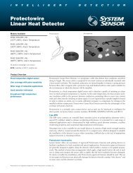
INSTALLATION AND MAINTENANCE INSTRUCTIONS<br />
<strong>RTS151KEY</strong>(A)<br />
<strong>Remote</strong> <strong>Test</strong> <strong>Station</strong><br />
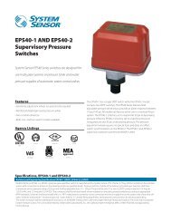
SpECIfICATIONS<br />
Dimensions: 4.6˝ H × 2.75˝ W × 1.8˝ D<br />
Weight: 0.24 Lbs.<br />
Power Requirements<br />
Power LED (Green): 14 – 35 VDC, 12 mA maximum<br />
Alarm LED (Red): 2.8 – 32 VDC, 12 mA maximum<br />
Alarm Response Time: 40 seconds maximum<br />
Temperature: –10°C to 60°C (14°F to 140°F)<br />
Humidity: 95% relative humidity, noncondensing Max<br />
Listing: UL, FM, CE<br />
NOTE: <strong>RTS151KEY</strong>(A) replaces RTS451KEY.<br />
NOTICE: This manual shall be left with the owner/user of this equipment.<br />
NOTE: A test coil is required only for use with D2/DNR/DH400/DH500 models.<br />
For D2 models order part # DCOIL. For DH400/500 models order part #Coil.<br />
GENERAL INfORMATION<br />
The <strong>System</strong> <strong>Sensor</strong> <strong>RTS151KEY</strong>(A) is an automatic fire detector accessory designed<br />
to test remotely located duct and beam detectors. For 4-wire detectors,<br />
the <strong>RTS151KEY</strong>(A) features a multi-colored LED that alternates between steady<br />
green and red. Green indicates power and that the detector board is in place.<br />
Red indicates alarm. For 2-wire detectors, the LED will show red for alarm.<br />
Consult the detector installation instructions for additional information.<br />
The National Fire Protection Association has published codes, standards, and<br />
recommended practices for the installation and use of this product. It is recommended<br />
that the installer be familiar with these requirements, with local<br />
codes, and any special requirements of the local authority having jurisdiction.<br />
RTS151 CONTENTS<br />
1 <strong>RTS151KEY</strong>(A) remote test station<br />
1 screw pack (2 mounting screws)<br />
2 Keys<br />
OpERATION<br />
<strong>Test</strong> Function<br />
Insert the key and turn clockwise to the “TEST” position.<br />
Alarm Indication<br />
With the key in the “TEST” position, some time will elapse (40 seconds maximum)<br />
depending on the detector type, before the alarm indicating LED will<br />
turn red.<br />
Reset Function<br />
Turn the key counterclockwise to the “RESET” position and hold. The LED<br />
should turn off. Then, turn the key back to the “NORMAL” position and remove.<br />
The <strong>RTS151KEY</strong>(A) is capable of resetting only certain models of detectors.<br />
Refer to the detector installation instructions for additional information.<br />
Wiring Instructions<br />
Consult the appropriate detector installation instructions for the applicable<br />
wiring diagram. The <strong>RTS151KEY</strong>(A) mounts to a single gang box (2 1 /2˝ minimum<br />
depth), or directly to the wall or ceiling.<br />
In Canadian applications, the <strong>RTS151KEY</strong>(A) is intended to be located in the<br />
same room as the smoke detector and within 60 feet of the unit.<br />
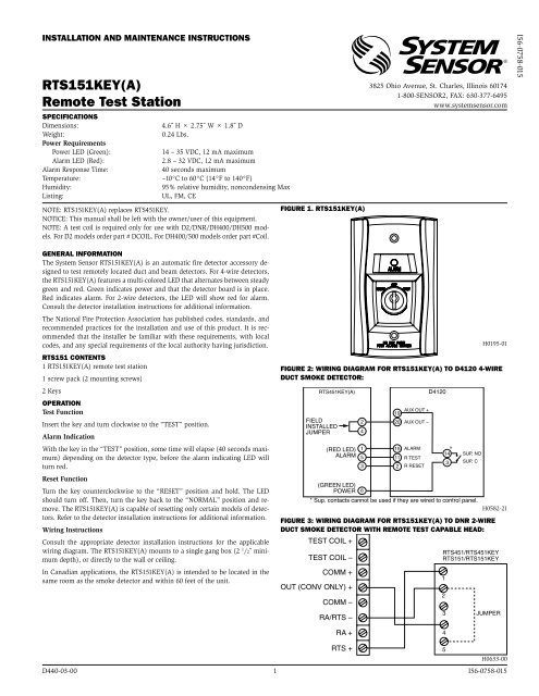
fIGURE 1. <strong>RTS151KEY</strong>(A)<br />
3825 Ohio Avenue, St. Charles, Illinois 60174<br />
1-800-SENSOR2, FAX: 630-377-6495<br />
www.systemsensor.com<br />
H0195-01<br />
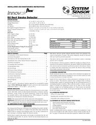
fIGURE 2: WIRING DIAGRAM fOR <strong>RTS151KEY</strong>(A) TO D4120 4-WIRE<br />
DUCT SMOKE DETECTOR:<br />
RTS451KEY(A)<br />
FIELD<br />
INSTALLED<br />
JUMPER<br />
(RED LED)<br />
ALARM<br />
H0582-21<br />
fIGURE 3: WIRING DIAGRAM fOR <strong>RTS151KEY</strong>(A) TO DNR 2-WIRE<br />
DUCT SMOKE DETECTOR WITH REMOTE TEST CApABLE HEAD:<br />
TEST COIL +<br />
RTS451/RTS451KEY<br />
TEST COIL –<br />
RTS151/<strong>RTS151KEY</strong><br />
D440-03-00 1 I56-0758-015<br />
2<br />
4<br />
1<br />
5<br />
3<br />
19<br />
AUX OUT +<br />
20 AUX OUT –<br />
15 ALARM<br />
11 R TEST<br />
2 R RESET<br />
D4120<br />
*<br />
14<br />
3<br />
SUP, NO<br />
SUP, C<br />
(GREEN LED)<br />
POWER 6<br />
* Sup. contacts cannot be used if they are wired to control panel.<br />
COMM +<br />
OUT (CONV ONLY) +<br />
COMM –<br />
RA/RTS –<br />
RA +<br />
RTS +<br />
1<br />
2<br />
3<br />
4<br />
5<br />
JUMPER<br />
H0633-00<br />
I56-0758-015
fIGURE 4: WIRING DIAGRAM fOR <strong>RTS151KEY</strong>(A) TO D2 2-WIRE DUCT SMOKE DETECTOR:<br />
MAGNET<br />
TEST<br />
SWITCH<br />
ALARM<br />
LED (RED)<br />
4<br />
5<br />
2<br />
1<br />
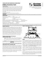
fIGURE 5. WIRING DIAGRAM fOR <strong>RTS151KEY</strong>(A) TO DH100ACDC<br />
4-WIRE DUCT SMOKE DETECTOR:<br />
DH100ACDCLP <strong>RTS151KEY</strong>(A)<br />
Alarm Signal 15<br />
1 (Red LED) Alarm<br />
Aux. Power +<br />
Sup. N. O.<br />
Sup. COM<br />
Aux. Power “<br />
Reset<br />
<strong>Test</strong><br />
19<br />
14<br />
3<br />
20<br />
2<br />
11<br />
* Sup. contacts cannot<br />
be used if they are<br />
wired to control panel.<br />
<strong>System</strong> <strong>Sensor</strong> warrants its enclosed product to be free from defects in materials and<br />
workmanship under normal use and service for a period of three years from date of<br />
manufacture. <strong>System</strong> <strong>Sensor</strong> makes no other express warranty for the enclosed product.<br />
No agent, representative, dealer, or employee of the Company has the authority to increase<br />
or alter the obligations or limitations of this Warranty. The Company’s obligation<br />
of this Warranty shall be limited to the replacement of any part of the product which<br />
is found to be defective in materials or workmanship under normal use and service<br />
during the three year period commencing with the date of manufacture. After phoning<br />
<strong>System</strong> <strong>Sensor</strong>’s toll free number 800-SENSOR2 (736-7672) for a Return Authorization<br />
number, send defective units postage prepaid to: <strong>System</strong> <strong>Sensor</strong>, Returns Department, RA<br />
6<br />
2<br />
3<br />
4<br />
5<br />
(Green LED)<br />
Power<br />
*<br />
H0156-08<br />
fIGURE 7. WIRING DIAGRAM fOR <strong>RTS151KEY</strong>(A) TO DH400ACDC<br />
DUCT SMOKE DETECTOR:<br />
DH400ACDC <strong>RTS151KEY</strong>(A)<br />
Alarm Signal 5<br />
1 (Red LED) Alarm<br />
Aux. Power +<br />
Sup. N. O.<br />
Sup. COM<br />
(–)<br />
(+)<br />
Aux. Power –<br />
Reset<br />
<strong>Test</strong><br />
7<br />
11<br />
10<br />
6<br />
3<br />
4<br />
+ TEST COIL<br />
– TEST COIL<br />
+ IN<br />
+ OUT<br />
– RA<br />
<strong>RTS151KEY</strong>(A)<br />
(OPTIONAL) REMOTE<br />
+ RA<br />
TEST STATION<br />
+ RTS<br />
D2<br />
METHOD #1 - AUX POWER LOCATED<br />
AT DUCT DETECTOR<br />
–<br />
6<br />
2<br />
3<br />
4<br />
5<br />
24 VDC<br />
AUX POWER<br />
(–) SUPPLIED<br />
BY USER<br />
(+)<br />
(100mA<br />
SUPPLY)<br />
24 VAC (+10%, –15%)<br />
FULL WAVE RECTIFIED,<br />
UNFILTERED POWER<br />
MAY BE USED<br />
* Sup. contacts<br />
cannot be used if<br />
they are wired to<br />
control panel.<br />
(Green LED)<br />
Power<br />
*<br />
H0156-09<br />
24 VDC<br />
AUX POWER<br />
SUPPLIED<br />
BY USER<br />
(100mA<br />
SUPPLY)<br />
24 VAC (+10%, –15%)<br />
FULL WAVE RECTIFIED,<br />
UNFILTERED POWER<br />
MAY BE USED<br />
THREE-YEAR LIMITED WARRANTY<br />
fIGURE 6. WIRING DIAGRAM fOR <strong>RTS151KEY</strong>(A) TO DH100 2-WIRE<br />
DUCT SMOKE DETECTOR:<br />
NOTE: Terminal 6 of the <strong>RTS151KEY</strong>(A) is not used when wired to a 2-wire detector.<br />
DH100 <strong>RTS151KEY</strong>(A)<br />
#__________, 3825 Ohio Avenue, St. Charles, IL 60174. Please include a note describing<br />
the malfunction and suspected cause of failure. The Company shall not be obligated to<br />
replace units which are found to be defective because of damage, unreasonable use,<br />
modifications, or alterations occurring after the date of manufacture. In no case shall the<br />
Company be liable for any consequential or incidental damages for breach of this or any<br />
other Warranty, expressed or implied whatsoever, even if the loss or damage is caused by<br />
the Company’s negligence or fault. Some states do not allow the exclusion or limitation of<br />
incidental or consequential damages, so the above limitation or exclusion may not apply<br />
to you. This Warranty gives you specific legal rights, and you may also have other rights<br />
which vary from state to state.<br />
D440-03-00 2 I56-0758-015<br />
©2011 <strong>System</strong> <strong>Sensor</strong><br />
<strong>Test</strong> +<br />
<strong>Test</strong> / Reset –<br />
Reset +<br />
RA +<br />
RA –<br />
V Out +<br />
1<br />
2<br />
3<br />
4<br />
5<br />
6<br />
5<br />
4<br />
3<br />
1 Alarm<br />
LED<br />
2<br />
6<br />
<strong>Test</strong><br />
Reset<br />
No Connection<br />
H0612-12<br />
H0193-05<br />
fIGURE 8. WIRING DIAGRAM fOR <strong>RTS151KEY</strong>(A) TO BEAM1224/<br />
BEAM1224S SMOKE DETECTOR:<br />
BEAM1224/BEAM1224S<br />
MAGNET<br />
TEST<br />
SWITCH<br />
ALARM<br />
LED (RED)<br />
REMOTE ALARM OUT T2-1<br />
AUX (–) T2-2<br />
RESET INPUT T2-4<br />
REMOTE TROUBLE OUTPUT T3-3<br />
<strong>RTS151KEY</strong>(A)<br />
(OPTIONAL) REMOTE<br />
TEST STATION<br />
NOTE: THE USE OF THE <strong>RTS151KEY</strong>(A) REQUIRES THE INSTALLATION OF<br />
AN ACCESSORY COIL, DCOIL, SOLD SEPARATELY.<br />
TEST INPUT T2-3<br />
OPTIONAL YELLOW LED<br />
1 (RED LED) ALARM<br />
NOTE: <strong>RTS151KEY</strong>(A) CAN BE USED WITH INTELLIGENT BEAM DETECTOR PRODUCTS.<br />
CONSULT INTELLIGENT BEAM DETECTOR MANUAL FOR ADDITIONAL INSTRUCTIONS<br />
H0585-05<br />
4<br />
5<br />
2<br />
1<br />
(–)<br />
(+)<br />
METHOD #2 - AUX POWER LOCATED<br />
AT TEST STATION<br />
2<br />
3<br />
4<br />
5<br />
– RA<br />
+ RA<br />
+ RTS<br />
<strong>RTS151KEY</strong>(A)<br />
+ TEST COIL<br />
– TEST COIL<br />
+ IN<br />
+ OUT<br />
–<br />
D2<br />
RESET<br />
TEST