DM100 Bitstream Analyzer User's Manual - Dolby Laboratories Inc.
DM100 Bitstream Analyzer User's Manual - Dolby Laboratories Inc.
DM100 Bitstream Analyzer User's Manual - Dolby Laboratories Inc.

Create successful ePaper yourself
Turn your PDF publications into a flip-book with our unique Google optimized e-Paper software.
������������������������<br />
�������������
Status<br />
Switches display to top-level<br />
status menu; shows details of<br />
input or output bitstream<br />
Power<br />
Hold for two seconds to<br />
turn <strong>DM100</strong> on or off<br />
Shift [LCD]<br />
Momentarily enables or<br />
disables LCD backlight<br />
Shift [P1-P4]<br />
Selects user-assigned custom<br />
presets<br />
Esc<br />
Moves display up one level<br />
in menu tree, or aborts<br />
current operation<br />
Up/Down Buttons<br />
Scroll through status or<br />
setup menu trees; changes<br />
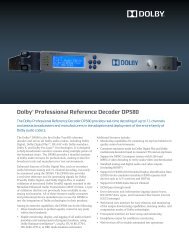
<strong>DM100</strong> <strong>Bitstream</strong> <strong>Analyzer</strong><br />
<strong>Bitstream</strong> <strong>Analyzer</strong><br />
Model <strong>DM100</strong><br />
Error<br />
Esc<br />
PCM<br />
<strong>Dolby</strong> <strong>Dolby</strong> V Ref<br />
Digital E<br />
LCD P1 P2<br />
Power Status Mon<br />
Shift<br />
Setup Gen<br />
P3 P4<br />
Enter<br />
Volume<br />
Mon<br />
Gen<br />
Setup<br />
RS-232<br />
settings Enter<br />
Interface<br />
Connector<br />
For test bitstream uploads,<br />
data logging, and firmware<br />
upgrades<br />
Volume Buttons<br />
Control level of speaker<br />
or headphone output (speaker<br />
is disabled when headphone<br />
is used)<br />
LEDs<br />
Flashing Red: Low battery<br />
Error<br />
Flashing Red: Error counter changed<br />
Red: Error condition<br />
See Error Stats menu, Section 3.2.8<br />
for these functions<br />
PCM, <strong>Dolby</strong> Digital,<br />
<strong>Dolby</strong> E<br />
Green: Receiving indicated input<br />
signal<br />
Flashing Green: (equal on/off)<br />
Decode Format setting does<br />
not match the input<br />
Flashing Green: (long on)<br />
AES3 channel status is being modified<br />
in Passthrough Mode. See Section 4.3.<br />
V Ref<br />
Green: A valid video reference<br />
input signal is present, and unit<br />
is in a mode that requires it<br />
Off: Current mode does not require<br />
a video reference<br />
Flashing Green: Current mode requires<br />
a video reference and it is invalid or<br />
not present<br />
Resets internal settings to<br />
quickly allow monitoring of<br />
input bitstreams. Does not<br />
change output mode.<br />
Turns on generator, and displays<br />
bitstream select menu; pressing<br />
again generates next bitstream<br />
in list<br />
Switches display to<br />
top-level setup menu;<br />
use to set <strong>DM100</strong> options<br />
Moves down one level in<br />
current menu item, or selects<br />
currently displayed option;<br />
also used to switch bottom<br />
line of LCD between graphic<br />
or numeric display from certain<br />
status menu items
<strong>Dolby</strong> <strong>Laboratories</strong>, <strong>Inc</strong>.<br />
Corporate Headquarters<br />
<strong>Dolby</strong> <strong>Laboratories</strong>, <strong>Inc</strong>.<br />
100 Potrero Avenue<br />
San Francisco, CA 94103-4813<br />
Telephone 415-558-0200<br />
Fax 415-863-1373<br />
www.dolby.com<br />
European Headquarters<br />
<strong>Dolby</strong> <strong>Laboratories</strong>, <strong>Inc</strong>.<br />
Wootton Bassett<br />
Wiltshire, SN4 8QJ, England<br />
Telephone (44) 1793-842100<br />
Fax (44) 1793-842101<br />
<strong>Dolby</strong> ® <strong>DM100</strong> User’s <strong>Manual</strong><br />
<strong>Dolby</strong> and the double-D symbol are registered trademarks of <strong>Dolby</strong> <strong>Laboratories</strong>. Surround EX is a<br />
trademark of <strong>Dolby</strong> <strong>Laboratories</strong>. Toslink is a trademark of Toshiba Corporation. Windows is a<br />
registered trademark of Microsoft Corporation. All other trademarks remain the property of their<br />
respective owners.<br />
© 2003 <strong>Dolby</strong> <strong>Laboratories</strong> <strong>Inc</strong>. All rights reserved.<br />
S03/13416/14616 Issue 2 Part No. 91751<br />
i
<strong>Dolby</strong> ® <strong>DM100</strong> User’s <strong>Manual</strong><br />
Table of Contents<br />
Chapter 1 Introduction<br />
1.1 About the <strong>DM100</strong>..................................................1-1<br />
Chapter 2 Getting Started<br />
2.1 Power.....................................................................2-1<br />
Battery Installation.....................................2-1<br />
[Power] Button...........................................2-2<br />
Battery Low LED.......................................2-2<br />
Auto-Power Off..........................................2-2<br />
2.2 Rear Belt Clip/Stand..............................................2-3<br />
2.3 Inputs .....................................................................2-4<br />
<strong>Dolby</strong> Digital..............................................2-4<br />
<strong>Dolby</strong> E ......................................................2-4<br />
PCM ...........................................................2-4<br />
Other...........................................................2-4<br />
Video..........................................................2-4<br />
2.4 Outputs ..................................................................2-5<br />
Headphone Output .....................................2-5<br />
Speaker Output...........................................2-5<br />
2.5 Hookup ..................................................................2-6<br />
2.6 Quick Start.............................................................2-7<br />
Making Your First Reading .......................2-7<br />
Generating a <strong>Bitstream</strong>...............................2-7<br />
2.7 Advanced Features ................................................2-8<br />
Measuring the Latency of Equipment ........2-8<br />
Measuring Audio/Video Frequency Drift ..2-8<br />
iii
<strong>Dolby</strong> ® <strong>DM100</strong> User’s <strong>Manual</strong><br />
Chapter 3 Operation: Status Mode<br />
3.1 Main Status Screen................................................ 3-1<br />
<strong>Dolby</strong> E ..................................................... 3-2<br />
<strong>Dolby</strong> Digital ............................................. 3-3<br />
PCM ........................................................... 3-3<br />
NULL Data ................................................ 3-4<br />
Pause Data.................................................. 3-4<br />
Data Type X............................................... 3-4<br />
3.2 The Status Menus .................................................. 3-5<br />
3.2.1 <strong>Dolby</strong> E Metadata Input Menu................... 3-6<br />
Px Prog Desc.............................................. 3-7<br />
Px Dialogue Lev ........................................ 3-7<br />
Px Channel Mode....................................... 3-8<br />
Px LFE Channel......................................... 3-8<br />
Px Bitstrm Mode........................................ 3-8<br />
Px Line Mode Pro ...................................... 3-9<br />
Px RF Mode Pro......................................... 3-9<br />
Px RF Ov Protect ....................................... 3-9<br />
Px Center Dwnmx...................................... 3-10<br />
Px Srnd Dwnmx......................................... 3-10<br />
Px <strong>Dolby</strong> Srnd............................................ 3-10<br />
Px Mixing Level ........................................ 3-11<br />
Px Room Type ........................................... 3-11<br />
Px Copyright .............................................. 3-11<br />
Px Orig Bitstrm.......................................... 3-11<br />
Px Extnd Bitstrm........................................ 3-12<br />
Px DC Filter ............................................... 3-13<br />
Px Lowpass Filt.......................................... 3-13<br />
Px LFE Filter.............................................. 3-13<br />
Px Srnd 3dB Attn....................................... 3-13<br />
Px Srnd Ph Shift......................................... 3-13<br />
Px Begin Gain............................................ 3-13<br />
Px End Gain ............................................... 3-13<br />
iv
<strong>Dolby</strong> ® <strong>DM100</strong> User’s <strong>Manual</strong><br />
3.2.2 <strong>Dolby</strong> Digital Metadata Input Menu ..........3-14<br />
DD Dialogue Lev .......................................3-15<br />
DD Channel Mode .....................................3-15<br />
DD LFE Channel .......................................3-15<br />
DD Data Rate .............................................3-16<br />
DD Bitstrm Mode.......................................3-16<br />
DD Line Mode Pro.....................................3-17<br />
DD RF Mode Pro .......................................3-17<br />
DD Center Dwnmx ....................................3-17<br />
DD Srnd Dwnmx .......................................3-18<br />
DD <strong>Dolby</strong> Srnd ..........................................3-18<br />
DD Mixing Level .......................................3-18<br />
DD Room Type..........................................3-19<br />
DD Copyright.............................................3-19<br />
DD Orig Bitstrm.........................................3-19<br />
DD Extnd Bitstrm ......................................3-20<br />
DD Dual Mono MD ...................................3-21<br />
DD Format .................................................3-22<br />
DD Sample Rate.........................................3-22<br />
DD <strong>Bitstream</strong> ID ........................................3-22<br />
DD Stream #...............................................3-23<br />
3.2.3 AES3 Status Menu .....................................3-24<br />
3.2.4 Input Level Menu.......................................3-26<br />
3.2.5 Generator Status Display............................3-27<br />
3.2.6 Video Reference Status Display.................3-28<br />
3.2.7 Timecode Status Display............................3-29<br />
3.2.8 Error Stats Menu ........................................3-30<br />
3.2.9 <strong>DM100</strong> Firmware Version .........................3-31<br />
v
<strong>Dolby</strong> ® <strong>DM100</strong> User’s <strong>Manual</strong><br />
Chapter 4 Operation: Setup Mode<br />
Introduction ................................................................... 4-1<br />
4.1 Monitor Control..................................................... 4-2<br />
4.2 Gen Control ........................................................... 4-4<br />
4.3 AES3 Output ......................................................... 4-6<br />
4.4 User Presets ........................................................... 4-8<br />
4.5 I/O Control ............................................................ 4-9<br />
4.6 System Settings ..................................................... 4-10<br />
Chapter 5 Reference Information<br />
5.1 Data Transfer......................................................... 5-1<br />
Test <strong>Bitstream</strong> Loading.............................. 5-1<br />
Data Logging ............................................. 5-1<br />
Firmware Upgrade ..................................... 5-2<br />
Data Transfer Error Messages.................... 5-2<br />
5.2 Unit Reset.............................................................. 5-3<br />
Restore Default Settings ............................ 5-3<br />
Hardware Reset.......................................... 5-3<br />
5.3 Connector Pinout Information............................... 5-4<br />
5.3.1 RS-232 Serial Port ..................................... 5-4<br />
5.3.2 XLR Connectors ........................................ 5-4<br />
5.3.3 Headphone Connector................................ 5-4<br />
5.4 <strong>DM100</strong> Specifications........................................... 5-5<br />
5.5 System Block Diagram.......................................... 5-2<br />
vi
<strong>Dolby</strong> ® <strong>DM100</strong> User’s <strong>Manual</strong><br />
1-1<br />
Chapter 1<br />
Introduction<br />
1.1 About the <strong>DM100</strong><br />
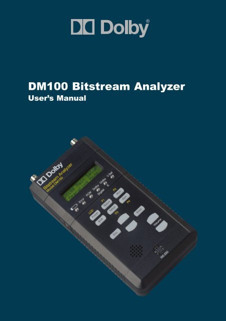
The <strong>Dolby</strong> ® <strong>DM100</strong> is a hand-held diagnostic tool that can<br />
monitor or generate <strong>Dolby</strong> Digital, <strong>Dolby</strong> E, and PCM<br />
bitstreams. The unit allows audio systems integrators and service<br />
engineers to quickly test the integrity and composition of these<br />
signals throughout a facility. The <strong>DM100</strong> is intended for use in<br />
broadcast, cable, DBS, and postproduction facilities, as well as<br />
DVD mastering and home theater installation.<br />
The <strong>DM100</strong> accepts input signals via XLR, BNC, and Toslink connectors. The unit identifies the format of the input signal and<br />
activates the appropriate built-in decoder. The decoded analog<br />
signal, sent to a standard 1/8-inch stereo headphone jack, can be<br />
switched to monitor any two decoded channels, while a small<br />
built-in speaker can monitor the sum of any channel pair. A<br />
front-panel LCD displays <strong>Dolby</strong> Digital and <strong>Dolby</strong> E metadata<br />
information. Six front-panel LEDs indicate critical bitstream and<br />
system status information.<br />
A set of <strong>Dolby</strong> Digital, <strong>Dolby</strong> E, and PCM test bitstreams is<br />
stored in internal, nonvolatile RAM, and can be changed in the<br />
field via software download. The selected test bitstream is<br />
produced simultaneously on all output connectors. The unit can<br />
receive and decode an input signal while simultaneously<br />
generating a test bitstream. The <strong>DM100</strong> also features a passthrough<br />
mode that allows modification of the input signal’s AES<br />
channel status bits before passing the signal to the output<br />
connectors. (The input signal can be monitored simultaneously.)<br />
The <strong>DM100</strong> also includes system level tests, such as latency<br />
measurements, and the ability to check the clock<br />
synchronization between audio and video signals.
<strong>Dolby</strong> ® <strong>DM100</strong> User’s <strong>Manual</strong><br />
2-1<br />
Chapter 2<br />
Getting Started<br />
2.1 Power<br />
The <strong>DM100</strong> is powered by four standard AA 1.5 V batteries or<br />
from an external 6V, 800 mA DC power supply via the power<br />
input connector. The internal batteries are disconnected when<br />
the external DC power supply is used.<br />
Battery Installation<br />
Push the cover in<br />
the direction shown<br />
to slide it out.<br />
Insert four AA<br />
batteries,<br />
alternating the<br />
positive and<br />
negative terminals,<br />
and replace the<br />
cover.
<strong>Dolby</strong> ® <strong>DM100</strong> User’s <strong>Manual</strong> Getting Started<br />
[Power] Button<br />
To turn on the <strong>DM100</strong>, press and hold the [Power] button down<br />
for two seconds. The display reads as shown for approximately<br />
one second while a self-test diagnostic runs.<br />
Model <strong>DM100</strong><br />
Unit Name<br />
The power-on process ends with the <strong>DM100</strong> operating in the<br />
last-used state. If the diagnostic test fails, the Error LED lights<br />
and an error message is displayed.<br />
To turn off the <strong>DM100</strong>, press [Power] again. The display reads<br />
“Power Off” and the unit shuts off.<br />
Power Off…<br />
Note: Any changes made to the system settings may be lost if the unit is<br />
powered off by unplugging the external power supply, unless batteries<br />
are installed.<br />
Battery Low LED<br />
The front-panel battery LED flashes when the<br />
batteries are nearly discharged. If the battery<br />
voltage drops below a usable level, the<br />
<strong>DM100</strong> display reads “Dead Battery” and the<br />
unit shuts off.<br />
Dead Battery…<br />
Auto-Power Off<br />
When the <strong>DM100</strong> is powered from batteries (external power<br />
supply not connected), the unit can be set to turn itself off after a<br />
selectable number of minutes with no user activity (5, 10, 15, or<br />
30 minutes). This feature can be disabled. The factory default<br />
setting is 15 minutes.<br />
The wait time is set from the Setup menu under System Settings,<br />
Power Management. See Section 4.6 for more information.<br />
2-2
<strong>Dolby</strong> ® <strong>DM100</strong> User’s <strong>Manual</strong> Getting Started<br />
External DC Power Supply<br />
When powered from the external power supply, the Power<br />
Management setting is ignored and the unit remains switched on.<br />
The LCD backlight and keypad backlights are also enabled,<br />
overriding the LCD Backlight setting. See Section 4.6 for more<br />
information.<br />
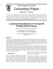
2.2 Rear Belt Clip/Stand<br />
The pull-out clip on the rear of the <strong>DM100</strong> can be used as a<br />
handy belt clip or a stand. Raise the clip by following these two<br />
steps:<br />
1. Lift to release<br />
2. Pull up<br />
1<br />
2<br />
2-3<br />
2<br />
LIFT TO UNLATCH<br />
2 PULL OUT<br />
1 1 LIFT TO UNLATCH
<strong>Dolby</strong> ® <strong>DM100</strong> User’s <strong>Manual</strong> Getting Started<br />
2.3 Inputs<br />
Each input connector (XLR, BNC, or Toslink ) is active when<br />
specifically selected, or, if the input selection is set to autodetect,<br />
the first input with a valid AES3 signal becomes the active<br />
input. See Section 4.5 for setting the input select function. See<br />
the specifications in Section 5.4 for details on supported sample<br />
rates, impedances, and more.<br />
The digital input format can be <strong>Dolby</strong> ® Digital, <strong>Dolby</strong> E, or<br />
PCM.<br />
<strong>Dolby</strong> Digital<br />
The <strong>DM100</strong> accepts 16- and 32-bit <strong>Dolby</strong> Digital bitstreams. It<br />
also accepts AES3 data that contains multiple <strong>Dolby</strong> Digital<br />
bitstreams (i.e., one 16-bit mode bitstream in each AES3<br />
channel).<br />
<strong>Dolby</strong> E<br />
The <strong>DM100</strong> accepts 16-, 20-, and 24-bit <strong>Dolby</strong> E bitstreams at<br />
NTSC (29.97 fps), PAL (25 fps), 23.98 fps, 24 fps, and 30 fps<br />
rates.<br />
PCM<br />
If the input signal does not contain a header indicating that a preencoded<br />
bitstream is being received, the <strong>DM100</strong> assumes the<br />
input signal is PCM audio.<br />
Other<br />
The <strong>DM100</strong> also accepts non-audio data over AES3. In this<br />
case, the LCD indicates that data is being received and the audio<br />
output mutes.<br />
Video<br />
The unit can use an analog composite NTSC or PAL black burst<br />
reference video signal for signal generation, via the Ref Video<br />
RCA connector. The input is internally terminated at 75Ω.<br />
2-4
<strong>Dolby</strong> ® <strong>DM100</strong> User’s <strong>Manual</strong> Getting Started<br />
2.4 Outputs<br />
The XLR and BNC output connectors are always active. The<br />
Toslink connector is enabled when it is selected.<br />
The digital output signal can be:<br />
Pass-through <strong>Dolby</strong> Digital, <strong>Dolby</strong> E, or PCM.<br />
The output clock is locked to the digital input.<br />
Or<br />
An internally generated <strong>Dolby</strong> Digital, <strong>Dolby</strong> E, or PCM test<br />
bitstream.<br />
The output clock can be locked to an internal 48 kHz clock, a digital input<br />
signal, or to 48 kHz derived from the video reference input. See Section 4.5<br />
for more information.<br />
Headphone Output<br />
The headphone output is used to monitor the decoded<br />
<strong>Dolby</strong> Digital, <strong>Dolby</strong> E, or PCM signal. Front-panel buttons<br />
adjust the headphone volume.<br />
Speaker Output<br />
The speaker output is used to monitor the decoded <strong>Dolby</strong><br />
Digital, <strong>Dolby</strong> E, or PCM signal when headphones are not being<br />
used. The signal is a mono version of the headphone output.<br />
Front-panel buttons adjust the speaker volume.<br />
Note: When listening to <strong>Dolby</strong> Digital bitstreams on the speaker output, RF<br />
Mode compression is always applied, regardless of the<br />
DD Compression setting in the Monitor Control Setup menu.<br />
See Section 4.1 for more information.<br />
2-5
<strong>Dolby</strong> ® <strong>DM100</strong> User’s <strong>Manual</strong> Getting Started<br />
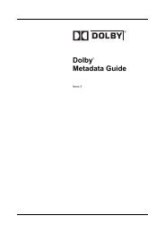
2.5 Hookup<br />
Figure 2-1 shows the locations for connecting components to the<br />
<strong>DM100</strong>.<br />
Ref Video In<br />
BNC F to RCA M<br />
Part Number 70217<br />
Power Adapter<br />
Part Numbers: 54065 USA<br />
54066 UK<br />
54067 Europe<br />
54068 Australia<br />
Figure 2-1 Connections<br />
Note: References to the front-panel buttons are shown using brackets<br />
throughout this manual (e.g., “[Status]”). References to multiple-button<br />
combinations mean sequences, not simultaneous button presses. Press<br />
the first button, release, and then press the next button.<br />
2-6<br />
Toslink Cable<br />
RCA F to BNC M<br />
Part Number 70218
<strong>Dolby</strong> ® <strong>DM100</strong> User’s <strong>Manual</strong> Getting Started<br />
2.6 Quick Start<br />
The <strong>DM100</strong> is designed to be easy and intuitive to use. Follow<br />
these simple procedures to begin taking your first readings and<br />
generating your first test streams.<br />
Making Your First Reading<br />
1. Turn on the unit by pressing [Power].<br />
2. Connect the input signal to the appropriate connector.<br />
3. Press [Mon]. This resets all the internal monitoring setup<br />
functions to the defaults.<br />
The LEDs should display the signal type received, and the<br />
display shows information about the incoming signal. If you<br />
cannot see this information, press [Status], then use [Enter],<br />
[Esc], and the [Up/Down] buttons to navigate through the status<br />
menus to view information about the incoming signal. See<br />
Section 3.2 for additional information.<br />
Adjust the audio level with the dedicated [Volume] buttons.<br />
Generating a <strong>Bitstream</strong><br />
1. Press [Gen] once. This turns the generator on and outputs a<br />
PCM test signal.<br />
2. To select other test streams, continue to press [Gen].<br />
Different clock sources can be used for the generator; these can<br />
be selected in the Gen Clock Source menu:<br />
Setup / I/O Control / Gen Clock Source<br />
See Section 4.5 for more information.<br />
To read the current status of the generator, press [Status] and<br />
navigate using the [Down] button until Generator Enter to<br />
View is displayed. Press [Enter] to see the current settings. See<br />
Section 3.2.5 for more information.<br />
You can even connect the output of the <strong>DM100</strong> to the input.<br />
Doing this allows you to listen to the test stream and view all of<br />
the streams’ settings.<br />
2-7
<strong>Dolby</strong> ® <strong>DM100</strong> User’s <strong>Manual</strong> Getting Started<br />
2.7 Advanced Features<br />
Measuring the Latency of Equipment<br />
The <strong>DM100</strong> can be used to measure the latency of other audio<br />
equipment. At user-defined intervals, the <strong>DM100</strong> generates a<br />
short burst of white noise, then measures the time taken for the<br />
signal to return.<br />
Set the <strong>DM100</strong> to measure latency by following these steps:<br />
1. Go to the Gen Control / Output Mode setup menu, and<br />
select Latency Test (see Section 4.2).<br />
2. Connect the Digital Out from the <strong>DM100</strong> to the<br />
equipment to be measured.<br />
3. Connect the output of the equipment to be measured to<br />
the <strong>DM100</strong>’s Digital Input.<br />
Different clock sources used for the generator can be set in the<br />
I/O Control / Gen Clock Source setup menu (see Section 4.5).<br />
The time interval between the noise bursts can be set in the<br />
Gen Control / Noise Burst Rate setup menu (see Section 4.2).<br />
To read the measured latency, press [Status] and navigate using<br />
the [Down] button until Generator ENTER to View is<br />
displayed. Press [Enter] to display the measured latency in either<br />
AES samples or milliseconds (see Section 3.2.5).<br />
Measuring Audio/Video Frequency Drift<br />
The <strong>DM100</strong> determine if an AES digital audio or reference<br />
signal is frequency-locked to a video black burst reference<br />
signal. The unit locks to the video reference, then measures the<br />
frequency difference between the Digital In input and the video<br />
reference.<br />
2-8
<strong>Dolby</strong> ® <strong>DM100</strong> User’s <strong>Manual</strong> Getting Started<br />
Set the unit to measure frequency drift as follows:<br />
1. Go to the Gen Control / Output Mode setup menu, and<br />
select A/V Freq Drift (see Section 4.2).<br />
2. Connect a 29.97 or 25 fps video reference to <strong>DM100</strong>’s<br />
V Ref input.<br />
3. Connect the test AES signal to the <strong>DM100</strong>’s Digital In.<br />
Read the measured frequency drift between the AES and video<br />
signals by pressing [Status] and then navigating using the<br />
[Down] button until Generator / Enter to View is displayed.<br />
Press [Enter] to read the measured frequency drift (see<br />
Section 3.2.5). The display indicates frequency difference in<br />
AES samples: a positive number indicates the AES input signal<br />
is faster than the video reference. Therefore, if the two signals<br />
are locked, the display will read “0 samples.” Pressing [Enter]<br />
resets the counter.<br />
Modifying the Pass Through Output Signal<br />
The <strong>DM100</strong> can be used to repair improperly authored audio<br />
streams. When in Pass Through mode, the <strong>DM100</strong> can modify<br />
channel status bits in the first and third bytes of the AES3 signal.<br />
In addition, the output audio channels can be skewed or swapped<br />
to correct improper channel alignment (see Section 4.5).<br />
2-9
<strong>Dolby</strong> ® <strong>DM100</strong> User’s <strong>Manual</strong><br />
Chapter 3<br />
Operation: Status Mode<br />
After power-on, the <strong>DM100</strong> defaults to Status mode, with the<br />
top-level main status screen displayed. Status mode is used for<br />
displaying, monitoring, and analyzing the input bitstream.<br />
Note: References to the front-panel buttons are shown using brackets<br />
throughout this manual (e.g., “[Status]”). References to multiple-button<br />
combinations mean sequences, not simultaneous button presses. Press<br />
the first button, release, and then press the next button.<br />
3.1 Main Status Screen<br />
The main status screen is the top level of the status menu tree. It<br />
displays one of the following possible combinations of<br />
information. The display shown below gives a typical example:<br />
<strong>Dolby</strong> Digital B<br />
3/2L 448kbps<br />
Input Data Type<br />
<strong>Dolby</strong> E Valid <strong>Dolby</strong> E bitstream<br />
<strong>Dolby</strong> Digital<br />
Valid 32-bit <strong>Dolby</strong> Digital<br />
bitstream<br />
DD/PCM<br />
Valid 16-bit <strong>Dolby</strong> Digital<br />
packed in Left channel<br />
PCM/DD<br />
Valid 16-bit <strong>Dolby</strong> Digital<br />
packed in Right channel<br />
DD/DD<br />
Two valid <strong>Dolby</strong> Digital<br />
bitstreams<br />
PCM Valid PCM bitstream<br />
NULL data NULL data type bitstream<br />
Pause data Pause data type bitstream<br />
Data Type X Other data type bitstream<br />
No Input No incoming bitstream<br />
The following pages describe the information displayed on the<br />
second line for each type of input data.<br />
3-1<br />
Active Input Connector<br />
A Set to Autodetect<br />
B Set to BNC<br />
X Set to XLR<br />
O Set to Optical
<strong>Dolby</strong> ® <strong>DM100</strong> User’s <strong>Manual</strong> Operation: Status Mode<br />
<strong>Dolby</strong> E<br />
When the incoming bitstream is <strong>Dolby</strong> ® E, the following<br />
information will be displayed:<br />
<strong>Dolby</strong> E B<br />
5.1+2 24bit<br />
Program Configuration 5.1+2<br />
5.1+2x1<br />
4+4<br />
4+2x2<br />
4+2+2x1<br />
4+4x1<br />
4x2<br />
3x2+2x1<br />
2x2+4x1<br />
2+6x1<br />
8x1<br />
5.1<br />
4+2<br />
4+2x1<br />
3x2<br />
2x2+2x1<br />
2+4x1<br />
6x1<br />
4<br />
2+2<br />
2+2x1<br />
4x1<br />
7.1<br />
7.1scrn<br />
Invalid <strong>Dolby</strong> E program<br />
configuration<br />
*******<br />
3-2<br />
16bit Bit Depth<br />
20bit<br />
24bit
<strong>Dolby</strong> ® <strong>DM100</strong> User’s <strong>Manual</strong> Operation: Status Mode<br />
<strong>Dolby</strong> Digital<br />
When the incoming bitstream is <strong>Dolby</strong> Digital, the following<br />
information will be displayed:<br />
1+1<br />
1/0<br />
2/0<br />
3/0<br />
2/1<br />
3/1<br />
2/2<br />
3/2<br />
3/0L<br />
2/1L<br />
3/1L<br />
2/2L<br />
3/2L<br />
<strong>Dolby</strong> Digital B<br />
3/2L 448kbps<br />
“L”means the LFE–<br />
enabled bit is set in the<br />
bitstream<br />
PCM<br />
When the incoming bitstream is PCM, and the <strong>DM100</strong> has<br />
locked to it, the following information will be displayed:<br />
PCM B<br />
44.1 kHz<br />
48 kHz<br />
44.1 kHz<br />
32 kHz<br />
Unknown Rate<br />
3-3<br />
56kbps<br />
64kbps<br />
80kbps<br />
96kbps<br />
112kbps<br />
128kbps<br />
160kbps<br />
192kbps<br />
224kbps<br />
256kbps<br />
320kbps<br />
384kbps<br />
448kbps<br />
512kbps<br />
576kbps<br />
640kbps
<strong>Dolby</strong> ® <strong>DM100</strong> User’s <strong>Manual</strong> Operation: Status Mode<br />
NULL Data<br />
When the incoming bitstream is Null data, as defined in the<br />
IEC 61937 or SMPTE 337M standards, the following screen is<br />
displayed:<br />
NULL data<br />
Pause Data<br />
When the incoming bitstream is Pause data, as defined in the<br />
IEC 61937 standard, the following screen is displayed:<br />
PAUSE data<br />
Data Type X<br />
When the data type of the incoming bitstream is not recognized<br />
as one of the preceeding types, the following screen is displayed:<br />
Data Type X<br />
3-4
<strong>Dolby</strong> ® <strong>DM100</strong> User’s <strong>Manual</strong> Operation: Status Mode<br />
3.2 The Status Menus<br />
From the top-level main Status display described above, you can<br />
step through the status menus by pressing the [Up] or [Down]<br />
button. Each menu below the top main Status display is<br />
described in the following manual sections.<br />
Scroll with the [Up]/[Down] buttons<br />
<strong>Dolby</strong> E A<br />
5.1+2 24bit<br />
[Down]▐<br />
<strong>Dolby</strong> E MD<br />
ENTER to View<br />
[Down]▐<br />
<strong>Dolby</strong> Digital MD<br />
ENTER to View<br />
[Down]▐<br />
AES3 Status<br />
ENTER to View<br />
[Down]▐<br />
Input Level<br />
ENTER to View<br />
[Down]▐<br />
Generator<br />
ENTER to View<br />
[Down]▐<br />
Video Ref<br />
29.97 fps<br />
[Down]▐<br />
Timecode 29 Dly<br />
00:00:00:00 N/A<br />
[Down]▐<br />
Error Stats<br />
ENTER to View<br />
[Down]▐<br />
Firmware Version<br />
2.0.0.0<br />
Top level Status display<br />
(A typical display is shown.)<br />
3-5<br />
<strong>Dolby</strong> E metadata menu<br />
<strong>Dolby</strong> Digital metadata menu<br />
AES3 status menu<br />
Input level menu<br />
<strong>Bitstream</strong> generator status display<br />
Video reference display<br />
Timecode/delay display<br />
Error status menu<br />
<strong>DM100</strong> firmware version
<strong>Dolby</strong> ® <strong>DM100</strong> User’s <strong>Manual</strong> Operation: Status Mode<br />
3.2.1 <strong>Dolby</strong> E Metadata Input Menu<br />
After pressing [Enter] to view this menu, press the [Down] or<br />
[Up] button to select the submenu options you wish to display.<br />
<strong>Dolby</strong> E MD<br />
ENTER to View<br />
See page 3-2 for the list of possible<br />
program configurations displayed.<br />
23.98 fps<br />
24 fps<br />
25 fps [PAL]<br />
29.97 fps [NTSC]<br />
30 fps<br />
50 fps<br />
59.94 fps<br />
60 fps<br />
****************<br />
N/A<br />
DE Prog Config<br />
[Down]▐<br />
<strong>Dolby</strong> E Prog 1<br />
ENTER to View<br />
[Down]▐<br />
<strong>Dolby</strong> E Prog 2—8<br />
(depending on <strong>Dolby</strong> E<br />
program configuration)<br />
[Down]▐<br />
DE Bit Depth<br />
16, 20, or 24Bit<br />
[Down]▐<br />
DE Frame Rate<br />
29.97 fps<br />
[Down]▐<br />
DE Position<br />
Line 14<br />
Displays the video line number<br />
where the <strong>Dolby</strong> E data begins.<br />
Line xxx<br />
Refer to SMPTE-170M and ITU-R<br />
BT.470-6 for video line structure.<br />
<strong>Dolby</strong> E input not present or <strong>DM100</strong><br />
blank<br />
decode format is not <strong>Dolby</strong> E.<br />
Video reference not present. N/A<br />
Video reference not equal to <strong>Dolby</strong> E Line<br />
frame rate.<br />
***<br />
During an audio-follow-video switch, the <strong>Dolby</strong> E frame is in<br />
danger of corruption if the “line” value displayed in this status<br />
screen is less than 11 or greater than 30 for 29.97 fps (NTSC),<br />
or less than 7 or greater than 35 for 25 fps (PAL).<br />
“Px” represents the selected program number, where x is a<br />
number between 1 and 8. Valid program numbers depend on the<br />
<strong>Dolby</strong> E program configuration. For example, 5.1+2 is two<br />
programs; therefore, only P1 and P2 are valid.<br />
Each metadata program parameter selection is described in the<br />
following sections.<br />
3-6<br />
[Enter]<br />
Px Prog Desc<br />
[Down]▐<br />
Px Dialogue Lev<br />
[Down]▐<br />
Px Channel Mode<br />
[Down]▐<br />
Px LFE Channel<br />
[Down]▐<br />
Px Bitstrm Mode<br />
[Down]▐<br />
Px Line Mode Pro<br />
[Down]▐<br />
Px RF Mode Pro<br />
[Down]▐<br />
Px RF Ov Protect<br />
[Down]▐<br />
Px Center Dwnmx<br />
[Down]▐<br />
Px Srnd Dwnmx<br />
[Down]▐<br />
Px <strong>Dolby</strong> Srnd<br />
[Down]▐<br />
Px Mixing Level<br />
[Down]▐<br />
Px Room Type<br />
[Down]▐<br />
Px Copyright<br />
[Down]▐<br />
Px Orig Bitstrm<br />
[Down]▐<br />
Px Extnd Bitstrm<br />
[Down]▐<br />
Px DC Filter<br />
[Down]▐<br />
Px Lowpass Filt<br />
[Down]▐<br />
Px LFE Filter<br />
[Down]▐<br />
Px Srnd 3dB Attn<br />
[Down]▐<br />
Px Srnd Ph Shift<br />
[Down]▐<br />
Px Begin Gain<br />
[Down]▐<br />
Px End Gain
<strong>Dolby</strong> ® <strong>DM100</strong> User’s <strong>Manual</strong> Operation: Status Mode<br />
Px Prog Desc<br />
<strong>Dolby</strong> E program description display:<br />
Px Prog Desc<br />
Description text<br />
The <strong>DM100</strong> has a 32-character buffer for each program, which<br />
stores the first characters in the description text field for that<br />
program. The display scrolls through the text automatically if the<br />
string is greater than 16 characters.<br />
Px Dialogue Lev<br />
A typical example is shown for the <strong>Dolby</strong> E Dialogue<br />
Normalization display:<br />
P2 Dialogue Lev<br />
–27 dB<br />
***************<br />
–1 dB<br />
–2 dB<br />
–3 dB<br />
•<br />
•<br />
•<br />
–31 dB<br />
N/A<br />
3-7
<strong>Dolby</strong> ® <strong>DM100</strong> User’s <strong>Manual</strong> Operation: Status Mode<br />
Px Channel Mode<br />
A typical example is shown for the <strong>Dolby</strong> E Channel Mode<br />
display:<br />
P2 Channel Mode<br />
2/0 Stereo<br />
Px LFE Channel<br />
1+1<br />
1/0 Mono<br />
2/0 Stereo<br />
3/0<br />
2/1<br />
3/1<br />
2/2<br />
3/2<br />
N/A<br />
P2 LFE Channel<br />
Disabled<br />
Disabled<br />
Enabled<br />
N/A<br />
Px Bitstrm Mode<br />
A typical example is shown for the <strong>Dolby</strong> E <strong>Bitstream</strong> Mode<br />
display:<br />
P2 Bitstrm Mode<br />
Main Complete<br />
Main Complete<br />
Main M&E<br />
Assc Visual Imp<br />
Assc Hear Imp<br />
Assc Dialogue<br />
Assc Commentary<br />
Assc Emergency<br />
Assc Voice Over<br />
Main Sv Karaoke<br />
N/A<br />
3-8
<strong>Dolby</strong> ® <strong>DM100</strong> User’s <strong>Manual</strong> Operation: Status Mode<br />
Px Line Mode Pro<br />
Px RF Mode Pro<br />
The <strong>Dolby</strong> E Line Mode and RF Mode Profile program<br />
parameters display the same second-line display.<br />
A typical example is shown for the RF Mode Profile display:<br />
If actual dynamic range<br />
control data is present:<br />
P2 RF Mode Pro<br />
Music Standard<br />
±xx dB<br />
▐<br />
Press the [Enter] button<br />
to toggle between a<br />
numeric display and a bar<br />
graph level display<br />
▐<br />
� � � | � � �<br />
RF: –48 dB 0 +48 dB<br />
Line: –24 dB 0 +24 dB<br />
Px RF Ov Protect<br />
RF overmodulation protection.<br />
P2 RF Ov Protect<br />
Disabled<br />
Disabled<br />
Enabled<br />
N/A<br />
3-9<br />
If dynamic range control<br />
presets are present:<br />
None<br />
Film Standard<br />
Film Light<br />
Music Standard<br />
Music Light<br />
Speech<br />
Invalid<br />
N/A
<strong>Dolby</strong> ® <strong>DM100</strong> User’s <strong>Manual</strong> Operation: Status Mode<br />
Px Center Dwnmx<br />
A typical example is shown for the <strong>Dolby</strong> E Center Downmix<br />
display:<br />
P2 Center Dwnmx<br />
0.500 (-6.0 dB)<br />
0.707 (-3.0 dB)<br />
0.596 (-4.5 dB)<br />
0.500 (-6.0 dB)<br />
***************<br />
N/A<br />
Px Srnd Dwnmx<br />
A typical example is shown for the <strong>Dolby</strong> E Surround Downmix<br />
display:<br />
P2 Srnd Dwnmx<br />
0.707 (-3.0 dB)<br />
0.707 (-3.0 dB)<br />
0.500 (-6.0 dB)<br />
0 (-999 dB)<br />
***************<br />
N/A<br />
Px <strong>Dolby</strong> Srnd<br />
A typical example is shown for the <strong>Dolby</strong> E Surround Mode<br />
display:<br />
P2 <strong>Dolby</strong> Srnd<br />
Not Indicated<br />
Not Indicated<br />
Not <strong>Dolby</strong> Srnd<br />
<strong>Dolby</strong> Srnd<br />
***************<br />
N/A<br />
3-10
<strong>Dolby</strong> ® <strong>DM100</strong> User’s <strong>Manual</strong> Operation: Status Mode<br />
Px Mixing Level<br />
A typical example is shown for the <strong>Dolby</strong> E Mixing Level<br />
display:<br />
P2 Mixing Level<br />
80 dB<br />
Px Room Type<br />
A typical example is shown for the <strong>Dolby</strong> E Room Type display:<br />
Px Copyright<br />
80 dB<br />
81 dB<br />
82 dB<br />
•<br />
•<br />
•<br />
111 dB<br />
Does Not Exist<br />
N/A<br />
P2 Room Type<br />
80 dB<br />
Not Indicated<br />
Large<br />
Small<br />
****************<br />
Does Not Exist<br />
N/A<br />
Px Orig Bitstrm<br />
A typical example is shown for the <strong>Dolby</strong> E Copyright display.<br />
The Original <strong>Bitstream</strong> program parameters display the same<br />
second line:<br />
P2 Copyright<br />
No<br />
3-11<br />
No<br />
Yes<br />
N/A
<strong>Dolby</strong> ® <strong>DM100</strong> User’s <strong>Manual</strong> Operation: Status Mode<br />
Px Extnd Bitstrm<br />
A typical example is shown for the Extended <strong>Bitstream</strong> metadata<br />
display. Other possibilities are also shown:<br />
Px Extnd Bitstrm<br />
ENTER to view<br />
Not Indicated<br />
Lt/Rt<br />
<strong>Dolby</strong> E Preferred Lo/Ro<br />
Downmix Status *****************<br />
Does Not Exist<br />
N/A<br />
1.414 (+3.0 dB)<br />
1.189 (+1.5 dB)<br />
1.000 (+0.0 dB)<br />
<strong>Dolby</strong> E Downmix 0.841 (–1.5 dB)<br />
Level Status 0.707 (–3.0 dB)<br />
0.595 (–4.6 dB)<br />
0.500 (–6.0 dB)<br />
0 (–999 dB)<br />
Not Active<br />
Does Not Exist<br />
N/A<br />
Not Indicated<br />
<strong>Dolby</strong> E Not Srnd EX<br />
Surround EX TM <strong>Dolby</strong> Srnd EX<br />
Status ****************<br />
Not Active<br />
Does Not Exist<br />
N/A<br />
Not Indicated<br />
<strong>Dolby</strong> E Disabled<br />
Headphone Enabled<br />
Mode ****************<br />
N/A<br />
<strong>Dolby</strong> E Standard<br />
A/D Converter HDCD<br />
Type Does Not Exist<br />
N/A<br />
3-12<br />
P2 Pref Dwnmx<br />
Lt/Rt<br />
Px Pref Dwnmx<br />
[Down]▐<br />
Px Lt/Rt C Dwnmx<br />
[Down]▐<br />
Px Lt/Rt S Dwnmx<br />
[Down]▐<br />
Px Lo/Ro C Dwnmx<br />
[Down]▐<br />
Px Lo/Ro S Dwnmx<br />
[Down]▐<br />
Px <strong>Dolby</strong> Srnd EX<br />
[Down]▐<br />
Px <strong>Dolby</strong> H Mode<br />
[Down]▐<br />
Px A/D Conv Type
<strong>Dolby</strong> ® <strong>DM100</strong> User’s <strong>Manual</strong> Operation: Status Mode<br />
Px DC Filter<br />
Px Lowpass Filt<br />
Px LFE Filter<br />
Px Srnd 3dB Attn<br />
Px Srnd Ph Shift<br />
When any of these <strong>Dolby</strong> E metadata programs is selected, the<br />
<strong>DM100</strong> displays the same information as shown in the example.<br />
A typical example is shown for the <strong>Dolby</strong> E Lowpass Filter<br />
display.<br />
Px Begin Gain<br />
Px End Gain<br />
A typical example is shown for the <strong>Dolby</strong> E Begin Gain and End<br />
Gain display:<br />
Px Begin Gain<br />
ENTER to view<br />
Gain ± yy.yy dB<br />
–inf<br />
N/A<br />
“N/A” indicates <strong>Dolby</strong> E input is not<br />
present or <strong>DM100</strong> decode format is not<br />
<strong>Dolby</strong> E.<br />
3-13<br />
P2 Lowpass Filt<br />
Disabled<br />
Disabled<br />
Enabled<br />
N/A<br />
P2 LFE Begin Gain<br />
+12.34 dB<br />
On Programs 1, 2, 3, 4 Px L Bgn Gain<br />
[Down]▐<br />
On Programs 1–8 Px C Bgn Gain<br />
[Down]▐<br />
On Program 1 Px Ls Bgn Gain<br />
[Down]▐<br />
On Programs 1, 2, 3, 4 Px R Bgn Gain<br />
[Down]▐<br />
On Program 1 Px LFE Bgn Gain<br />
[Down]▐<br />
On Program 1 Px Rs Bgn Gain<br />
[Down]▐<br />
On Programs 1,2 Px S Bgn Gain
<strong>Dolby</strong> ® <strong>DM100</strong> User’s <strong>Manual</strong> Operation: Status Mode<br />
3.2.2 <strong>Dolby</strong> Digital Metadata Input Menu<br />
After pressing [Enter] to select this function, press the [Down]<br />
or [Up] button to select the parameter you wish to display.<br />
<strong>Dolby</strong> Digital MD<br />
ENTER to View<br />
Each <strong>Dolby</strong> Digital metadata parameter display is described in<br />
the following manual sections.<br />
3-14<br />
DD Dialogue Lev<br />
[Down]▐<br />
DD Channel Mode<br />
[Down]▐<br />
DD LFE Channel<br />
[Down]▐<br />
DD Data Rate<br />
[Down]▐<br />
DD Bitstrm Mode<br />
[Down]▐<br />
DD Line Mode Pro<br />
[Down]▐<br />
DD RF Mode Pro<br />
[Down]▐<br />
DD Center Dwnmx<br />
[Down]▐<br />
DD Srnd Dwnmx<br />
[Down]▐<br />
DD <strong>Dolby</strong> Srnd<br />
[Down]▐<br />
DD Mixing Level<br />
[Down]▐<br />
DD Room Type<br />
[Down]▐<br />
DD Copyright<br />
[Down]▐<br />
DD Orig Bitstrm<br />
[Down]▐<br />
DD Extnd Bitstrm<br />
[Down]▐<br />
DD Dual Mono MD<br />
[Down]▐<br />
DD Format<br />
[Down]▐<br />
DD Sample Rate<br />
[Down]▐<br />
DD <strong>Bitstream</strong> ID<br />
[Down]▐<br />
DD Stream #
<strong>Dolby</strong> ® <strong>DM100</strong> User’s <strong>Manual</strong> Operation: Status Mode<br />
DD Dialogue Lev<br />
A typical example is shown for the <strong>Dolby</strong> Digital Dialogue<br />
Normalization Status display:<br />
DD Dialogue Lev<br />
–27 dB<br />
DD Channel Mode<br />
A typical example is shown for the <strong>Dolby</strong> Digital Channel Mode<br />
display:<br />
DD Channel Mode<br />
2/0 Stereo<br />
DD LFE Channel<br />
A typical example is shown for the <strong>Dolby</strong> Digital LFE Status<br />
display:<br />
DD LFE Channel<br />
Disabled<br />
3-15<br />
***************<br />
–1 dB<br />
–2 dB<br />
–3 dB<br />
•<br />
•<br />
•<br />
–31 dB<br />
N/A<br />
1+1<br />
1/0 Mono<br />
2/0 Stereo<br />
3/0<br />
2/1<br />
3/1<br />
2/2<br />
3/2<br />
N/A<br />
Disabled<br />
Enabled<br />
N/A
<strong>Dolby</strong> ® <strong>DM100</strong> User’s <strong>Manual</strong> Operation: Status Mode<br />
DD Data Rate<br />
A typical example is shown for the <strong>Dolby</strong> Digital Data Rate<br />
display:<br />
DD Data Rate<br />
448 kbps<br />
DD Bitstrm Mode<br />
A typical example is shown for the <strong>Dolby</strong> Digital <strong>Bitstream</strong><br />
Mode display:<br />
DD Bitstrm Mode<br />
Main Complete<br />
3-16<br />
56 kbps<br />
64 kbps<br />
80 kbps<br />
96 kbps<br />
112 kbps<br />
128 kbps<br />
160 kbps<br />
192 kbps<br />
224 kbps<br />
256 kbps<br />
320 kbps<br />
384 kbps<br />
448 kbps<br />
512 kbps<br />
576 kbps<br />
640 kbps<br />
N/A<br />
Main Complete<br />
Main M & E<br />
Assc Visual Imp<br />
Assc Dialogue<br />
Assc Commentary<br />
Assc Emergency<br />
Assc Voice Over<br />
Main Sv Karaoke<br />
N/A<br />
“N/A” indicates that a <strong>Dolby</strong> Digital input is not<br />
present, or the <strong>DM100</strong> decode format is not<br />
<strong>Dolby</strong> Digital.
<strong>Dolby</strong> ® <strong>DM100</strong> User’s <strong>Manual</strong> Operation: Status Mode<br />
DD Line Mode Pro<br />
DD RF Mode Pro<br />
The <strong>Dolby</strong> Digital Line Mode and RF Mode Profile parameters<br />
use the same display style.<br />
A typical example is shown for the RF Mode Profile display:<br />
If compre or dynrnge = 0,<br />
the level displayed is 0.<br />
If compre or dynrnge = 1,<br />
The level displayed is the<br />
decoded compre or dynrnge<br />
value from the metadata.<br />
DD RF Mode Pro<br />
±xx dB<br />
DD Center Dwnmx<br />
A typical example is shown for the <strong>Dolby</strong> Digital Center<br />
Downmix display:<br />
3-17<br />
±xx dB<br />
▐<br />
Press [Enter] to toggle<br />
between a numeric<br />
display and a bar graph<br />
level display<br />
▐<br />
� � � | � � �<br />
Rf: –48 dB 0 +48 dB<br />
Line: –24 dB 0 +24 dB<br />
DD Center Dwnmx<br />
0.707 (–3.0 dB)<br />
0.707 (-3.0 dB)<br />
0.596 (-4.5 dB)<br />
0.500 (-6.0 dB)<br />
***************<br />
Not Active<br />
N/A
<strong>Dolby</strong> ® <strong>DM100</strong> User’s <strong>Manual</strong> Operation: Status Mode<br />
DD Srnd Dwnmx<br />
A typical example is shown for the <strong>Dolby</strong> Digital Surround<br />
Downmix display:<br />
DD Srnd Dwnmx<br />
0.707 (-3.0 dB)<br />
DD <strong>Dolby</strong> Srnd<br />
A typical example is shown for the <strong>Dolby</strong> Digital, <strong>Dolby</strong><br />
Surround Mode display:<br />
DD <strong>Dolby</strong> Srnd<br />
Not Indicated<br />
Not Indicated<br />
Not <strong>Dolby</strong> Srnd<br />
<strong>Dolby</strong> Srnd<br />
***************<br />
Not Active<br />
N/A<br />
DD Mixing Level<br />
A typical example is shown for the <strong>Dolby</strong> Digital Mixing Level<br />
status display:<br />
DD Mixing Level<br />
80 dB<br />
3-18<br />
0.707 (-3.0 dB)<br />
0.500 (-6.0 dB)<br />
0 (-999 dB)<br />
***************<br />
Not Active<br />
N/A<br />
80 dB<br />
81 dB<br />
82 dB<br />
•<br />
•<br />
•<br />
111 dB<br />
Does Not Exist<br />
N/A
<strong>Dolby</strong> ® <strong>DM100</strong> User’s <strong>Manual</strong> Operation: Status Mode<br />
DD Room Type<br />
A typical example is shown for the <strong>Dolby</strong> Digital Room Type<br />
display:<br />
DD Room Type<br />
Large<br />
DD Copyright<br />
DD Orig Bitstrm<br />
A typical example is shown for the <strong>Dolby</strong> Copyright status<br />
display. The Original <strong>Bitstream</strong> program parameters display the<br />
same second line:<br />
DD Copyright<br />
Yes<br />
3-19<br />
Not Indicated<br />
Large<br />
Small<br />
**************<br />
Does Not Exist<br />
N/A<br />
No<br />
Yes<br />
N/A
<strong>Dolby</strong> ® <strong>DM100</strong> User’s <strong>Manual</strong> Operation: Status Mode<br />
DD Extnd Bitstrm<br />
A typical example is shown for the Extended <strong>Bitstream</strong><br />
information display. Other possibilities are shown:<br />
Px Extnd Bitstrm<br />
ENTER to view<br />
Not Indicated<br />
LtRt<br />
<strong>Dolby</strong> Digital LoRo<br />
Preferred Downmix *****************<br />
Status Does Not Exist<br />
N/A<br />
1.414 (+3.0 dB)<br />
1.189 (+1.5 dB)<br />
1.000 (+0.0 dB)<br />
<strong>Dolby</strong> Digital 0.841 (–1.5 dB)<br />
Downmix Level 0.707 (–3.0 dB)<br />
Status 0.595 (–4.6 dB)<br />
0.500 (–6.0 dB)<br />
0 (–999 dB)<br />
Not Active<br />
Does Not Exist<br />
N/A<br />
Not Indicated<br />
<strong>Dolby</strong> Digital Not Srnd EX<br />
Surround EX <strong>Dolby</strong> Srnd EX<br />
Status ****************<br />
Not Active<br />
Does Not Exist<br />
N/A<br />
Not Indicated<br />
<strong>Dolby</strong> Digital Disabled<br />
Headphone Enabled<br />
Mode ****************<br />
N/A<br />
<strong>Dolby</strong> Digital Standard<br />
A/D Converter HDCD<br />
Type Does Not Exist<br />
N/A<br />
3-20<br />
DD Pref Dwnmx<br />
Lt/Rt<br />
DD Pref Dwnmx<br />
[Down]▐<br />
DD Lt/Rt C Dwnmx<br />
[Down]▐<br />
DD Lt/Rt S Dwnmx<br />
[Down]▐<br />
DD Lo/Ro C Dwnmx<br />
[Down]▐<br />
DD Lo/Ro S Dwnmx<br />
[Down]▐<br />
DD <strong>Dolby</strong> Srnd EX<br />
[Down]▐<br />
DD <strong>Dolby</strong> H Mode<br />
[Down]▐<br />
DD A/D Conv Type
<strong>Dolby</strong> ® <strong>DM100</strong> User’s <strong>Manual</strong> Operation: Status Mode<br />
DD Dual Mono MD<br />
After pressing [Enter] to select this function, press the [Down]<br />
or [Up] button to select the Dual Mono metadata parameter you<br />
wish to display. A typical example screen is shown:<br />
DD Dual Mono MD<br />
ENTER to view<br />
*****************<br />
–1 dB<br />
Dual Mono –2 dB<br />
Dialogue –3 dB<br />
Normalization •<br />
•<br />
Status –31 dB<br />
N/A<br />
80 dB<br />
Dual Mono 81 dB<br />
Mixing Level 82 dB<br />
Status •<br />
•<br />
111 dB<br />
Does Not Exist<br />
N/A<br />
Not Indicated<br />
Dual Mono Large<br />
Room Type Small<br />
Status ****************<br />
Does Not Exist<br />
N/A<br />
±xx dB<br />
▐<br />
Press [Enter] to toggle<br />
between a numeric<br />
display and a bar graph<br />
level display<br />
▐<br />
� � � | � � �<br />
RF: –48 dB 0 +48 dB<br />
Line:<br />
–24 dB 0 +24 dB<br />
3-21<br />
DM Dialogue Lev<br />
–27 dB<br />
If the <strong>Dolby</strong> Digital bitstream is<br />
not a Dual Mono bitstream, the<br />
level displayed will be 0.<br />
DM Dialogue Lev<br />
[Down]▐<br />
DM Mixing Level<br />
[Down]▐<br />
DM Room Type<br />
[Down]▐<br />
DM RF Mode Pro<br />
[Down]▐<br />
DM Line Mode Pro
<strong>Dolby</strong> ® <strong>DM100</strong> User’s <strong>Manual</strong> Operation: Status Mode<br />
DD Format<br />
A typical example is shown for the <strong>Dolby</strong> Digital Format status<br />
display:<br />
DD Format<br />
Pro 32-bit<br />
DD Sample Rate<br />
A typical example is shown for the <strong>Dolby</strong> Digital Sample Rate<br />
status display:<br />
DD Sample Rate<br />
48 kHz<br />
DD <strong>Bitstream</strong> ID<br />
A typical example is shown for the <strong>Dolby</strong> Digital <strong>Bitstream</strong> ID<br />
status display:<br />
DD <strong>Bitstream</strong> ID<br />
8<br />
3-22<br />
Pro 32-bit<br />
Pro 16-bit Ch1<br />
Pro 16-bit Ch2<br />
Pro 16-bit Ch1&2<br />
Consumer<br />
N/A<br />
48 kHz<br />
44.1 kHz<br />
32 kHz<br />
N/A<br />
1—8<br />
N/A
<strong>Dolby</strong> ® <strong>DM100</strong> User’s <strong>Manual</strong> Operation: Status Mode<br />
DD Stream #<br />
A typical example is shown for the <strong>Dolby</strong> Digital Stream<br />
Number status display:<br />
DD Stream #<br />
0<br />
3-23<br />
1<br />
•<br />
•<br />
7<br />
N/A
<strong>Dolby</strong> ® <strong>DM100</strong> User’s <strong>Manual</strong> Operation: Status Mode<br />
3.2.3 AES3 Status Menu<br />
After pressing [Enter] to select this menu, press the [Down] or<br />
[Up] button to select the AES3 parameter you wish to display. A<br />
typical example screen is shown:<br />
AES3 Status<br />
ENTER to view<br />
Not Indicated<br />
Reserved (1—3)<br />
No Emphasis<br />
Reserved (5)<br />
50/15-us Emph<br />
J.17 Emph<br />
N/A<br />
Locked<br />
Unlocked<br />
N/A<br />
Not Indicated<br />
48 kHz<br />
44.1 kHz<br />
32 kHz<br />
N/A<br />
Not Indicated<br />
2-Channel<br />
1-Channel<br />
Primary/Sec<br />
Stereo<br />
User Defined (5)<br />
User Defined (6)<br />
Reserved (7—15)<br />
N/A<br />
20-bit<br />
24-bit<br />
20-bit+Aux<br />
User Defined<br />
Reserved (4—7)<br />
N/A<br />
A = bit 4 of byte 22<br />
B = bit 5 of byte 22<br />
C = bit 6 of byte 22<br />
D = bit 7 of byte 22<br />
ABCD<br />
N/A<br />
3-24<br />
AES3 Mode<br />
Professional<br />
Professional<br />
Consumer<br />
N/A<br />
Audio<br />
Non-Audio<br />
N/A<br />
Emphasis<br />
[Down]▐<br />
Freq Mode<br />
[Down]▐<br />
Sample Freq<br />
[Down]▐<br />
Channel Mode<br />
[Down]▐<br />
User Bits<br />
[Down]▐<br />
Aux Bits<br />
[Down]▐<br />
Word Length<br />
[Down]▐<br />
Ref Signal<br />
[Down]▐<br />
Reliability<br />
AES3 Mode<br />
[Down]▐<br />
Audio Mode<br />
[Down]▐<br />
Pro Chan Status<br />
Enter to View<br />
[Down]▐<br />
Continued on next page<br />
None<br />
192-bit Block<br />
Reserved AES18<br />
User Defined<br />
Reserved (4—15)<br />
N/A<br />
Not Indicated<br />
23/19 bits<br />
22/18 bits<br />
21/17 bits<br />
20/16 bits<br />
24/20 bits<br />
Reserved (6—7)<br />
N/A<br />
Not a Ref Signal<br />
Grade 1<br />
Grade 2<br />
Reserved<br />
N/A
<strong>Dolby</strong> ® <strong>DM100</strong> User’s <strong>Manual</strong> Operation: Status Mode<br />
Yes<br />
No<br />
N/A<br />
2ch No Pre-Emph<br />
Reserved 1—3<br />
2ch 50/15us<br />
Reserved (5—7)<br />
N/A<br />
XX represents the<br />
category code number<br />
in hex with leading<br />
zeroes. The category<br />
code is extracted from<br />
byte 1 of the channel<br />
status.<br />
32 kHz<br />
44.1 kHz<br />
48 kHz<br />
Reserved (1—3)<br />
Reserved (5—11)<br />
Reserved (13—15)<br />
N/A<br />
Not Indicated<br />
16—24 bits<br />
Reserved (6—7)<br />
Not Indicated<br />
Reserved (14—15)<br />
N/A<br />
Left<br />
Right<br />
N/A<br />
xxxx samples<br />
N/A<br />
Pa spacing can be used to help<br />
diagnose bitstream errors. Correct<br />
values are:<br />
<strong>Dolby</strong> Digital: 1,536 samples<br />
<strong>Dolby</strong> E/NTSC: 1,601/2 samples<br />
<strong>Dolby</strong> E/PAL: 1,920 samples<br />
xxxxxx<br />
N/A<br />
XX<br />
N/A<br />
Copyright<br />
[Down]▐<br />
Additional Info<br />
[Down]▐<br />
Category Code<br />
[Down]▐<br />
Source Number<br />
[Down]▐<br />
Channel Number<br />
[Down]▐<br />
Sample Freq<br />
[Down]▐<br />
Clock Accuracy<br />
[Down]▐<br />
Word Length<br />
Pa Alignment<br />
[Down]▐<br />
Pa Spacing<br />
[Down]▐<br />
Pc Value<br />
[Down]▐<br />
Pd Value<br />
0<br />
1<br />
N/A<br />
23▌ ▌ ▌ ▌ ▌ ▌ ▌ ▌ ▌ ▌ ▌ ▌ ▌ ▌ ▌ ▌ ▌ ▌ ▌ ▌ ▌ ▌ ▌ ▌ 00<br />
Active bits within the current PCM<br />
block of 1,536 samples are shown<br />
as solid at the center of each bar.<br />
3-25<br />
Continued from previous page<br />
[Down]▐<br />
Cons Chan Status<br />
Enter to View<br />
[Down]▐<br />
Not Indicated<br />
1—15<br />
N/A<br />
Not Indicated<br />
A (left)<br />
B (right)<br />
C—O<br />
N/A<br />
Level 2<br />
Level 3<br />
Level 1<br />
Reserved<br />
N/A<br />
▐<br />
337M Status<br />
Enter to View<br />
[Down]▐<br />
Validity Bit<br />
[Down]▐<br />
Bit Activity L<br />
[Down]▐<br />
Bit Activity R
<strong>Dolby</strong> ® <strong>DM100</strong> User’s <strong>Manual</strong> Operation: Status Mode<br />
3.2.4 Input Level Menu<br />
Press [Enter] to display Input Level status. The display<br />
combinations are shown below. A typical example screen is<br />
shown:<br />
Input is <strong>Dolby</strong> E DE<br />
Input is <strong>Dolby</strong> Digital DD<br />
Input is PCM PCM<br />
No input, or channel not<br />
present in input bitstream blank<br />
Input Level<br />
ENTER to view<br />
Ch1—8<br />
dB RMS dB Peak<br />
▐<br />
Press [Enter] to toggle<br />
between numeric display<br />
and a bargraph RMS level<br />
display.<br />
▐<br />
� � � |� � � � �<br />
– 90 dB RMS level 0 dB<br />
Digital Full-Scale<br />
Ch1 DE Prog 1 L<br />
-10 dB –6 dB<br />
3-26<br />
Prog 1—8 Displays program<br />
number if the input<br />
bitstream is <strong>Dolby</strong> E.<br />
Blank Input not <strong>Dolby</strong> E.<br />
Left Front L<br />
Right Front R<br />
Center C<br />
Low-Frequency Effects LFE<br />
Left Surround Ls<br />
Right Surround Rs<br />
Mono Surround S<br />
Ch 1 of a 1+1 stream C1<br />
Ch 2 of a 1+1 stream C2<br />
Channel not present in<br />
input bitstream<br />
Blank
<strong>Dolby</strong> ® <strong>DM100</strong> User’s <strong>Manual</strong> Operation: Status Mode<br />
3.2.5 Generator Status Display<br />
The unit is generating a<br />
non-PCM bitstream.<br />
The unit is generating a<br />
PCM bitstream.<br />
The unit is in<br />
Pass Through mode.<br />
The unit is in<br />
Latency Test mode.<br />
The unit is in<br />
A/V Freq Drift mode.<br />
Press [Enter] to display Generator status. The possible display<br />
combinations are shown below:<br />
Generator<br />
ENTER to view xxxxxHz –yydB<br />
Generating<br />
bitstream name<br />
OR<br />
PCM name<br />
OR<br />
blank<br />
Pass Through<br />
OR<br />
Measured Latency<br />
OR<br />
A/V Freq Drift<br />
See Section 4.2 for selecting stream and waveform names and<br />
frequencies.<br />
3-27<br />
F1—F2 –yydB<br />
–yydB<br />
Waveform is Sine<br />
or Square, Frequency and<br />
level in dBFS.<br />
Waveform is Frequency<br />
Sweep, Frequency range and<br />
level in dBFS.<br />
Waveform is Pink or<br />
White Noise, Level in dBFS.<br />
N/A Waveform is Silence.<br />
The latency between the<br />
output and input of the<br />
xxxx.x samples <strong>DM100</strong> in samples or ms.<br />
Press [enter] to switch<br />
between samples and time.<br />
xxx.x ms time<br />
No Input No AES3 input<br />
Noise burst not received<br />
N/A within 1.5 times the max<br />
latency setting.<br />
The difference in clock rate<br />
between the AES input and<br />
the Video reference input.<br />
A continuous counter<br />
indicates the drift of the<br />
xxxx samples AES input with respect to<br />
the video. A positive<br />
number indicates the AES<br />
input signal is faster than<br />
the video reference. Press<br />
[Enter] to reset the counter.<br />
No Input No AES3 input.<br />
No Video No video input.<br />
Video present, but not<br />
Wrong Video Rate<br />
at 29.97 or 25 fps.<br />
N/A Waiting to make a reading.
<strong>Dolby</strong> ® <strong>DM100</strong> User’s <strong>Manual</strong> Operation: Status Mode<br />
3.2.6 Video Reference Status Display<br />
A typical example is shown for the Video Reference input status<br />
display:<br />
Video Ref<br />
29.29 fps<br />
3-28<br />
25 fps<br />
Frame Rate. 29.97 fps<br />
No video input. No Input<br />
Video input present but invalid.<br />
Video Ref<br />
Error
<strong>Dolby</strong> ® <strong>DM100</strong> User’s <strong>Manual</strong> Operation: Status Mode<br />
3.2.7 Timecode Status Display<br />
Timecode<br />
Timecode xx Dly<br />
00:00:00:00 N/A<br />
<strong>Dolby</strong> Digital<br />
Timecode data as derived from the timestamp of the stream<br />
currently being decoded (if present). Encoding latency can be<br />
conveyed to a downstream MPEG broadcast encoder with a<br />
<strong>Dolby</strong> Digital stream.<br />
Semicolons are used to separate the timecode fields when<br />
receiving Drop Frame timecode.<br />
<strong>Dolby</strong> E<br />
Timecode data as carried within the <strong>Dolby</strong> E bitstream, derived<br />
from the metadata.<br />
“** :** :** :** N/A”<br />
The display shown above occurs under any of the following<br />
conditions:<br />
• A <strong>Dolby</strong> E or <strong>Dolby</strong> Digital bitstream is not being decoded<br />
(this includes selecting the PCM portion of a 16-bit <strong>Dolby</strong><br />
Digital/PCM stream).<br />
• The current <strong>Dolby</strong> E timecode field is set to “invalid” or the<br />
<strong>Dolby</strong> Digital bitstream does not contain timecode.<br />
3-29<br />
Timecode frame rate: 23, 24, 25, 29, or 30<br />
(23=23.98 fps)<br />
(29=29.97 fps)<br />
Timestamp data burst delay, if present,<br />
indicates the encode latency referenced<br />
to A/V sync. A positive number indicates<br />
an advance in milliseconds from the<br />
reference, while a negative number<br />
indicates a delay. Refer to SMPTE 339M<br />
for further information.
<strong>Dolby</strong> ® <strong>DM100</strong> User’s <strong>Manual</strong> Operation: Status Mode<br />
3.2.8 Error Stats Menu<br />
After pressing [Enter] to select the Error Statistics menu, press<br />
the [Down] or [Up] button to select the desired error screen. A<br />
typical example screen is shown.<br />
The first screen displays any current error condition that<br />
prevents correct operation of the <strong>DM100</strong>. Subsequent screens<br />
display a historical count of errors. Error counts over 99 display<br />
as 99. Press [Enter] to reset a displayed error count to 00.<br />
Error Stats<br />
ENTER to view<br />
No Error<br />
The channel mode in <strong>Dolby</strong> E Invalid Ch Mode<br />
input is invalid.<br />
Selected <strong>Dolby</strong> E program does Invalid Program<br />
not exist.<br />
Selected Decode Format not Invalid Format<br />
present in input.<br />
Selected AES Channel does not Invalid AES Ch<br />
contain a valid <strong>Dolby</strong> Digital<br />
stream.<br />
Selected Stream # is not present Invalid Stream #<br />
or does not contain a valid<br />
<strong>Dolby</strong> Digital stream.<br />
Selected Output Channel (for Invld Output Ch<br />
speaker/headphones) is not<br />
present in the input signal.<br />
Selected generator clock source Invalid Gen Clk<br />
is missing or bad, or in I/O<br />
Drift mode, the video input is<br />
missing or not at 29.97 or 25<br />
fps.<br />
The input is not set to No Input<br />
Autodetect and the selected<br />
input has no valid AES signal<br />
or there is no input when in<br />
A/V Freq Drift or Latency Test<br />
modes.<br />
3-30<br />
Error Cond<br />
No Error<br />
When receiving a<br />
bitstream, this screen<br />
shows the number of<br />
frames where the SMPTE-<br />
337M Pa word does not<br />
appear in the Left channel.<br />
Parity, Code,<br />
Confidence<br />
Error Cond<br />
[Down]▐<br />
<strong>Dolby</strong> E Errors<br />
CRC:xx<br />
[Down]▐<br />
<strong>Dolby</strong> D Errors<br />
CRC:xx<br />
[Down]▐<br />
Pa Alignment<br />
ERR:xx<br />
[Down]▐<br />
AES3 Errors 1<br />
P:aa CD:bb CF:cc<br />
[Down]▐<br />
Professional AES3 Errors 2<br />
Channel Status CRC CCRC:dd
<strong>Dolby</strong> ® <strong>DM100</strong> User’s <strong>Manual</strong> Operation: Status Mode<br />
3.2.9 <strong>DM100</strong> Firmware Version<br />
This last Status menu item displays the version of the firmware<br />
currently installed in your <strong>DM100</strong>.<br />
Firmware Version<br />
2.0.0.0<br />
Pressing [Down], [Esc], or [Status] returns the display to the<br />
top-level Main Status screen.<br />
3-31
<strong>Dolby</strong> ® <strong>DM100</strong> User’s <strong>Manual</strong><br />
Chapter 4<br />
Operation: Setup Mode<br />
Introduction<br />
Pressing [Setup] switches the <strong>DM100</strong> into Setup mode. Use this<br />
function to configure your <strong>DM100</strong>. All setup settings are saved<br />
when the unit is turned off. The settings shown in bold are the<br />
factory defaults. The setup menu choices are:<br />
<strong>DM100</strong> Main Setup<br />
Monitor Control<br />
The following pages show the setup selections available for each<br />
of the menu choices.<br />
4-1<br />
Monitor Control<br />
[Down]▐<br />
Gen Control<br />
[Down]▐<br />
AES3 Output<br />
[Down]▐<br />
User Presets<br />
[Down]▐<br />
I/O Control<br />
[Down]▐<br />
System Settings
<strong>Dolby</strong> ® <strong>DM100</strong> User’s <strong>Manual</strong> Operation: Setup Mode<br />
4.1 Monitor Control<br />
The Monitor Control menu contains all of the functions that<br />
control the audio output of the <strong>DM100</strong>. After pressing [Enter] to<br />
select the Monitor Control menu, press the [Down] or [Up]<br />
button to choose the desired setting:<br />
Decode Format chooses the type of bitstream the <strong>DM100</strong> will<br />
decode. This is normally set to Autodetect; however, it is<br />
possible to force the <strong>DM100</strong> to decode only one stream type, if<br />
required.<br />
Output Ch Map chooses which audio channels or downmix<br />
(Lt,Rt or Lo,Ro) are output from the headphone or speaker.<br />
<strong>Dolby</strong> E Prog Sel selects one of the available programs in a<br />
<strong>Dolby</strong> ® E stream for monitoring.<br />
DE Dialogue Lev applies the metadata parameter Dialogue<br />
Level or “dialnorm” to the audio output of a <strong>Dolby</strong> E stream.<br />
DD Stream Select and AES3 Ch Select choose which signal<br />
from a multiplexed <strong>Dolby</strong> Digital bitstream is decoded.<br />
DD Compression applies <strong>Dolby</strong> Digital dynamic range control<br />
data to the audio output. RF is the heaviest compression and<br />
Custom is the lightest. DD compression can be useful when<br />
listening in a noisy environment.<br />
When listening through the speaker, this setting has no effect,<br />
and RF Mode is always used.<br />
Headphone Mode sets mono or stereo mode for the<br />
headphones. Mono = (L+R)/2.<br />
4-2
<strong>Dolby</strong> ® <strong>DM100</strong> User’s <strong>Manual</strong> Operation: Setup Mode<br />
Custom disables<br />
dynamic range<br />
compression, except<br />
when listening to a<br />
downmix.<br />
Autodetect<br />
<strong>Dolby</strong> E<br />
<strong>Dolby</strong> Digital<br />
PCM<br />
L=Lo R=Ro<br />
L=Lt R=Rt<br />
L=L R=R<br />
L=C R=C<br />
L=Ls R=Rs<br />
L=LFE R=LFE<br />
Program 1<br />
Program 2—8<br />
Enabled<br />
Disabled<br />
Autodetect<br />
Stream 0—7<br />
Autodetect<br />
Channel 1<br />
Channel 2<br />
Channel 1+2<br />
Line Mode<br />
RF Mode<br />
Custom<br />
Stereo<br />
Mono<br />
<strong>DM100</strong> Main Setup<br />
Monitor Control<br />
4-3<br />
[Enter]<br />
[Enter]<br />
[Enter]<br />
Monitor Control<br />
Decode Format<br />
[Down]▐<br />
Monitor Control<br />
Output Ch Map<br />
[Down]▐<br />
Monitor Control<br />
<strong>Dolby</strong> E Prog Sel<br />
[Down]▐<br />
Monitor Control<br />
DE Dialogue Lev<br />
[Down]▐<br />
Monitor Control<br />
DD Stream Select<br />
[Down]▐<br />
Monitor Control<br />
AES3 Ch Select<br />
[Down]▐<br />
Monitor Control<br />
DD Compression<br />
[Down]▐<br />
Monitor Control<br />
Headphone Mode
<strong>Dolby</strong> ® <strong>DM100</strong> User’s <strong>Manual</strong> Operation: Setup Mode<br />
4.2 Gen Control<br />
The Gen Control menu contains all of the settings for the<br />
bitstream generator. After pressing [Enter] to select the<br />
Generator Control menu, press the [Down] or [Up] button to<br />
choose the desired setting:<br />
Output Mode switches the generator on or off, either passing<br />
through the input signal to the output connectors or connecting<br />
the generated signal to the output connectors. It also sets the unit<br />
to latency measurement or A/V frequency drift measurement<br />
modes.<br />
Gen Stream Sel selects the generator output stream from a list<br />
of <strong>Dolby</strong> E, <strong>Dolby</strong> Digital, and PCM streams.<br />
PCM Waveform contains the settings for the PCM generator<br />
signal, allowing sine, square, sweep, and pink or white noise<br />
signals to be created.<br />
DE Offset allows the <strong>Dolby</strong> E bitstream to be placed a number<br />
of lines away from the video sync point (a valid video reference<br />
input is needed for this function).<br />
DD Ch Mode chooses where to place a <strong>Dolby</strong> Digital stream in<br />
the output AES3 stream (Channel 1+2 is the usual setting).<br />
When measuring the latency of external equipment, the Noise<br />
Burst Rate function sets the frequency of the short noise bursts.<br />
See Section 2.7 for more information. The larger the setting, the<br />
less frequently the noise bursts are generated, and the larger the<br />
latencies that may be measured. However, larger settings<br />
increase the time taken to make each measurement.<br />
New bitstreams may be uploaded to the <strong>DM100</strong> using the<br />
Upload <strong>Bitstream</strong> function. To load and store new streams,<br />
connect a Windows ® PC to the <strong>DM100</strong> using the supplied cable.<br />
The baud rate is fixed at 115.2 kbps. Activate the Upload<br />
<strong>Bitstream</strong> function on the <strong>DM100</strong> and follow the prompts on the<br />
PC software supplied. During the upload, the <strong>DM100</strong> display<br />
will show progress. When complete, reboot using the [Esc] key.<br />
4-4
<strong>Dolby</strong> ® <strong>DM100</strong> User’s <strong>Manual</strong> Operation: Setup Mode<br />
Generator<br />
Latency Test<br />
A/V Freq Drift<br />
Pass Through<br />
PCM<br />
DE stream names<br />
DD stream names<br />
Sine<br />
Square<br />
Freq Sweep<br />
Silence<br />
Pink Noise<br />
White Noise<br />
1000 Hz<br />
20 Hz<br />
16000 Hz<br />
[Up] [Down] buttons step frequency.<br />
[Shift] toggles between 10 Hz and<br />
1 kHz steps. [Enter] selects.<br />
1 to 10 seconds, default is 5 sec<br />
Use [Up] [Down] buttons<br />
–60 to 0 dBFS, default –20 dBFS<br />
Use [Up] [Down] buttons<br />
Both, Left, Right<br />
2 to 10 seconds, default is 2 sec.<br />
Line 14<br />
Sets the video line number where<br />
the <strong>Dolby</strong> E data begins. Refer to<br />
SMPTE-170M and ITU-RBT.470-6<br />
for video line structure. The correct<br />
line number is 14 for 29.97 fps<br />
(NTSC) signals and 11 for 25 fps<br />
(PAL) signals.<br />
Channel 1<br />
Channel 2<br />
Channel 1+2<br />
Ready to Load<br />
to Abort<br />
<strong>DM100</strong> Main Setup<br />
Gen Control<br />
[Enter]<br />
[Enter]<br />
[Enter]<br />
[Enter]<br />
Gen Control<br />
Output Mode<br />
[Down]▐<br />
Gen Control<br />
Gen Stream Sel<br />
[Down]▐<br />
Gen Control When generating PCM<br />
PCM Waveform<br />
[Down]▐<br />
Gen Control When generating PCM<br />
PCM Frequency Sine or Square waveform<br />
[Down]▐<br />
Gen Control<br />
PCM Sweep Min F<br />
[Down]▐ When generating<br />
Gen Control PCM Freq Sweep<br />
PCM Sweep Max F Waveforms<br />
[Down]▐<br />
Gen Control<br />
PCM Sweep Time<br />
[Down]▐<br />
Gen Control When generating PCM<br />
PCM Amplitude (except silence)<br />
[Down]▐<br />
Gen Control When generating PCM<br />
PCM Channel<br />
[Down]▐<br />
Gen Control When Output mode is<br />
Noise Burst Rate Latency Test<br />
[Down]▐<br />
Gen Control When generating<br />
DE Position <strong>Dolby</strong> E streams<br />
[Down]▐<br />
Gen Control When generating<br />
DD Ch Mode <strong>Dolby</strong> Digital streams<br />
[Down]▐<br />
Gen Control<br />
Upload <strong>Bitstream</strong><br />
Upload <strong>Bitstream</strong><br />
ENTER=Yes ESC=No<br />
4-5<br />
[Enter]
<strong>Dolby</strong> ® <strong>DM100</strong> User’s <strong>Manual</strong> Operation: Setup Mode<br />
4.3 AES3 Output<br />
The AES3 Output menu allows the user to control the value of<br />
the AES3 status bits present on the output of the <strong>DM100</strong>. The<br />
output can be set to pass through each parameter from the input<br />
(or from the generator), or each parameter can be manually set to<br />
a desired value. When a value has been changed, the current<br />
decode LED will flash (long on, short off) to indicate this<br />
change. To reset all of the parameters, use the Pass Through All<br />
function.<br />
4-6
<strong>Dolby</strong> ® <strong>DM100</strong> User’s <strong>Manual</strong> Operation: Setup Mode<br />
Not Indicated<br />
Reserved (1—3)<br />
No Emphasis<br />
Reserved (5)<br />
50/15-us Emph<br />
J.17 Emph<br />
Pass Through<br />
Locked<br />
Unlocked<br />
Pass Through<br />
Not Indicated<br />
48 kHz<br />
44.1 kHz<br />
32 kHz<br />
Pass Through<br />
Pass Through<br />
No<br />
Yes<br />
2ch No Pre-Emph<br />
Reserved 1—3<br />
2ch 50/15us<br />
Reserved (5—7)<br />
Pass Through<br />
Pass Through<br />
32 kHz<br />
44.1 kHz<br />
48 kHz<br />
<strong>DM100</strong> Main Setup<br />
AES3 Output<br />
Professional<br />
Consumer<br />
Pass Through<br />
Audio<br />
Non-Audio<br />
Pass Through<br />
Pro Chan Status<br />
Emphasis<br />
[Down]▐<br />
Pro Chan Status<br />
Freq Mode<br />
[Down]▐<br />
Pro Chan Status<br />
Sample Freq<br />
Cons Chan Status<br />
Copyright<br />
[Down]▐<br />
Cons Chan Status<br />
Additional Info<br />
[Down]▐<br />
Cons Chan Status<br />
Sample Freq<br />
0<br />
1<br />
Pass Through<br />
Pass Through All<br />
ENTER=Yes ESC=No<br />
4-7<br />
[Enter]<br />
AES3 Output<br />
AES3 Mode<br />
[Down]▐<br />
AES3 Output<br />
Audio Mode<br />
[Down]▐<br />
AES3 Output<br />
Pro Chan Status<br />
[Down]▐<br />
AES3 Output<br />
Cons Chan Status<br />
[Down]▐<br />
AES3 Output<br />
Validity Bit<br />
[Down]▐<br />
AES3 Output<br />
Pass Through All
<strong>Dolby</strong> ® <strong>DM100</strong> User’s <strong>Manual</strong> Operation: Setup Mode<br />
4.4 User Presets<br />
Up to four user presets can be saved, named, and recalled. These<br />
presets contain a copy of the <strong>DM100</strong> setup information.<br />
01-<br />
02-<br />
03-<br />
04-<br />
After selecting preset 01<br />
number using the 02<br />
[Up]/[Down] buttons, 03<br />
press [Enter] to 04<br />
move to the editing<br />
screen.<br />
<strong>DM100</strong> Main Setup<br />
User Presets<br />
4-8<br />
[Enter]<br />
[Enter]<br />
[Enter]<br />
User Presets<br />
Recall Preset<br />
[Down]▐<br />
User Presets<br />
Save Preset<br />
xx is the preset number. Press the Enter xx Name<br />
[Up] or [Down] buttons to move name<br />
through the alphabet. Press [Enter]<br />
to select the character and move to<br />
next position. Use [Esc] to make<br />
any corrections.<br />
After 12 characters (including Save Settings?<br />
spaces) have been entered, the ENTER=Yes ESC=No<br />
preset and name can be saved.
<strong>Dolby</strong> ® <strong>DM100</strong> User’s <strong>Manual</strong> Operation: Setup Mode<br />
4.5 I/O Control<br />
The I/O control menu configures the physical input and output<br />
connections of the <strong>DM100</strong>. Input Select allows the user to<br />
choose a specific physical input rather than the default of<br />
Autodetect. Gen Clock Source chooses the reference signal for<br />
the generator. DAC on Non-Audio sets audio output mute or<br />
active when the incoming bitstream is flagged as non-audio data.<br />
Optical Output switches the Toslink TM<br />
optical output on or off.<br />
If not required, disable it to extend battery life.<br />
Logging Output can be used for long-term data recording.<br />
See Section 5.1 for more information.<br />
Passthru Ch Swap allows the output channels to be swapped or<br />
skewed when in Pass Through mode.<br />
Autodetect<br />
BNC<br />
XLR<br />
Optical<br />
Digital Input<br />
Video Ref 48 kHz<br />
Internal 48 kHz<br />
Mute<br />
Active<br />
Enabled<br />
Disabled<br />
Normal<br />
Swapped<br />
Skewed<br />
<strong>DM100</strong> Main Setup<br />
I/O Control<br />
4-9<br />
[Enter]<br />
[Enter]<br />
[Enter]<br />
I/O Control<br />
Input Select<br />
[Down]▐<br />
I/O Control<br />
Gen Clock Source<br />
[Down]▐<br />
I/O Control<br />
DAC on Non-Audio<br />
[Down]▐<br />
I/O Control<br />
Optical Output<br />
[Down]▐<br />
I/O Control<br />
Logging Output<br />
[Down]▐<br />
I/O Control<br />
Passthru Ch Swap<br />
Input Swapped Output Skewed Output<br />
Left L0 L1 L2 L3 R0 R1 R2 R3 R0 R1 R2<br />
Right R0 R1 R2 R3 L0 L1 L2 L3 L0 L1 L2 L3
<strong>Dolby</strong> ® <strong>DM100</strong> User’s <strong>Manual</strong> Operation: Setup Mode<br />
4.6 System Settings<br />
The System Settings menu contains options for setting user<br />
preferences for the <strong>DM100</strong>. RS-232 Baud Rate controls the<br />
speed of the RS-232 port logging data. Unit Name allows entry<br />
of up to 12 characters to give a <strong>DM100</strong> a unique identity. This is<br />
displayed during power on. The Power Management function<br />
controls how long the unit remains switched on after the last<br />
button press when operating on battery power. LCD Backlight<br />
and Contrast Adjust control aspects of the LCD. Firmware<br />
Upgrade is used to load new firmware into the <strong>DM100</strong>.<br />
Used for data logging. 115.2 kbps<br />
(see Section 4.5) 38.4 kbps<br />
19.2 kbps<br />
To edit this line, <strong>DM100</strong><br />
see Section 4.4<br />
15 min<br />
Auto power-off 10 min<br />
setting 5 min<br />
Disabled<br />
30 min<br />
Backlight always<br />
on, if enabled.<br />
Note: Backlight can<br />
also be toggled on and<br />
off by pressing [Shift]<br />
then [Power] button<br />
(battery operation only).<br />
Enabled<br />
Disabled<br />
<strong>DM100</strong> Main Setup<br />
System Settings<br />
Contrast Adjust<br />
▐▐▐▐<br />
Use [Up]/[Down]<br />
During the upgrade, the display Ready to Load<br />
will show progress. When complete, to Abort<br />
the <strong>DM100</strong> will reboot. The data rate<br />
is fixed at 115.2 kbps.<br />
Note: This function can be accessed directly. Turn off the <strong>DM100</strong><br />
by pressing the [Power] button. Press the [Power] button again<br />
while holding down the [Setup] button.<br />
4-10<br />
[Enter]<br />
[Enter]<br />
Firmware Upgrade<br />
ENTER=Yes ESC=No<br />
[Enter]<br />
System Settings<br />
RS232 Baud Rate<br />
[Down]▐<br />
System Settings<br />
Unit Name<br />
[Down]▐<br />
System Settings<br />
Power Management<br />
[Down]▐<br />
System Settings<br />
LCD Backlight<br />
[Down]▐<br />
System Settings<br />
Contrast Adjust<br />
[Down]▐<br />
System Settings<br />
Firmware Upgrade
<strong>Dolby</strong> ® <strong>DM100</strong> User’s <strong>Manual</strong> Operation: Setup Mode<br />
Note: When powered from the external power supply, the Power<br />
Management setting is ignored and the unit remains switched<br />
on. The LCD backlight and keypad backlights are also turned<br />
on, overriding the LCD Backlight setting.<br />
4-11
<strong>Dolby</strong> ® <strong>DM100</strong> User’s <strong>Manual</strong><br />
Chapter 5<br />
Reference Information<br />
5.1 Data Transfer<br />
Connect the RS-232 port on the front of the <strong>DM100</strong> to a<br />
computer using the cable provided. The RS-232 serial interface<br />
is used for:<br />
• Test bitstream loading.<br />
• Data logging. Status information can be transferred from<br />
the <strong>DM100</strong> via a terminal program. The status<br />
information is transmitted in the form of text messages<br />
that can be read on the terminal display.<br />
• Firmware upgrades.<br />
Test <strong>Bitstream</strong> Loading<br />
Test bitstream loading is accomplished using the Gen Control<br />
setup menu. Press the [Setup] button, then use the [Down]<br />
button to step to the Gen Control menu. See Section 4.2 for<br />
more information. The table at the end of this section lists<br />
possible error messages. Test bitstreams are loaded at a fixed<br />
data rate of 115.2 kbps.<br />
Data Logging<br />
This function can be used for long-term data recording. Any<br />
standard terminal program may be used on the computer. The<br />
logged data is in this order: time, parameter, and value. The<br />
logged time is the elapsed time since the <strong>DM100</strong> was last<br />
switched on. A fixed set of parameters is always logged (input<br />
format, errors, etc.). One additional parameter may be logged by<br />
navigating to the status screen that contains that parameter.<br />
5-1
<strong>Dolby</strong> ® <strong>DM100</strong> User’s <strong>Manual</strong> Reference Information<br />
First, set the baud rate you wish to use via the System Settings<br />
menu: Press the [Setup] button, then use the [Down] button to<br />
step to the System Settings menu. Press [Enter] and select the<br />
desired data rate with the [Up/Down] buttons. Press [Enter] to<br />
save. Next, to initiate logging: Press the [Setup] button again,<br />
then use the [Down] button to step to the I/O Control menu.<br />
Press [Enter], then use the [Down] button to step to Logging<br />
Output. Press [Enter] then use the [Down] button to select<br />
Enable. Press [Enter] to start logging via the RS-232 connection<br />
to your terminal program. See Sections 4.5 and 4.6.<br />
Firmware Upgrade<br />
With the <strong>DM100</strong> powered off, press the [Power] button, then<br />
hold down the [Setup] button. The <strong>DM100</strong> will display the<br />
Firmware Upgrade screen. The data transfer operates at a fixed<br />
data rate of 115.2 kbps. If an error occurs during the upgrade,<br />
the Error LED illuminates, an error message is displayed, and<br />
the data transfer halts.<br />
Pressing the [Esc] button exits the upgrade mode if data is not<br />
being transferred, or turns the unit off if a data transfer error<br />
occurs.<br />
Data Transfer Error Messages:<br />
Error Message Display Description<br />
HDR CHKSUM ERR Invalid checksum in file’s header.<br />
HDR LENGTH ERR Invalid length in file’s header.<br />
DATA CHKSUM ERR Invalid checksum in data portion of file.<br />
DATA LENGTH ERR Invalid data length specified in file’s header.<br />
FLASH INIT ERR Flash memory detection failed: device code not recognized.<br />
FLASH ERASE ERR Flash sector protected and can not be erased.<br />
FLASH PGM ERR XX Flash not blank at address YYYYYY (hex). Flash module<br />
AT ADDR YYYYYY error code given in XX (hex).<br />
IMAGE SIZE ERR Error in downloaded image size or address: Too large for<br />
either RAM or flash.<br />
VERIFY ERR Programmed image in flash does not match downloaded<br />
image after programming.<br />
PRODUCT ERR Product code in file’s header is not “<strong>DM100</strong>.”<br />
FLASH MEM FULL No space left in flash memory (when loading test bitstreams).<br />
TOO MANY STREAMS There is a limit of 200 streams in the unit.<br />
5-2
<strong>Dolby</strong> ® <strong>DM100</strong> User’s <strong>Manual</strong> Reference Information<br />
5.2 Unit Reset<br />
Restore Default Settings<br />
With the <strong>DM100</strong> powered off, press [Power] while holding<br />
down the [Enter] button. The factory default settings are restored<br />
without changing your presets or stored test bitstreams.<br />
Hardware Reset<br />
In the unlikely event that the restore procedure above does not<br />
work, the unit can also be reset by inserting a pen point or paper<br />
clip into the RESET hole on the back of the <strong>DM100</strong>. The unit<br />
will reset and power off.<br />
5-3
<strong>Dolby</strong> ® <strong>DM100</strong> User’s <strong>Manual</strong> Reference Information<br />
5.3 Connector Pinout Information<br />
5.3.1 RS-232 Serial Port<br />
Pin Connection Description<br />
1 NC<br />
2 NC<br />
3 RX Asynchronous data out<br />
4 Ground<br />
5 TX Asynchronous data in<br />
6 NC<br />
7 NC<br />
8 NC<br />
Note: This unit is a DCE device designed for connection to a DTE<br />
device. The TX is the data input and the RX is the data output<br />
5.3.2 XLR Connectors<br />
Pin Connection<br />
1 Signal Ground<br />
2 Signal +<br />
3 Signal –<br />
5.3.3 Headphone Connector<br />
Pin Connection<br />
Tip Left Channel<br />
Ring Right Channel<br />
Sleeve Common<br />
5-4
<strong>Dolby</strong> ® <strong>DM100</strong> User’s <strong>Manual</strong> Reference Information<br />
5.4 <strong>DM100</strong> Specifications<br />
Sampling Rates<br />
48 kHz for all modes,<br />
32 kHz and 44.1 kHz for <strong>Dolby</strong> Digital<br />
and PCM<br />
Video Frame Rates<br />
29.97 and 25 fps<br />
Frequency Response<br />
Digital Outputs: 20 Hz–20 kHz, ±0.25 dB<br />
Distortion<br />
<strong>DM100</strong> User’s <strong>Manual</strong> Reference Information<br />
5.5 System Block Diagram<br />
V-Ref<br />
Clock generation<br />
Video Reference<br />
Toslink<br />
AES-3<br />
Transmitter<br />
Toslink<br />
BNC<br />
Digital Signal<br />
Processor<br />
AES-3<br />
Receiver<br />
..<br />
.<br />
5-6<br />
XLR<br />
BNC<br />
Headphones<br />
XLR<br />
Internal Speaker<br />
Keypad<br />
Front Panel<br />
LCD and<br />
LEDs<br />
RS-232