Technical Specification - MK Electric
Technical Specification - MK Electric
Technical Specification - MK Electric

You also want an ePaper? Increase the reach of your titles
YUMPU automatically turns print PDFs into web optimized ePapers that Google loves.
Prestige 2Com <strong>Technical</strong><br />
technical hotline +44 (0)1268 563720 perimeter and distribution | cable management<br />
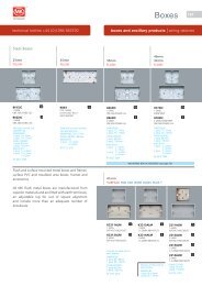
Data Trunking System<br />
Features<br />
l System bend radius 50mm<br />
Exceeds Cat 5e, 6 and 7 data cable<br />
requirements<br />
l Attractive styling complementary to<br />
Logic Plus<br />
l Aesthetic one piece fitting covers<br />
with carriers<br />
l Two equal compartments – maximises<br />
wiring compartment capacity<br />
l Accessory mounting in either or both<br />
compartments – giving flexibility/<br />
versatility<br />
l Unobtrusive screw fixing covers to<br />
maximise security against tampering<br />
l Ease of installation – butt jointed<br />
construction, no mitring required<br />
l Economical – cost effective 3<br />
components (2 x lids, 1 base)<br />
l Suitable for skirting or dado mounting<br />
l Pre-drilled base – ease/speed of<br />
installation<br />
l Accommodates matching <strong>MK</strong> and other<br />
BS switches and sockets<br />
l Interfaces with <strong>MK</strong> Premier, and Ega<br />
Industrial and Ega Mini Trunking and<br />
Conduit Systems<br />
l Strong PVCu sections are resistant to<br />
impact<br />
l Manufactured to high precision<br />
standards<br />
l Full range of components, spares and<br />
accessories<br />
l Mounting frames for LJU6C and Euro<br />
data outlets – cost effective, minimum<br />
space requirement (for mounting in SELV<br />
compartment only).<br />
l Choice of 180 RAL paint colours<br />
l All extrusions manufactured from 90%<br />
recycled material*<br />
* Based on 2008 consumption<br />
For a full range of corresponding products,<br />
see pages 323-328 in the product selector.<br />
description<br />
<strong>Technical</strong> specification<br />
Materials<br />
All components are manufactured from PVCu.<br />
Carriers, covers and cable dividers are extruded.<br />
Carrier couplers, corner carriers, stop ends<br />
and accessory boxes are formed by injection<br />
moulding.<br />
Colours<br />
The system is available in a standard white<br />
colour, with a choice of over 180 RAL paint<br />
colours on special orders.<br />
outlets<br />
The system is designed to accommodate the<br />
complementary range of Logic Plus switches and<br />
sockets. Other <strong>MK</strong> wiring devices may also be<br />
used.<br />
585<br />
The Prestige 2com trunking is a symmetrical two compartment system offering a Cat 6 flexible<br />
solution to routing data cabling whilst maintaining a slow bend radius of 50mm, with a separate<br />
compartment for power cables. The trunking is normally surface mounted at dado or skirting height<br />
but may also be used vertically. The covers are of the snap-on type with the option of screw fixing<br />
for added security against vandalism. Special accessories include adaptors for connection to the full<br />
range of <strong>MK</strong> Ega Mini Trunking.
586 Prestige 2Com <strong>Technical</strong><br />
cable management | perimeter and distribution www.mkelectric.co.uk<br />
Data Trunking System<br />
dimensions (mm)<br />
210<br />
60<br />
1<br />
1<br />
components<br />
Flat angles and tees<br />
These components are<br />
fabricated sections and space<br />
must be allowed for their<br />
inclusion in runs of trunking.<br />
All other components snap<br />
on over standard trunking<br />
profiles.<br />
VTS2001WHI main carrier +<br />
2 x VTS5WHI straight covers<br />
Weight:<br />
2.41 Kg/m<br />
Wall thickness:<br />
VTS2001WHI = 2.5mm, 2.0m<br />
VTS5WHI = 1.7mm<br />
PrESTiGE 2cOM cablE caPaciTy<br />
Type of Size cable compartment 1 compartment 1 compartment 1 compartment 1<br />
conductor Factor with 25mm with 35mm Ext corner<br />
back box back box 50mm data<br />
bend<br />
Full Term cSa 100% Fill (mm2 )<br />
4466<br />
Term at 45% Fill (mm<br />
2236 1633 3132<br />
2 )<br />
2009 1006 734 1409<br />
Power cables number of cables at 45% Fill<br />
PVC Stranded 1.5mm2 8.6 233 116 85 163<br />
2.5mm2 12.6 159 79 58 111<br />
4mm2 16.6 121 60 44 84<br />
6mm2 21.2 94 47 34 66<br />
data cables number of cables at 45% Fill (a) and Full capacity (b)<br />
a b a b a b a b<br />
Cat5E UTP 5.5mm dia. 30.2 66 147 33 74 24 54 46 103<br />
Cat5E STP 6.0mm dia. 36.0 55 124 27 62 20 45 39 87<br />
Cat6 UTP 6.5mm dia. 42.2 47 105 23 52 17 38 33 74<br />
Cat6 STP 7.0mm dia. 49.0 41 91 20 45 14 33 28 63<br />
A<br />
Flat angle Flat tee<br />
B<br />
A<br />
B<br />
B<br />
C<br />
D<br />
A<br />
diMEnSiOnS (mm)<br />
Flat angle a b<br />
VTS2012WHI 310 210<br />
Flat T details a b c d<br />
VTS2014WHI 310 210 410 210
Prestige 2Com <strong>Technical</strong><br />
technical hotline +44 (0)1268 563720 perimeter and distribution | cable management<br />
Data Trunking System<br />
component selection guide<br />
15mm*<br />
to wall<br />
End cap assembly<br />
VTS2006WHI<br />
External corner<br />
assembly<br />
VTS2004WHI<br />
* Minimum distance<br />
vTS2001Whi<br />
34mm*<br />
External corner<br />
Fixing Screw<br />
and cover<br />
VTS2019WHI<br />
vTS5Whi<br />
vTS5Whi<br />
190mm*<br />
34mm*18mm*<br />
internal corner<br />
assembly<br />
VTS2003WHI<br />
18mm*<br />
internal corner<br />
Fixing Screw<br />
and cover<br />
VTS2018WHI<br />
coupler assembly<br />
VTS2005WHI<br />
Flat Tee<br />
VTS2014WHI<br />
15mm* 15mm*<br />
587<br />
Flat angle<br />
VTS2012WHI
588 Prestige 2Com <strong>Technical</strong><br />
cable management | perimeter and distribution www.mkelectric.co.uk<br />
Data Trunking System<br />
installation guide<br />
General installation guidelines<br />
Tools and sundries required for installation:<br />
1. Fine toothed tenon saw or a hacksaw with a 32 – 26 TPI blade for<br />
cutting the trunking, or preferably a circular saw with a 350mm<br />
diameter fine tungsten tipped blade (100TPI approx.)<br />
2. All purpose knife or fine file for trimming of trunking<br />
3. Spirit level, Plumb Bob and chalk line<br />
4. A range of screwdrivers (flat or cross point) to suit fixing screws and<br />
Earth Carrier Connectors<br />
5. A 5.5mm Ø drill bit and No.8 Round head or Pan head screws with<br />
suitable washers to secure the trunking.<br />
6. Soft faced mallet to aid lid fitting<br />
Planning the installation<br />
It is important to spend some time planning the installation, before<br />
starting. Time spent on planning the layout at this stage can avoid<br />
mistakes later on. The installation is designed for a non-conductive<br />
substrate, if you have any queries please contact: <strong>MK</strong> <strong>Technical</strong> Sales<br />
Service Department. Telephone 01268 563720.<br />
1<br />
2<br />
1. Surface to which the trunking is to be installed should be flat and<br />
prepared for decorating.<br />
2. Establish the layout of the trunking run with particular attention to<br />
the following: -<br />
a. Changes in direction of the trunking.<br />
b. The position of any feeds to or from the system.<br />
c. The position of any connections with existing trunking/wiring<br />
systems.<br />
d. Allow for minimum distances between corners, couplers, screw<br />
fixings, angles and tees (please see individual technical sections<br />
for details).<br />
e. When installing at skirting level, ensure room is also allowed<br />
for future floor coverings to be fitted below trunking.<br />
3<br />
34mm<br />
5<br />
4<br />
13mm
technical hotline +44 (0)1268 563720 perimeter and distribution | cable management<br />
Data Trunking System<br />
General notes<br />
Prior to installation strike a line of trunking using<br />
a plumb and chalk line for vertical, and spirit<br />
levels for horizontal runs.<br />
1<br />
2<br />
3<br />
4<br />
Drill Holes in supporting walls prior to fixing<br />
When mounting at skirting level allowance<br />
should be made for thickness of floor finish<br />
Start Installation at a corner position<br />
Debur all carrier cut ends<br />
6<br />
118mm<br />
5<br />
6<br />
7<br />
8<br />
9<br />
Prestige 2Com <strong>Technical</strong><br />
Carrier couplers must be placed at all<br />
junctions between carriers<br />
Leave a gap of 5mm for expansion in long<br />
runs<br />
Fixings require washers and No. 8 Round or<br />
Pan head screws<br />
Fixings to be at 500mm centres and also at<br />
points within 100mm of each end<br />
Cut trunking to allow for mini trunking /<br />
conduit (9a) and box adaptor crossover<br />
bridge (9b).<br />
7<br />
9a<br />
56mm<br />
deep<br />
70mm<br />
wide<br />
100mm max 100mm max<br />
8<br />
500mm max<br />
34mm<br />
deep<br />
47mm<br />
wide<br />
34mm<br />
34mm<br />
210mm<br />
9b<br />
589
590 Prestige 2Com <strong>Technical</strong><br />
cable management | perimeter and distribution www.mkelectric.co.uk<br />
Data Trunking System<br />
installation guide continued<br />
10<br />
18<br />
14<br />
Trunking Covers<br />
to be cut<br />
8-10mm shorter<br />
than Trunking Base<br />
10<br />
15<br />
Debur all cover cut ends<br />
11<br />
Insert accessories in the following order<br />
12<br />
13<br />
14<br />
a Box adaptor<br />
b Accessory Boxes<br />
c Appropriate slide (VTS2081 shown)<br />
d Cross over bridge<br />
e External Corner Radius (into the Data/Telecom compartment)<br />
Power Cables<br />
Data / Communication cables<br />
Mark position where mains entry is required<br />
17<br />
16<br />
e<br />
Centre<br />
12<br />
13<br />
13mm<br />
for joint<br />
cover
technical hotline +44 (0)1268 563720 perimeter and distribution | cable management<br />
Data Trunking System<br />
17<br />
16<br />
d<br />
88mm<br />
for mini<br />
trunking<br />
adaptor<br />
Prestige 2Com <strong>Technical</strong><br />
Figure 1<br />
c<br />
b<br />
15<br />
16<br />
17<br />
18<br />
1 gang 76mm<br />
2 gang 137mm<br />
3 gang 197mm<br />
for outlet boxes<br />
591<br />
Fit covers by locating them correctly into position and pushing<br />
them firmly to snap in place.<br />
Determine whether corners need to be screw fixed (Fig 1).<br />
Continue to locate correctly the Corner and Joint covers<br />
and push them firmly until they snap into place. Fit the<br />
appropriate badge to the Corner Covers.<br />
Fit covers by locating them correctly into position and pushing<br />
them firmly to snap in place.<br />
Fit end caps by pushing them on from the front so the clips<br />
slide behind the retainers and engage in the main carrier.<br />
Drill 4.5mm dia.<br />
clearance hole<br />
to allow fixing<br />
of screw.<br />
a