Fix Speed Booster Set GS with FH-SH - Lowara
Fix Speed Booster Set GS with FH-SH - Lowara
Fix Speed Booster Set GS with FH-SH - Lowara

Create successful ePaper yourself
Turn your PDF publications into a flip-book with our unique Google optimized e-Paper software.
<strong>GS</strong>20-<strong>GS</strong>21-<strong>GS</strong>30<br />
Series<br />
FIXED-SPEED PRESSURE BOOSTER SETS WITH<br />
HORIZONTAL CENTRIFUGAL ELECTRIC PUMPS <strong>FH</strong> and <strong>SH</strong> SERIES<br />
Cod. od. 191000491 191000491 R RRev<br />
R ev ev.B ev .B Ed.06/2012<br />
Ed.06/2012<br />
50 50 Hz<br />
Hz
CONTENTS<br />
CONTENTS<br />
General introduction .............................................................................................................................5<br />
Choice and selection .............................................................................................................................6<br />
<strong>GS</strong>.../<strong>FH</strong> <strong>GS</strong>.../<strong>FH</strong> <strong>GS</strong>.../<strong>FH</strong> Series ................................................................................................................................13<br />
3<br />
13<br />
15<br />
Range ...............................................................................................................................................15<br />
16<br />
Characteristics of the electric pumps .............................................................................................16<br />
21<br />
Hydraulic performance tables ...........................................................................................................21<br />
24<br />
Electric data tables ...........................................................................................................................24<br />
25<br />
<strong>GS</strong>D20 - <strong>GS</strong>Y20 Series ......................................................................................................................25<br />
31<br />
<strong>GS</strong>D21 - <strong>GS</strong>Y21 Series ......................................................................................................................31<br />
39<br />
<strong>GS</strong>D30 - <strong>GS</strong>Y30 Series ......................................................................................................................39<br />
46<br />
Operating characteristics at 50 Hz ...................................................................................................46<br />
59<br />
Hc pressure drop curve ....................................................................................................................59
CONTENTS<br />
CONTENTS<br />
<strong>GS</strong>.../<strong>SH</strong> <strong>GS</strong>.../<strong>SH</strong> Series ...............................................................................................................................63<br />
4<br />
63<br />
65<br />
Range ..............................................................................................................................................65<br />
66<br />
Characteristics of the electric pumps ............................................................................................66<br />
71<br />
Hydraulic performance tables ...........................................................................................................71<br />
74<br />
Electric data tables............................................................................................................................74<br />
75<br />
<strong>GS</strong>D20 - <strong>GS</strong>Y20 Series ......................................................................................................................75<br />
81<br />
<strong>GS</strong>D21 - <strong>GS</strong>Y21 Series ......................................................................................................................81<br />
89<br />
<strong>GS</strong>D30 - <strong>GS</strong>Y30 Series ......................................................................................................................89<br />
96<br />
Operating characteristics at 50 Hz ...................................................................................................96<br />
110<br />
Hc pressure drop curve ...............................................................................................................110<br />
113<br />
Accessories ................................................................................................................................113<br />
117<br />
Technical Appendix .....................................................................................................................117
BOOSTER BOOSTER SETS SETS <strong>GS</strong> <strong>GS</strong> SERIES<br />
SERIES<br />
GENERAL GENERAL INTRODUCTION INTRODUCTION - - PRODUCT PRODUCT DESCRIPTION<br />
DESCRIPTION<br />
The <strong>GS</strong> series pressure booster units mainly comprise pumping stations assembled <strong>with</strong> two or three SV series vertical<br />
multistage pumps, or <strong>with</strong> <strong>FH</strong> or <strong>SH</strong> series enbloc horizontal pumps. A smaller pump can also be added to the main<br />
ones. Generally known as a jockey pump, it provides for minor usages in order to maintain system pressure <strong>with</strong>out<br />
starting the service pump.<br />
The <strong>GS</strong> series pressure booster units are constant speed sets and are used to distribute water in heating or filling<br />
systems.<br />
The pumps are mounted on a single base together <strong>with</strong> the other hydraulic components, such as on-off valves, check<br />
valves and the delivery and return manifolds.<br />
The electrical panel, supplied <strong>with</strong> a mounting bracket, is attached to the pressure booster unit base.<br />
The pumps start and stop according to the signals sent by the pressure transducer to the electrical control panel.<br />
The latter is fitted <strong>with</strong> an integrated electronic board. The pumps start and stop automatically depending on the<br />
water demand of the system.<br />
These pressure booster systems are combined <strong>with</strong> suitable expansion tanks in order to guarantee stable operation<br />
and reduce the starting frequency of the pumps.<br />
For the correct choice in capacity of the expansion vessel, see the relative chapter on page 126 of the catalogue.<br />
DESCRIPTION DESCRIPTION OF OF OPERA OPERATION<br />
OPERA TION<br />
The pumps start and stop according to the set pressures detected by the pressure transducer, thus ensuring the<br />
required amount of water is delivered. The pressure values can be directly set on the electronic board.<br />
For units <strong>with</strong> jockey pump, the latter will start first and stop last, depending on the set pressure values.<br />
When a tap is opened, water is drawn off from the tank, the pressure starts to fall until it reaches the starting value<br />
of the first pump. The delivery of water increases, the pressure falls even further and the other pumps start in<br />
sequence according to the demand for water.<br />
When consumption falls, the pressure in the system increases and the pumps stop when the set threshold pressure<br />
values are reached.<br />
If consumption falls to zero user demand, the last pump also stops.<br />
If the “timer” function is used, the last pump to work will remain operating for a set time after it is switched off, in<br />
order to reach maximum pressure. Make sure the maximum pressure is compatible <strong>with</strong> the system in which the<br />
pump is installed.<br />
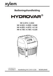
Example: <strong>GS</strong> series pressure booster units, operation.<br />
Stop<br />
H<br />
P1<br />
P2<br />
P3<br />
P1<br />
Start P2<br />
P3<br />
Pump 1 Pump 2 Pump 3<br />
�p<br />
∆p pressure differential between pumps, can be reduced to 0,5 bar.<br />
5<br />
Q
BOOSTER BOOSTER SETS SETS <strong>GS</strong> <strong>GS</strong> SERIES<br />
SERIES<br />
CHOICE CHOICE AND AND SELECTION<br />
SELECTION<br />
The demand of a water distribution system is generally determined by the designer according to the type of user<br />
structure being served.<br />
Users can be schools, hospitals, homes, offices, industries, hotels, shopping centres and for each the water demand<br />
changes due to the different requirements of the people living and working in these structures. To find the correct<br />
flow rate for the system in question, it is possible to consult pre-calculated tables that give an idea of the flow rate for<br />
the typology of user to serve (see pages 118-119 in this catalogue).<br />
Integral system calculation, instead, prevents excessive oversizing and therefore reduces running and installation<br />
costs.<br />
The theoretical water demand is calculated by summing the demand of each user. As, however, it is improbable that<br />
all users will want to use water at the same time, real demand is lower than theoretical demand.<br />
After defining the flow rate of the system, the head must be calculated. This must consider the following:<br />
- geodesic head: difference in level between the pumping station and the highest user<br />
- residual head: pressure demand from the most unfavourable user to serve<br />
- pressure drops: value in metres of pressure drops due to friction in the delivery pipes<br />
- inlet height: difference in level between the pump inlet and the surface of the water in the tank<br />
(positive or negative depending on the installation type)<br />
- inlet pressure drops: value in metres of pressure drops due to friction in the inlet piping and in any curves and valves.<br />
After analysing the above, the head required for the system is calculated.<br />
Now that the flow rate and head values are known, the most suitable pressure booster unit for the system can be<br />
chosen. The designer must decide whether to choose a pressure booster unit <strong>with</strong> two or three pumps, the third<br />
being a reserve pump satisfying demand during pump maintenance periods.<br />
INST INSTALLA INST ALLA ALLATION<br />
ALLA TION<br />
The <strong>GS</strong> series of pressure booster units must be installed in areas protected from frost and adequately ventilated in<br />
order to allow the motors to cool. The delivery and intake pipes should be connected using anti-vibration joints in<br />
order to limit vibrations and resonance in the system.<br />
Anti-vibration joint<br />
6<br />
delivery<br />
suction
BOOSTER BOOSTER SETS SETS <strong>GS</strong> <strong>GS</strong> SERIES<br />
SERIES<br />
INST INSTALLA INST ALLA ALLATION<br />
ALLA TION<br />
The <strong>GS</strong> series of pressure booster units are generally connected to pressurised tanks <strong>with</strong> a suitable capacity for the<br />
system. These tanks are normally expansion vessels for capacities up to 500 L. Tanks <strong>with</strong> higher capacities can also be<br />
supplied if necessary. In these cases, they are air-cushion tanks and a compressor is required to maintain the pressure<br />
inside the tank.<br />
In both cases, the tanks must be connected on the pressure booster unit delivery line. The system, commonly known<br />
as an “autoclave”, provides the system <strong>with</strong> a reserve of pressurised water and prevents frequent pump start-ups.<br />
For these systems, sufficient space must always be allowed in the area where the pressure booster set is installed.<br />
Always check maximum pump pressure in order to choose the right tanks for the pressure in question.<br />
SUCTION SUCTION SUCTION CONDITIONS<br />
CONDITIONS<br />
CONDITIONS<br />
Installation of the pressure booster set must be assessed especially as regards intake conditions. Intake conditions can<br />
negatively or positively affect the performance of the pressure booster unit and consequently system performance.<br />
A positive suction head is ideal for a pressure booster unit as it keeps the pumps constantly primed and the positive<br />
difference in level adds pressure to the system.<br />
A negative suction head is different. In this case, the risks for the pumps are priming which is connected <strong>with</strong> the<br />
intake piping, the NP<strong>SH</strong> of the pump and the difference in level between the pump and the water in the tank.<br />
In this type of installation, after checking the intake capacity of the pump, the overall pressure drop in the intake line<br />
must be calculated as this will reduce pump performance and consequently that of the pressure booster unit.<br />
In order to select the right pressure booster unit, the performance levels of the pumps installed on them are indicated<br />
in this catalogue. To simplify the calculation of net pressure, pressure drop curves, both for the delivery and intake<br />
lines of the pumps have been included (see the relative chapter).<br />
7
BOOSTER BOOSTER SETS SETS <strong>GS</strong> <strong>GS</strong> SERIES<br />
SERIES<br />
CALCULA CALCULATING CALCULA TING NET NET NET PRES PRESSURE<br />
PRES SURE<br />
When selecting the <strong>GS</strong> series of pressure booster units, reference must be made to pump performance.<br />
Performance is calculated from the characteristic curves of the pumps and does not consider any pressure drops<br />
generated by pipes and valves as in the pressure booster units.<br />
To help choose the right pressure booster unit and calculate the correct pressure at the delivery manifold, the following<br />
example is shown:<br />
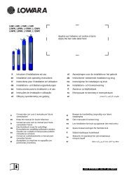
Given the duty point Q = 60 m 3 /h H = 36 mca and <strong>with</strong> two pumps working, the pump <strong>with</strong> the most suitable<br />
characteristic curve is chosen, that is, the one <strong>with</strong> a curve that guarantees the required flow and head values.<br />
H [m]<br />
NP<strong>SH</strong> [m]<br />
0 100 200 300 400 500 600 Q [US 700 gpm]<br />
60<br />
50<br />
40<br />
30<br />
20<br />
8<br />
6<br />
4<br />
2<br />
<strong>FH</strong> 40-200/55 ~ 2900 [rpm]<br />
ISO 9906 - Annex A<br />
0 100 200 300 400 500 Q [Imp gpm]<br />
1 P 2 P 3 P<br />
0<br />
0<br />
0 20 40 60 80 100 120 140 Q [m 160<br />
3 /h]<br />
0 500 1000 1500 2000 2500 Q [l/min]<br />
From the example, we have chosen the <strong>FH</strong>40-200/55 series<br />
pump which guarantees system performance. The pump<br />
curve is slightly oversized, but this provides a safety margin<br />
to counter the pressure drops in the pressure booster unit<br />
pipes.<br />
To know the effective pressure at the delivery manifold outlet,<br />
the pressure drops in the suction and delivery lines of each<br />
pump are calculated.<br />
To simplify calculations, the pressure drop curves for each<br />
pump, on page 131 of this catalogue, are used.<br />
Assuming a pressure booster unit <strong>with</strong> check valves on the<br />
suction line (curve B of Hc pressure drops) has been selected,<br />
one proceeds as follows:<br />
The Hc pressure drops on the pump suction line are to evaluated on the “B” curve. At a flow rate of 30 m 3 /h the value<br />
of Hc = 1,2 m.<br />
Similarly, the Hc pressure drops on the delivery line of the pump, as evaluated on the “B” curve, are analysed. At a<br />
flow rate of 30 m 3 /h, the value of Hc is 0,02 m.<br />
The total pressure drop on the delivery and suction lines is therefore 1,22 m.<br />
As regards the pressure drop in the suction and delivery manifolds, 5% <strong>with</strong> respect to the pressure drops in the<br />
pump suction and delivery can be considered.<br />
In this case, therefore, the value is 0,061 m.<br />
The total pressure drop is approximately: 1,281 m.<br />
Analysing the performance of the unit at a flow rate of 60 m 3 /h, the head H is 38 m.<br />
The net pressure at the delivery manifold is 38 – 1,281 = 36,7 m.<br />
Comparing this value <strong>with</strong> the rated value, 36,7m > 36m.<br />
The unit can therefore satisfy the demand of the system.<br />
H [ft]<br />
180<br />
160<br />
140<br />
120<br />
100<br />
80<br />
25<br />
20<br />
15<br />
10<br />
5<br />
NP<strong>SH</strong> [ft]<br />
76013_A_CH<br />
8
BOOSTER BOOSTER SETS SETS <strong>GS</strong> <strong>GS</strong> SERIES<br />
SERIES<br />
SUCTION SUCTION SUCTION CONDITIONS<br />
CONDITIONS<br />
CONDITIONS<br />
The above example does not consider the suction conditions of the pressure booster unit which, similarly, affect final<br />
performance. It is therefore always best to check the suction line for leaks, especially as regards positive head installations.<br />
An example of positive head installation relative to the above case is shown below:<br />
The chosen diameter of the suction piping is DN100.<br />
90° curve DN100 = 2,96 m<br />
Damper DN100 = 0,56 m<br />
Drain valve DN100 = 0,39 m (calculated from supplier data)<br />
Piping DN100 = 0,27 m (assuming a length of 2,5 m)<br />
Piping DN100, intake manifold = 0,1 m (length of manifold 0,89 m)<br />
Pressure drops on pump suction side (curve B) = 1,2m<br />
∑ pressure drops = 5,48 m<br />
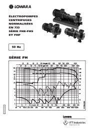
Remembering that: NP<strong>SH</strong> available = 10,33 + Hg - 5,48<br />
Replacing: 10,33 + Hg - 5,48 ≥ 2,5<br />
Hg<br />
9<br />
In the positive head installation, the designer must<br />
calculate the minimum installation height Hg of the<br />
pump in safety conditions in order to avoid<br />
cavitation and, therefore, de-priming of the pump.<br />
The relationship that must be checked and which<br />
connects this measurement is the following:<br />
NP<strong>SH</strong> available ≥ NP<strong>SH</strong> requested where equality is the<br />
limit condition.<br />
NP<strong>SH</strong> available = Patm + Hg - ∑ pressure drops.<br />
Where:<br />
Patm is the atmospheric pressure, equal to 10,33 m<br />
Hg is the geodetic difference in level<br />
The pressure drops are connected <strong>with</strong> to the<br />
suction piping and relative valves (foot and cut-off<br />
valves)<br />
NP<strong>SH</strong> requested is a pump parameter taken from the<br />
performance curve of the pump which in our case,<br />
at a flow rate of 30 m 3 /h corresponds to 2,5 m.<br />
Before calculating the NP<strong>SH</strong> available, the suction<br />
pressure drops are calculated using the tables on<br />
pages 199-200 in this catalogue, considering a<br />
material such as steel.<br />
Hg = 2,5 + 5,48 – 10,33 = - 2,35 m representing the limit, for which reason: NP<strong>SH</strong> available = NP<strong>SH</strong> requested<br />
Generally speaking, therefore, in order to assure correct operating conditions as regards the risk of cavitation, the<br />
pump must be positioned above the level of the tank so that the suction height is lower than the limit value of<br />
2,35 m.
SET SET IDENTIFICA<br />
IDENTIFICATION IDENTIFICA<br />
IDENTIFICATION<br />
TION CODE CODE<br />
CODE<br />
<strong>GS</strong> D I 21 RA / <strong>FH</strong>E50-200/110 + CA120/55 / DW / PA<br />
OPTIONS OPTIONS OPTIONS (ON (ON (ON DEMAND)<br />
DEMAND)<br />
10<br />
Code of jockey pump (if present)<br />
Code of service pump<br />
Versions:<br />
_ = Standard version<br />
DW = Drinking water version<br />
A316 = Special version AISI 316<br />
A304 = Special version AISI 304<br />
_ = <strong>with</strong> check valve on delivery side<br />
RA = <strong>with</strong> check valve on intake side<br />
20 = 2 service pumps<br />
21 = 2 service pumps + 1 jockey pump<br />
30 = 3 service pumps<br />
_ = standard<br />
I = <strong>with</strong> self-test<br />
Options<br />
Electric starting of service pump<br />
D = direct, up to and including 22 kW<br />
Y = star/delta<br />
SF = Softstarter<br />
Reference to series<br />
<strong>GS</strong> = command from a pressure sensor<br />
BAP High pressure switch installed on the delivery manifold.<br />
CM Oversized suction or delivery manifold.<br />
CV Unit <strong>with</strong> expansion vessels (normally 24 litres supplied separately and not mounted).<br />
IP65 Control panel versions IP65.<br />
KV Voltmeter Kit <strong>with</strong> phase switch.<br />
MA Pressure gauge installed on suction manifold.<br />
PA Minimum pressure gauge installed on the suction manifold for dry-running protection.<br />
RA Check valves installed on suction side.<br />
RE Panel incorporating a thermostat-controlled anti-condensate heater.<br />
RV Electrical panel <strong>with</strong> missing-phase, phase-asymmetry, minimum – maximum voltage control.<br />
SA No intake: no suction valves and suction manifold.<br />
SC Group <strong>with</strong> no control devices, such as pressure switches and transmitters; the pressure gauge is present.<br />
SCA No suction manifold (suction valves present).<br />
VA Electric control panel fitted <strong>with</strong> analogue voltmeter and ammeter.<br />
WM Wall-mounted electrical panel <strong>with</strong> fixing tabs. Cables L= 5m<br />
PP Pressure-switch control.<br />
AVAILABLE AILABLE VERSIONS<br />
VERSIONS<br />
A304 Main component in contact <strong>with</strong> liquid in stainless steel Aisi 304 or superior; gasket, sealing tape and thread sealing are suitable for<br />
drinking water. Bolts and screws galvanized. Flanges not in contact <strong>with</strong> the liquid in galvanized steel.<br />
B304 Main component in contact <strong>with</strong> liquid in stainless steel Aisi 304 or superior; gasket, sealing tape and thread sealing are suitable for<br />
drinking water. Bolts and screws in Aisi 304 or superior. Flanges not in contact <strong>with</strong> the liquid in Aisi 304 or superior.<br />
C304 Main component in contact <strong>with</strong> liquid in stainless steel Aisi 304 or superior; gasket, sealing tape and thread sealing are suitable for<br />
drinking water. Baseplate, frame, supports, bolts and screws in Aisi 304 or superior. Flanges not in contact <strong>with</strong> the liquid in Aisi 304<br />
or superior. Valves and their components completely in Aisi 304 or superior (body, disc, plate).<br />
A316 Main component in contact <strong>with</strong> liquid in stainless steel Aisi 316; gasket, sealing tape and thread sealing are suitable for drinking<br />
water. Pumps in Aisi 316 material. Bolts and screws galvanized. Flanges not in contact <strong>with</strong> the liquid in galvanized steel.<br />
B316 Main component in contact <strong>with</strong> liquid in stainless steel Aisi 316; gasket, sealing tape and thread sealing are suitable for<br />
drinkingwater. Pumps in Aisi 316 material. Bolts and screws in Aisi 316. Flanges not in contact <strong>with</strong> the liquid in Aisi 316.<br />
C316 Main component in contact <strong>with</strong> liquid in stainless steel Aisi 316; gasket, sealing tape and thread sealing are suitable for drinking<br />
water. Pumps in Aisi 316 material. Baseplate, frame, supports, bolts and screws in Aisi 316. Flanges not in contact <strong>with</strong> the liquid in<br />
Aisi 316. Valves and their components completely in Aisi 316 (body, disc, plate).<br />
DW Main component in contact <strong>with</strong> fluid suitable for drinking water or in stainless steel AISI 304 or superior quality.
CONTROL CONTROL P PPANEL<br />
P ANEL FOR FOR <strong>GS</strong>20, <strong>GS</strong>20, <strong>GS</strong>20, <strong>GS</strong>21, <strong>GS</strong>21, <strong>GS</strong>21, <strong>GS</strong>30<br />
<strong>GS</strong>30<br />
Electric Electric panel panel panel for powering, controlling and protecting a<br />
maximum of three three-phase pumps, <strong>with</strong> sheet steel casing<br />
(fig. 1) and protected to IP55.<br />
Main characteristics:<br />
- General doorlock switch, fuse holders and fuses, starting<br />
contactors and circuit breakers.<br />
- Standard input voltage: 3x400Vca +/-10%, 50/60Hz.<br />
Non-standard voltages available on request, 1x230Vac<br />
+/-10%, 3x230ca +/-10%, 50/60Hz.<br />
- Transformer for auxiliary low voltage circuit; auxiliary<br />
voltage 24Vac.<br />
- <strong>Lowara</strong> SM30 digital microprocessor-controlled control unit<br />
<strong>with</strong> LCD display and programming keyboard (see fig. 2),<br />
featuring the following functions:<br />
• Indicator lamps: power on (ref.1), general fault (ref.2),<br />
no water alarm (ref.3), pump running (ref.4);<br />
• Programming keyboard (ref.5);<br />
• Manual pump stop/start (one button for each pump) (ref.5);<br />
• Automatic cascade pump control <strong>with</strong> two electronic<br />
pressure transmitters. If a sensor develops a fault, the board<br />
automatically switches to the second sensor.<br />
Pressure switch control available on request.<br />
• Jockey pump management.<br />
• Cycle reversal function (can be disabled). Automatically<br />
switches pumps after every start/stop cycle.<br />
• Automatic, manual or disabled mode switches for each<br />
pump (inside the board).<br />
• Periodic system self-test <strong>with</strong> an electrovalve command<br />
which opens the hydraulic circuit, simulates a pressure drop<br />
and consequently activates the control devices (pressure<br />
switches and pressure transmitters). Pump diagnostics.<br />
• No-water protection system alternatives: float, minimum pressure switch, external contact or electrode probes<br />
<strong>with</strong> sensitivity adjustment.<br />
• Adjustable timer delaying tripping the no-water protection system.<br />
• Adjustable timer delaying starting of each pump.<br />
• Adjustable timer extending the operation of each pump.<br />
• System pressure drop offset function, only available <strong>with</strong> pressure sensor. This function improves system stability.<br />
• Adjustable analogue output, 0(4)-20mA or 0-2(10)Vdc, for visualising the analogue input signal.<br />
• Configurable relay <strong>with</strong> volt-free contact, delayed activation, signalling the following conditions:<br />
- Motor overload protection alarm.<br />
- No-water circuit alarm.<br />
- Pressure sensor fault.<br />
- Out-of-curve operation alarms (only if self-test is disabled).<br />
- Maximum intake pressure alarm.<br />
- Electrovalve opening permission for self-test circuit.<br />
• Configurable digital inputs.<br />
- AUX1 input configuration, maximum pressure switch or external self-test.<br />
- AUX2 input configuration, permission from external device (NO) or external alarm (NC).<br />
- AUX3 input configuration, change set (NO) or pressure switch operating out-of-curve.<br />
• 12Vdc output for powering the acoustic alarm.<br />
11<br />
fig. 1<br />
1<br />
2<br />
3<br />
4<br />
<strong>GS</strong><br />
fig. 2<br />
5
CONTROL CONTROL P PPANEL<br />
P ANEL FOR FOR <strong>GS</strong>20, <strong>GS</strong>20, <strong>GS</strong>20, <strong>GS</strong>21, <strong>GS</strong>21, <strong>GS</strong>21, <strong>GS</strong>30<br />
<strong>GS</strong>30<br />
• Alarms log and hour counters for each installed pump. Alarms visualised on display:<br />
- Maximum, minimum pressure;<br />
- Circuit breaker for each motor;<br />
- Pressure transmitter fault.<br />
- Out-of-curve operation;<br />
- No water;<br />
- Block for tripped external device (PTC, temperature probe, etc.)<br />
- Auto-test failed<br />
All the alarms light the Fault lamp (ref.2 – fig.2)<br />
The no-water alarm lights the Level alarm lamp (ref.3 – fig.2)<br />
• Standard, RS485 serial communication, slave, and ModBus RTU protocol.<br />
• The <strong>GS</strong>M/GPRS module can be connected to send pump alarms and/or operating states via sms or e-mail.<br />
Connection via RS485 serial connection. SIM card not included.<br />
• A relay board (optional) can be connected to boost the following signals: pump running, aut-man mode for<br />
each pump, overload alarm, no-water alarm, maximum/minimum pressure alarm, power on, self-test failed.<br />
The optional signal booster board has six relays, each of which can be configured using the <strong>Lowara</strong> SM30<br />
control unit.<br />
12
<strong>GS</strong>.../<strong>FH</strong> Series<br />
<strong>Fix</strong>ed-speed pressure booster sets<br />
Horizontal Centrifugal electric pumps <strong>FH</strong> series<br />
equipped <strong>with</strong> high efficiency motors<br />
flow rate up to 630 m 3 /h<br />
50 50 Hz<br />
Hz<br />
13<br />
<strong>GS</strong>.../<strong>FH</strong><br />
<strong>GS</strong>.../<strong>FH</strong>
<strong>GS</strong>.../<strong>FH</strong><br />
<strong>GS</strong>.../<strong>FH</strong><br />
<strong>GS</strong>.../<strong>FH</strong> <strong>GS</strong>.../<strong>FH</strong> SERIES<br />
SERIES<br />
HYDRA HYDRAULIC HYDRA ULIC PERFORMANCE PERFORMANCE RANGE RANGE A AAT<br />
A T 50 50 50 Hz<br />
Hz<br />
H [m]<br />
100<br />
90<br />
80<br />
70<br />
60<br />
50<br />
40<br />
30<br />
20<br />
10<br />
9<br />
8<br />
7<br />
6<br />
5<br />
20 30 40 50 60 70 80 100 200 300 400 500 600 700800 1000<br />
2000 Q 3000 [Imp gpm]<br />
30 40 50 60 70 80 100 200 300 400 500 600 700800 1000<br />
2000 3000 Q 4000 [US gpm]<br />
<strong>GS</strong>.../<strong>FH</strong><br />
<strong>GS</strong>.../<strong>FH</strong><br />
5 6 7 8 9 10 20 30 40 50 60 70 80 90100 200 300 400 500 600 700800900 Q 1000 [m 3 /h]<br />
100 200 300 400 500 600 800 1000 2000 3000 4000 5000 6000 8000 10000<br />
14<br />
Q [l/min]<br />
400<br />
300<br />
200<br />
100<br />
90<br />
80<br />
70<br />
60<br />
50<br />
40<br />
30<br />
20<br />
H [ft]<br />
76039_B_CH
RANGE<br />
RANGE<br />
The <strong>GS</strong> series of fixed-speed pressure boosters comprises models <strong>with</strong> 2 or 3 electric service pumps and<br />
an optional jockey pump in order to satisfy the specific needs of every application.<br />
<strong>GS</strong>20 <strong>GS</strong>20 SETS SETS<br />
SETS<br />
• <strong>Fix</strong>ed-speed sets <strong>with</strong> two<br />
horizontal service pumps,<br />
<strong>FH</strong> series, <strong>with</strong> power ratings<br />
up to 55 kW.<br />
<strong>GS</strong>21 <strong>GS</strong>21 SETS SETS<br />
SETS<br />
• <strong>Fix</strong>ed-speed sets <strong>with</strong> two<br />
service pumps and a jockey pump.<br />
Horizontal service electric pumps,<br />
<strong>FH</strong> series, <strong>with</strong> power ratings<br />
up to 55 kW.<br />
<strong>GS</strong>30 <strong>GS</strong>30 SETS SETS<br />
SETS<br />
• <strong>Fix</strong>ed-speed sets <strong>with</strong> three<br />
horizontal service pumps,<br />
<strong>FH</strong> series, <strong>with</strong> power ratings<br />
up to 55 kW.<br />
REFERENCE REFERENCE ST STANDARDS<br />
ST ANDARDS<br />
15<br />
Head Head up to 100m.<br />
Flow Flow rate rate up to 420 m3 /h.<br />
Head Head up to 100m.<br />
Flow Flow rate rate up to 420 m3 /h.<br />
Head Head up to 100m.<br />
Flow Flow rate rate up to 630 m3 /h.<br />
• The <strong>Lowara</strong> booster sets are CE-marked for conformity <strong>with</strong> the<br />
following directives:<br />
– Machinery Directive: 2006/42/EC.<br />
– Low Voltage Directive 2006/95/EC.<br />
– Electromagnetic Compatibility Directive 2004/108/EC<br />
Electric pump performance complies <strong>with</strong> the following standard:<br />
ISO 9906-A Rotodynamic pumps – hydraulic performance acceptance tests.<br />
<strong>GS</strong>.../<strong>FH</strong><br />
<strong>GS</strong>.../<strong>FH</strong>
<strong>GS</strong>.../<strong>FH</strong><br />
<strong>GS</strong>.../<strong>FH</strong><br />
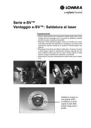
CHARACTERISTIC<br />
CHARACTERISTICS CHARACTERISTIC S OF OF THE THE ELECTRIC ELECTRIC PUMPS<br />
PUMPS<br />
The <strong>FH</strong> series of horizontal centrifugal pumps are single-impeller (<strong>FH</strong>E, <strong>FH</strong>S) or twin-impeller (2<strong>FH</strong>E) <strong>with</strong> cast-iron<br />
bodies and AISI 316L stainless steel shafts.<br />
Impeller: made of AISI 316L stainless steel laser technology welded, for sizes 32, 40, 50, 65-125, or cast iron for sizes<br />
65-160, 65-200, 65-250, 65-315, 80, 100, 125, 150.<br />
Hydraulic sizes and nominal diameter DN of suction and delivery ports according to EN 733 (ex DIN 24255).<br />
Flanges according to EN 1092-2 (ex UNI 2236) and DIN 2532.<br />
Motor: enbloc motor/pump coupling <strong>with</strong> bracket <strong>with</strong> impeller directly splined onto the motor shaft protrusion<br />
(<strong>FH</strong>E, 2<strong>FH</strong>E) or <strong>with</strong> joint, adaptor and rigid joint splined onto the shaft protrusion of normalised motors (<strong>FH</strong>S).<br />
Mechanical Mechanical seal<br />
seal<br />
16<br />
Technical echnical data data: data<br />
Flow rate: up to 650 m 3 /h (2 poles).<br />
750 m 3 /h (4 poles).<br />
Head: over 100 m (2 poles).<br />
60 m (4 poles).<br />
Temperature of pumped liquid:<br />
from -20°C to +85°C for <strong>FH</strong> 32, 40, 50,<br />
65, 80 standard version.<br />
from -30°C to +120°C for <strong>FH</strong> 100, 125,<br />
150 standard version (including<br />
65-315, 80-315 and 80-400).<br />
Up to +140°C for <strong>FH</strong> 100, 125, 150<br />
on request.<br />
Mechanical seal according to EN12756 (ex DIN 24960).<br />
Mechanical seal lubricated from circulation duct between the delivery line and the seal for <strong>FH</strong> 32, 40, 50, 65, 80<br />
(apart from 65-315, 80-315 and 80-400).<br />
Seat for mechanical seal peg for <strong>FH</strong>32, 40, 50, 65, 80 (apart from 65-315, 80 315 and 80-400).<br />
Anti-clockwise rotation looking at the pump from the suction port side.<br />
Motor Motor<br />
Motor<br />
Short circuit squirrel cage motor, totally enclosed, fan-cooled. Standard Standard supplied supplied IE2/IE3 IE2/IE3 IE2/IE3 motors motors are are are compliant<br />
compliant<br />
<strong>with</strong> <strong>with</strong> Regulation Regulation (EC) (EC) no. no. 640/2009 640/2009 and and IEC IEC 60034-30 60034-30. 60034-30<br />
Protection class IP55.<br />
Insulation class 155 (F).<br />
Performance levels according to EN 60034-1.<br />
Continuous service.<br />
Maximum ambient temperature: +40°C.<br />
Condensate drain plugs on all LOWARA motors.<br />
Standard voltage:<br />
Single-phase version 220-240 V, 50 Hz<br />
Three-phase version 220-240/380-415 V, 50 Hz for power ratings up to 3 kW;<br />
380-415/660-690 V, 50 Hz for power ratings higher than 3 kW.<br />
For electrical data of the motors used see Technical Appendix.
CHARACTERISTIC<br />
CHARACTERISTICS CHARACTERISTIC S OF OF THE THE ELECTRIC ELECTRIC PUMPS PUMPS PUMPS USED USED IN IN THE THE <strong>GS</strong><br />
<strong>GS</strong><br />
SERIES SERIES OF OF OF PRES PRESSURE PRES SURE BOOSTER BOOSTER SETS<br />
SETS<br />
HORIZONT<br />
HORIZONTAL HORIZONT AL ELECTRIC ELECTRIC PUMPS PUMPS SERIES:<br />
SERIES:<br />
<strong>FH</strong>E <strong>FH</strong>E 32, 32, 40, 40, 50, 50, 65, 65, 80<br />
80<br />
<strong>FH</strong>S <strong>FH</strong>S 65, 65, 80<br />
80<br />
Twin-impeller (2<strong>FH</strong>E) or single-impeller (<strong>FH</strong>E, <strong>FH</strong>S) cast iron horizontal centrifugal pump and shaft made of<br />
AISI 316L stainless steel.<br />
Impeller: made of AISI 316L stainless steel laser technology welded, for sizes 32, 40, 65-125 or cast iron<br />
for sizes 65-160, 65-200, 65-250, 80.<br />
Hydraulic sizes and nominal diameter DN of suction and discharge ports according to EN 733 (ex DIN 24255).<br />
Flanges according to EN 1092-2 (ex UNI 2236) and DIN 2532.<br />
Motor: enbloc motor/pump coupling <strong>with</strong> bracket <strong>with</strong> impeller directly splined onto the motor shaft protrusion<br />
(<strong>FH</strong>E, 2<strong>FH</strong>E) or <strong>with</strong> joint, adaptor and rigid joint splined onto the shaft protrusion of normalised motors (<strong>FH</strong>S).<br />
Standard Standard supplied supplied IE2/IE3 IE2/IE3 three-phase three-phase surface surface motors motors ≥ 0,75 0,75 kW kW are are compliant compliant <strong>with</strong><br />
<strong>with</strong><br />
Regulation Regulation (EC) (EC) no. no. 640/2009 640/2009 and and and IEC IEC IEC 60034-30 60034-30. 60034-30 Performance levels according to EN 60034-1.<br />
Painting: cathodic epoxy enamel.<br />
<strong>Booster</strong> <strong>Booster</strong> sets sets drinking drinking water water use use (DW (DW version), version), pump pump has has to to have have Ceramic, Ceramic, Carbon, Carbon, EPDM<br />
EPDM<br />
seals seals.<br />
seals<br />
17<br />
<strong>GS</strong>.../<strong>FH</strong><br />
<strong>GS</strong>.../<strong>FH</strong>
<strong>GS</strong>.../<strong>FH</strong><br />
<strong>GS</strong>.../<strong>FH</strong><br />
CARATTERISTICHE E LIMITI D' IMPIEGO GRUPPI GM_<strong>GS</strong> <strong>FH</strong>/<strong>SH</strong><br />
OPERA OPERATING OPERA OPERATING<br />
TING CHARACTERISTIC<br />
CHARACTERISTICS CHARACTERISTIC S AND AND LIMITS<br />
LIMITS<br />
Liquids handled Water containing no gas or corrosive and/or aggressive substances.<br />
Fluid temperature Above -10°C a + 80 °C<br />
Ambient temperature Above 0°C a + 40 °C<br />
Maximum operating pressure Max 8 bar, 10 bar, 16 bar *<br />
Minimum inlet pressure According to NP<strong>SH</strong> curve and losses, <strong>with</strong> a minimum margin of 0.5 m<br />
Maximum inlet pressure<br />
The inlet pressure added to the pressure of the pump at zero flow must be lower than the<br />
maximum operating pressure of the set.<br />
Installation<br />
Indoors, protected from the weather. Away from heat sources. Max elevation 1000 m ASL.<br />
Max humidity 50% <strong>with</strong>out condensation.<br />
Hourly starts<br />
(single pump)<br />
Sound emission See table<br />
0,25 kW � Pn � 3 kW max 60 starts per hour. Direct motor start;<br />
4 kW � Pn � 7,5 kW max 40 starts per hour. Direct motor start;<br />
11 kW � Pn � kW max 30 starts per hour. Direct motor start;<br />
18,5 kW � Pn � 22 kW max 24 starts per hour. Direct motor start;<br />
30 kW � Pn � 37 kW max 16 starts per hour. Start/delta start;<br />
Pn = 45 kW max 8 starts per hour. Start/delta start;<br />
* On request, PN above in function of the service pump gfixo_2p-en_c_ti<br />
If there's jockey pump, PN can be lower<br />
LIVELLI EMISSIONE SONORA GRUPPI <strong>GS</strong><br />
SOUND SOUND SOUND EMIS EMISSION EMIS SION LEVELS<br />
LEVELS<br />
50 Hz 2900 rpm LpA (dB ±2)**<br />
P2 (kW) IEC* G..20 G..30<br />
0,75 90R
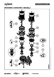
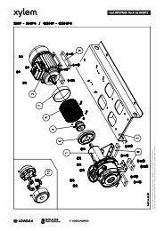
MAIN MAIN COMPONENTS<br />
COMPONENTS<br />
• Main Main on-off on-off valves valves fitted to the suction and<br />
lines of each pump, ball type <strong>with</strong> threaded<br />
connectors up to series <strong>FH</strong> 50, butterfly type for<br />
<strong>FH</strong> 65 and <strong>FH</strong> 80 pumps.<br />
• Check Check valve valve on the delivery side of each pump,<br />
spring type <strong>with</strong> threaded connected up to 2",<br />
double-swing type between flanges over 2".<br />
For applications <strong>with</strong> air-cushion autoclaves, the<br />
check valves are mounted on the suction side and the<br />
unit is fitted <strong>with</strong> a G 1/2" threaded hose connector<br />
for the air supply (<strong>GS</strong>…RA series).<br />
• Suction Suction manifold manifold in AISI 304 stainless steel,<br />
threaded or flanged depending on the type of pump<br />
(see drawings). Threaded water inlet connector.<br />
• Delivery Delivery Delivery manifold manifold in AISI 304 stainless steel,<br />
threaded or flanged depending on the type of pump<br />
(see drawings). Threaded R1" connectors <strong>with</strong> relative<br />
caps for connecting expansion vessels.<br />
• Pressure Pressure gauge gauge and two two control<br />
control<br />
transmitters transmitters located on the delivery side of<br />
the unit.<br />
• Various arious fittings fittings in nickel-plated brass, galvanised<br />
steel or stainless steel depending on the version.<br />
• Support Support base base for pump unit and board bracket<br />
in painted steel.<br />
• Control Control Control panel panel protected to IP55.<br />
AVAILABLE AILABLE ST STANDARD ST ANDARD VERSIONS<br />
VERSIONS<br />
See material table.<br />
ST STANDARD ST ANDARD VERSION<br />
VERSION<br />
For or general general use<br />
use<br />
Ball valves in nickel-plated brass, butterfly valves in<br />
polyamide, check valves in brass or painted cast-iron<br />
<strong>with</strong> flaps in steel, plugs, splines and flanges galvanised<br />
steel; manifolds in A304.<br />
DW DW VERSION VERSION (<strong>GS</strong>../DW)<br />
(<strong>GS</strong>../DW)<br />
For or use use <strong>with</strong> <strong>with</strong> drinking drinking drinking water<br />
water<br />
The main components in contact <strong>with</strong> the fluid are<br />
certified for drinking water or made from AISI 304 or<br />
superior stainless steel.<br />
Valves in nickel-plated brass, butterfly valves in epoxy,<br />
check valves <strong>with</strong> flaps in AISI 304 steel;<br />
manifolds in A304.<br />
19<br />
AISI AISI 304 304 VERSION VERSION VERSION (<strong>GS</strong>../A304),<br />
(<strong>GS</strong>../A304),<br />
AISI AISI AISI 316 316 (<strong>GS</strong>../A316)<br />
(<strong>GS</strong>../A316)<br />
For or special special uses<br />
uses<br />
The manifolds, valves, check valves and the main<br />
elements <strong>with</strong> parts in direct contact <strong>with</strong> the fluid are<br />
made of AISI 304 or AISI 316 stainless steel.<br />
Optional Optional Optional accessories:<br />
accessories:<br />
• Dry-running Dry-running prevention<br />
prevention prevention devices in one of the<br />
following versions:<br />
- float switch, for positive heads;<br />
- pack of probe electrodes, for positive heads.<br />
• Autoclaves Autoclaves in the following versions:<br />
- Air-cushion autoclaves <strong>with</strong> compressor and<br />
accessories for autoclave and compressor.<br />
- Diaphragm autoclaves instead of air-cushion<br />
versions.<br />
• Diaphragm Diaphragm expansion expansion vessel vessel <strong>with</strong> ball valve<br />
(one for each pump) in the following versions,<br />
depending on the maximum head of the pumps:<br />
- Hydro tube kit 24 L 8 bar<br />
- Hydro tube kit 24 L 10 bar<br />
- Hydro tube kit 24 L 16 bar<br />
• Alarms Alarms kit kit; kit<br />
• Air Air suction suction suction for RA version;<br />
• Air Air compressor compressor for RA version;<br />
SPECIAL SPECIAL SPECIAL VERSIONS VERSIONS A AAVAILABLE<br />
A AILABLE ON<br />
ON<br />
REQUEST REQUEST<br />
REQUEST<br />
(Contact (Contact the the Sales Sales and and T TTechnical<br />
T echnical Assistance<br />
Assistance<br />
Service)<br />
Service)<br />
• Units <strong>with</strong> non-standard input voltages, such as<br />
three-phase 3x230V, 3x440V.<br />
• Units <strong>with</strong> single-phase input voltages 1x230V.<br />
• Jockey pump other than the standard ones illustrated<br />
in the catalogue.<br />
• Support base in AISI 304, AISI 316 stainless steel.<br />
• Units <strong>with</strong> stainless steel expansion vessels.<br />
• Units <strong>with</strong> special valves.<br />
• Units <strong>with</strong> 4 electric pumps (<strong>GS</strong>40...).<br />
• Units <strong>with</strong> 5 electric pumps (<strong>GS</strong>41... <strong>GS</strong>50...).<br />
• Units <strong>with</strong> 6 electric pumps (<strong>GS</strong>51... <strong>GS</strong>60...).<br />
<strong>GS</strong>.../<strong>FH</strong><br />
<strong>GS</strong>.../<strong>FH</strong>
<strong>GS</strong>.../<strong>FH</strong><br />
<strong>GS</strong>.../<strong>FH</strong><br />
TABELLA MATERIALI GRUPPI A VELOCITA' FISSA CON POMPE <strong>FH</strong>E 32-40-50<br />
TABLE ABLE OF OF MA MA MATERIALS MA MA TERIALS FOR FOR SETS SETS WITH WITH <strong>FH</strong>E <strong>FH</strong>E 32-40-50 32-40-50 PUMPS<br />
PUMPS<br />
NAME<br />
MATERIAL<br />
(STANDARD) DW A304 A316<br />
Manifolds AISI 304 AISI 304 AISI 304 AISI 316<br />
On-off valves Nickel-plated brass<br />
Nickel-plated brass for<br />
AISI 304<br />
drinking water<br />
AISI 316<br />
Non-return valves AISI 304 AISI 304 AISI 304 AISI 316<br />
Pressure switches Chrome plated zinc alloy AISI 304 AISI 304 AISI 304<br />
Pressure transmitters AISI 316 AISI 316 AISI 316 AISI 316<br />
Nipples/caps/plugs/flanges Galvanized steel AISI 316 AISI 316 AISI 316<br />
Bracket Painted steel Painted steel Painted steel Painted steel<br />
Base Painted steel Painted steel Painted steel Painted steel<br />
Electric pump body<br />
Painted cast-iron for<br />
drinking water<br />
Painted cast-iron for<br />
drinking water<br />
20<br />
Painted cast-iron for<br />
drinking water<br />
TABELLA MATERIALI GRUPPI A VELOCITA' FISSA CON POMPE <strong>FH</strong>E 65-80<br />
Painted cast-iron for<br />
drinking water<br />
TABLE ABLE OF OF MA MATERIALS MA TERIALS FOR FOR SETS SETS WITH WITH <strong>FH</strong>E/<strong>FH</strong>S <strong>FH</strong>E/<strong>FH</strong>S 65-80 65-80 PUMPS<br />
PUMPS<br />
NAME<br />
MATERIAL<br />
(STANDARD) DW A304 A316<br />
Manifolds AISI 304 AISI 304 AISI 304 AISI 316<br />
On-off valves Polyamide Polyamide AISI 304 AISI 316<br />
Non-return valves<br />
Painted cast-iron <strong>with</strong><br />
stainless steel flaps<br />
Painted cast-iron <strong>with</strong><br />
stainless steel flaps<br />
AISI 304 AISI 316<br />
Pressure switches Chrome plated zinc alloy AISI 304 AISI 304 AISI 304<br />
Pressure transmitters AISI 316 AISI 316 AISI 316 AISI 316<br />
Nipples/caps/plugs/flanges Galvanized steel AISI 316 AISI 316 AISI 316<br />
Bracket Painted steel Painted steel Painted steel Painted steel<br />
Base Painted steel Painted steel Painted steel Painted steel<br />
Electric pump body<br />
Painted cast-iron for<br />
drinking water<br />
Painted cast-iron for<br />
drinking water<br />
Painted cast-iron for<br />
drinking water<br />
gfixofh_2p-en_a_tm<br />
Painted cast-iron for<br />
drinking water<br />
gfixofh65-80_2p-en_a_tm
<strong>GS</strong>.../<strong>FH</strong> <strong>GS</strong>.../<strong>FH</strong> SERIES SERIES BOOSTER BOOSTER SETS<br />
SETS<br />
TABELLA DI PRESTAZIONI IDRAULICHE A 50 Hz (PILOTA)<br />
HYDRA HYDRAULIC HYDRA ULIC PERFORMANCE PERFORMANCE T TTABLE<br />
T ABLE A AAT<br />
A T 50 50 HZ HZ (JOCKEY (JOCKEY PUMP)<br />
PUMP)<br />
PUMP<br />
TYPE l/min 0 12 20 25 30 35 40 45 50 60 73<br />
m 3 NOMINAL<br />
Q = DELIVERY<br />
POWER<br />
/h 0 0,7 1,2 1,5 1,8 2,1 2,4 2,7 3,0 3,6 4,4<br />
kW HP<br />
H = TOTAL HEAD METRES COLUMN OF WATER<br />
3SV02 0,37 0,5 15 14,5 14,3 14,0 13,5 13,0 12,4 11,7 9,8 6,5<br />
3SV03 0,37 0,5 22 21,2 20,8 20,3 19,6 18,7 17,7 16,6 13,7 8,6<br />
3SV04 0,37 0,5 29 27,7 27,1 26,2 25,2 23,9 22,5 20,8 16,8 10,1<br />
3SV05 0,55 0,75 37 36,4 35,8 35,0 33,9 32,6 31,1 29,2 24,5 16,2<br />
3SV06 0,55 0,75 44 43,4 42,6 41,6 40,2 38,6 36,6 34,3 28,5 18,5<br />
3SV07 0,75 1 53 51,8 51,0 50,0 48,7 47,0 45,0 42,5 36,1 24,6<br />
3SV08 0,75 1 60 59,1 58,2 57,0 55,4 53,4 51,0 48,1 40,7 27,5<br />
3SV09 1,1 1,5 68 66,8 65,8 64,5 62,8 60,6 57,9 54,6 46,4 31,6<br />
3SV10 1,1 1,5 75 73,8 72,7 71,3 69,3 66,9 63,8 60,2 51,0 34,5<br />
3SV11 1,1 1,5 82 81,0 79,7 78,0 75,8 73,1 69,7 65,7 55,5 37,4<br />
3SV12 1,1 1,5 90 87,8 86,4 84,5 82,1 79,1 75,5 71,1 59,9 40,1<br />
3SV13 1,5 2 98 96,7 95,4 93,5 91,0 87,8 83,9 79,2 67,2 45,6<br />
3SV14 1,5 2 106 104,1 102,5 100,4 97,7 94,2 89,9 84,8 71,8 48,5<br />
3SV16 1,5 2 120 117,8 116,1 113,6 110,5 106,5 101,6 95,8 80,9 54,2<br />
3SV19 2,2 3 144 142,3 140,3 137,5 133,9 129,2 123,5 116,7 99,1 67,6<br />
3SV21 2,2 3 159 157 155 151 147 142 136 128 108 74<br />
PRESTAZIONI IDRAULICHE POMPE PILOTA CA PER GRUPPI UNI9490 2 poli 50 Hz<br />
PUMP TYPE<br />
l/min 0 30 40 50 60 70 80 100 120 150<br />
m 3 NOMINAL<br />
Q = DELIVERY<br />
POWER<br />
/h 0 1,8 2,4 3 3,6 4,2 4,8 6 7,2 9<br />
kW HP<br />
H = TOTAL HEAD METRES COLUMN OF WATER<br />
CA 70/33 0,75 1 42,9 38,8 36,9 34,6 31,7 28,2 23,9<br />
CA 70/34 0,9 1,2 48,8 45,1 43,2 40,7 37,7 34,0 29,5<br />
CA 70/45 1,1 1,5 56,2 52,0 49,8 47,1 43,9 39,9 35,3<br />
CA 120/55 2,2 3 63,8 59,6 58,2 56,6 54,8 50,6 45,7 37,1<br />
Performance according to ISO 9906 - Annex A. 9490_pp_ca-2p50-en_a_th<br />
21<br />
gfix_fhe_pp_3sv-2p50-en_b_th<br />
<strong>GS</strong>.../<strong>FH</strong><br />
<strong>GS</strong>.../<strong>FH</strong>
<strong>GS</strong>.../<strong>FH</strong><br />
<strong>GS</strong>.../<strong>FH</strong><br />
<strong>GS</strong>20/<strong>FH</strong> <strong>GS</strong>20/<strong>FH</strong><br />
TABELLA PRESTAZIONI<br />
32-40, 32-40, 32-40, <strong>GS</strong>21/<strong>FH</strong> <strong>GS</strong>21/<strong>FH</strong><br />
IDRAULICHE<br />
<strong>GS</strong>20/<strong>FH</strong> 32-40, <strong>GS</strong>21/<strong>FH</strong> 32-40 32-40<br />
GRUPPI<br />
SERIES SERIES<br />
DI PRESSIONE<br />
SERIES BOOSTER BOOSTER<br />
SERIE<br />
SETS<br />
SETS<br />
GM/<strong>GS</strong>20/<strong>FH</strong>E32<br />
TABELLA DI PRESTAZIONI IDRAULICHE A 50 Hz (SERVIZIO)<br />
HYDRA HYDRAULIC HYDRA ULIC PERFORMANCE PERFORMANCE T TTABLE<br />
T ABLE A AAT<br />
A AT<br />
T 50 50 HZ HZ (SERVICE (SERVICE PUMP)<br />
PUMP)<br />
PUMP NOMINAL<br />
Q = DELIVERY<br />
TYPE POWER l/min 0 200 300 500 600 800 900 1200 1400 1600 1800 2400 2800 3000<br />
kW<br />
m 3 /h 0 12 18 30 36 48 54 72 84 96 108 144 168 180<br />
H = TOTAL HEAD METRES COLUMN OF WATER<br />
<strong>FH</strong>E 32-125/07 2 x 0,75 16,9 14,6 11,0 8,7<br />
<strong>FH</strong>E 32-125/11 2 x 1,1 21,9 19,6 16,3 14,2 9,0<br />
<strong>FH</strong>E 32-160/15 2 x 1,5 27,3 24,5 20,5 17,8 11,0<br />
<strong>FH</strong>E 32-160/22 2 x 2,2 34,7 32,0 28,0 25,3 18,8 15,0<br />
<strong>FH</strong>E 32-200/30 2 x 3 44,2 39,8 35,2 32,2 24,6 19,8<br />
<strong>FH</strong>E 32-200/40 2 x 4 54,4 50,0 45,0 41,9 34,6 30,3<br />
2<strong>FH</strong>E 32-250/55 2 x 5,5 79,0 74,7 71,0 62,0 56,0 37,0<br />
2<strong>FH</strong>E 32-250/75 2 x 7,5 99,0 95,3 92,0 83,0 76,0 58,0<br />
<strong>FH</strong>E 40-125/11 2 x 1,1 14,5 13,0 11,3 10,1 5,8<br />
<strong>FH</strong>E 40-125/15 2 x 1,5 18,1 16,7 15,0 13,9 9,6 6,0<br />
<strong>FH</strong>E 40-125/22 2 x 2,2 24,5 23,0 21,0 20,1 15,8 12,3 8,2<br />
<strong>FH</strong>E 40-160/30 2 x 3 31,5 29,4 27,5 26,1 21,5 17,4<br />
<strong>FH</strong>E 40-160/40 2 x 4 38,0 36,2 34,0 33,0 28,5 24,5 20,1<br />
<strong>FH</strong>E 40-200/55 2 x 5,5 46,5 44,0 41,5 40,2 34,5 29,5<br />
<strong>FH</strong>E 40-200/75 2 x 7,5 57,0 54,0 52,0 50,0 45,5 41,0 36,1<br />
<strong>FH</strong>E 40-250/92 2 x 9,2 64,0 59,0 56,0 55,0 49,0 45,0 39,5<br />
<strong>FH</strong>E 40-250/110 2 x 11 72,0 67,5 65,0 63,0 57,0 52,0 47,0<br />
<strong>FH</strong>E 40-250/150 2 x 15 85,0 80,0 77,0 75,0 70,0 65,0 60,0<br />
The table refers to performance <strong>with</strong> 2 pumps running.<br />
<strong>GS</strong>20/<strong>FH</strong> <strong>GS</strong>20/<strong>FH</strong><br />
GRUPPI DI<br />
50-80, 50-80, 50-80,<br />
PRESSIONE<br />
<strong>GS</strong>21/<strong>FH</strong> <strong>GS</strong>21/<strong>FH</strong><br />
SERIE <strong>GS</strong>20/<strong>FH</strong>50-80<br />
<strong>GS</strong>20/<strong>FH</strong> 50-80, <strong>GS</strong>21/<strong>FH</strong> 50-80 50-80 50-80 SERIES SERIES SERIES BOOSTER BOOSTER SETS<br />
SETS<br />
TABELLA DI PRESTAZIONI IDRAULICHE A 50 Hz (SERVIZIO)<br />
HYDRA HYDRAULIC HYDRA ULIC PERFORMANCE PERFORMANCE T TTABLE<br />
T ABLE AA<br />
AT AA<br />
T T 50 50 HZ HZ HZ (SERVICE (SERVICE PUMP)<br />
PUMP)<br />
22<br />
gfix_fhe32-40_2p-2p50-en_c_th<br />
PUMP NOMINAL<br />
TYPE POWER l/min 0 800 900 1200 1400 1600 1800 2400 2800 3000 3600 4000 4600 6000 7000<br />
m 3 Q = DELIVERY<br />
/h 0 48 54 72 84 96 108 144 168 180 216 240 276 360 420<br />
kW<br />
<strong>FH</strong>E 50-125/22 2 x 2,2 17,0 15,1 14,0 12,8 11,4 6,2<br />
<strong>FH</strong>E 50-125/30 2 x 3 20,0 18,8 18,0 16,9 15,6 10,5<br />
<strong>FH</strong>E 50-125/40 2 x 4 24,0 23,1 22,5 21,5 20,3 15,8 11,8<br />
<strong>FH</strong>E 50-160/55 2 x 5,5 32,0 30,6 29,5 28,0 26,6 20,5 14,8<br />
<strong>FH</strong>E 50-160/75 2 x 7,5 40,0 38,0 37,0 36,0 34,4 29,0 24,0 21,0<br />
<strong>FH</strong>E 50-200/92 2 x 9,2 50,5 46,8 45,0 43,0 40,9 32,5 25,7<br />
<strong>FH</strong>E 50-200/110 2 x 11 58,0 54,0 53,0 50,0 48,3 40,0 33,0 29,0<br />
<strong>FH</strong>E 50-250/150 2 x 15 68,0 64,0 63,0 61,0 59,0 50,0 41,0<br />
<strong>FH</strong>E 50-250/185 2 x 18,5 77,0 73,0 72,0 70,0 68,0 60,0 52,0 47,0<br />
<strong>FH</strong>E 50-250/220 2 x 22 86,0 82,5 81,0 80,0 78,0 70,0 61,0 57,0<br />
<strong>FH</strong>E 65-125/40 2 x 4 19,0 17,3 16,8 14,5 13,0 11,8<br />
<strong>FH</strong>E 65-125/55 2 x 5,5 23,0 21,3 20,9 19,0 17,5 16,7 13,7<br />
<strong>FH</strong>E 65-125/75 2 x 7,5 27,0 26,0 25,6 24,5 23,0 22,5 20,0 18,0<br />
<strong>FH</strong>E 65-160/92 2 x 9,2 33,0 31,5 30,0 28,0 27,1 24,0 21,5<br />
<strong>FH</strong>E 65-160/110 2 x 11 36,0 34,5 33,0 31,5 30,8 28,0 25,5<br />
<strong>FH</strong>E 65-160/150 2 x 15 42,0 41,0 40,0 38,5 37,8 35,0 33,0 29,5<br />
<strong>FH</strong>E 65-200/150 2 x 15 45,0 45,5 43,0 41,0 40,2 36,5 34,0<br />
<strong>FH</strong>E 65-200/185 2 x 18,5 52,0 52,0 51,0 49,0 48,0 44,5 42,0<br />
<strong>FH</strong>E 65-200/220 2 x 22 59,0 59,5 58,0 56,0 55,0 52,0 49,5 44,5<br />
<strong>FH</strong>E 65-250/220 2 x 22 62,0 61,0 58,0 56,0 54,0 48,5 44,0<br />
<strong>FH</strong>S65-250/300 2 x 30 76,0 74,5 73,0 70,5 69,0 64,0 61,0 54,0<br />
<strong>FH</strong>S65-250/370 2 x 37 90,0 88,0 86,0 84,0 82,5 78,0 74,5 68,0<br />
<strong>FH</strong>E80-160/110 2 x 11 27,0 27,3 26,0 24,5 22,5 16,0<br />
<strong>FH</strong>E80-160/150 2 x 15 33,0 32,5 31,0 30,0 28,0 22,0 16,5<br />
<strong>FH</strong>E80-160/185 2 x 18,5 39,0 38,0 36,5 35,5 34,0 28,5 23,3<br />
<strong>FH</strong>E80-200/220 2 x 22 48,0 47,0 45,0 43,5 41,0 32,5 24,5<br />
<strong>FH</strong>S80-200/300 2 x 30 60,0 59,5 58,0 57,0 54,5 47,0 40,5<br />
<strong>FH</strong>S80-250/370 2 x 37 71,0 70,0 67,0 65,0 61,0 49,0 38,0<br />
<strong>FH</strong>S80-250/450 2 x 45 80,0 80,5 78,0 76,0 72,5 62,0 51,4<br />
<strong>FH</strong>S80-250/550 2 x 55 92,0 93,0 91,0 89,5 86,5 77,0 68,4<br />
The table refers to performance <strong>with</strong> 2 pumps running.<br />
H = PREVALENZA TOTALE IN METRI COLONNA ACQUA<br />
gms_2pfh50-80_2p50-en_b_th
<strong>GS</strong>30/<strong>FH</strong> <strong>GS</strong>30/<strong>FH</strong><br />
GRUPPI DI PRESSIONE<br />
<strong>GS</strong>30/<strong>FH</strong> 32-40 32-40 SERIES SERIES<br />
SERIE<br />
SERIES BOOSTER BOOSTER<br />
GM_<strong>GS</strong>30/<strong>FH</strong>E32-40<br />
SETS<br />
SETS<br />
TABELLA DI PRESTAZIONI IDRAULICHE A 50 Hz (SERVIZIO)<br />
HYDRA HYDRAULIC HYDRA ULIC PERFORMANCE PERFORMANCE T TTABLE<br />
T ABLE A AAT<br />
A T 50 50 HZ HZ (SERVICE (SERVICE PUMP)<br />
PUMP)<br />
PUMP NOMINAL<br />
Q = DELIVERY<br />
TYPE POWER l/min 0 300 450 750 900 1200 1350 1800 2100 2400 2700 3600 4200 4500<br />
m 3 /h 0<br />
18 27 45 54 72 81 108 126 144 162 216 252 270<br />
kW<br />
H = PREVALENZA TOTALE IN METRI COLONNA ACQUA<br />
<strong>FH</strong>E 32-125/07 3 x 0,75 16,9 14,6 11,0 8,7<br />
<strong>FH</strong>E 32-125/11 3 x 1,1 21,9 19,6 16,3 14,2 9,0<br />
<strong>FH</strong>E 32-160/15 3 x 1,5 27,3 24,5 20,5 17,8 11,0<br />
<strong>FH</strong>E 32-160/22 3 x 2,2 34,7 32,0 28,0 25,3 18,8 15,0<br />
<strong>FH</strong>E 32-200/30 3 x 3 44,2 39,8 35,2 32,2 24,6 19,8<br />
<strong>FH</strong>E 32-200/40 3 x 4 54,4 50,0 45,0 41,9 34,6 30,3<br />
2<strong>FH</strong>E 32-250/55 3 x 5,5 79,0 74,7 71,0 62,0 56,0 37,0<br />
2<strong>FH</strong>E 32-250/75 3 x 7,5 99,0 95,3 92,0 83,0 76,0 58,0<br />
<strong>FH</strong>E 40-125/11 3 x 1,1 14,5 13,0 11,3 10,1 5,8<br />
<strong>FH</strong>E 40-125/15 3 x 1,5 18,1 16,7 15,0 13,9 9,6 6,0<br />
<strong>FH</strong>E 40-125/22 3 x 2,2 24,5 23,0 21,0 20,1 15,8 12,3 8,2<br />
<strong>FH</strong>E 40-160/30 3 x 3 31,5 29,4 27,5 26,1 21,5 17,4<br />
<strong>FH</strong>E 40-160/40 3 x 4 38,0 36,2 34,0 33,0 28,5 24,5 20,1<br />
<strong>FH</strong>E 40-200/55 3 x 5,5 46,5 44,0 41,5 40,2 34,5 29,5<br />
<strong>FH</strong>E 40-200/75 3 x 7,2 57,0 54,0 52,0 50,0 45,5 41,0 36,1<br />
<strong>FH</strong>E 40-250/92 3 x 9,2 64,0 59,0 56,0 55,0 49,0 45,0 39,5<br />
<strong>FH</strong>E 40-250/110 3 x 11 72,0 67,5 65,0 63,0 57,0 52,0 47,0<br />
<strong>FH</strong>E 40-250/150 3 x 15 85,0 80,0 77,0 75,0 70,0 65,0 60,0<br />
The table refers to performance <strong>with</strong> 3 pumps running.<br />
gfix_fhe32-40_3p-2p50-en_c_th<br />
<strong>GS</strong>30/<strong>FH</strong> <strong>GS</strong>30/<strong>FH</strong><br />
GRUPPI DI<br />
<strong>GS</strong>30/<strong>FH</strong> 50-80 50-80<br />
PRESSIONE<br />
SERIES SERIES<br />
SERIE<br />
SERIES BOOSTER BOOSTER<br />
<strong>GS</strong>30/<strong>FH</strong>50-80<br />
SETS<br />
SETS<br />
TABELLA DI PRESTAZIONI IDRAULICHE A 50 Hz (SERVIZIO)<br />
HYDRA HYDRAULIC HYDRA ULIC PERFORMANCE PERFORMANCE T TTABLE<br />
T ABLE AA<br />
AT AA<br />
T 50 50 HZ HZ HZ (SERVICE (SERVICE PUMP)<br />
PUMP)<br />
PUMP NOMINAL<br />
TYPE POWER l/min 0 1200 1350 1800 2100 2400 2700 3600 4200 4500 5400 6000 6900 9000 10500<br />
m 3 Q = DELIVERY<br />
/h 0 72 81 108 126 144 162 216 252 270 324 360 414 540 630<br />
kW<br />
<strong>FH</strong>E 50-125/22 3 x 2,2 17,0 15,1 14,0 12,8 11,4 6,2<br />
<strong>FH</strong>E 50-125/30 3 x 3 20,0 18,8 18,0 16,9 15,6 10,5<br />
<strong>FH</strong>E 50-125/40 3 x 4 24,0 23,1 22,5 21,5 20,3 15,8 11,8<br />
<strong>FH</strong>E 50-160/55 3 x 5,5 32,0 30,6 29,5 28,0 26,6 20,5 14,8<br />
<strong>FH</strong>E 50-160/75 3 x 7,5 40,0 38,0 37,0 36,0 34,4 29,0 24,0 21,0<br />
<strong>FH</strong>E 50-200/92 3 x 9,2 50,5 46,8 45,0 43,0 40,9 32,5 25,7<br />
<strong>FH</strong>E 50-200/110 3 x 11 58,0 54,0 53,0 50,0 48,3 40,0 33,0 29,0<br />
<strong>FH</strong>E 50-250/150 3 x 15 68,0 64,0 63,0 61,0 59,0 50,0 41,0<br />
<strong>FH</strong>E 50-250/185 3 x 18,5 77,0 73,0 72,0 70,0 68,0 60,0 52,0 47,0<br />
<strong>FH</strong>E 50-250/220 3 x 22 86,0 82,5 81,0 80,0 78,0 70,0 61,0 57,0<br />
<strong>FH</strong>E 65-125/40 3 x 4 19,0 17,3 16,8 14,5 13,0 11,8<br />
<strong>FH</strong>E 65-125/55 3 x 5,5 23,0 21,3 20,9 19,0 17,5 16,7 13,7<br />
<strong>FH</strong>E 65-125/75 3 x 7,5 27,0 26,0 25,6 24,5 23,0 22,5 20,0 18,0<br />
<strong>FH</strong>E 65-160/92 3 x 9,2 33,0 31,5 30,0 28,0 27,1 24,0 21,5<br />
<strong>FH</strong>E 65-160/110 3 x 11 36,0 34,5 33,0 31,5 30,8 28,0 25,5<br />
<strong>FH</strong>E 65-160/150 3 x 15 42,0 41,0 40,0 38,5 37,8 35,0 33,0 29,5<br />
<strong>FH</strong>E 65-200/150 3 x 15 45,0 45,5 43,0 41,0 40,2 36,5 34,0<br />
<strong>FH</strong>E 65-200/185 3 x 18,5 52,0 52,0 51,0 49,0 48,0 44,5 42,0<br />
<strong>FH</strong>E 65-200/220 3 x 22 59,0 59,5 58,0 56,0 55,0 52,0 49,5 44,5<br />
<strong>FH</strong>E 65-250/220 3 x 22 62,0 61,0 58,0 56,0 54,0 48,5 44,0<br />
<strong>FH</strong>S65-250/300 3 x 30 76,0 74,5 73,0 70,5 69,0 64,0 61,0 54,0<br />
<strong>FH</strong>S65-250/370 3 x 37 90,0 88,0 86,0 84,0 82,5 78,0 74,5 68,0<br />
<strong>FH</strong>E80-160/110 3 x 11 27,0 27,3 26,0 24,5 22,5 16,0<br />
<strong>FH</strong>E80-160/150 3 x 15 33,0 32,5 31,0 30,0 28,0 22,0 16,5<br />
<strong>FH</strong>E80-160/185 3 x 18,5 39,0 38,0 36,5 35,5 34,0 28,5 23,3<br />
<strong>FH</strong>E80-200/220 3 x 22 48,0 47,0 45,0 43,5 41,0 32,5 24,5<br />
<strong>FH</strong>S80-200/300 3 x 30 60,0 59,5 58,0 57,0 54,5 47,0 40,5<br />
<strong>FH</strong>S80-250/370 3 x 37 71,0 70,0 67,0 65,0 61,0 49,0 38,0<br />
<strong>FH</strong>S80-250/450 3 x 45 80,0 80,5 78,0 76,0 72,5 62,0 51,4<br />
<strong>FH</strong>S80-250/550 3 x 55 92,0 93,0 91,0 89,5 86,5 77,0 68,4<br />
The table refers to performance <strong>with</strong> 3 pumps running.<br />
H = PREVALENZA TOTALE IN METRI COLONNA ACQUA<br />
23<br />
gms_3pfh50-80_2p50-en_b_th<br />
<strong>GS</strong>.../<strong>FH</strong><br />
<strong>GS</strong>.../<strong>FH</strong>
<strong>GS</strong>.../<strong>FH</strong><br />
<strong>GS</strong>.../<strong>FH</strong><br />
<strong>GS</strong>20, <strong>GS</strong>20, <strong>GS</strong>21, <strong>GS</strong>21, <strong>GS</strong>30/<strong>FH</strong> <strong>GS</strong>30/<strong>FH</strong> SERIES SERIES BOOSTER BOOSTER SETS<br />
SETS<br />
TABELLA DATI ELETTRICI GRUPPI GM/<strong>GS</strong> 2 poli 50 Hz<br />
ELECTRICAL ELECTRICAL DA DATA DA A TT<br />
TABLE T ABLE A AAT<br />
A T 50 50 Hz<br />
Hz<br />
SERVICE JOCKEY<br />
PUMP PUMP<br />
3 X 400 V 3 X 400 V<br />
TYPE Pn In TYPE Pn In <strong>GS</strong>20 <strong>GS</strong>21 <strong>GS</strong>30<br />
kW A kW A A A A<br />
<strong>FH</strong>E 32-125/07 0,75 1,70 CA70/33 0,75 1,87 3,40 5,27 5,10<br />
<strong>FH</strong>E 32-125/11 1,1 2,39 CA70/33 0,75 1,87 4,78 6,65 7,17<br />
<strong>FH</strong>E 32-160/15 1,5 3,17 CA70/33 0,75 1,87 6,34 8,21 9,51<br />
<strong>FH</strong>E 32-160/22 2,2 4,64 CA70/33 0,75 1,87 9,28 11,15 13,92<br />
<strong>FH</strong>E 32-200/30 3 6,14 CA70/34 0,9 2,37 12,28 14,65 18,42<br />
<strong>FH</strong>E 32-200/40 4 7,63 CA70/45 1,1 2,83 15,26 18,09 22,89<br />
2<strong>FH</strong>E 32-250/55 5,5 10,4 3SV11 1,1 2,39 20,80 23,19 31,20<br />
2<strong>FH</strong>E 32-250/75 7,5 14,0 3SV13 1,5 3,17 28,00 31,17 42,00<br />
<strong>FH</strong>E 40-125/11 1,1 2,39 CA70/33 0,75 1,87 4,78 6,65 7,17<br />
<strong>FH</strong>E 40-125/15 1,5 3,17 CA70/33 0,75 1,87 6,34 8,21 9,51<br />
<strong>FH</strong>E 40-125/22 2,2 4,64 CA70/33 0,75 1,87 9,28 11,15 13,92<br />
<strong>FH</strong>E 40-160/30 3 6,14 CA70/33 0,75 1,87 12,28 14,15 18,42<br />
<strong>FH</strong>E 40-160/40 4 7,63 CA70/33 0,75 1,87 15,26 17,13 22,89<br />
<strong>FH</strong>E 40-200/55 5,5 10,4 CA70/34 0,9 2,37 20,80 23,17 31,20<br />
<strong>FH</strong>E 40-200/75 7,5 14,0 CA70/45 1,1 2,83 28,00 30,83 42,00<br />
<strong>FH</strong>E 40-250/92 9,2 16,8 CA120/55 1,85 4,65 33,60 38,25 50,40<br />
<strong>FH</strong>E 40-250/110 11 20,3 3SV10 1,1 2,39 40,60 42,99 60,90<br />
<strong>FH</strong>E 40-250/150 15 26,0 3SV12 1,1 2,39 52,00 54,39 78,00<br />
<strong>FH</strong>E 50-125/22 2,2 4,64 CA70/33 0,75 1,87 9,28 11,15 13,92<br />
<strong>FH</strong>E 50-125/30 3 6,14 CA70/33 0,75 1,87 12,28 14,15 18,42<br />
<strong>FH</strong>E 50-125/40 4 7,63 CA70/33 0,75 1,87 15,26 17,13 22,89<br />
<strong>FH</strong>E 50-160/55 5,5 10,4 CA70/33 0,75 1,87 20,80 22,67 31,20<br />
<strong>FH</strong>E 50-160/75 7,5 14,0 CA70/33 0,75 1,87 28,00 29,87 42,00<br />
<strong>FH</strong>E 50-200/92 9,2 16,8 CA70/45 1,1 2,83 33,60 36,43 50,40<br />
<strong>FH</strong>E 50-200/110 11 20,3 CA120/55 1,85 4,65 40,60 45,25 60,90<br />
<strong>FH</strong>E 50-250/150 15 26,0 3SV10 1,1 2,39 52,00 54,39 78,00<br />
<strong>FH</strong>E 50-250/185 18,5 33,2 3SV11 1,1 2,39 66,40 68,79 99,60<br />
<strong>FH</strong>E 50-250/220 22 38,6 3SV12 1,1 2,39 77,20 79,59 115,80<br />
<strong>FH</strong>E 65-125/40 4 7,63 CA70/33 0,75 1,87 15,26 17,13 22,89<br />
<strong>FH</strong>E 65-125/55 5,5 10,4 CA70/33 0,75 1,87 20,80 22,67 31,20<br />
<strong>FH</strong>E 65-125/75 7,5 14,0 CA70/33 0,75 1,87 28,00 29,87 42,00<br />
<strong>FH</strong>E 65-160/92 9,2 16,8 CA70/33 0,75 1,87 33,60 35,47 50,40<br />
<strong>FH</strong>E 65-160/110 11 20,3 CA70/33 0,75 1,87 40,60 42,47 60,90<br />
<strong>FH</strong>E 65-160/150 15 26,0 CA70/33 0,75 1,87 52,00 53,87 78,00<br />
<strong>FH</strong>E 65-200/150 15 26,0 CA70/34 0,9 2,37 52,00 54,37 78,00<br />
<strong>FH</strong>E 65-200/185 18,5 33,2 CA70/45 1,1 2,83 66,40 69,23 99,60<br />
<strong>FH</strong>E 65-200/220 22 38,6 CA120/55 1,85 4,65 77,20 81,85 115,80<br />
<strong>FH</strong>E 65-250/220 22 38,6 CA120/55 1,85 4,65 77,20 81,85 115,80<br />
<strong>FH</strong>S65-250/300 30 53,6 3SV11 1,1 2,39 107,20 109,59 160,80<br />
<strong>FH</strong>S65-250/370 37 65,8 3SV13 1,5 3,17 131,60 134,77 197,40<br />
<strong>FH</strong>E80-160/110 11 20,3 CA70/33 0,75 1,87 40,60 42,47 60,90<br />
<strong>FH</strong>E80-160/150 15 26,0 CA70/33 0,75 1,87 52,00 53,87 78,00<br />
<strong>FH</strong>E80-160/185 18,5 33,2 CA70/33 0,75 1,87 66,40 68,27 99,60<br />
<strong>FH</strong>E80-200/220 22 38,6 CA70/34 0,9 2,37 77,20 79,57 115,80<br />
<strong>FH</strong>S80-200/300 30 53,6 CA120/55 1,85 4,65 107,20 111,85 160,80<br />
<strong>FH</strong>S80-250/370 37 65,8 3SV10 1,1 2,39 131,60 133,99 197,40<br />
<strong>FH</strong>S80-250/450 45 78,0 3SV11 1,1 2,39 156,00 158,39 234,00<br />
<strong>FH</strong>S80-250/550 55 95,0 3SV13 1,5 3,17 190,00 193,17 285,00<br />
The current shown is the nominal current of the set. gms_fhes_2p50-en_e_te<br />
24<br />
CURRENT<br />
ABSORBED BY SET<br />
3 X 400V
<strong>Booster</strong><br />
<strong>Booster</strong><br />
sets<br />
sets<br />
<strong>GS</strong>D20 <strong>GS</strong>D20 - - - <strong>GS</strong>Y20<br />
<strong>GS</strong>Y20<br />
Series<br />
Series<br />
MARKET MARKET SECTORS<br />
SECTORS<br />
CIVIL, INDUSTRIAL<br />
APPLICA APPLICA APPLICATIONS<br />
APPLICA TIONS<br />
• Water network supply in condominiums, offices,<br />
hotels, shopping centres, factories.<br />
Water supply to agricultural water networks (e.g.<br />
irrigation).<br />
SPECIFICA<br />
SPECIFICATIONS<br />
SPECIFICA TIONS<br />
Flow Flow rate rate up to 420 m3 /h.<br />
Head Head up to 100 m.<br />
Electrical panel supply voltage:<br />
3 x 400V ± 10%.<br />
Frequency 50 Hz.<br />
Voltage for controls outside panel:<br />
24 Vac.<br />
Electrical panel<br />
protection class IP 55.<br />
Maximum service pump power:<br />
2 x 55 kW.<br />
25<br />
Motor start-up:<br />
- Direct for powers up to 22 kW<br />
inclusive for pump (<strong>GS</strong>D/).<br />
- Star/Delta for higher<br />
powers (<strong>GS</strong>Y/ set).<br />
- Softstarter, available on request<br />
(<strong>GS</strong>R../ set).<br />
Electric Electric pumps pumps <strong>with</strong><br />
<strong>with</strong><br />
horizontal horizontal axis axis: axis<br />
- <strong>FH</strong> series (motor protection<br />
class IP55).<br />
Maximum operating pressure:<br />
16 bar.<br />
Maximum temperature of<br />
pumped liquid : +80°C.<br />
<strong>GS</strong>.../<strong>FH</strong><br />
<strong>GS</strong>.../<strong>FH</strong>
<strong>GS</strong>.../<strong>FH</strong><br />
<strong>GS</strong>.../<strong>FH</strong><br />
TWO TWO-PUMP TWO -PUMP BOOSTER BOOSTER BOOSTER SETS, SETS, <strong>GS</strong>D20-<strong>GS</strong>Y20 <strong>GS</strong>D20-<strong>GS</strong>Y20 SERIES SERIES<br />
SERIES<br />
HORIZONT<br />
HORIZONT<br />
HORIZONTAL HORIZONT AL ELECTRIC ELECTRIC PUMPS PUMPS WITH WITH NON-RETURN NON-RETURN V VVAL<br />
V AL ALVE AL VE<br />
ON ON DISCHARGE DISCHARGE SIDE<br />
SIDE<br />
26
TWO TWO-PUMP TWO -PUMP BOOSTER BOOSTER BOOSTER SETS, SETS, <strong>GS</strong>D20-<strong>GS</strong>Y20 <strong>GS</strong>D20-<strong>GS</strong>Y20 SERIES SERIES<br />
SERIES<br />
HORIZONT<br />
HORIZONT<br />
HORIZONTAL HORIZONT AL ELECTRIC ELECTRIC PUMPS PUMPS WITH WITH NON-RETURN NON-RETURN V VVAL<br />
V AL ALVE AL VE<br />
ON ON DISCHARGE DISCHARGE SIDE<br />
SIDE<br />
<strong>GS</strong>D20 / <strong>GS</strong>Y20 DRW N° DNA DNM A B C D E F H H1 H2 H3 I L<br />
<strong>FH</strong>E 32-125/07 1 80 65 194 303 305 846 722 135 192 601 1189 1016 370 640<br />
<strong>FH</strong>E 32-125/11 1 80 65 194 303 305 846 722 135 192 601 1189 1016 370 640<br />
<strong>FH</strong>E 32-160/15 1 80 65 194 303 305 846 722 135 212 641 1229 1016 370 640<br />
<strong>FH</strong>E 32-160/22 1 80 65 194 303 305 846 722 135 212 641 1229 1016 370 640<br />
<strong>FH</strong>E 32-200/30 1 80 65 194 303 305 846 722 135 240 689 1277 1016 370 640<br />
<strong>FH</strong>E 32-200/40 1 80 65 194 303 305 846 722 135 240 689 1277 1016 370 640<br />
2<strong>FH</strong>E 32-250/55 1 80 65 194 300 362 900 722 135 240 704 1292 973 370 640<br />
2<strong>FH</strong>E 32-250/75 1 80 65 194 300 362 900 722 135 240 704 1292 973 370 640<br />
<strong>FH</strong>E 40-125/11 2 100 100 196 471 332 1109 842 200 192 659 1266 1017 490 890<br />
<strong>FH</strong>E 40-125/15 2 100 100 194 471 332 1107 842 200 192 659 1266 1017 490 890<br />
<strong>FH</strong>E 40-125/22 2 100 100 194 471 332 1107 842 200 192 659 1266 1017 490 890<br />
<strong>FH</strong>E 40-160/30 2 100 100 194 471 332 1107 842 200 212 699 1306 1017 490 890<br />
<strong>FH</strong>E 40-160/40 2 100 100 194 471 332 1107 842 200 212 699 1306 1017 490 890<br />
<strong>FH</strong>E 40-200/55 2 100 100 194 471 352 1127 842 200 240 747 1354 974 490 890<br />
<strong>FH</strong>E 40-200/75 2 100 100 194 471 352 1127 842 200 240 747 1354 974 490 890<br />
<strong>FH</strong>E 40-250/92 2 100 100 194 471 352 1127 842 200 260 812 1419 974 490 890<br />
<strong>FH</strong>E 40-250/110 2 100 100 194 471 352 1127 842 200 260 812 1419 974 490 890<br />
<strong>FH</strong>E 40-250/150 2 100 100 244 568 352 1274 842 200 260 812 1419 1121 490 890<br />
<strong>FH</strong>E 50-125/22 2 150 125 196 471 379 1189 842 200 212 737 1357 1017 490 890<br />
<strong>FH</strong>E 50-125/30 2 150 125 196 471 379 1189 842 200 212 737 1357 1017 490 890<br />
<strong>FH</strong>E 50-125/40 2 150 125 196 471 379 1189 842 200 212 737 1357 1017 490 890<br />
<strong>FH</strong>E 50-160/55 2 150 125 196 471 379 1189 842 200 240 785 1405 974 490 890<br />
<strong>FH</strong>E 50-160/75 2 150 125 196 471 379 1189 842 200 240 785 1405 974 490 890<br />
<strong>FH</strong>E 50-200/92 2 150 125 196 471 379 1189 842 200 240 805 1425 974 490 890<br />
<strong>FH</strong>E 50-200/110 2 150 125 196 471 379 1189 842 200 240 805 1425 974 490 890<br />
<strong>FH</strong>E 50-250/150 2 150 125 246 568 379 1336 842 200 260 850 1470 1121 490 890<br />
<strong>FH</strong>E 50-250/185 2 150 125 235 815 379 1572 842 365 300 890 1510 1121 490 1220<br />
<strong>FH</strong>E 50-250/220 2 150 125 285 815 379 1622 842 365 300 890 1510 1571 490 1220<br />
<strong>FH</strong>E65-125/40 3 200 150 196 471 589 1426 922 200 240 1034 1668 1017 490 890<br />
<strong>FH</strong>E65-125/55 3 200 150 196 471 589 1426 922 200 240 1034 1668 974 490 890<br />
<strong>FH</strong>E65-125/75 3 200 150 196 471 589 1426 922 200 240 1034 1668 974 490 890<br />
<strong>FH</strong>E65-160/92 3 200 150 196 471 589 1426 922 200 240 1054 1688 974 490 890<br />
<strong>FH</strong>E65-160/110 3 200 150 196 471 589 1426 922 200 240 1054 1688 974 490 890<br />
<strong>FH</strong>E65-160/150 3 200 150 246 568 589 1573 922 200 240 1054 1688 1121 490 890<br />
<strong>FH</strong>E65-200/150 3 200 150 246 568 589 1573 922 200 260 1099 1733 1121 490 890<br />
<strong>FH</strong>E65-200/185 3 200 150 235 815 589 1809 922 365 300 1139 1773 1121 490 1220<br />
<strong>FH</strong>E65-200/220 3 200 150 285 815 589 1859 922 365 300 1139 1773 1571 490 1220<br />
<strong>FH</strong>E65-250/220 3 200 150 285 815 589 1859 922 365 320 1184 1818 1571 490 1220<br />
<strong>FH</strong>S65-250/300 3 200 150 285 915 589 1959 922 365 320 1184 1818 1571 490 1220<br />
<strong>FH</strong>S65-250/370 3 200 150 285 915 589 1959 922 365 320 1184 1818 1571 490 1220<br />
<strong>FH</strong>E80-160/110 3 250 200 196 471 687 1556 982 200 260 1166 1825 974 490 890<br />
<strong>FH</strong>E80-160/150 3 250 200 246 568 687 1703 982 200 260 1166 1825 1121 490 890<br />
<strong>FH</strong>E80-160/185 3 250 200 235 815 687 1939 982 365 300 1206 1865 1121 490 1220<br />
<strong>FH</strong>E80-200/220 3 250 200 285 815 687 1989 982 365 300 1231 1890 1571 490 1220<br />
<strong>FH</strong>S80-200/300 3 250 200 285 915 687 2089 982 365 320 1251 1910 1571 490 1220<br />
<strong>FH</strong>S80-250/370 3 250 200 285 915 687 2089 982 365 320 1281 1940 1571 490 1220<br />
<strong>FH</strong>S80-250/450<br />
DIMENSIONS ON REQUEST<br />
<strong>FH</strong>S80-250/550<br />
Dimensions in mm. Tolerance ± 10 mm.<br />
DIMENSIONS ON REQUEST<br />
27<br />
gs20_fhe-en_b_td<br />
<strong>GS</strong>.../<strong>FH</strong><br />
<strong>GS</strong>.../<strong>FH</strong>
<strong>GS</strong>.../<strong>FH</strong><br />
<strong>GS</strong>.../<strong>FH</strong><br />
TWO TWO-PUMP TWO -PUMP BOOSTER BOOSTER SETS, SETS, <strong>GS</strong>D20-<strong>GS</strong>Y20 <strong>GS</strong>D20-<strong>GS</strong>Y20 RA RA SERIES SERIES<br />
SERIES<br />
HORIZONT<br />
HORIZONT<br />
HORIZONTAL HORIZONT AL ELECTRIC ELECTRIC PUMPS PUMPS WITH WITH NON-RETURN NON-RETURN V VVAL<br />
V AL ALVE AL VE<br />
ON ON SUCTION SUCTION SIDE<br />
SIDE<br />
28
TWO TWO-PUMP TWO -PUMP BOOSTER BOOSTER SETS, SETS, <strong>GS</strong>D20-<strong>GS</strong>Y20 <strong>GS</strong>D20-<strong>GS</strong>Y20 RA RA SERIES SERIES<br />
SERIES<br />
HORIZONT<br />
HORIZONT<br />
HORIZONTAL HORIZONT AL ELECTRIC ELECTRIC PUMPS PUMPS WITH WITH NON-RETURN NON-RETURN V VVAL<br />
V AL ALVE AL VE<br />
ON ON SUCTION SUCTION SIDE<br />
SIDE<br />
<strong>GS</strong>D20 / <strong>GS</strong>Y20RA DRW N° DNA DNM A B C D E F H H1 H2 H3 I L<br />
<strong>FH</strong>E 32-125/07 1 80 65 194 303 425 966 722 135 192 496 1084 1016 370 640<br />
<strong>FH</strong>E 32-125/11 1 80 65 194 303 425 966 722 135 192 496 1084 1016 370 640<br />
<strong>FH</strong>E 32-160/15 1 80 65 194 303 425 966 722 135 212 536 1124 1016 370 640<br />
<strong>FH</strong>E 32-160/22 1 80 65 194 303 425 966 722 135 212 536 1124 1016 370 640<br />
<strong>FH</strong>E 32-200/30 1 80 65 194 303 425 966 722 135 240 584 1172 1016 370 640<br />
<strong>FH</strong>E 32-200/40 1 80 65 194 303 425 966 722 135 240 584 1172 1016 370 640<br />
2<strong>FH</strong>E 32-250/55 1 80 65 194 300 441 979 722 135 240 583 1171 973 370 640<br />
2<strong>FH</strong>E 32-250/75 1 80 65 194 300 441 979 722 135 240 583 1171 973 370 640<br />
<strong>FH</strong>E 40-125/11 2 100 100 196 471 514 1291 842 200 192 548 1155 1017 490 890<br />
<strong>FH</strong>E 40-125/15 2 100 100 194 471 514 1289 842 200 192 548 1155 1017 490 890<br />
<strong>FH</strong>E 40-125/22 2 100 100 194 471 514 1289 842 200 192 548 1155 1017 490 890<br />
<strong>FH</strong>E 40-160/30 2 100 100 194 471 514 1289 842 200 212 588 1195 1017 490 890<br />
<strong>FH</strong>E 40-160/40 2 100 100 194 471 514 1289 842 200 212 588 1195 1017 490 890<br />
<strong>FH</strong>E 40-200/55 2 100 100 194 471 534 1309 842 200 240 636 1243 974 490 890<br />
<strong>FH</strong>E 40-200/75 2 100 100 194 471 534 1309 842 200 240 636 1243 974 490 890<br />
<strong>FH</strong>E 40-250/92 2 100 100 194 471 534 1309 842 200 260 701 1308 974 490 890<br />
<strong>FH</strong>E 40-250/110 2 100 100 194 471 534 1309 842 200 260 701 1308 974 490 890<br />
<strong>FH</strong>E 40-250/150 2 100 100 244 568 534 1456 842 200 260 701 1308 1121 490 890<br />
<strong>FH</strong>E 50-125/22 2 150 125 196 471 561 1371 842 200 212 624 1244 1017 490 890<br />
<strong>FH</strong>E 50-125/30 2 150 125 196 471 561 1371 842 200 212 624 1244 1017 490 890<br />
<strong>FH</strong>E 50-125/40 2 150 125 196 471 561 1371 842 200 212 624 1244 1017 490 890<br />
<strong>FH</strong>E 50-160/55 2 150 125 196 471 561 1371 842 200 240 672 1292 974 490 890<br />
<strong>FH</strong>E 50-160/75 2 150 125 196 471 561 1371 842 200 240 672 1292 974 490 890<br />
<strong>FH</strong>E 50-200/92 2 150 125 196 471 561 1371 842 200 240 692 1312 974 490 890<br />
<strong>FH</strong>E 50-200/110 2 150 125 196 471 561 1371 842 200 240 692 1312 974 490 890<br />
<strong>FH</strong>E 50-250/150 2 150 125 246 568 561 1518 842 200 260 737 1357 1121 490 890<br />
<strong>FH</strong>E 50-250/185 2 150 125 235 815 561 1754 842 365 300 777 1397 1121 490 1220<br />
<strong>FH</strong>E 50-250/220 2 150 125 285 815 561 1804 842 365 300 777 1397 1571 490 1220<br />
<strong>FH</strong>E65-125/40 3 200 150 196 471 649 1486 922 200 240 908 1542 1017 490 890<br />
<strong>FH</strong>E65-125/55 3 200 150 196 471 649 1486 922 200 240 908 1542 974 490 890<br />
<strong>FH</strong>E65-125/75 3 200 150 196 471 649 1486 922 200 240 908 1542 974 490 890<br />
<strong>FH</strong>E65-160/92 3 200 150 196 471 649 1486 922 200 240 928 1562 974 490 890<br />
<strong>FH</strong>E65-160/110 3 200 150 196 471 649 1486 922 200 240 928 1562 974 490 890<br />
<strong>FH</strong>E65-160/150 3 200 150 246 568 649 1633 922 200 240 928 1562 1121 490 890<br />
<strong>FH</strong>E65-200/150 3 200 150 246 568 649 1633 922 200 260 973 1607 1121 490 890<br />
<strong>FH</strong>E65-200/185 3 200 150 235 815 649 1869 922 365 300 1013 1647 1121 490 1220<br />
<strong>FH</strong>E65-200/220 3 200 150 285 815 649 1919 922 365 300 1013 1647 1571 490 1220<br />
<strong>FH</strong>E65-250/220 3 200 150 285 815 649 1919 922 365 320 1058 1692 1571 490 1220<br />
<strong>FH</strong>S65-250/300 3 200 150 285 915 649 2019 922 365 320 1058 1692 1571 490 1220<br />
<strong>FH</strong>S65-250/370 3 200 150 285 915 649 2019 922 365 320 1058 1692 1571 490 1220<br />
<strong>FH</strong>E80-160/110 3 250 200 196 471 754 1623 982 200 260 999 1658 974 490 890<br />
<strong>FH</strong>E80-160/150 3 250 200 246 568 754 1770 982 200 260 999 1658 1121 490 890<br />
<strong>FH</strong>E80-160/185 3 250 200 235 815 754 2006 982 365 300 1039 1698 1121 490 1220<br />
<strong>FH</strong>E80-200/220 3 250 200 285 815 754 2056 982 365 300 1064 1723 1571 490 1220<br />
<strong>FH</strong>S80-200/300 3 250 200 285 915 754 2156 982 365 320 1084 1743 1571 490 1220<br />
<strong>FH</strong>S80-250/370 3 250 200 285 915 754 2156 982 365 320 1114 1773 1571 490 1220<br />
<strong>FH</strong>S80-250/450<br />
DIMENSIONS ON REQUEST<br />
<strong>FH</strong>S80-250/550<br />
Dimensions in mm. Tolerance ± 10 mm.<br />
DIMENSIONS ON REQUEST<br />
29<br />
gs20ra_fhe-en_b_td<br />
<strong>GS</strong>.../<strong>FH</strong><br />
<strong>GS</strong>.../<strong>FH</strong>
<strong>GS</strong>.../<strong>FH</strong><br />
<strong>GS</strong>.../<strong>FH</strong><br />
30
<strong>Booster</strong><br />
<strong>Booster</strong><br />
sets<br />
sets<br />
<strong>GS</strong>D21 <strong>GS</strong>D21 - - - <strong>GS</strong>Y21<br />
<strong>GS</strong>Y21<br />
Series<br />
Series<br />
MARKET MARKET SECTORS<br />
SECTORS<br />
CIVIL, INDUSTRIAL<br />
APPLICA APPLICA APPLICATIONS<br />
APPLICA TIONS<br />
Water network supply in condominiums, offices,<br />
hotels, shopping centres, factories.<br />
Water supply to agricultural water networks (e.g.<br />
irrigation).<br />
SPECIFICA<br />
SPECIFICATIONS<br />
SPECIFICA TIONS<br />
Flow Flow rate rate up to 420 m3 /h.<br />
Head Head up to 100 m.<br />
Electrical panel supply voltage:<br />
3 x 400V ± 10%.<br />
Frequency 50 Hz.<br />
Voltage for controls outside panel:<br />
24 Vac.<br />
Electrical panel<br />
protection class IP 55.<br />
Maximum service pump power:<br />
2 x 55 kW.<br />
31<br />
Motor start-up:<br />
- Direct for powers up to 22 kW<br />
inclusive for pump (<strong>GS</strong>D/).<br />
- Star/Delta for higher<br />
powers (<strong>GS</strong>Y/ set).<br />
- Softstarter, available on request<br />
(<strong>GS</strong>R../ set).<br />
Electric Electric Electric pumps pumps <strong>with</strong><br />
<strong>with</strong><br />
horizontal horizontal axis axis: axis<br />
- <strong>FH</strong> series (motor protection<br />
class IP55).<br />
Electric Electric jock jock jockey jock ey pumps<br />
pumps<br />
- SV and CA series (motor protection<br />
class IP55).<br />
Maximum operating pressure:<br />
16 bar.<br />
Maximum temperature of<br />
pumped liquid : +80°C.<br />
<strong>GS</strong>.../<strong>FH</strong><br />
<strong>GS</strong>.../<strong>FH</strong>
<strong>GS</strong>.../<strong>FH</strong><br />
<strong>GS</strong>.../<strong>FH</strong><br />
TWO TWO-PUMP TWO -PUMP BOOSTER BOOSTER SETS, SETS, <strong>GS</strong>D21 <strong>GS</strong>D21 SERIES<br />
SERIES<br />
HORIZONT<br />
HORIZONT<br />
HORIZONTAL HORIZONT AL ELECTRIC ELECTRIC PUMPS PUMPS PUMPS WITH WITH JOCKEY JOCKEY PUMP PUMP<br />
PUMP<br />
NON-RETURN NON-RETURN V VVAL<br />
V AL ALVE ALVE<br />
VE ON ON DISCHARGE DISCHARGE SIDE<br />
SIDE<br />
32
TWO TWO-PUMP TWO -PUMP BOOSTER BOOSTER SETS, SETS, <strong>GS</strong>D21 <strong>GS</strong>D21 SERIES<br />
SERIES<br />
HORIZONT<br />
HORIZONT<br />
HORIZONTAL HORIZONT AL ELECTRIC ELECTRIC PUMPS PUMPS PUMPS WITH WITH JOCKEY JOCKEY PUMP PUMP<br />
PUMP<br />
NON-RETURN NON-RETURN V VVAL<br />
V AL ALVE ALVE<br />
VE ON ON DISCHARGE DISCHARGE SIDE<br />
SIDE<br />
<strong>GS</strong>D21 DRW N° DNA DNM A B C D E F H H1 H2 H3 I L<br />
<strong>FH</strong>E 32-125/07 1 80 65 244 303 305 896 1092 128 192 601 1189 973 370 995<br />
<strong>FH</strong>E 32-125/11 1 80 65 244 303 305 896 1092 128 192 601 1189 973 370 995<br />
<strong>FH</strong>E 32-160/15 1 80 65 244 303 305 896 1092 128 212 641 1229 973 370 995<br />
<strong>FH</strong>E 32-160/22 1 80 65 244 303 305 896 1092 128 212 641 1229 973 370 995<br />
<strong>FH</strong>E 32-200/30 1 80 65 244 303 305 896 1092 128 240 689 1277 973 370 995<br />
<strong>FH</strong>E 32-200/40 1 80 65 244 303 305 896 1092 128 240 689 1277 973 370 995<br />
2<strong>FH</strong>E 32-250/55 1 80 65 244 300 362 950 1092 128 240 704 1292 973 370 995<br />
2<strong>FH</strong>E 32-250/75 1 80 65 244 300 362 950 1092 128 240 704 1292 973 370 995<br />
<strong>FH</strong>E 40-125/11 2 100 100 246 471 332 1159 1332 177 192 659 1266 974 490 1334<br />
<strong>FH</strong>E 40-125/15 2 100 100 244 471 332 1157 1332 177 192 659 1266 974 490 1334<br />
<strong>FH</strong>E 40-125/22 2 100 100 244 471 332 1157 1332 177 192 659 1266 974 490 1334<br />
<strong>FH</strong>E 40-160/30 2 100 100 244 471 332 1157 1332 177 212 699 1306 974 490 1334<br />
<strong>FH</strong>E 40-160/40 2 100 100 244 471 332 1157 1332 177 212 699 1306 974 490 1334<br />
<strong>FH</strong>E 40-200/55 2 100 100 244 471 352 1177 1332 177 240 747 1354 974 490 1334<br />
<strong>FH</strong>E 40-200/75 2 100 100 244 471 352 1177 1332 177 240 747 1354 974 490 1334<br />
<strong>FH</strong>E 40-250/92 2 100 100 244 471 352 1177 1332 177 260 812 1419 1571 490 1334<br />
<strong>FH</strong>E 40-250/110 2 100 100 244 471 352 1177 1332 177 260 812 1419 1571 490 1334<br />
<strong>FH</strong>E 40-250/150 2 100 100 244 568 352 1274 1332 177 260 812 1419 1571 490 1334<br />
<strong>FH</strong>E 50-125/22 2 150 125 246 471 379 1239 1332 177 212 737 1357 974 490 1334<br />
<strong>FH</strong>E 50-125/30 2 150 125 246 471 379 1239 1332 177 212 737 1357 974 490 1334<br />
<strong>FH</strong>E 50-125/40 2 150 125 246 471 379 1239 1332 177 212 737 1357 974 490 1334<br />
<strong>FH</strong>E 50-160/55 2 150 125 246 471 379 1239 1332 177 240 785 1405 974 490 1334<br />
<strong>FH</strong>E 50-160/75 2 150 125 246 471 379 1239 1332 177 240 785 1405 974 490 1334<br />
<strong>FH</strong>E 50-200/92 2 150 125 246 471 379 1239 1332 177 240 805 1425 1571 490 1334<br />
<strong>FH</strong>E 50-200/110 2 150 125 246 471 379 1239 1332 177 240 805 1425 1571 490 1334<br />
<strong>FH</strong>E 50-250/150 2 150 125 246 568 379 1336 1332 177 260 850 1470 1571 490 1334<br />
<strong>FH</strong>E 50-250/185 2 150 125 285 815 379 1622 1332 355 300 890 1510 1571 490 1690<br />
<strong>FH</strong>E 50-250/220 2 150 125 285 815 379 1622 1332 355 300 890 1510 1571 490 1690<br />
<strong>FH</strong>E65-125/40 3 200 150 246 471 589 1476 1412 177 240 1034 1668 974 490 1334<br />
<strong>FH</strong>E65-125/55 3 200 150 246 471 589 1476 1412 177 240 1034 1668 974 490 1334<br />
<strong>FH</strong>E65-125/75 3 200 150 246 471 589 1476 1412 177 240 1034 1668 974 490 1334<br />
<strong>FH</strong>E65-160/92 3 200 150 246 471 589 1476 1412 177 240 1054 1688 1571 490 1334<br />
<strong>FH</strong>E65-160/110 3 200 150 246 471 589 1476 1412 177 240 1054 1688 1571 490 1334<br />
<strong>FH</strong>E65-160/150 3 200 150 246 568 589 1573 1412 177 240 1054 1688 1571 490 1334<br />
<strong>FH</strong>E65-200/150 3 200 150 246 568 589 1573 1412 177 260 1099 1733 1571 490 1334<br />
<strong>FH</strong>E65-200/185 3 200 150 285 815 589 1859 1412 355 300 1139 1773 1571 490 1690<br />
<strong>FH</strong>E65-200/220 3 200 150 285 815 589 1859 1412 355 300 1139 1773 1571 490 1690<br />
<strong>FH</strong>E65-250/220 3 200 150 285 815 589 1859 1412 355 320 1184 1818 1571 490 1690<br />
<strong>FH</strong>E80-160/110 3 250 200 246 471 687 1606 1472 177 260 1166 1825 1571 490 1334<br />
<strong>FH</strong>E80-160/150 3 250 200 246 568 687 1703 1472 177 260 1166 1825 1571 490 1334<br />
<strong>FH</strong>E80-160/185 3 250 200 285 815 687 1989 1472 355 300 1206 1865 1571 490 1690<br />
<strong>FH</strong>E80-200/220 3 250 200 285 815 687 1989 1472 355 300 1231 1890 1571 490 1690<br />
Dimensions in mm. Tolerance ± 10 mm.<br />
33<br />
gs21_fhe-en_b_td<br />
<strong>GS</strong>.../<strong>FH</strong><br />
<strong>GS</strong>.../<strong>FH</strong>
<strong>GS</strong>.../<strong>FH</strong><br />
<strong>GS</strong>.../<strong>FH</strong><br />
TWO TWO-PUMP TWO -PUMP BOOSTER BOOSTER SETS, SETS, <strong>GS</strong>D21 <strong>GS</strong>D21 RA RA SERIES<br />
SERIES<br />
HORIZONT<br />
HORIZONT<br />
HORIZONTAL HORIZONT AL ELECTRIC ELECTRIC PUMPS PUMPS PUMPS WITH WITH JOCKEY JOCKEY PUMP PUMP<br />
PUMP<br />
NON-RETURN NON-RETURN V VVAL<br />
V VAL<br />
AL ALVE AL VE ON ON SUCTION SUCTION SIDE<br />
SIDE<br />
34
TWO TWO-PUMP TWO -PUMP BOOSTER BOOSTER SETS, SETS, <strong>GS</strong>D21 <strong>GS</strong>D21 RA RA SERIES<br />
SERIES<br />
HORIZONT<br />
HORIZONT<br />
HORIZONTAL HORIZONT AL ELECTRIC ELECTRIC PUMPS PUMPS PUMPS WITH WITH JOCKEY JOCKEY PUMP PUMP<br />
PUMP<br />
NON-RETURN NON-RETURN V VVAL<br />
V VAL<br />
AL ALVE AL VE ON ON SUCTION SUCTION SIDE<br />
SIDE<br />
<strong>GS</strong>D21RA DRW N° DNA DNM A B C D E F H H1 H2 H3 I L<br />
<strong>FH</strong>E 32-125/07 1 80 65 244 303 425 1016 1092 128 192 496 1084 973 370 995<br />
<strong>FH</strong>E 32-125/11 1 80 65 244 303 425 1016 1092 128 192 496 1084 973 370 995<br />
<strong>FH</strong>E 32-160/15 1 80 65 244 303 425 1016 1092 128 212 536 1124 973 370 995<br />
<strong>FH</strong>E 32-160/22 1 80 65 244 303 425 1016 1092 128 212 536 1124 973 370 995<br />
<strong>FH</strong>E 32-200/30 1 80 65 244 303 425 1016 1092 128 240 584 1172 973 370 995<br />
<strong>FH</strong>E 32-200/40 1 80 65 244 303 425 1016 1092 128 240 584 1172 973 370 995<br />
2<strong>FH</strong>E 32-250/55 1 80 65 244 300 441 1029 1092 128 240 583 1171 973 370 995<br />
2<strong>FH</strong>E 32-250/75 1 80 65 244 300 441 1029 1092 128 240 583 1171 973 370 995<br />
<strong>FH</strong>E 40-125/11 2 100 100 246 471 514 1341 1332 177 192 548 1155 974 490 1334<br />
<strong>FH</strong>E 40-125/15 2 100 100 244 471 514 1339 1332 177 192 548 1155 974 490 1334<br />
<strong>FH</strong>E 40-125/22 2 100 100 244 471 514 1339 1332 177 192 548 1155 974 490 1334<br />
<strong>FH</strong>E 40-160/30 2 100 100 244 471 514 1339 1332 177 212 588 1195 974 490 1334<br />
<strong>FH</strong>E 40-160/40 2 100 100 244 471 514 1339 1332 177 212 588 1195 974 490 1334<br />
<strong>FH</strong>E 40-200/55 2 100 100 244 471 534 1359 1332 177 240 636 1243 974 490 1334<br />
<strong>FH</strong>E 40-200/75 2 100 100 244 471 534 1359 1332 177 240 636 1243 974 490 1334<br />
<strong>FH</strong>E 40-250/92 2 100 100 244 471 534 1359 1332 177 260 701 1308 1571 490 1334<br />
<strong>FH</strong>E 40-250/110 2 100 100 244 471 534 1359 1332 177 260 701 1308 1571 490 1334<br />
<strong>FH</strong>E 40-250/150 2 100 100 244 568 534 1456 1332 177 260 701 1308 1571 490 1334<br />
<strong>FH</strong>E 50-125/22 2 150 125 246 471 561 1421 1332 177 212 624 1244 974 490 1334<br />
<strong>FH</strong>E 50-125/30 2 150 125 246 471 561 1421 1332 177 212 624 1244 974 490 1334<br />
<strong>FH</strong>E 50-125/40 2 150 125 246 471 561 1421 1332 177 212 624 1244 974 490 1334<br />
<strong>FH</strong>E 50-160/55 2 150 125 246 471 561 1421 1332 177 240 672 1292 974 490 1334<br />
<strong>FH</strong>E 50-160/75 2 150 125 246 471 561 1421 1332 177 240 672 1292 974 490 1334<br />
<strong>FH</strong>E 50-200/92 2 150 125 246 471 561 1421 1332 177 240 692 1312 1571 490 1334<br />
<strong>FH</strong>E 50-200/110 2 150 125 246 471 561 1421 1332 177 240 692 1312 1571 490 1334<br />
<strong>FH</strong>E 50-250/150 2 150 125 246 568 561 1518 1332 177 260 737 1357 1571 490 1334<br />
<strong>FH</strong>E 50-250/185 2 150 125 285 815 561 1804 1332 355 300 777 1397 1571 490 1690<br />
<strong>FH</strong>E 50-250/220 2 150 125 285 815 561 1804 1332 355 300 777 1397 1571 490 1690<br />
<strong>FH</strong>E65-125/40 3 200 150 246 471 649 1536 1412 177 240 908 1542 974 490 1334<br />
<strong>FH</strong>E65-125/55 3 200 150 246 471 649 1536 1412 177 240 908 1542 974 490 1334<br />
<strong>FH</strong>E65-125/75 3 200 150 246 471 649 1536 1412 177 240 908 1542 974 490 1334<br />
<strong>FH</strong>E65-160/92 3 200 150 246 471 649 1536 1412 177 240 928 1562 1571 490 1334<br />
<strong>FH</strong>E65-160/110 3 200 150 246 471 649 1536 1412 177 240 928 1562 1571 490 1334<br />
<strong>FH</strong>E65-160/150 3 200 150 246 568 649 1633 1412 177 240 928 1562 1571 490 1334<br />
<strong>FH</strong>E65-200/150 3 200 150 246 568 649 1633 1412 177 260 973 1607 1571 490 1334<br />
<strong>FH</strong>E65-200/185 3 200 150 285 815 649 1919 1412 355 300 1013 1647 1571 490 1690<br />
<strong>FH</strong>E65-200/220 3 200 150 285 815 649 1919 1412 355 300 1013 1647 1571 490 1690<br />
<strong>FH</strong>E65-250/220 3 200 150 285 815 649 1919 1412 355 320 1058 1692 1571 490 1690<br />
<strong>FH</strong>E80-160/110 3 250 200 246 471 754 1673 1472 177 260 999 1658 1571 490 1334<br />
<strong>FH</strong>E80-160/150 3 250 200 246 568 754 1770 1472 177 260 999 1658 1571 490 1334<br />
<strong>FH</strong>E80-160/185 3 250 200 285 815 754 2056 1472 355 300 1039 1698 1571 490 1690<br />
<strong>FH</strong>E80-200/220 3 250 200 285 815 754 2056 1472 355 300 1064 1723 1571 490 1690<br />
Dimensions in mm. Tolerance ± 10 mm.<br />
35<br />
gs21ra_fhe-en_b_td<br />
<strong>GS</strong>.../<strong>FH</strong><br />
<strong>GS</strong>.../<strong>FH</strong>
<strong>GS</strong>.../<strong>FH</strong><br />
<strong>GS</strong>.../<strong>FH</strong><br />
TWO TWO-PUMP TWO -PUMP BOOSTER BOOSTER SETS, SETS, <strong>GS</strong>Y21 <strong>GS</strong>Y21 SERIES<br />
SERIES<br />
HORIZONT<br />
HORIZONT<br />
HORIZONTAL HORIZONT AL ELECTRIC ELECTRIC PUMPS PUMPS PUMPS WITH WITH JOCKEY JOCKEY PUMP PUMP<br />
PUMP<br />
NON-RETURN NON-RETURN V VVAL<br />
V AL ALVE ALVE<br />
VE ON ON DISCHARGE DISCHARGE SIDE<br />
SIDE<br />
<strong>GS</strong>Y21 DNA DNM B C D E F H H1 H2 I L X Y Z<br />
<strong>FH</strong>S65-250/300 200 150 915 589 1674 1412 355 320 1184 1818 490 1690 600 1500 300<br />
<strong>FH</strong>S65-250/370 200 150 915 589 1674 1412 355 320 1184 1818 490 1690 600 1500 300<br />
<strong>FH</strong>S80-200/300 250 200 915 687 1804 1472 355 320 1251 1910 490 1690 600 1500 300<br />
<strong>FH</strong>S80-250/370 250 200 915 687 1804 1472 355 320 1281 1940 490 1690 600 1500 300<br />
<strong>FH</strong>S80-250/450<br />
DIMENSIONS ON REQUEST<br />
<strong>FH</strong>S80-250/550<br />
Dimensions in mm. Tolerance ± 10 mm.<br />
DIMENSIONS ON REQUEST<br />
36<br />
gs21_fhe80-en_b_td
TWO TWO-PUMP TWO -PUMP BOOSTER BOOSTER SETS, SETS, <strong>GS</strong>Y21 <strong>GS</strong>Y21 RA RA SERIES<br />
SERIES<br />
HORIZONT<br />
HORIZONT<br />
HORIZONTAL HORIZONT AL ELECTRIC ELECTRIC PUMPS PUMPS PUMPS WITH WITH JOCKEY JOCKEY PUMP PUMP<br />
PUMP<br />
NON-RETURN NON-RETURN V VVAL<br />
V VAL<br />
AL ALVE AL VE ON ON SUCTION SUCTION SIDE<br />
SIDE<br />
<strong>GS</strong>Y21RA DNA DNM B C D E F H H1 H2 I L X Y Z<br />
<strong>FH</strong>S65-250/300 200 150 915 649 1734 1412 355 320 1058 1692 490 1690 600 1500 300<br />
<strong>FH</strong>S65-250/370 200 150 915 649 1734 1412 355 320 1058 1692 490 1690 600 1500 300<br />
<strong>FH</strong>S80-200/300 250 200 915 754 1871 1472 355 320 1084 1743 490 1690 600 1500 300<br />
<strong>FH</strong>S80-250/370 250 200 915 754 1871 1472 355 320 1114 1773 490 1690 600 1500 300<br />
<strong>FH</strong>S80-250/450<br />
DIMENSIONS ON REQUEST<br />
<strong>FH</strong>S80-250/550<br />
Dimensions in mm. Tolerance ± 10 mm.<br />
DIMENSIONS ON REQUEST<br />
37<br />
gs21ra_fhe80-en_b_td<br />
<strong>GS</strong>.../<strong>FH</strong><br />
<strong>GS</strong>.../<strong>FH</strong>
<strong>GS</strong>.../<strong>FH</strong><br />
<strong>GS</strong>.../<strong>FH</strong><br />
38
<strong>Booster</strong><br />
<strong>Booster</strong><br />
sets<br />
sets<br />
<strong>GS</strong>D30 <strong>GS</strong>D30 - - - <strong>GS</strong>Y30<br />
<strong>GS</strong>Y30<br />
Series<br />
Series<br />
MARKET MARKET SECTORS<br />
SECTORS<br />
CIVIL, INDUSTRIAL<br />
APPLICA APPLICA APPLICATIONS<br />
APPLICA TIONS<br />
Water network supply in condominiums, offices,<br />
hotels, shopping centres, factories.<br />
Water supply to agricultural water networks (e.g.<br />
irrigation).<br />
SPECIFICA<br />
SPECIFICATIONS<br />
SPECIFICA TIONS<br />
Flow Flow rate rate up to 630 m3 /h.<br />
Head Head up to 100 m.<br />
Electrical panel supply voltage:<br />
3 x 400V ± 10%.<br />
Frequency 50 Hz.<br />
Voltage for controls outside panel:<br />
24 Vac.<br />
Electrical panel<br />
protection class IP 55.<br />
Maximum service pump power:<br />
3 x 55 kW.<br />
39<br />
Motor start-up:<br />
- Direct for powers up to 22 kW<br />
inclusive for pump (<strong>GS</strong>D/).<br />
- Star/Delta for higher<br />
powers (<strong>GS</strong>Y/ set).<br />
- Softstarter, available on request<br />
(<strong>GS</strong>R../ set).<br />
Electric Electric pumps pumps <strong>with</strong><br />
<strong>with</strong><br />
horizontal horizontal axis axis: axis<br />
- <strong>FH</strong> series (motor protection<br />
class IP55).<br />
Maximum operating pressure:<br />
16 bar.<br />
Maximum temperature of<br />
pumped liquid : +80°C.<br />
<strong>GS</strong>.../<strong>FH</strong><br />
<strong>GS</strong>.../<strong>FH</strong>
<strong>GS</strong>.../<strong>FH</strong><br />
<strong>GS</strong>.../<strong>FH</strong><br />
THREE-PUMP THREE-PUMP THREE-PUMP BOOSTER BOOSTER SETS, SETS, <strong>GS</strong>D30 <strong>GS</strong>D30 SERIES<br />
SERIES<br />
HORIZONT<br />
HORIZONT<br />
HORIZONTAL HORIZONT AL ELECTRIC ELECTRIC PUMPS PUMPS WITH WITH NON-RETURN NON-RETURN V VVAL<br />
V AL ALVE AL VE<br />
ON ON DISCHARGE DISCHARGE SIDE<br />
SIDE<br />
40
THREE-PUMP THREE-PUMP THREE-PUMP BOOSTER BOOSTER SETS, SETS, <strong>GS</strong>D30 <strong>GS</strong>D30 SERIES<br />
SERIES<br />
HORIZONT<br />
HORIZONT<br />
HORIZONTAL HORIZONT AL ELECTRIC ELECTRIC PUMPS PUMPS WITH WITH NON-RETURN NON-RETURN V VVAL<br />
V AL ALVE AL VE<br />
ON ON DISCHARGE DISCHARGE SIDE<br />
SIDE<br />
<strong>GS</strong>D30 DRW N° DNA DNM A B C D E F H H1 H2 H3 I L<br />
<strong>FH</strong>E 32-125/07 2 100 80 244 303 317 974 1092 128 192 608 1202 973 370 995<br />
<strong>FH</strong>E 32-125/11 2 100 80 244 303 317 974 1092 128 192 608 1202 973 370 995<br />
<strong>FH</strong>E 32-160/15 2 100 80 244 303 317 974 1092 128 212 648 1242 973 370 995<br />
<strong>FH</strong>E 32-160/22 2 100 80 244 303 317 974 1092 128 212 648 1242 973 370 995<br />
<strong>FH</strong>E 32-200/30 2 100 80 244 303 317 974 1092 128 240 696 1290 973 370 995<br />
<strong>FH</strong>E 32-200/40 2 100 80 244 303 317 974 1092 128 240 696 1290 973 370 995<br />
2<strong>FH</strong>E 32-250/55 2 100 80 244 300 374 1028 1092 128 240 711 1305 973 370 995<br />
2<strong>FH</strong>E 32-250/75 2 100 80 244 300 374 1028 1092 128 240 711 1305 973 370 995<br />
<strong>FH</strong>E 40-125/11 2 125 125 246 471 345 1187 1332 177 192 672 1292 974 490 1334<br />
<strong>FH</strong>E 40-125/15 2 125 125 244 471 345 1185 1332 177 192 672 1292 974 490 1334<br />
<strong>FH</strong>E 40-125/22 2 125 125 244 471 345 1185 1332 177 192 672 1292 974 490 1334<br />
<strong>FH</strong>E 40-160/30 2 125 125 244 471 345 1185 1332 177 212 712 1332 974 490 1334<br />
<strong>FH</strong>E 40-160/40 2 125 125 244 471 345 1185 1332 177 212 712 1332 974 490 1334<br />
<strong>FH</strong>E 40-200/55 2 125 125 244 471 365 1205 1332 177 240 760 1380 974 490 1334<br />
<strong>FH</strong>E 40-200/75 2 125 125 244 471 365 1205 1332 177 240 760 1380 974 490 1334<br />
<strong>FH</strong>E 40-250/92 2 125 125 244 471 365 1205 1332 177 260 825 1445 1571 490 1334<br />
<strong>FH</strong>E 40-250/110 2 125 125 244 471 365 1205 1332 177 260 825 1445 1571 490 1334<br />
<strong>FH</strong>E 40-250/150 2 125 125 244 568 365 1302 1332 177 260 825 1445 1571 490 1334<br />
<strong>FH</strong>E 50-125/22 2 200 150 246 471 405 1292 1332 177 212 751 1385 974 490 1334<br />
<strong>FH</strong>E 50-125/30 2 200 150 246 471 405 1292 1332 177 212 751 1385 974 490 1334<br />
<strong>FH</strong>E 50-125/40 2 200 150 246 471 405 1292 1332 177 212 751 1385 974 490 1334<br />
<strong>FH</strong>E 50-160/55 2 200 150 246 471 405 1292 1332 177 240 799 1433 974 490 1334<br />
<strong>FH</strong>E 50-160/75 2 200 150 246 471 405 1292 1332 177 240 799 1433 974 490 1334<br />
<strong>FH</strong>E 50-200/92 2 200 150 246 471 405 1292 1332 177 240 819 1453 1571 490 1334<br />
<strong>FH</strong>E 50-200/110 2 200 150 246 471 405 1292 1332 177 240 819 1453 1571 490 1334<br />
<strong>FH</strong>E 50-250/150 2 200 150 246 568 405 1389 1332 177 260 864 1498 1571 490 1334<br />
<strong>FH</strong>E 50-250/185 2 200 150 285 815 405 1675 1332 355 300 904 1538 1571 490 1690<br />
<strong>FH</strong>E 50-250/220 2 200 150 285 815 405 1675 1332 355 300 904 1538 1571 490 1690<br />
<strong>FH</strong>E65-125/40 3 250 200 246 471 616 1535 1472 177 240 1060 1719 974 490 1334<br />
<strong>FH</strong>E65-125/55 3 250 200 246 471 616 1535 1472 177 240 1060 1719 974 490 1334<br />
<strong>FH</strong>E65-125/75 3 250 200 246 471 616 1535 1472 177 240 1060 1719 974 490 1334<br />
<strong>FH</strong>E65-160/92 3 250 200 246 471 616 1535 1472 177 240 1080 1739 1571 490 1334<br />
<strong>FH</strong>E65-160/110 3 250 200 246 471 616 1535 1472 177 240 1080 1739 1571 490 1334<br />
<strong>FH</strong>E65-160/150 3 250 200 246 568 616 1632 1472 177 240 1080 1739 1571 490 1334<br />
<strong>FH</strong>E65-200/150 3 250 200 246 568 616 1632 1472 177 260 1125 1784 1571 490 1334<br />
<strong>FH</strong>E65-200/185 3 250 200 285 815 616 1918 1472 355 300 1165 1824 1571 490 1690<br />
<strong>FH</strong>E65-200/220 3 250 200 285 815 616 1918 1472 355 300 1165 1824 1571 490 1690<br />
<strong>FH</strong>E65-250/220 3 250 200 285 815 616 1918 1472 355 320 1210 1869 1571 490 1690<br />
<strong>FH</strong>E80-160/110 3 300 250 246 471 712 1659 1472 177 260 1193 1879 1571 490 1334<br />
<strong>FH</strong>E80-160/150 3 300 250 246 568 712 1756 1472 177 260 1193 1879 1571 490 1334<br />
<strong>FH</strong>E80-160/185 3 300 250 285 815 712 2042 1472 355 300 1233 1919 1571 490 1690<br />
<strong>FH</strong>E80-200/220 3 300 250 285 815 712 2042 1472 355 300 1258 1944 1571 490 1690<br />
Dimensions in mm. Tolerance ± 10 mm.<br />
41<br />
gs30_fhe-en_b_td<br />
<strong>GS</strong>.../<strong>FH</strong><br />
<strong>GS</strong>.../<strong>FH</strong>
<strong>GS</strong>.../<strong>FH</strong><br />
<strong>GS</strong>.../<strong>FH</strong><br />
THREE-PUMP THREE-PUMP BOOSTER BOOSTER BOOSTER SETS, SETS, <strong>GS</strong>D30 <strong>GS</strong>D30 RA RA SERIES<br />
SERIES<br />
HORIZONT<br />
HORIZONT<br />
HORIZONTAL HORIZONT AL ELECTRIC ELECTRIC PUMPS PUMPS WITH WITH NON-RETURN NON-RETURN V VVAL<br />
V AL ALVE AL VE<br />
ON ON SUCTION SUCTION SIDE<br />
SIDE<br />
42
THREE-PUMP THREE-PUMP BOOSTER BOOSTER BOOSTER SETS, SETS, <strong>GS</strong>D30 <strong>GS</strong>D30 RA RA SERIES<br />
SERIES<br />
HORIZONT<br />
HORIZONT<br />
HORIZONTAL HORIZONT AL ELECTRIC ELECTRIC PUMPS PUMPS WITH WITH NON-RETURN NON-RETURN V VVAL<br />
V AL ALVE AL VE<br />
ON ON SUCTION SUCTION SIDE<br />
SIDE<br />
<strong>GS</strong>D30RA DRW N° DNA DNM A B C D E F H H1 H2 H3 I L<br />
<strong>FH</strong>E 32-125/07 2 100 80 244 303 437 1094 1092 128 192 503 1097 973 370 995<br />
<strong>FH</strong>E 32-125/11 2 100 80 244 303 437 1094 1092 128 192 503 1097 973 370 995<br />
<strong>FH</strong>E 32-160/15 2 100 80 244 303 437 1094 1092 128 212 543 1137 973 370 995<br />
<strong>FH</strong>E 32-160/22 2 100 80 244 303 437 1094 1092 128 212 543 1137 973 370 995<br />
<strong>FH</strong>E 32-200/30 2 100 80 244 303 437 1094 1092 128 240 591 1185 973 370 995<br />
<strong>FH</strong>E 32-200/40 2 100 80 244 303 437 1094 1092 128 240 591 1185 973 370 995<br />
2<strong>FH</strong>E 32-250/55 2 100 80 244 300 453 1107 1092 128 240 590 1184 973 370 995<br />
2<strong>FH</strong>E 32-250/75 2 100 80 244 300 453 1107 1092 128 240 590 1184 973 370 995<br />
<strong>FH</strong>E 40-125/11 2 125 125 246 471 527 1369 1332 177 192 561 1181 974 490 1334<br />
<strong>FH</strong>E 40-125/15 2 125 125 244 471 527 1367 1332 177 192 561 1181 974 490 1334<br />
<strong>FH</strong>E 40-125/22 2 125 125 244 471 527 1367 1332 177 192 561 1181 974 490 1334<br />
<strong>FH</strong>E 40-160/30 2 125 125 244 471 527 1367 1332 177 212 601 1221 974 490 1334<br />
<strong>FH</strong>E 40-160/40 2 125 125 244 471 527 1367 1332 177 212 601 1221 974 490 1334<br />
<strong>FH</strong>E 40-200/55 2 125 125 244 471 547 1387 1332 177 240 649 1269 974 490 1334<br />
<strong>FH</strong>E 40-200/75 2 125 125 244 471 547 1387 1332 177 240 649 1269 974 490 1334<br />
<strong>FH</strong>E 40-250/92 2 125 125 244 471 547 1387 1332 177 260 714 1334 1571 490 1334<br />
<strong>FH</strong>E 40-250/110 2 125 125 244 471 547 1387 1332 177 260 714 1334 1571 490 1334<br />
<strong>FH</strong>E 40-250/150 2 125 125 244 568 547 1484 1332 177 260 714 1334 1571 490 1334<br />
<strong>FH</strong>E 50-125/22 2 200 150 246 471 587 1474 1332 177 212 638 1272 974 490 1334<br />
<strong>FH</strong>E 50-125/30 2 200 150 246 471 587 1474 1332 177 212 638 1272 974 490 1334<br />
<strong>FH</strong>E 50-125/40 2 200 150 246 471 587 1474 1332 177 212 638 1272 974 490 1334<br />
<strong>FH</strong>E 50-160/55 2 200 150 246 471 587 1474 1332 177 240 686 1320 974 490 1334<br />
<strong>FH</strong>E 50-160/75 2 200 150 246 471 587 1474 1332 177 240 686 1320 974 490 1334<br />
<strong>FH</strong>E 50-200/92 2 200 150 246 471 587 1474 1332 177 240 706 1340 1571 490 1334<br />
<strong>FH</strong>E 50-200/110 2 200 150 246 471 587 1474 1332 177 240 706 1340 1571 490 1334<br />
<strong>FH</strong>E 50-250/150 2 200 150 246 568 587 1571 1332 177 260 751 1385 1571 490 1334<br />
<strong>FH</strong>E 50-250/185 2 200 150 285 815 587 1857 1332 355 300 791 1425 1571 490 1690<br />
<strong>FH</strong>E 50-250/220 2 200 150 285 815 587 1857 1332 355 300 791 1425 1571 490 1690<br />
<strong>FH</strong>E65-125/40 3 250 200 246 471 670 1589 1472 177 240 934 1593 974 490 1334<br />
<strong>FH</strong>E65-125/55 3 250 200 246 471 670 1589 1472 177 240 934 1593 974 490 1334<br />
<strong>FH</strong>E65-125/75 3 250 200 246 471 670 1589 1472 177 240 934 1593 974 490 1334<br />
<strong>FH</strong>E65-160/92 3 250 200 246 471 670 1589 1472 177 240 954 1613 1571 490 1334<br />
<strong>FH</strong>E65-160/110 3 250 200 246 471 670 1589 1472 177 240 954 1613 1571 490 1334<br />
<strong>FH</strong>E65-160/150 3 250 200 246 568 670 1686 1472 177 240 954 1613 1571 490 1334<br />
<strong>FH</strong>E65-200/150 3 250 200 246 568 670 1686 1472 177 260 999 1658 1571 490 1334<br />
<strong>FH</strong>E65-200/185 3 250 200 285 815 670 1972 1472 355 300 1039 1698 1571 490 1690<br />
<strong>FH</strong>E65-200/220 3 250 200 285 815 670 1972 1472 355 300 1039 1698 1571 490 1690<br />
<strong>FH</strong>E65-250/220 3 250 200 285 815 670 1972 1472 355 320 1084 1743 1571 490 1690<br />
<strong>FH</strong>E80-160/110 3 300 250 246 471 773 1720 1472 177 260 1026 1712 1571 490 1334<br />
<strong>FH</strong>E80-160/150 3 300 250 246 568 773 1817 1472 177 260 1026 1712 1571 490 1334<br />
<strong>FH</strong>E80-160/185 3 300 250 285 815 773 2103 1472 355 300 1066 1752 1571 490 1690<br />
<strong>FH</strong>E80-200/220 3 300 250 285 815 773 2103 1472 355 300 1091 1777 1571 490 1690<br />
Dimensions in mm. Tolerance ± 10 mm.<br />
43<br />
gs30ra_fhe-en_b_td<br />
<strong>GS</strong>.../<strong>FH</strong><br />
<strong>GS</strong>.../<strong>FH</strong>
<strong>GS</strong>.../<strong>FH</strong><br />
<strong>GS</strong>.../<strong>FH</strong><br />
THREE-PUMP THREE-PUMP THREE-PUMP BOOSTER BOOSTER SETS, SETS, <strong>GS</strong>Y30 <strong>GS</strong>Y30 SERIES<br />
SERIES<br />
HORIZONT<br />
HORIZONT<br />
HORIZONTAL HORIZONT AL ELECTRIC ELECTRIC PUMPS PUMPS WITH WITH NON-RETURN NON-RETURN V VVAL<br />
V AL ALVE AL VE<br />
ON ON DISCHARGE DISCHARGE SIDE<br />
SIDE<br />
<strong>GS</strong>Y30 DNA DNM B C D E F H H1 H2 I L X Y Z<br />
<strong>FH</strong>S65-250/300 250 200 915 616 1733 1472 355 320 1210 1869 490 1690 600 1500 300<br />
<strong>FH</strong>S65-250/370 250 200 915 616 1733 1472 355 320 1210 1869 490 1690 600 1500 300<br />
<strong>FH</strong>S80-200/300 300 250 915 712 1857 1472 355 320 1278 1964 490 1690 600 1500 300<br />
<strong>FH</strong>S80-250/370 300 250 915 712 1857 1472 355 320 1308 1994 490 1690 600 1500 300<br />
<strong>FH</strong>S80-250/450<br />
DIMENSIONS ON REQUEST<br />
<strong>FH</strong>S80-250/550<br />
Dimensions in mm. Tolerance ± 10 mm.<br />
DIMENSIONS ON REQUEST<br />
44<br />
gs30_fhe80-en_b_td
THREE-PUMP THREE-PUMP BOOSTER BOOSTER SETS, SETS, <strong>GS</strong>Y30 <strong>GS</strong>Y30 RA RA SERIES SERIES<br />
SERIES<br />
HORIZONT<br />
HORIZONT<br />
HORIZONTAL HORIZONT AL ELECTRIC ELECTRIC PUMPS PUMPS WITH WITH NON-RETURN NON-RETURN V VVAL<br />
V AL ALVE AL VE<br />
ON ON SUCTION SUCTION SIDE<br />
SIDE<br />
<strong>GS</strong>Y30RA DNA DNM B C D E F H H1 H2 I L X Y Z<br />
<strong>FH</strong>S65-250/300 250 200 915 670 1787 1472 355 320 1084 1743 490 1690 600 1500 300<br />
<strong>FH</strong>S65-250/370 250 200 915 670 1787 1472 355 320 1084 1743 490 1690 600 1500 300<br />
<strong>FH</strong>S80-200/300 300 250 915 773 1918 1472 355 320 1111 1797 490 1690 600 1500 300<br />
<strong>FH</strong>S80-250/370 300 250 915 773 1918 1472 355 320 1141 1827 490 1690 600 1500 300<br />
<strong>FH</strong>S80-250/450<br />
DIMENSIONS ON REQUEST<br />
<strong>FH</strong>S80-250/550<br />
Dimensions in mm. Tolerance ± 10 mm.<br />
DIMENSIONS ON REQUEST<br />
45<br />
gs30ra_fhe80-en_b_td<br />
<strong>GS</strong>.../<strong>FH</strong><br />
<strong>GS</strong>.../<strong>FH</strong>
<strong>GS</strong>.../<strong>FH</strong><br />
<strong>GS</strong>.../<strong>FH</strong><br />
BOOSTER BOOSTER SETS, SETS, <strong>GS</strong>.../<strong>FH</strong> <strong>GS</strong>.../<strong>FH</strong> SERIES<br />
SERIES<br />
OPERA OPERATING OPERA TING CHARACTERISTIC<br />
CHARACTERISTICS CHARACTERISTIC S A AAT<br />
A T 50 50 Hz Hz (JOCKEY (JOCKEY PUMP)<br />
PUMP)<br />
H [m]<br />
P p [kW]<br />
0<br />
0,12<br />
0,08<br />
0,04<br />
6<br />
30<br />
4<br />
2<br />
15<br />
10<br />
5<br />
0<br />
0<br />
0 1 2 3 4 Q [m5 3 kW/stage<br />
/h]<br />
NP<strong>SH</strong> [m]<br />
0 5 10 15 20 Q [US gpm]<br />
200<br />
180<br />
160<br />
140<br />
120<br />
100<br />
80<br />
60<br />
40<br />
20<br />
∼ 2900 [rpm]<br />
0 5 10 15<br />
10<br />
3SV02..3SV21<br />
12<br />
21<br />
16<br />
19<br />
14<br />
13<br />
11<br />
09<br />
08<br />
07<br />
06<br />
05<br />
04<br />
03<br />
02<br />
η<br />
ISO 9906 - Annex A<br />
Q [Imp gpm]<br />
0 10 20 30 40 50 60 70 80 Q [l/min]<br />
The performance curves do not take into account flow resistance in the valves and piping.<br />
The curves show performance <strong>with</strong> one pump running.<br />
These performances are valid for liquids <strong>with</strong> density ρ = 1.0 kg/dm³ and kinematic viscosity ν = 1 mm²/s.<br />
600<br />
500<br />
400<br />
300<br />
200<br />
100<br />
0<br />
70<br />
50<br />
H [ft]<br />
η [%]<br />
NP<strong>SH</strong> [ft]<br />
76928_C_CH<br />
46
BOOSTER BOOSTER SETS, SETS, <strong>GS</strong>.../<strong>FH</strong> <strong>GS</strong>.../<strong>FH</strong> SERIES<br />
SERIES<br />
OPERA OPERATING OPERA TING CHARACTERISTIC<br />
CHARACTERISTICS CHARACTERISTIC S A AAT<br />
A T 50 50 Hz Hz (SERVICE (SERVICE (SERVICE PUMP)<br />
PUMP)<br />
The performance curves do not take into account flow resistance in the valves and piping.<br />
The curves show the performance <strong>with</strong> one, two and three pumps running.<br />
These performances are valid for liquids <strong>with</strong> density ρ = 1.0 Kg/dm 3 and kinematic viscosity ν = 1 mm 2 /s.<br />
The declared NP<strong>SH</strong> values are laboratory values: for practical use we recommend increasing these values by 0.5 m.<br />
47<br />
<strong>GS</strong>.../<strong>FH</strong><br />
<strong>GS</strong>.../<strong>FH</strong>
<strong>GS</strong>.../<strong>FH</strong><br />
<strong>GS</strong>.../<strong>FH</strong><br />
BOOSTER BOOSTER SETS, SETS, <strong>GS</strong>.../<strong>FH</strong> <strong>GS</strong>.../<strong>FH</strong> SERIES<br />
SERIES<br />
OPERA OPERATING OPERA TING CHARACTERISTIC<br />
CHARACTERISTICS CHARACTERISTIC S A AAT<br />
A T 50 50 Hz Hz (SERVICE (SERVICE (SERVICE PUMP)<br />
PUMP)<br />
The performance curves do not take into account flow resistance in the valves and piping.<br />
The curves show the performance <strong>with</strong> one, two and three pumps running.<br />
These performances are valid for liquids <strong>with</strong> density ρ = 1.0 Kg/dm 3 and kinematic viscosity ν = 1 mm 2 /s.<br />
The declared NP<strong>SH</strong> values are laboratory values: for practical use we recommend increasing these values by 0.5 m.<br />
48
BOOSTER BOOSTER SETS, SETS, <strong>GS</strong>.../<strong>FH</strong> <strong>GS</strong>.../<strong>FH</strong> SERIES<br />
SERIES<br />
OPERA OPERATING OPERA TING CHARACTERISTIC<br />
CHARACTERISTICS CHARACTERISTIC S A AAT<br />
A T 50 50 Hz Hz (SERVICE (SERVICE (SERVICE PUMP)<br />
PUMP)<br />
The performance curves do not take into account flow resistance in the valves and piping.<br />
The curves show the performance <strong>with</strong> one, two and three pumps running.<br />
These performances are valid for liquids <strong>with</strong> density ρ = 1.0 Kg/dm 3 and kinematic viscosity ν = 1 mm 2 /s.<br />
The declared NP<strong>SH</strong> values are laboratory values: for practical use we recommend increasing these values by 0.5 m.<br />
49<br />
<strong>GS</strong>.../<strong>FH</strong><br />
<strong>GS</strong>.../<strong>FH</strong>
<strong>GS</strong>.../<strong>FH</strong><br />
<strong>GS</strong>.../<strong>FH</strong><br />
BOOSTER BOOSTER SETS, SETS, <strong>GS</strong>.../<strong>FH</strong> <strong>GS</strong>.../<strong>FH</strong> SERIES<br />
SERIES<br />
OPERA OPERATING OPERA TING CHARACTERISTIC<br />
CHARACTERISTICS CHARACTERISTIC S A AAT<br />
A T 50 50 Hz Hz (SERVICE (SERVICE (SERVICE PUMP)<br />
PUMP)<br />
The performance curves do not take into account flow resistance in the valves and piping.<br />
The curves show the performance <strong>with</strong> one, two and three pumps running.<br />
These performances are valid for liquids <strong>with</strong> density ρ = 1.0 Kg/dm 3 and kinematic viscosity ν = 1 mm 2 /s.<br />
The declared NP<strong>SH</strong> values are laboratory values: for practical use we recommend increasing these values by 0.5 m.<br />
50<br />
H [m]<br />
NP<strong>SH</strong> [m]<br />
0 100 200 300 400 500 600 Q [US 700 gpm]<br />
60<br />
50<br />
40<br />
30<br />
20<br />
8<br />
6<br />
4<br />
2<br />
<strong>FH</strong> 40-200/55 ~ 2900 [rpm] ISO 9906 - Annex A<br />
0 100 200 300 400 500<br />
1 P 2 P 3 P<br />
Q [Imp gpm]<br />
0<br />
0<br />
0 20 40 60 80 100 120 140 Q [m 160<br />
3 /h]<br />
0 500 1000 1500 2000 2500 Q [l/min]<br />
80<br />
H [ft]<br />
180<br />
160<br />
140<br />
120<br />
100<br />
25<br />
20<br />
15<br />
10<br />
5<br />
NP<strong>SH</strong> [ft]<br />
76013_A_CH
BOOSTER BOOSTER SETS, SETS, <strong>GS</strong>.../<strong>FH</strong> <strong>GS</strong>.../<strong>FH</strong> SERIES<br />
SERIES<br />
OPERA OPERATING OPERA TING CHARACTERISTIC<br />
CHARACTERISTICS CHARACTERISTIC S A AAT<br />
A T 50 50 Hz Hz (SERVICE (SERVICE (SERVICE PUMP)<br />
PUMP)<br />
The performance curves do not take into account flow resistance in the valves and piping.<br />
The curves show the performance <strong>with</strong> one, two and three pumps running.<br />
These performances are valid for liquids <strong>with</strong> density ρ = 1.0 Kg/dm 3 and kinematic viscosity ν = 1 mm 2 /s.<br />
The declared NP<strong>SH</strong> values are laboratory values: for practical use we recommend increasing these values by 0.5 m.<br />
51<br />
<strong>GS</strong>.../<strong>FH</strong><br />
<strong>GS</strong>.../<strong>FH</strong>
<strong>GS</strong>.../<strong>FH</strong><br />
<strong>GS</strong>.../<strong>FH</strong><br />
BOOSTER BOOSTER SETS, SETS, <strong>GS</strong>.../<strong>FH</strong> <strong>GS</strong>.../<strong>FH</strong> SERIES<br />
SERIES<br />
OPERA OPERATING OPERA TING CHARACTERISTIC<br />
CHARACTERISTICS CHARACTERISTIC S A AAT<br />
A T 50 50 Hz Hz (SERVICE (SERVICE (SERVICE PUMP)<br />
PUMP)<br />
The performance curves do not take into account flow resistance in the valves and piping.<br />
The curves show the performance <strong>with</strong> one, two and three pumps running.<br />
These performances are valid for liquids <strong>with</strong> density ρ = 1.0 Kg/dm 3 and kinematic viscosity ν = 1 mm 2 /s.<br />
The declared NP<strong>SH</strong> values are laboratory values: for practical use we recommend increasing these values by 0.5 m.<br />
52
BOOSTER BOOSTER SETS, SETS, <strong>GS</strong>.../<strong>FH</strong> <strong>GS</strong>.../<strong>FH</strong> SERIES<br />
SERIES<br />
OPERA OPERATING OPERA TING CHARACTERISTIC<br />
CHARACTERISTICS CHARACTERISTIC S A AAT<br />
A T 50 50 Hz Hz (SERVICE (SERVICE (SERVICE PUMP)<br />
PUMP)<br />
The performance curves do not take into account flow resistance in the valves and piping.<br />
The curves show the performance <strong>with</strong> one, two and three pumps running.<br />
These performances are valid for liquids <strong>with</strong> density ρ = 1.0 Kg/dm 3 and kinematic viscosity ν = 1 mm 2 /s.<br />
The declared NP<strong>SH</strong> values are laboratory values: for practical use we recommend increasing these values by 0.5 m.<br />
53<br />
<strong>GS</strong>.../<strong>FH</strong><br />
<strong>GS</strong>.../<strong>FH</strong>
<strong>GS</strong>.../<strong>FH</strong><br />
<strong>GS</strong>.../<strong>FH</strong><br />
BOOSTER BOOSTER SETS, SETS, <strong>GS</strong>.../<strong>FH</strong> <strong>GS</strong>.../<strong>FH</strong> SERIES<br />
SERIES<br />
OPERA OPERATING OPERA TING CHARACTERISTIC<br />
CHARACTERISTICS CHARACTERISTIC S A AAT<br />
A T 50 50 Hz Hz (SERVICE (SERVICE (SERVICE PUMP)<br />
PUMP)<br />
The performance curves do not take into account flow resistance in the valves and piping.<br />
The curves show the performance <strong>with</strong> one, two and three pumps running.<br />
These performances are valid for liquids <strong>with</strong> density ρ = 1.0 Kg/dm 3 and kinematic viscosity ν = 1 mm 2 /s.<br />
The declared NP<strong>SH</strong> values are laboratory values: for practical use we recommend increasing these values by 0.5 m.<br />
54
BOOSTER BOOSTER SETS, SETS, <strong>GS</strong>.../<strong>FH</strong> <strong>GS</strong>.../<strong>FH</strong> SERIES<br />
SERIES<br />
OPERA OPERATING OPERA TING CHARACTERISTIC<br />
CHARACTERISTICS CHARACTERISTIC S A AAT<br />
A T 50 50 Hz Hz (SERVICE (SERVICE (SERVICE PUMP)<br />
PUMP)<br />
The performance curves do not take into account flow resistance in the valves and piping.<br />
The curves show the performance <strong>with</strong> one, two and three pumps running.<br />
These performances are valid for liquids <strong>with</strong> density ρ = 1.0 Kg/dm 3 and kinematic viscosity ν = 1 mm 2 /s.<br />
The declared NP<strong>SH</strong> values are laboratory values: for practical use we recommend increasing these values by 0.5 m.<br />
55<br />
<strong>GS</strong>.../<strong>FH</strong><br />
<strong>GS</strong>.../<strong>FH</strong>
<strong>GS</strong>.../<strong>FH</strong><br />
<strong>GS</strong>.../<strong>FH</strong><br />
BOOSTER BOOSTER SETS, SETS, <strong>GS</strong>.../<strong>FH</strong> <strong>GS</strong>.../<strong>FH</strong> SERIES<br />
SERIES<br />
OPERA OPERATING OPERA TING CHARACTERISTIC<br />
CHARACTERISTICS CHARACTERISTIC S A AAT<br />
A T 50 50 Hz Hz (SERVICE (SERVICE (SERVICE PUMP)<br />
PUMP)<br />
H [m]<br />
NP<strong>SH</strong> [m]<br />
0 500 1000 1500 2000 Q [US gpm]<br />
90<br />
80<br />
70<br />
60<br />
50<br />
40<br />
8<br />
6<br />
4<br />
2<br />
<strong>FH</strong> 65-250/300 ~ 2900 [rpm] ISO 9906 - Annex A<br />
0 500 1000 1500<br />
1 P 2 P 3 P<br />
Q [Imp gpm]<br />
0<br />
0<br />
0 100 200 300 400 Q [m 500<br />
3 /h]<br />
0 2000 4000 6000 Q 8000 [l/min]<br />
The performance curves do not take into account flow resistance in the valves and piping.<br />
The curves show the performance <strong>with</strong> one, two and three pumps running.<br />
These performances are valid for liquids <strong>with</strong> density ρ = 1.0 Kg/dm 3 and kinematic viscosity ν = 1 mm 2 /s.<br />
The declared NP<strong>SH</strong> values are laboratory values: for practical use we recommend increasing these values by 0.5 m.<br />
280<br />
H [ft]<br />
260<br />
240<br />
220<br />
200<br />
180<br />
160<br />
140<br />
25<br />
20<br />
15<br />
10<br />
5<br />
NP<strong>SH</strong> [ft]<br />
76745_A_CH<br />
56<br />
H [m]<br />
0 500 1000 1500 2000 Q [US gpm]<br />
100<br />
NP<strong>SH</strong> [m]<br />
90<br />
80<br />
70<br />
60<br />
50<br />
8<br />
6<br />
4<br />
2<br />
<strong>FH</strong> 65-250/370 ~ 2900 [rpm] ISO 9906 - Annex A<br />
0 500 1000 1500<br />
1 P 2 P 3 P<br />
Q [Imp gpm]<br />
0<br />
0<br />
0 100 200 300 400 Q [m 500<br />
3 /h]<br />
0 2000 4000 6000 Q 8000 [l/min]<br />
H [ft]<br />
300<br />
250<br />
200<br />
25<br />
20<br />
15<br />
10<br />
5<br />
NP<strong>SH</strong> [ft]<br />
76746_A_CH
BOOSTER BOOSTER SETS, SETS, <strong>GS</strong>.../<strong>FH</strong> <strong>GS</strong>.../<strong>FH</strong> SERIES<br />
SERIES<br />
OPERA OPERATING OPERA TING CHARACTERISTIC<br />
CHARACTERISTICS CHARACTERISTIC S A AAT<br />
A T 50 50 Hz Hz (SERVICE (SERVICE (SERVICE PUMP)<br />
PUMP)<br />
H [m]<br />
NP<strong>SH</strong> [m]<br />
H [m]<br />
NP<strong>SH</strong> [m]<br />
0 500 1000 1500 2000 2500 Q [US 3000 gpm]<br />
30<br />
25<br />
20<br />
15<br />
10<br />
5<br />
8<br />
6<br />
4<br />
2<br />
<strong>FH</strong> 80-160/110 ~ 2900 [rpm] ISO 9906 - Annex A<br />
0 500 1000 1500 2000 Q [Imp 2500 gpm]<br />
1 P 2 P 3 P<br />
0<br />
0<br />
0 100 200 300 400 500 600 Q [m 700<br />
3 /h]<br />
40<br />
35<br />
30<br />
25<br />
20<br />
15<br />
8<br />
0 2000 4000 6000 8000 10000<br />
Q [l/min]<br />
0 500 1000 1500 2000 2500 Q [US 3000 gpm]<br />
45<br />
6<br />
4<br />
2<br />
<strong>FH</strong> 80-160/185 ~ 2900 [rpm] ISO 9906 - Annex A<br />
0 500 1000 1500 2000 Q [Imp 2500 gpm]<br />
1 P 2 P 3 P<br />
0<br />
0<br />
0 100 200 300 400 500 600 Q [m 700<br />
3 /h]<br />
0 2000 4000 6000 8000 10000<br />
Q [l/min]<br />
The performance curves do not take into account flow resistance in the valves and piping.<br />
The curves show the performance <strong>with</strong> one, two and three pumps running.<br />
These performances are valid for liquids <strong>with</strong> density ρ = 1.0 Kg/dm 3 and kinematic viscosity ν = 1 mm 2 /s.<br />
The declared NP<strong>SH</strong> values are laboratory values: for practical use we recommend increasing these values by 0.5 m.<br />
H [ft]<br />
80<br />
60<br />
40<br />
20<br />
25<br />
20<br />
15<br />
10<br />
5<br />
140<br />
H [ft]<br />
120<br />
100<br />
80<br />
60<br />
25<br />
20<br />
15<br />
10<br />
5<br />
NP<strong>SH</strong> [ft]<br />
76747_A_CH<br />
NP<strong>SH</strong> [ft]<br />
76749_A_CH<br />
57<br />
H [m]<br />
NP<strong>SH</strong> [m]<br />
H [m]<br />
NP<strong>SH</strong> [m]<br />
0 500 1000 1500 2000 2500 Q [US 3000 gpm]<br />
40<br />
35<br />
30<br />
25<br />
20<br />
15<br />
10<br />
8<br />
6<br />
4<br />
2<br />
<strong>FH</strong> 80-160/150 ~ 2900 [rpm] ISO 9906 - Annex A<br />
0 500 1000 1500 2000 Q [Imp 2500 gpm]<br />
1 P 2 P 3 P<br />
0<br />
0<br />
0 100 200 300 400 500 600 Q [m 700<br />
3 /h]<br />
50<br />
45<br />
40<br />
35<br />
30<br />
25<br />
20<br />
8<br />
0 2000 4000 6000 8000 10000<br />
Q [l/min]<br />
0 500 1000 1500 2000 Q [Imp 2500 gpm]<br />
0 500 1000 1500 2000 2500 Q [US 3000 gpm]<br />
55<br />
180<br />
6<br />
4<br />
2<br />
<strong>FH</strong> 80-200/220 ~ 2900 [rpm] ISO 9906 - Annex A<br />
1 P 2 P 3 P<br />
0<br />
0<br />
0 100 200 300 400 500 600 Q [m 700<br />
3 /h]<br />
0 2000 4000 6000 8000 10000<br />
Q [l/min]<br />
120<br />
80<br />
60<br />
40<br />
H [ft]<br />
100<br />
25<br />
20<br />
15<br />
10<br />
5<br />
H [ft]<br />
160<br />
140<br />
120<br />
100<br />
80<br />
25<br />
20<br />
15<br />
10<br />
5<br />
NP<strong>SH</strong> [ft]<br />
76748_A_CH<br />
NP<strong>SH</strong> [ft]<br />
76750_A_CH<br />
<strong>GS</strong>.../<strong>FH</strong><br />
<strong>GS</strong>.../<strong>FH</strong>
<strong>GS</strong>.../<strong>FH</strong><br />
<strong>GS</strong>.../<strong>FH</strong><br />
BOOSTER BOOSTER SETS, SETS, <strong>GS</strong>.../<strong>FH</strong> <strong>GS</strong>.../<strong>FH</strong> SERIES<br />
SERIES<br />
OPERA OPERATING OPERA TING CHARACTERISTIC<br />
CHARACTERISTICS CHARACTERISTIC S A AAT<br />
A T 50 50 Hz Hz (SERVICE (SERVICE (SERVICE PUMP)<br />
PUMP)<br />
H [m]<br />
NP<strong>SH</strong> [m]<br />
H [m]<br />
NP<strong>SH</strong> [m]<br />
0 500 1000 1500 2000 2500 Q [US 3000 gpm]<br />
70<br />
65<br />
60<br />
55<br />
50<br />
45<br />
40<br />
35<br />
8<br />
6<br />
4<br />
2<br />
<strong>FH</strong> 80-200/300 ~ 2900 [rpm] ISO 9906 - Annex A<br />
0 500 1000 1500 2000 Q [Imp 2500 gpm]<br />
1 P 2 P 3 P<br />
0<br />
0<br />
0 100 200 300 400 500 600 Q [m 700<br />
3 /h]<br />
0 2000 4000 6000 8000 10000<br />
Q [l/min]<br />
0 500 1000 1500 2000 2500 Q [US 3000 gpm]<br />
90<br />
80<br />
70<br />
60<br />
50<br />
40<br />
8<br />
6<br />
4<br />
2<br />
<strong>FH</strong> 80-250/450 ~ 2900 [rpm] ISO 9906 - Annex A<br />
0 500 1000 1500 2000 Q [Imp 2500 gpm]<br />
1 P 2 P 3 P<br />
0<br />
0<br />
0 100 200 300 400 500 600 Q [m 700<br />
3 /h]<br />
0 2000 4000 6000 8000 10000<br />
Q [l/min]<br />
The performance curves do not take into account flow resistance in the valves and piping.<br />
The curves show the performance <strong>with</strong> one, two and three pumps running.<br />
These performances are valid for liquids <strong>with</strong> density ρ = 1.0 Kg/dm 3 and kinematic viscosity ν = 1 mm 2 /s.<br />
The declared NP<strong>SH</strong> values are laboratory values: for practical use we recommend increasing these values by 0.5 m.<br />
220<br />
H [ft]<br />
200<br />
180<br />
160<br />
140<br />
120<br />
25<br />
20<br />
15<br />
10<br />
5<br />
280<br />
NP<strong>SH</strong> [ft]<br />
H [ft]<br />
260<br />
240<br />
220<br />
200<br />
180<br />
160<br />
140<br />
25<br />
20<br />
15<br />
10<br />
5<br />
76751_A_CH<br />
NP<strong>SH</strong> [ft]<br />
76753_A_CH<br />
58<br />
H [m]<br />
NP<strong>SH</strong> [m]<br />
0 500 1000 1500 2000 2500 Q [US 3000 gpm]<br />
80<br />
260<br />
70<br />
60<br />
50<br />
40<br />
30<br />
8<br />
H [m]<br />
6<br />
4<br />
2<br />
<strong>FH</strong> 80-250/370 ~ 2900 [rpm] ISO 9906 - Annex A<br />
0 500 1000 1500 2000 Q [Imp 2500 gpm]<br />
1 P 2 P 3 P<br />
0<br />
0<br />
0 100 200 300 400 500 600 Q [m 700<br />
3 /h]<br />
90<br />
80<br />
70<br />
60<br />
8<br />
0 2000 4000 6000 8000 10000<br />
Q [l/min]<br />
0 500 1000 1500 2000 Q [Imp 2500 gpm]<br />
0 500 1000 1500 2000 2500 Q [US 3000 gpm]<br />
100<br />
NP<strong>SH</strong> [m]<br />
6<br />
4<br />
2<br />
<strong>FH</strong> 80-250/550 ~ 2900 [rpm] ISO 9906 - Annex A<br />
1 P 2 P 3 P<br />
0<br />
0<br />
0 100 200 300 400 500 600 Q [m 700<br />
3 /h]<br />
0 2000 4000 6000 8000 10000<br />
Q [l/min]<br />
240<br />
H [ft]<br />
220<br />
200<br />
180<br />
160<br />
140<br />
120<br />
100<br />
25<br />
20<br />
15<br />
10<br />
5<br />
320<br />
NP<strong>SH</strong> [ft]<br />
H [ft]<br />
300<br />
280<br />
260<br />
240<br />
220<br />
200<br />
25<br />
20<br />
15<br />
10<br />
5<br />
76752_A_CH<br />
NP<strong>SH</strong> [ft]<br />
76754_A_CH
BOOSTER BOOSTER SETS, SETS, <strong>GS</strong>.../<strong>FH</strong> <strong>GS</strong>.../<strong>FH</strong> SERIES<br />
SERIES<br />
Hc Hc PRES PRESSURE PRES SURE DROP DROP CURVE<br />
CURVE<br />
0 20 40 60 80 100 120 Q [US gpm]<br />
0,010<br />
Hc [m]<br />
0,008<br />
0,006<br />
0,004<br />
0,002<br />
0,000<br />
4<br />
Hc [m]<br />
3<br />
2<br />
1<br />
<strong>FH</strong> 32<br />
0 20 40 60 80 100 Q [Imp gpm]<br />
Col 1 vs Col 2<br />
Col 50 vs Col 51<br />
Col 50 vs Col 51<br />
0<br />
0<br />
0 5 10 15 20 25 Q [m30 3 /h]<br />
0 100 200 300 400 Q [l/min] 500<br />
0 50 100 150 200 Q [US 250gpm]<br />
0,010<br />
Hc [m]<br />
0,008<br />
0,006<br />
0,004<br />
0,002<br />
0,000<br />
5<br />
Hc [m]<br />
4<br />
3<br />
2<br />
1<br />
<strong>FH</strong> 40<br />
0 50 100 150 200 Q [Imp gpm]<br />
Col 1 vs Col 2<br />
Col 50 vs Col 51<br />
Col 50 vs Col 51<br />
0<br />
0<br />
0 10 20 30 40 50 Q [m60 3 /h]<br />
0 200 400 600 800 Q [l/min] 1000<br />
The declared curves are valid for liquids <strong>with</strong> density ρ = 1.0 Kg/dm 3 and kinematic viscosity ν = 1 mm 2 /sec.<br />
Hc (A): Pressure drop curve <strong>with</strong> check valve installed on the delivery side of the pump.<br />
Hc (B): Pressure drop curve <strong>with</strong> check valve installed on the suction side of the pump.<br />
The pressure drops do not consider the pressure drops distributed in the manifold.<br />
A<br />
B<br />
SUCTION SIDE <strong>FH</strong> 32<br />
DISCHARGE SIDE<br />
B<br />
A<br />
Hc [ft]<br />
0,030<br />
0,025<br />
0,020<br />
0,015<br />
0,010<br />
0,005<br />
0,000<br />
12<br />
10<br />
8<br />
6<br />
4<br />
2<br />
Hc [ft]<br />
76706_A_CH<br />
59<br />
Hc [m]<br />
0 20 40 60 80 100 120 Q [US gpm]<br />
10<br />
8<br />
6<br />
4<br />
2<br />
0<br />
0,10<br />
Hc [m]<br />
0,08<br />
0,06<br />
0,04<br />
0,02<br />
0 20 40 60 80 100 Q [Imp gpm]<br />
Col 1 vs Col 2<br />
Col 50 vs Col 51<br />
Col 50 vs Col 51<br />
0,00<br />
0,00<br />
0 5 10 15 20 25 Q [m30 3 /h]<br />
Hc [m]<br />
15<br />
10<br />
5<br />
0<br />
0,10<br />
Hc [m]<br />
0 100 200 300 400 Q [l/min] 500<br />
SUCTION SIDE <strong>FH</strong> 40<br />
DISCHARGE SIDE<br />
Hc [ft]<br />
0,030<br />
0,025<br />
0,020<br />
0,015<br />
0,010<br />
0,005<br />
0,000<br />
16<br />
14<br />
12<br />
10<br />
8<br />
6<br />
4<br />
2<br />
Hc [ft]<br />
76707_A_CH<br />
0 50 100 150 200 Q [Imp gpm]<br />
0 50 100 150 200 Q [US 250gpm]<br />
20<br />
0,08<br />
0,06<br />
0,04<br />
0,02<br />
Col 1 vs Col 2<br />
Col 50 vs Col 51<br />
Col 50 vs Col 51<br />
0,00<br />
0,00<br />
0 10 20 30 40 50 Q [m60 3 /h]<br />
0 200 400 600 800 Q [l/min] 1000<br />
A<br />
B<br />
A<br />
B<br />
Hc [ft]<br />
30<br />
25<br />
20<br />
15<br />
10<br />
5<br />
0<br />
0,30<br />
0,25<br />
0,20<br />
0,15<br />
0,10<br />
0,05<br />
0<br />
Hc [ft]<br />
60<br />
50<br />
40<br />
30<br />
20<br />
10<br />
0,30<br />
0,25<br />
0,20<br />
0,15<br />
0,10<br />
0,05<br />
Hc [ft]<br />
76701_A_CH<br />
Hc [ft]<br />
76702_A_CH<br />
<strong>GS</strong>.../<strong>FH</strong><br />
<strong>GS</strong>.../<strong>FH</strong>
<strong>GS</strong>.../<strong>FH</strong><br />
<strong>GS</strong>.../<strong>FH</strong><br />
BOOSTER BOOSTER SETS, SETS, <strong>GS</strong>.../<strong>FH</strong> <strong>GS</strong>.../<strong>FH</strong> SERIES<br />
SERIES<br />
Hc Hc PRES PRESSURE PRES SURE DROP DROP CURVE<br />
CURVE<br />
0 100 200 300 400 Q [US gpm]<br />
0,05<br />
0,16<br />
Hc [m]<br />
0,04<br />
0,03<br />
0,02<br />
0,01<br />
0,00<br />
20<br />
Hc [m]<br />
Hc [m]<br />
Hc [m]<br />
15<br />
10<br />
5<br />
<strong>FH</strong> 50<br />
0 100 200 300<br />
Col 1 vs Col 2<br />
Col 50 vs Col 51<br />
Col 50 vs Col 51<br />
0<br />
0<br />
0 20 40 60 80 Q [m100 3 /h]<br />
0 200 400 600 800 1000 1200 1400 1600 Q [l/min]<br />
SUCTION SIDE <strong>FH</strong> 50<br />
DISCHARGE SIDE<br />
Q [Imp gpm]<br />
0 100 200 300 400 500 600 Q [US gpm] 700<br />
5<br />
16<br />
4<br />
3<br />
2<br />
1<br />
0<br />
25<br />
20<br />
15<br />
10<br />
5<br />
<strong>FH</strong> 65<br />
0 100 200 300 400 500 Q [Imp gpm]<br />
Col 1 vs Col 2<br />
Col 50 vs Col 51<br />
Col 50 vs Col 51<br />
0<br />
0<br />
0 20 40 60 80 100 120 140 Q [m160 3 /h]<br />
0 500 1000 1500 2000 2500 Q [l/min]<br />
The declared curves are valid for liquids <strong>with</strong> density ρ = 1.0 Kg/dm 3 and kinematic viscosity ν = 1 mm 2 /sec.<br />
Hc (A): Pressure drop curve <strong>with</strong> check valve installed on the delivery side of the pump.<br />
Hc (B): Pressure drop curve <strong>with</strong> check valve installed on the suction side of the pump.<br />
The pressure drops do not consider the pressure drops distributed in the manifold.<br />
A<br />
B<br />
Hc [ft]<br />
0,14<br />
0,12<br />
0,10<br />
0,08<br />
0,06<br />
0,04<br />
0,02<br />
0,00<br />
60<br />
50<br />
40<br />
30<br />
20<br />
10<br />
Hc [ft]<br />
76708_A_CH<br />
60<br />
Hc [m]<br />
Hc [m]<br />
0 100 200 300 400 Q [US gpm]<br />
40<br />
30<br />
20<br />
10<br />
0<br />
0,14<br />
0,12<br />
0,10<br />
0,08<br />
0,06<br />
0,04<br />
0,02<br />
0 100 200 300<br />
Col 1 vs Col 2<br />
Col 50 vs Col 51<br />
Col 50 vs Col 51<br />
Q [Imp gpm]<br />
0,00<br />
0,0<br />
0 20 40 60 80 Q [m100 3 /h]<br />
Hc [m]<br />
Hc [m]<br />
20<br />
15<br />
10<br />
5<br />
0<br />
10<br />
0 200 400 600 800 1000 1200 1400 1600 Q [l/min]<br />
SUCTION SIDE <strong>FH</strong> 65<br />
DISCHARGE SIDE<br />
A<br />
B<br />
14<br />
12<br />
10<br />
8<br />
6<br />
4<br />
2<br />
0<br />
80<br />
70<br />
60<br />
50<br />
40<br />
30<br />
20<br />
10<br />
Hc [ft]<br />
Hc [ft]<br />
76709_A_CH<br />
0 100 200 300 400 500 Q [Imp gpm]<br />
0 100 200 300 400 500 600 Q [US gpm] 700<br />
25<br />
80<br />
8<br />
6<br />
4<br />
2<br />
Col 1 vs Col 2<br />
Col 50 vs Col 51<br />
Col 50 vs Col 51<br />
0<br />
0<br />
0 20 40 60 80 100 120 140 Q [m160 3 /h]<br />
0 500 1000 1500 2000 2500 Q [l/min]<br />
A<br />
B<br />
A<br />
B<br />
0<br />
Hc [ft]<br />
120<br />
100<br />
80<br />
60<br />
40<br />
20<br />
0,4<br />
0,3<br />
0,2<br />
0,1<br />
60<br />
40<br />
20<br />
0<br />
30<br />
20<br />
10<br />
Hc [ft]<br />
76703_A_CH<br />
Hc [ft]<br />
Hc [ft]<br />
76704_A_CH
BOOSTER BOOSTER SETS, SETS, <strong>GS</strong>.../<strong>FH</strong> <strong>GS</strong>.../<strong>FH</strong> SERIES<br />
SERIES<br />
Hc Hc PRES PRESSURE PRES SURE DROP DROP CURVE<br />
CURVE<br />
Hc [m]<br />
0 100 200 300 400 500 600 Q [US gpm] 700<br />
4<br />
3<br />
2<br />
1<br />
0<br />
20<br />
Hc [m]<br />
15<br />
10<br />
5<br />
<strong>FH</strong> 80<br />
0 100 200 300 400 500 Q [Imp gpm]<br />
Col 1 vs Col 2<br />
Col 50 vs Col 51<br />
Col 50 vs Col 51<br />
0<br />
0<br />
0 50 100 150 200 Q [m250 3 /h]<br />
0 1000 2000 3000 Q 4000 [l/min]<br />
The declared curves are valid for liquids <strong>with</strong> density ρ = 1.0 Kg/dm 3 and kinematic viscosity ν = 1 mm 2 /sec.<br />
Hc (A): Pressure drop curve <strong>with</strong> check valve installed on the delivery side of the pump.<br />
Hc (B): Pressure drop curve <strong>with</strong> check valve installed on the suction side of the pump.<br />
The pressure drops do not consider the pressure drops distributed in the manifold.<br />
SUCTION SIDE <strong>FH</strong> 80<br />
DISCHARGE SIDE<br />
B<br />
A<br />
Hc [ft]<br />
12<br />
10<br />
8<br />
6<br />
4<br />
2<br />
0<br />
60<br />
50<br />
40<br />
30<br />
20<br />
10<br />
Hc [ft]<br />
76710_A_CH<br />
61<br />
Hc [m]<br />
Hc [m]<br />
0 100 200 300 400 500 600 Q [US gpm] 700<br />
25<br />
80<br />
20<br />
15<br />
10<br />
5<br />
0<br />
10<br />
8<br />
6<br />
4<br />
2<br />
0 100 200 300 400 500 Q [Imp gpm]<br />
Col 1 vs Col 2<br />
Col 50 vs Col 51<br />
Col 50 vs Col 51<br />
0<br />
0<br />
0 50 100 150 200 Q [m250 3 /h]<br />
0 1000 2000 3000 Q 4000 [l/min]<br />
B<br />
A<br />
60<br />
40<br />
20<br />
0<br />
30<br />
20<br />
10<br />
Hc [ft]<br />
Hc [ft]<br />
76705_A_CH<br />
<strong>GS</strong>.../<strong>FH</strong><br />
<strong>GS</strong>.../<strong>FH</strong>
<strong>GS</strong>.../<strong>FH</strong><br />
<strong>GS</strong>.../<strong>FH</strong><br />
62
<strong>GS</strong>.../<strong>SH</strong> Series<br />
<strong>Fix</strong>ed-speed pressure booster sets<br />
Horizontal Centrifugal electric pumps <strong>SH</strong> series<br />
in AISI 316 Stainless Steel in compliance EN 733<br />
equipped <strong>with</strong> high efficiency motors<br />
flow rate up to 667 m 3 /h<br />
50 50 Hz Hz<br />
Hz<br />
63<br />
<strong>GS</strong>.../<strong>SH</strong><br />
<strong>GS</strong>.../<strong>SH</strong>
<strong>GS</strong>.../<strong>SH</strong><br />
<strong>GS</strong>.../<strong>SH</strong><br />
<strong>GS</strong>.../<strong>SH</strong> <strong>GS</strong>.../<strong>SH</strong> SERIES SERIES<br />
SERIES<br />
HYDRA HYDRAULIC HYDRA ULIC PERFORMANCE PERFORMANCE RANGE RANGE A AAT<br />
A T 50 50 50 Hz<br />
Hz<br />
100<br />
H [m]<br />
80<br />
60<br />
40<br />
20<br />
10<br />
8<br />
6<br />
4<br />
Q [Imp gpm]<br />
40 50 60 80 100 200 300 400 500 600 800 1000<br />
2000 3000<br />
40 50 60 80 100 200 300 400 500 600 800 1000<br />
Q [US gpm]<br />
2000 3000 4000<br />
<strong>GS</strong>.../<strong>SH</strong><br />
<strong>GS</strong>.../<strong>SH</strong><br />
Q [m 3 10 20 30 40 50 60 80 100 /h] 200 300 400 500 600 800 1000<br />
200 300 400 600 800 1000 Q [l/min] 2000 3000 4000 6000 8000 10000<br />
64<br />
400<br />
300<br />
200<br />
H [ft]<br />
100<br />
80<br />
70<br />
60<br />
50<br />
40<br />
30<br />
20<br />
76804_A_CH
RANGE<br />
RANGE<br />
The <strong>GS</strong> series of fixed-speed pressure boosters comprises models <strong>with</strong> 2 or 3 electric service pumps and<br />
an optional jockey pump in order to satisfy the specific needs of every application.<br />
<strong>GS</strong>20 <strong>GS</strong>20 SETS SETS<br />
SETS<br />
• <strong>Fix</strong>ed-speed sets <strong>with</strong> two<br />
horizontal service pumps,<br />
<strong>SH</strong> series, <strong>with</strong> power ratings<br />
up to 37 kW.<br />
<strong>GS</strong>21 <strong>GS</strong>21 SETS SETS<br />
SETS<br />
• <strong>Fix</strong>ed-speed sets <strong>with</strong> two<br />
service pumps and a jockey pump.<br />
Horizontal service electric pumps,<br />
<strong>SH</strong> series, <strong>with</strong> power ratings<br />
up to 37 kW.<br />
<strong>GS</strong>30 <strong>GS</strong>30 SETS SETS<br />
SETS<br />
• <strong>Fix</strong>ed-speed sets <strong>with</strong> three<br />
horizontal service pumps,<br />
<strong>SH</strong> series, <strong>with</strong> power ratings<br />
up to 37 kW.<br />
REFERENCE REFERENCE ST STANDARDS<br />
ST ANDARDS<br />
65<br />
Head Head up to 100m.<br />
Flow Flow rate rate up to 444 m3 /h.<br />
Head Head up to 100m.<br />
Flow Flow rate rate up to 444 m3 /h.<br />
Head Head up to 100m.<br />
Flow Flow rate rate up to 666 m3 /h.<br />
The <strong>Lowara</strong> booster sets are CE-marked for conformity <strong>with</strong> the<br />
following directives:<br />
– Machinery Directive: 2006/42/EC.<br />
– Low Voltage Directive 2006/95/EC.<br />
– Electromagnetic Compatibility Directive 2004/108/EC<br />
Electric pump performance complies <strong>with</strong> the following standard:<br />
ISO 9906-A Rotodynamic pumps – hydraulic performance acceptance tests.<br />
<strong>GS</strong>.../<strong>SH</strong><br />
<strong>GS</strong>.../<strong>SH</strong>
<strong>GS</strong>.../<strong>SH</strong><br />
<strong>GS</strong>.../<strong>SH</strong><br />
CHARACTERISTIC<br />
CHARACTERISTICS CHARACTERISTIC S OF OF THE THE ELECTRIC ELECTRIC PUMPS<br />
PUMPS<br />
The <strong>SH</strong> series comprises single-stage centrifugal pumps in pressed AISI 316 stainless steel. The hydraulic sizes and the<br />
diameters of the suction and delivery ports comply <strong>with</strong> EN 733 (ex DIN 24255).<br />
Flange sizes comply <strong>with</strong> EN 1092-1. Available sizes: DN 25 to DN 80.<br />
Motor: enbloc motor/pump coupling <strong>with</strong> bracket <strong>with</strong> impeller directly splined onto the motor shaft protrusion<br />
(<strong>SH</strong>E) or <strong>with</strong> joint, adaptor and rigid joint splined onto the shaft protrusion of normalised motors (<strong>SH</strong>S).<br />
Mechanical Mechanical seal<br />
seal<br />
Mechanical seal as per EN12756 (ex DIN 24960).<br />
Anti-clockwise rotation looking at the pump from the suction port side.<br />
Motor Motor<br />
Motor<br />
66<br />
Technical echnical data data: data<br />
Flow rate: up to 240 m 3 /h (2 poles).<br />
130 m 3 /h (4 poles).<br />
Head: up to 110 m (2 poles).<br />
23 m (4 poles).<br />
Temperature of pumped liquid:<br />
Standard from -10°C to +120°C.<br />
Special versions available on request.<br />
Maximum operating pressure:12 bar (PN 12).<br />
Asynchronous three-phase, squirrel cage rotor, closed construction and externally ventilated.<br />
Performance levels according to EN 60034-1. Standard Standard Standard supplied supplied supplied IE2/IE3 IE2/IE3 IE2/IE3 motors motors motors are are are compliant compliant compliant <strong>with</strong> <strong>with</strong><br />
<strong>with</strong><br />
Regulation Regulation (EC) (EC) (EC) no. no. 640/2009 640/2009 and and IEC IEC 60034-30 60034-30. 60034-30<br />
Protection class IP55.<br />
Insulation class 155 (F).<br />
Max. ambient temperature 40° C.<br />
For different environmental conditions check the power rating.<br />
Condensate drain plugs on all <strong>Lowara</strong> motors.<br />
Standard voltage:<br />
Single-phase 220-240 V, 50 Hz<br />
Three-phase version: 220-240/380-415 V, 50 Hz for power ratings up to 3 kW;<br />
380-415/660-690 V, 50 Hz for power ratings higher than 3 kW.<br />
For electrical data of the motors used see Technical Appendix.
CHARACTERISTIC<br />
CHARACTERISTICS CHARACTERISTIC S OF OF THE THE ELECTRIC ELECTRIC PUMPS PUMPS PUMPS USED USED IN IN THE THE <strong>GS</strong><br />
<strong>GS</strong><br />
SERIES SERIES OF OF OF PRES PRESSURE PRES SURE BOOSTER BOOSTER SETS<br />
SETS<br />
HORIZONT<br />
HORIZONTAL HORIZONT AL ELECTRIC ELECTRIC PUMPS PUMPS SERIES:<br />
SERIES:<br />
<strong>SH</strong>E <strong>SH</strong>E 32, 32, 40, 40, 50, 50, 65, 65, 80 80 SERIES<br />
SERIES<br />
Single impeller cast iron horizontal centrifugal <strong>with</strong> pump body and shaft made of AISI 316L stainless steel.<br />
Closed impeller made of AISI 316L stainless steel laser technology welded (for sizes 25, 32, 40, 50, 65-160/75<br />
and 65-160/110A) or AISI CF8M cast stainless steel.<br />
Hydraulic sizes and nominal diameter DN of suction and discharge ports according to EN 733 (ex DIN 24255).<br />
Flanges according to EN 1092-2 (ex UNI 2236) and DIN 2532.<br />
Motor coupling: <strong>SH</strong>E, enbloc via joint <strong>with</strong> rotor directly splined onto the motor shaft protrusion. <strong>SH</strong>S, via joint,<br />
adaptor and rigid joint splined onto the protrusion of normalised motor shafts. Standard Standard supplied supplied IE2/IE3<br />
IE2/IE3<br />
three-phase three-phase surface surface motors motors ≥ 0,75 0,75 kW kW are are compliant compliant <strong>with</strong> <strong>with</strong> Regulation Regulation (EC) (EC) no. no. 640/2009 640/2009 and<br />
and<br />
IEC IEC 60034-30 60034-30 60034-30.<br />
60034-30<br />
Performance levels according to EN 60034-1.<br />
<strong>Booster</strong> <strong>Booster</strong> sets sets drinking drinking water water use use (DW (DW version), version), pump pump has has to to have have Ceramic, Ceramic, Carbon, Carbon, EPDM<br />
EPDM<br />
seals seals.<br />
seals<br />
67<br />
<strong>GS</strong>.../<strong>SH</strong><br />
<strong>GS</strong>.../<strong>SH</strong>
<strong>GS</strong>.../<strong>SH</strong><br />
<strong>GS</strong>.../<strong>SH</strong><br />
CARATTERISTICHE E LIMITI D' IMPIEGO GRUPPI GM_<strong>GS</strong> <strong>FH</strong>/<strong>SH</strong><br />
OPERA OPERATING OPERA OPERATING<br />
TING CHARACTERISTIC<br />
CHARACTERISTICS CHARACTERISTIC S AND AND LIMITS<br />
LIMITS<br />
Liquids handled Water containing no gas or corrosive and/or aggressive substances.<br />
Fluid temperature Above -10°C a + 80 °C<br />
Ambient temperature Above 0°C a + 40 °C<br />
Maximum operating pressure Max 8 bar, 10 bar, 16 bar *<br />
Minimum inlet pressure According to NP<strong>SH</strong> curve and losses, <strong>with</strong> a minimum margin of 0.5 m<br />
Maximum inlet pressure<br />
The inlet pressure added to the pressure of the pump at zero flow must be lower than the<br />
maximum operating pressure of the set.<br />
Installation<br />
Indoors, protected from the weather. Away from heat sources. Max elevation 1000 m ASL.<br />
Max humidity 50% <strong>with</strong>out condensation.<br />
Hourly starts<br />
(single pump)<br />
Sound emission See table<br />
LIVELLI EMISSIONE SONORA GRUPPI <strong>GS</strong><br />
SOUND SOUND SOUND EMIS EMISSION EMIS SION LEVELS<br />
LEVELS<br />
0,25 kW � Pn � 3 kW max 60 starts per hour. Direct motor start;<br />
4 kW � Pn � 7,5 kW max 40 starts per hour. Direct motor start;<br />
11 kW � Pn � kW max 30 starts per hour. Direct motor start;<br />
18,5 kW � Pn � 22 kW max 24 starts per hour. Direct motor start;<br />
30 kW � Pn � 37 kW max 16 starts per hour. Start/delta start;<br />
Pn = 45 kW max 8 starts per hour. Start/delta start;<br />
* On request, PN above in function of the service pump gfixo_2p-en_c_ti<br />
If there's jockey pump, PN can be lower<br />
50 Hz 2900 rpm LpA (dB ±2)**<br />
P2 (kW) IEC* G..20 G..30<br />
0,75 90R
MAIN MAIN COMPONENTS<br />
COMPONENTS<br />
• Main Main on-off on-off valves valves fitted to the suction and<br />
delivery lines of each pump, ball type <strong>with</strong> threaded<br />
connectors up to series <strong>SH</strong> 50, butterfly type for<br />
<strong>SH</strong> 65 and <strong>SH</strong> 80 pumps.<br />
• Check Check valve valve on the delivery side of each pump,<br />
spring type <strong>with</strong> threaded connected up to 2",<br />
double-swing type between flanges over 2". For<br />
applications <strong>with</strong> air-cushion autoclaves, the check<br />
valves are mounted on the suction side and the unit<br />
is fitted <strong>with</strong> a G 1/2" threaded hose connector for<br />
the air supply (<strong>GS</strong>…RA series).<br />
• Suction Suction manifold manifold in AISI 304 stainless steel,<br />
threaded or flanged depending on the type of pump<br />
(see drawings). Threaded water inlet connector.<br />
• Delivery Delivery Delivery manifold manifold in AISI 304 stainless steel,<br />
threaded or flanged depending on the type of pump<br />
(see drawings). Threaded R1" connectors <strong>with</strong> relative<br />
caps for connecting expansion vessels.<br />
• Pressure Pressure gauge gauge and two two control<br />
control<br />
transmitters<br />
transmitters transmitters located on the delivery side of<br />
the unit.<br />
• Various arious fittings fittings in nickel-plated brass, galvanised<br />
steel or stainless steel depending on the version.<br />
• Support Support base base base for pump unit and board bracket in<br />
painted steel.<br />
• Control Control Control panel panel protected to IP55.<br />
AVAILABLE AILABLE ST STANDARD ST ANDARD VERSIONS<br />
VERSIONS<br />
See material table.<br />
ST STANDARD ST ANDARD VERSION<br />
VERSION<br />
For or general general use<br />
use<br />
Ball valves in nickel-plated brass, butterfly valves in<br />
polyamide, check valves in brass or painted cast-iron<br />
<strong>with</strong> flaps in steel, plugs, splines and flanges galvanised<br />
steel; manifolds in A304.<br />
DW DW VERSION VERSION (<strong>GS</strong>../DW)<br />
(<strong>GS</strong>../DW)<br />
For or use use <strong>with</strong> <strong>with</strong> drinking drinking drinking water<br />
water<br />
The main components in contact <strong>with</strong> the fluid are<br />
certified for drinking water or made from AISI 304 or<br />
superior stainless steel.<br />
Valves in nickel-plated brass, butterfly valves in epoxy,<br />
check valves <strong>with</strong> flaps in AISI 304 steel;<br />
manifolds in A304.<br />
69<br />
AISI AISI 304 304 VERSION VERSION VERSION (<strong>GS</strong>../A304),<br />
(<strong>GS</strong>../A304),<br />
AISI AISI AISI 316 316 (<strong>GS</strong>../A316)<br />
(<strong>GS</strong>../A316)<br />
For or special special uses<br />
uses<br />
The manifolds, valves, check valves and the main<br />
elements <strong>with</strong> parts in direct contact <strong>with</strong> the fluid are<br />
made of AISI 304 or AISI 316 stainless steel.<br />
Optional Optional Optional accessories:<br />
accessories:<br />
• Dry-running Dry-running prevention<br />
prevention prevention devices in one of the<br />
following versions:<br />
- float switch, for negative heads;<br />
- pack of probe electrodes, for positive heads.<br />
• Autoclaves Autoclaves in the following versions:<br />
- Air-cushion autoclaves <strong>with</strong> compressor and<br />
accessories for autoclave and compressor.<br />
- Diaphragm autoclaves instead of air-cushion<br />
versions.<br />
• Diaphragm Diaphragm expansion expansion vessel vessel <strong>with</strong> ball valve<br />
(one for each pump) in the following versions,<br />
depending on the maximum head of the pumps:<br />
- Hydro tube kit 24 L 8 bar<br />
- Hydro tube kit 24 L 10 bar<br />
- Hydro tube kit 24 L 16 bar<br />
• Alarms Alarms Alarms kit kit; kit<br />
• Air Air suction suction for RA version;<br />
• Air Air compressor compressor for RA version;<br />
SPECIAL SPECIAL SPECIAL VERSIONS VERSIONS A AAVAILABLE<br />
A AILABLE ON<br />
ON<br />
REQUEST REQUEST<br />
REQUEST<br />
(Contact (Contact the the Sales Sales and and and technical technical Assistance<br />
Assistance<br />
Service)<br />
Service)<br />
• Units <strong>with</strong> non-standard input voltages, such as<br />
three-phase 3x230V, 3x440V.<br />
• Units <strong>with</strong> single-phase input voltages 1x230V.<br />
• Jockey pump other than the standard ones illustrated<br />
in the catalogue.<br />
• Support base in AISI 304, AISI 316 stainless steel.<br />
• Units <strong>with</strong> stainless steel expansion vessels.<br />
• Units <strong>with</strong> special valves.<br />
• Units <strong>with</strong> 4 electric pumps (<strong>GS</strong>40...).<br />
• Units <strong>with</strong> 5 electric pumps (<strong>GS</strong>41... <strong>GS</strong>50...).<br />
• Units <strong>with</strong> 6 electric pumps (<strong>GS</strong>51... <strong>GS</strong>60...).<br />
<strong>GS</strong>.../<strong>SH</strong><br />
<strong>GS</strong>.../<strong>SH</strong>
<strong>GS</strong>.../<strong>SH</strong><br />
<strong>GS</strong>.../<strong>SH</strong><br />
TABELLA MATERIALI GRUPPI A VELOCITA' FISSA CON POMPE <strong>SH</strong>E 25-50<br />
TABLE ABLE OF OF MA MATERIALS MA MA TERIALS FOR FOR SETS SETS WITH WITH <strong>SH</strong> <strong>SH</strong> 25-32-40-50 25-32-40-50 PUMPS PUMPS<br />
PUMPS<br />
NAME<br />
MATERIAL<br />
(STANDARD) DW A304 A316<br />
Manifolds AISI 304 AISI 304 AISI 304 AISI 316<br />
On-off valves Nickel-plated brass<br />
Nickel-plated brass for<br />
AISI 304<br />
drinking water<br />
AISI 316<br />
Non-return valves AISI 304 AISI 304 AISI 304 AISI 316<br />
Pressure switches Chrome plated zinc alloy AISI 304 AISI 304 AISI 304<br />
Pressure transmitters AISI 316 AISI 316 AISI 316 AISI 316<br />
Nipples/caps/plugs/flanges Galvanized steel AISI 316 AISI 316 AISI 316<br />
Bracket Painted steel Painted steel Painted steel Painted steel<br />
Base Painted steel Painted steel Painted steel Painted steel<br />
Electric pump body AISI 316 AISI 316 AISI 316 AISI 316<br />
TABELLA MATERIALI GRUPPI A VELOCITA' FISSA CON POMPE <strong>SH</strong>E 65-80<br />
TABLE ABLE OF OF MA MA MATERIALS MA TERIALS FOR FOR FOR SETS SETS WITH WITH <strong>SH</strong>E/<strong>SH</strong>S <strong>SH</strong>E/<strong>SH</strong>S 65-80 65-80 PUMPS<br />
PUMPS<br />
NAME<br />
MATERIAL<br />
(STANDARD) DW A304 A316<br />
Manifolds AISI 304 AISI 304 AISI 304 AISI 316<br />
On-off valves Polyamide Polyamide AISI 304 AISI 316<br />
Non-return valves<br />
Painted cast-iron <strong>with</strong><br />
stainless steel flaps<br />
Painted cast-iron <strong>with</strong><br />
stainless steel flaps<br />
70<br />
AISI 304 AISI 316<br />
Pressure switches Chrome plated zinc alloy AISI 304 AISI 304 AISI 304<br />
Pressure transmitters AISI 316 AISI 316 AISI 316 AISI 316<br />
Nipples/caps/plugs/flanges Galvanized steel AISI 316 AISI 316 AISI 316<br />
Bracket Painted steel Painted steel Painted steel Painted steel<br />
Base Painted steel Painted steel Painted steel Painted steel<br />
Electric pump body AISI 316 AISI 316 AISI 316 AISI 316<br />
gfixosh_2p-en_a_tm<br />
gfixosh65-80_2p-en_a_tm
<strong>GS</strong>.../<strong>SH</strong> <strong>GS</strong>.../<strong>SH</strong> <strong>GS</strong>.../<strong>SH</strong> SERIES SERIES BOOSTER BOOSTER SETS<br />
SETS<br />
TABELLA DI PRESTAZIONI IDRAULICHE A 50 Hz (PILOTA)<br />
HYDRA HYDRAULIC HYDRA ULIC PERFORMANCE PERFORMANCE T TTABLE<br />
T ABLE A AAT<br />
A T 50 50 HZ HZ (JOCKEY (JOCKEY PUMP)<br />
PUMP)<br />
PUMP<br />
TYPE l/min 0 12 20 25 30 35 40 45 50 60 73<br />
m 3 NOMINAL<br />
Q = DELIVERY<br />
POWER<br />
/h 0 0,7 1,2 1,5 1,8 2,1 2,4 2,7 3,0 3,6 4,4<br />
PRESTAZIONI IDRAULICHE POMPE PILOTA CA PER GRUPPI UNI9490 2 poli 50 Hz<br />
PUMP TYPE<br />
kW HP<br />
3SV02 0,37 0,5 15 14,5 14,3 14,0 13,5 13,0 12,4 11,7 9,8 6,5<br />
3SV03 0,37 0,5 22 21,2 20,8 20,3 19,6 18,7 17,7 16,6 13,7 8,6<br />
3SV04 0,37 0,5 29 27,7 27,1 26,2 25,2 23,9 22,5 20,8 16,8 10,1<br />
3SV05 0,55 0,75 37 36,4 35,8 35,0 33,9 32,6 31,1 29,2 24,5 16,2<br />
3SV06 0,55 0,75 44 43,4 42,6 41,6 40,2 38,6 36,6 34,3 28,5 18,5<br />
3SV07 0,75 1 53 51,8 51,0 50,0 48,7 47,0 45,0 42,5 36,1 24,6<br />
3SV08 0,75 1 60 59,1 58,2 57,0 55,4 53,4 51,0 48,1 40,7 27,5<br />
3SV09 1,1 1,5 68 66,8 65,8 64,5 62,8 60,6 57,9 54,6 46,4 31,6<br />
3SV10 1,1 1,5 75 73,8 72,7 71,3 69,3 66,9 63,8 60,2 51,0 34,5<br />
3SV11 1,1 1,5 82 81,0 79,7 78,0 75,8 73,1 69,7 65,7 55,5 37,4<br />
3SV12 1,1 1,5 90 87,8 86,4 84,5 82,1 79,1 75,5 71,1 59,9 40,1<br />
3SV13 1,5 2 98 96,7 95,4 93,5 91,0 87,8 83,9 79,2 67,2 45,6<br />
3SV14 1,5 2 106 104,1 102,5 100,4 97,7 94,2 89,9 84,8 71,8 48,5<br />
3SV16 1,5 2 120 117,8 116,1 113,6 110,5 106,5 101,6 95,8 80,9 54,2<br />
3SV19 2,2 3 144 142,3 140,3 137,5 133,9 129,2 123,5 116,7 99,1 67,6<br />
3SV21 2,2 3 159 157 155 151 147 142 136 128 108 74<br />
NOMINAL<br />
POWER<br />
Q = DELIVERY<br />
l/min 0 30 40 50 60 70 80 100 120 150<br />
m 3 /h 0<br />
H = TOTAL HEAD METRES COLUMN OF WATER<br />
1,8 2,4 3 3,6 4,2 4,8 6 7,2 9<br />
kW HP<br />
H = TOTAL HEAD METRES COLUMN OF WATER<br />
CA 70/33 0,75 1 42,9 38,8 36,9 34,6 31,7 28,2 23,9<br />
CA 70/34 0,9 1,2 48,8 45,1 43,2 40,7 37,7 34,0 29,5<br />
CA 70/45 1,1 1,5 56,2 52,0 49,8 47,1 43,9 39,9 35,3<br />
CA 120/55 2,2 3 63,8 59,6 58,2 56,6 54,8 50,6 45,7 37,1<br />
Performance according to ISO 9906 - Annex A. 9490_pp_ca-2p50-en_a_th<br />
71<br />
gfix_fhe_pp_3sv-2p50-en_b_th<br />
<strong>GS</strong>.../<strong>SH</strong><br />
<strong>GS</strong>.../<strong>SH</strong>
<strong>GS</strong>.../<strong>SH</strong><br />
<strong>GS</strong>.../<strong>SH</strong><br />
<strong>GS</strong>20/<strong>SH</strong>, <strong>GS</strong>20/<strong>SH</strong>, <strong>GS</strong>21/<strong>SH</strong> <strong>GS</strong>21/<strong>SH</strong> SERIES SERIES BOOSTER BOOSTER SETS<br />
SETS<br />
TABELLA PRESTAZUIONI IDRAULICHE GRUPPI DI PRESSIONE SERIE <strong>GS</strong>20/<strong>SH</strong><br />
HYDRA HYDRA HYDRAULIC HYDRA HYDRA ULIC PERFORMANCE PERFORMANCE T TTABLE<br />
T ABLE A AAT<br />
A AT<br />
T 50 50 HZ HZ (SERVICE (SERVICE PUMP)<br />
PUMP)<br />
SET NOMINAL<br />
Q = DELIVERY<br />
TYPE POWER l/min 0 300 400 500 600 800 900 1200 1400 1600 1800 2000 2400 3000 3600 4000 5000 6300 7400<br />
<strong>GS</strong>20/.. m 3 /h 0<br />
18 24 30 36 48 54 72 84 96 108 120 144 180 216 240 300 378 444<br />
kW<br />
H = TOTAL HEAD METRES COLUMN OF WATER<br />
<strong>SH</strong>E25-200/40 2 x 4 54,5 49,4 46,8 43,8 40,3 31,9 27<br />
<strong>SH</strong>E25.250/55 2 x 5,5 61,4 55,8 53,2 50,3 47 39,2<br />
<strong>SH</strong>E25-250/75 2 x 7,5 75,9 69,3 66,5 63,2 59,6 51,1<br />
<strong>SH</strong>E25-250/110 2 x 11 87,5 81,5 78,7 75,4 71,8 63,3 58,4<br />
<strong>SH</strong>E32-125/7,5 2 x 0,75 16,6 14,4 13,0 11,3 9,5<br />
<strong>SH</strong>E32-125/11 2 x 1,1 21,6 19,4 17,8 16,2 14,2 9,8<br />
<strong>SH</strong>E32-160/15 2 x 1,5 27,6 24,6 22,7 20,6 18,1 12,7<br />
<strong>SH</strong>E32-160/22 2 x 2,2 35,0 32,5 31,0 29,0 26,6 21,0 18,0<br />
<strong>SH</strong>E32-200/30 2 x 3 43,7 38,5 36,0 33,0 30,0 22,3<br />
<strong>SH</strong>E32-200/40 2 x 4 53,5 49,0 46,8 44,0 41,0 33,8 28,8<br />
<strong>SH</strong>E32-250/55 2 x 5,5 61,7 56,7 54,2 51,2 47,9 40,0<br />
<strong>SH</strong>E32-250/75 2 x 7,5 74,1 68,9 66,2 63,0 60,0 52,2<br />
<strong>SH</strong>E32-250/110 2 x 11 86,2 80,1 77,5 74,3 71,0 63,3 59<br />
<strong>SH</strong>E40-125/11 2 x 1,1 14,4 12,5 10,9 10,0 7,0<br />
<strong>SH</strong>E40-125/15 2 x 1,5 17,5 16,0 14,4 13 10,2 8,0<br />
<strong>SH</strong>E40-125/22 2 x 2,2 25,3 22,2 20,4 19,5 15,9 13,2<br />
<strong>SH</strong>E40-160/30 2 x 3 32,2 29,5 26,9 25 20,8 17,0<br />
<strong>SH</strong>E40-160/40 2 x 4 38,0 35,5 33,2 31,7 26,7 22,8 18,5<br />
<strong>SH</strong>E40-200/55 2 x 5,5 49,1 46,4 43,8 42 36,2 31,0 25,0<br />
<strong>SH</strong>E40-200/75 2 x 7,5 58,2 55,1 52,3 50,8 45,0 40,0 34,5<br />
<strong>SH</strong>E40-250/92 2 x 9,2 64,9 62,0 59,5 58 51,5 44,6<br />
<strong>SH</strong>E40-250/110 2 x 11 74,7 71,4 69,0 67,8 61,5 55,2<br />
<strong>SH</strong>E40-250/150 2 x 15 87,7 84,2 81,5 80 74,3 69,2 62,5<br />
<strong>SH</strong>E50-125/22 2 x 2,2 17,2 14,6 13,4 12,2 11,0 9,5 6,5<br />
<strong>SH</strong>E50-125/30 2 x 3 21,7 18,8 17,5 16,3 14,8 13,4 10,5<br />
<strong>SH</strong>E50-125/40 2 x 4 25,7 23,3 22,2 20,8 19,3 18,0 15,0<br />
<strong>SH</strong>E50-160/55 2 x 5,5 34,1 30,6 29,2 27,6 28,0 26,6 19,8<br />
<strong>SH</strong>E50-160/75 2 x 7,5 40,8 37,5 36,2 34,8 25,8 24,0 27,0 18,6<br />
<strong>SH</strong>E50-200/92 2 x 9,2 53,0 47,5 45,3 42,8 40,0 36,8 29,8<br />
<strong>SH</strong>E50-200/110 2 x 11 60,1 55,0 52,8 50,3 47,5 44,3 37,5<br />
<strong>SH</strong>E50-250/150 2 x 15 70,2 66,6 65,0 63,3 61,0 58,3 51,0<br />
<strong>SH</strong>E50-250/185 2 x 18,5 80,0 75,0 73,2 71,4 69,0 66,3 59,5<br />
<strong>SH</strong>E50-250/220 2 x 22 88,9 84,6 82,8 80,7 78,5 75,8 69,5<br />
<strong>SH</strong>E65-160/40 2 x 4 19,6 16,8 16,0 15,2 13,5 10,8 7,6<br />
<strong>SH</strong>E65-160/55 2 x 5,5 24,2 21,4 20,7 19,8 18,0 15,2 11,8<br />
<strong>SH</strong>E65-160/75 2 x 7,5 28,2 26,0 25,3 24,7 23,0 20,0 16,8 14,5<br />
<strong>SH</strong>E65-160/92 2 x 9,2 38,2 35,4 34,3 33,0 30,0 25,5 20,0<br />
<strong>SH</strong>E65-160/110 2 x 11 43,2 40,8 39,8 38,5 35,5 30,6 25,4 21,4<br />
<strong>SH</strong>E65-200/150 2 x 15 53,0 48,8 47,5 44,3 38,5 32,0<br />
<strong>SH</strong>E65-200/185 2 x 18,5 60,2 56,5 55,3 52,0 47,0 40,0 35,4<br />
<strong>SH</strong>E65-200/220 2 x 22 68,0 64,4 63,3 60,0 55,0 49,0 44,5<br />
<strong>SH</strong>S65-250/300 2 x 30 84,3 81,7 79,5 75,0 69,0 64,0<br />
<strong>SH</strong>S65-250/370 2 x 37 98,0 95,3 93,0 88,0 82,5 78,0<br />
<strong>SH</strong>E80-160/110 2 x 11 33,6 31,9 30,0 27,5 25,5 20,5 12,5<br />
<strong>SH</strong>E80-160/150 2 x 15 40,3 38,8 37,0 34,5 33,0 27,5 20,0<br />
<strong>SH</strong>E80-160/185 2 x 18,5 47,2 45,7 44,0 41,5 40,0 35,0 27,5 19,5<br />
<strong>SH</strong>E80-200/220 2 x 22 53,0 49,8 47,5 46,0 41,0 33,5<br />
<strong>SH</strong>S80-200/300 2 x 30 63,6 61,2 59,0 57,0 52,0 44,0 36,5<br />
<strong>SH</strong>S80-200/370 2 x 37 71,4 69,5 67,5 66,0 61,0 53,5 46,0<br />
The table refers to performance <strong>with</strong> 2 pumps running. gms_2psh_2p50-en_a_th<br />
72
<strong>GS</strong>30/<strong>SH</strong> <strong>GS</strong>30/<strong>SH</strong> SERIES SERIES BOOSTER BOOSTER SETS<br />
SETS<br />
TABELLA PRESTAZUIONI IDRAULICHE GRUPPI DI PRESSIONE SERIE <strong>GS</strong>30/<strong>SH</strong><br />
HYDRA HYDRAULIC HYDRA ULIC PERFORMANCE PERFORMANCE T TTABLE<br />
T ABLE A AAT<br />
A AT<br />
T 50 50 HZ HZ (SERVICE (SERVICE PUMP)<br />
PUMP)<br />
SET NOMINAL<br />
Q = DELIVERY<br />
TYPE POWER l/min 0 450 600 750 900 1200 1350 1800 2100 2400 2700 3000 3600 4500 5400 6000 7500 9450 11100<br />
<strong>GS</strong>30/.. m 3 /h 0 27 36 45 54 72 81 108 126 144 162 180 216 270 324 360 450 567 666<br />
kW<br />
H = TOTAL HEAD METRES COLUMN OF WATER<br />
<strong>SH</strong>E25-200 3 x 4 54,5 49,4 46,8 43,8 40,3 31,9 27<br />
<strong>SH</strong>E25.250 3 x 5,5 61,4 55,8 53,2 50,3 47 39,2<br />
<strong>SH</strong>E25-250 3 x 7,5 75,9 69,3 66,5 63,2 59,6 51,1<br />
<strong>SH</strong>E25-250 3 x 11 87,5 81,5 78,7 75,4 71,8 63,3 58,4<br />
<strong>SH</strong>E32-125 3 x 0,75 16,6 14,4 13,0 11,3 9,5<br />
<strong>SH</strong>E32-125 3 x 1,1 21,6 19,4 17,8 16,2 14,2 9,8<br />
<strong>SH</strong>E32-160 3 x 1,5 27,6 24,6 22,7 20,6 18,1 12,7<br />
<strong>SH</strong>E32-160 3 x 2,2 35,0 32,5 31,0 29,0 26,6 21,0 18,0<br />
<strong>SH</strong>E32-200 3 x 3 43,7 38,5 36,0 33,0 30,0 22,3<br />
<strong>SH</strong>E32-200 3 x 4 53,5 49,0 46,8 44,0 41,0 33,8 28,8<br />
<strong>SH</strong>E32-250 3 x 5,5 61,7 56,7 54,2 51,2 47,9 40,0<br />
<strong>SH</strong>E32-250 3 x 7,5 74,1 68,9 66,2 63,0 60,0 52,2<br />
<strong>SH</strong>E32-250 3 x 11 86,2 80,1 77,5 74,3 71,0 63,3 59<br />
<strong>SH</strong>E40-125 3 x 1,1 14,4 12,5 10,9 10,0 7,0<br />
<strong>SH</strong>E40-125 3 x 1,5 17,5 16,0 14,4 13 10,2 8,0<br />
<strong>SH</strong>E40-125 3 x 2,2 25,3 22,2 20,4 19,5 15,9 13,2<br />
<strong>SH</strong>E40-160 3 x 3 32,2 29,5 26,9 25 20,8 17,0<br />
<strong>SH</strong>E40-160 3 x 4 38,0 35,5 33,2 31,7 26,7 22,8 18,5<br />
<strong>SH</strong>E40-200 3 x 5,5 49,1 46,4 43,8 42 36,2 31,0 25,0<br />
<strong>SH</strong>E40-200 3 x 7,5 58,2 55,1 52,3 50,8 45,0 40,0 34,5<br />
<strong>SH</strong>E40-250 3 x 9,2 64,9 62,0 59,5 58 51,5 44,6<br />
<strong>SH</strong>E40-250 3 x 11 74,7 71,4 69,0 67,8 61,5 55,2<br />
<strong>SH</strong>E40-250 3 x 15 87,7 84,2 81,5 80 74,3 69,2 62,5<br />
<strong>SH</strong>E50-125 3 x 2,2 17,2 14,6 13,4 12,2 11,0 9,5 6,5<br />
<strong>SH</strong>E50-125 3 x 3 21,7 18,8 17,5 16,3 14,8 13,4 10,5<br />
<strong>SH</strong>E50-125 3 x 4 25,7 23,3 22,2 20,8 19,3 18,0 15,0<br />
<strong>SH</strong>E50-160 3 x 5,5 34,1 30,6 29,2 27,6 28,0 26,6 19,8<br />
<strong>SH</strong>E50-160 3 x 7,5 40,8 37,5 36,2 34,8 25,8 24,0 27,0 18,6<br />
<strong>SH</strong>E50-200 3 x 9,2 53,0 47,5 45,3 42,8 40,0 36,8 29,8<br />
<strong>SH</strong>E50-200 3 x 11 60,1 55,0 52,8 50,3 47,5 44,3 37,5<br />
<strong>SH</strong>E50-250 3 x 15 70,2 66,6 65,0 63,3 61,0 58,3 51,0<br />
<strong>SH</strong>E50-250 3 x 18,5 80,0 75,0 73,2 71,4 69,0 66,3 59,5<br />
<strong>SH</strong>E50-250 3 x 22 88,9 84,6 82,8 80,7 78,5 75,8 69,5<br />
<strong>SH</strong>E65-160 3 x 4 19,6 16,8 16,0 15,2 13,5 10,8 7,6<br />
<strong>SH</strong>E65-160 3 x 5,5 24,2 21,4 20,7 19,8 18,0 15,2 11,8<br />
<strong>SH</strong>E65-160 3 x 7,5 28,2 26,0 25,3 24,7 23,0 20,0 16,8 14,5<br />
<strong>SH</strong>E65-160 3 x 9,2 38,2 35,4 34,3 33,0 30,0 25,5 20,0<br />
<strong>SH</strong>E65-160 3 x 11 43,2 40,8 39,8 38,5 35,5 30,6 25,4 21,4<br />
<strong>SH</strong>E65-200 3 x 15 53,0 48,8 47,5 44,3 38,5 32,0<br />
<strong>SH</strong>E65-200 3 x 18,5 60,2 56,5 55,3 52,0 47,0 40,0 35,4<br />
<strong>SH</strong>E65-200 3 x 22 68,0 64,4 63,3 60,0 55,0 49,0 44,5<br />
<strong>SH</strong>S65-250 3 x 30 84,3 81,7 79,5 75,0 69,0 64,0<br />
<strong>SH</strong>S65-250 3 x 37 98,0 95,3 93,0 88,0 82,5 78,0<br />
<strong>SH</strong>E80-160 3 x 11 33,6 31,9 30,0 27,5 25,5 20,5 12,5<br />
<strong>SH</strong>E80-160 3 x 15 40,3 38,8 37,0 34,5 33,0 27,5 20,0<br />
<strong>SH</strong>E80-160 3 x 18,5 47,2 45,7 44,0 41,5 40,0 35,0 27,5 19,5<br />
<strong>SH</strong>E80-200 3 x 22 53,0 49,8 47,5 46,0 41,0 33,5<br />
<strong>SH</strong>S80-200 3 x 30 63,6 61,2 59,0 57,0 52,0 44,0 36,5<br />
<strong>SH</strong>S80-200 3 x 37 71,4 69,5 67,5 66,0 61,0 53,5 46,0<br />
The table refers to performance <strong>with</strong> 3 pumps running. gms_3psh_2p50-en_a_th<br />
73<br />
<strong>GS</strong>.../<strong>SH</strong><br />
<strong>GS</strong>.../<strong>SH</strong>
<strong>GS</strong>.../<strong>SH</strong><br />
<strong>GS</strong>.../<strong>SH</strong><br />
<strong>GS</strong>20, <strong>GS</strong>20, <strong>GS</strong>20, <strong>GS</strong>21, <strong>GS</strong>21, <strong>GS</strong>21, <strong>GS</strong>30 <strong>GS</strong>30/<strong>SH</strong> <strong>GS</strong>30 <strong>GS</strong>30/<strong>SH</strong><br />
/<strong>SH</strong> SERIES SERIES BOOSTER BOOSTER SETS SETS<br />
SETS<br />
TABELLA DATI ELETTRICI GRUPPI GM/<strong>GS</strong> 2 poli 50 Hz<br />
ELECTRICAL ELECTRICAL DA DATA DA A T TTABLE<br />
TT<br />
ABLE AA<br />
AT AA<br />
T 50 50 Hz<br />
Hz<br />
SERVICE JOCKEY<br />
PUMP PUMP<br />
3 X 400 V 3 X 400 V<br />
TYPE Pn In TYPE Pn In <strong>GS</strong>20 <strong>GS</strong>21 <strong>GS</strong>30<br />
kW A kW A A A A<br />
<strong>SH</strong>E25-200/40 4 7,63 CA70/45 1,1 2,83 15,26 18,09 22,89<br />
<strong>SH</strong>E25.250/55 5,5 10,4 CA120/55 1,85 4,65 20,80 25,45 31,20<br />
<strong>SH</strong>E25-250/75 7,5 14 3SV11 1,1 2,39 28,00 30,39 42,00<br />
<strong>SH</strong>E25-250/110 11 20,3 3SV12 1,1 2,39 40,60 42,99 60,90<br />
<strong>SH</strong>E32-125/07 0,75 1,7 CA70/33 0,75 1,87 3,40 5,27 5,10<br />
<strong>SH</strong>E32-125/11 1,1 2,39 CA70/33 0,75 1,87 4,78 6,65 7,17<br />
<strong>SH</strong>E32-160/15 1,5 3,17 CA70/33 0,75 1,87 6,34 8,21 9,51<br />
<strong>SH</strong>E32-160/22 2,2 4,64 CA70/33 0,75 1,87 9,28 11,15 13,92<br />
<strong>SH</strong>E32-200/30 3 6,14 CA70/34 0,9 2,37 12,28 14,65 18,42<br />
<strong>SH</strong>E32-200/40 4 7,63 CA70/45 1,1 2,83 15,26 18,09 22,89<br />
<strong>SH</strong>E32-250/55 5,5 10,4 CA120/55 1,85 4,65 20,80 25,45 31,20<br />
<strong>SH</strong>E32-250/75 7,5 14 3SV10 1,1 2,39 28,00 30,39 42,00<br />
<strong>SH</strong>E32-250/110 11 20,3 3SV12 1,1 2,39 40,60 42,99 60,90<br />
<strong>SH</strong>E40-125/11 1,1 2,39 CA70/33 0,75 1,87 4,78 6,65 7,17<br />
<strong>SH</strong>E40-125/15 1,5 3,17 CA70/33 0,75 1,87 6,34 8,21 9,51<br />
<strong>SH</strong>E40-125/22 2,2 4,64 CA70/33 0,75 1,87 9,28 11,15 13,92<br />
<strong>SH</strong>E40-160/30 3 6,14 CA70/33 0,75 1,87 12,28 14,15 18,42<br />
<strong>SH</strong>E40-160/40 4 7,63 CA70/33 0,75 1,87 15,26 17,13 22,89<br />
<strong>SH</strong>E40-200/55 5,5 10,4 CA70/34 0,9 2,37 20,80 23,17 31,20<br />
<strong>SH</strong>E40-200/75 7,5 14 CA120/55 1,85 4,65 28,00 32,65 42,00<br />
<strong>SH</strong>E40-250/92 9,2 16,8 3SV09 1,1 2,39 33,60 35,99 50,40<br />
<strong>SH</strong>E40-250/110 11 20,3 3SV11 1,1 2,39 40,60 42,99 60,90<br />
<strong>SH</strong>E40-250/150 15 26 3SV12 1,1 2,39 52,00 54,39 78,00<br />
<strong>SH</strong>E50-125/22 2,2 4,64 CA70/33 0,75 1,87 9,28 11,15 13,92<br />
<strong>SH</strong>E50-125/30 3 6,14 CA70/33 0,75 1,87 12,28 14,15 18,42<br />
<strong>SH</strong>E50-125/40 4 7,63 CA70/33 0,75 1,87 15,26 17,13 22,89<br />
<strong>SH</strong>E50-160/55 5,5 10,4 CA70/33 0,75 1,87 20,80 22,67 31,20<br />
<strong>SH</strong>E50-160/75 7,5 14 CA70/33 0,75 1,87 28,00 29,87 42,00<br />
<strong>SH</strong>E50-200/92 9,2 16,8 CA70/45 1,1 2,83 33,60 36,43 50,40<br />
<strong>SH</strong>E50-200/110 11 20,3 CA120/55 1,85 4,65 40,60 45,25 60,90<br />
<strong>SH</strong>E50-250/150 15 26 3SV10 1,1 2,39 52,00 54,39 78,00<br />
<strong>SH</strong>E50-250/185 18,5 33,2 3SV11 1,1 2,39 66,40 68,79 99,60<br />
<strong>SH</strong>E50-250/220 22 38,6 3SV12 1,1 2,39 77,20 79,59 115,80<br />
<strong>SH</strong>E65-160/40 4 7,63 CA70/33 0,75 1,87 15,26 17,13 22,89<br />
<strong>SH</strong>E65-160/55 5,5 10,4 CA70/33 0,75 1,87 20,80 22,67 31,20<br />
<strong>SH</strong>E65-160/75 7,5 14 CA70/33 0,75 1,87 28,00 29,87 42,00<br />
<strong>SH</strong>E65-160/92 9,2 16,8 CA70/33 0,75 1,87 33,60 35,47 50,40<br />
<strong>SH</strong>E65-160/110 11 20,3 CA70/33 0,75 1,87 40,60 42,47 60,90<br />
<strong>SH</strong>E65-200/150 15 26 CA70/45 1,1 2,83 52,00 54,83 78,00<br />
<strong>SH</strong>E65-200/185 18,5 33,2 CA120/55 1,85 4,65 66,40 71,05 99,60<br />
<strong>SH</strong>E65-200/220 22 38,6 3SV10 1,1 2,39 77,20 79,59 115,80<br />
<strong>SH</strong>S65-250/300 30 53,6 3SV12 1,1 2,39 107,20 109,59 160,80<br />
<strong>SH</strong>S65-250/370 37 65,8 3SV13 1,5 3,17 131,60 134,77 197,40<br />
<strong>SH</strong>E80-160/110 11 20,3 CA70/33 0,75 1,87 40,60 42,47 60,90<br />
<strong>SH</strong>E80-160/150 15 26 CA70/33 0,75 1,87 52,00 53,87 78,00<br />
<strong>SH</strong>E80-160/185 18,5 33,2 CA70/34 0,9 2,37 66,40 68,77 99,60<br />
<strong>SH</strong>E80-200/220 22 38,6 CA70/45 1,1 2,83 77,20 80,03 115,80<br />
<strong>SH</strong>S80-200/300 30 53,6 CA120/55 1,85 4,65 107,20 111,85 160,80<br />
<strong>SH</strong>S80-200/370 37 65,8 3SV10 1,1 2,39 131,60 133,99 197,40<br />
The current shown is the nominal current of the set. gms_shes_2p50_d_te<br />
74<br />
CURRENT<br />
ABSORBED BY SET<br />
3 X 400V
<strong>Booster</strong><br />
<strong>Booster</strong><br />
sets<br />
sets<br />
<strong>GS</strong>D20 <strong>GS</strong>D20 - - - <strong>GS</strong>Y20<br />
<strong>GS</strong>Y20<br />
Series<br />
Series<br />
MARKET MARKET SECTORS<br />
SECTORS<br />
CIVIL, INDUSTRIAL<br />
APPLICA APPLICA APPLICATIONS<br />
APPLICA TIONS<br />
Water network supply in condominiums, offices,<br />
hotels, shopping centres, factories.<br />
Water supply to agricultural water networks (e.g.<br />
irrigation).<br />
SPECIFICA<br />
SPECIFICATIONS<br />
SPECIFICA TIONS<br />
Flow Flow rate rate up to 444 m3 /h.<br />
Head Head up to 100 m.<br />
Electrical panel supply voltage:<br />
3 x 400V ± 10%.<br />
Frequency 50 Hz.<br />
Voltage for controls outside panel:<br />
24 Vac.<br />
Electrical panel<br />
protection class IP 55.<br />
Maximum service pump power:<br />
2 x 37 kW.<br />
75<br />
Motor start-up:<br />
- Direct for powers up to 22 kW<br />
inclusive for pump (<strong>GS</strong>D/).<br />
- Star/Delta for higher<br />
powers (<strong>GS</strong>Y/ set).<br />
- Softstarter, available on request<br />
(<strong>GS</strong>R../ set).<br />
Electric Electric pumps pumps <strong>with</strong><br />
<strong>with</strong><br />
horizontal horizontal axis axis: axis<br />
- <strong>SH</strong> series (motor protection<br />
class IP55).<br />
Maximum operating pressure:<br />
16 bar.<br />
Maximum temperature of<br />
pumped liquid : +80°C.<br />
<strong>GS</strong>.../<strong>SH</strong><br />
<strong>GS</strong>.../<strong>SH</strong>
<strong>GS</strong>.../<strong>SH</strong><br />
<strong>GS</strong>.../<strong>SH</strong><br />
TWO TWO-PUMP TWO -PUMP BOOSTER BOOSTER BOOSTER SETS, SETS, <strong>GS</strong>D20-<strong>GS</strong>Y20 <strong>GS</strong>D20-<strong>GS</strong>Y20 SERIES SERIES<br />
SERIES<br />
HORIZONT<br />
HORIZONT<br />
HORIZONTAL HORIZONT AL ELECTRIC ELECTRIC PUMPS PUMPS WITH WITH NON-RETURN NON-RETURN V VVAL<br />
V AL ALVE AL VE<br />
ON ON DISCHARGE DISCHARGE SIDE<br />
SIDE<br />
76
TWO TWO-PUMP TWO -PUMP BOOSTER BOOSTER BOOSTER SETS, SETS, <strong>GS</strong>D20-<strong>GS</strong>Y20 <strong>GS</strong>D20-<strong>GS</strong>Y20 SERIES SERIES<br />
SERIES<br />
HORIZONT<br />
HORIZONT<br />
HORIZONTAL HORIZONT AL ELECTRIC ELECTRIC PUMPS PUMPS WITH WITH NON-RETURN NON-RETURN V VVAL<br />
V AL ALVE AL VE<br />
ON ON DISCHARGE DISCHARGE SIDE<br />
SIDE<br />
<strong>GS</strong>D20 / <strong>GS</strong>Y20 DRW N° DNA DNM A B C D E F H H1 H2 H3 I L<br />
<strong>SH</strong>E25-200/40 1 80 65 192 302 290 828 722 135 240 638 1226 1016 370 640<br />
<strong>SH</strong>E25.250/55 1 80 65 192 302 310 848 722 135 260 703 1291 973 370 640<br />
<strong>SH</strong>E25-250/75 1 80 65 192 302 310 848 722 135 260 703 1291 973 370 640<br />
<strong>SH</strong>E25-250/110 1 80 65 192 302 310 848 722 135 260 703 1291 973 370 640<br />
<strong>SH</strong>E32-125/07 1 80 65 192 302 305 843 722 135 192 601 1189 1016 370 640<br />
<strong>SH</strong>E32-125/11 1 80 65 192 302 305 843 722 135 192 601 1189 1016 370 640<br />
<strong>SH</strong>E32-160/15 1 80 65 192 302 305 843 722 135 212 641 1229 1016 370 640<br />
<strong>SH</strong>E32-160/22 1 80 65 192 302 305 843 722 135 212 641 1229 1016 370 640<br />
<strong>SH</strong>E32-200/30 1 80 65 192 302 305 843 722 135 240 689 1277 1016 370 640<br />
<strong>SH</strong>E32-200/40 1 80 65 192 302 305 843 722 135 240 689 1277 1016 370 640<br />
<strong>SH</strong>E32-250/55 1 80 65 192 300 325 861 722 135 260 754 1342 973 370 640<br />
<strong>SH</strong>E32-250/75 1 80 65 192 300 325 861 722 135 260 754 1342 973 370 640<br />
<strong>SH</strong>E32-250/110 1 80 65 192 300 325 861 722 135 260 754 1342 973 370 640<br />
<strong>SH</strong>E40-125/11 2 100 100 196 471 332 1109 842 200 192 659 1266 1017 490 890<br />
<strong>SH</strong>E40-125/15 2 100 100 194 471 332 1107 842 200 192 659 1266 1017 490 890<br />
<strong>SH</strong>E40-125/22 2 100 100 194 471 332 1107 842 200 192 659 1266 1017 490 890<br />
<strong>SH</strong>E40-160/30 2 100 100 194 471 332 1107 842 200 212 699 1306 1017 490 890<br />
<strong>SH</strong>E40-160/40 2 100 100 194 471 332 1107 842 200 212 699 1306 1017 490 890<br />
<strong>SH</strong>E40-200/55 2 100 100 194 471 352 1127 842 200 240 747 1354 974 490 890<br />
<strong>SH</strong>E40-200/75 2 100 100 194 471 352 1127 842 200 240 747 1354 974 490 890<br />
<strong>SH</strong>E40-250/92 2 100 100 194 471 352 1127 842 200 260 812 1419 974 490 890<br />
<strong>SH</strong>E40-250/110 2 100 100 194 471 352 1127 842 200 260 812 1419 974 490 890<br />
<strong>SH</strong>E40-250/150 2 100 100 244 568 352 1274 842 200 260 812 1419 1121 490 890<br />
<strong>SH</strong>E50-125/22 2 150 125 196 471 379 1189 842 200 212 737 1357 1017 490 890<br />
<strong>SH</strong>E50-125/30 2 150 125 196 471 379 1189 842 200 212 737 1357 1017 490 890<br />
<strong>SH</strong>E50-125/40 2 150 125 196 471 379 1189 842 200 212 737 1357 1017 490 890<br />
<strong>SH</strong>E50-160/55 2 150 125 196 471 379 1189 842 200 240 785 1405 974 490 890<br />
<strong>SH</strong>E50-160/75 2 150 125 196 471 379 1189 842 200 240 785 1405 974 490 890<br />
<strong>SH</strong>E50-200/92 2 150 125 196 471 379 1189 842 200 240 805 1425 974 490 890<br />
<strong>SH</strong>E50-200/110 2 150 125 196 471 379 1189 842 200 240 805 1425 974 490 890<br />
<strong>SH</strong>E50-250/150 2 150 125 246 568 379 1336 842 200 260 850 1470 1121 490 890<br />
<strong>SH</strong>E50-250/185 2 150 125 235 815 379 1572 842 365 300 890 1510 1121 490 1220<br />
<strong>SH</strong>E50-250/220 2 150 125 285 815 379 1622 842 365 300 890 1510 1571 490 1220<br />
<strong>SH</strong>E65-160/40 3 200 150 196 471 589 1426 842 200 240 1054 1688 1017 490 890<br />
<strong>SH</strong>E65-160/55 3 200 150 196 471 589 1426 842 200 240 1054 1688 974 490 890<br />
<strong>SH</strong>E65-160/75 3 200 150 196 471 589 1426 842 200 240 1054 1688 974 490 890<br />
<strong>SH</strong>E65-160/92 3 200 150 196 471 589 1426 842 200 240 1054 1688 974 490 890<br />
<strong>SH</strong>E65-160/110 3 200 150 196 471 589 1426 842 200 240 1054 1688 974 490 890<br />
<strong>SH</strong>E65-200/150 3 200 150 246 568 589 1573 842 200 260 1099 1733 1121 490 890<br />
<strong>SH</strong>E65-200/185 3 200 150 235 815 589 1809 842 365 300 1139 1773 1121 490 1220<br />
<strong>SH</strong>E65-200/220 3 200 150 285 815 589 1859 842 365 300 1139 1773 1571 490 1220<br />
<strong>SH</strong>S65-250/300 3 200 150 285 915 589 1959 842 365 320 1184 1818 1571 490 1220<br />
<strong>SH</strong>S65-250/370 3 200 150 285 915 589 1959 842 365 320 1184 1818 1571 490 1220<br />
<strong>SH</strong>E80-160/110 3 250 200 196 471 687 1556 982 200 260 1166 1825 974 490 890<br />
<strong>SH</strong>E80-160/150 3 250 200 246 568 687 1703 982 200 260 1166 1825 1121 490 890<br />
<strong>SH</strong>E80-160/185 3 250 200 235 815 687 1939 982 365 300 1206 1865 1121 490 1220<br />
<strong>SH</strong>E80-200/220 3 250 200 285 815 687 1989 982 365 300 1231 1890 1571 490 1220<br />
<strong>SH</strong>S80-200/300 3 250 200 285 915 687 2089 982 365 320 1251 1910 1571 490 1220<br />
<strong>SH</strong>S80-200/370 3 250 200 285 915 687 2089 982 365 320 1281 1940 1571 490 1220<br />
Dimensions in mm. Tolerance ± 10 mm.<br />
77<br />
gs20_she-en_b_td<br />
<strong>GS</strong>.../<strong>SH</strong><br />
<strong>GS</strong>.../<strong>SH</strong>
<strong>GS</strong>.../<strong>SH</strong><br />
<strong>GS</strong>.../<strong>SH</strong><br />
TWO TWO-PUMP TWO -PUMP BOOSTER BOOSTER SETS, SETS, <strong>GS</strong>D20-<strong>GS</strong>Y20 <strong>GS</strong>D20-<strong>GS</strong>Y20 RA RA SERIES SERIES<br />
SERIES<br />
HORIZONT<br />
HORIZONT<br />
HORIZONTAL HORIZONT AL ELECTRIC ELECTRIC PUMPS PUMPS WITH WITH NON-RETURN NON-RETURN V VVAL<br />
V AL ALVE AL VE<br />
ON ON SUCTION SUCTION SIDE<br />
SIDE<br />
78
TWO TWO-PUMP TWO -PUMP BOOSTER BOOSTER SETS, SETS, <strong>GS</strong>D20-<strong>GS</strong>Y20 <strong>GS</strong>D20-<strong>GS</strong>Y20 RA RA SERIES SERIES<br />
SERIES<br />
HORIZONT<br />
HORIZONT<br />
HORIZONTAL HORIZONT AL ELECTRIC ELECTRIC PUMPS PUMPS WITH WITH NON-RETURN NON-RETURN V VVAL<br />
V AL ALVE AL VE<br />
ON ON SUCTION SUCTION SIDE<br />
SIDE<br />
<strong>GS</strong>D20 / <strong>GS</strong>Y20RA DRW N° DNA DNM A B C D E F H H1 H2 H3 I L<br />
<strong>SH</strong>E25-200/40 1 80 65 192 302 425 963 722 135 240 533 1121 1016 370 640<br />
<strong>SH</strong>E25.250/55 1 80 65 192 302 445 983 722 135 260 598 1186 973 370 640<br />
<strong>SH</strong>E25-250/75 1 80 65 192 302 445 983 722 135 260 598 1186 973 370 640<br />
<strong>SH</strong>E25-250/110 1 80 65 192 302 445 983 722 135 260 598 1186 973 370 640<br />
<strong>SH</strong>E32-125/07 1 80 65 192 302 425 963 722 135 192 496 1084 1016 370 640<br />
<strong>SH</strong>E32-125/11 1 80 65 192 302 425 963 722 135 192 496 1084 1016 370 640<br />
<strong>SH</strong>E32-160/15 1 80 65 192 302 425 963 722 135 212 536 1124 1016 370 640<br />
<strong>SH</strong>E32-160/22 1 80 65 192 302 425 963 722 135 212 536 1124 1016 370 640<br />
<strong>SH</strong>E32-200/30 1 80 65 192 302 425 963 722 135 240 584 1172 1016 370 640<br />
<strong>SH</strong>E32-200/40 1 80 65 192 302 425 963 722 135 240 584 1172 1016 370 640<br />
<strong>SH</strong>E32-250/55 1 80 65 192 300 445 981 722 135 260 649 1237 973 370 640<br />
<strong>SH</strong>E32-250/75 1 80 65 192 300 445 981 722 135 260 649 1237 973 370 640<br />
<strong>SH</strong>E32-250/110 1 80 65 192 300 445 981 722 135 260 649 1237 973 370 640<br />
<strong>SH</strong>E40-125/11 2 100 100 196 471 514 1291 842 200 192 548 1155 1017 490 890<br />
<strong>SH</strong>E40-125/15 2 100 100 194 471 514 1289 842 200 192 548 1155 1017 490 890<br />
<strong>SH</strong>E40-125/22 2 100 100 194 471 514 1289 842 200 192 548 1155 1017 490 890<br />
<strong>SH</strong>E40-160/30 2 100 100 194 471 514 1289 842 200 212 588 1195 1017 490 890<br />
<strong>SH</strong>E40-160/40 2 100 100 194 471 514 1289 842 200 212 588 1195 1017 490 890<br />
<strong>SH</strong>E40-200/55 2 100 100 194 471 534 1309 842 200 240 636 1243 974 490 890<br />
<strong>SH</strong>E40-200/75 2 100 100 194 471 534 1309 842 200 240 636 1243 974 490 890<br />
<strong>SH</strong>E40-250/92 2 100 100 194 471 534 1309 842 200 260 701 1308 974 490 890<br />
<strong>SH</strong>E40-250/110 2 100 100 194 471 534 1309 842 200 260 701 1308 974 490 890<br />
<strong>SH</strong>E40-250/150 2 100 100 244 568 534 1456 842 200 260 701 1308 1121 490 890<br />
<strong>SH</strong>E50-125/22 2 150 125 196 471 561 1371 842 200 212 624 1244 1017 490 890<br />
<strong>SH</strong>E50-125/30 2 150 125 196 471 561 1371 842 200 212 624 1244 1017 490 890<br />
<strong>SH</strong>E50-125/40 2 150 125 196 471 561 1371 842 200 212 624 1244 1017 490 890<br />
<strong>SH</strong>E50-160/55 2 150 125 196 471 561 1371 842 200 240 672 1292 974 490 890<br />
<strong>SH</strong>E50-160/75 2 150 125 196 471 561 1371 842 200 240 672 1292 974 490 890<br />
<strong>SH</strong>E50-200/92 2 150 125 196 471 561 1371 842 200 240 692 1312 974 490 890<br />
<strong>SH</strong>E50-200/110 2 150 125 196 471 561 1371 842 200 240 692 1312 974 490 890<br />
<strong>SH</strong>E50-250/150 2 150 125 246 568 561 1518 842 200 260 737 1357 1121 490 890<br />
<strong>SH</strong>E50-250/185 2 150 125 235 815 561 1754 842 365 300 777 1397 1121 490 1220<br />
<strong>SH</strong>E50-250/220 2 150 125 285 815 561 1804 842 365 300 777 1397 1571 490 1220<br />
<strong>SH</strong>E65-160/40 3 200 150 196 471 649 1486 842 200 240 928 1562 1017 490 890<br />
<strong>SH</strong>E65-160/55 3 200 150 196 471 649 1486 842 200 240 928 1562 974 490 890<br />
<strong>SH</strong>E65-160/75 3 200 150 196 471 649 1486 842 200 240 928 1562 974 490 890<br />
<strong>SH</strong>E65-160/92 3 200 150 196 471 649 1486 842 200 240 928 1562 974 490 890<br />
<strong>SH</strong>E65-160/110 3 200 150 196 471 649 1486 842 200 240 928 1562 974 490 890<br />
<strong>SH</strong>E65-200/150 3 200 150 246 568 649 1633 842 200 260 973 1607 1121 490 890<br />
<strong>SH</strong>E65-200/185 3 200 150 235 815 649 1869 842 365 300 1013 1647 1121 490 1220<br />
<strong>SH</strong>E65-200/220 3 200 150 285 815 649 1919 842 365 300 1013 1647 1571 490 1220<br />
<strong>SH</strong>S65-250/300 3 200 150 285 915 649 2019 842 365 320 1058 1692 1571 490 1220<br />
<strong>SH</strong>S65-250/370 3 200 150 285 915 649 2019 842 365 320 1058 1692 1571 490 1220<br />
<strong>SH</strong>E80-160/110 3 250 200 196 471 754 1623 982 200 260 999 1658 974 490 890<br />
<strong>SH</strong>E80-160/150 3 250 200 246 568 754 1770 982 200 260 999 1658 1121 490 890<br />
<strong>SH</strong>E80-160/185 3 250 200 235 815 754 2006 982 365 300 1039 1698 1121 490 1220<br />
<strong>SH</strong>E80-200/220 3 250 200 285 815 754 2056 982 365 300 1064 1723 1571 490 1220<br />
<strong>SH</strong>S80-200/300 3 250 200 285 915 754 2156 982 365 320 1084 1743 1571 490 1220<br />
<strong>SH</strong>S80-200/370 3 250 200 285 915 754 2156 982 365 320 1114 1773 1571 490 1220<br />
Dimensions in mm. Tolerance ± 10 mm.<br />
79<br />
gs20ra_she-en_b_td<br />
<strong>GS</strong>.../<strong>SH</strong><br />
<strong>GS</strong>.../<strong>SH</strong>
<strong>GS</strong>.../<strong>SH</strong><br />
<strong>GS</strong>.../<strong>SH</strong><br />
80
<strong>Booster</strong><br />
<strong>Booster</strong><br />
sets<br />
sets<br />
<strong>GS</strong>D21 <strong>GS</strong>D21 - - - <strong>GS</strong>Y21<br />
<strong>GS</strong>Y21<br />
Series<br />
Series<br />
MARKET MARKET SECTORS<br />
SECTORS<br />
CIVIL, INDUSTRIAL<br />
APPLICA APPLICA APPLICATIONS<br />
APPLICA TIONS<br />
Water network supply in condominiums, offices,<br />
hotels, shopping centres, factories.<br />
Water supply to agricultural water networks (e.g.<br />
irrigation).<br />
SPECIFICA<br />
SPECIFICATIONS<br />
SPECIFICA TIONS<br />
Flow Flow rate rate up to 444 m3 /h.<br />
Head Head up to 100 m.<br />
Electrical panel supply voltage:<br />
3 x 400V ± 10%.<br />
Frequency 50 Hz.<br />
Voltage for controls outside panel:<br />
24 Vac.<br />
Electrical panel<br />
protection class IP 55.<br />
Maximum service pump power:<br />
2 x 37 kW.<br />
81<br />
Motor start-up:<br />
- Direct for powers up to 22 kW<br />
inclusive for pump (<strong>GS</strong>D/).<br />
- Star/Delta for higher<br />
powers (<strong>GS</strong>Y/ set).<br />
- Softstarter, available on request<br />
(<strong>GS</strong>R../ set).<br />
Electric Electric pumps pumps pumps <strong>with</strong><br />
<strong>with</strong><br />
horizontal horizontal axis axis: axis<br />
- <strong>SH</strong> series (motor protection<br />
class IP55).<br />
Electric Electric jock jock jockey jock ey pumps<br />
pumps<br />
- SV and CA series (motor protection<br />
class IP55).<br />
Maximum operating pressure:<br />
16 bar.<br />
Maximum temperature of<br />
pumped liquid : +80C.<br />
<strong>GS</strong>.../<strong>SH</strong><br />
<strong>GS</strong>.../<strong>SH</strong>
<strong>GS</strong>.../<strong>SH</strong><br />
<strong>GS</strong>.../<strong>SH</strong><br />
TWO TWO-PUMP TWO -PUMP BOOSTER BOOSTER SETS, SETS, <strong>GS</strong>D21 <strong>GS</strong>D21 SERIES<br />
SERIES<br />
HORIZONT<br />
HORIZONT<br />
HORIZONTAL HORIZONT AL ELECTRIC ELECTRIC PUMPS PUMPS PUMPS WITH WITH JOCKEY JOCKEY PUMP PUMP<br />
PUMP<br />
NON-RETURN NON-RETURN V VVAL<br />
V AL ALVE ALVE<br />
VE ON ON DISCHARGE DISCHARGE SIDE<br />
SIDE<br />
82
TWO TWO-PUMP TWO -PUMP BOOSTER BOOSTER SETS, SETS, <strong>GS</strong>D21 <strong>GS</strong>D21 SERIES<br />
SERIES<br />
HORIZONT<br />
HORIZONT<br />
HORIZONTAL HORIZONT AL ELECTRIC ELECTRIC PUMPS PUMPS PUMPS WITH WITH JOCKEY JOCKEY PUMP PUMP<br />
PUMP<br />
NON-RETURN NON-RETURN V VVAL<br />
V AL ALVE ALVE<br />
VE ON ON DISCHARGE DISCHARGE SIDE<br />
SIDE<br />
<strong>GS</strong>D21 DRW N° DNA DNM A B C D E F H H1 H2 H3 I L<br />
<strong>SH</strong>E25-200/40 1 80 65 242 302 290 878 1092 128 240 638 1226 973 370 995<br />
<strong>SH</strong>E25.250/55 1 80 65 242 302 310 898 1092 128 260 703 1291 973 370 995<br />
<strong>SH</strong>E25-250/75 1 80 65 242 302 310 898 1092 128 260 703 1291 973 370 995<br />
<strong>SH</strong>E25-250/110 1 80 65 242 302 310 898 1092 128 260 703 1291 973 370 995<br />
<strong>SH</strong>E32-125/07 1 80 65 242 302 305 893 1092 128 192 601 1189 973 370 995<br />
<strong>SH</strong>E32-125/11 1 80 65 242 302 305 893 1092 128 192 601 1189 973 370 995<br />
<strong>SH</strong>E32-160/15 1 80 65 242 302 305 893 1092 128 212 641 1229 973 370 995<br />
<strong>SH</strong>E32-160/22 1 80 65 242 302 305 893 1092 128 212 641 1229 973 370 995<br />
<strong>SH</strong>E32-200/30 1 80 65 242 302 305 893 1092 128 240 689 1277 973 370 995<br />
<strong>SH</strong>E32-200/40 1 80 65 242 302 305 893 1092 128 240 689 1277 973 370 995<br />
<strong>SH</strong>E32-250/55 1 80 65 242 300 325 911 1092 128 260 754 1342 973 370 995<br />
<strong>SH</strong>E32-250/75 1 80 65 242 300 325 911 1092 128 260 754 1342 973 370 995<br />
<strong>SH</strong>E32-250/110 1 80 65 242 300 325 911 1092 128 260 754 1342 973 370 995<br />
<strong>SH</strong>E40-125/11 2 100 100 246 471 332 1159 1332 177 192 659 1266 974 490 1334<br />
<strong>SH</strong>E40-125/15 2 100 100 244 471 332 1157 1332 177 192 659 1266 974 490 1334<br />
<strong>SH</strong>E40-125/22 2 100 100 244 471 332 1157 1332 177 192 659 1266 974 490 1334<br />
<strong>SH</strong>E40-160/30 2 100 100 244 471 332 1157 1332 177 212 699 1306 974 490 1334<br />
<strong>SH</strong>E40-160/40 2 100 100 244 471 332 1157 1332 177 212 699 1306 974 490 1334<br />
<strong>SH</strong>E40-200/55 2 100 100 244 471 352 1177 1332 177 240 747 1354 974 490 1334<br />
<strong>SH</strong>E40-200/75 2 100 100 244 471 352 1177 1332 177 240 747 1354 974 490 1334<br />
<strong>SH</strong>E40-250/92 2 100 100 244 471 352 1177 1332 177 260 812 1419 1571 490 1334<br />
<strong>SH</strong>E40-250/110 2 100 100 244 471 352 1177 1332 177 260 812 1419 1571 490 1334<br />
<strong>SH</strong>E40-250/150 2 100 100 244 568 352 1274 1332 177 260 812 1419 1571 490 1334<br />
<strong>SH</strong>E50-125/22 2 150 125 246 471 379 1239 1332 177 212 737 1357 974 490 1334<br />
<strong>SH</strong>E50-125/30 2 150 125 246 471 379 1239 1332 177 212 737 1357 974 490 1334<br />
<strong>SH</strong>E50-125/40 2 150 125 246 471 379 1239 1332 177 212 737 1357 974 490 1334<br />
<strong>SH</strong>E50-160/55 2 150 125 246 471 379 1239 1332 177 240 785 1405 974 490 1334<br />
<strong>SH</strong>E50-160/75 2 150 125 246 471 379 1239 1332 177 240 785 1405 974 490 1334<br />
<strong>SH</strong>E50-200/92 2 150 125 246 471 379 1239 1332 177 240 805 1425 1571 490 1334<br />
<strong>SH</strong>E50-200/110 2 150 125 246 471 379 1239 1332 177 240 805 1425 1571 490 1334<br />
<strong>SH</strong>E50-250/150 2 150 125 246 568 379 1336 1332 177 260 850 1470 1571 490 1334<br />
<strong>SH</strong>E50-250/185 2 150 125 285 815 379 1622 1332 355 300 890 1510 1571 490 1690<br />
<strong>SH</strong>E50-250/220 2 150 125 285 815 379 1622 1332 355 300 890 1510 1571 490 1690<br />
<strong>SH</strong>E65-160/40 3 200 150 246 471 589 1476 1332 177 240 1054 1688 974 490 1334<br />
<strong>SH</strong>E65-160/55 3 200 150 246 471 589 1476 1332 177 240 1054 1688 974 490 1334<br />
<strong>SH</strong>E65-160/75 3 200 150 246 471 589 1476 1332 177 240 1054 1688 974 490 1334<br />
<strong>SH</strong>E65-160/92 3 200 150 246 471 589 1476 1332 177 240 1054 1688 1571 490 1334<br />
<strong>SH</strong>E65-160/110 3 200 150 246 471 589 1476 1332 177 240 1054 1688 1571 490 1334<br />
<strong>SH</strong>E65-200/150 3 200 150 246 568 589 1573 1332 177 260 1099 1733 1571 490 1334<br />
<strong>SH</strong>E65-200/185 3 200 150 285 815 589 1859 1332 355 300 1139 1773 1571 490 1690<br />
<strong>SH</strong>E65-200/220 3 200 150 285 815 589 1859 1332 355 300 1139 1773 1571 490 1690<br />
<strong>SH</strong>E80-160/110 3 250 200 246 471 687 1606 1472 177 260 1166 1825 1571 490 1334<br />
<strong>SH</strong>E80-160/150 3 250 200 246 568 687 1703 1472 177 260 1166 1825 1571 490 1334<br />
<strong>SH</strong>E80-160/185 3 250 200 285 815 687 1989 1472 355 300 1206 1865 1571 490 1690<br />
<strong>SH</strong>E80-200/220 3 250 200 285 815 687 1989 1472 355 300 1231 1890 1571 490 1690<br />
Dimensions in mm. Tolerance ± 10 mm.<br />
83<br />
gs21_she-en_b_td<br />
<strong>GS</strong>.../<strong>SH</strong><br />
<strong>GS</strong>.../<strong>SH</strong>
<strong>GS</strong>.../<strong>SH</strong><br />
<strong>GS</strong>.../<strong>SH</strong><br />
TWO TWO-PUMP TWO -PUMP BOOSTER BOOSTER SETS, SETS, <strong>GS</strong>D21 <strong>GS</strong>D21 RA RA SERIES<br />
SERIES<br />
HORIZONT<br />
HORIZONT<br />
HORIZONTAL HORIZONT AL ELECTRIC ELECTRIC PUMPS PUMPS PUMPS WITH WITH JOCKEY JOCKEY PUMP PUMP<br />
PUMP<br />
NON-RETURN NON-RETURN V VVAL<br />
V VAL<br />
AL ALVE AL VE ON ON SUCTION SUCTION SIDE<br />
SIDE<br />
84
TWO TWO-PUMP TWO -PUMP BOOSTER BOOSTER SETS, SETS, <strong>GS</strong>D21 <strong>GS</strong>D21 RA RA SERIES<br />
SERIES<br />
HORIZONT<br />
HORIZONT<br />
HORIZONTAL HORIZONT AL ELECTRIC ELECTRIC PUMPS PUMPS PUMPS WITH WITH JOCKEY JOCKEY PUMP PUMP<br />
PUMP<br />
NON-RETURN NON-RETURN V VVAL<br />
V VAL<br />
AL ALVE AL VE ON ON SUCTION SUCTION SIDE<br />
SIDE<br />
<strong>GS</strong>D21RA DRW N° DNA DNM A B C D E F H H1 H2 H3 I L<br />
<strong>SH</strong>E25-200/40 1 80 65 242 302 425 1013 1092 128 240 533 1121 973 370 995<br />
<strong>SH</strong>E25.250/55 1 80 65 242 302 445 1033 1092 128 260 598 1186 973 370 995<br />
<strong>SH</strong>E25-250/75 1 80 65 242 302 445 1033 1092 128 260 598 1186 973 370 995<br />
<strong>SH</strong>E25-250/110 1 80 65 242 302 445 1033 1092 128 260 598 1186 973 370 995<br />
<strong>SH</strong>E32-125/07 1 80 65 242 302 425 1013 1092 128 192 496 1084 973 370 995<br />
<strong>SH</strong>E32-125/11 1 80 65 242 302 425 1013 1092 128 192 496 1084 973 370 995<br />
<strong>SH</strong>E32-160/15 1 80 65 242 302 425 1013 1092 128 212 536 1124 973 370 995<br />
<strong>SH</strong>E32-160/22 1 80 65 242 302 425 1013 1092 128 212 536 1124 973 370 995<br />
<strong>SH</strong>E32-200/30 1 80 65 242 302 425 1013 1092 128 240 584 1172 973 370 995<br />
<strong>SH</strong>E32-200/40 1 80 65 242 302 425 1013 1092 128 240 584 1172 973 370 995<br />
<strong>SH</strong>E32-250/55 1 80 65 242 300 445 1031 1092 128 260 649 1237 973 370 995<br />
<strong>SH</strong>E32-250/75 1 80 65 242 300 445 1031 1092 128 260 649 1237 973 370 995<br />
<strong>SH</strong>E32-250/110 1 80 65 242 300 445 1031 1092 128 260 649 1237 973 370 995<br />
<strong>SH</strong>E40-125/11 2 100 100 246 471 514 1341 1332 177 192 548 1155 974 490 1334<br />
<strong>SH</strong>E40-125/15 2 100 100 244 471 514 1339 1332 177 192 548 1155 974 490 1334<br />
<strong>SH</strong>E40-125/22 2 100 100 244 471 514 1339 1332 177 192 548 1155 974 490 1334<br />
<strong>SH</strong>E40-160/30 2 100 100 244 471 514 1339 1332 177 212 588 1195 974 490 1334<br />
<strong>SH</strong>E40-160/40 2 100 100 244 471 514 1339 1332 177 212 588 1195 974 490 1334<br />
<strong>SH</strong>E40-200/55 2 100 100 244 471 534 1359 1332 177 240 636 1243 974 490 1334<br />
<strong>SH</strong>E40-200/75 2 100 100 244 471 534 1359 1332 177 240 636 1243 974 490 1334<br />
<strong>SH</strong>E40-250/92 2 100 100 244 471 534 1359 1332 177 260 701 1308 1571 490 1334<br />
<strong>SH</strong>E40-250/110 2 100 100 244 471 534 1359 1332 177 260 701 1308 1571 490 1334<br />
<strong>SH</strong>E40-250/150 2 100 100 244 568 534 1456 1332 177 260 701 1308 1571 490 1334<br />
<strong>SH</strong>E50-125/22 2 150 125 246 471 561 1421 1332 177 212 624 1244 974 490 1334<br />
<strong>SH</strong>E50-125/30 2 150 125 246 471 561 1421 1332 177 212 624 1244 974 490 1334<br />
<strong>SH</strong>E50-125/40 2 150 125 246 471 561 1421 1332 177 212 624 1244 974 490 1334<br />
<strong>SH</strong>E50-160/55 2 150 125 246 471 561 1421 1332 177 240 672 1292 974 490 1334<br />
<strong>SH</strong>E50-160/75 2 150 125 246 471 561 1421 1332 177 240 672 1292 974 490 1334<br />
<strong>SH</strong>E50-200/92 2 150 125 246 471 561 1421 1332 177 240 692 1312 1571 490 1334<br />
<strong>SH</strong>E50-200/110 2 150 125 246 471 561 1421 1332 177 240 692 1312 1571 490 1334<br />
<strong>SH</strong>E50-250/150 2 150 125 246 568 561 1518 1332 177 260 737 1357 1571 490 1334<br />
<strong>SH</strong>E50-250/185 2 150 125 285 815 561 1804 1332 355 300 777 1397 1571 490 1690<br />
<strong>SH</strong>E50-250/220 2 150 125 285 815 561 1804 1332 355 300 777 1397 1571 490 1690<br />
<strong>SH</strong>E65-160/40 3 200 150 246 471 649 1536 1332 177 240 928 1562 974 490 1334<br />
<strong>SH</strong>E65-160/55 3 200 150 246 471 649 1536 1332 177 240 928 1562 974 490 1334<br />
<strong>SH</strong>E65-160/75 3 200 150 246 471 649 1536 1332 177 240 928 1562 974 490 1334<br />
<strong>SH</strong>E65-160/92 3 200 150 246 471 649 1536 1332 177 240 928 1562 1571 490 1334<br />
<strong>SH</strong>E65-160/110 3 200 150 246 471 649 1536 1332 177 240 928 1562 1571 490 1334<br />
<strong>SH</strong>E65-200/150 3 200 150 246 568 649 1633 1332 177 260 973 1607 1571 490 1334<br />
<strong>SH</strong>E65-200/185 3 200 150 285 815 649 1919 1332 355 300 1013 1647 1571 490 1690<br />
<strong>SH</strong>E65-200/220 3 200 150 285 815 649 1919 1332 355 300 1013 1647 1571 490 1690<br />
<strong>SH</strong>E80-160/110 3 250 200 246 471 754 1673 1472 177 260 999 1658 1571 490 1334<br />
<strong>SH</strong>E80-160/150 3 250 200 246 568 754 1770 1472 177 260 999 1658 1571 490 1334<br />
<strong>SH</strong>E80-160/185 3 250 200 285 815 754 2056 1472 355 300 1039 1698 1571 490 1690<br />
<strong>SH</strong>E80-200/220 3 250 200 285 815 754 2056 1472 355 300 1064 1723 1571 490 1690<br />
Dimensions in mm. Tolerance ± 10 mm.<br />
85<br />
gs21ra_she-en_b_td<br />
<strong>GS</strong>.../<strong>SH</strong><br />
<strong>GS</strong>.../<strong>SH</strong>
<strong>GS</strong>.../<strong>SH</strong><br />
<strong>GS</strong>.../<strong>SH</strong><br />
TWO TWO-PUMP TWO -PUMP BOOSTER BOOSTER SETS, SETS, <strong>GS</strong>Y21 <strong>GS</strong>Y21 SERIES<br />
SERIES<br />
HORIZONT<br />
HORIZONT<br />
HORIZONTAL HORIZONT AL ELECTRIC ELECTRIC PUMPS PUMPS PUMPS WITH WITH JOCKEY JOCKEY PUMP PUMP<br />
PUMP<br />
NON-RETURN NON-RETURN V VVAL<br />
V AL ALVE ALVE<br />
VE ON ON DISCHARGE DISCHARGE SIDE<br />
SIDE<br />
<strong>GS</strong>Y21 DNA DNM B C D E F H H1 H2 I L X Y Z<br />
<strong>SH</strong>S65-250/300 200 150 915 589 1674 1332 355 320 1184 1818 490 1690 600 1500 300<br />
<strong>SH</strong>S65-250/370 200 150 915 589 1674 1332 355 320 1184 1818 490 1690 600 1500 300<br />
<strong>SH</strong>S80-200/300 250 200 915 687 1804 1472 355 320 1251 1910 490 1690 600 1500 300<br />
<strong>SH</strong>S80-200/370 250 200 915 687 1804 1472 355 320 1281 1940 490 1690 600 1500 300<br />
Dimensions in mm. Tolerance ± 10 mm.<br />
86<br />
gs21_she80-en_b_td
TWO TWO-PUMP TWO -PUMP BOOSTER BOOSTER SETS, SETS, <strong>GS</strong>Y21 <strong>GS</strong>Y21 RA RA SERIES<br />
SERIES<br />
HORIZONT<br />
HORIZONT<br />
HORIZONTAL HORIZONT AL ELECTRIC ELECTRIC PUMPS PUMPS PUMPS WITH WITH JOCKEY JOCKEY PUMP PUMP<br />
PUMP<br />
NON-RETURN NON-RETURN V VVAL<br />
V VAL<br />
AL ALVE AL VE ON ON SUCTION SUCTION SIDE<br />
SIDE<br />
<strong>GS</strong>Y21RA DNA DNM B C D E F H H1 H2 I L X Y Z<br />
<strong>SH</strong>S65-250/300 200 150 915 649 1734 1332 355 320 1058 1692 490 1690 600 1500 300<br />
<strong>SH</strong>S65-250/370 200 150 915 649 1734 1332 355 320 1058 1692 490 1690 600 1500 300<br />
<strong>SH</strong>S80-200/300 250 200 915 754 1871 1472 355 320 1084 1743 490 1690 600 1500 300<br />
<strong>SH</strong>S80-200/370 250 200 915 754 1871 1472 355 320 1114 1773 490 1690 600 1500 300<br />
Dimensions in mm. Tolerance ± 10 mm.<br />
87<br />
gs21ra_she80-en_b_td<br />
<strong>GS</strong>.../<strong>SH</strong><br />
<strong>GS</strong>.../<strong>SH</strong>
<strong>GS</strong>.../<strong>SH</strong><br />
<strong>GS</strong>.../<strong>SH</strong><br />
88
<strong>Booster</strong><br />
<strong>Booster</strong><br />
sets<br />
sets<br />
<strong>GS</strong>D30 <strong>GS</strong>D30 - - - <strong>GS</strong>Y30<br />
<strong>GS</strong>Y30<br />
Series<br />
Series<br />
MARKET MARKET SECTORS<br />
SECTORS<br />
CIVIL, INDUSTRIAL<br />
APPLICA APPLICA APPLICATIONS<br />
APPLICA TIONS<br />
Water network supply in condominiums, offices,<br />
hotels, shopping centres, factories.<br />
Water supply to agricultural water networks (e.g.<br />
irrigation).<br />
SPECIFICA<br />
SPECIFICATIONS<br />
SPECIFICA TIONS<br />
Flow Flow rate rate up to 666 m3 /h.<br />
Head Head up to 100 m.<br />
Electrical panel supply voltage:<br />
3 x 400V ± 10%.<br />
Frequency 50 Hz.<br />
Voltage for controls outside panel:<br />
24 Vac.<br />
Electrical panel<br />
protection class IP 55.<br />
Maximum service pump power:<br />
3 x 37 kW.<br />
89<br />
Motor start-up:<br />
- Direct for powers up to 22 kW<br />
inclusive for pump (<strong>GS</strong>D/).<br />
- Star/Delta for higher<br />
powers (<strong>GS</strong>Y/ set).<br />
- Softstarter, available on request<br />
(<strong>GS</strong>R../ set).<br />
Electric Electric Electric pumps pumps <strong>with</strong><br />
<strong>with</strong><br />
horizontal horizontal axis axis: axis<br />
- <strong>SH</strong> series (motor protection<br />
class IP55).<br />
Maximum operating pressure:<br />
16 bar.<br />
Maximum temperature of<br />
pumped liquid : +80°C.<br />
<strong>GS</strong>.../<strong>SH</strong><br />
<strong>GS</strong>.../<strong>SH</strong>
<strong>GS</strong>.../<strong>SH</strong><br />
<strong>GS</strong>.../<strong>SH</strong><br />
THREE-PUMP THREE-PUMP THREE-PUMP BOOSTER BOOSTER SETS, SETS, <strong>GS</strong>D30 <strong>GS</strong>D30 SERIES<br />
SERIES<br />
HORIZONT<br />
HORIZONT<br />
HORIZONTAL HORIZONT AL ELECTRIC ELECTRIC PUMPS PUMPS WITH WITH NON-RETURN NON-RETURN V VVAL<br />
V AL ALVE AL VE<br />
ON ON DISCHARGE DISCHARGE SIDE<br />
SIDE<br />
90
THREE-PUMP THREE-PUMP THREE-PUMP BOOSTER BOOSTER SETS, SETS, <strong>GS</strong>D30 <strong>GS</strong>D30 SERIES<br />
SERIES<br />
HORIZONT<br />
HORIZONT<br />
HORIZONTAL HORIZONT AL ELECTRIC ELECTRIC PUMPS PUMPS WITH WITH NON-RETURN NON-RETURN V VVAL<br />
V AL ALVE AL VE<br />
ON ON DISCHARGE DISCHARGE SIDE<br />
SIDE<br />
<strong>GS</strong>D30 DRW N° DNA DNM A B C D E F H H1 H2 H3 I L<br />
<strong>SH</strong>E25-200/40 2 100 80 242 302 302 956 1092 128 240 645 1239 973 370 995<br />
<strong>SH</strong>E25.250/55 2 100 80 242 302 322 976 1092 128 260 710 1304 973 370 995<br />
<strong>SH</strong>E25-250/75 2 100 80 242 302 322 976 1092 128 260 710 1304 973 370 995<br />
<strong>SH</strong>E25-250/110 2 100 80 242 302 322 976 1092 128 260 710 1304 973 370 995<br />
<strong>SH</strong>E32-125/07 2 100 80 242 302 317 971 1092 128 192 608 1202 973 370 995<br />
<strong>SH</strong>E32-125/11 2 100 80 242 302 317 971 1092 128 192 608 1202 973 370 995<br />
<strong>SH</strong>E32-160/15 2 100 80 242 302 317 971 1092 128 212 648 1242 973 370 995<br />
<strong>SH</strong>E32-160/22 2 100 80 242 302 317 971 1092 128 212 648 1242 973 370 995<br />
<strong>SH</strong>E32-200/30 2 100 80 242 302 317 971 1092 128 240 696 1290 973 370 995<br />
<strong>SH</strong>E32-200/40 2 100 80 242 302 317 971 1092 128 240 696 1290 973 370 995<br />
<strong>SH</strong>E32-250/55 2 100 80 242 300 337 989 1092 128 260 761 1355 973 370 995<br />
<strong>SH</strong>E32-250/75 2 100 80 242 300 337 989 1092 128 260 761 1355 973 370 995<br />
<strong>SH</strong>E32-250/110 2 100 80 242 300 337 989 1092 128 260 761 1355 973 370 995<br />
<strong>SH</strong>E40-125/11 2 125 125 246 471 345 1187 1332 177 192 672 1292 974 490 1334<br />
<strong>SH</strong>E40-125/15 2 125 125 244 471 345 1185 1332 177 192 672 1292 974 490 1334<br />
<strong>SH</strong>E40-125/22 2 125 125 244 471 345 1185 1332 177 192 672 1292 974 490 1334<br />
<strong>SH</strong>E40-160/30 2 125 125 244 471 345 1185 1332 177 212 712 1332 974 490 1334<br />
<strong>SH</strong>E40-160/40 2 125 125 244 471 345 1185 1332 177 212 712 1332 974 490 1334<br />
<strong>SH</strong>E40-200/55 2 125 125 244 471 365 1205 1332 177 240 760 1380 974 490 1334<br />
<strong>SH</strong>E40-200/75 2 125 125 244 471 365 1205 1332 177 240 760 1380 974 490 1334<br />
<strong>SH</strong>E40-250/92 2 125 125 244 471 365 1205 1332 177 260 825 1445 1571 490 1334<br />
<strong>SH</strong>E40-250/110 2 125 125 244 471 365 1205 1332 177 260 825 1445 1571 490 1334<br />
<strong>SH</strong>E40-250/150 2 125 125 244 568 365 1302 1332 177 260 825 1445 1571 490 1334<br />
<strong>SH</strong>E50-125/22 2 200 150 246 471 405 1292 1332 177 212 751 1385 974 490 1334<br />
<strong>SH</strong>E50-125/30 2 200 150 246 471 405 1292 1332 177 212 751 1385 974 490 1334<br />
<strong>SH</strong>E50-125/40 2 200 150 246 471 405 1292 1332 177 212 751 1385 974 490 1334<br />
<strong>SH</strong>E50-160/55 2 200 150 246 471 405 1292 1332 177 240 799 1433 974 490 1334<br />
<strong>SH</strong>E50-160/75 2 200 150 246 471 405 1292 1332 177 240 799 1433 974 490 1334<br />
<strong>SH</strong>E50-200/92 2 200 150 246 471 405 1292 1332 177 240 819 1453 1571 490 1334<br />
<strong>SH</strong>E50-200/110 2 200 150 246 471 405 1292 1332 177 240 819 1453 1571 490 1334<br />
<strong>SH</strong>E50-250/150 2 200 150 246 568 405 1389 1332 177 260 864 1498 1571 490 1334<br />
<strong>SH</strong>E50-250/185 2 200 150 285 815 405 1675 1332 355 300 904 1538 1571 490 1690<br />
<strong>SH</strong>E50-250/220 2 200 150 285 815 405 1675 1332 355 300 904 1538 1571 490 1690<br />
<strong>SH</strong>E65-160/40 3 250 200 246 471 616 1535 1332 177 240 1080 1739 974 490 1334<br />
<strong>SH</strong>E65-160/55 3 250 200 246 471 616 1535 1332 177 240 1080 1739 974 490 1334<br />
<strong>SH</strong>E65-160/75 3 250 200 246 471 616 1535 1332 177 240 1080 1739 974 490 1334<br />
<strong>SH</strong>E65-160/92 3 250 200 246 471 616 1535 1332 177 240 1080 1739 1571 490 1334<br />
<strong>SH</strong>E65-160/110 3 250 200 246 471 616 1535 1332 177 240 1080 1739 1571 490 1334<br />
<strong>SH</strong>E65-200/150 3 250 200 246 568 616 1632 1332 177 260 1125 1784 1571 490 1334<br />
<strong>SH</strong>E65-200/185 3 250 200 285 815 616 1918 1332 355 300 1165 1824 1571 490 1690<br />
<strong>SH</strong>E65-200/220 3 250 200 285 815 616 1918 1332 355 300 1165 1824 1571 490 1690<br />
<strong>SH</strong>E80-160/110 3 300 250 246 471 712 1659 1472 177 260 1193 1879 1571 490 1334<br />
<strong>SH</strong>E80-160/150 3 300 250 246 568 712 1756 1472 177 260 1193 1879 1571 490 1334<br />
<strong>SH</strong>E80-160/185 3 300 250 285 815 712 2042 1472 355 300 1233 1919 1571 490 1690<br />
<strong>SH</strong>E80-200/220 3 300 250 285 815 712 2042 1472 355 300 1258 1944 1571 490 1690<br />
Dimensions in mm. Tolerance ± 10 mm.<br />
91<br />
gs30_she-en_b_td<br />
<strong>GS</strong>.../<strong>SH</strong><br />
<strong>GS</strong>.../<strong>SH</strong>
<strong>GS</strong>.../<strong>SH</strong><br />
<strong>GS</strong>.../<strong>SH</strong><br />
THREE-PUMP THREE-PUMP BOOSTER BOOSTER BOOSTER SETS, SETS, <strong>GS</strong>D30 <strong>GS</strong>D30 RA RA SERIES<br />
SERIES<br />
HORIZONT<br />
HORIZONT<br />
HORIZONTAL HORIZONT AL ELECTRIC ELECTRIC PUMPS PUMPS WITH WITH NON-RETURN NON-RETURN V VVAL<br />
V AL ALVE AL VE<br />
ON ON SUCTION SUCTION SIDE<br />
SIDE<br />
92
THREE-PUMP THREE-PUMP BOOSTER BOOSTER BOOSTER SETS, SETS, <strong>GS</strong>D30 <strong>GS</strong>D30 RA RA SERIES<br />
SERIES<br />
HORIZONT<br />
HORIZONT<br />
HORIZONTAL HORIZONT AL ELECTRIC ELECTRIC PUMPS PUMPS WITH WITH NON-RETURN NON-RETURN V VVAL<br />
V AL ALVE AL VE<br />
ON ON SUCTION SUCTION SIDE<br />
SIDE<br />
<strong>GS</strong>D30RA DRW N° DNA DNM A B C D E F H H1 H2 H3 I L<br />
<strong>SH</strong>E25-200/40 2 100 80 242 302 437 1091 1092 128 240 540 1134 973 370 995<br />
<strong>SH</strong>E25.250/55 2 100 80 242 302 457 1111 1092 128 260 605 1199 973 370 995<br />
<strong>SH</strong>E25-250/75 2 100 80 242 302 457 1111 1092 128 260 605 1199 973 370 995<br />
<strong>SH</strong>E25-250/110 2 100 80 242 302 457 1111 1092 128 260 605 1199 973 370 995<br />
<strong>SH</strong>E32-125/07 2 100 80 242 302 437 1091 1092 128 192 503 1097 973 370 995<br />
<strong>SH</strong>E32-125/11 2 100 80 242 302 437 1091 1092 128 192 503 1097 973 370 995<br />
<strong>SH</strong>E32-160/15 2 100 80 242 302 437 1091 1092 128 212 543 1137 973 370 995<br />
<strong>SH</strong>E32-160/22 2 100 80 242 302 437 1091 1092 128 212 543 1137 973 370 995<br />
<strong>SH</strong>E32-200/30 2 100 80 242 302 437 1091 1092 128 240 591 1185 973 370 995<br />
<strong>SH</strong>E32-200/40 2 100 80 242 302 437 1091 1092 128 240 591 1185 973 370 995<br />
<strong>SH</strong>E32-250/55 2 100 80 242 300 457 1109 1092 128 260 656 1250 973 370 995<br />
<strong>SH</strong>E32-250/75 2 100 80 242 300 457 1109 1092 128 260 656 1250 973 370 995<br />
<strong>SH</strong>E32-250/110 2 100 80 242 300 457 1109 1092 128 260 656 1250 973 370 995<br />
<strong>SH</strong>E40-125/11 2 125 125 246 471 527 1369 1332 177 192 561 1181 974 490 1334<br />
<strong>SH</strong>E40-125/15 2 125 125 244 471 527 1367 1332 177 192 561 1181 974 490 1334<br />
<strong>SH</strong>E40-125/22 2 125 125 244 471 527 1367 1332 177 192 561 1181 974 490 1334<br />
<strong>SH</strong>E40-160/30 2 125 125 244 471 527 1367 1332 177 212 601 1221 974 490 1334<br />
<strong>SH</strong>E40-160/40 2 125 125 244 471 527 1367 1332 177 212 601 1221 974 490 1334<br />
<strong>SH</strong>E40-200/55 2 125 125 244 471 547 1387 1332 177 240 649 1269 974 490 1334<br />
<strong>SH</strong>E40-200/75 2 125 125 244 471 547 1387 1332 177 240 649 1269 974 490 1334<br />
<strong>SH</strong>E40-250/92 2 125 125 244 471 547 1387 1332 177 260 714 1334 1571 490 1334<br />
<strong>SH</strong>E40-250/110 2 125 125 244 471 547 1387 1332 177 260 714 1334 1571 490 1334<br />
<strong>SH</strong>E40-250/150 2 125 125 244 568 547 1484 1332 177 260 714 1334 1571 490 1334<br />
<strong>SH</strong>E50-125/22 2 200 150 246 471 587 1474 1332 177 212 638 1272 974 490 1334<br />
<strong>SH</strong>E50-125/30 2 200 150 246 471 587 1474 1332 177 212 638 1272 974 490 1334<br />
<strong>SH</strong>E50-125/40 2 200 150 246 471 587 1474 1332 177 212 638 1272 974 490 1334<br />
<strong>SH</strong>E50-160/55 2 200 150 246 471 587 1474 1332 177 240 686 1320 974 490 1334<br />
<strong>SH</strong>E50-160/75 2 200 150 246 471 587 1474 1332 177 240 686 1320 974 490 1334<br />
<strong>SH</strong>E50-200/92 2 200 150 246 471 587 1474 1332 177 240 706 1340 1571 490 1334<br />
<strong>SH</strong>E50-200/110 2 200 150 246 471 587 1474 1332 177 240 706 1340 1571 490 1334<br />
<strong>SH</strong>E50-250/150 2 200 150 246 568 587 1571 1332 177 260 751 1385 1571 490 1334<br />
<strong>SH</strong>E50-250/185 2 200 150 285 815 587 1857 1332 355 300 791 1425 1571 490 1690<br />
<strong>SH</strong>E50-250/220 2 200 150 285 815 587 1857 1332 355 300 791 1425 1571 490 1690<br />
<strong>SH</strong>E65-160/40 3 250 200 246 471 676 1595 1332 177 240 954 1613 974 490 1334<br />
<strong>SH</strong>E65-160/55 3 250 200 246 471 676 1595 1332 177 240 954 1613 974 490 1334<br />
<strong>SH</strong>E65-160/75 3 250 200 246 471 676 1595 1332 177 240 954 1613 974 490 1334<br />
<strong>SH</strong>E65-160/92 3 250 200 246 471 676 1595 1332 177 240 954 1613 1571 490 1334<br />
<strong>SH</strong>E65-160/110 3 250 200 246 471 676 1595 1332 177 240 954 1613 1571 490 1334<br />
<strong>SH</strong>E65-200/150 3 250 200 246 568 676 1692 1332 177 260 999 1658 1571 490 1334<br />
<strong>SH</strong>E65-200/185 3 250 200 285 815 676 1978 1332 355 300 1039 1698 1571 490 1690<br />
<strong>SH</strong>E65-200/220 3 250 200 285 815 676 1978 1332 355 300 1039 1698 1571 490 1690<br />
<strong>SH</strong>E80-160/110 3 300 250 246 471 779 1726 1472 177 260 1026 1712 1571 490 1334<br />
<strong>SH</strong>E80-160/150 3 300 250 246 568 779 1823 1472 177 260 1026 1712 1571 490 1334<br />
<strong>SH</strong>E80-160/185 3 300 250 285 815 779 2109 1472 355 300 1066 1752 1571 490 1690<br />
<strong>SH</strong>E80-200/220 3 300 250 285 815 779 2109 1472 355 300 1091 1777 1571 490 1690<br />
Dimensions in mm. Tolerance ± 10 mm.<br />
93<br />
gs30ra_she-en_b_td<br />
<strong>GS</strong>.../<strong>SH</strong><br />
<strong>GS</strong>.../<strong>SH</strong>
<strong>GS</strong>.../<strong>SH</strong><br />
<strong>GS</strong>.../<strong>SH</strong><br />
THREE-PUMP THREE-PUMP THREE-PUMP BOOSTER BOOSTER SETS, SETS, <strong>GS</strong>Y30 <strong>GS</strong>Y30 SERIES<br />
SERIES<br />
HORIZONT<br />
HORIZONT<br />
HORIZONTAL HORIZONT AL ELECTRIC ELECTRIC PUMPS PUMPS WITH WITH NON-RETURN NON-RETURN V VVAL<br />
V AL ALVE AL VE<br />
ON ON DISCHARGE DISCHARGE SIDE<br />
SIDE<br />
<strong>GS</strong>Y30 DNA DNM B C D E F H H1 H2 I L X Y Z<br />
<strong>SH</strong>S65-250/300 250 200 915 616 1733 1332 355 320 1210 1869 490 1690 600 1500 300<br />
<strong>SH</strong>S65-250/370 250 200 915 616 1733 1332 355 320 1210 1869 490 1690 600 1500 300<br />
<strong>SH</strong>S80-200/300 300 250 915 712 1857 1472 355 320 1278 1964 490 1690 600 1500 300<br />
<strong>SH</strong>S80-200/370 300 250 915 712 1857 1472 355 320 1308 1994 490 1690 600 1500 300<br />
Dimensions in mm. Tolerance ± 10 mm.<br />
94<br />
gs30_she80-en_b_td
THREE-PUMP THREE-PUMP BOOSTER BOOSTER SETS, SETS, <strong>GS</strong>Y30 <strong>GS</strong>Y30 RA RA SERIES SERIES<br />
SERIES<br />
HORIZONT<br />
HORIZONT<br />
HORIZONTAL HORIZONT AL ELECTRIC ELECTRIC PUMPS PUMPS WITH WITH NON-RETURN NON-RETURN V VVAL<br />
V AL ALVE AL VE<br />
ON ON SUCTION SUCTION SIDE<br />
SIDE<br />
<strong>GS</strong>Y30RA DNA DNM B C D E F H H1 H2 I L X Y Z<br />
<strong>SH</strong>S65-250/300 250 200 915 676 1793 1332 355 320 1084 1743 490 1690 600 1500 300<br />
<strong>SH</strong>S65-250/370 250 200 915 676 1793 1332 355 320 1084 1743 490 1690 600 1500 300<br />
<strong>SH</strong>S80-200/300 300 250 915 779 1924 1472 355 320 1111 1797 490 1690 600 1500 300<br />
<strong>SH</strong>S80-200/370 300 250 915 779 1924 1472 355 320 1141 1827 490 1690 600 1500 300<br />
Dimensions in mm. Tolerance ± 10 mm.<br />
95<br />
gs30ra_she80-en_b_td<br />
<strong>GS</strong>.../<strong>SH</strong><br />
<strong>GS</strong>.../<strong>SH</strong>
<strong>GS</strong>.../<strong>SH</strong><br />
<strong>GS</strong>.../<strong>SH</strong><br />
BOOSTER BOOSTER SETS, SETS, <strong>GS</strong>.../<strong>SH</strong> <strong>GS</strong>.../<strong>SH</strong> SERIES<br />
SERIES<br />
OPERA OPERATING OPERA TING CHARACTERISTIC<br />
CHARACTERISTICS CHARACTERISTIC S A AAT<br />
A T 50 50 Hz Hz (JOCKEY (JOCKEY PUMP)<br />
PUMP)<br />
H [m]<br />
P p [kW]<br />
0<br />
0,12<br />
0,08<br />
0,04<br />
6<br />
30<br />
4<br />
2<br />
15<br />
10<br />
5<br />
0<br />
0<br />
0 1 2 3 4 Q [m5 3 kW/stage<br />
/h]<br />
NP<strong>SH</strong> [m]<br />
0 5 10 15 20 Q [US gpm]<br />
200<br />
180<br />
160<br />
140<br />
120<br />
100<br />
80<br />
60<br />
40<br />
20<br />
∼ 2900 [rpm]<br />
0 5 10 15<br />
10<br />
3SV02..3SV21<br />
12<br />
21<br />
16<br />
19<br />
14<br />
13<br />
11<br />
09<br />
08<br />
07<br />
06<br />
05<br />
04<br />
03<br />
02<br />
η<br />
ISO 9906 - Annex A<br />
Q [Imp gpm]<br />
0 10 20 30 40 50 60 70 80 Q [l/min]<br />
The performance curves do not take into account flow resistance in the valves and piping.<br />
The curves show performance <strong>with</strong> one pump running.<br />
These performances are valid for liquids <strong>with</strong> density ρ = 1.0 kg/dm³ and kinematic viscosity ν = 1 mm²/s.<br />
600<br />
500<br />
400<br />
300<br />
200<br />
100<br />
0<br />
70<br />
50<br />
H [ft]<br />
η [%]<br />
NP<strong>SH</strong> [ft]<br />
76928_C_CH<br />
96
BOOSTER BOOSTER SETS, SETS, <strong>GS</strong>.../<strong>SH</strong> <strong>GS</strong>.../<strong>SH</strong> SERIES<br />
SERIES<br />
OPERA OPERATING OPERA TING CHARACTERISTIC<br />
CHARACTERISTICS CHARACTERISTIC S A AAT<br />
A T 50 50 Hz Hz (SERVICE (SERVICE (SERVICE PUMP)<br />
PUMP)<br />
H [m]<br />
NP<strong>SH</strong> [m]<br />
H [m]<br />
NP<strong>SH</strong> [m]<br />
0 100 200 300 400 Q [US gpm]<br />
60<br />
50<br />
40<br />
30<br />
20<br />
10<br />
0<br />
8<br />
6<br />
4<br />
2<br />
<strong>SH</strong> 25-200/40 ~ 2900 [rpm] ISO 9906 - Annex A<br />
0 100 200 300<br />
1 P 2 P 3 P<br />
Q [Imp gpm]<br />
0<br />
0<br />
0 20 40 60 80 Q [m100 3 /h]<br />
70<br />
60<br />
50<br />
40<br />
8<br />
0 200 400 600 800 1000 1200 1400 Q 1600 [l/min]<br />
0 100 200 300 400 Q [US gpm]<br />
80<br />
260<br />
6<br />
4<br />
2<br />
<strong>SH</strong> 25-250/75 ~ 2900 [rpm] ISO 9906 - Annex A<br />
0 100 200 300<br />
1 P 2 P 3 P<br />
Q [Imp gpm]<br />
0<br />
0<br />
0 20 40 60 80 Q [m100 3 /h]<br />
0 200 400 600 800 1000 1200 1400 1600 Q [l/min]<br />
The performance curves do not take into account flow resistance in the valves and piping.<br />
The curves show the performance <strong>with</strong> one, two and three pumps running.<br />
These performances are valid for liquids <strong>with</strong> density ρ = 1.0 Kg/dm 3 and kinematic viscosity ν = 1 mm 2 /s.<br />
The declared NP<strong>SH</strong> values are laboratory values: for practical use we recommend increasing these values by 0.5 m.<br />
50<br />
0<br />
H [ft]<br />
150<br />
100<br />
25<br />
20<br />
15<br />
10<br />
5<br />
H [ft]<br />
240<br />
220<br />
200<br />
180<br />
160<br />
140<br />
25<br />
20<br />
15<br />
10<br />
5<br />
NP<strong>SH</strong> [ft]<br />
76755_A_CH<br />
NP<strong>SH</strong> [ft]<br />
76757_A_CH<br />
97<br />
H [m]<br />
NP<strong>SH</strong> [m]<br />
H [m]<br />
NP<strong>SH</strong> [m]<br />
0 100 200 300 Q [US gpm]<br />
65<br />
60<br />
55<br />
50<br />
45<br />
40<br />
35<br />
30<br />
8<br />
6<br />
4<br />
2<br />
<strong>SH</strong> 25-250/55 ~ 2900 [rpm] ISO 9906 - Annex A<br />
0 100 200<br />
1 P 2 P 3 P<br />
0<br />
0<br />
0 20 40 60 Q [m80 3 /h]<br />
80<br />
70<br />
60<br />
50<br />
40<br />
8<br />
0 200 400 600 800 1000 1200<br />
0 100 200 300<br />
Q [Imp gpm]<br />
200<br />
180<br />
160<br />
140<br />
120<br />
100<br />
25<br />
20<br />
15<br />
10<br />
5<br />
Q [l/min]<br />
0 100 200 300 400 Q [US gpm]<br />
90<br />
6<br />
4<br />
2<br />
<strong>SH</strong> 25-250/110 ~ 2900 [rpm] ISO 9906 - Annex A<br />
1 P 2 P 3 P<br />
Q [Imp gpm]<br />
0<br />
0<br />
0 20 40 60 80 Q [m100 3 /h]<br />
0 200 400 600 800 1000 1200 1400 1600 Q [l/min]<br />
H [ft]<br />
280<br />
260<br />
240<br />
220<br />
200<br />
180<br />
160<br />
140<br />
25<br />
20<br />
15<br />
10<br />
5<br />
H [ft]<br />
NP<strong>SH</strong> [ft]<br />
76756_A_CH<br />
NP<strong>SH</strong> [ft]<br />
76758_A_CH<br />
<strong>GS</strong>.../<strong>SH</strong><br />
<strong>GS</strong>.../<strong>SH</strong>
<strong>GS</strong>.../<strong>SH</strong><br />
<strong>GS</strong>.../<strong>SH</strong><br />
BOOSTER BOOSTER SETS, SETS, <strong>GS</strong>.../<strong>SH</strong> <strong>GS</strong>.../<strong>SH</strong> SERIES<br />
SERIES<br />
OPERA OPERATING OPERA TING CHARACTERISTIC<br />
CHARACTERISTICS CHARACTERISTIC S A AAT<br />
A T 50 50 Hz Hz (SERVICE (SERVICE (SERVICE PUMP)<br />
PUMP)<br />
H [m]<br />
NP<strong>SH</strong> [m]<br />
H [m]<br />
NP<strong>SH</strong> [m]<br />
0 100 200 300 Q [US gpm]<br />
20<br />
15<br />
10<br />
5<br />
0<br />
4<br />
2<br />
<strong>SH</strong> 32-125/07 ~ 2900 [rpm] ISO 9906 - Annex A<br />
0 100 200<br />
1 P 2 P 3 P<br />
Q [Imp gpm]<br />
0<br />
0<br />
0 20 40 60 Q [m80 3 /h]<br />
25<br />
20<br />
15<br />
10<br />
5<br />
0<br />
6<br />
0 200 400 600 800 1000 1200 Q [l/min]<br />
0 100 200 300 Q [US gpm]<br />
30<br />
4<br />
2<br />
<strong>SH</strong> 32-160/15 ~ 2900 [rpm] ISO 9906 - Annex A<br />
0 100 200<br />
1 P<br />
2 P 3 P<br />
Q [Imp gpm]<br />
0<br />
0<br />
0 20 40 60 Q [m80 3 /h]<br />
0 200 400 600 800 1000 1200 Q [l/min]<br />
The performance curves do not take into account flow resistance in the valves and piping.<br />
The curves show the performance <strong>with</strong> one, two and three pumps running.<br />
These performances are valid for liquids <strong>with</strong> density ρ = 1.0 Kg/dm 3 and kinematic viscosity ν = 1 mm 2 /s.<br />
The declared NP<strong>SH</strong> values are laboratory values: for practical use we recommend increasing these values by 0.5 m.<br />
H [ft]<br />
60<br />
50<br />
40<br />
30<br />
20<br />
10<br />
0<br />
12<br />
8<br />
4<br />
H [ft]<br />
80<br />
60<br />
40<br />
20<br />
0<br />
16<br />
12<br />
8<br />
4<br />
NP<strong>SH</strong> [ft]<br />
76759_A_CH<br />
NP<strong>SH</strong> [ft]<br />
76761_A_CH<br />
98<br />
H [m]<br />
NP<strong>SH</strong> [m]<br />
H [m]<br />
NP<strong>SH</strong> [m]<br />
0 100 200 300 Q [US gpm]<br />
30<br />
25<br />
20<br />
15<br />
10<br />
5<br />
0<br />
4<br />
2<br />
<strong>SH</strong> 32-125/11 ~ 2900 [rpm] ISO 9906 - Annex A<br />
0 100 200<br />
1 P 2 P 3 P<br />
Q [Imp gpm]<br />
0<br />
0<br />
0 20 40 60 Q [m80 3 /h]<br />
35<br />
30<br />
25<br />
20<br />
15<br />
10<br />
6<br />
0 200 400 600 800 1000 1200 Q [l/min]<br />
0 100 200 300<br />
0 100 200 300 400 Q [US gpm]<br />
40<br />
4<br />
2<br />
<strong>SH</strong> 32-160/22 ~ 2900 [rpm] ISO 9906 - Annex A<br />
1 P 2 P 3 P<br />
Q [Imp gpm]<br />
0<br />
0<br />
0 20 40 60 80 Q [m100 3 /h]<br />
0 200 400 600 800 1000 1200 1400 1600 Q [l/min]<br />
H [ft]<br />
80<br />
60<br />
40<br />
20<br />
0<br />
12<br />
8<br />
4<br />
80<br />
60<br />
40<br />
NP<strong>SH</strong> [ft]<br />
H [ft]<br />
120<br />
100<br />
16<br />
12<br />
8<br />
4<br />
76760_A_CH<br />
NP<strong>SH</strong> [ft]<br />
76762_A_CH
BOOSTER BOOSTER SETS, SETS, <strong>GS</strong>.../<strong>SH</strong> <strong>GS</strong>.../<strong>SH</strong> SERIES<br />
SERIES<br />
OPERA OPERATING OPERA TING CHARACTERISTIC<br />
CHARACTERISTICS CHARACTERISTIC S A AAT<br />
A T 50 50 Hz Hz (SERVICE (SERVICE (SERVICE PUMP)<br />
PUMP)<br />
H [m]<br />
NP<strong>SH</strong> [m]<br />
NP<strong>SH</strong> [m]<br />
H [m]<br />
0 100 200 300 Q [US gpm]<br />
50<br />
160<br />
40<br />
30<br />
20<br />
10<br />
8<br />
6<br />
4<br />
2<br />
<strong>SH</strong> 32-200/30 ~ 2900 [rpm] ISO 9906 - Annex A<br />
0 100 200<br />
1 P 2 P 3 P<br />
Q [Imp gpm]<br />
0<br />
0<br />
0 20 40 60 Q [m80 3 /h]<br />
60<br />
55<br />
50<br />
45<br />
40<br />
35<br />
10<br />
0 200 400 600 800 1000 1200 Q [l/min]<br />
0 100 200 300 Q [US gpm]<br />
65<br />
8<br />
6<br />
4<br />
2<br />
<strong>SH</strong> 32-250/55 ~ 2900 [rpm] ISO 9906 - Annex A<br />
0 100 200<br />
1 P 2 P 3 P<br />
Q [Imp gpm]<br />
0<br />
0<br />
0 20 40 60 Q [m80 3 /h]<br />
0 200 400 600 800 1000 1200 Q [l/min]<br />
The performance curves do not take into account flow resistance in the valves and piping.<br />
The curves show the performance <strong>with</strong> one, two and three pumps running.<br />
These performances are valid for liquids <strong>with</strong> density ρ = 1.0 Kg/dm 3 and kinematic viscosity ν = 1 mm 2 /s.<br />
The declared NP<strong>SH</strong> values are laboratory values: for practical use we recommend increasing these values by 0.5 m.<br />
80<br />
60<br />
40<br />
H [ft]<br />
140<br />
120<br />
100<br />
24<br />
20<br />
16<br />
12<br />
8<br />
4<br />
H [ft]<br />
200<br />
180<br />
160<br />
140<br />
120<br />
30<br />
20<br />
10<br />
NP<strong>SH</strong> [ft]<br />
76763_A_CH<br />
NP<strong>SH</strong> [ft]<br />
76765_A_CH<br />
99<br />
H [m]<br />
NP<strong>SH</strong> [m]<br />
H [m]<br />
NP<strong>SH</strong> [m]<br />
0 100 200 300 400 Q [US gpm]<br />
60<br />
50<br />
40<br />
30<br />
20<br />
8<br />
6<br />
4<br />
2<br />
<strong>SH</strong> 32-200/40 ~ 2900 [rpm] ISO 9906 - Annex A<br />
0 100 200 300<br />
1 P 2 P 3 P<br />
Q [Imp gpm]<br />
0<br />
0<br />
0 20 40 60 80 Q [m100 3 /h]<br />
70<br />
60<br />
50<br />
40<br />
8<br />
0 200 400 600 800 1000 1200 1400 1600 Q [l/min]<br />
0 100 200 300<br />
0 100 200 300 400 Q [US gpm]<br />
80<br />
260<br />
6<br />
4<br />
2<br />
<strong>SH</strong> 32-250/75 ~ 2900 [rpm] ISO 9906 - Annex A<br />
1 P 2 P 3 P<br />
Q [Imp gpm]<br />
0<br />
0<br />
0 20 40 60 80 Q [m100 3 /h]<br />
0 200 400 600 800 1000 1200 1400 1600 Q [l/min]<br />
H [ft]<br />
180<br />
160<br />
140<br />
120<br />
100<br />
80<br />
24<br />
20<br />
16<br />
12<br />
8<br />
4<br />
H [ft]<br />
240<br />
220<br />
200<br />
180<br />
160<br />
140<br />
25<br />
20<br />
15<br />
10<br />
5<br />
NP<strong>SH</strong> [ft]<br />
76764_A_CH<br />
NP<strong>SH</strong> [ft]<br />
76766_A_CH<br />
<strong>GS</strong>.../<strong>SH</strong><br />
<strong>GS</strong>.../<strong>SH</strong>
<strong>GS</strong>.../<strong>SH</strong><br />
<strong>GS</strong>.../<strong>SH</strong><br />
BOOSTER BOOSTER SETS, SETS, <strong>GS</strong>.../<strong>SH</strong> <strong>GS</strong>.../<strong>SH</strong> SERIES<br />
SERIES<br />
OPERA OPERATING OPERA TING CHARACTERISTIC<br />
CHARACTERISTICS CHARACTERISTIC S A AAT<br />
A T 50 50 Hz Hz (SERVICE (SERVICE (SERVICE PUMP)<br />
PUMP)<br />
H [m]<br />
NP<strong>SH</strong> [m]<br />
H [m]<br />
NP<strong>SH</strong> [m]<br />
0 100 200 300 400 Q [US gpm]<br />
90<br />
80<br />
70<br />
60<br />
50<br />
8<br />
6<br />
4<br />
2<br />
<strong>SH</strong> 32-250/110 ~ 2900 [rpm] ISO 9906 - Annex A<br />
0 100 200 300<br />
1 P 2 P 3 P<br />
Q [Imp gpm]<br />
0<br />
0<br />
0 20 40 60 80 Q [m100 3 /h]<br />
18<br />
16<br />
14<br />
12<br />
10<br />
8<br />
6<br />
4<br />
0 200 400 600 800 1000 1200 1400 1600 Q [l/min]<br />
0 100 200 300 400 Q [Imp 500 gpm]<br />
0 100 200 300 400 500 Q [US 600 gpm]<br />
20<br />
3<br />
2<br />
1<br />
<strong>SH</strong> 40-125/15 ~ 2900 [rpm] ISO 9906 - Annex A<br />
1 P 2 P 3 P<br />
0<br />
0<br />
0 20 40 60 80 100 120 Q [m140 3 /h]<br />
0 500 1000 1500 2000<br />
Q [l/min]<br />
The performance curves do not take into account flow resistance in the valves and piping.<br />
The curves show the performance <strong>with</strong> one, two and three pumps running.<br />
These performances are valid for liquids <strong>with</strong> density ρ = 1.0 Kg/dm 3 and kinematic viscosity ν = 1 mm 2 /s.<br />
The declared NP<strong>SH</strong> values are laboratory values: for practical use we recommend increasing these values by 0.5 m.<br />
H [ft]<br />
280<br />
260<br />
240<br />
220<br />
200<br />
180<br />
25<br />
20<br />
15<br />
10<br />
5<br />
60<br />
50<br />
40<br />
30<br />
20<br />
10<br />
5<br />
NP<strong>SH</strong> [ft]<br />
H [ft]<br />
76767_A_CH<br />
NP<strong>SH</strong> [ft]<br />
76769_A_CH<br />
100<br />
H [m]<br />
NP<strong>SH</strong> [m]<br />
H [m]<br />
NP<strong>SH</strong> [m]<br />
0 100 200 300 400 500 Q [US 600 gpm]<br />
16<br />
14<br />
12<br />
10<br />
8<br />
6<br />
4<br />
4<br />
3<br />
2<br />
1<br />
<strong>SH</strong> 40-125/11 ~ 2900 [rpm] ISO 9906 - Annex A<br />
0 100 200 300 400 Q [Imp 500 gpm]<br />
1 P 2 P 3 P<br />
0<br />
0<br />
0 20 40 60 80 100 120 Q [m140 3 /h]<br />
26<br />
24<br />
22<br />
20<br />
18<br />
16<br />
14<br />
12<br />
10<br />
6<br />
0 500 1000 1500 2000<br />
Q [l/min]<br />
0 100 200 300 400 500 Q [Imp gpm]<br />
0 200 400 600 Q [US gpm]<br />
28<br />
90<br />
4<br />
2<br />
<strong>SH</strong> 40-125/22 ~ 2900 [rpm] ISO 9906 - Annex A<br />
1 P 2 P 3 P<br />
0<br />
0<br />
0 20 40 60 80 100 120 140 Q [m160 3 /h]<br />
0 500 1000 1500 2000 Q 2500 [l/min]<br />
50<br />
H [ft]<br />
40<br />
30<br />
20<br />
10<br />
5<br />
NP<strong>SH</strong> [ft]<br />
H [ft]<br />
80<br />
70<br />
60<br />
50<br />
40<br />
15<br />
10<br />
5<br />
76768_A_CH<br />
NP<strong>SH</strong> [ft]<br />
76770_A_CH
BOOSTER BOOSTER SETS, SETS, <strong>GS</strong>.../<strong>SH</strong> <strong>GS</strong>.../<strong>SH</strong> SERIES<br />
SERIES<br />
OPERA OPERATING OPERA TING CHARACTERISTIC<br />
CHARACTERISTICS CHARACTERISTIC S A AAT<br />
A T 50 50 Hz Hz (SERVICE (SERVICE (SERVICE PUMP)<br />
PUMP)<br />
H [m]<br />
NP<strong>SH</strong> [m]<br />
H [m]<br />
NP<strong>SH</strong> [m]<br />
0 200 400 600 Q [US gpm]<br />
35<br />
30<br />
25<br />
20<br />
15<br />
10<br />
6<br />
4<br />
2<br />
<strong>SH</strong> 40-160/30 ~ 2900 [rpm] ISO 9906 - Annex A<br />
0 100 200 300 400 500 Q [Imp gpm]<br />
1 P 2 P 3 P<br />
0<br />
0<br />
0 20 40 60 80 100 120 140 Q [m160 3 /h]<br />
50<br />
45<br />
40<br />
35<br />
30<br />
25<br />
20<br />
6<br />
0 500 1000 1500 2000 Q 2500 [l/min]<br />
0 100 200 300 400 500 Q [Imp gpm]<br />
0 200 400 600 Q [US gpm]<br />
55<br />
180<br />
4<br />
2<br />
<strong>SH</strong> 40-200/55 ~ 2900 [rpm] ISO 9906 - Annex A<br />
1 P 2 P 3 P<br />
0<br />
0<br />
0 20 40 60 80 100 120 140 Q [m160 3 /h]<br />
0 500 1000 1500 2000 Q 2500 [l/min]<br />
The performance curves do not take into account flow resistance in the valves and piping.<br />
The curves show the performance <strong>with</strong> one, two and three pumps running.<br />
These performances are valid for liquids <strong>with</strong> density ρ = 1.0 Kg/dm 3 and kinematic viscosity ν = 1 mm 2 /s.<br />
The declared NP<strong>SH</strong> values are laboratory values: for practical use we recommend increasing these values by 0.5 m.<br />
80<br />
60<br />
40<br />
H [ft]<br />
100<br />
15<br />
10<br />
5<br />
80<br />
NP<strong>SH</strong> [ft]<br />
H [ft]<br />
160<br />
140<br />
120<br />
100<br />
15<br />
10<br />
5<br />
76771_A_CH<br />
NP<strong>SH</strong> [ft]<br />
76773_A_CH<br />
101<br />
H [m]<br />
NP<strong>SH</strong> [m]<br />
H [m]<br />
NP<strong>SH</strong> [m]<br />
0 200 400 600 Q [US gpm]<br />
40<br />
35<br />
30<br />
25<br />
20<br />
15<br />
6<br />
4<br />
2<br />
<strong>SH</strong> 40-160/40 ~ 2900 [rpm] ISO 9906 - Annex A<br />
0 100 200 300 400 500 Q [Imp gpm]<br />
1 P 2 P 3 P<br />
0<br />
0<br />
0 20 40 60 80 100 120 140 Q [m160 3 /h]<br />
55<br />
50<br />
45<br />
40<br />
35<br />
30<br />
8<br />
0 500 1000 1500 2000 Q 2500 [l/min]<br />
0 100 200 300 400 500 Q [Imp gpm]<br />
0 200 400 600 Q [US gpm]<br />
60<br />
6<br />
4<br />
2<br />
<strong>SH</strong> 40-200/75 ~ 2900 [rpm] ISO 9906 - Annex A<br />
1 P 2 P 3 P<br />
0<br />
0<br />
0 20 40 60 80 100 120 140 Q [m160 3 /h]<br />
0 500 1000 1500 2000 Q 2500 [l/min]<br />
80<br />
60<br />
H [ft]<br />
120<br />
100<br />
15<br />
10<br />
5<br />
NP<strong>SH</strong> [ft]<br />
H [ft]<br />
180<br />
160<br />
140<br />
120<br />
100<br />
25<br />
20<br />
15<br />
10<br />
5<br />
76772_A_CH<br />
NP<strong>SH</strong> [ft]<br />
76774_A_CH<br />
<strong>GS</strong>.../<strong>SH</strong><br />
<strong>GS</strong>.../<strong>SH</strong>
<strong>GS</strong>.../<strong>SH</strong><br />
<strong>GS</strong>.../<strong>SH</strong><br />
BOOSTER BOOSTER SETS, SETS, <strong>GS</strong>.../<strong>SH</strong> <strong>GS</strong>.../<strong>SH</strong> SERIES<br />
SERIES<br />
OPERA OPERATING OPERA TING CHARACTERISTIC<br />
CHARACTERISTICS CHARACTERISTIC S A AAT<br />
A T 50 50 Hz Hz (SERVICE (SERVICE (SERVICE PUMP)<br />
PUMP)<br />
H [m]<br />
NP<strong>SH</strong> [m]<br />
H [m]<br />
NP<strong>SH</strong> [m]<br />
0 100 200 300 400 500 Q [US 600 gpm]<br />
70<br />
65<br />
60<br />
55<br />
50<br />
45<br />
40<br />
8<br />
6<br />
4<br />
2<br />
<strong>SH</strong> 40-250/92 ~ 2900 [rpm] ISO 9906 - Annex A<br />
0 100 200 300 400 Q [Imp 500 gpm]<br />
1 P 2 P 3 P<br />
0<br />
0<br />
0 20 40 60 80 100 120 Q [m140 3 /h]<br />
80<br />
70<br />
60<br />
50<br />
6<br />
0 500 1000 1500 2000<br />
0 200 400 600<br />
90<br />
4<br />
2<br />
Q [l/min]<br />
<strong>SH</strong> 40-250/150 ~ 2900 [rpm] ISO 9906 - Annex A<br />
0 100 200 300 400 500 Q [Imp 600 gpm]<br />
1 P 2 P 3 P<br />
Q [US gpm]<br />
0<br />
0<br />
0 20 40 60 80 100 120 140 160 Q [m180 3 /h]<br />
0 500 1000 1500 2000 2500 Q [l/min]<br />
The performance curves do not take into account flow resistance in the valves and piping.<br />
The curves show the performance <strong>with</strong> one, two and three pumps running.<br />
These performances are valid for liquids <strong>with</strong> density ρ = 1.0 Kg/dm 3 and kinematic viscosity ν = 1 mm 2 /s.<br />
The declared NP<strong>SH</strong> values are laboratory values: for practical use we recommend increasing these values by 0.5 m.<br />
H [ft]<br />
220<br />
200<br />
180<br />
160<br />
140<br />
25<br />
20<br />
15<br />
10<br />
5<br />
NP<strong>SH</strong> [ft]<br />
H [ft]<br />
280<br />
260<br />
240<br />
220<br />
200<br />
180<br />
15<br />
10<br />
5<br />
76775_A_CH<br />
NP<strong>SH</strong> [ft]<br />
76777_A_CH<br />
102<br />
H [m]<br />
NP<strong>SH</strong> [m]<br />
H [m]<br />
NP<strong>SH</strong> [m]<br />
0 200 400 600 Q [US gpm]<br />
80<br />
260<br />
75<br />
70<br />
65<br />
60<br />
55<br />
50<br />
45<br />
4<br />
2<br />
<strong>SH</strong> 40-250/110 ~ 2900 [rpm] ISO 9906 - Annex A<br />
0 100 200 300 400 500 Q [Imp gpm]<br />
1 P 2 P 3 P<br />
0<br />
0<br />
0 20 40 60 80 100 120 140 Q [m160 3 /h]<br />
18<br />
16<br />
14<br />
12<br />
10<br />
8<br />
6<br />
4<br />
6<br />
0 500 1000 1500 2000 Q 2500 [l/min]<br />
0 100 200 300 400 500 600 700 800 Q [Imp 900gpm]<br />
0 200 400 600 800<br />
Q<br />
1000<br />
[US gpm]<br />
20<br />
4<br />
2<br />
<strong>SH</strong> 50-125/22 ~ 2900 [rpm] ISO 9906 - Annex A<br />
1 P 2 P 3 P<br />
0<br />
0<br />
0 50 100 150 200 Q [m250 3 /h]<br />
0 1000 2000 3000 Q 4000 [l/min]<br />
H [ft]<br />
240<br />
220<br />
200<br />
180<br />
160<br />
10<br />
5<br />
H [ft]<br />
60<br />
50<br />
40<br />
30<br />
20<br />
15<br />
10<br />
5<br />
NP<strong>SH</strong> [ft]<br />
76776_A_CH<br />
NP<strong>SH</strong> [ft]<br />
76778_A_CH
BOOSTER BOOSTER SETS, SETS, <strong>GS</strong>.../<strong>SH</strong> <strong>GS</strong>.../<strong>SH</strong> SERIES<br />
SERIES<br />
OPERA OPERATING OPERA TING CHARACTERISTIC<br />
CHARACTERISTICS CHARACTERISTIC S A AAT<br />
A T 50 50 Hz Hz (SERVICE (SERVICE (SERVICE PUMP)<br />
PUMP)<br />
0 200 400 600 800 Q 1000 [US gpm]<br />
25<br />
80<br />
H [m]<br />
NP<strong>SH</strong> [m]<br />
H [m]<br />
NP<strong>SH</strong> [m]<br />
20<br />
15<br />
10<br />
5<br />
6<br />
4<br />
2<br />
<strong>SH</strong> 50-125/30 ~ 2900 [rpm] ISO 9906 - Annex A<br />
0 100 200 300 400 500 600 700 800 Q [Imp 900gpm]<br />
1 P 2 P 3 P<br />
0<br />
0<br />
0 50 100 150 200 Q [m250 3 /h]<br />
35<br />
30<br />
25<br />
20<br />
15<br />
10<br />
8<br />
0 1000 2000 3000 Q 4000 [l/min]<br />
0 100 200 300 400 500 600 700 800 900 1000 Q [Imp gpm]<br />
0 200 400 600 800 1000 Q 1200 [US gpm]<br />
40<br />
6<br />
4<br />
2<br />
<strong>SH</strong> 50-160/55 ~ 2900 [rpm] ISO 9906 - Annex A<br />
1 P 2 P 3 P<br />
0<br />
0<br />
0 50 100 150 200 250 Q [m300 3 /h]<br />
0 1000 2000 3000 4000 Q [l/min] 5000<br />
The performance curves do not take into account flow resistance in the valves and piping.<br />
The curves show the performance <strong>with</strong> one, two and three pumps running.<br />
These performances are valid for liquids <strong>with</strong> density ρ = 1.0 Kg/dm 3 and kinematic viscosity ν = 1 mm 2 /s.<br />
The declared NP<strong>SH</strong> values are laboratory values: for practical use we recommend increasing these values by 0.5 m.<br />
70<br />
60<br />
50<br />
40<br />
30<br />
20<br />
15<br />
10<br />
5<br />
80<br />
60<br />
40<br />
25<br />
20<br />
15<br />
10<br />
5<br />
H [ft]<br />
NP<strong>SH</strong> [ft]<br />
76779_A_CH<br />
H [ft]<br />
NP<strong>SH</strong> [ft]<br />
76781_A_CH<br />
103<br />
H [m]<br />
NP<strong>SH</strong> [m]<br />
H [m]<br />
NP<strong>SH</strong> [m]<br />
0 200 400 600 800 1000 Q 1200 [US gpm]<br />
30<br />
25<br />
20<br />
15<br />
10<br />
8<br />
6<br />
4<br />
2<br />
<strong>SH</strong> 50-125/40 ~ 2900 [rpm] ISO 9906 - Annex A<br />
0 100 200 300 400 500 600 700 800 900 Q 1000 [Imp gpm]<br />
1 P 2 P 3 P<br />
0<br />
0<br />
0 50 100 150 200 250 Q [m300 3 /h]<br />
40<br />
35<br />
30<br />
25<br />
20<br />
15<br />
8<br />
0 1000 2000 3000 4000 Q [l/min] 5000<br />
0 100 200 300 400 500 600 700 800 900 1000 Q [Imp gpm]<br />
0 200 400 600 800 1000 Q 1200 [US gpm]<br />
45<br />
6<br />
4<br />
2<br />
<strong>SH</strong> 50-160/75 ~ 2900 [rpm] ISO 9906 - Annex A<br />
1 P 2 P 3 P<br />
0<br />
0<br />
0 50 100 150 200 250 Q [m300 3 /h]<br />
0 1000 2000 3000 4000 Q [l/min] 5000<br />
80<br />
60<br />
40<br />
25<br />
20<br />
15<br />
10<br />
5<br />
80<br />
60<br />
H [ft]<br />
NP<strong>SH</strong> [ft]<br />
H [ft]<br />
140<br />
120<br />
100<br />
25<br />
20<br />
15<br />
10<br />
5<br />
76780_A_CH<br />
NP<strong>SH</strong> [ft]<br />
76782_A_CH<br />
<strong>GS</strong>.../<strong>SH</strong><br />
<strong>GS</strong>.../<strong>SH</strong>
<strong>GS</strong>.../<strong>SH</strong><br />
<strong>GS</strong>.../<strong>SH</strong><br />
BOOSTER BOOSTER SETS, SETS, <strong>GS</strong>.../<strong>SH</strong> <strong>GS</strong>.../<strong>SH</strong> SERIES<br />
SERIES<br />
OPERA OPERATING OPERA TING CHARACTERISTIC<br />
CHARACTERISTICS CHARACTERISTIC S A AAT<br />
A T 50 50 Hz Hz (SERVICE (SERVICE (SERVICE PUMP)<br />
PUMP)<br />
H [m]<br />
NP<strong>SH</strong> [m]<br />
H [m]<br />
0 200 400 600 800 1000 Q 1200 [US gpm]<br />
60<br />
50<br />
40<br />
30<br />
20<br />
10<br />
8<br />
6<br />
4<br />
2<br />
<strong>SH</strong> 50-200/92 ~ 2900 [rpm] ISO 9906 - Annex A<br />
0 100 200 300 400 500 600 700 800 900 1000 Q [Imp gpm]<br />
1 P 2 P 3 P<br />
0<br />
0<br />
0 50 100 150 200 250 Q [m300 3 /h]<br />
70<br />
60<br />
50<br />
40<br />
6<br />
0 1000 2000 3000 4000 Q [l/min] 5000<br />
0 200 400 600 800 1000 Q 1200 [US gpm]<br />
80<br />
260<br />
NP<strong>SH</strong> [m]<br />
4<br />
2<br />
<strong>SH</strong> 50-250/150 ~ 2900 [rpm] ISO 9906 - Annex A<br />
0 100 200 300 400 500 600 700 800 900 1000 Q [Imp gpm]<br />
1 P<br />
2 P 3 P<br />
0<br />
0<br />
0 50 100 150 200 Q [m250 3 /h]<br />
0 1000 2000 3000 4000 Q [l/min] 5000<br />
The performance curves do not take into account flow resistance in the valves and piping.<br />
The curves show the performance <strong>with</strong> one, two and three pumps running.<br />
These performances are valid for liquids <strong>with</strong> density ρ = 1.0 Kg/dm 3 and kinematic viscosity ν = 1 mm 2 /s.<br />
The declared NP<strong>SH</strong> values are laboratory values: for practical use we recommend increasing these values by 0.5 m.<br />
80<br />
60<br />
40<br />
H [ft]<br />
180<br />
160<br />
140<br />
120<br />
100<br />
25<br />
20<br />
15<br />
10<br />
5<br />
240<br />
220<br />
200<br />
180<br />
160<br />
140<br />
15<br />
10<br />
5<br />
NP<strong>SH</strong> [ft]<br />
76783_A_CH<br />
H [ft]<br />
NP<strong>SH</strong> [ft]<br />
76785_A_CH<br />
104<br />
H [m]<br />
NP<strong>SH</strong> [m]<br />
H [m]<br />
NP<strong>SH</strong> [m]<br />
0 200 400 600 800 1000 Q 1200 [US gpm]<br />
70<br />
60<br />
50<br />
40<br />
30<br />
20<br />
8<br />
6<br />
4<br />
2<br />
<strong>SH</strong> 50-200/110 ~ 2900 [rpm] ISO 9906 - Annex A<br />
0 100 200 300 400 500 600 700 800 900 1000 Q [Imp gpm]<br />
1 P 2 P 3 P<br />
0<br />
0<br />
0 50 100 150 200 250 Q [m300 3 /h]<br />
80<br />
70<br />
60<br />
50<br />
40<br />
6<br />
0 1000 2000 3000 4000 Q [l/min] 5000<br />
0 100 200 300 400 500 600 700 800 900 1000 Q [Imp gpm]<br />
0 200 400 600 800 1000 Q 1200 [US gpm]<br />
90<br />
4<br />
2<br />
<strong>SH</strong> 50-250/185 ~ 2900 [rpm] ISO 9906 - Annex A<br />
1 P 2 P 3 P<br />
0<br />
0<br />
0 50 100 150 200 250 Q [m300 3 /h]<br />
0 1000 2000 3000 4000 Q [l/min] 5000<br />
220<br />
200<br />
180<br />
160<br />
140<br />
120<br />
100<br />
80<br />
25<br />
20<br />
15<br />
10<br />
5<br />
280<br />
260<br />
240<br />
220<br />
200<br />
180<br />
160<br />
140<br />
15<br />
10<br />
5<br />
H [ft]<br />
NP<strong>SH</strong> [ft]<br />
76784_A_CH<br />
H [ft]<br />
NP<strong>SH</strong> [ft]<br />
76786_A_CH
BOOSTER BOOSTER SETS, SETS, <strong>GS</strong>.../<strong>SH</strong> <strong>GS</strong>.../<strong>SH</strong> SERIES<br />
SERIES<br />
OPERA OPERATING OPERA TING CHARACTERISTIC<br />
CHARACTERISTICS CHARACTERISTIC S A AAT<br />
A T 50 50 Hz Hz (SERVICE (SERVICE (SERVICE PUMP)<br />
PUMP)<br />
H [m]<br />
0 200 400 600 800 1000 Q 1200 [US gpm]<br />
100<br />
NP<strong>SH</strong> [m]<br />
H [m]<br />
NP<strong>SH</strong> [m]<br />
90<br />
80<br />
70<br />
60<br />
50<br />
6<br />
4<br />
2<br />
<strong>SH</strong> 50-250/220 ~ 2900 [rpm] ISO 9906 - Annex A<br />
0 100 200 300 400 500 600 700 800 900 1000 Q [Imp gpm]<br />
1 P 2 P 3 P<br />
0<br />
0<br />
0 50 100 150 200 250 Q [m300 3 /h]<br />
25<br />
20<br />
15<br />
10<br />
5<br />
8<br />
0 1000 2000 3000 4000 Q [l/min] 5000<br />
0 200 400 600 800 1000 1200 1400 Q 1600 [US gpm]<br />
30<br />
6<br />
4<br />
2<br />
<strong>SH</strong> 65-160/55 ~ 2900 [rpm] ISO 9906 - Annex A<br />
0 200 400 600 800 1000 1200 Q [Imp 1400 gpm]<br />
1 P 2 P 3 P<br />
0<br />
0<br />
0 100 200 300 Q [m400 3 /h]<br />
0 1000 2000 3000 4000 5000 6000 Q [l/min]<br />
The performance curves do not take into account flow resistance in the valves and piping.<br />
The curves show the performance <strong>with</strong> one, two and three pumps running.<br />
These performances are valid for liquids <strong>with</strong> density ρ = 1.0 Kg/dm 3 and kinematic viscosity ν = 1 mm 2 /s.<br />
The declared NP<strong>SH</strong> values are laboratory values: for practical use we recommend increasing these values by 0.5 m.<br />
320<br />
300<br />
280<br />
260<br />
240<br />
220<br />
200<br />
180<br />
15<br />
10<br />
5<br />
80<br />
60<br />
40<br />
20<br />
25<br />
20<br />
15<br />
10<br />
5<br />
H [ft]<br />
NP<strong>SH</strong> [ft]<br />
H [ft]<br />
76787_A_CH<br />
NP<strong>SH</strong> [ft]<br />
76789_A_CH<br />
105<br />
0 200 400 600 800 1000 1200 Q 1400 [US gpm]<br />
25<br />
80<br />
H [m]<br />
NP<strong>SH</strong> [m]<br />
H [m]<br />
NP<strong>SH</strong> [m]<br />
20<br />
15<br />
10<br />
5<br />
8<br />
6<br />
4<br />
2<br />
<strong>SH</strong> 65-160/40 ~ 2900 [rpm] ISO 9906 - Annex A<br />
0 200 400 600 800 1000 Q 1200 [Imp gpm]<br />
1 P 2 P 3 P<br />
0<br />
0<br />
0 50 100 150 200 250 300 Q [m350 3 /h]<br />
25<br />
20<br />
15<br />
10<br />
10<br />
0 1000 2000 3000 4000 5000<br />
Q [l/min]<br />
0 200 400 600 800 1000 1200 Q [Imp 1400 gpm]<br />
0 200 400 600 800 1000 1200 1400 Q 1600 [US gpm]<br />
30<br />
5<br />
<strong>SH</strong> 65-160/75 ~ 2900 [rpm] ISO 9906 - Annex A<br />
1 P 2 P 3 P<br />
0<br />
0<br />
0 100 200 300 Q [m400 3 /h]<br />
0 1000 2000 3000 4000 5000 6000 Q [l/min]<br />
70<br />
60<br />
50<br />
40<br />
30<br />
20<br />
25<br />
20<br />
15<br />
10<br />
5<br />
90<br />
80<br />
70<br />
60<br />
50<br />
40<br />
30<br />
20<br />
10<br />
H [ft]<br />
NP<strong>SH</strong> [ft]<br />
H [ft]<br />
76788_A_CH<br />
NP<strong>SH</strong> [ft]<br />
76790_A_CH<br />
<strong>GS</strong>.../<strong>SH</strong><br />
<strong>GS</strong>.../<strong>SH</strong>
<strong>GS</strong>.../<strong>SH</strong><br />
<strong>GS</strong>.../<strong>SH</strong><br />
BOOSTER BOOSTER SETS, SETS, <strong>GS</strong>.../<strong>SH</strong> <strong>GS</strong>.../<strong>SH</strong> SERIES<br />
SERIES<br />
OPERA OPERATING OPERA TING CHARACTERISTIC<br />
CHARACTERISTICS CHARACTERISTIC S A AAT<br />
A T 50 50 Hz Hz (SERVICE (SERVICE (SERVICE PUMP)<br />
PUMP)<br />
0 200 400 600 800 1000 1200 1400 Q 1600 [US gpm]<br />
40<br />
130<br />
H [m]<br />
NP<strong>SH</strong> [m]<br />
H [m]<br />
35<br />
30<br />
25<br />
20<br />
15<br />
6<br />
4<br />
2<br />
<strong>SH</strong> 65-160/92 ~ 2900 [rpm] ISO 9906 - Annex A<br />
0 200 400 600 800 1000 1200 Q [Imp 1400 gpm]<br />
1 P 2 P 3 P<br />
0<br />
0<br />
0 100 200 300 Q [m400 3 /h]<br />
50<br />
45<br />
40<br />
35<br />
30<br />
25<br />
8<br />
0 1000 2000 3000 4000 5000 6000 Q [l/min]<br />
0 200 400 600 800 1000 1200 1400 Q 1600 [US gpm]<br />
55<br />
180<br />
NP<strong>SH</strong> [m]<br />
6<br />
4<br />
2<br />
<strong>SH</strong> 65-200/150 ~ 2900 [rpm] ISO 9906 - Annex A<br />
0 200 400 600 800 1000 1200 Q [Imp 1400 gpm]<br />
1 P 2 P 3 P<br />
0<br />
0<br />
0 100 200 300 Q [m400 3 /h]<br />
0 1000 2000 3000 4000 5000 6000 Q [l/min]<br />
The performance curves do not take into account flow resistance in the valves and piping.<br />
The curves show the performance <strong>with</strong> one, two and three pumps running.<br />
These performances are valid for liquids <strong>with</strong> density ρ = 1.0 Kg/dm 3 and kinematic viscosity ν = 1 mm 2 /s.<br />
The declared NP<strong>SH</strong> values are laboratory values: for practical use we recommend increasing these values by 0.5 m.<br />
120<br />
110<br />
100<br />
90<br />
80<br />
70<br />
60<br />
50<br />
15<br />
10<br />
5<br />
160<br />
140<br />
120<br />
100<br />
25<br />
20<br />
15<br />
10<br />
5<br />
H [ft]<br />
NP<strong>SH</strong> [ft]<br />
76791_A_CH<br />
H [ft]<br />
NP<strong>SH</strong> [ft]<br />
76793_A_CH<br />
106<br />
H [m]<br />
NP<strong>SH</strong> [m]<br />
H [m]<br />
NP<strong>SH</strong> [m]<br />
0 200 400 600 800 1000 1200 1400 Q 1600 [US gpm]<br />
45<br />
40<br />
35<br />
30<br />
25<br />
20<br />
15<br />
6<br />
4<br />
2<br />
<strong>SH</strong> 65-160/110 ~ 2900 [rpm] ISO 9906 - Annex A<br />
0 200 400 600 800 1000 1200 Q [Imp 1400 gpm]<br />
1 P 2 P 3 P<br />
0<br />
0<br />
0 100 200 300 Q [m400 3 /h]<br />
60<br />
50<br />
40<br />
30<br />
6<br />
0 1000 2000 3000 4000 5000 6000 Q [l/min]<br />
0 200 400 600 800 1000 1200 Q [Imp 1400 gpm]<br />
0 200 400 600 800 1000 1200 1400 Q 1600 [US gpm]<br />
70<br />
4<br />
2<br />
<strong>SH</strong> 65-200/185 ~ 2900 [rpm] ISO 9906 - Annex A<br />
1 P 2 P 3 P<br />
0<br />
0<br />
0 100 200 300 Q [m400 3 /h]<br />
0 1000 2000 3000 4000 5000 6000 Q [l/min]<br />
140<br />
130<br />
120<br />
110<br />
100<br />
90<br />
80<br />
70<br />
60<br />
50<br />
15<br />
10<br />
5<br />
220<br />
200<br />
180<br />
160<br />
140<br />
120<br />
100<br />
15<br />
10<br />
5<br />
H [ft]<br />
NP<strong>SH</strong> [ft]<br />
76792_A_CH<br />
H [ft]<br />
NP<strong>SH</strong> [ft]<br />
76794_A_CH
BOOSTER BOOSTER SETS, SETS, <strong>GS</strong>.../<strong>SH</strong> <strong>GS</strong>.../<strong>SH</strong> SERIES<br />
SERIES<br />
OPERA OPERATING OPERA TING CHARACTERISTIC<br />
CHARACTERISTICS CHARACTERISTIC S A AAT<br />
A T 50 50 Hz Hz (SERVICE (SERVICE (SERVICE PUMP)<br />
PUMP)<br />
H [m]<br />
NP<strong>SH</strong> [m]<br />
H [m]<br />
NP<strong>SH</strong> [m]<br />
70<br />
60<br />
50<br />
40<br />
30<br />
8<br />
6<br />
4<br />
2<br />
<strong>SH</strong> 65-200/220 ~ 2900 [rpm] ISO 9906 - Annex A<br />
0 200 400 600 800 1000 1200 Q [Imp 1400 gpm]<br />
0 200 400 600 800 1000 1200 1400 Q 1600 [US gpm]<br />
1 P 2 P 3 P<br />
0<br />
0<br />
0 100 200 300 Q [m400 3 /h]<br />
90<br />
80<br />
70<br />
60<br />
10<br />
0 1000 2000 3000 4000 5000 6000 Q [l/min]<br />
0 500 1000 1500 Q 2000 [US gpm]<br />
100<br />
5<br />
<strong>SH</strong> 65-250/370 ~ 2900 [rpm] ISO 9906 - Annex A<br />
0 200 400 600 800 1000 1200 1400 1600 Q [Imp 1800gpm]<br />
1 P 2 P 3 P<br />
0<br />
0<br />
0 100 200 300 400 Q [m500 3 /h]<br />
0 1000 2000 3000 4000 5000 6000 7000 Q 8000 [l/min]<br />
The performance curves do not take into account flow resistance in the valves and piping.<br />
The curves show the performance <strong>with</strong> one, two and three pumps running.<br />
These performances are valid for liquids <strong>with</strong> density ρ = 1.0 Kg/dm 3 and kinematic viscosity ν = 1 mm 2 /s.<br />
The declared NP<strong>SH</strong> values are laboratory values: for practical use we recommend increasing these values by 0.5 m.<br />
240<br />
220<br />
200<br />
180<br />
160<br />
140<br />
120<br />
100<br />
25<br />
20<br />
15<br />
10<br />
5<br />
320<br />
300<br />
280<br />
260<br />
240<br />
220<br />
200<br />
30<br />
25<br />
20<br />
15<br />
10<br />
5<br />
H [ft]<br />
NP<strong>SH</strong> [ft]<br />
76795_A_CH<br />
H [ft]<br />
NP<strong>SH</strong> [ft]<br />
76797_A_CH<br />
107<br />
H [m]<br />
NP<strong>SH</strong> [m]<br />
H [m]<br />
NP<strong>SH</strong> [m]<br />
0 200 400 600 800 1000 1200 1400 Q 1600 [US gpm]<br />
90<br />
80<br />
70<br />
60<br />
50<br />
8<br />
6<br />
4<br />
2<br />
<strong>SH</strong> 65-250/300 ~ 2900 [rpm] ISO 9906 - Annex A<br />
0 200 400 600 800 1000 1200 Q [Imp 1400 gpm]<br />
1 P 2 P 3 P<br />
0<br />
0<br />
0 100 200 300 Q [m400 3 /h]<br />
30<br />
20<br />
10<br />
0<br />
8<br />
0 1000 2000 3000 4000 5000 6000 Q [l/min]<br />
0 500 1000 1500 2000 Q [Imp 2500 gpm]<br />
0 500 1000 1500 2000 2500 Q [US gpm] 3000<br />
40<br />
6<br />
4<br />
2<br />
<strong>SH</strong> 80-160/110 ~ 2900 [rpm] ISO 9906 - Annex A<br />
1 P 2 P 3 P<br />
0<br />
0<br />
0 100 200 300 400 500 600 Q [m700 3 /h]<br />
0 2000 4000 6000 8000 10000<br />
Q [l/min]<br />
280<br />
260<br />
240<br />
220<br />
200<br />
180<br />
25<br />
20<br />
15<br />
10<br />
5<br />
120<br />
100<br />
80<br />
60<br />
40<br />
20<br />
0<br />
25<br />
20<br />
15<br />
10<br />
5<br />
H [ft]<br />
NP<strong>SH</strong> [ft]<br />
76796_A_CH<br />
H [ft]<br />
NP<strong>SH</strong> [ft]<br />
76798_A_CH<br />
<strong>GS</strong>.../<strong>SH</strong><br />
<strong>GS</strong>.../<strong>SH</strong>
<strong>GS</strong>.../<strong>SH</strong><br />
<strong>GS</strong>.../<strong>SH</strong><br />
BOOSTER BOOSTER SETS, SETS, <strong>GS</strong>.../<strong>SH</strong> <strong>GS</strong>.../<strong>SH</strong> SERIES<br />
SERIES<br />
OPERA OPERATING OPERA TING CHARACTERISTIC<br />
CHARACTERISTICS CHARACTERISTIC S A AAT<br />
A T 50 50 Hz Hz (SERVICE (SERVICE (SERVICE PUMP)<br />
PUMP)<br />
H [m]<br />
NP<strong>SH</strong> [m]<br />
H [m]<br />
NP<strong>SH</strong> [m]<br />
0 500 1000 1500 2000 2500 Q [US gpm] 3000<br />
50<br />
160<br />
40<br />
30<br />
20<br />
10<br />
8<br />
6<br />
4<br />
2<br />
<strong>SH</strong> 80-160/150 ~ 2900 [rpm] ISO 9906 - Annex A<br />
0 500 1000 1500 2000 Q [Imp 2500 gpm]<br />
1 P 2 P 3 P<br />
0<br />
0<br />
0 100 200 300 400 500 600 Q [m700 3 /h]<br />
50<br />
40<br />
30<br />
20<br />
6<br />
0 2000 4000 6000 8000 10000<br />
Q [l/min]<br />
0 500 1000 1500 2000 2500 Q [US gpm] 3000<br />
60<br />
4<br />
2<br />
<strong>SH</strong> 80-200/220 ~ 2900 [rpm] ISO 9906 - Annex A<br />
0 500 1000 1500 2000 Q [Imp 2500 gpm]<br />
1 P 2 P 3 P<br />
0<br />
0<br />
0 100 200 300 400 500 600 Q [m700 3 /h]<br />
0 2000 4000 6000 8000 10000<br />
Q [l/min]<br />
The performance curves do not take into account flow resistance in the valves and piping.<br />
The curves show the performance <strong>with</strong> one, two and three pumps running.<br />
These performances are valid for liquids <strong>with</strong> density ρ = 1.0 Kg/dm 3 and kinematic viscosity ν = 1 mm 2 /s.<br />
The declared NP<strong>SH</strong> values are laboratory values: for practical use we recommend increasing these values by 0.5 m.<br />
140<br />
120<br />
100<br />
80<br />
60<br />
40<br />
25<br />
20<br />
15<br />
10<br />
5<br />
180<br />
160<br />
140<br />
120<br />
100<br />
80<br />
15<br />
10<br />
5<br />
H [ft]<br />
NP<strong>SH</strong> [ft]<br />
76799_A_CH<br />
H [ft]<br />
NP<strong>SH</strong> [ft]<br />
76801_A_CH<br />
108<br />
H [m]<br />
NP<strong>SH</strong> [m]<br />
H [m]<br />
NP<strong>SH</strong> [m]<br />
0 500 1000 1500 2000 2500 Q [US gpm] 3000<br />
50<br />
160<br />
40<br />
30<br />
20<br />
10<br />
8<br />
6<br />
4<br />
2<br />
<strong>SH</strong> 80-160/185 ~ 2900 [rpm] ISO 9906 - Annex A<br />
0 500 1000 1500 2000 Q [Imp 2500 gpm]<br />
1 P 2 P 3 P<br />
0<br />
0<br />
0 100 200 300 400 500 600 Q [m700 3 /h]<br />
60<br />
50<br />
40<br />
30<br />
6<br />
4<br />
2<br />
0 2000 4000 6000 8000 10000<br />
Q [l/min]<br />
<strong>SH</strong> 80-200/300 ~ 2900 [rpm] ISO 9906 - Annex A<br />
0 500 1000 1500 2000 2500 Q [Imp gpm]<br />
0 1000 2000 3000 Q [US gpm]<br />
70<br />
1 P 2 P 3 P<br />
0<br />
0<br />
0 200 400 600 Q [m800 3 /h]<br />
0 2000 4000 6000 8000 10000 12000 Q [l/min]<br />
140<br />
120<br />
100<br />
80<br />
60<br />
40<br />
25<br />
20<br />
15<br />
10<br />
5<br />
220<br />
200<br />
180<br />
160<br />
140<br />
120<br />
100<br />
15<br />
10<br />
5<br />
H [ft]<br />
NP<strong>SH</strong> [ft]<br />
76800_A_CH<br />
H [ft]<br />
NP<strong>SH</strong> [ft]<br />
76802_A_CH
BOOSTER BOOSTER SETS, SETS, <strong>GS</strong>.../<strong>SH</strong> <strong>GS</strong>.../<strong>SH</strong> SERIES<br />
SERIES<br />
OPERA OPERATING OPERA TING CHARACTERISTIC<br />
CHARACTERISTICS CHARACTERISTIC S A AAT<br />
A T 50 50 Hz Hz (SERVICE (SERVICE (SERVICE PUMP)<br />
PUMP)<br />
H [m]<br />
NP<strong>SH</strong> [m]<br />
70<br />
60<br />
50<br />
40<br />
30<br />
8<br />
6<br />
4<br />
2<br />
<strong>SH</strong> 80-200/370 ~ 2900 [rpm] ISO 9906 - Annex A<br />
0 500 1000 1500 2000 2500 Q [Imp gpm]<br />
0 1000 2000 3000 Q [US gpm]<br />
80<br />
1 P 2 P 3 P<br />
0<br />
0<br />
0 200 400 600 Q [m800 3 /h]<br />
0 2000 4000 6000 8000 10000 12000 Q [l/min]<br />
The performance curves do not take into account flow resistance in the valves and piping.<br />
The curves show the performance <strong>with</strong> one, two and three pumps running.<br />
These performances are valid for liquids <strong>with</strong> density ρ = 1.0 Kg/dm 3 and kinematic viscosity ν = 1 mm 2 /s.<br />
The declared NP<strong>SH</strong> values are laboratory values: for practical use we recommend increasing these values by 0.5 m.<br />
240<br />
200<br />
160<br />
120<br />
25<br />
20<br />
15<br />
10<br />
5<br />
H [ft]<br />
NP<strong>SH</strong> [ft]<br />
76803_A_CH<br />
109<br />
<strong>GS</strong>.../<strong>SH</strong><br />
<strong>GS</strong>.../<strong>SH</strong>
<strong>GS</strong>.../<strong>SH</strong><br />
<strong>GS</strong>.../<strong>SH</strong><br />
BOOSTER BOOSTER SETS, SETS, <strong>GS</strong>.../<strong>SH</strong> <strong>GS</strong>.../<strong>SH</strong> SERIES<br />
SERIES<br />
Hc Hc PRES PRESSURE PRES SURE DROP DROP CURVE<br />
CURVE<br />
0 20 40 60 80 100 120 Q [US gpm]<br />
0,010<br />
Hc [m]<br />
0,008<br />
0,006<br />
0,004<br />
0,002<br />
0,000<br />
4<br />
Hc [m]<br />
3<br />
2<br />
1<br />
<strong>SH</strong> 25<br />
0 20 40 60 80 100 Q [Imp gpm]<br />
Col 1 vs Col 2<br />
Col 50 vs Col 51<br />
Col 50 vs Col 51<br />
0<br />
0<br />
5 10 15 20 25 Q [m30 3 /h]<br />
0 100 200 300 400 Q [l/min] 500<br />
0 20 40 60 80 100 120 Q [US gpm]<br />
0,010<br />
Hc [m]<br />
0,008<br />
0,006<br />
0,004<br />
0,002<br />
0,000<br />
4<br />
Hc [m]<br />
3<br />
2<br />
1<br />
<strong>SH</strong> 32<br />
0 20 40 60 80 100 Q [Imp gpm]<br />
Col 1 vs Col 2<br />
Col 50 vs Col 51<br />
Col 50 vs Col 51<br />
0<br />
0<br />
5 10 15 20 25 Q [m30 3 /h]<br />
0 100 200 300 400 Q [l/min] 500<br />
The declared curves are valid for liquids <strong>with</strong> density ρ = 1.0 Kg/dm 3 and kinematic viscosity ν = 1 mm 2 /sec.<br />
Hc (A): Pressure drop curve <strong>with</strong> check valve installed on the delivery side of the pump.<br />
Hc (B): Pressure drop curve <strong>with</strong> check valve installed on the suction side of the pump.<br />
The pressure drops do not consider the pressure drops distributed in the manifold.<br />
SUCTION SIDE <strong>SH</strong> 25<br />
DISCHARGE SIDE<br />
A<br />
B<br />
Hc [ft]<br />
0,030<br />
0,025<br />
0,020<br />
0,015<br />
0,010<br />
0,005<br />
0,000<br />
12<br />
10<br />
8<br />
6<br />
4<br />
2<br />
Hc [ft]<br />
76717_A_CH<br />
110<br />
Hc [m]<br />
0 20 40 60 80 100 120 Q [US gpm]<br />
10<br />
8<br />
6<br />
4<br />
2<br />
0<br />
0,10<br />
Hc [m]<br />
0,08<br />
0,06<br />
0,04<br />
0,02<br />
0 20 40 60 80 100 Q [Imp gpm]<br />
Col 1 vs Col 2<br />
Col 50 vs Col 51<br />
Col 50 vs Col 51<br />
0,00<br />
0,00<br />
5 10 15 20 25 Q [m30 3 /h]<br />
Hc [m]<br />
8<br />
6<br />
4<br />
2<br />
0<br />
0,10<br />
Hc [m]<br />
0 100 200 300 400 Q [l/min] 500<br />
SUCTION SIDE <strong>SH</strong> 32<br />
DISCHARGE SIDE<br />
B<br />
A<br />
Hc [ft]<br />
0,030<br />
0,025<br />
0,020<br />
0,015<br />
0,010<br />
0,005<br />
0,000<br />
12<br />
10<br />
8<br />
6<br />
4<br />
2<br />
Hc [ft]<br />
76718_A_CH<br />
0 20 40 60 80 100 Q [Imp gpm]<br />
0 20 40 60 80 100 120 Q [US gpm]<br />
10<br />
0,08<br />
0,06<br />
0,04<br />
0,02<br />
Col 1 vs Col 2<br />
Col 50 vs Col 51<br />
Col 50 vs Col 51<br />
0,00<br />
0,00<br />
5 10 15 20 25 Q [m30 3 /h]<br />
0 100 200 300 400 Q [l/min] 500<br />
A<br />
B<br />
A<br />
B<br />
30<br />
25<br />
20<br />
15<br />
10<br />
5<br />
0<br />
Hc [ft]<br />
0,30<br />
0,25<br />
0,20<br />
0,15<br />
0,10<br />
0,05<br />
30<br />
25<br />
20<br />
15<br />
10<br />
5<br />
0<br />
Hc [ft]<br />
76711_A_CH<br />
Hc [ft]<br />
0,30<br />
0,25<br />
0,20<br />
0,15<br />
0,10<br />
0,05<br />
Hc [ft]<br />
76712_A_CH
BOOSTER BOOSTER SETS, SETS, <strong>GS</strong>.../<strong>SH</strong> <strong>GS</strong>.../<strong>SH</strong> SERIES<br />
SERIES<br />
Hc Hc PRES PRESSURE PRES SURE DROP DROP CURVE<br />
CURVE<br />
0 50 100 150 200 Q [US 250gpm]<br />
0,010<br />
Hc [m]<br />
0,008<br />
0,006<br />
0,004<br />
0,002<br />
0,000<br />
5<br />
Hc [m]<br />
4<br />
3<br />
2<br />
1<br />
<strong>SH</strong> 40<br />
0 50 100 150 200 Q [Imp gpm]<br />
Col 1 vs Col 2<br />
Col 50 vs Col 51<br />
Col 50 vs Col 51<br />
0<br />
0<br />
0 10 20 30 40 50 Q [m60 3 /h]<br />
0 200 400 600 800 Q [l/min] 1000<br />
0 100 200 300 400 Q [US gpm]<br />
0,05<br />
0,16<br />
Hc [m]<br />
0,04<br />
0,03<br />
0,02<br />
0,01<br />
0,00<br />
20<br />
Hc [m]<br />
15<br />
10<br />
5<br />
<strong>SH</strong> 50<br />
0 100 200 300<br />
Col 1 vs Col 2<br />
Col 50 vs Col 51<br />
Col 50 vs Col 51<br />
SUCTION SIDE <strong>SH</strong> 40<br />
DISCHARGE SIDE<br />
A<br />
B<br />
Hc [ft]<br />
0,030<br />
0,025<br />
0,020<br />
0,015<br />
0,010<br />
0,005<br />
0,000<br />
16<br />
14<br />
12<br />
10<br />
8<br />
6<br />
4<br />
2<br />
Hc [ft]<br />
76719_A_CH<br />
111<br />
Hc [m]<br />
0 50 100 150 200 Q [US 250gpm]<br />
20<br />
15<br />
10<br />
5<br />
0<br />
0,10<br />
Hc [m]<br />
0,08<br />
0,06<br />
0,04<br />
0,02<br />
0 50 100 150 200 Q [Imp gpm]<br />
Col 1 vs Col 2<br />
Col 50 vs Col 51<br />
Col 50 vs Col 51<br />
0,00<br />
0,00<br />
0 10 20 30 40 50 Q [m60 3 /h]<br />
Hc [m]<br />
Hc [m]<br />
30<br />
20<br />
10<br />
0<br />
0 200 400 600 800 Q [l/min] 1000<br />
SUCTION SIDE <strong>SH</strong> 50<br />
DISCHARGE SIDE<br />
Q [Imp gpm]<br />
0<br />
0<br />
0 20 40 60 80 Q [m100 3 /h]<br />
0 200 400 600 800 1000 1200 1400 1600 Q [l/min]<br />
The declared curves are valid for liquids <strong>with</strong> density ρ = 1.0 Kg/dm 3 and kinematic viscosity ν = 1 mm 2 /sec.<br />
Hc (A): Pressure drop curve <strong>with</strong> check valve installed on the delivery side of the pump.<br />
Hc (B): Pressure drop curve <strong>with</strong> check valve installed on the suction side of the pump.<br />
The pressure drops do not consider the pressure drops distributed in the manifold.<br />
A<br />
B<br />
Hc [ft]<br />
0,14<br />
0,12<br />
0,10<br />
0,08<br />
0,06<br />
0,04<br />
0,02<br />
0,00<br />
60<br />
50<br />
40<br />
30<br />
20<br />
10<br />
Hc [ft]<br />
76720_A_CH<br />
0 100 200 300<br />
0 100 200 300 400 Q [US gpm]<br />
40<br />
0,14<br />
0,12<br />
0,10<br />
0,08<br />
0,06<br />
0,04<br />
0,02<br />
Col 1 vs Col 2<br />
Col 50 vs Col 51<br />
Col 50 vs Col 51<br />
0,00<br />
0,0<br />
0 20 40 60 80 Q [m100 3 /h]<br />
0 200 400 600 800 1000 1200 1400 1600 Q [l/min]<br />
A<br />
B<br />
A<br />
B<br />
Q [Imp gpm]<br />
60<br />
50<br />
40<br />
30<br />
20<br />
10<br />
0<br />
Hc [ft]<br />
0,30<br />
0,25<br />
0,20<br />
0,15<br />
0,10<br />
0,05<br />
120<br />
100<br />
80<br />
60<br />
40<br />
20<br />
0<br />
0,4<br />
0,3<br />
0,2<br />
0,1<br />
Hc [ft]<br />
76713_A_CH<br />
Hc [ft]<br />
Hc [ft]<br />
76714_A_CH<br />
<strong>GS</strong>.../<strong>SH</strong><br />
<strong>GS</strong>.../<strong>SH</strong>
<strong>GS</strong>.../<strong>SH</strong><br />
<strong>GS</strong>.../<strong>SH</strong><br />
BOOSTER BOOSTER SETS, SETS, <strong>GS</strong>.../<strong>SH</strong> <strong>GS</strong>.../<strong>SH</strong> SERIES<br />
SERIES<br />
Hc Hc PRES PRESSURE PRES SURE DROP DROP CURVE<br />
CURVE<br />
Hc [m]<br />
0 100 200 300 400 500 Q [US 600 gpm]<br />
4<br />
3<br />
2<br />
1<br />
0<br />
20<br />
Hc [m]<br />
Hc [m]<br />
15<br />
10<br />
5<br />
0 100 200 300 400 Q [Imp 500 gpm]<br />
Col 1 vs Col 2<br />
Col 50 vs Col 51<br />
Col 50 vs Col 51<br />
0<br />
0<br />
0 20 40 60 80 100 120 Q [m140 3 /h]<br />
0<br />
20<br />
Hc [m]<br />
<strong>SH</strong> 65<br />
0 500 1000 1500 2000<br />
SUCTION SIDE <strong>SH</strong> 65<br />
DISCHARGE SIDE<br />
Q [l/min]<br />
0 100 200 300 400 500 600 Q [US gpm] 700<br />
4<br />
3<br />
2<br />
1<br />
15<br />
10<br />
5<br />
<strong>SH</strong> 80<br />
0 100 200 300 400 500 Q [Imp gpm]<br />
Col 1 vs Col 2<br />
Col 50 vs Col 51<br />
Col 50 vs Col 51<br />
0<br />
0<br />
0 50 100 150 200 Q [m250 3 /h]<br />
0 1000 2000 3000 Q 4000 [l/min]<br />
The declared curves are valid for liquids <strong>with</strong> density ρ = 1.0 Kg/dm 3 and kinematic viscosity ν = 1 mm 2 /sec.<br />
Hc (A): Pressure drop curve <strong>with</strong> check valve installed on the delivery side of the pump.<br />
Hc (B): Pressure drop curve <strong>with</strong> check valve installed on the suction side of the pump.<br />
The pressure drops do not consider the pressure drops distributed in the manifold.<br />
A<br />
B<br />
12<br />
10<br />
8<br />
6<br />
4<br />
2<br />
0<br />
60<br />
50<br />
40<br />
30<br />
20<br />
10<br />
Hc [ft]<br />
Hc [ft]<br />
76721_A_CH<br />
112<br />
Hc [m]<br />
Hc [m]<br />
Hc [m]<br />
Hc [m]<br />
0 100 200 300 400 500 Q [US 600 gpm]<br />
25<br />
80<br />
20<br />
15<br />
10<br />
5<br />
0<br />
10<br />
8<br />
6<br />
4<br />
2<br />
0 100 200 300 400 Q [Imp 500 gpm]<br />
Col 1 vs Col 2<br />
Col 50 vs Col 51<br />
Col 50 vs Col 51<br />
0<br />
0<br />
0 20 40 60 80 100 120 Q [m140 3 /h]<br />
20<br />
15<br />
10<br />
5<br />
0<br />
10<br />
0 500 1000 1500 2000<br />
A<br />
B<br />
Q [l/min]<br />
SUCTION SIDE <strong>SH</strong> 80<br />
DISCHARGE SIDE<br />
A<br />
B<br />
12<br />
10<br />
8<br />
6<br />
4<br />
2<br />
0<br />
60<br />
50<br />
40<br />
30<br />
20<br />
10<br />
Hc [ft]<br />
Hc [ft]<br />
76722_A_CH<br />
0 100 200 300 400 500 Q [Imp gpm]<br />
0 100 200 300 400 500 600 Q [US gpm] 700<br />
25<br />
80<br />
8<br />
6<br />
4<br />
2<br />
Col 1 vs Col 2<br />
Col 50 vs Col 51<br />
Col 50 vs Col 51<br />
0<br />
0<br />
0 50 100 150 200 Q [m250 3 /h]<br />
0 1000 2000 3000 Q 4000 [l/min]<br />
A<br />
B<br />
0<br />
Hc [ft]<br />
60<br />
40<br />
20<br />
30<br />
Hc [ft]<br />
20<br />
10<br />
0<br />
Hc [ft]<br />
60<br />
40<br />
20<br />
30<br />
Hc [ft]<br />
20<br />
10<br />
76715_A_CH<br />
76716_A_CH
ACCES ACCESSORIES<br />
ACCES SORIES<br />
113<br />
ACCES ACCESSORIES<br />
ACCES SORIES
ACCES ACCESSORIES<br />
ACCES SORIES<br />
DIAPHRAGM DIAPHRAGM T TTANKS<br />
T ANKS<br />
The booster sets are ready for installation, directly on the manifold, of 24-litre diaphragm tanks, one for each<br />
pump. The sets are also equipped <strong>with</strong> caps to close off the unused couplings. Larger tanks can also be connected<br />
to the unused end of the discharge manifold. For proper sizing of the tank please refer to the technical appendix.<br />
Kits Kits featuring the following accessories are available available on on request request: request<br />
− diaphragm tank;<br />
− on-off ball valve;<br />
− operating instructions;<br />
− packaging.<br />
DIAPHRAGM DIAPHRAGM STANDARD DIAPHRAGM T TTANK<br />
T ANK KIT<br />
KITVESSEL<br />
KIT<br />
Volume PN DIMENSIONS (mm)<br />
Materials<br />
Litres bar ø A B Valve Diaphragm Vessel Valve<br />
8 8 205 390 1" FF EPDM Painted steel Nickel-plated brass<br />
24 8 270 555 1" FF EPDM Painted steel Nickel-plated brass<br />
24 10 270 555 1" FF EPDM Painted steel Nickel-plated brass<br />
24 16 270 555 1" FF EPDM Painted steel Nickel-plated brass<br />
24 10 270 575 1" FF Butyl Stainless steel AISI 316 Stainless steel<br />
COUNTERFLANGE COUNTERFLANGE COUNTERFLANGE KIT<br />
KIT<br />
Manifolds up to 3" in diameter are usually supplied <strong>with</strong> threaded couplings and caps on unused end.<br />
Counterflange Counterflange Counterflange coupling coupling kits kits made of zinc-plated or stainless steel are available on request.<br />
The counterflange kits are equipped <strong>with</strong>:<br />
- threaded flange.<br />
- gasket and bolts/screws.<br />
- threaded counterflange (weld-on type for 3" diameter).<br />
THREADED THREADED COUNTERFLANGES<br />
COUNTERFLANGES<br />
DIMENSIONI KIT CONTROFLANGE TONDE FI<br />
KIT<br />
DIMENSIONS (mm) HOLES<br />
TYPE DN ø C ø A B ø D H ø F N° PN<br />
2" 50 Rp 2 125 16 165 24 18 4 25<br />
2" ½ 65 Rp 2 ½ 145 16 185 23 18 4 16<br />
3" 80 Rp 3 160 17 200 27 18 8 16<br />
Gcom-ctf-tonde-f-en_a_td<br />
DIMENSIONI KIT CONTROFLANGE TONDE A SALDARE<br />
WELD WELD-ON WELD -ON COUNTERFLANGES<br />
COUNTERFLANGES<br />
KIT<br />
DIMENSIONS (mm) HOLES<br />
TYPE DN ø C ø A B ø D ø F N° PN<br />
2" 50 61 125 19 165 18 4 16<br />
2"1/2 65 77 145 20 185 18 4 16<br />
3" 80 90 160 20 200 18 8 16<br />
4" 100 116 180 22 220 18 8 16<br />
5" 125 141,5 210 22 250 18 8 16<br />
6" 150 170,5 240 24 285 22 8 16<br />
8" 200 221,5 295 26 340 22 12 16<br />
10" 250 276,5 355 29 405 26 12 16<br />
12" 300 327,5 410 32 460 26 12 16<br />
Gcom-ctf-tonde-s-en_c_td<br />
114<br />
gcom-vmb_en_b_td
RUBBER RUBBER EXP EXPANSION EXP EXP ANSION JOINT JOINT JOINT KIT<br />
KIT<br />
The anti-vibrating joints or compensation joints can be used in order to absorb deformations, expansions, noises in<br />
the piping and to reduced ram blows. Moreover they can resist a high degree of empty that allows the absorption<br />
of negative expansions for depression.<br />
Being of elastic material it can be become deformed and be dilated facilitating therefore the installation, that it<br />
becomes simpler and fast, also in which the piping they are not aligned. It does not need assembly joints.<br />
TABELLA 1<br />
TABLE 1<br />
GIUNTI<br />
ELASTICI<br />
RUBBER<br />
EXPANSION<br />
JOINT<br />
DN<br />
A-B-C-D non possono essere sommati A-B-C-D can not be cumulative<br />
L A B C D<br />
COMPRESSIONE ESTENSIONE SPOSTAMENTO FLESSIONE ANGOLARE<br />
COMPRESSION EXTENSION TRANSVERSE ANGULAR MOVEMENT<br />
mm mm mm mm (°)<br />
32 1"1/4 95 8 4 8 15<br />
40 1"1/2 95 8 4 8 15<br />
50 2" 105 8 5 8 15<br />
65 2"1/2 115 12 6 10 15<br />
80 3" 130 12 6 10 15<br />
100 4" 135 18 10 12 15<br />
125 5" 170 18 10 12 15<br />
150 6" 180 18 10 12 15<br />
200 8" 205 25 14 22 15<br />
250 10" 240 25 14 22 15<br />
300 12" 260 25 14 22 15<br />
350 14" 265 25 16 22 15<br />
400 16" 265 25 16 22 15<br />
450 18" 265 25 16 22 15<br />
500 20" 265 25 16 22 15<br />
VIBRA VIBRATION VIBRA TION DAMPERS<br />
DAMPERS<br />
DIMENSIONS (mm)<br />
TYPE <strong>SH</strong>ORE ø A H L M<br />
VIBRATION DAMPER P20X20 60 20 20 18 6<br />
VIBRATION DAMPER P40X30 60 40 30 23 8<br />
VIBRATION DAMPER P100X50 60 100 50 50 16<br />
Note: Available versions M/F and F/F bst-ant-piedini-en_a_td<br />
115<br />
GD_JOINT_A_TD<br />
ACCES ACCESSORIES<br />
ACCES SORIES
ACCES ACCESSORIES<br />
ACCES SORIES<br />
DRY DRY RUNNING RUNNING PROTECTION PROTECTION SYSTEMS<br />
SYSTEMS<br />
Dry run shutdown systems should be installed to protect the pumps in case of insufficient water supply.<br />
FL FLOAT FL T SWITCH SWITCH SWITCH PROTECTION PROTECTION METHOD<br />
METHOD<br />
The float switch protection system is used when the water supply<br />
comes from open tanks. A float switch immersed in the tank is<br />
connected to the electrical panel.<br />
If the water supply is insufficient, the float switch opens the<br />
electric contact and the pumps stop running.<br />
ELECTRODE ELECTRODE PROBE PROBE PROTECTION<br />
PROTECTION<br />
METHOD<br />
METHOD<br />
The electrode probe protection system is used when the water<br />
supply comes from open tanks or wells. A set of three probes is<br />
connected directly to the electronic board in the electrical panel.<br />
With the three electrodes immersed in the water, the relay on the<br />
electronic board closes the contact, enabling the starting of the<br />
pumps. If the water supply is insufficient, the control circuit<br />
opens the electric contact and the pumps stop running.<br />
MINIMUM MINIMUM PRES PRESSURE PRES SURE SWITCH<br />
SWITCH<br />
PROTECTION PROTECTION METHOD<br />
METHOD<br />
The minimum pressure switch protection system is used when the<br />
water supply comes from water networks or pressurized tanks.<br />
The pressure switch is connected to the electronic board in the<br />
electrical panel.<br />
If the water supply is insufficient, the pressure switch opens the<br />
electric contact and the pumps stop running.<br />
116<br />
Gcom-pms1_a_dd<br />
Gcom-pms2_a_dd<br />
Gcom-pms3_a_dd
TECHNICAL<br />
TECHNICAL<br />
APPENDIX<br />
APPENDIX<br />
117<br />
TECHNICAL<br />
TECHNICAL<br />
APPENDIX<br />
APPENDIX
TECHNICAL<br />
TECHNICAL<br />
APPENDIX<br />
APPENDIX<br />
WATER REQUIREMENTS IN CIVIL USERS<br />
Determination of the water requirement depends on the type of users and contemporaneity factor. The calculation<br />
may be subject to regulations, standards or customs that may vary from country to country. The calculation method<br />
shown below is an example based on practical experience, designed to provide a reference value and not a substitute<br />
for detailed analytical calculation.<br />
Water requirements in condominiums<br />
The consumption table shows the maximum values for each delivery point, depending on the plumbing amenities.<br />
MAXIMUM CONSUMPTION FOR EACH DELIVERY POINT<br />
TYPE CONSUMPTION (l/min)<br />
Sink 9<br />
Dishwasher 10<br />
Washing machine 12<br />
Shower 12<br />
Bathtub 15<br />
Washbasin 6<br />
Bidet 6<br />
Flush tank WC 6<br />
Controlled flushing system WC 90<br />
118<br />
G-at-cm_a_th<br />
The sum of the water consumption values of each delivery point determines the maximum theoretical requirement,<br />
which must be reduced according to the contemporaneity coefficient, because in actual fact the<br />
delivery points are never used all together.<br />
f<br />
f<br />
f<br />
f<br />
=<br />
=<br />
=<br />
=<br />
1<br />
( 0,<br />
857x<br />
Nrx<br />
Na)<br />
1<br />
( 0,<br />
857x<br />
Nrx<br />
Na)<br />
1,<br />
03<br />
( 0,<br />
545x<br />
Nrx<br />
Na)<br />
0,<br />
8<br />
( 0,<br />
727x<br />
Nrx<br />
Na)<br />
Coefficient for apartments <strong>with</strong> one bathroom and flush tank WC<br />
Coefficient for apartments <strong>with</strong> one bathroom and controlled flushing system WC<br />
Coefficient for apartments <strong>with</strong> two bathrooms and flush tank WC<br />
Coefficient for apartments <strong>with</strong> two bathrooms and controlled flushing system WC<br />
f= coefficient; Nr= number of delivery points; Na= number of apartments<br />
The table of water requirements in civil users shows the maximum contemporaneity flow-rate values<br />
based on the number of apartments and the type of WC for apartments <strong>with</strong> one bathroom and two bathrooms.<br />
As regards apartments <strong>with</strong> one bathroom, 7 drawing points have been taken into consideration, while 11<br />
points have been considered for apartments <strong>with</strong> two bathrooms. If the number of drawing points or apartments is<br />
different, use the formulas to calculate the requirement.
TABLE OF WATER REQUIREMENTS IN CIVIL USERS<br />
NUMBER OF<br />
WITH FLU<strong>SH</strong> TANK WC WITH CONTROLLED FLU<strong>SH</strong>ING SYSTEM WC<br />
APARTMENTS 1 2 1 2<br />
FLOW RATE (l/min)<br />
1 32 40 60 79<br />
2 45 56 85 111<br />
3 55 68 105 136<br />
4 63 79 121 157<br />
5 71 88 135 176<br />
6 78 97 148 193<br />
7 84 105 160 208<br />
8 90 112 171 223<br />
9 95 119 181 236<br />
10 100 125 191 249<br />
11 105 131 200 261<br />
12 110 137 209 273<br />
13 114 143 218 284<br />
14 119 148 226 295<br />
15 123 153 234 305<br />
16 127 158 242 315<br />
17 131 163 249 325<br />
18 134 168 256 334<br />
19 138 172 263 343<br />
20 142 177 270 352<br />
21 145 181 277 361<br />
22 149 185 283 369<br />
23 152 190 290 378<br />
24 155 194 296 386<br />
25 158 198 302 394<br />
26 162 202 308 401<br />
27 165 205 314 409<br />
28 168 209 320 417<br />
29 171 213 325 424<br />
30 174 217 331 431<br />
35 187 234 357 466<br />
40 200 250 382 498<br />
45 213 265 405 528<br />
50 224 280 427 557<br />
55 235 293 448 584<br />
60 245 306 468 610<br />
65 255 319 487 635<br />
70 265 331 506 659<br />
75 274 342 523 682<br />
80 283 354 540 704<br />
85 292 364 557 726<br />
90 301 375 573 747<br />
95 309 385 589 767<br />
100 317 395 604 787<br />
120 347 433 662 863<br />
140 375 468 715 932<br />
160 401 500 764 996<br />
180 425 530 811 1056<br />
200 448 559 854 1114<br />
For seaside resorts, a flow rate increased by at least 20% must be considered. G-at-fi_a_th<br />
119<br />
TECHNICAL<br />
TECHNICAL<br />
APPENDIX<br />
APPENDIX
TECHNICAL<br />
TECHNICAL<br />
APPENDIX<br />
APPENDIX<br />
WATER REQUIREMENTS FOR COMMUNITY BUILDIN<strong>GS</strong><br />
The requirements of buildings intended for specific uses, such as offices, residential units, hotels, department<br />
stores, nursing homes and so on, are different from those of condominiums, and both their<br />
global daily water consumption and the maximum contemporaneity flow rate are usually greater. The diagram<br />
of water requirements for community buildings shows the maximum contemporaneity flow rate of<br />
some types of communities, for guidance.<br />
These requirements must be determined case by case <strong>with</strong> the utmost accuracy, using analytical calculation methods,<br />
according to particular needs and local provisions.<br />
For seaside resorts, the flow rate must be increased by at least 20%.<br />
1= Offices (N. of people)<br />
2= Department stores (N. of people)<br />
3= Nursing homes (N. of beds)<br />
4= Hotels, residences (N. of beds)<br />
120
USE OF BOOSTER SET<br />
Water is usually delivered by public supply systems and the pressure is generally sufficient for the proper operation<br />
of the users’ water and sanitary equipment.<br />
When this pressure is not sufficient, booster sets are employed to increase water pressure and ensure an<br />
acceptable minimum value at the furthest points. Therefore, the water supply to a building, group of buildings or<br />
to a system in general can be considered satisfactory when all the user points can deliver the required quantity of<br />
water.<br />
<strong>Set</strong> connection methods (intake side)<br />
Water can be supplied to a booster set in two ways:<br />
1 - By installing a water storage tank between the user’s offtake and the booster set (indirect connection, fig.<br />
7.1.1).<br />
2 - By connecting the booster set directly between the user’s offtake and the system (direct connection, fig. 7.1.1).<br />
The indirect connection does not allow the water system pressure to be utilized. Therefore, it requires pumps <strong>with</strong><br />
greater head.<br />
The direct connection allows the water system pressure to be utilized, provided the pressure fluctuation (∆ p) does<br />
not exceed 1 bar.<br />
If it does, a pressure reducer must be installed for proper operation of the booster set.<br />
WATER PIPE<br />
UNDER<br />
PRESSURE<br />
(1)<br />
SUPPLY<br />
USER’S OFFTAKE<br />
SUPPLY<br />
INDIRECT<br />
DIRECT<br />
USER’S OFFTAKE<br />
WATER STORAGE<br />
TANK<br />
PRESSURE REDUCER<br />
IF ∆p > Ibar<br />
(1) BY PIPE UNDER PRESSURE WE MEAN A WATER SYSTEM, A CLOSED TANK, ETC.<br />
(2) IN THE CASE OF A WATER SYSTEM INSTALL A CHECK VALVE (A) OR A DISCONNECTING DEVICE (B), UNLESS OTHERWISE PROVIDED BY LOCAL REGULATIONS<br />
121<br />
BOOSTER SET<br />
BOOSTER SET<br />
UTILISATION<br />
fig. 7.1.1<br />
TECHNICAL<br />
TECHNICAL<br />
APPENDIX<br />
APPENDIX
TECHNICAL<br />
TECHNICAL<br />
APPENDIX<br />
APPENDIX<br />
Water supply systems in civil buildings<br />
The configuration of the supply system must comply <strong>with</strong> the following conditions:<br />
- The minimum pressure ensuring the proper operation of the equipment must be guaranteed at the most<br />
unfavourable drawing point (1.5 bar for valves and flush tank WC, and 2 bar for controlled flushing system WC).<br />
- At the most favourable drawing point, pressure must not exceed 5 bar.<br />
Once these parameters have been satisfied, in relation to the height of the building and to the set intake<br />
conditions, the water supply system can have one of the following configurations:<br />
SUPPLY<br />
A) THE SET SERVES THE ENTIRE BUILDING<br />
SUPPLY<br />
WATER PIPE<br />
UNDER PRESSURE<br />
BOOSTER<br />
SET<br />
C) THE SET SERVES THE UPPER FLOORS, WHEREAS THE LOWER FLOORS<br />
ARE SUPPLIED BY THE WATER PIPE UNDER PRESSURE<br />
fig. 7.1.2 fig. 7.1.3<br />
fig. 7.1.4 fig. 7.1.5<br />
122<br />
SUPPLY<br />
B) THE SET SERVES THE ENTIRE BUILDING, BUT THE LOWER FLOORS ARE<br />
CONNECTED THROUGH A PRESSURE REDUCER SINCE THE PRESSURE TO THE<br />
NEAREST UTILIZATION POINTS IS TOO HIGH<br />
SUPPLY<br />
WATER PIPE<br />
UNDER PRESSURE<br />
BOOSTER<br />
SET<br />
D) THIS CASE RESEMBLES THE PREVIOUS ONE<br />
EXCEPT THAT PRESSURE REDUCERS NEED TO BE<br />
INSTALLED ON SOME OF THE LOWER FLOORS
DETERMINING THE HEAD OF THE SET AND INTAKE<br />
CONDITIONS<br />
Level intake<br />
The delivery head of the set (H tot) is the sum of:<br />
- He : geodetic difference in level between the set<br />
and the furthest delivery point.<br />
- Hc : flow resistance along all the pipes and<br />
through other system components, such as valves,<br />
filters, etc..<br />
- Hr : pressure required at the most unfavourable point.<br />
H tot = He+Hc+Hr<br />
Intake <strong>with</strong> positive head<br />
In this case, the necessary delivery head (H tot) will be<br />
reduced by the inlet pressure value (Hi).<br />
H tot = He+Hc+Hr- Hi<br />
Intake <strong>with</strong> negative head<br />
When the pumps suck from an underground tank or well,<br />
the necessary head will be increased by the value of the<br />
intake height (Ha):.<br />
H tot = He+Hc+Hr+ Ha<br />
In this case the intake height must be considered very<br />
carefully, bearing in mind that an excessive difference in<br />
level between the water storage tank and the set, or the<br />
wrong sizing of the intake pipe, can have adverse effects<br />
on pump operation, such as cavitation and unpriming.<br />
123<br />
TECHNICAL<br />
TECHNICAL<br />
APPENDIX<br />
APPENDIX
TECHNICAL<br />
TECHNICAL<br />
APPENDIX<br />
APPENDIX<br />
NP<strong>SH</strong><br />
NP<strong>SH</strong><br />
The minimum operating values that can be reached at the<br />
pump suction end are limited by the onset of cavitation.<br />
Cavitation is the formation of vapour-filled cavities <strong>with</strong>in<br />
liquids where the pressure is locally reduced to a critical value,<br />
or where the local pressure is equal to, or just below the<br />
vapour pressure of the liquid.<br />
The vapour-filled cavities flow <strong>with</strong> the current and<br />
when they reach a higher pressure area the vapour<br />
contained in the cavities condenses. The cavities collide,<br />
generating pressure waves that are transmitted to the<br />
walls. These, being subjected to stress cycles, gradually<br />
become deformed and yield due to fatigue. This<br />
phenomenon, characterized by a metallic noise<br />
produced by the hammering on the pipe walls, is called<br />
incipient cavitation.<br />
The damage caused by cavitation may be magnified by<br />
electrochemical corrosion and a local rise in<br />
temperature due to the plastic deformation of the<br />
walls. The materials that offer the highest resistance to<br />
heat and corrosion are alloy steels, especially austenitic<br />
steel. The conditions that trigger cavitation may be<br />
assessed by calculating the total net suction head,<br />
referred to in technical literature <strong>with</strong> the acronym<br />
NP<strong>SH</strong> (Net Positive Suction Head).<br />
The NP<strong>SH</strong> represents the total energy (expressed in m.)<br />
of the liquid measured at suction under conditions of<br />
incipient cavitation, excluding the vapour pressure<br />
(expressed in m.) that the liquid has at the pump inlet.<br />
To find the static height hz at which to install the<br />
machine under safe conditions, the following formula<br />
must be verified:<br />
hp + hz ≥ (NP<strong>SH</strong>r + 0.5) + hf + hpv<br />
where:<br />
hp is the absolute pressure applied to the free liquid<br />
surface in the suction tank, expressed in m. of<br />
liquid; hp is the quotient between the barometric<br />
pressure and the specific weight of the liquid.<br />
hz is the suction lift between the pump axis and the<br />
free liquid surface in the suction tank, expressed<br />
in m.; hz is negative when the liquid level is<br />
lower than the pump axis.<br />
hf is the flow resistance in the suction line and its<br />
accessories, such as: fittings, foot valve, gate<br />
valve, elbows, etc.<br />
hpv is the vapour pressure of the liquid at the<br />
operating temperature, expressed in m. of<br />
liquid. hpv is the quotient between the Pv vapour<br />
pressure and the liquid’s specific weight.<br />
0,5 is the safety factor.<br />
1<br />
124<br />
The maximum possible suction head for installation<br />
depends on the value of the atmospheric pressure<br />
(i.e. the elevation above sea level at which the pump<br />
is installed) and the temperature of the liquid.<br />
To help the user, <strong>with</strong> reference to water temperature<br />
(4° C) and to the elevation above sea level, the<br />
following tables show the drop in hydraulic pressure<br />
head in relation to the elevation above sea level, and<br />
the suction loss in relation to temperature.<br />
Water<br />
temperature (°C) 20 40 60 80 90 110 120<br />
Suction<br />
loss (m) 0,2 0,7 2,0 5,0 7,4 15,4 21,5<br />
Elevation above<br />
sea level (m) 500 1000 1500 2000 2500 3000<br />
Suction<br />
loss (m) 0,55 1,1 1,65 2,2 2,75 3,3<br />
Friction loss is shown in the tables at pages 127-128 of<br />
this catalogue. To reduce it to a minimum, especially<br />
in cases of high suction head (over 4-5 m.) or <strong>with</strong>in<br />
the operating limits <strong>with</strong> high flow rates, we<br />
recommend using a suction line having a larger<br />
diameter than that of the pump’s suction port.<br />
It is always a good idea to position the pump as close<br />
as possible to the liquid to be pumped.<br />
Make the following calculation:<br />
Liquid: water at ~15°C γ = 1 kg/dm 3<br />
Flow rate required: 30 m 3 /h<br />
Head for required delivery: 43 m.<br />
Suction lift: 3,5 m.<br />
The selection is an <strong>FH</strong>E 40-200/75 pump whose NP<strong>SH</strong><br />
required value is, at 30 m 3 /h, di 2,5 m.<br />
For water at 15 °C<br />
hp = Pa / γ = 10,33m, hpv = Pv / γ = 0,174m (0,01701 bar)<br />
The Hf flow resistance in the suction line <strong>with</strong> foot<br />
valves is ~ 1,2 m.<br />
By substituting the parameters in formula 1<br />
<strong>with</strong> the<br />
numeric values above, we have:<br />
10,33 + (-3,5) ≥ (2,5 + 0,5) + 1,2 + 0,17<br />
from which we have: 6,8 > 4,4<br />
The relation is therefore verified.
TECHNICAL APPENDIX VAPOUR PRESSURE PS VAPOUR<br />
PRESSURE AND ρ DENSITY OF WATER TABLE<br />
t T ps ρ t T ps ρ t T ps ρ<br />
°C K bar kg/dm 3<br />
°C K bar kg/dm 3<br />
°C K bar kg/dm 3<br />
0 273,15 0,00611 0,9998 55 328,15 0,15741 0,9857 120 393,15 1,9854 0,9429<br />
1 274,15 0,00657 0,9999 56 329,15 0,16511 0,9852 122 395,15 2,1145 0,9412<br />
2 275,15 0,00706 0,9999 57 330,15 0,17313 0,9846 124 397,15 2,2504 0,9396<br />
3 276,15 0,00758 0,9999 58 331,15 0,18147 0,9842 126 399,15 2,3933 0,9379<br />
4 277,15 0,00813 1,0000 59 332,15 0,19016 0,9837 128 401,15 2,5435 0,9362<br />
5 278,15 0,00872 1,0000 60 333,15 0,1992 0,9832 130 403,15 2,7013 0,9346<br />
6 279,15 0,00935 1,0000 61 334,15 0,2086 0,9826 132 405,15 2,867 0,9328<br />
7 280,15 0,01001 0,9999 62 335,15 0,2184 0,9821 134 407,15 3,041 0,9311<br />
8 281,15 0,01072 0,9999 63 336,15 0,2286 0,9816 136 409,15 3,223 0,9294<br />
9 282,15 0,01147 0,9998 64 337,15 0,2391 0,9811 138 411,15 3,414 0,9276<br />
10 283,15 0,01227 0,9997 65 338,15 0,2501 0,9805 140 413,15 3,614 0,9258<br />
11 284,15 0,01312 0,9997 66 339,15 0,2615 0,9799 145 418,15 4,155 0,9214<br />
12 285,15 0,01401 0,9996 67 340,15 0,2733 0,9793 155 428,15 5,433 0,9121<br />
13 286,15 0,01497 0,9994 68 341,15 0,2856 0,9788 160 433,15 6,181 0,9073<br />
14 287,15 0,01597 0,9993 69 342,15 0,2984 0,9782 165 438,15 7,008 0,9024<br />
15 288,15 0,01704 0,9992 70 343,15 0,3116 0,9777 170 433,15 7,920 0,8973<br />
16 289,15 0,01817 0,9990 71 344,15 0,3253 0,9770 175 448,15 8,924 0,8921<br />
17 290,15 0,01936 0,9988 72 345,15 0,3396 0,9765 180 453,15 10,027 0,8869<br />
18 291,15 0,02062 0,9987 73 346,15 0,3543 0,9760 185 458,15 11,233 0,8815<br />
19 292,15 0,02196 0,9985 74 347,15 0,3696 0,9753 190 463,15 12,551 0,8760<br />
20 293,15 0,02337 0,9983 75 348,15 0,3855 0,9748 195 468,15 13,987 0,8704<br />
21 294,15 0,24850 0,9981 76 349,15 0,4019 0,9741 200 473,15 15,550 0,8647<br />
22 295,15 0,02642 0,9978 77 350,15 0,4189 0,9735 205 478,15 17,243 0,8588<br />
23 296,15 0,02808 0,9976 78 351,15 0,4365 0,9729 210 483,15 19,077 0,8528<br />
24 297,15 0,02982 0,9974 79 352,15 0,4547 0,9723 215 488,15 21,060 0,8467<br />
25 298,15 0,03166 0,9971 80 353,15 0,4736 0,9716 220 493,15 23,198 0,8403<br />
26 299,15 0,03360 0,9968 81 354,15 0,4931 0,9710 225 498,15 25,501 0,8339<br />
27 300,15 0,03564 0,9966 82 355,15 0,5133 0,9704 230 503,15 27,976 0,8273<br />
28 301,15 0,03778 0,9963 83 356,15 0,5342 0,9697 235 508,15 30,632 0,8205<br />
29 302,15 0,04004 0,9960 84 357,15 0,5557 0,9691 240 513,15 33,478 0,8136<br />
30 303,15 0,04241 0,9957 85 358,15 0,5780 0,9684 245 518,15 36,523 0,8065<br />
31 304,15 0,04491 0,9954 86 359,15 0,6011 0,9678 250 523,15 39,776 0,7992<br />
32 305,15 0,04753 0,9951 87 360,15 0,6249 0,9671 255 528,15 43,246 0,7916<br />
33 306,15 0,05029 0,9947 88 361,15 0,6495 0,9665 260 533,15 46,943 0,7839<br />
34 307,15 0,05318 0,9944 89 362,15 0,6749 0,9658 265 538,15 50,877 0,7759<br />
35 308,15 0,05622 0,9940 90 363,15 0,7011 0,9652 270 543,15 55,058 0,7678<br />
36 309,15 0,05940 0,9937 91 364,15 0,7281 0,9644 275 548,15 59,496 0,7593<br />
37 310,15 0,06274 0,9933 92 365,15 0,7561 0,9638 280 553,15 64,202 0,7505<br />
38 311,15 0,06624 0,9930 93 366,15 0,7849 0,9630 285 558,15 69,186 0,7415<br />
39 312,15 0,06991 0,9927 94 367,15 0,8146 0,9624 290 563,15 74,461 0,7321<br />
40 313,15 0,07375 0,9923 95 368,15 0,8453 0,9616 295 568,15 80,037 0,7223<br />
41 314,15 0,07777 0,9919 96 369,15 0,8769 0,9610 300 573,15 85,927 0,7122<br />
42 315,15 0,08198 0,9915 97 370,15 0,9094 0,9602 305 578,15 92,144 0,7017<br />
43 316,15 0,09639 0,9911 98 371,15 0,9430 0,9596 310 583,15 98,70 0,6906<br />
44 317,15 0,09100 0,9907 99 372,15 0,9776 0,9586 315 588,15 105,61 0,6791<br />
45 318,15 0,09582 0,9902 100 373,15 1,0133 0,9581 320 593,15 112,89 0,6669<br />
46 319,15 0,10086 0,9898 102 375,15 1,0878 0,9567 325 598,15 120,56 0,6541<br />
47 320,15 0,10612 0,9894 104 377,15 1,1668 0,9552 330 603,15 128,63 0,6404<br />
48 321,15 0,11162 0,9889 106 379,15 1,2504 0,9537 340 613,15 146,05 0,6102<br />
49 322,15 0,11736 0,9884 108 381,15 1,3390 0,9522 350 623,15 165,35 0,5743<br />
50 323,15 0,12335 0,9880 110 383,15 1,4327 0,9507 360 633,15 186,75 0,5275<br />
51 324,15 0,12961 0,9876 112 385,15 1,5316 0,9491 370 643,15 210,54 0,4518<br />
52 325,15 0,13613 0,9871 114 387,15 1,6362 0,9476 374,15 647,30 221,20 0,3154<br />
53 326,15 0,14293 0,9862 116 389,15 1,7465 0,9460<br />
54 327,15 0,15002 0,9862 118 391,15 1,8628 0,9445<br />
G-at_npsh_a_sc<br />
125<br />
TECHNICAL<br />
TECHNICAL<br />
APPENDIX<br />
APPENDIX
TECHNICAL<br />
TECHNICAL<br />
APPENDIX<br />
APPENDIX<br />
CHOOSING AND<br />
SIZING THE<br />
SURGE TANK<br />
The purpose of the surge tank is to limit the number of hourly starts<br />
of the pumps, placing part of its stock of water, which is maintained<br />
under pressure by the air above it, at the disposal of the system.<br />
The surge tank can be of the air cushion or diaphragm type.<br />
In the air cushion version there is no clear separation between air and<br />
water. Since part of the air tends to mix <strong>with</strong> water, it is necessary to<br />
restore it by means of air supply units or a compressor.<br />
In the diaphragm version, neither air supply units nor compressor are<br />
needed, as contact between air and water is prevented by a flexible<br />
diaphragm inside the tank.<br />
The following method, which is used to determine the volume of a<br />
surge tank, is valid both for horizontal and vertical surge tanks.<br />
When calculating the volume of the surge tank, it is generally<br />
sufficient to consider the first pump only.<br />
AIR-CU<strong>SH</strong>ION SURGE<br />
TANK<br />
It is determined in relation to flow rate, pump pressure, and number<br />
of starts per hour allowed by the motor.<br />
1,25 x Qp x (Pmax + 10)<br />
Va =<br />
4 x Z x (Pmax - Pmin)<br />
where:<br />
Va = Total volume of the air-cushion surge tank in m3 Qp = Average pump flow rate in m3 /h<br />
Pmax = Maximum pressure setting (wcm)<br />
Pmin = Minimum pressure setting (wcm)<br />
Z = Maximum number of starts per hour allowed by the motor<br />
Warning! By pump flow rate we mean the average between the flow<br />
rate at the maximum pressure switch setting (Qmax) and the flow<br />
rate at the minimum pressure switch setting (Qmin), i.e.:<br />
Example:<br />
CN 32 - 160/22 pump<br />
Pmax = 32 mca<br />
Pmin = 22 mca<br />
Qp = 18 m3 /h<br />
Z =30<br />
Qp =<br />
Qmax + Qmin<br />
2<br />
(m 3 /h)<br />
Va = 1,25 x 18 x (32 + 10) = 0,788 m3 4 x 30 x (32 - 22)<br />
A 750-litre surge tank is therefore required.<br />
126<br />
DIAPHRAGM TANK<br />
If you decide to use a diaphragm tank, the volume will be lower than<br />
that of the air-cushion tank. It can be calculated <strong>with</strong> the following<br />
formula:<br />
Vm =<br />
Qp<br />
4 x Z<br />
x<br />
1 -<br />
1<br />
(Pmin - 2)<br />
Pmax<br />
where:<br />
Vm = Total volume of the air-cushion surge tank in m3 Qp = Average pump flow rate in m3 /h<br />
Pmax = Maximum pressure setting (wcm)<br />
Pmin = Minimum pressure setting (wcm)<br />
Z = Maximum number of starts per hour allowed by the motor<br />
Example:<br />
CN 32 - 160/22 pump<br />
Pmax = 32 mca<br />
Pmin = 22 mca<br />
Qp = 18 m 3 /h<br />
Z =30<br />
Vm = Qp<br />
x<br />
1<br />
= 0,4 m3 4 x Z<br />
1 -<br />
(Pmin - 2)<br />
Pmax<br />
A 500-litre surge tank is therefore required.<br />
Approximate comparison between <strong>Lowara</strong><br />
air-cushion tanks and diaphragm tanks, as<br />
regards some pressure switch setting<br />
values<br />
NOMINAL NOMINAL CAPACITY PRESSURE SWITCH PRESSURE SETTING SWITCH (bar) min/max SETTING<br />
CAPACITY OF AIR<br />
1,5/2,5 2/3 2,5/3,5 3/4 3,5/4,5 4/5 4,5/5,5 5/6 5,5/6,5<br />
OF CU<strong>SH</strong>ION AIR CU<strong>SH</strong>ION TANK1,5/2,5<br />
2/3 2,5/3,5 3/4 3,5/4,5 4/5 4,5/5,5 5/6 5,5/6,5 6/7<br />
TANK (litres)<br />
NOMINAL CAPACITY OF DIAPHRAGM TANK (litres)<br />
(litres)<br />
NOMINAL CAPACITY OF DIAPHRAGM VESSEL (litres)<br />
100<br />
100<br />
200<br />
N. 2 ball types tanks/cylinder type tanks or 60 l Export tank or 100-litre tanks (Ispesl tested) table<br />
N°2 ball type vessels/cylinder type vessels<br />
or 60l Export tank or 100-litre vessels (ISPESL tested)<br />
100<br />
200<br />
100<br />
300<br />
300<br />
200<br />
200<br />
500<br />
500<br />
300<br />
300<br />
1000<br />
500<br />
1500 1000 500 + 200 500 500 + 300<br />
2000<br />
1500 500 + 200<br />
500 + 500<br />
500 + 300<br />
2000<br />
2500<br />
500<br />
+<br />
500 + 500<br />
500 + 500 + 300<br />
500<br />
+<br />
500<br />
500<br />
+<br />
500<br />
500<br />
2500 +<br />
500<br />
500 + 500 + 300 s_swp-en_a_th<br />
tab. 7.2.1
TABLE OF FLOW RESISTANCE IN 100 m OF STRAIGHT CAST<br />
IRON PIPELINE (HAZEN-WILLIAMS FORMULA C=100)<br />
m 3 FLOW RATE NOMINAL DIAMETER in mm and INCHES<br />
/h l/min 15 20 25 32 40 50 65 80 100 125 150 175 200 250 300 350 400<br />
1/2" 3/4" 1" 1 1/4" 1 1/2" 2 2 1/2" 3" 4" 5" 6" 7" 8" 10" 12" 14" 16"<br />
0,6 10<br />
v<br />
hr<br />
0,94<br />
16<br />
0,53<br />
3,94<br />
0,34<br />
1,33<br />
0,21<br />
0,40<br />
0,13<br />
0,13 The hr values must be multiplied by:<br />
0,9 15<br />
v<br />
hr<br />
1,42<br />
33,9<br />
0,80<br />
8,35<br />
0,51<br />
2,82<br />
0,31<br />
0,85<br />
0,20<br />
0,29<br />
0.71 for galvanized or painted steel pipes<br />
0.54 for stainless steel or copper pipes<br />
1,2 20<br />
v<br />
hr<br />
1,89<br />
57,7<br />
1,06<br />
14,21<br />
0,68<br />
4,79<br />
0,41<br />
1,44<br />
0,27<br />
0,49<br />
0,17<br />
0,16<br />
0.47 for PVC or PE pipes<br />
1,5 25<br />
v<br />
hr<br />
2,36<br />
87,2<br />
1,33<br />
21,5<br />
0,85<br />
7,24<br />
0,52<br />
2,18<br />
0,33<br />
0,73<br />
0,21<br />
0,25<br />
1,8 30<br />
v<br />
hr<br />
2,83<br />
122<br />
1,59<br />
30,1<br />
1,02<br />
10,1<br />
0,62<br />
3,05<br />
0,40<br />
1,03<br />
0,25<br />
0,35<br />
2,1 35<br />
v<br />
hr<br />
3,30<br />
162<br />
1,86<br />
40,0<br />
1,19<br />
13,5<br />
0,73<br />
4,06<br />
0,46<br />
1,37<br />
0,30<br />
0,46<br />
2,4 40<br />
v<br />
hr<br />
2,12<br />
51,2<br />
1,36<br />
17,3<br />
0,83<br />
5,19<br />
0,53<br />
1,75<br />
0,34<br />
0,59<br />
0,20<br />
0,16<br />
3 50<br />
v<br />
hr<br />
2,65<br />
77,4<br />
1,70<br />
26,1<br />
1,04<br />
7,85<br />
0,66<br />
2,65<br />
0,42<br />
0,89<br />
0,25<br />
0,25<br />
3,6 60<br />
v<br />
hr<br />
3,18<br />
108<br />
2,04<br />
36,6<br />
1,24<br />
11,0<br />
0,80<br />
3,71<br />
0,51<br />
1,25<br />
0,30<br />
0,35<br />
4,2 70<br />
v<br />
hr<br />
3,72<br />
144<br />
2,38<br />
48,7<br />
1,45<br />
14,6<br />
0,93<br />
4,93<br />
0,59<br />
1,66<br />
0,35<br />
0,46<br />
4,8 80<br />
v<br />
hr<br />
4,25<br />
185<br />
2,72<br />
62,3<br />
1,66<br />
18,7<br />
1,06<br />
6,32<br />
0,68<br />
2,13<br />
0,40<br />
0,59<br />
5,4 90<br />
v<br />
hr<br />
3,06<br />
77,5<br />
1,87<br />
23,3<br />
1,19<br />
7,85<br />
0,76<br />
2,65<br />
0,45<br />
0,74<br />
0,30<br />
0,27<br />
6 100<br />
v<br />
hr<br />
3,40<br />
94,1<br />
2,07<br />
28,3<br />
1,33<br />
9,54<br />
0,85<br />
3,22<br />
0,50<br />
0,90<br />
0,33<br />
0,33<br />
7,5 125<br />
v<br />
hr<br />
4,25<br />
142<br />
2,59<br />
42,8<br />
1,66<br />
14,4<br />
1,06<br />
4,86<br />
0,63<br />
1,36<br />
0,41<br />
0,49<br />
9<br />
150<br />
v<br />
hr<br />
3,11<br />
59,9<br />
1,99<br />
20,2<br />
1,27<br />
6,82<br />
0,75<br />
1,90<br />
0,50<br />
0,69<br />
0,32<br />
0,23<br />
10,5 175<br />
v<br />
hr<br />
3,63<br />
79,7<br />
2,32<br />
26,9<br />
1,49<br />
9,07<br />
0,88<br />
2,53<br />
0,58<br />
0,92<br />
0,37<br />
0,31<br />
12 200<br />
v<br />
hr<br />
4,15<br />
102<br />
2,65<br />
34,4<br />
1,70<br />
11,6<br />
1,01<br />
3,23<br />
0,66<br />
1,18<br />
0,42<br />
0,40<br />
15 250<br />
v<br />
hr<br />
5,18<br />
154<br />
3,32<br />
52,0<br />
2,12<br />
17,5<br />
1,26<br />
4,89<br />
0,83<br />
1,78<br />
0,53<br />
0,60<br />
0,34<br />
0,20<br />
18 300<br />
v<br />
hr<br />
3,98<br />
72,8<br />
2,55<br />
24,6<br />
1,51<br />
6,85<br />
1,00<br />
2,49<br />
0,64<br />
0,84<br />
0,41<br />
0,28<br />
24 400<br />
v<br />
hr<br />
5,31<br />
124<br />
3,40<br />
41,8<br />
2,01<br />
11,66<br />
1,33<br />
4,24<br />
0,85<br />
1,43<br />
0,54<br />
0,48<br />
0,38<br />
0,20<br />
30 500<br />
v<br />
hr<br />
6,63<br />
187<br />
4,25<br />
63,2<br />
2,51<br />
17,6<br />
1,66<br />
6,41<br />
1,06<br />
2,16<br />
0,68<br />
0,73<br />
0,47<br />
0,30<br />
36 600<br />
v<br />
hr<br />
5,10<br />
88,6<br />
3,02<br />
24,7<br />
1,99<br />
8,98<br />
1,27<br />
3,03<br />
0,82<br />
1,02<br />
0,57<br />
0,42<br />
0,42<br />
0,20<br />
42 700<br />
v<br />
hr<br />
5,94<br />
118<br />
3,52<br />
32,8<br />
2,32<br />
11,9<br />
1,49<br />
4,03<br />
0,95<br />
1,36<br />
0,66<br />
0,56<br />
0,49<br />
0,26<br />
48 800<br />
v<br />
hr<br />
6,79<br />
151<br />
4,02<br />
42,0<br />
2,65<br />
15,3<br />
1,70<br />
5,16<br />
1,09<br />
1,74<br />
0,75<br />
0,72<br />
0,55<br />
0,34<br />
54 900<br />
v<br />
hr<br />
7,64<br />
188<br />
4,52<br />
52,3<br />
2,99<br />
19,0<br />
1,91<br />
6,41<br />
1,22<br />
2,16<br />
0,85<br />
0,89<br />
0,62<br />
0,42<br />
60 1000<br />
v<br />
hr<br />
5,03<br />
63,5<br />
3,32<br />
23,1<br />
2,12<br />
7,79<br />
1,36<br />
2,63<br />
0,94<br />
1,08<br />
0,69<br />
0,51<br />
0,53<br />
0,27<br />
75 1250<br />
v<br />
hr<br />
6,28<br />
96,0<br />
4,15<br />
34,9<br />
2,65<br />
11,8<br />
1,70<br />
3,97<br />
1,18<br />
1,63<br />
0,87<br />
0,77<br />
0,66<br />
0,40<br />
90 1500<br />
v<br />
hr<br />
7,54<br />
134<br />
4,98<br />
48,9<br />
3,18<br />
16,5<br />
2,04<br />
5,57<br />
1,42<br />
2,29<br />
1,04<br />
1,08<br />
0,80<br />
0,56<br />
105 1750<br />
v<br />
hr<br />
8,79<br />
179<br />
5,81<br />
65,1<br />
3,72<br />
21,9<br />
2,38<br />
7,40<br />
1,65<br />
3,05<br />
1,21<br />
1,44<br />
0,93<br />
0,75<br />
120 2000<br />
v<br />
hr<br />
6,63<br />
83,3<br />
4,25<br />
28,1<br />
2,72<br />
9,48<br />
1,89<br />
3,90<br />
1,39<br />
1,84<br />
1,06<br />
0,96<br />
0,68<br />
0,32<br />
150 2500<br />
v<br />
hr<br />
8,29<br />
126<br />
5,31<br />
42,5<br />
3,40<br />
14,3<br />
2,36<br />
5,89<br />
1,73<br />
2,78<br />
1,33<br />
1,45<br />
0,85<br />
0,49<br />
180 3000<br />
v<br />
hr<br />
6,37<br />
59,5<br />
4,08<br />
20,1<br />
2,83<br />
8,26<br />
2,08<br />
3,90<br />
1,59<br />
2,03<br />
1,02<br />
0,69<br />
0,71<br />
0,28<br />
210 3500<br />
v<br />
hr<br />
7,43<br />
79,1<br />
4,76<br />
26,7<br />
3,30<br />
11,0<br />
2,43<br />
5,18<br />
1,86<br />
2,71<br />
1,19<br />
0,91<br />
0,83<br />
0,38<br />
240 4000<br />
v<br />
hr<br />
8,49<br />
101<br />
5,44<br />
34,2<br />
3,77<br />
14,1<br />
2,77<br />
6,64<br />
2,12<br />
3,46<br />
1,36<br />
1,17<br />
0,94<br />
0,48<br />
300 5000<br />
v<br />
hr<br />
6,79<br />
51,6<br />
4,72<br />
21,2<br />
3,47<br />
10,0<br />
2,65<br />
5,23<br />
1,70<br />
1,77<br />
1,18<br />
0,73<br />
360 6000<br />
v<br />
hr<br />
8,15<br />
72,3<br />
5,66<br />
29,8<br />
4,16<br />
14,1<br />
3,18<br />
7,33<br />
2,04<br />
2,47<br />
1,42<br />
1,02<br />
420 7000<br />
v<br />
hr<br />
6,61<br />
39,6<br />
4,85<br />
18,7<br />
3,72<br />
9,75<br />
2,38<br />
3,29<br />
1,65<br />
1,35<br />
1,21<br />
0,64<br />
480 8000<br />
v<br />
hr<br />
7,55<br />
50,7<br />
5,55<br />
23,9<br />
4,25<br />
12,49<br />
2,72<br />
4,21<br />
1,89<br />
1,73<br />
1,39<br />
0,82<br />
540 9000<br />
v<br />
hr<br />
8,49<br />
63,0<br />
6,24<br />
29,8<br />
4,78<br />
15,5<br />
3,06<br />
5,24<br />
2,12<br />
2,16<br />
1,56<br />
1,02<br />
1,19<br />
0,53<br />
600 10000<br />
v<br />
hr<br />
6,93<br />
36,2<br />
5,31<br />
18,9<br />
3,40<br />
6,36<br />
2,36<br />
2,62<br />
1,73<br />
1,24<br />
1,33<br />
0,65<br />
G-at-pct_a_th<br />
hr = flow resistance for 100m of straight pipeline (m)<br />
V = water speed (m/s)<br />
127<br />
TECHNICAL<br />
TECHNICAL<br />
APPENDIX<br />
APPENDIX
TECHNICAL<br />
TECHNICAL<br />
APPENDIX<br />
APPENDIX<br />
FLOW RESISTANCE<br />
TABLE OF FLOW RESISTANCE IN BENDS, VALVES AND GATES<br />
The flow resistance is calculated using the equivalent pipeline length method according to the table below:<br />
ACCESSORY<br />
TYPE 25 32 40 50 65 80 100 125 150 200 250 300<br />
Equivalent pipeline length (m)<br />
45° bend 0,2 0,2 0,4 0,4 0,6 0,6 0,9 1,1 1,5 1,9 2,4 2,8<br />
90° bend 0,4 0,6 0,9 1,1 1,3 1,5 2,1 2,6 3,0 3,9 4,7 5,8<br />
90° smooth bend 0,4 0,4 0,4 0,6 0,9 1,1 1,3 1,7 1,9 2,8 3,4 3,9<br />
Union tee or cross 1,1 1,3 1,7 2,1 2,6 3,2 4,3 5,3 6,4 7,5 10,7 12,8<br />
Gate - - - 0,2 0,2 0,2 0,4 0,4 0,6 0,9 1,1 1,3<br />
Non return valve 1,1 1,5 1,9 2,4 3,0 3,4 4,7 5,9 7,4 9,6 11,8 13,9<br />
The table is valid for the Hazen Williams coefficient C = 100 (cast iron pipework). For steel pipework, multiply the<br />
values by 1.41. For stainless steel, copper and coated cast iron pipework, multiply the values by 1.85.<br />
When the equivalent pipeline length has been determined, the flow resistance is obtained from the table of<br />
flow resistance.<br />
The values given are guideline values which are bound to vary slightly according to the model, especially for gate<br />
valves and non-return valves, for which it is a good idea to check the values supplied by the manufacturers.<br />
128<br />
DN<br />
G-a-pcv_a_th
Air supply unit<br />
The most commonly used air supply unit model is the “depression” type, which uses the depression produced by<br />
the pump suction.<br />
fig. 7.2.2 - The air supply unit consists of a body made of plastic<br />
material suitable for foodstuffs (1), a spherical rubber<br />
shutter (2), an upper brass union (3) <strong>with</strong> an air valve (4),<br />
a Venturi tube (5), and a flexible pipe (6) to be connected<br />
to the pump intake.<br />
Air supply unit operation<br />
fig. 7.2.3 - When the pump starts up, the intake pressure is lower<br />
than the pressure in the surge tank. This difference<br />
causes water to flow from the surge tank to the pump<br />
intake, through the air supply unit.<br />
fig. 7.2.4 - The flow of water that passes through the<br />
Venturi tube (5) generates a depression and<br />
allows the opening of the air valve (4). As a<br />
consequence, air enters the body of the supply<br />
unit.<br />
100<br />
100<br />
200<br />
LOW 5<br />
300 200 LOW 5<br />
500 300<br />
LOW 10<br />
700<br />
1000 500<br />
1500 700<br />
LOW 10<br />
2000<br />
1000<br />
2500<br />
3000 1500<br />
LOW 25<br />
4000<br />
2000<br />
5000<br />
LOW 40<br />
6000 2500<br />
3000<br />
LOW 25<br />
4000<br />
5000<br />
6000<br />
LOW 40<br />
129<br />
fig. 7.2.5 - The air accumulated inside the body pushes the rubber<br />
ball (2) to the bottom, thus blocking the passage. At this<br />
point the valve closes and the rubber ball prevents the air<br />
accumulated inside the body of the air supply unit from<br />
reaching the pump intake.<br />
fig. 7.2.6 - When the pump stops the depression ceases and a flow<br />
of water is produced, which lifts the ball and pushes the<br />
air in the body of the supply unit into the tank.<br />
TABELLA PER LA SCELTA DELL'ALIMENTATORE D'ARIA<br />
Air supply unit selection tank<br />
TANK TANK AVERAGE AVERAGE PRESSURE SETTING<br />
CAPACITY<br />
L L 2.5 2,5 3.5 3,5<br />
bar<br />
bar<br />
4.54,5 5.55,5 6.5 6,5 7.5 7,5<br />
g_air-en_a_th<br />
tab. 7.2.7<br />
This cycle is repeated each time the pump starts up until the required quantity of air has accumulated. To ensure proper system operation, no<br />
check valve must be mounted between the pump delivery outlet and the surge tank, as it would impede the return flow of water through the<br />
pump.<br />
TECHNICAL<br />
TECHNICAL<br />
APPENDIX<br />
APPENDIX
TECHNICAL<br />
TECHNICAL<br />
APPENDIX<br />
APPENDIX<br />
ASSESSMENT OF PROBABLE DEMAND (VALID IN U.K. ONLY)<br />
The method adopted is based on loading unit values as detailed in the Plumbing Engineering Design Guide<br />
published by the Institute of Plumbing.<br />
When designing a hot or cold water supply system an assessment must be made to obtain the maximum probable<br />
simultaneous demand.<br />
Depending on the type of services being provided it rarely occurs for all the appliances to be used at the same time<br />
therefore the design usually allows for a peak usage which is less than the maximum.<br />
Probable demand will depend on the type of building and its use, type of appliances installed and frequency of<br />
use.<br />
The simultaneous demand in most installations can be calculated <strong>with</strong> an adequate degree of accuracy using the<br />
loading unit concept.<br />
The usage patterns and types of appliances in different installations will vary greatly.<br />
Sports and Leisure centres for example are usually calculated directly by the flow rates of each appliance, <strong>with</strong>out<br />
diversity factors. Each case will need to be looked at in its own right and assessed accordingly. Judgement of the<br />
designer must prevail.<br />
Loading unit values vary for each type of appliance. A loading unit has no<br />
precise value in terms of litres per second.<br />
See loading unit table below.<br />
By multiplying the total number of each appliance by the appropriate<br />
loading unit number and adding the resultant totals together, the<br />
recommended flow can be read from the chart.<br />
Loading unit table<br />
APPLIANCE Loading Recommended<br />
Unit Flow L/s<br />
WC 1,5 0,12<br />
Wash basin (hot & cold) 3 0,3<br />
Sink (hot & cold) 6 0,4<br />
Bath (hot & cold) 20 0,6<br />
Shower (hot & cold) 10 0,24<br />
Washing machine 2 0,3<br />
g_at_a_LU<br />
Working Example<br />
A block of standard flats containing a total of 70 dwellings<br />
Each standard flat is assumed to have:<br />
1 x Hand basin hot & cold = 3 L/U x 70 = 210<br />
1 x WC cold only = 1.5 L/U x 70 = 105<br />
1 x Shower hot & cold = 10 L/U x 70 = 700<br />
1 x Sink hot & cold = 6 L/U x 70 = 420<br />
Total Loading Unit =1435<br />
This figure can now be read from the chart opposite: total flow = 8.5 L/s<br />
130<br />
LOADING UNITS FLOW L/s<br />
8000<br />
5000<br />
3000<br />
2000<br />
1500<br />
1000<br />
800<br />
400<br />
200<br />
100<br />
70<br />
50<br />
30<br />
20<br />
10<br />
G_at_004a<br />
30<br />
20<br />
15<br />
10<br />
8<br />
6<br />
5<br />
4<br />
3<br />
2<br />
1.5<br />
1<br />
0.8<br />
0.6<br />
0.5<br />
0.4<br />
0.3
ASSESSING HEAD REQUIREMENT (VALID IN U.K. ONLY)<br />
The head required in a boosted cold water system consists of three components, static head, residual pressure<br />
and system friction losses. The values of these three components are added together to give the total required<br />
head at the system flow rate.<br />
Static head (He): This is the difference between the break<br />
tank low water line and the highest discharge point in the<br />
building. If the height of the build is not known, then 2.8-3.0<br />
metres per floor can be used to assess the building height.<br />
Residual pressure (Hr): This is the pressure required at the<br />
highest outlet device, normally 20metres.<br />
Note: some modern showers may require higher pressures.<br />
System friction losses (Hc): The total losses through<br />
pipework, pipework fittings, valves, PRVs and all other<br />
equipment fed through the pumpset must be added to find the<br />
total system losses.<br />
On conventional systems that do not include excessive runs of<br />
pipe or specialised components a rough guide would be to allow<br />
0.05 metres friction loss for each metre of static head.<br />
Example:<br />
Static head (He): Building height four floors @ 2.8m each = 11.2m +<br />
Residual pressure (Hr): Pressure at highest outlet = 20m +<br />
Friction loses (Hc): 11.2 (static head) x 0.05 = 0.56m<br />
Total pump head required (H) = 31.76m (3.11 Bar)<br />
Pressure limitations<br />
The designer must ensure that adequate precautions are taken to ensure that the system is capable of<br />
<strong>with</strong>standing the closed valve head produced by the pump set. In cases where closed valve pressures cannot be<br />
tolerated, pressure reducing valves<br />
should be fitted down stream of<br />
the booster set.<br />
PIPE SIZE SUCTION PIPE DELIVERY PIPE<br />
Velocity<br />
Pipework <strong>with</strong>in the system should<br />
be sized to limit the velocity to the<br />
figures stated in table below.<br />
Higher velocities will lead to<br />
excessive noise, wear and higher<br />
running costs.<br />
BOOSTER SIZING<br />
What information do we require to size a booster set?<br />
•<br />
•<br />
As a minimum we need to know:<br />
– The total flow rate, or information to assess this.<br />
– The total head at flow rate, or the height of building.<br />
– If the pumps are to operate under positive head, or suction lift conditions.<br />
– Where the set is to be sited, I.E. basement or roof.<br />
– Preferred choice fixed of variable speed<br />
Additional information if available:<br />
– How to split the duty for particular applications I.E. duty/standby or duty/assist.<br />
– The size and material of the connecting pipework.<br />
– Is a Jockey pump required.<br />
131<br />
G_at_005_a<br />
m/s m/s<br />
Less than 80mm 0,46 0,91 to 1,07<br />
100-150mm 0,55 1,22 to 1,52<br />
200mm 0,76 1,68<br />
250 and above 0,91 1,82 to 2,13<br />
Hc<br />
Hr<br />
He<br />
H<br />
g_at_a_fs<br />
TECHNICAL<br />
TECHNICAL<br />
APPENDIX<br />
APPENDIX
TECHNICAL<br />
TECHNICAL<br />
APPENDIX<br />
APPENDIX<br />
ACCES ACCES ACCESSORIES<br />
ACCES ACCES SORIES<br />
AIR SUPPLY UNITS<br />
VALVES<br />
NON-RETURN VALVES COUPLIN<strong>GS</strong><br />
132<br />
FLOAT SWITCHES<br />
CYLINDER WATER TANK<br />
PRESSURE TRANSMITTER
VOL VOLUMETRIC OL OLUMETRIC OL UMETRIC CAPACITY CAP CAPACITY CAP ACITY<br />
Litres Cubic metres Cubic feet Cubic feet Imp. gal. US gal.<br />
per minute per hour per hour per minute per minute per minute<br />
l/min m 3 /h ft 3 /h ft 3 /min Imp. gal/min Us gal./min<br />
1,0000 0,0600 2,1189 0,0353 0,2200 0,2642<br />
16,6667 1,0000 35,3147 0,5886 3,6662 4,4029<br />
0,4719 0,0283 1,0000 0,0167 0,1038 0,1247<br />
28,3168 1,6990 60,0000 1,0000 6,2288 7,4805<br />
4,5461 0,2728 9,6326 0,1605 1,0000 1,2009<br />
3,7854 0,2271 8,0208 0,1337 0,8327 1,0000<br />
PRES PRES PRESSURE PRES PRESSURE SURE AND AND AND HEAD HEAD<br />
HEAD<br />
Newton per kilo Pascal bar Pound force per metre millimetre of<br />
square metre square inch of water mercury<br />
N/m 2 kPa bar psi m H2O mm Hg<br />
1,0000 0,0010 1 x 10 -5<br />
1.45 x 10 -4<br />
1.02 x 10 -4 0,0075<br />
1000,0000 1,0000 0,0100 0,1450 0,1020 7,5006<br />
1 x 10 5 100,0000 1,0000 14,5038 10,1972 750,0638<br />
6894,7570 6,8948 0,0689 1,0000 0,7031 51,7151<br />
9806,6500 9,8067 0,0981 1,4223 1,0000 73,5561<br />
133,3220 0,1333 0,0013 0,0193 0,0136 1,0000<br />
LENG LENG LENGTH LENG LENGTH TH<br />
millimetre centimetre metre inch foot yard<br />
VOL VOLUME OL OLUME OLUME<br />
UME<br />
mm cm m in ft yd<br />
1,0000 0,1000 0,0010 0,0394 0,0033 0,0011<br />
10,0000 1,0000 0,0100 0,3937 0,0328 0,0109<br />
1000,0000 100,0000 1,0000 39,3701 3,2808 1,0936<br />
25,4000 2,5400 0,0254 1,0000 0,0833 0,0278<br />
304,8000 30,4800 0,3048 12,0000 1,0000 0,3333<br />
914,4000 91,4400 0,9144 36,0000 3,0000 1,0000<br />
cubic metre litre millilitre imp. Gallon US gallon cubic foot<br />
m 3 litro ml imp. gal. US gal. ft 3<br />
1,0000 1000,0000 1 x 10 6 219,9694 264,1720 35,3147<br />
0,0010 1,0000 1000,0000 0,2200 0,2642 0,0353<br />
1 x 10 -6 0,0010 1,0000 2.2 x 10 -4<br />
2.642 x 10 -4<br />
3.53 x 10 -5<br />
0,0045 4,5461 4546,0870 1,0000 1,2009 0,1605<br />
0,0038 3,7854 3785,4120 0,8327 1,0000 0,1337<br />
0,0283 28,3168 28316,8466 6,2288 7,4805 1,0000<br />
133<br />
G-at_pp-en_a_sc<br />
TECHNICAL<br />
TECHNICAL<br />
APPENDIX<br />
APPENDIX
TECHNICAL<br />
TECHNICAL<br />
APPENDIX<br />
APPENDIX<br />
FURTHER FURTHER PRODUCT PRODUCT PRODUCT SELECTION SELECTION AND AND DOCUMENT<br />
DOCUMENTATION<br />
DOCUMENT TION<br />
Xylect<br />
Xylect<br />
Xylect is pump solution selection software <strong>with</strong> an extensive online database of product information across the entire<br />
<strong>Lowara</strong>, and Vogel range of pumps and related products, <strong>with</strong> multiple search options and helpful project management<br />
facilities. The system holds up-to-date product information on thousands of products and accessories.<br />
The possibility to search by applications and the detailed information output given makes it easy to make the optimal<br />
selection <strong>with</strong>out having detailed knowledge about the <strong>Lowara</strong> and Vogel products.<br />
The search can be made by:<br />
• Application<br />
• Product type<br />
• Duty point<br />
Xylect gives a detailed output:<br />
• List <strong>with</strong> search results<br />
• Performance curves (flow, head, power,<br />
efficiency, NP<strong>SH</strong>)<br />
• Motor data<br />
• Dimensional drawings<br />
• Options<br />
• Data sheet printouts<br />
• Document downloads incl dxf files<br />
The search by application guides users not familiar <strong>with</strong><br />
the product range to the right choice.<br />
134
FURTHER FURTHER PRODUCT PRODUCT PRODUCT SELECTION SELECTION AND AND DOCUMENT<br />
DOCUMENTATION<br />
DOCUMENT TION<br />
Xylect<br />
Xylect<br />
The detailed output makes it easy to select the optimal pump from the given alternatives.<br />
The best way to work <strong>with</strong> Xylect is to create a<br />
personal account. This makes it possible to:<br />
• <strong>Set</strong> own standard units<br />
• Create and save projects<br />
• Share projects <strong>with</strong> other Xylect users<br />
Every user have a My Xylect space, where all projects<br />
are saved.<br />
For more information about Xylect please contact<br />
our sales network or visit www.xylect.com.<br />
Dimensional drawings appear on the screen and can be<br />
downloaded in dxf format.<br />
135<br />
TECHNICAL<br />
TECHNICAL<br />
APPENDIX<br />
APPENDIX
TECHNICAL<br />
TECHNICAL<br />
APPENDIX<br />
APPENDIX<br />
BOOSTER BOOSTER BOOSTER SETS, SETS, <strong>GS</strong> <strong>GS</strong> SERIES SERIES SERIES WITH WITH ELECTRIC ELECTRIC ELECTRIC PUMPS PUMPS PUMPS CA<br />
CA<br />
DATI ELETTRICI SERIE CA 2 poli 50 Hz<br />
ELECTRICAL ELECTRICAL ELECTRICAL DA DATA DA A A AAT<br />
A T 50 50 Hz, Hz, Hz, 2 2 POLES<br />
POLES<br />
PUMP MOTOR INPUT INPUT CAPACIT. PUMP MOTOR INPUT INPUT INPUT<br />
TYPE TYPE POWER* CURRENT* TYPE TYPE POWER* CURRENT* CURRENT*<br />
1 ~<br />
kW<br />
220-240 V<br />
A µF / 450 V<br />
3 ~<br />
kW<br />
220-240 V<br />
A<br />
380-415 V<br />
A<br />
CAM70/33 SM71CA/1075 1,15 5,16 20 CA70/33 SM80CA/307PE 1,06 3,24 1,87<br />
CAM70/34 SM71CA/1095 1,39 6,22 25 CA70/34 SM80CA/311PE 1,28 4,10 2,37<br />
CAM70/45 SM80CA/1115 1,76 7,92 30 CA70/45 SM80CA/311PE 1,63 4,90 2,83<br />
CAM120/33 SM80CA/1115 1,67 7,53 30 CA120/33 SM80CA/311PE 1,54 4,69 2,71<br />
CAM120/35 SM80CA/1155 2,18 9,87 40 CA120/35 SM80CA/315PE 2,01 6,11 3,53<br />
CAM120/55 PLM90CA/1225 2,54 11,5 70 CA120/55 PLM90CA/322 2,55 8,05 4,65<br />
CAM200/33 PLM90CA/1225 2,29 10,4 70 CA200/33 PLM90CA/322 2,26 7,47 4,31<br />
CAM200/35 PLM90CA/1225 2,94 12,6 70 CA200/35 PLM90CA/322 3,02 9,08 5,24<br />
- - - - - CA200/55 PLM90CA/330 3,51 10,7 6,18<br />
*Maximum value in specified range. ca-2p50-en_f_te<br />
MOTORI TRIFASE CA 50 Hz, 2 poli<br />
THREE-PHASE THREE-PHASE MOTORS MOTORS A AAT<br />
A AT<br />
T 50 50 Hz, Hz, 2 2 POLES<br />
POLES<br />
P N<br />
%<br />
∆ 220 V ∆ 230 V ∆ 240 V ∆ 380 V ∆ 400 V ∆ 415 V<br />
Y 380 V Y 400 V<br />
Y 415 V Y 660 V<br />
Y 690 V<br />
kW 4/4 3/4 2/4 4/4 3/4 2/4 4/4 3/4 2/4 4/4 3/4 2/4 4/4 3/4 2/4 4/4 3/4 2/4<br />
0,75 82,5 83,1 81,3 82,8 82,7 80,1 82,6 82,0 78,9 82,5 82,0 78,9 82,5 82,0 78,9 82,5 82,0 78,9<br />
0,9 84,0 84,7 83,4 84,4 84,5 82,5 84,3 84,0 81,4 84,0 84,0 81,4 84,0 84,0 81,4 84,0 84,0 81,4<br />
1,1 84,0 84,7 83,4 84,4 84,5 82,5 84,3 84,0 81,4 84,0 84,0 81,4 84,0 84,0 81,4 84,0 84,0 81,4<br />
1,5 85,6 86,5 85,8 85,9 86,4 84,9 86,0 86,0 84,0 85,6 86,0 84,0 85,6 86,0 84,0 85,6 86,0 84,0<br />
1,85 83,7 83,7 83,7 83,7 83,7 83,7 83,7 83,7 83,7 83,7 83,7 83,7 83,7 83,7 83,7 83,7 83,7 83,7<br />
2,2 83,7 83,7 83,7 83,7 83,7 83,7 83,7 83,7 83,7 83,7 83,7 83,7 83,7 83,7 83,7 83,7 83,7 83,7<br />
3 85,5 86,8 85,6 86,1 86,8 85,6 86,3 86,8 85,6 85,5 86,8 85,6 85,5 86,8 85,6 85,5 86,8 85,6<br />
PN Manufacturer<br />
<strong>Lowara</strong> srl Unipersonale<br />
Reg. No. 341820260<br />
Montecchio Maggiore Vicenza - Italia<br />
N. of fN kW Model<br />
Poles Hz<br />
0,75 SM80CA/307PE<br />
80<br />
0,9 SM80CA/311PE<br />
80<br />
1,1 SM80CA/311PE<br />
80<br />
1,5 SM80CA/315PE<br />
80<br />
2 50<br />
1,85 PLM90BG/322<br />
90<br />
2,2 PLM90BG/322<br />
90<br />
3 PLM90BG/330<br />
90<br />
IEC SIZE<br />
Construction<br />
Design<br />
SPECIAL<br />
Efficiency η N<br />
Voltage UN V<br />
Operating conditions **<br />
∆<br />
Y ∆<br />
Y<br />
Altitude T. amb ATEX<br />
PN 220 V 230 V 240 V 380 V 400 V 415 V 380 V 400 V 415 V 660 V 690 V<br />
Above Sea min/max<br />
kW<br />
IN (A)<br />
min Level (m) °C<br />
0,75 2,96 2,94 2,96 1,71 1,70 1,71 1,70 1,69 1,70 0,98 0,98 2875 ÷ 2895<br />
0,9 4,19 4,14 4,16 2,42 2,39 2,40 2,41 2,38 2,38 1,39 1,37<br />
1,1 4,19 4,14 4,16 2,42 2,39 2,40 2,41 2,38 2,38 1,39 1,37<br />
1,5 5,56 5,49 5,51 3,21 3,17 3,18 3,21 3,18 3,19 1,85 1,84<br />
� 1000 -15 / 40 No<br />
1,85 8,05 8,04 8,09 4,65 4,64 4,67 4,62 4,61 4,63 2,67 2,66<br />
2,2 8,05 8,04 8,09 4,65 4,64 4,67 4,62 4,61 4,63 2,67 2,66 2885 ÷ 2900<br />
3 10,8 10,6 10,6 6,23 6,14 6,12 6,18 6,10 6,06 3,57 3,52 2850 ÷ 2885<br />
Note: Observe the regulations and codes locally in force regarding sorted waste disposal.<br />
** Operating conditions to be referred to motor only. About electric pump, refer to limits in user’s manual.<br />
ca-ie2-mott-2p50-en_c_te<br />
-1<br />
nN 2870 ÷ 2900<br />
2870 ÷ 2900<br />
2870 ÷ 2895<br />
2885 ÷ 2900<br />
136<br />
cosϕ ls / lN 0,78 7,38<br />
0,79 8,31<br />
0,79 8,31<br />
0,80 8,80<br />
0,80 8,63<br />
0,80 8,63<br />
0,82 8,39<br />
Data for 400 V / 50 Hz Voltage<br />
See note.<br />
TN Nm Ts/TN 2,48 3,57<br />
3,63 3,95<br />
3,63 3,95<br />
4,96 4,31<br />
7,25 3,74<br />
7,25 3,74<br />
9,96 3,50<br />
IE<br />
3<br />
2<br />
Year of<br />
manufacture<br />
By June 2011<br />
Tm/Tn<br />
3,75<br />
3,95<br />
3,95<br />
4,10<br />
3,71<br />
3,71<br />
3,32
BOOSTER BOOSTER BOOSTER<br />
MOTORI TRIFASE<br />
SETS, SETS,<br />
PER<br />
<strong>GS</strong> <strong>GS</strong><br />
SERIE<br />
SERIES SERIES<br />
1-125 SV<br />
WITH WITH<br />
50 Hz,<br />
ELECTRIC ELECTRIC<br />
2 poli (fino a<br />
PUMPS PUMPS PUMPS<br />
22 kW)<br />
e-SV<br />
e-SV<br />
THREE-PHASE THREE-PHASE MOTORS MOTORS A AAT<br />
A T 50 50 Hz, Hz, 2 2 POLES POLES (up (up to to 22 22 kW)<br />
kW)<br />
P N<br />
kW 4/4 3/4 2/4 4/4 3/4 2/4 4/4 3/4 2/4 4/4 3/4 2/4 4/4 3/4 2/4 4/4 3/4 2/4<br />
0,37 - - - - - - - - - - - - - - - - - - -<br />
0,55 - - - - - - - - - - - - - - - - - - -<br />
0,75 82,5 83,1 81,3 82,8 82,7 80,1 82,6 82,0 78,9 82,5 82,0 78,9 82,5 82,0 78,9 82,5 82,0 78,9<br />
1,1 84,0 84,7 83,4 84,4 84,5 82,5 84,3 84,0 81,4 84,0 84,0 81,4 84,0 84,0 81,4 84,0 84,0 81,4<br />
1,5 85,6 86,5 85,8 85,9 86,4 84,9 86,0 86,0 84,0 85,6 86,0 84,0 85,6 86,0 84,0 85,6 86,0 84,0<br />
2,2 83,7 83,7 83,7 83,7 83,7 83,7 83,7 83,7 83,7 83,7 83,7 83,7 83,7 83,7 83,7 83,7 83,7 83,7<br />
3 85,5 86,8 85,6 86,1 86,8 85,6 86,3 86,8 85,6 85,5 86,8 85,6 85,5 86,8 85,6 85,5 86,8 85,6<br />
4 86,3 86,3 86,3 86,3 86,3 86,3 86,3 86,3 86,3 86,3 86,3 86,3 86,3 86,3 86,3 86,3 86,3 86,3<br />
5,5 87,6 87,6 87,6 87,6 87,6 87,6 87,6 87,6 87,6 87,6 87,6 87,6 87,6 87,6 87,6 87,6 87,6 87,6<br />
7,5 88,6 88,1 88,1 88,6 88,1 88,1 88,6 88,1 88,1 88,6 88,1 88,1 88,6 88,1 88,1 88,6 88,1 88,1<br />
11 90,3 91,1 90,3 90,3 91,1 90,3 90,3 91,1 90,3 90,3 91,1 90,3 90,8 91,1 90,3 91,0 91,1 90,3<br />
15 90,3 90,3 90,3 90,3 90,3 90,3 90,3 90,3 90,3 90,3 90,3 90,3 90,3 90,3 90,3 90,3 90,3 90,3<br />
18,5 91,2 91,2 91,2 91,2 91,2 91,2 91,2 91,2 91,2 91,2 91,2 91,2 91,2 91,2 91,2 91,2 91,2 91,2<br />
22 91,3 91,3 91,3 91,3 91,3 91,3 91,3 91,3 91,3 91,3 91,3 91,3 91,3 91,3 91,3 91,3 91,3 91,3<br />
PN Manufacturer<br />
<strong>Lowara</strong> srl Unipersonale<br />
Reg. No. 341820260<br />
Montecchio Maggiore Vicenza - Italia<br />
N. of fN kW Model<br />
Poles Hz<br />
0,37 SM71RB14/304<br />
71R<br />
0,55 SM71B14/305<br />
71<br />
0,75 SM80B14/307PE<br />
80<br />
1,1 SM80B14/311PE<br />
80<br />
1,5 SM90RB14/315PE<br />
90R<br />
2,2 PLM90B14/322<br />
90<br />
3 PLM100RB14/330<br />
100R<br />
4 PLM112RB14/340<br />
112R<br />
5,5 PLM132RB5/355<br />
132R<br />
7,5 PLM132B5/375<br />
132<br />
11 PLM160RB5/3110<br />
160R<br />
15 PLM160B5/3150<br />
160<br />
18,5 PLM160B5/3185<br />
160<br />
22 PLM180RB5/3220<br />
180R<br />
Efficiency η N<br />
%<br />
∆ 220 V ∆ 230 V ∆ 240 V ∆ 380 V ∆ 400 V ∆ 415 V<br />
Y 380 V<br />
Y 400 V<br />
Y 415 V Y 660 V<br />
Y 690 V<br />
Construction<br />
Design<br />
2 50<br />
Voltage UN V<br />
∆<br />
Y ∆<br />
Y<br />
PN 220 V 230 V 240 V 380 V 400 V 415 V<br />
IN (A)<br />
380 V 400 V 415 V 660 V 690 V<br />
kW<br />
0,37 2,20 2,34 2,51 1,27 1,35 1,45 - - - - -<br />
0,55 2,56 2,56 2,62 1,48 1,48 1,51 - - - - -<br />
0,75 2,96 2,94 2,96 1,71 1,70 1,71 1,70 1,69 1,70 0,98 0,98<br />
1,1 4,19 4,14 4,16 2,42 2,39 2,40 2,41 2,38 2,38 1,39 1,37<br />
1,5 5,56 5,49 5,51 3,21 3,17 3,18 3,21 3,18 3,19 1,85 1,84<br />
2,2 8,05 8,04 8,09 4,65 4,64 4,67 4,62 4,61 4,63 2,67 2,66<br />
3 10,8 10,6 10,6 6,23 6,14 6,12 6,18 6,10 6,06 3,57 3,52<br />
4 13,6 13,5 13,5 7,88 7,77 7,79 7,80 7,63 7,65 4,51 4,41<br />
5,5 18,3 18,0 17,9 10,6 10,4 10,3 10,6 10,4 10,5 6,14 6,02<br />
7,5 25,4 24,8 24,4 14,7 14,3 14,1 14,5 14,0 13,9 8,35 8,11<br />
11 36,0 35,1 34,7 20,8 20,3 20,0 20,8 20,3 20,1 12,0 11,7<br />
15 47,2 45,3 44,0 27,2 26,2 25,4 27,2 26,0 25,3 15,7 15,0<br />
18,5 58,3 56,9 55,9 33,7 32,9 32,3 34,1 33,2 32,8 19,7 19,1<br />
22 68,3 66,2 64,3 39,4 38,2 37,1 40,0 38,6 37,8 23,1 22,3<br />
IEC SIZE*<br />
V18/B14<br />
V1/B5<br />
* R = Reduced size of motor casing as compared to shaft extension and flange. sv-ie2-mott22-2p50-en_c_te<br />
** Operating conditions to be referred to motor only. About electric pump, refer to limits in user’s manual.<br />
137<br />
cosϕ<br />
0,66<br />
0,74<br />
0,78<br />
0,79<br />
0,80<br />
0,80<br />
0,82<br />
0,85<br />
0,87<br />
0,87<br />
0,87<br />
0,91<br />
0,88<br />
0,89<br />
n N<br />
min<br />
2870 ÷ 2900<br />
2870 ÷ 2895<br />
2885 ÷ 2900<br />
2850 ÷ 2885<br />
-1<br />
2740 ÷ 2790<br />
2825 ÷ 2850<br />
2875 ÷ 2895<br />
2895 ÷ 2920<br />
2885 ÷ 2905<br />
2920 ÷ 2935<br />
2910 ÷ 2925<br />
2940 ÷ 2950<br />
2945 ÷ 2955<br />
2945 ÷ 2955<br />
Data for 400 V / 50 Hz Voltage<br />
T N<br />
ls / l N Nm Ts/TN<br />
4,32 1,38 4,14<br />
5,97 1,85 3,74<br />
7,38 2,48 3,57<br />
8,31 3,63 3,95<br />
8,80 4,96 4,31<br />
8,63 7,25 3,74<br />
8,39 9,96 3,50<br />
9,52 13,1 3,04<br />
10,3 18,1 4,43<br />
9,21 24,5 3,26<br />
9,72 36,0 3,46<br />
8,45 48,6 2,26<br />
9,75 59,8 2,82<br />
9,50 71,1 2,74<br />
Observe the regulations and codes locally<br />
in force regarding sorted waste disposal.<br />
IE<br />
3<br />
Operating conditions **<br />
Altitude<br />
Above Sea<br />
Level (m)<br />
� 1000<br />
2<br />
T. amb<br />
min/max<br />
°C<br />
-15 / 40<br />
Year of<br />
manufacture<br />
Tm/Tn<br />
By June 2011<br />
3,13<br />
3,56<br />
3,75<br />
3,95<br />
4,10<br />
3,71<br />
3,32<br />
4,40<br />
5,80<br />
4,55<br />
4,56<br />
3,81<br />
4,53<br />
4,26<br />
ATEX<br />
No<br />
TECHNICAL<br />
TECHNICAL<br />
APPENDIX<br />
APPENDIX
TECHNICAL<br />
TECHNICAL<br />
APPENDIX<br />
APPENDIX<br />
BOOSTER BOOSTER BOOSTER<br />
MOTORI TRIFASE<br />
SETS, SETS,<br />
PER<br />
<strong>GS</strong> <strong>GS</strong><br />
SERIE<br />
SERIES SERIES<br />
<strong>FH</strong>E 50<br />
WITH WITH<br />
Hz, 2 poli<br />
ELECTRIC ELECTRIC PUMPS PUMPS PUMPS <strong>FH</strong>E<br />
<strong>FH</strong>E<br />
THREE-PHASE THREE-PHASE MOTORS MOTORS A AAT<br />
A T 50 50 Hz, Hz, 2 2 POLES POLES (up (up to to 22 22 kW)<br />
kW)<br />
P N<br />
Y 380 V Y 400 V<br />
kW 4/4 3/4 2/4 4/4 3/4 2/4 4/4 3/4 2/4 4/4 3/4 2/4 4/4 3/4 2/4 4/4 3/4 2/4<br />
0,75 82,5 83,1 81,3 82,8 82,7 80,1 82,6 82,0 78,9 82,5 82,0 78,9 82,5 82,0 78,9 82,5 82,0 78,9<br />
1,1 84,0 84,7 83,4 84,4 84,5 82,5 84,3 84,0 81,4 84,0 84,0 81,4 84,0 84,0 81,4 84,0 84,0 81,4<br />
1,5 85,6 86,5 85,8 85,9 86,4 84,9 86,0 86,0 84,0 85,6 86,0 84,0 85,6 86,0 84,0 85,6 86,0 84,0<br />
2,2 83,7 83,7 83,7 83,7 83,7 83,7 83,7 83,7 83,7 83,7 83,7 83,7 83,7 83,7 83,7 83,7 83,7 83,7<br />
3 85,5 86,8 85,6 86,1 86,8 85,6 86,3 86,8 85,6 85,5 86,8 85,6 85,5 86,8 85,6 85,5 86,8 85,6<br />
4 86,3 86,3 86,3 86,3 86,3 86,3 86,3 86,3 86,3 86,3 86,3 86,3 86,3 86,3 86,3 86,3 86,3 86,3<br />
5,5 87,6 87,6 87,6 87,6 87,6 87,6 87,6 87,6 87,6 87,6 87,6 87,6 87,6 87,6 87,6 87,6 87,6 87,6<br />
7,5 88,6 88,1 88,1 88,6 88,1 88,1 88,6 88,1 88,1 88,6 88,1 88,1 88,6 88,1 88,1 88,6 88,1 88,1<br />
9,2 89,3 88,8 88,8 89,3 88,8 88,8 89,3 88,8 88,8 89,3 88,8 88,8 89,3 88,8 88,8 89,3 88,8 88,8<br />
11 90,3 91,1 90,3 90,3 91,1 90,3 90,3 91,1 90,3 90,3 91,1 90,3 90,8 91,1 90,3 91,0 91,1 90,3<br />
15 90,3 90,3 90,3 90,3 90,3 90,3 90,3 90,3 90,3 90,3 90,3 90,3 90,3 90,3 90,3 90,3 90,3 90,3<br />
18,5 91,2 91,2 91,2 91,2 91,2 91,2 91,2 91,2 91,2 91,2 91,2 91,2 91,2 91,2 91,2 91,2 91,2 91,2<br />
22 91,3 91,3 91,3 91,3 91,3 91,3 91,3 91,3 91,3 91,3 91,3 91,3 91,3 91,3 91,3 91,3 91,3 91,3<br />
PN Manufacturer<br />
<strong>Lowara</strong> srl Unipersonale<br />
Reg. No. 341820260<br />
Montecchio Maggiore Vicenza - Italia<br />
N. of fN kW Model<br />
Poles Hz<br />
0,75 SM90RB14S/307PE 90R<br />
1,1 SM90RB14S/311PE 90R<br />
1,5 SM90RB14S/315PE 90R<br />
2,2 PLM90B14S/322<br />
90<br />
3 PLM90B14S/330<br />
90<br />
4 PLM112RB14S/340 112R<br />
5,5 PLM112B14S/355<br />
112<br />
7,5 PLM132B14S/375<br />
132<br />
9,2 PLM132B14S/392<br />
132<br />
11 PLM132B14S/3110 132<br />
15 PLM160B34S/3150 160<br />
18,5 PLM160B34S/3185 160<br />
22 PLM160B34S/3220 160<br />
2 50<br />
Voltage UN V<br />
∆<br />
Y ∆<br />
Y<br />
PN 220 V 230 V 240 V 380 V 400 V 415 V<br />
IN (A)<br />
380 V 400 V 415 V 660 V 690 V<br />
kW<br />
0,75 2,96 2,94 2,96 1,71 1,70 1,71 1,70 1,69 1,70 0,98 0,98<br />
1,1 4,19 4,14 4,16 2,42 2,39 2,40 2,41 2,38 2,38 1,39 1,37<br />
1,5 5,56 5,49 5,51 3,21 3,17 3,18 3,21 3,18 3,19 1,85 1,84<br />
2,2 8,05 8,04 8,09 4,65 4,64 4,67 4,62 4,61 4,63 2,67 2,66<br />
3 10,8 10,6 10,6 6,23 6,14 6,12 6,18 6,10 6,06 3,57 3,52<br />
4 13,6 13,5 13,5 7,88 7,77 7,79 7,80 7,63 7,65 4,51 4,41<br />
5,5 18,3 18,0 17,9 10,6 10,4 10,3 10,6 10,4 10,5 6,14 6,02<br />
7,5 25,4 24,8 24,4 14,7 14,3 14,1 14,5 14,0 13,9 8,35 8,11<br />
9,2 29,7 28,9 28,3 17,2 16,7 16,4 17,3 16,8 16,6 10,0 9,70<br />
11 36,0 35,1 34,7 20,8 20,3 20,0 20,8 20,3 20,1 12,0 11,7<br />
15 47,2 45,3 44,0 27,2 26,2 25,4 27,2 26,0 25,3 15,7 15,0<br />
18,5 58,3 56,9 55,9 33,7 32,9 32,3 34,1 33,2 32,8 19,7 19,1<br />
22 68,3 66,2 64,3 39,4 38,2 37,1 40,0 38,6 37,8 23,1 22,3<br />
IEC SIZE*<br />
Construction<br />
Design<br />
Efficiency η N<br />
%<br />
∆ 220 V ∆ 230 V ∆ 240 V ∆ 380 V ∆ 400 V ∆ 415 V<br />
Y 415 V Y 660 V Y 690 V<br />
SPECIAL<br />
* R = Reduced size of motor casing as compared to shaft extension and flange. fhe-ie2-mott-2p50-en_c_te<br />
** Operating conditions to be referred to motor only. About electric pump, refer to limits in user’s manual.<br />
138<br />
0,78<br />
0,79<br />
0,80<br />
0,80<br />
0,82<br />
0,85<br />
0,87<br />
0,87<br />
0,88<br />
0,87<br />
0,91<br />
0,88<br />
0,89<br />
7,38 2,48 3,57 3,75<br />
8,31 3,63 3,95 3,95<br />
8,80 4,96 4,31 4,10<br />
8,63 7,25 3,74 3,71<br />
8,39 9,96 3,50 3,32<br />
9,52 13,1 3,04 4,40<br />
10,3 18,1 4,43 5,80<br />
9,21 24,5 3,26 4,55<br />
9,66 30,0 3,17 4,54<br />
9,72 36,0 3,46 4,56<br />
8,45 48,6 2,26 3,81<br />
9,75 59,8 2,82 4,53<br />
9,50 71,1 2,74 4,26<br />
min<br />
2870 ÷ 2895<br />
2885 ÷ 2900<br />
2850 ÷ 2885<br />
2895 ÷ 2920<br />
2885 ÷ 2905<br />
2920 ÷ 2935<br />
2910 ÷ 2930<br />
2910 ÷ 2925<br />
2940 ÷ 2950<br />
2945 ÷ 2955<br />
2945 ÷ 2955<br />
-1<br />
2875 ÷ 2895<br />
2870 ÷ 2900<br />
Data for 400 V / 50 Hz Voltage<br />
T N<br />
cosϕ ls / l N Nm<br />
n N<br />
Observe the regulations and codes locally<br />
in force regarding sorted waste disposal.<br />
Altitude<br />
Above Sea<br />
Level (m)<br />
Ts/T N<br />
IE<br />
3<br />
2<br />
T. amb<br />
min/max<br />
°C<br />
� 1000 -15 / 40<br />
Year of<br />
manufacture<br />
Tm/Tn<br />
Operating conditions **<br />
By June 2011<br />
ATEX<br />
No
BOOSTER BOOSTER BOOSTER<br />
MOTORI TRIFASE<br />
SETS, SETS,<br />
PER<br />
<strong>GS</strong> <strong>GS</strong><br />
SERIE<br />
SERIES SERIES<br />
<strong>FH</strong>F 50<br />
WITH WITH<br />
Hz, 2 poli<br />
ELECTRIC ELECTRIC<br />
(da 22kW fino<br />
PUMPS PUMPS PUMPS<br />
a132kW)<br />
<strong>FH</strong>S<br />
<strong>FH</strong>S<br />
THREE-PHASE THREE-PHASE MOTORS MOTORS MOTORS A AAT<br />
A T 50 50 Hz, Hz, 2 2 2 POLES POLES (from (from 22 22 to to 132 132 kW)<br />
kW)<br />
P N<br />
kW<br />
22<br />
30<br />
37<br />
45<br />
55<br />
75<br />
90<br />
110<br />
132<br />
4/4<br />
∆ 380 V<br />
Y 660 V<br />
3/4 2/4<br />
Efficiency η N<br />
4/4<br />
%<br />
∆ 400 V<br />
Y 690 V<br />
3/4<br />
2/4<br />
91,8 92,2 92,2 92,0 92,4 92,2 92,4 92,4 91,8<br />
92,6 92,9 92,7 92,5 93,0 92,9 93,0 93,0 92,3<br />
93,0 93,3 93,2 93,0 93,4 93,3 93,5 93,4 92,8<br />
93,2 93,5 93,4 93,3 93,6 93,6 93,8 93,6 93,1<br />
93,6 93,8 93,8 93,6 93,9 93,9 94,0 93,8 93,3<br />
94,1 94,3 93,6 93,4 94,3 94,3 94,3 94,2 93,2<br />
94,4 94,6 94,2 94,0 94,6 94,6 94,5 94,5 93,8<br />
94,8 94,9 94,5 94,3 94,9 94,9 94,9 94,8 94,1<br />
94,9 95,1 94,6 94,5 95,1 95,1 95,2 95,1 94,4<br />
PN Manufacturer<br />
WEG Equipamentos Eletricos S.A.<br />
Reg. No. 07.175.725/0010-50<br />
Jaragua do Sul - SC (Brazil)<br />
N. of fN kW Model<br />
Poles Hz<br />
22 W22 180M2-B3 22kW<br />
180 B3<br />
30 W22 200L2-B3 (B35) 30kW 200<br />
37 W22 200L2-B3 (B35) 37kW 200<br />
45 W22 225S/M2-B3 (B35) 45kW 225<br />
55 W22 250S/M2-B3 (B35) 55kW 250 2 50<br />
75 W22 280S/M2-B3 75kW 280<br />
90 W22 280S/M2-B3 90kW 280<br />
110 W22 315S/M2-B3 110kW 315<br />
132 W22 315S/M2-B3 132kW 315<br />
IEC SIZE<br />
Construction<br />
Design<br />
B3 / B35<br />
B3<br />
Voltage UN V<br />
Operating conditions **<br />
∆<br />
Y Altitude T. amb ATEX<br />
PN 380 V 400 V 415 V 660 V 690 V nN Above Sea min/max<br />
kW<br />
IN (A) min<br />
22<br />
30<br />
37<br />
45 81,50 78,00 75,80 46,92<br />
55 99,20 95,00 92,50 57,12<br />
� 1000 -15 / 40 No<br />
75 135,00 129,00 126,00 77-73 74,78 2970 ÷ 2975<br />
90 161,00 154,00 151,00 92,70 89,28 2970 ÷ 2975<br />
110 196,00 188,00 183,00 112,85 108,99 2975 ÷ 2980<br />
132<br />
** Operating conditions to be referred to motor only. About electric pump, refer to limits in user’s manual.<br />
Note: Observe the regulations and codes locally in force regarding sorted waste disposal.<br />
fhf-ie2-mott132-2p50-en_a_te<br />
-1 Level (m) °C<br />
40,90 39,10 38,10 23,55 22,67 2940 ÷ 2950<br />
55,90 53,60 52,20 32,18 31,07 2950 ÷ 2960<br />
68,70 65,80 64,00 39,.55 38,14 2945 ÷ 2955<br />
45,22 2955 ÷ 2960<br />
55,07 2955 ÷ 2960<br />
232,00 223,00 217,00 133,58 129,28 2975 ÷ 2980<br />
139<br />
cosϕ<br />
4/4<br />
ls / l N<br />
0,88 7,30 71,40 2,20 3,00<br />
0,87 6,50 97,00 2,40 2,70<br />
0,87 6,80 120,0 2,40 2,60<br />
0,89 7,00 145,0 2,20 2,80<br />
0,89 7,00 178,0 2,20 2,80<br />
0,89 7,00 241,0 2,00 2,80<br />
0,89 7,00 289,0 2,00 2,80<br />
0,89 7,30 353,0 2,00 2,90<br />
0,90 7,30 423,0 2,00 2,90<br />
See note.<br />
∆ 415 V<br />
3/4 2/4<br />
Data for 400 V / 50 Hz Voltage<br />
T N<br />
IE<br />
2<br />
Year of<br />
manufacture<br />
Nm Ts/T N Tm/Tn<br />
By June 2011<br />
TECHNICAL<br />
TECHNICAL<br />
APPENDIX<br />
APPENDIX
TECHNICAL<br />
TECHNICAL<br />
APPENDIX<br />
APPENDIX<br />
BOOSTER BOOSTER BOOSTER<br />
MOTORI TRIFASE<br />
SETS, SETS,<br />
PER<br />
<strong>GS</strong> <strong>GS</strong><br />
SERIE<br />
SERIES SERIES<br />
<strong>SH</strong>E 50<br />
WITH WITH<br />
Hz, 2 poli<br />
ELECTRIC ELECTRIC PUMPS PUMPS PUMPS <strong>SH</strong>E <strong>SH</strong>E<br />
<strong>SH</strong>E<br />
THREE-PHASE THREE-PHASE MOTORS MOTORS A AAT<br />
A T 50 50 Hz, Hz, 2 2 POLES POLES (up (up to to 22 22 kW)<br />
kW)<br />
P N<br />
%<br />
∆ 220 V ∆ 230 V ∆ 240 V ∆ 380 V ∆ 400 V ∆ 415 V<br />
Y 380 V Y 400 V<br />
kW 4/4 3/4 2/4 4/4 3/4 2/4 4/4 3/4 2/4 4/4 3/4 2/4 4/4 3/4 2/4 4/4 3/4 2/4<br />
0,75 82,5 83,1 81,3 82,8 82,7 80,1 82,6 82,0 78,9 82,5 82,0 78,9 82,5 82,0 78,9 82,5 82,0 78,9<br />
1,1 84,0 84,7 83,4 84,4 84,5 82,5 84,3 84,0 81,4 84,0 84,0 81,4 84,0 84,0 81,4 84,0 84,0 81,4<br />
1,5 85,6 86,5 85,8 85,9 86,4 84,9 86,0 86,0 84,0 85,6 86,0 84,0 85,6 86,0 84,0 85,6 86,0 84,0<br />
2,2 83,7 83,7 83,7 83,7 83,7 83,7 83,7 83,7 83,7 83,7 83,7 83,7 83,7 83,7 83,7 83,7 83,7 83,7<br />
3 85,5 86,8 85,6 86,1 86,8 85,6 86,3 86,8 85,6 85,5 86,8 85,6 85,5 86,8 85,6 85,5 86,8 85,6<br />
4 86,3 86,3 86,3 86,3 86,3 86,3 86,3 86,3 86,3 86,3 86,3 86,3 86,3 86,3 86,3 86,3 86,3 86,3<br />
5,5 87,6 87,6 87,6 87,6 87,6 87,6 87,6 87,6 87,6 87,6 87,6 87,6 87,6 87,6 87,6 87,6 87,6 87,6<br />
7,5 88,6 88,1 88,1 88,6 88,1 88,1 88,6 88,1 88,1 88,6 88,1 88,1 88,6 88,1 88,1 88,6 88,1 88,1<br />
9,2 89,3 88,8 88,8 89,3 88,8 88,8 89,3 88,8 88,8 89,3 88,8 88,8 89,3 88,8 88,8 89,3 88,8 88,8<br />
11 90,3 91,1 90,3 90,3 91,1 90,3 90,3 91,1 90,3 90,3 91,1 90,3 90,8 91,1 90,3 91,0 91,1 90,3<br />
15 90,3 90,3 90,3 90,3 90,3 90,3 90,3 90,3 90,3 90,3 90,3 90,3 90,3 90,3 90,3 90,3 90,3 90,3<br />
18,5 91,2 91,2 91,2 91,2 91,2 91,2 91,2 91,2 91,2 91,2 91,2 91,2 91,2 91,2 91,2 91,2 91,2 91,2<br />
22 91,3 91,3 91,3 91,3 91,3 91,3 91,3 91,3 91,3 91,3 91,3 91,3 91,3 91,3 91,3 91,3 91,3 91,3<br />
Voltage UN V<br />
∆<br />
Y ∆<br />
Y<br />
PN 220 V 230 V 240 V 380 V 400 V 415 V<br />
IN (A)<br />
380 V 400 V 415 V 660 V 690 V<br />
kW<br />
0,75 2,96 2,94 2,96 1,71 1,70 1,71 1,70 1,69 1,70 0,98 0,98<br />
1,1 4,19 4,14 4,16 2,42 2,39 2,40 2,41 2,38 2,38 1,39 1,37<br />
1,5 5,56 5,49 5,51 3,21 3,17 3,18 3,21 3,18 3,19 1,85 1,84<br />
2,2 8,05 8,04 8,09 4,65 4,64 4,67 4,62 4,61 4,63 2,67 2,66<br />
3 10,8 10,6 10,6 6,23 6,14 6,12 6,18 6,10 6,06 3,57 3,52<br />
4 13,6 13,5 13,5 7,88 7,77 7,79 7,80 7,63 7,65 4,51 4,41<br />
5,5 18,3 18,0 17,9 10,6 10,4 10,3 10,6 10,4 10,5 6,14 6,02<br />
7,5 25,4 24,8 24,4 14,7 14,3 14,1 14,5 14,0 13,9 8,35 8,11<br />
9,2 29,7 28,9 28,3 17,2 16,7 16,4 17,3 16,8 16,6 10,0 9,70<br />
11 36,0 35,1 34,7 20,8 20,3 20,0 20,8 20,3 20,1 12,0 11,7<br />
15 47,2 45,3 44,0 27,2 26,2 25,4 27,2 26,0 25,3 15,7 15,0<br />
18,5 58,3 56,9 55,9 33,7 32,9 32,3 34,1 33,2 32,8 19,7 19,1<br />
22 68,3 66,2 64,3 39,4 38,2 37,1 40,0 38,6 37,8 23,1 22,3<br />
IEC SIZE*<br />
SPECIAL<br />
Efficiency η N<br />
PN Manufacturer<br />
<strong>Lowara</strong> srl Unipersonale<br />
Reg. No. 341820260<br />
Montecchio Maggiore Vicenza - Italia<br />
N. of fN kW Model<br />
Poles Hz<br />
0,75 SM90RB14S/307PE 90R<br />
1,1 SM90RB14S/311PE 90R<br />
1,5 SM90RB14S/315PE 90R<br />
2,2 PLM90B14S/322<br />
90<br />
3 PLM90B14S/330<br />
90<br />
4 PLM112RB14S/340 112R<br />
5,5 PLM112B14S/355<br />
112 2 50<br />
7,5 PLM132B14S/375<br />
132<br />
9,2 PLM132B14S/392<br />
132<br />
11 PLM132B14S/3110 132<br />
15 PLM160B34S/3150 160<br />
18,5 PLM160B34S/3185 160<br />
22 PLM160B34S/3220 160<br />
Y 415 V Y 660 V Y 690 V<br />
Construction<br />
Design<br />
* R = Reduced size of motor casing as compared to shaft extension and flange. she-ie2-mott-2p50-en_c_te<br />
** Operating conditions to be referred to motor only. About electric pump, refer to limits in user’s manual.<br />
140<br />
cosϕ<br />
0,78<br />
0,79<br />
0,80<br />
0,80<br />
0,82<br />
0,85<br />
0,87<br />
0,87<br />
0,88<br />
0,87<br />
0,91<br />
0,88<br />
0,89<br />
n N<br />
ls / l N<br />
min<br />
2885 ÷ 2900<br />
2850 ÷ 2885<br />
2895 ÷ 2920<br />
2885 ÷ 2905<br />
2920 ÷ 2935<br />
2910 ÷ 2930<br />
2910 ÷ 2925<br />
-1<br />
2875 ÷ 2895<br />
2870 ÷ 2900<br />
2870 ÷ 2895<br />
2940 ÷ 2950<br />
2945 ÷ 2955<br />
2945 ÷ 2955<br />
Data for 400 V / 50 Hz Voltage<br />
Observe the regulations and codes locally<br />
in force regarding sorted waste disposal.<br />
T N<br />
Nm<br />
Ts/T N<br />
IE<br />
3<br />
2<br />
Operating conditions **<br />
Altitude<br />
Above Sea<br />
Level (m)<br />
T. amb<br />
min/max<br />
°C<br />
� 1000 -15 / 40<br />
Year of<br />
manufacture<br />
Tm/Tn<br />
7,38 2,48 3,57 3,75<br />
8,31 3,63 3,95 3,95<br />
8,80 4,96 4,31 4,10<br />
8,63 7,25 3,74 3,71<br />
8,39 9,96 3,50 3,32<br />
9,52 13,1 3,04 4,40<br />
10,3 18,1 4,43 5,80<br />
9,21 24,5 3,26 4,55<br />
9,66 30,3 3,17 4,54<br />
9,72 36,0 3,46 4,56<br />
8,45 48,6 2,26 3,81<br />
9,75 59,8 2,82 4,53<br />
9,50 71,1 2,74 4,26<br />
By June 2011<br />
ATEX<br />
No
BOOSTER BOOSTER<br />
MOTORI TRIFASE<br />
SETS, SETS,<br />
PER<br />
<strong>GS</strong> <strong>GS</strong><br />
SERIE<br />
SERIES SERIES<br />
<strong>SH</strong>S-<strong>SH</strong>F<br />
WITH WITH<br />
50 Hz,<br />
ELECTRIC ELECTRIC ELECTRIC<br />
2 poli (da 22kW<br />
PUMPS PUMPS PUMPS<br />
fino a75kW)<br />
<strong>SH</strong>S<br />
<strong>SH</strong>S<br />
THREE-PHASE THREE-PHASE MOTORS MOTORS A AAT<br />
A T 50 50 Hz, Hz, 2 2 POLES POLES (from (from 22 22 to to to 75 75 kW) kW)<br />
kW)<br />
P N<br />
kW<br />
22<br />
30<br />
37<br />
45<br />
55<br />
75<br />
PN Manufacturer<br />
WEG Equipamentos Eletricos S.A.<br />
Reg. No. 07.175.725/0010-50<br />
Jaragua do Sul - SC (Brazil)<br />
N. of fN kW Model<br />
Poles Hz<br />
22 W22 180M2-B3 22kW<br />
180 B3<br />
30 W22 200L2-B3 (B35) 30kW 200 B3<br />
37<br />
45<br />
W22 200L2-B3 (B35) 37kW<br />
W22 225S/M2-B3 45kW<br />
200<br />
225<br />
B35<br />
2 50<br />
55 W22 250S/M2-B3 55kW 250 B3<br />
75 W22 280S/M2-B3 75kW 280<br />
P N<br />
kW<br />
22<br />
30<br />
37<br />
45<br />
55<br />
75<br />
4/4<br />
∆ 380 V<br />
Y 660 V<br />
3/4 2/4<br />
91,8 92,2 92,2 92,0 92,4 92,2 92,4 92,4 91,8<br />
92,6 92,9 92,7 92,5 93,0 92,9 93,0 93,0 92,3<br />
93,0 93,3 93,2 93,0 93,4 93,3 93,5 93,4 92,8<br />
93,2 93,5 93,4 93,3 93,6 93,6 93,8 93,6 93,1<br />
93,6 93,8 93,8 93,6 93,9 93,9 94,0 93,8 93,3<br />
94,1 94,3 93,6 93,4 94,3 94,3 94,3 94,2 93,2<br />
∆<br />
Voltage U N<br />
Construction<br />
Design<br />
** Operating conditions to be referred to motor only. About electric pump, refer to limits in user’s manual.<br />
Note: Observe the regulations and codes locally in force regarding sorted waste disposal.<br />
V<br />
IEC SIZE<br />
Efficiency η N<br />
%<br />
∆ 400 V<br />
Y 690 V<br />
4/4 3/4<br />
2/4<br />
141<br />
cosϕ<br />
40,90 39,10 38,10 23,55 22,67 2940 ÷ 2950<br />
55,90 53,60 52,20 32,18 31,07 2950 ÷ 2960<br />
68,70 65,80 64,00 39,.55 38,14 2945 ÷ 2955<br />
81,50 78,00 75,80 46,92 45,22 2955 ÷ 2960<br />
99,20 95,00 92,50 57,12 55,07 2955 ÷ 2960<br />
135,00 129,00 126,00 77-73 74,78 2970 ÷ 2975<br />
Y<br />
T N<br />
0,88 7,30 71,40 2,20 3,00<br />
0,87 6,50 97,00 2,40 2,70<br />
0,87 6,80 120,0 2,40 2,60<br />
0,89 7,00 145,0 2,20 2,80<br />
0,89 7,00 178,0 2,20 2,80<br />
0,89 7,00 241,0 2,00 2,80<br />
Above Sea min/max<br />
IN (A) min -1 380 V 400 V 415 V 660 V 690 V nN Level (m) °C<br />
4/4<br />
ls / l N<br />
See note.<br />
∆ 415 V<br />
3/4 2/4<br />
Data for 400 V / 50 Hz Voltage<br />
Nm Ts/T N<br />
Altitude<br />
2<br />
Operating conditions **<br />
T. amb<br />
IE<br />
� 1000 -15 / 40<br />
Year of<br />
manufacture<br />
Tm/Tn<br />
By June 2011<br />
ATEX<br />
No<br />
shf-ie2-mott75-2p50-en_a_te<br />
TECHNICAL<br />
TECHNICAL<br />
APPENDIX<br />
APPENDIX
TECHNICAL<br />
TECHNICAL<br />
APPENDIX<br />
APPENDIX<br />
142
Xylem<br />
1) The tissue in plants that brings water upward from the roots;<br />
2) a leading global water technology company.<br />
We’re 12,000 people unifi ed in a common purpose: creating innovative solutions<br />
to meet our world’s water needs. Developing new technologies that will improve<br />
the way water is used, conserved, and re-used in the future is central to our work.<br />
We move, treat, analyze, and return water to the environment, and we help people<br />
use water effi ciently, in their homes, buildings, factories and farms. In more than 150<br />
countries, we have strong, long-standing relationships <strong>with</strong> customers who know us<br />
for our powerful combination of leading product brands and applications expertise,<br />
backed by a legacy of innovation.<br />
For more information on how Xylem can help you, go to xyleminc.com.<br />
Headquarters<br />
LOWARA S.r.l. Unipersonale<br />
Via Vittorio Lombardi 14<br />
36075 Montecchio Maggiore - Vicenza - Italy<br />
Tel.(+39) 0444 707111 - Fax(+39) 0444 492166<br />
e-mail: lowara.mkt@xyleminc.com<br />
web: www.lowara.com - www.completewatersystems.com<br />
LOWARA reserves the right to make modifi cation <strong>with</strong>out prior notice.<br />
LOWARA is a trademark of Xylem Inc. or one of its subsidiaries.