Frankfurt RCM 82 - Blaupunkt
Frankfurt RCM 82 - Blaupunkt
Frankfurt RCM 82 - Blaupunkt

Create successful ePaper yourself
Turn your PDF publications into a flip-book with our unique Google optimized e-Paper software.
AUTORADIO CASSETTEN-AUTORADIO<br />
Einbauanleitung D<br />
Fitting instructions GB<br />
Instructions de montage F<br />
Instrucciones de montaje E<br />
Istruzioni di montaggio I<br />
Monteringsanvisning S<br />
Inbouwinstrukties NL<br />
Instruções de montagem P<br />
3 D92 653 018 (05.92)<br />
D<br />
Sicherheitshinweise<br />
Einbau- und Anschlußvorschriften<br />
Für die Dauer der Montage und des Anschlusses ist der Minuspol<br />
der Batterie abzuklemmen.<br />
Beim Bohren von Löchern darauf achten, daß keine Fahrzeugteile<br />
(Batterie, Kabel, Sicherungskasten) beschädigt werden.<br />
Der Querschnitt des Pluskabels darf 1 mm nicht unterschreiten.<br />
Das Gerät ist mit einer Sicherung, 7,5 A flink, abgesichert.<br />
Warnung! Das Seitenteil des Autoradiogehäuses wird im<br />
Betrieb sehr heiß.<br />
Es ist darauf zu achten, daß keine Kabel oder Kunststoffteile<br />
am Gehäuse anliegen.<br />
Hinweis:<br />
Die zum Lieferumfang dieses Autoradios gehörende Halterung ermöglicht<br />
den Einbau in Fahrzeugen mit DIN-Autoradioausschnitt von 1<strong>82</strong> x<br />
53 mm, 165 mm Einbauraum und einer Instrumententafeldicke im<br />
Bereich der Befestigungslaschen von 1 - 20 mm, siehe Fig. 1.<br />
Für Fahrzeuge mit abweichender Einbausituation liefert <strong>Blaupunkt</strong> für<br />
die gängigsten Fahrzeuge fahrzeugspezifische Einbausätze für 50/52<br />
mm Geräte.<br />
Prüfen Sie daher, ob die Einbausituation im Fahrzeug vorliegt, und<br />
verwenden Sie zum Einbau ggf. einen fahrzeugspezifischen Einbausatz,<br />
z. B. VW Golf II/Jetta II: 7 608 3<strong>82</strong>4 73.<br />
Bei Verwendung von Einbausätzen für 52 mm Geräte sind 4 Distanzplatten<br />
Best.-Nr. 8 601 055 056 zu verwenden, Fig. 1a.<br />
Autoradioeinbauvorbereitung<br />
Das Autoradio wird in den vom Fahrzeughersteller vorgesehenen<br />
Autoradioausschnitt eingebaut.<br />
Autoradioausschnitt freilegen (Ablagefach oder Blindblende ausclipsen)<br />
oder Autoradioausschnitt auf 1<strong>82</strong> x 53 mm ausarbeiten.<br />
Hinter den Autoradioausschnitt fassen und prüfen, welche Befestigungslaschen<br />
der Halterung umgebogen werden können.<br />
Hinweis: Möglichst alle Befestigungslaschen umbiegen.<br />
Halterung in den Ausschnitt einsetzen und entsprechend die Befestigungslaschen<br />
mit einem Schraubendreher umbiegen, siehe Fig. 1, 2.<br />
Anschluß<br />
Anschlußübersicht ....................................................................... Fig. 4<br />
Anschlußhinweise ........................................................................ Fig. 5<br />
Equalizer- und Amplifieranschluß ................................................ Fig. 6<br />
Anschluß CD-Player ................................................................ Fig. 7, 8<br />
Lautsprecheranschluß:<br />
4 Lautsprecher 4 x 20 W / 4 Ω ..................................................... Fig. 9<br />
2 Lautsprecher 2 x 25 W / 4 Ω ................................................... Fig. 10<br />
2 Lautsprecher 2 x 25 W / 4 Ω mit Amplifier .............................. Fig. 11<br />
<strong>Frankfurt</strong> <strong>RCM</strong> <strong>82</strong><br />
Wichtiger Hinweis!<br />
Bei Nichtbeachten besteht Zerstörungsgefahr der Endstufen.<br />
Lautsprecherausgänge nicht mit Masse verbinden!<br />
Anschluß mit fahrzeugseitigem Systemstecker<br />
Bei Fahrzeugen, die fahrzeugseitig mit Systemstecker ausgerüstet sind,<br />
können die Systemstecker mit Plus-Minus und Lautsprecheranschluß<br />
am fahrzeugspezifischen Quick-Fit des Autoradios aufgesteckt werden,<br />
siehe Fig. 12.<br />
Anschluß mit fahrzeugspezifischen QuickFit<br />
Für Audi, BMW, Opel, VW, Nissan ist ein fahrzeugspezifisches QuickFit<br />
(Anschlußkästchen) erforderlich. Für 4-Kanal- oder Preamp-Betrieb:<br />
Audi/VW: 7 607 853 090, BMW: 7 607 739 090, Opel: 7 607 677 090,<br />
Nissan: 7 607 736 090.<br />
Für 2-Kanal- oder Preamp-Betrieb: Audi/VW: 7 607 867 090<br />
Anschlußkästchen wechseln<br />
1. Schraube lösen, obere und untere Haltefeder mit einem spitzen<br />
Gegenstand oder einer stabilen Messerklinge durch Unterhebeln<br />
entriegeln, siehe Fig. 15.<br />
2. Anschlußkästchen herausziehen, siehe Fig. 16.<br />
3. Anschlußkästchen für 2-Kanal-Betrieb seitenrichtig und parallel zum<br />
Gehäuse ansetzen und vorsichtig eindrücken, siehe Fig. 17.<br />
4. Schraube wieder festziehen und obere sowie untere Haltefeder<br />
einclipsen.<br />
5. Sicherung beim Anschlußkästchen austauschen.<br />
Anschluß mit fahrzeugseitigem QuickOut<br />
Bei Fahrzeugen, die fahrzeugseitig mit QuickOut ausgerüstet sind (z. Z.<br />
Opel), muß die fahrzeugseitige QuickOut ausgebaut werden.<br />
Autoradioeinbau<br />
Autoradio von vorn in die Halterung einsetzen und einschieben, bis die<br />
seitlichen Rastfedern rechts und links arretieren (deutliches Knacken<br />
hörbar).<br />
Autoradioausbau<br />
Bügel links und rechts in die vorhandenen Löcher der Blende stecken<br />
und so weit eindrücken, bis deutliches Knacken zu hören ist (seitliche<br />
Federn entriegelt).<br />
Gerät an den beiden Bügeln herausziehen, siehe Fig. 3.<br />
Hinweis:<br />
Eingerastete Bügel können nur nach Herausziehen des Gerätes entfernt<br />
werden.<br />
QuickOut (herausnehmbare Gerätehalterung)<br />
Die autoradiospezifische QuickOut-Halterung verwenden.
GB<br />
Notes on Safety<br />
Instructions for installation and connection<br />
Disconnect the minus pole of the battery during installation and connection.<br />
When drilling holes, be sure not to damage any vehicle parts (battery,<br />
cable, fuse box, etc.).<br />
The positive cable must have a cross-section of at least 1 mm. The unit<br />
is protected by a quick-acting fuse of 7,5 A.<br />
The side panel of the car radio heats up considerably during<br />
operation.<br />
Attention: Thus pay attention that the cables are not in contact with<br />
the housing.<br />
Note:<br />
By means of the support included in delivery you can mount the set in cars<br />
with a DIN car radio cutout of 1<strong>82</strong> x 53 mm, an installation depth of 165<br />
mm and an instrument panel thickness around the fixing clips of 1 - 20<br />
mm, see fig. 1.<br />
For cars with other cutout dimensions <strong>Blaupunkt</strong> delivers car-specific<br />
installation kits for common car types for 50/52 mm sets. Use enclosed<br />
distance plates only for installation kits of 52 mm sets.<br />
Please check the dimensions and, if necessary, use a car-specific<br />
installation kit, e. g. VW Golf II / Jetta II/: 7 608 3<strong>82</strong>4 73.<br />
When using installation sets for units of 52 mm, four distance plates,<br />
order number 8 601 055 056 must be used, fig. 1a.<br />
Preparation of car radio installation<br />
Install the car radio into the DIN cutout provided in your car’s dashboard<br />
ex factory.<br />
Prepare the car radio DIN cutout (unlock shelf or dummy cover) or cut out<br />
the car radio compartment to 1<strong>82</strong> x 53 mm.<br />
Grasp behind the car radio cutout and check how many of the fixing strips<br />
of the car radio support may be bent.<br />
Note:<br />
Try to bend as many fixing strips as possible.<br />
Insert the support into the cutout and bend the appropriate fixing strips<br />
with a screwdriver, see fig. 1, 2.<br />
Connection<br />
Connection overview .................................................................... fig. 4<br />
Notes on connection ..................................................................... fig. 5<br />
Connection of equalizer and amplifier .......................................... fig. 6<br />
Connection CD player .............................................................. fig. 7, 8<br />
Loudspeaker connection:<br />
4 speakers 4 x 20 W / 4 Ω ............................................................ fig. 9<br />
2 speakers 2 x 25 W / 4 Ω .......................................................... fig. 10<br />
2 speakers 2 x 25 W / 4 Ω with amplifier .....................................fig. 11<br />
Important note!<br />
If these notes are disregarded, there is danger of destroying the<br />
final stages.<br />
Do not connect speaker outputs to ground!<br />
Connection with multiple plug installed ex factory<br />
In vehicles equipped with a system plug, the latter can be connected<br />
together with plus, minus and loudspeaker line to the car-specific Quick-<br />
Fit of the car radio, see fig. 12.<br />
Connecton with vehicle specific QuickFit<br />
For Audi, BMW, Opel, VW and Nissan vehicles a car specific QuickFit<br />
(connecting box) is required. For 4-channel and preamp operation: Audi/<br />
VW: 7 607 853 090, BMW: 7 607 739 090, Opel: 7 607 677 090, Nissan:<br />
7 607 736 090.<br />
For 2-channel and preamp operation: Audi/VW: 7 607 867 090<br />
Change connecting box<br />
1. Loosen the screw and unlock the top and bottom support springs by<br />
lifting them with a sharp object or a solid knife blade, see fig. 15.<br />
2. Pull out the connecting box, see fig. 16.<br />
3. For two channel operation, position the connecting box with the sides<br />
in the correct position and parallel to the cabinet, and push it in<br />
carefully, see fig. 17.<br />
4. Tighten the screw and clip in the top and the bottom support screw.<br />
5. Replace the fuse of the connecting box.<br />
Connection with QuickOut installed ex factory<br />
If a car is fitted with QuickOut ex factory (at present Opel), the QuickOut<br />
ex factory has to be removed.<br />
Ground cable<br />
Do not connect the ground cable to the negative pole of the battery.<br />
Route the ground cable to a suitable ground point (car body screw, car<br />
body metal sheet) and shorten it accordingly.<br />
Remove the insulation from the ground cable and attach the forked cable<br />
lug (if necessary, solder it).<br />
Scratch off the paint from the contact area of the ground point and<br />
lubricate it with graphite grease (important for good ground contact).<br />
Screw on the ground cable.<br />
Positive cable (ACC +12 V) (ignition)<br />
+12V<br />
Connect the positive cable together with distributor to pin 30 (constant<br />
power) or pin 15 (positive line connected via ignition) of the fuse holder<br />
behind the fuse.<br />
Permanent plus connection (Battery +12 V) per. +12V<br />
Connect the permanent plus terminal together with the cable and cable<br />
clamp to a fuse-protected positive line (e.g. clock, warning flasher).<br />
Control cable (Power Antenna +)<br />
+12V<br />
When connecting a fully automatic motor antenna, use the cable clamp<br />
to fasten the control cable of the motor antenna to the control cable.<br />
Lighting connection (Illumination)<br />
Lighting connection for vehicles with adjustable dashboard lighting (pluscontrolled).<br />
Telephone mute (Low)<br />
If you have connected a car telephone, your car radio will be mutet during<br />
telephone calls.<br />
Telephone mute is not possible if a CD player is installed in your car.<br />
Car radio installation<br />
Insert the car radio from the front into the support and push in until the<br />
stop springs on the sides engage right and left (distinct click to be heard).<br />
Removal of the car radio<br />
Insert the brackets right and left into the provided trimplate holes and<br />
push in until you hear a distinct click (lateral springs are unlocked).<br />
Using both brackets (see fig. 5), pull the unit out.<br />
Note<br />
Locked brackets can only be removed after taking out the unit.<br />
QuickOut<br />
Use the car-radio-specific QuickOut support.<br />
F<br />
Notes de sécurité<br />
Instructions de montage et de branchement<br />
Pendant le montage et le branchement des appareils, il convient de<br />
déconnecter le pôle négatif de la battérie.
Veiller à ce qu’aucun élément de voiture (tel que la battérie, les câbles,<br />
les porte-fusibles) ne soit pas endommagé par le perçage des trous).<br />
La section du câble positif ne doit pas eútre inférieure à 1 mm. L’appareil<br />
est protégépar l’intermédiaire d’un fusible à déclenchement rapide 7,5 A.<br />
Le panneau latéral de l’autoradio s’échauffe considérablement<br />
pendant l’opération.<br />
Attention: Préfer attention à ce qu’aucun câble ne touche le boîtier.<br />
Note:<br />
A l’aide du support inclus dans le jeu de montage vous pouvez monter<br />
le poste dans des voitures qui disposent d’une découpe DIN de 1<strong>82</strong> x 53<br />
mm, d’une profondeur de 175 mm et d’une épaisseur du tableau de bord<br />
de 5,2 - 6,3 mm autour des éclisses de montage, voir fig. 1.<br />
<strong>Blaupunkt</strong> livre des jeux de montage spéciaux pour les voitures courantes<br />
avec découpes différentes pour les appareils 50/52 mm.<br />
Veuillez donc vérifier les mesures de la découpe de votre voiture et, si<br />
nécessaire, commander un jeu de montage spécial, p. ex. VW Golf II /<br />
Jetta II: 7 608 3<strong>82</strong>4 73.<br />
En utilisant des jeux d’installation pour des postes de 52 mm il faut utiliser<br />
4 plaques de distance, numéro de référence 8 601 055 056, fig. 1a.<br />
Préparation pour l’installation d’autoradio<br />
Monter l’autoradio dans la découpe autoradio prévue d’origine.<br />
Ouvrir la découpe autoradio (dégager le compartiment ou le cache<br />
factice) ou élargir la découpe à 1<strong>82</strong> x 53 mm.<br />
Saisir derrière la découpe autoradio et essayer combien des éclisses de<br />
montage peuvent être courbées.<br />
Note: si possible, courber toutes les éclisses de montage.<br />
Insérer le support dans la découpe et courber les éclisses correspondantes<br />
à l’aide d’un tournevis, voir fig. 1 et 2.<br />
Raccordement<br />
Vue d’ensemble des raccordements ............................................ fig. 4<br />
Indication pour le raccordement ................................................... fig. 5<br />
Raccordement de l’égaliseur et de l’amplificateur ......................... fig. 6<br />
Raccordement du lecteur CD ................................................... fig. 7, 8<br />
Raccordement des haut-parleurs:<br />
4 H-P LF, 4 x 20 W / 4 Ω .............................................................. fig. 9<br />
2 H-P 2 x 25 W / 4 Ω ................................................................... fig. 10<br />
2 H-P 2 x 25 W / 4 Ω avec amplificateur .....................................fig. 11<br />
Informations importantes!<br />
Observez les précautions suivantes pour éviter que les étages de<br />
sortie soient endommagés.<br />
Ne pas raccorder les sorties H-P à la masse!<br />
Branchement pour les connecteurs-systèmes incorporés dans<br />
la voiture<br />
Lorsqu’il s’agit d’une voiture déjà munie d’un connecteur-système, les<br />
connecteurs positif, négatif ainsi que les connecteurs des haut-parleurs<br />
peuvent être branchés sur le Quick-Fit spécificié pour la radio, voir<br />
fig. 12.<br />
Connexion avec QuickFit spécifique de la voiture<br />
Une boîte de connexion spécifique (QuickFit) est nécessaire pour les<br />
voitures Audi, BMW, Opel, VW et Nissan. Pour le service 4 canaux ou<br />
préampli: Audi/VW: 7 607 853 090, BMW: 7 607 739 090, Opel: 7 607 677<br />
090, Nissan: 7 607 736 090.<br />
Pour le service 2 canaux ou préampli: Audi/VW: 7 607 867 090<br />
Changer la boîte de connexion<br />
1. Desserrer la vis, dévérrouiller les ressorts de retenue superieur et<br />
inférieur en les levant à l’aide d’un objet pointu ou d’une lame de<br />
couteau, voir fig. 15.<br />
2. Retirer la boîte de jonction, voir fig. 16.<br />
3. Placer la bote de jonction pour le service deux canaux avec la face<br />
correcte parallèlement au botier et presser avec prudence, voir fig.<br />
17.<br />
4. Resserer la vis et accrocher les ressorts de retenue supérieur et<br />
inférieur.<br />
5. Echanger le fusible de la boîte de jonction.<br />
Branchement dans le cas d’un extractible monté dans la voiture<br />
Lorsqu’il s’agit d’une voiture équipée d’un extractible (p. ex. Opel), il faut<br />
démonter l’extractible monté dans la voiture.<br />
Câble de masse (Ground)<br />
Ne pas raccorder le câble de masse au poúle négatif de la batterie.<br />
Faire passer le câble de masse à un point de masse approprié (boulon<br />
de carrosserie, toúle de carrosserie) et raccourcir le câble à la longueur<br />
convenable.<br />
Enlever le matériel isolant du bout de câble et attacher la cosse de câble<br />
fourchée (si nécessaire, soudez-la).<br />
Dégratter la peinture du point de masse et l’enduire d’une couche de<br />
graisse à graphite (important pour une bonne connexion à la masse).<br />
Visser le câble de masse.<br />
Câble d’alimentation positive (ACC +12 V)<br />
(ignition)<br />
+12V<br />
Brancher le câble positif au moyen du distributeur anfichable derrière le<br />
fusible sur le porte-fusible borne 30 (plus permanent) ou borne 15 (plus<br />
par l’intermédiaire de la cléde contact).<br />
Raccordement au plus permanent<br />
(Battery +12 V)<br />
per. +12V<br />
Raccorder le plus permanent avec le câble et le serre-câble à un câble<br />
de plus permanent protégé(p.ex. montre, interrupteur du clignotant<br />
d’avertissement).<br />
Câble de commande (Power Antenna +)<br />
+12V<br />
En cas de raccordement d’une antenne moteur tout automatique, utiliser<br />
le serre-câble pour attacher le câble de commande de l’antenne moteur<br />
au câble de commande.<br />
Conexion d’illumination (Illumination)<br />
Conexion d’illumination pour des véhicules à illumination du tableau de<br />
bord réglable (réglépar positif).<br />
Régulation en muet lors d’une conversation téléphonique (Low)<br />
Lorsqu’on branche un téléphone, l’autoradio est automatiquement régléen<br />
muet pendant la conservation téléphonique.<br />
Lorsqu’on branche un lecteur CD, la régulation en muet n’est pas<br />
possible.<br />
Montage de l’autoradio<br />
Insérer l’autoradio par le devant dans le support et pousser jusqu’à ce<br />
que les ressorts d’arrêt s’enclenchent à droite et à gauche (clic distinct<br />
audible).<br />
Démontage de l’autoradio<br />
Insérer les étriers dans les trous préparés du cache à droite et à gauche<br />
jusqu’à ce que vous entendiez un clic distinct (les ressorts latéraux sont<br />
déverrouillés).<br />
Retirer l’appareil à l’aide des deux étriers, voir fig. 5.<br />
Note<br />
Des étriers verrouillés ne peuvent eútre enlevés qu’après avoir retiré<br />
l’appareil.<br />
QuickOut (support extractible)<br />
Il convient d’utiliser le support QuickOut spécifique.
E<br />
Información de seguridad<br />
Instrucciones de instalación y conexión<br />
Durante la instalación y conexión desconectar el polo negativo de la<br />
batería.<br />
Taladrando huecos, cerciorarse que no estropeen elementos del vehículo<br />
(batería, cables, caja de fusibles).<br />
La sección transversal del cable positivo no debe ser menos de 1 mm.<br />
El aparator estárotejido por un fusible de respuesta rápida de 7,5 A.<br />
La parte lateral de la caja del autorradio se calienta considerablemente<br />
durante el funcionamiento.<br />
Atención: Por ello, asegurarse que ningunas cables estén en<br />
contacto con la caja.<br />
Nota:<br />
El soporte suministrado con este autorradio le posibilita el montaje en<br />
vehículos con recorte de autorradio DIN de 1<strong>82</strong> x 53 mm, un espacio de<br />
montaje de 165 mm y un grosor del tablero de instrumentos de 1 - 20 mm<br />
junto a las eclisas de fijación, véase fig. 1.<br />
Para vehículos con situación de montaje diferente, <strong>Blaupunkt</strong> entrega<br />
juegos de montaje específicos al vehículo para los vehículos corrientes<br />
para aparatos de 50/52 mm. Utilizar las placas distanciadoras solamente<br />
para juegos de montaje de aparatos de 52 mm.<br />
Controle Vd. por lo tanto la situación de montaje en el vehículo y emplee<br />
Vd. en caso dado un juego de montaje específico para el montaje, ej. VW<br />
Golf II / Jetta II: 7 608 3842 73.<br />
En combinación con juegos de instalación para aparatos de 52 mm, se<br />
precisa 4 placas distanciadoras, numero de pedido 8 601 055 056, vea<br />
fig. 1a.<br />
Pasos preparativos<br />
Montar el autorradio en el recorte del autorradio previsto por el fabricante<br />
del vehículo.<br />
Librar el recorte del autorradio (soltar la repisa o el frontis ciego) o<br />
elaborar un recorte de 1<strong>82</strong> x 53 mm para el autorradio.<br />
Asir dentro del recorte del autorradio y verificar eclisa as de fijación del<br />
soporte que pueden doblarse.<br />
Nota: A ser posible, doblar todas las eclisas de fijación.<br />
Poner el soporte en el recorte y doblar las eclisas de fijación<br />
correspondientes con un destornillador, véase fig. 1, 2.<br />
Conexión<br />
Conexión ilustrada ........................................................................ fig. 4<br />
Notas de instalación ..................................................................... fig. 5<br />
Conexión de ecualizador y amplificador ....................................... fig. 6<br />
Conexión del reproductor de CD .............................................. fig. 7, 8<br />
Conexión de altavoces:<br />
4 altavoces 4 x 20 W / 4 Ω ........................................................... fig. 9<br />
2 altavoces 2 x 25 W / 4 Ω ......................................................... fig. 10<br />
2 altavoces 2 x 25 W / 4 Ω con amplificador ............................... fig. 11<br />
Notas importantes!<br />
Al no prestar atención a estas notas hay peligro de destruir los<br />
pasos final.<br />
No conectar salidas de altavoces a masa!<br />
Conexión con enchufe muóltiple ya existente<br />
En vehículos que disponen de enchufes muóltiples, la conexión de<br />
positivo, negativo y altavoces se puede efectuar al Quick-Fit de la autoradio,<br />
véase fig. 12.<br />
Conexión con QuickFit específico<br />
Se necesita una caja de conexión específica (QuickFit) para los vehículos<br />
Audi, BMW, Opel, VW y Nissan. Para operación a 4 canales o preamp:<br />
Audi/VW: 7 607 853 090, BMW: 7 607 739 090, Opel: 7 607 677 090,<br />
Nissan: 7 607 736 090.<br />
Para operación a 2 canales o preamp: Audi/VW: 7 607 867 090<br />
Cambiar la caja de conexión<br />
1. Solte el tornillo, desencastre el muelle soporte arriba y abajo con un<br />
objeto agudo o con una hoja de cuchillo moviédolos arriba y abajo,<br />
véase fig. 15.<br />
2. Tire la caja de conexión, véase fig. 16.<br />
3. Hay que colocar la caja de conexión para el servicio de dos canales<br />
con el lado correcto parallelamente a la caja y apretar cuidosamente,<br />
véase fig. 17.<br />
4. Apriete los tornillos y enclave los muelles soporte arriba y abajo.<br />
5. Cambiar el fusible de la caja de conexión.<br />
Conexión con soporte extraible instalado de fábrica<br />
En vehículos que vienen de fábrica con el soporte extraible QuickOut (p.<br />
ej. Opel), es preciso desmontar el soporte instalado ex fábrica.<br />
Cable de masa (Ground)<br />
No conectar el cable de masa al polo negativo de la batería.<br />
Colocar el cable de masa en un punto de masa apropiado (tornillo de la<br />
carrocera, chapa de la carrocera) y acortarlo a la longitud correspondiente.<br />
Quitar el aislamiento del extremo del cable de masa, y fijar el terminal de<br />
cable de garras (en caso dado soldar).<br />
Rascar el barniz de la superficie de contacto y engrasar el punto de masa<br />
con grasa de grafito (importante para buen contacto a masa).<br />
Atornillar el cable de masa.<br />
Cable de potencial positivo (ACC +12 V)<br />
(ignition)<br />
+12V<br />
Acoplar el cable positivo junto con el conector multiple al portafusibles<br />
detrás del fusible al borne 30 (polo positivo permanente) o 15 (a través<br />
del encendido).<br />
Conexión del positivo permanente<br />
(Battery +12 V)<br />
per. +12V<br />
Conectar la conexión del positivo permanente con cable y borne de cable<br />
a un cable de positivo permanente asegurado (p. ej., reloj, conmutador<br />
de luz intermitente).<br />
Cable de mando (Power Antenna +)<br />
+12V<br />
Si se conecta una antena de motor automática, debe conectarse el cable<br />
de mando de la antena, por medio del sujetacable, al cable de mando.<br />
Conexión de iluminación (Illumination)<br />
Conexión de iluminación para vehículos con iluminación regulable del<br />
tablero de instrumentos (regulado con positivo).<br />
Enmudecimiento telefónico (Low)<br />
Si Ud. ha conectado un teléfono, el autorradio seráenmudecido durante<br />
las conversaciones telefónicas.<br />
El enmudecimiento telefónico no es posible si Ud. ha conectado un<br />
reproductor de discos compactos.<br />
Montaje del autorradio<br />
Poner el autorradio por delante en el soporte y empujar hasta que los<br />
resortes de enganche laterales engatillen a derecha e izquierda (claro<br />
crujido audible).<br />
Desmontaje del autorradio<br />
Meter los estribos a izquierda y derecha en los agujeros existentes del<br />
frontis y presionar tanto hasta que sea audible un claro crujido<br />
(desenclavadas los resortes laterales).<br />
Quitar el aparato en ambos estribos, véase fig. 5.<br />
Nota:<br />
Los estribos encajados sólo pueden ser sacados tras quitar el aparato.<br />
QuickOut (soporte extraible)<br />
Utilizar el soporte extraible QuickOut específico al vehículo.
I<br />
Misure di sicurezza<br />
Avvertenze di installazione e di collegamento<br />
Per l’intera durata dell’installazione e del collegamento dell’apparecchio<br />
staccate il polo di massa della batteria.<br />
Durante la trapanatura dei fori, fate attenzione che nessuna parte del<br />
veicolo (batteria, cavi, scatola dei fusibili) venga danneggiata.<br />
La sezione del cavo positivo non deve superare 1 mm. L’apparecchio è<br />
con una sicurezza, 7,5 A flink.<br />
La parte laterale dell’alloggaimento dell’autoradio si riscalda<br />
fortemente durante l’esercizio della radio.<br />
Attenzione: Per questo motivo bisogna fare attenzione che nessun<br />
cavo tocchi l’alloggiamento.<br />
Avvertenza:<br />
Il supporto fornito in dotazione con quest’autoradio, ne consente il<br />
montaggio in vetture con apertura per autoradio secondo norme DIN, di<br />
1<strong>82</strong> x 53 mm, profundità di 165 mm ed uno spessore della plancia<br />
portastrumento nella zona delle linguette di fissaggio, pari a 1 - 20 mm,<br />
vedi fig. 1.<br />
Per autovetture con installazione radio diversa, <strong>Blaupunkt</strong> fornisce per le<br />
vetture comuni pezzi specifici per apparacchi 50/52 mm. Utilisare le<br />
piastrine distanziatrici acclusi esclusivamente per il montaggio 52 mm.<br />
Vogliate quindi controllare se la vettura in questione presenta le condizioni<br />
sopra descritte; all’occorrenza andrà usato un kit di montaggio specifico,<br />
per es. VW Golf II / Jetta II: 7 608 3<strong>82</strong>4 73.<br />
Usando i set di montaggio per apparecchi di 52 mm è necessario<br />
utilizzare 4 piastrine distanziatrici no. d’ordinazione 8 601 055 056, vedi<br />
Fig. 1a.<br />
Preparazioni per l’installazione dell’autoradio<br />
L’autoradio viene montata nell’apertura appositamente prevista dal<br />
costruttore della vettura.<br />
Liberare l’apertura (staccare il ripiano portaoggetti o la mascherina<br />
cieca), oppure allargare l’apertura a 1<strong>82</strong> x 53 mm.<br />
Far passare la mano dietro all’apertura dell’autoradio e verificare quali<br />
linguette di fissaggio del supporto possono venir piegate.<br />
Avvertenza: Possibilmente piegare tutte le linguette di fissaggio.<br />
Introdurre il supporto nell’apertura e piegare opportunamente le linguette<br />
di fissaggio con un giraviti, vedi Fig. 1 e 2.<br />
Collegamento<br />
Vista generale di collegamento .................................................... fig. 4<br />
Avvertenze di collegamento ......................................................... fig. 5<br />
Collegamento dell’equillizzatore e dell’amplicatore ....................... fig. 6<br />
Collegamento CD-Player .......................................................... fig. 7, 8<br />
Collegamento degli altoparlanti:<br />
4 altoparlanti 4 x 20 W / 4 Ω ......................................................... fig. 9<br />
2 altoparlanti 2 x 25 W / 4 Ω ....................................................... fig. 10<br />
2 altoparlanti 2 x 25 W / 4 Ω con amplificatore............................ fig. 11<br />
Avvertenza importante!<br />
La non osservanza di queste indicazioni puó portare alla distruzione<br />
degli stadi finali.<br />
Non collegate le uscite per altoparlanti con massa!<br />
Collegamento in caso di un attacco a presa<br />
Nell’autovettura giá equipaggiate con un Quick-Out le prese con attacco<br />
positivo, negativo e per gli altoparlanti possono essere inscrite nel Quick-<br />
Fit dell’autoradio specifico per la vettura, vedere fig. 12.<br />
Collegamento con QuickFit specifico per la vettura<br />
Per le vetture Audi, BMW, Opel, VW, Nissan sono necessari specifici<br />
Quick Fit (connettori di congiunzione). Per il funzionamento con 4 canali<br />
oppure con Preamp: Audi/VW: 7 607 853 090, BMW: 7 607 739 090,<br />
Opel: 7 607 677 090, Nissan: 7 607 736 090.<br />
Per il funzionamento con 2 canali oppure con Preamp: Audi/VW:<br />
7 607 867 090<br />
Cambiate la scatoletta di connessione<br />
1. Allentare la vite, sbloccare la molla di fermo superiore e inferiore.<br />
Sbloccare le molle di fermo utilizzando un oggetto appuntito o una<br />
lama di coltello, vedere fig. 15.<br />
2. Sfilare i box di collegamento, vedere fig. 16.<br />
3. Inserire i box per il funzionamento bicanale nel glusto lato e in<br />
posizione parallela rispetto alla scatola, premere con cautela, vedere<br />
fig. 17.<br />
4. Stringere di nuovo la vite ed agganciare la molla di fermo superiore<br />
e quella inferiore.<br />
5. Sostituire il fusibile nel box di collegamento.<br />
Collegamento con spina del sistemo sul veicolo (sin<br />
apparecchio CD)<br />
In autovetture equipaggiate già in produzione con un QuickOut (per il<br />
momento la Opel), questo QuickOut deve esere smontao.<br />
Cavo di massa (Ground)<br />
Il cavo di massa non va allacciato al polo negativo della batteria.<br />
Installare il cavo di massa verso un punto di massa adatto (vite carrozzeria,<br />
lamiera carrozzeria) e accorciare di conseguenza il punto di massa e<br />
fissare il capocorda ad artigli (se necessario saldarlo).<br />
Raschiare la superficie di contatto del punto di massa fino a ferla<br />
diventare lucida e quindi ingrassarla con un lubrificante grafitico (importante<br />
perchéassicura un buon collegamento a massa).<br />
Avvitare il cavo di massa.<br />
Cavo positivo (ACC +12 V) (ignition)<br />
+12V<br />
Inserite il cavo positivo con distributore spina nel portafusibili morsetto 30<br />
(positivo permanente) o morsetto 15 (positivo collegato al di sopra dell’<br />
accensione) a valle del fusibile.<br />
Collegamento positivo permanente<br />
(Battery 12 +V)<br />
per. +12V<br />
Collegare il contatto positivo permanente tramite un morsetto, ad<br />
un’alimentazione permanente, p.s. orologio, lampeggiatore d’emergenza.<br />
Cavo comandi (Power Antenna +)<br />
+12V<br />
Per un collegamento di un’antenna a motore completamente automatica,<br />
agganciare il cavo comandi dell’antenna con il morsetto del cavo al cavo<br />
comandi.<br />
Contatto di illuminazione (Illumination)<br />
Contatto per vettura con l’illuminazione regolabile della strumentazione<br />
di bordo (regolazione sul positivo).<br />
Telefonmute<br />
Collegando un telefono l’autoradio viene ammutolita durante le telefonate.<br />
Con il collegamento di un apparecchio CD la funzione “Telefon-Mute”<br />
diventa impossible.<br />
Installazione autoradio<br />
Introdurre anteriormente l’autoradio nel supporto e spingerla in dentro<br />
finché non si ode lo scatto delle molle d’arresto sul lato destro e sinistro.<br />
Smontaggio dell’autoradio<br />
Infilare le staffe a sinistra e a destra nei fori già predisposti della mostrina<br />
e spingerle fino a quando scattano in modo udibile (molle laterali<br />
sbloccate).<br />
Sfilare l’apparecchio dalle due staffe (vedi fig. 5).<br />
Avvertenza<br />
Le staffe possono essere tolte solamente dopo avex tirato fuori<br />
dell’autoradio.<br />
QuickOut (supporto dell’apparecchio estraibile)<br />
Utilizzate il supporto estraibile QuickOut specifico dell’autoradio.
S<br />
Säkerhetsföreskrifter<br />
Monterings-och inkopplingsinformation<br />
Under monterings- och inkopplingstiden skall bilbatteriets minuspol vara<br />
lossad.<br />
Vara noga med att inga delar i bilen (batteri, ledningarnar, högtalare)<br />
skadas vid borrning av hål.<br />
Plusledningens area får ej vara mindre än 1 mm. Apparaten är avsäkrad<br />
med en 7,5 A snabb säkring.<br />
Bilstereons hölje blir under drift mycket varmt.<br />
Varning: Det år därför viktigt att se till att inga kablar ligger emot höljet.<br />
Anmärkning:<br />
Det fäste som ingår i leveransomfattningen av denna bilradio, gör det<br />
möjligt med inbyggnad i fordon med DIN-bilradiourtaget av 1<strong>82</strong> x 53 mm,<br />
175 mm monteringsutrymme och en instrumentbrädestjocklek vid<br />
fästtungorna av 5,2 - 6,3 mm, se fig. 1.<br />
För bilar med avvikande radiouttag har <strong>Blaupunkt</strong>, för de vanligaste<br />
bildodellerna, bilspecifika monteringssatser för apparater med 500/52<br />
mm:s höjd. De mödföljande distansplattorna skall endast användas i<br />
kombination med monteringssatser avsedda för 52 mm:s apparater.<br />
Kontrollera därför, vilka monteringsförhållanden som föreligger för fordonet<br />
och använd om så visar sig lämpligt en fordonsspecifik monteringssats,<br />
t ex VW Golf II / Jetta II: 7 608 3<strong>82</strong>4 73.<br />
Om monteringssats för apparater med 52 mm:s höjd används skall 4<br />
distansplattor artikelnummer 8 601 055 056 användas, fig. 1a.<br />
Förberedelser för bilstereomontering<br />
Bilradion monteras i det bilradiourtaget som utförts från fabrik.<br />
Frilägg bilradiourtaget (lossa clipsfastsatt hyllfack eller blindpanel), eller<br />
arbeta ut ett bilratiourtag om 1<strong>82</strong> x 53 mm.<br />
Fatta bakom bilradiourtaget och kontrollera, vilka av fästanordningens<br />
fästtungor, som kan böjas om.<br />
Anmärkning: Böj om så många fästtungor som möjligt.<br />
Sätt in fästanordningen i urtaget och böj om fästtungorna med en<br />
skruvmejsel, se fig. 1, 2.<br />
Anslutningar<br />
Anslutningsöversikt ....................................................................... fig. 4<br />
Anslutningsinformation ................................................................. fig. 5<br />
Equalizer- och amplifieranslutning................................................ fig. 6<br />
Anslutning av CD-spelare ......................................................... fig. 7, 8<br />
Högtalaranslutning:<br />
4 högtalare 4 x 20 W / 4 Ω ............................................................ fig. 9<br />
2 högtalare 2 x 25 W / 4 Ω .......................................................... fig. 10<br />
2 högtalare 2 x 25 W / 4 Ω med amplifier .................................... fig. 11<br />
Observa!<br />
Om följande ej beaktas finns risk för att slutstegen skadas.<br />
Högtalarutgångarna får ej anslutas till chassiet!<br />
Inkoppling i bilar med ISO-systemkontakter<br />
På bilar som är fabriksutrustade med ISO-systemkontakt kan kontakterna<br />
med spääningar och högtalare direkt anslutas till bilstereon om denna<br />
försetts med en bilspecifik Quick Fit, se fig. 12.<br />
Anslut med bilspecifikt QuickFit<br />
För Audi, BMW, Opel, VW, Nissan erfordras en bilspecifik QuickFit<br />
(kontaktstycke). För 4-kanals eller Preamp Out-användning: Audi/VW: 7<br />
607 853 090, BMW: 7 607 739 090, Opel: 7 607 677 090, Nissan: 7 607<br />
736 090.<br />
För 2-kanals eller Preamp Out-användning: Audi/VW: 7 607 867 090<br />
Byt kontaktblock<br />
1. Lossa skruvarna, haka av övre och undre hållfjädrarna. Hållfjädrarna<br />
hakas av med en spetsig dorn eller stabil skruvmejsel, se fig. 15.<br />
2. Drag ut anlsutningsenheten, se fig. 16.<br />
3. Den nya anslutningsenheten för tvåkanal sätts försiktigt på plats, se<br />
fig. 17.<br />
4. Skruva åter fast skruvarna och haka på övre och undre hållfjädrarna.<br />
5. Flytta över säkringen till den nya anslutningsenheten.<br />
Inkoppling i bilar med fabriksmonterad QuickOut-kassett<br />
På de bilar som levereras med fabriksmonterad QuickOut-hallare (t. ex.<br />
Opel), måste denna hållare demonteras.<br />
Godsledning (Ground)<br />
Kläm inte fast jordkabeln till batteriets minuspol.<br />
Lägg godsledningen till ett lämpligt godsställe (t.ex. karosserieskruv,<br />
karosserieplåt) och förkorta godsledningen om det behövs.<br />
va Avisolera godsledningen och sätt fast en kabelsko met klor (evtl.<br />
fastlödning).<br />
Skrapa godspunktens kontaktyta metalliskt ren och smörj in den med<br />
grafitfett (viktigt för en bra godsförbindning). Skruva fast godsledningen.<br />
Plusledning (ACC +12 V) (ignition)<br />
+12V<br />
Plusledningen ansluts, på den avsäkrade sidan, till säkringshållaren Kl.<br />
30 (direktplus) eller Kl. 15 (plus över tändningslås).<br />
Direktplusanslutning (Battery +12 V)<br />
per. +12V<br />
För en oklanderlig funktion måste bilstereoapparater med elektroniskt<br />
minne anslutas till direktplus med hjälp av ledningen och klämman<br />
(medlevereras bilstereon).<br />
Styrledning (Power Antenna +)<br />
+12V<br />
Vid anslutning av en helautomatisk motorantenn skall styrledningen från<br />
motorantennen sättas fast med kabelklämman vid styrledningen.<br />
Anslutning för instrumentbelysning<br />
(Illumination)<br />
Anslutning för bilens reglerbara instrumentbelysning (plusreglerad).<br />
Telefonmuting (Low)<br />
När en biltelefons mute-utgång ansluts till bilstereon är denna tyst under<br />
telefonsamtalet.<br />
Vid anslutning av en CD-spelare är telefonmuting ej möjlig.<br />
Montering av bilradio<br />
Sätt in bilradion framifrån i fästanordningen och skjut in, tills hållfjädrarna<br />
på sidorna till höger och till vänster griper in (ett tydligt knäpp hörs).<br />
Demontering av bilradio<br />
Stick in byglar till vänster och till höger i de befintliga hålen i panelen och<br />
tryck in så långt, att ett tydligt knäpp hörs (sidofjädrarna går ur ingrepp).<br />
Drag ut apparaten med de båda byglarna, se fig. 5.<br />
Observera<br />
Intryckta byglar kan endast tas bort efter det att apparaten dragits ut.<br />
QuickOut (stöldskassett)<br />
Till denna bilstereo passar QuickOut.<br />
NL<br />
Veiligheidsvoorschriften<br />
Inbouw en aansluiting<br />
Vóór het inbouwen en aansluiten van het toestel dient men de minpool<br />
van de accu los te koppelen.<br />
Let er op, dat bij het boren van gaten geen voertuigdelen (accu, kabels,<br />
zekeringenkast) worden beschadigd.<br />
De diameter van de pluskabel moet minimaal 1 mm bedragen. Het<br />
toestel is beveiligd met een standaard 7,5 A glaszekering.<br />
Zijkant autoradiobehuizing wordt in gebruik zeer heet.<br />
Let er daarom op, dat geen kabels tegen de behuizing liggen.
Let op!<br />
De bij deze autoradio meegeleverde houder maakt inbouw mogelijk in<br />
automobielen met een volgens DIN aangebrachte autoradio-uitsparing<br />
van 1<strong>82</strong> x 53 mm, een inbouwruimte van 165 mm en een dikte van de<br />
dashboardwand bij de bevestigingslippen van 1 - 20 mm (zie fig. 1).<br />
Voor voertuigen met een afwijkende inbouwsituatie levert <strong>Blaupunkt</strong><br />
voor de meest voorkomende typen voertuigspecifieke inbouwsets voor<br />
50/52 mm.<br />
Let er dan ook op, of uw auto voor het bijgevoegde montagemateriaal<br />
geschikt is en gebruik anders een inbouwset, die speciaal daarvoor is<br />
bestemd, b.v. VW Golf II/Jetta II: 7 608 3<strong>82</strong>4 73.<br />
Bij gebruik van inbouwsets voor 52 mm toestellen zijn 4 vulplaatjes<br />
bestelnummer 8 601 055 056 nodig (fig. 1a).<br />
Voorbereiding autoradio-inbouw<br />
De autoradio wordt in de reeds door de fabriek aangebrachte autoradiouitsparing<br />
gemonteerd.<br />
Uitsparing vrijmaken door eventueel opbergvakje of afdekplaat te<br />
verwijderen; uitsparing zonodig bijwerken tot de afmetingen 1<strong>82</strong> x 53<br />
mm.<br />
Achter de uitsparing voor de autoradio tasten en nagaan, welke<br />
bevestigingslippen van de houder kunnen worden omgebogen.<br />
Let op: zo mogelijk alle bevestigingslippen ombuigen.<br />
Houder in de uitsparing plaatsen en de bevestigingslippen met een<br />
schroevedraaier ombuigen (fig. 1 en 2).<br />
Aansluiting<br />
Aansluitschema ............................................................................ fig. 4<br />
Aansluitinstructies ......................................................................... fig. 5<br />
Aansluiting equalizer en amplifier ................................................. fig. 6<br />
Aansluiting CD-speler ............................................................... fig. 7, 8<br />
Luidsprekeraansluiting:<br />
4 luidsprekers 4 x 20 W / 4 Ω ....................................................... fig. 9<br />
2 luidsprekers 2 x 25 W / 4 Ω ..................................................... fig. 10<br />
2 luidsprekers 2 x 25 W / 4 Ω met amplifier ................................ fig. 11<br />
Belangrijke opmerking!<br />
Bij niet-inachtneming bestaat gevaar voor beschadiging van de<br />
eindtrappen.<br />
Luidsprekeruitgangen niet op massa aansluiten!<br />
Aansluiting bij voertuigen die reeds in de fabriek zijn voorzien<br />
van systeemstekers<br />
Bij voertuigen die in de fabriek reeds zijn voorzien van systeemstekers,<br />
kunnen de systeemstekers met plus/min en luidsprekeraansluiting op<br />
het voertuigspecifieke aansluitblok van het toestel worden aangesloten<br />
(fig. 12).<br />
Aansluiting met voertuigspecifiek Quick-Fit aansluitblook<br />
Voor Audi, BMW, Opel, VW en Nissan is een voortuigspecifiek QuickFit<br />
(verwisselbaar) aansluitblok nodig. Voor 4-kanaals of Preamp-gebruik:<br />
Audi/VW: 7 607 853 090, BMW: 7 607 739 090, Opel: 7 607 677 090,<br />
Nissan: 7 607 736 090.<br />
Voor 2-kanaals of Preamp-gebruik: Audi/VW: 7 607 867 090<br />
Aansluitblok vervangen<br />
1. Schroef losdraaien, bovenste en onderste bevestigingsclips<br />
ontgrendelen. Bevestigingsclips met een puntig voorwerp uitbuigen<br />
(fig. 15).<br />
2. Aansluitblok uittrekken (fig. 16).<br />
3. Aansluitblok bij 2-kanaals gebruik in de juiste richting en parallel met<br />
de behuizing aanbrengen en voorzichtig aandrukken (fig. 17).<br />
4. Schroef weer vastdraaien en bovenste en de onderste bevestigingsclips<br />
weer inclipsen.<br />
5. Zekering bij het aansluitblok verwisselen.<br />
Aansluiting bij voertuigen die reeds in de fabriek zijn voorzien<br />
van een anti-diefstalslede<br />
Bij voetuigen, die reeds in de fabriek zijn voorzien van een antidiefstalslede<br />
(op dit moment Opel), moet de fabrieksslede worden<br />
uitgebouwd.<br />
Aardekabel (Ground)<br />
Massakabel niet aan de minpool van de accu vastklemmen.<br />
Aardekabel aan daartoe geschikt aardepunt aansluiten (carrosserieschroef,<br />
carrosserieplaatwerk) en afhankelijk van de ligging van dit<br />
aardepunt inkorten.<br />
Isolatie aan het einde van de aardekabel verwijderen en de kabelschoen<br />
aansluiten (eventueel vastsolderen).<br />
Kontaktvlak van het aardepunt blank krabben en met grafietvet insmeren<br />
(belangrijk voor een goede aardeverbinding).<br />
Aardekabel vastschroeven.<br />
Pluskabel (ACC +12 V) (ignition)<br />
+12V<br />
Pluskabel met stekerverdeler achter de zekering aansluiten op<br />
zekeringshouder Kl. 30 (constante plus) of Kl. 15 (plus via contactslot<br />
geschakeld).<br />
Aansluiten van constante plus (Battery +12 V) per. +12V<br />
Constante plusaansluiting met kabel en kabelklem aan een gezekerde<br />
constante pluskabel (bijv. tijdklokje, knipperlichtschakelaar) aansluiten.<br />
Besturingskabel (Power Antenne +)<br />
+12V<br />
Als een volautomatische motorantenne is aangesloten moet de<br />
besturingskabel voor de motorantenne m.b.v. de kabelklem aan de<br />
besturingskabel worden aangesloten.<br />
Aansluiting voor verlichting (Illumination)<br />
Aansluiting voor verlichting bij voertuigen met regelbare dashboardverlichting<br />
(plus-geregeld).<br />
Telefoon-mute (Low)<br />
Is een autotelefoon aangesloten, dan wordt de radio voor de duur van het<br />
telefoongesprek stomgeschakeld.<br />
Telefoon-mute is niet mogelijk wanneer een CD-speler is aangesloten.<br />
Montage van de autoradio<br />
Autoradio voor in de houder plaatsen en inschuiven tot de zijveren rechts<br />
en links vergrendelen (klikken duidelijk hoorbaar vast).<br />
Autoradio-uitbouw<br />
Beugels links en rechts door de gaten van het front schuiven en zover<br />
naar binnen drukken, totdat een duidelijke klik hoorbaar is (de zijveren<br />
zijn nu ontgrendeld).<br />
Toestel dan aan de twee beugels naar buiten trekken (fig. 5).<br />
Opmerking<br />
Als de beugels eenmaal vastzitten, kunnen zij slechts worden verwijderd,<br />
als het toestel helemaal naar buiten is getrokken.<br />
Anti-diefstalslede<br />
Gebruik de toestelspecifieke anti-diefstalslede.<br />
P<br />
Indicações de segurança<br />
Instruções de montagem e de ligação<br />
Durante o períôdo de montagem e de ligação do aparelho deve-se<br />
separar o pólo negativo da bateria.<br />
Ao fazer os orifícios ter atenção para naõ danificar nenhuma peça do<br />
veculo (bateria, cabos, caixa de fusíveis).<br />
A secção transversal do cabo positivo naõ deve ultrapassar 1 mm. O<br />
aparelho está equipado com um fusível 7,5 A “flink”.<br />
Com o auto-rádio em funcionamento, a parte lateral da caixa do aparelho<br />
fica muito quente.<br />
Atenção: Por isso naõ deve haver quaisquer cabos encostados à caixa.<br />
Indicação:<br />
O suporte que faz parte dos acessórios deste auto-rádio possibilita a<br />
montagem em veículos com receptáculo para auto-rádios DIN de 1<strong>82</strong> x<br />
53 mm, 165 mm de espaço de montagem e uma espessura do painel de<br />
instrumentos na zona da braçadeira de fixação de 1 - 20 mm, ver Fig. 1.
Para veiculos com situação de montagem diferente, a <strong>Blaupunkt</strong> fornece<br />
jogos de montagem para aparelhos de 50/52 mm, específicos para os<br />
veículos mais usuais.<br />
Verifique se existe uma situação de montagem no veículo e utilize para<br />
a montagem, eventualmente, um jogo de peças de montagem específico<br />
para os veículos, p. ex. VW Golf II / Jetta II: 7 608 3<strong>82</strong>4 73.<br />
No caso de utilizar jogos de montagem para aparelhos de 52 mm deverá<br />
aplicar 4 placas distanciadoras (Nr. de Enc. 8 601 055 056), Fig. 1a.<br />
Preparação de montagem do auto-rádio<br />
O auto-rádio é montado no receptáculo para auto-rádios previsto pelo<br />
fabricante do veículo.<br />
Pôr a descoberto o receptáculo para o auto-rádio (retirar o escaninho ou<br />
a porta falsa) ou ampliar o receptáculo para 1<strong>82</strong> x 53 mm.<br />
Tocar e verificar, por detrás do receptáculo do auto-rádio, qual a<br />
braçadeira de fixação do suporte que pode ser dobrada.<br />
Indicação: Se possível, dobrar todas as braçadeiras de fixação.<br />
Encaixar o suporte no receptáculo e dobrar as braçadeiras de fixação<br />
com uma chave de parafusos, ver Fig. 1, 2.<br />
Ligação<br />
Esquema de ligação ..................................................................... fig. 4<br />
Indicações de ligação ................................................................... fig. 5<br />
Ligação de equalizadores e amplificadores ..................................fig. 6<br />
Ligação de CD-Player .............................................................. fig. 7, 8<br />
Ligação de altifalantes:<br />
4 altifalantes 4 x 20 W / 4 Ω ......................................................... fig. 9<br />
2 altifalantes 2 x 25 W / 4 Ω ....................................................... fig. 10<br />
2 altifalantes 2 x 25 W / 4 Ω com amplificadores ........................ fig. 11<br />
Indicação importante!<br />
Se não se tiver cuidado e não se observarem as indicaçoes há<br />
perigo de danificação dos andares finais.<br />
As saídas dos altifalantes não devem ser ligadas com massa!<br />
Ligação com o sistema de fichas disponível no automóvel<br />
Nos automóveis previamente equipados com o sistema de fichas, este<br />
poderá ser ligado com os terminais positivo-negativo e de altifalantes ao<br />
sistema de ligação especifico do veículo, ver fig. 12.<br />
Ligação com o QuickFit específico do veículo<br />
Para Audi, BMW, Opel, VW, Nissan é necessário um QuickFit (caixa de<br />
ligação. Para funcionamento com 4 canais ou funcionamento Preamp:<br />
Audi/VW: 7 607 853 090, BMW: 7 607 739 090, Opel: 7 607 677 090,<br />
Nissan: 7 607 736 090.<br />
Para funcionamento com 2 canais ou funcionamento Preamp: Audi/VW:<br />
7 607 867 090.<br />
Trocar as caixas de ligações<br />
1. Soltar o parafuso, destravar as molas de apoio superior e inferior,<br />
com um objecto pontiagudo ou com a lâmina estável de uma faca, fig.<br />
15.<br />
2. Retirar a caixa de ligações, fig. 16.<br />
3. Para o funcionamento com 2 canais, aplicar a caixa de ligações<br />
lateral e paralelamente à carcaça e pressionar cuidosamente, fig. 17.<br />
4. Voltar a apertar o parafuso e fixar as molas de apolo superior e<br />
inferior.<br />
5. Substituir os fusíveis na caixa de ligações.<br />
Ligação da gaveta ao sistema do automóvel<br />
No caso de veículos que venham de fábrica equipados com QuickOut<br />
(por. ex. Opel), este QuickOut tem que ser desmontado.<br />
Cabo de massa (Ground)<br />
O cabo de massa na-o deve ser ligado ao polo negativo da bateria.<br />
Colocar o cabo de massa num ponto adequado da massa (parafuso da<br />
carroçaria, chapa do carro) e encurtar o ponto de massa em conformidade.<br />
Isolar o cabo de massa e fixar o terminal de cabo com garra (se<br />
necessário, soldá-lo).<br />
A superfcie de contacto do ponto de massa deve ser raspada atéficar<br />
polida e lubrificada com massa grafitada (importante para um bom<br />
contacto de massa). Aparafusar o cabo de massa.<br />
Cabo positivo (ACC +12 V) (ignition)<br />
+12V<br />
O cabo positivo deve ser fixado com a ficha de encaixe no suporte de<br />
fusíveis Kl. 30 (positivo permanente) ou Kl. 15 (positivo conectado<br />
através do interruptor de ignição) atrás do fusível.<br />
Ligação do positivo permanente<br />
(Battery +12 V)<br />
per. +12V<br />
Fazer a ligação do positivo permanente com cabo e borne a um cabo de<br />
positivo permanente com protecção (por ex. relógio, interruptor de<br />
“pisca”).<br />
Cabo de comando (Power Antenna +)<br />
+12V<br />
Para a ligação de uma antena automática com motor, fixar o cabo de<br />
comando da antena com as braçadeiras no cabo de comando.<br />
Ligação da iluminação (Illumination)<br />
Ligação da iluminação para veculos com iluminação regulável do painel<br />
de instrumentos (regulado com positivo).<br />
Telephone Mute<br />
Quando o telephone chama ou entra em funcionamento, o som do<br />
aparelho é cortado automaticamente.<br />
A função Telephone Mute nao está activa quando o CD está em<br />
funcionamento.<br />
Instalação do auto-rádio<br />
Encaixar o auto-rádio no suporte, pela parte da frente e introduzi-lo até<br />
as molas laterais do entalhe ficarem bloqueadas à esquerda e à direita<br />
(“clic” claramente audível).<br />
Remoção do auto-rádio<br />
Encaixar a braçadeira à esquerda e à direita nos orifícios existentes da<br />
janela falsa e premir atése ouvir claramente um “clic”(desbloqueadas) as<br />
molas laterais).<br />
Extrair o aparelho pelas duas braçadeiras, ver fig. 3.<br />
Indicação:<br />
As braçadeiras travadas só podem ser removidos após a remoção do<br />
aparelho.<br />
QuickOut (suporte móvel do aparelho)<br />
Utilizar o suporte “QuickOut”específico do aparelho.
* * Dem CD-Changer beiliegendes Adapterkabel oder Anschlußblock<br />
7 607 675 060 verwenden.<br />
* * Use the adapter cable enclosed to the CD-changer or the connecting<br />
block 7 607 675 060.<br />
* * Utiliser le cåble d’adapteur inclus au changeur CD ou le bloc de<br />
raccordement 7 607 675 060.<br />
* * Utilizar el cable adaptor adjunto al cambiador de discos compactos o<br />
la caja de conexión 7 607 675 060.<br />
* * Utilizzate il cavo adattore oppure il blocco d’allacciamento<br />
7 607 675 060 fornito.<br />
* * Använd den med CD-växlaren medföljande adapterkabeln eller<br />
anslutningsblock 7 607 675 060.<br />
* * Den met de CD-wisselaar meegeleverde adapterkabel gebruiken of<br />
aansluitblock 7 607 675 060.<br />
* * Utilizar o cabo adaptador em anexo ao CD-changer ou o bloco<br />
terminal 7 607 675 060.<br />
Für weitere Anschlußkombinationen mit anderen Amplifiern oder Equalizer / Amplifier oder Subwoofing wenden Sie sich bitte an Ihren Fachhändler.<br />
/ For further connection configurations with other amplifiers, equalizer / amplifier or subwoofing, please contact your dealer! / pour raccorder d’autres<br />
amplificateurs, égaliseurs / amplificateurs ou un subwoofer, consultez votre spécialiste, s.v.p.! / Para otras combinaciones de conexión con otros<br />
amplificadores, ecualizadores o subwoofer, sirvase Vd. consultar su especialista! / Per altre combinazioni con altri amplificatori o Equalizzatore-<br />
Amplificatore oppure Subwoofing? Chiedete al Vs. rivenditore. / Ytterligare kombinationer med andra Amplifier eller Equalizer-Amplifier eller Sub<br />
Woofing? Fråga Din fackhandlare om närmare information. / Raadpleeg uw vakhandelaar voor nog meer aansluitcombinaties met andere<br />
versterkers, equalizer / versterkers of met subwoofing. / Verificar na caixa de montagem do auto-rádio quais as patilhas de fixação que podem ser<br />
dobradas.<br />
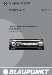
Lautsprecheranschluß / Loudspeaker connection / Raccordement des haut-parleurs /<br />
Conexión de altavoces / Collegamento degli altoparlanti / Högtalaranslutning / Luidsprekeraansluiting /<br />
Ligação de altifalantes<br />
Equalizer- und Amplifieranschluß / Connection of equalizer and amplifier / Raccordement de égaliseur et de<br />
l’amplificateur / Conexión de equalizador y amplificador / Collegamento dell’equillizzatore e dell’amplificatore<br />
/ Equalizer- och amplifieranslutning / Aansluiting equalizer en amplifier / Ligação de equalizadore e<br />
amplificadore<br />
Anschluß: siehe Einbauanleitung Amplifier / Connection: refer to installation instructions amplifier / Branchement: voir l’instruction de montage pour<br />
amplificateur / Conexión: véase las instrucciones de montaje para amplificador / Inkoppling: Se Amplifierns monteringsanvisning / Aansluiting: zie<br />
de inbouwinstructie voor de versterker / Ligação: Ver instruções de montagem referentes a amplificadores.<br />
Anschluß CD Player / Connection CD-Player / Raccordement de CD-Player / Conexión de CD-Player /<br />
Collegamento CD-Player / Anslutning av CD-spelare / Aansluiting CD-Player / Ligação de CD-Player<br />
* * Dem CD-Changer beiliegendes Adapterkabel oder Anschlußblock<br />
7 607 675 060 verwenden.<br />
* * Use the adapter cable enclosed to the CD-changer or the connecting<br />
block 7 607 675 060.<br />
* * Utiliser le cåble d’adapteur inclus au changeur CD ou le bloc de<br />
raccordement 7 607 675 060.<br />
* * Utilizar el cable adaptor adjunto al cambiador de discos compactos o<br />
la caja de conexión 7 607 675 060.<br />
* * Utilizzate il cavo adattore oppure il blocco d’allacciamento<br />
7 607 675 060 fornito.<br />
* * Använd den med CD-växlaren medföljande adapterkabeln eller<br />
anslutningsblock 7 607 675 060.<br />
* * Den met de CD-wisselaar meegeleverde adapterkabel gebruiken of<br />
aansluitblock 7 607 675 060.<br />
* * Utilizar o cabo adaptador em anexo ao CD-changer ou o bloco<br />
terminal 7 607 675 060.<br />
ILLUSTRATIONEN / ILLUSTRATIONS / ILLUSTRACIONES / ILLUSTRAZIONI / ILLUSTRATIONER / AFBEELDINGEN / ILLUSTRAÇOES<br />
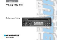
Anschlußübersicht / Connection overview / Vue d’ensemble des raccordements / Conexión ilustrada / Vista<br />
generale di collegamento / Anslutningsöversikt / Aansluitschema / Esquema de ligação
Anschlußhinweise, Fig. 5<br />
Masseanschluß (Ground)<br />
Massekabel nicht am Minuspol der Batterie anklemmen.<br />
Massekabel zu einem geeigneten Massepunkt verlegen (Karosserieschraube,<br />
Karosserieblech) und entsprechend Massepunkt kürzen.<br />
Massekabel abisolieren und Krallenkabelschuh anschlagen (ggf. nachlöten).<br />
Kontaktfläche des Massepunktes metallisch blank kratzen und mit<br />
Graphitfett einfetten (wichtig für gute Masseverbindung).<br />
Massekabel anschrauben.<br />
Pluskabelanschluß (ACC + 12 V)<br />
(Ignition)<br />
+12V<br />
Pluskabel mit Steckverteiler am Sicherungshalter Kl. 30 (Dauerplus)<br />
oder Kl. 15 (Plus über Zündschloß geschaltet) hinter der Sicherung<br />
anstecken.<br />
Dauerplusanschluß (Battery + 12 V)<br />
per. +12V<br />
Dauerplusanschluß mit Kabel und Kabelklemme an ein abgesichertes<br />
Dauerplus-Kabel (z. B. Zeituhr, Warnblinkschalter anschließen.<br />
Steuerkabel (Power Antenna +)<br />
+12V<br />
Bei Anschluß einer vollautomatischen Motorantenne Steuerkabel von<br />
der Motorantenne mit der Kabelklemme am Steuerkabel anklemmen.<br />
Beleuchtungsanschluß (Illumination)<br />
Beleuchtungsanschluß für Fahrzeuge mit regelbarer Instrumentenbeleuchtung<br />
(plusgeregelt).
MC/HDR<br />
<strong>Blaupunkt</strong>-Werke GmbH<br />
Bosch Telecom
Anschluß mit fahrzeugseitigem Systemstecker<br />
Fahrzeugseitiges Pluskabel nicht verwenden.<br />
Anschluß mit fahrzeugspezifischem QuickFit<br />
ist nicht möglich.<br />
Hinweis:<br />
2-Kanal Audi QuickFit 7 607 867 090 nicht verwenden.<br />
Zerstörungsgefahr der Endstufen!<br />
Pluskabelanschluß (ACC + 12 V)<br />
(Ignition)<br />
Fahrzeugseitiges Pluskabel nicht anschließen.<br />
Pluskabel (rot) mit starkem Querschnitt (2,5 mm2 ) zur Batterie verlegen<br />
(Kabel nicht unmittelbar an Kabelbäumen verlegen). Sicherungshalter<br />
zur Absicherung des Pluskabels anschließen und am Pluspol der<br />
Batterie anklemmen (ggf. Loch in Spritzwand bohren und entsprechend<br />
Kabeldurchführung verwenden).<br />
Hinweis:<br />
Auf Kundenwunsch kann bei Schaltung der Radioanlage über das<br />
Zündschloß die werkseitig verlegte geschaltete Plusleitung an ein Relais<br />
(Bosch Best.-Nr. 0 332 014 125) angeschlossen werden.<br />
Connection with multiple plug installed ex factory<br />
Do not use the positive cable installed ex<br />
factory.<br />
Connecton with vehicle specific Quick-Fit<br />
Not possible<br />
Note:<br />
Do not use the 2-channel Audi QuickFit 7 607 867 090. Danger of<br />
destroying the final stages!<br />
Positive cable (ACC + 12 V) (ignition)<br />
Do not use the positive cable installed in the car.<br />
Route the positive cable (thick red cable of 2.5 mm2 ) to the battery (do not<br />
route the cable near the cable harnesses). Connect the fuse holder to<br />
protect the positive cable and connect it to the positive pole of the battery<br />
(if necessary, drill a hole into the fire wall and use cable ducts).<br />
Note:<br />
Upon customer request and if the car radio system is operated via the<br />
ignition, the switched positive line, installed ex factory, can be connected<br />
to a relay (Bosch part no. 0 332 014 125).<br />
Branchement pour les connecteurs-systèmes incorporés dans<br />
la voiture<br />
Ne pas utiliser le câble positif installé de<br />
l’usine.<br />
Connexion avec QuickFit spécifique de la voiture<br />
n’est pas possible.<br />
Note:<br />
Ne pas utiliser le QuickFit Audi 2 canaux 7 607 867 090. Danger<br />
d’endommager les étages de sortie!<br />
Câble d’alimentation positive (ACC 12 V)<br />
(ignition)<br />
Ne pas raccorder le câble positif installé dans la voiture.<br />
Poser le câble positif (câble rouge d’une épaisseur de 2,5 mm2 ) vers le<br />
batterie (éviter de passer le câble près de faisceaux de câbles). Raccorder<br />
le porte-fusible pour protéger le câble positif et l’attacher au pôle de la<br />
batterie (si nécessaire, percer un trou dans le tablier d’auvent et utiliser<br />
un passe-câble approprié).<br />
Remarque:<br />
Si l’autoradio est raccordé par la serrure d’allumage, il est possible, sur<br />
demande du client, de relier sur un relais, réf. Bosch 0 332 014 125, le<br />
câble positif branché (installé d’origine).<br />
Conexión con enchufe múltiple ya existente<br />
No utilice el cable instalado de fábrica.<br />
Conexión con QuickFit específico<br />
No posible.<br />
Nota:<br />
No utilizar el conector Audi QuickFit a dos canales 7 607 867 090.<br />
Pueden dañarse las etapas finales!<br />
Cable de potencial positivo (ACC + 12 V)<br />
(ignition)<br />
Acoplar el cable positivo junto con el conector multíple al portafusibles<br />
detrás del fusible al borne 30 (polo positivo permanente) o 15 (a través<br />
del encendido).<br />
Conexión del positivo permanente<br />
(Battería +12 V)<br />
No conectar el cable positivo instalado en el coche.<br />
Colocar el cable positivo (rojo) con fuerte sección (2,5 mm2 ) hacia la<br />
batería (no colocar el cable cerca de árboles de conjuntos cableados).<br />
Conectar el portafusibles para proteger el cable positivo y conectarlo al<br />
polo positivo de la batería (en caso dado, taladrar un agujero en la pared<br />
salpicadero y emplear el aislador pasapanel correspondiente).<br />
Nota:<br />
Al conectar el equipo audio por el encendido, puede conectarse a un<br />
relé, (no. de pedido Bosch 0 332 014 125), al deseo del cliente, el cable<br />
positivo conectado colocado de fábrica.<br />
Collegamento con la spina già predisposta nella vettura<br />
Non utilizzare il cavo positivo della vettura.<br />
Collegamento con un QuickFit specifico per la vettura<br />
Non è possibile.<br />
Avvertenza:<br />
Non utilizzate il Audi QuickFit a 2 canali 7 607 867 090. Pericolo di<br />
distruzione degli stadi finali!<br />
Cavo positivo (ACC +12 V)<br />
(ignition)<br />
Non collegare il cavo positivo già predisposto nella vettura.<br />
Posare il cavo positivo (rosso) con una grande sezione (2,5 mm2 ) alla<br />
batteria. (Fare attenzione a non posare il cavo direttamente vicino a<br />
gruppi di cavi elettrici.) Come protezione per il cavo positivo allacciare un<br />
portafusibile e collegarlo al polo positivo della batteria (perforare<br />
eventualmente la parete divisoria ed usare un passacavo adatto).<br />
Avvertenza:<br />
Nel caso di un impianto radío comandato attraverso il contatto<br />
d’accensione, su richiesta del cliente il conduttore positivo già predisposto<br />
e collegato in fabbrica può essere collegato ad un relé (Numero<br />
d’ordinazione Bosch 0 332 014 125).
Inkoppling till fabriksframdragen systemkontakt<br />
Använd ej den framdragna plusledningen.<br />
Inkoppling med bilspecifikt QuickFit<br />
är oj möjlig<br />
Observa:<br />
Använd ej 2-kanal Audi QuickFit 7 607 867 090. Risk finns för skador på<br />
slutstegen!<br />
Pluskabelanslutning (ACC +12 V)<br />
(ignition)<br />
Anslut ej den fabriksframdragna pluskabeln.<br />
En pluskabel (röd) med grov area (2,5 mm2 ) dras direkt till batteriet.<br />
(Placera ej kabeln i närheten av befintliga kabelstammar.) Montera på en<br />
säkringshållare för avsäkring av kabeln och anslut till batteriets pluspol<br />
(använd gummigenomföringar när kabeln dras genom borrade hål).<br />
Hänvisning:<br />
Om kunden önskar att bilstereon skall kopplas över bilens tändlås måste<br />
ett relå (Bosch art.nr. 0 332 014 125) användar.<br />
Aansluiting bij voertuigen die reeds in de fabriek zijn voorzien<br />
van systeemstekers<br />
ACC-pluskabel van het voertuig niet gebruiken.<br />
Aansluiting met voertuigspecifieke Quick-Fit<br />
is niet mogelijk.<br />
Opmerking:<br />
2-kanaals QuickFit-aansluitblok (7 607 867 090) niet gebruiken. Gevaar<br />
voor beschadiging eindtrappen!<br />
Pluskabel (ACC +12 V)<br />
(ignition)<br />
ACC-pluskabel van het voertuig niet gebruiken.<br />
Pluskabel (rood) met forse doorsnede (2,5 mm2) direct naar accu<br />
trekken (kabel niet direct langs kabelbomen aanbrengen). Zekeringhouder<br />
als beveiling in de pluskabel opnemen en op de pluspool van de accu<br />
vastklemmen (eventueel tussenwand doorboren en passende<br />
doorvoertule gebruiken).<br />
Opmerking:<br />
Desgewenst kan bij schakeling van de installatie via het contactslot de<br />
van de fabriek uit aangebrachte pluskabel op een relais (bestelnr.<br />
0 332 014 125) worden aangesloten.<br />
Ligação com o sistema de fichas disponível no automóvel<br />
Não utilizar o cabo positivo do veículo.<br />
Ligação com o QuickFit especfico do veículo<br />
não é possível.<br />
Indicação<br />
Não utilizare um QuickFit com 2 canais 7 607 867 090. Perigo de<br />
danificação dos andares finais!<br />
Cabo positivo (ACC +12 V)<br />
(ignition)<br />
Não conectar o cabo positivo do veículo.<br />
LIgar o cabo positivo (vermelho) de diâmetro largo (2,5 mm2 ) com a<br />
bateria (não instalar o cabo directamente a uma cablagem préformada).<br />
Conectar o dispositivo de segurança como protecção do cabo positivo,<br />
e ligá-lo ao pólo positivo da bateria (se necessário fazer um furo na chapa<br />
e utilizar o orifício de cabos correspondente).<br />
Indicação:<br />
A desejo do cliente é possível conectar no caso de uma conexão do rádio<br />
através da ignição, a linha positiva instalada de fábrica a um relé (Bosch<br />
No. de artigo 0 332 014 125).